Measurement techniques of tailored optical fibres - CiteSeerX

Encyclopaedia of Materials Science and Technology - Updates", K.H.J. Buschow, R.W. Chan, M.C. Flemings, E.J. Kramer, S. Mahajan, P. Veyssiere (eds.), Elsevier, July, pp. 1-6 (2005).
Page -1-
MAGNETO-MECHANICAL STIMULATION OF BONE GROWTH A.E. Markaki and T.W. Clyne*
Department of Materials Science & Metallurgy Cambridge University Pembroke Street, Cambridge CB2 3QZ, UK e-mail: [email protected]
1. Background Replacement of hip, knee and other joints, usually as a treatment for degenerative arthritis, is
becoming increasingly common, with the worldwide market currently worth about $5 billion and an estimated annual growth rate of around 9%. These operations bring pain relief to millions, but the treatment is plagued by a substantial problem. The stem of the prosthesis, which is commonly pushed down into a recess in the host bone, often becomes loose after a time. The problem is getting worse as joint replacement rates rise and operations are carried out on younger and more active patients.
Prosthetic implants are attached to bone either with cement or via bone in-growth into a rough or porous surface. Although bone cement provides immediate fixation, cemented implants frequently loosen in time due to the poor wear and fatigue properties of such cement. Furthermore, in-vivo polymerization is likely to take place, with deleterious effects on the surrounding tissue. Strong bone-implant bonding can be achieved in the absence of cement by bone tissue growth into an implant surface which is rough or porous, preferably with channels of around 100-300 µm in diameter (Bobyn, Pilliar et al. 1980). However, this does not occur very readily or quickly and might typically take at least a couple of weeks – a period during which there is a serious danger of complete debonding if exercise is undertaken prematurely.
It is now well established (Frost 1987; Akhouayri, Lafage-Proust et al. 2000; Mosley 2000) that bone growth is stimulated by mechanical stress and becomes sluggish in its absence. Resultant phenomena include loss of bone density and strength in astronauts after extended periods in a hypo-gravity environment and localised bone resorption adjacent to prosthetic implants, as a consequence of stress shielding. This latter effect arises because prostheses are stiffer than surrounding bone, inhibiting it from being strained. (Most metals have a stiffness of about 100-200 GPa, whereas that of cortical bone is about 7-27 GPa).
Implants must satisfy well-defined biological and mechanical requirements. The range of materials known to be biocompatible, and in some cases bioactive, when in contact with bone tissue, is now quite extensive. Certain structural metals, notably titanium alloys and some stainless steels, have good biocompatibility, which can be improved by suitable surface coatings (Ducheyne, Van Raemdonek et al. 1986; De Groot, Geesink et al. 1987; Lacefield 1988; Shirkhanzadeh 1991; Nishiguchi, Kato et al. 1999; Kim, Takadama et al. 2000). Mechanical requirements include sufficient strength to avoid plastic deformation, brittle fracture and fatigue crack propagation, preferably with a stiffness at least approximately matching that of bone (to minimise stress shielding). It has been recognised (Chang, Oka et al. 1996; Oka, Chang et al. 1997; Hutmacher 2000; Kang, Yoon et al. 2002; Livingston, Ducheyne et al. 2002; Vehof, Haus et al. 2002) that potential for both stiffness matching and bone in-growth channels is offered by open-celled, highly porous metals. A possible problem with such highly porous materials is that they are unacceptably weak, particularly under tensile loading (Gibson 2000; Markaki and Clyne 2001). However, certain types of porous metal, produced by bonding together metallic fibres(Ducheyne, Aernoudt et al. 1978), do exhibit promising strength and toughness levels.
2. The Concept of Magneto-Mechanical Activation A radical new approach is proposed to the crucial problem of interfacial loosening. The idea
involves a highly porous ferromagnetic material being used for the implant, at least in the near-
* Corresponding author

Encyclopaedia of Materials Science and Technology - Updates", K.H.J. Buschow, R.W. Chan, M.C. Flemings, E.J. Kramer, S. Mahajan, P. Veyssiere (eds.), Elsevier, July, pp. 1-6 (2005).
Page -2-
surface region, into which bone growth will occur. This material can be made by assembling fibres of a magnetic material, such as ferritic stainless steel (which has good biocompatibity). Strong inter-fibre bonding can be achieved by brazing or sintering. An example is shown in Fig.1. Such a material can be actuated by the imposition of a magnetic field, with the fibres becoming magnetised along their length and tending to align parallel with the applied field. The resultant deformation of the fibre array generates a shape change, as illustrated in Fig.2. In-growing bone tissue filling the inter-fibre space would be mechanically strained during such deformation.
A simple analytical model (Markaki and Clyne 2004; Markaki and Clyne 2005) has been developed to predict the expected levels of deformation. Predictions indicate that, using magnetic field strengths already employed for diagnostic purposes (∼1 Tesla), it should be possible to generate strain levels sufficient to stimulate bone growth and to improve bone-implant bond, provided the architecture of the fibre array conforms to certain (achievable) requirements. The therapy would involve exposure to a suitable magnetic field after the implant operation, particularly during the short period immediately afterwards (the critical period for bone in-growth).
This concept should not be confused with that of an externally-applied magnetic field itself directly stimulating bone growth, which has often been suggested (Xu, Tomita et al. 2001; Kotani, Kawaguchi et al. 2002; Linovitz, Pathria et al. 2002), but which lacks both a clear mechanistic explanation and convincing experimental evidence for its efficacy. It also differs from the idea (Bausch, Moller et al. 1999) of using micro- or nano-scale ferromagnetic beads to generate forces within cells, which presents practical difficulties. In contrast to these two suggestions, the mechanistic basis for the proposed approach is simple, clear and well-founded.
3. Magneto-Mechanical Deflection Model An analytical magneto-mechanical model has been developed (Markaki and Clyne 2004) which
can be used to estimate the distortions induced in a free-standing porous specimen by application of a magnetic field. The model is based on the deflection of individual fibre segments (between joints) experiencing bending moments as a result of the induced magnetic dipole, with any straining associated with conventional elastic stretching or compression of the fibres in the loading direction being negligible in comparison. This is expected to be an acceptable approximation provided the segments are relatively slender. The corresponding lower limit on the segment aspect ratio is not well-defined, but by analogy with known characteristics of the bending of short beams, it is expected to be about 3. The geometry of such deflections is illustrated in Fig.3.
Furthermore, it is worth mentioning that any effects from demagnetising fields have not been taken into account. In reality, any finite shape magnet will produce a magnetic field directly opposite to the applied magnetic field. However, neglecting the effect of these demagnetizing fields is unlikely to generate large errors in the proposed model, at least for rod-like ferromagnets magnetised along their length (demagnetizing fields in the fibre axis are low).
4. Behaviour of a Random Fibre Array Prediction of the deformation characteristics of a three-dimensional array of bonded fibres is
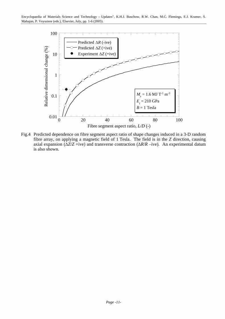
complex, particularly if they are not in a regular arrangement. For a random fibre orientation distribution, the deflection of a fibre segment will be constrained by neighbouring segments. However, if it is assumed that, averaged over the volume, constraint effects will cancel out, then the overall deformation can be predicted by summing the contributions from individual segments, taken in isolation. The net axial extension (∆Z/Z), which is positive, and the net transverse contraction (∆R/R), which is negative, are predicted (Markaki and Clyne 2004) to conform to Eqns. (1) and (2) respectively. It can be seen that magnetically-induced shape changes can be substantial, particularly for large segment aspect ratios, L/D - see Fig.4.
∆ZZ
= 16MsB9Ef
⎛
⎝ ⎜ ⎜
⎞
⎠ ⎟ ⎟
LD
⎛ ⎝ ⎜
⎞ ⎠ ⎟
2
(1)
∆RR
= −16M sB9πEf
⎛
⎝ ⎜ ⎜
⎞
⎠ ⎟ ⎟
LD
⎛ ⎝ ⎜
⎞ ⎠ ⎟
2
(2)

Encyclopaedia of Materials Science and Technology - Updates", K.H.J. Buschow, R.W. Chan, M.C. Flemings, E.J. Kramer, S. Mahajan, P. Veyssiere (eds.), Elsevier, July, pp. 1-6 (2005).
Page -3-
where B is the applied field, Ms is the saturation magnetization, Ef is the fibre modulus and L, D are the fibre length and diameter respectively.
The stiffness of the array, Earray, can also be predicted, using a similar approach (Markaki and Clyne 2004), which leads to
Earray = 9Ef f
32 LD
⎛ ⎝ ⎜
⎞ ⎠ ⎟
2 (3)
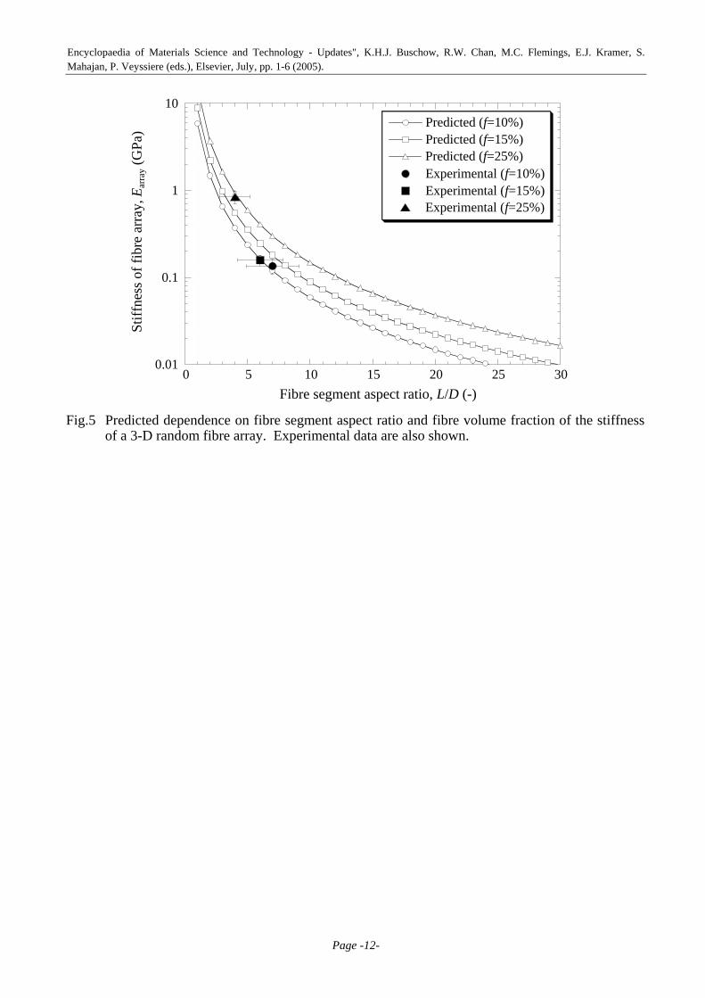
The stiffness thus depends on fibre volume fraction, f, as well as segment aspect ratio, L/D. Comparisons with experimental data are presented in Fig.5, which confirms that predictions are in good agreement with measured values. It can be seen that a low L/D (<~3) is required in order to match the stiffness of this material to that of cortical bone (~10 GPa).
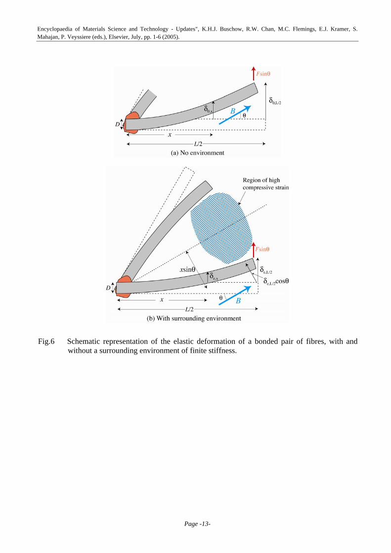
5. Straining of Material within a Fibre Array The model can be extended to predict the deformation of a fibre array when the space between the
fibres is filled with a material (ie an environment) of finite stiffness, Ee. This has the effect of reducing the fibre deflections - see Fig.6. Strains can be calculated between a pair of fibres which are taken in isolation and symmetrically oriented on opposite sides of the magnetic field axis, as shown in Fig.6(b). An estimate of the maximum strains induced in the space-filling material can be obtained using a simple force balance approach (Markaki and Clyne 2004). These strains will occur at the fibre mid-point, where the relative deflections are greatest. The analysis leads to
εmax ≈ 12πMs Bsin θ
LD
⎛ ⎝ ⎜
⎞ ⎠ ⎟
2
9πEf tanθ + 28EeLD
⎛ ⎝ ⎜
⎞ ⎠ ⎟
3⎛
⎝ ⎜ ⎜
⎞
⎠ ⎟ ⎟
(4)
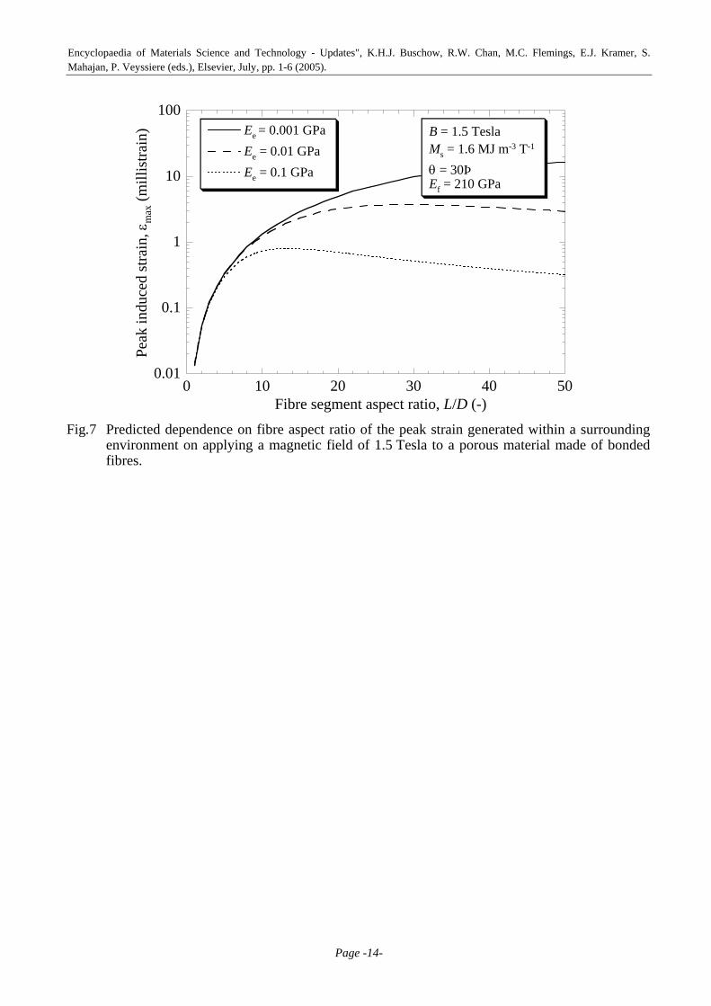
where θ is the angle between the fibre axis and the magnetic field axis (Fig.6). Predictions are shown in Fig.7, for several matrix stiffness levels. It can be seen that strain levels
expected to be physiologically beneficial (~1 millistrain) could be generated, particularly with relatively high L/D ratios. Generated strains clearly depend on the constraint imposed by the surrounding material. This is illustrated in Fig.8 (Markaki and Clyne 2005), which shows relative length changes of fibre arrays surrounded by air, resin and rubber, as a function of the applied magnetic field. Fairly good agreement is apparent between measured and predicted behaviour, although there are indications that the strain might approach a saturation level at high fields – at least for the uninfiltrated array. This is expected, since fibre alignment will become increasingly inhibited by neighbourhood constraint. It seems likely that numerical simulation will be needed in order to model the phenomenon more accurately, in conjunction with fuller characterisation of the material (particularly the distributions of fibre orientation and fibre segment aspect ratio).
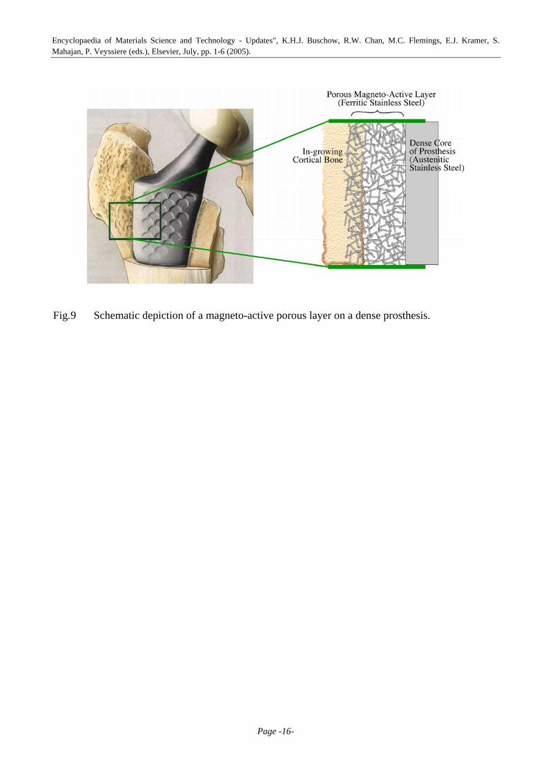
6. Integrated Prosthesis Design Model predictions (Figs.4 and 5) indicate that a single material cannot have both (a) a sufficiently
high fibre segment aspect ratio to confer the potential for magneto-mechanical induction of therapeutically beneficial strains and (b) a low enough aspect ratio to be sufficiently stiff to provide a good match with that of bone. However, an integrated design, involving a porous magneto-active layer bonded to a dense non-magnetic core, may allow this combination - see Fig.9. By varying the relative sectional areas of the two constituents, it should be possible to tailor the overall stiffness of the device. The porous layer would need to be relatively thick, since the regions immediately adjacent to the core would be constrained from deforming under the influence of a magnetic field. Furthermore, cell attachment and proliferation might need to be facilitated via deposition of bio-active coatings. Thin, compliant coatings will be desirable, to avoid constricting the pores within the fibre array and to reduce the danger of coating damage from magnetically-induced fibre deformation. It is in any event clear that systematic in vitro experimentation is now needed, to explore whether bone tissue cell growth can in fact be promoted via the proposed mechanism.

Encyclopaedia of Materials Science and Technology - Updates", K.H.J. Buschow, R.W. Chan, M.C. Flemings, E.J. Kramer, S. Mahajan, P. Veyssiere (eds.), Elsevier, July, pp. 1-6 (2005).
Page -4-
Acknowledgements Financial support for this work has come from the Cambridge-MIT Institute (CMI) and from
EPSRC, via a platform grant.

Encyclopaedia of Materials Science and Technology - Updates", K.H.J. Buschow, R.W. Chan, M.C. Flemings, E.J. Kramer, S. Mahajan, P. Veyssiere (eds.), Elsevier, July, pp. 1-6 (2005).
Page -5-
References Akhouayri, O., M. H. Lafage-Proust, A. Rattner, N. Laroche, A. Caillot-Augusseau, C. Alexandre
and L. Vico (2000). "Effects of Static or Dynamic Mechanical Stresses on Osteoblast Phenotype Expression in Three-Dimensional Contractile Collagen Gels." J. Cellular Biochemistry 76: 217-230.
Bausch, A. R., W. Moller and E. Sackmann (1999). "Measurement of Local Viscoelasticity and Forces in Living Cells by Magnetic Tweezers." Biophysical Journal 76: 573-579.
Bobyn, J. D., R. M. Pilliar, H. U. Cameron and G. C. Weatherly (1980). "The Optimum Pore Size for the Fixation of Porous-Surfaced Metal Implants by the Ingrowth of Bone." Clin. Orth. and Related Research 150: 263-270.
Chang, Y. S., M. Oka, M. Kobayashi, H. O. Gu, Z. L. Li, T. Nakamura and Y. Ikada (1996). "Significance of Interstitial Bone Ingrowth under Load-bearing Conditions: A Comparison between Solid and Porous Implant Materials." Biomaterials 17: 1141-1148.
De Groot, K., R. Geesink, C. P. A. T. Klein and P. Serekian (1987). "Plasma Sprayed Coatings of Hydroxyapatite." J. Biomed. Mater. Res. 21: 1375-1381.
Ducheyne, P., E. Aernoudt and P. De Meester (1978). "The Mechanical Behaviour of Porous Austenitic Stainless Steel Fibre Structures." J. Mater. Sci. 13: 2650-2658.
Ducheyne, P., W. Van Raemdonek, J. C. Heughbaert and M. Heughbaert (1986). "Structural Analysis of Hydroxyapatite Coatings on Titanium." Biomaterials 7: 97-103.
Frost, H. M. (1987). "Bone "Mass" and the "Mechanostat": A Proposal." Anatomical Record 219: 1-9.
Gibson, L. J. (2000). "Mechanical Behaviour of Metallic Foams." Ann. Rev. Mater. Sci. 30: 191-227.
Hutmacher, D. W. (2000). "Scaffolds in Tissue Engineering Bone and Cartilage." Biomaterials 21: 2529-2543.
Kang, S. B., K. S. Yoon, J. S. Kim, T. H. Nam and V. E. Gjunter (2002). "In vivo Result of Porous TiNi Shape Memory Alloy: Bone Response and Growth." Materials Transactions, JIM 43: 1045-1048.
Kim, H. M., H. Takadama, T. Kokubo, S. Nishiguchi and T. Nakamura (2000). "Formation of a Bioactive Graded Surface Structure on Ti-15Mo-5Zr-3Al Alloy by Chemical Treatment." Biomaterials 21: 353-358.
Kotani, H., H. Kawaguchi, T. Shimoaka, M. Iwasaka, S. Ueno, H. Ozawa, K. Nakamura and K. Hoshi (2002). "Strong Static Magnetic Field Stimulates Bone Formation to a Defininite Orientation In Vitro and In Vivo." J. Bone & Min. Res. 17: 1814-1821.
Lacefield, W. R. (1988). "Hydroxyapatite Coating." N. Y. Acad. Sci. 523: 72-80. Linovitz, R. J., M. Pathria, M. Bernhardt, D. Green, M. D. Law, R. A. McGuire, P. X. Montesano,
G. Rechtine, R. M. Salib, J. T. Ryaby, J. S. Faden, R. Ponder, L. R. Muenz, F. P. Magee and S. A. Garfin (2002). "Combined Magnetic Fields Accelerate and Increase Spine Fusion - A Double-blind, Randomized, Placebo Controlled Study." Spine 27: 1383-1388.
Livingston, T., P. Ducheyne and J. Garino (2002). "In vivo Evaluation of a Bioactive Scaffold for Bone Tissue Engineering." J. Biomed. Mater. Res. 62: 1-13.
Markaki, A. E. and T. W. Clyne (2001). "The Effect of Cell Wall Microstructure on the Deformation and Fracture of Aluminium-Based Foams." Acta Mater. 49: 1677-1686.
Markaki, A. E. and T. W. Clyne (2004). "Magneto-Mechanical Stimulation of Bone Growth in a Bonded Array of Ferromagnetic Fibres." Biomaterials 25: 4805-4815.
Markaki, A. E. and T. W. Clyne (2005). "Magneto-Mechanical Actuation of Bonded Ferromagnetic Fibre Arrays." Acta Mater. 53: 877-889.
Mosley, J. R. (2000). "Osteoporosis and Bone Functional Adaptation: Mechanobiological Regulation of Bone Architecture in Growing and Adult Bone, a Review." J. Rehab. Res. & Develop. 37: 189-199.
Nishiguchi, S., H. Kato, H. Fujita, H. M. Kim, F. Miyaji, T. Kokubo and T. Nakamura (1999). "Enhancement of Bone Bonding Strengths of Titanium Alloy Implants by Alkali and Heat Treatments." J. Biomed. Mater. Res. (Appl. Biomater.) 48: 689-696.

Encyclopaedia of Materials Science and Technology - Updates", K.H.J. Buschow, R.W. Chan, M.C. Flemings, E.J. Kramer, S. Mahajan, P. Veyssiere (eds.), Elsevier, July, pp. 1-6 (2005).
Page -6-
Oka, M., Y. S. Chang, T. Nakamura, K. Ushio, J. Toguchida and H. O. Gu (1997). "Synthetic Osteochondral Replacement of the Femoral Articular Surface." J. Bone & Joint Surgery (UK) 79: 1003-1007.
Shirkhanzadeh, M. (1991). "Bioactive Calcium Phosphate Coatings prepared by Electrodeposition." J. Mater. Sci. Letters 10: 1415-1421.
Vehof, J. W., M. T. Haus, A. E. de Ruijter, P. H. Spauwen and J. A. Jansen (2002). "Bone Formation in Transforming Growth Factor Beta-I-Loaded Titanium Fiber Mesh Implants." Clinical Oral Implants Research 13: 94-102.
Xu, S., N. Tomita, R. Ohata, Q. Yan and Y. Ikada (2001). "Static Magnetic Field Effects on Bone Formation of Rats with an Ischemic Bone Model." Bio-Medical Materials & Engineering 11: 257-263.
Encyclopaedia of Materials Science and Technology - Updates", K.H.J. Buschow, R.W. Chan, M.C. Flemings, E.J. Kramer, S. Mahajan, P. Veyssiere (eds.), Elsevier, July, pp. 1-6 (2005).
Page -7-
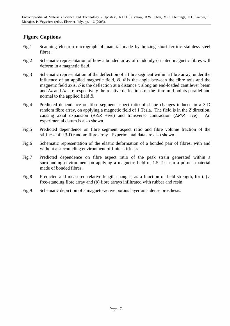
Figure Captions
Fig.1 Scanning electron micrograph of material made by brazing short ferritic stainless steel fibres.
Fig.2 Schematic representation of how a bonded array of randomly-oriented magnetic fibres will deform in a magnetic field.
Fig.3 Schematic representation of the deflection of a fibre segment within a fibre array, under the influence of an applied magnetic field, B. θ is the angle between the fibre axis and the magnetic field axis, δ is the deflection at a distance x along an end-loaded cantilever beam and ∆z and ∆r are respectively the relative deflections of the fibre mid-points parallel and normal to the applied field B.
Fig.4 Predicted dependence on fibre segment aspect ratio of shape changes induced in a 3-D random fibre array, on applying a magnetic field of 1 Tesla. The field is in the Z direction, causing axial expansion (∆Z/Z +ive) and transverse contraction (∆R/R –ive). An experimental datum is also shown.
Fig.5 Predicted dependence on fibre segment aspect ratio and fibre volume fraction of the stiffness of a 3-D random fibre array. Experimental data are also shown.
Fig.6 Schematic representation of the elastic deformation of a bonded pair of fibres, with and without a surrounding environment of finite stiffness.
Fig.7 Predicted dependence on fibre aspect ratio of the peak strain generated within a surrounding environment on applying a magnetic field of 1.5 Tesla to a porous material made of bonded fibres.
Fig.8 Predicted and measured relative length changes, as a function of field strength, for (a) a free-standing fibre array and (b) fibre arrays infiltrated with rubber and resin.
Fig.9 Schematic depiction of a magneto-active porous layer on a dense prosthesis.

Encyclopaedia of Materials Science and Technology - Updates", K.H.J. Buschow, R.W. Chan, M.C. Flemings, E.J. Kramer, S. Mahajan, P. Veyssiere (eds.), Elsevier, July, pp. 1-6 (2005).
Page -8-
Fig.1 Scanning electron micrograph of material made by brazing short ferritic stainless steel fibres.

Encyclopaedia of Materials Science and Technology - Updates", K.H.J. Buschow, R.W. Chan, M.C. Flemings, E.J. Kramer, S. Mahajan, P. Veyssiere (eds.), Elsevier, July, pp. 1-6 (2005).
Page -9-
Fig.2 Schematic representation of how a bonded array of randomly-oriented magnetic fibres will deform in a magnetic field.

Encyclopaedia of Materials Science and Technology - Updates", K.H.J. Buschow, R.W. Chan, M.C. Flemings, E.J. Kramer, S. Mahajan, P. Veyssiere (eds.), Elsevier, July, pp. 1-6 (2005).
Page -10-
Fig.3 Schematic representation of the deflection of a fibre segment within a fibre array, under the influence of an applied magnetic field, B. θ is the angle between the fibre axis and the magnetic field axis, δ is the deflection at a distance x along an end-loaded cantilever beam and ∆z and ∆r are respectively the relative deflections of the fibre mid-points parallel and normal to the applied field B.
Encyclopaedia of Materials Science and Technology - Updates", K.H.J. Buschow, R.W. Chan, M.C. Flemings, E.J. Kramer, S. Mahajan, P. Veyssiere (eds.), Elsevier, July, pp. 1-6 (2005).
Page -11-
0.01
0.1
1
10
100
0 20 40 60 80 100
Predicted ∆R (-ive)Predicted ∆Z (+ive)Experiment ∆Z (+ive)
Rel
ativ
e di
men
sion
al c
hang
e (%
)
Fibre segment aspect ratio, L/D (-)
Ms = 1.6 MJ T-1 m-3
Ef = 210 GPa
B = 1 Tesla
Fig.4 Predicted dependence on fibre segment aspect ratio of shape changes induced in a 3-D random
fibre array, on applying a magnetic field of 1 Tesla. The field is in the Z direction, causing axial expansion (∆Z/Z +ive) and transverse contraction (∆R/R –ive). An experimental datum is also shown.
Encyclopaedia of Materials Science and Technology - Updates", K.H.J. Buschow, R.W. Chan, M.C. Flemings, E.J. Kramer, S. Mahajan, P. Veyssiere (eds.), Elsevier, July, pp. 1-6 (2005).
Page -12-
0.01
0.1
1
10
0 5 10 15 20 25 30
Predicted (f=10%)Predicted (f=15%)Predicted (f=25%)Experimental (f=10%)Experimental (f=15%)Experimental (f=25%)
Stif
fnes
s of f
ibre
arr
ay, E
arra
y (G
Pa)
Fibre segment aspect ratio, L/D (-) Fig.5 Predicted dependence on fibre segment aspect ratio and fibre volume fraction of the stiffness
of a 3-D random fibre array. Experimental data are also shown.
Encyclopaedia of Materials Science and Technology - Updates", K.H.J. Buschow, R.W. Chan, M.C. Flemings, E.J. Kramer, S. Mahajan, P. Veyssiere (eds.), Elsevier, July, pp. 1-6 (2005).
Page -13-
Fig.6 Schematic representation of the elastic deformation of a bonded pair of fibres, with and without a surrounding environment of finite stiffness.
Encyclopaedia of Materials Science and Technology - Updates", K.H.J. Buschow, R.W. Chan, M.C. Flemings, E.J. Kramer, S. Mahajan, P. Veyssiere (eds.), Elsevier, July, pp. 1-6 (2005).
Page -14-
0.01
0.1
1
10
100
0 10 20 30 40 50
Ee = 0.001 GPaEe = 0.01 GPaEe = 0.1 GPa
Peak
indu
ced
stra
in, ε
max
(mill
istra
in)
Fibre segment aspect ratio, L/D (-)
B = 1.5 TeslaMs = 1.6 MJ m-3 T-1
θ = 30ÞEf = 210 GPa
Fig.7 Predicted dependence on fibre aspect ratio of the peak strain generated within a surrounding
environment on applying a magnetic field of 1.5 Tesla to a porous material made of bonded fibres.

Encyclopaedia of Materials Science and Technology - Updates", K.H.J. Buschow, R.W. Chan, M.C. Flemings, E.J. Kramer, S. Mahajan, P. Veyssiere (eds.), Elsevier, July, pp. 1-6 (2005).
Page -15-
0 0.05 0.1 0.15 0.2 0.25 0.30
0.2
0.4
0.6
0.8
1
1.2
ExperimentPredicted (L/D=6)Predicted (L/D=10)
Relative deflection parallel to field, ∆Z / Z (%)
App
lied
field
, B (T
esla
)(a)
0 0.05 0.1 0.15 0.2 0.25 0.30
0.2
0.4
0.6
0.8
1
1.2
Experiment (rubber matrix)Predicted (rubber matrix), L/D=6Predicted (rubber matrix), L/D=10Experiment (resin matrix)Predicted (resin matrix), L/D=6
Relative deflection parallel to field, ∆Z / Z (%)
App
lied
field
, B (T
esla
)
(b)
Fig.8 Predicted and measured relative length changes, as a function of field strength, for (a) a free-standing fibre array and (b) fibre arrays infiltrated with rubber and resin.
Encyclopaedia of Materials Science and Technology - Updates", K.H.J. Buschow, R.W. Chan, M.C. Flemings, E.J. Kramer, S. Mahajan, P. Veyssiere (eds.), Elsevier, July, pp. 1-6 (2005).
Page -16-
Fig.9 Schematic depiction of a magneto-active porous layer on a dense prosthesis.
Copyright © 2022 FDOKUMEN