Macao Bridge (HZMB) Hong Kong Link Road Project - YWL ...
12
ICE HKA Annual Conference 2015 Thinking out of the box in infrastructure development and retrofitting 53 Innovative solutions in Hong Kong – Zhuhai – Macao Bridge (HZMB) Hong Kong Link Road Project Man Chan Dragages Hong Kong Limited, Hong Kong Donald S.H. Chan China Harbour Engineering Company Limited (Hong Kong), Hong Kong Patrick W.H. Ng Highways Department, Government of the Hong Kong SAR Y.W. Leung and L.L. Yue YWL Engineering Private Limited, Singapore Keywords: ABSTRACT: The viaducts of the Hong Kong Link Road under Contract HY/2011/09 are precast prestressed concrete structures constructed using segmental balanced cantilever method with span length ranging from 35m to 180m. About 7 km of the viaducts are marine structures and some special techniques have been employed to tackle the challenges encountered in this environment. This paper covers the design and construction methods adopted in the marine viaducts to meet particular operation needs. It delineates the prestressed method employed in the formation of monolithic deck-column connections. Precast segmental piers are used in order to improve construction efficiency and works quality. The pier structural behaviour and measures to enhance the long-term performance are discussed. Pile caps in the marine viaducts are either built at +3.95mPD above the water in open sea at Western Waters or below existing seabed in Airport Channel where flow disturbance should be minimized. The pile caps above water are constructed using precast concrete shells designed as temporary work. Special design and construction considerations for the shells are discussed in this paper. 1 INTRODUCTION The Hong Kong Link Road (HKLR) is a prominent structure that serves to connect the Main Bridge of HongKong-Zuhai-Macao Bridge (HZMB) at the HKSAR Boundary and the tunnel portal at Scenic Hill in Airport Island (See Figure 1). The works under Highways Department Contract No. HY/2011/09 comprises mainly design and construction of approximately 9km of viaducts supporting dual 3-lane carriageways passing through four zones. In the west, it is open water with a vast horizon where the HKLR connects to the HZMB Main Bridge in the mainland. Two 1-way navigation channels, each with a minimum navigable width of 100m, are designed to have a clear spacing of 200m. See Figure 2a. Existing seabed in this area is generally underlain by 30m-40m of soft marine clay. Due to the presence of fault zones, the bedrock in some locations exceeds 100m deep. As the viaducts approach San Shek Wan and Sha Lo Wan, the geology changes drastically where bedrock becomes very shallow. Since an archaeological site is located in the vicinity, no structures (either permanent or temporary) are allowed to be built in this sensitive zone and therefore, long-span decks (165m-180m) have been adopted in this area. Long-span decks are continuously employed in the Airport Channel where a 2-way navigation channel of 46m is provided. A 180m long span is used to cater for the sharp skew angle of the navigation channel. All pile caps within the Airport Channel are embedded below existing seabed in order to minimise any hydrodynamic impact to the Channel, except those for the navigation span which are emerged with the pile cap top above the sea at +3.95mPD. See Figure 2b.
-
Upload
khangminh22 -
Category
Documents
-
view
5 -
download
0
Transcript of Macao Bridge (HZMB) Hong Kong Link Road Project - YWL ...

ICE HKA Annual Conference 2015
Thinking out of the box in infrastructure development and retrofitting
53
Innovative solutions in Hong Kong – Zhuhai – Macao Bridge (HZMB) Hong Kong Link Road Project
Man Chan Dragages Hong Kong Limited, Hong Kong
Donald S.H. Chan China Harbour Engineering Company Limited (Hong Kong), Hong Kong
Patrick W.H. Ng Highways Department, Government of the Hong Kong SAR
Y.W. Leung and L.L. Yue YWL Engineering Private Limited, Singapore
Keywords:
ABSTRACT: The viaducts of the Hong Kong Link Road under Contract HY/2011/09 are precast prestressed concrete structures constructed using segmental balanced cantilever method with span length ranging from 35m to 180m. About 7 km of the viaducts are marine structures and some special techniques have been employed to tackle the challenges encountered in this environment. This paper covers the design and construction methods adopted in the marine viaducts to meet particular operation needs. It delineates the prestressed method employed in the formation of monolithic deck-column connections. Precast segmental piers are used in order to improve construction efficiency and works quality. The pier structural behaviour and measures to enhance the long-term performance are discussed. Pile caps in the marine viaducts are either built at +3.95mPD above the water in open sea at Western Waters or below existing seabed in Airport Channel where flow disturbance should be minimized. The pile caps above water are constructed using precast concrete shells designed as temporary work. Special design and construction considerations for the shells are discussed in this paper. 1 INTRODUCTION
The Hong Kong Link Road (HKLR) is a prominent structure that serves to connect the Main Bridge of HongKong-Zuhai-Macao Bridge (HZMB) at the HKSAR Boundary and the tunnel portal at Scenic Hill in Airport Island (See Figure 1). The works under Highways Department Contract No. HY/2011/09 comprises mainly design and construction of approximately 9km of viaducts supporting dual 3-lane carriageways passing through four zones.
In the west, it is open water with a vast horizon where the HKLR connects to the HZMB Main Bridge in the mainland. Two 1-way navigation channels, each with a minimum navigable width of 100m, are designed to have a clear spacing of 200m. See Figure 2a. Existing seabed in this area is generally underlain by 30m-40m of soft marine clay. Due to the presence of fault zones, the bedrock in some locations exceeds 100m deep.
As the viaducts approach San Shek Wan and Sha Lo Wan, the geology changes drastically where bedrock becomes very shallow. Since an archaeological site is located in the vicinity, no structures (either permanent or temporary) are allowed to be built in this sensitive zone and therefore, long-span decks (165m-180m) have been adopted in this area.
Long-span decks are continuously employed in the Airport Channel where a 2-way navigation channel of 46m is provided. A 180m long span is used to cater for the sharp skew angle of the navigation channel. All pile caps within the Airport Channel are embedded below existing seabed in order to minimise any hydrodynamic impact to the Channel, except those for the navigation span which are emerged with the pile cap top above the sea at +3.95mPD. See Figure 2b.

ICE HKA Annual Conference 2015
Thinking out of the box in infrastructure development and retrofitting
54
About 2 km of the viaducts are on land along the southern side of the Airport Island. One of the critical site constraints for constructing the viaducts is the requirement on Airport Height Restriction (AHR) pursuant to the Hong Kong Airport (Control of Obstructions) Ordinance. All works on the Airport Island have to be carefully planned and designed without imposing any risk to the normal operation of the airport.
There are many challenges in this project, namely, voluminous construction in marine environment that imposes difficulties in material logistics, working close to sensitive areas such as the archaeological site & Hong Kong International Airport (HKIA), foundation works in complex geology with significant ground variation and so on. This 12.9 billion Hong Kong dollar contract was awarded to Dragages-China Harbour-VSL Joint Venture (DCVJV) in June 2012. YWL Engineering Pte Ltd (YWL) was appointed as the Designer and construction engineering consultant for the marine viaducts.
Figure 1 Location plan
2 CHARACTERISTICS OF THE VIADUCTS
Precast segmental technology has been proven to be an efficient method to large scale viaduct projects and has many successful examples in Hong Kong and worldwide. This technique was selected as the predominant form in the design of the viaducts in this project. Since the majority of the bridge spans are over 75m long, balanced cantilever method with epoxy glued joints was adopted due to its flexibility and cost effectiveness in construction.
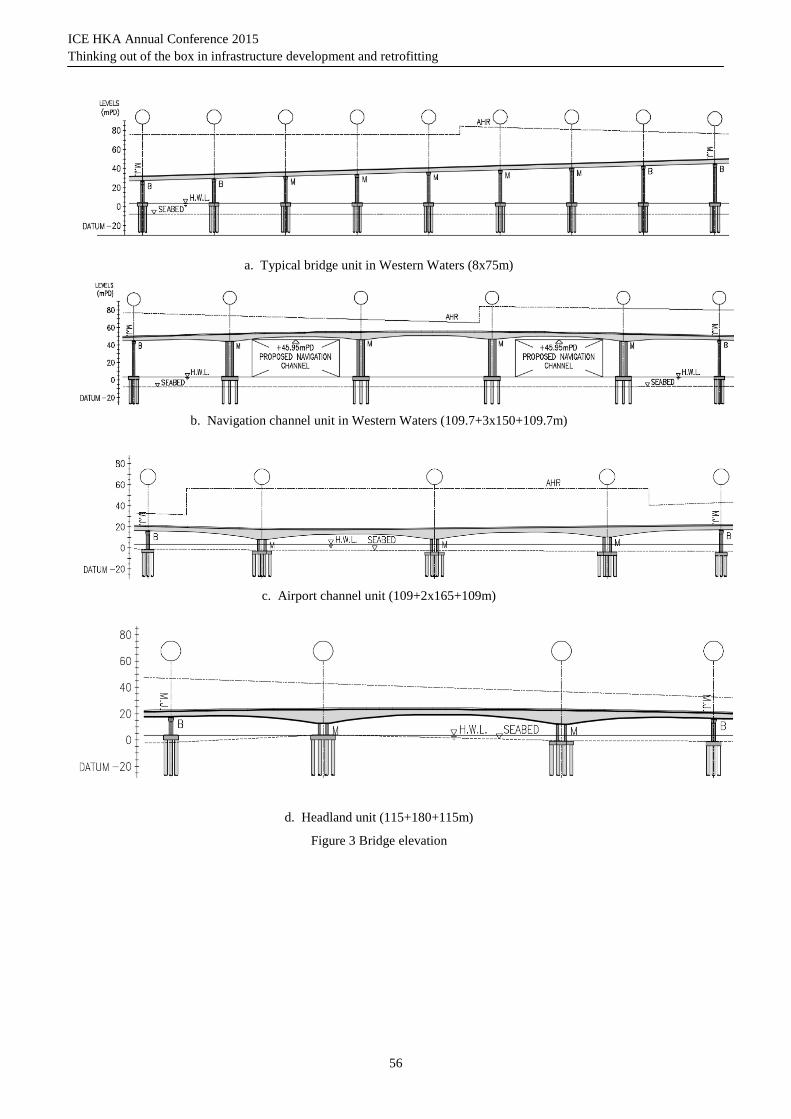
The viaducts in this project consist of 115 spans with span length ranging from 35m to 180m. Conventional medium span decks were primarily used in the land viaducts. The typical span length of the marine viaducts in Western Waters is 75m with a constant box depth of 4m. In articulation design, a typical bridge unit of 8-span continuous deck (600m long) was adopted with optimal use of bearings and movement joints so as to reduce future maintenance effort. Other than the first internal piers, all other internal piers were constructed monolithically with the bridge deck (see Figure 4a and 4b). To improve the aesthetics, the length of the end span was made the same as the internal ones in order to provide a regular rhythm of the spans (see Figure 3a).
ICE HKA Annual Conference 2015
Thinking out of the box in infrastructure development and retrofitting
55
a. Viaducts in Western Waters
b. Viaducts in airport channel & headland
Figure 2 Artist impression
The functional requirement of the navigation channels in Western Waters was realized by a 5-span bridge unit with a configuration of 109m+3x150m+109m. Movement joints and bearings were provided only at the 2 ends of this 668m long bridge. The segmental box girder has a continuously varying depth from 7.936m at pier to 4m near the mid span. The internal twin-blade piers were monolithically connected to the deck. The form of these piers was selected with the objective to minimize the longitudinal stiffness of the bridge and reduce the lock-in effects due to creep, shrinkage and thermal deformations (see Figure 3b & 4c).
A grade-separated turnaround facility near San Shek Wan comprised of slip roads in the form of single-lane viaducts bifurcates from the HKLR mainline carriageways forming an elevated junction above. It consists of 6-span continuous mainline deck integrated with 2 ramps. A smaller box section of 9m wide was deployed for the ramps.
In the headland between San Shek Wan (SSW) and Sha Lo Wan (SLW), where an archaeological site had been located, a long-span deck of 180m overpassing the headland was proposed. The bridge configuration that provides a 180m long clear span in the centre is a 3-span continuous structure with two 115m long end spans. The segmental box girder has a continuously varying depth from 10m at pier to 4m near the mid span. The vertical alignment of the bridge was designed to satisfy the criterion that the span over the existing SLW pier will not obstruct its daily operation. The articulation of this bridge unit is similar to the one in the navigation channel with monolithic internal twin-blade piers and bearings at two ends (see Figure 3d).
For viaducts in the Airport Channel, 4 bridge units with two generic configurations of 109m+2x165m+109m (see Figure 3c) and 115m+2x180m+115m were proposed. Their articulation is the same as other long span structure in this project.
ICE HKA Annual Conference 2015
Thinking out of the box in infrastructure development and retrofitting
56
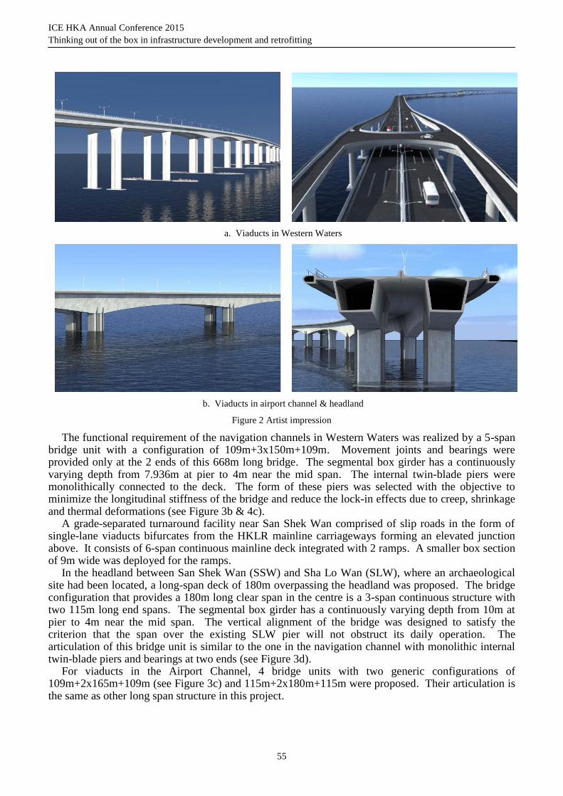
a. Typical bridge unit in Western Waters (8x75m)
b. Navigation channel unit in Western Waters (109.7+3x150+109.7m)
c. Airport channel unit (109+2x165+109m)
d. Headland unit (115+180+115m)
Figure 3 Bridge elevation
ICE HKA Annual Conference 2015
Thinking out of the box in infrastructure development and retrofitting
57
a. Typical pier bearings
b. Typical monolithic pier
c. Double blade pier for span larger than 100m
Figure 4 Bridge sectional view
ICE HKA Annual Conference 2015
Thinking out of the box in infrastructure development and retrofitting
58
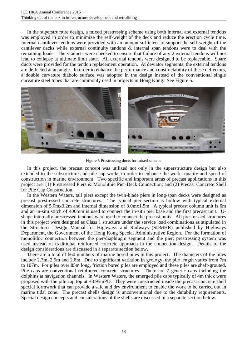
In the superstructure design, a mixed prestressing scheme using both internal and external tendons was employed in order to minimize the self-weight of the deck and reduce the erection cycle time. Internal cantilever tendons were provided with an amount sufficient to support the self-weight of the cantilever decks while external continuity tendons & internal span tendons were to deal with the remaining loads. The viaducts were checked to ensure that failure of any 2 external tendons will not lead to collapse at ultimate limit state. All external tendons were designed to be replaceable. Spare ducts were provided for the tendon replacement operation. At deviator segments, the external tendons are deflected at an angle. In order to enhance the performance and constructability of these deflectors, a double curvature diabolo surface was adopted in the design instead of the conventional single curvature steel tubes that are commonly used in projects in Hong Kong. See Figure 5.
Figure 5 Prestressing ducts for mixed scheme
In this project, the precast concept was utilized not only in the superstructure design but also extended to the substructure and pile cap works in order to enhance the works quality and speed of construction in marine environment. Two specific and important areas of precast applications in this project are: (1) Prestressed Piers & Monolithic Pier-Deck Connection; and (2) Precast Concrete Shell for Pile Cap Construction.
In the Western Waters, tall piers except the twin-blade piers in long-span decks were designed as precast prestressed concrete structures. The typical pier section is hollow with typical external dimension of 5.0mx3.2m and internal dimension of 3.0mx1.5m. A typical precast column unit is 6m and an in-situ stitch of 400mm is used to connect the in-situ pier base and the first precast unit. U-shape internally prestressed tendons were used to connect the precast units. All prestressed structures in this project were designed as Class 1 structure under the service load combinations as stipulated in the Structures Design Manual for Highways and Railways (SDMHR) published by Highways Department, the Government of the Hong Kong Special Administrative Region. For the formation of monolithic connection between the pier/diaphragm segment and the pier, prestressing system was used instead of traditional reinforced concrete approach in the connection design. Details of the design considerations are discussed in a separate section below.
There are a total of 660 numbers of marine bored piles in this project. The diameters of the piles include 2.3m, 2.5m and 2.8m. Due to significant variation in geology, the pile length varies from 7m to 107m. For piles over 85m long, friction bored piles are employed and these piles are shaft-grouted. Pile caps are conventional reinforced concrete structures. There are 7 generic caps including the dolphins at navigation channels. In Western Waters, the emerged pile caps typically of 4m thick were proposed with the pile cap top at +3.95mPD. They were constructed inside the precast concrete shell special formwork that can provide a safe and dry environment to enable the work to be carried out in marine tidal zone. The precast shells design is unconventional due to the durability requirements. Special design concepts and considerations of the shells are discussed in a separate section below.
ICE HKA Annual Conference 2015
Thinking out of the box in infrastructure development and retrofitting
59
3 PRESTRESSED PIER AND MONOLITHIC PIER-DECK CONNECTION
In earlier projects in Hong Kong, deck-pier monolithic connections are typically formed by two methods. The first one is to cast the pier segment together with the pier as an integral unit by in-situ method. For geometry control purpose, wet joints are subsequently introduced between the pier segment and the first typical segments on both sides during deck construction. The second common approach is to precast the pier segment as a shell which will later be infilled with in-situ concrete and the connection joint is normally a reinforced concrete structure. If the pier shell segment is match-cast with the adjacent segments, the wet joints could be eliminated.
In this project, the monolithic connection between the pier segment and the pier was achieved using prestressing. All structural components were precast. This method is a new attempt in the local practice and is driven by the need to minimize the in-situ concrete works in the marine environment and optimization of the erection cycle time. After the pier segment was installed with geometry adjusted, its spatial position was fixed on temporary supports. The precast plinths would then be grouted prior to application of the vertical nailing prestressing in the formation of the monolithic joint.
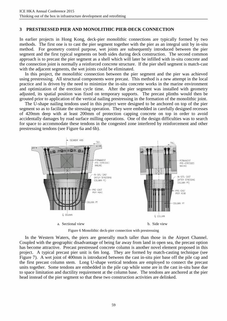
The U-shape nailing tendons used in this project were designed to be anchored on top of the pier segment so as to facilitate the stressing operation. They were embedded in carefully designed recesses of 420mm deep with at least 200mm of protection capping concrete on top in order to avoid accidentally damages by road surface milling operations. One of the design difficulties was to search for space to accommodate these tendons in the congested zone interfered by reinforcement and other prestressing tendons (see Figure 6a and 6b).
a. Sectional view b. Side view
Figure 6 Monolithic deck-pier connection with prestressing
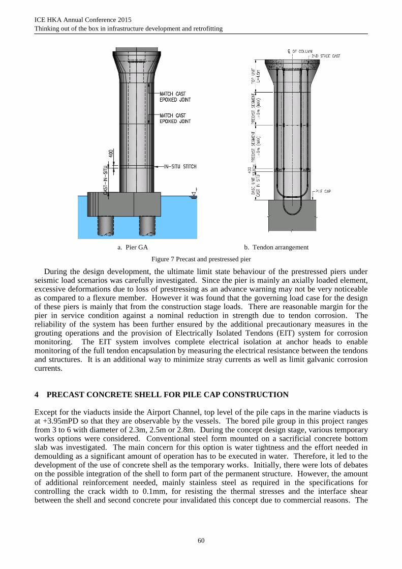
In the Western Waters, the piers are generally much taller than those in the Airport Channel. Coupled with the geographic disadvantage of being far away from land in open sea, the precast option has become attractive. Precast prestressed concrete column is another novel element proposed in this project. A typical precast pier unit is 6m long. They are formed by match-casting technique (see Figure 7). A wet joint of 400mm is introduced between the cast in-situ pier base off the pile cap and the first precast column stem. Long U-shape vertical tendons are employed to connect the precast units together. Some tendons are embedded in the pile cap while some are in the cast in-situ base due to space limitation and ductility requirement at the column base. The tendons are anchored at the pier head instead of the pier segment so that these two construction activities are delinked.
ICE HKA Annual Conference 2015
Thinking out of the box in infrastructure development and retrofitting
60
a. Pier GA b. Tendon arrangement
Figure 7 Precast and prestressed pier
During the design development, the ultimate limit state behaviour of the prestressed piers under seismic load scenarios was carefully investigated. Since the pier is mainly an axially loaded element, excessive deformations due to loss of prestressing as an advance warning may not be very noticeable as compared to a flexure member. However it was found that the governing load case for the design of these piers is mainly that from the construction stage loads. There are reasonable margin for the pier in service condition against a nominal reduction in strength due to tendon corrosion. The reliability of the system has been further ensured by the additional precautionary measures in the grouting operations and the provision of Electrically Isolated Tendons (EIT) system for corrosion monitoring. The EIT system involves complete electrical isolation at anchor heads to enable monitoring of the full tendon encapsulation by measuring the electrical resistance between the tendons and structures. It is an additional way to minimize stray currents as well as limit galvanic corrosion currents.
4 PRECAST CONCRETE SHELL FOR PILE CAP CONSTRUCTION
Except for the viaducts inside the Airport Channel, top level of the pile caps in the marine viaducts is at +3.95mPD so that they are observable by the vessels. The bored pile group in this project ranges from 3 to 6 with diameter of 2.3m, 2.5m or 2.8m. During the concept design stage, various temporary works options were considered. Conventional steel form mounted on a sacrificial concrete bottom slab was investigated. The main concern for this option is water tightness and the effort needed in demoulding as a significant amount of operation has to be executed in water. Therefore, it led to the development of the use of concrete shell as the temporary works. Initially, there were lots of debates on the possible integration of the shell to form part of the permanent structure. However, the amount of additional reinforcement needed, mainly stainless steel as required in the specifications for controlling the crack width to 0.1mm, for resisting the thermal stresses and the interface shear between the shell and second concrete pour invalidated this concept due to commercial reasons. The
ICE HKA Annual Conference 2015
Thinking out of the box in infrastructure development and retrofitting
61
final decision was to use the precast concrete shells mainly as temporary works but integrated with the permanent cap as additional protection against corrosive marine environment.
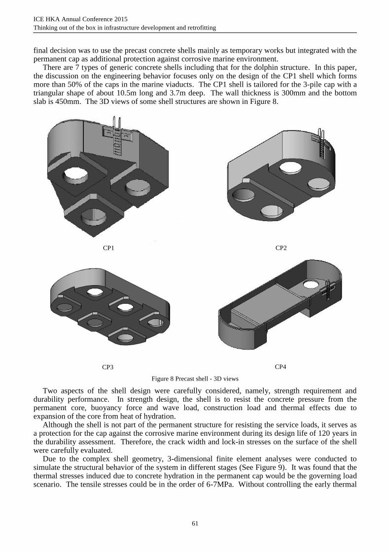
There are 7 types of generic concrete shells including that for the dolphin structure. In this paper, the discussion on the engineering behavior focuses only on the design of the CP1 shell which forms more than 50% of the caps in the marine viaducts. The CP1 shell is tailored for the 3-pile cap with a triangular shape of about 10.5m long and 3.7m deep. The wall thickness is 300mm and the bottom slab is 450mm. The 3D views of some shell structures are shown in Figure 8.
CP1
CP2
CP3
CP4
Figure 8 Precast shell - 3D views
Two aspects of the shell design were carefully considered, namely, strength requirement and durability performance. In strength design, the shell is to resist the concrete pressure from the permanent core, buoyancy force and wave load, construction load and thermal effects due to expansion of the core from heat of hydration.
Although the shell is not part of the permanent structure for resisting the service loads, it serves as a protection for the cap against the corrosive marine environment during its design life of 120 years in the durability assessment. Therefore, the crack width and lock-in stresses on the surface of the shell were carefully evaluated.
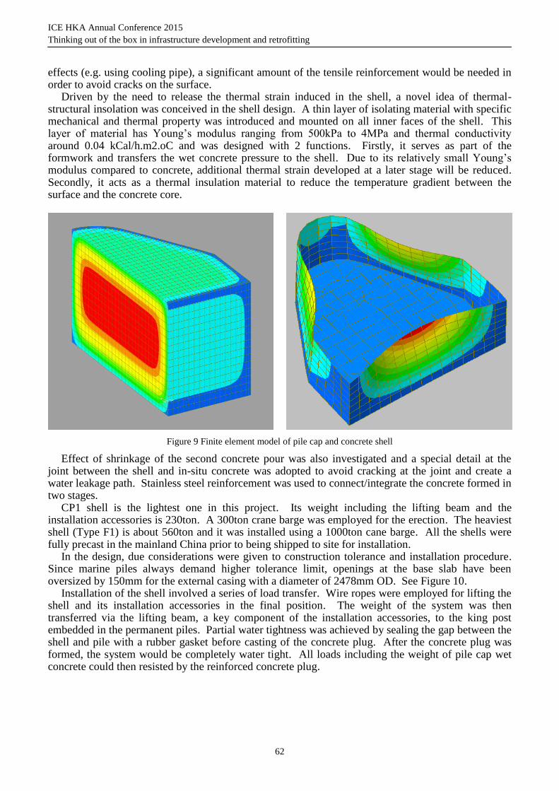
Due to the complex shell geometry, 3-dimensional finite element analyses were conducted to simulate the structural behavior of the system in different stages (See Figure 9). It was found that the thermal stresses induced due to concrete hydration in the permanent cap would be the governing load scenario. The tensile stresses could be in the order of 6-7MPa. Without controlling the early thermal
ICE HKA Annual Conference 2015
Thinking out of the box in infrastructure development and retrofitting
62
effects (e.g. using cooling pipe), a significant amount of the tensile reinforcement would be needed in order to avoid cracks on the surface.
Driven by the need to release the thermal strain induced in the shell, a novel idea of thermal-structural insolation was conceived in the shell design. A thin layer of isolating material with specific mechanical and thermal property was introduced and mounted on all inner faces of the shell. This layer of material has Young’s modulus ranging from 500kPa to 4MPa and thermal conductivity around 0.04 kCal/h.m2.oC and was designed with 2 functions. Firstly, it serves as part of the formwork and transfers the wet concrete pressure to the shell. Due to its relatively small Young’s modulus compared to concrete, additional thermal strain developed at a later stage will be reduced. Secondly, it acts as a thermal insulation material to reduce the temperature gradient between the surface and the concrete core.
Figure 9 Finite element model of pile cap and concrete shell
Effect of shrinkage of the second concrete pour was also investigated and a special detail at the joint between the shell and in-situ concrete was adopted to avoid cracking at the joint and create a water leakage path. Stainless steel reinforcement was used to connect/integrate the concrete formed in two stages.
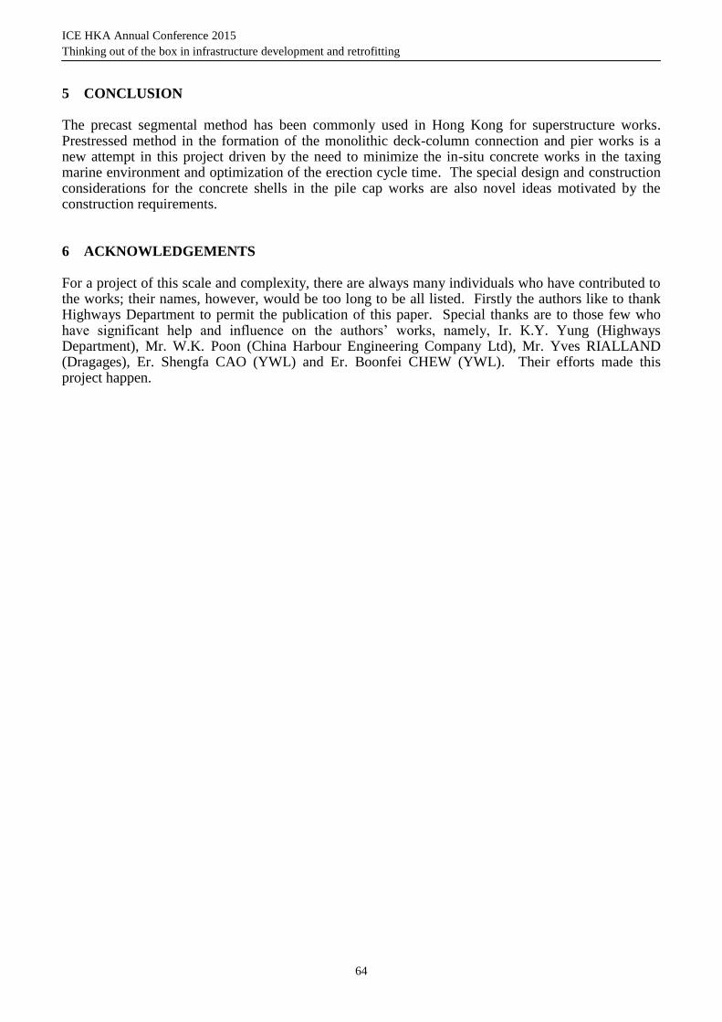
CP1 shell is the lightest one in this project. Its weight including the lifting beam and the installation accessories is 230ton. A 300ton crane barge was employed for the erection. The heaviest shell (Type F1) is about 560ton and it was installed using a 1000ton cane barge. All the shells were fully precast in the mainland China prior to being shipped to site for installation.
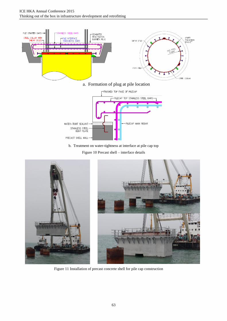
In the design, due considerations were given to construction tolerance and installation procedure. Since marine piles always demand higher tolerance limit, openings at the base slab have been oversized by 150mm for the external casing with a diameter of 2478mm OD. See Figure 10.
Installation of the shell involved a series of load transfer. Wire ropes were employed for lifting the shell and its installation accessories in the final position. The weight of the system was then transferred via the lifting beam, a key component of the installation accessories, to the king post embedded in the permanent piles. Partial water tightness was achieved by sealing the gap between the shell and pile with a rubber gasket before casting of the concrete plug. After the concrete plug was formed, the system would be completely water tight. All loads including the weight of pile cap wet concrete could then resisted by the reinforced concrete plug.
ICE HKA Annual Conference 2015
Thinking out of the box in infrastructure development and retrofitting
63
a. Formation of plug at pile location
b. Treatment on water-tightness at interface at pile cap top
Figure 10 Precast shell – interface details
Figure 11 Installation of precast concrete shell for pile cap construction
ICE HKA Annual Conference 2015
Thinking out of the box in infrastructure development and retrofitting
64
5 CONCLUSION
The precast segmental method has been commonly used in Hong Kong for superstructure works. Prestressed method in the formation of the monolithic deck-column connection and pier works is a new attempt in this project driven by the need to minimize the in-situ concrete works in the taxing marine environment and optimization of the erection cycle time. The special design and construction considerations for the concrete shells in the pile cap works are also novel ideas motivated by the construction requirements.
6 ACKNOWLEDGEMENTS
For a project of this scale and complexity, there are always many individuals who have contributed to the works; their names, however, would be too long to be all listed. Firstly the authors like to thank Highways Department to permit the publication of this paper. Special thanks are to those few who have significant help and influence on the authors’ works, namely, Ir. K.Y. Yung (Highways Department), Mr. W.K. Poon (China Harbour Engineering Company Ltd), Mr. Yves RIALLAND (Dragages), Er. Shengfa CAO (YWL) and Er. Boonfei CHEW (YWL). Their efforts made this project happen.