Steel Bridge Design Handbook
85
CHAPTER 19 Corrosion Protection of Steel Bridges Steel Bridge Design Handbook February 2022
-
Upload
khangminh22 -
Category
Documents
-
view
3 -
download
0
Transcript of Steel Bridge Design Handbook

CHAPTER 19
Corrosion Protection of Steel Bridges
Steel Bridge Design Handbook
February 2022

© AISC 2022
by
American Institute of Steel Construction
All rights reserved. This book or any part thereof must not be reproduced in any form without the written permission of the publisher.
The AISC and NSBA logos are registered trademarks of AISC.
The information presented in this publication has been prepared following recognized principles of design and construction. While it is believed to be accurate, this information should not be used or relied upon for any specific application without competent professional examination and verification of its accuracy, suitability and applicability by a licensed engineer or architect. The publication of this information is not a representation or warranty on the part of the American Institute of Steel Construction, its officers, agents, employees or committee members, or of any other person named herein, that this information is suitable for any general or particular use, or of freedom from infringement of any patent or patents. All representations or warranties, express or implied, other than as stated above, are specifically disclaimed. Anyone making use of the information presented in this publication assumes all liability arising from such use.
Caution must be exercised when relying upon standards and guidelines developed by other bodies and incorporated by reference herein since such material may be modified or amended from time to time sub-sequent to the printing of this edition. The American Institute of Steel Construction bears no responsibility for such material other than to refer to it and incorporate it by reference at the time of the initial publication of this edition.
Printed in the United States of America

Foreword
The Steel Bridge Design Handbook covers a full range of topics and design examples to provide bridge
engineers with the information needed to make knowledgeable decisions regarding the selection, design,
fabrication, and construction of steel bridges. The Handbook has a long history, dating back to the 1970s
in various forms and publications. The more recent editions of the Handbook were developed and
maintained by the Federal Highway Administration (FHWA) Office of Bridges and Structures as FHWA
Report No. FHWA-IF-12-052 published in November 2012, and FHWA Report No. FHWA-HIF-16-002
published in December 2015. The previous development and maintenance of the Handbook by the
FHWA, their consultants, and their technical reviewers is gratefully appreciated and acknowledged.
This current edition of the Handbook is maintained by the National Steel Bridge Alliance (NSBA), a
division of the American Institute of Steel Construction (AISC). This Handbook, published in 2021, has
been updated and revised to be consistent with the 9th edition of the AASHTO LRFD Bridge Design
Specifications which was released in 2020. The updates and revisions to various chapters and design
examples have been performed, as noted, by HDR, M.A. Grubb & Associates, Don White, Ph.D., and
NSBA. Furthermore, the updates and revisions have been reviewed independently by Francesco Russo,
Ph.D., P.E., Brandon Chavel, Ph.D., P.E., and NSBA.
The Handbook consists of 19 chapters and 6 design examples. The chapters and design examples of the
Handbook are published separately for ease of use, and available for free download at the NSBA website,
www.aisc.org/nsba.
The users of the Steel Bridge Design Handbook are encouraged to submit ideas and suggestions for
enhancements that can be implemented in future editions to the NSBA and AISC at [email protected].

TECHNICAL REPORT DOCUMENTATION PAGE
1. Title and Subtitle
Steel Bridge Design Handbook
Chapter 19: Corrosion Protection of Steel Bridges
2. Report Date
February 2022
3. Original Author(s)
Robert Kogler (Rampart, LLC) and Justin Ocel,
PE, PhD (FHWA)
4. Revision Author(s)
Brandon Chavel, PE, PhD (NSBA)
5. Sponsoring Agency Name and Address
National Steel Bridge Alliance, a division of the
American Institute of Steel Construction
130 E. Randolph, Suite 2000 Chicago, IL 60601
6. Revision Performing Organization Name
and Address
National Steel Bridge Alliance, a division of the
American Institute of Steel Construction 130 E. Randolph, Suite 2000
Chicago, IL 60601
7. Supplementary Notes
A previous edition of this volume (FHWA-IF-12-052-Vol. 19) was authored by Robert Kogler (Rampart, LLC) through subcontract to HDR Engineering, Inc. in 2006. The revised edition of this
volume (FHWA-HIF-16-002-Vol. 19) was rewritten by Justin Ocel and Robert Kogler. This edition of
the Handbook was updated to be current with the 9th edition of the AASHTO LRFD Bridge Design Specifications, released in 2020.
8. Abstract
Corrosion is a serious threat to the long-term function and integrity of a steel bridge. Structural steel will corrode if left unprotected or inadequately protected from the natural environment. This corrosion
can take the form of general uniform thickness loss or concentrated pitting depending on exposure to
the environment and the steel design detail in question. Bridge designers should view corrosion as a
long term threat to the integrity of the bridge structure, and is a critical consideration that must be addressed in a rational manner during the design process.
While there are several proven strategies for corrosion protection of steel bridges, there is no universal solution. The proper system must be chosen to accommodate cost, fabrication and productivity, and
long term performance and maintenance. Additionally, each corrosion protection system must be
selected based on the anticipated exposure of the structure to corrosive elements over its lifetime. This module highlights the most common issues confronting bridge designers regarding corrosion protection
and provides guidance in this area.
9. Keywords Steel Bridge, Corrosion, Corrosion Protection, Steel Coatings, Galvanization, Metalized, Weathering Steel,
Corrosion Resistance Alloys, Life Cycle Cost Analysis
10. AISC Publication No.
B919-22

i
Steel Bridge Design Handbook:
Corrosion Protection of Steel Bridges
Table of Contents
1.0 INTRODUCTION AND BACKGROUND ........................................................................... 1
2.0 ENVIRONMENT ................................................................................................................. 3
3.0 MATERIALS FOR CORROSION PROTECTION ............................................................... 8
3.1 Coatings for Abrasive-Blasted Steel ..................................................................................8
3.1.1 Zinc-Rich Paint Systems .............................................................................................9
3.1.1.1 Non-Zinc Systems .............................................................................................. 12
3.1.2 Thermal Spray Metalizing ......................................................................................... 12
3.2 Hot Dip Galvanizing........................................................................................................ 14
3.3 Weathering Steel ............................................................................................................. 19
3.4 Additional Corrosion Resistant Alloys ............................................................................. 21
4.0 HISTORICAL PERFORMANCE OF MATERIALS ........................................................... 23
4.1.1 Uncoated Weathering Steel ....................................................................................... 23
4.1.2 Galvanizing and Metalizing ...................................................................................... 26
4.1.3 Zinc-Rich Paint Systems ........................................................................................... 29
4.1.4 Duplex Coating Systems ........................................................................................... 34
5.0 CORROSION CONSIDERATIONS IN DESIGN ............................................................... 35
5.1 Broad Topic Considerations ............................................................................................ 35
5.1.1 Complexity ............................................................................................................... 35
5.1.2 Height and Access .................................................................................................... 35
5.1.3 Large and Unique Structures ..................................................................................... 35
5.1.4 Utilities ..................................................................................................................... 36
5.1.5 Rail Sharing .............................................................................................................. 36
5.2 Superstructure Selection/Layout Considerations .............................................................. 36
5.2.6 Deck Joints ............................................................................................................... 36
5.2.7 Drainage Areas ......................................................................................................... 39
5.2.8 Splash Zones (Lateral Clearance) .............................................................................. 41

ii
5.2.9 Splash Zone (Vertical Clearance) .............................................................................. 43
5.2.10 Fascia Beams and Other Outboard Members ........................................................... 44
5.2.11 Bottom Flanges ....................................................................................................... 44
5.2.12 Cables ..................................................................................................................... 46
5.2.13 Gratings, Bearings, and Curbs ................................................................................. 46
5.2.14 Built-Up Members .................................................................................................. 46
5.3 Element Detailing ............................................................................................................ 49
5.3.15 Water Traps ............................................................................................................ 49
5.3.16 Inaccessible Details ................................................................................................. 54
5.3.17 Box and Tubular Members ...................................................................................... 54
5.3.18 Dissimilar Metals .................................................................................................... 54
5.3.19 Weathering Steel ..................................................................................................... 54
5.3.20 Galvanizing ............................................................................................................ 56
5.3.21 Metalizing ............................................................................................................... 57
5.4 Fabrication and Application of Corrosion Protection Systems .......................................... 58
5.4.22 Slip Resistance ........................................................................................................ 59
6.0 COST .................................................................................................................................. 60
6.1 Initial Cost Numbers ........................................................................................................ 61
7.0 SUMMARY ........................................................................................................................ 65
8.0 ACKNOWLEDGMENTS ................................................................................................... 66
9.0 REFERENCES.................................................................................................................... 67
iii
List of Figures
Figure 1. Photo. Photograph of a severed connection due to corrosion. ........................................1
Figure 2. Graph. North America corrosion rates for carbon steel and zinc in various exposure
environments. ................................................................................................................6
Figure 3. Photo. Testing of various generically similar paint systems shows wide variations in
performance. ............................................................................................................... 11
Figure 4. Illustration. Metalized coating formed on top of blast-cleaned steel surface in the form
of overlapping “splats”. ............................................................................................... 13
Figure 5. Photo. Metalizing of a bridge member in the field (photo courtesy of R. Kogler). ....... 13
Figure 6. Illustration. Stages of the hot-dip galvanizing process. Taken from reference 28......... 15
Figure 7. Photo. Hot dip galvanizing kettle with long beam being dipped at one end. ................ 16
Figure 8. Photo. Different color of rust patina in new transmission tower (close) and older (far).
.................................................................................................................................... 20
Figure 9. Graph. Relative corrosion rates of carbon and weather grade steels in various
environments. .............................................................................................................. 21
Figure 10. Illustration. Locations of all steel bridges in lower 48 states...................................... 23
Figure 11. Graph. Superstructure condition ratings of uncoated weathering steel bridges by year
built. ............................................................................................................................ 25
Figure 12. Graph. Condition ratings of original coating systems in Missouri (numbers by data
points represent replicates).(reproduced from 61) ................................................................... 30
Figure 13. Graph. 20-year performance of zinc-rich systems on the Mathis Bridge.(reproduced from 53)
.................................................................................................................................... 32
Figure 14. Photo. Bridge in West Virginia with a single-coat inorganic zinc-rich paint system
after 25 years. .............................................................................................................. 33
Figure 15. Photo. Deterioration of bearing area beneath a leaking joint with only single-coat
inorganic zinc-rich paint. ............................................................................................. 33
Figure 16. Photo. Steel directly beneath transverse expansion joints that have leaked corrosive
runoff from the deck. ................................................................................................... 37
Figure 17. Photo. Steel directly beneath longitudinal expansion joints that have leaked corrosive
runoff from the deck. ................................................................................................... 37
iv
Figure 18. Illustration. (Top) Closely spaced parallel bridges. (Bottom) One bridge carrying both
directions of travel. ...................................................................................................... 38
Figure 19. Photo. Closely spaced girders lead to difficult access for maintenance activities. ...... 38
Figure 20. Photo. The area under an open grid deck acting as one large leaking joint. ............... 39
Figure 21. Photo. Missing portion of deck drain downspout. ..................................................... 40
Figure 22. Photo. Clogged drain leaking water onto superstructure. ........................................... 40
Figure 23. Photo. Through truss showing darkened area in close proximity to the travel lane (i.e.
splash zone) that is corroding faster than other parts of the truss outside the splash zone.
.................................................................................................................................... 42
Figure 24. Illustration. Closely spaced parallel structures with a grade difference. ..................... 42
Figure 25. Illustration. Vertical clearance of a grade separated structure. ................................... 43
Figure 26. Photo. Accelerated corrosion on the inbound fascia girder of a grade separate
structure, particularly over the right travel lane. ........................................................... 43
Figure 27. Photo. Corrosion localized to upper surface of lower flange, the rest of the bridge is
fine. ............................................................................................................................. 44
Figure 28. Photo. Heavy corrosion of bottom flange and web due to collection of poultice. ....... 45
Figure 29. Illustration. Flat flange (left) and transversely curved flange (right). ......................... 45
Figure 30. Photo. Corroded bearing. .......................................................................................... 46
Figure 31. Photo. Annotated picture of riveted, built-up lower chord truss member. .................. 47
Figure 32. Photo. Annotated picture of riveted lower truss chord connection. ............................ 48
Figure 33. Photo. Inside of built-up box member. ...................................................................... 49
Figure 34. Photo. Girder end on a bearing below a leaking deck joint. Horizontal flange and
vertical stiffeners create an excellent trap for debris and moisture. ............................... 50
Figure 35. Illustration. Transverse plate snipe size, larger is better. ........................................... 51
Figure 36. Schematic. Proper orientation of drip bar. Taken from Reference 14. ....................... 52
Figure 37. Photo. Debris accumulation at a lateral gusset plate detail. ....................................... 53
Figure 38. Photo. Corroded lateral gusset plate detail. ............................................................... 53
Figure 39. Illustration. Difference between squared off flange splice plates (left), and tapered
flange splice plates (right). Bolts not shown for clarity. ............................................... 54
Figure 40. Photo. Connection plate welded to rolled I-beam along with corrosion emanating from
unsealed weld. ............................................................................................................. 57

v
Figure 41. Graph. Relative pricing of various steel alloys (March 2013). ................................... 62
Figure 42. Schematic. Elevation view of girder detailing. .......................................................... 63

vi
List of Tables
Table 1. Corrosion Rates for Carbon Steel and Zinc Throughout North America(8) ......................5
Table 2. Carbon Steel Corrosion Rates for Various Environments According to ISO 9223(11) .....7
Table 3. Expected Life of Typical Galvanized Coating Across North America .......................... 18
Table 4. Estimated Life of Metalized and Galvanized Coating Per Exposure Condition ............ 27
Table 5. 34-Year Exposure Results of Metalizing at Kure Beach, NC(56) ................................... 28
Table 6. Estimated Life of Zinc-Rich Paint Systems Per Exposure Condition............................ 31
Table 7. 18-Year Comparison of Coating Costs in Shop and Field ............................................ 63
Table 8. Percent Premium of Different Corrosion Mitigation Strategies Over A709 Gr.50 ........ 64

1
1.0 INTRODUCTION AND BACKGROUND
Corrosion can threaten the long-term function and integrity of a steel bridge. Structural steel will
corrode if left unprotected or inadequately protected from the natural environment. It is a time-
based process that generally takes several years to develop deterioration significant enough to
cause concern. For this reason, corrosion is often considered an ownership or maintenance issue.
While this may be true in practical terms, corrosion is most appropriately addressed by
specification of a proper corrosion protection system, and the designer must view long-term
corrosion protection as a design consideration.
Two prominent bridge collapses were the Silver Bridge (Point Pleasant, WV) in 1967 and the
Mianus River Bridge (Greenwich, CT) in 1983. (1, 2) While corrosion was a player in these two
failures, it was not the sole reason either. The Silver Bridge collapsed due to fracture of a non-
redundant eyebar where a stress-corrosion crack led to fatigue growth and ultimately fracture.
The Mianus River bridge failed when pack rust almost pushed a hanger bar off its pin, but
ultimate failure occurred when the tip of the pin fractured. In either case, the collapse would have
been prevented with a different structural design, more judicious materials selection, or closer
attention to in-service inspection. Regardless, corrosion was a player in the collapses and it
demonstrates that corrosion mitigation also needs to be a design consideration. Corrosion has
been cited as a contributing factor in bridge failures of varying severity, including several
failures and many load postings due to section loss in primary members. An example of bridge
corrosion is exhibited in Figure 1 that shows a broken connection due to corrosion. Therefore,
corrosion is not an issue to be taken lightly by the designer.
Figure 1. Photo. Photograph of a severed connection due to corrosion.
While there are several proven strategies for corrosion protection of steel bridges, there is no
universal solution. A proper protection system must be chosen to accommodate cost, fabrication
and productivity, long-term performance and maintenance. Additionally, each corrosion
protection system must be selected based on the anticipated exposure of the structure to corrosive

2
elements over its lifetime. The remainder of this document discusses four key issues confronting
the steel bridge designer regarding corrosion protection; environment, materials for corrosion
protection, design aspects, and cost.

3
2.0 ENVIRONMENT
The United States covers a variety of climate and exposure zones, which vary greatly in terms of
temperature, humidity, ultraviolet radiation from the sun, pollution, and airborne salts. Therefore,
it cannot be expected that all corrosion protection systems (protective coating systems or
corrosion-resistant alloys) will perform equally across the United States. This means that site
conditions themselves will play an important role in the decision process.
The performance expected from a durable corrosion protection system is highly dependent on the
general corrosion-promoting factors associated with its surrounding, “macro” environment. A
bridge’s macro-environment is defined by general, local weather metrics such as rainfall,
temperature, and level of contaminants such as chlorides. Perhaps more important is the “micro”
environment associated with specific bridge members or elements. The micro-environment for a
bridge element is defined by its material, configuration, and orientation relative to splash or
runoff from the roadway, and exposure to direct sunlight, which may stress protection systems
over the long term. Under these definitions, each bridge has a single macro-environment, but a
single bridge may have several different micro-environments.
In general, the performance of corrosion protection systems on a bridge is driven by:
• the quality of application of protective coating systems, including particularly, the
quality of surface preparation prior to coating application,
• expected damage or deterioration the coating expects to receive during service,
• the severity of the general exposure of the macro-environment, and
• the severity of localized micro-environments within the bridge that is a function of
bridge detailing discussed later in the volume.
The local environment, or macro-environment, of a structure substantially influences the rate of
corrosion of exposed steel and the deterioration of the protective coating. Traditionally, corrosion
engineers have classified the general, macro-environment surrounding a structure as mild (rural),
industrial (moderate), or severe (marine). These general classifications are of some limited use to
the bridge designer as a starting point for determining the appropriate level of corrosion
protection required for the structure. The designer should begin by assessing the surrounding
environment for the subject bridge with specific focus on the potential for salts or deleterious
chemicals to contact and remain on the steel surfaces and for excessive amounts of moisture to
distinguished:(3)
Rural (Mild): Little to no exposure to natural airborne and applied deicing salts. Low pollution in
the form of sulfur dioxide, low humidity and rainfall, absence of chemical fumes, and usually an
interior (inland) location.
Industrial (Moderate): An environment in which a bridge is exposed to some (occasional)
airborne salts or deicing salt runoff. This is a broad macro-environment category which includes
many non-coastal bridges which receive de-icing treatment irregularly. Further definition of
micro-environments within this category becomes more important. A location with low or no salt
may still be classified as moderate if it is directly downwind of industrial processing with
corrosive airborne contaminants (e.g., sulfur dioxide), in a heavily polluted urban area, or

4
moderate to high humidity. This classification has become less important in recent years as long-
term corrosion data shows the corrosive effects of airborne pollutants has diminished with the
implementation of clean stack gas regulations.(4)
Marine (Severe): High salt content from proximity to seacoast or from deicing salt, high
humidity and moisture. Bridges immediately proximate to the coast should be considered to be in
a severe environment. Most studies have also classified areas within one to two miles of the
coast as “marine” environments as well. Further inland, the severity of the macro-environment is
dependent upon prevailing wind and general weather patterns.(5, 6)
The above definitions are, by necessity, generic. Many bridges will not fall distinctly into any of
the categories. Some bridges may have intermediate climates with moderate pollution and
moderate humidity, while others may suffer from high humidity, high sulfur dioxide, and salt.
Frequently there is a large variation in the environment even within a very small geographic area
due to local effects. Salt and moisture levels may vary substantially from one end of a structure
to the other. The direction of sun and wind and the degree of sheltering strongly influence the
highly critical time of wetness of structural members. Steel that is never exposed to sunlight may
have a much higher time-of-wetness than unsheltered members. It does not appear that there is a
specific “critical” or “threshold” acceptable time of wetness. Rather, a higher time of wetness
combined with higher levels of contamination in the moisture and on the steel surface leads to
higher corrosion rates.(7)
Table 1 shows section loss data developed in a comprehensive study conducted by the American
Society for Testing and Materials (ASTM) from 1961-1964.(8) The study was performed
worldwide, but only North American results are presented in Table 1. For each location, carbon
steel and zinc, 4 inch by 6-inch panels were exposed for one and two years each, and the mass
loss was converted to a uniform value expressed as mils per year, per side. Results for zinc are
discussed because it will become evident throughout the remainder of this document that it plays
an integral role in many corrosion protection systems. The data show the general increase in
corrosion rates when moving from rural to industrial to marine exposure sites, with a rapid
increase in rate as the salt and moisture content of the environment increases in marine
environments. The data also show that there is a wide variation in corrosion rates within each
macro-environment depending on such variables as distance from the shoreline, height above
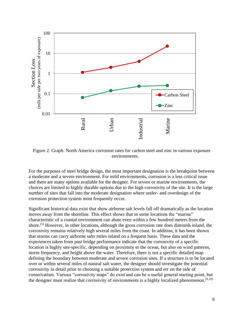
ground level, and others. The data is graphically shown in Figure 2, which plots the average
section loss per material for each exposure condition, using just the two-year exposure data. The
vertical axis is plotted on a logarithmic scale. The data indicate that section loss is logarithmic
with the severity of the environment (the data plot fairly linearly), and the zinc erosion data is
roughly one to two orders of magnitude less than carbon steel. It is also important to note that
these are corrosion rates for ambient conditions with no direct exposure to deicing salts. Direct,
frequent contact between bare steel or zinc and deicing salts will produce corrosion rates closer
to those listed for a marine environment, even in non-marine locations. Lastly, since this study
was conducted in the early 1960s at the height of industrialization in America, pollution was
likely near its peak, and the corrosion rates are likely conservative in today’s environment. Clean
air regulations have led to less aggressive environments from airborne pollution, and the steel
bridge designer needs to be cognizant mostly of marine exposures and of frequent exposure to
deicing chemicals.

5
Table 1. Corrosion Rates for Carbon Steel and Zinc Throughout North America(8)
Carbon Steel Zinc
Location Macro-
Environment
Loss (mils per side per
1 yr.)
Loss (mils per side per
2 yr.)
Loss (mils per side per
1 yr.)
Loss (mils per side per
2 yr.)
Norman Wells, Northwest Territories Rural 0.02 0.12 0.01 0.01
Phoenix, AZ Rural 0.26 0.36 0.02 0.02
Saskatoon, Saskatchewan Rural 0.24 0.45 0.02 0.02
Morenci, MI Rural 1.05 1.54 0.05 0.09
Potter County, PA Rural 0.86 1.62 0.04 0.10
State College, PA Rural 0.99 1.81 0.05 0.09
Durham, NH Rural 1.39 2.15 0.07 0.12
South Bend, PA Semi-Rural 1.57 2.62 0.08 0.14
Esquimalt, British Columbia Rural Marine 0.68 1.05 0.02 0.04
Ottawa, Ontario Urban 0.99 1.55 0.04 0.09
Montreal, Quebec Urban 1.28 1.85 0.09 0.19
Halifax (York Redoubt), Nova Scotia Urban 1.25 2.10 0.07 0.12
Columbus, OH Urban 1.62 2.59 0.07 0.17
Middletown, OH Semi-Industrial 1.43 2.27 0.05 0.10
Monroeville, PA Semi-Industrial 2.25 3.85 0.08 0.15
Detroit, MI Industrial 0.91 1.14 0.05 0.10
Waterbury, CT Industrial 0.00 1.78 0.10 0.21
Pittsburg, PA Industrial 1.68 2.41 0.09 0.20
Trail, British Columbia Industrial 1.91 2.74 0.07 0.12
Bethlehem, PA Industrial 2.17 2.96 0.05 0.10
Cleveland, OH Industrial 2.09 3.08 0.09 0.22
Newark, NJ Industrial 2.85 4.00 0.13 0.29
Bayonne, NJ Industrial 4.99 6.11 0.21 0.38
East Chicago, IN Industrial 4.36 6.66 0.11 0.14
Halifax (Federal Bldg.), Nova Scotia Industrial 5.41 8.96 0.31 0.58
Brazos River, TX Industrial Marine 4.23 7.35 0.08 0.14
Daytona Beach, FL Marine 8.21 23.32 0.09 0.16
Point Reyes, CA Marine 12.41 39.52 0.06 0.12
Kure Beach, NC (800 ft. from coast) Marine 3.35 11.50 0.10 0.16
Kure Beach, NC (80 ft. from coast) Marine 28.05 42.11 0.26 0.50
Cape Kennedy, FL (0.5 mi. from coast)
Marine 1.62 6.80 0.06 0.09
Cape Kennedy, FL (60 yd. from coast, 60 ft. elevation)
Marine 2.41 10.37 0.12 0.35
Cape Kennedy, FL (60 yd. from coast, 30 ft. elevation)
Marine 2.79 12.99 0.14 0.32
Cape Kennedy, FL (60 yd. from coast, ground elevation)
Marine 7.52 34.82 0.15 0.33
6
0.01
0.1
1
10
100S
ecti
on
Lo
ss
(mil
s per
sid
e per
tw
o y
ears
of
exposu
re)
Carbon Steel
Zinc
Ru
ral
Urb
an
Ind
ust
rial
Mar
ine
Figure 2. Graph. North America corrosion rates for carbon steel and zinc in various exposure
environments.
For the purposes of steel bridge design, the most important designation is the breakpoint between
a moderate and a severe environment. For mild environments, corrosion is a less critical issue
and there are many options available for the designer. For severe or marine environments, the
choices are limited to highly durable options due to the high corrosivity of the site. It is the large
number of sites that fall into the moderate designation where under- and overdesign of the
corrosion protection system most frequently occur.
Significant historical data exist that show airborne salt levels fall off dramatically as the location
moves away from the shoreline. This effect shows that in some locations the “marine”
characteristic of a coastal environment can abate even within a few hundred meters from the
shore.(5) However, in other locations, although the gross corrosion rate does diminish inland, the
corrosivity remains relatively high several miles from the coast. In addition, it has been shown
that storms can carry airborne salts miles inland on a frequent basis. These data and the
experiences taken from past bridge performance indicate that the corrosivity of a specific
location is highly site-specific, depending on proximity to the ocean, but also on wind patterns,
storm frequency, and height above the water. Therefore, there is not a specific detailed map
defining the boundary between moderate and severe corrosion sites. If a structure is to be located
over or within several miles of natural salt water, the designer should investigate the potential
corrosivity in detail prior to choosing a suitable protection system and err on the side of
conservatism. Various “corrosivity maps” do exist and can be a useful general starting point, but
the designer must realize that corrosivity of environments is a highly localized phenomenon.(9,10)

7
Outside the U.S., there is a standard for classification of environmental corrosivity that is widely
used.(11) This standard breaks down into corrosivity categories from C1 (mild) to C5 (severe)
with an additional category, C5M (severe marine) for marine exposures. The expected range of
corrosion rate for each classification is shown in Table 2. While this standard is not widely used
in the highway bridge industry in the U.S., it has gained popular use for offshore and utility
structures and an increasing number of coatings suppliers and researchers are referring to this
classification system for generating performance data and recommending materials.
Table 2. Carbon Steel Corrosion Rates for Various Environments According to ISO 9223(11)
Environment Carbon Steel Corrosion Rate
(mils per year)
C1 0.05
C2 <1
C3 1 to 2
C4 2 to 3
C5 3 to 8
C5M 8 to 28
Away from the coast, the question of designation between moderate and severe becomes one of
frequency of deicing salt application and the realistic ability to keep the deicing salt runoff,
splash, and salt aerosol (produced primarily by truck traffic on wet, salted roads) from contacting
the steel superstructure. Again, there are areas of the country where deicing applications are
frequent and heavy. In these (mostly northern) areas the default position for the designer must be
a high-durability corrosion protection system, unless the designer can painstakingly detail the
particular bridge to avoid all potential contact between regular salt containing runoff and splash
and the structural steel.(12, 13, 14) There is also a large portion of the country where deicing salts are
never used. In these areas, the corrosion protection issue is simplified somewhat. It is the area in
the middle latitudes of the country where deicing salts are applied inconsistently or infrequently
and where the question of adequate long-term corrosion protection must be addressed in a
rational, site-specific manner.
Defining the corrosion environment is important because the suitability of weathering steels and
the durability of protective coatings are directly affected by their exposure environment. Thus, in
some locales, there may be several corrosion protection options appropriate for the exposure;
whereas in more severe locations there may only be a few options.

8
3.0 MATERIALS FOR CORROSION PROTECTION
As the long-term performance of steel bridge systems has become more important to owners,
four types of corrosion mitigation strategies have risen in popularity for use with steel bridges:
• corrosion-resistant steel,
• zinc-rich primer paint systems,
• hot-dip galvanizing, and
• thermal spray metalizing,
Each option has its benefits and drawbacks. All of these “best practice” technologies use the
electrochemistry of corrosion to the advantage of the long-term durability of the system. Three of
these technologies rely on cathodic protection of the structural steel by an applied coating
containing sacrificial metallic components.
Passive, or sacrificial, cathodic protection involves the intentional use of a metal that is more
electrochemically active than the metal to be protected within a given service environment. For
natural environments containing moisture and salt, zinc and aluminum are both
“electrochemically active” with respect to steel. Thus, both of these metals will naturally
sacrifice, or preferentially corrode, to protect steel when the two metals are in electrical contact
and within the same environment.(15) Zinc and aluminum anodes are routinely used to protect
ships, offshore platforms, and even residential hot water heaters. Similarly, coatings containing
these sacrificial metals can be thought of as sprayable, thin, distributed sacrificial anodes when
applied in a manner that creates electrical continuity with the steel and within the matrix of the
coating. In addition to providing cathodic protection, these coatings also serve as barrier
coatings, separating the steel structure from the corrosive elements in the surrounding
environment.
The remaining corrosion protection option, corrosion-resistant steel, involves fabricating the
bridge from steels with an inherent high tolerance against corrosion. Weathering steels are
specially formulated alloys that form oxides at the interface of the steel and the environment that
are more adherent than the normal ferric or ferrous oxides (i.e., rust) that form during corrosion
of regular carbon steel. Additionally, there are bridges that have been fabricated from various
grades of stainless steel.(16, 17)
3.1 Coatings for Abrasive-Blasted Steel
For several decades, the predominant protective coating system used for bridge steel was several
coats of lead-containing alkyd paint. This system was inexpensive, easy to apply, and provided
reasonable corrosion protection as long as periodic maintenance painting was performed. This
system was generally applied directly over intact mill scale with little to no surface preparation.
In the 1970s, the advantages of abrasive blasting to remove mill scale and provide a clean,
roughened surface for paint application became well known. Since this time, full-scale surface
cleaning by abrasive blasting has become standard practice. The benefits of this surface
preparation to the performance of coatings are unquestioned today.(18) The use of sophisticated

9
surface preparation opened the door for the use of truly high performance coatings—primarily
multi-coat systems using a zinc-rich primer as the main corrosion protection component.
3.1.1 Zinc-Rich Paint Systems
The majority of state highway departments currently specify the use of some type of zinc-rich
primer based coating system and this has now been the case for many years. Zinc-rich coatings
are typically either two or three coats of paint with the primer coat having a heavy loading of
zinc pigment to provide cathodic protection. These primers are either inorganic zinc (IOZ) or
organic zinc (OZ). IOZ primers consist of zinc metal powder mixed into an inorganic silicate
paint binder. This binder can be either solventborne (ethyl silicate) or waterborne (alkali silicate).
OZ primers contain zinc metal pigment mixed into an organic paint resin such as epoxy or
urethane.
A 1996 survey by the Transportation Research Board found that 42 of 54 bridge agencies
specified zinc-rich primers for new construction.(19) Ethyl-silicate inorganic zinc was the shop
primer of choice, and today nearly all states have zinc-rich primer systems as an option for new
steel that may serve in corrosive conditions. Additionally, a 2014 synthesis conducted by
Minnesota DOT showed that for full maintenance repainting of existing structures 36 of 42
responding states use organic (epoxy or urethane) zinc rich primer based systems and 18 of 42
use inorganic zinc rich primer based systems.(20) For new steel, although the use of full shop
application for all coats is increasing, the predominant approach is to blast and prime in the shop
and apply field topcoats following erection of the structure.
Zinc-rich paint systems can be applied by any traditional method of paint application, but for
bridge applications, they are generally applied using airless spray equipment for productivity or
sometimes by brush in spot-painting and maintenance applications. With the exception of using
corrosion-resistant alloys for the superstructure, the zinc-rich paint systems offer the most
flexibility in terms of application (i.e., that is they can be applied in the shop, in the field, or
both); however, it should be noted that the quality of the application and subsequent performance
is closely related to adherence to mixing, application, and curing condition requirements and,
especially, to surface preparation requirements specified by the paint manufacturer and bridge
agency specifications.
Of the technologies discussed here, the zinc-rich paints have the unique limitation of coating
drying and curing time in their process. If a multi-coat system is used, which is most common,
the dry or cure time of each coat must be considered in the overall coating process time. Coating
dry or cure time can be a limiting factor in the production of a steel member and possibly
increase fabrication cost.
As zinc-rich paint systems have gained increasing popularity over the past four decades,
manufacturers have focused formulation efforts on easing logistical burdens associated with
application. Two significant issues associated with shop application of zinc-rich systems are dry
and cure time and slip resistance of primers applied to the faying surfaces.
For all coatings, cure time is affected by the specifics of the coatings’ formulation and the
ambient conditions during the drying and curing period. In general, warmer ambient

10
temperatures create faster cures for most paint systems. Additionally, the amount of moisture in
the air during application and curing can have a significant effect on the cure time of primers.
These factors can become a significant point when selecting between coating systems of similar
demonstrated or assumed performance. Shorter cure times can have a profound positive effect on
the logistics of applying multiple coats or handling of painted steel in the shop. This is true
whether the goal is faster shipment to the construction site or merely moving the steel through
the paint shop in a more efficient manner. Each fabricator and each job has different metrics, but
in general, all other performance parameters being equal, a faster curing primer provides
significant advantages to fabrication shops. Additionally, coatings with rapid drying time tend to
spend less time vulnerable to handling damage and contamination in the shop and field
application environment. This has an overall positive effect on quality of the coating system.
While inorganic zincs can have rapid “dry-to-handle” times, the “dry to recoat” times (e.g., the
time the fabricator must wait before applying the midcoat over the primer) for most inorganic
zincs are on the order of 24 hours. Many organic zinc rich coatings are now formulated
specifically for fast cure properties. Catalyzed organic coatings are now available that cure (for
handling and overcoating) within a few hours, or even within several minutes in some cases.
Some of these materials are also designed to allow application under a greater range of
environmental conditions (e.g., high humidity). These properties have had the greatest impact to
date in field maintenance painting where the use of faster drying paints has allowed work
schedules and lane closures to be compressed so the maintenance painting jobs can be done at
night, during off traffic hours; however, this concept of rapid cure coatings has begun to work its
way into new construction and shop fabrication as well, particularly as more steel is receiving
multiple-coat paint systems in the shop. Saving time and minimizing the curing period has
helped fabricators increase the throughput of their paint shops.
Zinc-rich primers are almost always topcoated for added corrosion resistance and additional
functionality (color and gloss). Testing of zinc coating systems is required by most states to
confirm the acceptability of individual paint systems. Testing via natural marine exposure, as
seen in Figure 3, is a direct method of paint performance evaluation; however, this method
requires a long time to discriminate between high performance systems. For practicality, natural
exposure testing must be complemented with accelerated laboratory testing to rank the durability
of paint formulations. Of important note, paints must be tested and specified as systems, designed
and supplied by a single manufacturer to be used together; paints supplied by separate
manufacturers are not always compatible. Specification of coatings by generic type or using an
“or equal” approach can lead to disappointing performance results.

11
Figure 3. Photo. Testing of various generically similar paint systems shows wide variations in
performance.
Initial applications of zinc-rich coating systems to bridges beginning in the 1970s used vinyl
topcoats. With regulations now limiting the amount of solvent in coatings, vinyls have been
replaced with an epoxy mid-coat with a polyurethane topcoat. This three-coat approach to bridge
painting is accepted practice over much of the nation. In this approach, the zinc-rich primer
provides the primary corrosion protection for the steel. The epoxy midcoat provides an excellent
moisture barrier, sealing for IOZ primers, adds physical protection to the zinc primer, and
provides a better surface for the top coat. The polyurethane topcoat forms a weatherable
additional moisture barrier with long-term color and gloss retention and resistance to gradual
erosion (chalking) caused by exposure to sunlight.
Most agencies maintain their own unique set of qualification factors for proprietary coatings.
Sometimes these factors are state-specific. Cooperative regional working groups have also
shared resources to develop common qualification and approval lists (e.g., the Northeast
Protective Coatings Committee, NEPCOAT). These systems employ a battery of standard
accelerated “torture tests” which attempt to mimic years of harsh exposure over the period of a
few thousand hours in a test cabinet. In recent years, the bridge community has established a
nationwide cooperative testing program for bridge paint performance. This program, the
National Transportation Product Evaluation Program (NTPEP), is maintained by the American
Association of State Highway and Transportation Officials (AASHTO) and provides the first
national level clearinghouse for bridge paint performance data under the Structural Steel
Coatings branch of the program.(21) This program has brought a greater level of consistency and
performance to bridge paint coatings. The designer should consider this a unique, unbiased
resource for paint material selection. An additional, important aspect of this program is the
chemical and physical “fingerprint” testing done on each paint formulation tested. The DataMine
maintained by the program offers bridge specifiers both performance data for each paint system
along with chemical makeup data that can be used to verify delivery of consistent paint materials
over time.

12
Quality of application is a key factor in the success or failure of any paint system. The
AASHTO/NSBA Steel Bridge Collaboration has produced a guide specification for shop
painting steel structures.(22) This document represents a good collection of detailed language and
specification references for achieving quality. Good Painting Practice, Volume 1, published by
the Society for Protective Coatings (SSPC), also provides an excellent reference for the issues
involved in painting bridges and other industrial steel structures.(3) These references reinforce the
fact that surface preparation is the key to success for bridge coatings. Zinc-rich coatings are
typically specified with at a surface cleanliness level of “near white” (SSPC-SP 10) in order to
achieve excellent long term performance. Any compromise in cleanliness from that level will
generally result in decreased performance of the paint system and designers should consider
specifying the highest degree of cleanliness if product datasheets say a system is compatible with
multiple surface cleanliness standards.
Paint system performance has improved since the 1980’s due to the advent of better materials by
manufacturers, institutionalization of improved surface preparation and quality practices by
industry, coupled with the increased demands for performance driven by bridge owners. In the
future, there is great potential for paint system performance to improve in many areas. The
aforementioned AASHTO national testing program has opened the opportunities for bridge
owners and specifiers to reexamine many of the entrenched practices of a three-coat paint
specification. Industry efforts are underway to develop coatings that can match the performance
of three coat systems with two-coat or even a single fast-drying coat of paint. Success on this
front would remove a significant production bottleneck from the steel fabrication shop—
allowing time for paint to dry before handling—and also potentially save significant cost.
Long-term aesthetic performance of bridge paint systems has generally received little attention
by specifiers; however, that is changing, particularly for “signature” bridges or those with
community involvement in the design process. Properties such as color and gloss retention can
now be more easily analyzed for specific paint formulations. As the aesthetics of bridges become
more important to engineers and community groups alike, the robust performance characteristics
of modern industrial coating systems will become more important to bridge construction and
rehabilitation efforts. The NTPEP data mine contains performance data on each coating’s color
and gloss retention properties.
3.1.1.1 Non-Zinc Systems
Some owners have tried to stay dedicated to the use of non-zinc (mostly waterborne) paint
systems so that they have that coating systems in their toolbox should environmental regulations
get tighter. However, these systems are typically restricted to non-aggressive exposures, so
performance-wise, they do not stack up against a zinc-bearing paint systems. Therefore, the
focus of this document is only on zinc-rich paint systems.
3.1.2 Thermal Spray Metalizing
Metalizing is a term used to describe the process of thermal spraying a metal coating onto a
substrate like steel. The thermal spray industry is mature and can be highly technical for some
applications. However, metalizing as presently applied to the corrosion protection of bridge steel
is straightforward. Although many choices of thermal sprayed alloys are potentially available, by

13
far the dominant choices for bridge steel are pure zinc, 85 percent zinc/15 percent aluminum
alloy, and pure aluminum. Metalized coatings are applied using a heat source to melt a metal
feedstock (typically in a wire or powder form) at the tip of a spray gun that uses compressed air
to propel the molten metal onto the target steel. The heat source can be either flame or electric
arc, similar to the heat sources for welding equipment. Once the molten metal hits the steel
surface, it immediately re-solidifies into a solid sacrificial coating. The coating is built up with a
series of overlapping “splats” of metal. Achieving proper specified thickness is important to
mitigate the possibility of porosity through the coating.(23) Figure 4 shows a depiction of this
application. Figure 5 illustrates a typical field metalizing application.
Figure 4. Illustration. Metalized coating formed on top of blast-cleaned steel surface in the form
of overlapping “splats”.
Figure 5. Photo. Metalizing of a bridge member in the field (photo courtesy of R. Kogler).
Several factors have held back the proliferation of metalizing in the bridge market. The concerns
of owners and fabricators include cost, productivity, and the learning curve of the industry with
regard to the nuances of the metalizing process. Specifically, metalizing during new construction
generally requires fabricators to bring in a specialist firm to do the work, either at the fabricator’s
facility or by transporting the steel to a metalizing shop. Although application of metalizing is not
particularly complex, it does require specific expertise and power sources to effectively and
productively produce a protective coating. Although spraying of metalizing is a “line of sight”
process similar to spraying paint, unlike paint, metalizing has no solvent, so there is no “flow and
14
leveling” of the coating after it hits the steel surface and instantly solidifies. This factor makes
application of metalizing slightly less forgiving than spray painting. In addition, metalizing
application is also notably slower than application of traditional paint systems. Paints can be sprayed
at up to 1000 square feet of surface per man-hour, while metalizing applications are more typically
on the order of 100-200 square feet per man-hour.(24) On the other hand, when the need for multiple
(usually three) coats of paint and required cure time for each coat are factored in, the productivity
rates for metalizing versus painting have less disparity.
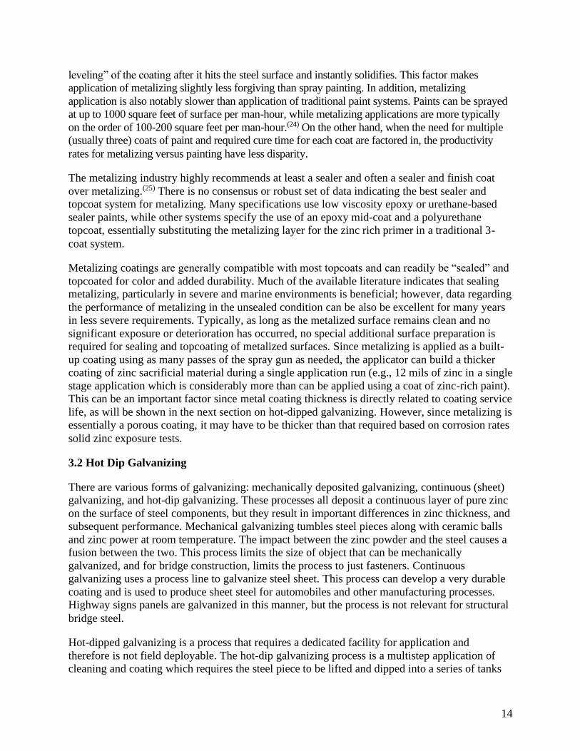
The metalizing industry highly recommends at least a sealer and often a sealer and finish coat
over metalizing.(25) There is no consensus or robust set of data indicating the best sealer and
topcoat system for metalizing. Many specifications use low viscosity epoxy or urethane-based
sealer paints, while other systems specify the use of an epoxy mid-coat and a polyurethane
topcoat, essentially substituting the metalizing layer for the zinc rich primer in a traditional 3-
coat system.
Metalizing coatings are generally compatible with most topcoats and can readily be “sealed” and
topcoated for color and added durability. Much of the available literature indicates that sealing
metalizing, particularly in severe and marine environments is beneficial; however, data regarding
the performance of metalizing in the unsealed condition can be also be excellent for many years
in less severe requirements. Typically, as long as the metalized surface remains clean and no
significant exposure or deterioration has occurred, no special additional surface preparation is
required for sealing and topcoating of metalized surfaces. Since metalizing is applied as a built-
up coating using as many passes of the spray gun as needed, the applicator can build a thicker
coating of zinc sacrificial material during a single application run (e.g., 12 mils of zinc in a single
stage application which is considerably more than can be applied using a coat of zinc-rich paint).
This can be an important factor since metal coating thickness is directly related to coating service
life, as will be shown in the next section on hot-dipped galvanizing. However, since metalizing is
essentially a porous coating, it may have to be thicker than that required based on corrosion rates
solid zinc exposure tests.
3.2 Hot Dip Galvanizing
There are various forms of galvanizing: mechanically deposited galvanizing, continuous (sheet)
galvanizing, and hot-dip galvanizing. These processes all deposit a continuous layer of pure zinc
on the surface of steel components, but they result in important differences in zinc thickness, and
subsequent performance. Mechanical galvanizing tumbles steel pieces along with ceramic balls
and zinc power at room temperature. The impact between the zinc powder and the steel causes a
fusion between the two. This process limits the size of object that can be mechanically
galvanized, and for bridge construction, limits the process to just fasteners. Continuous
galvanizing uses a process line to galvanize steel sheet. This process can develop a very durable
coating and is used to produce sheet steel for automobiles and other manufacturing processes.
Highway signs panels are galvanized in this manner, but the process is not relevant for structural
bridge steel.
Hot-dipped galvanizing is a process that requires a dedicated facility for application and
therefore is not field deployable. The hot-dip galvanizing process is a multistep application of
cleaning and coating which requires the steel piece to be lifted and dipped into a series of tanks

15
or kettles (as seen in Figures 6 and 7). The final dip in the process is immersing the component
into molten kettle of pure zinc, typically at temperatures between 820 and 900 °F. These kettles
are typically around 40 feet long, but kettles up to 60 feet long exist. The heat from this zinc dip
creates a metallurgical bond between the zinc and steel, and creates a layer of sacrificial zinc.
The composition of zinc layer depends on the chemistry of the steel and largely plays into the
thickness of the coating, therefore a designer cannot specify a desired coating thickness for a hot-
dipped galvanized component. When the silicon level in the steel is between 0.04 and 0.15
percent or above 0.22 percent the steel is considered “reactive”.(26) For reactive steels, the entire
galvanized layer is zinc/iron intermetallics that can be excessively thick (generally thicker than
10 mils) and also brittle. The other problem with reactive steels is the intermetallic layer can
continue to grow, and overall galvanized thickness is controlled by dwell time in the tank, but
this can be mitigated by abrasive blasting in lieu of acid pickling. For non-reactive steels, the
intermetallics form with a gradient in the zinc/iron ratio being more iron bearing near the steel
and decreasing through the thickness to the outer layer that is pure zinc. The nonreactive steels
develop a thickness that is on the order of 4 mils thick, and dwell time in the tank does not cause
coating thickness to increase. Most of the time, the galvanizer does not know the chemistry of
the steel being dipped, and therefore through experience has developed a knowledge of dwell
time the piece should be immersed to get a galvanized coating that meets the quality control
requirement of ASTM A123 for both reactive and nonreactive steels. ASTM A123 defines the
sampling requirements for hot-dipped pieces by which coating thickness is assessed and accepted
by.(27) For the typical thickness of plate used in bridges, ASTM A123 generally would require a
minimum galvanized coating thickness of 3.9 mils or thicker.
Figure 6. Illustration. Stages of the hot-dip galvanizing process. Taken from reference 28.

16
Figure 7. Photo. Hot dip galvanizing kettle with long beam being dipped at one end.
Beyond environmental factors already discussed, the life of galvanizing is directly related to the
thickness of the zinc coating. Table 3 repeats the corrosion rate of zinc in various North
American environments from Table 1 and extends it to an expected life of an initially 3.9 mil
thick galvanized coating. This is a minimum thickness and it is most likely that the actual
thickness will be heavier than this, as thickness is mostly related to the steel chemistry and then
possibly by dwell time in the zinc bath. As shown in the table, the expected life varies greatly
depending on the environment, ranging from as low as 15 years for an aggressive industrial
environment to a high of 780 years for a rural environment. While the corrosion rate of zinc is
quite slow in most natural environments, it can increase to anywhere from 0.1 to 0.4 mils per
year in damp, salt-rich environments, or as high as 0.5 mils per year as shown in Table 3.(8) The
American Galvanizers Association has published life estimation tools that are built around
exposure data (like that shown in Table 3), but with a safety factor.(29) These prediction tools and
even the data in Table 3 are based on macro-environment exposure data and often reported as a
gross average based on total mass loss. The micro-environmental factors specific to a bridge
could drastically reduce these projections. For instance, it has also been found that the skyward
exposed faces corrode 20 to 80 percent faster than those facing the ground, and any estimation
should consider factors such as these.(30) In considering these potentially long lifetimes
associated with mild and moderate environments it is critical to also remember that micro-
environments on each structural element can be created with details that trap or concentrate
moisture and debris. These micro-environments will create the life limiting locations on the
structure for the overall coating.
Galvanizing can be, and often is, topcoated for color and additional corrosion resistance.
Topcoating galvanizing is a process that has caused performance issues for owners in the past
due to errors in surface preparation and application processes. Based on a history of poorly
adhering coatings applied to hot-dipped zinc in the 80’s and 90’s, galvanizers, paint producers,
and researchers wrote and published an ASTM standard to remedy the situation.(31 ) Users should
consult with latest version of ASTM D6386, “Standard Practice for Preparation of Zinc (Hot-
Dip Galvanized) Coated Iron and Steel Product and Hardware Surfaces for Painting” when

17
specifying paint over hot-dipped galvanizing and work closely with the fabricator as some of the
requirements do not work well in the conventional work flow of coating bridge components.(32 )

18
Table 3. Expected Life of Typical Galvanized Coating Across North America
Location Macro-
Environment
Loss Rate (mils per side per 2
yr.)
Years Before Depletion of 3.9
mils Zinc
Norman Wells, Northwest Territories Rural 0.01 780.0
Phoenix, AZ Rural 0.02 390.0
Saskatoon, Saskatchewan Rural 0.02 390.0
Morenci, MI Rural 0.09 86.7
Potter County, PA Rural 0.10 78.0
State College, PA Rural 0.09 86.7
Durham, NH Rural 0.12 65.0
South Bend, PA Semi-Rural 0.14 55.7
Esquimalt, British Columbia Rural Marine 0.04 195.0
Ottawa, Ontario Urban 0.09 86.7
Montreal, Quebec Urban 0.19 41.1
Halifax (York Redoubt), Nova Scotia Urban 0.12 65.0
Columbus, OH Urban 0.17 45.9
Middletown, OH Semi-Industrial 0.10 78.0
Monroeville, PA Semi-Industrial 0.15 52.0
Detroit, MI Industrial 0.10 78.0
Waterbury, CT Industrial 0.21 37.1
Pittsburg, PA Industrial 0.20 39.0
Trail, British Columbia Industrial 0.12 65.0
Bethlehem, PA Industrial 0.10 78.0
Cleveland, OH Industrial 0.22 35.5
Newark, NJ Industrial 0.29 26.9
Bayonne, NJ Industrial 0.38 20.5
East Chicago, IN Industrial 0.14 55.7
Halifax (Federal Bldg.), Nova Scotia Industrial 0.58 13.4
Brazos River, TX Industrial Marine 0.14 55.7
Daytona Beach, FL Marine 0.16 48.8
Point Reyes, CA Marine 0.12 65.0
Kure Beach, NC (800 ft. lot) Marine 0.16 48.8
Kure Beach, NC (80 ft. lot) Marine 0.50 15.6
Cape Kennedy, FL (0.5 mi. from coast)
Marine 0.09 86.7
Cape Kennedy, FL (60 yd. from coast, 60 ft. elevation)
Marine 0.35 22.3
Cape Kennedy, FL (60 yd. from coast, 30 ft. elevation)
Marine 0.32 24.4
Cape Kennedy, FL (60 yd. from coast, ground elevation)
Marine 0.33 23.6

19
3.3 Weathering Steel
Weathering steel is an important option for the bridge designer. Bridge steels fall under the
ASTM A709 designation. The typical weathering steel is referred to as A709 Grade 50W, which
is essentially the same as ASTM A588 (this is often referred to as Cor-ten, which was a
particular trademarked name). Also within A709 are the “high performance steels”, or HPS
grades, with strengths of 50, 70, and 100 ksi, all weathering grade. The HPS grades have
essentially the same corrosion resistance as Grade 50W.
Oxidation of steel is the process of corrosion. Most people understand that “rusting” is the
oxidation of steel, though in this case the oxides that develop continually flake off and expose
new uncorroded steel, which is an unstable for of rusting. Alloying the steel can enhance its
corrosion resistance. For instance, alloying with small amounts of copper, nickel, chromium,
silicon, and phosphorus creates a class of corrosion-resistant steels referred to as “weathering”
steels. Under a wide range of exposure conditions, weathering steels also rust, but form oxides
that remain tightly adherent to the steel substrate and develop a much more stable oxide layer
than non-weathering steel. Shortly after blast cleaning to remove mill scale, weathering steel
turns “rusty” in appearance, but as the stable “patina” (oxide) develops over many wet and dry
cycles (usually between 6 and 24 months depending on environment), the oxide layer will
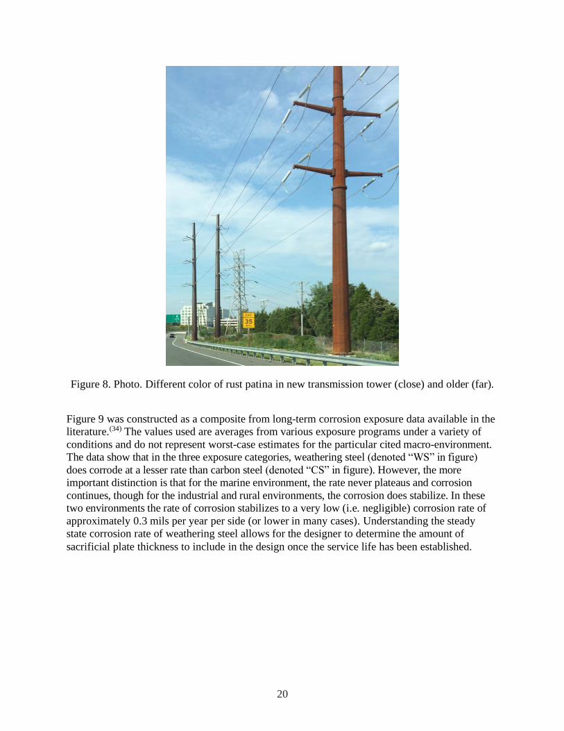
stabilize to a deep brown, almost purple color when the patina is fully developed.(12) While not a
bridge, the transmission towers shown in Figure 8 show the difference is recently erected
weathering steel transmission tower with a brown patina versus one that has been in-service for
many years with the dark chocolate/purple color.
20
Figure 8. Photo. Different color of rust patina in new transmission tower (close) and older (far).
Figure 9 was constructed as a composite from long-term corrosion exposure data available in the
literature.(34) The values used are averages from various exposure programs under a variety of
conditions and do not represent worst-case estimates for the particular cited macro-environment.
The data show that in the three exposure categories, weathering steel (denoted “WS” in figure)
does corrode at a lesser rate than carbon steel (denoted “CS” in figure). However, the more
important distinction is that for the marine environment, the rate never plateaus and corrosion
continues, though for the industrial and rural environments, the corrosion does stabilize. In these
two environments the rate of corrosion stabilizes to a very low (i.e. negligible) corrosion rate of
approximately 0.3 mils per year per side (or lower in many cases). Understanding the steady
state corrosion rate of weathering steel allows for the designer to determine the amount of
sacrificial plate thickness to include in the design once the service life has been established.

21
0
5
10
15
20
25
30
35
40
0 2 4 6 8 10 12 14 16 18
Sec
tio
n L
oss
(mil
s m
easu
red
per
sid
e)
Years of Exposure
CS - Marine
WS - Marine
CS - Industrial
WS - Industrial
CS - Rural
WS - Rural
Figure 9. Graph. Relative corrosion rates of carbon and weather grade steels in various
environments.
3.4 Additional Corrosion Resistant Alloys
Other classes of corrosion-resistant alloys are the so-called “stainless” alloys. A steel is generally
considered stainless provided its chromium content exceeds 10.5 percent. However, there are
many classes of stainless alloys (i.e., austentic, superaustentic, ferritic, martensitic, and duplex)
that, depending on the alloy and desired properties, will contain up to 30 percent chromium, 10
percent nickel, and 5 percent molybdenum. Considering the macro-environments of bridges,
stainless alloys would essentially not develop any rust product, and represent the upper echelon
of corrosion performance. However, the alloys used are expensive, and stainless grades of steel
have historically been thought too cost-prohibitive for the construction of an entire bridge
superstructure.
The steel industry continues to research and produce advanced alloys, which promise enhanced
corrosion resistance with practical cost and fabrication qualities.(33) Recently, the steel industry
has begun marketing “near stainless” grades that contain the minimum of 10.5 percent chromium
and fall under the ASTM A1010 specification; this is essentially the leanest stainless steel can
become.(35, 36) More recently, this particular stainless steel has been adopted as part of the ASTM
A709 specification, and is referred to as ASTM A709 Grade 50CR. At the time of writing
(2021), only six known bridges had been built with A709 Grade 50CR steel; one in California,
two in Oregon, one on a private property in Pennsylvania, and two in Virginia. The A709 Grade
50CR steel has roughly 100 times the corrosion resistance of ASTM A709 Grade50W, and

22
approximately 40 times the corrosion resistance of hot-dip galvanizing.(37) Despite this enhanced
corrosion resistance, a weathered A709 Grade 50CR surface will develop a rust colored patina
similar to weathering steel.
There are a few nuances that should be known before selecting A709 Grade 50CR steel. There is
no weld consumable specific to welding A709 Grade 50CR and it must be welded with austenitic
filler metal, similar to welding practices for higher grades of stainless steels. These filler metals
have much more corrosion resistance than the A709 Grade 50CR itself, so the welds will always
appear to be shiny throughout the life of the bridge (essentially cathodically protected by the rest
of the nearby A709 Grade 50CR material), while the rest of the A1010 naturally weathers.
Additionally, the only product available in A709 Grade 50CR is hot-rolled plate. Since cross-
frames are typically made from rolled shape product, a different grade of steel must be used for
them, or A709 Grade 50CR plate must be bent to make equivalent shapes. One solution is to
make the cross-frames from weathering steel and use Type 3 high-strength fasteners, though it
would be expected that cross-frames would corrode faster than the girders if the owner was
willing replace them during the life of the bridge. Second, the cross-frames could be galvanized
and bolted with galvanized high-strength fasteners. Third, use galvanized cross-frames with
high-strength stainless steel fasteners. With both the second and third options, there is a concern
with galvanic corrosion at the locations where dissimilar metals contact each other. Galvanic
corrosion is related the difference in potential voltage between the two metals in contact, the
aggressiveness of the environment, and the ratio of areas in contact. Generally, situations with
large cathodes and small anodes should be avoided, and this would lend larger concern to
galvanizing in contact with the A709 Grade 50CR steel (e.g., galvanized bolts sacrifice
themselves to the A709 Grade 50CR), in lieu of stainless in contact with the A709 Grade 50CR
(e.g., A709 Grade 50CR sacrificing itself to ASTM A193 B8M bolts). Other fabrication and
construction guidance is provided by the plate producer for A709 Grade 50CR product.(37)
Conceptually, it is possible to build an entire bridge from more robust stainless alloys other than
A709 Grade 50CR, but not as long as bridges are designed and fabricated on first cost basis. As
an example, 20 years ago no bridge designer would have imagined using solid stainless rebar in
bridge decks though at the time of writing, there have been at least 80 bridge decks constructed
with solid stainless steel rebar.(38) With life-cycle cost analysis becoming more popular, and ever
increasing resistance to lane closures for maintenance and rehabilitation, it is likely in the future
that fully stainless steel bridges may be realized in the next 20 years. Bridge designers should
continually revisit this concept, as eventually it may prove viable. Along with choosing stainless
steels, designers will have to invest time in writing good fabrication and construction
specifications. For instance, the American Welding Society publishes the D1.6 Structural
Welding Code—Stainless Steel, but bridges are welded according to D1.5, Bridge Welding Code,
and thought will have to put into how to marry the two together.(39, 40) Similarly, the same
thought will have to be put into specifying a fully stainless, high-strength bolt that can be
pretensioned, and the qualification procedures to ensure it.
23
4.0 HISTORICAL PERFORMANCE OF MATERIALS
This section is meant to provide data that can be used to assess the historical performance of the
materials described above. Since performance is closely tied with the macro- and micro-
environments on the specific structure, a thorough discussion cannot be presented; rather,
performance will be discussed in broad terms. It is also helpful to understand how many steel
bridges are in the inventory that require corrosion protection, to offer some perspective on the
statistically viability of the data.
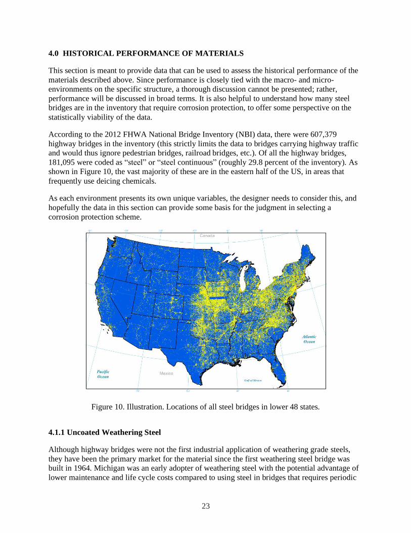
According to the 2012 FHWA National Bridge Inventory (NBI) data, there were 607,379
highway bridges in the inventory (this strictly limits the data to bridges carrying highway traffic
and would thus ignore pedestrian bridges, railroad bridges, etc.). Of all the highway bridges,
181,095 were coded as “steel” or “steel continuous” (roughly 29.8 percent of the inventory). As
shown in Figure 10, the vast majority of these are in the eastern half of the US, in areas that
frequently use deicing chemicals.
As each environment presents its own unique variables, the designer needs to consider this, and
hopefully the data in this section can provide some basis for the judgment in selecting a
corrosion protection scheme.
Figure 10. Illustration. Locations of all steel bridges in lower 48 states.
4.1.1 Uncoated Weathering Steel
Although highway bridges were not the first industrial application of weathering grade steels,
they have been the primary market for the material since the first weathering steel bridge was
built in 1964. Michigan was an early adopter of weathering steel with the potential advantage of
lower maintenance and life cycle costs compared to using steel in bridges that requires periodic
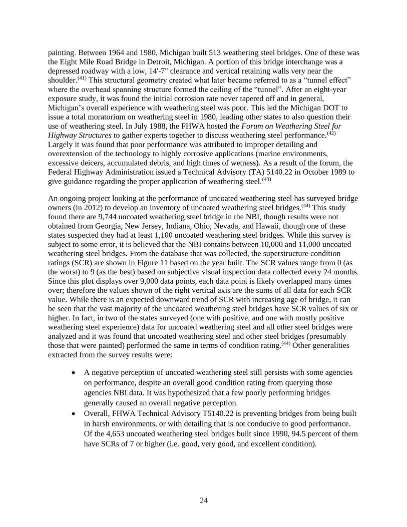
24
painting. Between 1964 and 1980, Michigan built 513 weathering steel bridges. One of these was
the Eight Mile Road Bridge in Detroit, Michigan. A portion of this bridge interchange was a
depressed roadway with a low, 14'-7" clearance and vertical retaining walls very near the
shoulder.(41) This structural geometry created what later became referred to as a “tunnel effect”
where the overhead spanning structure formed the ceiling of the “tunnel”. After an eight-year
exposure study, it was found the initial corrosion rate never tapered off and in general,
Michigan’s overall experience with weathering steel was poor. This led the Michigan DOT to
issue a total moratorium on weathering steel in 1980, leading other states to also question their
use of weathering steel. In July 1988, the FHWA hosted the Forum on Weathering Steel for
Highway Structures to gather experts together to discuss weathering steel performance.(42)
Largely it was found that poor performance was attributed to improper detailing and
overextension of the technology to highly corrosive applications (marine environments,
excessive deicers, accumulated debris, and high times of wetness). As a result of the forum, the
Federal Highway Administration issued a Technical Advisory (TA) 5140.22 in October 1989 to
give guidance regarding the proper application of weathering steel.(43)
An ongoing project looking at the performance of uncoated weathering steel has surveyed bridge
owners (in 2012) to develop an inventory of uncoated weathering steel bridges.(44) This study
found there are 9,744 uncoated weathering steel bridge in the NBI, though results were not
obtained from Georgia, New Jersey, Indiana, Ohio, Nevada, and Hawaii, though one of these
states suspected they had at least 1,100 uncoated weathering steel bridges. While this survey is
subject to some error, it is believed that the NBI contains between 10,000 and 11,000 uncoated
weathering steel bridges. From the database that was collected, the superstructure condition
ratings (SCR) are shown in Figure 11 based on the year built. The SCR values range from 0 (as
the worst) to 9 (as the best) based on subjective visual inspection data collected every 24 months.
Since this plot displays over 9,000 data points, each data point is likely overlapped many times
over; therefore the values shown of the right vertical axis are the sums of all data for each SCR
value. While there is an expected downward trend of SCR with increasing age of bridge, it can
be seen that the vast majority of the uncoated weathering steel bridges have SCR values of six or
higher. In fact, in two of the states surveyed (one with positive, and one with mostly positive
weathering steel experience) data for uncoated weathering steel and all other steel bridges were
analyzed and it was found that uncoated weathering steel and other steel bridges (presumably
those that were painted) performed the same in terms of condition rating.(44) Other generalities
extracted from the survey results were:
• A negative perception of uncoated weathering steel still persists with some agencies
on performance, despite an overall good condition rating from querying those
agencies NBI data. It was hypothesized that a few poorly performing bridges
generally caused an overall negative perception.
• Overall, FHWA Technical Advisory T5140.22 is preventing bridges from being built
in harsh environments, or with detailing that is not conducive to good performance.
Of the 4,653 uncoated weathering steel bridges built since 1990, 94.5 percent of them
have SCRs of 7 or higher (i.e. good, very good, and excellent condition).

25
0
1
2
3
4
5
6
7
8
9
10
196
4
196
8
197
2
197
6
198
0
198
4
198
8
1992
1996
2000
200
4
200
8
201
2
Supers
tructu
re C
onditio
n R
ating
(NB
I C
odin
g I
tem
#59)
Year of Construction
1049
3318
3117
948
281
47
20
4
Figure 11. Graph. Superstructure condition ratings of uncoated weathering steel bridges by year
built.
The FHWA Technical Advisory also cautions against the use weathering steel in “tunnel-like”
conditions of grade separate with certain geometric traits. However, the advisory does not
provide geometric specifics defining what categorizes a grade separation as a “tunnel”. Recent
computational fluid dynamics research has found that a single truck passage beneath a bridge
with 16 foot vertical clearance does not exhibit the traits of a “tunnel”.(45) Rather, the transport of
spray from truck wheels does not elevate to the girders above unless there are multiple vehicles
traveling in a train, travel lanes within approximately five feet of a vertical abutment, or wind.
Wind by far had the largest effect on mobilizing tire spray from vehicle up to the level of the
girders. These notions suggest the “tunnel” effect is more dependent upon the average daily
traffic and local wind conditions, not necessarily just the vertical clearance of the bridge.
The graph shown earlier in this report (Figure 9) illustrates a key performance property of
weathering steel. In the initial of exposure (years 1 and 2), corrosion rates for weathering steels
are lower, but similar to that of carbon steel. Afterwards, properly functioning weathering steel
(i.e., properly detailed and located) will corrode at a steady-state rate less than 0.3 mils per year.
Corrosion in excess of this rate indicates that weathering steel should not be used bare at that
location or in that configuration.(7, 12) Improperly located or detailed weathering steel structures
have shown average corrosion rates of up to 4 mils per year per exposed side. Since weathering
steel tends to exhibit local pitting as it corrodes, the depth of pits can be much deeper.(7, 9, 12, 13)

26
4.1.2 Galvanizing and Metalizing
Assessing the past performance of galvanized and metalized coatings is difficult for two reasons.
One, there is not a nationwide, accessible database of galvanized and metalized highway bridges.
Most states maintain a database of bridge data beyond that required to be reported to the NBI,
but access is not readily available. Two, there has yet to be a comprehensive study looking at the
performance of these coatings over the entire inventory. The American Galvanizers Association
maintains for marketing purposes a listing of some bridges that are galvanized, and scant
performance data is available in trade journals and state research reports focusing on evaluation
of new coatings. It is believed that at most there are a couple thousand fully galvanized or
metalized highway bridges existing in the inventory and overall their performance has been quite
good. The following are some examples that have been found in the available literature.
The first reported fully galvanized bridge was built in Michigan and open to traffic in 1967.(46)
This multi-girder bridge is a low water crossing over a river. The bridge was visited by the
county engineer in 1991 (after 25 years) and noted to be in very good condition with no
rusting.(47) According to the 2012 NBI data for this bridge, the SCR is 7 (i.e., good condition)
after 46 years of service, but it is unknown what maintenance actions have been taken. It was
also found between the years of 1966 and 1973 that a particular galvanizer galvanized 123 state
and county bridges (in Ohio) and magnetic coating thickness measurements on two of them
taken in 1983 found that with the remaining thickness, a total life of 60 and 90 years could be
achieved (these are in rural locations).(47)
Brevoort republished a paper in 1996 that outlined predicted lives of 89 different coatings
(including metalizing) to the first maintenance action along with cost. This paper was first
published in 1979, and again in 1982, 1984, 1986, 1988, and 1990 and evolved based on
feedback from a variety of people in the coatings field. The paper continued to receive revision
by multiple authors through 2014, but the life estimates remained mostly static during that time
period except for galvanizing.(48, 49, 50, 51) The lives of galvanized and metalized systems
reproduced from these publications is shown in Table 4. The data for galvanizing was referenced
from the American Galvanizers Association and had a distinct change between the 2008 and
2014 editions. The estimated life of pure zinc metalizing in rural, industrial, and heavy industrial
was 33, 22, and16 years respectively. Marine environments had a suggested life of 17.5 years.
The paper was revisited again in 2006 by Leyland who had evaluated a handful of Maine and
Connecticut bridges, and generally they found the Brevoort predictions to be conservative for
paints, but of the four galvanized bridges visited, none had reached the Brevoort life prediction,
though they were all still in good condition (one was 36 years old).(52) The American Galvanizers
Association has commented that it believes the estimates used for galvanizing life in the series of
Brevoort reports significantly underestimates the expected life of hot dip galvanizing, and that
this is likely the cause of disparity between the 2008 and 2014 editions of the paper.

27
Table 4. Estimated Life of Metalized and Galvanized Coating Per Exposure Condition
Coating System
Nu
mb
er o
f C
oats
Mil
d (
rura
l)/C
2
Mod
erate
(in
du
stri
al)
/C3
Sev
ere
(hea
vy
ind
ust
rial)
/C5
-I
Coast
al
hea
vy
ind
ust
rial
/ C
5-M
Zinc metalizing 1 33 22 16 16
Zinc metalizing/sealer 2 34 24 17 18
Zinc
metalizing/sealer/polyurethane 3 39 27 22 22
4 mils hot-dipped galvanizing
(1979-2008) 1 68 33 21 (blank)
4 mils hot-dipped galvanizing
(2014) 1 100 90 72 (blank)
An interesting coating comparison study was conducted by the New Jersey DOT. This study
evaluated 47 different experimental coating systems and surface preparation combinations. The
coatings were applied between 1986 and 1987 to individual spans of the Mathis Bridge between
Toms River and Seaside Heights, NJ.(53) This multi-span girder bridge is a coastal environment
built close to the water. Both pure zinc and 85 percent zinc / 15 percent aluminum metalizing
(with topcoats) were considered systems, and were applied to two of the spans. All the coatings
were evaluated after 1, 8 and 20 years of life by rating them visually using ASTM D610.(54) This
standard ranks the performance on a scale of 0 (the worst) to 10 (the best). Both metalized spans
were found to be the best performing systems after 20 years of exposure, each rated as a 9. Only
localized rusting was beginning to form at the interface of the girder to the bearing. Brevoort
suggested a life of 17.5 years for zinc metalizing in a marine environment; the New Jersey study
indicates that his predictions are likely conservative. The New Jersey data is in strong agreement
with data from the landmark study conducted by the American Welding Society on the corrosion
rate of metalizing.(55) This 19-year exposure study placed test panels of metalized coatings at
seven of the ASTM exposure sites listed in Table 1 (Brazos River, TX; Columbus, OH; East
Chicago, IN; Kure Beach 80 feet, NC; Kure Beach 800 feet, NC; Bayonne, NJ; Point Reyes,
CA). The test panels were thermal sprayed with pure aluminum, pure zinc, or zinc/aluminum
alloy, and were untreated, sealed with aluminum vinyl, or sealed with chlorinated rubber. After
19 years of exposure, none of the untreated aluminum specimens ever had the base metal
attacked, even at thicknesses down to three mils thick. Despite the base metal being protected,
the aluminum metalizing did discolor, had a blotchy appearance, or had pinpoint nodes of white
rust. Even with the sealers investigated, the discoloration and blotchiness was not prevented. As
for the untreated zinc metalizing, most sites saw significant base metal attack with the three mil
thick coating and not until the coating was nine mils thick was the base metal protected in all the

28
exposure sites. With the aluminum vinyl sealed zinc, the base metal and zinc were unaffected at
all exposure sites at the three mil thickness.
Another long-term study was conducted by Cambridge University beginning in 1951 considering
27 metalized coatings of single and multi-metal compositions. Exposure sites were selected in
England and the United States though all panels were removed after 10.5 years except for those
at the 800 foot Kure Beach location in North Carolina. After 34 years of exposure, the panels at
Kure Beach were revaluated and indicated continued corrosion free performance for several of
the variants.(56) The study examined ten different proportions of zinc and aluminum that were
mixed individual powders of each alloy (MP), alloyed together then powdered (AP), or applied
individually (SEP) and the observations are duplicated in Table 5. Conventional modern
metalizing would be compared to the “AP” or “SEP” data points. In the aggressive Kure Beach
environment, the best performing alloys contained more than 50 percent aluminum, and zinc
alone required six mils of thickness to be effective, whereas aluminum by itself only required
three mils.
Table 5. 34-Year Exposure Results of Metalizing at Kure Beach, NC(56)
Coating Zero Percent Base
Metal Rust
Up to 30 Percent
Base Metal rust and
Yellow Rust
Staining
50-100 Percent Base
Metal Rust and
Yellow Rust
Staining
3 mils of 90/10 Zn/Al MP AP
3 mils of 80/20 Zn/Al MP and AP
3 mils of 70/30 Zn/Al MP and AP
3 mils of 60/40 Zn/Al MP and AP
3 mils of 50/50 Zn/Al AP MP
3 mils of 40/60 Zn/Al AP MP
3 mils of 30/70 Zn/Al MP AP
3 mils of 20/80 Zn/Al MP and AP
3 mils of 10/90 Zn/Al AP
3 mils of Zn SEP
6 mils of Zn SEP
3 mils of Al SEP
6 mils of Al SEP
Both the AWS and Cambridge University exposure studies showed that for equal thicknesses,
higher percentages of aluminum in the metalizing performed better than those with higher
proportions of zinc. As described earlier in this document, the metalizing industry has more or
less settled on pure zinc or 85/15 percent zinc/aluminum, which is contrary to the exposure study
findings. The difference is cost; zinc is faster and easier to apply than aluminum, and market
conditions have more or less driven pure zinc and 85/15 to be the preferred choice for

29
metalizing. Additionally, the exposure studies showed that 3 mils of aluminum or 6 mils of zinc
provided rust-free performance for 53 years in the aggressive Kure Beach marine environment;
however, recommended practice is to apply metalizing around 10 to 16 mils of thickness for a
service life greater than 40 years.(57) It is good practice to factor up coating thickness in practice
over that proven via exposure testing, but the industry recommendation has already been factored
up by at least two. Owners who specify metalizing thicknesses over industry recommendations
are likely not getting any benefit for the cost they are investing.
Exposure studies conducted by FHWA in marine locations in both Louisiana and New Jersey
over 5 and 6.5 years, respectively, found metalizing to be some of the top performing coating
systems.(18) Both zinc and zinc/aluminum coatings were tested, some with sealers. All systems
exhibited virtually no rust in during the test period (~0.01 percent of the coated surface) for both
the sealed and unsealed metalized test panels. Extrapolating the rust data out to a two percent
rust coverage suggested a life of approximately 30 years for the marine exposure. This also
shows that the Brevoort predictions are likely conservative.
Other international literature exists on the performance of galvanizing and metalizing, but it was
largely omitted from this discussion because the environments will likely be different from those
in the United States. For instance, one reference from Venezuela looked at the performance of
galvanized transmission towers built over the ocean, and found galvanizing to have reached
failure after 42 months of exposure.(58) The environment is quite aggressive roughly two to four
times that of the Kure Beach, 80 ft. lot described in Table 1. In this situation, there are also high
humidly and constant winds that tend to erode the galvanizing. In extreme environments such as
this, designers need to consider duplex systems employing galvanizing in combination with a
durable topcoat. The United Kingdom has been committed to the use of thermal spray metalized
coatings as a primer for their bridges (as an island nation, much of the UK is a fairly severe
environment), although the preferred system for bridge steel has been a thinner coat
(approximately 4 mils) of metalizing (aluminum) followed by up to four paint topcoats.(59)
For the most part, galvanized and metalized coatings perform quite well. Based on the literature
presented in this section, in rural environments they appear to be good for the life of the
structure, though in marine environment they will probably get around 20+ years of
maintenance-free service for the most corrosive areas of the structure, with longer service on less
corrosive areas.
4.1.3 Zinc-Rich Paint Systems
Based on the inventory numbers presented in the prior two sections, by far the most common
corrosion protection scheme for steel highway bridges is paint. However, as with galvanizing
and metalizing, there has yet to be a comprehensive evaluation of coating performance in the US,
and evidence regarding real-world, real-time performance on actual bridges is mainly anecdotal.
Data available in the literature is sparse, and primarily related to accelerated lab testing, and field
exposing coatings for short periods of time.(18, 60, 61, 62) There is also a negative impression of
paint systems in general that tend to cloud the data were owners are very familiar with
maintaining old coating systems (e.g., lead-based paints, coating applied with no surface
preparation) that could not come close to meeting the performance of modern coating systems.
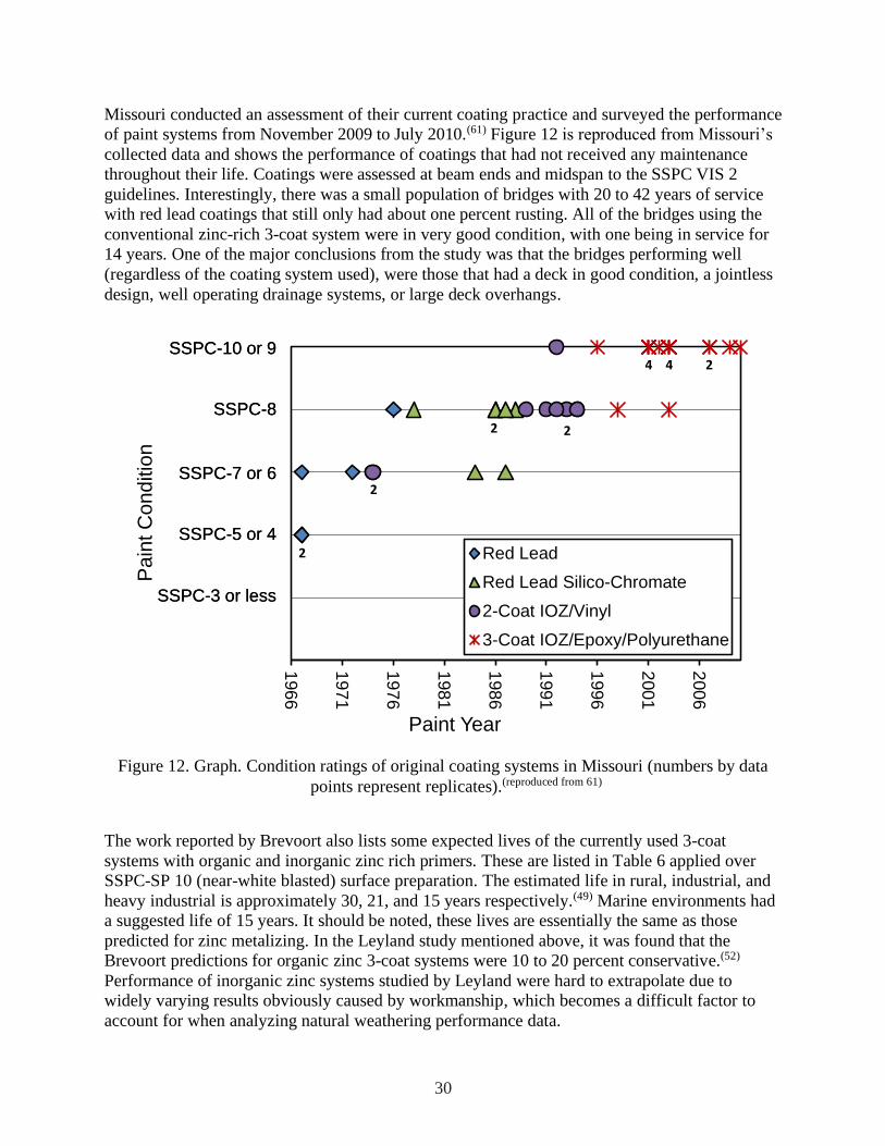
30
Missouri conducted an assessment of their current coating practice and surveyed the performance
of paint systems from November 2009 to July 2010.(61) Figure 12 is reproduced from Missouri’s
collected data and shows the performance of coatings that had not received any maintenance
throughout their life. Coatings were assessed at beam ends and midspan to the SSPC VIS 2
guidelines. Interestingly, there was a small population of bridges with 20 to 42 years of service
with red lead coatings that still only had about one percent rusting. All of the bridges using the
conventional zinc-rich 3-coat system were in very good condition, with one being in service for
14 years. One of the major conclusions from the study was that the bridges performing well
(regardless of the coating system used), were those that had a deck in good condition, a jointless
design, well operating drainage systems, or large deck overhangs.
2
2 2
2
4 4 2
196
6
197
1
197
6
198
1
198
6
199
1
1996
200
1
200
6
Pa
int C
on
ditio
n
Paint Year
Red Lead
Red Lead Silico-Chromate
2-Coat IOZ/Vinyl
3-Coat IOZ/Epoxy/Polyurethane
SSPC-3 or less
SSPC-5 or 4
SSPC-7 or 6
SSPC-8
SSPC-10 or 9
SSPC-3 or less
SSPC-5 or 4
SSPC-7 or 6
SSPC-8
SSPC-10 or 9
Figure 12. Graph. Condition ratings of original coating systems in Missouri (numbers by data
points represent replicates).(reproduced from 61)
The work reported by Brevoort also lists some expected lives of the currently used 3-coat
systems with organic and inorganic zinc rich primers. These are listed in Table 6 applied over
SSPC-SP 10 (near-white blasted) surface preparation. The estimated life in rural, industrial, and
heavy industrial is approximately 30, 21, and 15 years respectively.(49) Marine environments had
a suggested life of 15 years. It should be noted, these lives are essentially the same as those
predicted for zinc metalizing. In the Leyland study mentioned above, it was found that the
Brevoort predictions for organic zinc 3-coat systems were 10 to 20 percent conservative.(52)
Performance of inorganic zinc systems studied by Leyland were hard to extrapolate due to
widely varying results obviously caused by workmanship, which becomes a difficult factor to
account for when analyzing natural weathering performance data.

31
Table 6. Estimated Life of Zinc-Rich Paint Systems Per Exposure Condition
Coating System
Nu
mb
er o
f C
oats
Mil
d (
rura
l)/C
2
Mod
erate
(in
du
stri
al)
/C3
Sev
ere
(hea
vy
ind
ust
rial)
/C5
-I
Coast
al
hea
vy
ind
ust
rial
/ C
5-M
Epoxy
Zinc/polyurethane/polyurethane 3 32 23 15 15
Epoxy
Zinc/epoxy/polyurethane 3 29 20 14 14
Inorganic Zinc 1 27 17 12 12
Inorganic Zinc/epoxy/epoxy 3 32 23 17 17
Inorganic
Zinc/polyurethane/polyurethane 3 32 23 17 17
Inorganic
Zinc/epoxy/polyurethane 3 30 21 15 15
In the Mathis Bridge study described in 4.1.2, systems using both IOZ and OZ primer with both
SSPC-SP 6 and SP 10 preparation were also evaluated after 20 years of marine exposure.(53) This
study evaluated a number of different systems, even some that did not use zinc-rich primers (so-
called “barrier” systems). The performance data validated the trend that for these conventional
coatings, three coats of paint is generally more effective than two or one coat (however, more
recent developments in the coatings industry have produced materials that provide high levels of
durability with two or even one coat at a higher build). The data show that systems with zinc-rich
primers prove to be the best performers, but not all zinc rich primer systems performed well. The
coating performance ratings after 1, 8, and 20 years of exposure are represented in Figure 13 for
just those systems that used zinc-rich primers. Looking strictly at the five 3-coat systems, after
20 years of exposure in this marine environment, the ratings ranged from five to eight on the
ASTM D610 scale. However, of those 15 zinc-rich systems, the top seven performers (roughly
the top half) survived to a rating of 7 or higher after 20 years in a very severe exposure, applied
as a maintenance coating over previously deteriorated steel. Interestingly, this data set does not
show a clear separation between systems applied over SSPC-SP 6 versus SSPC-SP 10 blasted
surfaces. But in a practical sense, there is often only a slight difference between those two
specifications in field work.
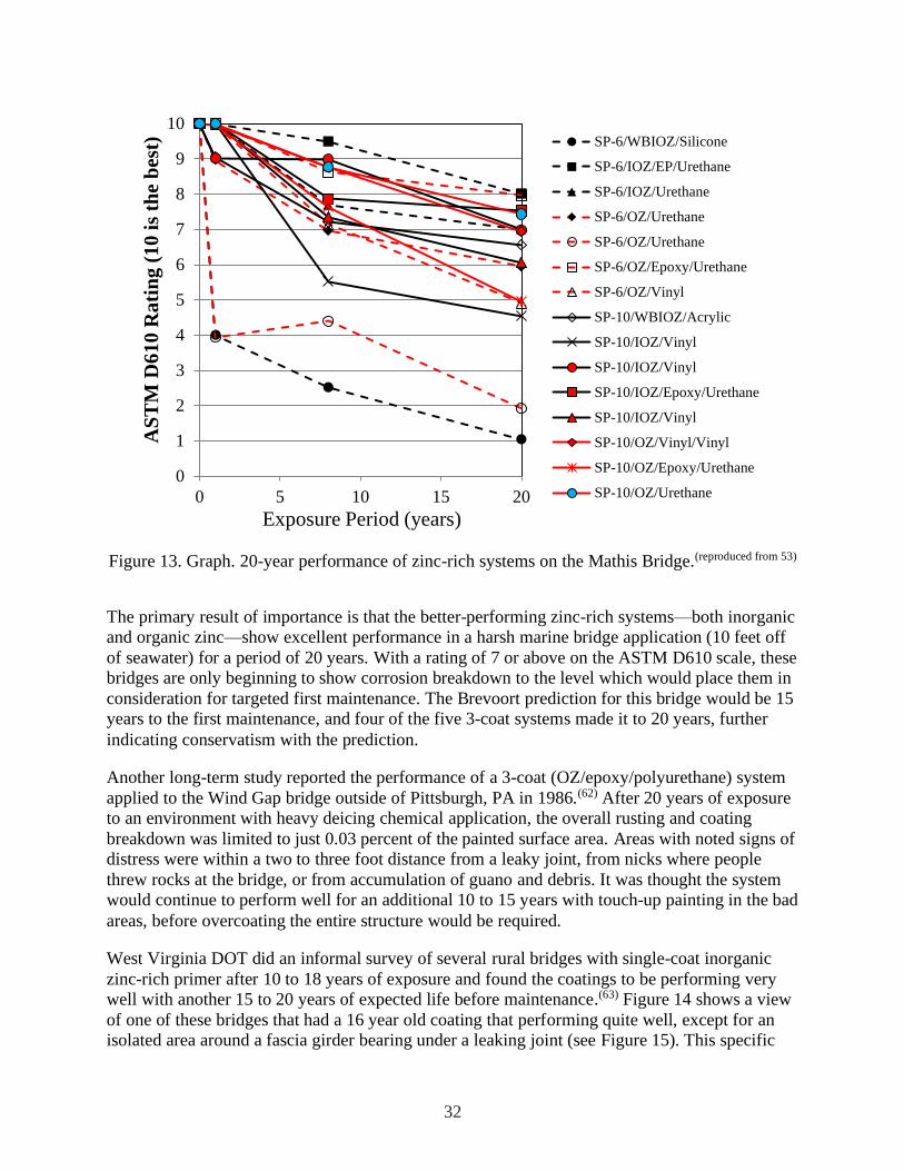
32
0
1
2
3
4
5
6
7
8
9
10
0 5 10 15 20
AS
TM
D6
10
Ra
tin
g (
10
is
the
bes
t)
Exposure Period (years)
SP-6/WBIOZ/Silicone
SP-6/IOZ/EP/Urethane
SP-6/IOZ/Urethane
SP-6/OZ/Urethane
SP-6/OZ/Urethane
SP-6/OZ/Epoxy/Urethane
SP-6/OZ/Vinyl
SP-10/WBIOZ/Acrylic
SP-10/IOZ/Vinyl
SP-10/IOZ/Vinyl
SP-10/IOZ/Epoxy/Urethane
SP-10/IOZ/Vinyl
SP-10/OZ/Vinyl/Vinyl
SP-10/OZ/Epoxy/Urethane
SP-10/OZ/Urethane
Figure 13. Graph. 20-year performance of zinc-rich systems on the Mathis Bridge.(reproduced from 53)
The primary result of importance is that the better-performing zinc-rich systems—both inorganic
and organic zinc—show excellent performance in a harsh marine bridge application (10 feet off
of seawater) for a period of 20 years. With a rating of 7 or above on the ASTM D610 scale, these
bridges are only beginning to show corrosion breakdown to the level which would place them in
consideration for targeted first maintenance. The Brevoort prediction for this bridge would be 15
years to the first maintenance, and four of the five 3-coat systems made it to 20 years, further
indicating conservatism with the prediction.
Another long-term study reported the performance of a 3-coat (OZ/epoxy/polyurethane) system
applied to the Wind Gap bridge outside of Pittsburgh, PA in 1986.(62) After 20 years of exposure
to an environment with heavy deicing chemical application, the overall rusting and coating
breakdown was limited to just 0.03 percent of the painted surface area. Areas with noted signs of
distress were within a two to three foot distance from a leaky joint, from nicks where people
threw rocks at the bridge, or from accumulation of guano and debris. It was thought the system
would continue to perform well for an additional 10 to 15 years with touch-up painting in the bad
areas, before overcoating the entire structure would be required.
West Virginia DOT did an informal survey of several rural bridges with single-coat inorganic
zinc-rich primer after 10 to 18 years of exposure and found the coatings to be performing very
well with another 15 to 20 years of expected life before maintenance.(63) Figure 14 shows a view
of one of these bridges that had a 16 year old coating that performing quite well, except for an
isolated area around a fascia girder bearing under a leaking joint (see Figure 15). This specific

33
result reinforces the overriding premise that holds for all of these highly durable corrosion
resistant coatings—the life of the coating is often determined by the very severe local conditions
created by detailing of the structure as it intersects with concentrated salt-containing runoff,
splash and drainage.
Figure 14. Photo. Bridge in West Virginia with a single-coat inorganic zinc-rich paint system
after 25 years.
Figure 15. Photo. Deterioration of bearing area beneath a leaking joint with only single-coat
inorganic zinc-rich paint.
It must be noted that high-performance zinc-rich primer systems tend to fail at specific points of
coating damage and often these localized areas of failure can be repaired during routine or
periodic maintenance. Properly managed, bridges using zinc-rich primer coating systems can last
much longer with periodic touch-up painting, avoiding the large costs and traffic delays often
associated with wholesale repainting of an existing bridge.
34
4.1.4 Duplex Coating Systems
Zinc-rich paint systems are really multi-layers of different liquid coatings. Technically, these
could be considered a duplex coating, but for this publication a duplex coating is defined as one
that uses multiple different corrosion mitigation schemes for a single bridge. For instance, rather
than a using a zinc-rich primer over steel, hot-dip galvanizing or metalizing could be used as the
“primer” then further topcoated for uniform color appearance and barrier protection.
Conservatively, one could consider each of the coatings decoupled from each other and merely
add together the predictive lives for each system to estimate the overall life of the complete
duplex system. In reality there is a synergetic effect between each of the coatings, and their effect
on the life of the duplex coating is multiplicative. For instance, paint applied over hot-dip
galvanizing would act as a barrier protecting the zinc from corroding until exposed. At the same
time, topcoat failures usually begin from small defects and holidays in the substrate that begin to
rust and blister the coating, but since the zinc could sacrifice at these locations, the barrier coat
achieves a longer life. Van Eijnsbergen has published based on observational data that painted
hot-dip galvanizing lifes can be 1.5 to 2.3 times the sum of the two lives of the individual
coatings.(64) The 1.5 factor is for aggressive environment and 2.3 for less aggressive
environments. It could reasonably be assumed the same synergetic behavior could be expected
for barrier coatings applied over metalizing.
The notion of longer life of coated weathering steel versus coated non-weathering steel is still a
controversial topic. There are numerous older references that allude to this, though the steels
tested did not have the same chemistries as modern weathering steel, the coatings were not
representative of modern three-coat zinc rich systems, the exposure environments were not
representative of bridge sites, nor was modern surface preparation used.(65, 66, 67) There is one
unpublished 15-year exposure study performed at the Kure Beach 80 foot lot between coated
weathering steel and regular carbon steel that were both coated.(68) The specimens were blast
cleaned to white metal and ten different two- and three-coat systems were applied. Considering
all the coating systems together using a subjective scale between zero (complete rusting) and 100
(no rusting), the coated weathering steel panels scored 83 versus 39 for the carbon steel,
demonstrating twice the rusting resistance. However, accelerated testing results in the era of
modern bridge coatings with proper substrate preparation and zinc-rich system have found that
coated weathering steel offers no benefit over regular steel.(18, 69, 70)
35
5.0 CORROSION CONSIDERATIONS IN DESIGN
Steel bridge designs continue to evolve so that there are many different types currently in
service. Steel bridges can be simple rolled beam or plate girder construction with all of the steel
located below the level of the roadway deck. They can be constructed of a combination of steel
trusses located below and above the deck. They can have unique, challenging components such
as main cables and suspender cables on a suspension or cable-stayed bridge, or they can be
highly complex with moving parts such as a bascule or lift span bridge. Corrosion protection has
to be considered for both the initial years of a bridge’s service life, but also the on-going
maintenance activities it will see throughout its entire service life.
5.1 Broad Topic Considerations
In the scoping of a bridge design project when various superstructure designs are being
evaluated, the corrosion protection scheme should be on the list of important items considered by
the designer. The local site conditions and type of superstructure will have an influence the type
of corrosion protection scheme, and its overall cost to the project. The following variables are
considered important in that they may impact coating materials or methods chosen:
5.1.1 Complexity
Bridges with high levels of surface complexity are more difficult and expensive to clean and
paint or metalize. Complex details include box beams, riveted or bolted construction, lacing bars,
and tight clearances between members.
5.1.2 Height and Access
Rigging for access to steel surfaces is often an important factor in the cost and schedule of a
bridge coating project. By their very function, bridges cross difficult-to-access areas. Often,
access to a structure is also heavily affected by local traffic patterns or environmental concerns.
Sometimes viaducts and overpasses may be accessed from below. Arch, truss, suspension and
bridges over water, however, require at least some closure of the bridge deck for access and
equipment placement. Also, bridge painting operations must be contained and ventilated to trap,
collect, and dispose of blasting waste and paint overspray during any field maintenance
activities.
5.1.3 Large and Unique Structures
Cable-stayed and suspension bridges have unusual features which require a separate approach
when performing painting. There may be a requirement for separate specifications and contracts
for painting of tower, cables, anchorage areas, fixed approach spans and suspended truss spans.
In addition, moveable bridges have special requirements associated with moving mechanical
parts. These unique features require protective coatings with added flexibility and compatibility
with specific lubricants.

36
5.1.4 Utilities
Many bridges serve as a piggyback for local utility crossings. Live utilities attached to bridge
steel can affect the maintenance-painting operation. Utilities must be protected during painting
operations, and their physical presence may obstruct maintenance painting of underlying structural
steel.
5.1.5 Rail Sharing
Some bridges share their capacity between automotive traffic and rail traffic. This presents the
unique challenge of operating with deference to the rail schedule for access. The proximity of
high voltage third rails can also restrict the use of certain surface preparation methods,
particularly those using high-pressure water.
5.2 Superstructure Selection/Layout Considerations
The most important considerations in designing for corrosion protection of a steel bridge are
preventing water ponding, diverting the flow of runoff water to prevent it from impinging on the
steel structure, preventing the accumulation of debris that traps salt and moisture, and preventing
natural salt or applied deicing salt from contacting the steel surface as much as possible.(12) The
intent of this section is to educate designers on the locations that are commonly problematic for
corrosion that may further influence preliminary engineering activities and highlight the
opportunities that exist in the design stage to mitigate them, or highlight areas that need a more
robust protection schemes than in other areas.
In a general sense, any horizontal flat surface will pond water, and stagnant water will accelerate
the breakdown of any protection scheme. To envision areas susceptible to corrosion, designers
need to imagine how water will flow around and within their structures and focus attention on
the areas where it will be frequently wetted or potential to be ponded, especially if the water will
be salt laden. Since many bridges cross a body of water, there is an inherent source of local
moisture to promote corrosion and coating deterioration. This is especially true if salt or brackish
water is near the bridge. For highway bridges, the other primary source of corrosivity is the large
quantity of deicing salt spread on the roadway during the winter months. This is a factor only in
areas that experience freezing temperatures and frequent winter storms. Where salt is applied, it
tends to drain from the bridge deck through expansion joints and other designed drainage areas
onto the structural steel below, collecting onto any horizontal surfaces and continuing to damage
the coated steel for several months or years after application.
There are several areas on each structure that should be examined separately from the standpoint
of localized corrosivity. These include deck joints, drainage areas, lateral and vertical splash
zones, fascia elements, bottom flanges, cables, gratings/bearings/curbs, and built-up members.
5.2.6 Deck Joints
Use of integral abutments rather than expansion joints at the ends of spans can significantly
reduce the maintenance needs of a bridge. In cases where joints must be employed, minimize the
number of joints by employing continuous spans, and use closed or sealed joints as opposed to
open joints with troughs. Experience shows that troughs tend to fail or become clogged with

37
debris over time, limiting their effectiveness. Consider use of sealed modular joints in place of
multiple single compression seal joints.(71) Figure 16 and Figure 17 depict corrosion due to water
leakage and entrapment.
Figure 16. Photo. Steel directly beneath transverse expansion joints that have leaked corrosive
runoff from the deck.
Figure 17. Photo. Steel directly beneath longitudinal expansion joints that have leaked corrosive
runoff from the deck.
Figure 18(top) illustrates closely spaced parallel superstructure units that should be avoided. The
longitudinal joint between the two will cause focused splash onto the two interior fascia girders.
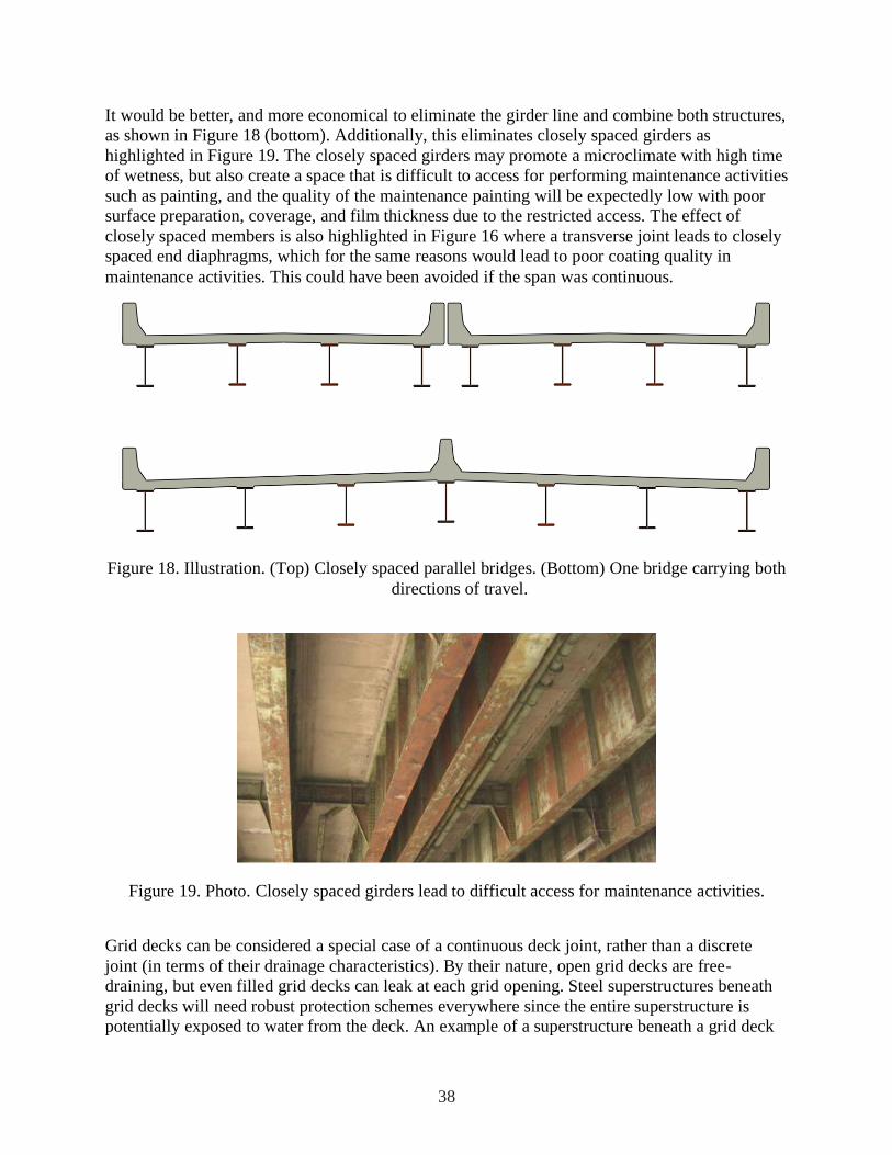
38
It would be better, and more economical to eliminate the girder line and combine both structures,
as shown in Figure 18 (bottom). Additionally, this eliminates closely spaced girders as
highlighted in Figure 19. The closely spaced girders may promote a microclimate with high time
of wetness, but also create a space that is difficult to access for performing maintenance activities
such as painting, and the quality of the maintenance painting will be expectedly low with poor
surface preparation, coverage, and film thickness due to the restricted access. The effect of
closely spaced members is also highlighted in Figure 16 where a transverse joint leads to closely
spaced end diaphragms, which for the same reasons would lead to poor coating quality in
maintenance activities. This could have been avoided if the span was continuous.
Figure 18. Illustration. (Top) Closely spaced parallel bridges. (Bottom) One bridge carrying both
directions of travel.
Figure 19. Photo. Closely spaced girders lead to difficult access for maintenance activities.
Grid decks can be considered a special case of a continuous deck joint, rather than a discrete
joint (in terms of their drainage characteristics). By their nature, open grid decks are free-
draining, but even filled grid decks can leak at each grid opening. Steel superstructures beneath
grid decks will need robust protection schemes everywhere since the entire superstructure is
potentially exposed to water from the deck. An example of a superstructure beneath a grid deck

39
is shown in Figure 20, in which it can be seen that the majority of the steel coating has failed and
active corrosion is occurring.
Figure 20. Photo. The area under an open grid deck acting as one large leaking joint.
5.2.7 Drainage Areas
Certain areas of the steel structure below the roadway surface will see the majority of drainage
and runoff from the deck above. These areas will have a higher time of wetness than the rest of
the steel structure. They will also receive an increased level of dirt and debris from the roadway.
This is critical in areas that receive significant amounts of deicing salt. These areas will often
have a much higher corrosion rate relative to the rest of the bridge. Designed, directed drainage
is often inadequate and deck-mounted expansion joints often leak as well. An example of
corrosion due to drainage can be seen in Figure 21 where a drain pipe can be seen coming from
deck, but there is a missing section of pipe between the portion coming from the deck to the
vertical drain pipe attached to the steel column, thus allowing water to directly splash the vertical
steel column. Figure 22 illustrates a drain that has clogged and is leaking directly on the
structural steel.

40
Figure 21. Photo. Missing portion of deck drain downspout.
Figure 22. Photo. Clogged drain leaking water onto superstructure.

41
Drains and scuppers have traditionally been undersized and receive little attention in
maintenance. Most frequently, these systems have a useful life of only the first few years. They
should be minimized and kept as far away from structural steel as possible. Drains and scuppers
should be detailed to have adequate capacity, and detailed to have a steep slope and no sharp
bends to minimize debris from clogging them.
5.2.8 Splash Zones (Lateral Clearance)
Splash zones exist in the lower parts of bridges over any body of water and also in areas that
receive significant splash and spray from traffic. These areas include the lower parts of towers
and pilings; parapets, curbs, and guardrails; and lower portions of overhead truss structures and
overpasses. For example, splash zones are prevalent on through trusses where traffic travels very
closely to the truss members, and the zone ranges from the curb level to about ten feet over the
roadway; this is shown in Figure 23. The area highlighted in the figure with yellow brackets
denotes the zone that would be frequently wetted by spray from vehicle tires, and it can be seen
that the coating is starting to break down in this zone. Another situation is illustrated in Figure 24
with two closely spaced parallel structures with an elevation difference. Traffic or snow removal
equipment on the left span will inevitably inundate the left fascia girder of the right-hand span.
In this case, it would be ideal if the two structures could be combined, eliminating the
longitudinal joint between them. If there must be parallel structures, they should be spaced 30
feet or more away from each other to avoid splashing. Splash zones may be unavoidable, but
consideration should be given to using a more durable protection scheme in these locations, and
providing accessibility for maintenance of the protection system.
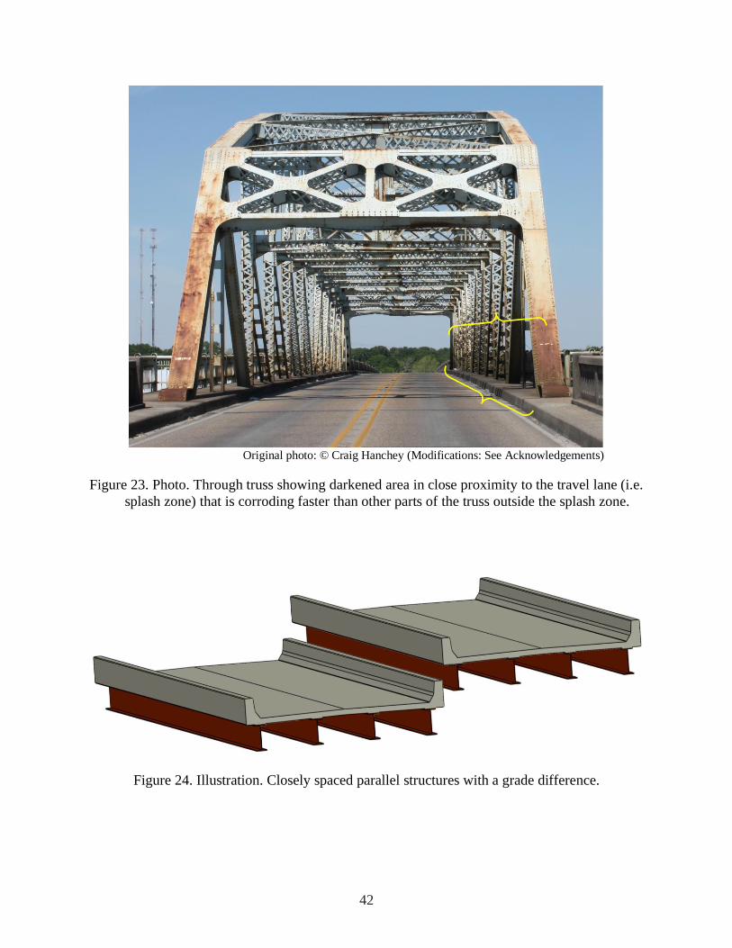
42
Original photo: © Craig Hanchey (Modifications: See Acknowledgements)
Figure 23. Photo. Through truss showing darkened area in close proximity to the travel lane (i.e.
splash zone) that is corroding faster than other parts of the truss outside the splash zone.
Figure 24. Illustration. Closely spaced parallel structures with a grade difference.
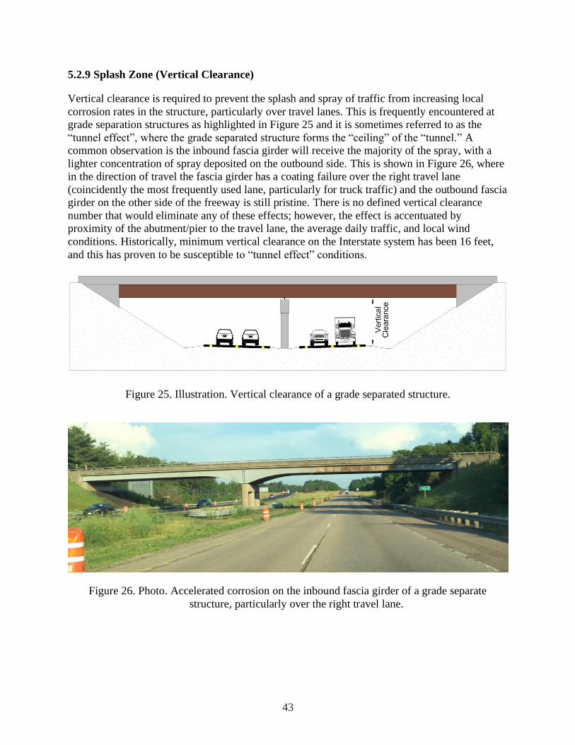
43
5.2.9 Splash Zone (Vertical Clearance)
Vertical clearance is required to prevent the splash and spray of traffic from increasing local
corrosion rates in the structure, particularly over travel lanes. This is frequently encountered at
grade separation structures as highlighted in Figure 25 and it is sometimes referred to as the
“tunnel effect”, where the grade separated structure forms the “ceiling” of the “tunnel.” A
common observation is the inbound fascia girder will receive the majority of the spray, with a
lighter concentration of spray deposited on the outbound side. This is shown in Figure 26, where
in the direction of travel the fascia girder has a coating failure over the right travel lane
(coincidently the most frequently used lane, particularly for truck traffic) and the outbound fascia
girder on the other side of the freeway is still pristine. There is no defined vertical clearance
number that would eliminate any of these effects; however, the effect is accentuated by
proximity of the abutment/pier to the travel lane, the average daily traffic, and local wind
conditions. Historically, minimum vertical clearance on the Interstate system has been 16 feet,
and this has proven to be susceptible to “tunnel effect” conditions.
Figure 25. Illustration. Vertical clearance of a grade separated structure.
Figure 26. Photo. Accelerated corrosion on the inbound fascia girder of a grade separate
structure, particularly over the right travel lane.

44
5.2.10 Fascia Beams and Other Outboard Members
Salt and moisture carried by prevailing coastal winds and increased ultraviolet exposure
(sunlight) can accelerate corrosion and coating failures in these areas. It may be prudent to
specify more robust protection schemes for these locations (versus those that are sheltered).
Painted members exposed to direct sunlight (e.g., fascias) must have a topcoat that is inherently
resistant to ultraviolet degradation.
5.2.11 Bottom Flanges
Commonly it is observed that the upper surface of I-shaped bottom flanges will corrode before
the rest of the I-shape, as seen in Figure 27 and Figure 28. The lower portions of flanged
structures corrode early due to higher times of wetness for these parts relative to the rest of the
bridge, because they are likely horizontal and can pond water. The higher time of wetness is also
caused by preferential condensation on the lower portions of a steel element. While not a
recommendation of this handbook, an ideal solution would be to curve the lower flange such that
water could not pond on it. This is illustrated in Figure 29 where the right-hand girder in the
zoomed in view has a transversely curved lower flange. Certainly, there are logistical issues with
the concept; such as how to bend the flange, cutting transverse connection plates to fit, and
making bearings to accept the curved surface. However, it illustrates that prevention of ponding
water is the goal, but it is not always attainable (unless the entire bridge has a vertical grade). In
the case of lower flanges, designing away the problem is not possible and only more durable
protection schemes can be specified.
Figure 27. Photo. Corrosion localized to upper surface of lower flange, the rest of the bridge is
fine.
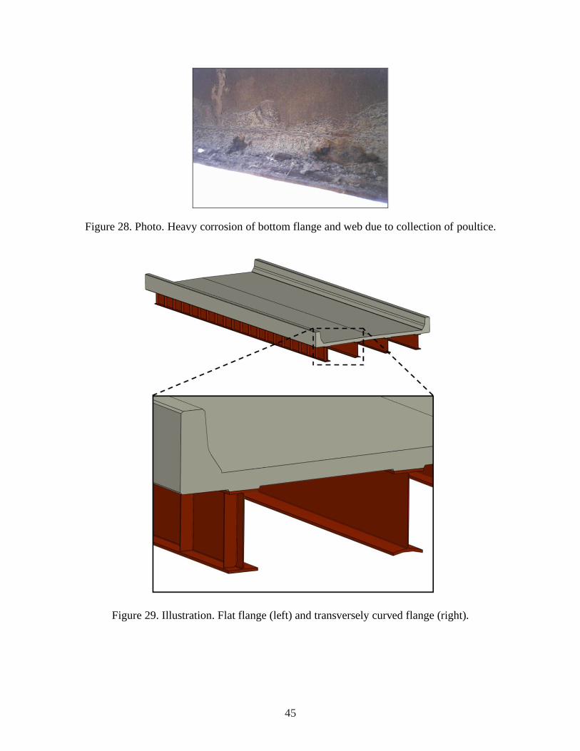
45
Figure 28. Photo. Heavy corrosion of bottom flange and web due to collection of poultice.
Figure 29. Illustration. Flat flange (left) and transversely curved flange (right).

46
5.2.12 Cables
Coatings for suspender cables must demonstrate excellent long-term performance and flexibility
under corrosive and high sunlight exposure. Success has been found with certain unique
formulations of thick-film waterborne acrylic as well as calcium-sulfonate-modified alkyd
coatings with slow-dry properties.
5.2.13 Gratings, Bearings, and Curbs
These elements are difficult and inefficient to paint in the traditional manner. Bearings represent
the lowest point on the superstructure, and as such are likely subject to the highest time of
wetness, and typically are difficult to protect from corrosion. An example of a corroded bearing
is shown in Figure 30. Consideration should be given to galvanize, metalize or fabricate these
types of elements from inherently corrosion-resistant alloys.
Figure 30. Photo. Corroded bearing.
5.2.14 Built-Up Members
Built-up members are more an artifact of past design and construction practice, but it may be
presented as an option for the purposes of aesthetics or historical rehabilitation. However, bolted
or riveted built-up member cross-sections should be avoided since they are impossible to
maintain and generally the faying surfaces only receive an initial coat of primer for protection.
For instance, shown in Figure 31 is the lower chord of a deck truss. The member has an
intermittent cover plate to form the built-up box, which creates a horizontal element to pond
water. The consequences of this arrangement are focused, severe section loss in the angle
element where it abuts the cover plate, plus pack rust on the top cover plate. Figure 32 is a

47
picture from the same truss, but of a lower chord connection. The lower chord elements are tied
with lacing, which creates many intersecting surfaces that all show corrosion and pack rust.
Figure 31. Photo. Annotated picture of riveted, built-up lower chord truss member.

48
Figure 32. Photo. Annotated picture of riveted lower truss chord connection.
Figure 33 shows the inside of a closed, built-up box member from a truss. The picture was taken
through an access hole and not oriented with respect to gravity, but the member was horizontal.
Because the member was horizontal, water ponded on the inside atop the bottom box cover plate,
and caused through-thickness corrosion in the box web plate over an approximate four-foot
length. Small box members also pose maintenance and corrosion remediation challenges due to
limited access.
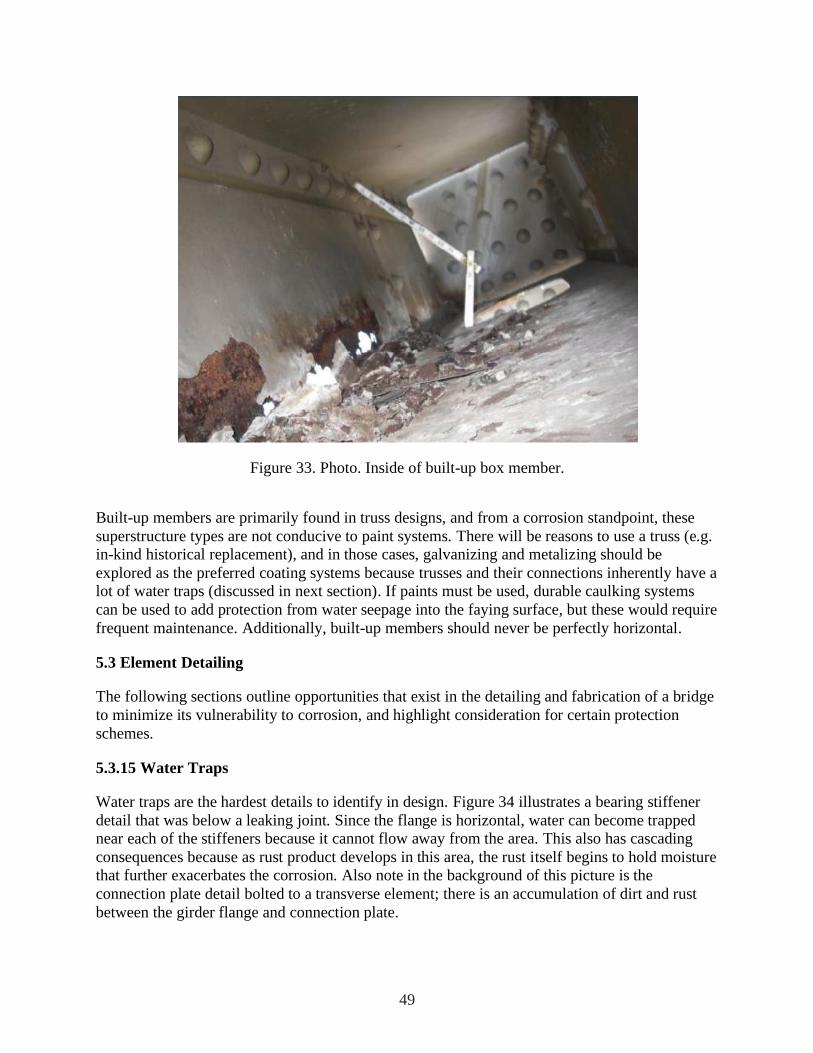
49
Figure 33. Photo. Inside of built-up box member.
Built-up members are primarily found in truss designs, and from a corrosion standpoint, these
superstructure types are not conducive to paint systems. There will be reasons to use a truss (e.g.
in-kind historical replacement), and in those cases, galvanizing and metalizing should be
explored as the preferred coating systems because trusses and their connections inherently have a
lot of water traps (discussed in next section). If paints must be used, durable caulking systems
can be used to add protection from water seepage into the faying surface, but these would require
frequent maintenance. Additionally, built-up members should never be perfectly horizontal.
5.3 Element Detailing
The following sections outline opportunities that exist in the detailing and fabrication of a bridge
to minimize its vulnerability to corrosion, and highlight consideration for certain protection
schemes.
5.3.15 Water Traps
Water traps are the hardest details to identify in design. Figure 34 illustrates a bearing stiffener
detail that was below a leaking joint. Since the flange is horizontal, water can become trapped
near each of the stiffeners because it cannot flow away from the area. This also has cascading
consequences because as rust product develops in this area, the rust itself begins to hold moisture
that further exacerbates the corrosion. Also note in the background of this picture is the
connection plate detail bolted to a transverse element; there is an accumulation of dirt and rust
between the girder flange and connection plate.

50
Figure 34. Photo. Girder end on a bearing below a leaking deck joint. Horizontal flange and
vertical stiffeners create an excellent trap for debris and moisture.
If the bridge has connection plates, or transverse stiffeners that are connected to the bottom
flange, this represents a localized dam for water. Typical detailing practice would be to snipe the
corner of the plate to provide clearance for the web-to-flange welds. If the snipe is too small, it
could easily trap debris and create a dammed condition. Figure 35 highlights two connection
plates with different sized snipes, and the larger would be preferred for reduced tendency to trap
debris and become clogged. AASHTO has no guidance for minimum/maximum size of the
snipe, but it should be as large as possible. Experience has found that one by one inch snipes are
not adequate. If coatings will be applied, larger snipes also facilitate easier blast cleaning and
ability to achieve adequate film thickness within the snipe. Proper snipes are an important
consideration on bridges with a vertical grade so water can freely flow downhill, rather than
being trapped behind every connection plate.

51
Figure 35. Illustration. Transverse plate snipe size, larger is better.
Drip bars can also be welded in place to divert water before getting to a trap. However, careful
attention must be paid to orient them at the correct angle so they themselves do not become a
water trap. Figure 36 illustrates how to determine the orientation of a drip bar.

52
Figure 36. Schematic. Proper orientation of drip bar. Taken from Reference 14.
Figure 37 shows a picture of a lateral gusset plate detail and the accumulation of dirt, bird guano,
and even a dead bird. Since the lateral plate is horizontal, poultice tends to collect on it and not
freely drain away, causing localized high times of wetness, leading to corrosion. Figure 38 shows
a lateral gusset plate detail that has mostly corroded away because it was perfectly horizontal and
ponded water. It is not practical to slope these plates, but drainage holes can be provided to help
mitigate any ponding. Where members such as horizontal gusset plates must be used, consider
using a high level of corrosion protection (duplex galvanizing/painting or metalizing) for these
specific elements.

53
Figure 37. Photo. Debris accumulation at a lateral gusset plate detail.
Figure 38. Photo. Corroded lateral gusset plate detail.
Another less commonly identified water trap is flange splice plates within a bolted field splice. If
the girder is on a vertical grade, water flowing down the flange will get trapped by the flange
splice plates. A solution is to combine the functionality of the drip bar into the flange splice plate
itself so it can shed water away from the web. This is illustrated in Figure 39 where the left-
handed splice has square-ended splice plates, and the right-handed splice has a downhill taper.
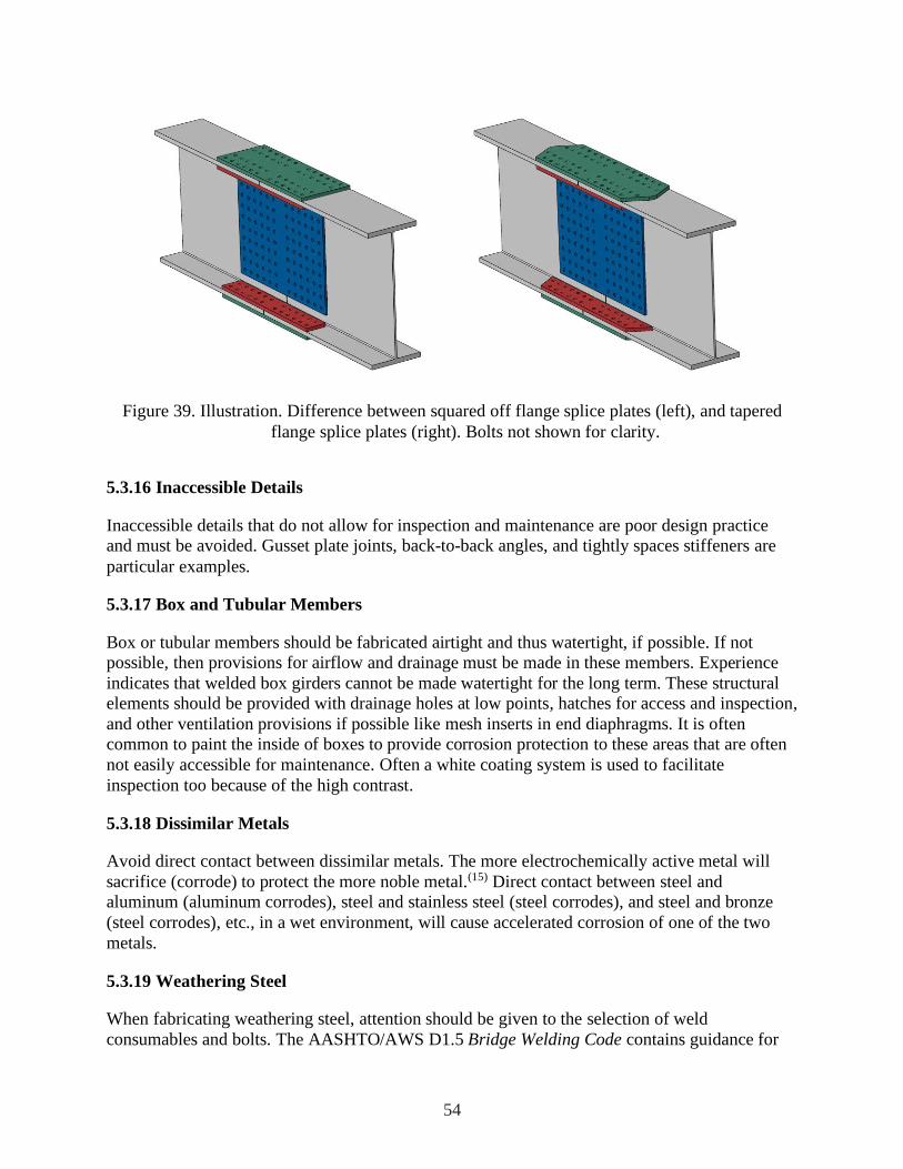
54
Figure 39. Illustration. Difference between squared off flange splice plates (left), and tapered
flange splice plates (right). Bolts not shown for clarity.
5.3.16 Inaccessible Details
Inaccessible details that do not allow for inspection and maintenance are poor design practice
and must be avoided. Gusset plate joints, back-to-back angles, and tightly spaces stiffeners are
particular examples.
5.3.17 Box and Tubular Members
Box or tubular members should be fabricated airtight and thus watertight, if possible. If not
possible, then provisions for airflow and drainage must be made in these members. Experience
indicates that welded box girders cannot be made watertight for the long term. These structural
elements should be provided with drainage holes at low points, hatches for access and inspection,
and other ventilation provisions if possible like mesh inserts in end diaphragms. It is often
common to paint the inside of boxes to provide corrosion protection to these areas that are often
not easily accessible for maintenance. Often a white coating system is used to facilitate
inspection too because of the high contrast.
5.3.18 Dissimilar Metals
Avoid direct contact between dissimilar metals. The more electrochemically active metal will
sacrifice (corrode) to protect the more noble metal.(15) Direct contact between steel and
aluminum (aluminum corrodes), steel and stainless steel (steel corrodes), and steel and bronze
(steel corrodes), etc., in a wet environment, will cause accelerated corrosion of one of the two
metals.
5.3.19 Weathering Steel
When fabricating weathering steel, attention should be given to the selection of weld
consumables and bolts. The AASHTO/AWS D1.5 Bridge Welding Code contains guidance for

55
weld consumable selection so the weld itself will weather in a similar manner to the weathering
steel plate material. Additionally, high-strength bolts should also be specified as Type 3, or
“weathering” grade so they also weather the same as the weathering steel plate material. It is
essential to thoroughly and uniformly blast clean all surfaces to remove mill scale and allow for
formation of a uniform protective patina. This is particularly true in order to achieve a uniform
attractive appearance on fascia beams.
Weathering steel bridges also suffer from perception issues when it comes to staining of concrete
piers and abutments. Water flowing over uncoated weathering steel and onto concrete elements
will stain the concrete brown. While purely an aesthetic issue to the concrete elements, simple
things can prevent this. For instance, properly oriented drip bars can divert most water off the
structure before every getting to the substructure. Stainless steel or galvanized sheet material can
be bent into a pan and installed between the superstructure and the bearing that would divert
water away from the concrete element. More specific detail guidance on drip bars and pans can
be found in McDad et. al.(14)
The FHWA Technical Advisory (TA 5140.22) also contains specific detailing rules meant just
for uncoated weathering steel to overcome the poor performance of uncoated weathering steel
bridges built up to the late 1980s.(43) These rules are broad, and somewhat duplicative of the
general considerations in the sections above, but represent a minimum list of concerns that
should be evaluated when detailing a uncoated weathering steel bridge design.
• Use jointless bridge designs when at all possible.
• Coat the ends of girders for a distance of 1.5 times the girder depth near abutments
and either side of expansion joints, in particular in deicing zones.
• Minimize the number of bridge deck scuppers.
• Do not use details that will accumulate water or debris, improperly orientated drip
bars, or square-ended flange splice plates on girders with a vertical grade, or
stiffener/connection plates that are not coped.
• Since box members generally cannot be perfectly sealed, provide means of air
circulation and water drainage along with screens over the openings.
• Seal overlapping surfaces exposed to water to prevent capillary action. This is mainly
in reference to non-slip-critical connections where rust pack could develop.
Additional guidance that has been reported in other evaluations of weathering steel since
publishing the TA are as follows.(72)
• Use sufficient deck overhangs to protect the fascia girder bottom flange. Experience
would show a deck overhang equal to the girder depth would prevent this, but this
configuration is also not always possible (e.g., for long spans with deep girders).
• Do not use timber or steel grid decks as they tend to allow water to drain through and
become trapped on the top girder flange.
• Do not use exotic or unknown deicing chemicals or materials without some data
regarding their potential effect (e.g., anti-freeze, organic agricultural wastes, etc.).(13)
56
5.3.20 Galvanizing
When galvanizing an entire bridge structure, attention to detailing can make a project more
conducive to hot-dipping. Understanding that galvanizing is a thermal shock to steel element that
can lead to distortion problems and possibly cracking. The American Galvanizers Association
has publications that provide guidance for designing products that will be hot-dipped, and
readers are encouraged to consult these. The following list represents some key issues to be
considered for bridge design:
• Elements must be designed for size relative to the size of available galvanizing kettles
as it is best to immerse the entire part into the kettle in a single dip. As of this writing,
the American Galvanizers Association (AGA) lists the kettle sizes of all of its
member galvanizers. There are many kettles available at 40+ feet long and over 6 feet
deep and several galvanizers have kettles that are 60+ feet long and 10 feet deep. For
long members, it is possible to “double dip” where each end is dipped individually,
with some overlap. The double-dipped area will be visually apparent, and the
designer would have to coordinate with a galvanizer to ensure the depth and length of
their tanks could fully cover a double dipped beam. In terms of design, additional
bolted field splices may be required to limit the length of beams/girder, if double-
dipping is not allowed.
• Highly constrained welded details should be carefully assessed whether they should
be hot-dipped because the thermal cycle could cause cracking.
• Symmetry of the part should be maintained as much as possible, also to avoid
cracking.
• Avoid large disparities in plate thicknesses that are joined together, again, to avoid
distortion and cracking from differential thermal expansion. An example is the tube-
to-base plate detail in sign and lighting structures, where the baseplate is often thicker
than 2 inch, the tube is often thinner than 3/8 inch and there is published
documentation of cracking during fabrication.
• Provide venting when at all possible for enclosed shapes to allow the caustic solutions
and molten zinc to freely flow in and out. Parts with sealed pockets of air can explode
in the zinc bath from thermal expansion of the air within, not only leading to part
damage, but likely harm to those overseeing the dipping operation. Refer to ASTM
A385 and galvanizer recommendation for venting requirements.(26)
• Gaps between plies should be seal welded, as molten zinc cannot flow into a gap less
than 3/32 inch. However, the caustic cleaning solutions can flow into these gaps and
the residual left behind, along with moisture in the air, will corrode the steel. Shown
in Figure 40 is an unsealed weld attaching a connection plate to a rolled girder; the
galvanizing never adhered and preferential corrosion is occurring at this location. Seal
welds present structural issues beyond corrosion that can be difficult to navigate. The
weld does not know its only function is to seal, its very presence means it will likely
transmit stress that could lead to fatigue and/or fractures issues. Seal welds sometimes
violate American Welding Society (AWS) criteria. For instance, wrapping fillet welds

57
in opposing directions around a common plane is prohibited, in particular Clause
2.8.8 in D1.5 and Clause 2.9.3.5 in D1.1. (40, 73) First, this type of weld is difficult to
implement because the welding position has to change and second, there is a high
likelihood of undercut when wrapping welds in different directions. Steel bridges
always have connection plate details that are unsealed when being welded to the
flange because of potential undercut, though wrapping this particular weld has been
shown not to be detrimental to fatigue.(74) Designers should work with owners to
reach consensus about how to handle seal welds as there are consequences to both the
long-term corrosion performance and possibly the structural function.
Figure 40. Photo. Connection plate welded to rolled I-beam along with corrosion emanating from
unsealed weld.
• Welded details that are galvanized do demonstrate a lower fatigue life than
ungalvanized welds. Test data performed on ancillary sign structures show there is
about a one category reduction in the fatigue strength. Full-scale galvanized bridge
details have not been tested, though it would be conservative to assume the same
reduction.(75, 76)
• Designers cannot specify a thickness for galvanizing because it is controlled by
chemistry of the steel, though they should understand that specifying ASTM A123 as
a quality control measure does guarantee a minimum thickness of galvanizing.(27)
5.3.21 Metalizing
Since metalizing is a “line of sight” operation and because the “gun” end of the equipment can
be difficult to manipulate into tight areas, the person performing the metalizing has to be able to
see everything that needs to be coated. Therefore, metalizing will not be a viable option for
small, enclosed spaces.
58
Metalizing also requires some unique shop practices that should be understood and considered in
planning of the job. For metalizing to bond well to the steel a good surface preparation is
mandatory. Metalizing requires an SSPC-SP 10 “near-white” surface preparation with an angular
surface profile. This is not an exotic requirement, but it means that steel shot cannot be used as a
blast medium because shot leaves a peened (rounded) surface profile that the metalizing cannot
adhere to. All fabrication shops are capable of running pure grit in their centrifugal blast
machines; however, most prefer to run either a shot/grit mix or pure shot since this extends the
useful life of the wheels of the blast machine. It is essential that the fabrication shop performing
a metalizing job change to “grit” media. For similar reasons, flame cut edges likely need to
ground prior to blasting because they tend to be harder than the blast media and proper surface
profile cannot be attained. A qualification bend test of a metalized coupon before fabrication will
help screen out potential problems, along with an ASTM D4541 adhesion test to verify bond.(77,
25)
Metalizing is analogous to spray painting, though not as forgiving. The spray pattern always
needs to be normal to the surface, whereas solvent-containing paint tends to be more forgiving of
the particular direction and overlap of spray passes by the applicator. The application rate of
metalizing is also much slower than painting, and there is not a correlation between using thicker
wires with higher amperage; generally higher amperage just increases the amount of consumable
that becomes overspray (i.e., transfer efficiency goes down).(77) Those considering the use of
metalizing should consult the joint standard SSPC-CS 23.00/AWS C2.23M/NACE No. 12.(25)
While not specific to bridges, NCHRP Report 528 provides good discussion on the variables that
affect metaling application and performance, as well as an 11-section guide for metalizing
written in a specification format. (80)
Generally, metalizing is most efficient for pieces with large areas of uninterrupted square
footage, and will not be as cost-effective as galvanizing when individually treating large numbers
of small pieces.(79)
Metalizing presents an advantage over galvanizing for exposure to severe marine environments.
Since the life of a zinc-coated structure in a high-chloride environment is determined by the
thickness of zinc, in severe environments it is advantageous to apply a thicker coating of zinc (or
aluminum). This is easily done through specification and quality assurance with metalizing.
However, since thickness for hot dip galvanizing is limited by the process and the specific
characteristics of the base metal, there is a practical limit to the thickness of applied zinc in
galvanizing.
5.4 Fabrication and Application of Corrosion Protection Systems
Bridge fabrication issues are always an important driver for the ultimate selection of a corrosion
protection scheme for a specific bridge. The corrosion protection options considered must be
viewed in terms of the practicality of getting a cost-effective and high-quality application in the
specific fabrication shop for the structure. The cost of bridge fabrication is related to the number
and duration of handling or waiting (e.g., for cure time) operations that take place during
fabrication.

59
Edges tend to show coating breakdown well before the general flat surfaces of steel in corrosive
atmospheres. When painting with barrier-type coatings (e.g., epoxies and polyurethanes, etc.), it
is good painting practice to hand stripe edges and complex surfaces prior to application over
larger flat surfaces, in essence providing double thickness in these areas. This is because solvent-
borne coatings tend to “pull back” to some degree from edges during curing due to surface
tension of the paint film. This can result in a coating film that is less than 50 percent of the
intended thickness on the edge while still attaining full thickness on the flat surfaces. Breaking
sharp edges with a grinder before painting is also specified but this is a labor-intensive process
and limited testing has shown that inorganic zinc-rich primers mitigate this need to a large
degree.(81) Paint systems using zinc, especially in severe environments, typically do not require
significant mechanical conditioning as long as striping (brush or spray) is employed. Galvanizing
is insensitive to this because the zinc bond naturally rounds over sharp edges, creating a uniform
zinc thickness and if the proper anchor pattern is provided, it should not be a problem for
metalizing either.
5.4.22 Slip Resistance
When specifying corrosion protection systems, one fabrication issue to consider is treatment of
slip-critical connections. Slip-critical connections are bolted connections that employ a bolt
clamping force which squeezes steel plies together, creating a certain level of frictional slip
resistance that is a service design consideration. The slip resistance is directly related the friction
factor or slip coefficient that can be developed between the plies. In the AASHTO LRFD Bridge
Design Specifications, there are four classes of slip resistance considered in design; Class A, B,
and C, each with a different slip coefficient (0.30, 0.50, 0.30, and 0.45, respectively).(82) A Class
A surface is unpainted mill scale or has a coating qualified by test to have a slip coefficient of
0.30 or greater. A Class B surface is unpainted and blast-cleaned to SSPC-SP6 or better,
unsealed pure zinc or 85/15 zinc/aluminum thermal sprayed coating with a thickness less than or
equal to 16 mils, or has a coating qualified by test to have a slip coefficient of 0.50 or greater. A
Class C surface is a hot-dip galvanized surface. A Class D surface has a coating qualified by test
to have a slip coefficient of 0.45 or greater. The slip coefficient is measured using a test
published by the Research Council on Structural Connections specification.(83) Additionally, the
RCSC specification implies that a certain level of slip resistance also yields a certain level of
creep resistance (i.e., thicker coatings would tend to creep under sustained loads over long
periods of time).
From the fabricators prospective, it would be easier to blast clean everything, then apply primer
immediately following without having to mask off the faying surfaces in the bolted areas.
Therefore, it is easier to use a primer that can develop the assumed friction factor and avoid
masking altogether. There are many options for both organic and inorganic zinc-rich primers that
can meet either Class A or B slip resistance. Likewise, both zinc and zinc/aluminum metalizing
can easily achieve Class B slip resistance at 12 mils of thickness (aluminum was not tested but
likely could also attain Class B).(84) Since metalizing is often seal coated, the limited data in the
literature suggest that the faying surfaces should not be sealed, though the testing was not
exhaustive and it is possible that some sealers may be able to achieve slip resistance, but it would
have to be proven through testing.(84, 85)

60
6.0 COST
The last factor involved in the selection of a corrosion mitigation strategy is determining the
impact of the cost of the various corrosion protection options on the cost of ownership of the
bridge over its entire life. This is referred to as life-cycle cost analysis and is defined in U.S. Law
as follows:
“a process for evaluating the total economic worth of a usable project segment by
analyzing initial costs and discounted future costs, such as maintenance, user costs,
reconstruction, rehabilitation, restoring, and resurfacing costs, over the life of the
project segment.”(86)
Determining life-cycle cost requires knowledge of the first cost (including the raw material,
fabrication, and construction costs for a particular corrosion mitigation strategy), the
maintenance costs associated with the corrosion mitigation strategy, and the estimated service
life of the structure. After considering the entire maintenance life of a structure, the life-cycle
cost of a particular corrosion protection strategy can be determined. More importantly, a life-
cycle cost analysis of various corrosion mitigation strategies can provide economic justification
for a particular strategy.
Alternative bridge corrosion protection costs may be compared by comparing the discounted
present value of the life-cycle costs of each available option to the discounted present value of
the life-cycle costs of the base case scenario. A life-cycle cost analysis between competing
corrosion mitigation strategies must consider the following factors:
• Total initial construction cost for each of the options being considered. This includes
the base case option that the alternatives will be compared too.
• Assumed performance life of each corrosion mitigation strategy under consideration
as well as the performance life of the base case alternative.
• Assumed life-cycle costs, if any, for periodic maintenance actions for each of the
corrosion mitigation strategies selected in the specific environmental exposure.
Differences in initial construction cost of corrosion mitigation strategies need to be assembled
based on the application being considered and market conditions. The initial construction cost
includes the purchase and installation of the strategy being considered. Suppliers are able to
provide useful estimates of purchasing and installing each strategy. Prevailing market rates for
labor and equipment should be used. Costs of installation provided by suppliers will vary with
costs included in bids from construction contractors whose bids are based on profitability
concerns. The initial construction cost used in an analysis of competing corrosion mitigation
strategies should consider the best reasonable costs available.
Significant analysis has been made regarding life-cycle corrosion control strategies for existing
steel bridges.(87, 88) These analyses researched the highly variable cost factors associated with
field coating removal and application for bridges. The best approach for an individual bridge
owner is to use their own historical cost data from recent jobs as a basis for this analysis. Since
actual cost totals from completed projects are heavily dependent on the construction contractor’s

61
profitability actions, decision makers are encouraged to contact suppliers to obtain costs for use
in the life-cycle cost analysis. These estimated costs should include purchasing costs and
expected time frames for installation as well as expected performance periods between remedial
activities to maintain the performance of the strategy.
A life-cycle cost analysis must consider various options for initial and maintenance corrosion
control systems. By properly choosing an initial corrosion protection system for a specific
structure (e.g., zinc-rich paint, galvanizing, metalizing, or corrosion resistant steel), the goal of
the designer should be to limit future maintenance actions associated with corrosion protection to
targeted maintenance touch-up or zone painting only in those areas that are most severely
affected by the concentrated corrosivity of the environment and detailing of the structure. If this
is achieved, a life-cycle cost analysis would focus on initial installed cost of a durable corrosion
protection system complemented by the cost of these relatively few targeted field maintenance
actions.
6.1 Initial Cost Numbers
As stated above, one of the three parts needed in a life-cycle cost analysis is an estimate of the
first cost. This section will attempt to present some numbers, but due diligence should be
exercised when using them.
Shown in Figure 41 is the relative cost between various steel alloys using ASTM A709 Grade 50
as the basis, normalized considering a plate size of one inch thick by 96 inch wide and 480 inch
long (because plate size has a major influence on price). The numbers were provided by a steel
producer in March 2013 and, considering that steel prices are highly variable (caused by unusual
steel market conditions, plate dimensions, energy costs, alloy surcharges, scrap costs, etc.), these
numbers are a snapshot in time and will certainly vary (up or down) month to month, and year to
year.(89) Designers and fabricators should not use these cost ratios in a life-cycle cost analysis and
should contact suppliers directly. Additionally, these are just the steel material cost borne by a
fabricator, and do not consider the cost associated with the actual fabrication of the bridge. As
seen in the figure, the more corrosion-resistant alloys are three to six times more expensive than
ordinary steel. However, if they can truly offer a maintenance-free structure, then a life-cycle
cost analysis may show these options represent the best value.

62
A709 Gr. 50
A709 Gr. 50W
A709 HPS 50W
A70 HPS 70W
A709 HPS 100W
A1010
Lean Duplex (UR2202)
Duplex (2205/A240)
0 1 2 3 4 5 6 7 8 9
Relative Pricing of Plate ($/ton)
Ste
el G
rad
e
Figure 41. Graph. Relative pricing of various steel alloys (March 2013).
A sample of coating costs is shown in Table 7, assembled from References 49, 50, and 51, which
are snapshots of costs from 1996, 2008, and 2014, respectively. The referenced works provide
more detailed numbers for a broad range of situations, but the presentation herein is meant to
show the difference and trends in cost associated with shop and field application of liquid
coatings. In this case, the assumed surface preparation was SSPC-SP 10, and the coating system
was a sprayed 3-coat IOZ/epoxy/polyurethane system. The cost includes the liquid coating
material cost and the labor and equipment associated with the surface preparation and coating
application. The referenced works consider other cost factors and the table data consider no
multiplier for structure type, surface condition in the case of field application that requires a full
blast and repaint, nor cost associated with containment for field application. As the data in the
table suggest, the cost associated with liquid coatings has roughly doubled in the past 18 years,
and there is a fairly consistent trend of a 30 percent premium for field application over shop
application.

63
Table 7. 18-Year Comparison of Coating Costs in Shop and Field
Year Shop Application a, b Field Application a, b
1996 $1.91/sq. ft. $2.43/sq. ft.
2006 $2.56/sq. ft. $3.52/sq. ft.
2014 $4.11/sq. ft. $5.08/sq. ft.
a - Coating assumed to be IOZ primer/epoxy/polyurethane. b - Surface preparation assumed to be SSPC-SP 10.
As part of this publication in 2016, the National Steel Bridge Alliance queried four of their
member fabricators to provide differential steel bridge fabrication cost estimates for an example
girder. The sample of four fabricators was diverse representing large and small production
abilities, and located on each coast and in the north and south. The detailing of the girder is
shown in Figure 42. Each fabricator was asked to provide a cost estimate to fully fabricate the
girder considering five corrosion mitigation strategies; uncoated weathering steel, non-
weathering grade steel with 3-coat paint system, galvanized non-weathering grade steel,
metalized non-weathering grade steel, and ASTM A709 Gr. 50CR (ASTM A1010) steel.
19' - 0"
18" x 1" bottom flange
57' - 0"
18" x 112" bottom flange
19' - 0"
18" x 1" bottom flange
95' - 0" center-to-center bearings
18" x 3 4" top flange
78 " Shear Studs
38' @ 6" spacing
12" x 32" web
Bearing Stiffener (each side)
7" x 3 4"
Connection Plates
5" x 12"
Bearing Stiffener (each side)
7" x 3 4"
78 " Shear Studs
9" spacing
78 " Shear Studs
38' @ 6" spacing
Figure 42. Schematic. Elevation view of girder detailing.
Table 8 shows the percent differential cost from each of the fabricators using an unpainted, non-
weathering steel (ASTM A709 Gr. 50) girder as the base case option. This base case option is
not realistic as it reflects having no corrosion mitigation strategy, but is used in order to illustrate
the premium associated with various other corrosion mitigation strategies. Each of the fabricators
was asked to provide costs as well as any assumptions they felt relevant, which are reflected in
the table notes. In this example, the girder was not originally designed with consideration for
galvanizing, and at 95 feet in length is too long to be single-dipped. Some fabricators choose to
add a bolted splice (which carries a cost premium), and one chose to pursue a double dip. The
average cost premium for uncoated weathering steel was 4 percent, and 19 percent for the 3-coat

64
paint system. Each of these had little variation, reflecting the comfort level in the estimating of
these two strategies. However, for galvanizing and metalizing, the variation in the cost estimate
is much greater. For instance, the galvanizing option had a low of 31 percent, high of 82 percent,
and average of 51percent. Included in these costs are the additional fabrication associated with
adding a splice (if noted), and also the burden associated with transporting the girder to and from
the galvanizer. The total cost for a fabricator to supply a galvanized bridge girder is very much a
function of the galvanizing capability that is within a reasonable distance from the fabricator.
Likewise, the metalizing option had a low of 51 percent, high of 110 percent, and average of 73
percent, and that represents likely a different blast cleaning strategy (grit versus shot blasting),
bringing a specialty contractor to the fabricator’s facility to apply the metalizing, and any
premium reflecting the fabricator’s unease with the process (i.e., risk). Costs are not presented in
the table for the ASTM A709 Gr. 50CR (A1010) option because most of the fabricators had no
experience with using the material. However, considering the premium for the base metal and
welding electrodes, the cost premium was 79 percent for the ASTM A709 Gr. 50CR (A1010)
option. Note that previously the ASTM A709 Gr. 50CR (A1010) material was described
approximately 2.7 times more expensive than A709 Grade 50, but that is greatly reduced when
the fabrication costs are considered, reflecting that material costs are a small portion of the
overall fabrication costs.
Table 8. Percent Premium of Different Corrosion Mitigation Strategies Over A709 Gr.50 (from
2016 NSBA fabricator query)
A709 Gr. 50W
A709 Gr. 50
w/3-coat
system a
A709 Gr. 50
fully
galvanized
A709 Gr. 50
fully metalized
w/sealer b
Fabricator 1 2 c 14 31 e 57
Fabricator 2 2 d 20 41 e 51
Fabricator 3 6 21 82 f 110
Fabricator 4 5 19 51 e 73
Average 4 19 51 73
a – IOZ primer/Epoxy intermediate/Polyurethane topcoat. b – 11 mils of 85/15 Zn/Al plus clear sealer. c – Material only not considering painting the girder ends (fabricator noted painting the
girder ends would increase total cost, not difference in premium, six percent. d – Material only not considering painting the girder ends (fabricator noted painting the
girder ends would increase total cost, not difference in premium, two percent. e – Includes adding a bolted splice to accommodate limitation of galvanizing bath length. f – Assumes a double dip in galvanizing tank.

65
7.0 SUMMARY
The inherent corrosivity of many natural environments and the highly corrosive nature of deicing
salts applied to highways over much of the U.S. create challenging conditions for the long-term
maintenance-free function of a bridge. Corrosion can be a considerable risk to a steel bridge,
however, designers have many corrosion protection options at their disposal to mitigate that risk.
Protective coatings, when properly applied, can provide decades of protection for very little initial
cost. Weathering grade steels are available in strengths up to 100 ksi as well. These steels
provide an excellent low-cost corrosion protection option, but the designer must be realistic
about the potential environmental exposure both on a macro and micro level. Detailing the
structure to eliminate joints (which will eventually leak) and areas that trap and maintain wet
conditions is essential for all structures, painted and unpainted. Designers are encouraged to learn
from past practices where corrosion protection was not considered a priority in the initial design
stage. Past errors in judgment have underestimated the potential effects of moisture and salt and
have led to significant costs for replacement of elements, and whole structures well before their
functional obsolescence. Designers are directed toward the references used to develop this chapter
for more robust guidance.

66
8.0 ACKNOWLEDGMENTS
The original photo in Figure 22 on page 39 is the copyright property of Craig Hanchey; FHWA
received written permission to publish the photo for the 2016 version of the Handbook (FHWA-
HIF-16-002). For this report in 2016, FHWA modified the photo by cropping out some of the
background and adding yellow lines to depict the splash zone in the through truss. For more
information about the original photo, go to
https://www.flickr.com/photos/21953562@N07/5630472728/in/photolist-9zxDo1-9zxC3m.

67
9.0 REFERENCES
1. National Transportation Safety Board (1971). “Collapse of U.S. 35 Highway Bridge,
Point Pleasant, West Virginia, December 15, 1967.” Highway Accident Report
NTSB/HAR-71/01. Washington D.C.
2. National Transportation Safety Board (1984). “Collapse of a Suspended Span of
Interstate Route 95 Highway Bridge Over the Mianus River, Greenwich, Connecticut,
June 28, 1983.” Highway Accident Report NTSB/HAR-84/03. Washington, D.C.
3. SSPC. (2012). “Painting Steel Bridges and Structures,” Good Painting Practice. Volume
I, Chapter 6.1. The Society for Protective Coatings. Pittsburgh, PA.
4. Kuceera, V. (2003). “Reduction of Air Pollutants – A Tool for Control of Atmospheric
Corrosion.” Revista de Metalurgia. Spain.
5. Junge, E. and Gustafson, P.E. (1956). “On the Distribution of Sea Salt over the United
States and its Removal by Precipitation.” U.S. Air Force Research Center. Cambridge,
MA.
6. Bitcon, J.C. and Russo, S.G. (2008). “Modification of Geographic Corrosivity Index and
its Application to Overseas Bases.” Report number DTSO-TR-2109. Australian Defence
Science and Technology Organisation. Australia.
7. Ault, P., Ellor, J., Repp, J., and Shaw, B. (2000). “Characterization of the Environment.”
Report number FHWA-RD-00-030. Federal Highway Administration. McLean, VA.
8. Coburn, S. K., Larrabee, C. P., and Lawson, H. H. (1968). “Corrosiveness of Various
Atmospheric Test Sites as Measured by Specimens of Steel and Zinc.” Metal Corrosion
in the Atmosphere, Seventieth Annual Meeting, Boston, MA, 25-30 June 1967, ASTM STP
435, American Society for Testing and Materials. Philadelphia, PA.
9. Tullmin, M. and Roberge, P.R. (2000). “Atmospheric Corrosion,” Uhlig’s Corrosion
Handbook, 2nd Edition. Wiley. New York, NY.
10. Drozdz, S., Abbott, W., Jackson. J. (2007). “Measuring the Rate and Impact of Corrosion
on DoD Equipment and Facilities.” Report number TR-07-18. US ARMY Corps of
Engineers, Engineer Research Development Center, Construction Engineering Research
Laboratory. Champaign, IL.
11. ISO. (2012). “Standard 9223 – Corrosion of Metals and Alloys – Corrosivity of
Atmospheres – Classification, Determination, and Estimation.” International Standards
Organization (ISO). Geneva, Switzerland.
12. Albrecht P., Coburn S.K., Wattar F.M., Tinklenberg G. L., and Gallagher W. P. (1989).
“Guidelines for the Use of Weathering Steel in Bridges.” National Cooperative Highway
Research Program (NCHRP) Report 314. Transportation Research Board. Washington
D.C.

68
13. Nickerson, R. L. (1995). “Performance of Weathering Steel in Highway Bridges – A
Third Phase Report,” American Iron and Steel Institute. Washington D.C.
14. McDad B., Laffrey D. C., Damman M., and Medlock R. D. (2000). “Performance of
Weathering Steel in TxDOT Bridges.” Project 0-1818. Texas Department of
Transportation. Austin, TX.
15. Fontana, M. G. (1986). Corrosion Engineering. Page 292. McGraw-Hill. New York, NY.
16. Gedge, G. (2008). “Structural uses of stainless steel — buildings and civil engineering.”
Journal of Constructional Steel Research. Vol. 64. Pages 1194–1198.
doi:http://dx.doi.org/10.1016/j.jcsr.2008.05.006. Elsevier.
17. Seradj, H. (2014). “Oregon’s Second ASTM A1010 Bridge.” World Steel Bridge
Symposium. March 26-28, 2014. Toronto, Ontario, Canada.
18. Kogler, R. A., Ault, J. P., and Farschon, C. L. (1997). “Environmentally Acceptable
Materials for the Corrosion Protection of Steel Bridges.” Report number FHWA-RD-96-
058. Federal Highway Administration. McLean, VA.
19. Appleman, B. (1997) “Lead-based Paint Removal for Steel Highway Bridges,” National
Cooperative Highway Research Program Synthesis 251. Transportation Research Board.
Washing D.C.
20. KTA-Tator, Inc. (2014). “Transportation Agency Practices Currently Employed for
Bridge Maintenance Painting Operations: Findings from a National Survey.”
Transportation Research Synthesis, TRS 1404. Minnesota Department of Transportation.
St. Paul, MN.
21. AASHTO. (2004). “Project Work Plan for the Evaluation of Structural Steel Coatings.”
American Association of State Highway and Transportation Officials (AASHTO)
National Transportation Product Evaluation Program (NTPEP). Washington D.C.
22. AASHTO/NSBA. (2014). “S8.1-2014, Guide Specification for Application of Coating
Systems.” American Association of State Highway and Transportation Officials/National
Steel Bridge Alliance (AASHTO/NSBA) Steel Bridge Collaboration S 8.1. Washington
D.C.
23. Race, T. D. (1992). “Evaluation of Seven Sealer Systems for Metallized Zinc and
Aluminum Coatings in Fresh and Salt Waters,” Report number AD-A256 758. US Army
Corps of Engineers, Construction Engineering Research Laboratory. Champaign, IL.
24. Farschon, C. L., McGaulley, W., and Shaw, Brad. (2001). “Cost Effective Alternative
Methods for Steel Bridge Paint System Maintenance.” Unpublished report. Federal
Highway Administration. McLean, VA.

69
25. American Welding Society. (1993). Guide for the Protection of Steel with Thermal
Sprayed Coatings of Aluminum and Zinc and their Alloys and Composites. American
Welding Society. Miami, FL.
26. ASTM. (2011). “ASTM A385/A385M Standard Practice for Providing High-quality Zinc
Coatings (Hot-Dip).” Book of Standards Volume 01.06. ASTM International. West
Conshohocken, PA.
27. ASTM. (2013). “ASTM A123/A123M-13, Standard Specification for Zinc (Hot-Dipped
Galvanized) Coatings on Iron and Steel Products.” Book of Standards Volume 01.06.
ASTM International. West Conshohocken, PA.
28. American Galvanizers Association. (2009). “Hot-Dip Galvanizing for Sustainable
Design.” American Galvanizers Association. Centennial, CO.
29. American Galvanizers Association. (unknown). “Performance of Hot-Dipped Galvanized
Steel Products – In the Atmosphere, Soil, Water, Concrete, and More.” American
Galvanizers Association. Centennial, CO.
30. Townsend, H. E. (2006). “Estimating the Life of Galvanized Coatings on Steel Sheet.”
Materials Performance. Vol. 45. No. 3. NACE International. Houston, TX.
31. American Galvanizers Association. (2012). “Duplex Systems – Painting Over Hot-Dip
Galvanized Steel.” American Galvanized Association. Centennial, CO.
32. ASTM. (2010). “ASTM D6386-10, Standard Practice for Preparation of Zinc (Hot-Dip
Galvanized) Coated Iron and Steel Product and Hardware Surfaces for Painting.” Book of
Standards 06.02. ASTM International. Conshohocken, PA.
33. Wilson, A. (2005). “Improvements to High Performance Steels,” 2005 World Steel
Bridge Symposium, Orlando, FL. National Steel Bridge Alliance. Chicago, IL.
34. Albrecht, P. and Hall, T.T. (2003). “Atmospheric Corrosion Resistance of Structural
Steels.” Journal of Materials in Civil Engineering. Vol 15. Issue 1. Pages 2-24. American
Society of Civil Engineers. Reston, VA.
35. ASTM. (2013). “ASTM A1010/A1010M-13 Standard Specification for Higher-strength
Martensitic Stainless Steel Plate, Sheet, and Strip.” Book of Standards 01.03. ASTM
International. West Conshohocken, PA.
36. Fletcher, F. (2011). “Improved Corrosion-Resistant Steel for Highway Bridge
Construction,” Report number FHWA-HRT-11-062. Federal Highway Adminstration.
McLean, VA.
37. ArcelorMittal USA. (2013). “Durracorr®/A1010: Bridge Applications and Fabrication
Guidelines.” Found at
http://www.arcelormittalna.com/plateinformation/documents/en/Inlandflats/ProductBroch

70
ure/ARCELORMITTAL%20DURACORR%20BRIDGES.pdf . Arcelor Mittal USA.
Coatesville, PA.
38. Personal email communication with Danielle Kleinhans representing the Concrete
Reinforcing Steel Institute, 13August2014.
39. American Welding Society. (2007). “Structural Welding Code – Stainless Steel.” AWS
D1.6/D1.6M:2007. American Welding Society. Miami, FL.
40. American Welding Society. (2010). “Bridge Welding Code.” AASHTO/AWS
D1.5M/D1.5:2010. American Welding Society. Miami, FL.
41. Hourigan, E. V. and Holt, R. C. (1982). “Performance of Weathering Steel in Highway
Bridges – A First Phase Report.” American Iron and Steel Institute. Washington D.C.
42. Congress, N. (1989). “Forum on Weathering Steel for Highway Structures: Summary
Report.” Report number FHWA-TS-89-016. Federal Highway Administration.
Washington D.C.
43. FHWA. (1989). “Uncoated Weathering Steel in Structures.” Technical Advisory
T5140.22. Federal Highway Administration. Washington D.C.
44. McConnell, J., Shenton, H., III, Mertz, D., and Kaur, D. (2014). "National Review on
Use and Performance of Uncoated Weathering Steel Highway Bridges." Journal of
Bridge Engineering. http://dx.doi.org/10.1061/(ASCE)BE.1943-5592.0000580. American
Society of Civil Engineers. Reston, VA.
45. Lottes, S. A., & Bojanowski, C. (2013). “Computer Modeling and Analysis of Truck
Generated Salt-Spray Transport Near Bridges.” Report number ANL/ESD/13-1. Argonne
National Laboratory. Argonne, IL. Retrieved from
http://www.osti.gov/scitech/biblio/1087817.
46. Main. R. (1967). “Michigan’s Galvanized Bridge – First in the United States.” Highway
Research Record. No. 200. Highway Research Board. Washington D.C.
47. Robison, R. (1991). “A New Look at Galvanized Steel Bridges.” Civil Engineering.
American Society for Civil Engineers. Reston, VA.
48. Brevoort, G.H. and Roebuck, A. M. (1979). “The Simplified Cost Calculation and
Comparison of Paint and Protective Coating Systems: Expanded Life and Economic
Justification.” CORROSION 79. Paper No. 37. NACE International, Houston, TX.
49. Brevoort, G. H., MeLampy, M., and Shields, K. (1996). “Updated Protective Coating
Costs, Products, and Service Life,” CORROSION 96. Paper No. 477. NACE
International, Houston, TX.

71
50. Helsel, J. L., Lanterman, R., and Wissmar, K. (2008). “Expected Service Life and Cost
Considerations for Maintenance and New Construction Protective Coating Work.”
CORROSION 2008. Paper 08279. NACE International. Houston, TX.
51. Helsel, J. L., Reina, M., and Lanterman, R. (2014). “Expected Service Life and Cost
Considerations for Maintenance and New Construction Protective Coating Work.”
CORROSION 2014. Paper 4088. NACE International. Houston, TX.
52. Leyland, D. S. and Castler, L. B. (2006). “Time Tested Performance of Bridge Coatings.”
SSPC 2006 Conference Proceedings. The Society for Protective Coatings. Pittsburgh,
PA.
53. Ault. J. P. and Farschon, C. L. (2008). “20-Year Performance of Bridge Maintenance
Systems.” SSPC 2008 Conference Proceedings. The Society for Protective Coatings.
Pittsburgh, PA.
54. ASTM. (2012). “ASTM D610-08 Standard Practice for Evaluating Degree of Rusting on
Painted Steel Surfaces.” Book of Standards Volume 06.01. ASTM International. West
Conshohocken, PA.
55. AWS. (1974). “Corrosion Tests of Flame-Sprayed Coated Steel – 19-Year Report.”
Report number AWS C2.14-74. American Welding Society. Miami, FL.
56. Kain, R. M. and Baker, E. A. (1987). “Marine Atmospheric Corrosion Museum Report
on the Performance of Thermal Spray Coatings on Steel.” Testing of Metallic and
Inorganic Coatings, ASTM STP 947. W. B. Harding and G. A. DiBari, Eds. American
Society for Testing and Materials, pp. 211-234. Philadelphia, PA.
57. Phull, B. S., Kain, R. M., & Pikul, S. J. (2007). Long-term Marine Atmospheric
Corrosion Testing. Paper No. 07237. Presented at the CORROSION 2007, NACE
International.
58. Romero, N. et. al. (2006). “Behavior of Galvanized Steel in Tropical Marine
Environments.” Materials Performance. Vol. 45. No. 2. Pages 24–27. NACE
International, Houston, TX.
59. Bernecki, T. et. al. (1997) “FHWA Study Tour for Bridge Maintenance Coatings,”
Report number FHWA-PL-96-031. Federal Highway Administration. Washington D.C.
60. Lohrey, E. C. (1995). “Field Evaluation of Zinc-Based Protective Coatings for Structural
Steel.” Report number FHWA-CT-RD-1084-F-95-1. Connecticut Department of
Transportation. Rocky Hill, CT.
61. Meyers, J. J., Zheng, W., and Washer, G. (2010). “Structural Steel Coatings for
Corrosion Mitigation.” Report number OR11-006. Missouri Department of
Transportation. Jefferson City, MO.

72
62. Machen, J. D. (2008). “A 20-Year Performance Evaluation of an Organic Zinc Rich Paint
System.” SSPC 2008 Conference Proceedings. Pittsburgh, PA.
63. Appleman, B.R. and Kline, E. S. (2003) “Analysis of Costs for Shop Painting of
Bridges,” Unpublished FHWA Research Report. McLean, VA.
64. Van Eijnsbergen, J. F. H. (1994) Duplex Systems – Hot-dip Galvanizing Plus Painting.
Elsevier. Amsterdam, Netherlands.
65. Copson, H. R. and Larrabee, C. P. (1959). “Extra Durability of Paint on Low-Alloy
Steels.” ASTM Bulletin 242. Pages 68–74. American Society of Testing and Materials.
Philadelphia, PA.
66. Schmitt, R. J. and Mathay, W. L. (1967). “Tests Show Performance of Low Alloy Steels
in Chemical Plant Environments.” Materials Protection, 6(9). Pages 37–42. National
Association of Corrosion Engineers. Houston, TX.
67. Coburn, S. K. (1978). “Technological advance - is it worth the investment? Increasing
container service life with painted USS Cor-Ten steel.” Proceedings of the 2nd Container
Technology Conference. Vol. 2. Pages 177–199. Cargo Systems International. Brighton,
England.
68. Wonders, H. W. (unknown) Internal publication on marine protective coatings on carbon
and COR-TEN steels. United States Steel Corporation, Pittsburgh, PA.
69. Appleman, B. R., and Weaver, R. E. F. (1992) “Maintenance Coating of Weathering
Steel.” Report umber FHWA-RD-91-087. Federal Highway Administration. McLean,
VA.
70. Kogler, R. A. and Mott, W. (1992). “Environmentally Acceptable Materials for the
Corrosion Protection of Steel Bridges: Task C, Laboratory Evaluation.” Report number
FHWA-RD-91-060. Federal Highway Administration. McLean, VA.
71. Dexter, R. J., Mutziger, M. J., and Osberg, C. B. (2002). “Performance Testing of
Modular Bridge Joint Systems.” National Cooperative Highway Research Program
(NCHRP) Report 467. Transportation Research Board. Washington D.C.
72. Barth, K. (2010). “An Assessment of Weathering Steel Bridges in West Virginia,”
Proceedings of the 8th International Conference on Short and Medium Span Bridges.
Niagara Falls, Canada.
73. AWS. (2010). “Structural Welding Code – Steel 22nd Edition” AWS D1.1/D1.1M:2010.
American Welding Society. Miami, FL.
74. Spadea, J. R. and Frank, K. H. (2004). “Fatigue Strength of Fillet-Welded Transverse
Stiffeners with Undercuts.” Report number FHWA/TX-05/0-4178-1. Texas Department
of Transportation. Austin, TX.
73
75. Koenigs, M. T. (2003). “Fatigue Resistance of Traffic Signal Mast-arm Connection
Details.” Master’s Thesis, University of Texas at Austin. Austin, TX.
76. Ocel, J. M. (2014). “Fatigue Testing of Galvanized and Ungalvanized Socket
Connections.” Report number FHWA-HRT-14-066. Federal Highway Administration.
McLean, VA.
77. DuPlissie, K. (1997). “Lessons Learned of the I-95 Thermal Spray Project in
Connecticut.” Fifth World Congress on Coating Systems for Bridges and Steel
Structures. St. Louis, MO.
78. American Welding Society. (2003). “Specification for the Application of Thermal Spray
Coatings (Metallizing) of Aluminum, Zinc, and Their Alloys and Composites for the
Corrosion Protection of Steel.” SSPC-CS 23.00/AWS C 2.23M/NACE No.12. Pittsburgh,
PA.
79. Bracken, J. (2013). “Galvanizing versus Metallizing of Structural Steel.” Presentation to
Mid-Atlantic Quality Assurance Workshop – Metals Breakout Session. Williamsburg,
VA.
80. Ellor, J.A., Young, W.T., and Repp, J. (2004). “Thermal Sprayed Metal Coatings to
Protect Sheet Piling: Final Report and Guide.” National Cooperative Highway Research
Program (NCHRP) Report 528. Transportation Research Board. Washington D.C.
81. Corbett, W. (2000). “The Same Old Grind…An Investigation of Zinc-Rich Primer
Performance Over Steel Corners,” Bridge Crossings. No. 17. National Steel Bridge
Alliance. Chicago, IL.
82. AASHTO. (2020). AASHTO LRFD Bridge Design Specifications (9th ed.). Washington,
DC: American Association of State Highway and Transportation Officials.
83. RCSC. (2009). “Specification for Structural Joints Using High-Strength Bolts - Appendix
A.” Research Council on Structural Connections. Chicago, IL.
84. Ocel, J. (2014). “TechBrief: Slip and Creep of Thermal Spray Coatings.” Report number
FHWA-HRT-14-083. Federal Highway Administration. McLean, VA.
85. Kulak, G. L., Fisher, J. W., & Struik, J. H. A. (2001). Guide to Design Criteria for Bolted
and Riveted Joints - Second Edition (Second). Chicago, IL: American Institute of Steel
Construction - Research Council on Structural Connections.
86. United States Code. (2010). 23 UCS 106F(2).
87. Kogler, R. (2000). “Coating Material Selection for Optimum Steel Bridge Life Cycle
Cost.” Presented at the 16th Annual US/Japan Bridge Engineering Workshop, McLean,
VA.

74
88. Bernecki, T.F. et. al. (1994). “Issues Impacting Bridge Painting: An Overview.” Report
number FHWA-RD-94-098. Federal Highway Administration. McLean, VA.
89. Personal email communication with Fred Fletcher representing ArcelorMittal,
24March2013.

B919-22
Smarter. Stronger. Steel.
National Steel Bridge Alliance312.670.2400 | aisc.org/nsba