Low-cost wireless network architecture for developing countries
6
Low-cost Wireless Network Architecture for Developing Countries Yvon Gourhant, Elena Lukashova * , Malla Reddy Sama, Sherif Abdel Wahed, Djamal-Eddine Meddour and Daniel Philip Venmani Orange Labs, Lannion, France Emails: {yvon.gourhant, mallareddy.sama, sherif.abdelwahed, djamal.meddour, danielphilip.venmani}@orange.com, * [email protected] Abstract—The emergence of Internet access and advanced wireless technologies has its limitations across the globe, i.e. today there exist several rural regions, especially in developing countries, that do not afford Internet connectivity. In this paper, we present a design of a cost-effective wireless network architecture that aims at providing Internet in fix-usage within those countries. We claim that with few design changes to the 3GPP architecture, it is possible to extend Internet connectivity within suburban and rural areas by deploying numerous hotspots based on sharing tasks and revenues with local actors. Index Terms—Developing countries, Internet, 3GPP, Small Cells I. I NTRODUCTION The penetration of Internet is nearly at the beginning in most of the developing countries even if it is increasing day by day in some of these countries; 16% of Africans have access to the Internet whereas 75% in Europe and 61% in America according to 2013 Global Internet Usage [1]. We expect that the arrival of sub-marine cables in developing countries will bridge this gap. However, building mobile access networks in these regions presents radically different challenges than in western countries, considering low ARPU customers [2]. In this paper, we target wireless Internet connectivity in developing countries. The current way is to deploy 4G e- Node B or 3G Node B at the same locations than the existing 2G sites, but the question of improving the throughput at the border of cells and extending the broadband coverage beyond those existing sites is still open. In order to go faster than with traditional business models, we propose to share passive infrastructure, tasks of marketing and management operations with infopreneurs rather than between Mobile Network Operators. An infopreneur acts as a local virtual access operator: she/he owns and manages the site, increases the operator customers by bringing more clients within his/her vicinity, taking care of sales, etc. This new business model fits developing countries because it takes roots on existing agents in charge of recharging prepaid cards (and/or mobile money account) who may extend their business. This is also an opportunity for Mobile Network Operators (MNO) thanks to cost savings. The counter part is that the site locations will be chosen by infopreneurs. In this paper, we propose a design of a cost-effective wireless network architecture that calls for deploying spot cells in order to extend 3G/4G coverage in the “some-what-dense” spots that are out of range of existing sites and increase end- user throughput. A Spot Cell encompasses a Home e/Node-B(HNB) con- nected to a Home Gateway (HGW) which is connected to the traditional Node-B (NB)/eNode-B (eNB) through a directive antenna that increases the signal strength (see Fig. 1). MSC Node B Node B RNC SGSN GGSN I2 I1 Iu-CS Gs PDN Network Gi PCRF OCS HLR Gx Gy Gr Global Operator traffic Infopreneurs traffic Infopreneurs traffic with untrusted link Secure tunnel Secondary link Iub Iub HGW + Yagi Antenna UE HGW + Yagi Antenna UE L-GW (Local Service) L-GW (Local Service) Primary Link (3G wireless P2P) Secondary Link (3G wireless P2P) HNB HNB IPSec Gateway Packet Switch Service Optional Services HNB-Core-GW Fig. 1. Proposed architecture providing 3G connectivity spots. Green colored links represent the traffic coming from infopreneur’s HNB with a secure tunnel set up between the HGW and the core network; orange colored links represents the traffic of traditional devices connected to the global operator. In the same vein, it applies to LTE/EPC architecture. Thus, hotspots of connectivity for fix-usage Internet are provided outside coverage of a traditional NB without adding extra back-haul link since access from traditional NB is used for back-hauling the HNB. The motivation to design a new architecture rather than a new algorithm is that in the context of emerging countries we expect major cost savings from reusing mass-market products. Typically, the price of femtocells has critically reduced during the last months due to the high number of units sold in mature markets. Typically the cost of a femtocell is being now roughly equal to the price of a WiFi Access Point. Therefore, we propose a new way of integrating femto cells into the 3GPP 3G/4G architectures and a new business model based on sharing risks and revenues with infopreneurs. The related works are presented in section II. Our proposed architecture is described in section III. Section IV discusses the 978-1-4799-5350-9/14/$31.00 c 2014 IEEE
-
Upload
independent -
Category
Documents
-
view
2 -
download
0
Transcript of Low-cost wireless network architecture for developing countries
Low-cost Wireless Network Architecture forDeveloping Countries
Yvon Gourhant, Elena Lukashova∗, Malla Reddy Sama, Sherif Abdel Wahed,Djamal-Eddine Meddour and Daniel Philip Venmani
Orange Labs, Lannion, FranceEmails: {yvon.gourhant, mallareddy.sama, sherif.abdelwahed, djamal.meddour, danielphilip.venmani}@orange.com,
Abstract—The emergence of Internet access and advancedwireless technologies has its limitations across the globe, i.e.today there exist several rural regions, especially in developingcountries, that do not afford Internet connectivity. In thispaper, we present a design of a cost-effective wireless networkarchitecture that aims at providing Internet in fix-usage withinthose countries. We claim that with few design changes to the3GPP architecture, it is possible to extend Internet connectivitywithin suburban and rural areas by deploying numerous hotspotsbased on sharing tasks and revenues with local actors.
Index Terms—Developing countries, Internet, 3GPP, SmallCells
I. INTRODUCTION
The penetration of Internet is nearly at the beginning inmost of the developing countries even if it is increasing day byday in some of these countries; 16% of Africans have accessto the Internet whereas 75% in Europe and 61% in Americaaccording to 2013 Global Internet Usage [1]. We expect thatthe arrival of sub-marine cables in developing countries willbridge this gap. However, building mobile access networks inthese regions presents radically different challenges than inwestern countries, considering low ARPU customers [2].
In this paper, we target wireless Internet connectivity indeveloping countries. The current way is to deploy 4G e-Node B or 3G Node B at the same locations than the existing2G sites, but the question of improving the throughput at theborder of cells and extending the broadband coverage beyondthose existing sites is still open.
In order to go faster than with traditional business models,we propose to share passive infrastructure, tasks of marketingand management operations with infopreneurs rather thanbetween Mobile Network Operators. An infopreneur acts asa local virtual access operator: she/he owns and managesthe site, increases the operator customers by bringing moreclients within his/her vicinity, taking care of sales, etc. Thisnew business model fits developing countries because it takesroots on existing agents in charge of recharging prepaidcards (and/or mobile money account) who may extend theirbusiness. This is also an opportunity for Mobile NetworkOperators (MNO) thanks to cost savings. The counter partis that the site locations will be chosen by infopreneurs.
In this paper, we propose a design of a cost-effectivewireless network architecture that calls for deploying spot cellsin order to extend 3G/4G coverage in the “some-what-dense”
spots that are out of range of existing sites and increase end-user throughput.
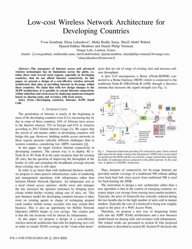
A Spot Cell encompasses a Home e/Node-B(HNB) con-nected to a Home Gateway (HGW) which is connected to thetraditional Node-B (NB)/eNode-B (eNB) through a directiveantenna that increases the signal strength (see Fig. 1).
MSCNode B
Node B
RNC
SGSNGGSN
I2
I1
Iu-C
S Gs
PDN Network
Gi
PCRF OCSHLR
Gx
Gy
Gr
Global Operator trafficInfopreneurs traffic
Infopreneurs traffic
with untrusted link
Secure tunnel
Secondary link
Iub
Iub
HGW + Yagi
Antenna
UE
HGW + Yagi
Antenna
UE
L-GW
(Local Service)
L-GW
(Local Service)
Primary Link
(3G wireless P2P)
Secondary Link
(3G wireless P2P)
HNB
HNB
IPSec
Gateway
Packet
Switch
Service
Optional
Services
HNB-Core-GW
Fig. 1. Proposed architecture providing 3G connectivity spots. Green coloredlinks represent the traffic coming from infopreneur’s HNB with a secure tunnelset up between the HGW and the core network; orange colored links representsthe traffic of traditional devices connected to the global operator. In the samevein, it applies to LTE/EPC architecture.
Thus, hotspots of connectivity for fix-usage Internet areprovided outside coverage of a traditional NB without addingextra back-haul link since access from traditional NB is usedfor back-hauling the HNB.
The motivation to design a new architecture rather than anew algorithm is that in the context of emerging countries weexpect major cost savings from reusing mass-market products.Typically, the price of femtocells has critically reduced duringthe last months due to the high number of units sold in maturemarkets. Typically the cost of a femtocell is being now roughlyequal to the price of a WiFi Access Point.
Therefore, we propose a new way of integrating femtocells into the 3GPP 3G/4G architectures and a new businessmodel based on sharing risks and revenues with infopreneurs.The related works are presented in section II. Our proposedarchitecture is described in section III. Section IV discusses the
978-1-4799-5350-9/14/$31.00 c© 2014 IEEE
practical feasibility of the proposed solution, and performanceevaluations are presented in section V. Finally, section VIconcludes the paper and gives some perspectives.
II. RELATED WORKS
There exist several ways to improve the throughput at theborder of cells and to increase coverage beyond existing sites.Site sharing and/or outsourcing have been widely adopted,especially in rural areas of developing countries. Active net-work sharing has been set up by mobile network operatorsbut mostly in Europe due to the ease of political/regulatoryissues [3]. It has not been adopted in developing countriesbecause the network sharing models defined in 3GPP standards[4] do not allow competition at network flow level. In recentliterature ([5], [6]), they have introduced network operatordifferentiation along with sharing at the network flow level.In fact, serious changes are required on the 3GPP architecture(e.g., impacts on GTP protocol or Node B).
3G/LTE relays ([7], [8]) is a serious option for improvingcoverage, especially where wired infrastructures are lacking,but the cost saving is not enough for targeting ARPU ofdeveloping countries. This is mainly because of the major costscoming from passive infrastructure (tower or site rent, energy,civil works). We propose to reuse the infopreneur house and toshare revenues. In that context, current relays implementationsdo not fit the requirements of our proposed business model dueto the following reasons: (1) relays are usually under controlof MNO for security issues, but they can’t be trusted in ourbusiness model; (2) their location is usually chosen by MNOin order to optimize coverage [9] and to reduce interferences;an update of radio planning is required each time a new site isdeployed. Instead of this, spot cells should be plug-and-playin order to ease deployment and their location will be chosenby the infopreneurs.
Our business model requires also counting the traffic goingthrough every spot cells in order to share revenues withinfopreneurs, and consequently to identify each spot cell.
III. ARCHITECTURE DESCRIPTION
In the 3GPP standardized femtocell architecture ([10], [11]and [12]), HNB are connected to the mobile core networkby a fixed network access through a HNB Gateway (HNB-Core-GW). A typical HNB is a residential/entreprise femtocellwith limited coverage range radius (<100m) but also lowpower consumption. This architecture is not often applicablein developing countries because wired infrastructures are notas largely deployed as in developed economies. We thereforeappeal for extensions of this architecture reusing Home NodeB.
A. Proposed Architecture
The MNO provides a radio local loop to the infopreneursince it gives him/her access to the radio access spectrum.But it is still the responsibility of the MNO to take careof the authentication (of both the infopreneur equipment’s
and the end-users), accounting, backhaul and interconnectionconnectivity, and end-to-end (e2e) security issues.
Spot Cells include outdoor HNB directly connected tothe MNO network through HGW equipped with a 3G/LTEinterface and passive directive antennas in order to get a bettersignal strength than simple UE.
• Backhaul Connections/Resiliency: a HGW may havetwo 3G/LTE wireless point-to-point connections with 2different nearest NB, one as primary link and otheras secondary link, for resiliency purpose (Fig. 1). Noadditional backhaul links is therefore required for the spotcell (as in the case when it would be needed if a newtraditional NB is added) thanks to the licensed 3G/4Gspectrum provided by the traditional NB acting as theHGW backhaul connection.
• AAA Server: the SIM details (e.g., IMSI) are registeredin the MNO AAA system (Authentication, Authorizationand Accounting). This registration is based on info-preneur slices shown in Fig. 2. The MNO takes care ofsupplying a bunch of SIM cards to infopreneurs, so itsauthentication server knows any User Equipment (UE)as well as the infopreneur HGW. The MNO bills allthe clients and share revenues with infopreneurs. TheHGW authenticates with global operator AAA server.After successful authentication, the AAA server allocatesthe APN address for the HGW. All HNBs connectedto HGW may start SIM authentication process withAAA server which sends the HNB policies to HGW.Then the HGW allocates the local IP address for HNB.The enhanced AAA server detects end-users connectedthrough a HNB in order to avoid charging traffic twice,since the architecture leads to a loop inside the corenetwork.
SGSN GGSN
Data Base
Global Operator
Users N1, N2,... Nn
Infopreneur_n
Users N1, N2,... Nn
Infopreneur_2
Users N1, N2,... Nn
Infopreneur_1
Users N1, N2,... Nn
Add New Users
Change Users Policies
Change User Profile
Etc..
Infopreneur_1
Infopreneur_2Infopreneur_N
Add New Users
Change Users Policies
Change User Profile
Etc..
Add New Users
Change Users Policies
Change User Profile
Etc..
Global Operator Core Network
AAA Server
Fig. 2. AAA Server with dedicated API to Infopreneurs.
• Global Operator AAA Management API: dedicatedto Infopreneurs: the global operator provides a dedicatedAPI to infopreneurs in order they can manage theirclients through the AAA server slices as shown in Fig. 2.Infopreneurs are contact points of clients: they monitortheir usage, re-credit them or remove their account.
• Secure Connections: similarly to [12], the HNB isconnected to a Secure-GW and then to the HNB-Core-GW. This makes sure that no traffic going to the corenetwork is malicious. The consequence is that a loop iscreated in the core network between the GGSN/P-GW,the HNB-Core-GW and the SGSN/S-GW.
• Global mobility is not supported since no coverage con-tinuity is guaranteed between small cells, but roamingbetween infopreneur sites is considered by the AAAserver.
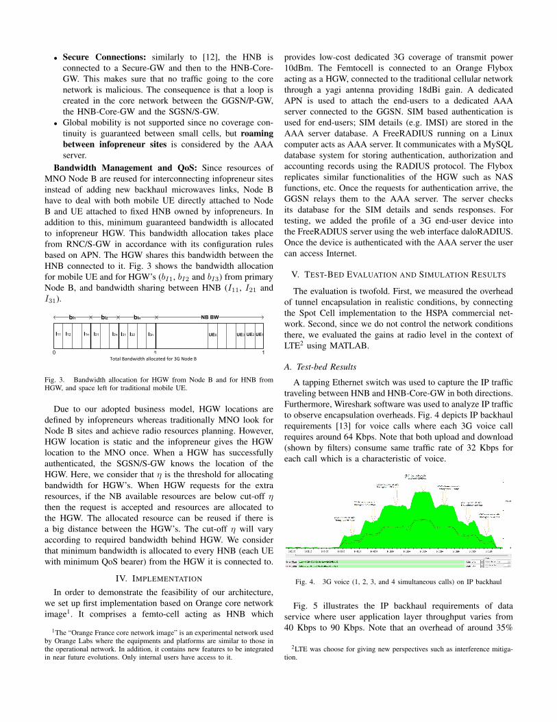
Bandwidth Management and QoS: Since resources ofMNO Node B are reused for interconnecting infopreneur sitesinstead of adding new backhaul microwaves links, Node Bhave to deal with both mobile UE directly attached to NodeB and UE attached to fixed HNB owned by infopreneurs. Inaddition to this, minimum guaranteed bandwidth is allocatedto infopreneur HGW. This bandwidth allocation takes placefrom RNC/S-GW in accordance with its configuration rulesbased on APN. The HGW shares this bandwidth between theHNB connected to it. Fig. 3 shows the bandwidth allocationfor mobile UE and for HGW’s (bI1, bI2 and bI3) from primaryNode B, and bandwidth sharing between HNB (I11, I21 andI31).
I11 I12 I1n I21 I2n I31 I32 I3n UE1UE2UE3UE6
NB BWbI1 bI2 bIn
0 1η
Total Bandwidth allocated for 3G Node B
Fig. 3. Bandwidth allocation for HGW from Node B and for HNB fromHGW, and space left for traditional mobile UE.
Due to our adopted business model, HGW locations aredefined by infopreneurs whereas traditionally MNO look forNode B sites and achieve radio resources planning. However,HGW location is static and the infopreneur gives the HGWlocation to the MNO once. When a HGW has successfullyauthenticated, the SGSN/S-GW knows the location of theHGW. Here, we consider that η is the threshold for allocatingbandwidth for HGW’s. When HGW requests for the extraresources, if the NB available resources are below cut-off ηthen the request is accepted and resources are allocated tothe HGW. The allocated resource can be reused if there isa big distance between the HGW’s. The cut-off η will varyaccording to required bandwidth behind HGW. We considerthat minimum bandwidth is allocated to every HNB (each UEwith minimum QoS bearer) from the HGW it is connected to.
IV. IMPLEMENTATION
In order to demonstrate the feasibility of our architecture,we set up first implementation based on Orange core networkimage1. It comprises a femto-cell acting as HNB which
1The “Orange France core network image” is an experimental network usedby Orange Labs where the equipments and platforms are similar to those inthe operational network. In addition, it contains new features to be integratedin near future evolutions. Only internal users have access to it.
provides low-cost dedicated 3G coverage of transmit power10dBm. The Femtocell is connected to an Orange Flyboxacting as a HGW, connected to the traditional cellular networkthrough a yagi antenna providing 18dBi gain. A dedicatedAPN is used to attach the end-users to a dedicated AAAserver connected to the GGSN. SIM based authentication isused for end-users; SIM details (e.g. IMSI) are stored in theAAA server database. A FreeRADIUS running on a Linuxcomputer acts as AAA server. It communicates with a MySQLdatabase system for storing authentication, authorization andaccounting records using the RADIUS protocol. The Flyboxreplicates similar functionalities of the HGW such as NASfunctions, etc. Once the requests for authentication arrive, theGGSN relays them to the AAA server. The server checksits database for the SIM details and sends responses. Fortesting, we added the profile of a 3G end-user device intothe FreeRADIUS server using the web interface daloRADIUS.Once the device is authenticated with the AAA server the usercan access Internet.
V. TEST-BED EVALUATION AND SIMULATION RESULTS
The evaluation is twofold. First, we measured the overheadof tunnel encapsulation in realistic conditions, by connectingthe Spot Cell implementation to the HSPA commercial net-work. Second, since we do not control the network conditionsthere, we evaluated the gains at radio level in the context ofLTE2 using MATLAB.
A. Test-bed Results
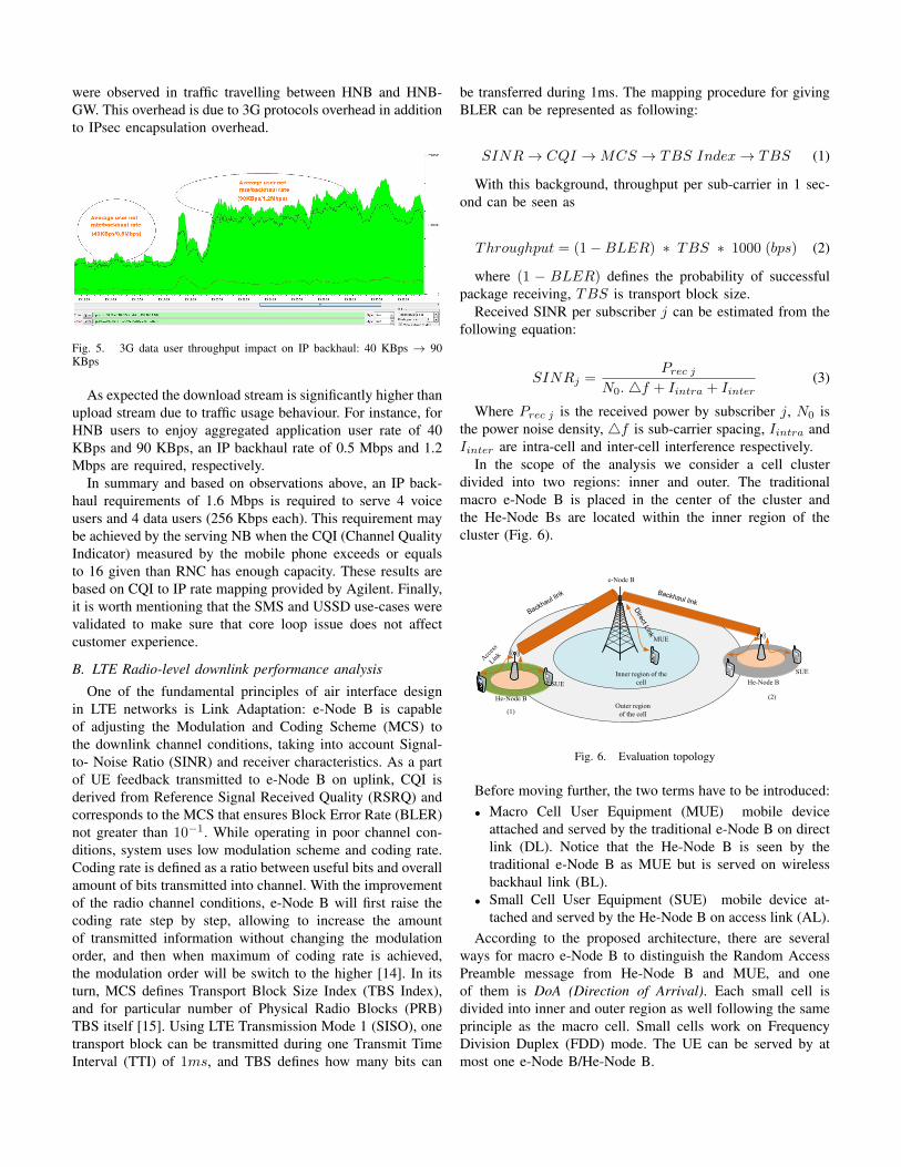
A tapping Ethernet switch was used to capture the IP traffictraveling between HNB and HNB-Core-GW in both directions.Furthermore, Wireshark software was used to analyze IP trafficto observe encapsulation overheads. Fig. 4 depicts IP backhaulrequirements [13] for voice calls where each 3G voice callrequires around 64 Kbps. Note that both upload and download(shown by filters) consume same traffic rate of 32 Kbps foreach call which is a characteristic of voice.
Fig. 4. 3G voice (1, 2, 3, and 4 simultaneous calls) on IP backhaul
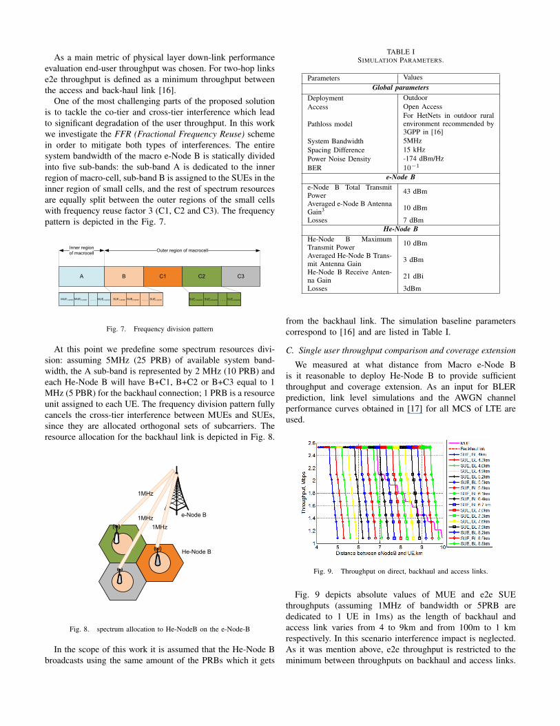
Fig. 5 illustrates the IP backhaul requirements of dataservice where user application layer throughput varies from40 Kbps to 90 Kbps. Note that an overhead of around 35%
2LTE was choose for giving new perspectives such as interference mitiga-tion.
were observed in traffic travelling between HNB and HNB-GW. This overhead is due to 3G protocols overhead in additionto IPsec encapsulation overhead.
Fig. 5. 3G data user throughput impact on IP backhaul: 40 KBps → 90KBps
As expected the download stream is significantly higher thanupload stream due to traffic usage behaviour. For instance, forHNB users to enjoy aggregated application user rate of 40KBps and 90 KBps, an IP backhaul rate of 0.5 Mbps and 1.2Mbps are required, respectively.
In summary and based on observations above, an IP back-haul requirements of 1.6 Mbps is required to serve 4 voiceusers and 4 data users (256 Kbps each). This requirement maybe achieved by the serving NB when the CQI (Channel QualityIndicator) measured by the mobile phone exceeds or equalsto 16 given than RNC has enough capacity. These results arebased on CQI to IP rate mapping provided by Agilent. Finally,it is worth mentioning that the SMS and USSD use-cases werevalidated to make sure that core loop issue does not affectcustomer experience.
B. LTE Radio-level downlink performance analysis
One of the fundamental principles of air interface designin LTE networks is Link Adaptation: e-Node B is capableof adjusting the Modulation and Coding Scheme (MCS) tothe downlink channel conditions, taking into account Signal-to- Noise Ratio (SINR) and receiver characteristics. As a partof UE feedback transmitted to e-Node B on uplink, CQI isderived from Reference Signal Received Quality (RSRQ) andcorresponds to the MCS that ensures Block Error Rate (BLER)not greater than 10−1. While operating in poor channel con-ditions, system uses low modulation scheme and coding rate.Coding rate is defined as a ratio between useful bits and overallamount of bits transmitted into channel. With the improvementof the radio channel conditions, e-Node B will first raise thecoding rate step by step, allowing to increase the amountof transmitted information without changing the modulationorder, and then when maximum of coding rate is achieved,the modulation order will be switch to the higher [14]. In itsturn, MCS defines Transport Block Size Index (TBS Index),and for particular number of Physical Radio Blocks (PRB)TBS itself [15]. Using LTE Transmission Mode 1 (SISO), onetransport block can be transmitted during one Transmit TimeInterval (TTI) of 1ms, and TBS defines how many bits can
be transferred during 1ms. The mapping procedure for givingBLER can be represented as following:
SINR→ CQI →MCS → TBS Index→ TBS (1)
With this background, throughput per sub-carrier in 1 sec-ond can be seen as
Throughput = (1−BLER) ∗ TBS ∗ 1000 (bps) (2)
where (1 − BLER) defines the probability of successfulpackage receiving, TBS is transport block size.
Received SINR per subscriber j can be estimated from thefollowing equation:
SINRj =Prec j
N0. 4f + Iintra + Iinter(3)
Where Prec j is the received power by subscriber j, N0 isthe power noise density, 4f is sub-carrier spacing, Iintra andIinter are intra-cell and inter-cell interference respectively.
In the scope of the analysis we consider a cell clusterdivided into two regions: inner and outer. The traditionalmacro e-Node B is placed in the center of the cluster andthe He-Node Bs are located within the inner region of thecluster (Fig. 6).
Backhaul link
Dire
ct Lin
k
e-Node B
MUE
Outer region
of the cell
Inner region of the
cell
He-Node B
Acc
ess
Link
SUE
Backhaul link
(1)
(2)
He-Node B
SUE
Fig. 6. Evaluation topology
Before moving further, the two terms have to be introduced:• Macro Cell User Equipment (MUE) mobile device
attached and served by the traditional e-Node B on directlink (DL). Notice that the He-Node B is seen by thetraditional e-Node B as MUE but is served on wirelessbackhaul link (BL).
• Small Cell User Equipment (SUE) mobile device at-tached and served by the He-Node B on access link (AL).
According to the proposed architecture, there are severalways for macro e-Node B to distinguish the Random AccessPreamble message from He-Node B and MUE, and oneof them is DoA (Direction of Arrival). Each small cell isdivided into inner and outer region as well following the sameprinciple as the macro cell. Small cells work on FrequencyDivision Duplex (FDD) mode. The UE can be served by atmost one e-Node B/He-Node B.
As a main metric of physical layer down-link performanceevaluation end-user throughput was chosen. For two-hop linkse2e throughput is defined as a minimum throughput betweenthe access and back-haul link [16].
One of the most challenging parts of the proposed solutionis to tackle the co-tier and cross-tier interference which leadto significant degradation of the user throughput. In this workwe investigate the FFR (Fractional Frequency Reuse) schemein order to mitigate both types of interferences. The entiresystem bandwidth of the macro e-Node B is statically dividedinto five sub-bands: the sub-band A is dedicated to the innerregion of macro-cell, sub-band B is assigned to the SUEs in theinner region of small cells, and the rest of spectrum resourcesare equally split between the outer regions of the small cellswith frequency reuse factor 3 (C1, C2 and C3). The frequencypattern is depicted in the Fig. 7.
A B C1 C2
Inner region
of macrocellOuter region of macrocell
MUE1,center MUE2,center MUEn,center. . .
C3
SUE1,boarder . . . SUE1,center SUE2,center SUEn,center. . . SUE2,boarder SUEn,boarder
Fig. 7. Frequency division pattern
At this point we predefine some spectrum resources divi-sion: assuming 5MHz (25 PRB) of available system band-width, the A sub-band is represented by 2 MHz (10 PRB) andeach He-Node B will have B+C1, B+C2 or B+C3 equal to 1MHz (5 PBR) for the backhaul connection; 1 PRB is a resourceunit assigned to each UE. The frequency division pattern fullycancels the cross-tier interference between MUEs and SUEs,since they are allocated orthogonal sets of subcarriers. Theresource allocation for the backhaul link is depicted in Fig. 8.
1MHz
e-Node B
He-Node B
1MHz
1MHz
Fig. 8. spectrum allocation to He-NodeB on the e-Node-B
In the scope of this work it is assumed that the He-Node Bbroadcasts using the same amount of the PRBs which it gets
TABLE ISIMULATION PARAMETERS.
Parameters ValuesGlobal parameters
Deployment OutdoorAccess Open Access
Pathloss modelFor HetNets in outdoor ruralenvironment recommended by3GPP in [16]
System Bandwidth 5MHzSpacing Difference 15 kHzPower Noise Density -174 dBm/HzBER 10−1
e-Node Be-Node B Total TransmitPower 43 dBm
Averaged e-Node B AntennaGain3 10 dBm
Losses 7 dBmHe-Node B
He-Node B MaximumTransmit Power 10 dBm
Averaged He-Node B Trans-mit Antenna Gain 3 dBm
He-Node B Receive Anten-na Gain 21 dBi
Losses 3dBm
from the backhaul link. The simulation baseline parameterscorrespond to [16] and are listed in Table I.
C. Single user throughput comparison and coverage extension
We measured at what distance from Macro e-Node Bis it reasonable to deploy He-Node B to provide sufficientthroughput and coverage extension. As an input for BLERprediction, link level simulations and the AWGN channelperformance curves obtained in [17] for all MCS of LTE areused.
Fig. 9. Throughput on direct, backhaul and access links.
Fig. 9 depicts absolute values of MUE and e2e SUEthroughputs (assuming 1MHz of bandwidth or 5PRB arededicated to 1 UE in 1ms) as the length of backhaul andaccess link varies from 4 to 9km and from 100m to 1 kmrespectively. In this scenario interference impact is neglected.As it was mention above, e2e throughput is restricted to theminimum between throughputs on backhaul and access links.
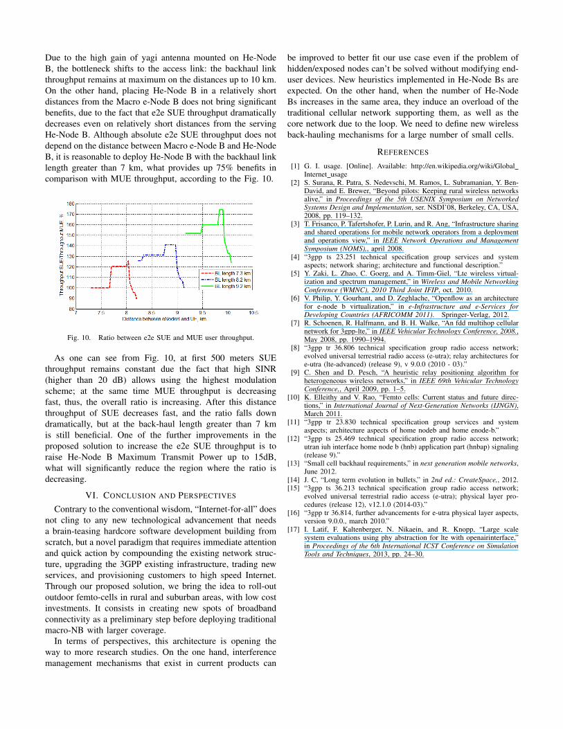
Due to the high gain of yagi antenna mounted on He-NodeB, the bottleneck shifts to the access link: the backhaul linkthroughput remains at maximum on the distances up to 10 km.On the other hand, placing He-Node B in a relatively shortdistances from the Macro e-Node B does not bring significantbenefits, due to the fact that e2e SUE throughput dramaticallydecreases even on relatively short distances from the servingHe-Node B. Although absolute e2e SUE throughput does notdepend on the distance between Macro e-Node B and He-NodeB, it is reasonable to deploy He-Node B with the backhaul linklength greater than 7 km, what provides up 75% benefits incomparison with MUE throughput, according to the Fig. 10.
Fig. 10. Ratio between e2e SUE and MUE user throughput.
As one can see from Fig. 10, at first 500 meters SUEthroughput remains constant due the fact that high SINR(higher than 20 dB) allows using the highest modulationscheme; at the same time MUE throughput is decreasingfast, thus, the overall ratio is increasing. After this distancethroughput of SUE decreases fast, and the ratio falls downdramatically, but at the back-haul length greater than 7 kmis still beneficial. One of the further improvements in theproposed solution to increase the e2e SUE throughput is toraise He-Node B Maximum Transmit Power up to 15dB,what will significantly reduce the region where the ratio isdecreasing.
VI. CONCLUSION AND PERSPECTIVES
Contrary to the conventional wisdom, “Internet-for-all” doesnot cling to any new technological advancement that needsa brain-teasing hardcore software development building fromscratch, but a novel paradigm that requires immediate attentionand quick action by compounding the existing network struc-ture, upgrading the 3GPP existing infrastructure, trading newservices, and provisioning customers to high speed Internet.Through our proposed solution, we bring the idea to roll-outoutdoor femto-cells in rural and suburban areas, with low costinvestments. It consists in creating new spots of broadbandconnectivity as a preliminary step before deploying traditionalmacro-NB with larger coverage.
In terms of perspectives, this architecture is opening theway to more research studies. On the one hand, interferencemanagement mechanisms that exist in current products can
be improved to better fit our use case even if the problem ofhidden/exposed nodes can’t be solved without modifying end-user devices. New heuristics implemented in He-Node Bs areexpected. On the other hand, when the number of He-NodeBs increases in the same area, they induce an overload of thetraditional cellular network supporting them, as well as thecore network due to the loop. We need to define new wirelessback-hauling mechanisms for a large number of small cells.
REFERENCES
[1] G. I. usage. [Online]. Available: http://en.wikipedia.org/wiki/GlobalInternet usage
[2] S. Surana, R. Patra, S. Nedevschi, M. Ramos, L. Subramanian, Y. Ben-David, and E. Brewer, “Beyond pilots: Keeping rural wireless networksalive,” in Proceedings of the 5th USENIX Symposium on NetworkedSystems Design and Implementation, ser. NSDI’08, Berkeley, CA, USA,2008, pp. 119–132.
[3] T. Frisanco, P. Tafertshofer, P. Lurin, and R. Ang, “Infrastructure sharingand shared operations for mobile network operators from a deploymentand operations view,” in IEEE Network Operations and ManagementSymposium (NOMS),, april 2008.
[4] “3gpp ts 23.251 technical specification group services and systemaspects; network sharing; architecture and functional description.”
[5] Y. Zaki, L. Zhao, C. Goerg, and A. Timm-Giel, “Lte wireless virtual-ization and spectrum management,” in Wireless and Mobile NetworkingConference (WMNC), 2010 Third Joint IFIP, oct. 2010.
[6] V. Philip, Y. Gourhant, and D. Zeghlache, “Openflow as an architecturefor e-node b virtualization,” in e-Infrastructure and e-Services forDeveloping Countries (AFRICOMM 2011). Springer-Verlag, 2012.
[7] R. Schoenen, R. Halfmann, and B. H. Walke, “An fdd multihop cellularnetwork for 3gpp-lte,” in IEEE Vehicular Technology Conference, 2008.,May 2008, pp. 1990–1994.
[8] “3gpp tr 36.806 technical specification group radio access network;evolved universal terrestrial radio access (e-utra); relay architectures fore-utra (lte-advanced) (release 9), v 9.0.0 (2010 - 03).”
[9] C. Shen and D. Pesch, “A heuristic relay positioning algorithm forheterogeneous wireless networks,” in IEEE 69th Vehicular TechnologyConference,, April 2009, pp. 1–5.
[10] K. Elleithy and V. Rao, “Femto cells: Current status and future direc-tions,” in International Journal of Next-Generation Networks (IJNGN),March 2011.
[11] “3gpp tr 23.830 technical specification group services and systemaspects; architecture aspects of home nodeb and home enode-b.”
[12] “3gpp ts 25.469 technical specification group radio access network;utran iuh interface home node b (hnb) application part (hnbap) signaling(release 9).”
[13] “Small cell backhaul requirements,” in next generation mobile networks,June 2012.
[14] J. C, “Long term evolution in bullets,” in 2nd ed.: CreateSpace,, 2012.[15] “3gpp ts 36.213 technical specification group radio access network;
evolved universal terrestrial radio access (e-utra); physical layer pro-cedures (release 12), v12.1.0 (2014-03).”
[16] “3gpp tr 36.814, further advancements for e-utra physical layer aspects,version 9.0.0., march 2010.”
[17] I. Latif, F. Kaltenberger, N. Nikaein, and R. Knopp, “Large scalesystem evaluations using phy abstraction for lte with openairinterface,”in Proceedings of the 6th International ICST Conference on SimulationTools and Techniques, 2013, pp. 24–30.