Investigation on a low-cost single wavelength converged wired-60 GHz wireless OFDM-based system...
10
Investigation on a Low-Cost Single Wavelength Converged Wired-60 GHz Wireless OFDM Based System Employing a Photonic Patch Antenna Spiros Mikroulis *a,c , Ivan Aldaya b , Ioannis Petropoulos a , Elias Giacoumidis b , Kostantinos Voudouris a , Ioannis Tomkos c a Department of Electronics, Division of Telecommunications, Technological Educational Institute of Athens, Egaleo, 12210, Athens, Greece b Optical Communications Group, Département Communications & Électronique, 46 rue Barrault, 75013, Telecom Paris-Tech, Paris, France c Networks and Optical Communications (NOC) Group, Athens Information Technology (AIT), P.O. Box 68, Markopoulo Ave, 19002, Peania, Athens, Greece ABSTRACT A low cost converged wireline and 60GHz wireless hybrid system utilizing a single wavelength is proposed, employing two single electrode LiNbO 3 modulators for all-optical mm-wave frequency up-conversion and baseband modulation, respectively. Additionally, a novel 15dBi, broadband, coplanar based, photonic patch array antenna is designed on a high dielectric substrate for application as an indoor compact photonic-wireless transceiver. In order to evaluate the fiber-wireless system performance a microwave/optical/wireless design is utilized, employing 3Gb/s orthogonal frequency division multiplexed (OFDM) broadband wireless and passive optical network (PON) signals, co-propagating in a single mode fiber (SMF). An acceptable performance is calculated for a 10m indoor wireless channel and a PON urban link in the order of up to 20km, respectively. At last, a comparison of alternative RoF/PON photonic up conversion schemes is presented. Keywords: Radio over Fiber, PON, photonic integrated antenna, OFDM. 1. INTRODUCTION Wireless-based access technology has been tremendously developed over the last decade, powered by the simultaneous advance of high bit-rate demanding services. However, the wireless access data rates must be extended far beyond the current standards, which are in the order of 100Mbps. It is a necessity to utilize the license-free spectrum at 60GHz, which offers (in accordance to FCC) an available bandwidth of 7GHz in order to satisfy the aforementioned high-bit rate requirements. Ongoing such needs, some preliminary work has been performed to satisfy the demands for high bit rate wireless services reaching 1 Gb/s, or more, for hot spots in short area indoor networks. In such a manner, several wireless standards have been proposed and being under consideration in order to benefit from the 60GHz unlicensed band, an example is; wireless High Definition audio/video standard (Wireless HD) which is based upon IEEE 802.15.3c [1]. However, 60 GHz spectrum imposes several challenges in a real environment due to the increased path loss and reduced coverage, which envisages a high density of installed radio access points in contrast to social needs for energy conservation and cost reduction. In respect to the optical access network development, recent advances in wired broadband access, such as passive optical network (PON)-based fiber-to-the-x (FTTx) [2-4] tend to resist against the bottleneck in the cable network deployment due to the high signal capacity divergence between access and backhaul networks, known as the “last mile” problem. In recent years, radio-over-fiber (RoF) technology has emerged as a promising candidate for bridging the gap between the aforementioned technologies i.e. high mobility (wireless/mobile) and high capacity (optical) networks. RoF networks provide transparency against modulation techniques and support various digital formats and wireless standards *corresponding author, e-mail: [email protected] (S. Mikroulis) Broadband Access Communication Technologies VII, edited by Benjamin B. Dingel, Raj Jain, Katsutoshi Tsukamoto, Proc. of SPIE Vol. 8645, 86450J · © 2013 SPIE · CCC code: 0277-786X/13/$18 · doi: 10.1117/12.2000413 Proc. of SPIE Vol. 8645 86450J-1 Downloaded From: http://proceedings.spiedigitallibrary.org/ on 09/29/2014 Terms of Use: http://spiedl.org/terms
Transcript of Investigation on a low-cost single wavelength converged wired-60 GHz wireless OFDM-based system...

Investigation on a Low-Cost Single Wavelength Converged Wired-60
GHz Wireless OFDM Based System Employing a Photonic Patch
Antenna
Spiros Mikroulis*a,c
, Ivan Aldayab, Ioannis Petropoulos
a, Elias Giacoumidis
b, Kostantinos
Voudourisa, Ioannis Tomkos
c
a Department of Electronics, Division of Telecommunications, Technological Educational Institute
of Athens, Egaleo, 12210, Athens, Greece b Optical Communications Group, Département Communications & Électronique, 46 rue Barrault,
75013, Telecom Paris-Tech, Paris, France c Networks and Optical Communications (NOC) Group, Athens Information Technology (AIT),
P.O. Box 68, Markopoulo Ave, 19002, Peania, Athens, Greece
ABSTRACT
A low cost converged wireline and 60GHz wireless hybrid system utilizing a single wavelength is proposed, employing
two single electrode LiNbO3 modulators for all-optical mm-wave frequency up-conversion and baseband modulation,
respectively. Additionally, a novel 15dBi, broadband, coplanar based, photonic patch array antenna is designed on a
high dielectric substrate for application as an indoor compact photonic-wireless transceiver. In order to evaluate the
fiber-wireless system performance a microwave/optical/wireless design is utilized, employing 3Gb/s orthogonal
frequency division multiplexed (OFDM) broadband wireless and passive optical network (PON) signals, co-propagating
in a single mode fiber (SMF). An acceptable performance is calculated for a 10m indoor wireless channel and a PON
urban link in the order of up to 20km, respectively. At last, a comparison of alternative RoF/PON photonic up
conversion schemes is presented.
Keywords: Radio over Fiber, PON, photonic integrated antenna, OFDM.
1. INTRODUCTION
Wireless-based access technology has been tremendously developed over the last decade, powered by the simultaneous
advance of high bit-rate demanding services. However, the wireless access data rates must be extended far beyond the
current standards, which are in the order of 100Mbps. It is a necessity to utilize the license-free spectrum at 60GHz,
which offers (in accordance to FCC) an available bandwidth of 7GHz in order to satisfy the aforementioned high-bit
rate requirements. Ongoing such needs, some preliminary work has been performed to satisfy the demands for high bit
rate wireless services reaching 1 Gb/s, or more, for hot spots in short area indoor networks. In such a manner, several
wireless standards have been proposed and being under consideration in order to benefit from the 60GHz unlicensed
band, an example is; wireless High Definition audio/video standard (Wireless HD) which is based upon IEEE 802.15.3c
[1]. However, 60 GHz spectrum imposes several challenges in a real environment due to the increased path loss and
reduced coverage, which envisages a high density of installed radio access points in contrast to social needs for energy
conservation and cost reduction.
In respect to the optical access network development, recent advances in wired broadband access, such as passive
optical network (PON)-based fiber-to-the-x (FTTx) [2-4] tend to resist against the bottleneck in the cable network
deployment due to the high signal capacity divergence between access and backhaul networks, known as the “last mile”
problem. In recent years, radio-over-fiber (RoF) technology has emerged as a promising candidate for bridging the gap
between the aforementioned technologies i.e. high mobility (wireless/mobile) and high capacity (optical) networks. RoF
networks provide transparency against modulation techniques and support various digital formats and wireless standards
*corresponding author, e-mail: [email protected] (S. Mikroulis)
Broadband Access Communication Technologies VII, edited by Benjamin B. Dingel, Raj Jain, Katsutoshi Tsukamoto, Proc. of SPIE Vol. 8645, 86450J · © 2013 SPIE · CCC code: 0277-786X/13/$18 · doi: 10.1117/12.2000413
Proc. of SPIE Vol. 8645 86450J-1
Downloaded From: http://proceedings.spiedigitallibrary.org/ on 09/29/2014 Terms of Use: http://spiedl.org/terms

J 'JRAU
oSMF
OLT
in a cost-effective manner. Moreover, they offer significant simplification of base stations (BSs) to remote antenna units
(RAUs) connected through a central base station (CBS), potentially re-using the already deployed FTTx infrastructure.
In this case, one of the most important issues is to modulate and transmit both wired and wireless signals over a single
wavelength (i.e. WDM-PON channel).
Another important issue when viewed from a business perspective is the low cost deployment of dense RAUs. In this
case, planar antenna is a promising candidate due to its low-cost, lightweight, simple manufacture and compatibility
with MMIC/OEIC technology. Moreover, for the mm-wave radio over fiber case planar antennas have dimensions
comparable to the electronic/optoelectronic devices, so they could be potentially integrated on the same substrate (i.e.
InP). In addition to this, a planar antenna, examples are patch/slot antennas, can be fabricated in an array configuration,
increasing thus the overall gain and enabling mm-wave techniques in the optical domain to be utilized for beamforming
techniques in smart antenna applications. On the other hand it is well known that patch antennas provide comparatively
narrow impedance bandwidth, typically a few percent. To overcome bandwidth issues several methods have been
proposed; multilayer structures [5], slot shapes such as U-slot [6], bending probe and shorting pin or shorting wall
structures [7].
In this work, a low cost converged wireline and 60GHz wireless hybrid PON architecture (Fig. 1) for next-generation
access networks is proposed, which employs two single electrode LiNbO3 modulators for all-optical frequency up-
conversion utilizing a single WDM-PON channel. Additionally, two types of potentially integrated coplanar to
microstrip patch array antennas are designed on a high dielectric substrate for a contribution to the simple and low-cost
deployment of the photonic-wireless transceiver at the RAUs. The first type of coplanar-to-microstrip patch antenna
incorporates Rogers 6010 substrate for a hybrid integration scenario and the second one is based on an InP substrate in
accordance to a monolithic integration perspective. The hybrid optical-wireless system is numerically evaluated using
cost-effective intensity-modulation with direct-detection (IM/DD) model for optical OFDM (OOFDM) transmission and
subcarrier OFDM wireless modulation scheme, being developed in an Optisystem/ Matlab /HFSS / ADS co-simulation
environment, as well as Matlab/ VPI for transmission performance verifications, including antenna/photodiode aspects.
An acceptable forward error correction (FEC) aided performance (EVM) <32% (bit-error-rate, BER <10-3
) is estimated
for both the 3Gb/s OFDM-based IEEE 802.15.3c wireless prestandard and the 3Gb/s OFDM-PON transmission signal
using a wireless indoor channel in the order of 10m and a standard SMF (SSMF)-PON urban scenario in the order of up
to 20km length, respectively.
2. THEORY AND MODEL
In accordance to IEEE 802.15.3c wireless prestandard a 60GHz OFDM modulation scheme employing quadrature phase
shift keying (QPSK) coding is implemented at the CBS. OFDM band employs 512 quadratic phase shift keying
(QPSK)-modulated subcarriers using a 1024 fast Fourier transform (FFT) size leading to a data rate of 3Gb/s at a
bandwidth of 1.5GHz. In the developed model, prior to data transmission, a pilot OFDM symbol known to the receiver
is sent, acting as a reference for correct demodulation through channel estimation. Regarding PON modulation scheme,
Figure 1. Proposed FTTH-PON/60 GHz wired-wireless network topology.
Proc. of SPIE Vol. 8645 86450J-2
Downloaded From: http://proceedings.spiedigitallibrary.org/ on 09/29/2014 Terms of Use: http://spiedl.org/terms
.iC,b/sOPSK
Modulator
OLT
35GHz025GHz
OFDMModulator
OPTICALFILTER
POWERSPLITTER
1:2
DFB
SMF
/ Mach \ZehnderLiNbO
Modulator
H2 DC
OFDM -PONModulator
10B1FBG
MachZehnderL:NbO
Modulator
DC
EDFA
SMF
OPTICALFILTER
OPTICALCOMBINER
OPTICAL OPTICALSPLITTER SPLITTER
1:8 1:2
SSMF
EDFA
Jplink
OPTICALFILTER
FBG
VIII
Tx PATCHANTENNA
PD
Rx HORNANTENNA
RAU
PON -channel
OFDM- 'Demodulator
ONU
LPF
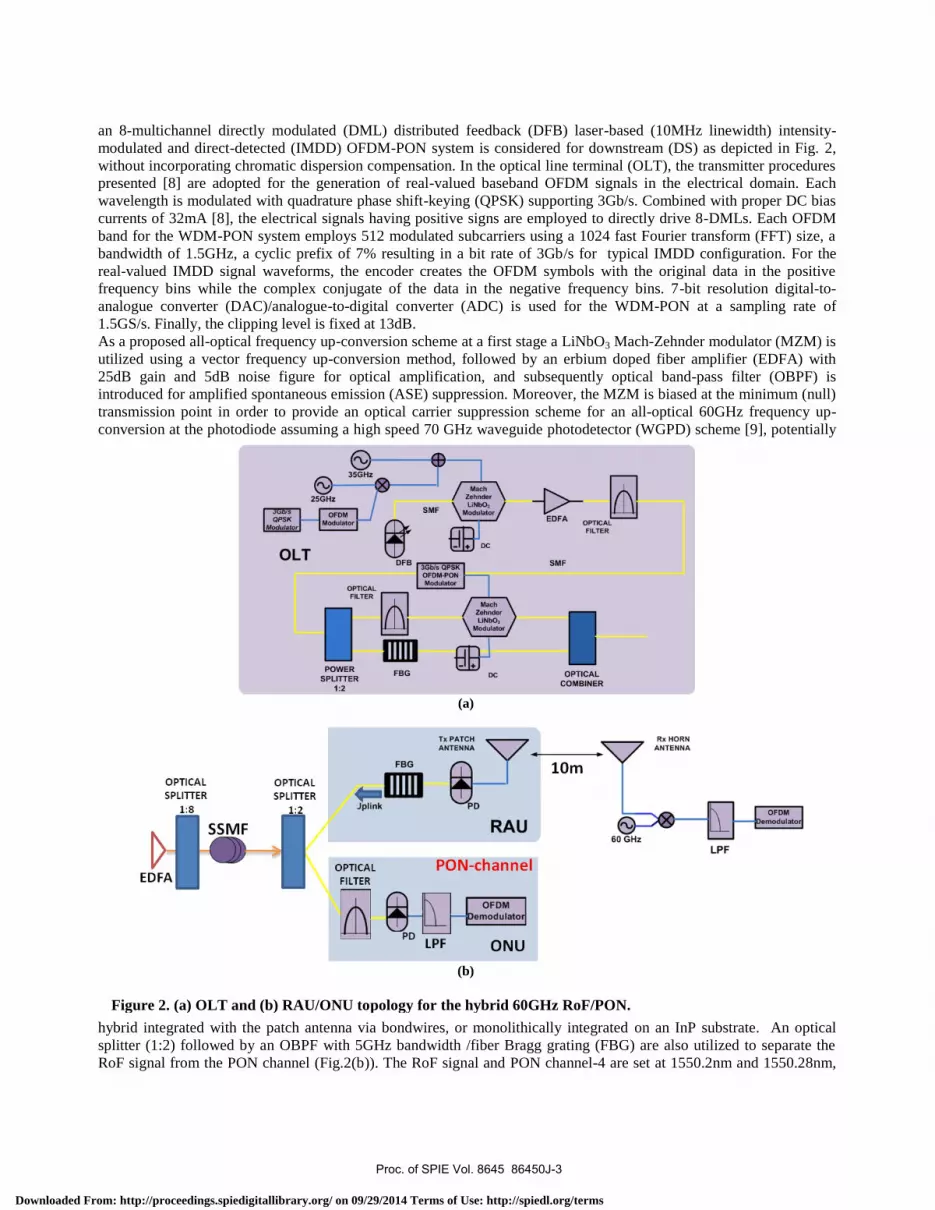
an 8-multichannel directly modulated (DML) distributed feedback (DFB) laser-based (10MHz linewidth) intensity-
modulated and direct-detected (IMDD) OFDM-PON system is considered for downstream (DS) as depicted in Fig. 2,
without incorporating chromatic dispersion compensation. In the optical line terminal (OLT), the transmitter procedures
presented [8] are adopted for the generation of real-valued baseband OFDM signals in the electrical domain. Each
wavelength is modulated with quadrature phase shift-keying (QPSK) supporting 3Gb/s. Combined with proper DC bias
currents of 32mA [8], the electrical signals having positive signs are employed to directly drive 8-DMLs. Each OFDM
band for the WDM-PON system employs 512 modulated subcarriers using a 1024 fast Fourier transform (FFT) size, a
bandwidth of 1.5GHz, a cyclic prefix of 7% resulting in a bit rate of 3Gb/s for typical IMDD configuration. For the
real-valued IMDD signal waveforms, the encoder creates the OFDM symbols with the original data in the positive
frequency bins while the complex conjugate of the data in the negative frequency bins. 7-bit resolution digital-to-
analogue converter (DAC)/analogue-to-digital converter (ADC) is used for the WDM-PON at a sampling rate of
1.5GS/s. Finally, the clipping level is fixed at 13dB.
As a proposed all-optical frequency up-conversion scheme at a first stage a LiNbO3 Mach-Zehnder modulator (MZM) is
utilized using a vector frequency up-conversion method, followed by an erbium doped fiber amplifier (EDFA) with
25dB gain and 5dB noise figure for optical amplification, and subsequently optical band-pass filter (OBPF) is
introduced for amplified spontaneous emission (ASE) suppression. Moreover, the MZM is biased at the minimum (null)
transmission point in order to provide an optical carrier suppression scheme for an all-optical 60GHz frequency up-
conversion at the photodiode assuming a high speed 70 GHz waveguide photodetector (WGPD) scheme [9], potentially
hybrid integrated with the patch antenna via bondwires, or monolithically integrated on an InP substrate. An optical
splitter (1:2) followed by an OBPF with 5GHz bandwidth /fiber Bragg grating (FBG) are also utilized to separate the
RoF signal from the PON channel (Fig.2(b)). The RoF signal and PON channel-4 are set at 1550.2nm and 1550.28nm,
(a)
(b)
Figure 2. (a) OLT and (b) RAU/ONU topology for the hybrid 60GHz RoF/PON.
(b) Fig. 2: (a) OLT and (b) RAU/ONU topology for hybrid 60GHz RoF with WDM-PON channel-4.
Proc. of SPIE Vol. 8645 86450J-3
Downloaded From: http://proceedings.spiedigitallibrary.org/ on 09/29/2014 Terms of Use: http://spiedl.org/terms
Patch antenna
)ficrostrip line
Rogers Duroid 5
Foam layer
0
Rogers Duroid 6010
respectively. All WDM-PON signals are aggregated using a multiplexer such as an array waveguide grating (AWG)
with a channel spacing of 100GHz, and subsequently launched into a SSMF of 1km. Such frequency spacing relaxes the
nonlinear WDM effects of cross-phase modulation (XPM) and four-wave mixing (FWM). Afterwards, the received
WDM signals are de-multiplexed and the hybrid RoF/WDM-PON channel-4 is launched into 1km of SSMF and
subsequently amplified (EDFA) 15 dB and splitter (1:8). Then, the co-propagated signals are launched over 0-30km of
SSMF and subsequently received in the CBS/optical network unit (ONU) using an optical splitter (1:2) (Fig.2(b)). It
should be noted that both PIN-detector’s shot and thermal noises in the receiver are computed following procedures
similar to those previously presented [8].
A patch antenna in a 2x4 array configuration has been designed, based on the criteria of the recently developed wireless
indoor gigabit network standards [1]. The performed analysis and incorporation in the optical system design, utilizing
Optisystem 11.0 platform, is provided through electromagnetic simulations via HFSS combined with transmission line
theory aided by ADS following an indirect hybrid integration design method. In such a case, the microwave properties
of the patch antenna/WGPD are included in the Optisystem 11.0 platform through proper scattering (“S”) matrix
parameters and each component is independently designed and matched to a separate 50Ω transmission line. In this
configuration an optimum material combination can be used in a co-planar based transmission line configuration.
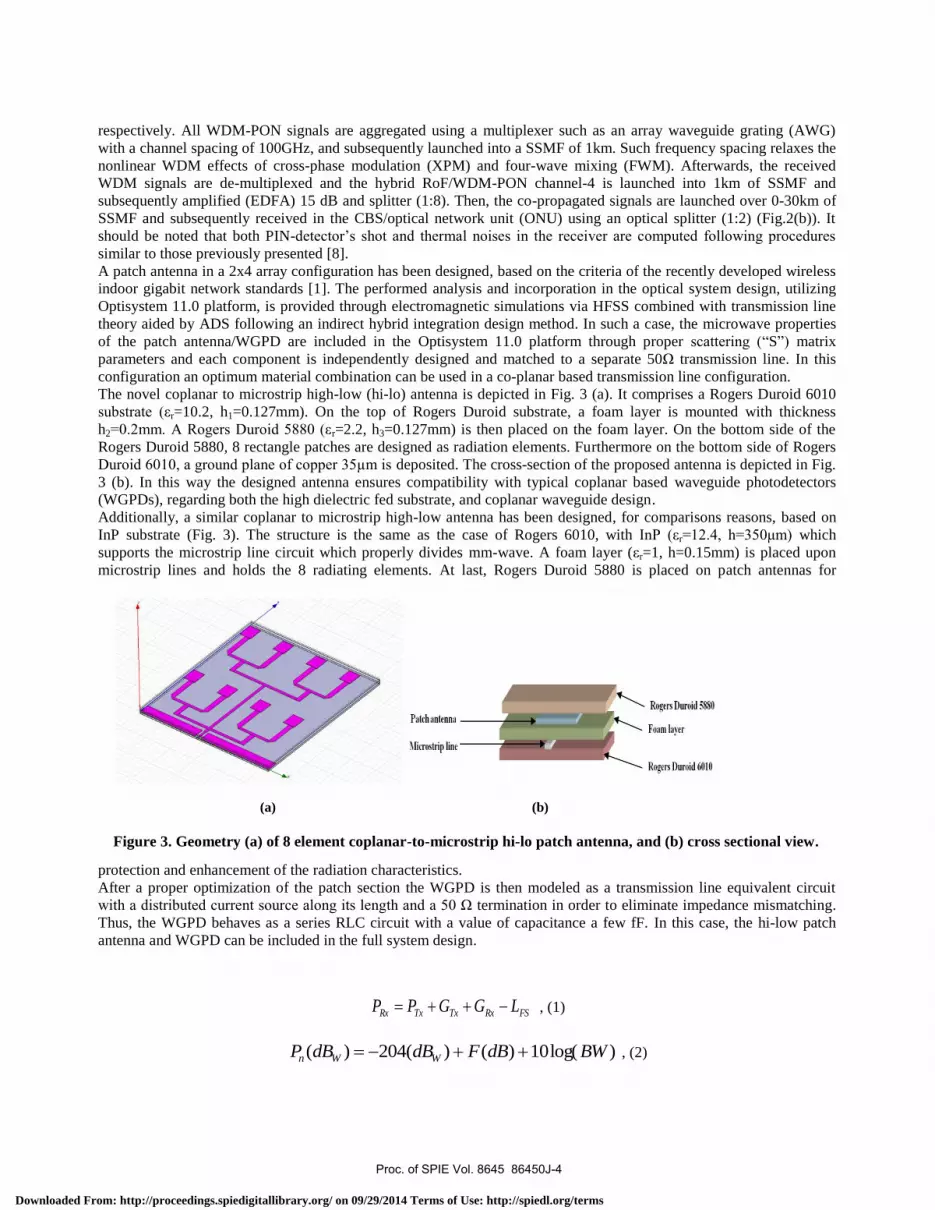
The novel coplanar to microstrip high-low (hi-lo) antenna is depicted in Fig. 3 (a). It comprises a Rogers Duroid 6010
substrate (εr=10.2, h1=0.127mm). On the top of Rogers Duroid substrate, a foam layer is mounted with thickness
h2=0.2mm. A Rogers Duroid 5880 (εr=2.2, h3=0.127mm) is then placed on the foam layer. On the bottom side of the
Rogers Duroid 5880, 8 rectangle patches are designed as radiation elements. Furthermore on the bottom side of Rogers
Duroid 6010, a ground plane of copper 35µm is deposited. The cross-section of the proposed antenna is depicted in Fig.
3 (b). In this way the designed antenna ensures compatibility with typical coplanar based waveguide photodetectors
(WGPDs), regarding both the high dielectric fed substrate, and coplanar waveguide design.
Additionally, a similar coplanar to microstrip high-low antenna has been designed, for comparisons reasons, based on
InP substrate (Fig. 3). The structure is the same as the case of Rogers 6010, with InP (εr=12.4, h=350μm) which
supports the microstrip line circuit which properly divides mm-wave. A foam layer (εr=1, h=0.15mm) is placed upon
microstrip lines and holds the 8 radiating elements. At last, Rogers Duroid 5880 is placed on patch antennas for
protection and enhancement of the radiation characteristics.
After a proper optimization of the patch section the WGPD is then modeled as a transmission line equivalent circuit
with a distributed current source along its length and a 50 Ω termination in order to eliminate impedance mismatching.
Thus, the WGPD behaves as a series RLC circuit with a value of capacitance a few fF. In this case, the hi-low patch
antenna and WGPD can be included in the full system design.
FSRxTxTxRx LGGPP , (1)
)log(10)()(204)( BWdBFdBdBP WWn , (2)
(a) (b)
Figure 3. Geometry (a) of 8 element coplanar-to-microstrip hi-lo patch antenna, and (b) cross sectional view.
Proc. of SPIE Vol. 8645 86450J-4
Downloaded From: http://proceedings.spiedigitallibrary.org/ on 09/29/2014 Terms of Use: http://spiedl.org/terms

o
-5
-10
-15
-20
-25
-30
-35
l
56 58 60 62 64
Frequency (GHz)
.-.m-a....Ccco
20
15
10
5
0
-5
-10
-15
20-90 -60 -30 0 30 60
Angle (deg)90
u)
5
-15
55 56 57 58 59 60 61 62 63 64 65
Freq (GHz)
5
'm-a
Ç oco
(9
-5-zz plan
- yz plane
i ,
I ,
,
\
t
..
i //
-60 o
Angle (deg)60
)1(log(102
11SGPGPEIRP intt , (3)
Moreover, in order to calculate the wireless channel characteristics equations (1)–(3) are used in a link budget
configuration incorporated in the optical system, assuming a commercially available 25dBi horn antenna at the wireless
receiver and noise figure calculated from Eq. (2).
2
2
n
nn
s
sr
EVM , (4)
At last, Error vector Magnitude (EVM) is calculated in accordance to Eq. (4) where rn and sn are the received and ideal
constellation points respectively, and N is the number of constellation points. The EVM offers a quantitative evaluation
for the spreading of the received constellation points.
3. RESULTS AND DISCUSSION
The calculated S11 parameter of the Duroid 6010 array is shown in Fig. 4 (a). The array presents S11=-17.12dB for
57.6GHz and S11=-33.34dB for 60.4GHz. The value of bandwidth around 60GHz is estimated to be 2.04GHz. The
radiation pattern of the 2×4 array is depicted in Fig. 4 (b). The radiation pattern of the patch array presents 14.9dBi with
HPBW equal to 20.520 and 18.270 for xz and yz planes respectively. The characteristics of the InP array are depicted in
Figs 5a and 5b, respectively. The InP based array presents two resonances at 59.8GHz (S11=-15.16dB) and 63.45GHz
(S11=-15.96dB). The bandwidth is estimated to be 1.81GHz and the radiation pattern presents a maximum gain of
7.15dBi in yz plane. The features of both arrays are included in the Table 1: Rogers 6010 provides improved bandwidth
(a) (b)
Figure 4. S11 parameter (a) and radiation pattern (b) of the Duroid based patch antenna.
(a) (b)
Figure 5. S11 parameter (a) and radiation pattern (b) of the InP based Coplanar-to-microstrip patch antenna
Proc. of SPIE Vol. 8645 86450J-5
Downloaded From: http://proceedings.spiedigitallibrary.org/ on 09/29/2014 Terms of Use: http://spiedl.org/terms

C1
2.0
1.5
1.0
0.5
0.0
-0.5
-1.0
-1.5
-2.0
-2.0
`.
60GHz si nal at Rx 10mr :pr.,..., _ r ' ~ .
'ns. .;t f1
., -
}.i.rrr
,i fs.i i;0i' «a,o
-1.5 -1.0 -0.5 0.0 0.5 1.0 1.5 2.0
I, a.u.
cß
C'1
2.0
1.5
1.0
0.5
0.0
-0.5
-1.0
-1.5
-2.0-2.0
----PON si nal at Rx
.
.. -`E... .. `'
Y1. '...r J,..
. :r.. f.>s
:.-1.5 -1.0 -0.5 0.0 0.5 1.0 1 5 2 0
I, a.u.
20
10-
-10-
-20 r r1549.8 1550.0 1550.2
Wavelength (nm)
n
UNMODULATED QPSK-OFDM/PON
PSK -OFDM QPSK -OF
60 GHz PHOTONICUP- CONVERSION
DSB-SC
f O.
-35 -25 (GHz) 1550nm (OGHz) +25 +35 (GHz)
because of the utilization of lower permittivity substrate. Gain is also enhanced due to lower quality factor of the
structure. The InP array presents weak performance due to the high permittivity substrate which leads to the excitation
of surface waves that produce strong side lobe levels and gain degradation. The aforementioned coplanar array presents
optimum Bandwidth due to stacked geometry and relatively improved gain despite the high permittivity substrate
utilized.
The modulated optical spectrum, utilizing single electrode MZM assisted all-optical frequency up- conversion scheme is
depicted in Fig.6. The MZM is modulated with a sinusoidal signal at 25GHz carrying the RoF-OFDM signal from
WDM-PON channel and a sinusoidal signal of 35GHz carrying the baseband (i.e. PON) data. In Fig.7 the received
indicative QPSK-OFDM constellation diagrams are depicted for (a) 60GHz RoF signal at 10m wireless link after 10km
co-propagation with PON signal at SSMF, and (b) OFDM based PON signal after 10km co-propagation with RoF
signal: An acceptable FEC aided performance EVM<32% (BER=10-3
) is calculated for both signals, 22.4% for the
wireless signal and 12.3% for the wired (i.e. PON) signal.
Figure 7. Indicative constellation diagrams for co-propagated 60 RoF and PON, respectively
Table 1: Features of Rogers 6010 and InP arrays
Antenna S11 (dB) Bandwidth
(GHz)
Gain (dBi) HPBW (deg)
xz plane yz plane
Rogers 6010
array
-17.12 (57.6GHz)
-33.34 (60.4GHz)
2.04 14.9 20.52 18.27
InP array -15.16 (59.8GHz)
-15.96 (63.45GHz)
1.81 7.15 26.15 14.91
Figure 6. Optical spectrum and photonic up conversion scheme
Proc. of SPIE Vol. 8645 86450J-6
Downloaded From: http://proceedings.spiedigitallibrary.org/ on 09/29/2014 Terms of Use: http://spiedl.org/terms

- 1,- 20 lan--15 Ian' 10 Ian -
5bn
Plauxtea =15.5dßm
_ Piauncrea =12.5dßm
FEC Wit
FEC limit
-- Pbu,crcd =15.5dBrn-PbuK.ed =12.5dBm
Figure 8. RoF single channel analysis: BER in terms of the wireless distance for fiber lengths ranging from 5 to
20 km and a launched power of (a) 15.5 dBm and (b) 12.5 dBm. (c) Wireless distance vs. fiber length to achieve a
10-3
BER and (d) BER as a function of the received power (after the receiver antenna).
In Fig. 8 the BER in terms of the wireless distance is given for different fiber lengths, for a single channel with an
optical power of 15.5 dBm, Fig. 8(a), and 12.5 dBm, Fig, 8(b). As expected, the BER increases for longer fiber length
and wireless link, as well as for lower launched power, since the received power decreases. In Fig. 8(c) the tradeoff
between the fiber length and the wireless link is represented for both launched power, meaning that the longer the fiber
link is, the shorter the maximum length of the wireless link for achieving a BER of 10-3
. In Fig. 8(d) the BER as a
function of the received power (after the receiver antenna) is represented also for 15.5 and 12.5 dBm. The fact that BER
levels for different launched power levels lay on the same curve means that the performance limiting factor is the noise
induced in the receiver by the amplifier that compensates for the high losses in the wireless link. Nonlinearities are then
negligible in comparison to the effect of the noise. From this figure, a conclusion that the sensitivity for the particular
modulation format and bitrate is -65 dBm can be extracted.
From the single channel analysis we conclude that the performance of the system is limited by noise due to the high
losses of the wireless link, this issue can be partially overcomed by increasing the transmitted power. However, the
launched power cannot be arbitrarily increased due to the physical constrain on the output power of the EDFA. Since a
single EDFA is used to simultaneously amplify various channels, as the number of the channels increases, the power per
channel decreases. For the next analysis, an EDFA with maximum output power of 21.5 dBm has been considered. In
order to make a fair comparison, the multichannel system is compared to a single channel with the same power per
channel. In this way, a system with 4 channels will have a power per channel of 15.5 dBm and that with 8 channels will
have a power per channel of 12.5 dBm, coinciding with the single channel analysis. Fig. 9 shows the BER in terms of
the wireless link distance for (a) 4 channels and (b) 8 channels. The BER levels with single channel (with the same
power per channel) have also been included in order to compare the effect of the transmission of multiple channels.
Proc. of SPIE Vol. 8645 86450J-7
Downloaded From: http://proceedings.spiedigitallibrary.org/ on 09/29/2014 Terms of Use: http://spiedl.org/terms

F EC limit
---- 8 ch.1 kmA -- 8 ch. 5 km
8 ch. 10 km- -lch.lkm- -1 ch. 5km--1 ch. 10km
In Fig. 9 (a) and (b) can be appreciated that for small wireless distances where the losses are not very high and the
received power is significantly higher than the sensitivity threshold, there is some difference between the single and the
multiple channels configurations. This difference may be attributed to nonlinearities due to the higher total launched
power. However, as the wireless link distance increases, the difference becomes negligible meaning that even in the case
of multiple channels, the system is limited by noise.
4. ALTERNATIVE ROF-PON SCENARIO AND COMPARISON
In this section, alternative hybrid RoF-PON OLTs will be presented for future research. In Fig. 10(a) a RoF generation
technique which has already been proposed is modified to use the carrier to transport the PON signal. In the RAU/ONU,
the frequency doubling is performed suppressing the PON signal and beating the upper and lower modulation sidebands.
In comparison to the studied configuration, it requires a lower number of electrical and optical components but the
generated millimeter wave signal is a product of the beating of two sidebands, which makes it more sensitive to the fiber
chromatic dispersion. In Fig. 10(b) a multiwavelength source (MWS) is used to generate a frequency comb whose
components are separated by half the desired millimeter wave frequency, in our case 30 GHz. Then the different tones
are segregated using a demultiplexer, an AWG for example. Three tones are used for each hybrid RoF-PON channel,
one of tones, let’s say the lower frequency tone is modulated with the RoF signal, the tone with the middle frequency is
modulated with the PON signal and the tone with the higher frequency is left unmodulated to be used as the reference
tone for the RoF signal. These three tones are multiplexed together with the rest of the channels. In this technique, the
relatively high cost of the MWS is shared by the high number of simultaneously generated RoF-PON channels. It is also
important to note the lack of broad bandwidth MZM, in contrast, this technique is not compatible with the 100 GHz
spacing common in PON networks. Another multichannel generation scheme is presented in Fig. 10(c). In this case, the
RoF generation part has been already studied. The main advantage is the use of a single MZM to simultaneously up-
convert several channels, reducing significantly the system cost. The PON signals are generated also using directly
modulated lasers and then are interleaved with the RoF signals. The cost of the system is relatively low due to the
replacement of the external modulation by the direct modulation (only one external modulator is required), however,
this result in poorer performance consequence of the laser modulation impairments. The last configuration, presented in
Fig. 10(d), takes advantage of the multiple modes generated by a Fabry-Perot laser (FPL). A single MZM is used to
simultaneously modulate the different modes at half the millimeter wave frequency. Afterwards, a demultiplexer with
100 GHz frequency separation is used, obtaining at each input a set of three tones separated by 30 GHz. FBGs are used
to select each tone, one of them is modulated with the RoF signal, another with the RoF signal, and the last is not
modulated. Then, they are combined and multiplexed with other channels. The high number of
Figure 9. Multiple channel analysis (a) for 4 channels and (b) for 8 channels.
Proc. of SPIE Vol. 8645 86450J-8
Downloaded From: http://proceedings.spiedigitallibrary.org/ on 09/29/2014 Terms of Use: http://spiedl.org/terms

MI-
aa
aaa
a
L.._ i
(a) (b)
(c)
(d)
Figure 10. Different alternative for hybrid PON-RoF OLTs, based on (a) modified simple optical frequency
doubling, (b) multiwavelength source (MWS), (c) simultaneous upconversion, and (d) using a Fabry-Perot
laser.
Proc. of SPIE Vol. 8645 86450J-9
Downloaded From: http://proceedings.spiedigitallibrary.org/ on 09/29/2014 Terms of Use: http://spiedl.org/terms

components of this technique is compensated by the cheap light source and the lack of broad bandwidth external
modulators, however, it is not clear how the mode partition noise of the FPL will affect the system performance.
5. CONCLUSIONS
A novel hybrid PON service is proposed employing a single electrode LiNbO3 modulator OFDM-based RoF scheme at
3Gb/s for all-optical frequency up-conversion co-propagating with a 3Gb/s OFDM-PON channel in a single wavelength.
An acceptable FEC aided performance EVM<32% (BER <10-3
) limited by the high free space path loss (i.e. wireless
receiver noise) has been achieved for a wireless link up to 10m and for a SSMF-PON in the order of up to 20km length,
respectively.
REFERENCES
1. http://www.wirelesshd.org/
2. K. Prince, J. B. Jensen, A. Caballero, X. Yu, T. B. Gibbon, D. Zibar, N. Guerrero, A. V. Osadchiy, and I. T. Monroy
“Converged Wireline and Wireless Access Over a 78-km Deployed Fiber Long-Reach WDM PON” IEEE Photon.
Technol. Lett., Vol. 21, No. 17, (2009)
3. C.T. Lin, Optical Fiber Communication (OFC), paper no. OThM7, (2007)
4. F. Effenberger, D. Cleary, O. Harran, G. Kramer, R. D. Li, M. Oron, T. Pfeiffer, “An Introduction to PON
Technologies” IEEE Commun. Magazine, Vol. 45, No.3, (2007)
5. Z. F. Liu, P. S. Kooi, L. W. Li, M. S. Leong, T. S. Yeo, “A method for designing broadband microstrip antennas in
multilayered planar structures”, IEEE Transactions on Antennas and Propagation, vol. 47, no. 9, pp. 1416-1420, (1999)
6. S. Weigand, G. H. Huff, K. H. Pan, J. T. Bernhard, “Analysis and Design of Broad-band Single Layer Rectangular U-
slot Microstrip Patch Antennas”, IEEE Transacions on Antennas and Propagation, vol. 51, no. 3, pp. 457-468, (2003)
7. S. K. Sharma, M. Rattan, “Analysis of Broadbanding and Minimization Techniques for Square Patch Antenna”,
IETE Journal of Research, vol. 56, no. 2, pp. 88-93, (2010)
8. E. Giacoumidis, A. Tsokanos, J. Xianqing, J. M. Tang, IEEE Photonics Journal, Vol. 2, No. 2, (2010)
9. A. Stohr, S. Babiel, P. J. Cannard, B. Charbonier, F. van Dick, S. Fedderwitz, D. Moodie, L. Pavlovic, L.
Ponnampalam, C. C. Renaud, D. Rogers, V. Rymanov, A. Seeds, A. G. Steffan, A. Umbach, M. Weib, “Millimeter-
wave photonic components for broadband wireless systems” IEEE Trans. Microw. Theory and Techn. vol. 58, no. 11,
pp. 3071-3082, (2010)
Proc. of SPIE Vol. 8645 86450J-10
Downloaded From: http://proceedings.spiedigitallibrary.org/ on 09/29/2014 Terms of Use: http://spiedl.org/terms