Load and Resistance Factor Design of Cold-formed Steel ...
25
Missouri University of Science and Technology Missouri University of Science and Technology Scholars' Mine Scholars' Mine International Specialty Conference on Cold- Formed Steel Structures (1984) - 7th International Specialty Conference on Cold-Formed Steel Structures Nov 13th, 12:00 AM Load and Resistance Factor Design of Cold-formed Steel Load and Resistance Factor Design of Cold-formed Steel Structural Members Structural Members Theodore V. Galambos Wei-wen Yu Missouri University of Science and Technology, [email protected] Follow this and additional works at: https://scholarsmine.mst.edu/isccss Part of the Structural Engineering Commons Recommended Citation Recommended Citation Galambos, Theodore V. and Yu, Wei-wen, "Load and Resistance Factor Design of Cold-formed Steel Structural Members" (1984). International Specialty Conference on Cold-Formed Steel Structures. 2. https://scholarsmine.mst.edu/isccss/7iccfss/7iccfss-session10/2 This Article - Conference proceedings is brought to you for free and open access by Scholars' Mine. It has been accepted for inclusion in International Specialty Conference on Cold-Formed Steel Structures by an authorized administrator of Scholars' Mine. This work is protected by U. S. Copyright Law. Unauthorized use including reproduction for redistribution requires the permission of the copyright holder. For more information, please contact [email protected].
-
Upload
khangminh22 -
Category
Documents
-
view
6 -
download
0
Transcript of Load and Resistance Factor Design of Cold-formed Steel ...

Missouri University of Science and Technology Missouri University of Science and Technology
Scholars' Mine Scholars' Mine
International Specialty Conference on Cold-Formed Steel Structures
(1984) - 7th International Specialty Conference on Cold-Formed Steel Structures
Nov 13th, 12:00 AM
Load and Resistance Factor Design of Cold-formed Steel Load and Resistance Factor Design of Cold-formed Steel
Structural Members Structural Members
Theodore V. Galambos
Wei-wen Yu Missouri University of Science and Technology, [email protected]
Follow this and additional works at: https://scholarsmine.mst.edu/isccss
Part of the Structural Engineering Commons
Recommended Citation Recommended Citation Galambos, Theodore V. and Yu, Wei-wen, "Load and Resistance Factor Design of Cold-formed Steel Structural Members" (1984). International Specialty Conference on Cold-Formed Steel Structures. 2. https://scholarsmine.mst.edu/isccss/7iccfss/7iccfss-session10/2
This Article - Conference proceedings is brought to you for free and open access by Scholars' Mine. It has been accepted for inclusion in International Specialty Conference on Cold-Formed Steel Structures by an authorized administrator of Scholars' Mine. This work is protected by U. S. Copyright Law. Unauthorized use including reproduction for redistribution requires the permission of the copyright holder. For more information, please contact [email protected].

Seventh International Specialty Conference on Cold-Formed Steel Structures St. Louis, Missouri, U.S.A., November 13-14, 1984
LOAD AND RESISTANCE FACTOR DESIGN OF COLD-FORMED STEEL STRUCTURAL MEMBERS
by
Theodore V. Galambos l and Wei~Wen Yu2
I. INTRODUCTION
In the United States and some other countries, the current method of designing cold-formed steel structural members is based on the allowable stress design method. In this approach, the stresses in structural members are computed by using accepted methods of structural analysis for the specified service loads. These stresses should not exceed the allowable stresses permitted by the applicable design specification (Refs. I and 2).
Recently, the load and resistance factor design method for designing hot-rolled and built-up members has been proposed in the United States (Ref. 3). The limit states design method has been used in Canada and Europe for sometime as an alternate to the allowable stress design criteria (Refs. 2 and 4). In this method, separate load and resistance factors are applied to specified loads and nominal resistance to ensure that the probability of reaching a limit state is acceptably small. These factors reflect the uncertainties of analysiS, design, loading, material properties and fabrication.
In order to develop load and resistance factor design (LRFD) criteria for cold-formed steel structural members, a joint research project was sponsored by American Iron and Steel Institute under the direction of the authors.
I Professor in Civil Engineering, Department of Civil and Mineral Engineering, University of Minnesota, Minneapolis, Minnesota.
2 Curators' Professor of 'Civil Engineering, University of MissouriRolla, Rolla, Missouri.
519

520 SEVENTH SPECIALTY CONFERENCE
Subsequently, tentative recommendations with a commentary have been prepared for consideration of the American Iron and Steel Institute (Ref. 5). This proposed document contains six sections for designing cold-formed steel structural members and connections. The background information for developing the proposed design criteria for structural members is discussed in this paper. For connections, additional information can be found .in Ref. 5.
II. DESIGN PROCEDURE
A. Load and Resistance Factor Design
Ae,discussed in the Introduction, the current method of designing cold-formed steel structural members, as presented in the 1980 AISI Specification (Ref. 1), is based on the allowable stress design method. The allowable stress is determined by dividing a stress at a limit state by a factor of safety. Usual factors 0f safety inherent in the AISI Specification for the Design of ColdFormed Steel Structural Members are 5/3 for beams and 23/12 for columns.
A limit state is the condition at which the structural usefulness of a loa.d-carrying element is impaired to such an extent that it becomes unsafe for the occupants of the structure, or the element no longer performs its intended function. Typical limit states for cold-formed steel members are excessive deflection, yielding, buckling and attainment of maximum strength after local buckling (i.e., post-buckling strength). These limit states have been established through experience in practice or in the laboratory, and they have been thoroughly investigated through analytical and experimental research. The background for· the establishment of the limit states is extensively documented in the Commentary on the AISI Specification (Refs. 6 and 7), and a continuing research effort provides further improvement in understanding them.
The factors of safety are provided to account for the uncertainties and variabilities inherent in the loads, the analysis, the limit state model, the material properties and the geometry. Through experience it has been established that the present factors of safety provide satisfactory design.
The allowable stress design method employs only one factor of safety for a limit state. The use of multiple load factors provides a refinement in the design which can account for the different. degrees of the uncertainties and variabilities of the design parameters. Such a design method is called load and resistance factor design, and its format is expressed by the following design criterion:

LOAD AND RESISTANCE FACTOR DESIGN
where Rn the nominal resistance
~ resistance factor Yi load factors
Qi load effects
(1)
The nominal resistance is the strength of the element or member for a given limit state, computed for nominal section properties and for minimum specified material properties according to the appropriate analytical model which defines the strength. For a column, for example, ~ = AFcr ' where A is the cross-sectional area and Fcr is the buckling stress. The resistance factor ~ accounts for the uncertainties and variabilities inherent in Rn , and it is usually less,.than unity. The load effects Qi are the forces on the cross section (bending moment, axial force, shear force) determined from the specified minimum loads by structural analysis, and the Yi's are the corresponding load factors which account for the uncertainties and variabilities of the loads. The load factors are greater than unity.
The advantages of LRFD are: (1) the uncertainties and the variabilities of different types of loads and resistances are different (e.g., dead load is less variable than wind load), and so these differences can be accounted for by use of multiple factors, and (2) by using probability theory all designs can achieve ideally a uniform reliability. Thus LRFD provides the basis for a more rational and refined design method than is possible with the allowable stress design method.
B. Probabilistic Concepts
Factors of safety or load factors are provided against the uncertainties and variabilities which are inherent in the design process. Structural design consists of comparing nominal load effects Q to nominal resistances R, but both Q and R are random parameters. A limit state is violated if R<Q. While the possibility of this event ever occurring is never zero, a successful design should, nevertheless, have only an acceptably small probability of exceeding the limit state. If the exact probability distributions of Q and R were known, then the probability of R - Q < 1 could be exactly determined for any design. In general the distributions of Q and R are not known, and only the means, Qm and Rm, and the standard deviations, 0Q and oR are available. Nevertheless it is possible to determine relative reliabilities of several designs by using the concept of the "reliability index " 6, which is extensively discussed in Refs. 8 through 11. This reliability index can be expressed by the equation
6 R.n(Rm/Qm)
Iv2+v2 R Q
(2)
521
522 SEVENTH SPECIALTY CONFERENCE
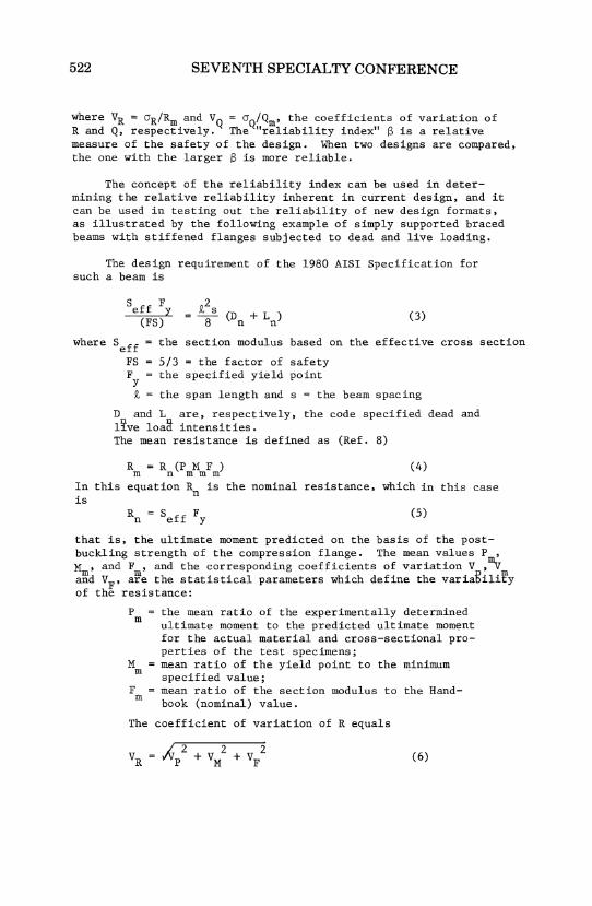
where VR = 0R/Rm and VQ = 0Q/Qm' the coefficients of variation of Rand Q, respectively. The "reliability index" B is a relative measure of the safety of the design. When two designs are compared, the one with the larger B is more reliable.
The concept of the reliability index can be used in determining the relative reliability inherent in current design, and it can be used in testing out the reliability of new design formats, as illustrated by the following example of simply supported braced beams with stiffened flanges subjected to dead and live loading.
The design requirement of the 1980 AISI Specification for such a beam is
where
S ff F 2 e y ~ (D + Ln) (3) (FS) 8 n
S eff
the section modulus based on the effective cross section
FS 5/3 = the factor of safety F the specified yield point y
Q, the span length and s = the beam spacing
D and L are, respectively, the code specified dead and l~ve loa~ intensities. The mean resistance is defined as (Ref. 8)
(4)
In this equation Rn is the nominal resistance, which in this case is
(5)
that is, the ultimate moment predicted on the basis of the postbuckling strength of the compression flange. The mean values P , M , and F , and the corresponding coefficients of variation V ,mv a~d VF , a~e the statistical parameters which define the variaRilify of the resistance:
P m
M m
F m
the mean ratio of the experimentally determined ultimate moment to the predicted ultimate moment for the actual material and cross-sectional properties of the test specimens; mean ratio of the yield point to the minimum specified value; mean ratio of the section modulus to the Handbook (nominal) value.
The coefficient of variation of R equals
(6)

LOAD AND RESISTANCE FACTOR DESIGN
The values of these data were obtained from examining all available tests on beams with stiffened compression flanges, and from analyzing data on yield point values from tests and crosssectional dimensions from many measurements. This information is developed in Refs. 12 and 13, and it is given below:
Pm = 1.08, Vp = 0.10; Mm = 1.10, VM = 0.10; Fm = 1.0, VF = 0.05 and thus Rm = 1.19 Rn and VR = 0.15.
and
The mean load effect is equal to
v = Q
~(Dm VD)2 + (Lm VL)2
D + L m m
(7)
(8)
where Dm and Lm are the mean dead and live load intensities, respectively, and VD and VL are the corresponding coefficients of variation.
Load statistics have been analyzed in Ref. 9, where it was shown that
Dm = 1.05 Dn , VD = 0.1; Lm = Ln , VL = 0.25.
The mean live load intensity equals the code live load intensity if the tributary area is small enough so that no live load reduction is included. Substitution of the load statistics into Eqs. 7 and 8 gives
t 2s (1.05 D 1) Qm =-8- n+ L L n n
(9)
_IC·~:Dn)2 VD2 + V 2 VQ
L
C.05 D ) n + 1 L n
(10)
Q and V thus depend on the dead-to-live load ratio. Cold-formed b~ams tY~ically have small Dn/Ln, and for the purposes of checking the reliability of these LRFD criteria it will be assumed that Dn/Ln
1/3, and so Qm = 1.35Ln (t2 s/8) and VQ = 0.19.
From Eq. 3 we obtain the nominal design capacity for D /L 1/3 and FS = 5/3. Thus n n
R m
Qm = 1.19 x 2.22 x L (t2
n
1. 35L (t2 s/8) n
s/8) 1.96
523
524 SEVENTH SPECIALTY CONFERENCE
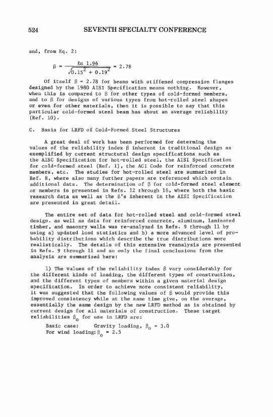
and, from Eq. 2:
8 £n 1.96 = 2.78 /0.152 + 0.192
Of itself S = 2.78 for beams with stiffened compression flanges designed by the 1980 AISI Specification means nothing. However, when this is compared to 8 for other types of cold-formed members, and to 8 for designs of various types from hot-rolled steel shapes or even for other materials, then it is possible to say that this particular cold-formed steel beam has about an average reliability (Ref. 10).
C. Basis for LRFD of Cold-Formed Steel Structures
A great deal of work has been performed for determing the values of the reliability index 8 inherent in traditional design as exemplified by current structural design specifications such as the AISC Specification for hot-rolled steel, the AISI Specification for cold-formed steel (Ref. 1), the ACI Code for reinforced concrete members, etc. The studies for hot-rolled steel are summarized in Ref. 8, where also many further papers are referenced which contain additional data. The determination of 8 for cold-formed steel element, or members is presented in Refs. 12 through 16, where both the basic research data as well as the 8' s inherent in the AISI Spe'cification are presented in great detail.
The entire set of data for hot-rolled steel and cold-formed steel design. as well as data for reinforced concrete, aluminum, laminated timber, and masonry walls was re-analyzed in Refs. 9 through 11 by using a) updated load statistics and b) a more advanced level of probability distributions which describe the true distributions more realistically. The details of this extensive reanalysis are presented in Refs. 9 through 11 and so only the final conclusions from the analysis are summa.r ized here:
1) The values of the reliability index 8 vary considerably for the different kinds of loading, the different types of construction, and the different types of members within a given material design specification. In order to achieve more consistent relia.bility, it was suggested that the folloWing values of S would provide this improved consistency while at the same time give, on the average, essentially the same design by the new LRFD method as is obtained by current design for all materials of construction. These target reliabilities So for use in LRFD are:
Basic case: Gravity loading, 80 = 3.0 For wind loading: 80 = 2.5

LOAD AND RESISTANCE FACTOR DESIGN
2) The following load factors and load combinations were developed in Refs. 9 and 11 to give essentially the same S's as the target S 's, and are recommended for use with the 1980 ANSI Load Code (Rgf. 17) for all materials, including cold-formed steel:
where
1.4Dn 1.2Dn + 1.6 (Ln or Sn) 1.2Dn + 0.5 (Ln or Sn) + 1.3Wn 1.2Dn + 0.5 (Ln or Sn) + 1.5En 1.2Dn + 0.5Ln + 1.6Sn 1.2Dn + 1.6Sn + 0.8Wn 0.9Dn - 1.3Wn 0.9Dn - 1.5En 1. 2Dn + 1.2Pn
Dn nominal dead load Ln nominal live load due to occupancy Sn nominal snow load WtJ. nominal wind load En nominal earthquake load Pn nominal ponding load, including the
to ponded liquid. increase due
Deflection calculations for serviceability criteria are to be made with the appropriate unfactored loads.
The load factors and load combinations given above have been recommended for use with the LRFD criteria for cold-formed steel. The following portions of this paper present the background for the resistance factors ¢ listed in Table 1, and which are recommended for use in the AISI LRFD Specification. These ¢ factors were determined in conformance with the load factors given above to approximately provide a target S of 3.0 for members and 4.0 for connections, respectively, for ~he load combination 1.2Dn + 1.6Ln . For practical reasons it is desirable to have relatively few different resistence factors, and so the actual values of S will differ from the derived targets. This means that
¢Rn = c(1.2Dn + 1.6Ln) = (1.2Dn/Ln + 1.6) cLn (11)
where c is the deterministic influence coefficient translating load intensities to load effects.
By assuming Dn/Ln = 113, Eqs. 11 and 9 can be rewritten as follows:
Rn 2.00(cLn /¢) (12)
Qm Therefore,
1. 350cLn (13)
(14)
525

526
(a)
(b)
(c)
(d)
(e)
SEVENTH SPECIALTY CONFERENCE
TABLE 1
Resistance Factors
(Section 8.3.5 of the Proposed Tentative Recommendations)
Type of Strength
Tension members
Flexural members
Section strength Laterally unbraced beams
Web design
Shear strength* Flexural strength Web crippling
Axially loaded compression
Beam - columns
¢c
¢s
¢
Cylindrical tubular
Flexural strength Axial compression
members
Resistance Factor, ¢
members
0.90
0.90 0.90
0.90 0.90 0.80
0.80
0.80
0.90
0.90
0.90 0.80
*When h/t < 1.0
The ¢ factors can be computed from Eq. 14 and the following equation by using VQ = 0.19:
tn(Rm/~) Target So = (15)
h 2 + V 2 R Q
In the above calculation, the values of (Rm/Qm) and VR can be obtained from Refs. 12 through 16.

LOAD AND RESISTANCE FACTOR DESIGN
The resistance factors ¢ can also be determined for the desired S and the resistance statistics ~/Rn and VR from charts provided ~n Ref. 9. For example, for the cold-formed beams with stiffened compression flanges, for which Rm/Rn = 1.19 and VR = 0.15, for a D/L ratio of 1/3 and So = 3.0, ¢ = 0.86 f~om the charts in Ref. 9.
III. DESIGN OF MEMBERS
A. Yield Point
The following statistical data (mean values and coefficients of variation) on material and cross-sectional properties were developed in Refs. 12 and 13 for use in the derivation of the resistance factors ¢:
(Fy)m = 1.10 Fy; Mm = 1.10; VFy = VM = 0.10
(Fya)m= 1.10 Fya; Mm = 1.10; VFya = VM = 0.11
(Fu)m = 1.10 Fu; Mm= 1.10; VFu = VM = 0.08
Fm = 1.00; VF = 0.05
The subscript m refers to mean values. The symbol V stands for coefficient of variation. The symbols M and F are, respectively, the ratio of the mean-to-the nominal material property or crosssectional property; and Fy ' Fya ' and Fu are, respectively, the specified minimum yield point, the average yield point including the effect of cold forming, and the specified minimum tensile strength.
These data are based on the analysis of many samples, and they are representative properties of materials and cross sections used in the industrial application of cold-formed steel structures.
B. Tension Members
The resistance factor of ¢ = 0.90 used for tension member design was derived from the procedure described in Section II.A of this paper and a selected S value of approximately 3.0. In the determination of the resistgnce factor, the following formulas were used for Rm and Rn:
R m
R n
A (F ) n y m
A F n y
(16)
(17)
(18)
in which A is the net area of the cross section, (F) is equal to 1.10 Fy asndiscussed in Section III.A of the paper. YB~ using VM = 0.10, VF = 0.05 and Vp = 0, the coefficient of variation VR is:
527

528 SEVENTH SPECIALTY CONFERENCE
(19)
Based on Vs = 0.19, the resistance factor is approximately 0.85 for S = 3. , which is rounded off to ¢ = 0.90, glvlng S = 2.7 which is about the same reliability as that of beams.
C. Flexural Members
Flexural members are differentiated according to whether or not the member is laterally braced. If such members are laterally supported, then they are proportioned according to the strength of the cross section. If they are laterally unbraced, then the limit state is lateral-torsional buckling. Cross section strength depends on whether or not the compression flange is composed of stiffened or unstiffened elements.
i) Section Strength
a) Flexural Members with Stiffened Compression Flange
The strength of beams with a compression flange having stiffened elements is based on the post-buckling strength of the member, and use is made in LRFD of the effective width concept in the same way as in the 1980 AISI Specification (Ref. 1). References 6 and 7 provide an extensive treatment of the background research.
The experimental basis for the post-buckling strength of coldformed beams is examined in Ref. 12, where Table 3 gives the calculation of the predicted strength according to Winter's effective width formulas. A total of 43 tests were examined, and the statistics are summarized as follows:
Pm = 1.08, Vp = 0.10
The symbol P is the ratio of the experimental strength to the strength predicted by the effective width theory for the material and crosssectional properties of the test specimens. The mean and coefficient of variation of the resistance are equal to:
and
R m
1.08 x 1.10 x 1.0 R n
1.19 R n
va = !Gp 2 + vM2 + VF2 = ~0.102 + 0.112 + 0.052 = 0.16
The nominal strength Ru is based on the nominal effective cross section and on the specified minimum yield point, i.e., Rn = SeffFy.
The value of S, as determined from the charts in Ref. 9 for the selected value of ¢ = 0.9 for a dead-to-live load ratio of 1/3 is approximately 2.73.

LOAD AND RESISTANCE FACTOR DESIGN 529
b) Flexural Members with Unstiffened Compression Flanges
The basis for the prediction of the strength of beams with unstiffened compression flanges in these LRFD criteria and in the 1980 AISI Specification is the plate buckling theory. The data of the tests are given in Table 3 of Ref. 13, and they are summarized as follow:
for 63.3/~ < wit < 25; Pm = 1.24; Vp = 0.13 (for 24 tests) for 25 < wit < 60; Pm = 1.76, Vp = 0.21 (for 26 tests)
where wit is the width/thickness ratio of the unstiffened flange element. If all 50 tests are averaged, Pm = 1.51 and Vp = 0.26. It is evident from these data that the theory underestimates the capacity considerably. This has long been noted, and a generalized effective-width theory, including both stiffened and unstiffened compression flanges, has been proposed (Ref. 18). The same 50 test results with this improved theory give Pm = 1.04 and Vp = 0.14. Since the intent of these LRFD criteria is to provide only a translation from the 1980 Allowable Stress Design criteria (Ref. 1) into a LRFD format, no change in the basic treatment of the underlying theory was made. The ¢-factor is derived as follows:
for 63.3/~ < wit < 25:
Rm/Rn = Pm Mm Fm = 1.24 x 1.10 x 1.0 1.36
VR = tGp 2 + VM2 + VF2 = vO~132 + 0.102 + 0.052 0.17
for 25 <,wit < 60:
Rm/Rn = 1.76 x 1.0 x 1.0 = 1.76
VR = ;6.212 + 0.062 + 0.052 = 0.22
In the latter case the limit state is elastic buckling. M = 1.0 and Vm = 0.06 have been used to account for the basic materiaT variable, the elastic modulus, E.
The ranges of Rm/Rn and VR in both instances are beyond the charts provided in Ref. 9. The procedure will thus be to select a value of ¢ and then to determine the resulting reliability index using Eq. 2. For a dead-to-live load ratio of Dn/Ln = 1/3, the load effect data is Qm = (1.05 Dn/Ln + 1) cLn = 1.35 cLn and VQ = 0.19. According to the LRFD load factors
¢ Rn = c (1.2Dn + 1.6Ln) = cLn (1.2Dn/Ln + 1.6) = 2.0 cLn
or 2.0cLn Rn = -¢--
530 SEVENTH SPECIALTY CONFERENCE
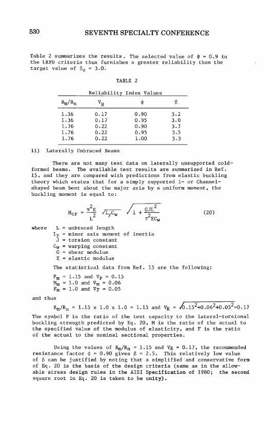
Table 2 summarizes the results. The selected value of $ = 0.9 in the LRFD criteria thus furnishes a greater reliability than the target value of 60 = 3.0.
TABLE 2
Reliability Index Values
Rm/Rn VR ¢ 6
1.36 0.17 0.90 3.2 1.36 0.17 0.95 3.0 1. 76 0.22 0.90 3.7 1. 76 0.22 0.95 3.5 1. 76 0.22 1.00 3.3
ii) Laterally Unbraced Beams
There are not many test data on laterally unsupported coldformed beams. The available test results are summarized in Ref. 15, and they are compared with predictions from elastic buckling theory which states that for a simply supported 1- or Channelshaped beam bent about the major axis by a uniform moment, the buckling moment is equal to:
where L = unbraced length
GJL2 +--
2 1f ECw
Iy = minor axis moment of inertia J = torsion constant
Cw = warping constant G = shear modulus E = elastic modulus
(20)
The statistical data from Ref. 15 are the following:
Pm = 1.15 and Vp = 0.15 MID = 1.0 and Vm 0.06 Fm = 1.0 and VF = 0.05
and thus
Rm/~ = 1.15 x 1.0 x 1.0 = 1.15 and VR = 10.152+0.062+0.05 2=0.17
The symbol P is the ratio of the test capacity to the lateral-torsional buckling strength predicted by Eq. 20, M is the ratio of the actual to the specified value of the modulus of elasticity, and F is the ratio of the actual to the nominal sectional properties.
Using the values of Rm/Rn = 1.15 and VR = 0.17, the recommended resistance factor ¢ = 0.90 gives 6 = 2.5. This relatively low value of 6 can be justified by noting that a simplified:and conservative form of Eq. 20 is the basis of the design criteria (same as in the allowable stress design rules in the AISI Specification of 1980; the second square root in Eq. 20 is taken to be unity).

LOAD AND RESISTANCE FACTOR DESIGN
iii) Web Strength
For the design of beam webs, consideration should be given to the shear strength, bending strength, combined bending and shear, and web crippling.
a) Shear Strength of Beam Webs
The shear strength of beam webs is governed by either yielding .or buckling, depending on the hIt ratio and the mechanical properties of steel. For beam webs having small. hIt ratios, the shear strength is governed by shear yielding, i.e.: '
(21)
in which Aw is the area of the beam web computed by (hxt), and Ty is the yield point of steel in shear.
For beam webs having large hIt ratios, the shear strength is governed by elastic shear buckling, i.e.:
k 'IT2EA Vu = AwTcr = v w
12 (l-i) (h}t) 2 (22)
531
in which Tcr is the critical shear buckling stress in the elastic range, k is the shear buckling coefficient, E is the modulus of elasticity, ~vis the Poisson's ratio, h is the web depth, and t is the web thickness. By using E = 29,500 ksi and ~ = 0.3, the shear strength, Vu , can be determined as follows:
v u
26,700 kv Aw
(hIt) 2 (23)
For beam webs having moderate hIt ratios, the shear str~ngth is based on inelastic buckling, i.e.:
(24)
In the above equation, the maximum shear stress is based on the allowable shear stress specified in Section 3.4.1 of the AISI Specification and a safety factor of 5/3.
In view of the fact that the appropriate test data on shear are not available, the ~ factors were derived from the condition that the nominal resistance for the· LRFD method is the same as the nominal resistance for the allowable stress design method. Thus,
~Rn)LRFD = (Rn)ASD (25)

532 SEVENTH SPECIALTY CONFERENCE
Since (Rn)LRFD ~ c(1.2Dn+l.6Ln)/¢
(Rn)ASD ~ c(F.S.) (Dn+Ln)
(26)
(27)
the resistance factors can be computed from the following formula:
1.2(D /L ) + 1.6
¢ = (F.S.~(Dn/L + 1) n n
(28)
By using a dead-to-live load ratio of D IL = 1/3, the ¢ factors computed from the above equation are li~tea in Table 3 for three different ranges of hit ratios. The factors of safety are adopted from the AISI Specification for allowable stress design. It should be noted that the use of a small safety factor of 1.44 for yielding in shear is justified by long-standing use and by the minor consequences of incipient yielding in shear compared with those associated with yielding in tension and compression.
TABLE 3
Resistance Factors for S~ Strength of Beam Webs
F. S. for ¢ Factor Recommended Range of hit Ratio Allowable Stress Computed ¢ Factor
Design by Eq. 28
h/t< l71/k7F 1.44 - v Y
1.04 1.00
l7l/k7F ~ h/t< 243~ v y- - v Y 1.67 0.90 0.90
hit > 243/k7F 1.71 0.88 0.90 v y
b) Flexural Strength of Beams Governed by Webs
The flexural strength of beams is governed by either yielding or buckling of beam webs.
The bending strength of beams governed by webs was studied in Refs. 16 and 19 by comparing the experimental data and the predicted results. Based on a study made on beams having stiffened and unstiffened flanges, the statistical data are as follows (Table III of Ref. 19) :
(a)
(b)
Beams having Pm = 1.00; Mm = 1.10; Fm = 1.00; Rm/Rn = 1.10;
Beams having Pm 0.99; Mm = 1.10; Fm = 1.00; lim/Rn = 1.09;
stiffened flanges Vp 0.08 Vm 0.10 VR 0.05 V){ 0.14
unstiffened flanges Vp 0.09 VM 0.10 VF 0.05 VR 0.14
LOAD AND RESISTANCE FACTOR DESIGN
For ¢ = 0.90, the computed S's are 2.52 and 2.48 for beams having stiffened flanges and beams having unstiffened flanges, respectively.
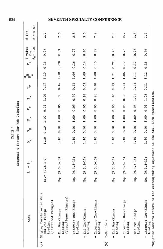
On the basis of the statistical analysis of the available test data on web crippling, the values of Pm,Mm,Fm,Vp ' VM, and VF were computed and selected. These values are presented in Table 4 (See Table III of Ref. 19). By using So = 3.0 and the computed values of VR for different conditons, the resistance factors, ¢, were calculated by using Eq. 11 for various conditions as listed in Table 4. For the purpose of simplicity, the value of ¢ = 0.80 is used. The values of S corresponding to this value of ¢ are also given in Table 4.
D. Axially Loaded Compression Members
The available experimental data on cold~formed steel axially loaded compression members were evaluated in Ref. 14, The test results were compared to the predictions based on the same mathematical models on which the AISI Specification (Ref. 1) was based. The design provisions in these LRFD criteria are also based on the same mathematical models.
a) Cross-Sectional Strength
Axially loaded columns are designed against overall instability and local instability. This latter effect is included through the
5::33
use of the Q-factor in the column equations where this is appropriate. For columns the resistance factor ¢ thus includes both types of instability. Beam-columns are designed both against an overall stability limit state and against a member strength limit state separately. Therefore it is necessary to derive a value of ¢ for member strength to be used in beam-column design. The basis for the determination of ¢ for the limit state of member strength is the capacity of a compressed short member. Stub column strength is predicted from the effective-width concept for members with stiffened elements, and the theory of plate buckling is used for the prediction of the capacity of members with unstiffened elements. This latter theory is overly conservative, and a generalized effective-width formula has been developed for use with both stiffened and unstiffened elements (Ref. 18). However, the new recommendations have not yet been incorporated into the AISI Specification as of this date (1984), and so the buckling limit state is retained here for unstiffened elements. It should be noted that the statistical evaluation of the test results in Refs. 12, 13, and 14 also includes the comparisons with the generalized effective-width approach. Thus the necessary information to develop new ¢-factors when the specification is changed is already developed.
Stiffened Elements
Stub-column strength was analyzed in Ref. 12 by comparing the experimental strength to the prediction from the effective-width (post-buckling strength) theory. A total of 44 tests were reported,
Cas
e
(a)
Sin
gle
, U
nre
info
rced
Web
s -
End
On
e-F
lan
ge
Lo
adin
g
(Sti
ffen
ed
Fla
ng
es)
-E
nd
On
e-F
lan
ge
Lo
adin
g
(Un
stif
fen
ed
Fla
ng
es)
-In
teri
or
On
e-F
lan
ge
Lo
adin
g
-E
nd
Tw
o-F
lan
ge
Lo
adin
g
-In
teri
or
Tw
o-F
lan
ge
Lo
adin
g
(b)
I-S
ecti
on
s
-E
nd O
ne-
Fla
ng
e L
oad
ing
Inte
rio
r O
ne-
Fla
ng
e L
oad
ing
-E
nd T
wo
-Fla
ng
e L
oad
ing
TAB
LE
4
Com
pute
d ~-Factors
for
Web
C
rip
pli
ng
R
P n
u
Eq
.*
(9.3
.3-9
)
Eq
. (9
.3.3
-10
)
Eq
. (9
.3.3
-11
)
Eq
. (9
.3.3
-12
)
Eq
. (9
.3.3
-13
)
Eq
. (9
.3.3
-14
)
Eq
. (9
.3.3
-15
)
Eq
. (9
.3.3
-16
)
R
cp v
alu
e
M
V M
F V F
P
Vp
m
V R
m
m
m
R
fo
r n
130
'"
3.0
1.1
0
0.1
0
1.0
0
0.0
5
1.0
0
0.1
2
1.1
0
0.1
6
0.7
7
1.1
0
0.1
0
1.0
0
0.0
5
1.0
0
0.1
6
1.1
0
0.2
0
-0.7
1
1.1
0
0.1
0
1.0
0
0.0
5
0.9
9
0.1
1
1.0
9
0.1
6
0.7
7
1.1
0
0.1
0
1.0
0
0.0
5
0.9
9
0.0
9
1.0
9
0.1
4
0.8
0
1.1
0
0.1
0
1.0
0
0.0
5
0.9
8
0.1
0
1.0
8
0.1
5
0.7
9
1.1
0
0.1
0
1.0
0
0.0
5
1.1
0
0.1
9
1.2
1
0.2
2
0.7
5
1.1
0
0.1
0
1.0
0
0.0
5
0.9
6
0.1
3
1.0
6
0.1
7
0.7
3
1.1
0
0.1
0
1.0
0
0.0
5
1.0
1
0.1
3
1.1
1
0.1
7
0.7
7
13 fo
r
cp =
0.8
0
2.9
2.6
2.8
3.0
2.9
2.8
2.7
2.8
-In
teri
or
Tw
o-F
lan
ge
Eq
. (9
.3.3
-17
) 1
.10
0
.10
1
.00
0
.05
1
.02
0
.11
1
.12
0
.16
0
.79
2
.9
Lo
adin
g
*E
qu
.ati
on
Num
bers
re
fers
to
th
e co
rresp
on
din
g e
qu
ati
on
s in
th
e A
ISI
LRFD
S
pecif
icati
on
.
01
CI
:I """ ~ ~ ~ 00 ~ o :; ~ .....
::I o o ~ ~ Z o t.%J

LOAD AND RESISTANCE FACTOR DESIGN
and the statistical data are Pm = 1.10; ~ = 1.10; Fm = 1.0; Rm/Rn = 1. 21 ;
as follows Vp 0.10 VF = 0.10 VF = 0.05 VR = 0.15
(Table 4 in Ref. 12):
The reliability index S. as determined from the charts in Ref. 9 for a Dn/Ln of 1/3 is 2.9 for the selected value of ~s = 0.9.
Unstiffened Elements
The strength of stub-columns with unstiffened elements was analyzed in Ref. 13 according to the plate buckling theory. and the statistical data from Table 4 in Ref. 13 are as follows:
a) width-thickness ratios < 25
Number of data: Pm 1.08; Mm = 1.10**; Fm = 1.0; R;;/Rn = 1.19;
22* Vp = 0.11 VM 0.10 VF 0.05 VR 0.16
For the recommended ~s 0.9 the reliability index is S 2.7 when Dn/Ln = 1/3 (Ref. 9).
b) width-thickness ratios > 25
Number of data: Pm = 1.69; ~ = 1.00**; Fm = 1.0; Rro/Rn = 1.69;
0.18 0.06 0.05 0.20
For the recommended ~s 0.9. the reliability index S = 3.7 when D /L = 1/3. This is considerably above the target of So 3 and a vR1u~ of ~s = 1.0 could have been justified. However. ~s = 0.9 is recommended for the sake of consistency.
Column Strength
535
Column capacity in these LRFD criteria is based on the same prediction models as were employed in the formulation of the AISI Specification: elastic buckling theory for the case of slender columns. and the
* Last test from Table 4b in Ref. 13 is included in the data for w/t > 25.
** Limit state is inelastic buckling. and so the statistics of the yield stress are used here.
*** This includes the last test point from Table 4b and all data from Table 4c of Ref. 13. except that the last two tests were omitted. These stub columns had w/t of about 60 and their inclusion would have biased the results unduly.
536 SEVENTH SPECIALTY CONFERENCE
tangent modulus theory for columns of intermediate and short length. Two types of limit states are considered: flexural buckling in the plane perpendicular to the minor principal axis (FB) and torsionalflexural buckling (TFB). In the latter case it is required that the cross section is compact. i.e •• Q = 1.0. while in the case of FB the cross-sectional strength of noncompact shapes is accommodated through the use of Q < 1.0. same as in the 1980 AISI Specification.
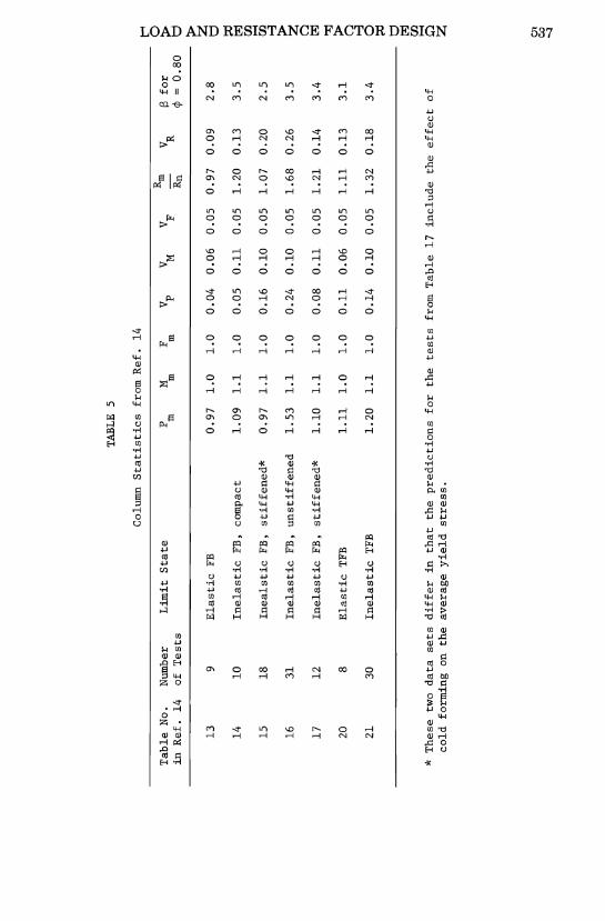
The resistance factor ~ = 0.80 was selected on the basis of the statistical data given ia Ref. 7. The summary of the information is given in Table 5.
The reliability index S was determined from the charts in Ref. 9 for a DnlRn ratio of 1/3. The target of So = 3.0 is not entirely satisfied. and different ~-factors could have been used for the different cases.
E. Beam-Columns
With the exception of one set of beam-column tests (see Ref. 15) for hat shapes for which the limit state was torsional-flexural buckling. there are no tests of cold-formed s,teel beam-columns. The LRFD design criteria provides the same interaction equa'tions as the 1980 Edition of the AISI Specification (Ref. 1). with ~c = 0.80 (i.e •• as recommended for columns) when the limit state is overall member instability. and ~s = 0.90 (i.e •• as recommended for laterally braced beams) when the limit state is section strength. In the calculation of the factored nominal beam strength. ~u. the ~-factor is taken as 0.90 when the limit state is section strength and for laterally unbraced members. the ~-factor is also 0.90.
IV. SUMMARY
The tentative recommendations for load and resistance factor design of cold-formed steel have been developed. This paper presents a discussion of the reasoning behind. and the justification for. various provisions being proposed for designing various types of cold-formed steel structural members. Additional publications are mentioned in the discussion for future reference.
V. ACKNOWLEDGMENTS
This project was sponsored by the American Iron and Steel Institu~e The technical guidance provided by the A~SI Task Group on Lo~d and.Res1s tance Factor Design under the chairmansh1p of Mr. Karl H. K11ppste1n and the AISI Staff. Dr. Albert L. Johnson. is gratefully acknowledged. Thanks are also expressed to, Drs. M. K. Ravindra. T. N. Rang. and B. Supornsilaphachai for their contributions to the development of load and resistance factor design criteria.
TABL
E 5
Col
umn
Sta
tisti
cs f
rom
Ref
. 14
Tab
le N
o.
P F
V M
VF
Rm
i3 fo
r N
umbe
r L
imit
Sta
te
M
Vp
V R
in R
ef.
14
of
Test
s m
m
m
R
n cp
= O
.SO
13
9 E
last
ic F
B 0
.97
1
.0
1.0
0
.04
0
.06
0
.05
0
.97
0
.09
2
.S
14
10
Inela
stic
FB
, co
mpa
ct
1.0
9
1.1
1
.0
0.0
5
0.1
1
0.0
5
1.2
0
0.1
3
3.5
15
lS
Ineals
tic F
B,
stif
fen
ed
*
0.9
7
1.1
1
.0
0.1
6
0.1
0
0.0
5
1.0
7
0.2
0
2.5
16
31
Inela
stic
FB
, u
nst
iffe
ned
1
.53
1
.1
1.0
0
.24
0
.10
0
.05
1
.6S
0
.26
3
.5
17
12
Inela
stic
FB
, st
iffe
ned
*
1.1
0
1.1
1
.0
O.O
S 0
.11
0
.05
1
.21
0
.14
3
.4
20
S E
last
ic T
FB
loll
1
.0
1.0
0
.11
0
.06
0
.05
lo
ll
0.1
3
3.1
21
30
Inela
stic
TFB
1
.20
1
.1
1.0
0
.14
0
.10
0
.05
1
.32
O
.lS
3
.4
* T
hes
e tw
o d
ata
se
ts d
iffe
r in
th
at
the
pre
dic
tio
ns
for
the
tests
fr
om T
able
17
incl
ud
e th
e eff
ect
of
cold
fo
rmin
g
on
the
aver
age
yie
ld s
tress
.
t""
0 >
t:l >
Z
t:l ~ r:n
.....
r:n
>-3 ~ 0 t:I
:j "".:l >
0 >-3
0 ;:d
t:l
t:I:j r:n
.....
0 Z
en
c,;,
"'I

538 SEVENTH SPECIALTY CONFERENCE
APPENDIX I - REFERENCES
1. American Iron and Steel Insitute, "Specification for the Design of Cold-Formed Steel Structural Members", 1980 Edition.
2. Canadian Standards Association, "Cold Formed Steel Structural Members", CSA Standard S136-l974.
3. American Institute of Steel Construction, "Proposed Load & Resistance Factor Design Specification for Structural Steel Buildings", September 1, 1983.
4. European Convention for Constructional Steelwork, "European Recommendations for the Design of Profiled Sheeting", ECCSTC7-l983, CONSTRADO, London, April 1983.
5. Galambos, T. V., and Yu, W. W., "Revised Tentative Recommendations -Load and Resistance Factor Design Criteria for Cold-Formed Steel Structural Members With Commentary", Seventh Progress Report, University of Missouri-Rolla, September 1983.
6. Winter, G., "Commentary on the 1968 Edition of the Specification for the Design of Cold-Formed Steel Structural Members", published by American Iron and Steel Institute, 1970.
7. American Iron and Steel Institute, "Commentary on the September 3, 1980 Edition of the Specification for the Design of ColdFormed Steel Structural Members", Cold-Formed Steel Design Manual Part II, 1983.
8. Ravindra, M. K., and Galambos, T. V., "Load and Resistance Factor Design for Steel", Journal of the Structural Division, ASCE, Vol. 104, No. ST9, September 1978.
9. Ellingwood, B., Galambos, T. V., MacGregor, J.G., and Cornell, C. A., "Development of a Probability Based Load Criterion for American National Standard A58: Building Code Requirements for Minimum Design Loads in Buildings and Other Structures", NBS Special Publication 577, June 1980.
10. Galambos, T. V., Ellingwood, B., MacGregor, J. G., and Cornell, C. A., "Probability Based Load Criteria: Assessment of Current Design Practice", Journal of the Structural Division, ASCE, Vol. 108, No. STS, May 1982.
11. Ellingwood, B., MacGregor, J. G., Galambos, T. V., and Cornell, C. A., "Probability Based Load Criteria: Load Factors and Load Combinations", Journal of the Structural Divisibn, ASCE, Vol. 108, No. ST5, May 1982.
LOAD AND RESISTANCE FACTOR DESIGN
12. Rang, T. N., Galambos, T. V., and Yu, W. W., "Study of Design Formats and Safety Index Combined with Calibration of the AISI Formulas for Cold Work and Effective Design Width", First Progress Report, University of Missouri-Rolla, January 1979.
13. Rang, T. N., Galambos, T. V., and Yu, W. W., "Statistical Analysis of Mechanical Properties and Thickness of Materials Combined with Calibrations of the AISI Design Provisions on Unstiffened Elements and Connections", Second Progress Report, University of Missouri-Rolla, January 1979.
14. Rang, T. N., Galambos, T. V., and Yu, W. W., "Calibration of the Design Provisions on Connections and Axially Loaded Compression Members", Third Progress Report, University of Missouri-Rolla, January 1979.
15. Rang, T. N., Galambos, T. V., and Yu, W. W., "Calibration of the Design Provisions on Laterally Unbraced Beams and Beam-Columns", Fourth Progress Report, University of Missouri-Rolla, January 1979.
16. Supornsilaphachai, B., Galambos, T. V., and Yu, W. W., "Calibration of the Design Provisions on Beam Webs", Fifth Progress Report, University of Missouri-Rolla, September 1979.
17. American National Standards Institute, "Building Code Requirements for Minimum Design Loads in Buildings and Other Structures", ANSI A58.l-l980.
18. Kalyaranaman, V., Pekoz, T., and Winter, G., "Unstiffened Compression Elements", Journal of the Structural Division, ASCE, Vol. 103, No. ST9, September 1977.
19. Supornsilaphachai, B., "Load and Resistance Factor Design of ColdFormed Steel Structural Members", Ph.D. Thesis, University of Missouri-Rolla, 1980.
539

540 SEVENTH SPECIALTY CONFERENCE
APPENDIX II - NOTATION
The following symbols are used in this paper:
Pn Pu Q Qm R
Rm Rn Seff Sn s t V
cross-sectional area net area area of beam web deterministic influence coefficient translating load intensities to load effect warping constant mean dead load nominal dead load
= modulus of elasticity = nominal earthquake load = buckling stress = mean ratio of the actual section modulus to the nominal value
specified minimum tensile strength specific yield point average yield point shear modulus clear distance between flanges measured along the plane of the web
= moment of inertia about y-axis torsional constant
= shear buckling coefficient = unbraced length = mean live load
nominal live load span length mean ratio of the yield point to the minimum specified value nominal ultimate bending moment
= mean ratio of the experimentally determined ultimate moment to the predicted ultimate moment of test specimens
= nominal ponding load = nominal ultimate concentrated load
load effect mean load effect resistance mean value of resistance nominal resistance section modulus based on the effective cross section nominal snow load beam spacing thickness coefficient of variation
Vu shear strength Wn nominal wind load w flat width of compression element S reliability index 80 target reliability index

LOAD AND RESISTANCE FACTOR DESIGN 541
y = load factor ~ = resistance factor ~ = Poisson's ratio o = standard deviation Ty = yield point in shear