LindabGeneral information and theory
34
Lindab General information and theory lindab | for a better climate
-
Upload
khangminh22 -
Category
Documents
-
view
3 -
download
0
Transcript of LindabGeneral information and theory

LindabGeneral information and theory
l indab | for a better climate

2
l indab | general information and theory
We reserve the right to make changes without prior notice
2022.06.09

3
l indab | general information and theory
We reserve the right to make changes without prior notice
2022.06.09
At Lindab we are driven by a strong desire to continuously
generate improvements and to simplify construction. We
do that by developing products and systems that are easy
to use and energy efficient, together with industry-leading
knowledge, support, logistics and efficient availability.
We want to simplify everything – from designing, ordering,
delivery, goal achievement and installation to the entire
way of doing business with us. By simplifying in every
stage of the construction process, we also contribute to
energy-efficiency.
A good thinking company
Good thinking is a deeply rooted philosophy that guides
us in everything we do. We firmly believe that good think-
ing makes good solutions to the challenges we all face.
Taking responsibility for what we do and how we do things
is therefore important to us. Because good thinking is not
only about making life easier and more comfortable for our
customers and end users. It is also a matter of thinking in a
global perspective, all the time. Knowing that we at Lindab
are helping to make the world a better place.
We simplify construction
lindQST – Lindab Quick Selection ToollindQST is an advanced web tool that makes the selection
of our solutions quick and simple.
With lindQST all documentation is made available directly
on the web. That means consultants, installers and archi-
tects always have access to the latest documentation,
installation instructions and product images etc. lindQST
is a unique online tool were you can simulate your room in
the Indoor Climate Designer, keep track of your projects
Eurovent certificationLindab's circular duct system with rubber gasket con-
nections Lindab Safe and Lindab Safe Click is certified
to strength and leakage in tightness class D according to
the Eurovent Certified Performance program for circular
metallic ducts systems (DUCT-MC). Check ongoing validity
of certificate:
www.eurovent-certification.com
DUCT-MCIdentification number 17.11.002
The purpose of Eurovent third party Certification is to
create a common set of criteria to all relevant features for
the rating of products in this system and ensure the
constancy of performance over time.
Through specification of products in Lindab's certi-
fied system, Lindab Safe and Lindab Safe Click, the
engineer's tasks become easier, since there is no need to
carry out detailed comparison and performance qualifica-
tion testing. Consultants, specifiers and users can select
products with the assurance that the catalogue data are
accurate to a certain level.
Lindab products that are Eurovent certified have the
Eurovent logotype in the footer of the technical documen-
tation.
Note: Most Lindab Safe and Lindab Safe Click and the
most commonly used product in a ventilation system are
essentially better than class D, however some products
are according to EN 15727 not class D as a single product.
These products are stated in the documentation as Class
C and can be used in D class systems to a limited exten-
sion.
and share it with your business partners etc. lindQST pro-
vides a simple shortcut to Lindab’s material and is a tool
that speeds up and simplifies the daily work. All informa-
tion is just a mouse-click away.
4
l indab | general information and theory
We reserve the right to make changes without prior notice
2022.06.09
Content
Dimensions .....................................................................................................5Designations and examples ......................................................................5
Length .......................................................................................................6
Angle .........................................................................................................6
Fittings.......................................................................................................6
Weight .......................................................................................................6
Sheet metal thickness ...............................................................................6
Ducts .........................................................................................................6
Materials .........................................................................................................7Corrosivity classes according to ISO 12944-2 .........................................7
Sheet metal quality ...................................................................................7
Sheet metal thicknesses ...........................................................................8
Galvanic corrosion ...................................................................................8
Temperature limits for our materials .........................................................9
Resistance of the Safe system to various substances ........................... 10
The SI system ............................................................................................... 15Units ........................................................................................................ 15
Some basic units..................................................................................... 15
Some derived units ................................................................................. 15
For pressure, .......................................................................................... 15
Some additional units ............................................................................. 15
Some multiple prefixes ........................................................................... 15
Conversion factors .................................................................................. 16
Pressure .......................................................................................................20Total pressure = dynamic pressure + static pressure ............................20
Pressure drop .......................................................................................... 21
Pressure drop calculation .......................................................................22
Prerequisites ...........................................................................................23
Designations used ..................................................................................23
Sound ........................................................................................................... 24About silencers ....................................................................................... 24
Method of measurement ......................................................................... 24
Attenuation material and cleaning of the silencers ................................. 24
Ventilation does not have to be noisy! ....................................................25
Choosing silencers .................................................................................32
5
l indab | general information and theory
We reserve the right to make changes without prior notice
2022.06.09
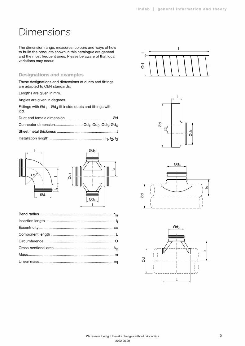
The dimension range, measures, colours and ways of how to build the products shown in this catalogue are general and the most frequent ones. Please be aware of that local variations may occur.
Designations and examplesThese designations and dimensions of ducts and fittings are adapted to CEN standards.
Lengths are given in mm.
Angles are given in degrees.
Fittings with Ød1 – Ød4 fit inside ducts and fittings with Ød.
Duct and female dimension ..............................................Ød
Connector dimension........................... Ød1, Ød2, Ød3, Ød4
Sheet metal thickness ..........................................................t
Installation length .................................................... l, l1, l2, l3
l 3
l
Ød 1
Ød3
Ød4
l
r m ll i
Ød1
Bend radius ........................................................................rm
Insertion length .................................................................... li
Eccentricity ........................................................................cc
Component length ...............................................................L
Circumference ..................................................................... O
Cross-sectional area ..........................................................Ac
Mass ....................................................................................m
Linear mass ........................................................................ml
l
Ød
t
l
ccØ
d
Ød 2
l 3
L
Ød
Ød3
l 3
Ød3
Ød
Dimensions
6
l indab | general information and theory
We reserve the right to make changes without prior notice
2022.06.09
Tolerances
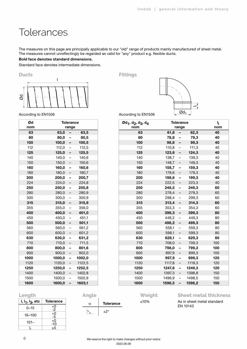
The measures on this page are principally applicable to our "old" range of products mainly manufactured of sheet metal. The measures cannot unreflectingly be regarded as valid for "any" product e.g. flexible ducts.
Bold face denotes standard dimensions. Standard face denotes intermediate dimensions.
Ødnom
Tolerancerange
63 63,0 – 63,580 80,0 – 80,5
100 100,0 – 100,5112 112,0 – 112,5125 125,0 – 125,5140 140,0 – 140,6150 150,0 – 150,6160 160,0 – 160,6180 180,0 – 180,7200 200,0 – 200,7224 224,0 – 224,8250 250,0 – 250,8280 280,0 – 280,9300 300,0 – 300,9315 315,0 – 315,9355 355,0 – 356,0400 400,0 – 401,0450 450,0 – 451,1500 500,0 – 501,1560 560,0 – 561,2600 600,0 – 601,2630 630,0 – 631,2710 710,0 – 711,5800 800,0 – 801,6900 900,0 – 902,0
1000 1000,0 – 1002,01120 1120,0 – 1122,51250 1250,0 – 1252,51400 1400,0 – 1402,81500 1500,0 – 1502,91600 1600,0 – 1603,1
Ød1, d2, d3, d4nom
Tolerancerange
linom
63 61,8 – 62,3 4080 78,8 – 79,3 40
100 98,8 – 99,3 40112 110,8 – 111,3 40125 123,8 – 124,3 40140 138,7 – 139,3 40150 148,7 – 149,3 40160 158,7 – 159,3 40180 178,6 – 179,3 40200 198,6 – 199,3 40224 222,5 – 223,3 40250 248,5 – 249,3 60280 278,4 – 279,3 60300 298,4 – 299,3 60315 313,4 – 314,3 60355 353,3 – 354,3 60400 398,3 – 399,3 80450 448,2 – 449,3 80500 498,2 – 499,3 80560 558,1 – 559,3 80600 598,1 – 599,3 80630 628,1 – 629,3 80710 708,0 – 709,3 100800 798,0 – 799,3 100900 897,9 – 899,3 100
1000 997,9 – 999,3 1201120 1117,8 – 1119,3 1201250 1247,8 – 1249,3 1201400 1397,3 – 1398,8 1501500 1496,9 – 1498,5 1501600 1596,5 – 1598,2 150
Ductsl
Ød
According to EN1506
Fittings
According to EN1506
l i
Ød1
Length Angle Weight Sheet metal thicknessl, l1, l3, etc Tolerance
0–15 +0 -2
16–100 +0 -5
101– +0 -10
L ±5
� Tolerance
±2°
±10% As in sheet metal standard EN 10143
7
l indab | general information and theory
We reserve the right to make changes without prior notice
2022.06.09
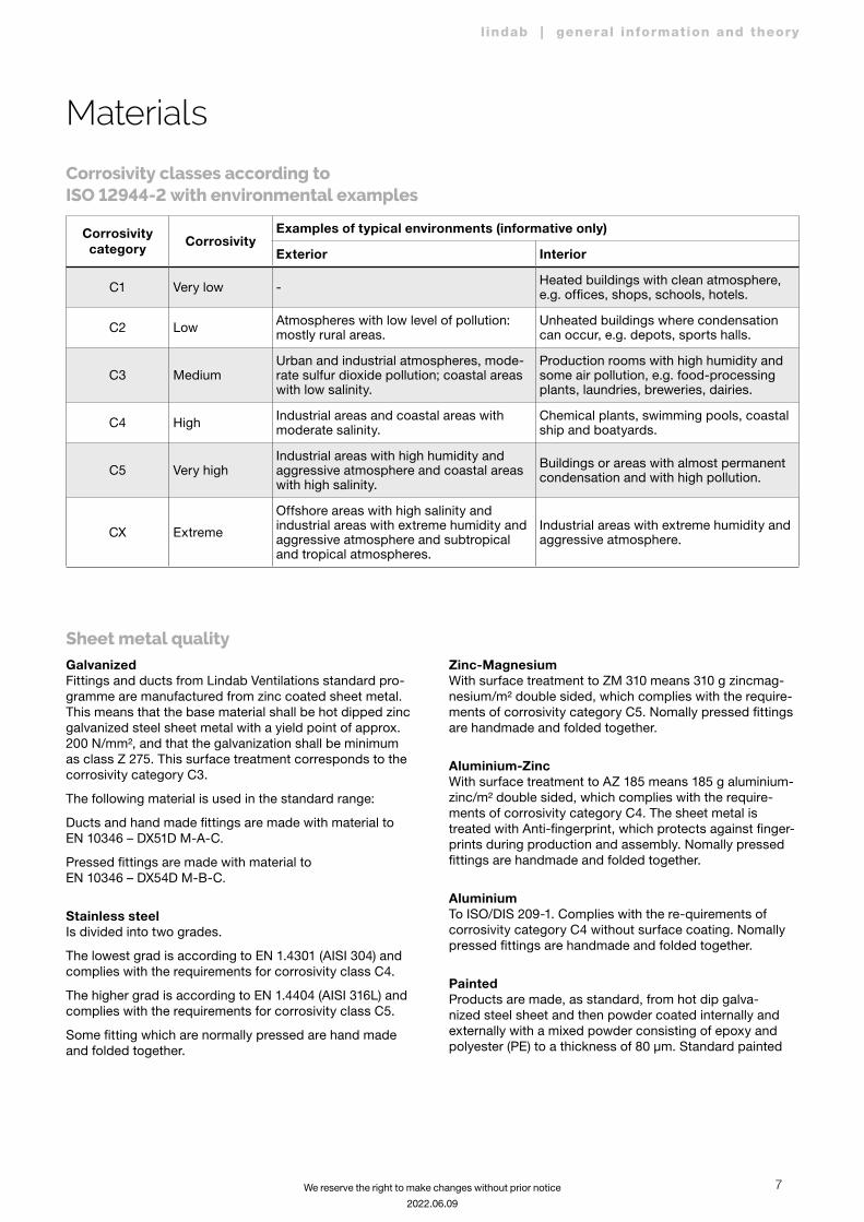
Sheet metal quality
Materials
GalvanizedFittings and ducts from Lindab Ventilations standard pro-gramme are manufactured from zinc coated sheet metal. This means that the base material shall be hot dipped zinc galvanized steel sheet metal with a yield point of approx. 200 N/mm², and that the galvanization shall be minimum as class Z 275. This surface treatment corresponds to the corrosivity category C3.
The following material is used in the standard range:
Ducts and hand made fittings are made with material to EN 10346 – DX51D M-A-C.
Pressed fittings are made with material to EN 10346 – DX54D M-B-C.
Stainless steel Is divided into two grades.
The lowest grad is according to EN 1.4301 (AISI 304) and complies with the requirements for corrosivity class C4.
The higher grad is according to EN 1.4404 (AISI 316L) and complies with the requirements for corrosivity class C5.
Some fitting which are normally pressed are hand made and folded together.
Zinc-Magnesium With surface treatment to ZM 310 means 310 g zincmag-nesium/m² double sided, which complies with the require-ments of corrosivity category C5. Nomally pressed fittings are handmade and folded together.
Aluminium-ZincWith surface treatment to AZ 185 means 185 g aluminium-zinc/m² double sided, which complies with the require-ments of corrosivity category C4. The sheet metal is treated with Anti-fingerprint, which protects against finger-prints during production and assembly. Nomally pressed fittings are handmade and folded together.
AluminiumTo ISO/DIS 209-1. Complies with the re-quirements of corrosivity category C4 without surface coating. Nomally pressed fittings are handmade and folded together.
PaintedProducts are made, as standard, from hot dip galva-nized steel sheet and then powder coated internally and externally with a mixed powder consisting of epoxy and polyester (PE) to a thickness of 80 µm. Standard painted
Corrosivity classes according to ISO 12944-2 with environmental examples
Corrosivity category Corrosivity
Examples of typical environments (informative only)
Exterior Interior
C1 Very low - Heated buildings with clean atmosphere, e.g. offices, shops, schools, hotels.
C2 Low Atmospheres with low level of pollution: mostly rural areas.
Unheated buildings where condensation can occur, e.g. depots, sports halls.
C3 MediumUrban and industrial atmospheres, mode-rate sulfur dioxide pollution; coastal areas with low salinity.
Production rooms with high humidity and some air pollution, e.g. food-processing plants, laundries, breweries, dairies.
C4 High Industrial areas and coastal areas with moderate salinity.
Chemical plants, swimming pools, coastal ship and boatyards.
C5 Very highIndustrial areas with high humidity and aggressive atmosphere and coastal areas with high salinity.
Buildings or areas with almost permanent condensation and with high pollution.
CX Extreme
Offshore areas with high salinity and industrial areas with extreme humidity and aggressive atmosphere and subtropical and tropical atmospheres.
Industrial areas with extreme humidity and aggressive atmosphere.
8
l indab | general information and theory
We reserve the right to make changes without prior notice
2022.06.09
Materialsproducts comply with the requirements of corrosivity category C4.
Standard colors are:
NCS S0502-y, gloss 30 which is equivalent to RAL 9010
NCS S1002-G, gloss 30 which is equivalent to RAL 9003
The gloss is defined by the Gardner 60° scale. Other colors can be made on request.
NOTE! For ducts of Ø 100 the maximum length is 1,5 m for internal coating.
Products can be coated on the inside only, for hygienic or liquid tightness reasons, or on the outside for aesthetic reasons. The standard outside coated color for aesthetic reasons is NCS S1002-G, gloss 30 which is equivalent to RAL 9003. These products are available as stock items for a limited circular duct assortment, called EVIT.
Powder coating can be optionally obtained in thicknesses of up to 200 µm. Products painted with mix powder, epoxy and polyester, can after some time of exposure to UV radiation receive changes in color. Hence storage in sun-light ought to be avoided.
Thickness of the surfaceA surface treatment to class Z 275 is defined in EN 10346 and means 275 g zinc/m² double sided. Z 275 thus tells the total amount of zinc on both sides of a 1 m² sheet metal plate. The thickness can thus be calculated as:
Zinc thickness = zinc weight
number of sides ⋅ zinc density =
= 0,275 2 ⋅ 7140
· 106 = 19 m m
Sheet metal thicknessesThe sheet metal thickness tolerances is defined in EN 10143. The thickness of each product is chosen by Lindab to withstand normal use in ventilation, handling on trucks, building places and during mounting of the system. If there is special requirement for thicker material the inner diam-eter of the ducts will be smaller and special arrangements can be needed.
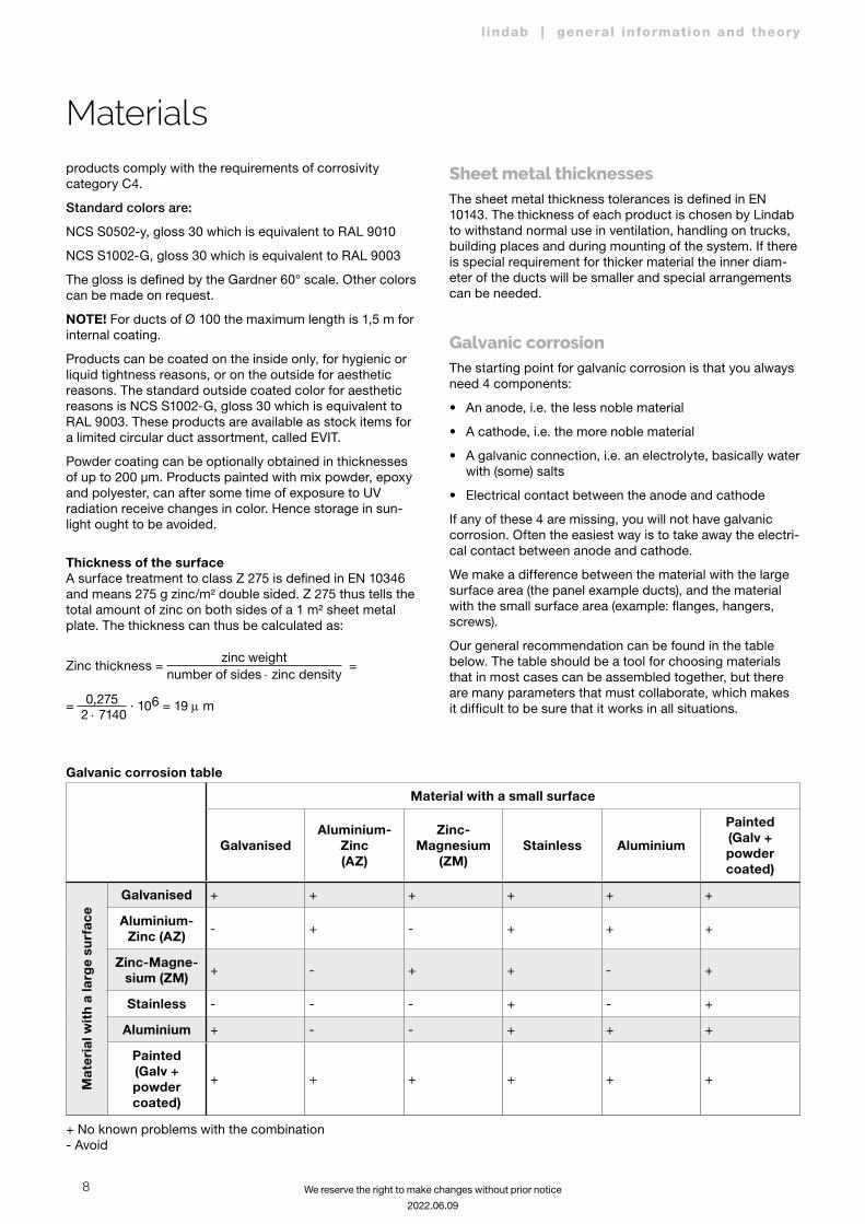
Galvanic corrosion The starting point for galvanic corrosion is that you always need 4 components:
• An anode, i.e. the less noble material
• A cathode, i.e. the more noble material
• A galvanic connection, i.e. an electrolyte, basically water with (some) salts
• Electrical contact between the anode and cathode
If any of these 4 are missing, you will not have galvanic corrosion. Often the easiest way is to take away the electri-cal contact between anode and cathode.
We make a difference between the material with the large surface area (the panel example ducts), and the material with the small surface area (example: flanges, hangers, screws).
Our general recommendation can be found in the table below. The table should be a tool for choosing materials that in most cases can be assembled together, but there are many parameters that must collaborate, which makes it difficult to be sure that it works in all situations.
Galvanic corrosion table
Material with a small surface
GalvanisedAluminium-
Zinc (AZ)
Zinc- Magnesium
(ZM)Stainless Aluminium
Painted (Galv + powder coated)
Mat
eria
l wit
h a
larg
e su
rfac
e
Galvanised + + + + + +
Aluminium-Zinc (AZ) - + - + + +
Zinc-Magne-sium (ZM) + - + + - +
Stainless - - - + - +
Aluminium + - - + + +
Painted (Galv + powder coated)
+ + + + + +
+ No known problems with the combination - Avoid
9
l indab | general information and theory
We reserve the right to make changes without prior notice
2022.06.09
Materials
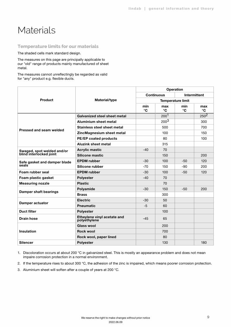
Temperature limits for our materialsThe shaded cells mark standard design.
The measures on this page are principally applicable to our "old" range of products mainly manufactured of sheet metal.
The measures cannot unreflectingly be regarded as valid for "any" product e.g. flexible ducts.
Product Material/type
Operation
Continuous Intermittent
Temperature limit
min°C
max°C
min°C
max°C
Pressed and seam welded
Galvanized steel sheet metal 2001 2502
Aluminium sheet metal 2003 300
Stainless steel sheet metal 500 700
ZincMagnesium sheet metal 100 150
PE/EP coated products 80 100
Aluzink sheet metal 315
Swaged, spot welded and/or blind interlocked joint
Acrylic mastic -40 70
Silicone mastic 150 200
Safe gasket and damper blade seals
EPDM rubber -30 100 -50 120
Silicone rubber -70 150 -90 200
Foam rubber seal EPDM rubber -30 100 -50 120
Foam plastic gasket Polyester -40 70
Measuring nozzle Plastic 70
Damper shaft bearingsPolyamide -30 150 -50 200
Brass 300
Damper actuatorElectric -30 50
Pneumatic -5 60
Duct filter Polyester 100
Drain hose Etheylene vinyl acetate and polyethylene -45 65
Insulation
Glass wool 200
Rock wool 700
Rock wool, paper lined 80
Silencer Polyester 130 180
1. Discoloration occurs at about 200 °C in galvanized steel. This is mostly an appearance problem and does not mean impaire corrosion protection in a normal environment.
2. If the temperature rises to about 300 °C, the adhesion of the zinc is impaired, which means poorer corrosion protection.
3. Aluminium sheet will soften after a couple of years at 200 °C.
10
l indab | general information and theory
We reserve the right to make changes without prior notice
2022.06.09
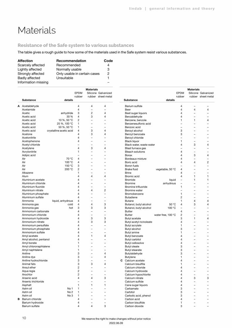
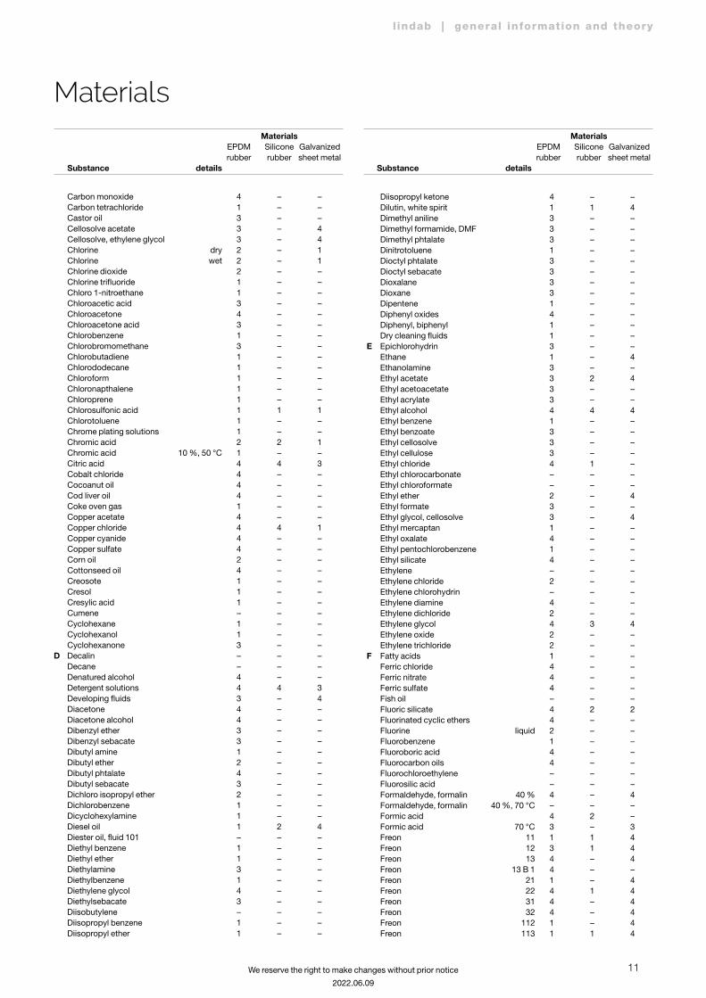
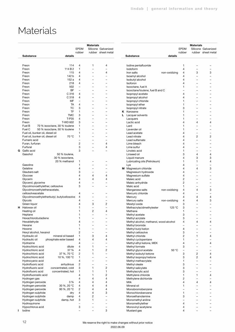
MaterialsResistance of the Safe system to various substancesThe table gives a rough guide to how some of the materials used in the Safe system resist various substances.
Affection Recommendation CodeScarcely affected Recommended 4Lightly affected Normally usable 3Strongly affected Only usable in certain cases 2Badly affected Unsuitable 1Information missing –
Materials EPDM Silicone Galvanized rubber rubber sheet metal Substance details
Materials EPDM Silicone Galvanized rubber rubber sheet metal Substance details
A Acetaldehyde 4 4 4 Acetamide 4 – – Acetic anhydride 3 2 4 Acetic acid 30 % 4 3 4 Acetic acid 10 %, 50 °C 2 – – Acetic acid 25 %, 100 °C 1 – – Acetic acid 50 %, 50 °C 1 – – Acetic acid crystalline acetic acid 4 3 4 Acetone 4 3 4 Acetonitrile 4 – – Acetophenone 4 – – Acetyl chloride – – – Acetylene 4 3 4 Acrylonitrile 1 – – Adipic acid – – – Air 70 °C 4 – – Air 100 °C 4 – – Air 150 °C 3 – – Air 200 °C 2 – – Alkazene 1 – – Alum 4 4 4 Aluminium acetate 4 – – Aluminium chloride 4 – – Aluminium fluoride 4 – – Aluminium nitrate 4 4 2 Aluminium phosphate 4 – – Aluminium sulfate 4 – – Ammonia liquid, anhydrous 4 – – Ammonia gas cold 4 4 3 Ammonia gas hot 3 3 3 Ammonium carbonate 4 – – Ammonium chloride 4 – – Ammonium hydroxide 4 3 3 Ammonium nitrate 4 3 3 Ammonium persulfate 4 – – Ammonium phosphate 4 – – Ammonium sulfate 4 – – AmyI acetate 4 1 4 Amyl alcohol, pentanol 4 – – Amyl borate 1 – – Amyl chloronaphtalene 1 – – Amyl naphtalene 1 – – Aniline 3 – 4 Aniline dye 3 – 4 Aniline hydrochloride 3 – – Animal fats 3 3 4 Ansul ether 2 – – Aqua regia 2 – – Arochlor 2 – – Arsenic acid 4 4 3 Arsenic trichloride – – – Asphalt 1 1 1 Astm oil No 1 1 – – Astm oil No 2 1 – – Astm oil No 3 1 – –B Barium chloride 4 – – Barium hydroxide 4 – – Barium sulfate 4 4 3
Barium sulfide 4 – – Beer 4 4 4 Beet sugar liquors 4 – – Benzaldehyde 4 – – Benzene, benzole 1 1 4 Benzenesulfonic acid – – – Benzoic acid – – – Benzyl alcohol 3 – – Benzyl benzoate 3 – – Benzyl chloride – – – Black liquor 1 – – Black water, waste water 4 3 4 Blast furnace gas – – – Bleach solutions 4 – – Borax 4 3 4 Bordeaux mixture 4 – – Boric acid 4 4 2 Boron fuels – – – Brake fluid vegetable, 50 °C 4 – – Brine 4 – – Bromic acid 4 1 1 Bromide liquid – 1 1 Bromine anhydrous – – – Bromine trifluoride 1 – – Bromine water – – – Bromobenzene 1 – – Butadiene 2 – – Butane 1 4 4 Butanol, butyl alcohol 50 °C 4 3 4 Butanol, butyl alcohol 100 °C – – – Butter 4 – – Butter water free, 100 °C 2 – – Butyl acetate 3 1 4 Butyl acetyl ricinoleate 4 – – Butyl acrylate 1 – – Butyl alcohol 3 – – Butyl amine 1 – – Butyl benzoate 4 – – Butyl carbitol 4 – – Butyl cellosolve 4 – – Butyl oleate 3 – – Butyl stearate 3 – – Butylaldehyde 3 – – Butylene 1 – –C Calcium acetate 4 – – Calcium bisulfite 1 – – Calcium chloride 4 – – Calcium hydroxide 4 – – Calcium hypochlorite 4 – – Calcium nitrate 4 3 3 Calcium sulfide 4 – – Cane sugar liquors 4 – – Carbamate 3 – – Carbitol 3 – – Carbolic acid, phenol 3 – – Carbon acid 4 – – Carbon bisulfide 1 – – Carbon dioxide 3 – –
11
l indab | general information and theory
We reserve the right to make changes without prior notice
2022.06.09
Materials EPDM Silicone Galvanized rubber rubber sheet metal Substance details
Materials EPDM Silicone Galvanized rubber rubber sheet metal Substance details
Carbon monoxide 4 – – Carbon tetrachloride 1 – – Castor oil 3 – – Cellosolve acetate 3 – 4 Cellosolve, ethylene glycol 3 – 4 Chlorine dry 2 – 1 Chlorine wet 2 – 1 Chlorine dioxide 2 – – Chlorine trifluoride 1 – – Chloro 1-nitroethane 1 – – Chloroacetic acid 3 – – Chloroacetone 4 – – Chloroacetone acid 3 – – Chlorobenzene 1 – – Chlorobromomethane 3 – – Chlorobutadiene 1 – – Chlorododecane 1 – – Chloroform 1 – – Chloronapthalene 1 – – Chloroprene 1 – – Chlorosulfonic acid 1 1 1 Chlorotoluene 1 – – Chrome plating solutions 1 – – Chromic acid 2 2 1 Chromic acid 10 %, 50 °C 1 – – Citric acid 4 4 3 Cobalt chloride 4 – – Cocoanut oil 4 – – Cod liver oil 4 – – Coke oven gas 1 – – Copper acetate 4 – – Copper chloride 4 4 1 Copper cyanide 4 – – Copper sulfate 4 – – Corn oil 2 – – Cottonseed oil 4 – – Creosote 1 – – Cresol 1 – – Cresylic acid 1 – – Cumene – – – Cyclohexane 1 – – Cyclohexanol 1 – – Cyclohexanone 3 – –D Decalin – – – Decane – – – Denatured alcohol 4 – – Detergent solutions 4 4 3 Developing fluids 3 – 4 Diacetone 4 – – Diacetone alcohol 4 – – Dibenzyl ether 3 – – Dibenzyl sebacate 3 – – Dibutyl amine 1 – – Dibutyl ether 2 – – Dibutyl phtalate 4 – – Dibutyl sebacate 3 – – Dichloro isopropyl ether 2 – – Dichlorobenzene 1 – – Dicyclohexylamine 1 – – Diesel oil 1 2 4 Diester oil, fluid 101 – – – Diethyl benzene 1 – – Diethyl ether 1 – – Diethylamine 3 – – Diethylbenzene 1 – – Diethylene glycol 4 – – Diethylsebacate 3 – – Diisobutylene – – – Diisopropyl benzene 1 – – Diisopropyl ether 1 – –
Diisopropyl ketone 4 – – Dilutin, white spirit 1 1 4 Dimethyl aniline 3 – – Dimethyl formamide, DMF 3 – – Dimethyl phtalate 3 – – Dinitrotoluene 1 – – Dioctyl phtalate 3 – – Dioctyl sebacate 3 – – Dioxalane 3 – – Dioxane 3 – – Dipentene 1 – – Diphenyl oxides 4 – – Diphenyl, biphenyl 1 – – Dry cleaning fluids 1 – –E Epichlorohydrin 3 – – Ethane 1 – 4 Ethanolamine 3 – – Ethyl acetate 3 2 4 Ethyl acetoacetate 3 – – Ethyl acrylate 3 – – Ethyl alcohol 4 4 4 Ethyl benzene 1 – – Ethyl benzoate 3 – – Ethyl cellosolve 3 – – Ethyl cellulose 3 – – Ethyl chloride 4 1 – Ethyl chlorocarbonate – – – Ethyl chloroformate – – – Ethyl ether 2 – 4 Ethyl formate 3 – – Ethyl glycol, cellosolve 3 – 4 Ethyl mercaptan 1 – – Ethyl oxalate 4 – – Ethyl pentochlorobenzene 1 – – Ethyl silicate 4 – – Ethylene – – – Ethylene chloride 2 – – Ethylene chlorohydrin – – – Ethylene diamine 4 – – Ethylene dichloride 2 – – Ethylene glycol 4 3 4 Ethylene oxide 2 – – Ethylene trichloride 2 – –F Fatty acids 1 – – Ferric chloride 4 – – Ferric nitrate 4 – – Ferric sulfate 4 – – Fish oil – – – Fluoric silicate 4 2 2 Fluorinated cyclic ethers 4 – – Fluorine liquid 2 – – Fluorobenzene 1 – – Fluoroboric acid 4 – – Fluorocarbon oils 4 – – Fluorochloroethylene – – – Fluorosilic acid – – – Formaldehyde, formalin 40 % 4 – 4 Formaldehyde, formalin 40 %, 70 °C – – – Formic acid 4 2 – Formic acid 70 °C 3 – 3 Freon 11 1 1 4 Freon 12 3 1 4 Freon 13 4 – 4 Freon 13 B 1 4 – – Freon 21 1 – 4 Freon 22 4 1 4 Freon 31 4 – 4 Freon 32 4 – 4 Freon 112 1 – 4 Freon 113 1 1 4
Materials
12
l indab | general information and theory
We reserve the right to make changes without prior notice
2022.06.09
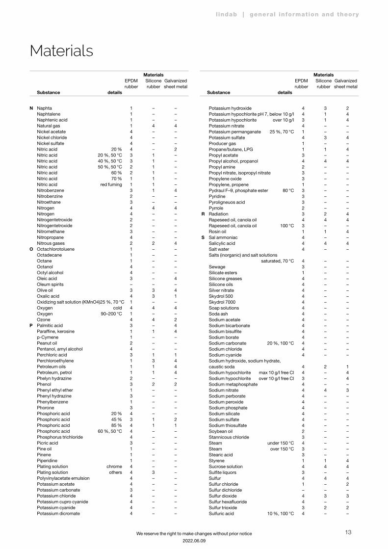
Materials EPDM Silicone Galvanized rubber rubber sheet metal Substance details
Materials EPDM Silicone Galvanized rubber rubber sheet metal Substance details
Freon 114 4 1 4 Freon 114 B 2 1 – – Freon 115 4 – 4 Freon 142 b 4 – – Freon 152 a 4 – – Freon 218 4 – – Freon 502 – – – Freon BF – – – Freon C 316 4 – – Freon C 318 4 – – Freon MF – – – Freon TA 4 – – Freon TC 3 – – Freon TF 1 – – Freon TMC 3 – – Freon T-P35 4 – – Freon T-WD 602 3 – – Fuel B 70 % isooctane, 30 % toulene 1 – – Fuel C 50 % isooctane, 50 % toulene 1 – – Fuel oil, bunker oil, diesel oil 1 – – Fuel oil, bunker oil, diesel oil 70 °C 1 – – Fumaric acid – – – Furan, furfuran 2 – 4 Furfural 3 – 4G Gallic acid 3 – – Gasohol 50 % toulene, 30 % isooctane, 20 % methanol 1 – – Gasoline 1 – – Gelatine 4 – – Glaubers salt 3 – – Glucose 4 4 4 Glycerin 4 4 4 Glycerol, glycerine 4 – – Glycolmonoethylether, cellosolve 3 – – Glycolmonoethyletheracetate, cellosolveacetate 4 – – Glycolmonoethyletherbutyl, butylcellosolve 4 – – Glycols 4 – – Green liquor 4 3 2H Halowax oil 1 – – Heating oil 1 2 4 Heptane 1 – – Hexachlorobutadiene 1 – – Hexaldehyde 4 – – Hexane 1 – – Hexene 1 – – Hexyl alcohol, hexanol 2 – – Hydraulic oil mineral oil based 1 3 4 Hydraulic oil phosphate ester based 4 4 4 Hydrazine 4 – – Hydrochloric acid dilute 4 1 – Hydrochloric acid 37 % 4 1 2 Hydrochloric acid 37 %, 70 °C 2 1 – Hydrochloric acid 10 %, 100 °C 1 – – Hydrocyanic acid 4 – – Hydrofluoric acid anhydrous 2 – – Hydrofluoric acid concentrated, cold 3 1 2 Hydrofluoric acid concentrated, hot 1 1 1 Hydrofluorosilic acid 4 1 2 Hydrogen gas 4 4 4 Hydrogen peroxide 3 % 4 4 4 Hydrogen peroxide 30 %, 20 °C 4 4 4 Hydrogen peroxide 90 %, 20 °C 2 4 4 Hydrogen sulphide dry 4 4 3 Hydrogen sulphide damp 4 2 – Hydrogen sulphide damp, hot 3 1 – Hydroquinone – – – Hypochlorus acid 3 – –I Iodine – – 3
Iodine pentafluoride 1 – – Iodoform 4 – – Iron salts non-oxidizing 4 3 3 Isoamyl alcohol 4 – – Isobutyl alcohol 4 – – Isoforon 4 – – Isooctane, fuel A 1 – – Isooctane/toulene, fuel B and C – – – Isopropyl acetate 4 – – Isopropyl alcohol 4 – – Isopropyl chloride 1 – – Isopropyl ether 1 – – Isopropyl nitrate 3 – –K Kerosene 1 – –L Lacquer solvents 1 – – Lacquers 1 – – Lactic acid 4 4 4 Lard 1 – – Lavender oil 1 – – Lead acetate 4 – – Lead nitrate 4 2 2 Lead sulfamate 4 – – Lime bleach 4 – – Lime sulfur 4 – – Linoleic acid 1 – – Linseed oil 3 4 4 Liquid manure 4 3 3 Lubricating oils (Petroleum) 1 1 4 Lye 4 – –M Magnesium chloride 4 4 3 Magnesium hydroxide 4 – – Magnesium sulfate 4 – – Maleic acid 2 – – Maleic anhydride 2 – – Malic acid 1 – – Manganese salts non-oxidizing 4 4 3 Mercuric chloride 4 – – Mercury 4 4 4 Mercury salts non-oxidizing 4 4 3 Mesityl oxide 3 – – Methacrylacidmethylester 125 °C 3 – – Methane 1 – – Methyl acetate 3 – – Methyl acrylate 3 – – Methyl alcohol, methanol, wood alcohol 4 4 4 Methyl bromide – – – Methyl butyl keton 4 – – Methyl cellosolve 3 – – Methyl chloride 2 1 4 Methyl cyclopentane 1 – – Methyl ethyl ketone, MEK 4 – 4 Methyl formate 3 – – Methyl glycol acetate 50 °C – – – Methyl isobutyl ketone 3 2 4 Methyl isopropyl ketone 3 2 4 Methyl methacrylate 1 – – Methyl oleate 3 – – Methyl salicylate 3 – – Methylacrylic acid 3 – – Methylene chloride 1 1 4 Methylene dichloride 2 – – Milk 4 4 4 Mineral oil 1 – – Monobromobenzene – – – Monochlorobenzene 1 – – Monoethanolamine 3 – – Monomethyl aniline – – – Monomethylether 4 – – Monovinyl acetylene 4 – – Mustard gas 4 – –
Materials
13
l indab | general information and theory
We reserve the right to make changes without prior notice
2022.06.09
N Naphta 1 – – Naphtalene 1 – – Naphtenic acid 1 – – Natural gas 1 4 4 Nickel acetate 4 – – Nickel chloride 4 – – Nickel sulfate 4 – – Nitric acid 20 % 4 – 2 Nitric acid 20 %, 50 °C 3 1 – Nitric acid 40 %, 50 °C 3 1 – Nitric acid 50 %, 50 °C 2 1 – Nitric acid 60 % 2 1 – Nitric acid 70 % 1 1 – Nitric acid red fuming 1 1 – Nitrobenzene 3 1 4 Nitrobenzine 2 – – Nitroethane 3 – – Nitrogen 4 4 4 Nitrogen 4 – – Nitrogentetroxide 2 – – Nitrogentetroxide 2 – – Nitromethane 3 – – Nitropropane 4 – – Nitrous gases 2 2 4O Octachlorotoluene 1 – – Octadecane 1 – – Octane 1 – – Octanol 4 – – Octyl alcohol 4 – – Oleic acid 3 – 4 Oleum spirits – – – Olive oil 3 3 4 Oxalic acid 4 3 1 Oxidizing salt solution (KMnO4) 25 %, 70 °C 1 – – Oxygen cold 4 4 4 Oxygen 90–200 °C 1 – – Ozone 4 4 2P Palmitic acid 3 – 4 Paraffine, kerosine 1 1 4 p-Cymene 1 – – Peanut oil 2 – – Pentanol, amyl alcohol 4 – – Perchloric acid 3 1 1 Perchloroethylene 1 3 4 Petroleum oils 1 1 4 Petroleum, petrol 1 1 4 Phelyn hydrazine 2 – – Phenol 3 2 2 Phenyl ethyl ether 1 – – Phenyl hydrazine 3 – – Phenylbenzene 1 – – Phorone 3 – – Phosphoric acid 20 % 4 – – Phosphoric acid 45 % 3 1 2 Phosphoric acid 85 % 4 1 1 Phosphoric acid 60 %, 50 °C 4 – – Phosphorus trichloride 4 – – Picric acid 3 – – Pine oil 1 – – Pinene 1 – – Piperidine 1 – – Plating solution chrome 4 – – Plating solution others 4 3 – PoIyvinylacetate emulsion 4 – – Potassium acetate 4 – – Potassium carbonate 3 – – Potassium chloride 4 – – Potassium cupro cyanide 4 – – Potassium cyanide 4 – – Potassium dicromate 4 – –
Potassium hydroxide 4 3 2 Potassium hypochlorite pH 7, below 10 g/l 4 1 4 Potassium hypochlorite over 10 g/l 3 1 4 Potassium nitrate 4 – – Potassium permanganate 25 %, 70 °C 1 – – Potassium sulfate 4 3 4 Producer gas 1 – – Propane/butane, LPG 1 1 4 Propyl acetate 3 – – Propyl alcohol, propanol 4 4 4 Propyl amine 2 – – Propyl nitrate, isopropyl nitrate 3 – – Propylene oxide 3 – – Propylene, propene 1 – – Pydraul F–9, phosphate ester 80 °C 3 – – Pyridine 3 – – Pyroligneuos acid 3 – – Pyrrole 2 – –R Radiation 3 2 4 Rapeseed oil, canola oil 4 4 4 Rapeseed oil, canola oil 100 °C 3 – – Rosin oil 1 1 4S Sal ammoniac 4 – – Salicylic acid 4 4 4 Salt water 4 – – Salts (inorganic) and salt solutions saturated, 70 °C 4 – – Sewage 3 – – Silicate esters 1 – – Silicone greases 4 – – Silicone oils 4 – – Silver nitrate 4 – – Skydrol 500 4 – – Skydrol 7000 4 – – Soap solutions 4 – – Soda ash 4 – – Sodium acetale 4 – – Sodium bicarbonate 4 – – Sodium bisulfite 4 – – Sodium borate 4 – – Sodium carbonate 20 %, 100 °C 4 – – Sodium chloride 4 – – Sodium cyanide 4 – – Sodium hydroxide, sodium hydrate, caustic soda 4 2 1 Sodium hypochlorite max 10 g/l free Cl 4 – 4 Sodium hypochlorite over 10 g/l free Cl 3 – 4 Sodium metaphosphate 4 – – Sodium nitrate 4 4 3 Sodium perborate 4 – – Sodium peroxide 4 – – Sodium phosphate 4 – – Sodium silicate 4 – – Sodium sulfate 4 – – Sodium thiosulfate 4 – – Soybean oil 2 – – Stannicous chloride 3 – – Steam under 150 °C 4 – – Steam over 150 °C 3 – – Stearic acid 3 – – Styrene 1 1 4 Sucrose solution 4 4 4 Sulfite liquors 3 – – Sulfur 4 4 4 Sulfur chloride 1 – 2 Sulfur dichloride – – – Sulfur dioxide 4 3 3 Sulfur hexafluoride 4 – – Sulfur trioxide 3 2 2 Sulfuric acid 10 %, 100 °C 4 – –
Materials EPDM Silicone Galvanized rubber rubber sheet metal Substance details
Materials EPDM Silicone Galvanized rubber rubber sheet metal Substance details
Materials
14
l indab | general information and theory
We reserve the right to make changes without prior notice
2022.06.09
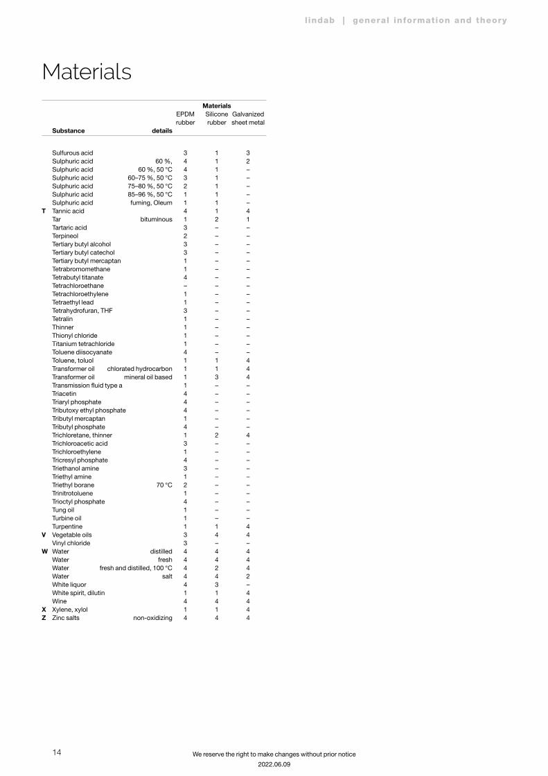
Sulfurous acid 3 1 3 Sulphuric acid 60 %, 4 1 2 Sulphuric acid 60 %, 50 °C 4 1 – Sulphuric acid 60–75 %, 50 °C 3 1 – Sulphuric acid 75–80 %, 50 °C 2 1 – Sulphuric acid 85–96 %, 50 °C 1 1 – Sulphuric acid fuming, Oleum 1 1 –T Tannic acid 4 1 4 Tar bituminous 1 2 1 Tartaric acid 3 – – Terpineol 2 – – Tertiary butyl alcohol 3 – – Tertiary butyl catechol 3 – – Tertiary butyl mercaptan 1 – – Tetrabromomethane 1 – – Tetrabutyl titanate 4 – – Tetrachloroethane – – – Tetrachloroethylene 1 – – Tetraethyl lead 1 – – Tetrahydrofuran, THF 3 – – Tetralin 1 – – Thinner 1 – – Thionyl chloride 1 – – Titanium tetrachloride 1 – – Toluene diisocyanate 4 – – Toluene, toluol 1 1 4 Transformer oil chlorated hydrocarbon 1 1 4 Transformer oil mineral oil based 1 3 4 Transmission fluid type a 1 – – Triacetin 4 – – Triaryl phosphate 4 – – Tributoxy ethyl phosphate 4 – – Tributyl mercaptan 1 – – Tributyl phosphate 4 – – Trichloretane, thinner 1 2 4 Trichloroacetic acid 3 – – Trichloroethylene 1 – – Tricresyl phosphate 4 – – Triethanol amine 3 – – Triethyl amine 1 – – Triethyl borane 70 °C 2 – – Trinitrotoluene 1 – – Trioctyl phosphate 4 – – Tung oil 1 – – Turbine oil 1 – – Turpentine 1 1 4V Vegetable oils 3 4 4 Vinyl chloride 3 – –W Water distilled 4 4 4 Water fresh 4 4 4 Water fresh and distilled, 100 °C 4 2 4 Water salt 4 4 2 White liquor 4 3 – White spirit, dilutin 1 1 4 Wine 4 4 4X Xylene, xylol 1 1 4Z Zinc salts non-oxidizing 4 4 4
Materials EPDM Silicone Galvanized rubber rubber sheet metal Substance details
Materials
15
l indab | general information and theory
We reserve the right to make changes without prior notice
2022.06.09
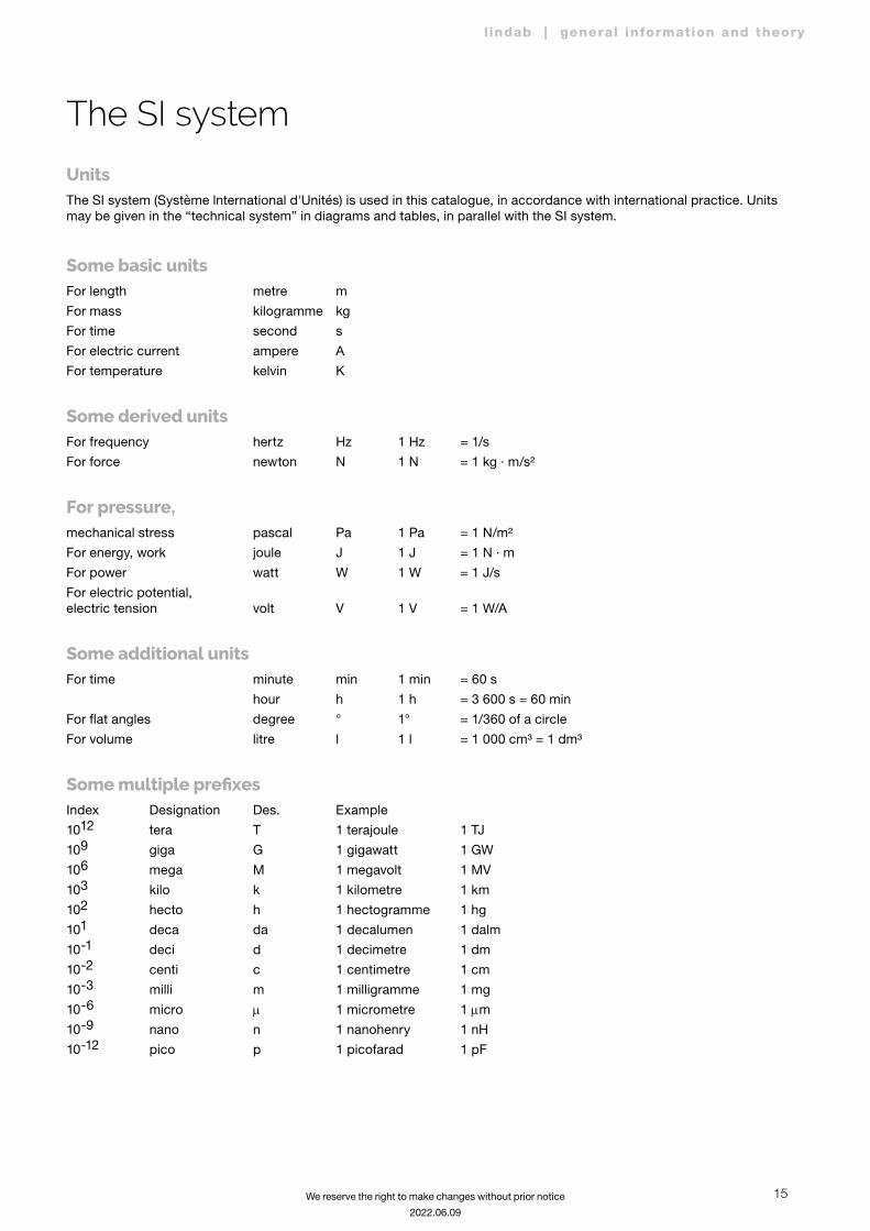
The SI system
UnitsThe SI system (Système lnternational d'Unités) is used in this catalogue, in accordance with international practice. Units may be given in the “technical system” in diagrams and tables, in parallel with the SI system.
Some basic unitsFor length metre m
For mass kilogramme kg
For time second s
For electric current ampere A
For temperature kelvin K
Some derived unitsFor frequency hertz Hz 1 Hz = 1/s
For force newton N 1 N = 1 kg · m/s²
For pressure, mechanical stress pascal Pa 1 Pa = 1 N/m²
For energy, work joule J 1 J = 1 N · m
For power watt W 1 W = 1 J/s
For electric potential, electric tension volt V 1 V = 1 W/A
Some additional unitsFor time minute min 1 min = 60 s
hour h 1 h = 3 600 s = 60 min
For flat angles degree ° 1° = 1/360 of a circle
For volume litre l 1 l = 1 000 cm³ = 1 dm³
Some multiple prefixesIndex Designation Des. Example
1012 tera T 1 terajoule 1 TJ
109 giga G 1 gigawatt 1 GW
106 mega M 1 megavolt 1 MV
103 kilo k 1 kilometre 1 km
102 hecto h 1 hectogramme 1 hg
101 deca da 1 decalumen 1 dalm
10-1 deci d 1 decimetre 1 dm
10-2 centi c 1 centimetre 1 cm
10-3 milli m 1 milligramme 1 mg
10-6 micro m 1 micrometre 1 mm
10-9 nano n 1 nanohenry 1 nH
10-12 pico p 1 picofarad 1 pF
16
l indab | general information and theory
We reserve the right to make changes without prior notice
2022.06.09
The SI system
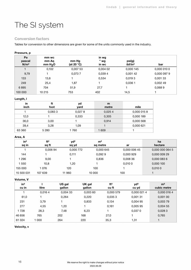
Conversion factorsTables for conversion to other dimensions are given for some of the units commonly used in the industry.
Pressure, p
PapascalN/m²
mm wcmm Aq
mm H2Omm Hg
(at 20 °C)
in wg" wgin wc
psi(g)ibf/in² bar
1 0,102 0,007 53 0,004 02 0,000 145 0,000 010 0
9,79 1 0,073 7 0,039 4 0,001 42 0,000 097 9
133 13,6 1 0,534 0,019 3 0,001 33
249 25,4 1,87 1 0,036 1 0,002 49
6 895 704 51,9 27,7 1 0,068 9
100 000 10 215 753 402 14,5 1
Length, l
ininch
ftfoot
ydyard
mmetre mile
1 0,083 3 0,027 8 0,025 4 0,000 015 8
12,0 1 0,333 0,305 0,000 189
36,0 3,00 1 0,914 0,000 568
39,4 3,28 1,09 1 0,000 621
63 360 5 280 1 760 1 609 1
Area, A
in²sq in
ft²sq ft
yd²sq yd
m²sq metre ar
hahectare
1 0,006 94 0,000 772 0,000 645 0,000 006 45 0,000 000 064 5
144 1 0,111 0,092 9 0,000 929 0,000 009 29
1 296 9,00 1 0,836 0,008 36 0,000 083 6
1 550 10,8 1,20 1 0,010 0 0,000 100
155 000 1 076 120 100 1 0,010 0
15 500 031 107 639 11 960 10 000 100 1
Volume, V
in³cu in
llitre
US galgallon
UK galgallon
ft³cu ft
yd³cu yd
m³cubic metre
1 0,016 4 0,004 33 0,003 60 0,000 579 0,000 021 4 0,000 016 4
61,0 1 0,264 0,220 0,035 3 0,001 31 0,001 00
231 3,79 1 0,833 0,134 0,004 95 0,003 79
277 4,55 1,20 1 0,161 0,005 95 0,004 55
1 728 28,3 7,48 6,23 1 0,037 0 0,028 3
46 656 765 202 168 27,0 1 0,765
61 024 1 000 264 220 35,3 1,31 1
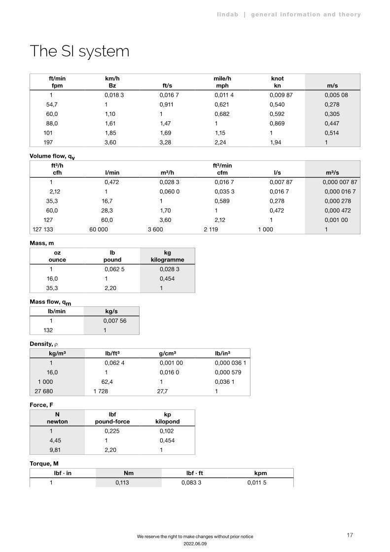
Velocity, v
17
l indab | general information and theory
We reserve the right to make changes without prior notice
2022.06.09
ft/minfpm
km/hBz ft/s
mile/hmph
knotkn m/s
1 0,018 3 0,016 7 0,011 4 0,009 87 0,005 08
54,7 1 0,911 0,621 0,540 0,278
60,0 1,10 1 0,682 0,592 0,305
88,0 1,61 1,47 1 0,869 0,447
101 1,85 1,69 1,15 1 0,514
197 3,60 3,28 2,24 1,94 1
Volume flow, qvft³/hcfh l/min m³/h
ft³/mincfm l/s m³/s
1 0,472 0,028 3 0,016 7 0,007 87 0,000 007 87
2,12 1 0,060 0 0,035 3 0,016 7 0,000 016 7
35,3 16,7 1 0,589 0,278 0,000 278
60,0 28,3 1,70 1 0,472 0,000 472
127 60,0 3,60 2,12 1 0,001 00
127 133 60 000 3 600 2 119 1 000 1
Mass, m
ozounce
lbpound
kgkilogramme
1 0,062 5 0,028 3
16,0 1 0,454
35,3 2,20 1
Mass flow, qmlb/min kg/s
1 0,007 56
132 1
Density, r
kg/m³ lb/ft³ g/cm³ lb/in³
1 0,062 4 0,001 00 0,000 036 1
16,0 1 0,016 0 0,000 579
1 000 62,4 1 0,036 1
27 680 1 728 27,7 1
Force, F
Nnewton
lbfpound-force
kpkilopond
1 0,225 0,102
4,45 1 0,454
9,81 2,20 1
Torque, M
lbf · in Nm lbf · ft kpm
1 0,113 0,083 3 0,011 5
The SI system
18
l indab | general information and theory
We reserve the right to make changes without prior notice
2022.06.09
The SI system
lbf · in Nm lbf · ft kpm
8,85 1 0,738 0,102
12,0 1,36 1 0,138
86,8 9,81 7,23 1
Energy, work, E
Jjoule
Nm, Ws
BtuBritish
thermal unitkcal
kilocalorie kWh
1 0,000 948 0,000 239 0,000 000 278
1 055 1 0,252 0,000 293
4 187 3,97 1 0,001 16
3 600 000 3 412 860 1
Power, P
Btu/h
Wwatt
Nm/s, J/s kcal/h
hkmetric
horsepower
hpUK, US
horsepower
1 0,293 0,252 0,000 398 0,000 393
3,41 1 0,860 0,001 36 0,001 34
3,97 1,16 1 0,001 58 0,001 56
2 510 735 632 1 0,986
2 544 746 641 1,01 1
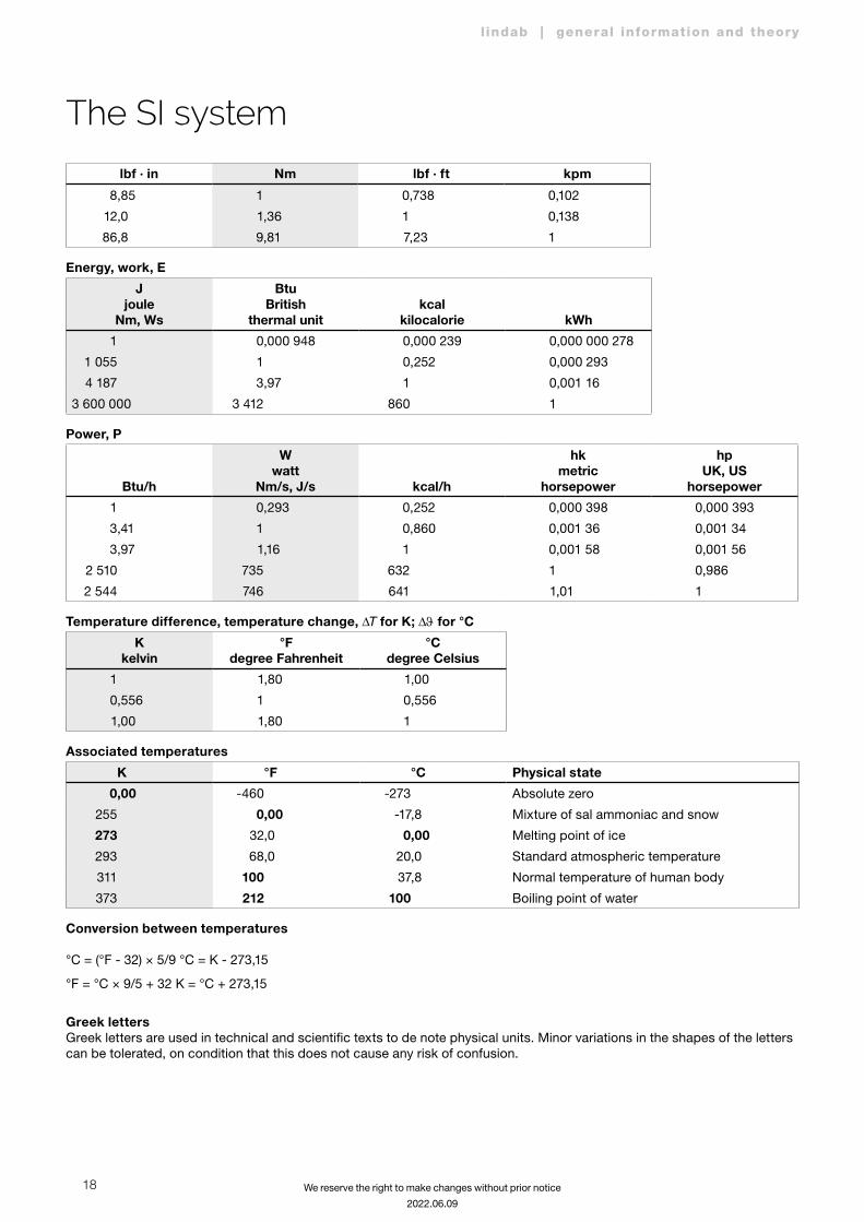
Temperature difference, temperature change, DT for K; DJ for °C
Kkelvin
°Fdegree Fahrenheit
°Cdegree Celsius
1 1,80 1,00
0,556 1 0,556
1,00 1,80 1
Associated temperatures
K °F °C Physical state
0,00 -460 -273 Absolute zero
255 0,00 -17,8 Mixture of sal ammoniac and snow
273 32,0 0,00 Melting point of ice
293 68,0 20,0 Standard atmospheric temperature
311 100 37,8 Normal temperature of human body
373 212 100 Boiling point of water
Conversion between temperatures °C = (°F - 32) × 5/9 °C = K - 273,15
°F = °C × 9/5 + 32 K = °C + 273,15
Greek lettersGreek letters are used in technical and scientific texts to de note physical units. Minor variations in the shapes of the letters can be tolerated, on condition that this does not cause any risk of confusion.

19
l indab | general information and theory
We reserve the right to make changes without prior notice
2022.06.09
Name Lower case Upper case
alfa a A
beta b B
gamma g G
delta d D
epsilon e E
zeta z Z
eta h H
teta J Q
jota i I
kappa k K
lambda l L
my m M
ny n N
ksi x X
omikron o O
pi p P
ro r R
sigma s S
tau t T
ypsilon u U
fi j F
ki c C
psi y Y
omega w W
The SI system
20
l indab | general information and theory
We reserve the right to make changes without prior notice
2022.06.09
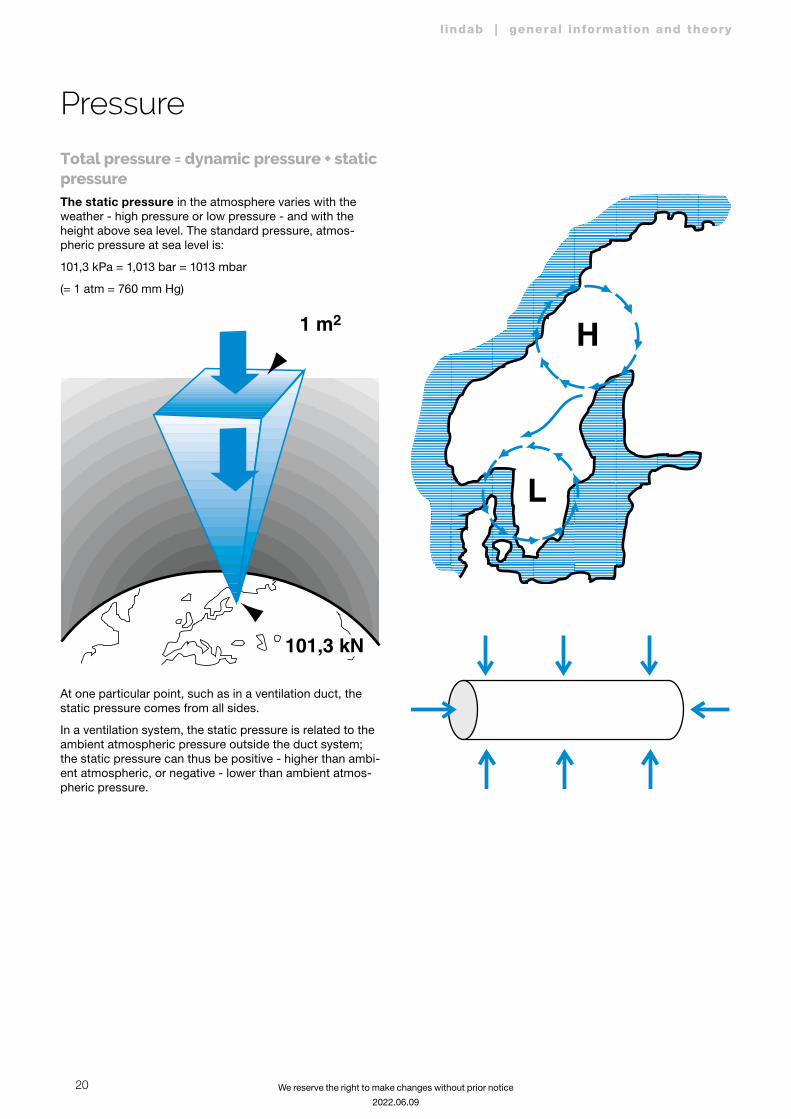
Pressure
Total pressure = dynamic pressure + static pressureThe static pressure in the atmosphere varies with the weather - high pressure or low pressure - and with the height above sea level. The standard pressure, atmos-pheric pressure at sea level is:
101,3 kPa = 1,013 bar = 1013 mbar
(= 1 atm = 760 mm Hg)
101,3 kN
1 m2
At one particular point, such as in a ventilation duct, the static pressure comes from all sides.
In a ventilation system, the static pressure is related to the ambient atmospheric pressure outside the duct system; the static pressure can thus be positive - higher than ambi-ent atmospheric, or negative - lower than ambient atmos-pheric pressure.

21
l indab | general information and theory
We reserve the right to make changes without prior notice
2022.06.09
Pressure dropIf you produce a static pressure difference in an open duct system, you can get the air to flow from a point of higher pressure to a point of lower pressure - from the atmos-phere via the inlet grating to the suction side of the fan, and from the supply side of the fan via the supply terminals back to the atmosphere. The pressure difference is con-verted into kinetic energy.
Dynamic pressure is a measure of the kinetic energy of the moving air. The connection between pressure and energy is easy to see if you use SI system units
Pa = N/m² = Nm/m³ = J/m³ i.e. energy (in J) per unit volume (in m³) of the flowing air.
The dynamic pressure depends on
Pd = r ∙ ²
2v with the units
m³ m³kg
m³kg
s²kgm
m²1
s²m² m
m²N
sm ²
∙ ∙ ∙ ∙= = == = PaN
Flow in a duct system is normally not free of loss. Friction losses occur and the air is forced to change direction. It requires pressure (i.e. energy) to manage both dynamic and static pressure - the sum of these two is referred to as total pressure.
pt = ps + pd
Since ps will be negative in relation to atmospheric pres-sure (on the suction side of the fan), this means that pt will also be negative if the total of ps and pd is negative.
Pressure drop and flow lossesIn a ventilation system, you want to get air moving! Clean air is to be supplied to the occupancy zone and polluted air must leave the room, process or machine. Energy is needed to move the air, which is added via the fan, which gets the air moving.
In order to flow through a duct system, air has to overcome two types of flow resistances or pressure drops:
• friction loss between the flowing air and the duct walls.
• single loss when the air changes direction or speed.
Friction loss (also known as the R value) is expressed in
the unit Pa/m Dpf = dh
l ∙ r
²2v
where
Dpf = friction loss per metre (Pa/m).
l = friction factor related to duct material and surface roughness.
dh = hydraulic diameter of the duct, the diameter of a cir-cular duct which gives the same friction pressure drop at the same flow velocity as a rectangular duct.
dh = a + b
2 ∙ a ∙ b
where a and b are duct sides.
For a circular duct, dh = d
r = air density (kg/m³)
v = average velocity of the air (m/s)
Pressure
22
l indab | general information and theory
We reserve the right to make changes without prior notice
2022.06.09
Pressure
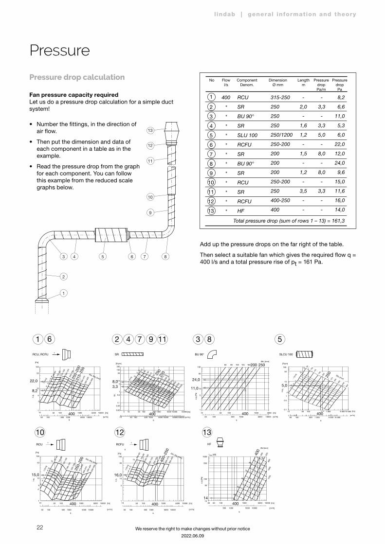
Pressure drop calculation
Fan pressure capacity requiredLet us do a pressure drop calculation for a simple duct system!
Add up the pressure drops on the far right of the table.
Then select a suitable fan which gives the required flow q = 400 l/s and a total pressure rise of pt = 161 Pa.
• Number the fittings, in the direction of air flow.
• Then put the dimension and data of each component in a table as in the example.
• Read the pressure drop from the graph for each component. You can follow this example from the reduced scale graphs below.
No Flowl/s
ComponentDenom.
DimensionØ mm
Lengthm
PressuredropPa/m
PressuredropPa
2
3
4
5
6
7
8
9
10
11
12
13
1 400
"
"
"
"
"
"
"
"
"
"
"
"
RCU
SR
BU 90°
SR
SLU 100
RCFU
SR
BU 90°
SR
RCU
SR
RCFU
HF
315-250
250
250
250
250/1200
250-200
200
200
200
250-200
250
400-250
400
-
2,0
-
1,6
1,2
-
1,5
-
1,2
-
3,5
-
-
-
3,3
-
3,3
5,0
-
8,0
-
8,0
-
3,3
-
-
8,2
6,6
11,0
5,3
6,0
22,0
12,0
24,0
9,6
15,0
11,6
16,0
14,0
Total pressure drop (sum of rows 1 – 13) = 161,3
RCU, RCFU SR BU 90°
HFRCU
500
1000
30
500 1000 5000 10000
50 100 500
1250
1000
800
630
500400
40
50
60
70
80
90
1000 5000 10000
100
50
1410
Ød [mm]
[l/s]
[m3/h]
q
∆ p t
[Pa]
LWA [dB]
SLCU 100
1 2 4 7 9 11 36
10RCFU
12 13
8 5
100
50
v
10
22,0
8,2
1
5
10
[Pa]
10050 500
80–6
310
0–80
125–
100
160–
125
200–
160
500–
400
630–
500
1000 5000 10000
50 100 500 1000 5000 10000 [l/s]
[m3/h]q
∆ p t
v [m
/s]
Ød1 Ød2 [mm]
2
3
4
5
6789
400
250–
200
400–
315
15,0 16,0
5 10 50 100 1000 5000 10000 50000
q
0.02
0.05
0.1
0.5
1
5
108,03,3
24,0
11,0
50
100
200
2
34
5
10
1520
ød [mm]
v [m
/s]
[l/s]
[Pa/m]
6380
100
125
160
315
400
500
630
800
1000
1250
10 50 100 500 1000 5000 10000 50000100000 [m3/h]
∆pt
500
200
250
400
100
50
10
5
1
10
50 100 500
63 80 100 125 160200 250Ød1 [mm]
1000 5000 10000
50 100 500 1000 3000 [l/s]
[m3/h]
q
∆ p t
[Pa]
400
2
4
5
10
15
315
10 50 100 500 1 000 5 000 10 000
q
0.1
0.5
1
5,010
50
100
∆ p
t
v [m
/s]
[m3/h]
[l/s]
[Pa/m]
50 100 500 1 000 5 000 10 000
Ød1 [mm]
54
3
80
100
125
160
200
400
500
630
800
400
250
100
50
10
1
5
10
[Pa]
10050 500
80–6
310
0–80
125–
100
160–
125
200–
160
315–
250
400–
315
500–
400
630–
500
1000 5000 10000
50 100 500 1000 5000 10000 [l/s]
[m3/h]
q
∆ p t
v [m
/s]
Ød1 Ød2 [mm]
3
4
5
678910
15
v v
250–
200
400
q
∆ p t
v [m
/s]
Ød1 Ød2 [mm]100
50
10
1
5
10
[Pa]
10050 500
100–
6312
5–80
160–
100
200–
125
250–
160
315–
200
500–
315
630–
400
1000 5000 10000
50 100 500 1000 5000 10000 [l/s]
[m3/h]
5
6
78910
15
v
400
400–
250
400
315–
250
13
12
11
10
9
5 87643
2
1
23
l indab | general information and theory
We reserve the right to make changes without prior notice
2022.06.09
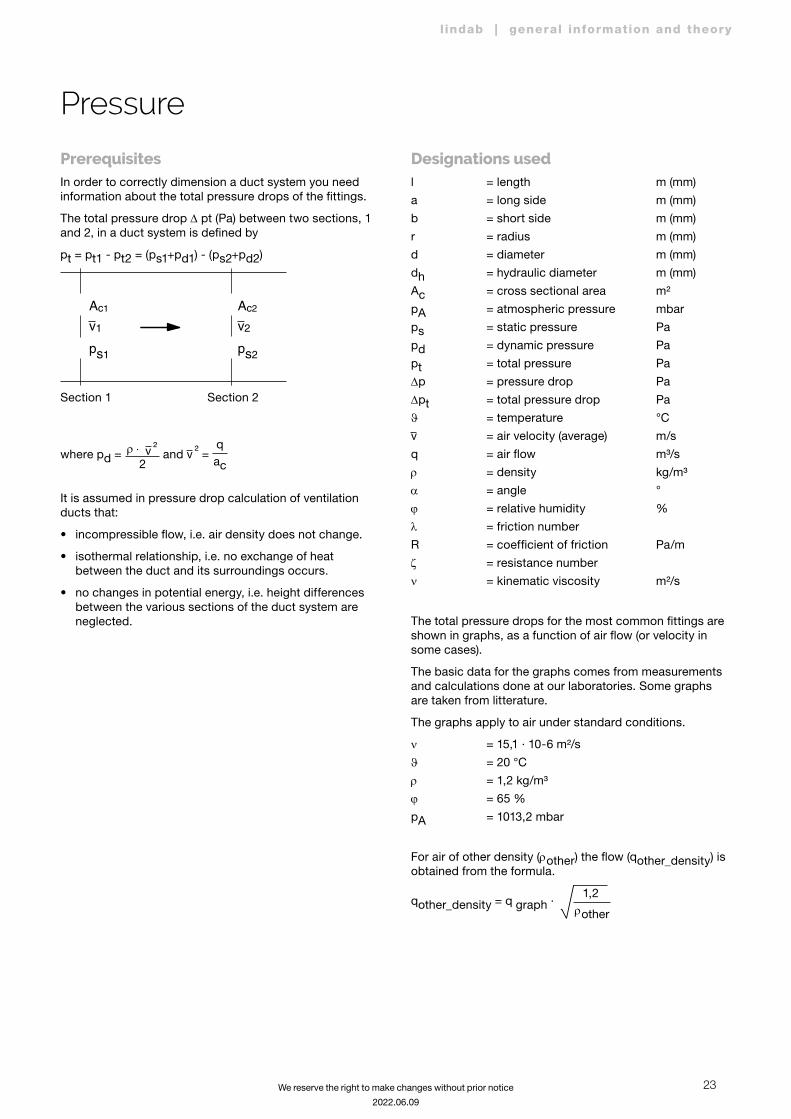
PrerequisitesIn order to correctly dimension a duct system you need information about the total pressure drops of the fittings.
The total pressure drop D pt (Pa) between two sections, 1 and 2, in a duct system is defined by
pt = pt1 - pt2 = (ps1+pd1) - (ps2+pd2)
Section 1 Section 2
Ac1
ps1
v1
Ac2
ps2
v2
where pd = r ⋅ ²2v and ²v =
ac
q
It is assumed in pressure drop calculation of ventilation ducts that:
• incompressible flow, i.e. air density does not change.
• isothermal relationship, i.e. no exchange of heat between the duct and its surroundings occurs.
• no changes in potential energy, i.e. height differences between the various sections of the duct system are neglected.
Designations usedl = length m (mm)
a = long side m (mm)
b = short side m (mm)
r = radius m (mm)
d = diameter m (mm)
dh = hydraulic diameter m (mm)
Ac = cross sectional area m²
pA = atmospheric pressure mbar
ps = static pressure Pa
pd = dynamic pressure Pa
pt = total pressure Pa
Dp = pressure drop Pa
Dpt = total pressure drop Pa
J = temperature °C
v = air velocity (average) m/s
q = air flow m³/s
r = density kg/m³
a = angle °
j = relative humidity %
l = friction number
R = coefficient of friction Pa/m
z = resistance number
n = kinematic viscosity m²/s
The total pressure drops for the most common fittings are shown in graphs, as a function of air flow (or velocity in some cases).
The basic data for the graphs comes from measurements and calculations done at our laboratories. Some graphs are taken from litterature.
The graphs apply to air under standard conditions.
n = 15,1 · 10-6 m²/s
J = 20 °C
r = 1,2 kg/m³
j = 65 %
pA = 1013,2 mbar
For air of other density (rother) the flow (qother_density) is obtained from the formula.
qother_density = q graph ∙ rother
1,2
Pressure
24
l indab | general information and theory
We reserve the right to make changes without prior notice
2022.06.09
Sound
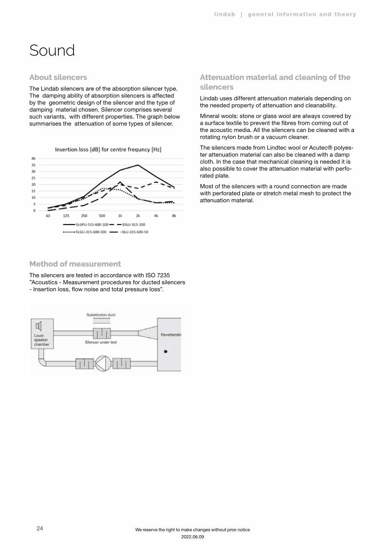
About silencersThe Lindab silencers are of the absorption silencer type. The damping ability of absorption silencers is affected by the geometric design of the silencer and the type of damping material chosen. Silencer comprises several such variants, with different properties. The graph below summarises the attenuation of some types of silencer.
Method of measurementThe silencers are tested in accordance with ISO 7235 ”Acoustics - Measurement procedures for ducted silencers - Insertion loss, flow noise and total pressure loss”.
Attenuation material and cleaning of the silencersLindab uses different attenuation materials depending on the needed property of attenuation and cleanability.
Mineral wools: stone or glass wool are always covered by a surface textile to prevent the fibres from coming out of the acoustic media. All the silencers can be cleaned with a rotating nylon brush or a vacuum cleaner.
The silencers made from Lindtec wool or Acutec® polyes-ter attenuation material can also be cleaned with a damp cloth. In the case that mechanical cleaning is needed it is also possible to cover the attenuation material with perfo-rated plate.
Most of the silencers with a round connection are made with perforated plate or stretch metal mesh to protect the attenuation material.
25
l indab | general information and theory
We reserve the right to make changes without prior notice
2022.06.09
Sound
Ventilation does not have to be noisy!If you use your common sense, and construct your air treatment system with consideration and good compo-nents, you can often avoid problems and complaints.
Fans make noise, this is something you can not do a lot about. But you can prevent the noise from getting into the areas connected to the fan system - you can absorb and damp the noise on the way.
This description does not claim to teach you how to calcu-late and attenuate noise in a ventilation system - there are books available on this.
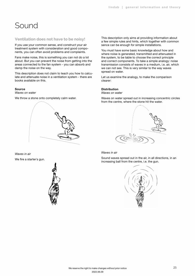
SourceWaves on water
We throw a stone onto completely calm water.
Waves in air
We fire a starter´s gun.
This description only aims at providing information about a few simple rules and hints, which together with common sence can be enough for simple installations.
You must have some basic knowledge about how and where noise is generated, transmitted and attenuated in the system, to be table to choose the correct principle and correct components. To take a simple analogy: noise transmission consists of waves in a medium, i.e. air, which we can not see. This is very similar to the way waves spread on water.
Let us examine the analogy, to make the comparison clearer:
DistributionWaves on water
Waves on water spread out in increasing concentric circles from the centre, where the stone hit the water.
Waves in air
Sound waves spread out in the air, in all directions, in an increasing ball from the centre, i.e. the gun.
26
l indab | general information and theory
We reserve the right to make changes without prior notice
2022.06.09
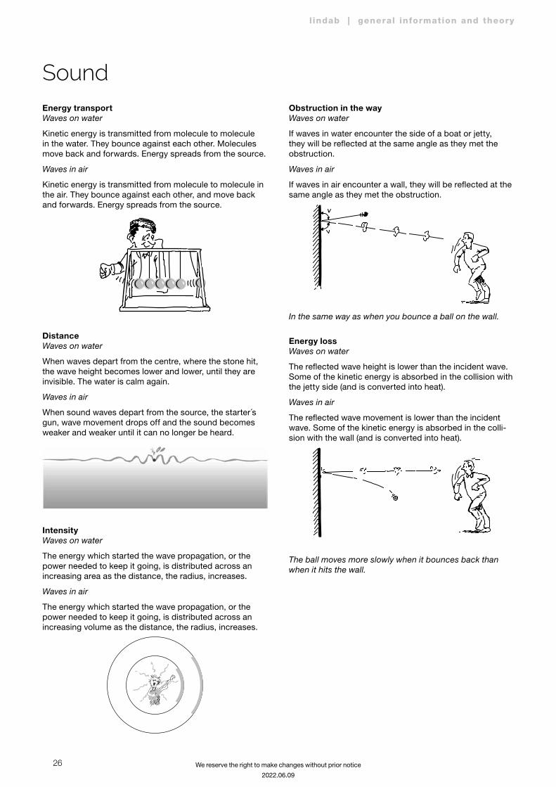
Energy transportWaves on water
Kinetic energy is transmitted from molecule to molecule in the water. They bounce against each other. Molecules move back and forwards. Energy spreads from the source.
Waves in air
Kinetic energy is transmitted from molecule to molecule in the air. They bounce against each other, and move back and forwards. Energy spreads from the source.
DistanceWaves on water
When waves depart from the centre, where the stone hit, the wave height becomes lower and lower, until they are invisible. The water is calm again.
Waves in air
When sound waves depart from the source, the starter´s gun, wave movement drops off and the sound becomes weaker and weaker until it can no longer be heard.
IntensityWaves on water
The energy which started the wave propagation, or the power needed to keep it going, is distributed across an increasing area as the distance, the radius, increases.
Waves in air
The energy which started the wave propagation, or the power needed to keep it going, is distributed across an increasing volume as the distance, the radius, increases.
Obstruction in the wayWaves on water
If waves in water encounter the side of a boat or jetty, they will be reflected at the same angle as they met the obstruction.
Waves in air
If waves in air encounter a wall, they will be reflected at the same angle as they met the obstruction.
In the same way as when you bounce a ball on the wall.
Energy lossWaves on water
The reflected wave height is lower than the incident wave. Some of the kinetic energy is absorbed in the collision with the jetty side (and is converted into heat).
Waves in air
The reflected wave movement is lower than the incident wave. Some of the kinetic energy is absorbed in the colli-sion with the wall (and is converted into heat).
The ball moves more slowly when it bounces back than when it hits the wall.
Sound
27
l indab | general information and theory
We reserve the right to make changes without prior notice
2022.06.09
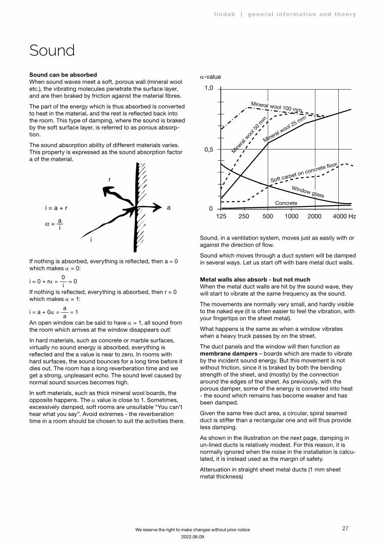
Sound can be absorbedWhen sound waves meet a soft, porous wall (mineral wool etc.), the vibrating molecules penetrate the surface layer, and are then braked by friction against the material fibres.
The part of the energy which is thus absorbed is converted to heat in the material, and the rest is reflected back into the room. This type of damping, where the sound is braked by the soft surface layer, is referred to as porous absorp-tion.
The sound absorption ability of different materials varies. This property is expressed as the sound absorption factor a of the material.
ai = a + r α = —a
i
r
i
If nothing is absorbed, everything is reflected, then a = 0 which makes a = 0:
i = 0 + ra = i0
= 0
If nothing is reflected, everything is absorbed, then r = 0 which makes a = 1:
i = a + 0a = aa
= 1
An open window can be said to have a = 1, all sound from the room which arrives at the window disappears out!
In hard materials, such as concrete or marble surfaces, virtually no sound energy is absorbed, everything is reflected and the a value is near to zero. In rooms with hard surfaces, the sound bounces for a long time before it dies out. The room has a long reverberation time and we get a strong, unpleasant echo. The sound level caused by normal sound sources becomes high.
In soft materials, such as thick mineral wool boards, the opposite happens. The a value is close to 1. Sometimes, excessively damped, soft rooms are unsuitable “You can’t hear what you say”. Avoid extremes - the reverberation time in a room should be chosen to suit the activities there.
125 250 500 1000 2000 4000 Hz
1,0
α-value
Mineral wool 100 mm
0,5
0
Mine
ral w
ool 5
0 m
m
Mineral wool 25 mm
Concrete
Window glass
Soft carpet on concrete floor
Sound, in a ventilation system, moves just as easily with or against the direction of flow.
Sound which moves through a duct system will be damped in several ways. Let us start off with bare metal duct walls.
Metal walls also absorb - but not muchWhen the metal duct walls are hit by the sound wave, they will start to vibrate at the same frequency as the sound.
The movements are normally very small, and hardly visible to the naked eye (it is often easier to feel the vibration, with your fingertips on the sheet metal).
What happens is the same as when a window vibrates when a heavy truck passes by on the street.
The duct panels and the window will then function as membrane dampers – boards which are made to vibrate by the incident sound energy. But this movement is not without friction, since it is braked by both the bending strength of the sheet, and (mostly) by the connection around the edges of the sheet. As previously, with the porous damper, some of the energy is converted into heat - the sound which remains has become weaker and has been damped.
Given the same free duct area, a circular, spiral seamed duct is stiffer than a rectangular one and will thus provide less damping.
As shown in the illustration on the next page, damping in un-lined ducts is relatively modest. For this reason, it is normally ignored when the noise in the installation is calcu-lated, it is instead used as the margin of safety.
Attenuation in straight sheet metal ducts (1 mm sheet metal thickness)
Sound

28
l indab | general information and theory
We reserve the right to make changes without prior notice
2022.06.09
Attenuation in straight sheet etal ducts
(1 mm sheet metal thickness)
AttenuationdB per m
0,6
0,5
0,4
0,3
0,2
0,1
0
CB
A
De
fg
h
63 125 250 500 > 1k
Middle frequency octave band Hz
Duct dimensions
Rectangular sheet metal ducts 75–200A
Circular sheet metal ducts
800–1000D
400–800C
200–400B
Ø75–200e
800–1600h
400–800g
200–400f
Absorption is more effectiveThe damping becomes more effective if we put absor-bent material into the duct system. The way that sound is damped was described above, part of the sound energy is absorbed by the absorption material which is hit by the sound.
If the sound waves bounce enough times against porous surfaces, the remaining sound energy, the kinetic energy which makes your eardrums vibrate, will be so low that it does not cause annoyance!
Where should you put the absorption material in the
ducts?The answer is obvious - where the material comes into contact with the greatest number of sound waves. Noise which travels along a long, unlined, straight duct will be directed by reflection against the duct walls. Absorption material here is of less use than if it is put in a bend, a suc-tion or pressure plenum chamber or in a straight duct just after a fan, or anywhere where we have “turbulent sound flow”. The more times sound bounces against the soft sides, the more useful the material becomes.
Why the curved silencer BSLU is so effective!
Straight silencers concentrate the absorption material
There is a complement to the description of sound waves above. When the sound waves travel along a porous surface, they will be deflected towards the duct walls. This deflection is called, “diffraction”.
This, and the way that sound propagation is disturbed by turbulence, gives that straight silencers can have high attenuation.
Sound

29
l indab | general information and theory
We reserve the right to make changes without prior notice
2022.06.09
As we can see from the values for SLU 50 and SLU 100,
damping varies with a few simple rules:
To attenuate low frequencies (< 500 Hz) thicker absorption material is needed. SLU 100 is more efficient than SLU 50.
SLU 50
Ød1nom
lmm
Insertion loss [dB] for centre frequncy [Hz]
63 125 250 500 1k 2k 4k 8k
315 600 0 2 4 10 22 9 6 7
315 900 2 3 7 16 31 13 8 9
315 1200 2 3 8 20 39 16 9 10
SLU 100
Ød1nom
lmm
Insertion loss [dB] for centre frequncy [Hz]
63 125 250 500 1k 2k 4k 8k
315 600 2 5 9 14 12 6 4 5
315 900 3 6 13 20 19 10 6 7
315 1200 4 8 16 27 25 15 9 10
To attenuate high frequencies (> 500 Hz), thinner absorption material is suf-ficient. SLU 50 is just as effective as SLU 100.
SLU 50
Ød1nom
lmm
Insertion loss [dB] for centre frequncy [Hz]
63 125 250 500 1k 2k 4k 8k
315 600 0 2 4 10 22 9 6 7
315 900 2 3 7 16 31 13 8 9
315 1200 2 3 8 20 39 16 9 10
SLU 100
Ød1nom
lmm
Insertion loss [dB] for centre frequncy [Hz]
63 125 250 500 1k 2k 4k 8k
315 600 2 5 9 14 12 6 4 5
315 900 3 6 13 20 19 10 6 7
315 1200 4 8 16 27 25 15 9 10
The longer way the sound has to pass over the absorption surface the higher the attenuation. Long silencers have higher attenuation than short ones. SLU with l = 600 attenuates more than SLU with l = 300.
SLU 50
Ød1nom
lmm
Insertion loss [dB] for centre frequncy [Hz]
63 125 250 500 1k 2k 4k 8k
315 600 0 2 4 10 22 9 6 7
315 900 2 3 7 16 31 13 8 9
315 1200 2 3 8 20 39 16 9 10
NOTE!
The attenuation is not directly propor-tional to the length. The reason for this is that you get an extra attenuation at cross section area changes, and all silencers have two of them irrespective of their length.
The shorter distance between the absorbing surfaces the higher the attenuation. Silencers with small diam-eter attenuates more than big ones. SLU Ø 200 attenuates more than SLU Ø 315.
SLU 50
Ød1nom
lmm
Insertion loss [dB] for centre frequncy [Hz]
63 125 250 500 1k 2k 4k 8k
200 600 1 3 8 15 28 19 12 8
200 900 2 4 11 21 37 28 16 10
200 1200 2 5 14 27 46 36 21 13
315 600 0 2 4 10 22 9 6 7
315 900 2 3 7 16 31 13 8 9
315 1200 2 3 8 20 39 16 9 10
For the same reason, an extra pod gives higher attenuation than a silencer of the same diameter, but without a pod. SLGPU 100 attenuates more than SLU 100.
SLU 100
Ød1nom
lmm
Insertion loss [dB] for centre frequncy [Hz]
63 125 250 500 1k 2k 4k 8k
315 600 2 5 9 14 12 6 4 5
315 900 3 6 13 20 19 10 6 7
315 1200 4 8 16 27 25 15 9 10
SLGPU 100
Ød1nom
lmm
Insertion loss [dB] for centre frequncy [Hz]
63 125 250 500 1k 2k 4k 8k
315 600 2 5 11 22 31 35 26 18
315 900 3 7 15 29 40 44 34 23
315 1200 3 8 19 36 46 50 39 26
Noise frequency influences the choice of silencerAs we see in the tables above, the damping ability varies with the frequency of sound. Before we look at the choice of silencers, it could be a good idea to describe the concept of frequency in greater detail.
A sound source influences the surrounding air, and makes it vibrate. The character of the sound depends on the variations in pressure which occur in the air.
Let us assume that the sound source is a vibrating plate - the changes in pressure, or the sound will then have the same frequency as the vibrations in the plate. The strength of the sound will depend on the amount that the plate vibrates, i.e. the amplitude of the movement. Let us start off with that:
If there is only one note, of a single frequency, the pressure will vary sinusoidally, so a pure note is referred to as a sine wave.
Sound
30
l indab | general information and theory
We reserve the right to make changes without prior notice
2022.06.09
Sound
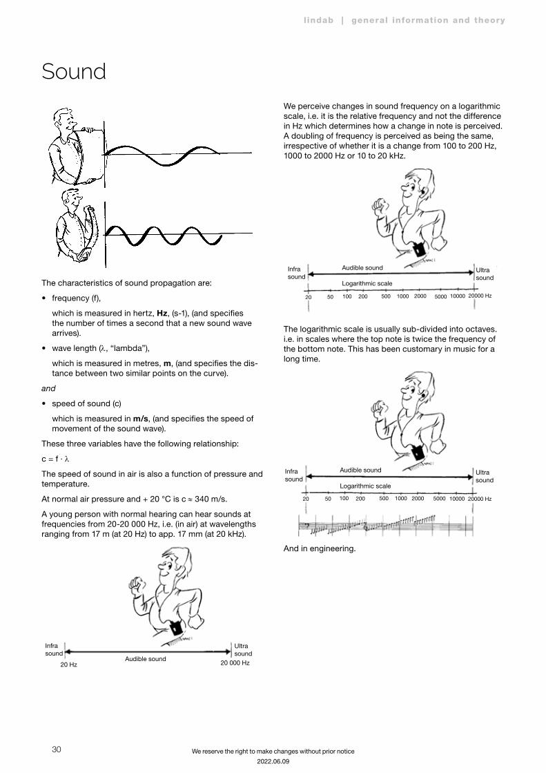
The characteristics of sound propagation are:
• frequency (f),
which is measured in hertz, Hz, (s-1), (and specifies the number of times a second that a new sound wave arrives).
• wave length (l, “lambda”),
which is measured in metres, m, (and specifies the dis-tance between two similar points on the curve).
and
• speed of sound (c)
which is measured in m/s, (and specifies the speed of movement of the sound wave).
These three variables have the following relationship:
c = f · l
The speed of sound in air is also a function of pressure and temperature.
At normal air pressure and + 20 °C is c ≈ 340 m/s.
A young person with normal hearing can hear sounds at frequencies from 20-20 000 Hz, i.e. (in air) at wavelengths ranging from 17 m (at 20 Hz) to app. 17 mm (at 20 kHz).
Infrasound
Audible sound
Ultrasound
20 Hz 20 000 Hz
We perceive changes in sound frequency on a logarithmic scale, i.e. it is the relative frequency and not the difference in Hz which determines how a change in note is perceived. A doubling of frequency is perceived as being the same, irrespective of whether it is a change from 100 to 200 Hz, 1000 to 2000 Hz or 10 to 20 kHz.
Infrasound
Audible sound
Logarithmic scale
Ultrasound
20 50 100 200 500 1000 2000 5000 10000 20000 Hz
The logarithmic scale is usually sub-divided into octaves. i.e. in scales where the top note is twice the frequency of the bottom note. This has been customary in music for a long time.
Infrasound
Audible sound
Logarithmic scale
Ultrasound
20 50 100 200 500 1000 2000 5000 10000 20000 Hz
And in engineering.

31
l indab | general information and theory
We reserve the right to make changes without prior notice
2022.06.09
Sound
Infrasound
Audible sound
Logarithmic scale
Ultrasound
20 50 100 200 500 1000 2000 5000 10000 20000 Hz
Border frequency for octave band
Geometrical centre frequency for octave band
16 31,5 63 125 250 500 Hz 1 2 4 8 16 kHz
22 44 88 176
352
704
1408
2820
5640
1130
0
2260
0
The concept of decibelThe stronger the sound is, the harder the particles of air will bump into each other.
Sound pressure changes in the audible area can vary within very wide limits. Some sounds are so weak that we can not hear them. The so-called audible limit varies with frequency and is 20 mPa at about 1000 Hz .
Other sounds are so loud that we risk hearing damage. The pain limit, the sound pressure which causes pain in your ears also varies with frequency, but is about 20 Pa at 1000 Hz. This means that it is a million times louder than the weakest sound we can perceive.
We also perceive changes in sound pressure on a loga-rithmic scale. A sound level concept using the decibel (dB) as the unit, has been created to express comparable values.
The dB unit, which is used in many different applications,
is generally defined as: 10 · log (X/X0), where X is the unit measured, i.e. the sound pressure, and X0 is a reference level expressed in the same units. The relationship of X/X0 is thus dimensionless. The reference level from which the dB unit is specified, is given instead. This means that you generally express the level in dB (above X0).
Our perception of soundWe react differently to two sounds which have the same sound pressure level and different frequencies.
Curves which describe how people normally perceive sounds of varying strength and frequency have been constructed through experiments on large numbers of volunteers. These so-called hearing level curves are designated by the sound pressure level for each curve at a frequency of 1 kHz. The unit used for the curves is the phon.
Hearing level curves
140
130
120
110
100
90
80
70
60
50
40
30
20
10
0
10020 50 1000200 500 2000 500015000
Frequence (Hz)
140
130
120
110
100
90
80
70
60
50
40
30
20
10
0
Hearing level (phon)
130
120
110
100
90
80
70
60
50
40
30
20
10
10000
Sound pressure level dB (over 20 mPa)
Hearing threshold
Example:
The sound pressure level 70 dB at 50 Hz is normally perceived as being as loud as 50 dB at 1000 Hz.
Sound levels

32
l indab | general information and theory
We reserve the right to make changes without prior notice
2022.06.09
Several methods are used to compare the disturbance caused by two different sounds, and where the perception of the ear to noise has been modelled.
The simplest way is to compare their “weighted” sound levels. The incoming sound is filtered in an electronic filter to reduce the components, mostly the low-frequency components, where the ear is not so sensitive, and amplify the components between 1 and 4 kHz, where we are most sensitive.
Sound meters usually have three electronic filters, A-, B- and C-filter. The A-filter is mostly used these days, where the result, the “weighted” sound level, is expressed in dB (A)
)31 63 125 250 500 1 2 4 8 16 kHz
2-60
-50
-40
-30
-20
-10
0
Attenuation dB (above 20 mPa)
2 5 102 2 5 103 2 5 104 Hz
CC
BB
AA
AACC
BB
Choosing silencers The fan is the primary sound source in a ventilation system, but intrusive noise can also be caused by an unsuitable choice of duct components and terminal units:
Lw = 40 + 10 · log q + 20 · log pt dB (above 1 pW)
q = air flow (in m³/s) through the fan
pt = total pressure rise (in Pa) in the fan
40 = “specific noise power level” which considers the effi-ciency of the fan at its point of operation, and the SI units for q and pt.
The noise generated in the fan must be attenuated in the duct system, at some point before the room terminal unit. Some of the attenuation is “natural”, examples are given above. This attenuation is often not enough, and addi-tional silencers can be put in the duct system - in the main channel near the fan to damp the fan noise to all the duct branches or in the branch ducts only to damp particularly sensitive rooms.
Low air speeds should be selected in the ducts, to avoid disturbing noise in the rooms.
• At a given air speed, a doubling of that speed corre-sponds to a 12 dB increase in noise levels.
Low air speeds also cut operating costs.
• At a given air speed, the fan power required increases as the square of the air speed.
In this example, calculation has shows that the existing attenuation in the duct system is not enough. The table shows that more attenuation is needed. What to choose?
Example
Duct Ø315
63 125 250 500 1k 2k 4k 8kBefore X X X X X X X X dBAfter X X X X X X X X dBDifference 2 4 9 19 21 12 7 7 dB
Lindab has a large range of silencers with varying charac-teristics and dimensions. Lets see what might fit!
Sound
33
l indab | general information and theory
We reserve the right to make changes without prior notice
2022.06.09
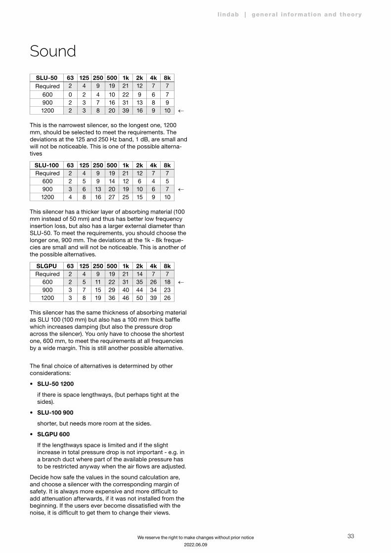
SLU-50 63 125 250 500 1k 2k 4k 8kRequired 2 4 9 19 21 12 7 7
600 0 2 4 10 22 9 6 7900 2 3 7 16 31 13 8 91200 2 3 8 20 39 16 9 10 ←
This is the narrowest silencer, so the longest one, 1200 mm, should be selected to meet the requirements. The deviations at the 125 and 250 Hz band, 1 dB, are small and will not be noticeable. This is one of the possible alterna-tives
SLU-100 63 125 250 500 1k 2k 4k 8kRequired 2 4 9 19 21 12 7 7
600 2 5 9 14 12 6 4 5900 3 6 13 20 19 10 6 7 ←1200 4 8 16 27 25 15 9 10
This silencer has a thicker layer of absorbing material (100 mm instead of 50 mm) and thus has better low frequency insertion loss, but also has a larger external diameter than SLU-50. To meet the requirements, you should choose the longer one, 900 mm. The deviations at the 1k - 8k freque-cies are small and will not be noticeable. This is another of the possible alternatives.
SLGPU 63 125 250 500 1k 2k 4k 8kRequired 2 4 9 19 21 14 7 7
600 2 5 11 22 31 35 26 18 ←900 3 7 15 29 40 44 34 231200 3 8 19 36 46 50 39 26
This silencer has the same thickness of absorbing material as SLU 100 (100 mm) but also has a 100 mm thick baffle which increases damping (but also the pressure drop across the silencer). You only have to choose the shortest one, 600 mm, to meet the requirements at all frequencies by a wide margin. This is still another possible alternative.
The final choice of alternatives is determined by other considerations:
• SLU-50 1200
if there is space lengthways, (but perhaps tight at the sides).
• SLU-100 900
shorter, but needs more room at the sides.
• SLGPU 600
If the lengthways space is limited and if the slight increase in total pressure drop is not important - e.g. in a branch duct where part of the available pressure has to be restricted anyway when the air flows are adjusted.
Decide how safe the values in the sound calculation are, and choose a silencer with the corresponding margin of safety. It is always more expensive and more difficult to add attenuation afterwards, if it was not installed from the beginning. If the users ever become dissatisfied with the noise, it is difficult to get them to change their views.
Sound

Most of us spend the majority of our time indoors. In-
door climate is crucial to how we feel, how productive
we are and if we stay healthy.
We at Lindab have therefore made it our most important
objective to contribute to an indoor climate that improves
people’s lives. We do this by developing energy-efficient
ventilation solutions and durable building products. We
also aim to contribute to a better climate for our planet
by working in a way that is sustainable for both people
and the environment.
Lindab | For a better climate