LGA/LGC LCA/LCC - HVAC Parts Shop
76
© 1999 Lennox Industries Inc. Litho U.S.A. Page 1 Corp. 9913−L7 LGA/LGC LCA/LCC Service Literature 21 / 30 TON 74 / 105 kW Revised 01−2009 LGA/LGC/LCA/LCC SERIES The LGA /LGC/ LCA/LCC 21, 25 and 30 ton (74, 88, 105 kW) units are configured to order units (CTO) with a wide selection of factory installed options. The LGA/LGC248H/360H gas/ electric packaged rooftop units are available in 260,000 Btuh, 360,000 Btuh and 480,000 Btuh (76.2 kW, 105.5 and 137.7 kW) heating inputs. Gas heat sections are designed with Len- nox’ aluminized steel tube heat exchangers. The LCA/ LCC248H/360H cooling packaged rooftop units are equipped with the same cooling sections as the LGA/ LGC248H/360H units. LCA/LGA248, LCC/LGC300H and LCC/LGC360H units may contain a supply air blower equipped with a variable frequency drive A96 (VFD) which varies supply air CFM. As duct static increases, the supply air volume will decrease. As duct static decreases, the supply air volume will in- crease. Optional electric heat is factory−or field−installed in LCA /LCC units. Electric heat operates in single or multiple stages de- pending on the kW input size. 30kW through 120kW heat sections are available for the LCA/LCC248H/360H. LGA/ LGC and LCA/LCC units have identical refrigerant circuits with 21, 25 and 30 ton (74, 88 and 105kW) cooling capaci- ties. LGA/LCA360H units utilize three compressors, while the LGA/LCA300H and LGA/LCA248H units utilize four compressors. Units are also designed for R−410A refrigerant. See unit nameplate for refrigerant type and charge. Operating pres- sures and pressure switch settings are significantly higher than units charged with R−22. Service equipment for R−410A units must be rated for R−410A refrigerant. The LGA and LCA units are designed to accept any of sev- eral different energy management thermostat control sys- tems with minimum field wiring. Factory or field provided control options connect to the unit with jack plugs. When "plugged in" the controls become an integral part of the unit wiring. Information contained in this manual is intended for use by qulified service technicians only. All specifications are sub- ject to change. Procedures outlined in this manual are pre- sented as a recommendation only and do not supersede or replace local or state codes. If the unit must be lifted for service, rig unit by attaching four cables to the holes located in the unit base rail (two holes at each corner). Refer to the installation instructions for the prop- er rigging technique. LGA360 WARNING Improper installation, adjustment, alteration, service or maintenance can cause property damage, person- al injury or loss of life. Installation and service must be performed by a qualified installer or service agency. WARNING Electric shock hazard. Can cause injury or death. Before attempting to perform any service or maintenance, turn the electrical power to unit OFF at discon- nect switch(es). Unit may have multiple power supplies.
-
Upload
khangminh22 -
Category
Documents
-
view
2 -
download
0
Transcript of LGA/LGC LCA/LCC - HVAC Parts Shop

© 1999 Lennox Industries Inc.
Litho U.S.A.Page 1
Corp. 9913−L7
LGA/LGCLCA/LCC
Service Literature21 / 30 TON74 / 105 kWRevised 01−2009
LGA/LGC/LCA/LCC SERIES
The LGA /LGC/ LCA/LCC 21, 25 and 30 ton (74, 88, 105 kW)
units are configured to order units (CTO) with a wide selection
of factory installed options. The LGA/LGC248H/360H gas/
electric packaged rooftop units are available in 260,000 Btuh,
360,000 Btuh and 480,000 Btuh (76.2 kW, 105.5 and 137.7
kW) heating inputs. Gas heat sections are designed with Len-
nox’ aluminized steel tube heat exchangers. The LCA/
LCC248H/360H cooling packaged rooftop units are
equipped with the same cooling sections as the LGA/
LGC248H/360H units.
LCA/LGA248, LCC/LGC300H and LCC/LGC360H units
may contain a supply air blower equipped with a variable
frequency drive A96 (VFD) which varies supply air CFM. As
duct static increases, the supply air volume will decrease.
As duct static decreases, the supply air volume will in-
crease.
Optional electric heat is factory−or field−installed in LCA /LCC
units. Electric heat operates in single or multiple stages de-
pending on the kW input size. 30kW through 120kW heat
sections are available for the LCA/LCC248H/360H. LGA/
LGC and LCA/LCC units have identical refrigerant circuits
with 21, 25 and 30 ton (74, 88 and 105kW) cooling capaci-
ties. LGA/LCA360H units utilize three compressors, while
the LGA/LCA300H and LGA/LCA248H units utilize four
compressors.
Units are also designed for R−410A refrigerant. See unit
nameplate for refrigerant type and charge. Operating pres-
sures and pressure switch settings are significantly higher
than units charged with R−22. Service equipment for
R−410A units must be rated for R−410A refrigerant.
The LGA and LCA units are designed to accept any of sev-
eral different energy management thermostat control sys-
tems with minimum field wiring. Factory or field provided
control options connect to the unit with jack plugs. When
"plugged in" the controls become an integral part of the unit
wiring.
Information contained in this manual is intended for use by
qulified service technicians only. All specifications are sub-
ject to change. Procedures outlined in this manual are pre-
sented as a recommendation only and do not supersede or
replace local or state codes.
If the unit must be lifted for service, rig unit by attaching four
cables to the holes located in the unit base rail (two holes at
each corner). Refer to the installation instructions for the prop-
er rigging technique.
LGA360
WARNINGImproper installation, adjustment, alteration, serviceor maintenance can cause property damage, person-al injury or loss of life. Installation and service mustbe performed by a qualified installer or serviceagency.
WARNINGElectric shock hazard. Can cause injuryor death. Before attempting to performany service or maintenance, turn theelectrical power to unit OFF at discon-nect switch(es). Unit may have multiplepower supplies.
Page 2
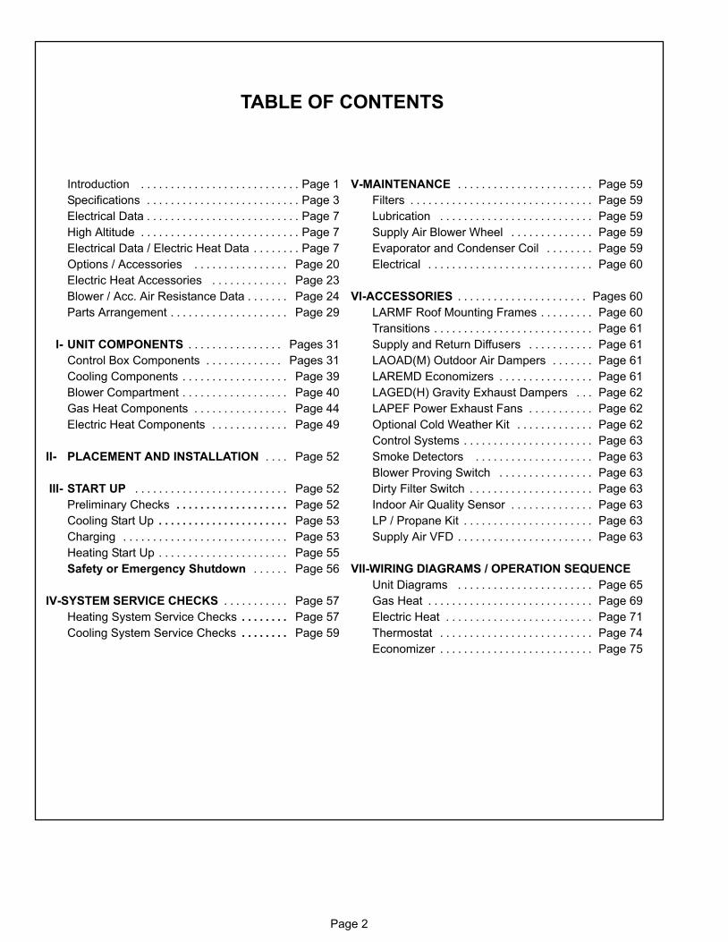
TABLE OF CONTENTS
Introduction Page 1. . . . . . . . . . . . . . . . . . . . . . . . . . .
Specifications Page 3. . . . . . . . . . . . . . . . . . . . . . . . . .
Electrical Data Page 7. . . . . . . . . . . . . . . . . . . . . . . . . .
High Altitude Page 7. . . . . . . . . . . . . . . . . . . . . . . . . . .
Electrical Data / Electric Heat Data Page 7. . . . . . . .
Options / Accessories Page 20. . . . . . . . . . . . . . . .
Electric Heat Accessories Page 23. . . . . . . . . . . . .
Blower / Acc. Air Resistance Data Page 24. . . . . . .
Parts Arrangement Page 29. . . . . . . . . . . . . . . . . . . .
I− UNIT COMPONENTS Pages 31. . . . . . . . . . . . . . . .
Control Box Components Pages 31. . . . . . . . . . . . .
Cooling Components Page 39. . . . . . . . . . . . . . . . . .
Blower Compartment Page 40. . . . . . . . . . . . . . . . . .
Gas Heat Components Page 44. . . . . . . . . . . . . . . .
Electric Heat Components Page 49. . . . . . . . . . . . .
II− PLACEMENT AND INSTALLATION Page 52. . . .
III− START UP Page 52. . . . . . . . . . . . . . . . . . . . . . . . . .
Preliminary Checks Page 52. . . . . . . . . . . . . . . . . . .
Cooling Start Up Page 53. . . . . . . . . . . . . . . . . . . . . .
Charging Page 53. . . . . . . . . . . . . . . . . . . . . . . . . . . .
Heating Start Up Page 55. . . . . . . . . . . . . . . . . . . . . .
Safety or Emergency Shutdown Page 56. . . . . .
IV−SYSTEM SERVICE CHECKS Page 57. . . . . . . . . . .
Heating System Service Checks Page 57. . . . . . . .
Cooling System Service Checks Page 59. . . . . . . .
V−MAINTENANCE Page 59. . . . . . . . . . . . . . . . . . . . . . .
Filters Page 59. . . . . . . . . . . . . . . . . . . . . . . . . . . . . . .
Lubrication Page 59. . . . . . . . . . . . . . . . . . . . . . . . . .
Supply Air Blower Wheel Page 59. . . . . . . . . . . . . .
Evaporator and Condenser Coil Page 59. . . . . . . .
Electrical Page 60. . . . . . . . . . . . . . . . . . . . . . . . . . . .
VI−ACCESSORIES Pages 60. . . . . . . . . . . . . . . . . . . . . .
LARMF Roof Mounting Frames Page 60. . . . . . . . .
Transitions Page 61. . . . . . . . . . . . . . . . . . . . . . . . . . .
Supply and Return Diffusers Page 61. . . . . . . . . . .
LAOAD(M) Outdoor Air Dampers Page 61. . . . . . .
LAREMD Economizers Page 61. . . . . . . . . . . . . . . .
LAGED(H) Gravity Exhaust Dampers Page 62. . .
LAPEF Power Exhaust Fans Page 62. . . . . . . . . . .
Optional Cold Weather Kit Page 62. . . . . . . . . . . . .
Control Systems Page 63. . . . . . . . . . . . . . . . . . . . . .
Smoke Detectors Page 63. . . . . . . . . . . . . . . . . . . .
Blower Proving Switch Page 63. . . . . . . . . . . . . . . .
Dirty Filter Switch Page 63. . . . . . . . . . . . . . . . . . . . .
Indoor Air Quality Sensor Page 63. . . . . . . . . . . . . .
LP / Propane Kit Page 63. . . . . . . . . . . . . . . . . . . . . .
Supply Air VFD Page 63. . . . . . . . . . . . . . . . . . . . . . .
VII−WIRING DIAGRAMS / OPERATION SEQUENCE
Unit Diagrams Page 65. . . . . . . . . . . . . . . . . . . . . . .
Gas Heat Page 69. . . . . . . . . . . . . . . . . . . . . . . . . . . .
Electric Heat Page 71. . . . . . . . . . . . . . . . . . . . . . . . .
Thermostat Page 74. . . . . . . . . . . . . . . . . . . . . . . . . .
Economizer Page 75. . . . . . . . . . . . . . . . . . . . . . . . . .

Page 3
SPECIFICATIONS LGA/LCAGeneralData
Nominal Tonnage (kW) 21 Ton 21 Ton 21 Ton 21 Ton
Model No. 248H2B 248H4B 248H2V 248H4V
Efficiency Type High High High High
Blower Type Constant AirVolume (CAV)
Constant AirVolume (CAV)
Variable AirVolume (VAV)
Variable AirVolume (VAV)
CoolingPerformance
Gross Cooling Capacity − Btuh (kW) 257,000 (75.3) 257,000 (75.3) 257,000 (75.3) 257,000 (75.3)1 Net Cooling Capacity − Btuh (kW) 248,000 (72.6) 248,000 (72.6) 248,000 (72.6) 248,000 (72.6)
ARI Rated Air Flow − cfm (L/s) 8,000 (3775) 8,000 (3775) 8,000 (3775) 8,000 (3775)
Total Unit Power (kW) 21.2 21.2 21.2 21.81 EER (Btuh/Watt) 11.7 11.7 11.7 11.4
2 Integrated Part Load Value (Btuh/Watt) 12.3 12.7 14.0 14.2
Refrigerant Type R−22 R−410A R−22 R−410A
Refrigerant ChargeFurnished
Circuit 1 12 lbs. 8 oz.(5.67 kg)
13 lbs. 0 oz.(5.90 kg)
12 lbs. 8 oz.(5.67 kg)
13 lbs. 0 oz.(5.90 kg)
Circuit 2 12 lbs. 8 oz.(5.67 kg)
13 lbs. 0 oz.(5.90 kg)
12 lbs. 8 oz.(5.67 kg)
13 lbs. 0 oz.(5.90 kg)
Circuit 3 12 lbs. 8 oz.(5.67 kg)
13 lbs. 0 oz.(5.90 kg)
12 lbs. 8 oz.(5.67 kg)
13 lbs. 0 oz.(5.90 kg)
Circuit 4 12 lbs. 8 oz.(5.67 kg)
13 lbs. 0 oz.(5.90 kg)
12 lbs. 8 oz.(5.67 kg)
13 lbs. 0 oz.(5.90 kg)
Compressor Type (no.) Scroll (4) Scroll (4) Scroll (4) Scroll (4)
Gas Heating Options Available − See Page 7 Standard (2 Stage), Medium (2 Stage), or High (2 Stage)
OutdoorCoils
Net face area − sq. ft. (m2) total 70.6 (6.6) 70.6 (6.6) 70.6 (6.6) 70.6 (6.6)
Tube diameter − in. (mm) 3/8 (9.5) 3/8 (9.5) 3/8 (9.5) 3/8 (9.5)
Number of rows 2 2 2 2
Fins per inch (m) 20 (787) 20 (787) 20 (787) 20 (787)
Outdoor CoilFans
Motor horsepower (W) (6) 1/3 (249) (6) 1/3 (249) (6) 1/3 (249) (6) 1/3 (249)
Motor rpm 1075 1075 1075 1075
Total Motor watts 2500 2500 2500 2500
Diameter − in. (mm) (6) 24 (610) (6) 24 (610) (6) 24 (610) (6) 24 (610)
Number of blades 3 3 3 3
Total Air volume − cfm (L/s) 21,500 (10,145) 21,500 (10,145) 21,500 (10,145) 21,500 (10,145)
IndoorCoils
Net face area − sq. ft. (m2) total 33.3 (3.1) 33.3 (3.1) 33.3 (3.1) 33.3 (3.1)
Tube diameter − in. (mm) 3/8 (9.5) 3/8 (9.5) 3/8 (9.5) 3/8 (9.5)
Number of rows 3 3 3 3
Fins per inch (m) 14 (551) 14 (551) 14 (551) 14 (551)
Condensate Drain − number & size (1) 1 in. NPT coupling
Expansion device type Balanced Port Thermostatic Expansion Valve, removeable power head3 IndoorBlower andDriveSelection
Nominal motor output 5 hp (3.7 kW) − 7.5 hp (5.6 kW) − 10 hp (7.5 kW)
Max. usable motor output (US Only) 5.75 hp (4.3 kW) − 8.63 hp (6.4 kW) − 11.5 hp (8.6 kW)
Motor − Drive kit 5 hpkit #1 − 660−810 rpmkit #2 − 770−965 rpmkit #6 − 560−710 rpm
7.5 hpkit #3 − 715−880 rpmkit #4 − 770−965 rpm
10 hpkit #3 − 715−880 rpmkit #5 − 850−1045 rpm
5 hpkit #7 − 965 rpm
7.5 hpkit #8 − 965 rpm
10 hpkit #9 − 1045 rpm
Blower�wheel�nominal�dia.�x�width (2) 18 x 15 in. (457 x 381 mm)
Filters Type of filter Disposable, pleated MERV 7 (standard) or MERV 11 (optional)
Number and size − in. (mm) (12) 20 x 20 x 2 (508 x 508 x 51)
Electrical characteristics 208/230V, 460V or 575V − 60 hertz − 3 phase
NOTE − Net capacity includes evaporator blower motor heat deduction. Gross capacity does not include evaporator blower motor heat deduction.1 Tested at conditions included in with ARI Standard 340/360; 95�F (35�C) outdoor air temperature and 80�F (27�C) db/67�F (19�C) wb entering evaporator air; minimumexternal duct static pressure.2 Integrated Part Load Value tested at 80�F (27�C) outdoor air temperature.3 Using total air volume and system static pressure requirements determine from blower performance tables rpm and motor output required. Maximum usable output of
motors furnished are shown. In Canada, nominal motor output is also maximum usable motor output. If motors of comparable output are used, be sure to keepwithin the service factor limitations outlined on the motor nameplate.
Page 4
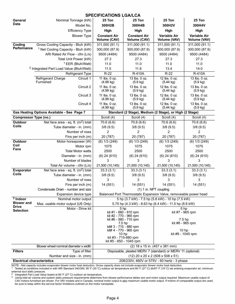
SPECIFICATIONS LGA/LCAGeneralData
Nominal Tonnage (kW) 25 Ton 25 Ton 25 Ton 25 Ton
Model No. 300H2B 300H4B 300H2V 300H4V
Efficiency Type High High High High
Blower Type Constant AirVolume (CAV)
Constant AirVolume (CAV)
Variable AirVolume (VAV)
Variable AirVolume (VAV)
CoolingPerformance
Gross Cooling Capacity − Btuh (kW) 311,000 (91.1) 311,000 (91.1) 311,000 (91.1) 311,000 (91.1)1 Net Cooling Capacity − Btuh (kW) 300,000 (87.9) 300,000 (87.9) 300,000 (87.9) 300,000 (87.9)
ARI Rated Air Flow − cfm (L/s) 9500 (4484) 9500 (4484) 9500 (4484) 9500 (4484)
Total Unit Power (kW) 27.3 27.3 27.3 27.31 EER (Btuh/Watt) 11.0 11.0 11.0 11.0
2 Integrated Part Load Value (Btuh/Watt) 11.5 11.8 13.4 14.0
Refrigerant Type R−22 R−410A R−22 R−410A
Refrigerant ChargeFurnished
Circuit 1 11 lbs. 0 oz.(4.99 kg)
13 lbs. 0 oz.(5.9 kg)
12 lbs. 0 oz.(5.44 kg)
13 lbs. 0 oz.(5.9 kg)
Circuit 2 11 lbs. 0 oz.(4.99 kg)
13 lbs. 0 oz.(5.9 kg)
12 lbs. 0 oz.(5.44 kg)
13 lbs. 0 oz.(5.9 kg)
Circuit 3 11 lbs. 0 oz.(4.99 kg)
13 lbs. 0 oz.(5.9 kg)
12 lbs. 0 oz.(5.44 kg)
13 lbs. 0 oz.(5.9 kg)
Circuit 4 11 lbs. 0 oz.(4.99 kg)
13 lbs. 0 oz.(5.9 kg)
12 lbs. 0 oz.(5.44 kg)
13 lbs. 0 oz.(5.9 kg)
Gas Heating Options Available − See Page 7 Standard (2 Stage), Medium (2 Stage), or High (2 Stage)
Compressor Type (no.) Scroll (4) Scroll (4) Scroll (4) Scroll (4)
OutdoorCoils
Net face area − sq. ft. (m2) total 70.6 (6.6) 70.6 (6.6) 70.6 (6.6) 70.6 (6.6)
Tube diameter − in. (mm) 3/8 (9.5) 3/8 (9.5) 3/8 (9.5) 3/8 (9.5)
Number of rows 2 2 2 2
Fins per inch (m) 20 (787) 20 (787) 20 (787) 20 (787)
OutdoorCoilFans
Motor horsepower (W) (6) 1/3 (249) (6) 1/3 (249) (6) 1/3 (249) (6) 1/3 (249)
Motor rpm 1075 1075 1075 1075
Total Motor watts 2500 2500 2500 2500
Diameter − in. (mm) (6) 24 (610) (6) 24 (610) (6) 24 (610) (6) 24 (610)
Number of blades 3 3 3 3
Total Air volume − cfm (L/s) 21,500 (10,145) 21,500 (10,145) 21,500 (10,145) 21,500 (10,145)
EvaporatorCoils
Net face area − sq. ft. (m2) total 33.3 (3.1) 33.3 (3.1) 33.3 (3.1) 33.3 (3.1)
Tube diameter − in. (mm) 3/8 (9.5) 3/8 (9.5) 3/8 (9.5) 3/8 (9.5)
Number of rows 3 3 3 3
Fins per inch (m) 14 (551) 14 (551) 14 (551) 14 (551)
Condensate Drain − number and size (1) 1 in. NPT coupling
Expansion device type Balanced Port Thermostatic Expansion Valve, removeable power head3 IndoorBlower andDriveSelection
Nominal motor output 5 hp (3.7 kW) − 7.5 hp (5.6 kW) − 10 hp (7.5 kW)
Max. usable motor output (US Only) 5.75 hp (4.3 kW) − 8.63 hp (6.4 kW) − 11.5 hp (8.6 kW)
Motor − Drive kit 5 hpkit #1 − 660 − 810 rpmkit #2 − 770 − 965 rpmkit #6 − 560 − 710 rpm
7.5 hpkit# 3 − 715 − 880 rpmkit# 4 − 770 − 965 rpm
10 hpkit #3 − 715−880 rpm
kit #5 − 850 − 1045 rpm
5 hpkit #7 − 965 rpm
7.5 hpkit #8 − 965 rpm
10 hpkit #9 − 1045 rpm
Blower�wheel�nominal�diameter�x�width (2) 18 x 15 in. (457 x 381 mm)
Filters Type of filter Disposable, pleated MERV 7 (standard) or MERV 11 (optional)
Number and size − in. (mm) (12) 20 x 20 x 2 (508 x 508 x 51)
Electrical characteristics 208/230V, 460V or 575V − 60 hertz − 3 phase
NOTE − Net capacity includes evaporator blower motor heat deduction. Gross capacity does not include evaporator blower motor heat deduction.1 Tested at conditions included in with ARI Standard 340/360; 95�F (35�C) outdoor air temperature and 80�F (27�C) db/67�F (19�C) wb entering evaporator air; minimumexternal duct static pressure.2 Integrated Part Load Value tested at 80�F (27�C) outdoor air temperature.3 Using total air volume and system static pressure requirements determine from blower performance tables rpm and motor output required. Maximum usable output of
CAV motors furnished are shown. For VAV models and in Canada, nominal motor output is also maximum usable motor output. If motors of comparable output are used,be sure to keep within the service factor limitations outlined on the motor nameplate.
Page 5
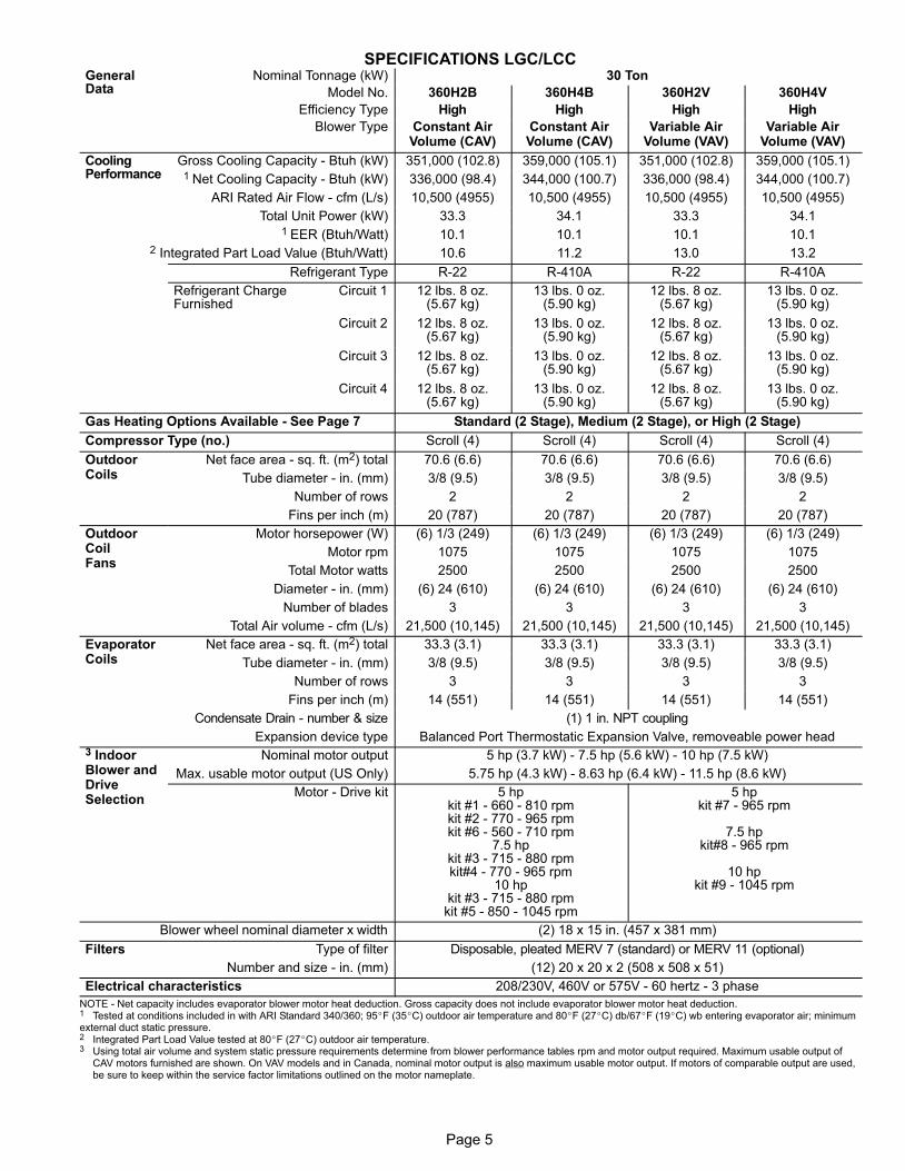
SPECIFICATIONS LGC/LCCGeneralData
Nominal Tonnage (kW) 30 Ton
Model No. 360H2B 360H4B 360H2V 360H4V
Efficiency Type High High High High
Blower Type Constant AirVolume (CAV)
Constant AirVolume (CAV)
Variable AirVolume (VAV)
Variable AirVolume (VAV)
CoolingPerformance
Gross Cooling Capacity − Btuh (kW) 351,000 (102.8) 359,000 (105.1) 351,000 (102.8) 359,000 (105.1)1 Net Cooling Capacity − Btuh (kW) 336,000 (98.4) 344,000 (100.7) 336,000 (98.4) 344,000 (100.7)
ARI Rated Air Flow − cfm (L/s) 10,500 (4955) 10,500 (4955) 10,500 (4955) 10,500 (4955)
Total Unit Power (kW) 33.3 34.1 33.3 34.11 EER (Btuh/Watt) 10.1 10.1 10.1 10.1
2 Integrated Part Load Value (Btuh/Watt) 10.6 11.2 13.0 13.2
Refrigerant Type R−22 R−410A R−22 R−410A
Refrigerant ChargeFurnished
Circuit 1 12 lbs. 8 oz.(5.67 kg)
13 lbs. 0 oz.(5.90 kg)
12 lbs. 8 oz.(5.67 kg)
13 lbs. 0 oz.(5.90 kg)
Circuit 2 12 lbs. 8 oz.(5.67 kg)
13 lbs. 0 oz.(5.90 kg)
12 lbs. 8 oz.(5.67 kg)
13 lbs. 0 oz.(5.90 kg)
Circuit 3 12 lbs. 8 oz.(5.67 kg)
13 lbs. 0 oz.(5.90 kg)
12 lbs. 8 oz.(5.67 kg)
13 lbs. 0 oz.(5.90 kg)
Circuit 4 12 lbs. 8 oz.(5.67 kg)
13 lbs. 0 oz.(5.90 kg)
12 lbs. 8 oz.(5.67 kg)
13 lbs. 0 oz.(5.90 kg)
Gas Heating Options Available − See Page 7 Standard (2 Stage), Medium (2 Stage), or High (2 Stage)
Compressor Type (no.) Scroll (4) Scroll (4) Scroll (4) Scroll (4)
OutdoorCoils
Net face area − sq. ft. (m2) total 70.6 (6.6) 70.6 (6.6) 70.6 (6.6) 70.6 (6.6)
Tube diameter − in. (mm) 3/8 (9.5) 3/8 (9.5) 3/8 (9.5) 3/8 (9.5)
Number of rows 2 2 2 2
Fins per inch (m) 20 (787) 20 (787) 20 (787) 20 (787)
OutdoorCoilFans
Motor horsepower (W) (6) 1/3 (249) (6) 1/3 (249) (6) 1/3 (249) (6) 1/3 (249)
Motor rpm 1075 1075 1075 1075
Total Motor watts 2500 2500 2500 2500
Diameter − in. (mm) (6) 24 (610) (6) 24 (610) (6) 24 (610) (6) 24 (610)
Number of blades 3 3 3 3
Total Air volume − cfm (L/s) 21,500 (10,145) 21,500 (10,145) 21,500 (10,145) 21,500 (10,145)
EvaporatorCoils
Net face area − sq. ft. (m2) total 33.3 (3.1) 33.3 (3.1) 33.3 (3.1) 33.3 (3.1)
Tube diameter − in. (mm) 3/8 (9.5) 3/8 (9.5) 3/8 (9.5) 3/8 (9.5)
Number of rows 3 3 3 3
Fins per inch (m) 14 (551) 14 (551) 14 (551) 14 (551)
Condensate Drain − number & size (1) 1 in. NPT coupling
Expansion device type Balanced Port Thermostatic Expansion Valve, removeable power head3 IndoorBlower andDriveSelection
Nominal motor output 5 hp (3.7 kW) − 7.5 hp (5.6 kW) − 10 hp (7.5 kW)
Max. usable motor output (US Only) 5.75 hp (4.3 kW) − 8.63 hp (6.4 kW) − 11.5 hp (8.6 kW)
Motor − Drive kit 5 hpkit #1 − 660 − 810 rpmkit #2 − 770 − 965 rpmkit #6 − 560 − 710 rpm
7.5 hpkit #3 − 715 − 880 rpmkit#4 − 770 − 965 rpm
10 hpkit #3 − 715 − 880 rpmkit #5 − 850 − 1045 rpm
5 hpkit #7 − 965 rpm
7.5 hpkit#8 − 965 rpm
10 hpkit #9 − 1045 rpm
Blower�wheel�nominal�diameter�x�width (2) 18 x 15 in. (457 x 381 mm)
Filters Type of filter Disposable, pleated MERV 7 (standard) or MERV 11 (optional)
Number and size − in. (mm) (12) 20 x 20 x 2 (508 x 508 x 51)
Electrical characteristics 208/230V, 460V or 575V − 60 hertz − 3 phase
NOTE − Net capacity includes evaporator blower motor heat deduction. Gross capacity does not include evaporator blower motor heat deduction.1 Tested at conditions included in with ARI Standard 340/360; 95�F (35�C) outdoor air temperature and 80�F (27�C) db/67�F (19�C) wb entering evaporator air; minimumexternal duct static pressure.2 Integrated Part Load Value tested at 80�F (27�C) outdoor air temperature.3 Using total air volume and system static pressure requirements determine from blower performance tables rpm and motor output required. Maximum usable output of
CAV motors furnished are shown. On VAV models and in Canada, nominal motor output is also maximum usable motor output. If motors of comparable output are used,be sure to keep within the service factor limitations outlined on the motor nameplate.
Page 6
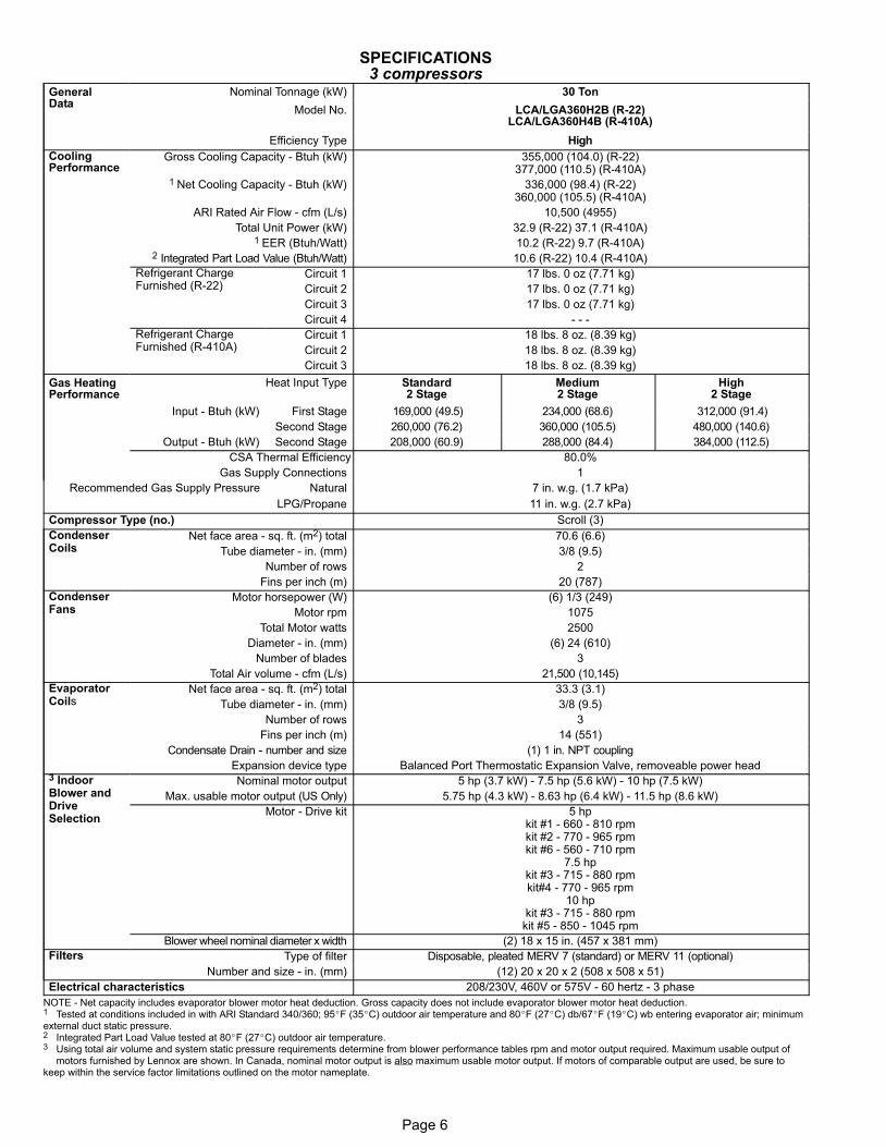
SPECIFICATIONS3 compressors
GeneralData
Nominal Tonnage (kW) 30 Ton
Model No. LCA/LGA360H2B (R−22)LCA/LGA360H4B (R−410A)
Efficiency Type High
CoolingPerformance
Gross Cooling Capacity − Btuh (kW) 355,000 (104.0) (R−22)377,000 (110.5) (R−410A)
1 Net Cooling Capacity − Btuh (kW) 336,000 (98.4) (R−22)360,000 (105.5) (R−410A)
ARI Rated Air Flow − cfm (L/s) 10,500 (4955)
Total Unit Power (kW) 32.9 (R−22) 37.1 (R−410A)1 EER (Btuh/Watt) 10.2 (R−22) 9.7 (R−410A)
2 Integrated Part Load Value (Btuh/Watt) 10.6 (R−22) 10.4 (R−410A)
Refrigerant ChargeFurnished (R-22)
Circuit 1 17 lbs. 0 oz (7.71 kg)
Circuit 2 17 lbs. 0 oz (7.71 kg)
Circuit 3 17 lbs. 0 oz (7.71 kg)
Circuit 4 - - -
Refrigerant ChargeFurnished (R-410A)
Circuit 1 18 lbs. 8 oz. (8.39 kg)
Circuit 2 18 lbs. 8 oz. (8.39 kg)
Circuit 3 18 lbs. 8 oz. (8.39 kg)
Gas HeatingPerformance
Heat Input Type Standard2 Stage
Medium2 Stage
High2 Stage
Input − Btuh (kW) First Stage 169,000 (49.5) 234,000 (68.6) 312,000 (91.4)
Second Stage 260,000 (76.2) 360,000 (105.5) 480,000 (140.6)
Output − Btuh (kW) Second Stage 208,000 (60.9) 288,000 (84.4) 384,000 (112.5)
CSA Thermal Efficiency 80.0%
Gas Supply Connections 1
Recommended Gas Supply Pressure Natural 7 in. w.g. (1.7 kPa)
LPG/Propane 11 in. w.g. (2.7 kPa)
Compressor Type (no.) Scroll (3)
CondenserCoils
Net face area − sq. ft. (m2) total 70.6 (6.6)
Tube diameter − in. (mm) 3/8 (9.5)
Number of rows 2
Fins per inch (m) 20 (787)
CondenserFans
Motor horsepower (W) (6) 1/3 (249)
Motor rpm 1075
Total Motor watts 2500
Diameter − in. (mm) (6) 24 (610)
Number of blades 3
Total Air volume − cfm (L/s) 21,500 (10,145)
EvaporatorCoils
Net face area − sq. ft. (m2) total 33.3 (3.1)
Tube diameter − in. (mm) 3/8 (9.5)
Number of rows 3
Fins per inch (m) 14 (551)
Condensate Drain − number and size (1) 1 in. NPT coupling
Expansion device type Balanced Port Thermostatic Expansion Valve, removeable power head3 IndoorBlower andDriveSelection
Nominal motor output 5 hp (3.7 kW) − 7.5 hp (5.6 kW) − 10 hp (7.5 kW)
Max. usable motor output (US Only) 5.75 hp (4.3 kW) − 8.63 hp (6.4 kW) − 11.5 hp (8.6 kW)
Motor − Drive kit 5 hpkit #1 − 660 − 810 rpmkit #2 − 770 − 965 rpmkit #6 − 560 − 710 rpm
7.5 hpkit #3 − 715 − 880 rpmkit#4 − 770 − 965 rpm
10 hpkit #3 − 715 − 880 rpmkit #5 − 850 − 1045 rpm
Blower�wheel�nominal�diameter�x�width (2) 18 x 15 in. (457 x 381 mm)
Filters Type of filter Disposable, pleated MERV 7 (standard) or MERV 11 (optional)
Number and size − in. (mm) (12) 20 x 20 x 2 (508 x 508 x 51)
Electrical characteristics 208/230V, 460V or 575V − 60 hertz − 3 phase
NOTE − Net capacity includes evaporator blower motor heat deduction. Gross capacity does not include evaporator blower motor heat deduction.1 Tested at conditions included in with ARI Standard 340/360; 95�F (35�C) outdoor air temperature and 80�F (27�C) db/67�F (19�C) wb entering evaporator air; minimumexternal duct static pressure.2 Integrated Part Load Value tested at 80�F (27�C) outdoor air temperature.3 Using total air volume and system static pressure requirements determine from blower performance tables rpm and motor output required. Maximum usable output of
motors furnished by Lennox are shown. In Canada, nominal motor output is also maximum usable motor output. If motors of comparable output are used, be sure tokeep within the service factor limitations outlined on the motor nameplate.

Page 7
SPECIFICATIONS GAS HEAT
Gas HeatingPerformance
Heat Input Type Standard (2 Stage) Medium (2 Stage) High (2 Stage)
Input − Btuh (KW) First Stage 169,000 (49.5) 234,000 (68.6) 312,000 (91.4)
Second Stage 260,000 (76.2) 360,000 (105.5) 480,000 (140.6)
Output − Btuh (kW) First Stage − − − − − − − − −
Second Stage 208,000 (60.9) 288,000 (84.4) 384,000 (112.5)
CSA Thermal Efficiency 80.0%
Gas Supply Connections 1 in. npt
Recommended Gas Supply Pressure − Natural 7 in. w.g. (1.7 kPa)
LPG/Propane 11 in. w.g. (2.7 kPa)
HIGH ALTITUDE
Units may be installed at altitudes up to 2000 feet (610 m) above sea level without any modi-
fication. At altitudes above 2000 feet (610 m), units must be derated to match gas manifold
pressures shown in table below. NOTE − This is the only permissible derate for these units.
Altitude − ft. (m)Natural Gas LPG/Propane
in. w.g. kPa in. w.g. kPa
2001 − 3000 (610 − 915) 3.6 0.90 10.2 2.54
3001 − 4000 (915 − 1220) 3.5 0.87 9.9 2.46
4001 − 5000 (1220 − 1525) 3.4 0.85 9.6 2.39
5001 − 6000 (1525 − 1830) 3.3 0.82 9.4 2.34
6001 − 7000 (1830 − 2135) 3.2 0.80 9.1 2.26
7001 − 8000 (2135 − 2440) 3.1 0.77 8.8 2.19
ELECTRIC HEAT CAPACITIES
VoltsInput
30 kW 45 kW 60 kW 90 kW 120 kW
kWInput
BtuhOutput
No. ofSteps
kWInput
BtuhOutput
No. ofSteps
kWInput
BtuhOutput
No. ofSteps
kWInput
BtuhOutput
No. ofSteps
kWInput
BtuhOutput
No. ofSteps
208 22.5 76,800 1 33.8 115,300 2 45.0 153,600 2 67.6 230,700 2 90.2 307,800 2220 25.2 86,000 1 37.8 129,000 2 50.4 172,000 2 75.6 258,000 2 100.8 344,000 2230 27.5 93,900 1 41.3 141,000 2 55.1 188,000 2 82.7 282,200 2 110.2 376,100 2240 30.0 102,400 1 45.0 153,600 2 60.0 204,800 2 90.0 307,100 2 120.0 409,500 2440 25.2 86,000 1 37.8 129,000 2 50.4 172,000 2 75.6 258,000 2 100.8 344,000 2460 27.5 93,900 1 41.3 141,000 2 55.1 188,000 2 82.7 282,200 2 110.2 376,100 2480 30.0 102,400 1 45.0 153,600 2 60.0 204,800 2 90.0 307,100 2 120.0 409,500 2550 25.2 86,000 1 37.8 129,000 2 50.4 172,000 2 75.6 258,000 2 100.8 344,000 2575 27.5 93,900 1 41.3 141,000 2 55.1 188,000 2 82.7 282,200 2 110.2 376,100 2600 30.0 102,400 1 45.0 153,600 2 60.0 204,800 2 90.0 307,100 2 120.0 409,500 2
ELECTRICAL DATA3 compressors
Model�No. LGA/LCA360H (R−22) LGA/LCA360H (R−410A)Line�voltage�data�−�60�Hz�−�3�phase 208/230V 460V 575V 208/230V 460V 575V
Compressors (3) Rated load amps each (total) 30.1 (90.3) 15.5 (46.5) 12.1 (36.3) 33.3 (99.9) 17.9 (53.7) 11.5 (34.5)
Locked rotor amps each (total) 225 (675) 114 (342) 80 (240) 239 (717) 125 (375) 80 (240)
CondenserFan�Motors (6)
Full�load�amps� each(total) 2.4 (14.4) 1.3 (7.8) 1 (6) 2.4 (14.4) 1.3 (7.8) 1 (6)
Locked�rotor�amps each (total) 4.7 (28.2) 2.4 (14.4) 1.9 (11.4) 4.7 (28.2) 2.4 (14.4) 1.9 (11.4)
EvaporatorBlower Motor
Motor Output − hp 5 7.5 10 5 7.5 10 5 7.5 10 5 7.5 10 5 7.5 10 5 7.5 10
kW 3.7 5.6 7.5 3.7 5.6 7.5 3.7 5.6 7.5 3.7 5.6 7.5 3.7 5.6 7.5 3.7 5.6 7.5
Full�load�amps 16.7 24.2 30.8 7.6 11 14 6.1 9 11 16.7 24.2 30.8 7.6 11 14 6.1 9 11
Locked�rotor�amps 105 152 193 45.6 66 84 36.6 54 66 105 152 193 45.6 66 84 36.6 54 66
1 Maximum OvercurrentProtection (amps)
With Exhaust Fans 150 150 175 80 80 90 60 60 70 175 175 175 90 90 100 60 60 60
Less Exhaust Fans 150 150 150 80 80 80 60 60 60 150 175 175 90 90 90 60 60 60
2 MinimumCircuit Ampacity
With Exhaust Fans 137 144 151 70 74 77 55 58 60 147 155 161 78 81 84 53 56 58
Less Exhaust Fans 129 137 143 66 70 73 52 55 57 140 147 154 74 77 80 50 53 55
OptionalPower�Exhaust Fans
(No.)�Horsepower (W) (3) 1/3 (249) (3) 1/3 (249) (3) 1/3 (249) (3) 1/3 (249) (3) 1/3 (249) (3) 1/3 (249)
Full�load�amps�(total) 7.2 3.9 3 7.2 3.9 3
Locked�rotor�amps�(total) 14.1 7.2 5.7 14.1 7.2 5.7
Service Outlet (2) 115 volt GFCI (amp rating) 15 15 15 15 15 15
NOTE�− Extremes�of�operating�range�are�plus�and�minus�10%�of�line�voltage.1 HACR type breaker or fuse.2 Refer�to�National or Canadian�Electrical�Code�manual�to�determine�wire,�fuse�and�disconnect�size�requirements.

Page 8
ELECTRICAL/ELECTRIC HEAT DATA LGA/LCA21 TON HIGH EFFICIENCY (R−22) 248H2
Voltage − 60hz − 3 phase 208/230V 460V 575V
Compressors(4)
Rated Load Amps (total) 17.3 (69.2) 9 (36) 7.1 (28.4)
Locked Rotor Amps (total) 123 (492) 62 (248) 50 (200)
Outdoor FanMotors (6)
Full Load Amps (total) 2.4 (14.4) 1.3 (7.8) 1 (6)
Locked Rotor Amps (total) 4.7 (28.2) 2.4 (14.4) 1.9 (11.4)
StandardPEF (3)
Horsepower (W) 1/3 (249) 1/3 (249) 1/3 (249)
Full Load Amps(total) 7.2 (21.6) 3.9 (11.7) 3 (9)
Locked Rotor Amps (total) 14.1 (42.3) 7.2 (21.6) 5.7 (17.1)
50% HighStatic PEF(2)
Horsepower (W) 2 (1491) 2 (1491) 2 (1491)
Full Load Amps(total) 7.5 (15) 3.4 (6.8) 2.7 (5.4)
Locked Rotor Amps (total) 69.4 (138.8) 31.4 (62.8) 20.1 (40.2)
100% HighStatic PEF(3)
Horsepower (W) 2 (1491) 2 (1491) 2 (1491)
Full Load Amps(total) 7.5 (22.5) 3.4 (10.2) 2.7 (8.1)
Locked Rotor Amps (total) 69.4 (208.2) 31.4 (94.2) 20.1 (60.3)
Service Outlet 115V GFI 15 Amps 15 Amps 15 Amps
Indoor BlowerMotor
Horsepower 5 7.5 10 5 7.5 10 5 7.5 10
Rated Load Amps 16.7 24.2 30.8 7.6 11 14 6.1 9 11
Locked Rotor Amps 105 152 193 45.6 66 84 36.6 54 661 MinimumCircuitAmpacity
with StandardPEF
0 kW 112 120 126 58 61 64 46 49 51
30 kW 121 130 138 60 64 68 48 52 54
45 kW 166 175 183 82 87 90 66 70 72
60 kW 175 184 192 87 91 95 70 73 76
90 kW 247 256 264 123 127 131 98 102 105
120 kW 319 328 337 159 163 167 127 131 133
with 50%High Static PEF
0 kW 120 128 134 61 64 67 48 51 53
30 kW 130 140 148 64 68 72 51 55 57
45 kW 175 185 193 86 90 94 69 73 75
60 kW 184 194 202 91 95 99 73 76 79
90 kW 257 266 274 127 131 135 101 105 108
120 kW 329 338 346 163 167 171 130 134 136
with 100%High Static PEF
0 kW 128 135 142 64 68 71 51 54 56
30 kW 140 149 157 68 72 76 54 58 60
45 kW 185 194 202 90 95 98 72 76 78
60 kW 194 203 211 95 99 103 76 80 82
90 kW 266 275 284 131 135 139 105 108 111
120 kW 338 348 356 167 171 175 134 137 140
without power exhaust 105 113 119 54 58 61 43 46 482 MaximumOvercurrentProtection
with StandardPEF
0 kW 125 125 150 60 70 70 50 50 60
30 kW 125 150 150 60 70 70 50 60 60
45 kW 175 175 200 90 90 90 70 70 80
60 kW 175 200 200 90 100 100 70 80 80
90 kW 250 3 300 3 300 125 150 150 100 110 110
120 kW 3 350 3 350 3 350 175 175 175 150 150 150
with 50%High Static PEF
0 kW 125 150 150 70 70 80 50 60 60
30 kW 150 150 150 70 70 80 60 60 60
45 kW 175 200 200 90 90 100 70 80 80
60 kW 200 200 225 100 100 100 80 80 80
90 kW 3 300 3 300 3 300 150 150 150 110 110 110
120 kW 3 350 3 350 3 350 175 175 175 150 150 150
with 100%High Static PEF
0 kW 150 150 175 70 70 80 60 60 60
30 kW 150 150 175 70 80 80 60 60 60
45 kW 200 200 225 90 100 100 80 80 80
60 kW 200 225 225 100 100 110 80 80 90
90 kW 3 300 3 300 3 300 150 150 150 110 110 125
120 kW 3 350 3 350 3 400 175 175 175 150 150 150
without power exhaust 110 125 150 60 60 70 45 50 50
NOTE�− Extremes�of�operating�range�are�plus�and�minus�10%�of�line�voltage. TABLE CONTINUED ON NEXT PAGE1 Refer�to�National or Canadian�Electrical�Code�manual�to�determine�wire,�fuse�and�disconnect�size�requirements.2 HACR type breaker or fuse.3 Factory installed circuit breaker not available.
Page 9
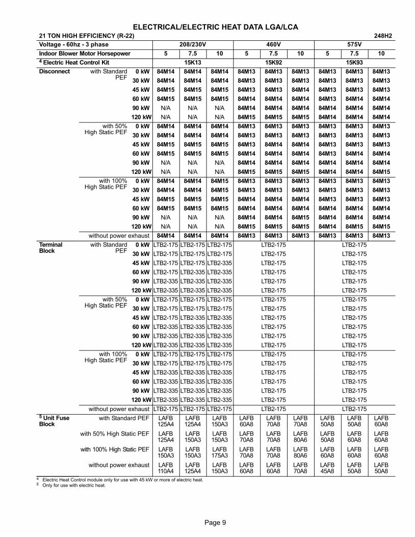
ELECTRICAL/ELECTRIC HEAT DATA LGA/LCA21 TON HIGH EFFICIENCY (R−22) 248H2
Voltage − 60hz − 3 phase 208/230V 460V 575V
Indoor Blower Motor Horsepower 5 7.5 10 5 7.5 10 5 7.5 10
4 Electric Heat Control Kit 15K13 15K92 15K93
Disconnect with StandardPEF
0 kW 84M14 84M14 84M14 84M13 84M13 84M13 84M13 84M13 84M13
30 kW 84M14 84M14 84M14 84M13 84M13 84M13 84M13 84M13 84M13
45 kW 84M15 84M15 84M15 84M13 84M13 84M14 84M13 84M13 84M13
60 kW 84M15 84M15 84M15 84M14 84M14 84M14 84M13 84M14 84M14
90 kW N/A N/A N/A 84M14 84M14 84M14 84M14 84M14 84M14
120 kW N/A N/A N/A 84M15 84M15 84M15 84M14 84M14 84M14
with 50%High Static PEF
0 kW 84M14 84M14 84M14 84M13 84M13 84M13 84M13 84M13 84M13
30 kW 84M14 84M14 84M14 84M13 84M13 84M13 84M13 84M13 84M13
45 kW 84M15 84M15 84M15 84M13 84M14 84M14 84M13 84M13 84M13
60 kW 84M15 84M15 84M15 84M14 84M14 84M14 84M13 84M14 84M14
90 kW N/A N/A N/A 84M14 84M14 84M14 84M14 84M14 84M14
120 kW N/A N/A N/A 84M15 84M15 84M15 84M14 84M14 84M15
with 100%High Static PEF
0 kW 84M14 84M14 84M15 84M13 84M13 84M13 84M13 84M13 84M13
30 kW 84M14 84M14 84M15 84M13 84M13 84M13 84M13 84M13 84M13
45 kW 84M15 84M15 84M15 84M14 84M14 84M14 84M13 84M13 84M13
60 kW 84M15 84M15 84M15 84M14 84M14 84M14 84M14 84M14 84M14
90 kW N/A N/A N/A 84M14 84M14 84M15 84M14 84M14 84M14
120 kW N/A N/A N/A 84M15 84M15 84M15 84M14 84M15 84M15
without power exhaust 84M14 84M14 84M14 84M13 84M13 84M13 84M13 84M13 84M13
TerminalBlock
with StandardPEF
0 kW LTB2−175 LTB2−175 LTB2−175 LTB2−175 LTB2−175
30 kW LTB2−175 LTB2−175 LTB2−175 LTB2−175 LTB2−175
45 kW LTB2−175 LTB2−175 LTB2−335 LTB2−175 LTB2−175
60 kW LTB2−175 LTB2−335 LTB2−335 LTB2−175 LTB2−175
90 kW LTB2−335 LTB2−335 LTB2−335 LTB2−175 LTB2−175
120 kW LTB2−335 LTB2−335 LTB2−335 LTB2−175 LTB2−175
with 50%High Static PEF
0 kW LTB2−175 LTB2−175 LTB2−175 LTB2−175 LTB2−175
30 kW LTB2−175 LTB2−175 LTB2−175 LTB2−175 LTB2−175
45 kW LTB2−175 LTB2−335 LTB2−335 LTB2−175 LTB2−175
60 kW LTB2−335 LTB2−335 LTB2−335 LTB2−175 LTB2−175
90 kW LTB2−335 LTB2−335 LTB2−335 LTB2−175 LTB2−175
120 kW LTB2−335 LTB2−335 LTB2−335 LTB2−175 LTB2−175
with 100%High Static PEF
0 kW LTB2−175 LTB2−175 LTB2−175 LTB2−175 LTB2−175
30 kW LTB2−175 LTB2−175 LTB2−175 LTB2−175 LTB2−175
45 kW LTB2−335 LTB2−335 LTB2−335 LTB2−175 LTB2−175
60 kW LTB2−335 LTB2−335 LTB2−335 LTB2−175 LTB2−175
90 kW LTB2−335 LTB2−335 LTB2−335 LTB2−175 LTB2−175
120 kW LTB2−335 LTB2−335 LTB2−335 LTB2−175 LTB2−175
without power exhaust LTB2−175 LTB2−175 LTB2−175 LTB2−175 LTB2−1755 Unit FuseBlock
with Standard PEF LAFB125A4
LAFB125A4
LAFB150A3
LAFB60A8
LAFB70A8
LAFB70A8
LAFB50A8
LAFB50A8
LAFB60A8
with 50% High Static PEF LAFB125A4
LAFB150A3
LAFB150A3
LAFB70A8
LAFB70A8
LAFB80A6
LAFB50A8
LAFB60A8
LAFB60A8
with 100% High Static PEF LAFB150A3
LAFB150A3
LAFB175A3
LAFB70A8
LAFB70A8
LAFB80A6
LAFB60A8
LAFB60A8
LAFB60A8
without power exhaust LAFB110A4
LAFB125A4
LAFB150A3
LAFB60A8
LAFB60A8
LAFB70A8
LAFB45A8
LAFB50A8
LAFB50A8
4 Electric Heat Control module only for use with 45 kW or more of electric heat.5 Only for use with electric heat.
Page 10
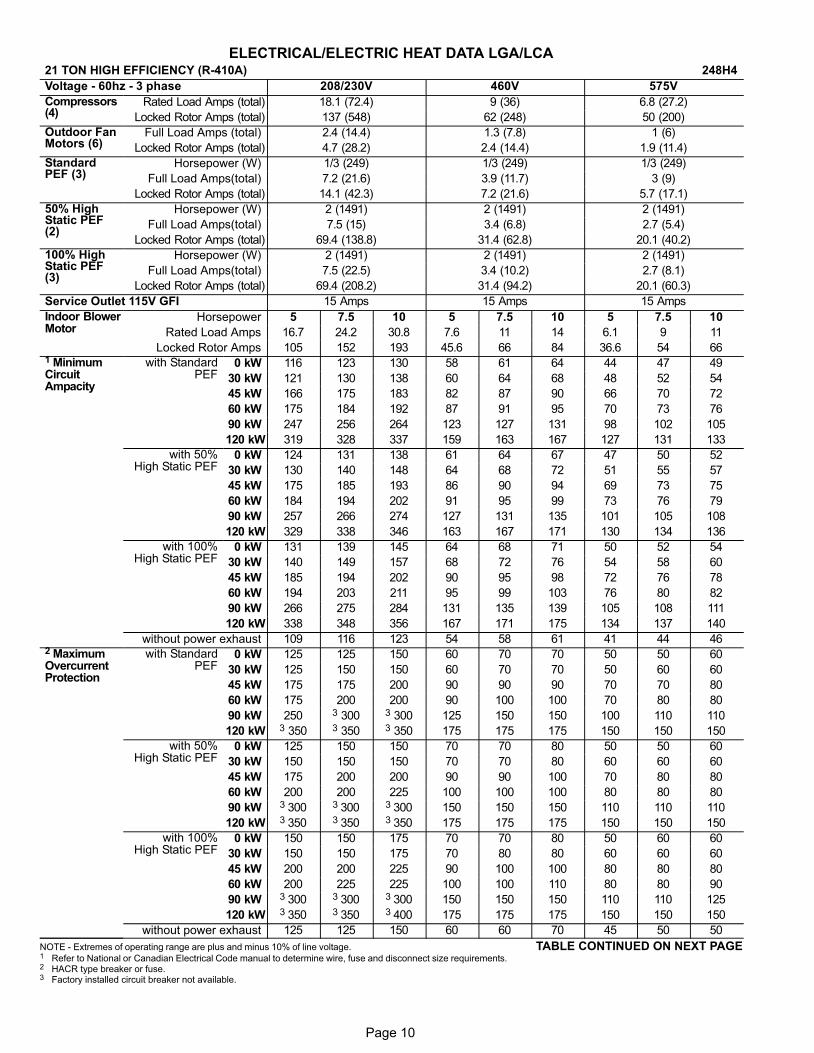
ELECTRICAL/ELECTRIC HEAT DATA LGA/LCA21 TON HIGH EFFICIENCY (R−410A) 248H4
Voltage − 60hz − 3 phase 208/230V 460V 575V
Compressors(4)
Rated Load Amps (total) 18.1 (72.4) 9 (36) 6.8 (27.2)
Locked Rotor Amps (total) 137 (548) 62 (248) 50 (200)
Outdoor FanMotors (6)
Full Load Amps (total) 2.4 (14.4) 1.3 (7.8) 1 (6)
Locked Rotor Amps (total) 4.7 (28.2) 2.4 (14.4) 1.9 (11.4)
StandardPEF (3)
Horsepower (W) 1/3 (249) 1/3 (249) 1/3 (249)
Full Load Amps(total) 7.2 (21.6) 3.9 (11.7) 3 (9)
Locked Rotor Amps (total) 14.1 (42.3) 7.2 (21.6) 5.7 (17.1)
50% HighStatic PEF(2)
Horsepower (W) 2 (1491) 2 (1491) 2 (1491)
Full Load Amps(total) 7.5 (15) 3.4 (6.8) 2.7 (5.4)
Locked Rotor Amps (total) 69.4 (138.8) 31.4 (62.8) 20.1 (40.2)
100% HighStatic PEF(3)
Horsepower (W) 2 (1491) 2 (1491) 2 (1491)
Full Load Amps(total) 7.5 (22.5) 3.4 (10.2) 2.7 (8.1)
Locked Rotor Amps (total) 69.4 (208.2) 31.4 (94.2) 20.1 (60.3)
Service Outlet 115V GFI 15 Amps 15 Amps 15 Amps
Indoor BlowerMotor
Horsepower 5 7.5 10 5 7.5 10 5 7.5 10
Rated Load Amps 16.7 24.2 30.8 7.6 11 14 6.1 9 11
Locked Rotor Amps 105 152 193 45.6 66 84 36.6 54 661 MinimumCircuitAmpacity
with StandardPEF
0 kW 116 123 130 58 61 64 44 47 49
30 kW 121 130 138 60 64 68 48 52 54
45 kW 166 175 183 82 87 90 66 70 72
60 kW 175 184 192 87 91 95 70 73 76
90 kW 247 256 264 123 127 131 98 102 105
120 kW 319 328 337 159 163 167 127 131 133
with 50%High Static PEF
0 kW 124 131 138 61 64 67 47 50 52
30 kW 130 140 148 64 68 72 51 55 57
45 kW 175 185 193 86 90 94 69 73 75
60 kW 184 194 202 91 95 99 73 76 79
90 kW 257 266 274 127 131 135 101 105 108
120 kW 329 338 346 163 167 171 130 134 136
with 100%High Static PEF
0 kW 131 139 145 64 68 71 50 52 54
30 kW 140 149 157 68 72 76 54 58 60
45 kW 185 194 202 90 95 98 72 76 78
60 kW 194 203 211 95 99 103 76 80 82
90 kW 266 275 284 131 135 139 105 108 111
120 kW 338 348 356 167 171 175 134 137 140
without power exhaust 109 116 123 54 58 61 41 44 462 MaximumOvercurrentProtection
with StandardPEF
0 kW 125 125 150 60 70 70 50 50 60
30 kW 125 150 150 60 70 70 50 60 60
45 kW 175 175 200 90 90 90 70 70 80
60 kW 175 200 200 90 100 100 70 80 80
90 kW 250 3 300 3 300 125 150 150 100 110 110
120 kW 3 350 3 350 3 350 175 175 175 150 150 150
with 50%High Static PEF
0 kW 125 150 150 70 70 80 50 50 60
30 kW 150 150 150 70 70 80 60 60 60
45 kW 175 200 200 90 90 100 70 80 80
60 kW 200 200 225 100 100 100 80 80 80
90 kW 3 300 3 300 3 300 150 150 150 110 110 110
120 kW 3 350 3 350 3 350 175 175 175 150 150 150
with 100%High Static PEF
0 kW 150 150 175 70 70 80 50 60 60
30 kW 150 150 175 70 80 80 60 60 60
45 kW 200 200 225 90 100 100 80 80 80
60 kW 200 225 225 100 100 110 80 80 90
90 kW 3 300 3 300 3 300 150 150 150 110 110 125
120 kW 3 350 3 350 3 400 175 175 175 150 150 150
without power exhaust 125 125 150 60 60 70 45 50 50
NOTE�− Extremes�of�operating�range�are�plus�and�minus�10%�of�line�voltage. TABLE CONTINUED ON NEXT PAGE1 Refer�to�National or Canadian�Electrical�Code�manual�to�determine�wire,�fuse�and�disconnect�size�requirements.2 HACR type breaker or fuse.3 Factory installed circuit breaker not available.

Page 11
ELECTRICAL/ELECTRIC HEAT DATA LGA/LCA21 TON HIGH EFFICIENCY (R−410A) 248H4
Voltage − 60hz − 3 phase 208/230V 460V 575V
Indoor Blower Motor Horsepower 5 7.5 10 5 7.5 10 5 7.5 10
4 Electric Heat Control Kit 15K13 15K92 15K93
Disconnect with StandardPEF
0 kW 84M14 84M14 84M14 84M13 84M13 84M13 84M13 84M13 84M13
30 kW 84M14 84M14 84M14 84M13 84M13 84M13 84M13 84M13 84M13
45 kW 84M15 84M15 84M15 84M13 84M13 84M14 84M13 84M13 84M13
60 kW 84M15 84M15 84M15 84M14 84M14 84M14 84M13 84M14 84M14
90 kW N/A N/A N/A 84M14 84M14 84M14 84M14 84M14 84M14
120 kW N/A N/A N/A 84M15 84M15 84M15 84M14 84M14 84M14
with 50%High Static PEF
0 kW 84M14 84M14 84M15 84M13 84M13 84M13 84M13 84M13 84M13
30 kW 84M14 84M14 84M15 84M13 84M13 84M13 84M13 84M13 84M13
45 kW 84M15 84M15 84M15 84M13 84M14 84M14 84M13 84M13 84M13
60 kW 84M15 84M15 84M15 84M14 84M14 84M14 84M13 84M14 84M14
90 kW N/A N/A N/A 84M14 84M14 84M14 84M14 84M14 84M14
120 kW N/A N/A N/A 84M15 84M15 84M15 84M14 84M14 84M15
with 100%High Static PEF
0 kW 84M14 84M15 84M15 84M13 84M13 84M13 84M13 84M13 84M13
30 kW 84M14 84M15 84M15 84M13 84M13 84M13 84M13 84M13 84M13
45 kW 84M15 84M15 84M15 84M14 84M14 84M14 84M13 84M13 84M13
60 kW 84M15 84M15 84M15 84M14 84M14 84M14 84M14 84M14 84M14
90 kW N/A N/A N/A 84M14 84M14 84M15 84M14 84M14 84M14
120 kW N/A N/A N/A 84M15 84M15 84M15 84M14 84M15 84M15
without power exhaust 84M14 84M14 84M14 84M13 84M13 84M13 84M13 84M13 84M13
TerminalBlock
with StandardPEF
0 kW LTB2−175 LTB2−175 LTB2−175 LTB2−175 LTB2−175
30 kW LTB2−175 LTB2−175 LTB2−175 LTB2−175 LTB2−175
45 kW LTB2−175 LTB2−175 LTB2−335 LTB2−175 LTB2−175
60 kW LTB2−175 LTB2−335 LTB2−335 LTB2−175 LTB2−175
90 kW LTB2−335 LTB2−335 LTB2−335 LTB2−175 LTB2−175
120 kW LTB2−335 LTB2−335 LTB2−335 LTB2−175 LTB2−175
with 50%High Static PEF
0 kW LTB2−175 LTB2−175 LTB2−175 LTB2−175 LTB2−175
30 kW LTB2−175 LTB2−175 LTB2−175 LTB2−175 LTB2−175
45 kW LTB2−175 LTB2−335 LTB2−335 LTB2−175 LTB2−175
60 kW LTB2−335 LTB2−335 LTB2−335 LTB2−175 LTB2−175
90 kW LTB2−335 LTB2−335 LTB2−335 LTB2−175 LTB2−175
120 kW LTB2−335 LTB2−335 LTB2−335 LTB2−175 LTB2−175
with 100%High Static PEF
0 kW LTB2−175 LTB2−175 LTB2−175 LTB2−175 LTB2−175
30 kW LTB2−175 LTB2−175 LTB2−175 LTB2−175 LTB2−175
45 kW LTB2−335 LTB2−335 LTB2−335 LTB2−175 LTB2−175
60 kW LTB2−335 LTB2−335 LTB2−335 LTB2−175 LTB2−175
90 kW LTB2−335 LTB2−335 LTB2−335 LTB2−175 LTB2−175
120 kW LTB2−335 LTB2−335 LTB2−335 LTB2−175 LTB2−175
without power exhaust LTB2−175 LTB2−175 LTB2−175 LTB2−175 LTB2−1755 Unit FuseBlock
with Standard PEF LAFB125A4
LAFB124A4
LAFB150A3
LAFB60A8
LAFB70A8
LAFB70A8
LAFB50A8
LAFB50A8
LAFB60A8
with 50% High Static PEF LAFB125A4
LAFB150A3
LAFB150A3
LAFB70A8
LAFB70A8
LAFB80A6
LAFB50A8
LAFB50A8
LAFB60A8
with 100% High Static PEF LAFB150A3
LAFB150A3
LAFB175A3
LAFB70A8
LAFB70A8
LAFB80A6
LAFB50A8
LAFB60A8
LAFB60A8
without power exhaust LAFB125A4
LAFB125A4
LAFB150A3
LAFB60A8
LAFB60A8
LAFB70A8
LAFB45A8
LAFB50A8
LAFB50A8
4 Electric Heat Control module only for use with 45 kW or more of electric heat.5 Only for use with electric heat.

Page 12
ELECTRICAL/ELECTRIC HEAT DATA LGC/LCC25 TON HIGH EFFICIENCY (R−22) 300H2
Voltage − 60hz − 3 phase 208/230V 460V 575V
Compressors(4)
Rated Load Amps (total) 18.6 (74.4) 9 (36) 7.4 (29.6)
Locked Rotor Amps (total) 156 (624) 75 (300) 54 (216)
Outdoor FanMotors (6)
Full Load Amps (total) 2.4 (14.4) 1.3 (7.8) 1 (6)
Locked Rotor Amps (total) 4.7 (28.2) 2.4 (14.4) 1.9 (11.4)
StandardPEF (3)
Horsepower (W) 1/3 (249) 1/3 (249) 1/3 (249)
Full Load Amps(total) 7.2 (21.6) 3.9 (11.7) 3 (9)
Locked Rotor Amps (total) 14.1 (42.3) 7.2 (21.6) 5.7 (17.1)
50% HighStatic PEF(2)
Horsepower (W) 2 (1491) 2 (1491) 2 (1491)
Full Load Amps(total) 7.5 (15) 3.4 (6.8) 2.7 (5.4)
Locked Rotor Amps (total) 69.4 (138.8) 31.4 (62.8) 20.1 (40.2)
100% HighStatic PEF(3)
Horsepower (W) 2 (1491) 2 (1491) 2 (1491)
Full Load Amps(total) 7.5 (22.5) 3.4 (10.2) 2.7 (8.1)
Locked Rotor Amps (total) 69.4 (208.2) 31.4 (94.2) 20.1 (60.3)
Service Outlet 115V GFI 15 Amps 15 Amps 15 Amps
Indoor BlowerMotor
Horsepower 5 7.5 10 5 7.5 10 5 7.5 10
Rated Load Amps 16.7 24.2 30.8 7.6 11 14 6.1 9 11
Locked Rotor Amps 105 152 193 45.6 66 84 36.6 54 661 MinimumCircuitAmpacity
with StandardPEF
0 kW 118 125 132 58 61 64 47 50 52
30 kW 121 130 138 60 64 68 48 52 54
45 kW 166 175 183 82 87 90 66 70 72
60 kW 175 184 192 87 91 95 70 73 76
90 kW 247 256 264 123 127 131 98 102 105
120 kW 319 328 337 159 163 167 127 131 133
with 50%High Static PEF
0 kW 126 133 140 61 64 67 49 52 54
30 kW 130 140 148 64 68 72 51 55 57
45 kW 175 185 193 86 90 94 69 73 75
60 kW 184 194 202 91 95 99 73 76 79
90 kW 257 266 274 127 131 135 101 105 108
120 kW 329 338 346 163 167 171 130 134 136
with 100%High Static PEF
0 kW 133 141 147 64 68 71 52 55 57
30 kW 140 149 157 68 72 76 54 58 60
45 kW 185 194 202 90 95 98 72 76 78
60 kW 194 203 211 95 99 103 76 80 82
90 kW 266 275 284 131 135 139 105 108 111
120 kW 338 348 356 167 171 175 134 137 140
without power exhaust 111 118 125 54 58 61 44 47 492 MaxiumOvercurrentProtection
with StandardPEF
0 kW 125 150 150 60 70 70 50 50 60
30 kW 125 150 150 60 70 70 50 60 60
45 kW 175 175 200 90 90 90 70 70 80
60 kW 175 200 200 90 100 100 70 80 80
90 kW 250 3 300 3 300 125 150 150 100 110 110
120 kW 3 350 3 350 3 350 175 175 175 150 150 150
with 50%High Static PEF
0 kW 150 150 150 70 70 80 50 60 60
30 kW 150 150 150 70 70 80 60 60 60
45 kW 175 200 200 90 90 100 70 80 80
60 kW 200 200 225 100 100 100 80 80 80
90 kW 3 300 3 300 3 300 150 150 150 110 110 110
120 kW 3 350 3 350 3 350 175 175 175 150 150 150
with 100%High Static PEF
0 kW 150 150 175 70 70 80 60 60 60
30 kW 150 150 175 70 80 80 60 60 60
45 kW 200 200 225 90 100 100 80 80 80
60 kW 200 225 225 100 100 110 80 80 90
90 kW 3 300 3 300 3 300 150 150 150 110 110 125
120 kW 3 350 3 350 3 400 175 175 175 150 150 150
without power exhaust 125 125 150 60 60 70 50 50 60
NOTE�− Extremes�of�operating�range�are�plus�and�minus�10%�of�line�voltage. TABLE CONTINUED ON NEXT PAGE1 Refer�to�National or Canadian�Electrical�Code�manual�to�determine�wire,�fuse�and�disconnect�size�requirements.2 HACR type breaker or fuse.3 Factory installed circuit breaker not available.
Page 13
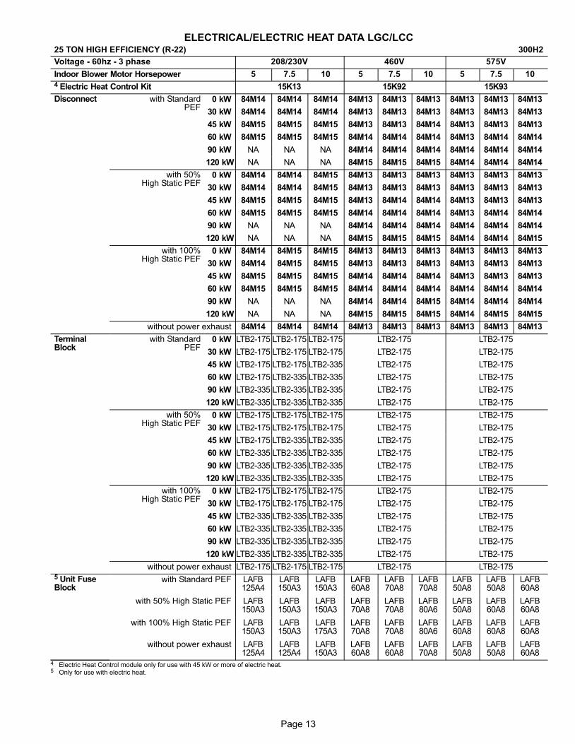
ELECTRICAL/ELECTRIC HEAT DATA LGC/LCC25 TON HIGH EFFICIENCY (R−22) 300H2
Voltage − 60hz − 3 phase 208/230V 460V 575V
Indoor Blower Motor Horsepower 5 7.5 10 5 7.5 10 5 7.5 10
4 Electric Heat Control Kit 15K13 15K92 15K93
Disconnect with StandardPEF
0 kW 84M14 84M14 84M14 84M13 84M13 84M13 84M13 84M13 84M13
30 kW 84M14 84M14 84M14 84M13 84M13 84M13 84M13 84M13 84M13
45 kW 84M15 84M15 84M15 84M13 84M13 84M14 84M13 84M13 84M13
60 kW 84M15 84M15 84M15 84M14 84M14 84M14 84M13 84M14 84M14
90 kW NA NA NA 84M14 84M14 84M14 84M14 84M14 84M14
120 kW NA NA NA 84M15 84M15 84M15 84M14 84M14 84M14
with 50%High Static PEF
0 kW 84M14 84M14 84M15 84M13 84M13 84M13 84M13 84M13 84M13
30 kW 84M14 84M14 84M15 84M13 84M13 84M13 84M13 84M13 84M13
45 kW 84M15 84M15 84M15 84M13 84M14 84M14 84M13 84M13 84M13
60 kW 84M15 84M15 84M15 84M14 84M14 84M14 84M13 84M14 84M14
90 kW NA NA NA 84M14 84M14 84M14 84M14 84M14 84M14
120 kW NA NA NA 84M15 84M15 84M15 84M14 84M14 84M15
with 100%High Static PEF
0 kW 84M14 84M15 84M15 84M13 84M13 84M13 84M13 84M13 84M13
30 kW 84M14 84M15 84M15 84M13 84M13 84M13 84M13 84M13 84M13
45 kW 84M15 84M15 84M15 84M14 84M14 84M14 84M13 84M13 84M13
60 kW 84M15 84M15 84M15 84M14 84M14 84M14 84M14 84M14 84M14
90 kW NA NA NA 84M14 84M14 84M15 84M14 84M14 84M14
120 kW NA NA NA 84M15 84M15 84M15 84M14 84M15 84M15
without power exhaust 84M14 84M14 84M14 84M13 84M13 84M13 84M13 84M13 84M13
TerminalBlock
with StandardPEF
0 kW LTB2−175 LTB2−175 LTB2−175 LTB2−175 LTB2−175
30 kW LTB2−175 LTB2−175 LTB2−175 LTB2−175 LTB2−175
45 kW LTB2−175 LTB2−175 LTB2−335 LTB2−175 LTB2−175
60 kW LTB2−175 LTB2−335 LTB2−335 LTB2−175 LTB2−175
90 kW LTB2−335 LTB2−335 LTB2−335 LTB2−175 LTB2−175
120 kW LTB2−335 LTB2−335 LTB2−335 LTB2−175 LTB2−175
with 50%High Static PEF
0 kW LTB2−175 LTB2−175 LTB2−175 LTB2−175 LTB2−175
30 kW LTB2−175 LTB2−175 LTB2−175 LTB2−175 LTB2−175
45 kW LTB2−175 LTB2−335 LTB2−335 LTB2−175 LTB2−175
60 kW LTB2−335 LTB2−335 LTB2−335 LTB2−175 LTB2−175
90 kW LTB2−335 LTB2−335 LTB2−335 LTB2−175 LTB2−175
120 kW LTB2−335 LTB2−335 LTB2−335 LTB2−175 LTB2−175
with 100%High Static PEF
0 kW LTB2−175 LTB2−175 LTB2−175 LTB2−175 LTB2−175
30 kW LTB2−175 LTB2−175 LTB2−175 LTB2−175 LTB2−175
45 kW LTB2−335 LTB2−335 LTB2−335 LTB2−175 LTB2−175
60 kW LTB2−335 LTB2−335 LTB2−335 LTB2−175 LTB2−175
90 kW LTB2−335 LTB2−335 LTB2−335 LTB2−175 LTB2−175
120 kW LTB2−335 LTB2−335 LTB2−335 LTB2−175 LTB2−175
without power exhaust LTB2−175 LTB2−175 LTB2−175 LTB2−175 LTB2−1755 Unit FuseBlock
with Standard PEF LAFB125A4
LAFB150A3
LAFB150A3
LAFB60A8
LAFB70A8
LAFB70A8
LAFB50A8
LAFB50A8
LAFB60A8
with 50% High Static PEF LAFB150A3
LAFB150A3
LAFB150A3
LAFB70A8
LAFB70A8
LAFB80A6
LAFB50A8
LAFB60A8
LAFB60A8
with 100% High Static PEF LAFB150A3
LAFB150A3
LAFB175A3
LAFB70A8
LAFB70A8
LAFB80A6
LAFB60A8
LAFB60A8
LAFB60A8
without power exhaust LAFB125A4
LAFB125A4
LAFB150A3
LAFB60A8
LAFB60A8
LAFB70A8
LAFB50A8
LAFB50A8
LAFB60A8
4 Electric Heat Control module only for use with 45 kW or more of electric heat.5 Only for use with electric heat.
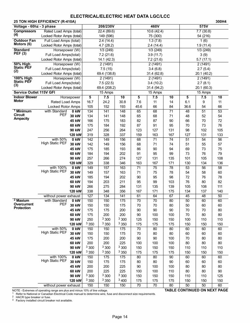
Page 14
ELECTRICAL/ELECTRIC HEAT DATA LGC/LCC25 TON HIGH EFFICIENCY (R−410A) 300H4
Voltage − 60hz − 3 phase 208/230V 460V 575V
Compressors(4)
Rated Load Amps (total) 22.4 (89.6) 10.6 (42.4) 7.7 (30.8)
Locked Rotor Amps (total) 149 (596) 75 (300) 54 (216)
Outdoor FanMotors (6)
Full Load Amps (total) 2.4 (14.4) 1.3 (7.8) 1 (6)
Locked Rotor Amps (total) 4.7 (28.2) 2.4 (14.4) 1.9 (11.4)
StandardPEF (3)
Horsepower (W) 1/3 (249) 1/3 (249) 1/3 (249)
Full Load Amps(total) 7.2 (21.6) 3.9 (11.7) 3 (9)
Locked Rotor Amps (total) 14.1 (42.3) 7.2 (21.6) 5.7 (17.1)
50% HighStatic PEF(2)
Horsepower (W) 2 (1491) 2 (1491) 2 (1491)
Full Load Amps(total) 7.5 (15) 3.4 (6.8) 2.7 (5.4)
Locked Rotor Amps (total) 69.4 (138.8) 31.4 (62.8) 20.1 (40.2)
100% HighStatic PEF(3)
Horsepower (W) 2 (1491) 2 (1491) 2 (1491)
Full Load Amps(total) 7.5 (22.5) 3.4 (10.2) 2.7 (8.1)
Locked Rotor Amps (total) 69.4 (208.2) 31.4 (94.2) 20.1 (60.3)
Service Outlet 115V GFI 15 Amps 15 Amps 15 Amps
Indoor BlowerMotor
Horsepower 5 7.5 10 5 7.5 10 5 7.5 10
Rated Load Amps 16.7 24.2 30.8 7.6 11 14 6.1 9 11
Locked Rotor Amps 105 152 193 45.6 66 84 36.6 54 661 MinimumCircuitAmpacity
with StandardPEF
0 kW 134 141 148 65 68 71 48 51 53
30 kW 134 141 148 65 68 71 48 52 54
45 kW 166 175 183 82 87 90 66 70 72
60 kW 175 184 192 87 91 95 70 73 76
90 kW 247 256 264 123 127 131 98 102 105
120 kW 319 328 337 159 163 167 127 131 133
with 50%High Static PEF
0 kW 142 149 156 68 71 74 51 54 56
30 kW 142 149 156 68 71 74 51 55 57
45 kW 175 185 193 86 90 94 69 73 75
60 kW 184 194 202 91 95 99 73 76 79
90 kW 257 266 274 127 131 135 101 105 108
120 kW 329 338 346 163 167 171 130 134 136
with 100%High Static PEF
0 kW 149 157 163 71 75 78 53 56 58
30 kW 149 157 163 71 75 78 54 58 60
45 kW 185 194 202 90 95 98 72 76 78
60 kW 194 203 211 95 99 103 76 80 82
90 kW 266 275 284 131 135 139 105 108 111
120 kW 338 348 356 167 171 175 134 137 140
without power exhaust 127 134 141 61 64 67 45 48 502 MaxiumOvercurrentProtection
with StandardPEF
0 kW 150 150 175 70 70 80 50 60 60
30 kW 150 150 175 70 70 80 50 60 60
45 kW 175 175 200 90 90 90 70 70 80
60 kW 175 200 200 90 100 100 70 80 80
90 kW 250 3 300 3 300 125 150 150 100 110 110
120 kW 3 350 3 350 3 350 175 175 175 150 150 150
with 50%High Static PEF
0 kW 150 150 175 70 80 80 60 60 60
30 kW 150 150 175 70 80 80 60 60 60
45 kW 175 200 200 90 90 100 70 80 80
60 kW 200 200 225 100 100 100 80 80 80
90 kW 3 300 3 300 3 300 150 150 150 110 110 110
120 kW 3 350 3 350 3 350 175 175 175 150 150 150
with 100%High Static PEF
0 kW 150 175 175 80 80 90 60 60 60
30 kW 150 175 175 80 80 90 60 60 60
45 kW 200 200 225 90 100 100 80 80 80
60 kW 200 225 225 100 100 110 80 80 90
90 kW 3 300 3 300 3 300 150 150 150 110 110 125
120 kW 3 350 3 350 3 400 175 175 175 150 150 150
without power exhaust 150 150 150 70 70 80 50 50 60
NOTE�− Extremes�of�operating�range�are�plus�and�minus�10%�of�line�voltage. TABLE CONTINUED ON NEXT PAGE1 Refer�to�National or Canadian�Electrical�Code�manual�to�determine�wire,�fuse�and�disconnect�size�requirements.2 HACR type breaker or fuse.3 Factory installed circuit breaker not available.
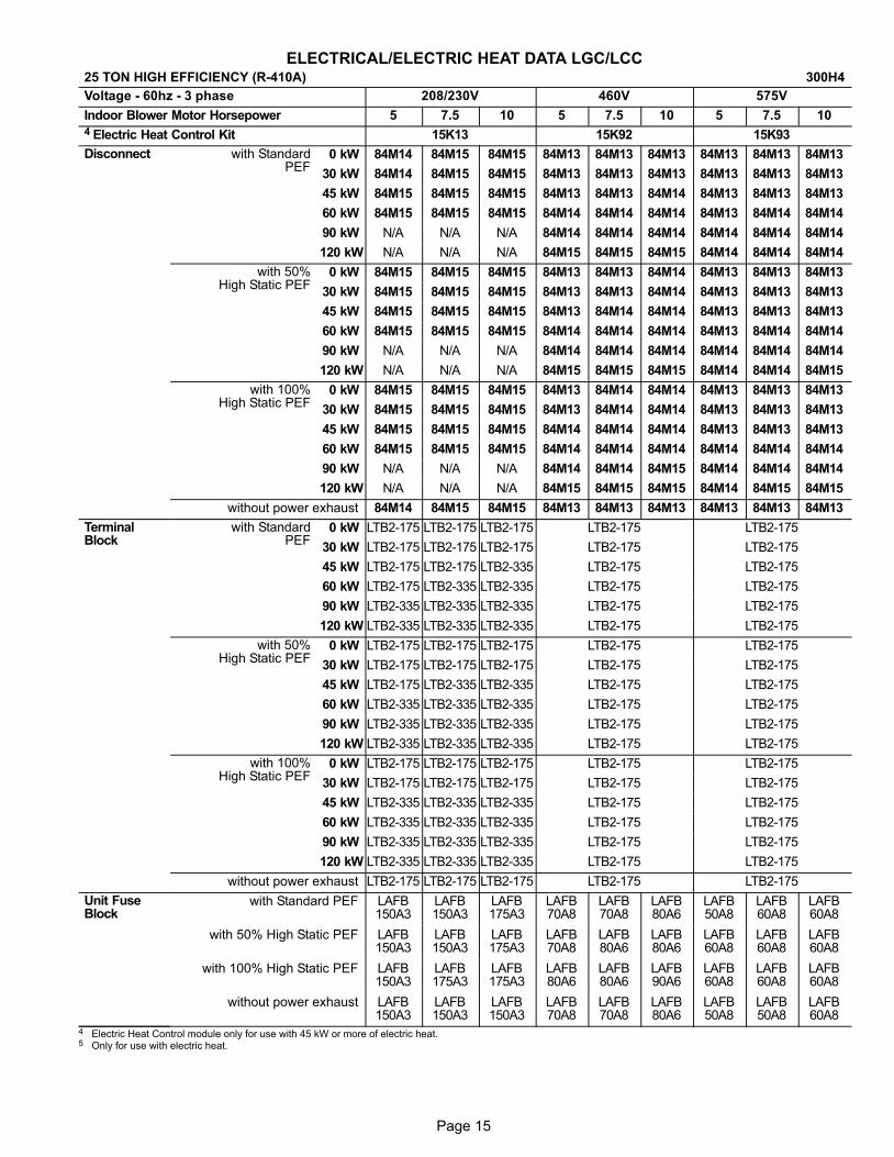
Page 15
ELECTRICAL/ELECTRIC HEAT DATA LGC/LCC25 TON HIGH EFFICIENCY (R−410A) 300H4
Voltage − 60hz − 3 phase 208/230V 460V 575V
Indoor Blower Motor Horsepower 5 7.5 10 5 7.5 10 5 7.5 10
4 Electric Heat Control Kit 15K13 15K92 15K93
Disconnect with StandardPEF
0 kW 84M14 84M15 84M15 84M13 84M13 84M13 84M13 84M13 84M13
30 kW 84M14 84M15 84M15 84M13 84M13 84M13 84M13 84M13 84M13
45 kW 84M15 84M15 84M15 84M13 84M13 84M14 84M13 84M13 84M13
60 kW 84M15 84M15 84M15 84M14 84M14 84M14 84M13 84M14 84M14
90 kW N/A N/A N/A 84M14 84M14 84M14 84M14 84M14 84M14
120 kW N/A N/A N/A 84M15 84M15 84M15 84M14 84M14 84M14
with 50%High Static PEF
0 kW 84M15 84M15 84M15 84M13 84M13 84M14 84M13 84M13 84M13
30 kW 84M15 84M15 84M15 84M13 84M13 84M14 84M13 84M13 84M13
45 kW 84M15 84M15 84M15 84M13 84M14 84M14 84M13 84M13 84M13
60 kW 84M15 84M15 84M15 84M14 84M14 84M14 84M13 84M14 84M14
90 kW N/A N/A N/A 84M14 84M14 84M14 84M14 84M14 84M14
120 kW N/A N/A N/A 84M15 84M15 84M15 84M14 84M14 84M15
with 100%High Static PEF
0 kW 84M15 84M15 84M15 84M13 84M14 84M14 84M13 84M13 84M13
30 kW 84M15 84M15 84M15 84M13 84M14 84M14 84M13 84M13 84M13
45 kW 84M15 84M15 84M15 84M14 84M14 84M14 84M13 84M13 84M13
60 kW 84M15 84M15 84M15 84M14 84M14 84M14 84M14 84M14 84M14
90 kW N/A N/A N/A 84M14 84M14 84M15 84M14 84M14 84M14
120 kW N/A N/A N/A 84M15 84M15 84M15 84M14 84M15 84M15
without power exhaust 84M14 84M15 84M15 84M13 84M13 84M13 84M13 84M13 84M13
TerminalBlock
with StandardPEF
0 kW LTB2−175 LTB2−175 LTB2−175 LTB2−175 LTB2−175
30 kW LTB2−175 LTB2−175 LTB2−175 LTB2−175 LTB2−175
45 kW LTB2−175 LTB2−175 LTB2−335 LTB2−175 LTB2−175
60 kW LTB2−175 LTB2−335 LTB2−335 LTB2−175 LTB2−175
90 kW LTB2−335 LTB2−335 LTB2−335 LTB2−175 LTB2−175
120 kW LTB2−335 LTB2−335 LTB2−335 LTB2−175 LTB2−175
with 50%High Static PEF
0 kW LTB2−175 LTB2−175 LTB2−175 LTB2−175 LTB2−175
30 kW LTB2−175 LTB2−175 LTB2−175 LTB2−175 LTB2−175
45 kW LTB2−175 LTB2−335 LTB2−335 LTB2−175 LTB2−175
60 kW LTB2−335 LTB2−335 LTB2−335 LTB2−175 LTB2−175
90 kW LTB2−335 LTB2−335 LTB2−335 LTB2−175 LTB2−175
120 kW LTB2−335 LTB2−335 LTB2−335 LTB2−175 LTB2−175
with 100%High Static PEF
0 kW LTB2−175 LTB2−175 LTB2−175 LTB2−175 LTB2−175
30 kW LTB2−175 LTB2−175 LTB2−175 LTB2−175 LTB2−175
45 kW LTB2−335 LTB2−335 LTB2−335 LTB2−175 LTB2−175
60 kW LTB2−335 LTB2−335 LTB2−335 LTB2−175 LTB2−175
90 kW LTB2−335 LTB2−335 LTB2−335 LTB2−175 LTB2−175
120 kW LTB2−335 LTB2−335 LTB2−335 LTB2−175 LTB2−175
without power exhaust LTB2−175 LTB2−175 LTB2−175 LTB2−175 LTB2−175
Unit FuseBlock
with Standard PEF LAFB150A3
LAFB150A3
LAFB175A3
LAFB70A8
LAFB70A8
LAFB80A6
LAFB50A8
LAFB60A8
LAFB60A8
with 50% High Static PEF LAFB150A3
LAFB150A3
LAFB175A3
LAFB70A8
LAFB80A6
LAFB80A6
LAFB60A8
LAFB60A8
LAFB60A8
with 100% High Static PEF LAFB150A3
LAFB175A3
LAFB175A3
LAFB80A6
LAFB80A6
LAFB90A6
LAFB60A8
LAFB60A8
LAFB60A8
without power exhaust LAFB150A3
LAFB150A3
LAFB150A3
LAFB70A8
LAFB70A8
LAFB80A6
LAFB50A8
LAFB50A8
LAFB60A8
4 Electric Heat Control module only for use with 45 kW or more of electric heat.5 Only for use with electric heat.
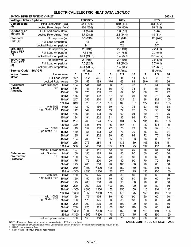
Page 16
ELECTRICAL/ELECTRIC HEAT DATA LGC/LCC30 TON HIGH EFFICIENCY (R−22) 360H2
Voltage − 60hz − 3 phase 208/230V 460V 575V
Compressors(4)
Rated Load Amps (total) 22.4 (89.6) 10.9 (43.6) 8.3 (33.2)
Locked Rotor Amps (total) 164 (656) 100 (400) 78 (312)
Outdoor FanMotors (6)
Full Load Amps (total) 2.4 (14.4) 1.3 (7.8) 1 (6)
Locked Rotor Amps (total) 4.7 (28.2) 2.4 (14.4) 1.9 (11.4)
StandardPEF (3)
Horsepower (W) 1/3 (249) 1/3 (249) 1/3 (249)
Full Load Amps(total) 7.2 3.9 3
Locked Rotor Amps(total) 14.1 7.2 5.7
50% HighStatic PEF(2)
Horsepower (W) 2 (1491) 2 (1491) 2 (1491)
Full Load Amps(total) 7.5 (15) 3.4 (6.8) 2.7 (5.4)
Locked Rotor Amps(total) 69.4 (138.8) 31.4 (62.8) 20.1 (40.2)
100% HighStatic PEF(3)
Horsepower (W) 2 (1491) 2 (1491) 2 (1491)
Full Load Amps(total) 7.5 (22.5) 3.4 (10.2) 2.7 (8.1)
Locked Rotor Amps(total) 69.4 (208.2) 31.4 (94.2) 20.1 (60.3)
Service Outlet 115V GFI 15 Amps 15 Amps 15 Amps
Indoor BlowerMotor
Horsepower 5 7.5 10 5 7.5 10 5 7.5 10
Full Load Amps 16.7 24.2 30.8 7.6 11 14 6.1 9 11
Locked Rotor Amps 105 152 193 45.6 66 84 36.6 54 661 MinimumCircuitAmpacity
with StandardPEF
0 kW 134 141 148 66 70 73 51 54 56
30 kW 134 141 148 66 70 73 51 54 56
45 kW 166 175 183 82 87 90 66 70 72
60 kW 175 184 192 87 91 95 70 73 76
90 kW 247 256 264 123 127 131 98 102 105
120 kW 319 328 337 159 163 167 127 131 133
with 50%High Static PEF
0 kW 142 149 156 69 72 75 53 56 58
15 kW 142 149 156 69 72 75 53 56 58
30 kW 175 185 193 86 90 94 69 73 75
45 kW 184 194 202 91 95 99 73 76 79
60 kW 257 266 274 127 131 135 101 105 108
120 kW 329 338 346 163 167 171 130 134 136
with 100%High Static PEF
0 kW 149 157 163 72 76 79 56 59 61
15 kW 149 157 163 72 76 79 56 59 61
30 kW 185 194 202 90 95 98 72 76 78
45 kW 194 203 211 95 99 103 76 80 82
60 kW 266 275 284 131 135 139 105 108 111
120 kW 338 348 356 167 171 175 134 137 140
without power exhaust 127 134 141 62 66 69 48 51 532 MaximumOvercurrentProtection
with StandardPEF
0 kW 150 150 175 70 80 80 60 60 60
30 kW 150 150 175 70 80 80 60 60 60
45 kW 175 175 200 90 90 90 70 70 80
60 kW 175 200 200 90 100 100 70 80 80
90 kW 250 3 300 3 300 125 150 150 100 110 110
120 kW 3 350 3 350 3 350 175 175 175 150 150 150
with 50%High Static PEF
0 kW 150 150 175 70 80 80 60 60 60
30 kW 150 150 175 70 80 80 60 60 60
45 kW 175 200 200 90 90 100 70 80 80
60 kW 200 200 225 100 100 100 80 80 80
90 kW 3 300 3 300 3 300 150 150 150 110 110 110
120 kW 3 350 3 350 3 350 175 175 175 150 150 150
with 100%High Static PEF
0 kW 150 175 175 80 80 90 60 60 70
30 kW 150 175 175 80 80 90 60 60 70
45 kW 200 200 225 90 100 100 80 80 80
60 kW 200 225 225 100 100 110 80 80 90
90 kW 3 300 3 300 3 300 150 150 150 110 110 125
120 kW 3 350 3 350 3 400 175 175 175 150 150 150
without power exhaust 150 150 150 70 70 80 50 60 60
NOTE�− Extremes�of�operating�range�are�plus�and�minus�10%�of�line�voltage. TABLE CONTINUED ON NEXT PAGE1 Refer�to�National or Canadian�Electrical�Code�manual�to�determine�wire,�fuse�and�disconnect�size�requirements.2 HACR type breaker or fuse.3 Factory installed circuit breaker not available.
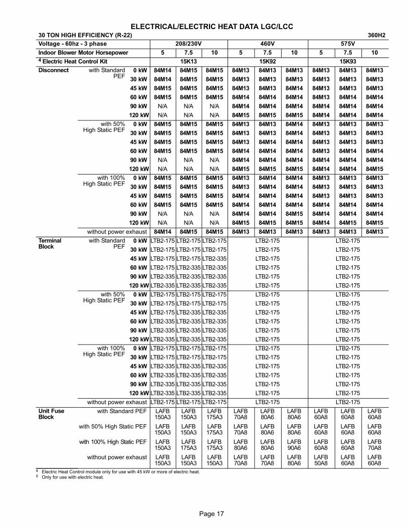
Page 17
ELECTRICAL/ELECTRIC HEAT DATA LGC/LCC30 TON HIGH EFFICIENCY (R−22) 360H2
Voltage − 60hz − 3 phase 208/230V 460V 575V
Indoor Blower Motor Horsepower 5 7.5 10 5 7.5 10 5 7.5 10
4 Electric Heat Control Kit 15K13 15K92 15K93
Disconnect with StandardPEF
0 kW 84M14 84M15 84M15 84M13 84M13 84M13 84M13 84M13 84M13
30 kW 84M14 84M15 84M15 84M13 84M13 84M13 84M13 84M13 84M13
45 kW 84M15 84M15 84M15 84M13 84M13 84M14 84M13 84M13 84M13
60 kW 84M15 84M15 84M15 84M14 84M14 84M14 84M13 84M14 84M14
90 kW N/A N/A N/A 84M14 84M14 84M14 84M14 84M14 84M14
120 kW N/A N/A N/A 84M15 84M15 84M15 84M14 84M14 84M14
with 50%High Static PEF
0 kW 84M15 84M15 84M15 84M13 84M13 84M14 84M13 84M13 84M13
30 kW 84M15 84M15 84M15 84M13 84M13 84M14 84M13 84M13 84M13
45 kW 84M15 84M15 84M15 84M13 84M14 84M14 84M13 84M13 84M13
60 kW 84M15 84M15 84M15 84M14 84M14 84M14 84M13 84M14 84M14
90 kW N/A N/A N/A 84M14 84M14 84M14 84M14 84M14 84M14
120 kW N/A N/A N/A 84M15 84M15 84M15 84M14 84M14 84M15
with 100%High Static PEF
0 kW 84M15 84M15 84M15 84M13 84M14 84M14 84M13 84M13 84M13
30 kW 84M15 84M15 84M15 84M13 84M14 84M14 84M13 84M13 84M13
45 kW 84M15 84M15 84M15 84M14 84M14 84M14 84M13 84M13 84M13
60 kW 84M15 84M15 84M15 84M14 84M14 84M14 84M14 84M14 84M14
90 kW N/A N/A N/A 84M14 84M14 84M15 84M14 84M14 84M14
120 kW N/A N/A N/A 84M15 84M15 84M15 84M14 84M15 84M15
without power exhaust 84M14 84M15 84M15 84M13 84M13 84M13 84M13 84M13 84M13
TerminalBlock
with StandardPEF
0 kW LTB2−175 LTB2−175 LTB2−175 LTB2−175 LTB2−175
30 kW LTB2−175 LTB2−175 LTB2−175 LTB2−175 LTB2−175
45 kW LTB2−175 LTB2−175 LTB2−335 LTB2−175 LTB2−175
60 kW LTB2−175 LTB2−335 LTB2−335 LTB2−175 LTB2−175
90 kW LTB2−335 LTB2−335 LTB2−335 LTB2−175 LTB2−175
120 kW LTB2−335 LTB2−335 LTB2−335 LTB2−175 LTB2−175
with 50%High Static PEF
0 kW LTB2−175 LTB2−175 LTB2−175 LTB2−175 LTB2−175
30 kW LTB2−175 LTB2−175 LTB2−175 LTB2−175 LTB2−175
45 kW LTB2−175 LTB2−335 LTB2−335 LTB2−175 LTB2−175
60 kW LTB2−335 LTB2−335 LTB2−335 LTB2−175 LTB2−175
90 kW LTB2−335 LTB2−335 LTB2−335 LTB2−175 LTB2−175
120 kW LTB2−335 LTB2−335 LTB2−335 LTB2−175 LTB2−175
with 100%High Static PEF
0 kW LTB2−175 LTB2−175 LTB2−175 LTB2−175 LTB2−175
30 kW LTB2−175 LTB2−175 LTB2−175 LTB2−175 LTB2−175
45 kW LTB2−335 LTB2−335 LTB2−335 LTB2−175 LTB2−175
60 kW LTB2−335 LTB2−335 LTB2−335 LTB2−175 LTB2−175
90 kW LTB2−335 LTB2−335 LTB2−335 LTB2−175 LTB2−175
120 kW LTB2−335 LTB2−335 LTB2−335 LTB2−175 LTB2−175
without power exhaust LTB2−175 LTB2−175 LTB2−175 LTB2−175 LTB2−175
Unit FuseBlock
with Standard PEF LAFB150A3
LAFB150A3
LAFB175A3
LAFB70A8
LAFB80A6
LAFB80A6
LAFB60A8
LAFB60A8
LAFB60A8
with 50% High Static PEF LAFB150A3
LAFB150A3
LAFB175A3
LAFB70A8
LAFB80A6
LAFB80A6
LAFB60A8
LAFB60A8
LAFB60A8
with 100% High Static PEF LAFB150A3
LAFB175A3
LAFB175A3
LAFB80A6
LAFB80A6
LAFB90A6
LAFB60A8
LAFB60A8
LAFB70A8
without power exhaust LAFB150A3
LAFB150A3
LAFB150A3
LAFB70A8
LAFB70A8
LAFB80A6
LAFB50A8
LAFB60A8
LAFB60A8
4 Electric Heat Control module only for use with 45 kW or more of electric heat.5 Only for use with electric heat.
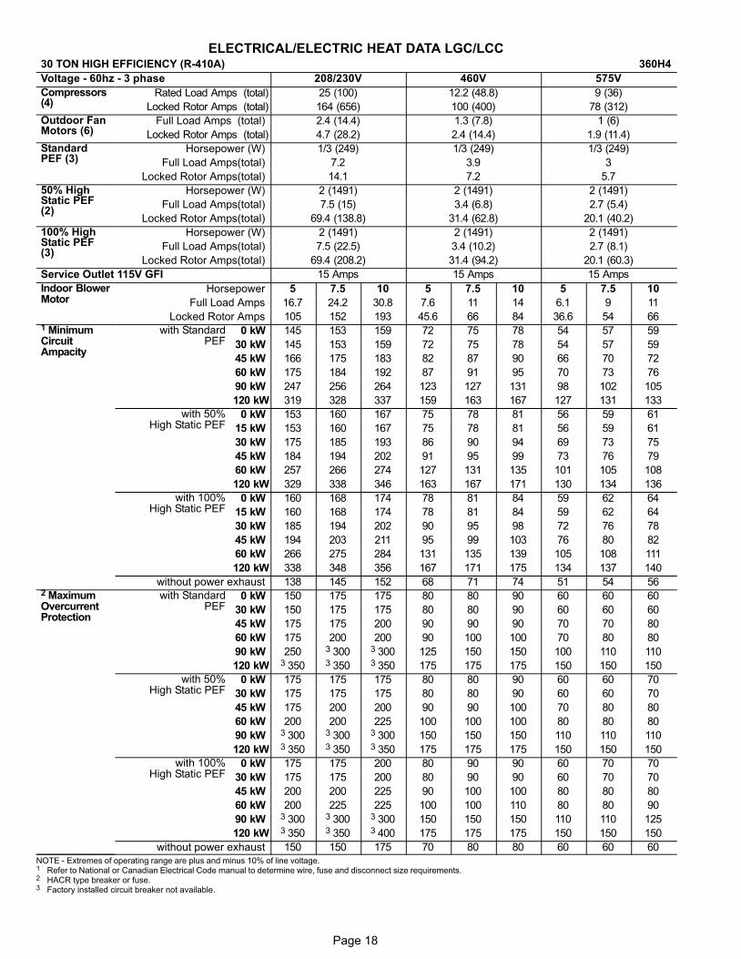
Page 18
ELECTRICAL/ELECTRIC HEAT DATA LGC/LCC30 TON HIGH EFFICIENCY (R−410A) 360H4
Voltage − 60hz − 3 phase 208/230V 460V 575V
Compressors(4)
Rated Load Amps (total) 25 (100) 12.2 (48.8) 9 (36)
Locked Rotor Amps (total) 164 (656) 100 (400) 78 (312)
Outdoor FanMotors (6)
Full Load Amps (total) 2.4 (14.4) 1.3 (7.8) 1 (6)
Locked Rotor Amps (total) 4.7 (28.2) 2.4 (14.4) 1.9 (11.4)
StandardPEF (3)
Horsepower (W) 1/3 (249) 1/3 (249) 1/3 (249)
Full Load Amps(total) 7.2 3.9 3
Locked Rotor Amps(total) 14.1 7.2 5.7
50% HighStatic PEF(2)
Horsepower (W) 2 (1491) 2 (1491) 2 (1491)
Full Load Amps(total) 7.5 (15) 3.4 (6.8) 2.7 (5.4)
Locked Rotor Amps(total) 69.4 (138.8) 31.4 (62.8) 20.1 (40.2)
100% HighStatic PEF(3)
Horsepower (W) 2 (1491) 2 (1491) 2 (1491)
Full Load Amps(total) 7.5 (22.5) 3.4 (10.2) 2.7 (8.1)
Locked Rotor Amps(total) 69.4 (208.2) 31.4 (94.2) 20.1 (60.3)
Service Outlet 115V GFI 15 Amps 15 Amps 15 Amps
Indoor BlowerMotor
Horsepower 5 7.5 10 5 7.5 10 5 7.5 10
Full Load Amps 16.7 24.2 30.8 7.6 11 14 6.1 9 11
Locked Rotor Amps 105 152 193 45.6 66 84 36.6 54 661 MinimumCircuitAmpacity
with StandardPEF
0 kW 145 153 159 72 75 78 54 57 59
30 kW 145 153 159 72 75 78 54 57 59
45 kW 166 175 183 82 87 90 66 70 72
60 kW 175 184 192 87 91 95 70 73 76
90 kW 247 256 264 123 127 131 98 102 105
120 kW 319 328 337 159 163 167 127 131 133
with 50%High Static PEF
0 kW 153 160 167 75 78 81 56 59 61
15 kW 153 160 167 75 78 81 56 59 61
30 kW 175 185 193 86 90 94 69 73 75
45 kW 184 194 202 91 95 99 73 76 79
60 kW 257 266 274 127 131 135 101 105 108
120 kW 329 338 346 163 167 171 130 134 136
with 100%High Static PEF
0 kW 160 168 174 78 81 84 59 62 64
15 kW 160 168 174 78 81 84 59 62 64
30 kW 185 194 202 90 95 98 72 76 78
45 kW 194 203 211 95 99 103 76 80 82
60 kW 266 275 284 131 135 139 105 108 111
120 kW 338 348 356 167 171 175 134 137 140
without power exhaust 138 145 152 68 71 74 51 54 562 MaximumOvercurrentProtection
with StandardPEF
0 kW 150 175 175 80 80 90 60 60 60
30 kW 150 175 175 80 80 90 60 60 60
45 kW 175 175 200 90 90 90 70 70 80
60 kW 175 200 200 90 100 100 70 80 80
90 kW 250 3 300 3 300 125 150 150 100 110 110
120 kW 3 350 3 350 3 350 175 175 175 150 150 150
with 50%High Static PEF
0 kW 175 175 175 80 80 90 60 60 70
30 kW 175 175 175 80 80 90 60 60 70
45 kW 175 200 200 90 90 100 70 80 80
60 kW 200 200 225 100 100 100 80 80 80
90 kW 3 300 3 300 3 300 150 150 150 110 110 110
120 kW 3 350 3 350 3 350 175 175 175 150 150 150
with 100%High Static PEF
0 kW 175 175 200 80 90 90 60 70 70
30 kW 175 175 200 80 90 90 60 70 70
45 kW 200 200 225 90 100 100 80 80 80
60 kW 200 225 225 100 100 110 80 80 90
90 kW 3 300 3 300 3 300 150 150 150 110 110 125
120 kW 3 350 3 350 3 400 175 175 175 150 150 150
without power exhaust 150 150 175 70 80 80 60 60 60NOTE�− Extremes�of�operating�range�are�plus�and�minus�10%�of�line�voltage.1 Refer�to�National or Canadian�Electrical�Code�manual�to�determine�wire,�fuse�and�disconnect�size�requirements.2 HACR type breaker or fuse.3 Factory installed circuit breaker not available.

Page 19
ELECTRICAL/ELECTRIC HEAT DATA LGC/LCC30 TON HIGH EFFICIENCY (R−410A) 360H4
Voltage − 60hz − 3 phase 208/230V 460V 575V
Indoor Blower Motor Horsepower 5 7.5 10 5 7.5 10 5 7.5 10
4 Electric Heat Control Kit 15K13 15K92 15K93
Disconnect with StandardPEF
0 kW 84M15 84M15 84M15 84M13 84M14 84M14 84M13 84M13 84M13
30 kW 84M15 84M15 84M15 84M13 84M14 84M14 84M13 84M13 84M13
45 kW 84M15 84M15 84M15 84M13 84M14 84M14 84M13 84M13 84M13
60 kW 84M15 84M15 84M15 84M14 84M14 84M14 84M13 84M14 84M14
90 kW N/A N/A N/A 84M14 84M14 84M14 84M14 84M14 84M14
120 kW N/A N/A N/A 84M15 84M15 84M15 84M14 84M14 84M14
with 50%High Static PEF
0 kW 84M15 84M15 84M15 84M14 84M14 84M14 84M13 84M13 84M13
30 kW 84M15 84M15 84M15 84M14 84M14 84M14 84M13 84M13 84M13
45 kW 84M15 84M15 84M15 84M14 84M14 84M14 84M13 84M13 84M13
60 kW 84M15 84M15 84M15 84M14 84M14 84M14 84M13 84M14 84M14
90 kW N/A N/A N/A 84M14 84M14 84M14 84M14 84M14 84M14
120 kW N/A N/A N/A 84M15 84M15 84M15 84M14 84M14 84M15
with 100%High Static PEF
0 kW 84M15 84M15 84M15 84M14 84M14 84M14 84M13 84M13 84M13
30 kW 84M15 84M15 84M15 84M14 84M14 84M14 84M13 84M13 84M13
45 kW 84M15 84M15 84M15 84M14 84M14 84M14 84M13 84M13 84M13
60 kW 84M15 84M15 84M15 84M14 84M14 84M14 84M14 84M14 84M14
90 kW N/A N/A N/A 84M14 84M14 84M15 84M14 84M14 84M14
120 kW N/A N/A N/A 84M15 84M15 84M15 84M14 84M15 84M15
without power exhaust 84M15 84M15 84M15 84M13 84M14 84M14 84M13 84M13 84M13
TerminalBlock
with StandardPEF
0 kW LTB2−175 LTB2−175 LTB2−175 LTB2−175 LTB2−175
30 kW LTB2−175 LTB2−175 LTB2−175 LTB2−175 LTB2−175
45 kW LTB2−175 LTB2−175 LTB2−335 LTB2−175 LTB2−175
60 kW LTB2−175 LTB2−335 LTB2−335 LTB2−175 LTB2−175
90 kW LTB2−335 LTB2−335 LTB2−335 LTB2−175 LTB2−175
120 kW LTB2−335 LTB2−335 LTB2−335 LTB2−175 LTB2−175
with 50% HighStatic PEF
0 kW LTB2−175 LTB2−175 LTB2−175 LTB2−175 LTB2−175
30 kW LTB2−175 LTB2−175 LTB2−175 LTB2−175 LTB2−175
45 kW LTB2−175 LTB2−335 LTB2−335 LTB2−175 LTB2−175
60 kW LTB2−335 LTB2−335 LTB2−335 LTB2−175 LTB2−175
90 kW LTB2−335 LTB2−335 LTB2−335 LTB2−175 LTB2−175
120 kW LTB2−335 LTB2−335 LTB2−335 LTB2−175 LTB2−175
with 100% HighStatic PEF
0 kW LTB2−175 LTB2−175 LTB2−175 LTB2−175 LTB2−175
30 kW LTB2−175 LTB2−175 LTB2−175 LTB2−175 LTB2−175
45 kW LTB2−335 LTB2−335 LTB2−335 LTB2−175 LTB2−175
60 kW LTB2−335 LTB2−335 LTB2−335 LTB2−175 LTB2−175
90 kW LTB2−335 LTB2−335 LTB2−335 LTB2−175 LTB2−175
120 kW LTB2−335 LTB2−335 LTB2−335 LTB2−175 LTB2−175
without power exhaust LTB2−175 LTB2−175 LTB2−175 LTB2−175 LTB2−175
Unit FuseBlock
with Standard PEF LAFB150A3
LAFB175A3
LAFB175A3
LAFB80A6
LAFB80A6
LAFB90A6
LAFB60A8
LAFB60A8
LAFB60A8
with 50% High Static PEF LAFB175A3
LAFB175A3
LAFB175A3
LAFB80A6
LAFB80A6
LAFB90A6
LAFB60A8
LAFB60A8
LAFB70A8
with 100% High Static PEF LAFB175A3
LAFB175A3
LAFB175A3
LAFB80A6
LAFB90A6
LAFB90A6
LAFB60A8
LAFB70A8
LAFB70A8
without power exhaust LAFB150A3
LAFB150A3
LAFB175A3
LAFB70A8
LAFB80A6
LAFB80A6
LAFB60A8
LAFB60A8
LAFB60A8
4 Electric Heat Control module only for use with 45 kW or more of electric heat.5 Only for use with electric heat.
Page 20
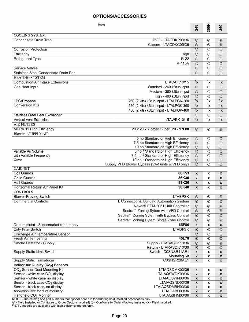
OPTIONS/ACCESSORIES
Item
24
8
30
0H
36
0
COOLING SYSTEMCondensate Drain Trap PVC − LTACDKP09/36 � � �
Copper − LTACDKC09/36 � � �
Corrosion Protection � � �
Efficiency High � � �
Refrigerant Type R−22 � � �
R−410A � � �
Service Valves � � �
Stainless Steel Condensate Drain Pan � � �
HEATING SYSTEMCombustion Air Intake Extensions LTACAIK10/15 1x 1x 1x
Gas Heat Input Standard − 260 kBtuh input � � �
Medium − 360 kBtuh input � � �
High − 480 kBtuh input � � �
LPG/PropaneConversion Kits
260 (2 kits) kBtuh input − LTALPGK−260 1x 1x 1x
360 (2 kits) kBtuh input − LTALPGK−360 1x 1x 1x
480 (2 kits) kBtuh input − LTALPGK−480 1x 1x 1x
Stainless Steel Heat Exchanger � � �
Vertical Vent Extension LTAWEK10/15 1x 1x 1x
AIR FILTERSMERV 11 High Efficiency 20 x 20 x 2 order 12 per unit − 97L88 � � �
Blower − SUPPLY AIR5 hp Standard or High Efficiency � � �
7.5 hp Standard or High Efficiency � � �
10 hp Standard or High Efficiency � � �
Variable Air Volumewith Variable FrequencyDrive
5 hp 2 Standard or High Efficiency � � �
7.5 hp 2 Standard or High Efficiency � � �
10 hp 2 Standard or High Efficiency � � �
Supply VFD Blower Bypass (VAV units w/VFD only) � � �
CABINETCoil Guards 88K53 x x x
Grille Guards 86K30 x x x
Hail Guards 88K26 x x x
Horizontal Return Air Panel Kit 38K48 x x x
CONTROLSBlower Proving Switch LTABPSK � � �
Commercial Controls L Connection® Building Automation System � � �
Novar® ETM−2051 Unit Controller � � �
Sectra� Zoning Sytem with VFD Control � � �
Sectra� Zoning Sytem with Bypass Control � � �
Sectra� Zoning Sytem Single Zone Control � � �
Dehumidistat − Supermarket reheat only 65F86 x x x
Dirty Filter Switch LTADFSK � � �
Discharge Air Temperature Sensor � � �
Fresh Air Tempering 45L78 � � �
Smoke Detector − Supply Supply − LTASASDK10/36 � � �
Return − LTARASDK10/30 � � �
Supply Static Limit Switch Switch − C0SNSR11AE1 x x xMounting Kit x x x
Supply Static Transducer C0SNSR20AE1 x x x
Indoor Air Quality (Co2) Sensors
CO2 Sensor Duct Mounting Kit LTIAQSDMK03/36 x x xSensor − white case CO2 display LTAIAQSWDK03/36 x x xSensor − white case no display LTAIAQSWN03/36 x x xSensor − black case CO2 display LTAIAQSND03/36 x x xSensor − black case, no display LTAIAQSDMBN03/36 x x xAspiration Box for duct mounting LTIAQABD03/36 x x xHandheld CO2 Monitor LTAIAQSHM03/36 x x x
NOTE − The catalog and part numbers that appear here are for ordering field installed accessories only.⊗ − Field Installed or Configure to Order (factory installed) � − Configure to Order (Factory Installed) X − Field Installed.2 575V models are available with high efficiency motors only.
Page 21
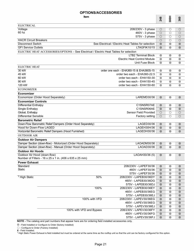
OPTIONS/ACCESSORIESItem
24
8
30
0H
36
0
ELECTRICALVoltage60 hz
208/230V − 3 phase � � �
460V − 3 phase � � �
575V − 3 phase � � �
HACR Circuit Breakers � � �
Disconnect Switch See Electrical / Electric Heat Tables for selection � � �
GFI Service Outlets LTAGFIK10/15 � � �
ELECTRIC HEAT ACCESSORIES/OPTIONS − See Electrical / Electric Heat Tables for selection
LTB2 Terminal Block � � �
Electric Heat Control Module � � �
Unit Fuse Block � � �
ELECTRIC HEAT30 kW order one each − EHA360−15 & EHA360S−15 � � �
45 kW order two each − EHA360−22.5 � � �
60 kW order two each − EHA150−30 � � �
90 kW order two each − EHA150−45 � � �
120 kW order two each − EHA150−60 � � �
ECONOMIZER
Economizer
Economizer (Order Hood Separately) LAREMD30/36 � � �
Economizer Controls
Differential Enthalpy C1SNSR07AE � � �
Single Enthalpy C1SNSR06AE � � �
Global, Enthalpy Sensor Field Provided � � �
Differential Sensible Factory setting � � �
Barometric Relief
Down−Flow Barometric Relief Dampers (Order Hood Separately) LAGED30/36 � � �
Hood for Down−Flow LAGED LAGEH30H/36 � � �
Horizontal Barometric Relief Dampers (Hood Furnished) LAGEDH30/36 � � �
OUTDOOR AIR
Outdoor Air Dampers
Damper Section (down−flow) − Motorized (Order Hood Separately) LAOADM30/36 � � �
Damper Section (down−flow) − Manual (Order Hood Separately) LAOAD30/36 � � �
Outdoor Air Hoods
Outdoor Air Hood (down−flow)Number of Filters − 16 x 25 x 1 in. (406 x 635 x 25 mm)
LAOAH30/36 (5) � � �
Power Exhaust
StandardStatic
208/230V − LAPEF30/36 � � �
460V − LAPEF30/36 � � �
575V − LAPEF30/36 � � �
1 High Static 50% 208/230V − LAPEB30/36DY � � �
460V − LAPEB30/36DG � � �
575V − LAPEB30/36DJ � � �
100% 208/230V − LAPEB30/36EY � � �
460V − LAPEB30/36EG � � �
575V − LAPEB30/36EJ � � �
100% with VFD 208/230V − LAPEV30/36EG � � �
460V − LAPEV30/36EG � � �
575V − LAPEV30/36EJ � � �
100% with VFD and Bypass 208/230V − LAPEV30/36FY � � �
460V − LAPEV30/36FG � � �
575V − LAPEV30/36FJ � � �
NOTE − The catalog and part numbers that appear here are for ordering field installed accessories only.
⊗ − Field Installed or Configure to Order (factory installed)
� − Configure to Order (Factory Installed)
X − Field Installed.1 High Static Power Exhaust is field installed but must be ordered at the same time as the rooftop unit so that the unit can be factory configured for this option.
Page 22
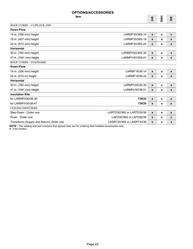
OPTIONS/ACCESSORIESItem
24
8
30
0H
36
0
ROOF CURBS − CLIPLOCK 1000
Down−Flow
14 in. (356 mm) height LARMF30/36S−14 x x x
18 in. (457 mm) height LARMF30/36S−18 x x x
24 in. (610 mm) height LARMF30/36S−24 x x x
Horizontal
30 in. (762 mm) height LARMFH30/36S−30 x x x
41 in. (1041 mm) height LARMFH30/36S−41 x x x
ROOF CURBS − STANDARD
Down−Flow
14 in. (356 mm) height LARMF18/36−14 x x x
24 in. (610 m) height LARMF18/36−24 x x x
Horizontal
30 in. (762 mm) height LARMFH30/36−30 x x x
41 in. (1041 mm) height LARMFH30/36−41 x x x
Insulation Kits
for LARMFH30/36−30 73K33 x x x
for LARMFH30/36−41 73K35 x x x
CEILING DIFFUSERS
Step−Down − Order one LARTD30/36S or LARTD30/36 x x x
Flush − Order one LAFD30/36S or LAFD30/36 x x x
Transitions (Supply and Return) Order one LASRT30/36S or LASRT30/36 x x x
NOTE − The catalog and part numbers that appear here are for ordering field installed accessories only.X − Field Installed.
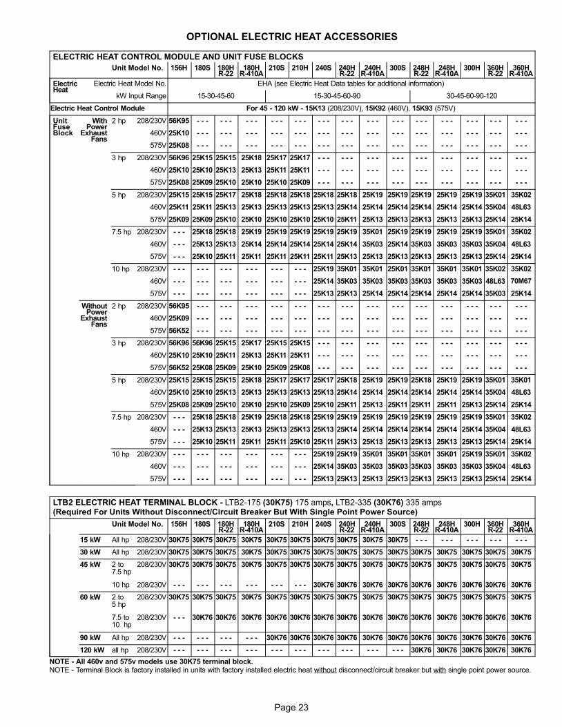
Page 23
OPTIONAL ELECTRIC HEAT ACCESSORIES
ELECTRIC HEAT CONTROL MODULE AND UNIT FUSE BLOCKS
Unit Model No. 156H 180S 180HR−22
180HR−410A
210S 210H 240S 240HR−22
240HR−410A
300S 248HR−22
248HR−410A
300H 360HR−22
360HR−410A
ElectricHeat
Electric Heat Model No. EHA (see Electric Heat Data tables for additional information)
kW Input Range 15−30−45−60 15−30−45−60−90 30−45−60−90−120
Electric Heat Control Module For 45 − 120 kW − 15K13 (208/230V), 15K92 (460V), 15K93 (575V)
UnitFuseBlock
WithPower
ExhaustFans
2 hp 208/230V 56K95 − − − − − − − − − − − − − − − − − − − − − − − − − − − − − − − − − − − − − − − − − −
460V 25K10 − − − − − − − − − − − − − − − − − − − − − − − − − − − − − − − − − − − − − − − − − −
575V 25K08 − − − − − − − − − − − − − − − − − − − − − − − − − − − − − − − − − − − − − − − − − −
3 hp 208/230V 56K96 25K15 25K15 25K18 25K17 25K17 − − − − − − − − − − − − − − − − − − − − − − − − − − −
460V 25K10 25K10 25K13 25K13 25K11 25K11 − − − − − − − − − − − − − − − − − − − − − − − − − − −
575V 25K08 25K09 25K10 25K10 25K10 25K09 − − − − − − − − − − − − − − − − − − − − − − − − − − −
5 hp 208/230V 25K15 25K15 25K17 25K18 25K18 25K18 25K18 25K18 25K19 25K19 25K19 25K19 25K19 35K01 35K02
460V 25K11 25K11 25K13 25K13 25K13 25K13 25K13 25K14 25K14 25K14 25K14 25K14 25K14 35K04 48L63
575V 25K09 25K09 25K10 25K10 25K10 25K10 25K10 25K11 25K13 25K13 25K13 25K13 25K13 25K14 25K14
7.5 hp 208/230V − − − 25K18 25K18 25K19 25K19 25K19 25K19 25K19 35K01 25K19 25K19 25K19 25K19 35K01 35K02
460V − − − 25K13 25K13 25K14 25K14 25K14 25K14 25K14 35K03 25K14 35K03 35K03 35K03 35K04 48L63
575V − − − 25K10 25K11 25K11 25K11 25K11 25K11 25K13 25K13 25K13 25K13 25K13 25K13 25K14 25K14
10 hp 208/230V − − − − − − − − − − − − − − − − − − 25K19 35K01 35K01 25K01 35K01 35K01 35K01 35K02 35K02
460V − − − − − − − − − − − − − − − − − − 25K14 35K03 35K03 35K03 35K03 35K03 35K03 48L63 70M67
575V − − − − − − − − − − − − − − − − − − 25K13 25K13 25K14 25K14 25K14 25K14 25K14 35K03 25K14
WithoutPower
ExhaustFans
2 hp 208/230V 56K95 − − − − − − − − − − − − − − − − − − − − − − − − − − − − − − − − − − − − − − − − − −
460V 25K09 − − − − − − − − − − − − − − − − − − − − − − − − − − − − − − − − − − − − − − − − − −
575V 56K52 − − − − − − − − − − − − − − − − − − − − − − − − − − − − − − − − − − − − − − − − − −
3 hp 208/230V 56K96 56K96 25K15 25K17 25K15 25K15 − − − − − − − − − − − − − − − − − − − − − − − − − − −
460V 25K10 25K10 25K11 25K13 25K11 25K11 − − − − − − − − − − − − − − − − − − − − − − − − − − −
575V 56K52 25K08 25K09 25K10 25K09 25K08 − − − − − − − − − − − − − − − − − − − − − − − − − − −
5 hp 208/230V 25K15 25K15 25K15 25K18 25K17 25K17 25K17 25K18 25K19 25K19 25K18 25K19 25K19 35K01 35K01
460V 25K10 25K10 25K13 25K13 25K13 25K13 25K13 25K14 25K14 25K14 25K14 25K14 25K14 35K04 48L63
575V 25K08 25K09 25K10 25K10 25K10 25K09 25K10 25K11 25K13 25K11 25K11 25K11 25K13 25K14 25K14
7.5 hp 208/230V − − − 25K18 25K18 25K19 25K18 25K18 25K19 25K19 25K19 25K19 25K19 25K19 25K19 35K01 35K02
460V − − − 25K13 25K13 25K13 25K13 25K13 25K13 25K14 25K14 25K14 25K14 25K14 25K14 35K04 48L63
575V − − − 25K10 25K11 25K11 25K11 25K10 25K11 25K13 25K13 25K13 25K13 25K13 25K13 25K14 25K14
10 hp 208/230V − − − − − − − − − − − − − − − − − − 25K19 25K19 35K01 35K01 35K01 35K01 25K19 35K01 35K02
460V − − − − − − − − − − − − − − − − − − 25K14 35K03 35K03 35K03 35K03 35K03 35K03 35K04 48L63
575V − − − − − − − − − − − − − − − − − − 25K13 25K13 25K13 25K13 25K13 25K13 25K13 25K14 25K14
LTB2 ELECTRIC HEAT TERMINAL BLOCK − LTB2−175 (30K75) 175 amps, LTB2−335 (30K76) 335 amps(Required For Units Without Disconnect/Circuit Breaker But With Single Point Power Source)
Unit Model No. 156H 180S 180HR−22
180HR−410A
210S 210H 240S 240HR−22
240HR−410A
300S 248HR−22
248HR−410A
300H 360HR−22
360HR−410A
15 kW All hp 208/230V 30K75 30K75 30K75 30K75 30K75 30K75 30K75 30K75 30K75 30K75 − − − − − − − − − − − − − − −
30 kW All hp 208/230V 30K75 30K75 30K75 30K75 30K75 30K75 30K75 30K75 30K75 30K75 30K75 30K75 30K75 30K75 30K75
45 kW 2 to7.5 hp
208/230V 30K75 30K75 30K75 30K75 30K75 30K75 30K75 30K75 30K75 30K75 30K75 30K75 30K75 30K75 30K75
10 hp 208/230V − − − − − − − − − − − − − − − − − − 30K76 30K76 30K76 30K76 30K76 30K76 30K76 30K76 30K76
60 kW 2 to5 hp
208/230V 30K75 30K75 30K75 30K75 30K75 30K75 30K75 30K75 30K75 30K75 30K75 30K75 30K75 30K75 30K75
7.5 to10 hp
208/230V − − − 30K76 30K76 30K76 30K76 30K76 30K76 30K76 30K76 30K76 30K76 30K76 30K76 30K76 30K76
90 kW All hp 208/230V − − − − − − − − − − − − 30K76 30K76 30K76 30K76 30K76 30K76 30K76 30K76 30K76 30K76 30K76
120 kW all hp 208/230V − − − − − − − − − − − − − − − − − − − − − − − − − − − − − − 30K76 30K76 30K76 30K76 30K76
NOTE − All 460v and 575v models use 30K75 terminal block.NOTE − Terminal Block is factory installed in units with factory installed electric heat without disconnect/circuit breaker but with single point power source.
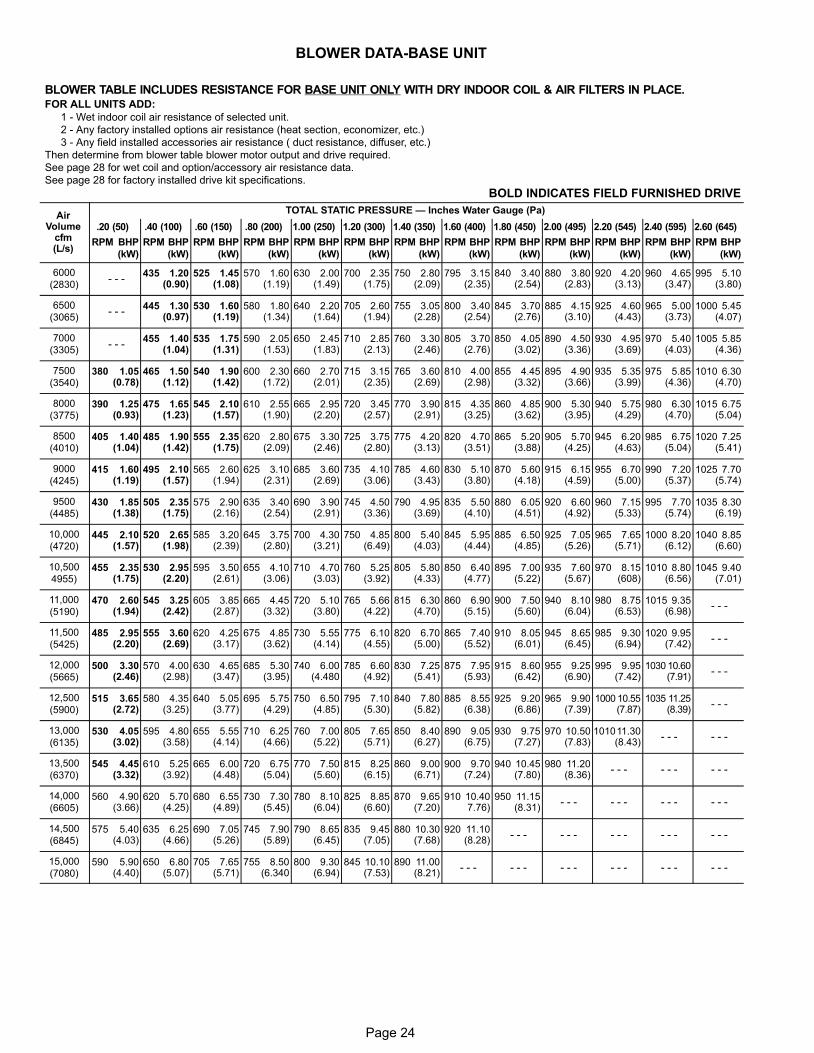
Page 24
BLOWER DATA−BASE UNIT
BLOWER TABLE INCLUDES RESISTANCE FOR BASE UNIT ONLY WITH DRY INDOOR COIL & AIR FILTERS IN PLACE.FOR ALL UNITS ADD:
1 − Wet indoor coil air resistance of selected unit.
2 − Any factory installed options air resistance (heat section, economizer, etc.)
3 − Any field installed accessories air resistance ( duct resistance, diffuser, etc.)
Then determine from blower table blower motor output and drive required.
See page 28 for wet coil and option/accessory air resistance data.
See page 28 for factory installed drive kit specifications.
BOLD INDICATES FIELD FURNISHED DRIVE
AirVolume
cfm(L/s)
TOTAL STATIC PRESSURE � Inches Water Gauge (Pa)
.20 (50) .40 (100) .60 (150) .80 (200) 1.00 (250) 1.20 (300) 1.40 (350) 1.60 (400) 1.80 (450) 2.00 (495) 2.20 (545) 2.40 (595) 2.60 (645)
RPM BHP
(kW)
RPM BHP
(kW)
RPM BHP
(kW)
RPM BHP
(kW)
RPM BHP
(kW)
RPM BHP
(kW)
RPM BHP
(kW)
RPM BHP
(kW)
RPM BHP
(kW)
RPM BHP
(kW)
RPM BHP
(kW)
RPM BHP
(kW)
RPM BHP
(kW)
6000
(2830)- - -
435 1.20(0.90)
525 1.45(1.08)
570 1.60(1.19)
630 2.00(1.49)
700 2.35(1.75)
750 2.80(2.09)
795 3.15(2.35)
840 3.40(2.54)
880 3.80(2.83)
920 4.20(3.13)
960 4.65(3.47)
995 5.10(3.80)
6500
(3065)- - -
445 1.30(0.97)
530 1.60(1.19)
580 1.80(1.34)
640 2.20(1.64)
705 2.60(1.94)
755 3.05(2.28)
800 3.40(2.54)
845 3.70(2.76)
885 4.15(3.10)
925 4.60(4.43)
965 5.00(3.73)
1000 5.45(4.07)
7000
(3305)- - -
455 1.40(1.04)
535 1.75(1.31)
590 2.05(1.53)
650 2.45(1.83)
710 2.85(2.13)
760 3.30(2.46)
805 3.70(2.76)
850 4.05(3.02)
890 4.50(3.36)
930 4.95(3.69)
970 5.40(4.03)
1005 5.85(4.36)
7500
(3540)380 1.05
(0.78)465 1.50
(1.12)540 1.90
(1.42)600 2.30
(1.72)660 2.70
(2.01)715 3.15
(2.35)765 3.60
(2.69)810 4.00
(2.98)855 4.45
(3.32)895 4.90
(3.66)935 5.35
(3.99)975 5.85
(4.36)1010 6.30
(4.70)
8000
(3775)390 1.25
(0.93)475 1.65
(1.23)545 2.10
(1.57)610 2.55
(1.90)665 2.95
(2.20)720 3.45
(2.57)770 3.90
(2.91)815 4.35
(3.25)860 4.85
(3.62)900 5.30
(3.95)940 5.75
(4.29)980 6.30
(4.70)1015 6.75
(5.04)
8500
(4010)405 1.40
(1.04)485 1.90
(1.42)555 2.35
(1.75)620 2.80
(2.09)675 3.30
(2.46)725 3.75
(2.80)775 4.20
(3.13)820 4.70
(3.51)865 5.20
(3.88)905 5.70
(4.25)945 6.20
(4.63)985 6.75
(5.04)1020 7.25
(5.41)
9000
(4245)415 1.60
(1.19)495 2.10
(1.57)565 2.60
(1.94)625 3.10
(2.31)685 3.60
(2.69)735 4.10
(3.06)785 4.60
(3.43)830 5.10
(3.80)870 5.60
(4.18)915 6.15
(4.59)955 6.70
(5.00)990 7.20
(5.37)1025 7.70
(5.74)
9500
(4485)430 1.85
(1.38)505 2.35
(1.75)575 2.90
(2.16)635 3.40
(2.54)690 3.90
(2.91)745 4.50
(3.36)790 4.95
(3.69)835 5.50
(4.10)880 6.05
(4.51)920 6.60
(4.92)960 7.15
(5.33)995 7.70
(5.74)1035 8.30
(6.19)
10,000
(4720)445 2.10
(1.57)520 2.65
(1.98)585 3.20
(2.39)645 3.75
(2.80)700 4.30
(3.21)750 4.85
(6.49)800 5.40
(4.03)845 5.95
(4.44)885 6.50
(4.85)925 7.05
(5.26)965 7.65
(5.71)1000 8.20
(6.12)1040 8.85
(6.60)
10,500
4955)455 2.35
(1.75)530 2.95
(2.20)595 3.50
(2.61)655 4.10
(3.06)710 4.70
(3.03)760 5.25
(3.92)805 5.80
(4.33)850 6.40
(4.77)895 7.00
(5.22)935 7.60
(5.67)970 8.15
(608)1010 8.80
(6.56)1045 9.40
(7.01)
11,000
(5190)470 2.60
(1.94)545 3.25
(2.42)605 3.85
(2.87)665 4.45
(3.32)720 5.10
(3.80)765 5.66
(4.22)815 6.30
(4.70)860 6.90
(5.15)900 7.50
(5.60)940 8.10
(6.04)980 8.75
(6.53)1015 9.35
(6.98)- - -
11,500
(5425)485 2.95
(2.20)555 3.60
(2.69)620 4.25
(3.17)675 4.85
(3.62)730 5.55
(4.14)775 6.10
(4.55)820 6.70
(5.00)865 7.40
(5.52)910 8.05
(6.01)945 8.65
(6.45)985 9.30
(6.94)1020 9.95
(7.42)- - -
12,000
(5665)500 3.30
(2.46)570 4.00
(2.98)630 4.65
(3.47)685 5.30
(3.95)740 6.00
(4.480785 6.60
(4.92)830 7.25
(5.41)875 7.95
(5.93)915 8.60
(6.42)955 9.25
(6.90)995 9.95
(7.42)1030 10.60
(7.91)- - -
12,500
(5900)515 3.65
(2.72)580 4.35
(3.25)640 5.05
(3.77)695 5.75
(4.29)750 6.50
(4.85)795 7.10
(5.30)840 7.80
(5.82)885 8.55
(6.38)925 9.20
(6.86)965 9.90
(7.39)1000 10.55
(7.87)1035 11.25
(8.39)- - -
13,000
(6135)530 4.05
(3.02)595 4.80
(3.58)655 5.55
(4.14)710 6.25
(4.66)760 7.00
(5.22)805 7.65
(5.71)850 8.40
(6.27)890 9.05
(6.75)930 9.75
(7.27)970 10.50
(7.83)101011.30
(8.43)- - - - - -
13,500
(6370)545 4.45
(3.32)610 5.25
(3.92)665 6.00
(4.48)720 6.75
(5.04)770 7.50
(5.60)815 8.25
(6.15)860 9.00
(6.71)900 9.70
(7.24)940 10.45
(7.80)980 11.20
(8.36)- - - - - - - - -
14,000
(6605)560 4.90
(3.66)620 5.70
(4.25)680 6.55
(4.89)730 7.30
(5.45)780 8.10
(6.04)825 8.85
(6.60)870 9.65
(7.20)910 10.40
7.76)950 11.15
(8.31)- - - - - - - - - - - -
14,500
(6845)575 5.40
(4.03)635 6.25
(4.66)690 7.05
(5.26)745 7.90
(5.89)790 8.65
(6.45)835 9.45
(7.05)880 10.30
(7.68)920 11.10
(8.28)- - - - - - - - - - - - - - -
15,000
(7080)590 5.90
(4.40)650 6.80
(5.07)705 7.65
(5.71)755 8.50
(6.340800 9.30
(6.94)845 10.10
(7.53)890 11.00
(8.21)- - - - - - - - - - - - - - - - - -
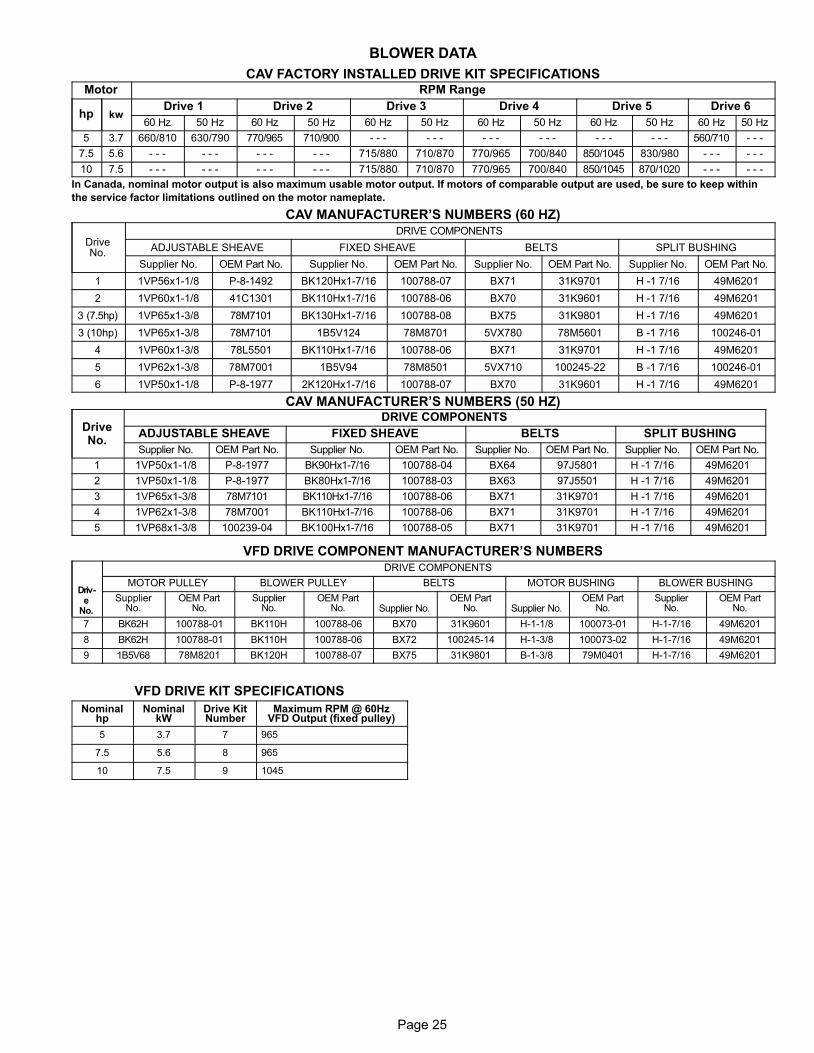
Page 25
BLOWER DATA
CAV FACTORY INSTALLED DRIVE KIT SPECIFICATIONSMotor RPM Range
hp kwDrive 1 Drive 2 Drive 3 Drive 4 Drive 5 Drive 6
60 Hz 50 Hz 60 Hz 50 Hz 60 Hz 50 Hz 60 Hz 50 Hz 60 Hz 50 Hz 60 Hz 50 Hz
5 3.7 660/810 630/790 770/965 710/900 − − − − − − − − − − − − − − − − − − 560/710 − − −
7.5 5.6 − − − − − − − − − − − − 715/880 710/870 770/965 700/840 850/1045 830/980 − − − − − −
10 7.5 − − − − − − − − − − − − 715/880 710/870 770/965 700/840 850/1045 870/1020 − − − − − −
In Canada, nominal motor output is also maximum usable motor output. If motors of comparable output are used, be sure to keep within
the service factor limitations outlined on the motor nameplate.
CAV MANUFACTURER’S NUMBERS (60 HZ)
DriveNo.
DRIVE COMPONENTS
ADJUSTABLE SHEAVE FIXED SHEAVE BELTS SPLIT BUSHING
Supplier No. OEM Part No. Supplier No. OEM Part No. Supplier No. OEM Part No. Supplier No. OEM Part No.
1 1VP56x1−1/8 P−8−1492 BK120Hx1-7/16 100788−07 BX71 31K9701 H −1 7/16 49M6201
2 1VP60x1−1/8 41C1301 BK110Hx1-7/16 100788−06 BX70 31K9601 H −1 7/16 49M6201
3 (7.5hp) 1VP65x1−3/8 78M7101 BK130Hx1-7/16 100788−08 BX75 31K9801 H −1 7/16 49M6201
3 (10hp) 1VP65x1−3/8 78M7101 1B5V124 78M8701 5VX780 78M5601 B −1 7/16 100246−01
4 1VP60x1−3/8 78L5501 BK110Hx1-7/16 100788−06 BX71 31K9701 H −1 7/16 49M6201
5 1VP62x1−3/8 78M7001 1B5V94 78M8501 5VX710 100245−22 B −1 7/16 100246−01
6 1VP50x1−1/8 P−8−1977 2K120Hx1-7/16 100788−07 BX70 31K9601 H −1 7/16 49M6201
CAV MANUFACTURER’S NUMBERS (50 HZ)
DriveNo.
DRIVE COMPONENTS
ADJUSTABLE SHEAVE FIXED SHEAVE BELTS SPLIT BUSHING
Supplier No. OEM Part No. Supplier No. OEM Part No. Supplier No. OEM Part No. Supplier No. OEM Part No.
1 1VP50x1−1/8 P−8−1977 BK90Hx1−7/16 100788−04 BX64 97J5801 H −1 7/16 49M6201
2 1VP50x1−1/8 P−8−1977 BK80Hx1−7/16 100788−03 BX63 97J5501 H −1 7/16 49M6201
3 1VP65x1−3/8 78M7101 BK110Hx1−7/16 100788−06 BX71 31K9701 H −1 7/16 49M6201
4 1VP62x1−3/8 78M7001 BK110Hx1−7/16 100788−06 BX71 31K9701 H −1 7/16 49M6201
5 1VP68x1−3/8 100239−04 BK100Hx1−7/16 100788−05 BX71 31K9701 H −1 7/16 49M6201
VFD DRIVE COMPONENT MANUFACTURER’S NUMBERS
Driv-e
No.
DRIVE COMPONENTS
MOTOR PULLEY BLOWER PULLEY BELTS MOTOR BUSHING BLOWER BUSHING
SupplierNo.
OEM PartNo.
SupplierNo.
OEM PartNo. Supplier No.
OEM PartNo. Supplier No.
OEM PartNo.
SupplierNo.
OEM PartNo.
7 BK62H 100788−01 BK110H 100788−06 BX70 31K9601 H−1−1/8 100073−01 H−1−7/16 49M6201
8 BK62H 100788−01 BK110H 100788−06 BX72 100245−14 H−1−3/8 100073−02 H−1−7/16 49M6201
9 1B5V68 78M8201 BK120H 100788−07 BX75 31K9801 B−1−3/8 79M0401 H−1−7/16 49M6201
VFD DRIVE KIT SPECIFICATIONS
Nominalhp
NominalkW
Drive KitNumber
Maximum RPM @ 60HzVFD Output (fixed pulley)
5 3.7 7 965
7.5 5.6 8 965
10 7.5 9 1045
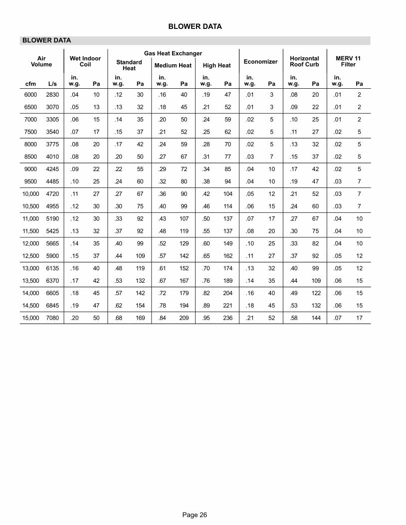
Page 26
BLOWER DATA
BLOWER DATA
AirVolume
Wet IndoorCoil
Gas Heat Exchanger
EconomizerHorizontalRoof Curb
MERV 11FilterStandard
Heat Medium Heat High Heat
cfm L/sin.
w.g. Pain.
w.g. Pain.
w.g. Pain.
w.g. Pain.
w.g. Pain.
w.g. Pain.
w.g. Pa
6000 2830 .04 10 .12 30 .16 40 .19 47 .01 3 .08 20 .01 2
6500 3070 .05 13 .13 32 .18 45 .21 52 .01 3 .09 22 .01 2
7000 3305 .06 15 .14 35 .20 50 .24 59 .02 5 .10 25 .01 2
7500 3540 .07 17 .15 37 .21 52 .25 62 .02 5 .11 27 .02 5
8000 3775 .08 20 .17 42 .24 59 .28 70 .02 5 .13 32 .02 5
8500 4010 .08 20 .20 50 .27 67 .31 77 .03 7 .15 37 .02 5
9000 4245 .09 22 .22 55 .29 72 .34 85 .04 10 .17 42 .02 5
9500 4485 .10 25 .24 60 .32 80 .38 94 .04 10 .19 47 .03 7
10,000 4720 .11 27 .27 67 .36 90 .42 104 .05 12 .21 52 .03 7
10,500 4955 .12 30 .30 75 .40 99 .46 114 .06 15 .24 60 .03 7
11,000 5190 .12 30 .33 92 .43 107 .50 137 .07 17 .27 67 .04 10
11,500 5425 .13 32 .37 92 .48 119 .55 137 .08 20 .30 75 .04 10
12,000 5665 .14 35 .40 99 .52 129 .60 149 .10 25 .33 82 .04 10
12,500 5900 .15 37 .44 109 .57 142 .65 162 .11 27 .37 92 .05 12
13,000 6135 .16 40 .48 119 .61 152 .70 174 .13 32 .40 99 .05 12
13,500 6370 .17 42 .53 132 .67 167 .76 189 .14 35 .44 109 .06 15
14,000 6605 .18 45 .57 142 .72 179 .82 204 .16 40 .49 122 .06 15
14,500 6845 .19 47 .62 154 .78 194 .89 221 .18 45 .53 132 .06 15
15,000 7080 .20 50 .68 169 .84 209 .95 236 .21 52 .58 144 .07 17
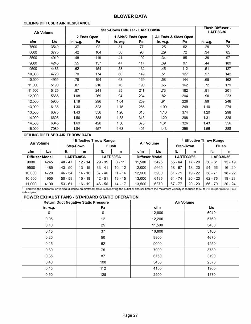
Page 27
BLOWER DATA
CEILING DIFFUSER AIR RESISTANCE
Air VolumeStep-Down Diffuser − LARTD30/36
Flush Diffuser −LAFD30/36
2 Ends Open 1 Side/2 Ends Open All Ends & Sides Open
cfm L/s in. w.g. Pa in. w.g. Pa in. w.g. Pa in. w.g. Pa
7500 3540 .37 92 .31 77 .25 62 .29 72
8000 3775 .42 104 .36 90 .29 72 .34 85
8500 4010 .48 119 .41 102 .34 85 .39 97
9000 4245 .55 137 .47 117 .39 97 .44 109
9500 4485 .62 154 .53 132 .45 112 .51 127
10,000 4720 .70 174 .60 149 .51 127 .57 142
10,500 4955 .78 194 .68 169 .58 144 .65 162
11,000 5190 .87 216 .76 190 .65 162 .72 179
11,500 5425 .97 241 .85 211 .73 182 .81 201
12,000 5665 1.08 269 .94 234 .82 204 .90 223
12,500 5900 1.19 296 1.04 259 .91 226 .99 246
13,000 6135 1.30 323 1.15 286 1.00 249 1.10 274
13,500 6370 1.43 356 1.26 313 1.10 374 1.20 298
14,000 6605 1.56 388 1.38 343 1.20 298 1.31 326
14,500 6845 1.69 420 1.50 373 1.31 326 1.43 356
15,000 7080 1.84 457 1.63 405 1.43 356 1.56 388
CEILING DIFFUSER AIR THROW DATA
Air Volume1 Effective Throw Range
Air Volume1 Effective Throw Range
Step-Down Flush Step-Down Flush
cfm L/s ft. m ft. m cfm L/s ft. m ft. m
Diffuser Model LARTD30/36 LAFD30/36 Diffuser Model LARTD30/36 LAFD30/36
9000 4245 40 − 47 12 − 14 29 − 35 8 − 11 11,500 5425 55 − 64 17 − 20 50 − 61 15 − 19
9500 4485 43 − 50 13 − 15 33 − 41 10 − 12 12,000 5665 58 − 67 18 − 20 54 − 66 16 − 20
10,000 4720 46 − 54 14 − 16 37 − 46 11 − 14 12,500 5900 61 − 71 19 − 22 58 − 71 18 − 22
10,500 4955 50 − 58 15 − 18 42 − 51 13 − 15 13,000 6135 64 − 74 20 − 23 62 − 75 19 − 23
11,000 4190 53 − 61 16 − 19 46 − 56 14 − 17 13,500 6370 67 − 77 20 − 23 66 − 79 20 − 241 Throw is the horizontal or vertical distance an airstream travels on leaving the outlet�or diffuser before the maximum velocity is reduced to 50 ft. (15 m) per minute. Foursides open.
POWER EXHAUST FANS − STANDARD STATIC OPERATION
Return Duct Negative Static Pressure Air Volume
in. w.g. Pa cfm L/s
0 0 12,800 6040
0.05 12 12,200 5760
0.10 25 11,500 5430
0.15 37 10,800 5100
0.20 50 9900 4670
0.25 62 9000 4250
0.30 75 7900 3730
0.35 87 6750 3190
0.40 100 5450 2570
0.45 112 4150 1960
0.50 125 2900 1370
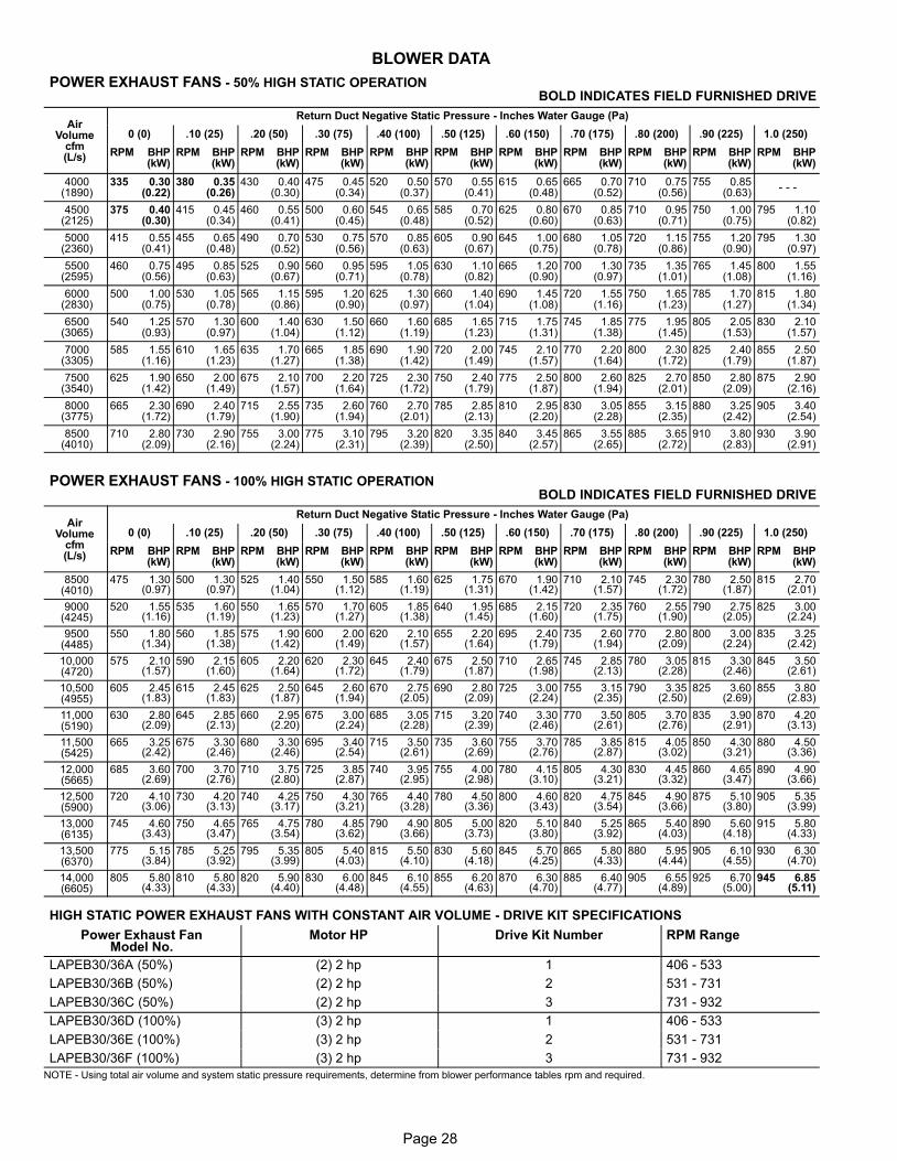
Page 28
BLOWER DATA
POWER EXHAUST FANS − 50% HIGH STATIC OPERATION BOLD INDICATES FIELD FURNISHED DRIVE
AirVolume
cfm(L/s)
Return Duct Negative Static Pressure − Inches Water Gauge (Pa)
0 (0) .10 (25) .20 (50) .30 (75) .40 (100) .50 (125) .60 (150) .70 (175) .80 (200) .90 (225) 1.0 (250)
RPM BHP(kW)
RPM BHP(kW)
RPM BHP(kW)
RPM BHP(kW)
RPM BHP(kW)
RPM BHP(kW)
RPM BHP(kW)
RPM BHP(kW)
RPM BHP(kW)
RPM BHP(kW)
RPM BHP(kW)
4000(1890)
335 0.30(0.22)
380 0.35(0.26)
430 0.40(0.30)
475 0.45(0.34)
520 0.50(0.37)
570 0.55(0.41)
615 0.65(0.48)
665 0.70(0.52)
710 0.75(0.56)
755 0.85(0.63)
− − −
4500(2125)
375 0.40(0.30)
415 0.45(0.34)
460 0.55(0.41)
500 0.60(0.45)
545 0.65(0.48)
585 0.70(0.52)
625 0.80(0.60)
670 0.85(0.63)
710 0.95(0.71)
750 1.00(0.75)
795 1.10(0.82)
5000(2360)
415 0.55(0.41)
455 0.65(0.48)
490 0.70(0.52)
530 0.75(0.56)
570 0.85(0.63)
605 0.90(0.67)
645 1.00(0.75)
680 1.05(0.78)
720 1.15(0.86)
755 1.20(0.90)
795 1.30(0.97)
5500(2595)
460 0.75(0.56)
495 0.85(0.63)
525 0.90(0.67)
560 0.95(0.71)
595 1.05(0.78)
630 1.10(0.82)
665 1.20(0.90)
700 1.30(0.97)
735 1.35(1.01)
765 1.45(1.08)
800 1.55(1.16)
6000(2830)
500 1.00(0.75)
530 1.05(0.78)
565 1.15(0.86)
595 1.20(0.90)
625 1.30(0.97)
660 1.40(1.04)
690 1.45(1.08)
720 1.55(1.16)
750 1.65(1.23)
785 1.70(1.27)
815 1.80(1.34)
6500(3065)
540 1.25(0.93)
570 1.30(0.97)
600 1.40(1.04)
630 1.50(1.12)
660 1.60(1.19)
685 1.65(1.23)
715 1.75(1.31)
745 1.85(1.38)
775 1.95(1.45)
805 2.05(1.53)
830 2.10(1.57)
7000(3305)
585 1.55(1.16)
610 1.65(1.23)
635 1.70(1.27)
665 1.85(1.38)
690 1.90(1.42)
720 2.00(1.49)
745 2.10(1.57)
770 2.20(1.64)
800 2.30(1.72)
825 2.40(1.79)
855 2.50(1.87)
7500(3540)
625 1.90(1.42)
650 2.00(1.49)
675 2.10(1.57)
700 2.20(1.64)
725 2.30(1.72)
750 2.40(1.79)
775 2.50(1.87)
800 2.60(1.94)
825 2.70(2.01)
850 2.80(2.09)
875 2.90(2.16)
8000(3775)
665 2.30(1.72)
690 2.40(1.79)
715 2.55(1.90)
735 2.60(1.94)
760 2.70(2.01)
785 2.85(2.13)
810 2.95(2.20)
830 3.05(2.28)
855 3.15(2.35)
880 3.25(2.42)
905 3.40(2.54)
8500(4010)
710 2.80(2.09)
730 2.90(2.16)
755 3.00(2.24)
775 3.10(2.31)
795 3.20(2.39)
820 3.35(2.50)
840 3.45(2.57)
865 3.55(2.65)
885 3.65(2.72)
910 3.80(2.83)
930 3.90(2.91)
POWER EXHAUST FANS − 100% HIGH STATIC OPERATIONBOLD INDICATES FIELD FURNISHED DRIVE
AirVolume
cfm(L/s)
Return Duct Negative Static Pressure − Inches Water Gauge (Pa)
0 (0) .10 (25) .20 (50) .30 (75) .40 (100) .50 (125) .60 (150) .70 (175) .80 (200) .90 (225) 1.0 (250)
RPM BHP(kW)
RPM BHP(kW)
RPM BHP(kW)
RPM BHP(kW)
RPM BHP(kW)
RPM BHP(kW)
RPM BHP(kW)
RPM BHP(kW)
RPM BHP(kW)
RPM BHP(kW)
RPM BHP(kW)
8500(4010)
475 1.30(0.97)
500 1.30(0.97)
525 1.40(1.04)
550 1.50(1.12)
585 1.60(1.19)
625 1.75(1.31)
670 1.90(1.42)
710 2.10(1.57)
745 2.30(1.72)
780 2.50(1.87)
815 2.70(2.01)
9000(4245)
520 1.55(1.16)
535 1.60(1.19)
550 1.65(1.23)
570 1.70(1.27)
605 1.85(1.38)
640 1.95(1.45)
685 2.15(1.60)
720 2.35(1.75)
760 2.55(1.90)
790 2.75(2.05)
825 3.00(2.24)
9500(4485)
550 1.80(1.34)
560 1.85(1.38)
575 1.90(1.42)
600 2.00(1.49)
620 2.10(1.57)
655 2.20(1.64)
695 2.40(1.79)
735 2.60(1.94)
770 2.80(2.09)
800 3.00(2.24)
835 3.25(2.42)
10,000(4720)
575 2.10(1.57)
590 2.15(1.60)
605 2.20(1.64)
620 2.30(1.72)
645 2.40(1.79)
675 2.50(1.87)
710 2.65(1.98)
745 2.85(2.13)
780 3.05(2.28)
815 3.30(2.46)
845 3.50(2.61)
10,500(4955)
605 2.45(1.83)
615 2.45(1.83)
625 2.50(1.87)
645 2.60(1.94)
670 2.75(2.05)
690 2.80(2.09)
725 3.00(2.24)
755 3.15(2.35)
790 3.35(2.50)
825 3.60(2.69)
855 3.80(2.83)
11,000(5190)
630 2.80(2.09)
645 2.85(2.13)
660 2.95(2.20)
675 3.00(2.24)
685 3.05(2.28)
715 3.20(2.39)
740 3.30(2.46)
770 3.50(2.61)
805 3.70(2.76)
835 3.90(2.91)
870 4.20(3.13)
11,500(5425)
665 3.25(2.42)
675 3.30(2.46)
680 3.30(2.46)
695 3.40(2.54)
715 3.50(2.61)
735 3.60(2.69)
755 3.70(2.76)
785 3.85(2.87)
815 4.05(3.02)
850 4.30(3.21)
880 4.50(3.36)
12,000(5665)
685 3.60(2.69)
700 3.70(2.76)
710 3.75(2.80)
725 3.85(2.87)
740 3.95(2.95)
755 4.00(2.98)
780 4.15(3.10)
805 4.30(3.21)
830 4.45(3.32)
860 4.65(3.47)
890 4.90(3.66)
12,500(5900)
720 4.10(3.06)
730 4.20(3.13)
740 4.25(3.17)
750 4.30(3.21)
765 4.40(3.28)
780 4.50(3.36)
800 4.60(3.43)
820 4.75(3.54)
845 4.90(3.66)
875 5.10(3.80)
905 5.35(3.99)
13,000(6135)
745 4.60(3.43)
750 4.65(3.47)
765 4.75(3.54)
780 4.85(3.62)
790 4.90(3.66)
805 5.00(3.73)
820 5.10(3.80)
840 5.25(3.92)
865 5.40(4.03)
890 5.60(4.18)
915 5.80(4.33)
13,500(6370)
775 5.15(3.84)
785 5.25(3.92)
795 5.35(3.99)
805 5.40(4.03)
815 5.50(4.10)
830 5.60(4.18)
845 5.70(4.25)
865 5.80(4.33)
880 5.95(4.44)
905 6.10(4.55)
930 6.30(4.70)
14,000(6605)
805 5.80(4.33)
810 5.80(4.33)
820 5.90(4.40)
830 6.00(4.48)
845 6.10(4.55)
855 6.20(4.63)
870 6.30(4.70)
885 6.40(4.77)
905 6.55(4.89)
925 6.70(5.00)
945 6.85(5.11)
HIGH STATIC POWER EXHAUST FANS WITH CONSTANT AIR VOLUME − DRIVE KIT SPECIFICATIONS
Power Exhaust FanModel No.
Motor HP Drive Kit Number RPM Range
LAPEB30/36A (50%) (2) 2 hp 1 406 − 533
LAPEB30/36B (50%) (2) 2 hp 2 531 − 731
LAPEB30/36C (50%) (2) 2 hp 3 731 − 932
LAPEB30/36D (100%) (3) 2 hp 1 406 − 533
LAPEB30/36E (100%) (3) 2 hp 2 531 − 731
LAPEB30/36F (100%) (3) 2 hp 3 731 − 932
NOTE − Using total air volume and system static pressure requirements, determine from blower performance tables rpm and required.
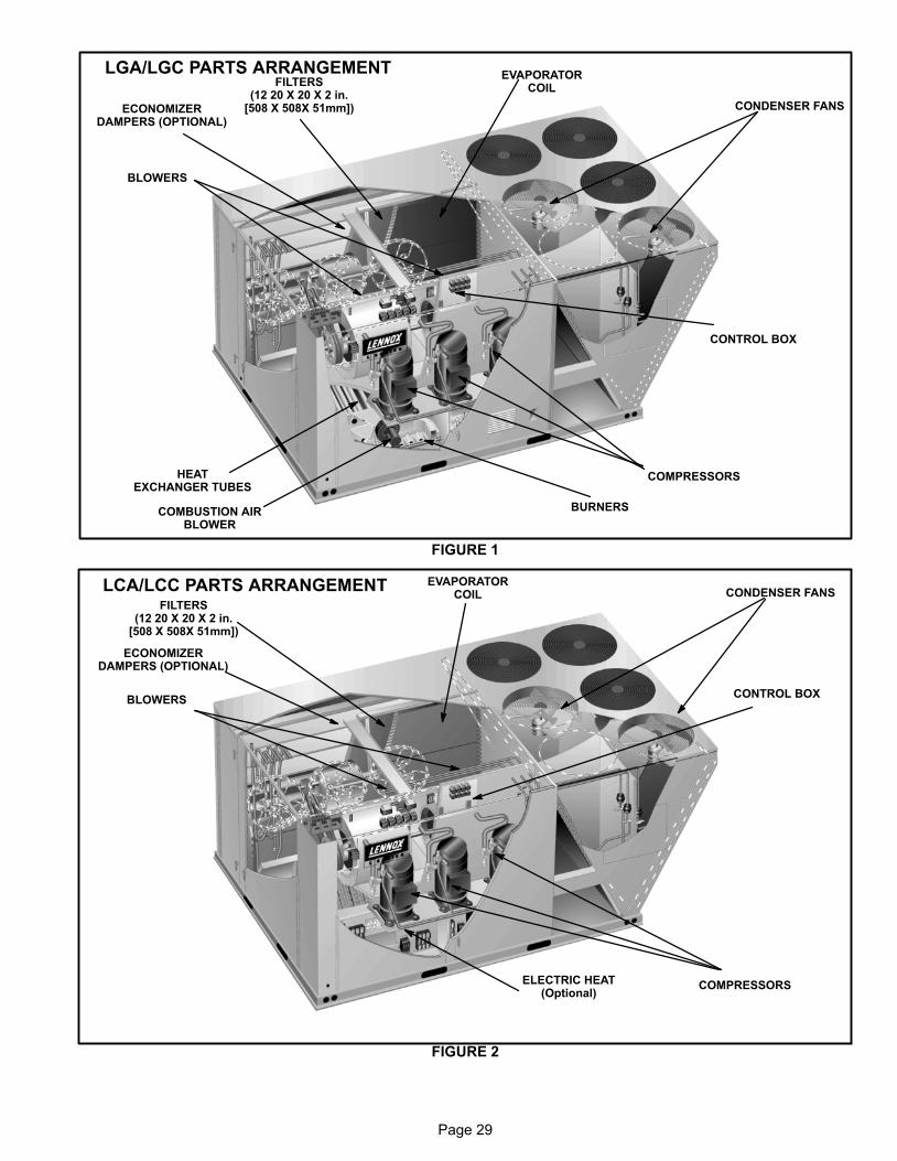
Page 29
COMBUSTION AIRBLOWER
EVAPORATORCOIL
CONDENSER FANS
COMPRESSORS
BURNERS
HEATEXCHANGER TUBES
BLOWERS
FILTERS(12 20 X 20 X 2 in.
[508 X 508X 51mm])ECONOMIZERDAMPERS (OPTIONAL)
CONTROL BOX
LGA/LGC PARTS ARRANGEMENT
FIGURE 1
ELECTRIC HEAT(Optional)
EVAPORATORCOIL CONDENSER FANS
COMPRESSORS
BLOWERS
ECONOMIZERDAMPERS (OPTIONAL)
CONTROL BOX
FIGURE 2
LCA/LCC PARTS ARRANGEMENTFILTERS
(12 20 X 20 X 2 in.[508 X 508X 51mm])
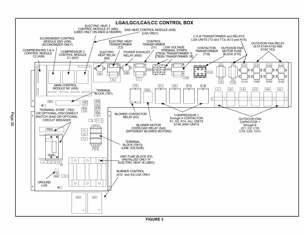
Pag
e 3
0
FIGURE 3
BLOWER CONTACTORRELAY (K3)
GROUNDLUG
TERMINALBLOCK (TB13)
(LINE VOLTAGE)
TERMINALBLOCK (TB1)
ELECTRICHEAT RELAY
(K9)
ELECTRIC HEATTRANSFORMER
(T2)
MAIN CONTROLMODULE M1 (A55)
COMPRESSOR 2CONTROL MODULE
C1 (A57)
CONTROLTRANSFORMER
(T1) OUTDOOR FANMOTOR FUSEBLOCK (F10)
CONTACTORTRANSFORMER
(T18)
LOW VOLTAGETERMINAL STRIPS
[(TB34) TRANSFORMER 1][(TB35) TRANSFORMER 18]
COMPRESSORS 3 & 4CONTROL MODULE
C2 (A59)
ELECTRIC HEAT 2 CONTROL MODULE E1 (A60)
(USED ONLY ON 45kW & HIGHER)
ECONOMIZER CONTROLMODULE EM1 (A56)
(ECONOMIZER ONLY)
BLOWER MOTOROVERLOAD RELAY (S42)
(DIFFERENT BLOWER MOTORS)
COMPRESSOR 1through 4 CONTACTORK1, K2, K14, ALL UNITS
K146 300H UNITS
UNIT FUSE BLOCK (F4)(INSTALLED ONLY IF
ELECTRIC HEAT IS USED)
OUTDOOR FANCAPACITOR 1
through 6 (C1, C2, C18,C19, C20, C21)
POWER EXHAUSTRELAY (K65)
OUTDOOR FAN RELAY(K10 K149 K152 K68
K150 153)
C.A.B TRANSFORMER and RELAYSLGA UNITS (T3 and T13) (K13 and K19)
BURNER CONTROL(A12 and A3) LGA ONLY
LGA/LGC/LCA/LCC CONTROL BOX
GAS HEAT CONTROL MODULE (A58)(LGA ONLY)
TERMINAL STRIP (TB2) OR OPTIONAL DISCONNECTSWITCH (S48) OR OPTIONAL
CIRCUIT BREAKER
(TB2)
(S48)
Page 31
I−UNIT COMPONENTS
CAUTIONElectrostatic discharge can affect electroniccomponents. Take precautions during furnaceinstallation and service to protect the furnace’selectronic controls. Precautions will help toavoid control exposure to electrostatic dis-charge by putting the furnace, the control and thetechnician at the same electrostatic potential.Neutralize electrostatic charge by touching handand all tools on an unpainted unit surface, suchas the gas valve or blower deck, before perform-ing any service procedure.
ELECTROSTATIC DISCHARGE (ESD)
Precautions and Procedures
LGA /LGC/LCA/LCC 21, 25 and 30 ton (74, 88 and 105 kW)
units are configure to order units (CTO). Unit components
are shown in figures 1 and 2. All units come standard with
hinged unit panels. The unit panels may be held open with
the door rod located inside the unit. All L1, L2, and L3 wiring
is color coded; L1 is red, L2 is yellow, and L3 is blue.
A−Control Box Components
Control box components are shown in figure 3, The control
box is located in the upper left portion of the compressor
compartment.
1−Disconnect Switch S48 (Optional all units)
All units may be equipped with an optional disconnect switch
S48. Other factory or field installed optional circuit breakers
may be used, such as CB10. S48 and CB10 are toggle
switches, which can be used by the service technician to dis-
connect power to the unit.
2−Control Transformer T1 (all units)
All units use a single line voltage to 24VAC transformer
mounted in the control box. Transformer supplies power
to control circuits in the unit. The transformer is rated at
70VA and is protected by a 3.5 amp circuit breaker
(CB8). The 208/230 (Y) voltage transformers use two
primary voltage taps
as shown in figure 4,
while 460 (G) and 575
(J) voltage transform-
ers use a single prima-
ry voltage tap. Units
will be factory wired for
230V (orange and
black). 208V (red and
black) applications
should be re−wired in
the field.
3−Contactor Transformer T18
T18 is a single line voltage to 24VAC transformer used in
all units. Transformer T18 is protected by a 3.5 amp circuit
breaker (CB18). T18 is identical to transformer T1. The
transformer supplies 24VAC power to the contactors.
4−C. A. B. Transformers T3 & T13(460V & 575V units built prior to 10−2003)
LGA/LGC 460 (G) and 575 (J) voltage units built prior to
10−2003 use two auto voltage to 230VAC transformers
mounted in the control box. The transformers have an output
rating of 0.5A. T3 transformer supplies 230 VAC power to
combustion air inducer motor (B6), while T13 transformer sup-
plies power to combustion air inducer motor (B15).
5−Terminal Strips TB1, TB2, TB13, TB34, TB35TB1 terminal strip distributes 24V power and common from
the thermostat to the control box components. TB13 termi-
nal strip distributes line voltage power to the line voltage
items in the unit. TB34 terminal strip distributes 24V pow-
er from T1 to the control box components. TB35 terminal
strip distributes 24V power from T18 to the contactors in
the control box. TB2 distributes line voltage to the unit
and is found more commonly on LCA/LCC units
equipped with electric heat. TB2 can be replaced with
Disconnect switch S48. All L1, L2, and L3 wiring is color
coded; L1 is red, L2 is yellow, and L3 is blue.
6−Outdoor Fan Motor Fuse Block & Fuses F10(all units)
Three line voltage fuses F10 provide overcurrent protec-
tion to all condenser fans (and optional power exhaust
fans) in all units. The fuses are rated at 30A in 208/230V
units and 15A in all others.
7−Unit Fuse Block & Fuses F4 (LCA/LCC units only)
Three line voltage fuses F4 provide short circuit and ground
fault protection to all cooling components in the LCA/LCC
units. The fuses are rated in accordance with the amperage of
the cooling components.
8−Outdoor Fan Capacitors C1, C2, C18,C19,C20, C21
Fan capacitors C1, C2, C18, C19, C20 and C21 are 370V /
10 MFD capacitors used to assist in the start up of condens-
er fans B4, B5, B21, B22, B23 and B24. respectively.
9−Compressor Contactors K1, K2, K14, K146All compressor contactors are three pole double break
contactors with a 24VAC coil. In 3 compressor units
(early 360 model) K1 (energized by A55), K2 (energized
by A57), and K14 (energized by A59) energize compres-
sors B1, B2, and B13 respectively in response to first or
second stage cooling demands. In all other LGA/LGC/
LCALCC248H/360H units K1 (energized by A55), K2
(energized by A57), K14 and K146 (energized by A59)
energize compressors B1, B2, B13, and B20 respec-
tively.
FIGURE 4
BLUE YELLOW
ORANGE
RED
BLACK
230 VOLTS
208 VOLTS
PRIMARY
SECONDARY
208/230V TRANSFORMER
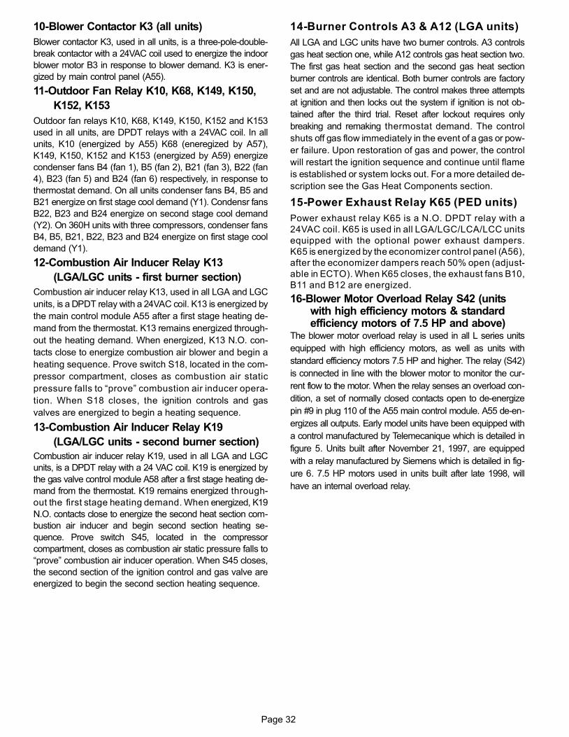
Page 32
10−Blower Contactor K3 (all units)
Blower contactor K3, used in all units, is a three-pole-double-
break contactor with a 24VAC coil used to energize the indoor
blower motor B3 in response to blower demand. K3 is ener-
gized by main control panel (A55).
11−Outdoor Fan Relay K10, K68, K149, K150,
K152, K153
Outdoor fan relays K10, K68, K149, K150, K152 and K153
used in all units, are DPDT relays with a 24VAC coil. In all
units, K10 (energized by A55) K68 (eneregized by A57),
K149, K150, K152 and K153 (energized by A59) energize
condenser fans B4 (fan 1), B5 (fan 2), B21 (fan 3), B22 (fan
4), B23 (fan 5) and B24 (fan 6) respectively, in response to
thermostat demand. On all units condenser fans B4, B5 and
B21 energize on first stage cool demand (Y1). Condensr fans
B22, B23 and B24 energize on second stage cool demand
(Y2). On 360H units with three compressors, condenser fans
B4, B5, B21, B22, B23 and B24 energize on first stage cool
demand (Y1).
12−Combustion Air Inducer Relay K13
(LGA/LGC units − first burner section)
Combustion air inducer relay K13, used in all LGA and LGC
units, is a DPDT relay with a 24VAC coil. K13 is energized by
the main control module A55 after a first stage heating de-
mand from the thermostat. K13 remains energized through-
out the heating demand. When energized, K13 N.O. con-
tacts close to energize combustion air blower and begin a
heating sequence. Prove switch S18, located in the com-
pressor compartment, closes as combustion air static
pressure falls to �prove" combustion air inducer opera-
tion. When S18 closes, the ignition controls and gas
valves are energized to begin a heating sequence.
13−Combustion Air Inducer Relay K19
(LGA/LGC units − second burner section)
Combustion air inducer relay K19, used in all LGA and LGC
units, is a DPDT relay with a 24 VAC coil. K19 is energized by
the gas valve control module A58 after a first stage heating de-
mand from the thermostat. K19 remains energized through-
out the first stage heating demand. When energized, K19
N.O. contacts close to energize the second heat section com-
bustion air inducer and begin second section heating se-
quence. Prove switch S45, located in the compressor
compartment, closes as combustion air static pressure falls to
�prove" combustion air inducer operation. When S45 closes,
the second section of the ignition control and gas valve are
energized to begin the second section heating sequence.
14−Burner Controls A3 & A12 (LGA units)
All LGA and LGC units have two burner controls. A3 controls
gas heat section one, while A12 controls gas heat section two.
The first gas heat section and the second gas heat section
burner controls are identical. Both burner controls are factory
set and are not adjustable. The control makes three attempts
at ignition and then locks out the system if ignition is not ob-
tained after the third trial. Reset after lockout requires only
breaking and remaking thermostat demand. The control
shuts off gas flow immediately in the event of a gas or pow-
er failure. Upon restoration of gas and power, the control
will restart the ignition sequence and continue until flame
is established or system locks out. For a more detailed de-
scription see the Gas Heat Components section.
15−Power Exhaust Relay K65 (PED units)
Power exhaust relay K65 is a N.O. DPDT relay with a
24VAC coil. K65 is used in all LGA/LGC/LCA/LCC units
equipped with the optional power exhaust dampers.
K65 is energized by the economizer control panel (A56),
after the economizer dampers reach 50% open (adjust-
able in ECTO). When K65 closes, the exhaust fans B10,
B11 and B12 are energized.
16−Blower Motor Overload Relay S42 (unitswith high efficiency motors & standardefficiency motors of 7.5 HP and above)
The blower motor overload relay is used in all L series units
equipped with high efficiency motors, as well as units with
standard efficiency motors 7.5 HP and higher. The relay (S42)
is connected in line with the blower motor to monitor the cur-
rent flow to the motor. When the relay senses an overload con-
dition, a set of normally closed contacts open to de−energize
pin #9 in plug 110 of the A55 main control module. A55 de−en-
ergizes all outputs. Early model units have been equipped with
a control manufactured by Telemecanique which is detailed in
figure 5. Units built after November 21, 1997, are equipped
with a relay manufactured by Siemens which is detailed in fig-
ure 6. 7.5 HP motors used in units built after late 1998, will
have an internal overload relay.
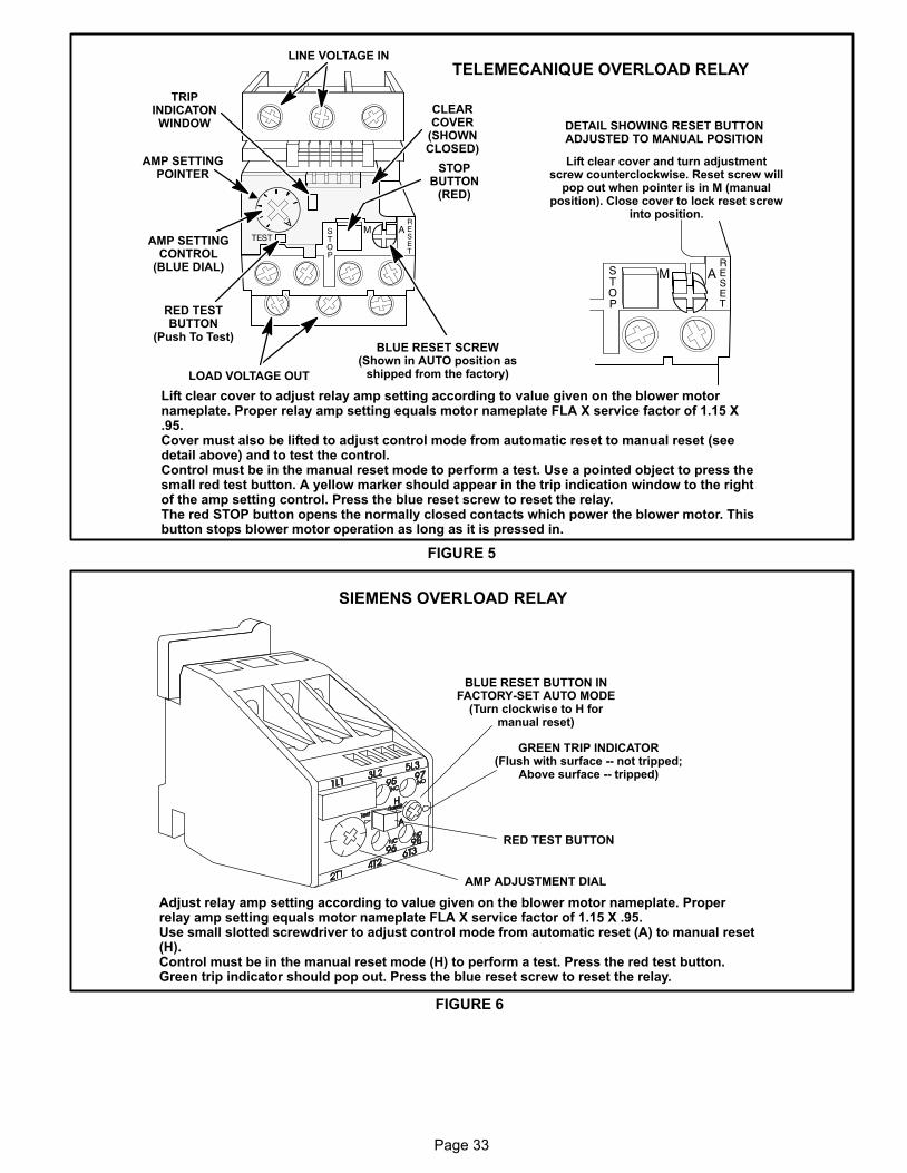
Page 33
CLEARCOVER
(SHOWNCLOSED)
STOPBUTTON
(RED)
RED TESTBUTTON
(Push To Test)
AMP SETTINGCONTROL
(BLUE DIAL)
TRIPINDICATONWINDOW
LINE VOLTAGE IN
AMP SETTINGPOINTER
BLUE RESET SCREW(Shown in AUTO position as
shipped from the factory)LOAD VOLTAGE OUT
DETAIL SHOWING RESET BUTTONADJUSTED TO MANUAL POSITION
Lift clear cover and turn adjustmentscrew counterclockwise. Reset screw will
pop out when pointer is in M (manualposition). Close cover to lock reset screw
into position.
TELEMECANIQUE OVERLOAD RELAY
Lift clear cover to adjust relay amp setting according to value given on the blower motornameplate. Proper relay amp setting equals motor nameplate FLA X service factor of 1.15 X.95.Cover must also be lifted to adjust control mode from automatic reset to manual reset (seedetail above) and to test the control. Control must be in the manual reset mode to perform a test. Use a pointed object to press thesmall red test button. A yellow marker should appear in the trip indication window to the rightof the amp setting control. Press the blue reset screw to reset the relay.The red STOP button opens the normally closed contacts which power the blower motor. Thisbutton stops blower motor operation as long as it is pressed in.
FIGURE 5
SIEMENS OVERLOAD RELAY
Adjust relay amp setting according to value given on the blower motor nameplate. Properrelay amp setting equals motor nameplate FLA X service factor of 1.15 X .95.Use small slotted screwdriver to adjust control mode from automatic reset (A) to manual reset(H). Control must be in the manual reset mode (H) to perform a test. Press the red test button.Green trip indicator should pop out. Press the blue reset screw to reset the relay.
BLUE RESET BUTTON INFACTORY-SET AUTO MODE
(Turn clockwise to H formanual reset)
GREEN TRIP INDICATOR(Flush with surface −− not tripped;
Above surface −− tripped)
AMP ADJUSTMENT DIAL
RED TEST BUTTON
FIGURE 6
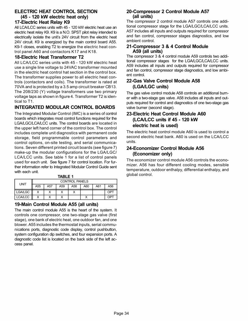
Page 34
ELECTRIC HEAT CONTROL SECTION(45 − 120 kW electric heat only)
17−Electric Heat Relay K9All LCA/LCC series units with 45 − 120 kW electric heat use an
electric heat relay K9. K9 is a N.O. SPST pilot relay intended to
electrically isolate the unit’s 24V circuit from the electric heat
24V circuit. K9 is energized by the main control board A55.
K9−1 closes, enabling T2 to energize the electric heat con-
trol panel A60 and contactors K17 and K18.
18−Electric Heat Transformer T2All LCA/LCC series units with 45 − 120 kW electric heat
use a single line voltage to 24VAC transformer mounted
in the electric heat control hat section in the control box.
The transformer supplies power to all electric heat con-
trols (contactors and coils). The transformer is rated at
70VA and is protected by a 3.5 amp circuit breaker CB13.
The 208/230 (Y) voltage transformers use two primary
voltage taps as shown in figure 4. Transformer T2 is iden-
tical to T1.
INTEGRATED MODULAR CONTROL BOARDS
The Integrated Modular Control (IMC) is a series of control
boards which integrates most control functions required for the
LGA/LGC/LCA/LCC units. The control boards are located in
the upper left hand corner of the control box. The control
includes complete unit diagnostics with permanent code
storage, field programmable control parameters and
control options, on-site testing, and serial communica-
tions. Seven different printed circuit boards (see figure 7)
make-up the modular configurations for the LGA/LGC/
LCA/LCC units. See table 1 for a list of control panels
used for each unit. See figure 7 for control location. For fur-
ther information refer to Integrated Modular Control Guide sent
with each unit.
TABLE 1
UNITCONTROL PANELS
A55 A57 A59 A58 A60 A61 A56
LGA/LGC X X X X OPT
LCA/LCC X X X X OPT
19−Main Control Module A55 (all units)The main control module A55 is the heart of the system. It
controls one compressor, one two-stage gas valve (first
stage), one bank of electric heat, one outdoor fan, and one
blower. A55 includes the thermostat inputs, serial commu-
nications ports, diagnostic code display, control pushbutton,
system configuration dip switches, and four expansion ports. A
diagnostic code list is located on the back side of the left ac-
cess panel.
20−Compressor 2 Control Module A57(all units)
The compressor 2 control module A57 controls one addi-
tional compressor stage for the LGA/LGC/LCA/LCC units.
A57 includes all inputs and outputs required for compressor
and fan control, compressor stages diagnostics, and low
ambient control.
21−Compressor 3 & 4 Control ModuleA59 (all units)
The compressor 3 & 4 control module A59 controls two addi-tional compressor stages for the LGA/LGC/LCA/LCC units.A59 includes all inputs and outputs required for compressorand fan control, compressor stage diagnostics, and low ambi-ent control.
22−Gas Valve Control Module A58
(LGA/LGC units)
The gas valve control module A58 controls an additional burn-
er with a two-stage gas valve. A58 includes all inputs and out-
puts required for control and diagnostics of one two-stage gas
valve burner (second stage).
23−Electric Heat Control Module A60
(LCA/LCC units if 45 − 120 kW
electric heat is used)
The electric heat control module A60 is used to control a
second electric heat bank. A60 is used on the LCA/LCC
units.
24−Economizer Control Module A56(Economizer only)
The economizer control module A56 controls the econo-
mizer. A56 has four different cooling modes, sensible
temperature, outdoor enthalpy, differential enthalpy, and
global control.

Page 35
IMC BOARD INPUTS AND OUTPUTS
FIGURE 7
P110 P111 P112 P113
P114
P115 P116
SENSORSINPUTS
OUTPUTS
COMPRESSORSAFETY INPUTS
BURNERINPUTS
ROOMTHERMOSTAT
(A2)
A55
A56 A57 A58P117
A60P120
A59OR
IMC AND ADD−ON BOARD LOCATION AND OPERATION
A55:
A56:Optional
Economizer
and/or Power
Exhaust Fan
A57(LCA / LGA):
Second
compressor
1 Outdoor fan
A58:Second Gas
Valve
A60:Second Electric
Heat Section
A59 (LCA / LGA):Compressors 3
and 4 and Outdoor
Fans (4)
or
1 Blower
1 Compressor
1 Outdoor fan
1 Gas valve
1 Reversing valve
1 Electric heat section
TB1 connects to P110. Room thermostat connects to TB1. See section C2 inthe wiring diagram section P.65
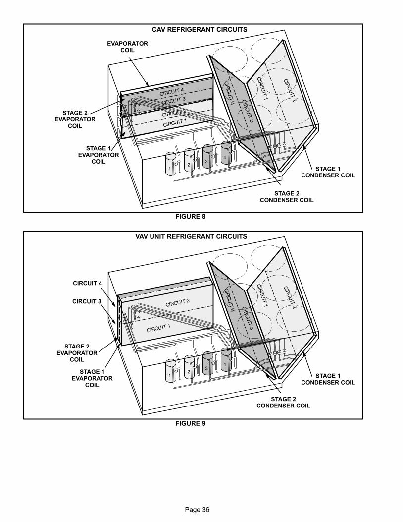
Page 36
EVAPORATORCOIL
STAGE 1CONDENSER COIL
FIGURE 8
STAGE 2CONDENSER COIL
STAGE 1EVAPORATOR
COIL
STAGE 2EVAPORATOR
COIL
CAV REFRIGERANT CIRCUITS
VAV UNIT REFRIGERANT CIRCUITS
STAGE 1CONDENSER COIL
FIGURE 9
STAGE 2CONDENSER COIL
STAGE 1EVAPORATOR
COIL
STAGE 2EVAPORATOR
COIL
CIRCUIT 3
CIRCUIT 4
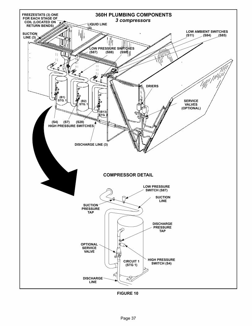
Page 37
360H PLUMBING COMPONENTS3 compressors
FIGURE 10
COMPRESSOR DETAIL
FREEZESTATS (3) ONEFOR EACH STAGE OFCOIL (LOCATED ON
RETURN BENDS)
SUCTION LINE (3)
LIQUID LINE(3)
LOW AMBIENT SWITCHES(S11) (S84) (S85)
HIGH PRESSURE SWITCHES
(S4) (S7) (S28)
LOW PRESSURE SWITCHES(S87) (S88) (S98)
DRIERS
SERVICEVALVES
(OPTIONAL)
DISCHARGE LINE (3)
SUCTIONLINE
SUCTIONPRESSURE
TAP
LOW PRESSURESWITCH (S87)
DISCHARGELINE
HIGH PRESSURESWITCH (S4)
DISCHARGEPRESSURE
TAP
OPTIONALSERVICE
VALVE
CIRCUIT 1(STG 1)
(B1)STG. 1 (B2)
STG. 1
(B13)STG. 2
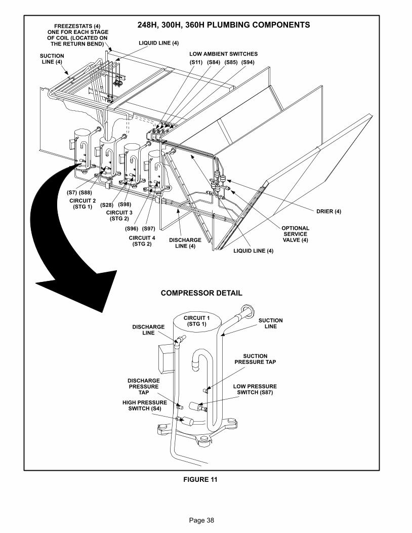
Page 38
248H, 300H, 360H PLUMBING COMPONENTS
FIGURE 11
SUCTIONLINEDISCHARGE
LINE
DISCHARGEPRESSURE
TAPLOW PRESSURE
SWITCH (S87)
HIGH PRESSURESWITCH (S4)
SUCTIONPRESSURE TAP
COMPRESSOR DETAIL
CIRCUIT 1(STG 1)
(S11) (S84) (S85) (S94)
LIQUID LINE (4)
OPTIONALSERVICEVALVE (4)
DRIER (4)
LIQUID LINE (4)
DISCHARGELINE (4)
SUCTIONLINE (4)
(S28) (S98)
(S96) (S97)
(S88)(S7)
LOW AMBIENT SWITCHES
CIRCUIT 2(STG 1)
CIRCUIT 3(STG 2)
CIRCUIT 4(STG 2)
FREEZESTATS (4) ONE FOR EACH STAGEOF COIL (LOCATED ON
THE RETURN BEND)
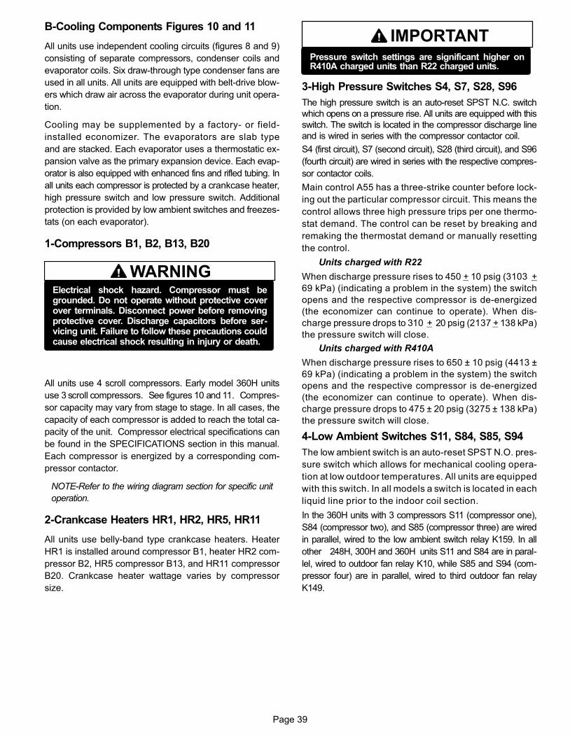
Page 39
B−Cooling Components Figures 10 and 11
All units use independent cooling circuits (figures 8 and 9)
consisting of separate compressors, condenser coils and
evaporator coils. Six draw−through type condenser fans are
used in all units. All units are equipped with belt-drive blow-
ers which draw air across the evaporator during unit opera-
tion.
Cooling may be supplemented by a factory- or field-
installed economizer. The evaporators are slab type
and are stacked. Each evaporator uses a thermostatic ex-
pansion valve as the primary expansion device. Each evap-
orator is also equipped with enhanced fins and rifled tubing. In
all units each compressor is protected by a crankcase heater,
high pressure switch and low pressure switch. Additional
protection is provided by low ambient switches and freezes-
tats (on each evaporator).
1−Compressors B1, B2, B13, B20
WARNINGElectrical shock hazard. Compressor must begrounded. Do not operate without protective coverover terminals. Disconnect power before removingprotective cover. Discharge capacitors before ser-vicing unit. Failure to follow these precautions couldcause electrical shock resulting in injury or death.
All units use 4 scroll compressors. Early model 360H units
use 3 scroll compressors. See figures 10 and 11. Compres-
sor capacity may vary from stage to stage. In all cases, the
capacity of each compressor is added to reach the total ca-
pacity of the unit. Compressor electrical specifications can
be found in the SPECIFICATIONS section in this manual.
Each compressor is energized by a corresponding com-
pressor contactor.
NOTE−Refer to the wiring diagram section for specific unit
operation.
2−Crankcase Heaters HR1, HR2, HR5, HR11
All units use belly-band type crankcase heaters. Heater
HR1 is installed around compressor B1, heater HR2 com-
pressor B2, HR5 compressor B13, and HR11 compressor
B20. Crankcase heater wattage varies by compressor
size.
IMPORTANTPressure switch settings are significant higher onR410A charged units than R22 charged units.
3−High Pressure Switches S4, S7, S28, S96
The high pressure switch is an auto-reset SPST N.C. switch
which opens on a pressure rise. All units are equipped with this
switch. The switch is located in the compressor discharge line
and is wired in series with the compressor contactor coil.
S4 (first circuit), S7 (second circuit), S28 (third circuit), and S96
(fourth circuit) are wired in series with the respective compres-
sor contactor coils.
Main control A55 has a three−strike counter before lock-
ing out the particular compressor circuit. This means the
control allows three high pressure trips per one thermo-
stat demand. The control can be reset by breaking and
remaking the thermostat demand or manually resetting
the control.
Units charged with R22
When discharge pressure rises to 450 + 10 psig (3103 +
69 kPa) (indicating a problem in the system) the switch
opens and the respective compressor is de−energized
(the economizer can continue to operate). When dis-
charge pressure drops to 310 + 20 psig (2137 + 138 kPa)
the pressure switch will close.
Units charged with R410A
When discharge pressure rises to 650 ± 10 psig (4413 ±
69 kPa) (indicating a problem in the system) the switch
opens and the respective compressor is de−energized
(the economizer can continue to operate). When dis-
charge pressure drops to 475 ± 20 psig (3275 ± 138 kPa)
the pressure switch will close.
4−Low Ambient Switches S11, S84, S85, S94
The low ambient switch is an auto-reset SPST N.O. pres-
sure switch which allows for mechanical cooling opera-
tion at low outdoor temperatures. All units are equipped
with this switch. In all models a switch is located in each
liquid line prior to the indoor coil section.
In the 360H units with 3 compressors S11 (compressor one),
S84 (compressor two), and S85 (compressor three) are wired
in parallel, wired to the low ambient switch relay K159. In all
other 248H, 300H and 360H units S11 and S84 are in paral-
lel, wired to outdoor fan relay K10, while S85 and S94 (com-
pressor four) are in parallel, wired to third outdoor fan relay
K149.
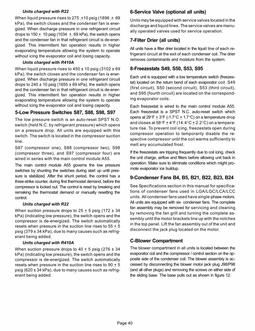
Page 40
Units charged with R22
When liquid pressure rises to 275 +10 psig (1896 + 69
kPa), the switch closes and the condenser fan is ener-
gized. When discharge pressure in one refrigerant circuit
drops to 150 + 10 psig (1034 + 69 kPa), the switch opens
and the condenser fan in that refrigerant circuit is de−ener-
gized. This intermittent fan operation results in higher
evaporating temperature allowing the system to operate
without icing the evaporator coil and losing capacity.
Units charged with R410A
When liquid pressure rises to 450 ± 10 psig (3102 ± 69
kPa), the switch closes and the condenser fan is ener-
gized. When discharge pressure in one refrigerant circuit
drops to 240 ± 10 psig (1655 ± 69 kPa), the switch opens
and the condenser fan in that refrigerant circuit is de−ener-
gized. This intermittent fan operation results in higher
evaporating temperature allowing the system to operate
without icing the evaporator coil and losing capacity.
5−Low Pressure Switches S87, S88, S98, S97
The low pressure switch is an auto-reset SPST N.O.
switch (held N.C. by refrigerant pressure) which opens
on a pressure drop. All units are equipped with this
switch. The switch is located in the compressor suction
line.
S87 (compressor one), S88 (compressor two), S98
(compressor three), and S97 (compressor four) are
wired in series with the main control module A55.
The main control module A55 governs the low pressure
switches by shunting the switches during start up until pres-
sure is stabilized. After the shunt period, the control has a
three-strike counter, during first thermostat demand, before the
compressor is locked out. The control is reset by breaking and
remaking the thermostat demand or manually resetting the
control.
Units charged with R22
When suction pressure drops to 25 + 5 psig (172 ± 34
kPa) (indicating low pressure), the switch opens and the
compressor is de−energized. The switch automatically
resets when pressure in the suction line rises to 55 + 5
psig (379 ± 34 kPa), due to many causes such as refrig-
erant being added.
Units charged with R410A
When suction pressure drops to 40 + 5 psig (276 ± 34
kPa) (indicating low pressure), the switch opens and the
compressor is de−energized. The switch automatically
resets when pressure in the suction line rises to 90 + 5
psig (620 ± 34 kPa), due to many causes such as refrig-
erant being added.
6−Service Valve (optional all units)
Units may be equipped with service valves located in the
discharge and liquid lines. The service valves are manu-
ally operated valves used for service operation.
7−Filter Drier (all units)
All units have a filter drier located in the liquid line of each re-
frigerant circuit at the exit of each condenser coil. The drier
removes contaminants and moisture from the system.
8−Freezestats S49, S50, S53, S95
Each unit is equipped with a low temperature switch (freezes-
tat) located on the return bend of each evaporator coil. S49
(first circuit), S50 (second circuit), S53 (third circuit),
and S95 (fourth circuit) are located on the correspond-
ing evaporator coils.
Each freezestat is wired to the main control module A55.
Each freezestat is a SPST N.C. auto−reset switch which
opens at 29°F + 3°F (-1.7°C + 1.7°C) on a temperature drop
and closes at 58°F + 4°F (14.4°C + 2.2°C) on a tempera-
ture rise. To prevent coil icing, freezestats open during
compressor operation to temporarily disable the re-
spective compressor until the coil warms sufficiently to
melt any accumulated frost.
If the freezestats are tripping frequently due to coil icing, check
the unit charge, airflow and filters before allowing unit back in
operation. Make sure to eliminate conditions which might pro-
mote evaporator ice buildup.
9−Condenser Fans B4, B5, B21, B22, B23, B24
See Specifications section in this manual for specifica-
tions of condenser fans used in LGA/LGC/LCA/LCC
units. All condenser fans used have single−phase motors.
All units are equipped with six condenser fans. The complete
fan assembly may be removed for servicing and cleaning
by removing the fan grill and turning the complete as-
sembly until the motor brackets line up with the notches
in the top panel. Lift the fan assembly out of the unit and
disconnect the jack plug located on the motor.
C−Blower Compartment
The blower compartment in all units is located between the
evaporator coil and the compressor / control section on the op-
posite side of the condenser coil. The blower assembly is ac-
cessed by disconnecting the blower motor jack plug J98/P98
(and all other plugs) and removing the screws on either side of
the sliding base. The base pulls out as shown in figure 12.
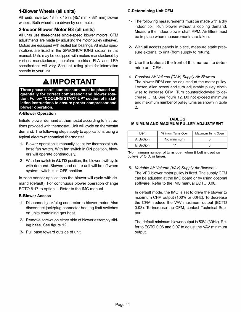
Page 41
1−Blower Wheels (all units)
All units have two 18 in. x 15 in. (457 mm x 381 mm) blower
wheels. Both wheels are driven by one motor.
2−Indoor Blower Motor B3 (all units)All units use three-phase single-speed blower motors. CFM
adjustments are made by adjusting the motor pulley (sheave).
Motors are equipped with sealed ball bearings. All motor spec-
ifications are listed in the SPECIFICATIONS section in this
manual. Units may be equipped with motors manufactured by
various manufacturers, therefore electrical FLA and LRA
specifications will vary. See unit rating plate for information
specific to your unit.
IMPORTANTThree phase scroll compressors must be phased se-quentially for correct compressor and blower rota-tion. Follow �COOLING START−UP" section of instal-lation instructions to ensure proper compressor andblower operation.
A−Blower Operation
Initiate blower demand at thermostat according to instruc-
tions provided with thermostat. Unit will cycle on thermostat
demand. The following steps apply to applications using a
typical electro−mechanical thermostat.
1− Blower operation is manually set at the thermostat sub-
base fan switch. With fan switch in ON position, blow-
ers will operate continuously.
2− With fan switch in AUTO position, the blowers will cycle
with demand. Blowers and entire unit will be off when
system switch is in OFF position.
In zone sensor applications the blower will cycle with de-
mand (default). For continuous blower operation change
ECTO 6.17 to option 1. Refer to the IMC manual.
B−Blower Access
1− Disconnect jack/plug connector to blower motor. Also
disconnect jack/plug connector heating limit switches
on units containing gas heat.
2− Remove screws on either side of blower assembly slid-
ing base. See figure 12.
3− Pull base toward outside of unit.
C−Determining Unit CFM
1− The following measurements must be made with a dry
indoor coil. Run blower without a cooling demand.
Measure the indoor blower shaft RPM. Air filters must
be in place when measurements are taken.
2− With all access panels in place, measure static pres-
sure external to unit (from supply to return).
3− Use the tables at the front of this manual to deter-
mine unit CFM.
4− Constant Air Volume (CAV) Supply Air Blowers −
The blower RPM can be adjusted at the motor pulley.
Loosen Allen screw and turn adjustable pulley clock-
wise to increase CFM. Turn counterclockwise to de-
crease CFM. See figure 12. Do not exceed minimum
and maximum number of pulley turns as shown in table
2.
TABLE 2MINIMUM AND MAXIMUM PULLEY ADJUSTMENT
Belt Minimum Turns Open Maximum Turns Open
A Section No minimum 5
B Section 1* 6
*No minimum number of turns open when B belt is used onpulleys 6" O.D. or larger.
5− Variable Air Volume (VAV) Supply Air Blowers −
The VFD blower motor pulley is fixed. The supply CFM
can be adjusted at the IMC board or by using optional
software. Refer to the IMC manual ECTO 0.08.
In default mode, the IMC is set to drive the blower to
maximum CFM output (100% or 60Hz). To decrease
the CFM, reduce the VAV maximum output (ECTO
0.08). To increase the CFM, contact Technical Sup-
port.
The default minimum blower output is 50% (30Hz). Re-
fer to ECTO 0.06 and 0.07 to adjust the VAV minimum
output.
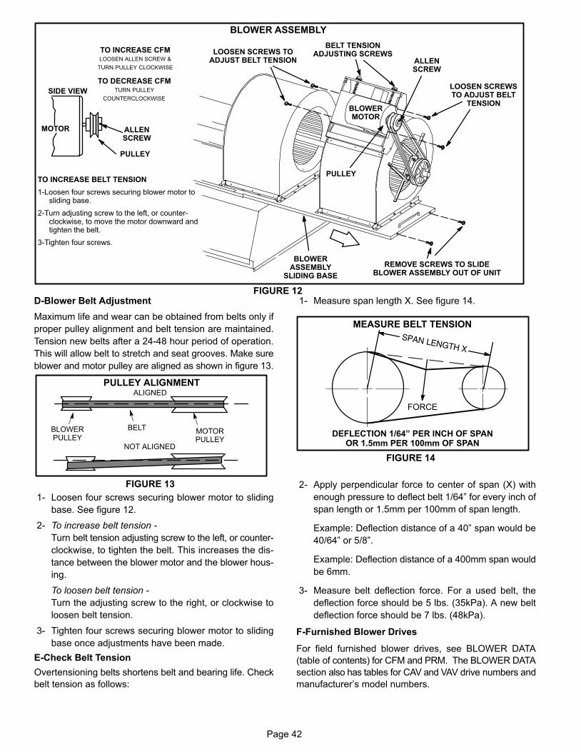
Page 42
BLOWER ASSEMBLY
TO INCREASE BELT TENSION
1−Loosen four screws securing blower motor tosliding base.
2−Turn adjusting screw to the left, or counter-clockwise, to move the motor downward andtighten the belt.
3−Tighten four screws.
TO INCREASE CFMLOOSEN ALLEN SCREW &
TURN PULLEY CLOCKWISE
TO DECREASE CFMTURN PULLEY
COUNTERCLOCKWISE
FIGURE 12
LOOSEN SCREWSTO ADJUST BELT
TENSIONBLOWERMOTOR
REMOVE SCREWS TO SLIDEBLOWER ASSEMBLY OUT OF UNIT
LOOSEN SCREWS TOADJUST BELT TENSION
PULLEY
ALLENSCREW
BELT TENSIONADJUSTING SCREWS
BLOWERASSEMBLY
SLIDING BASE
PULLEY
MOTOR ALLENSCREW
SIDE VIEW
D−Blower Belt Adjustment
Maximum life and wear can be obtained from belts only if
proper pulley alignment and belt tension are maintained.
Tension new belts after a 24−48 hour period of operation.
This will allow belt to stretch and seat grooves. Make sure
blower and motor pulley are aligned as shown in figure 13.
FIGURE 13
PULLEY ALIGNMENT
BELTBLOWERPULLEY
MOTORPULLEY
NOT ALIGNED
ALIGNED
1− Loosen four screws securing blower motor to sliding
base. See figure 12.
2− To increase belt tension −
Turn belt tension adjusting screw to the left, or counter-
clockwise, to tighten the belt. This increases the dis-
tance between the blower motor and the blower hous-
ing.
To loosen belt tension −
Turn the adjusting screw to the right, or clockwise to
loosen belt tension.
3− Tighten four screws securing blower motor to sliding
base once adjustments have been made.
E−Check Belt Tension
Overtensioning belts shortens belt and bearing life. Check
belt tension as follows:
1− Measure span length X. See figure 14.
MEASURE BELT TENSION
FIGURE 14
DEFLECTION 1/64" PER INCH OF SPANOR 1.5mm PER 100mm OF SPAN
FORCE
2− Apply perpendicular force to center of span (X) with
enough pressure to deflect belt 1/64" for every inch of
span length or 1.5mm per 100mm of span length.
Example: Deflection distance of a 40" span would be
40/64" or 5/8".
Example: Deflection distance of a 400mm span would
be 6mm.
3− Measure belt deflection force. For a used belt, the
deflection force should be 5 lbs. (35kPa). A new belt
deflection force should be 7 lbs. (48kPa).
F−Furnished Blower Drives
For field furnished blower drives, see BLOWER DATA
(table of contents) for CFM and PRM. The BLOWER DATA
section also has tables for CAV and VAV drive numbers and
manufacturer’s model numbers.
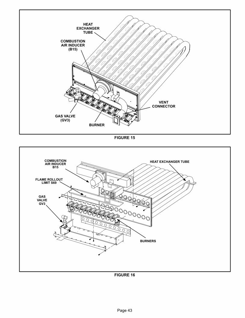
Page 43
FIGURE 15
BURNER
COMBUSTIONAIR INDUCER
(B15)
VENTCONNECTOR
GAS VALVE(GV3)
HEATEXCHANGER
TUBE
FIGURE 16
FLAME ROLLOUTLIMIT S69
GASVALVE
GV3
BURNERS
COMBUSTIONAIR INDUCER
B15
HEAT EXCHANGER TUBE
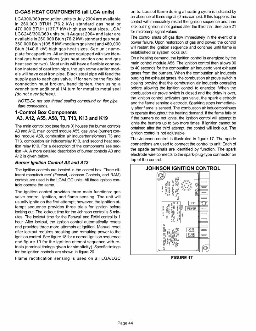
Page 44
D−GAS HEAT COMPONENTS (all LGA units)
LGA300/360 production units to July 2004 are available
in 260,000 BTUH (76.2 kW) standard gas heat or
470,000 BTUH (137.7 kW) high gas heat sizes. LGA/
LGC248/300/360 units built August 2004 and later are
available in 260,000 Btuh (76.2 kW) standard gas heat,
360,000 Btuh (105.5 kW) medium gas heat and 480,000
Btuh (140.6 kW) high gas heat sizes. See unit name-
plate for capacities. All units are equipped with two iden-
tical gas heat sections (gas heat section one and gas
heat section two). Most units will have a flexible connec-
tion instead of cast iron pipe, though some earlier mod-
els will have cast iron pipe. Black steel pipe will feed the
supply gas to each gas valve. If for service the flexible
connection must broken, hand tighten, then using a
wrench turn additional 1/4 turn for metal to metal seal
(do not over tighten).
NOTE−Do not use thread sealing compound on flex pipe
flare connections.
1−Control Box Components A3, A12, A55, A58, T3, T13, K13 and K19
The main control box (see figure 3) houses the burner controls
A3 and A12, main control module A55, gas valve (burner) con-
trol module A58, combustion air inducertransformers T3 and
T13, combustion air inducerrelay K13, and second heat sec-
tion relay K19. For a description of the components see sec-
tion I-A. A more detailed description of burner controls A3 and
A12 is given below.
Burner Ignition Control A3 and A12
The ignition controls are located in the control box. Three dif-
ferent manufacturers’ (Fenwal, Johnson Controls, and RAM)
controls are used in the LGA/LGC units. All three ignition con-
trols operate the same.
The ignition control provides three main functions: gas
valve control, ignition, and flame sensing. The unit will
usually ignite on the first attempt; however, the ignition at-
tempt sequence provides three trials for ignition before
locking out. The lockout time for the Johnson control is 5 min-
utes. The lockout time for the Fenwall and RAM control is 1
hour. After lockout, the ignition control automatically resets
and provides three more attempts at ignition. Manual reset
after lockout requires breaking and remaking power to the
ignition control. See figure 18 for a normal ignition sequence
and figure 19 for the ignition attempt sequence with re-
trials (nominal timings given for simplicity). Specific timings
for the ignition controls are shown in figure 20.
Flame rectification sensing is used on all LGA/LGC
units. Loss of flame during a heating cycle is indicated by
an absence of flame signal (0 microamps). If this happens, the
control will immediately restart the ignition sequence and then
lock out if ignition is not gained after the third trial. See table 21
for microamp signal values .
The control shuts off gas flow immediately in the event of a
power failure. Upon restoration of gas and power, the control
will restart the ignition sequence and continue until flame is
established or system locks out.
On a heating demand, the ignition control is energized by the
main control module A55. The ignition control then allows 30
to 40 seconds for the combustion air inducerto vent exhaust
gases from the burners. When the combustion air induceris
purging the exhaust gases, the combustion air prove switch is
closing proving that the combustion air induceris operating
before allowing the ignition control to energize. When the
combustion air prove switch is closed and the delay is over,
the ignition control activates gas valve, the spark electrode
and the flame sensing electrode. Sparking stops immediate-
ly after flame is sensed. The combustion air inducercontinues
to operate throughout the heating demand. If the flame fails or
if the burners do not ignite, the ignition control will attempt to
ignite the burners up to two more times. If ignition cannot be
obtained after the third attempt, the control will lock out. The
ignition control is not adjustable.
The Johnson control is illustrated in figure 17. The spade
connections are used to connect the control to unit. Each of
the spade terminals are identified by function. The spark
electrode wire connects to the spark-plug-type connector on
top of the control.
FIGURE 17
JOHNSON IGNITION CONTROL

Page 45
ÉÉÉÉÉÉÉÉÉÉÉÉÉÉÉÉÉÉÉÉÉÉÉÉÉÉÉÉ
ÉÉÉÉÉÉ
ÉÉÉÉÉÉÉÉÉÉÉÉ ÉÉÉÉÉÉÉÉÉÉÉ
ÉÉÉÉÉÉÉÉÉÉÉ
NORMAL IGNITION SEQUENCETIMINGS NOMINAL
THERMOSTAT DEMAND
COMBUSTION AIR BLOWER
GAS VALVE
IGNITION SPARK
BLOWERIGNITION TRIAL
SECONDS 0 30 35 0 110
ON / CLOSED
OFF / OPENEND OFDEMAND
1
ÉÉÉÉÉÉÉÉÉÉÉÉÉÉÉÉÉÉÉÉÉÉÉÉÉÉ
COMBUSTION AIR PROVE SWITCH
5 570
FIGURE 18
FIGURE 19
RETRIALS − IGNITION ATTEMPT SEQUENCE − TIMINGS NOMINALÉÉÉÉÉÉ
ÉÉÉ
THERMOSTAT DEMAND
COMBUSTION AIR BLOWER
GAS VALVEIGNITION SPARK
BLOWER
IGNITION TRIAL
SECONDS 0 30 35 70ON
OFF
ÉÉÉÉÉÉÉÉÉÉÉÉÉÉÉÉÉÉÉÉÉÉÉÉÉÉÉÉÉÉÉÉÉÉÉÉÉÉÉÉÉÉÉÉÉÉÉÉÉÉÉÉÉÉÉÉÉ
ÉÉÉÉÉÉÉ
ÉÉ
65 100 105
WATCHGUARD
LOCKOUT
COMBUSTION AIR PROVE SWITCHÉÉÉÉÉÉÉÉÉÉÉÉÉÉÉÉÉÉÉÉÉÉÉÉÉÉÉÉÉÉÉÉÉÉÉÉÉÉ
5
FIGURE 20
ÉÉÉ
ÉÉÉÉÉÉÉÉÉÉÉÉÉÉÉÉÉÉÉÉÉÉÉÉÉÉÉÉÉÉÉÉÉ
ÉÉÉÉÉÉÉÉÉÉÉ
THERMOSTAT DEMAND
COMBUSTION AIR BLOWERGAS VALVE
IGNITION SPARK
BLOWERIGNITION TRIAL
SECONDS 0 30
ON
OFF
IGNITION CONTROL TIMING
ÉÉÉÉÉÉ ÉÉ
ÉÉÉÉ É ÉÉÉ
ÉÉÉ
30 30HEATING
CYCLE
6 (+3.4, −2.0) SEC. END OFTHERMOSTAT
DEMAND
1 2 3
42 SEC. 122 SEC.
WARNINGSHOCK HAZARD. SPARK RELATED COMPONENTSCONTAIN HIGH VOLTAGE WHICH CAN CAUSEPERSONAL INJURY OR DEATH. DISCONNECTPOWER BEFORE SERVICING. CONTROL IS NOTFIELD REPAIRABLE. UNSAFE OPERATION WILLRESULT. IF THE CONTROL IS INOPERABLE, SIM-PLY REPLACE THE ENTIRE CONTROL.
2−Heat Exchanger (Figures 15 and 16)
Two Styles used
The LGA/LGC units use aluminized steel inshot burners with
matching tubular aluminized steel (stainless steel is an option)
heat exchangers and two-stage redundant gas valves. LGA/
LGC uses two eleven tube/burners for high heat, two nine tube
burners for medium heat (if applicable, see unit nameplate)
and two six tube/burners for standard heat. Each burner uses
a burner venturi to mix gas and air for proper combustion.
Combustion takes place at each tube entrance. As hot com-
bustion gases are drawn upward through each tube by the
combustion air blower, exhaust gases are drawn out the top
and fresh air/gas mixture is drawn in at the bottom. Heat is
transferred to the air stream from all surfaces of the heat ex-
changer tubes. The supply air blowers, controlled by the main
control panel A55, force air across all surfaces of the tubes to
extract the heat of combustion. The shape of the tubes ensur-
es maximum heat exchange.
The gas valves accomplish staging by allowing more or less
gas to the burners as called for by heating demand.
3−Burner Assembly (Figure 21)
The burners are controlled by the spark electrode, flame sens-
ing electrode, gas valve and combustion air blower. The spark
electrode, flame sensing electrode and gas valve are directly
controlled by ignition control. Ignition control and combustion
air induceris controlled by main control panel A55.
Burners
All units use inshot burners (see figures 21 and 22). Burn-
ers are factory set and do not require adjustment. A peep
hole with cover is furnished in the heating access
panel for flame viewing. Always operate the unit with
the access panel in place. Burners can be removed
individually for service. Burner maintenance and
service is detailed in the SERVICE CHECKS sec-
tions of this manual.
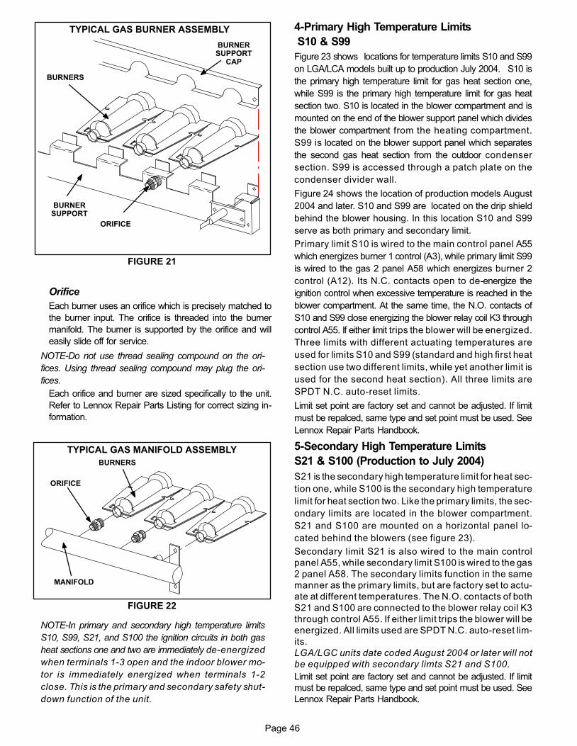
Page 46
FIGURE 21
TYPICAL GAS BURNER ASSEMBLY
BURNERS
ORIFICE
BURNERSUPPORT
BURNERSUPPORT
CAP
Orifice
Each burner uses an orifice which is precisely matched to
the burner input. The orifice is threaded into the burner
manifold. The burner is supported by the orifice and will
easily slide off for service.
NOTE−Do not use thread sealing compound on the ori-
fices. Using thread sealing compound may plug the ori-
fices.
Each orifice and burner are sized specifically to the unit.
Refer to Lennox Repair Parts Listing for correct sizing in-
formation.
FIGURE 22
TYPICAL GAS MANIFOLD ASSEMBLY
BURNERS
MANIFOLD
ORIFICE
NOTE−In primary and secondary high temperature limits
S10, S99, S21, and S100 the ignition circuits in both gas
heat sections one and two are immediately de−energized
when terminals 1−3 open and the indoor blower mo-
tor is immediately energized when terminals 1−2
close. This is the primary and secondary safety shut−
down function of the unit.
4−Primary High Temperature Limits
S10 & S99
Figure 23 shows locations for temperature limits S10 and S99
on LGA/LCA models built up to production July 2004. S10 is
the primary high temperature limit for gas heat section one,
while S99 is the primary high temperature limit for gas heat
section two. S10 is located in the blower compartment and is
mounted on the end of the blower support panel which divides
the blower compartment from the heating compartment.
S99 is located on the blower support panel which separates
the second gas heat section from the outdoor condenser
section. S99 is accessed through a patch plate on the
condenser divider wall.
Figure 24 shows the location of production models August
2004 and later. S10 and S99 are located on the drip shield
behind the blower housing. In this location S10 and S99
serve as both primary and secondary limit.
Primary limit S10 is wired to the main control panel A55
which energizes burner 1 control (A3), while primary limit S99
is wired to the gas 2 panel A58 which energizes burner 2
control (A12). Its N.C. contacts open to de−energize the
ignition control when excessive temperature is reached in the
blower compartment. At the same time, the N.O. contacts of
S10 and S99 close energizing the blower relay coil K3 through
control A55. If either limit trips the blower will be energized.
Three limits with different actuating temperatures are
used for limits S10 and S99 (standard and high first heat
section use two different limits, while yet another limit is
used for the second heat section). All three limits are
SPDT N.C. auto−reset limits.
Limit set point are factory set and cannot be adjusted. If limit
must be repalced, same type and set point must be used. See
Lennox Repair Parts Handbook.
5−Secondary High Temperature Limits
S21 & S100 (Production to July 2004)
S21 is the secondary high temperature limit for heat sec-
tion one, while S100 is the secondary high temperature
limit for heat section two. Like the primary limits, the sec-
ondary limits are located in the blower compartment.
S21 and S100 are mounted on a horizontal panel lo-
cated behind the blowers (see figure 23).
Secondary limit S21 is also wired to the main control
panel A55, while secondary limit S100 is wired to the gas
2 panel A58. The secondary limits function in the same
manner as the primary limits, but are factory set to actu-
ate at different temperatures. The N.O. contacts of both
S21 and S100 are connected to the blower relay coil K3
through control A55. If either limit trips the blower will be
energized. All limits used are SPDT N.C. auto−reset lim-
its.
LGA/LGC units date coded August 2004 or later will not
be equipped with secondary limts S21 and S100.
Limit set point are factory set and cannot be adjusted. If limit
must be repalced, same type and set point must be used. See
Lennox Repair Parts Handbook.
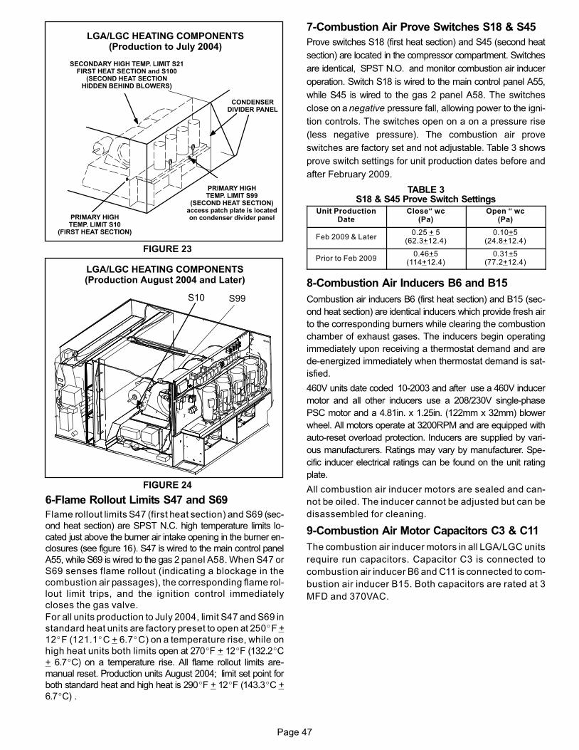
Page 47
LGA/LGC HEATING COMPONENTS(Production to July 2004)
FIGURE 23
PRIMARY HIGHTEMP. LIMIT S99
(SECOND HEAT SECTION)access patch plate is locatedon condenser divider panelPRIMARY HIGH
TEMP. LIMIT S10(FIRST HEAT SECTION)
SECONDARY HIGH TEMP. LIMIT S21FIRST HEAT SECTION and S100
(SECOND HEAT SECTIONHIDDEN BEHIND BLOWERS)
CONDENSERDIVIDER PANEL
LGA/LGC HEATING COMPONENTS(Production August 2004 and Later)
FIGURE 24
S10 S99
6−Flame Rollout Limits S47 and S69
Flame rollout limits S47 (first heat section) and S69 (sec-
ond heat section) are SPST N.C. high temperature limits lo-
cated just above the burner air intake opening in the burner en-
closures (see figure 16). S47 is wired to the main control panel
A55, while S69 is wired to the gas 2 panel A58. When S47 or
S69 senses flame rollout (indicating a blockage in the
combustion air passages), the corresponding flame rol-
lout limit trips, and the ignition control immediately
closes the gas valve.
For all units production to July 2004, limit S47 and S69 in
standard heat units are factory preset to open at 250�F +
12�F (121.1�C + 6.7�C) on a temperature rise, while on
high heat units both limits open at 270�F + 12�F (132.2�C
+ 6.7�C) on a temperature rise. All flame rollout limits are-
manual reset. Production units August 2004; limit set point for
both standard heat and high heat is 290�F + 12�F (143.3�C +
6.7�C) .
7−Combustion Air Prove Switches S18 & S45
Prove switches S18 (first heat section) and S45 (second heat
section) are located in the compressor compartment. Switches
are identical, SPST N.O. and monitor combustion air inducer
operation. Switch S18 is wired to the main control panel A55,
while S45 is wired to the gas 2 panel A58. The switches
close on a negative pressure fall, allowing power to the igni-
tion controls. The switches open on a on a pressure rise
(less negative pressure). The combustion air prove
switches are factory set and not adjustable. Table 3 shows
prove switch settings for unit production dates before and
after February 2009.
TABLE 3S18 & S45 Prove Switch Settings
Unit ProductionDate
Close� wc(Pa)
Open � wc(Pa)
Feb 2009 & Later0.25 + 5
(62.3+12.4)0.10+5
(24.8+12.4)
Prior to Feb 20090.46+5
(114+12.4)0.31+5
(77.2+12.4)
8−Combustion Air Inducers B6 and B15
Combustion air inducers B6 (first heat section) and B15 (sec-
ond heat section) are identical inducers which provide fresh air
to the corresponding burners while clearing the combustion
chamber of exhaust gases. The inducers begin operating
immediately upon receiving a thermostat demand and are
de−energized immediately when thermostat demand is sat-
isfied.
460V units date coded 10−2003 and after use a 460V inducer
motor and all other inducers use a 208/230V single-phase
PSC motor and a 4.81in. x 1.25in. (122mm x 32mm) blower
wheel. All motors operate at 3200RPM and are equipped with
auto-reset overload protection. Inducers are supplied by vari-
ous manufacturers. Ratings may vary by manufacturer. Spe-
cific inducer electrical ratings can be found on the unit rating
plate.
All combustion air inducer motors are sealed and can-
not be oiled. The inducer cannot be adjusted but can be
disassembled for cleaning.
9−Combustion Air Motor Capacitors C3 & C11
The combustion air inducer motors in all LGA/LGC units
require run capacitors. Capacitor C3 is connected to
combustion air inducer B6 and C11 is connected to com-
bustion air inducer B15. Both capacitors are rated at 3
MFD and 370VAC.
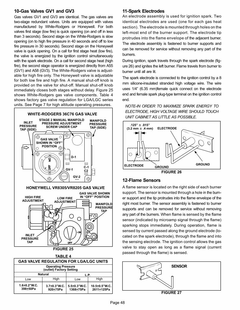
Page 48
10−Gas Valves GV1 and GV3
Gas valves GV1 and GV3 are identical. The gas valves are
two-stage redundant valves. Units are equipped with valves
manufactured by White−Rodgers or Honeywell. For both
valves first stage (low fire) is quick opening (on and off in less
than 3 seconds). Second stage on the White−Rodgers is slow
opening (on to high fire pressure in 40 seconds and off to low
fire pressure in 30 seconds). Second stage on the Honeywell
valve is quick opening. On a call for first stage heat (low fire),
the valve is energized by the ignition control simultaneously
with the spark electrode. On a call for second stage heat (high
fire), the second stage operator is energized directly from A55
(GV1) and A58 (GV3). The White−Rodgers valve is adjust-
able for high fire only. The Honeywell valve is adjustable
for both low fire and high fire. A manual shut−off knob is
provided on the valve for shut−off. Manual shut-off knob
immediately closes both stages without delay. Figure 25
shows White−Rodgers gas valve components. Table 4
shows factory gas valve regulation for LGA/LGC series
units. See Page 7 for high altitude operating pressures.
FIGURE 25
LOW FIREADJUSTMENT
HIGH FIREADJUSTMENT
INLETPRESSURE
TAP
MANIFOLDPRESSURE
TAP
HONEYWELL VR8305/VR8205 GAS VALVE
GAS VALVE SHOWNIN �OFF" POSITION
WHITE−RODGERS 36C76 GAS VALVE
D−1
GV−1C−1C2
GV−2
MANIFOLDPRESSURETAP (SIDE)
STAGE 2 MANUAL MANIFOLDPRESSURE ADJUSTMENT
SCREW UNDER CAP
INLETPRESSURETAP (SIDE)
GAS VALVESHOWN IN �OFF"
POSITION
TABLE 4
GAS VALVE REGULATION FOR LGA/LGC UNITS
Operating Pressure(outlet) Factory Setting
Natural L.P.
3.7+0.3"W.C.920+75Pa
Low High Low High
1.6+0.2"W.C.398+50Pa
10.5+0.5"W.C.2611+125Pa
5.5+0.3"W.C.1368+75Pa
11−Spark ElectrodesAn electrode assembly is used for ignition spark. Two
identical electrodes are used (one for each gas heat
section). The electrode is mounted through holes on the
left-most end of the burner support. The electrode tip
protrudes into the flame envelope of the adjacent burner.
The electrode assembly is fastened to burner supports and
can be removed for service without removing any part of the
burners.
During ignition, spark travels through the spark electrode (fig-
ure 26) and ignites the left burner. Flame travels from burner to
burner until all are lit.
The spark electrode is connected to the ignition control by a 8
mm silicone-insulated stranded high voltage wire. The wire
uses 1/4" (6.35 mm)female quick connect on the electrode
end and female spark plug−type terminal on the ignition control
end.
NOTE−IN ORDER TO MAXIMIZE SPARK ENERGY TO
ELECTRODE, HIGH VOLTAGE WIRE SHOULD TOUCH
UNIT CABINET AS LITTLE AS POSSIBLE.
GROUND
ELECTRODE
GROUNDELECTRODE
.125" ± .015"(3.2 mm ± .4 mm)
FIGURE 26
12−Flame Sensors
A flame sensor is located on the right side of each burner
support. The sensor is mounted through a hole in the burn-
er support and the tip protrudes into the flame envelope of the
right most burner. The sensor assembly is fastened to burner
supports and can be removed for service without removing
any part of the burners. When flame is sensed by the flame
sensor (indicated by microamp signal through the flame)
sparking stops immediately. During operation, flame is
sensed by current passed along the ground electrode (lo-
cated on the spark electrode), through the flame and into
the sensing electrode. The ignition control allows the gas
valve to stay open as long as a flame signal (current
passed through the flame) is sensed.
FIGURE 27
SENSOR
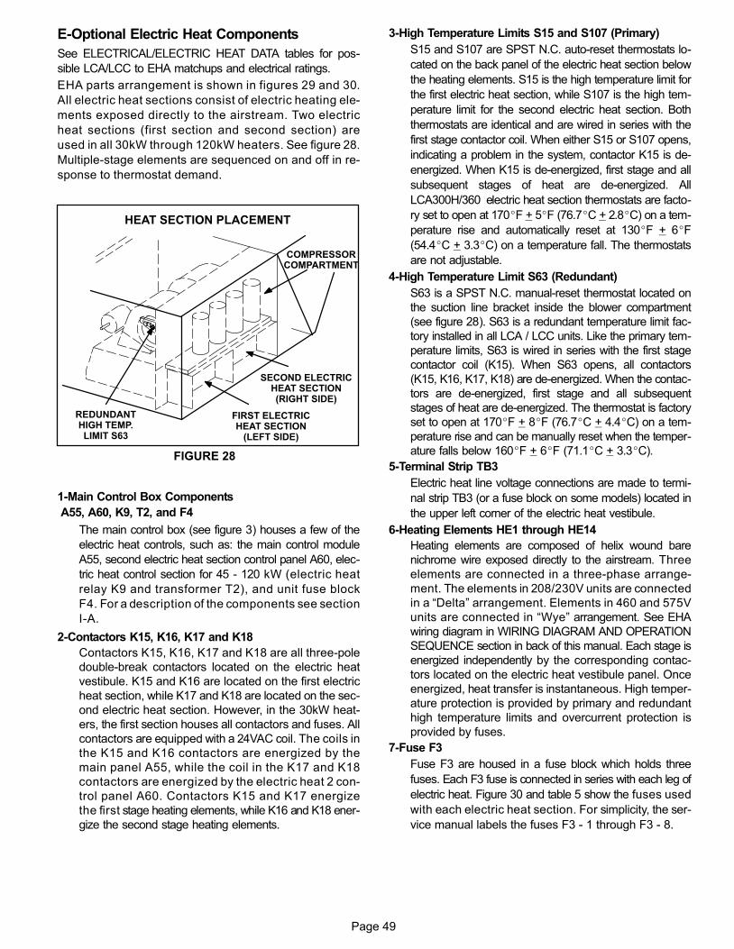
Page 49
E−Optional Electric Heat Components
See ELECTRICAL/ELECTRIC HEAT DATA tables for pos-
sible LCA/LCC to EHA matchups and electrical ratings.
EHA parts arrangement is shown in figures 29 and 30.
All electric heat sections consist of electric heating ele-
ments exposed directly to the airstream. Two electric
heat sections (first section and second section) are
used in all 30kW through 120kW heaters. See figure 28.
Multiple-stage elements are sequenced on and off in re-
sponse to thermostat demand.
FIGURE 28
HEAT SECTION PLACEMENT
REDUNDANTHIGH TEMP.LIMIT S63
FIRST ELECTRICHEAT SECTION
(LEFT SIDE)
SECOND ELECTRICHEAT SECTION(RIGHT SIDE)
COMPRESSORCOMPARTMENT
1−Main Control Box Components
A55, A60, K9, T2, and F4
The main control box (see figure 3) houses a few of the
electric heat controls, such as: the main control module
A55, second electric heat section control panel A60, elec-
tric heat control section for 45 - 120 kW (electric heat
relay K9 and transformer T2), and unit fuse block
F4. For a description of the components see section
I-A.
2−Contactors K15, K16, K17 and K18
Contactors K15, K16, K17 and K18 are all three-pole
double-break contactors located on the electric heat
vestibule. K15 and K16 are located on the first electric
heat section, while K17 and K18 are located on the sec-
ond electric heat section. However, in the 30kW heat-
ers, the first section houses all contactors and fuses. All
contactors are equipped with a 24VAC coil. The coils in
the K15 and K16 contactors are energized by the
main panel A55, while the coil in the K17 and K18
contactors are energized by the electric heat 2 con-
trol panel A60. Contactors K15 and K17 energize
the first stage heating elements, while K16 and K18 ener-
gize the second stage heating elements.
3−High Temperature Limits S15 and S107 (Primary)
S15 and S107 are SPST N.C. auto-reset thermostats lo-
cated on the back panel of the electric heat section below
the heating elements. S15 is the high temperature limit for
the first electric heat section, while S107 is the high tem-
perature limit for the second electric heat section. Both
thermostats are identical and are wired in series with the
first stage contactor coil. When either S15 or S107 opens,
indicating a problem in the system, contactor K15 is de-
energized. When K15 is de-energized, first stage and all
subsequent stages of heat are de-energized. All
LCA300H/360 electric heat section thermostats are facto-
ry set to open at 170�F + 5�F (76.7�C + 2.8�C) on a tem-
perature rise and automatically reset at 130�F + 6�F
(54.4�C + 3.3�C) on a temperature fall. The thermostats
are not adjustable.
4−High Temperature Limit S63 (Redundant)
S63 is a SPST N.C. manual-reset thermostat located on
the suction line bracket inside the blower compartment
(see figure 28). S63 is a redundant temperature limit fac-
tory installed in all LCA / LCC units. Like the primary tem-
perature limits, S63 is wired in series with the first stage
contactor coil (K15). When S63 opens, all contactors
(K15, K16, K17, K18) are de-energized. When the contac-
tors are de-energized, first stage and all subsequent
stages of heat are de-energized. The thermostat is factory
set to open at 170�F + 8�F (76.7�C + 4.4�C) on a tem-
perature rise and can be manually reset when the temper-
ature falls below 160�F + 6�F (71.1�C + 3.3�C).
5−Terminal Strip TB3
Electric heat line voltage connections are made to termi-
nal strip TB3 (or a fuse block on some models) located in
the upper left corner of the electric heat vestibule.
6−Heating Elements HE1 through HE14
Heating elements are composed of helix wound bare
nichrome wire exposed directly to the airstream. Three
elements are connected in a three-phase arrange-
ment. The elements in 208/230V units are connected
in a �Delta" arrangement. Elements in 460 and 575V
units are connected in �Wye" arrangement. See EHA
wiring diagram in WIRING DIAGRAM AND OPERATION
SEQUENCE section in back of this manual. Each stage is
energized independently by the corresponding contac-
tors located on the electric heat vestibule panel. Once
energized, heat transfer is instantaneous. High temper-
ature protection is provided by primary and redundant
high temperature limits and overcurrent protection is
provided by fuses.
7−Fuse F3
Fuse F3 are housed in a fuse block which holds three
fuses. Each F3 fuse is connected in series with each leg of
electric heat. Figure 30 and table 5 show the fuses used
with each electric heat section. For simplicity, the ser-
vice manual labels the fuses F3 − 1 through F3 − 8.
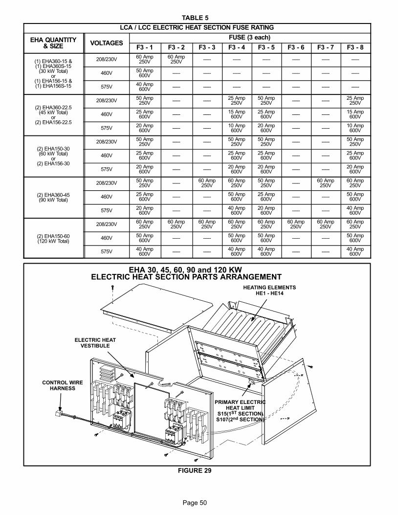
Page 50
TABLE 5
LCA / LCC ELECTRIC HEAT SECTION FUSE RATING
EHA QUANTITY& SIZE VOLTAGES
FUSE (3 each)
F3 − 1 F3 − 2 F3 − 3 F3 − 4 F3 − 5 F3 − 6 F3 − 7 F3 − 8
(1) EHA360−15 &(1) EHA360S−15
(30 kW Total)or
(1) EHA156−15 &(1) EHA156S−15
208/230V60 Amp250V
60 Amp250V −−−−− −−−−− −−−−− −−−−− −−−−− −−−−−
460V50 Amp600V −−−−− −−−−− −−−−− −−−−− −−−−− −−−−− −−−−−
575V40 Amp600V −−−−− −−−−− −−−−− −−−−− −−−−− −−−−− −−−−−
(2) EHA360−22.5(45 kW Total)
or(2) EHA156−22.5
208/230V50 Amp250V −−−−− −−−−−
25 Amp250V
50 Amp250V −−−−− −−−−−
25 Amp250V
460V25 Amp600V −−−−− −−−−−
15 Amp600V
25 Amp600V −−−−− −−−−−
15 Amp600V
575V20 Amp600V −−−−− −−−−−
10 Amp600V
20 Amp600V −−−−− −−−−−
10 Amp600V
(2) EHA150−30(60 kW Total)
or(2) EHA156−30
208/230V50 Amp250V −−−−− −−−−−
50 Amp250V
50 Amp250V −−−−− −−−−−
50 Amp250V
460V25 Amp600V −−−−− −−−−−
25 Amp600V
25 Amp600V −−−−− −−−−−
25 Amp600V
575V20 Amp600V −−−−− −−−−−
20 Amp600V
20 Amp600V −−−−− −−−−−
20 Amp600V
(2) EHA360−45(90 kW Total)
208/230V50 Amp250V −−−−−
60 Amp250V
60 Amp250V
50 Amp250V −−−−−
60 Amp250V
60 Amp250V
460V25 Amp600V −−−−− −−−−−
50 Amp600V
25 Amp600V −−−−− −−−−−
50 Amp600V
575V20 Amp600V −−−−− −−−−−
40 Amp600V
20 Amp600V −−−−− −−−−−
40 Amp600V
(2) EHA150−60(120 kW Total)
208/230V60 Amp250V
60 Amp250V
60 Amp250V
60 Amp250V
60 Amp250V
60 Amp250V
60 Amp250V
60 Amp250V
460V50 Amp600V −−−−− −−−−−
50 Amp600V
50 Amp600V −−−−− −−−−−
50 Amp600V
575V40 Amp600V −−−−− −−−−−
40 Amp600V
40 Amp600V −−−−− −−−−−
40 Amp600V
FIGURE 29
EHA 30, 45, 60, 90 and 120 KW ELECTRIC HEAT SECTION PARTS ARRANGEMENT
PRIMARY ELECTRICHEAT LIMIT
S15(1ST SECTION)S107(2nd SECTION)
HEATING ELEMENTSHE1 − HE14
CONTROL WIREHARNESS
ELECTRIC HEATVESTIBULE

Page 51
FIGURE 30
ELECTRIC HEAT VESTIBULE PARTS ARRANGEMENT
TERMINAL STRIP(TB3)
FIRST STAGE ELECTRICHEAT CONTACTOR K15
SECOND STAGE ELECTRICHEAT CONTACTOR K16
FIRST HEAT SECTION (LEFT SIDE)
SECOND HEAT SECTION (RIGHT SIDE)
FUSE F3F3 - 1 FUSE F3
F3 - 2FUSE F3
F3 - 3
FUSE F3F3 - 4
TERMINAL STRIP(TB3)
FIRST STAGE ELECTRICHEAT CONTACTOR K17
SECOND STAGE ELECTRICHEAT CONTACTOR K18
FUSE F3F3 - 5 FUSE F3
F3 - 6FUSE F3
F3 - 7
FUSE F3F3 - 8
ACCESS DOOR
ACCESS DOOR
Page 52
II−PLACEMENT AND INSTALLATION
Make sure the unit is installed in accordance with the
installation instructions and all applicable codes. See
accessories section for conditions requiring use of the
optional roof mounting frame (LARMF18/36 or
LARMFH30/36).
III−STARTUP − OPERATION − CHARGING
IMPORTANT−The crankcase heater must be energized for
24 hours before attempting to start compressor. Set thermo-
stat so there is no demand to prevent compressors from cycl-
ing.
IMPORTANTUnits contain either R22 or R410A refrigerant. Checkthe nameplate to determine the type of refrigerantbefore installation or servicing.
NOTE − These units must not be used as a �construction heat-
er" at any time during any phase of construction. Very low re-
turn air temperatures, harmful vapors, and misplacement of
the filters will damage the unit and its efficiency. Additionally, a
unit which will be subject to cold temperatures when not in op-
eration must have a vapor barrier installed to seal the duct con-
nections. Failure to protect the unit from moisture laden air or
harmful vapors (generated from the construction process and
temporary combustion heating equipment) will cause corro-
sive condensation within the unit. Failure to properly protect
the unit in this situation will cause electrical and electronic com-
ponent failure and could affect the unit warranty status.
A−Preliminary Checks
1− Make sure that unit is installed in accordance with the
installation instructions and applicable codes.
2− Inspect all electrical wiring, both field- and factory-
installed, for loose connections. Tighten as required.
3− Check to ensure that refrigerant lines do not rub against
the cabinet or against other refrigerant lines.
4− Check voltage at disconnect switch. Voltage must be
within range listed on nameplate. If not, consult power
company and have voltage condition corrected before
starting unit.
5− Make sure filters are in place before start-up.
B−Cooling Start−Up
1− Initiate first and second stage cooling demands ac-
cording to instructions provided with thermostat.
2− First−stage thermostat demand will energize com-
pressors 1 and 2. Second−stage thermostat demand
will energize compressors 3 and 4 (fourth compres-
sor on 21 and 25 ton units). On units with an econo-
mizer, when outdoor air is acceptable, a first−stage
demand will energize the economizer; a second−
stage demand will energize compressors 1 and 2.
3− Units contain four refrigerant circuits or systems. Evap-
orator and condenser coil refrigerant circuits 1 and 2
make up stage 1 cooling. Evaporator and condenser
refrigerant circuits 3 and 4 make up stage 2 cooling.
See figures 8 and 9.
360H with 3 compressors −
Units contain three refrigerant circuits or systems.
Evaporator and condenser coil refrigerant circuits 1
and 2 make up stage 1 cooling. Evaporator and con-
denser coil refrigerant circuit 3 makes up stage 2 cool-
ing.
4− Each refrigerant circuit is separately charged with R22
or R410A refrigerant. See unit rating plate for correct
amount of charge.
5− Refer to Cooling Operation and Adjustment section for
proper method to check refrigerant charge.
Three Phase Scroll Compressor Voltage Phasing
Three phase scroll compressors must be phased se-
quentially to ensure correct compressor and blower rota-
tion and operation. Compressor and blower are wired in
phase at the factory. Power wires are color−coded as fol-
lows: line 1−red, line 2−yellow, line 3−blue.
1− Observe suction and discharge pressures and blower
rotation on unit start−up.
2− Suction pressure must drop, discharge pressure must
rise, and blower rotation must match rotation marking.
If pressure differential is not observed or blower rotation is
not correct:
3− Disconnect all remote electrical power supplies.
4− Reverse any two field−installed wires connected to the
line side of S48 disconnect or TB13 terminal strip. Do
not reverse wires at blower contactor.
5− Make sure the connections are tight.
Discharge and suction pressures should operate at their
normal start-up ranges.
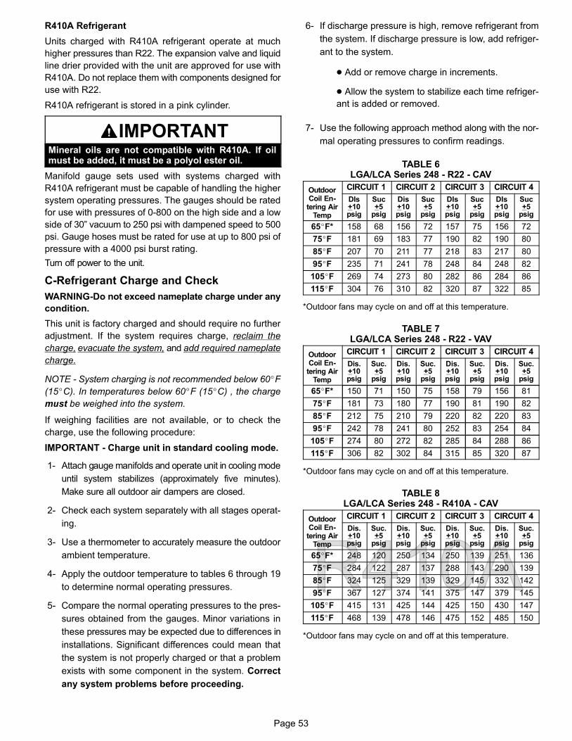
Page 53
R410A Refrigerant
Units charged with R410A refrigerant operate at much
higher pressures than R22. The expansion valve and liquid
line drier provided with the unit are approved for use with
R410A. Do not replace them with components designed for
use with R22.
R410A refrigerant is stored in a pink cylinder.
IMPORTANTMineral oils are not compatible with R410A. If oilmust be added, it must be a polyol ester oil.
Manifold gauge sets used with systems charged with
R410A refrigerant must be capable of handling the higher
system operating pressures. The gauges should be rated
for use with pressures of 0−800 on the high side and a low
side of 30" vacuum to 250 psi with dampened speed to 500
psi. Gauge hoses must be rated for use at up to 800 psi of
pressure with a 4000 psi burst rating.
Turn off power to the unit.
C−Refrigerant Charge and Check
WARNING−Do not exceed nameplate charge under any
condition.
This unit is factory charged and should require no further
adjustment. If the system requires charge, reclaim the
charge, evacuate the system, and add required nameplate
charge.
NOTE − System charging is not recommended below 60�F
(15�C). In temperatures below 60�F (15�C) , the charge
must be weighed into the system.
If weighing facilities are not available, or to check the
charge, use the following procedure:
IMPORTANT − Charge unit in standard cooling mode.
1− Attach gauge manifolds and operate unit in cooling mode
until system stabilizes (approximately five minutes).
Make sure all outdoor air dampers are closed.
2− Check each system separately with all stages operat-
ing.
3− Use a thermometer to accurately measure the outdoor
ambient temperature.
4− Apply the outdoor temperature to tables 6 through 19
to determine normal operating pressures.
5− Compare the normal operating pressures to the pres-
sures obtained from the gauges. Minor variations in
these pressures may be expected due to differences in
installations. Significant differences could mean that
the system is not properly charged or that a problem
exists with some component in the system. Correct
any system problems before proceeding.
6− If discharge pressure is high, remove refrigerant from
the system. If discharge pressure is low, add refriger-
ant to the system.
� Add or remove charge in increments.
� Allow the system to stabilize each time refriger-
ant is added or removed.
7− Use the following approach method along with the nor-
mal operating pressures to confirm readings.
TABLE 6LGA/LCA Series 248 − R22 − CAV
OutdoorCoil En-tering Air
Temp
CIRCUIT 1 CIRCUIT 2 CIRCUIT 3 CIRCUIT 4
DIs+10psig
Suc+5
psig
Dis+10psig
Suc+5
psig
DIs+10psig
Suc+5
psig
DIs+10psig
Suc+5
psig
65�F* 158 68 156 72 157 75 156 72
75�F 181 69 183 77 190 82 190 80
85�F 207 70 211 77 218 83 217 80
95�F 235 71 241 78 248 84 248 82
105�F 269 74 273 80 282 86 284 86
115�F 304 76 310 82 320 87 322 85
*Outdoor fans may cycle on and off at this temperature.
TABLE 7LGA/LCA Series 248 − R22 − VAV
OutdoorCoil En-tering Air
Temp
CIRCUIT 1 CIRCUIT 2 CIRCUIT 3 CIRCUIT 4
Dis.+10psig
Suc.+5
psig
Dis.+10psig
Suc.+5
psig
Dis.+10psig
Suc.+5
psig
Dis.+10psig
Suc.+5
psig
65�F* 150 71 150 75 158 79 156 81
75�F 181 73 180 77 190 81 190 82
85�F 212 75 210 79 220 82 220 83
95�F 242 78 241 80 252 83 254 84
105�F 274 80 272 82 285 84 288 86
115�F 306 82 302 84 315 85 320 87
*Outdoor fans may cycle on and off at this temperature.
TABLE 8LGA/LCA Series 248 − R410A − CAV
OutdoorCoil En-tering Air
Temp
CIRCUIT 1 CIRCUIT 2 CIRCUIT 3 CIRCUIT 4
Dis.+10psig
Suc.+5
psig
Dis.+10psig
Suc.+5
psig
Dis.+10psig
Suc.+5
psig
Dis.+10psig
Suc.+5
psig
65�F* 248 120 250 134 250 139 251 136
75�F 284 122 287 137 288 143 290 139
85�F 324 125 329 139 329 145 332 142
95�F 367 127 374 141 375 147 379 145
105�F 415 131 425 144 425 150 430 147
115�F 468 139 478 146 475 152 485 150
*Outdoor fans may cycle on and off at this temperature.
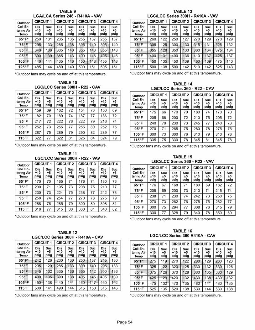
Page 54
TABLE 9LGA/LCA Series 248 − R410A − VAV
OutdoorCoil En-tering Air
Temp
CIRCUIT 1 CIRCUIT 2 CIRCUIT 3 CIRCUIT 4
DIs+10psig
Suc+5
psig
Dis+10psig
Suc+5
psig
DIs+10psig
Suc+5
psig
DIs+10psig
Suc+5
psig
65�F* 250 131 235 135 255 137 255 137
75�F 295 133 285 138 305 140 305 140
85�F 340 136 335 140 355 143 355 143
95�F 390 139 385 143 400 146 405 146
105�F 440 141 435 146 450 148 455 148
125�F 485 144 480 149 500 151 505 151
*Outdoor fans may cycle on and off at this temperature.
TABLE 10LGC/LCC Series 300H − R22 − CAV
OutdoorCoil En-tering Air
Temp
CIRCUIT 1 CIRCUIT 2 CIRCUIT 3 CIRCUIT 4
DIs+10psig
Suc+5
psig
Dis+10psig
Suc+5
psig
DIs+10psig
Suc+5
psig
DIs+10psig
Suc+5
psig
65�F* 159 69 162 72 154 73 150 69
75�F 182 70 189 74 187 77 186 72
85�F 217 72 222 76 222 79 216 74
95�F 252 73 255 77 255 80 252 75
105�F 287 75 289 79 290 82 289 77
115�F 322 77 322 81 325 84 324 79
*Outdoor fans may cycle on and off at this temperature.
TABLE 11LGC/LCC Series 300H − R22 − VAV
OutdoorCoil En-tering Air
Temp
CIRCUIT 1 CIRCUIT 2 CIRCUIT 3 CIRCUIT 4
DIs+10psig
Suc+5
psig
Dis+10psig
Suc+5
psig
DIs+10psig
Suc+5
psig
DIs+10psig
Suc+5
psig
65�F* 170 70 165 71 176 74 180 76
75�F 200 71 195 73 208 75 210 77
85�F 230 73 224 75 238 77 242 78
95�F 258 74 254 77 270 78 275 79
105�F 288 76 285 79 300 80 308 81
115�F 318 77 315 80 330 81 340 82
*Outdoor fans may cycle on and off at this temperature.
TABLE 12LGC/LCC Series 300H − R410A − CAV
OutdoorCoil En-tering Air
Temp
CIRCUIT 1 CIRCUIT 2 CIRCUIT 3 CIRCUIT 4
DIs+10psig
Suc+5
psig
Dis+10psig
Suc+5
psig
DIs+10psig
Suc+5
psig
DIs+10psig
Suc+5
psig
65�F* 242 126 230 130 250 137 245 130
75�F 295 129 285 133 300 140 295 133
85�F 345 132 335 136 355 142 350 136
95�F 400 135 390 138 405 145 405 139
105�F 450 138 440 141 460 147 460 142
115�F 500 141 490 144 515 150 515 146
*Outdoor fans may cycle on and off at this temperature.
TABLE 13LGC/LCC Series 300H − R410A − VAV
OutdoorCoil En-tering Air
Temp
CIRCUIT 1 CIRCUIT 2 CIRCUIT 3 CIRCUIT 4
DIs+10psig
Suc+5
psig
Dis+10psig
Suc+5
psig
DIs+10psig
Suc+5
psig
DIs+10psig
Suc+5
psig
65�F* 260 122 250 127 270 129 270 129
75�F 305 125 300 130 315 131 325 132
85�F 355 128 350 133 360 134 375 134
95�F 400 131 400 136 410 137 425 137
105�F 450 135 450 139 460 139 475 140
115�F 500 138 500 142 510 142 525 143
*Outdoor fans may cycle on and off at this temperature.
TABLE 14LGC/LCC Series 360 − R22 − CAV
OutdoorCoil En-tering Air
Temp
CIRCUIT 1 CIRCUIT 2 CIRCUIT 3 CIRCUIT 4
DIs+10psig
Suc+5
psig
Dis+10psig
Suc+5
psig
DIs+10psig
Suc+5
psig
DIs+10psig
Suc+5
psig
65�F* 175 66 170 70 180 74 170 70
75�F 205 68 200 72 210 75 205 72
85�F 240 70 230 73 245 77 240 73
95�F 270 71 265 75 280 78 275 75
105�F 300 73 300 76 310 79 310 76
115�F 335 75 330 78 345 81 345 78
*Outdoor fans may cycle on and off at this temperature.
TABLE 15LGC/LCC Series 360 − R22 − VAV
OutdoorCoil En-tering Air
Temp
CIRCUIT 1 CIRCUIT 2 CIRCUIT 3 CIRCUIT 4
DIs+10psig
Suc+5
psig
Dis+10psig
Suc+5
psig
DIs+10psig
Suc+5
psig
DIs+10psig
Suc+5
psig
65�F* 176 67 168 71 180 69 182 72
75�F 208 69 200 73 210 71 215 74
85�F 238 71 230 74 242 73 250 75
95�F 270 73 262 76 275 75 282 77
105�F 300 75 294 77 308 76 315 79
115�F 330 77 328 79 340 78 350 80
*Outdoor fans may cycle on and off at this temperature.
TABLE 16LGC/LCC Series 360 R410A − CAV
OutdoorCoil En-tering Air
Temp
CIRCUIT 1 CIRCUIT 2 CIRCUIT 3 CIRCUIT 4
DIs+10psig
Suc+5
psig
Dis+10psig
Suc+5
psig
DIs+10psig
Suc+5
psig
DIs+10psig
Suc+5
psig
65�F* 275 119 270 122 280 129 280 123
75�F 325 122 320 125 330 132 330 126
85�F 375 126 370 128 380 135 380 129
95�F 425 129 420 132 430 138 430 132
105�F 475 132 470 135 480 141 480 135
115�F 525 135 520 138 530 144 530 138
*Outdoor fans may cycle on and off at this temperature.
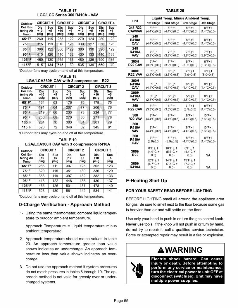
Page 55
TABLE 17LGC/LCC Series 360 R410A − VAV
OutdoorCoil En-tering Air
Temp
CIRCUIT 1 CIRCUIT 2 CIRCUIT 3 CIRCUIT 4
DIs+10psig
Suc+5
psig
Dis+10psig
Suc+5
psig
DIs+10psig
Suc+5
psig
DIs+10psig
Suc+5
psig
65�F* 260 115 255 122 270 124 280 123
75�F 315 119 310 125 330 127 330 126
85�F 360 122 360 129 380 130 390 129
95�F 415 126 410 132 430 133 440 133
105�F 460 130 465 136 480 136 490 136
115�F 515 134 515 139 535 139 550 140
*Outdoor fans may cycle on and off at this temperature.
TABLE 18LGA/LCA360H CAV with 3 compressors − R22
OutdoorCoil En-tering Air
Temp
CIRCUIT 1 CIRCUIT 2 CIRCUIT 3
DIs+10psig
Suc+5
psig
Dis+10psig
Suc+5
psig
DIs+10psig
Suc+5
psig
65�F* 164 63 176 76 178 75
75�F 191 64 207 77 206 76
85�F 219 66 233 78 234 77
95�F 250 68 270 80 271 78
105�F 284 70 303 81 301 79
115�F 320 72 346 82 345 81
*Outdoor fans may cycle on and off at this temperature.
TABLE 19LGA/LCA360H CAV with 3 compressors R410A
OutdoorCoil En-tering Air
Temp
CIRCUIT 1 CIRCUIT 2 CIRCUIT 3
DIs+10psig
Suc+5
psig
Dis+10psig
Suc+5
psig
DIs+10psig
Suc+5
psig
65�F* 286 111 307 125 302 123
75�F 320 115 351 130 336 129
85�F 363 119 397 132 382 133
95�F 413 122 448 135 430 137
105�F 465 126 501 137 478 140
115�F 523 130 561 142 534 141
*Outdoor fans may cycle on and off at this temperature.
D−Charge Verification − Approach Method
1− Using the same thermometer, compare liquid temper-
ature to outdoor ambient temperature.
Approach Temperature = Liquid temperature minus
ambient temperature.
2− Approach temperature should match values in table
20. An approach temperature greater than value
shown indicates an undercharge. An approach tem-
perature less than value shown indicates an over-
charge.
3− Do not use the approach method if system pressures
do not match pressures in tables 6 through 19. The ap-
proach method is not valid for grossly over or under-
charged systems.
TABLE 20
UnitLiquid Temp. Minus Ambient Temp.
1st Stage 2nd Stage 3rd Stage 4th Stage
248 R22CAV/VAV
8°F+1(4.4°C+0.5)
8°F+1(4.4°C+0.5)
8°F+1(4.4°C+0.5)
8°F+1(4.4°C+0.5)
248R410ACAV
8°F+1(4.4°C+0.5)
8°F+1(4.4°C+0.5)
8°F+1(4.4°C+0.5)
8°F+1(4.4°C+0.5)
248R410A
VAV7°F+1
(3.9°C+0.5)7°F+1
(3.9°C+0.5)7°F+1
(3.9°C+0.5)7°F+1
(3.9°C+0.5)
300HR22 CAV
6°F+1(3.3°C+0.5)
7°F+1(3.9°C+0.5)
6°F+1(3.3°C+0.5)
6°F+1(3.3°C+0.5)
300HR22 VAV
6°F+1(3.3°C+0.5)
6°F+1(3.3°C+0.5)
7°F+1(3.9+0.5)
9°F+1(5.0+0.5)
300HR410ACAV
8°F+1(4.4°C+0.5)
8°F+1(4.4°C+0.5)
8°F+1(4.4°C+0.5)
8°F+1(4.4°C+0.5)
300HR410A
VAV5°F+1
(2.8°C+0.5)5°F+1
(2.8°C+0.5)5°F+1
(2.8°C+0.5)8°F+1
(4.4°C+0.5)
360R22 CAV
6°F+1(3.3°C+0.5)
6°F+1(3.3°C+0.5)
7°F+1(3.9+0.5)
8°F+1(4.4°C+0.5)
360R22 VAV
8°F+1(4.4°C+0.5)
8°F+1(4.4°C+0.5)
8°F+1(4.4°C+0.5)
10°F+1(5.6°C+0.5)
360R410A
VAV8°F+1
(4.4°C+0.5)8°F+1
(4.4°C+0.5)8°F+1
(4.4°C+0.5)10°F+1
(5.6°C+0.5)
360R410ACAV
7°F+1(3.9+0.5)
7°F+1(3.9+0.5)
8°F+1(4.4°C+0.5)
8°F+1(4.4°C+0.5)
360HR22
8°F + 1 (4.4‘°C +
0.5)
10°F + 1 (5.6°C +
0.5)
8°F + 1 (4.4°C +
0.5) NA
360HR410A
12°F + 1 (6.7°C +
0.5)
14°F + 1 (7.8°C +
0.5)
13°F + 1 (7.2°C +
0.5) NA
E−Heating Start Up
FOR YOUR SAFETY READ BEFORE LIGHTING
BEFORE LIGHTING smell all around the appliance area
for gas. Be sure to smell next to the floor because some gas
is heavier than air and will settle on the floor.
Use only your hand to push in or turn the gas control knob.
Never use tools. If the knob will not push in or turn by hand,
do not try to repair it, call a qualified service technician.
Force or attempted repair may result in a fire or explosion.
WARNINGElectric shock hazard. Can causeinjury or death. Before attempting toperform any service or maintenance,turn the electrical power to unit OFF atdisconnect switch(es). Unit may havemultiple power supplies.

Page 56
WARNINGDanger of explosion. Can cause injuryor product or property damage. Ifoverheating occurs or if gas supplyfails to shut off, shut off the manual gasvalve to the appliance before shuttingoff electrical supply.
WARNINGSMOKE POTENTIAL
The heat exchanger in this unit could be a source ofsmoke on initial firing. Take precautions with respectto building occupants and property. Vent initial sup-ply air outside when possible.
WARNINGDanger of explosion. Can cause injury ordeath. Do not attempt to light manually.Unit has a direct spark ignition system.
This unit is equipped with an automatic spark ignition sys-
tem. There is no pilot. In case of a safety shutdown, move
thermostat switch to OFF and return the thermostat switch
to HEAT to reset ignition control.
WARNINGDanger of explosion and fire. Can causeinjury or product or property damage.You must follow these instructionsexactly.
Placing Unit In Operation
Gas Valve Operation for White Rodgers 36C Se-
ries Valve (Figure 31) and Honeywell VR8305Q (Figure
32) Series Gas Valve
WHITE RODGERS 36C GAS VALVE
GASVALVE KNOB
SHOWN IN �ON"POSITION
FIGURE 31
INLETPRESSURE
TAP
HONEYWELL VR8305Q SERIES GAS VALVE
Gas valve knob is shown in OFF position.
FIGURE 32
LOW FIREADJUSTMENT
HIGH FIREADJUSTMENT
INLETPRESSURE
TAP
1− Set thermostat to lowest setting.
2− Turn off all electrical power to appliance.
3− This appliance is equipped with an ignition device
which automatically lights the burner. Do not try to light
the burner by hand.
4− Open or remove the heat section access panel.
5− Turn the knob on the gas valve clockwise to OFF.
Do not force.
6− Wait five minutes to clear out any gas. If you then smell
gas, STOP! Immediately call your gas supplier from a
neighbor’s phone. Follow the gas supplier’s instruc-
tions. If you do not smell gas, go to the next step.
7− Turn the knob on the gas valve counterclockwise to
ON. Do not force.
8− Close or replace the heat section access panel.
9− Turn on all electrical power to unit.
10− Set thermostat to desired setting.
11− The combustion air inducer will start. The burners will
light within 40 seconds.
12− If the appliance does not light the first time (gas line
not fully purged), it will attempt up to two more igni-
tions before locking out.
13− If lockout occurs, repeat steps 1 through 10.
14− If the appliance will not operate, follow the instructions
�Turning Off Gas to Appliance" and call your service
technician or gas supplier.
Turning Off Gas to Unit
1− If using an electromechanical thermostat, set to the
lowest setting.
2− Before performing any service, turn off all electrical
power to the unit.
3− Open or remove the heat section access panel.
4− Turn the knob on the gas valve clockwise to OFF.
Do not force.
5− Close or replace the heat section access panel.
F−Safety or Emergency Shutdown
Turn off power to unit.
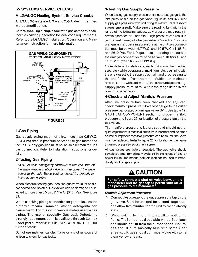
Page 57
IV− SYSTEMS SERVICE CHECKS
A−LGA/LGC Heating System Service Checks
All LGA/LGC units are A.G.A and C.G.A. design certified
without modification.
Before checking piping, check with gas company or au-
thorities having jurisdiction for local code requirements.
Refer to the LGA/LGC Installation, Operation and Main-
tenance instruction for more information.
UNIT
GROUNDJOINT UNION
MANUAL MAINSHUT−OFF VALVE
(REFER TO LOCAL CODES)
GAS PIPINGSUPPORT
DRIP LEG
ROOFMOUNTING
FRAME
GAS PIPING COMPONENTSREFER TO INSTALLATION INSTRUCTIONS
FIGURE 33
VALVE
CAP HERE TO ISO-LATE VALVEWHEN PRESSURETESTING LINE
1−Gas Piping
Gas supply piping must not allow more than 0.5"W.C.
(124.3 Pa) drop in pressure between the gas meter and
the unit. Supply gas pipe must not be smaller than the unit
gas connection. Refer to installation instructions for de-
tails.
2−Testing Gas Piping
NOTE−In case emergency shutdown is required, turn off
the main manual shut-off valve and disconnect the main
power to the unit. These controls should be properly la-
beled by the installer.
When pressure testing gas lines, the gas valve must be dis-
connected and isolated. Gas valves can be damaged if sub-
jected to more than 0.5 psig [14"W.C. (3481 Pa)]. See figure
33.
When checking piping connection for gas leaks, use the
preferred means. Common kitchen detergents can
cause harmful corrosion on various metals used in gas
piping. The use of specialty Gas Leak Detector is
strongly recommended. It is available through Lennox
under part number 31B2001. See CORP 8411−L10, for
further details.
Do not use matches, candles, flame or any other source of
ignition to check for gas leaks.
3−Testing Gas Supply Pressure
When testing gas supply pressure, connect test gauge to the
inlet pressure tap on the gas valve (figure 31 and 32). Test
supply gas pressure with unit firing at maximum rate (both
stages energized). Make sure the reading falls within the
range of the following values. Low pressure may result in
erratic operation or �underfire." High pressure can result in
permanent damage to the gas valve or �overfire." For nat-
ural gas units, operating pressure at the unit gas connec-
tion must be between 4.7"W.C. and 10.5"W.C. (1168 Pa
and 2610 Pa). For L.P. gas units, operating pressure at
the unit gas connection must be between 10.8"W.C. and
13.0"W.C. (2685 Pa and 3232 Pa).
On multiple unit installations, each unit should be checked
separately while operating at maximum rate, beginning with
the one closest to the supply gas main and progressing to
the one furthest from the main. Multiple units should
also be tested with and without the other units operating.
Supply pressure must fall within the range listed in the
previous paragraph.
4−Check and Adjust Manifold Pressure
After line pressure has been checked and adjusted,
check manifold pressure. Move test gauge to the outlet
pressure tap located on unit gas valve GV1. See table 4 in
GAS HEAT COMPONENT section for proper manifold
pressure and figure 25 for location of pressure tap on the
gas valve.
The manifold pressure is factory set and should not re-
quire adjustment. If manifold pressure is incorrect and no other
source of improper manifold pressure can be found, the valve
must be replaced. Refer to figure 25 for location of gas valve
(manifold pressure) adjustment screw.
All gas valves are factory regulated. The gas valve should
completely and immediately cycle off in the event of gas or
power failure. The manual shut-off knob can be used to imme-
diately shut off gas supply.
CAUTIONFor safety, connect a shut-off valve between themanometer and the gas tap to permit shut off ofgas pressure to the manometer.
Manifold Adjustment Procedure
1− Connect test gauge to the outlet pressure tap on the
gas valve. Start the unit (call for second stage heat)
and allow five minutes for the unit to reach steady
state.
2− While waiting for the unit to stabilize, notice the
flame. The flame should be stable without flashback
and should not lift from the burner heads. Natural
gas should burn basically blue with some clear
streaks. L.P. gas should burn mostly blue with some
clear yellow streaks.
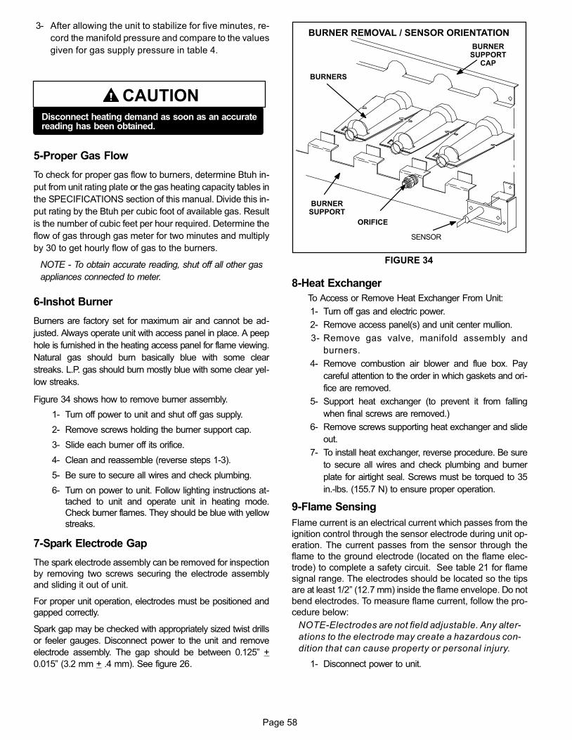
Page 58
3− After allowing the unit to stabilize for five minutes, re-
cord the manifold pressure and compare to the values
given for gas supply pressure in table 4.
CAUTIONDisconnect heating demand as soon as an accuratereading has been obtained.
5−Proper Gas Flow
To check for proper gas flow to burners, determine Btuh in-
put from unit rating plate or the gas heating capacity tables in
the SPECIFICATIONS section of this manual. Divide this in-
put rating by the Btuh per cubic foot of available gas. Result
is the number of cubic feet per hour required. Determine the
flow of gas through gas meter for two minutes and multiply
by 30 to get hourly flow of gas to the burners.
NOTE − To obtain accurate reading, shut off all other gas
appliances connected to meter.
6−Inshot Burner
Burners are factory set for maximum air and cannot be ad-
justed. Always operate unit with access panel in place. A peep
hole is furnished in the heating access panel for flame viewing.
Natural gas should burn basically blue with some clear
streaks. L.P. gas should burn mostly blue with some clear yel-
low streaks.
Figure 34 shows how to remove burner assembly.
1− Turn off power to unit and shut off gas supply.
2− Remove screws holding the burner support cap.
3− Slide each burner off its orifice.
4− Clean and reassemble (reverse steps 1−3).
5− Be sure to secure all wires and check plumbing.
6− Turn on power to unit. Follow lighting instructions at-
tached to unit and operate unit in heating mode.
Check burner flames. They should be blue with yellow
streaks.
7−Spark Electrode Gap
The spark electrode assembly can be removed for inspection
by removing two screws securing the electrode assembly
and sliding it out of unit.
For proper unit operation, electrodes must be positioned and
gapped correctly.
Spark gap may be checked with appropriately sized twist drills
or feeler gauges. Disconnect power to the unit and remove
electrode assembly. The gap should be between 0.125" +
0.015" (3.2 mm + .4 mm). See figure 26.
FIGURE 34
BURNER REMOVAL / SENSOR ORIENTATION
BURNERS
ORIFICE
BURNERSUPPORT
BURNERSUPPORT
CAP
SENSOR
8−Heat Exchanger
To Access or Remove Heat Exchanger From Unit:
1− Turn off gas and electric power.
2− Remove access panel(s) and unit center mullion.
3− Remove gas valve, manifold assembly and
burners.
4− Remove combustion air blower and flue box. Pay
careful attention to the order in which gaskets and ori-
fice are removed.
5− Support heat exchanger (to prevent it from falling
when final screws are removed.)
6− Remove screws supporting heat exchanger and slide
out.
7− To install heat exchanger, reverse procedure. Be sure
to secure all wires and check plumbing and burner
plate for airtight seal. Screws must be torqued to 35
in.-lbs. (155.7 N) to ensure proper operation.
9−Flame Sensing
Flame current is an electrical current which passes from the
ignition control through the sensor electrode during unit op-
eration. The current passes from the sensor through the
flame to the ground electrode (located on the flame elec-
trode) to complete a safety circuit. See table 21 for flame
signal range. The electrodes should be located so the tips
are at least 1/2" (12.7 mm) inside the flame envelope. Do not
bend electrodes. To measure flame current, follow the pro-
cedure below:
NOTE−Electrodes are not field adjustable. Any alter-
ations to the electrode may create a hazardous con-
dition that can cause property or personal injury.
1− Disconnect power to unit.
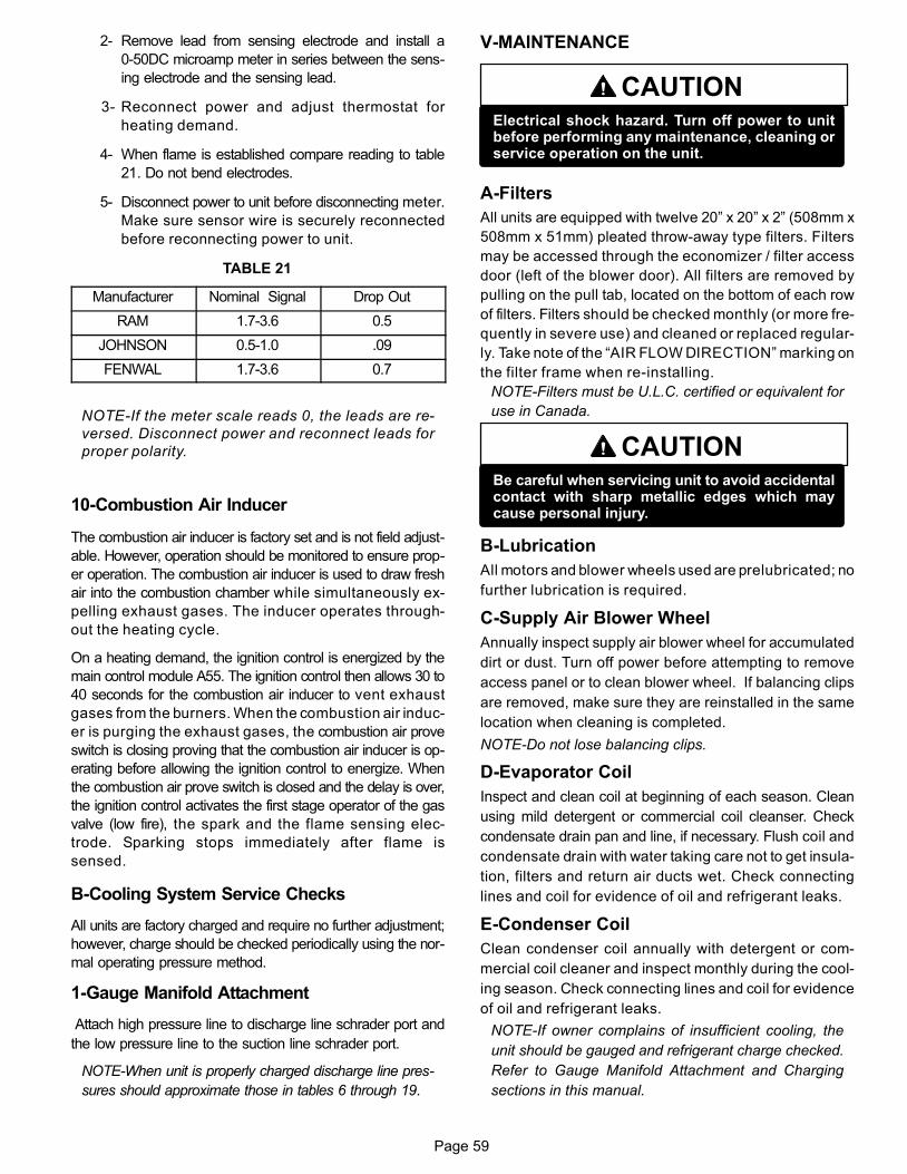
Page 59
2− Remove lead from sensing electrode and install a
0−50DC microamp meter in series between the sens-
ing electrode and the sensing lead.
3− Reconnect power and adjust thermostat for
heating demand.
4− When flame is established compare reading to table
21. Do not bend electrodes.
5− Disconnect power to unit before disconnecting meter.
Make sure sensor wire is securely reconnected
before reconnecting power to unit.
TABLE 21
Manufacturer Nominal Signal Drop Out
RAM 1.7−3.6 0.5
JOHNSON 0.5−1.0 .09
FENWAL 1.7−3.6 0.7
NOTE−If the meter scale reads 0, the leads are re-
versed. Disconnect power and reconnect leads for
proper polarity.
10−Combustion Air Inducer
The combustion air inducer is factory set and is not field adjust-
able. However, operation should be monitored to ensure prop-
er operation. The combustion air inducer is used to draw fresh
air into the combustion chamber while simultaneously ex-
pelling exhaust gases. The inducer operates through-
out the heating cycle.
On a heating demand, the ignition control is energized by the
main control module A55. The ignition control then allows 30 to
40 seconds for the combustion air inducer to vent exhaust
gases from the burners. When the combustion air induc-
er is purging the exhaust gases, the combustion air prove
switch is closing proving that the combustion air inducer is op-
erating before allowing the ignition control to energize. When
the combustion air prove switch is closed and the delay is over,
the ignition control activates the first stage operator of the gas
valve (low fire), the spark and the flame sensing elec-
trode. Sparking stops immediately after flame is
sensed.
B−Cooling System Service Checks
All units are factory charged and require no further adjustment;
however, charge should be checked periodically using the nor-
mal operating pressure method.
1−Gauge Manifold Attachment
Attach high pressure line to discharge line schrader port and
the low pressure line to the suction line schrader port.
NOTE−When unit is properly charged discharge line pres-
sures should approximate those in tables 6 through 19.
V−MAINTENANCE
CAUTIONElectrical shock hazard. Turn off power to unitbefore performing any maintenance, cleaning orservice operation on the unit.
A−Filters
All units are equipped with twelve 20" x 20" x 2" (508mm x
508mm x 51mm) pleated throw−away type filters. Filters
may be accessed through the economizer / filter access
door (left of the blower door). All filters are removed by
pulling on the pull tab, located on the bottom of each row
of filters. Filters should be checked monthly (or more fre-
quently in severe use) and cleaned or replaced regular-
ly. Take note of the �AIR FLOW DIRECTION" marking on
the filter frame when re−installing.
NOTE−Filters must be U.L.C. certified or equivalent for
use in Canada.
CAUTIONBe careful when servicing unit to avoid accidentalcontact with sharp metallic edges which maycause personal injury.
B−Lubrication
All motors and blower wheels used are prelubricated; no
further lubrication is required.
C−Supply Air Blower Wheel
Annually inspect supply air blower wheel for accumulated
dirt or dust. Turn off power before attempting to remove
access panel or to clean blower wheel. If balancing clips
are removed, make sure they are reinstalled in the same
location when cleaning is completed.
NOTE−Do not lose balancing clips.
D−Evaporator Coil
Inspect and clean coil at beginning of each season. Clean
using mild detergent or commercial coil cleanser. Check
condensate drain pan and line, if necessary. Flush coil and
condensate drain with water taking care not to get insula-
tion, filters and return air ducts wet. Check connecting
lines and coil for evidence of oil and refrigerant leaks.
E−Condenser Coil
Clean condenser coil annually with detergent or com-
mercial coil cleaner and inspect monthly during the cool-
ing season. Check connecting lines and coil for evidence
of oil and refrigerant leaks.
NOTE−If owner complains of insufficient cooling, the
unit should be gauged and refrigerant charge checked.
Refer to Gauge Manifold Attachment and Charging
sections in this manual.
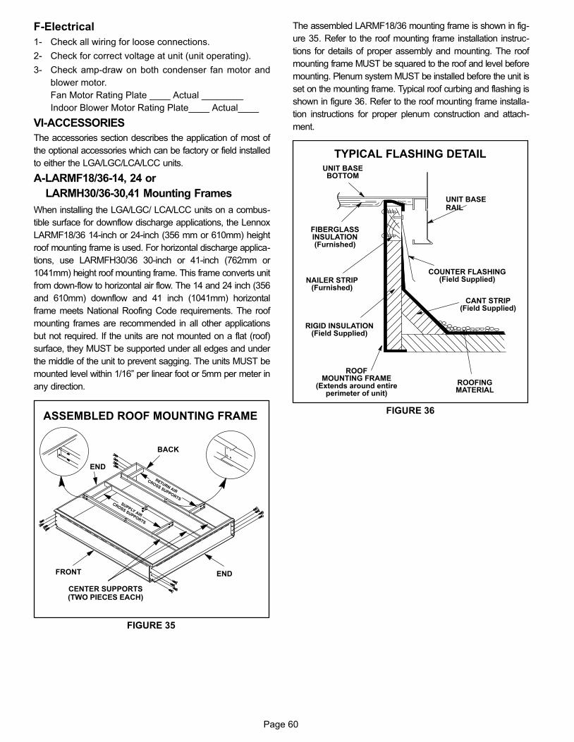
Page 60
F−Electrical
1− Check all wiring for loose connections.
2− Check for correct voltage at unit (unit operating).
3− Check amp−draw on both condenser fan motor and
blower motor.
Fan Motor Rating Plate ____ Actual ________
Indoor Blower Motor Rating Plate____ Actual____
VI−ACCESSORIES
The accessories section describes the application of most of
the optional accessories which can be factory or field installed
to either the LGA/LGC/LCA/LCC units.
A−LARMF18/36-14, 24 or
LARMH30/36−30,41 Mounting Frames
When installing the LGA/LGC/ LCA/LCC units on a combus-
tible surface for downflow discharge applications, the Lennox
LARMF18/36 14-inch or 24-inch (356 mm or 610mm) height
roof mounting frame is used. For horizontal discharge applica-
tions, use LARMFH30/36 30-inch or 41-inch (762mm or
1041mm) height roof mounting frame. This frame converts unit
from down-flow to horizontal air flow. The 14 and 24 inch (356
and 610mm) downflow and 41 inch (1041mm) horizontal
frame meets National Roofing Code requirements. The roof
mounting frames are recommended in all other applications
but not required. If the units are not mounted on a flat (roof)
surface, they MUST be supported under all edges and under
the middle of the unit to prevent sagging. The units MUST be
mounted level within 1/16" per linear foot or 5mm per meter in
any direction.
FIGURE 35
ASSEMBLED ROOF MOUNTING FRAME
FRONT
END
END
BACK
CENTER SUPPORTS(TWO PIECES EACH)
The assembled LARMF18/36 mounting frame is shown in fig-
ure 35. Refer to the roof mounting frame installation instruc-
tions for details of proper assembly and mounting. The roof
mounting frame MUST be squared to the roof and level before
mounting. Plenum system MUST be installed before the unit is
set on the mounting frame. Typical roof curbing and flashing is
shown in figure 36. Refer to the roof mounting frame installa-
tion instructions for proper plenum construction and attach-
ment.
FIGURE 36
ROOFMOUNTING FRAME
(Extends around entireperimeter of unit)
FIBERGLASSINSULATION(Furnished)
COUNTER FLASHING(Field Supplied)
UNIT BASEBOTTOM
RIGID INSULATION(Field Supplied)
ROOFINGMATERIAL
CANT STRIP(Field Supplied)
NAILER STRIP(Furnished)
UNIT BASERAIL
TYPICAL FLASHING DETAIL
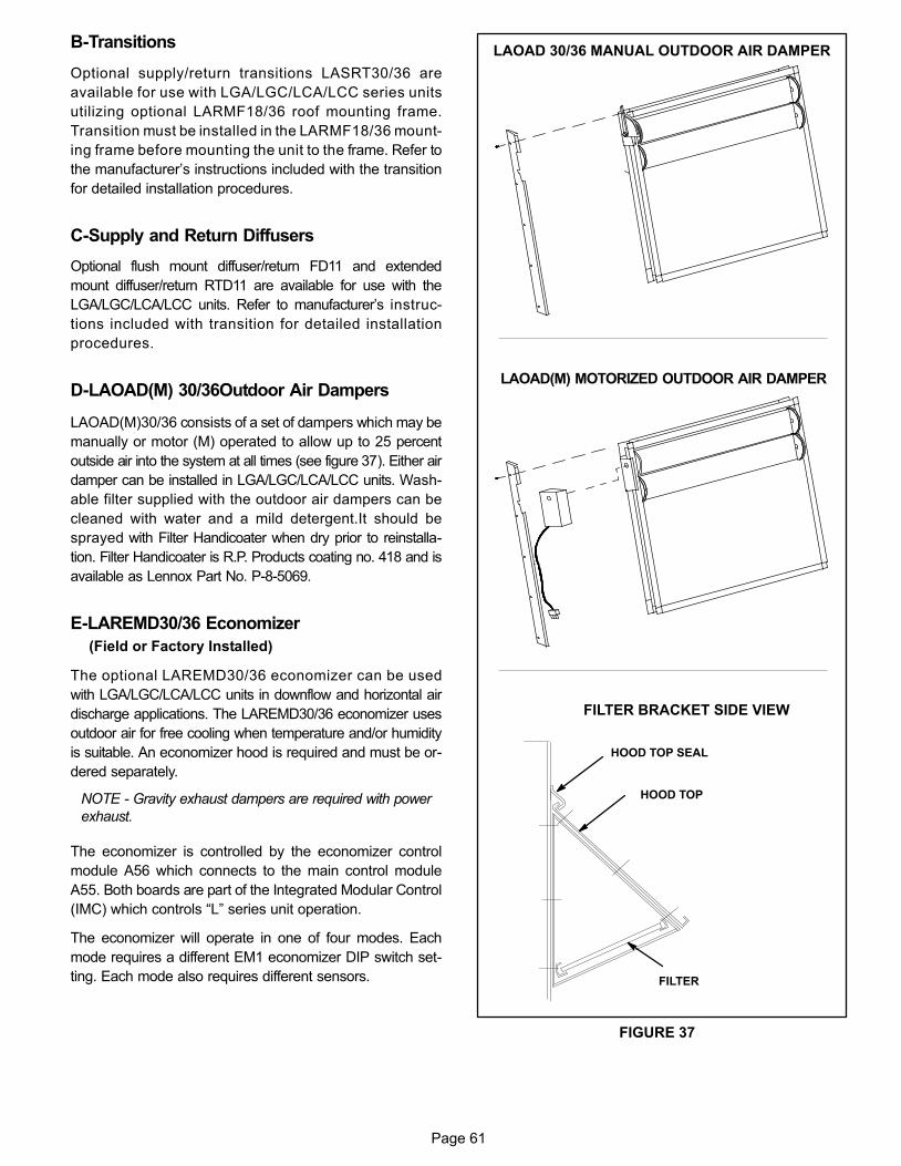
Page 61
B−Transitions
Optional supply/return transitions LASRT30/36 are
available for use with LGA/LGC/LCA/LCC series units
utilizing optional LARMF18/36 roof mounting frame.
Transition must be installed in the LARMF18/36 mount-
ing frame before mounting the unit to the frame. Refer to
the manufacturer’s instructions included with the transition
for detailed installation procedures.
C−Supply and Return Diffusers
Optional flush mount diffuser/return FD11 and extended
mount diffuser/return RTD11 are available for use with the
LGA/LGC/LCA/LCC units. Refer to manufacturer’s instruc-
tions included with transition for detailed installation
procedures.
D−LAOAD(M) 30/36Outdoor Air Dampers
LAOAD(M)30/36 consists of a set of dampers which may be
manually or motor (M) operated to allow up to 25 percent
outside air into the system at all times (see figure 37). Either air
damper can be installed in LGA/LGC/LCA/LCC units. Wash-
able filter supplied with the outdoor air dampers can be
cleaned with water and a mild detergent.It should be
sprayed with Filter Handicoater when dry prior to reinstalla-
tion. Filter Handicoater is R.P. Products coating no. 418 and is
available as Lennox Part No. P−8−5069.
E−LAREMD30/36 Economizer
(Field or Factory Installed)
The optional LAREMD30/36 economizer can be used
with LGA/LGC/LCA/LCC units in downflow and horizontal air
discharge applications. The LAREMD30/36 economizer uses
outdoor air for free cooling when temperature and/or humidity
is suitable. An economizer hood is required and must be or-
dered separately.
NOTE − Gravity exhaust dampers are required with power
exhaust.
The economizer is controlled by the economizer control
module A56 which connects to the main control module
A55. Both boards are part of the Integrated Modular Control
(IMC) which controls �L" series unit operation.
The economizer will operate in one of four modes. Each
mode requires a different EM1 economizer DIP switch set-
ting. Each mode also requires different sensors.
LAOAD(M) MOTORIZED OUTDOOR AIR DAMPER
LAOAD 30/36 MANUAL OUTDOOR AIR DAMPER
FIGURE 37
FILTER BRACKET SIDE VIEW
HOOD TOP
FILTER
HOOD TOP SEAL
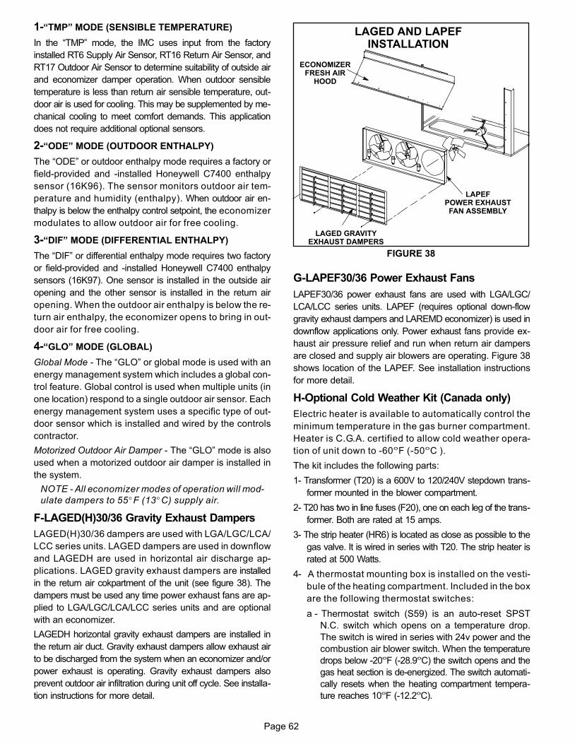
Page 62
1−�TMP" MODE (SENSIBLE TEMPERATURE)
In the �TMP" mode, the IMC uses input from the factory
installed RT6 Supply Air Sensor, RT16 Return Air Sensor, and
RT17 Outdoor Air Sensor to determine suitability of outside air
and economizer damper operation. When outdoor sensible
temperature is less than return air sensible temperature, out-
door air is used for cooling. This may be supplemented by me-
chanical cooling to meet comfort demands. This application
does not require additional optional sensors.
2−�ODE" MODE (OUTDOOR ENTHALPY)
The �ODE" or outdoor enthalpy mode requires a factory or
field−provided and −installed Honeywell C7400 enthalpy
sensor (16K96). The sensor monitors outdoor air tem-
perature and humidity (enthalpy). When outdoor air en-
thalpy is below the enthalpy control setpoint, the economizer
modulates to allow outdoor air for free cooling.
3−�DIF" MODE (DIFFERENTIAL ENTHALPY)
The �DIF" or differential enthalpy mode requires two factory
or field−provided and −installed Honeywell C7400 enthalpy
sensors (16K97). One sensor is installed in the outside air
opening and the other sensor is installed in the return air
opening. When the outdoor air enthalpy is below the re-
turn air enthalpy, the economizer opens to bring in out-
door air for free cooling.
4−�GLO" MODE (GLOBAL)
Global Mode − The �GLO" or global mode is used with an
energy management system which includes a global con-
trol feature. Global control is used when multiple units (in
one location) respond to a single outdoor air sensor. Each
energy management system uses a specific type of out-
door sensor which is installed and wired by the controls
contractor.
Motorized Outdoor Air Damper − The �GLO" mode is also
used when a motorized outdoor air damper is installed in
the system.
NOTE − All economizer modes of operation will mod-
ulate dampers to 55�F (13�C) supply air.
F−LAGED(H)30/36 Gravity Exhaust Dampers
LAGED(H)30/36 dampers are used with LGA/LGC/LCA/
LCC series units. LAGED dampers are used in downflow
and LAGEDH are used in horizontal air discharge ap-
plications. LAGED gravity exhaust dampers are installed
in the return air cokpartment of the unit (see figure 38). The
dampers must be used any time power exhaust fans are ap-
plied to LGA/LGC/LCA/LCC series units and are optional
with an economizer.
LAGEDH horizontal gravity exhaust dampers are installed in
the return air duct. Gravity exhaust dampers allow exhaust air
to be discharged from the system when an economizer and/or
power exhaust is operating. Gravity exhaust dampers also
prevent outdoor air infiltration during unit off cycle. See installa-
tion instructions for more detail.
FIGURE 38
LAPEFPOWER EXHAUSTFAN ASSEMBLY
LAGED GRAVITYEXHAUST DAMPERS
ECONOMIZERFRESH AIR
HOOD
LAGED AND LAPEFINSTALLATION
G−LAPEF30/36 Power Exhaust Fans
LAPEF30/36 power exhaust fans are used with LGA/LGC/
LCA/LCC series units. LAPEF (requires optional down-flow
gravity exhaust dampers and LAREMD economizer) is used in
downflow applications only. Power exhaust fans provide ex-
haust air pressure relief and run when return air dampers
are closed and supply air blowers are operating. Figure 38
shows location of the LAPEF. See installation instructions
for more detail.
H−Optional Cold Weather Kit (Canada only)
Electric heater is available to automatically control the
minimum temperature in the gas burner compartment.
Heater is C.G.A. certified to allow cold weather opera-
tion of unit down to -60°F (-50°C ).
The kit includes the following parts:
1− Transformer (T20) is a 600V to 120/240V stepdown trans-
former mounted in the blower compartment.
2− T20 has two in line fuses (F20), one on each leg of the trans-
former. Both are rated at 15 amps.
3− The strip heater (HR6) is located as close as possible to the
gas valve. It is wired in series with T20. The strip heater is
rated at 500 Watts.
4− A thermostat mounting box is installed on the vesti-
bule of the heating compartment. Included in the box
are the following thermostat switches:
a − Thermostat switch (S59) is an auto-reset SPST
N.C. switch which opens on a temperature drop.
The switch is wired in series with 24v power and the
combustion air blower switch. When the temperature
drops below -20°F (−28.9°C) the switch opens and the
gas heat section is de-energized. The switch automati-
cally resets when the heating compartment tempera-
ture reaches 10°F (-12.2°C).

Page 63
b − Thermostat switch (S60) is an auto-reset SPST
N.C. switch which opens on a temperature rise.
The switch is wired in series with HR6 and T20.
When the temperature rises above 20°F (-6.7°C)
the switch opens and the electric heater is de-ener-
gized. The switch automatically resets when the
heating compartment temperature reaches -10°F
(−23.3°C).
c −Thermostat switch (S61) is an auto-reset SPST
N.O. switch which closes on a temperature drop.
The switch is wired in series with HR6 and T20.
When temperature drops below 20°F (-6.7°C)
the switch closes and electric heater is ener-
gized. The switch automatically opens when
heating compartment temperature reaches 50°F
(10°C).
I−Control SystemsThree different types of control systems may be used with
the LGA/LGC/LCA/LCC series units. All thermostat wiring
is connected to terminal block TB1 located in the control
box of the unit. Each thermostat has additional control op-
tions available. See thermostat installation instructions for
more detail.
1− Electro-mechanical thermostat (13F06)
The electro-mechanical thermostat is a two stage heat /
two stage cool thermostat with dual temperature levers.
A non-switching or manual system switch subbase
may be used.
2− Electronic thermostat (see price book)
Any two stage heat / two stage cool electronic ther-
mostat may be used.
3− Honeywell T7300 thermostat (81G59)
The Honeywell T7300 thermostat is a programmable, in-
ternal or optional remote temperature sensing thermo-
stat. The T7300 provides occupied and unoccupied
changeover control.
J−Smoke Detectors A17 and A64Photoelectric smoke detectors are a factory installed op-
tion. The smoke detectors can be installed in the supply air
section (A64), return air section (A17), or in both the supply
and return air section. Wiring for the smoke detectors are
shown on the temperature control section (C2) wiring dia-
gram in back of this manual.
K−Blower Proving Switch S52The blower proving switch monitors blower operation and
locks out the unit in case of blower failure. The switch is
N.O. and closes at .14" W.C. (34.9 Pa) The switch is
mounted on the upper left hand corner of the blower deck.
Wiring for the blower proving switch is shown on the tempera-
ture control section (C2) wiring diagram in back of this manual.
L−Dirty Filter Switch S27
The dirty filter switch senses static pressure increase indi-
cating a dirty filter condition. The switch is N.O. and closes
at 1" W.C. (248.6 Pa) The switch is mounted on the top filter
channel corner. Wiring for the dirty filter switch is shown on
the temperature control section (C2) wiring diagram in back of
this manual. Actuation of this switch does not affect unit opera-
tion.
M−Indoor Air Quality (CO2) Sensor A63
The indoor air quality sensor monitors CO2 levels and re-
ports the levels to the main control module A55. The board
adjusts the economizer dampers according to the CO2
levels. The sensor is mounted next to the indoor thermo-
stat or in the return air duct. Refer to the indoor air quality
sensor installation instructions for proper adjustment.
Wiring for the indoor air quality switch is shown on the tem-
perature control section (C2) wiring diagram in back of this
manual.
N−LP / Propane KitTwo natural to LP / propane gas changeover kits are re-
quired for gas conversion on LGA/LGC units (one for each gas
heat section). The kit includes manifold adjustment spring,
manifold cap, eleven burner orifices, and three stickers. For
more detail refer to the natural to LP gas changover kit installa-
tion instructions.
O−Supply Air VFD
Units may contain a supply air blower equipped with a vari-
able frequency drive A96 (VFD) which varies supply air
CFM. As duct static increases, the supply air volume will
decrease. As duct static decreases, the supply air volume
will increase.
The IMC uses input from a pressure transducer (A30) to
maintain a 1.0" w.c. (default) static pressure. Refer to the
IMC manual ECTO 0.04 and 0.05 to adjust the static pres-
sure setpoint.
The pressure transducer is shipped in a box in the blower
compartment. Install the transducer according to manufac-
turer’s instructions.
Note −Make sure the transducer is installed in the main duct
at least 2/3 of the distance away from the unit.
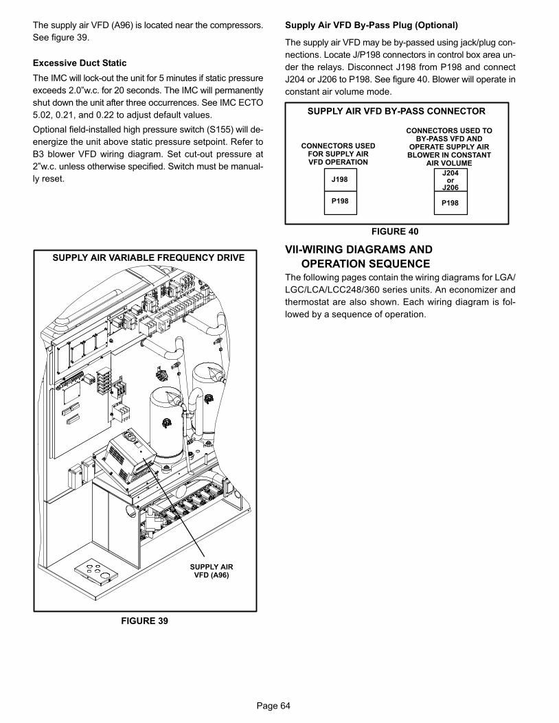
Page 64
The supply air VFD (A96) is located near the compressors.
See figure 39.
Excessive Duct Static
The IMC will lock−out the unit for 5 minutes if static pressure
exceeds 2.0"w.c. for 20 seconds. The IMC will permanently
shut down the unit after three occurrences. See IMC ECTO
5.02, 0.21, and 0.22 to adjust default values.
Optional field−installed high pressure switch (S155) will de−
energize the unit above static pressure setpoint. Refer to
B3 blower VFD wiring diagram. Set cut−out pressure at
2"w.c. unless otherwise specified. Switch must be manual-
ly reset.
FIGURE 39
SUPPLY AIR VARIABLE FREQUENCY DRIVE
SUPPLY AIRVFD (A96)
Supply Air VFD By−Pass Plug (Optional)
The supply air VFD may be by−passed using jack/plug con-
nections. Locate J/P198 connectors in control box area un-
der the relays. Disconnect J198 from P198 and connect
J204 or J206 to P198. See figure 40. Blower will operate in
constant air volume mode.
J204or
J206
FIGURE 40
SUPPLY AIR VFD BY−PASS CONNECTOR
CONNECTORS USEDFOR SUPPLY AIRVFD OPERATION
CONNECTORS USED TOBY−PASS VFD AND
OPERATE SUPPLY AIRBLOWER IN CONSTANT
AIR VOLUME
J198
P198 P198
VII−WIRING DIAGRAMS AND
OPERATION SEQUENCE
The following pages contain the wiring diagrams for LGA/
LGC/LCA/LCC248/360 series units. An economizer and
thermostat are also shown. Each wiring diagram is fol-
lowed by a sequence of operation.
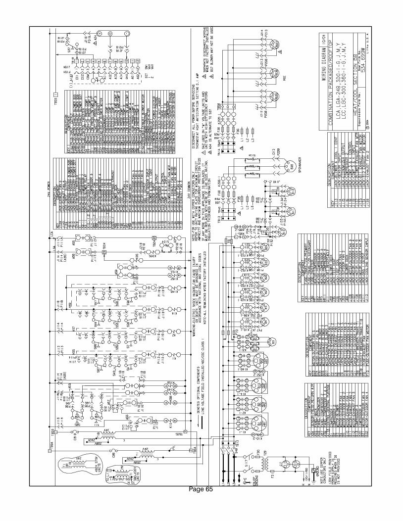
Page 65
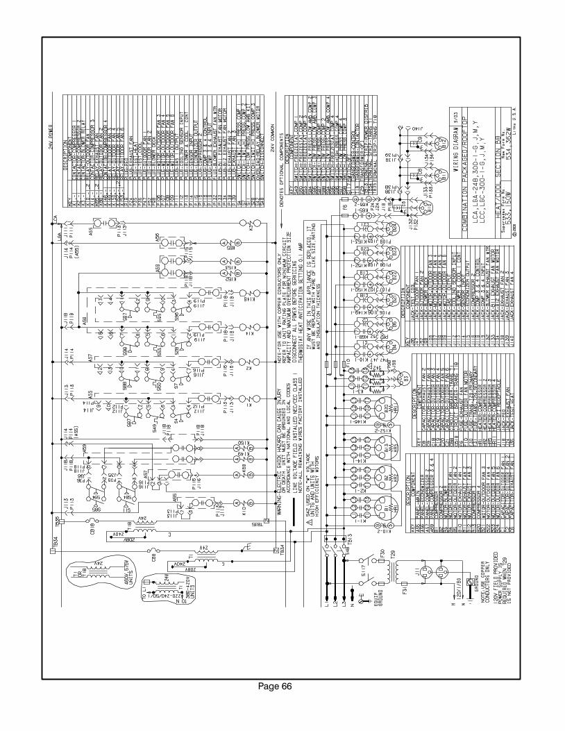
Page 66
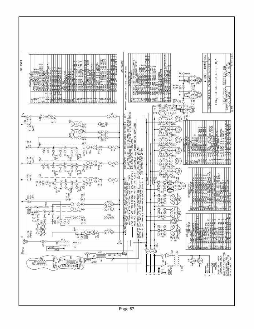
Page 67
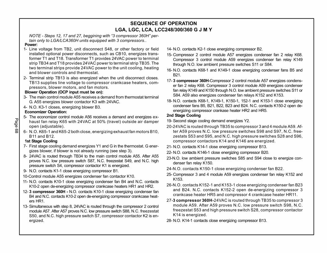
Pag
e 6
8
SEQUENCE OF OPERATION
LGA, LGC, LCA, LCC248/300/360 G J M Y
NOTE − Steps 12, 17 and 27, beggining with �3 compressor 360H" per-tain only to LGA/LCA360H units equipped with 3 compressors..
Power:1− Line voltage from TB2, unit disconnect S48, or other factory or field
installed optional power disconnects, such as CB10, energizes trans-former T1 and T18. Transformer T1 provides 24VAC power to terminalstrip TB34 and T18 provides 24VAC power to terminal strip TB35. Thetwo terminal strips provide 24VAC power to the unit cooling, heatingand blower controls and thermostat.
2− Terminal strip TB13 is also energized when the unit disconnect closes.TB13 supplies line voltage to compressor crankcase heaters, com-pressors, blower motors, and fan motors.
Blower Operation (OCP input must be on):
3− The main control module A55 receives a demand from thermostat terminalG. A55 energizes blower contactor K3 with 24VAC.
4− N.O. K3-1 closes, energizing blower B3.Economizer Operation:
5− The economizer control module A56 receives a demand and energizes ex-haust fan relay K65 with 24VAC at 50% (travel) outside air damperopen (adjustable).
6− N.O. K65-1 and K65-2 both close, energizing exhaust fan motors B10,B11 and B12.
1st Stage Cooling
7− First stage cooling demand energizes Y1 and G in the thermostat. G ener-gizes blower, if blower is not already running (see step 3).
8− 24VAC is routed through TB34 to the main control module A55. After A55proves N.C. low pressure switch S87, N.C. freezestat S49, and N.C. highpressure switch S4, compressor contactor K1 is energized.
9− N.O. contacts K1−1 close energizing compressor B1.
10−Control module A55 energizes condenser fan contactor K10.
11− N.O. contacts K10−1 close energizing condenser fan B4 and N.C. contactsK10−2 open de-energizing compressor crankcase heaters HR1 and HR2.
12− 3 compressor 360H − N.O. contacts K10−1 close energizing condenser fanB4 and N.C. contacts K10−2 open de-energizing compressor crankcase heat-ers HR1.
13− Simultaneous with step 8, 24VAC is routed through the compressor 2 controlmodule A57. After A57 proves N.C. low pressure switch S88, N.C. freezestatS50, and N.C. high pressure switch S7, compressor contactor K2 is en-ergized.
14− N.O. contacts K2−1 close energizing compressor B2.
15− Compressor 2 control module A57 energizes condenser fan 2 relay K68.Compressor 3 control module A59 energizes condenser fan relay K149through N.O. low ambient pressure switches S11 or S84.
16− N.O. contacts K68−1 and K149−1 close energizing condenser fans B5 andB21.
17− 3 compressor 360H−Compressor 2 control module A57 energizes condens-er fan 2 relay K68. Compressor 3 control module A59 energizes condenserfan relay K149 and K150 through N.O. low ambient pressure switches S11 orS84. A59 also energizes condenser fan relays K152 and K153.
18− N.O. contacts K68−1, K149−1, K150−1, 152−1 and K153−1 close energizingcondenser fans B5, B21, B22, B23 and B24. N.C. contacts K150−2 open de−energizing compressor crankase heater HR2 and HR5.
2nd Stage Cooling
19− Second stage cooling demand energizes Y2.
20−24VAC is routed through TB35 to compressor 3 and 4 module A59. Af-ter A59 proves N.C. low pressure switches S98 and S97, N.C. free-zestats S53 and S95, and N.C. high pressure switches S28 and S96,compressor contactors K14 and K146 are energized.
21− N.O. contacts K14−1 close energizing compressor B13.
22− N.O. contacts K146−1 close energizing compressor B20.
23−N.O. low ambient pressure switches S85 and S94 close to energize con-denser fan relay K150.
24−N.O. contacts K150−1 close energizing condenser fan B22.
25− Compressor 3 and 4 module A59 energizes condenser fan relay K152 andK153.
26−N.O. contacts K152−1 and K153−1 close energizing condenser fan B23and B24. N.C. contacts K152−2 open de-energizing compressor 3crankcase heater HR5 and compressor 4 crankcase heater HR11.
27−3 compressor 360H−24VAC is routed through TB35 to compressor 3module A59. After A59 proves N.C. low pressure switch S98, N.C.freezestat S53 and high pressure switch S28, compressor contactorK14 is energized.
28− N.O. K14−1 contacts close energizing compressor B13.
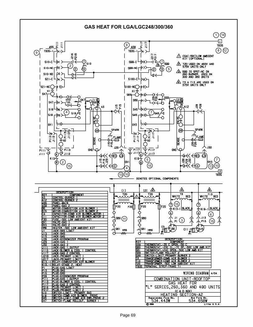
Page 69
GAS HEAT FOR LGA/LGC248/300/360
8
9
7
11
14
12
1
2
3
4
7
5
9
1515 13 10
1013
4
2
15
6
5
15
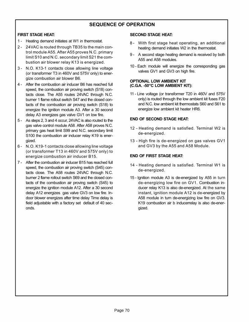
Page 70
SEQUENCE OF OPERATION
FIRST STAGE HEAT:
1 − Heating demand initiates at W1 in thermostat.
2 − 24VAC is routed through TB35 to the main con-
trol module A55. After A55 proves N.C. primary
limit S10 and N.C. secondary limit S21 the com-
bustion air blower relay K13 is energized.
3 − N.O. K13-1 contacts close allowing line voltage
(or transformer T3 in 460V and 575V only) to ener-
gize combustion air blower B6.
4 − After the combustion air inducer B6 has reached full
speed, the combustion air proving switch (S18) con-
tacts close. The A55 routes 24VAC through N.C.
burner 1 flame rollout switch S47 and the closed con-
tacts of the combustion air proving switch (S18) to
energize the ignition module A3. After a 30 second
delay A3 energizes gas valve GV1 on low fire.
5 − As steps 2, 3 and 4 occur, 24VAC is also routed to the
gas valve control module A58. After A58 proves N.C.
primary gas heat limit S99 and N.C. secondary limit
S100 the combustion air inducer relay K19 is ener-
gized.
6 − N.O. K19-1 contacts close allowing line voltage
(or transformer T13 in 460V and 575V only) to
energize combustion air inducer B15.
7 − After the combustion air inducer B15 has reached full
speed, the combustion air proving switch (S45) con-
tacts close. The A58 routes 24VAC through N.C.
burner 2 flame rollout switch S69 and the closed con-
tacts of the combustion air proving switch (S45) to
energize the ignition module A12. After a 30 second
delay A12 energizes gas valve GV3 on low fire. In-
door blower energizes after time delay Time delay is
field adjustable with a factory set default of 40 sec-
onds.
SECOND STAGE HEAT:
8 − With first stage heat operating, an additional
heating demand initiates W2 in the thermostat.
9 − A second stage heating demand is received by both
A55 and A58 modules.
10 − Each module will energize the corresponding gas
valves GV1 and GV3 on high fire.
OPTIONAL LOW AMBIENT KIT(C.G.A. -50°C LOW AMBIENT KIT):
11 − Line voltage (or transformer T20 in 460V and 575V
only) is routed through the low ambient kit fuses F20
and N.C. low ambient kit thermostats S60 and S61 to
energize low ambient kit heater HR6.
END OF SECOND STAGE HEAT:
12 − Heating demand is satisfied. Terminal W2 is
de-energized.
13 − High fire is de-energized on gas valves GV1
and GV3 by the A55 and A58 Module.
END OF FIRST STAGE HEAT:
14 − Heating demand is satisfied. Terminal W1 is
de-energized.
15 − Ignition module A3 is de-energized by A55 in turn
de-energizing low fire on GV1. Combustion in-
ducer relay K13 is also de-energized. At the same
instant, ignition module A12 is de-energized by
A58 module in turn de-energizing low fire on GV3.
K19 combustion air b inducerrelay is also de-ener-
gized.
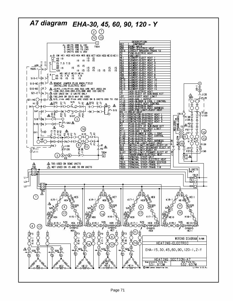
Page 71
A7 diagram EHA−30, 45, 60, 90, 120 − Y
5
6
7
8
9
10
11
12
13
15
1
2
3
4
14
16
17
4
69
11
13
1414
14
16
17
17
17
3

Page 72
SEQUENCE OF OPERATIONA7 DIAGRAM − EHA−30, 45, 60, 90, 120 − Y
A6 DIAGRAM − EHA−30, 45, 60, 90, 120 − G, J
Diagrams A7 and A6 are the EHA electric heat sec-
tions used in the LHA and LCA units. The Y voltage
diagram (A7) use elements configured in a Wye.
The G and J voltage diagram (A6) use elements
configured in a Delta. Both diagrams A7 and A6 fol-
low the following sequence of operation:
NOTE:Two electric heat sections are used in all 30kW
through 120kW heaters. The heat sections are la-
belled first electric heat section (left side) and sec-
ond electric heat section (right side). See figure 28.
NOTE: In the case of EHA 30kW, the second heat
section (right side) is a slave (only has electric
heat elements and a limit). In this case the A60
module, T2 transformer, and K9 heat relay are not
used. Line voltage is supplied to elements in both
heat section one (left side) and two (right side) by
the contactors in heat section one (left side) and
all control is through the A55 module.
HEATING ELEMENTS:
1 − Terminal strip TB3 is energized when the unit discon-
nect closes. TB3 supplies line voltage to electric heat
elements HE1 through HE14. Each heating element
is protected by fuse F3.
FIRST STAGE HEAT:
2 − Heating demand initiates at W1 in thermostat.
3 − 24VAC is routed through TB34 to the main control
module A55. After A55 proves N.C. primary limits
S15 (heat section one, left side), S107 (heat section
two, right side), and redundant electric heat limit S63,
the electric heat contactor K15 and heat relay K9 are
energized. Indoor blower is energized with no time
delay.
4 − N.O. contact K15-1 closes allowing the first bank of
elements in heat section one (left side) to be ener-
gized.
5 − At the same time, line voltage is routed through
transformer T2, which provides 24VAC to the
electric heat control module A60. A60 is ener-
gized when N.O. contacts K9-1 close. A N.O.
contact in A60 closes,
energizing electric heat relay K17.
6 − N.O. contacts K17-1 close allowing the first set of ele-
ments in heat section two (right side) to be energized.
SECOND STAGE HEAT:
7 − With the first stage heat operating, an additional
heating demand initiates at W2 in the
thermostat.
8 − 24VAC is routed through the main control mod-
ule A55, which in turn energizes the electric
heat contactor K16.
9 − N.O. contacts K16-1 close allowing the second set of
elements in heat section one (left side) to be en-
ergized.
10 − Simultaneous with step eight, a N.O. contact in
the electric heat control module A60 closes, al-
lowing 24VAC to energize electric heat contac-
tor K18.
11 − N.O. contacts K18-1 close allowing the second set of
elements in heat section two
(right side) to be energized.
END OF SECOND STAGE HEAT:
12 − Heating demand is satisfied. Terminal W2 in the ther-
mostat is de-energized.
13 − Electric heat contactors K16 and K18 are
de-energized.
14 − The second set of electric heat elements in heat
sections one (left side) and two (right side) are
de-energized.
END OF FIRST STAGE HEAT:
15 − Heating demand is satisfied. Terminal W1 in the ther-
mostat is de-energized.
16 − Electric heat contactors K15 and K17 are
de-energized.
17 − The first set of electric heat elements in heat
sections one (left side) and two (right side) are
de-energized.
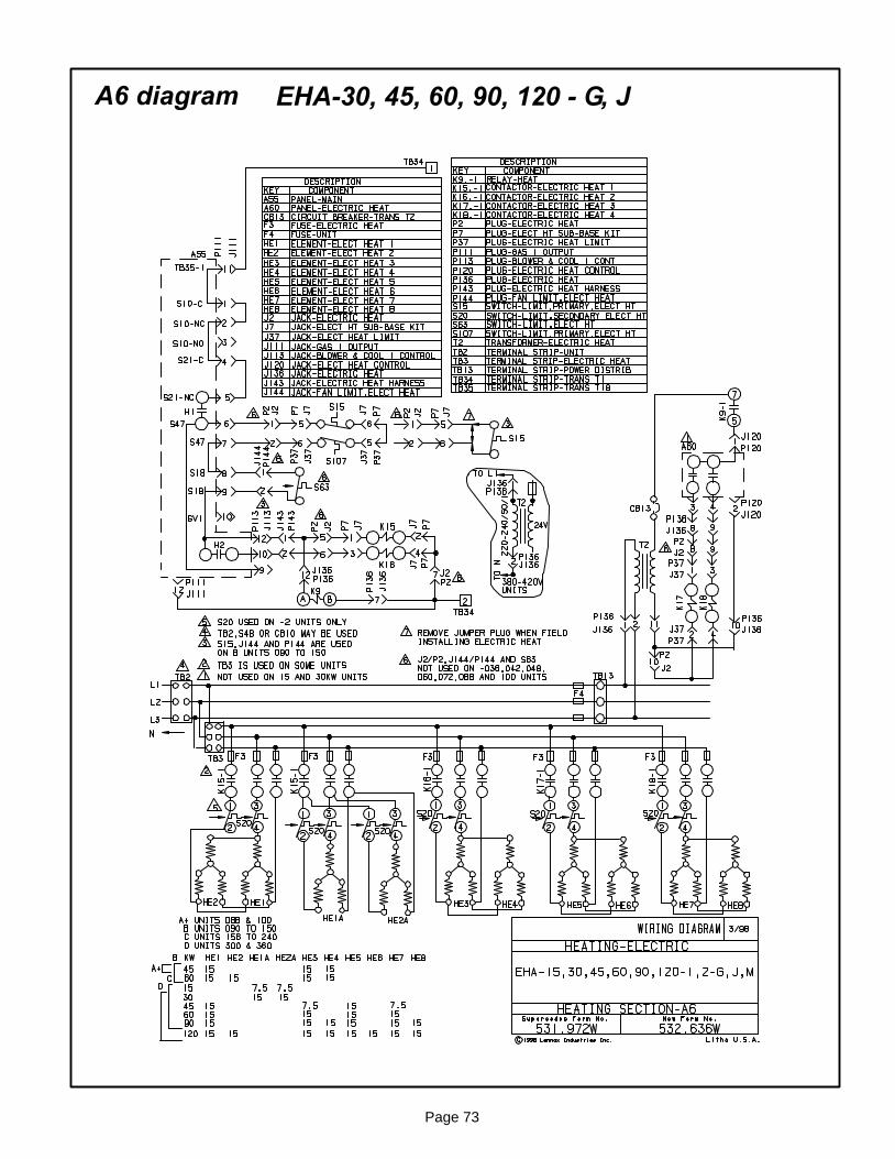
Page 73
A6 diagram EHA−30, 45, 60, 90, 120 − G, J
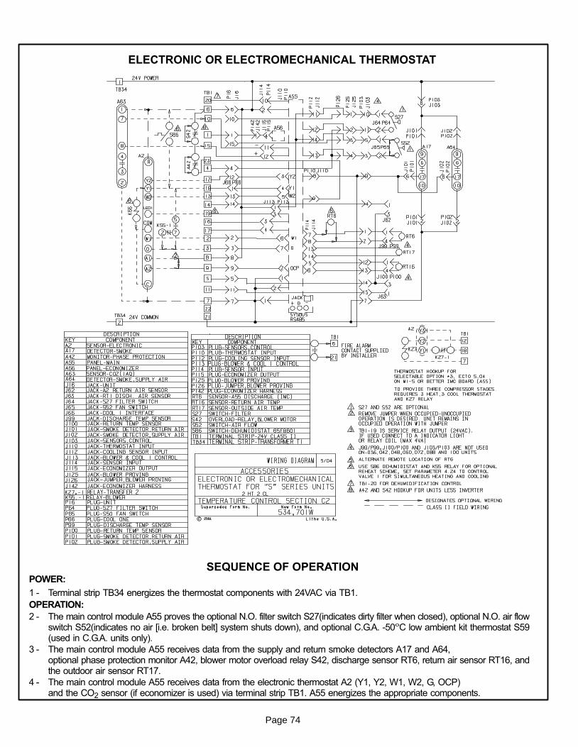
Page 74
ELECTRONIC OR ELECTROMECHANICAL THERMOSTAT
SEQUENCE OF OPERATIONPOWER:
1 − Terminal strip TB34 energizes the thermostat components with 24VAC via TB1.
OPERATION:
2 − The main control module A55 proves the optional N.O. filter switch S27(indicates dirty filter when closed), optional N.O. air flowswitch S52(indicates no air [i.e. broken belt] system shuts down), and optional C.G.A. -50°C low ambient kit thermostat S59(used in C.G.A. units only).
3 − The main control module A55 receives data from the supply and return smoke detectors A17 and A64,optional phase protection monitor A42, blower motor overload relay S42, discharge sensor RT6, return air sensor RT16, andthe outdoor air sensor RT17.
4 − The main control module A55 receives data from the electronic thermostat A2 (Y1, Y2, W1, W2, G, OCP)and the CO2 sensor (if economizer is used) via terminal strip TB1. A55 energizes the appropriate components.
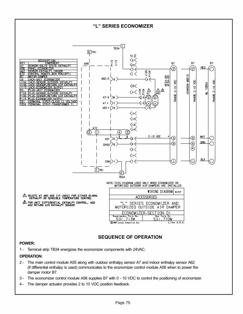
Page 75
�L" SERIES ECONOMIZER
SEQUENCE OF OPERATION
POWER:
1 − Terminal strip TB34 energizes the economizer components with 24VAC.
OPERATION:
2 − The main control module A55 along with outdoor enthalpy sensor A7 and indoor enthalpy sensor A62
(if differential enthalpy is used) communicates to the economizer control module A56 when to power the
damper motor B7.
3 − The economizer control module A56 supplies B7 with 0 − 10 VDC to control the positioning of economizer.
4 − The damper actuator provides 2 to 10 VDC position feedback.
Page 76
NOTES