A comparison of LCC and LC filters for its application in electronic ballast for metal-halide lamps
6
A Comparison of LCC and LC Filters for its Application in Electronic Ballast for Metal- Halide Lamps J. Correa, M. Ponce, A. Lopez, J. Arau Centro Nacional de Investigacion y Desarrollo Tecnologico-CENIDET Departamento de Electronica Cuernavaca, Mexico E-mail: [email protected] P.O. BOX 5-164, C.P. 62050 FAX: +52 (73) 12-24-34, Abstract- A complete LC and LCC Resonant Tanks analysis for its application in the starting and stabilization of Metal-Halide Lamps is presented in this paper. The operation with a single frequency for the starting and steady-state phases, the maximum gain voltage during pre- starting phase, the possibility to achieve soft switching in the switches during the starting and steady-state lamp operation and the resonant tank design limitations for these conditions are considered in the analysis. Experimental prototypes were built to verify the analysis and the results are included. 1. INTRODUCTION For many years High Intensity Discharge (HID) Lamps have been used for industrial and external lighting applications. Nowadays, HID lamps are an attractive light source due to their high efficacy and their high electric power per discharge length unit, which allows to have high luminous flux light sources with a reduced size [l]. Metal Halide Lamps supplied using a high frequency electronic ballast have become an attractive light source thanks to their compactness, good color rendering and high efficacy. However, compared to fluorescent lamps, the Metal Halide lamps require a higher ignition voltage for the gas ionization during the starting phase (1.5 to 5kV for cold starting); besides, an appropriate lamp current for the transition from the glow discharge to the full high pressure arc [2] must be supplied. Similarly to fluorescent lamps, HID lamps could be ignited and stabilized through a high frequency inverter plus a resonant tank. There are many resonant tank topologies applied to electronic ballast for fluorescent lamps and some of them have been analyzed in [3-51 and widely studied in the literature. The LC and LCC resonant tanks, shown in figure 1, are the simplest and most used topologies for the ignition and stabilization of discharge lamps. The unique difference between both tanks is the Cs capacitor in series with the inductor Lr. This capacitor has been used to filtering the dc component in the class D amplifiers, but if this capacitor is considered in the design, it represents additional advantages in the lamp management. Most of the analysis reported [l-51 only consider if the resonant tank is capable to ignite and stabilize the discharge current in the lamp. In this paper not only these basic issues are considered, but three other aspects that are also examined: 1. Starting and steady-state frequencies are the same. 2. Maximum gain voltage during the pre-starting phase. 3. Turn-on and turn-off transitions in the switches with zero current switching (ZCS). LR CRS a) b) Fig. 1. (a) LC Resonant Tank; (b) LCC Resonant Tank 0-7803-7067-8/01/$10.00 02001 IEEE J.M. Alonso Area de Tecnologia Electronica Universidad de Oviedo Campus de Viesques sln Gijon, 33204. SPAIN. FAX: +34-98-5 182138 The first point considers that it is possible to ignite and stabilize the lamp with the same frequency in both operation phases. In most cases, two frequencies are considered: the first one is for the lamp ignition and the second one for the lamp stabilization. However, it is possible to use the same frequency in order to satisfy both conditions. The use of a unique switching frequency simplifies the control circuit and diminishes the resonant inverter cost. If the switching frequency is equal to the natural resonant tank frequency during the pre-starting phase, the tank will be in resonance and a very high voltage will be obtained in the Crp terminals. This means that the maximum voltage that the tank is capable to produce will be applied to the lamp. The third point establishes the switching frequency is the same to the natural resonant tank frequency in the steady state, which means that the resonant tank will be operating in resonance during the steady state. In these conditions the resonant tank is not able to limit the lamp current. In the conventional electronic ballast, the natural tank frequency is lower than the switching frequency and the resonant tank presents an inductive behavior and lets to limit the lamp current. However, in an inductive behavior the inverter power factor is lower than the unity, the rms current in the switches increases and the conduction losses also grow higher. The current and voltage waveforms in the switches for this operation conditions are shown in Fig. 2a. As can be seen the current is delayed to the voltage and the turn off switching will be in a "hard mode". The advantage of operating the resonant tank in resonance during the steady state is that it will behave like a resistance, and the power factor will be equal to the unity. Under these conditions, the stress in the switches is lower and the conductions losses will be also lower. The switches wave forms for the current and the voltage are shown in fig. 2b. As can be seen, the voltage and current are in phase and the switching losses are the lowest. Fig. 2. Voltage and Current waveforms in the switches, (a) fr(sFfs, (b) fr(s)=fs. The stabilization problem, established by the third point, requires an extra stage in order to stabilize the lamp current. This function can be implemented with the first stage used as a power factor corrector in a traditional electronic ballast scheme, like in Fig 3. This stage not only will be used as a power factor corrector, but it can also be used to stabilize the lamp current if the control is appropriate [6]. In this paper the LC and LCC resonant tank analysis is presented in order to fulfill the three conditions mentioned before. In this analysis (a phasor-based analysis) is considered that the quality factor is high enough to obtain a sinusoidal waveform in the 114
-
Upload
independent -
Category
Documents
-
view
0 -
download
0
Transcript of A comparison of LCC and LC filters for its application in electronic ballast for metal-halide lamps

A Comparison of LCC and LC Filters for its Application in Electronic Ballast for Metal- Halide Lamps
J. Correa, M. Ponce, A. Lopez, J. Arau Centro Nacional de Investigacion y Desarrollo Tecnologico-CENIDET
Departamento de Electronica
Cuernavaca, Mexico
E-mail: [email protected]
P.O. BOX 5-164, C.P. 62050
FAX: +52 (73) 12-24-34,
Abstract- A complete LC and LCC Resonant Tanks analysis for its application in the starting and stabilization of Metal-Halide Lamps is presented in this paper. The operation with a single frequency for the starting and steady-state phases, the maximum gain voltage during pre- starting phase, the possibility to achieve soft switching in the switches during the starting and steady-state lamp operation and the resonant tank design limitations for these conditions are considered in the analysis. Experimental prototypes were built to verify the analysis and the results are included.
1. INTRODUCTION For many years High Intensity Discharge (HID) Lamps have been
used for industrial and external lighting applications. Nowadays, HID lamps are an attractive light source due to their high efficacy and their high electric power per discharge length unit, which allows to have high luminous flux light sources with a reduced size [l].
Metal Halide Lamps supplied using a high frequency electronic ballast have become an attractive light source thanks to their compactness, good color rendering and high efficacy. However, compared to fluorescent lamps, the Metal Halide lamps require a higher ignition voltage for the gas ionization during the starting phase (1.5 to 5kV for cold starting); besides, an appropriate lamp current for the transition from the glow discharge to the full high pressure arc [2] must be supplied.
Similarly to fluorescent lamps, HID lamps could be ignited and stabilized through a high frequency inverter plus a resonant tank. There are many resonant tank topologies applied to electronic ballast for fluorescent lamps and some of them have been analyzed in [3-51 and widely studied in the literature. The LC and LCC resonant tanks, shown in figure 1, are the simplest and most used topologies for the ignition and stabilization of discharge lamps. The unique difference between both tanks is the Cs capacitor in series with the inductor Lr. This capacitor has been used to filtering the dc component in the class D amplifiers, but if this capacitor is considered in the design, it represents additional advantages in the lamp management.
Most of the analysis reported [l-51 only consider if the resonant tank is capable to ignite and stabilize the discharge current in the lamp. In this paper not only these basic issues are considered, but three other aspects that are also examined:
1. Starting and steady-state frequencies are the same. 2. Maximum gain voltage during the pre-starting phase. 3. Turn-on and turn-off transitions in the switches with zero
current switching (ZCS). LR CRS
a) b) Fig. 1. (a) LC Resonant Tank; (b) LCC Resonant Tank
0-7803-7067-8/01/$10.00 02001 IEEE
J.M. Alonso Area de Tecnologia Electronica
Universidad de Oviedo Campus de Viesques sln
Gijon, 33204. SPAIN.
FAX: +34-98-5 182 138
The first point considers that it is possible to ignite and stabilize the lamp with the same frequency in both operation phases. In most cases, two frequencies are considered: the first one is for the lamp ignition and the second one for the lamp stabilization. However, it is possible to use the same frequency in order to satisfy both conditions. The use of a unique switching frequency simplifies the control circuit and diminishes the resonant inverter cost.
If the switching frequency is equal to the natural resonant tank frequency during the pre-starting phase, the tank will be in resonance and a very high voltage will be obtained in the Crp terminals. This means that the maximum voltage that the tank is capable to produce will be applied to the lamp.
The third point establishes the switching frequency is the same to the natural resonant tank frequency in the steady state, which means that the resonant tank will be operating in resonance during the steady state. In these conditions the resonant tank is not able to limit the lamp current. In the conventional electronic ballast, the natural tank frequency is lower than the switching frequency and the resonant tank presents an inductive behavior and lets to limit the lamp current. However, in an inductive behavior the inverter power factor is lower than the unity, the rms current in the switches increases and the conduction losses also grow higher. The current and voltage waveforms in the switches for this operation conditions are shown in Fig. 2a. As can be seen the current is delayed to the voltage and the turn off switching will be in a "hard mode".
The advantage of operating the resonant tank in resonance during the steady state is that it will behave like a resistance, and the power factor will be equal to the unity. Under these conditions, the stress in the switches is lower and the conductions losses will be also lower. The switches wave forms for the current and the voltage are shown in fig. 2b. As can be seen, the voltage and current are in phase and the switching losses are the lowest.
Fig. 2. Voltage and Current waveforms in the switches, (a) fr(sFfs, (b) fr(s)=fs. The stabilization problem, established by the third point, requires
an extra stage in order to stabilize the lamp current. This function can be implemented with the first stage used as a power factor corrector in a traditional electronic ballast scheme, like in Fig 3. This stage not only will be used as a power factor corrector, but it can also be used to stabilize the lamp current if the control is appropriate [6].
In this paper the LC and LCC resonant tank analysis is presented in order to fulfill the three conditions mentioned before. In this analysis (a phasor-based analysis) is considered that the quality factor is high enough to obtain a sinusoidal waveform in the
114

resonant tank current. This paper is organized as follows: The LCC and LC analysis are presented in sections I1 and 111 respectively taking into account the three issues established in the introduction. Section IV presents a comparison between both resonant tanks based on the results of sections I1 and 111. Section V describes a design method for the LC and LCC tanks and some simulation results are also presented. Finally, experimental results and conclusions are presented in section VI and VI1 respectively.
11. LCC RESONANT TANK ANALYSlS The scheme of traditional electronic ballast with power factor
correction is shown in Fig. 3. In this scheme the first stage is used as power factor corrector in order to fulfill the standards about power factor and total harmonic distortion and to obtain a regulated DC bus voltage. The second one is a high frequency inverter plus a resonant tank for lamp starting and stabilization during steady-state operation. In this case the second stage is composed by a half- bridge inverter plus a LCC resonant tank.
1 HIDLAMP T
AC *Ti STAGE pFc
LINE
-I-- I I Fig 3. Half-Bridge Inverter as an Electronic Ballast for HID Lamps.
The analysis is based on the use of the fundamental approximation technique [7] and considering that the HID lamp may be modeled as a large resistance before ionization and small resistance (RL) after ionization. If the lamp power is maintained constant the resistance value remains constant during steady state operation. The simplified circuit is shown in Fig. 4, in which the inverter is represented by the fundamental voltage (Va) applied to the LC tank, the HID lamp is RL and Rp represents all parasitic inverter resistances. Xce and Req are series impedances and are
RI, ’ Xc R,.Xc2 R,’ + Xc’ R,’ +Xc’
given by Xce = and R e q = respectively.
For the analysis, all variables express the maximum value of the waveform that each one represents.
XL XCS
Va f--YqqRL vaf--+T2 J
a) b)
XL XCS XCE
C)
Fig 4. a). LCC Filter, b). Pre-Ignition Stage, c). Steady-Sate Stage 11.1. LCC Resonant Tank Analysis for a Single Switching Frequency and Maximum Gain Voltage.
The equivalent circuits for pre-starting and steady state phases are shown in Fig. 4. Before the lamp ignites, it may be modeled as a
large resistance (open circuit), after the ignition the lamp is modeled as a nominal lamp resistance (RL). Before the ignition (Fig. 4b):
-- V O I O M = XCP Va JRp’ + ( X L - Xcs - Xcp)’
From (1) the gain voltage will reach their maximum value only if the next condition is satisfied: XL - xcs - xcp = 0
It means that the circuit operates in resonance during the pre- starting stage in order to obtain a maximum gain voltage.
For the steady state operation (Fig. 4.c) the HID lamp behaves as a resistance. Assuming a 100% efficiency and considering that all reactive elements do not dissipate energy and the Rp effect is negligible, all energy is dissipated in Req. From power definition:
P, =- VX’ (3) 2 R e q
From Fig. 4.c, we obtain:
Va Re 4 ,/Re q z + ( X L - Xcs - Xce)’
vx =
Replacing (4) in (3): Vu ’ 2p,.
(XL - Xcs - Xce)’ = -Re q - Re q2
Replacing the maximum gain voltage condition (2) in (5):
(Xcp - Xce)’ = -Re Vu ’ q - Re q’ 2PL
(4)
Replacing Req and Xce expressions in (6) and solving for Xcp, we obtain:
(7)
where: V, is the maximum value of the fundamental voltage applied to the resonant tank. VL is the rms lamp voltage. PL is the lamp power.
From quality factor definition for the circuit in Fig 4c: XL = Q Re q ; and the Xcs value is obtained from the maximum gain voltage condition, it means: Xcs = XL - Xcp .
Due to Xcs value must be higher than zero implies that (Xes = XL - Xcp > 0) . Replacing (7) and the quality factor definition in the maximum gain voltage condition ( 2 ) we obtain:
2VL2 +v,’ JZVLVO
(8)
This expression determines the minimum value necessary to satisfy Xcs>O and must also be satisfied in order to maintain a LCC resonant tank configuration for maximum gain voltage operation. For design purposes, the filter quality factor value must be high enough to obtain sinusoidal current.
Replacing ( 2 ) and (7) in (1) gives the maximum gain voltage expression for the pre-starting stage:
(9)
The maximum starting voltage applied to the lamp is specified by the next expression:
115

II.2 LCC Resonant Tank Analysis for Turn On and Turn OfSat Zero Current Switching.
The objective of the analysis for turn on and turn off at zero current switching is to achieve the current and voltage applied to the LCC resonant tank are in phase during steady state stage. The pre- starting stage analysis (Fig. 4b) is exactly the same as the analysis for maximum gain voltage, due to this, the gain voltage during pre- starting stage is determined by (1).
Similarly to case of maximum gain voltage, the HID lamp behavior is a resistance for the analysis in steady state operation (Fig. 4c). Assuming a 100% efficiency and considering that all reactive elements do not dissipate energy and the Rp effect is not significant, all energy is dissipated in Req. From power definition ( 3 ) and obtaining Vx fi-om Fig. 4c, expression (4) is again obtained. In order to achieve turn-on and turn-off at zero current switching during steady state operation, next condition must be satisfied: XL - Xcs - Xce = 0 (1 1)
It means that the circuit should be operated in resonance during steady state. Replacing (1 1) in (4) we obtain: Vx = Vu (12)
Replacing (12) in ( 3 ) we obtain: 1 Re q = - Vu
2PL Replacing Req expression in (13) and solving for Xcp, w,e obtain:
Va V, ' x c p = (14)
P, Jm Xcp will be a real value only if next condition is satisfied:
vu <Jz V, (15) It means that the fundamental voltage applied to the tank must be
lower than the lamp peak voltage. From quality factor definition for the circuit in fig 4c:
XL = Q Re q ; the Xcs value is obtained from replacing the quality factor definition in the zero current switching condition (1 l), it means: Xcs = Q Re q - Xce and:
Due to Xcs value must be higher than zero, this implies that
J~v , ' - vu2 vu
This expression determines the minimum value necessary in order to satisfy Xcs > 0 and must be satisfied in order to maintain an LCC resonant tank configuration for a turn on and turn off at zero current switching operation. For design purposes, the filter quality factor must be high enough to obtain a sinusoidal current.
In order to achieve turn on and turn off at zero current switching and starting the lamp with a unique switching frequency is necessary to satisfy both conditions: maximum gain voltage (2) and turn on and turn off at ZCS (1 1). In order to fulfill these conditions, it is necessary that Xcp = Xce . It means Xcp = 0 and it is not a
solution, since it is not possible to achieve turn on and turn off at ZCS and starting the lamp with the same switching frequency. The circuit requires two frequencies: the first one for the lamp starting and the second one for the steady-state operation. Starting frequency is determined by:
7
Fstarting = Fs - dz where
Fstarting is lamp ignition frequency, Fs is the steady sate operation frequency.
111 LC RESONANT TANK ANALYSIS: A PARTICULAR CASE OF LCC FILTER LC resonant tank is a particular case of the LCC filter and it is
obtained when Xcs = 0. The LC filter diagram and the equivalent circuits for the pre-starting and steady-state stages are shown in Fig. 5 . In this case the Req and Xce expressions are exactly the same as those in the LCC resonant tank.
Va BRL vaf., a) b)
XL XCE
Va r -T2 4-J
C)
Fig 5. a). LC Filter, b). Pre-ignition Stage, c). Steady Sate Stage
III.I LC Resonant Tank Anal-vsis for a Single Switching Frequency and Maximum Gain Voltage.
When Xcs = 0 from (1) the expression for the maximum gain voltage for the LC resonant tank is obtained:
(19) -- V O - M = XCP Vu JRp2 + ( X L - x c p ) *
The gain voltage will reach their maximum value only if the next condition is satisfied: XL - x c p = 0 (20)
It means that the circuit operates in resonance during the steady state in order to obtain a maximum gain voltage.
The analysis in steady sate is exactly the same as that performed for the LCC filter. From ( 5 ) and considering that Xcs=O for the LC resonant tank, we obtain:
Vu (XL - Xce)' = -Re q - Re q 2 2 4
Replacing the maximum gain voltage condition (20) for the LC filter in (21) we obtain again (6), for this reason the Xcp expression is exactly the same for LCC and LC resonant tanks.
From quality factor definition for the circuit in fig 5c: XL = Q Re q ; and replacing it in the maximum gain voltage condition for the LC filter, we obtain:
Expression (22) means that in a LC filter the quality factor is determined by the fundamental voltage applied to the tank and by
116

the rms lamp voltage. Q is a fixed value and it can not change once the rms voltage applied to the tank and the rms lamp voltage are established.
The expressions for the maximum gain voltage and the maximum starting voltage are exactly the same than expressions (9) and (10) respectively. It must be noted that there is a quantitative difference due to the parasitic resistance of the Cs in the LCC filter, but the qualitative expressions are exactly the same. If we consider that the Cs resistance parasitic effect is negligible, then the maximum gain voltage and the maximum starting voltage applied to the lamp are the same for both resonant tanks.
III.2 LC Resonant Tank AnaLvsis for Turn On and Turn OjJat Zero Current Switching.
Like in the LCC resonant tank case, the objective in the analysis for turn on and turn off at zero current switching is to achieve that the current and voltage applied to the LCC resonant tank are in phase during steady-state stage. Considering the LCC analysis and taking into account that Xcs = 0, from (4) we obtain:
vu Re 4 vx = ,/Req2 +(XC-Xce)’
For the LC resonant tank, the turn on and turn off at ZCS condition for the steady state is: XL-Xce=O (24)
Replacing this condition in (23) we obtain the same results as those in the LCC resonant tank, this is, the fundamental voltage applied to the tank must be lower than the rms lamp voltage.
R Due to Xcs = 0, from obtain Q = L or:
XCP
J2VLZ -vu* vu
Expression (25) means that the quality factor of the LC resonant tank is a fixed value and it is determined by the fundamental voltage and by the rms lamp voltage. Unlike the case of the LCC filter, Q is a fixed value when the Va and VL values are given.
Alike the LCC filter case, in order to achieve turn on and turn off at ZCS and to start the lamp with the same switching frequency, it is necessary to satisfy both conditions: maximum gain voltage (20) and turn on and turn off conditions (24). Due to this Xcp = Xce , and this condition is satisfied only when Xcp =O. It is not a solution and is not possible to achieve turn on and turn off at ZCS and starting the lamp with the same switching frequency. For these reason, like in the LCC resonant filter, the circuit requires two frequencies: the first one for the lamp starting and the second one for the steady state operation. The expressions for the voltage gain, the starting voltage applied to the lamp and the starting frequency are exactly the same as those in the LCC resonant tank.
IV. LC AND LCC FILTERS: A COMPARATIVE ANALYSIS. LCC and LC filter expressions for maximum gain voltage
operation are resumed in Table I. The quality factor for both resonant tanks depends only on the fundamental voltage applied to the tank and by the rms lamp voltage. According to (8) and (20) the maximum gain voltage and the maximum starting voltage applied to the lamp (for both resonant tanks) do not depend on the filter quality factor, but the filter parasitic resistance has a big influence on these parameters. The maximum gain voltage and maximum starting- voltage applied to the lamp expressions are exactly the same for both resonant tanks; however, it must be noted that LCC filter has an
extra element (Cs) and, as a consequence, the parasitic elements in the LCC filter are higher than the LC filter and then, the starting voltage applied to the lamp is lower than LC filter depending de Cs parasitic resistance.
When the LC and LCC filters are designed for turn on and tum off at ZCS for the steady state, the fundamental voltage value must be lower than the peak lamp voltage. According to Table I1 the quality factor for both filters depends only on the lamp voltage and on the fundamental voltage applied to the tank. Alike the case of maximum gain voltage, there is a minimum quality factor value for the LCC filter determined by (1 7).
In the LC filter the quality factor is a fixed value and it can not be selected arbitrarily because it is automatic determined when the fundamental voltage and the lamp are selected. But in the LCC filter case the quality factor must satisfy expression (17), but once it is satisfied, it can be selected according to the designer criteria. It is possible due to the Cs presence and for instance, the LCC filter is a more flexible structure than the LC resonant tank.
IV.1 Parasitic Resistance ERect on LC and LCC Filters Performance Quality factor, maximum gain voltage and maximum starting-
voltage lamp curves for the LCC filter are shown in the figures 6 to 8 for the Metal Halide Lamps CDM-T Family of 35, 70 and 150 Watts.
LCC filter curves can be applied to the LC filter, according to the results of the previous sections, the LC filter is a particular case of the LCC resonant tank. Only must be noted that all considerations mentioned before (about quality factor and parasitic resistance) should be keeping in mind in order to make a correct interpretation of the characteristics.
V. LCC RESONANT TANK DESING PROCEDURE FOR A SINGLE SWITCHING FREQUENCY AND MAXIMUM GAIN VOLTAGE
The fundamental voltage (Va) is determined by the inverter topology and by the supply voltage. For example, for a full bridge
inverter the fundamental voltage is Vu = - , and for a half
bridge inverter is Vu = - . The design parameters are: the
fundamental voltage (Va) applied to the tank, the rms lamp voltage (VL), the lamp power (PL), the switching frequency (Fs), the lamp equivalent resistance (RL) and the parasitic resistance (Rp). The LCC resonant tank design procedure for the maximum gain voltage condition is:
4 vcc x
2vcc x
1 .- Xcp value is determined by (6). 2.- Once Xcp is known, the minimum quality factor value is obtained from expression (8) and it should be high enough to have a sinusoidal filter current. 3.- XL and Xcs values are obtained from the quality factor definition (Fig 4.c) and the maximum gain voltage condition for the LCC tank respectively.
For the LC resonant tank, the procedure is exactly the same as that for the LCC resonant tank case, but it must be noted that filter quality factor is a fixed value and is determined by the rms voltage lamp and the fundamental voltage applied to the resonant tank. LCC resonant tank design procedure for turn on and turn off at ZCS is very similar but the correspondent expressions should be used.
As an example, for an electronic ballast for a CDM-R 70W lamp (PL=~OW, VL=90V), with a LCC resonant tank and a full bridge inverter supplied by 360 Vdc (Va=458.3V), a switching frequency of 23 kHz and Rp=lO we obtain: Cp=16.7nF, Cs=163.5nF, L1=3.16mH, M,,=41.38, V,%=18.967 V and Q=4.25.
117

TABLE II EXPRESSIONS FOR LCC AND LC FILTERS FOR TURN ON AND TURN OFF AT ZCS SWITCHING
LCC FILTER
200 300 400 500 FUNDAh4l3TAL VOLTAGE Va
Fundamental Voltage vs Quality Factor (Rp=lO) Fig. 6. LCC Filter Quality Factor Curves.
LCC-FILWB 100 .
200 300 400 500 600 FUNDAMENTAL VOLTAGE Va
Fundamental Voltage vs Gain Voltage (Rp=lO) Fig. 7. LCC Filter Gain Voltage Curves.
In the case of using a LC filter for the same lamp, with a full bridge inverter supplied by 360 Vdc (Va=458.3 V), a switching frequency of 22 kHz. and Rp=lO we obtain: Cp=17.48nF, L1=2.99m, M,,,=41.38, V,,bg=14,896 V and Q=3.86.
60000
50000
9 40000
U
3 30000
U
20000 i VI
10000 n t 7-
L . . . . . . . . I . . . . , . . . . , I
200 300 400 500 600 FUNLlAMENTAL VOLTAGE Va
Fundamental Voltage vs Srarting Voltage (Rp=lO) Fig. 8. LCC Filter Starting Voltage Curves
Starting lamp voltage for the LCC filter is shown in Fig 9 just after the lamp ignites. The LCC resonant tank can generates almost 20 kV for the lamp ignition with Rp=lO. As mentioned before, the starting voltage depends strongly of the filter parasitic elements.
Starting lamp voltage for the LC resonant tank is presented in Fig 10. The starting voltage like in the LCC filter case, is almost 20 kV too. In both cases, the starting voltage is too high. However, in the practice this voltage is not applied to the lamp due to high value. The switching frequency is slightly greater than the resonant frequency in order to avoid damage in the ballast components.
LCC filter simulations for turn on and turn off at ZCS are shown in Fig 1 1. In this case, due to the circuit restrictions the fundamental voltage applied to the tank must be lower than the lamp peak voltage. For this reason the resonant tank only generates 1.4 KV for the lamp ignition, and it is possible that this voltage is not high enough to ignite the lamp.
Experimental results are presented in Fig 12. The LCC resonant tank voltage and current lamp waveforms for steady state are shown in Fig 12a. The Fig 12b shows the current and voltage waveforms in the LC resonant tank, as can be seen they are very similar to the LCC waveforms. For the turn on and turn off LCC resonant tank case we had problems during the lamp starting due to the starting voltage was not high enough to ignite the lamp. The lamp was
VI. EXPERIMENTAL RESULTS
118
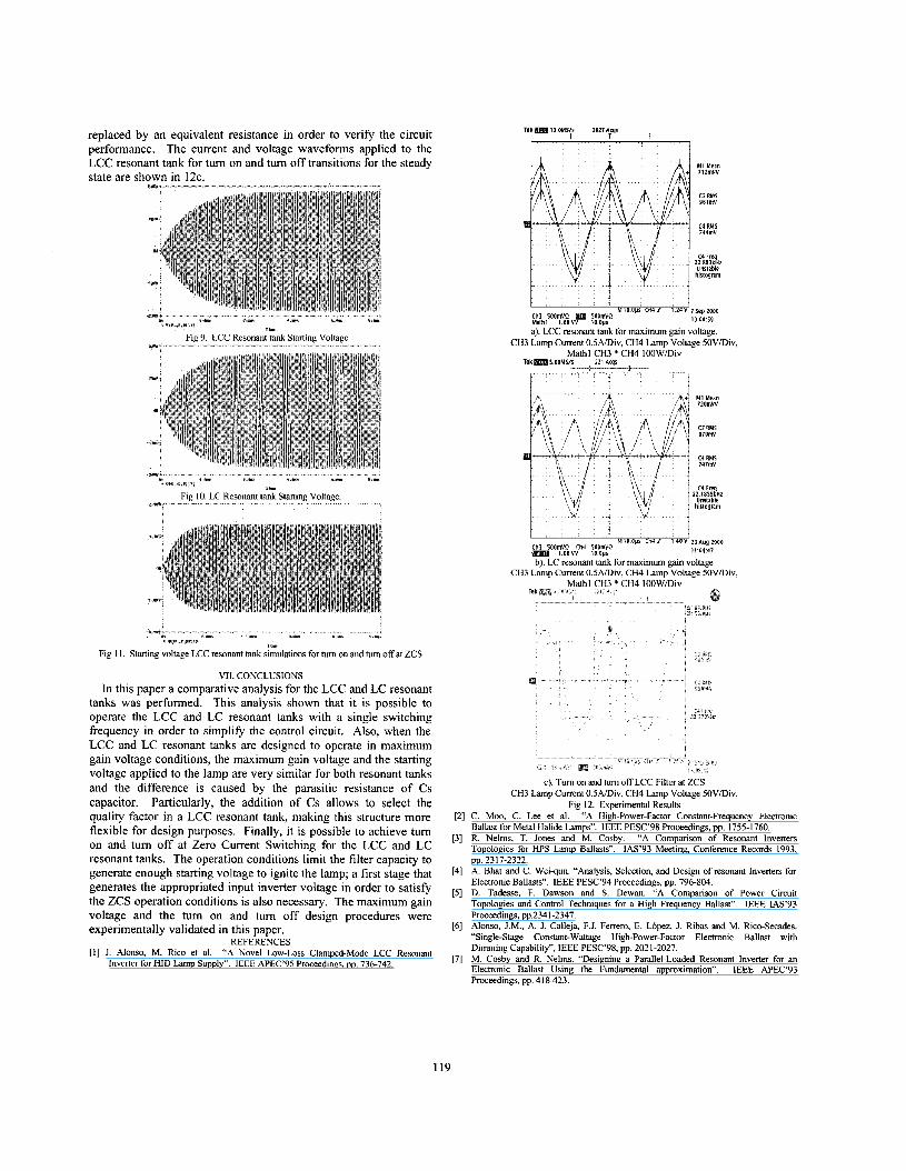
replaced by an equivalent resistance in order to verify the circuit performance. The current and voltage waveforms applied to the LCC resonant tank for turn on and turn off transitions for the steady state are shown in 12c.
-*l-.x..xl”“Ix..- __”.”^” ”,”,, ...̂ lll”-l.~”l, _-,-,, .... ,...
Fig 9 LCC Resonant tank Starting Voltage w- -
.- *h *I * - x 1 - _ - ?si.
i a s ‘#(I 1 II 1,
Fig I O LC Resonant tank Starting Voltage 1 .”-
.- Fig I I. Staning voltage LCC resonant tank simulations for turn on and turn off at ZCS
VII. CONCLUSIONS In this paper a comparative analysis for the LCC and LC resonant
tanks was performed. This analysis shown that it is possible to operate the LCC and LC resonant tanks with a single switching frequency in order to simplify the control circuit. Also, when the LCC and LC resonant tanks are designed to operate in maximum gain voltage conditions, the maximum gain voltage and the starting voltage applied to the lamp are very similar for both resonant tanks and the difference is caused by the parasitic resistance of Cs capacitor. Particularly, the addition of Cs allows to select the quality factor in a LCC resonant tank, making this structure more flexible for design purposes. Finally, it is possible to achieve turn on and turn off at Zero Current Switching for the LCC and LC resonant tanks. The operation conditions limit the filter capacity to generate enough starting voltage to ignite the lamp; a first stage that generates the appropriated input inverter voltage in order to satisfy the ZCS operation conditions is also necessary. The maximum gain voltage and the turn on and turn off design procedures were experimentally validated in this paper.
REFERENCES [I] J. Alonso, M. Rico et al. “A Novel Low-Loss Clamped-Mode LCC Resonant
Inverter for HID Lamp Supply”. IEEE APEC’95 Proceedings, pp. 736-742.
Tex I Q OMS/$ 2627 A q l t - e
t i
MI Mean 712mvv
c3 RMS 961mV
C4 RMS 744mV
c4 keg 2 2 . 8 8 3 ~ ~ ~
Unstable hislogram
I I Ch3 500mVQ BW 50QmVQ Mathl I OOVV loops a) LCC remnant tank for maximum gam voltage
CH3 Lamp Current 0 5A/DiV, CH4 Lamp Voltage SOV/Div,
M I O O P S U141 124V7sep2OQO IO 0 0 59
Mathl CH3 * CH4 100W/Div t----l r 4-
R k m S O O M S l s 221 Acqs
t I I . . I
M I m a n 720mVV
c3 RMS 97OmV
c4 RMS 747mv
c4 mq ~Z.IIESLHZ
Unstable halognm
I I MI00111 Ch4f I 4 O V 23(+~g2000
11 0447 Ch3 500mVQ Ch4 5OQmVQ I OOVV 10 0115
bl LC resonant tank for maximum e m voltaee CH3 Lamp Current OSADiv, CH4 Lamp’Voltage <OV/Div,
Mathl CH3 * CH4 I00WDiv
m c) Turn on and turn off LCC Filter at ZCS
CH3 Lamp Current 0 5A/DiV, CH4 Lamp Voltage SOViDiv, Fig 12 Experimental Results
[2] C Moo, C Lee et al “A High-Power-Factor Constant-Frequency Electromc Ballast for Metal Halide Lamps” IEEE PESC’98 Proceedings, pp 1755-1760
[3] R Nelms, T Jones and M Cosby “A Companson of Resonant Inverters Topologies for HPS Lamp Ballasts” IAS’93 Meeting, Conference Records 1993, pp 2317-2322
[4] A Bhat and C Weiqun “Analysis, Selection, and Design of resonant Inverters for Electronic Ballasts” IEEE PESC’94 Proceedmgs, pp 796-804
[5] D Tadesse, F Dawson and S Dewan “‘A Cornpanson of Power Circuit Topologies and Control Techniques for a High Frequency Ballast” IEEE IAS’93 Proceedings, pp 234 1-2347
[6] Alonso, J M , A J Calleja, F J Ferrero, E Lopez, 1 Ribas and M RiceSecades “Single-Stage Constant-Wattage High-Power-Factor Electronic Ballast with Dimming Capability”, IEEE PESC’98, pp 2021-2027
[7] M Cosby and R Nelms “Designing a Parallel-Loaded Resonant Inverter for an Electronic Ballast Using the Fundamental approxunation” IEEE APEC‘93 Proceedings, pp 418423
119