A Review of LCC-HVDC and VSC-HVDC Technologies and ...
9
TRANSACTIONS ON ENVIRONMENT AND ELECTRICAL ENGINEERING ISSN 2450-5730 Vol 1, No 3 (2016) © Oluwafemi E. Oni, Kamati I. Mbangula, and Innocent E. Davidson Abstract—High Voltage Direct Current (HVDC) systems has been an alternative method of transmitting electric power from one location to another with some inherent advantages over AC transmission systems. The efficiency and rated power carrying capacity of direct current transmission lines highly depends on the converter used in transforming the current from one form to another (AC to DC and vice versa). A well-configured converter reduces harmonics, increases power transfer capabilities, and reliability in that it offers high tolerance to fault along the line. Different HVDC converter topologies have been proposed, built and utilised all over the world. The two dominant types are the line commutated converter LCC and the voltage source converter VSC. This review paper evaluates these two types of converters, their operational characteristics, power rating capability, control capability and losses. The balance of the paper addresses their applications, advantages, limitations and latest developments with these technologies. Index Terms—Commutation failure, HVDC, line commutated converter, modular multilevel converter, voltage source converter. I. INTRODUCTION he first electric generator was DC machine, as well as the first electric power transmission system by Thomas Edison [1, 2]. In the last few decades, High Voltage Direct Current (HVDC) technology has been used, due to some of its inherent benefits in long distance transmission application. It is widely used all over the world for bulk power delivery over long distances, interconnections of asynchronous systems, stability of AC lines, power control, long submarine transmission and renewable energy integration. Reduction in the right of way (ROW) is another edge over AC systems [3]. HVDC transmission system involve the use of converter for the conversion of AC to DC (rectifier) at the transmitting end, and converting the DC back to AC at the receiving end (inverter), [4]. This converter usually has a 12-pulse arrangement, of valves connected in a star-delta, star-star formation to the AC networks. A reactor, dc capacitor and AC filters are also part of the converter circuitry. The two ends of This paper was submitted for review on July 28, 2016 and accepted on September, 9, 2016. This work was supported by Eskom Power Plant Engineering Institute, Eskom Centre of Excellence in University of KwaZulu- Natal. Westville campus, South Africa. O. E Oni is with Electrical Engineering Department, University of KwaZulu-Natal. Durban 4041, South Africa (e-mail: [email protected]). K. N. I. Mbangula was with Department Electrical Engineering, University of KwaZulu-Natal. Durban 4041, South Africa. He is now with the Department the converters are connected via DC transmission lines which can be either overhead cable or submarine cable or directly in the same location as in the case of back-to-back configuration. Continuous progress in HVDC systems is linked to advances in the power electronics technologies for the fabrication of highly efficient semiconductor devices for HVDC converter topology [5]. There are two dominant methods used in converting AC to DC and vice versa. These methods are the Line commutated converter LCC and the voltage source converter VSC. The success of these two technologies became possible with the development of power electronics devices [6, 7]. Before the power electronics was the transverter, electrolytic and the atmospheric converter, all these are part of the several attempts made for AC/DC conversion. These entire attempts failed due to some technical reasons and safety measures inherent in using them [8]. The invention of mercury-arc valves brought temporary success to AC/DC conversion which later became outdated. The mercury arc valve which operated then have either been scrapped or upgraded to semiconductor converter technology [9]. Semiconductors devices have been in used since 1970s and are still a growing technology because of the high switching capacity and ability to withstand high current rating. Examples are the diode, diac, triac, thyristors, MOS-controlled thyristors (MCTs) [10], insulated-gate bipolar transistors (IGBT) and integrated gate-commutated thyristors (IGCTs) etc. [11]. This paper looks critically into the two dominant HVDC converter technologies taking into consideration their operational characteristic and their output AC waveform when subjected to three-phase short circuit as well as dc line fault. The simulation is carried out on DigSILENT Powerfactory and the results of each technology are compared alongside each other. II. CONVERTER CONFIGURATION AND TOPOLOGY HVDC interconnections can be configured in different forms to suit different desired performance and operational of Electrical Engineering, University of Namibia. Ongwediva 3624, Namibia (e-mail: [email protected]). I. E. Davidson was with Department of Electrical Engineering, University of KwaZulu-Natal. Durban 4041, South Africa. He is now with the Department of Electrical Power Engineering, Durban University of Technology. Durban 4001, South Africa (e-mail: [email protected]). A Review of LCC-HVDC and VSC-HVDC Technologies and Applications Oluwafemi E. Oni, Kamati I. Mbangula, and Innocent E. Davidson T
-
Upload
khangminh22 -
Category
Documents
-
view
0 -
download
0
Transcript of A Review of LCC-HVDC and VSC-HVDC Technologies and ...

TRANSACTIONS ON ENVIRONMENT AND ELECTRICAL ENGINEERING ISSN 2450-5730 Vol 1, No 3 (2016)
© Oluwafemi E. Oni, Kamati I. Mbangula, and Innocent E. Davidson
Abstract—High Voltage Direct Current (HVDC) systems has
been an alternative method of transmitting electric power from
one location to another with some inherent advantages over AC
transmission systems. The efficiency and rated power carrying
capacity of direct current transmission lines highly depends on the
converter used in transforming the current from one form to
another (AC to DC and vice versa). A well-configured converter
reduces harmonics, increases power transfer capabilities, and
reliability in that it offers high tolerance to fault along the line.
Different HVDC converter topologies have been proposed, built
and utilised all over the world. The two dominant types are the line
commutated converter LCC and the voltage source converter
VSC. This review paper evaluates these two types of converters,
their operational characteristics, power rating capability, control
capability and losses. The balance of the paper addresses their
applications, advantages, limitations and latest developments with
these technologies.
Index Terms—Commutation failure, HVDC, line commutated
converter, modular multilevel converter, voltage source converter.
I. INTRODUCTION
he first electric generator was DC machine, as well as the
first electric power transmission system by Thomas Edison
[1, 2]. In the last few decades, High Voltage Direct Current
(HVDC) technology has been used, due to some of its inherent
benefits in long distance transmission application. It is widely
used all over the world for bulk power delivery over long
distances, interconnections of asynchronous systems, stability
of AC lines, power control, long submarine transmission and
renewable energy integration. Reduction in the right of way
(ROW) is another edge over AC systems [3].
HVDC transmission system involve the use of converter for
the conversion of AC to DC (rectifier) at the transmitting end,
and converting the DC back to AC at the receiving end
(inverter), [4]. This converter usually has a 12-pulse
arrangement, of valves connected in a star-delta, star-star
formation to the AC networks. A reactor, dc capacitor and AC
filters are also part of the converter circuitry. The two ends of
This paper was submitted for review on July 28, 2016 and accepted on
September, 9, 2016. This work was supported by Eskom Power Plant
Engineering Institute, Eskom Centre of Excellence in University of KwaZulu-
Natal. Westville campus, South Africa.
O. E Oni is with Electrical Engineering Department, University of
KwaZulu-Natal. Durban 4041, South Africa (e-mail: [email protected]).
K. N. I. Mbangula was with Department Electrical Engineering, University of KwaZulu-Natal. Durban 4041, South Africa. He is now with the Department
the converters are connected via DC transmission lines which
can be either overhead cable or submarine cable or directly in
the same location as in the case of back-to-back configuration.
Continuous progress in HVDC systems is linked to advances in
the power electronics technologies for the fabrication of highly
efficient semiconductor devices for HVDC converter topology
[5].
There are two dominant methods used in converting AC to
DC and vice versa. These methods are the Line commutated
converter LCC and the voltage source converter VSC. The
success of these two technologies became possible with the
development of power electronics devices [6, 7]. Before the
power electronics was the transverter, electrolytic and the
atmospheric converter, all these are part of the several attempts
made for AC/DC conversion. These entire attempts failed due
to some technical reasons and safety measures inherent in using
them [8].
The invention of mercury-arc valves brought temporary
success to AC/DC conversion which later became outdated.
The mercury arc valve which operated then have either been
scrapped or upgraded to semiconductor converter technology
[9]. Semiconductors devices have been in used since 1970s and
are still a growing technology because of the high switching
capacity and ability to withstand high current rating. Examples
are the diode, diac, triac, thyristors, MOS-controlled thyristors
(MCTs) [10], insulated-gate bipolar transistors (IGBT) and
integrated gate-commutated thyristors (IGCTs) etc. [11].
This paper looks critically into the two dominant HVDC
converter technologies taking into consideration their
operational characteristic and their output AC waveform when
subjected to three-phase short circuit as well as dc line fault.
The simulation is carried out on DigSILENT Powerfactory and
the results of each technology are compared alongside each
other.
II. CONVERTER CONFIGURATION AND TOPOLOGY
HVDC interconnections can be configured in different forms
to suit different desired performance and operational
of Electrical Engineering, University of Namibia. Ongwediva 3624, Namibia (e-mail: [email protected]).
I. E. Davidson was with Department of Electrical Engineering, University
of KwaZulu-Natal. Durban 4041, South Africa. He is now with the Department
of Electrical Power Engineering, Durban University of Technology. Durban
4001, South Africa (e-mail: [email protected]).
A Review of LCC-HVDC and VSC-HVDC
Technologies and Applications
Oluwafemi E. Oni, Kamati I. Mbangula, and Innocent E. Davidson
T

requirements, namely:
1) Back to back connection
This has both the inverter and the rectifier in the same
location, and the valves are normally in the same building. It
therefore has a short dc line of few meters located inside the
same environment.
2) Monopolar connection
This has both converters separated by a single dc pole line,
either positive or negative voltage. The ground is used as a
current return path. Most submarine cable connections use
monopolar systems.
3) Homopolar connection
This has two or more dc line of the same polarity connected
to the converters. Negate polarity is normally used for less
corona and reactive power loss. Ground is used as the return
path. It works as a monopole when one pole develop a fault.
The disadvantage of high cost make it unpopular and seldom
used.
4) Bipolar connection
This is the most popular method in HVDC interconnection of
converters. It is similar to the homopolar connection, but it
has different polarities. Each pole is independent, that is, it
can operate with a single pole with ground used as return path
[3].
5) Multi-terminal connection
This has more than two sets of converters operating
independently. Each converters can operate as a rectifier or
an inverter [12].
B. COMPONENTS OF A CONVERTER STATION
HVDC converter stations comprises of different
interconnected system working together for efficient power
transmission. Predominantly, any HVDC converter station
comprises of the converter circuits itself, then the converter
transformer, smoothening reactors, harmonics filters, and other
peripherals devices. Few definitions of the most important parts
are explained below.
1) Converter transformer
LCC HVDC uses special type of transformer different from
the AC transformer in that it has special features such as on
load tap changes and follow different configuration. For
example, the 12-pulse converter can follow six single-phase
two windings, three single-phase three winding or two three-
phase two windings configuration to suit specification and
operational performance [13, 14]. But the VSC HVDC uses
same transformer as the normal AC transformer.
2) Smoothing Reactors
This is used for removal of ripples of the DC current. It is
also used to limit the rate of rise of the fault current on the
DC line.
3) Harmonic filters
These are connected to the converter terminals to provide a
low impedance path to ground for removal of harmonics
current. Filter used also provide the AC line with the reactive
power compensation.
III. LINE COMMUTATED CONVERTER (LCC-HVDC)
LCC, also known as a current source converter CSC uses a
thyristors base technology for its converter. The thyristors are
silicon semiconductor devices with four layers of N and P type
material acting as bi-stable switches, triggered on with a gate
pulse and stayed in that on condition until the next current zero
crossing. In other for LCC to commutate, the converters require
a very high synchronous voltage source, thereby hindering it
use for a black start operation. With LCC current rating
reaching up to 6250A and blocking voltage of 10KV, this make
LCC to have the highest voltage and power rating level of all
the HVDC converter technologies [15-17].
LCC achieves its control by regulating the firing angle ᾱ on
both rectifier and inverting side. It has an approach that utilizes
a uni-directional line commutated flow of DC current which is
inject into a receiving AC network, thereby termed CSC
because the output current is kept at a constant level [18].
TABLE I
RECENT LCC –HVDC PROJECTS
PROJECT
NAME LOCATION CHARACTERISTIC
(MW) (KV) Year (km)
UK
- Netherlands 1000 ±400 2011 260
Jinpin – Sunan
China 7200 ±800 2012 2093
Mundra –
Haryana India 2500 ±500 2012 960
Rio –
Madeira Brazil 800 100 2012 B-B
Rio – Madeira
Brazil 2x3150 ±600 2013 2375
Xiluodu –
Guangdong China 6400 ±500 2013 1251
Nuozhadu –
Guangdong China 5000 ±800 2013 1451
Southern Hami –
Zhengzhou
China 8000 ±800 2014 2200
Biswanath – Agra
India 6000 ±800 2014 1728
Xiluodu-
Zhejiang China 8000 ±800 2014 1688
Zhundong –
Sichuan* China 10000 ±1100 2015 2600
Power reversal from one station to another is carried out by
inverting the DC voltage polarity in both stations but the current
direction remains constant. The technology operates with good
reliability and minimal maintenance. It is the most suitable way
of transmitting bulk power using high voltage transmission
lines. These features make LCC technology the most popular
among HVDC schemes [19].
Table 1 shows few of the recent LCC-based HVDC around
the globe. Zhundong-Sichuan scheme has the highest voltage
and power, and the longest distance, project in China [20].
IV. VOLTAGE SOURCE CONVERTER (VSC-HVDC)
Voltage source converter uses insulated gate bipolar
transistor IGBT technology. The current in this technology can
both be switched on and off at any time independent of the AC
voltage, that is, it creates its own AC voltages in case of
blackstart [21]. Its converters operate at a high frequency with

pulse width modulation PWM which allows simultaneous
adjustment of the amplitude and phase angle of converter while
keeping the voltage constant [22]. VSC has high degree of
flexibility with inbuilt capability to control both its active and
reactive power as shown in fig. 1, which makes it more useful
in urban power network area [23].
This technology was develop in the 1990’s with the first
project commissioned by ABB, 1997 [9]. But due to its capacity
limits, VSC-HVDC has not been able to make much edge over
its contemporary LCC scheme due to low device rating, high
power losses and high dielectric stress on equipment insulation.
Its application is approaching 1800MW, 500KV. An example
is the 1400MW, ±525KV Nordlink that interconnect the grid of
Statnett in Norway and TenneT in Germany over a distance of
623km [24]. A lot of research is ongoing to override this
limitation [25] and to have the ability to ride through fault [26].
Ref. [27] explain VSC control, modelling, simulation and
stability analysis in power systems.
The basic building block of VSC-HVDC topology start with
two-level converter [28, 29]. It is like a six-pulse bridge in
which IGBT with inverse-parallel diodes replaced the
thyristors, and the dc smoothing reactor of LCC is replaced by
DC capacitor as shown in fig. 2. It derives its name from the
fact that it has a switching device which are complementarily
operated to generate two levels of voltage (+Vdc/2 and –Vdc/2)
at the ac output terminal of the converter. This complementary
operation only allows one switching devices to operate at a
time, and the other is turned off. Simultaneous turning on of
both two switching devices will lead to short circuit of the
capacitor across the dc link which may destroy the converter
switches due to over-current. With this topology, each
semiconductors switch withstands the full voltage stress that is
flowing in the link [30].
Prevention of the dc voltage from changing polarity is done
by the diode that is connected in parallel to the IGBT, since the
diode can only conduct when forward biased, thereby
discharging the dc circuits. But the current flows in both
direction, passing through either the IGBT or the diode [31].
It adopt the pulse width modulation (PWM) techniques to
control the gate switching frequency of the IGBT, and to reduce
the harmonic distortion generated by the converter. Due to high
switching losses in the IGBTs as a result of the PWM which is
switched on and off many times in a cycles, the overall
transmission efficiency of a two-level converter is very poor
compared to the LCC converter. Another major setback is that
a high level of electromagnetic interference occur when two-
level converter is used for high voltage DC systems [32].
An attempt to reduce the poor harmonic distortion and to
have a high efficient VSC converter brings about the multi-level
converter (MMC, which start from the three-level converter
with three discrete voltage level).
It synthesizes more than two voltage level at the AC terminal
of each phase as shown in fig. 3. Several types of multilevel
converter have been mention and analyzed in the literature [33-
35], such as the diode clamped, where diodes are used as
clamped and the dc output is subdivided into switches by a
capacitors.
Fig. 1. VSC-HVDC scheme design
Fig. 2. Block diagram of a two-level VSC-HVDC
With n-levels, there will be n+1 capacitors, and n-1 switch
pair are required to work in a complementary manner to
generate the output dc voltage. High efficiency for switching at
fundamental frequency, low cost and a lesser number of
components are some of its merits. However it suffer setback as
its less attractive for high voltage transmission due to difficulty
in charging and discharging of its dc capacitor, lack of modular
index and large inductance stray in the clamping path which
have effect on the converter switching characteristics [33, 34].
Flying capacitors multilevel converter is another type which
made use of a pre-charged capacitor. Unlike the diode clamped,
two or more switch can synthesize an output voltage at the ac
output terminal of the converter, and has a phase redundancies
which allows specific choice of capacitor to be charge or
discharged for voltage balancing across different levels. It has
the ability to control real and reactive power flow, and to ride
through fault and voltage sag because of its large number of
capacitors [35]. Nevertheless, as the level increases, so does the
size of the capacitors, as it becomes bulky. Also, the control to
track the voltage for all the capacitor becomes complicated, as
it requires high frequency switches. The single-phase full
bridge is the building block for the cascaded H-bridge
multilevel link. It has four switches connected to an isolated
capacitor (separate dc source). Each H-link generate three
voltage levels. Easy modularized layout package for the series
H-bridge, makes it cheap and quickly to fabricate. It also have
more possible output voltage-levels than the dc source. Good
for reactive power compensation. With good voltage balancing
capability through adaptive control action. However, cascaded
H-bridge conversion is not suitable for HVDC application
because it H-bridge requires the use of many isolated DC
sources in series [36].
Recently, a new alternative of VSC-HVDC circuits was

proposed in 2003, at the University of Bundeswehr in Munich,
Germany, by Prof. Rainer Marquardt [37, 38]. These converter
topologies is based on series-connection of several sub-modules
of two semiconductor switches and a capacitor. This topology
is known as modular multilevel converter (MMC or M2C) as
shown in the (fig 3). The converter can either adopt the half
bridge cascaded or full-bridge connections for the arrangement
of each sub modules. The half-bridge modular multilevel (HB-
MMC) addresses some of the limitation encountered in the
convectional VSC converter. Namely; the reduction in the
magnitude of the transient dc fault current, converter scalable
to the highest transmission voltage through addition of more
levels, great reduction in the harmonic content and elimination
of low-order harmonics which usually requires large filters, and
losses reduced to approximately 1% per converter. All these
features made HB-MMC to be widely adopted in recent years.
But the HB-MMC freewheeling diodes is unable to stop AC
grid contribution to the dc fault current which makes it in need
of fast acting dc circuit breaker, else the excessive current
stresses may damage the freewheeling diode. The recent
technology that overrides the overcurrent fault condition of the
HB-MMC is the full bridge multilevel converter (FB-MMC).
Though, this technology increases semiconductor losses but the
important feature of dc fault reverse blocking capability was
achieved by the converter by blocking current flow in the
converter switches during dc faults, thereby disallowing both
active and reactive power exchange that may want to occur
between the dc systems and the ac grid [39, 40].
Other recent HVDC converter topologies with intrinsic dc
fault ride-through capabilities are alternative arm modular
multilevel (AA-MMC) converters and hybrid cascaded
multilevel converter with ac side H-bridge cells. These
converters achieve dc fault reverse blocking capability in order
to eliminate ac grid contribution to dc side faults, but has little
footprint and conversion losses compared to the H-bridge
modular multilevel converter [39-41].
Independent control of power at each converter is possible,
with one converter controlling the DC voltage at the link to
match the nominal level and the other converter sets the amount
of active power through the link. With the help of the phase
reactor from the series inductance between the converter and
the AC grid (fig 4), active and reactive power control was
achieved as depict in (1) and (2).
X
UUP convac sin
(1)
X
UUUQ acconvconv )sin( (2)
X-represent the series reactance of the phase reactor and the
transformer in the converter station.
Ability of VSC-HVDC to absorb and inject active and
reactive power is shown in the P-Q-capability chart below (fig
4). This P-Q capability chart characteristic can be termed to a
circle with a radius equal to the maximum MVA rating of the
converters. Available reactive power depends on the active
power transmitted which directly fall between the operating
ranges of the converter MVA rating. The converters are
restricted by the power electronics switches current rating and
the capability circles. Vac is raised above the AC grid voltage
to inject reactive power. The converter voltage however suffers
restriction to the maximum rating of the power electronics
which limit the capability chart for higher AC voltage.
Nevertheless, VSC remains the most suitable choice in
transmitting renewable energy (such as wind power and solar
power) either offshore or onshore systems. Table II shows some
existing VSC-HVDC installations.
Fig. 3. Modular multilevel converter topology
Fig. 4. Simplified PQ characteristic of a VSC HVDC terminal [42]
TABLE II
SOME VSC-HVDC INSTALLATIONS
PROJECT
NAME LOCATION CHARACTERISTICS
(KV) Year (MW) (Km)
Borwin 1 Germany ±150 2009 400 200
Caprivi link Namibia ±350 2010 300 951
Transbay USA ±200 2010 400 85
EWIC UK ±200 2012 500 261
Inelfe France ±320 2013 1000 65
Skagerrak 4 Norway ±500 2014 700 244
TABLE III A COMPARISON OF LCC AND VSC SCHEMES
LCC VSC
Thyristor base technology IGBT base technology
The semiconductor can with-stand
voltage in either polarity
Withstand current in either
direction
Constant current direction Current direction changes with
power
Energy is stored inductively Store energy capacitively
Turned on by a gate pulse but rely
on external circuit for its turn off
Both turn on and off is carried
out without the help of an
external circuit
High power capability Lower power capability
Good overload capability Has weak overload capability
Requires stronger AC systems for
excellent performance
Operate well in a weak AC
systems
Requires additional equipment for
black start operation Possesses black start capability
Requires AC and DC harmonic filters for removal of distortion and
harmonics
Requires no filter because it generates an insignificant level
of harmonics
Poor in reactive power control Good reactive power control
Large site area, dominated by
harmonic filters A more compact site area
Requires converter transformer Conventional transformer is used
Lower station losses Higher station losses
More mature technology Still at its infancy
Reversal of power is done by reversing the voltage polarity
Power is reverse by changing the current direction
Higher voltage capability of over 1000KV
Lower voltage capability of almost 600KV
Mostly used to transmit bulk power for a long distance
Used for transmitting power
from remote area with
renewable energy
Suffers commutation failures as a result of a sudden drop in the
amplitude or phase shift in the AC
voltage, which result in dc temporal over-current Though, the effect has
no significant impact on the AC
systems as it’s a self-clearing effect within a few power frequency
cycles.
Ability to turn on as well to be
turned off makes it immune to any voltage dips or transient AC
disturbance; therefore, it does
not suffer commutation failure.
Commutation failures, need for change in dc polarity when
converter want to change from
rectifier to inverter mode make LCC HVDC more problematic to
adopt in a multi-terminal HVDC
system. Reason for low number of LCC base technology for multi-
terminal HVDC.
Suitable for multi-terminal
HVDC systems because it does
suffer from commutation failures, has independent,
multidirectional power flow,
and operate with the same voltage polarity.
During short circuits on the dc line,
control of the firing angle of the thyristors valves stops the increase
of dc fault current. This converter control and protections reduces the
damage caused by the fault current.
Incased of overhead lines fault,
power transmission is stopped for
arc de-ionization, after which
power transmission resumed.
Continuous conduction in the
diode will cause an increase in dc fault current even when the
IGBTs are turned off. The ac
circuit breakers at both VSC HVDC ends must be opened to
stop the diode conduction. The
converter link must be re-started after fault has been removed.
TABLE IV
A COMPARISON OF THYRISTOR AND IGBT
FEATURES THYRISTORS IGBT
Max. Voltage rating (V) 8000 1700 Voltage blocking Sync/Async Async.
Voltage blocking Sync/Async Async. Gating Pulse Voltage
Conduction drop (V) 1.2 3
Switching frequency (KHz) 1 20 Development target maximum voltage rating
(KV) 10 3.5
Development target maximum current rating (KA)
8 2
Fig. 5 shows an overview of HVDC projects around the
world and fig. 6 depict HVDC available ratings for different
transmission medium.
Fig. 5. Overview of HVDC projects around the world
Fig. 6. Available ratings of HVDC systems (UDC refers to voltage per pole, and
IDC is the current rating, in a bipolar setup, P=2UDC IDC)[13]
V. FAULT CHARACTERISTIC OF LCC AND VSC
DigSILENT PowerFactory was used for the modelling of
both technologies. This is to explain briefly the transient
response of LCC and VSC HVDC to faults in the AC network
on the two side of the converters’ end.
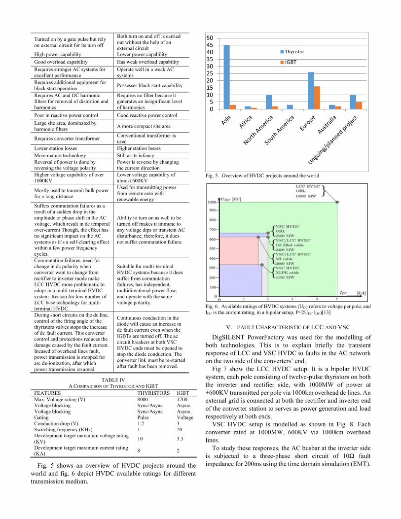
Fig 7 show the LCC HVDC setup. It is a bipolar HVDC
system, each pole consisting of twelve-pulse thyristors on both
the inverter and rectifier side, with 1000MW of power at
±600KV transmitted per pole via 1000km overhead dc lines. An
external grid is connected at both the rectifier and inverter end
of the converter station to serves as power generation and load
respectively at both ends.
VSC HVDC setup is modelled as shown in Fig. 8. Each
converter rated at 1000MW, 600KV via 1000km overhead
lines.
To study these responses, the AC busbar at the inverter side
is subjected to a three-phase short circuit of 10Ω fault
impedance for 200ms using the time domain simulation (EMT).
05
101520253035404550
Thyristor
IGBT

Fig. 7. LCC modelling on DigSILENT
During EMT simulation of both the LCC and VSC model,
fig. 9 shows the graphic subplots for the current waveforms for
LCC HVDC converter scheme. During the fault period, each
converter controller helps in alleviating the effect of the fault
on the converter. Like in the case of LCC, the voltage current
order limiter (VDCOL) in the rectifier controller help to reduce
the dc current, which in turn aid the inverter side to regain fast
from commutation problem.
Fig. 10 shows subplot for VSC HVDC, during three-phase
AC fault on the inverter busbar with little or no impact of the
AC fault on the converter operation. This subplot shows that
VSC HVDC system is immune to AC fault
Fig. 8. VSC HVDC model on DigSILENT
Different fault analysis which has been carried out on both
two technologies on ability to reduce switching surge
overvoltage and power systems restoration after blackout was
discussed in [43]. The use of LCC-HVDC for different
purposes, such as to improved voltage stability, transient and
rotor angle stability was discussed in [44-47], while [48-50]
talks on the new hybrid multi-level converter (alternate-Arm
multi-level) with half-bridge multi-level benefit of low
distortion, losses and full H-bridge converter benefit of DC-side
fault blocking capability. The alternate-Arm multi-level
discussed also have the ability to supply reactive during severe
abnormal operation. This makes it more useful for AC grid
during fault since it can provide reactive power support during
voltage instability
Fig. 9. LCC HVDC converter current during fault.

Fig. 10. Monopolar HVDC model.
VI. FUTURE TREND
VSC HVDC has more technical advantages than the
contemporary LCC HVDC being a new method of HVDC
transmission technology. The future trend in the development
of this technology is likely to lead to a more efficient and
cheaper use of VSC-HVDC. With an ongoing, never ceasing
improvement, research and development on VSC-HVDC
technology, especially in the area of converter design and
topology, such breakthrough will surely contribute to the spread
of VSC-HVDC transmission systems with overhead lines and
accelerate the practical realization of HVDC networks that use
VSC technology.
Future trends also include the manufacturing of better power
cable with higher voltage rating for VSC HVDC transmission.
320XLPE HVDC are still the maximum rating in service. But
with ongoing research on power cables with high power rating
and reduced cost, this will bring about more attraction to VSC-
HVDC technology.
The use of VSC HVDC will continue to increase and apply
to different power system interconnections at higher dc voltage
and power rating.
Fig. 11 shows the earlier stage of VSC based HVDC
converter technology with much power losses. But due to the
development in the converter and control technology, the
present VSC-based HVDC technology is of lower magnitude.
But with the introduction of the multi-level VSC configuration,
this has significantly narrow the gap between LCC and VSC
HVDC schemes.
Fig. 11. LCC and VSC power loss
VII. CONCLUSION
The two dominant HVDC transmitting technology have been
reviewed in this paper. Power electronics being the building
block of any converter station, and the efficiency of these two
technologies depend in the converter topology and the switches
(semiconductors) used in fabricating them. LCC has the highest
power rating and can sustain better during faults. However, for
power control, flexibility and high converter efficiency, the
VSC is superior. Though with this trend, LCC may remain the
more utilized of these technologies in the near future due to its
high reliability and well-established thyristors base technology
that it utilizes. However, with the improvement in VSC
technology and the advantages which it offers over LCC, VSC
is bound to grow, and gain more recognition and market share,
especially with the large-scale renewable energy integration
into traditional AC power grids going on worldwide.

REFERENCES
[1] S. Shah, R. Hassan, and S. Jian, "HVDC transmission system
architectures and control - A review," in Control and Modeling for Power Electronics, 2013 IEEE 14th Workshop on, 2013, pp. 1-8.
[2] N. M. Kirby, "HVDC system solutions," in Transmission and Distribution
Conference and Exposition T&D, IEEE PES, 2012, pp. 1-3. [3] M. H. Okba, M. H. Saied, M. Z. Mostafa, and T. M. Abdel-Moneim,
"High voltage direct current transmission - A review, part I," in
Energytech, 2012 IEEE, 2012, pp. 1-7. [4] R. Radzuan, M. A. A. Raop, M. K. M. Salleh, M. K. Hamzah, and R. A.
Zawawi, "The designs of low power AC-DC converter for power
electronics system applications," in Computer Applications and Industrial Electronics, IEEE Symposium on, 2012, pp. 113-117.
[5] N. Flourentzou, V. G. Agelidis, and G. D. Demetriades, "VSC-Based
HVDC Power Transmission Systems: An Overview," Power Electronics, IEEE Transactions on, vol. 24, pp. 592-602, 2009.
[6] M. P. Bahrman, "HVDC transmission overview," in Transmission and
Distribution Conference and Exposition, 2008; IEEE/PES, 2008, pp. 1-7. [7] H. K. Müller, S. S. Torbaghan, M. Gibescu, M. M. Roggenkamp, and M.
A. M. M. van der Meijden, "The need for a common standard for voltage
levels of HVDC VSC technology," Energy Policy, vol. 63, pp. 244-251, 12// 2013.
[8] L. de Andrade and T. P. de Leao, "A brief history of direct current in
electrical power systems," in HISTory of ELectro-technology CONference (HISTELCON), 2012 Third IEEE, 2012, pp. 1-6.
[9] S. M. Yousuf and M. S. Subramaniyan, "HVDC and Facts in Power
System," International Journal of Science and Research, vol. 2, 2013. [10] B. K. Bose, "Evaluation of modern power semiconductor devices and
future trends of converters," Industry Applications, IEEE Transactions on,
vol. 28, pp. 403-413, 1992. [11] S. Tamai, "High power converter technologies for saving and sustaining
energy," in Power Semiconductor Devices & IC's (ISPSD), 2014 IEEE
26th International Symposium on, 2014, pp. 12-18. [12] E. Kontos, R. T. Pinto, S. Rodrigues, and P. Bauer, "Impact of HVDC
Transmission System Topology on Multiterminal DC Network Faults,"
Power Delivery, IEEE Transactions on, vol. 30, pp. 844-852, 2015.
[13] M. Jafar and M. Molinas, "A transformerless series reactive/harmonic
compensator for line-commutated HVDC for grid integration of offshore
wind power," Industrial Electronics, IEEE Transactions on, vol. 60, pp. 2410-2419, 2013.
[14] T. N. Tran, L. Luo, J. Xu, S. Dong, Z. Zhang, Z. Zhao, et al., "Analysis of
the characteristics of the new converter transformer based on the matrix model," Power Delivery, IEEE Transactions on, vol. 27, pp. 821-830,
2012.
[15] J. Vobecky, "The current status of power semiconductors," Facta Universitatis, Series: Electronics and Energetics, vol. 28, pp. 193-203,
2015.
[16] M. Schenk, J. Przybilla, U. Kellner-Werdehausen, R. Barthelmess, J. Dorn, G. Sachs, et al., "State of the Art of Bipolar Semiconductors for
Very High Power Applications,"; Proceedings of International Exhibition
and Conference for Power Electronics, Intelligent Motion, Renewable Energy and Energy Management;, Europe 2015, pp. 1-8.
[17] J. Vobecky, V. Botan, K. Stiegler, U. Meier, and M. Bellini, "A novel
ultra-low loss four inch thyristor for UHVDC," in Power Semiconductor
Devices & IC's,IEEE 27th International Symposium, 2015, pp. 413-416.
[18] C. Guo, Y. Liu, C. Zhao, X. Wei, and W. Xu, "Power Component Fault Detection Method and Improved Current Order Limiter Control for
[19] H. Jingbo, L. Mingjie, Y. Jun, C. Qing, X. Tao, and Y. Zhao, "Research
on dynamic characteristics and countermeasures of AC-DC hybrid power system with large scale HVDC transmission," in Power System
Technology (POWERCON), 2014 International Conference on, 2014, pp.
799-805. [20] Anonymous, "HVDC Projest List," Prepared for HVDC and Flexible AC
transmission subcommitted of the IEEE Treansmission and Distribution
Committee, March 2012. [21] Y. Jiang-Hafner, H. Duchen, M. Karlsson, L. Ronstrom, and B.
Abrahamsson, "HVDC with voltage source converters-a powerful
standby black start facility," in Transmission and Distribution Conference and Exposition, 2008; D. IEEE/PES, 2008, pp. 1-9.
[22] K. Friedrich, "Modern HVDC PLUS application of VSC in Modular
Multilevel Converter topology," in Industrial Electronics (ISIE), 2010 IEEE International Symposium on, 2010, pp. 3807-3810.
[23] J. Luo, J. Yao, D. Wu, C. Wen, S. Yang, and J. Liu, "Application research
on VSC-HVDC in urban power network," in Power Engineering and
Automation Conference (PEAM), 2011 IEEE, 2011, pp. 115-119.
[24] M. Callavik, P. Lundberg, and O. Hansson, "NORDLINK Pioneering
VSC-HVDC interconnector between Norway and Germany," March 2015.
[25] V. Gelman, "Insulated-Gate Bipolar Transistor Rectifiers: Why They Are
Not Used in Traction Power Substations," Vehicular Technology Magazine, IEEE, vol. 9, pp. 86-93, 2014.
[26] O. Abarrategui, D. Larruskain, I. Zamora, V. Valverde, G. Buigues, and
A. Iturregi, "VSC-based HVDC System Capability to Ride Through Faults," International Conference on Renewable Energy and Power
Quality, 2015.
[27] F. Shewarega and I. Erlich, "Simplified Modeling of VSC-HVDC in Power System Stability Studies," International Federation of Automatic
Control, Cape Town, South Africa, 2014.
[28] C. C. Davidson and D. Trainer, "Innovative concepts for hybrid multi-level converters for HVDC power transmission," in AC and DC Power
Transmission. 9th IET International Conference on, 2010, pp. 1-5.
[29] R. Marquardt, "Modular Multilevel Converter: An universal concept for HVDC-Networks and extended DC-Bus-applications," in Power
Electronics Conference (IPEC), 2010 International, 2010, pp. 502-507.
[30] T. Guangfu, H. Zhiyuan, and P. Hui, "R&D and application of voltage sourced converter based high voltage direct current engineering
technology in China," Journal of Modern Power Systems and Clean
Energy, vol. 2, pp. 1-15, 2014. [31] P. Hurtuk, R. Radvan, and M. Frivaldský, "Investigation of possibilities
to increasing efficiency of full bridge converter designed for low output voltage and high output current applications," in ELEKTRO, 2012, 2012,
pp. 129-132.
[32] R. Marquardt, "Modular Multilevel Converter topologies with DC-Short circuit current limitation," in Power Electronics and ECCE Asia, 2011
IEEE 8th International Conference on, 2011, pp. 1425-1431.
[33] H. Abu-Rub, J. Holtz, J. Rodriguez, and G. Baoming, "Medium-voltage multilevel converters—State of the art, challenges, and requirements in
industrial applications," Industrial Electronics, IEEE Transactions on, vol.
57, pp. 2581-2596, 2010. [34] G. P. Adam, S. J. Finney, A. M. Massoud, and B. W. Williams, "Capacitor
balance issues of the diode-clamped multilevel inverter operated in a
quasi two-state mode," Ieee Transactions on Industrial Electronics, vol. 55, pp. 3088-3099, Aug 2008.
[35] E. Najafi and A. H. M. Yatim, "Design and implementation of a new
multilevel inverter topology," Industrial Electronics, IEEE Transactions on, vol. 59, pp. 4148-4154, 2012.
[36] Y. Zhang, G. P. Adam, T. C. Lim, S. J. Finney, and B. W. Williams,
"Analysis of modular multilevel converter capacitor voltage balancing based on phase voltage redundant states," Iet Power Electronics, vol. 5,
pp. 726-738, 2012.
[37] M. Glinka and R. Marquardt, "A new AC/AC multilevel converter family," Industrial Electronics, IEEE Transactions on, vol. 52, pp. 662-
669, 2005.
[38] A. Lesnicar and R. Marquardt, "An innovative modular multilevel converter topology suitable for a wide power range," in Power Tech
Conference Proceedings, 2003, p. 6.
[39] G. P. Adam, O. Anaya-Lara, G. M. Burt, D. Telford, B. W. Williams, and J. R. McDonald, "Modular multilevel inverter: pulse width modulation
and capacitor balancing technique," IET Power Electronics, vol. 3, pp.
702-715, 2010. [40] G. Adam and I. Davidson, "Robust and Generic Control of Full-Bridge
Modular Multilevel Converter High-Voltage DC Transmission Systems,"
in IEEE Power electronic transaction, 2015. [41] S. Qiang, L. Wenhua, L. Xiaoqian, R. Hong, X. Shukai, and L. Licheng,
"A Steady-State Analysis Method for a Modular Multilevel Converter,"
Power Electronics, IEEE Transactions on, vol. 28, pp. 3702-3713, 2013.M. Glinka and R. Marquardt, "A new AC/AC multilevel converter
family," Industrial Electronics, IEEE Transactions on, vol. 52, pp. 662-
669, 2005. [42] Eskom, HVDC Power Transmission: Basic Principles, Planning and
Converter Technology (Part 1): Crown Publication cc., 2012.
[43] G. P. Adam, S. Finney, K. Bell, and B. Williams, "Transient capability
assessments of HVDC voltage source converters," in Power and Energy
Conference at Illinois (PECI), 2012 IEEE, 2012, pp. 1-8.
[44] K N I Mbangula, O. E. Oni and I E Davidson, "The Impact of HVDC Schemes on Network Transient Rotor Angle Stability," 24th Southern
African Universities Power Engineering Conference, South Africa
January 2016.
[45] O. E. Oni, K N I Mbangula, and I. E Davidson "Voltage Stability
Improvement of a Multi-Machine System using HVDC", in press, IEEE
power system conference, USA, March 2016. [46] K N I Mbangula and I E Davidson, “Detailed power system transient
stability analysis using expert system concepts and stability improvement
of a large multi-machine HVAC network using HVDC technologies,” Proceedings of the 23rd South African Universities Power Engineering
Conference, South Africa, January 2015.
[47] K N I Mbangula, I E Davidson and R Tiako, “Improving Power System Stability of South Africa’s HVAC Network Using Strategic Placement of
HVDC Links”. Proceedings of the CIGRE International Symposium 2015
Development of Electricity Infrastructures for Sub-Saharan Africa, Cape Town, South Africa, October 26-30, 2015.
[48] M. Merlin, T. Green, P. D. Mitcheson, D. Trainer, D. Critchley, and R.
Crookes, "A new hybrid multi-level voltage-source converter with DC fault blocking capability," in AC and DC Power Transmission, 2010.
ACDC. 9th IET International Conference on, 2010, pp. 1-5.
[49] G. P. Adam, K. H. Ahmed, S. J. Finney, K. Bell, and B. W. Williams, "New Breed of Network Fault-Tolerant Voltage-Source-Converter
HVDC Transmission System," IEEE Transactions on Power Systems,
vol. 28, pp. 335-346, Feb 2013. [50] N. Nayak, S. K. Routray, and P. K. Rout, "A robust control strategies to
improve transient stability in VSC-HVDC based interconnected power
systems," in Energy, Automation, and Signal (ICEAS), 2011 International Conference on, 2011, pp. 1-8.
Oluwafemi E. Oni was born in
Nigeria on 17 September 1988. He
received his BSc (Honours) Degree in
Electrical and electronic engineering
from Ekiti State University, Ado
Ekiti, Nigeria, in 2013. He then
proceed to University of KwaZulu-
Natal, Durban, South Africa in 2015
for his MSc degree in electrical
engineering (currently handed in his Thesis for examination).
He was a system and maintenance engineer at Egbin Power
Thermal Plant, Lagos, Nigeria, in 2012 and Omotosho Power
plant, Ore, Nigeria, in 2013/2014. He is currently a Research
Assistance with Department of Electrical Engineering,
University of KwaZulu-Natal. His research includes power
systems stability analysis using High Voltage Direct Current
transmission scheme, integration of renewable energy into the
grid using multi-terminal HVDC scheme, and smart grid
systems using FACTs.
Mr. Oni’s award and honors include MTN foundation
scholarships, ETISALAT scholarship and Ekiti state
scholarship.
Kamati N.I. Mbangula was born in
Namibia on 20 August 1989. He
graduated with a BSc. (Honours)
Degree in Electrical Engineering from
the University of Namibia (UNAM).
He pursued his postgraduate studies in
South Africa at the University of
KwaZulu-Natal (RSA), and carried out
his research at the Eskom Centre of
Excellence in High Voltage Direct Current (HVDC). His work
experience includes working as a Staff Development Fellow at
UNAM, and working as a research assistant and lab technician
at the Eskom centre of excellence in HVDC. He is currently
employed as a lecturer at UNAM. His fields of interests include
power systems stability analysis, and low voltage reticulation
systems design and analysis.
Innocent E. Davidson (M’92–SM’02)
received the BSc (Hons) and MSc degrees in
Electrical Engineering from University of
Ilorin in 1984, and 1987 respectively. PhD in
electrical engineering from the University of
Cape Town, Rondebosch, South Africa1998;
and Postgraduate Diploma in business
management from the University of KwaZulu-Natal, South
Africa, 2004; Associate Certificate, sustainable energy
management, British Columbia Institute of Technology,
Burnaby, Canada, 2011.
From 1994-1995, he was Engineering Inspector, Rainbow
Energy Project at EASIGAS (Pty) Ltd, Cape Town; Senior
Lecturer, University of Pretoria (1999-2001); Senior Lecturer,
Department of Electrical Engineering, University of KwaZulu-
Natal (UKZN), 2001–2006; Part-time Instructor, Graduate
Engineering Program (Power & Energy), UKZN High Voltage
DC Centre (2000-2008) a program co-offered by UKZN and
Eskom - South Africa’s Electric Utility. From 2005–2006, he
was a Visiting Professor, Powertech Labs Inc., Surrey, BC, a
world leading consortium in clean energy technologies,
independent testing services, power system solutions and smart
utility services. From 2007-2011 he was Energy Consultant in
Surrey, BC, implementing energy efficiency (electricity/gas)
measures, British Columbia provincial government’s mandate
on Climate Change. He has been an invited guest writer for the
IEEE Power and Energy technical magazine as an Expert on
Africa: “Energizing Africa’s Emerging Economy”, IEEE
Power and Energy, Vol. 3, No 4, July/August 2005. He was
Associate Professor of Electrical Engineering and Research
Coordinator, University of Namibia (2012-2014); Director,
Eskom Centre of Excellence in HVDC Engineering, UKZN
(2014-2016). Currently, he is a Full Professor of Electrical
Engineering, Durban University of Technology, South Africa.
He is the author/co-author of over 150-refereed journal and
conference papers. His research focus is on Grid integration of
renewable energy using Smart Technologies and Innovation for
Smart Cities.
Prof Davidson is a member, Western Canada Group of
Chartered Engineers (WCGCE); the Institute of Engineering
and Technology (IET Canada) British Columbia Chapter; a
Chartered Engineer, C.Eng. United Kingdom. He is a Fellow of
the South African Institute of Electrical Engineers and a
registered professional engineer, P. Eng. (ECSA), South Africa.