LETTERS - University of Delaware
106
LETTERS Reduction and selective oxo group silylation of the uranyl dication Polly L. Arnold 1 , Dipti Patel 1 , Claire Wilson 2 & Jason B. Love 1 Uranium occurs in the environment predominantly as the uranyl dication [UO 2 ] 21 . Its solubility renders this species a problematic contaminant 1–3 which is, moreover, chemically extraordinarily robust owing to strongly covalent U–O bonds 4 . This feature mani- fests itself in the uranyl dication showing little propensity to par- take in the many oxo group functionalizations and redox reactions typically seen with [CrO 2 ] 21 , [MoO 2 ] 21 and other transition metal analogues 5–9 . As a result, only a few examples of [UO 2 ] 21 with functionalized oxo groups are known. Similarly, it is only very recently that the isolation and characterization of the singly reduced, pentavalent uranyl cation [UO 2 ] 1 has been reported 10–12 . Here we show that placing the uranyl dication within a rigid and well-defined molecular framework while keeping the environment anaerobic allows simultaneous single-electron reduction and selec- tive covalent bond formation at one of the two uranyl oxo groups. The product of this reaction is a pentavalent and monofunctiona- lized [O5U … —OR] 1 cation that can be isolated in the presence of transition metal cations. This finding demonstrates that under appropriate reaction conditions, the uranyl oxo group will readily undergo radical reactions commonly associated only with transition metal oxo groups. We expect that this work might also prove useful in probing the chemistry of the related but highly radioactive plu- tonyl and neptunyl analogues found in nuclear waste. Reactions of the uranyl dication that result in the functionalization or transformation of the U5O groups are rare. Examples include atypical Lewis base behaviour of the uranyl dioxo group towards alkali metals in the solid state 13,14 , and the formation of an unusual O5U5ORB(C 6 F 5 ) 3 adduct involving significant and asymmetric U5O bond lengthening 15 . Photolysis of uranyl phosphine oxide com- plexes in the presence of alcohols results in two-electron reduction and the formation of U(IV) alkoxides, via the highly oxidizing *UO 2 21 excited state; the U(IV) complexes can be hydrolysed to regenerate the uranyl dication cleanly 16 . Usually, the [UO 2 ] 1 cation sponta- neously disproportionates to [UO 2 ] 21 and U(IV) phases in an aqueous environment. We reported recently 17 that the reaction between the mono-uranyl complex, 1 (R 5 H), and transition metal silylamides [M{N(Si(CH 3 ) 3 ) 2 } 2 ] (M 5 Mn, Fe, Co) forms the molecular cation– cation complexes, 2, in which, uniquely, the transition metal bonds to the endo-uranyl oxygen atom (Fig. 1a), that is, the uranyl acts as a Lewis base to the transition metal 18 ; in this case, no electron transfer between the metals was seen. In search of alternative synthetic routes, we have found that the one-pot reaction between 1 (R 5 CH 3 ), FeI 2 , and the silylamide base KN(Si(CH 3 ) 3 ) 2 at –78 uC resulted in the formation of the new cation–cation complex [UO(OSi(CH 3 ) 3 )(thf)Fe 2 I 2 (L)], 3, in 80% isolated yield, Fig. 1a (see Methods and Supplementary Information for synthetic details; thf stands for tetrahydrofuran). The X-ray single-crystal structure of 3 (Fig. 2a, and Supplementary Information) shows that the macrocycle geometry remains wedge- shaped, even though two tetrahedral Fe cations are now incorporated in the lower cavity, and a Si(CH 3 ) 3 group is bound to the exo-uranyl oxygen. The uranyl cation displays a distorted pentagonal bipyramidal geometry with a linear O1–U1–O2 group (172.16(17)u). The U–O bond distances confirm that the uranyl fragment in 3 is in the pen- tavalent oxidation state. The endo-U1–O1 (1.870(4) A ˚ ) bond distance in 3 is elongated compared with those of the hexavalent [UO 2 ] 21 com- plexes 1 (R 5 H: U1–O1 1.790(4) A ˚ ) and 2 (M 5 Mn: U1–O1 1.808(4) A ˚ ), and is similar to experimental 10–12,19 and calculated 20,21 bond distances for pentavalent [UO 2 ] 1 (range 1.811 to 1.934 A ˚ ). The exo-U1–O2 (1.993(4) A ˚ ) bond distance is appreciably longer than U1– O1 (compare with 2 (M 5 Mn): U1–O2 1.768(5) A ˚ ), but is signifi- cantly shorter than in tetravalent U–OSiR 3 complexes 22 and pentaval- ent U–OR compounds 23 (all greater than 2.0 A ˚ ). This implies that the exo-U–O bond still retains some multiple bond character, but less than that of the endo-U–O bond. Both Fe1 and Fe2 are four-coordinate and bound to the macrocycle by single iminopyrrolides, and to each other 1 School of Chemistry, University of Edinburgh, West Mains Road, Edinburgh EH9 3JJ, UK. 2 Rigaku Europe, Chaucer Business Park, Watery Lane, Sevenoaks, Kent TN15 6QY, UK. R O NH NH N N HN HN N N N N N N HN NH N N U O thf R M X O N N N N N N N U O thf M X N R R R Si(CH 3 ) 2 R′ R R R R R R R (ii) H 4 L 1 2 M = Mn, Fe, Co (R = H) (iii) 3 M = Fe, X = I, R′ = CH 3 4 M = Fe, X = I, R′ = C 6 H 5 5 M = Zn, X = I, R′ = CH 3 6 M = Zn, X = Cl, R′ = CH 3 (R = CH 3 ) N N N N M thf N N N N U O O thf (i) R R R R O U O VI O U O VI K K K 2 -1 1 E (CH 3 ) 3 Si O U O V K K – · E Si(CH 3 ) 3 O U O V XM MX 3 Si(CH 3 ) 3 +2 MX 2 –2 KX Solvent H abstraction, coupling + (CH 3 ) 3 Si-E + 2KH E = N(Si(CH 3 ) 3 ) 2 , CH 2 C 6 H 5 , NH(Si(CH 3 ) 3 ) a b Figure 1 | Reductive silylation of the uranyl dication. a, Synthesis of the uranyl complex 1 and cation–cation complexes. b, Proposed mechanism. Reagents and conditions (i) [UO 2 (thf) 2 {N(Si(CH 3 ) 3 ) 2 } 2 ], thf (thf 5 tetrahydrofuran); (ii) [M{N(Si(CH 3 ) 3 ) 2 } 2 ], thf, heat (M 5 Mn, Fe, Co; R 5 H); (iii) either KN(Si(CH 3 ) 2 R9) 2 , MX 2 (M 5 Fe, X 5 I, R95 CH 3 ,C 6 H 5 ; M 5 Zn, X 5 Cl, I, R95 CH 3 ) or KH, FeI 2 , N(Si(CH 3 ) 3 ) 3 or C 6 H 5 CH 2 Si(CH 3 ) 3 ; thf, –80 uC, R 5 CH 3 . Vol 451 | 17 January 2008 | doi:10.1038/nature06467 315 Nature Publishing Group ©2008
-
Upload
khangminh22 -
Category
Documents
-
view
0 -
download
0
Transcript of LETTERS - University of Delaware

LETTERS
Reduction and selective oxo group silylation of theuranyl dicationPolly L. Arnold1, Dipti Patel1, Claire Wilson2 & Jason B. Love1
Uranium occurs in the environment predominantly as the uranyldication [UO2]21. Its solubility renders this species a problematiccontaminant1–3 which is, moreover, chemically extraordinarilyrobust owing to strongly covalent U–O bonds4. This feature mani-fests itself in the uranyl dication showing little propensity to par-take in the many oxo group functionalizations and redox reactionstypically seen with [CrO2]21, [MoO2]21 and other transition metalanalogues5–9. As a result, only a few examples of [UO2]21 withfunctionalized oxo groups are known. Similarly, it is only veryrecently that the isolation and characterization of the singlyreduced, pentavalent uranyl cation [UO2]1 has been reported10–12.Here we show that placing the uranyl dication within a rigid andwell-defined molecular framework while keeping the environmentanaerobic allows simultaneous single-electron reduction and selec-tive covalent bond formation at one of the two uranyl oxo groups.The product of this reaction is a pentavalent and monofunctiona-lized [O5U…—OR]1 cation that can be isolated in the presence oftransition metal cations. This finding demonstrates that underappropriate reaction conditions, the uranyl oxo group will readilyundergo radical reactions commonly associated only with transitionmetal oxo groups. We expect that this work might also prove usefulin probing the chemistry of the related but highly radioactive plu-tonyl and neptunyl analogues found in nuclear waste.
Reactions of the uranyl dication that result in the functionalizationor transformation of the U5O groups are rare. Examples includeatypical Lewis base behaviour of the uranyl dioxo group towardsalkali metals in the solid state13,14, and the formation of an unusualO5U5ORB(C6F5)3 adduct involving significant and asymmetricU5O bond lengthening15. Photolysis of uranyl phosphine oxide com-plexes in the presence of alcohols results in two-electron reduction andthe formation of U(IV) alkoxides, via the highly oxidizing *UO2
21
excited state; the U(IV) complexes can be hydrolysed to regeneratethe uranyl dication cleanly16. Usually, the [UO2]1 cation sponta-neously disproportionates to [UO2]21 and U(IV) phases in an aqueousenvironment. We reported recently17 that the reaction between themono-uranyl complex, 1 (R 5 H), and transition metal silylamides[M{N(Si(CH3)3)2}2] (M 5 Mn, Fe, Co) forms the molecular cation–cation complexes, 2, in which, uniquely, the transition metal bonds tothe endo-uranyl oxygen atom (Fig. 1a), that is, the uranyl acts as a Lewisbase to the transition metal18; in this case, no electron transfer betweenthe metals was seen. In search of alternative synthetic routes, we havefound that the one-pot reaction between 1 (R 5 CH3), FeI2, and thesilylamide base KN(Si(CH3)3)2 at –78 uC resulted in the formation ofthe new cation–cation complex [UO(OSi(CH3)3)(thf)Fe2I2(L)], 3, in80% isolated yield, Fig. 1a (see Methods and SupplementaryInformation for synthetic details; thf stands for tetrahydrofuran).
The X-ray single-crystal structure of 3 (Fig. 2a, and SupplementaryInformation) shows that the macrocycle geometry remains wedge-shaped, even though two tetrahedral Fe cations are now incorporated
in the lower cavity, and a Si(CH3)3 group is bound to the exo-uranyloxygen. The uranyl cation displays a distorted pentagonal bipyramidalgeometry with a linear O1–U1–O2 group (172.16(17)u). The U–Obond distances confirm that the uranyl fragment in 3 is in the pen-tavalent oxidation state. The endo-U1–O1 (1.870(4) A) bond distancein 3 is elongated compared with those of the hexavalent [UO2]21 com-plexes 1 (R 5 H: U1–O1 1.790(4) A) and 2 (M 5 Mn: U1–O11.808(4) A), and is similar to experimental10–12,19 and calculated20,21
bond distances for pentavalent [UO2]1 (range 1.811 to 1.934 A). Theexo-U1–O2 (1.993(4) A) bond distance is appreciably longer than U1–O1 (compare with 2 (M 5 Mn): U1–O2 1.768(5) A), but is signifi-cantly shorter than in tetravalent U–OSiR3 complexes22 and pentaval-ent U–OR compounds23 (all greater than 2.0 A). This implies that theexo-U–O bond still retains some multiple bond character, but less thanthat of the endo-U–O bond. Both Fe1 and Fe2 are four-coordinate andbound to the macrocycle by single iminopyrrolides, and to each other
1School of Chemistry, University of Edinburgh, West Mains Road, Edinburgh EH9 3JJ, UK. 2Rigaku Europe, Chaucer Business Park, Watery Lane, Sevenoaks, Kent TN15 6QY, UK.
R O
NH
NH
N
NHN
HN
N
N
NN
N
N
HN
NHN
N
U
O
thf
R
MX
O
NN
N
N
NN
N
U
O
thf
M
X
N
R
R
R
Si(CH3)2R′
R
R
RR
RR
R
(ii)
H4L 1
2 M = Mn, Fe, Co (R = H)(iii)
3 M = Fe, X = I, R′ = CH34 M = Fe, X = I, R′ = C6H55 M = Zn, X = I, R′ = CH36 M = Zn, X = Cl, R′ = CH3 (R = CH3)
N N
N NM
thf
N N
N NU
O
Othf(i)
R
R
R
R
O
U
O
VI
O
U
O
VI
K KK2-11
E(CH3)3Si
O
U
O
V
K K– ·E
Si(CH3)3
O
U
O
V
XM MX3
Si(CH3)3
+2 MX2
–2 KX
Solvent H abstraction, coupling
+ (CH3)3Si-E+ 2KH
E = N(Si(CH3)3)2, CH2C6H5, NH(Si(CH3)3)
a
b
Figure 1 | Reductive silylation of the uranyl dication. a, Synthesis of theuranyl complex 1 and cation–cation complexes. b, Proposed mechanism.Reagents and conditions (i) [UO2(thf)2{N(Si(CH3)3)2}2], thf(thf 5 tetrahydrofuran); (ii) [M{N(Si(CH3)3)2}2], thf, heat (M 5 Mn, Fe, Co;R 5 H); (iii) either KN(Si(CH3)2R9)2, MX2 (M 5 Fe, X 5 I, R9 5 CH3, C6H5;M 5 Zn, X 5 Cl, I, R9 5 CH3) or KH, FeI2, N(Si(CH3)3)3 orC6H5CH2Si(CH3)3; thf, –80 uC, R 5 CH3.
Vol 451 | 17 January 2008 | doi:10.1038/nature06467
315Nature Publishing Group©2008
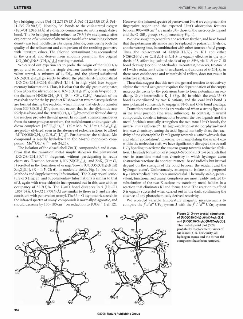
by a bridging iodide (Fe1–I1 2.7317(13) A, Fe2–I1 2.6335(13) A, Fe1–I1–Fe2 70.30(3)u). Notably, Fe1 bonds to the endo-uranyl oxygen(Fe1–O1 1.946(4) A) at a distance commensurate with a single dativebond. The Fe-bridging iodide refined to 79.7(3)% occupancy; afterexploration of a number of alternative models the remaining electrondensity was best modelled as a bridging chloride, considering both thequality of the refinement and comparison of the resulting geometrywith literature values. The chloride contaminant has accumulatedin the crystal, and derives from amounts present in the original[UO2(thf)2{N(Si(CH3)3)2}2] starting material.
We carried out experiments to probe the origin of the Si(CH3)3
group and to confirm the single electron transfer to form penta-valent uranyl. A mixture of 1, FeI2, and the phenyl-substitutedKN(Si(CH3)2C6H5)2 reacts to afford the phenylsilyl-functionalized[UO(OSi(CH3)2C6H5)(thf)Fe2I2(L)] 4, in high yield (see Supple-mentary Information). Thus, it is clear that the silyl group originatesfrom either the silylamide base, KN(Si(CH3)2R9)2, or its by-product,the disilazane HN(Si(CH3)2R9)2 (R9 5 CH3, C6H5). Analysis of themass balance for the by-product KI shows that two molar equivalentsare formed during the reaction, which implies that electron transferfrom KN(Si(CH3)2R9)2 does not occur; that is, the silylamide actssolely as a base, and the HN(Si(CH3)2R9)2 by-product formed duringthe reaction provides the silyl group. In contrast, chemical analoguesfrom the same group as uranium, the molybdenum and tungsten cis-dioxo complexes [MVIO2(L9)2]2– (M 5 Mo, W; L9 5 1,2-S2C6H4),are readily silylated, even in the absence of redox reactions, to afford[MVIO(OSi(C6H5)2(C4H9)t)(L9)2]–. Furthermore, the silylated Mocompound is rapidly hydrolysed to the Mo(IV) mono-oxo com-pound [MoIVO(L9)2]2– (refs 24,25).
The isolation of the closed-shell Zn(II) compounds 5 and 6 con-firms that the transition metal simply stabilizes the pentavalent[UO(OSi(CH3)2R9)]1 fragment, without participating in redoxchemistry. Reaction between 1, KN(Si(CH3)3)2, and ZnX2 (X 5 Cl,I) resulted in the formation of orange/brown [UO(OSi(CH3)3)(thf)Zn2X2(L)], (X 5 I; 5, Cl; 6), in moderate yields, Fig. 1a (see onlineMethods and Supplementary Information). The X-ray crystal struc-ture of 5 (Fig. 2b, and Supplementary Information) is similar to thatof 3, again with trace chloride incorporated but in this case with anoccupancy of 52.7(3)%. The U…—O bond distances in 5 (U1–O11.867(3) A, U1–O2 1.975(3) A) are similar to those in 3, and are alsoconsistent with pentavalent uranyl. The U 5 O asymmetric stretch inthe infrared spectra of uranyl compounds is normally diagnostic, andshould decrease by 100–180 cm–1 on reduction to [UO2]1 (ref. 12).
However, the infrared spectra of pentavalent 3 to 6 are complex in thefingerprint region and the expected U5O absorption featuresbetween 800–700 cm–1 are masked by those of the macrocyclic ligandand the O–SiR3 groups (Supplementary Fig. 1).
We have sought to generalize the reaction further, and have foundthat the potassium silylamide may be replaced by potassium hydride,another strong base, in combination with other sources of silyl group.Thus, the replacement of KN(Si(CH3)3)2 by KH and eitherN(Si(CH3)3)3 or C6H5CH2Si(CH3)3 is equally effective in the syn-thesis of 3, affording isolated yields of up to 85%, via N–Si or C–Sibond cleavage (see online Methods). In contrast, however, treatmentof 1 with a reductant (rather than a base), and a source of Si(CH3)3, inthese cases cobaltocene and trimethylsilyl triflate, does not result inreductive silylation.
These data suggest that this new and general reaction to reductivelysilylate the uranyl oxo group requires the deprotonation of the emptymacrocyclic cavity by the potassium base to form potentially an oxi-dizing, U(VI) intermediate K2-1 (Fig. 1b) in which the endo-U5Obond is coordinated by two K cations, and the exo-U5O bond isnow polarized sufficiently to engage in N–Si and C–Si bond cleavage.
Transition metal oxo bonds are weakened when a strong ligand isin the trans position (the trans influence). In contrast, in uranylcompounds, covalent interactions between the oxo ligands and themetal f orbitals mutually strengthen the two trans U5O bonds, theinverse trans influence26. In high-oxidation-state porphyrin-basediron oxo chemistry, tuning the axial ligand markedly alters the reac-tivity of the electrophilic Fe5O group towards alkane hydroxylationand olefin epoxidation6. Likewise, by manipulating the uranyl oxowithin the molecular cleft, we have significantly disrupted the overallUO2 bonding to activate the exo oxo group towards reductive silyla-tion. The ready formation of strong O–Si bonds in 3 to 6 parallels thatseen in transition metal oxo chemistry in which hydrogen atomabstraction reactions do not require metal-based radicals, but insteaddepend on the strength of the bond between the oxidant and thehydrogen atom9. Unfortunately, attempts to isolate the proposedK2-1 intermediate have been unsuccessful. Thermally stable, penta-valent, functionalized uranyl complexes are most readily isolated bysubstitution of the two K cations by transition metal halides in areaction that eliminates KI and forms 3 to 6. The reaction to afford3 is equally successful when carried out in the dark, confirming theabsence of any photochemically derived reactivity.
We recorded variable temperature magnetic measurements tocompare the f 1d 6d 6 UFe2 system 3 with the f 1d10d10 UZn2 system
Si1
N3 N2
N4
N1
N5 N8
N7Zn2
Zn1
N6
Si1
O2 O2
O3
O3U1
U1
O1O1
Fe1
Fe2I1
I1
I2
I2
Cl1 Cl1
a bFigure 2 | X-ray crystal structuresof [UO(OSi(CH3)3)(thf)Fe2I2(L)]and [UO(OSi(CH3)3)(thf)Zn2I2(L)].Thermal ellipsoid plot (50%probability displacement) views of(a) 3 and (b) 5. For clarity, allhydrogen atoms and the minor thfcomponent have been removed.
LETTERS NATURE | Vol 451 | 17 January 2008
316Nature Publishing Group©2008

5. The room-temperature moment of 7.74 BM for 3 (BM 5 Bohrmagnetons), and the Curie–Weiss behaviour (2 to 300 K) suggeststhe presence of two, high-spin, Fe(II) centres and one f 1 U(V) centre(Supplementary Fig. 2) that are magnetically independent; the ther-mal variation of the product of molar magnetic susceptibility andtemperature, xMT, is dominated by the magnetic contribution fromthe Fe ions. In contrast, the magnetic behaviour for 5 (2 to 300 K)should only contain contributions from the U centre27; it displays twodistinct regions (Supplementary Fig. 2) associated with the depopu-lation of excited crystal field states of the U(V) f 1 cation and is similarto that observed for the few known organometallic pentavalenturanium complexes28,29. The moment at low temperature rises from0.41 to 1.11 BM and increases to 2.38 BM at high temperature. Incontrast, the moment of a U(IV) (f 2) system would be expected to behigher at room temperature (3.58 BM), and the reciprocal suscepti-bility would become temperature-independent below about 40 K. Apreliminary electron paramagnetic resonance study of 5 in frozenmethyl-thf at 5 K (Supplementary Fig. 3) displays a strong, broadresonance at g 5 2.2 that supports the presence of a single f electron.
We have shown that the use of a macrocyclic architecture to placethe uranyl ion in a rigid and asymmetric coordination environmentallows the generation of a reactive and highly oxidizing uranyl complexwhich can selectively cleave N–Si and C–Si bonds to form singly, cova-lently functionalized pentavalent uranyl complexes. These reactive Uoxo compounds may also provide functional chemical models for thehighly radioactive f1 plutonium and neptunium dioxo cations30.
METHODS SUMMARYWorking under a dry, oxygen-free dinitrogen atmosphere, with reagents dissolved
or suspended in aprotic solvents, and combined or isolated using cannula and
glove box techniques, we first treated the free macrocycle H4L with a bis(amido)
uranyl precursor, to form the hinged macrocyclic complex [UO2(thf)(H2L)] in
which one N4-donor compartment remains vacant. Treatment of this complex
with two equivalents of potassium base and a suitable silylated reagent (or a basecontaining an ancillary silyl group) afforded a soluble complex in which the
uranium was shown to be both singly reduced and silylated at the exo oxo group,
as the UO(OSiR3) dication. This asymmetric pentavalent uranyl complex is then
readily isolated, purified, and characterized by a final salt elimination reaction to
produce two equivalents of potassium halide, and to place two transition metal
cations (as Fe or Zn chloride or iodide salts, MX) into the remaining cavity of the
macrocycle, affording [UO(OSiR3)(thf)(L)(MX)2]. We characterized all com-
pounds by elemental analysis, Fourier transform infrared spectroscopy, and either
variable-temperature magnetic moment measurements or nuclear magnetic
resonance (NMR) spectroscopy (paramagnetic and diamagnetic compounds
respectively). Additionally, we determined the solid-state structures of two of
the silylated complexes by single-crystal X-ray diffraction studies.
Full Methods and any associated references are available in the online version ofthe paper at www.nature.com/nature.
Received 8 June; accepted 9 November 2007.
1. Amme, M., Wiss, T., Thiele, H., Boulet, P. & Lang, H. Uranium secondary phaseformation during anoxic hydrothermal leaching processes of UO2 nuclear fuel.J. Nucl. Mater. 341, 209–223 (2005).
2. Lovley, D. R., Phillips, E. J. P., Gorby, Y. A. & Landa, E. R. Microbial reduction ofuranium. Nature 350, 413–416 (1991).
3. Suzuki, Y., Kelly, S. D., Kemner, K. M. & Banfield, J. F. Radionuclide contamination:Nanometre-size products of uranium bioreduction. Nature 419, 134 (2002).
4. Denning, R. G. Electronic structure and bonding in actinyl ions and their analogs.J. Phys. Chem. A 111, 4125–4143 (2007).
5. Kuhn, F. E., Santos, A. M. & Abrantes, M. Mononuclear organomolybdenum(VI)dioxo complexes: Synthesis, reactivity, and catalytic applications. Chem. Rev. 106,2455–2475 (2006).
6. Nam, W. High-valent iron(IV)-oxo complexes of heme and non-heme ligands inoxygenation reactions. Acc. Chem. Res. 40, 522–531 (2007).
7. Jin, N., Ibrahim, M., Spiro, T. G. & Groves, J. T. Trans-dioxo manganese(V)porphyrins. J. Am. Chem. Soc. 129, 12416–12417 (2007).
8. Limberg, C. The role of radicals in metal-assisted oxygenation reactions. Angew.Chem. Int. Edn Engl. 42, 5932–5954 (2003).
9. Mayer, J. M. Hydrogen atom abstraction by metal–oxo complexes: Understandingthe analogy with organic radical reactions. Acc. Chem. Res. 31, 441–450 (1998).
10. Burdet, F., Pecaut, J. & Mazzanti, M. Isolation of a tetrameric cation-cationcomplex of pentavalent uranyl. J. Am. Chem. Soc. 128, 16512–16513 (2006).
11. Natrajan, L., Burdet, F., Pecaut, J. & Mazzanti, M. Synthesis and structure of a stablepentavalent-uranyl coordination polymer. J. Am. Chem. Soc. 128, 7152–7153 (2006).
12. Berthet, J. C., Siffredi, G., Thuery, P. & Ephritikhine, M. Easy access to stablepentavalent uranyl complexes. Chem. Commun.3184–3186 (2006).
13. Burns, C. J. et al. A trigonal bipyramidal uranyl amido complex: Synthesis andstructural characterization of Na(thf)2UO2{N(SiMe3)2}3. Inorg. Chem. 39,5464–5468 (2000).
14. Sarsfield, M. J., Helliwell, M. & Raftery, J. Distorted equatorial coordinationenvironments and weakening of U5O bonds in uranyl complexes containing NCNand NPN ligands. Inorg. Chem. 43, 3170–3179 (2004).
15. Sarsfield, M. J. & Helliwell, M. Extending the chemistry of the uranyl ion: Lewisacid coordination to a U5O oxygen. J. Am. Chem. Soc. 126, 1036–1037 (2004).
16. Kannan, S., Vaughn, A. E., Weis, E. M., Barnes, C. L. & Duval, P. B. Anhydrousphotochemical uranyl(VI) reduction: Unprecedented retention of equatorialcoordination accompanying reversible axial oxo/alkoxide exchange. J. Am. Chem.Soc. 128, 14024–14025 (2006).
17. Arnold, P. L., Blake, A. J., Wilson, C. & Love, J. B. Uranyl complexation by a Schiff-base, polypyrrolic macrocycle. Inorg. Chem. 43, 8206–8208 (2004).
18. Arnold, P. L., Patel, D., Blake, A. J., Wilson, C. & Love, J. B. Selective oxofunctionalization of the uranyl ion with 3d metal cations. J. Am. Chem. Soc. 128,9610–9611 (2006).
19. Docrat, T. I. et al. X-ray absorption spectroscopy of tricarbonatodioxouranate(V),[UO2(CO3)3]5–, in aqueous solution. Inorg. Chem. 38, 1879–1882 (1999).
20. Hay, P. J., Martin, R. L. & Schreckenbach, G. Theoretical studies of the propertiesand solution chemistry of AnO2
21 and AnO21 aquo complexes for An 5 U, Np,and Pu. J. Phys. Chem. A 104, 6259–6270 (2000).
21. Wander, M. C. F., Kerisit, S., Rosso, K. M. & Schoonen, M. A. A. Kinetics oftriscarbonato uranyl reduction by aqueous ferrous iron: A theoretical study.J. Phys. Chem. A 110, 9691–9701 (2006).
22. Zi, G. et al. Preparation and reactions of base-free bis(1,2,4-tri-tert-butylcyclopentadienyl)uranium oxide, Cp’2UO. Organometallics 24, 4251–4264(2005).
23. Cotton, F. A., Marler, D. O. & Schwotzer, W. Dinuclear uranium alkoxides:preparation and structures of KU2(OCMe3)9, U2(OCMe3)9, and U2(OCHMe2)10,containing [U(IV),U(IV)], [U(IV),U(V)], and [U(V),U(V)], respectively. Inorg. Chem.23, 4211–4215 (1984).
24. Donahue, J. P., Goldsmith, C. R., Nadiminti, U. & Holm, R. H. Synthesis, structures,and reactivity of bis(dithiolene)molybdenum(IV,VI) complexes related to theactive sites of molybdoenzymes. J. Am. Chem. Soc. 120, 12869–12881 (1998).
25. Lorber, C., Donahue, J. P., Goddard, C. A., Nordlander, E. & Holm, R. H. Synthesis,structures, and oxo transfer reactivity of bis(dithiolene)tungsten(IV, VI)complexes related to the active sites of tungstoenzymes. J. Am. Chem. Soc. 120,8102–8112 (1998).
26. O’Grady, E. & Kaltsoyannis, N. On the inverse trans influence. Density functionalstudies of [MOX5]n– (M 5 Pa, n5 2; M 5 U, n5 1; M 5 Np, n5 0; X 5 F, Cl or Br).J. Chem. Soc., Dalton Trans.1233–1239 (2002).
27. Costes, J. P., Dahan, F., Dupuis, A. & Laurent, J. P. Nature of the magneticinteraction in the (Cu21, Ln31) pairs: An empirical approach based on thecomparison between homologous (Cu21, Ln31) and (NiLS
21, Ln31) complexes.Chem. Eur. J. 4, 1616–1620 (1998).
28. Castro-Rodriguez, I., Olsen, K., Gantzel, P. & Meyer, K. Uranium tris-aryloxidederivatives supported by triazacyclononane: engendering U(III) center with asingle pocket for reactivity. J. Am. Chem. Soc. 125, 4565–4571 (2003).
29. Rosen, R. K., Andersen, R. A. & Edelstein, N. M. A bimetallic molecule withantiferromagnetic coupling between the uranium centres. J. Am. Chem. Soc. 112,4588–4590 (1990).
30. Reilly, S. D. & Neu, M. P. Pu(VI) hydrolysis: further evidence for a dimeric plutonylhydroxide and contrasts with U(VI) chemistry. Inorg. Chem. 45, 1839–1846 (2006).
Supplementary Information is linked to the online version of the paper atwww.nature.com/nature.
Acknowledgements We thank the EPSRC (UK), the Royal Society, and theUniversities of Edinburgh and Nottingham for support, J. Sanchez-Benitez andP. Anderson of Edinburgh University for help with magnetic susceptibilitymeasurements and chloride analysis respectively, R. Edge and the EPSRC EPRservice at the University of Manchester, and D. Leigh for his advice.
Author Contributions D.P. synthesized and characterized the compounds, andsolved the crystal structure data. C.W. mounted the crystals, collected thesingle-crystal X-ray crystallographic data, modelled the disorder components inthe structures, and checked the final structure solutions. P.L.A. and J.B.L. generatedand managed the project, helped characterize the complexes, analysed the dataand wrote the manuscript.
Author Information X-ray crystallographic coordinates for 3 and 5 have beendeposited at the Cambridge Crystallographic Database, numbers 649987 and649988 respectively. Reprints and permissions information is available atwww.nature.com/reprints. Correspondence and requests for materials should beaddressed to P.L.A. ([email protected]) or J.B.L. ([email protected]).
NATURE | Vol 451 | 17 January 2008 LETTERS
317Nature Publishing Group©2008

METHODS[UO2(thf)(H2L)].thf, 1. To a stirred solution of [UO2(thf)2{N(Si(CH3)3)2}2]
(2.94 g, 4.0 mmol) in thf (20 ml, –78 uC) we added slowly a solution of H4L
(2.64 g, 4.0 mmol) in thf (20 ml, –78 uC). The resulting solution was allowed
to warm to room temperature over 16 h, after which the volatiles were removed
under vacuum and the residual solids redissolved in thf (15 ml). Addition of
hexane (20 ml) afforded a precipitate that was isolated by filtration, washed with
hexane (2 3 10 ml), and dried under vacuum to yield 3.76 g, 88% of 1 as a brown
solid. Analysis. Found: C, 56.00; H, 5.55; N, 10.51. C50H58N8O4U requires: C,
55.96; H, 5.46; N, 10.44%; infrared (Nujol, cm–1): n 908(s) (UO2 asymmetricstretch).
[UO(OSi(CH3)3)(thf)Fe2I2(L)], 3. To a stirred mixture of 1 (0.27 g, 0.25 mmol)
and KN(Si(CH3)3)2 (0.10 g, 0.53 mmol) we added thf (20 ml) at –78 uC, and
added the resulting solution dropwise to stirred slurry of FeI2 (0.15 g, 0.50 mmol,
beads) in thf (10 ml, –78 uC). The resulting mixture was allowed to warm to
room temperature over 42 h, after which we removed the solid KI by filtration
and washed it with thf (2 3 5 ml). The combined filtrates were evaporated to
dryness, the residual solids extracted into hot toluene (20 ml), filtered and dried
under vacuum to yield 0.29 g, 80% of 3 as a dark red solid. Analysis. Found: C,
40.93; H, 4.07; N, 7.64. C49H57N8O3Fe2I2SiU requires: C, 40.93; H, 4.00; N,
7.79%. Magnetic moment (superconducting quantum interference device
(SQUID) 300 K): meff 7.74 BM; electron impact mass spectrometry: m/z 343
(37.7%, [UO(OSi(CH3)3)]1).
Alternative syntheses of 3. A. To a stirred mixture of 1 (0.10 g, 0.09 mmol) and
KH (9 mg, 0.23 mmol) we added thf (20 ml) at –78 uC, and allowed the mixture
to warm to room temperature over 45 min. We filtered the resulting mixture
dropwise by cannula into a stirred slurry of FeI2 (56 mg, 0.18 mmol) and
N(Si(CH3)3)3 (21 mg, 0.09 mmol) in thf (10 ml, –78 uC). Room-temperaturework up as above yielded 0.09 g, 69% of 3 as a dark red solid. B. To a stirred
mixture of 1 (0.10 g, 0.09 mmol) and KH (9 mg, 0.23 mmol) we added thf
(20 ml) at –78 uC and allowed the mixture to warm to room temperature over
45 min. We filtered the resulting mixture dropwise on to a stirred slurry of FeI2
(56 mg, 0.18 mmol) and C6H5CH2Si(CH3)3 (15 mg, 0.09 mmol) in thf (15 ml, –
78 uC). Room-temperature work up as above yielded 0.11 g, 85% of 3 as a dark
red solid.
[UO(OSi(CH3)3)(thf)Zn2I2(L)], 5. To a stirred mixture of 1 (0.34 g, 0.32 mmol)
and KN(Si(CH3)3)2 (0.13 g, 0.63 mmol) we added thf (20 ml) at –78 uC. After
15 min, we added the mixture dropwise to a stirred slurry of ZnI2 (0.20 g,
0.63 mmol) in toluene (20 ml, –78 uC). Room-temperature work up as above
yielded 0.21 g, 46% of 5 as a pale brown solid. Analysis. Found: C, 40.30; H, 3.91;
7.70. C49H57N8I2O3SiZn2U requires: C, 40.40; H, 3.95; N, 7.69%. Magnetic
moment (SQUID, 300 K): meff 2.38BM. Electron paramagnetic resonance spec-
troscopy (frozen glass methyl-thf solution, 5 K, 0–1.6 T, 2 mW, 9.610794 GHz):
g 5 2.2.
[UO(OSi(CH3)3)(thf)Zn2Cl2(L)], 6. To a stirred mixture of 1 (0.10 g,
0.09 mmol) and KN(Si(CH3)3)2 (0.036 g, 0.18 mmol) we added thf (15 ml) at
–78 uC. After 15 min, we added the mixture dropwise to a stirred slurry of ZnCl2(0.025 g, 0.18 mmol) in toluene (20 ml, –78 uC). Room-temperature work up as
above yielded 0.06 g, 56% of 6 as a pale brown solid. Analysis. Found: C, 46.30; H,
4.50; 8.72. C49H57N8Cl2O3SiZn2U requires: C, 46.19; H, 4.52; N, 8.80%.
Magnetic moment (SQUID, 300 K): meff 3.01BM.
Reaction between 1 and KN(Si(CH3)3)2: attempted synthesis of[UO(OSi(CH3)3)(thf)K2L]. To a stirred mixture of 1 (0.10 g, 0.10 mmol) and
KN(Si(CH3)3)2 (0.041 g, 0.21 mmol) we added thf (20 ml) at –78 uC. We allowed
the resulting red solution to warm to room temperature over 2 h, after which we
removed the volatiles from the now dark brown solution. We washed the solid
residues with toluene (1 3 10 ml) and dried them to form a dark brown solid,
which was redissolved in a minimal amount of thf (1–2 ml) and cooled (–30 uC) for
16 h. The resulting dark precipitate was isolated and was found to be no longer
soluble in thf. Elemental analysis indicated that the compound had decomposed.
Reaction between 1 and cobaltocene and trimethylsilyl triflate: attemptedsynthesis of [UO(OSi(CH3)3)(thf)(H2L)] and cobaltocenium triflate. To a
stirred mixture of 1 (0.10 g, 0.09 mmol) and Co(C5H5)2 (0.017 g, 0.09 mmol)
we added thf (20 ml) at –78 uC, and added (CH3)3SiOTf (0.020 g, 0.09 mmol)
into the mixture by syringe. We allowed the mixture to warm to room temper-
ature over 16 h. We removed the volatiles from the now dark red solution to
afford a viscous red oil. Elemental analysis indicated that the compounds had
decomposed.
Reaction between 1 and excess KH for the identification of by-products. We
added cold thf (0.5 ml, –35 uC) and a few drops of C6D6 to cold (–35 uC) 1(10 mg, 0.009 mmol) and KH (2 mg, 0.05 mmol) in a Teflon-tapped NMR tube.
Upon warming, we observed gas evolution, which we identified as dissolved
dihydrogen at d 5 4.4 p.p.m. in the 1H NMR spectrum.
Reaction between 1 and 2 KN(Si(CH3)3)2 for the identification of by-pro-ducts. We added cold thf (0.5 ml, –35 uC) and a few drops of C6D6 to cold
(–35 uC) 1 (5 mg, 0.005 mmol), and KN(Si(CH3)3)2 (1.8 mg, 0.009 mmol) in
a Teflon-tapped NMR tube. By integration, one molar equivalent of
HN(Si(CH3)3)2 was observed in the 1H NMR spectrum.
Crystallography. Dark red single crystals of 3 (needle-shaped) and 5 (parallel-
epiped) were grown from saturated C6D6 solutions at room temperature.
doi:10.1038/nature06467
Nature Publishing Group©2008

Reduction and Selective Oxo Group Silylation of the Uranyl Dication
A review of the inorganic chemistry behind the original work completed by Polly L. Arnold, Dipti Patel, Claire Wilson, & Jason B. Love
Samantha J. Brannick*
Department of Biochemistry and Chemistry, University of Delaware, Newark, Delaware 19713
RECEIVED DATE: November 23, 2010; E-mail: [email protected]
Uranium is a radioactive actinide metal that is typically
found at low concentrations in soil and rock. There is a
greater amount of uranium present on earth than some
other metals; in fact uranium is nearly forty times more
abundant than silver.1 Uranium occurs in the environment
predominantly as the uranyl dication [UO2]2+
.2 It is
characteristically unreactive due to the stability of its
uranium-oxygen double bond.3 Recently, however, Arnold
et al. has discovered a method of reducing and selectively
functionalizing the uranyl dication to a product that is a
pentavalent and monofunctionalized cation. The research
show the pentavalent uranyl cation can be isolated and
characterized when first row cations are simultaneously
present. The chemistry involved in this reduction may
provide further insight into other reactions involving various
highly radioactive elements found in nuclear waste, such as
plutonyl.2
Uranium contamination is a large environmental concern. It can
be found deposited throughout both surface and ground water.
This contamination is caused by uranium mining, irrigation of
agricultural lands, and disposal of nuclear waste. Uranium is most
commonly found in its oxidized form UVI, [UO2]2+. Reducing the
soluble uranyl dication to an insoluble UIV form, [UO2], is an
important mechanism for the immobilization of uranium in
aquatic sediments and for the formation of some uranium ores.3
This would allow for an easier way to harvest uranium which
would be beneficial due to its ability to be a radioactive energy
source. The reduction of the uranyl dication sets precedent for
chemistry that may characterize other radioactive actinide metals
that have multiple redox states and are insoluble in their reduced
form.3
The fact that the uranyl dication is very soluble is caused by the
linear and strongly covalent U=O bonds. This strong covalent
bond makes functionalization of the oxo groups difficult and
therefore the pentavalent uranyl complex uncommon. Essentially,
Arnold et al. attempted to do what nature does, only better. This
seems to be an ongoing theme in most inorganic and organic
chemistry. Though uranium reduction is most often thought of as
a non-biological process, it has been shown by Lovley et al. that
its precedence lies within dissimilatory Fe(III)-reducing
microorganisms, or organisms that can produce an inorganic
element from an organic element.3
The important feature of these microorganisms is that they can
obtain energy for growth by electron transport to UVI.3
Microorganisms, such as geobacter metallireducens strain GS-15,
thrive in anaerobic environments by performing, essentially, a
redox reaction with Fe(III) acting as the oxidizing agent and
acetate as the reducing agent (Equation 1).
CH3COO- + 8Fe(III) + 4H2O 8Fe(II) + 2HCO3- + 9H+ (1)
Lovley et al. reported thermodynamic calculations that show,
per electron transferred, acetate oxidation coupled to UVI
reduction has the potential to yield more than twice the energy
that is available from FeIII reduction.3 If more energy is produced,
a more efficient process for removal of uranium contamination,
and possibly other nuclear waste, can be achieved. Lovley et al.
also show that when GS-15 is placed into an anaerobic
environment with acetate as the only reducing agent and UVI as
the only possible reductant, UVI was reduced to UIV over time as
shown in Figure 1a.3
Figure 1. (a) Relationship between GS-15 placed in an anaerobic
environment with acetate as the only available reducing agent and U(VI)
as the only possible reductant. (b) Addition of [2-14C]-acetate into the
media caused the production of 14CO2 to be directly proportional to the
reduction of UVI. Both figures support the idea that the reduction of UVI to
UIV and the oxidation of acetate to carbon dioxide provided energy to
probe the growth of GS-15.
One of the key features of this redox reaction is the pentavalent
uranyl cation, UO2+. This intermediate, however, is very unstable
due to its strong covalent U=O bonds. Although microorganisms
are naturally able to readily reduce UVI to UIV, it has been quite a
struggle for chemists to do the same.2 If functionalization of the
uranyl oxygens is achieved, the covalent bond between the
uranium and its oxygens will weaken and therefore make the
reduction of [UO2]2+ more feasible.
Functionalization of the oxo groups on the uranyl dication will
create a pentavalent uranyl complex. If the formation of a stable
UO2+ complex is found, this will afford scientists the opportunity
to better understand its structure and other chemical properties

and therefore possibly provide a better understanding of the
natural reduction of uranium by microorganisms, such as GS-15.
Unlike other similar elements that form stable and isolatable
AnO+ species, the UO2+ is very unstable because it readily
disproportionates, or acts as both a reductant and an oxidant, into
U(IV) and [UO2]2+.4 This characteristic causes the formation of
pentavalent uranyl species to be limited. In order to probe
formation of a stable pentavalent uranyl complex, the utilization
of cation-cation interactions must be employed.5,6 In order to
comprehend the impact cation-cation interactions have on the
stability of a pentavalent uranyl complex, the uranyl dication must
first be understood.
As previously stated, uranium is found in its most common,
soluble form [UO2]2+. This uranyl dication contains a uranium
atom double-bonded to two oxygen atoms with linear geometry
(O=U=O). Because this portion of the molecule is linear, ligands
can only attach perpendicular to the O=U=O. However, it is clear
from the work of Arnold et al. and others that there is a way to
allow the oxygen atoms to react.2 While in an anaerobic media, if
the [UO2]2+ is placed in a rigid asymmetric molecular framework,
it will allow for both selective covalent bond formation at one of
the oxo groups as well as single-electron transfer.2 Boncella
suggests that the uranyl complexes adapt a Pac-Man-like structure
in which the endo-uranyl oxygen atom interacts with the two
potassium atoms ultimately perturbing the U=O bond and
therefore allowing the exo-uranyl oxygen to be selectively
functionalized.7 This is demonstrated by Arnold and Love’s recent
finding that binding the linear O=U=O molecule within a Schiff
base pyrrole macrocycle with a hinged geometry.8 Ultimately, this
structural adaptation produces an isolable pentavalent and
monofunctionalized [O=U-OR]+ cation.
Burdet et al. believe that the production of these pentavalent
and monofunctionalized uranyl species will favor metal cation
interactions and therefore lead to the formation of cation-cation
complexes. This phenomenon is due to the fact that the U=O
oxygens have a lower Lewis basicity, making them more prone to
accept electrons. The endo-oxygen is able to coordinate to the
cations, leaving the exo-oxygen open for functionalization.
The preparation of stable pentavalent uranium compounds
[UO2]+ is a tedious process that involves careful consideration of
both ligands and the media.4 Burdet et al. reported the synthesis
and characterization of the first isolated stable pentavalent uranyl
iodide, {[UO2Py5][KI2Py2]}n, (1).4 This crystalline polymer is a
result of cation-cation interactions between pentavalent uranyl
complexes, [UO2]+, and potassium. When 1 reacts with two
equivalents of Kdbm in pyridine to produce blue crystals of
{[UO2(dbm)2]4[K6Py10]}·I2·Py2 (2). This complex contains four
pentavalent uranyl complexes presented in Figure 2.4
Figure 2. Top and side ORTEP representations of
{[UO2(dbm)2]4[K6Py10]}·I2·Py2 (2).
Another noteworthy synthesis of a pentavalent uranyl complex
was that of Natrajan et al. who have recently formed the first
pentavalent uranium silicate.9 Their synthesis of 1 is the first
known reproducible synthetic route to a UO2+ coordination
complex (Figure 3).9 They also report the first structurally
characterized dioxouranium(V). Their product was synthesized
via the reduction of UI3·thf by water and a pyridine solution
(PyNO). This reaction is done through a two-electron oxidation of
UIII. The reaction of [UO2Pyx]I and 2PyHI in the presence of
potassium iodide led to the reproducible isolation of 1, suggesting
the pyridine stabilizes the UO2+ species against
disproportionation.9
Figure 3. ORTEP representations, both top and bottom, of the uranyl
complex {[UO2Py5][KI2Py2]}n (1).
Both Burdet et al. and Natrajan et al. provide some precedence
for the reduction and selective oxo silylation of the uranyl
dication performed by Arnold et al. The creation of 1 allows
chemists to comprehend the electronic structure of the pentavalent
uranyl species.9 Uranium, in this complex, is a seven-coordinate
species affording pentagonal bipyramidal coordination geometry.
It is coordinated by two trans oxo ligands and five coplanar
pyridine nitrogen as shown in Figure 3.9 It can be noted that the
large negative charge from the U=O oxygens allows the molecule
to form the cation-cation complexes and the fact that the iodide
ion is not coordinated to the metal ion in 1 allows easier
dissociation of the U-I bond due to the higher electron density of
UV.9
Though [UO2]+ is usually prone to disproportionation, Arnold
et al. has been able to form a cation-cation complex through the
reaction of a mono-uranyl complex (3), FeI2, and KN(Si(CH3)3)2
to afford a phenylsilyl-functionalized
[UO(OSi(CH3)3)(thf)FeI2(L)], (4) as seen in Figure 4.2 In this
reaction, the silylation occurs at the exo-uranyl oxygen atom via
single electron transfer. It was concluded that the silyl group
comes from the silylated base or from the by-product, disilazane.2
Like previously stated, bond distance between the uranium and
oxygen atoms provide verification that a pentavalent complex was
formed.
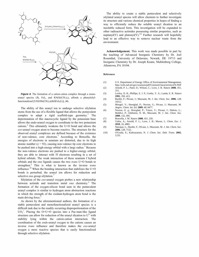
Figure 4. The formation of a cation-cation complex through a mono-
uranyl species (3), FeI2, and KN(Si(CH3)3)2 affords a phenylsilyl-
functionalized [UO(OSi(CH3)3)(thf)FeI2(L)], (4).
The ability of this uranyl ion to undergo selective silylation
stems from the use of a flexible ligand that allows the pentavalent
complex to adapt a rigid scaffold-type geometry.7 The
deprotonation of this macrocyclic ligand by the potassium base
allows the endo-uranyl oxygen to coordinate to the two potassium
cations.2 This ultimately weakens the U=O bond and allows the
exo-uranyl oxygen atom to become reactive. The structure for the
observed uranyl complexes are defined because of the existence
of non-valence, core electrons.7 According to Boncella, the
energies of electrons in uranium are distorted, due to its high
atomic number (z = 92), causing non-valence 6p core electrons to
be pushed into a high-energy orbital with a large radius.7 Because
the non-valence electrons are pushed to a higher-energy orbital,
they are able to interact with 5f electrons resulting in a set of
hybrid orbitals. The weak interaction of these uranium f hybrid
orbitals and the oxo ligands causes the two trans U=O bonds to
strengthen.2 This is what is known as the inverse trans
influence.10 When the bonding interaction that stabilizes the U=O
bonds is perturbed, the uranyl ion allows for reduction and
selective oxo group silylation.7
Silylation of the exo-uranyl oxygen probes a new relationship
between actinide and transition metal oxo chemistry.2 The
formation of the oxygen-silicon bond seen in the pentavalent
uranyl complex is similar to hydrogen atom abstraction reactions
in which the strength of the oxidant-hydrogen atom bond is the
main driving force.2
As shown by the aforementioned authors, the formation of a
stable pentavalent and monofunctionalized uranyl species is a
difficult task due to the readily occurring disproportionation of the
UO2+. Placing the O=U=O species into a Pac-man-like ligand
structure can allow for reduction of the uranyl dication to UV with
stability lying within the cation-cation interaction. The
coordination of the endo-uranyl oxygen to the cations causes an
inverse trans influence and therefore makes the exo-uranyl
oxygen a more reactive species that is easily functionalized
through selective silylation.
The ability to create a stable pentavalent and selectively
silylated uranyl species will allow chemists to further investigate
its structure and various chemical properties in hopes of finding a
way to efficiently reduce the soluble uranyl dication to an
insoluble reduced form. This investigation will be expanded to
other radioactive actinides possessing similar properties, such as
neptunyl(V) and plutonyl(V).5,6 Further research will hopefully
lead to an effective way to remove nuclear waste from the
environment.
Acknowledgement. This work was made possible in part by
the teaching of Advanced Inorganic Chemistry by Dr. Joel
Rosenthal, University of Delaware, Newark, DE 19713 and
Inorganic Chemistry by Dr. Joseph Keane, Muhlenberg College,
Allentown, PA 18104. References
(1) U.S. Department of Energy Office of Environmental Management,
http://web.ead.anl.gov/uranium/pdf/UraniumCharacteristicsFS.PDF
(2) Arnold, P. L.; Patel, D.; Wilson, C.; Love, J. B. Nature 2008, 451,
315.
(3) Lovley, D. R.; Phillips, E. J. P.; Gorby, Y. A.; Landa, E. R. Nature
1991, 350, 413. (4) Burdet, F.; Pécaut, J.; Mazzanti, M. J. Am. Chem. Soc. 2006, 128,
16512.
(5) Mougel, V.; Horeglad, P.; Nocton, G.; Pécaut, J.; Mazzanti, M.
Angew. Chem. Int. Ed. 2009, 48, 8477.
(6)
Maldivi, P.; Edelstein, N. M.; Mazzanti, M. J. Am. Chem. Soc.
2009, 132, 495. (7) Boncella, J. M. Nature 2008, 451, 250.
(8) Yahia, A.; Arnold, P. L.; Love, J. B.; Maron, L. Chem. Eur. J.
2010, 16, 4881.
(9) Natrajan, L.; Burdet, F.; Pécaut, J.; Mazzanti, M. J. Am. Chem. Soc.
2006, 128, 7152.
(10) O'Grady, E.; Kaltsoyannis, N. J. Chem. Soc. Dalt. Trans. 2002,
1233.
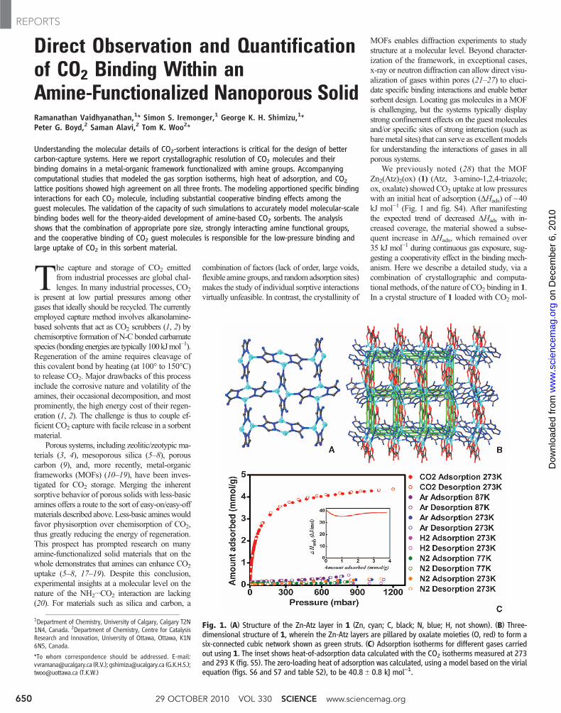
Direct Observation and Quantificationof CO2 Binding Within anAmine-Functionalized Nanoporous SolidRamanathan Vaidhyanathan,1* Simon S. Iremonger,1 George K. H. Shimizu,1*Peter G. Boyd,2 Saman Alavi,2 Tom K. Woo2*
Understanding the molecular details of CO2-sorbent interactions is critical for the design of bettercarbon-capture systems. Here we report crystallographic resolution of CO2 molecules and theirbinding domains in a metal-organic framework functionalized with amine groups. Accompanyingcomputational studies that modeled the gas sorption isotherms, high heat of adsorption, and CO2
lattice positions showed high agreement on all three fronts. The modeling apportioned specific bindinginteractions for each CO2 molecule, including substantial cooperative binding effects among theguest molecules. The validation of the capacity of such simulations to accurately model molecular-scalebinding bodes well for the theory-aided development of amine-based CO2 sorbents. The analysisshows that the combination of appropriate pore size, strongly interacting amine functional groups,and the cooperative binding of CO2 guest molecules is responsible for the low-pressure binding andlarge uptake of CO2 in this sorbent material.
The capture and storage of CO2 emittedfrom industrial processes are global chal-lenges. In many industrial processes, CO2
is present at low partial pressures among othergases that ideally should be recycled. The currentlyemployed capture method involves alkanolamine-based solvents that act as CO2 scrubbers (1, 2) bychemisorptive formation of N-C bonded carbamatespecies (bonding energies are typically 100kJmol−1).Regeneration of the amine requires cleavage ofthis covalent bond by heating (at 100° to 150°C)to release CO2. Major drawbacks of this processinclude the corrosive nature and volatility of theamines, their occasional decomposition, and mostprominently, the high energy cost of their regen-eration (1, 2). The challenge is thus to couple ef-ficient CO2 capture with facile release in a sorbentmaterial.
Porous systems, including zeolitic/zeotypic ma-terials (3, 4), mesoporous silica (5–8), porouscarbon (9), and, more recently, metal-organicframeworks (MOFs) (10–19), have been inves-tigated for CO2 storage. Merging the inherentsorptive behavior of porous solids with less-basicamines offers a route to the sort of easy-on/easy-offmaterials described above. Less-basic amineswouldfavor physisorption over chemisorption of CO2,thus greatly reducing the energy of regeneration.This prospect has prompted research on manyamine-functionalized solid materials that on thewhole demonstrates that amines can enhance CO2
uptake (5–8, 17–19). Despite this conclusion,experimental insights at a molecular level on thenature of the NH2···CO2 interaction are lacking(20). For materials such as silica and carbon, a
combination of factors (lack of order, large voids,flexible amine groups, and randomadsorption sites)makes the study of individual sorptive interactionsvirtually unfeasible. In contrast, the crystallinity of
MOFs enables diffraction experiments to studystructure at a molecular level. Beyond character-ization of the framework, in exceptional cases,x-ray or neutron diffraction can allow direct visu-alization of gases within pores (21–27) to eluci-date specific binding interactions and enable bettersorbent design. Locating gas molecules in a MOFis challenging, but the systems typically displaystrong confinement effects on the guest moleculesand/or specific sites of strong interaction (such asbaremetal sites) that can serve as excellent modelsfor understanding the interactions of gases in allporous systems.
We previously noted (28) that the MOFZn2(Atz)2(ox) (1) (Atz, 3-amino-1,2,4-triazole;ox, oxalate) showed CO2 uptake at low pressureswith an initial heat of adsorption (DHads) of ~40kJ mol−1 (Fig. 1 and fig. S4). After manifestingthe expected trend of decreased DHads with in-creased coverage, the material showed a subse-quent increase in DHads, which remained over35 kJ mol−1 during continuous gas exposure, sug-gesting a cooperativity effect in the binding mech-anism. Here we describe a detailed study, via acombination of crystallographic and computa-tional methods, of the nature of CO2 binding in 1.In a crystal structure of 1 loaded with CO2 mol-
1Department of Chemistry, University of Calgary, Calgary T2N1N4, Canada. 2Department of Chemistry, Centre for CatalysisResearch and Innovation, University of Ottawa, Ottawa, K1N6N5, Canada.
*To whom correspondence should be addressed. E-mail:[email protected] (R.V.); [email protected] (G.K.H.S.);[email protected] (T.K.W.)
Fig. 1. (A) Structure of the Zn-Atz layer in 1 (Zn, cyan; C, black; N, blue; H, not shown). (B) Three-dimensional structure of 1, wherein the Zn-Atz layers are pillared by oxalate moieties (O, red) to form asix-connected cubic network shown as green struts. (C) Adsorption isotherms for different gases carriedout using 1. The inset shows heat-of-adsorption data calculated with the CO2 isotherms measured at 273and 293 K (fig. S5). The zero-loading heat of adsorption was calculated, using a model based on the virialequation (figs. S6 and S7 and table S2), to be 40.8 T 0.8 kJ mol−1.
29 OCTOBER 2010 VOL 330 SCIENCE www.sciencemag.org650
REPORTS
on
Dec
embe
r 6,
201
0w
ww
.sci
ence
mag
.org
Dow
nloa
ded
from

ecules, the CO2 binding sites are readily identi-fied, even from room temperature diffraction data.The characteristics of CO2 uptake in 1, includingisotherm, heat of adsorption, and location of CO2
molecules, are modeled with high accuracy via acombination of classical grand canonical MonteCarlo (GCMC) simulations, molecular dynamics(MD) simulations, and periodic density functionaltheory (DFT) calculations. Thus, 1·(CO2)1.3 servesto calibrate these methods for modeling gas sorp-tion in MOFs. The modeling enables the par-titioning of CO2 binding in 1 into componentsbased both on neighboring groups and the natureof interaction (electrostatics/dispersion).
Single crystals of 1 were prepared via a pro-cedure modified from that previously reported(28), for the phases with hydrated and evacuatedpores (29). X-ray crystallography of evacuated1 showed no electron density in the voids, thusconfirming the effectiveness of the activation pro-cedure and the stability of the crystal. CO2was thenloaded into evacuated crystals of 1, and x-ray dif-fraction experiments conducted at 123, 173, 195,and 293 K all yielded refinable data. The CO2
molecules could be located within the pores in allcases andwere ordered except at 293K, where thedisorder could be modeled. The 173-K data setyielded the best refinement parameters [refinementfactor (R) = 2.7%, weighted R (Rw) = 6.5%] andwill be used for structural discussions.
The 173-K structure refinement gave a for-mula of 1·(CO2)1.30, which agrees well with thecalculated loading of 1.35 CO2 from the adsorp-tion isotherms at 840 mbar and 293 K (which arecomparable conditions to those of single-crystal
experiments). In the lattice Zn, aminotriazolatelayers are pillared by oxalate ions, with free aminegroups lining the pores (Fig. 1).
Within each pore, two independent CO2 bind-ing sites were located: CO2-I [O(100)-C(100)-O(101)] and CO2-II [O(200)-C(200)-O(201)] (Fig.2 and fig. S1). CO2-I, near the free amine group,was 80% occupied, and CO2-II, closer to the ox-alates, was 50% occupied; in filled pores, neitherCO2 molecule showed positional disorder. CO2
could interact with an amine via N-H···O hydro-gen bonding or via an interaction between the Nlone pair and the C atom of CO2. The H atoms ofthe amine groups were readily located in thex-ray structure of 1·(CO2)1.30, enabling direct vi-sualization of the H-bonding. CO2-I was adjacentto the amine, with its electropositive C atomoriented toward the electronegative N atom[C(d+)···N(d–) = 3.151(8) Å; the C-N of mono-ethanolamine carbamate was modeled as 1.45 Å(30) and factoring C and N van der Waal radii =3.25 Å]. The bowing of the protons on the Natoms (~21° from the mean triazole plane)confirms that the lone pair is not delocalized intothe triazole ring (Fig. 2). Both O atoms of CO2-Iare within the range of longer H-bonds to theamine [N4-H···O100 = 3.039(4), O101 = 3.226(9)Å], with angles also corroborating very weakinteractions [∠ N-H···O: O100 = 97.486(1)°;O101 = 95.822(1)°]. The C atom of CO2-I alsointeracts with an oxalate O atom lining the pore[C(d+)…O(d–) = 3.155(8) Å]. The amine under-goes stronger H-bonding with oxalate O atoms[N4-H···O2 = 2.888(7), O4 = 2.122(2) Å, ∠ N-H···O = 154.718(1)° and 137.843(1)°, respectively].
CO2-II was located between oxalate groups alongthe b axis. The O(d–) of CO2-II interacts with theC(d+) of the oxalate [O(d–)(CO2)…C(d+)(Ox) =2.961(5) Å]. In contrast to CO2-I, CO2-II interactswith a proximal amine via only a single H-bond[(N8-H···O200 = 2.783(8),∠N-H···O = 101.953(1)°].There is an interaction between CO2 moleculesas one O atom of CO2-I forms a contact withthe C of CO2-II [(C(d+)…O(d–) = 3.023(7) Å,C200···O100]. This CO2-CO2 interaction is high-ly relevant because it is most likely the origin ofthe observed increasing DHads with loading.
Regarding the geometries of the CO2 mole-cules, both appear, with sizeable uncertainties,slightly bent [∠O-C-O: CO2-I, 175.72(1.01)°;CO2-II, 177.15(1.66)°]. Given that a 3s range ofangles approaches or includes linearity and thefact that neither chemical intuition nor themodelingstudies support a nonlinear structure, the apparentbend of the CO2 molecules probably arises fromtheir positional distributions rather than any truedistortion in bonding. The C-O bond lengths[CO2-I: 1.137(8), 1.079(9) Å; CO2-II: 1.141(13),1.125(13) Å] were slightly shorter than reported[1.155(1) Å] in a 150-K/ambient pressure structureof pure CO2 (31). Variable-temperature x-ray crys-tallography showed that although the CO2 bondlengths and angles varied slightly with temperature,their occupancies and orientations did not appre-ciably change (table S1). A decrease in total gasuptake would be expected with increasing tem-perature; however, for 1, this did not change be-tween 195 and 273 K. This observation, coupledwith the order of the gasmolecules, reinforces thefact that the collective interactions are highlyfavorable for CO2 binding. Insight regarding thespecific interactions was gained through compu-tational modeling.
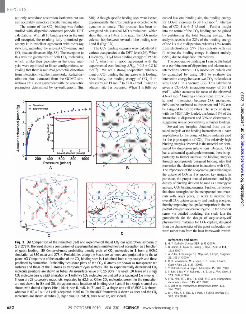
To investigate the nature of theCO2 interactionswith 1 and the cooperative guest-guest bindingeffects, we used a combination of dispersion-corrected (32) periodic DFT calculations and clas-sical GCMC simulations andMD simulations (33),in which the partial charge parameters were derivedfrom the periodic DFTcalculations bymeans of theREPEAT method (34). Figure 3A displays the ex-cellent agreement between the experimental andGCMC-simulated CO2 adsorption isotherms of1 at 273 K. The parameters associated with theCO2-1 intermolecular potential were not adjusted toobtain this quality of fit. Figure 3B shows a center-of-mass probability density plot from a GCMCsimulation of 1 (at 850 mbar and 273 K), wheredarker regions reveal a greater probability of findingCO2.Even at 273K, binding sites arewell localized,and the symmetry of the probability clouds sug-gests two distinct binding sites, corroborating thecrystallography. To compare the CO2 binding sitesdetermined computationally and crystallographically,the experimental CO2 positions are superimposedon three-dimensional isosurfaces of the probabilitiesfor C andO in Fig. 3C. The remarkable agreementbetween the simulated and experimental CO2 po-sitions suggests that GCMC simulations that areoften used to study gas adsorption inMOFs (33, 35)
Fig. 2. X-ray structure ofCO2 binding in 1·(CO2)1.3 at173 K. (A) The role of theamine group of Atz in bindingCO2-I is depicted. TheH atomsof the amine group (locatedcrystallographically) H-bondto oxalate O atoms, directingthe N lone pair toward theC(d+) atom of the CO2 mole-cule. H-bond distances shownare for H-acceptor interactions.(B) Both crystallographicallyindependent CO2 moleculesare shown trapped in a pore,showing the cooperative in-teraction between CO2-I andCO2-II molecules. The CO2…NH2 interaction is representedas a dotted purple bond, andthe CO2…CO2 interaction isindicated as a dotted yellowbond. (C) This panel showsthe other interactions present.The CO2-I…Ox interactionsare shown in orange, and theCO2…NH2 hydrogen bond in-teractions are shown in green.For clarity, H atoms are shownin purple.
www.sciencemag.org SCIENCE VOL 330 29 OCTOBER 2010 651
REPORTS
on
Dec
embe
r 6,
201
0w
ww
.sci
ence
mag
.org
Dow
nloa
ded
from
not only reproduce adsorption isotherms but canalso accurately reproduce specific binding sites.
The nature of the CO2 binding was furtherstudied with dispersion-corrected periodic DFTcalculations. With all 16 binding sites in the unitcell occupied, the resulting fully optimized ge-ometry is in excellent agreement with the x-raystructure, including the relevant CO2-amine andCO2-oxalate distances (fig. S8). The exception tothis was the geometries of both CO2 molecules,which, unlike their geometry in the x-ray anal-ysis, were optimized to linear configurations, re-vealing that there is minimal geometric distortionfrom interaction with the framework. Radial dis-tribution plots extracted from the GCMC sim-ulations are also in agreement with the geometricparameters determined by crystallography (fig.
S10). Although specific binding sites were locatedexperimentally, the CO2 binding is expected to bedynamic in nature. This prospect has been in-vestigated via classical MD simulations, whichshow that, in a 1.4-ns time span, the CO2 mole-cule can hop between several of the binding sitesI and II (Fig. 3D).
The CO2 binding energies were calculated atvarious occupancies at the DFT level (29). When1 is empty, CO2-I has a binding energy of 39.6 kJmol−1, which is in good agreement with theexperimental zero-loading DHads (40.8 T 0.8 kJmol−1). We see a strong cooperative enhance-ment of CO2 binding that increases with loading.Specifically, the binding energy of CO2-II in-creases by 4.6 kJ mol−1 to 37.0 kJ mol−1 when anadjacent site I is occupied. When 1 is fully oc-
cupied less one binding site, the binding energyfor CO2-II increases to 38.1 kJ mol−1, whereasthat of CO2-I is 44.2 kJ mol−1. Further insightinto the nature of the CO2 binding can be gainedby partitioning the total binding energy. Thisanalysis reveals that 82% of the binding energyof site I is due to dispersion, whereas 18% resultsfrom electrostatics (29). This contrasts with siteII, where the binding energy is almost entirely(99%) due to dispersion interactions.
The cooperative binding in 1 can be attributedto a combination of dispersion and electrostaticinteractions between CO2 molecules, which canbe quantified by using DFT to evaluate theinteraction energy between twoCO2molecules atsites I and II in a vacuum (29). This calculationgives a CO2-CO2 interaction energy of 3.9 kJmol−1, which accounts for most of the observed4.6–kJ mol−1 binding enhancement. Of the 3.9–kJ mol−1 interaction between CO2 molecules,66% can be attributed to dispersion and 34% canbe assigned to electrostatics. The same analysis,with the MOF fully loaded, attributes 61% of theinteraction to dispersion and 39% to electrostatics,suggesting similar cooperativity at higher loadings.
Several key insights obtained from the de-tailed analysis of the binding interactions in 1 haveimplications for the design of future materials usedfor the physisorption of CO2. The relatively highbinding energies observed in the material are dom-inated by dispersion interactions. Because CO2
has a substantial quadrupole moment, there is op-portunity to further increase the binding energiesthrough appropriately designed binding sites thatmaximize the electrostatic interactions with CO2.The importance of the cooperative guest binding tothe uptake of CO2 in 1 is another key insight. Inparticular, the proper mutual orientation and highdensity of binding sites can be used as a strategy toincrease CO2 binding energies. Further, we believethat these strategies can be incorporated into mate-rials with larger pores, in order to increase theoverall CO2 uptake capacity and binding energies,thereby improving the uptake properties in the im-portant low–partial-pressure regime. In the broadestsense, via detailed modeling, this study lays thegroundwork for the design of easy-on/easy-offphysisorptive materials for CO2 capture, designedfrom the characteristics of the guest molecules out-ward rather than from the host framework inward.
References and Notes1. G. T. Rochelle, Science 325, 1652 (2009).2. B. Arstad, R. Blom, O. Swang, J. Phys. Chem. A 111,
1222 (2007).3. A. Zukal, I. Dominguez, J. Mayerová, J. Cejka, Langmuir
25, 10314 (2009).4. R. V. Siriwardane, M. S. Shen, E. P. Fisher, J. Losch,
Energy Fuels 19, 1153 (2005).5. Y. Belmabkhout, A. Sayari, Adsorption 15, 318 (2009).6. S. Kim, J. Ida, V. V. Guliants, J. Y. S. Lin, J. Phys. Chem. B
109, 6287 (2005).7. S. N. Kim, W. J. Son, J. S. Choi, W. S. Ahn, Microporous
Mesoporous Mater. 115, 497 (2008).8. J. Wei et al., Microporous Mesoporous Mater. 116,
394 (2008).9. B. J. Kim, K. S. Cho, S. J. Park, J. Colloid Interface Sci.
342, 575 (2010).
Fig. 3. (A) Comparison of the simulated (red) and experimental (blue) CO2 gas adsorption isotherm of1 at 273 K. The inset shows a comparison of experimental and simulated heats of adsorption as a functionof guest loading. (B) Center-of-mass probability density plots of CO2 molecules in 1 from a GCMCsimulation at 850 mbar and 273 K. Probabilities along the b axis are summed and projected onto the acplane. (C) Comparison of the location of the CO2 binding sites in 1 obtained from x-ray analysis and thosepredicted by simulation. Probability isosurface plots of the CO2 O atoms are shown as transparent redsurfaces and those of the C atoms as transparent cyan surfaces. The 16 experimentally determined CO2molecule positions are shown as tubes. An isosurface value of 0.15 Bohr−3 is used. (D) Trace of a singleCO2 molecule during a MD simulation of 1 with five CO2 molecules per unit cell or a loading of 1.6 mmol g
–1.Shown are 23 successive snapshots, separated by 62.5 ps. Other CO2 molecules present in the simulationare not shown. In (B) and (D), the approximate locations of binding sites I and II in a single channel areshown with dotted ellipses (site I, black; site II, red). In (B) and (C), a single unit cell of MOF 1 is shown,whereas in (D) a 2 × 1 × 1 cell is depicted. In (B) to (D), the MOF framework is shown as lines and the CO2molecules are shown as tubes (C, light blue; O, red; N, dark blue; Zn, not shown).
29 OCTOBER 2010 VOL 330 SCIENCE www.sciencemag.org652
REPORTS
on
Dec
embe
r 6,
201
0w
ww
.sci
ence
mag
.org
Dow
nloa
ded
from

10. B. Wang, A. P. Côté, H. Furukawa, M. O’Keeffe,O. M. Yaghi, Nature 453, 207 (2008).
11. P. K. Thallapally et al., J. Am. Chem. Soc. 130,16842 (2008).
12. A. R. Millward, O. M. Yaghi, J. Am. Chem. Soc. 127,17998 (2005).
13. N. A. Ramsahye et al., J. Phys. Chem. C 112, 514 (2008).14. S. R. Caskey, A. G. Wong-Foy, A. J. Matzger, J. Am. Chem.
Soc. 130, 10870 (2008).15. A. Phan et al., Acc. Chem. Res. 43, 58 (2010).16. K. S. Walton et al., J. Am. Chem. Soc. 130, 406 (2008).17. A. Demessence, D. M. D’Alessandro, M. L. Foo, J. R. Long,
J. Am. Chem. Soc. 131, 8784 (2009).18. J. An, S. J. Geib, N. L. Rosi, J. Am. Chem. Soc. 132,
38 (2010).19. B. Arstad, H. Fjellvåg, K. O. Kongshaug, O. Swang, R. Blom,
Adsorption 14, 755 (2008).20. C. Villiers, J. P. Dognon, R. Pollet, P. Thuéry,
M. Ephritikhine, Angew. Chem. Int. Ed. 49, 3465(2010).
21. R. Kitaura et al., Science 298, 2358 (2002).22. R. Matsuda et al., Nature 436, 238 (2005).23. S. Takamizawa et al., J. Am. Chem. Soc. 132, 3783 (2010).24. J. P. Zhang, X. M. Chen, J. Am. Chem. Soc. 131,
5516 (2009).
25. P. D. C. Dietzel et al., Chem. Commun. (Camb.) 41,5125 (2008).
26. H. Wu, J. M. Simmons, G. S. Srinivas, W. Zhou,T. Yildirim, J. Phys. Chem. Lett 1, 1946 (2010).
27. V. K. Peterson, Y. Liu, C. M. Brown, C. J. Kepert, J. Am.Chem. Soc. 128, 15578 (2006).
28. R. Vaidhyanathan, S. S. Iremonger, K. W. Dawson,G. K. H. Shimizu, Chem. Commun. (Camb.) 35,5230 (2009).
29. Supporting material on Science Online includescomplete details of the crystallography (crystallographicinformation files for all temperatures), gas sorptionexperiments, and computational modeling (including amovie showing the correlation of experimental andmodeled CO2 positions in 1).
30. H. Deguchi et al., Ind. Eng. Chem. Res. 49, 6 (2010).31. A. Simon, K. Peters, Acta Crystallogr. B 36, 2750
(1980).32. S. Grimme, J. Comput. Chem. 27, 1787 (2006).33. T. Düren, Y. S. Bae, R. Q. Snurr, Chem. Soc. Rev. 38,
1237 (2009).34. C. Campañá, B. Mussard, T. K. Woo, J. Chem. Theory
Comput. 5, 2866 (2009).35. M. Tafipolsky, S. Amirjalayer, R. Schmid, Microporous
Mesoporous Mater. 129, 304 (2010).
36. T.K.W. and G.K.H.S. thank the Natural Sciences andEngineering Research Council of Canada. G.K.H.S. thanksthe Institute for Sustainable Energy, Environmentand Economy at the University of Calgary and theAlberta Energy Research Institute for partial financial supportof this work. T.K.W. and P.G.B. thank the Canada ResearchChairs Program and the High Performance ComputingVirtual Laboratory for financial support. Crystallographicdata for the structures reported in this paper have beendeposited with the Cambridge Crystallographic Data Centre(CCDC) under reference numbers CCDC 782638 to 782642.These data can be obtained free of charge via www.ccdc.cam.ac.uk/conts/retrieving.html (or from the CCDC, 12 UnionRoad, Cambridge CB2 1EZ, UK).
Supporting Online Materialwww.sciencemag.org/cgi/content/full/330/6004/650/DC1Materials and MethodsSOM TextFigs. S1 to S12Tables S1 to S5ReferencesMovie S1
25 June 2010; accepted 30 September 201010.1126/science.1194237
The Occurrence and MassDistribution of Close-in Super-Earths,Neptunes, and JupitersAndrew W. Howard,1,2* Geoffrey W. Marcy,1 John Asher Johnson,3Debra A. Fischer,4 Jason T. Wright,5 Howard Isaacson,1 Jeff A. Valenti,6Jay Anderson,6 Doug N. C. Lin,7,8 Shigeru Ida9
The questions of how planets form and how common Earth-like planets are can be addressedby measuring the distribution of exoplanet masses and orbital periods. We report the occurrencerate of close-in planets (with orbital periods less than 50 days), based on precise Dopplermeasurements of 166 Sun-like stars. We measured increasing planet occurrence with decreasingplanet mass (M). Extrapolation of a power-law mass distribution fitted to our measurements,df/dlogM = 0.39 M−0.48, predicts that 23% of stars harbor a close-in Earth-mass planet (rangingfrom 0.5 to 2.0 Earth masses). Theoretical models of planet formation predict a deficit of planetsin the domain from 5 to 30 Earth masses and with orbital periods less than 50 days. This region ofparameter space is in fact well populated, implying that such models need substantial revision.
The architecture of our solar system, withsmall rocky planets orbiting close to theSun and gas-liquid giant planets farther
out, provides key properties that inform theoriesof planet formation and evolution. As more plan-
etary systems are discovered, the planet occur-rence fractions and distributions of mass andorbital distance similarly shape our understandingof how planets form, interact, and evolve. Suchproperties can be measured using precise Dopplermeasurements of the host stars that interact gravi-tationally with their planets. These measurementsreveal the planetary orbits and minimum masses(M sini, due to unknown orbital inclinations i).
In the core-accretion theory of planet forma-tion, planets are built from the collisions andsticking together of rock-ice planetesimals, grow-ing to Earth size and beyond, followed by thegravitational accretion of hydrogen and heliumgas. This process has been simulated numeri-cally (1–4), predicting the occurrence of planetsin a two-parameter space defined by their massesand orbital periods (P). These simulations pre-dict that there should be a paucity of planets, a“planet desert” (3), in the mass range from ~1
to 30 Earth masses (MEarth) orbiting inside of~1 astronomical unit (AU), depending on theexact treatment of inward planet migration.
We used precise Doppler measurements ofa well-defined sample of nearby stars to detectplanets having masses of 3 to 1000 MEarth or-biting within the inner 0.25 AU. The 235 main-sequence G-, K-, and M-type dwarf stars inour NASA–University of California Eta-EarthSurvey were selected from the Hipparcos cat-alog on the basis of brightness (V < 11), distance(<25 pc), luminosity (MV > 3.0), low chromo-spheric activity (logR′HK < −4.7), lack of stellarcompanions, and observability from Keck Obser-vatory. The resulting set of stars is nearly free ofselection bias; in particular, stars were neitherincluded nor excluded based on their likelihoodto harbor a planet. [The stars and planets are listedin the supporting online material (SOM).] Herewe focus on the 166 G- and K-type stars, withmasses of 0.54 to 1.28 solar masses and B − V <1.4. We analyzed previously announced planets,new candidate planets, and nondetections on astar-by-star basis to measure close-in planet oc-currence as a function of planet mass.
We measured at least 20 radial velocities(RVs) for each star, achieving 1 m s−1 precision(5) with the HIRES echelle spectrometer (6) atKeck Observatory. To achieve sensitivity on timescales ranging from years to days, the observa-tions of each star were spread over 5 years, withat least one cluster of 6 to 12 observations in a12-night span. Stars with candidate planets wereobserved intensively, leading to several discov-eries (5, 7, 8). In total, 33 planets (Fig. 1) havebeen detected around 22 stars in our sample(5, 7, 9–22), some of which were discovered byother groups. Sixteen of these planets have P <50 days. Our analysis also includes five can-didate low-mass planets from the Eta-EarthSurvey with P < 50 days and false alarm prob-abilities (5) of <5%.
1Department of Astronomy, University of California, Berkeley,CA 94720, USA. 2Space Sciences Laboratory, University ofCalifornia, Berkeley, CA 94720, USA. 3Department of Astro-physics, California Institute of Technology, Pasadena, CA91125, USA. 4Department of Astronomy, Yale University, NewHaven, CT 06511, USA. 5Department of Astronomy and As-trophysics, The Pennsylvania State University, University Park,PA 16802, USA. 6Space Telescope Science Institute, 3700 SanMartin Drive, Baltimore, MD 21218, USA. 7University of Cal-ifornia Observatories/Lick Observatory, University of California,Santa Cruz, CA 95064, USA. 8Kavli Institute for Astronomyand Astrophysics, Peking University, Beijing, China. 9TokyoInstitute of Technology, Ookayama, Meguro-ku, Tokyo 152-8551, Japan.
*To whom correspondence should be addressed. E-mail:[email protected]
www.sciencemag.org SCIENCE VOL 330 29 OCTOBER 2010 653
REPORTS
on
Dec
embe
r 6,
201
0w
ww
.sci
ence
mag
.org
Dow
nloa
ded
from

Introduction to metal-organic frameworks and the application on adsorption of CO2
Di Cui*
Department of Chemistry and Biochemistry, University of Delaware, Newark, Delaware, 19711
RECEIVED DATE (automatically inserted by publisher); Email: [email protected]
ABSTRACT Different methods of adsorption of CO2 are
reviewed. By comparison, functionalized metal-organic
frameworks merge the inherent physisorption of porous
solids with the chemical sorption of weak bases, showing
advantages of less energy cost and higher uptake of CO2.
Detailed discussion focuses on the choices of metal ions
and organic ligands for synthesis of metal-organic
frameworks. Also, incorporating experimental work with
computational analysis reveal the specific binding
interaction between guest molecules and the amine groups
of the metal-organic frameworks, which can provide useful
direction for the design of more efficient and selective
functional metal-organic frameworks.
Carbon dioxide is a kind of gas that is often produced during
the industrial processes. However, direct emissions of CO2 into
the atmosphere may cause green house effect that is responsible
for change to warmth of the global climate. Therefore, separation
of low partial pressures CO2 from other gases would be highly
attractive for the purpose of ameliorating anthropogenic climate
change.
Several methods have been developed to capture CO2 among
other gases and regenerate it later. Acids can react with bases,
based on this simple principle, technology for gas desulfurization
by using lime or limestone slurry has been developed. 1 Similarly,
aqueous amine solutions can be used for CO2 absorption. 2 There
are several mechanisms about this reaction; one general accepted
mechanism shows as in the Scheme 1.
Scheme 1. Mechnism of CO2 absorption by aqueous amine solution
This is a termolecular concerted mechanism. The lone pair
electrons on the nitrogen atom, serving as nucleophilic reagent,
attack the electrophilic CO2. Simultaneously, proton transfers
from the amino nitrogen atom to a nearby base molecule. The
base can be water or another amine. The reasonableness of this
mechanism has been proved by quantum chemical calculations.
Calculations show that direct reaction of monoethanolamine and
CO2 without addition base has a quite high barrier for changing
from ground state to transition state with the activation energy
about 170kJ/mol. 3 On the other hand, if termolecular reaction is
considered, which regards a water molecule will serve as
additional base, the activation energy will lower to 108kJ/mol.
The decrease in activation energy shows that it is reasonable to
think that carbamate acid molecule is formed from one CO2
molecule and one amine molecule with one water molecule or
another amine molecule acting as catalyst.
Although widely used, this method has a major drawback.
Releasing of CO2 from the carbamate acid requires the cleavage
of C-N bond that has bonding energy about 100kJ/mol, 4 which
means that regeneration of CO2 by this method is a high energy
cost process. Besides, in the gas-liquid systems, a low
concentration of amines present in the aqueous solution, causing
corrosion problem.
An alternative method to separate CO2 is the use of solid
sorbents. Adsorption and separation of CO2 over a range of
porous solid adsorbents have been well studied. Common physical
absorbents, including activated carbons 5-6 and zeolites, 7-9 process
relatively high CO2 adsorption capacities; however, they decline
rapidly with increasing temperature. Solid chemical adsorbents,
including hydrotalcite 10 and various basic metal oxides 11 can
adsorb CO2 at high temperatures; however, they suffered from
either low CO2 capacities or severe energy cost due to the high
desorption temperatures.
Another kind of promising solid sorbent is metal-organic
frameworks, which is a new development on the interface
between molecular coordination chemistry and materials science.
They are composed of two major components: metal ions and
organic molecules called linkers. The organic units are typically
mono-, di-, tri-, or tetravalent ligands. Different combinations of
metal ions and organic molecules can have different effects on the
structure and properties of the metal-organic frameworks.
Dictating how many ligands can bind to the metal ions and in
which orientation can give some information of the metal’s
coordination preference, which affects the size and shape of pores
a lot.
In order to make metal-organic frameworks, in principle, it is
only necessary to react a potentially bridging ligand with a metal
ion which has more than one vacant site. 12 However, for the
purpose of characterization, it is only applicable to investigate
several specific kinds of metal-ligand combination. Crystal
structure of metal-organic frameworks is quite important to
interpret their observed properties. Two kinds of structure can
arise, either infinite extended polymetric or discrete closed
oligometrc structures. The most detailed structural information
will be gained from single crystal X-ray crystallography.
Therefore, it is quite difficult to investigate structure of
amorphous solid phases. To avoid an amorphous product,
complexes that are used should be labile. From inorganic lecture,
we know that complexes that can react very rapidly are called
labile. One criterion for lability is that a reaction has half-life of
one minute or less. Complexes that are labile usually have low
NR
R
H
: C
O
O
B:
1

activation energy, which means that bond formation is rapidly
reversible, so the initial formed kinetic products, which may be
mixtures, have the opportunity to rearrange and give a single
thermodynamically favored product. Usually, labile metal ions
include Cu+, Cu2+, Ag+, Cd2+, Zn2+, Co2+ and Ni2+. Although there
are exceptions, general rules can be given for the labile electronic
structures. Labile complexes are generally those with low ligand
field stabilization energies, including d1, d2, high-spin d4, high-
spin d5, high-spin d6, d7, d9, d10.
Ligand types also need to be considered for the formation of
ordered crystal structures. If a ligand has a number of possible
conformations, the geometry of the frameworks will be hard to
predict. A good way is to use rigid ligands that can reduce the
orientation freedom of the ligand lone pairs, such as the following
ligands.
Figure 1 Examples of rigid ligands used in the synthesis of metal-
organic frameworks
Large pore metal-organic frameworks are quite effective for
storing high capacities of the gas, usually at higher pressures.
When the pressure is low, the effectiveness of the adsorption goes
down. Also, the selection of adsorption is poor based on pore size
only. One method to improve this is to chemically functionate the
pores of the metal-organic frameworks with groups capable of
interacting strongly with the guest molecules. Since amine groups
can react easily with CO2 gas molecules, using amine-derivative
metal-organic frameworks to adsorb CO2 gas molecules have
been investigated. 13 However, details on the interaction between
functional amine groups and CO2 are still lacking both on
experimental level. In this article, 4 porous Zn-aminotriazolato-
oxalate compound, with a formula Zn2(C2O4)(C2N4H3)2 is used as
the adsorbent. Diffraction experiments have been conducted to
study the specific binding interactions between guest molecules
and the metal-organic frameworks. Direct visualization of gases
molecules within pores by the diffraction experiments, combining
with computational modeling, makes the molecular details of
CO2-sorbent interactions understandable. Cooperative binding of
CO2 guest molecules has been proved by both experimental
method and computational method. This is a key factor to
influence the uptake of CO2. The meaning of this work is that
with the foundational understanding of the binding between guest
molecules and adsorbent, the theory-aided design of future metal-
organic frameworks that have low-pressure binding and large
uptake of CO2 is possible.
Details study of the nature of CO2 binding in Zn-
aminotriazolato-oxalate compound can be obtained via a
combination of experimental and computational methods.
X-ray crystallography of evacuated metal-organic frameworks
shows no electron density in the voids, confirming the stability of
the crystal. After loading into CO2, X-ray diffraction experiments
shows that the CO2 molecules could be located within the pores.
More detailed information about the location of CO2 within the
pores can also be obtained. Typically, the metal-organic
frameworks display strong confinement effects on the CO2, so it is
possible to localize these gases molecules in the pores.
Calculations based on this method shows a formula of
Zn2(C2O4)(C2N4H3)2.(CO2)1.30.
Via thermodynamics experiments, adsorption isotherms for
different gases by Zn2(C2O4)(C2N4H3)2 are obtained, which shows
the fact that Zn2(C2O4)(C2N4H3)2 can capture CO2 selectively by
comparison with other kinds of gases. Calculations based on these
thermodynamic data show the formula of
Zn2(C2O4)(C2N4H3)2.(CO2)1.35, which agrees well with the one
obtains from the crystallography.
One important phenomena that is observed within
Zn2(C2O4)(C2N4H3)2 is the cooperativity effect in the binding of
CO2. Zn2(C2O4)(C2N4H3)2 showed CO2 uptake at low pressures
with an initial heat of adsorption of 40kJ/mol. With the
increasement of pressure of the CO2, the heat of adsorption of the
material decreased. However, continuity of the exposure showed
an increasement of the heat of adsorption. Another example of
cooperativity effect of CO2 binding is that with increasing
temperature, there would be expected to observe a decrease of the
uptake of the gas. However, experiments conducting at
temperature between 195 and 273K show that there is little
change of the amount of uptake. To illustrate these facts, a
combination of crystallographic and computational methods has
been used. Study shows that within each pore, there are two
independent CO2 binding sites. One can show as CO2-I, which
locates near the free amine group; another can show as CO2-II,
which locates closer to the oxalates. There are two ways of
interaction between CO2 and amine. One is that CO2 interacts
with an amine via N-H...O hydrogen bonding; another one is the
interaction between the N lone pair and the C atom of CO2.
Besides these, there is an interaction between two neighboring
CO2 molecules. One O atom of CO2-I can form a contact with the
C atom of CO2-II, which accounts for the cooperative effect.
Details investigation of cooperative binding in
Zn2(C2O4)(C2N4H3)2 by DFT shows that the nature of interaction
between two neighboring CO2 molecules should include two
kinds of interaction: dispersion and electrostatic interactions.
Calculation shows that the interaction energy of CO2-CO2 is
3.9kJ/mol, which is in accordance with the observed 4.6kJ/mol.
Among the interaction energy, 66% is derived from dispersion
and 34% is derived from the electrostatics.
These carefully and complicatedly calculations provide a key
insight to fully understand the binding interactions between CO2
and the metal organic framework, which can give a guidance for
the future design of the materials for CO2 adsorption. Studies
show that three main factors, including appropriate pore size,
N N
(A)
N
NN
N
(B)
N
N N
N
NN
(C)
CO2--
O2C
(D)
N CO2-
(E)
2
interaction between amine functional groups and guest molecules ,
and the cooperative binding of CO2 guest molecules, are
responsible for the low-pressure binding and large uptake of CO2
within the Zn2(C2O4)(C2N4H3)2 frameworks. One aspect of the
future research on this topic should focus on the enhancement of
the cooperativity of guest molecules. To enhance the cooperative
effect, either dispersion interactions or electrostatic interactions
should be strengthened. Since CO2 has a substantial quadrupole
moment, it is possible to increase the electrostatic interactions
between two neighboring CO2 molecules by improve the binding
sites. Also, metal-organic frameworks with larger pores should be
investigated more in order to discover materials with higher CO2
uptake capacity and more selective on CO2 during low partial
pressure.
Acknowledgment
Supporting Information Available:
REFERENCES 1. Nonhebel, G.; Trans. Faraday Soc; 1936, 32, 1291 2.Rochelle, G. T.; Science; 2009, 325, 1652. 3.Arstad, B.; Blom, R.; Swang, O.; J. Phys. Chem. A; 2007, 111, 1222. 4.Vaidhyanathan, R.; Iremonger, S. S.; Shimizu, G.K.H.; Boyd, P. G. ; Alavi, S. Woo, T. K.; Science, 2010, 330, 650 5. Yong, Z.; Mata, V.; Rodrigues, A. E; Adsorption; 2001, 7, 41. 6.Ottiger, S.; Pini, R.; Storti, G.; Mazzotti, M.; Langmuir, 2008, 24, 9531. 7.Siporin, S. E.; McClaine, B. C.; Davis, R. J.; Langmuir, 2003, 19, 4707. 8. Plant, D. F.; Maurin, G.; Deroche, I.; Gaberova, L.; Llewwllyn, P. L.; Chem. Phys. Lett.; 2006, 426, 387. 9.Pawlesa, J.; Zukal, A.; Cejka, J.; Adsorption; 2007, 13, 2413. 10. Reijers, H. Th. J.; Valster-Schiermeier, S. E. A.; Cobden, P. D.; Ind. Eng. Chem. Res.; 2006, 45, 2522. 11. Gaffney, T. R.; Golden, T. C.; Mayorga, S. G.; Brozozowski, J. R.; Talyer, F. W. U. S. Patent 5, 917, 136, 1999. 12. James, Stuart L.; Chem. Soc. Rev.; 2003, 32, 276. 13. Vaidhyanathan. R.; Iremonger, S. S.; Dawson, K. W.; Shimizu, G. K. H.; Chem. Commun.; 2009, 35, 5230.
3
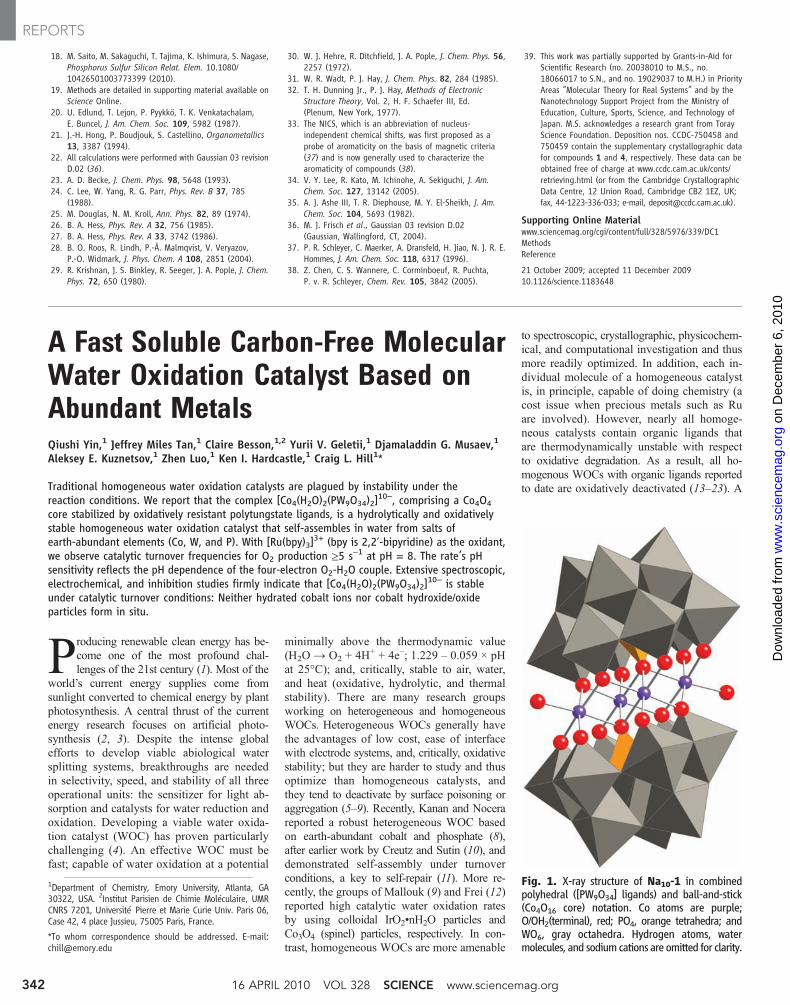
18. M. Saito, M. Sakaguchi, T. Tajima, K. Ishimura, S. Nagase,Phosphorus Sulfur Silicon Relat. Elem. 10.1080/10426501003773399 (2010).
19. Methods are detailed in supporting material available onScience Online.
20. U. Edlund, T. Lejon, P. Pyykkö, T. K. Venkatachalam,E. Buncel, J. Am. Chem. Soc. 109, 5982 (1987).
21. J.-H. Hong, P. Boudjouk, S. Castellino, Organometallics13, 3387 (1994).
22. All calculations were performed with Gaussian 03 revisionD.02 (36).
23. A. D. Becke, J. Chem. Phys. 98, 5648 (1993).24. C. Lee, W. Yang, R. G. Parr, Phys. Rev. B 37, 785
(1988).25. M. Douglas, N. M. Kroll, Ann. Phys. 82, 89 (1974).26. B. A. Hess, Phys. Rev. A 32, 756 (1985).27. B. A. Hess, Phys. Rev. A 33, 3742 (1986).28. B. O. Roos, R. Lindh, P.-A. Malmqvist, V. Veryazov,
P.-O. Widmark, J. Phys. Chem. A 108, 2851 (2004).29. R. Krishnan, J. S. Binkley, R. Seeger, J. A. Pople, J. Chem.
Phys. 72, 650 (1980).
30. W. J. Hehre, R. Ditchfield, J. A. Pople, J. Chem. Phys. 56,2257 (1972).
31. W. R. Wadt, P. J. Hay, J. Chem. Phys. 82, 284 (1985).32. T. H. Dunning Jr., P. J. Hay, Methods of Electronic
Structure Theory, Vol. 2, H. F. Schaefer III, Ed.(Plenum, New York, 1977).
33. The NICS, which is an abbreviation of nucleus-independent chemical shifts, was first proposed as aprobe of aromaticity on the basis of magnetic criteria(37) and is now generally used to characterize thearomaticity of compounds (38).
34. V. Y. Lee, R. Kato, M. Ichinohe, A. Sekiguchi, J. Am.Chem. Soc. 127, 13142 (2005).
35. A. J. Ashe III, T. R. Diephouse, M. Y. El-Sheikh, J. Am.Chem. Soc. 104, 5693 (1982).
36. M. J. Frisch et al., Gaussian 03 revision D.02(Gaussian, Wallingford, CT, 2004).
37. P. R. Schleyer, C. Maerker, A. Dransfeld, H. Jiao, N. J. R. E.Hommes, J. Am. Chem. Soc. 118, 6317 (1996).
38. Z. Chen, C. S. Wannere, C. Corminboeuf, R. Puchta,P. v. R. Schleyer, Chem. Rev. 105, 3842 (2005).
39. This work was partially supported by Grants-in-Aid forScientific Research (no. 20038010 to M.S., no.18066017 to S.N., and no. 19029037 to M.H.) in PriorityAreas “Molecular Theory for Real Systems” and by theNanotechnology Support Project from the Ministry ofEducation, Culture, Sports, Science, and Technology ofJapan. M.S. acknowledges a research grant from TorayScience Foundation. Deposition nos. CCDC-750458 and750459 contain the supplementary crystallographic datafor compounds 1 and 4, respectively. These data can beobtained free of charge at www.ccdc.cam.ac.uk/conts/retrieving.html (or from the Cambridge CrystallographicData Centre, 12 Union Road, Cambridge CB2 1EZ, UK;fax, 44-1223-336-033; e-mail, [email protected]).
Supporting Online Materialwww.sciencemag.org/cgi/content/full/328/5976/339/DC1MethodsReference
21 October 2009; accepted 11 December 200910.1126/science.1183648
A Fast Soluble Carbon-Free MolecularWater Oxidation Catalyst Based onAbundant MetalsQiushi Yin,1 Jeffrey Miles Tan,1 Claire Besson,1,2 Yurii V. Geletii,1 Djamaladdin G. Musaev,1Aleksey E. Kuznetsov,1 Zhen Luo,1 Ken I. Hardcastle,1 Craig L. Hill1*
Traditional homogeneous water oxidation catalysts are plagued by instability under thereaction conditions. We report that the complex [Co4(H2O)2(PW9O34)2]
10–, comprising a Co4O4
core stabilized by oxidatively resistant polytungstate ligands, is a hydrolytically and oxidativelystable homogeneous water oxidation catalyst that self-assembles in water from salts ofearth-abundant elements (Co, W, and P). With [Ru(bpy)3]
3+ (bpy is 2,2′-bipyridine) as the oxidant,we observe catalytic turnover frequencies for O2 production ≥5 s−1 at pH = 8. The rate’s pHsensitivity reflects the pH dependence of the four-electron O2-H2O couple. Extensive spectroscopic,electrochemical, and inhibition studies firmly indicate that [Co4(H2O)2(PW9O34)2]
10– is stableunder catalytic turnover conditions: Neither hydrated cobalt ions nor cobalt hydroxide/oxideparticles form in situ.
Producing renewable clean energy has be-come one of the most profound chal-lenges of the 21st century (1). Most of the
world’s current energy supplies come fromsunlight converted to chemical energy by plantphotosynthesis. A central thrust of the currentenergy research focuses on artificial photo-synthesis (2, 3). Despite the intense globalefforts to develop viable abiological watersplitting systems, breakthroughs are neededin selectivity, speed, and stability of all threeoperational units: the sensitizer for light ab-sorption and catalysts for water reduction andoxidation. Developing a viable water oxida-tion catalyst (WOC) has proven particularlychallenging (4). An effective WOC must befast; capable of water oxidation at a potential
minimally above the thermodynamic value(H2O → O2 + 4H+ + 4e–; 1.229 – 0.059 × pHat 25°C); and, critically, stable to air, water,and heat (oxidative, hydrolytic, and thermalstability). There are many research groupsworking on heterogeneous and homogeneousWOCs. Heterogeneous WOCs generally havethe advantages of low cost, ease of interfacewith electrode systems, and, critically, oxidativestability; but they are harder to study and thusoptimize than homogeneous catalysts, andthey tend to deactivate by surface poisoning oraggregation (5–9). Recently, Kanan and Nocerareported a robust heterogeneous WOC basedon earth-abundant cobalt and phosphate (8),after earlier work by Creutz and Sutin (10), anddemonstrated self-assembly under turnoverconditions, a key to self-repair (11). More re-cently, the groups of Mallouk (9) and Frei (12)reported high catalytic water oxidation ratesby using colloidal IrO2•nH2O particles andCo3O4 (spinel) particles, respectively. In con-trast, homogeneous WOCs are more amenable
to spectroscopic, crystallographic, physicochem-ical, and computational investigation and thusmore readily optimized. In addition, each in-dividual molecule of a homogeneous catalystis, in principle, capable of doing chemistry (acost issue when precious metals such as Ruare involved). However, nearly all homoge-neous catalysts contain organic ligands thatare thermodynamically unstable with respectto oxidative degradation. As a result, all ho-mogenous WOCs with organic ligands reportedto date are oxidatively deactivated (13–23). A
1Department of Chemistry, Emory University, Atlanta, GA30322, USA. 2Institut Parisien de Chimie Moléculaire, UMRCNRS 7201, Université Pierre et Marie Curie Univ. Paris 06,Case 42, 4 place Jussieu, 75005 Paris, France.
*To whom correspondence should be addressed. E-mail:[email protected]
Fig. 1. X-ray structure of Na10-1 in combinedpolyhedral ([PW9O34] ligands) and ball-and-stick(Co4O16 core) notation. Co atoms are purple;O/OH2(terminal), red; PO4, orange tetrahedra; andWO6, gray octahedra. Hydrogen atoms, watermolecules, and sodium cations are omitted for clarity.
16 APRIL 2010 VOL 328 SCIENCE www.sciencemag.org342
REPORTS
on
Dec
embe
r 6,
201
0w
ww
.sci
ence
mag
.org
Dow
nloa
ded
from
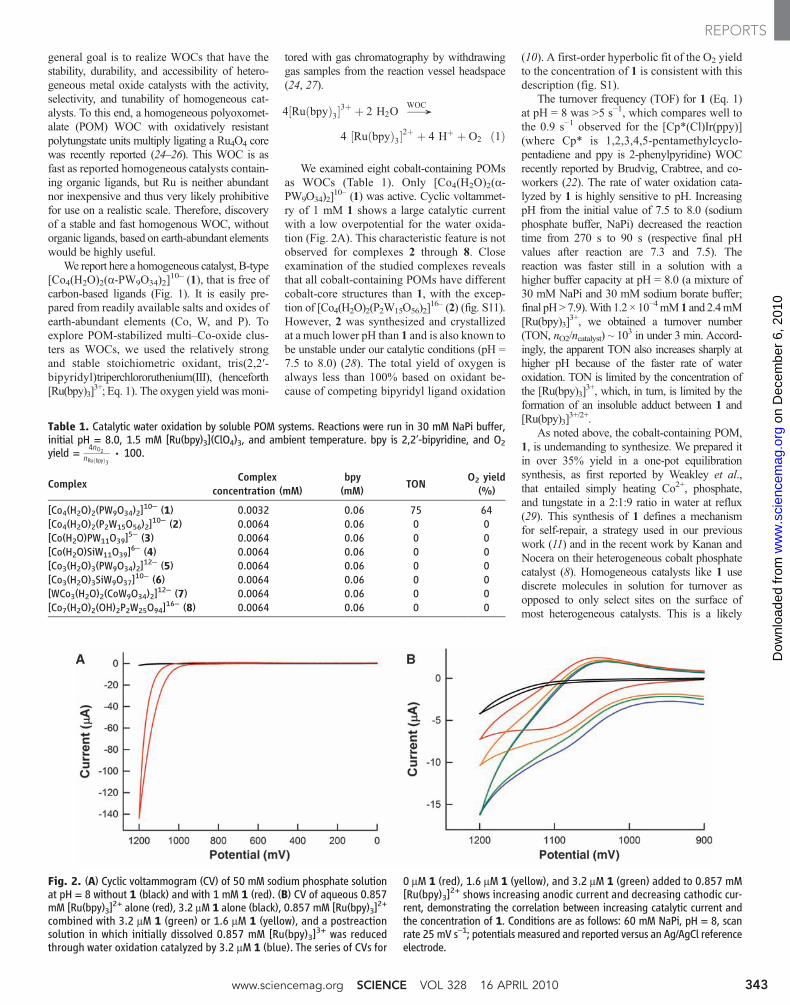
general goal is to realize WOCs that have thestability, durability, and accessibility of hetero-geneous metal oxide catalysts with the activity,selectivity, and tunability of homogeneous cat-alysts. To this end, a homogeneous polyoxomet-alate (POM) WOC with oxidatively resistantpolytungstate units multiply ligating a Ru4O4 corewas recently reported (24–26). This WOC is asfast as reported homogeneous catalysts contain-ing organic ligands, but Ru is neither abundantnor inexpensive and thus very likely prohibitivefor use on a realistic scale. Therefore, discoveryof a stable and fast homogenous WOC, withoutorganic ligands, based on earth-abundant elementswould be highly useful.
We report here a homogeneous catalyst, B-type[Co4(H2O)2(a-PW9O34)2]
10– (1), that is free ofcarbon-based ligands (Fig. 1). It is easily pre-pared from readily available salts and oxides ofearth-abundant elements (Co, W, and P). Toexplore POM-stabilized multi–Co-oxide clus-ters as WOCs, we used the relatively strongand stable stoichiometric oxidant, tris(2,2′-bipyridyl)triperchlororuthenium(III), (henceforth[Ru(bpy)3]
3+; Eq. 1). The oxygen yield was moni-
tored with gas chromatography by withdrawinggas samples from the reaction vessel headspace(24, 27).
4½RuðbpyÞ3�3þ þ 2 H2O →WOC
4 ½RuðbpyÞ3�2þ þ 4 Hþ þ O2 ð1Þ
We examined eight cobalt-containing POMsas WOCs (Table 1). Only [Co4(H2O)2(a-PW9O34)2]
10– (1) was active. Cyclic voltammet-ry of 1 mM 1 shows a large catalytic currentwith a low overpotential for the water oxida-tion (Fig. 2A). This characteristic feature is notobserved for complexes 2 through 8. Closeexamination of the studied complexes revealsthat all cobalt-containing POMs have differentcobalt-core structures than 1, with the excep-tion of [Co4(H2O)2(P2W15O56)2]
16– (2) (fig. S11).However, 2 was synthesized and crystallizedat a much lower pH than 1 and is also known tobe unstable under our catalytic conditions (pH =7.5 to 8.0) (28). The total yield of oxygen isalways less than 100% based on oxidant be-cause of competing bipyridyl ligand oxidation
(10). A first-order hyperbolic fit of the O2 yieldto the concentration of 1 is consistent with thisdescription (fig. S1).
The turnover frequency (TOF) for 1 (Eq. 1)at pH = 8 was >5 s−1, which compares well tothe 0.9 s−1 observed for the [Cp*(Cl)Ir(ppy)](where Cp* is 1,2,3,4,5-pentamethylcyclo-pentadiene and ppy is 2-phenylpyridine) WOCrecently reported by Brudvig, Crabtree, and co-workers (22). The rate of water oxidation cata-lyzed by 1 is highly sensitive to pH. IncreasingpH from the initial value of 7.5 to 8.0 (sodiumphosphate buffer, NaPi) decreased the reactiontime from 270 s to 90 s (respective final pHvalues after reaction are 7.3 and 7.5). Thereaction was faster still in a solution with ahigher buffer capacity at pH = 8.0 (a mixture of30 mM NaPi and 30 mM sodium borate buffer;final pH>7.9).With 1.2 × 10⁻⁴mM 1 and 2.4mM[Ru(bpy)3]
3+, we obtained a turnover number(TON, nO2/ncatalyst) ~ 103 in under 3 min. Accord-ingly, the apparent TON also increases sharply athigher pH because of the faster rate of wateroxidation. TON is limited by the concentration ofthe [Ru(bpy)3]
3+, which, in turn, is limited by theformation of an insoluble adduct between 1 and[Ru(bpy)3]
3+/2+.As noted above, the cobalt-containing POM,
1, is undemanding to synthesize. We prepared itin over 35% yield in a one-pot equilibrationsynthesis, as first reported by Weakley et al.,that entailed simply heating Co2+, phosphate,and tungstate in a 2:1:9 ratio in water at reflux(29). This synthesis of 1 defines a mechanismfor self-repair, a strategy used in our previouswork (11) and in the recent work by Kanan andNocera on their heterogeneous cobalt phosphatecatalyst (8). Homogeneous catalysts like 1 usediscrete molecules in solution for turnover asopposed to only select sites on the surface ofmost heterogeneous catalysts. This is a likely
Table 1. Catalytic water oxidation by soluble POM systems. Reactions were run in 30 mM NaPi buffer,initial pH = 8.0, 1.5 mM [Ru(bpy)3](ClO4)3, and ambient temperature. bpy is 2,2′-bipyridine, and O2yield =
4nO2nRuðbpyÞ3
· 100.
Complex Complexconcentration (mM)
bpy(mM) TON O2 yield
(%)
[Co4(H2O)2(PW9O34)2]10– (1) 0.0032 0.06 75 64
[Co4(H2O)2(P2W15O56)2]10– (2) 0.0064 0.06 0 0
[Co(H2O)PW11O39]5– (3) 0.0064 0.06 0 0
[Co(H2O)SiW11O39]6– (4) 0.0064 0.06 0 0
[Co3(H2O)3(PW9O34)2]12– (5) 0.0064 0.06 0 0
[Co3(H2O)3SiW9O37]10– (6) 0.0064 0.06 0 0
[WCo3(H2O)2(CoW9O34)2]12– (7) 0.0064 0.06 0 0
[Co7(H2O)2(OH)2P2W25O94]16– (8) 0.0064 0.06 0 0
Fig. 2. (A) Cyclic voltammogram (CV) of 50 mM sodium phosphate solutionat pH = 8 without 1 (black) and with 1 mM 1 (red). (B) CV of aqueous 0.857mM [Ru(bpy)3]
2+ alone (red), 3.2 mM 1 alone (black), 0.857 mM [Ru(bpy)3]2+
combined with 3.2 mM 1 (green) or 1.6 mM 1 (yellow), and a postreactionsolution in which initially dissolved 0.857 mM [Ru(bpy)3]
3+ was reducedthrough water oxidation catalyzed by 3.2 mM 1 (blue). The series of CVs for
0 mM 1 (red), 1.6 mM 1 (yellow), and 3.2 mM 1 (green) added to 0.857 mM[Ru(bpy)3]
2+ shows increasing anodic current and decreasing cathodic cur-rent, demonstrating the correlation between increasing catalytic current andthe concentration of 1. Conditions are as follows: 60 mM NaPi, pH = 8, scanrate 25 mV s–1; potentials measured and reported versus an Ag/AgCl referenceelectrode.
www.sciencemag.org SCIENCE VOL 328 16 APRIL 2010 343
REPORTS
on
Dec
embe
r 6,
201
0w
ww
.sci
ence
mag
.org
Dow
nloa
ded
from

factor in a far higher observed efficiency of cata-lytic water oxidation per cobalt atom in the caseof 1 relative to the heterogeneous cobalt phos-phate catalyst.
Aqueous cobalt ions and cobalt hydroxide/oxides that form in situ from the former are bothknown to be WOCs (6, 8, 10). Thus, we nowdescribe seven lines of experimental evidencethat 1 is a stable molecular WOC under turnoverconditions and does not form either aqueouscobalt ions or cobalt hydroxide/oxide. The firsttwo arguments are that no changes are observedin either the ultraviolet and visible absorption(UV-Vis) or the 31P nuclear magnetic resonance(NMR) spectra of a solution of 1 at pH = 8 (thepH in the catalytic experiments) over a 1-monthperiod (figs. S3 and S4C). UV-Vis and 31P NMRspectra also both establish that 1 is stable for atleast 1daywithin thepHrangeof3.5 to9 (fig. S4).
The third experimental probe of the stabilityof 1 involved selective catalyst poisoning ex-periments using 2,2′-bipyridine (bpy) as aninhibitor (fig. S2). Bpy reacts with Co(aq)2+ toform [Co(bpy)3]
2+ (30), inhibiting all wateroxidation activity. In contrast, the addition ofthe same molar excess of bpy to solutions of1 has a relatively minor effect on the apparentwater oxidation activity (Table 2). The observedslight decrease in activity can be attributed tobpy competitively coordinating to the cobaltcore of 1 or the irreversible oxidative degrada-tion of bpy, which is proportional to the bpyconcentration. Similarly, aging 1 under reactionconditions for 3 days had no effect on its cata-lytic water oxidation activity (Table 2), whereasaging Co(NO3)2 under the same conditions for 3days substantially decreased its catalytic activity.This observation tracks with well-known cobalthydroxide/oxide formation above neutral pH
(31), decreasing the effective surface area andcatalytic activity. In addition, at pH = 6.2, nowater oxidation was observed for reactionscatalyzed by 1, whereas Co(NO3)2 was stillcapable of catalyzing a small extent of wateroxidation (Table 2). These results are consistentwith 1 being the catalytically active species andits polydentate polytungstate ligands preventingformation of cobalt hydroxide/oxide particles.
For our fourth probe of the stability of 1, wecharacterized the postreaction solution contain-ing 1 by using 31P NMR despite the low solu-bility of 1 in the presence of excess [Ru(bpy)3]
2+.When [1] = 0.015 mM, as few as 40 equiva-lents of [Ru(bpy)3]
3+/2+ (corresponding to a TONof eight to nine) made the postreaction solu-tion supersaturated, as indicated by the for-mation of a light yellow precipitate that formsin minutes to hours. To prevent precipitation,we removed [Ru(bpy)3]
2+ from the postreac-tion solution by adding NaBPh4 and removingsolid [Ru(bpy)3][BPh4]2 by filtration. In the31P NMR spectrum of this solution, 1 [1850 partsper million, full width at half maximum (Dn1/2) =600 Hz] was the only species detected besidesthe free phosphate originating from the buffersolution, indicating that 1 remains intact undercatalytic water oxidation conditions (fig. S5).
The fifth and sixth experimental probes of thestability of 1 involved IR characterization andreuse of the WOC after an initial catalytic run,which we carried out under conditions scaled upby a factor of 19 relative to run 1 in Table 2. Afterthe reaction was complete, we saturated the solu-tion with [Ru(bpy)3]
2+, which acts as a counterionfor complex 1, resulting in its precipitation. Theinfrared spectrum of the precipitate showed thecharacteristic peaks of 1, a B-type sandwichpolytungstate, [Co4(H2O)2(PW9O34)2]
10–, at
1037, 939, 882, and 767 cm−1 (fig. S6),indicating that the POM framework remainsintact after catalysis. For simplicity, we assumeda 1:1 ratio of the [Ru(bpy)3]
2+ and 1 in theprecipitate and assigned the molecular formula ofthe precipitate to be Na8Ru(bpy)3-1. Applyingthe corresponding molecular weight, we used~0.0032 mM Na8Ru(bpy)3-1 as catalyst in thereaction of [Ru(bpy)3]
3+ with water in pH = 8NaPi buffer in the presence of bpy. Thisreaction gave an O2 yield of 49.3% and aTON of 58 per 1, exactly reproducing the activityof pure crystalline Na10-1 (run 2, Table 2).
The seventh argument for the stability of1 during catalysis is voltammetric behavior dem-onstrating that catalytic activity of the activespecies is retained after turnover. Specifically, wedocument an electrochemical-chemical mecha-nism involving 1: in absence of 1, a conventionalvoltammogram was observed for the [Ru(bpy)3]
3+/[Ru(bpy)3]
2+ couple; however, upon additionof 1, an increased anodic current peak and a de-creased cathodic current peak were observedfor this couple (Fig. 2B). This indicates therapid reduction of [Ru(bpy)3]
3+ by 1 followedby reduction of the oxidized 1 by water. Theobserved catalytic current increased with cata-lyst concentration (24). In addition, Fig. 2B com-pares the current for a freshly prepared solutionof [Ru(bpy)3]
2+ and 1 (green line) with that for asolution that has already undergone catalyticchemical reduction of an equivalent amountof [Ru(bpy)3]
3+ by 1 (blue line). These twocatalytic currents match, implying that there isno evident catalyst deactivation and that theconcentration of 1 remains constant after catal-ysis. In contrast, the same cyclic voltammetricexperiment usingCo(NO3)2 in place of 1 showed amarked decrease in the catalytic water oxidationcurrent for the solution after chemical water oxida-tion when compared with that of an analogoussolution containing unreacted [Ru(bpy)3]
2+ andCo(NO3)2 (fig. S7). Once again, this finding isconsistent with aqueous cobalt hydrolyzing andcondensing to hydroxide/oxide particles under oxi-dative conditions, decreasing the effective catalystconcentration.
Computational studies of the electronic struc-ture of 1 provide additional support for theoxidative stability of the polytungstate ligands.The four highest occupied molecular orbitals(HOMOs) of a high-spin ground state 1 aremostly cobalt core orbitals, and there is almostno involvement of tungstate orbitals (fig. S8).These findings indicate that the polytungstateligands are unlikely to participate in the wateroxidation reaction and should be effectively inertunder catalytic conditions.
Our reporting of this catalyst establishes d-electron–transition metal oxide clusters stabilizedby robust polydentate POM ligands as a com-pelling class of self-assembling inorganic com-plexes capable of catalyzing fast water oxidationin a homogeneous medium. This prompts theexamination of other POM-stabilized multi–
Table 2. The effect of bpy on the catalytic water oxidation activity of 1 and Co(aq)2+. Dashed entryindicates not applicable.
Run ComplexComplex
concentration(mM)
bpy (mM) Buffer TON O2 yield(%)
1 1 0.0032 0 pH = 8 NaPi 78.1 66.72 1 0.0032 0.3012 pH = 8 NaPi 56 483 Co(NO3)2 0.013* 0.3012 pH = 8 NaPi 0 04 Co(NO3)2 0.060† 0.3012 pH = 8 NaPi 0.2 <45 Co(NO3)2 0.013 0 pH = 8 NaPi 23.4 806 No catalyst – 0 pH = 8 NaPi 0 07 1 0.0032 0 pH = 6.2
NaPi/phthalic acid‡0 0
8 Co(NO3)2 0.013 0 pH = 6.2NaPi/phthalic acid
10 35
9 1 0.0032 0.135 pH = 8 NaPi 70.3 6010 1 (aged)§ 0.0032 0.135 pH = 8 NaPi 71.2 60.811 Co(NO3)2
(aged)§0.013 0 pH = 8 NaPi 9.8 33.6
12 CoO|| 0.0032 0 pH = 8 NaPi 0 0*Same theoretical cobalt concentration as 0.0032 mM 1. †Same solid mass as 0.0032 mM 1. ‡A mixed buffer of 30 mMNaPi and 30 mM phthalic acid at pH = 6.2 was used. §A 1 mM stock solution in 30 mM pH = 8 NaPi was left for 72 hoursbefore use. ||Not soluble, suspension obtained after 10 min of sonication.
16 APRIL 2010 VOL 328 SCIENCE www.sciencemag.org344
REPORTS
on
Dec
embe
r 6,
201
0w
ww
.sci
ence
mag
.org
Dow
nloa
ded
from
transition-metal oxide cluster molecules involv-ing both other metals (e.g., Fe and Mn) and newPOM ligands as candidate WOCs. Moreover,the identification of a molecular Co-based WOCmay allow further investigation of its mecha-nism of action, providing a basis for the under-standing of Co-based water oxidation catalysisin general. In addition, 1 may serve as a templatefor future optimizations of all-inorganic WOCsas well as their incorporation into water splittingsystems. No photosensitizers were used in thisreport. Although [Ru(bpy)3]
3+ was used as astoichiometric oxidant in this study in order todemonstrate the water oxidation activity of 1,it is ultimately desirable to use solar power toaccomplish water oxidation. The apparentlystraightforward use of [Ru(bpy)3]
2+ as a photo-sensitizer, however, might not be optimal giventhe oxidative instability of this complex.
References and Notes1. J. Chow, R. J. Kopp, P. R. Portney, Science 302, 1528
(2003).2. N. S. Lewis, D. G. Nocera, Proc. Natl. Acad. Sci. U.S.A.
103, 15729 (2006).3. V. Balzani, A. Credi, M. Venturi, ChemSusChem 1, 26
(2008).4. R. Eisenberg, H. B. Gray, Inorg. Chem. 47, 1697
(2008).
5. V. Y. Shafirovich, N. K. Khannanov, V. V. Strelets, Nouv.J. Chim. 4, 81 (1980).
6. A. Harriman, I. J. Pickering, J. M. Thomas, P. A.Christensen, J. Chem. Soc., Faraday Trans. I 84, 2795(1988).
7. G. L. Elizarova, G. M. Zhidomirov, V. N. Parmon, Catal.Today 58, 71 (2000).
8. M. W. Kanan, D. G. Nocera, Science 321, 1072(2008); published online 31 July 2008(10.1126/science.1162018).
9. W. J. Youngblood et al., J. Am. Chem. Soc. 131, 926(2009).
10. P. K. Ghosh, B. S. Brunschwig, M. Chou, C. Creutz,N. Sutin, J. Am. Chem. Soc. 106, 4772 (1984).
11. I. A. Weinstock et al., Nature 414, 191 (2001).12. F. Jiao, H. Frei, Angew. Chem. Int. Ed. 48, 1841 (2009).13. S. W. Gersten, G. J. Samuels, T. J. Meyer, J. Am. Chem.
Soc. 104, 4029 (1982).14. T. Wada, K. Tsuge, K. Tanaka, Angew. Chem. Int. Ed. 39,
1479 (2000).15. J. Limburg et al., J. Am. Chem. Soc. 123, 423 (2001).16. J. K. Hurst, Coord. Chem. Rev. 249, 313 (2005).17. R. Zong, R. P. Thummel, J. Am. Chem. Soc. 127, 12802
(2005).18. J. T. Muckerman, D. E. Polyansky, T. Wada, K. Tanaka,
E. Fujita, Inorg. Chem. 47, 1787 (2008).19. R. Brimblecombe, G. F. Swiegers, G. C. Dismukes,
L. Spiccia, Angew. Chem. Int. Ed. 47, 7335 (2008).20. S. Romain, F. Bozoglian, X. Sala, A. Llobet, J. Am. Chem. Soc.
131, 2768 (2009).21. S. W. Kohl et al., Science 324, 74 (2009).22. J. F. Hull et al., J. Am. Chem. Soc. 131, 8730 (2009).23. H. Kunkely, A. Vogler, Angew. Chem. Int. Ed. 48, 1685
(2009).
24. Y. V. Geletii et al., Angew. Chem. Int. Ed. 47, 3896 (2008).25. A. Sartorel et al., J. Am. Chem. Soc. 130, 5006 (2008).26. Y. V. Geletii et al., J. Am. Chem. Soc. 131, 7522 (2009).27. Materials and methods are available as supporting
material on Science Online.28. L. Ruhlmann, L. Nadjo, J. Canny, R. Contant,
R. Thouvenot, Eur. J. Inorg. Chem. 2002, 975 (2002).29. T. J. R. Weakley, H. T. Evans Jr., J. S. Showell,
G. F. Tourné, C. M. Tourné, J. Chem. Soc. Chem. Commun.4, 139 (1973).
30. F. H. Burstall, R. S. Nyholm, J. Chem. Soc. 1952, 3570(1952).
31. J. Baes, F. Charles, R. E. Mesmer, The Hydrolysis of Cations(Wiley, New York, 1976).
32. We thank the U.S. Department of Energy through grantDE-FG02-03ER-15461 for support of this work. C.B.thanks the French Ministère de l‘Éducation Nationale,de la Recherche, et de la Technologie for a researchfellowship. Additional details on the crystal structureinvestigations may be obtained from theFachinformationszent Wrum Karlsruhe, 76344Eggenstein-Leopoldshafen, Germany, on quotingregistry number CSD-421465.
Supporting Online Materialwww.sciencemag.org/cgi/content/full/science.1185372/DC1Materials and MethodsFigs. S1 to S11References
1 December 2009; accepted 25 February 2010Published online 11 March 2010;10.1126/science.1185372Include this information when citing this paper.
Oxoboryl Complexes: Boron−OxygenTriple Bonds Stabilized in theCoordination Sphere of PlatinumHolger Braunschweig,* Krzysztof Radacki, Achim Schneider
Monomeric oxoboranes have hitherto been detected only as short-lived species in gas-phase orlow-temperature matrix experiments. Here, we report formation of the oxoboryl complextrans-[(Cy3P)2BrPt(B≡O)] (Cy being cyclohexyl) by means of reversible liberation oftrimethylsilylbromide from the boron–bromine oxidative addition product of dibromo(trimethylsiloxy)borane and [Pt(PCy3)2] in room-temperature toluene solution. The platinumcomplex is inert toward oligomerization, even under photolytic conditions and at elevatedtemperatures. The bromide was substituted by thiophenolate, and spectral parameters of bothproducts as well as results of computational and x-ray diffraction studies are in agreement with theformulation of a triple bond between boron and oxygen. The boron–oxygen distance of 120.5(7)picometers shows a bond shortening of 7.2% as compared with a double bond, which is similarto the shortening observed in carbon–carbon analogs.
The element boron is popularly known forits unique propensity to participate in mul-ticenter bonds to compensate its intrinsic
electron-deficiency. Thus, various structural mo-tifs have been described that exhibit boron withcoordination numbers higher than its actual va-lency (1). However, not least because of the im-portance of boranes in organic syntheses (2) thechemistry of boron-containing compounds fea-
turing exclusively classical, electron-precise bondshas been established during the last century, andtherefore examples with tricoordinate boron like-wise are plentiful. Though species with dicoordi-nate boron are considerablymore unusual, differentstrategies to prepare and stabilize those compoundshave been applied successfully (3–8).
Since boroxine (H3B3O3) could be identifiedas the product of highly energetic reactions ofdifferent ternary systems (9), numerous attemptshave been undertaken to synthesize its mono-meric counterparts, namely oxoboranes (XBOs).However, those species could be detected onlyin either gas-phase (10–13) or low-temperaturematrix isolation studies (14–19). Further evi-dence for the existence of those compounds wasobtained through different trapping experiments(20–22) or nuclear magnetic resonance (NMR)spectroscopic observation of the correspondingLewis base adduct (22). Microwave (11) and in-frared (IR) data (14–19) suggest a very stronglinkage of boron and oxygen; because of the simi-larity of the photoelectron spectrum of H3CBOwith the isoelectronic H3CCNmolecule (12, 13),the B–O linkage was described by a triple bond.Nevertheless, probably because of the polar na-ture of this bond, the highly reactive monomersreadily undergo cyclooligomerization even at tem-peratures of approximately 50 K (19, 23) andan x-ray structural elucidation could not beperformed.
Commonly, kinetic lability of low-valent spe-cies can be compensated by use of bulky substit-uents that inhibit bimolecular attack, as wassuccessfully demonstrated by the preparation ofa stable disilyne (24). In contrast, XBOs contain-
Institut für Anorganische Chemie, Julius-Maximilians-UniversitätWürzburg, Am Hubland, 97074 Würzburg, Germany.
*To whom correspondence should be addressed. E-mail:[email protected] Scheme 1. Preparation of trans-[(Cy3P)2BrPt(BO)] (2).
www.sciencemag.org SCIENCE VOL 328 16 APRIL 2010 345
REPORTS
on
Dec
embe
r 6,
201
0w
ww
.sci
ence
mag
.org
Dow
nloa
ded
from

A Novel Brand of Water Oxidation Catalysts: the Groundwork for a New Generation
John DiMeglio
Department of Chemistry and Biochemistry, University of Delaware, Newark DE, 19716
Inspired by the global shift to renewable energy
sources, there has been much effort to design viable water
oxidation catalysts (WOCs). Previous WOCs have been
plagued with instabilities or based on rare and expensive
metals. Herein an analysis of a novel WOC based on earth
abundant metals is described. This WOC was characterized
via CV, 31
P NMR, UV-Vis and IR spectroscopy. Further
studies are suggested for the design and use of this new
brand of WOC.
Renewable energy has been a scientific and politic hot-
topic for the past several decades. Inspired by the ever rising CO2
levels in the atmosphere and our dependence on foreign oil ,
science has made strides toward alternative energy sources. Many
of these advances have been in the area of solar energy.
Nevertheless, we still lack a reliable way to store energy captured
by the sun.1 Plants have perfected this, however by storing this
energy in the form of chemical bonds via photosynthesis.2
Inspired by this process, chemists have develop a series of water
oxidation catalysts (WOCs). These WOCs are intended to use
solar radiation to oxidize water to H2 and O2(Scheme 1). Recently
a novel type of WOC, composed of abundant metals has been
reported by Yin and co workers.3 To demonstrate the significance
of this discovery, a brief history of WOC research is discussed.
Scheme 1. The two half reactions for the oxidation of water to
oxygen and hydrogen.
Fujishima and Honda were the first to report conditions
for the photo-electrochemical oxidation of water. Using a TiO2
electrode and a potential of nearly -0.5 V, they observed the
evolution of O2(g) signifying water oxidation.4 However, since
then more efficient pathways for water oxidation have been
uncovered, included a series of homogeneous and heterogeneous
catalysts. The former has the advantage of being easier to study
and more efficient, while the ladder is typically cheaper and more
stable.3
Some examples of homogeneneous WOCs include the
[(bpy)2(H2O)Ru-O-Ru(H2O)(bpy)2] system that oxidized water
via the pathway shown (Scheme 2). However, this dimer is
unstable and after a few cycles a loss of catalytic activity as well
as its distinctive blue color is observed.5 Newer homogeneous
systems include the [RuIII2(O)2(3,6-tBu2qui)2(btpyan)]4+ system
(where 3,6-tBu2qui =3,6-di-tert-butyl-1,2-semiquinone and btpyan
= 1,8-bis(2,2‘:6‘,2‘‘-terpyridyl)anthracene) which have been
shown to have promote the catalytic oxidation of water.6
However, this complex and several other similar are limited by
the use of organic ligands, which are thermodynamically unstable
in the presence of O2.3
Scheme 2. Oxidation of water proposed by Grensten, Samuels,
and Myer, where cat. = [(bpy)2(H2O)Ru-O-Ru(H2O)(bpy)2].5
Heterogeneous catalysts, however, are much more
stable under these conditions. Examples include the self-
assembling Co, P, and K based catalyst reported by Kanan and
Nocera, as well as IrO2●nH2O based nanoparticles reported by
Youngblood and coworkers.7,8 Drawbacks to these systems
include the inherit inefficiency of heterogeneous catalysis as well
as the tendency for catalysts of these types to deactivate by
surface poisoning and aggregation.3
It is clear that the most efficient WOC must have the
activity and selectivity of a homogeneous catalyst with the
efficiency and durability of a heterogeneous catalyst. With this in
mind a homogeneous polyoxometalate (POM) WOC with
oxidatively stable polytungstate ligands around a Ru4O4 core has
been reported.9 Although this POM WOC has demonstrated the
viability of homogeneous catalysts, it was limited by the rarity
and expense of ruthenium.
An effort was therefore put forth to investigate potential
POM WOC based on abundant metals. Yin and coworkers were
the first to publish the use of [Co4(H2O)2(PW9O34)2]10- (1, Figure
1) as a WOC.3 The synthesis of this complex is trivial and
involves a one-pot reaction of Co2+, phosphate, and tungstate salts
as previously reported by Weakley et al.10 Other POM based Co
complexes were made(2-8), however none of them showed
reactivity toward water under oxidizing conditions (Table 1).
Modeling studies have shown that 1 has a unique Co core
structure that 3-8 lacked. Unfortunately, 2 which shares this core
structure is unstable at the desired pH range of 7.5-8.0.

Figure 1. X ray structure of 1, highlighting the Cu4O16 core with a
ball and stick representation and the POM ligands as
polyhedrons.3
Table 1. List of all POM based complexes investigated by Yin
and co-workers. these reactions were run in a 30 mM NaPi buffer,
initial pH = 8.0, 1.5 mM [Ru(bpy)3](ClO4)3, 1 was run at a
complex concentration of 0.032 mM, while 2-8 were run at
0.0064 mM complex concentration.3
Complex TON O2 yield (%)
[Co4(H2O)2(PW9O34)2]10- (1) 75 64
[Co4(H2O)2(P2W15O56)2]10- (2) 0 0
[Co(H2O)PW11O39]5- (3) 0 0
[Co(H2O)SiW11O39]6- (4) 0 0
[Co3(H2O)3(PW9O34)2]12- (5) 0 0
[Co3(H2O)3SiW9O37]10- (6) 0 0
[WCo3(H2O)2(CoW9O3)2]12- (7) 0 0
[Co7(H2O)2(OH)2P2W25O94]16- (8) 0 0
These POM systems were evaluated by mixing the
catalyst with the strong stoichiometric oxidant tris(2,2'-
bipyridyl)triperchlororuthenium(III) ([Ru(bpy)3]3+) (Scheme 3).
Aliquots were taken from the head space of this reaction and
analyzed using GC. It was found that only 1 showed propensity to
oxidize water to give an O2 yield (4n O2/n Ru(bpy)3) of 64 % and
a turnover number (TON, n O2/n catalyst) of 75. The O2 yield is
limited by the Ru(bpy)3 because of a competing reaction where
the bipyridyl ligand gets oxidized. Likewise, the TON is limited
by the amount of Ru(bpy)3, since this reagent is stoichiometric.
Once it was determined that 1 was a potential WOC, further
analytical information was obtained via CV, 31P NMR, UV-Vis
and IR spectroscopy.3
Scheme 3. Oxidation scheme proposed by Yin and co workers,
where cat. = [Co4(H2O)2(PW9O34)2]10-.
Cyclic voltamitry (CV) is a common electrochemical
experiment where the oxidation and reduction potentials of a
complex are evaluated by varying the potential across a working
and reference electrode, while the current of the solution is
measured. A third electrode, a reference is required to standardize
these results to NHE.11 With this electrochemical technique in
hand it was determined that 1 operates at a low-over potential for
the water oxidation by examining the reductive wave
corresponding to the catalytic current. (Figure 2) It was further
shown that upon addition of 1 to a solution of [Ru(bpy)3]3+, there
is an increase in anodic current and a decrease in cathoic current.
Further, as the concentration of 1 increases, the greater the change
in anodic and cathodic currents. (Figure 3) These observations
support that upon reduction of [Ru(bpy)3]3+ by 1, there is a
reduction of the oxidized form of 1 by water.
Figure 2. CV of a 50 mM sodium phosphate solution without 1
(black) and with 1 mM 1 (red).3
Figure 3. CV of 0.857 mM [Ru(bpy)3]2+ alone (red), 3.2 µM 1
alone (black), 0.857 mM [Ru(bpy)3]2+ with 1.6 µM 1 (yellow) or
3.2 µM 1 (green), and a postreaction solution of 0.857 mM
[Ru(bpy)3]3+ and 3.2 µM 1 (blue).3
Since stability was a major issue for past WOCs an
extensive effort was put forth to evaluate the longevity of 1 under
various conditions. It was shown that over one month there was
no change in the 31P NMR or UV-Vis spectra of 1 at a pH = 8. In
another experiment, a molar excess of 2,2'-bupridine (bpy), a
known inhibitor that reacts with free Co2+ ions was added to a
solution of 1. After little change to its catalytic activity it is
believed that there was minimal Co2+(aq) ions in solution. Third, a
13P NMR spectrum of a post reaction solution displayed no
unexpected resonances. Further, 1 was precipitated out of a post
reaction solution and characterized with IR spectroscopy. This
solid was shown to retain its catalytic ability and via the presence
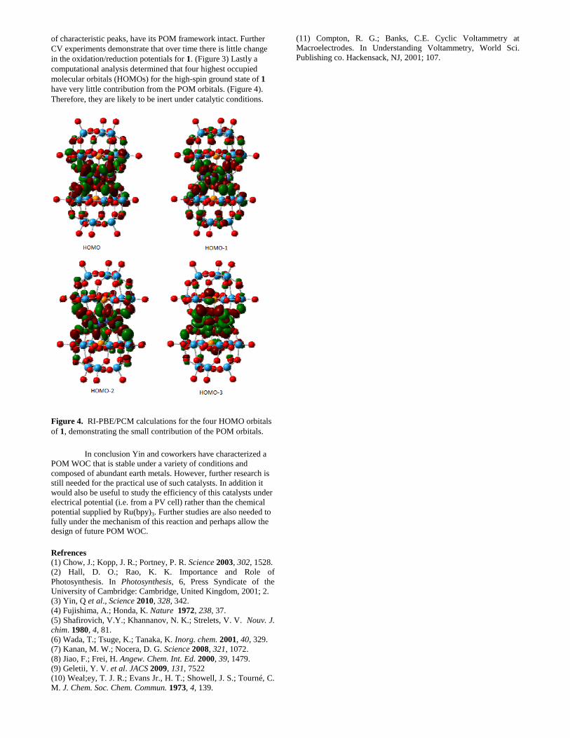
of characteristic peaks, have its POM framework intact. Further
CV experiments demonstrate that over time there is little change
in the oxidation/reduction potentials for 1. (Figure 3) Lastly a
computational analysis determined that four highest occupied
molecular orbitals (HOMOs) for the high-spin ground state of 1
have very little contribution from the POM orbitals. (Figure 4).
Therefore, they are likely to be inert under catalytic conditions.
Figure 4. RI-PBE/PCM calculations for the four HOMO orbitals
of 1, demonstrating the small contribution of the POM orbitals.
In conclusion Yin and coworkers have characterized a
POM WOC that is stable under a variety of conditions and
composed of abundant earth metals. However, further research is
still needed for the practical use of such catalysts. In addition it
would also be useful to study the efficiency of this catalysts under
electrical potential (i.e. from a PV cell) rather than the chemical
potential supplied by Ru(bpy)3. Further studies are also needed to
fully under the mechanism of this reaction and perhaps allow the
design of future POM WOC.
Refrences
(1) Chow, J.; Kopp, J. R.; Portney, P. R. Science 2003, 302, 1528.
(2) Hall, D. O.; Rao, K. K. Importance and Role of
Photosynthesis. In Photosynthesis, 6, Press Syndicate of the
University of Cambridge: Cambridge, United Kingdom, 2001; 2.
(3) Yin, Q et al., Science 2010, 328, 342.
(4) Fujishima, A.; Honda, K. Nature 1972, 238, 37.
(5) Shafirovich, V.Y.; Khannanov, N. K.; Strelets, V. V. Nouv. J.
chim. 1980, 4, 81.
(6) Wada, T.; Tsuge, K.; Tanaka, K. Inorg. chem. 2001, 40, 329.
(7) Kanan, M. W.; Nocera, D. G. Science 2008, 321, 1072.
(8) Jiao, F.; Frei, H. Angew. Chem. Int. Ed. 2000, 39, 1479.
(9) Geletii, Y. V. et al. JACS 2009, 131, 7522
(10) Weal;ey, T. J. R.; Evans Jr., H. T.; Showell, J. S.; Tourné, C.
M. J. Chem. Soc. Chem. Commun. 1973, 4, 139.
(11) Compton, R. G.; Banks, C.E. Cyclic Voltammetry at
Macroelectrodes. In Understanding Voltammetry, World Sci.
Publishing co. Hackensack, NJ, 2001; 107.

Stable Magnesium(I) Compoundswith Mg-Mg BondsShaun P. Green,1,2 Cameron Jones,1* Andreas Stasch1*
The chemistry of the group 2 metals (beryllium, magnesium, calcium, strontium, and barium) isdominated by the +2 oxidation state. Here, we report the reductions of two magnesium(II) iodidecomplexes with potassium metal in toluene, leading to thermally stable magnesium(I) compounds,(L)MgMg(L) (where L is [(Ar)NC(NPri2)N(Ar)]
– or {[(Ar)NC(Me)]2CH}–, Ar is 2,6-diisopropylphenyl, Me
is methyl, and Pri is isopropyl) in moderate yields. The results of x-ray crystallographic and theoreticalstudies are consistent with central Mg2
2+ units that have single, covalent magnesium-magnesiumbonding interactions with 2.8508 ± 0.0012 (standard deviation) and 2.8457 ± 0.0008 angstrom bondlengths, respectively, and predominantly ionic interactions with the anionic ligands (L).
Magnesium is ubiquitous in living orga-nisms, Earth’s crust, and seawater (1).Like the other alkaline earth metals
(group 2 metals), magnesium is present in all itsknown stable compounds in the +2 oxidationstate. It plays a major role in nature as the centralion in chlorophyll because its redox-inertcharacter is important for the charge separationin photosynthesis (1). The reduction of othermetal ions has involved the formation of directmetal-metal bonds. For example, homonuclearcompounds, RMIMIR (where R represents anorganic or similar substituent and M is a metal),of p- or d-block metals have been prepared withthe metal centers formally in the +1 oxidationstate. Two recent landmark advances in this fieldare the synthesis of a chromium(I) dimer[L'CrCrL', where L' is C6H3(C6H3Pr
i2-2,6)2-2,6
and Pri is isopropyl] containing a metal-metalquintuple bonding interaction (2) and thesynthesis of a zinc(I) compound, (h5-C5Me5)ZnZn(h5-C5Me5) (where Me is methyl) (3).Since the report on the latter, the chemicalsimilarities between zinc and the lighter group 2metals have prompted theoreticians to examinethe possibility of preparing complexes of the typeRMMR (where M is Be, Mg, or Ca), with theconclusion that such reduced s-block compoundsshould be stable given the correct choice ofligand (4–6). A number of magnesium(I)compounds, for example, HMgMgH, havepreviously been studied under, for example,matrix isolation conditions (7), and mononu-clear compounds, for example, MgI(NC), havebeen detected in circumstellar clouds (8). More-over, the formation of synthetically importantGrignard reagents, RMgX (where X is a halide),has been proposed to proceed via magnesium(I)compounds of the type RMgMgX (9). In ad-dition, related cluster compounds, RMg4X, ofundetermined structure have been investigatedby using mass spectrometry experiments (10).
However, no examples of stable molecular group2 metal(I) compounds have been isolated.
In the past 2 years, we have developedand used the bulky guanidinate ligands,[(Ar)NC(NR'2)N(Ar)]– [where Ar is 2,6-diisopropylphenyl and R' is isopropyl (Priso)or cyclohexyl (Giso)] to access complexes ofp-block elements in the +1 oxidation state, forexample, GaI(Giso) (11) and [GeI(Priso)]2 (12).The ability of these sterically hindered, N,N'-chelating ligands to stabilize low oxidation statecomplexes is strikingly similar to that of bulkyexamples from the well-studied b-diketiminateclass of ligand, for example, {[(Ar)NC(Me)]2CH}
–
(Nacnac) (13). Here, we report the use of bothPriso and Nacnac ligands to prepare molecularmagnesium(I) compounds that contain struc-turally characterized magnesium-magnesiumbonds. We examined the nature of the bondingin these compounds by theoretical studies andalso carried out preliminary reactivity studies.
The new magnesium(II) complex,(Priso)Mg(m-I)2Mg(OEt2)(Priso) (OEt2 is di-ethyl ether), was prepared as a precursor toone of the target magnesium(I) compounds (14).This was spectroscopically characterized, and itsx-ray crystal structure was determined (fig. S2).Reduction of (Priso)Mg(m-I)2Mg(OEt2)(Priso)and the known compound, MgI(OEt2)(Nacnac)(15), with an excess of potassium metal in tolueneover 24 hours led to the crystalline magnesium(I)compounds [Mg(Priso)]2 1 (colorless, yield of28.5%) and [Mg(Nacnac)]2 2 (yellow, yield of56.5%), respectively, after workup (Fig. 1) (14).Although both compounds are air- and moisture-sensitive, they are thermally stable and fully de-compose only at temperatures in excess of 170°Cand 300°C, respectively, the former with deposi-tion of elemental magnesium. The x-ray crystalstructure of each compound was obtained (Figs. 2and 3) (16). Both possess distorted trigonalplanar coordination geometries with delocal-ized ligand backbones. Although their Mg-Ndistances [2.0736(10) (or ±0.0010) Å for 1 and amean value of 2.060 Å for 2; the number inparentheses indicates the standard deviation]are in the known range for Mg-N bonds (17),they are longer than all such bonds in com-plexes in which b-diketiminates ligate three-coordinate magnesium(II) centers. Despite thepaucity of Mg-Mg bonds for comparison, thelengths of those interactions in 1 and 2 are sim-ilar [2.8508(12) Å and 2.8457(8) Å, respective-ly]. Although these distances are considerablyshorter than those in diatomic or elemental mag-nesium (3.890 Å and 3.20 Å, respectively) (18, 19),they are longer than the sum of two mag-nesium covalent radii (2.72 Å) (19). The dis-tances are, however, in the range of previously
1School of Chemistry, Monash University, Post Office Box23, Victoria 3800, Australia. 2School of Chemistry, MainBuilding, Cardiff University, Cardiff CF10 3AT, UK.
*To whom correspondence should be addressed. E-mail:[email protected] (C.J.); [email protected] (A.S.) Fig. 1. Formation of compounds 1, 2, and 5.
14 DECEMBER 2007 VOL 318 SCIENCE www.sciencemag.org1754
REPORTS
on
Dec
embe
r 6,
201
0w
ww
.sci
ence
mag
.org
Dow
nloa
ded
from

calculated Mg-Mg separations in theoretical mo-lecular compounds, for example, the cyclopenta-dienyl magnesium(I) dimer, (C5H5)MgMg(C5H5)[2.776 Å (B3LYP calculations) (4) and 2.809 Å(BP86) (5)], the 2,6-diphenylphenyl magnesium(I)dimer, {[C6H3(C6H5)2-2,6]MgMg[C6H3(C6H5)2-2,6]}[2.838 Å (BP86) (6)], and HMgMgH [2.862 Å(B3LYP) (4) and 2.884 Å (BP86) (5)]. It should alsobe noted that two nonbonded Mg...Mg interactionsin one cluster compound, [Mg(THF)(m-C6H4)]4(THF is tetrahydrofuran) (20), are shorter [2.804(2)Å and 2.841(2) Å] than the separations in1 and 2.
Considering the relatively longMg-Mg bondsin 1 and 2, the possibility that these com-pounds actually exist as hydride-bridged mag-nesium(II) dimers, [Mg(L)(m-H)]2 (L is Prisoor Nacnac), cannot be overlooked. However,the combined weight of the crystallographic,spectroscopic, theoretical, and chemical evi-dence discounts this possibility (vide infra).First, the heterocycle least squares planes in1 are orthogonal, whereas compound 2 hasclose to orthogonal heterocycle planes (dihedralangle is 80.2°) and is isostructural with the re-lated metal(I) dimers, [MI(Nacnac)]2 [M is Zn(21) or Mn (22)]. If 1 and 2 were hydride-bridgeddimers, their heterocycles would, instead, be ex-pected to be close to coplanar. In addition, in thefinal difference maps of the structural refinementsof both compounds, there were no regions of resid-ual electron density of greater than 0.15 electronsper cubic angstrom close to the Mg-Mg vectors,again suggesting the absence of hydride ligands.
The nuclear magnetic resonance (NMR) spec-troscopic data for diamagnetic 1 and 2 are con-sistent with their proposed formulations. Nobridging hydride resonances were observed inthe expected chemical shift range in the 1H NMRspectra of the complexes (23). In addition, theirelectron ionization high-resolution accurate massspectra exhibit molecular ion envelopes with iso-topic mass distributions that match well those cal-culated for the hydride-free complexes (fig. S1).In this respect, the stability of 2 in the gas phase isdemonstrated by the fact that it can be sublimedintact at 230°C (circa 10−6 mm Hg). The Ramanspectra of the compounds display a number oflow-frequency absorptions, although none ofthese can be confidently assigned as arising fromMg-Mg stretching modes. Similarly, little informa-tion regarding the structures of the complexes canbe obtained from their infrared spectra. Mg-H-Mgstretching absorptions originating from the alter-natively formulated complexes, [Mg(L)(m-H)]2,would certainly lie in the fingerprint region (24)and would, thus, be difficult to assign due tooverlap with low-frequency ligand modes. Be-cause we have not yet been able to prepare au-thentic samples of [Mg(L)(m-H)]2 by rationalroutes (14), we cannot compare their infraredspectra {and the infrared spectra of their deuteratedanalogs, [Mg(L)(m-D)]2} with those of 1 and 2.
In order to examine the nature of the bondingin 1, density functional theory (DFT) calcula-
Fig. 2. Molecular structure of 1 (hydrogen atoms omitted, ellipsoids shown at the 20% probabilitylevel). Selected bond lengths and angles: Mg(1)-Mg(1)W 2.8508(12) Å, Mg(1)-N(1) 2.0736(10) Å,N(1)-C(1) 1.3497(12) Å, N(2)-C(1) 1.389(2) Å; N(1)-Mg(1)-N(1)' 65.54(5)°, N(1)-C(1)-N(1)' 112.53(13)°,N(1)-Mg(1)-Mg(1)W 147.23(3)°.
Fig. 3. Molecular structure of 2 (hydrogen atoms omitted, ellipsoids shown at the 20% probability level).Selected bond lengths and angles: Mg(1)-Mg(2) 2.8457(8) Å, Mg(1)-N(2) 2.0547(13) Å, Mg(1)-N(1)2.0643(13) Å, N(1)-C(2) 1.3354(18) Å, C(1)-C(2) 1.5135(19) Å, Mg(2)-N(3) 2.0571(13) Å, Mg(2)-N(4)2.0656(12) Å, N(2)-C(4) 1.3251(17) Å, C(2)-C(3) 1.4041(19) Å, N(3)-C(31) 1.3269(18) Å, C(3)-C(4)1.4041(19) Å, N(4)-C(33) 1.3368(17) Å, C(4)-C(5) 1.5116(19) Å, C(30)-C(31) 1.514(2) Å, C(31)-C(32)1.409(2) Å, C(32)-C(33) 1.398(2) Å, C(33)-C(34) 1.5157(19) Å; N(2)-Mg(1)-N(1) 91.78(5)°, N(2)-Mg(1)-Mg(2) 128.50(4)°, N(1)-Mg(1)-Mg(2) 139.35(4)°, N(3)-Mg(2)-N(4) 91.80(5)°, N(3)-Mg(2)-Mg(1)129.65(4)°, N(4)-Mg(2)-Mg(1) 138.24(4)°.
www.sciencemag.org SCIENCE VOL 318 14 DECEMBER 2007 1755
REPORTS
on
Dec
embe
r 6,
201
0w
ww
.sci
ence
mag
.org
Dow
nloa
ded
from

tions (B3LYP and BP86) (25) were carried outon themodel complex, {Mg[(Ar'N)2C(NMe2)]}23 (Ar' is C6H3Me2-2,6). The geometry of the op-timized structure was found to be in close agree-ment with that in the crystal structure of 1 (i.e.,with effectively orthogonal heterocycle planes)but with slightly underestimated Mg-Mg bondlengths (with B3LYP, 2.828 Å; with BP86,2.839Å) and slightly overestimatedMg-Ndistances(withB3LYP,mean =2.102Å;withBP86,mean =2.114 Å). Figure 4A depicts the highest occupiedmolecular orbital (HOMO) of the complex, whichlargely comprises the metal-metal s-bonding inter-action. The two lowest unoccupied orbitals, LUMO(Fig. 4B) and LUMO+1 (fig. S4), are almost de-generate (energy difference of 0.11 eV, 2.6 kcalmol−1) and predominantly encompass metal-metalp-bonding orbitals derived from metal px- and py-orbital overlaps respectively. A similar arrange-ment of frontier orbitals has been calculated for[C6H3(C6H5)2-2,6]ZnZn[C6H3(C6H5)2-2,6] (26).The HOMO-LUMO gap in 3 (4.02 eV, 93.0 kcalmol−1) is comparable with those calculated for both(C5H5)MgMg(C5H5) (3.87 eV, 89.5 kcalmol
−1) (5)and [C6H3(C6H5)2-2,6]ZnZn[C6H3(C6H5)2-2,6](4.25 eV, 97.6 kcal mol−1) (26). In addition, theresults of a natural bonding orbital (NBO) analysis(B3LYP) of theMg-Mg interaction in 3 indicatea high s-character, single covalent bond (93.2%s-, 6.0% p-, and 0.8% d-character; Wiberg bondindex = 0.914), whereas the metal-ligand inter-actions are predominantly ionic (natural chargefor Mg, +0.82 mean, and for N, –0.97 mean).Accordingly, the molecule can be viewed as ananion-stabilized Mg2
2+ unit, as has been dis-cussed for other model RMgMgR systems (4–6).
We were prompted to analyze the theoreticalhydride complex, {Mg[(Ar'N)2C(NMe2)](m-H)}24, using DFT calculations (B3LYP) for pur-
poses of comparison with 1 and 3. In contrast tothose complexes, the optimized geometry of 4 ex-hibits coplanar heterocycles, oriented nearly or-thogonal to the bridging, symmetrical Mg2H2 unit.Scans of the potential energy hypersurface ofthe less bulkymodel, {Mg[(HN)2C(NH2)](m-H)}2,at density functional (B3LYP) and ab initio (MP2)levels of theory, show this conformation to be theglobal minimum (14). Moreover, there are no localminima associated with any conformation of themolecule in which the planes of the magnesiumheterocycles are orthogonal or close to orthogonalwith each other. Surprisingly, the Mg...Mg sepa-ration in 4 at 2.770 Å (Mg-H mean distance =1.890 Å) is substantially shorter than in 3, despitea less pronouncedmetal-metal interaction (Wibergbond index = 0.307). In this respect, previous the-oretical studies have concluded that metal-metaldistances in hydride bridged complexes can beshorter than in corresponding hydride-free, metal-metal bonded complexes (27). The results of allcalculations undertaken are fully consistent with1 (and by implication 2) being a magnesium(I)dimer, not a hydride bridged magnesium(II)dimer.
Although 1 and 2 would be expected to behighly reducing, we have found that they donot react with dihydrogen or dinitrogen intoluene, even at elevated temperatures (80°C)or when irradiated with ultraviolet light (l =254 nm). The lack of reactivity of the com-plexes toward dihydrogen is not surprisingwhen it is considered that the closely relatedaddition of H2 to [(C5H5)MgMg(C5H5)] [togenerate two molecules of (C5H5)MgH] hasbeen calculated to be an endothermic process(4). Surprisingly, exposure of the three-coordinatemagnesium centers in 1 and 2 to THF in C6D6
solutions does not lead to evidence of THF coor-
dination as judged by 1H or 13C{1H} NMRspectroscopy. However, a weak, transient coor-dination of THF cannot be ruled out in these ex-periments on the basis of the results of thereaction of 2 with the carbodiimide CyNCNCy(Cy is cyclohexyl) in toluene at –70°C (Fig. 1).This led to immediate loss of the yellow color of2 and the isolation of the magnesium magnesio-amidinate complex, 5, after warming the reactionmixture to 20°C (14). Presumably, this reactionoccurs via an initial coordination of one N-centerof the carbodiimide at a magnesium center, fol-lowed by a double reduction of the carbodiimideand its concomitant insertion into the Mg-Mgbond of 2 (28, 29). The spectroscopic data for 5are consistent with the solid-state structure deter-mined by an x-ray crystallographic study (fig. S4).In contrast to the nearly orthogonal Mg(Nacnac)least squares planes in 2, these planes in 5 aremutually parallel and orthogonal to the CyN-CNCy unit. Reaction of the carbodiimide withthe alternative hydride-bridged magnesium(II)complex, [Mg(Nacnac)(m-H)]2, would not be ex-pected to give compound 5 but instead C=N bondhydromagnesiation.
References and Notes1. W. Kaim, B. Schwederski, Bioinorganic Chemistry:
Inorganic Elements in the Chemistry of Life - AnIntroduction and Guide (Wiley, Chichester, 1994),chapters 2 and 4.
2. T. Nguyen et al., Science 310, 844 (2005); publishedonline 22 September 2005 (10.1126/science.1116789).
3. I. Resa, E. Carmona, E. Gutierrez-Puebla, A. Monge,Science 305, 1136 (2004).
4. Y. Xie, H. F. Schaefer III, E. D. Jemmis, Chem. Phys. Lett.402, 414 (2005).
5. A. Velazquez, I. Fernandez, G. Frenking, G. Merino,Organometallics 26, 4731 (2007).
6. M. Westerhausen et al., Chem. Eur. J. 13, 6292 (2007).7. X. Wang, L. Andrews, J. Chem. Phys. A 108, 11511 (2004).8. S. Petrie, Aust. J. Chem. 56, 259 (2003).
Fig. 4. Representations of (A) the HOMO (–4.75 eV) and (B) the LUMO (–0.722 eV) of the model system {Mg[(Ar'N)2C(NMe2)]}2 3 (Ar' is C6H3Me2-2,6).
14 DECEMBER 2007 VOL 318 SCIENCE www.sciencemag.org1756
REPORTS
on
Dec
embe
r 6,
201
0w
ww
.sci
ence
mag
.org
Dow
nloa
ded
from

9. P. G. Jasien, C. E. Dykstra, J. Am. Chem. Soc. 105, 2089(1983).
10. L. A. Tjurina et al., Organometallics 23, 1349 (2004).11. C. Jones, P. C. Junk, J. A. Platts, A. Stasch, J. Am. Chem.
Soc. 128, 2206 (2006).12. S. P. Green, C. Jones, P. C. Junk, K.-A. Lippert, A. Stasch,
Chem. Commun. 3978 (2006).13. L. Bourget-Merle, M. F. Lappert, J. R. Severn, Chem. Rev.
102, 3031 (2002).14. Materials and methods are available on Science Online.15. J. Prust et al., Z. Anorg. Allg. Chem. 627, 2032 (2001).16. Crystal data for 1 and 2 were obtained at 123(2) K with
use of an Enraf-Nonius Kappa charge-coupled devicediffractometer and MoKa radiation (l = 0.71073 A ).The crystal data are as follows. For 1: a = b = 18.409(3) A,c = 17.640(4) A, tetragonal, I41/a, Z = 4, R1 for 3176[data intensity I > 2s(I)] unique data = 0.0448, andwR2 (all 4353 unique data) = 0.1256. For 2: a =14.444(3) A, b = 14.203(3) A, c = 26.742(5) A, b =94.87(3)°, monoclinic, P21/c, Z = 4, R1 for 9054 [dataintensity I > 2s(I)] unique data = 0.0428, and wR2 (all11,843 unique data) = 0.1145.
17. As determined from a survey of the CambridgeCrystallographic Database, September 2007.
18. K. P. Huber, G. Herzberg, Constants of Diatomic Molecules(Van Nostrand, New York, 1979), pp. 116 and 394.
19. J. Emsley, The Elements (Clarendon, Oxford, ed. 2, 1995).20. M. A. G. M. Tinga et al., J. Am. Chem. Soc. 115, 2808
(1993).21. Y. Wang et al., J. Am. Chem. Soc. 127, 11944 (2005).22. J. Chai et al., J. Am. Chem. Soc. 127, 9201 (2005).23. R. E. Mulvey et al., Chem. Commun. 376 (2002).24. E. C. Ashby, A. B. Goel, Inorg. Chem. 18, 1306
(1979).25. M. J. Frisch et al., Gaussian 98, Revision A.10, Gaussian,
Incorporated, Pittsburgh, PA (2001).26. Z. Zhu et al., Angew. Chem. Int. Ed. 45, 5807 (2006).27. M.-H. Baik, R. A. Friesner, G. Parkin, Polyhedron 23,
2879 (2004).28. A recent precedent for these reactions exists with the
insertions of the carbodiimide, CyN=C=NCy, into the Fe-Bbonds of terminal iron borylene complexes, e.g.,(C5H5)Fe(CO)2(BNCy2), to give ferro-amidinate complexes ofboron, e.g., [(C5H5)Fe(CO)2C(NCy)2]BNCy2. These reactions
are thought to proceed via initial N-coordination of thecarbodiimide at the borylene center (29).
29. G. A. Pierce et al., Angew. Chem. Int. Ed. 46, 2043 (2007).30. We are grateful to the Australian Research Council for
providing fellowships to C.J. and A.S. We also thank theEngineering and Physical Sciences Research Council ofthe UK for a partly funded studentship (S.P.G.). Metricaldata for (Priso)Mg(m-I)2Mg(OEt2)(Priso)·(hexane)0.5, 1,2, and 5·(toluene)2 are freely available from theCambridge Crystallographic Database Center (CCDC codes661565 to 661568).
Supporting Online Materialwww.sciencemag.org/cgi/content/full/1150856/DC1Materials and MethodsFigs. S1 to S4Tables S1 to S3References
24 September 2007; accepted 26 October 2007Published online 8 November 2007;10.1126/science.1150856Include this information when citing this paper.
Activity of CeOx and TiOxNanoparticles Grown on Au(111) in theWater-Gas Shift ReactionJ. A. Rodriguez,1* S. Ma,1 P. Liu,2 J. Hrbek,1 J. Evans,3 M. Pérez3
The high performance of Au-CeO2 and Au-TiO2 catalysts in the water-gas shift (WGS) reaction(H2O + CO→H2 + CO2) relies heavily on the direct participation of the oxide in the catalytic process.Although clean Au(111) is not catalytically active for the WGS, gold surfaces that are 20 to 30%covered by ceria or titania nanoparticles have activities comparable to those of good WGS catalystssuch as Cu(111) or Cu(100). In TiO2-x/Au(111) and CeO2-x/Au(111), water dissociates on Ovacancies of the oxide nanoparticles, CO adsorbs on Au sites located nearby, and subsequentreaction steps take place at the metal-oxide interface. In these inverse catalysts, the moderatechemical activity of bulk gold is coupled to that of a more reactive oxide.
Nearly 95% of the hydrogen supply isproduced from the reforming of crude oil,coal, natural gas, wood, organic wastes,
and biomass (1), but this reformed fuel contains 1 to10% CO, the presence of which degrades theperformance of the Pt electrode in fuel cell systems(2). To get clean hydrogen for fuel cells and otherindustrial applications, the water-gas shift (WGS)reaction (CO + H2O→CO2 + H2) is critical. Cur-rent industrial catalysts for the WGS (mixtures ofFe-Cr or Zn-Al-Cu oxides) are pyrophoric and nor-mally require lengthy and complex activation stepsbefore usage (3). Au-CeO2 and Au-TiO2 nano-materials have recently been reported to be veryefficient catalysts for the WGS (3–5). This is re-markable because neither bulk Au (6) nor bulkceria and titania are known asWGS catalysts (3, 4).
The nature of the active phase(s) in thesemetal/oxide nanocatalysts and the WGS reaction
mechanism are still unclear. For example, theas-prepared Au-CeO2 catalysts contain nano-particles of pure gold and gold oxides (AuOx)dispersed on a nanoceria support. Each of thesegold species could be in the active phase (3–5),and the ceria support may not be a simple spec-tator in these systems (7). Although pure ceria isa very poor WGS catalyst, the properties of thisoxide were found to be crucial for the observedactivity of the Au-CeO2 nanocatalysts (4, 6, 8).Several studies dealing with metal/oxide pow-der catalysts and the WGS reaction indicatethat the oxide plays a direct role in the reaction(3, 4, 9, 10), but because of the complex nature ofthese systems, there is no agreement on its role.Thus, we performed a series of experiments to testthe chemical and catalytic properties of CeO2 andTiO2 nanoparticles (NPs) dispersed on a Au(111)template, as inverse model catalysts. Results ofdensity-functional calculations point to a very highbarrier for the dissociation of H2O on Au(111) orAu(100) (11), which leads to negligible activity forthe WGS process. Even gold NPs cannot dis-sociate water and catalyze the WGS reaction (11).
Part of the experiments described below werecarried out in ultrahigh-vacuum (UHV) chambers
that have attached a batch reactor (12) or havecapabilities for scanning tunneling microscopy(STM) (13). High-resolution x-ray photoelectronspectroscopy (XPS) spectra, probing only thenear-surface region in the oxide/gold systems(5, 14), were acquired at the U7A beamline of theNational Synchrotron Light Source. To prepare theTiO2/Au(111) surfaces, Ti atoms were vapor de-posited on a gold substrate covered with NO2 at100 K (15). The temperature was then raised to700 K and the TiNOx particles were transformedinto TiO2. STM images indicated that this meth-odology produces flat NPs of TiO2 exhibiting acombination of rutile and anatase phases (15). TheNPs of ceria were prepared according to two dif-ferent procedures. In the first one, labeled CeO2-Ihere, alloys of CeAux/Au(111) were exposed to O2
(~5 × 10⁻⁷ torr) at 500 to 700 K for 5 to 10 min(13, 14). The CeO2 NPs grew dispersed on theherringbone structure of Au(111) (Fig. 1A) andhad a rough three-dimensional structure that didnot exhibit any particular face of ceria (Fig. 1B). Inthe second procedure, labeled CeO2-II here, Ce wasvapor deposited onto Au(111) under an atmosphereof O2 (~5 × 10⁻⁷ torr) at 550 K and then heated to700 K. In these cases, the CeO2 NPs grew pref-erentially at the steps between the terraces in theAu(111) substrate (Fig. 1C) and displayed regionswith a CeO2(111) orientation. When there was adeficiency of oxygen, groups or clusters of O va-cancies were seen in STM images (Fig. 1D). Thisresult is similar to that found for bulk CeO2-x(111)(16). High-resolution XPS showed that Au atomsdo not incorporate into the ceria lattice (14).Gold 4f spectra taken at photon energies of 240 to380 eV, probing only two to three layers near thesurface, showed the absence of the features ex-pected for Au cations incorporated into ceria (5).
In Fig. 2, the WGS activity of a series ofTiO2/Au(111), CeO2-I/Au(111), and CeO2-II/Au(111) surfaces is shown. The fraction of theAu(111) substrate covered by the TiO2 or CeO2
particles was determined by means of ion-scattering spectroscopy (5, 7). In the kinetics mea-surements, the sample was transferred from the
1Chemistry Department, Brookhaven National Laboratory,Upton, NY 11973, USA. 2Center for Functional Nano-materials, Brookhaven National Laboratory, Upton, NY11973, USA. 3Facultad de Ciencias, Universidad Centralde Venezuela, Caracas, 1020-A Venezuela.
*To whom correspondence should be addressed. E-mail:[email protected]
www.sciencemag.org SCIENCE VOL 318 14 DECEMBER 2007 1757
REPORTS
on
Dec
embe
r 6,
201
0w
ww
.sci
ence
mag
.org
Dow
nloa
ded
from

Stable Magnesium(I) Compounds with Mg-Mg Bonds: A Summary and Expansion of Research Done By Andreas Stasch 1
Amber A. S. Gietter Department of Chemistry and Biochemistry, University of Delaware, Newark, DE 19716
RECEIVED: November 23, 2010
Our knowledge of chemistry is in a constant state of flux, as one discovery can single-handedly change our understanding of science and discoveries made in the future. Advances in the ever-evolving field that is chemistry allow seemingly once impossible and implausible ideas to become real molecules and reactions. One area where this is exceptionally true is metal chemistry. Transition metals are constantly investigated and, as this research details, advances in transitional metal chemistry has led to the creation, isolation, and application of Mg2
2+ complexes. One of the most interesting properties of metals is their
ability to have multiple oxidation states. Not only does this affect physical properties such as color and boiling point, but also ligand coordination and chemical reactivity. The multiple oxidation states of transition metal complexes have been thoroughly investigated, but those of the main group elements are less explored. Typically, when dealing with alkali earth metals, a +2 oxidation state is expected, with the electronic configuration 1s22s22p6. However, as this research has shown, it is possible to obtain a stable +1 oxidation state (electronic configuration 1s22s22p63s1) on Mg when using an LxM-MLx framework. One of the first groundbreaking examples of M-M bonds was by Cotton and came in the form of [Re2Cl8]2-.2 This discovery proved that it was possible to form stable M-M bonds without the assistance of a bridging hydride. A landmark discovery, and an inspiration to the research presented here occurred in 2004 by the Carmona group.3 The Carmona group successfully synthesized and characterized Zn2
2+ complexes. Although this had already been accomplished with the heavier (and thus larger atomic radii) metals of group 12, (Cd and Hg),4 the isolation of a ZnI complex, with many physical and chemical similarities to group 2 metals, fostered hope that isolating an MgI-MgI bond was achievable.
Although prior to this research, there were no examples of isolated MgI-MgI bonds, there are several examples of uncharacterized LxMg-MgLx complexes.5-7 Andrews and co-workers successfully synthesized an HMgMgH complex.5 Through IR and DFT calculations, they determined the MgI-MgI bond length to be 2.867 Å. Another investigation probed RMgMgX complexes for use as Grignard reagents.6 Here, MgI-MgI bond lengths ranged from 2.880 Å to 2.916 Å depending on the ligands used. A general trend showed (he more electron withdrawing the ligand, the shorter the Mg-Mg bond length. Finally, MgI had been isolated in a MgI(CN) complex,7 although there was no investigation into the possibility of the formation of a M-M bond. Spectroscopic data on these complexes is limited however because most are highly unstable and readily decompose.
A previous investigation by Stasch and co-workers led to the isolation of the M1+ form of p-block elements Ge 1 and Ga
2 using the LxM-MLx framework.8,9 In both instances, a bidentate nitrogen ligand with the general formula [(Ar)NC (NR’2)N(Ar)]- was employed (Figure 1). Using this success as a guide, N-heterocyclic carbene (NHC) ligand frameworks were again investigated. The priso [(Ar)NC (NiPr2)N(Ar)]- 3 and nacnac [(Ar)NC(Me)]2CH- 4 derivatives were isolated and used for further characterization (Figure 1). These ligands were ideal for two reasons. First, NHC ligands are notoriously good σ donors, and therefore able to aid to the stability of the Mg-Mg bond. Also, it was later found the steric bulk of the ligands prevented disproportionation of the Mg-Mg bond,10 likely due to the strong secondary stabilizing interactions of the ligands.11
Ar=C6H3
iPr2 -2,6 (Dip)
Figure 1. Investigated M-L Frameworks of GeI, GaI, and MgI
The synthesis of 3 and 4 is described in Scheme 1. The
iodine derivative of both complexes was reacted at room temperature in the presence of a potassium mirror for 24 hours. After work up, 3 (colorless) and 4 (yellow) were obtained in moderate yield (28.5% and 56.5% respectively). Surprisingly, the complexes exhibited good thermal stability. Compound 3 decomposed at 170°C while 4 was stable up to 300°C. Compound 4 is also stable in the gas phase, subliming at 230°C (10-6 mm Hg). Compound 3 decomposed to Mg solid.12 Scheme 1. Formation of compounds 3 and 4
Ar= 2,6- iPr2C6H3
[(Priso)Mg(µ-I)2(OEt2)(Priso)]or
[MgI(OEt2)(Nacnac)]
K(s), toluene
-(KI)Mg
N
N
Ar
Ar
MgN
NH
Ar
Ar
3= Priso, 4= Nacnac
Once the complexes where successfully made, it was
important to properly characterize the compounds to assure there was no bridging ligands causing an MgII complex.
1
2
3
4
N
N
Ar
Ar
NCy2MgN
N
Ar
Ar
Cy2N Mg
N NAr Ar
NCy2
GaN
N
Ar
Ar
NCy2GeN
N
Ar
Ar
Cy2N Ge
N
NMg
N
NMg
ArH3C
H3C Ar
Ar CH3
CH3Ar

Several techniques were used to accomplish this. First, x-ray analysis was obtained for 3 and 4 (Figure 2) and the bond lengths analyzed. It was determined the bond lengths were 2.8508 Å (3) and 2.8457 Å (4). Initially, these results were worrisome as the bond lengths were close to those reported for other MgI-MgI (see above), but not indicative of failure. These numbers were also drastically different from diatomic (3.890 Å), elemental (3.20 Å), and nonbonded interactions between (Mg•••Mg, 2.804 Å) magnesium.
Figure 2: X-ray spectra of complexes 3 and 4
Even though the results coincided with other MgI species, it was important to further confirm the structure. Several factors contributed to the dismissal of the presence of a bridging hydrogen. First, inspection of the x-ray structures showed the NHC ligands to be nearly orthogonal, which is inconsistent with the coplanar ligand geometry normally observed in bridging complexes. Further conformation came when creation of electron-density difference maps showed no regions with a ρ> 0.15 e-/ Å3 near the M-M bond. Raman and IR spectroscopy were performed, but the results were unable to confirm or deny the existence of a bridge. The final proof arose from NMR analysis. Analysis of the NMR spectra did not show a hydride resonance near 3.70 ppm (obtained in C6D5CD3), the shift expected from bridged complexes.13
Investigation into the nature of the MgI-MgI bond of 3 was also conducted. DFT calculations (B3LYP/BP86) showed the HOMO corresponding to a M-M bond with high σ-character. Additional investigation into the M-M bond was done via a natural bonding orbital (NBO) analysis (B3LYP). The results indicated one, covalent bond of almost entirely σ character (93.2% s, 6.0% p, 0.8% d).
The reactivity of 3 and 4 was also investigated. Contrary to expectations, neither compound was highly reducing as shown by their inertness to H2 and N2.1 Neither increased temperature nor UV light irritation facilitated reactivity. Reactivity (Scheme 2) was observed between 4 and CyNCNCy. When the reaction warmed to room temperature, a color loss of compound 4 was observed, and the unique magnesium magnesioamidinate, compound 5, was isolated. X-ray data showed the NHC ligands had shifted and were parallel to each other and orthogonal to CyNCNCy, consistent to insertion of the ligand into the M-M bond. Encouraged by the reactivity with CyNCNCy, the investigation into the ability of the complex to act as a two-electron/ two-center reductant was continued.10 It was discovered that 4 showed promise as a selective reducing agent toward both organic and inorganic molecules (6-9, Scheme 2).10 Some examples, such as the use of Mg complexes to reduce cot2- were known, but were not able to be efficiently crystallized.14 The isolation and characterization of 6 shed light onto the Mg-cot interactions.
X-ray data showed η2 coordination between metal and ligand. As with formation of 6, reduction of isocyanates 7 was known,15 but a compound where the ligands bridge two magnesium complexes has never been reported. It is hypothesized this is caused by the sterics of the nacnac ligands. The reaction of 4 with the azide species, AdN3 is the most interesting. The product 8 contains six contiguous nitrogen atoms, yet was thermally and shock stable unlike similar compounds (and azides themselves for that matter).16 Finally, azobenzene, a molecule previously only reducible by LaII complexes,17 was reduced to yield 9. This is also one of the first examples of an azobenzene acting as a dianionic bis(κ2-azaallyl) ligand. The structure of all complexes was confirmed crystallographically. It was found the tetrahedral geometry of the metal center was distorted (although to varying degrees) by the bridging ligands.
Scheme 2.. Compounds formed from two-center/ two-electron reductions by MgI-MgI bonds
N
NCy
Cy
CyNCNCyToluene, -70oC
Ar= 2,6- iPr2C6H3
PhN=NPh
Mg
Mg
MgN
N
Ar
ArMg
N
N
Ar
ArCH3
CH3
H3C
H3C
MgN
N
Ar
ArMg
N
N
Ar
Ar CH3
CH3
H3C
H3C
NN
H
H
1) cot2) THF
N NNN
N NAd
Ad
AdN3
Ad= 1-adamantyl
N
O
N
O
tButButBuN=C=O
45
67
8
9
N
NMg
N
NMg
ArH3C
H3C Ar
Ar CH3
CH3Ar
N
NMg
Ar CH3
CH3Ar
N
NMg
ArH3C
H3C Ar
N
NMg
ArH3C
H3C ArN
NMg
Ar CH3
CH3Ar
N
NAr CH3
CH3Ar
N
N
ArH3C
H3C Ar
In a separate study by Stasch and coworkers, the bridged magnesium (II) hydride Nacnac complex, 10, was isolated.18 This presented the opportunity to study the reactivity of the bridged complex as a comparison. Although bridged hydride structures similar to 10 were known, the results of reactivity were inconsistent and uninformative.19 Scheme 3 shows the results of a sister experiment. There was no reactivity observed with tBuNCO or cot. The other reagents, PhN=NPh, AdN3, and CyN=C=NCy all cleaved (rather than inserted into) the Mg-Mg bond affording compounds 11-13 in good yields. These results were analogous to previous studies done with calcium hydride and iron hydride complexes: 20,21 fostering hope more applications were obtainable. Scheme 3. Ability of [(nacnac)Mg-(µ-H)2Mg(nacnac)] to act as a reducing agent.
N
N
Cy
Cy
H
CyN=C=NCy N
NN
Ad
H
AdN3
cotheat (1h), reflux
unsepertable mixtureof products
tBuNCO unsepertable mixtureof products
NPh
N
H Ph
PhN=NPh
11 12
13Ar= 2,6- iPr2C6H3
N
NMg
N
NMg
ArH3C
H3CAr
Ar CH3
CH3Ar
H
H
10
N
NMg
ArH3C
H3C Ar
N
NMg
ArH3C
H3C Ar
N
NMg
ArH3C
H3C ArAd= 1-adamantyl
3 4

Compound 4 was also investigated for its reactivity towards Lewis bases and ethers.18 As shown in Scheme 4, 4 reacted with several ethers and Lewis bases to afford crystalline products 14-17. THF (14) and dioxane (15) proved to be only weakly coordinating as shown by the regeneration of 4 when placed under a vacuum or high temperatures. NMR studies conducted showed the equilibrium heavily favored 4. DMAP (16) and 4-tBuPy (17) however showed exceptional stability under both thermal (decomposing at 159-160°C and 248-250°C respectively) and vacuum conditions. NMR spectra showed no evidence of free Lewis base in solution. All the complexes proved to be very stable towards disproportionation into Mg(s) and Mg2+
(aq).
Scheme 4, Ether or Lewis Base Coordination to 4.
Ar= 2,6- iPr2C6H3
L= THF (14) = Dioxane (15) = DMAP (16) = 4-tBuPy (17)
L
Ar= 2,6- iPr2C6H3
L
L
N
NMg
N
NMg
ArH3C
H3C Ar
Ar CH3
CH3Ar
N
NMg
N
NMg
ArH3C
H3C Ar
Ar CH3
CH3Ar
4
An x-ray analysis of all structures was also conducted. As seen when 4 was used as a reducing agent, the Nacnac ligands rotated from orthogonal to essentially parallel and a distorted tetrahedral geometry was observed. The most intriguing data collected however related to the exceptionally long Mg-Mg bond lengths. As stated previously, the Mg-Mg bond length in 4 is 2.8457 Å. The observed bond lengths showed surprising variability (14= 3.0560 Å, 15= 3.1499 Å, 16= 3.1962 Å, 17= 3.1260 Å). More interesting still is the ligand donation strength does not correlate with the bond length. The weakly donating dioxane (15) has the second longest bond length and the strongly coordinating 4-tBuPy (17) has the second shortest. These observations force one to conclude electronic factors do not play a major role in determination of bond length for these complexes. DFT investigation (B3LYP) of a similar complex ([(Mg[(HNCH)2CH]]2) and the THF adduct ([(Mg[(HNCH)2CH](THF)]2) yielded a bond length difference of 0.08 Å (2.865 Å and 2.945 Å respectively) which is almost three times lower than observed (ΔÅ= 0.21). Although sterics likely play some role in the discrepancy, a partial potential energy diagram was constructed to investigate the energy required to elongate the Mg-Mg bond (Figure 3). As shown, the equilibrium is shallow so a 0.20 Å difference only increases the entire energy of the system by 1.2 kcal/mol. This means a sizeable bond elongation can occur with relatively small thermodynamic implications. Using these findings as a stepping-stone, Stasch and coworkers began even further expanding on the reductive ability of 4. One path inspired by the above findings was the possibility of isolating a derivative of the Gomberg- Bachmann magnesium ketyl ([IMg(OCPh2•)]).22 The reaction was successfully accomplished to afford 18 (Scheme 5) in good yield. Characterization and conformation of the product was obtained via x-ray analysis. A sister experiment was conducted focusing on the reduction of a tricyclic aromatic compound, anthracene. Scheme 5 details these reactions. The original ligand was unreactive towards anthracene, so a modified aromatic group, C6H2Me3-2,4,6 (Mes 4a) was introduced. This alteration proved effective, giving the reduced product 19 in good yield. X-ray and NMR analysis
Figure 3. Potential Energy Curve of ([(Mg[(HNCH)2CH]]2) As a Function of Distance
confirmed the supposed structure. These were the first examples of compounds of these types being successfully characterized. Scheme 5. Preperation of Gomberg- Bachmann Magnesium Ketyl and Reduction of Anthracene
Ar= 2,6- iPr2C6H3 4 =2,4,6-Me3C6H2 (Mes) 4a
1)benzophenone
2) DMAP
N
NMe2
OPh
Ph
anthracene
18
19
NNMg
N NMg
Mes
CH3H3C
Mes
Mes
CH3H3C
Mes
N
NMg
N
NMg
ArH3C
H3C Ar
Ar CH3
CH3Ar
N
NMg
DipH3C
H3C Dip
A final unique example is the ability of 4 and 4a to act as a
reducing agent for organometallic complexes.23 As shown in Scheme 6 below, the successful reduction of 20 to 21 was observed, but the yields (5% for 4 and 20% for 4a) were poor. This successful reduction however was encouraging. There is precedence to believe the yield of these complexes and the scope of organometallic complexes reduced by magnesium will be expanded in the not so distant future (Stasch published the successful synthesis of dimeric alumninum complexes in October 2010).24 Scheme 6. Utilizing 4 and 4a as Reductive Agents Towards Organometallic Reagents
Ar= 2,6- iPr2C6H3 4 =2,4,6-Me3C6H2 (Mes) 4a
N N ArAr
GeCl
Cl
N N ArAr
Ge
NNAr Ar
Ge
2021
N
NMg
N
NMg
ArH3C
H3C Ar
Ar CH3
CH3Ar
N
NMg
N
NMg
ArH3C
H3CAr
Ar CH3
CH3Ar
Cl
Cl
Stasch and coworkers have shattered the previous view of
alkaline metals as only existing as MII compounds. They have forever changed the chemistry of magnesium and have opened the doors to exciting and intriguing new possibilities. Research relating to the expansion in practical application and improvement of Mg complexes is still expanding, although the current focus is mainly on its Lewis acid/base properties. Also, obtaining clean reactions with dihydrogen to yield magnesium

hydride are being pursed.25 The investigation into new Priso, Giso, and Nacnac type ligands and the reactivity differences caused by both stereo and electronic altercations is ongoing.26 It is also important to note, most of the above examples are the first with the small, lightweight, inexpensive, non-toxic magnesium metal. Magnesium has shown ability to chemically replace highly toxic samarium among other undesirable metals. Also, the development of other group II metals, such as calcium and strontium, can be examined. The already developed chemistry can be applied to Mg complexes and the developing chemistry of Mg complexes can shed insight onto the new reactivity of the other group II metals.27,28 These facts make the investigation and development of synthetically useful methodology even more alluring. _______________________________________________ References (1) Green, S. P.; Jones, C.; Stasch, A. Science 2007, 318, 1754. (2) Cotton, F. A.; Curtis, N. F.; Harris, C. B.; Johnson, B. F. G.; Lippard, S.
J.; Mague, J. T.; Robinson, W. R.; Wood, J. S. Science 1964, 145, 1305. (3) Resa, I.; Carmona, E.; Gutierrez-Puebla, E.; Monge, A. Science 2004,
305, 1136. (4) F.A. Cotton, G. W., C.A. Murillo, M. Bochmann Advanced Inorganic
Chemistry; 6 ed.; Wiley: New York, 1999. (5) Wang, X.; Andrews, L. J. Phys. Chem. A 2004, 108, 11511. (6) Jasien, P. G.; Dykstra, C. E. J. Amer. Chem. Soc. 1983, 105, 2089. (7) Petrie, S. Australian Journal of Chemistry 2003, 56, 259. (8) Green, S. P.; Jones, C.; Junk, P. C.; Lippert, K.-A.; Stasch, A. Chem.
Comm. 2006, 3978. (9) Jones, C.; Junk, P. C.; Platts, J. A.; Stasch, A. J. Amer. Chem. Soc. 2006,
128, 2206. (10) Bonyhady, S. J.; Green, S. P.; Jones, C.; Nembenna, S.; Stasch, A.
Angew. Chem. Int. Ed. 2009, 48, 2973. (11) Buchanan, W. D.; Allis, D. G.; Ruhlandt-Senge, K. Chem. Comm. 2010,
46, 4449. (12) Westerhausen, M. Angew. Chem. Int. Ed. 2008, 47, 2185. (13) Gallagher, D. J.; Henderson, K. W.; Kennedy, A. R.; O'Hara, C. T.;
Mulvey, R. E.; Rowlings, R. B. Chem. Comm. 2002, 376. (14) Alonso, T.; Harvey, S.; Junk, P. C.; Raston, C. L.; Skelton, B.; White, A.
H. Organomet. 1987, 6, 2110. (15) Yuan, F.; Shena, Q.; Sun, J. Polyhedron 1998, 17, 2009. (16) Mackay, D.; McIntyre, D. D.; Taylor, N. J. J. Org. Chem. 1982, 47, 532. (17) Evans, W. J.; Drummond, D. K.; Chamberlain, L. R.; Doedens, R. J.;
Bott, S. G.; Zhang, H.; Atwood, J. L. J. Amer. Chem. Soc. 1988, 110, 4983.
(18) Green, S. P.; Jones, C.; Stasch, A. Angew. Chem. Int. Ed. 2008, 47, 9079. (19) Ashby, E. C.; Lin, J. J.; Goel, A. B. J. Org. Chem. 1978, 43, 1557. (20) Spielmann, J.; Harder, S. Chem. – Euro. J. 2007, 13, 8928. (21) Yu, Y.; Sadique, A. R.; Smith, J. M.; Dugan, T. R.; Cowley, R. E.;
Brennessel, W. W.; Flaschenriem, C. J.; Bill, E.; Cundari, T. R.; Holland, P. L. J. Amer. Chem. Soc. 2008, 130, 6624.
(22) Jones, C.; McDyre, L.; Murphy, D. M.; Stasch, A. Chem. Comm. 2010, 46, 1511.
(23) Sidiropoulos, A.; Jones, C.; Stasch, A.; Klein, S.; Frenking, G. Angew. Chem. Int. Ed. 2009, 48, 9701.
(24) Bonyhady, S. J.; Collis, D.; Frenking, G.; Holzmann, N.; Jones, C.; Stasch, A. Nat Chem 2010, 2, 865.
(25) Schulz, S. Chem – Euro. J. 2010, 16, 6416.
(26) Jin, G.; Jones, C.; Junk, P. C.; Lippert, K.-A.; Rose, R. P.; Stasch, A. New Journal of Chemistry 2009, 33, 64.
(27) Barrett, A. G. M.; Crimmin, M. R.; Hill, M. S.; Procopiou, P. A. Proceedings of the Royal Society A: Mathematical, Physical and Engineering Science 2010, 466, 927.
(28) Bonyhady, S. J.; Jones, C.; Nembenna, S.; Stasch, A.; Edwards, A. J.; McIntyre, G. J. Chem. – Euro. J. 2010, 16, 938.
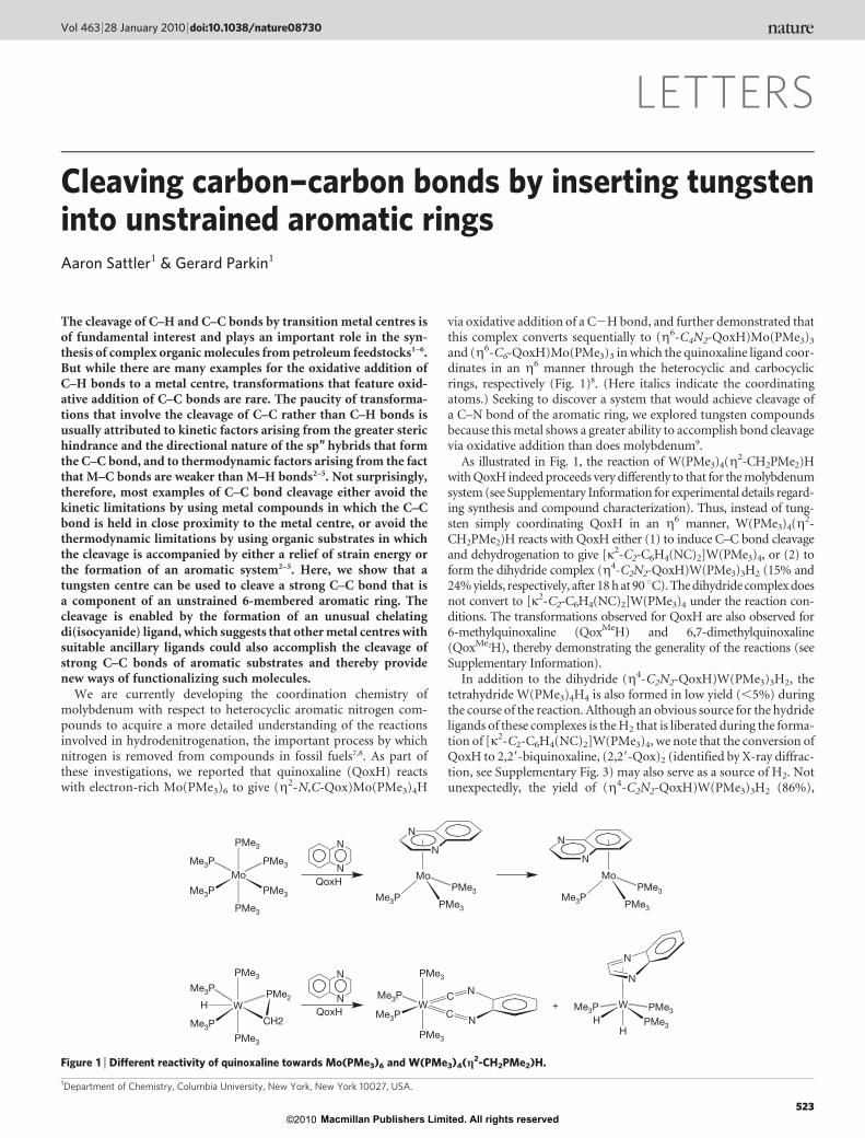
LETTERS
Cleaving carbon–carbon bonds by inserting tungsteninto unstrained aromatic ringsAaron Sattler1 & Gerard Parkin1
The cleavage of C–H and C–C bonds by transition metal centres isof fundamental interest and plays an important role in the syn-thesis of complex organic molecules from petroleum feedstocks1–6.But while there are many examples for the oxidative addition ofC–H bonds to a metal centre, transformations that feature oxid-ative addition of C–C bonds are rare. The paucity of transforma-tions that involve the cleavage of C–C rather than C–H bonds isusually attributed to kinetic factors arising from the greater sterichindrance and the directional nature of the spn hybrids that formthe C–C bond, and to thermodynamic factors arising from the factthat M–C bonds are weaker than M–H bonds2–5. Not surprisingly,therefore, most examples of C–C bond cleavage either avoid thekinetic limitations by using metal compounds in which the C–Cbond is held in close proximity to the metal centre, or avoid thethermodynamic limitations by using organic substrates in whichthe cleavage is accompanied by either a relief of strain energy orthe formation of an aromatic system2–5. Here, we show that atungsten centre can be used to cleave a strong C–C bond that isa component of an unstrained 6-membered aromatic ring. Thecleavage is enabled by the formation of an unusual chelatingdi(isocyanide) ligand, which suggests that other metal centres withsuitable ancillary ligands could also accomplish the cleavage ofstrong C–C bonds of aromatic substrates and thereby providenew ways of functionalizing such molecules.
We are currently developing the coordination chemistry ofmolybdenum with respect to heterocyclic aromatic nitrogen com-pounds to acquire a more detailed understanding of the reactionsinvolved in hydrodenitrogenation, the important process by whichnitrogen is removed from compounds in fossil fuels7,8. As part ofthese investigations, we reported that quinoxaline (QoxH) reactswith electron-rich Mo(PMe3)6 to give (g2-N,C-Qox)Mo(PMe3)4H
via oxidative addition of a C2H bond, and further demonstrated thatthis complex converts sequentially to (g6-C4N2-QoxH)Mo(PMe3)3
and (g6-C6-QoxH)Mo(PMe3)3 in which the quinoxaline ligand coor-dinates in an g6 manner through the heterocyclic and carbocyclicrings, respectively (Fig. 1)8. (Here italics indicate the coordinatingatoms.) Seeking to discover a system that would achieve cleavage ofa C–N bond of the aromatic ring, we explored tungsten compoundsbecause this metal shows a greater ability to accomplish bond cleavagevia oxidative addition than does molybdenum9.
As illustrated in Fig. 1, the reaction of W(PMe3)4(g2-CH2PMe2)Hwith QoxH indeed proceeds very differently to that for the molybdenumsystem (see Supplementary Information for experimental details regard-ing synthesis and compound characterization). Thus, instead of tung-sten simply coordinating QoxH in an g6 manner, W(PMe3)4(g2-CH2PMe2)H reacts with QoxH either (1) to induce C–C bond cleavageand dehydrogenation to give [k2-C2-C6H4(NC)2]W(PMe3)4, or (2) toform the dihydride complex (g4-C2N2-QoxH)W(PMe3)3H2 (15% and24% yields, respectively, after 18 h at 90 uC). The dihydride complex doesnot convert to [k2-C2-C6H4(NC)2]W(PMe3)4 under the reaction con-ditions. The transformations observed for QoxH are also observed for6-methylquinoxaline (QoxMeH) and 6,7-dimethylquinoxaline(QoxMe2H), thereby demonstrating the generality of the reactions (seeSupplementary Information).
In addition to the dihydride (g4-C2N2-QoxH)W(PMe3)3H2, thetetrahydride W(PMe3)4H4 is also formed in low yield (,5%) duringthe course of the reaction. Although an obvious source for the hydrideligands of these complexes is the H2 that is liberated during the forma-tion of [k2-C2-C6H4(NC)2]W(PMe3)4, we note that the conversion ofQoxH to 2,29-biquinoxaline, (2,29-Qox)2 (identified by X-ray diffrac-tion, see Supplementary Fig. 3) may also serve as a source of H2. Notunexpectedly, the yield of (g4-C2N2-QoxH)W(PMe3)3H2 (86%),
1Department of Chemistry, Columbia University, New York, New York 10027, USA.
W
N
N
Me3PH
PMe3
HPMe3
W
PMe3
Me3P
Me3P
PMe3
NC
CN
+W
PMe3
CH2
PMe2Me3P
Me3P
PMe3
H
Mo
PMe3
PMe3
PMe3Me3P
Me3P
PMe3
QoxH
N
N
QoxH
Me3P
Mo
PMe3
PMe3
N
N
Me3P
Mo
PMe3
PMe3
N
N
N
N
Figure 1 | Different reactivity of quinoxaline towards Mo(PMe3)6 and W(PMe3)4(g2-CH2PMe2)H.
Vol 463 | 28 January 2010 | doi:10.1038/nature08730
523Macmillan Publishers Limited. All rights reserved©2010

relative to that of [k2-C2-C6H4(NC)2]W(PMe3)4, increases con-siderably if the reaction between W(PMe3)4(g2-CH2PMe2)H andQoxH is performed under an atmosphere of H2 (see SupplementaryInformation).
The dihydride complexes (g4-C2N2-QoxR2H)W(PMe3)3H2 (whereR2 5 H, H; Me, H; or Me, Me) represent unprecedented examples ofg4-coordination of this dinuclear aromatic compound via the hetero-cyclic ring, as clearly seen from the structure of (g4-C2N2-QoxMe2H)W(PMe3)3H2 shown in Fig. 2. As such, (g4-C2N2-QoxR2H)W(PMe3)3H2 provide important new structural motifs forthe means by which heterocyclic nitrogen compounds may bind to thesurface of hydrodenitrogenation catalysts.
The most significant aspect of the reactions betweenW(PMe3)4(g2-CH2PMe2)H and QoxR2H, however, pertains to theformation of [k2-C2-C6H2R2(NC)2]W(PMe3)4: as is evident from thestructure of [k2-C2-C6H2Me2(NC)2]W(PMe3)4 in Fig. 3, the forma-tion of these compounds requires the breaking of an aromatic C–Cbond that is substantially stronger than a typical C–C single bond10.Remarkably, this unprecedented cleavage of the aromatic C–C bondtakes place in preference to that of the C–N bond. The latter bondmight have been expected to be more reactive because the cleavage ofthe C-N bond in pyridine11 and its derivatives12–15 has been achievedby various metal centres, thereby making the cleavage of the C–Cbond in the present system all the more remarkable.
The cleaved quinoxaline fragments within [k2-C2-C6H2R2(NC)2]-W(PMe3)4, namely C6H2R2(NC)2, correspond to known di(isocya-nide) compounds16. As such, [k2-C2-C6H2R2(NC)2]W(PMe3)4 maybe viewed as simple transition-metal isocyanide complexes of thetype ML4(CNR)2 for which there is precedent. However, the [k2-C2-C6H2R2(NC)2]W(PMe3)4 complexes exhibit several interest-ing structural features. For example, whereas the majority oftransition-metal isocyanide compounds have almost linear C–N–Cbond angles (the mean C–N–C bond angle for isocyanide com-pounds listed in the Cambridge Structural Database (Version 5.30)is 172u), the geometries at nitrogen in each of the [k2-C2-C6H2R2(NC)2]W(PMe3)4 complexes are severely bent (125–128u).Such bending, which has also been observed for some monodentateisocyanide complexes17, is consistent with considerable metal-to-ligand p-backbonding so that W5C5N–R is a better descriptionof the interaction than is WrC–;N1–R (ref. 18). Further evidencefor the multiply bonded nature of the W–C interactions in [k2-C2-C6H2R2(NC)2]W(PMe3)4 is the observed average W–C bond length
of 1.93 A, which compares favourably with the mean value of 1.98 Afor structurally characterized compounds with W5CR2 doublebonds listed in the Cambridge Structural Database (Version 5.30),but is much shorter than the mean W–C single bond length of 2.23 A.
A high degree of backbonding is also suggested by the n(CN)stretching frequencies of [k2-C2-C6H2R2(NC)2]W(PMe3)4 rangingfrom 1,698–1,709 cm–1 (see Supplementary Information), which isat the low end for transition-metal isocyanide complexes; for com-parison, n(CN) for isocyanide complexes span a range of at least2,310 cm–1 to 1,670 cm–1 (refs 19, 20). Similarly, the 13C nuclearmagnetic resonance (NMR) spectroscopic signals of transition-metalisocyanide compounds span at least 151.8–238.7 parts per million(p.p.m.) (refs 20, 21), with the compound having the most downfieldchemical shift, namely [Fe(CNXyl)4]22, having the lowest n(CN)stretching frequency and a highly bent C–N–C bond angle of144(3)u (e.s.d. in parentheses; ref. 20). The 13C NMR chemical shiftof 211.4 p.p.m. for [k2-C2-C6H3Me(NC)2]W(PMe3)4 (see Sup-plementary Information) is thus also consistent with considerablebackbonding in this molecule.
An interesting point to note is that chelating isocyanide ligands arenot common because M–C–N–R moieties prefer to adopt linearcoordination at both nitrogen and carbon21. For this reason,although o-(CN)2C6H4 has been employed as a ligand, it does notchelate but instead serves as a bridging ligand22. In accord with suchbehaviour, the smallest ring size previously reported for a complex ofa bidentate di(isocyanide) ligand is 12, as illustrated by [k2-C2-CH2{OC6H4(NC)}2]Cr(CO)4 (ref. 23). The 7-membered ring of[k2-C2-C6H4(NC)2]W(PMe3)4, featuring two W–C–N bond anglesthat are close to linear (165u–169u), is thus exceptionally small for atransition-metal complex of a bidentate di(isocyanide) ligand. Theability to isolate such an unusual compound may result from the factthat its mechanism of formation involves insertion of the tungstencentre into the aromatic ring; indeed, treatment of W(PMe3)4(g2-CH2PMe2)H with o-(CN)2C6H4 at room temperature results inthe immediate formation of an unidentified precipitate, with noevidence for formation of [k2-C2-C6H4(NC)2]W(PMe3)4 by 1HNMR spectroscopy.
Several different mechanisms could explain the observed forma-tion of [k2-C2-C6H4(NC)2]W(PMe3)4, of which one involves thedirect insertion of tungsten into the C–C bond followed by twoa-hydrogen elimination steps. Such a process is in line with theobservation that electron-donating substituents on olefins promoteC–C bond cleavage, as exemplified by the use of enetetramines togenerate N-heterocyclic carbene compounds24,25. However, wefavour the alternative mechanism outlined in Fig. 4 that comprises aseries of C–H bond cleavage reactions to access a benzyne-type inter-mediate [g2-C2-C6H4(NCCN)]W(PMe3)4H2, from which [k2-C2-C6H4(NC)2]W(PMe3)4 is then obtained via a sequence that involvesreductive elimination of H2 and C–C bond cleavage. The feasibility ofthis mechanism is supported by the report of the ruthenium benzyne
W P1
P3
P2
C1
C2
N1
N2
C3
C4
C5
C6
C7
C8
C9
C10
Figure 2 | Molecular structure of (g4-C2N2-QoxMe2H)W(PMe3)3H2.
P1
P4
P3
P2
W
C2 N2C4
C6C8
C10
C9C7
C5C3
N1C1
Figure 3 | Molecular structure of [k2-C2-C6H2Me2(NC)2]W(PMe3)4.
LETTERS NATURE | Vol 463 | 28 January 2010
524Macmillan Publishers Limited. All rights reserved©2010

complex (g2-C6H4)Ru(PMe3)4 (ref. 26), a structural analogue of theproposed intermediate [g2-C2-C6H4(NCCN)2]W(PMe3)4. Further-more, the observation of several other compounds such as mono-nuclear (g2-N,C-Qox)W(PMe3)4H and (k2-N,C-Qox)W(PMe3)4H(Fig. 4), and dinuclear (m–g2-N,C-k2-N,C-Qox9)[W(PMe3)4H]2
(Supplementary Fig. 2), during the course of the reaction providesevidence that C–H bond cleavage is facile in this system. Note, how-ever, that C–H bond cleavage is reversible and that the mere obser-vation of (g2-N,C-Qox)W(PMe3)4H is thus not proof that this speciesis directly involved in the C–C bond cleavage process. A computa-tional analysis of the reaction is, therefore, needed to establish whichof the different mechanisms is the most reasonable for the observedtransformations.
Finally, we note that the overall cleavage of the C–C bond of thebenzyne-type species proposed in this system resembles the forma-tion of bis(isocyanide) compounds by base-induced cleavage of dia-minoacetylene species27, a process that is the reverse of the well-known coupling reactions of isocyanides25,28,29. It is also worth notingthat acetylenic C–C bonds have been successfully cleaved usingmetal-cluster complexes30.
In conclusion, we note that the cleavage of an aromatic C–C bondby insertion of tungsten into an aromatic ring enables a quinoxalinecompound to be converted to an o-diisocyanobenzene derivative, atransformation that may potentially be extended to other systems andthereby provide a new means of functionalizing aromatic molecules.
Received 29 May; accepted 9 November 2009.
1. Jones, W. D. in Comprehensive Organometallic Chemistry III, Vol. 1, Ch. 1.25 (edsCrabtree, R. H. & Mingos, D. M. P.) (Elsevier, 2006).
2. Jones, W. D. The fall of the C–C bond. Nature 364, 676–677 (1993).3. Jun, C. H. Transition metal-catalyzed carbon-carbon bond activation. Chem. Soc.
Rev. 33, 610–618 (2004).
4. van der Boom, M. E., &. Milstein, D. Cyclometalated phosphine-based pincercomplexes: Mechanistic insight in catalysis, coordination, and bond activation.Chem. Rev. 103, 1759–1792 (2003).
5. Crabtree, R. H. The organometallic chemistry of alkanes. Chem. Rev. 85, 245–269(1985).
6. Rybtchinski, B., &. Milstein, D. Metal insertion into C–C bonds in solution. Angew.Chem. Int. Edn Engl. 38, 870–883 (1999).
7. Zhu, G. Tanski, J. M., Churchill, D. G., Janak, K. E. & Parkin, G. The reactivity ofMo(PMe3)6 towards heterocyclic nitrogen compounds: transformations relevantto hydrodenitrogenation. J. Am. Chem. Soc. 124, 13658–13659 (2002).
8. Zhu, G. Pang, K. & Parkin, G. New modes for coordination of aromatic heterocyclicnitrogen compounds to molybdenum: catalytic hydrogenation of quinoline, isoqui-noline, and quinoxaline by Mo(PMe3)4H4. J. Am. Chem. Soc. 130, 1564–1565 (2008).
9. Buccella, D., &. Parkin, G. p-tert-butylcalix[4] arene complexes of molybdenumand tungsten: reactivity of the calixarene methylene C-H bond and the facilemigration of the metal around the phenolic rim of the calixarene. J. Am. Chem. Soc.128, 16358–16364 (2006).
10. Cyranski, M. K. Energetic aspects of cyclic pi-electron delocalization: evaluationof the methods of estimating aromatic stabilization energies. Chem. Rev. 105,3773–3811 (2005).
11. Kleckley, T. S. Bennett, J. L., Wolczanski, P. T. & Lobkovsky, E. B. Pyridine C5Nbond cleavage mediated by (silox)3Nb(silox 5 tBu3SiO). J. Am. Chem. Soc. 119,247–248 (1997).
12. Bonanno, J. B. Veige, A. S., Wolczanski, P. T. & Lobkovsky, E. B. Amide derivativesof tantalum and a niobium-promoted ring opening of 3,5-lutidine. Inorg. Chim.Acta 345, 173–184 (2003).
13. Gray, S. D. Weller, K. J., Bruck, M. A., Briggs, P. M. & Wigley, D. E. Carbon-nitrogenbond-cleavage in an g2(N, C)-pyridine complex-induced by intramolecularmetal-to-ligand alkyl migration - models for hydrodenitrogenation catalysis. J.Am. Chem. Soc. 117, 10678–10693 (1995).
14. Weller, K. J. Filippov, I. Briggs, P. M. & Wigley, D. E. Pyridine degradationintermediates as models for hydrodenitrogenation catalysis: preparation andproperties of a metallapyridine complex. Organometallics 17, 322–329 (1998).
15. Bailey, B. C. Fan, H. Huffman, J. C., Baik, M. H. & Mindiola, D. J. Room temperaturering-opening metathesis of pyridines by a transient Ti;C linkage. J. Am. Chem.Soc. 128, 6798–6799 (2006).
16. Ito, Y. Ohnishi, A. Ohsaki, H. & Murakami, M. A preparative method for ortho-diisocyanoarenes. Synthesis 714–715 (1988).
17. Wagner, N. L. Laib, F. E. & Bennett, D. W. Conformational isomerism in (p-RC6H4NC)2W(dppe)2: substantial structural changes resulting from subtledifferences in the pi-acidity of p-RC6H4NC. J. Am. Chem. Soc. 122, 10856–10867(2000).
18. Kuznetsov, M. L. Theoretical studies of transition metal complexes with nitrilesand isocyanides. Russ. Chem. Rev. 71, 265–282 (2002).
19. Strauch, H. C. et al. Reactions of (butadiene)tantalocene cation with alkylisocyanides. Organometallics 18, 3802–3812 (1999).
20. Brennessel, W. W., &. Ellis, J. E. [Fe(CNXyl)4]2-: an isolable and structurallycharacterized homoleptic isocyanidemetalate dianion. Angew. Chem. Int. Edn Engl.46, 598–600 (2007).
21. Hahn, F. E. The coordination chemistry of multidentate isocyanide ligands. Angew.Chem. Int. Edn Engl. 32, 650–665 (1993).
22. Espinet, P. Soulantica, K. Charmant, J. P. H. & Orpen, A. G. 1,2-Phenylenediisocyanide for metallotriangles. Chem. Commun. 915–916 (2000).
23. Hahn, F. E. Tamm, M. Imhof, L. & Lugger, T. Preparation and crystal structures of abidentate isocyanide and its tetracarbonylchromium complex. J. Organomet.Chem. 526, 149–155 (1996).
24. Lappert, M. F. Contributions to the chemistry of carbene metal chemistry. J.Organomet. Chem. 690, 5467–5473 (2005).
25. Wilker, C. N. ;. Hoffmann, R. & Eisenstein, O. Coupling methylenes, methynes andother p-systems on one or two metal centers. Nouv. J. Chim. 7, 535–544 (1983).
26. Hartwig, J. F. Bergman, R. G. & Andersen, R. A. Structure, synthesis, and chemistryof (PMe3)4Ru(g2-benzyne). Reactions with arenes, alkenes, and heteroatom-containing organic-compounds. Synthesis and structure of a monomerichydroxide complex. J. Am. Chem. Soc. 113, 3404–3418 (1991).
WH
PMe3
Me3P
Me3P
PMe3
NN
WH
PMe3
Me3P
Me3P
PMe3
N
NHW
PMe3
Me3P
Me3P
PMe3
N
NW
PMe3
Me3P
Me3P
PMe3
NC
C N
–H2
WH
PMe3
Me3P
Me3P
PMe3
N
N
NNWH
PMe3
Me3P
Me3P
PMe3
W
PMe3
Me3P
Me3P
PMe3
NNW
PMe3
CH2
PMe2Me3P
Me3P
PMe3
H– PMe3
κ1–N
κ1–C
κ2–C2
κ2–N,C
η2–N,C
η2–C2 η2–C2
N
N
Figure 4 | Possible mechanism for formation of [k2-C2-C6H4(NC)2]W(PMe3)4.
NATURE | Vol 463 | 28 January 2010 LETTERS
525Macmillan Publishers Limited. All rights reserved©2010

27. Pombeiro, A. J. L. da Silva, M. & Michelin, R. A. Aminocarbyne complexes derivedfrom isocyanides activated towards electrophilic addition. Coord. Chem. Rev. 218,43–74 (2001).
28. Carnahan, E. M. Protasiewicz, J. D. & Lippard, S. J. 15 years of reductive coupling:what have we learned? Acc. Chem. Res. 26, 90–97 (1993).
29. Ito, Y. et al. Aromatizing oligomerization of 1,2-di-isocyanoarene to quinoxalineoligomers. J. Chem. Soc. Chem. Commun. 403–405 (1990).
30. Clauss, A. D. ;. Shapley, J. R.; Wilker, C. N. & Hoffmann, R. Alkyne scission on atrimetallic framework: experimental evidence and theoretical analysis.Organometallics 3, 619 (1984).
Supplementary Information is linked to the online version of the paper atwww.nature.com/nature.
Acknowledgements We thank the US Department of Energy, Office of BasicEnergy Sciences (DE-FG02-93ER14339) for supporting this research. We thankThe National Science Foundation (CHE-0619638) for the acquisition of an X-raydiffractometer. We thank W. Sattler for discussions.
Author Contributions G.P. supervised the project. A.S. synthesized andcharacterized the compounds. G.P. and A.S. analysed the data and wrote themanuscript.
Author Information Reprints and permissions information is available atwww.nature.com/reprints. The authors declare no competing financial interests.X-ray crystallographic coordinates have been deposited at the CambridgeCrystallographic Database (CCDC #734113–734121). Correspondence andrequests for materials should be addressed to G.P. ([email protected]).
LETTERS NATURE | Vol 463 | 28 January 2010
526Macmillan Publishers Limited. All rights reserved©2010

A review of the process of carbon-carbon bond cleavage by insertion of tungsten into unstrained aromatic rings.
Parikshit V. Gokhale.
Department of Chemistry, University of Delaware.
RECEIVED DATE (automatically inserted by publisher); [email protected]
In the present paper, the authors disclose a method which
uses a tungsten metal center and it can be used to cleave a
strong C-C bond of an unstrained 6-membered aromatic
ring. The reaction proceeds through an unusual chelating
di(isocyanide) ligand. Thus, this method provides a new
way of functionalizing strong C-C bonds.
As we all know, the cleavage of C-H and C-C bonds and funtionalizing them plays an important role in organic synthesis of complex molecules. This is mostly accomplished by using transition metal centers. The review
2 deals with a
number of recent advancements dealing with methodologies directed towards the activation of C-C bonds in strained and unstrained molecules catalyzed by transition metal complexes. The review
3 in Angew Chem International Edition
deals with the transition metal insertion into strong C-C bonds in solution, the reaction mechanisms involved, reactivity patterns, factors controlling the competition between C-C and C-H bond cleavage, use of different metals, thermodynamics and kinetics of C-C bond cleavage etc. There are many examples of oxidative addition of C-H bonds to a metal center in literature, but the same involving C-C bonds is quite rare. This is mainly because of the kinetic factors arising from the greater steric hindrance and the directional nature of the sp
n hybrid
orbitals that form the C-C bond. It can also be attributed to the thermodynamic factors due to the fact that M-C bonds are weaker than M-H bonds. So C-H bond cleavage is more prevalent. In current literature, examples of C-C bond cleavage find some loopholes. For examples, they avoid the kinetic limitations by using metal compounds in which the C-C bond is held in close proximity to the metal center. So the C-C bond effectively gets cleaved. Other examples which avoid the thermodynamic limitations make use of organic substrates in which C-C bond cleavage is accompanied by either a relief of strain energy or formation of a more stable aromatic system. Again the C-C bond effectively gets cleaved.
In the present paper, the authors disclose a method which uses a tungsten metal center and it can be used to cleave a strong C-C bond of an unstrained 6-membered aromatic ring. The reaction proceeds through an unusual chelating di(isocyanide) ligand. Thus, this method provides a new way of functionalizing strong C-C bonds. A paper by Parkin
4 studies the reactivity of
Mo(PMe3)6 towards heterocyclic nitrogen compounds in transformations relevant to hydrodenitrogenation (HDN). HDN is a process by which nitrogen is removed from fossil fuels for minimizing NOx emissions. Again, a paper by Parkin
5 discloses a method which uses a
molybdenum catalyst, namely, Mo(PMe3)4H4 to effect hydrogenation of quinolone, isoquinoline and quinoxaline which is a necessary step in HDN. While studying the hydrodenitrogenation reaction of compounds by using molybdenum, the authors of the present paper found out that molybdenum reacts with quinoxaline via oxidative addition of C-H bond. In order to find a system which can cleave C-N bond of an aromatic ring, the metal tungsten was explored as it shows a greater ability to accomplish bond cleavage via oxidative addition than molybdenum
6.
Scheme 1. Reaction of quinoxaline with the molybdenum and tungsten complexes.
Mo
PMe3
PMe3
Me3P PMe3
Me3P PMe3
N
N
QoxH
N
NMo
PMe3
PMe3Me3P
N
N MoMe3P
PMe3
PMe3
W
PMe3
PMe3
Me3P
Me3P CH2
PMe3
H
N
N
QoxH
N
N
C
CW
PMe3
PMe3
Me3P
Me3PN
NWPMe3
Me3P
PMe3
Me3PH
The reaction with tungsten proceeded differently as compared to molybdenum. W(PMe3)4(η
2-
CH2PMe2)H reacts with QoxH to form: 1) [κ2-C2-
C6H4(NC)2]W(PMe3)4 by inducing C-C bond
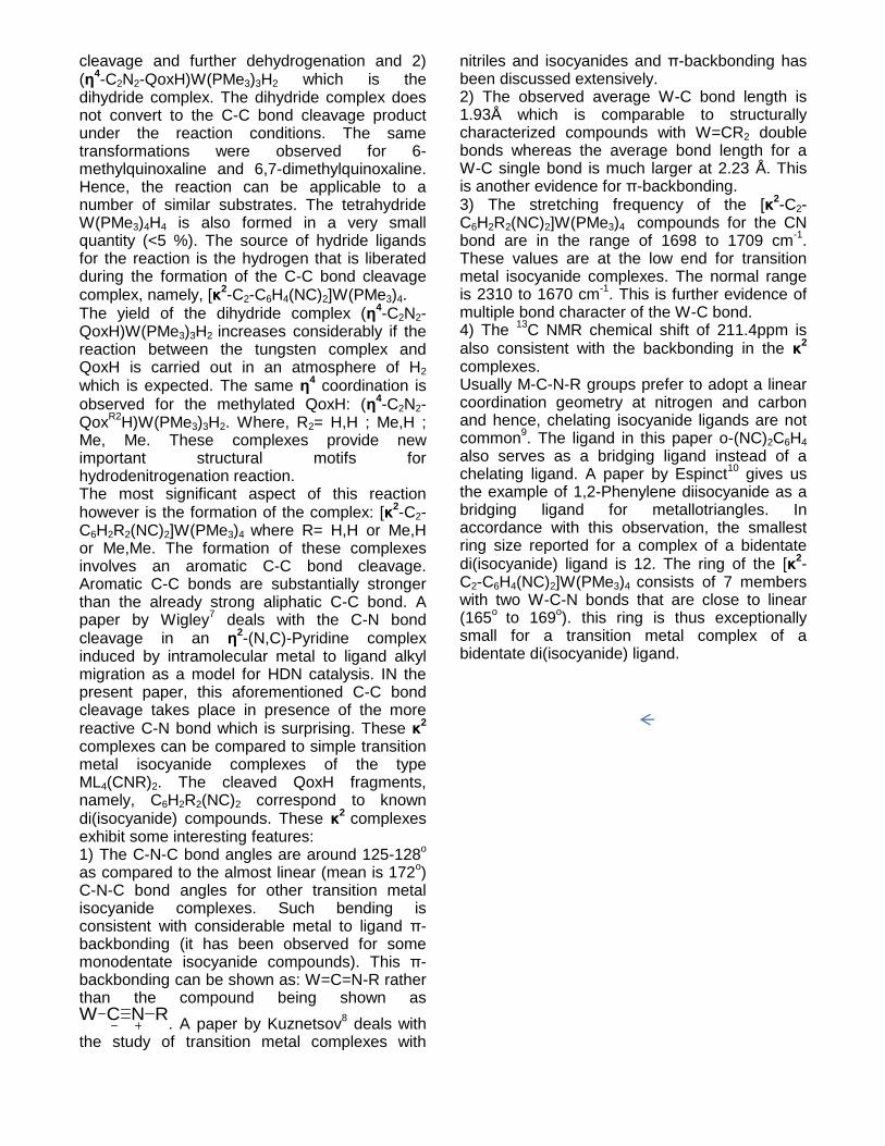
cleavage and further dehydrogenation and 2) (η
4-C2N2-QoxH)W(PMe3)3H2 which is the
dihydride complex. The dihydride complex does not convert to the C-C bond cleavage product under the reaction conditions. The same transformations were observed for 6-methylquinoxaline and 6,7-dimethylquinoxaline. Hence, the reaction can be applicable to a number of similar substrates. The tetrahydride W(PMe3)4H4 is also formed in a very small quantity (<5 %). The source of hydride ligands for the reaction is the hydrogen that is liberated during the formation of the C-C bond cleavage complex, namely, [κ
2-C2-C6H4(NC)2]W(PMe3)4.
The yield of the dihydride complex (η4-C2N2-
QoxH)W(PMe3)3H2 increases considerably if the reaction between the tungsten complex and QoxH is carried out in an atmosphere of H2 which is expected. The same η
4 coordination is
observed for the methylated QoxH: (η4-C2N2-
QoxR2
H)W(PMe3)3H2. Where, R2= H,H ; Me,H ; Me, Me. These complexes provide new important structural motifs for hydrodenitrogenation reaction. The most significant aspect of this reaction however is the formation of the complex: [κ
2-C2-
C6H2R2(NC)2]W(PMe3)4 where R= H,H or Me,H or Me,Me. The formation of these complexes involves an aromatic C-C bond cleavage. Aromatic C-C bonds are substantially stronger than the already strong aliphatic C-C bond. A paper by Wigley
7 deals with the C-N bond
cleavage in an η2-(N,C)-Pyridine complex
induced by intramolecular metal to ligand alkyl migration as a model for HDN catalysis. IN the present paper, this aforementioned C-C bond cleavage takes place in presence of the more reactive C-N bond which is surprising. These κ
2
complexes can be compared to simple transition metal isocyanide complexes of the type ML4(CNR)2. The cleaved QoxH fragments, namely, C6H2R2(NC)2 correspond to known di(isocyanide) compounds. These κ
2 complexes
exhibit some interesting features: 1) The C-N-C bond angles are around 125-128
o
as compared to the almost linear (mean is 172o)
C-N-C bond angles for other transition metal isocyanide complexes. Such bending is consistent with considerable metal to ligand π-backbonding (it has been observed for some monodentate isocyanide compounds). This π-backbonding can be shown as: W=C=N-R rather than the compound being shown as W C N R
. A paper by Kuznetsov8 deals with
the study of transition metal complexes with
nitriles and isocyanides and π-backbonding has been discussed extensively. 2) The observed average W-C bond length is 1.93Å which is comparable to structurally characterized compounds with W=CR2 double bonds whereas the average bond length for a W-C single bond is much larger at 2.23 Å. This is another evidence for π-backbonding. 3) The stretching frequency of the [κ
2-C2-
C6H2R2(NC)2]W(PMe3)4 compounds for the CN bond are in the range of 1698 to 1709 cm
-1.
These values are at the low end for transition metal isocyanide complexes. The normal range is 2310 to 1670 cm
-1. This is further evidence of
multiple bond character of the W-C bond. 4) The
13C NMR chemical shift of 211.4ppm is
also consistent with the backbonding in the κ2
complexes. Usually M-C-N-R groups prefer to adopt a linear coordination geometry at nitrogen and carbon and hence, chelating isocyanide ligands are not common
9. The ligand in this paper o-(NC)2C6H4
also serves as a bridging ligand instead of a chelating ligand. A paper by Espinct
10 gives us
the example of 1,2-Phenylene diisocyanide as a bridging ligand for metallotriangles. In accordance with this observation, the smallest ring size reported for a complex of a bidentate di(isocyanide) ligand is 12. The ring of the [κ
2-
C2-C6H4(NC)2]W(PMe3)4 consists of 7 members with two W-C-N bonds that are close to linear (165
o to 169
o). this ring is thus exceptionally
small for a transition metal complex of a bidentate di(isocyanide) ligand.

Scheme 2. Plausible mechanism for the reaction.
WMe3P CH2
PMe3Me3PPMe3
PMe3H
N
N
-PMe3
NNW
PMe3
PMe3
Me3P
Me3PW
PMe3
PMe3Me3P
Me3P
H
NNW
HPMe3
Me3P
Me3P
Me3P
NN
NN
WH
PMe3
Me3P
Me3P
Me3P
N
N
W
PMe3
PMe3Me3P
Me3P-H2H H
N
N
W
PMe3
PMe3Me3P
Me3P
N
N
C
CW
PMe3
PMe3Me3P
Me3P
There are several mechanisms proposed for the formation of the [κ
2-C2-C6H4(NC)2]W(PMe3)4
complex. One mechanism outlined involves the direct insertion of tungsten into the C-C bond which is then followed by two α-hydrogen eliminations. This mechanism has been said to be in accordance with the fact that electron donating substituents on olefins promote C-C bond cleavage. The authors however, present another mechanism which they think is more favorable. In this mechanism, initially there is a series of C-H bond cleavage reactions which gives access to a benzyne type intermediate [η
2-
C2-C6H4(NCCN)]W(PMe3)4H2. This intermediate is further converted to [κ
2-C2-
C6H4(NC)2]W(PMe3)4 through reductive elimination of H2 and C-C bond cleavage. The authors cite that this mechanism is supported by a report of ruthenium benzyne complex [η
2-
C6H4]Ru(PMe3)4 11
. This complex can be considered as a structural analogue of the intermediate [η
2-C2-C6H4(NCCN)2]W(PMe3)4H2.
Some other intermediates that are observed in this reaction are: (η
2-N,C-Qox)W(PMe3)4H , (κ
2-
N,C-Qox)W(PMe3)4H , (µ-η2-N,C- κ
2-N,C-
Qox’)[W(PMe3)4H]2. The presence of these intermediates confirm that the reaction proceeds
through the second mechanism and that C-H bond cleavage is facile in this system. Still the observation of (η
2-N,C-Qox)W(PMe3)4H cannot
confirm that this species is involved in the C-C bond cleavage as C-H bond cleavage is reversible. The overall cleavage of the C-C bond in the given system resembles the process by which bis(isocyanide) compounds are formed by base-induced cleavage of diaminoacetylene species
12,13. Another points the authors note is
that the cleaving of acetylenic C-C bonds have been cleaved using metal cluster complexes. In summary, the authors have provided a beautiful method in which an aromatic C-C bond in quinoxaline can be cleaved by insertion of tungsten to yield a o-diisocyanobenzene derivative. This methodology can be extended to other systems as well thus providing new ways of functionalizing organic molecules.
Acknowledgement. The author is grateful to Professor Joel
Rosenthal and the University of Delaware and to the scientific
community.
SUPPORTING INFORMATION AVAILABLE: Detailed
experimental procedures including spectroscopic and analytical data.
This material is available free of charge via the internet at
http://pubs.acs.org.
References (1) Jones, W. D. The fall of the C–C bond. Nature 364, 676–677 (1993). (2) Jun, C. H. Transition metal-catalyzed carbon-carbon bond activation. Chem. Soc. Rev. 33, 610–618 (2004). (3) Rybtchinski, B., &. Milstein, D. Metal insertion into C–C bonds in solution. Angew. Chem. Int. Edn Engl. 38, 870–883 (1999). (4) Zhu, G. Tanski, J. M., Churchill, D. G., Janak, K. E. & Parkin, G. The reactivity of Mo(PMe3)6 towards heterocyclic nitrogen compounds: transformations relevant to hydrodenitrogenation. J. Am. Chem. Soc. 124, 13658–13659 (2002). (5) Zhu, G. Pang, K. & Parkin, G. New modes for coordination of aromatic heterocyclic nitrogen compounds to molybdenum: catalytic hydrogenation of quinoline, isoquinoline, and quinoxaline byMo(PMe3)4H4. J. Am. Chem. Soc. 130, 1564–1565 (2008).

(6) Buccella, D., &. Parkin, G. p-tert-butylcalix[4] arene complexes of molybdenum and tungsten: reactivity of the calixarene methylene C-H bond and the facile migration of the metal around the phenolic rim of the calixarene. J. Am. Chem. Soc. 128, 16358–16364 (2006). (7) Gray, S. D. Weller, K. J., Bruck, M. A., Briggs, P. M. & Wigley, D. E. Carbon-nitrogen bond-cleavage in an g2(N, C)-pyridine complex-induced by intramolecular metal-to-ligand alkyl migration - models for hydrodenitrogenation catalysis. J. Am. Chem. Soc. 117, 10678–10693 (1995). (8) Kuznetsov, M. L. Theoretical studies of transition metal complexes with nitriles and isocyanides. Russ. Chem. Rev. 71, 265–282 (2002). (9) Hahn, F. E. The coordination chemistry of multidentate isocyanide ligands. Angew. Chem. Int. Edn Engl. 32, 650–665 (1993). (10) Espinet, P. Soulantica, K. Charmant, J. P. H. & Orpen, A. G. 1,2-Phenylene diisocyanide for metallotriangles. Chem. Commun. 915–916 (2000). (11) Hartwig, J. F. Bergman, R. G. & Andersen, R. A. Structure, synthesis, and chemistry of (PMe3)4Ru(g2-benzyne). Reactions with arenes, alkenes, and heteroatomcontaining organic-compounds. Synthesis and structure of a monomeric hydroxide complex. J. Am. Chem. Soc. 113, 3404–3418 (1991). (12) Pombeiro, A. J. L. da Silva, M. & Michelin, R. A. Aminocarbyne complexes derived from isocyanides activated towards electrophilic addition. Coord. Chem. Rev. 218, 43–74 (2001). (13) Ito, Y. et al. Aromatizing oligomerization of 1,2-di-isocyanoarene to quinoxaline oligomers. J. Chem. Soc. Chem. Commun. 403–405 (1990).

In Situ Formation of anOxygen-Evolving Catalyst in NeutralWater Containing Phosphate and Co2+Matthew W. Kanan and Daniel G. Nocera*
The utilization of solar energy on a large scale requires its storage. In natural photosynthesis,energy from sunlight is used to rearrange the bonds of water to oxygen and hydrogenequivalents. The realization of artificial systems that perform “water splitting” requires catalyststhat produce oxygen from water without the need for excessive driving potentials.Here we report such a catalyst that forms upon the oxidative polarization of an inert indiumtin oxide electrode in phosphate-buffered water containing cobalt (II) ions. A variety of analyticaltechniques indicates the presence of phosphate in an approximate 1:2 ratio with cobalt in thismaterial. The pH dependence of the catalytic activity also implicates the hydrogen phosphateion as the proton acceptor in the oxygen-producing reaction. This catalyst not only forms in situfrom earth-abundant materials but also operates in neutral water under ambient conditions.
Sunlight is the only renewable and carbon-neutral energy source of sufficient scale toreplace fossil fuels and meet rising global
energy demand (1). The diurnal variation in localinsolation, however, demands a cost-effectivestorage of solar energy for its large-scale utili-zation. Of the possible storage methods, natureprovides the blueprint for storing sunlight in theform of chemical fuels (1, 2). The primary stepsof natural photosynthesis involve the absorptionof sunlight and its conversion into spatially sepa-rated electron/hole pairs. The holes of this wirelesscurrent are then captured by the oxygen-evolvingcomplex (OEC) to oxidize water to oxygen andthe electrons are captured by photosystem I toreduce NADP+ (nicotinamide adenine dinucleo-tide phosphate) to NADPH (the reduced form ofNADP+), nature’s form of hydrogen (3). Thus,the overall primary events of photosynthesis storesolar energy in a fuel by rearranging the chemi-cal bonds of water to form H2 (i.e., NADPH)and O2.
An approach to duplicating photosynthesisoutside of a photosynthetic membrane is to con-vert sunlight into spatially separated electron/hole pairs within a photovoltaic cell and thencapture the charges with catalysts that mediate“water splitting” (1, 4). The four holes arecaptured by a catalyst at the anode to produceoxygen, and the four electrons are captured by aseparate catalyst at the cathode to producehydrogen. The net result is the storage of solarenergy in the chemical bonds of H2 and O2.
A key determinant of energy storage in ar-tificial photosynthesis is the efficiency of thewater-splitting catalysts. Electrocatalysts that areefficient for solar-to-fuels conversion must oper-ate close to the Nernstian potentials (E) for theH2O/O2 and H2O/H2 half-cell reactions shown in
Scheme 1 (half-cell potentials given in the con-vention of reduction potentials).
The voltage in addition to E that is requiredto attain a given catalytic activity—referred to asoverpotential—limits the efficiency of convertinglight into catalytic current. Of the two reactions,the H2O/O2 reaction is considerably more com-plex (5). This reaction requires a four-electronoxidation of two water molecules coupled to theremoval of four protons to form a relatively weakoxygen-oxygen bond. In addition to controllingthis proton-coupled electron transfer (PCET)(6, 7), a catalyst must tolerate prolonged exposureto oxidizing conditions. Even at the thermody-namic limit, water oxidation requires an oxidiz-
ing power that causes most chemical functionalgroups to degrade. Accordingly, the generation ofoxygen from water presents a substantial chal-lenge toward realizing artificial photosynthesis (8).
The fine-tuned molecular machinery of theOEC oxidizes water at a low overpotential usinga Mn4O4Ca cluster (9–12). Outside the OEC, ex-amples of water oxidation catalysts include first-row spinel and perovskite metal oxides, whichrequire concentrated basic solutions (pH > 13)and moderate overpotentials (<400 mV), andpreciousmetals and preciousmetal oxides, whichoperate with similar efficiencies under acidic con-ditions (pH < 1) (13–15). However, few catalystsoperate in neutral water under ambient condi-tions. Neutral water is oxidized at Pt electrodes,and some precious metal oxides have been re-ported to operate electrocatalytically in neutral orweakly acidic solutions (16). The development ofan earth-abundant, first-row catalyst that operatesat pH 7 at low overpotential remains a funda-mental chemical challenge. Here, we report anoxygen-evolving catalyst that forms in situ uponanodic polarization of an inert electrode in neutralaqueous phosphate solutions containing Co2+.Oxygen generation occurs under benign condi-tions: pH = 7, 1 atm, and room temperature.
Cobalt ions in the presence of chemical oxi-dants such as Ru(bpy)3
3+ (bpy, bipyridine; Eo =1.26, where Eo is the standard potential) catalyzethe oxidation of water to O2 in neutral phosphatesolutions (17, 18). Oxygen yields drop in thesereactions when oxidized Co species precipitatefrom solution because the catalytically activespecies is removed from the solution-phase re-action. However, an oxidation-induced precipita-
Department of Chemistry, 6-335, Massachusetts Instituteof Technology, Cambridge, MA 02139–4307, USA.
*To whom correspondence should be addressed. E-mail:[email protected]
2H2OO2 + 4H+ + 4e–
2H2O
2H2 4H+ + 4e–
2H2 + O2
Eanodic = 1.23 V – 0.059 (pH) V vs NHE
Ecathodic = 0 V – 0.059 (pH) V vs NHE
Erxn = –1.23 V
Scheme 1.
0 1 2 3 4 5 6 7 80.25
0.50
0.75
1.00
1.25
mA
/cm
2
time / h
0 1 2 3 4 5
2.0
4.0
6.0
mA
/10–
5 cm
2
time / h
AB
1.4 1.2 1.0 0.8 0.6 0.4 0.2 0.0
50 µA
V (vs NHE)
1.4 1.2 1.0
25 µA
V (vs NHE)
Fig. 1. (A) Cyclic voltammagram in 0.1 M KPi electrolyte at pH 7.0 with no Co2+ ion present (black line)and with 0.5 mM Co2+ present (red line). The potential was measured against a Ag/AgCl reference andconverted to NHE potentials by using E(NHE) = E(Ag/AgCl) + 0.197 V. (B) Current density profile for bulkelectrolysis at 1.29 V (versus NHE) in 0.1 M KPi electrolyte at pH 7.0 containing 0.5 mM Co2+. (Inset)Profile in the absence of Co2+.
22 AUGUST 2008 VOL 321 SCIENCE www.sciencemag.org1072
REPORTS
on
Dec
embe
r 6,
201
0w
ww
.sci
ence
mag
.org
Dow
nloa
ded
from

tion may be exploited to prepare electrocatalystsin situ if the precipitated material remains cat-alytically active and can be oxidized at an electrodesurface. To explore this possibility forCo-catalyzedwater oxidation, we examined electrochemical oxi-dations of aqueous solutions containing phosphateand Co2+. Cyclic voltammetry of a 0.5 mM solu-tion of Co(NO3)2 in 0.1 M potassium phosphatepH7.0 (KPi electrolyte) exhibits an oxidationwaveatEp = 1.13V (whereEp is the peakpotential) versusthe normal hydrogen electrode (NHE), followed bythe onset of a strong catalytic wave at 1.23 V (Fig.1A). A broad, relatively weak reduction wave is ob-served on the cathodic scan. The presence of a cat-alytic wave prompted us to examine the electrodeactivity during controlled-potential electrolysis.
Indium tin oxide (ITO) was used as the elec-trode for bulk electrolysis to ensure a minimalbackground activity for O2 production. An elec-trolysis at 1.29 V without stirring in neutral KPielectrolyte containing 0.5 mM Co2+ exhibits arising current density that reaches a peak value>1 mA/cm2 after 7 to 8 hours (Fig. 1B). Duringthis time, a dark coating forms on the ITOsurface, and effervescence from this coating be-
comes increasingly vigorous (19).The same resultsare observed with either CoSO4, Co(NO3)2, orCo(OTf )2 (where OTf = triflate) as the Co2+
source, which indicates that the original Co2+
counterion is unimportant and that this activitydoes not depend on an impurity found in a specificsource. The amount of charge passed during thecourse of an 8-hour electrolysis far exceeds whatcould be accounted for by stoichiometric oxidationof the Co2+ in solution (20). These observations areindicative of the in situ formation of an oxygen-evolving catalyst. Catalyst formation also pro-ceeds on a fluorine tin oxide electrode and if KPiis replaced by NaPi electrolyte. In a control ex-periment, the current density during bulk elec-trolysis under identical conditions in the absence ofCo2+ rapidly drops to a baseline level of ~25 nA/cm2
(inset in Fig. 1B).The morphology of the electrode coating
formed during electrolysis in the presence of Co2+
was examined by scanning electron microscopy(SEM). The electrodeposited material consists ofparticles that have coalesced into a thin film andindividual micrometer-sized particles on top ofthe film (Fig. 2A). The ITO substrate can be seen
through cracks in the film that form upon drying,as evidenced by particles that are split into com-plementary pieces. The film thickness graduallyincreases over the course of the electrodeposition(see fig. S4 for additional images). At maximumactivity under these electrolysis conditions, thefilm is >2 mm thick. The x-ray powder diffractionpattern of an electrodeposited catalyst showsbroad amorphous features and no peaks indica-tive of crystalline phases other than the peaks as-sociated with the ITO layer (fig. S1).
In the absence of detectable crystallites, thecomposition of the electrodeposited material wasanalyzed by three complementary techniques.Energy-dispersive x-ray analysis (EDX) spectrawere obtained from multiple 100-to-300–m2
regions of several independently prepared sam-ples. These spectra identify Co, P, K, andO as theprincipal elemental components of the material(Fig. 2B). Although the material’s morphology isnot ideally suited for quantitative EDX, the analy-ses consistently indicate a Co:P:K ratio between~2:1:1 and 3:1:1. To obtain an independent deter-mination of elemental composition, electrolysiswas performedwith several larger ITO electrodes;the deposited material was scraped off and com-bined for a total yield of ~3 mg. Microanalyticalelemental analysis of the combined material in-dicates 31.1% Co, 7.70% P, and 7.71% K, cor-responding to a 2.1:1.0:0.8 Co:P:K ratio. Finally,the surface of an electrodeposited catalyst on theITO substrate was analyzed by x-ray photoelectronspectroscopy (XPS). All peaks in theXPS spectraare accounted for by the elements detected above,in addition to In and Sn from the ITO substrate.The high-resolution P 2p peak at 133.1 eV isconsistent with phosphate. The Co 2p peaks at780.7 and 795.7 eVare in a range typical of Co2+
or Co3+ bound to oxygen (fig. S2) (21). Together,the x-ray diffraction and analytical results indi-cate that electrolysis of a Co2+ solution in neutralKPi electrolyte results in the electrodeposition ofan amorphous Co oxide or hydroxide incorporat-ing a substantial amount of phosphate anion at astoichiometric ratio of roughly 2:1:1 for Co:P:K.
A B
5µm 5µm
CoPKO KCo
1 2 3 4 5 6 7 8 9 10E / keV
0.2
0.4
0.6
0.8
1.0
1.2
cps
/ eV
Fig. 2. (A) SEM image (30° tilt) of the electrodeposited catalyst after 30 C/cm2 were passed in 0.1 M KPielectrolyte at pH 7.0, containing 0.5 mM Co2+. The ITO substrate can be seen through cracks in the driedfilm. (B) Typical EDX histogram acquired at 12 kV. cps, counts per second.
0.5 1.0 1.5 2.0 2.5 3.0 3.50
1000
2000
3000
4000
cou
nts
1.0 1.5 2.0 2.50
20
40
60
80
% A
bund
ance
time / h
2.1 ± 0.2%
24.5 ± 0.6%
73.4 ± 0.6%
1.0 2.0 3.00
40
80
120
time (h)
A B
µmol
O2
C
0 2 4 6 8 10 12 14 160
20
40
60
80
100
time / htime / h
Fig. 3. (A) Mass spectrometric detection of isotopically labeled 16,16O2 (blackline), 16,18O2 (blue line), and
18,18O2 (red line) during electrolysis of a catalystfilm on ITO in a KPi electrolyte containing 14.6% 18OH2. The green arrowindicates the initiation of electrolysis at 1.29 V (NHE), and the red arrowindicates the termination of electrolysis. (Inset) Expansion of the 18,18O2signal. (B) Percent abundance of each isotope over the course of the
experiment. Average observed abundance of T2s is indicated above each line.Statistical abundances are 72.9, 24.9, and 2.1%. (C) O2 production measuredby fluorescent sensor (red line) and theoretical amount of O2 produced (blueline), assuming a Faradic efficiency of 100%. The green arrow indicates theinitiation of electrolysis at 1.29 V, and the red arrow indicates the terminationof electrolysis.
www.sciencemag.org SCIENCE VOL 321 22 AUGUST 2008 1073
REPORTS
on
Dec
embe
r 6,
201
0w
ww
.sci
ence
mag
.org
Dow
nloa
ded
from

Three experiments were performed to estab-lish that the catalytic activity observed with thismaterial corresponds to authentic water oxida-tion. Each of these experiments was performed inneutral KPi electrolyte in the absence of Co2+.Catalyst coatings (~1.3 cm2) were prepared in apreliminary step as described above and storedunder ambient laboratory conditions until theywere used.
To confirm that water is the source of the O2
produced, electrolysis was performed in helium-saturated electrolyte containing 14.6% 18OH2 ina gas-tight electrochemical cell in line with a massspectrometer. The helium carrier gas was contin-uously flowed through the headspace of theanodic compartment into the mass spectrometer,and the relative abundances of 32O2,
34O2, and36O2 were monitored at 2-s intervals. Withinminutes of initiating electrolysis at 1.29 V, thesignals for the three isotopes began to rise abovetheir background levels as the O2 produced bythe catalyst escaped into the headspace. Uponterminating the electrolysis 1 hour later, these sig-nals slowly returned to their background levels(Fig. 3A). The 32O2,
34O2, and36O2 isotopes were
detected in the statistical ratio (72.9, 24.9, and2.1% relative abundances, respectively) (Fig. 3B).
The Faradaic efficiency of the catalyst wasmeasured with a fluorescence-based O2 sensor.Electrolysis was performed in KPi electrolyte in agas-tight electrochemical cell under an N2 atmo-sphere with the sensor placed in the headspace.After initiating electrolysis at 1.29 V, the percent-age of O2 detected in the headspace rose in ac-cord with what was predicted by assuming thatall of the current was caused by 4e– oxidation ofwater to produce O2 (Fig. 3C). The amount of O2
produced (95 mmol, 3.0 mg) greatly exceeds theamount of catalyst (~0.2 mg), which shows noperceptible decomposition during the course ofthe experiment.
The stability of phosphate under catalytic con-ditions was assayed by 31P nuclear magnetic res-onance (NMR). Electrolysis in a two-compartmentcell with 10 mL of KPi electrolyte (1 mmol phos-phate) on each side was allowed to proceed until45 C had been passed through the cell (0.46mmolelectrons). Electrolysis solutions from both cham-bers show single, clean 31P resonances, whichindicate that the electrolyte is robust under theseconditions (fig. S3). Together, the mass spectrom-etry, Faradaic efficiency, and 31P NMR resultsdemonstrate that the electrodeposited catalystcleanly oxidizesH2O toO2 in neutralKPi solutions.
The current density of a catalyst on ITO wasmeasured as a function of the overpotential (h) inKPi electrolyte without Co2+ (black circles inFig. 4A). At pH 7.0, appreciable catalytic currentis observed beginning at h = 0.28 V, and a currentdensity of 1 mA/cm2 (corresponding to 9 mmolO2 cm
–2 h–1) requires h = 0.41 V. The Tafel plotdeviates slightly from linearity, possibly reflect-ing an uncompensated iR drop caused by thesurface resistivity of the ITO (8 to 12 ohms persquare). Substantial improvements in the activity
profile may be attainable without changing thecatalyst composition by depositing on alternativesubstrates or improving ohmic contact to the ITO.
The catalyst used to obtain the Tafel plot atpH 7 was subsequently transferred to KPielectrolyte at pH 4.6, and the current densitywas measured at a constant applied potential(1.24 V) while the pH was increased incremen-tally to 9.4 by adding aliquots of concentratedKOH. A plot of the log of current density versuspH exhibits a steep initial rise that levels off in thehigh-pH range such that increasing the pH from 8to 9.4 at this applied potential has little effect(Fig. 4B). These data can be converted to a Tafelplot by using Eq. 1 (Scheme 1) and accountingfor iR drop (see Fig. 4 legend). A comparison tothe Tafel plot obtained at pH 7 indicates that thecatalyst exhibits approximately Nernstian behav-ior from pH 5 to 8: Increasing the pH by one unitat constant applied potential (1.24 V) has nearlythe same effect as increasing the overpotential by0.059 V at pH 7 (red circles in Fig. 4A). Thisresult implicates a reversible ne–, nH+ removalbefore the rate-determining step for O2 evolutionin this pH range (here, n is the number of equiv-alents). Thus, an important component of theactivity at pH 7 with this catalyst is the existenceof one or more intermediates precedingO2 forma-tion that are deprotonated reversibly byHPO4
2– ina PCETevent (22). The pH-independent behaviorabove pH 8 at the applied potential may indicate achange in mechanism, most likely involving adeprotonated intermediate.
In addition to mediating the deprotonation re-quired for catalysis, the KPi electrolyte providesa medium for in situ catalyst formation. Giventhat phosphate is a structural element and that thecatalyst forms under oxidizing conditions, it isplausible that deposition is driven by the inter-action of phosphate andCo3+. By judicious choiceof other metal-anion pairs or combinations ofmultiple metals and anions, it may be possible toaccess other oxygen-evolving catalysts that form
in situ and operate in neutral solutions. In situformation is advantageous because, in principle,it enables catalyst deposition on a variety of sub-strates, including those that are too delicate totolerate traditional catalyst preparation techniques.This attribute is important for interfacing a cata-lyst with a variety of electrochemical or photo-electrochemical cell designs.
In situ formation also implies a self-repair mech-anism. Proposed molecular mechanisms involvingO2/H2O cycles at Co centers suggest that catalyticreactions cycle among Co2+-, Co3+-, and Co4+-oxo oxidation states (18, 23). The propensity ofmetal ion dissolution has been shown to correlatewith ligand substitution (24). Given that Co3+ issubstitutionally inert relative to Co2+, a dynamicequilibrium between Co2+-HPO4
2– in solutionand Co3+-HPO4
2– on the anodically poised elec-trode may be established. More generally, if acatalytic cycle involves an oxidation state that isprone to dissolution, this process can be counteredby continual catalyst formation by establishing anequilibrium with the judicious choice of an anion.
The results reported herein highlight a newarea of exploration for the development of easilyprepared, earth-abundant catalysts that oxidizewater. If artificial photosynthesis is to enable thestorage of solar energy commensurate with globaldemand, water-splitting chemistry will need to beperformed at a daunting scale. Storing the equiv-alent of the current energy demand would requiresplitting more than 1015 mol/year of water, whichis roughly 100 times the scale of nitrogen fixationby the Haber-Bosch process. The conditions underwhich water splitting is performed will determinehow solar energy is deployed. The catalyst reportedhere has many elements of natural photosynthesis,including (i) its formation from earth-abundantmetal ions in aqueous solution, (ii) a plausiblepathway for self-repair, (iii) a carrier for protonsin neutral water, and (iv) the generation of O2 atlow overpotential, neutral pH, 1 atm, and roomtemperature.
BA
4 5 6 7 8 9 10–5.0
–4.5
–4.0
–3.5
–3.0
–2.5
log(
A/c
m2 )
pH0.25 0.30 0.35 0.40 0.45 0.50
–4.5
–4.0
–3.5
–3.0
–2.5
–2.0
η / V
pH = 8.0pH = 5.0
log(
A/c
m2 )
Fig. 4. (A) Tafel plot (black circles), h = (Vappl – iR) – E(pH 7) (where Vappl is the applied potential),of a catalyst film on ITO in 0.1 M KPi electrolyte pH 7.0, corrected for the iR drop of the solution.pH data were converted into a Tafel plot (red circles), h = (Vappl + 0.059∆pH – iR) – E(pH 7),assuming Nernstian behavior and correcting for the iR drop of the solution. The pH = 5 and pH = 8data points are indicated by arrows. (B) Current density dependence on pH in 0.1 M KPi electrolyte.The potential was set at 1.24 V (versus NHE) with no iR compensation.
22 AUGUST 2008 VOL 321 SCIENCE www.sciencemag.org1074
REPORTS
on
Dec
embe
r 6,
201
0w
ww
.sci
ence
mag
.org
Dow
nloa
ded
from

References and Notes1. N. S. Lewis, D. G. Nocera, Proc. Natl. Acad. Sci. U.S.A.
103, 15729 (2006).2. N. Nelson, A. Ben-Shem, Nat. Rev. Mol. Cell Biol. 5, 971
(2004).3. J. Barber, Philos. Trans. R. Soc. London Ser. A 365, 1007
(2007).4. A. J. Bard, M. A. Fox, Acc. Chem. Res. 28, 141 (1995).5. T. A. Betley, Q. Wu, T. Van Voorhis, D. G. Nocera, Inorg.
Chem. 47, 1849 (2008).6. R. I. Cukier, D. G. Nocera, Annu. Rev. Phys. Chem. 49,
337 (1998).7. M. H. V. Huynh, T. J. Meyer, Chem. Rev. 107, 5004 (2007).8. R. Eisenberg, H. B. Gray, Inorg. Chem. 47, 1697 (2008).9. K. N. Ferreira, T. M. Iverson, K. Maghlaoui, J. Barber,
S. Iwata, Science 303, 1831 (2004), published online5 February 2004; 10.1126/science.1093087.
10. S. Iwata, J. Barber, Curr. Opin. Struct. Biol. 14, 447 (2004).11. J. Yano et al., Science 314, 821 (2006).12. B. Loll, J. Kern, W. Saenger, A. Zouni, J. Biesiadka,
Nature 438, 1040 (2005).13. S. Trassati, in Electrochemistry of Novel Materials,
J. Lipkowski, P. N. Ross, Eds. (VCH, New York, 1994), chap. 5.
14. J. O. Bockris, T. J. Otagawa, J. Electrochem. Soc. 131,290 (1984).
15. M. R. Tarasevich, B. N. Efremov, in Electrodes ofConductive Metal Oxides, S. Trasatti, Ed. (Elsevier,Amsterdam, 1980), chap. 5.
16. M. Yagi, E. Tomita, S. Sakita, T. Kuwabara, K. Nagai,J. Phys. Chem. B 109, 21489 (2005).
17. V. Y. Shafirovich, N. K. Khannanov, V. V. Strelets, Nouv.J. Chim. 4, 81 (1980).
18. B. S. Brunschwig, M. H. Chou, C. Creutz, P. Ghosh,N. Sutin, J. Am. Chem. Soc. 105, 4832 (1983).
19. Materials and methods, videos of an active electrode, andfigs. S1 to S4 are available as supporting material onScience Online.
20. In a typical experiment, >40 C are passed over 8 hours,whereas oxidation of all the Co2+ in solution requires1.9 C per oxidation-state change.
21. K. D. Bomben, J. F. Moulder, P. E. Sobol, W. F. Stickel, inHandbook of X-Ray Photoelectron Spectra: A ReferenceBook of Standard Spectra for Identification, J. Chastain,Ed. (Perkin Elmer, Eden Prairie, MN, 1992).
22. T. Irebo, S. Y. Reece, M. Sjödin, D. G. Nocera,L. Hammarström, J. Am. Chem. Soc. 129, 15462 (2007).
23. C. J. Chang, Z.-H. Loh, C. Shi, F. C. Anson, D. G. Nocera,J. Am. Chem. Soc. 126, 10013 (2004).
24. W. H. Casey, J. Colloid Interface Sci. 146, 586(1991).
25. This work was supported by a grant from the NSFChemical Bonding Center (CHE-0802907). M.W.K. issupported by a Ruth L. Kirchenstein National ResearchService Award postdoctoral fellowship provided by NIH(F32GM07782903). We thank E. Shaw for obtaining XPSspectra, G. Henoch for providing the videos in thesupporting online material, and Y. Surendranath formany productive discussions.
Supporting Online Materialwww.sciencemag.org/cgi/content/full/1162018/DC1Materials and MethodsFigs. S1 to S4Movies S1 and S2
19 June 2008; accepted 18 July 2008Published online 31 July 2008;10.1126/science.1162018Include this information when citing this paper.
The Global Atmospheric Circulationon Moist IsentropesOlivier Pauluis,1* Arnaud Czaja,2 Robert Korty3
The global atmospheric circulation transports energy from the equatorial regions to higherlatitudes through a poleward flow of high-energy and -entropy parcels and an equatorwardflow of air with lower energy and entropy content. Because of its turbulent nature, thiscirculation can only be described in some averaged sense. Here, we show that the total masstransport by the circulation is twice as large when averaged on moist isentropes than whenaveraged on dry isentropes. The additional mass transport on moist isentropes correspondsto a poleward flow of warm moist air near Earth's surface that rises into the uppertroposphere within mid-latitudes and accounts for up to half of the air in the uppertroposphere in polar regions.
Earth absorbs shortwave radiation from theSun and emits back longwave radiation tospace. Although the total amounts of en-
ergy received and emitted are about equal, Earthabsorbs more energy than it emits in the equa-torial regions and emits more energy than it ab-sorbs at high latitudes (1). Such imbalance requiresan energy transport by the atmosphere and theoceans, with the former responsible for the bulkof the transport in mid-latitudes (2). Determiningthe relationship between the atmospheric energytransport and the global distribution of temper-ature and humidity is a central question for ourunderstanding of the Earth's climate.
Averaging the global atmospheric circulationusually implies computing a zonal and temporalmean over a sufficiently long period. One of themost common descriptions is the Eulerian mean
circulation (1), obtained by averaging the flowat constant pressure or geopotential height. TheEulerian mean stream function Yp is defined as
Ypðp; fÞ ¼ 1
t ∫t
0∫2p
0∫psurf
pva cos f
dp
gdldt ð1Þ
Here, p is pressure, f is latitude, t is the timeperiod over which the average is computed, psurfis surface pressure, l is longitude, a is Earth'sradius, v is the meridional velocity, and g is thegravitational acceleration. Figure 1A shows theannual mean stream function on pressure sur-faces based on the National Centers for Environ-mental Prediction–National Center for AtmosphericResearch (NCEP-NCAR) Reanalysis monthlydata (3) from January 1970 to December 2004.The Eulerian-mean circulation exhibits a three-cellstructure in each hemisphere: the Hadley cell inthe tropics, the Ferrel cell in mid-latitudes, and apolar cell at high latitudes. The Hadley and polarcells, with air parcels moving poleward at highaltitude and equatorward at low altitude, are directcirculations that transport energy toward the poles.In the Ferrel cell, the flow is poleward near thesurface and equatorward at high altitude. This cor-responds to an energy transport toward the equa-
tor. Nonetheless, in mid-latitudes, synoptic-scale(~1000 km) eddies transport more energy towardthe poles than is brought equatorward by the Ferrelcell, so that the total energy transport in the atmo-sphere remains poleward.
An alternative to the Eulerian mean circula-tion is to average the circulation on isentropicsurfaces (4–6). In atmospheric sciences, it is com-mon to use the potential temperature q instead ofentropy. The potential temperature is given by
q ¼ p0p
� � RCpT , with p the pressure, R the ideal gas
constant, Cp the specific heat, T the temperature,and p0 = 1000 mbar an arbitrary reference pres-sure. Potential temperature is conserved for re-versible adiabatic transformations in the absenceof a phase transition, and a surface of constantpotential temperature corresponds to isentropicsurfaces. The stream function Yq(q,f) on poten-tial temperature surfaces is defined by
Yqðq0; fÞ
¼ 1
t ∫t
0∫2p
0∫psurf
0Hðq0− qÞva cos f dp
gdldt ð2Þ
Here,H(x) is the Heavyside function, withH(x) =1 for x ≥ 0 and H(x) = 0 for x < 0. Figure 1Bshows the annual mean stream function on poten-tial temperature surfaces based on the NCEP-NCAR Reanalysis daily data from January 1970to December 2004.
In contrast to the Eulerian mean circulation,the circulation in isentropic coordinates exhibits asingle overturning cell in each hemisphere. Be-cause the atmosphere is stratified in potentialtemperature (∂zq > 0), the isentropic circulationcorresponds to a poleward flow at upper levelsbalanced by a return flow near Earth's surface—in the direction opposite to the Eulerian meancirculation (4). The meridional mass transport onan isentrope can be written as
rqv ¼ rqv þ rq′v′ (3)
1Courant Institute of Mathematical Sciences, New YorkUniversity, 251 Mercer Street, New York, NY 10012, USA.2Space and Atmospheric Physics Group, Department ofPhysics, Imperial College, Huxley Building, Room 726, LondonSW7 2AZ, UK. 3Department of Atmospheric Sciences, TexasA&M University, 3150 TAMU, College Station, TX 77843–3150, USA.
*To whom correspondence should be addressed. E-mail:[email protected]
www.sciencemag.org SCIENCE VOL 321 22 AUGUST 2008 1075
REPORTS
on
Dec
embe
r 6,
201
0w
ww
.sci
ence
mag
.org
Dow
nloa
ded
from
Review of: In Situ Formation of an Oxygen-Evolving Catalyst in Neutral Water Containing Phosphate and Co2+
Eric Guardino* Department of Chemistry University of Delaware, Newark, DE 19716 USA
RECEIVED DATE 11-23-10; [email protected]
The world is in an energy crisis and in need of a renewable resource for energy. Solar energy is a renewable source that could provide the energy that is needed, but for it to be an effective source of energy there needs to be a way to store the energy it can produce. Nature stores solar energy by converting water into oxygen and hydrogen through photosynthesis. Artificial systems of water splitting need catalysts that can split water without very high potentials. This paper reports a catalyst that forms on an inert indium tin oxide electrode in phosphate-buffered water containing cobalt(II) ions. Many techniques were used to determine that this catalyst splits water with very little overpotential. The catalytic activity is pH dependent and the hydrogen phosphate ion is the proton acceptor in the oxygen-producing reaction. The catalyst forms in situ from earth-abundant materials and also functions in neutral water under ambient conditions.
CO2 levels are rising at a rapid rate and are currently greater than 380 ppm. Over the past 650,000 years and probably longer, CO2 levels have been between 210 and 300 ppm. At the rate CO2 levels have been increasing the concentration of CO2 is expected to be between 550 – 650 ppm before the end of the 21st century. The exact repercussions of a CO2 concentration this high are not for certain, but it could have potentially disastrous effects on the environment.
In order to try and contain the CO2 level and keep it from rising indefinitely, carbon neutral energy sources are needed. There are three main sources of carbon neutral energy that could be employed to help slow the increase of CO2 concentration. The three ways are nuclear fission, carbon capture and storage, and renewable energy. The problem with using nuclear fission is the impracticality of building enough nuclear reactors in a short enough period of time to have the desired effect. A nuclear reactor would need to be built every 1.6 days for the next 45 years to produce enough power to limit CO2 emissions. The time scale for nuclear fission is too long to have an important effect on carbon emissions in the near future. Carbon capture and storage involves dissolving CO2 into underground aquifers and keeping it there. Underground aquifers can leak and if this is the case the trapped CO2 will end up back in the atmosphere. It is very difficult to determine the amount of leakage in an aquifer and even if it is determined for one aquifer, every aquifer is different. If leakage can be minimized CO2 sequestration through this method could help limit CO2 emissions in the short term, but is not a long term solution. The third way of slowing down the carbon emission rate is to use renewable
energy. There are multiple forms of renewable energy including biomass, wind power, and solar power. Of these three sources of energy solar power provides the greatest amount. More solar energy strikes the surface of the earth in one hour than all of the energy consumed on the planet in one year.
The use of solar power requires the capture of energy from the sun and then its storage. Due to the intermittency of sunlight, storage of excess energy produced during the day is vital to making solar power a viable energy source. There are three main ways to store energy on the scale needed to power the world when the sun is not out. The first is to store the energy in batteries, but there are no batteries cheap enough to store the required amount of energy and there is not very much room for improvement in battery technology. A second way to store energy would be to store it mechanically. For example, the excess energy during the day could be used to power a turbine to pump water up hill and then at night the water would flow back down and create energy. This method is not practical due to the large volumes of water that would need to be pumped and released every day. A third way in which solar energy could be stored is by storing it chemically. This means using solar energy to break and make chemical bonds. Nature stores solar energy chemically through photosynthesis. In photosynthesis the energy from the sun is used to convert water molecules into oxygen and natures equivalent of hydrogen, NADPH (1).
One way to recreate photosynthesis outside of a cellular membrane is to convert the sunlight into spatially separated electron/hole pairs and then capture the charges with catalysts that mediate water splitting. The holes are found at the anode and a catalyst there produces oxygen whereas the electrons are found at the cathode and a catalyst turns them into hydrogen. This process stores the solar energy in the chemical bonds of H2 and O2 (2). Bard and Fox state that figuring out how to efficiently undergo this process is the holy grail of chemistry (3). The major problem with this is the efficiency of the catalyst. Efficient catalysts will operate close to the Nernstian potentials for the half-cell reactions and must be able to withstand oxidizing conditions. The half-cell reactions for the oxidation of water can be seen in Scheme 1 (2).
Half-cell reactions are a part of reduction-oxidation (redox) chemistry. Redox chemistry is a class of chemistry that involves the transfer of electrons among reactants. In a redox reaction there are two parts (halves) of the reaction, the oxidation half and the reduction half. The reason a redox equation can be broken into two halves is that in order for an oxidation to occur a reduction also needs to occur. This is because when a chemical species is oxidized it loses electrons and these electrons need to go into another molecule. When this second molecule gains these electrons that is called

reduction. Every half reaction has a potential assigned to it that is referenced to the standard hydrogen electrode. The standard hydrogen electrode undergoes the half reaction shown in Scheme 2 and is assigned a potential of 0 V.
The catalyst within a cell that splits water is called the oxygen-evolving complex (OEC). The OEC uses a Mn4O4Ca cluster to oxidize water to oxygen and release electrons that reduce NADP+ into NADPH. Other catalysts that can oxidize water are first row spinel and perovskite metal oxides and precious metals and their oxides. The former require moderate overpotentials and very basic solutions (pH 13-15) and the latter have similar efficiencies, but require very acidic solutions (pH <1) (2). An overpotential is the difference between the amount of current used to complete a reaction and how much current is needed theoretically. For every electrochemical reaction done the smallest overpotential possible is desired because that would make the reaction the most efficient.
There are very few catalysts that oxidize water under neutral conditions. Pt electrodes can reduce neutral water along with some precious metal oxides when operated electrocatalytically (2). Sutin et. al. reported a Co2+ catalyst that oxidized water to O2 at neutral pH. In that paper they use Ru(bpy)3
3+ and they believe the Co2+ goes through a Co4+ intermediate before forming H2O2 and regenerating Co2+ (4). This paper reports an oxygen-evolving catalyst that forms in situ in neutral aqueous phosphate solutions containing Co2+.
It has been shown that Co2+ ions in the presence of oxidants in neutral phosphate solutions catalyze the oxidation of water to O2. In these reactions cobalt oxides precipitate out and cause the yields of the reactions to diminish. This paper
proposes that if the precipitates were still catalytically active there would be no drop off in production with the formation of solid cobalt oxides.
Cyclic voltammetry was performed on an aqueous solution containing phosphate and cobalt ions. An oxidation wave was observed at Ep=1.13 V vs. NHE along with a strong catalytic wave that began at 1.23 V (Figure 1) (2). Cyclic voltammetry is an electrochemical technique that involves a working electrode, a counter electrode, and a reference electrode. The working electrode is the electrode where the reaction of interest takes place whereas the counter electrode is just there to make sure current can flow through the system. The reference electrode is a stable electrode with a well-known potential. The use of a reference electrode allows for the potential of the cell to be determined. Currently there is no way to determine the potential of a cell absolutely, it must be referenced to a known potential.
Bulk electrolysis was performed using an indium tin oxide (ITO) working electrode to minimize the background activity of O2. When the peak current is reached (>1 mA/cm2) a dark coating forms on the ITO electrode and effervescence increases rapidly (Figure 1). To rule out the possibility of this effervescence coming from the anion or an impurity in solution the same results were observed with various Co2+ salts. These results are due to the formation of an oxygen evolving catalyst on the ITO electrode.
The compound formed on the ITO electrode was analyzed by energy-dispersive x-ray analysis (EDX), microanalytical elemental analysis, and x-ray photoelectron spectroscopy (XPS). The EDX experiment consistently returned Co:P:K ratios between 2:1:1 and 3:1:1 (Figure 2). The microanalytical elemental analysis determined the compound was composed of 31.1% Co, 7.70% P, and 7.71% K which corresponds to a 2.1:1.0:.8 Co:P:K ratio. The XPS spectra contained Co, P, K, In, and Sn. The indium and tin were from the electrode whereas the cobalt, phosphorous and potassium were from the
2H+(aq) + 2e- H2 E= 0 V
Figure 1. (A) Cyclic voltammagram at pH 7 where the black line is without Co2+ ions and the red line is with Co2+. (B) Current density profile for bulk electrolysis at 1.29 V at pH 7 containing Co2+. (Inset) In the absence of Co2+.
Scheme 1. Half-Cell Reactions for the Oxidation of Water
Scheme 2. Standard Hydrogen Electrode Potential Half Reaction

compound. There was a phosphorous 2p peak at 133.1 eV that corresponds to phosphate and there were Co 2p peaks at 780.7 and 795.7 eV. These two peaks correspond to typical Co2+ or Co3+ bound to oxygen. All three of these experiments lead to the conclusion that an amorphous cobalt oxide or hydroxide containing phosphate anion is forming with a ratio of 2:1:1 for Co:P:K.
The next step was to prove that the oxygen being formed was actually coming from the oxidation of water and not something else in the solution. In order to establish this they performed three more experiments in neutral KPi electrolyte without any Co2+ present. The first experiment that was done was running the electrolysis in a helium saturated electrolyte containing 14.6% 18OH2. The 32O, 34O, and 36O levels were monitored and detected with a relative abundance of 72.9%, 24.9%, and 2.1% respectively. The second experiment run was to test the Faradaic efficiency. A fluorescence-based O2 sensor was used to detect the amount of O2 in the headspace of the reaction. The amount of O2 they detected correlated to the amount expected from the 4e- oxidation of water. In addition the amount of O2 formed was much greater than the amount of catalyst so it seems that there is not really any decomposition of the catalyst during electrolysis. The third experiment was to make sure the O2 formed was not coming from the phosphate in the solution. In order to determine this electrolysis was done in solutions only containing the KPi electrolyte and phosphate. After 45 C had gone through the solution a 31P NMR was taken of the solution and there were only single clean peaks. This means that the phosphate was not degrading under electrolysis and therefore was not the source of the O2 formed during the reaction.
Electrochemical studies were then done on the catalyst to learn more about it. The current density of the catalyst was measured as a function of the overpotential (η). This was graphed as a Tafel plot and appreciable catalytic current can be seen at η=.28 V (Black Dots Figure 3). The current density reaches 1 mA/cm2 at η=.41 V. This same catalyst was tested under different pH levels and the log of the current density increased linearly until a pH of 8 was reached at which point the increase leveled off. This data was converted to a Tafel plot and it displays Nernstian behavior from pH levels 5-8 (Red Dots Figure 3). The reason for the leveling off of the
Tafel plot above pH of 8 may be due to a change in the mechanism.
The KPi electrolyte provides a medium for in situ catalyst formation. The deposition of this catalyst may be driven by the interaction of phosphate and Co3+. It may be possible to form other oxygen-evolving compounds from other metal-anion pairs that form in situ under neutral conditions. A big benefit of in situ formation of a catalyst is that it allows for catalysts to be used in situations too sensitive for a normal catalyst. Another benefit of in situ formation of a catalyst is that it incorporates a self-repair mechanism. A proposed mechanism for this in situ formation involves forming an equilibrium between Co2+-HPO4 and Co3+-HPO4. If a catalytic cycle involves an oxidation state that is prone to dissolution, continuous formation of catalyst can happen (2). In this case the oxidation state prone to dissolution is Co2+ because it has been shown that Co2+ has a much shorter lifetime than Co3+ (5). Co2+ has a shorter lifetime than Co3+ because metals with lower oxidation states react more rapidly.
Overall this article reports a water oxidation catalyst that can be formed in situ from earth-abundant metals at a neutral pH. In order for water splitting chemistry to store the world’s energy supply 1015 moles of water will have to be split every year. This very large scale may be hard to obtain, but this may be applicable on a smaller scale in a short time period.
The main part of this research that needs to be completed still is characterization of the catalyst. The percent composition of the catalyst is roughly known, but if a more detailed account of what the catalyst actually consisted of could be obtained that would be very useful. A crystal structure would help in many ways such as figuring out a mechanism for the catalysis. 31P NMR was taken to determine the stability of the phosphate in solution, but was not taken of the catalyst itself. This may give some insight into the structure of the catalyst.
References 1. N. S. Lewis, D. G. Nocera, Proc. Natl. Acad. Sci. U.S.A. 103, 15729
(2006). 2. M. W. Kanan, D. G. Nocera, Science 321, 1072 (2008) 3. A. J. Bard, M. A. Fox, Acc. Chem. Res. 28, 141 (1995) 4. B. S. Brunschwig, M. H. Chou, C. Creutz, P. Ghosh, N. Sutin, J. Am.
Chem. Soc. 105, 4832 (1983). 5. W. H. Casey, J. Colloid Interface Sci. 146, 586 (1991).
Figure 2. EDX histogram acquired at 12 kV. Counts per second. Figure 3. The black circles are a Tafel plot of a catalyst film on the ITO electrode at pH of 7. The red circles are a Tafel plot of the pH data.

LETTERS
Ligand exchanges and selective catalytichydrogenation in molecular single crystalsZheng Huang1, Peter S. White1 & Maurice Brookhart1
Chemical reactions inside single crystals are likely to be highlyselective, but examples of single crystal to single crystal (SC–SC)transformations are uncommon, because crystallinity is difficultto retain following the rearrangement of atoms in the solidstate1–19. The most widely studied SC–SC transformations involvesolvent exchange reactions in porous coordination polymers ormetal–organic frameworks, which take advantage of the robustpolymeric networks of the hosts2,8,9–11. Examples of reactionsoccurring within molecular organic crystals generally involvephoto-induced reactions, such as the coupling of alkenes oralkynes within the crystal1,2,12–15. For nonporous molecular in-organic or organometallic crystals, single-crystal transformationsinvolving the formation or cleavage of metal–ligand bonds arerare17–21; known examples usually involve ligand loss from thesingle crystal and reversible religation, a process sometimesaccompanied by decay of the single crystal to a microcrystallinepowder20,21. Here we report a series of SC–SC transformations thatinvolve the interchange of multiple small gaseous ligands (N2, CO,NH3, C2H4, H2 and O2) at an iridium centre in molecular singlecrystals of a pincer Ir(I) complex. The single crystal remains intactduring these ligand-exchange reactions, which occur within thecrystal and do not require prior ligand extrusion. We reveal aselective catalytic transformation within a nonporous molecularcrystal: pincer iridium single crystals ligated with nitrogen, ethyl-ene or hydrogen show selective hydrogenation of ethylene relativeto propylene (25:1) when surface sites are passified by CO.
Our interest in using iridium pincer complexes in catalytic reac-tions22,23 led to the synthesis of [Ir]-N2 (see Fig. 1), a square planarIr(I) complex supported by the bulky, electron-deficient pincerligand C6H3[OP(C6H2(CF3)3-2,4,6)2]2-1,3 (see SupplementaryInformation). Crystallization of [Ir]-N2 from toluene gave light-red single crystals that were discovered to undergo SC–SC exchangereactions with small gases to yield [Ir]-CO, [Ir]-NH3, [Ir]-C2H4, [Ir]-(H)2(H2) and [Ir]-O2. Structures of all complexes were established byX-ray diffraction analysis. Table 1 and Supplementary Table 1 sum-marize all crystal data and selected bond distances and angles; dis-placement ellipsoid plots (ORTEP) of all structures are shown inFig. 1.
In mononuclear [Ir]-N2, nitrogen coordinates to Ir(I) in an end-onmode (Fig. 1) with a N(2)–N(1)–Ir(1) bond angle of 176.5(5) u and aN(1)–N(2) bond distance of 1.106(5) A (free N2 5 1.098 A).Analogous complexes bearing less hindered pincer ligands formdinitrogen-bridged dinuclear complexes, for example [C6H3-2,6-(OPtBu2)2]Ir–N;N–Ir[C6H3-2,6-(OPtBu2)2] (refs 24, 25). In [Ir]-N2, the four CF3-substituted aryl rings form a deep pocket aroundthe Ir centre and prevent dimer formation. Crystals of [Ir]-N2 have anon-merohedral twinned structure with a rotation of ,180 u about thereciprocal axis [0, 0, 1]. (All the other derived structures show thistwinning behaviour.) Each unit-cell contains two independent [Ir]-N2
molecules, related by a crystallographic centre of symmetry, and fivetoluene molecules (Fig. 2a). One of the toluene molecules is disorderedabout an inversion centre and is located at the corner of the unit-cell.As depicted in Fig. 2b, the [Ir]-N2 molecules are stacked along the aaxis to form channels which are filled with the (disordered) toluenemolecules. Along the b axis there is a second channel, which is filledwith four toluene molecules per unit-cell (Fig. 2c).
Exposure of single crystals of [Ir]-N2 to 1 atm of CO results in arapid (,1 min) colour change from light red to orange with reten-tion of the single-crystal morphology. Examination of this crystal byX-ray diffraction revealed that a carbonyl complex, [Ir]-CO, hadbeen formed (Fig. 1). The Ir(1)–C(43) and C(43)–O(44) bond dis-tances are 1.937(5) A and 1.101(7) A, respectively, and are consistentwith analogous bond lengths in a similar pincer Ir(I)-CO complex26.
Similar ligand-substitution reactions occur when crystals of [Ir]-N2 are exposed to ammonia, ethylene or hydrogen. Reaction of [Ir]-N2 with NH3 results in a colour change from pale red to dark red inless than 1 min, and formation of [Ir]-NH3 (Fig. 1). The Ir(1)–N(1)distance of 2.163(8) A (where numbers in parentheses represent oneestimated standard deviation) is close to the Ir–N distance in a similarsquare planar pincer Ir(I)-NH3 complex27. Treatment of single crys-tals of [Ir]-N2 with 1 atm ethylene forms deep-red single crystals of[Ir]-C2H4 within a few hours. Ethylene is bound perpendicular to thesquare plane with Ir(1)–C(43) and Ir(1)–C(44) distances of2.182(8) A and 2.168(8) A. Single crystals of [Ir]-N2 exposed to H2
(,1.5 atm) do not show a significant colour change after several days;however, analysis by X-ray diffraction revealed complete loss ofnitrogen and formation of an apparent tetrahydride. It is problematicto locate metal-bound hydrogen atoms by X-ray diffraction, so weconfirmed the formation of a tetrahydride using solution 1H NMRspectroscopy. Dissolution in toluene-d8 of crystals exposed to H2
(135 min) reveal a broad signal at 29.21 p.p.m. (23 uC) in the 1HNMR spectrum, which integrates for four hydrogens. The chemicalshift of 29.21 p.p.m. is consistent with similar pincer iridium tetra-hydrides25. The structure of this tetrahydride is very likely to be anIr(III) dihydride g2-dihydrogen complex [Ir]-(H)2(H2)28.
[Ir]-N2, [Ir]-CO, [Ir]-NH3 [Ir]-C2H4, and [Ir]-(H)2(H2) all havethe same space group and essentially identical lattice parameters. Thepincer ligand sets of these systems are superimposable, as are thepositions of the toluene molecules in the crystal. Figure 3 shows asuperposition of [Ir]-N2, [Ir]-CO, [Ir]-NH3, [Ir]-C2H4 and [Ir]-(H)2(H2), which clearly demonstrates the fidelity of ligand and solventpositions in each of these structures.
Under air, pale-red single crystals of [Ir]-N2 acquire a dark-greencolour in less than 12 h and retain single-crystal morphology. X-raydiffraction analysis revealed loss of N2 and formation of a mono-peroxo Ir(III) complex, [Ir]-O2. Oxygen binds to Ir in a side-on modewith an O(3)–Ir(1)–O(4) bond angle of 39.3(5) u. The pentacoordi-nate Ir(III) centre has a distorted trigonal bipyramidal geometry with
1Department of Chemistry, University of North Carolina at Chapel Hill, Chapel Hill, North Carolina 27599, USA.
Vol 465 | 3 June 2010 | doi:10.1038/nature09085
598Macmillan Publishers Limited. All rights reserved©2010

the two P atoms occupying axial positions. The Ir(1)–O(3) and Ir(1)–O(4) bond distances are 2.052(10) A and 2.024(10) A, respectively.The O(3)–O(4) bond distance of 1.372(15) A is typical of peroxocomplexes29. [Ir]-O2 is slightly distorted from [Ir]-N2 compared tothe other four systems (Table 1) and is composed of at least three (andpossibly further minor, unidentifiable) components as a result of atwin/split structure.
The transformations described above all involve displacement ofnitrogen from [Ir]-N2. Other SC–SC interconversions are possible,depending on the relative binding strengths of the ligands. Forexample, [Ir]-C2H4 converts to [Ir]-CO (,30 min under 1 atm ofCO) and [Ir]-(H)2(H2) converts to [Ir]-CO (in ,1 min under 1 atmof CO). CO has the strongest binding affinity in this series, becausenone of the other ligands studied displace CO from [Ir]-CO. In
addition to X-ray analysis, all ligand-exchange reactions were con-firmed by NMR analysis to be quantitative. Following exchange, theexcess gaseous ligand was removed under vacuum and crystals weredissolved and analysed by solution NMR spectroscopy. Size selecti-vity is shown in exchange reactions: exposure of single crystals of[Ir]-N2 to 1 atm of propylene does not lead to any displacement ofnitrogen over the course of five days, but exposure of a toluene-d8
solution of [Ir]-N2 to 1 atm of propylene results in complete displace-ment of nitrogen in 10 min.
Exposure of single crystals of [Ir]-N2 to high vacuum at 25 uCresults in no loss of nitrogen or toluene over one week, whereasdisplacement of N2 by CO or NH3 occurs in minutes. This indicatesthat ligand exchanges occur within the crystal, not by means of nitro-gen loss from the crystal followed by diffusion of CO or NH3 into the
Table 1 | Crystal data and structure-refinement summary.
[Ir]-N2
[Ir]-CO [Ir]-NH3
[Ir]-C2H
4[Ir]-(H)
2(H
2) [Ir]-O
2
Formula C59.5H
31F
36Ir N
2O
2P
2C
60.5H31
F36
IrO3P
2C
59.5H34
F36
IrNO2P
2C
61.5H35
F36
IrO2P
2C
59.5H35
F36
Ir O2P
2C
59.5H31
F36
IrO4P
2
Crystal system Triclinic Triclinic Triclinic Triclinic Triclinic TriclinicSpace group P-1 P-1 P-1 P-1 P-1 P-1a (A) 12.4720(3) 12.4680(5) 12.4758(5) 12.4844(6) 12.4334(11) 12.769(3)b (A) 14.0891(4) 14.1099(6) 14.0658(5) 14.2365(6) 14.0615(12) 13.637(3)c (A) 18.6382(5) 18.6021(7) 18.5976(6) 18.5497(9) 18.6354(14) 17.835(3)a (deg) 108.865(2) 108.852(3) 108.155(2) 108.791(3) 108.879(5) 99.088(13)b (deg) 99.010(2) 98.939(3) 99.291(3 98.572(3) 98.956(6) 87.194(15)c (deg) 97.567(2) 97.635(3) 97.445(3) 98.284(3) 97.594(6) 96.357(17)V (A3) 3002.11(14) 3000.1(2) 3003.56(19) 3020.6(2) 2986.6(4) 3046.3(10)Z 2 2 2 2 2 2
T (K) 100(2) 100(2) 100(2) 100(2) 100(2) 100(2)R
1[I.2s(I)] 0.0389 0.0415 0.0556 0.0531 0.0445 0.1090
wR2
(all data) 0.0866 0.0916 0.1305 0.1313 0.1001 0.2925
Numbers in parentheses indicate one estimated standard deviation. a, b, c, unit-cell parameters; a, b, c, unit-cell angles; V, unit-cell volume; T, sample temperature; Z, number of formula units in theunit cell; R1 5
P| Fobs 2 Fcalc | /
P| Fobs | ; wR2 5 (
Pw(Fobs
2 2 Fcalc2)2)1/2/
PwFobs
2.
Air
[Ir]-N2
H2
CO
[Ir]-NH3
[Ir]-C2H4
[Ir]-(H)2(H2)
NH3
CH2=CH2
[Ir]-O2
[Ir]-COCOCO
< 1 min
< 1 min
< 12 h
< 12 h
< 2 d CH2=CH2
5 d H2
< 1 min 30 min
< 1 d
Figure 1 | Single-crystal structures of [Ir]-N2, [Ir]-CO, [Ir]-NH3, [Ir]-C2H4,[Ir]-(H)2(H2), and [Ir]-O2. Iridium, dark green; phosphorus, pink; fluorine,light green; oxygen, red; nitrogen, dark blue; carbon, grey; hydrogen, lightblue. Hydrogen atoms are omitted for clarity, except for those in C2H4, NH3
and H2 ligands. All SC–SC transformations occur at 25 uC in the presence of1 atm of gas, except for the transformation of [Ir]-N2 to [Ir]-(H)2(H2), forwhich 1.5 atm of H2 was used.
NATURE | Vol 465 | 3 June 2010 LETTERS
599Macmillan Publishers Limited. All rights reserved©2010
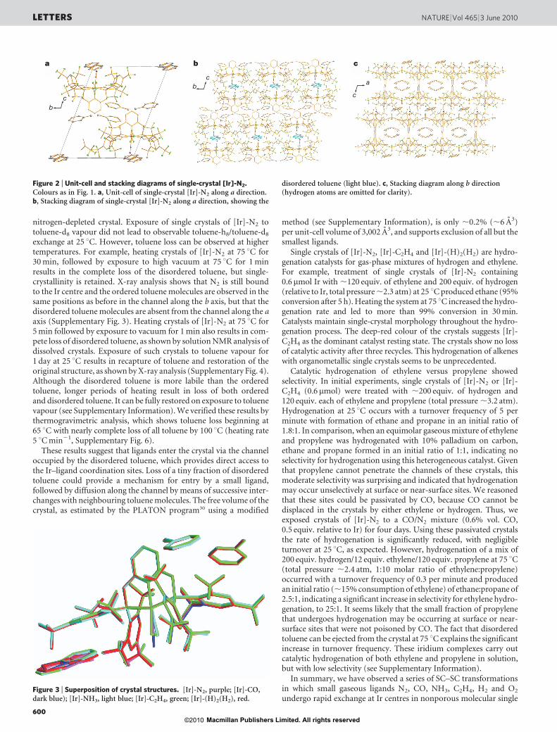
nitrogen-depleted crystal. Exposure of single crystals of [Ir]-N2 totoluene-d8 vapour did not lead to observable toluene-h8/toluene-d8
exchange at 25 uC. However, toluene loss can be observed at highertemperatures. For example, heating crystals of [Ir]-N2 at 75 uC for30 min, followed by exposure to high vacuum at 75 uC for 1 minresults in the complete loss of the disordered toluene, but single-crystallinity is retained. X-ray analysis shows that N2 is still boundto the Ir centre and the ordered toluene molecules are observed in thesame positions as before in the channel along the b axis, but that thedisordered toluene molecules are absent from the channel along the aaxis (Supplementary Fig. 3). Heating crystals of [Ir]-N2 at 75 uC for5 min followed by exposure to vacuum for 1 min also results in com-pete loss of disordered toluene, as shown by solution NMR analysis ofdissolved crystals. Exposure of such crystals to toluene vapour for1 day at 25 uC results in recapture of toluene and restoration of theoriginal structure, as shown by X-ray analysis (Supplementary Fig. 4).Although the disordered toluene is more labile than the orderedtoluene, longer periods of heating result in loss of both orderedand disordered toluene. It can be fully restored on exposure to toluenevapour (see Supplementary Information). We verified these results bythermogravimetric analysis, which shows toluene loss beginning at65 uC with nearly complete loss of all toluene by 100 uC (heating rate5 uC min21, Supplementary Fig. 6).
These results suggest that ligands enter the crystal via the channeloccupied by the disordered toluene, which provides direct access tothe Ir–ligand coordination sites. Loss of a tiny fraction of disorderedtoluene could provide a mechanism for entry by a small ligand,followed by diffusion along the channel by means of successive inter-changes with neighbouring toluene molecules. The free volume of thecrystal, as estimated by the PLATON program30 using a modified
method (see Supplementary Information), is only ,0.2% (,6 A3)per unit-cell volume of 3,002 A3, and supports exclusion of all but thesmallest ligands.
Single crystals of [Ir]-N2, [Ir]-C2H4 and [Ir]-(H)2(H2) are hydro-genation catalysts for gas-phase mixtures of hydrogen and ethylene.For example, treatment of single crystals of [Ir]-N2 containing0.6mmol Ir with ,120 equiv. of ethylene and 200 equiv. of hydrogen(relative to Ir, total pressure ,2.3 atm) at 25 uC produced ethane (95%conversion after 5 h). Heating the system at 75 uC increased the hydro-genation rate and led to more than 99% conversion in 30 min.Catalysts maintain single-crystal morphology throughout the hydro-genation process. The deep-red colour of the crystals suggests [Ir]-C2H4 as the dominant catalyst resting state. The crystals show no lossof catalytic activity after three recycles. This hydrogenation of alkeneswith organometallic single crystals seems to be unprecedented.
Catalytic hydrogenation of ethylene versus propylene showedselectivity. In initial experiments, single crystals of [Ir]-N2 or [Ir]-C2H4 (0.6mmol) were treated with ,200 equiv. of hydrogen and120 equiv. each of ethylene and propylene (total pressure ,3.2 atm).Hydrogenation at 25 uC occurs with a turnover frequency of 5 perminute with formation of ethane and propane in an initial ratio of1.8:1. In comparison, when an equimolar gaseous mixture of ethyleneand propylene was hydrogenated with 10% palladium on carbon,ethane and propane formed in an initial ratio of 1:1, indicating noselectivity for hydrogenation using this heterogeneous catalyst. Giventhat propylene cannot penetrate the channels of these crystals, thismoderate selectivity was surprising and indicated that hydrogenationmay occur unselectively at surface or near-surface sites. We reasonedthat these sites could be passivated by CO, because CO cannot bedisplaced in the crystals by either ethylene or hydrogen. Thus, weexposed crystals of [Ir]-N2 to a CO/N2 mixture (0.6% vol. CO,0.5 equiv. relative to Ir) for four days. Using these passivated crystalsthe rate of hydrogenation is significantly reduced, with negligibleturnover at 25 uC, as expected. However, hydrogenation of a mix of200 equiv. hydrogen/12 equiv. ethylene/120 equiv. propylene at 75 uC(total pressure ,2.4 atm, 1:10 molar ratio of ethylene:propylene)occurred with a turnover frequency of 0.3 per minute and producedan initial ratio (,15% consumption of ethylene) of ethane:propane of2.5:1, indicating a significant increase in selectivity for ethylene hydro-genation, to 25:1. It seems likely that the small fraction of propylenethat undergoes hydrogenation may be occurring at surface or near-surface sites that were not poisoned by CO. The fact that disorderedtoluene can be ejected from the crystal at 75 uC explains the significantincrease in turnover frequency. These iridium complexes carry outcatalytic hydrogenation of both ethylene and propylene in solution,but with low selectivity (see Supplementary Information).
In summary, we have observed a series of SC–SC transformationsin which small gaseous ligands N2, CO, NH3, C2H4, H2 and O2
undergo rapid exchange at Ir centres in nonporous molecular single
c
c
c
a
b
b
a b c
Figure 2 | Unit-cell and stacking diagrams of single-crystal [Ir]-N2.Colours as in Fig. 1. a, Unit-cell of single-crystal [Ir]-N2 along a direction.b, Stacking diagram of single-crystal [Ir]-N2 along a direction, showing the
disordered toluene (light blue). c, Stacking diagram along b direction(hydrogen atoms are omitted for clarity).
Figure 3 | Superposition of crystal structures. [Ir]-N2, purple; [Ir]-CO,dark blue); [Ir]-NH3, light blue; [Ir]-C2H4, green; [Ir]-(H)2(H2), red.
LETTERS NATURE | Vol 465 | 3 June 2010
600Macmillan Publishers Limited. All rights reserved©2010

crystals of an iridium(I) pincer complex. Substitutions occur asso-ciatively within the crystal and not by ligand loss followed by uptakeof the incoming ligand. Most remarkable is that single crystals of [Ir]-N2, [Ir]-(H)2(H2) or [Ir]-C2H4 function as alkene-hydrogenationcatalysts. When surface and near-surface sites are passivated by treat-ment with CO, a 25:1 selectivity is observed for hydrogenation ofethylene versus propylene, suggesting that hydrogenation occurswithin the crystal. To our knowledge, this is the first demonstrationof a catalytic hydrogenation reaction occurring within the interior ofan organometallic crystal. The substrate selectivity shown demon-strates the potential for using molecular crystals to carry out selectivecatalytic reactions.
Received 7 January 2010; accepted 15 April 2010.
1. Foxman, B. M. & Ward, M. D. Molecules in the Solid State 534–548 (MRS, 2007).2. Vittal, J. J. Supramolecular structural transformations involving coordination
polymers in the solid state. Coord. Chem. Rev. 251, 1781–1795 (2007).3. Atwood, J. L., Barbour, L. J., Jerga, A. & Schottel, B. L. Guest transport in a
nonporous organic solid via dynamic van der Waals cooperativity. Science 298,1000–1002 (2002).
4. Cotton, F. A. et al. Crystal-to-crystal oxidative deprotonation of a di(m-hydroxo) toa di(m-oxo) dimer of dimolybdenum units. Inorg. Chem. 46, 3245–3250 (2007).
5. Hu, C.-H. & Englert, U. Space filling versus symmetry: two consecutive crystal-to-crystal phase transitions in a 2D network. Angew. Chem. Intl Edn Engl. 45,3457–3459 (2006).
6. Xue, D., Zhang, W., Chen, X. & Wang, H. Single-crystal-to-single-crystaltransformation involving release of ridging water molecules and conversion ofchain helicity in a chiral three-dimensional metal-organic framework. Chem.Commun. 1551–1553 (2008).
7. Iordanidis, L. & Kanatzidis, M. G. Redox-induced ‘‘zipper’’ action in Rb2Bi4Se7 andCs2Bi4Se7: coupling of slabs to a three-dimensional framework through single-crystal to single-crystal conversion. Angew. Chem. Intl Edn Engl. 39, 1928–1930(2000).
8. Kawano, M. & Fujita, M. Direct observation of crystalline-state guest exchange incoordination networks. Coord. Chem. Rev. 251, 2592–2605 (2007).
9. Ghosh, S. K., Kaneko, W., Kiriya, D., Ohba, M. & Kitagawa, S. A bistable porouscoordination polymer with a bond-switching mechanism showing reversiblestructural and functional transformations. Angew. Chem. Intl Edn Engl. 47,8843–8847 (2008).
10. Haneda, T., Kawano, M., Kawamichi, T. & Fujita, M. Direct observation of thelabile imine formation through single-crystal-to-single-crystal reactions in thepores of a porous coordination network. J. Am. Chem. Soc. 130, 1578–1579 (2008).
11. Ghosh, S. K., Zhang, J. & Kitagawa, S. Reversible topochemical transformation of asoft crystal of a coordination polymer. Angew. Chem. Intl Edn Engl. 46, 7965–7968(2007).
12. Garcia-Garibay, M. A. Molecular crystals on the move: from single-crystal-to-single-crystal photoreactions to molecular machinery. Angew. Chem. Intl Edn Engl.46, 8945–8947 (2007).
13. Kobatake, S., Takami, S., Muto, H., Ishikawa, T. & Irie, M. Rapid and reversible shapechanges of molecular crystals on photoirradiation. Nature 446, 778–781 (2007).
14. Bucar, D. & MacGillivray, L. R. Preparation and reactivity of nanocrystallinecocrystals formed via sonocrystallization. J. Am. Chem. Soc. 129, 32–33 (2007).
15. Warren, M. R. et al. Reversible 100% linkage isomerization in a single-crystal tosingle-crystal transformation: photocrystallographic identification of themetastable [Ni(dppe)(g1-ONO)Cl] isomer. Angew. Chem. Intl Edn Engl. 48,5711–5714 (2009).
16. Li, B. et al. Solvent-induced transformation of single crystals of a spin-crossover(SCO) compound to single crystals with two distinct SCO centers. J. Am. Chem.Soc. 132, 1558–1566 (2010).
17. Das, S. K. & Supriya, S. Reversible single crystal to single crystal transformationthrough Fe-O(H)Me/Fe-OH2 bond formation/bond breaking in a gas-solidreaction at an ambient condition. J. Am. Chem. Soc. 129, 3464–3465 (2007).
18. Libri, S. et al. Ligand substitution within nonporous crystals of a coordinationpolymer: elimination from and insertion into Ag–O bonds by alcohol molecules ina solid–vapor reaction. Angew. Chem. Intl Edn Engl. 47, 1693–1697 (2008).
19. Bezzu, C. G., Helliwell, M., Warren, J. E., Allan, D. R. & McKeown, N. B. Heme-likecoordination chemistry within nanoporous molecular crystals. Science 327,1627–1630 (2010).
20. Albrecht, M., Lutz, M., Spek, A. L. & van Koten, G. Organoplatinum crystals forgas-triggered switches. Nature 406, 970–974 (2000).
21. Lennartson, A., Hakansson, M. & Jagner, S. Cis- and trans-bis(benzoylacetonato)-pyridinecopper(II): co-crystallisation of isomers and reversible pyridine loss withretention of crystallinity. N. J. Chem. 31, 344–347 (2007).
22. Goldman, A. S. et al. Catalytic alkane metathesis by tandem alkanedehydrogenation-olefin metathesis. Science 312, 257–261 (2006).
23. Huang, Z. et al. Highly active and recyclable heterogeneous iridium pincercatalysts for transfer dehydrogenation of alkanes. Adv. Synth. Catal. 351, 188–206(2009).
24. Ghosh, R., Kanzelberger, M., Emge, T. J., Hall, G. S. & Goldman, A. S. Dinitrogencomplexes of pincer-ligated iridium. Organometallics 25, 5668–5671 (2006).
25. Gottker-Schnetmann, I., White, P. S. & Brookhart, M. Synthesis and properties ofiridium bis(phosphinite) pincer complexes (p-XPCP)IrH2, (p-XPCP)Ir(CO),(p-XPCP)Ir(H)(aryl), and {(p-XPCP)Ir}2{m-N2} and their relevance in alkanetransfer dehydrogenation. Organometallics 23, 1766–1776 (2004).
26. Morales-Morales, D. et al. Selective dehydrogenation of alcohols and diolscatalyzed by a dihydrido iridium PCP pincer complex. Can. J. Chem. 79, 823–829(2001).
27. Kanzelberger, M. et al. Distinct thermodynamics for the formation and cleavage ofN-H bonds in aniline and ammonia. Directly-observed reductive elimination ofammonia from an isolated amido hydride complex. J. Am. Chem. Soc. 125,13644–13645 (2003).
28. Hebden, T. J. et al. Dihydrogen/dihydride or tetrahydride? An experimental andcomputational investigation of pincer iridium polyhydrides. Inorg. Chem. 49,1733–1742 (2010).
29. Williams, D. B., Kaminsky, W., Mayer, J. M. & Goldberg, K. I. Reactions of iridiumhydride pincer complexes with dioxygen: new dioxygen complexes and reversibleO2 binding. Chem. Commun. 4195–4197 (2008).
30. Spek, A. L. Single-crystal structure validation with the program PLATON. J. Appl.Cryst. 36, 7–13 (2003).
Supplementary Information is linked to the online version of the paper atwww.nature.com/nature.
Acknowledgements This work is financially supported by the National ScienceFoundation under the auspices of the Centre for Enabling New Technologiesthrough Catalysis (CENTC).
Author Contributions M.B. directed the project. Z.H. carried out all complexsyntheses, crystallizations and reactions. P.S.W. carried out single crystal X-raydiffraction experiments and crystal structure determinations. M.B. and Z.H.analysed the data and wrote the manuscript.
Author Information Supplementary crystallographic data for this paper has beendeposited at the Cambridge Crystallographic Data Centre under depositionnumbers CCDC 728556 to 728561, 729323, 729324 and 759994 to 759996.These data can be obtained free of charge from www.ccdc.cam.ac.uk/data_request/cif. Reprints and permissions information is available atwww.nature.com/reprints. The authors declare no competing financial interests.Readers are welcome to comment on the online version of this article atwww.nature.com/nature. Correspondence and requests for materials should beaddressed to M.B. ([email protected]).
NATURE | Vol 465 | 3 June 2010 LETTERS
601Macmillan Publishers Limited. All rights reserved©2010

Ligand exchanges and selective catalytic hydrogenation in molecular single crystals Review by Tatsiana Haidzinskaya
RECEIVED DATE 11/23/2010
ABSTRACT Single crystal to single crystal (SC–SC)
transformations were studied for Ir(I) complex with a pincer
ligand. The exchange of small ligands such as N2, CO, NH3,
C2H4, H2 and O2 was observed on the metal center. The
crystal structure of the complex was retained. The
mechanism for the substitution was proposed to be
associative with small ligands approaching a metal center
via crystal channels. The complex is also capable of
selective catalytic hydrogenation, which makes it the first
demonstration of a catalytic hydrogenation reaction
occurring within the interior of an organometallic crystal.
Chemical transformations of a single crystal are very
uncommon because crystallinity is difficult to retain after the
reorganization of the atoms in the chemical reactions.1 The most
studied single crystal to single crystal (SC–SC) transformation
involves solvent exchange reactions in porous coordination
polymers or metal–organic componds.2 The removal of solvents
without affecting the single crystal nature of the coordination
complexes is not necessarily considered as structural
transformation. However, many complexes undergo distortion and
sliding of network structures, change in conformation and
coordination environment during solvation, or desolvation
processes.3 A number of porous rigid coordination polymers often
exhibit zeolitic behavior and retain single crystal nature during
solvation and desolvation.4 Kitagawa, Yaghi, Atwood and others
have reported that these rigid porous coordination polymers can
be used as gas storage materials.5 The removal of solvents during
SC-SC conversion has also been found to accompany by change
in magnetic properties,6 negative thermal expansion7 and
luminescent properties.8 Another example of single crystal to
single crystal (SC–SC) transformations is the formation or
cleavage of metal–ligand bonds.9 These reactions are very rare
and sometimes result in the crystal decay with the formation of a
microcrystalline powder.10
Figure 1. Single-crystal structures of [Ir]-N2, [Ir]-CO, [Ir]-NH3, [Ir]-C2H4, [Ir]-(H)2(H2), and [Ir]-O2. Iridium, dark green;
phosphorus, pink; fluorine, light green; oxygen, red; nitrogen, dark blue; carbon, grey; hydrogen, light blue. Hydrogen atoms are omitted for clarity, except for those in C2H4, NH3 and H2 ligands. All SC–SC transformations occur at 25
oC in the presence
of 1 atm of gas, except for the transformation of [Ir]-N2 to [Ir]-(H)2(H2), for which 1.5 atm of H2 was used.

Figure 2. Unit-cell and stacking diagrams of single-crystal [Ir]-N2. Colors as in Fig. 1. a, Unit-cell of single-crystal [Ir]-N2 along a direction. b, Stacking diagram of single-crystal [Ir]-N2 along a direction, showing the disordered toluene (light blue). c, Stacking diagram along b direction (hydrogen atoms are omitted for clarity).
Maurice Brookhart et. al. from the University of North Carolina
reported a study on a single crystal of Ir(I) complex with a pincer
ligand.11 The researchers observed the exchange of small ligands
such as N2, CO, NH3, C2H4, H2 and O2 on the metal center with
the retention of the crystal structure. The scientists also
discovered selective catalytic hydrogenation of ethylene to ethane
in the presence of propylene when the metal center is ligated with
N2, C2H4, H2 and small amounts of CO. This is the first reported
catalytic hydrogenation reaction that occurs within the interior of
a molecular single crystal, which opens up the opportunity for the
further development of the research area where single crystals
could be used as catalysts in the catalytic reactions with high
selectivities.
The researchers started the project with the synthesis and
characterization of Ir(I) complex with a pincer ligand ligated with
nitrogen. [Ir]-N2 – is a square planar complex, and after the
recrystallization from toluene it has a light red color. Bond length
and angles are provided in the Table 1. The bulky, electron-
deficient pincer ligand C6H3[OP(C6H2(CF3)3-2,4,6)2]2-1,3 with the
four CF3-substituted aryl rings was used to create a pocket and
prevent dimerization. Each unit cell contains two molecules of
[Ir]-N2 complex and five molecules of toluene. One molecule of
toluene is disordered about an inversion center and located at the
corner of a unit cell. The other four solvent molecules are highly
ordered (Figure 2).
With [Ir]-N2 complex in hand, the researchers decided to
investigate the possibility of ligand exchange reactions. The
crystal was exposed to gaseous small ligands such as CO, NH3,
C2H4, H2 and O2. In the case of CO, a rapid color change was
observed. Within one minute after the exposure to carbon
monoxide the complex changed its color from light red to orange.
When exposed to NH3 atmosphere, [Ir]-N2 complex became dark
red in less than one minute; and in case of ethylene, it took several
hours for a complex to acquire a deep red color. In all provided
examples, the crystal structure was retained and the analysis of the
products by X-ray diffraction showed the loss of nitrogen and the
formation of [Ir]-CO, [Ir]-NH3, and [Ir]-C2H4 complexes
correspondingly. When [Ir]-N2 complex was exposed to H2 no
color change was observed, but X-ray diffraction and proton
NMR confirmed the loss of nitrogen and the formation of a tetra
hydride. [Ir]-N2, [Ir]-CO, [Ir]- NH3, [Ir]-C2H4, and [Ir]-(H)2(H2)
complexes have the same lattice parameters and the pincer ligand
sets are superimposable (Figure 3). Under air, [Ir]-N2 complex
gradually changes color to dark green and the X-ray diffraction
analysis shows the formation of a monoperoxo Ir(III) complex.
The structure of the complex is distorted and not superimposable
with the previously described complexes. The exposure of the
[Ir]-N2 complex to propylene does not lead to the displacement of
nitrogen. All ligand displacement transformations were found to
be quantitative.
Figure 3. Superposition of crystal structures. [Ir]-N2, purple; [Ir]-CO, dark blue); [Ir]-NH3, light blue; [Ir]-C2H4, green; [Ir]-(H)2(H2), red.
To determine the mechanism of ligand exchange reaction the
researchers decided to carry out several experiments by exposing
a crystal to vacuum and heat. When the complex was exposed to
high vacuum at room temperature for one week the loss of
nitrogen or toluene was not observed. It proved that the ligand
displacement did not happen through a dissociative mechanism.
As we discussed in class, in the dissociative mechanism the metal-
ligand bond is fully broken before the new metal-ligand bond is
formed. The stability of the complex under vacuum at room
temperature proves that the metal-nitrogen bond is relatively
strong and does not break spontaneously under reaction
conditions. Exposure of a single crystal to toluene-D8 did not lead
to observable toluene-H8/toluene-D8 exchange at room
temperature as well. When the crystal was heated under vacuum,
the complete loss of toluene was observed. The loss of toluene
started at 65 oC with the disordered toluene and at 100 oC
complete loss of toluene was detected. The following exposure of
the crystal to the toluene vapor led to the restoration of the
original structure. The researchers suggested that ligands enter the
crystal via the channel occupied by the disordered toluene. The
loss of small amounts of toluene gives a possibility for a small
ligand to enter the channel and diffuse through the channel to the
ligand metal coordination site.
Because iridium complexes are known to catalyze
hydrogenation reactions, the scientists were interested in the
catalytic abilities of a single crystal [Ir]-N2 as a hydrogenation
catalyst. The researchers exposed the complex to a

Table 1. Crystal data and structure-refinement summary.
mixture of ethylene (120 equivalents) and hydrogen (200
equivalents) at room temperature and obtained ethane in 95 %
yield after 5 hours. Increasing the temperature to 75 oC led to 99%
conversion in 30 minutes. This is the first reported catalytic
hydrogenation reaction that occurs within the interior of a
molecular single crystal. An interest in selective hydrogenation
led to another experiment where equimolar mixture of ethylene
and propylene under the same conditions gave 1.8:1.0 mixture of
ethane to propane. Higher selectivity was expected due to the fact
that propylene cannot penetrate the channels of the crystals. It led
to the conclusion that hydrogenation occurs not only at the metal
center inside the crystal but on the surface and near surface sites
of the crystal as well. These sites could be passivated with CO due
to the strong binding affinity of the ligand and the observation that
ethylene and hydrogen cannot displace CO from the complex. The
researchers exposed crystals of [Ir]-N2 to a CO/N2 mixture (0.6%
vol. CO, 0.5 equiv. relative to Ir) for four days and used these
passivated crystals in the hydrogenation reaction. The rate of the
reaction was considerably reduced, but the selectivity was
increased to 25:1 ratio of ethane to propane. The rate of the
reaction can be increased by heating the reaction mixture with
reduction of selectivity.
In conclusion, the scientists observed ligand exchange
transformations in nonporous molecular single crystals of an
iridium (I) pincer complex. The proposed mechanism of this
associative exchange is via crystal channels occupied by toluene.
The complex is also capable of selective hydrogenation, which,
according to the authors, makes it the first demonstration of a
catalytic hydrogenation reaction occurring within the interior of
an organometallic crystal. For the future directions, I would
suggest the researchers to search for another transition metal
complex capable of selective hydrogenation inside the crystal. I
would test Rh, Co, Ru, Os, Pd, Pt complexes for similar
transformations. I believe it would be necessary to enlarge the size
of the crystal channels to increase the substrate scope of the
reaction. It can be achieved by using larger ligands, such as tris-
pyrazolyl borate, or solvent molecules, such as mesitylene or
1,3,5-triisopropylbenzene. Larger channels might provide the
opportunity for selective hydrogenation of larger molecules, for
example, butene and propene. To check if the
selectivity is based solely on the size of the ligands I would
recommend to run the hydrogenation reaction of ethylene and
propylene in solution. If no selectivity is observed, crystal
channels are responsible for the selectivity. I also suggest running
the hydrogenation reaction with alkynes. Selective hydrogenation
of acetylene in the presence of propyne may be of scientific
interest as well.
REFERENCES
1. Atwood, J. L.; Barbour, L. J.; Jerga, A.; Schottel, B. L.
Science 2002, 298,1000–1002.
2. Vittal, J. J. Coord. Chem. Rev. 2007, 251, 1781–1795.
3. a) Dobrzanska, L.; Lloyd G. O.; Esterhuysen, C.; Barbour,
L. J. Angew Chem. Int. Ed. 2006, 45, 5856.
b) Dobrzanska L., Lloyd G.O., Raubenheimer H. G., Barbour
L. J., J. Am. Chem. Soc. 2005, 127, 13134.
c) Dobrza´ska, L.; Lloyd, G.O.; Raubenheimer, H. G.;
Barbour L. J. J. Am. Chem. Soc. 2006, 128, 698.
d) Okubo, T.; Asami, A.; Noro, S.; Yoshitomi, T.; Kitagawa,
S.; Ishii, T.; Matsuzaka, H.; Seki, K. Angew. Chem. Int. Ed,
1999,. 38, 140.
4. Kitagawa, S.; Uemura, K. Chem. Soc. Rev. 2005, 34, 109.
5. a) Kitagawa, S.; Noro, S.; Nakamura, T.; Takayoshi, T.
Chem. Commun. 2006, 701. b) Yaghi, O. M. Angew. Chem.
Int. Ed. 2005, 44, 4670. c) Atwood, J. L.; Barbour, L. J.;
Jerga, A.; Schottel, B. L., Science, 2002, 298, 1000.
6. Kurmoo, M.; Kumagai, H.; Chapman, K. W.; Kepert, C. J.
Chem. Commun. 2005, 3012.
7. Pretsch, T.; Chapman, K. W.; Halder, G. J.; Kerpert, C. J.
Chem. Commun. 2006, 1587.
8. Wong, K.-L.; Law, G.-L.; Yang, Y.-Y.; Wong, W.-T. Adv.
Mater. 18 2006, 1051.
9. a) Das, S. K.; Supriya, S. J. Am. Chem. Soc. 2007, 129,
3464–3465. b) Libri S. Angew. Chem. Int. Ed 2008, 47,
1693–1697. c) Bezzu, C. G.; Helliwell, M.; Warren, J. E.;
Allan, D. R.; McKeown, N. B. Science, 2010, 327, 1627–
1630.
10. Albrech, M.; Lutz, M; Spek, A. L. Nature 2000, 406, 970–
974.
11. Huang, Z.; White, P. S.; Brookhart, M. Nature 2010, 465,
598-60
[Ir]-N2 [Ir]-CO [Ir]-NH3 [Ir]-C2H4 [Ir]-(H)2(H2) [Ir]-O2
Formula C59.5H31F36IrN2O2P2 C60.5H31F36IrO3P2 C59.5H34F36IrNO2P2 C61.5H35F36IrO2P2 C59.5H35F36IrO2P2 C59.5H31F36
IrO4P2
Crystal
System Triclinic Triclinic Triclinic Triclinic Triclinic Triclinic
Space group P-1 P-1 P-1 P-1 P-1 P-1
a (A°) 12.4720(3) 12.4680(5) 12.4758(5) 12.4844(6) 12.4334(11) 12.769(3)
b (A°) 14.0891(4) 14.1099(6) 14.0658(5) 14.2365(6) 14.0615(12) 13.637(3)
c (A°) 18.6382(5) 18.6021(7) 18.5976(6) 18.5497(9) 18.6354(14) 17.835(3)
! (deg) 108.865(2) 108.852(3) 108.155(2) 108.791(3) 108.879(5) 99.088(13)
" (deg) 99.010(2) 98.939(3) 99.291(3) 98.572(3) 98.956(6) 87.194(15)
# (deg) 97.567(2) 97.635(3) 97.445(3) 98.284(3) 97.594(6) 96.357(17)
V (A°3) 3002.11(14) 3000.1(2) 3003.56(19) 3020.6(2) 2986.6(4) 3046.3(10)
Z 2 2 2 2 2 2
T(K) 100(2) 100(2) 100(2) 100(2) 100(2) 100(2)
R1 [I>2s(I)] 0.0389 0.0415 0.0556 0.0531 0.0445 0.1090
wR2 (all
data) 0.0866 0.0916 0.01305 0.1313 0.1001 0.2925

the ion trap, which alters the spectrum of the emittedphotons and degrades the quantum interference,reduces the average fidelity by less than 1%.
The entangling gate central to this tele-portation protocol is a heralded, probabilisticprocess. The net probability for coincident de-tection of two emitted photons is given by Pgate ¼( pBell)½ pphTfiberTopticsx(DW/4p)�2 ≈ 2:2� 10−8,where pBell = 0.25 accounts for the detectionof only one out of the four possible Bell states;pp = 0.5 is the fraction of photons with the cor-rect polarization (half are filtered out as beingproduced by s decays); h = 0.15 is the quantumefficiency of each PMT; Tfiber = 0.2 is the cou-pling and transmission of each photon throughthe single-mode optical fiber; Toptics = 0.95 is thetransmission of each photon through the otheroptical components; x = 1 – 0.005 = 0.995, where0.005 is the branching ratio into the 2D3/2 level;and DW/4p = 0.02 is the solid angle of light col-lection. The attempt rate of 75 kHz is currentlylimited by the time of the state preparation mi-crowave pulse, resulting in about one successfulteleportation event every 12 min. However, theexpression for Pgate reveals multiple ways tosubstantially increase the success rate. The mostdramatic increase would be achieved by increas-ing the effective solid angle of collection, which,for instance, could be accomplished by surround-
ing each ion with an optical cavity. Although im-provements that increase the success probabilityof the gate operation can enhance scalability, evenwith a low success probability this gate can stillbe scaled to more complex systems (16).
The fidelity obtained in the current experi-ment is evidence of the excellent coherence prop-erties of the photonic frequency qubit and the“clock” state atomic qubit. Together, these com-plementary qubits provide a robust system forapplications in quantum information. The tele-portation scheme demonstrated here could beused as the elementary constituent of a quantumrepeater. Moreover, the entangling gate imple-mented in this protocol may be used for scalablemeasurement-based quantum computation.
References and Notes1. W. K. Wootters, W. H. Zurek, Nature 299, 802 (1982).2. C. H. Bennett et al., Phys. Rev. Lett. 70, 1895 (1993).3. H.-J. Briegel, W. Dür, J. I. Cirac, P. Zoller, Phys. Rev. Lett.
81, 5932 (1998).4. D. Gottesman, I. L. Chuang, Nature 402, 390 (1999).5. D. Bouwmeester et al., Nature 390, 575 (1997).6. D. Boschi, S. Branca, F. De Martini, L. Hardy, S. Popescu,
Phys. Rev. Lett. 80, 1121 (1998).7. A. Furusawa et al., Science 282, 706 (1998).8. J. F. Sherson et al., Nature 443, 557 (2006).9. Y.-A. Chen et al., Nat. Phys. 4, 103 (2008).10. L.-M. Duan, M. D. Lukin, J. I. Cirac, P. Zoller, Nature 414,
413 (2001).
11. M. Riebe et al., Nature 429, 734 (2004).12. M. D. Barrett et al., Nature 429, 737 (2004).13. M. Riebe et al., N. J. Phys. 9, 211 (2007).14. S. Massar, S. Popescu, Phys. Rev. Lett. 74, 1259 (1995).15. S. J. van Enk, N.Lütkenhaus, H. J. Kimble, Phys. Rev. A
75, 052318 (2007).16. L.-M. Duan et al., Phys. Rev. A 73, 062324 (2006).17. R. Van Meter, K. M. Itoh, T. D. Ladd, http://arxiv.org/abs/
quant-ph/0507023.18. P. Maunz et al., Nat. Phys. 3, 538 (2007).19. D. L. Moehring et al., Nature 449, 68 (2007).20. S. Olmschenk et al., Phys. Rev. A 76, 052314 (2007).21. D. N. Matsukevich, P. Maunz, D. L. Moehring, S. Olmschenk,
C. Monroe, Phys. Rev. Lett. 100, 150404 (2008).22. M. J. Madsen et al., Phys. Rev. Lett. 97, 040505 (2006).23. B. B. Blinov, D. L. Moehring, L.-M. Duan, C. Monroe,
Nature 428, 153 (2004).24. C. K. Hong, Z. Y. Ou, L. Mandel, Phys. Rev. Lett. 59, 2044
(1987).25. Y. H. Shih, C. O. Alley, Phys. Rev. Lett. 61, 2921 (1988).26. S. L. Braunstein, A. Mann, Phys. Rev. A 51, R1727 (1995).27. C. Simon, W. T. M. Irvine, Phys. Rev. Lett. 91, 110405
(2003).28. J. B. Altepeter, E. R. Jeffrey, P. G. Kwiat, in Advances in
Atomic, Molecular, and Optical Physics, P. Berman, C. Lin,Eds. (Elsevier, San Diego, CA, 2006), vol. 52, pp. 105–159.
29. J. L. O’Brien et al., Phys. Rev. Lett. 93, 080502 (2004).30. M. Horodecki, P. Horodecki, R. Horodecki, Phys. Rev. A
60, 1888 (1999).31. This work is supported by the Intelligence Advanced
Research Projects Activity (IARPA) under Army ResearchOffice contract, the NSF Physics at the Information Frontierprogram, and the NSF Physics Frontier Center at JQI.
14 October 2008; accepted 19 December 200810.1126/science.1167209
Femtosecond XANES Study of theLight-Induced Spin CrossoverDynamics in an Iron(II) ComplexCh. Bressler,1 C. Milne,1 V.-T. Pham,1 A. ElNahhas,1 R. M. van der Veen,1,2W. Gawelda,1,2* S. Johnson,2 P. Beaud,2 D. Grolimund,2 M. Kaiser,1,2C. N. Borca,2 G. Ingold,2 R. Abela,2 M. Chergui1†
X-ray absorption spectroscopy is a powerful probe of molecular structure, but it has previously beentoo slow to track the earliest dynamics after photoexcitation. We investigated the ultrafastformation of the lowest quintet state of aqueous iron(II) tris(bipyridine) upon excitation of thesinglet metal-to-ligand-charge-transfer (1MLCT) state by femtosecond optical pump/x-ray probetechniques based on x-ray absorption near-edge structure (XANES). By recording the intensityof a characteristic XANES feature as a function of laser pump/x-ray probe time delay, we find thatthe quintet state is populated in about 150 femtoseconds. The quintet state is further evidenced byits full XANES spectrum recorded at a 300-femtosecond time delay. These results resolve along-standing issue about the population mechanism of quintet states in iron(II)-basedcomplexes, which we identify as a simple 1MLCT→3MLCT→5T cascade from the initiallyexcited state. The time scale of the 3MLCT→5T relaxation corresponds to the period of theiron-nitrogen stretch vibration.
There is a large class of iron(II)-basedmolecular complexes that exhibit twoelectronic states closely spaced in energy:
a low-spin (LS) singlet and a high-spin (HS)quintet state. They therefore manifest spin cross-over (SCO) behavior, wherein conversion from aLS ground state to a HS excited state (or thereverse) can be induced by small temperature orpressure changes or by light absorption (1, 2).
The SCO phenomenon has been much studiedusing steady-state (2) and ultrafast (3–6) opticalspectroscopies, with the goal of identifying theelementary steps leading to formation of the HSstate. A representative energy level diagram of allFe(II)-based complexes is shown in Fig. 1 (7).The main difference between them concerns theabsolute energies of states, not their energetic or-dering (2). All crystallographic studies point to an
Fe-N bond elongation by ~0.2 Å in the HS com-pared to the LS state (1, 2). Theoretical studiesshow that the Fe-N bond length of the singlet andtriplet metal-centered (MC) 1,3T states lies half-way between those of the LS and HS states (7).Obviously, accessing the HS excited state byabsorption of light from the LS ground state isforbidden by the spin selection rules. Therefore,the doorway to the HS state is ideally via thesinglet metal-to-ligand-charge-transfer (1MLCT)that exhibits strong absorption bands in the visi-ble spectrum, or via the weakly absorbing andlower-lying 1,3T states (1, 2). The time scale andthe route going from the initially excited 1MLCTstate to the lowest-lying quintet state are still thesubject of debate. Steady-state spectroscopic studiesat cryogenic temperatures showed that excitationinto the MC 1,3T states leads to population of the5T2 state with a quantum efficiency of ~80% (2).Researchers therefore concluded that the relaxa-tion cascade from the 1MLCTstate to the HS 5T2state proceeds via the intermediate 1,3T states.However, for excitation of the 1MLCT state, therelaxation process was reported to occur with100% efficiency at both 10 K (2) and at room
1Ecole Polytechnique Fédérale de Lausanne, Laboratoire deSpectroscopie Ultrarapide, ISIC, FSB-BSP, CH-1015 Lausanne,Switzerland. 2Swiss Light Source, Paul-Scherrer Institut, CH-5232Villigen PSI, Switzerland.
*Present address: Laser Processing Group, Instituto de Optica,Consejo Superior de Investigaciones Científicas, Serrano 121,E-28006 Madrid, Spain.†To whom correspondence should be addressed. E-mail:[email protected]
www.sciencemag.org SCIENCE VOL 323 23 JANUARY 2009 489
REPORTS
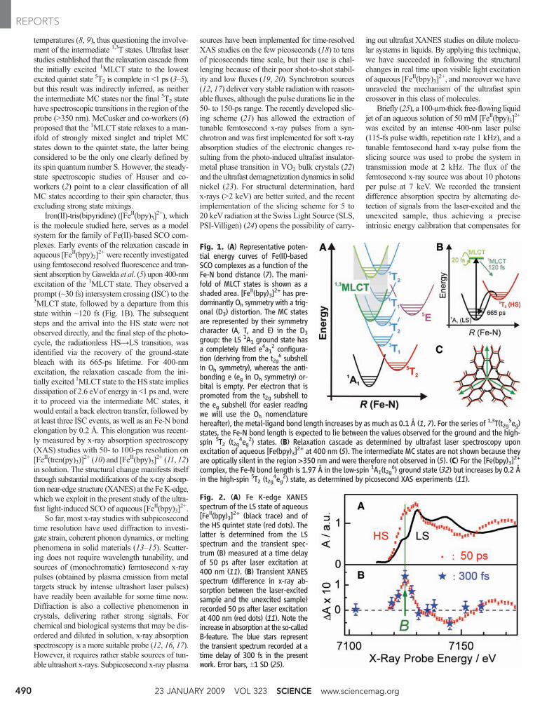
temperatures (8, 9), thus questioning the involve-ment of the intermediate 1,3T states. Ultrafast laserstudies established that the relaxation cascade fromthe initially excited 1MLCT state to the lowestexcited quintet state 5T2 is complete in <1 ps (3–5),but this result was indirectly inferred, as neitherthe intermediate MC states nor the final 5T2 statehave spectroscopic transitions in the region of theprobe (>350 nm). McCusker and co-workers (6)proposed that the 1MLCT state relaxes to a man-ifold of strongly mixed singlet and triplet MCstates down to the quintet state, the latter beingconsidered to be the only one clearly defined byits spin quantum number S. However, the steady-state spectroscopic studies of Hauser and co-workers (2) point to a clear classification of allMC states according to their spin character, thusexcluding strong state mixings.
Iron(II)-tris(bipyridine) ([FeII(bpy)3]2+), which
is the molecule studied here, serves as a modelsystem for the family of Fe(II)-based SCO com-plexes. Early events of the relaxation cascade inaqueous [FeII(bpy)3]
2+ were recently investigatedusing femtosecond resolved fluorescence and tran-sient absorption by Gawelda et al. (5) upon 400-nmexcitation of the 1MLCT state. They observed aprompt (~30 fs) intersystem crossing (ISC) to the3MLCT state, followed by a departure from thisstate within ~120 fs (Fig. 1B). The subsequentsteps and the arrival into the HS state were notobserved directly, and the final step of the photo-cycle, the radiationless HS→LS transition, wasidentified via the recovery of the ground-statebleach with its 665-ps lifetime. For 400-nmexcitation, the relaxation cascade from the ini-tially excited 1MLCTstate to the HS state impliesdissipation of 2.6 eVof energy in <1 ps and, wereit to proceed via the intermediate MC states, itwould entail a back electron transfer, followed byat least three ISC events, as well as an Fe-N bondelongation by 0.2 Å. This elongation was recent-ly measured by x-ray absorption spectroscopy(XAS) studies with 50- to 100-ps resolution on[FeII(tren(py)3)]
2+ (10) and [FeII(bpy)3]2+ (11, 12)
in solution. The structural change manifests itselfthrough substantial modifications of the x-ray absorp-tion near-edge structure (XANES) at the FeK-edge,which we exploit in the present study of the ultra-fast light-induced SCO of aqueous [FeII(bpy)3]
2+.So far, most x-ray studies with subpicosecond
time resolution have used diffraction to investi-gate strain, coherent phonon dynamics, or meltingphenomena in solid materials (13–15). Scatter-ing does not require wavelength tunability, andsources of (monochromatic) femtosecond x-raypulses (obtained by plasma emission from metaltargets struck by intense ultrashort laser pulses)have readily been available for some time now.Diffraction is also a collective phenomenon incrystals, delivering rather strong signals. Forchemical and biological systems that may be dis-ordered and diluted in solution, x-ray absorptionspectroscopy is a more suitable probe (12, 16, 17).However, it requires rather stable sources of tun-able ultrashort x-rays. Subpicosecond x-ray plasma
sources have been implemented for time-resolvedXAS studies on the few picoseconds (18) to tensof picoseconds time scale, but their use is chal-lenging because of their poor shot-to-shot stabil-ity and low fluxes (19, 20). Synchrotron sources(12, 17) deliver very stable radiation with reason-able fluxes, although the pulse durations lie in the50- to 150-ps range. The recently developed slic-ing scheme (21) has allowed the extraction oftunable femtosecond x-ray pulses from a syn-chrotron and was first implemented for soft x-rayabsorption studies of the electronic changes re-sulting from the photo-induced ultrafast insulator-metal phase transition in VO2 bulk crystals (22)and the ultrafast demagnetization dynamics in solidnickel (23). For structural determination, hardx-rays (>2 keV) are better suited, and the recentimplementation of the slicing scheme for 5 to20 keV radiation at the Swiss Light Source (SLS,PSI-Villigen) (24) opens the possibility of carry-
ing out ultrafast XANES studies on dilute molecu-lar systems in liquids. By applying this technique,we have succeeded in following the structuralchanges in real time upon visible light excitationof aqueous [FeII(bpy)3]
2+, and moreover we haveunraveled the mechanism of the ultrafast spincrossover in this class of molecules.
Briefly (25), a 100-mm-thick free-flowing liquidjet of an aqueous solution of 50 mM [FeII(bpy)3]
2+
was excited by an intense 400-nm laser pulse(115-fs pulse width, repetition rate 1 kHz), and atunable femtosecond hard x-ray pulse from theslicing source was used to probe the system intransmission mode at 2 kHz. The flux of thefemtosecond x-ray source was about 10 photonsper pulse at 7 keV. We recorded the transientdifference absorption spectra by alternating de-tection of signals from the laser-excited and theunexcited sample, thus achieving a preciseintrinsic energy calibration that compensates for
Fig. 1. (A) Representative poten-tial energy curves of Fe(II)-basedSCO complexes as a function of theFe-N bond distance (7). The mani-fold of MLCT states is shown as ashaded area. [FeII(bpy)3]
2+ has pre-dominantly Oh symmetry with a trig-onal (D3) distortion. The MC statesare represented by their symmetrycharacter (A, T, and E) in the D3group: the LS 1A1 ground state hasa completely filled e4a1
2 configura-tion (deriving from the t2g
6 subshellin Oh symmetry), whereas the anti-bonding e (eg in Oh symmetry) or-bital is empty. Per electron that ispromoted from the t2g subshell tothe eg subshell (for easier readingwe will use the Oh nomenclaturehereafter), the metal-ligand bond length increases by as much as 0.1 Å (1, 7). For the series of 1,3T(t2g
5eg)states, the Fe-N bond length is expected to lie between the values observed for the ground and the high-spin 5T2 (t2g
4eg2) states. (B) Relaxation cascade as determined by ultrafast laser spectroscopy upon
excitation of aqueous [Fe(bpy)3]2+ at 400 nm (5). The intermediate MC states are not shown because they
are optically silent in the region >350 nm and were therefore not observed in (5). (C) For the [Fe(bpy)3]2+
complex, the Fe-N bond length is 1.97 Å in the low-spin 1A1(t2g6) ground state (32) but increases by 0.2 Å
in the high-spin 5T2 (t2g4eg
2) state, as determined by picosecond XAS experiments (11).
Fig. 2. (A) Fe K-edge XANESspectrum of the LS state of aqueous[FeII(bpy)3]
2+ (black trace) and ofthe HS quintet state (red dots). Thelatter is determined from the LSspectrum and the transient spec-trum (B) measured at a time delayof 50 ps after laser excitation at400 nm (11). (B) Transient XANESspectrum (difference in x-ray ab-sorption between the laser-excitedsample and the unexcited sample)recorded 50 ps after laser excitationat 400 nm (red dots) (11). Note theincrease in absorption at the so-calledB-feature. The blue stars representthe transient spectrum recorded at atime delay of 300 fs in the presentwork. Error bars, T1 SD (25).
23 JANUARY 2009 VOL 323 SCIENCE www.sciencemag.org490
REPORTS

drifts of the laser or synchrotron energies andfluxes. The time resolution was <250 fs (25).
Figure 2A shows the Fe K-edge XANESspectra of aqueous [FeII(bpy)3]
2+ in its ground(LS) and excited (HS) state. The spectrum ofthe latter was retrieved from the LS spectrumand the difference spectrum recorded 50 ps afterlaser excitation (red dots in Fig. 2B) (11). Thestrongest increase in absorption upon LS to HSconversion occurs at the so-called B-feature (ar-row in Fig. 2), which was previously identified asa structure-sensitive above-ionization multiple-scattering resonance (26). The increase in inten-sity of the B-feature is concomitant with theincrease in Fe-N bond distance upon LS to HSconversion, reflecting a well-established correla-tion between edge absorption intensity and bonddistance [see, e.g., (27)]. For the present system,this correlation was confirmed (fig. S1) by a sim-ulation of the XANES spectrum using the MinuitXANES (MXAN) code (11, 28), which addition-ally shows a nearly linear relationship between theFe-N bond elongation and the intensity of theB-feature. The B-feature intensity is therefore asignature of the Fe-N bond elongation, and itallows us to distinguish the various states that canbe grouped by their similar Fe-N bond distances:(i) the LS ground and the 1,3MLCT states; (ii) the1,3T states, which exhibit an elongation of 0.1 Årelative to the ground state (7); and (iii) the 5Tstate, which exhibits a 0.2 Å elongation (11).Based on this correlation, we analyze the ob-served light-induced changes at the B-featureas a function of the time delay between theoptical pump pulse and the x-ray probe pulse inthe femtosecond to picosecond time domain.
Figure 3 shows the transient signal at theB-feature as a function of time delay (the insetshows an expanded region out to 10 ps). It ischaracterized by a steep rise followed by a pla-teau beyond 250 to 300 fs, which suggests thatthe system has reached the HS state within thistime frame. This suggestion is confirmed by theenergy scan recorded at a time delay of 300 fs(blue stars in Fig. 2B), which agrees with thetransient absorption spectrum recorded at 50-pstime delay. Considering a simple four-level kineticmodel 1A1→
1MLCT→3MLCT→5T, we simu-lated the signal with no adjustable parameters,assuming (i) an optical/x-ray cross-correlation of250 fs; (ii) the 1MLCT and 3MLCT decay timesmeasured in (5) (Fig. 1B); (iii) the cross sectionsat the B-feature for the LS and HS states (Fig. 2A),as well as for the intermediate 1,3T states, derivedfrom the relationship between the Fe-N bond elon-gation and the B-feature intensity (25); and (iv)the absorption cross section of the MLCT state(s).For the latter, based on our previous study ofthe analogous [RuII(bpy)3]
2+ molecule (29), theMLCT and LS XANES are expected to be sim-ilar, except for a shift to higher energies of theMLCT XANES spectrum, due to the oxidationof the central metal atom (over the time thesystem remains in the MLCT manifold). At theFe K-edge, this oxidation state shift amounts toat most +2 eV based on a study of Fe(II)- andFe(III)-hexacyanide (30).
Figure 3B shows the simulated time evolutionof the signal due to the various states, including(solid curves) and excluding (dashed curves) theMLCT states, as well as the resulting total signal(red traces). The blue shift of theMLCTspectrum
should lead to an initial decrease in absorption ofthe signal, which we do not observe. The simu-lations (green trace in Fig. 3B) confirm that ourpump-probe correlation time brings this initial sig-nal decrease below our experimental sensitivity,thus accounting for its absence in the data. Also,we note that time zero is hardly affected byinclusion of the signal due to the MLCT state,and its value changes by at most 40 fs whencomparing the simulations with and without the(temporary) oxidation shift. Finally, introducingthe 1,3T state(s) can reproduce the data only for afitted relaxation time of <60 fs (25). Such a shortlifetime, however, is unrealistic because it cor-responds to the period of high frequency modesof the system, which in addition would need to beshared among the 1,3T states that all have po-tential curves with identical equilibrium distancesand curvatures along the Fe-N coordinate (Fig.1A). Consequently, the agreement between theexperimental and the simulated time trace (Fig.3A) implies that the rise time (~150 fs) of thex-ray absorption of the HS state corresponds to thedecay of the 3MLCT state (5). Thus, the popu-lation of the 3MLCT state proceeds to the quintetstate directly and bypasses the intermediate 1,3Tstates. Furthermore, the derived relaxation timescale corresponds to the period of the Fe-N stretchmode, which lies in the 130- to 160-fs range forall Fe(II)-based complexes, according to Ramanstudies (31). Therefore, here the observation ofthe structural dynamics allows us to unambigu-ously unravel the population relaxation pathway.
Because the 3MLCT state lies about 1.5 eVabove the quintet state (Fig. 1), the latter is pop-ulated in high vibrational levels. However, we donot observe vibrational cooling in the quintetstate, because XANES spectroscopy is in generalnot very sensitive to Debye-Waller factors, whichreflect the uncertainty in atomic coordinates dueto thermal motion.
The general picture of the light-induced SCOprocess that emerges from this study becomesvery simple and is summarized in Fig. 1B. Thefull cascade reduces a two-step ISC process,1MLCT→3MLCT→5T. The bypassing of the in-termediate 1,3T states resolves the issue of mul-tiple ultrafast ISC steps among states that arequasiparallel with respect to the Fe-N coordinate(Fig. 1A). Dissipation of the energy difference in theultrafast cascade is accounted for by storage of vi-brational energy in the quintet state. Finally, the unitquantum efficiency of the SCO process from the1MLCTstate into the quintet statemakes sense in thecontext of excluding any leakage back to the groundstate (9) through the bypassing of the 1,3T states.
Considering that [FeII(bpy)3]2+ is a model
system for all Fe(II)-based SCO complexes, webelieve that our results are of general validity tothis family. These results also underscore thepower of ultrafast x-ray absorption spectroscopyfor the study of molecular structural dynamics ofdilute systems. In the present case, resolving thestructural dynamics unravels the pathways of spinand electronic relaxation.
Fig. 3. (A) Time scan of the signal(blue points) at the B-feature (at7126 eV) (Fig. 2B) as a function oflaser pump/x-ray probe time de-lay after excitation of aqueous[FeII(bpy)3]
2+ at 400 nm. The insetshows a long time scan up to a10-ps time delay. The red traceis the simulated signal assuminga simple four-step kinetic model1A1→
1MLCT→3MLCT→5T to describethe spin conversion process [see(B)]. The vertical arrow displays theexpected effect of the elongation of0.2 Å for the Fe-N bond elongationDR between the LS and HS states.Error bars, T1 SD (25). (B) Simu-lated transient absorption traces ofthe individual states (black, green,and blue) and total (red) tracebased on a four-step kinetic model1A1→
1MLCT→3MLCT→5T, with the1MLCT→3MLCT intersystem crossingtaking place in 20 to 30 fs and thedepopulation of the 3MLCT statetaking place in 120 fs, as deter-mined by ultrafast fluorescence and transient absorption studies (5). Neglect of the absorption decreasedue to the MLCT states (dashed traces) does not affect the final simulated signal. The kinetics wereconvoluted with a cross-correlation of 250 fs between laser and x-ray pulse.
www.sciencemag.org SCIENCE VOL 323 23 JANUARY 2009 491
REPORTS

References and Notes1. P. Gutlich, H. A. Goodwin, Top. Curr. Chem. 233, 1 (2004).2. A. Hauser, Top. Curr. Chem. 234, 155 (2004).3. J. K. McCusker et al., J. Am. Chem. Soc. 115, 298 (1993).4. J. E. Monat, J. K. McCusker, J. Am. Chem. Soc. 122, 4092
(2000).5. W. Gawelda et al., J. Am. Chem. Soc. 129, 8199 (2007).6. C. Brady, J. J. McGarvey, J. K. McCusker, H. Toftlund,
D. N. Hendrickson, Top. Curr. Chem. 235, 1 (2004).7. B. Ordejon, C. de Graaf, C. Sousa, J. Am. Chem. Soc. 130,
13961 (2008).8. C. Creutz, M. Chou, T. L. Netzel, M. Okumura, N. Sutin,
J. Am. Chem. Soc. 102, 1309 (1980).9. M. A. Bergkamp, C. K. Chang, T. L. Netzel, J. Phys. Chem.
87, 4441 (1983).10. M. Khalil et al., J. Phys. Chem. A 110, 38 (2006).11. W. Gawelda et al., Phys. Rev. Lett. 98, 057401 (2007).12. C. Bressler, R. Abela, M. Chergui, Z. Kristallogr. 223, 307
(2008).13. A. Cavalleri, R. W. Schoenlein, Top. Appl. Phys. 92, 309
(2004).14. M. Bargheer, N. Zhavoronkov, M. Woerner, T. Elsaesser,
Chem. Phys. Chem. 7, 783 (2006).
15. K. J. Gaffney, H. N. Chapman, Science 316, 1444 (2007).16. L. X. Chen, Angew. Chem. Int. Ed. 43, 2886 (2004).17. C. Bressler, M. Chergui, Chem. Rev. 104, 1781 (2004).18. F. Raksi et al., J. Chem. Phys. 104, 6066 (1996).19. I. V. Tomov, J. Chen, X. Ding, P. M. Rentzepis,
Chem. Phys. Lett. 389, 363 (2004).20. T. Lee, Y. Jiang, C. G. Rose-Petruck, F. Benesch,
J. Chem. Phys. 122, 084506 (2005).21. R. W. Schoenlein et al., Science 287, 2237 (2000).22. A. Cavalleri et al., Phys. Rev. Lett. 95, 067405 (2005).23. C. Stamm et al., Nat. Mater. 6, 740 (2007).24. P. Beaud et al., Phys. Rev. Lett. 99, 174801 (2007).25. Materials and methods are available as supporting
material on Science Online.26. V. Briois, P. Sainctavit, G. J. Long, F. Grandjean,
Inorg. Chem. 40, 912 (2001).27. H. Dau, P. Liebisch, M. Haumann, Anal. Bioanal. Chem.
376, 562 (2003).28. M. Benfatto, A. Congiu-Castellano, A. Daniele, S. D. Longa,
J. Synchrotron Radiat. 8, 267 (2001).29. W. Gawelda et al., J. Am. Chem. Soc. 128, 5001 (2006).30. A. Bianconi, in X-ray Absorption Principles,
Applications, Techniques of EXAFS, SEXAFS and XANES,
D. C. P. Koningsberger, R. Prins, Eds. (Wiley, New York,1988), pp. 573–662.
31. J. P. Tuchagues, A. Bousseksou, G. Molnar, J. J. McGarvey,F. Varret, Top. Curr. Chem. 235, 85 (2004).
32. S. Dick, Z. Kristallogr., New Cryst. Struct. 213, 356 (1998).33. This work was funded by the Swiss National Science
Foundation (FNRS), 110464, 107956, 620-066145, and105239, and by Staatssekretariat für Bildung undForschungcontract COST D35 C06.0016. We are verygrateful to A. Hauser (Geneva) for providing us with thesamples, as well as for many useful discussions. We alsothank M. Benfatto (Rome) for providing us with the MXANcode and for useful discussions.
Supporting Online Materialwww.sciencemag.org/cgi/content/full/1165733/DC1Materials and MethodsFig. S1References
25 June 2008; accepted 1 December 2008Published online 11 December 2008;10.1126/science.1165733Include this information when citing this paper.
Complementary Active Sites CauseSize-Selective Reactivity of AluminumCluster Anions with WaterPatrick J. Roach,1 W. Hunter Woodward,1 A. W. Castleman Jr.,1*Arthur C. Reber,2 Shiv N. Khanna2
The reactions of metal clusters with small molecules often depend on cluster size. The selectivityof oxygen reactions with aluminum cluster anions can be well described within an electronicshell model; however, not all reactions are subject to the same fundamental constraints. Weobserved the size selectivity of aluminum cluster anion reactions with water, which can beattributed to the dissociative chemisorption of water at specific surface sites. The reactivitydepends on geometric rather than electronic shell structure. Identical arrangements of multipleactive sites in Al16
–, Al17–, and Al18
– result in the production of H2 from water.
Metal clusters possess electronic shellsthat result from quantum confinementof the nearly free valence electrons (1–3).
Because the shell structures of clusters and atomsare similar, shell-filling concepts from traditionalvalence bond theory can be applied to the descrip-tion of clusters (4, 5). The result of a chemicalinteraction may then be explained through theenergy minimization that results when a clustercloses an incomplete electronic shell (closed shelln = 2, 8, 18, 20, 34, 40, …), either by directionization or through the formation of a covalentor ionic bond (3–11). A cluster can therefore beassigned as a superatom analog of a specificgroup of the periodic table on the basis of thedifference between its valence electron count andthe number of electrons required to fill the nearestsuperatomic shell (8–11).
The previously reported size-selective reac-tions of Al clusters with O2 (4, 6–11) result fromthe superatomic electronic structure. However,the observed selective reactivity of Al clusteranions with water is inconsistent with the closingof superatom shells. For example, Al23
– andAl37
– are both considered by the superatommod-el to have rare gas–like closed electronic shells(4) yet adsorb water molecules, whereas Al14
–
and Al46– have open electronic shells but do
not adsorb water molecules (fig. S1) (12). Weinvestigated what combination of geometric andelectronic features could account for this ob-served reactivity. We found that pure Al clusteranions of certain sizes harbor distinct active sitesin which a pair of adjacent Al atoms is respon-sible for the dissociative chemisorption of water.The complementary active site consists of one Alatom that acts as a Lewis acid and a second Alatom that acts as a Lewis base. The ability of anadjacent pair of different elements to promotesimilar chemical activity is known inmetal oxides(13) and at the interface of dissimilar metals (14)because of the different electron affinity of eachelement. In the current case, however, we show
that the conditions required for reactivity are metin certain clusters that consist of only a singleelement. Understanding how a specific shape orsize will affect the affinity of a metal clustertoward a specific reagent may facilitate futureefforts to design either stable or reactive materialsfor specific technological applications (15–18).
Reactions between water (12) and anionic Alclusters comprising 7 to 60 atoms (Fig. 1) wereobserved under multicollisional conditions in afast-flow reactor (fig. S2) (12). When water wasintroduced into the fast-flow reactor, productswere observed that we have assigned as adductsof Al anion clusters with water. Most clustersadsorbed one or more water molecules with vary-ing intensity, whereas no adducts were observedfor other species (fig. S1) (12). The distinct dif-ferences in the reactivity of similarly sized clus-ters suggests that small differences in electronicand geometric structure play an important role indetermining the reactivity of aluminum nano-structures with water.
Al12– is the smallest cluster that reacts to form
a product of observable intensity (Fig. 2A); thus,we analyzed this species by a first-principles ap-proach within a gradient-corrected density func-tional formalism (12). The initial interaction weconsidered between a water molecule and an Alcluster anion was the nucleophilic attack of wateron the Al surface. This reaction requires thedonation of lone-pair electrons from water to thelowest unoccupied molecular orbital (LUMO) ofthe cluster (or LUMO+1 in odd-electron species,as the lone pair interacts most stronglywith levelswhere both spin states are unoccupied) where theprobability density of the vacant orbital protrudesout from the cluster structure into vacuum (19–22).Previous rules proposed by Chrêtien et al. (23)suggest that the susceptibility of a specific spe-cies to a nucleophilic reactant is increased as therelative energy of a cluster’s LUMOdecreases, ascompared to other species (fig. S3A) (12). Al-though the observation of a strong Al12H2O
–
product peak (the LUMO energy of Al12– is a
1Departments of Chemistry and Physics, Pennsylvania StateUniversity, University Park, PA 16802, USA. 2Departmentof Physics, Virginia Commonwealth University, Richmond,VA 23284, USA.
*To whom correspondence should be addressed. E-mail:[email protected]
23 JANUARY 2009 VOL 323 SCIENCE www.sciencemag.org492
REPORTS
Femtosecond XANES Study of the Light-Induced Spin Crossover Dynamics in an Iron(II) Complex
Yuan Hu Brown Laboratories, Department of Chemistry and Biochemistry, University of Delaware, Newark, Delaware 19716
RECEIVED DATE (automatically inserted by publisher); E-mail: [email protected]
Recently, a new technique--femtosecond optical pump/x-ray probe is been employed to investigated the ultrafast formation of the lowest quintet state of aqueous iron(II) tris(bipyridine) upon excitation of the singlet metal-to-ligand-charge-transfer (1MLCT) state based on x-ray absorption near-edge structure (XANES).
There is a long-standing issue1-12 about the population mechanism of the singlet state (low spin state) to the quintet state (high spin state) in iron(II)-based complexes. X-ray absorption spectroscopy with subpicosecond time resolution, has been used as a powerful probe of molecular structure to uncover the mechanism, which turns out to be too slow to track the earliest dynamics after photoexcitation.
Chergui and his coworkers solve this issue. They have used the femtosecond optical pump/x-ray probe
technique based on x-ray absorption near-edge structure (XANES), to investigate the ultrafast formation of the lowest quintet state of aqueous iron(II) tris(bipyridine) [FeII(bpy)3]2+ upon excitation of the singlet metal-to-ligand-charge-transfer (1MLCT) state. The observation of the structural dynamics allows them to unambiguously unravel the population relaxation pathway. They found that the quintet state is populated in about 150 femtoseconds, which was evidenced by its full XANES spectrum recorded at a 300-femtosecond time delay. They identify it as a simple 1MLCT→3MLCT→5T cascade from the initially excited state.
As it is concerned, a lot of metal complexes exhibit two electronic states: a high-spin (HS) state and a low-spin (LS) state, which mainly depends on the difference between the splitting energy (Δ) and the pair energy (P). When the two energies are close to each other, an interconversion of the spin states of the complex can occur. This phenomenon is called Spin Crossover (SCO).
Figure 1. The principal types of spin transition curves (high spin fraction γHS vs temperature T) : (a) gradual ; (b) abrupt ; (c) with hysteresis ; (d) two steps; (e) incomplete13
There are several types of SCO phenomenon depicted in Figure 1, in which γHS (the high-spin molar fraction) is plotted vs. Temperature. The figure shows a gradual spin transition (Figure 1a), an abrupt transition (Figure 1b), an abrupt transition with hysteresis (Figure 1c), a two-step transition (Figure 1d), and an incomplete transition (Figure 1e).
The SCO complexes are very useful, since the spin states of complexes can be easily changed as a result of external stimuli such as a variation of temperature, pressure, light irradiation or an influence of a magnetic field.14 They have an ideal inherent molecular bistability (HS and LS) in which a single molecule or an assembly of molecules can be used as active elements in novel thermal switches, optical switches or information memory devices, since the bistability leads to changes in the colour of the material and major magnetic changes15.
A larger class of iron(II)-based complexes are found processing the SCO property. Iron is the first row transition metal. The iron(II) has 6 d-electrons. The splitting energy (Δ) of octahedral structure between eg and t2g is very small. The iron(II)-based molecular complexes exhibit two electronic states: a high-spin (HS) state and a low-spin (LS) (scheme 1). The spin multiplicity of HS state is quintet, and the one of LS state is singlet. According to the multiplicity, the HS state is paramagnetic and the LS state is diamagnetic (Figure 2).
Figure 2. The iron(II)-based molecular complexes exhibit two electronic states
Spin selection rules tell us transitions between states of different spin multiplicities are forbidden. That is to say, the transition from singlet LS to quintet HS is forbidden by selection rules, since they have different spin multiplicities.
Figure 3 is Tanabe-Sugano diagram for a transition metal ion with d6 electrons. From the lecture we know that, 5T2
5E, 1A1
1T1, 1A11T2 are allowed. They have the same spin
multiplicity. As the spin multiplicity changes in SCO, the mechanism of the
SCO here turns out to be a big issue. However, there is another way to the HS state, which is via the
singlet metal-to-ligand-charge-transfer (1MLCT) which may exhibit strong absorption bands in the visible spectrum with molar

absorptivity about 1,000~50,000 M-1·cm-1, or via the weakly absorbing and lower-lying 1,3T states.7, 13 The time scale and the route( going from the initially excited 1MLCT state to the lowest-lying quintet state) are the subject of debate. X-ray absorption spectroscopy (XAS) is used to discover the mechanism, but the time resolution is subpicosecond, which has turned out to be too slow to track the earliest dynamics after photoexcitation.
Figure 3. Tanabe-Sugano diagram for a transition metal ion with d6 electrons.
In the class, we have learned that, XANES affords the metal oxidation state and coordination environment. The spin multiplicity affects the coordination environment. So HS and LS display different spectra (figure 4A).
Figure 4A. The Fe K-edge XANES spectra of aqueous [FeII(bpy)3]2+ in its ground (LS) and excited (HS) state. Figure 4B. The spectrum of the latter was retrieved from the LS spectrum and the difference spectrum recorded 50 ps after laser excitation (red dots in Figure 4B).10 (50 PS = 50,000 FS)
By applying femtosecond x-ray pulses, the structural changes in real time upon visible light excitation of aqueous iron(II)-tris(bipyridine) ([FeII(bpy)3]2+), which serves as a model system for the family of Fe(II)-based SCO complexes are followed , and the mechanism of the ultrafast spin crossover in this class of molecules is unraveled.
The most significant consequences of SCO are the changes in metal-to-ligand bond distances. Usually, HS state has a larger volume than LS state. When the spin multiplicity changes from LS to HS, the metal-to-ligand bonds will be elongated, due to the population of the eg orbitals which have a slight antibonding character. X-ray crystallography can be used to measure the bond distances between the metal and the ligands, which give insight
into the spin state of the complex.16 The strongest increase in absorption intensity upon LS to HS
conversion is called B-feature (arrow in Figure 4)17-31 which complies with the increase in Fe-N bond distance10.
Figure 4A shows the XANES of Fe(II) from excited (HS) state to its ground (LS), and Figure 4B shows the XANES of the complex excited from its ground (LS) to excited (HS) state spectrum which is recorded at 300 fs and 50 ps after laser excitation (red dots in Figure 4B)10. That means the complex exhibits HS state within 300 fs, as the spectrum at 300 fs is the same as that at 50 ps, which is a long time equal to 50,000 fs. Figure 5A. Time scan of the signal (blue points) at the B-feature as a function of laser pump/x-ray probe time delay after excitation of aqueous [FeII(bpy)3]2+ at 400 nm. Figure 5B. Simulated transient absorption traces of the individual states (black, green, and blue) and total (red) trace based on a four-step kinetic model 1A1 →
1MLCT → 3MLCT → 5T, with the 1MLCT → 3MLCT intersystem crossing taking place in 20 to 30 fs and the depopulation of the 3MLCT state taking place in 120 fs, as determined by ultrafast fluorescence and transient absorption studies.
Figure 5A shows the transient signal at the B-feature as a function of time delay (the inset shows an expanded region out to 10 ps). It is characterized by a steep rise followed by a plateau beyond 250 to 300 fs, which suggests that the system has reached the HS state within this time frame. And this result is confirmed by the energy scan recorded at a time delay of 300 fs in Fig 4A.
Figure 6. Representative potential energy curves of Fe(II)-based SCO complexes as a function of the Fe-N bond distance.

From figure 6, several ways to accomplish the change of spin states could be assumed. Chergui and his coworkers have investigated all of the possible ways by simulated transient absorption traces of the individual states (black, green, and blue) and total (red) trace based on a four-step kinetic model 1A1→1MLCT→3MLCT→5T (fig 5B).
Consequently, the agreement between the experimental and the simulated time trace (Figure 5A) implies that the rise time (~150 fs) of the x-ray absorption of the HS state corresponds to the decay of the 3MLCT state.
The observation of the structural dynamics allows Chergui and his coworkers to unambiguously unravel the population relaxation pathway. They summarized the general picture of the light-induced SCO process that emerges from this study in Figure 7.
Figure 7. Relaxation cascade as determined by ultrafast laser spectroscopy upon excitation of aqueous [FeII(bpy)3]2+ at 400 nm.
The full cascade reduces a two-step Intersystem crossing (ISC) process 1MLCT→3MLCT→5T. ISC is a process involving a transition between two electronic states with different spin multiplicity.
Their results are thought to be of general validity to all Fe(II)-based SCO complexes, since [FeII(bpy)3]2+ is a model system. They also proved a powerful new method can be employed in the future study of molecular structural dynamics of dilute systems. REFERENCES (1). Creutz, C.; Chou, M.; Netzel, T. L.; Okumura, M.; Sutin, N. J. Am.
Chem. Soc. 1980, 102, 1309-1319. (2). Bergkamp, M. A.; Chang, C. K.; Netzel, T. L. J. Phys. Chem. 1983, 87,
4441-4446. (3). McCusker, J. K.; Walda, K. N.; Dunn, R. C.; Simon, J. D.; Magde, D.;
Hendrickson, D. N. J. Am. Chem. Soc. 1993, 115, 298-307. (4). Monat, J. E.; McCusker, J. K. J. Am. Chem. Soc. 2000, 122, 4092-4097. (5). Brady, C.; McGarvey, J. J.; McCusker, J. K.; Toftlund, H.; Hendrickson,
D. N. In Spin Crossover in Transition Metal Compounds Iii; Springer-Verlag Berlin: Berlin, 2004; Vol. 235, p 1-22.
(6). Gutlich, P.; Goodwin, H. A. In Spin Crossover in Transition Metal Compounds I; Springer-Verlag Berlin: Berlin, 2004; Vol. 233, p 1-47.
(7). Hauser, A. In Spin Crossover in Transition Metal Compounds Ii; Springer-Verlag Berlin: Berlin, 2004; Vol. 234, p 155-198.
(8). Khalil, M.; Marcus, M. A.; Smeigh, A. L.; McCusker, J. K.; Chong, H. H. W.; Schoenlein, R. W. J. Phys. Chem. A 2006, 110, 38-44.
(9). Gawelda, W.; Cannizzo, A.; Pham, V. T.; van Mourik, F.; Bressler, C.; Chergui, M. J. Am. Chem. Soc. 2007, 129, 8199-8206.
(10). Gawelda, W.; Pham, V.-T.; Benfatto, M.; Zaushitsyn, Y.; Kaiser, M.; Grolimund, D.; Johnson, S. L.; Abela, R.; Hauser, A.; Bressler, C.; Chergui, M. Phys. Rev. Lett. 2007, 98, 057401.
(11). Ordejon, B.; de Graaf, C.; Sousa, C. J. Am. Chem. Soc. 2008, 130, 13961-13968.
(12). Bressler, C.; Abela, R.; Chergui, M. Z. Kristallogr. 2008, 223, 307. (13). Gütlich, P.; Goodwin, H. A. Top. Curr. Chem., 2004 , 233 : 1-47 (14). Gütlich, P.; Goodwin, H. A. Spin Crossover in Transition Metal
Compounds I; Springer-Verlag, 2004. (15). Gütlich, P.; Goodwin, H. A. Spin Crossover in Transition Metal
Compounds III; Springer-Verlag: New York, 2004; Vol. 3. (16). Graaf, C. d.; Sousa, C. Chem. Eur. J. 2010, 16, 4550-4556. (17). Briois, V.; Sainctavit, P.; Long, G. J.; Grandjean, F. Inorg. Chem. 2001,
40, 912-918.
(18). Raksi, F.; Wilson, K. R.; Jiang, Z.; Ikhlef, A.; Cote, C. Y.; Kieffer, J.-C. J. Chem. Phys.1996, 104, 6066-6069.
(19). Schoenlein, R. W.; Chattopadhyay, S.; Chong, H. H.; nbsp; W.; Glover, T. E.; Heimann, P. A.; Shank, C. V.; Zholents, A. A.; Zolotorev, M. S. Science 2000, 287, 2237-2240.
(20). Benfatto, M.; Congiu-Castellano, A.; Daniele, A.; Longa, S. D. J. Synchrot. Radiat. 2001, 8, 267-269.
(21). Dau, H.; Liebisch, P.; Haumann, M. Anal. Bioanal. Chem. 2003, 376, 562-583.
(22). Bressler, C.; Chergui, M. Chem. Rev. 2004, 104, 1781-1812. (23). Chen, L. X. Angew. Chem. Int. Ed. 2004, 43, 2886-2905. (24). Tomov, I. V.; Chen, J.; Ding, X.; Rentzepis, P. M. Chem. Phys. Lett.
2004, 389, 363-366. (25). Tuchagues, J. P.; Bousseksou, A.; Molnar, G.; McGarvey, J. J.; Varret,
F. In Spin Crossover in Transition Metal Compounds Iii; Springer-Verlag Berlin: Berlin, 2004; Vol. 235, p 85-103.
(26). Lee, T.; Jiang, Y.; Rose-Petruck, C. G.; Benesch, F. J. Chem. Phys. 2005, 122, 084506.
(27). Bargheer, M.; Zhavoronkov, N.; Woerner, M.; Elsaesser, T. Chem. Phys. Chem. 2006, 7, 783-792.
(28). Gawelda, W.; Johnson, M.; de Groot, F. M. F.; Abela, R.; Bressler, C.; Chergui, M. J. Am. Chem. Soc. 2006, 128, 5001-5009.
(29). Beaud, P.; Johnson, S. L.; Streun, A.; Abela, R.; Abramsohn, D.; Grolimund, D.; Krasniqi, F.; Schmidt, T.; Schlott, V.; Ingold, G. Phys. Rev. Lett. 2007, 99, 174801.
(30). Gaffney, K. J.; Chapman, H. N. Science 2007, 316, 1444-1448. (31). Bressler, C.; Milne, C.; Pham, V.-T.; ElNahhas, A.; van der Veen, R. M.;
Gawelda, W.; Johnson, S.; Beaud, P.; Grolimund, D.; Kaiser, M.; Borca, C. N.; Ingold, G.; Abela, R.; Chergui, M. Science 2009, 323, 489-492.

Multinuclear palladium compounds containingpalladium centers ligated by five silicon atomsShigeru Shimada†‡, Yong-Hua Li†, Yoong-Kee Choe§, Masato Tanaka¶, Ming Bao†�, and Tadafumi Uchimaru§
†Research Institute for Innovation in Sustainable Chemistry, National Institute of Advanced Industrial Science and Technology (AIST), Tsukuba Central 5,1-1-1 Higashi, Tsukuba, Ibaraki 305-8565, Japan; §Research Institute for Computational Sciences, National Institute of Advanced Industrial Scienceand Technology (AIST), Tsukuba Central 2, 1-1-1 Umezono, Tsukuba, Ibaraki 305-8568, Japan; and ¶Chemical Resources Laboratory, TokyoInstitute of Technology, Nagatsuta, Midori-ku, Yokohama 226-8503, Japan
Edited by Jack Halpern, University of Chicago, Chicago, IL, and approved March 12, 2007 (received for review January 17, 2007)
Palladium (Pd) generally prefers low oxidation states. So far, nostable Pd compound with a �5 oxidation state is known. Here, wereport two multinuclear Pd compounds containing Pd centersligated by five silicon (Si) atoms. A thermal condensation reactionof [{1,2-C6H4(SiMe2)(SiH2)}PdII(Me2PCH2CH2PMe2)] (Me � methyl)afforded two stereoisomers of dinuclear PdII compounds and atrinuclear Pd compound as major products and a tetranuclear Pdcompound as a minor product. The structures of the four Pdcompounds were confirmed by single-crystal x-ray structure anal-ysis. The dinuclear Pd compounds have a dimeric structure of[{1,2-C6H4(SiMe2)(SiH)}PdII(Me2PCH2CH2PMe2)] connected througha Si–Si single bond formed by dehydrogenation of two moleculesof the starting compound. The trinuclear and tetranuclear Pdcompounds proved to have Pd centers bonded to five Si atoms withnormal Pd–Si single-bond distances. Theoretical calculations of thetrinuclear and tetranuclear Pd compounds accurately reproducedtheir x-ray structures and suggested that all of the Pd–Si bonds ofthe central Pd atoms have a relatively high single-bond character.
transition metal � hydrosilanes � oxidation states
Palladium (Pd) compounds provide useful catalysts for organictransformations to produce a wide range of organic compounds
such as pharmaceuticals, agrochemicals, and organic materials forvarious applications (1, 2). Organopalladium compounds, typicalintermediates in Pd-catalyzed organic transformations, generallyprefer low formal oxidation states such as 0 and �2. Only relativelyrecently has the importance of organopalladium compounds with a�4 formal oxidation state been recognized (3, 4). The first stableorganopalladium compounds with this �4 formal oxidation state,PdIV(C6F5)2Cl2(L–L) (L–L � bidentate neutral ligands), wereisolated in 1975 (5); then, alkylpalladium(IV) species were alsoisolated and intensively studied (3, 6). However, an organopalla-dium compound with a formal oxidation state exceeding �4 hasnever been identified. On the other hand, highly electronegativefluorine ligands reportedly can produce �5 and �6 oxidation statesin inorganic Pd compounds, although such species are unstable andhave not been well characterized (7, 8). Electrochemical formationof PdO3 is also suggested (9). It is also known that more electropos-itive ligands such as hydride and silyl ligands can form stabletransition-metal compounds with high formal oxidation states suchas K2ReVIIH9, (Me5C5)IrVH4, and (Me5C5)MV(H)2(SiEt3)2 (M �Co, Rh, Ir) (10–14).
We have found that sterically less demanding chelating silylligands are useful in stabilizing silyl transition-metal compoundswith high formal oxidation states (15) and reported silylpalladi-um(IV) (16) and silylnickel(IV) compounds (17). During our effortto synthesize silyl group 10 transition-metal compounds with formaloxidation states exceeding �4, we obtained a trinuclear Pd com-pound 1 (Fig. 1), which has a central Pd atom ligated by six Si atoms(18). X-ray structure analysis of compound 1 showed a possibleSi–Si bonding interaction between two pairs of Si atoms and leadto two possible structural descriptions, 1a (six Pd–Si single bonds,formal oxidation state �6) and 1b (two Pd–Si single bonds and twoSi–Si �-bonds coordinating to the Pd atom, formal oxidation state
�2) (18, 19). Theoretical calculations for compound 1 suggestedthat 1b more appropriately represented the bonding structure ofthis compound than did 1a (20, 21). In this article, we describe twomultinuclear Pd compounds, each of which has a Pd center ligatedby five Si atoms. X-ray structure analysis as well as theoreticalcalculations suggested that each Pd–Si bond of the central Pd atomshas a relatively high single-bond character.
Results and DiscussionThe trinuclear Pd compound 1 was synthesized by the thermalcondensation reaction of three molecules of Pd(II) compound[{1,2-C6H4(SiH2)2}PdII(R2PCH2CH2PR2)] 2. We simply modifiedthe structure of the starting Pd compound 2 by putting two methylgroups on one of the two Si atoms. Because the Si–C bonds aremuch less reactive toward transition metals than are Si–H bonds,the modified compound [{1,2-C6H4(SiMe2)(SiH2)}PdII(dmpe)] 3[dmpe � 1,2-bis(dimethylphosphino)ethane] was expected not toproduce a compound similar to 1.
A thermal condensation reaction of compound 3, which wasprepared by the reaction of 1,2-C6H4(SiMe2H)(SiH3) (22) with
Author contributions: S.S. and M.T. designed research; S.S., Y.-H.L., Y.-K.C., M.B., and T.U.performed research; S.S. analyzed data; and S.S. and Y.-K.C. wrote the paper.
The authors declare no conflict of interest.
This article is a PNAS Direct Submission.
Abbreviations: AIM, atoms in molecule; DME, 1,2-dimethoxyethane; dmpe, 1,2-bis(dimethylphosphino)ethane.
Data deposition: The atomic coordinates have been deposited in the Cambridge StructuralDatabase, Cambridge Crystallographic Data Centre, Cambridge CB2 1EZ, United Kingdom(CSD reference nos. 626200–626203).
‡To whom correspondence should be addressed. E-mail: [email protected].
�Present address: State Key Laboratory of Fine Chemicals, Dalian University of Technology,158 Zhongshan Road, Dalian 116012, China.
This article contains supporting information online at www.pnas.org/cgi/content/full/0700450104/DC1.
© 2007 by The National Academy of Sciences of the USA
Fig. 1. Two structural description of compound 1.
7758–7763 � PNAS � May 8, 2007 � vol. 104 � no. 19 www.pnas.org�cgi�doi�10.1073�pnas.0700450104
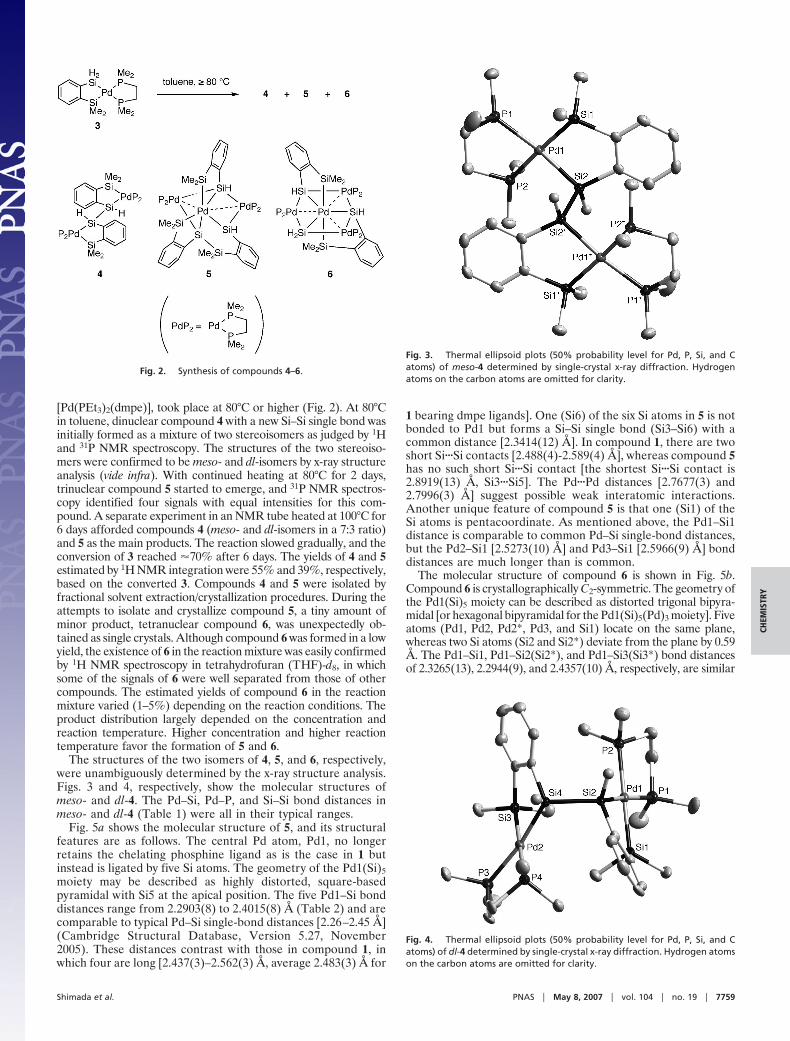
[Pd(PEt3)2(dmpe)], took place at 80°C or higher (Fig. 2). At 80°Cin toluene, dinuclear compound 4 with a new Si–Si single bond wasinitially formed as a mixture of two stereoisomers as judged by 1Hand 31P NMR spectroscopy. The structures of the two stereoiso-mers were confirmed to be meso- and dl-isomers by x-ray structureanalysis (vide infra). With continued heating at 80°C for 2 days,trinuclear compound 5 started to emerge, and 31P NMR spectros-copy identified four signals with equal intensities for this com-pound. A separate experiment in an NMR tube heated at 100°C for6 days afforded compounds 4 (meso- and dl-isomers in a 7:3 ratio)and 5 as the main products. The reaction slowed gradually, and theconversion of 3 reached �70% after 6 days. The yields of 4 and 5estimated by 1H NMR integration were 55% and 39%, respectively,based on the converted 3. Compounds 4 and 5 were isolated byfractional solvent extraction/crystallization procedures. During theattempts to isolate and crystallize compound 5, a tiny amount ofminor product, tetranuclear compound 6, was unexpectedly ob-tained as single crystals. Although compound 6 was formed in a lowyield, the existence of 6 in the reaction mixture was easily confirmedby 1H NMR spectroscopy in tetrahydrofuran (THF)-d8, in whichsome of the signals of 6 were well separated from those of othercompounds. The estimated yields of compound 6 in the reactionmixture varied (1–5%) depending on the reaction conditions. Theproduct distribution largely depended on the concentration andreaction temperature. Higher concentration and higher reactiontemperature favor the formation of 5 and 6.
The structures of the two isomers of 4, 5, and 6, respectively,were unambiguously determined by the x-ray structure analysis.Figs. 3 and 4, respectively, show the molecular structures ofmeso- and dl-4. The Pd–Si, Pd–P, and Si–Si bond distances inmeso- and dl-4 (Table 1) were all in their typical ranges.
Fig. 5a shows the molecular structure of 5, and its structuralfeatures are as follows. The central Pd atom, Pd1, no longerretains the chelating phosphine ligand as is the case in 1 butinstead is ligated by five Si atoms. The geometry of the Pd1(Si)5moiety may be described as highly distorted, square-basedpyramidal with Si5 at the apical position. The five Pd1–Si bonddistances range from 2.2903(8) to 2.4015(8) Å (Table 2) and arecomparable to typical Pd–Si single-bond distances [2.26–2.45 Å](Cambridge Structural Database, Version 5.27, November2005). These distances contrast with those in compound 1, inwhich four are long [2.437(3)–2.562(3) Å, average 2.483(3) Å for
1 bearing dmpe ligands]. One (Si6) of the six Si atoms in 5 is notbonded to Pd1 but forms a Si–Si single bond (Si3–Si6) with acommon distance [2.3414(12) Å]. In compound 1, there are twoshort Si���Si contacts [2.488(4)-2.589(4) Å], whereas compound 5has no such short Si���Si contact [the shortest Si���Si contact is2.8919(13) Å, Si3���Si5]. The Pd���Pd distances [2.7677(3) and2.7996(3) Å] suggest possible weak interatomic interactions.Another unique feature of compound 5 is that one (Si1) of theSi atoms is pentacoordinate. As mentioned above, the Pd1–Si1distance is comparable to common Pd–Si single-bond distances,but the Pd2–Si1 [2.5273(10) Å] and Pd3–Si1 [2.5966(9) Å] bonddistances are much longer than is common.
The molecular structure of compound 6 is shown in Fig. 5b.Compound 6 is crystallographically C2-symmetric. The geometry ofthe Pd1(Si)5 moiety can be described as distorted trigonal bipyra-midal [or hexagonal bipyramidal for the Pd1(Si)5(Pd)3 moiety]. Fiveatoms (Pd1, Pd2, Pd2*, Pd3, and Si1) locate on the same plane,whereas two Si atoms (Si2 and Si2*) deviate from the plane by 0.59Å. The Pd1–Si1, Pd1–Si2(Si2*), and Pd1–Si3(Si3*) bond distancesof 2.3265(13), 2.2944(9), and 2.4357(10) Å, respectively, are similar
Fig. 2. Synthesis of compounds 4–6.
Fig. 3. Thermal ellipsoid plots (50% probability level for Pd, P, Si, and Catoms) of meso-4 determined by single-crystal x-ray diffraction. Hydrogenatoms on the carbon atoms are omitted for clarity.
Fig. 4. Thermal ellipsoid plots (50% probability level for Pd, P, Si, and Catoms) of dl-4 determined by single-crystal x-ray diffraction. Hydrogen atomson the carbon atoms are omitted for clarity.
Shimada et al. PNAS � May 8, 2007 � vol. 104 � no. 19 � 7759
CHEM
ISTR
Y

to those of common Pd–Si single bonds. The axial Pd1–Si3(Si3*)bond distances are relatively long; this is partly because the two axialSi atoms [Si3 and Si3*] locate in trans to each other, and the strongtrans-influence (or structural trans-effect) of Si atoms lengthens thePd–Si bond distances (23). The three equatorial Si atoms (Si1, Si2,and Si2*) are pentacoordinate, like Si1 in compound 5. The Pd–Sidistances for the outer Pd atoms [2.5124(5)–2.6093(9) Å] are muchlonger than those of common Pd–Si single bonds.
Although it is difficult and less meaningful to assign a formaloxidation state for each atom in cluster-type compounds (19, 20),an unusual �5 formal oxidation state may be assigned to the centralPd atoms (Pd1) in 5 and 6, if each Pd1–Si bond is simply countedto increase the formal oxidation state of Pd1 by �1. Therefore, wecarried out density functional theory calculations for 5 and 6 toobtain further information about the structures of compounds 5and 6. We also further evaluated the bonding of 5 and 6, usingMayer’s bond order analysis (24) and Bader’s atoms in molecule(AIM) analysis (25); the former was used for the bonding analysisof compound 1 (20), and the latter searches for bond critical pointsand indicates the existence of a chemical bond between two atomssharing the bond critical point. Both calculated structures of 5 and6 accurately reproduced the x-ray structures of 5 and 6. Table 2summarizes selected bond distances obtained from x-ray analysisand density functional theory calculations and Mayer bond ordersfor 5 and 6 [see supporting information (SI) Tables 4 and 5 forCartesian coordinates for the calculated structures of 5 and 6, andsee SI Tables 6 and 7 for further lists of Mayer bond orders for 5and 6]. For compound 5, the bond orders of the five Pd1–Si bonds(0.67–0.77) are higher than the highest value (0.63) calculated forthe Pd–Si bonds of the central Pd atom in compound 1 (20). The
total bond orders of the five Pd1–Si bonds (3.63) is also higher thanthat of the six central Pd–Si bonds (3.32) in 1 (20). The calculatedbond orders and the bond distances determined by x-ray analysissuggest that the five Pd1–Si bonds in 5 have a relatively highsingle-bond character. The bonds between the pentacoordinate Si1and terminal Pd atoms (Pd2 and Pd3) have lower bond orders(average 0.50), as expected from the long bond distances. The total(3.59) and individual bond orders (0.67–0.75) of the five Pd1–Sibonds in 6 are at a level similar to those of 5, suggesting that the fivePd1–Si bonds in 6 also have a relatively high single-bond character.The six outer Pd–Si bonds in 6 have lower bond orders (average0.48), as expected from the long bond distances.
Because attempted AIM analysis on compounds 5 and 6 failedas a result of its inability to find bond critical points for the C–Hbonds of the benzene rings of 5 and 6, we carried out AIM analysison model systems M5 and M6 (Fig. 6a; see also SI Figs. 7 and 8),which were constructed by removing carbon atoms from 5 and 6,respectively. The Cartesian coordinates of core regions were fixed,while the positions of the substituted hydrogen atoms wereoptimized. Thus, the nature of the chemical bonds of the coreregions in the model compounds M5 and M6 should be the sameas those in the real systems. AIM analysis on M5 and M6 wassuccessful and indicated the existence of bond critical points in allPd1–Si bonds of M5 and M6 (Fig. 6b). This result also supports thebonding nature of Pd1–Si bonds of compounds 5 and 6. Mayer bondorder analysis (Table 2) suggested a possible weak bonding inter-action between Pd atoms in compounds 5 and 6 (bond order �0.20–0.22) and also between Si3 and Si5 atoms (bond order � 0.28)in compound 5, although the Si3���Si5 distance is long. AIM analyseson the model compounds showed the existence of bond criticalpoints only between Pd atoms in M6 but not between Pd atoms orSi3 and Si5 atoms in M5.
The formation of silylpalladium compounds with unusual Pdcenters ligated by five Si atoms represents one of interestingfeatures of Si ligands in transition metal chemistry. Althoughinterest in the chemistry of transition metal compounds with Siligands is rapidly growing (26), the field is still at the initial stage ofdevelopment compared with the organometallic chemistry of tran-sition metals. We believe Si ligands will provide further uniquechemistry of transition metals and lead to the development ofunique catalyses.
Materials and MethodsAll manipulations of air-sensitive materials were carried out undera nitrogen atmosphere by using standard Schlenk tube techniques
Fig. 5. Thermal ellipsoid plots (50% probability level for Pd, P, Si, and C atoms) of compound 5 (a) and compound 6 (b) determined by single-crystal x-raydiffraction. Hydrogen atoms on the carbon atoms (for 5 and 6) and carbon atoms on the phosphorus atoms (for 6) are omitted for clarity.
Table 1. Selected bond distances (Å) for compounds meso- anddl-4
Bond meso-4 dl-4
Pd1–Si1 2.3634(10) 2.3713(16)Pd1–Si2 2.3405(9) 2.3626(14)Pd2–Si3 2.3632(17)Pd2–Si4 2.3613(15)Pd1–P1 2.3307(10) 2.3259(16)Pd1–P2 2.3391(9) 2.3465(15)Pd2–P3 2.3277(17)Pd2–P4 2.3402(15)Si–Si 2.3720(13) 2.355(2)
7760 � www.pnas.org�cgi�doi�10.1073�pnas.0700450104 Shimada et al.

or in a glovebox filled with argon or nitrogen. Toluene-d8, THF-d8,and benzene-d6 were distilled from Na/benzophenone ketyl. Allother anhydrous solvents were purchased from Kanto Chemicals orAldrich and degassed before use. 1H (499.1 MHz), 29Si (99.1 MHz),and 31P (202.0 MHz) NMR spectra were recorded on a JEOLLA500 spectrometer. Chemical shifts are given in parts per million,using external references [tetramethylsilane (0 ppm) for 1H and29Si, and 85% H3PO4 (0 ppm) for 31P] or residual solvent signal forthe 1H NMR in THF-d8 (the residual solvent signal at lower fieldposition was set to 3.60 ppm), and coupling constants are reportedin hertz.
Synthesis of [{1,2-C6H4(SiMe2)(SiH2)}Pd(dmpe)], 3. A toluene solution(5 ml) of Pd(PEt3)4 (300 mg, 0.52 mmol) and dmpe (78 mg, 0.52
mmol) was stirred at room temperature overnight. Volatiles wereremoved under vacuum to leave Pd(PEt3)2(dmpe) as a viscoussolid. To the solid was added toluene (5 ml) and 1,2-C6H4(SiMe2H)(SiH3) (87 mg, 0.52 mmol) at 0°C. During theaddition of 1,2-C6H4(SiMe2H)(SiH3), a small amount of gas evo-lution was observed. Then the mixture was stirred at room tem-perature for 12 h under a nitrogen atmosphere. Removal of thevolatiles under vacuum and washing the residual solid with hexanegave 3 in 72% yield (157 mg) as a pale brown powder. The productis practically pure and used for the following reactions withoutfurther purification. 1H NMR (toluene-d8) � 0.73 (t, 6H, JP-H � 2),0.92–1.04 (m, 16H), 5.57 (t, 2H, JP-H � 10, JSi-H � 158), 7.32 (t, 1H,JH-H � 7), 7.36 (t, 1H, JH-H � 7), 7.82 (d, 1H, JH-H � 7), 8.07 (d, 1H,JH-H � 7). 31P NMR (toluene-d8) � 13.2 (br). 29Si{1H} NMR(toluene-d8, dept) � �17.7 (d, JP-Si � 137, (JH-Si � 158), SiH2). Themeasurement parameters were adjusted to the silicon atoms withdirectly bound hydrogen atoms. The JH-Si value was determined by1H-coupled spectrum. 29Si{1H} NMR (toluene-d8, inept) � 31.8 (d,JP-Si � 145, SiMe2). The measurement parameters were adjusted tothe silicon atoms with two methyl groups. Anal. Calcd. forC14H28P2PdSi2: C, 39.95; H, 6.71. Found C, 40.14; H, 6.65.
Thermal Condensation Reaction of 3. Isolation of compounds 4 and 5. Atoluene solution (10 ml) of 3 (507 mg, 1.20 mmol) was heated in an
Table 3. Calculated and observed 29Si NMR chemical shifts[� (ppm)] of compounds 5 and 6
Compound 5 Compound 6
Si Calculated Observed Calculated Observed
Si1 122.1 130.9 101.6 103.0Si2 (Si2*) 25.8 25.0 147.0 (147.1) 139.3Si3 (Si3*) 194.8 173.1 24.6 (24.5) 19.0Si4 43.5 38.7 — —Si5 202.7 210.7 — —Si6 �32.1 �21.1 — —
The atomic numbering refers to that in Fig. 5.
Table 2. Experimental (x-ray diffraction) and calculated bond distances and Mayer bondorders for compounds 5 and 6
Bond
Distance, Å
Experimental Calculated Bond order
Compound 5
Pd1–Si1 2.3526(11) 2.401 0.672Pd1–Si2 2.4015(8) 2.457 0.747Pd1–Si3 2.3385(8) 2.384 0.709Pd1–Si4 2.3464(11) 2.405 0.729Pd1–Si5 2.2903(8) 2.326 0.769Pd2–Si1 2.5273(10) 2.564 0.542Pd2–Si3 2.3832(9) 2.443 0.628Pd3–Si1 2.5966(9) 2.652 0.455Pd3–Si5 2.4033(11) 2.439 0.668Pd1–Pd2 2.7996(3) 2.939 0.200Pd1–Pd3 2.7677(3) 2.899 0.211Si3���Si5 2.8919(13) 2.928 0.280
Compound 6
Pd1–Si1 2.3265(13) 2.349 0.673Pd1–Si2 or Pd1–Si2* 2.2944(9) 2.32 0.747Pd1–Si3 or Pd1–Si3* 2.4357(10) 2.508 0.713Pd2–Si1 or Pd2*–Si1 2.5124(5) 2.572 0.519Pd2–Si2 or Pd2*–Si2* 2.5781(10) 2.621 0.460Pd3–Si2 or Pd3–Si2* 2.6093(9) 2.649 0.449Pd1–Pd2 or Pd1–Pd2* 2.7332(3) 2.815 0.204Pd1–Pd3 2.7013(4) 2.804 0.218
Fig. 6. AIM analysis. (a) Structure of model compounds M5 and M6. (b) AIManalysis results for model compounds M5 and M6. Some of hydrogen atoms areomitted for clarity. Dots between the atoms represent the bond critical points.
Shimada et al. PNAS � May 8, 2007 � vol. 104 � no. 19 � 7761
CHEM
ISTR
Y

oil bath at 90°C for 44 h, at 95°C for 51 h, and then at 100°C for 47 h.After cooling to room temperature, volatiles were removed undervacuum to give crude solid products. NMR measurement of thecrude products showed that the conversion of 3 was �68% and theformation of 4 (�39%, meso-4/dl-4 � 72/28) and 5 (�23%) asmajor products. The crude products were dissolved in THF (�20ml) and filtered through a membrane filter (Sartorius Minisart SRP15, no. 17573). The filtrate was evacuated to remove volatiles, andthe remaining solid was extracted with hexane (3 � 4 ml) andhexane/toluene mixture (1/1, 3 � 3 ml), leaving a solid mixturemainly consisting of 4 and 5. The solid was dissolved in toluene (20ml) by heating at 100°C for a few minutes. After cooling to roomtemperature, the supernatant was transferred to another Schlenktube to remove a small amount of undissolved materials on thebottom. A few crystals of 4 were added to the solution to inducecrystallization, and the mixture was kept at room temperature for1 day to give almost colorless crystals of 4. The supernatant wasremoved by decantation, and the remaining crystals were washedwith toluene (1 � 1 ml and 2 � 0.5 ml) and hexane (1 � 0.5 ml and2 � 1 ml) and dried under vacuum to give 65 mg of 4 (meso-4:dl-4 �78:22). The supernatant was evacuated to remove the solvent, andthe resulting solid was dissolved in 16 ml of 1,2-dimethoxyethane(DME) by heating in an oil bath at 100°C for a few minutes. Keepingthe solution at room temperature for 1 day gave orange-red crystalsof 5 containing DME as a cocrystallization solvent. The superna-tant was removed by decantation, and the remaining crystals werewashed with DME and hexane to give 27 mg (6%) of 5. Theseparated supernatant was evacuated to remove the solvent, and theresulting solid was recrystallized from toluene to give additional 4(58 mg). Total isolated yield of 4 was 24%. Compound 4: 1H NMR(benzene-d6, 4:1 mixture of meso- and dl-isomers) � 0.43 (d, 6H ofmeso-isomer, JP-H � 3); 0.69–1.15 (m, 38H of meso-isomer and 44Hof dl-isomer); 5.62 (ddd, 2H of dl-isomer, JP-H � 4, 8, 23, Si-H); 5.86(ddd, 2H of meso-isomer, JP-H � 5, 8, 19, Si-H); 7.21–7.37 (m, 4Hof meso-isomer and 4H of dl-isomer); 7.67 (d, 2H of meso-isomer,JH-H � 7); 7.81 (d, 4H of dl-isomer, JH-H � 8); 8.07 (d, 2H ofmeso-isomer, JH-H � 7). 31P NMR (benzene-d6, 4:1 mixture of meso-and dl-isomers) � value 10.2 (d, meso-isomer, JP-P � 13); 10.6 (d,dl-isomer, JP-P � 15); 10.9 (d, meso-isomer, JP-P � 13); 13.3 (d,dl-isomer, JP-P � 15). Anal. calcd. for C28H54P4Pd2Si4: C, 40.04; H,6.48. Found C, 40.43; H, 6.48. Compound 5. 1H NMR (THF-d8) ��0.10 (s, 3H, SiCH3), �0.08 (s, 3H, SiCH3), �0.03 (s, 3H, SiCH3),0.07 (d, 3H, JP-H � 8, PCH3), 0.13 (d, 3H, JP-H � 7, PCH3), 0.20 (d,3H, JP-H � 9, PCH3), 0.43 (d, 3H, JP-H � 8, PCH3), 0.45 (s, 3H,SiCH3), 0.70 (s, 3H, SiCH3), 0.72 (s, 3H, SiCH3), 1.44 (d, 3H, JP-H� 7, PCH3), 1.54 (d, 3H, JP-H � 9, PCH3), 1.59 (d, 3H, JP-H � 7,PCH3), 1.61 (d, 3H, JP-H � 8, PCH3), 1.50 - 1.85 (m, 8H,PCH2CH2P), 6.86–6.90 (m, 2H), 7.00–7.11 (m, 4H), 7.15 (dt, 1H,JH-H � 1 and 7), 7.37–7.40 (m, 1H), 7.45–7.49 (m, 1H), 7.60–7.67 (m,2H), 7.76–7.85 (m, 2H), 8.01 (d, 1H, JH-H � 7 Hz). 31P{1H} NMR(THF-d8) � 15.7 (dd, JP-P � 10 and 31), 17.3 (dd, JP-P � 12 and 29),18.9 (dd, JP-P � 10 and 29), 21.0 (dd, JP-P � 12 and 31). 29Si{1H}NMR (THF-d8, nne) � �21.1 (d, JP-Si � 6, Si6), 25.0 (s, Si2 (or Si4)),38.7 (d, JP-Si � 18, Si4 (or Si2)), 129.8–132.0 (m, Si1), 173.1 (d,JP-Si � 113, Si3), 210.7 (ddd, JP-Si � 12, 34, 122, Si5). The assignmentis based on the coupling pattern of the signals as well as theprediction by the theoretical calculations (Table 3). IR (KBrpellet, cm�1) 1999 (Si–H), 1972 (Si–H). Anal. calcd. forC36H64P4Pd3Si6�C4H10O2 C, 40.08; H, 6.22. Found C, 40.27; H, 6.23.Isolation of compound 6. A toluene solution (100 ml) of 3 (910 mg,2.16 mmol) was heated in an oil bath at 100°C for 6 days. Theestimated molar ratio of 3/4 (two isomers)/5/6 by 1H NMR spec-
troscopy was 73/19/7.7/0.3 at this stage. The solution was evacuatedto reduce the volume to �40 ml and then was heated in an oil bathat 100°C for 58 h. The estimated molar ratio of 3/4 (two isomers)/5/6by 1H NMR spectroscopy was 48/34/17/1 at this stage. The mixturewas evacuated to dryness and washed with hexane (2 � 7 ml and3 � 5 ml) to leave solid materials. The solid was dried undervacuum, dissolved in toluene (7 ml), and heated in an oil bath at100°C for 84 h. The estimated molar ratio of 3/4 (two isomers)/5/6by 1H NMR spectroscopy was 29/38/30/3 at this stage. The mixturewas evacuated to dryness and reacted with 1,2-C6H4(SiMe2H)(SiH3) (111 mg, 0.67 mmol) in THF (10 ml) at 40°C for 11 h [thishydrosilane selectively reacted with compound 4 to form an un-identified product(s), which has much higher solubility in hexanethan does 4 and can be easily removed from the mixture by solventextraction]. The mixture was evacuated to dryness and washed withhexane (4 � 5 ml), hexane/toluene (3/2) mixture (4 � 5 ml), andhexane/toluene (1/1) mixture (3 � 7 ml). The residue was dissolvedin THF (20 ml), filtered through a membrane filter (SartoriusMinisart SRP 15, no. 17573), and evacuated to dryness to giveyellow-brown solid (179 mg). 1H and 31P NMR spectroscopyshowed that the solid consisted of 5 and 6 in a 92:8 molar ratio.Fortunately, compound 6 has higher solubility in DME but muchlower solubility in diethyl ether than does 5. The solid was extractedwith DME (6 ml) to give a mixture of 5 and 6 in a 3:4 molar ratioand to leave pure 5 (153 mg, 19% yield). Then, the mixture (afterevacuation) was extracted with diethyl ether (1 � 3 ml, 1 � 2 ml,1 � 1 ml) to leave compound 6 with �80% purity by 1H and 31PNMR spectroscopy (9 mg). Compound 6: 1H NMR (THF-d8) ��0.48 (s, 6H, SiCH3), �0.37 (s, 6H, SiCH3), 0.03 (d, 6H, JP-H � 7,PCH3), 1.36–1.40 (m, 12H, PCH3), 1.48–1.51 (m, 6H, PCH3),1.56–1.58 (m, 6H, PCH3), 1.68 (d, 6H, JP-H � 7, PCH3), 1.50–1.90(m, 12H, PCH2CH2P), 6.06 (tt, 2H, JP-H � 7 and 20, SiH2), 6.62 (t,2H, JH-H � 7, aromatic H), 6.91 (t, 2H, JH-H � 7, aromatic H), 6.94(d, 2H, JH-H � 7, aromatic H), 7.76–7.93 (br m, 2H, SiH), 7.89 (d,2H, JH-H � 7, aromatic H). The assignments of SiH2 and SiH signalsare based on the coupling patterns of the signals and the predictionby the theoretical calculations. 31P{1H} NMR (THF-d8) � 11.7–12.6(m), 14.1 (s). 29Si{1H} NMR (THF-d8, dept) � 102.0–103.9 (m, Si1),138.1–140.5 (m, Si2 and Si2*). The measurement parameters wereadjusted to the silicon atoms with directly bound hydrogen atoms.The assignments of the signals are based on the prediction by thetheoretical calculations (Table 3). 29Si{1H} NMR (THF-d8, inept)� 19.0 (s, Si3 and Si3*). The measurement parameters were adjustedto the silicon atoms with two methyl groups.
X-Ray Data Collection, Structure Determination, and Refinement. Fordetails on x-ray data collection, structure determination, andrefinement for compounds meso-4, dl-4, 5, and 6, see SI Materialsand Methods and SI Data Set.
Computational Details. The calculations for geometry optimiza-tions, vibrational frequency analysis, NMR chemical shifts,Mayer’s bond-order analysis, and AIM analysis were carried outwith the Gaussian 03 program package (27). For further detailson computations, see SI Materials and Methods.
Y.-H.L. thanks the Japan Society for the Promotion of Science for apostdoctoral fellowship. This work was supported by Ministry of Edu-cation, Science, Sports, and Culture (Japan) Grants-in-Aid for ScientificResearch 15350037 and 05F05666.
1. Tsuji J (2004) Palladium Reagents and Catalysts (Wiley, Chichester, UK).2. Malleron J-L, Fiaud J-C, Legros J-Y (1997) Handbook of Palladium-Catalyzed
Organic Reactions (Academic, San Diego).3. Canty AJ (1992) Acc Chem Res 25:83–90.4. Elsevier CJ (1999) Coord Chem Rev 185/186:809–822.
5. Uson R, Fornies J, Navarro R (1975) J Organomet Chem 96:307–312.6. Byers PK, Canty AJ, Skelton BW, White AH (1986) J Chem Soc Chem
Commun, 1722–1724.7. Timakov AA, Prusakov VN, Drobyshevskii YV (1982) Russ J Inorg Chem
27:1704–1705.
7762 � www.pnas.org�cgi�doi�10.1073�pnas.0700450104 Shimada et al.

8. Sokolov VB, Drobyshevskii YV, Prusakov VN, Ryzhkov AV, Khoroshev SS(1976) Proc Acad Sci USSR 229:503–505.
9. Chausse V, Regull P, Victori L (1987) J Electroanal Chem 238:115–128.10. Abrahams SC, Ginsberg AP, Knox K (1964) Inorg Chem 3:558–567.11. Gilbert TM, Bergman RG (1983) Organometallics 2:1458–1460.12. Fernandez MJ, Maitlis PM (1982) J Chem Soc Chem Commun, 310–311.13. Fernandez MJ, Maitlis PM (1983) Organometallics 2:164–165.14. Brookhart M, Grant BE, Lenges CP, Prosenc MH, White PS (2000) Angew
Chem Int Ed 39:1676–1679.15. Shimada S, Tanaka M (2006) Coord Chem Rev 250:991–1011.16. Shimada S, Tanaka M, Shiro M (1996) Angew Chem Int Ed Engl 35:1856–1858.17. Shimada S, Rao MLN, Tanaka M (1999) Organometallics 18:291–293.18. Chen WZ, Shimada S, Tanaka M (2002) Science 295:308–310.
19. Crabtree RH (2002) Science 295:288–289.20. Sherer EC, Kinsinger CR, Kormos BL, Thompson JD, Cramer CJ (2002)
Angew Chem Int Ed 41:1953–1956.21. Aullon G, Lledos A, Alvarez S (2002) Angew Chem Int Ed 41:1956–1959.22. Shimada S, Rao MLN, Hayashi T, Tanaka M (2001) Angew Chem Int Ed
40:213–216.23. Coe BJ, Glenwright SJ (2000) Coord Chem Rev 203:5–80.24. Mayer I (1983) Chem Phys Lett 97:270–274.25. Bader RFW (1991) Chem Rev 91:893–928.26. Corey JY, Braddock-Wilking J (1999) Chem Rev 99:175–292.27. Frisch MJ, Trucks GW, Schlegel HB, Scuseria GE, Robb MA, Cheeseman JR,
Montgomery JA, Jr, Vreven T, Kudin KN, Burant JC, et al. (2004) Gaussian03 (Gaussian, Inc, Wallingford, CT), Revision C.02.
Shimada et al. PNAS � May 8, 2007 � vol. 104 � no. 19 � 7763
CHEM
ISTR
Y

The first examples of multinuclear PdV supported by silicon atoms
Jesse R. McAtee *
Department of Chemistry and Biochemistry University of Delaware, Newark Delaware 19716
RECEIVED DATE (automatically inserted by publisher); E-mail [email protected]
Abstract: The condensation of three [{1,2-
C6H4(SiH2)2}PdII(R2PCH2CH2PR2)] molecules had
previously been reported to give rise to a complex which
was originally reported as having a +4 oxidation state on
Palladium (Pd). Since then it has been assigned a formal
PdII oxidation, however, due to the difference of reactivity of
hydro-silanes and alkyl-silanes the condensation of three
units of [{1,2-C6H4(SiH2)(SiMe2)}PdII(R2PCH2CH2PR2)] gave
rise to 3 new complexes of unique structure. For the first
time we report two multinuclear compounds with a +5
oxidation state on Palladium.
Palladium IV and other Pd species of high oxidation state
have been of great interest to many chemists in the last five
years.1 While the existence of Pd
IV has been reported in the
literature for over three decades,2 it has not been until recently
that stable complexes have been well characterized.3-9
Due to
the reactive nature of palladium in high oxidation states there
has been relatively few species isolated. There are also many
works containing PdIV
proposed intermediates (many of which
are stable enough for thorough characterization) that with or
without heating can undergo reductive elimination.6-9
The PdIV
species have been of great interest due to the prospects of a
PdII-Pd
IV catalytic cycle similar to the well established and
accepted Pd0-Pd
II catalytic cycle. Most of the Pd
IV complexes
described have either been supported by halogens and
chelating ligands such as 2-phenylpyridine and 1,2-
disilylbenzenes.
Scheme 1. Synthesis of 2 with Two Representations of the
Structure of 2.
H2Si
SiH2
Pd
Et2P
PEt2
Toluene
80oC
-2H2
-Et2P(CH2)2PEt2
1
Two decades ago Canty described the interest of applying
the chemistry of PdIV
beyond the known complexes supported
by chelating nitrogen donor ligands to those supported by
other ligands or phosphines due to their predominant role in
Pd0-Pd
II catalytic cycles.
10 Herein is the description of 2, 4, 5,
and 6 which contain not only high oxidation state, but are
complexes supported by ligands other than nitrogen donor
ligands, namely silanes. The complexes described may give
further understanding of the unusual bonding nature of the
metalloid silicon in varying electronic states.
The condensation of three molecules of [{1,2-
C6H4(SiH2)2}PdII(R2PCH2CH2PR2)] 1 gives rise to 2 which
after much scrutiny by the scientific community has been
given a formal oxidation state of +2.The bonding interactions
between the Si-Si bond and metal center is of particular
interest and worthy of complex analysis. Similarly the
condensation of 3 initially gave rise to 4, and when this
dinuclear compound was heated further to 80°C for 48h, the
formation of 5 occurred. During purification 6 was found as a
single crystal, which was later confirmed by 1HNMR as being
in the crude mixture in low amounts. The formation of 4 arises
from a new Si-Si bond, and contains two typical square-planar
PdII metal centers. The bonding interactions in 2 can now be
described as square-planar like, but the mode of bonding is
quite atypical and worthy of some discussion.
Scheme 2. Synthesis of 4, 5, and 6.
PdP2 = Pd
Me2P
PMe2
H2Si
SiMe2
Pd
Me2P
PMe2
toluene, > 80oC
4 + 5 + 6
P2PdSiMe2
HSi
P2Pd
Me2Si
SiH
4
Si
Pd
PdP2 PdP2
SiH
SiH
Me2Si
Me2Si
Me2Si
56
Pd SiPdP2
HSi
2HSi
PdP2
Si
SiH2
PdP2
3
Compounds have been prepared that have a tautomeric
relationship between the η2 form and oxidative addition to the
metal to the silicon-hydrogen bond of a silane (Figure 1a).11
Palladium has been seen to activate di-silanes presumably by a
similar mechanism, activating a Si-Si bond to undergo
interesting chemical reactions.12, 13
If it is viewed that the Si-Si
bond is σ donating to Pd in 2, there is the possibility that the
empty σ* orbital on silicon could accept electrons from the
dxz and dyz orbitals given appropriate geometry and overlap,
which are indeed present in the molecule.14
This may account
for the low bond order with respect to both Si-Si and Si-Pd
2

bonds. This back-bonding phenomena is present in some
simple organic silicon containing molecules such as
tetrasilylamine (H3Si)3N. The planar geometry of this molecule
is accounted for by the sharing of the filled 2pz orbital on
nitrogen to the empty 3d orbital on each of the Si atoms
caused by good overlap (Figure 1b) .15
It has also been shown
that given the proper substituents on silicon, a transannular
bond can be formed intramolecular between nitrogen and
silicon (Figure 1c).16
Mn
R3Si H
Mn+2
R3Si HH3Si N
SiH3
SiH3Si
NR
R
FFFa
b c
Figure 1. Bonding Interactions of Silicon. (a) Tautomerization of Si-H-metal bond, (b) Lone pair to empty d orbital contribution gibing rise to planar molecule, (c) The NSi transannular bonding of quasisilatranes.
The bonding nature of this unique complex may be
nonlinear similar to a description by Bater.17
He showed that
in diborane (also in a metalloid species) the density of the
electrons is bent inward to maximize their efficiency of the
electron deficient species (Figure 2). The overall geometry of
2 can be described as a near square planar PdII species if
arrows are drawn from the centroid (cen) of the Si-Si bonds to
the palladium. This gives a planar coordination with Si-Pd-Si,
Si-Pd-cen, and cen-Pd-cen angles all close to 90° which sum
to 360°.14
Figure 2. Vector of Charge Distribution about Diborane. Note the bond paths linking the two equatorial protons to the axial borons are bent inward so to maximize efficiency in the electron deficient heterocycle.
While the bond order for this molecule is arguably greater
than two, it would be unconventional to assign a higher
oxidation state when the molecule contains many elements of
a PdII complex. A common method for giving a numerical
value for bond order is Meyer’s bond order (MBO) analysis.18
It is an exceptionally strong tool for the determination of
bonds in many organic compounds. The way chemists
commonly depict bonds on paper may correlate little to the
values calculated for metalloids like silicon and boron. For
example Boron-Boron, Boron-Nitrogen, and Boron-Hydrogen
bonds gave MBOs less than 0.5 in B2H6 and B3NH3.18
This
may not be unexpected in the case of the ammonium borane
complex where the interaction can be drawn as a complexing
arrow. Values of under 0.5 for B-H bonds however may
suggest that without alterations of parameters to compensate
for such non-classical electronic valences, MBOs can vary.
Modifications or additional variables have commonly been
invoked to explain bond order. In the early description of a
chemical bond by Pauling a bond order was describes as equal
to the exponential of ((the difference of a bond from its
common value) over a variable).19
The common value for a
bond is based on averages of measured distances and the
variable is appropriately fitted.
Similar to this MBOs also change nonlinearly with regard to
distance, so a small distance can account for a drastic change
in order. Tanaka and coworkers deemed “typical Pd-Si single
bond distances” to be (2.26-2.45 Ǻ) after computation using
Cambridge Structural Database for their pool of molecules.
Experimental values of 2.4357 and 2.2944 Ǻ gave MBOs of
0.71 and 0.75 respectivly.3 Perhaps there are other factors to be
considered when looking at Pd-Si bonds which can account
for the observed distances.
Figure 3: Structure of Compounds 5.
Ligands that give Structural Trans Effects (STEs) are strong
σ donors and anionic silyl ligands are known to exhibit some
of the largest STEs to opposing ligands in both square planar
and octahedral complexes.20
In the report of the first hexa-
valent PdIV
complex, Tanaka noted a larger STE from silicon
than from phosphorus in compound 6.5 Compounds 5 and 6
contain two opposing silicon ligands which may be expected
to have the longest of the Pd-Si distances. However, this is
only true of one of the two Si atoms in 5. This may be due to
the Si3-Pd1 bond being a bridge of three metallacycles and the
rings’ conformations adding additional force to draw the Si
atom slightly closer to the Pd center than the opposing ligand.
Typically the STE is thought of as acting by strong electron
donation into the d orbital on the metal and in effect
lengthening the opposing bond interacting with the same d
orbital. When the geometry is atypical as in 5, which can be
described as highly distorted square based pyramidal, the STE
of the equatorial ligands is difficult to propose. Complex 6,
having a distorted hexoganal-bipyrimidal structure, also lacks
linearly opposing geometry about the equatorial ligands and
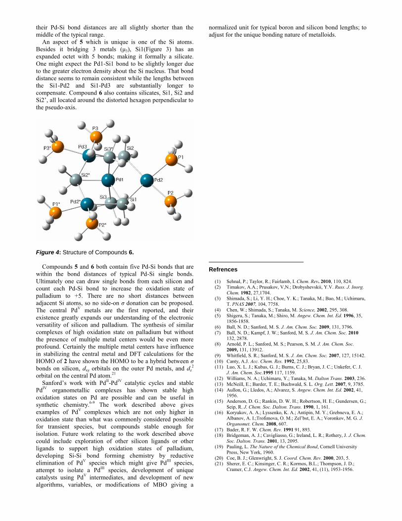
their Pd-Si bond distances are all slightly shorter than the
middle of the typical range.
An aspect of 5 which is unique is one of the Si atoms.
Besides it bridging 3 metals (μ3), Si1(Figure 3) has an
expanded octet with 5 bonds; making it formally a silicate.
One might expect the Pd1-Si1 bond to be slightly longer due
to the greater electron density about the Si nucleus. That bond
distance seems to remain consistent while the lengths between
the Si1-Pd2 and Si1-Pd3 are substantially longer to
compensate. Compound 6 also contains silicates, Si1, Si2 and
Si2’, all located around the distorted hexagon perpendicular to
the pseudo-axis.
Figure 4: Structure of Compounds 6.
Compounds 5 and 6 both contain five Pd-Si bonds that are
within the bond distances of typical Pd-Si single bonds.
Ultimately one can draw single bonds from each silicon and
count each Pd-Si bond to increase the oxidation state of
palladium to +5. There are no short distances between
adjacent Si atoms, so no side-on σ donation can be proposed.
The central PdV metals are the first reported, and their
existence greatly expands our understanding of the electronic
versatility of silicon and palladium. The synthesis of similar
complexes of high oxidation state on palladium but without
the presence of multiple metal centers would be even more
profound. Certainly the multiple metal centers have influence
in stabilizing the central metal and DFT calculations for the
HOMO of 2 have shown the HOMO to be a hybrid between σ
bonds on silicon, dxy orbitals on the outer Pd metals, and dz2
orbital on the central Pd atom.21
Sanford’s work with PdII-Pd
IV catalytic cycles and stable
PdIV
organometallic complexes has shown stable high
oxidation states on Pd are possible and can be useful in
synthetic chemistry.6-9
The work described above gives
examples of PdV complexes which are not only higher in
oxidation state than what was commonly considered possible
for transient species, but compounds stable enough for
isolation. Future work relating to the work described above
could include exploration of other silicon ligands or other
ligands to support high oxidation states of palladium,
developing Si-Si bond forming chemistry by reductive
elimination of PdV species which might give Pd
III species,
attempt to isolate a PdIII
species, development of unique
catalysts using PdV intermediates, and development of new
algorithms, variables, or modifications of MBO giving a
normalized unit for typical boron and silicon bond lengths; to
adjust for the unique bonding nature of metalloids.
1
Refrences
(1) Sehnal, P.; Taylor, R.; Fairlamb, I. Chem. Rev. 2010, 110, 824. (2) Timakov, A.A.; Prusakov, V,N.; Drobyshevskii, Y.V. Russ. J. Inorg.
Chem. 1982, 27,1704. (3) Shimada, S.; Li, Y. H.; Choe, Y. K.; Tanaka, M.; Bao, M.; Uchimaru,
T. PNAS 2007, 104, 7758.
(4) Chen, W.; Shimada, S.; Tanaka, M. Science, 2002, 295, 308.
(5) Shigeru, S.; Tanaka, M.; Shiro, M. Angew. Chem. Int. Ed. 1996, 35, 1856-1858.
(6) Ball, N. D.; Sanford, M. S. J. Am. Chem. Soc. 2009, 131, 3796.
(7) Ball, N. D.; Kampf, J. W.; Sanford, M. S. J. Am. Chem. Soc. 2010 132, 2878.
(8) Arnold, P. L.; Sanford, M. S.; Pearson, S. M. J. Am. Chem. Soc.
2009, 131, 13912.
(9) Whitfield, S. R.; Sanford, M. S. J. Am. Chem. Soc. 2007, 127, 15142.
(10) Canty, A.J. Acc. Chem. Res. 1992, 25,83. (11) Luo, X. L. J.; Kubas, G. J.; Burns, C. J.; Bryan, J. C.; Unkefer, C. J.
J. Am. Chem. Soc.1995 117, 1159.
(12) Williams, N. A.; Uchimaru, Y.; Tanaka, M. Dalton Trans. 2003, 236.
(13) McNeill, E.; Barder, T. E.; Buchwald, S. L. Org. Lett. 2007, 9, 3785.
(14) Aullon, G.; Lledos, A.; Alvarez, S. Angew. Chem. Int. Ed. 2002, 41, 1956.
(15) Anderson, D. G.; Rankin, D. W. H.; Robertson, H. E.; Gundersen, G.;
Seip, R. J. Chem. Soc. Dalton. Trans. 1990, 1, 161. (16) Koryukov, A. A.; Lyssenko, K. A.; Antipin, M. Y.; Grebneva, E. A.;
Albanov, A. I.;Trofimova, O. M.; Zel’bst, E. A.; Voronkov, M. G. J.
Organomet. Chem. 2008, 607.
(17) Bader, R. F. W. Chem. Rev. 1991 91, 893. (18) Bridgeman, A. J.; Cavigliasso, G.; Ireland, L. R.; Rothery, J. J. Chem.
Soc. Dalton. Trans. 2001, 13, 2095. (19) Pauling, L. The Nature of the Chemical Bond, Cornell University
Press, New York, 1960.
(20) Coe, B. J.; Glenwright, S. J. Coord. Chem. Rev. 2000, 203, 5. (21) Sherer, E. C.; Kinsinger, C. R.; Kormos, B.L.; Thompson, J. D.;
Cramer, C.J. Angew. Chem. Int. Ed. 2002, 41, (11), 1953-1956.

© 2009 Macmillan Publishers Limited. All rights reserved.
A diiron(IV) complex that cleaves strongC–H and O–H bondsDong Wang1, Erik R. Farquhar1, Audria Stubna2, Eckard Munck2* and Lawrence Que, Jr1*
The controlled cleavage of strong C–H bonds such as those of methane poses a significant and industrially importantchallenge for chemists. In nature, methane is oxidized to methanol by soluble methane monooxygenase via a diiron(IV)intermediate called Q. However, the only two reported diiron(IV) complexes have activities towards C–H bonds that fall farshort of the activity of this biological catalyst. In this paper, we model the chemistry of MMO-Q by generating an oxo-bridged diiron(IV) complex by electrochemical oxidation. This species is a more effective oxidant. It can attack C–H bonds asstrong as 100 kcal mol21 and reacts with cyclohexane 100- to 1,000-fold faster than mononuclear FeIV==O complexes ofclosely related ligands. Strikingly, this species can also cleave the strong O–H bonds of methanol and t-butanol instead oftheir weaker C–H bonds, representing the first example of O–H bond activation for iron complexes.
The controlled cleavage of strong C–H bonds such as those ofmethane remains an elusive goal and one of great industrialand practical importance. In nature, methane hydroxylation
occurs by oxygen activation through the action of soluble and par-ticulate methane monooxygenases (MMOs) found in methane-metabolizing bacteria1–4. The much better characterized solubleMMOs have a non-haem diiron active site that reacts with O2 toproduce an oxo-bridged diiron(IV) oxidant called Q that effectsthe transformation5–8. The generation of a diiron(IV) complex thatcan oxidize strong C–H bonds thus represents an appealing chal-lenge for synthetic chemists.
To date, only two types of (m-oxo)diiron(IV) complexes have beencharacterized. The first example, represented by two complexesof tetraamido macrocyclic ligands (TAMLs) characterized byGhosh et al.9, is stable at room temperature, but no oxidationchemistry involving C–H bond cleavage has been reported. Thesecond example, reported by Xue et al.10, uses the neutral tetradentateN4 ligand tris(3,5-dimethyl-4-methoxypyridylmethyl)amine toform [FeIV
2(m-O)2(N4)2]4þ and serves as a synthetic precedent forthe FeIV
2(m-O)2 core proposed for MMO-Q. This complex is stablefor only 1 hour at 240 8C and can attack the weak C–H bonds ofdihydroanthracene. These (m-oxo)diiron(IV) complexes thusexhibit reactivities that fall far short of that associated with thediiron active site of soluble MMO. In this study, we report a muchmore strongly oxidizing (m-oxo)diiron(IV) complex, obtained byelectrochemical oxidation of its (m-oxo)diiron(III) precursor, that iscapable of cleaving not only the strong C–H bonds of cyclohexanebut also the even stronger O–H bonds of aliphatic alcohols.
The starting point for this study is [FeIII2O(L)2]2þ (1), a
(m-oxo)diiron(III) complex of L, where L is N,N-bis-(30,50-dimethyl-40-methoxypyridyl-20-methyl)-N 0-acetyl-1,2-diaminoethane. Its struc-ture (Fig. 1a) shows that L acts as a pentadentate ligand with an N4Odonor set, where the N4 subset binds to one iron centreand the oxygen atom coordinates to the other iron site. This structureresembles that of a recently described complex of a closely relatedligand11, both having a (m-oxo)diiron(III) unit that is supportedby two carboxamido bridges. The fact that the bridgingmoieties are connected to the terminal ligands results insmaller Fe–(m-O)–Fe angles than are typically found for closely
related (m-oxo)bis(m-carboxylato)diiron(III) complexes12, and these(m-oxo)bis(m-carboxamido)diiron(III) complexes have the shortestFe–Fe distances (approximately 3 Å) in this class of complexes.
Cyclic voltammetry (CV) of 1 in CH3CN at room temperaturereveals the presence of two redox waves (Fig. 2a). Scanning anodicallyfrom 0 V versus the ferrocenium/ferrocene couple (Fcþ/0) elicits anoxidative wave with a peak potential Ep,a¼þ1.07 V versus Fcþ/0;scan reversal below 1.2 V gives rise to a reductive wave with a peakpotential Ep,c¼þ0.33 V, which is not observed unless the oxidativewave at þ1.07 V is also present. A similarly large separation ofthe oxidative and reductive waves was observed by Wieghardtand co-workers13 in the one-electron oxidation of related(m-oxo)bis(m-carboxylato)diiron(III) complexes. Although not strictlyreversible according to CV criteria (for example, reversibility requires apeak separation between Ep,a and Ep,c of approximately 0.06 V), theseone-electron redox transformations are reversible according to spectro-potentiometric and chemical methods. More interestingly, increasingthe potential above 1.20 V in the CV experiment on 1 reveals asecond redox process (Fig. 2a) with a half-wave potentialE1/2¼þ1.50 V versus Fcþ/0; in this case, the separation between theoxidative and reductive waves (DE¼ 0.07 V) approaches that expectedfor reversible CV behaviour. These results suggest that 1 can beoxidized in two one-electron steps to attain a diiron(IV) oxidation state.
Controlled potential bulk electrolysis has been used in this study toprepare sufficient amounts of the oxidized species for detailed spectro-scopic characterization. The complex 1 exhibits optical features at370 nm (1¼ 3,400 M21 cm21), 432 nm (1¼ 2,200 M21 cm21),508 nm (1¼ 730 M21 cm21) and 680 nm (1¼ 180 M21 cm21)(Fig. 2b, dotted line), the latter two bands being characteristic of a(m-oxo)diiron(III) complex with an Fe–O–Fe angle of approximately1308 (refs 12 and 14). Electrolysis of 1 at potentials above þ0.70 Vversus Fcþ/0 in CD3CN at 240 8C produces a dark-red species 2with absorbance maxima at 550 nm (1¼ 1800 M21 cm21) and878 nm (1¼ 770 M21 cm21) (Fig. 2b, solid line). These featuresresemble those reported by Wieghardt and co-workers13 in the one-electron oxidation of (m-oxo)bis(m-carboxylato)diiron(III) complexesto generate iron(III)iron(IV) derivatives. The complex 2 is stable forseveral days at 240 8C, and can be re-reduced to regenerate 1 in quan-titative yield either electrochemically by shifting to a potential below
1Department of Chemistry and Center for Metals in Biocatalysis, University of Minnesota, Minneapolis, Minnesota 55455, USA, 2Department of Chemistry,Carnegie Mellon University, Pittsburgh, Pennsylvania 15213, USA. *e-mail: [email protected]; [email protected]
ARTICLESPUBLISHED ONLINE: 29 MARCH 2009 | DOI: 10.1038/NCHEM.162
NATURE CHEMISTRY | VOL 1 | MAY 2009 | www.nature.com/naturechemistry 145

© 2009 Macmillan Publishers Limited. All rights reserved.
þ0.70 V or chemically by the addition of one equivalent of ferrocene.Thus, the oxidation of 1 to 2 is reversible. Counting charge during theoxidative electrolysis reveals the extraction of one electron from 1, con-sistent with the reductive titration. Thus, 2 is a one-electron-oxidizedderivative of 1.
Increasing the bulk electrolysis potential to þ1.70 V after the for-mation of 2 in CD3CN at 240 8C affords a black species 3 with nodistinct absorption bands (Fig. 2b, dashed line). The complex 3 ismuch less stable than 2, but its half-life of about 1 hour at 240 8Cis sufficiently long to allow its spectroscopic characterization. It isformed in 85% yield, as indicated by Mossbauer spectroscopy (seebelow) and reductive titration (Fig. 2b, inset), where the addition of0.85 equivalent of ferrocene converts 3 to 2. Thus, 3 is a two-elec-tron-oxidized derivative of 1. The time required to accumulate 3 ismuch longer than that for complete conversion of 1 to 2, and theyield of 3 is greater with CD3CN as solvent in place of CH3CN(85% versus only 30%) and with KPF6 as electrolyte in place of a qua-ternary ammonium salt—substitutions that minimize the number ofpotentially oxidizable C–H bonds in the electrolysis medium.
X-ray absorption spectroscopy demonstrates that oxidation of 1 to 2and 3 occurs at the iron centres. As shown in Fig. 3a and Table 1, the FeK-edge exhibits a progressive blue shift from 1 to 2 to 3, the total upshiftof 1.5 eV being in accord with a stepwise increase in the oxidation stateof the diiron unit in this series. Extended X-ray absorption fine struc-ture (EXAFS) analysis (Fig. 3b and Supplementary Fig. S1; Table 1 and
Supplementary Tables S2–S4) reveals further structural details. For 1,the respective Fe–N/O and Fe–C distances of 2.11 and 3.07 Å are asexpected for the ligand L bound to a high-spin iron(III) centre. Thesedistances decrease by 0.15 and 0.2 Å in 2 and 3, respectively, whichis consistent with the iron centres in these complexes undergoing atransition to low spin on oxidation. There are additional features inthe EXAFS results that are assignable to the Fe–O–Fe unit. TheFe–m-O distance of 1.78 Å in 1 decreases to 1.71 Å in 2 and 3; thelatter distances compare favourably with those of the two crystallogra-phically characterized [FeIV
2(O)(TAML)2]22 complexes (1.7284(8)and 1.744(3) Å)9. The Fe–Fe distance increases from 2.97 Å in1 to 3.07 Å in 2 and 3.08 Å in 3. The changes in Fe–Fe distance arecomparable to the 0.05–0.08 Å increase observed on one-electronoxidation of [FeIIIMIII(m-O)(m-O2CR)2(Me3TACN)2]2þ (M¼ Fe orCr; TACN¼ 1,4,7-triazacyclononane) and [FeIIIFeIV(m-O)2(N4)2]3þ
(refs 10,13). These results suggest strongly that the (m-oxo)bis(m-car-boxamido)diiron core is maintained on oxidation (Fig. 1b).
Mossbauer studies also show that oxidation occurs at the ironcentres. The 4.2 K zero-field Mossbauer spectrum of 1 exhibits asingle quadrupole doublet with parameters and high-field behaviourtypical of an antiferromagnetically coupled (m-oxo)diiron(III) unit,as expected (Table 1). On oxidation to 2 and 3, the isomershifts decrease substantially to values near 0 mm s21 (Table 1), indi-cating that the high-spin iron(III) sites of 1 convert to low-spin ironcentres. The corresponding spectrum of 3 (Fig. 4a) also exhibits asingle quadrupole doublet representing 85–90% of the iron
1.46 V0.33 V
1.07 V
1.53 V
5 A
1.8 1.2 0.6 0.0 –0.6
8
6
4
2
0
450 650 850 1,050Wavelength (nm)
Equivalents Fc
Potential vs Fc+/o (V)
A (7
70 n
m)
(mM
−1 c
m−1
)
0.00
1
2
3
0.6 1.2 1.8
Figure 2 | Characterization of complexes 1, 2 and 3. a, Cyclic voltammetry
of 1 in CH3CN at room temperature with 0.10 M KPF6 as the supporting
electrolyte at a scan rate of 100 mV s21. Peak potentials are shown next to
each peak. b, Ultraviolet/visible spectra of the FeIII–O–FeIII complex 1
(dotted line), the FeIII–O–FeIV species 2 (solid line) and the FeIV–O–FeIV
complex 3 (dashed line) taken in CD3CN at 240 8C. The inset shows
ferrocene titration of 1 mM 3 monitored at 770 nm.
O5
N3N4
N2N1
O2
O4 O6
N8 N7
O3
O7
N N
NNOO
O1.71
(1.78)
3.08
(2.97)
N
NN
N
FeIV FeIV
N5
N6O1
Fe1 Fe2
Figure 1 | Structures of the complexes 1 and 3. a, ORTEP plot of
[FeIII2O(L)2]2þ (1) with thermal ellipsoids drawn at the 50% probability
level. Carbon atoms shown are not labelled, and hydrogen atoms are
omitted for clarity. Selected distances and angles: Fe1–O1: 1.795(16) Å;
Fe1–O2: 2.007(16) Å; Fe1–N1: 2.237(2) Å; Fe1–N2, N3: 2.157(2) Å; Fe1–N4:
2.088(2) Å; Fe1–Fe2: 3.007(3) Å; Fe1–O1–Fe2: 113.68(8)8. b, Schematic
representation of the structure of 3 with labelled Fe–Fe and Fe–O distances
(in Å) determined by EXAFS analysis. Values in parentheses are the
corresponding distances in 1 (see also Table 1).
ARTICLES NATURE CHEMISTRY DOI: 10.1038/NCHEM.162
NATURE CHEMISTRY | VOL 1 | MAY 2009 | www.nature.com/naturechemistry146
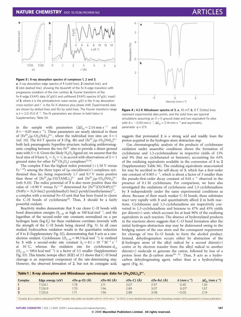
© 2009 Macmillan Publishers Limited. All rights reserved.
in the sample with parameters (DEQ¼ 2.14 mm s21 andd¼20.05 mm s21). These parameters are nearly identical to thoseof [FeIV
2(m-O)2(N4)2]4þ, where the individual iron sites are S¼ 1(ref. 10). The 8.0 T spectra of 3 (Fig. 4b) and [FeIV
2(m-O)2(N4)2]4þ
both lack paramagnetic hyperfine structure, indicating antiferromag-netic coupling between the two FeIV sites to provide a dimer groundstate with S¼ 0. Given the likely N4O2 ligand set, we assume that thelocal sites of 3 have S1¼ S2¼ 1, in accord with observations of S¼ 1ground states for other FeIV(N4O2) complexes15,16.
The complex 3 has the highest redox potential (þ1.50 V versusFcþ/0) among the three types of (m-oxo)diiron(IV) complexes syn-thesized thus far, being respectively 1.7 and 0.7 V more positivethan those of [FeIV
2(m-O)(TAML)2]22 and [FeIV2(m-O)2(N4)2]4þ
(refs 9,10). The redox potential of 3 is also more positive than thevalue of þ0.90 V versus Fcþ/0 determined for [FeIV(O)(N4Py)]2þ
(N4Py¼N,N-bis(2-pyridylmethyl)-bis(2-pyridyl)methylamine)17,a complex with a terminal Fe¼O unit that has been found to cleavethe C–H bonds of cyclohexane18. Thus, 3 should be a fairlypowerful oxidant.
Reactivity studies demonstrate that 3 can cleave C–H bonds withbond dissociation energies DC–H as high as 100 kcal mol21, and thelogarithm of the second-order rate constants normalized on a perhydrogen basis (log k02) for these oxidations correlates inversely withthe strength of the C–H bonds being cleaved (Fig. 5). In all casesstudied, hydrocarbon oxidation results in the quantitative reductionof 3 to 2 (Supplementary Fig. S2), demonstrating that 3 acts as a one-electron oxidant. Cyclohexane (DC–H¼ 99.3 kcal mol21) is oxidizedby 3 with a second-order rate constant k2¼ 8.1� 1022 M21 s21
at 10 8C, whereas the oxidation rate for cyclohexane-d12(DC–D¼ 100.6 kcal mol21) is a factor of 3.5 smaller (SupplementaryFig. S3). This kinetic isotope effect (KIE) of 3.5 shows that C–H bondcleavage is an important component of the rate-determining step.However, the observed formation of 2, but not its conjugate acid,
suggests that protonated 2 is a strong acid and readily loses theproton acquired in the hydrogen-atom abstraction step.
Gas chromatographic analysis of the products of cyclohexaneoxidation under anaerobic conditions shows the formation ofcyclohexene and 1,3-cyclohexadiene in respective yields of 13%and 9% (but no cyclohexanol or benzene), accounting for 63%of the oxidizing equivalents available in the conversion of 3 to 2(Supplementary Table S6). The oxidizing equivalents unaccountedfor may be ascribed to the self-decay of 3, which has a first-orderrate constant of 0.003 s21, which is about a factor of 3 smaller thanthe pseudo-first-order decay constant of 0.01 s21 observed in thepresence of 0.1 M cyclohexane. For comparison, we have alsoinvestigated the oxidations of cyclohexene and 1,3-cyclohexadieneby 3 independently under the same experimental conditions asabove. Because of their much weaker C–H bonds, these substratesreact very rapidly with 3 and quantitatively afford 2 in both reac-tions. Cyclohexene and 1,3-cyclohexadiene are respectively con-verted to 1,3-cyclohexadiene and benzene in 47% and 45% yieldsper diiron(IV) unit, which account for at least 90% of the oxidizingequivalents in each reaction. The absence of hydroxylated productsin the reactions above suggests that C–O bond formation after theinitial hydrogen-abstraction step may be disfavoured owing to thebridging nature of the oxo atom and the consequent requirementfor cleavage of two Fe–O bonds to form the alcohol product.Instead, dehydrogenation occurs either by abstraction of theb-hydrogen atom of the alkyl radical by a second diiron(IV)centre or by electron transfer from the alkyl radical to anotherdiiron(IV) molecule to generate the cation, followed by loss of aproton from the b-carbon atom19221. Thus, 3 acts as a hydro-carbon dehydrogenating agent, rather than as a hydroxylatingagent (Fig. 6).
−5
2
0
4
2
0
Abs
orpt
ion
(%)
0 5Velocity (mm s−1)
Figure 4 | 4.2 K Mossbauer spectra of 3. a, 45 mT; b, 8 T. Dotted lines
represent experimental data points, and the solid lines are spectral
simulations assuming an S¼0 ground state and two equivalent Fe sites
with d¼20.05 mm s21, DEQ¼ 2.14 mm s21 and asymmetry
parameter h¼0.9.
Table 1 | X-ray absorption and Mossbauer spectroscopic data for [Fe2O(L)2]n1.
Complex Edge energy (eV) r(Fe–m-O) (Å) r(Fe–N) (Å) r(Fe–C) (Å) r(Fe–Fe) (Å) d (mm s21) DEQ (mm s21)
1 7,124.1 1.78 2.11 3.07 2.97 0.45 1.302 7,124.9 1.70 1.96 2.89 3.07 0.07* 1.573 7,125.6 1.71 1.96 2.88 3.08 20.05 2.14
*Complex 2 is a valence-delocalized FeIIIFeIV complex that yields one doublet with d¼0.07 mm s21 at 120 K; a more detailed description of this interesting complex will be presented in a future publication.
0 1 2 3 4 5 67,1307,120eV
Fluo
resc
ence
sum
FT m
agni
tude
r’ (Å)
k (Å−1)2
k3(k
)
4 6 8 10 12 14
Figure 3 | X-ray absorption spectra of complexes 1, 2 and 3.
a, X-ray absorption edge spectra of 1 (solid line), 2 (dashed line), and
3 (dot–dashed line), showing the blueshift of the Fe K-edge transition with
progressive oxidation of the iron centres. b, Fourier transform of the
Fe K-edge EXAFS data (k3x(k)) and unfiltered EXAFS spectra (k3x(k), inset)
of 3, where k is the photoelectron wave vector, x(k) is the X-ray absorption
cross-section and r 0 is the Fe–X distance plus phase shift. Experimental data
are shown by dotted lines and fits by solid lines. The Fourier transform range
is k¼ 2.0–15.0 Å21. The fit parameters are shown in bold italics in
Supplementary Table S4.
NATURE CHEMISTRY DOI: 10.1038/NCHEM.162 ARTICLES
NATURE CHEMISTRY | VOL 1 | MAY 2009 | www.nature.com/naturechemistry 147
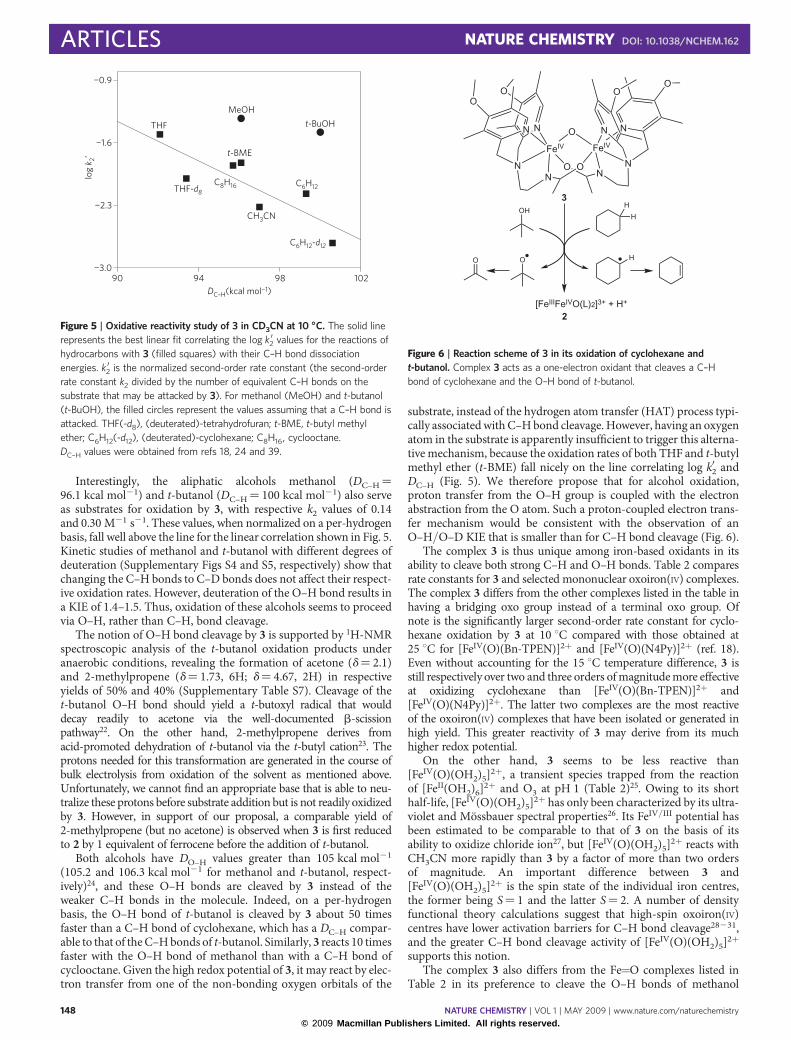
© 2009 Macmillan Publishers Limited. All rights reserved.
Interestingly, the aliphatic alcohols methanol (DC–H¼96.1 kcal mol21) and t-butanol (DC–H¼ 100 kcal mol21) also serveas substrates for oxidation by 3, with respective k2 values of 0.14and 0.30 M21 s21. These values, when normalized on a per-hydrogenbasis, fall well above the line for the linear correlation shown in Fig. 5.Kinetic studies of methanol and t-butanol with different degrees ofdeuteration (Supplementary Figs S4 and S5, respectively) show thatchanging the C–H bonds to C–D bonds does not affect their respect-ive oxidation rates. However, deuteration of the O–H bond results ina KIE of 1.4–1.5. Thus, oxidation of these alcohols seems to proceedvia O–H, rather than C–H, bond cleavage.
The notion of O–H bond cleavage by 3 is supported by 1H-NMRspectroscopic analysis of the t-butanol oxidation products underanaerobic conditions, revealing the formation of acetone (d¼ 2.1)and 2-methylpropene (d¼ 1.73, 6H; d¼ 4.67, 2H) in respectiveyields of 50% and 40% (Supplementary Table S7). Cleavage of thet-butanol O–H bond should yield a t-butoxyl radical that woulddecay readily to acetone via the well-documented b-scissionpathway22. On the other hand, 2-methylpropene derives fromacid-promoted dehydration of t-butanol via the t-butyl cation23. Theprotons needed for this transformation are generated in the course ofbulk electrolysis from oxidation of the solvent as mentioned above.Unfortunately, we cannot find an appropriate base that is able to neu-tralize these protons before substrate addition but is not readily oxidizedby 3. However, in support of our proposal, a comparable yield of2-methylpropene (but no acetone) is observed when 3 is first reducedto 2 by 1 equivalent of ferrocene before the addition of t-butanol.
Both alcohols have DO–H values greater than 105 kcal mol21
(105.2 and 106.3 kcal mol21 for methanol and t-butanol, respect-ively)24, and these O–H bonds are cleaved by 3 instead of theweaker C–H bonds in the molecule. Indeed, on a per-hydrogenbasis, the O–H bond of t-butanol is cleaved by 3 about 50 timesfaster than a C–H bond of cyclohexane, which has a DC–H compar-able to that of the C–H bonds of t-butanol. Similarly, 3 reacts 10 timesfaster with the O–H bond of methanol than with a C–H bond ofcyclooctane. Given the high redox potential of 3, it may react by elec-tron transfer from one of the non-bonding oxygen orbitals of the
substrate, instead of the hydrogen atom transfer (HAT) process typi-cally associated with C–H bond cleavage. However, having an oxygenatom in the substrate is apparently insufficient to trigger this alterna-tive mechanism, because the oxidation rates of both THF and t-butylmethyl ether (t-BME) fall nicely on the line correlating log k02 andDC–H (Fig. 5). We therefore propose that for alcohol oxidation,proton transfer from the O–H group is coupled with the electronabstraction from the O atom. Such a proton-coupled electron trans-fer mechanism would be consistent with the observation of anO–H/O–D KIE that is smaller than for C–H bond cleavage (Fig. 6).
The complex 3 is thus unique among iron-based oxidants in itsability to cleave both strong C–H and O–H bonds. Table 2 comparesrate constants for 3 and selected mononuclear oxoiron(IV) complexes.The complex 3 differs from the other complexes listed in the table inhaving a bridging oxo group instead of a terminal oxo group. Ofnote is the significantly larger second-order rate constant for cyclo-hexane oxidation by 3 at 10 8C compared with those obtained at25 8C for [FeIV(O)(Bn-TPEN)]2þ and [FeIV(O)(N4Py)]2þ (ref. 18).Even without accounting for the 15 8C temperature difference, 3 isstill respectively over two and three orders of magnitude more effectiveat oxidizing cyclohexane than [FeIV(O)(Bn-TPEN)]2þ and[FeIV(O)(N4Py)]2þ. The latter two complexes are the most reactiveof the oxoiron(IV) complexes that have been isolated or generated inhigh yield. This greater reactivity of 3 may derive from its muchhigher redox potential.
On the other hand, 3 seems to be less reactive than[FeIV(O)(OH2)5]2þ, a transient species trapped from the reactionof [FeII(OH2)6]2þ and O3 at pH 1 (Table 2)25. Owing to its shorthalf-life, [FeIV(O)(OH2)5]2þ has only been characterized by its ultra-violet and Mossbauer spectral properties26. Its FeIV/III potential hasbeen estimated to be comparable to that of 3 on the basis of itsability to oxidize chloride ion27, but [FeIV(O)(OH2)5]2þ reacts withCH3CN more rapidly than 3 by a factor of more than two ordersof magnitude. An important difference between 3 and[FeIV(O)(OH2)5]2þ is the spin state of the individual iron centres,the former being S¼ 1 and the latter S¼ 2. A number of densityfunctional theory calculations suggest that high-spin oxoiron(IV)centres have lower activation barriers for C–H bond cleavage28231,and the greater C–H bond cleavage activity of [FeIV(O)(OH2)5]2þ
supports this notion.The complex 3 also differs from the Fe¼O complexes listed in
Table 2 in its preference to cleave the O–H bonds of methanol
90 94 98 102−3.0
−2.3
−1.6
−0.9
CH3CN
log k 2
’
DC–H(kcal mol−1)
C6H12-d12
C6H12
t-BME
C8H16THF-d8
THF t-BuOHMeOH
Figure 5 | Oxidative reactivity study of 3 in CD3CN at 10 88888C. The solid line
represents the best linear fit correlating the log k 02 values for the reactions of
hydrocarbons with 3 (filled squares) with their C–H bond dissociation
energies. k 02 is the normalized second-order rate constant (the second-order
rate constant k2 divided by the number of equivalent C–H bonds on the
substrate that may be attacked by 3). For methanol (MeOH) and t-butanol
(t-BuOH), the filled circles represent the values assuming that a C–H bond is
attacked. THF(-d8), (deuterated)-tetrahydrofuran; t-BME, t-butyl methyl
ether; C6H12(-d12), (deuterated)-cyclohexane; C8H16, cyclooctane.
DC–H values were obtained from refs 18, 24 and 39.
FeIV FeIV
O
O ON
N
NN
NN
N N
OO O
O
3
H
H
HOH
O O
2[FeIIIFeIVO(L)2]3+ + H+
Figure 6 | Reaction scheme of 3 in its oxidation of cyclohexane and
t-butanol. Complex 3 acts as a one-electron oxidant that cleaves a C–H
bond of cyclohexane and the O–H bond of t-butanol.
ARTICLES NATURE CHEMISTRY DOI: 10.1038/NCHEM.162
NATURE CHEMISTRY | VOL 1 | MAY 2009 | www.nature.com/naturechemistry148

© 2009 Macmillan Publishers Limited. All rights reserved.
and t-butanol, rather than their C–H bonds. This difference isstrikingly demonstrated by the observation of C–H/C–D KIEs of4–8 for methanol oxidation by the three oxoiron(IV) complexes25,32
and the absence of a KIE for oxidation by 3. Instead, for methanoland t-butanol oxidation by 3, there is a small but measurableO–H/O–D KIE. Why 3 should specifically target the O–H bondinstead of the weaker C–H bonds of the alcohol is not clear, andwill be the subject of further investigation.
In conclusion, we have generated and characterized a noveldiiron(IV) complex 3 with a redox potential þ1.50 V versus Fcþ/0,the highest FeIV/III potential determined electrochemically todate9,10,13,17,33235. This high potential suggests that 3 should be apowerful oxidant. Indeed, 3 can cleave the strong C–H bonds ofcyclohexane, whereas [FeIV
2(m-O)2(N4)2]4þ, a complex that servesas the synthetic precedent for the FeIV
2(m-O)2 core proposed forMMO-Q (ref. 10), can only attack the weak C–H bonds of dihy-droanthracene. Furthermore, 3 reacts much faster with cyclohexanethan do mononuclear FeIV¼O complexes of closely related ligands.Unexpectedly, we find that 3 preferentially cleaves the stronger O–Hbonds of methanol and t-butanol instead of their C–H bonds, repre-senting the first example of O–H bond activation for iron com-plexes. However, the rate of cyclohexane oxidation by 3 is stillorders of magnitude smaller than the rate of oxidation ofmethane by the diiron(IV) intermediate Q of MMO36,37. This reactiv-ity gap may arise from a difference in the spin states of the individ-ual iron centres in the complexes (S¼ 1 for 3 and S¼ 2 for Q). Thecomplex 3 also differs from MMO-Q in that it carries out substratedehydrogenation rather than hydroxylation. From this perspective,the action of 3 more closely resembles that of fatty acid desaturases,which, like MMO, also have diiron active sites and are thus pro-posed to generate diiron(IV) oxidants in their catalytic cycle38. Asdiscussed for 3 above, the difference in the reactivities of MMOand the fatty acid desaturases may hinge on the relative ease bywhich C–O bond formation between the incipient alkyl radicaland the Fe–OH unit (that is, oxygen rebound) can take place relativeto electron transfer between them19221, and the results for 3 canhelp us understand how different but related enzyme active sitescan modulate the outcome of substrate oxidation. Lastly, our intri-guing results demonstrate that complexes with very high FeIV/III
potential can be generated in high yield and characterized spectro-scopically, and they set the stage for future efforts aimed at moreefficient hydrocarbon oxidation by synthetic iron complexes.
Received 26 November 2008; accepted 16 February 2009;published online 29 March 2009
References1. Hanson, R. S. & Hanson, T. E. Methanotrophic bacteria. Microbiol. Rev. 60,
439–471 (1996).2. Wallar, B. J. & Lipscomb, J. D. Dioxygen activation by enzymes containing
binuclear non-heme iron clusters. Chem. Rev. 96, 2625–2657 (1996).3. Merkx, M. et al. Dioxygen Activation and methane hydroxylation by soluble
methane monooxygenase: A tale of two irons and three proteins. Angew. Chem.Int. Ed. 40, 2782–2807 (2001).
4. Balasubramanian, R. & Rosenzweig, A. C. Structural and mechanistic insightsinto methane oxidation by particulate methane monooxygenase. Acc. Chem. Res.40, 573–580 (2007).
5. Lee, S.-K., Fox, B. G., Froland, W. A., Lipscomb, J. D. & Munck, E. A transientintermediate of the methane monooxygenase catalytic cycle containing anFeIVFeIV cluster. J. Am. Chem. Soc. 115, 6450–6451 (1993).
6. Liu, K. E. et al. Kinetic and spectroscopic characterization of intermediates andcomponent interactions in reactions of methane monooxygenase fromMethylococcus capsulatus (Bath). J. Am. Chem. Soc. 117, 10174–10185 (1995).
7. Nesheim, J. C. & Lipscomb, J. D. Large kinetic isotope effects in methaneoxidation catalyzed by methane monooxygenase: Evidence for C–H bondcleavage in a reaction cycle intermediate. Biochemistry 35, 10240–10247 (1996).
8. Shu, L. et al. An FeIV2 O2 diamond core structure for the key intermediate Q of
methane monooxygenase. Science 275, 515–518 (1997).9. Ghosh, A. et al. Catalytically active m-oxodiiron(IV) oxidants from iron(III) and
dioxygen. J. Am. Chem. Soc. 127, 2505–2513 (2005).10. Xue, G. et al. A synthetic precedent for the [FeIV
2 (m-O)2] diamond core proposedfor methane monooxygenase intermediate Q. Proc. Natl Acad. Sci. USA 104,20713–20718 (2007).
11. Xu, J.-Y. et al. Iron(III) complexes with the ligand N0 ,N0-bis[(2-pyridyl)-methyl]ethylenediamine (uns-penp) and its amide derivative N-acetyl-N0 ,N0-bis[(2-pyridyl)methyl]ethylenediamine (acetyl-uns-penp). Eur. J. Inorg. Chem.1601–1610 (2006).
12. Kurtz, D. M. Jr Oxo- and hydroxo-bridged diiron complexes: A chemicalperspective on a biological unit. Chem. Rev. 90, 585–606 (1990).
13. Slep, L. D. et al. Mixed-valent fFeIV(m-O)(m-carboxylato)2FeIIIg3þ core.J. Am. Chem. Soc. 125, 15554–15570 (2003).
14. Norman, R. E. et al. (m-Oxo)(m-carboxylato)diiron(III) complexes with distinctiron sites. Consequences of the inequivalence and its relevance to dinucleariron–oxo proteins. J. Am. Chem. Soc. 112, 1554–1562(1990).
15. Jackson, T. A. et al. Axial ligand effects on the geometric and electronicstructures of nonheme oxoiron(IV) complexes. J. Am. Chem. Soc. 130,12394–12407 (2008).
16. Rohde, J. U. et al. Nonheme oxoiron(IV) complexes of tris(2-pyridylmethyl)amine with cis-monoanionic ligands. Inorg. Chem. 45,6435–6445 (2006).
17. Collins, M. J., Ray, K. & Que, L. Jr Electrochemical generation of a nonhemeoxoiron(IV) complex. Inorg. Chem. 45, 8009–8011 (2006).
18. Kaizer, J. et al. Nonheme FeIVO complexes that can oxidize the C–H bonds ofcyclohexane at room temperature. J. Am. Chem. Soc. 126, 472–473 (2004).
19. Kumar, D., de Visser, S. P., Sharma, P. K., Cohen, S. & Shaik, S. Radical clocksubstrates, their C–H hydroxylation mechanism by cytochrome P450, and otherreactivity patterns: What does theory reveal about the clocks’ behaviour?J. Am. Chem. Soc. 126, 1907–1920 (2004).
20. Kumar, D., de Visser, S. P. & Shaik, S. Oxygen economy of cytochrome P450:What is the origin of the mixed functionality as a dehydrogenase-oxidase
Table 2 | Second-order rate constants (M21 s21) for the reactions of iron(IV) complexes*.
Complexes† E1/2 (FeIV/III)(vs Fc1/0)
Fe spin state Cyclo-C6H12 CH3CN Methanol t-butanol Ref.
3 (10 8C) 1.50 S¼ 1 0.081 [C–H, 3.5] 0.014 0.14 [O–H, 1.5] 0.30 [O–H, 1.4] This work[Fe(O)(Bn-TPEN)]2þ
(25 8C).0.90 S¼ 1 3.9� 1024 2� 1026 ‡
[C–H, 4]2.8� 1023 §
[C–H, 8]NA 18,32
[Fe(O)(N4Py)]2þ
(25 8C)0.90 S¼ 1 5.5� 1025 2� 1027 ‡ 4.4�1024 §
[C–H, 7]NA 17,18,32
[Fe(O)(OH2)5]2þ
(25 8C)� 1.4k S¼ 2 NA} 4.1 [C–H, 4.1] 572 [C–H, 4.4] 60 25,27
MMO-Q (25 8C) NA S¼ 2 (3–4)� 104 forCH4
36,37
NA, not available.*KIE values (where available) are shown in square brackets.†Bn-TPEN, N-benzyl-N,N0 ,N0-tris(2-pyridylmethyl)-1,2-diaminoethane; N4Py, N,N-bis(2-pyridylmethyl)-bis(2-pyridyl)methylamine.‡ Estimated from t1/2 values in CH3CN solvent from ref. 18 or 32.§ Data obtained at 40 8C from ref. 32.k It has not been possible to establish the FeIV/III potential for [Fe(O)(OH2)5]2þ by electrochemical means because of its very short lifetime; the value given here is an estimate from ref. 27 based on its ability tooxidize Cl2 ion.} No oxidation rate has been reported for cyclohexane or any other hydrocarbon because of the immiscibility of such substrates with the aqueous medium in which [Fe(O)(OH2)5]2þ is generated.
NATURE CHEMISTRY DOI: 10.1038/NCHEM.162 ARTICLES
NATURE CHEMISTRY | VOL 1 | MAY 2009 | www.nature.com/naturechemistry 149

© 2009 Macmillan Publishers Limited. All rights reserved.
enzyme compared with its normal function? J. Am. Chem. Soc. 126,5072–5073 (2004).
21. Jin, Y. & Lipscomb, J. D. Desaturation reactions catalyzed by soluble methanemonooxygenase. J. Biol. Inorg. Chem. 6, 717–725 (2001).
22. Griller, D. & Ingold, K. U. Free-radical clocks. Acc. Chem. Res. 13,317–323 (1980).
23. Vollhardt, K. P. C. The reactions of alcohols and the chemistry of ethers, inOrganic Chemistry 308–358 (W. H. Freeman, 1987).
24. Luo, Y.-R. in Comprehensive Handbook of Chemical Bond Energies 255–369(Taylor & Francis, 2007).
25. Pestovsky, O. & Bakac, A. Reactivity of aqueous fe(IV) in hydride and hydrogenatom transfer reactions. J. Am. Chem. Soc. 126, 13757–13764 (2004).
26. Pestovsky, O. et al. Aqueous FeIV¼O: Spectroscopic identification and oxo groupexchange. Angew. Chem. Int. Ed. 44, 6871–6874 (2005).
27. Jacobsen, F., Holcman, J. & Sehested, K. Reactions of the ferryl ion with somecompounds found in cloud water. Int. J. Chem. Kinet. 30, 215–221 (1998).
28. Shaik, S., Hirao, H. & Kumar, D. Reactivity of high-valent iron–oxo species inenzymes and synthetic reagents: A tale of many states. Acc. Chem. Res. 40,532–542 (2007).
29. Sastri, C. V. et al. Axial ligand tuning of a nonheme iron(IV)–oxo unit forhydrogen atom abstraction. Proc. Natl Acad. Sci. USA 104, 19181–19186 (2007).
30. Decker, A. et al. Spectroscopic and quantum chemical studies on low-spinFeIV¼O complexes: Fe–O bonding and its contributions to reactivity.J. Am. Chem. Soc. 129, 15983–15996 (2007).
31. Bernasconi, L., Louwerse, M. J. & Baerends, E. J. The role of equatorial and axialligands in promoting the activity of non-heme oxidoiron(IV) catalysts in alkanehydroxylation. Eur. J. Inorg. Chem. 3023–3033 (2007).
32. Klinker, E. J. High-valent iron compounds supported by pentadentate ligands.PhD thesis, Univ. Minnesota–Twin Cities (2007).
33. Berben, L. A. & Peters, J. C. Dimanganese and diiron complexes of a binucleatingcyclam ligand: Four-electron, reversible oxidation chemistry at high potentials.Inorg. Chem. 47, 11669–11679 (2008).
34. Berry, J. F., Bill, E., Bothe, E., Neese, F. & Wieghardt, K. Octahedral non-hemeoxo and non-oxo Fe(IV) complexes: An experimental/theoretical comparison.J. Am. Chem. Soc. 128, 13515–13528 (2006).
35. Zheng, H., Yoo, S. J., Munck, E. & Que, L. Jr The flexible Fe2(m-O)2diamond core: A terminal iron(IV)–oxo species generated from the oxidationof a bis(m-oxo)diiron(III) complex. J. Am. Chem. Soc. 122, 3789–3790 (2000).
36. Brazeau, B. J. & Lipscomb, J. D. Kinetics and thermodynamics of methanemonooxygenase compound Q formation and reaction with substrates.Biochemistry 39, 13503–13515 (2000).
37. Valentine, A. M., Stahl, S. S. & Lippard, S. J. Mechanistic studies of the reactionof reduced methane monooxgyenase hydroxylase with dioxygen and substrates.J. Am. Chem. Soc. 121, 3876–3887 (1999).
38. Fox, B. G., Lyle, K. S. & Rogge, C. E. Reactions of the diiron enzyme stearoyl-acylcarrier protein desaturase. Acc. Chem. Res. 37, 421–429 (2004).
39. Luo, Y.-R. in Comprehensive Handbook of Chemical Bond Energies 19–147(Taylor & Francis, 2007).
AcknowledgementsThis work was supported by NIH Grants EB-001475 (E.M.) and GM-38767 (L.Q.) and NIHGraduate Traineeship GM-08700 (E.R.F.). XAS data were collected on beamlines 7-3 and9-3 at the Stanford Synchrotron Radiation Lightsource (SSRL), a national user facilityoperated by Stanford University on behalf of the US Department of Energy, Office of BasicEnergy Sciences. The SSRL Structural Molecular Biology Program is supported by theDepartment of Energy, Office of Biological and Environmental Research, and by theNational Institutes of Health, National Centre for Research Resources and the BiomedicalTechnology Program. We thank M. Latimer and A. Aranda for technical support andadvice during XAS data collection. We also thank V.G. Young Jr and the X-rayCrystallographic Laboratory of the University of Minnesota for expert assistance in thecrystal structure determination.
Author contributionsD.W., E.M. and L.Q. conceived and designed the experiments; D.W., E.R.F. and A.S.performed the experiments; D.W., E.R.F., A.S. and E.M. analysed the data; D.W., E.R.F.,A.S., E.M. and L.Q. wrote the paper. All authors discussed the results and commented onthe manuscript.
Additional informationSupplementary information accompanies this paper at www.nature.com/naturechemistry.Reprints and permission information is available online at http://npg.nature.com/reprintsandpermissions/. Correspondence and requests for materials should be addressed toE.M. and L.Q.
ARTICLES NATURE CHEMISTRY DOI: 10.1038/NCHEM.162
NATURE CHEMISTRY | VOL 1 | MAY 2009 | www.nature.com/naturechemistry150
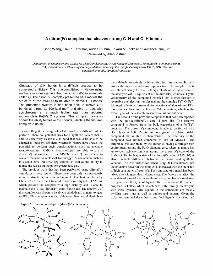
Figure 1. Three reported (µ-oxo)diiron(IV) compounds.
A diiron(IV) complex that cleaves strong C–H and O–H bonds
Dong Wang, Erik R. Farquhar, Audria Stubna, Eckard Mu¨nck* and Lawrence Que, Jr*
Reviewed by Allen Pistner
1Department of Chemistry and Center for Metals in Biocatalysis, University of Minnesota, Minneapolis, Minnesota 55455,
USA, 2Department of Chemistry,Carnegie Mellon University, Pittsburgh, Pennsylvania 15213, USA. *e-mail:
[email protected]; [email protected].
Cleavage of C-H bonds is a difficult process to be
completed artificially. This is accomplished in Nature using
methane monooxygenase that has a diiron(IV) intermediate
called Q. The diiron(IV) complex presented here models the
structure of the MMO-Q to be able to cleave C-H bonds.
The presented system is has been able to cleave C-H
bonds as strong as 100 kcal mol-1
and able to react with
cyclohexane at a much higher rate than reported
mononuclear Fe(IV)=O systems. This complex has also
shown the ability to cleave O-H bonds, which is the first iron
complex to do so
Controlling the cleavage of a C-H bond is a difficult task to
perform. There are potential uses for a synthetic system that is
able to selectively cleave a C-H bond that would be able to be
adapted to industry. Efficient systems in Nature have shown the
potential to perform such transformations, such as methane
monooxygenase (MMOs). Methanotrophs are able to use a
diiron(IV) intermediate of the MMOs called Q that is able to
convert methane to methanol for energy.1 A conversion such as
this could have industrial applications as well as the ability to
reduce the release of the potent greenhouse gas.
The previous work that has been performed using diiron(IV)
complexes is very limited. There have been only two previously
reported structures, as seen in Figure 1. The first put forth by
Ghosh et al2 used the tetraamido macrocycle ligands (TAMLs),
which provide the complex with high stability and is able to
maintain the (µ-oxo)diiron(IV) core (Figure 1a). The reactivity of
this complex was shown to be able to catalytically transfer oxygen
to PPh3. This complex was also able to oxidize benzyl alcohols to
the aldehyde selectively, without forming any carboxylic acid
groups through a two-electron type reaction. The complex reacts
with the efficiency to covert 60 equivalents of benzyl alcohol to
the aldehyde with 1 equivalent of the diiron(IV) complex. Cyclic
voltammetry of the compound revealed that it goes through a
reversible one-electron transfer making the complex FeIV-O–FeIII.
Although able to perform oxidation reactions of alcohols and PPh3
this complex does not display any C-H activation, which is the
overall goal of the research presented in this current paper.
The second of the previous compounds that has been reported
with the (µ-oxo)diiron(IV) core (Figure 1b). The reactive
compound is formed from the bulk electrolysis of a FeIIIFeIV
precursor. The diiron(IV) compound is able to be formed with
electrolysis at 900 mV for an hour giving a relative stable
compound that is able to characterized. The reactivity of the
compound was limited compared to that of MMO-Q. The
difference was attributed by the author as having a nitrogen rich
environment around the Fe-O diamond core, where as nature has
an oxygen rich environment around the diiron(IV) core of the
MMO-Q. The high spin state of the diiron(IV) core of MMO-Q is
also a notable difference between the natural and synthetic
versions. This was further confirmed using DFT calculations that
the oxidative power of the complex is increased with the inclusion
of high spin states of iron(IV). The spin state of a metal has been
talked about in great detail during class. The factors that affect the
spin state of a metal are the oxidation state, number of orientation
of ligand and the type of ligand. The oxidation of the system
proposed is Fe(IV) which is achieved only through electrolysis
with these systems. The ligands in the compound are mostly
pyridine type rings as well as amines and oxygen. Given the
oxidation state and the rather strong field ligands it is of no real
a
b c

surprise that the spin state of the iron atoms are low spin in this
complex.
In this current paper, the complex describes shows improved
reactivity toward the cleavage of C-H bonds. The complex begins
as a (µ-oxo)diiron(III) (1) which is a pentadentate ligand,
donating with four nitrogen atoms and one oxygen.
The analysis begins with cyclic voltammetry, which is scanned
anodically with ferrocene as the standard, as seen in Figure 2.
Two redox waves were observed with the first oxidation at Ep,a =
+1.07 V with the corresponding reductive peak at Ep,c = +0.33 V
on the return sweep. The large difference between the peaks limits
the transformation and not considered to be reversible. The
second oxidative peak observed while scanning anodoically was
at Ep,a = +1.53 V with the corresponding reductive wave at Ep,c =
+1.46 V. The difference between the peaks is 0.07 V, which is
approaching the 0.06 V CV criteria to identify a transition as
being reversible.
The result of the CV is that species 1 is able to go through a
one-electron transfer to make iron(IV)iron(III) derivative (2).
Complex 2 is stable at -40 °C for several days if the potential
remains above +0.70 V and can regenerate complex 1 if the
potential is dropped below +0.70 V in quantitative yield, making
this transformation a reversible process.
Redox chemistry is a topic that was discusses during the course
and the determination of the favorability of oxidation and
reduction. Cyclic voltammetry, which was also discussed, is an
application of using redox chemistry to determine the potential at
which the electron transfers is able to take place. This is done by
measuring the current while the potential of the electrode is swept
between the boundaries that are set. This allows for the
determination of the potential needed to either oxidize or reduce a
given compound as seen above and can help determine the
potential for bulk electrolysis as well
The conversion of complex 2 to complex 3 (Figure 1c), the
diiron(IV) species can be accomplished using bulk electrolysis
with a potential of +1.70 V. Complex 3 was stable enough for
spectroscopic characterization, however the half life was reported
as about 1 hour at -40 °C. The conversion of 2 to 3 is also less
efficient than the conversion for 1 to 2. The yield was reported as
85% but is solvent dependent. The best results were seen using
CD3CN in place of acetonitrile. The electrolyte was limited to
KPF6 rather than quaternary-ammonium salts to limit the C-H
bonds in the solution.
The structure was solved using extended X-ray absorption fine
structure (EXAFS) analysis allowing for the determination of the
distances between the iron atoms as well as the bond lengths of
the Fe-O-Fe between the different complexes. The distances are
higher in complex 1 as it is in high spin state, where as the
distances are shorter in the low spin states of iron in 2 and 3. The
oxidation states were further confirmed using Mossbauer studies.
The reactivity of the active complex 3 was studied through
kinetic isotope effects (KIE). The studies revealed that 3 has the
ability to cleave relatively strong C-H bonds that are around 100
kcal mol-1. The KIE of 3.5 showed that the cleavage of the C-H
bond is a large part of the rate determining step of the reaction.
The study also revealed the formation of complex 2 after cleavage
of the C-H bond. This indicated that 3 acts through a one electron
donation for the bond cleavage. The formation of 2 is seen and not
the conjugate acid, showing that the hydrogen is lost from the
complex into the solution.
The products of the reaction were monitored as cyclohexane
was reacted with 3. The products that were seen were cyclohexene
and 1,3-cyclohezadiene in poor yields. There was no formation of
benzene or cyclohexanol. Further studies were performed with
using cyclohexene and 1,3-cyclohexadiene as reactants. The
cyclohexene was converted to 1,3-cycloheadiene in 47% yield,
while the 1,3-cyclohexadiene was converted to benzene in 45%
yield. The products of the reactions are the result of C-H bond
cleavage with no showing of alcohol products. The authors
propose two mechanisms for the formation of the products. The
first is the initial formation of the alkyl radical which is followed
by the removal of a β-hydrogen of the alkyl radical by a second
diiron(IV) center. The other proposed mechanism is the electron
transfer from the alkyl radical to the diiron(IV) center to create a
cation, which then loses a proton at the β-position to form the
double bond.
Figure 2. CV of 1 in CH3CN at room temperature.
Figure 3. Oxidative reactivity of 3.
Figure 4. Reaction Scheme of 3 with cyclohexane
and t-butanol.

Table 1. Second-order rate constants for he reactions with iron(IV) complexes.
Complexes E1/2 (FeIV/III) (vs Fc+/0)
Fe spin state
Cyclo-C6H12 CH3CN Methanol t-butanol Ref
3 1.50 S = 1 0.081 [C-H], 3.5 0.014 0.14 [O-H, 1.5] 0.30 [O-H, 1.4]
[Fe(O)(Bn-TPEN)]
2+ >0.90 S=1 3.9 x 10
-4 2 x 10
-6 [C-H, 4] 2.8 x 10
-3 NA 4,5
[Fe(O)(N4Py)]2+
0.90 S=1 5.5 x 10⁻⁵
2 x 10⁻⁷
4.4 x 10⁻⁴
[C-H, 7]
NA 6,7
[Fe(O)(OH2)5]2+
~1.4 S=2 NA 4.1 [C-H, 4.1] 572 [C-H, 4.4] 60 8 MMO-Q NA S=2 (3-4)x10
4 for CH4
The study of 3 with the reaction of aliphatic alcohols such as
methanol and t-butanol also gave interesting results. The KIE
studies were performed first with the deuteration of the C-H
bonds, which showed no impact on the kinetics of the reaction.
The deuteration of the O-H bonds however, showed a KIE of 1-
1.5, which leads to the interpretation that the reaction goes
through the O-H bond cleavage rather than the cleavage of C-H.
The products of the reaction of 3 with t-butanol were monitored
using 1H NMR, where the formation of acetone and 2-
methylpropene was seen. The reaction is proposed to go through
the formation of the radical at the oxygen and then lead to the
formation of acetone. They propose that the alcohol proton
transfer from the O-H is coupled with the loss of an electron from
the oxygen from a non-bonding orbital (Figure 4).
The formation of the 2-methylpropene indicates that a
competing reaction is taking place. This is proposed to be caused
by the electrolysis of the solvent to give the protons needed to
make the t-butyl cation that undergoes dehydrogenation. This
would be avoided if the solution would be able to buffered to
prevent the reaction of the protons with the t-butanol, however,
the authors have not been successful in finding a base that would
not be oxidized by complex 3.
In Table 1 are listed iron species that have been characterized
and have shown the ability to perform similar chemistry as that of
complex 3. The first is [Fe(O)(Bn-TPEN)]2+ complex that uses the
pentadentate ligand as a form of nonheme oxoiron(IV) complex.4
This compound has shown too active in C-H activation but in
much lower rates. This complex hydroxylates alkanes rather than
the one-electron transfer mechanism put forth by the authors of
this paper.
The second complex is another nonheme pentadentate ligand
that forms the complex [Fe(O)(N4Py)]2+.5 This compound again
uses the oxoiron(IV) structure, however the compound is activate
through electrolysis from the FeII species through a two-electron
transfer. This differs from the previous compound that activated
from FeIII by electrolysis. The reactivity of this system is lower
than that of the recent report as well as the previous mononuclear
system.
The third mononuclear FeIV complex that is compared is
[Fe(O)(OH2)5]2+, which is different from the others in that it has a
high spin state at the iron center. This high spin state allows for a
greater rate of reactivity, which is seen in acetonitile, methanol
and t-butanol. The shortcoming of this complex is that the
stability of the complex is limited and being immiscible in
nonpolar solutions like that of cyclohexane. The activated
iron(IV) complex is accessed using a two electron process, but
due to the instability of the complex the potential at which the
FeIII/FeIV transformation has not been fully established.
The reactivity of MMO-Q with the rate constant for the
reaction with methane is still greatly above that of the synthesized
compounds. This structure still provides a synthetic target in
which to pursue in order to achieve the desired goal of C-H
activation.
Kinetics and rate laws were another topic that was covered in
class and although KIEs were not specifically discussed,
understanding the general scheme of kinetics allows for
understand of the meaning.
The overall goal of the research is rather well defined, with the
pursuit of a structure that is comparable to that of the active
intermediate MMO-Q. In the current work the authors propose a
compound that is relatively reactive, however lacks in stability as
well as high rates of reactivity. The reactivity of the mononuclear
iron(IV) complex and the MMO-Q is much higher than that of the
other complexes, which can be possibly correlated to the high spin
state of the iron. Therefore the overall goal of the research should
be in the direction of a stable high spin diiron(IV) complex that is
stable enough to be used as a C-H activator.
In the current paper the only solvent that is used for the cyclic
voltammetry is deuterated acetonitrile because of the need to a
solvent that does not contain C-H bonds. It would be interesting to
see the effects of other solvents, whether it be other deuterated
solvents or a solvent such as carbon tetrachloride that also does
not contain C-H bonds.
The ability to determine an acceptable base that can be used to
keep the reaction neutral but not provide other potential C-H
bonds to be cleaved is a challenge that should be investigated
further. This may provide better results as well as future
applications in the next systems that will be designed for the
cleavage of C-H bonds.
References 1. Merkx, M. et al. Dioxygen Activation and methane hydroxylation by
soluble methane monooxygenase: A tale of two irons and three proteins.
Angew. Chem. Int. Ed. 40, 2782–2807 (2001). 2. Ghosh, A. et al. Catalytically active m-oxodiiron(IV) oxidants from
iron(III) and dioxygen. J. Am. Chem. Soc. 127, 2505–2513 (2005). 3. Xue, G. et al. A synthetic precedent for the [FeIV
2 (m-O)2] diamond core proposed for methane monooxygenase intermediate Q. Proc. Natl Acad.
Sci. USA 104, 20713–20718 (2007).
4. Kaizer, J. et al. Nonheme FeIVO complexes that can oxidize the C–H
bonds of cyclohexane at room temperature. J. Am. Chem. Soc. 126, 472–473 (2004).
5. Collins, M. J., Ray, K. & Que, L. Jr Electrochemical generation of a nonheme oxoiron(IV) complex. Inorg. Chem. 45, 8009–8011 (2006).
6. Pestovsky, O. & Bakac, A. Reactivity of aqueous fe(IV) in hydride and hydrogen atom transfer reactions. J. Am. Chem. Soc. 126, 13757–13764
(2004).
7. Jacobsen, F., Holcman, J. & Sehested, K. Reactions of the ferryl ion with some compounds found in cloud water. Int. J. Chem. Kinet. 30,
215–221 (1998).
8. Valentine, A. M., Stahl, S. S. & Lippard, S. J. Mechanistic studies of the reactionof reduced methane monooxgyenase hydroxylase with dioxygen
and substrates. J. Am. Chem. Soc. 121, 3876–3887 (1999).

but creates increased mass transport losses atcurrent densities of >0.1 A cm−2. It is clearfrom these results that improvements in electrodemass transport properties are required to over-come this performance loss.
The results of 100-hour durability tests infuel cells using hydrogen/oxygen and hydrogen/air as anode/cathode gases are shown in fig. S4.Relative to the stable current densities obtainedby Bashyam and Zelenay (32) for tests per-formed under the same conditions (0.2 A cm−2
with H2/O2 at 0.5 V; 0.13 to 0.14 A cm−2 withH2/air at 0.4 V), the initial current densities pro-duced by the catalyst in this work (0.75 A cm−2
with H2/O2 at 0.5 V; 0.58 A cm−2 with H2/airat 0.4 V) were much higher and remained higherthroughout the 100-hour period, with final valuesof 0.33Acm−2withH2/O2 at 0.5Vand 0.36Acm−2
with H2/air at 0.4 V.The best NPMC in this work has a much
higher initial activity, but less stability, than thoseprepared by Bashyam and Zelenay according to anonpyrolytic method based on a cobalt salt andpolypyrrole deposited on carbon black (32).Continued research must now focus on improvingthe stability of these NPMCs and optimizing theircathode mass-transport properties.
References and Notes1. H. A. Gasteiger, S. S. Kocha, B. Sompalli, F. T. Wagner,
Appl. Catal. B 56, 9 (2005).2. H. A. Gasteiger, J. E. Panels, S. G. Yan, J. Power Sources
127, 162 (2004).
3. R. Jasinski, Nature 201, 1212 (1964).4. J. P. Dodelet, in N4-Macrocyclic Metal Complexes,
J. H. Zagal, F. Bedioui, J. P. Dodelet, Eds. (Springer,New York, 2006), pp. 83–147.
5. S. Gupta, D. Tryk, I. Bae, W. Aldred, E. Yeager,J. Appl. Electrochem. 19, 19 (1989).
6. M. Yuasa et al., Chem. Mater. 17, 4278 (2005).7. N. P. Subramanian et al., J. Power Sources 157, 56
(2006).8. E. B. Easton, A. Bonakdarpour, J. R. Dahn, Electrochem.
Solid State Lett. 9, A463 (2006).9. R. Z. Yang, A. Bonakdarpour, E. B. Easton, P. Stoffyn-Egli,
J. R. Dahn, J. Electrochem. Soc. 154, A275 (2007).10. J. Maruyama, I. Abe, Chem. Commun. 2007, 2879
(2007).11. T. E. Wood, Z. Tan, A. K. Schmoeckel, D. O’Neill,
R. Atanasoski, J. Power Sources 178, 510 (2008).12. A. Garsuch, K. MacIntyre, X. Michaud, D. A. Stevens,
J. R. Dahn, J. Electrochem. Soc. 155, B953 (2008).13. T. Schilling, M. Bron, Electrochim. Acta 53, 5379
(2008).14. A. H. C. Sirk, S. A. Campbell, V. I. Birss, J. Electrochem.
Soc. 155, B592 (2008).15. J. Maruyama, N. Fukui, M. Kawaguchi, I. Abe, J. Power
Sources 182, 489 (2008).16. V. Nallathambi, J.-W. Lee, S. P. Kumaraguru, G. Wu,
B. N. Popov, J. Power Sources 183, 34 (2008).17. U. I. Koslowski, I. Abs-Wurmbach, S. Fiechter, P. Bogdanoff,
J. Phys. Chem. C 112, 15356 (2008).18. J. Maruyama, J. Okamura, K. Miyazaki, Y. Uchimoto,
I. Abe, J. Phys. Chem. C 112, 2784 (2008).19. J. M. Ziegelbauer et al., J. Phys. Chem. C 112, 8839
(2008).20. F. Jaouen, F. Charreteur, J. P. Dodelet, J. Electrochem. Soc.
153, A689 (2006).21. F. Jaouen, M. Lefèvre, J. P. Dodelet, M. Cai, J. Phys. Chem. B
110, 5553 (2006).22. F. Jaouen, J. P. Dodelet, J. Phys. Chem. C 111, 5963
(2007).
23. F. Jaouen, A. M. Serventi, M. Lefevre, J. P. Dodelet,P. Bertrand, J. Phys. Chem. C 111, 5971 (2007).
24. F. Jaouen, S. Marcotte, J. P. Dodelet, G. Lindbergh,J. Phys. Chem. B 107, 1376 (2003).
25. F. Charreteur, F. Jaouen, S. Ruggeri, J. P. Dodelet,Electrochim. Acta 53, 2925 (2008).
26. See supporting material on Science Online.27. U. S. Department of Energy, Technical Plan: Fuel Cells,
2007 (www1.eere.energy.gov/hydrogenandfuelcells/mypp/pdfs/fuel_cells.pdf).
28. F. Charreteur, S. Ruggeri, F. Jaouen, J. P. Dodelet,Electrochim. Acta 53, 6881 (2008).
29. F. Jaouen, J. P. Dodelet, Electrochim. Acta 52, 5975(2007).
30. M. Lefèvre, J.-P. Dodelet, Electrochim. Acta 53, 8269(2008).
31. Although detailed cost analysis of these Fe-basedelectrocatalysts was not performed, their principalelements are carbon, nitrogen, and iron and they requireno expensive precursors or processing steps. Theirmanufacturing cost is conservatively estimated to be atleast two orders of magnitude lower than that ofcurrent Pt-based ORR catalysts for PEMFCs.
32. R. Bashyam, P. Zelenay, Nature 443, 63 (2006).33. Supported by General Motors of Canada and the
Natural Sciences and Engineering Council of Canada.The Cabot Corporation provided the carbon black.U.S. patent application US 61/112,844 related to thiswork was filed on 10 November 2008.
Supporting Online Materialwww.sciencemag.org/cgi/content/full/324/5923/71/DC1Materials and MethodsSOM TextFigs. S1 to S4Tables S1 and S2References
19 December 2008; accepted 9 February 200910.1126/science.1170051
Consecutive Thermal H2 andLight-Induced O2 Evolution from WaterPromoted by a Metal ComplexStephan W. Kohl,1 Lev Weiner,2 Leonid Schwartsburd,1 Leonid Konstantinovski,2Linda J. W. Shimon,2 Yehoshoa Ben-David,1 Mark A. Iron,2 David Milstein1*
Discovery of an efficient artificial catalyst for the sunlight-driven splitting of water intodioxygen and dihydrogen is a major goal of renewable energy research. We describe asolution-phase reaction scheme that leads to the stoichiometric liberation of dihydrogen anddioxygen in consecutive thermal- and light-driven steps mediated by mononuclear, well-definedruthenium complexes. The initial reaction of water at 25°C with a dearomatized ruthenium(II) [Ru(II)] pincer complex yields a monomeric aromatic Ru(II) hydrido-hydroxo complexthat, on further reaction with water at 100°C, releases H2 and forms a cis dihydroxo complex.Irradiation of this complex in the 320-to-420–nanometer range liberates oxygen andregenerates the starting hydrido-hydroxo Ru(II) complex, probably by elimination of hydrogenperoxide, which rapidly disproportionates. Isotopic labeling experiments with H2
17O andH2
18O show unequivocally that the process of oxygen–oxygen bond formation is intramolecular,establishing a previously elusive fundamental step toward dioxygen-generatinghomogeneous catalysis.
Thedesign of efficient catalytic systems forsplitting water into H2 and O2, driven bysunlight without the use of sacrificial
reductants or oxidants, is among the mostimportant challenges facing science today, under-
pinning the long-term potential of hydrogen as aclean, sustainable fuel (1, 2). In this context, it isessential to enhance our basic understanding ofthe fundamental chemical steps involved in suchprocesses (3–17). Of the two parts of the water-
splitting cycle, the oxidation half-cycle to formO2 presents the greatest challenge. Well-definedmetal complexes that catalyze water oxidation todioxygen are rare and generally require a sac-rificial strong oxidant. The molecular mecha-nisms of such systems, including that of theintensively studied “blue dimer” cis,cis-[(bpy)2(H2O)Ru
IIIORuIII(OH2)(bpy)2]4+ (3, 11, 12), are
generally thought to involve metal oxo interme-diates and bimolecular steps, but clarification ofthe fundamental chemical principles responsiblefor O–O bond formation remains a considerablechallenge. In addition, a major challenge facedby hydrogen and oxygen photogenerationsystems based on soluble metal complexes isthat for a viable system, the two half-cycles mustbe combined, avoiding the use of sacrificial oxi-dants and reductants.We present here a ruthenium-mediated reaction sequence that, in a stepwisestoichiometric manner, generates hydrogen ther-mally and oxygen photochemically, involveswell-defined complexes, and demonstrates thefeasibility of unimolecular O–O bond forma-tion at a single metal center.
1Department of Organic Chemistry, The Weizmann Instituteof Science, Rehovot 76100, Israel. 2Department of ChemicalResearch Support, The Weizmann Institute of Science,Rehovot 76100, Israel.
*To whom correspondence should be addressed. E-mail:[email protected]
3 APRIL 2009 VOL 324 SCIENCE www.sciencemag.org74
REPORTS
on
Dec
embe
r 6,
201
0w
ww
.sci
ence
mag
.org
Dow
nloa
ded
from

We have previously reported that the non-aromatic pincer Ru(II) complex 1 (Fig. 1) is apowerful catalyst for the coupling of alcoholsto form esters with the liberation of H2 (18) andfor the dehydrogenative coupling of alcoholswith amines to produce amides (19). We havenow studied the reactivity of this complex withwater. The addition of one equivalent of waterto a solution of 1 in tetrahydrofuran (THF) atroom temperature immediately led to ligandaromatization with quantitative formation ofthe trans hydrido-hydroxo complex 2 (Fig. 1),
which we isolated and fully characterized(20). This compound is probably formed by amechanism involving coordination of water atthe vacant coordination site trans to the hydrideligand, followed by proton migration to theside arm. This unique water activation processinvolves cooperation between the metal andthe ligand and no change in the metal oxidationstate (21).
Characteristic spectroscopic features in the1H nuclear magnetic resonance (NMR) spec-trum of 2 are the large downfield shift of the
hydride ligand resonance from –26.5 parts permillion (ppm) (d, 2JPH = 25.5 Hz) in 1 to–14.9 ppm (d, 2JPH = 27.5 Hz) and a doubletat –1.4 ppm (3JPH = 2.3 Hz) assigned to thehydroxo ligand. If one equivalent of D2O isused instead of H2O, one deuterium atom isincorporated at the side-arm benzylic carbon,leading to a broad peak (because of unre-solved small 2JHD and 2JPD) at 2.8 ppm in the2H NMR spectrum; the OD group gives riseto a signal at –1.2 ppm (complex 2-D2, Fig. 1).These reactions are reversible. Placing the solidunder vacuum or heating it in benzene solu-tion at 65°C resulted in water elimination toquantitatively yield the starting complex 1. Di-rect spectroscopic evidence for coordinationof the hydroxo group to the metal center wasobtained by adding one equivalent of H2
17Oto 1 in THF. The oxygen atom in the labeledcomplex 2-17O exhibits a singlet at 32.43 ppmin the 17O NMR spectrum (in THF). Coupling(2JOP,
2JOC) of the17O atom (s = 5/2) with the
adjacent ligands leads to broadening of thesignal in the 31P NMR spectrum at 112.14 ppmand the appearance of a more complicated sig-nal for the carbonyl ligand in the 13C{1H}NMRspectrum (d = 209.27 ppm). The doublet inthe 1H NMR spectrum (d = 14.78 ppm) assignedto the hydride ligand in the trans position isnot affected.
Repeating the reaction in benzene by ad-ding an excess of water to 1 resulted in for-mation of colorless crystals at the interfacebetween the water and benzene layers. X-raydiffraction analysis of the isolated solid (2.nH2O)shows a distorted octahedral coordination ge-ometry at ruthenium (Fig. 2). The Ru–O–H non-linear angle [103(3)] indicates repulsion betweenthe oxygen lone pairs and d electrons of thecomplex (22, 23). The crystals are composedof alternating layers of the metal complex, ben-zene, and water. The hydroxo groups of thecomplex are involved in hydrogen bonding withthe water layer (figs. S4 to S6). These crystalsare stable below 10°C and release the solvatedwater at room temperature.
Heating complex 2 (or 2.nH2O) in refluxingwater for 3 days resulted in evolution of H2 withconcomitant formation of the green cis dihy-droxo complex 3 (Fig. 3). The gas was collectedin a burette, and hydrogen was detected bythe reaction of a sample of the gas phase with(PEt3)3IrCl to form mer-cis-(PEt3)3Ir(H)2Cl (24).H2 was quantified with gas chromatography(GC) (yield: 37%). The NMR yield of thecomplex 3 was 45%. Some unreacted 2.nH2O(25%) remained, the rest being unidentifiedproducts. This reaction may proceed by elec-trophilic attack by water on the hydride lig-and. Pure 3 was independently prepared byreaction of 2.nH2O with N2O (25, 26): N2Owas bubbled into a THF solution of 2.nH2O for10 min at room temperature, after which thesolution was stirred overnight and turned green.We isolated and fully characterized the result-
Fig. 2. Structure of the trans hydrido-hydroxocomplex 2.nH2O (ellipsoids shown at 50%probability level). Hydrogen atoms are shownonly for the hydride and hydroxo ligands. Thewater and benzene layers are omitted forclarity. Selected bond distances (in angstroms)and angles (in degrees): Ru1–H1, 1.54(3);Ru1–C1, 1.820(3); Ru1–N2, 2.097(2); Ru1–N1, 2.241(2); Ru1–O2, 2.261(2); Ru1–P1,2.2653(8); N2–Ru1–C1, 173.02(10); N1–Ru1–P1, 159.12(7); H1–Ru1–O2, 171.9(13);N2–Ru1–O2, 86.94(8); N1–Ru1–O2, 82.44(9);Ru1–O2–H2, 103(3).
Fig. 3. Thermal activation of waterby the hydrido-hydroxo complex 2with liberation of H2, independentsynthesis of the dihydroxo complex3 using N2O, and O2 formationupon photolysis of 3 regeneratingcomplex 2. h, Planck’s constant; n,frequency.
Fig. 1. Reactions of water with complex 1. Et, ethyl.
www.sciencemag.org SCIENCE VOL 324 3 APRIL 2009 75
REPORTS
on
Dec
embe
r 6,
201
0w
ww
.sci
ence
mag
.org
Dow
nloa
ded
from

ant green microcrystalline solid 3 (60% yield).It is stable in a THF solution up to 65°C butdecomposes into unidentified products at 102°Cin dioxane. The 31P{1H} NMR spectrum of 3shows a singlet at 94.0 ppm, representing anupfield shift of 14 ppm relative to the corre-sponding singlet of complex 2. The two tert-butyl (tBu) groups of PtBu2 give rise to differentsignals in both the 1H and 13C{1H}NMR spec-tra, and the ethyl groups of NEt2 are also non-equivalent, indicating C1 symmetry and a cisdihydroxo arrangement. The hydroxo ligandsgive rise to a broad signal at –7.4 ppm in the 1HNMR spectrum and absorb at 3413 cm–1 in theinfrared (IR) spectrum. The carbonyl ligand ex-hibits a doublet at 207.4 ppm (2JPC = 16.1 Hz)in the 13C{1H} NMR spectrum and absorbs at1923 cm–1 in the IR spectrum. The main peakin the mass spectrum (electrospray ionization)
at mass/charge ratio (m/z) = 453 (100) can beassigned to the cation [M – OOH]+ and the peakat m/z = 469 (18) is characteristic for [M –OH]+.Elemental analysis agrees with the calculatedvalues for our posited structure.
We next studied the stability of complex 3on exposure to light. Irradiation of THF oraqueous solutions of 3 under N2 or Ar with a300-W halogen lamp filtered through perspex(27) over 2 days resulted in a color change fromgreen to greenish-yellow, accompanied by O2
evolution. NMR of the solution showed that be-sides unreacted 3 (33%), the hydrido-hydroxocomplex 2.nH2O (45%) was formed, in ad-dition to some unidentified by-products (22%),most probably phosphine oxides (Fig. 3). Theliberated gas was identified as dioxygen byGC–mass spectrometry (GC-MS) and by thereaction with (PEt3)3IrCl to form the dioxy-
gen complex (PEt3)3Ir(O2)Cl (20). This spe-cific and very sensitive reaction was alsoused for quantification (20). The yield of thedetected dioxygen formed from the reactionin water was 23% (34% based on reacted 3).When irradiation of aqueous solutions of 3was performed under argon flow to removethe generated O2, clean conversion of 3 (49%,the rest being unreacted 3) to 2.nH2O (49%)was observed, with no by-products being formed,indicating that the unidentified by-productsare a result of reaction with the generateddioxygen.
To verify that O2 was released from the di-hydroxo complex, a labeled complex bearing two18OH groups (3-18O18O) was prepared usingH2
18O (Fig. 4). The 18O-H stretching vibration isshifted in the IR spectrum to lower energy by 14wavenumbers, to 3399 cm–1, whereas all NMRspectra are identical to those of 3. Upon ir-radiation (27) of 3-18O18O in H2O,
36O2 wasformed as the major dioxygen product, as con-firmed by GC-MS (Fig. 4A and fig. S3A). Noexchange between 3-18O18O and H2
16O was ob-served, indicating that no substantial Ru-OH dis-sociation took place.
An important question is whether the O–Obond formation process is intra- or intermolecular.To address this issue, we prepared the isotopicallymixed-labeled dihydroxo complex 3-18O16O bytreatment of 2-18O with N2
16O (Fig. 4A). Uponphotolysis, 34O2 was formed predominantly withonly small amounts of 32O2 and 36O2 observed(observed ratio 32O2:
34O2:36O2, 3.8:16.2:1) (fig
S3B) (20). Moreover, we performed a crossoverexperiment involving photolysis of equimolaramounts of complexes 3-18O18O and 3-16O16O,resulting in formation of 36O2 and 32O2 withonly a small amount of 34O2 (observed ratio32O2:
34O2:36O2, 13.1:1:15.6) (Fig. 4B). Thus,
our results unambiguously show that the O-O
Fig. 4. Photolysis of iso-topically labeleddihydroxocomplexes. (A) Synthesisand photolysis of com-plexes 3-18O18O and3-18O16O. (B) Mass spec-trum of a gaseous extractfrom the photolytic reactionof equimolar amounts of3-18O18O and 3-16O16O,showing virtually no cross-over.
Fig. 5. Proposed mechanismfor the formation of H2 andO2 from water.
3 APRIL 2009 VOL 324 SCIENCE www.sciencemag.org76
REPORTS
on
Dec
embe
r 6,
201
0w
ww
.sci
ence
mag
.org
Dow
nloa
ded
from

bond formation process in this system is intra-molecular and involves a single metal center.
We suggest that upon photolysis, complex 3liberates hydrogen peroxide in a reductive elim-ination step (28, 29), which then catalyticallydisproportionates into O2 and water ( Fig. 5). Ourlabeling studies show that, if H2O2 is indeed anintermediate in the O2 generation process, thenO2 is formed by two electron oxidation of H2O2
without scission of the O–O bond, as reportedfor the reaction catalyzed by the enzyme cata-lase (30).
The metal-to-ligand charge transfer (MLCT)band of 3 has an absorbance maximum in theultraviolet-visible (UV-Vis) spectrum in waterat wavelength l = 380 nm (extinction coefficiente = 8157 cm–1M–1). Weaker absorptions ap-pear at l = 459 nm (e = 2045 cm–1M–1) and l =716 nm (e = 505 cm–1M–1) (fig. S2). The the-oretical UV-Vis spectrum (of the NMe2, PMe2model of 3) in water was determined by time-dependent density functional theory (TDDFT)(figs S8 and S9 and table S5). When a 400-nmfilter was used, the yield of produced O2 de-creased to only 8 to 10%. Together with filtrationof wavelengths of l < 320 nm by the perspexfilter, this observation is in line with an effectivespectral range corresponding to the MLCT bandof 3 (320 to 420 nm).
Unlike the dihydroxo complex 3, the hydrido-hydroxo complex 2 was stable toward irra-diation with a 300-W halogen lamp for 2 days,with or without the perspex filter, and did notrelease O2. This observation is in line with anintramolecular, mononuclear O–O bond forma-tion mechanism.
Because the intermediacy of H2O2 mightgive rise to hydroxyl radicals, via a Fenton-type reaction (31), we employed the spin trap5,5-dimethyl-1-pyrroline-1-oxide (DMPO) (32)to detect them. Electron paramagnetic reso-nance spectra did provide evidence for DMPO-OH adducts (fig. S7A). However, it is clearthat these hydroxyl radicals are not substan-tially involved in O2 production (as the iso-topic labeling experiments would have resultedin scrambling). Thus, in the presence of theOH radical scavenger tert-butanol (33), nohydroxyl radicals were observed, whereas theamount of O2 formed remained unchanged.Further evidence supporting hydrogen perox-ide as the source of hydroxyl radicals, and thatthe hydroxyl radicals are not the source of theproduced O2, was obtained from experimentswith the enzyme catalase, which is an extremelyefficient catalyst for the disproportionation ofhydrogen peroxide to O2 and water by a non-radical mechanism. If H2O2 were the sourceof hydroxyl radicals, its interception by cata-lase would retard their formation. When irra-diation of 3 was performed in the presence ofcatalase, only traces of hydroxyl radicals wereobserved (fig. S7C), whereas the amount of O2
produced remained almost unchanged (actuallyslightly increased). Thus, we believe that H2O2
forms photolitically from 3 and undergoes dis-proportionation to O2 and water, with only amarginal amount of it forming hydroxyl rad-icals, perhaps by a Fenton-type reaction. Asexpected, no OH radicals were detected whenthe hydrido-hydroxo complex 2.nH2O wasirradiated.
Combining the separate stoichiometric re-actions presented here gives rise to a stepwisecycle in which H2 and O2 are released in con-secutive steps, and the starting Ru complex isregenerated (Fig. 5). The cycle starts with thetrans hydrido-hydroxo complex 2.nH2O thatreacts with water under refluxing conditions,evolving H2 and forming the cis dihydroxocomplex 3. The second step is light-induced.Irradiating 3 may release hydrogen peroxideby reductive elimination, probably forming aRu(0) intermediate, which converts to 1 by mi-gration of a proton from the methylene groupof the phosphorus side arm to the rutheniumcenter to form a hydride ligand with coincidentdearomatization of the pyridine ring (34, 35).The liberated hydrogen peroxide is then rap-idly catalytically decomposed into dioxygenand water. A possible catalyst for this latter re-action is complex 1. The addition of a very diluteTHF solution of 1 to a THF solution of hydrogenperoxide at room temperature resulted in imme-diate O2 evolution, as detected by GC-MS andby reaction with (PEt3)3IrCl (20). In the last stepof the cycle, the water reacts readily with 1 toform the starting complex 2.
We believe that our studies indicate a dis-tinct approach toward a complete cycle for thegeneration of dihydrogen and dioxygen fromwater catalyzed by metal complexes and showthat light-induced O–O bond formation can beintramolecular and need not necessarily involvebimolecular mechanisms, dinuclear complexes,and metal oxo intermediates.
References and Notes1. N. S. Lewis, D. G. Nocera, Proc. Natl. Acad. Sci. U.S.A.
103, 15729 (2006).2. V. Balzani, A. Credi, M. Venturi, ChemSusChem 1, 26
(2008).3. R. A. Binstead, C. W. Chronister, J. Ni, C. W. Hartshorn,
T. J. Meyer, J. Am. Chem. Soc. 122, 8464 (2000).4. J. H. Alstrum-Acevedo, M. K. Brennaman, T. J. Meyer,
Inorg. Chem. 44, 6802 (2005).5. T. A. Betley, Q. Wu, T. Van Voorhis, D. G. Nocera,
Inorg. Chem. 47, 1849 (2008).6. J. K. Hurst, Coord. Chem. Rev. 249, 313 (2005).7. M. Yagi, M. Kaneko, Chem. Rev. 101, 21 (2001).8. W. Ruttinger, G. C. Dismukes, Chem. Rev. 97, 1 (1997).9. I. Romero et al., Inorg. Chem. 47, 1824 (2008).10. Z. Deng, H.-W. Tseng, R. Zong, D. Wang, R. Thummel,
Inorg. Chem. 47, 1835 (2008).11. J. K. Hurst, J. L. Cape, A. E. Clark, S. Das, C. Qin, Inorg.
Chem. 47, 1753 (2008).12. X. Yang, M.-H. Baik, J. Am. Chem. Soc. 128, 7476
(2006).13. J. T. Muckerman, D. E. Polyansky, T. Wada, K. Tanaka,
E. Fujita, Inorg. Chem. 47, 1787 (2008).14. N. D. McDaniel, F. J. Coughlin, L. L. Tinker, S. Bernhard,
J. Am. Chem. Soc. 130, 210 (2008); and referencestherein.
15. Y. V. Geletii et al., Angew. Chem. Int. Ed. 47, 3896(2008); and references therein.
16. J. Limburg et al., Science 283, 1524 (1999).17. S. Chakraborty, T. J. Wadas, H. Hester, R. Schmehl,
R. Eisenberg, Inorg. Chem. 44, 6865 (2005).18. J. Zhang, G. Leitus, Y. Ben-David, D. Milstein,
J. Am. Chem. Soc. 127, 10840 (2005).19. C. Gunanathan, Y. Ben-David, D. Milstein, Science 317,
790 (2007).20. Experimental details are available as supporting material
on Science Online.21. DFT calculations on a model system (with PMe2, NMe2
groups) at the PCM(H2O)-M06/SDB-cc-pVDZ//M06/SDD(d)level indicate that the Gibbs free energy change(DG) = –5.4 kcal/mol for H2O coordination andDG = –5.7 kcal/mol and DG‡ = 9.4 kcal/mol for thesubsequent proton migration. Addition of a bridgingwater molecule as part of the proton-transfer transitionstate lowers the barrier to DG‡ = 3.6 kcal/mol. Accordingto this DFT calculation, the D atom would selectivelytransfer to the same side of the double bond as thehydroxo ligand, but we have not yet demonstrated thisexperimentally.
22. P. E. M. Siegbahn, M. R. A. Blomberg, M. Svenson,J. Phys. Chem. 97, 2564 (1993).
23. D. Milstein, J. C. Calabrese, I. D. Williams, J. Am. Chem.Soc. 108, 6387 (1986).
24. O. Blum, D. Milstein, J. Am. Chem. Soc. 117, 4582(1995).
25. Reaction of a Ru(H)(OH) complex with N2O wasreported to yield a Ru(OH)2 complex (26). We foundthat bubbling N2O into a solution of the crystallinematerial 2.nH2O (rather then 2) avoided the formationof impurities.
26. A. W. Kaplan, R. G. Bergman, Organometallics 17, 5072(1998).
27. We used a filter made of polymethylmethacrylate(perspex, thickness = 1 cm) during the irradiation.This material absorbs UV light at wavelengths shorterthan l = 320 nm. Irradiation without perspex gavemore by-products, and dioxygen was formed inonly 19% yield.
28. Photochemically induced reductive elimination of HOClfrom a Pt(IV)(Cl)(OH) complex was suggested (29).
29. Y. Nakabayashi et al., Chem. Eur. J. 13, 3980 (2007).30. S. Kato, T. Ueno, S. Fukuzumi, Y. Watanabe, J. Biol.
Chem. 279, 52376 (2004).31. C. Walling, Acc. Chem. Res. 8, 125 (1975).32. M. A. Grela, M. E. J. Coronel, A. J. Colussi, J. Phys. Chem.
100, 16940 (1996).33. J. von Sonntag, E. Mvula, K. Hildenbrand, C. von
Sonntag, Chem. Eur. J. 10, 440 (2004).34. For such a proton migration process with a PNP-Ir(I)
complex, see (35).35. E. Ben-Ari, G. Leitus, L. J. W. Shimon, D. Milstein, J. Am.
Chem. Soc. 128, 15390 (2006).36. This project was supported by the Israel Science
Foundation, the Petroleum Research Fund administeredby the American Chemical Society, the programme forDeutsch-Israelische Partnerschaft, and the Helen andMartin Kimmel Center for Molecular Design. S.W.K.thanks the Humboldt Foundation for a Feodor LynenPostdoctoral Fellowship. D.M. holds the Israel MatzProfessorial Chair of Organic Chemistry. We thankM. Feller for fruitful discussions, A. Tishbee andR. Kramer for performing mass spectroscopy, A. Khenkinand H. Weissman for carrying out GC-MS and GCmeasurements, and E. Shirman for photon fluxmeasurements. Structural parameters for 2.nH2O areavailable free of charge from the CambridgeCrystallographic Data Centre under identification numberCCDC-681749.
Supporting Online Materialwww.sciencemag.org/cgi/content/full/324/5923/74/DC1Materials and MethodsSOM TextFigs. S1 to S9Tables S1 to S5References
17 November 2008; accepted 13 February 200910.1126/science.1168600
www.sciencemag.org SCIENCE VOL 324 3 APRIL 2009 77
REPORTS
on
Dec
embe
r 6,
201
0w
ww
.sci
ence
mag
.org
Dow
nloa
ded
from

1
Consecutive Thermal H2 and Light-Induced O2 Evolution from Water Promoted by a Metal Complex
Stephan W. Kohla, Lew Weiner
b, Leonid Schwartsburd
a, Lenoid Konstantinovski
b, Linda J. W. Shimon
b,
Yehoshoa Ben Davida, Mark A. Iron
b, David Milstein
a.
a Department of organic chemistry, The Weizmann Instituteof Science, Rehovot 76100, Israel. b Department of chemical research support, The Weizmann Instituteof Science, Rehovot 76100, Israel.
E-mail: [email protected]
ABSTRACT By using a structurally well-defined Ru(II)
pincer complex, water had been successfully decomposed
into H2 and O2 in sequence. Experimental data show O2
releasing through an intramolecular procedure on the single
metal complex center.
Global energy demanding is facing huge increase for the next
decades. As conservative speculation, the total amount of global
energy need will be doubled in the mid 21 century, while tripled
by 2100 1. In light of this context, looking for more reliable
energy source with enormous storage would be an imperative
mission. As both the academic and industrial divisions longer
endeavored research domain, more effective transfer, store and
utilize solar energy has been pushing steady toward our final goal
– replace our energy demand by the endlessly solar power.
As a tutorial instruction, Richard Eisenberg briefly described
three normal strategies of utilizing solar energy 2. Our first
principle is to transfer light into electronic energy, photovoltaic
devices, for example. The second one is kind of indirect pathway;
however, still constitute an important force of modern energy
supply market – the bio-fuels made from naturally photosynthesis
products. For the last strategy, and most studied in chemistry labs,
is how to split water molecules into O2 and H2.
Chemically speaking, water molecule, with CAS register
Number 7732-18-5, is one of the most simplest compounds
consist of only two H-atoms and one O-atom. The O-H bond
energy is about119 kcal/mol. When electronically dissociation of
water happens, the following two half-reactions happened:
cathode, 4 H+ + 4 e- = 2 H2, Ec = 0 V – 0.059 V pH (NHE,
Normal Hydrogen Electrode); Anode, O2 + 4 e- + 4 H+ = 2 H2O,
Ea = 1.23 V – 0.059 V pH (NHE). Practically, the second half
reaction is much more challenge than the first one as it requires
simultaneously breaking down four O-H bond with four electrons
transfer.
Figure 1. structure of Blue dimer and Crystal 2.nH2O
In order to solve that problem, large volume of study has been
operated. The most importance discovery should be the so-called
“blue dimer” 3 (cis, cis-[(bpy)2(H2O)RuIIIORuIII(OH2)(bpy)2]4+ ,
bpy = 2,2′-bipyridine, Figure 1). Even these kind of d5-Ru(III)
species showed increased turnover number of O2 evolution
reaction, the mechanism of how O2 been released are still elusive.
Besides, for sake of continuously splitting water molecule, the
two half reaction has to be combined together, otherwise an
equivalent reductant or oxidant will be necessity.
Here, a striking work 4 from Milstein’s group state the first time
of consecutive H2 and O2 generation promoted by Ru-pincer
liangd complexes. This work is done by a straightforwardly
observation and certification process. However, through the
authors’ detailed analysis, a unimolecular O-O bond formation
within a single metal complex can be deduced.
Basically, this work has some precursor research concerning
the ability of non-aromatic pincer Ru(II)-PNN complex 1. In the
author’s former works, compound 1 was found to be able to help
constructing esters and amides from alcohols and amine
dehydrogenative coupling 5 (Scheme 1). So, what will happen if
putting together two equivalent water molecules?
Scheme 1. Precedent work by Milstein’s group
Step 1: Water activation by non-aromatic Ru(II) complexes 1.
Experimental data shows the non-aromatic pincer Ru(II)
complex1 would undergo a special way of react with H2O
(Scheme 2). The OH group will add trans to hydride in compound
1, while H-atom add to the ligand side chain to form an aromatic
trident ligand, see compound 2. Structure of 2 can be further
confirmed by the product 2-D and 2-O17 which obtained by
reaction 1 with D2O and H2O17, respectively. Feature of this
process is the center metal remain to be Ru(II). Besides, x-ray
diffraction analysis of compound 2. nH2O crystal demonstrate a
distorted octahedral coordination geometry, implicit a chiral metal
complex (Figure 1).
Step 2: Thermal H2 generation. Heat 2 in water would generate
H2 gas at 45% percent yield after three days. This reaction may
work through hydrolysis process of Metal hydride which renders
H2 and Metal hydroxide (Scheme 3). Similar reaction also
happened between 2 and N2O. Here, by NMR analysis, both two
N
PtBu2
H
NEt2
Ru CO
H
1
2 RCH2OH RCO2CH2R 2 H21
R1CH2OH R2NH21
R1CONHR2 2 H2
HO-H HO-H1
HO-OH H2
H2O + O2?
works
works
chem 651final presentationZhou Qi

2
tetra-butyl and ethyl group in the ligand arm show different
chemical shifts, thus, the real geometry of 3 should be chiral
which only possible when the two OH groups adopts cis position.
Scheme 2. H2O activation by RuII complex 1
Scheme 3. Thermal Generation of H2 from complex 2 and water
Step 3: photochemical induced O2. After obtain cis-dihydroxyl
Ru(II) complex 3 (Scheme 4), the author expose it to light. When
argon flow was used upon the reaction, 49% conversion of 3 can
be achieved. Here, the author utilize isotope labeling experiment
to detect where O2 was formed. By analysis the ratio of different
allotrope of oxygen gas, the only reasonable explanation is an
intramolecular O-O bond formation pathway, which never been
envisioned before (Scheme 5). Analyzing the composition of O2
collected after expose labeled species to light, the author found
that major product of intramolecular O-O formation has been
obtained in both cases. Moreover, in the cross over experiment,
only tiny amount of 34O2 was detected which further support the
intramolecular O2 evolution process.
Scheme 4. Photochemical evolution of O2
Finally, the three steps mentioned about composed the
following postulated mechanism of this water splitting reaction
(Scheme 6). As we can seen, after releasing H2 by gas, O2
evolution happened in presence of light (320-400 nm).
In addition to the geometry analysis, the author also applied the
metal-to-ligand charge transfer (MLCT) analysis in determine the
way of O2 releasing procedure, both of which are connect to what
we learned on the course.
Scheme 5. Isotope labeling experiments for studying O2 generation
process
Scheme 6. Proposed Mechanism
This work greatly induced people’s interest in figuring out the
detailed mechanism of the reaction. Michael B. Hall and Fang
Wei Hai’s groups published their DFT calculation result toward
the reaction pathway soon afterward 6a-6b, both of which give
some interesting supplementary comment based on their
calculations, for example, endothermic H2O2 formation (6b). On
N
PtBu2
H
NEt2
Ru CO
H
1
H2O / THF
vac. or heatN
PtBu2
H
NEt2
Ru CO
H
2
H
OH
N
PtBu2
H
NEt2
Ru CO
H
2-D
D
OD
N
PtBu2
H
NEt2
Ru CO
H
2-O17
H
O17H
N
PtBu2
H
NEt2
Ru CO
H
2
H
OH
N
PtBu2
H
NEt2
Ru OH
OH
3
H
CO
H2O, heat
H2
3 days
Metal-H + H-O-H H2 + Metal-OH
45% yield
2 + N2O 3 N2
N
PtBu2
H
NEt2
Ru CO
H
2
H
OH
N
PtBu2
H
NEt2
Ru OH
OHH
CO
3
light, 2 daysO2
23% yield
N
PtBu2
H
NEt2
Ru CO
H
2
H
18OH
N
PtBu2
H
NEt2
Ru 18OH
18OHH
CO
N
PtBu2
H
NEt2
Ru 18OH
16OHH
CO
H2O18
-H2
N2O16
-H2
hv
hv
36O2
1 : 16.2 : 3.8
36O2 :34O2 :
32O2
N
PtBu2
H
NEt2
Ru 18OH
18OHH
CO
N
PtBu2
H
NEt2
Ru 18OH
16OHH
CO
hv 36O2 :
34O2 :
32O2
15.6 : 1 : 13.2

3
the other hand, deeper research into the ligand dearomatization-
aromatization effect had also been calculated by Kazunari
Yoshizawa group 6c.
To sum up, Kohl’s work rendered us with both novel ideas of
water splitting and challenges. Through this work, we can see that
by appropriate ligand design, we can avoid using stochimetric
reductant or oxidant to combining the two half reactions together
and using different strategy in H2 and O2 evolution. Moreover,
experimental analysis such as NMR (1H, 13C, 17O, 31P, 2-
dimentional), x-ray Diffraction, GC, GC-MS, IR, UV-VIS, EPR
(electron paramagnetic resonance spectroscopy) have all turn out
to be the tools. It hints that we should consider more about how to
greatly utilize the gears at hand.
However, this work still suffered some shortcomings, like low
yield and long reaction time (5 days for a complete reaction cycle).
In addition to that, how to find a more effective catalyst to lower
the catalyst loading would be a potential breakthrough point of
this type of reaction.
References
(1) Cook, T. R.; Dogutan, D. K.; Reece, S. Y.; Surendranath, Y.; Teets, T. S.; Nocera, D. G. Chem. Rev. 2010, 110, 6474-6502. (2) Eisenberg, R. Science, 2009, 324, 44-45. (3) Gersten, S. W.; Samuels, G. J.; Meyer, T. J. J. Am. Chem. Soc. 1982, 104, 4030-4032. (4) Kohl, S. W.; Weiner, L.; Schwartsburd, L.; Konstantinovski, L.; Shimon, L. J.; Ben-David, Y.; Iron, M. A.; Milstein, D. Science, 2009, 324, 74-77. (5) (a) Zhang, J.; Leitus, G.; Ben-David, Y.; Milstein, D. J. Am. Chem. Soc. 2005, 127, 10840-10841. (b) Gunanathan, C., Ben-David, Y.; Milstein, D. Science, 2007, 317, 790-792. (6) (a)Yang, X. Z.; Hall, M. B.; J. Am. Chem. Soc. 2010, 132, 120-130. (b) Yue, C.; Fang, W. H. J. Phys. Chem. A, 2010, 114, 10334-10338. (c) Li, J.; Shiota, Y., Yoshizawa, K. J. Am. Chem. Soc. 2009, 131, 13584-13585.

Electrocatalytic CO2 Conversion toOxalate by a Copper ComplexRaja Angamuthu,1 Philip Byers,1 Martin Lutz,2 Anthony L. Spek,2 Elisabeth Bouwman1*
Global warming concern has dramatically increased interest in using CO2 as a feedstock forpreparation of value-added compounds, thereby helping to reduce its atmospheric concentration.Here, we describe a dinuclear copper(I) complex that is oxidized in air by CO2 rather than O2;the product is a tetranuclear copper(II) complex containing two bridging CO2-derived oxalategroups. Treatment of the copper(II) oxalate complex in acetonitrile with a soluble lithium saltresults in quantitative precipitation of lithium oxalate. The copper(II) complex can then be nearlyquantitatively electrochemically reduced at a relatively accessible potential, regenerating the initialdinuclear copper(I) compound. Preliminary results demonstrate six turnovers (producing 12equivalents of oxalate) during 7 hours of catalysis at an applied potential of –0.03 volts versusthe normal hydrogen electrode.
Research toward carbon dioxide fixationenjoys much attention at present, as aresult of the alarming reports that link
global warming and its potentially devastatingeffects with the steadily increasing concentrationof CO2 in the atmosphere. Chemical activationof carbon dioxide could help to reduce its con-centration in the atmosphere while at the sametime exploiting it as a carbon feedstock for theproduction of useful organic compounds (1–5).Transition-metal complexes, especially of cop-per and zinc (6, 7), as well as simple salts suchas lithium hydroxide monohydrate and soda-lime (mixture of sodium and calcium hydrox-ides) are well known for their assistance in thestoichiometric transformation of carbon dioxideto carbonate salts (8–17). Mixtures of glycol andamines (glycol-amine) as well as coordinationcomplexes of polyamines have been reported tobind CO2 reversibly through the formation ofcarbamates (8, 15, 17, 18). In contrast, reductiveconversion of CO2 into useful products of indus-trial significance such as formaldehyde, formicacid, methanol, or oxalic acid has proven morechallenging to achieve selectively (19, 20).
The one-electron reduction of CO2 into theCO2
• – radical anion occurs at potentials as highas –1.97 V versus NHE (normal hydrogen elec-trode) inN,N-dimethylformamide, and the CO2
• –
may further react to formCO, carbonate, formate,or oxalate (19–21). Selective production of oxa-late would be much preferred because dimethyloxalate is a useful feedstock, for example, for theproduction of methyl glycolate. The assistance oftransition-metal complexes appears mandatory todirect the reactivity of the CO2
• – radical aniontoward a specific product, in addition to optimiz-ing electrochemical parameters such as currentdensity. Moreover, the inner-sphere electron-transfer mechanisms that proceed with most
transition metal systems result in less-negativereduction potentials, which may improve overallthermodynamic favorability of the reduction, as-suming there is an accessible way to liberate theproduct after the electron-transfer reaction (20).Reductive coupling of CO2 to form the oxalatedianion has been accomplished by electrochemi-cal methods, including outer-sphere electrontransfer using mercury or lead electrodes andinner-sphere electron transfer using transition-metal complexes or anion radicals of aromatichydrocarbons, esters, and nitriles as electro-catalysts (20–22). Mechanistic understanding ofthe metal-catalyzed reduction of CO2 to C2 or C3
fragments is also highly relevant for an improvedunderstanding of the natural photosynthetictransformation of atmospheric CO2 to function-alized C3 molecules (3-phosphoglycerate).
We herein report a copper complex, whichspontaneously captures and reductively couplesCO2 from the air selectively, yielding an oxalate-
bridged copper(II) tetramer in acetonitrile solution.Moreover, we have found that this copper systemcan be used repeatedly as a catalyst for the reduc-tive coupling of CO2 to oxalate upon electrochem-ical reduction. The reduction of the copper(II)complex occurs at a readily accessible potentialthat is nearly 2 V less negative than that requiredfor outer-sphere reduction of CO2 to CO2
•–.The ligand HL [N-(2-mercaptopropyl)-N,N-
bis(2-pyridylmethyl)amine] was designed for thesynthesis of biomimetic models for nickel-containing superoxide dismutase. In addition tostudies with nickel salts, reactions were per-formed with copper and zinc for comparison.Upon mixing of equimolar amounts of Cu(acac)2(Hacac is acetylacetone), the ligand HL, andHBF4 in acetonitrile at room temperature, weobtained a yellow-colored solution, in which asexpected the thiolate-containing ligand wasoxidized by the copper(II) ion. The solution wasanalyzed with positive-ion electrospray ioniza-tion mass spectroscopy (ESI-MS); a prominentsignal at mass/charge (m/z) ratio of 335.91showed an isotopic distribution envelope match-ing that calculated for the dinuclear copper(I)complex [1]2+ (Fig. 1) (23). This complex [1]2+
can also be synthesized by the reaction of thepreoxidized disulfide ligandwith two equivalentsof [Cu(CH3CN)4]BF4 in dry acetonitrile. Thisyellow-colored solution turned greenish-blueupon exposure to air; over the course of 3 dayscrystals formed, which we isolated in 72% yieldand analyzed by x-ray diffraction. We observed atetranuclear copper(II) structure [CuII2(L-L)(m-oxalato-k4O1,O2:O3,O4)]2(BF4)4 {[2](BF4)4,Fig. 1}, with bridging oxalate anions that mustoriginate from CO2 in the air. A positive-ion ESI-MS spectrum acquired from the acetonitrilesolution is consistent with this molecular struc-
1Leiden Institute of Chemistry, Gorlaeus Laboratories, LeidenUniversity, Post Office Box 9502, 2300 RA Leiden, Netherlands.2Bijvoet Center for Biomolecular Research, Crystal and Struc-tural Chemistry, Utrecht University, Padualaan 8, 3584 CHUtrecht, Netherlands.
*To whom correspondence should be addressed. E-mail:[email protected]
Fig. 1. Schematic overview of the formation and reactivity of the complexes [1]2+, [2]4+, and [3]4+. Cu,brown; N, blue; S, yellow; O, red; Cl, green; C, black. BF4 anions, solvent molecules, and hydrogen atoms areomitted for clarity. Selected (average) bond lengths (Å) for [2]4+: Cu–Oeq, 1.963(2); Cu–Oax, 2.283(2); Cu–Npy, 1.991(2); Cu–Namine, 2.026(2); S1–S2, 2.0423(16); Cu1⋅⋅⋅S1, 2.9837(12); Cu2⋅⋅⋅S2, 2.9731(12);Cu1⋅⋅⋅Cu2, 5.3205(6); Cu1⋅⋅⋅Cu2i, 5.4295(6). Selected (average) bond lengths (Å) for [3]4+: Cu1–Cl1i
2.2479(6); Cu2–Cl2 2.2440(7); Cu1–Cl1 2.8589(6); Cu–Npy, 1.984(1); Cu–Namine, 2.052(2); S1–S2,2.0388(11); Cu1⋅⋅⋅S1, 3.0036(9); Cu2–S2, 2.7343(7); Cu1⋅⋅⋅Cu1i, 3.5677(5); Cu1⋅⋅⋅Cu2, 6.1248(4).Symmetry operation i; 1 – x, 1 – y, 1 – z. Estimated standard deviations in the last digits are given inparentheses. Further details are provided in (23).
www.sciencemag.org SCIENCE VOL 327 15 JANUARY 2010 313
REPORTS
on
Dec
embe
r 6,
201
0w
ww
.sci
ence
mag
.org
Dow
nloa
ded
from

ture, showing a prominent signal atm/z of 379.35(figs. S9 and S10). We thus found that the initialCu(I) complex is oxidized by CO2 rather thanO2.Indeed, purging carbon dioxide into a solutionof complex [1]2+ results in the formation of thetetranuclear oxalate-bridged complex [2]4+, whichwas fully characterized by Fourier transforminfrared spectroscopy (FT-IR), ESI-MS, and ele-mental analysis. That carbon dioxide is the or-igin of the oxalate dianion was proven with theuse of 13CO2; the resulting copper(II) complexshowed a signal atm/z of 381.06 (fig. S11). Thereaction of [1]2+ in an O2 atmosphere understrict exclusion of CO2 resulted in a deep greensolution containing a copper(II) compound witha molecular ion peak at m/z = 361.16 in posi-tive ion ESI-MS that is consistent with the ex-pected dihydroxo complex of molecular formula[CuII(L-L)CuII(m-OH)2(H2O)]
2+(fig. S12).In the solid state, [2]4+ consists of a cyclic
centrosymmetric dimer of two dinuclear moietiesbridged by two oxalato dianions (fig. S13). Eachdinuclear moiety consists of two crystallograph-ically independent copper(II) ions. The twocopper(II) ions within the asymmetric unit bindto the same disulfide ligand and are separated by5.3205 T 0.0006 [5.3205(6)] Å. The copper ionsare situated in square-pyramidal environments,with the three nitrogen donors of themeridionallycoordinated dipicolylamine unit occupying threecorners of the basal plane. One of the oxygensfrom the bridging oxalato dianion is situated at thefourth corner of the basal plane, with another oxy-gen from the same oxalato dianion occupying theapical position. However, for both copper ions one
of the disulfide sulfur atoms can be regarded as asixth ligand at meaningful axial distances of2.9837(12) and 2.9731(12) Å. (Further parametersare provided in table S1.)
In an attempt to crystallize the original com-plex [1]2+, chloroform was let to diffuse into theinitial reaction mixture containing the copper(I)complex in an argon atmosphere. Interestingly,this yielded the unexpected tetranuclear com-pound [ClCuII(L-L)CuII(m-Cl)]2(BF4)4 {[3](BF4)4,Fig. 1} with bridging and terminal chloride anionsthat can only originate from chloroform (24). Thesolid-state structure of [3]4+ was obtained by x-raydiffraction from a blue crystal of [3](BF4)4. Themolecular structure of [3]4+ is confirmed by apositive-ion ESI-MS spectrum of the compoundacquired from acetonitrile solution, which showsa prominent signal atm/z = 370.71 (figs. S14 andS15). Complex [3]4+ is a linear centrosymmetricdimer of two dinuclear moieties bridged by twochloride anions (figs. S16 and S17). The twocopper(II) ions within the asymmetric unit arebound to the same disulfide ligand and are sep-arated by 6.1248(4) Å. The copper ions in [3]4+
are situated in pentacoordinate environmentsresembling those in complex [2]4+; the thioethersulfur and the chloride donors replace the oxalatooxygen donors in [2]4+.
Inspired by this finding, we explored whethercomplex [2]4+ could be converted to this chloridecomplex [3]4+ by treatment with HCl, in theprocess liberating the CO2-derived oxalic acid.
Addition of four equivalents of hydrochloricacid to an acetonitrile solution of [2](BF4)4 indeedleads to elimination of oxalic acid with concurrent
formation of [3](BF4)4 as confirmed by ESI-MS andelemental analysis. The electrochemical reductionof [3](BF4)4 occurs at the cathodic peak potential(Epc) of +0.06VversusNHE (fig. S18), producinga copper(I) complex that selectively producescomplex [2]4+ upon reaction with CO2. This resultstimulated us to explore the possibility of using thecopper/disulfide-ligand system as an electrocata-lyst for the selective reduction of CO2.
To that end, we undertook electrochemicalreduction of complex [3]4+ by using controlledpotential coulometry and monitored the processby using electronic absorption spectroscopy. Thecopper complex [3](BF4)4 (0.9 g, 0.5 mmol) wasdissolved in 100 ml of 0.1 M tetrabutylammo-nium hexafluoridophosphate in acetonitrile; thesolution was then reduced at +0.03 V versusNHE. A current dropwas observed after 195C ofcharge was passed, the quantity expected for aone-electron reduction of each copper ion. Thedisappearance of the characteristic d-d transitionband (~670 nm) of [3]4+ during electrolysis con-firmed the formation of a copper(I) species (fig.S19). The resulting yellow-colored solution wasshown by ESI-MS to contain the dinuclearcopper(I) complex [1]2+ (fig. S20). The cyclicvoltammogram of this solution showed a revers-ible oxidation process at the anodic peak poten-tial (Epa) of +0.81 V versus NHE (fig. S21).
Bubbling carbon dioxide into this solutionturned the color greenish-blue, indicating the for-mation of complex [2]4+ as confirmed by ESI-MSanalysis of the solution. The cyclic voltammo-gram of [2]4+ produced in this reaction sequencewas identical to that of the independentlysynthesized and isolated [2]4+ and showed anirreversible reduction process at –0.03 V versusNHE (fig. S22). The bulk electrolysis experimentwas then repeated under the same conditions butwith use of lithium perchlorate as the supportingelectrolyte in a CO2-saturated acetonitrile solution.These conditions resulted in the precipitation oflithiumoxalate as the generated copper(I) complexspontaneously reacted with the CO2 available inthe solution to form oxalate (fig. S23). In order toquantify the selectivity of our electrocatalyst, wehalted electrolysis after passing 195 C of charge(the charge expected for a one-electron reductionof each copper ion), purged the solution with CO2,and removed the lithium oxalate precipitate byfiltration under an argon atmosphere. The 24-mg(0.24-mmol) yield of lithium oxalate [as con-firmed by ESI-MS spectrometry, nuclear magneticresonance (NMR), and FT-IR spectroscopy, figs.S24 and S25] corresponded to nearly quantitativecurrent efficiency (96%) for formation of thedesired product. The remaining blue-colored solu-tion was shown to contain the dinuclear copper(II)complex [(CH3CN)Cu
II(L-L)CuII(CH3CN)]4+ [4]4+
as characterized byESI-MS spectrometry (fig. S26).We proceeded to saturate this solution with argonto remove the remaining CO2 and then subjected itto a second electrolysis run; 185 C of charge wasconsumed before the current dropped, indicating re-generation of nearly 95% of the copper(I) complex.
Fig. 2. Formation of [4]4+
from [2]4+ or [3]4+.
Fig. 3. Proposed electrocatalytic cycle for oxalate formation.
15 JANUARY 2010 VOL 327 SCIENCE www.sciencemag.org314
REPORTS
on
Dec
embe
r 6,
201
0w
ww
.sci
ence
mag
.org
Dow
nloa
ded
from

Both complexes [2]4+ and [3]4+ upon mixingwith LiClO4 in acetonitrile yield [4]4+ as con-firmed by ESI-MS spectrometry (Fig. 2 and figs.S27 and S28). Therefore, in another attempt touse the complex [2]4+ as an electrocatalyst in thisreaction, the electrochemical cell containing anacetonitrile solution of complex [2]4+ and lithiumperchlorate (as supporting electrolyte) was stirredto precipitate all the available oxalate. Then thesolution was electrolyzed at –0.03 V versus NHEwith continuous purging of CO2. The consump-tion of current continued linearly for more than3.3 hours, consuming three equivalents of charge(12 electrons) per four copper ions, with concur-rent crystallization of lithium oxalate. Thereafter,the rate of the reaction gradually decreased as thecrystallized lithium oxalate started to cover theelectrode surface, thereby hampering electrontransfer (fig. S29). In total, the electrocatalysiscould be extended for more than 7 hours, withconsumption of 6 equivalents of charge (24 elec-trons) and generating 12 equivalents of oxalate permolecule of [2]4+.
We have thus devised an electrocatalytic sys-tem based on a copper coordination compoundthat is able to activate and convert CO2 selec-tively into oxalate at readily accessible potentials,in the simple but very effective catalytic cycleshown in Fig. 3. The finding that a copper(I)system is oxidized by CO2 rather than O2 impliesthat the selective binding of CO2 to the copper(I)ions offers a low-energy pathway for the forma-tion of the CO2
•– radical anion. The copper(II)oxalate complex [2]4+ is thermodynamicallyfavored; the binding of CO2 to the Cu(I) centersin [1]2+ and the formation of oxalate appears tobe highly selective and relatively rapid. Because
of the low solubility of lithium oxalate in aceto-nitrile, the release of the oxalate dianion from [2]4+
in the presence of lithium perchlorate is instan-taneous, generating the complex [4]4+. Therefore,for the current system the electrocatalytic reduc-tion of the copper(II) ion to copper(I) appears tobe rate-limiting. The precipitation of the lithiumoxalate formed during the reaction onto the elec-trode surface hampers efficient electron transfer.Tuning the redox potential of the copper complexby altering the ligand structure with a variety ofsubstituents, immobilization of the complex ontothe electrode surface, and improved methods forthe removal of oxalate may result in improvedefficiency of the catalytic system.We believe thatour studies will instigate further development ofcoordination complexes for catalytic CO2 seques-tration, its selective conversion and use as fuelssuch as methanol or as feedstock in the synthesisof useful organic compounds.
References and Notes1. T. Reda, C. M. Plugge, N. J. Abram, J. Hirst, Proc. Natl.
Acad. Sci. U.S.A. 105, 10654 (2008).2. M. Aresta, A. Dibenedetto, Dalton Trans. 2007, 2975 (2007).3. D. P. Schrag, Science 315, 812 (2007).4. T. Sakakura, J. C. Choi, H. Yasuda, Chem. Rev. 107, 2365
(2007).5. C. S. Song, Catal. Today 115, 2 (2006).6. S. Youngme, N. Chaichit, P. Kongsaeree, G. A. van
Albada, J. Reedijk, Inorg. Chim. Acta 324, 232 (2001).7. G. A. van Albada, I. Mutikainen, O. Roubeau, U. Turpeinen,
J. Reedijk, Inorg. Chim. Acta 331, 208 (2002).8. J. Notni, S. Schenk, H. Görls, H. Breitzke, E. Anders,
Inorg. Chem. 47, 1382 (2008).9. B. Sarkar, B. J. Liaw, C. S. Fang, C. W. Liu, Inorg. Chem.
47, 2777 (2008).10. B. Verdejo et al., Eur. J. Inorg. Chem. 2008, 84 (2008).11. J. M. Chen, W. Wei, X. L. Feng, T. B. Lu, Chem. Asian J. 2,
710 (2007).
12. A. Company et al., Inorg. Chem. 46, 9098 (2007).13. R. P. Doyle et al., Dalton Trans. 2007, 5140 (2007).14. M. Fondo, A. M. García-Deibe, N. Ocampo, J. Sanmartín,
M. R. Bermejo, Dalton Trans. 2007, 414 (2007).15. B. Verdejo et al., Inorg. Chem. 45, 3803 (2006).16. R. Johansson, M. Jarenmark, A. F. Wendt,
Organometallics 24, 4500 (2005).17. E. García-España, P. Gaviña, J. Latorre, C. Soriano,
B. A. Verdejo, J. Am. Chem. Soc. 126, 5082 (2004).18. H. J. Himmel, Eur. J. Inorg. Chem. 2007, 675 (2007).19. E. E. Benson, C. P. Kubiak, A. J. Sathrum, J. M. Smieja,
Chem. Soc. Rev. 38, 89 (2009).20. J. M. Savéant, Chem. Rev. 108, 2348 (2008).21. C. Amatore, J. M. Savéant, J. Am. Chem. Soc. 103, 5021
(1981).22. Y. Kushi, H. Nagao, T. Nishioka, K. Isobe, K. Tanaka,
J. Chem. Soc. Chem. Commun. 1995, 1223 (1995).23. Synthesis and characterization details are provided as
supporting material on Science Online.24. A similar reactivity of coordination complexes with
chloroform has been observed and reported before; see,for example, (25).
25. I. M. Angulo et al., Eur. J. Inorg. Chem. 2001, 1465(2001).
26. This work was supported by the Leiden Institute ofChemistry. X-ray crystallographic work was supported(M.L. and A.L.S.) by the Council for the Chemical Sciencesof The Netherlands Organization for Scientific Research(CW-NWO). J. Reedijk and M. T. M. Koper are gratefullyacknowledged for stimulating discussions. P.B. (IthacaCollege, New York) was involved in the project through asummer exchange program. Crystallographic data for[2](BF4)4 and [3](BF4)4 have been deposited with theCambridge Crystallographic Data Center under referencenumbers 717726 and 717727.
Supporting Online Materialwww.sciencemag.org/cgi/content/full/327/5963/313/DC1Materials and MethodsSOM TextFigs. S1 to S30Tables S1 and S2References
19 June 2009; accepted 25 November 200910.1126/science.1177981
Ligand-Enabled Reactivity andSelectivity in a Synthetically VersatileAryl C–H OlefinationDong-Hui Wang, Keary M. Engle, Bing-Feng Shi, Jin-Quan Yu*
The Mizoroki-Heck reaction, which couples aryl halides with olefins, has been widely used to stitchtogether the carbogenic cores of numerous complex organic molecules. Given that the position-selective introduction of a halide onto an arene is not always straightforward, direct olefination ofaryl carbon-hydrogen (C–H) bonds would obviate the inefficiencies associated with generatinghalide precursors or their equivalents. However, methods for carrying out such a reaction havesuffered from narrow substrate scope and low positional selectivity. We report an operationallysimple, atom-economical, carboxylate-directed Pd(II)-catalyzed C–H olefination reaction withphenylacetic acid and 3-phenylpropionic acid substrates, using oxygen at atmospheric pressure asthe oxidant. The positional selectivity can be tuned by introducing amino acid derivatives asligands. We demonstrate the versatility of the method through direct elaboration of commercialdrug scaffolds and efficient syntheses of 2-tetralone and naphthoic acid natural product cores.
Unactivated carbon–hydrogen (C–H) bondsare among the simplest andmost commonstructural motifs in naturally occurring
organic molecules, and, as such, they are ideal
targets for chemical transformations. AlthoughC–H bonds are generally unreactive, during thepast several decades transition metal catalysis hasemerged as an effective means of converting unac-
tivated C–H bonds into carbon–heteroatom andcarbon–carbon (C–C) bonds (1–5). This technol-ogy has proven to be valuable in natural productssynthesis, where several distinct C–H function-alization strategies have been exploited (6–12).
Traditionally, C–C bonds between aryl andolefinic fragments have been forged through thePd-catalyzed Mizoroki-Heck reaction, whichcouples aryl halides or triflates with olefins(Fig. 1A). Considering the prominence of thistransformation in organic synthesis (13), Pd-catalyzed olefination of aryl C–H bonds has thepotential to emerge as a powerful platform formore direct access to carbogenic cores of com-plex molecules (Fig. 1, A and E), particularly incases in which the position-selective introductionof a halide is problematic. However, the fewpioneering examples of Pd-catalyzed C–H olefi-nation in total synthesis to date are restricted tospecific cases, generally including electron-richheterocycles, such as indoles and pyrroles, and/or
Scripps Research Institute, 10550 North Torrey Pines Road,La Jolla, CA 92037, USA.
*To whom correspondence should be addressed. E-mail:[email protected]
www.sciencemag.org SCIENCE VOL 327 15 JANUARY 2010 315
REPORTS
on
Dec
embe
r 6,
201
0w
ww
.sci
ence
mag
.org
Dow
nloa
ded
from

AAAA ReviewReviewReviewReview ofofofof ElectrocatalyticElectrocatalyticElectrocatalyticElectrocatalytic ConversionConversionConversionConversion ofofofof COCOCOCO2222 totototo OxalateOxalateOxalateOxalate bybybyby aaaa CopperCopperCopperCopper ComplexComplexComplexComplex....Tian Qiu
Department of Chemistry and Biochemistry, University of DelawareRECEIVEDRECEIVEDRECEIVEDRECEIVED DATEDATEDATEDATE 11/24/201011/24/201011/24/201011/24/2010; Email Address: [email protected]
ABSTRACT Worldwide green house effect caused bythe significant release of carbon dioxide owning tofossil fuel combustion demands effective measures tolower down the concentration of carbon dioxide inour living environment. A considerable researchesfocusing on the conversion of carbon dioxide hasbeen done. This article generally reviews severalearlier trials of carbon dioxide conversion andintroduces a new electrocatalytic way to reducecarbon dioxide to oxalate using a copper/disulfidecomplex. The reduction process is highly selective,effective and costs fewer energy input compared tomost process reported before. Cyclic voltammogramis used to study the reduction qualitatively andpotential coulometry is use to study the reductionquantitatively.
The tremendous emission of carbon dioxide (CO2) due to themajor reliance of fossil fuel combustion causes the globalwarming during the past few decades. Capturing CO2 from formthe atmosphere and then exploiting it as stock chemicals is a goodstrategy to mitigate the climate change while at the same timegenerating fuel resources. The biggest obstacle to transform CO2
into useful chemicals is its low energy level as raw material1-4.Extensive efforts to activate CO2 chemically have been made.Few research groups use transition metal complexes, especiallycopper5-12, zinc11,13,14, and nickel15 to convert CO2 to carbonate(CO32-) salts, which is a helpful way to undergo CO2 fixation. Onegroup had synthesized a Pd complex which is reactive towardCO2 insertion16. A carbamylation produced by atmospheric CO2
assisted by a complexed metal ion and amino groups in theenvironment17 and a formation of carbamate molecules byreaction of amides of main group elements (such as Li or Mg)with CO2 18 are also reported.
Compared to stoichiometrically binding CO2, reducing CO2 toindustrial significant products such as CO, methanol,formaldehyde, formic acid and oxalic acid is more meaningful butchallenging. People tried to perform direct electrochemicalreduction of CO2 on various metal elctrodes19. This is, however,considered not a practical strategy. Because according to theequilibrium potentials in water for a series of CO2 reductions andtheir variations with pH shown in Figure 1, the reduction inneutral system could happen only if extra electrical energy is putin. Furthermore, the fact is even more disappointing since thereduction process of CO2 requires to form CO2
•- radical anion asan early step, and the standard potential for the formation of theanion radical CO2•- is -1.90 V vs SCE in water, which means toovercome a great overpotential owing to the kinetic barrier causedby the large HOMO-LUMO gap in the molecule.19 Theelectrochemical reduction of CO2 catalyzed by metal complexeshas attracted continuous attention over past decades because they
help to mediate CO2 reduction at less negative potentials20. FromFigure.1, it is obvious that the reduction potential to CO andHCOO- is relatively less negative in a neutral system. So earlyresearches are mainly focused on producing CO or HCOO- usingtransition metal, such as Rh21, Co22 and Ru23 catalysts. Latergrowing interest is put in catalyzing the electrochemical reductionof CO2 accompanied by C-C bond formation. Not only first rowmetal complexes are reported to be active electrocalaysts, forexample following a series Ni-dppm-Ligand clusters have beenstudied24, a PVA/[Ni(dppm)2Cl2]-coated Pt electrode was reportedto electrocatalyse CO2 reduction to oxalate at -1.1V vs SCE25, butalso a rhodium disulfide complex assisted oxalate formation at -1.50V vs SCE with a 60% current efficiency26 and a iridiumdisulfide complex catalysed oxalate formation at -1.30V (vsAg/AgCl) with a nearly 60% current efficiency.27
Figure 1. CO2 reduction standard potential vs. pH .
The above listed researches were all done decades ago andfacing a major problem of not able to lower the external electricalenergy input during the reduction process to a readily accessibleone. Nevertheless, several practical experiences are provided withrespect to improve the favorability of the conversion of CO2 intooxalate. First, the studies reveal that metal-disulfide clusters havegood selectivity of producing oxalate in the electrochemical CO2
reduction. This is probably due to the a strong interaction betweenS22- and the metal centers, which tends to remove electron densityfrom the S-S π* antibonding orbitals toward metal d orbitals. Thisassists metals to dump electron density to CO2 during redoxprocess, meanwhile leading to a strengthened S-S bond whichlowers the overall molecule energy after the electron transferprocess. Second, the electrochemical processes all happen inanhydrous conditions to exclude H+ ions, which favors a furtherreduction of protonated CO2•- then forming products like formicacid instead of oxalate. Third, to drive the reduction reaction ofCO2 to oxalate forward, keeping removing the forming oxalateout of the reaction system is helpful. One can manage to do that

with the usage of chemicals that can produce oxalate containingprecipitate.In this paper, the group has developed a new electrocatalytic
cycle of high selective CO2 to oxalate reduction by a coppercomplex at much less negative potential than former researches.The reductive copper(I) complex [1]2+(Figure. 2) was prepared bymixing of a HL ligand(Figure. 3) with one equivalent of Cu(acac)2(Hacac is acetylacetone) and HBF4 in acetonitrile. [1]2+ wascharacterized with positive-ion electrospray inoization massspectroscopy (ESI-MS). When exposure the yielding solution toair, it spontaneously captures and reduce CO2 while itself turningto a tetranuclear copper(II) structure[2]4+(Figure. 2), which is fullycharacterized by Fourier transform infrared spectroscopy, ESI-MSand elemental analysis. The experiment to react the copper(I)complex with pure O2 resulted in a totally different product fromthat carried out in the air, which confirms a better reactivity withCO2 over O2 of the compound. Adding four equivalents ofhydrochloric acid to an acetonitrile solution of [2](BF4)4 results inanother compound [3](BF4)4(Figure. 2) as confirmed by ESI-MSanalysis and elemental analysis. The discovery of [2]4+ will easilyeliminate the oxalate can be attribute to an unexpected formationof crystal [3]4+ containing newly formed Cu-Cl bridging bonds inthe attempt to crystallize [1]2+ with chloroform. Conductingelectrochemical reduction of [3](BF4)4 at +0.03V to produce theinitial [1]2+ complex yields the expected result confirmed by ESI-MS analysis.
Figure 2 Schematic overview of the formation and reactivity of thecomplexes [1]2+, [2]4+(consists tow dimers), and [3]4+. Each dimer in [2]4+consists two copper(II) ions situated in square-pyramidal environmentswith three N and one O(from the oxalate) donors on the basal plane andone O(another from the oxalate) at the apical position.
Figure 3 [N-(2-mecaptopropyl-N,N-bis(2-pyridylmethyl)amine], ligand.
The cyclic voltammongrams of the copper(II) complex [3]4+ andthe oxalate containing copper(II) structure [2]4+is showed in
Figure 4. In The cyclic voltammogram of complex[3]4+ showed acathodic peak current of Cu2+/+ at +0.06V vs SCE indicating theclose of a complete redox circle of the copper/disulfide-ligandelectrocatalyse CO2 reduction system. Besides, the cyclicvotammogram of complex[2]4+ showed a irreversible reductionprocess at -0.03V vs SCE indicating that the C2O4
2- anion fallsapart when copper is reduced, which provide a potential prospectto realize the redox circle that an apt method is need to remove thereleasing C2O42- thus providing a driving force of the whole redox.
Figure 4. The cyclic voltammograms(measured in identical condition) ofcomplex[3]4+ (left) and complex[2]4+ (right).
Therefore, the design of the redox cycle is revised by theinduction of lithium perchlorate into the system. Firstly, the saltsolution supports the electrolyte in the CO2-saturated acetonitrilesolution. Secondly, Li+ and ClO4
2-'s reduction potential do not fallinto the range of the potential applied for the electrochemical CO2
reduction. Thirdly, Li2ClO4 as a precipitate lowers theconcentration of the reduction product, thus contributes to thethermodynamic favorability of the reduction. Forth, the knowingthe solid weigh helps to quantify the reaction, due to which ameasurement of current efficiency and catalyst regeneratepercentage is conducted using controlled potential coulometry.The corresponding results indicate a 96% current efficiency in thisconversion which is much more improved compared to historicalreseaches26-27. In addition, a 95% regeneration of copper(I)complex shows a minor consumption of the catalyst. Thepracticality of this CO2 reduction cycle can be reflected by thesuccess of more than 7 hours' electrocatalysis experiment. Herein,a proposed electrocatalytic mechanism of the CO2 conversion isshowed in Figure 5.
Figure 5. A possible electrocatalytic mechanism for oxalate formation.
N
N
S H
N

The high selectivity and reaction efficiency can be interpretedfrom the follow aspects. Metal complexes show great advantageto mediate CO2 reduction at less negative potentials. The electrontransfer process accompanies with the Cu-O bonds formation andbreak, which follows the inner-sphere electron transfermechanism. The exchange of ligand determines the rate of innersphere electron transfer. Cu(I) has a d10 electron configuration,which is labile and favors fast reaction. The disulfide part of theligand is very electron rich and tend to push electron densitytoward Cu which is also electron rich and further helps to donateelectron to CO2. Meanwhile, the low solubility of lithium oxalateassists the breakage of Cu-O bonds and moves the equilibriumtoward reducing more CO2 to oxalate. These effects add uptogether result in a lower barrier of forming metal-carbon dioxideradical anion intermediate and improves the reaction rate, alsocuts down the consumption of additional energy input.The new electrocatalytic method developed in this paper makes
a great leap forward in the whole development of theelectrochemically reduce carbon dioxide. It not only performs anextraordinary high selectivity and great thermodynamicfavorablity of CO2 reduction over O2 in atmosphere by usingcommonly used copper complex, and using a much less negativepotential to accomplish the reduction cycle, but also improves thecurrent efficiency to a significant extent. It gives the industrialapplication of the carbon dioxide conversion a promising future.Nevertheless, the system still carries some inherent shortages withrespect to the reduction rate. Since the rate of reduction of CO2
gradually slowed due to the deposition of solid lithium oxalate onthe electrode, a low cost method for the clearance of theprecipitate on the electrode or a better way for the removal ofoxalate need to be invested efforts on. In addition, this studyprovides us a vision of designing metal complexes ahead target ondifferent reduction missions of the carbon dioxide. Researches canbe focused on trying other metals or altering the ligand structurewith various substituents to improve the function of the catalystor develop a practical way to convert carbon dioxide to otheruseful organic fuels.
ACKNOWLEDGMENT The author acknowledge Peng Wangand Jiaming Lin for helpful discussion relating to this project. Theauthors thank Professor Rosenthal for helpful instruction.
REFERENCES
(1) Aresta, M.; Dibenedetto, A. Dalton Trans. 2007, 2975 -2992.(2) Schrag D. P. Science 2007,315, 812 -813.(3) Sakakura T.; Choi J. C.; Yasuda H. Chem. Rev. 2007,107,2365-2387.(4) Song C. S.; Catal. Today 2006,115, 2-32.(5) Youngme S.; Chaichit N.; Kongsaeree P.; van Albada G. A.; Reedijk J.
Inorg. Chim. Acta 2001,324, 232-240.(6) van Albada G. A.; Mutikainen, I.; Roubeau O.; Turpeinen U.; Reedijk J.
Inorg. Chim. Acta 2002,331, 208-215.(7) Verdejo B. et al. Eur. J. Inorg. Chem. 2008,84-97.(8) Chen J. M.; Wei W.; Feng X. L.; Lu T. B. Chem. Asian J. 2007,2,710-719.(9) Company A. et al. Inorg. Chem. 2007,46, 9098-9110.(10) Doyle R. P. et al. Dalton Trans. 2007, 5140-5147.(11) Verdejo B. et al. Inorg. Chem. 2006,45, 3803-3815.(12) García-España E.; Gaviña P.; Latorre J.; Soriano C.; Verdejo B. A. J. Am.
Chem. Soc. 2004,126, 5082-5083(13) Notni J.; Schenk S.; Görls H.; Breitzke H.; Anders E. Inorg. Chem.
2008,47, 1382-1390.(14) Sarkar B.; Liaw B. J.; Fang C. S.; Liu C. W. Inorg. Chem. 2008,47, 2777-
2785.(15) Fondo M.; García-Deibe A. M.; Ocampo N.; Sanmartín J.; Bermejo M. R.
Dalton Trans. 2007, 414-416.(16) Johansson R.; Jarenmark M.; Wendt A. F. Organometallics 2005,24, 4500-
4502.(17) García-España E.; Gaviña P.; Latorre J.; Soriano C.; Verdejo B. A. J. Am.
Chem. Soc. 2004,126, 5082-5803.(18) Himmel H. J. Eur. J. Inorg. Chem. 2007, 675-683.(19) Ikeda S.; Takagi T.; Ito K. Bull. Chem. Soc. Jpn. 1987,60,2517-2522.(20) Benson E. E.; Kubiak C. P.; Sathrum A. J.; Smieja J. M. Chem. Soc. Rev.
2009,38, 89-99.
(21) Calabrese J.C.; Herskovitz T.; Kinney J. B. J. Am. Chem. Soc.1983,105,5914.
(22) Gambarotta S,; Arena F.; Floriani C.; Zanazzi P. F. J. Am. Chem. Soc.1982,104,5082.
(23) Tanaka H.; Nagao H.; Tanaka K. Inorg. Chem. 1992,31,1971.(24) Ali M. M.; Sato H.; Mizukawa T.; Tsuge K.; Haga M.; Tanaka K. J.
Chem. Soc., Chem. Commun. 1998, 249.(25) Christensen P. A.; Jiggins S. J. J. Electroanalaytial Chem. 1995,387,127-
132.(26) Kushi Y.; Nagao H.; Nishioka T.; Isobe K.; Tanaka K. Chem. Lett.
1994,2175-2178.(27) Kushi T.; Nagao H.; Nishioka T.; Isobe K.; Tanaka K. J. Chem. Soc.
Chem. Commun. 1995,1223-1224.

longitudes; in panels B and C, obtained just 6
days apart, the ring appears to be consistently
brightest at longitudes leading (to the right of)
Portia, which can be identified in the figure as
R2’s bright interior neighbor. If R2 arises from
a belt of macroscopic bodies, then the brighter
clumps might be transient phenomena arising
when embedded parent bodies collide; a similar
process is believed to be at work in Saturn’s
clumpy F ring (18–21).
Discussion. Dynamical simulations of the
closely packed inner uranian moons reveal that
they will perturb each other into crossing orbits
at million-year time scales (3). The discovery
of Cupid orbiting so close to Belinda substan-
tially exacerbates the stability problem (22).
Our new findings provide a clearer picture of
this rapidly and chaotically evolving system.
The largest moons show orbital changes with-
in decades; these subtle variations can, over
time, lead to orbital collisions and disruptions.
So close to the Roche limit, one might expect
to find one or more debris belts within this
evolving system; R2 is likely to be one such
example. Mab and R1 are distant enough to be
unaffected by the dynamical turmoil within
the Portia group, but the mysterious orbital
variations of Mab suggest that it may play a
part in the underlying interactions. It is as yet
unclear whether related phenomena are at
work within Uranus’s main ring system.
The rings and smallermoons listed in Tables 1
and 2 have probably changed quite substantially
since the time of the dinosaurs, and perhaps even
since the time of the Roman Empire. Uranus
does not host a swarm of independent moons and
rings, but instead features a closely coupled dy-
namical system that rivals the other known ring-
moon systems in its subtlety and complexity.
References and Notes1. B. A. Smith et al., Science 233, 43 (1986).2. E. Karkoschka, Icarus 151, 69 (2001).3. M. J. Duncan, J. J. Lissauer, Icarus 125, 1 (1997).4. See supporting material on Science Online.5. M. R. Showalter, J. J. Lissauer, IAU Circ. 8194 (2003).6. M. R. Showalter, J. J. Lissauer, IAU Circ. 8209 (2003).7. E. Karkoschka, Icarus 151, 51 (2001).8. W. M. Owen Jr., S. P. Synnott, Astron. J. 93, 1268 (1987).9. R. A. Jacobson, Astron. J. 115, 1195 (1998).10. J. A. Burns, D. P. Hamilton, M. R. Showalter, in
Interplanetary Dust, E. Grun, B. A. S. Gustafson,S. F. Dermott, H. Fechtig, Eds. (Springer-Verlag, Berlin,2001), pp. 641–725.
11. J. A. Burns et al., in Jupiter: The Planet, Satellites andMagnetosphere, F. Bagenal, Ed. (Cambridge Univ. Press,Cambridge, 2004), pp. 241–262.
12. M. R. Showalter, J. N. Cuzzi, Icarus 103, 124 (1993).13. H. B. Throop, L. W. Esposito, Icarus 131, 152 (1998).14. J. J. Lissauer, R. G. French, Icarus 146, 12 (2000).15. A. L. Broadfoot et al., Science 233, 74 (1986).16. J. E. Colwell, L. W. Esposito, Icarus 86, 530 (1990).17. J. E. Colwell, L. W. Esposito, J. Geophys. Res. 97, 10227
(1992).18. J. N. Cuzzi, J. A. Burns, Icarus 74, 284 (1988).19. M. R. Showalter, Science 282, 1099 (1998).20. F. Poulet, B. Sicardy, P. D. Nicholson, E. Karkoschka,
J. Caldwell, Icarus 144, 135 (2000).21. J. M. Barbara, L. W. Esposito, Icarus 160, 161 (2002).22. J. A. Meyer, personal communication.23. Support for this publication was provided by NASA through
proposals GO-9823, GO-10102, and GO-10274 from theSpace Telescope Science Institute, which is operated by theAssociation of Universities for Research in Astronomy underNASA contract NAS5-26555. Additional support wasprovided by NASA’s Planetary Geology and GeophysicsProgram (M.R.S.). We thank A. Roman and R. Gilliland fortheir extensive support in the planning and execution of ourHST observations.
Supporting Online Materialwww.sciencemag.org/cgi/content/full/1122882/DC1Materials and MethodsTables S1 to S3Movie S1
21 November 2005; accepted 15 December 2005Published online 22 December 2005;10.1126/science.1122882Include this information when citing this paper.
REPORTS
Electrodes with High Powerand High Capacity forRechargeable Lithium BatteriesKisuk Kang,1 Ying Shirley Meng,1 Julien Breger,2 Clare P. Grey,2 Gerbrand Ceder1*
New applications such as hybrid electric vehicles and power backup require rechargeable batteriesthat combine high energy density with high charge and discharge rate capability. Using ab initiocomputational modeling, we identified useful strategies to design higher rate battery electrodesand tested them on lithium nickel manganese oxide [Li(Ni0.5Mn0.5)O2], a safe, inexpensive materialthat has been thought to have poor intrinsic rate capability. By modifying its crystal structure, weobtained unexpectedly high rate-capability, considerably better than lithium cobalt oxide (LiCoO2),the current battery electrode material of choice.
Rechargeable Li batteries offer the high-
est energy density of any battery tech-
nology, and they power most of today_sportable electronics. Although most electronics
require only moderately high charge/discharge
rates, newer applications, such as regenerative
braking in hybrid electric vehicles (HEVs), power
backup, and portable power tools, require both
high energy and high power density (i.e., the
ability to charge and discharge very fast), which
has been difficult to accomplish with Li batteries.
Cathode electrodes in rechargeable Li batteries
store Liþ and electrons by the concurrent inser-
tion of Liþ in a crystal structure and the reduc-
tion of a transition-metal ion (1). Good electrode
materials therefore have high reversible storage
capacity for Li (to obtain long battery life per
unit weight or volume of the battery) and rapid
solid-state Liþ and electron transport. Reason-
able charge/discharge times require that, at room
temperature, Liþ ions can diffuse over microme-
ter distances in a matter of an hour (minutes for
HEV technology). Hence, materials with very fast
Li diffusivity are needed to produce batteries ca-
pable of satisfying high power demands in new
applications. In this report, we use ab initio com-
putational modeling to identify the basic energy
barrier that limits Liþ-ion hopping in a prototyp-
ical layered electrode structure and use the
insights gained from these calculations to syn-
thesize a material with substantially better rate
capability.
Many current (e.g., LiCoO2in today_s bat-
teries) and potential intercalation electrodes
have the layered structure shown in Fig. 1A,
consisting of layers of transition-metal cations
separated from Li layers by oxygen. In this
structure, Li is coordinated octahedrally by oxy-
gens but diffuses from site to site by hopping
through intermediate tetrahedral sites (Fig. 1B)
(2). Previous work has identified the tetrahedral
site as being close to the maximum-energy po-
sition along the path between octahedral sites
(3). Because Li hops require thermal energy
fluctuations, the hopping rate decreases expo-
nentially with the energy of the activated state,
and small reductions in this activation energy
can lead to substantial improvement of the Li
diffusion and of the rate at which an electrode
can be charged or discharged. At room temper-
ature, a reduction of activation energy of only
57 meV increases the rate of Li migration by a
factor of 10 Eexp(–57 meV/kT) È 10^. The en-
ergy required for a Liþ ion to cross the activated
1Center for Materials Science and Engineering and De-partment of Materials Science and Engineering, Massa-chusetts Institute of Technology, 77 Massachusetts Avenue,Cambridge, MA 02139, USA. 2Department of Chemistry,State University of New York, Stony Brook, NY 11794–3400, USA.
*To whom correspondence should be addressed. E-mail:[email protected]
977www.sciencemag.org SCIENCE VOL 311 17 FEBRUARY 2006
on
Dec
embe
r 6,
201
0w
ww
.sci
ence
mag
.org
Dow
nloa
ded
from

state is likely to depend on the size of the
tetrahedral site (strain effect) as well as on the
electrostatic interaction between Liþ in the ac-
tivated state and the transition-metal cation di-
rectly below it (Fig. 1B). Hence, a strategy to
increase Li diffusivity should focus on reducing
these two contributions to the activation energy.
Using ab initio calculations performed in the
generalized gradient approximation to density
functional theory (GGA DFT), we can gauge the
effect of both the strain and electrostatic con-
tributions to the activation energy. The table in
Fig. 1B shows the calculated energy for a Liþ
ion in the tetrahedral site with various other cat-
ions in the face-sharing octahedron adjoining it.
Clearly, a low-valent transition metal such as
Ni2þ is beneficial to the Li diffusion. The reduc-
tion from Co3þ (currently used) to Ni2þ leads
to a hopping rate that is higher by a factor of
54 EÈexp(100 meV/kT)^. Hence, a material
such as Li(Ni2þ0.5Mn4þ
0.5)O
2, in which half the
Liþ-activated states come in contact with Ni2þ,should have substantially higher Li diffusivity at
the early stage of charging than the currently used
battery material LiCoO2, in which all the path-
ways are in contact with Co3þ. Because the
number of high-rate pathways is well above the
percolation limit, the presence of low-rate path-
ways (in contact with Mn4þ) in LiNi0.5Mn
0.5O2
should not substantially reduce the Li diffusivity.
It is expected that the benefit of Ni2þ is no-
ticeable until the charging level is so high that
the Ni2þ pathways do not percolate anymore.
LiNi0.5Mn
0.5O2is fundamentally different
from the currently used electrode material,
LiCoO2, in which Co can only exchange one
electron, and removal of all Li leads to an un-
stable material containing only highly oxidized
Co4þ ions. In comparison, the transition-metal
layer in Li(Ni0.5Mn
0.5)O
2is bifunctional, with
Ni2þ acting as a double redox-active center (4–7)
and Mn4þ providing stability to the host struc-
ture (8). Although the distinctive electronic prop-
erties of Li(Ni0.5Mn
0.5)O
2have been shown
to result in high battery capacity for this material
at very low charge/discharge rates (4, 5, 9, 10),
this capacity advantage over current electrode
materials completely disappears at commer-
cially interesting rates, in apparent contradiction
to the predictions made based on the calculations
(Fig. 1B). Our calculations were performed for
materials with an ideal layered structure. How-
ever, in all Li(Ni0.5Mn
0.5)O
2materials synthe-
sized thus far, perfect separation between Li and
transition-metal cations into alternating layers
could not be achieved, with all materials exhib-
iting 8 to 12% exchange of Li and Ni (4, 5, 9, 10).
Calculations were, therefore, performed to explore
the effect of Li/Ni site exchange on the Li mo-
bility. Figure 2 shows ab initio computations of
the activation energy as a function of the distance
between the oxygen layers on each side of the
plane of Liþ ions (Fig. 2). As this layer-to-layer
distance grows, the space in the activation site
increases. It is clear that more space between these
oxygen layers substantially reduces the activation
energy for Li motion. These calculations also
clearly point to the Li/Ni disorder as the reason
Li(Ni0.5Mn
0.5)O
2has not yet lived up to its high
rate potential. The solid lines show the calculated
O-O interlayer spacing for a material with 8.3% of
Li-Ni site disorder. The dashed lines give the
equivalent spacing for a hypothetical material with
no Li/Ni disorder. Our calculations indicate that
the Li slab space reduces from 2.64 to 2.62 )when 8.3% of transition metal is present in the Li
layer. Li motion is so sensitive to the spacing
between oxygen layers that this very small change
(È0.02 )) results in a 20- to 30-meV increase in
the activation barrier. More important, Li/Ni dis-
order greatly limits the opening of the Li slab
space upon delithiation (i.e., on charging the bat-
tery). The Li slab space expands during the early
stages of delithiation as a result of the removal
of O2–-Liþ-O2– bonds across the slab, leading to
faster Li motion. Whereas the Li slab space in-
creases from 2.64 to 2.74 ) in a perfect layered
system, calculations indicate that it only increases
from 2.62 to 2.69 ) when 8.3% Ni ions are
present in the Li layer. These observations clearly
indicate that the diffusivity of Li should be great-
ly improved by reducing the Li/transition-metal
(Ni) exchange in Li(Ni0.5Mn
0.5)O
2, a fact that has
already been noticed experimentally in LiNiO2
and LiTiS2compounds (11, 12).
Although Li-containing materials prepared
through traditional high-temperature synthesis
routes contain substantial Li/Ni disorder and are,
therefore, unlikely to be high-rate electrodes, better
ordering can be expected in Na(Ni0.5Mn
0.5)O
2
because the larger size difference between Naþ
and Ni2þ or Mn4þ creates a larger driving force
for separating the alkali ions and the transition-
metal ions in discrete layers. We have previously
shown that the driving force for layering is likely
to be increased if a larger ion, such as Naþ, isused instead of Liþ because of the increased size
mismatch between Naþ and transition-metal ions
such as Ni2þ (13). Na compounds can be trans-
Fig. 1. (A) The structure of Li(Ni0.5Mn0.5)O2 consists of layers of transitionmetal (Ni and Mn) separated from Li layers by oxygen. In materials madeby a conventional high-temperature synthesis, partial exchange of Li andNi ions is always observed, which contracts the space through which Lican move. (B) Li moves from one octahedral site to another by passing
through an intermediate tetrahedral site where it encounters strongrepulsion from a nearby transition-metal cation. The table shows theactivation barrier for Li motion for various transition metals near theactivated state. Values were calculated by GGA DFT for various chemistriesand Li contents.
Fig. 2. Calculated activation barrier for Li mi-gration in Li(Ni0.5Mn0.5)O2 as a function of the Lislab space. Triangles and circles represent the ac-tivated state that face-shares with Ni and Mn,respectively. The activation barriers have beencalculated for a hypothetically perfect layered sys-tem, for a system with 8.3% excess Ni present inthe Li layer without a change in the transition-metal layer, and for a system with 8.3% Li-Niexchange.
REPORTS
17 FEBRUARY 2006 VOL 311 SCIENCE www.sciencemag.org978
on
Dec
embe
r 6,
201
0w
ww
.sci
ence
mag
.org
Dow
nloa
ded
from

formed to well-layered Li compounds by ion
exchange of Naþ for Liþ (14–16). Ion exchange
is a soft chemical approach performed at rel-
atively low temperature so that only Naþ is re-
placed by Liþ, keeping the rest of the structure
intact. We have indeed obtained a well-layered
material with excellent performance by ion-
exchanging Li for Na in Na(Ni0.5Mn
0.5)O
2. De-
tails of the synthesis procedure are given in the
Supporting Online Material (17).
The x-ray diffraction (XRD) pattern of the
Li(Ni0.5Mn
0.5)O
2obtained by ion exchange
EIE-Li(Ni0.5Mn
0.5)O
2^ is shown in Fig. 3A. For
comparison, we also show Li(Ni0.5Mn
0.5)O
2
synthesized through a conventional solid-state
reaction ESS-Li(Ni0.5Mn
0.5)O
2^. The refined
structural parameters for SS-Li(Ni0.5Mn
0.5)O
2
are in good agreement with the literature
(4, 9, 10, 18–20). Noticeably, there is a sub-
stantial increase in the c-lattice parameter from
14.28 ) in SS-Li(Ni0.5Mn
0.5)O
2to 14.34 ) in
IE-Li(Ni0.5Mn
0.5)O
2. The c-lattice parameter
is perpendicular to the layers in the structure of
Fig. 1, and its increase signifies an increase in the
space around the Li layer. Defining the Li slab
space as the average distance between the oxygen
layers around the Li layer, the Li slab space in-
creases from 2.59 ) in SS-Li(Ni0.5Mn
0.5)O
2to
2.65 ) in IE-Li(Ni0.5Mn
0.5)O
2. Given the com-
putational results in Fig. 2, IE-Li(Ni0.5Mn
0.5)O
2
should therefore have a substantially higher Li
diffusivity. The small quantitative disagreement
with the calculated slab spaces is typical for
modern ab initio approaches. No Na precursor
peaks are visible in the XRD, and only about
0.3 weight percent of Na could be detected by
inductively coupled plasma (ICP) measurement
in IE-Li(Ni0.5Mn
0.5)O
2, which implies that the
ion exchange of Na and Li is complete.
Rietveld refinement of the XRD gives
Li/Ni exchanges of 10.9% and 4.3%, respec-
tively, in the SS-Li(Ni0.5Mn
0.5)O
2and IE-
Li(Ni0.5Mn
0.5)O
2. Because the site occupancies
obtained by Rietveld refinement can be some-
what inaccurate as a result of preferential texture
of the sample, and when refining occupancies for
multiple cations on the same crystallographic site,
the Li/Ni exchange was independently verified by
solid state 6Li magic angle spinning nuclear
magnetic resonance (MAS NMR). Quantitative
analysis of the 1450–parts per million peak in the
NMR spectrum, which is known to correspond to
Li in a transition-metal site (21), reveals that Li-
Ni exchange is even lower, about 0.5% (17). This
suggests that our strategy to obtain a better lay-
ered structure with larger slab space is successful.
Electron microscopy revealed plate-shaped
crystals of about 1 mm for IE-Li(Ni0.5Mn
0.5)O
2,
whereas the SS-Li(Ni0.5Mn
0.5)O
2forms cubic
particles of about 0.5 mm (17). The anisotropic
shape of the crystallites offers further evidence for
the more layered structure of IE-Li(Ni0.5Mn
0.5)O
2.
Figure 3B shows the first charge and dis-
charge profiles of IE-Li(Ni0.5Mn
0.5)O
2and SS-
Li(Ni0.5Mn
0.5)O
2tested in an electrochemical
cell at a rate corresponding to fully charging the
theoretical capacity of the material in 20 hours
(C/20). Whereas the charge/discharge behavior
of IE-Li(Ni0.5Mn
0.5)O
2is very similar to that of
SS-Li(Ni0.5Mn
0.5)O
2below 4 V, the plateau at
4.3 V is more pronounced in IE-Li(Ni0.5Mn
0.5)O
2.
Because the 4.3-V plateau is observed at about
x 0 0.6 to 0.7 ELi1–x
(Ni0.5Mn
0.5)O
2^, it could be
caused by Li-vacancy ordering (22). The ab-
sence of transition metals in the Li layer is like-
ly to enhance Li-vacancy ordering.
Figure 4A shows that, despite its larger parti-
cle size, the rate capability of IE-Li(Ni0.5Mn
0.5)O
2
is superior to that of SS-Li(Ni0.5Mn
0.5)O
2. Al-
though the performance of the materials is
similar at low rates, IE-Li(Ni0.5Mn
0.5)O
2retains
much higher capacity at high rates than does SS-
Li(Ni0.5Mn
0.5)O
2. Even at a 6C rate (one charge
of 280 mAh/g in 10 min), IE-Li(Ni0.5Mn
0.5)O
2
delivers a discharge capacity of 183 mAh/g.
There is no published data available for a rate as
high as 6C, but comparison with the best elec-
trochemical data published for this material so
far E135 mAh/g at a 397 mA/g rate (9)^ confirms
that we have developed a material with substan-
tially improved performance.
For practical applications, the trade-off be-
tween power (rate) and energy density is impor-
tant and is often represented in a Ragone plot
(Fig. 4B). Most Li-battery materials show a sub-
stantial decrease in specific energy as one draws
more current from them, making them less use-
ful in applications such as EV (electric vehicle),
HEV, and power tools, where high charge and
Fig. 3. (A) XRD patterns of SS-Li(Ni0.5Mn0.5)O2 (top) and IE-Li(Ni0.5Mn0.5)O2 (bottom). The observedpattern, the calculated peak positions, and the difference between the two patterns are shown for eachXRD pattern. The bottom inset is the XRD pattern of the Na precursor. The precursor peak is not observedafter ion exchange. The Rietveld refinement of SS-Li(Ni0.5Mn0.5)O2 (in R-3m) gives c 0 14.2820(14) A,a 0 2.8850(1) A, and z 0 0.25736(37); the Ni-Li exchange 0 10.9%, with Rp 0 13.6 and Rwp 0 15.3.The refinement of IE-Li(Ni0.5Mn0.5)O2 gives c 0 14.3437(8) A, a 0 2.8924(1) A, and z 0 0.25907(21);the Ni-Li exchange 0 4.3%, with Rp 0 7.08 and Rwp 0 8.74. (B) First charge/discharge curves of IE-Li(Ni0.5Mn0.5)O2 and SS-Li(Ni0.5Mn0.5)O2 within the voltage window of 3.0 to 4.6 V at C/20 rate.
Fig. 4. (A) The discharge curve at various C rates forIE-Li(Ni0.5Mn0.5)O2 (above) and SS-Li(Ni0.5Mn0.5)O2(below). In the rate test, the cell was charged at C/20to 4.6 V, then held at 4.6 V for 5 hours and dis-charged at different rates. 1C corresponds to 280mA/g. The electrode loading is 0.15 cm2/mg. (B) TheRagone plot for the two samples (only active elec-trode is included in the weight).
REPORTS
979www.sciencemag.org SCIENCE VOL 311 17 FEBRUARY 2006
on
Dec
embe
r 6,
201
0w
ww
.sci
ence
mag
.org
Dow
nloa
ded
from

discharge rates are required. Figure 4B shows
that IE-Li(Ni0.5Mn
0.5)O
2clearly retains its en-
ergy storage capacity even at the very high rate
required for those applications. At a 6-min
charge/discharge rate, IE-Li(Ni0.5Mn
0.5)O
2de-
livers almost double the energy density of SS-
Li(Ni0.5Mn
0.5)O
2. Initial tests on the capacity
retention with full charge/discharge cycling are
promising, with a fade of 0.6% per cycle for IE-
Li(Ni0.5Mn
0.5)O
2versus 0.8% per cycle for SS-
Li(Ni0.5Mn
0.5)O
2(17).
In conclusion, we have used ab initio com-
putational modeling to infer that the combined
use of low-valent transition-metal cations and
low strain in the activated state are key strategies
for increasing the rate capability of layered
cathode materials, and we have successfully syn-
thesized Li(Ni0.5Mn
0.5)O
2with very little intra-
layer disordering to optimize those factors. In
agreement with our theoretical predictions, this
material retains its capacity at high rates. Sub-
stitution of Co for Ni and Mn can also be used to
reduce the Li/Ni exchange and improve rate
performance (23, 24), although the use of Co
increases the cost and reduces the safety of the
material (25). Although Li(Ni0.5Mn
0.5)O
2dis-
plays an exciting combination of high rate and
high capacity, several other factors, such as
thermal stability, cycle life, and the extra cost
from the ion-exchange process, will need to be
further investigated before its application in
commercial products can be considered. If the
outcome of such development studies is positive,
Li(Ni0.5Mn
0.5)O
2would be a potential cathode
material for high rate applications.
References and Notes1. M. S. Whittingham, Science 192, 1126 (1976).2. A. Van der Ven, G. Ceder, Electrochem. Solid-State Lett.
3, 301 (2000).3. A. Van der Ven, G. Ceder, J. Power Sources 97-98, 529
(2001).4. T. Ohzuku, Y. Makimura, Chem. Lett. (Jpn.) 8, 744 (2001).5. Z. Lu, D. D. MacNeil, J. R. Dahn, Electrochem. Solid-State
Lett. 4, A191 (2001).6. J. Reed, G. Ceder, Electrochem. Solid-State Lett. 5, A145
(2002).7. J. M. Paulsen, J. R. Dahn, J. Electrochem. Soc. 147, 2478
(2000).8. M. M. Thackeray, Prog. Solid State Chem. 25, 1 (1997).9. Y. Makimura, T. Ohzuku, J. Power Sources 119-121, 156
(2003).10. Z. Lu, L. Y. Beaulieu, R. A. Donaberger, C. L. Thomas,
J. R. Dahn, J. Electrochem. Soc. 149, A778 (2002).11. C. Delmas et al., J. Power Sources 68, 120 (1997).12. M. S. Whittingham, U.S. Pat. 4,007,055 (1975).13. E. J. Wu, P. D. Tepesch, G. Ceder, Philos. Mag. B 77, 1039
(1998).14. A. R. Armstrong, P. G. Bruce, Nature 381, 499 (1996).15. C. Delmas, J. J. Braconnier, A. Maazaz, P. Hagenmuleer,
Rev. Chimie Minerale 19, 343 (1982).
16. K. Kang et al., Chem. Mater. 15, 4503 (2003).17. Materials and methods are available as supporting
material on Science Online.18. Y. S. Meng et al., Chem. Mater. 17, 2386 (2005).19. H. Kobayashi et al., J. Mater. Chem. 13, 590 (2003).20. W. S. Yoon et al., Electrochem. Solid-State Lett. 5, A263
(2002).21. C. P. Grey, W. S. Yoon, J. Reed, G. Ceder, Electrochem.
Solid-State Lett. 7, A290 (2004).22. C. Delmas et al., Int. J. Inorg. Mater. 1, 11 (1999).23. Z. Lu, D. D. MacNeil, J. R. Dahn, Electrochem. Solid-State
Lett. 4, A200 (2001).24. T. Ohzuku, Y. Makimura, Chem. Lett. (Jpn.) 7, 642 (2001).25. J. Jiang, K. W. Eberman, L. J. Krause, J. R. Dahn,
J. Electrochem. Soc. 152, A1879 (2005).26. The authors would like to thank Y. Shao-Horn for valuable
discussion. This work was supported by the MaterialsResearch Science and Engineering Centers program ofthe National Science Foundation under award DMR02-13282 and by the Assistant Secretary for EnergyEfficiency and Renewable Energy, Office of FreedomCARand Vehicle Technologies of the U.S. Department ofEnergy under contract DE-AC03-76SF00098, subcontracts6517748 and 6517749, with the Lawrence BerkeleyNational Laboratory.
Supporting Online Materialwww.sciencemag.org/cgi/content/full/311/5763/977/DC1Materials and MethodsFigs. S1 to S4References
2 November 2005; accepted 20 January 200610.1126/science.1122152
Plasma Acceleration Above MartianMagnetic AnomaliesR. Lundin,1 D. Winningham,2 S. Barabash,1 R. Frahm,2 M. Holmstrom,1 J.-A. Sauvaud,3
A. Fedorov,3 K. Asamura,4 A. J. Coates,5 Y. Soobiah,5 K. C. Hsieh,6 M. Grande,7 H. Koskinen,8,9
E. Kallio,8 J. Kozyra,10 J. Woch,11 M. Fraenz,11 D. Brain,12 J. Luhmann,12 S. McKenna-Lawler,13
R. S. Orsini,14 P. Brandt,15 P. Wurz16
Auroras are caused by accelerated charged particles precipitating along magnetic fieldlines into a planetary atmosphere, the auroral brightness being roughly proportional to theprecipitating particle energy flux. The Analyzer of Space Plasma and Energetic Atoms experimenton the Mars Express spacecraft has made a detailed study of acceleration processes on thenightside of Mars. We observed accelerated electrons and ions in the deep nightside high-altituderegion of Mars that map geographically to interface/cleft regions associated with martiancrustal magnetization regions. By integrating electron and ion acceleration energy down tothe upper atmosphere, we saw energy fluxes in the range of 1 to 50 milliwatts per square meterper second. These conditions are similar to those producing bright discrete auroras aboveEarth. Discrete auroras at Mars are therefore expected to be associated with plasma accelerationin diverging magnetic flux tubes above crustal magnetization regions, the auroras beingdistributed geographically in a complex pattern by the many multipole magnetic field linesextending into space.
Earth_s polar aurora and related phenome-
na, such as magnetic and ionospheric dis-
turbances, have been studied for well
over half a century. The first proof that the
aurora is caused by energetic electrons pre-
cipitating into Earth_s topside atmosphere
came from high-altitude sounding-rocket mea-
surements (1). Electrons accelerated downward
by magnetic field–aligned electric fields cause
intense bright auroral arcs, often referred to as
discrete auroras. Intense fluxes of nearly mono-
energetic electrons (2) were the first evidence
for magnetic field–aligned electric fields. Sub-
sequent observations of accelerated electrons
were made from polar orbiting satellites. The
electrons_ peak energy displayed a characteris-
tic Binverted-V[ signature in an energy-time
spectrogram (3), which became the particle
attribute of a discrete aurora. An additional
proof of concept was observations of electrons
and ions accelerated in opposite directions
(4, 5).
Inverted-V–like ion features near Mars, first
reported by the Phobos-2 spacecraft (6), were
associated with the temporal and spatial varia-
bility of the energy and momentum transfer
between martian plasma and the solar wind
(7, 8). This was because auroras, specifically
discrete auroras, are associated with magnetized
planets, and no strong intrinsic magnetic fields
were evident from Phobos-2 data, thus ruling
out any analogy with the terrestrial aurora.
TheMars Global Surveyor (MGS) findings of
crustal magnetic anomalies at Mars (9) con-
siderably changed the picture. We now expect to
find diverging magnetic field Bcusps[ above
Mars (10) and closed magnetic loops (11), with
local magnetic conditions similar to those found
above Earth_s polar region, albeit weaker and
topologically different. A set of magnetic multi-
poles at specific longitudes and latitudes of Mars
may characterize the crustal magnetization. In-
deed, the first observation of auroral emission at
Mars (12) was made above a strong crustal mag-
netization at 177-E and 52-S. The emissions in
the 150- to 300-nm bands (CO and O) were most
likely excited by high fluxes of charged particles.
Our study identified regions with downward-
accelerated electrons and upward-accelerated
ionospheric ions near local midnight.We studied
how the acceleration regions map to magnetic
cusps and clefts bound by strong magnetizations
at Mars. We compared the energy spectra of
accelerated electrons in the nightside of Mars
with those associated with terrestrial discrete
auroras. Finally, we computed the energy flux of
precipitating electrons and estimated, from a
REPORTS
17 FEBRUARY 2006 VOL 311 SCIENCE www.sciencemag.org980
on
Dec
embe
r 6,
201
0w
ww
.sci
ence
mag
.org
Dow
nloa
ded
from
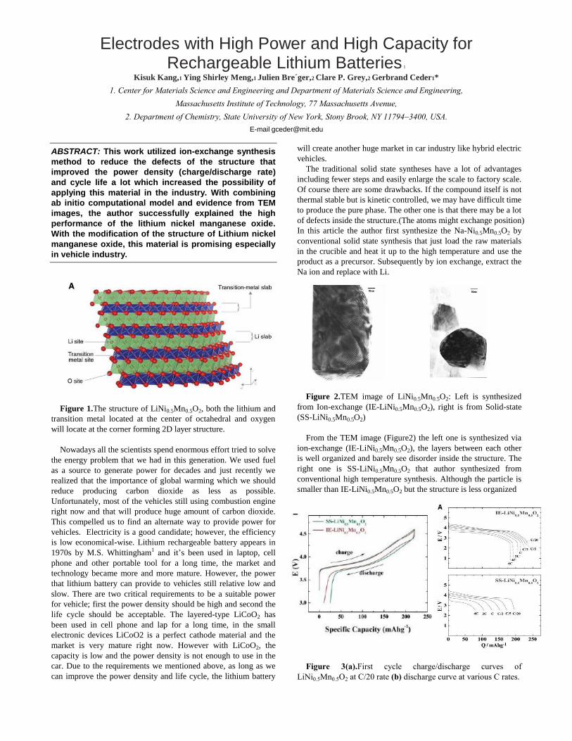
Electrodes with High Power and High Capacity for Rechargeable Lithium Batteries 1
Kisuk Kang,1 Ying Shirley Meng,1 Julien Bre ger,2 Clare P. Grey,2 Gerbrand Ceder1*
1. Center for Materials Science and Engineering and Department of Materials Science and Engineering,
Massachusetts Institute of Technology, 77 Massachusetts Avenue,
2. Department of Chemistry, State University of New York, Stony Brook, NY 11794–3400, USA.
E-mail [email protected]
ABSTRACT: This work utilized ion-exchange synthesis
method to reduce the defects of the structure that
improved the power density (charge/discharge rate)
and cycle life a lot which increased the possibility of
applying this material in the industry. With combining
ab initio computational model and evidence from TEM
images, the author successfully explained the high
performance of the lithium nickel manganese oxide.
With the modification of the structure of Lithium nickel
manganese oxide, this material is promising especially
in vehicle industry.
Figure 1.The structure of LiNi0.5Mn0.5O2, both the lithium and
transition metal located at the center of octahedral and oxygen
will locate at the corner forming 2D layer structure.
Nowadays all the scientists spend enormous effort tried to solve
the energy problem that we had in this generation. We used fuel
as a source to generate power for decades and just recently we
realized that the importance of global warming which we should
reduce producing carbon dioxide as less as possible.
Unfortunately, most of the vehicles still using combustion engine
right now and that will produce huge amount of carbon dioxide.
This compelled us to find an alternate way to provide power for
vehicles. Electricity is a good candidate; however, the efficiency
is low economical-wise. Lithium rechargeable battery appears in
1970s by M.S. Whittingham1 and it’s been used in laptop, cell
phone and other portable tool for a long time, the market and
technology became more and more mature. However, the power
that lithium battery can provide to vehicles still relative low and
slow. There are two critical requirements to be a suitable power
for vehicle; first the power density should be high and second the
life cycle should be acceptable. The layered-type LiCoO2 has
been used in cell phone and lap for a long time, in the small
electronic devices LiCoO2 is a perfect cathode material and the
market is very mature right now. However with LiCoO2, the
capacity is low and the power density is not enough to use in the
car. Due to the requirements we mentioned above, as long as we
can improve the power density and life cycle, the lithium battery
will create another huge market in car industry like hybrid electric
vehicles.
The traditional solid state syntheses have a lot of advantages
including fewer steps and easily enlarge the scale to factory scale.
Of course there are some drawbacks. If the compound itself is not
thermal stable but is kinetic controlled, we may have difficult time
to produce the pure phase. The other one is that there may be a lot
of defects inside the structure.(The atoms might exchange position)
In this article the author first synthesize the Na-Ni0.5Mn0.5O2 by
conventional solid state synthesis that just load the raw materials
in the crucible and heat it up to the high temperature and use the
product as a precursor. Subsequently by ion exchange, extract the
Na ion and replace with Li.
Figure 2.TEM image of LiNi0.5Mn0.5O2: Left is synthesized
from Ion-exchange (IE-LiNi0.5Mn0.5O2), right is from Solid-state
(SS-LiNi0.5Mn0.5O2)
From the TEM image (Figure2) the left one is synthesized via
ion-exchange (IE-LiNi0.5Mn0.5O2), the layers between each other
is well organized and barely see disorder inside the structure. The
right one is SS-LiNi0.5Mn0.5O2 that author synthesized from
conventional high temperature synthesis. Although the particle is
smaller than IE-LiNi0.5Mn0.5O2 but the structure is less organized
Figure 3(a).First cycle charge/discharge curves of
LiNi0.5Mn0.5O2 at C/20 rate (b) discharge curve at various C rates.

than it. The author mentioned in SS-LiNi0.5Mn0.5O2 they always
observed Li and Ni atoms exchange sites that will increase the
activation barrier of lithium diffusion. The reason why there is
less Li-Ni exchange site in IE-LiNi0.5Mn0.5O2 is that according to
the Shannon radii, the radius of Na+(1.18) and Ni2+(0.69) are quite
different therefore using Na to synthesize NaNi0.5Mn0.5O2 the
exchange of Na and Ni is not likely happen. We can synthesize
the framework first and replace the Na with Li; this will solve the
site-exchange problem. If Ni is in Li site, the length of lithium
slab will decrease and this will increase the lithium-oxygen
bonding (Li-O) which higher the activation barrier. In Figure 4,
base on the computational calculation if there is 8.3% Li-Ni
exchange the barrier energy will increase 100mev which is pretty
remarkable. According to SSNMR data in Figure 5, the peak at
670 and 1450 are lithium in lithium slab and transition slap
respectively. It’s quite obvious that the Li-Ni exchange in IE-
LiNi0.5Mn0.5O2 is really low which means the strategy (ion
exchange) the author use is working.
Figure 4.Calculate activation barrier as a function of Li slab
space
Figure 5. Solid-State NMR spectrum of IE-Ni0.5Mn0.5O2 and
SS- IE-Ni0.5Mn0.5O2, the peak at 670ppm is Li at Li-slab and peak
at 1450ppm is Li at Transition metal slab
In the first charge/discharge curves (Figure 4a), the difference
is quite small. However, after cycles several times (Figure 5a) if
there are defects inside the structure when lithium traveling inside,
lithium will be trapped by the defects that will lower the capacity.
The cycle life will be better for IE-LiNi0.5Mn0.5O2 than SS-
LiNi0.5Mn0.5O2 as well; the cycle life of lithium battery has
something to do with thermal stability of structure. When the
battery is working especially in high charge/discharge rate (Figure
3b) that will generate heat and inducing phase transition easily.
Therefore, if the structure is well ordered that will improve the
thermal stability and has longer life time. However one point I
would like to address here, is the nano effect. If we can minimize
the particle size, which means shorten the lithium diffusion
distance and we can increase the power density. On the other hand,
nano-particle usually has higher energy than bulk material which
will lower the cycle life. The performance of nano material maybe
excellent at begin but it will drop very fast either due to the
aggregation or phase transition. The best case scenario is we can
synthesize a nano-particle with no defect and is thermal
stable.(Usually that won’t happen in reality).
Figure 6.Cycle numbers test at 1C rate
Figure 7.ab initio computational model for activation barrier of
different transition metals
The other important issue is that how easily of lithium can
move inside the structure and this one relate to the activation
barrier. Lithium is coordinated octahedrally by oxygen and due to
previous work2,3 , the path way of lithium hopping inside the
structure like Figure 5. Lithium ion will pass through the
tetrahedral site, therefore the transition metals below that
tetrahedral site will influence a lot and the activation barrier
became rate determine step of lithium diffusion. The lower
activation barrier energy the faster of lithium diffusion which
means it can provide high power density. From the table the
transition metals Ni2+ and Mn4+ give relative low energy barrier,
this explains why the performance of LiNi0.5Mn0.5O2 is better than
others. In the article author mentions that the function of LiCoO2
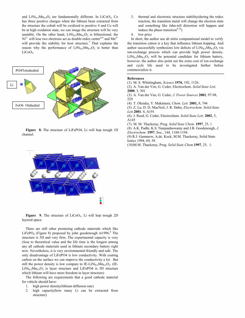
and LiNi0.5Mn0.5O2 are fundamentally different. In LiCoO2, Co
has three positive charges when the lithium been extracted from
the structure the cobalt will be oxidized to positive 4 and Co will
be at high oxidation state, we can image the structure will be very
unstable. On the other hand, LiNi0.5Mn0.5O2 is bifunctional, the
Ni2+ will lose two electrons act as double redox center4-6 and Mn4+
will provide the stability for host structure.7 That explains the
reason why the performance of LiNi0.5Mn0.5O2 is better than
LiCoO2.
Figure 8. The structure of LiFePO4, Li will hop trough 1D
channel.
Figure 9. The structure of LiCoO2, Li will hop trough 2D
layered space.
There are still other promising cathode materials which like
LiFePO4 (Figure 8) proposed by john goodenough in1996.8 The
structure is 3D and very firm. The experimental capacity is very
close to theoretical value and the life time is the longest among
any all cathode materials used in lithium secondary battery right
now. Nevertheless, it is very environmental-friendly and safe. The
only disadvantage of LiFePO4 is low conductivity. With coating
carbon on the surface we can improve the conductivity a lot. But
still the power density is low compare to IE-LiNi0.5Mn0.5O2. (IE-
LiNi0.5Mn0.5O2 is layer structure and LiFePO4 is 3D structure
which lithium will have more freedom in layer structure)
The following are requirements that a good cathode material
for vehicle should have:
1. high power density(lithium diffusion rate)
2. high capacity(how many Li can be extracted from
structure)
3. thermal and electronic structure stability(during the redox
reaction, the transition metal will change the electron state
and something like Jahn-tell distortion will happen and
induce the phase transition9.10)
4. low price
In short, the author use ab initio computational model to verify
the transition cation is a key that influence lithium hopping. And
author successfully synthesizes low defects of LiNi0.5Mn0.5O2 via
ion-exchange process which can provide high power density.
LiNi0.5Mn0.5O2 will be potential candidate for lithium battery,
however, the author also point out the extra cost of ion-exchange
and cycle life need to be investigated further before
commercialize it.
References
(1). M. S. Whittingham, Science 1976, 192, 1126.
(2). A. Van der Ven, G. Ceder, Electrochem. Solid-State Lett.
2000, 3, 301
(3). A. Van der Ven, G. Ceder, J. Power Sources 2001, 97-98,
529
(4). T. Ohzuku, Y. Makimura, Chem. Lett. 2001, 8, 744
(5). Z. Lu, D. D. MacNeil, J. R. Dahn, Electrochem. Solid-State
Lett.2001, 4, A191
(6). J. Reed, G. Ceder, Electrochem. Solid-State Lett. 2002, 5,
A145
(7). M. M. Thackeray, Prog. Solid State Chem. 1997, 25, 1
(8) A.K. Padhi, K.S. Nanjundaswamy and J.B. Goodenough, J.
Electrochem. 1997, Soc., 144, 1188-1194.
(9) R.J. Gummow, A.de. Kock, M.M. Thackeray, Solid State
Ionics 1994, 69, 59.
(10)M.M. Thackeray, Prog. Solid State Chem.1997, 25, 1.
FeO6 Otahedral
PO4Tetrahedral
Li


High catalytic activity of Au/CeOx/TiO2(110)controlled by the nature of the mixed-metal oxideat the nanometer levelJoon B. Parka, Jesus Graciania, Jaime Evansb, Dario Stacchiolaa, Shuguo Maa, Ping Liua, Akira Nambua,Javier Fernandez Sanzc, Jan Hrbeka, and Jose A. Rodrigueza,1
aChemistry Department, Brookhaven National Laboratory, Upton, NY 11973; bFacultad de Ciencias, Universidad Central de Venezuela, Caracas,1020-A, Venezuela; and cDepartamento de Química Física, Universidad de Sevilla, E-41012-Seville, Spain
Edited by Gabor A. Somorjai, University of California, Berkeley, CA, and approved January 30, 2009 (received for review December 11, 2008)
Mixed-metal oxides play a very important role in many areas ofchemistry, physics, materials science, and geochemistry. Recently,there has been a strong interest in understanding phenomenaassociated with the deposition of oxide nanoparticles on thesurface of a second (host) oxide. Here, scanning tunneling micros-copy, photoemission, and density-functional calculations are usedto study the behavior of ceria nanoparticles deposited on aTiO2(110) surface. The titania substrate imposes nontypical coor-dination modes on the ceria nanoparticles. In the CeOx/TiO2(110)systems, the Ce cations adopt an structural geometry and anoxidation state (�3) that are quite different from those seen in bulkceria or for ceria nanoparticles deposited on metal substrates. Theincrease in the stability of the Ce3� oxidation state leads to anenhancement in the chemical and catalytic activity of the ceriananoparticles. The codeposition of ceria and gold nanoparticles ona TiO2(110) substrate generates catalysts with an extremely highactivity for the production of hydrogen through the water–gasshift reaction (H2O � CO3H2 � CO2) or for the oxidation of carbonmonoxide (2CO � O23 2CO2). The enhanced stability of the Ce3�
state is an example of structural promotion in catalysis describedhere on the atomic level. The exploration of mixed-metal oxides atthe nanometer level may open avenues for optimizing catalyststhrough stabilization of unconventional surface structures withspecial chemical activity.
heterogeneous catalysis � imaging � structural properties �surface reactivity
M ixed-metal oxides play a very important role in many areasof chemistry, physics, materials science, and geochemistry
(1–6). In technological applications, they are used in the fabri-cation of microelectronic circuits, piezoelectric devices, andsensors and as catalysts. Over the years, there has been a stronginterest in understanding the behavior of mixed-metal oxides ata fundamental level (1–3). What happens when nanoparticles(NPs) of a given metal oxide are deposited on the surface of asecond (host) oxide (3, 7)? In principle, the combination of 2metals in an oxide matrix can produce materials with novelstructural and/or electronic properties. At a structural level, adopant can introduce stress into the lattice of an oxide host,inducing in this way the formation of defects. On the other hand,the lattice of the oxide host can impose on the dopant elementnontypical coordination modes. Finally, metal7metal or metal7 oxygen 7 metal interactions in mixed-metal oxides can giveelectronic states not seen in single-metal oxides.
In this article, we use photoemission, scanning tunneling micros-copy (STM), and calculations based on density-functional theory(DFT) to study the behavior of ceria NPs in contact with TiO2(110).Ceria and titania are among the most widely used oxides in catalysis(1, 4–6, 8–12). These oxides are important components in catalystsused for the production of clean hydrogen through the water–gasshift reaction (H2O � CO3 H2 � CO2) and for the oxidation ofcarbon monoxide (2CO � O2 3 2CO2). Ceria and titania adopt
different crystal lattices in their most stable bulk phases, fluoriteand rutile, respectively (2, 13). Within the fluorite structure each Ceatom is bonded to 8 O atoms, whereas 6 O atoms surround the Tiatoms in the rutile structure. One of the most interesting propertiesof ceria is its ability to undergo a conversion between ‘‘�4’’ and‘‘�3’’ formal oxidation states (13). The surface chemistry andcatalytic properties of CeO2 depend on the formation of Ce3� ions(13), and different approaches are followed to maximize theirconcentration (4, 5, 8). In the CeOx/TiO2(110) systems, the titaniasubstrate imposes on the ceria NPs nontypical coordination modeswith a subsequent change in the relative stability of the Ce3�/Ce4�
oxidation states that leads to a significant enhancement in chemicalactivity. Furthermore, the deposition of gold NPs on CeOx/TiO2(110) produces surfaces with an extremely high catalyticactivity for the water–gas shift reaction and the oxidation of CO.This is quite remarkable because neither Au/TiO2(110) nor Au/CeO2(111) come close to matching the catalytic activity of Au/CeOx/TiO2(110).
Experimental and Theoretical MethodsMicroscopy, Photoemission, and Catalytic Tests. The microscopystudies were carried out in an Omicron variable temperatureSTM system that is directly attached to a main ultrahigh vacuum(UHV) chamber equipped with optics for low-energy electrondiffraction, instrumentation for Auger electron spectroscopyand surface cleaning facilities (9, 14). Chemically etched W tipswere used for imaging the surfaces. The TiO2(110) crystal wascleaned by several cycles of Ne� sputtering (1 keV, 40 min) andannealing (950 K, 5 min), and XPS/AES studies confirmed thatthere were no surface contaminants after this treatment (15).
Furthermore, the high-resolution STM images of the surfaceexhibited bright Ti rows separated by 6.5 Å, as typically observedfor TiO2(110)-(1x1) (16). Photoemission studies were performedat beamline U7A of the National Synchrotron Light Source(NSLS) at Brookhaven National Laboratory (9) by using aphoton energy of 625 eV to collect the O 1s and Ti 2p regions,and 325 eV to collect the Ce 4d, Au 4f, and valence regions. Ina separate UHV chamber, we acquired XPS spectra (Ce 3d, Ti2p, O 1s, and Au 4f regions) and UPS spectra (valence region)using Mg K� and He-I radiation, respectively. Ce and Au weredeposited on TiO2(110) by using metal evaporators (9, 14, 17).The flux of the Au doser was calibrated by depositing Au ontoa Mo(100) crystal and measuring the thermal desorption spectra ofthe admetal (17). The area of the titania surface covered by ceria
Author contributions: J.B.P., J.G., J.E., D.S., S.M., P.L., A.N., J.F.S., J.H., and J.A.R. designedresearch; J.B.P., J.G., J.E., D.S., S.M., A.N., and J.A.R. performed research; J.B.P., J.G., J.E., D.S.,S.M., P.L., A.N., J.F.S., J.H., and J.A.R. analyzed data; and J.A.R. wrote the paper.
The authors declare no conflict of interest.
This article is a PNAS Direct Submission.
1To whom correspondence should be addressed. E-mail: [email protected].
www.pnas.org�cgi�doi�10.1073�pnas.0812604106 PNAS � March 31, 2009 � vol. 106 � no. 13 � 4975–4980
CHEM
ISTR
Y
and gold was estimated by using STM images or a combination ofion-scattering spectroscopy (ISS) and photoemission (9, 17).
The catalytic studies were carried out in a system that com-bines a batch reactor and a UHV chamber (9, 17). The samplecould be transferred between the reactor and UHV chamberwithout exposure to air. Typically, it was transferred to the batchreactor at �298 K, and then the reactant gases were introduced(water–gas shift: 20 Torr of CO and 10 Torr of H2O; COoxidation: 4 torr of CO and 2 Torr of O2). The catalytic activityfor the water–gas shift was measured at 625 K (9, 17), with atemperature of 300 K for the oxidation of CO (10). Productyields were analyzed by gas chromatography or mass spectros-copy (9, 17). The amount of molecules produced was normalizedby the active area exposed by the sample. In our reactor, asteady-state regime for the water–gas shift or the oxidation ofCO was reached after 2–3 min of reaction time.
DFT Calculations. Periodic DFT � U calculations were performedby using the VASP code (18) using a (4 � 2) 6-layer thicksupercell to model the TiO2(110) surface (19). The adlayer andfirst 4 layers of the titania slab were allowed to relax during theDFT geometry optimizations. We used the Perdew–Wang 91GGA functional for exchange-correlation, the projector-augmented wave approach, and plane-waves with a cutoff energyset at 400 eV. We treated the Ti (3s, 3p, 3d, 4s), Ce (4f, 5s, 5p,5d, 6s), and O (2s,2p) electrons as valence states, whereas theremaining electrons were kept frozen as core states (19). Thecalculations were performed at the � point of the Brillouin zone(18). To reproduce the valence spectra of Ce/TiO2(110), seebelow, we used Ueff parameters with a value of 4.5 eV for Ce andTi. This value is close to those used in previous studies for bulkceria or titania (20). The introduction of the Ueff parameters inthe DFT calculations was found to be essential to correctlyreproduce the position of the occupied Ce 4f and Ti 3d levels inthe valence region, even though the trends found in the ener-getics for the coadsorption of Ce and O on TiO2(110) werealmost the same with or without the Ueff parameters.
Growth of Ceria on TiO2(110)In Fig. 1, we show STM images acquired after depositing cerium onTiO2(110) under different conditions. Fig. 1A corresponds to animage obtained after dosing Ce atoms under ultrahigh vacuum(UHV) at a sample temperature of 298 K. The bright spots have anaverage height of 1.4 � 0.2 Å over the flat terrace and correspondto clusters of cerium oxide. The corresponding XPS and UPSspectra indicated that cerium was in an oxidation state of �3, and,consequently, its deposition led to the partial reduction of titaniumcations with the appearance of Ti3�. Fig. 2 Left shows a typical UPSspectrum for this type of Ce/TiO2(110) surface. The features �1 eVcan be assigned to Ti3� centers (1, 16), whereas those at 2–3.5 eVcorrespond to Ce3� centers (21). The existence of Ce3� is corrob-orated by the Ce 3d XPS data in Fig. 2 Right. The Ce 3d XPSspectrum for the as-prepared Ce/TiO2(110) surface has the distinc-tive line shape of Ce3� species (21, 22). Using DFT calculations, weinvestigated the bonding of Ce atoms to the TiO2(110) surface. TheCe atoms prefer the bonding configuration shown at the bottom ofFig. 2, interacting simultaneously with bridging and in-plane Oatoms of the titania substrate. Upon adsorption, Ce formallyreleases 3 electrons to the oxide host, which move from the 6s and5d levels in Ce to the lower-energy 3d levels in Ti, reducing 3 Ti4�
cations to Ti3�. The fourth valence electron from Ce is in a 4f levelof lower energy than the 3d from Ti and therefore is not transferred,leaving the oxidation state of Ce as 3�. The adsorption of oxygenon the Ce/TiO2(110) surfaces led to the disappearance of Ti3� sitesin the XPS/UPS spectra and in the DFT-calculated density of states.The stability of the Ce3� cations was verified by their resistance tooxidation under UHV conditions. We had to expose the Ce/TiO2(110) surfaces to an O2 pressure of 1 Torr in the batch reactorto obtain the typical Ce 3d XPS spectrum of Ce4� cations (21, 22),see Fig. 2 Right.
To avoid the reduction of the titania substrate, Ce atoms weredeposited at 600 K and annealed to 900 K under O2 (�1 � 10�7
Torr) for 5 min. This led to the image shown in Fig. 1B. In thisimage, the features nonrelated to the ideal TiO2(110) surface canbe separated according to their height, as seen in Fig. 1C. Mostof the spots (�80%) have a height of 1.3 � 0.2 Å. These spots
CBA
D E F
5f Tibridging O In plane O3.5 x 3.5 nm 3.5 x 3.5 nm
0
5
10
15
20
25
30
35
40
45
0.9 1.1 1.3 1.5 1.7 1.9 2.1 2.3Cluster height (Å)
Clu
ster
den
sity
(50
X 5
0nm
2 )
TiOx
CeOxCeOx
TiOx
CeOx
Fig. 1. STM results illustrating morphological changes of CeOx on the TiO2(110) surface. (A) STM image (15 � 15 nm) taken after depositing Ce atoms at 298K in UHV (Vt � 1.3 V and It � 0.05 nA). (B) STM image (15 � 15 nm) acquired after depositing Ce atoms at 600 K and subsequent annealing at 900 K in O2 (PO2
�1 � 10�7 Torr) (Vt � 1.2 V and It � 0.07 nA). (C) Height distribution for the spots seen in B. (D and E) Zoomed-in STM images (3.5 � 3.5 nm) of a diagonal arrayof CeOx taken at different imaging condition of 1.2 V, 0.06 nA and 0.4 V, 0.06 nA, respectively. (F) Model showing possible orientations for the bright protrusionsof CeOx in D and E. The dimers of ceria are shown as a combination of white and yellow spheres.
4976 � www.pnas.org�cgi�doi�10.1073�pnas.0812604106 Park et al.
can be attributed to CeOx, after comparing with the image in Fig.1A for Ce/TiO2(110). A minority of the spots (�20%) in Fig. 1Bhave a height of 1.9 � 0.3 Å. These features were not seen forCe/TiO2(110) and probably correspond to (1 � 2) reconstruc-tions of TiO2(110) induced by O2 chemisorption (11, 16). Theyare a consequence of the migration of interstitial Ti atoms fromthe bulk to the surface of the titania crystal (11, 16). We foundthem also in blank experiments for O2/TiO2(110). In Fig. 1B, thespots due to CeOx are arranged forming units that are oriented�48°, 66°, or 90° with respect to the Ti rows of the oxidesubstrate. These units were not seen in blank experiments forCe/TiO2(110) or O2/TiO2(110) and are characteristic of theO2/CeOx/TiO2(110) systems. Close-up images of a �44° alignedunit are shown in Fig. 1 D and E. In Fig. 1D, the bright ceria spotsare centered on 5f Ti rows and all have a height close to 1.35 Åand a diameter of 6.8 Å. Their size and position suggests that eachspot may contain 2 Ce atoms located in between the O bridging and5f Ti rows. This is confirmed by scanning the same feature withlower imaging bias (0.4 V instead of 1.2 V), where the electrontunneling occurs at different density of states in CeOx/TiO2(110)systems (Fig. 1E). From the STM data, one can construct astructural model consisting of an array of dimers of ceria asdisplayed in Fig. 1F. According to our measurements of core andvalence photoemission, the oxidation state of the Ce atoms insidethe dimers is essentially �3. Thus, in the CeOx/TiO2(110) systems,the Ce cations adopt a structural geometry and an oxidation statethat are quite different from those seen in bulk ceria (2, 13) or forNPs of ceria deposited on metal substrates (7, 9).
Using DFT, we investigated the process of adsorption–oxidation for Ce deposited on TiO2(110). Fig. 3 shows thecalculated energy pathway for such a process. The adsorptionenergy of atomic Ce is very high (�E � �7.23 eV). On its moststable adsorption site, Ce interacts with 2 bridging and 1 in-planeO atoms (Fig. 3, step1). The fact that 3 electrons move from highto lower energy levels, Ce(5d16s2)3 Ti(3d1), explains in part thehigh adsorption energy of Ce. The adsorption process of atomicCe could be described as
Ce � 3Ti4�TiO2 3 Ce3� � 3Ti3�TiO2 [1]
The dissociation of O2 near the adsorbed Ce is a highly exo-thermic process (�E � �6.66 eV). The final structure is a unitof CeO2 over TiO2(110), where the O atoms are adsorbed on topof in-plane Ti atoms and strongly interact with the Ce atom (Fig. 3,step 2). The oxidation state of the Ce in this configuration is 4�
Ce3� � 3Ti3�TiO2 � O23 CeO2Ce4� /TiO2 [2]
Such CeO2 monomers could be assigned to the smallest spotsobserved in STM at very low coverages of ceria. For the surfacein Fig. 1B, possible CeO2 monomers are denoted by arrows and,as predicted by the DFT calculations, they are not located at thecenter of the Ti rows. The CeO2 monomers are excellent sites for
s u'
v'
v0after WGS reaction
Ce ~ 30% of surface
Binding Energy (eV)
880890900910920
Ce 3d XPS
u'''
u''u
v'''
v''
v
v'
v0
u0u'
Ce/TiO2(110) + O2
Ce/TiO2(110)
(a)
(b)
Ce3+
Ce4+
Binding Energy (eV)
Fig. 2. Electronic properties of CeOx/TiO2 (110). (Left) (Top) Shown is a UPS spectrum acquired after depositing Ce atoms on TiO2(110) at 298 K. The featuresmarked by vertical lines are not seen on clean stoichiometric TiO2(110). (Middle and Bottom) Displayed are DFT calculated density-of-states (DOS) for aCe/TiO2(110) surface, including occupied (positive binding energy) and unoccupied states (negative binding energy, states not observable in UPS). The drawingin the Inset shows the bonding configuration of the Ce atoms. Color code for spheres is gray, cerium; red, oxygen; white, titanium. (Right) Ce 3d XPS spectra takenafter depositing Ce on TiO2(110) at 298 K (lower), with subsequent exposure to 1 Torr of O2 (upper). The change in the line shape denotes a Ce3� 3 Ce4�
transformation (21, 22). The ‘‘u’’ and ‘‘v’’ peaks refer to various final states that are caused by transitions from valence band electrons into Ce 4f states (22).
Fig. 3. DFT calculated energy pathway for the adsorption and oxidation ofCe on TiO2(110). The following steps were examined: (1) adsorption of Ce; (2)O2 adsorption-dissociation and formation of the first monomer (CeO2); (3)adsorption of a second cerium atom; (4) formation of the first Ce2O2 dimer; (5)adsorption of 1⁄2O2 and formation of the Ce2O3 dimer; and (6) adsorption of1⁄2O2 and formation of 2 CeO2 monomers.
Park et al. PNAS � March 31, 2009 � vol. 106 � no. 13 � 4977
CHEM
ISTR
Y

the adsorption of a second Ce atom to form dimers (Fig. 3, step4). The increment in the adsorption energy with respect to theadsorption on a clean surface is due to the fact that 1 of the 3electrons released by the incoming Ce does not go to thehigh-energy 3d levels of Ti but rather to the 4f of Ce4� from theCeO2 monomer, which is reduced to Ce3�
CeO2Ce4� /TiO2 � Ce
� 2Ti4�TiO2 3 Ce2O2Ce3� on TiO2 � 2Ti3�TiO2
[3]
The addition of oxygen to the Ce2O2 unit generates Ce2O3.
Ce2O2Ce3� /TiO2 � 2Ti3�TiO2 �12
O23 Ce2O3Ce3�
[4]
on TiO2, and the ceria dimer adopts a configuration (Fig. 3, step5) where shared oxygen leads to a diagonal arrangement inagreement with the results of STM (Fig. 1 E and F). In thepresence of oxygen, the complete oxidation of Ce has to beconsidered, going from a Ce2O3 dimer to 2 CeO2 monomers (Fig.3, step 6). Differently from the previous step, here, there are nothigh-energy Ti 3d electrons but 2 electrons in low-energy Ce 4fstates. The process is exothermic but only by �0.92 eV, 3 timesless than the energy released in the previous step. This meansthat as long as Ti3� species exist, O2 will prefer to adsorb anddissociate on them because the stabilization energy for thesystem is much higher. Therefore, even though the oxidationprocess of dimers is favorable, the other site is preferred for theadsorption and dissociation of O2. This illustrates the complexinterplay that one can have when dealing with the electronic andchemical properties of a mixed-metal oxide.
For applications in catalysis, the relative stability of theCe3�/Ce4� oxidation states of ceria is a very important issue (1,4–6, 13, 23, 24). We calculated the energy released by thereactions
Ce2O3 �12
O23 2CeO2 [5]
2CeO2 � CO3 Ce2O3 � CO2 [6]
for both bulk ceria and Ce2O3 dimers deposited on TiO2(110).The �E for the oxidation process, (the reaction shown in 5), was�2.56 eV in the case of bulk Ce2O3 and �0.92 eV for the Ce2O3dimers bonded to titania. The reduction of CeO2/TiO2(110) byCO, (the reaction shown in 6), was a very exothermic processwith a �E of �2.35 eV. In contrast, the �E for the correspondingreaction of bulk CeO2 was �0.71 eV. These trends were con-firmed by comparing reduction/oxidation experiments on CeO2(111) and CeOx/TiO2(110). For example, a CeO2(111) surfacedid not undergo reduction under an atmosphere of 20 Torr ofCO at 400 K (17), but a CeO2/TiO2(110) surface (formed byexposing CeOx/TiO2(110) to 1 Torr of O2 at 298 K) wascompletely transformed into Ce2O3/TiO2(110). The high stabil-ity of the Ce3� cations in CeOx/TiO2(110) is a consequence oftheir nontypical coordination mode and the effect of Ce (4f)–O(2p)–Ti (3d) bonding interactions.
Catalytic Activity of Au/CeOx/TiO2(110)The WGS reaction is a critical catalytic process for the produc-tion of clean hydrogen in the chemical industry (4, 5). There isa continuous search for catalysts with a better WGS activity(4–6, 9). As shown below, the deposition of gold NPs onCeOx/TiO2(110) yielded surfaces with an extremely high cata-
lytic activity for the WGS. Fig. 4 displays STM images acquiredfrom the same surface area before (Fig. 4A) and after (Fig. 4B)depositing gold on CeOx/TiO2(110) at 298 K with subsequentannealing to 600 K (Fig. 4C). The CeOx/TiO2(110) was prean-nealed under O2 (�1 � 10�7 Torr) at 900 K and had amorphology similar to that seen in Fig. 1B. The deposition of Auat room temperature, �0.2 monolayer, produced 3-dimensionalmetal particles anchored to steps of the titania surface, ‘‘a’’ sites,to the (1 � 2) reconstructions of TiO2(110), ‘‘b’’ sites, and to theCeOx dimers, ‘‘c’’ sites. Annealing to 600 K produced largeparticles of Au that were simultaneously located on b and c sites.Au NPs with a diameter as large as 5.9 nm and a height of 1.3nm were seen, but smaller metal particles were also present onthe CeOx/TiO2(110) surface. On this surface, the dispersion ofthe Au NPs was substantially larger than seen on a pureTiO2(110) surface where Au mainly binds to the steps (10, 15).
Neither CeOx/TiO2(110) nor Au(111) were able to catalyzethe WGS. However, Au/CeOx/TiO2(110) surfaces are outstand-ing catalysts for the WGS as shown in Fig. 5. We performed testexperiments in which Au/TiO2(110) surfaces were preparedfollowing the same steps used for the synthesis of Au/CeOx/TiO2(110) but without the deposition of cerium. The Au/TiO2(110) systems were good WGS catalysts, see Fig. 5 Upper,but they did not come close to match the activity of Au/CeOx/TiO2(110). The same is valid when comparing with the WGSactivities of Au/CeO2(111) (17), CeOx/Au(111) (9), Cu/ZnO(0001) (17), and copper single crystals (17, 25). Cu/ZnO isthe most common WGS catalyst used in the industry (5, 17, 25),and copper is the best pure-metal catalyst (25, 26). For theAu/CeOx/TiO2(110) catalyst in Fig. 5, one could assume that theconcentration of active sites is proportional to the number ofceria regions in contact with gold NPs. Because only 12% of thetitania support was covered by ceria, as measured by ionscattering spectroscopy (ISS), the Au/CeOx/TiO2(110) catalystmust be at least 300 times more active than a Cu (100) surfaceon a per-active-site basis.*
Postreaction characterization of the Au/CeOx/TiO2(110) sur-faces with XPS showed the presence of metallic Au and Ce3�
cations. An identical result was found in in situ measurements ofX-ray absorption spectroscopy for Au/CeOx/TiO2 powders under
*It is usually assumed that all atoms of a flat Cu(100) surface, 1.53 � 1015 atoms cm�2, areactive in the WGS reaction (25). The structural model in Fig. 1F was used to calculate thearea occupied by a Ce2O3 dimer on the TiO2(110) surface. Using this and the ceria coveragedetermined from ISS measurements (�12% of the titania surface was covered), we findthat the concentration of Ce in the Au/CeOx/TiO2(110) catalyst of Fig. 5 was in the orderof 0.03 � 1015 atoms cm�2. This is an upper limit to the actual concentration of the activesites, because not all of the Ce atoms had a Au particle nearby (see Fig. 4 B and C). Aftersubtracting the WGS activity of Au/TiO2(110) from that of Au/CeOx/TiO2(110), one findsthat the Au/ceria sites are at least 300 times more active than the atoms in a Cu(100)surface.
A
a
a b
c
B
a b
c
C
b,cb,c
Fig. 4. Morphology of Au/CeOx/TiO2 (110). (A) STM image of a CeOx/TiO2(110) surface. Ce was deposited at 600 K under an atmosphere of O2 (�1 �10�7 Torr) and then the sample was annealed at 900 K in O2. (B) STM image fora Au/CeOx/TiO2(110) surface. The gold was deposited on the same area shownin A at 298 K. Approximately 6% of the surface was covered with Au. (C) STMimage obtained after annealing the system in B to 600 K. All of the STM imagescorrespond to an area of 20 � 20 nm and imaging conditions of Vt � 1.5 V andIt � 0.03 nA.
4978 � www.pnas.org�cgi�doi�10.1073�pnas.0812604106 Park et al.

WGS reaction conditions. The high catalytic activity of Au/CeOx/TiO2(110) can be attributed to the special chemical prop-erties of the supported Ce2O3 dimers and cooperative effects atceria–gold interfaces. Usually, the rate-determining step in theWGS reaction is the dissociation of water (9, 17, 26). IsolatedNPs of gold cannot dissociate this molecule (27, 28). We foundthat the Ce3� sites present in CeOx/TiO2(110) easily dissociatewater, but, upon exposure to CO, highly stable HCOx specieswere formed on the oxide surface and there was no productionof H2 or CO2 gas. In Au/CeOx/TiO2(110), one has a bifunctionalcatalyst: The adsorption and dissociation of water takes place onthe oxide, CO adsorbs on gold NP sites, and all subsequentreaction steps occur at oxide–metal interfaces. Au NPs docatalyze the reaction of OH with CO to yield a HOCO inter-mediate and then H2 and CO2 (27). Previous studies for the WGSon Au–CeO2 catalysts point to a direct participation of the oxidein the reaction process (4, 5, 9). Our results illustrate thetremendous impact that an optimization of the chemical prop-erties of nanoceria can have on the activity of a WGS catalyst.
Nowadays, the oxidation of CO on Au/TiO2 catalysts isreceiving a lot of attention (1, 10, 29, 30). Fig. 6 displays the COoxidation activity of Au/TiO2(110) and Au/CeOx/TiO2(110) as afunction of Au coverage. In the case of Au/TiO2(110) a maxi-mum in the production of CO2 is seen at a Au coverage of �0.3mL. Previous studies have shown that there is a marked sizeeffect on the catalytic activity, with Au clusters in the range of3–3.5 nm exhibiting the maximum reactivity (10, 29). Our STM
studies for Au/TiO2(110) and Au/CeOx/TiO2(110) also show astrong variation in catalytic activity with Au particle size. In allcases, Au/CeOx/TiO2(110) is a much better catalyst for theoxidation of CO than Au/TiO2(110). If the maximum catalyticactivities seen in Fig. 6 are normalized by the number of Auatoms present on the oxide supports (10, 29), we estimateturnover frequencies (TOFs) for CO oxidation of 2.1 moleculesper site�1 s�1 for Au/TiO2(110) and 6.2 molecules per site�1 s�1
for Au/CeOx/TiO2(110). These should be taken as lower limitsfor the TOFs because we probably overestimated the number ofexposed Au active sites. Here, we are following previous studies(10, 29) that estimate the TOFs assuming total dispersion of Auon the oxide substrate. In any case, the TOF of Au/CeOx/TiO2(110) is already larger than the TOF found, under similarconditions of pressure and temperature, for the oxidation of COon a highly active Au ultrathin film supported on a reduced TiOxsubstrate: �4 molecules per site�1 s�1 (30).
The rate-limiting step for the oxidation of CO on Au/oxidesurfaces is the activation and dissociation of the O2 molecule(31–33). The oxide probably helps in the stabilization of anOC�O2 intermediate and the breaking of the O–O bond. Thestructure of the titania supported ceria nanoparticles shouldfacilitate their direct interaction with an OC�O2 intermediate.Postreaction surface analysis with XPS showed the presence ofa significant amount of Ce3� in the Au/CeOx/TiO2(110) cata-lysts. This and a relatively high dispersion of Au (Fig. 4B) couldbe responsible for the superior activity of Au/CeOx/TiO2(110)during the oxidation of CO at room temperature.
Summary and ConclusionsScanning tunneling microscopy, photoemission, and density-functional calculations were used to study the behavior of ceriananoparticles deposited on a TiO2(110) surface. The titania sub-strate imposes nontypical coordination modes on the ceria nano-particles. In the CeOx/TiO2(110) systems, the Ce cations adopt anstructural geometry and an oxidation state (�3) that are quitedifferent from those seen in bulk ceria or for ceria nanoparticlesdeposited on metal substrates. The increase in the stability of theCe3� oxidation state leads to an enhancement in the chemical andcatalytic activity of the ceria nanoparticles. The codeposition ofceria and gold nanoparticles on a TiO2(110) substrate generatescatalysts with an extremely high activity for the production ofhydrogen through the water–gas shift reaction (H2O � CO3H2 �CO2) or for the oxidation of carbon monoxide (2CO � O2 3
Au coverage / ML
0.0 0.4 0.8 1.2 1.6 2.0 2.4
mol
ecul
es p
rodu
ced
/ 10
17 m
olec
cm
-2
0
5
10
15
2020 Torr CO, 10 Torr H2O 625 K
H2CO2
on TiO2(110)
H2
on CeOx/TiO2(110)
H2
mo
lecu
les
pro
du
ced
/ 1
017
mo
lecu
le c
m-2
0
5
10
15
20
Au/CeOx/TiO2 Cu(100)Au/CeO2 Au/TiO2 Au(111) Cu/ZnO
Fig. 5. Water-gas shift catalysis. (Upper) Water–gas shift activity of Au/TiO2(110) and Au/CeOx/TiO2(110) as a function of Au coverage. The area ofTiO2(110) covered by CeOx was measured with ISS, before depositing gold, andfound to be �12% of the clean substrate. The reported values for the productionof H2 (blue curve) and CO2 (black curve) were obtained after exposing thecatalysts to 20 Torr of CO and 10 Torr of H2O at 625 K for 5 min. The number ofH2 andCO2 moleculesproduced isnormalizedbythesamplesurfacearea. (Lower)Comparison of the water–gas shift activity of Cu(100), Au(111), and 0.5 mL of Ausupported on TiO2(110), CeO2(111) or CeOx/TiO2(110). The data for Cu(100),Cu/ZnO(0001) and Au/CeO2(111) were taken from ref. 17.
Au coverage / ML
0.0 0.4 0.8 1.2 1.6 2.0 2.4
CO
2 m
olec
ules
pro
duce
d / 1
017 m
olec
cm
-2
0
2
4
6
8
10
12
144 Torr CO, 2 Torr O2 300 K
on TiO2(110)
on CeOx/TiO2(110)
Fig. 6. CO oxidation activity of Au/TiO2(110) and Au/CeOx/TiO2(110) as afunction of Au coverage. The area of TiO2(110) covered by CeOx was measuredwith ISS, before depositing gold, and found to be �16% of the clean substrate.The reported values for the production of CO2 were obtained after exposingthe catalysts to 4 Torr of CO and 2 Torr of O2 at 300 K for 5 min. The numberof CO2 molecules produced is normalized by the sample surface area.
Park et al. PNAS � March 31, 2009 � vol. 106 � no. 13 � 4979
CHEM
ISTR
Y

2CO2). Our results illustrate the high impact that an optimizationof the chemical properties of nanoceria can have on the activity ofa WGS or CO oxidation catalyst. This approach should be valid ingeneral for catalysts that contain ceria as part of a mixed-metaloxide (4–7), opening new directions for tuning catalytic activity bycoupling appropriate pairs of oxides. The key issue is to takeadvantage of the complex interactions that occur in a mixed-metaloxide at the nanometer level.
ACKNOWLEDGMENTS. We thank M. Perez for thought-provoking discussionsabout the mechanism for the WGS reaction on Au/CeOx/TiO2(110). The workperformed at Brookhaven National Laboratory was supported by the U.S.Department of Energy, Office of Basic Energy Sciences under contract DE-AC02-98CH10886. J.E. is grateful to the Instituto de Tecnología Venezolanapara el Petroleo for partial support of the work carried out at the UniversidadCentral de Venezuela. The work done at Seville was funded by Ministry ofScience and Innovation Grant MAT2008-04918 and Barcelona Supercomput-ing Center—Centro Nacional de Supercomputacion (Spain).
1. Zhou B, Hermans S, Somorjai GA, eds (2004) Nanotechnology in Catalysis (Kluwer–Plenum, New York).
2. Rao CNR, Raveau B (1998) Transition Metal Oxides: Structure, Properties and Synthesisof Ceramic Oxides (Wiley, New York), 2nd Ed.
3. Knauth P, Schoonman J, eds (2002) Nanocrystalline Metals and Oxides: SelectedProperties and Applications (Springer, Berlin).
4. Fu Q, Saltsburg H, Flytzani-Stephanopoulos M (2003) Active nonmetallic Au and Ptspecies on ceria-based water–gas shift catalysts. Science 301:935–938.
5. Burch R (2006) Gold catalysts for pure hydrogen production in the water–gas shiftreaction: Activity, structure and reaction mechanism. Phys Chem Chem Phys 8:5483–5500.
6. Gonzalez ID, Navarro RM, Alvarez-Galvan MC, Rosa F, Fierro JLG (2008) Performanceenhancement in the water–gas shift reaction of platinum deposited over a cerium-modified TiO2 support. Catal Commun 9:1759–1765.
7. Fernandez-García M, Martinez-Arias A, Hanson JC, Rodriguez JA (2004) Nanostruc-tured oxides in chemistry: Characterization and properties. Chem Rev 104:4063–4104.
8. Esch F, et al. (2005) Electron localization determines defect formation on ceria sub-strates. Science 309:752–755.
9. Rodriguez JA, et al. (2007) Activity of CeOx and TiOx nanoparticles grown on Au(111)in the water–gas shift reaction. Science 318:1757–1760.
10. Valden M, Lai X, Goodman DW (1998) Onset of catalytic activity of gold clusters ontitania with the appearance of nonmetallic properties. Science 281:1647–1650.
11. Wendt S, et al. (2008) The role of interstitial sites in the Ti3d defect state in the bandgap of titania. Science 320:1755–1759.
12. Diwald O, Thompson TL, Goralski EG, Walck SD, Yates JT (2004) The effect of nitrogenion implantation on the photoactivity of TiO2 rutile single crystals. J Phys Chem B108:52–57.
13. Trovarelli A (1996) Catalytic properties of ceria and CeO2-containing materials. CatalRev Sci Eng 38:439–520.
14. Ma S, Rodriguez JA, Hrbek J (2008) STM study of the growth of cerium oxide nano-particles on Au(111). Surf Sci 602:3272–3279.
15. Park JB, Conner SF, Chen DA (2008) Bimetallic Pt-Au clusters on TiO2(110): Growth,surface composition, and metal-support interactions. J Phys Chem C 112:5490–5500.
16. Diebold U (2003) The surface science of titanium dioxide. Surf Sci Rep 48:53–229.17. Rodriguez JA, et al. (2007) Water gas shift reaction on Cu and Au nanoparticles
supported on CeO2(111) and ZnO(0001): Intrinsic activity and importance of supportinteractions. Angew Chem Int Ed 46:1329–1332.
18. Kresse G, Furthmuller J (1996) Efficiency of ab-initio total energy calculations for metalsand semiconductors using a plane-wave basis set. Comput Mater Sci 6:15–50.
19. Graciani J, Alvarez LJ, Rodriguez JA, Sanz JF (2008) N doping of rutile TiO2(110) surface:A theoretical DFT study. J Phys Chem C 112:2624–2631.
20. Fabris S, de Gironcoli S, Baroni S, Vicario G, Balducci G (2005) Taming multiple valencywith density functionals: A case study of defective ceria. Phys Rev B 71:041101.
21. Liu G, Rodriguez JA, Hrbek J, Dvorak J, Peden CHF (2001) Electronic and chemicalproperties of Ce0.8Zr0.2O2(111) surfaces: Photoemission, XANES, density-functional,and NO2 adsorption studies. J Phys Chem B 105(32):7762–7770.
22. Pfau A, Schierbaum KD (1994) The electronic-structure of stoichiometric and reducedCeO2 surfaces—An XPS, UPS and HREELS study. Surf Sci 321:71–80.
23. Wang X, et al. (2008) Ceria-based catalysts for the production of H2 through thewater–gas-shift reaction: Time-resolved XRD and XAFS studies. Top Catal 49:81–88.
24. Jacobs G, et al. (2004) Water–gas shift: Comparative screening of metal promoters formetal/ceria systems and role of the metal. Appl Catal A 258:203–214.
25. Nakamura J, Campbell JM, Campbell CT (1990) Kinetics and mechanism of the water–gas shift reaction catalyzed by the clean and Cs-promoted Cu(110) surface—A com-parison with Cu(111). J Chem Soc Faraday Trans 86:2725–2734.
26. Gokhale AA, Dumesic JA, Mavrikakis M (2008) On the mechanism of low-temperaturewater gas shift reaction on copper. J Am Chem Soc 130:1402–1414.
27. Liu P, Rodriguez JA (2007) Water–gas-shift reaction on metal nanoparticles andsurfaces. J Chem Phys 126:164705.
28. Ojifinni RA, et al. (2008) Water-enhanced low-temperature CO oxidation and isotopeeffects on atomic oxygen-covered Au(111). J Am Chem Soc 130:6801–6812.
29. Bamwenda GR, Tsubota S, Nakamura T, Haruta M (1997) The influence of the prepa-ration methods on the catalytic activity of platinum and gold supported on TiO2 for COoxidation. Catal Lett 44:83–87.
30. Chen MS, Goodman DW (2004) The structure of catalytically active gold on titania.Science 306:252–255.
31. Hernandez NC, Sanz JF, Rodriguez JA (2006) Unravelling the origin of the high-catalyticactivity of supported Au: A density-functional theory-based interpretation. J Am ChemSoc 128:15600–15601.
32. Molina LM, Hammer B (2003) Active role of oxide support during CO oxidation atAu/MgO. Phys Rev Lett 90:206102.
33. Remediakis IN, Lopez N, Norskov JK (2005) CO oxidation on rutile-supported Aunanoparticles. Angew Chem Int Ed 44:1824–1826.
4980 � www.pnas.org�cgi�doi�10.1073�pnas.0812604106 Park et al.

Review: High Catalytic Activity of Au/CeOx/TiO2(110) Controlled by the Nature of Mixed-Metal Oxide at the Nanometer Level
Devan Turner
1 December 2010
ABSTRACT In this paper, Park et al. propose and
characterize a new heterogeneous catalyst that consists of
a metal supported by a mixed-metal oxide. The
effectiveness of the catalyst has been measured by
comparing it against other well known catalysts in the water-
gas shift reaction as well as in the oxidation of carbon
monoxide.
Introduction
The water-gas shift reaction is of great importance in
the chemical community. In this reaction, water vapor and
carbon monoxide interact to produce hydrogen gas and carbon
dioxide. This is used in industry for the production of high-purity
hydrogen, methanol production, and in fuel-cell powered vehicles.
Methanol can be produced in a reaction between hydrogen gas
and carbon dioxide, both of which are products of the water-gas
shift (WGS) reaction3. The WGS reaction is also of import in
fuel-cell technology due to the requirements of the system. In
fuel-cells, there is a small amount, usually less than 10%, of
carbon monoxide present. Carbon monoxide strongly interacts
with transition metals; therefore it reacts with the platinum anode
and severely decreases the lifetime of the fuel-cell. A strong
WGS catalyst can effectively keep CO within acceptable levels
and extend the lifetime of the fuel cell1.
The WGS reaction is usually catalyzed by an oxide
supported metal, which is the typical build of many heterogeneous
catalysts, such as Cu/ZnO. There has been a great deal of debate
about the role of the oxide support in these types of catalysts. It is
thought to be a structural promoter5. In other words, the support
creates a structure conducive to catalysis; there are active-sites
created by the lattice network of the metal-oxide that consist of
vacancies or defects and it is these defects that anchor the metal to
the substrate5,6,7,8. This is best exemplified in the work of Yoon et
al. The catalytic activity of gold octamers was determined on
both defect poor and defect rich MgO. When analyzed with mass
spectrometry, a higher concentration of CO2 was produced in the
species that contained more defects8. The support also
participates in partial charge transfer with the metal support in
these active sites6,8. Beyond its structural usefulness, the oxide
support interacts with the reactants and aids the reaction at the
metal-support interface where the oxide is available for oxidation
and reduction or oxygen storage. Among the many types of metal
oxides used as support, CeO2 is one of the best5,7.
A great deal of research has also gone into investigating
the catalytic properties of different metals. Late transition metals,
such as platinum, often show high catalytic activity when
Figure 1 Comparison of the catalytic activity of Au/CeOx/TiO2 versus
other oxide supported gold catalysts, Cu/ZnO, and gold and copper metal.
The activity is determined by the amount of hyrdrogen gas produced by
the reaction
supported by metal oxides. Copper was also found to be a highly
active metal7. In its bulk form, gold does not catalyze this
reaction; however, in nano-sized clusters, its catalytic properties
increase greatly. Recently, it has been found that nanosized gold
particles supported by metal oxides are exceptionally effective
catalysts for both the WGS reaction as well as CO oxidation5,6,7,8.
This is because gold better adheres to the oxide support and is
also enhanced by partial electron transfer from the oxide support.
Its catalytic activity is dependent on the size of the gold
nanoparticles as well as gold coverage of the oxide support2. The
increased catalytic activity is also due to the fact that the gold
clusters create electronic resonances with the 2π* electronic levels
of O2 8.
Catalytic Activity of Au/CeOx/TiO2(110)
Building on the findings that metal-oxides doped with
gold have high catalytic acitivty as well as other findings that
catalysts using ceria as an oxide support are among the best
catalysts, Park et al have synthesized a new heterogeneous
catalyst using both of these components. Specifically in this
article, the authors have found that a TiO2 (titania) surface, doped
with both CeO2 (ceria) and gold nanoparticles will have catalytic
activity that is much higher than the current WGS catalyst,
Cu/ZnO as well as both titania or ceria supported gold
nanoparticles. In order to produce Au/CeOx/TiO2, titania was first
doped with ceria and the resulting species was then impregnanted
with gold nanoparticles. In the optimization of ceria growth on
titania, it was found that ceria dimers form when supported on
titania; these dimers can spontaneously break back down into
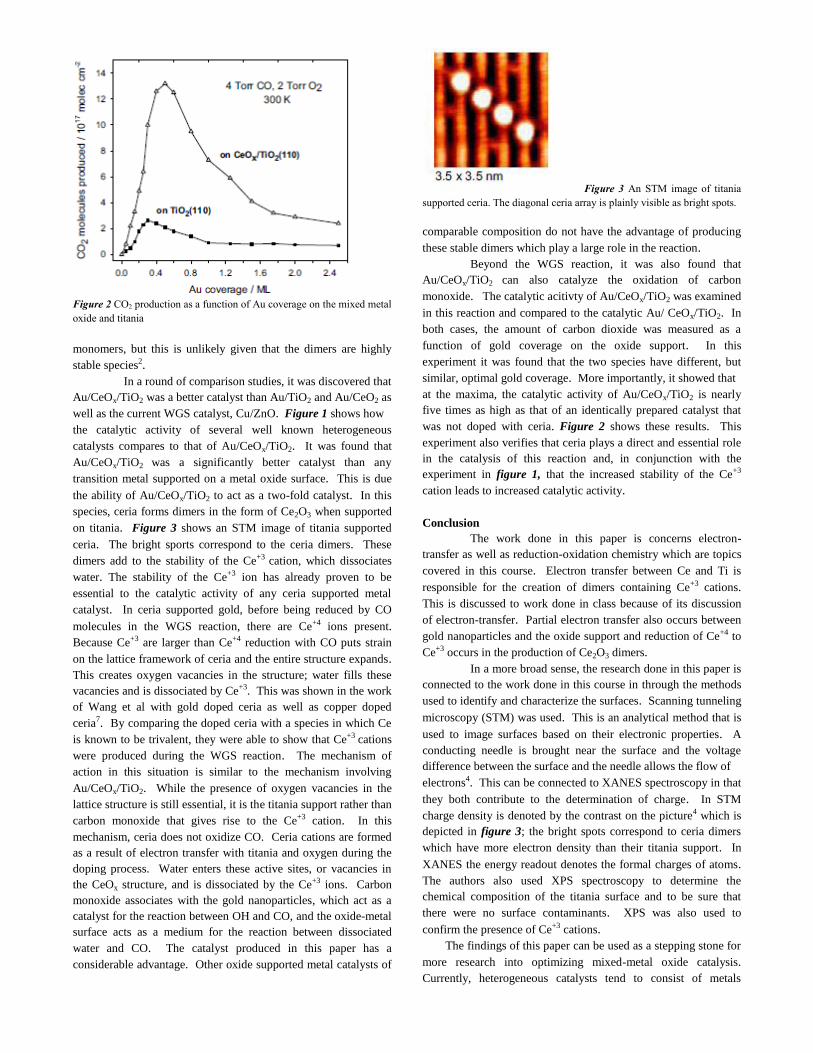
Figure 2 CO2 production as a function of Au coverage on the mixed metal
oxide and titania
monomers, but this is unlikely given that the dimers are highly
stable species2.
In a round of comparison studies, it was discovered that
Au/CeOx/TiO2 was a better catalyst than Au/TiO2 and Au/CeO2 as
well as the current WGS catalyst, Cu/ZnO. Figure 1 shows how
the catalytic activity of several well known heterogeneous
catalysts compares to that of Au/CeOx/TiO2. It was found that
Au/CeOx/TiO2 was a significantly better catalyst than any
transition metal supported on a metal oxide surface. This is due
the ability of Au/CeOx/TiO2 to act as a two-fold catalyst. In this
species, ceria forms dimers in the form of Ce2O3 when supported
on titania. Figure 3 shows an STM image of titania supported
ceria. The bright sports correspond to the ceria dimers. These
dimers add to the stability of the Ce+3 cation, which dissociates
water. The stability of the Ce+3 ion has already proven to be
essential to the catalytic activity of any ceria supported metal
catalyst. In ceria supported gold, before being reduced by CO
molecules in the WGS reaction, there are Ce+4 ions present.
Because Ce+3 are larger than Ce+4 reduction with CO puts strain
on the lattice framework of ceria and the entire structure expands.
This creates oxygen vacancies in the structure; water fills these
vacancies and is dissociated by Ce+3. This was shown in the work
of Wang et al with gold doped ceria as well as copper doped
ceria7. By comparing the doped ceria with a species in which Ce
is known to be trivalent, they were able to show that Ce+3 cations
were produced during the WGS reaction. The mechanism of
action in this situation is similar to the mechanism involving
Au/CeOx/TiO2. While the presence of oxygen vacancies in the
lattice structure is still essential, it is the titania support rather than
carbon monoxide that gives rise to the Ce+3 cation. In this
mechanism, ceria does not oxidize CO. Ceria cations are formed
as a result of electron transfer with titania and oxygen during the
doping process. Water enters these active sites, or vacancies in
the CeOx structure, and is dissociated by the Ce+3 ions. Carbon
monoxide associates with the gold nanoparticles, which act as a
catalyst for the reaction between OH and CO, and the oxide-metal
surface acts as a medium for the reaction between dissociated
water and CO. The catalyst produced in this paper has a
considerable advantage. Other oxide supported metal catalysts of
Figure 3 An STM image of titania
supported ceria. The diagonal ceria array is plainly visible as bright spots.
comparable composition do not have the advantage of producing
these stable dimers which play a large role in the reaction.
Beyond the WGS reaction, it was also found that
Au/CeOx/TiO2 can also catalyze the oxidation of carbon
monoxide. The catalytic acitivty of Au/CeOx/TiO2 was examined
in this reaction and compared to the catalytic Au/ CeOx/TiO2. In
both cases, the amount of carbon dioxide was measured as a
function of gold coverage on the oxide support. In this
experiment it was found that the two species have different, but
similar, optimal gold coverage. More importantly, it showed that
at the maxima, the catalytic activity of Au/CeOx/TiO2 is nearly
five times as high as that of an identically prepared catalyst that
was not doped with ceria. Figure 2 shows these results. This
experiment also verifies that ceria plays a direct and essential role
in the catalysis of this reaction and, in conjunction with the
experiment in figure 1, that the increased stability of the Ce+3
cation leads to increased catalytic activity.
Conclusion
The work done in this paper is concerns electron-
transfer as well as reduction-oxidation chemistry which are topics
covered in this course. Electron transfer between Ce and Ti is
responsible for the creation of dimers containing Ce+3 cations.
This is discussed to work done in class because of its discussion
of electron-transfer. Partial electron transfer also occurs between
gold nanoparticles and the oxide support and reduction of Ce+4 to
Ce+3 occurs in the production of Ce2O3 dimers.
In a more broad sense, the research done in this paper is
connected to the work done in this course in through the methods
used to identify and characterize the surfaces. Scanning tunneling
microscopy (STM) was used. This is an analytical method that is
used to image surfaces based on their electronic properties. A
conducting needle is brought near the surface and the voltage
difference between the surface and the needle allows the flow of
electrons4. This can be connected to XANES spectroscopy in that
they both contribute to the determination of charge. In STM
charge density is denoted by the contrast on the picture4 which is
depicted in figure 3; the bright spots correspond to ceria dimers
which have more electron density than their titania support. In
XANES the energy readout denotes the formal charges of atoms.
The authors also used XPS spectroscopy to determine the
chemical composition of the titania surface and to be sure that
there were no surface contaminants. XPS was also used to
confirm the presence of Ce+3 cations.
The findings of this paper can be used as a stepping stone for
more research into optimizing mixed-metal oxide catalysis.
Currently, heterogeneous catalysts tend to consist of metals
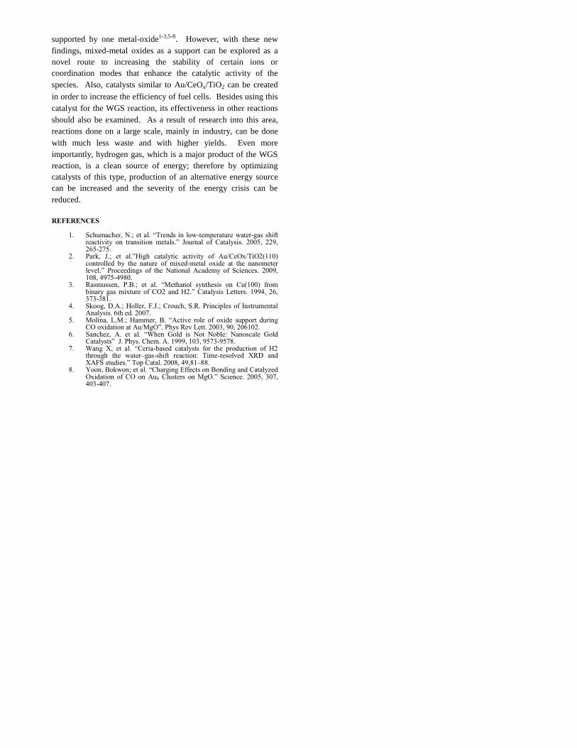
supported by one metal-oxide1-3,5-8. However, with these new
findings, mixed-metal oxides as a support can be explored as a
novel route to increasing the stability of certain ions or
coordination modes that enhance the catalytic activity of the
species. Also, catalysts similar to Au/CeOx/TiO2 can be created
in order to increase the efficiency of fuel cells. Besides using this
catalyst for the WGS reaction, its effectiveness in other reactions
should also be examined. As a result of research into this area,
reactions done on a large scale, mainly in industry, can be done
with much less waste and with higher yields. Even more
importantly, hydrogen gas, which is a major product of the WGS
reaction, is a clean source of energy; therefore by optimizing
catalysts of this type, production of an alternative energy source
can be increased and the severity of the energy crisis can be
reduced.
REFERENCES
1. Schumacher, N.; et al. “Trends in low-temperature water-gas shift reactivity on transition metals.” Journal of Catalysis. 2005, 229, 265-275.
2. Park, J.; et al.”High catalytic activity of Au/CeOx/TiO2(110) controlled by the nature of mixed-metal oxide at the nanometer level.” Proceedings of the National Academy of Sciences. 2009, 108, 4975-4980.
3. Rasmussen, P.B.; et al. “Methanol synthesis on Cu(100) from binary gas mixture of CO2 and H2.” Catalysis Letters. 1994, 26, 373-381.
4. Skoog, D.A.; Holler, F.J.; Crouch, S.R. Principles of Instrumental Analysis. 6th ed. 2007.
5. Molina, L.M.; Hammer, B. “Active role of oxide support during CO oxidation at Au/MgO”. Phys Rev Lett. 2003, 90, 206102.
6. Sanchez, A. et al. “When Gold is Not Noble: Nanoscale Gold Catalysts” J. Phys. Chem. A. 1999, 103, 9573-9578.
7. Wang X, et al. “Ceria-based catalysts for the production of H2 through the water–gas-shift reaction: Time-resolved XRD and XAFS studies.” Top Catal. 2008, 49,81–88.
8. Yoon, Bokwon; et al. “Charging Effects on Bonding and Catalyzed Oxidation of CO on Au8 Clusters on MgO.” Science. 2005, 307, 403-407.