Lecture Note 8-1 Hydraulic Systems
71
System Analysis Spring 2015 1 Lecture Note 8-1 Hydraulic Systems
-
Upload
khangminh22 -
Category
Documents
-
view
0 -
download
0
Transcript of Lecture Note 8-1 Hydraulic Systems

System Analysis Spring 2015
1
Lecture Note 8-1Hydraulic Systems

System Analysis Spring 2015
2
Vehicle Model - Brake Model
Brake Model
BrakePedal
VacuumBooster
MasterCylinder
ProportionnigValve
FontWheel
RearWheel
Brake Pedal
Vacuum Booster
Master Cylinder
ProportioningValve
Fundamental structure of a hydraulic brake

System Analysis Spring 2015
3
Conservation of Mass, Force and Pressure
mi mom q q
1 1 1
2 2 2
22 1 1 2
1
1 1 23 2 1
2 2 1
)
( )
iii f p Af p A
Af f P PAL L Af f fL L A
Force
1 1 2 2
12 1
2
)i Volume A dx A dxAdx dxA
2 1) Prii essue p p gh

System Analysis Spring 2015
4
Hydraulic Excavator
Boom Up
Boom Down
Arm Dump
Arm CrowdBucket Crowd
Bucket Dump
Swing(선회)
Travel(주행)

System Analysis Spring 2015
5
유압굴삭기 회로도
System Analysis Spring 2015
6
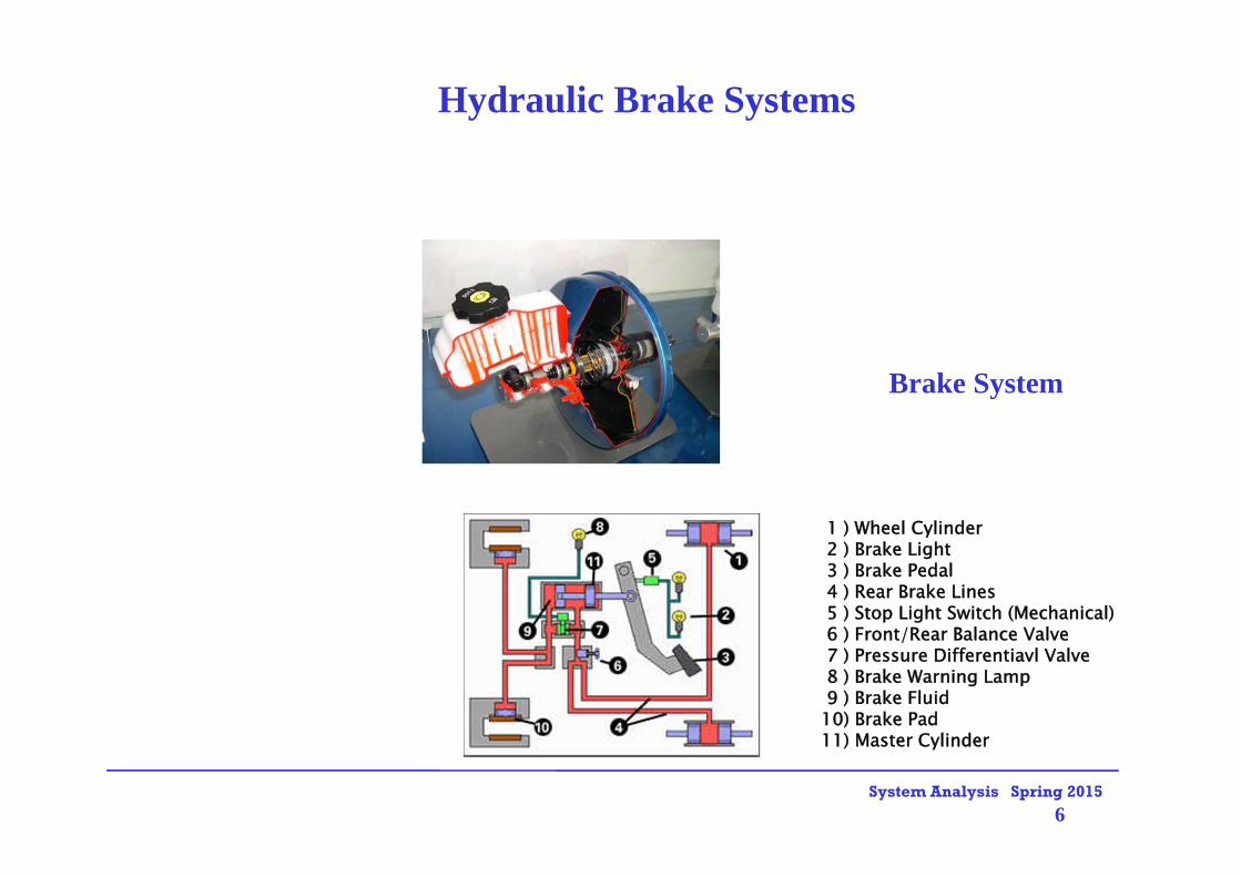
Hydraulic Brake Systems
Brake System
1 ) Wheel Cylinder2 ) Brake Light3 ) Brake Pedal4 ) Rear Brake Lines5 ) Stop Light Switch (Mechanical)6 ) Front/Rear Balance Valve7 ) Pressure Differentiavl Valve8 ) Brake Warning Lamp9 ) Brake Fluid
10) Brake Pad11) Master Cylinder

System Analysis Spring 2015
7
Vehicle Model - Brake Model
Brake Model
BrakePedal
VacuumBooster
MasterCylinder
ProportionnigValve
FontWheel
RearWheel
Brake Pedal
Vacuum Booster
Master Cylinder
ProportioningValve
Fundamental structure of a hydraulic brake

System Analysis Spring 2015
8
• Pneumatically controlled dexterous hand
• Hydraulically powered dexterous arm
Applications of Fluid Power• Space shuttle Columbia
• Space shuttle vehicle

System Analysis Spring 2015
9
Applications of Fluid Power• Hydraulically powered Sky-tram
• Hydraulic power brush drive
• Hydraulically driven turntable
• Oceanography

System Analysis Spring 2015
10
Automatic Transmission

System Analysis Spring 2015
11
Press

System Analysis Spring 2015
12
Linear Actuators
Airplane
PressMotion Simulator
Robot

System Analysis Spring 2015
13
Landing gear system of AIRBUS A330
Hydraulic Systems : Landing Gear System

System Analysis Spring 2015
14
1P 2P
Tank
Load
Control valve
)( 21 PPAF P
(70 ~ 210 )Hydraulic actuator bar
Hydraulic Systems
Hydraulic pump

15
Why hydraulic ?Internal combustion EngineTurbineElectric motorHydraulic actuator……
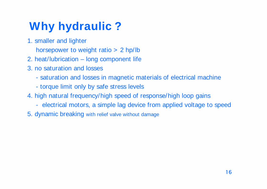
16
Why hydraulic ?1. smaller and lighter
horsepower to weight ratio > 2 hp/lb 2. heat/lubrication – long component life 3. no saturation and losses
- saturation and losses in magnetic materials of electrical machine- torque limit only by safe stress levels
4. high natural frequency/high speed of response/high loop gains - electrical motors, a simple lag device from applied voltage to speed
5. dynamic breaking with relief valve without damage

17
Disadvantages1. not so readily available
2. small allowable tolerances result in high costs
3. hydraulic fluids imposes upper temperature limit.
4. fluid contamination: dirt and contamination
5. basic design procedures are lacking and difficult, complexity of hydraulic control analysis
6. not so flexible, linear, accurate, and inexpensive as electronic and/or electromechanical devices

18
Primary Functions of a Hydraulic Fluid

System Analysis Spring 2015
19
Conservation of Mass, Force and Pressure
mi mom q q
1 1 1
2 2 2
22 1 1 2
1
1 1 23 2 1
2 2 1
)
( )
iii f p Af p A
Af f P PAL L Af f fL L A
Force
1 1 2 2
12 1
2
)i Volume A dx A dxAdx dxA
2 1) Prii essue p p gh

System Analysis Spring 2015
20
Gear Pumps (External)– fixed displacement pump– uses spur gear (teeth are parallel to the axis of the gear)– noisy at relatively high speeds

System Analysis Spring 2015
21
Internal Gear Pump

System Analysis Spring 2015
22
Internal Gear Pump
• Gerotor Pump

System Analysis Spring 2015
23
Internal Gear Pump
• Lobe Pump

System Analysis Spring 2015
24
Simple Vane Pump

System Analysis Spring 2015
25
Balanced Vane Pump

System Analysis Spring 2015
26
Piston Pump (Swash Plate Type)
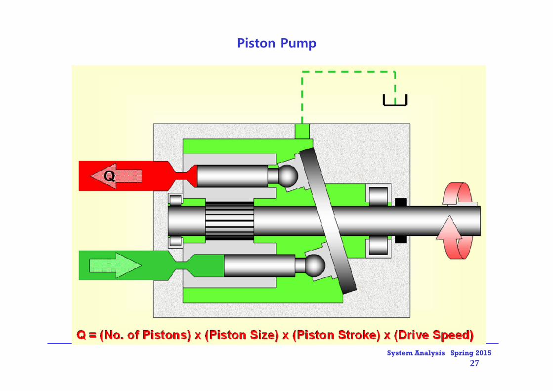
System Analysis Spring 2015
27
Piston Pump

System Analysis Spring 2015
28
Pump
Electric Motor or Engine

System Analysis Spring 2015
29
Hydraulic Pump
– the heart of a hydraulic system– converts mechanical energy into hydraulic energy– hydrostatic pump– Displacement
• the amount of fluid ejected per revolution• unit: cm3/rev, cc/rev, cm3/rad, cc/rad

System Analysis Spring 2015
30
Pump Torque• Mechanical power supplied to pump
• Hydraulic power delivered by pump
• Therefore
: :
pH PQ
P pressure rise across the pumpQ delivery rate
th th p
th p
T PQ P D
T PD
mH T
]/3[ : radmDp 배제용적펌프여기서

System Analysis Spring 2015
31
Hydraulic Motors and Actuators

System Analysis Spring 2015
32
Hydraulic Systems : Valve-motor Combination

System Analysis Spring 2015
33
Application of Hydraulic Motors

System Analysis Spring 2015
34
Gear Motors

System Analysis Spring 2015
35
Valve-piston combination
Hydraulic Systems : Valve-piston Combination

System Analysis Spring 2015
36
Hydraulic Excavator
Boom Up
Boom Down
Arm Dump
Arm CrowdBucket Crowd
Bucket Dump
Swing(선회)
Travel(주행)

System Analysis Spring 2015
37
Hydraulic Excavator

System Analysis Spring 2015
38
Automotive Application
Active Suspension

System Analysis Spring 2015
39
Rough terrain forklift driven by hydraulic cylinders

System Analysis Spring 2015
40
Double-acting Cylinder Design

System Analysis Spring 2015
41
Cylinder Construction

System Analysis Spring 2015
42
Types of Valves: shearing elements

System Analysis Spring 2015
43
Types of Valves: seating elements

System Analysis Spring 2015
44
Directional Control Valve

System Analysis Spring 2015
45
Schematic of a single stage electrohydraulic
servovalve connected to a motor with
inertia load
Hydraulic Systems : Single Stage Electrohydraulic Servovalve

System Analysis Spring 2015
46
Solenoid-Actuated Valves
Solenoid-actuated, three-position,
spring-centered, four-way,
directional control valve
Single solenoid-actuated, two-position,
spring-offset, four-way,
directional control valve

System Analysis Spring 2015
47
Operation of Solenoid to Shift of Valve

System Analysis Spring 2015
48
Schematic of a two-stage electrohydraulic
servovalve with force feedback controlling
a motor with inertia load
Hydraulic Systems : Two-stage Electrohydraulic Servovalve

System Analysis Spring 2015
49
Solenoid-controlled, Pilot-operated Valve

System Analysis Spring 2015
50
Servo Valve StructureMoog 760 Series
Moog 30 Series

System Analysis Spring 2015
51
N N
SS
N S
Operation of Servo Valve

System Analysis Spring 2015
52
Operation of Servo Valve: Torque MotorTorque Motor
Hydraulic Amplifier

System Analysis Spring 2015
53
Operation of Servo Valve: Valve Spool
Valve Spool
System Analysis Spring 2015
54
Hydraulic Servo Systems

System Analysis Spring 2015
55
Hydraulic Excavator
Boom Up
Boom Down
Arm Dump
Arm CrowdBucket Crowd
Bucket Dump
Swing(선회)
Travel(주행)

System Analysis Spring 2015
56
Valve-piston combination
Hydraulic Systems : Valve-piston Combination

System Analysis Spring 2015
57
Operation of Solenoid to Shift of Valve

System Analysis Spring 2015
58
PV 11 PV 22
mRTPV
1
,
V PV
where Compressibility
1 2 2 1
1
, ( )
1 ;
1 1 1
1
B
B
B
PV
VP dP V V V V V dV
dPV K Bulk modulusdV
dP dV K dVV V
dP dVKdt V dt
Hydraulic Servo System : Compressibility

System Analysis Spring 2015
59

System Analysis Spring 2015
60
Basic Modeling of Dynamic Cylinder• Generalized Flow - Continuity equation
• Equation of motion
dtdPV
dtdVQ
e
1111 0
dtdPV
dtdVQ
e
22220
dtdPVuAQ
e
1111
dtdPVuAQ
e
2222
LfbvdtdvmAPAP 2211
v
load
1Q 2Q
1P 2P
1A 2A1V 2V
Lf
mass m

System Analysis Spring 2015
61
0P SP 0P
2Q 1Q
2P 1P
:SP supply pressure
piston
servosystem
21 1
2 ( ) /
: , :
: , :
d S
d
Q C a x P P m s
a area gradient x displacement
density C discharge coefficient
spool
2 2 0
2 0
2 ( )
2 ( 0)
d
d
Q C a x P P
C a x P P
Hydraulic Servo System
x
y
System Analysis Spring 2015
62
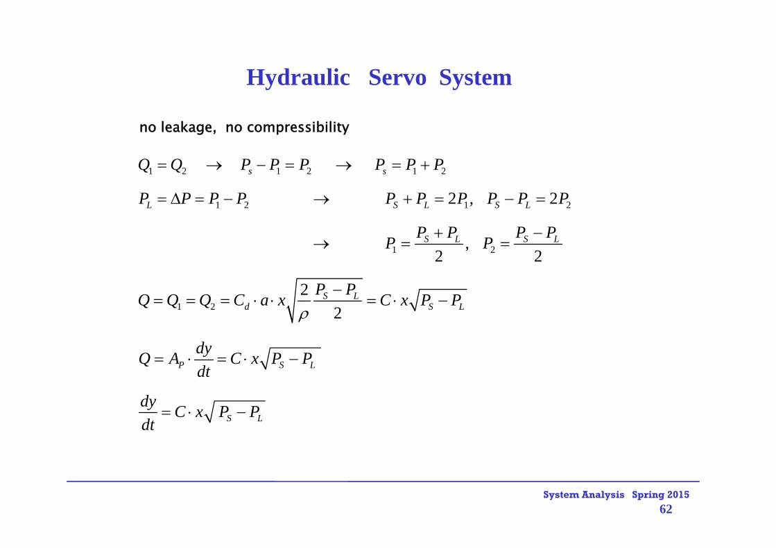
no leakage, no compressibility
1 2 1 2 1 2
1 2 1 2
1 2
1 2
2 , 2
,2 2
22
s s
L S L S L
S L S L
S Ld S L
Q Q P P P P P P
P P P P P P P P P P
P P P PP P
P PQ Q Q C a x C x P P
P S L
S L
dyQ A C x P Pdt
dy C x P Pdt
Hydraulic Servo System

System Analysis Spring 2015
63
, , ,
( , ) ( ) ( )
1 1( ) ( ) ( )2
L L
S L L L L
L L Lx P x PL
S L L L
S L
d y C x P P y y y x x x P P Pdt
dy f ff x P x x P Pdt x P
d y C P P x x C x P Pdt P P
1
1
0, 0 , 0
( ).( )
L
S
d yif x Pdt
dy C P x K xdt
KY sT FX s S
Hydraulic Servo System

System Analysis Spring 2015
64
0P
1Q 2Q
SP
12 11 21 22
Ap
0P
1P2P
:sP supply pressure
x
ypA
0
11 0 1
12 0 1
1 11 12
0 ,
2( ) ( )
2( ) ( 0 )
d S
d
x A A
Q C A ax P P
Q C A ax P
Q Q Q
21 0 2
22 0 2
2 22 21
2( ) ( )
2( ) ( 0 )
d S
d
Q C A ax P P
Q C A ax P
Q Q Q
Hydraulic Servo System
Flow equations :

System Analysis Spring 2015
65
Assume no leakage 21 QQ
11
1 21 2
1 2
0,
1 1
1 1 ( )
0,
1 1 1 1( ), ( )p P
y
dP dVdt V dt
QV
y
dp dpQ A y Q A ydt V dt V
1 2
1 2
( )
( )
p
p
my A p p by
my by A p p
Equation of motion :
Hydraulic Servo System

System Analysis Spring 2015
66
Hydraulic Servo System Model
1 2
11
1
22
2
1 11 12 0 1 0 1
2 22 21 0 2 0 2
1 2
( )
1 1 ( )
1 1 ( )
2 2( ) ( ) ( ) ( 0 )
2 2( ) ( 0 ) ( ) ( )
p
p
P
d S d
d d S
my by A p p
dp Q A ydt V
dp Q A ydt V
Q Q Q C A ax P P C A ax P
Q Q Q C A ax P C A ax P P
Q Q

System Analysis Spring 2015
67
1 2 1 2
0 1 2 0 1 2
1 2 1 2
0 1 2 1 2
0
2 2 2 2( ) ( ) ( ) ( )
0,
2 2 2 2( ) ( )
2 2 2 2( ) ( ) 0
d S d S
d S S
d S S
Q Q Q Q
C A ax P P P C A ax P P P
when x
C ax P P P P P P
C A P P P P P P
To make an identical equati
1 2 1 2 1 2
1 2 1 2
, ,
, ,2 2
s s s
s L s LL
Pon P P P P P P P P
P P P Plet P P P P P
Hydraulic Servo System : Linearization

System Analysis Spring 2015
68
Operating point :
1 11 1 0, 0 0, 0
10, 0 1
10, 0 0 2
1 2 2
1 21 2
0, 0
( , ) (0,0) ( 0) ( 0)
12
1
,
L L
L
L
L
L x p x p LL
x p d S
x p dL S
L L
LL
x p
Q QQ x p Q x px p
Q C a p Kx
Q C A Kp p
Q K x K p Q Q
dp dp dpp p pdt dt dt
Hydraulic Servo System : Linearization
1 0 01 1( ) ( ) ( ) ( )
( , )
d s L d s L
L L L
Q C ax A P P C A ax P P
Q Q x P

System Analysis Spring 2015
69
11 2
1 1
21 2
2
1 2
1 2
1 1 1 1( ) ( )
1 1 ( )
1 1 (2 2 2 )
( ) ( ) :( )
p L
L p L p
L p
LL p
my by A p
dp Q A y K x K p A ydt V V
dp K x K p A ydt V
let V V
dp K x K p A ydt V
Y s cubic equation formX s
Hydraulic Servo System

System Analysis Spring 2015
70
Simplification : No compressibility, No leakage
1 2 12
21
2 2
1 22 2
2 2
1 ( )
( )( ) ( 1)
,
L p
L L p L p
pp
p
p p
my by p A
Q K x K p A y p K x A yK
A Kmy b y A xK K
Y s KX s s Ts
K A mKK TK b A K b A
Hydraulic Servo System

System Analysis Spring 2015
71
End of Hydraulic systems 8-1