Session Lecture note : Strength of Materials
14
Session Lecture note : Pramudiyanto, M.Eng. g{x V|ä|Ä tÇw cÄtÇÇ|Çz XÇz|ÇxxÜ|Çz Xwâvtà|ÉÇ WxÑtÜàÅxÇà Faculty of Engineering, State University of Yogyakarta Strength of Materials Deflection of Transversally Loaded Beam 05
Transcript of Session Lecture note : Strength of Materials

Session
Lecture note :Pramudiyanto, M.Eng.
g{x V|ä|Ä tÇw cÄtÇÇ|Çz XÇz|ÇxxÜ|Çz Xwâvtà|ÉÇ WxÑtÜàÅxÇàFaculty of Engineering, State University of Yogyakarta
Strength of Materials
Deflection of Transversally Loaded Beam
05

g{x V|ä|Ä tÇw cÄtÇÇ|Çz XÇz|ÇxxÜ|Çz Xwâvtà|ÉÇ WxÑtÜàÅxÇàFaculty of Engineering, State University of Yogyakarta
we will be concerned with another aspect inthe design of beams, namely, the determinationof the deflection. Of particular interest is thedetermination of the maximum deflection of abeam under a given loading, since the designspecifications of a beam will generally includea maximum allowable value for its deflection.
A knowledge of the deflections is required toanalyze indeterminate beams. These are beamsin which the number of reactions at thesupports exceeds the number of equilibriumequations available to determine theseunknowns.

g{x V|ä|Ä tÇw cÄtÇÇ|Çz XÇz|ÇxxÜ|Çz Xwâvtà|ÉÇ WxÑtÜàÅxÇàFaculty of Engineering, State University of Yogyakarta
a prismatic beam subjected to purebending is bent into an arc of circleand that, within the elastic range, thecurvature of the neutral surface can beexpressed as
To determine the slope and deflection of the beam at any given point, we firstderive the following second-order linear differential equation, which governs theelastic curve characterizing the shape of the deformed beam :

g{x V|ä|Ä tÇw cÄtÇÇ|Çz XÇz|ÇxxÜ|Çz Xwâvtà|ÉÇ WxÑtÜàÅxÇàFaculty of Engineering, State University of Yogyakarta
Cantilever BeamThe cantilever beam AB is of uniformcross section and carries a load P at itsfree end A. Determine the equation ofthe elastic curve and the deflectionand slope at A.
SOLUTIONUsing the free-body diagram of the portion AC of the beam, where C is located at a distance x from end A, we find:
Substituting for M and multiplying both members by the constant EI, we write
Integrating x, we obtain :

g{x V|ä|Ä tÇw cÄtÇÇ|Çz XÇz|ÇxxÜ|Çz Xwâvtà|ÉÇ WxÑtÜàÅxÇàFaculty of Engineering, State University of Yogyakarta
We now observe that at the fixed end B wehave x = L and = dy/dx = 0. Substitutingthese values and solving for C1, we have:
Which we carry back into :
Integrating both members, we write :
At B we have x = L, y = 0. substituting thiswe have :
0
Carrying the value of C2, we obtain the equation of the elastic curve :
Or 3 2The deflection and slope at A :
3
2
g{x V|ä|Ä tÇw cÄtÇÇ|Çz XÇz|ÇxxÜ|Çz Xwâvtà|ÉÇ WxÑtÜàÅxÇàFaculty of Engineering, State University of Yogyakarta
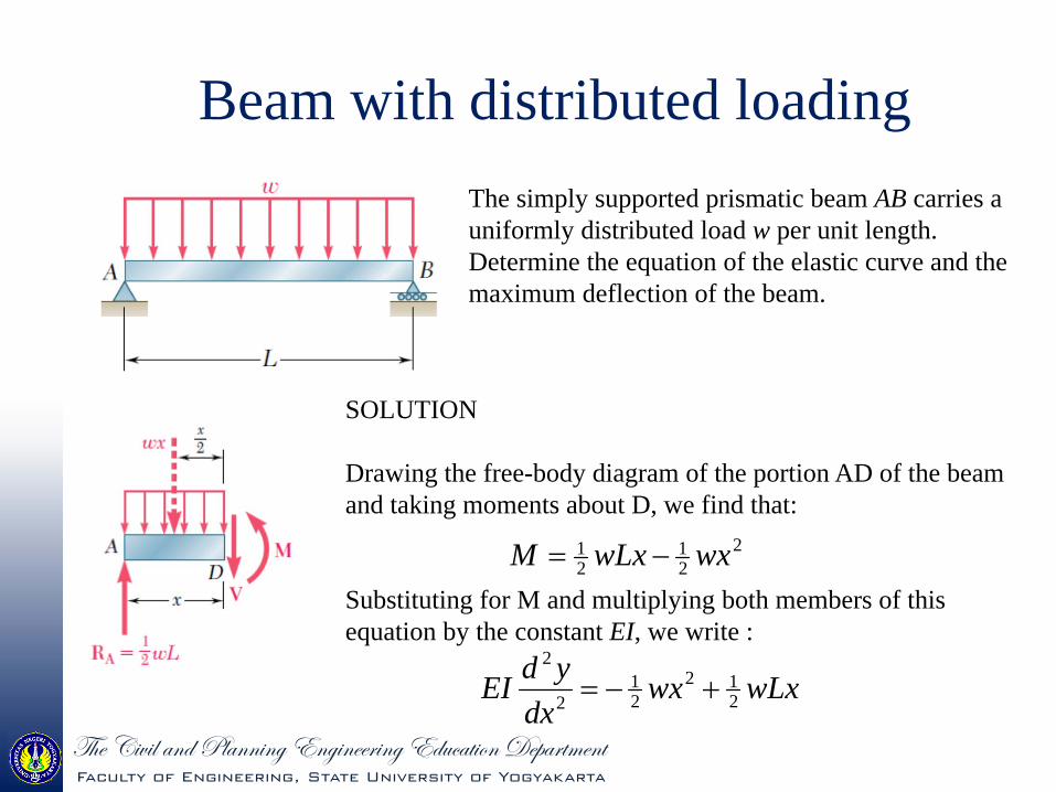
Beam with distributed loadingThe simply supported prismatic beam AB carries a uniformly distributed load w per unit length. Determine the equation of the elastic curve and the maximum deflection of the beam.
SOLUTION
Drawing the free-body diagram of the portion AD of the beam and taking moments about D, we find that:
Substituting for M and multiplying both members of this equation by the constant EI, we write :
221
21 wxwLxM
wLxwxdx
ydEI 212
21
2
2

g{x V|ä|Ä tÇw cÄtÇÇ|Çz XÇz|ÇxxÜ|Çz Xwâvtà|ÉÇ WxÑtÜàÅxÇàFaculty of Engineering, State University of Yogyakarta
Integrating twice, we have:
Observing that y=0 at both ends of the beam, we first let x=0 and y=0 in first equation and obtain C2=0. We then make x=L and y=0 in the same equation and write :
Carrying the values of C1 and C2 back into previous equation, we obtain the equation of elastic curve :
2134
123
121
241
41
61
CxCwLxwxEIy
CwLxwxdxdyEI
31
144
241
121
2410
wLC
LCwLwL
xLLxxEI
wy
xwLwLxwxEIy
334
334
224
241
121
241

g{x V|ä|Ä tÇw cÄtÇÇ|Çz XÇz|ÇxxÜ|Çz Xwâvtà|ÉÇ WxÑtÜàÅxÇàFaculty of Engineering, State University of Yogyakarta
Substituting the value obtained for C1, we check that the slope of the beam is zero for x=L/2 and that the elastic curve has a minimum at the midpoint C of the beam. Letting x = L/2, we have :
The maximum deflection or, more precisely, the maximum absolute value of deflection, is thus :
EIwLLLLLL
EIwyC 384
528
21624
43
34
EIwLy
3845 4
max

g{x V|ä|Ä tÇw cÄtÇÇ|Çz XÇz|ÇxxÜ|Çz Xwâvtà|ÉÇ WxÑtÜàÅxÇàFaculty of Engineering, State University of Yogyakarta
Beam with point loading
For the prismatic beam and the loading shown, determine the slope and deflection at point D.
We must divide the beam into two portions, AD and DB, and determine the function y(x) which defines the elastic curve for each of these portions.
SOLUTIONFrom A to D (x < L/4). We draw the free-body diagram of a portion of beam AE of length x < L/4. Taking moments about E, we have
Pxdx
ydEIxPM43
43
21
2
1

g{x V|ä|Ä tÇw cÄtÇÇ|Çz XÇz|ÇxxÜ|Çz Xwâvtà|ÉÇ WxÑtÜàÅxÇàFaculty of Engineering, State University of Yogyakarta
where y1(x) is the function which defines the elastic curve for portion AD of the beam. Integrating in x, we write
213
1
121
1
81
83
CxCPxEIy
CPxdxdyEIEI
From D to B (x > L/4). We now draw the free-body diagram of a portion of beam AE of length x > L/4 and write
PLPxdx
ydEILxPxPM41
41
443
22
2
2

g{x V|ä|Ä tÇw cÄtÇÇ|Çz XÇz|ÇxxÜ|Çz Xwâvtà|ÉÇ WxÑtÜàÅxÇàFaculty of Engineering, State University of Yogyakarta
where y2(x) is the function which defines the elastic curve for portion DB of the beam. Integrating in x, we write
4323
2
322
2
81
241
41
81
CxCPLxPxEIy
CPLxPxdxdyEIEI
The conditions that must be satisfied by the constants of integration have been summarized. At the support A, we must have x = 0 and y1 = 0. At the support B, we must have x = L and y2 = 0. Also, the fact that there can be no sudden change in deflection or in slope at point D requires that y1 = y2 and 1 = 2 when x = L/4. We have therefore:

g{x V|ä|Ä tÇw cÄtÇÇ|Çz XÇz|ÇxxÜ|Çz Xwâvtà|ÉÇ WxÑtÜàÅxÇàFaculty of Engineering, State University of Yogyakarta
384,
12811,0,
1287
4153611
4512,
4
1287
1283,
4
12100,
00,0
3
4
2
32
2
1
43
3
1
3
21
32
12
21
433
2
21
PLCPLCCPLC
CLCPLLCPLyyLx
CPLCPLLx
CLCPLyLx
Cyx
Substituting for C1 and C2, we write that for x L/4 :
xPLPxEIy
PLPxEI
1287
81
1287
83
23
1
22
1

g{x V|ä|Ä tÇw cÄtÇÇ|Çz XÇz|ÇxxÜ|Çz Xwâvtà|ÉÇ WxÑtÜàÅxÇàFaculty of Engineering, State University of Yogyakarta
Letting x = L/4 in each of these equations, we find that the slope and deflection at point D are, respectively,
EIPLy
EIPL
DD 2563,
32
32
We note that, since 0, the deflection at D is not the maximum deflection of the beam.

g{x V|ä|Ä tÇw cÄtÇÇ|Çz XÇz|ÇxxÜ|Çz Xwâvtà|ÉÇ WxÑtÜàÅxÇàFaculty of Engineering, State University of Yogyakarta
THANK YOUThat’s for now