Layered architecture for assembling business applications from distributed components
18
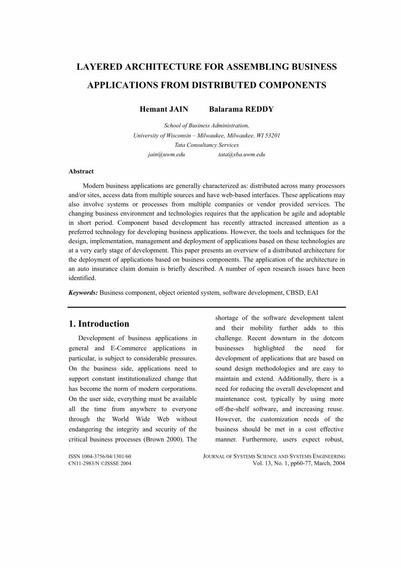
ISSN 1004-3756/04/1301/60 JOURNAL OF SYSTEMS SCIENCE AND SYSTEMS ENGINEERING CN11-2983/N ©JSSSE 2004 Vol. 13, No. 1, pp60-77, March, 2004 LAYERED ARCHITECTURE FOR ASSEMBLING BUSINESS APPLICATIONS FROM DISTRIBUTED COMPONENTS Hemant JAIN Balarama REDDY School of Business Administration, University of Wisconsin – Milwaukee, Milwaukee, WI 53201 Tata Consultancy Services [email protected] [email protected] Abstract Modern business applications are generally characterized as: distributed across many processors and/or sites, access data from multiple sources and have web-based interfaces. These applications may also involve systems or processes from multiple companies or vendor provided services. The changing business environment and technologies requires that the application be agile and adoptable in short period. Component based development has recently attracted increased attention as a preferred technology for developing business applications. However, the tools and techniques for the design, implementation, management and deployment of applications based on these technologies are at a very early stage of development. This paper presents an overview of a distributed architecture for the deployment of applications based on business components. The application of the architecture in an auto insurance claim domain is briefly described. A number of open research issues have been identified. Keywords: Business component, object oriented system, software development, CBSD, EAI 1. Introduction Development of business applications in general and E-Commerce applications in particular, is subject to considerable pressures. On the business side, applications need to support constant institutionalized change that has become the norm of modern corporations. On the user side, everything must be available all the time from anywhere to everyone through the World Wide Web without endangering the integrity and security of the critical business processes (Brown 2000). The shortage of the software development talent and their mobility further adds to this challenge. Recent downturn in the dotcom businesses highlighted the need for development of applications that are based on sound design methodologies and are easy to maintain and extend. Additionally, there is a need for reducing the overall development and maintenance cost, typically by using more off-the-shelf software, and increasing reuse. However, the customization needs of the business should be met in a cost effective manner. Furthermore, users expect robust,
Transcript of Layered architecture for assembling business applications from distributed components
ISSN 1004-3756/04/1301/60 JOURNAL OF SYSTEMS SCIENCE AND SYSTEMS ENGINEERING CN11-2983/N ©JSSSE 2004 Vol. 13, No. 1, pp60-77, March, 2004
LAYERED ARCHITECTURE FOR ASSEMBLING BUSINESS
APPLICATIONS FROM DISTRIBUTED COMPONENTS
Hemant JAIN Balarama REDDY
School of Business Administration,
University of Wisconsin – Milwaukee, Milwaukee, WI 53201 Tata Consultancy Services
[email protected] [email protected]
Abstract
Modern business applications are generally characterized as: distributed across many processors and/or sites, access data from multiple sources and have web-based interfaces. These applications may also involve systems or processes from multiple companies or vendor provided services. The changing business environment and technologies requires that the application be agile and adoptable in short period. Component based development has recently attracted increased attention as a preferred technology for developing business applications. However, the tools and techniques for the design, implementation, management and deployment of applications based on these technologies are at a very early stage of development. This paper presents an overview of a distributed architecture for the deployment of applications based on business components. The application of the architecture in an auto insurance claim domain is briefly described. A number of open research issues have been identified.
Keywords: Business component, object oriented system, software development, CBSD, EAI
1. Introduction Development of business applications in
general and E-Commerce applications in particular, is subject to considerable pressures. On the business side, applications need to support constant institutionalized change that has become the norm of modern corporations. On the user side, everything must be available all the time from anywhere to everyone through the World Wide Web without endangering the integrity and security of the critical business processes (Brown 2000). The
shortage of the software development talent and their mobility further adds to this challenge. Recent downturn in the dotcom businesses highlighted the need for development of applications that are based on sound design methodologies and are easy to maintain and extend. Additionally, there is a need for reducing the overall development and maintenance cost, typically by using more off-the-shelf software, and increasing reuse. However, the customization needs of the business should be met in a cost effective manner. Furthermore, users expect robust,
JAIN and REDDY
JOURNAL OF SYSTEMS SCIENCE AND SYSTEMS ENGINEERING / Vol. 13, No. 1, March, 2004 61
high-performance systems in the face of constant change in the underlying technologies, reconfiguration of system and occasional failure of some pieces of the system. The technological advances in object oriented development, distributed systems, networking and web services lead us to conclude that the future software intensive solutions in almost all domains will be distributed across many sites, access data from multiple sources, and have Web-based interfaces (Brown 2000).
Component Based Software Development (CBSD) has recently attracted increased attention as a new approach for building applications. It advocates an approach whereby applications would be assembled from pre-built parts known as business components. A business component is the software implementation of an autonomous business concept or business process (Apte and Sankar 1990). Thus in CBSD the process of building a business application can be considered to be consisting of two stages: Component Fabrication (building the Business Components) and Application Assembly (building a Business Application from Components) (Jain et al. 2001). The Component Fabrication stage of CBSD consists of various phases: Domain Analysis and Modeling, Component Identification, Component Design & Implementation, Acceptance and Roll Out & Deployment. Herzum and Sims (2000) identify essential characteristics of business components as: • A self-contained software construct that
has a defined use, a well-defined runtime interface and can be autonomously deployed.
• A component is built for composition and collaboration with other components.
• A component isomorphically represents a single autonomous business concept.
• The component assembler may not have the skills and/or tools necessary to create the component.
Components can be of various types such as Graphical User Interface (GUI) components, infrastructure components, and business components. GUI components are generally more reusable across various organizations in different business domains than business components, which are generally reusable within a business domain, such as an Insurance Domain. The extent of reuse also depends upon the granularity of a business component. A smaller component such as an ‘Interest Computation’ component can be more widely reused even across industry domains (whenever an interest computation is needed), when compared to a larger component such as an ‘Insurance Policy’ component which can be used only within the Insurance industry domain. It can however be used by many companies within the same domain. Business components can be reused across domains if the domains overlap. Vitharana et al. (2004) identified a number of managerial goals such as, development cost of the component, potential reusability, ease of assembly of final application, and maintenance cost. They developed an optimization model for identifying appropriate business components.
Although the concept of component-based development has been discussed in the literature, the practical application of this approach in the development of large-scale
Layered Architecture for Assembling Business Applications from Distributed Components
62 JOURNAL OF SYSTEMS SCIENCE AND SYSTEMS ENGINEERING / Vol. 13, No. 1, March, 2004
business applications has not been reported. This paper presents a layered architecture for the implementation and deployment of components from which business applications can be assembled. The work presented here is part of a major research effort targeted at applying component-based approach to the development of large-scale business applications. Section 2 presents a brief overview of the Component Identification and the Component Management processes. Section 3 describes a layered architecture for the implementation of business components and their assembly into customized business applications. Section 4 briefly describes application of the approach to an auto insurance claims domain.
2. Component Identification and Management Traditionally, the identification of the
components has been based upon intuition and experience. This means that the component are first identified based on the functions they need to perform. A detailed design of the component, including identification of its constituent classes, is done next. This method is suitable for identifying the technical or GUI components. However, while identifying business components other factors like inter-component relationship, potential for reuse, ease of assembly, and maintenance cost needs to be considered. The traditional approach does not offer the designer ways to consider the above important factors during component identification. A formal approach for identifying reusable business components
is described in (Jain et al. 2001). A refined form this approach has also been applied to identification of web services (Jain et al. 2004). The approach was implemented in a tool known as ‘COMIT’ (Jain et al. 2004).
For component based system development to become a viable commercial technology, two important aspects needs to be addressed: the availability of a large number of standard interchangeable components and the ease of finding the right components. The problem of finding the right component can be addressed by building a component repository. A component repository must, however be complemented with effective management tools that allow for registering, installing and browsing components in the repository (Allen and Frost 1998). Vitharana et al. (2003) proposed a comprehensive classification and coding system for business components. Component in the repository can be defined as a hierarchical structure where the component itself represents the highest level of abstraction. Interfaces, methods, parameters, exceptions and data types are represented at the subsequent levels of abstraction (Vitharana et al. 2003).
3. Layered architecture for implementation and deployment of components Various frameworks like ‘.Net’ and
‘Enterprise Java Beans (EJB)’ are available for implementing and deploying distributed business applications. Additionally, Web Services technology can achieve interoperability across these platforms. Based

JAIN and REDDY
JOURNAL OF SYSTEMS SCIENCE AND SYSTEMS ENGINEERING / Vol. 13, No. 1, March, 2004 63
on the above technologies, we present a layered architecture developed for the implementation and deployment of business components. Based on the above architecture a proof of concept prototype is developed to show the feasibility of large-scale component based development.
After identifying components, detailed design of the components and their interfaces
needs to be completed. The component interfaces represents the public interface through which the functionality of the component can be used. These interfaces can also be defined using Web Services technology. Figure 1 shows four example components identified from a domain represented by six classes. Figure 1 also shows attributes and operations associated with some of the classes.
Attributes:int ID ;String name;
_____________________________Operations:
getName(){ ...;return name;}setName(){ ...}findByName(){ ...;return ID;}
Class 1Class 2Class 3Class 4Class 5Class 6
Class 1Class 3Class 4
Component 1
Class 1Class 5Class 2
Component 2
inner details
of Class 1
Class 3Class 4Class 5Class 6
Component 3
Class 1Class 6
Component 4
Attributes: Date from,to ; double amount;_____________________________Operations: getReport(Dates){ ...;return report;} calculateTotal(){ ...;return amount;}
inne
r det
ails
of C
lass
4
Attributes:long partyID ;String action;Date today ;File logFile;
_____________________________Operations:
writeLog(ID,action){ // write into Log file }
inner details
of Class 3
Figure 1 Components are obtained by grouping classes
3.1 Component Deployment
Architectures
A number of technological frameworks are currently available for the development and deployment of components. These frameworks are typically based on either Java technologies or .Net framework. They also support the
deployment of components as web services. This section summarizes the features of the above technical frameworks.
The basic functionally offered by these frameworks is management of distributed objects. It provides an infrastructure that facilitates transaction management, server side component implementation, load balancing,
Layered Architecture for Assembling Business Applications from Distributed Components
64 JOURNAL OF SYSTEMS SCIENCE AND SYSTEMS ENGINEERING / Vol. 13, No. 1, March, 2004
concurrency management, and other essential services.
Business components can be developed using any of the commercial environments either based on .Net or Java technologies. Components from these environments can interoperate using web services interface. In order to create proof of concept business components we selected an EJB based environment provided by WebLogic® Server.
3.2 Business Component Architecture
Once the deployment environment has been chosen, an efficient and flexible architecture for the development and deployment of business components that allows easy assembly of application needs to be designed. The architecture needs to support key features of the business components like plug and play capability, abstraction and encapsulation of relevant piece of business logic, and explicit transaction management. An essential feature of the component architecture is to enable application assembler to select components of various granularity to allow assembly of an application that satisfies user requirements. The architecture also needs to support implementation and modification of business processes and workflow based on the changing needs of the application users without significant programming effort.
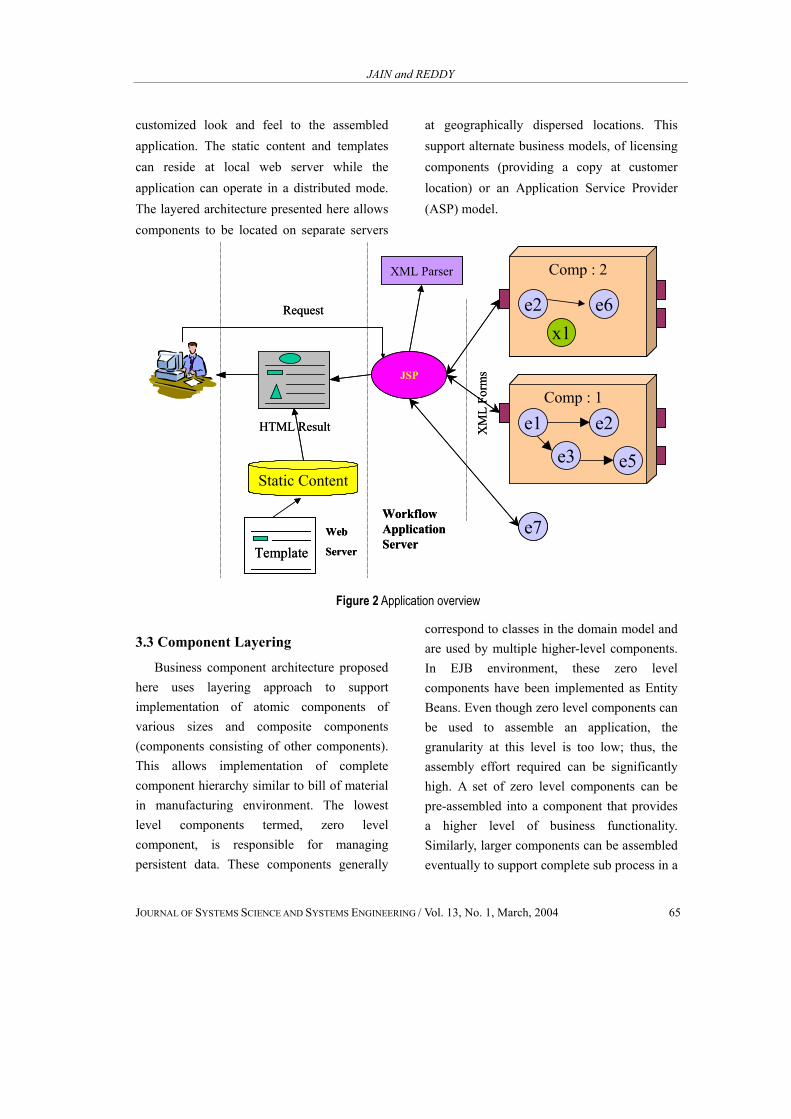
Figure 2 represents the structure of an application assembled using the proposed layered architecture. Business components reside in the application layer and are served by commercial application servers like
Weblogic® Server. As described earlier, business component encapsulate business logic, business rules, and interfaces. Each business component can support one or more interfaces. Based on business functionality supported an interface logically groups methods, which are exposed by the component. Interface methods can be called from outside of component by another business component or technical components such as Graphical User Interface component. Java Server Pages (JSP) has been used to implement user interface of the assembled application. JSP provides a flexible and reliable mechanism for implementing web based user interface. A component interface, which requires user input of data or displays information to the user, has one or more JSP associated with it. The JSPs are stored in the repository along with the component. Each data element in JSP are internally linked to the elements of the component interface described by XML forms (in case of web services WSDL can be used to describe component interface). The sequence of executing JSPs associated with the components determines the sequence of activities in the workflow. The JSP execution sequencing can also support workflow logic such as looping forking etc.
Thus, the proposed architecture provide facilities to implement alternative workflow by changing the sequence of JSPs. In web-based application deployment mode, the workflow is programmed as a Java Servlet. The XML forms act as data layer between the workflow logic (servlet) and the Component. Templates and static content can be used to provide
JAIN and REDDY
JOURNAL OF SYSTEMS SCIENCE AND SYSTEMS ENGINEERING / Vol. 13, No. 1, March, 2004 65
customized look and feel to the assembled application. The static content and templates can reside at local web server while the application can operate in a distributed mode. The layered architecture presented here allows components to be located on separate servers
at geographically dispersed locations. This support alternate business models, of licensing components (providing a copy at customer location) or an Application Service Provider (ASP) model.
Static Content
JSP
HTML Result
Template
Request e2 e6x1
Comp : 2
e1
e3
e2
e5
Comp : 1
XML Parser
e7
XM
L Fo
rms
Web
Server
Workflow Application Server
Static Content
JSP
HTML Result
Template
Request e2 e6x1
Comp : 2
e2 e6x1
Comp : 2
e1
e3
e2
e5
Comp : 1
e1
e3
e2
e5
Comp : 1
e1
e3
e2
e5
Comp : 1
XML Parser
e7
XM
L Fo
rms
Web
Server
Workflow Application Server
Figure 2 Application overview
3.3 Component Layering
Business component architecture proposed here uses layering approach to support implementation of atomic components of various sizes and composite components (components consisting of other components). This allows implementation of complete component hierarchy similar to bill of material in manufacturing environment. The lowest level components termed, zero level component, is responsible for managing persistent data. These components generally
correspond to classes in the domain model and are used by multiple higher-level components. In EJB environment, these zero level components have been implemented as Entity Beans. Even though zero level components can be used to assemble an application, the granularity at this level is too low; thus, the assembly effort required can be significantly high. A set of zero level components can be pre-assembled into a component that provides a higher level of business functionality. Similarly, larger components can be assembled eventually to support complete sub process in a

Layered Architecture for Assembling Business Applications from Distributed Components
66 JOURNAL OF SYSTEMS SCIENCE AND SYSTEMS ENGINEERING / Vol. 13, No. 1, March, 2004
business process e.g. order entry and validation, claim intimation & registration. When assembling larger business application systems the designer can evaluate the functionality offered by these larger components including the business rules and processes supported by them with respect to the user requirements (Jain et al. 2003). If a good fit is obtained the component is used as is, else the functionality is built by assembling lower level components. Thus, the proposed architecture offers significant flexibility in application assembly than the commercially available frameworks. Since components at the higher level uses, zero level components to manage persistence, Session Beans have been used for the implementation of higher-level Business
Components. Figure 3 describes the implementation
structure of a Business component. It can be observed from the figure that component-1 bean exposes only the interfaces to the application developer or assembler, hiding the communication between the zero level components (classes). In addition, the architecture doesn’t require the zero level components to be in the same location as the business component. The zero level components are distributed entity beans. Business Components communicates with the outside environment through component interface described using XML based data structure or web services.
Outside World
getReport()/* invocation fromRemote Interfaceof Component-1 */
Class-4(Remote Interface)______________________public Object getReport(){ /* actual implementation iscoded here */return reportObject ;}private voidwriteLog(ID,event){ Class4-RemoteObj.writeLog() ;}
Class-1(Remote Interface)______________________public intfindByName(String Name){/*actual implementation iscoded here*/return ID;}
public int findByName(StringName){return Class1-RemoteObj.findByName(Name);}
public Object getReport(){ return Class4-RemoteObj.getReport()}
Component-1 Bean RMI
RMI
Class-3(Remote Interface)______________________public void writeLog(intID,String event){/*actual implementation iscoded here*/}
Internal BeanCommunication
Figure 3 Structure of a business component
JAIN and REDDY
JOURNAL OF SYSTEMS SCIENCE AND SYSTEMS ENGINEERING / Vol. 13, No. 1, March, 2004 67
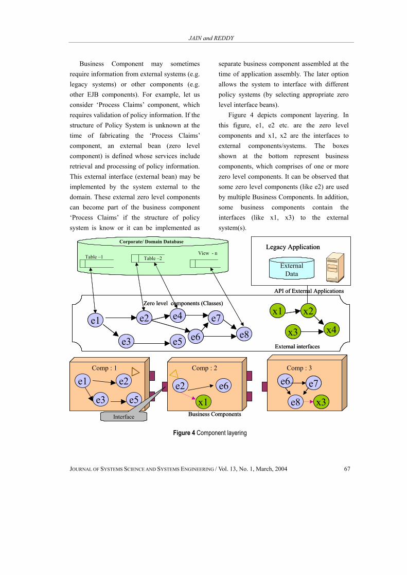
Business Component may sometimes require information from external systems (e.g. legacy systems) or other components (e.g. other EJB components). For example, let us consider ‘Process Claims’ component, which requires validation of policy information. If the structure of Policy System is unknown at the time of fabricating the ‘Process Claims’ component, an external bean (zero level component) is defined whose services include retrieval and processing of policy information. This external interface (external bean) may be implemented by the system external to the domain. These external zero level components can become part of the business component ‘Process Claims’ if the structure of policy system is know or it can be implemented as
separate business component assembled at the time of application assembly. The later option allows the system to interface with different policy systems (by selecting appropriate zero level interface beans).
Figure 4 depicts component layering. In this figure, e1, e2 etc. are the zero level components and x1, x2 are the interfaces to external components/systems. The boxes shown at the bottom represent business components, which comprises of one or more zero level components. It can be observed that some zero level components (like e2) are used by multiple Business Components. In addition, some business components contain the interfaces (like x1, x3) to the external system(s).
Table –2
e4
ExternalData
Legacy Application
Zero level components (Classes)x1 x2
x3 x4e7
e6
e8e1 e2
e3 e5 External interfaces
e1
e3
e2
e5
e6
e2 e6x1 e8
e6 e7
x3
Comp : 1 Comp : 2 Comp : 3
Business ComponentsInterface
Corporate/ Domain Database
Table –1 View - n
API of External Applications
Table –2
e4
ExternalData
Legacy Application
Zero level components (Classes)x1 x2
x3 x4e7
e6
e8e1 e2
e3 e5 External interfaces
e1
e3
e2
e5
e6
e2 e6x1 e8
e6 e7
x3
e6 e7
x3
Comp : 1 Comp : 2 Comp : 3
Business ComponentsInterface
Corporate/ Domain Database
Table –1 View - n
API of External Applications
Figure 4 Component layering
Layered Architecture for Assembling Business Applications from Distributed Components
68 JOURNAL OF SYSTEMS SCIENCE AND SYSTEMS ENGINEERING / Vol. 13, No. 1, March, 2004
3.4 Component Communication The structure required for supporting
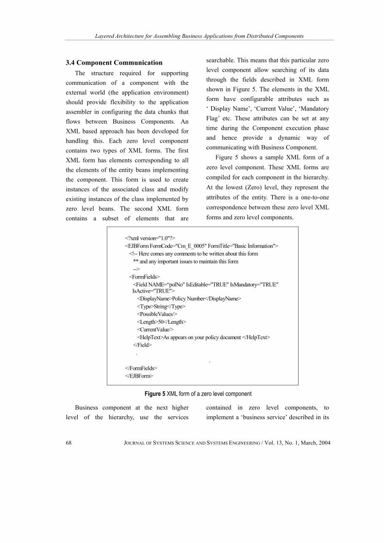
communication of a component with the external world (the application environment) should provide flexibility to the application assembler in configuring the data chunks that flows between Business Components. An XML based approach has been developed for handling this. Each zero level component contains two types of XML forms. The first XML form has elements corresponding to all the elements of the entity beans implementing the component. This form is used to create instances of the associated class and modify existing instances of the class implemented by zero level beans. The second XML form contains a subset of elements that are
searchable. This means that this particular zero level component allow searching of its data through the fields described in XML form shown in Figure 5. The elements in the XML form have configurable attributes such as ‘ Display Name’, ‘Current Value’, ‘Mandatory Flag’ etc. These attributes can be set at any time during the Component execution phase and hence provide a dynamic way of communicating with Business Component.
Figure 5 shows a sample XML form of a zero level component. These XML forms are compiled for each component in the hierarchy. At the lowest (Zero) level, they represent the attributes of the entity. There is a one-to-one correspondence between these zero level XML forms and zero level components.
<?xml version="1.0"?><EJBForm FormCode="Cm_E_0005" FormTitle="Basic Information">
<!-- Here comes any comments to be written about this form** and any important issues to maintain this form-->
<FormFields><Field NAME=“polNo" IsEditable="TRUE" IsMandatory="TRUE"IsActive="TRUE">
<DisplayName>Policy Number</DisplayName><Type>String</Type><PossibleValues/><Length>50</Length><CurrentValue/><HelpText>As appears on your policy document </HelpText>
</Field>.
.</FormFields></EJBForm>
Figure 5 XML form of a zero level component
Business component at the next higher level of the hierarchy, use the services
contained in zero level components, to implement a ‘business service’ described in its

JAIN and REDDY
JOURNAL OF SYSTEMS SCIENCE AND SYSTEMS ENGINEERING / Vol. 13, No. 1, March, 2004 69
interface. The ‘business service’ communicates with either business user or other components through a set of XML forms. These XML forms provide links to various zero level XML forms. Apart from the links to the Zero Level XML forms, they can contain additional data elements.
Whenever a particular business service is requested through an interface, the business component sends the corresponding business
component level XML form. If the XML form contains any links a utility program, ‘XML Merger’, to merge these zero level forms, is dynamically invoked. This utility program uses a simple merge technique (Roman 1999). Figure 6 shows a sample XML form for a business component. This XML form provides links to two Zero Level XML forms and one additional data element.
<?xml version="1.0"?><EJBForm FormCode="Cm_C_0002" FormTitle="Claimant Details Form">
<!-- Here comes any comments to be written about this form** and any important issues to maintain this form-->
<FormFields><subForm FormCode="Cm_E_0005" FormTitle="Basic Info"/><subForm FormCode="Cm_E_0017" FormTitle="Party Info"/><subForm FormCode="Cm_E_0002" FormTitle="ClaimantDetails"/><Field NAME="NumberOfInvovedParties" IsEditable="TRUE"IsMandatory="TRUE" IsActive="TRUE">
<DisplayName>Number of People Involved </DisplayName><Type>String</Type><PossibleValues/><Length>3</Length><CurrentValue/><HelpText>Excluding you, Enter '0' to add the people later</HelpText>
</Field></FormFields>
</EJBForm>
Figure 6 XML form of a business component
Another important feature of the XML based data structure developed here is the provision of User-defined data elements in zero level components. During the fabrication of entity beans for zero level components, few additional attributes are defined in the entity beans and in the database tables designated for future use. The application assembler may like to add / delete few fields to/from the zero level
bean to help customize the application based on unique business requirements. This provides flexibility and customization capability in a cost effective manner.
3.5 Application Assembly
The ability to quickly assemble applications from the available Business Components involves selection of appropriate
Layered Architecture for Assembling Business Applications from Distributed Components
70 JOURNAL OF SYSTEMS SCIENCE AND SYSTEMS ENGINEERING / Vol. 13, No. 1, March, 2004
components, configuration of User Interface to provide the look and feel required by the application and the assembly of components to support required workflow. Business Components have limited configuration capabilities such as changing display names of attributes and default values. Additionally, user defined fields can be used to provide further customization capability. Workflow
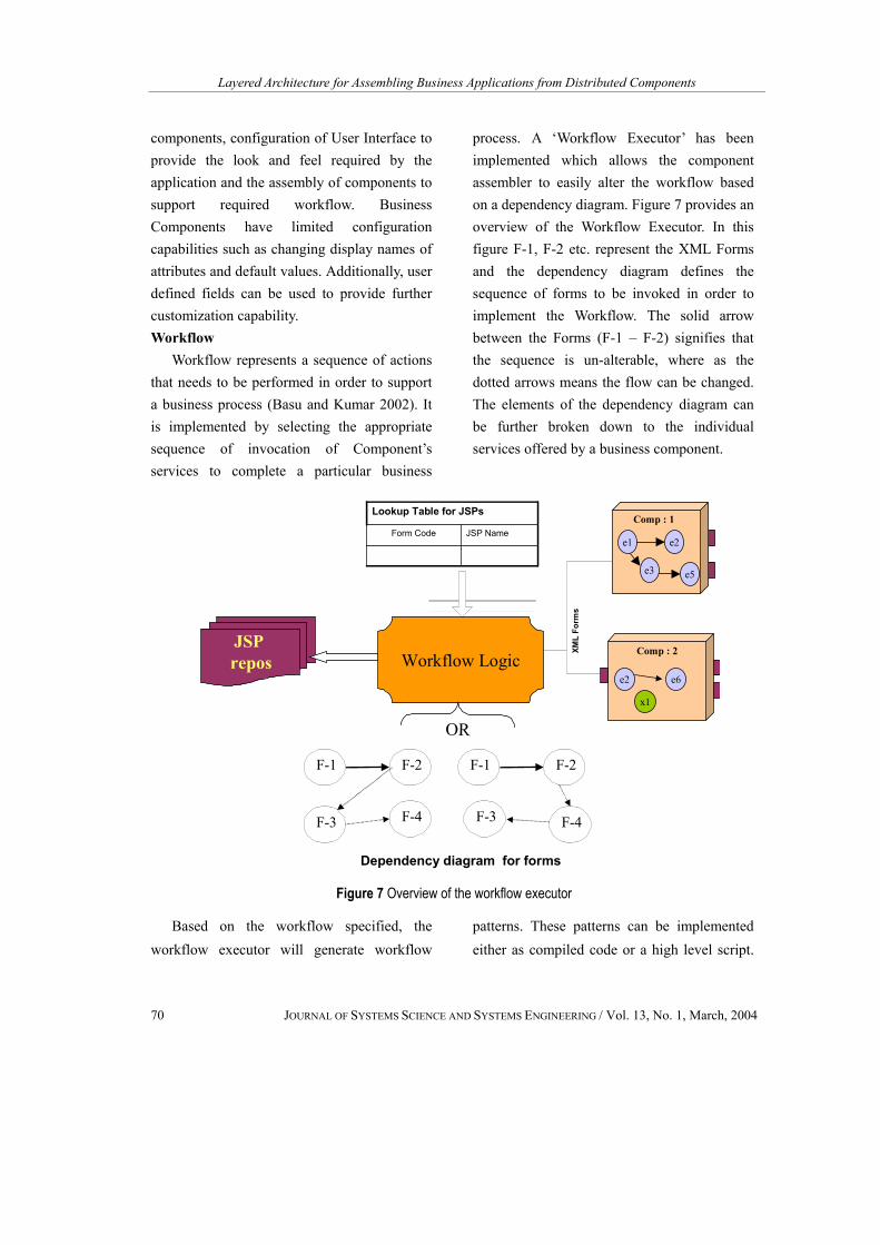
Workflow represents a sequence of actions that needs to be performed in order to support a business process (Basu and Kumar 2002). It is implemented by selecting the appropriate sequence of invocation of Component’s services to complete a particular business
process. A ‘Workflow Executor’ has been implemented which allows the component assembler to easily alter the workflow based on a dependency diagram. Figure 7 provides an overview of the Workflow Executor. In this figure F-1, F-2 etc. represent the XML Forms and the dependency diagram defines the sequence of forms to be invoked in order to implement the Workflow. The solid arrow between the Forms (F-1 – F-2) signifies that the sequence is un-alterable, where as the dotted arrows means the flow can be changed. The elements of the dependency diagram can be further broken down to the individual services offered by a business component.
XML
Form
s
Dependency diagram for forms
JSP repos Workflow Logic
JSP NameForm Code
Lookup Table for JSPs
e1
e3
e2
e5
Comp : 1
e2 e6
x1
Comp : 2
F-2F-1
F-3 F-4
F-2F-1
F-3 F-4
OR
Figure 7 Overview of the workflow executor
Based on the workflow specified, the workflow executor will generate workflow
patterns. These patterns can be implemented either as compiled code or a high level script.
JAIN and REDDY
JOURNAL OF SYSTEMS SCIENCE AND SYSTEMS ENGINEERING / Vol. 13, No. 1, March, 2004 71
For the current implementation, Java Servlet is used to implement the workflow patterns.
As mentioned in the previous section, each of the XML form corresponding to workflow activity (F1, F2 --) are implemented as JSP, and stored in a JSP repository. The servlet uses the dependency diagram to invoke appropriate JSP whose name is obtained from a lookup table as shown in Figure 7. The JSP receives the merged XML and parses it into a HTML form with well-formatted Fields. Based on the input entered by the user into the HTML form, the workflow executor invokes the corresponding forms and the necessary services from the Components. The workflow executor can redirect the control to other business components and/or displays another JSP to seek additional input from the user.
3.6 Tools Used for Deployment This section describes the tools
(commercial as well as in-house) that were used for deploying the components. 3.6.1 Commercial Software
Weblogic® Server was used as the application server to deploy components. The major services offered by Weblogic® server are: • Proven, reliable e-commerce platform • Comprehensive enterprise java support,
including EJB and JMS • Enterprise e-business scalability:
Clustering of dynamic web pages (servlets, java server pages), client connection sharing and database resource pooling
• Maximum development and deployment flexibility: Tight integration with and support for leading databases,
development tools, and other environments • Supports all services of J2EE viz., JNDI,
RMI, JTS, JMS etc. • Secure Sockets Layer (SSL) support for
integration of encryption and authentication security into e-commerce solutions
• Access Control Lists ( ACL ) for controlling access to components and applications
• Audit Log support 3.6.2 In-house Efforts
A Flexible & customizable GUI schema was designed using XML data interfaces. DOM based parsing was implemented in these utility programs using IBM’s xml4j parser. Centralized Java servlets implement the workflow between the business components. This was achieved by sequencing the prewritten JSPs corresponding to services of a business component. This sequence was further externalized in order to allow customization of business flow.
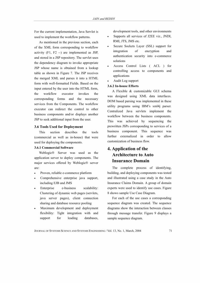
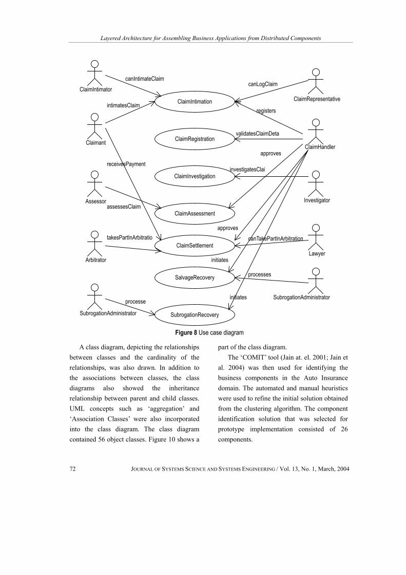
4. Application of the Architecture to Auto Insurance Domain The complete process of identifying,
building, and deploying components was tested and illustrated using a case study in the Auto Insurance Claims Domain. A group of domain experts were used to identify use cases. Figure 8 shows sample Use Case Diagram.
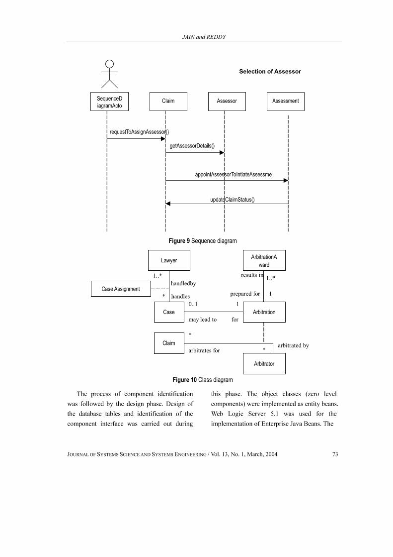
For each of the use cases a corresponding sequence diagram was created. The sequence diagrams show the interaction between classes through message transfer. Figure 9 displays a sample sequence diagram.
Layered Architecture for Assembling Business Applications from Distributed Components
72 JOURNAL OF SYSTEMS SCIENCE AND SYSTEMS ENGINEERING / Vol. 13, No. 1, March, 2004
ClaimIntimation
ClaimRegistration
ClaimInvestigation
ClaimAssessment
ClaimSettlement
SalvageRecovery
SubrogationRecovery
ClaimIntimator
Claimant
Assessor
Arbitrator
SubrogationAdministrator
canIntimateClaim
intimatesClaim
receivesPayment
assessesClaim
processe
takesPartInArbitratio
ClaimRepresentative
ClaimHandler
Investigator
Lawyer
SubrogationAdministrator
canLogClaim
registers
validatesClaimDeta
approves
investigatesClai
approves
processes
initiates
initiates
canTakePartInArbitration
Figure 8 Use case diagram
A class diagram, depicting the relationships between classes and the cardinality of the relationships, was also drawn. In addition to the associations between classes, the class diagrams also showed the inheritance relationship between parent and child classes. UML concepts such as ‘aggregation’ and ‘Association Classes’ were also incorporated into the class diagram. The class diagram contained 56 object classes. Figure 10 shows a
part of the class diagram. The ‘COMIT’ tool (Jain at. el. 2001; Jain et
al. 2004) was then used for identifying the business components in the Auto Insurance domain. The automated and manual heuristics were used to refine the initial solution obtained from the clustering algorithm. The component identification solution that was selected for prototype implementation consisted of 26 components.
JAIN and REDDY
JOURNAL OF SYSTEMS SCIENCE AND SYSTEMS ENGINEERING / Vol. 13, No. 1, March, 2004 73
SequenceD iagramActo
Assessment Claim Assessor
requestToAssignAssessor()
getAssessorDetails()
appointAssessorToIntiateAssessme
updateClaimStatus()
Selection of Assessor
Figure 9 Sequence diagram
Lawyer
Case
ArbitrationAward
Arbitration
Arbitrator
Case Assignment
Claim
1..* 1..*
0..1 1
handledby
* handles
may lead to for
arbitrates forarbitrated by
results in
prepared for 1
*
*
Figure 10 Class diagram
The process of component identification was followed by the design phase. Design of the database tables and identification of the component interface was carried out during
this phase. The object classes (zero level components) were implemented as entity beans. Web Logic Server 5.1 was used for the implementation of Enterprise Java Beans. The

Layered Architecture for Assembling Business Applications from Distributed Components
74 JOURNAL OF SYSTEMS SCIENCE AND SYSTEMS ENGINEERING / Vol. 13, No. 1, March, 2004
Add Intimation Details Add Claimant Details Add Involved Party Details
Add Involved
Structure Details
Add Involved
Vehicle Details
Add Event Details
Figure 11 Dependency diagram for business use case ‘Claim Intimation’
Check Policy Existence
Initiate Intimation
Claim Intimation Party
Claimant
Add Claimant DetailsSearch
Intimation Details
Figure 12 Services offered by business component ‘Claim Intimation’
persistent data were stored in Oracle 8i database. The 26 business components identified above were implemented as session
beans. Some of these 26 business components were used to create 6 higher-level components that supported sub processes such as claim
JAIN and REDDY
JOURNAL OF SYSTEMS SCIENCE AND SYSTEMS ENGINEERING / Vol. 13, No. 1, March, 2004 75
initiation, claim assessment etc. For the purpose of assembling an
application for a specific company we used requirements of a simulated Tata Insurance company. Appropriate components were selected to assemble a complete insurance claim application for the simulated company (Jain at. el. 2003).
Figure 11 shows the part of an application dependency diagram, which represents the business use case ‘Claim Intimation’. Each element in this diagram represents a ‘service’ provided by a business component. The arrows depict the sequence of execution of these services. For example, the service ‘Add Intimation Details’ in this diagram is served by business component named ‘Claim Intimation’. Other services offered by this component are shown in Figure 12. Some of the other services of this component are invoked at different stages of the workflow. It is not necessary to invoke all the services of the component. The ability to change application in response to changes in business processes or workflow was tested and was found to work well.
5. Conclusions and Future Direction Component based system development
technology is becoming increasingly important and is being looked upon as a potential solution to the software crisis. In spite of increased activities in this field the availability of off-the-shelf business components is very limited. Additionally, systematic approaches, tools and techniques for component identification, development, deployment and
management are lacking. This paper presented an overview of a major research effort targeted at addressing issues related to component identification, development, and storage and application assembly. A layered architecture based on the Enterprise Java Beans, XML, and JSP technology is presented. The architecture was applied to auto insurance claims domain to serve as proof of concept. Further work needs to be done to test this framework on a much larger domain. Also reusability of components across multiple domains needs to be tested. Additionally, issues related to performance of the end applications and its scalability needs to be addressed.
References [1] Allen, P. and S. Frost, Component-Based
Development for Enterprise Systems: Applying the SELECT Perspective, Cambridge University Press, Cambridge, UK, 1998.
[2] Apte, U. and C. S. Sankar , “Reusability- based strategy for development of information systems: implementation experience of a bank”, MIS Quarterly, Vol. 14, No. 4, pp421-433, 1990.
[3] Basu, A. and A. Kumar, “Research commentary: workflow management issues in e-Business”, Information Systems Research, Vol. 13, No. 1, pp1-14, 2002.
[4] Brown, A. W., Large-scale component- based development, Prentice Hall, 2000.
[5] Herzum, P. and O. Sims, Business Component Factory: A Comprehensive Overview of Component-Based

Layered Architecture for Assembling Business Applications from Distributed Components
76 JOURNAL OF SYSTEMS SCIENCE AND SYSTEMS ENGINEERING / Vol. 13, No. 1, March, 2004
Development for the Enterprise, John Wiley & Sons, New York, 2000.
[6] Jain, H., N. Chalimeda, N. Ivaturi and B. Reddy, “Business component identification – a Formal approach”, Proc. of IEEE Conference on Enterprise Distributed Object Computing, 2001.
[7] Jain, H, H. Zhao, and N. Chinta, “A spanning tree based approach to identifying web services”, International Journal of Web Services Research, Vol. 1, No. 1, pp1-20, 2004.
[8] Jain, H., P. Vitharana and M. Zahedi, “An assessment model for requirements identification in component-based software development”, The DATA BASE for Advances in Information Systems, Vol. 34, No. 4, pp 47-63, 2003.
[9] Monson-Haefel, R., Enterprise Java Beans, O’Reilly and Associates, Inc., 2000.
[10] Navarro, A., C. White and L. Burman, Mastering XML, SYBEX, Inc, 1999.
[11] Roman, E., Mastering Enterprise Java Beans and the Java 2 Platform Enterprise edition, Wiley Computer publication, 1999.
[12] Rosenberg, D. and K. Scott, Use Case Driven Object Modeling with UML- A Practical Approach, Addison Wesley Longman, Inc., 1999.
[13] Vitharana, P., H. Jain and M. Zahedi, “Strategy-based design of reusable business components”, to appear IEEE Transactions on Systems, Man and Cybernetics – Part C Applications and Reviews, 2004.
[14] Vitharana, P., M. Zahedi, and H. Jain,
“Knowledge-based repository scheme for storing and retrieving business components: a theoretical design and an empirical analysis”, IEEE Transactions on Software Engineering, Vol. 29, No. 7, pp649-664, 2003.
Hemant Jain is Wisconsin Distinguished & Tata Consultancy Services Professor of Management Information System. Prof. Jain received his Ph. D. in Information System from Lehigh University in 1981, a M. Tech. in Industrial Engineering from I.I.T. Kharagpur (India) and B.S. in Mechanical Engineering from University of Indore (India).
Prof. Jain’s interests are in the area of Electronic Commerce, System Development using Reusable Components and Web Services, Distributed and Co-operative Computing Systems, Architecture Design, Database Management and Data Warehousing. He has published over fourty articles in leading journals like Information Systems Research, MIS Quarterly, IEEE transactions on Software Engineering, Journal of MIS, IEEE Transactions Systems Man and Cybernetics, Navel Research Quarterly, Decision Sciences, Decision Support Systems, Communications of ACM and Information & Management. Additionally, he has published over 40 papers in referred conference proceedings. Prof. Jain is on the Editorial Board of the Information Technology & Management, Information Management, International Journal of Information Technology, and Decision Making, Journal of Information Technology Cases & Applications, and Journal of Web services Research. He is a member of Service, Systems,

JAIN and REDDY
JOURNAL OF SYSTEMS SCIENCE AND SYSTEMS ENGINEERING / Vol. 13, No. 1, March, 2004 77
and Organizations Technical Committee of the IEEE SMC Society. He has consulted for a number of fortune 500 companies.
Balarama Reddy Thavanati is an IT Analyst, with Tata Consultancy Services, India. He received a Masters of Technology in Industrial
Engineering & Management from Indian institute of technology, Kharagpur, India and B. Tech. in Electronics & Communication Engineering from Sri Venkateswara University, Tirupati, India. He is published a number of papers in conference proceedings. He is a member of IEEE.