LaserCM Portable Particle Counter Marketing Kit - ESMA Group
101
LaserCM Portable Particle Counter Marketing Kit FDCM133UK Date: September 2005 Related Catalogue: FDCB118GB2
-
Upload
khangminh22 -
Category
Documents
-
view
0 -
download
0
Transcript of LaserCM Portable Particle Counter Marketing Kit - ESMA Group
LaserCM
Portable Particle Counter
Marketing Kit
FDCM133UK
Date: September 2005
Related Catalogue: FDCB118GB2
Contents
1. Introduction 2. Features 3. Benefits
4. Examples of Applications 5. Working and Testing 6. Interpreting Results
7. How the Laser CM20 Works 8. ISO Standards – Understanding MTD 9. Specifications and Peripherals 10. Service and Recalibration 11. Questions and Answers
12. Fluid Compatability 13. Ordering Information
14. Endorsements
15. Other Available products 16.1. Advantages 17. Presentation
18. Contact Information
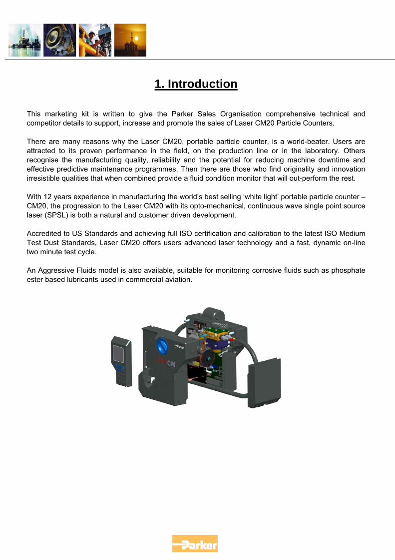
1. Introduction
This marketing kit is written to give the Parker Sales Organisation comprehensive technical and competitor details to support, increase and promote the sales of Laser CM20 Particle Counters.
There are many reasons why the Laser CM20, portable particle counter, is a world-beater. Users are attracted to its proven performance in the field, on the production line or in the laboratory. Others recognise the manufacturing quality, reliability and the potential for reducing machine downtime and effective predictive maintenance programmes. Then there are those who find originality and innovation irresistible qualities that when combined provide a fluid condition monitor that will out-perform the rest.
With 12 years experience in manufacturing the world’s best selling ‘white light’ portable particle counter – CM20, the progression to the Laser CM20 with its opto-mechanical, continuous wave single point source laser (SPSL) is both a natural and customer driven development.
Accredited to US Standards and achieving full ISO certification and calibration to the latest ISO Medium Test Dust Standards, Laser CM20 offers users advanced laser technology and a fast, dynamic on-line two minute test cycle.
An Aggressive Fluids model is also available, suitable for monitoring corrosive fluids such as phosphate ester based lubricants used in commercial aviation.
2. Features Test Time: 2 minutes. Repeat Test Time: Every 2 minutes. Principle of Operation: Optical scanning analysis and measurement of actual
particulates. Particle counts:
2+, 5+, 15+, 25+, 50+ and 100+ microns. 4+, 6+, 14+, 21+, 38+ and 70+ microns(c).
International codes ISO 7-23, NAS 0-12 Data entry:
32 character two line dot matrix LCD. Full alpha numeric entry facility on keypad.
Data retrieval: Memory access gives test search facility. Calibration:
Capable of achieving certification to ISO 4406:1999 and with traceability to ISO 11171 for SRM 2806, via ISO 11943 by accepted on-line methods confirmed by the relevant ISO procedures.
Re-calibration: Consult Parker. Max. working pressure: 420 bar. Max. flow rate:
400 l/min when used with System 20 Sensors. Higher with Single Point Sampler (Consult Parker).
Working Conditions: Laser CM20 will operate with the system working normally. Memory store: 300 test (scrolling memory) capacity. Computer compatibility: Interface via RS 232 connection @ 9600 baud rate. Portability: Only 8 kg. Laser CM20 has its own battery pack. Power requirement: Battery powered or via the 12vDC input. System connection: Via System 20 Inline Sensors or the Single Point Sampler. Printer facility: Integral 16 column printer for hard copy data. Leak free sampling:
System 20 Inline Sensors ensure sealed fluid extraction and no contamination ingress.
Certification: Complies with all relevant EC declarations of conformity.
FAIL SAFE FEATURES
Special ‘Diagnostics’ are incorporated into the Laser CM20 microprocessor control to ensure effective testing.
Circuitry: Incorporates an internal diagnostic programme to ensure integrity of results.
Adequate flow: Flow test facility ensures adequate flow. Adverse conditions: On-board trace heating enabling testing in adverse conditions can be
offered as an optional extra. DATA MANAGEMENT
A specially designed DATUM software package is supplied to enable downloading of test results onto a computer
3. Benefits
• Routine contamination monitoring of oil systems with Laser CM20 saves time and saves money.
• Contamination monitoring is now possible while machinery is working – Laser CM20 saves
on production downtime. • Instant, accurate results are available to international standards in hard copy form. That
means system maintenance decisions can be taken immediately. • Laser CM20 ensures that machinery hydraulic systems are tested in manufacture to ISO
cleanliness standards. • Data entry allows individual equipment test log details to be recorded. • Data retrieval of test results from memory via hand set display. • Data graphing of up to 30 test results can be selected for integral printing. • Automatic test cycle logging of up to 300 tests can be selected via hand set display. • User friendly instrument improves familiarity and awareness of service and maintenance
personnel. • Manufactured from lightweight Lexan expanded structural foam, which is both durable and
strong. • Totally portable, can be used as easily in the field as in the laboratory. • Computer interfacing available for downloading data on to compatible computer, through
Laser CM20’s RS232 serial port @ 9600 baud rate. • Internal diagnostic feature ensures Laser CM20 will work accurately and reliably. • Supplied in an Astraboard carrying case. • Automatic calibration reminder.
4. Examples of Applications
Railroad Way Maintenance Equipment Service support Delivery certification Railroad Equipment Manufacturers Cleanliness certification Warranty protection Pulp & Paper Plants Preventative maintenance Lumber Mills Preventative maintenance Heavy Equipment Manufacturers Roll-off cleanliness testing Warranty certification Service tool Industrial Hydraulic Systems Troubleshooting tool Preventative maintenance Amusements Parks Preventative maintenance Service tool Flight Simulator Manufacturers Roll-off cleanliness testing Service & Installation Tool Warranty back-up Marine Hydraulic Systems Service tool Power Generation Stations Preventative maintenance Transport Departments Highway equipment maintenance Mobile Equipment Manufacturers Roll-off cleanliness testing Warranty certification
Oil & Gas Platforms Preventative maintenance Service tool Oil Rig Suppliers Certification of components Oil Reclamation Certification Hydraulic Repair Centres Test stand certification Repair certification Warranty protection Hydraulic Component Manufacturers Component cleanliness certification Warranty protection Mining Operations Preventative maintenance Service tool Automotive Manufacturing & Suppliers Cleanliness testing Component flushing Endurance testing Steel Mills Preventative maintenance Shipbuilding Cleanliness testing Flushing efficiency
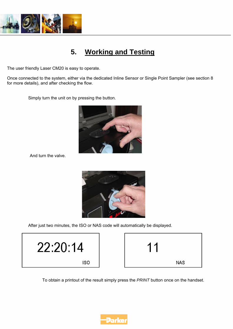
5. Working and Testing
The user friendly Laser CM20 is easy to operate. Once connected to the system, either via the dedicated Inline Sensor or Single Point Sampler (see section 8 for more details), and after checking the flow.
Simply turn the unit on by pressing the button.
And turn the valve.
After just two minutes, the ISO or NAS code will automatically be displayed.
To obtain a printout of the result simply press the PRINT button once on the handset.
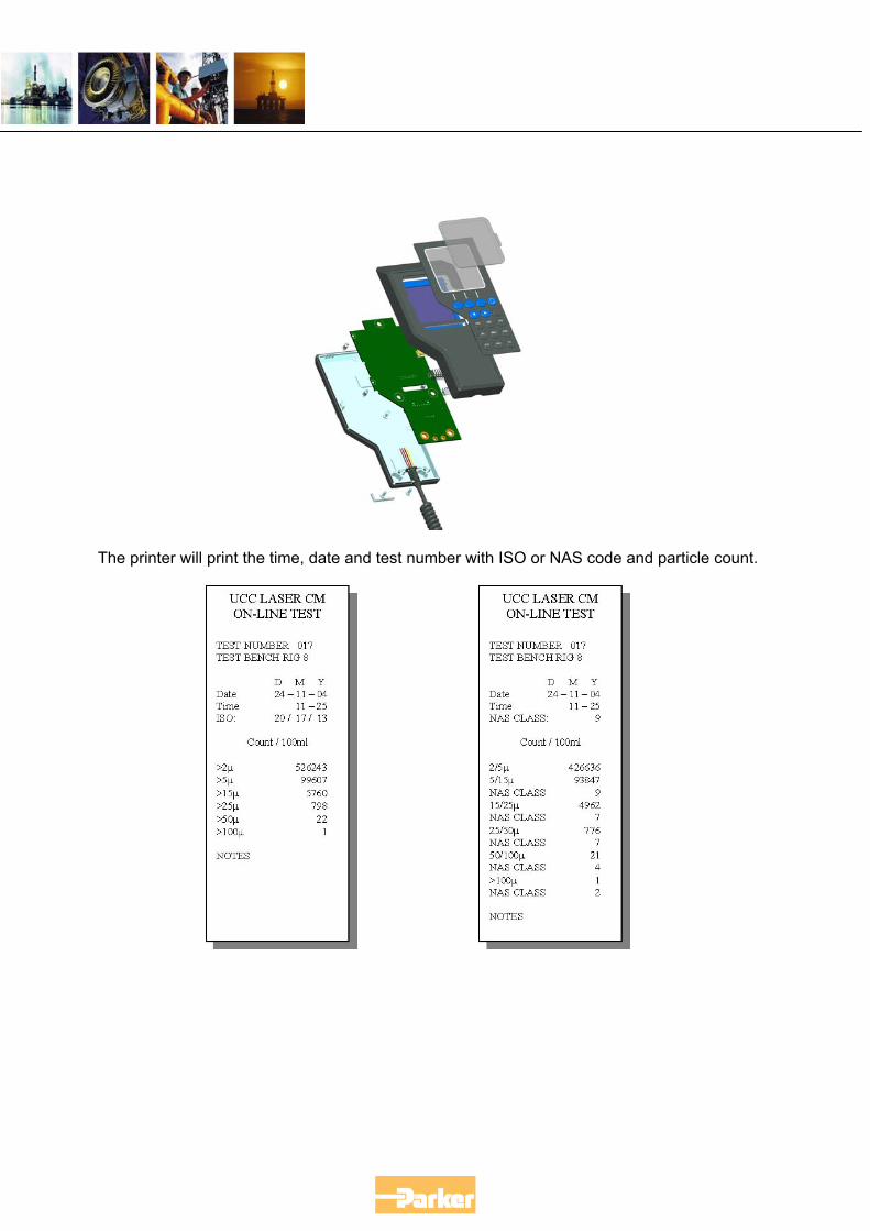
The printer will print the time, date and test number with ISO or NAS code and particle count.
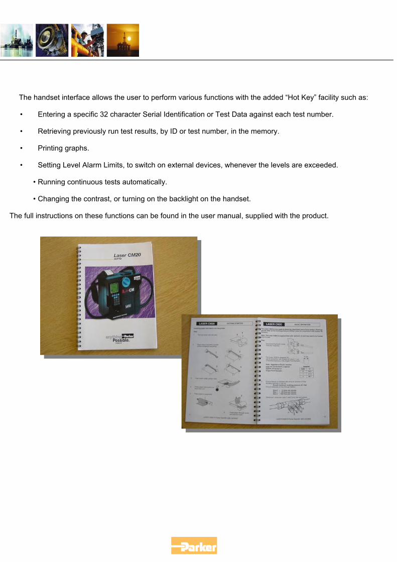
The handset interface allows the user to perform various functions with the added “Hot Key” facility such as: • Entering a specific 32 character Serial Identification or Test Data against each test number. • Retrieving previously run test results, by ID or test number, in the memory. • Printing graphs. • Setting Level Alarm Limits, to switch on external devices, whenever the levels are exceeded.
• Running continuous tests automatically. • Changing the contrast, or turning on the backlight on the handset.
The full instructions on these functions can be found in the user manual, supplied with the product.
6. Interpr
6.1 Typical Data Read – Out
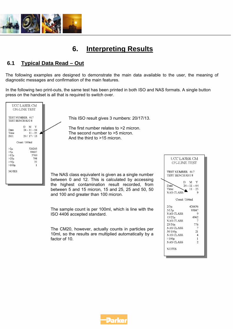
The following examples are designed to demonstradiagnostic messages and confirmation of the main fea In the following two print-outs, the same test has beenpress on the handset is all that is required to switch ov
This ISO result gives The first number relaThe second number And the third to >15
The NAS class equivalent is gbetween 0 and 12. This is cthe highest contamination between 5 and 15 micron, 15and 100 and greater than 100 The sample count is per 100mISO 4406 accepted standard. The CM20, however, actually10ml, so the results are multifactor of 10.
eting Results
te the main data available to the user, the meaning of tures.
printed in both ISO and NAS formats. A single button er.
3 numbers: 20/17/13.
tes to >2 micron. to >5 micron. micron.
iven as a single number alculated by accessing result recorded, from and 25, 25 and 50, 50 micron.
l, which is line with the
counts in particles per plied automatically by a
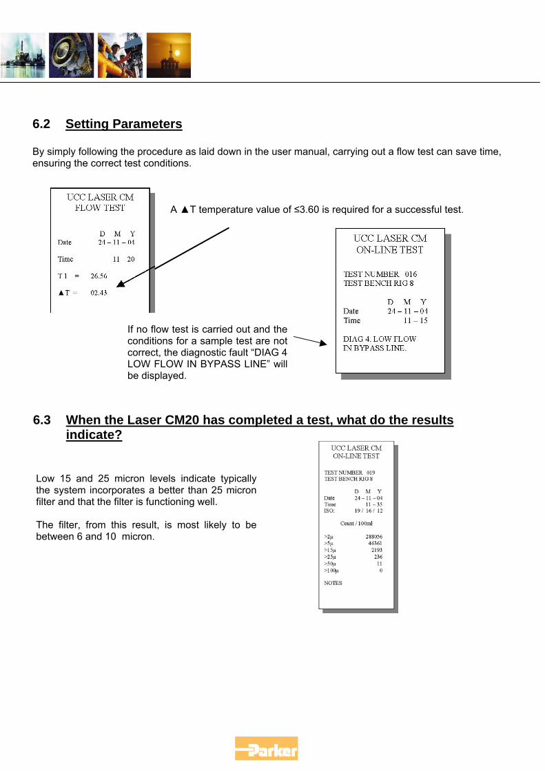
6.2 Setting Parameters By simply following the procedure as laid down in the user manual, carrying out a flow test can save time, ensuring the correct test conditions.
6.3
Lothfilt Thbe
A ▲T temperature value of ≤3.60 is required for a successful test.
If no flow test is carried out and theconditions for a sample test are notcorrect, the diagnostic fault “DIAG 4LOW FLOW IN BYPASS LINE” willbe displayed.
When the Laser CM20 has completed a test, what do the results indicate?
w 15 and 25 micron levels indicate typically e system incorporates a better than 25 micron er and that the filter is functioning well.
e filter, from this result, is most likely to be tween 6 and 10 micron.
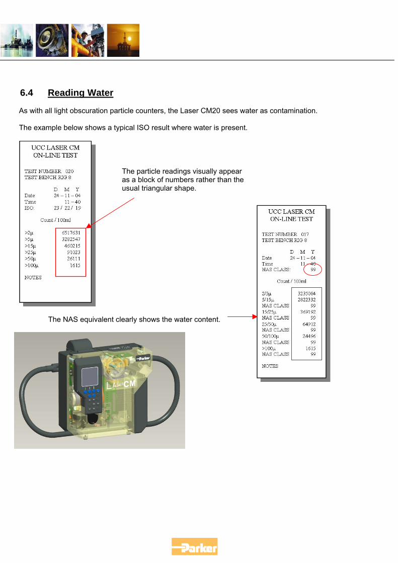
6.4 Reading Water
As with all light obscuration particle counters, the Laser CM20 sees water as contamination. The example below shows a typical ISO result where water is present.
The NAS equivalent clearly shows the water content.
The particle readings visually appear as a block of numbers rather than the usual triangular shape.
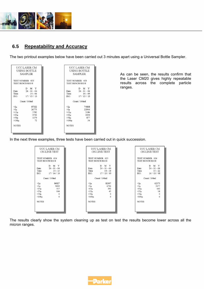
6.5 Repeatability and Accuracy
The two printout examples below have been carried out 3 minutes apart using a Universal Bottle Sampler.
As can be seen, the results confirm that the Laser CM20 gives highly repeatable results across the complete particle ranges.
In the next three examples, three tests have been carried out in quick succession.
The results clearly show the system cleaning up as test on test the results become lower across all the micron ranges.
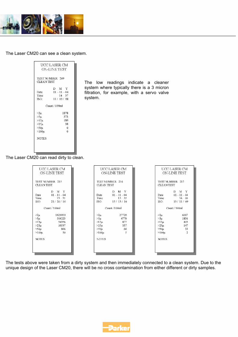
The Laser CM20 can see a clean system.
The low readings indicate a cleanersystem where typically there is a 3 micronfiltration, for example, with a servo valvesystem.
The Laser CM20 can read dirty to clean.
The tests above were taken from a dirty system and then immediately connected to a clean system. Due to the unique design of the Laser CM20, there will be no cross contamination from either different or dirty samples.
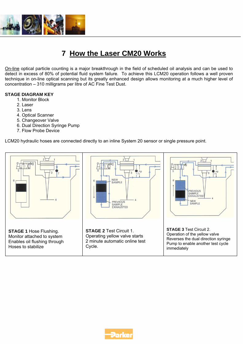
7 How the Laser CM20 Works
On-line optical particle counting is a major breakthrough in the field of scheduled oil analysis and can be used to detect in excess of 80% of potential fluid system failure. To achieve this LCM20 operation follows a well proven technique in on-line optical scanning but its greatly enhanced design allows monitoring at a much higher level of concentration – 310 milligrams per litre of AC Fine Test Dust. STAGE DIAGRAM KEY
1. Monitor Block 2. Laser 3. Lens 4. Optical Scanner 5. Changeover Valve 6. Dual Direction Syringe Pump 7. Flow Probe Device
LCM20 hydraulic hoses are connected directly to an inline System 20 sensor or single pressure point.
STAGE 2 Test Circuit 1. Operating yellow valve starts 2 minute automatic online test Cycle.
STAGE 1 Hose Flushing. Monitor attached to system Enables oil flushing through Hoses to stabilize
STAGE 3 Test Circuit 2. Operation of the yellow valve Reverses the dual direction syringe Pump to enable another test cycle immediately
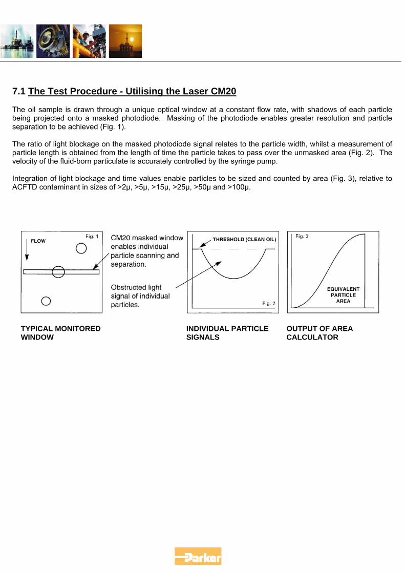
7.1 The Test Procedure - Utilising the Laser CM20
The oil sample is drawn through a unique optical window at a constant flow rate, with shadows of each particle being projected onto a masked photodiode. Masking of the photodiode enables greater resolution and particle separation to be achieved (Fig. 1). The ratio of light blockage on the masked photodiode signal relates to the particle width, whilst a measurement of particle length is obtained from the length of time the particle takes to pass over the unmasked area (Fig. 2). The velocity of the fluid-born particulate is accurately controlled by the syringe pump. Integration of light blockage and time values enable particles to be sized and counted by area (Fig. 3), relative to ACFTD contaminant in sizes of >2µ, >5µ, >15µ, >25µ, >50µ and >100µ.
TYPICAL MONITORED INDIVIDUAL PARTICLE OUTPUT OF AREA WINDOW SIGNALS CALCULATOR
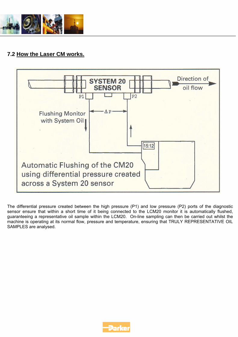
7.2 How the Laser CM works.
The differential pressure created between the high pressure (P1) and low pressure (P2) ports of the diagnostic sensor ensure that within a short time of it being connected to the LCM20 monitor it is automatically flushed, guaranteeing a representative oil sample within the LCM20. On-line sampling can then be carried out whilst the machine is operating at its normal flow, pressure and temperature, ensuring that TRULY REPRESENTATIVE OIL SAMPLES are analysed.
7.3 On-Line Monitoring for Oil Cleanliness Standards
There are many reasons why contamination level monitoring should be carried out on-line and all are associated with achieving an oil sample that is truly representative of the condition of the oil whilst the machine or system is in operation. Major influences on true representative oil samples are:
• Actual sampling procedure • Cleanliness standards of sample bottle • Static sampling rather than dynamic, as on-line • Changes in physical state of oil – due to time delays • Particle suspension in fluid • Possible aeration of sample • Sample dilution errors
SAMPLING PROCEDURE The most significant error in traditional oil analysis derives from the actual way in which the oil sample is collected. Even though the oil sample may have been taken from a dynamic part of the system, whilst the machine is running, the sample valve or fitting from which the samples are collected are often added to the system as an after thought and consequently are not fitted to representative parts of the circuit. Often sample valve flushing procedures are inadequate or are simply not adhered to, resulting in “dead spots” of oil, containing large accumulations of contaminant, being washed straight into the sample container.
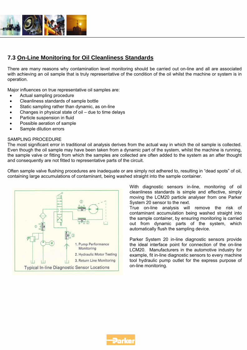
With diagnostic sensors in-line, monitoring of oil cleanliness standards is simple and effective, simply moving the LCM20 particle analyser from one Parker System 20 sensor to the next. True on-line analysis will remove the risk of contaminant accumulation being washed straight into the sample container, by ensuring monitoring is carried out from dynamic parts of the system, which automatically flush the sampling device. Parker System 20 in-line diagnostic sensors provide the ideal interface point for connection of the on-line LCM20. Manufacturers in the automotive industry for example, fit in-line diagnostic sensors to every machine tool hydraulic pump outlet for the express purpose of on-line monitoring.
8 ISO Standards – Understanding MTD
ACFTD (Air Cleaner Fine Test Dust) was formatted in the 1960’s, but is no longer being produced. The obsolescence of this dust has led to the adoption of a new dust MTD. MTD (Medium Test Dust) having a particle size distribution close to ACFTD was selected as a replacement. However, MTD produced results somewhat different to ACFTD, so the NIST (National Institute of Standards & Technology) undertook a project to certify the particle size distribution of ISO MTD. The result was particle sizes below 10µm were greater than previously measured. Particles sizes reported based on NIST would be represented as µm (c), with “c” referring to “certified”. Therefore the CM20 reported sizes are as follows:
ACFTD 2µ 5µ 15µ 25µ 50µ 100µ
MTD offers true traceability, improved particle size accuracy and better batch-to-batch reproduction.
MTD 4µ ( c ) 6µ ( c ) 14µ ( c ) 21µ ( c ) 38µ ( c ) 70µ (c )
8.1 ISO 11171
Many people have begun to ask the question, “Does the Laser CM20 conform to ISO 11171?”. ISO 11171 is a standard that has been developed for Automatic Particle Counters (APC) that is fixed in the system at one point only. The LCM20 is considered to be a "Portable Contamination Monitor". This standard, therefore, does not cover our products. A full calibration to ISO 11171, which is via bottle sampling using 2 special traceable bottles of test dust oil (SRM 2806 @ $691, not including labour), takes many hours of work, many calculations and must meet 5 annexes. 1. Flow rate limits, 2. Coincidence errors, 3. Resolution, 4. Accuracy of the sensor 5. Volume accuracy of the sample. As soon as one of these annexes changes, the calibration is void. These are neither practical nor affordable for our production units. The requirements we can meet are ISO 4406:1999, which is the ability to size, count and report 4 micron(c), 6 micron(c), and 14 micron(c) particles using Medium Test Dust (MTD). We also have traceability to ISO 11171, via ISO:11943 - ("Hydraulic fluid power - on-line liquid automatic particle-counting systems - Methods of calibration and validation”), as our Master units were calibrated to a system, which was fully compliant with the 5 annexes above.
8.2 The importance of Contamination Codes. The international Standard for defining the cleanliness of hydraulic or lubricating fluids is ISO4406. The standard clearly defines progressive numerical levels of particulate on a cumulative basis. Such data must be considered when designing a system or selecting components. Determining an acceptable contamination level for a system will depend upon the selected components’ sensitivity, as well as the performance and positioning of the filtration equipment. By emphasising the importance of system cleanliness, in terms of analysis and control to both manufacturer and user, a cost-effective programme of contamination control and equipment maintenance can be achieved. What is an ISO number? An ISO contamination number provides a band of contamination particle quantities greater than 5 micron and greater than 15 micron per millilitre of fluid. (for example, ISO code 18/13 indicates that there are between 130,000 and 250,000 particles larger than 5 micron and between 4,000 and 8,000 particles larger than 15 micron per 100 ml of fluid. Confirming/Monitoring cleanliness of fluid Many of the problems of system/component failure associated with the presence of contamination could be eradicated by cleanliness level monitoring. By monitoring the cleanliness level of a system in a controlled and traceable maintenance programme, the user is able to ensure that any deviation from the requisite parameters are detected early and acted upon to prevent further deterioration. 8.3 Sources of Contamination Solid contaminants will be encountered as a result of four main sources. Knowledge concerning their basic characteristics is important when considering the design and positioning of filter equipment. New Oil Contamination Stored oil, in drums or tanks will inevitably contain solid contaminants. Most drum oil is only filtered to 50 micron before being despatched. Drums will contribute contaminants to the oil if stored incorrectly. Corrosion may occur if condensate water is allowed to accumulate, thus leading to oxide particulate generation. Drums left open, or tanks with ineffective vent filters, will allow atmospheric contamination to be ingressed. Using a Parker Portable Filtration Package will ensure that solid contaminant is removed whilst transferring fluid, before it can enter the system and ultimately damage components. Built in contamination Even the cleanest assembly shop will inevitably build in some contaminant during the production procedure. Contaminants such as metal, rubber (hoses etc.), pipe sealant and fibres will be evident. In this respect the Parker Contamination Monitor, LCM20, is an invaluable aid in the monitoring of cleanliness levels during the flushing stage of any assembly operation, be it component or system.
Ingressed contamination Atmospheric contamination particularly in a dirty environment can best reduced by having effective reservoir breathers. For example, specifying a Parker Filler Breather Filter will ensure that the risk of surrounding contamination ingressing through the reservoir vent port will be greatly reduced. Contaminant is also ingressed through normal servicing/routine maintenance operations. In fact, any action that entails direct con tact between the system fluid and the environmental will allow contaminant to be ingressed. Generated contamination If potentially harmful contaminant is not quickly removed from a system, it will cause a greater and greater accumulation of solids through a cycle of regeneration. As particles impact upon surfaces, they gradually cause microscopic stress cracks which propagate until a fracture occurs, generating contaminant. This leads to damage to critical tolerances between fine machined surfaces and damaging modifications to clearances. Starting with a clean system and keeping it clean with Parker suction and return line filters such as the Multiflow tank mounted filter with built-in condition indicator is the best way to keep the wheels turning! 8.4 Knowing the System Factors such as component load, pressure, critical clearances and others must be considered when analysing why components fail due to contamination. Also confirming which type of contaminant induced failure has been the cause, eg: catastrophic, intermittent or degradation failure. Knowing the system also means knowing the best way to sample the fluid as the first step to checking and establishing acceptable and achievable contamination targets. The principal sampling methods can be defined as:- Bottle Sampling Taken when the system is in operation it is representative of system conditions at that moment of time and thus a subject to system factors, ie. location, fluid viscosity, point in duty cycle etc. For purposes of accuracy and consistency it is important to maintain a regime of repeated sampling at similar conditions and intervals. As a sampling technique, the fluid is collected into a sample bottle for remote analysis at a designated laboratory. This provides the potential for error as well as time delay in receiving results. On-line Sampling The most preferred method of obtaining data on cleanliness levels. By sampling on-line error potentials associated with bottle analysis are effectively removed. It allows for analysis to be rapidly conducted at virtually any time and at a broad range of conditions, duty and criticality. The LCM20 coupled with the System 20 In Line Sensor provides a most effective combination of equipment to identify cleanliness levels. The LCM20 can also be connected to a single pressure point by using the Parker Single Point Sampler. 8.5 Setting the Targets The first move in establishing correct cleanliness levels is to confirm how clean the system must be. Critical components within the system must be identified and ISO codes established for each one from manufacturers specifications. The target System Cleanliness Level is the lowest ISO code required of all the critical components in the system.
8.6 Achieving the targets The most important factors to consider are: the level of system cleanliness required by the critical components to ensure minimal damaging effect. The efficiency of the filtration equipment applied. The positioning of the filtration equipment. The nature and severity of duty and operating environment. Correct filter specification is essential Parker filters are designed and performance tested to ISO4572 (Multipass Filter Performance Test method) to enable efficient contamination control and assist in maintenance of cleanliness levels. As a guide, the following chart indicates suggest acceptable contamination levels in various types of system.
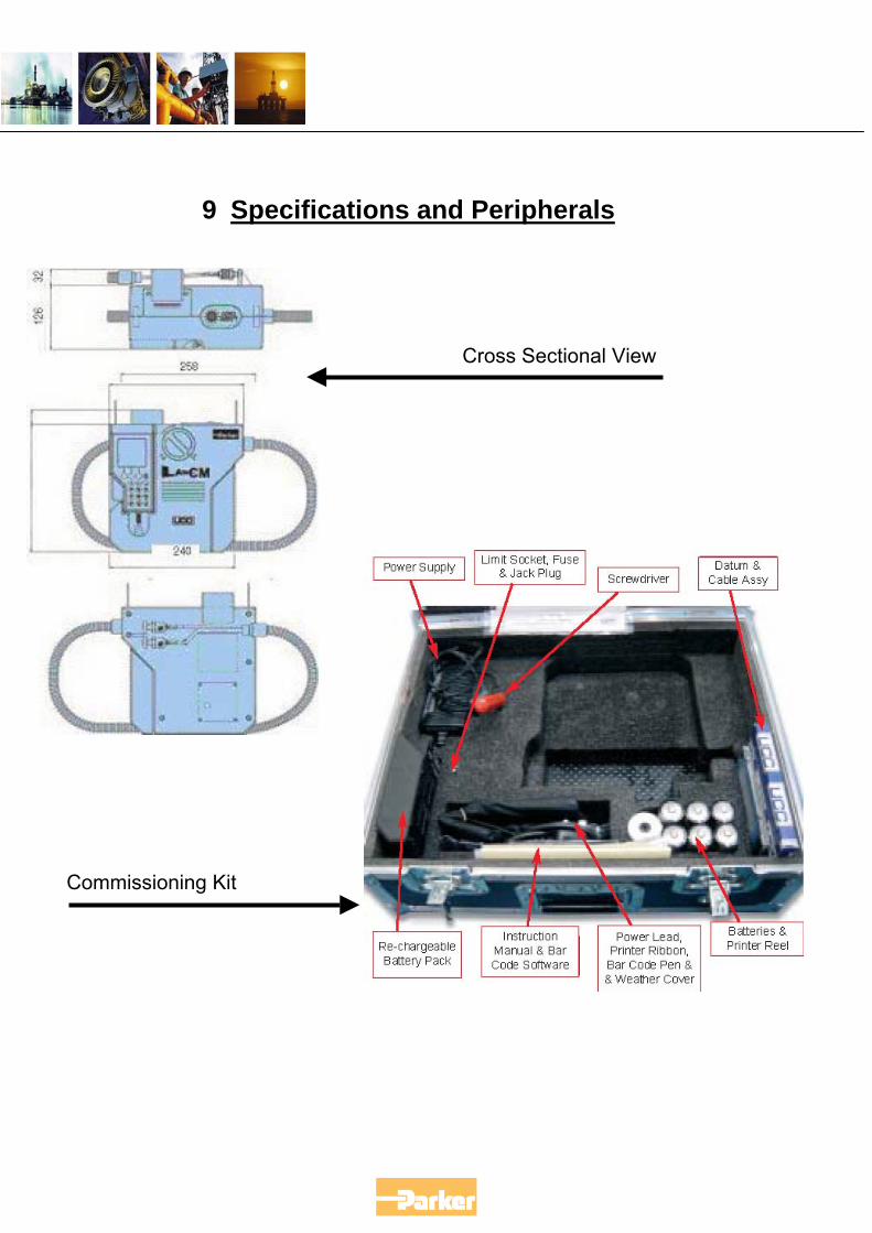
9 Specifications and Peripherals
Cross Sectional View
Commissioning Kit
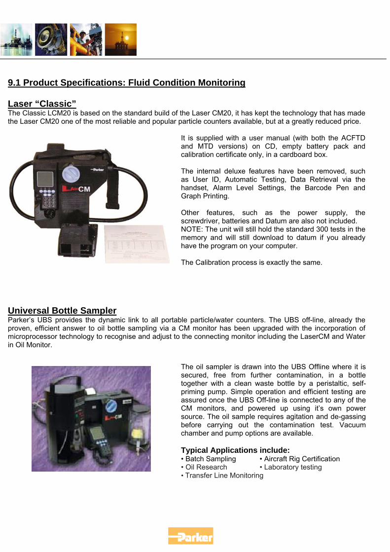
9.1 Product Specifications: Fluid Condition Monitoring Laser “Classic” The Classic LCM20 is based on the standard build of the Laser CM20, it has kept the technology that has made the Laser CM20 one of the most reliable and popular particle counters available, but at a greatly reduced price.
It is supplied with a user manual (with both the ACFTD and MTD versions) on CD, empty battery pack and calibration certificate only, in a cardboard box. The internaI deluxe features have been removed, such as User ID, Automatic Testing, Data Retrieval via the handset, Alarm Level Settings, the Barcode Pen and Graph Printing. Other features, such as the power supply, the screwdriver, batteries and Datum are also not included. NOTE: The unit will still hold the standard 300 tests in the memory and will still download to datum if you already have the program on your computer. The Calibration process is exactly the same.
Universal Bottle Sampler Parker’s UBS provides the dynamic link to all portable particle/water counters. The UBS off-line, already the proven, efficient answer to oil bottle sampling via a CM monitor has been upgraded with the incorporation of microprocessor technology to recognise and adjust to the connecting monitor including the LaserCM and Water in Oil Monitor.
The oil sampler is drawn into the UBS Offline where it is secured, free from further contamination, in a bottle together with a clean waste bottle by a peristaltic, self-priming pump. Simple operation and efficient testing are assured once the UBS Off-line is connected to any of the CM monitors, and powered up using it’s own power source. The oil sample requires agitation and de-gassing before carrying out the contamination test. Vacuum chamber and pump options are available. Typical Applications include: • Batch Sampling • Aircraft Rig Certification • Oil Research • Laboratory testing • Transfer Line Monitoring
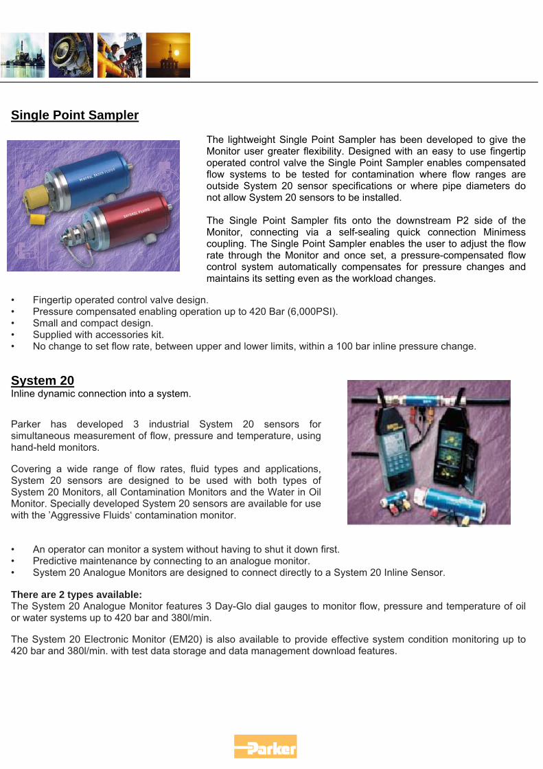
Single Point Sampler
The lightweight Single Point Sampler has been developed to give the Monitor user greater flexibility. Designed with an easy to use fingertip operated control valve the Single Point Sampler enables compensated flow systems to be tested for contamination where flow ranges are outside System 20 sensor specifications or where pipe diameters do not allow System 20 sensors to be installed. The Single Point Sampler fits onto the downstream P2 side of the Monitor, connecting via a self-sealing quick connection Minimess coupling. The Single Point Sampler enables the user to adjust the flow rate through the Monitor and once set, a pressure-compensated flow control system automatically compensates for pressure changes and maintains its setting even as the workload changes.
• Fingertip operated control valve design. • Pressure compensated enabling operation up to 420 Bar (6,000PSI). • Small and compact design. • Supplied with accessories kit. • No change to set flow rate, between upper and lower limits, within a 100 bar inline pressure change. System 20 Inline dynamic connection into a system.
Parker has developed 3 industrial System 20 sensors for simultaneous measurement of flow, pressure and temperature, using hand-held monitors.
Covering a wide range of flow rates, fluid types and applications, System 20 sensors are designed to be used with both types of System 20 Monitors, all Contamination Monitors and the Water in Oil Monitor. Specially developed System 20 sensors are available for use with the ’Aggressive Fluids‘ contamination monitor.
• An operator can monitor a system without having to shut it down first. • Predictive maintenance by connecting to an analogue monitor. • System 20 Analogue Monitors are designed to connect directly to a System 20 Inline Sensor. There are 2 types available: The System 20 Analogue Monitor features 3 Day-Glo dial gauges to monitor flow, pressure and temperature of oil or water systems up to 420 bar and 380l/min.
The System 20 Electronic Monitor (EM20) is also available to provide effective system condition monitoring up to 420 bar and 380l/min. with test data storage and data management download features.
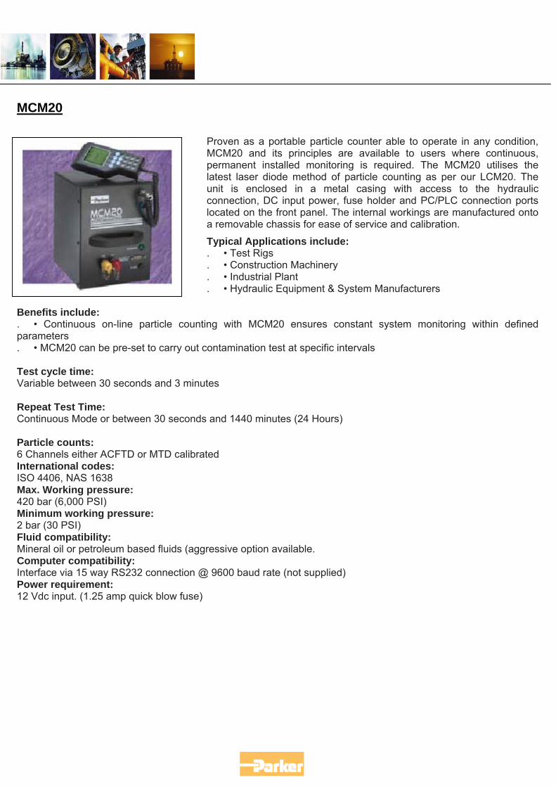
MCM20
Proven as a portable particle counter able to operate in any condition, MCM20 and its principles are available to users where continuous, permanent installed monitoring is required. The MCM20 utilises the latest laser diode method of particle counting as per our LCM20. The unit is enclosed in a metal casing with access to the hydraulic connection, DC input power, fuse holder and PC/PLC connection ports located on the front panel. The internal workings are manufactured onto a removable chassis for ease of service and calibration.
Typical Applications include: . • Test Rigs . • Construction Machinery . • Industrial Plant . • Hydraulic Equipment & System Manufacturers
Benefits include: . • Continuous on-line particle counting with MCM20 ensures constant system monitoring within defined parameters . • MCM20 can be pre-set to carry out contamination test at specific intervals Test cycle time: Variable between 30 seconds and 3 minutes Repeat Test Time: Continuous Mode or between 30 seconds and 1440 minutes (24 Hours) Particle counts: 6 Channels either ACFTD or MTD calibrated International codes: ISO 4406, NAS 1638 Max. Working pressure: 420 bar (6,000 PSI) Minimum working pressure: 2 bar (30 PSI) Fluid compatibility: Mineral oil or petroleum based fluids (aggressive option available. Computer compatibility: Interface via 15 way RS232 connection @ 9600 baud rate (not supplied) Power requirement: 12 Vdc input. (1.25 amp quick blow fuse)
10 Service and Recalibration
With ever growing competition for on-line particle counting, one of the major selling points of the Laser CM20 and other peripherals is the option of a dedicated Service Centre in the Country of sale, offering full service and re-calibration. Ask anyone in places such as America, Brazil, India, Singapore and Japan, not to mention France and most recently Norway and they will all tell you of many occasions where a sale has swung their way because they have had fully trained engineers, who speak their language and can help in technical matters quickly and confidently. Obviously, we still have many parts of the world, not covered by these Service Centres, which is why we have our own service department at the CMC, dealing with all UK and worldwide users.
11 Questions and Answers
What is the difference between on-line and bottle sampling? On-line monitoring is taking the instrument to the system while bottle sampling is taking the sample from the system to the instrument in a laboratory. On-line monitoring gives a more representative result of the system, due to the fact that fluid is circulating while the test is being taken. In the bottle sample a small portion of the fluid is drawn out of the system for analysis. The analysis is based on a small volume of fluid out of a typically large volume reservoir. Which method is better, on-line or bottle sampling? While bottle sampling allows the user to get a more complete analysis of the fluid, the drawback is the time to receive the results. The system is still operating while you wait for the result, so acting upon the result is fruitless. On-line monitoring allows the user to get the limited analysis in a few minutes and if the result is bad a re-sample can be taken right away. If it still shows poor results then an action can be taken right away. I already send samples to a lab, why should I buy a particle counter? Customers I’ve spoken to that send samples out routinely find a low percentage that are bad. Therefore, a significant saving can be realised if only those samples that fail the initial on-line analysis be sent to the lab for further analysis. When you sit down and calculate the cost of unnecessary lab samples your return on investment can be a matter of months, not to mention the speed of predicting the failure before it occurs. Will my existing bottle sample results match the LCM20 results? No, they probably will not. The reason for it is that the variables in the method of sampling are different. With a bottle you have two inherent problems, one is in extracting the sample from the system. Has it been done the same way, has the bottle been contaminated prior to filling the bottle, plus the cleanliness of the bottle before a sample is added. The second one is at the other end. Did the lab handle the sample correctly? Did they cross contaminate your sample with another? All these variables have been introduced into the bottle results. With the LCM20 the only variable is in the hook-up to the system. The LCM20 will flush its own line before the beginning of the test. Generally, the on-line results will be 1 or 2 ISO codes lower than the bottle because of all the variability of the bottle. How much pressure do I need to take a sample? The LCM20 needs a minimum of 5 psi differential and 30 psi line pressure. This will allow the oil to flow out and back into the system. Pressure only is needed for a single point sampling, but flow is needed for sensor applications. Does water in the oil affect the LCM20? Yes, water will affect the LCM20 particle count. The water will appear as large particles on the printout. This happens because the water has a lower viscosity than the oil and it will get into the view volume of the sensor and the detector will think it’s a large particle. Most people think this is a fault of the LCM20, but all light blockage instruments have the same problem, besides water is a contaminate and should be counted.
Does the LCM20 count air bubbles? Yes, air bubbles will be counted as particles in the LCM20. Again, if the system has air, it is considered a contaminate and should be accounted for. Generally no problems because in high pressure systems air is not that likely to be present in bubbles big enough to count.
Questions and Answers Continued….. What kinds of fluids can I run through the LCM20? The standard LCM20 is compatible with all petroleum and synthetic oils. Some phosphate esters can be run, but Skydrol cannot. Parker offers a Skydrol version of the LCM20 for this. What fluid temperature will the LCM20 handle? The LCM20 can handle oils as hot as 93°C. What viscosity of oil can I run through the LCM20? Viscosity’s up to 100 centistokes with no assistance can flow through the LCM20. With the use of a single point sampler and the trace-heating element, we can run viscosity of 800 centistokes. Where is the best place to take a sample in a system? The most asked question of all. Our recommendation is as close to the output of the pump. It provides the highest pressure and flow conditions, plus the oil at that position is indicative of the reservoir’s oil condition. A lot of people like to look downstream of the filter element, which is fine if you want to monitor the efficiency of the element. On the return line is another, often suggested, place which to me doesn’t make much sense. If the cleanliness should rise at this point, how would you determine where it came from? You would be forced to backtrack through the system until you found the point where the cleanliness went down. On the other hand, if you monitor what is feeding all the components and maintained the feed oil, the system should last. I also believe that a periodic check at other points in the system isn’t a bad idea. This will certainly give the operator peace of mind. The right answer is the question “What is the user interested in accomplishing through monitoring”? Do I have to install the System 20 sensor to do a particle count? No, you do not have to install the System 20 Sensors in-line and do particle counting. They are necessary only if you want to do temperature, flow and pressure measurements. If the system is pressurized the LCM20 can be connected directly to any pressure point via SPS methods. Care should be taken when connecting to a pressure point that the discharge hose is pointed away from anyone. Have a bucket or pail to catch the waste; better yet it could be returned to the reservoir or a lower pressure point in the system. Do you have a bottle sampler? Yes we do have a bottle sampling device. It works off 12VDC and the LCM20 connects directly to it. The UBS has a built-in waste container. I have a pressure compensated system. Can I sample from it? Yes, but only while it’s working. The problem is that there is flow only when there is demand. Closed loop systems are easier because you can have pressure with no flow and it is generally high enough to get the oil through the LCM20 via a single point. With open loop we have more difficulty because you can have flow with no pressure. This presents a problem in getting the oil out of the system. In those cases it is wise to work the system as close to normal operation keeping safety issues in mind to get the sample out.
Questions and Answers Continued….. What should my system’s ISO code be? This is the most difficult question to answer. You have to know what components are in the system to determine what it should be. Then you need to know the maintenance history of the system to determine where it might be now. Published literature has always said, set the cleanliness level of your system on the least tolerant component to maximise the system’s efficiency. How do I know the sample data is good or bad? Well, there is no foolproof way of knowing if the data is good or bad. Generally, if there are no error messages at the end of the test then you can consider the data good. Remember, the LCM20 counts whatever is in the fluid stream at that time. One thing to do is run several tests without moving the counter to see if the count is repeatable and consistent if successive tests give relatively the same code or count then that is what the system is. You may not like the answer, but that is another issue. What happens when the LCM20 reaches 300 tests in one memory? When the LCM20 reaches 300th test the memory rolls back to test number one. Some misunderstanding with this is that you get tests 299 and back. This is not true. The rollover that occurs cleans the memory and begins at one. It is wise when you get close to download the results so you don’t lose any data. Does the LCM20 need to be calibrated? Yes, it is recommended that the LCM20 be verified once a year against the master unit in the factory. As with any analytical instrument periodic verification is recommended. This is not unusual.
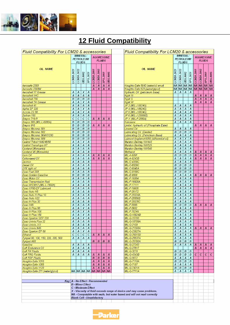
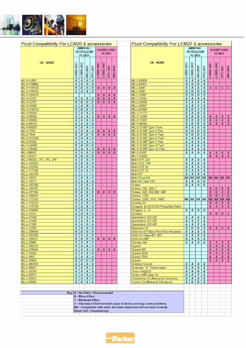
12 Fluid Compatibility
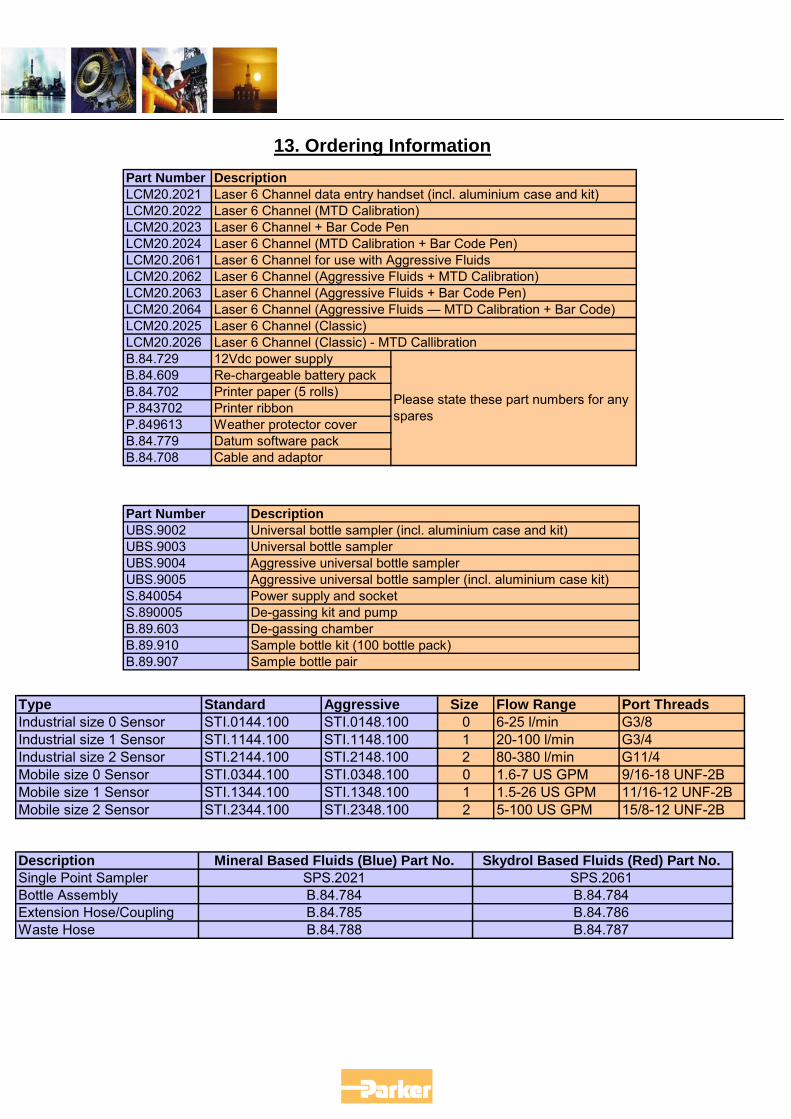
13. Ordering Information
Part Number LCM20.2021 LCM20.2022 LCM20.2023 LCM20.2024 LCM20.2061 LCM20.2062 LCM20.2063 LCM20.2064 LCM20.2025LCM20.2026B.84.729 12Vdc power supply B.84.609 Re-chargeable battery pack B.84.702 Printer paper (5 rolls) P.843702 Printer ribbon P.849613 Weather protector cover B.84.779 Datum software pack B.84.708 Cable and adaptor
Laser 6 Channel (Classic) - MTD Callibration
Please state these part numbers for any spares
Description
Laser 6 Channel (Aggressive Fluids — MTD Calibration + Bar Code)
Laser 6 Channel data entry handset (incl. aluminium case and kit) Laser 6 Channel (MTD Calibration) Laser 6 Channel + Bar Code Pen Laser 6 Channel (MTD Calibration + Bar Code Pen) Laser 6 Channel for use with Aggressive Fluids Laser 6 Channel (Aggressive Fluids + MTD Calibration) Laser 6 Channel (Aggressive Fluids + Bar Code Pen)
Laser 6 Channel (Classic)
Part Number Description UBS.9002 Universal bottle sampler (incl. aluminium case and kit) UBS.9003 Universal bottle sampler UBS.9004 Aggressive universal bottle sampler UBS.9005 Aggressive universal bottle sampler (incl. aluminium case kit) S.840054 Power supply and socket S.890005 De-gassing kit and pump B.89.603 De-gassing chamber B.89.910 Sample bottle kit (100 bottle pack) B.89.907 Sample bottle pair
Type Standard Aggressive Size Flow Range Port Threads Industrial size 0 Sensor STI.0144.100 STI.0148.100 0 6-25 l/min G3/8 Industrial size 1 Sensor STI.1144.100 STI.1148.100 1 20-100 l/min G3/4 Industrial size 2 Sensor STI.2144.100 STI.2148.100 2 80-380 l/min G11/4 Mobile size 0 Sensor STI.0344.100 STI.0348.100 0 1.6-7 US GPM 9/16-18 UNF-2B Mobile size 1 Sensor STI.1344.100 STI.1348.100 1 1.5-26 US GPM 11/16-12 UNF-2B Mobile size 2 Sensor STI.2344.100 STI.2348.100 2 5-100 US GPM 15/8-12 UNF-2B
Description Mineral Based Fluids (Blue) Part No. Skydrol Based Fluids (Red) Part No. Single Point Sampler SPS.2021 SPS.2061 Bottle Assembly B.84.784 B.84.784 Extension Hose/Coupling B.84.785 B.84.786 Waste Hose B.84.788 B.84.787
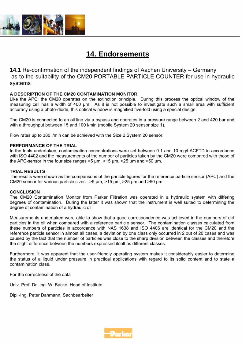
14. Endorsements
14.1 Re-confirmation of the independent findings of Aachen University – Germany as to the suitability of the CM20 PORTABLE PARTICLE COUNTER for use in hydraulic systems A DESCRIPTION OF THE CM20 CONTAMINATION MONITOR Like the APC, the CM20 operates on the extinction principle. During this process the optical window of the measuring cell has a width of 400 µm. As it is not possible to investigate such a small area with sufficient accuracy using a photo-diode, this optical window is magnified five-fold using a special design. The CM20 is connected to an oil line via a bypass and operates in a pressure range between 2 and 420 bar and with a throughput between 15 and 100 l/min (mobile System 20 sensor size 1). Flow rates up to 380 l/min can be achieved with the Size 2 System 20 sensor. PERFORMANCE OF THE TRIAL In the trials undertaken, contamination concentrations were set between 0.1 and 10 mg/l ACFTD in accordance with ISO 4402 and the measurements of the number of particles taken by the CM20 were compared with those of the APC-sensor in the four size ranges >5 µm, >15 µm, >25 µm and >50 µm. TRIAL RESULTS The results were shown as the comparisons of the particle figures for the reference particle sensor (APC) and the CM20 sensor for various particle sizes: >5 µm, >15 µm, >25 µm and >50 µm. CONCLUSION The CM20 Contamination Monitor from Parker Filtration was operated in a hydraulic system with differing degrees of contamination. During the latter it was shown that the instrument is well suited to determining the degree of contamination of a hydraulic oil. Measurements undertaken were able to show that a good correspondence was achieved in the numbers of dirt particles in the oil when compared with a reference particle sensor. The contamination classes calculated from these numbers of particles in accordance with NAS 1638 and ISO 4406 are identical for the CM20 and the reference particle sensor in almost all cases, a deviation by one class only occurred in 2 out of 20 cases and was caused by the fact that the number of particles was close to the sharp division between the classes and therefore the slight difference between the numbers expressed itself as different classes. Furthermore, it was apparent that the user-friendly operating system makes it considerably easier to determine the status of a liquid under pressure in practical applications with regard to its solid content and to state a contamination class. For the correctness of the data Univ. Prof. Dr.-Ing. W. Backe, Head of Institute Dipl.-Ing. Peter Dahmann, Sachbearbeiter
14.2 Harrier AEDIT report from Royal Air Force.
15 Other Available Products
15.1 Oilcheck
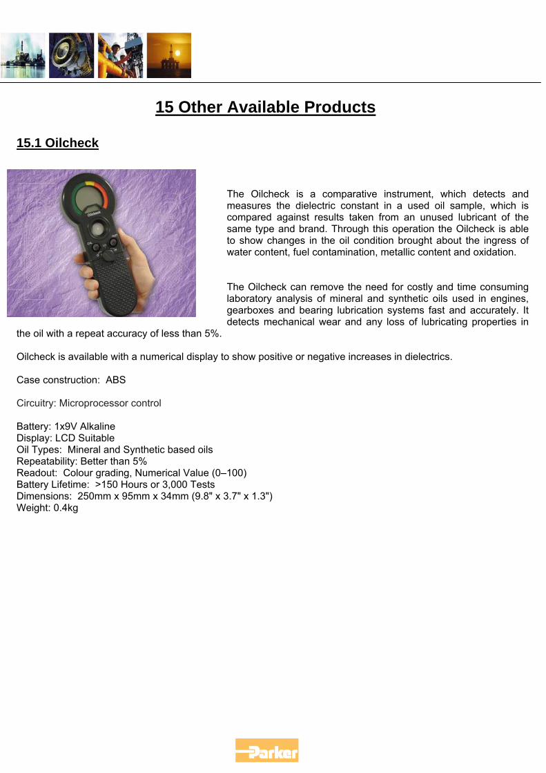
The Oilcheck is a comparative instrument, which detects and measures the dielectric constant in a used oil sample, which is compared against results taken from an unused lubricant of the same type and brand. Through this operation the Oilcheck is able to show changes in the oil condition brought about the ingress of water content, fuel contamination, metallic content and oxidation. The Oilcheck can remove the need for costly and time consuming laboratory analysis of mineral and synthetic oils used in engines, gearboxes and bearing lubrication systems fast and accurately. It detects mechanical wear and any loss of lubricating properties in
the oil with a repeat accuracy of less than 5%. Oilcheck is available with a numerical display to show positive or negative increases in dielectrics. Case construction: ABS Circuitry: Microprocessor control Battery: 1x9V Alkaline Display: LCD Suitable Oil Types: Mineral and Synthetic based oils Repeatability: Better than 5% Readout: Colour grading, Numerical Value (0–100) Battery Lifetime: >150 Hours or 3,000 Tests Dimensions: 250mm x 95mm x 34mm (9.8" x 3.7" x 1.3") Weight: 0.4kg
15.2 Moisture Sensor
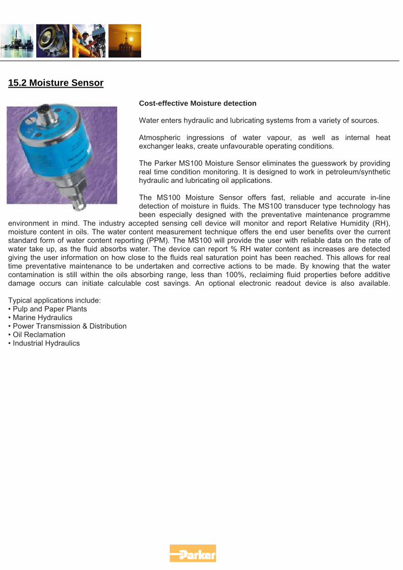
Cost-effective Moisture detection Water enters hydraulic and lubricating systems from a variety of sources. Atmospheric ingressions of water vapour, as well as internal heat exchanger leaks, create unfavourable operating conditions. The Parker MS100 Moisture Sensor eliminates the guesswork by providing real time condition monitoring. It is designed to work in petroleum/synthetic hydraulic and lubricating oil applications. The MS100 Moisture Sensor offers fast, reliable and accurate in-line detection of moisture in fluids. The MS100 transducer type technology has been especially designed with the preventative maintenance programme
environment in mind. The industry accepted sensing cell device will monitor and report Relative Humidity (RH), moisture content in oils. The water content measurement technique offers the end user benefits over the current standard form of water content reporting (PPM). The MS100 will provide the user with reliable data on the rate of water take up, as the fluid absorbs water. The device can report % RH water content as increases are detected giving the user information on how close to the fluids real saturation point has been reached. This allows for real time preventative maintenance to be undertaken and corrective actions to be made. By knowing that the water contamination is still within the oils absorbing range, less than 100%, reclaiming fluid properties before additive damage occurs can initiate calculable cost savings. An optional electronic readout device is also available. Typical applications include: • Pulp and Paper Plants • Marine Hydraulics • Power Transmission & Distribution • Oil Reclamation • Industrial Hydraulics
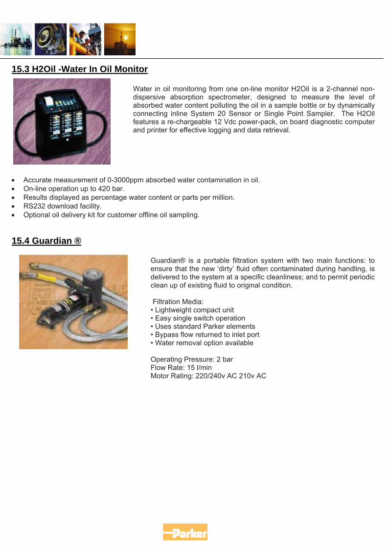
15.3 H2Oil -Water In Oil Monitor Water in oil monitoring from one on-line monitor H2Oil is a 2-channel non-dispersive absorption spectrometer, designed to measure the level of absorbed water content polluting the oil in a sample bottle or by dynamically connecting inline System 20 Sensor or Single Point Sampler. The H2Oil features a re-chargeable 12 Vdc power-pack, on board diagnostic computer and printer for effective logging and data retrieval.
• Accurate measurement of 0-3000ppm absorbed water contamination in oil. • On-line operation up to 420 bar. • Results displayed as percentage water content or parts per million. • RS232 download facility. • Optional oil delivery kit for customer offline oil sampling. 15.4 Guardian ®
Guardian® is a portable filtration system with two main functions: to ensure that the new ‘dirty’ fluid often contaminated during handling, is delivered to the system at a specific cleanliness; and to permit periodic clean up of existing fluid to original condition. Filtration Media: • Lightweight compact unit • Easy single switch operation • Uses standard Parker elements • Bypass flow returned to inlet port • Water removal option available Operating Pressure: 2 bar Flow Rate: 15 l/min Motor Rating: 220/240v AC 210v AC
15.5 5MF and 10MF Series
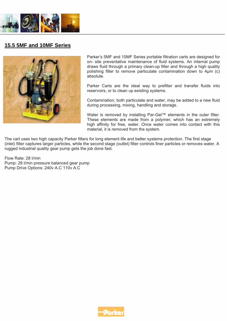
Parker’s 5MF and 10MF Series portable filtration carts are designed for on- site preventative maintenance of fluid systems. An internal pump draws fluid through a primary clean-up filter and through a high quality polishing filter to remove particulate contamination down to 4µm (c) absolute. Parker Carts are the ideal way to prefilter and transfer fluids into reservoirs, or to clean up existing systems. Contamination, both particulate and water, may be added to a new fluid during processing, mixing, handling and storage. Water is removed by installing Par-Gel™ elements in the outer filter. These elements are made from a polymer, which has an extremely high affinity for free, water. Once water comes into contact with this material, it is removed from the system.
The cart uses two high capacity Parker filters for long element life and better systems protection. The first stage (inlet) filter captures larger particles, while the second stage (outlet) filter controls finer particles or removes water. A rugged industrial quality gear pump gets the job done fast. Flow Rate: 28 l/min Pump: 28 l/min pressure balanced gear pump Pump Drive Options: 240v A.C 110v A.C
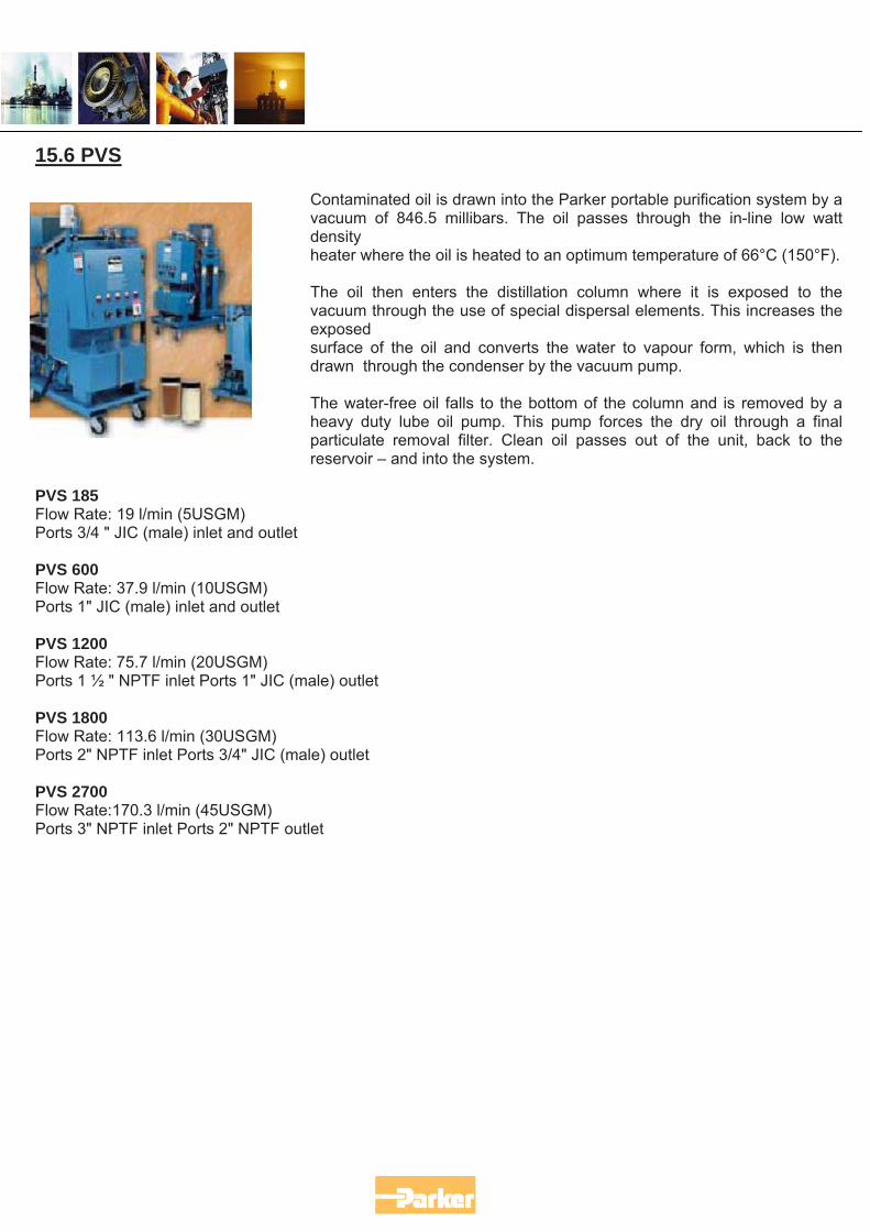
15.6 PVS
Contaminated oil is drawn into the Parker portable purification system by a vacuum of 846.5 millibars. The oil passes through the in-line low watt density heater where the oil is heated to an optimum temperature of 66°C (150°F). The oil then enters the distillation column where it is exposed to the vacuum through the use of special dispersal elements. This increases the exposed surface of the oil and converts the water to vapour form, which is then drawn through the condenser by the vacuum pump. The water-free oil falls to the bottom of the column and is removed by a heavy duty lube oil pump. This pump forces the dry oil through a final particulate removal filter. Clean oil passes out of the unit, back to the reservoir – and into the system.
PVS 185 Flow Rate: 19 l/min (5USGM) Ports 3/4 " JIC (male) inlet and outlet PVS 600 Flow Rate: 37.9 l/min (10USGM) Ports 1" JIC (male) inlet and outlet PVS 1200 Flow Rate: 75.7 l/min (20USGM) Ports 1 ½ " NPTF inlet Ports 1" JIC (male) outlet PVS 1800 Flow Rate: 113.6 l/min (30USGM) Ports 2" NPTF inlet Ports 3/4" JIC (male) outlet PVS 2700 Flow Rate:170.3 l/min (45USGM) Ports 3" NPTF inlet Ports 2" NPTF outlet
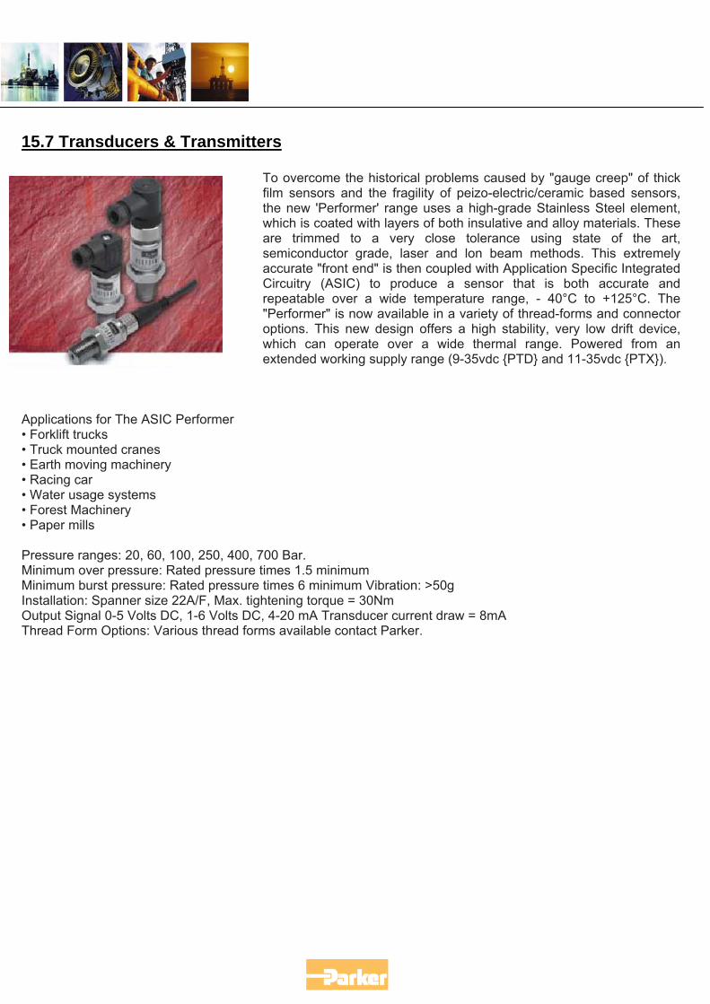
15.7 Transducers & Transmitters
To overcome the historical problems caused by "gauge creep" of thick film sensors and the fragility of peizo-electric/ceramic based sensors, the new 'Performer' range uses a high-grade Stainless Steel element, which is coated with layers of both insulative and alloy materials. These are trimmed to a very close tolerance using state of the art, semiconductor grade, laser and lon beam methods. This extremely accurate "front end" is then coupled with Application Specific Integrated Circuitry (ASIC) to produce a sensor that is both accurate and repeatable over a wide temperature range, - 40°C to +125°C. The "Performer" is now available in a variety of thread-forms and connector options. This new design offers a high stability, very low drift device, which can operate over a wide thermal range. Powered from an extended working supply range (9-35vdc {PTD} and 11-35vdc {PTX}).
Applications for The ASIC Performer • Forklift trucks • Truck mounted cranes • Earth moving machinery • Racing car • Water usage systems • Forest Machinery • Paper mills Pressure ranges: 20, 60, 100, 250, 400, 700 Bar. Minimum over pressure: Rated pressure times 1.5 minimum Minimum burst pressure: Rated pressure times 6 minimum Vibration: >50g Installation: Spanner size 22A/F, Max. tightening torque = 30Nm Output Signal 0-5 Volts DC, 1-6 Volts DC, 4-20 mA Transducer current draw = 8mA Thread Form Options: Various thread forms available contact Parker.
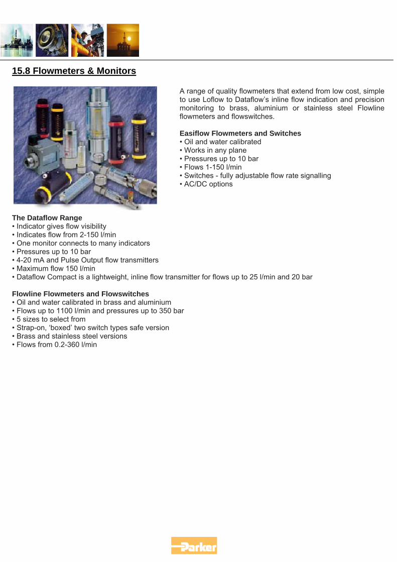
15.8 Flowmeters & Monitors A range of quality flowmeters that extend from low cost, simple to use Loflow to Dataflow’s inline flow indication and precision monitoring to brass, aluminium or stainless steel Flowline flowmeters and flowswitches. Easiflow Flowmeters and Switches • Oil and water calibrated • Works in any plane • Pressures up to 10 bar • Flows 1-150 l/min • Switches - fully adjustable flow rate signalling • AC/DC options
The Dataflow Range • Indicator gives flow visibility • Indicates flow from 2-150 l/min • One monitor connects to many indicators • Pressures up to 10 bar • 4-20 mA and Pulse Output flow transmitters • Maximum flow 150 l/min • Dataflow Compact is a lightweight, inline flow transmitter for flows up to 25 l/min and 20 bar Flowline Flowmeters and Flowswitches • Oil and water calibrated in brass and aluminium • Flows up to 1100 l/min and pressures up to 350 bar • 5 sizes to select from • Strap-on, ‘boxed’ two switch types safe version • Brass and stainless steel versions • Flows from 0.2-360 l/min
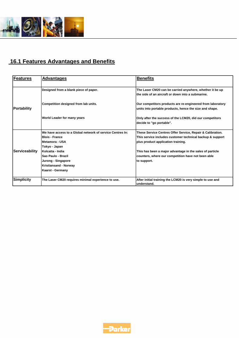
16.1 Features Advantages and Benefits
Features Advantages Benefits
Designed from a blank piece of paper. The Laser CM20 can be carried anywhere, whether it be up the side of an aircraft or down into a submarine.
Competition designed from lab units. Our competitors products are re-engineered from laboratory Portability units into portable products, hence the size and shape.
World Leader for many years Only after the success of the LCM20, did our competitors decide to "go portable".
We have access to a Global network of service Centres In: These Service Centres Offer Service, Repair & Calibration.Blois - France This service includes customer technical backup & supportMetamora - USA plus product application training.Tokyo - Japan
Serviceability Kolcatta - India This has been a major advantage in the sales of particle Sao Paulo - Brazil counters, where our competition have not been able Jurong - Singapore to support.Kristiansand - NorwayKaarst - Germany
Simplicity The Laser CM20 requires minimal experience to use. After initial training the LCM20 is very simple to use andunderstand.
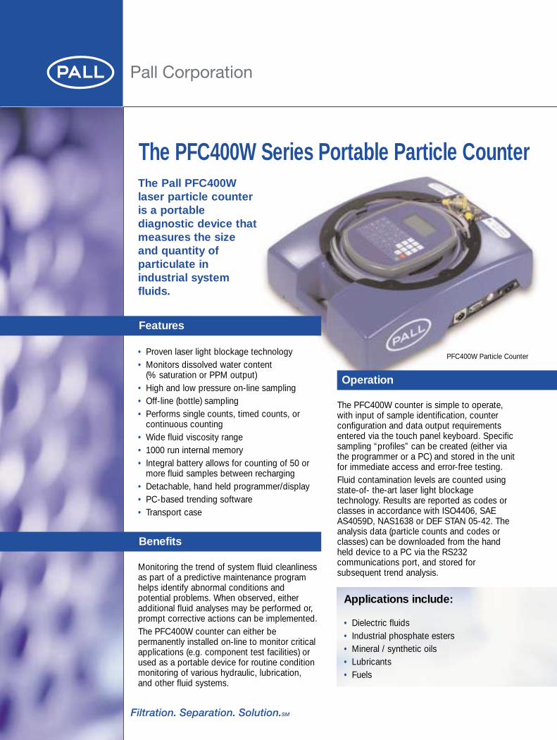
The Pall PFC400Wlaser particle counteris a portablediagnostic device thatmeasures the sizeand quantity ofparticulate inindustrial systemfluids.
Features
• Proven laser light blockage technology• Monitors dissolved water content
(% saturation or PPM output)• High and low pressure on-line sampling• Off-line (bottle) sampling• Performs single counts, timed counts, or
continuous counting• Wide fluid viscosity range• 1000 run internal memory• Integral battery allows for counting of 50 or
more fluid samples between recharging• Detachable, hand held programmer/display • PC-based trending software• Transport case
The PFC400W Series Portable Particle Counter
Operation
Benefits
Monitoring the trend of system fluid cleanlinessas part of a predictive maintenance programhelps identify abnormal conditions andpotential problems. When observed, eitheradditional fluid analyses may be performed or,prompt corrective actions can be implemented. The PFC400W counter can either bepermanently installed on-line to monitor criticalapplications (e.g. component test facilities) orused as a portable device for routine conditionmonitoring of various hydraulic, lubrication,and other fluid systems.
Applications include:
• Dielectric fluids• Industrial phosphate esters• Mineral / synthetic oils• Lubricants• Fuels
PFC400W Particle Counter
The PFC400W counter is simple to operate,with input of sample identification, counterconfiguration and data output requirementsentered via the touch panel keyboard. Specificsampling “profiles” can be created (either viathe programmer or a PC) and stored in the unitfor immediate access and error-free testing. Fluid contamination levels are counted usingstate-of- the-art laser light blockagetechnology. Results are reported as codes orclasses in accordance with ISO4406, SAEAS4059D, NAS1638 or DEF STAN 05-42. Theanalysis data (particle counts and codes orclasses) can be downloaded from the handheld device to a PC via the RS232communications port, and stored forsubsequent trend analysis.
Counting Sizes: 4, 6, 10, 14, 21, 30, 38 & 70 µm(c)Cleanliness Code Ranges: ISO 4406: 01 to 23
NAS1638: 00 to 12SAE AS4059D: 000A to 12FDEF STAN: 400F to >6300F
Calibration: Based on ISO 11171Water content: 0% to 100% of saturation. Values can
also be displayed as parts per million(ppm) (requires fluid constants)
OperatingPressures: Low Pressure range: 0 to 5 bar (500kPa)
(70 psi)High Pressure range: 4 to 400 bar
(40,000kPa)(60 to 5,800 psi)
Operating Viscosity: 2 to 300 cSt (to 1,500 SUS)Fluid operatingTemperature: 10°C to 100°C (50°F to 212°F)FluidCompatibility: Petroleum based fluids, industrial
phosphate esters, mineral oils, dielectricfluids, kerosene coolants and syntheticfluids (aqueous fluids are unsuitable)
Seals: FluorocarbonSample Time: <2 minutes (adjustable)Power Supply: 100 - 240VAC, 50 – 60 Hz or
10VDC – 36VDCOutput: RS232 D9 connectorEnclosure: IP55, NEMA 4ElectromagneticCompatibility: Complies with EN50082-2, 1995 for
immunity EC standard and alsoEN50081-1, 1992 standard for emissions
Weight: 9 Kg (19.8 lb)Dimensions: 410 x 130 x 335 mm
(16.1 x 5.1 x 13.2 inches)
Ordering Information
Pall Part Number Description
PFC400W Portable Laser Particle Counter withintegrated water sensor, for use withpetroleum based fluids, phosphateesters, mineral & synthetic fluids;includes Cleanliness Trendersoftware and transport case.
PFC400WPRTE Optional thermal printer (EU) PFC400WPRTUS Optional thermal printer (US)
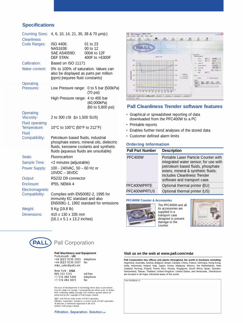
Pall Cleanliness Trender software features
Specifications
• Graphical or spreadsheet reporting of data downloaded from the PFC400W to a PC
• Printable reports• Enables further trend analyses of the stored data • Customer defined alarm limits
Pall Machinery and EquipmentPortsmouth - UK+44 (0)23 9230 3303 telephone+44 (0)23 9230 2507 faxm&[email protected]
New York - USA800 333 7255 toll free+1 516 484 5400 telephone+1 516 484 3825 fax
Visit us on the web at www.pall.com/m&e
Pall Corporation has offices and plants throughout the world in locations including:Argentina, Australia, Austria, Belgium, Brazil, Canada, China, France, Germany, Hong Kong,India, Indonesia, Ireland, Italy, Japan, Korea, Malaysia, Mexico, the Netherlands, NewZealand, Norway, Poland, Puerto Rico, Russia, Singapore, South Africa, Spain, Sweden,Switzerland, Taiwan, Thailand, United Kingdom, United States, and Venezuela. Distributorsare located in all major industrial areas of the world.
Your distributor is:
Because of developments in technology these data or procedures may be subject to change. Consequently we advise users to reviewtheir continuing validity annually. Part numbers quoted above areprotected by the Copyright of Pall Europe Limited.
and Pall are trade marks of Pall Corporation. Filtration. Separation. Solution is a service mark of Pall Corporation.® indicates a trademark registered in the USA.©2003, Pall Europe Limited.
The PFC400W and allits accessories aresupplied in atransport casedesigned to preventdamage to thecounter.
PFC400W Counter & Accessories
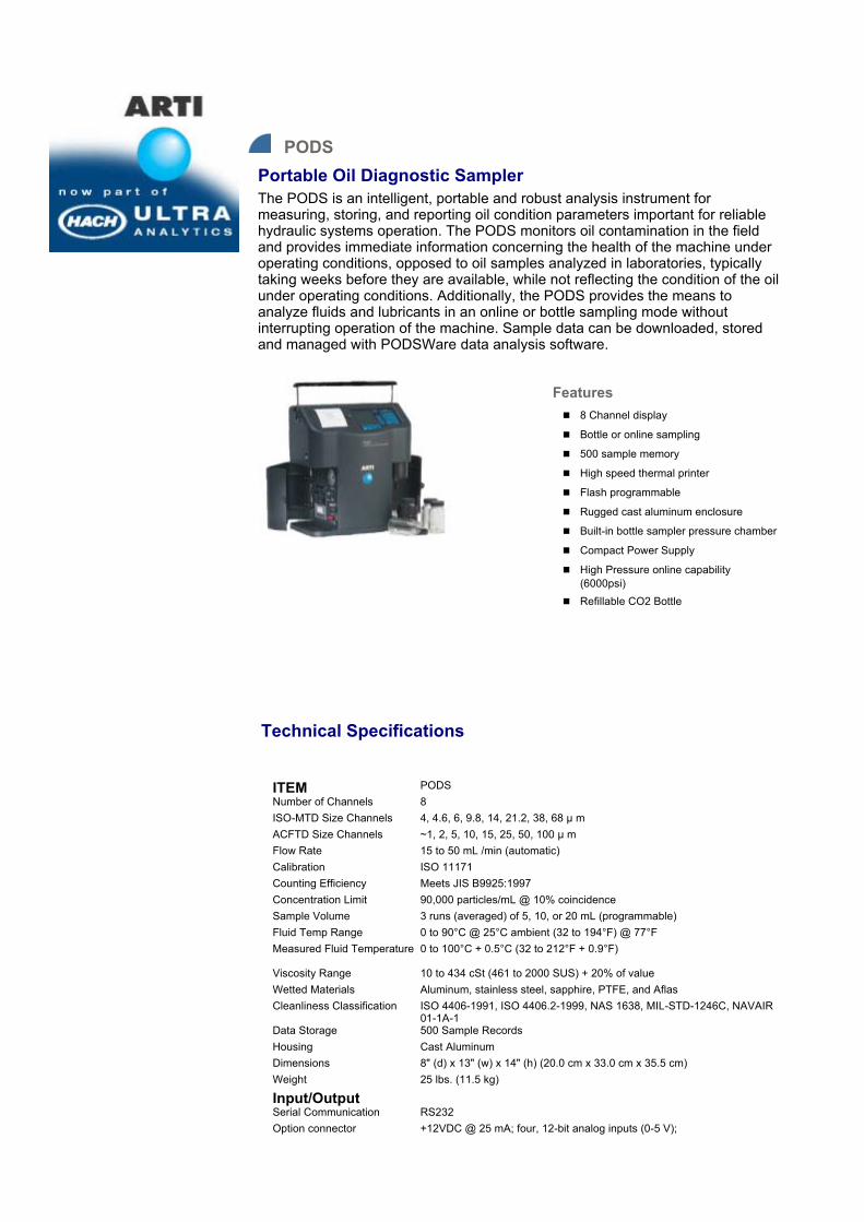
PODS Portable Oil Diagnostic Sampler The PODS is an intelligent, portable and robust analysis instrument for measuring, storing, and reporting oil condition parameters important for reliable hydraulic systems operation. The PODS monitors oil contamination in the field and provides immediate information concerning the health of the machine under operating conditions, opposed to oil samples analyzed in laboratories, typically taking weeks before they are available, while not reflecting the condition of the oil under operating conditions. Additionally, the PODS provides the means to analyze fluids and lubricants in an online or bottle sampling mode without interrupting operation of the machine. Sample data can be downloaded, stored and managed with PODSWare data analysis software.
Features8 Channel display
Bottle or online sampling
500 sample memory
High speed thermal printer
Flash programmable
Rugged cast aluminum enclosure
Built-in bottle sampler pressure chamber
Compact Power Supply
High Pressure online capability (6000psi) Refillable CO2 Bottle
Technical Specifications
ITEM PODS Number of Channels 8 ISO-MTD Size Channels 4, 4.6, 6, 9.8, 14, 21.2, 38, 68 µ m ACFTD Size Channels ~1, 2, 5, 10, 15, 25, 50, 100 µ m Flow Rate 15 to 50 mL /min (automatic) Calibration ISO 11171 Counting Efficiency Meets JIS B9925:1997 Concentration Limit 90,000 particles/mL @ 10% coincidence Sample Volume 3 runs (averaged) of 5, 10, or 20 mL (programmable) Fluid Temp Range 0 to 90°C @ 25°C ambient (32 to 194°F) @ 77°F Measured Fluid Temperature
0 to 100°C + 0.5°C (32 to 212°F + 0.9°F) Viscosity Range 10 to 434 cSt (461 to 2000 SUS) + 20% of value Wetted Materials Aluminum, stainless steel, sapphire, PTFE, and Aflas Cleanliness Classification ISO 4406-1991, ISO 4406.2-1999, NAS 1638, MIL-STD-1246C, NAVAIR
01-1A-1 Data Storage 500 Sample Records Housing Cast Aluminum Dimensions 8" (d) x 13" (w) x 14" (h) (20.0 cm x 33.0 cm x 35.5 cm) Weight 25 lbs. (11.5 kg)
Input/Output Serial Communication RS232 Option connector +12VDC @ 25 mA; four, 12-bit analog inputs (0-5 V);
+5 VDC @ 25mA, Digital Output (open collector) Bottle Operation Purge Volume 15 to 30 mL (Automatic) CO2 Cartridge 4.5oz, Replaceable, rechargeable, 60 Samples w/full cartridge Shop Air 6.2 to 7.6 bar (90 to 110 psi) clean, dry Online Operation Fluid Pressure 6.2 to 413.7 bar (90 to 6000 psi) Purge Volume Programmable Operating Time Programmable hold time and number of samples P/bower DC Input +24 VDC, 2A AC Adapter Universal 100 - 240 VAC, 50 - 60 Hz, 60 W Rechargeable Battery Nickel-Metal Hydride Operating Time 4 hours Continuous Recharge Time 2.5 hours
Environmental Operating RH/Temp 20 to 85% non-condensing / 0 to 50°C (32 to 122°F) Storage RH/Temp Up to 98% non-condensing / -40 to 70°C (-40 to 158°F) Accessories Carrying Case High Pressure Hose Adapter CO2 Bottles Hand Pump (vacuum) Plastic Sample Bottles Display Cover (Optional) Online Adapter
Standard CE
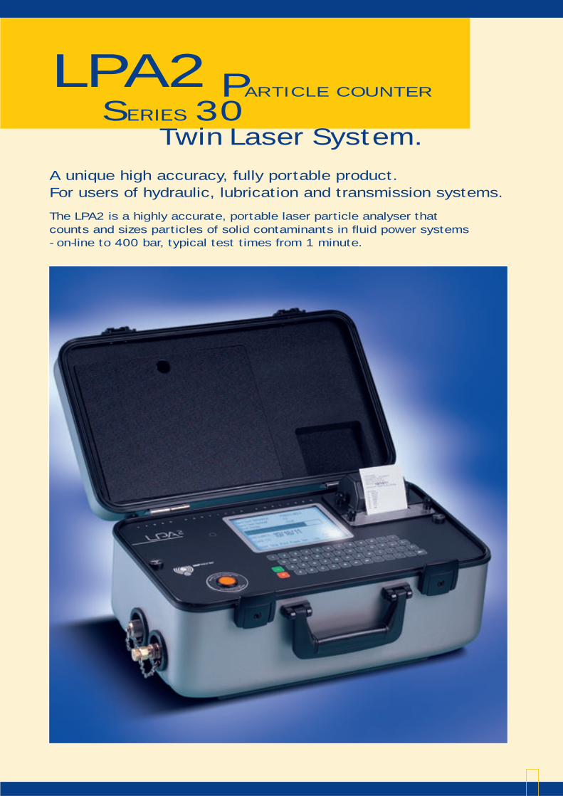
LPA2SERIES 30
PARTICLE COUNTER
Twin Laser System.
A unique high accuracy, fully portable product.For users of hydraulic, lubrication and transmission systems.
The LPA2 is a highly accurate, portable laser particle analyser that counts and sizes particles of solid contaminants in fluid power systems- on-line to 400 bar, typical test times from 1 minute.
The experience of designers and users of hydraulic and lubricationsystems is that 75% of system failures are as a direct resultof contamination. Knowing the cleanliness level of the fluid is thebasis for contamination control.
Exclusive MP Filtri technology.
The combination of the two
lasers with the unique optics and
photodiode package enables the
LPA2 to give ultra accuracy
combined with excellent repeatability.
Laser 1A single point high accuracy
laser measures par ticles
of contamination at 4µm (c)
and 6µm (c) giving ultra
accuracy with excellent
repeatability.
Laser 2Standard accuracy laser
specifically designed for system
contaminants between 6µm (c)
and 68µm (c).
The LPA2 gives accurate results of the amounts
and sizes of contaminants - instant results. LPA2 is calibrated
with ISO Medium Test Dust (MTD) based on
ISO 11171:1999 calibration standard.
The new MTD has a certified distribution standard
verified by NIST (National Institute of Standard
and Technology), USA. The LPA2 is designed to meet
the new ISO 4406 cleanliness classification code which
is a 3-part code, 4µm(c), 6µm(c) and 14µm(c).
The LPA2 also provides results in the NAS 1638 code.
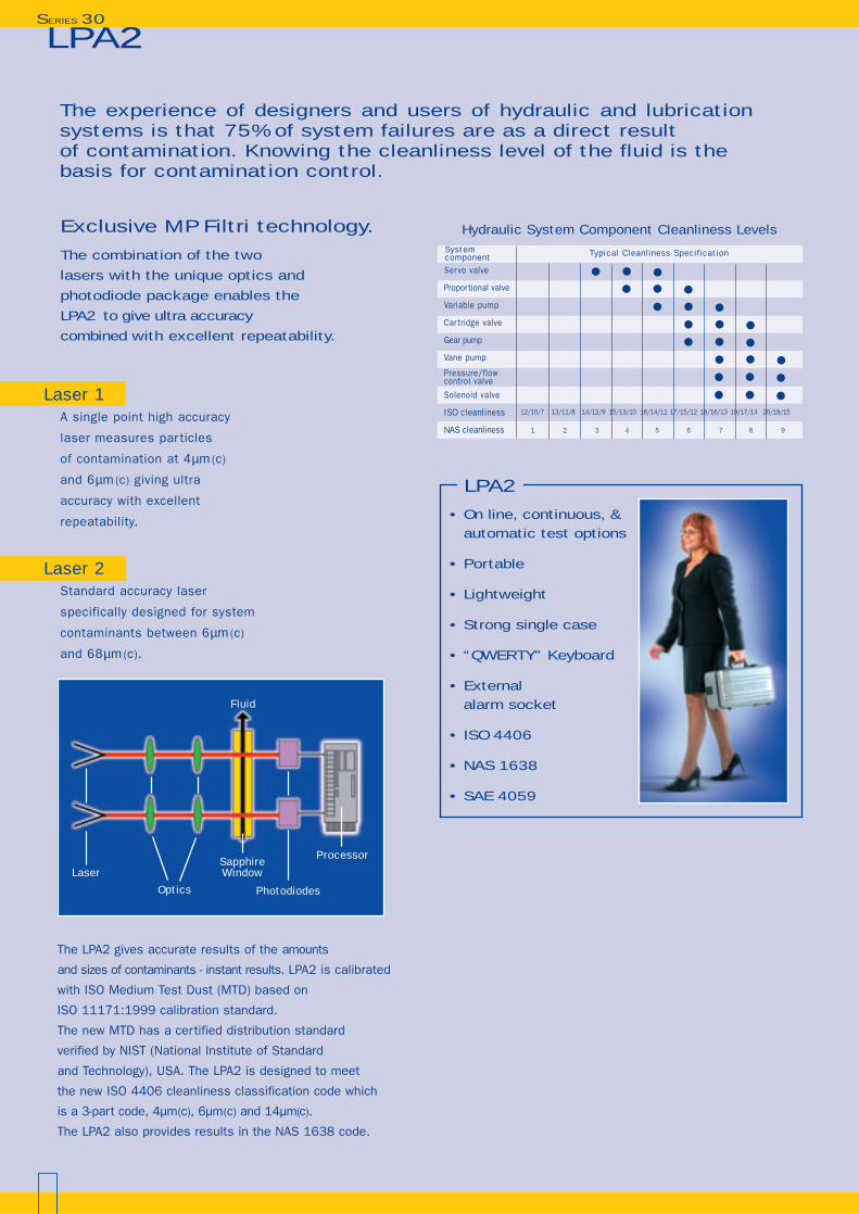
Hydraulic System Component Cleanliness Levels
Ser vo valve
Proportional valve
Variable pump
Car tridge valve
Gear pump
Vane pump
Pressure/flow control valve
Solenoid valve
ISO cleanliness
NAS cleanliness
System component Typical Cleanliness Specification
12/10/7 13/11/8 14/12/9 15/13/10 16/14/11 17/15/12 18/16/13 19/17/14 20/18/15
1 2 3 4 5 6 7 8 9
Fluid
SapphireWindow
Optics
Processor
Laser
Photodiodes
• On line, continuous, &automatic test options
• Portable
• Lightweight
• Strong single case
• “QWERTY” Keyboard
• External alarm socket
• ISO 4406
• NAS 1638
• SAE 4059
LPA2
LPA22SERIES 30
LPA2 SERIES 30
Featur es
• The LPA2 is a single case,lightweight product.The LPA2 is a robust and rugged, fully portable user friendly instrument, particularly useful in field applications where “ease of use” is fundamental.
• Power (100 + test). The LPA2 incorporates a large capacity rechargable battery, which can be recharged with 12/24 volt power supply. The LPA2 will perform in excess of 100 tests before recharging is required.
• Data storage 600 test.
• Minimess connections. The LPA2 uses standard minimess connections (M16 x 2) to the hydraulic system.
• Language options as standard.The LPA2 offers 4 language options as standard (English, Italian, French & German).
• External alarm socket.A plug in adaptor (supplied) which allows
an external alarm/indicator to be attached.
• On-line Testingto 400 bar pressure.
• Phosphate ester compatibleproducts available.
• Monitor + keyboardThe LPA2 features a large LCD screen with a full size QWERTY keyboard, displayingboth ISO 4406, NAS1638 and SAE4059 code results.
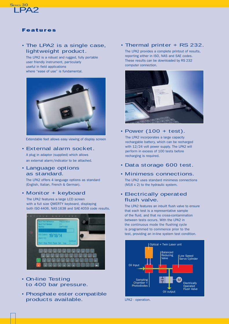
• Electrically operated flush valve.The LPA2 features an inbuilt flush valve to ensurethat each test is a representative sample of the fluid, and that no cross-contamination between tests occurs. With the LPA2 in the continuous mode the flushing cycle is programmed to commence prior to thetest, providing an in-line system test condition.
Optical + Twin Laser unit
BalancedReducingValve
Low SpeedServo Cylinder
Oil Input
Oil output
ElectricallyOperatedFlush Valve
Extendable feet allows easy viewing of display screen
LPA2 - operation.
Sampling Chamber +
Photodiodes
M
• Thermal printer + RS 232.The LPA2 provides a complete printout of results, reporting either in ISO, NAS and SAE codes. These results can be downloaded by RS 232 computer connection.
F e a t u r e s LPA2 SERIES 30
• Technology. The LPA2 uses a revolutionary designThe patented fluid handling conceptenables it to be use on hydraulic systemsup to 400 bar working pressure, however the product has a single action constant low pressure pumping unit to ensure that steady state flow is achieved for every test.The LPA2 is calibrated with ISO MTD based on ISO 11171.The correlation between particle sizes of ACFTD (old standard) to ISO MTD (new standard) is a follows:
ACFTD ISO MTD(old standard) (new standard)
1 45 615 1425 2130 25
50* 38
75* 50100* 68
* Yet to be conf i rmed by NIST.
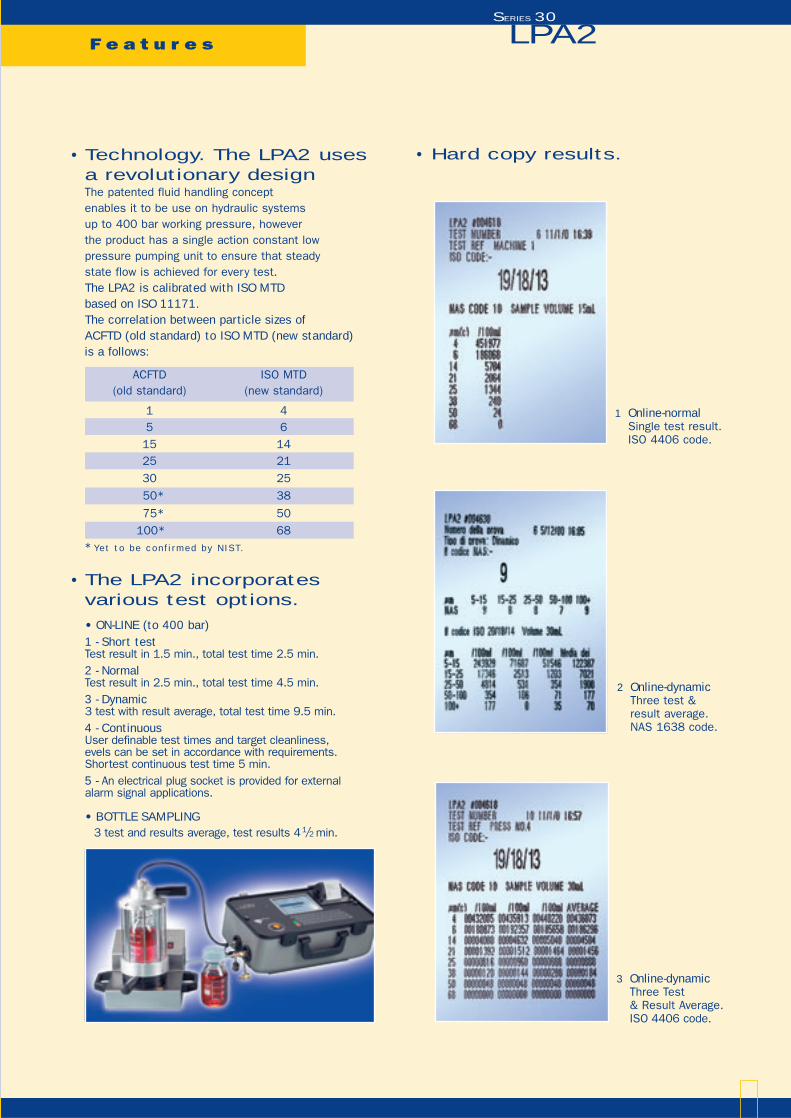
• Hard copy results.
1 Online-normalSingle test result.ISO 4406 code.
3 Online-dynamicThree Test & Result Average.ISO 4406 code.
2 Online-dynamicThree test & result average.NAS 1638 code.
• The LPA2 incorporates various test options.
• ON-LINE (to 400 bar)1 - Short testTest result in 1.5 min., total test time 2.5 min.2 - NormalTest result in 2.5 min., total test time 4.5 min.3 - Dynamic3 test with result average, total test time 9.5 min.4 - ContinuousUser definable test times and target cleanliness,evels can be set in accordance with requirements.Shortest continuous test time 5 min.5 - An electrical plug socket is provided for externalalarm signal applications.
• BOTTLE SAMPLING3 test and results average, test results 41/2 min.
Featur es
• Accreditation. The LPA2 is CE marked and supplied with an EMS acceptance certificate.
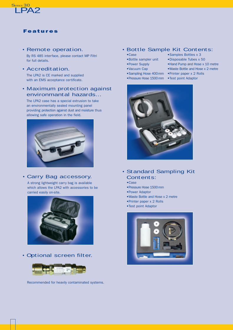
• Maximum protection againstenvironmantal hazards... The LPA2 case has a special extrusion to take an environmentally sealed mounting panel providing protection against dust and moisture thus allowing safe operation in the field.
• Remote operation.By RS 485 interface, please contact MP Filtrifor full details.
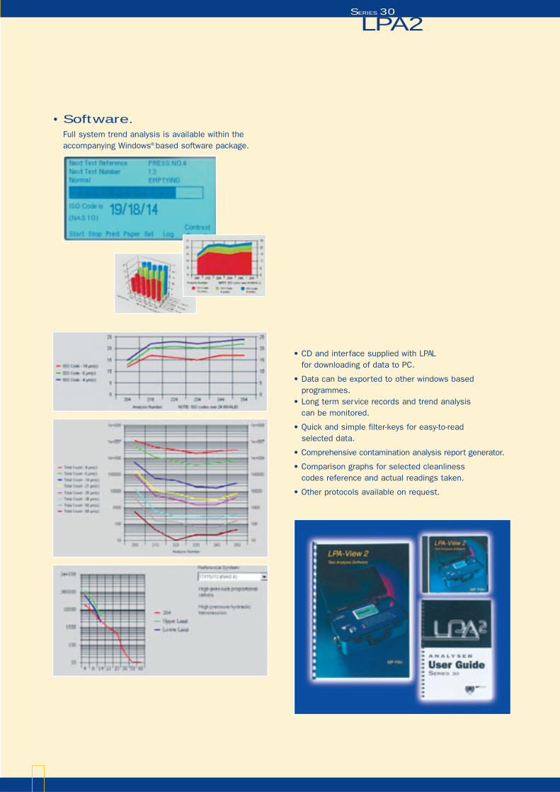
• Carry Bag accessory.A strong lightweight carry bag is availablewhich allows the LPA2 with accessories to becarried easily on-site.
• Optional screen filter.
Recommended for heavily contaminated systems.
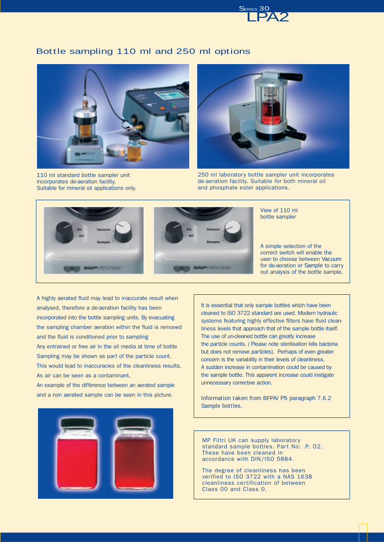
• Bottle Sample Kit Contents:•Case •Samples Bottles x 3•Bottle sampler unit •Disposable Tubes x 50•Power Supply •Hand Pump and Hose x 10 metre•Vacuum Cap •Waste Bottle and Hose x 2 metre•Sampling Hose 400mm •Printer paper x 2 Rolls•Pressure Hose 1500mm •Test point Adaptor
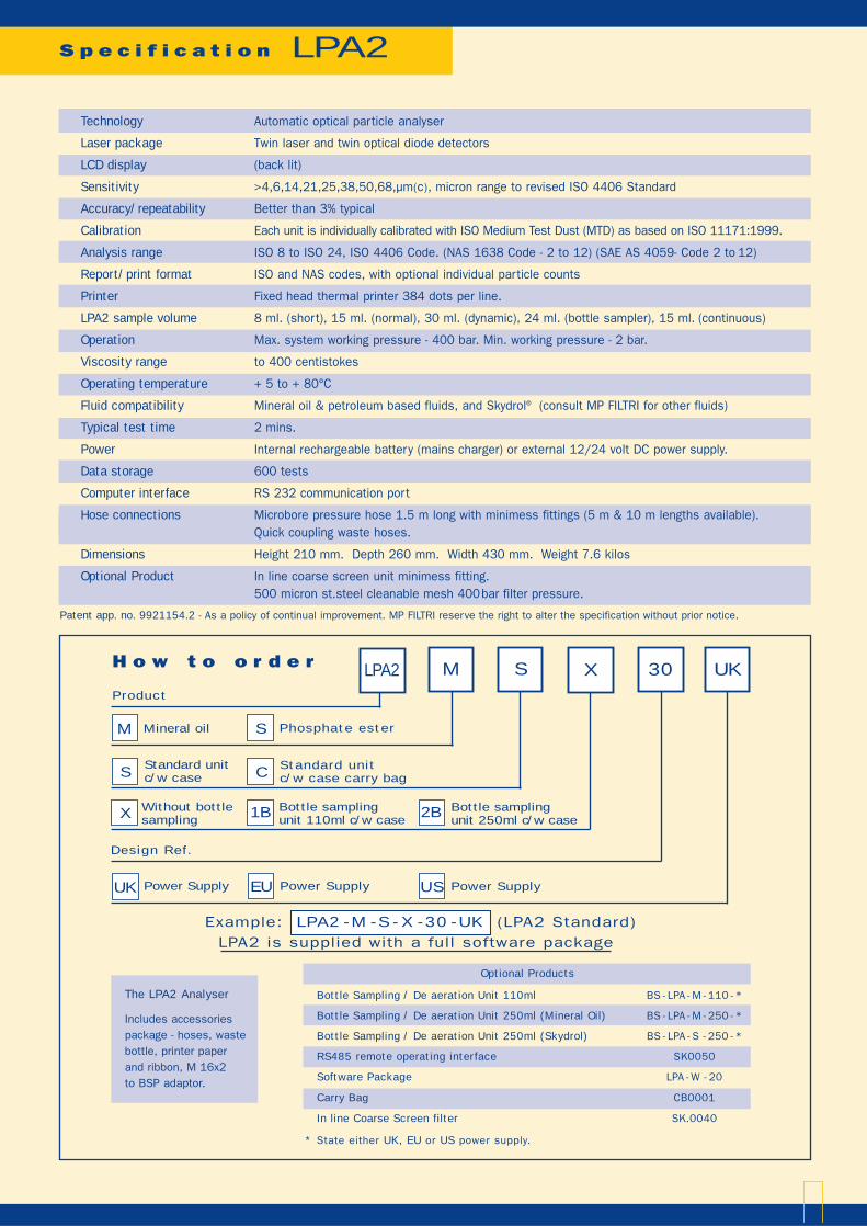
• Standard Sampling Kit Contents:•Case•Pressure Hose 1500mm•Power Adaptor•Waste Bottle and Hose x 2 metre•Printer paper x 2 Rolls•Test point Adaptor
LPA2 SERIES 30
Bottle sampling 110 ml and 250 ml options
LPA2 SERIES 30
110 ml standard bottle sampler unit incorporates de-aeration facility. Suitable for mineral oil applications only.
250 ml laboratory bottle sampler unit incorporatesde-aeration facility. Suitable for both mineral oiland phosphate ester applications.
A simple selection of the correct switch will enable theuser to choose between Vacuumfor de-aeration or Sample to carry out analysis of the bottle sample.
View of 110 mlbottle sampler
A highly aerated fluid may lead to inaccurate result when
analysed, therefore a de-aeration facility has been
incorporated into the bottle sampling units. By evacuating
the sampling chamber aeration within the fluid is removed
and the fluid is conditioned prior to sampling
Any entrained or free air in the oil media at time of bottle
Sampling may be shown as part of the particle count.
This would lead to inaccuracies of the cleanliness results.
As air can be seen as a contaminant.
An example of the difference between an aerated sample
and a non aerated sample can be seen in this picture.
MP Filtri UK can supply laborator y standard sample bottles. Par t No: .P. O2.These have been cleaned in accordance with DIN/ISO 5884.
The degree of cleanliness has beenverified to ISO 3722 with a NAS 1638cleanliness cer tification of between Class 00 and Class 0.
It is essential that only sample bottles which have been cleaned to ISO 3722 standard are used. Modern hydraulic systems featuring highly effective filters have fluid clean-liness levels that approach that of the sample bottle itself.The use of un-cleaned bottle can greatly increase the particle counts. ( Please note sterilisation kills bacteriabut does not remove particles). Perhaps of even greaterconcern is the variability in their levels of cleanliness. A sudden increase in contamination could be caused by the sample bottle. This apparent increase could instigateunnecessary corrective action.
Information taken from BFPA/P5 paragraph 7.6.2Sample bottles.
LPA2 SERIES 30
• Software.Full system trend analysis is available within theaccompanying Windows® based software package.
• CD and interface supplied with LPA L for downloading of data to PC.
• Data can be exported to other windows based programmes.
• Long term service records and trend analysis can be monitored.
• Quick and simple filter-keys for easy-to-read selected data.
• Comprehensive contamination analysis report generator.
• Comparison graphs for selected cleanliness codes reference and actual readings taken.
• Other protocols available on request.
S p e c i f i c a t i o n LPA2
Patent app. no. 9921154.2 - As a policy of continual improvement. MP FILTRI reserve the right to alter the specification without prior notice.
Technology Automatic optical particle analyser
Laser package Twin laser and twin optical diode detectors
LCD display (back lit)
Sensitivity >4,6,14,21,25,38,50,68,µm(c), micron range to revised ISO 4406 Standard
Accuracy/repeatability Better than 3% typical
Calibration Each unit is individually calibrated with ISO Medium Test Dust (MTD) as based on ISO 11171:1999.
Analysis range ISO 8 to ISO 24, ISO 4406 Code. (NAS 1638 Code - 2 to 12) (SAE AS 4059- Code 2 to 12)
Report/print format ISO and NAS codes, with optional individual particle counts
Printer Fixed head thermal printer 384 dots per line.
LPA2 sample volume 8 ml. (short), 15 ml. (normal), 30 ml. (dynamic), 24 ml. (bottle sampler), 15 ml. (continuous)
Operation Max. system working pressure - 400 bar. Min. working pressure - 2 bar.
Viscosity range to 400 centistokes
Operating temperature + 5 to + 80°C
Fluid compatibility Mineral oil & petroleum based fluids, and Skydrol® (consult MP FILTRI for other fluids)
Typical test time 2 mins.
Power Internal rechargeable battery (mains charger) or external 12/24 volt DC power supply.
Data storage 600 tests
Computer interface RS 232 communication port
Hose connections Microbore pressure hose 1.5 m long with minimess fittings (5 m & 10 m lengths available).Quick coupling waste hoses.
Dimensions Height 210 mm. Depth 260 mm. Width 430 mm. Weight 7.6 kilos
Optional Product In line coarse screen unit minimess fitting.500 micron st.steel cleanable mesh 400bar filter pressure.
LPA2 M S 30X UKH o w t o o r d e r
Product
Mineral oil
Standard unit c/w case
Phosphate ester
Design Ref.
M S
Power Supply Power SupplyUK EU Power SupplyUS
S
X Bottle samplingunit 110ml c/w case
Without bottle sampling 1B Bottle sampling
unit 250ml c/w case2B
Standard unit c/w case carry bagC
The LPA2 Analyser
Includes accessoriespackage - hoses, wastebottle, printer paperand ribbon, M 16x2to BSP adaptor.
* State either UK, EU or US power supply.
Bottle Sampling / De aeration Unit 110ml BS - LPA - M - 110 - *
Bottle Sampling / De aeration Unit 250ml (Mineral Oil) BS - LPA - M - 250 - *
Bottle Sampling / De aeration Unit 250ml (Skydrol) BS - LPA - S - 250 - *
RS485 remote operating interface SK0050
Software Package LPA - W - 20
Carry Bag CB0001
In line Coarse Screen filter SK.0040
Optional Products
Example: LPA2 - M - S - X - 30 - UK (LPA2 Standard)LPA2 is supplied with a full software package
LPA2 SERIES 30
App l i cat ions and test imon ia ls
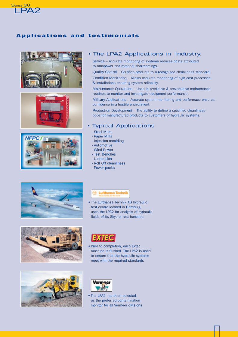
• The LPA2 Applications in Industry.Service – Accurate monitoring of systems reduces costs attributed to manpower and material shortcomings.
Quality Control – Certifies products to a recognised cleanliness standard.
Condition Monitoring – Allows accurate monitoring of high cost processes & installations ensuring system reliability.
Maintenance Operations – Used in predictive & preventative maintenance routines to monitor and investigate equipment performance.
Military Applications – Accurate system monitoring and performace ensures confidence in a hostile environment.
Production Development – The ability to define a specified cleanliness code for manufactured products to customers of hydraulic systems.
• The Lufthansa Technik AG hydraulic test centre located in Hamburg, uses the LPA2 for analysis of hydraulic fluids of its Skydrol test benches.
• Prior to completion, each Extecmachine is flushed. The LPA2 is usedto ensure that the hydraulic systemsmeet with the required standards
• The LPA2 has been selected as the preferred contamination monitor for all Vermeer divisions
• Typical Applications- Steel Mills- Paper Mills- Injection moulding- Automotive- Wind Power- Test Benches- Lubrication- Roll Off cleanliness- Power packs
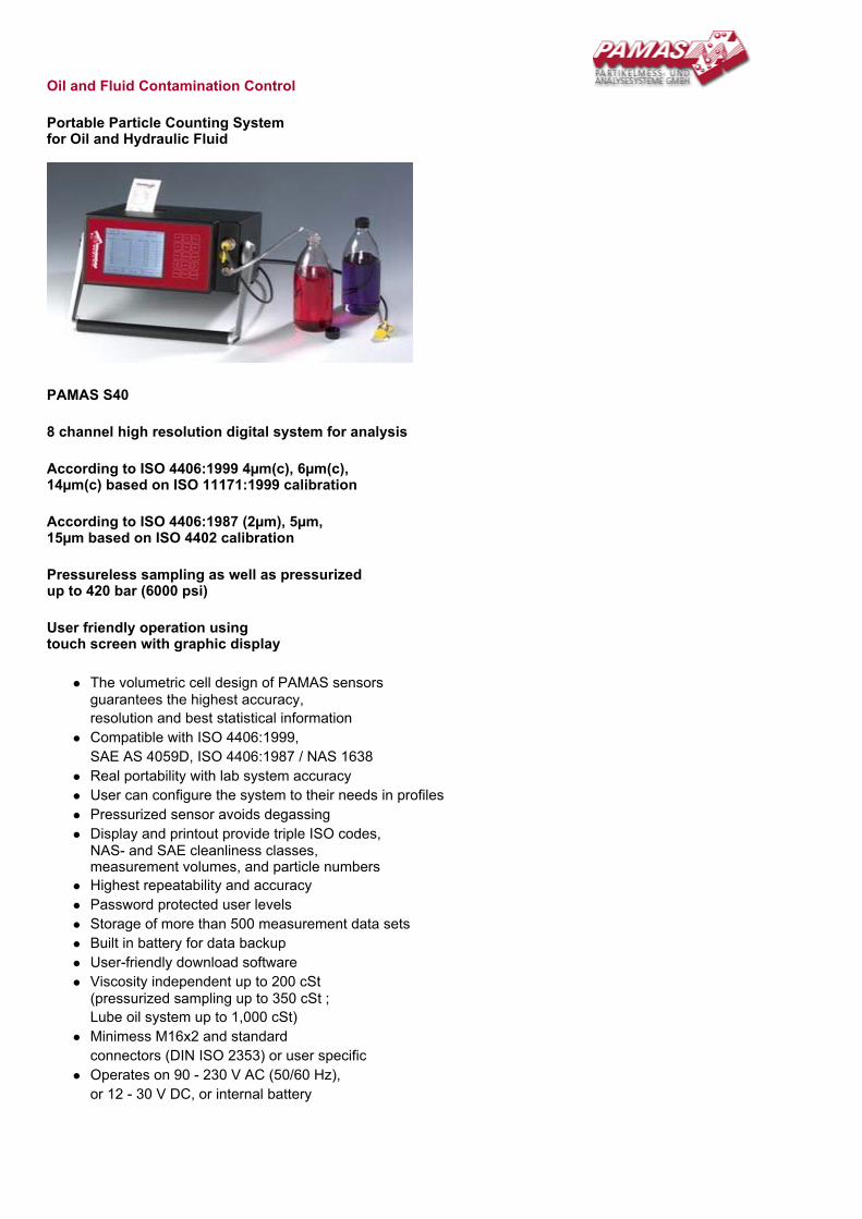
Oil and Fluid Contamination Control
Portable Particle Counting System for Oil and Hydraulic Fluid
PAMAS S40
8 channel high resolution digital system for analysis
According to ISO 4406:1999 4µm(c), 6µm(c), 14µm(c) based on ISO 11171:1999 calibration
According to ISO 4406:1987 (2µm), 5µm, 15µm based on ISO 4402 calibration
Pressureless sampling as well as pressurized up to 420 bar (6000 psi)
User friendly operation using touch screen with graphic display
The volumetric cell design of PAMAS sensors guarantees the highest accuracy, resolution and best statistical information Compatible with ISO 4406:1999, SAE AS 4059D, ISO 4406:1987 / NAS 1638 Real portability with lab system accuracy User can configure the system to their needs in profiles Pressurized sensor avoids degassing Display and printout provide triple ISO codes, NAS- and SAE cleanliness classes, measurement volumes, and particle numbers Highest repeatability and accuracy Password protected user levels Storage of more than 500 measurement data sets Built in battery for data backup User-friendly download software Viscosity independent up to 200 cSt (pressurized sampling up to 350 cSt ; Lube oil system up to 1,000 cSt) Minimess M16x2 and standard connectors (DIN ISO 2353) or user specific Operates on 90 - 230 V AC (50/60 Hz), or 12 - 30 V DC, or internal battery
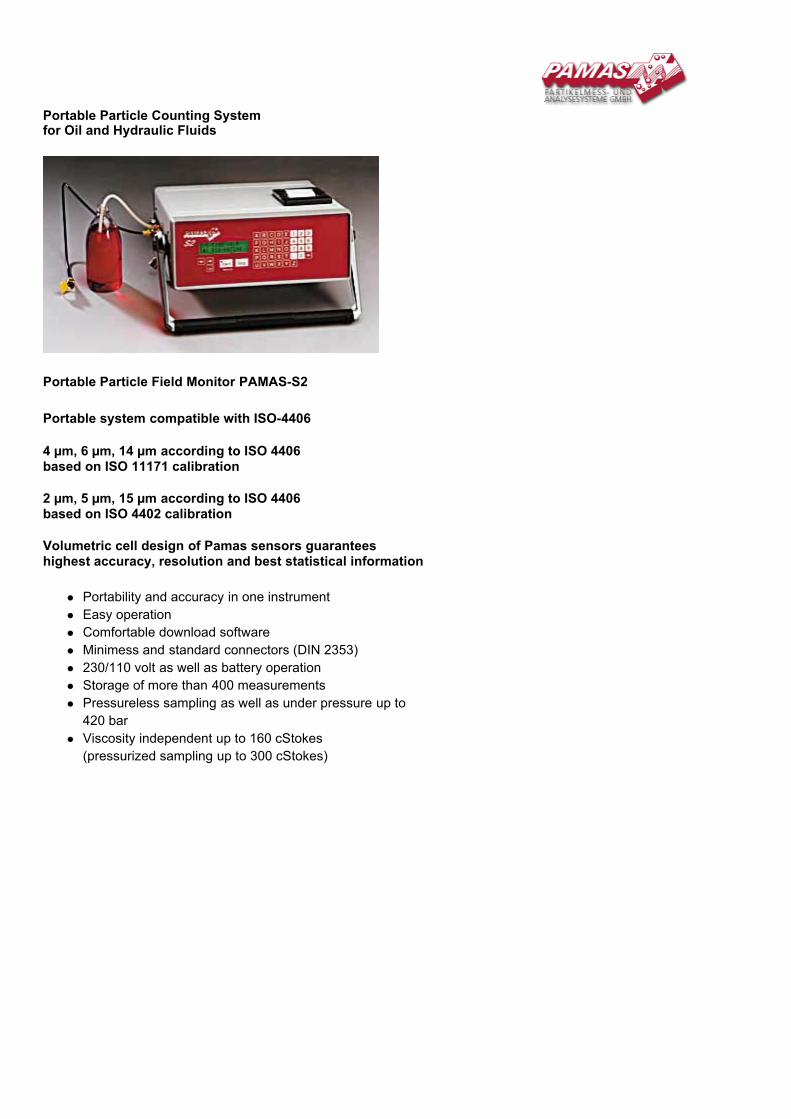
Portable Particle Counting System for Oil and Hydraulic Fluids
Portable Particle Field Monitor PAMAS-S2
Portable system compatible with ISO-4406 4 µm, 6 µm, 14 µm according to ISO 4406 based on ISO 11171 calibration 2 µm, 5 µm, 15 µm according to ISO 4406 based on ISO 4402 calibration Volumetric cell design of Pamas sensors guarantees highest accuracy, resolution and best statistical information
Portability and accuracy in one instrument Easy operation Comfortable download software Minimess and standard connectors (DIN 2353) 230/110 volt as well as battery operation Storage of more than 400 measurements Pressureless sampling as well as under pressure up to 420 bar Viscosity independent up to 160 cStokes (pressurized sampling up to 300 cStokes)
Fluid Service Catalog
Fluid Service
1-888-99 HYDAC
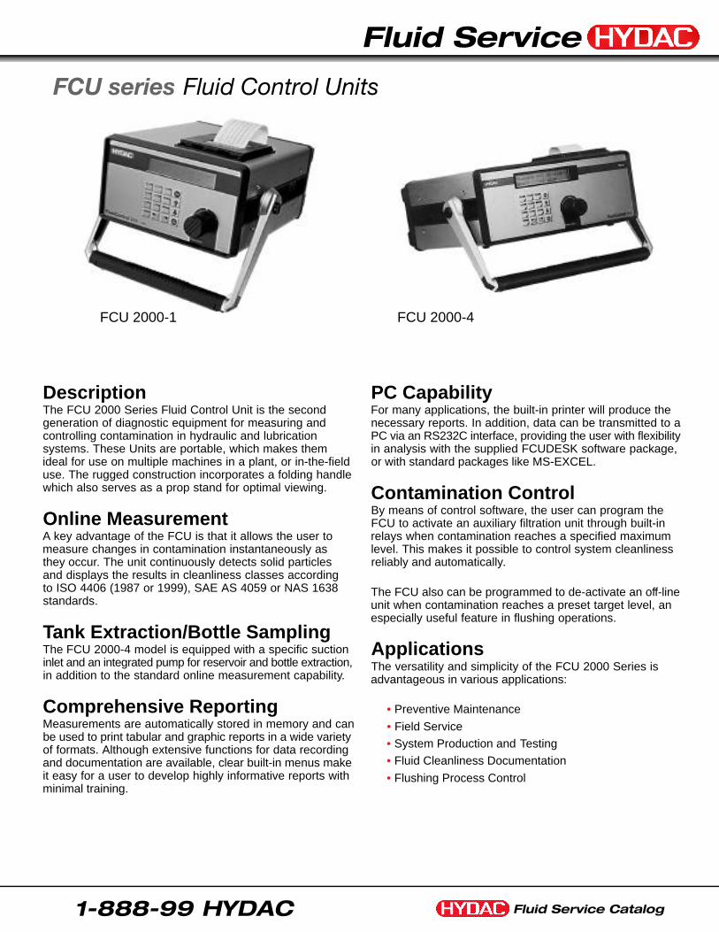
DescriptionThe FCU 2000 Series Fluid Control Unit is the second generation of diagnostic equipment for measuring and controlling contamination in hydraulic and lubrication systems. These Units are portable, which makes them ideal for use on multiple machines in a plant, or in-the-fielduse. The rugged construction incorporates a folding handlewhich also serves as a prop stand for optimal viewing.
Online MeasurementA key advantage of the FCU is that it allows the user tomeasure changes in contamination instantaneously as they occur. The unit continuously detects solid particles and displays the results in cleanliness classes accordingto ISO 4406 (1987 or 1999), SAE AS 4059 or NAS 1638standards.
Tank Extraction/Bottle SamplingThe FCU 2000-4 model is equipped with a specific suctioninlet and an integrated pump for reservoir and bottle extraction,in addition to the standard online measurement capability.
Comprehensive ReportingMeasurements are automatically stored in memory and canbe used to print tabular and graphic reports in a wide varietyof formats. Although extensive functions for data recordingand documentation are available, clear built-in menus makeit easy for a user to develop highly informative reports withminimal training.
PC CapabilityFor many applications, the built-in printer will produce thenecessary reports. In addition, data can be transmitted to aPC via an RS232C interface, providing the user with flexibilityin analysis with the supplied FCUDESK software package,or with standard packages like MS-EXCEL.
Contamination ControlBy means of control software, the user can program theFCU to activate an auxiliary filtration unit through built-inrelays when contamination reaches a specified maximumlevel. This makes it possible to control system cleanlinessreliably and automatically.
The FCU also can be programmed to de-activate an off - l i n eunit when contamination reaches a preset target level, anespecially useful feature in flushing operations.
ApplicationsThe versatility and simplicity of the FCU 2000 Series isadvantageous in various applications:
• Preventive Maintenance
• Field Service
• System Production and Testing
• Fluid Cleanliness Documentation
• Flushing Process Control
FCU series Fluid Control Units
FCU 2000-4FCU 2000-1
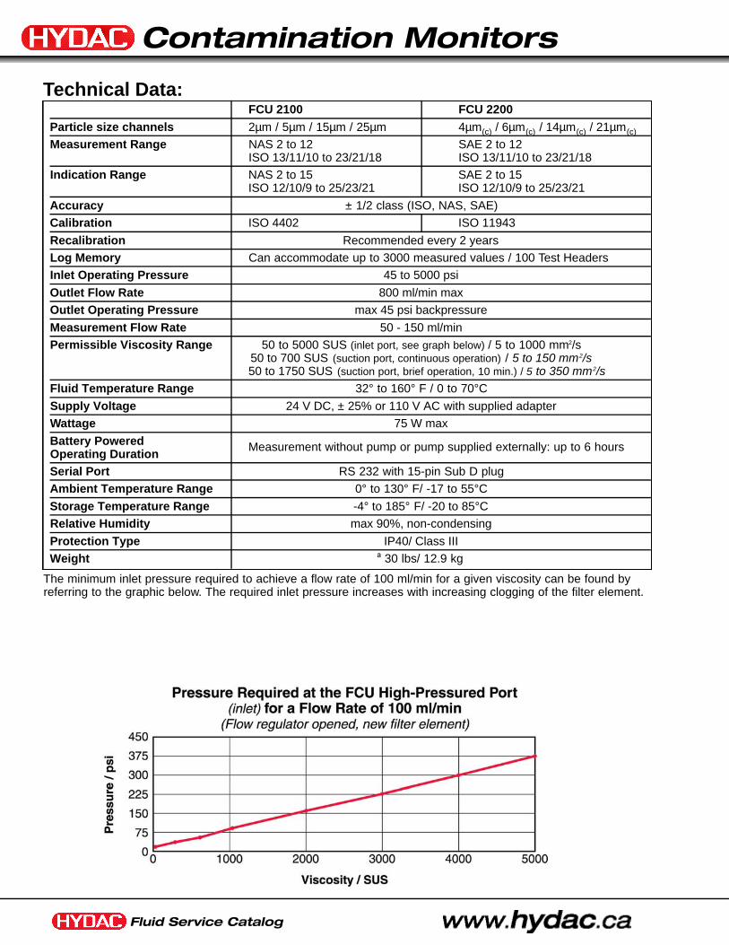
Fluid Service Catalog
Contamination Monitors
FCU 2100 FCU 2200Particle size channels 2µm / 5µm / 15µm / 25µm 4µm(c) / 6µm(c) / 14µm(c) / 21µm(c)
Measurement Range NAS 2 to 12 SAE 2 to 12ISO 13/11/10 to 23/21/18 ISO 13/11/10 to 23/21/18
Indication Range NAS 2 to 15 SAE 2 to 15ISO 12/10/9 to 25/23/21 ISO 12/10/9 to 25/23/21
Accuracy ± 1/2 class (ISO, NAS, SAE)
Calibration ISO 4402 ISO 11943
Recalibration Recommended every 2 years
Log Memory Can accommodate up to 3000 measured values / 100 Test Headers
Inlet Operating Pressure 45 to 5000 psi
Outlet Flow Rate 800 ml/min max
Outlet Operating Pressure max 45 psi backpressure
Measurement Flow Rate 50 - 150 ml/min
Permissible Viscosity Range 50 to 5000 SUS (inlet port, see graph below) / 5 to 1000 mm2/s50 to 700 SUS (suction port, continuous operation) / 5 to 150 mm2/s50 to 1750 SUS (suction port, brief operation, 10 min.) / 5 to 350 mm2/s
Fluid Temperature Range 32° to 160° F / 0 to 70°C
Supply Voltage 24 V DC, ± 25% or 110 V AC with supplied adapter
Wattage 75 W max
Battery Powered Measurement without pump or pump supplied externally: up to 6 hoursOperating DurationSerial Port RS 232 with 15-pin Sub D plug
Ambient Temperature Range 0° to 130° F/ -17 to 55°C
Storage Temperature Range -4° to 185° F/ -20 to 85°C
Relative Humidity max 90%, non-condensing
Protection Type IP40/ Class III
Weight ª 30 lbs/ 12.9 kg
The minimum inlet pressure required to achieve a flow rate of 100 ml/min for a given viscosity can be found byreferring to the graphic below. The required inlet pressure increases with increasing clogging of the filter element.
Technical Data:
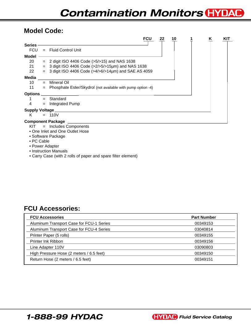
Fluid Service Catalog
Contamination Monitors
1-888-99 HYDAC
FCU 22 10 1 K KIT
SeriesFCU = Fluid Control Unit
Model20 = 2 digit ISO 4406 Code (>5/>15) and NAS 163821 = 3 digit ISO 4406 Code (>2/>5/>15µm) and NAS 163822 = 3 digit ISO 4406 Code (>4/>6/>14µm) and SAE AS 4059
Media10 = Mineral Oil11 = Phosphate Ester/Skydrol (not available with pump option -4)
Options1 = Standard4 = Integrated Pump
Supply VoltageK = 110V
Component PackageKIT = Includes Components• One Inlet and One Outlet Hose• Software Package• PC Cable• Power Adapter• Instruction Manuals• Carry Case (with 2 rolls of paper and spare filter element)
FCU Accessories Part NumberAluminum Transport Case for FCU-1 Series 00349153
Aluminum Transport Case for FCU-4 Series 03040814
Printer Paper (5 rolls) 00349155
Printer Ink Ribbon 00349156
Line Adapter 110V 03090803
High Pressure Hose (2 meters / 6.5 feet) 00349150
Return Hose (2 meters / 6.5 feet) 00349151
Model Code:
FCU Accessories:
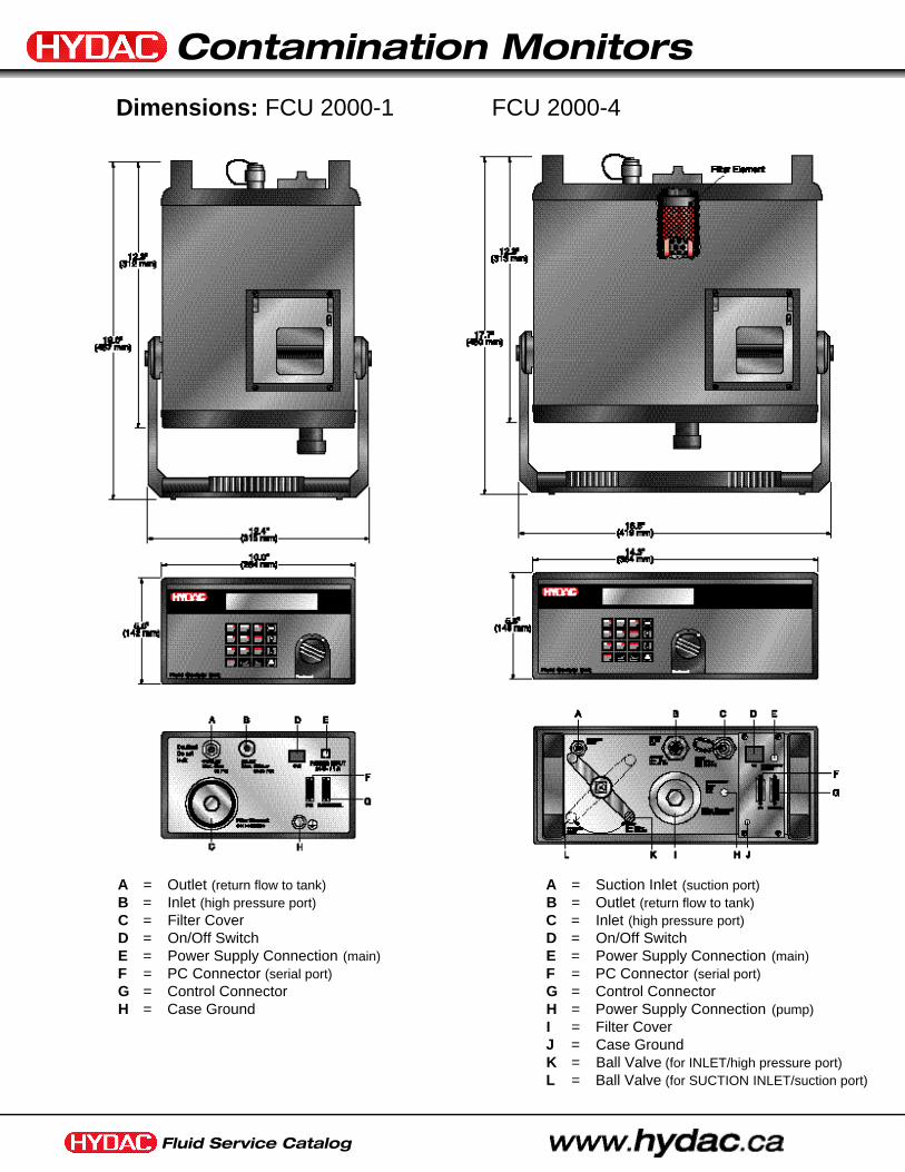
Fluid Service Catalog
Contamination Monitors
Dimensions: FCU 2000-1 FCU 2000-4
A = Outlet (return flow to tank)B = Inlet (high pressure port)C = Filter CoverD = On/Off SwitchE = Power Supply Connection (main)F = PC Connector (serial port)G = Control ConnectorH = Case Ground
A = Suction Inlet (suction port)B = Outlet (return flow to tank)C = Inlet (high pressure port)D = On/Off SwitchE = Power Supply Connection (main)F = PC Connector (serial port)G = Control ConnectorH = Power Supply Connection (pump)I = Filter CoverJ = Case GroundK = Ball Valve (for INLET/high pressure port)L = Ball Valve (for SUCTION INLET/suction port)
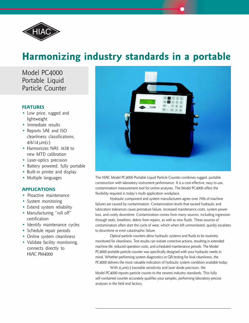
Harmonizing industry standards in a portableModel PC4000Portable LiquidParticle Counter
FEATURES• Low price, rugged and
lightweight• Immediate results• Reports SAE and ISO
cleanliness classifications,4/6/14 µm(c)
• Harmonizes NAS 1638 tonew MTD calibration
• Laser-optics precision• Battery powered, fully portable• Built-in printer and display• Multiple languages
APPLICATIONS• Proactive maintenance• System monitoring• Extend system reliability• Manufacturing “roll off”
certification• Identify maintenance cycles• Schedule repair periods• Online system cleanliness• Validate facility monitoring,
connects directly toHIAC PM4000
The HIAC Model PC4000 Portable Liquid Particle Counter combines rugged, portableconstruction with laboratory instrument performance. It is a cost-effective, easy to use,contamination measurement tool for online analyses. The Model PC4000 offers theflexibility required in today’s multi-application workplace.
Hydraulic component and system manufacturers agree–over 70% of machinefailures are caused by contamination. Contamination levels that exceed hydraulic andlubrication tolerances cause premature failure, increased maintenance costs, system powerloss, and costly downtime. Contamination comes from many sources, including ingressionthrough seals, breathers, debris from repairs, as well as new fluids. These sources ofcontamination often start the cycle of wear, which when left unmonitored, quickly escalatesto downtime or even catastrophic failure.
Optical particle counters allow hydraulic systems and fluids to be routinelymonitored for cleanliness. Test results can initiate corrective actions, resulting in extendedmachine life, reduced operation costs, and scheduled maintenance periods. The ModelPC4000 portable particle counter was specifically designed with your hydraulic needs inmind. Whether performing system diagnostics or QA testing for final cleanliness, thePC4000 delivers the most valuable indication of hydraulic system condition available today.
With 4 µm(c) traceable sensitivity and laser diode precision, theModel PC4000 reports particle counts to the newest industry standards. This fullyself-contained counter accurately qualifies your samples, performing laboratory-preciseanalyses in the field and factory.
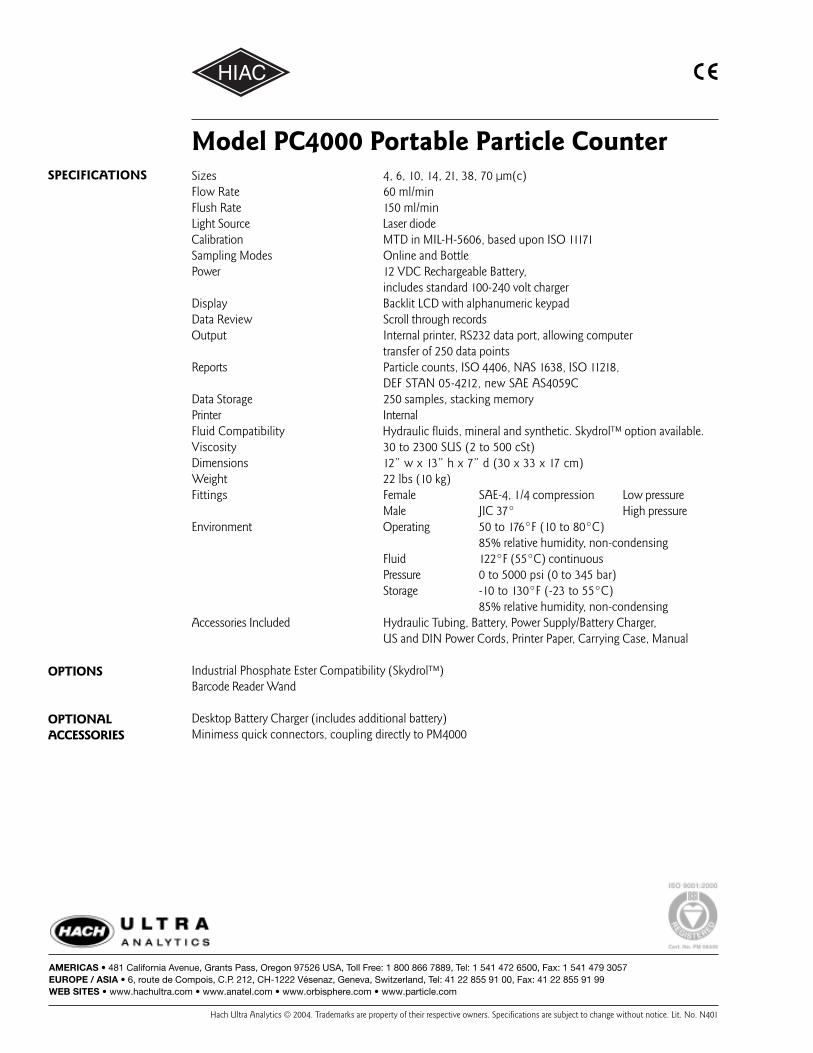
Sizes 4, 6, 10, 14, 21, 38, 70 µm(c)Flow Rate 60 ml/minFlush Rate 150 ml/minLight Source Laser diodeCalibration MTD in MIL-H-5606, based upon ISO 11171Sampling Modes Online and BottlePower 12 VDC Rechargeable Battery,
includes standard 100-240 volt chargerDisplay Backlit LCD with alphanumeric keypadData Review Scroll through recordsOutput Internal printer, RS232 data port, allowing computer
transfer of 250 data pointsReports Particle counts, ISO 4406, NAS 1638, ISO 11218,
DEF STAN 05-4212, new SAE AS4059CData Storage 250 samples, stacking memoryPrinter InternalFluid Compatibility Hydraulic fluids, mineral and synthetic. Skydrol™ option available.Viscosity 30 to 2300 SUS (2 to 500 cSt)Dimensions 12” w x 13” h x 7” d (30 x 33 x 17 cm)Weight 22 lbs (10 kg)Fittings Female SAE-4, 1/4 compression Low pressure
Male JIC 37° High pressureEnvironment Operating 50 to 176°F (10 to 80°C)
85% relative humidity, non-condensingFluid 122°F (55°C) continuousPressure 0 to 5000 psi (0 to 345 bar)Storage -10 to 130°F (-23 to 55°C)
85% relative humidity, non-condensingAccessories Included Hydraulic Tubing, Battery, Power Supply/Battery Charger,
US and DIN Power Cords, Printer Paper, Carrying Case, Manual
Industrial Phosphate Ester Compatibility (Skydrol™)Barcode Reader Wand
Desktop Battery Charger (includes additional battery)Minimess quick connectors, coupling directly to PM4000
SPECIFICATIONS
Model PC4000 Portable Particle Counter
OPTIONS
OPTIONALACCESSORIES
AMERICAS • 481 California Avenue, Grants Pass, Oregon 97526 USA, Toll Free: 1 800 866 7889, Tel: 1 541 472 6500, Fax: 1 541 479 3057EUROPE / ASIA • 6, route de Compois, C.P. 212, CH-1222 Vésenaz, Geneva, Switzerland, Tel: 41 22 855 91 00, Fax: 41 22 855 91 99WEB SITES • www.hachultra.com • www.anatel.com • www.orbisphere.com • www.particle.com
Hach Ultra Analytics © 2004. Trademarks are property of their respective owners. Specifications are subject to change without notice. Lit. No. N401
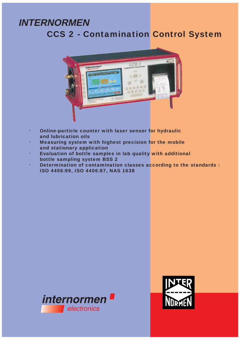
INTERNORMENCCS 2 - Contamination Control System
Online-particle counter with laser sensor for hydraulic and lubrication oilsMeasuring system with highest precision for the mobile and stationary applicationEvaluation of bottle samples in lab quality with additional bottle sampling system BSS 2Determination of contamination classes according to the standards :ISO 4406:99, ISO 4406:87, NAS 1638
·
·
·
·

CCS 2 - Contamination Control System
Online Analysis
Important information is available with use of particle distribution data to analyseconditions in hydraulic and lubrication systems:• Efficiency of the filter configuration in use
• Compliance with fluid cleanliness demanded for the assigned components
• Shifting of the system wear position• Variation with secondary contaminationThrough use of this data, the user can optimize system cleanliness to reduce system component wear, oil degradation and system downtime. Particle analysiscan be executed by various methods. One common method is by taking a bottlesample and sending it to a lab for analysis. This can be problematic, if care is not taken to assure the quality of each sample (e.g. bottle cleanliness, sampling location, etc.). In addition, sampling at dynamic operating conditions is extremely difficult or not practical. Oil sampling out of the reservoir also limits results to basicoil condition, rather than specific data for each system. Bottle sampling is becomingless advantageous as costs rise and time elapses between sampling and final results.
Technology
The development of the CCS 2 focuses on realizing an Online measuring methodwith lab-quality results, making particle analysis by operating conditions possible at various points in the system. Oil analysis for hydraulic components such as servo valves, proportional valves or high pressure pumps can now be achieved online, making fast reaction possible for alarming situations, which need immediate attention. This fast reaction can be achieved by a system integrated relays outputsignal.
The actual contamination condition of the pressure or lubrication medium is determined by means of automatic particle counting through a laser sensor (light gate principle) and an integrated metering unit including a system pressure adjustment from 1.5 to 420 bar.The announcement of the contamination condition takes place in the form ofparticle numbers per measuring volume as well as particle numbers per contamination classes refering to ISO 4406:99, ISO 4406:87 or NAS 1638.The excess of programmable contamination classes limit values produces the expenditure of electrical control signals to the generation of alarm functionsor controlling of an off-line filter unit.The industrial PC with key pad, colour TFT-display, and user friendly software guarantees easy operation and data management. The documentation of the measurement data can be displayed on the integrated printer or downloaded to another PC through the RS 232 connection. We get it to the light!
Measuring with our Contamination Control System CCS 2.
Solid-Contamination-Control
Online measuring pointpressure line
p = 1.5 ... 420 bar
hydraulic system
tank / return line
p = 0 ... 2 bar
TSS 1Tank-Sampling-System
CCS 2display printer RS 232 control signal
PC
e.g. Offline filter station
e.g. optical / acoustic signal
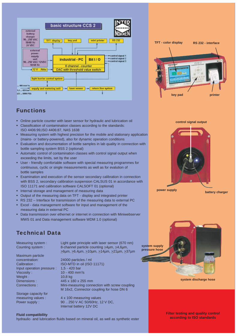
Filter testing and quality controlaccording to ISO standards
Functions
• Online particle counter with laser sensor for hydraulic and lubrication oil• Classification of contamination classes according to the standards:
ISO 4406:99,ISO 4406:87, NAS 1638• Measuring system with highest precision for the mobile and stationary application
(mains- or battery-powered), also for dynamic operation conditions• Evaluation and documentation of bottle samples in lab quality in connection with
bottle sampling system BSS 2 (optional)• Automatic control of contamination classes with control signal output when
exceeding the limits, set by the user• User - friendly comfortable software with special measuring programmes for
continuous, cyclic or single measurements as well as for evalution of bottle samples
• Examination and execution of the sensor secondary calibration in connectionwith BSS 2, secondary calibration suspension CALSUS 01 in accordance with ISO 11171 and calibration software CALSOFT 01 (optional)
• Internal storage and management of measuring data• Output of the measuring data on TFT - display and integrated printer• RS 232 – Interface for transmission of the measuring data to external PC• Excel - data management software for input and management of the
measuring data in external PC• Data transmission over ethernet or internet in connection with Miniwebserver
MWS 01 and Data management software WDM 1.0 (optional)
Technical Data
Measuring system : Light gate principle with laser sensor (670 nm)Counting system : 8-channel particle counting >4µm, >4,6µm,
>6µm, >6,4µm, >10µm, >14µm, >21µm, >37µmMaximum particleconcentration: 24000 particles / mlCalibration : ISO-MTD in oil (ISO 11171)Input operation pressure : 1,5 - 420 barViscosity : 10 - 400 mm2/sWeight : 10,8 kgDimensions : 445 x 180 x 255 mmConnections : Mini-measuring connection with screw coupling
M 16x2, Connector coupling for hose DN 6Storage capacity for measuring values : 4 x 100 measuring valuesPower supply : 90 .. 250 V AC 50/60Hz, 12 V DC,
Internal battery 12V DC
Fluid compatibilityhydraulic- and lubrication fluids based on mineral oil, as well as synthetic ester
TFT - color display
key pad printer
RS 232 - interface
control signal output
system supplypressure hose
system discharge hose
power supplybattery charger

17. Presentation
17.1 Presentation Outlining the Laser CM20 against the Competition
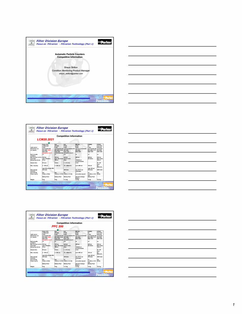
1
TM
Filter Division EuropeFocus on Filtration - Filtration Technology (Part 1)
Automatic Particle CountersCompetitive Information
Automatic Particle CountersCompetitive Information
Shaun SkiltonCondition Monitoring Product Manager
Shaun SkiltonCondition Monitoring Product Manager
TM
Filter Division EuropeFocus on Filtration - Filtration Technology (Part 1)
Competition InformationCompetition Information
Parker UCC Pall Arti MPFiltri PAMAS HYDACLCM20.2021 PFC200 PODS LPA2 S2 FCU 2010
Light source Laser Laser Laser Laser Laser Infra-redSensitivity >um 2,5,15,25,50,100 2,5,15,25,50,100 1,2,5,10,15,25,50,100 4,6,14,21,25,38,50,68 2,5,15,25,50,100 5,15,25,50Int. classes ISO 4406,11218* ISO 4406,11218 ISO 4406 ISO 4406 ISO 4406,11171 ISO 4406
NAS 1638 NAS 1638 NAS 1638 NAS 1638 NAS 1638 NAS 1638NAVAIR 01-1A-17* DEFSTAN 05-42 NAVAIR 01-1A-17*
Built in bottlesampling
no no yes no no no
Max Pressure on-line 420 bar 345 bar 420 bar 400 bar 420 bar 350 barFlow Rate upto 150ml/min upto 150 ml/min 20-50 ml/min ? 25 ml/min 800 ml/minMeasuring volume 10 ml 100 ml 45ml 15/30/24 ml
norm/din/bottle100 ml
Sample time 90 secs 2 mins 1 - 2.5 mins 3 min 40 -120secs
Max. viscosity 2 - 100 cst 2 - 500 cst 10 – 430mm²/s up to 400 cst 160 cst 20 –800mm²/s
upto 500 cst with SPS upto 300 cstData storage(number)
300 tests 500 tests min 100 !!! (ascatalogue)
550 tests 3000 tests
Auto testing yes yes no ? no yesPower source 12Vdc or 9Vdc 12Vdc or 12 Vdc 12Vdc or 12 Vdc as country request 12.3Vdc or 14.4
Vdc24Vdc
Battery Pack Battery Pack Battery Pack Internal rechargeBattery
Battery Pack
Weight 8 kg 9 kg 11.5 kg 7,6 Kg 12 kg 12.4 kg
LCM20.2021LCM20.2021
TM
Filter Division EuropeFocus on Filtration - Filtration Technology (Part 1)
Competition InformationCompetition Information
Parker UCC Pall Arti MPFiltri PAMAS HYDACLCM20.2021 PFC200 PODS LPA2 S2 FCU 2010
Light source Laser Laser Laser Laser Laser Infra-redSensitivity >um 2,5,15,25,50,100 2,5,15,25,50,100 1,2,5,10,15,25,50,100 4,6,14,21,25,38,50,68 2,5,15,25,50,100 5,15,25,50Int. classes ISO 4406,11218* ISO 4406,11218 ISO 4406 ISO 4406 ISO 4406,11171 ISO 4406
NAS 1638 NAS 1638 NAS 1638 NAS 1638 NAS 1638 NAS 1638NAVAIR 01-1A-17* DEFSTAN 05-42 NAVAIR 01-1A-17*
Built in bottlesampling
no no yes no no no
Max Pressure on-line 420 bar 345 bar 420 bar 400 bar 420 bar 350 barFlow Rate upto 150ml/min upto 150 ml/min 20-50 ml/min ? 25 ml/min 800 ml/minMeasuring volume 10 ml 100 ml 45ml 15/30/24 ml
norm/din/bottle100 ml
Sample time 90 secs 2 mins 1 - 2.5 mins 3 min 40 -120secs
Max. viscosity 2 - 100 cst 2 - 500 cst 10 – 430mm²/s up to 400 cst 160 cst 20 –800mm²/s
upto 500 cst with SPS upto 300 cstData storage(number)
300 tests 500 tests min 100 !!! (ascatalogue)
550 tests 3000 tests
Auto testing yes yes no ? no yesPower source 12Vdc or 9Vdc 12Vdc or 12 Vdc 12Vdc or 12 Vdc as country request 12.3Vdc or 14.4
Vdc24Vdc
Battery Pack Battery Pack Battery Pack Internal rechargeBattery
Battery Pack
Weight 8 kg 9 kg 11.5 kg 7,6 Kg 12 kg 12.4 kg
PFC 200PFC 200
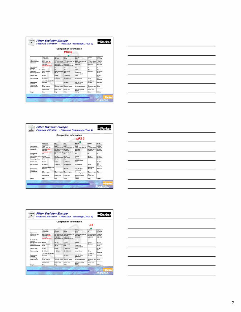
2
TM
Filter Division EuropeFocus on Filtration - Filtration Technology (Part 1)
Competition InformationCompetition Information
Parker UCC Pall Arti MPFiltri PAMAS HYDACLCM20.2021 PFC200 PODS LPA2 S2 FCU 2010
Light source Laser Laser Laser Laser Laser Infra-redSensitivity >um 2,5,15,25,50,100 2,5,15,25,50,100 1,2,5,10,15,25,50,100 4,6,14,21,25,38,50,68 2,5,15,25,50,100 5,15,25,50Int. classes ISO 4406,11218* ISO 4406,11218 ISO 4406 ISO 4406 ISO 4406,11171 ISO 4406
NAS 1638 NAS 1638 NAS 1638 NAS 1638 NAS 1638 NAS 1638NAVAIR 01-1A-17* DEFSTAN 05-42 NAVAIR 01-1A-17*
Built in bottlesampling
no no yes no no no
Max Pressure on-line 420 bar 345 bar 420 bar 400 bar 420 bar 350 barFlow Rate upto 150ml/min upto 150 ml/min 20-50 ml/min ? 25 ml/min 800 ml/minMeasuring volume 10 ml 100 ml 45ml 15/30/24 ml
norm/din/bottle100 ml
Sample time 90 secs 2 mins 1 - 2.5 mins 3 min 40 -120secs
Max. viscosity 2 - 100 cst 2 - 500 cst 10 – 430mm²/s up to 400 cst 160 cst 20 –800mm²/s
upto 500 cst with SPS upto 300 cstData storage(number)
300 tests 500 tests min 100 !!! (ascatalogue)
550 tests 3000 tests
Auto testing yes yes no ? no yesPower source 12Vdc or 9Vdc 12Vdc or 12 Vdc 12Vdc or 12 Vdc as country request 12.3Vdc or 14.4
Vdc24Vdc
Battery Pack Battery Pack Battery Pack Internal rechargeBattery
Battery Pack
Weight 8 kg 9 kg 11.5 kg 7,6 Kg 12 kg 12.4 kg
PODSPODS
TM
Filter Division EuropeFocus on Filtration - Filtration Technology (Part 1)
Competition InformationCompetition InformationLPS 2LPS 2
Parker UCC Pall Arti MPFiltri PAMAS HYDACLCM20.2021 PFC200 PODS LPA2 S2 FCU 2010
Light source Laser Laser Laser Laser Laser Infra-redSensitivity >um 2,5,15,25,50,100 2,5,15,25,50,100 1,2,5,10,15,25,50,100 4,6,14,21,25,38,50,68 2,5,15,25,50,100 5,15,25,50Int. classes ISO 4406,11218* ISO 4406,11218 ISO 4406 ISO 4406 ISO 4406,11171 ISO 4406
NAS 1638 NAS 1638 NAS 1638 NAS 1638 NAS 1638 NAS 1638NAVAIR 01-1A-17* DEFSTAN 05-42 NAVAIR 01-1A-17*
Built in bottlesampling
no no yes no no no
Max Pressure on-line 420 bar 345 bar 420 bar 400 bar 420 bar 350 barFlow Rate upto 150ml/min upto 150 ml/min 20-50 ml/min ? 25 ml/min 800 ml/minMeasuring volume 10 ml 100 ml 45ml 15/30/24 ml
norm/din/bottle100 ml
Sample time 90 secs 2 mins 1 - 2.5 mins 3 min 40 -120secs
Max. viscosity 2 - 100 cst 2 - 500 cst 10 – 430mm²/s up to 400 cst 160 cst 20 –800mm²/s
upto 500 cst with SPS upto 300 cstData storage(number)
300 tests 500 tests min 100 !!! (ascatalogue)
550 tests 3000 tests
Auto testing yes yes no ? no yesPower source 12Vdc or 9Vdc 12Vdc or 12 Vdc 12Vdc or 12 Vdc as country request 12.3Vdc or 14.4
Vdc24Vdc
Battery Pack Battery Pack Battery Pack Internal rechargeBattery
Battery Pack
Weight 8 kg 9 kg 11.5 kg 7,6 Kg 12 kg 12.4 kg
TM
Filter Division EuropeFocus on Filtration - Filtration Technology (Part 1)
Competition InformationCompetition Information
Parker UCC Pall Arti MPFiltri PAMAS HYDACLCM20.2021 PFC200 PODS LPA2 S2 FCU 2010
Light source Laser Laser Laser Laser Laser Infra-redSensitivity >um 2,5,15,25,50,100 2,5,15,25,50,100 1,2,5,10,15,25,50,100 4,6,14,21,25,38,50,68 2,5,15,25,50,100 5,15,25,50Int. classes ISO 4406,11218* ISO 4406,11218 ISO 4406 ISO 4406 ISO 4406,11171 ISO 4406
NAS 1638 NAS 1638 NAS 1638 NAS 1638 NAS 1638 NAS 1638NAVAIR 01-1A-17* DEFSTAN 05-42 NAVAIR 01-1A-17*
Built in bottlesampling
no no yes no no no
Max Pressure on-line 420 bar 345 bar 420 bar 400 bar 420 bar 350 barFlow Rate upto 150ml/min upto 150 ml/min 20-50 ml/min ? 25 ml/min 800 ml/minMeasuring volume 10 ml 100 ml 45ml 15/30/24 ml
norm/din/bottle100 ml
Sample time 90 secs 2 mins 1 - 2.5 mins 3 min 40 -120secs
Max. viscosity 2 - 100 cst 2 - 500 cst 10 – 430mm²/s up to 400 cst 160 cst 20 –800mm²/s
upto 500 cst with SPS upto 300 cstData storage(number)
300 tests 500 tests min 100 !!! (ascatalogue)
550 tests 3000 tests
Auto testing yes yes no ? no yesPower source 12Vdc or 9Vdc 12Vdc or 12 Vdc 12Vdc or 12 Vdc as country request 12.3Vdc or 14.4
Vdc24Vdc
Battery Pack Battery Pack Battery Pack Internal rechargeBattery
Battery Pack
Weight 8 kg 9 kg 11.5 kg 7,6 Kg 12 kg 12.4 kg
S2S2
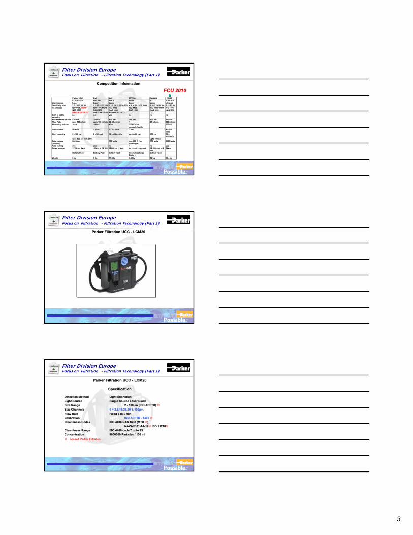
3
TM
Filter Division EuropeFocus on Filtration - Filtration Technology (Part 1)
Competition InformationCompetition Information
Parker UCC Pall Arti MPFiltri PAMAS HYDACLCM20.2021 PFC200 PODS LPA2 S2 FCU 2010
Light source Laser Laser Laser Laser Laser Infra-redSensitivity >um 2,5,15,25,50,100 2,5,15,25,50,100 1,2,5,10,15,25,50,100 4,6,14,21,25,38,50,68 2,5,15,25,50,100 5,15,25,50Int. classes ISO 4406,11218* ISO 4406,11218 ISO 4406 ISO 4406 ISO 4406,11171 ISO 4406
NAS 1638 NAS 1638 NAS 1638 NAS 1638 NAS 1638 NAS 1638NAVAIR 01-1A-17* DEFSTAN 05-42 NAVAIR 01-1A-17*
Built in bottlesampling
no no yes no no no
Max Pressure on-line 420 bar 345 bar 420 bar 400 bar 420 bar 350 barFlow Rate upto 150ml/min upto 150 ml/min 20-50 ml/min ? 25 ml/min 800 ml/minMeasuring volume 10 ml 100 ml 45ml 15/30/24 ml
norm/din/bottle100 ml
Sample time 90 secs 2 mins 1 - 2.5 mins 3 min 40 -120secs
Max. viscosity 2 - 100 cst 2 - 500 cst 10 – 430mm²/s up to 400 cst 160 cst 20 –800mm²/s
upto 500 cst with SPS upto 300 cstData storage(number)
300 tests 500 tests min 100 !!! (ascatalogue)
550 tests 3000 tests
Auto testing yes yes no ? no yesPower source 12Vdc or 9Vdc 12Vdc or 12 Vdc 12Vdc or 12 Vdc as country request 12.3Vdc or 14.4
Vdc24Vdc
Battery Pack Battery Pack Battery Pack Internal rechargeBattery
Battery Pack
Weight 8 kg 9 kg 11.5 kg 7,6 Kg 12 kg 12.4 kg
FCU 2010FCU 2010
TM
Filter Division EuropeFocus on Filtration - Filtration Technology (Part 1)
Parker Filtration UCC - LCM20Parker Filtration UCC - LCM20
TM
Filter Division EuropeFocus on Filtration - Filtration Technology (Part 1)
Parker Filtration UCC - LCM20
Specification
Parker Filtration UCC - LCM20
Specification
Detection Method Light ExtinctionLight Source Single Source Laser DiodeSize Range 2 - 100µm (ISO ACFTD) Size Channels 6 = 2,5,15,25,50 & 100µm,Flow Rate Fixed 8 ml / minCalibration ISO ACFTD - 4402Cleanliness Codes ISO 4406 NAS 1638 (MTD )
NAVAIR 01-1A-17 ISO 11218Cleanliness Range ISO 4406 code 7 upto 23Concentration 9000000 Particles / 100 ml consult Parker Filtration
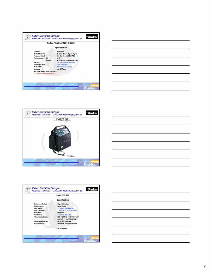
4
TM
Filter Division EuropeFocus on Filtration - Filtration Technology (Part 1)
Parker Filtration UCC - LCM20
Specification
Parker Filtration UCC - LCM20
Specification
Test time 2 minutesWetted Material St Steel Brass Pyrex NylonPressure Rated 420 Bar Direct ( 6000 PSI)Temperature Oil 80ºC
Ambient 40ºC Higher for short periods Viscosity 100 cSt ( 500cSt with SPS )Oil Sample Size 15ml sampledBuilt in BSA Alternative accessorySoftware via DATumBar code reader / limit control consult Parker Filtration UCC
TM
Filter Division EuropeFocus on Filtration - Filtration Technology (Part 1)
Pall PFC 200www.pall.com/pfc200/prod_pfc200_p2.asp
Pall PFC 200www.pall.com/pfc200/prod_pfc200_p2.asp
TM
Filter Division EuropeFocus on Filtration - Filtration Technology (Part 1)
Pall - PFC 200
Specification
Pall - PFC 200
Specification
Detection Method Light ExtinctionLight Source Laser DiodeSize Range 2 - 100µm (ISO ACFTD)Size Channels 7 = 2,5,10,15,25,50 & 100µm,Flow Rate 60ml/minCalibration Based on ISO 4402Cleanliness Codes ISO 4406 NAS 1638 DEFSTAN
NAVAIR 01-1A-17 ISO 11218Cleanliness Range up to ISO 4406 - 23 Concentration 16000000 Particles / 100 ml
un confirmed
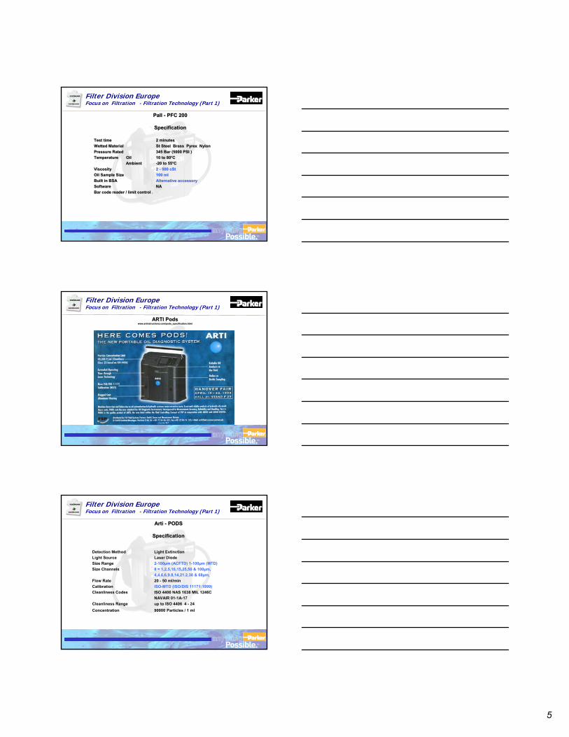
5
TM
Filter Division EuropeFocus on Filtration - Filtration Technology (Part 1)
Pall - PFC 200
Specification
Pall - PFC 200
Specification
Test time 2 minutesWetted Material St Steel Brass Pyrex NylonPressure Rated 345 Bar (5000 PSI )Temperature Oil 10 to 80ºC
Ambient -20 to 55ºCViscosity 2 - 500 cStOil Sample Size 100 mlBuilt in BSA Alternative accessorySoftware NABar code reader / limit control .
Test time 2 minutesWetted Material St Steel Brass Pyrex NylonPressure Rated 345 Bar (5000 PSI )Temperature Oil 10 to 80ºC
Ambient -20 to 55ºCViscosity 2 - 500 cStOil Sample Size 100 mlBuilt in BSA Alternative accessorySoftware NABar code reader / limit control .
TM
Filter Division EuropeFocus on Filtration - Filtration Technology (Part 1)
ARTI Podswww.artinstructions.com/pods_specification.html
ARTI Podswww.artinstructions.com/pods_specification.html
TM
Filter Division EuropeFocus on Filtration - Filtration Technology (Part 1)
Arti - PODS
Specification
Arti - PODS
Specification
Detection Method Light ExtinctionLight Source Laser DiodeSize Range 2-100µm (ACFTD) 1-100µm (MTD) Size Channels 8 = 1,2,5,10,15,25,50 & 100µm,
4,4.6,6,9.8,14,21.2,38 & 68µm,Flow Rate 20 - 50 ml/minCalibration ISO-MTD (ISO/DIS 11171:1999)Cleanliness Codes ISO 4406 NAS 1638 MIL 1246C
NAVAIR 01-1A-17 Cleanliness Range up to ISO 4406 4 - 24 Concentration 90000 Particles / 1 ml
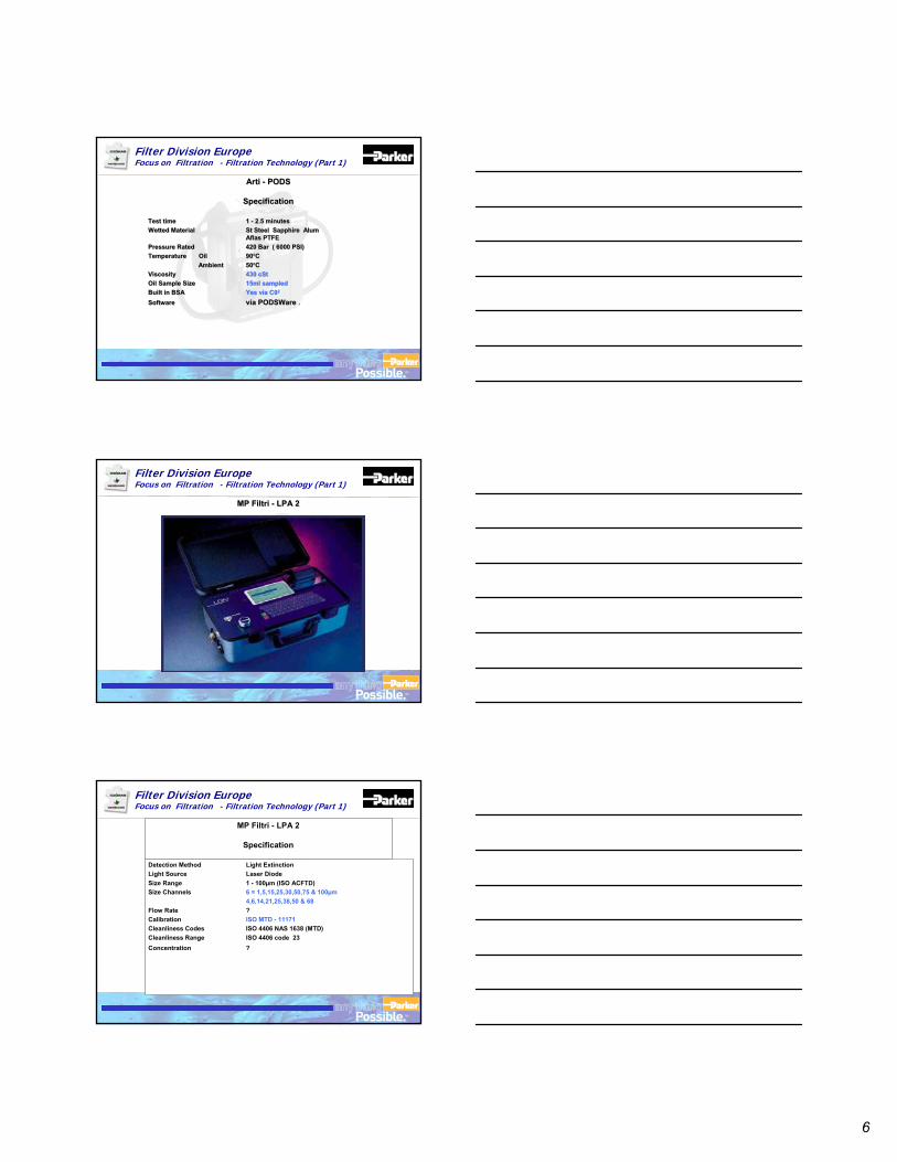
6
TM
Filter Division EuropeFocus on Filtration - Filtration Technology (Part 1)
Arti - PODS
Specification
Arti - PODS
Specification
Test time 1 - 2.5 minutesWetted Material St Steel Sapphire Alum
Aflas PTFEPressure Rated 420 Bar ( 6000 PSI)Temperature Oil 90ºC
Ambient 50ºC Viscosity 430 cStOil Sample Size 15ml sampledBuilt in BSA Yes via C02
Software via PODSWare .
Test time 1 - 2.5 minutesWetted Material St Steel Sapphire Alum
Aflas PTFEPressure Rated 420 Bar ( 6000 PSI)Temperature Oil 90ºC
Ambient 50ºC Viscosity 430 cStOil Sample Size 15ml sampledBuilt in BSA Yes via C02
Software via PODSWare .
TM
Filter Division EuropeFocus on Filtration - Filtration Technology (Part 1)
MP Filtri - LPA 2MP Filtri - LPA 2
TM
Filter Division EuropeFocus on Filtration - Filtration Technology (Part 1)
MP Filtri - LPA 2
Specification
MP Filtri - LPA 2
Specification
Detection Method Light ExtinctionLight Source Laser DiodeSize Range 1 - 100µm (ISO ACFTD)Size Channels 6 = 1,5,15,25,30,50,75 & 100µm
4,6,14,21,25,38,50 & 68Flow Rate ?Calibration ISO MTD - 11171Cleanliness Codes ISO 4406 NAS 1638 (MTD)Cleanliness Range ISO 4406 code 23Concentration ?
Detection Method Light ExtinctionLight Source Laser DiodeSize Range 1 - 100µm (ISO ACFTD)Size Channels 6 = 1,5,15,25,30,50,75 & 100µm
4,6,14,21,25,38,50 & 68Flow Rate ?Calibration ISO MTD - 11171Cleanliness Codes ISO 4406 NAS 1638 (MTD)Cleanliness Range ISO 4406 code 23Concentration ?
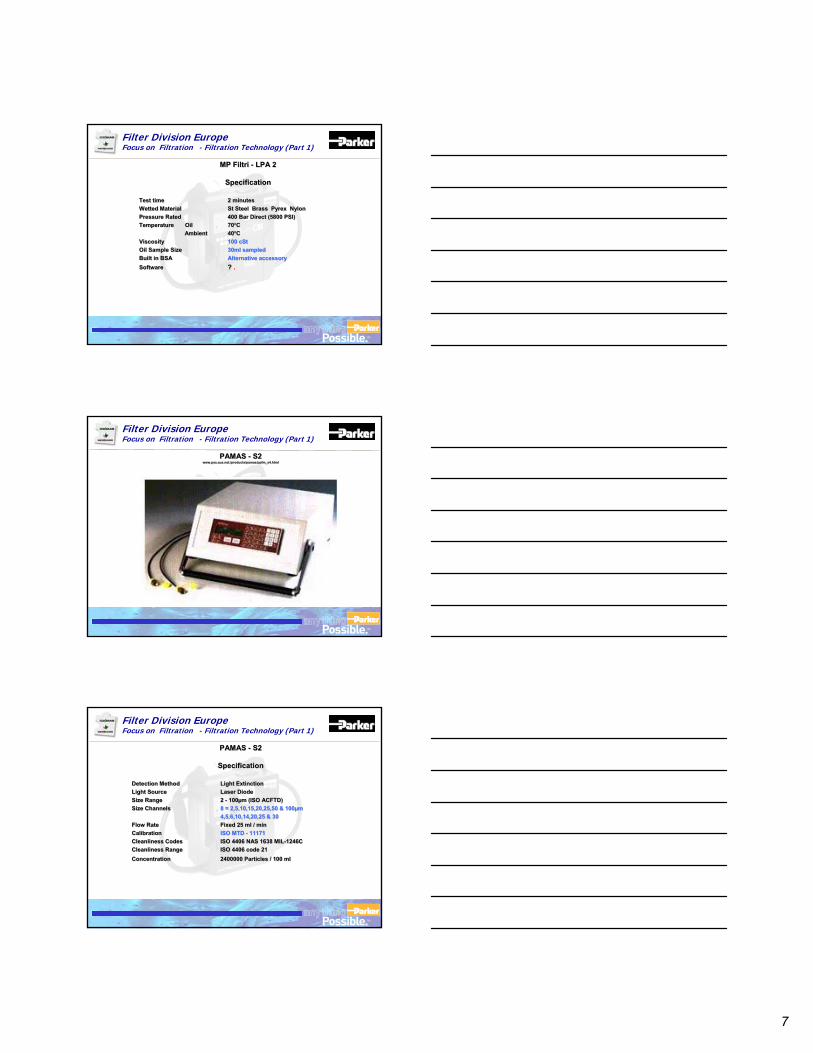
7
TM
Filter Division EuropeFocus on Filtration - Filtration Technology (Part 1)
MP Filtri - LPA 2
Specification
MP Filtri - LPA 2
Specification
Test time 2 minutesWetted Material St Steel Brass Pyrex NylonPressure Rated 400 Bar Direct (5800 PSI)Temperature Oil 70ºC
Ambient 40ºC Viscosity 100 cStOil Sample Size 30ml sampledBuilt in BSA Alternative accessorySoftware ? .
Test time 2 minutesWetted Material St Steel Brass Pyrex NylonPressure Rated 400 Bar Direct (5800 PSI)Temperature Oil 70ºC
Ambient 40ºC Viscosity 100 cStOil Sample Size 30ml sampledBuilt in BSA Alternative accessorySoftware ? .
TM
Filter Division EuropeFocus on Filtration - Filtration Technology (Part 1)
PAMAS - S2www.pss.aus.net./products/pamas/ppfm_s4.html
PAMAS - S2www.pss.aus.net./products/pamas/ppfm_s4.html
TM
Filter Division EuropeFocus on Filtration - Filtration Technology (Part 1)
PAMAS - S2
Specification
PAMAS - S2
Specification
Detection Method Light ExtinctionLight Source Laser DiodeSize Range 2 - 100µm (ISO ACFTD) Size Channels 8 = 2,5,10,15,20,25,50 & 100µm
4,5,6,10,14,20,25 & 30Flow Rate Fixed 25 ml / minCalibration ISO MTD - 11171Cleanliness Codes ISO 4406 NAS 1638 MIL-1246CCleanliness Range ISO 4406 code 21Concentration 2400000 Particles / 100 ml
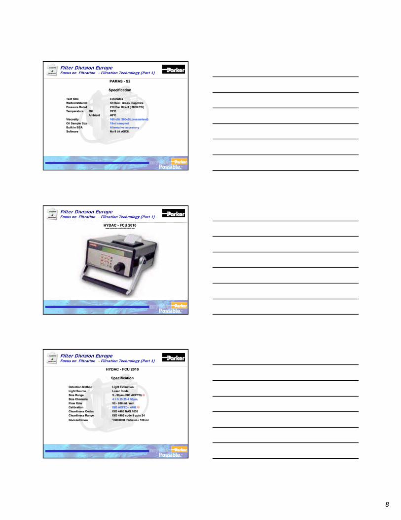
8
TM
Filter Division EuropeFocus on Filtration - Filtration Technology (Part 1)
PAMAS - S2
Specification
PAMAS - S2
Specification
Test time 4 minutesWetted Material St Steel Brass Sapphire Pressure Rated 210 Bar Direct ( 3000 PSI)Temperature Oil 70ºC
Ambient 40ºCViscosity 160 cSt (300cSt pressurised)Oil Sample Size 15ml sampledBuilt in BSA Alternative accessorySoftware No 8 bit ASCII .
Test time 4 minutesWetted Material St Steel Brass Sapphire Pressure Rated 210 Bar Direct ( 3000 PSI)Temperature Oil 70ºC
Ambient 40ºCViscosity 160 cSt (300cSt pressurised)Oil Sample Size 15ml sampledBuilt in BSA Alternative accessorySoftware No 8 bit ASCII .
TM
Filter Division EuropeFocus on Filtration - Filtration Technology (Part 1)
HYDAC - FCU 2010www.hydacusa.com/fluid/fcutech.htm
HYDAC - FCU 2010www.hydacusa.com/fluid/fcutech.htm
TM
Filter Division EuropeFocus on Filtration - Filtration Technology (Part 1)
HYDAC - FCU 2010
Specification
HYDAC - FCU 2010
Specification
Detection Method Light ExtinctionLight Source Laser DiodeSize Range 5 - 50µm (ISO ACFTD) Size Channels 4 = 5,15,25 & 50µm,Flow Rate 50 - 800 ml / minCalibration ISO ACFTD - 4402Cleanliness Codes ISO 4406 NAS 1638Cleanliness Range ISO 4406 code 9 upto 24Concentration 16000000 Particles / 100 ml
Detection Method Light ExtinctionLight Source Laser DiodeSize Range 5 - 50µm (ISO ACFTD) Size Channels 4 = 5,15,25 & 50µm,Flow Rate 50 - 800 ml / minCalibration ISO ACFTD - 4402Cleanliness Codes ISO 4406 NAS 1638Cleanliness Range ISO 4406 code 9 upto 24Concentration 16000000 Particles / 100 ml
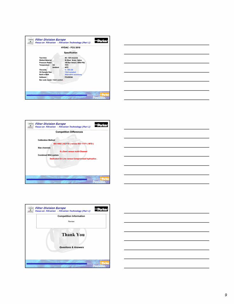
9
TM
Filter Division EuropeFocus on Filtration - Filtration Technology (Part 1)
HYDAC - FCU 2010
Specification
HYDAC - FCU 2010
Specification
Test time 40 - 120 secondsWetted Material St Steel Brass NylonPressure Rated 350 Bar Direct ( 5000 PSI)Temperature Oil 70ºC
Ambient 40ºCViscosity 5 - 100 cStOil Sample Size 15ml sampledBuilt in BSA Alternative accessorySoftware FCUDESKBar code reader / limit control .
Test time 40 - 120 secondsWetted Material St Steel Brass NylonPressure Rated 350 Bar Direct ( 5000 PSI)Temperature Oil 70ºC
Ambient 40ºCViscosity 5 - 100 cStOil Sample Size 15ml sampledBuilt in BSA Alternative accessorySoftware FCUDESKBar code reader / limit control .
TM
Filter Division EuropeFocus on Filtration - Filtration Technology (Part 1)
Competition DifferencesCompetition Differences
Calibration Method
ISO 4402 ( ACFTD ) verses ISO 11171 ( MTD )
Size channels
6 x fixed versus multi-Channel
Combined BSA system
Dedicated On Line versus Compromised hydrualics .
Calibration Method
ISO 4402 ( ACFTD ) verses ISO 11171 ( MTD )ISO 4402 ( ACFTD ) verses ISO 11171 ( MTD )
Size channels
6 x fixed versus multi6 x fixed versus multi--ChannelChannel
Combined BSA system
Dedicated On Line versus Compromised Dedicated On Line versus Compromised hydrualicshydrualics ..
TM
Filter Division EuropeFocus on Filtration - Filtration Technology (Part 1)
Questions & AnswersQuestions & Answers
Competition Information
Review
Thank You
17. Presentation
17.2 Presentation Outlining the Laser CM20 & Contamination
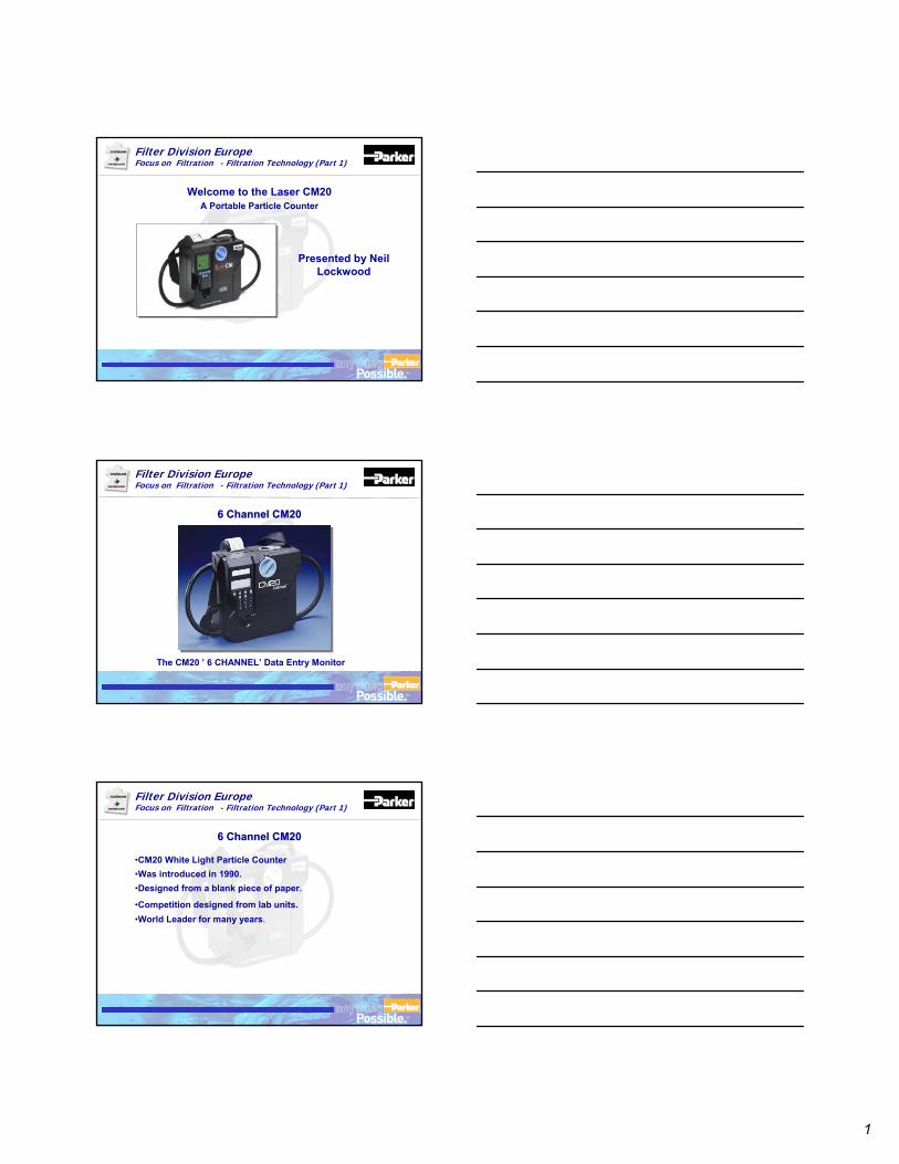
1
TM
Filter Division EuropeFocus on Filtration - Filtration Technology (Part 1)
Welcome to the Laser CM20A Portable Particle Counter
Presented by Neil Lockwood
TM
Filter Division EuropeFocus on Filtration - Filtration Technology (Part 1)
The CM20 ’ 6 CHANNEL’ Data Entry Monitor
6 Channel CM206 Channel CM20
TM
Filter Division EuropeFocus on Filtration - Filtration Technology (Part 1)
•CM20 White Light Particle Counter •Was introduced in 1990.•Designed from a blank piece of paper.
•Competition designed from lab units.•World Leader for many years.
6 Channel CM20 6 Channel CM20
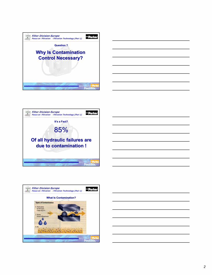
2
TM
Filter Division EuropeFocus on Filtration - Filtration Technology (Part 1)
Why Is Contamination Why Is Contamination Control Necessary?Control Necessary?
Question ?Question ?
TM
Filter Division EuropeFocus on Filtration - Filtration Technology (Part 1)
85%85%Of all hydraulic failures are Of all hydraulic failures are
due to contamination !due to contamination !
It’s a Fact?It’s a Fact?
TM
Filter Division EuropeFocus on Filtration - Filtration Technology (Part 1)
What Is Contamination?What Is Contamination?
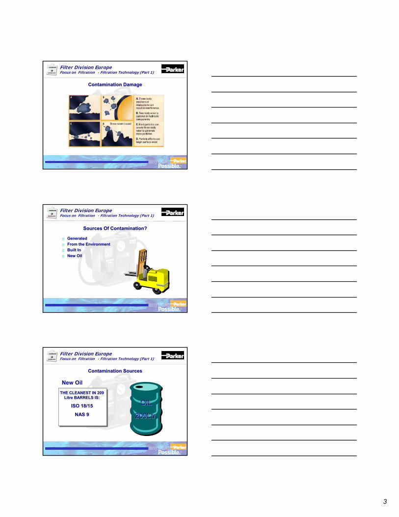
3
TM
Filter Division EuropeFocus on Filtration - Filtration Technology (Part 1)
Contamination DamageContamination Damage
TM
Filter Division EuropeFocus on Filtration - Filtration Technology (Part 1)
GeneratedGeneratedFrom the EnvironmentFrom the EnvironmentBuilt InBuilt InNew OilNew Oil
Sources Of Contamination?Sources Of Contamination?
TM
Filter Division EuropeFocus on Filtration - Filtration Technology (Part 1)
New OilTHE CLEANEST IN 209 THE CLEANEST IN 209
Litre BARRELS IS:Litre BARRELS IS:
ISO 18/15ISO 18/15
NAS 9NAS 9
Contamination SourcesContamination Sources
OILOIL
209Ltr209Ltr.
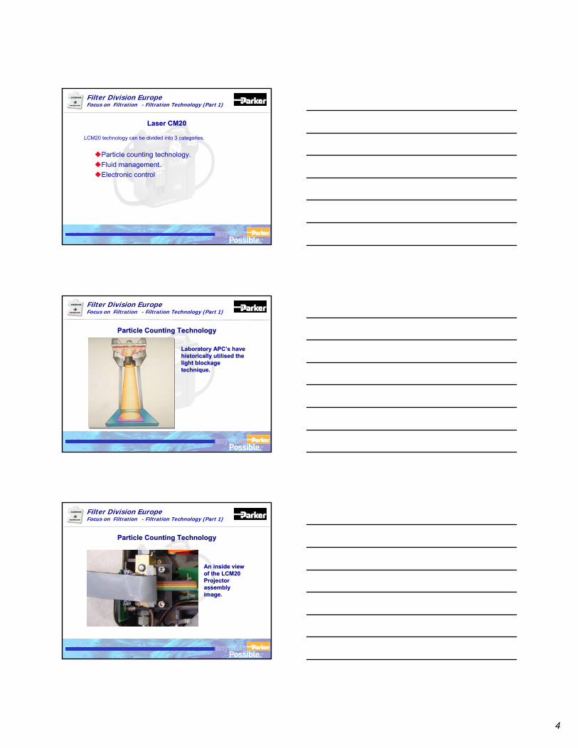
4
TM
Filter Division EuropeFocus on Filtration - Filtration Technology (Part 1)
LCM20 technology can be divided into 3 categories.
Particle counting technology.Fluid management.Electronic control
Laser CM20Laser CM20
TM
Filter Division EuropeFocus on Filtration - Filtration Technology (Part 1)
Laboratory Laboratory APC’s APC’s have have historically utilised the historically utilised the light blockage light blockage technique.technique.
Particle Counting Technology Particle Counting Technology
TM
Filter Division EuropeFocus on Filtration - Filtration Technology (Part 1)
An inside view An inside view of the LCM20 of the LCM20 Projector Projector assembly assembly image.image.
Particle Counting Technology Particle Counting Technology
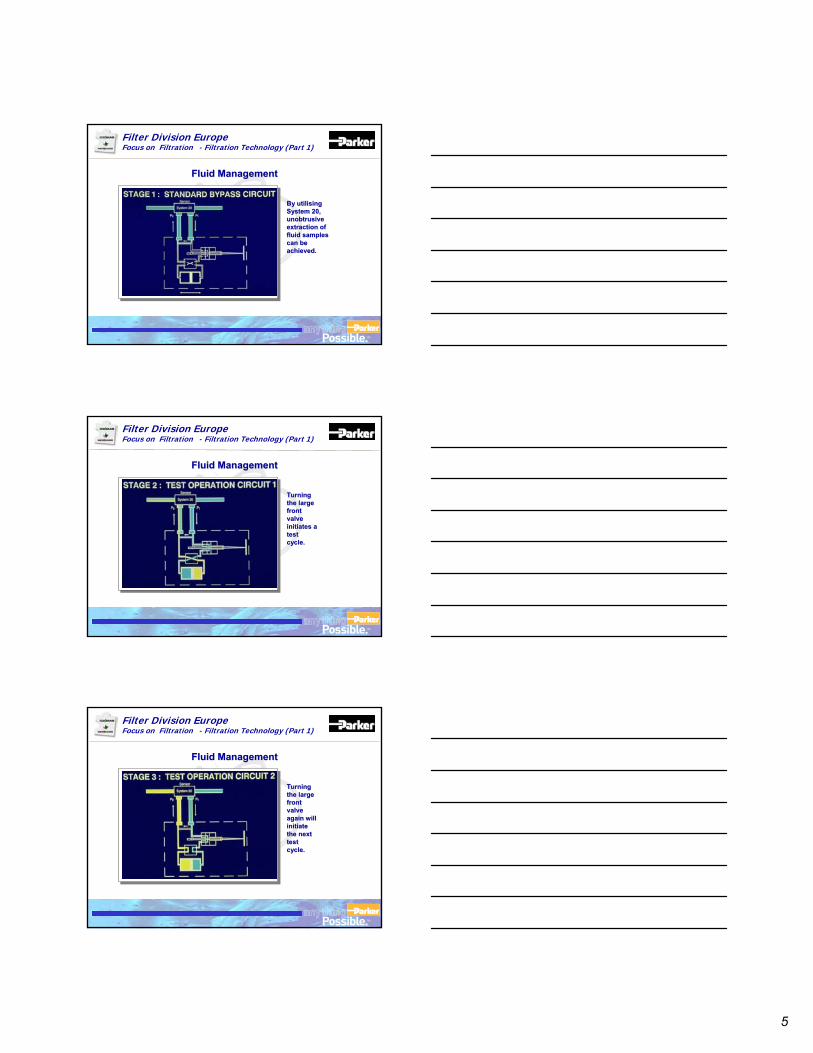
5
TM
Filter Division EuropeFocus on Filtration - Filtration Technology (Part 1)
By utilising By utilising System 20, System 20, unobtrusive unobtrusive extraction of extraction of fluid samples fluid samples can be can be achieved.achieved.
Fluid ManagementFluid Management
TM
Filter Division EuropeFocus on Filtration - Filtration Technology (Part 1)
Turning Turning the large the large front front valve valve initiates a initiates a test test cycle.cycle.
Fluid ManagementFluid Management
TM
Filter Division EuropeFocus on Filtration - Filtration Technology (Part 1)
Turning Turning the large the large front front valve valve again will again will initiate initiate the next the next test test cycle.cycle.
Fluid ManagementFluid Management
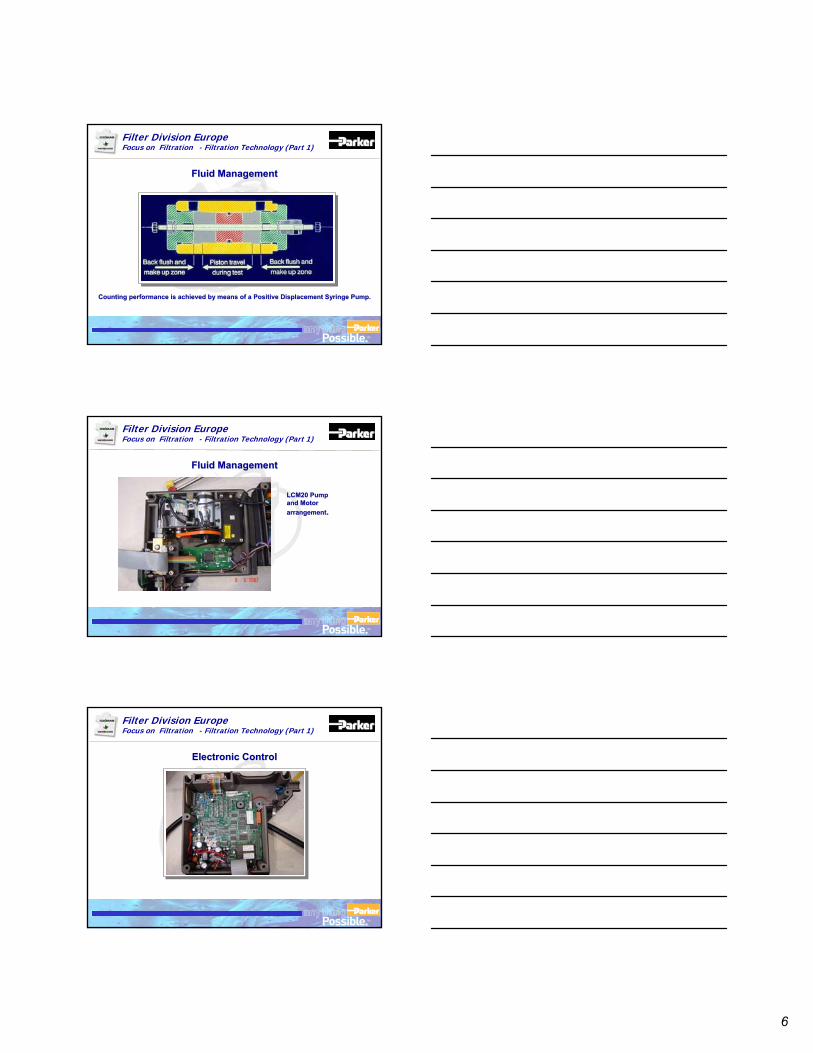
6
TM
Filter Division EuropeFocus on Filtration - Filtration Technology (Part 1)
Counting performance is achieved by means of a Positive DisplaceCounting performance is achieved by means of a Positive Displacement Syringe Pump.ment Syringe Pump.
Fluid ManagementFluid Management
TM
Filter Division EuropeFocus on Filtration - Filtration Technology (Part 1)
LCM20 Pump LCM20 Pump and Motor and Motor arrangementarrangement..
Fluid ManagementFluid Management
TM
Filter Division EuropeFocus on Filtration - Filtration Technology (Part 1)
Electronic Control Electronic Control
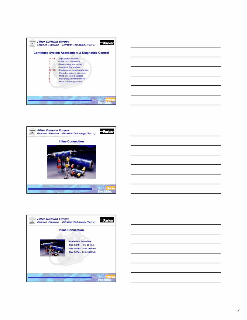
7
TM
Filter Division EuropeFocus on Filtration - Filtration Technology (Part 1)
1A / 1B - Light source deviation.2 - Valve knob interference.3 - Power supply interruption.4 - Internal oil flow analysis.5A / 5B - Displacement pump irregularities.6 - Corrective systems alignment.7 - Micro processor diagnostic.8 - Flow probe parameter checks.9 - Motor overload protection.
ContinuosContinuos System Assessment & Diagnostic ControlSystem Assessment & Diagnostic Control
TM
Filter Division EuropeFocus on Filtration - Filtration Technology (Part 1)
Inline Connection Inline Connection
TM
Filter Division EuropeFocus on Filtration - Filtration Technology (Part 1)
Inline Connection Inline Connection
Available in three sizes.Available in three sizes.
Size 0 (3/8) Size 0 (3/8) –– 6 to 25 l/min6 to 25 l/min
Size 1 (3/4) Size 1 (3/4) –– 20 to 100 l/min20 to 100 l/min
Size 2 (1¼) Size 2 (1¼) –– 80 to 380 l/min80 to 380 l/min
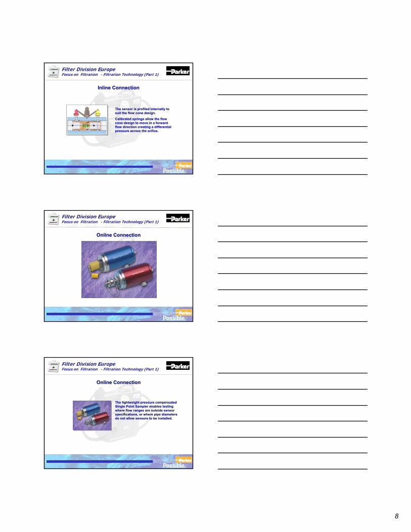
8
TM
Filter Division EuropeFocus on Filtration - Filtration Technology (Part 1)
Inline Connection Inline Connection
The sensor is profiled internally to The sensor is profiled internally to suit the flow cone design. suit the flow cone design.
Calibrated springs allow the flow Calibrated springs allow the flow cone design to move in a forward cone design to move in a forward flow direction creating a differential flow direction creating a differential pressure across the orifice. pressure across the orifice.
TM
Filter Division EuropeFocus on Filtration - Filtration Technology (Part 1)
Online Connection Online Connection
TM
Filter Division EuropeFocus on Filtration - Filtration Technology (Part 1)
Online Connection Online Connection
The lightweight pressure compensated The lightweight pressure compensated Single Point Sampler enables testing Single Point Sampler enables testing where flow ranges are outside sensor where flow ranges are outside sensor specifications, or where pipe diameters specifications, or where pipe diameters do not allow sensors to be installed.do not allow sensors to be installed.
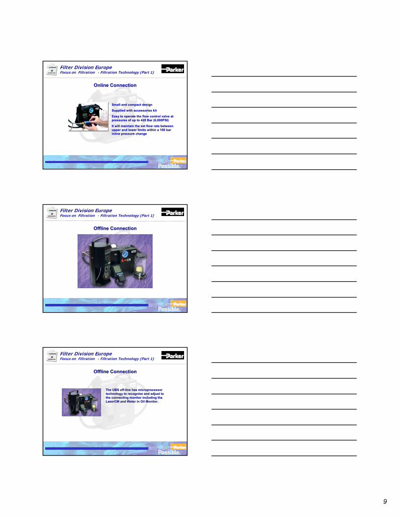
9
TM
Filter Division EuropeFocus on Filtration - Filtration Technology (Part 1)
Online Connection Online Connection
Small and compact designSmall and compact design
Supplied with accessories kitSupplied with accessories kit
Easy to operate the flow control valve at Easy to operate the flow control valve at pressures of up to 420 Bar (6,000PSI)pressures of up to 420 Bar (6,000PSI)
It will maintain the set flow rate between It will maintain the set flow rate between upper and lower limits within a 100 bar upper and lower limits within a 100 bar inline pressure changeinline pressure change
TM
Filter Division EuropeFocus on Filtration - Filtration Technology (Part 1)
Offline Connection Offline Connection
TM
Filter Division EuropeFocus on Filtration - Filtration Technology (Part 1)
Offline Connection Offline Connection
The UBS offThe UBS off--line has microprocessor line has microprocessor technology to recognise and adjust to technology to recognise and adjust to the connecting monitor including the the connecting monitor including the LaserCMLaserCM and Water in Oil Monitor.and Water in Oil Monitor.
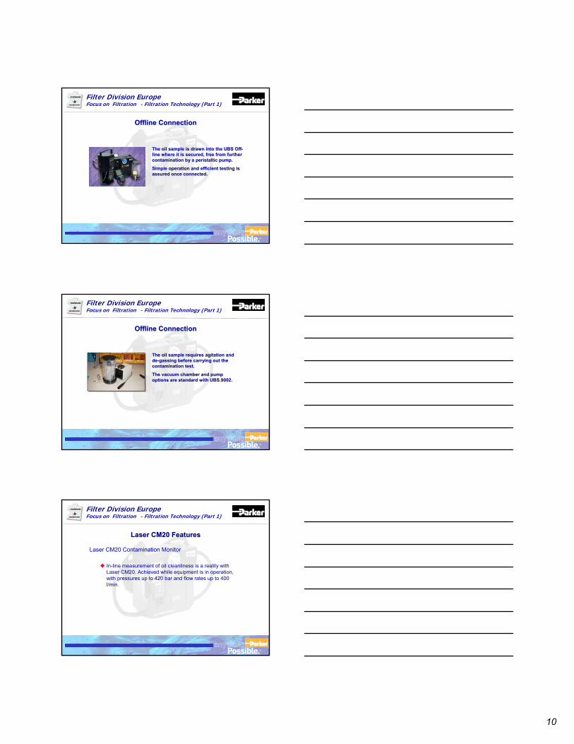
10
TM
Filter Division EuropeFocus on Filtration - Filtration Technology (Part 1)
Offline Connection Offline Connection
The oil sample is drawn into the UBS OffThe oil sample is drawn into the UBS Off--line where it is secured, free from further line where it is secured, free from further contamination by a peristaltic pump. contamination by a peristaltic pump.
Simple operation and efficient testing is Simple operation and efficient testing is assured once connected.assured once connected.
TM
Filter Division EuropeFocus on Filtration - Filtration Technology (Part 1)
Offline Connection Offline Connection
The oil sample requires agitation and The oil sample requires agitation and dede--gassing before carrying out the gassing before carrying out the contamination test. contamination test.
The vacuum chamber and pump The vacuum chamber and pump options are standard with UBS.9002.options are standard with UBS.9002.
TM
Filter Division EuropeFocus on Filtration - Filtration Technology (Part 1)
Laser CM20 Contamination Monitor
In-line measurement of oil cleanliness is a reality with Laser CM20. Achieved while equipment is in operation, with pressures up to 420 bar and flow rates up to 400 l/min.
Laser CM20 Features Laser CM20 Features
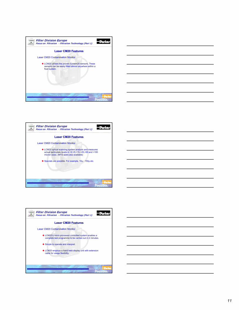
11
TM
Filter Division EuropeFocus on Filtration - Filtration Technology (Part 1)
Laser CM20 Contamination Monitor
LCM20 utilises the proven System20 sensors. These sensors can be easily fitted almost anywhere within a fluid system.
Laser CM20 Features Laser CM20 Features
TM
Filter Division EuropeFocus on Filtration - Filtration Technology (Part 1)
Laser CM20 Contamination Monitor
LCM20 optical scanning system analysis and measures actual particulate levels in >2,>5,>15,>25,>50 and >100 micron sizes. (MTD sizes also available)
Specials are possible. For example, 10µ - 150µ etc.
Laser CM20 Features Laser CM20 Features
TM
Filter Division EuropeFocus on Filtration - Filtration Technology (Part 1)
Laser CM20 Contamination Monitor
LCM20’s micro processor controlled system enables a complete test programme to be carried out in 2 minutes.
Simple to operate and interpret.
LCM20 employs a hand held display unit with extension cable for usage flexibility.
Laser CM20 Features Laser CM20 Features
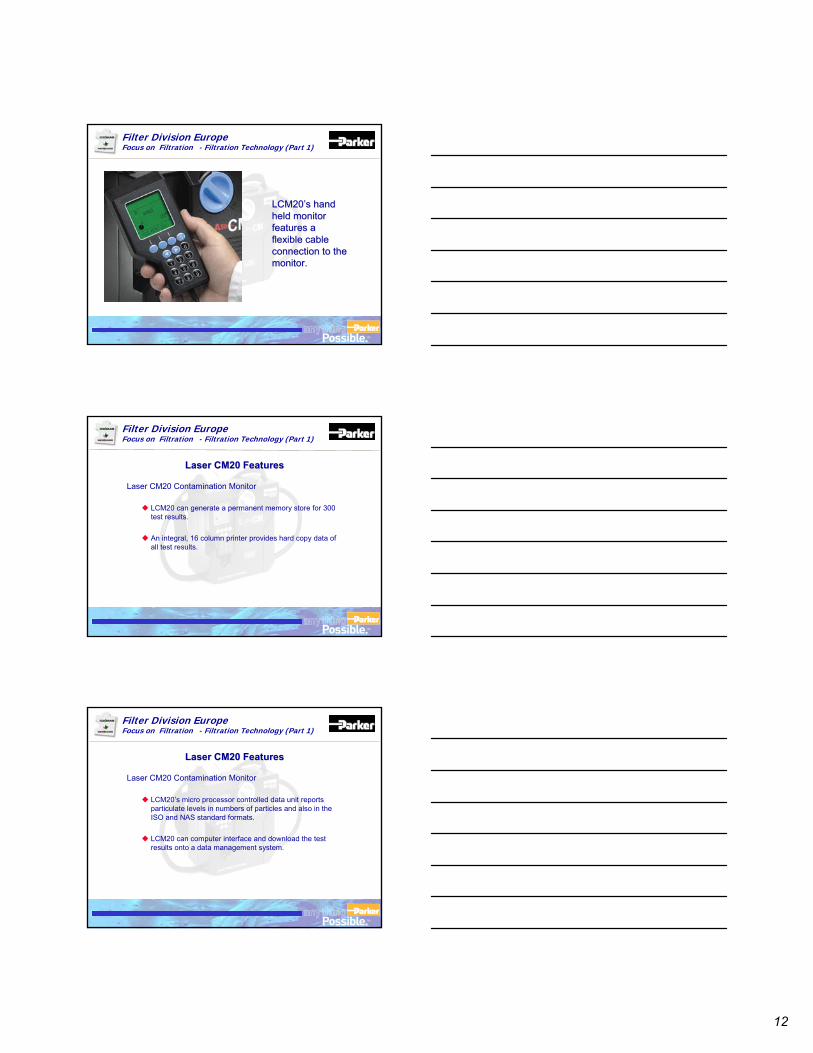
12
TM
Filter Division EuropeFocus on Filtration - Filtration Technology (Part 1)
LCM20’s hand LCM20’s hand held monitor held monitor features a features a flexible cable flexible cable connection to the connection to the monitor.monitor.
TM
Filter Division EuropeFocus on Filtration - Filtration Technology (Part 1)
Laser CM20 Contamination Monitor
LCM20 can generate a permanent memory store for 300 test results.
An integral, 16 column printer provides hard copy data of all test results.
Laser CM20 Features Laser CM20 Features
TM
Filter Division EuropeFocus on Filtration - Filtration Technology (Part 1)
Laser CM20 Contamination Monitor
LCM20’s micro processor controlled data unit reports particulate levels in numbers of particles and also in the ISO and NAS standard formats.
LCM20 can computer interface and download the test results onto a data management system.
Laser CM20 Features Laser CM20 Features
13
TM
Filter Division EuropeFocus on Filtration - Filtration Technology (Part 1)
Laser CM20 Features Laser CM20 Features
TM
Filter Division EuropeFocus on Filtration - Filtration Technology (Part 1)
Laser CM20 Contamination Monitor
Alarm Level TestingThe LCM has a built in relay switch module that can be set to either switch on or off an external device, wired through the limit switch socket.
The Bar Code Wand is available as an optional extra and allows the user to enter the 32 character serial ID or test data against the test number from a standard 39 bar code.
Laser CM20 Features Laser CM20 Features
TM
Filter Division EuropeFocus on Filtration - Filtration Technology (Part 1)
Cumulative sales in excess of 4000 world wide45% total market share200 - 250 units sales per year
•Asia Pacific 60% Market Share•Middle East 60% “ “•North & South Europe 35% “ “•North America Inc. Canada 40% “ “•South America 45% “ “
Global Leader Global Leader
14
TM
Filter Division EuropeFocus on Filtration - Filtration Technology (Part 1)
From the many and varied applications for LCM20 these are just a few of the typical opportunities.
CONSTRUCTION MACHINERYExcavators. Material Handlers. Digger Loaders. Compaction Equipment. Drilling and Piling. Material Process Machinery. Crawlers and Graders. Power Plant. Tunnelling. Cranes. Road Making Equipment.
INDUSTRIAL PLANTAutomotive Manufacturing Lines. Robotic Assembly Equipment. Injection Moulding Machines. Machine Tools.
HYDRAULIC EQUIPMENT & SYSTEM MANUFACTURERSRESEARCH & TESTING INSTITUTESOFF-SHORE & POWER GENERATIONMARINEMILITARY EQUIPMENT APPLICATION.
Typical Industrial Applications Typical Industrial Applications
TM
Filter Division EuropeFocus on Filtration - Filtration Technology (Part 1)
•Global Accounts are -
•MOD UK Aircraft service certificationNavy ship Hydraulic service ring mainArmy Ground Defence & Auxiliary services
•Supported by NSN (Nato Stock Numbers) accreditation
Military Customers Military Customers
TM
Filter Division EuropeFocus on Filtration - Filtration Technology (Part 1)
Royal Air Force
Royal Navy
British Army
Japanese Military
British Aerospace
Canadian DND
US Naval Air
Belgian, Malaysian Navy and Airforce, Finnish, Australian, UAE, Oman, India, French, Korean, Singapore
Military Customers Military Customers
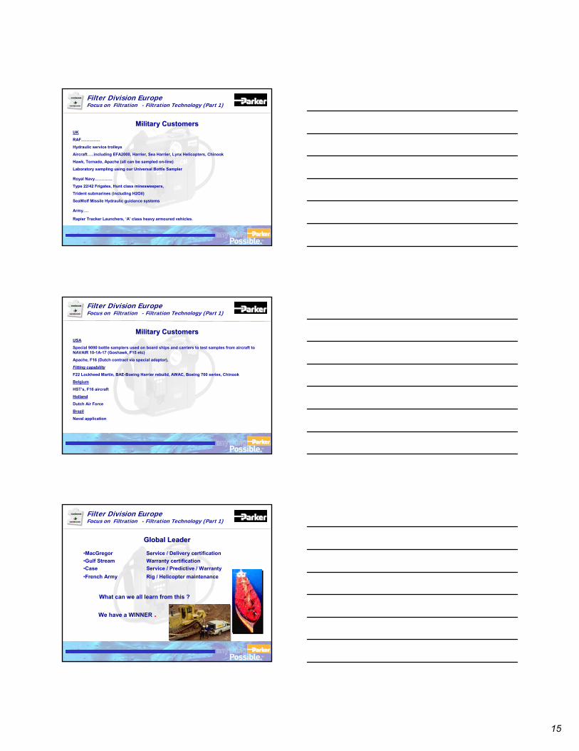
15
TM
Filter Division EuropeFocus on Filtration - Filtration Technology (Part 1)
UK
RAF…………..
Hydraulic service trolleys
Aircraft…..including EFA2000, Harrier, Sea Harrier, Lynx Helicopters, Chinook
Hawk, Tornado, Apache (all can be sampled on-line)
Laboratory sampling using our Universal Bottle Sampler
Royal Navy………….
Type 22/42 Frigates, Hunt class minesweepers,
Trident submarines (including H2Oil)
SeaWolf Missile Hydraulic guidance systems
Army….
Rapier Tracker Launchers, ‘A’ class heavy armoured vehicles.
Military Customers Military Customers
TM
Filter Division EuropeFocus on Filtration - Filtration Technology (Part 1)
USA
Special 9090 bottle samplers used on board ships and carriers to test samples from aircraft to NAVAIR 10-1A-17 (Goshawk, F15 etc)
Apache, F16 (Dutch contract via special adaptor),
Fitting capability
F22 Lockheed Martin, BAE-Boeing Harrier rebuild, AWAC, Boeing 700 series, Chinook
Belgium
HST’s, F16 aircraft
Holland
Dutch Air Force
Brazil
Naval application
Military Customers Military Customers
TM
Filter Division EuropeFocus on Filtration - Filtration Technology (Part 1)
•MacGregor Service / Delivery certification•Gulf Stream Warranty certification•Case Service / Predictive / Warranty•French Army Rig / Helicopter maintenance
We have a WINNER .
What can we all learn from this ?
Global Leader Global Leader
16
TM
Filter Division EuropeFocus on Filtration - Filtration Technology (Part 1)
•We have access to the Global market leader.FACTFACT The number of sales shows this.The number of sales shows this.•We have access to the respected, well engineered unit that has been recognised by the worlds top class industries.
FACTFACT The account names indicate this.The account names indicate this.•We have access to a product that is revered & mimicked by our competition.
FACTFACT The competition are reThe competition are re--engineering products engineering products to follow the CM / LCM hydraulic philosophy.to follow the CM / LCM hydraulic philosophy.
Summary Summary
TM
Filter Division EuropeFocus on Filtration - Filtration Technology (Part 1)
•We have access to a Global network of service Centres.BloisBlois FranceFrance
MetamoraMetamora USAUSATokyoTokyo JapanJapan
KolcattaKolcatta IndiaIndia
Sao PauloSao Paulo BrazilBrazilJurongJurong SingaporeSingapore
KristiansandKristiansand NorwayNorway
KaarstKaarst GermanyGermany
•Offering Service, Repair & Calibration.Customer technical backup & support.Product application training.
Global Support Global Support
TM
Filter Division EuropeFocus on Filtration - Filtration Technology (Part 1)
Parker Hannifin UK Ltd - Condition Monitoring Centre.
•Participates in BFPA “British Fluid Power Association” sittings•2 CMC employees sit on Technical Committee TC6•Thus supporting & influencing ISO / NFPA / SAE decision in implementing Industrial standards.
Global Involvement Global Involvement
17
TM
Filter Division EuropeFocus on Filtration - Filtration Technology (Part 1)
The Laser CM20A Portable Particle Counter
Thank You!

18. Laser CM Contact Information Manufacturing and Sales Locations Parker Hannifin (UK) Ltd Filter Division Europe Condition Monitoring Centre Brunel Way Thetford, Norfolk, IP24 1HP, UK Phone: +44 (0) 1842 763299 Fax: +44 (0) 1842 756300 Email: [email protected] Parker Hannifin (UK) Ltd Filter Division Europe (HQ) Shaw Cross Business Park Dewsbury, West Yorkshire WF12 7RD, UK Phone: +44 (0) 1924 487000 Fax: +44 (0) 1924 487001 Email: [email protected]
Parker Filtration BV Filter Division Europe Stieltesweg 8 6827 BV Arnhem, The Netherlands Phone: +31 26 3760376 Fax: +31 26 3643620 Email: [email protected]
Parker Hannifin Oy Filter Division Europe Salmentie 260 FIN - 31700 Urjala Finland Phone: +358 (0)3 54100 Fax: +358 (0)3 5410100 Email: [email protected]
Parker Hannifin Corp Hydraulic Filter Division 16810 Fulton County Road Metamora, Ohio, USA Phone: +1 (419) 6444311 Fax: +1 (419) 6446205
For all other countries please contact: European Product Information Centre (24 Hr.): 00800 27 27 5374 www.parker.com/eurofilt Email: [email protected]
©Parker Hannifin 2005 Brochure: FDCM133UK 09/05
Worldwide Sales Locations
Argentina +54 (11) 4752 4129 Australia +61 (2) 9 634 777 Austria +43 2622 23501-0 Belgium +32 (67) 280900 Brazil +55 12 3955 1000 Canada +1 800 272 7537 Central & South America/Caribbean +1 305 470 8800 China +86 (21) 6445 9339 Czech Republic +42 0 2 830 85 221 Denmark +45 0 43 56 04 00 Finland +358 (0) 3 54100 France +33 0 254 741403 Germany +49 - 2131 - 40160 Hong Kong +852 (2) 428 8008 Hungary +36 (1) 252 8137 India +91 55907081 85 Indonesia +60-3-5638 1476 Italy +39 02 451921 Japan +81 3 6408 3900 Jordan +(962) (6) 810679 Korea +82 31 379 2200 Malaysia +62-811-179135 Mexico +1 800 272 7537 Netherlands +31 0 541 585000 New Zealand +64 (9) 573 1523 Norway +47 64 91 1000 Philippines +63 34 4323779 Poland +48 225732 400 Singapore + 65 688 76300 South Africa +11 961 0700 Spain +34 (91) 675 7300 Sweden + 46 8 5979 5000 Switzerland +41 0 22 307 7111 Taiwan +886 2 2298 8987 Thailand +662 693 3304 United Arab Emirates +971 2 6788587 United Kingdom +44 0 1924 487000 USA +1 800 272 7537 Venezuela +58 212 238 54 22