Laser shock processing and its effects on microstructure and properties of metal alloys: a review
18
I ·~ .. 1111111111111111" II Relais Request No. DAY-29214230 Customer Code 96-0198 Delivery Method SED Request Number RZDVBOll118 DSED24 COPY~ Date Printed : Date Submitted: 10-Feb-2011 11 :46 10-Feb-2011 09:49 4542.246000 TITLE: YEAR: VOLUME/PART: PAGES: AUTHOR: ARTICLE TITLE: SHELFMARK: INTERNATIONAL JOURNAL OF FATIGUE 2002 2002; VOL 24; NUMBER 10; PP 1021 RZDVB011118 DSED24 COPYRTIINTERNATIONAL JOURNAL OF FATIGUEI2002; VOL 24; NUMBER 10; PP 1021-10361LASER SHOCK PROCESSING AND ITS EFFECTS0IN MICROSTRUCTURE AND PROPERTIESOF METALIMONTROSS, C. S. WEI, T. YE, L. CLARK, G.14542.246000 0142-112 3 I DELIVERING THE WORLD'S KNOWLEDGE : ThiS document has been supplied by the British Library :. www.bl.uk The contents of the attached document are copyright works. Unless you have the permission of the copyright owner, the Copyright Licensing Agency Ltd or another authorised licensing body, you may not copy, store in any electronic medium or otherwise reproduce or resell any of the content, even for internal purposes, except as may be allowed by law. The document has been supplied under our Copyright Fee Paid service. You are therefore agreeing to the terms of supply for our Copyright Fee Paid service, available at : http://www.bl.uk/reshelp/atyourdesk/docsupply/help/terms/index.html
-
Upload
independent -
Category
Documents
-
view
1 -
download
0
Transcript of Laser shock processing and its effects on microstructure and properties of metal alloys: a review
I·~.. 1111111111111111" IIRelais Request No. DAY-29214230Customer Code96-0198
Delivery MethodSED
Request NumberRZDVBOll118 DSED24 COPY~
Date Printed :Date Submitted:
10-Feb-2011 11 :4610-Feb-2011 09:49
4542.246000TITLE:YEAR:VOLUME/PART:PAGES:AUTHOR:ARTICLE TITLE:SHELFMARK:
INTERNATIONAL JOURNAL OF FATIGUE20022002; VOL 24; NUMBER 10; PP 1021
RZDVB011118 DSED24 COPYRTIINTERNATIONAL JOURNAL OF FATIGUEI2002; VOL 24;NUMBER 10; PP 1021-10361LASER SHOCK PROCESSING AND ITS EFFECTS0INMICROSTRUCTURE AND PROPERTIESOF METALIMONTROSS, C. S. WEI, T. YE, L. CLARK,G.14542.246000 0142-112 3
I DELIVERING THE WORLD'S KNOWLEDGE: ThiS document has been supplied by the British Library
:. www.bl.uk
The contents of the attached document are copyright works. Unless you have the permissionof the copyright owner, the Copyright Licensing Agency Ltd or another authorised licensingbody, you may not copy, store in any electronic medium or otherwise reproduce or resell anyof the content, even for internal purposes, except as may be allowed by law.
The document has been supplied under our Copyright Fee Paid service. You are thereforeagreeing to the terms of supply for our Copyright Fee Paid service, available at :http://www.bl.uk/reshelp/atyourdesk/docsupply/help/terms/index.html

InternationalJournal of
Fatigue
Laser shock processing and its effects on microstructure andproperties of metal alloys: a review
a Center of Expertise in Damage Mechanics, Center for Advanced Materials Technology, School of Aerospace, Mechanical and MechatronicEngineering, University of Sydney, Sydney, NSW 2006, Australia
b Airframes and Engines Division, Aeronautical and Maritime Research Laboratory, 506 Lorimer Street, Fishermens Bend, Victoria 3207,Australia
The current status of research and development on laser shock processing of metals, also known as laser peening, using Q-switchedhigh power lasers is reviewed. The influence of processing parameters on the laser-induced shock waves in metal components arediscussed and analyzed. Special attention is paid to the residual stresses and improved fatigue performance from laser peening,which are compared with conventional shot peening results. Modification of microstructure, surface morphology, hardness, andstrength by laser peening is also discussed. Finally, applications of laser peening are addressed. Results to date indicate that laserpeening has great potential as a means of improving the mechanical performance of components. © 2002 Elsevier Science Ltd.All rights reserved.
For the past six decades, shot peening has been themost effective and widely used method of introducingcompressive residual stresses into the surface of metalsto improve fatigue performance. Shot peening is rela-tively inexpensive, uses robust process equipment, andcan be used on large or small areas as required. How-ever, the shot peening process has its limitations. Indetermining the compressive stresses produced, the pro-cess was semi-quantitative and depended upon a metalstrip or gage called an Almen type gage to proVide anindication of shot peening intensity. This gage did notguarantee that the shot peening intensity would be uni-form across the component being peened. Secondly, thecompressive residual stresses were limited in depth, usu-ally not exceeding 0.25 mm in soft metals such as alumi-num alloys and less in harder metals. Thirdly, the peen-
• Corresponding author. Tel.: +61-2-9351-4798; fax: +61-2-9351-7060.
E-mail address:[email protected](L.Ye).
ing process resulted in a roughened surface, especiallyin soft metals like aluminum. This roughness needs tobe removed before use in wear applications and typicalprocesses used removed the majority of the compressivelayer. An alternative novel surface processing tech-nology, namely laser shock processing (also known aslaser peening), can induce greater depths of residualstress into metal surfaces using high-power, Q-switchedlaser pulses.
The ability of a pulsed laser beam to generate shockwaves was first recognized and explored in the early1960s [1,2]. Subsequent studies established the con-ditions for enhancing the amplitude of stress waves,making it possible to induce plastic deformation in met-allic targets [3-6]. Prototype facilities were developedand initial feasibility studies were performed at BattelleColumbus Laboratories (USA) for utilizing laser inducedshock waves to modify material properties [7-13]. After-wards, many research groups, in particular laboratoriesin France such as CLF A (Cooperation Laser Franco-Allemande-Arcueil Cedex), LALP (Laboratoired' Application des Lasers de Puissance-Arcueil Cedex)and LULl (Laboratoire d'Utilisation des Lasers
0142-1123/021$ - see front matter © 2002 ElsevierScience Ltd. All rights reserved.PU: 50142-1123(02)00022-1
Intenses-Ecole Poly technique, Palaiseau Cedex),expended much effort in the investigation and exploi-tation of this process for industrial applications [14-19].Through these efforts, laser peening is emerging as analternative to conventional shot peening processes.
The object of this article is to present an overview ofthe state of the art of laser shock processing, highlightingsome applications of this process. This field has beenreviewed earlier with an emphasis on some selected top-ics [20-22] but no comprehensive review of processoptimization and material aspects is available to date.
When the power density of a laser pulse from a Q-switched laser is sufficiently high and when the pulsehits a metal surface, shock waves can be generated. Ascompared with continuously generated laser beams fromhelium-neon or carbon dioxide lasers, in Q-switchedlasers the laser pulse resonates (or Q-switches) throughthe lasing medium until the laser pulse exceeds a thres-hold and leaves the laser. In this way, Q-switched laserscan generate GW beams of 1-100+ ] pulses less than100 ns in length as compared with kW beams from con-tinuous carbon dioxide lasers.
The plastic deformation caused by the shock wavewhile propagating into the metal can result in residualcompressive stresses. The physics and mechanisms ofshock wave generation by lasers has been investigatedintensively [7,23-28]. In early published experiments[2,4], the irradiated target was in a vacuum and the laserproduced a plasma that expanded freely. The resultingpeak laser induced shock wave pressures ranged from 1GPa up to 1 TPa when the incident laser power densitywas varied from about 0.1 GW/cm2 to 106 GW/cm2• Thetime duration of the shock wave pressure pulse wasroughly equal to the laser pulse duration, typically 50 nsin length, because of the rapid adiabatic cooling of thelaser generated plasma in the vacuum [11,20].
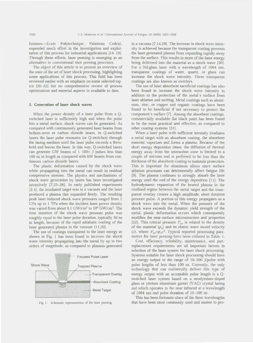
The use of coatings transparent to the laser energy asshown in Fig. 1 has been found to increase the shockwave intensity propagating into the metal by up to twoorders of magnitude, as compared to plasmas generated
in a vacuum [7,14,29]. The increase in shock wave inten-sity is achieved because the transparent coating preventsthe laser generated plasma from expanding rapidly awayfrom the surface. This results in more of the laser energybeing delivered into the material as a shock wave [30].For a Nd:glass laser with a wavelength of 1064 nm,transparent coatings of water, quartz, or glass canincrease the shock wave intensity. These transparentcoatings are also known as overlays.
The use of laser absorbent sacrificial coatings has alsobeen found to increase the shock wave intensity inaddition to the protection of the metal's surface fromlaser ablation and melting. Metal coatings such as alumi-num, zinc, or copper and organic coatings have beenfound to be beneficial if not necessary to protect thecomponent's surface [7]. Among the absorbent coatings,commercially available flat black paint has been foundto be the most practical and effective, as compared toother coating systems [31].
When a laser pulse with sufficient intensity irradiatesa metal target with an absorbent coating, the absorbentmaterial vaporizes and forms a plasma. Because of theshort energy deposition times, the diffusion of thermalenergy away from the interaction zone is limited to acouple of microns and is preferred to be less than thethickness of the absorbent coating to maintain protection.This is important for aluminum alloys since surfaceablation processes can detrimentally affect fatigue life[9]. The plasma continues to strongly absorb the laserenergy until the end of the energy deposition [11]. Thehydrodynamic expansion of the heated plasma in theconfined region between the metal target and the trans-parent overlay creates a high amplitude, short durationpressure pulse. A portion of this energy propagates as ashock wave into the metal. When the pressure of theshock wave exceeds the dynamic yield strength of themetal, plastic deformation occurs which consequentlymodifies the near-surface microstructure and properties[22]. This critical pressure Fsw is related to the densityof the material (Po) and its elastic wave sound velocity(c), where Fsw=Pod. Typical reported processing para-meters for laser peening have been collated in Table 1.
Cost, efficiency, reliability, maintenance, and part-replacement requirements are all important factors inselection of the laser system for laser shock processing.Systems suitable for laser shock processing should havean energy output in the range of 10-500 ]/pulse withpulse lengths of less than 100 ns. Currently, the onlytechnology that can realistically deliver this type ofenergy output with an acceptable pulse length is a Q-switched laser system based on a neodymium-dopedglass or yttrium aluminum garnet (YAG) crystal lasingrod which operates in the near infrared at a wavelengthof 1064 nm and pulse duration of 10-100 ns.
This has been fortunate since of the three wavelengthsthat have been most commonly used and easiest to pro-

Table ITypical processing parameters reported for laser shock processing of metals
Treated materials Laser type Laser Power density Pulse duration Laser beam Absorbent coaling Transparent overlay Pressure References (j
power (CW/cm2) (ns) size (mm) (CPa) t.Il
m g:"
Zn, AI Nd:glass 500 20-40 Lead, zinc, black paint (8-10 Quartz or water (0.3 10 [7] ~llm) cm) ~
Fe-3wt%Si Nd:glass 500 0.1-1 25-200 Lead Quartz [9] '",...5086-H32,6061-T6 Nd:glass 500 1.13-4.39, 25 1-3.0, 1.6-- Quartz 2-6 [10]
.....
"1.34-2.16 2.0 q;2024-T351,2024-T851, Nd:glass 20-30 6-30 Black paint Quartz or water [131 :;
'"7075-T631,7075-T73 g""2024-T3 Nd:glass 200 4.4-12 13-18 11.4-16.3 Aluminum coated plastic Quartz [62] ~
2024-T62 Nd:glass 18, 23 1.57, 7.32 6, 8 Black paint (0.1 mm) K7 glass (4.5 mm) [36J'"Hadfield steel Nd:glass 100 2.4xlO' -0.6 3-3.5 Black paint (40-50 llm) None -2 [51] '":;
316L stainless steel Nd:glass 80 300 0.6 7.5 Black paint None 18 [16] ~D55CI steel, 316L stainless Nd:glass 1-8 4-5 Al paint Al adhesive Water 2.7-6 [52] -.,
steel ~316L stainless steel, Nd:glass 40 8-9 8-10 3-4 Al foil, Al adhesive or paint Water 5.5-6 [85] ~.
'"XI2CrNi12-2-2 steel<b
'"AI-12Si, A356 AI, 7075 Nd:glass 80 1-8 15-30 5-12 Water (2-5 mm) 2.5 [58[•..t\)
Fe-30%Ni KDP 4000 10'_10' I 25 No None [38[ '"304 stainless steel Nd:glass 2xlO' 2xlO' 0.6 3-6 Black paint None 15-60 [64J ~18Ni(250) steel Nd:YAC 0.03 IxlO' 0.1 0.1 Black paint (-O.lmm) Water (-3.5 mm) [65] ~SAE 10 10 steel Nd:glass 5-200 120-4700 0.6 3.0-3.5 Black paint (40-50 llm) None <2.5 [86] .,
80>
duce, {1064 nm (near infra-red), 532 nm (green) or 355nm (ultraviolet)}, the near infra-red wavelength has onlya modest absorption coefficient in water overlays, suf-ficient interaction with the metals surface, and highdielectric breakdown threshold. Although the 532 nm(green) wavelength has the lowest absorption in water,generating the 532 nm (green) or 355 nm (ultraviolet)wavelengths with harmonic single crystals from 1064nm laser pulses reduces the laser pulse energy output bya factor of two or more due to the conversion processand to associated inefficiencies.
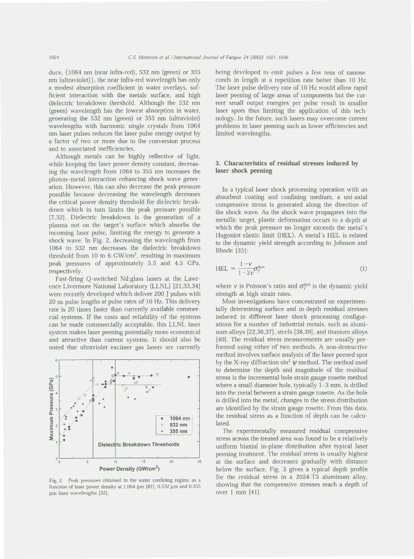
Although metals can be highly reflective of light,while keeping the laser power density constant, decreas-ing the wavelength from 1064 to 355 nm increases thephoton-metal interaction enhancing shock wave gener-ation. However, this can also decrease the peak pressurepossible because decreasing the wavelength decreasesthe critical power density threshold for dielectric break-down which in turn limits the peak pressure possible[7,32]. Dielectric breakdown is the generation of aplasma not on the target's surface which absorbs theincoming laser pulse, limiting the energy to generate ashock wave. In Fig. 2, decreasing the wavelength from1064 to 532 nm decreases the dielectric breakdownthreshold from 10 to 6 GW/cm2, resulting in maximumpeak pressures of approximately 5.5 and 4.5 GPa,respectively.
Fast-firing Q-switched Nd:glass lasers at the Lawr-ence Livermore National Laboratory (LLNL) [21,33,34Jwere recently developed which deliver 200 J pulses with20 ns pulse lengths at pulse rates of 10Hz. This deliveryrate is 20 times faster than currently available commer-cial systems. If the costs and reliability of the systemscan be made commercially acceptable, this LLNL lasersystem makes laser peening potentially more economicaland attractive than current systems. It should also benoted that ultraviolet excimer gas lasers are currently
.,9" q.. . ',..,....• '
._.~ .,11,'...'~'.'.•10 15 20
Power Density (GW/cm2)
Fig. 2. Peak pressures obtained in the water confining regime as afunction of laser power density at 1.064 llm [87]. 0.532 llm and 0.355llm laser wavelengths [32].
being developed to emit pulses a few tens of nanose-conds in length at a repetition rate better than 10 Hz.The laser pulse delivery rate of 10Hz would allow rapidlaser peening of large areas of components but the cur-rent small output energies per pulse result in smallerlaser spots thus limiting the application of this tech-nology. In the future, such lasers may overcome currentproblems in laser peening such as lower efficiencies andlimited wavelengths.
3. Characteristics of residual stresses induced bylaser shock peening
In a typical laser shock processing operation with anabsorbent coating and confining medium, a uni-axialcompressive stress is generated along the direction ofthe shock wave. As the shock wave propagates into themetallic target, plastic deformation occurs to a depth atwhich the peak pressure no longer exceeds the metal'sHugoniot elastic limit (HEL). A metal's HEL is relatedto the dynamic yield strength according to Johnson andRhode [35]:
I-vHEL = __ ~yn1-2v y
where v is Poisson's ratio and ~yn is the dynamic yieldstrength at high strain rates.
Most investigations have concentrated on experimen-tally determining surface and in-depth residual stressesinduced in different laser shock processing configur-ations for a number of industrial metals, such as alumi-num alloys [22,36,37], steels [38,39], and titanium alloys[40]. The residual stress measurements are usually per-formed using either of two methods. A non-destructivemethod involves surface analysis of the laser peened spotby the X-ray diffraction sin2 ljImethod. The method usedto determine the depth and magnitude of the residualstress is the incremental hole strain gauge rosette methodwhere a small diameter hole, typically 1-3 mm, is drilledinto the metal between a strain gauge rosette. As the holeis drilled into the metal, changes in the stress distributionare identified by the strain gauge rosette. From this data,the residual stress as a function of depth can be calcu-lated .
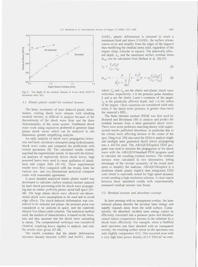
The experimentally measured residual compressivestress across the treated area was found to be a relativelyuniform biaxial in-plane distribution after typical laserpeening treatment. The residual stress is usually highestat the surface and decreases gradually with distancebelow the surface. Fig. 3 gives a typical depth profilefor the residual stress in a 2024- T3 aluminum alloy,shOWing that the compressive stresses reach a depth ofover 1 mm [41].
100
0m- •0-:2'i-1OO~
U5co-5 -200'wQl0::
-300
-40000 0.5 1.0
Depth Below Surface [mm]
Fig. 3. The depth of the residual stresses in 6-mm thick 2034-T3aluminum alloy [41].
The basic mechanics of laser induced plastic defor-mation, relating shock wave stresses with resultingresidual stresses, is difficult to analyze because of thediscontinuity of the shock wave front and the threedimensionality of the stress system. Traditional shockwave work using explosives preferred to generate largeplanar shock waves which can be analyzed in onedimension, greatly Simplifying analysis.
An early analysis of shock wave propagation behav-iour and basic mechanics attempted using hydrodynamicshock wave codes and compared the predictions withetched specimens [9]. The calculated results crudelymatched the experimental results. In line with the histori-cal analyses of explosively driven shock waves, highpowered lasers were used to cause spallation of alumi-num and copper foils [42-44]. These experimentalresults were then compared with the results from thevarious one- and two-dimensional analytical computercodes with reasonable agreement.
A more detailed analytical elastic-plastic model wasdeveloped to calculate surface residual stresses inducedby laser shock processing with the shock wave propagat-ing into an elastic-perfectly plastic metal half space [45-48]. The large planar shock wave allowed one-dimen-sional shock wave assumptions to be used and to avoidedge effects. The shock-induced deformation was con-sidered to be uniaxial and planar, the pressure pulse wasconsidered to be uniform in space, and the materialsobeyed Von Mises yield criterion. The analytical methodused, the method of characteristics, is based on the litera-ture and also assumes that the shock wave unloadingis elastic. The computational technique was consideredclassical, requiring heavy algebra to analyze, and onlythe results were given [47,48].
The model considers that the plastic deformationincreases linearly between lxHEL and 2xHEL. Above
2xHEL, plastic deformation is assumed to reach amaximum limit and above 2.5xHEL, the surface releasewaves occur and amplify from the edges of the impactsthus modifying the residual stress field, regardless of theimpact shape (circular or square). The plastically affec-ted depth, Lp, and the maximum surface residual stress<J'surf can be calculated from Ballard et al. [46,47]:
L = CelCpl'l'p Ce1- Cpl
where Cel and Cp1 are the elastic and plastic shock wavevelocities, respectively; 'l' is the pressure pulse duration;A. and f.l are the elastic Lame's constants of the target;Lp is the plastically affected depth; and r is the radiusof the impact. These equations are considered valid onlywhen P, the shock wave pressure, is greater than twicethe material's HEL.
The finite element method (FEM) was first used byBraisted and Brockman [49] to analyze and predict theresidual stresses from a laser generated shock wave.There were some problems matching theory with experi-mental results published elsewhere, in particular due tothe release wave affecting stresses in the center of thespot. Ding et al. [50] also used the FEM to analyze singleand multiple laser generated shock waves propagatinginto a 35CD4 steel. The ABAQUS/Explicit FEM pro-gram was used to simulate the propagation of the shockwave with the ABAQUS/Standard FEM program usedto calculate the resulting residual stresses. The residualstresses were calculated in two dimensions, takingadvantage of the circular symmetry of the round laserspots to simplify the analyses. ABAQUS/Explicit is anonlinear elastic-plastic explicit time integration FEMcode which is especially suited for high speed dynamicevents needing a high resolution solution. A close matchbetween these simulated results with experimentallymeasured residual stresses was found.
In laser peening with no transparent overlay, the laserinduced plasma absorbs the incident laser energy andrapidly expands away from the solid surface. Conse-quently, the absorbed, incident laser energy cannot beefficiently converted into a pressure pulse and thereforecannot induce compressive stresses in the substrate by ashock wave effectively. For example, when a Hadfieldsteel specimen was laser shocked with no transparentoverlay, the resulting surface stress on the specimen wasonly slightly compressive [51]. This occurred even witha very high laser power density of 2.4 TW/cm2 as com-
pared with the power densities of 1 GW/cm2 commonlyused elsewhere.
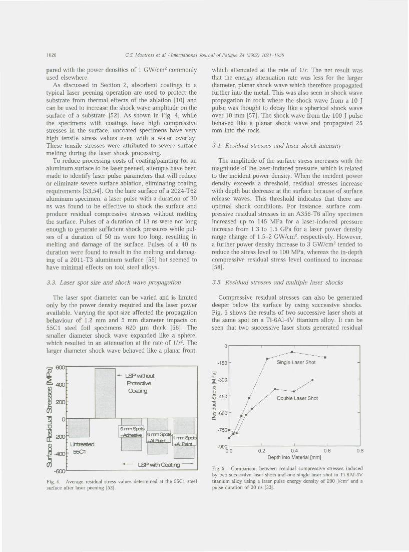
As discussed in Section 2, absorbent coatings in atypical laser peening operation are used to protect thesubstrate from thermal effects of the ablation [10] andcan be used to increase the shock wave amplitude on thesurface of a substrate [52]. As shown in Fig. 4, whilethe specimens with coatings have high compressivestresses in the surface, uncoated specimens have veryhigh tensile stress values even with a water overlay.These tensile stresses were attributed to severe surfacemelting during the laser shock processing.
To reduce processing costs of coating/painting for analuminum surface to be laser peened, attempts have beenmade to identify laser pulse parameters that will reduceor eliminate severe surface ablation, eliminating coatingrequirements [53,54]. On the bare surface of a 2024-T62aluminum specimen, a laser pulse with a duration of 30ns was found to be effective to shock the surface andproduce residual compressive stresses without meltingthe surface. Pulses of a duration of 13 ns were not longenough to generate sufficient shock pressures while pul-ses of a duration of 50 ns were too long, resulting inmelting and damage of the surface. Pulses of a 40 nsduration were found to result in the melting and damag-ing of a 2011-T3 aluminum surface [55] but seemed tohave minimal effects on tool steel alloys.
The laser spot diameter can be varied and is limitedonly by the power density required and the laser poweravailable. Varying the spot size affected the propagationbehaviour of 1.2 mm and 5 mm diameter impacts on55Cl steel foil specimens 620 /lm thick [56]. Thesmaller diameter shock wave expanded like a sphere,which resulted in an attenuation at the rate of lIr. Thelarger diameter shock wave behaved like a planar front,
LSP wth::lutPrdectiveCoatirg
Fig. 4. Average residual stress values determined at the 55C! steelsurface after laser peening [52].
which attenuated at the rate of 1/r. The net result wasthat the energy attenuation rate was less for the largerdiameter, planar shock wave which therefore propagatedfurther into the metal. This was also seen in shock wavepropagation in rock where the shock wave from a 10 Jpulse was thought to decay like a spherical shock waveover 10 mm [57]. The shock wave from the 100 J pulsebehaved like a planar shock wave and propagated 25mm into the rock.
The amplitude of the surface stress increases with themagnitude of the laser-induced pressure, which is relatedto the incident power density. When the incident powerdensity exceeds a threshold, residual stresses increasewith depth but decrease at the surface because of surfacerelease waves. This threshold indicates that there areoptimal shock conditions. For instance, surface com-pressive residual stresses in an A356- T6 alloy specimenincreased up to 145 MPa for a laser-induced pressureincrease from 1.3 to 1.5 GPa for a laser power densityrange change of 1.5-2 GW/cm2, respectively. However,a further power density increase to 3 GW/cm2 tended toreduce the stress level to 100 MPa, whereas the in-depthcompressive residual stress level continued to increase[58].
Compressive residual stresses can also be generateddeeper below the surface by using successive shocks.Fig. 5 shows the results of two successive laser shots atthe same spot on a Ti-6AI-4V titanium alloy. It can beseen that two successive laser shots generated residual
roQ.
~ -300l/ll/lQ)
c75 -450(ij:J"0
.~ -6000::
0.2 0.4 0.6Depth into Material [mm)
Fig. 5. Comparison between residual compressive stresses inducedby two successive laser shots and one single laser shot in Ti-6AI-4Vtitanium alloy using a laser pulse energy density of 200 J/cm' and apulse duration of 30 ns [33].
stresses deeper than a single shot [59]. The same trendwas observed in other alloy systems. For a 0.55% carbonsteel, as the number of shots on the surface increasedfrom one to three, the depth of compressive residualstresses increased from 0.9 to 1.8 mm [60]. For a 7075aluminum alloy, repeated impacts had a very beneficialeffect on the compressive residual stress levels on thesurface. A 4 GW/cm2 treatment generates a residualcompressive stress of 170 MPa at the first impact, 240MPa at second impact and 340 MPa after the thirdimpact [58].
Due to power density requirements and laser poweravailability, even laser systems with the potential for 200J per pulse will be limited in the area covered per pulse.Overlapping of the laser spots is the method used to laserpeen larger areas or large components. Overlapping oflaser spots has been investigated for many industrialmetals such as 1026 steel and ductile cast iron [41],A356, A112Si, and 7075 aluminum alloys [58], 55Clsteel [52] and titanium [40]. The results showed thatthere was a relatively uniform distribution of compress-ive residual stresses across the overlapped regions afterlaser shock processing. No indication of tensile residualstresses in the overlap regions was reported by theresearchers, which indicated that little or no degradationof the properties would occur when larger areas weretreated.
Two laser impact diameters with the same power den-sity of 5 GW/cm2 were used to investigate the interactionof both overlapping and spot sizes on material properties[52]. Laser shock processing was performed on 55Clsteel with 6 mm diameter and 1 mm diameter overlap-ping spots. The large, 6 mm diameter spots were bigenough to span the notch lengthwise along the specimenand were overlapped 50% in one direction only acrossthe width of the specimen's notch. The smaller 1 mmdiameter spots were overlapped 25% in two directionsalong the length and width of the specimen's notch.Residual stress measurements showed that, with a smallimpact configuration, the plastically affected depths werestrongly reduced. This confirms the reduced propagationdistance results for small laser spots [56].
Proper alignment and overlap of the laser spots willbe critical. Analysis was conducted with a micro inden-tation system of a polished cross section through laserpeen spots that were adjacent but not overlapping [61].A decrease in hardness between the two laser peen spotswas found. It was hypothesized that the shock waveaffected the preViously shocked zone with an expansiverelease wave. Expansive release waves have been foundto follow intense shock waves [38].
3.7. Residual stresses and laser shock processing thinsections
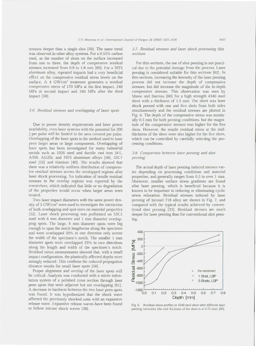
For thin sections, the use of shot peening is not practi-cal due to the potential damage from the process. Laserpeening is considered suitable for thin sections [62]. Inthin sections, increasing the intensity of the laser peeningprocess did not increase the depth of compressivestresses, but did increase the magnitude of the in-depthcompressive stresses. This observation was seen byMasse and Barreau [60] for a high strength 4340 steelsheet with a thickness of 1.5 mm. The sheet was lasershock peened with one and five shots from both sidessimultaneously and the residual stresses are plotted inFig. 6. The depth of the compressive stress was nomin-ally 0.5 mm for both peening conditions, but the magni-tude of the compressive stresses was higher for the fiveshots. However, the tensile residual stress at the mid-thickness of the sheet were also higher for the five shots,which can be controlled by carefully selecting the pro-cessing conditions.
3.8. Comparison between laser peening and shotpeening
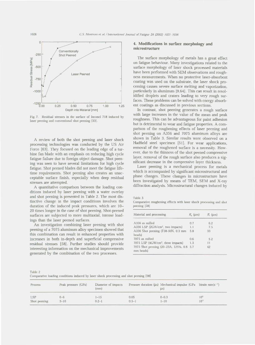
The actual depth of laser peening induced stresses var-ies depending on processing conditions and materialproperties, and generally ranges from 0.5 to over 1 mm.Moreover, smaller surface stress gradients are foundafter laser peening, which is beneficial because it isknown to be important in reducing or eliminating cyclicstress relaxation. Residual stresses induced by laserpeening of Inconel 718 alloy are shown in Fig. 7, andcompared with the typical results achieved by conven-tional shot peening [33]. Residual stresses are muchdeeper for laser peening than for conventional shot peen-ing.
400
~a:~-2Xl
<7)-400~-€ro"tl~-ID)
-10c0
-12Xl0.0 0.1
1S1d, LSP5S1ds,LSP
0.2 0.3 0.4 0.5 0.6 0.7 0.8~h [mn]
Fig. 6. Residual stress profiles in 4340 steel sheet after different laserpeening intensities (the mid-thickness of the sheet is at 0.75 mm) [60].
roIl.
~VI -500VI~enlii::>"0'enQ)0::
0.25 0.50 0.75 1.00Depth into Material [mm]
Fig. 7. Residual stresses in the surface of Inconel 718 induced bylaser peening and conventional shot peening [33J.
A review of both the shot peening and laser shockprocessing technologies was conducted by the US AirForce [63). They focused on the leading edge of a tur-bine fan blade with an emphasis on reducing high cyclefatigue failure due to foreign object damage. Shot peen-ing was seen to have several limitations for high cyclefatigue. Shot peened blades did not meet the fatigue life-time requirements. Shot peening also creates an unac-ceptable surface finish, especially when deep residualstresses are attempted.
A quantitative comparison between the loading con-ditions induced by laser peening with a water overlayand shot peening is presented in Table 2. The most dis-tinctive change in the impact conditions involves theduration of the induced peak pressures, which are 10-20 times longer in the case of shot peening. Shot-peenedsurfaces are subjected to more multiaxial, intense load-ings than the laser peened surfaces.
An investigation combining laser peening with shotpeening of a 7075 aluminum alloy specimen showed thatthis combination can result in enhanced properties withincreases in both in-depth and superficial compressiveresidual stresses [58). Further studies should provideinteresting information on the mechanical improvementsgenerated by the combination of the two processes.
4. Modifications in surface morphology andmicrostructure
The surface morphology of metals has a great effecton fatigue behaviour. Many investigations related to thesurface morphology of laser shock processed materialshave been performed with SEM observations and rough-ness measurements. When no protective laser-absorbentcoating was used on the substrate, the laser shock pro-cessing causes severe surface melting and vaporization,particularly in aluminum [9,64). This can result in resol-idified droplets and craters leading to very rough sur-faces. These problems can be solved with energy absorb-ent coatings as discussed in previous sections.
In contrast, shot peening generates a rough surfacewith large increases in the value of the mean and peakroughness. This can be advantageous for paint adhesionbut is detrimental to wear and fatigue properties. A com-parison of the roughening effects of laser peening andshot peening on A356 and 7075 aluminum alloys areshown in Table 3. Similar results were observed on aHadfield steel specimen [51). For wear applications,removal of the roughened surface is a necessity. How-ever, due to the thinness of the shot peened compressivelayer, removal of the rough surface also produces a sig-nificant decrease in the compressive layer thickness.
Laser peening is a mechanical process for metalswhich is accompanied by significant microstructural andphase changes. These changes in microstructure havebeen investigated by means of TEM, SEM and X-raydiffraction analysis. Microstructural changes induced by
Table 3Comparative roughening effects with laser shock processing and shotpeening [58]
A356 as milled 0.7 6.2A356 LSP (2CW/cm2• two impacts) 1.1 7.5A356 Shot peening (F38-50N. 0.3 mm 5.8 33beads)7075 as milled 0.6 5.27075 LSP (4CW/cm2• three impacts) 1.3 II7075 Shot peening (20-23A. 125%. 0.6 5.7 42mm beads)
Table 2Comparative loading conditions induced by laser shock processing and shot peening [58]
Process Peak pressure (CPa) Diameter of impacts Pressure duration (jJ.s) Mechanical impulse (CPa Strain rate(s-')(mm) ~s)
LSP 0-6 I-IS 0.05 0-0.3 106
Shot peening 3-10 0.2-1 0.5-1 1-10 104

LSP have been related to the laser process parametersand the heat treatment condition of the alloys.
The dislocation density increased significantly in laserpeened aluminum alloys such as welded 5086-H32,6061- T6 [10], 2024- T62 [36] but no quantitative analysishas been noted. High dislocation densities were also aprominent microstructural feature in low carbon steelsafter laser peening [39]. Laser peening of Hadfieldmanganese steel was found to induce extensive forma-tion of £-hcp martensite and high density dislocations inthe y-fcc austenite matrix [51].
Investigations of the effect of laser peening of weldzones in 18Ni(250) maraging steel showed that after thelaser peening treatment, the austenite weld phasereverted to martensite and the dislocation density quali-tatively increased in the martensite matrix [39,65].Numerous twins as well as a-phase embryos located atthe twin intersections were found in laser peened 304austenitic stainless steel [16J and 316L stainless steel[64].
A Fe-Ni alloy was laser shock processed with a laserpower density of 100 CW/cm2 and 10 TW/cm2 withouttransparent overlay and absorbent coating [38]. Very thintwinned grains were found on the surface because ofmelting and rapid solidifying. A martensite transform-ation zone was found at the back face of the lasershocked Fe-Ni alloy sample due to reflection of theshock wave from the back face.
No fundamental understanding in the laser peeningliterature has been noted on the interaction of the micro-structure with laser induced shock waves and theresulting changes in the microstructure. The majority ofthe reports on microstructural changes have been quali-tative with few quantitative details such as dislocationdensity.
The lack a fundamental understanding of the laserpeening process was most clearly seen with the unexpec-ted property changes when the weld region of a 6061-T6 weld specimen was laser peened [66]. Laser shockwaves of 3.5 and 6 CPa shock pressures, were used tolaser peen various spots of the weld specimen from thebase metal through the heat affected zone (HAZ) into theweld. One of the first property changes was the change inelastic modulus in the laser peened aluminum which wasnot previously noted in the literature. The hardness of themetal increased as noted in the literature but the depth ofthe property changes varied with respect to the weldcenter and HAZ. The depth of the changes in hardnessand elastic modulus varied from 1.5 mm in the as-received metal to up to 2.5 mm in the HAZ for the 3.5CPa laser peen spots. For the 6 CPa laser peen spots,the depth of changes varied from 2 mm in the as-received metal to 3 mm in the HAZ. These depths weresignificantly greater than the depths reported in theliterature such as by Peyre et al. [58].
The minimal change in hardness of the bulk material
outside the HAZ from the 3.5 CPa pressure laser peenpulse has been noted before [13]. Laser peening has beenreported to improve the hardness of underaged 2024-T351 but not peak aged materials like a 2024- T851,7075-T651, or 7075-T73. However, the fatigue and ten-sile strength was improved for all materials. For the6061-T6 specimens unaffected by the welding, there wasno change in hardness or strength reported [9]. It washypothesized that the precipitation hardening in the T6condition is significantly large enough to mask anyshock wave strain hardening. It was also hypothesizedthat exceeding a threshold shock wave pressure of 7.5CPa was required to Significantly change the propertiesof peak aged aluminum alloys [12]. From the investi-gation of property changes with the UMIS [66], a shockwave with a pressure of 6 CPa was sufficient to signifi-cantly increase the hardness in the bulk 6061- T6material.
Another example of the lack of fundamental under-standing of the laser peening process in metals is theself-limiting hardness changes in 6061-T6 specimens[67]. For 3.5 CPa shock wave pressures, one repetitionincreased hardness but not five repetitions. When 6 CPashock wave pressures were used, both one and five rep-etitions increased hardness. Increases in the metal'sHugoniot elastic limit and changes in the metal'sdynamic yield strength with each laser shock wave wereidentified as the two mechanisms responsible for theself-limiting hardness changes. With each laser gener-ated shock wave, the pressure must remain Significantlygreater than the increased Hugoniot elastic limit anddynamic yield strength for further shock processing andsurface hardness changes to occur.
Many materials display pronounced improvements infatigue life with laser shock processing. The beneficialeffects of laser shock processing may originate from sur-face compressive stresses in the large affected depth andsurface quality, which delay the development of fatiguecracking. Investigations on several different aspects ofthe fatigue behaviours, such as fatigue life, fatiguestrength and fretting fatigue, have been reported.
Investigations on aluminum alloys, steels, andtitanium alloys have shown that laser peening canincrease fatigue strength. The initial research workfocused on the effect of laser peening on the fatiguecrack growth of pre-existing cracks, using different laserspot shapes on the pre-cracks [62]. The two differentlaser peening spot configurations around a hole in a2024-T3 aluminum alloy specimen are shown in Fig.
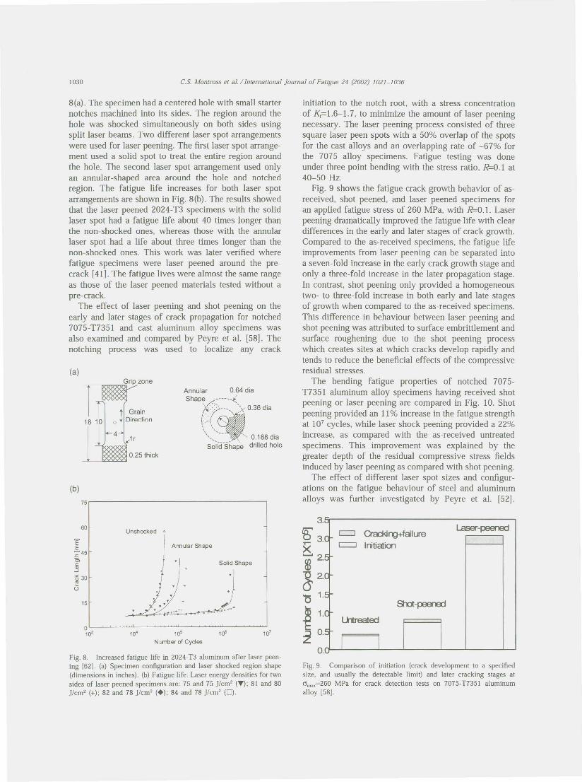
8(a). The specimen had a centered hole with small starternotches machined into its sides. The region around thehole was shocked simultaneously on both sides usingsplit laser beams. Two different laser spot arrangementswere used for laser peening. The first laser spot arrange-ment used a solid spot to treat the entire region aroundthe hole. The second laser spot arrangement used onlyan annular-shaped area around the hole and notchedregion. The fatigue life increases for both laser spotarrangements are shown in Fig. 8(b). The results showedthat the laser peened 2024-T3 specimens with the solidlaser spot had a fatigue life about 40 times longer thanthe non-shocked ones, whereas those with the annularlaser spot had a life about three times longer than thenon-shocked ones. This work was later verified wherefatigue specimens were laser peened around the pre-crack [41]. The fatigue lives were almost the same rangeas those of the laser peened materials tested without apre-crack.
The effect of laser peening and shot peening on theearly and later stages of crack propagation for notched7075-T7351 and cast aluminum alloy specimens wasalso examined and compared by Peyre et al. [58]. Thenotching process was used to localize any crack
Annular 0.64 diaShape ------1X>----,~ 0.36 dia
f;"J\~\ "\ ••__~-_-:_-- 0: 188 diaSolid Shape drilled hole
EE:;; 45c,~~ 30U
10' 105
N umber of Cyd es
Fig. 8. Increased fatigue life in 2024-T3 aluminum after laser peen-ing [62]. (a) Specimen configuration and laser shocked region shape(dimensions in inches). (b) Fatigue life. Laser energy densities for twosides of laser peened specimens are: 75 and 75 jlcm2 (T); 81 and 80j/cm2 (+); 82 and 78 j/cm2 (+); 84 and 78 j/cm2 (0).
initiation to the notch root, with a stress concentrationof K;=1.6-1.7, to minimize the amount of laser peeningnecessary. The laser peening process consisted of threesquare laser peen spots with a 50% overlap of the spotsfor the cast alloys and an overlapping rate of -67% forthe 7075 alloy specimens. Fatigue testing was doneunder three point bending with the stress ratio, R=0.1 at40-50 Hz.
Fig. 9 shows the fatigue crack growth behavior of as-received, shot peened, and laser peened specimens foran applied fatigue stress of 260 MPa, with R=0.1. Laserpeening dramatically improved the fatigue life with cleardifferences in the early and later stages of crack growth.Compared to the as-received specimens, the fatigue lifeimprovements from laser peening can be separated intoa seven- fold increase in the early crack growth stage andonly a three-fold increase in the later propagation stage.In contrast, shot peening only proVided a homogeneoustwo- to three-fold increase in both early and late stagesof growth when compared to the as-received specimens.This difference in behaviour between laser peening andshot peening was attributed to surface embrittlement andsurface roughening due to the shot peening processwhich creates sites at which cracks develop rapidly andtends to reduce the beneficial effects of the compressiveresidual stresses.
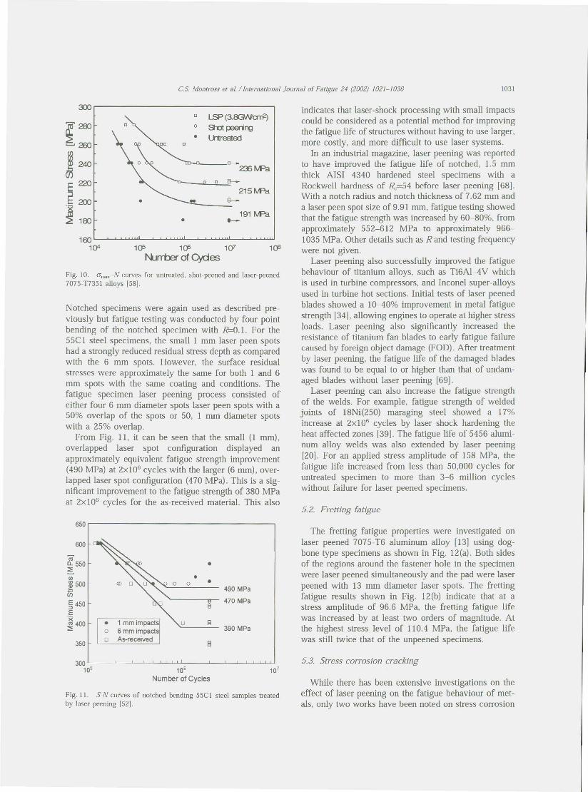
The bending fatigue properties of notched 7075-T7351 aluminum alloy specimens haVing received shotpeening or laser peening are compared in Fig. 10. Shotpeening proVided an 11% increase in the fatigue strengthat 107 cycles, while laser shock peening proVided a 22%increase, as compared with the as-received untreatedspecimens. This improvement was explained by thegreater depth of the residual compressive stress fieldsinduced by laser peening as compared with shot peening.
The effect of different laser spot sizes and configur-ations on the fatigue behaviour of steel and aluminumalloys was further investigated by Peyre et al. [52].
3.
~ 3.8.~ 2.
~~'0 1.
~ 1..z O.
O.
~rg+faiILreInitiation
Fig. 9. Comparison of initiation (crack development to a specifiedsize, and usually the detectable limit) and later cracking stages atcrmax=260 MPa for crack detection tests on 7075-T7351 aluminumalloy [58].
~0 L..SP (3.row'ari1
~~0 SlJt peerirg• Ultreated
•.••.•260
~ 240 0_
tJj 235tvPa
E 220 9 0 8-
~215tvPa
2XJ • S-
~ 100191 tvPa• --
1001~ 1()5 1cP 107
N.Jrrber of Cycles
Fig. 10. CYmax-N curves for untreated, shot-peened and laser-peened7075-T7351 alloys [58].
Notched specimens were again used as described pre-viously but fatigue testing was conducted by four pointbending of the notched specimen with R=0.1. For the55e 1 steel specimens, the small 1 mm laser peen spotshad a strongly reduced residual stress depth as comparedwith the 6 mm spots. However, the surface residualstresses were approximately the same for both 1 and 6mm spots with the same coating and conditions. Thefatigue specimen laser peening process consisted ofeither four 6 mm diameter spots laser peen spots with a50% overlap of the spots or 50, 1 mm diameter spotswith a 25% overlap.
From Fig. 11, it can be seen that the small (1 mm),overlapped laser spot configuration displayed anapproximately equivalent fatigue strength improvement(490 MPa) at 2xl06 cycles with the larger (6 mm), over-lapped laser spot configuration (470 MPa). This is a sig-nificant improvement to the fatigue strength of 380 MPaat 2x10⁶ cycles for the as-received material. This also
roa.. 550~ •
•0 •
490 MPa
470 MPa
• 1 mm impacts EI0 6 mm impacts 390 MPa
0 As-receivedEI
'"gJ 500cJ)
5450E'x~ 400
106Number of Cycles
Fig. II. SoN curves of notched bending 55e I steel samples treatedby laser peening [521.
indicates that laser-shock processing with small impactscould be considered as a potential method for improvingthe fatigue life of structures without haVing to use larger,more costly, and more difficult to use laser systems .
In an industrial magazine, laser peening was reportedto have improved the fatigue life of notched, 1.5 mmthick AlSI 4340 hardened steel specimens with aRockwell hardness of Rc=54 before laser peening [68].With a notch radius and notch thickness of 7.62 mm anda laser peen spot size of 9.91 mm, fatigue testing showedthat the fatigue strength was increased by 60-80%, fromapproXimately 552-612 MPa to approximately 966-1035 MPa. Other details such as R and testing frequencywere not given.
Laser peening also successfully improved the fatiguebehaviour of titanium alloys, such as Ti6AI-4V whichis used in turbine compressors, and Inconel super-alloysused in turbine hot sections. Initial tests of laser peenedblades showed a 10-40% improvement in metal fatiguestrength [34], allowing engines to operate at higher stressloads. Laser peening also Significantly increased theresistance of titanium fan blades to early fatigue failurecaused by foreign object damage (FaD). After treatmentby laser peening, the fatigue life of the damaged bladeswas found to be equal to or higher than that of undam-aged blades without laser peening [69].
Laser peening can also increase the fatigue strengthof the welds. For example, fatigue strength of weldedjoints of 18Ni(250) maraging steel showed a 17%increase at 2x10⁶ cycles by laser shock hardening theheat affected zones [39]. The fatigue life of 5456 alumi-num alloy welds was also extended by laser peening[20]. For an applied stress amplitude of 158 MPa, thefatigue life increased from less than 50,000 cycles foruntreated specimen to more than 3-6 million cycleswithout failure for laser peened specimens.
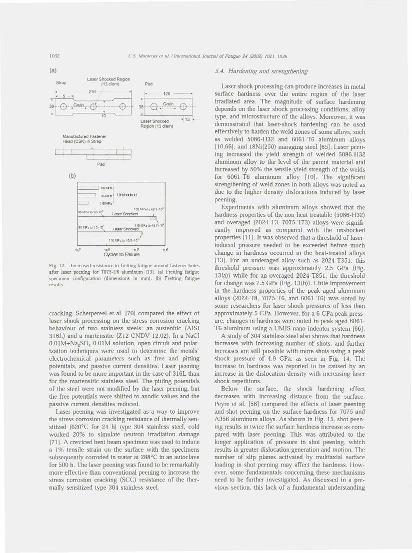
The fretting fatigue properties were investigated onlaser peened 7075-T6 aluminum alloy [13] using dog-bone type specimens as shown in Fig. 12(a). Both sidesof the regions around the fastener hole in the specimenwere laser peened simultaneously and the pad were laserpeened with 13 mm diameter laser spots. The frettingfatigue results shown in Fig. 12(b) indicate that at astress amplitude of 96.6 MPa, the fretting fatigue lifewas increased by at least two orders of magnitude. Atthe highest stress level of 110.4 MPa, the fatigue lifewas still twice that of the unpeened specimens.
While there has been extensive investigations on theeffect of laser peening on the fatigue behaviour of met-als, only two works have been noted on stress corrosion
38 -0 - )'JilLn_. -E5-- -------Q--19
Laser ShockedRegion (13 diam)
Manufactured FastenerHead (CSK) in Strap
:=}Lhhrlaj116M=Ja
106 MPa to t8.3.,o"MPato J2x1011 Laser~
>-'16 MPa to 48.7x10·
Laser Stocked
10; 10"Cycles to FailLl'e
Fig. 12. Increased resistance to fretting fatigue around fastener holesafter laser peening for 7075-T6 aluminum 1131. (a) Fretting fatiguespecimen configuration (dimensions in mm). (b) Fretting fatigueresults.
cracking. Scherpereel et al. [70) compared the effect oflaser shock processing on the stress corrosion crackingbehaviour of two stainless steels: an austenitic (AISI316L) and a martensitic (Z12 CNDV 12.02). In a NaCl0.01M+NazS04 O.OlM solution, open circuit and polar-ization techniques were used to determine the metals'electrochemical parameters such as free and pittingpotentials, and passive current densities. Laser peeningwas found to be more important in the case of 316L thanfor the martensitic stainless steel. The pitting potentialsof the steel were not modified by the laser peening, butthe free potentials were shifted to anodic values and thepassive current densities reduced.
Laser peening was investigated as a way to improvethe stress corrosion cracking resistance of thermally sen-sitized (620°C for 24 h) type 304 stainless steel, coldworked 20% to simulate neutron irradiation damage[71]. A creviced bent beam specimen was used to inducea 1% tensile strain on the surface with the specimenssubsequently corroded in water at 288°C in an autoclavefor 500 h. The laser peening was found to be remarkablymore effective than conventional peening to increase thestress corrosion cracking (SCe) resistance of the ther-mally sensitized type 304 stainless steel.
Laser shock processing can produce increases in metalsurface hardness over the entire region of the laserirradiated area. The magnitude of surface hardeningdepends on the laser shock processing conditions, alloytype, and microstructure of the alloys. Moreover, it wasdemonstrated that laser-shock hardening can be usedeffectively to harden the weld zones of some alloys, suchas welded 5086-H32 and 6061-T6 aluminum alloys[10,66], and 18Ni(250) maraging steel [65). Laser peen-ing increased the yield strength of welded 5086-H32aluminum alloy to the level of the parent material andincreased by 50% the tensile yield strength of the weldsfor 6061-T6 aluminum alloy [10]. The significantstrengthening of weld zones in both alloys was noted asdue to the higher density dislocations induced by laserpeening.
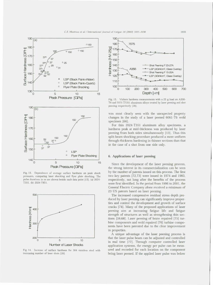
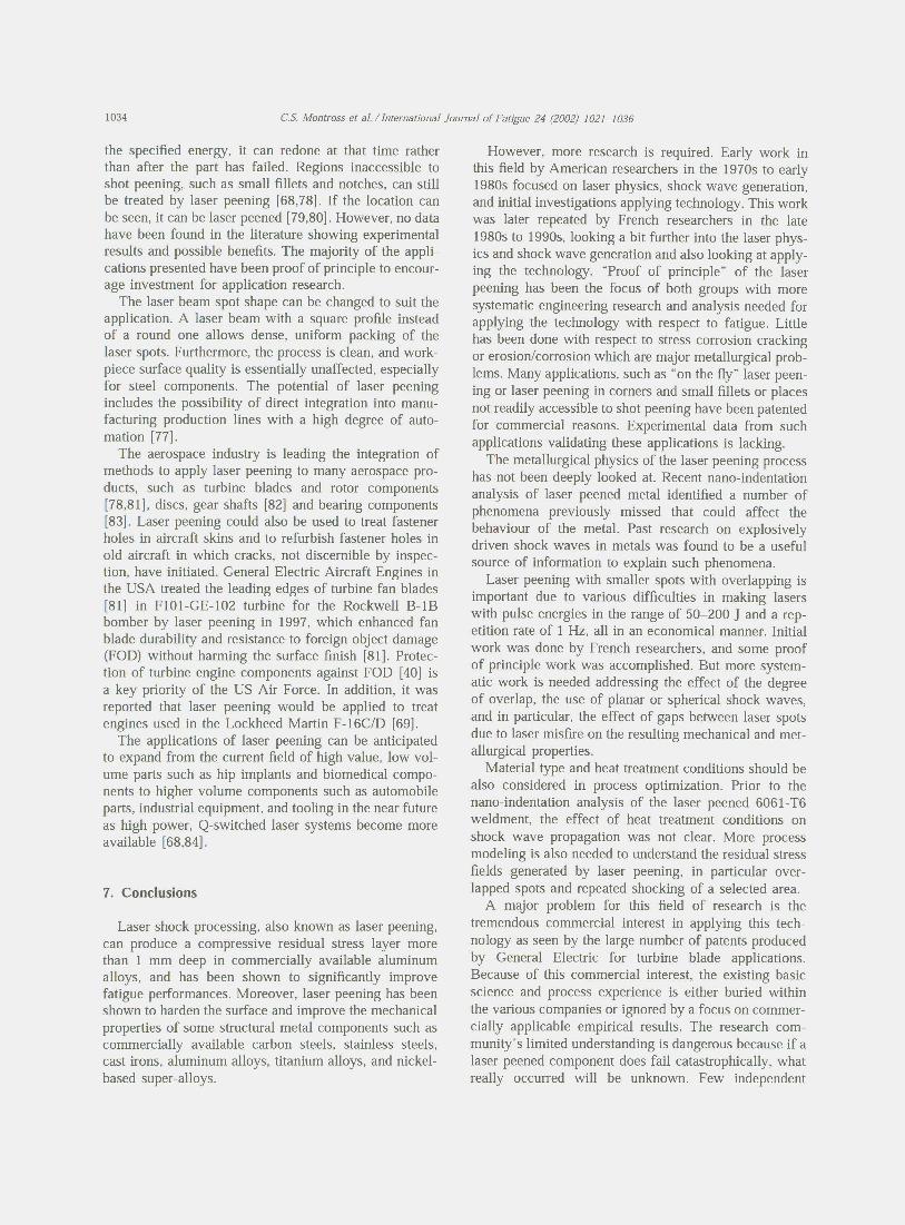
Experiments with aluminum alloys showed that thehardness properties of the non-heat treatable (5086-H32)and overaged (2024- T3, 7075- T73) alloys were signifi-cantly improved as compared with the unshockedproperties [11]. It was observed that a threshold of laser-induced pressure needed to be exceeded before muchchange in hardness occurred in the heat-treated alloys[13). For an underaged alloy such as 2024-T351, thisthreshold pressure was approximately 2.5 GPa (Fig.13(a)) while for an overaged 2024-T85I, the thresholdfor change was 7.5 GPa (Fig. 13(b)). Little improvementin the hardness properties of the peak aged aluminumalloys (2024-T8, 7075-T6, and 6061-T6) was noted bysome researchers for laser shock pressures of less thanapproXimately 5 GPa. However, for a 6 GPa peak press-ure, changes in hardness were noted in peak aged 6061-T6 aluminum using a UMIS nano-indentor system [66].
A study of 304 stainless steel also shows that hardnessincreases with increasing number of shots, and furtherincreases are still possible with more shots using a peakshock pressure of 4.9 GPa, as seen in Fig. 14. Theincrease in hardness was reported to be caused by anincrease in the dislocation density with increasing lasershock repetitions.
Below the surface, the shock hardening effectdecreases with increasing distance from the surface.Peyre et al. [58] compared the effects of laser peeningand shot peening on the surface hardness for 7075 andA356 aluminum alloys. As shown in Fig. 15, shot peen-ing results in twice the surface hardness increase as com-pared with laser peening. This was attributed to thelonger application of pressure in shot peening, whichresults in greater dislocation generation and motion. Thenumber of slip planes activated by multiaxial surfaceloading in shot peening may affect the hardness. How-ever, some fundamentals concerning these mechanismsneed to be further investigated. As discussed in a pre-vious section, this lack of a fundamental understanding
LSP (Ba:k Paint+'ll.al:er)LSP (Ba:k Paint-tUJartz)
Ryer PlateShc:d<i~13:>
o 5 10Peak Pressure [CPa]
~100•.....•
~ 170
~100
~~150
150370o
LSPRyer PlateShc:d<i~
5 10Peak Pressure [CPa]
Fig. 13. Dependence of average surface hardness on peak shockpressures, comparing laser shocking and flyer plate shocking. Thepulse durations in ns are shown beside each data point [13]. (a) 2024-T351, (b) 2024- T851.
'E'400§:
~~:m
2000 5 10
Fig. 14. Increase of surface hardness for 304 stainless steel withincreasing number of laser shots 120].
~17O~100
W;:~120
110
100o 100 200 ~ 400 500 000 700D3ph [llrrl
~ Shct Peenirg F 23-27A--- L..SP(2GNarr-, GC5S Oia1ay)~ Shct Peenirg F 15-2OA--- L..SP(2G/llarr-, GC5S Oia1ay)
Fig. 15. Vickers hardness measurements with a 25 g load on A356-T6 and 7075- T735l aluminum alloys treated by laser peening and shotpeening respectively [58].
was most clearly seen with the unexpected propertychanges in the study of a laser peened 6061-T6 weldspecimen [66].
For thin 2024- T351 aluminum alloy specimens, ahardness peak at mid-thickness was produced by laserpeening from both sides simultaneously [13]. Thus thissplit-beam shocking procedure produced a more uniformthrough-thickness hardening in thinner sections than thatin the case of a shot from one side only.
Since the development of the laser peening process,the strong interest in its commercialization can be seenby the number of patents issued on this process. The firsttwo key patents [72,73] were issued in 1974 and 1983,respectively, not long after the benefits of the processwere first identified. In the period from 1996 to 2001, theGeneral Electric Company alone received a minimum of23 US patents based on laser peening.
The increased compressive residual stress depth pro-duced by laser peening can significantly improve proper-ties and control the development and growth of surfacecracks [74]. Many of the proposed applications of laserpeening aim at increasing fatigue life and fatiguestrength of structures as well as strengthening thin sec-tions [59,68]. Laser peening of braze repaired [75] tur-bine components and weld repaired [76] turbine compo-nents have been patented due to the clear improvementin properties.
A unique advantage of the laser peening process isthat the laser pulse beam can be adjusted and controlledin real time [77]. Through computer controlled laserapplication systems, the energy per pulse can be meas-ured and recorded for each location on the componentbeing laser peened. If the applied laser pulse was below
the specified energy, it can redone at that time ratherthan after the part has failed. Regions inaccessible toshot peening, such as small fillets and notches, can stillbe treated by laser peening [68,78]. If the location canbe seen, it can be laser peened [79,80]. However, no datahave been found in the literature showing experimentalresults and possible benefits. The majority of the appli-cations presented have been proof of principle to encour-age investment for application research.
The laser beam spot shape can be changed to suit theapplication. A laser beam with a square profile insteadof a round one allows dense, uniform packing of thelaser spots. Furthermore, the process is clean, and work-piece surface quality is essentially unaffected, especiallyfor steel components. The potential of laser peeningincludes the possibility of direct integration into manu-facturing production lines with a high degree of auto-mation [77].
The aerospace industry is leading the integration ofmethods to apply laser peening to many aerospace pro-ducts, such as turbine blades and rotor components[78,81]. discs, gear shafts [82] and bearing components[83]. Laser peening could also be used to treat fastenerholes in aircraft skins and to refurbish fastener holes inold aircraft in which cracks, not discernible by inspec-tion, have initiated. General Electric Aircraft Engines inthe USA treated the leading edges of turbine fan blades[81] in F101-GE-102 turbine for the Rockwell B-lBbomber by laser peening in 1997, which enhanced fanblade durability and resistance to foreign object damage(FOD) without harming the surface finish [81]. Protec-tion of turbine engine components against FOD [40] isa key priority of the US Air Force. In addition, it wasreported that laser peening would be applied to treatengines used in the Lockheed Martin F-16C/D [69].
The applications of laser peening can be anticipatedto expand from the current field of high value, low vol-ume parts such as hip implants and biomedical compo-nents to higher volume components such as automobileparts, industrial equipment, and tooling in the near futureas high power, Q-switched laser systems become moreavailable [68,84].
Laser shock processing, also known as laser peening,can produce a compressive residual stress layer morethan 1 mm deep in commercially available aluminumalloys, and has been shown to significantly improvefatigue performances. Moreover, laser peening has beenshown to harden the surface and improve the mechanicalproperties of some structural metal components such ascommercially available carbon steels, stainless steels,cast irons, aluminum alloys, titanium alloys, and nickel-based super-alloys.
However, more research is required. Early work inthis field by American researchers in the 1970s to early1980s focused on laser physics, shock wave generation,and initial investigations applying technology. This workwas later repeated by French researchers in the late1980s to 1990s, looking a bit further into the laser phys-ics and shock wave generation and also looking at apply-ing the technology. "Proof of principle" of the laserpeening has been the focus of both groups with moresystematic engineering research and analysis needed forapplying the technology with respect to fatigue. Littlehas been done with respect to stress corrosion crackingor erosion/corrosion which are major metallurgical prob-lems. Many applications, such as "on the fly" laser peen-ing or laser peening in corners and small fillets or placesnot readily accessible to shot peening have been patentedfor commercial reasons. Experimental data from suchapplications validating these applications is lacking.
The metallurgical physics of the laser peening processhas not been deeply looked at. Recent nano-indentationanalysis of laser peened metal identified a number ofphenomena preViously missed that could affect thebehaviour of the metal. Past research on explosivelydriven shock waves in metals was found to be a usefulsource of information to explain such phenomena.
Laser peening with smaller spots with overlapping isimportant due to various difficulties in making laserswith pulse energies in the range of 50-200 ] and a rep-etition rate of 1 Hz, all in an economical manner. Initialwork was done by French researchers, and some proofof principle work was accomplished. But more system-atic work is needed addressing the effect of the degreeof overlap, the use of planar or spherical shock waves,and in particular, the effect of gaps between laser spotsdue to laser misfire on the resulting mechanical and met-allurgical properties.
Material type and heat treatment conditions should bealso considered in process optimization. Prior to thenano-indentation analysis of the laser peened 6061- T6weldment, the effect of heat treatment conditions onshock wave propagation was not clear. More processmodeling is also needed to understand the residual stressfields generated by laser peening, in particular over-lapped spots and repeated shocking of a selected area.
A major problem for this field of research is thetremendous commercial interest in applying this tech-nology as seen by the large number of patents producedby General Electric for turbine blade applications.Because of this commercial interest, the existing basicscience and process experience is either buried withinthe various companies or ignored by a focus on commer-cially applicable empirical results. The research com-munity's limited understanding is dangerous because if alaser peened component does fail catastrophically, whatreally occurred will be unknown. Few independent

people will have the background able to analyze whathappened let alone provide a preventative solution.
The authors are grateful to the support from the Air-frames and Engines Division of the Aeronautical &Maritime Research Laboratory in Defence Science andTechnology Organisation. The authors would like theacknowledge the comments from the referees whichhelped improve this paper.
[1] Askar yan CA, Moroz EM. Pressure on evaporation of mailer in aradiation beam. Journal of Experimental and Theoretical PhysicsLetters 1963;16:1638-44.
[2] White RM. Elastic wave generation by electron bombardmentor electromagnetic wave absorption. Journal of Applied Physics1963;34:2123-4.
[3] Gregg OW, Thomas Sj. Momentum transfer produced by focusedlaser giant pulses. Journal of Applied Physics 1966;27:2787-9.
[4j Skeen CH, York CM. Laser-Induced "blow-off' phenomenon.Applied Physics Leiters 1968; 12:369-71.
[5j Anderholm NC. Laser-generated stress waves. Applied PhysicsLetters 1970;16:113-5.
[6J Jones ED. Ultrafast laser-induced stress waves in solids. AppliedPhysics Letters 1971;18:33-5.
[7] Fairand BP, Clauer AH, Jung RG. Wilcox BA. Quantitativeassessment of laser-induced stress waves generated at confinedsurfaces. Applied Physics Letters 1974;25:431-3.
[8J Fairand BP, Clauer AH. Use of laser generated shocks to improvethe properties of metals and alloys. Industrial Applications ofHigh Power Laser Technology 1976;86: 112-9.
[9] Fairand BP. Clauer AH. Wilcox BA. Pulsed laser induced defor-mation in an Fe-3 Wt Pct Si alloy. Metallurgical Transactions A1977;8A: 119-25.
[10] Fairand BP, Clauer AH. Wilcox BA. Laser shock hardening ofweld zones in aluminum alloys. Metallurgical Transactions A1976;8A:1871-6.
[11] Fairand BP. Clauer AH. Laser generated stress waves: theircharacteristics and their effects to materials. Presented at Proc.American Inst. of Physics Conf. on 'Laser Solid Interactions andLaser Processing'; 1978.
[12J Fairand BP. Clauer AH. Applications of laser-induced stresswaves. Presented at Lasers in Modem Industry Seminar; 1978.
[13] Clauer AH, Fairand BP. Interaction of laser-induced stress waveswith metals. Presented at Proc. ASM Conference Applications ofLasers in Materials Processing; Washington DC; 1979.
[14] Fabbro R, Fournier 1. Ballard P, Devaux D. Virmont j. Physicalstudy of laser-produced plasma in confined geometry. Journal ofApplied Physics 1990;68:775-84.
[15j Ortiz Jr., AL, Penney CM. Jones MG, Erikson CEo US Patent4,937,421; General Electric Company. Schenectady, New York;1990.
[16j Devaux 0, Fabbro R. Tollier L. Bartnicki E. Generation of shockwaves by laser induced plasma in confined geometry. Journal ofApplied Physics 1993;74:2268-73.
[17J Gerland M, Hal10uin M, Presles HN. Comparison of two newsurface treatment processes, laser induced shock waves and pri-mary explosive: application to fatigue behaviour. MaterialsScience and Engineering 1992;156A:175-82.
118j Takayanagi N. US Patent 5.571.575; Toyota Jidosha KabushikiKaisha (Aichi. JP); 1996.
[19] Peyre P. Fabbro R, Berthe L. Dubouchet C. Laser shock pro-cessing of materials. physical processes involved and examplesof applications. Journal of Laser Applications 1996;8: 135-41.
[20j Clauer AH, Holbrook JH, Fairand BP. Effects of laser inducedshock waves on metals. In: Meyers MA. Murr LE. editors. Shockwaves and high-strain-rate phenomena in metals. New York: Ple-num Publishing Corporation; 1981. p. 675-702.
[21] Bergstrom RP. Laser shock processing. Production1993; I05:49-51.
[22] Clauer AH. Laser shock peening for fatigue resistance. In: Gre-gory JK, Rack HJ. Eylon 0, editors. Surface performance oftitanium. Warrendale (PA): TMS; 1996. p. 217-30.
[23J O'Keefe JD. Skeen CH. Laser-induced stress-wave and impulseaugmentation. Applied Physics Letters 1972;21:464-6.
[24] Hoffman CG. Laser-target interactions. Journal of Applied Phys-ics 1974;45:2125-8.
[25] Yang LC. Stress waves generated in thin metallic films by a Q-switched ruby laser. Journal of Applied Physics 1974;45:2601-7.
[26J Romain JP. Collet F, Hallouin M. Fabbro R, Faral B, Pepin H.Laser shock experiments at pressures above 100 Mbar. Physica1986; 139, 140B:595-598.
[27J Ling P, Wight CA. Laser-generated shock waves in thin films ofenergetic materials. Journal of Applied Physics 1995;78:7022-5.
[28J Couturier S. de Resseduier M, Hallouin M. Romain JP, Bauer F.Shock profile induced by short laser pulses. Journal of AppliedPhysics 1996;79:9338-42.
[29J Fairand BP. Wilcox BA, Gallagher WJ, Williams ON. Lasershock-induced microstructural and mechanical property changesin 7075 aluminum. Journal of Applied Physics 1972;43:3893-6.
[30J Montross CS, Florea V, Bolger JA. Laser-induced shock wavegeneration and shock wave enhancement in basalt. InternationalJournal of Rock Mechanics and Mining Sciences 1999;36:849-55.
[311 Montross CS. Florea V. Swain MY. Influence of coatings on sub-surface mechanical properties of laser peened 2011-T3 alumi-num. Journal of Materials Science 2001;36:1801-7.
1321 Berthe L, Fabbro R, Peyre p. Bartnicki E. Wavelength depen-dence of laser shock wave generation in the water confinementregime. Journal of Applied Physics 1999;85:7552-5.
[33J Dane CB. Hackel LA, Daly 1. Harrison j. Shot peening withlasers. Advanced Materials and Processes 1998;153:37-8.
[34J Ashley S. Powerful laser means better peening. MechanicalEngineering 1998;120:12.
[35] Johnson JN, Rhode RW. Dynamic deformation twinning in shockloaded iron. Journal of Applied Physics 1971;42:4171-82.
[36J Zhang H, Yu C. Laser shock processing of 2024-T62 aluminumalloy. Materials Science and Engineering 1998;257 A:322-7.
[37] Clauer AH, Dulaney JL. Rice RC, Koucky JR. Laser shock pro-cessing for treating fastener holes in aging aircraft. In: Atluri SN.Harris CEo Hoggard A, Miller N, Sampath SG. editors. Durabilityof metal aircraft structures. Atlanta (GA): Atlanta TechnologyPublications; 1992. p. 350-61.
[38J Grevey D, Maiffredy L. Vannes AB. Laser shock on a TRIPalloy: mechanical and metallurgical consequences. Journal ofMaterials Science 1992;27:2110-6.
[39] Banas G. Elsayed-Ali HE. Lawrence FV, Rigsbee JM. Lasershock-induced mechanical and microstructural modification ofwelded maraging steel. Journal of Applied Physics1990;67:2380-4.
[40J Ruschau JJ. John R, Thompson SR, Nicholas T. Fatigue cracknucleation and growth rate behaviour of laser shock peenedtitanium. International Journal of Fatigue 1999;21:S199-S209.
[41J Clauer AH, Koucky JR. Laser shock processing increases thefatigue life of metal parts. Materials and Processing 1991;6:3-5.
[42J Collet F. Marty L, Hallouin M, Romain JP. Virmont J. Fabbro

R, Faral B. Two-dimensional study of shock breakout at the rearface of laser irradiated metallic targets. Journal of Applied Phys-ics 1988;64:4474-7.
[43] Cottet F, Boustie M. Spallation studies in aluminum targets usingshock waves induced by laser irradiation at various pulse dur-ations. Journal of Applied Physics 1989;66:4067-73.
1441 de Resseguier T, Couturier S, David J, Nierat G. Spallation ofmetal targets subjected to intense laser shocks. Journal of AppliedPhysics 1997;82:2617-32.
145] Dubouchet C. PhO dissertation in Metallurgy. Orsay (France):Universite d'Orsay; 1993.
[46] Ballard P. Contraintes residuelles induites par impact rapide.Application au choc-Iaser. In: Metallurgy. Paris (France): EcolePolytechnique France; 1991, p. 217.
[47] Ballard P, Fournier J, Fabbro R, Frelat ]. Residual stressesinduced by laser shocks. Journal de Physique IV 1991;1:487-94.
[48] Ballard P, Frelat J, Rougier Y, Girardot D. Plastic strain andresidual stress fields induced by a homogeneous impact of theboundary of an elastic half space. European Journal of Mech-anics, A/Solids 1995;14:1005-16.
[49] Braisted W, Brockman R. Finite element simulation of lasershock peening. International Journal of Fatigue 1999;21:719-24.
[50] Ding K, Ye L, Montross CS. Finite element simulation of mul-tiple laser shock peening of 35CD4 steel. Materials ProcessingTechnology, submitted for publication.
[51] Chu JP, Rigsbee JM, Banas G, Lawrence FV, Elsayed-Ali HE.Effects of laser-shock processing on the microstructure and sur-face mechanical properties of Hadfield manganese steel. Metal-lurgical and Materials Transactions A 1995;26A:1507-17.
[521 Peyre P, Berthe L, Scherpereel X, Fabbro R. Laser-shock pro-cessing of aluminum coated 55C I steel in water-confinementregime, characterization and application to high-cycle fatiguebehaviour. Journal of Materials Science 1998;33: 1421-9.
[531 Zhang Y, Zang S, Zang X, Cai L, Yang J, Ren N. Investigationof the surface qualities of laser shock processed zones and theeffect on fatigue life of aluminum alloy. Surface and CoatingsTechnology 1997;92: 104-9.
[541 Cai L, Zhang Y. Study of laser parameters optimum of lasershocking against fatigue and fracture of metal. Chinese Journalof Lasers 1996;23A:1117-20.
[55] Montross CS, Florea V. Unpublished work, Redstone Mining,Sydney (Australia); 1997.
[56] Fabbro R, Peyre P, Berthe L, Sherpereel X. Physics and appli-cations of laser-shock processing. Journal of Laser Applications1998; 10:265-79.
[57] Bolger JA, Montross CS, Rode AV. Shock waves in basalt rockgenerated with high powered lasers in a confined geometry. Jour-nal of Applied Physics 1999;86:5461-6.
[58] Peyre P, Fabbro R, Merrien P, Lieurade HP. Laser shock pro-cessing of aluminum alloys. Application to high cycle fatiguebehaviour. Materials Science and Engineering 1996;A210:102-13.
[59] Dane CB, Hackel LA, Daly J, Harrison]. Laser peening of met-als-enabling laser technology. Advanced Materials and Pro-cesses 1997;May:13-27.
[60] Masse JE, Barreau G. Surface modification by laser inducedshock waves. Surface Engineering 1995;11:131-2.
[61] Montross CS, Florea V, Brandt M, Swain MV. The effect ofpeening with small, high energy, Q-switched laser spots on sub-surface properties of aluminum. Journal of Materials Science Let-ters, submitted for publication.
[62] Clauer AH, Walters CT, Ford SC. The effects of laser shockprocessing on the fatigue properties of -T3 aluminum. In: Lasersin materials processing. Metals Park (OH): American Society forMetals; 1983. p. 7-22.
[63] Thompson SD, See D, Lykins CD, Sampson PG. Laser shock
peening vs shot peening, a damage tolerance investigation. In:Gregory JK, Rack H), Eylon D, editors. Surface performance oftitanium. Warrendale (PA): The Minerals, Metals & MaterialsSociety; 1997. p. 239-51.
[641 Gerland M, Hallouin M. Effect of pressure on the microstructureof an austenitic stainless steel shock-loaded by very short laserpulses. Journal of Materials Science 1994;29:345-51.
[651 Banas G, Lawrence FV, Rigsbee JM. Laser shock hardening ofweld maraging steel. In: Meguld SA, editor. Surface engineering.New York: Elsevier Applied Science; 1990. p. 280-90.
[661 Montross CS, Florea V, Brandt M, Swain MY. Subsurfaceproperties oflaser peened 6061- T6 Al weldments. Surface Engin-eering 2000; 16: 116-21.
[67J Montross CS, Brandt M, Swain MV. Self-limiting hardnesschanges in laser peened 6061- T6 aluminum. Surface Engineering2001; 17(6):477-82.
[68] Vaccari JA. Laser shocking extends fatigue life. AmericanMachinist 1992;July:62-4.
[69] Brown AS. A shocking way to strengthen metal. In: AerospaceAmerica. 1998. p. 21-3.
[70] Scherpereel X, Peyre P, Fabbro R, Lederer G, Celati N. Modifi-cations of mechanical and electrochemical properties of stainlesssteels surfaces by laser shock processing. Presented at Proceed-ings of SPIE-Europto Conference; Munich (Germany); 1997.
[71] Obata M, Sano Y, Mukai N, Yoda M, Shima S, Kanno M. Effectof laser peening on residual stress and stress corrosion crackingfor type 304 stainless steel. Presented at International Conferenceon Shot Peening-7; 1999.
[72] Mallozi PJ, Fairand BP. US Patent 3,850,698; IndustrialMaterials Limited; 1974.
[73] Clauer AH, Fairand BP, Ford SC, Walters CT. US Patent4,401,477; Battelle Development Corporation; 1983.
[741 Mannava S, Cowie WD. US Patent 5,569,018; General ElectricCompany (Cincinnati, OH); 1996.
[75J Mannava S, Ferrigno S]. US Patent 5,675,892; General ElectricCompany (Cincinnati, OH); 1997.
[76J Ferrigno SJ, Cowie WD, Mannava S. US Patent 5,846,057; Gen-eral Electric Company (Cincinnati, OH); 1998.
[77] Mannava S. US Patent 5,756,965; General Electric Company(Cincinnati, OH); 1998.
[78] Mannava S, McDaniel AE, Cowie WD. US Patent 5,492,447;General Electric Company (Cincinnati, OH); 1996.
[79J Clauer AH, Dulaney JL, Toller SM. Canada Patent 2226444; LSPTechnologies; 1998.
[80J Clauer AH, Dulaney JL, Toller SM, Walters CT. Canada Patent2226451; LSP Technologies; 1998.
[81] Mannava S, McDaniel AE, Cowie WD, Halila H, Rhoda JE, Gut-knecht JE. US Patent 5,591,009; General Electric Company(Cincinnati, OH); 1997.
[82] Ferrigno SJ, McAllister KG, Mannava S. US Patent 6,200,689;Cincinnati (OH); General Electric Company, 2001.
[83J Casarcia DA, Cowie WD, Mannava S. US Patent 5,584,586; Cin-cinnati (OH); General Electric Company, 1996.
[84J Clauer AH. New life for laser shock processing. Industrial LaserReview 1996;March:7-9.
[85J Peyre P, Berthe L, Scherpereel X, Fabbro R, Bartnicki E. Experi-mental study of laser driven shock waves in stainless steels. Jour-nal of Applied Physics 1998;84:5985-92.
[86] Banas G, Chu JP, Rigsbee JM, Lawrence FV, Elsayed-Ali HE.Laser shock processing of low carbon steel. In: Aliabadi MH,Brebbia CA, editors. Computer methods and experimentalmeasurements for surface treatment effect. South Hampton (UK):Computational Mechanics Publications; 1993. p. 171-84.
[87] Berthe L, Fabbro R, Peyre P, Tollier L, Bartnicki E. Shock wavesfrom a water-confined laser-generated plasma. Journal of AppliedPhysics 1997;82:2826-32.