l j 1055-855 - The Ranger Station
10
l f'AvM + ffuMG {!o. t3a'f. 391 . Mu (/{<( 3 . JjJ7-- 0 5'¥, ':t·.·l" Au.ro.Mc:Tru 11- .. 1-411-{t?:;)i- . OPERATION AND SERVICE MANUAL ) WITH PARTS LIST J (/ / d- 3J.f If . [, '3'H> WHEEL-HORSE PRODUCTS, INC. 5/ I.)J ·· .7/_E/4 ,ud t:d ,.' ./"1 · . .- / I i C:. ,., . \ models l j 1055-855 . . . /1 LJ"' . 11:· c .. /< 1</l;f rl C;--c j,/cj It l '¥Is S (E-c 1f . 3fV o i • • : • • • • . . . ·--· • • • • • • : .· . . • • • . . . . • • • • • • • .9/C'lF . . -) : . . .... i J,ql .· :? • : SOUTH BEND, IND. • I •
-
Upload
khangminh22 -
Category
Documents
-
view
3 -
download
0
Transcript of l j 1055-855 - The Ranger Station

l 6,4!{?-JJI~{s&; f'AvM + ffuMG
{!o. t3a'f. 391 . 6~tt&l& Mu (/{<( 3 .
JjJ7-- 0 5'¥, 3tJ~~
':t·.·l" .,~kvsc~;.-;. Au.ro.Mc:Tru 11-..
1-411-{t?:;)i- ;~g:3 .
OPERATION AND
SERVICE MANUAL
) WITH PARTS LIST
~
J (/ / d-3J.f If . [, ~cP~ '3'H>
WHEEL-HORSE PRODUCTS, INC.
~· 5/ ~ I.)J ·· .7/_E/4 ,ud t:d ,.' ./"1 · . .- / I i C:.
,., .
Cj(p~ \ models
l j 1055-855 . . . /1 LJ"' ,.,.~ . 11:· c .. /< 1</l;f rl .~: ·~
C;--c j,/cj It l '¥Is ~~';'--~": S (E-c 1f . 3fV o i
• • : • • • • . . . ·--· • • • • • • : .· . .
• • • . . . . • • • • • • •
.9/C'lF 1Js-Gc~3
. . -)
: . . .... ~11 ~ i i~?-).9- J,ql .· :? • : SOUTH BEND, IND. • I t-t.~~ •
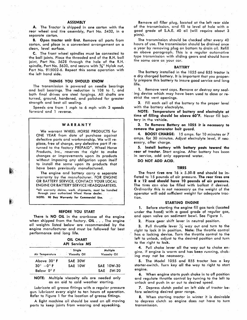
ASSEMBLY A. The Tractor is shipped in one carton with the
rear wheel and tire assembly, Part No. 5432, in a separate carton.
B. Open tractor unit first. Remove all parts from carton, and place in a convenient arrangement on a clean, level surface.
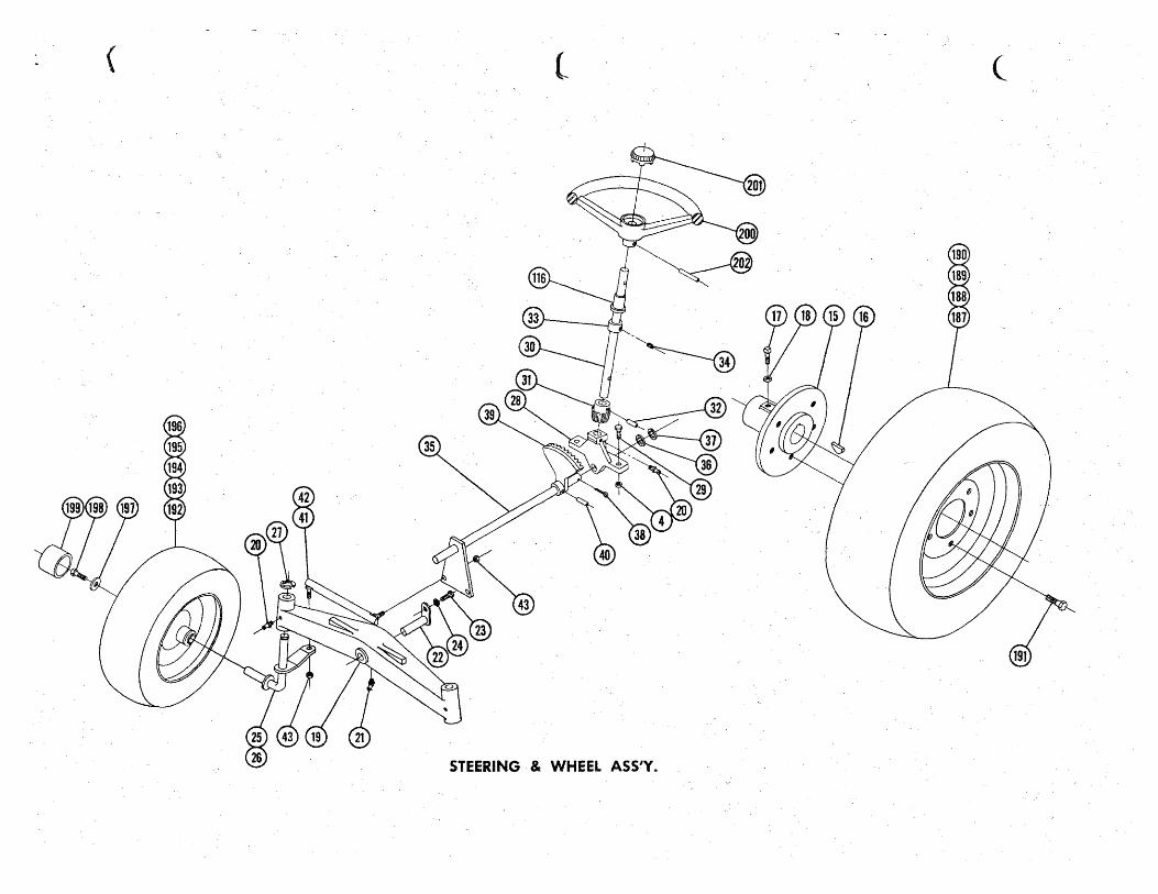
C. The front wheel spindles must be connected to the ball joints. Place the threaded end of the R.H. ball joint, Part No. 5628 through the hole of the R.H. spindle, Part No. 5630, and secure with %" Nylok nut, Part No. 915002-6. Repeat this same operation with the left hand side.
THINGS YOU SHOULD kNOW The transmission is powered on needle bearings
and ball bearings. The reduction is 108 to 1, and both final drives are steel forgings. All shafts are turned, ground, hardened, and polished for greater strength and best oil sealing.
Speeds are from 1 mph to 6 mph with 3 speeds forward and 1 reverse.
WARRANTY
We warrant WHEEL HORSE PRODUCTS for ONE YEAR from date of purchase against defective parts and workmanship. We will replace, free of charge, any defective part if returned to the factory PREPAID*. Wheel Horse Products, Inc., reserves the right to make changes or improvements upon its products without imposing any obligation upon itself to install the same upon its products that have been previously manufactured.
The engine and battery carry a separate warranty by the manufacturer. FOR ENGINE OR BATTERY SERVICE, CONTACT YOUR LOCAL ENGINE OR BATTERY SERVICE HEADQUARTERS. *All warranty claims, work, shipments, must be handled
through your authorized Wheel Horse dealer •.
NOTE: 90 Day Warranty for Commercial Use.
BEFORE YOU START There is NO OIL in the crankcase of the engine
when shipped from the factory. OIL ... The engine oil weights listed below are recommended by the engine manufacturer and must be followed for best performance and long life.
Air Temperature
Above 30° F 30° -0° F Below 0° F
OIL CHART API Service MS
' Single
Viscosity Oil
SAE 30W SAE lOW
Multiple
Viscosity Oil
SAE lOW-30 SAE 5W-20
NOTE: Multiple viscosity oils are needed only as an aid to cold weather starting.
Lubricate all grease fittings with a regular pressure gun lubricant every eight to ten hours of operation. Refer to Figure 1 for the location of grease fittings.
A light machine oil should be used on all moving parts to keep ioints from wearing and squeaking.
Remove oil filler plug, located at the left rear side of the transmission, and fill to level of hole with a good grade of S.A.E. 40 oil (will require about 3 pints).
The transmission should be checked after every 40 hours of use. The transmission should be drained once a year by removing plug on bottom to drain oil. Refill as above paragraph. This is a regular automotive type transmission with sliding gears and should have the same care as your car.
BATTERY The battery installed in the 1055 and 855 tractor is
a dry charged battery. It is important that you properly prepare this battery to insure good ~ervice and long life.
1. Remove vent caps. Remove or destroy any seal· lng device which may have been used to close or restrict the vent openings.
2. Fill each cell of the battery to the proper level with the battery electrolyte.
NOTE: Temperature of battery and electrolyte at time of filling should be above 60°F. Never fill battery in the vehicle.
3. To Remove Battery on 1055 it is necessary to remove the generator belt guard.
4. BOOST CHARGE: 15 amps. for 10 minutes or 7 amps. for 30 minutes. Adjust electrolyte levet if necessary, after charge.
5. Install battery with battery posts toward the rear of tractor. Start engine. After battery has been in service, add only approved water.
DO NOT ADD ACID.
TIRES The front tires· are 16 x 5.50-8 and should be in·
flated to 15 pounds of air pressure. The rear tires are 8 x 12 and should have 10 pounds of air pressure. The tires can also be filled with ballast if desired.
· Ordinarily this is not necessary as the weight of the operator will add sufficient weight for adequate traction.
STARTING ENGINE 1. Before starting the engine fill gas tank (located
under the hood) with a good grade of regular gas, and open valve on sediment bowL See Figur~ 1.
2~ Place gear shift lever in neutral position.
3. Pull throttle lever X way out and turn to the right to lock it in position. Note: The throttle contr~l has a locking device. Turn the throttle control to the left to unlock, adjust to the desired position and turn to the right to lock.
4. Pull choke lever all the way out to choke engine. If engine is warm and has been running, chok-
. it:lg may not be necessary. ·
5. The Model 1 055 and 855 tractor has a key starter-switch. Turn key all the way to right to start engine.
6. When engine starts push choke in to off position and regulate throttle control by turning to the left to unlock and push in or out to desired speed.
7. Depress clutch pedal on left side of tractor before selecting desired gear range.
8. When starting tractor in winter it is desirable to depress clutch so engine does not have to turn transmission.

··..,.t
CLUTCHING Don't force the gear shift lever if the gears do not
immediately mesh. Depress dutch pedal all the way down and let up, then depress again and shift. To avoid sudden starts, release clutch pedal slowly. While in motion do not shift gears without ·depressing clutch pedal.
The clutch pedal also operates the brakes WHEN DEPRESSED ALL THE WAY DOWN. for this reason, you should depress the clutch pedal ONlY 73 OF THE WAY DOWN WHEN SHIFTING while in motion. This clutchbrake pedal combination makes clutching automatic as you apply the brakes to stop.
PARKING BRAKE The parking brake is located on the left side of
the tractor as shown in Figure 1. To set the parking brake depress the clutch-broke pedal as far as possible and push the parking brake down. To release the brake depress the clutch-brake pedal.
ATTACHING TOOLS Complete information on the assembly, attachment,
operation and service of the many attaching tools will be provided with each attachment.
All drawn implements attach in seconds. Simply lift the tractor hitch pin, insert the tongue, and replace pin.
All power implements will use the attachment clutch pedal located on the right side of the tractor.
NOTE: The idler brocket assembly furnished with the 36" Rotary Mower and 42" Sickle Bar will not work on 1055 tractor. Replace this assembly with with Kit Number 6051.
CARE OF TRACTOR 1. Keep tractor greased and oiled regularly. Re
fer to Figure 1 for the location of grease fittings. Check transmission and engine case oil levels.
2. Keep engine air cleaner clean. This will add to engine life.
3. Keep tires properly inflated. See previous instructions.
4. Keep tractor covered and in a dry place when not in use.
5. Keep grass and dirt out of engine cowling as these will stop the flow of air and decrease engine life.
6. BRAKE ADJUSTMENT. The brake band, located on the left side of the transmission, brakes the transmission and in turn stops the wheels.
To adjust, depress clutch brake pedal and move parking brake lever forward into the engaged position. Tighten nut on brake rod until both rear wheels skid when tractor is pushed - parking brake engaged. Tighten nut another Y2 turn. The brake and parking brake ore now properly adjusted.
7. CLUTCH-BRAKE PEDAL ADJUSTMENT. The clutch-brake pedal rod may be turned in or out to adjust the pedal to operator's desired position. Re· move pin from rod and turn rod in or out for adjustment. There ore also two holes in the pedal to adjust for travel. The upper hole is for a short movement of travel, the lower hole is for a long movement.
8. When replacing belts or mounting drive implements make sure all pulleys are in line.
9. BATTERY. Check liquid after every 40 hours of use. If tractor has been in storage it may be necessary to recharge.
10. Your tractor is only as good as the service you give it. See your Wheel Horse Dealer for a thorough check-up after each season of use.
11. When replacing belts be sure to purchase genuine Wheel Horse belts, as these belts ore specifically designed for each application.
(NOTE: Make sure all pulleys are in line.)
12. To raise seat/fender unit pull knob back. See Fig. 1. Seat should be latched before operating tractor.
FOR YOUR SAFETY
A. Keep all guards on at all times.
B. Never abuse your tractor by improper handling.
C. Keep hands and feet from moving parts.
D. Remove key when not in use.
E. Be careful on high uneven ground.
REGULATOR
liGHTER
COIL
SF!t.RK PLUG
KOHLER
GfN. WARNING
GROUND
IGNITION-ST~RTE~ SWITCH
WIRING FOR 1055-855
SPECIFICATIONS ISpeciflcotions subject to chonge without nofice.l
length Overall . • . . . . • . . . • • . • • • • • • • • • . • . . . . • . . • . . . . . 61 inches Wheelbase . . . . . . . . . . • • . • . . . . • . . . . . • • • • . • . . • • • • • • . 41 X inches Width Overall ...•.••.•.........••••..•.••••• ·• . . . . . • 34 inches Width at Front Wheels . . . . • . . . . . . • • • . • • . • • • • . . • • 33~ inches Height •.....• , . . . • • • • • • • . • . • • • • . . . . • • • . • • • . . . • . . . . • 37 inches Height to Top of Hood •••••..•••.••...••..•....... 33~ inches Approx. Shipping Weight 10 H.P. . ••.•.•••••.•......... 512 lbs. Approx. Shipping Weight 8 H.P. . .•••••.••.•••..•...•. 464 lbs. Crop Clearance • . • . . . • . • • • • • • • • • • • . . . • • • • • • • . • • • • • . 7}!,l inches Frome Clearance ••..••••••••••••.•.•.•••••••.••••• 13~ inches Engine (4-cycle, single cylinder, air cooled) Electric Start 10 & 8 H.P. Engine Oil Cap~city ..•......... 8 H.P. 2~ pints • 10 H.P. 3 pints Fuel Capacity . . . . . . . . . • . . • . • . • . . . . . . . . . • . . . . • • • . • . . • . 6 quarts Tires (front) 5.50-8 Pneumatic (16" wheel dia.) Tires (rear) Terra· Type 8.00 x 12" Pneumatic (22~" wheel dia.) Speeds - 3 Forward to 6 mph. 1 Reverse to 2~ mph. Turning radius (to outside of outside wheel) . • • . • . . . . . . . . . . . • 6'

HOOD LATCH
RELEASE KNOB FOR SEAT /FENDER UNIT
( (_ (
STEERING & WHEEL ASS'Y.

MAIN FRAME,


Ref.
No.
1
2
3
4
5
6
7
8
9
10
11
12
13
14
15
16
17
18
19
20
21
22
23
24
25
26
27
28
29
30
31
32
33
34
35
. 36
37
38
39
40
- 41 .. 42
43
44
45
46
47
48
49
50
51
52
53
PARTS LIST for 1055-855 LAWN and GARDEN TRACTOR (Except Transmission - see page 10 for Transmission break down and Parts List
Part
No.
5422
5634
5645
915663-4
908034-4
920009-4
920083-4
908032-4
5622
960151-4
5425
1611
909849-6
937014
4996
937022
909554-4
915113-6
5638
1030
~481
2294
908015-4
920082-4
5630
5631
5618
4412
90803.5-4
5335
3917
933215
1085
909848-6
5639
5210
1278
932035-4
5627
933229
5628
5629
915002-4
5411
3950
4899
933158
1623
1536
1363
2593
3935
1861
When ordering parts always list Part No. and name of part. -'
Description
Ass'y. Frame (1055)
Ass'y. Frame (855)
Ass'y. Hoodstand
Nut %·16 Elastic Stop
Bolt Hex %-16 x 1
Washer % S.A.E.
lockwasher % Plain
Bolt Hex %-16 x % Ass'y. Cover Plate
Bolt Whizlock ~ -20 x X Pulley (1055)
Pulley (855)
Set Screw ~ -20 x k'6 Nylok
Key #9 Woodruff
Hub - Wheel 5 Bolt
Key #15 Woodruff
Set Screw Square Hd. % ·16 x 1
Nut %-16 Nylok
Axle - Front
Fitting - Grease
Fitting - Grease 45°
Ass'y. Pin & Plate
Bolt Hex j{4-l8 x X lockwasher X6 Plain
Ass'y. Spindle R.H.
Ass'y. Spindle L.H.
"E" Ring % Dia.
Support Steering
Bolt Hex %-16 x 1X
Shaft - Steering Upper.
Gear - Steering Pinion
Roll Pin X x 1X
Collar
Set Screw X -20 x ~ Nylok
Ass'y. Steering Shaft - lower
Washer - Shim (.015)
Washer - Shim (.050)
Cotter Pin ~6 x 1 X Sector - Steering
Roll Pin X, x lX
Ass'y. Boll Joint R.H.
Ass'y. Boll Joint L.H.
Nut %-24 Nylok
Ass'y. Idler Arm & Shaft (1055)
Ass'y. Idler Arm & Shaft (855}
Arm - Clutch Rod Pivot
Roll Pin Ya x lX Pulley - Idler
Bushing
Bolt Hex %-16 x Ya Special (855)
Rod -Clutch
Rod - Brake
Stud - Clutch Rod
No.
Req'd.
1
1
1
13
4
6
11
8
1
6
1
1
1
1
2
2 4
5
l
3
1
1
9
9
1
1
2
1
9
1
1
1
1
2
1
1
1
1
1
1
1
1
4
1
1
1
2
1
1
1
1
1
1
Ref.
No.
54
55
56
57
58
59
60
61
62
63
64
65
66
67
68
69
70
71
72
73
14
75
76
71
78
79
80
81
82
83
84
85
86
87
88
89
90
91
92
93
94
95
96
97
98
99
100
101
102
103
104
105
106
Part
No.
932017-4
1014
5544
2267
933504
5448
2266
4438
5449
4439
933168
3624
3578
3680
1000
933506
5640
2179
5280
3931
932120-4
933503
3926
3988
936125
4246
4239
5714
5416
5385
933188
5465
5455
.5457
915112-6
933503
5467
5469
933182
5505
5468
915902-..4
5466
5522
5438
5437
5651
4993
909068-~
909082-~
5660
5661
5666
No.
Description Req'd.
Cotter Pin Ya x 1 4
Spring - Clutch 1
Ass'y. lever & Knob - Brake 1
Pedal - Clutch 1
Hair Pin 1
Ass'y. Lift lever (1055) 1
Ass'y. Lift Lever (855) 1
Plunger 1
Rod (1055) 1
Rod (855) 1
Roll Pin ~2 x 1~6 1
Spring 1
Guide - Plunger Rod 1
Cap - Plunger Rod 2
Grip - Handle 1
Hair Pin 1
Quadrant 1
Rod - Height Control 1
Knob - Height Control 1
Ass'y. Cable - Lift 1
Pin Clevis X Dia. 2
Hair Pin 2
H~~ 1
Pin - Hitch 1
Snap Ring % Shaft 2
Ass'y. Trip Lever 1
Pedal - Attachmtnt Clutch 1
Spring 1
Link (1 055) 1
link (855) 1
Roll Pin ~6 x 1 2
Ass'y. Hood \
Bracket - Hood Hinge 1
Bushing - Nylon 2
Nut ~,-18 Nylok 6
Hair Pin 2
Lever - Hood Latth 1
Knob 1
Roll Pin ~6 x % 1
Roller - Rubber 2
Roller - Steel · 2
Nut - Low Crown #10-24 2
Speed Nut ~ Dia. Push On 2
Rod - Hood latch 1
Ornament - Hood latch 1
Speed Nut Ya Dio. Push On 2
Ass'y. Belt Guard (1055) 1
Au'y. Belt (855) 1
Screw Round Hd. X6-18 x X (1055) 1
Screw Round Hd. %·16 x X (855) 1
Ass'y. Fender (1055) 1
Au'y. Fender (855) 1
Bushing -- Nylon 2

PARTS LIST for 1055-855 LAWN and GARDEN TRACTOR (Except Transmission - see page 10 for Transmission break down and Parts List
When ordering parts always list Part No. and name of part.
Ref. Part No. Ref. Part No. No. No. Description Req'd. No. No. Description Req'd.
107 908182-6 Bolt %-24 X Ya Nylok 2 160 1786 Ass'y. Fuel Strainer 1 108 4937 Spacer 2 161 1192 Nipple - Fuel Tank 1
109 5667 Bumper - Rubber 4 162 908034-4 Bolt Hex %-16 x 1 (1055) 2 110 4953 Ass'y. Battery Box 1 163 5436 Hose - Fuel (1 055) 1
111 915111-6 Nut Y.;-20 Nylok 8 164 1796 Hose - Fuel (855) l
112 4958 Clamp - Battery 1 165 4256 Clip - Fuel 2 113 5450 Housing - Control Panel 1 166 4988 Ass'y. Switch - Ignition 1
114 908016-4 Bolt Hex K6- 18 x % 4 167 4882 Nut Hex %-32 Special 1 115 5442 Speed Nut #10-16 Thread 4 168 4881 lockwasher % t 116 5409 Bushing - Nylon 1 169 4989 Key - Ignition 1
117 5458 Support - Fuel Tank 1 170 5451 Insulator Switch 1 118 909054-4 Bolt Round Hd. X-20 x % 6 171 5423 Ass'y. Lamp ·- Generator 1 119 5453 Panel - Complete 1 172 2712 Battery (1055) 1 120 926308-4 Screw-Self Tap #10-16 x% Type "8" 4 173 3653 Battery (855) 1 121 5439 Grommet - Rubber , 174 5480 Ass'y. Cigar lighter - Complete 1 122 5424 Guide- Belt (1055) 1 175 5481 Ass'y. Knob & Plug 1 123 5696 Ass'y. latch & Knob 1 176 5483 Shell 1
124 920007-4 Washer X S.A.E. 2 177 5482 Ass'y. Sockdt 1 125 5460 Ass'y. Engine - 10 H.P. Kohler (1055) 1 178 915562 Nut #8-32 Brass 2 126 5151 . Ass'y. Engine - 8 H.P. Kohler (855) 1 179 920078-4 Lockwasher #8 1 127 5613 Stud %-16 x 1Y.; (1055) 2 180 5484 Ass'y. Wire 1 128 1217 Elbow 90° 2 181 5445 Wiring Harness 1 129 5222 Elbow 90° Special 1 182 3660 Wire Battery to Ground 1 130 5223 Nipple % Pipe x 3X (Special) l 183 908002-4 Bolt Hex X -20 x Ya 2 131 5224 Cap% Pipe 1 184 5557 Base - Seat 1 132 2873 Muffler (1055) 1 185 5556 Cushion Seat 1
133 5429 Muffler (855) 1 186 908030-4 Bolt Hex %-16 x X 2 134 3939 Elbow 1" x 45° (1055) 1 187 5432 Ass'y. Wheel & Tire- Rear 2 135 943367-4 Nipple 111 Pipe x 2~ 1 188 5433 Wheel 2 136 3947 Nipple 1" Close Pipe (1055) 1 189 5434 Tire - lawn & Garden 2 137 5412 Pulley - Engine (1055) 1 190 5435 Valve 2 138 1621 Pulley - Engine (855) 1 191 1004 Lug Bolt Wheel K6·20 10 139 1349 Key :!{ x X x 1 X 1 192 5637 Ass'y. Wheel Tire & Tube - Front 2
140 909862-6 Set Screw K6- 18 x K6 ( 1 055) 2 193 5635 Wheel 2
141 5440 Ass'y. Control - Choke (1055) 1 194 4999 Bearing - Ball 4
142 5441 Ass'y. Control - Throttle (1055) 1 195 5636 Tire 2 143 1364 Nut ~6·18 Round 2 196 5512 Tube 2
144 920127-4 lockwasher Yt6 Shakeproof 2 197 2844 Washer 2 145 5170 Ass'y. Control - Choke (855) 1 198 908033-6 Bolt %-16 X Ya Nylok 2 146 5171 Ass'y. Control - Throttle (855) 1 199 2816 Hub Cap 2
147 1277 Clip - Throttle Cable (855) 1 200 4983 Steering Wheel 1
148 909000-4 Bolt - Round Hd. #8-32 x X (855) 1 201 2897 Insert 1
149 915562-4 Nut .;...... Hex #8-32 (855) 1 202 933213 Roll Pin :!{ x 1 1
150 920078-4 lockwasher #8 (855) 1 203 1813 Tool Pin 1 151 5431 Nut Hex Special X-20 (1055) 1
152 . 1391 Screw - X -20 x % Sems ( 1 055) 1
204 937305 Wrench Ys Hex Allen 1
205 1576 "Y"-Belt Drive 70 x!~ - t
153 2879 Clip (1055) 1 206 5604 Decal (Fender) 1
154 5417 Tank - Fuel 1 207 5415 Decal - Wheel Horse 2 155 5459 Clamp - Tank 1 208 5621 Decal - 1055 1
156 5464 Tape - Regulator Insulator 1 209 5620 Decal - 855 1
157 5186 Cap - Fuel Tank 1 210 5462 Decal - Decor - Hood 1
158 909059-4 Bolt X -20 x 1 :!{ Round Head 1 211 4581 Decal Steering Wheel 1
159 915182-4 Nut :l{-20 Square 1 212 4421 Foot Rest 2 . -·~ -·

TRANSMISSION PARTS LIST When ordering parts always list Part No. and name of part.
Ref. Part No. Ref. Part No. No. No. Description Req'd. No. No. Description Req'd.
1 3900 Case • Transmission 1 33 3903 Gear • Brake Shaft 1 2 1533 Bearing - Ball 2 34 3906 Gear· Bull 1 3 3915 Pin - Locating 2 35 3905 Case • Differential 2 4 1532 Bearing - Needle l 36 3Y04 Axle • Rear 2 s 1529 Bearing - Needle 2 6 1508 Bearing - Needle 2
37 3908 Gear. Axle 2 38 933217 Pin • Roll ~ x 1 ~ 2
7 l528 Searing - Need\e OC)<j{;; 3 p 2. 8 1232 Seal- Oil - / 3
39 4235 Gear • Differential Pinion 4 40 1329 Cap Screw • Hex. 7{6-18 x 3 ~ 4
9 1303 Seal- Oil 1 41 1316 Nut • Hex. Lock 7{6-18 4 10 3503 Fork - Shift 2 42 3912 Gasket 1 11 .5615 Rail • Front Shift 1 43 3901 Case Transmission 1 12 5616 Rail • Rear Shift 1 44 1530 Bearing - Needle 1 13 933156 Pin · Roll Ya x 1 2 14 3517 Ball· Stop 2 15 3518 Spring - Stop 1 16 5614 Shift Pin • Stop 1 17 3522 Gear · Input Drive 1 18 1518 Bearing . Needle 1
45 1531 Bearing - Needle 1 46 943460-4 X Std. Pipe Plug 1 47 943420-4 % Std. Pipe Plug 1 48 908038-4 Bolt Hex. - %-16 x 2 5 49 908043-4 Bolt - Hex. %-16 x 372 1 50 915113-6 Nut- Nylock %-16 6
19 3907 Shaft - Spline 1 51 5632 Stick - Shift Ass'y. 1 20 936125 Snap Ring Truarc % Shaft 1 21 3523 Gear (Hi & lntr.) 1 22 3524 Gear (Low & Reverse) 1 54 1239 Screw - Soc. Hd. • Set X -20 x % 1 23 3526 Gear - Spline Shaft 1 55 915111-4 Nut - Hex. Lock X-20 1 24 3910 Cluster . Shaft 1 56 3577 Boot - Shift Lever 1 25 937014 Key - #9 Woodruff 2 57 1001 Knob - Shift 1 26 3525 Gear • Cluster 1 58 3902 Drum • Brake 1 27 1504 Bushing • Bronze 2 59 937022 Key #15 VVoodruff 1 28 3.528 Pinion • Cluster Shaft Reduction 1 60 936131 Snap Ring 1" Shaft 1 29 3527 Gear - Cluster Shaft Reduction 1 61 4437 Band - Brake 1
30 4204 Gear · Reverse Idler 1 62 908002-4 Bolt - Hex. X -20 x % 2 31 1516 Bushing • Bronze 1 63 920081-4 Washer • Lock X 2 32 3909 Pin . Reverse Idler 5