Manual Ford Ranger 2003
256
Introduction 3 Instrument Cluster 10 Warning and control lights 10 Gauges 13 Entertainment Systems 16 AM/FM stereo 16 AM/FM stereo with CD 18 AM/FM stereo cassette with CD 30 Climate Controls 39 Manual heating and air conditioning 39 Lights 42 Headlamps 42 Turn signal control 45 Bulb replacement 45 Driver Controls 51 Windshield wiper/washer control 51 Steering wheel adjustment 52 Power windows 53 Mirrors 53 Speed control 54 Locks and Security 63 Keys 63 Locks 63 Anti-theft system 65 Seating and Safety Restraints 72 Seating 72 Safety restraints 74 Air bags 86 Child restraints 96 Table of Contents Table of Contents 1
Transcript of Manual Ford Ranger 2003

Introduction 3
Instrument Cluster 10
Warning and control lights 10Gauges 13
Entertainment Systems 16
AM/FM stereo 16AM/FM stereo with CD 18AM/FM stereo cassette with CD 30
Climate Controls 39
Manual heating and air conditioning 39
Lights 42
Headlamps 42Turn signal control 45Bulb replacement 45
Driver Controls 51
Windshield wiper/washer control 51Steering wheel adjustment 52Power windows 53Mirrors 53Speed control 54
Locks and Security 63
Keys 63Locks 63Anti-theft system 65
Seating and Safety Restraints 72
Seating 72Safety restraints 74Air bags 86Child restraints 96
Table of Contents
Table of Contents
1

Driving 110
Starting 110Brakes 115Transmission operation 118Trailer towing 136
Roadside Emergencies 149Getting roadside assistance 149Hazard flasher switch 150Fuel pump shut-off switch 150Fuses and relays 151Changing tires 161Jump starting 167Wrecker towing 173
Customer Assistance 174
Reporting safety defects (U.S. only) 182
Cleaning 183
Maintenance and Specifications 189Engine compartment 191Engine oil 195Battery 200Fuel information 207Part numbers 231Refill capacities 232Lubricant specifications 235
Accessories 242
Index 246
All rights reserved. Reproduction by any means, electronic or mechanicalincluding photocopying, recording or by any information storage and retrievalsystem or translation in whole or part is not permitted without writtenauthorization from Ford Motor Company. Ford may change the contents withoutnotice and without incurring obligation.
Copyright © 2002 Ford Motor Company
Table of Contents
2

CALIFORNIA Proposition 65 Warning
WARNING: Engine exhaust, some of its constituents, andcertain vehicle components contain or emit chemicals known to
the State of California to cause cancer and birth defects or otherreproductive harm. In addition, certain fluids contained in vehicles andcertain products of component wear contain or emit chemicals knownto the State of California to cause cancer and birth defects or otherreproductive harm.
CONGRATULATIONSCongratulations on acquiring your new Ford. Please take the time to getwell acquainted with your vehicle by reading this handbook. The moreyou know and understand about your vehicle the greater the safety andpleasure you will derive from driving it.
For more information on Ford Motor Company and its products visit thefollowing website:
• In the United States: www.ford.com
• In Canada: www.ford.ca
• In Australia: www.ford.com.au
• In Mexico: www.ford.com.mx
Additional owner information is given in separate publications.
This Owner’s Guide describes every option and model variant availableand therefore some of the items covered may not apply to yourparticular vehicle. Furthermore, due to printing cycles it may describeoptions before they are generally available.
Remember to pass on the Owner’s Guide when reselling the vehicle. It isan integral part of the vehicle.
Fuel pump shut-off switch In the event of an accident thesafety switch will automatically cut off the fuel supply to the
engine. The switch can also be activated through sudden vibration (e.g.collision when parking). To reset the switch, refer to the Fuel pumpshut-off switch in the Roadside emergencies chapter.
Introduction
Introduction
3

SAFETY AND ENVIRONMENT PROTECTION
Warning symbols in this guide
How can you reduce the risk of personal injury and prevent possibledamage to others, your vehicle and its equipment? In this guide, answersto such questions are contained in comments highlighted by the warningtriangle symbol. These comments should be read and observed.
Warning symbols on your vehicle
When you see this symbol, it isimperative that you consult therelevant section of this guide beforetouching or attempting adjustmentof any kind.
Protecting the environmentWe must all play our part inprotecting the environment. Correctvehicle usage and the authorizeddisposal of waste cleaning andlubrication materials are significantsteps towards this aim. Information in this respect is highlighted in thisguide with the tree symbol.
BREAKING-IN YOUR VEHICLEYour vehicle does not need an extensive break-in. Try not to drivecontinuously at the same speed for the first 1,600 km (1,000 miles) ofnew vehicle operation. Vary your speed to allow parts to adjustthemselves to other parts.
Drive your new vehicle at least 800 km (500 miles) before towing atrailer.
Do not add friction modifier compounds or special break-in oils duringthe first few thousand kilometers (miles) of operation, since theseadditives may prevent piston ring seating. See Engine oil in theMaintenance and specifications chapter for more information on oilusage.
Introduction
4

SPECIAL NOTICES
Emission warrantyThe New Vehicle Limited Warranty includes Bumper-to-BumperCoverage, Safety Restraint Coverage, Corrosion Coverage, and 7.3LPower Stroke Diesel Engine Coverage. In addition, your vehicle is eligiblefor Emissions Defect and Emissions Performance Warranties. For adetailed description of what is covered and what is not covered, refer tothe Warranty Guide that is provided to you along with your Owner’sGuide.
Data RecordingComputers in your vehicle are capable of recording detailed datapotentially including but not limited to information such as:
• the use of restraint systems including seat belts by the driver andpassengers,
• information about the performance of various systems and modules inthe vehicle, and
• information related to engine, throttle, steering, brake or other systemstatus.
Any of this information could potentially include information regardinghow the driver operates the vehicle potentially including but not limitedto information regarding vehicle speed, brake or accelerator applicationor steering input. This information may be stored during regularoperation or in a crash or near crash event.
This stored information may be read out and used by:
• Ford Motor Company.
• service and repair facilities.
• law enforcement or government agencies.
• others who may assert a right or obtain your consent to know suchinformation.
Introduction
5

Special instructionsFor your added safety, your vehicle is fitted with sophisticated electroniccontrols.
Please read the section Supplemental Restraint System (SRS)in the Seating and safety restraints chapter. Failure to follow
the specific warnings and instructions could result in personal injury.
Front seat mounted rear facing child or infant seats shouldNEVER be used in front of a passenger side air bag unless the
air bag can be and is turned OFF.
Notice to owners of pickup trucks and utility type vehicles
Utility vehicles have a significantly higher rollover rate thanother types of vehicles.
Before you drive your vehicle, please read this Owner’s Guide carefully.Your vehicle is not a passenger car. As with other vehicles of this type,failure to operate this vehicle correctly may result in loss of vehiclecontrol, vehicle rollover, personal injury or death.
Be sure to read Driving off road in the Driving chapter.
Introduction
6
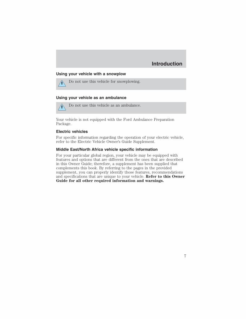
Using your vehicle with a snowplow
Do not use this vehicle for snowplowing.
Using your vehicle as an ambulance
Do not use this vehicle as an ambulance.
Your vehicle is not equipped with the Ford Ambulance PreparationPackage.
Electric vehiclesFor specific information regarding the operation of your electric vehicle,refer to the Electric Vehicle Owner’s Guide Supplement.
Middle East/North Africa vehicle specific informationFor your particular global region, your vehicle may be equipped withfeatures and options that are different from the ones that are describedin this Owner Guide; therefore, a supplement has been supplied thatcomplements this book. By referring to the pages in the providedsupplement, you can properly identify those features, recommendationsand specifications that are unique to your vehicle. Refer to this OwnerGuide for all other required information and warnings.
Introduction
7

These are some of the symbols you may see on your vehicle.
Vehicle Symbol Glossary
Safety Alert See Owner’s Guide
Fasten Safety Belt Air Bag-Front
Air Bag-Side Child Seat
Child Seat InstallationWarning
Child Seat LowerAnchor
Child Seat TetherAnchor
Brake System
Anti-Lock Brake SystemBrake Fluid -Non-Petroleum Based
Traction Control AdvanceTrac�
Master Lighting Switch Hazard Warning Flasher
Fog Lamps-Front Fuse Compartment
Fuel Pump Reset Windshield Wash/Wipe
WindshieldDefrost/Demist
Rear WindowDefrost/Demist
Introduction
8

Vehicle Symbol Glossary
Power WindowsFront/Rear
Power Window Lockout
Child Safety DoorLock/Unlock
Interior LuggageCompartment ReleaseSymbol
Panic Alarm Engine Oil
Engine CoolantEngine CoolantTemperature
Do Not Open When Hot Battery
Avoid Smoking, Flames,or Sparks
Battery Acid
Explosive Gas Fan Warning
Power Steering FluidMaintain Correct FluidLevel
MAX
MIN
Emission System Engine Air Filter
Passenger CompartmentAir Filter
Jack
Check fuel cap Low tire warning
Introduction
9

WARNING LIGHTS AND CHIMES
Warning lights and gauges can alert you to a vehicle condition that maybecome serious enough to cause expensive repairs. A warning light mayilluminate when a problem exists with one of your vehicle’s functions.Many lights will illuminate when you start your vehicle to make sure thebulb works. If any light remains on after starting the vehicle, have therespective system inspected immediately.
Check engine: The Check Engineindicator light illuminates when theignition is first turned to the ONposition to check the bulb. Solidillumination after the engine isstarted indicates the On Board Diagnostics System (OBD-II) hasdetected a malfunction. Refer to On board diagnostics (OBD-II) in theMaintenance and Specifications chapter. If the light is blinking, enginemisfire is occurring which could damage your catalytic converter. Drivein a moderate fashion (avoid heavy acceleration and deceleration) andhave your vehicle serviced immediately.
Under engine misfire conditions, excessive exhaust temperaturescould damage the catalytic converter, the fuel system, interior
floor coverings or other vehicle components, possibly causing a fire.
Check fuel cap: Illuminates whenthe fuel cap may not be properlyinstalled. Continued driving withthis light on may cause the CheckEngine warning light to come on,refer to Fuel filler cap in the Maintenance and Specifications chapter.
CHECKENGINE
CHECKFUELCAP
Instrument Cluster
Instrument Cluster
10

Brake system warning light: Toconfirm the brake system warninglight is functional, it willmomentarily illuminate when theignition is turned to the ON positionwhen the engine is not running, or in a position between ON and START,or by applying the parking brake when the ignition is turned to the ONposition. If the brake system warning light does not illuminate at thistime, seek service immediately from your dealership. Illumination afterreleasing the parking brake indicates low brake fluid level or a failure tobrake proportioning and the brake system should be inspectedimmediately by your servicing dealership.
Driving a vehicle with the brake system warning light on isdangerous. A significant decrease in braking performance may
occur. It will take you longer to stop the vehicle. Have the vehiclechecked by your dealer immediately.
Anti-lock brake system: If theABS light stays illuminated orcontinues to flash, a malfunction hasbeen detected; have the systemserviced immediately. Normalbraking is still functional unless the brake warning light also isilluminated.
Air bag readiness: If this light failsto illuminate when ignition is turnedto ON, continues to flash or remainson, have the system servicedimmediately. A chime will alsosound when a malfunction in the supplemental restraint system has beendetected.
Safety belt: Reminds you to fastenyour safety belt. A chime will alsosound to remind you to fasten yoursafety belt.
Charging system: Illuminates whenthe battery is not charging properly.
!BRAKE
ABS
Instrument Cluster
11

Check gage: Illuminates when anyof the following conditions hasoccurred:
• The engine coolant temperatureis high.
• The engine oil pressure is low.
• The fuel gauge is at or near empty.
Door ajar: Illuminates when theignition is in the ON position andany door is open.
Overdrive off (if equipped):Illuminates when the overdrivefunction of the transmission hasbeen turned off, refer to theDriving chapter. If the light flashes steadily, have the system servicedimmediately.
Four wheel drive low(if equipped): Illuminates whenfour-wheel drive low is engaged.
Four wheel drive high(if equipped): Illuminates whenfour-wheel drive high is engaged. Itmay also illuminate when the 4WDLOW is engaged, refer to the Driving chapter for more information.
Anti-theft system: Flashes whenthe Securilock� Passive Anti-theftSystem has been activated.
Speed control: Illuminates whenthe speed control is engaged. Turnsoff when the speed control systemis disengaged.
CHECKGAGE
DOORAJAR
O/DOFF
4WDLOW
SPEEDCONT
Instrument Cluster
12

Turn signal: Illuminates when theleft or right turn signal or thehazard lights are turned on. If theindicators stay on or flash faster, check for a burned out bulb.
High beams: Illuminates when thehigh beam headlamps are turned on.
Key-in-ignition warning chime: Sounds when the key is left in theignition in the OFF/LOCK or ACC position and the driver’s door isopened.
Headlamps on warning chime: Sounds when the headlamps or parkinglamps are on, the ignition is off (and the key is not in the ignition) andthe driver’s door is opened.
GAUGES
Speedometer: Indicates thecurrent vehicle speed.
Instrument Cluster
13

Engine coolant temperaturegauge: Indicates engine coolanttemperature. At normal operatingtemperature, the needle will be inthe normal range (between “H” and“C”). If it enters the red section,the engine is overheating. Stopthe vehicle as soon as safelypossible, switch off the engineand let the engine cool.
Never remove the coolant reservoir cap while the engine isrunning or hot.
Odometer: Registers the totalkilometers (miles) of the vehicle.
Trip odometer: Registers thekilometers (miles) of individualjourneys. To reset, depress thecontrol button.
Tachometer: Indicates the enginespeed in revolutions per minute.Driving with your tachometerpointer continuously at the top ofthe scale may damage the engine.
C
H
10 MPH
20
5060 70
30
4080
90
km/h
0 0 0
101
001
201
0 0 0 0 0 040
60
80 100120
140
160
18020
Instrument Cluster
14

Battery voltage gauge: Indicatesthe battery voltage when theignition is in the ON position. If thepointer moves and stays outside thenormal operating range (asindicated by arrows), have thevehicle’s electrical system checkedas soon as possible.
Engine oil pressure gauge:Indicates engine oil pressure. Theneedle should stay in the normaloperating range (between “L” and“H”). If the needle falls below thenormal range, stop the vehicle, turnoff the engine and check the engineoil level. Add oil if needed. If the oillevel is correct, have your vehiclechecked at your dealership or by aqualified technician.
Fuel gauge: Indicatesapproximately how much fuel is leftin the fuel tank (when the ignitionis in the ON position). The fuelgauge may vary slightly when thevehicle is in motion or on a grade.
Refer to Filling the tank in theMaintenance and Specificationschapter for more information.
L
H
H
L
Instrument Cluster
15

AM/FM STEREO
1. Seek: Press / to find thenext strong station down/up thefrequency band.
2. Tune: Press / to manuallychange radio frequency down/up.
3. AM/FM: Press to choose afrequency band in radio mode.
1 2 3 4 AM/FM
SEEKTONE
CLK TUNE
TONE VOL
12
FMST DX
VOLPUSH
ON
5
3
6 7
4
1 2
AM/FM
Entertainment Systems
Entertainment Systems
16

4. Memory preset buttons: To seta station: Select frequency bandAM/FM; tune to a station, press andhold a preset button until sound returns.
5. Power/volume: Press to turnON/OFF; turn to increase ordecrease volume levels.
6. Tone: Press TONE until thedesired level — Bass, Treble, Fadeappears on the display. Turn thevolume control to raise/lower thelevels, or to move the audio soundfrom the right to left or the front toback (if equipped).
7. CLK (Clock): To set the hour,press and hold CLK until CLOCKSET appears in the display. PressSEEK to decrease orincrease the hours.
To set the minute, press and hold CLK until CLOCK set appears in thedisplay. Press TUNE to decrease or increase the minutes.
1 2 3 4
TONE
CLK
VOLPUSH
ON
TONE
CLK
Entertainment Systems
17

AM/FM STEREO / SINGLE CD RADIO
1. Balance: Press / to shiftsound to the left/right speakers.
2. Fade: Press / to shiftsound to the front/rear speakers.
3. SCN (Scan): Press to hear abrief sampling of all listenablestations or CD tracks. Press again tostop.
4. CLK: To set the hour, press andhold CLK and press SEEK todecrease or increase thehours.
BASSCD
TREB BAL FADESCN
CLK
AMFM
VOL - PUSH ON
SEEK EJ
COMP
DISC
DISCSTUNE
1 2 3 4 5 6
FM1 ST
SHUFFLECDCD
14 15 16 17 18 1 2 3 413
6 58
12
11
7910
CLK
Entertainment Systems
18

To set the minute, press and hold CLK and press TUNE to decreaseor increase the minutes.
5. EJ (eject): Press to eject a CD.
6. COMP (Compression): In CDmode, press to bring louder andsofter levels into more comfortablelistening level. The compression icon (c) will appear in the display.
7. Shuffle: Press to listen to thetracks on the CD in random order.Press again to turn off.
8. Memory presets: To set astation: Select frequency bandAM/FM; tune to a station. Press andhold a preset button until sound returns. This radio is equipped with sixstation memory preset controls which allow you to set up to six AMstations and 12 FM stations (six in FM1 and six in FM2).
9. CD: Press and hold untildesired selection is reached.
10. CD: Press and hold untildesired selection is reached.
11. Tune / Discs: In radio mode,press to move up or down thefrequency band in individualincrements.
12. Seek: Press and releaseSEEK / for previous/nextstrong station, selection or track.
13. Power/volume: Press to turnON/OFF; turn to increase ordecrease volume levels.
SHUFFLE
6
1 2 3 4 5 6SHUFFLECDCD
Entertainment Systems
19

14. CD: Press to enter CD mode orto play a CD already loaded into thesystem.
15. AM/FM: Press to choose afrequency band in radio mode.
16. Bass: Press / toincrease/decrease the bass output.
17. Treble: Press / toincrease/decrease the treble output.
18. CD door: Insert a CD printedside up.
CD unit are designed to playcommercially pressed 12 cm (4.75 in) audio compact discs only.Due to technical incompatibility, certain recordable andre-recordable compact discs may not function correctly whenused in Ford CD players. Irregular shaped CDs, CDs with ascratch protection film attached, and CDs with homemade paper(adhesive) labels should not be inserted into the CD player. Thelabel may peel and cause the CD to become jammed. It isrecommended that homemade CDs be identified with permanentfelt tip marker rather than adhesive labels. Ball point pens maydamage CDs. Please contact your dealer for further information.
DISC
Entertainment Systems
20

PREMIUM IN-DASH SIX CD SOUND SYSTEM
1. Seek: Press and releaseSEEK / for previous/nextstrong station, or track of currentdisc.
2. Rewind: Press for a slow rewind,press and hold for a fast rewind.
Fast forward: Press for a slowadvance, press and hold for a fastadvance.
3. Comp (Compression): In CD mode, press to adjust the soft and loudpassages together for a more consistent listening level. Press the COMPcontrol until COMP ON is displayed.
4. Mute: Press to MUTE playingmedia; press again return to playingmedia. In CD mode, MUTE acts as apause feature.
5. Eject: Press to eject a CD. Pressand hold to auto eject all loadeddiscs.
Entertainment Systems
21

6. Bass: Press BASS; then pressSEL / to decrease/increasethe bass output.
Treble: Press TREB; then pressSEL / to decrease/increasethe treble output.
7. Select: Use with Bass, Treble,Balance and Fade controls to adjustlevels. Use with MENU to set theclock and engage RDS.
8. Balance: Press BAL; then pressSEL / to shift sound to theleft/right speakers.
Fade: Press FADE; then pressSEL / to shift sound to therear/front speakers.
9. Menu: Press MENU and SEL toaccess clock mode, RDS on/off,Traffic, Program type, Show typeand Compression modes.
Traffic: Allows you to hear traffic broadcasts. With the feature ON, pressSEEK or SCAN to find a station broadcasting a traffic report (if it isbroadcasting RDS data). Traffic information is not available in mostU.S. markets.
FIND Program type: Allows you to search RDS-equipped stations for acertain category of music format: Classic, Country, Info, Jazz, Oldies,R&B, Religious, Rock, Soft, Top 40.
Show TYPE: Displays the station’s call letters and format.
Compression: Brings soft and loud CD passages together for a moreconsistent listening level.
Setting the clock: Press MENU until SELECT HOUR or SELECTMINUTE is displayed. Use SEL to manually increase ( ) or decrease( ) the hours/minutes. Press MENU again to disengage clock mode.
Entertainment Systems
22

10. Memory presets: To set astation: Select frequency bandAM/FM; tune to a station, press andhold a preset button until soundreturns. In CD mode, press to move between CDs.This radio is equipped with six station memory preset controls whichallow you to set up to six AM stations and 12 FM stations (six in FM1and six in FM2).
11. CD: Press to select CD mode.
Seamless play: In CD mode, thetransition between the end of oneCD and the beginning of another will not contain delay time unless SEEKor a preset control is pressed.
12. AM/FM: Press to select afrequency band in radio mode.
Autostore: Allows you to set thestrongest local radio stations without losing your original manually setpreset stations for AM/FM1/FM2 . Press and momentarily hold AM/FM.AUTOSTORE will flash on the display. When the six strongest stationsare filled, the station stored in preset 1 will begin playing. If there areless than six strong stations, the system will store the last one in theremaining presets. Press again to disengage.
13. Power/volume: Press to turnON/OFF; turn to increase ordecrease volume levels.
14. Load: Press to load a CD. Pressand hold to load up to six discs.
15. Shuffle: Press to play tracks inrandom order. Press SHUF to cyclethrough SHUF DISC (if equipped),SHUF TRAC or SHUF OFF.
16. Scan: Press to hear a briefsampling of all listenable stations orCD tracks. Press again to stop.
Entertainment Systems
23
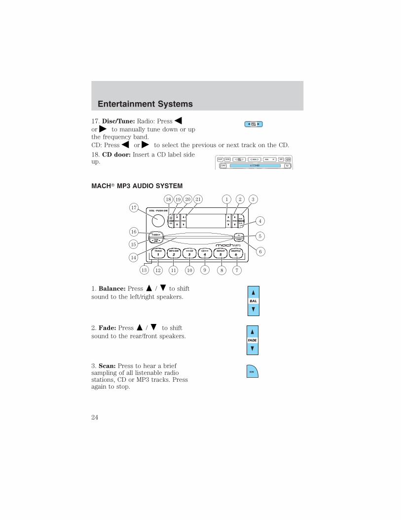
17. Disc/Tune: Radio: Pressor to manually tune down or upthe frequency band.CD: Press or to select the previous or next track on the CD.
18. CD door: Insert a CD label sideup.
MACH� MP3 AUDIO SYSTEM
1. Balance: Press / to shiftsound to the left/right speakers.
2. Fade: Press / to shiftsound to the rear/front speakers.
3. Scan: Press to hear a briefsampling of all listenable radiostations, CD or MP3 tracks. Pressagain to stop.
Entertainment Systems
24
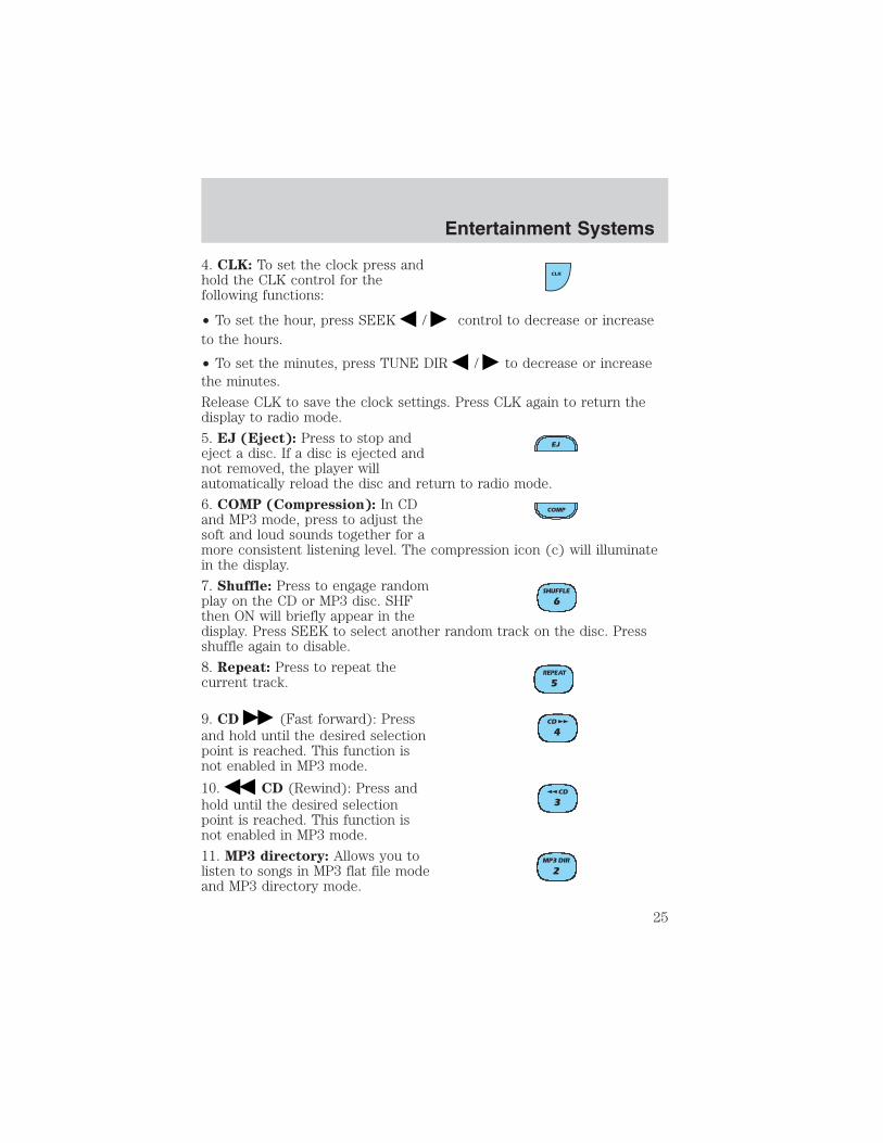
4. CLK: To set the clock press andhold the CLK control for thefollowing functions:
• To set the hour, press SEEK / control to decrease or increaseto the hours.
• To set the minutes, press TUNE DIR / to decrease or increasethe minutes.
Release CLK to save the clock settings. Press CLK again to return thedisplay to radio mode.
5. EJ (Eject): Press to stop andeject a disc. If a disc is ejected andnot removed, the player willautomatically reload the disc and return to radio mode.
6. COMP (Compression): In CDand MP3 mode, press to adjust thesoft and loud sounds together for amore consistent listening level. The compression icon (c) will illuminatein the display.
7. Shuffle: Press to engage randomplay on the CD or MP3 disc. SHFthen ON will briefly appear in thedisplay. Press SEEK to select another random track on the disc. Pressshuffle again to disable.
8. Repeat: Press to repeat thecurrent track.
9. CD (Fast forward): Pressand hold until the desired selectionpoint is reached. This function isnot enabled in MP3 mode.
10. CD (Rewind): Press andhold until the desired selectionpoint is reached. This function isnot enabled in MP3 mode.
11. MP3 directory: Allows you tolisten to songs in MP3 flat file modeand MP3 directory mode.
Entertainment Systems
25

• Insert a MP3 disc to engage in the flat file mode. The MP3 icon will bedisplayed.
• While in the MP3 flat file mode, press the MP3 DIR control to enterinto the directory mode. Press the TUNE DIR control to changedirectories. The MP3 icon and the DIR icon will be displayed.
12. Track: Press to locate a specificMP3 track or directory. TRAC willappear in the display. Rotate volumecontrol to advance or reverse through the tracks or directories. The MP3icon will flash in the display while the MACH� track function is enabled.
13. Memory presets: To set a station: Select frequency band AM/FM;tune to a station, press and hold a preset button until sound returns.
14. CD door: Insert a CD with thelabel side up.
15. Tune/Directory: Press TUNEDIR / to change the radiofrequency down/up or change theMP3 directories.
16. Seek: Press and releaseSEEK / for previous/nextstrong station selection or CD andMP3 tracks.
17. Power/volume: Press to turnON/OFF; turn to increase ordecrease volume levels.
18. CD: Press CD to play a CD orMP3 disc. When the MP3 disc isloaded, CD and LOAD will appearon the display. The display willbriefly show the total number of tracks on the disc as TXXX(XXX=number of tracks).
Entertainment Systems
26
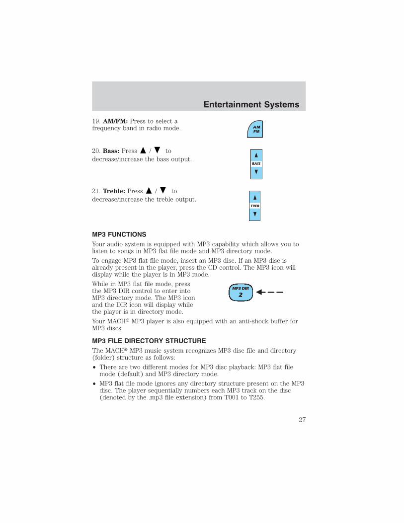
19. AM/FM: Press to select afrequency band in radio mode.
20. Bass: Press / todecrease/increase the bass output.
21. Treble: Press / todecrease/increase the treble output.
MP3 FUNCTIONSYour audio system is equipped with MP3 capability which allows you tolisten to songs in MP3 flat file mode and MP3 directory mode.
To engage MP3 flat file mode, insert an MP3 disc. If an MP3 disc isalready present in the player, press the CD control. The MP3 icon willdisplay while the player is in MP3 mode.
While in MP3 flat file mode, pressthe MP3 DIR control to enter intoMP3 directory mode. The MP3 iconand the DIR icon will display whilethe player is in directory mode.
Your MACH� MP3 player is also equipped with an anti-shock buffer forMP3 discs.
MP3 FILE DIRECTORY STRUCTUREThe MACH� MP3 music system recognizes MP3 disc file and directory(folder) structure as follows:
• There are two different modes for MP3 disc playback: MP3 flat filemode (default) and MP3 directory mode.
• MP3 flat file mode ignores any directory structure present on the MP3disc. The player sequentially numbers each MP3 track on the disc(denoted by the .mp3 file extension) from T001 to T255.
Entertainment Systems
27
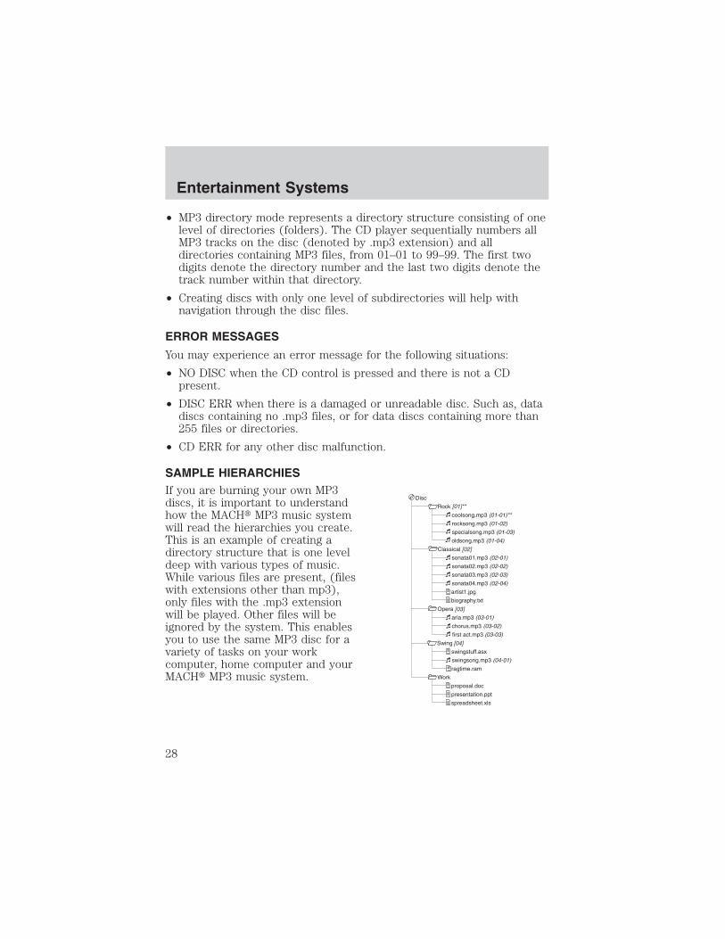
• MP3 directory mode represents a directory structure consisting of onelevel of directories (folders). The CD player sequentially numbers allMP3 tracks on the disc (denoted by .mp3 extension) and alldirectories containing MP3 files, from 01–01 to 99–99. The first twodigits denote the directory number and the last two digits denote thetrack number within that directory.
• Creating discs with only one level of subdirectories will help withnavigation through the disc files.
ERROR MESSAGES
You may experience an error message for the following situations:
• NO DISC when the CD control is pressed and there is not a CDpresent.
• DISC ERR when there is a damaged or unreadable disc. Such as, datadiscs containing no .mp3 files, or for data discs containing more than255 files or directories.
• CD ERR for any other disc malfunction.
SAMPLE HIERARCHIESIf you are burning your own MP3discs, it is important to understandhow the MACH� MP3 music systemwill read the hierarchies you create.This is an example of creating adirectory structure that is one leveldeep with various types of music.While various files are present, (fileswith extensions other than mp3),only files with the .mp3 extensionwill be played. Other files will beignored by the system. This enablesyou to use the same MP3 disc for avariety of tasks on your workcomputer, home computer and yourMACH� MP3 music system.
Entertainment Systems
28
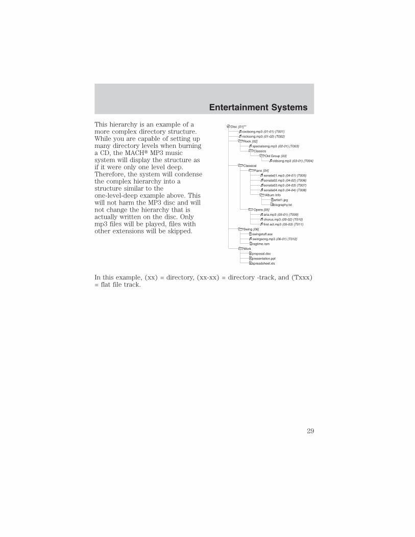
This hierarchy is an example of amore complex directory structure.While you are capable of setting upmany directory levels when burninga CD, the MACH� MP3 musicsystem will display the structure asif it were only one level deep.Therefore, the system will condensethe complex hierarchy into astructure similar to theone-level-deep example above. Thiswill not harm the MP3 disc and willnot change the hierarchy that isactually written on the disc. Onlymp3 files will be played, files withother extensions will be skipped.
In this example, (xx) = directory, (xx-xx) = directory -track, and (Txxx)= flat file track.
Disc [01]**
coolsong.mp3 (01-01) {T001}
rocksong.mp3 (01-02) {T002}
Rock [02]
specialsong.mp3 (02-01) {T003}
Classics
Old Group [03]
oldsong.mp3 (03-01) {T004}
Classical
Piano [04]
sonata01.mp3 (04-01) {T005}
sonata02.mp3 (04-02) {T006}
sonata03.mp3 (04-03) {T007}
sonata04.mp3 (04-04) {T008}
Album Info
artist1.jpg
biography.txt
Opera [05]
aria.mp3 (05-01) {T009}
chorus.mp3 (05-02) {T010}
first act.mp3 (05-03) {T011}
Swing [06]
swingstuff.asx
swingsong.mp3 (06-01) {T012}
ragtime.ram
Work
proposal.doc
presentation.ppt
spreadsheet.xls
Entertainment Systems
29

PREMIUM AM/FM STEREO/CASSETTE/SINGLE CD
1. Power/volume: Press to turnON/OFF; turn to increase/decreasevolume.
2. Scan: Press to hear a briefsampling of all listenable stations,tape selections or CD tracks. Pressagain to stop.
3. CD Door: Insert a CD with thelabel side up.
CD unit are designed to playcommercially pressed 12 cm(4.75 in) audio compact discs only. Due to technicalincompatibility, certain recordable and re-recordable compactdiscs may not function correctly when used in Ford CD players.Irregular shaped CDs, CDs with a scratch protection filmattached, and CDs with homemade paper (adhesive) labels should
SCAN
Entertainment Systems
30

not be inserted into the CD player. The label may peel and causethe CD to become jammed. It is recommended that homemadeCDs be identified with permanent felt tip marker rather thanadhesive labels. Ball point pens may damage CDs. Please contactyour dealer for further information.
4. Cassette door: Insert thecassette with the opening to theright.
5. Eject: Press to eject thecassette/CD. The radio will resumeplaying.
6. Tape: Press to start tape play.Press to stop tape duringrewind/fast forward.
CD: Press to start CD play. With thedual media audio, press CD totoggle between single CD and CDchanger play (if equipped).
7. Mute: Press to MUTE playingmedia; press again return to playingmedia.
8. Auto: Press to set first sixstrongest stations (if available) intoAM, FM1 or FM2 memory buttons;press again to return to normalstations.
9. Clock: Press and hold to set theclock. Press the SEEK todecrease hours or SEEK toincrease hours. Press the TUNE
Entertainment Systems
31

to decrease minutes or TUNE to increase minutes. If your vehiclehas a stand alone clock this control will not function.
10. Balance: Press BAL; then pressSEL / to shift sound to theleft/right speakers.
Fade: Press FADE; then pressSEL / to shift sound to therear/front speakers.
11. Memory preset buttons: Toset a station: Select frequency bandAM/FM, tune to a station, press andhold a preset button until sound returns.
12. Shuffle (CD): Press to playtracks in random order.
13. Compression (CD): Press tobring soft and loud passagestogether for a more consistentlistening level.
14. Dolby� noise reduction:
Works in tape mode only. Reducestape noise and hiss; press toactivate/deactivate.
The Dolby� noise reduction system is manufactured under license fromDolby Laboratories Licensing Corporation. Dolby� and the double-Dsymbol are registered trademarks of Dolby Laboratories LicensingCorporation.
15. Side 1–2: Works in tape modeonly. Press to play reverse side ofthe tape.
Entertainment Systems
32

16. Fast Forward (FF): Press fora slow advance, press and hold for afast advance.
17. Rewind (REW): Press for aslow rewind, press and hold for afast rewind.
18. Select (SEL): Use with Bass,Treble, Balance and Fade controls.
19. Bass: Press BASS; then pressSEL / to decrease/increasethe bass output.
Treble: Press TREB; then pressSEL / to decrease/increasethe treble output.
20. Tune: Works in radio mode only.Press TUNE / to changefrequency down/up.
21. Seek: Press and releaseSEEK / for previous/nextstrong station, selection or track.
22. AM/FM: Press to selectAM/FM1/FM2 frequency band.
FF
2
REW
1
SEL
SEEK
TUNE
SEEK
TUNE
Entertainment Systems
33

TREMOR AUDIO SYSTEM
1. MUTE: Press to mute the playingmedia. Press again to return to theplaying media.
2. TAPE: Insert the cassette withthe opening to the right. If a tape isalready inserted into the system,press TAPE to being tape play.
3. CD: Insert a CD label side up. If aCD is already inserted, press CD tobegin CD play.
TAPE
CD
Entertainment Systems
34

4. TUNE: Works in radio mode.Press to move down or upthe frequency band.
5. SEEK: Turn to listen to theprevious (left) or next (right) radiostation, cassette selection, or CDtrack.
SCAN: Press to hear a shortsampling of all listenable radiostations, cassette selections or CD tracks. Press again to stop and remainon a desired selection.
6. EJ (Eject): Press to eject a tape.
7. BAL (Balance): Press BAL, thenpress SEL( Select) control to adjustthe sound between the left orright speakers.
FADE: Press FADE, and then press SEL (Select) to adjust the soundbetween the front and rear speakers.
8. COMP (Compression): Press tobring soft and loud passagestogether for a more consistentlistening level.
SHUF (Shuffle): Works in CD mode only. Press to randomly play alltracks on the current disc. Press again to disengage random play.
9. (Dolby� noise reduction):
Works in tape mode only. Reducestape noise and hiss; press toactivate/deactivate.
Side 1–2: Works in tape mode only. Press to change the playing side ofthe tape.
10. SEL (Select): Allows you toadjust various settings such as basslevels, RDS information, the time,etc.
TUNE
BAL FADE
SHUFCOMP5 6
SIDE 1-23 4
SEL
Entertainment Systems
35

11. REW (rewind)/FF (fastforward): Press to play previous orthe next cassette selections or CDtracks.
12. BASS: Press BASS and thenpress SEL to decrease orincrease the bass levels.
TREB (treble): Press TREB and then press SEL to decrease orincrease the treble levels.
13. ON/Off/VOL (Volume): Pressto turn the system ON. Turn toadjust the volume levels. Press againto turn the system off.
14. AUTO: Press to set first sixstrong stations into AM, FM1 orFM2 memory controls; press againto return to normal stations.
RDS: Press to engage Radio Data System and select:
• TRAFFIC — Interrupts playing media to play a traffic report. Toactivate, press SCAN or SEEK when TRAFFIC ON is displayed.
• FIND program type — Press SEL to choose the desired program type:Classic, Country, Info., Jazz/R&B, Religious, Rock, Soft or Top 40.
• SHOW — Displays station name, station type and/or radio text. PressRDS until SHOW is displayed.
CLK (Clock): Press RDS until SET HOURS is displayed. Press SEL todecrease or increase the hours.Press RDS again until SET MIN is displayed. Press SEL to decreaseor increase the minutes. If your vehicle has a stand alone clock thiscontrol will not function.
REW FF1 2
BASS TREB
VOLPUSH
ON
AUTO RDSCLK
Entertainment Systems
36

15. AM/FM: Press to select AM orFM frequency bands. Press to endtape or CD play and begin radioplay.
16. EJ (Eject): Press to eject a CD.
RADIO FREQUENCIESAM and FM frequencies are established by the Federal CommunicationsCommission (FCC) and the Canadian Radio and TelecommunicationsCommission (CRTC). Those frequencies are:
AM - 530, 540–1700, 1710 kHz
FM- 87.7, 87.9–107.7, 107.9 MHz
RADIO RECEPTION FACTORSThere are three factors that can affect radio reception:
• Distance/strength: The further you travel from an FM station, theweaker the signal and the weaker the reception.
• Terrain: Hills, mountains, tall buildings, power lines, electric fences,traffic lights and thunderstorms can interfere with your reception.
• Station overload: When you pass a broadcast tower, a stronger signalmay overtake a weaker one and play while the weak station frequencyis displayed.
CASSETTE/PLAYER CAREDo:
• Use only cassettes that are 90 minutes long or less.
• Tighten very loose tapes by inserting a finger or pencil into the holeand turning the hub.
• Remove loose labels before inserting tapes.
• Allow tapes which have been subjected to extreme heat, humidity orcold to reach a moderate temperature before playing.
• Clean the cassette player head with a cassette cleaning cartridge after10–12 hours of play to maintain good sound/operation.
AM
FM
Entertainment Systems
37

Don’t:
• Expose tapes to direct sunlight, extreme humidity, heat or cold.
• Leave tapes in the cassette player for a long time when not beingplayed.
CD/CD PLAYER CAREDo:
• Handle discs by their edges only. Never touch the playing surface.
• Inspect discs before playing. Clean only with an approved CD cleanerand wipe from the center out.
Don’t:
• Expose discs to direct sunlight or heat sources for extended periodsof time.
• Insert more than one disc into each slot of the CD changer magazine.
• Clean using a circular motion.
CD units are designed to play commercially pressed 12 cm (4.75in) audio compact discs only. Due to technical incompatibility,certain recordable and re-recordable compact discs may notfunction correctly when used in Ford CD players. Irregularshaped CDs, CDs with a scratch protection film attached, and CDswith homemade paper (adhesive) labels should not be insertedinto the CD player. The label may peel and cause the CD tobecome jammed. It is recommended that homemade CDs beidentified with permanent felt tip marker rather than adhesivelabels. Ball point pens may damage CDs. Please contact yourdealer for further information.
AUDIO SYSTEM WARRANTY AND SERVICERefer to the Warranty Guide for audio system warranty information. Ifservice is necessary, see your dealer or qualified technician.
Entertainment Systems
38

HEATER ONLY SYSTEM(IF EQUIPPED)1. Fan speed adjustment: Controlsthe volume of air circulated in thevehicle.
2. Temperature selection:Controls the temperature of theairflow in the vehicle.
3. Air flow selections: Controls the direction of the airflow in thevehicle. See the following for a brief description on each control.
: Distributes outside air through the instrument panel vents.
OFF: Outside air is shut out and the fan will not operate.
: Distributes outside air through the instrument panel vents and thefloor vents.
: Distributes outside air through the floor vents.
: Distributes outside air through the windshield defroster vents andfloor vents.
: Distributes outside air through the windshield defroster vents.
OPERATING TIPS• To reduce fog build up on the windshield during humid weather, place
the air flow selector in the position.
• To reduce humidity build up inside the vehicle during cold or warmweather, do not drive with the air flow selector in the OFF position.
• Under normal weather conditions, do not leave the air flow selector inOFF when the vehicle is parked. This allows the vehicle to “breathe”using the outside air inlet vents.
• Do not put objects under the front seats that will interfere with the airflow to the back seats.
• Remove any snow, ice or leaves from the air intake area at the base ofthe windshield.
Climate Controls
Climate Controls
39

To aid in side window defogging/demisting in cold weather:
1. Select
2. Set the temperature control to full heat
3. Set the fan speed to HI
4. Direct the outer instrument panel vents towards the side windows
To increase airflow to the outer instrument panel vents, close the ventslocated in the middle of the instrument panel.
Do not place objects on top of the instrument panel as theseobjects may become projectiles in a collision or sudden stop.
MANUAL HEATING AND AIRCONDITIONING SYSTEM1. Fan speed adjustment: Controlsthe volume of air circulated in thevehicle.
2. Temperature selection:Controls the temperature of theairflow in the vehicle.
3. Air flow selections: Controls the direction of the airflow in thevehicle. See the following for a brief description on each control.
MAX A/C: Uses recirculated air to cool the vehicle. Air flows from theinstrument panel vents only.
A/C: Uses outside air to cool the vehicle. Air flows from the instrumentpanel vents only.
: Distributes outside air through the instrument panel vents.
OFF: Outside air is shut out and the fan will not operate.
: Distributes outside air through the instrument panel vents and thefloor vents.
: Distributes outside air through the floor vents.
: Distributes outside air through the windshield defroster vents andfloor vents.
: Distributes outside air through the windshield defroster vents.
Climate Controls
40

OPERATING TIPS• To reduce fog build up on the windshield during humid weather, place
the air flow selector in the position.
• To reduce humidity build up inside the vehicle: do not drive with theair flow selector in the OFF or MAX A/C position.
• Under normal weather conditions, do not leave the air flow selector inMAX A/C or OFF when the vehicle is parked. This allows the vehicleto “breathe” using the outside air inlet vents.
• Do not put objects under the front seats that will interfere with theairflow to the back seats.
• Remove any snow, ice or leaves from the air intake area at the base ofthe windshield.
To aid in side window defogging/demisting in cold weather:
1. Select
2. Select A/C
3. Modulate the temperature control to maintain comfort.
4. Set the fan speed to HI
5. Direct the outer instrument panel vents towards the side windows
To increase airflow to the outer instrument panel vents, close the ventslocated in the middle of the instrument panel.
Do not place objects on top of the instrument panel as theseobjects may become projectiles in a collision or sudden stop.
Climate Controls
41

HEADLAMP CONTROL
Turns the lamps off.
Turns on the parkinglamps, instrument panel lamps,license plate lamps and tail lamps.
Turns the headlamps on.
Foglamp control (if equipped)
The foglamps can be turned onwhen the headlamp control is ineither of the following positions:
• Parking lamps
• Low beams
Press the foglamp control to activate the foglamps.
Press the foglamp control again to deactivate the foglamps.
When the highbeams are activated, the foglamps will not operate.
Daytime running lamps (DRL) (if equipped)
Turns the headlamps on with a reduced output.
To activate:
• the ignition must be in the ON position and
• the headlamp control is in the OFF, parking lamp or autolampposition.
Always remember to turn on your headlamps at dusk or duringinclement weather. The Daytime Running Lamp (DRL) system
does not activate with your tail lamps and generally may not provideadequate lighting during these conditions. Failure to activate yourheadlamps under these conditions may result in a collision.
OFF
Lights
Lights
42

High beams
Push the lever toward theinstrument panel to activate. Pullthe lever towards you to deactivate.
Flash to passPull toward you slightly to activateand release to deactivate.
PANEL DIMMER CONTROL
Use to adjust the brightness of theinstrument panel and all applicableswitches in the vehicle duringheadlamp and parklamp operation.
Move the control up or down toadjust the intensity of the panellighting.
Move the control to the full uprightposition, past detent, to turn on the interior lamps.AIMING THE HEADLAMPSThe headlamps on your vehicle are properly aimed before leaving theassembly plant. If your vehicle is involved in an accident or if you haveproblems fixing the alignment of your headlamps, have them checked bya qualified service technician.Headlamp aim adjustmentThe headlamps on your vehicle can only be vertically adjusted. Yourvehicle does not require horizontal aim adjustments.
DIM
Lights
43

To adjust the headlamps:
1. Park your vehicle on a levelsurface about 7.6 meters (25 feet)away from a vertical plain surface(3). Check your headlamp alignmentat night or in a dark area so thatyou can see the headlamp beampattern.
• (1) Eight feet
• (2) Center height of lamp toground
• (3) Twenty-five feet
• (4) Horizontal reference line
2. The center of the headlamp has a 3.0 mm circle on the lens. Measurethe height from the center of your headlamp to the ground (2) and marka 2.4 meter (8 foot) long horizontal line on the plain surface (1) at thisheight (masking tape works well).
3. Turn on the low beam headlamps.The brightest part of the lightshould be below the horizontal line(4). If it is above the line theheadlamp will need to be adjusted.
4. Open the hood.
5. Locate the vertical adjuster foreach headlamp. Adjust the aim byturning the adjuster control eitherclockwise (to adjust down) orcounterclockwise (to adjust up).
Note: Use a 4 mm socket or boxwrench to turn the vertical adjustercontrol.
6. Horizontal aiming is not requiredfor this vehicle and isnon-adjustable.
Lights
44

TURN SIGNAL CONTROL
• Push down to activate the leftturn signal.
• Push up to activate the right turnsignal.
INTERIOR LAMPS
DOME LAMPThe courtesy lamp lights when:
• any door is opened.
• the instrument panel dimmerswitch is held up until thecourtesy lamps come on.
• the remote entry controls arepressed and the ignition is OFF.
BULBS
Replacing exterior bulbs
Check the operation of all the bulbs frequently.
Using the right bulbs
Replacement bulbs are specified in the chart below. Headlamp bulbsmust be marked with an authorized “D.O.T.” for North America and an“E” for Europe to assure lamp performance, light brightness and patternand safe visibility. The correct bulbs will not damage the lamp assemblyor void the lamp assembly warranty and will provide quality bulb burntime.
Lights
45
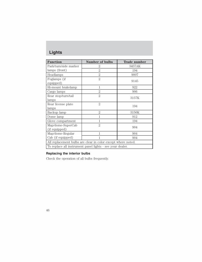
Function Number of bulbs Trade number
Park/turn/side markerlamps (front)
2 3457AK2 194
Headlamps 2 9007Foglamps (ifequipped)
29145
Hi-mount brakelamp 1 922Cargo lamps 2 906Rear stop/turn/taillamps
23157K
Rear license platelamps
2194
Backup lamp 2 3156KDome lamp 1 912Glove compartment 1 194Map/dome-SuperCab(if equipped)
2904
Map/dome-RegularCab (if equipped)
1 9041 904
All replacement bulbs are clear in color except where noted.To replace all instrument panel lights - see your dealer.
Replacing the interior bulbs
Check the operation of all bulbs frequently.
Lights
46

Replacing headlamp bulbsTo remove the headlamp bulb:
1. Turn the headlamp switch is inthe OFF position, then open thehood.
2. Remove two screws and cover(if equipped).
3. At the back of the headlamp, pryup the two retainer pins to releasethe headlamp assembly from thevehicle and pull headlamp forward.
4. Disconnect the electricalconnector from the bulb by pullingrearward.
5. Remove the bulb retaining ring byrotating it counterclockwise andslide the ring off the plastic base.
6. Remove the old bulb by pulling itstraight out of the lamp.
Handle a halogen headlamp bulb carefully and keep out ofchildren’s reach. Grasp the bulb only by its plastic base and do
not touch the glass. The oil from your hand could cause the bulb tobreak the next time the headlamps are operated.
Install the new bulb(s) in reverse order.
Lights
47

Replacing front side marker bulbs1. Turn the headlamp switch to theOFF position and then open thehood.
2. Remove two screws and cover(if equipped).
3. At the back of the headlamp, pryup the two retainer pins to releasethe headlamp assembly from thevehicle and pull headlamp forward.
4. Remove screw(s) from lampassembly and disengage lampassembly (it has a snap fit).
5. Rotate bulb socketcounterclockwise and remove fromlamp assembly.
6. Carefully pull bulb straight out ofsocket and push in the new bulb.
7. Install the bulb socket in lampassembly by turning clockwise.
Install the new lamp in reverse order.
Lights
48
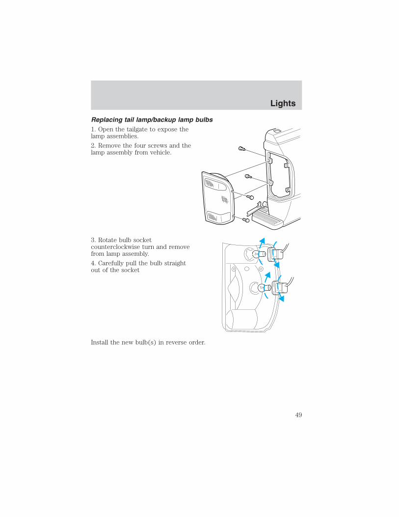
Replacing tail lamp/backup lamp bulbs1. Open the tailgate to expose thelamp assemblies.
2. Remove the four screws and thelamp assembly from vehicle.
3. Rotate bulb socketcounterclockwise turn and removefrom lamp assembly.
4. Carefully pull the bulb straightout of the socket
Install the new bulb(s) in reverse order.
Lights
49

Replacing foglamp bulbs (if equipped)1. Remove the bulb socket from thefoglamp by turningcounterclockwise.
2. Disconnect the electricalconnector.
Install the new bulb in reverse order.
Replacing high-mount brakelamp and cargo lamp bulbs1. Remove the two screws and lampassembly from vehicle.
2. Remove the bulb socket fromlamp assembly by rotating itcounterclockwise.
3. Carefully pull bulb straight out ofsocket.
Install the new bulb(s) in reverse order.
Replacing license plate lamp bulbs1. Reach behind the rear bumper tolocate the bulb socket.
2. Twist the socket counterclockwiseand remove.
3. Carefully pull the bulb straightout of the socket.
Install the new bulb(s) in reverse order.
Lights
50

MULTI-FUNCTION LEVERWindshield wiper: Rotate the endof the control away from you toincrease the speed of the wipers(from desired interval to low or highspeed position); rotate towards youto decrease the speed of the wipers.
Windshield washer: Push the endof the stalk:
• briefly: causes a single swipe ofthe wipers without washer fluid.
• a quick push and hold: the wiperswill swipe three times withwasher fluid.
• a long push and hold: the wipers and washer fluid will be activated forup to ten seconds.
Changing the wiper blades1. Pull the wiper arm away from thevehicle. Turn the blade at an anglefrom the wiper arm. Push the lockpin manually to release the bladeand pull the wiper blade downtoward the windshield to remove itfrom the arm.
2. Attach the new wiper to thewiper arm and press it into placeuntil a click is heard.
3. Replace wiper blades every 6 months for optimum performance.
Driver Controls
Driver Controls
51

TILT STEERING WHEEL (IF EQUIPPED)To adjust the steering wheel:
1. Pull and hold the steering wheelrelease control toward you.
2. Move the steering wheel up ordown until you find the desiredlocation.
3. Release the steering wheelrelease control. This will lock thesteering wheel in position.
Never adjust the steering wheel when the vehicle is moving.
AUXILIARY POWER POINT
Power outlets are designed foraccessory plugs only. Do nothang any type of accessory oraccessory bracket from the plug.Improper use of the poweroutlet can cause damage notcovered by your warranty.
The auxiliary power point is locatedon the instrument panel. Do notplug optional electrical accessoriesinto the cigarette lighter. Use thepower point.
Do not use the power point for operating the cigarette lighter element.
The Maximum power each power point can supply depends on the fuserating. For example: a 20A fuse should supply a maximum of 240 Watts,a 15A fuse should supply a maximum of 180 Watts and a 10A fuse shouldsupply a maximum of 120 Watts. Exceeding these limits will result in ablown fuse. Refer to Passenger Compartment Fuse Panel in theRoadside Emergencies chapter for fuse ratings in your vehicle.
Always keep the power point caps closed when not being used.
Driver Controls
52

POWER WINDOWS (IF EQUIPPED)
When closing the powerwindows, you should verify
they are free of obstructions andensure that children and/or petsare not in the proximity of thewindow openings.
Press and hold the bottom part of the rocker switch to open the window.Press and hold the top part of the rocker switch to close the window.
One touch downAllows the driver’s window to openfully without holding the controldown. Press completely down onAUTO and release quickly. Pressagain to stop.
POWER SIDE VIEW MIRRORS (IF EQUIPPED)
To adjust your mirrors:
1. Select to adjust the leftmirror or to adjust the rightmirror.
2. Move the control in the directionyou wish to tilt the mirror.
3. Return to the center position tolock mirrors in place.
Driver Controls
53

SPEED CONTROL (IF EQUIPPED)With speed control set, you canmaintain a speed of 48 km/h (30mph) or more without keeping yourfoot on the accelerator pedal. Speedcontrol does not work at speedsbelow 48 km/h (30 mph).
Do not use the speedcontrol in heavy traffic or
on roads that are winding, slipperyor unpaved.
Setting speed control
The controls for using your speedcontrol are located on the steeringwheel for your convenience.
1. Press the ON control and releaseit.
2. Accelerate to the desired speed.
3. Press the SET ACCEL controland release it.
4. Take your foot off the acceleratorpedal.
5. The indicator light SPEEDCONT on the
instrument cluster will turn on.
Note:
• Vehicle speed may vary momentarily when driving up and down asteep hill.
• If the vehicle speed increases above the set speed on a downhill, youmay want to apply the brakes to reduce the speed.
Driver Controls
54

• If the vehicle speed decreases more than 16 km/h (10 mph) belowyour set speed on an uphill, your speed control will disengage.
• If the vehicle speed decreases to 40 km/h (25 mph) or less, yourspeed control will disengage
Disengaging speed control
To disengage the speed control:
• Depress the brake pedal or
• Depress the clutch pedal (if equipped).
Disengaging the speed control will not erase previous set speed.
Note: When you use the clutch pedal to disengage the speed control,the engine speed may briefly increase, this is normal.
Resuming a set speedPress the RSM (resume) control andrelease it. This will automaticallyreturn the vehicle to the previouslyset speed. The RSM control will notwork if the vehicle speed is notfaster than 48 km/h (30 mph).
Increasing speed while using speed controlThere are three ways to set a higherspeed:
• Press and hold the SET ACCELcontrol until you get to thedesired speed, then release thecontrol.
• Press and release the SETACCEL control to operate theTap-Up function. Each tap will increase the set speed by 1.6 km/h(1 mph).
• Use the accelerator pedal to get to the desired speed. When thevehicle reaches that speed press and release the SET ACCEL control.
Driver Controls
55

Reducing speed while using speed controlThere are three ways to reduce aset speed:
• Press and hold the COASTcontrol until you get to thedesired speed, then release thecontrol.
• Press and release the COASTcontrol to operate the Tap-Downfunction. Each tap will decrease the set speed by 1.6 km/h (1 mph).
• Depress the brake pedal or theclutch pedal (if equipped) untilthe desired vehicle speed isreached, press the SET ACCELcontrol.
Turning off speed controlThere are two ways to turn off thespeed control:
• Press the speed control OFFcontrol.
• Turn OFF the ignition.
Note: When you turn off the speedcontrol or the ignition, your speedcontrol set speed memory is erased.
Driver Controls
56

CENTER CONSOLE (IF EQUIPPED)Your vehicle may be equipped with avariety of console features. Theseinclude:
• Utility compartment withcassette/compact disc storage
• Cupholders
• Coin holder slots
• Flip up armrest
Use only soft cups in the cupholder. Hard objects can injure youin a collision.
Cell phone useThe use of Mobile Communications Equipment has become increasinglyimportant in the conduct of business and personal affairs. However,drivers must not compromise their own or others’ safety when usingsuch equipment. Mobile Communications can enhance personal safetyand security when appropriately used, particularly in emergencysituations. Safety must be paramount when using mobile communicationsequipment to avoid negating these benefits.Mobile Communication Equipment includes, but is not limited to cellularphones, pagers, portable email devices, in vehicle communicationssystems, telematics devices and portable two-way radios.
A driver’s first responsibility is the safe operation of the vehicle.The most important thing you can do to prevent a crash is to
avoid distractions and pay attention to the road. Wait until it is safe tooperate Mobile Communications Equipment.
CARGO AREA FEATURES
Cargo area shade (if equipped)Your vehicle may be equipped with notches in the side trim panels thatare used for a cargo area shade. See your dealer for more information.
Driver Controls
57

BEDRAILS (IF EQUIPPED)
• This bedrail is for appearance use only.
• To help prevent injury, do not use bedrail to retain cargo.
• Retain cargo with the pickup tie down hooks.
BED EXTENDER (IF EQUIPPED)
Your vehicle may be equipped with a bed extender designed to extendthe pickup box for longer loads.
To extend the bed extender:
1. Lower tailgate.
2. Pull the round knobs on each sideof the extender to release it fromthe pickup box.
3. Pivot extender on to the tailgate.
4. Evenly push down on theextender and push the round knobsin on each side locking it in place.
Green markings on the shaftindicate the locked position. Thelocking clip screws below the middlebar can be tightenedcounterclockwise for extra security.
Note: If the red marking on theshaft is visible, the bed extenderis not locked or properly secured.
To stow the bed extender, follow steps one through four in reverse order.
The bed extender may be used to secure a load of up to 46 kg (100 lbs.)on the tailgate.
The bed extender should always be kept in the stowed positionwith the tailgate closed when not in use.
When driving the vehicle off road, the bed extender should beremoved and the tailgate closed.
Driver Controls
58

To remove the bed extender:
1. Extend the bed extender.
2. Pull the round knobs on each sideof the extender to unlock it.
Make sure the locking clip screwsare loose before removing theextender.
3. Press the locking clips below themiddle bar on each side and lift theextender out of the bed.
To install the bed extender, follow the removal procedure in reverseorder.
TONNEAU COVER (IF EQUIPPED)
The tonneau cover has been designed to maximize fuel economy andshould be fully installed whenever possible.
The rear panel can be folded in half and secured behind the cab, or thewhole cover can be removed completely from the vehicle.
To avoid damage to the cover, do not operate the vehicle unlessthe cover is fully installed, or securely stowed.
To open the front panel:
• Open the lock cover and unlockthe front or rear panel.
• Lift the panel to access items inthe pickup box.
The panels will automaticallylock when lowered onto thepickup box.
• To close, lower the front or rearpanel down on the pickup box.
Driver Controls
59

Do not drive with front panelunlocked or folded on top of therear panel.
To stow the rear panel:
• Before driving with the tonneaucover open, stow the rear panel.
• Disconnect the hydrauliccylinders from the ball stud onthe pickup box and secure themin the clips on the tonneau cover.
• Lift the rear panel up, lay it ontop of the front panel and secureit to the hooks on the front panelwith the tiedown cords.
Failure to secure the rear panelcould damage the tonneau coveror vehicle.
Driver Controls
60

The cargo divider is designed todivide your pickup box in half orrotate 90° to allow you full use ofthe pickup box.
To rotate the cargo divider 90°:
• Open front panel.
• Pull the lower release lever outon each side of the cargo dividerto unlatch from the pickup box.
• Rotate the divider 90° parallelwith the tonneau cover andsecure it to the pickup box withthe lower release levers.
To rotate the cargo divider back,follow the procedure in reverse order.
To remove the cargo divider:
• Open the front panel.
• Pull two release levers out oneach side of the cargo dividerfrom the pickup box and remove.
For installation of the cargo divider,follow the removal procedure inreverse order.
Driver Controls
61

To remove the tonneau cover:
The tonneau cover needs to besupported during removal. This is atwo person operation.
• Remove the cargo divider, referto To remove the cargo divideron the previous page.
• Disconnect the hydrauliccylinders from the pickup boxand secure them in the clips onthe tonneau cover. Close the front panel.
• Open and support the front panel.
• Stow the rear panel on top of the front panel, refer to To stow therear panel shown previously.
• Pull two release levers on the underside of the tonneau cover from thepickup box and remove the tonneau cover.
For installation of the tonneau cover, reverse the removal procedure.
Driver Controls
62

KEYS
The key operates all locks on your vehicle. In case of loss, replacementkeys are available from your dealer.
You should always carry a second key with you in a safe place in caseyou require it in an emergency.
Refer to SecuriLock� Passive Anti-Theft System for more information.
POWER DOOR LOCKS (IF EQUIPPED)If the door does not unlock whenthe top of the control is pressed,see Interior power door unlockdisable feature in the Remote entrysection in this chapter.
Press the top of the control tounlock all doors and the bottom tolock all doors.
INTERIOR TONNEAU COVER RELEASE (IF EQUIPPED)
Your vehicle is equipped with a mechanical interior tonneau coverrelease handle that provides a means of escape for children and adults inthe event they become locked inside the pickup box.
Adults are advised to familiarize themselves with the operation andlocation of the release handle.
UNLOCK
LOCK
Locks and Security
Locks and Security
63
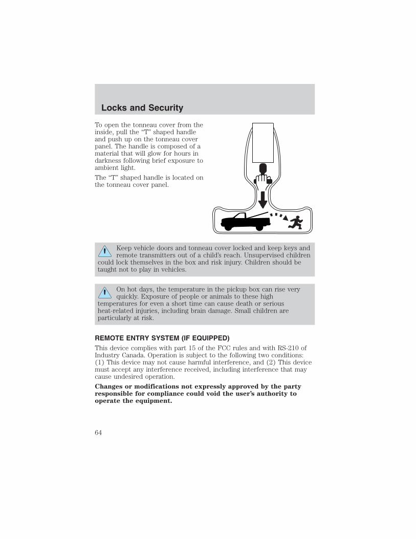
To open the tonneau cover from theinside, pull the “T” shaped handleand push up on the tonneau coverpanel. The handle is composed of amaterial that will glow for hours indarkness following brief exposure toambient light.
The “T” shaped handle is located onthe tonneau cover panel.
Keep vehicle doors and tonneau cover locked and keep keys andremote transmitters out of a child’s reach. Unsupervised children
could lock themselves in the box and risk injury. Children should betaught not to play in vehicles.
On hot days, the temperature in the pickup box can rise veryquickly. Exposure of people or animals to these high
temperatures for even a short time can cause death or seriousheat-related injuries, including brain damage. Small children areparticularly at risk.
REMOTE ENTRY SYSTEM (IF EQUIPPED)This device complies with part 15 of the FCC rules and with RS-210 ofIndustry Canada. Operation is subject to the following two conditions:(1) This device may not cause harmful interference, and (2) This devicemust accept any interference received, including interference that maycause undesired operation.
Changes or modifications not expressly approved by the partyresponsible for compliance could void the user’s authority tooperate the equipment.
Locks and Security
64

Your vehicle is equipped with a remote entry system which allows you to:
• unlock the vehicle doors withouta key.
• lock all the vehicle doors withouta key.
• activate the personal alarm.
If there is any potential remote keyless entry problem with your vehicle,ensure ALL remote entry transmitters are taken to the dealership, toaid in troubleshooting.
Unlocking the doors
1. Press and release to unlock the driver’s door. Note: The interiorlamps will illuminate.
2. Press and release again within three seconds to unlock all thedoors.
Locking the doors
1. Press and release to lock all the doors.
2. Press and release again within three seconds to confirm that all thedoors are closed and locked. Note: the doors will lock again, the hornwill chirp once, and the lamps will flash.
If any of the doors are not properly closed the horn will make two quickchirps and the lamps will not flash.
Locks and Security
65

Power door unlock disabledThe UNLOCK feature on your powerdoor locks will not work from insidethe vehicle when:
• the ignition has been turned to the OFF position, and• 20 seconds elapse after all vehicle doors are closed and locked using
the remote entry transmitter, or the power door unlock control (whilethe accompanying door is open).
The UNLOCK feature will work again after:• a door has become ajar,• the ignition is turned to the ON position, or
• using the UNLOCK control on your remote entry transmitter, or
• using the keyless entry keypad to unlock the vehicle.
Deactivating/activating power door lock disable featureThis feature can be activated and deactivated by an authorized dealer.
Sounding a panic alarmPress to activate the alarm. The horn will sound for a maximum of30 seconds and the parklamps will flash for a maximum of 3 minutes.Press again or turn the ignition to ON to deactivate, or wait for the alarmto timeout in 3 minutes.
Note: The panic alarm will only operate when the ignition is in the OFFor ACC position.
Replacing the batteryThe remote entry transmitter uses one coin type three-volt lithiumbattery CR2032 or equivalent. The typical operating range for yourremote entry transmitter is approximately 10 meters (33 feet). Adecrease in the operating range could be caused by:
• weather conditions,
• nearby radio towers,
UNLOCK
LOCK
Locks and Security
66

• structures around the vehicle and• other vehicles parked next to the vehicle.
To replace the battery:
1. Twist a thin coin between the twohalves of the remote entrytransmitter near the key ring. DONOT TAKE THE FRONT PART OFTHE REMOTE ENTRYTRANSMITTER APART.
2. Remove the old battery.
3. Insert the new battery. Refer tothe diagram inside the remote entrytransmitter for the correct orientation of the battery.4. Snap the two halves back together.Note: Replacement of the battery will not cause the remote transmitterto become deprogrammed from your vehicle. The remote transmittershould operate normally after battery replacement.
Replacing lost remote entry transmittersIf you would like to have your remote entry transmitter reprogrammedbecause you lost one, or would like to buy additional remote entrytransmitters, you can either reprogram them yourself, or take allremote entry transmitters to your authorized dealer forreprogramming.How to reprogram your remote entry transmittersYou must have all remote entry transmitters (maximum of four)available before beginning this procedure.
To reprogram the remote entrytransmitters:
1. Ensure the vehicle iselectronically unlocked.
2. Put the key in the ignition.
3. Turn the key from the 2 (LOCK)position to 3 (OFF).
4. Cycle, eight times, rapidly (within10 seconds) between the 3 (OFF)position and 4 (ON). Note: Theeighth turn must end in the 4 (ON) position.
3
2
1
5
4
Locks and Security
67

5. The doors will lock, then unlock, to confirm that the programmingmode has been activated.
6. Within 20 seconds press any button on the remote entry transmitter.Note: If more than 20 seconds have passed you will need to start theprocedure over again.
7. The doors will lock, then unlock, to confirm that this remote entrytransmitter has been programmed.
8. Repeat Step 6 to program each additional remote entry transmitter.
9. Turn the ignition to the 3 (OFF) position after you have finishedprogramming all of the remote entry transmitters. Note: After 20seconds have passed, you will automatically exit the programming mode.
10. The doors will lock, then unlock, to confirm that the programmingmode has been exited.
Illuminated entryThe interior lamps illuminate when the remote entry system is used tounlock the door(s) or sound the personal alarm.
The illuminated entry system will turn off the interior lights if:
• the ignition switch is turned to the ON position, or
• the remote transmitter lock control is pressed, or
• after 25 seconds of illumination.
The dome lamp control (if equipped) must not be set to the OFFposition for the illuminated entry system to operate.
The inside lights will not turn off if:
• they have been turned on with the dimmer control, or
• any door is open.
The battery saver will shut off the interior lamps 45 minutes after thelast door is closed, even if the dimmer control is on.
SECURILOCK� PASSIVE ANTI-THEFT SYSTEMSecuriLock� passive anti-theft system is an engine immobilizationsystem. This system is designed to prevent the engine from being startedunless a coded key programmed to your vehicle is used. The use ofthe wrong type of coded key may lead to a “no-start” condition.
Your vehicle comes with two coded keys; additional coded keys may bepurchased from your dealer. The dealer can program your spare keys to
Locks and Security
68

your vehicle or you can program the keys yourself. Refer toProgramming spare keys for instructions on how to program the codedkey.
Note: The SecuriLock� passive anti-theft system is not compatible withnon-Ford aftermarket remote start systems. Use of these systems mayresult in vehicle starting problems and a loss of security protection.
Note: Large metallic objects, electronic devices that are used topurchase gasoline or similar items, or a second coded key on the samekey chain may cause vehicle starting issues. You need to prevent theseobjects from touching the coded key while starting the engine. Theseobjects will not cause damage to the coded key, but may cause amomentary issue if they are too close to the key when starting theengine. If a problem occurs, turn the ignition off, remove all objects onthe key chain away from the coded key and restart the engine.
Theft indicatorThe theft indicator is located in the instrument cluster.
• When the ignition is in the OFF position, the indicator will flash onceevery 2 seconds to indicate the SecuriLock� system is functioning asa theft deterrent.
• When the ignition is in the ON position, the indicator will glow for 3seconds, then turn off, to indicate normal system functionality.
If a problem occurs with the SecuriLock� system, the indicator will flashrapidly or glow steadily when the ignition is in the ON position. If thisoccurs, the vehicle should be taken to an authorized dealer for service.
Automatic armingThe vehicle is armed immediatelyafter switching the ignition to the 3(OFF) position.
The THEFT indicator will flashevery two seconds when the vehicleis armed.
3
2
1
5
4
Locks and Security
69

Automatic disarming
Switching the ignition to the 4 (ON) position with a coded key disarmsthe vehicle.
• The THEFT indicator will illuminate for three seconds and then goout.
• If the THEFT indicator stays on for an extended period of time orflashes rapidly, have the system serviced by your dealer.
Replacement keys
If your keys are lost or stolen and you don’t have an extra coded key,you will need to have your vehicle towed to a dealership. The key codesneed to be erased from your vehicle and new coded keys will need to beprogrammed.
Replacing coded keys can be very costly. Store an extra programmed keyaway from the vehicle in a safe place to help prevent anyinconveniences. Please visit an authorized dealer to purchase additionalspare or replacement keys.
Programming spare keys
You can program your own coded keys to your vehicle. Please read andunderstand the entire procedure before you begin.
Tips:
• A maximum of eight keys can be coded to your vehicle.
• Only use Securilock� keys.
• You must have two previously programmed coded keys (keys thatalready operate your vehicle’s engine) and the new unprogrammedkey(s) readily accessible.
• If no previously programmed coded keys are available, you must takeyour vehicle to your dealer to have the spare key(s) programmed.
Locks and Security
70

1. Insert a previously programmedcoded key into the ignition.
2. Turn the ignition from the 3(OFF) position to the 4 (ON)position. Keep the ignition in the 4(ON) position for at least onesecond, but no more than 10seconds.
3. Turn the ignition to the 3 (OFF)position, and remove the coded keyfrom the ignition.
4. Within ten seconds of removing the previously programmed coded key,insert the other previously programmed coded key into the ignition.
5. Turn the ignition from the 3 (OFF) position to the 4 (ON) position.Keep the ignition in the 4 (ON) position for at least one second but notmore than 10 seconds.
6. Turn the ignition to the 3 (OFF) position, and remove the second keyfrom the ignition.
7. Within twenty seconds of removing the previously programmed codedkey, insert the unprogrammed key (new/valet key) into the ignition.
8. Turn the ignition from the 3 (OFF) position to the 4 (ON) position.Keep the ignition in the 4 (ON) position for at least one second.
9. Your new unprogrammed key is now programmed.
If the key has been successfully programmed it will start the vehicle’sengine and the theft indicator light will illuminate for three seconds andthen go out. If the key was not successfully programmed, it will not startyour vehicle’s engine and the theft indicator light will flash on and offrapidly. If failure repeats, bring your vehicle to your dealer to have thenew key(s) programmed.
To program additional new unprogrammed key(s), repeat this procedurefrom step 1 for each additional key.
3
2
1
5
4
Locks and Security
71

SEATING
Notes:
Reclining the seatback can cause an occupant to slide under theseat’s safety belt, resulting in severe personal injuries in the
event of a collision.
Do not pile cargo higher than the seatbacks to reduce the risk ofinjury in a collision or sudden stop.
Adjusting the front manual seat
Never adjust the driver’s seat or seatback when the vehicle ismoving.
Always drive and ride with your seatback upright and the lapbelt snug and low across the hips.
Lift handle to move seat forward orbackward.
Pull lever up to adjust seatback.
Seating and Safety Restraints
Seating and Safety Restraints
72

Using the manual lumbar support (if equipped)Turn the lumbar support controlclockwise to increase firmness.
Turn the lumbar support controlcounterclockwise to increasesoftness.
Passenger side rear access (if equipped)Pull up on the recliner handle. Theseat will lean forward and unlockthe track. Slide the seat forward toaccess the rear area of the cab.
To return seat to original position, slide the seat bottom back, then pushthe seatback up to lock it in place. If the seatback is pushed first, theseat will lock, and you will have to use the seat adjust handle to movethe seat back to the original position.
REAR SEATS
Center facing jump seat (2 door SuperCab) (if equipped)
To open, pull inboard and down on the seat handle.
To stow the seat, pull seat bottom back to the fully upright position.
Do not install a child seat in a center facing jump seat.
Seating and Safety Restraints
73

Center facing jump seat (4 door SuperCab) (if equipped)To open, pull seat assembly down,then raise seatback.
To stow the seat, fold seat backdown and raise seat assembly to thefully upright position.
Do not install a child seat ina center facing jump seat.
Booster seats must beinstalled only in seating
positions equipped with acombination lap/shoulder belt.
SAFETY RESTRAINTS
Safety restraints precautions
Always drive and ride with your seatback upright and the lapbelt snug and low across the hips.
To reduce the risk of injury, make sure children sit where theycan be properly restrained.
Never let a passenger hold a child on his or her lap while thevehicle is moving. The passenger cannot protect the child from
injury in a collision.
All occupants of the vehicle, including the driver, should alwaysproperly wear their safety belts, even when an air bag (SRS) is
provided.
Seating and Safety Restraints
74

It is extremely dangerous to ride in a cargo area, inside oroutside of a vehicle. In a collision, people riding in these areas
are more likely to be seriously injured or killed. Do not allow people toride in any area of your vehicle that is not equipped with seats andsafety belts. Be sure everyone in your vehicle is in a seat and using asafety belt properly.
In a rollover crash, an unbelted person is significantly more likelyto die than a person wearing a safety belt.
Each seating position in your vehicle has a specific safety beltassembly which is made up of one buckle and one tongue that
are designed to be used as a pair. 1) Use the shoulder belt on theoutside shoulder only. Never wear the shoulder belt under the arm. 2)Never swing the safety belt around your neck over the inside shoulder.3) Never use a single belt for more than one person.
On four-door SuperCab vehicles, do not open the rear door whenthe rear safety belt is still buckled.
Combination lap and shoulder belts1. Insert the belt tongue into theproper buckle (the buckle closest tothe direction the tongue is comingfrom) until you hear a snap and feelit latch. Make sure the tongue issecurely fastened in the buckle.
Seating and Safety Restraints
75

2. To unfasten, push the releasebutton and remove the tongue fromthe buckle.
The front outboard safety restraints in the vehicle are combination lapand shoulder belts. The front passenger outboard safety belt has twotypes of locking modes described below:
Vehicle sensitive mode
This is the normal retractor mode, which allows free shoulder belt lengthadjustment to your movements and locking in response to vehiclemovement. For example, if the driver brakes suddenly or turns a cornersharply, or the vehicle receives an impact of approximately 8 km/h (5 mph)or more, the combination safety belts will lock to help reduce forwardmovement of the driver and passengers.
Automatic locking mode
The automatic locking mode is not available on the driver safety belt.
In this mode, the shoulder belt is automatically pre-locked. The belt willstill retract to remove any slack in the shoulder belt. The automaticlocking mode is not available on the driver safety belt.
This mode should be used any time a child safety seat is installed in apassenger front seat. Refer to Safety restraints for children or Safetyseats for children later in this chapter.
Seating and Safety Restraints
76

How to use the automatic locking mode• Buckle the combination lap and
shoulder belt.
• Grasp the shoulder portion andpull downward until the entirebelt is pulled out.
• Allow the belt to retract. As the belt retracts, you will hear a clickingsound. This indicates the safety belt is now in the automatic lockingmode.
How to disengage the automatic locking mode
Disconnect the combination lap/shoulder belt and allow it to retractcompletely to disengage the automatic locking mode and activate thevehicle sensitive (emergency) locking mode.
After any vehicle collision, the seat belt system at all outboardseating positions (except driver, which has no “automatic locking
retractor” feature) must be checked by a qualified technician to verifythat the “automatic locking retractor” feature for child seats is stillfunctioning properly. In addition, all safety belts should be checked forproper function.
Seating and Safety Restraints
77

BELT AND RETRACTOR ASSEMBLY MUST BE REPLACED ifthe safety belt assembly “automatic locking retractor” feature or
any other safety belt function is not operating properly when checkedaccording to the procedures in Workshop Manual.
Failure to replace the Belt and Retractor assembly couldincrease the risk of injury in collisions.
Energy Management Feature• This vehicle has a safety belt system with an energy management
feature at the front outboard seating positions to help further reducethe risk of injury in the event of a head-on collision.
• This safety belt system has a retractor assembly that is designed topay out webbing in a controlled manner. This feature is designed tohelp reduce the belt force acting on the occupant’s chest.
Safety belt pretensionerYour vehicle is equipped with safety belt pretensioners at the driver andfront outboard passenger seating positions.
The safety belt pretensioners are designed to activate during certainfrontal or near-frontal collisions with sufficient longitudinal deceleration.A safety belt pretensioner is a device which tightens the webbing of thelap and shoulder belts in such a way that they fit more snugly againstthe body.
The driver and front outboard passenger safety belt system (includingretractors, buckle assembly, pretensioner assembly with seat and heightadjusters) must be replaced if the vehicle is involved in a collision thatresults in the activation of the safety belt pretensioners. Refer to theSafety belt maintenance section in this chapter.
Failure to replace the safety belt assembly under the aboveconditions could result in severe personal injuries in the event of
a collision.
Front safety belt height adjustmentYour vehicle has safety belt height adjustments for the driver and frontpassenger. Adjust the height of the shoulder belt so the belt rests acrossthe middle of your shoulder.
Seating and Safety Restraints
78
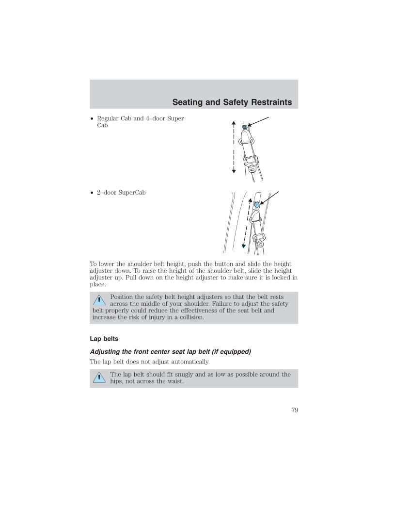
• Regular Cab and 4–door SuperCab
• 2–door SuperCab
To lower the shoulder belt height, push the button and slide the heightadjuster down. To raise the height of the shoulder belt, slide the heightadjuster up. Pull down on the height adjuster to make sure it is locked inplace.
Position the safety belt height adjusters so that the belt restsacross the middle of your shoulder. Failure to adjust the safety
belt properly could reduce the effectiveness of the seat belt andincrease the risk of injury in a collision.
Lap belts
Adjusting the front center seat lap belt (if equipped)
The lap belt does not adjust automatically.
The lap belt should fit snugly and as low as possible around thehips, not across the waist.
Seating and Safety Restraints
79

Insert the tongue into the correctbuckle (the buckle closest to thedirection the tongue is comingfrom). To lengthen the belt, turn thetongue at a right angle to the beltand pull across your lap until itreaches the buckle. To tighten thebelt, pull the loose end of the beltthrough the tongue until it fits snugly across the hips.
Shorten and fasten the belt whennot in use.
Adjusting the rear center facing jump seat lap belt (if equipped)The lap belt will adjust automatically. To fasten, grasp the tongue, andwith a continuous motion, pull out enough webbing to buckle the tongueinto the correct buckle. If you did not pull out enough webbing to reachthe buckle, allow the tongue to retract fully before trying to pull it outagain.
The lap belt should fit snugly and as low as possible around thehips, not across the waist.
If you need to lengthen the belt, unfasten it and repeat the procedureabove.
To unfasten the belt, push in the release button prior to opening the reardoor.
Safety belt extension assemblyIf the safety belt is too short when fully extended, there is a 20 cm (8inch) safety belt extension assembly that can be added (part number611C22). This assembly can be obtained from your dealer at no cost.
Seating and Safety Restraints
80

Use only extensions manufactured by the same supplier as the safetybelt. Manufacturer identification is located at the end of the webbing onthe label. Also, use the safety belt extension only if the safety belt is tooshort for you when fully extended.
Do not use extensions to change the fit of the shoulder beltacross the torso.
Safety belt warning light and indicator chime
The safety belt warning light illuminates in the instrument cluster and achime sounds to remind the occupants to fasten their safety belts.
Conditions of operation
If... Then...
The driver’s safety belt is notbuckled before the ignitionswitch is turned to the ONposition...
The safety belt warning lightilluminates 1-2 minutes and thewarning chime sounds 4-8 seconds.
The driver’s safety belt isbuckled while the indicatorlight is illuminated and thewarning chime is sounding...
The safety belt warning light andwarning chime turn off.
The driver’s safety belt isbuckled before the ignitionswitch is turned to the ONposition...
The safety belt warning light andindicator chime remain off.
BeltMinder
The BeltMinder feature is a supplemental warning to the safety beltwarning function. This feature provides additional reminders to thedriver that the driver’s safety belt is unbuckled by intermittentlysounding a chime and illuminating the safety belt warning lamp in theinstrument cluster.
Seating and Safety Restraints
81
If... Then...
The driver’s safety belt is notbuckled before the vehicle hasreached at least 5 km/h (3mph) and 1-2 minutes haveelapsed since the ignitionswitch has been turned toON...
The BeltMinder feature is activated -the safety belt warning lightilluminates and the warning chimesounds for 6 seconds every 30seconds, repeating for approximately5 minutes or until safety belt isbuckled.
The driver’s safety belt isbuckled while the safety beltindicator light is illuminatedand the safety belt warningchime is sounding...
The BeltMinder feature will notactivate.
The driver’s safety belt isbuckled before the ignitionswitch is turned to the ONposition...
The BeltMinder feature will notactivate.
The following are reasons most often given for not wearing safety belts:(All statistics based on U.S. data)
Reasons given... Consider...
“Crashes are rare events” 36700 crashes occur every day. Themore we drive, the more we areexposed to “rare” events, even forgood drivers. 1 in 4 of us will be
seriously injured in a crash during
our lifetime.
“I’m not going far” 3 of 4 fatal crashes occur within 25
miles of home.“Belts are uncomfortable” We design our safety belts to enhance
comfort. If you are uncomfortable -try different positions for the safetybelt upper anchorage and seatbackwhich should be as upright aspossible; this can improve comfort.
Seating and Safety Restraints
82

Reasons given... Consider...
“I was in a hurry” Prime time for an accident.
BeltMinder reminds us to take a fewseconds to buckle up.
“Safety belts don’t work” Safety belts, when used properly,reduce risk of death to front seatoccupants by 45% in cars, and by60% in light trucks.
“Traffic is light” Nearly 1 of 2 deaths occur in
single-vehicle crashes, many whenno other vehicles are around.
“Belts wrinkle my clothes” Possibly, but a serious crash can domuch more than wrinkle your clothes,particularly if you are unbelted.
“The people I’m with don’twear belts”
Set the example, teen deaths occur 4times more often in vehicles withTWO or MORE people. Children andyounger brothers/sisters imitatebehavior they see.
“I have an air bag” Air bags offer greater protection whenused with safety belts. Frontal airbagsare not designed to inflate in rear andside crashes or rollovers.
“I’d rather be thrown clear” Not a good idea. People who areejected are 40 times more likely
to DIE. Safety belts help preventejection, WE CAN’T “PICK OURCRASH”.
Do not sit on top of a buckled safety belt to avoid the BeltMinder chime. Sitting on the safety belt will increase the risk of
injury in an accident. To disable (one-time) or deactivate the BeltMinder feature please follow the directions stated below.
Seating and Safety Restraints
83

One time disableAny time the safety belt is buckled and then unbuckled during anignition ON cycle, the BeltMinder will be disabled for that ignition cycleonly.
Deactivating/activating the BeltMinder featureRead steps 1 - 9 thoroughly before proceeding with thedeactivation/activation programming procedure.
The BeltMinder feature can be deactivated/activated by performing thefollowing procedure:
Before following the procedure, ensure that the following conditions aremet:
• The parking brake is set.
• The gearshift is in P (Park) (automatic transmission) or the neutralposition (manual transmission).
• The ignition switch is in the OFF position.
• All vehicle doors are closed.
• The driver’s safety belt is unbuckled.
• The parklamps/headlamps are in OFF position (If vehicle is equippedwith Autolamps, this will not affect the procedure).
To reduce the risk of injury, do not deactivate/activate the BeltMinder feature while driving the vehicle.
BeltMinder activation and deactivation procedure
1. Turn the ignition switch to the RUN (or ON) position. (DO NOTSTART THE ENGINE.)
2. Wait until the safety belt warning light turns off. (Approximately 1–2minutes.)
• Steps 3–5 must be completed within 60 seconds or the procedure willhave to be repeated.
3. Buckle then unbuckle the safety belt three times, ending with thesafety belt unbuckled. This can be done before or during BeltMinderwarning activation.
4. Turn on the parklamps/headlamps, turn off the parklamps/headlamps.
5. Buckle then unbuckle the safety belt three times, ending with thesafety belt unbuckled.
Seating and Safety Restraints
84

• After step 5 the safety belt warning light will be turned on for threeseconds.
6. Within seven seconds of the safety belt warning light turning off,buckle then unbuckle the safety belt.
• This will disable BeltMinder if it is currently enabled, or enableBeltMinder if it is currently disabled.
7. Confirmation of disabling BeltMinder is provided by the safety beltwarning light flashing four times per second for three seconds.
8. Confirmation of enabling BeltMinder is provided by:
• The safety belt warning light flashing four times per second for threeseconds.
• Followed by three seconds with the safety belt warning light off.
• Once again, the safety belt warning light will flash four times persecond for three seconds.
9. After receiving confirmation, the deactivation/activation procedure iscomplete.
Safety belt maintenance
Inspect the safety belt systems periodically to make sure they workproperly and are not damaged. Inspect the safety belts to make surethere are no nicks, tears or cuts. Replace if necessary. All safety beltassemblies, including retractors, buckles, front safety belt buckleassemblies, buckle support assemblies (slide bar-if equipped), shoulderbelt height adjusters (if equipped), shoulder belt guide on seatback (ifequipped), child safety seat LATCH and tether anchors, and attachinghardware, should be inspected after a collision. Ford Motor Companyrecommends that all safety belt assemblies used in vehicles involved in acollision be replaced. However, if the collision was minor and a qualifiedtechnician finds that the belts do not show damage and continue tooperate properly, they do not need to be replaced. Safety belt assembliesnot in use during a collision should also be inspected and replaced ifeither damage or improper operation is noted.
The energy absorbing functions may have been activated in a collision sothe restraints should be examined; if the front air bags have deployed,the pretensioners have also deployed and must be replaced — regardlessof whether there was an occupant in the passenger seat or not.
Seating and Safety Restraints
85
Failure to inspect and if necessary replace the safety beltassembly under the above conditions could result in severe
personal injuries in the event of a collision.
Refer to Interior in the Cleaning chapter.
AIR BAG SUPPLEMENTAL RESTRAINT SYSTEM (SRS)
Important supplemental restraint system (SRS) precautionsThe supplemental restraint systemis designed to work with the safetybelt to help protect the driver andright front passenger from certainupper body injuries.
Air bags DO NOT inflate slowly orgently and the risk of injury from adeploying air bag is greatest close tothe trim covering the air bagmodule.
All occupants of the vehicle, including the driver, should alwaysproperly wear their safety belts, even when an air bag (SRS) is
provided.
National Highway Traffic Safety Administration (NHTSA)recommends a minimum distance of at least 25 cm (10 inches)
between an occupant’s chest and the driver air bag module.
Seating and Safety Restraints
86

Never place your arm over the air bag module as a deploying airbag can result in serious arm fractures or other injuries.
Never place a rear facing infant seat in the front seat unless thepassenger air bag is turned off.
Steps you can take to properly position yourself away from the airbag:
• Move your seat to the rear as far as you can while still reaching thepedals comfortably.
• Recline the seat slightly (one or two degrees) from the uprightposition.
Do not put anything on or over the air bag module. Placingobjects on or over the air bag inflation area may cause those
objects to be propelled by the air bag into your face and torso causingserious injury.
Do not attempt to service, repair, or modify the Air BagSupplemental Restraint System or its fuses. See your Ford or
Lincoln Mercury dealer.
The front passenger air bag is not designed to offer protection toan occupant in the center front seating position.
Modifying or adding equipment to the front end of the vehicle(including frame, bumper, front end body structure and tow
hooks) may affect the performance of the air bag system, increasingthe risk of injury. Do not modify the front end of the vehicle.
Additional equipment may affect the performance of the air bagsensors increasing the risk of injury. Please refer to the Body
Builders Layout Book for instructions about the appropriate installationof additional equipment.
Seating and Safety Restraints
87

Children and air bags
For additional important safety information, read all information onsafety restraints in this guide.
Never place a rearward facing child safety restraint in front of anairbag. Airbags have been known to kill or injure children in
front facing child safety restraints. Whenever placing a child safety seatin a front seating position (including center if equipped), turn off thepassenger side air bag switch after being certain the child is properlyrestrained. If using a forward facing child safety restraint in the frontoutboard seat, slide the seat all the way back, and turn off thepassenger air bag. If using a rear facing child safety seat in the frontoutboard seating position, make sure the passenger airbag is turned offand slide the passenger seat all the way forward until the safety seatrests on the dashboard. See Passenger air bag on/off switch in thischapter.
Do not install a child seat ina center facing jump seat.
Seating and Safety Restraints
88

An air bag can kill or injure a child in a child seat. Child seatsshould never be placed in the front seats, unless passenger air
bag switch is turned off. See Passenger air bag on/off switch in thischapter.
Rear facing child seats should NEVER be placed in the frontseats unless the passenger airbag switch is turned off.
Booster seats must be installed only in seating positionsequipped with a combination lap/shoulder belt.
To reduce the risk of injury, make sure children sit where theycan be properly restrained.
How does the air bag supplemental restraint system work?The air bag SRS is designed toactivate when the vehicle sustainssufficient longitudinal deceleration.
The fact that the air bags did notinflate in a collision does not meanthat something is wrong with thesystem. Rather, it means the forceswere not of the type sufficient tocause activation. Air bags aredesigned to inflate in frontal andnear-frontal collisions, not rollover,side-impact, or rear-impacts.
Seating and Safety Restraints
89

The air bags inflate and deflaterapidly upon activation. After air bagdeployment, it is normal to notice asmoke-like, powdery residue orsmell the burnt propellant. This mayconsist of cornstarch, talcumpowder (to lubricate the bag) orsodium compounds (e.g., bakingsoda) that result from thecombustion process that inflates theair bag. Small amounts of sodiumhydroxide may be present whichmay irritate the skin and eyes, butnone of the residue is toxic.
While the system is designed to helpreduce serious injuries, it may alsocause minor abrasions, swelling or temporary hearing loss. Because airbags must inflate rapidly and with considerable force, there is the risk ofdeath or serious injuries such as fractures, facial and eye injuries orinternal injuries, particularly to occupants who are not properlyrestrained or are otherwise out of position at the time of air bagdeployment. Thus, it is extremely important that occupants be properlyrestrained as far away from the air bag module as possible whilemaintaining vehicle control.
Several air bag system components get hot after inflation. Do nottouch them after inflation.
If the air bag has deployed, the air bag will not functionagain and must be replaced immediately. If the air bag is not
replaced, the unrepaired area will increase the risk of injury in acollision.
The SRS consists of:
• driver and passenger air bag modules (which include the inflators andair bags),
• one or more impact and safing sensors, passenger air bag deactivationswitch and diagnostic monitor (RCM)
• a readiness light and tone,
• and the electrical wiring which connects the components.
Seating and Safety Restraints
90
The RCM (restraints control module) monitors its own internal circuitsand the supplemental air bag electrical system warning (including thepassenger air bag deactivation switch, the impact sensors, the systemwiring, the air bag system readiness light, the air bag back up power andthe air bag ignitors).
Determining if the system is operational
The SRS uses readiness lights in the instrument cluster and thepassenger air bag deactivate switch or a tone to indicate the condition ofthe system. Refer to the Air bag readiness section in the Instrumentcluster chapter or Passenger air bag on/off switch section in thischapter. Routine maintenance of the air bag is not required.
A difficulty with the system is indicated by one or more of the following:
• The readiness lights will eitherflash or stay lit.
• The readiness lights will notilluminate immediately afterignition is turned on.
• A series of five beeps will be heard. The tone pattern will repeatperiodically until the problem and/or light are repaired.
If any of these things happen, even intermittently, have the SRS servicedat your dealership or by a qualified technician immediately. Unlessserviced, the system may not function properly in the event of acollision.
Disposal of air bags and air bag equipped vehicles (includingpretensioners)
See your local dealership or qualified technician. Air bags MUST BEdisposed of by qualified personnel.
Seating and Safety Restraints
91

Passenger air bag ON/OFF switch
An air bag ON/OFF switchhas been installed in this
vehicle. Before driving, alwayslook at the face of the switch tobe sure the switch is in the properposition in accordance with theseinstructions and warnings. Failureto put the switch in a properposition can increase the risk ofserious injury or death in acollision.
Turning the passenger air bag off1. Insert the ignition key, turn theswitch to OFF position and hold inOFF position while removing thekey.
2. When the ignition is turned to theON position the OFF lightilluminates briefly, momentarilyshuts off and then turns back on.This indicates that the passenger airbag is deactivated.
If the light fails to illuminate when the passenger air bag switchis in the OFF position and the ignition switch is in the On
position, have the passenger air bag switch serviced at your Ford orLincoln-Mercury dealer immediately.
In order to avoid inadvertent activation of the switch, alwaysremove the ignition key from the passenger air bag ON/OFF
switch.
ON OFF
OFF
PASSENGER AIRBAG
ON OFF
OFF
PASSENGER AIRBAG
Seating and Safety Restraints
92

Turning the passenger air bag back onThe passenger air bag remains OFF until you turn it back ON.
1. Insert the ignition key and turnthe switch to ON.
2. The OFF light will brieflyilluminate when the ignition isturned to ON. This indicates thatthe passenger air bag is operational.
If the OFF light is illuminated when the passenger air bagON/OFF switch is in the ON position and the ignition switch is
ON, have the passenger air bag ON/OFF switch serviced at your Fordor Lincoln-Mercury dealer immediately.
The passenger side air bag should always be ON (the air bag OFF lightshould not be illuminated) unless the passenger is a person who meetsthe requirements stated either in Category 1, 2 or 3 of theNHTSA/Transport Canada deactivation criteria which follows.
The safety belts for the driver and right front passenger seatingpositions have been specifically designed to function together
with the air bags in certain types of crashes. When you turn OFF yourair bag, you not only lose the protection of the air bag, you also mayreduce the effectiveness of your safety belt system, which wasdesigned to work with the air bag. If you are not a person who meetsthe requirements stated in the NHTSA/Transport Canada deactivationcriteria turning OFF the air bag can increase the risk of serious injuryor death in a collision.
Always use safety belts and child restraints properly. If a child ina rear facing infant seat must be transported in front, the
passenger air bag must be turned OFF. This is because the back of theinfant seat is too close to the inflating air bag and the risk of a fatalinjury to the infant when the air bag inflates is substantial.
ON OFF
OFF
PASSENGER AIRBAG
Seating and Safety Restraints
93

The vast majority of drivers and passengers are much safer with an airbag than without. To do their job and reduce the risk of life threateninginjuries, air bags must open with great force, and this force can pose apotentially deadly risk in some situations, particularly when a front seatoccupant is not properly buckled up. The most effective way to reducethe risk of unnecessary air bag injuries without reducing the overallsafety of the vehicle is to make sure all occupants are properlyrestrained in the vehicle, especially in the front seat. This provides theprotection of safety belts and permits the air bags to provide theadditional protection they were designed to provide. If you choose todeactivate your air bag, you are losing the very significant risk reducingbenefits of the air bag and you are also reducing the effectiveness of thesafety belts, because safety belts in modern vehicles are designed towork as a safety system with the air bags.
Read all air bag Warning labels in the vehicle as well as the otherimportant air bag instructions and Warnings in this Owner’s Guide.
NHTSA deactivation criteria (excluding Canada)1. Infant. An infant (less than 1 year old) must ride in the front seatbecause:
• the vehicle has no rear seat;
• the vehicle has a rear seat too small to accommodate a rear-facinginfant seat; or
• the infant has a medical condition which, according to the infant’sphysician, makes it necessary for the infant to ride in the front so thatthe driver can constantly monitor the child’s condition.
2. Child age 1 to 12. A child age 1 to 12 must ride in the front seatbecause:
• the vehicle has no rear seat;
• although children ages 1 to 12 ride in the rear seat(s) wheneverpossible, children ages 1 to 12 sometimes must ride in the frontbecause no space is available in the rear seat(s) of the vehicle; or
• the child has a medical condition which, according to the child’sphysician, makes it necessary for the child to ride in the front seat sothat the driver can constantly monitor the child’s condition.
3. Medical condition. A passenger has a medical condition which,according to his or her physician:
• causes the passenger air bag to pose a special risk for the passenger;and
Seating and Safety Restraints
94

• makes the potential harm from the passenger air bag in a crashgreater than the potential harm from turning OFF the air bag andallowing the passenger, even if belted, to hit the dashboard orwindshield in a crash.
This vehicle has special energy management safety belts for thedriver and/or right front passenger. These particular belts are
specifically designed to work with air bags to help reduce the risk ofinjury in a collision. The energy management safety belt is designed togive or release additional belt webbing in some accidents to reduceconcentration of force on an occupant’s chest and reduce the risk ofcertain bone fractures and injuries to underlying organs. In a crash, ifthe air bag is turned OFF, this energy management safety belt mightpermit the person wearing the belt to move forward enough to incur aserious or fatal injury. The more severe the crash, and the heavier theoccupant, the greater the risk. Be sure the air bag is turned ON for anyperson who does not qualify under the NHTSA deactivation criteria.
Transport Canada deactivation criteria (Canada Only)1. Infant: An infant (less than 1 year old) must ride in the front seatbecause:• the vehicle has no rear seat;• the rear seat in the vehicle cannot accommodate a rear-facing infant
seat; or• the infant has a medical condition which, according to the infant’s
physician, makes it necessary for the infant to ride in the front seat sothat the driver can monitor the infant’s condition.
2. Child age 12 or under: A child age 12 or under must ride in thefront seat because:
• the vehicle has no rear seat;
• although children age 12 and under ride in the rear seat wheneverpossible, children age 12 and under have no option but to sometimesride in the front seat because rear seat space is insufficient; or
• the child has a medical condition that, according to the child’sphysician, makes it necessary for the child to ride in the front seat sothat the driver can monitor the child’s condition.
3. Medical condition: A passenger has a medical condition that,according to his or her physician:
• poses a special risk for the passenger if the air bag deploys; and
Seating and Safety Restraints
95

• makes the potential harm from the passenger air bag deploymentgreater than the potential harm from turning OFF the air bag andexperiencing a crash without the protection offered by the air bag.
This vehicle has special energy management safety belts for thedriver and/or right front passenger. These particular belts are
specifically designed to work with air bags to help reduce the risk ofinjury in a collision. The energy management safety belt is designed togive or release additional belt webbing in some accidents to reduceconcentration of force on an occupant’s chest and reduce the risk ofcertain bone fractures and injuries to underlying organs. In a crash, ifthe air bag is turned OFF, this energy management safety belt mightpermit the person wearing the belt to move forward enough to incur aserious or fatal injury. The more severe the crash, and the heavier theoccupant, the greater the risk. Be sure the air bag is turned ON for anyperson who does not qualify under the Transport Canada deactivationcriteria.
SAFETY RESTRAINTS FOR CHILDRENSee the following sections for directions on how to properly use safetyrestraints for children. Also see Air bag supplemental restraint system(SRS) in this chapter for special instructions about using air bags.
Important child restraint precautionsYou are required by law to use safety restraints for children in the U.S.and Canada. If small children ride in your vehicle (generally children whoare four years old or younger and who weigh 18 kg [40 lbs] or less), youmust put them in safety seats made especially for children. Check yourlocal and state or provincial laws for specific requirements regarding thesafety of children in your vehicle.
Never let a passenger hold a child on his or her lap while thevehicle is moving. The passenger cannot protect the child from
injury in a collision.
Always follow the instructions and warnings that come with any infant orchild restraint you might use.
Do not install a child seat in a center facing jump seat.
Seating and Safety Restraints
96

Children and safety beltsIf the child is the proper size, restrain the child in a safety seat. Childrenwho are too large for child safety seats (as specified by your child safetyseat manufacturer) should always wear safety belts.
Follow all the important safety restraint and air bag precautions thatapply to adult passengers in your vehicle.
If the shoulder belt portion of a combination lap and shoulder belt canbe positioned so it does not cross or rest in front of the child’s face orneck, the child should wear the lap and shoulder belt. Moving the childcloser to the center of the vehicle may help provide a good shoulder beltfit.
Do not leave children, unreliable adults, or pets unattended inyour vehicle.
Child booster seatsChildren outgrow a typical convertible or toddler seat when they weigh40 pounds and are around 4 years of age. Although the lap/shoulder beltwill provide some protection, these children are still too small forlap/shoulder belts to fit properly, which could increase the risk of seriousinjury.
To improve the fit of both the lap and shoulder belt on children whohave outgrown child safety seats, Ford Motor Company recommends useof a belt-positioning booster.
Booster seats position a child so that safety belts fit better. They lift thechild up so that the lap belt rests low across the hips and the kneesbend comfortably. Booster seats also make the shoulder belt fit betterand more comfortably for growing children.
When children should use booster seats
Children need to use booster seats from the time they outgrow thetoddler seat until they are big enough for the vehicle seat andlap/shoulder belt to fit properly. Generally this is when they weigh about80 lbs (about 8 to 12 years old).
Seating and Safety Restraints
97

Booster seats should be used until you can answer YES to ALL of thesequestions:
• Can the child sit all the way backagainst the vehicle seat back withknees bent comfortably at theedge of the seat withoutslouching?
• Does the lap belt rest low across the hips?• Is the shoulder belt centered on the shoulder and chest?• Can the child stay seated like this for the whole trip?Types of booster seatsThere are two types of belt-positioning booster seats:
• Those that are backless.
If your backless booster seat has aremovable shield, remove theshield and use the lap/shoulderbelt. If a seating position has alow seat back and no headrestraint, a backless booster seatmay place your child’s head (topof ear level) above the top of theseat. In this case, move thebackless booster to anotherseating position with a higher seat back and lap/shoulder belts.
• Those with a high back.
If, with a backless booster seat,you cannot find a seating positionthat adequately supports yourchild’s head, a high back boosterseat would be a better choice.
Both can be used in any vehicle in a seating position equipped withlap/shoulder belts if your child is over 40 lbs.
Seating and Safety Restraints
98
The shoulder belt should cross the chest, resting snugly on the center ofthe shoulder. The lap belt should rest low and snug across the hips,never up high across the stomach.
If the booster seat slides on the vehicle seat, placing a rubberized meshsold as shelf or carpet liner under the booster seat may improve thiscondition.
The importance of shoulder belts
Using a booster without a shoulder belt increases the risk of a child’shead hitting a hard surface in a collision. For this reason, you shouldnever use a booster seat with a lap belt only. It is best to use a boosterseat with lap/shoulder belts in the back seat- the safest place for childrento ride.
Follow all instructions provided by the manufacturer of thebooster seat.
Never put the shoulder belt under a child’s arm or behind theback because it eliminates the protection for the upper part of
the body and may increase the risk of injury or death in a collision.
Never use pillows, books, or towels to boost a child. They canslide around and increase the likelihood of injury or death in a
collision.
SAFETY SEATS FOR CHILDREN
Seating and Safety Restraints
99

Child and infant or child safety seats
Use a safety seat that is recommended for the size and weight of thechild. Carefully follow all of the manufacturer’s instructions with thesafety seat you put in your vehicle. If you do not install and use thesafety seat properly, the child may be injured in a sudden stop orcollision.
When installing a child safety seat:
• Review and follow the informationpresented in the Air bagsupplemental restraint system(SRS) section in this chapter.
• Use the correct safety belt bucklefor that seating position (thebuckle closest to the direction thetongue is coming from).
• Insert the belt tongue into theproper buckle until you hear asnap and feel it latch. Make sure the tongue is securely fastened in thebuckle.
• Keep the buckle release button pointing up and away from the safetyseat, with the tongue between the child seat and the release button,to prevent accidental unbuckling.
• Place seat back in upright position.
• Put the safety belt in the automatic locking mode. Refer to Automaticlocking mode (passenger side front and outboard rear seatingpositions) (if equipped) section in this chapter.
Ford recommends the use of a child safety seat having a top tetherstrap. Install the child safety seat in a seating position with a tetheranchor. For more information on top tether straps, refer to Attachingchild safety seats with tether straps. in this chapter.
Carefully follow all of the manufacturer’s instructions includedwith the safety seat you put in your vehicle. If you do not install
and use the safety seat properly, the child may be injured in a suddenstop or collision.
Seating and Safety Restraints
100

Installing child safety seats with combination lap and shoulderbelts1. Position the child safety seat in aseat with a combination lap andshoulder belt.
Air bags can kill or injure a child in a child seat. NEVER put arear-facing child seat in the front unless the passenger air bag
switch is turned off. If you must use a forward-facing child seat in thefront seat, move the seat all the way back and turn the passenger airbag off. See Passenger air bag on/off switch.
An air bag can kill or injure a child in a child seat. Child seatsshould never be placed in the front seats, unless the passenger
air bag switch is turned off, See Passenger air bag on/off switch.
Rear facing child seats should NEVER be placed in the frontseats unless the passenger airbag switch is turned off.
2. Pull down on the shoulder beltand then grasp the shoulder beltand lap belt together.
Seating and Safety Restraints
101

3. While holding the shoulder andlap belt portions together, route thetongue through the child seataccording to the child seatmanufacturer’s instructions. Be surethe belt webbing is not twisted.
4. Insert the belt tongue into theproper buckle (the buckle closest tothe direction the tongue is comingfrom) for that seating position untilyou hear and feel the latch engage.Make sure the tongue is latchedsecurely by pulling on it.
5. To put the retractor in theautomatic locking mode, grasp theshoulder portion of the belt and pulldownward until all of the belt isextracted and a click is heard.
6. Allow the belt to retract. The belt will click as it retracts to indicate itis in the automatic locking mode.
Seating and Safety Restraints
102

7. Pull the lap belt portion acrossthe child seat toward the buckle andpull up on the shoulder belt whilepushing down with knee on thechild seat.
8. Allow the safety belt to retract toremove any slack in the belt.
9. Before placing the child in theseat, forcibly tilt the seat forwardand back to make sure the seat issecurely held in place. To checkthis, grab the seat at the belt pathand attempt to move it side to sideand forward. There should be nomore than one inch of movement forproper installation.
10. Try to pull the belt out of the retractor to make sure the retractor isin the automatic locking mode (you should not be able to pull more beltout). If the retractor is not locked, unbuckle the belt and repeat stepstwo through nine.
Check to make sure the child seat is properly secured before each use.
Attaching child safety seats with tether straps
Most new forward-facing child safety seats include a tether strap whichgoes over the back of the seat and hooks to an anchoring point. Tetherstraps are available as an accessory for many older safety seats. Contactthe manufacturer of your child seat for information about ordering atether strap.
The tether anchors in your vehicle are located on the back of the frontseat cushion.
Seating and Safety Restraints
103

The tether strap anchors in your vehicle are in the following positions(shown from top view):
• Bucket seats
• 60/40 seats
Attach the tether strap only to the appropriate tether anchor asshown. The tether strap may not work properly if attached
somewhere other than the correct tether anchor.
1. Position the child safety seat on the front seat cushion.
2. Route the child safety seat tether strap over the back of the seat.
Seating and Safety Restraints
104

3. Locate the correct anchor for the selected seating position.
The tether anchor is located on therear lower portion of the passengerseat.
4. Clip the tether strap to theanchor.
Seating and Safety Restraints
105

Center seating location
When installing a child safety seat in the front center position, route thetether strap over the center arm rest and clip it to the center anchor.
Seating and Safety Restraints
106
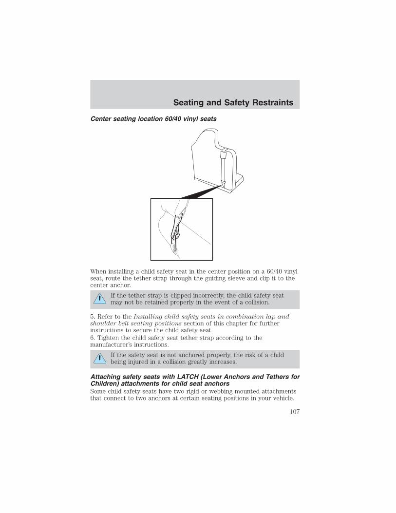
Center seating location 60/40 vinyl seats
When installing a child safety seat in the center position on a 60/40 vinylseat, route the tether strap through the guiding sleeve and clip it to thecenter anchor.
If the tether strap is clipped incorrectly, the child safety seatmay not be retained properly in the event of a collision.
5. Refer to the Installing child safety seats in combination lap andshoulder belt seating positions section of this chapter for furtherinstructions to secure the child safety seat.6. Tighten the child safety seat tether strap according to themanufacturer’s instructions.
If the safety seat is not anchored properly, the risk of a childbeing injured in a collision greatly increases.
Attaching safety seats with LATCH (Lower Anchors and Tethers forChildren) attachments for child seat anchorsSome child safety seats have two rigid or webbing mounted attachmentsthat connect to two anchors at certain seating positions in your vehicle.
Seating and Safety Restraints
107

This type of child seat eliminates the need to use safety belts to attachthe child seat. For forward-facing child seats, the tether strap must alsobe attached to the proper tether anchor. See Attaching safety seats withtether straps in this chapter.
Your vehicle may be equipped with LATCH anchors for child seatinstallation at the seating positions with tan or gray locator buttons.
• Bucket seats
• 60/40 seats
Never attach two LATCH child safety seats to the same anchor.In a crash, one anchor may not be strong enough to hold two
child safety seat attachments and may break, causing serious injury ordeath.
Connectors on the LATCH child seatand the child seat instructions mayuse the symbol shown here. Yourvehicle seat will have plain gray ortan buttons, instead of this symbol, to indicate the location of the LATCHlower anchors.
Seating and Safety Restraints
108

The lower anchors for child seatinstallation are located at the rearsection of the front passenger seatbetween the cushion and seat back.The LATCH anchors are below thegray or tan locator buttons on theseat back. Two plastic LATCHguides may be obtained at no chargefrom any Ford dealer (part number1W4Z-54613F16–AA). They snaponto the latch lower anchor in thevehicle to help attach a child seatwith rigid latch attachments. It willhold the seat foam away and exposethe anchor making attachment ofthe child seat easier.
Follow the child seat manufacturer’s instructions to properly install achild seat with LATCH attachments.
Attach LATCH lower attachments of the child seat only to theanchors shown.
If you install a child seat with rigid LATCH attachments, do not tightenthe tether strap enough to lift the child seat off the vehicle seat cushionwhen the child is seated in it. Keep the tether strap just snug withoutlifting the front of the child seat. Keeping the child seat just touching thevehicle seat gives the best protection in a severe crash.
Each time you use the safety seat, check that the seat is properlyattached to the lower anchors and tether anchor. Try to tilt the childseat from side to side. Also try to tug the seat forward. Check to see ifthe anchors hold the seat in place.
If the safety seat is not anchored properly, the risk of a childbeing injured in a crash greatly increases.
Seating and Safety Restraints
109

STARTING
Positions of the ignition1. ACCESSORY, allows the electricalaccessories such as the radio tooperate while the engine is notrunning.
2. LOCK, locks the steering wheel,automatic transmission gearshiftlever and allows key removal. Forvehicle equipped with a manualtransmission, you must depress theignition release lever to release thekey.
3. OFF, shuts off the engine and all accessories without locking thesteering wheel. This position also allows the automatic transmission shiftlever to be moved from the P (Park) position without the brake pedalbeing depressed.
When the key is in the ignition OFF position, the automatictransmission shift lever can be moved from the P (Park) position
without the brake pedal depressed. To avoid unwanted vehiclemovement, always set the parking brake.
4. ON, all electrical circuits operational. Warning lights illuminated. Keyposition when driving.
5. START, cranks the engine. Release the key as soon as the enginestarts.
Preparing to start your vehicleEngine starting is controlled by the powertrain control system. Thissystem meets all Canadian Interference-Causing Equipment standardrequirements regulating the impulse electrical field strength of radionoise.
When starting a fuel-injected engine, don’t press the accelerator beforeor during starting. Only use the accelerator when you have difficultystarting the engine. For more information on starting the vehicle, refer toStarting the engine in this chapter.
3
1
2
5
4
Driving
Driving
110

Extended idling at high engine speeds can produce very hightemperatures in the engine and exhaust system, creating the risk
of fire or other damage.
Do not park, idle, or drive your vehicle in dry grass or other dryground cover. The emission system heats up the engine
compartment and exhaust system, which can start a fire.
Do not start your vehicle in a closed garage or in other enclosedareas. Exhaust fumes can be toxic. Always open the garage door
before you start the engine. See Guarding against exhaust fumes inthis chapter for more instructions.
If you smell exhaust fumes inside your vehicle, have your dealerinspect your vehicle immediately. Do not drive if you smell
exhaust fumes.
Important safety precautionsWhen the engine starts, the idle RPM runs faster to warm the engine. Ifthe engine idle speed does not slow down automatically, have the vehiclechecked.
Before starting the vehicle:
1. Make sure all occupants buckle their safety belts. For moreinformation on safety belts and their proper usage, refer to the Seatingand safety restraints chapter.
2. Make sure the headlamps and electrical accessories are off.
Driving
111

If starting a vehicle with an automatic transmission:
• Make sure the parking brake isset.
• Make sure the gearshift is in P(Park).
If starting a vehicle with a manualtransmission:
1. Make sure the parking brake isset.
2. Push the clutch pedal to the floor.
Driving
112

• Turn the key to 4 (ON) withoutturning the key to 5 (START).
Make sure the corresponding lights illuminate or illuminate briefly. If alight fails to illuminate, have the vehicle serviced.
• If the driver’s safety belt is fastened, the light may not illuminate.
Starting the engine1. Turn the key to 4 (ON) withoutturning the key to 5 (START). Ifthere is difficulty in turning the key,rotate the steering wheel until thekey turns freely.
2. Turn the key to 5 (START), thenrelease the key as soon as theengine starts. Excessive crankingcould damage the starter.
Note: If the engine does not start within five seconds on the first try,turn the key to 3 (OFF), wait 10 seconds and try again.
1
2
34
5
3
2
1
5
4
Driving
113

Cold weather starting (flexible fuel vehicles only)In cold weather, ethanol fuel distributors should supply winter grade(Ed85) ethanol. If summer grade (Ed85) ethanol is used in cold weather,you may experience increased cranking times, rough idle or hesitationuntil the engine has warmed up. Consult your fuel distributor for theavailability of winter grade (Ed85) ethanol. High-quality blends of wintergrade (Ed85) ethanol will produce satisfactory cold weather starting anddriving results.Cold starting performance can also be improved by using an engine blockheater. Engine block heaters are available as an option and can beobtained from your Ford dealer. Consult the engine block heater sectionfor proper use of the engine block heater.If you experience cold weather starting problems on (Ed85) ethanol, andneither an alternative brand of (Ed85) ethanol nor an engine blockheater is available, adding unleaded gasoline to your tank will improvecold starting performance. Your vehicle is designed to operate on (Ed85)ethanol, unleaded gasoline alone, or any mixture of the two.
If the engine fails to start using the preceding instructions (flexiblefuel vehicles only)1. Press and hold down the accelerator 1/3 to 1/2 way to floor, thencrank the engine.2. When the engine starts, release the key, then gradually release theaccelerator pedal as the engine speeds up. If the engine still fails to start,repeat Step 1.
Using the engine block heater (if equipped)An engine block heater warms the engine coolant which aids in startingand heater/defroster performance. Use of an engine block heater isstrongly recommended if you live in a region where temperatures reach-23° C (-10° F) or below. For best results, plug the heater in at leastthree hours before starting the vehicle. The heater can be plugged in thenight before starting the vehicle.
To reduce the risk of electrical shock, do not use your heaterwith ungrounded electrical systems or two-pronged (cheater)
adapters.
Guarding against exhaust fumesCarbon monoxide is present in exhaust fumes. Take precautions to avoidits dangerous effects.
Driving
114

If you smell exhaust fumes inside your vehicle, have your dealerinspect your vehicle immediately. Do not drive if you smell
exhaust fumes.
Important ventilating information
If the engine is idling while the vehicle is stopped for a long period oftime, open the windows at least 2.5 cm (one inch) or adjust the heatingor air conditioning to bring in fresh air.
BRAKES
Occasional brake noise is normal. If a metal-to-metal, continuous grindingor continuous squeal sound is present, the brake linings may be worn-outand should be inspected by a qualified service technician. If the vehiclehas continuous vibration or shudder in the steering wheel while braking,the vehicle should be inspected by a qualified service technician.
Four-wheel anti-lock brake system (ABS)
Your vehicle is equipped with an Anti-lock Braking System (ABS). Thissystem helps you maintain steering control during emergency stops bykeeping the brakes from locking. Noise from the ABS pump motor andbrake pedal pulsation may be observed during ABS braking; anypulsations or mechanical noise you may feel or hear is normal.
Using ABS
When hard braking is required, apply continuous force on the brakepedal; do not pump the brake pedal since this will reduce theeffectiveness of the ABS and will increase your vehicle’s stoppingdistance. The ABS will be activated immediately, allowing you to retainfull steering control during hard braking and on slippery surfaces.However, the ABS does not decrease stopping distance.
ABS warning lamp ABS
The ABS lamp in the instrument cluster momentarily illuminates whenthe ignition is turned to ON. If the light does not illuminate during startup, remains on or flashes, the ABS may be disabled and may need to beserviced.
Driving
115

Even when the ABS is disabled,normal braking is still effective. (Ifyour BRAKE warning lampilluminates with the parking brakereleased, have your brake systemserviced immediately.)
Parking brake
To set the parking brake (1), pressthe parking brake pedal down untilthe pedal stops.
The BRAKE warning lamp willilluminate and will remainilluminated until the parking brakeis released.
To release, pull the lever (2).
Always set the parking brake fully and make sure that thegearshift is securely latched in P (Park) (automatic
transmission) or in 1 (First) (manual transmission).
STEERINGTo prevent damage to the power steering system:
• Never hold the steering wheel at its furthest turning points (until itstops) for more than a few seconds when the engine is running.
• Do not operate the vehicle with a low power steering pump fluid level(below the MIN mark on the reservoir).
If the power steering system breaks down (or if the engine is turnedoff), you can steer the vehicle manually, but it takes more effort.
!BRAKE
!BRAKE
Driving
116

If the steering wanders or pulls, check for:
• an improperly inflated tire
• uneven tire wear
• loose or worn suspension components
• loose or worn steering components
• improper steering alignment
TRACTION-LOK AXLE (IF EQUIPPED)This axle provides added traction on slippery surfaces, particularly whenone wheel is on a poor traction surface. Under normal conditions, theTraction-Lok axle functions like a standard rear axle.
PREPARING TO DRIVE YOUR VEHICLE
Utility vehicles have a significantly higher rollover rate thanother types of vehicles.
In a rollover crash, an unbelted person is significantly more likelyto die than a person wearing a safety belt.
Your vehicle has larger tires and increased ground clearance, giving thevehicle a higher center of gravity than a passenger car.
Vehicles with a higher center of gravity such as utility andfour-wheel drive vehicles handle differently than vehicles with a
lower center of gravity. Utility and four-wheel drive vehicles are notdesigned for cornering at speeds as high as passenger cars any morethan low-slung sports cars are designed to perform satisfactorily underoff-road conditions. Avoid sharp turns, excessive speed and abruptmaneuvers in these vehicles. Failure to drive cautiously could result inan increased risk of loss of vehicle control, vehicle rollover, personalinjury and death.
Loaded vehicles, with a higher center of gravity, may handledifferently than unloaded vehicles. Extra precautions, such as
slower speeds and increased stopping distance, should be taken whendriving a heavily loaded vehicle.
Driving
117
AUTOMATIC TRANSMISSION OPERATION (IF EQUIPPED)
Brake-shift interlock
This vehicle is equipped with a brake-shift interlock feature that preventsthe gearshift lever from being moved from P (Park) when the ignition isin the ON position unless the brake pedal is depressed.
If you cannot move the gearshift lever out of P (Park) with ignition inthe ON position and the brake pedal depressed:
1. Apply the parking brake, turn ignition key to LOCK, then remove thekey.
2. Insert the key and turn it to OFF. Apply the brake pedal and shiftto N (Neutral).
When the key is in the ignition OFF position, the automatictransmission shift lever can be moved from the P (Park) position
without the brake pedal depressed. To avoid unwanted vehiclemovement, always set the parking brake.
3. Start the vehicle.
If it is necessary to use the above procedure to move the gearshift lever,it is possible that a fuse has blown or the vehicle’s brakelamps are notoperating properly. Refer to Fuses and relays in the Roadsideemergencies chapter.
Do not drive your vehicle until you verify that the brakelampsare working.
Always set the parking brake fully and make sure the gearshift islatched in P (Park). Turn the ignition to the LOCK position and
remove the key whenever you leave your vehicle.
If the parking brake is fully released, but the brake warning lampremains illuminated, the brakes may not be working properly.
See your dealer or a qualified service technician.
Driving
118
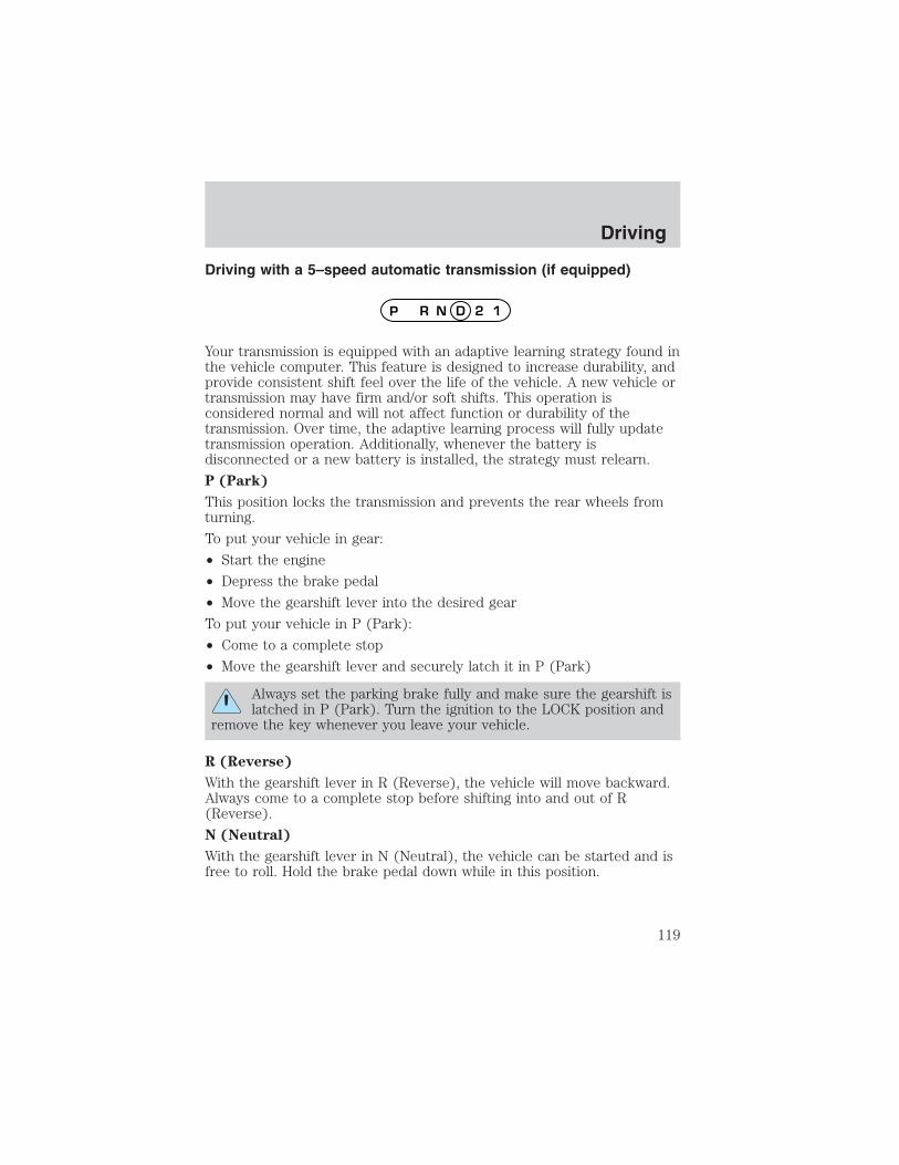
Driving with a 5–speed automatic transmission (if equipped)
Your transmission is equipped with an adaptive learning strategy found inthe vehicle computer. This feature is designed to increase durability, andprovide consistent shift feel over the life of the vehicle. A new vehicle ortransmission may have firm and/or soft shifts. This operation isconsidered normal and will not affect function or durability of thetransmission. Over time, the adaptive learning process will fully updatetransmission operation. Additionally, whenever the battery isdisconnected or a new battery is installed, the strategy must relearn.
P (Park)
This position locks the transmission and prevents the rear wheels fromturning.
To put your vehicle in gear:
• Start the engine
• Depress the brake pedal
• Move the gearshift lever into the desired gear
To put your vehicle in P (Park):
• Come to a complete stop
• Move the gearshift lever and securely latch it in P (Park)
Always set the parking brake fully and make sure the gearshift islatched in P (Park). Turn the ignition to the LOCK position and
remove the key whenever you leave your vehicle.
R (Reverse)
With the gearshift lever in R (Reverse), the vehicle will move backward.Always come to a complete stop before shifting into and out of R(Reverse).
N (Neutral)
With the gearshift lever in N (Neutral), the vehicle can be started and isfree to roll. Hold the brake pedal down while in this position.
Driving
119

(Overdrive)
The normal driving position for thebest fuel economy. Transmissionoperates in gears one throughfive. (Overdrive) can bedeactivated by pressing thetransmission control switch on the end of the gearshift lever. This willilluminate the O/D OFF lamp and activate Drive.
Drive (not shown)
Drive is activated when the transmission control switch is pressed.
• This position allows for all forward gears except overdrive.
• O/D OFF lamp is illuminated.
• Provides engine braking.
• Use when driving conditions cause excessive shifting from O/D toother gears. Examples: city traffic, hilly terrain, heavy loads, trailertowing and when engine braking is required.
• To return to O/D (overdrive mode), press the transmission controlswitch. The O/D OFF lamp will not be illuminated.
• O/D (Overdrive) is automatically returned each time the key is turnedoff.
2 (Second)
Use 2 (Second) to start-up on slippery roads or to provide additionalengine braking on downgrades.
1 (First)
• Provides maximum engine braking.
• Allows upshifts by moving gearshift lever.
• Will not downshift into 1 (First) at high speeds; allows for 1 (First)when vehicle reaches slower speeds.
Forced downshifts
• Allowed in (Overdrive) or Drive.
• Depress the accelerator to the floor.
• Allows transmission to select an appropriate gear.
O/DON/OFF
Driving
120

MANUAL TRANSMISSION OPERATION (IF EQUIPPED)
Using the clutchThe manual transmission has a starter interlock that prevents crankingthe engine unless the clutch pedal is fully depressed.
To start the vehicle:
1. Make sure the parking brake is fully set.
2. Press the clutch pedal to the floor, then put the gearshift lever in theneutral position.
3. Start the engine, then press the brake pedal and release the parkingbrake.
4. Move the gearshift lever to the desired gear, then slowly release theclutch pedal while slowly pressing on the accelerator.
Do not drive with your foot resting on the clutch pedal or use the clutchpedal to hold your vehicle at a standstill while waiting on a hill. Theseactions will reduce the life of the clutch.
1 3 5
2 4 R
Driving
121

Recommended shift speedsDownshift according to the following charts for your specificengine/drivetrain combination:
Upshifts when accelerating (for best fuel economy)
Shift from:Transfer case position (if equipped)
2H or 4H 4L1 - 2 14 km/h (10 mph) 5 km/h (4 mph)2 - 3 32 km/h (22 mph) 11 km/h (9 mph)3 -4 50 km/h (33 mph) 19 km/h (13 mph)4 - 5 (Overdrive) 71 km/h (41 mph) 27 km/h (17 mph)
Upshifts when cruising (recommended for best fuel economy)
Shift from:Transfer case position (if equipped)
2H or 4H 4L1 -2 16 km/h (10 mph) 6 km/h (4 mph)2 - 3 26 km/h (19 mph) 10 km/h (8 mph)3 - 4 43 km/h (28 mph) 16 km/h (12 mph)4 - 5 (Overdrive) 68 km/h (40 mph) 26 km/h (16 mph)
Maximum downshift speeds
Shift from:Transfer case position (if equipped)
2H or 4H 4L5 (Overdrive) - 4 88 km/h (55 mph) 34 km/h (22 mph)4 - 3 72 km/h (45 mph) 27 km/h (18 mph)3 - 2 56 km/h (35 mph) 21 km/h (14 mph)2 - 1 32 km/h (20 mph) 11 km/h (8 mph)
Reverse1. Make sure that your vehicle is at a complete stop before you shift intoR (Reverse). Failure to do so may damage the transmission.2. Move the gearshift lever into the neutral position and wait at leastthree seconds before shifting into R (Reverse).• The gearshift lever can only be moved into R (Reverse) by moving it
from left of 3 (Third) and 4 (Fourth) before shifting into R (Reverse).This is a lockout feature that protects the transmission fromaccidentally being shifted into R (Reverse) from 5 (Overdrive).
Parking your vehicle1. Apply the brake and shift into the neutral position.2. Fully apply the parking brake, then shift into 1 (First).
Driving
122

3. Turn the ignition off.
Do not park your vehicle in Neutral, it may move unexpectedlyand injure someone. Use 1 (First) gear and set the parking brake
fully.
Removing the key
Turn the ignition off, push the release lever (located above the ignition),then turn the key toward you and remove the key.
If your vehicle gets stuck in mud or snow
If your vehicle gets stuck in mud or snow, it may be rocked out byshifting from forward and reverse gears, stopping between shifts in asteady pattern. Press lightly on the accelerator in each gear.
Do not rock the vehicle if the engine is not at normal operating
temperature or damage to the transmission may occur.
Do not rock the vehicle for more than a minute or damage to thetransmission and tires may occur, or the engine may overheat.
FOUR-WHEEL DRIVE (4WD) OPERATION (IF EQUIPPED)
For important information regarding safe operation of this typeof vehicle, see Preparing to drive your vehicle in this chapter.
Four–wheel drive (4WD) supplies power to all four wheels. 4WD shouldnot be operated on dry pavement; driveline damage may occur.
If equipped with the Electronic Shift 4WD System, and 4WD Lowis selected while the vehicle is moving, the 4WD system will notengage. This is normal and should be no reason for concern. Referto Shifting to/from 4WD Low for proper operation.
4WD system indicator lights• 4WD - Illuminates when 4H
(4WD High) is engaged.
• 4WD LOW – Illuminates when 4L(4WD Low) is engaged.
Driving
123

Using a manual 4WD system (if equipped)
2H (2WD High) – Power to the rear wheels only; used for street andhighway driving.
4H (4WD High) – Used for extra traction such as in snow or icy roadsor in off-road situations. Not intended for use on dry pavement.
N (Neutral) – No power to either front or rear wheels.
4L (4WD Low)– Uses extra gearing to provide maximum power to allfour wheels at reduced speeds. Intended only for off-road applicationssuch as deep sand, steep grades or pulling heavy objects. 4L (4WD Low)will not engage while the vehicle is moving; this is normal and should beno reason for concern. Refer to Shifting to/from 4L (4WD Low) forproper operation.
Shifting between 2H (2WD high) and 4H (4WD high)• Move the transfer case lever between 2H (2WD High) and 4H (4WD
High) at a stop or any forward speed.
Note: Do not perform this operation if the rear wheels are slipping.
Shifting to/from 4L (4WD Low)1. Bring the vehicle to a complete stop.
2. Depress the brake.
3. On vehicles equipped with an automatic transmission, place thetransmission in N (Neutral); on vehicles equipped with a manualtransmission, depress the clutch.
4. Move the transfer case lever through N (Neutral) directly to thedesired position. The 4WD LOW indicator will illuminate once thetransfer case has engaged.
• If the transfer case does not engage, repeat steps 1 through 4.
2H4H
4LN
Driving
124

Using the N (Neutral) positionThe transfer case N (Neutral) position overrides the transmissionand puts the vehicle in neutral regardless of transmissiongearshift lever position. The vehicle can move forward orbackward.
This position should only be used when towing the vehicle.
Do not leave the vehicle unattended with the transfer case in theN (Neutral) position. Always set the parking brake fully and turn
off the ignition when leaving the vehicle.
Using the electronic shift 4WD system (if equipped)
2WD (2WD High) - Power to the rear wheels only; used for street andhighway driving.4X4 HIGH (4WD High) - Used for extra traction such as in snow or icyroads or in off-road situations. Not intended for use on dry pavement.4X4 LOW (4WD Low) - Uses extra gearing to provide maximum powerto all four wheels. Intended only for off-road applications such as deepsand, steep grades or pulling heavy objects. 4L (4WD Low) will notengage while the vehicle is moving; this is normal and should be noreason for concern. Refer to Shifting to/from 4L (4WD Low) for properoperation.Shifting between 2WD (2WD High) and 4X4 HIGH (4WD High)• Move the 4WD control between 2WD and 4X4 HIGH at any forward
speed.Note: Do not perform this operation if the rear wheels are slipping.Shifting to/from 4X4 LOW (4WD Low)1. Bring the vehicle to a complete stop2. Depress the brake
4X4HIGH2WD
4X4LOW
Driving
125

3. On vehicles equipped with an automatic transmission, place thetransmission in N (Neutral); on vehicles equipped with a manualtransmission, depress the clutch.4. Move the 4WD control to the desired position.• If shifting into 4X4 LOW (4WD Low), wait for the LOW RANGE light
in the instrument cluster to turn on indicating the shift is complete.• If shifting out of 4X4 LOW (4WD Low), wait for the LOW RANGE light
in the instrument cluster to turn off indicating the shift is complete.
Driving off-road with truck and utility vehicles4WD vehicles are specially equipped for driving on sand, snow, mud andrough terrain and have operating characteristics that are somewhatdifferent from conventional vehicles, both on and off the road.
How your vehicle differs from other vehiclesTruck and utility vehicles can differ from some other vehicles. Yourvehicle may be higher to allow it to travel over rough terrain withoutgetting hung up or damaging underbody components.The differences that make your vehicle so versatile also make it handledifferently than an ordinary passenger car.
Maintain steering wheel control at all times, especially in rough terrain.Since sudden changes in terrain can result in abrupt steering wheelmotion, make sure you grip the steering wheel from the outside. Do notgrip the spokes.
Drive cautiously to avoid vehicle damage from concealed objects such asrocks and stumps.
You should either know the terrain or examine maps of the area beforedriving. Map out your route before driving in the area. To maintainsteering and braking control of your vehicle, you must have all fourwheels on the ground and they must be rolling, not sliding or spinning.
Basic operating principles• Do not use 4WD on dry, hard surfaced roads. Doing so will produce
excessive noise, increase tire wear and may damage drive components.4WD modes are only intended for consistently slippery or loosesurfaces.
• Drive slower in strong crosswinds which can affect the normal steeringcharacteristics of your vehicle.
• Be extremely careful when driving on pavement made slippery byloose sand, water, gravel, snow or ice.
Driving
126

If your vehicle goes off the edge of the pavement
• If your vehicle goes off the edge of the pavement, slow down, butavoid severe brake application, ease the vehicle back onto thepavement only after reducing your speed. Do not turn the steeringwheel too sharply while returning to the road surface.
• It may be safer to stay on the apron or shoulder of the road and slowdown gradually before returning to the pavement. You may losecontrol if you do not slow down or if you turn the steering wheel toosharply or abruptly.
• It often may be less risky to strike small objects, such as highwayreflectors, with minor damage to your vehicle rather than attempt asudden return to the pavement which could cause the vehicle to slidesideways out of control or roll over. Remember, your safety and thesafety of others should be your primary concern.
Vehicles with a higher center of gravity such as utility andfour-wheel drive vehicles handle differently than vehicles with a
lower center of gravity. Utility and four-wheel drive vehicles are notdesigned for cornering at speeds as high as passenger cars any morethan low-slung sports cars are designed to perform satisfactorily underoff-road conditions. Avoid sharp turns, excessive speed and abruptmaneuvers in these vehicles. Failure to drive cautiously could result inan increased risk of loss of vehicle control, vehicle rollover, personalinjury and death.
If your vehicle gets stuckIf your vehicle gets stuck in mud or snow it may be rocked out byshifting between forward and reverse gears, stopping between shifts, in asteady pattern. Press lightly on the accelerator in each gear.
Do not rock the vehicle if the engine is not at normal operatingtemperature or damage to the transmission may occur.
Do not rock the vehicle for more than a few minutes or damageto the transmission and tires may occur or the engine mayoverheat.
Always set the parking brake fully and make sure the gearshift islatched in P (Park). Turn the ignition to the LOCK position and
remove the key whenever you leave your vehicle.
Driving
127

If the parking brake is fully released, but the brake warning lampremains illuminated, the brakes may not be working properly.
See your dealer or a qualified service technician.
Do not spin the wheels at over 56 km/h (35 mph). The tires mayfail and injure a passenger or bystander.
Emergency maneuvers• In an unavoidable emergency situation where a sudden sharp turn
must be made, remember to avoid “over-driving” your vehicle, i.e.,turn the steering wheel only as rapidly and as far as required to avoidthe emergency. Excessive steering will result in less vehicle control,not more. Additionally, smooth variations of the accelerator and/orbrake pedal pressure should be utilized if changes in vehicle speed arecalled for. Avoid abrupt steering, acceleration or braking which couldresult in an increased risk of loss of vehicle control, vehicle rolloverand/or personal injury. Use all available road surface to return thevehicle to a safe direction of travel.
• In the event of an emergency stop, avoid skidding the tires and do notattempt any sharp steering wheel movements.
Vehicles with a higher center of gravity such as utility andfour-wheel drive vehicles handle differently than vehicles with a
lower center of gravity. Utility and four-wheel drive vehicles are notdesigned for cornering at speeds as high as passenger cars any morethan low-slung sports cars are designed to perform satisfactorily underoff-road conditions. Avoid sharp turns, excessive speed and abruptmaneuvers in these vehicles. Failure to drive cautiously could result inan increased risk of loss of vehicle control, vehicle rollover, personalinjury and death.
• If the vehicle goes from one type of surface to another (i.e., fromconcrete to gravel) there will be a change in the way the vehicleresponds to a maneuver (steering, acceleration or braking). Again,avoid these abrupt inputs.
ParkingOn some 4WD vehicles, when the transfer case is in the N (Neutral)position, the engine and transmission are disconnected from the rest ofthe driveline. Therefore, the vehicle is free to roll even if the automatic
Driving
128

transmission is in P (Park) or the manual transmission is in gear. Do notleave the vehicle unattended with the transfer case in the N (Neutral)position. Always set the parking brake fully and turn off the ignitionwhen leaving the vehicle.
4WD Systems
4WD (when you select a 4WD mode) uses all four wheels to power thevehicle. This increases traction, enabling you to drive over terrain androad conditions that a conventional two-wheel drive vehicle cannot.
Power is supplied to all four wheelsthrough a transfer case. On 4WDvehicles, the transfer case allowsyou to select 4WD when necessary.Information on transfer caseoperation and shifting procedurescan be found in the Drivingchapter. Information on transfercase maintenance can be found in the Maintenance and specificationschapter. You should become thoroughly familiar with this informationbefore you operate your vehicle.
Normal characteristics
On some 4WD models, the initial shift from two-wheel drive to 4x4 whilethe vehicle is moving can cause some momentary clunk and ratchetingsounds. This is the front drivetrain coming up to speed and theautomatic locking hubs engaging and is not cause for concern.
Sand
When driving over sand, try to keep all four wheels on the most solidarea of the trail. Avoid reducing the tire pressures but shift to a lowergear and drive steadily through the terrain. Apply the accelerator slowlyand avoid spinning the wheels.
If you must reduce the tire pressure for whatever reason in sand, makesure you re-inflate the tires as soon as possible.
Avoid excessive speed because vehicle momentum can work against youand cause the vehicle to become stuck to the point that assistance maybe required from another vehicle. Remember, you may be able to backout the way you came if you proceed with caution.
Driving
129

Mud and waterIf you must drive through highwater, drive slowly. Traction orbrake capability may be limited.
When driving through water,determine the depth; avoid waterhigher than the bottom of the hubs(if possible) and proceed slowly. Ifthe ignition system gets wet, thevehicle may stall.Once through water, always try the brakes. Wet brakes do not stop thevehicle as effectively as dry brakes. Drying can be improved by movingyour vehicle slowly while applying light pressure on the brake pedal.
Be cautious of sudden changes in vehicle speed or direction when youare driving in mud. Even 4WD vehicles can lose traction in slick mud. Aswhen you are driving over sand, apply the accelerator slowly and avoidspinning your wheels. If the vehicle does slide, steer in the direction ofthe slide until you regain control of the vehicle.
If the transmission, transfer case or front axle are submerged in water,their fluids should be checked and changed, if necessary.
Driving through deep water may damage the transmission.
If the front or rear axle is submerged in water, the axle lubricant shouldbe replaced.
After driving through mud, clean off residue stuck to rotating driveshaftsand tires. Excess mud stuck on tires and rotating driveshafts causes animbalance that could damage drive components.
“Tread Lightly” is an educationalprogram designed to increase publicawareness of land-use regulationsand responsibilities in our nationswilderness areas. Ford MotorCompany joins the U.S. Forest Service and the Bureau of LandManagement in encouraging you to help preserve our national forest andother public and private lands by “treading lightly.”
Driving on hilly or sloping terrainAlthough natural obstacles may make it necessary to travel diagonally upor down a hill or steep incline, you should always try to drive straight upor straight down. Avoid driving crosswise or turning on steep
Driving
130

slopes or hills. A danger lies in losing traction, slipping sideways andpossibly rolling over. Whenever driving on a hill, determine beforehandthe route you will use. Do not drive over the crest of a hill withoutseeing what conditions are on the other side. Do not drive in reverseover a hill without the aid of an observer.
When climbing a steep slope or hill,start in a lower gear rather thandownshifting to a lower gear from ahigher gear once the ascent hasstarted. This reduces strain on theengine and the possibility of stalling.
If you do stall out, do not try toturn around because you might rollover. It is better to back down to asafe location.
Apply just enough power to thewheels to climb the hill. Too muchpower will cause the tires to slip,spin or lose traction, resulting inloss of vehicle control.
Descend a hill in the same gear youwould use to climb up the hill toavoid excessive brake applicationand brake overheating. Do notdescend in neutral; instead,disengage overdrive or manuallyshift to a lower gear. Whendescending a steep hill, avoidsudden hard braking as you couldlose control. When you brake hard,the front wheels can’t turn and ifthey aren’t turning, you won’t beable to steer. The front wheels have to be turning in order to steer thevehicle. Rapid pumping of the brake pedal will help you slow the vehicleand still maintain steering control.If your vehicle has anti-lock brakes, apply the brakes steadily. Do not“pump” the brakes.
Driving on snow and ice4WD vehicles have advantages over 2WD vehicles in snow and ice butcan skid like any other vehicle.
Driving
131

Should you start to slide while driving on snowy or icy roads, turn thesteering wheel in the direction of the slide until you regain control.Avoid sudden applications of power and quick changes of direction onsnow and ice. Apply the accelerator slowly and steadily when startingfrom a full stop.Avoid sudden braking as well. Although a 4WD vehicle may acceleratebetter than a two-wheel drive vehicle in snow and ice, it won’t stop anyfaster, because as in other vehicles, braking occurs at all four wheels. Donot become overconfident as to road conditions.Make sure you allow sufficient distance between you and other vehiclesfor stopping. Drive slower than usual and consider using one of the lowergears. In emergency stopping situations, avoid locking of the wheels. Usea “squeeze” technique, push on the brake pedal with a steadily increasingforce which allows the wheels to brake yet continue to roll so that youmay steer in the direction you want to travel. If you lock the wheels,release the brake pedal and repeat the squeeze technique. If your vehicleis equipped with a Four Wheel Anti-Lock Brake System (ABS), apply thebrake steadily. Do not “pump” the brakes. Refer to the Brakes section ofthis chapter for additional information on the operation of the anti-lockbrake system.Never drive with chains on the front tires of 4WD vehicles without alsoputting them on the rear tires. This could cause the rear to slide andswing around during braking.
Tires, Replacement Requirements
Do not use a size and type of tire and wheel other than thatoriginally provided by Ford Motor Company because it can affect
the safety and performance of your vehicle, which could result in anincreased risk of loss of vehicle control, vehicle rollover, and/or seriouspersonal injury or death.
Make sure all tires and wheels on the vehicle are of the same size, type,tread design, brand and load-carrying capacity. If you have questionsregarding tire replacement, see an authorized Ford or Lincoln/Mercurydealer.If you nevertheless decide to equip your 4WD for off-road use with tireslarger than what Ford Motor Company recommends, you should not usethese tires for highway driving.If you use any tire/wheel combination not recommended by Ford MotorCompany, it may adversely affect vehicle handling and could causesteering, suspension, axle or transfer case failure as well as the increasedrisk of loss of vehicle control.
Driving
132

Do not use “aftermarket lift kits” or other suspension modifications,whether or not they are used with larger tires and wheels.
These “aftermarket lift kits” could adversely affect the vehicle’s handlingcharacteristics, which could lead to loss of vehicle control or rollover andserious injury.
Tires can be damaged during off-road use. For your safety, tires that aredamaged should not be used for highway driving because they are morelikely to blow out or fail.
You should carefully observe the recommended tire inflation pressurefound on the safety compliance certification label attached to the leftfront door lock facing or door latch post pillar. Failure to follow tirepressure recommendations can adversely affect the way your vehiclehandles. Do not exceed the Ford Motor Company recommended pressureeven if it is less than the maximum pressure allowed for the tire.
Each day before you drive, checkyour tires. If one looks lower thanthe others, use a tire gauge to checkpressure of all tires, and adjust ifrequired. Check tire pressure with atire gauge every few weeks(including spare). Safe operationrequires tires that are neitherunderinflated nor a vehicle which isoverloaded.
Periodically inspect the tire treads and remove stones, nails, glass orother objects that may be wedged in the tread grooves. Check for holesor cuts that may permit air leakage from the tire and make necessaryrepairs.
Inspect the tire side walls for cuts, bruises and other damage. If internaldamage to the tire is suspected, have the tire demounted and inspectedin case it needs to be repaired or replaced.
Maintenance and ModificationsThe suspension and steering systems on your vehicle have been designedand tested to provide predictable performance whether loaded or emptyand durable load carrying capability. For this reason, Ford MotorCompany strongly recommends that you do not make modifications suchas adding or removing parts (such as lift kits or stabilizer bars) or byusing replacement parts not equivalent to the original factory equipment.
Driving
133
Any modifications to a vehicle that raise the center of gravity can make itmore likely the vehicle will roll over as a result of a loss of control. FordMotor Company recommends that caution be used with any vehicle equippedwith a high load or device (such as ladder racks or pickup box cover).Failure to maintain your vehicle properly may void the warranty, increaseyour repair cost, reduce vehicle performance and operational capabilitiesand adversely affect driver and passenger safety. Frequent inspection ofvehicle chassis components is recommended if the vehicle is subjected toheavy off-road usage.
DRIVING THROUGH WATERIf driving through deep or standing water is unavoidable, proceed veryslowly especially if the depth is not known. Never drive through waterthat is higher than the bottom of the hubs (for trucks) or the bottom ofthe wheel rims (for cars). Traction or brake capability may be limitedand your vehicle may stall. Water may also enter your engine’s air intakeand severely damage your engine.
Once through the water, always dry the brakes by moving your vehicleslowly while applying light pressure on the brake pedal. Wet brakes donot stop the vehicle as quickly as dry brakes. Driving through deepwater where the transmission vent tube is submerged may allowwater into the transmission and cause internal transmissiondamage.
VEHICLE LOADINGBefore loading a vehicle, familiarize yourself with the following terms:
• Base Curb Weight: Weight of the vehicle including any standardequipment, fluids, lubricants, etc. It does not include occupants oraftermarket equipment.
• Payload: Combined maximum allowable weight of cargo, occupantsand optional equipment. The payload equals the gross vehicle weightrating minus base curb weight.
• GVW (Gross Vehicle Weight): Base curb weight plus payload weight.
• GVWR (Gross Vehicle Weight Rating): Maximum allowable totalweight of the base vehicle, occupants, optional equipment and cargo.The GVWR is specific to each vehicle and is listed on the SafetyCertification Label on the driver’s door pillar.
• GAWR (Gross Axle Weight Rating): Carrying capacity for each axlesystem. The GAWR is specific to each vehicle and is listed on theSafety Certification Label on the driver’s door pillar.
Driving
134

• GCW (Gross Combined Weight): The combined weight of thetowing vehicle (including occupants and cargo) and the loaded trailer.
• GCWR (Gross Combined Weight Rating): Maximum allowablecombined weight of towing vehicle (including occupants and cargo)and the loaded trailer.
• Maximum Trailer Weight Rating: Maximum weight of a trailer thevehicle is permitted to tow. The maximum trailer weight rating isdetermined by subtracting the vehicle curb weight for eachengine/transmission combination, any required option weight for trailertowing and the weight of the driver from the GCWR for the towingvehicle.
• Maximum Trailer Weight: Maximum weight of a trailer the loadedvehicle (including occupants and cargo) is permitted to tow. It isdetermined by subtracting the weight of the loaded trailer towingvehicle from the GCWR for the towing vehicle.
• Trailer Weight Range: Specified range of trailer weight from zero tothe maximum trailer weight rating.
Remember to figure in the tongue load of your loaded trailer whenfiguring the total weight.
The Safety Certification Label, located on the driver’s door pillar, listsvehicle weight rating limitations. Before adding any additional equipment,refer to these limitations.
Always ensure that the weight of occupants, cargo and equipment iswithin the weight limitations, including both gross vehicle weight andfront and rear gross axle weight rating limits.
Note: Do not exceed the GVWR or the GAWR specified on thecertification label.
Exceeding any vehicle weight rating limitation could result inserious damage to the vehicle, loss of vehicle control, vehicle
rollover, and/or personal injury.
Do not use replacement tires with lower load carrying capacities than theoriginals because they may lower the vehicle’s GVWR and GAWRlimitations. Replacement tires with a higher limit than the originals donot increase the GVWR and GAWR limitations.
Driving
135

Special loading instructions for owners of pickup trucks andutility-type vehicles
For important information regarding safe operation of this typeof vehicle, see the Preparing to drive your vehicle section in
this chapter.
Loaded vehicles may handle differently than unloaded vehicles.Extra precautions, such as slower speeds and increased stopping
distance, should be taken when driving a heavily loaded vehicle.
Your vehicle can haul more cargo and people than most passenger cars.Depending upon the type and placement of the load, hauling cargo andpeople may raise the center of gravity of the vehicle.
Calculating the load your vehicle can carry/tow
1. Use the appropriate maximum GCWR chart (in the Trailer Towingsection in this chapter) for your type of engine and rear axle ratio.
2. Weigh your vehicle without cargo. To obtain correct weights, take yourvehicle to a shipping company or an inspection station for trucks.
3. Subtract your loaded weight from the maximum GCWR in the chart.This is the maximum trailer weight your vehicle can tow. It must bebelow the maximum trailer weight shown in the chart.
TRAILER TOWING
Your vehicle may tow a class I, II or III trailer provided the maximumtrailer weight is less than or equal to the maximum trailer weight listedfor your engine and rear axle ratio on the following charts.
Your vehicle’s load capacity is designated by weight, not by volume, soyou cannot necessarily use all available space when loading a vehicle.
Towing a trailer places an additional load on your vehicle’s engine,transmission, axle, brakes, tires and suspension. Inspect thesecomponents carefully after any towing operation.
Driving
136

4x2 w/manual transmission
Engine Rear
axle
ratio
Maximum
GCWR - kg
(lbs.)
Maximum
trailer
weight - kg
(lbs.)
Maximum
frontal
area of
trailer - m2
(ft2)
Regular Cab w/6’ box
2.3L All 2177 (4800) 753 (1660) Equal tofrontal areaof vehicle
3.0L(non-torsion
barsuspension)
All 2722 (6000) 1207 (2660) 4.64 (50)
3.0L (torsionbar
suspension)
All 2722 (6000) 1152 (2540) 4.64 (50)
4.0L(non-torsion
barsuspension)
All 3175 (7000) 1624 (3580) 4.64 (50)
4.0L (torsionbar
suspension)
All 3175 (7000) 1569 (3460) 4.64 (50)
Regular Cab w/7’ box
2.3L All 2177 (4800) 726 (1600) Equal tofrontal areaof vehicle
3.0L All 2722 (6000) 1179 (2600) 4.64 (50)4.0L All 3175 (7000) 1597 (3520) 4.64 (50)
SuperCab
2.3L All 2177 (4800) 671 (1480) Equal tofrontal areaof vehicle
Driving
137

4x2 w/manual transmission
Engine Rear
axle
ratio
Maximum
GCWR - kg
(lbs.)
Maximum
trailer
weight - kg
(lbs.)
Maximum
frontal
area of
trailer - m2
(ft2)
3.0L(non-torsion
barsuspension)
All 2722 (6000) 1125 (2480) 4.64 (50)
3.0L (torsionbar
suspension)
All 2722 (6000) 1052 (2320) 4.64 (50)
4.0L(non-torsion
barsuspension)
All 3175 (7000) 1542 (3400) 4.64 (50)
4.0L (torsionbar
suspension)
All 3175 (7000) 1479 (3260) 4.64 (50)
For high altitude operation, reduce GCW by 2% per 300 meters (1000ft.) elevation.For definition of terms used in this table see Vehicle Loading earlierin this chapter.To determine maximum trailer weight designed for your particularvehicle, see Calculating the load your vehicle can carry/tow earlierin this chapter.Maximum trailer weight is shown. The combined weight of thecompleted towing vehicle (including hitch, passengers and cargo) andthe loaded trailer must not exceed the Gross Combined Weight Rating(GCWR).
Driving
138

4x4 w/manual transmission
Engine Rear axle
ratio
Maximum
GCWR - kg
(lbs.)
Maximum
trailer
weight - kg
(lbs)
Maximum
frontal area
of trailer -
m2 (ft2)
Regular Cab w/6’ box
3.0L All 2722 (6000) 1180 (2380) 4.64 (50)4.0L All 3175 (7000) 1506 (3320) 4.64 (50)
Regular Cab w/7’ box
3.0L All 2722 (6000) 1061 (2340) 4.64 (50)4.0L All 3175 (7000) 1479 (3260) 4.64 (50)
SuperCab
3.0L All 2722 (6000) 1007 (2220) 4.64 (50)4.0L All 3175 (7000) 1424 (3140) 4.64 (50)4.0L(FX4
package)
All 3175 (7000) 1234 (2720) 4.64 (50)
For high altitude operation, reduce GCW by 2% per 300 meters (1000ft.) of elevation.For definition of terms used in this table, see Vehicle loading earlierin this chapter.To determine maximum trailer weight designed for your vehicle, seeCalculating the load your vehicle can carry/tow earlier in thischapter.Maximum trailer weight is shown. The combined weight of thecompleted towing vehicle (including hitch, passengers and cargo) andthe loaded trailer must not exceed the Gross Combined Weight Rating(GCWR).
Driving
139
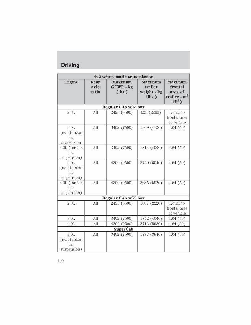
4x2 w/automatic transmission
Engine Rear
axle
ratio
Maximum
GCWR - kg
(lbs.)
Maximum
trailer
weight - kg
(lbs.)
Maximum
frontal
area of
trailer - m2
(ft2)
Regular Cab w/6’ box
2.3L All 2495 (5500) 1025 (2260) Equal tofrontal areaof vehicle
3.0L(non-torsion
barsuspension
All 3402 (7500) 1869 (4120) 4.64 (50)
3.0L (torsionbar
suspension)
All 3402 (7500) 1814 (4000) 4.64 (50)
4.0L(non-torsion
barsuspension)
All 4309 (9500) 2740 (6040) 4.64 (50)
4.0L (torsionbar
suspension)
All 4309 (9500) 2685 (5920) 4.64 (50)
Regular Cab w/7’ box
2.3L All 2495 (5500) 1007 (2220) Equal tofrontal areaof vehicle
3.0L All 3402 (7500) 1842 (4060) 4.64 (50)4.0L All 4309 (9500) 2712 (5980) 4.64 (50)
SuperCab
3.0L(non-torsion
barsuspension)
All 3402 (7500) 1787 (3940) 4.64 (50)
Driving
140

4x2 w/automatic transmission
Engine Rear
axle
ratio
Maximum
GCWR - kg
(lbs.)
Maximum
trailer
weight - kg
(lbs.)
Maximum
frontal
area of
trailer - m2
(ft2)
3.0L (torsionbar
suspension)
All 3402 (7500) 1715 (3780) 4.64 (50)
4.0L(non-torsion
barsuspension)
All 4309 (9500) 2667 (5880) 4.64 (50)
4.0L (torsionbar
suspension)
All 4309 (9500) 2595 (5720) 4.64 (50)
For high altitude operation, reduce GCW by 2% per 300 meters (1000ft.) elevation.For definition of terms used in this table see Vehicle Loading earlierin this chapter.To determine maximum trailer weight designed for your particularvehicle, see Calculating the load your vehicle can carry/tow earlierin this chapter.Maximum trailer weight is shown. The combined weight of thecompleted towing vehicle (including hitch, passengers and cargo) andthe loaded trailer must not exceed the Gross Combined Weight Rating(GCWR).
Driving
141

4x4 w/automatic transmission
Engine Rear axle
ratio
Maximum
GCWR - kg
(lbs.)
Maximum
trailer
weight - kg
(lbs.)
Maximum
frontal area
of trailer -
m2 (ft2)
Regular Cab w/6’ box
3.0L All 3402 (7500) 1751 (3860) 4.64 (50)4.0L All 4309 (9500) 2622 (5780) 4.64 (50)
Regular Cab w/7’ box
3.0L All 3402 (7500) 1724 (3800) 4.64 (50)4.0L All 4309 (9500) 2595 (5720) 4.64 (50)
SuperCab
3.0L All 3402 (7500) 1669 (3680) 4.64 (50)4.0L All 4309 (9500) 2540 (5600) 4.64 (50)4.0L(FX4
package)
All 4309 (9500) 2350 (5180) 4.64 (50)
For high altitude operation, reduce GCW by 2% per 300 meters (1000ft.) of elevation.For definition of terms used in this table, see Vehicle loading earlierin this chapter.To determine maximum trailer weight designed for your vehicle, seeCalculating the load your vehicle can carry/tow earlier in thischapter.Maximum trailer weight is shown. The combined weight of thecompleted towing vehicle (including hitch, passengers and cargo) andthe loaded trailer must not exceed the Gross Combined Weight Rating(GCWR).
Do not exceed the GVWR or the GAWR specified on thecertification label.
Driving
142
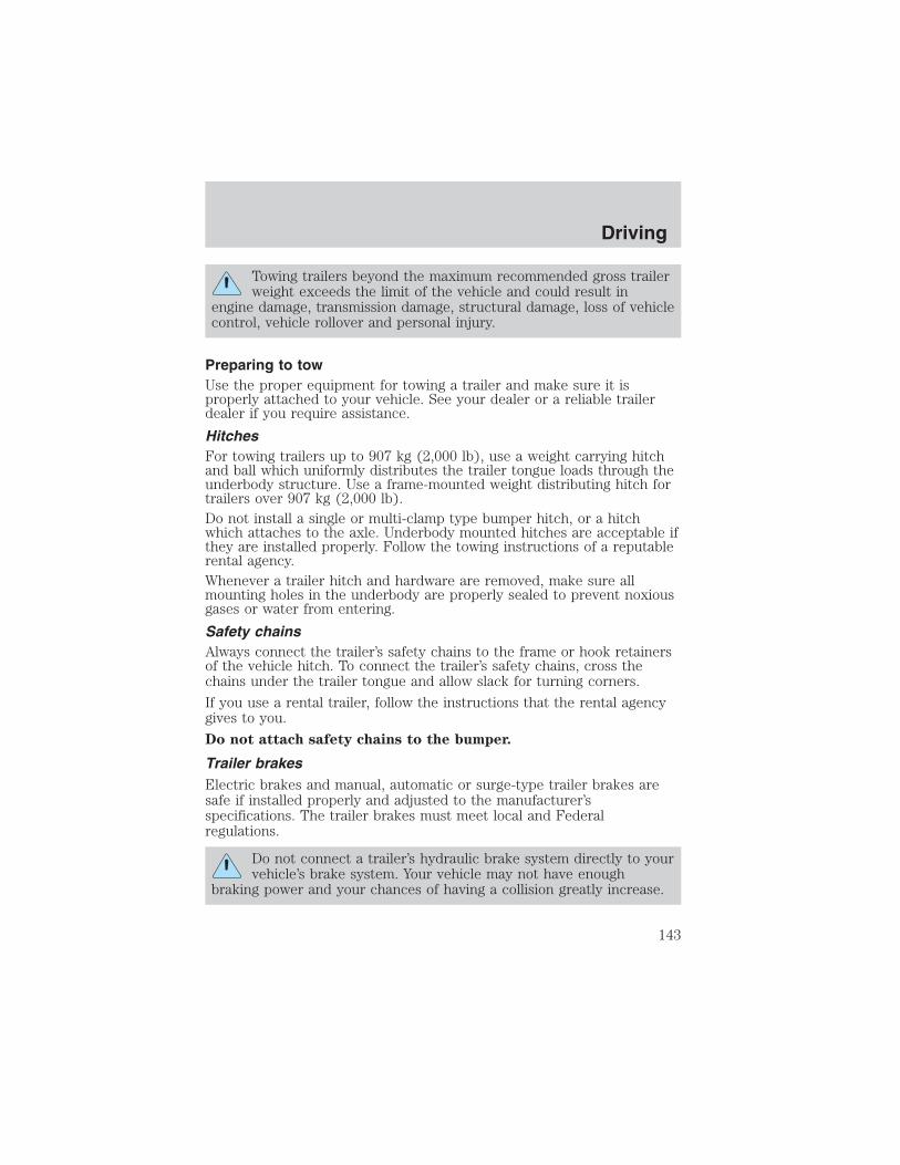
Towing trailers beyond the maximum recommended gross trailerweight exceeds the limit of the vehicle and could result in
engine damage, transmission damage, structural damage, loss of vehiclecontrol, vehicle rollover and personal injury.
Preparing to towUse the proper equipment for towing a trailer and make sure it isproperly attached to your vehicle. See your dealer or a reliable trailerdealer if you require assistance.
HitchesFor towing trailers up to 907 kg (2,000 lb), use a weight carrying hitchand ball which uniformly distributes the trailer tongue loads through theunderbody structure. Use a frame-mounted weight distributing hitch fortrailers over 907 kg (2,000 lb).Do not install a single or multi-clamp type bumper hitch, or a hitchwhich attaches to the axle. Underbody mounted hitches are acceptable ifthey are installed properly. Follow the towing instructions of a reputablerental agency.Whenever a trailer hitch and hardware are removed, make sure allmounting holes in the underbody are properly sealed to prevent noxiousgases or water from entering.
Safety chainsAlways connect the trailer’s safety chains to the frame or hook retainersof the vehicle hitch. To connect the trailer’s safety chains, cross thechains under the trailer tongue and allow slack for turning corners.
If you use a rental trailer, follow the instructions that the rental agencygives to you.
Do not attach safety chains to the bumper.
Trailer brakesElectric brakes and manual, automatic or surge-type trailer brakes aresafe if installed properly and adjusted to the manufacturer’sspecifications. The trailer brakes must meet local and Federalregulations.
Do not connect a trailer’s hydraulic brake system directly to yourvehicle’s brake system. Your vehicle may not have enough
braking power and your chances of having a collision greatly increase.
Driving
143

The braking system of the tow vehicle is rated for operation at theGVWR not GCWR.
Trailer lamps
Trailer lamps are required on most towed vehicles. Make sure yourtrailer lamps conform to local and Federal regulations. See your dealer ortrailer rental agency for proper instructions and equipment for hookingup trailer lamps.
Using a step bumper
The optional step bumper is equipped with an integral hitch and requiresonly a ball with a 19 mm (3/4 inch) shank diameter. The bumper has a907 kg (2,000 lb.) trailer weight and 91 kg (200 lb.) tongue weightcapability.
The rated capacities (as shown in this guide) for trailer towing with thefactory bumper are only valid when the trailer hitch ball is installeddirectly into the ball hole in the bumper. Addition of bracketry to eitherlower the ball hitch position or extend the ball hitch rearward willsignificantly increase the loads on the bumper and its attachments. Thiscan result in the failure of the bumper or the bumper attachments. Useof any type of hitch extensions should be considered abuse.
Trailer tow connectorThe trailer tow connector is locatedunder the rear bumper, on thedriver’s side of the vehicle.
Refer to the following chart for information regarding thefactory-equipped trailer tow connector:
1
2
34
Driving
144

Trailer tow connector
Color Function Comment
1. Dark Green Trailer right-handturn signal
Circuit activated when brakepedal is depressed or whenignition is on and right-handturn signal is applied.
2. Yellow Trailer left-hand turnsignal
Circuit activated when brakepedal is depressed or whenignition is on and left-handturn signal is applied.
3. Tan/White Tail lamp Relay controlled circuitactivated when the parklamps/headlamps are on.
4. White Ground Matching vehicle circuitreturns to battery’s negativeground.
Driving while you towWhen towing a trailer:• Turn off the speed control. The speed control may shut off
automatically when you are towing on long, steep grades.• Consult your local motor vehicle speed regulations for towing a trailer.• To eliminate excessive shifting, use a lower gear. This will also assist
in transmission cooling. (For additional information, refer to theDriving with a 5–speed automatic transmission section in thischapter.
• Under extreme conditions with large frontal trailers, high outsidetemperatures and highway speeds, the coolant gauge may indicatehigher than normal coolant temperatures. If this occurs, reduce speeduntil the coolant temperature returns to the normal range. Refer toEngine coolant temperature gauge in the Instrument clusterchapter.
• Anticipate stops and brake gradually.• Do not exceed the GCWR rating or transmission damage may occur.
Servicing after towingIf you tow a trailer for long distances, your vehicle will require morefrequent service intervals. Refer to your scheduled maintenance guide formore information.
Driving
145

Trailer towing tips• Practice turning, stopping and backing up before starting on a trip to
get the feel of the vehicle trailer combination. When turning, makewider turns so the trailer wheels will clear curbs and other obstacles.
• Allow more distance for stopping with a trailer attached.
• The trailer tongue weight should be 10–15% of the loaded trailerweight.
• After you have traveled 80 km (50 miles), thoroughly check yourhitch, electrical connections and trailer wheel lug nuts.
• To aid in engine/transmission cooling and A/C efficiency during hotweather while stopped in traffic, place the gearshift lever in P (Park)(automatic transmission) or N (Neutral) (manual transmissions).
• Vehicles with trailers should not be parked on a grade. If you mustpark on a grade, place wheel chocks under the trailer’s wheels.
Launching or retrieving a boatDisconnect the wiring to the trailer before backing the trailerinto the water. Reconnect the wiring to the trailer after thetrailer is removed from the water.
When backing down a ramp during boat launching or retrieval:
• do not allow the static water level to rise above the bottom edge ofthe rear bumper.
• do not allow waves to break higher than 15 cm (6 inches) above thebottom edge of the rear bumper.
Exceeding these limits may allow water to enter vehicle components:
• causing internal damage to the components.
• affecting driveability, emissions and reliability.
Replace the rear axle lubricant any time the axle has been submerged inwater. Rear axle lubricant quantities are not to be checked or changedunless a leak is suspected or repair required.
RECREATIONAL TOWINGFollow these guidelines if you have a need for recreational towing. Anexample of recreational towing would be towing your vehicle behind amotorhome. These guidelines are designed to ensure that yourtransmission is not damaged.
Driving
146

4x2 and 4x4 vehicles equipped with a manual transmission:
Note: 4x2 vehicles with a manual transmission and 4x4 vehicles with anelectronic-shift transfer case and a manual transmission, follow theseguidelines for recreational towing:Note: 4x4 vehicles equipped with an electronic-shift transfer case, youmust set the 4WD control to 2H (2WD High) before flat towing.Before you have your vehicle towed:• Release the parking brake.• Move the gearshift to the neutral position.• Turn the key in the ignition to the OFF/UNLOCKED position.• The maximum recommended speed is 88 km/h (55 mph).• The maximum recommended distance is unlimited.• The vehicle must be towed in the forward position to ensure no
damage is done to the internal transmission components.In addition, it is recommended that you follow the instructionsprovided by the aftermarket manufacturer of the towingapparatus if one has been installed.
4x4 vehicles equipped with manual-shift transfer case:
• Release the parking brake.• Turn the key in the ignition to the OFF/UNLOCKED position.
• Place the transmission in N (Neutral).
• Place the transfer case lever in N (Neutral).
• Do not exceed 88 km/h (55 mph) vehicle speed.
• The maximum recommended distance is unlimited.
• The vehicle must be towed in the forward position to ensure nodamage is done to the internal transfer case components.
The transfer case N (Neutral) position overrides the transmissionand puts the vehicle in neutral regardless of transmissiongearshift lever position. The vehicle can move forward orbackward.
This position should only be used when towing the vehicle.
Do not leave the vehicle unattended with the transfer case in theN (Neutral) position. Always set the parking brake fully and turn
off the ignition when leaving the vehicle.
Driving
147

After reaching the destination, you must place the Ranger’s 4x4 gearshiftlever in gear (2H, 4H or 4L).
4x2 and 4x4 vehicles equipped with automatic transmissions:
4x2 vehicles with automatic transmissions or 4x4 vehicles with anelectronic-shift transfer case and automatic transmission, follow theseguidelines for recreational towing:
• Release the parking brake.
• Turn the key in the ignition to the OFF/UNLOCKED position.
• Place the transmission in N (Neutral).
• Do not exceed a distance of 80 km (50 miles).
• Do not exceed 56 km/h (35 mph) vehicle speed.
• The vehicle must be towed in the forward position to ensure nodamage is done to the internal transfer case components.
If a distance of 80 km (50 miles) or a speed of 56 km/h (35 mph) mustbe exceeded, you must disconnect the front (4x4 only) and reardriveshafts. Ford recommends the driveshafts be removed/installed onlyby a qualified technician. See your local dealer for driveshaftremoval/installation.
Improper removal/installation of the driveshaft can causetransmission fluid or transfer case fluid loss, damage to thedriveshaft and internal transmission and transfer casecomponents.
CAMPER BODIESYour Ranger Pickup is not recommended for slide–in camper bodies.
Driving
148

GETTING ROADSIDE ASSISTANCETo fully assist you should you have a vehicle concern, Ford MotorCompany offers a complimentary roadside assistance program. Thisprogram is separate from the New Vehicle Limited Warranty. The serviceis available:
• 24–hours, seven days a week
• for the New Vehicle Limited Warranty period of three years or 60,000 km(36,000 miles), whichever occurs first on Ford and Mercury vehicles, andfour years or 80,000 km (50,000 miles) on Lincoln vehicles.
Roadside assistance will cover:
• changing a flat tire
• jump-starts
• lock-out assistance
• limited fuel delivery
• towing of your disabled vehicle to the nearest Ford Motor Companydealership, or your selling dealer if within 56.3 km (35 miles) of thenearest Ford Motor Company dealership (one tow per disablement).Even non-warranty related tows, like accidents or getting stuck in themud or snow, are covered (some exclusions apply, such as impoundtowing or repossession).
Canadian customers refer to your Owner Information Guide forinformation on:
• coverage period
• exact fuel amounts
• towing of your disabled vehicle
• emergency travel expense reimbursement
• travel planning benefits
USING ROADSIDE ASSISTANCEComplete the roadside assistance identification card and place it in yourwallet for quick reference. In the United States, this card is found in theOwner Guide portfolio in the glove compartment in Ford vehicles and ismailed to you if you own a Mercury or Lincoln. In Canada, the card isfound in the Owner Information Guide in the glove compartment.
U.S. Ford or Mercury vehicle customers who require roadside assistance,call 1–800–241–3673; Lincoln vehicle customers call 1–800–521–4140.
Roadside Emergencies
Roadside Emergencies
149

Canadian customers who require roadside assistance, call1–800–665–2006.
If you need to arrange roadside assistance for yourself, Ford MotorCompany will reimburse a reasonable amount. To obtain reimbursementinformation, U.S. Ford or Mercury vehicles customers call1-800-241-3673; Lincoln vehicle customers call 1–800–521–4140.
Canadian customers who need to obtain reimbursement information, call1–800–665–2006.
ROADSIDE COVERAGE BEYOND BASIC WARRANTY
In the United States, you may purchase additional roadside assistancecoverage beyond this period through the Ford Auto Club by contactingyour Ford or Lincoln Mercury dealer.
Similarly in Canada, for uninterrupted Roadside Assistance coverage, youmay purchase extended coverage prior to your Basic Warranty’s RoadsideAssistance expiring. For more information and enrollment, contact1–877–294–2582 or visit our website at www.ford.ca.
HAZARD FLASHER
The hazard flasher is located on thesteering column, just behind thesteering wheel. The hazard flasherswill operate when the ignition is inany position.
Push in the flasher control and allfront and rear direction signals willflash. Press the flasher control againto turn them off. Use it when yourvehicle is disabled and is creating asafety hazard for other motorists.
Note: With extended use, the flasher may run down your battery.
FUEL PUMP SHUT-OFF SWITCH FUELRESET
This device stops the electric fuel pump from sending fuel to the enginewhen your vehicle has had a substantial jolt.
After an accident, if the engine cranks but does not start, this switchmay have been activated.
Roadside Emergencies
150

This switch is located in the frontpassenger’s footwell, by the kickpanel access cover.
To reset the switch:
1. Turn the ignition OFF.
2. Check the fuel system for leaks.
3. If no leaks are apparent, reset theswitch by pushing in on the resetbutton.
4. Turn the ignition ON.
5. Wait a few seconds and returnthe key to OFF.
6. Make another check of leaks.
FUSES AND RELAYS
FusesIf electrical components in thevehicle are not working, a fuse mayhave blown. Blown fuses areidentified by a broken wire withinthe fuse. Check the appropriatefuses before replacing any electricalcomponents.
Note: Always replace a fuse with one that has the specified amperagerating. Using a fuse with a higher amperage rating can cause severe wiredamage and could start a fire.
15
Roadside Emergencies
151

Standard fuse amperage rating and color
COLOR
Fuse
rating
Mini
fuses
Standard
fuses
Maxi
fuses
Cartridge
maxi
fuses
Fuse link
cartridge
2A Grey Grey — — —3A Violet Violet — — —4A Pink Pink — — —5A Tan Tan — — —
7.5A Brown Brown — — —10A Red Red — — —15A Blue Blue — — —20A Yellow Yellow Yellow Blue Blue25A Natural Natural — — —30A Green Green Green Pink Pink40A — — Orange Green Green50A — — Red Red Red60A — — Blue — Yellow70A — — Tan — Brown80A — — Natural — Black
Passenger compartment fuse panelThe fuse panel is located on theleft-hand side of the instrumentpanel facing the driver’s side door.Pull the panel cover outward toaccess the fuses.
Roadside Emergencies
152

To remove a fuse use the fuse puller tool provided.
The fuses are coded as follows:
Fuse/Relay
Location
Fuse Amp
Rating
Passenger Compartment Fuse
Panel Description
1 5A Power mirror switch2 10A Daytime Running Lights (DRL),
Back-up lamps, Transmission,Passenger air bag deactivationswitch, Blower motor relay
3 7.5A Left stop/turn trailer towconnector
4 — Not used5 15A 4x4 control module6 2A Brake pressure switch7 7.5A Right stop/turn trailer tow
connector8 — Not used9 7.5A Brake pedal position switch
12
34
56
78
910
1112
1314
1516
1718
1920
2122
2324
2526
2930
35
36
3132
33
34
2728
Roadside Emergencies
153

Fuse/Relay
Location
Fuse Amp
Rating
Passenger Compartment Fuse
Panel Description
10 7.5A Speed control servo/amplifierassembly, Generic ElectronicModule (GEM), Shift lockactuator, Turn signals, 4x4
11 7.5A Instrument cluster, 4x4, Main lightswitch, Truck Central SecurityModule (TCSM), GEM
12 — Not used13 20A Brake pedal position switch14 10A ABS control module15 — Not used16 30A Windshield wiper motor, Wiper
HI/LO relay, Wiper run/park relay17 20A Cigar lighter, Data Link Connector
(DLC)18 — Not used19 25A Powertrain Control Module (PCM)
power diode, Ignition, PATS20 7.5A GEM, Radio21 15A Hazard flasher22 20A Auxiliary power socket23 — Not used24 7.5A Clutch Pedal Position (CPP)
switch, Starter interrupt relay25 — Not used26 10A Battery saver relay, Auxiliary relay
box, Restraint Central Module(RCM), Generic ElectronicModule (GEM), Instrumentcluster
27 — Not used28 7.5A GEM, Radio
Roadside Emergencies
154
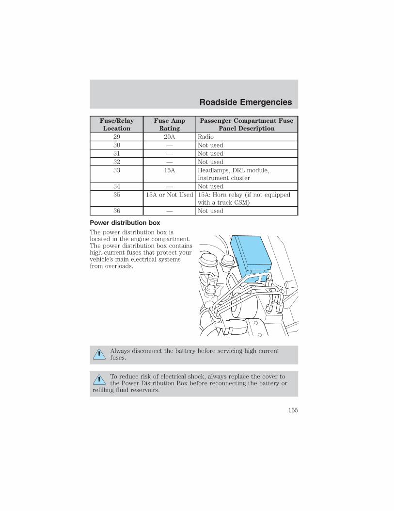
Fuse/Relay
Location
Fuse Amp
Rating
Passenger Compartment Fuse
Panel Description
29 20A Radio30 — Not used31 — Not used32 — Not used33 15A Headlamps, DRL module,
Instrument cluster34 — Not used35 15A or Not Used 15A: Horn relay (if not equipped
with a truck CSM)36 — Not used
Power distribution boxThe power distribution box islocated in the engine compartment.The power distribution box containshigh-current fuses that protect yourvehicle’s main electrical systemsfrom overloads.
Always disconnect the battery before servicing high currentfuses.
To reduce risk of electrical shock, always replace the cover tothe Power Distribution Box before reconnecting the battery or
refilling fluid reservoirs.
Roadside Emergencies
155

If the battery has been disconnected and reconnected, refer to theBattery section of the Maintenance and specifications chapter.
2.3L engine (if equipped)
The high-current fuses are coded as follows:
Fuse/Relay
Location
Fuse Amp
Rating
Power Distribution Box
Description
1 50A** I/P fuse panel2 — Not used3 — Not used4 — Not used5 — Not used6 50A** Anti-lock Brake System (ABS)
pump motor7 30A* Powertrain Control Module (PCM)8 20A* Power door locks, Remote entry9 — Not used
10 — Not used11 50A** Starter relay, Ignition switch
1 2 3 4 521 22 23 24
25 26 27 28
29 30 31 32
33 34 35 36
37 38 39 40
41 42 43 44
6 7 8 9 10
55
4948
54535251
5656 B
56 A
5050 B
50 A4745
45 B
45 A46
46 B
46 A
11 12 13 14 15
16 17 18 19 20
Roadside Emergencies
156

Fuse/Relay
Location
Fuse Amp
Rating
Power Distribution Box
Description
12 20A* Power windows13 — Not used14 — Not used15 — Not used16 40A** Blower motor17 20A** Auxiliary cooling fan18 — Not used19 — Not used20 — Not used21 10A* PCM memory22 — Not used23 20A* Fuel pump motor24 30A* Headlamps25 10A* A/C clutch solenoid26 — Not used27 — Not used28 30A* ABS module29 — Not used30 15A* Trailer tow31 20A* Foglamps, Daytime Running
Lamps (DRL)32 — Not used33 15A* Park Lamp34 — Not used35 — Not used36 — Not used37 — Not used38 10A* Left headlamp low beam39 — Not used40 — Not used41 20A* Heated oxygen sensors
Roadside Emergencies
157

Fuse/Relay
Location
Fuse Amp
Rating
Power Distribution Box
Description
42 10A* Right headlamp low beam43 — (Resistor)44 — Not used
45A — Wiper HI/LO45B — Wiper park/run46A — Fuel pump46B — Trailer tow47 — Starter48 — Auxiliary cooling fan49 — Not used50 — Not used51 — Not used52 — Not used53 — PCM Diode54 — PCM55 — Blower
56A — A/C clutch solenoid56B — Front washer pump
* Mini Fuses ** Maxi Fuses
Roadside Emergencies
158

3.0L and 4.0L engines (if equipped)
The high-current fuses are coded as follows:
Fuse/Relay
Location
Fuse Amp
Rating
Power Distribution Box
Description
1 50A** I/P fuse panel2 50A** Amplifier (Tremor audio system
only)3 — Not used4 — Not used5 — Not used6 50A** Anti-lock Brake System (ABS)
pump motor7 30A* Powertrain Control Module (PCM)8 20A* Power door locks, Remote entry9 — Not used
10 — Not used11 50A** Starter relay, Ignition switch12 20A* Power windows
Roadside Emergencies
159
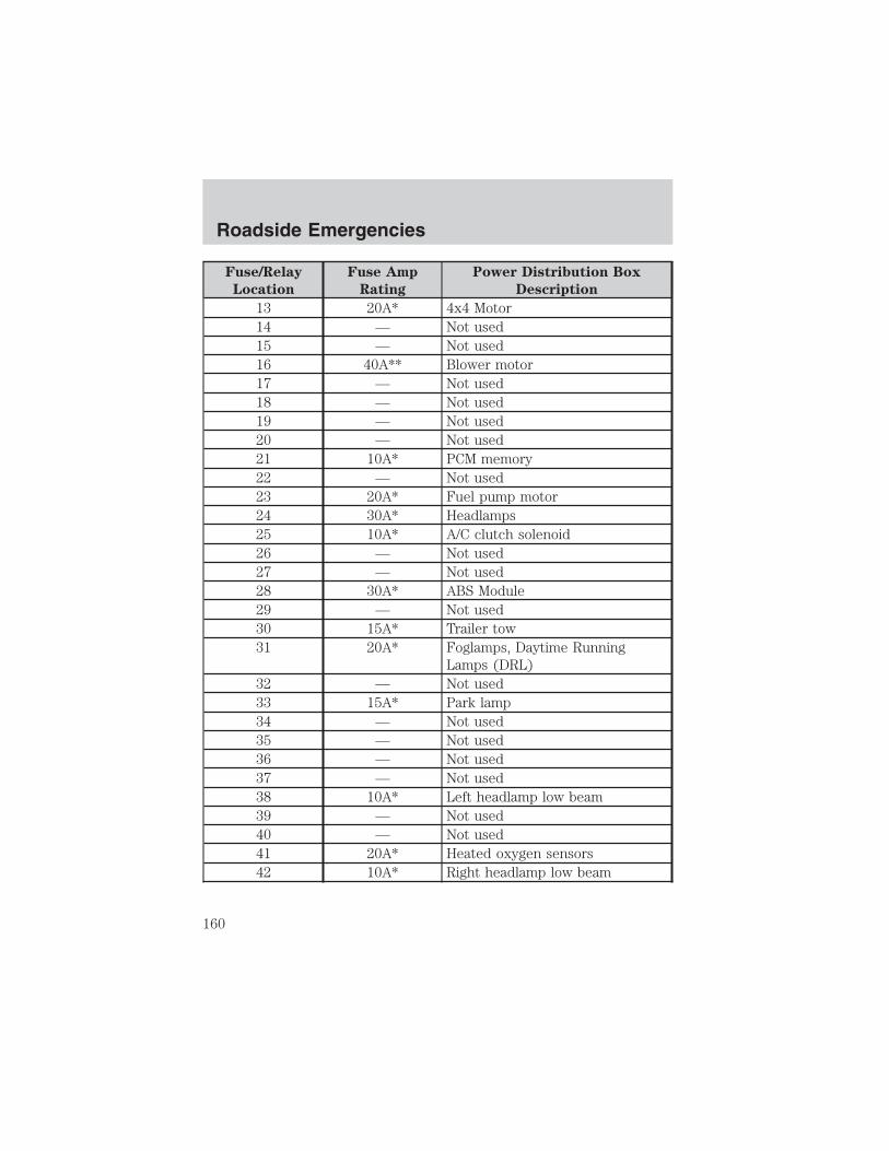
Fuse/Relay
Location
Fuse Amp
Rating
Power Distribution Box
Description
13 20A* 4x4 Motor14 — Not used15 — Not used16 40A** Blower motor17 — Not used18 — Not used19 — Not used20 — Not used21 10A* PCM memory22 — Not used23 20A* Fuel pump motor24 30A* Headlamps25 10A* A/C clutch solenoid26 — Not used27 — Not used28 30A* ABS Module29 — Not used30 15A* Trailer tow31 20A* Foglamps, Daytime Running
Lamps (DRL)32 — Not used33 15A* Park lamp34 — Not used35 — Not used36 — Not used37 — Not used38 10A* Left headlamp low beam39 — Not used40 — Not used41 20A* Heated oxygen sensors42 10A* Right headlamp low beam
Roadside Emergencies
160

Fuse/Relay
Location
Fuse Amp
Rating
Power Distribution Box
Description
43 — Not used44 — Not used
45A — Wiper HI/LO45B — Wiper park/run46A — Fuel pump46B — Trailer tow47A — A/C clutch solenoid47B — Front washer pump48A — Fog lamps48B — Fog lamp relay51 — Not used52 — Not used53 — PCM Diode54 — PCM55 — Blower56 — Starter
* Mini Fuses ** Maxi FusesCHANGING THE TIRESIf you get a flat tire while driving, do not apply the brake heavily.Instead, gradually decrease your speed. Hold the steering wheel firmlyand slowly move to a safe place on the side of the road.
The use of tire sealants is not recommended and maycompromise the integrity of your tires.
Temporary spare tire informationYour vehicle may be equipped with a conventional spare tire that may bedifferent in size (smaller diameter and narrower width) than other tireson your vehicle. If this is the case, your spare tire is considered“temporary” and the spare wheel will be labeled as such. Replace thistire with a tire of the same size, speed rating and load carrying capacityas the other road tires as soon as possible.It is not recommended that the vehicle be operated in 4WD modes witha “temporary” (i.e. dissimilar size) spare. If 4WD operation is necessary,do not operate above speeds of 16 km/h (10 mph) or for distances above80 km (50 miles).
Roadside Emergencies
161

If you use the temporary spare tire continuously or do not followthese precautions, the tire could fail, causing you to lose control
of the vehicle, possibly injuring yourself or others.
When driving with the temporary spare tire do not:
• exceed 80 km/h (50 mph) or drive further than 3,200 km (2,000 miles)total under any circumstances
• load the vehicle beyond maximum vehicle load rating listed on theSafety Compliance Label
• tow a trailer
• use more than one temporary spare tire at a time
Use of a temporary spare tire at any one wheel location can lead toimpairment of the following:
• Handling, stability and braking performance
• Comfort and noise
• Ground clearance and parking at curbs
• Winter driving capability
Conventional spare tire information
If you have the conventional spare tire that is the same size as yourother road tires, you can use the spare as you would any of the othertires. The spare tire will be equivalent to your road tires, although it maynot have the same appearance (black-side wall instead of outlined-whiteletters).
Location of the spare tire and tools
The spare tire and tools for your vehicle are stowed in the followinglocations:
Roadside Emergencies
162
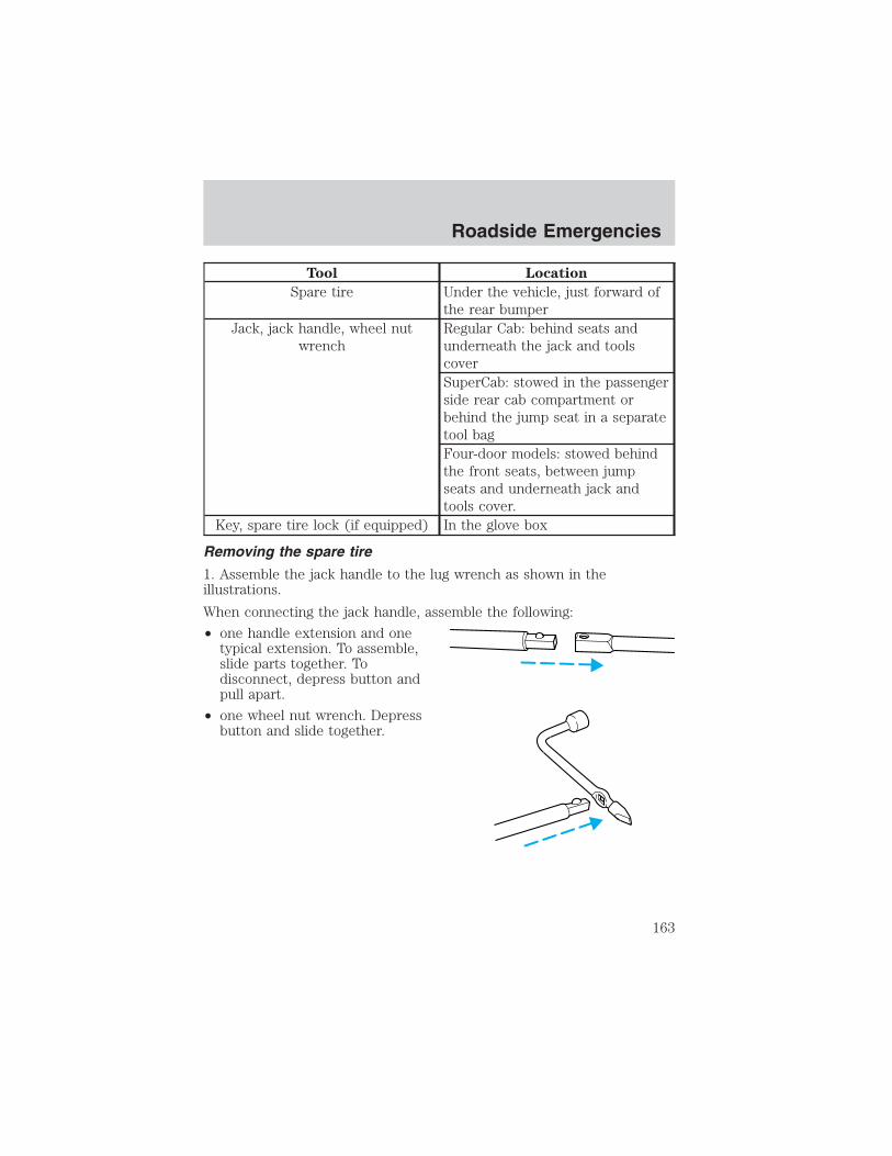
Tool Location
Spare tire Under the vehicle, just forward ofthe rear bumper
Jack, jack handle, wheel nutwrench
Regular Cab: behind seats andunderneath the jack and toolscoverSuperCab: stowed in the passengerside rear cab compartment orbehind the jump seat in a separatetool bagFour-door models: stowed behindthe front seats, between jumpseats and underneath jack andtools cover.
Key, spare tire lock (if equipped) In the glove box
Removing the spare tire
1. Assemble the jack handle to the lug wrench as shown in theillustrations.
When connecting the jack handle, assemble the following:
• one handle extension and onetypical extension. To assemble,slide parts together. Todisconnect, depress button andpull apart.
• one wheel nut wrench. Depressbutton and slide together.
Roadside Emergencies
163

2. If equipped, unlock and removethe spare tire carrier lock from therear access hole located just abovethe rear bumper and below thetailgate.
3. Insert the straight end of the jackhandle into the rear access holelocated just above the rear bumperand below the tailgate.
Forward motion will stop andresistance to turning will be feltwhen properly engaged.
4. Turn the handle counterclockwiseuntil tire is lowered to the groundand the cable is slightly slack.
5. Remove the retainer from the spare tire.
Tire change procedure
To prevent the vehicle from moving when you change a tire, besure the parking brake is set, then block (in both directions) the
wheel that is diagonally opposite (other side and end of the vehicle) tothe tire being changed.
If the vehicle slips off the jack, you or someone else could beseriously injured.
Roadside Emergencies
164

1. Park on a level surface, activatehazard flashers and place gearshiftlever in P (Park) (automatictransmission) or 1 (First) (manualtransmission).
2. Set the parking brake and turnengine OFF.
3. Block the diagonally oppositewheel.
4. Insert tapered end of the lugwrench behind hub caps and twistthem off.
5. Loosen each wheel lug nutone-half turn counterclockwise butdo not remove them until the wheelis raised off the ground.
6. Position the jack according to thefollowing guides and turn the jackhandle clockwise until the tire is amaximum of 25 mm (1 inch) off the ground.
• Front
Roadside Emergencies
165

• Rear
To lessen the risk ofpersonal injury, do not put
any part of your body under thevehicle while changing a tire. Donot start the engine when yourvehicle is on the jack. The jack isonly meant for changing the tire.
• Never use the differential as ajacking point.
7. Remove the wheel lug nuts with the lug wrench.8. Replace the flat tire with the spare tire, making sure the valve stem isfacing outward. Reinstall the lug nuts until the wheel is snug against thehub. Do not fully tighten the lug nuts until the wheel has been lowered.9. Lower the wheel by turning the jack handle counterclockwise.
10. Remove the jack and fullytighten the lug nuts, in the ordershown, to 135 Nm (100 lb-ft). Notethat these tightening specificationsare for nut and bolt threads that arefree of dirt and rust. Use only Fordrecommended (1/2–20) replacementfasteners.
11. Stow the flat tire. Refer toStowing the flat/spare tire.
12. Stow the jack and lug wrench. Make sure the jack is fastened so itdoes not rattle when you drive.
1
43
25
Roadside Emergencies
166
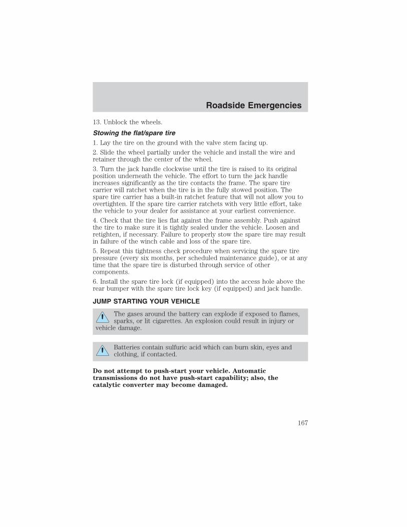
13. Unblock the wheels.
Stowing the flat/spare tire1. Lay the tire on the ground with the valve stem facing up.
2. Slide the wheel partially under the vehicle and install the wire andretainer through the center of the wheel.
3. Turn the jack handle clockwise until the tire is raised to its originalposition underneath the vehicle. The effort to turn the jack handleincreases significantly as the tire contacts the frame. The spare tirecarrier will ratchet when the tire is in the fully stowed position. Thespare tire carrier has a built-in ratchet feature that will not allow you toovertighten. If the spare tire carrier ratchets with very little effort, takethe vehicle to your dealer for assistance at your earliest convenience.
4. Check that the tire lies flat against the frame assembly. Push againstthe tire to make sure it is tightly sealed under the vehicle. Loosen andretighten, if necessary. Failure to properly stow the spare tire may resultin failure of the winch cable and loss of the spare tire.
5. Repeat this tightness check procedure when servicing the spare tirepressure (every six months, per scheduled maintenance guide), or at anytime that the spare tire is disturbed through service of othercomponents.
6. Install the spare tire lock (if equipped) into the access hole above therear bumper with the spare tire lock key (if equipped) and jack handle.
JUMP STARTING YOUR VEHICLE
The gases around the battery can explode if exposed to flames,sparks, or lit cigarettes. An explosion could result in injury or
vehicle damage.
Batteries contain sulfuric acid which can burn skin, eyes andclothing, if contacted.
Do not attempt to push-start your vehicle. Automatictransmissions do not have push-start capability; also, thecatalytic converter may become damaged.
Roadside Emergencies
167

Preparing your vehicle
When the battery is disconnected or a new battery is installed, thetransmission must relearn its shift strategy. As a result, the transmissionmay have firm and/or soft shifts. This operation is considered normal andwill not affect function or durability of the transmission. Over time, theadaptive learning process will fully update transmission operation.
1. Use only a 12–volt supply to start your vehicle.
2. Do not disconnect the battery of the disabled vehicle as this coulddamage the vehicle’s electrical system.
3. Park the booster vehicle close to the hood of the disabled vehiclemaking sure the two vehicles do not touch. Set the parking brake onboth vehicles and stay clear of the engine cooling fan and other movingparts.
4. Check all battery terminals and remove any excessive corrosion beforeyou attach the battery cables. Ensure that vent caps are tight and level.
5. Turn the heater fan on in both vehicles to protect any electricalsurges. Turn all other accessories off.
Connecting the jumper cables
1. Connect the positive (+) jumper cable to the positive (+) terminal ofthe discharged battery.
Note: In the illustrations, lightning bolts are used to designate theassisting (boosting) battery.
+–
+–
Roadside Emergencies
168
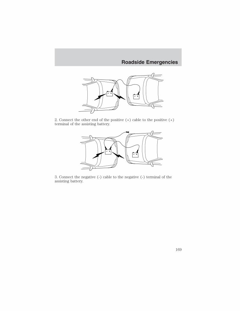
2. Connect the other end of the positive (+) cable to the positive (+)terminal of the assisting battery.
3. Connect the negative (-) cable to the negative (-) terminal of theassisting battery.
+–
+–
+–
+–
Roadside Emergencies
169

4. Make the final connection of the negative (-) cable to an exposedmetal part of the stalled vehicle’s engine, away from the battery and thecarburetor/fuel injection system. Do not use fuel lines, engine rockercovers or the intake manifold as grounding points.
Do not connect the end of the second cable to the negative (-)terminal of the battery to be jumped. A spark may cause an
explosion of the gases that surround the battery.
5. Ensure that the cables are clear of fan blades, belts, moving parts ofboth engines, or any fuel delivery system parts.
Jump starting
1. Start the engine of the booster vehicle and run the engine atmoderately increased speed.
2. Start the engine of the disabled vehicle.
3. Once the disabled vehicle has been started, run both engines for anadditional three minutes before disconnecting the jumper cables.
+–
+–
Roadside Emergencies
170

Removing the jumper cables
Remove the jumper cables in the reverse order that they wereconnected.
1. Remove the jumper cable from the ground metal surface.
Note: In the illustrations, lightning bolts are used to designate theassisting (boosting) battery.
2. Remove the jumper cable on the negative (-) connection of thebooster vehicle’s battery.
+–
+–
+–
+–
Roadside Emergencies
171

3. Remove the jumper cable from the positive (+) terminal of the boostervehicle’s battery.
4. Remove the jumper cable from the positive (+) terminal of thedisabled vehicle’s battery.
After the disabled vehicle has been started and the jumper cablesremoved, allow it to idle for several minutes so the engine computer canrelearn its idle conditions.
+–
+–
+–
+–
Roadside Emergencies
172

WRECKER TOWING
If you need to have your vehicle towed, contact a professional towingservice or, if you are a member of a roadside assistance program, yourroadside assistance service provider.
It is recommended that your vehicle be towed with a wheel lift or flatbedequipment. Do not tow with a slingbelt. Ford Motor Company has notapproved a slingbelt towing procedure.
On 4x2 vehicles, it is acceptable to tow the vehicle with the front wheelson the ground and the rear wheels off the ground.
On 4x4 vehicles, it is recommended that your vehicle be towed with awheel lift and dollies or flatbed equipment with all the wheels off theground.
If the vehicle is towed by other means or incorrectly, vehicledamage may occur.
Ford Motor Company produces a towing manual for all authorized towtruck operators. Have your tow truck operator refer to this manual forproper hook-up and towing procedures for your vehicle.
Roadside Emergencies
173

GETTING THE SERVICES YOU NEED
At homeFord Motor Company and Ford of Canada have authorized dealerships toservice your vehicle. It is preferred that you return to the authorizeddealer where your vehicle was purchased when warranty repairs areneeded. However, you may also take your vehicle to another Ford MotorCompany or Ford of Canada dealership authorized for warranty repairs.Certain warranty repairs require special training though, so not alldealers are authorized to perform all warranty repairs. That means thatdepending on the warranty repair needed, the vehicle may need to betaken to another dealer. If a particular dealership cannot assist you, thencontact the Customer Relationship Center.
If you have questions or concerns, or are unsatisfied with the service youare receiving, follow these steps:
1. Contact your Sales Representative or Service Advisor at yourselling/servicing dealership.
2. If your inquiry or concern remains unresolved, contact the SalesManager or Service Manager at the dealership.
3. If the inquiry or concern cannot be resolved at the dealership level,please contact the Ford Customer Relationship Center.
Away from homeIf you own a Ford or Mercury vehicle and are away from home whenyour vehicle needs service, or if you need more help than the dealershipcould provide, after following the steps described above, contact theFord Customer Relationship Center to find an authorized dealership tohelp you.
In the United States:
Ford Motor CompanyCustomer Relationship Center16800 Executive Plaza DriveP.O. Box 6248Dearborn, Michigan 481211-800-392-3673 (FORD)(TDD for the hearing impaired: 1-800-232-5952)www.ford.com
In Canada:Customer Relationship Centre
Customer Assistance
Customer Assistance
174

Ford Motor Company of Canada, LimitedP.O. Box 2000Oakville, Ontario L6J 5E41-800-565-3673 (FORD)www.ford.caIf you own a Lincoln vehicle and are away from home when your vehicleneeds service, or if you need more help than the dealership couldprovide, after following the steps described above, contact the FordCustomer Relationship Center to find an authorized dealership to helpyou.In the United States:Ford Motor CompanyCustomer Relationship Center16800 Executive Plaza DriveP.O. Box 6248Dearborn, Michigan 481211-800-521-4140(TDD for the hearing impaired: 1-800-232-5952)www.ford.comIn Canada:Customer Relationship CentreFord Motor Company of Canada, LimitedP.O. Box 2000Oakville, Ontario L6J 5E41-800-565-3673 (FORD)www.ford.caIn order to help you service your Ford or Lincoln Mercury vehicle, pleasehave the following information available when contacting a CustomerRelationship Center:
• Your telephone number (home and business)
• The name of the dealer and the city where the dealership is located
• The year and make of your vehicle
• The date of vehicle purchase
• The current odometer reading
• The vehicle identification number (VIN)
If you still have a complaint involving a warranty dispute, you may wishto contact the Dispute Settlement Board (U.S.).
In some states (in the U.S.) you must directly notify Ford in writingbefore pursuing remedies under your state’s warranty laws. Ford is alsoallowed a final repair attempt in some states.
Customer Assistance
175
In the United States, a warranty dispute must be submitted to theDispute Settlement Board before taking action under the Magnuson-MossWarranty Act, or to the extent allowed by state law, before pursuingreplacement or repurchase remedies provided by certain state laws. Thisdispute handling procedure is not required prior to enforcing statecreated rights or other rights which are independent of theMagnuson-Moss Warranty Act or state replacement or repurchase laws.
FORD EXTENDED SERVICE PLANYou can get more protection for your new car or light truck bypurchasing Ford Extended Service Plan (Ford ESP) coverage. Ford ESPis an optional service contract which is backed by Ford Motor Companyor Ford Motor Service Company (in the U.S.) and Ford of Canada (inCanada). It provides the following:
• Benefits during the warranty period depending on the plan youpurchase (such as: reimbursement for rentals; coverage for certainmaintenance and wear items).
• Protection against covered repair costs after your Bumper-to-BumperWarranty expires.
You may purchase Ford ESP from any participating Ford and LincolnMercury and Ford of Canada dealer. There are several plans available invarious time, distance and deductible combinations which can be tailoredto fit your own driving needs. Ford ESP also offers reimbursementbenefits for towing and rental coverage.
When you buy Ford ESP, you receive Peace-of-Mind protectionthroughout the United States and Canada, provided by a network ofmore than 5,000 participating Ford or Lincoln Mercury and Ford ofCanada dealers.
If you did not take advantage of the Ford Extended Service Plan at thetime of purchasing your vehicle, you may still be eligible. Since thisinformation is subject to change, please ask your dealer for completedetails about Ford Extended Service Plan coverage options, or visit theFord ESP website at www.ford-esp.com.
THE DISPUTE SETTLEMENT BOARD (U.S. ONLY)The Dispute Settlement Board is:
• an independent, third-party arbitration program for warranty disputes.
• available free to owners and lessees of qualifying Ford Motor Companyvehicles.
Customer Assistance
176

The Dispute Settlement Board may not be available in all states. FordMotor Company reserves the right to change eligibility limitations, modifyprocedures and/or to discontinue this service without notice and withoutincurring obligations per applicable state law.
What kinds of cases does the Board review?Unresolved warranty repair concerns or vehicle performance concerns ason Ford and Lincoln Mercury cars and Ford and Lincoln Mercury lighttrucks which are within the terms of any applicable written new vehiclewarranty are eligible for review, except those involving:• a non-Ford product• a non-Ford dealership• sales disputes between customer and dealer except those associated with
warranty repairs or concerns with the vehicle’s performance as designed• a request for reimbursement of consequential expenses unless a
service or product concern is being reviewed• items not covered by the New Vehicle Limited Warranty (including
maintenance and wear items)• alleged personal injury/property damage claims• cases currently in litigation• vehicles not used primarily for family, personal or household purposes
(except in states where the Dispute Settlement Board is required toreview commercial vehicles)
• vehicles with non-U.S. warranties
Concerns are ineligible for review if the New Vehicle Limited Warrantyhas expired at receipt of your application and, in certain states eligibilityis dependent upon the customer’s possession of the vehicle.
Eligibility may differ according to state law. For example, see the uniquebrochures for California, West Virginia, Georgia and Wisconsinpurchasers/lessees.
Board membershipThe Board consists of:
• Three consumer representatives
• A Ford or Lincoln Mercury dealership representative
Consumer candidates for Board membership are recruited and trained byan independent consulting firm. The dealership Board member is chosenfrom Ford and Lincoln Mercury dealership management, recognized fortheir business leadership qualities.
Customer Assistance
177

What the Board needs
To have your case reviewed you must complete the application in theDSB brochure and mail it to the address provided on the applicationform. Some states will require you to use certified mail, with returnreceipt requested.
Your application is reviewed and, if it is determined to be eligible, youwill receive an acknowledgment indicating:
• The file number assigned to your application.
• The toll-free phone number of the DSB’s independent administrator.
Your dealership and a Ford Motor Company representative will then beasked to submit statements.
To properly review your case, the Board needs the following information:
• Legible copies of all documents and maintenance or repair ordersrelevant to the case.
• The year, make, model, and Vehicle Identification Number (VIN) listedon your vehicle ownership license.
• The date of repair(s) and mileage at the time of occurrence(s).
• The current mileage.
• The name of the dealer(s) who sold or serviced the vehicle.
• A brief description of your unresolved concern.
• A brief summary of the action taken by the dealer(s) and Ford MotorCompany.
• The names (if known) of all the people you contacted at thedealership(s).
• A description of the action you expect to resolve your concern.
You will receive a letter of explanation if your application does notqualify for Board review.
Oral presentationsIf you would like to make an oral presentation, indicate YES to question6 on the application. While it is your right to make an oral presentationbefore the Board, this is not a requirement and the Board will decide thecase whether or not an oral presentation is made. An oral presentationmay be requested by the Board as well.
Customer Assistance
178

Making a decisionBoard members review all available information related to eachcomplaint, including oral presentations, and arrive at a fair and impartialdecision. Board review may be terminated at any time by either party.
Every effort is made to decide the case within 40 days of the date thatall requested information is received by the Board. Since the Boardgenerally meets once a month, it may take longer for the Board toconsider some cases.
After a case is reviewed, the Board mails you a decision letter and aform on which to accept or reject the Board’s decision. The decisions ofthe Board are binding on Ford (and, in some cases, on the dealer) butnot on consumers who are free to pursue other remedies available tothem under state or federal law.
To request a DSB Brochure/ApplicationFor a brochure/application, speak to your dealer or write/call to theBoard at the following address/phone number:
Dispute Settlement BoardP.O. Box 5120Southfield, MI 48086–51201–800–428–3718
You may also contact the North American Customer Relationship Centerat 1-800-392-3673 (Ford), TDD for the hearing impaired: 1-800-232-5952or by writing to the Center at the following address:
Ford Motor CompanyCustomer Relationship Center16800 Executive Plaza DriveP.O. Box 6248Dearborn, Michigan 48121
UTILIZING THE MEDIATION/ARBITRATION PROGRAM (CANADAONLY)In those cases where you continue to feel that the efforts by Ford andthe dealer to resolve a factory-related vehicle service concern have beenunsatisfactory, Ford of Canada participates in an impartial third partymediation/arbitration program administered by the Canadian MotorVehicle Arbitration Plan (CAMVAP).
Customer Assistance
179

The CAMVAP program is a straight-forward and relatively speedyalternative to resolve a disagreement when all other efforts to produce asettlement have failed. This procedure is without cost to you and isdesigned to eliminate the need for lengthy and expensive legalproceedings.In the CAMVAP program, impartial third-party arbitrators conducthearings at mutually convenient times and places in an informalenvironment. These impartial arbitrators review the positions of theparties, make decisions and, when appropriate, render awards to resolvedisputes. CAMVAP decisions are fast, fair, and final; the arbitrator’saward is binding both to you and Ford of Canada.
CAMVAP services are available in all territories and provinces. For moreinformation, without charge or obligation, call your CAMVAP ProvincialAdministrator directly at 1-800-207-0685.
GETTING ASSISTANCE OUTSIDE THE U.S. AND CANADABefore exporting your vehicle to a foreign country, contact theappropriate foreign embassy or consulate. These officials can inform youof local vehicle registration regulations and where to find unleaded fuel.
If you cannot find unleaded fuel or can only get fuel with an anti-knockindex lower than is recommended for your vehicle, contact a district orowner relations/customer relationship office.
The use of leaded fuel in your vehicle without proper conversion maydamage the effectiveness of your emission control system and may causeengine knocking or serious engine damage. Ford Motor Company/Ford ofCanada is not responsible for any damage caused by use of improperfuel.
In the United States, using leaded fuel may also result in difficultyimporting your vehicle back into the U.S.
If your vehicle must be serviced while you are traveling or living inCentral or South America, the Caribbean, or the Middle East, contact thenearest Ford dealership. If the dealership cannot help you, write or call:
FORD MOTOR COMPANYWORLDWIDE DIRECT MARKET OPERATIONS1555 Fairlane DriveFairlane Business Park #3Allen Park, Michigan 48101U.S.A.Telephone: (313) 594-4857FAX: (313) 390-0804
Customer Assistance
180

If you are in another foreign country, contact the nearest Forddealership. If the dealership employees cannot help you, they can directyou to the nearest Ford affiliate office.
If you buy your vehicle in North America and then relocate outside ofthe U.S. or Canada, register your vehicle identification number (VIN) andnew address with Ford Motor Company Worldwide Direct MarketOperations.
ORDERING ADDITIONAL OWNER’S LITERATURETo order the publications in this portfolio, contact Helm, Incorporated at:
HELM, INCORPORATEDP.O. Box 07150Detroit, Michigan 48207
Or call:
For a free publication catalog, order toll free: 1-800-782-4356
Monday-Friday 8:00 a.m. - 6:00 p.m. EST
Helm, Incorporated can also be reached by their website:www.helminc.com.
(Items in this catalog may be purchased by credit card, check ormoney order.)
Obtaining a French owner’s guideFrench Owner’s Guides can be obtained from your dealer or by writing toFord Motor Company of Canada, Limited, Service Publications, P.O. Box1580, Station B, Mississauga, Ontario L4Y 4G3.
IN CALIFORNIA (U.S. ONLY)California Civil Code Section 1793.2(d) requires that, if a manufactureror its representative is unable to repair a motor vehicle to conform to thevehicle’s applicable express warranty after a reasonable number ofattempts, the manufacturer shall be required to either replace thevehicle with one substantially identical or repurchase the vehicle andreimburse the buyer in an amount equal to the actual price paid orpayable by the consumer (less a reasonable allowance for consumeruse). The consumer has the right to choose whether to receive a refundor replacement vehicle.
Customer Assistance
181

California Civil Code Section 1793.22(b) presumes that the manufacturerhas had a reasonable number of attempts to conform the vehicle to itsapplicable express warranties if, within the first 18 months of ownershipof a new vehicle or the first 29,000 km (18,000 miles), whichever occursfirst:
1. Two or more repair attempts are made on the same nonconformitylikely to cause death or serious bodily injury OR
2. Four or more repair attempts are made on the same nonconformity (adefect or condition that substantially impairs the use, value or safety ofthe vehicle) OR
3. The vehicle is out of service for repair of nonconformities for a total ofmore than 30 calendar days (not necessarily all at one time)
In the case of 1 or 2 above, the consumer must also notify themanufacturer of the need for the repair of the nonconformity at thefollowing address:
Ford Motor Company16800 Executive Plaza DriveMail Drop 3NE-BDearborn, MI 48126
REPORTING SAFETY DEFECTS (U.S. ONLY)If you believe that your vehicle hasa defect which could cause a crashor could cause injury or death, youshould immediately inform the National Highway Traffic SafetyAdministration (NHTSA) in addition to notifying Ford Motor Company.
If NHTSA receives similar complaints, it may open an investigation, andif it finds that a safety defect exists in a group of vehicles, it may order arecall and remedy campaign. However, NHTSA cannot become involvedin individual problems between you, your dealer, or Ford MotorCompany.
To contact NHTSA, you may either call the Auto Safety Hotline toll-free at1–800–424–9393 (or 366–0123 in the Washington D.C. area) or write to:
NHTSAU.S. Department of TransportationWashington, D.C. 20590
You can also obtain other information about motor vehicle safety fromthe Hotline.
Customer Assistance
182

WASHING THE EXTERIORWash your vehicle regularly with cool or lukewarm water and a neutralPh shampoo, such as Motorcraft Detail Wash (ZC-3–A), which is availablefrom your dealer.
• Never use strong household detergents or soap, such as dish washingor laundry liquid. These products can discolor and spot paintedsurfaces.
• Never wash a vehicle that is “hot to the touch” or during exposure tostrong, direct sunlight.
• Always use a clean sponge or carwash mitt with plenty of water forbest results.
• Dry the vehicle with a chamois or soft terry cloth towel in order toeliminate water spotting.
• It is especially important to wash the vehicle regularly during thewinter months, as dirt and road salt are difficult to remove and causedamage to the vehicle.
• Immediately remove items such as gasoline, diesel fuel, bird droppingsand insect deposits because they can cause damage to the vehicle’spaintwork and trim over time.
• Remove any exterior accessories, such as antennas, before entering acar wash.
• Suntan lotions and insect repellents can damage any paintedsurface; if these substances come in contact with your vehicle,wash off as soon as possible.
• If your vehicle is equipped with running boards, do not userubber, plastic and vinyl protectant products on the runningboard surface, as the area may become slippery.
WAXINGApplying a polymer paint sealant to your vehicle every six months willassist in reducing minor scratches and paint damage.
• Wash the vehicle first.
• Do not use waxes that contain abrasives.
• Do not allow paint sealant to come in contact with any non-body(low-gloss black) colored trim, such as grained door handles, roofracks, bumpers, side moldings, mirror housings or the windshield cowlarea. The paint sealant will “gray” or stain the parts over time.
Cleaning
Cleaning
183
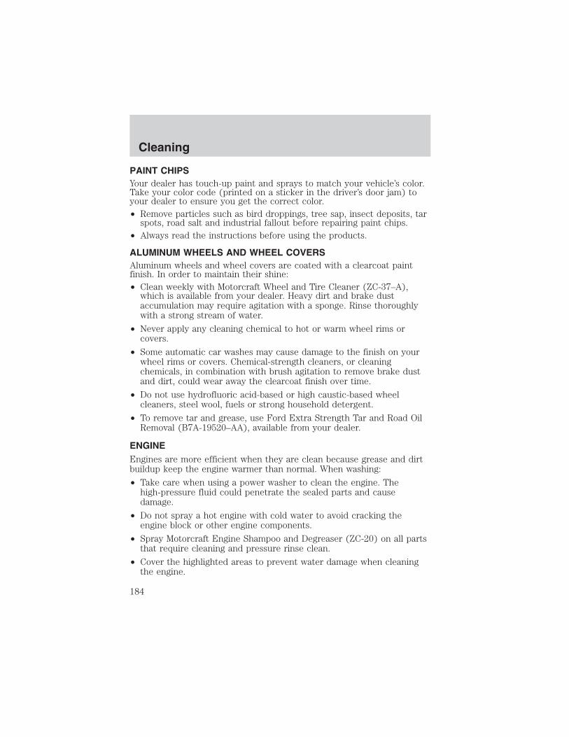
PAINT CHIPSYour dealer has touch-up paint and sprays to match your vehicle’s color.Take your color code (printed on a sticker in the driver’s door jam) toyour dealer to ensure you get the correct color.• Remove particles such as bird droppings, tree sap, insect deposits, tar
spots, road salt and industrial fallout before repairing paint chips.• Always read the instructions before using the products.
ALUMINUM WHEELS AND WHEEL COVERSAluminum wheels and wheel covers are coated with a clearcoat paintfinish. In order to maintain their shine:• Clean weekly with Motorcraft Wheel and Tire Cleaner (ZC-37–A),
which is available from your dealer. Heavy dirt and brake dustaccumulation may require agitation with a sponge. Rinse thoroughlywith a strong stream of water.
• Never apply any cleaning chemical to hot or warm wheel rims orcovers.
• Some automatic car washes may cause damage to the finish on yourwheel rims or covers. Chemical-strength cleaners, or cleaningchemicals, in combination with brush agitation to remove brake dustand dirt, could wear away the clearcoat finish over time.
• Do not use hydrofluoric acid-based or high caustic-based wheelcleaners, steel wool, fuels or strong household detergent.
• To remove tar and grease, use Ford Extra Strength Tar and Road OilRemoval (B7A-19520–AA), available from your dealer.
ENGINEEngines are more efficient when they are clean because grease and dirtbuildup keep the engine warmer than normal. When washing:
• Take care when using a power washer to clean the engine. Thehigh-pressure fluid could penetrate the sealed parts and causedamage.
• Do not spray a hot engine with cold water to avoid cracking theengine block or other engine components.
• Spray Motorcraft Engine Shampoo and Degreaser (ZC-20) on all partsthat require cleaning and pressure rinse clean.
• Cover the highlighted areas to prevent water damage when cleaningthe engine.
Cleaning
184
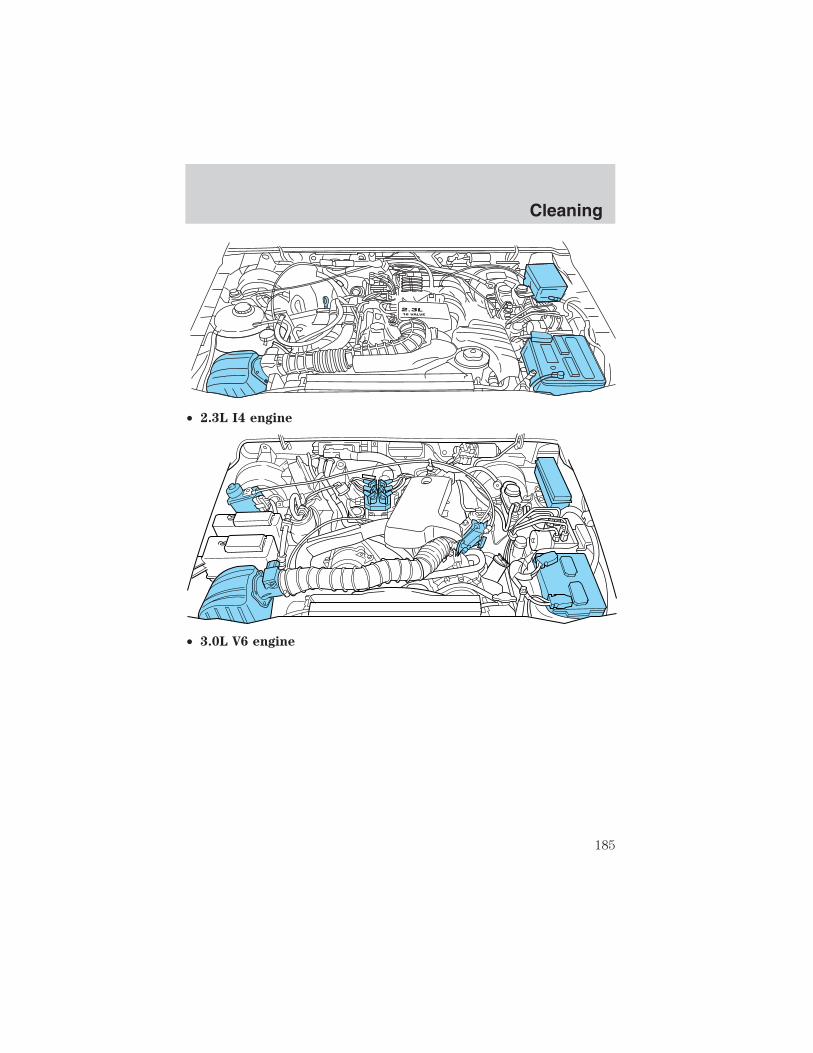
• 2.3L I4 engine
• 3.0L V6 engine
2.3L16 VALVE
Cleaning
185

• 4.0L SOHC V6 engine
• Never wash or rinse the engine while it is running; water in therunning engine may cause internal damage.
PLASTIC (NON-PAINTED) EXTERIOR PARTSUse only approved products to clean plastic parts. These products areavailable from your dealer.
• For routine cleaning, use Motorcraft Detail Wash (ZC-3–A).
• If tar or grease spots are present, use Ford Extra Strength Tar andRoad Oil Removal (B7A-19520–AA).
WINDOWS AND WIPER BLADESThe windshield, rear window and wiper blades should be cleanedregularly. If the wiper does not wipe properly, substances on thewindshield, rear window or the wiper blades may be the cause. Thesemay include hot wax treatments used by commercial car washes, treesap, or other organic contamination. To clean these items, please followthese tips:
• The windshield or rear window may be cleaned with a non-abrasivecleaner such as Motorcraft Ultra Clear Spray Glass Cleaner (ZC-23),available from your dealer.
• Do not use abrasives, as they may cause scratches.
• Do not use fuel, kerosene, or paint thinner to clean any parts.
• Wiper blades can be cleaned with isopropyl (rubbing) alcohol orwindshield washer solution. Be sure to replace wiper blades when theyappear worn or do not function properly.
Cleaning
186

INSTRUMENT PANEL AND CLUSTER LENSClean the instrument panel with a damp cloth, then dry with a dry cloth.• Avoid cleaners or polish that increase the gloss of the upper portion of
the instrument panel. The dull finish in this area helps protect thedriver from undesirable windshield reflection.
Do not use chemical solvents or strong detergents when cleaningthe steering wheel or instrument panel to avoid contamination of
the air bag system.
• Be certain to wash or wipe your hands clean if you have been in contactwith certain products such as insect repellent and suntan lotion in orderto avoid possible damage to the interior painted surfaces.
INTERIORFor fabric, carpets, cloth seats and safety belts:• Remove dust and loose dirt with a vacuum cleaner.• Remove light stains and soil with Ford Extra Strength Upholstery
Cleaner (E8AZ-19523–AA).• If grease or tar is present on the material, spot-clean the area first
with Motorcraft Spot and Stain Remover (ZC-14).• Never saturate the seat covers with cleaning solution.• Do not use household cleaning products or glass cleaners, which can
stain and discolor the fabric and affect the flame retardant abilities ofthe seat materials.
Do not use cleaning solvents, bleach or dye on the vehicle’sseatbelts, as these actions may weaken the belt webbing.
LEATHER SEATS (IF EQUIPPED)Your leather seating surfaces have a clear, protective coating over theleather.• To clean, use a soft cloth with Motorcraft Deluxe Leather and Vinyl
Cleaner (ZC-11–A). Dry the area with a soft cloth.• To help maintain its resiliency and color, use the Motorcraft Deluxe
Leather Care Kit (ZC-11–D), available from your authorized dealer.• Do not use household cleaning products, alcohol solutions, solvents or
cleaners intended for rubber, vinyl and plastics, or oil/petroleum-basedleather conditioners. These products may cause premature wearing ofthe clear, protective coating.
Cleaning
187

UNDERBODYFlush the complete underside of your vehicle frequently. Keep body anddoor drain holes free from packed dirt.
FORD, LINCOLN AND MERCURY CAR CARE PRODUCTSYour Ford, Lincoln or Mercury dealer has many quality products availableto clean your vehicle and protect its finishes. These quality productshave been specifically engineered to fulfill your automotive needs; theyare custom designed to complement the style and appearance of yourvehicle. Each product is made from high quality materials that meet orexceed rigid specifications. For best results, use the following productsor products of equivalent quality:Motorcraft Custom Clearcoat Polish (ZC–8–A)Ford Custom Vinyl Protectant* (not available in Canada)(F2AZ—19530–A)Motorcraft Vinyl Cleaner (Canada only) (CXC-93)
Motorcraft Vinyl Conditioner (Canada only) (CXC-94)Motorcraft Deluxe Leather and Vinyl Cleaner (not available in Canada)(ZC-11–A)Ford Extra Strength Tar and Road Oil Remover* (not available inCanada) (B7A-19520–AA)Ford Extra Strength Upholstery Cleaner (not available in Canada)(E8AZ-19523–AA)Motorcraft Custom Bright Metal Cleaner (ZC-15)Motorcraft Wheel and Tire Cleaner (ZC-37–A)Motorcraft Dash and Vinyl Cleaner (ZC-38–A)Motorcraft Car Care Kit (ZC-26)Ford Premium Car Wash Concentrate (F2SZ-19523–WC)Motorcraft Carlite Glass Cleaner (Canada only) (CXC-100)Motorcraft Spot and Stain Remover (ZC-14)Motorcraft Detail Wash (ZC-3–A)Motorcraft Tire Detailer (ZC-28)Motorcraft Triple Clean (ZC-13)Motorcraft Ultra-Clear Spray Glass Cleaner (not available in Canada)(ZC-23)
Motorcraft Engine Shampoo and Degreaser (ZC-20)
* May be sold with the Motorcraft name
Cleaning
188

SERVICE RECOMMENDATIONSTo help you service your vehicle:
• We highlight do-it-yourself items in the engine compartment for easylocation.
• We provide a scheduled maintenance guide which makes trackingroutine service easy.
If your vehicle requires professional service, your dealership can providethe necessary parts and service. Check your Warranty Guide/OwnerInformation Guide to find out which parts and services are covered.
Use only recommended fuels, lubricants, fluids and service partsconforming to specifications. Motorcraft parts are designed and built toprovide the best performance in your vehicle.
PRECAUTIONS WHEN SERVICING YOUR VEHICLE• Do not work on a hot engine.
• Make sure that nothing gets caught in moving parts.
• Do not work on a vehicle with the engine running in an enclosedspace, unless you are sure you have enough ventilation.
• Keep all open flames and other lit material away from the battery andall fuel related parts.
Working with the engine off• Automatic transmission:
1. Set the parking brake and shift to P (Park).
2. Turn off the engine and remove the key.
3. Block the wheels.
• Manual transmission:
1. Set the parking brake, depress the clutch and place the gearshift in 1(First).
2. Turn off the engine and remove the key.
3. Block the wheels.
Maintenance and Specifications
Maintenance and Specifications
189

Working with the engine on
• Automatic transmission:
1. Set the parking brake and shift to P (Park).
2. Block the wheels.
• Manual transmission:
1. Set the parking brake, depress the clutch and place the gearshift in N(Neutral).
2. Block the wheels.
Note: Do not start your engine with the air cleaner removed and do notremove it while the engine is running.
OPENING THE HOOD
1. Inside the vehicle, pull the hoodrelease handle located under thebottom of the instrument panel nearthe steering column.
2. Go to the front of the vehicle andrelease the auxiliary latch that islocated under the front center ofthe hood.
3. Lift the hood and support it withthe prop rod.
Maintenance and Specifications
190
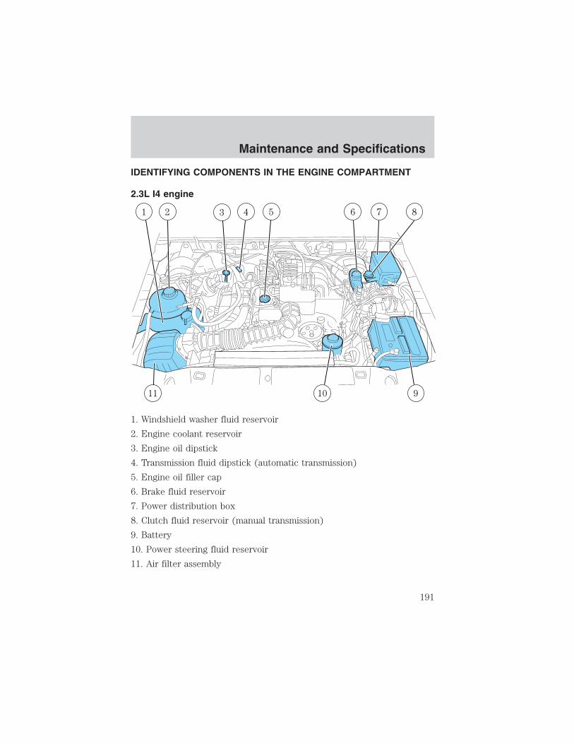
IDENTIFYING COMPONENTS IN THE ENGINE COMPARTMENT
2.3L I4 engine
1. Windshield washer fluid reservoir
2. Engine coolant reservoir
3. Engine oil dipstick
4. Transmission fluid dipstick (automatic transmission)
5. Engine oil filler cap
6. Brake fluid reservoir
7. Power distribution box
8. Clutch fluid reservoir (manual transmission)
9. Battery
10. Power steering fluid reservoir
11. Air filter assembly
Maintenance and Specifications
191

3.0L V6 engine
1. Engine coolant reservoir
2. Windshield washer fluid reservoir
3. Engine oil filler cap
4. Automatic transmission fluid dipstick (if equipped)
5. Engine oil dipstick
6. Brake fluid reservoir
7. Power distribution box
8. Clutch fluid reservoir (if equipped)
9. Battery
10. Power steering fluid reservoir
11. Air filter assembly
Maintenance and Specifications
192
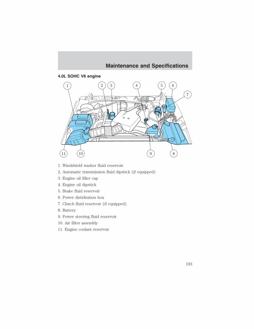
4.0L SOHC V6 engine
1. Windshield washer fluid reservoir
2. Automatic transmission fluid dipstick (if equipped)
3. Engine oil filler cap
4. Engine oil dipstick
5. Brake fluid reservoir
6. Power distribution box
7. Clutch fluid reservoir (if equipped)
8. Battery
9. Power steering fluid reservoir
10. Air filter assembly
11. Engine coolant reservoir
Maintenance and Specifications
193

WINDSHIELD WASHER FLUID
Add fluid to fill the reservoir if thelevel is low. In very cold weather, donot fill the reservoir completely.
Only use a washer fluid that meetsFord specification WSB-M8B16–A2.Refer to Lubricant specificationsin this chapter.
State or local regulations on volatile organic compounds may restrict theuse of methanol, a common windshield washer antifreeze additive.Washer fluids containing non-methanol antifreeze agents should be usedonly if they provide cold weather protection without damaging thevehicle’s paint finish, wiper blades or washer system.
If you operate your vehicle in temperatures below 4.5° C(40° F), use washer fluid with antifreeze protection. Failure to
use washer fluid with antifreeze protection in cold weather could resultin impaired windshield vision and increase the risk of injury oraccident.
Note: Do not put washer fluid in the engine coolant reservoir. Washerfluid placed in the cooling system may harm engine and cooling systemcomponents.
WASHER FLUID
ON LY
RADIATORCOOLANTONLY
Maintenance and Specifications
194

ENGINE OIL
Checking the engine oil
Refer to the scheduled maintenance guide for the appropriate intervalsfor checking the engine oil.
1. Make sure the vehicle is on level ground.
2. Turn the engine off and wait a few minutes for the oil to drain into theoil pan.
3. Set the parking brake and ensure the gearshift is securely latched in P(Park) (automatic transmission) or 1 (First) (manual transmission).
4. Open the hood. Protect yourself from engine heat.
5. Locate and carefully remove the engine oil level indicator (dipstick).
• 2.3L I4 engine
MAXMIN
Maintenance and Specifications
195

• 3.0L V6 engine
• 4.0L SOHC V6 engine
MAXMIN
Maintenance and Specifications
196
6. Wipe the indicator clean. Insert the indicator fully, then remove itagain.
• If the oil level is between the MIN and MAX marks, the oil level isacceptable, DO NOT ADD OIL.
• If the oil level is below the MIN mark, add enough oil to raise the levelwithin the MIN-MAX range.
• 2.3L I4 engine
• 3.0L V6 engine
Maintenance and Specifications
197
• 4.0L SOHC V6 engine
• Oil levels above the MAX mark may cause engine damage. Some oilmust be removed from the engine by a service technician.
7. Put the indicator back in and ensure it is fully seated.
Adding engine oil
1. Check the engine oil. For instructions, refer to Checking the engineoil in this chapter.
2. If the engine oil level is not within the normal range, add only certifiedengine oil of the recommended viscosity. Remove the engine oil filler capand use a funnel to pour the engine oil into the opening.
3. Recheck the engine oil level. Make sure the oil level is not above theMAX mark or the letter F in FULL on the engine oil level indicator(dipstick).
4. Install the indicator and ensure it is fully seated.
5. Fully install the engine oil filler cap by turning the filler cap clockwiseuntil three clicks can be heard.
To avoid possible oil loss, DO NOT operate the vehicle with theengine oil level indicator and/or the engine oil filler cap removed.
Maintenance and Specifications
198

Engine Oil Recommendations2.3L & 3.0L Engines
Look for this certificationtrademark.
SAE 5W-20 engine oil is recommended.Change your engine oil and filter according to the appropriate schedulelisted in the scheduled maintenance guide.Do not use supplemental engine oil additives, oil treatments or enginetreatments. They are unnecessary and could, under certain conditions,lead to engine damage which is not covered by your warranty.4.0L Engine
Look for this certificationtrademark.
SAE 5W-30 engine oil is recommended.Only use oils “Certified For Gasoline Engines” by the AmericanPetroleum Institute (API). Use Motorcraft or an equivalent oil meetingFord Specification WSS-M2C205–A.Do not use supplemental engine oil additives, oil treatments or enginetreatments. They are unnecessary and could, under certain conditions,lead to engine damage which is not covered by your warranty.Change your engine oil according to the appropriate schedule listed inthe scheduled maintenance guide.
Maintenance and Specifications
199

Engine Oil Filter Recommendation
Change your engine oil filter according to the appropriate schedule listedin the scheduled maintenance guide. Ford production and aftermarket(Motorcraft) oil filters are designed for added engine protection and longlife. If a replacement oil filter is used that does not meet Ford Materialand design specifications, start-up engine noises or knock may beexperienced.It is recommended you use the appropriate Motorcraft oil filter (oranother brand meeting Ford specifications) for your engine.
BATTERY
Your vehicle is equipped with aMotorcraft maintenance-free batterywhich normally does not requireadditional water during its life ofservice.
However, for severe usage or in high temperature climates, check thebattery electrolyte level. Refer to the scheduled maintenance guide forthe service interval schedules.Keep the electrolyte level in each cell up to the “level indicator”.Do not overfill the battery cells.
If the electrolyte level in the battery is low, you can add plain tap waterto the battery, as long as you do not use hard water (water with a highmineral or alkali content). If possible, however, try to only fill the batterycells with distilled water. If the battery needs water often, have thecharging system checked.If your battery has a cover/shield, make sure it is reinstalledafter the battery has been cleaned or replaced.
For longer, trouble-free operation, keep the top of the battery clean anddry. Also, make certain the battery cables are always tightly fastened tothe battery terminals.
Maintenance and Specifications
200

If you see any corrosion on the battery or terminals, remove the cablesfrom the terminals and clean with a wire brush. You can neutralize theacid with a solution of baking soda and water.
Batteries normally produce explosive gases which can causepersonal injury. Therefore, do not allow flames, sparks or lighted
substances to come near the battery. When working near the battery,always shield your face and protect your eyes. Always provide properventilation.
When lifting a plastic-cased battery, excessive pressure on theend walls could cause acid to flow through the vent caps,
resulting in personal injury and/or damage to the vehicle or battery.Lift the battery with a battery carrier or with your hands on oppositecorners.
Keep batteries out of reach of children. Batteries contain sulfuricacid. Avoid contact with skin, eyes or clothing. Shield your eyes
when working near the battery to protect against possible splashing ofacid solution. In case of acid contact with skin or eyes, flushimmediately with water for a minimum of 15 minutes and get promptmedical attention. If acid is swallowed, call a physician immediately.
Battery posts, terminals and related accessories contain lead andlead compounds. Wash hands after handling.
Because your vehicle’s engine is electronically controlled by a computer,some control conditions are maintained by power from the battery. Whenthe battery is disconnected or a new battery is installed, the engine mustrelearn its idle and fuel trim strategy for optimum driveability andperformance. To begin this process:
1. With the vehicle at a complete stop, set the parking brake.
2. Put the gearshift lever in P (Park), turn off all accessories and startthe engine.
3. Run the engine until it reaches normal operating temperature.
4. Allow the engine to idle for at least one minute.
5. Turn the A/C on and allow the engine to idle for at least one minute.
6. Drive the vehicle to complete the relearning process.
Maintenance and Specifications
201

• The vehicle may need to be driven to relearn the idle and fuel trimstrategy.
• If you do not allow the engine to relearn its idle trim, the idlequality of your vehicle may be adversely affected until the idletrim is eventually relearned.
When the battery is disconnected or a new battery installed, thetransmission must relearn its adaptive strategy. As a result of this, thetransmission may shift firmly. This operation is considered normal andwill not affect function or durability of the transmission. Over time theadaptive learning process will fully update transmission operation to itsoptimum shift feel.
If the battery has been disconnected or a new battery has been installed,the clock and the preset radio stations must be reset once the battery isreconnected.
• Always dispose of automotivebatteries in a responsible manner.Follow your local authorizedstandards for disposal. Call yourlocal authorized recycling centerto find out more about recyclingautomotive batteries.
ENGINE COOLANT
Checking engine coolantThe concentration and level of engine coolant should be checked at themileage intervals listed in the scheduled maintenance guide. The coolantconcentration should be maintained at 50/50 coolant and distilled water,which equates to a freeze point of -36° C (-34° F). Coolant concentrationtesting is possible with a hydrometer or antifreeze tester (such as theRotunda Battery and Antifreeze Tester, 014–R1060). The level of coolantshould be maintained at the “cold full” of “cold fill range” level in thecoolant reservoir. If the level falls below, add coolant per the instructionsin the Adding Engine Coolant section.
LE
AD
RE
TU
RN
RECYCLE
Maintenance and Specifications
202

Your vehicle was factory-filled with a 50/50 engine coolant and waterconcentration. If the concentration of coolant falls below 40% or above60%, the engine parts could become damaged or not work properly. A
50–50 mixture of coolant and water provides the following:
• Freeze protection down to -36° C (-34° F).
• Boiling protection up to 129° C (265° F).
• Protection against rust and other forms of corrosion.
• Enables calibrated gauges to work properly.
• 2.3L engines
• 3.0L and 4.0L engines
When the engine is cold, check the level of the engine coolant in thereservoir.
• The engine coolant should be at the “cold fill level” or within the “coldfill range” as listed on the engine coolant reservoir (depending uponapplication).
RADIATORCOOLANT
ONLY
Maintenance and Specifications
203

• Refer to the Scheduled Maintenance Guide for service intervalschedules.
• Be sure to read and understand Precautions when servicing yourvehicle in this chapter.
If the engine coolant has not been checked at the recommended interval,the engine coolant reservoir may become low or empty. If the reservoir islow or empty, add engine coolant to the reservoir. Refer to Addingengine coolant in this chapter.
Note: Automotive fluids are not interchangeable; do not use enginecoolant, antifreeze or windshield washer fluid outside of its specifiedfunction and vehicle location.
Adding engine coolantWhen adding coolant, make sure it is a 50/50 mixture of engine coolantand distilled water. Add the mixture to the coolant reservoir, when theengine is cool, until the appropriate fill level is obtained.
Do not add engine coolant when the engine is hot. Steam andscalding liquids released from a hot cooling system can burn you
badly. Also, you can be burned if you spill coolant on hot engine parts.
Do not put engine coolant in the windshield washer fluidcontainer. If sprayed on the windshield, engine coolant could
make it difficult to see through the windshield.
• Add Motorcraft Premium Gold Engine Coolant(yellow-colored), VC-7–A (VC-7–B in Oregon), meeting FordSpecification WSS-M97B51–A1.
Note: Use of Motorcraft Cooling System Stop Leak Pellets, VC-6, maydarken the color of Motorcraft Premium Gold Engine Coolant fromyellow to golden tan.
• Do not add/mix an orange-colored, extended life coolant suchas Motorcraft Speciality Orange Engine Coolant, VC-2 (US) orCXC-209 (Canada), meeting Ford specification WSS-M97B44–Dwith the factory-filled coolant. Mixing Motorcraft Speciality OrangeEngine Coolant or any orange-colored extended life product with yourfactory filled coolant can result in degraded corrosion protection.
Maintenance and Specifications
204

• A large amount of water without engine coolant may be added, in caseof emergency, to reach a vehicle service location. In this instance, thecooling system must be drained and refilled with a 50/50 mixture ofengine coolant and distilled water as soon as possible. Water alone(without engine coolant) can cause engine damage from corrosion,overheating or freezing.
• Do not use alcohol, methanol, brine or any engine coolantsmixed with alcohol or methanol antifreeze (coolant). Alcoholand other liquids can cause engine damage from overheating orfreezing.
• Do not add extra inhibitors or additives to the coolant. Thesecan be harmful and compromise the corrosion protection of the enginecoolant.
For vehicles with overflow coolant systems with a non-pressurized capon the coolant recovery system, add coolant to the coolant recoveryreservoir when the engine is cool. Add the proper mixture of coolant andwater to the “cold full” level. For all other vehicles, which have a coolantdegas system with a pressurized cap, or if it is necessary to remove thecoolant pressure relief cap on the radiator of a vehicle with an overflowsystem, follow these steps to add engine coolant.
To reduce the risk of personal injury, make sure the engine iscool before unscrewing the coolant pressure relief cap. The
cooling system is under pressure; steam and hot liquid can come outforcefully when the cap is loosened slightly.
1. Before you begin, turn the engine off and let it cool.
2. When the engine is cool, wrap a thick cloth around the coolantpressure relief cap on the coolant reservoir (an opaque plastic bottle).Slowly turn cap counterclockwise (left) until pressure begins to release.
3. Step back while the pressure releases.
4. When you are sure that all the pressure has been released, use thecloth to turn it counterclockwise and remove the cap.
5. Fill the coolant reservoir slowly with the proper coolant mixture (seeabove), to within the “cold fill range” or the “cold full” level on thereservoir. If you removed the radiator cap in an overflow system, fill theradiator until the coolant is visible and radiator is almost full.
6. Replace the cap. Turn until tightly installed. (Cap must be tightlyinstalled to prevent coolant loss.)
Maintenance and Specifications
205

After any coolant has been added, check the coolant concentration, referto Checking Engine Coolant section. If the concentration is not 50/50(protection to –34° F/–36° C), drain some coolant and adjust theconcentration. It may take several drains and additions to obtain a 50/50coolant concentration.Whenever coolant has been added, the coolant level in the coolantreservoir should be checked the next few times you drive the vehicle. Ifnecessary, add enough 50/50 concentration of engine coolant anddistilled water to bring the liquid level to the proper level.If you have to add more than 1.0 liter (1.0 quart) of engine coolant permonth, have your dealer check the engine cooling system. Your coolingsystem may have a leak. Operating an engine with a low level of coolantcan result in engine overheating and possible engine damage.
Recycled engine coolantFord Motor Company does NOT recommend the use of recycled enginecoolant in vehicles originally equipped with Motorcraft Premium GoldEngine Coolant since a Ford-approved recycling process is not yetavailable.
Used engine coolant should be disposed of in an appropriatemanner. Follow your community’s regulations and standards for recyclingand disposing of automotive fluids.
Coolant refill capacityTo find out how much fluid your vehicle’s cooling system can hold, referto Refill capacities in this chapter.Fill your engine coolant reservoir as outlined in Adding engine coolantin this chapter.
Severe climatesIf you drive in extremely cold climates (less than –36° C [–34° F]):• It may be necessary to increase the coolant concentration
above 50%.
• NEVER increase the coolant concentration above 60%.
• Increased engine coolant concentrations above 60% willdecrease the overheat protection characteristics of the enginecoolant and may cause engine damage.
• Refer to the chart on the coolant container to ensure thecoolant concentration in your vehicle will provide adequatefreeze protection at the temperatures in which you drive in thewinter months.
Maintenance and Specifications
206

If you drive in extremely hot climates:
• It is still necessary to maintain the coolant concentration
above 40%.
• NEVER decrease the coolant concentration below 40%.
• Decreased engine coolant concentrations below 40% willdecrease the corrosion protection characteristics of the enginecoolant and may cause engine damage.
• Decreased engine coolant concentrations below 40% willdecrease the freeze protection characteristics of the enginecoolant and may cause engine damage.
• Refer to the chart on the coolant container to ensure thecoolant concentration in your vehicle will provide adequateprotection at the temperatures in which you drive.
Vehicles driven year-round in non-extreme climates should use a 50/50mixture of engine coolant and distilled water for optimum cooling systemand engine protection.
WHAT YOU SHOULD KNOW ABOUT AUTOMOTIVE FUELS
Important safety precautions
Do not overfill the fuel tank. The pressure in an overfilled tankmay cause leakage and lead to fuel spray and fire.
The fuel system may be under pressure. If the fuel filler cap isventing vapor or if you hear a hissing sound, wait until it stops
before completely removing the fuel filler cap. Otherwise, fuel mayspray out and injure you or others.
If you do not use the proper fuel filler cap, excessive pressure orvacuum in the fuel tank may damage the fuel system or cause
the fuel cap to disengage in a collision, which may result in possiblepersonal injury.
Automotive fuels can cause serious injury or death if misused ormishandled.
Maintenance and Specifications
207

Fuel ethanol and gasoline may contain benzene, which is acancer-causing agent.
Observe the following guidelines when handling automotive fuel:
• Extinguish all smoking materialsand any open flames beforefueling your vehicle.
• Always turn off the vehicle beforefueling.
• Automotive fuels can be harmfulor fatal if swallowed. Fuels such as gasoline and ethanol are highlytoxic and if swallowed can cause death or permanent injury. If fuel isswallowed, call a physician immediately, even if no symptoms areimmediately apparent. The toxic effects of fuel may not be visible forhours.
• Avoid inhaling fuel vapors. Inhaling too much fuel vapor of any kindcan lead to eye and respiratory tract irritation. In severe cases,excessive or prolonged breathing of fuel vapor can cause seriousillness and permanent injury.
• Avoid getting fuel liquid in your eyes. If fuel is splashed in the eyes,remove contact lenses (if worn), flush with water for 15 minutes andseek medical attention. Failure to seek proper medical attention couldlead to permanent injury.
• Fuels can also be harmful if absorbed through the skin. If fuel issplashed on the skin and/or clothing, promptly remove contaminatedclothing and wash skin thoroughly with soap and water. Repeated orprolonged skin contact with fuel liquid or vapor causes skin irritation.
• Be particularly careful if you are taking “Antabuse” or other forms ofdisulfiram for the treatment of alcoholism. Breathing gasoline and/orethanol vapors, or skin contact could cause an adverse reaction. Insensitive individuals, serious personal injury or sickness may result. Iffuel is splashed on the skin, promptly wash skin thoroughly with soapand water. Consult a physician immediately if you experience anadverse reaction.
• FFV fuel tanks may contain zero to 85 percent ethanol. Any fuelblends containing gasoline and ethanol should be treated the same as“Fuel Ethanol ”. To identify if your vehicle is an FFV, check your VINor the label on the inside of your fuel filler door. When checking theVIN look for the engine type identifier (8th character). If your vehicleis an FFV, then the character will be labeled as a “V.”
Maintenance and Specifications
208
Pure ethanol is the alcohol which is the intoxicating agent in liquor, beerand wine. It is distilled from the fermentation of plants such as field cornand sugar cane. When ethanol is used in the making of motor fuels, asmall amount of a bad tasting chemical is added to discourage beverageuse. The resulting fuel is called Ed100 meaning 100% pure ethanoldiluted by 2% to 5% gasoline as the “denaturant.”Fuel ethanol (summer blendd) is then made by adding 15% moreunleaded gasoline. The resulting fuel also has a higher octane rating thanunleaded regular gasoline and other properties which allow enginedesigns with greater efficiency and power.Winter blends may contain up to 30% (E70)unleaded gasoline (25% plusthe denaturant) to enhance cold engine starts. Severely cold weathermay require additional measures for reliable starting. Refer to ColdWeather Starting in the Driving chapter.Ethanol is more chemically active than gasoline. It corrodes some metalsand causes some plastic and rubber components to swell, break down orbecome brittle and crack, especially when mixed with gasoline. Specialmaterials and procedures have been developed for flexible fuel vehiclesand the dispensers used by ethanol fuel providers.
Flexible fuel components and standard unleaded gasoline fuelcomponents are not interchangeable. If your vehicle is not
serviced in accordance with flexible fuel vehicles procedures, damagemay occur and your warranty may be invalidated.
When refueling always shut the engine off and never allowsparks or open flames near the filler neck. Never smoke while
refueling. Fuel vapor is extremely hazardous under certain conditions.Care should be taken to avoid inhaling excess fumes.
The flow of fuel through a fuel pump nozzle can produce staticelectricity, which can cause a fire if fuel is pumped into an
ungrounded fuel container.
Use the following guidelines to avoid static build-up when filling anungrounded fuel container:
• Place approved fuel container on the ground.
• DO NOT fill a fuel container while it is in the vehicle (including thecargo area).
Maintenance and Specifications
209

• Keep the fuel pump nozzle in contact with the fuel container whilefilling.
• DO NOT use a device that would hold the fuel pump handle in the fillposition.
Fuel Filler CapYour fuel tank filler cap has an indexed design with a 1/8 turn on/offfeature.
When fueling your vehicle:
1. Turn the engine off.
2. Carefully turn the filler cap counterclockwise 1/8 of a turn until itstops.
3. Pull to remove the cap from the fuel filler pipe.
4. To install the cap, align the tabs on the cap with the notches on thefiller pipe.
5. Turn the filler cap clockwise 1/8 of a turn until it stops.
“Check Fuel Cap” illuminates when the ignition is turned to the ONposition to ensure your bulb is working. When this light turns on, checkthe fuel filler cap. Continuing to operate the vehicle with the Check FuelCap light on, can activate the Service Engine Soon warning. When thefuel filler cap is properly re-installed, the light(s) will turn off after aperiod of normal driving. It may take a long period of time for thesystem to detect an improperly installed fuel filler cap.
If you must replace the fuel filler cap, replace it with a fuel fillercap that is designed for your vehicle. The customer warranty maybe void for any damage to the fuel tank or fuel system if thecorrect genuine Ford or Motorcraft fuel filler cap is not used.
The fuel system may be under pressure. If the fuel filler cap isventing vapor or if you hear a hissing sound, wait until it stops
before completely removing the fuel filler cap. Otherwise, fuel mayspray out and injure you or others.
If you do not use the proper fuel filler cap, excessive pressure orvacuum in the fuel tank may damage the fuel system or cause
the fuel cap to disengage in a collision, which may result in possiblepersonal injury.
Maintenance and Specifications
210

Choosing the right fuelUse only UNLEADED FUEL. The use of leaded fuel is prohibited by lawand could damage your vehicle.
If your vehicle is a flexible fuel vehicle (FFV), use only UNLEADEDFUEL and (E85) ETHANOL. The use of leaded fuel is prohibited by lawand could damage your vehicle.
Do not use fuel containing methanol. It can damage critical fuel systemcomponents.
Your vehicle was not designed to use fuel or fuel additives with metalliccompounds, including manganese-based compounds containing MMT.
Repairs to correct the effects of using a fuel for which your vehicle wasnot designed may not be covered by your warranty.
Octane recommendationsDo not be concerned if your enginesometimes knocks lightly. However,if it knocks heavily under mostdriving conditions while you areusing fuel with the recommendedoctane rating, see your dealer or a qualified service technician to preventany engine damage.
Unleaded Gasoline engines
Your vehicle is designed to use “Regular” unleaded gasoline with an(R+M)/2 octane rating of 87. We do not recommend the use of gasolineslabeled as “Regular” that are sold with octane ratings of 86 or lower inhigh altitude areas.
FFV engine (if equipped)
Your vehicle is designed to use (E85) Fuel Ethanol, “Regular” unleadedgasoline or any percentage of the two fuels combined.
U.S. government regulations require fuel ethanol dispensingpumps to have a small, square, orange and black label with thecommon abbreviation or the appropriate percentage for thatregion. Use of other fuels such as Fuel Methanol may causepowertrain damage, a loss of vehicle performance, and yourwarranty may be invalidated.
87(R+M)/2 METHOD
Maintenance and Specifications
211

Fuel qualityMany of the world’s automakers issued the World-wide Fuel Charter thatrecommends gasoline specifications to provide improved performanceand emission control system protection for your vehicle. Gasolines thatmeet the World-wide Fuel Charter should be used when available. Askyour fuel supplier about gasolines that meet the World-wide FuelCharter.It should not be necessary to add any aftermarket products to your fueltank if you continue to use high quality fuel of the recommended octanerating. Aftermarket products could cause damage to the fuel system.Repairs to correct the effects of using an aftermarket product in yourfuel may not be covered by your warranty.Unleaded Gasoline engines
If you are experiencing starting, rough idle or hesitation driveabilityproblems during a cold start, try a different brand of “Regular” unleadedgasoline. “Premium” unleaded gasoline is not recommended (particularlyin the United States) because it may cause these problems to becomemore pronounced. If the problems persist, see your dealer or a qualifiedservice technician.FFV engine (if equipped)
Your FFV will operate well on ordinary “Regular” unleaded gasoline, butonly the highest quality fuel ethanol will provide the same level ofprotection and performance. To identify if your vehicle is an FFV, checkyour VIN or the label on the inside of your fuel filler door. Whenchecking the VIN, look for the engine type identifier (8th character). Ifyour vehicle is an FFV, then the character will be labeled as a “V.”If you operate your vehicle 50% or more of the time on ethanol, youshould follow a different maintenance schedule. See the ScheduledMaintenance Guide for more information.
If you are experiencing a rough or rolling idle after start-up with theoutside temperature above 27° C (80° F), the idle should improve within10 to 30 seconds. If the problems persist below this temperature, seeyour dealer or a qualified service technician.
Cleaner airFord endorses the use of reformulated “cleaner-burning” gasolines toimprove air quality.
Running out of fuelAvoid running out of fuel because this situation may have an adverseaffect on powertrain components.
Maintenance and Specifications
212

If you have run out of fuel:• You may need to cycle the ignition from OFF to ON several times after
refueling, to allow the fuel system to pump the fuel from the tank tothe engine.
• Your “Check Engine” indicator may come on. For more information onthe “Check Engine” indicator, refer to the Instrument Clusterchapter.
Fuel FilterFor fuel filter replacement, see your dealer or a qualified servicetechnician. Refer to the scheduled maintenance guide for the appropriateintervals for changing the fuel filter.Replace the fuel filter with an authorized Motorcraft part. Thecustomer warranty may be void for any damage to the fuel systemif an authorized Motorcraft fuel filter is not used.
ESSENTIALS OF GOOD FUEL ECONOMY
Measuring techniquesYour best source of information about actual fuel economy is you, thedriver. You must gather information as accurately and consistently aspossible. Fuel expense, frequency of fill-ups or fuel gauge readings areNOT accurate as a measure of fuel economy. We do not recommend takingfuel economy measurements during the first 1,600 km (1,000 miles) ofdriving (engine break-in period). You will get a more accuratemeasurement after 3,000 km–5,000 km (2,000 miles-3,000 miles).
Filling the tankThe advertised fuel capacity of the fuel tank on your vehicle is equal tothe rated refill capacity of the fuel tank as listed in the Refill capacitiessection of this chapter.
The advertised capacity is the amount of the indicated capacity and theempty reserve combined. Indicated capacity is the difference in theamount of fuel in a full tank and a tank when the fuel gauge indicatesempty. Empty reserve is the small amount of fuel remaining in the fueltank after the fuel gauge indicates empty.
The amount of usable fuel in the empty reserve varies and shouldnot be relied upon to increase driving range. When refueling yourvehicle after the fuel gauge indicates empty, you might not beable to refuel the full amount of the advertised capacity of thefuel tank due to the empty reserve still present in the tank.
Maintenance and Specifications
213

For consistent results when filling the fuel tank:• Turn the engine/ignition switch to the off position prior to refueling,
an error in the reading will result if the engine is left running.
• Use the same filling rate setting (low — medium — high) each timethe tank is filled.
• Allow no more than 2 automatic click-offs when filling.
• Always use fuel with the recommended octane rating.
• Use a known quality gasoline, preferably a national brand.
• Use the same side of the same pump and have the vehicle facing thesame direction each time you fill up.
• Have the vehicle loading and distribution the same every time.
Your results will be most accurate if your filling method is consistent.
Calculating fuel economy1. Fill the fuel tank completely and record the initial odometer reading(in kilometers or miles).
2. Each time you fill the tank, record the amount of fuel added (in litersor gallons).
3. After at least three to five tank fill-ups, fill the fuel tank and recordthe current odometer reading.
4. Subtract your initial odometer reading from the current odometerreading.
5. Follow one of the simple calculations in order to determine fueleconomy:
Calculation 1: Multiply liters used by 100, then divide by totalkilometers traveled.
Calculation 2: Divide total miles traveled by total gallons used.
Keep a record for at least one month and record the type of driving (cityor highway). This will provide an accurate estimate of the vehicle’s fueleconomy under current driving conditions. Additionally, keeping recordsduring summer and winter will show how temperature impacts fueleconomy. In general, lower temperatures give lower fuel economy.
Driving style — good driving and fuel economy habitsGive consideration to the lists that follow and you may be able to changea number of variables and improve your fuel economy.
Maintenance and Specifications
214

Habits• Smooth, moderate operation can yield up to 10% savings in fuel.• Steady speeds without stopping will usually give the best fuel
economy.• Idling for long periods of time (greater than one minute) may waste
fuel.• Anticipate stopping; slowing down may eliminate the need to stop.• Sudden or hard accelerations may reduce fuel economy.• Slow down gradually.• Driving at reasonable speeds (traveling at 88 km/h [55 mph] uses 15%
less fuel than traveling at 105 km/h [65 mph]).• Revving the engine before turning it off may reduce fuel economy.• Using the air conditioner or defroster may reduce fuel economy.• You may want to turn off the speed control in hilly terrain if
unnecessary shifting between third and fourth gear occurs.Unnecessary shifting of this type could result in reduced fueleconomy.
• Warming up a vehicle on cold mornings is not required and mayreduce fuel economy.
• Resting your foot on the brake pedal while driving may reduce fueleconomy.
• Combine errands and minimize stop-and-go driving.
Maintenance• Keep tires properly inflated and use only recommended size.• Operating a vehicle with the wheels out of alignment will reduce fuel
economy.• Use recommended engine oil. Refer to Lubricant specifications in
this chapter.
• Perform all regularly scheduled maintenance items. Follow therecommended maintenance schedule and owner maintenance checksfound in your vehicle scheduled maintenance guide.
Conditions• Heavily loading a vehicle or towing a trailer may reduce fuel economy
at any speed.
• Carrying unnecessary weight may reduce fuel economy (approximately0.4 km/L [1 mpg] is lost for every 180 kg [400 lb] of weight carried).
Maintenance and Specifications
215

• Adding certain accessories to your vehicle (for example bugdeflectors, rollbars/light bars, running boards, ski/luggage racks) mayreduce fuel economy.
• Using fuel blended with alcohol may lower fuel economy.• Fuel economy may decrease with lower temperatures during the first
12–16 km (8–10 miles) of driving.• Driving on flat terrain offers improved fuel economy as compared to
driving on hilly terrain.• Transmissions give their best fuel economy when operated in the top
cruise gear and with steady pressure on the gas pedal.• Four-wheel-drive operation (if equipped) is less fuel efficient than
two-wheel-drive operation.• Close windows for high speed driving.
EPA window stickerEvery new vehicle should have the EPA window sticker. Contact yourdealer if the window sticker is not supplied with your vehicle. The EPAwindow sticker should be your guide for the fuel economy comparisonswith other vehicles.It is important to note the box in the lower left corner of the windowsticker. These numbers represent the Range of L/100 km (MPG)expected on the vehicle under optimum conditions. Your fuel economymay vary depending upon the method of operation and conditions.
EMISSION CONTROL SYSTEMYour vehicle is equipped with various emission control components and acatalytic converter which will enable your vehicle to comply withapplicable exhaust emission standards. To make sure that the catalyticconverter and other emission control components continue to workproperly:
• Use only the specified fuel listed.
• Avoid running out of fuel.
• Do not turn off the ignition while your vehicle is moving, especially athigh speeds.
• Have the items listed in your scheduled maintenance guide performedaccording to the specified schedule.
The scheduled maintenance items listed in the scheduled maintenanceguide are essential to the life and performance of your vehicle and to itsemissions system.
Maintenance and Specifications
216
If other than Ford, Motorcraft or Ford-authorized parts are used formaintenance replacements or for service of components affectingemission control, such non-Ford parts should be equivalent to genuineFord Motor Company parts in performance and durability.
Do not park, idle, or drive your vehicle in dry grass or other dryground cover. The emission system heats up the engine
compartment and exhaust system, which can start a fire.
Illumination of the “Check Engine” light, charging system warning lightor the temperature warning light, fluid leaks, strange odors, smoke orloss of engine power, could indicate that the emission control system isnot working properly.
Exhaust leaks may result in entry of harmful and potentiallylethal fumes into the passenger compartment.
Do not make any unauthorized changes to your vehicle or engine. Bylaw, vehicle owners and anyone who manufactures, repairs, services,sells, leases, trades vehicles, or supervises a fleet of vehicles are notpermitted to intentionally remove an emission control device or preventit from working. Information about your vehicle’s emission system is onthe Vehicle Emission Control Information Decal located on or near theengine. This decal identifies engine displacement and gives some tune upspecifications.
Please consult your “Warranty Guide” for complete emission warrantyinformation.
On board diagnostics (OBD-II)Your vehicle is equipped with a computer that monitors the engine’semission control system. This system is commonly known as the OnBoard Diagnostics System (OBD-II). This OBD-II system protects theenvironment by ensuring that your vehicle continues to meetgovernment emission standards. The OBD-II system also assists theservice technician in properly servicing your vehicle. When the CheckEngine/Service Engine Soon light illuminates, the OBD-II system hasdetected a malfunction. Temporary malfunctions may cause your CheckEngine/Service Engine Soon light to illuminate. Examples are:
1. The vehicle has run out of fuel. (The engine may misfire or runpoorly.)
2. Poor fuel quality or water in the fuel.
Maintenance and Specifications
217

3. The fuel cap may not have been securely tightened.
These temporary malfunctions can be corrected by filling the fuel tankwith good quality fuel and/or properly tightening the fuel cap. After threedriving cycles without these or any other temporary malfunctionspresent, the Check Engine/Service Engine Soon light should turn off.(A driving cycle consists of a cold engine startup followed by mixedcity/highway driving.) No additional vehicle service is required.
If the Check Engine/Service Engine Soon light remains on, have yourvehicle serviced at the first available opportunity.
Readiness for Inspection/Maintenance (I/M) testing
In some localities, it may be a legal requirement to pass an I/M test ofthe on-board diagnostics system. If your “Check Engine/Service EngineSoon” light is on, refer to the description in the Warning lights andchimes section of the Instrument cluster chapter. Your vehicle may notpass the I/M test with the “Check Engine/Service Engine Soon” light on.
If the vehicle’s powertrain system or its battery has just been serviced,the on-board diagnostics system is reset to a “not ready for I/M test”condition. To ready the on-board diagnostics system for I/M testing, aminimum of 30 minutes of city and highway driving is necessary asdescribed below:
• First, at least 10 minutes of driving on an expressway or highway.
• Next, at least 20 minutes driving in stop-and-go, city-type traffic withat least four idle periods.
Allow the vehicle to sit for at least eight hours without starting theengine. Then, start the engine and complete the above driving cycle. Theengine must warm up to its normal operating temperature. Once started,do not turn off the engine until the above driving cycle is complete.
Maintenance and Specifications
218

CHECKING AND ADDING POWER STEERING FLUID• 2.3L I4 engine
• 3.0L V6 engine
• 4.0L V6 engine
DO NOTOVER FILL
POWERSTEERING
FLUID
Maintenance and Specifications
219

Check the power steering fluid. Refer to the scheduled maintenanceguide for the service interval schedules. If adding fluid is necessary, useonly MERCON� ATF.1. Start the engine and let it run until it reaches normal operatingtemperature (the engine coolant temperature gauge indicator will benear the center of the normal area between H and C).2. While the engine idles, turn the steering wheel left and right severaltimes.
3. Turn the engine off.
4. If your vehicle is equipped with a 3.0L V6 engine, check the fluidlevel on the dipstick. It should be within the FULL HOT range. Do notadd fluid if the level is within this range.
5. If your vehicle is equipped with a 4.0L SOHC V6 or 2.3L I4engine, check the fluid level in the reservoir. It should be between theMIN and MAX lines. Do not add fluid if the level is within this range.
6. If the fluid is low, add fluid in small amounts, continuously checkingthe level until it reaches the FULL HOT range. Be sure to put thedipstick back in the reservoir.
BRAKE FLUID RESERVOIR
The fluid level will drop slowly asthe brakes wear, and will rise whenthe brake components are replaced.Fluid levels below the “MAX” linethat do not trigger the brake systemwarning lamp are within the normaloperating range, there is no need toadd fluid. If the fluid levels are outside of the normal operating range,the performance of your brake system could be compromised, seekservice from your dealer immediately.
CLUTCH FLUID (IF EQUIPPED)Check the fluid level. Refer to the scheduled maintenance guide for theservice interval schedules.
During normal operation, the fluid level in the clutch reservoir shouldremain constant. If the fluid level drops, refill the fluid level to the stepin the reservoir.
Use only a DOT 3 brake fluid designed to meet Ford specificationESA-M6C25–A. Refer to Lubricant Specifications in this chapter.
MAX
Maintenance and Specifications
220

Brake fluid is toxic. If brake fluid contacts the eyes, flush eyeswith running water for 15 minutes. Seek medical attention if
irritation persists. If taken internally, drink water and induce vomiting.Seek medical attention immediately.
1. Clean the reservoir cap beforeremoval to prevent dirt and waterfrom entering the reservoir.
2. Remove cap and rubberdiaphragm from reservoir.
3. Add fluid until the level reachesthe step in the reservoir.
4. Reinstall rubber diaphragm andcap onto reservoir.
TRANSMISSION FLUID
Checking automatic transmission fluid (if equipped)
Refer to your scheduled maintenance guide for scheduled intervals forfluid checks and changes. Your transmission does not consume fluid.However, the fluid level should be checked if the transmission is notworking properly, i.e., if the transmission slips or shifts slowly or if younotice some sign of fluid leakage.
Automatic transmission fluid expands when warmed. To obtain anaccurate fluid check, drive the vehicle until it is at normal operatingtemperature (approximately 30 km [20 miles]). If your vehicle has beenoperated for an extended period at high speeds, in city traffic during hotweather or pulling a trailer, the vehicle should be turned off for about 30minutes to allow fluid to cool before checking.
1. Drive the vehicle 30 km (20 miles) or until it reaches normal operatingtemperature.
2. Park the vehicle on a level surface and engage the parking brake.
Maintenance and Specifications
221

3. With the parking brake engaged and your foot on the brake pedal,start the engine and move the gearshift lever through all of the gearranges. Allow sufficient time for each gear to engage.
4. Latch the gearshift lever in P (Park) and leave the engine running.
5. Remove the dipstick, wiping it clean with a clean, dry lint free rag. Ifnecessary, refer to Identifying components in the engine compartmentin this chapter for the location of the dipstick.
6. Install the dipstick making sure it is fully seated in the filler tube.
7. Remove the dipstick and inspect the fluid level. The fluid should be inthe designated area for normal operating temperature or ambienttemperature.
Low fluid levelDo not drive the vehicle if the fluidlevel is at the bottom of the dipstickand the ambient temperature isabove 10°C (50°F).
Correct fluid level
The transmission fluid should be checked at normal operating temperature66°C-77°C (150°F-170°F) on a level surface. The normal operatingtemperature can be reached after approximately 30 km (20 miles) ofdriving.
You can check the fluid without driving if the ambient temperature isabove 10°C (50°F). However, if fluid is added at this time, an overfillcondition could result when the vehicle reaches normal operatingtemperature.
The transmission fluid should be inthis range if at normal operatingtemperature (66°C-77°C[150°F-170°F]).
The transmission fluid should be inthis range if at ambient temperature(10°C-35°C [50°F-95°F]).
Maintenance and Specifications
222
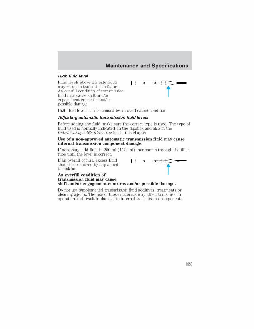
High fluid levelFluid levels above the safe rangemay result in transmission failure.An overfill condition of transmissionfluid may cause shift and/orengagement concerns and/orpossible damage.
High fluid levels can be caused by an overheating condition.
Adjusting automatic transmission fluid levels
Before adding any fluid, make sure the correct type is used. The type offluid used is normally indicated on the dipstick and also in theLubricant specifications section in this chapter.
Use of a non-approved automatic transmission fluid may causeinternal transmission component damage.
If necessary, add fluid in 250 ml (1/2 pint) increments through the fillertube until the level is correct.
If an overfill occurs, excess fluidshould be removed by a qualifiedtechnician.
An overfill condition oftransmission fluid may causeshift and/or engagement concerns and/or possible damage.
Do not use supplemental transmission fluid additives, treatments orcleaning agents. The use of these materials may affect transmissionoperation and result in damage to internal transmission components.
Maintenance and Specifications
223

Checking and adding manual transmission fluid (if equipped)1. Clean the filler plug.
2. Remove the filler plug andinspect the fluid level.
3. Fluid level should be at thebottom of the opening.
4. Add enough fluid through thefiller opening so that the fluid levelis at the bottom of the opening.
5. Install and tighten the fill plugsecurely.
Use only fluid that meets Ford specifications. Refer to LubricantSpecifications in this chapter.
Maintenance and Specifications
224

Checking and adding transfer case fluid (if equipped)1. Clean the filler plug.
2. Remove the filler plug andinspect the fluid level.
3. Add only enough fluid throughthe filler opening so that the fluidlevel is at the bottom of theopening.
Use only fluid that meets Ford specifications. Refer to LubricantSpecifications in this chapter.
DRIVELINE UNIVERSAL JOINT AND SLIP YOKE
Your vehicle may be equipped with universal joints that requirelubrication. Refer to the scheduled maintenance guide for maintenanceintervals. If the original universal joints are replaced with universal jointsequipped with grease fittings, lubrication will also be necessary.
Maintenance and Specifications
225

INFORMATION ABOUT UNIFORM TIRE QUALITY GRADINGNew vehicles are fitted with tiresthat have a rating on them calledTire Quality Grades. The Qualitygrades can be found whereapplicable on the tire sidewallbetween tread shoulder andmaximum section width. Forexample:
• Treadwear 200 Traction AA Temperature A
These Tire Quality Grades are determined by standards that the UnitedStates Department of Transportation has set.
Tire Quality Grades apply to new pneumatic tires for use on passengercars. They do not apply to deep tread, winter-type snow tires,space-saver or temporary use spare tires, tires with nominal rimdiameters of 10 to 12 inches or limited production tires as defined inTitle 49 Code of Federal Regulations Part 575.104(c)(2).
U.S. Department of Transportation-Tire quality grades: The U.S.Department of Transportation requires Ford to give you the followinginformation about tire grades exactly as the government has written it.
Treadwear
The treadwear grade is a comparative rating based on the wear rate ofthe tire when tested under controlled conditions on a specifiedgovernment test course. For example, a tire graded 150 would wear oneand one-half (1 1/2) times as well on the government course as a tiregraded 100. The relative performance of tires depends upon the actualconditions of their use, however, and may depart significantly from thenorm due to variations in driving habits, service practices, anddifferences in road characteristics and climate.
Traction AA A B C
The traction grades, from highest to lowest are AA, A, B, and C. Thegrades represent the tire’s ability to stop on wet pavement as measuredunder controlled conditions on specified government test surfaces ofasphalt and concrete. A tire marked C may have poor tractionperformance.
Maintenance and Specifications
226
The traction grade assigned to this tire is based onstraight-ahead braking traction tests, and does not include
acceleration, cornering, hydroplaning or peak traction characteristics.
Temperature A B CThe temperature grades are A (the highest), B and C, representing thetire’s resistance to the generation of heat and its ability to dissipate heatwhen tested under controlled conditions on a specified indoor laboratorytest wheel. Sustained high temperature can cause the material of the tireto degenerate and reduce tire life, and excessive temperature can lead tosudden tire failure. The grade C corresponds to a level of performancewhich all passenger car tires must meet under the Federal Motor VehicleSafety Standard No. 109. Grades B and A represent higher levels ofperformance on the laboratory test wheel than the minimum required bylaw.
The temperature grade for this tire is established for a tire thatis properly inflated and not overloaded. Excessive speed,
underinflation, or excessive loading, either separately or incombination, can cause heat buildup and possible tire failure.
SERVICING YOUR TIRES
Checking the tire pressure• Use an accurate tire pressure gauge.
• Check the tire pressure when tires are cold, after the vehicle has beenparked for at least one hour or has been driven less than 5 km (3 miles).
• Adjust tire pressure to recommended specifications found on theCertification Label. Tire pressure information can also be found on theTire Information label located on the inside of the fuel filler door.
Improperly inflated tires can affect vehicle handling and can failsuddenly, possibly resulting in loss of vehicle control, vehicle
rollover and/or personal injury.
Maintenance and Specifications
227

Tire rotation
Because your vehicle’s tires perform different jobs, they often weardifferently. To make sure your tires wear evenly and last longer, rotatethem as indicated in the scheduled maintenance guide. If you notice thatthe tires wear unevenly, have them checked.
• Four tire rotation
• Five tire rotation
Note: Do not use a temporary spare tire for a five tire rotation.
Maintenance and Specifications
228

Replacing the tiresReplace the tires when the wearband is visible through the tiretreads. Due to exposure to theelements and exhaust you shouldreplace the spare tire when youreplace the other tires.
When replacing full size tires, never mix radial bias-belted, orbias-type tires. Use only the tire sizes that are listed on the
Certification Label. Make sure that all tires are the same size, speedrating, and load-carrying capacity. Use only the tire combinationsrecommended on the label. If you do not follow these precautions,your vehicle handling may be affected which can lead to loss of vehiclecontrol, vehicle rollover and/or personal injury.
Make sure that all replacement tires are of the same size, type,speed rating, load-carrying capacity and tread design (e.g., “All
Terrain”, “Touring”, etc.), as originally offered by Ford.
Do not replace your tires with “high performance” tires or largersize tires.
Failure to follow these precautions may adversely affect thehandling of the vehicle, and increase the risk of loss of vehicle
control, vehicle rollover and/or personal injury.
Tires that are larger or smaller than your vehicle’s original tires may alsoaffect the accuracy of your speedometer.
Maintenance and Specifications
229
SNOW TIRES AND CHAINS
Driving too fast for conditions creates the possibility of loss ofvehicle control. Driving at very high speeds for extended periods
of time may result in damage to vehicle components.
Snow tires must be the same size and grade as the tires youcurrently have on your vehicle.
The tires on your vehicle have all weather treads to provide traction inrain and snow. However, in some climates, you may need to use snowtires and chains. If you need to use snow tires and chains, it isrecommended that steel wheels are used of the same size andspecifications as those originally installed.
Follow these guidelines when using snow tires and chains:
• Do not use tire chains on aluminum wheels. Chains may chip thewheels.
• Use only SAE Class S chains.
• Install chains securely, verifying that the chains do not touch anywiring, brake lines or fuel lines.
• Drive cautiously. If you hear the chains rub or bang against yourvehicle, stop and re-tighten the chains. If this does not work, removethe chains to prevent damage to your vehicle.
• If possible, avoid fully loading your vehicle.
• Remove the tire chains when they are no longer needed. Do not usetire chains on dry roads.
• The suspension insulation and bumpers will help prevent vehicledamage. Do not remove these components from your vehicle whenusing snow tires and chains.
Maintenance and Specifications
230
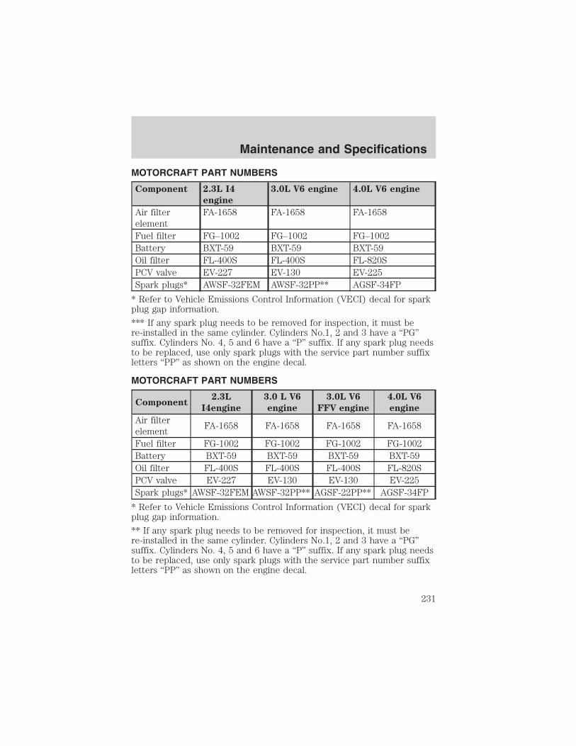
MOTORCRAFT PART NUMBERS
Component 2.3L I4
engine
3.0L V6 engine 4.0L V6 engine
Air filterelement
FA-1658 FA-1658 FA-1658
Fuel filter FG–1002 FG–1002 FG–1002Battery BXT-59 BXT-59 BXT-59Oil filter FL-400S FL-400S FL-820SPCV valve EV-227 EV-130 EV-225Spark plugs* AWSF-32FEM AWSF-32PP** AGSF-34FP
* Refer to Vehicle Emissions Control Information (VECI) decal for sparkplug gap information.
*** If any spark plug needs to be removed for inspection, it must bere-installed in the same cylinder. Cylinders No.1, 2 and 3 have a “PG”suffix. Cylinders No. 4, 5 and 6 have a “P” suffix. If any spark plug needsto be replaced, use only spark plugs with the service part number suffixletters “PP” as shown on the engine decal.
MOTORCRAFT PART NUMBERS
Component2.3L
I4engine
3.0 L V6
engine
3.0L V6
FFV engine
4.0L V6
engine
Air filterelement
FA-1658 FA-1658 FA-1658 FA-1658
Fuel filter FG-1002 FG-1002 FG-1002 FG-1002Battery BXT-59 BXT-59 BXT-59 BXT-59Oil filter FL-400S FL-400S FL-400S FL-820SPCV valve EV-227 EV-130 EV-130 EV-225Spark plugs* AWSF-32FEM AWSF-32PP** AGSF-22PP** AGSF-34FP
* Refer to Vehicle Emissions Control Information (VECI) decal for sparkplug gap information.
** If any spark plug needs to be removed for inspection, it must bere-installed in the same cylinder. Cylinders No.1, 2 and 3 have a “PG”suffix. Cylinders No. 4, 5 and 6 have a “P” suffix. If any spark plug needsto be replaced, use only spark plugs with the service part number suffixletters “PP” as shown on the engine decal.
Maintenance and Specifications
231

REFILL CAPACITIES
Fluid Ford Part
Name
Application Capacity
Engine oil(includes filterchange)7
Motorcraft SAE5W- 20 PremiumSynthetic BlendMotor Oil (US)Motorcraft SAE5W-20 SuperPremium MotorOil (Canada)
2.3L engine 3.8L (4.0quarts)
3.0L V6 engine 4.3L (4.5quarts)
Motorcraft SAE5W- 30 SuperPremium MotorOil
4.0L V6 engine 4.7L (5.0quarts)
Brake fluid andClutch fluid
Motorcraft HighPerformanceDOT 3 MotorVehicle BrakeFluid
All Fill to line orstep (for clutch)on reservoir
Power steeringfluid
MotorcraftMERCON� ATF
All Fill to range ondipstick orreservoir
Maintenance and Specifications
232
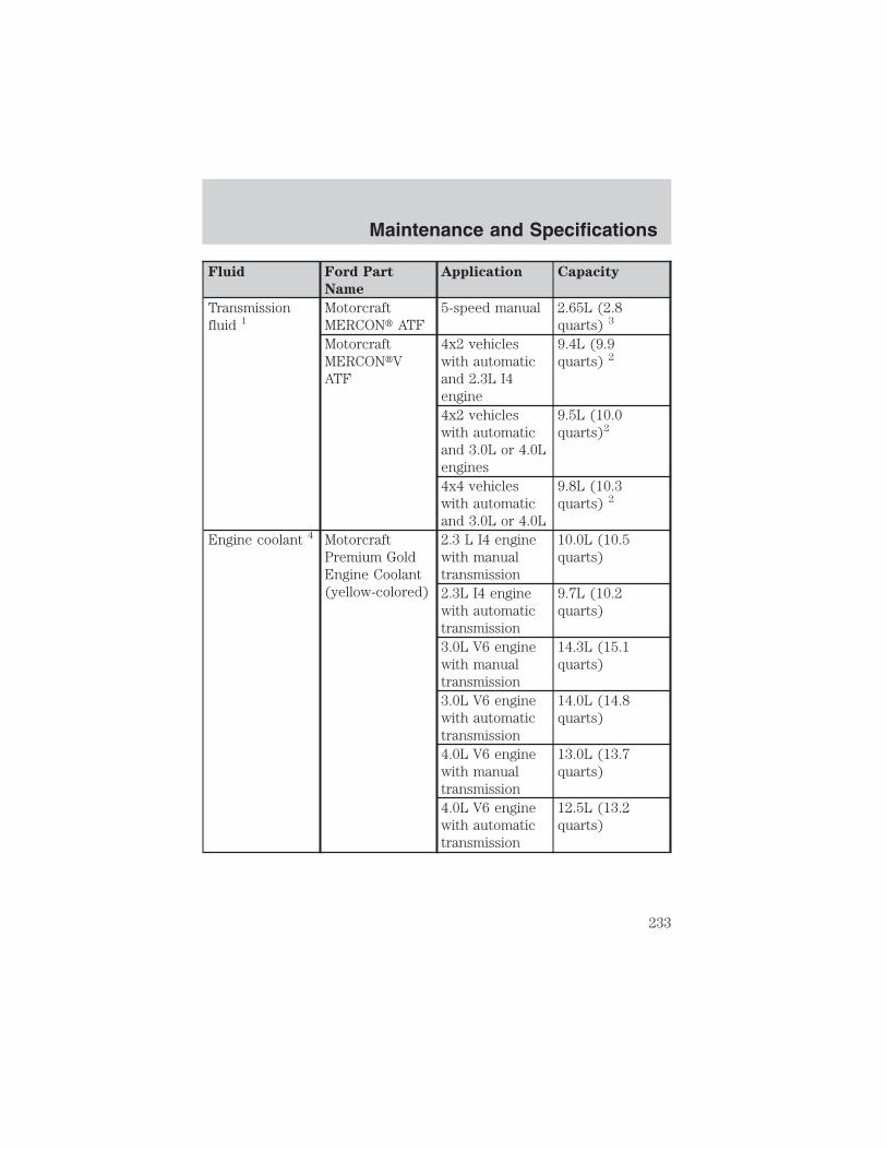
Fluid Ford Part
Name
Application Capacity
Transmissionfluid 1
MotorcraftMERCON� ATF
5-speed manual 2.65L (2.8quarts) 3
MotorcraftMERCON�VATF
4x2 vehicleswith automaticand 2.3L I4engine
9.4L (9.9quarts) 2
4x2 vehicleswith automaticand 3.0L or 4.0Lengines
9.5L (10.0quarts)2
4x4 vehicleswith automaticand 3.0L or 4.0L
9.8L (10.3quarts) 2
Engine coolant 4 MotorcraftPremium GoldEngine Coolant(yellow-colored)
2.3 L I4 enginewith manualtransmission
10.0L (10.5quarts)
2.3L I4 enginewith automatictransmission
9.7L (10.2quarts)
3.0L V6 enginewith manualtransmission
14.3L (15.1quarts)
3.0L V6 enginewith automatictransmission
14.0L (14.8quarts)
4.0L V6 enginewith manualtransmission
13.0L (13.7quarts)
4.0L V6 enginewith automatictransmission
12.5L (13.2quarts)
Maintenance and Specifications
233

Fluid Ford Part
Name
Application Capacity
Fuel tank N/A Regular cab(Short wheelbase)
62.4L (16.5gallons)
Regular cab(Long wheelbase)
75.7L (20.0gallons)
SuperCab 73.8L (19.5gallons)
Transfer caseFluid
MotorcraftMERCON� ATF
4x4 Vehicles 1.2L (1.25quarts)
Front axlelubricant
Motorcraft SAE80W-90Premium RearAxle Lubricant
4x4 Vehicles 1.7L (3.6 pints)
Rear axlelubricant
5, 6Motorcraft SAE80W-90Premium RearAxle Lubricant
All (exceptFX4)
2.4-2.5L (5.0-5.3pints)
Rear axlelubricant (FX4only)6
Motorcraft SAE75W-140Synthetic RearAxle Lubricant
FX4 only 2.5-2.6L(5.25-5.5 pints)
Windshieldwasher fluid
MotorcraftPremiumWindshieldWasherConcentrate
All 2.6L (2.75quarts)
1Ensure the correct automatic transmission fluid is used. Transmissionfluid requirements are indicated on the dipstick or on the dipstickhandle. MERCON� and MERCON� V are not interchangeable. DO NOTmix MERCON� and MERCON�V. Refer to the scheduled maintenanceguide to determine the correct service interval.
Maintenance and Specifications
234

2Indicates only approximate dry-fill capacity. Some applications may varybased on cooler size and if equipped with an in-tank cooler. The amountof transmission fluid and fluid level should be set by the indication onthe dipstick’s normal operating range.3Service refill capacity for the manual transmission is determined byfilling the transmission to the bottom of the filler hole with the vehicleon a level surface.4Add the coolant type originally equipped in your vehicle.5Traction-Lok axles use 2.2–2.4L (4.75–5.0 pints) of rear axle lubricant.6Add 118 ml (4 oz.) of Additive Friction Modifier XL–3 or equivalentmeeting Ford specification EST-M2C118–A for complete refill ofTraction-Lok axles.
Service refill capacities are determined by filling the rear axle 6 mm to14 mm (1/4 inch to 9/16 inch) below the bottom of the filler hole.7Use of sythetic or sythetic blend motor oil is not mandatory. Engine oilneed only meet the requirements of Ford specification WSS-M2C153–Hand the API Certification mark.
LUBRICANT SPECIFICATIONS
Item
Ford part
name or
equivalent
Ford part
number
Ford
specification
Front axle(4X4)
Motorcraft SAE80W-90Premium RearAxle Lubricant
XY-80W90-QL WSP-M2C197-A
Rear axle
Motorcraft SAE80W-90Premium RearAxle Lubricant1
XY-80W90-QL WSP-M2C197-A
Rear axle (FX4only)
Motorcraft SAE75W-140Synthetic RearAxle Lubricant1
XY-75W140–QL WSL-M2C192–A
Maintenance and Specifications
235

Item
Ford part
name or
equivalent
Ford part
number
Ford
specification
Brake fluid andclutch fluid (ifequipped)
Motorcraft HighPerformanceDOT 3 MotorVehicle BrakeFluid
PM-1 ESA-M6C25-Aand DOT 3
Door weatherstrips
SiliconeLubricant
F5AZ-19553–AA ESR-M13P4-A
Engine coolant MotorcraftPremium GoldEngine Coolant(yellow-colored)
VC-7–A WSS-M97B51-A1
Engine oil
2.3L and 3.0L
engines
Motorcraft SAE5W-20 PremiumSynthetic BlendMotor Oil (US)Motorcraft SAE5W-20 SuperPremium MotorOil (Canada)
XO-5W20-QSP(US)CXO-5W20–LSP12(Canada)
WSS-M2C153-Hand APICertificationMark
4.0L engines
Motorcraft SAE5W-30 SuperPremium MotorOil
XO-5W30-QSP WSS-M2C205–Aand APICertificationMark
Hinges, doorchecks, latches,striker plates,fuel filler doorhinge and seattracks
Multi-PurposeGrease
XG-4 or XL-5 ESB-M1C159-Aor ESB-M1C93-B
Maintenance and Specifications
236

Item
Ford part
name or
equivalent
Ford part
number
Ford
specification
Transmission/steering/parkingbrake linkagesand pivots,brake and clutchpedal shaft,clutch pilotbearing and.input shaftspline (manualtransmission)
MotorcraftPremiumLong-Life Grease
XG-1-C orXG-1-K
ESA-M1C75-B
Power steeringfluid, transfercase fluid (4X4)and transmissionfluid (manual)
MotorcraftMERCON� ATF
XT-2-QDX MERCON�
Automatictransmission(5R44E and5R55E)
MotorcraftMERCON�VATF 2
XT-5-QM MERCON�V
Windshieldwasher fluid
MotorcraftPremiumWindshieldWasherConcentrate
ZC-32–A WSB-M8B16–A2
1Add 118 ml (4 oz.) of Additive Friction Modifier XL-3 or equivalentmeeting Ford specification EST-M2C118–A for complete refill ofTraction-Lok axles.2Ensure the correct automatic transmission fluid is used. Transmissionfluid requirements are indicated on the dipstick or on the dipstickhandle. MERCON� and MERCON� V are not interchangeable. DO NOTmix MERCON� and MERCON� V. Refer to your scheduled maintenanceguide to determine the correct service interval.
Maintenance and Specifications
237

ENGINE DATA
Engine 2.3L I4 engine 3.0L V6 engine 4.0L V6 engine
Cubic inches 138 182 245Required fuel 87 octane 87 octane 87 octaneFiring order 1-3-4-2 1-4-2-5-3-6 1-4-2-5-3-6
Spark plug gap1.04-1.19 mm(0.041-0.047inch)
1.07-1.1 7mm(0.042-0.046inch)
1.3-1.4 mm(0.052-0.056inch)
Ignition system EDIS EDIS EDISCompressionratio
9.7:19.7:1 9.0:1
VEHICLE DIMENSIONS
Vehicle
dimensions
Regular Cab
Short Wheel
Base (SWB) mm
(in)
Regular Cab
Long Wheel
Base (LWB)
mm (in)
Supercab mm
(in)
(1) Overalllength
4763 (187.5) 5093 (200.5) 5153 (202.9)
(2) Overallwidth
1785 (70.3) 1785 (70.3) 1785 (70.3)
(3) Overallheight 4x2/4x4
1 593.5 (62.7) /1655 (65.2)
1596 (62.8) /1 655 (65.2)
1599 (62.9) /1 657 (65.2)
(4) Wheelbase 2831 (111.4) 2983 (117.4) 3192 (125.7)(5) Track -Front
1486 (58.5) 1486 (58.5) 1485 (58.5)
(5) Track -Rear
1455 (57.3) 1455 (57.3) 1455 (57.3)
Maintenance and Specifications
238

2
5
3
1
4
Maintenance and Specifications
239

IDENTIFYING YOUR VEHICLE
Certification labelThe National Highway Traffic SafetyAdministration Regulations requirethat a Certification label be affixedto a vehicle and prescribe where theCertification label may be located.The Certification label is located onthe front door latch pillar on thedriver’s side.
1
4
Maintenance and Specifications
240
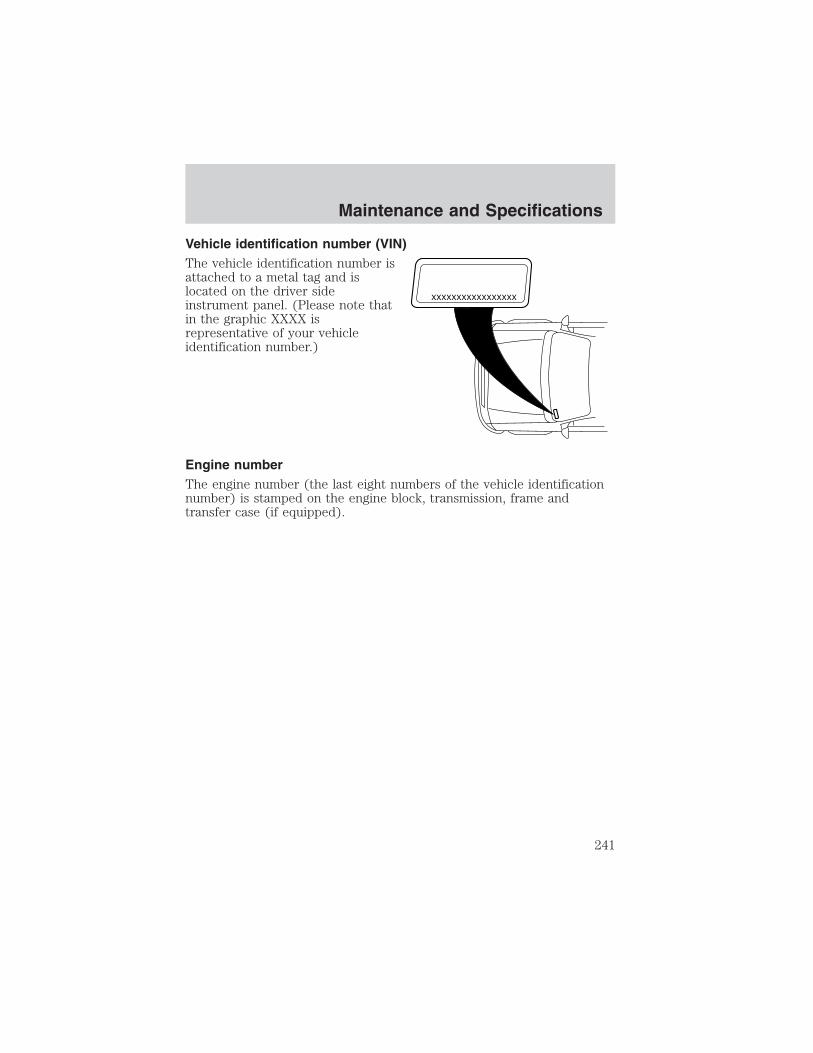
Vehicle identification number (VIN)The vehicle identification number isattached to a metal tag and islocated on the driver sideinstrument panel. (Please note thatin the graphic XXXX isrepresentative of your vehicleidentification number.)
Engine numberThe engine number (the last eight numbers of the vehicle identificationnumber) is stamped on the engine block, transmission, frame andtransfer case (if equipped).
XXXXXXXXXXXXXXXXX
Maintenance and Specifications
241

FORD ACCESSORIES FOR YOUR VEHICLEA wide selection of genuine Ford accessories are available for yourvehicle through your local authorized Ford, Lincoln, Mercury or Ford ofCanada dealer. These quality accessories have been specificallyengineered to fulfill your automotive needs; they are custom designed tocomplement the style and aerodynamic appearance of your vehicle. Inaddition, each accessory is made from high quality materials and meetsor exceeds Ford’s rigorous engineering and safety specifications. FordMotor Company will repair or replace any properly dealer-installed Fordaccessory found to be defective in factory-supplied materials orworkmanship during the warranty period, as well as any componentdamaged by the defective accessory. The accessory will be warranted forwhichever provides you the greatest benefit:
• 12 months or 20,000 km (12,000 miles) (whichever occurs first), or
• the remainder of your new vehicle limited warranty.
This means that genuine Ford accessories purchased along with your newvehicle and installed by the dealer are covered for the full length of yourNew Vehicle’s Limited Warranty — 3 years or 60,000 km (36,000 miles)(whichever occurs first). Contact your dealer for details and a copy of thewarranty.
Not all accessories are available for all models.
Following is a list of several Ford Genuine Accessory products. Not allaccessories are available for all models. To find out what accessories areavailable for your vehicle, please contact your dealer or visit our onlinestore at: www.fordaccessories.com.
Vehicle SecurityCargo security shade
Keyless entry system
Styled wheel protector locks
Vehicle security systems
Accessories
Accessories
242
Comfort and convenienceCargo cage / bed extender
Cargo organizers
Cargo retainer net
Engine block heaters
Manual sliding rear window
Remote start
Tire step
Travel equipmentAutomatic headlamp system with DRL
Bed rail caps
Bed tent (Short bed, Styleside only)
Cellular phone holder
Compass mirror
Compass mirror with outside temperature reading
Daytime running lights
First aid kit
Fog lights
Peace of mind kit
Pickup box rails (tubular)
Removable bike carrier (bed mount/hitch mount)
Running boards/bars
Speed control
Trailer hitch (Class III)
Trailer hitch bars and balls
Trailer hitch wiring adaptor
Trailgate table
Accessories
243

Protection and appearance equipmentAir bag anti-theft locks
Bed mats
Bedliners
Bull bars (chrome & black)
Carpeted floor mats with logo
Door edge guards
Front end covers (full and sport)
Bug deflectors
Cap (hard — color keyed — Leer supplier branded)
Locking gas cap
Rear window deflector
Removable tailgate lock
Retractable bed hooks
Running boards and bars
Side window air deflectors
Skid plate (4x4 only)
Spare tire lock
Tailgate protector
Tail lamp surrounds (chrome & black)
Tonneau covers — soft (snap and snapless)
Tonneau cover (hard 2 piece)
Tonneau cover (color keyed-Leer supplier branded)
Universal floor mats
Wheels
Wheel locks
Accessories
244

For maximum vehicle performance, keep the following information inmind when adding accessories or equipment to your vehicle:
• When adding accessories, equipment, passengers and luggage to yourvehicle, do not exceed the total weight capacity of the vehicle or ofthe front or rear axle (GVWR or GAWR as indicated on the Safetycompliance certification label). Consult your dealer for specific weightinformation.
• The Federal Communications Commission (FCC) and Canadian RadioTelecommunications Commission (CRTC) regulate the use of mobilecommunications systems - such as two-way radios, telephones andtheft alarms - that are equipped with radio transmitters. Any suchequipment installed in your vehicle should comply with FCC or CRTCregulations and should be installed only by a qualified servicetechnician.
• Mobile communications systems may harm the operation of yourvehicle, particularly if they are not properly designed for automotiveuse or are not properly installed. When operated, such systems maycause the engine to stumble or stall or cause the transmission to bedamaged or operate improperly. In addition, such systems may bedamaged or their performance may be affected by operating yourvehicle. (Citizens band [CB] transceivers, garage door openers andother transmitters with outputs of five watts or less will not ordinarilyaffect your vehicle’s operation.)
• Ford cannot assume responsibility for any adverse effects or damagethat may result from the use of such equipment.
Accessories
245

A
Air bag supplemental restraintsystem ..........................................86
and child safety seats ..............88description ................................86disposal ......................................91driver air bag ............................89indicator light ...........................91operation ...................................89passenger air bag .....................89passenger deactivationswitch ........................................92
Air cleaner filter .......................231Ambulance packages ....................7Antifreeze (see Enginecoolant) .....................................202
Anti-lock brake system(see Brakes) ..............................115
Audio systemAM/FM .......................................16Single CD ..................................18
Audio system(see Radio) ....16, 18, 21, 24, 30, 34
Automatic transmission ............118driving an automaticoverdrive .................................119fluid, adding ............................221fluid, checking ........................221fluid, refill capacities ..............232fluid, specification ..................238
Auxiliary power point .................52
Axlelubricant specifications ..235, 238refill capacities ........................232traction lok ..............................117
B
Battery .......................................200
acid, treating emergencies .....200jumping a disabled battery ....167maintenance-free ....................200replacement, specifications ...231servicing ..................................200
Bed extender ..............................58
BeltMinder ...................................81
Brakes ........................................115anti-lock ...................................115anti-lock brake system (ABS)warning light ...........................115fluid, checking and adding ....220fluid, refill capacities ..............232fluid, specifications .........235, 238lubricant specifications ..235, 238parking ....................................116shift interlock ..........................118
Bulbs ............................................45
C
Calculating load ........................136
Capacities for refilling fluids ....232
Cargo area shade ........................57
Cargo net .....................................57
Cassette tape player .............18, 21
CD-single premium ...16, 24, 30, 34
Cell phone use ............................57
Certification Label ....................240
Changing a tire .........................161
Child safety restraints ................97child safety belts ......................97
Child safety seats ................99–100attaching with tether straps ..103in front seat ............................101in rear seat ..............................101
Index
Index
246

Cleaning your vehicleengine compartment ..............184instrument panel ....................187interior .....................................187plastic parts ............................186safety belts ..............................187washing ....................................183waxing .....................................183wheels ......................................184wiper blades ............................186
Clock adjustAM/FM .......................................16Single CD ..................................18
Clutchfluid ..........................................220operation while driving ..........121recommended shift speeds ....122
Console ........................................57
Coolantchecking and adding ..............202refill capacities ................206, 232specifications ..................235, 238
Cruise control(see Speed control) ....................54
Customer Assistance ................149Ford accessories for yourvehicle .....................................188Ford Extended ServicePlan ..........................................176Getting assistance outside theU.S. and Canada .....................180Getting roadside assistance ...149Getting the service youneed .........................................174Ordering additional owner’sliterature .................................181The Dispute SettlementBoard .......................................176
Utilizing theMediation/ArbitrationProgram ...................................179
D
Daytime running lamps(see Lamps) ................................42
Dipstickautomatic transmissionfluid ..........................................221engine oil .................................195
Doorslubricant specifications ..........235
Driveline universal joint andslip yoke ....................................225
Driving under specialconditions ..................123, 127, 130
sand .........................................129snow and ice ...........................131through water .................130, 134
E
Emergencies, roadsidejump-starting ..........................167
Emergency Flashers .................150
Emission control system ..........216
Engine ........................................238cleaning ...................................184coolant .....................................202idle speed control ...................200lubricationspecifications ..................235, 238refill capacities ........................232service points ..................191–193starting after a collision .........150
Engine block heater .................114
Engine oil ..................................195
Index
247

checking and adding ..............195dipstick ....................................195filter, specifications ........199, 231recommendations ...................199refill capacities ........................232specifications ..................235, 238
Exhaust fumes ..........................114
F
Flexible Fuel Vehicle (FFV) ....207
Fluid capacities .........................232
Foglamps .....................................42
Four-Wheel Drive vehicles .......123driving off road .......................126electronic shift ........................125indicator light .........................123lever operated shift ................124preparing to drive yourvehicle .....................................117
Fuel ............................................207calculating fuel economy .......213cap ...........................................210capacity ...................................232choosing the right fuel ...........211comparisons with EPA fueleconomy estimates .................216detergent in fuel .....................212filling your vehicle withfuel ...........................207, 210, 213filter, specifications ........213, 231fuel pump shut-off switch .....150improving fuel economy ........213octane rating ...................211, 238quality ......................................212running out of fuel .................212safety information relating toautomotive fuels .....................207
Fuel - flex fuel vehicle(FFV) .................................207, 211
Fuel pump shut-off switch .......150Fuses ..................................151–152
G
Gas cap (see Fuel cap) ............210Gas mileage (see Fueleconomy) ...................................213Gauges .........................................13GAWR (Gross Axle WeightRating) .......................................134
calculating ...............................136definition .................................134driving with a heavy load ......134location ....................................134
GVWR (Gross Vehicle WeightRating) .......................................134
calculating .......................134, 136definition .................................134driving with a heavy load ......134location ....................................134
H
Hazard flashers .........................150Headlamps ...................................42
aiming ........................................43bulb specifications ....................45daytime running lights .............42flash to pass ..............................43high beam .................................43replacing bulbs .........................47turning on and off ....................42
Heatingheating and air conditioningsystem .................................39–40
Hood ..........................................190
I
Ignition ...............................110, 238
Index
248

Infant seats(see Safety seats) ...............99–100Inspection/maintenance (I/M)testing ........................................218
Instrument panelcleaning ...................................187cluster ........................................10lighting up panel andinterior .......................................43
J
Jack ............................................161positioning .......................161, 164storage .............................161–163
Jump-starting your vehicle ......167
K
Keyspositions of the ignition .........110
L
Lampsbulb replacementspecifications chart ..................45cargo lamps ...............................43daytime running light ...............42fog lamps ...................................42headlamps .................................42headlamps, flash to pass ..........43instrument panel, dimming .....43interior lamps .....................45–46replacing bulbs .............45, 47–50
Lane change indicator(see Turn signal) ........................45
Lights, warning and indicator ....10anti-lock brakes (ABS) ..........115
Load limits .................................134
GAWR ......................................134GVWR ......................................134trailer towing ..........................134
Loading instructions .................136
Lubricant specifications ...235, 238
Lumbar support, seats ...............73
M
Manual transmission .................121fluid capacities ........................232lubricant specifications ..........238reverse .....................................122
Mirrorsside view mirrors (power) .......53
Motorcraft parts ................213, 231
O
Octane rating ............................211
Oil (see Engine oil) ..................195
P
Parking brake ............................116
Parts (see Motorcraft parts) ....231
Power distribution box(see Fuses) ...............................155
Power door locks ........................63
Power mirrors .............................53
Power point .................................52
Power steering ..........................116fluid, checking and adding ....219fluid, refill capacity ................232fluid, specifications .........235, 238
Power Windows ...........................53
Index
249

Preparing to drive yourvehicle ........................................117
R
Radio ..............16, 18, 21, 24, 30, 34AM/FM .......................................16Single CD ..................................18
Relays ........................................151
Remote entry system .................65illuminated entry ......................68locking/unlocking doors .....63, 65
Roadside assistance ..................149
S
Safety Belt Maintenance ............85
Safety belts (see Safetyrestraints) ..............................74–78
Safety defects, reporting ..........182
Safety restraints ....................74–78belt minder ...............................81extension assembly ..................80for adults .............................75–78for children .........................96–97lap belt ......................................79safety belt maintenance ...........85warning light and chime ..........81
Safety seats for children ....99–100
Seat belts (see Safetyrestraints) ....................................74
Seats ............................................72child safety seats ..............99–100
Servicing your vehicle ..............189
Snowplowing .................................7
Spare tire (see Changing theTire) ...................................161–162
Spark plugs,specifications .....................231, 238
Special noticeambulance conversions ..............7utility-type vehicles ....................6
Specification chart,lubricants ...........................235, 238
Speed control ..............................54
Starting a flex fuel vehicle .......114
Starting your vehicle .......110–111,113
jump starting ..........................167
Steering wheeltilting .........................................52
StereoAM/FM .......................................16Single CD ..................................18
T
Tilt steering wheel ......................52
Tires ...........................161, 226–227changing ..................161–162, 164checking the pressure ............227replacing ..................................229rotating ....................................228snow tires and chains ............230tire grades ...............................227treadwear ................................226
Tonneau cover .............................59
Towing .......................................136recreational towing .................146trailer towing ..........................136wrecker ....................................173
Traction-lok rear axle ...............117
Transfer casefluid checking .........................225
Index
250

Transmissionautomatic operation ...............118fluid, checking and adding(automatic) .............................221fluid, checking and adding(manual) .................................224fluid, refill capacities ..............232lubricant specifications ..235, 238manual operation ....................121
Trunk ...........................................63Turn signal ..................................45
V
Vehicle dimensions ...................238
Vehicle Identification Number(VIN) ..........................................241
Vehicle loading ..........................134
camper bodies ........................148
Ventilating your vehicle ...........115
W
Warning lights (see Lights) .......10
Washer fluid ..............................194
Water, Driving through .............134
Windowspower .........................................53
Windshield washer fluid andwipers ..........................................51
checking and adding fluid .....194replacing wiper blades .............51
Wrecker towing .........................173
Index
251

252

253

254

255

256