KUKA.ArcTech Analog -- Configuration Release 1.1
128
ArcTechAnalog_Pro_R1.1 02.05.00 en 1 of 125 SOFTWARE KR C2 KUKA.ArcTechAnalog -- Configuration Arc welding for power sources with analog reference voltage Release 1.1 for KUKA System Software (KSS) Release 5.2, 5.3, 5.4, 5.5 Issued: 28 Juli 2008 Version: 00
-
Upload
khangminh22 -
Category
Documents
-
view
4 -
download
0
Transcript of KUKA.ArcTech Analog -- Configuration Release 1.1

ArcTechAnalog_Pro_R1.1 02.05.00 en 1 of 125
SOFTWARE
KR C2
KUKA.ArcTech Analog -- ConfigurationArc welding for power sources with analog reference voltage
Release 1.1
for KUKA System Software (KSS) Release 5.2, 5.3, 5.4, 5.5
Issued: 28 Juli 2008 Version: 00

2 of 125 ArcTechAnalog_Pro_R1.1 02.05.00 en
e Copyright 2008
KUKA Roboter GmbHThis documentation or excerpts therefrommay not be reproduced or disclosed to third parties without the express permission of the publishers.Other functions not described in this documentation may be operable in the controller. The user has no claim to these functions, however, inthe case of a replacement or service work.We have checked the content of this documentation for conformity with the hardware and software described. Nevertheless, discrepanciescannot be precluded, for which reason we are not able to guarantee total conformity. The information in this documentation is checked on aregular basis, however, and necessary corrections will be incorporated in subsequent editions.Subject to technical alterations without an effect on the function.

3 of 125ArcTechAnalog_Pro_R1.1 02.05.00 en
Contents
1 Introduction 7. . . . . . . . . . . . . . . . . . . . . . . . . . . . . . . . . . . . . . . . . . . . . . . . . . . . .
1.1 System requirements 7. . . . . . . . . . . . . . . . . . . . . . . . . . . . . . . . . . . . . . . . . . . . . . . . . . . . . . . . . . .
1.2 Operating convenience 8. . . . . . . . . . . . . . . . . . . . . . . . . . . . . . . . . . . . . . . . . . . . . . . . . . . . . . . . .
1.3 Overview of the configurable functions 8. . . . . . . . . . . . . . . . . . . . . . . . . . . . . . . . . . . . . . . . . . . .
2 Safety 9. . . . . . . . . . . . . . . . . . . . . . . . . . . . . . . . . . . . . . . . . . . . . . . . . . . . . . . . . . .
2.1 Additional safety instructions for “KUKA.ArcTech Analog” 9. . . . . . . . . . . . . . . . . . . . . . . . . . . .
2.2 Liability 9. . . . . . . . . . . . . . . . . . . . . . . . . . . . . . . . . . . . . . . . . . . . . . . . . . . . . . . . . . . . . . . . . . . . . . .
2.3 Designated use 9. . . . . . . . . . . . . . . . . . . . . . . . . . . . . . . . . . . . . . . . . . . . . . . . . . . . . . . . . . . . . . . .
2.4 Symbols and icons 10. . . . . . . . . . . . . . . . . . . . . . . . . . . . . . . . . . . . . . . . . . . . . . . . . . . . . . . . . . . . .2.4.1 Safety symbols 10. . . . . . . . . . . . . . . . . . . . . . . . . . . . . . . . . . . . . . . . . . . . . . . . . . . . . . . . . . . . . . . .2.4.2 Icons 10. . . . . . . . . . . . . . . . . . . . . . . . . . . . . . . . . . . . . . . . . . . . . . . . . . . . . . . . . . . . . . . . . . . . . . . . .
3 Graphical user interface (HMI) of the KUKA Control Panel (KCP) 11. . . .
3.1 Selecting the “Expert” user group 11. . . . . . . . . . . . . . . . . . . . . . . . . . . . . . . . . . . . . . . . . . . . . . . .
3.2 Configurable options ($CONFIG.DAT) 11. . . . . . . . . . . . . . . . . . . . . . . . . . . . . . . . . . . . . . . . . . . .
3.3 Configurable options (A10.DAT) 12. . . . . . . . . . . . . . . . . . . . . . . . . . . . . . . . . . . . . . . . . . . . . . . . . .
4 “KUKA.ArcTech Analog” programs 13. . . . . . . . . . . . . . . . . . . . . . . . . . . . . . . .
4.1 Program structure 13. . . . . . . . . . . . . . . . . . . . . . . . . . . . . . . . . . . . . . . . . . . . . . . . . . . . . . . . . . . . . .
4.2 Overview of files for “KUKA.ArcTech Analog” 14. . . . . . . . . . . . . . . . . . . . . . . . . . . . . . . . . . . . . .
5 Adaptation to the periphery, configurable options 17. . . . . . . . . . . . . . . . . .
5.1 Digital outputs and inputs 17. . . . . . . . . . . . . . . . . . . . . . . . . . . . . . . . . . . . . . . . . . . . . . . . . . . . . . .5.1.1 Overview and purpose 17. . . . . . . . . . . . . . . . . . . . . . . . . . . . . . . . . . . . . . . . . . . . . . . . . . . . . . . . . .5.1.2 Index table for physical digital outputs 19. . . . . . . . . . . . . . . . . . . . . . . . . . . . . . . . . . . . . . . . . . . .5.1.3 Signal tables for digital outputs 21. . . . . . . . . . . . . . . . . . . . . . . . . . . . . . . . . . . . . . . . . . . . . . . . . . .5.1.4 Examples of a signal configuration 23. . . . . . . . . . . . . . . . . . . . . . . . . . . . . . . . . . . . . . . . . . . . . . .5.1.5 Index table for physical digital inputs 25. . . . . . . . . . . . . . . . . . . . . . . . . . . . . . . . . . . . . . . . . . . . . .5.1.6 Signal tables for digital inputs 26. . . . . . . . . . . . . . . . . . . . . . . . . . . . . . . . . . . . . . . . . . . . . . . . . . . .
5.2 Customer--specific adaptation of weld sequences 29. . . . . . . . . . . . . . . . . . . . . . . . . . . . . . . . . .5.2.1 Subroutines for weld commands 29. . . . . . . . . . . . . . . . . . . . . . . . . . . . . . . . . . . . . . . . . . . . . . . . .5.2.2 Error handling routines 33. . . . . . . . . . . . . . . . . . . . . . . . . . . . . . . . . . . . . . . . . . . . . . . . . . . . . . . . . .
6 Description of the weld commands 37. . . . . . . . . . . . . . . . . . . . . . . . . . . . . . . .6.1 Controlling welding and wire feed with the status keys on the KUKA Control Panel 37. . . . . .6.1.1 Manual activation and deactivation of the weld process (FLY ARC) 37. . . . . . . . . . . . . . . . . . .
6.2 Activating the welding package 39. . . . . . . . . . . . . . . . . . . . . . . . . . . . . . . . . . . . . . . . . . . . . . . . . .
6.3 Initialization (ARC--INIT) 39. . . . . . . . . . . . . . . . . . . . . . . . . . . . . . . . . . . . . . . . . . . . . . . . . . . . . . . .6.3.1 Checking the specified Submit routine 39. . . . . . . . . . . . . . . . . . . . . . . . . . . . . . . . . . . . . . . . . . . .6.3.2 Setting the cyclical analog channel for ONLINE optimizing 39. . . . . . . . . . . . . . . . . . . . . . . . . . .

KUKA.ArcTech Analog -- Configuration
4 of 125 ArcTechAnalog_Pro_R1.1 02.05.00 en
6.3.3 Required setting for reduced velocity in T1 40. . . . . . . . . . . . . . . . . . . . . . . . . . . . . . . . . . . . . . . .6.3.4 Required settings for backward motion of a welding application 40. . . . . . . . . . . . . . . . . . . . . . .
6.4 ARC ON command 41. . . . . . . . . . . . . . . . . . . . . . . . . . . . . . . . . . . . . . . . . . . . . . . . . . . . . . . . . . . . .6.4.1 Welding constraints 41. . . . . . . . . . . . . . . . . . . . . . . . . . . . . . . . . . . . . . . . . . . . . . . . . . . . . . . . . . . .6.4.2 Gas preflow 42. . . . . . . . . . . . . . . . . . . . . . . . . . . . . . . . . . . . . . . . . . . . . . . . . . . . . . . . . . . . . . . . . . .6.4.3 Configuration: monitoring the weld power source 43. . . . . . . . . . . . . . . . . . . . . . . . . . . . . . . . . . .6.4.4 Configuration: robot motion start after weld start 43. . . . . . . . . . . . . . . . . . . . . . . . . . . . . . . . . . .6.4.5 Configuration of the weld modes 44. . . . . . . . . . . . . . . . . . . . . . . . . . . . . . . . . . . . . . . . . . . . . . . . .6.4.6 Configuration of the WELD start signal 44. . . . . . . . . . . . . . . . . . . . . . . . . . . . . . . . . . . . . . . . . . . .6.4.7 Configuration of the error handling for an ignition failure 45. . . . . . . . . . . . . . . . . . . . . . . . . . . . .6.4.8 Configuration of gas postflow 46. . . . . . . . . . . . . . . . . . . . . . . . . . . . . . . . . . . . . . . . . . . . . . . . . . . .6.4.9 Configuration of necessary acknowledgement signals 46. . . . . . . . . . . . . . . . . . . . . . . . . . . . . . .6.4.10 Activating the ramp function 47. . . . . . . . . . . . . . . . . . . . . . . . . . . . . . . . . . . . . . . . . . . . . . . . . . . . .6.4.11 Schematic sequence diagram 48. . . . . . . . . . . . . . . . . . . . . . . . . . . . . . . . . . . . . . . . . . . . . . . . . . .6.4.12 Ignition process signal flow diagram 49. . . . . . . . . . . . . . . . . . . . . . . . . . . . . . . . . . . . . . . . . . . . . .6.4.13 Activation of delayed weld process monitoring after ignition 50. . . . . . . . . . . . . . . . . . . . . . . . . .
6.5 ARC SWITCH command 50. . . . . . . . . . . . . . . . . . . . . . . . . . . . . . . . . . . . . . . . . . . . . . . . . . . . . . . .6.5.1 Schematic sequence diagram 51. . . . . . . . . . . . . . . . . . . . . . . . . . . . . . . . . . . . . . . . . . . . . . . . . . .6.5.2 Signal diagrams 52. . . . . . . . . . . . . . . . . . . . . . . . . . . . . . . . . . . . . . . . . . . . . . . . . . . . . . . . . . . . . . .6.5.3 Signal tables 54. . . . . . . . . . . . . . . . . . . . . . . . . . . . . . . . . . . . . . . . . . . . . . . . . . . . . . . . . . . . . . . . . .
6.6 ARC OFF command 54. . . . . . . . . . . . . . . . . . . . . . . . . . . . . . . . . . . . . . . . . . . . . . . . . . . . . . . . . . .6.6.1 Signal tables 55. . . . . . . . . . . . . . . . . . . . . . . . . . . . . . . . . . . . . . . . . . . . . . . . . . . . . . . . . . . . . . . . . .
6.7 Burnfree options 57. . . . . . . . . . . . . . . . . . . . . . . . . . . . . . . . . . . . . . . . . . . . . . . . . . . . . . . . . . . . . . .6.7.1 Configuration: burnfree 57. . . . . . . . . . . . . . . . . . . . . . . . . . . . . . . . . . . . . . . . . . . . . . . . . . . . . . . . .6.7.2 Burnfree duration and number of burnfree attempts 57. . . . . . . . . . . . . . . . . . . . . . . . . . . . . . . . .
6.8 Burnback mode -- A_BB_MODE 58. . . . . . . . . . . . . . . . . . . . . . . . . . . . . . . . . . . . . . . . . . . . . . . . .6.8.1 Burnback mode A_BB_MODE=#ACT_PAR 58. . . . . . . . . . . . . . . . . . . . . . . . . . . . . . . . . . . . . . . .6.8.2 Burnback mode A_BB_MODE = #REDUCE 58. . . . . . . . . . . . . . . . . . . . . . . . . . . . . . . . . . . . . . .6.8.3 Schematic sequence diagram 59. . . . . . . . . . . . . . . . . . . . . . . . . . . . . . . . . . . . . . . . . . . . . . . . . . .
7 Configuration of analog outputs 63. . . . . . . . . . . . . . . . . . . . . . . . . . . . . . . . . .
7.1 Maximum number of analog outputs -- A_ACT_AN_MAX 63. . . . . . . . . . . . . . . . . . . . . . . . . . . .7.1.1 Addressing of the analog outputs -- A_ANAOUT_NO[8] 63. . . . . . . . . . . . . . . . . . . . . . . . . . . . .
7.2 Adaptation of analog outputs 1 and 2 specific to the power source 64. . . . . . . . . . . . . . . . . . . .7.2.1 Number of characteristic points 65. . . . . . . . . . . . . . . . . . . . . . . . . . . . . . . . . . . . . . . . . . . . . . . . . .7.2.2 Linear characteristic 66. . . . . . . . . . . . . . . . . . . . . . . . . . . . . . . . . . . . . . . . . . . . . . . . . . . . . . . . . . . .7.2.3 Non--linear characteristic 68. . . . . . . . . . . . . . . . . . . . . . . . . . . . . . . . . . . . . . . . . . . . . . . . . . . . . . . .
8 Mechanical weaving 69. . . . . . . . . . . . . . . . . . . . . . . . . . . . . . . . . . . . . . . . . . . . . .
8.1 Fundamentals 69. . . . . . . . . . . . . . . . . . . . . . . . . . . . . . . . . . . . . . . . . . . . . . . . . . . . . . . . . . . . . . . . .
8.2 Weave patterns 70. . . . . . . . . . . . . . . . . . . . . . . . . . . . . . . . . . . . . . . . . . . . . . . . . . . . . . . . . . . . . . . .
8.3 Two--dimensional weaving 72. . . . . . . . . . . . . . . . . . . . . . . . . . . . . . . . . . . . . . . . . . . . . . . . . . . . . .8.3.1 Creating the “Spiral” weave pattern 73. . . . . . . . . . . . . . . . . . . . . . . . . . . . . . . . . . . . . . . . . . . . . . .8.3.2 “Double 8” weave pattern 76. . . . . . . . . . . . . . . . . . . . . . . . . . . . . . . . . . . . . . . . . . . . . . . . . . . . . . .
8.4 Changing and creating patterns for mechanical weaving 77. . . . . . . . . . . . . . . . . . . . . . . . . . . . .8.4.1 Changing existing weave patterns 77. . . . . . . . . . . . . . . . . . . . . . . . . . . . . . . . . . . . . . . . . . . . . . . .8.4.2 Creating your own weave patterns 79. . . . . . . . . . . . . . . . . . . . . . . . . . . . . . . . . . . . . . . . . . . . . . .
8.5 Notes on mechanical weaving 80. . . . . . . . . . . . . . . . . . . . . . . . . . . . . . . . . . . . . . . . . . . . . . . . . . .

5 of 125ArcTechAnalog_Pro_R1.1 02.05.00 en
8.5.1 Weave frequency, weave length, path velocity (travel speed) 80. . . . . . . . . . . . . . . . . . . . . . . . .8.5.2 Rotation of the weave plane 81. . . . . . . . . . . . . . . . . . . . . . . . . . . . . . . . . . . . . . . . . . . . . . . . . . . . .
9 Thermal weaving 83. . . . . . . . . . . . . . . . . . . . . . . . . . . . . . . . . . . . . . . . . . . . . . . . .
9.1 Fundamentals 83. . . . . . . . . . . . . . . . . . . . . . . . . . . . . . . . . . . . . . . . . . . . . . . . . . . . . . . . . . . . . . . . .9.1.1 Weave patterns 83. . . . . . . . . . . . . . . . . . . . . . . . . . . . . . . . . . . . . . . . . . . . . . . . . . . . . . . . . . . . . . . .9.1.2 Example of a signal diagram 85. . . . . . . . . . . . . . . . . . . . . . . . . . . . . . . . . . . . . . . . . . . . . . . . . . . . .
9.2 Combined mechanical and thermal weaving 85. . . . . . . . . . . . . . . . . . . . . . . . . . . . . . . . . . . . . . .9.2.1 Combination possibilities 85. . . . . . . . . . . . . . . . . . . . . . . . . . . . . . . . . . . . . . . . . . . . . . . . . . . . . . . .9.2.2 Practical application possibilities (examples) 87. . . . . . . . . . . . . . . . . . . . . . . . . . . . . . . . . . . . . . .
10 “KUKA.ArcTech Analog” settings 89. . . . . . . . . . . . . . . . . . . . . . . . . . . . . . . . .
10.1 Power source characteristic settings 89. . . . . . . . . . . . . . . . . . . . . . . . . . . . . . . . . . . . . . . . . . . . . .
10.2 Configuration of the physical interface ($CONFIG.DAT) 90. . . . . . . . . . . . . . . . . . . . . . . . . . . . .10.2.1 Physical outputs 90. . . . . . . . . . . . . . . . . . . . . . . . . . . . . . . . . . . . . . . . . . . . . . . . . . . . . . . . . . . . . . .10.2.2 Configuration of the physical inputs 90. . . . . . . . . . . . . . . . . . . . . . . . . . . . . . . . . . . . . . . . . . . . . . .
10.3 Settings in the file A10.DAT 91. . . . . . . . . . . . . . . . . . . . . . . . . . . . . . . . . . . . . . . . . . . . . . . . . . . . .
11 Default data sets, resource distribution 93. . . . . . . . . . . . . . . . . . . . . . . . . . .
11.1 Setting the default data sets 93. . . . . . . . . . . . . . . . . . . . . . . . . . . . . . . . . . . . . . . . . . . . . . . . . . . . .
11.2 KUKA.ArcTech Analog resource distribution 94. . . . . . . . . . . . . . . . . . . . . . . . . . . . . . . . . . . . . . .11.2.1 Interrupt definitions at R1 level (all ARC versions) 94. . . . . . . . . . . . . . . . . . . . . . . . . . . . . . . . . .11.2.2 $CYCFLAG indices 94. . . . . . . . . . . . . . . . . . . . . . . . . . . . . . . . . . . . . . . . . . . . . . . . . . . . . . . . . . . .11.2.3 $TIMER indices 94. . . . . . . . . . . . . . . . . . . . . . . . . . . . . . . . . . . . . . . . . . . . . . . . . . . . . . . . . . . . . . . .11.2.4 Interrupt indices 94. . . . . . . . . . . . . . . . . . . . . . . . . . . . . . . . . . . . . . . . . . . . . . . . . . . . . . . . . . . . . . .
12 Fault situations and fault service functions 95. . . . . . . . . . . . . . . . . . . . . . . .
12.1 Ignition faults 95. . . . . . . . . . . . . . . . . . . . . . . . . . . . . . . . . . . . . . . . . . . . . . . . . . . . . . . . . . . . . . . . . .12.1.1 Configuration: number of permissible ignition attempts ($CONFIG.DAT) 95. . . . . . . . . . . . . . .12.1.2 Setting the ignition fault option ($CONFIG.DAT) 95. . . . . . . . . . . . . . . . . . . . . . . . . . . . . . . . . . . .12.1.3 Special features of user--defined ignition fault service functions (#USR_START) 96. . . . . . . .12.1.4 Ignition fault signals 97. . . . . . . . . . . . . . . . . . . . . . . . . . . . . . . . . . . . . . . . . . . . . . . . . . . . . . . . . . . .
12.2 Media faults of periphery faults 98. . . . . . . . . . . . . . . . . . . . . . . . . . . . . . . . . . . . . . . . . . . . . . . . . .12.2.1 Configuring the monitoring functions 98. . . . . . . . . . . . . . . . . . . . . . . . . . . . . . . . . . . . . . . . . . . . . .12.2.2 Ignoring temporary interrupts (A_SWINDL_OPT) 99. . . . . . . . . . . . . . . . . . . . . . . . . . . . . . . . . . .
12.3 Robot faults (IR_STOPMESS faults) 99. . . . . . . . . . . . . . . . . . . . . . . . . . . . . . . . . . . . . . . . . . . . . .12.3.1 Deactivation 99. . . . . . . . . . . . . . . . . . . . . . . . . . . . . . . . . . . . . . . . . . . . . . . . . . . . . . . . . . . . . . . . . . .12.3.2 Reactivation 100. . . . . . . . . . . . . . . . . . . . . . . . . . . . . . . . . . . . . . . . . . . . . . . . . . . . . . . . . . . . . . . . . . .12.3.3 Signal diagram for IR--STOPMESS or seam error fault situations 100. . . . . . . . . . . . . . . . . . . . .
12.4 TechStop faults 101. . . . . . . . . . . . . . . . . . . . . . . . . . . . . . . . . . . . . . . . . . . . . . . . . . . . . . . . . . . . . . . .12.4.1 Description of the subroutine SPS.SUB 101. . . . . . . . . . . . . . . . . . . . . . . . . . . . . . . . . . . . . . . . . . .12.4.2 Interruption of the welding process after interpreter stop 101. . . . . . . . . . . . . . . . . . . . . . . . . . . . .12.4.3 Restart after an interpreter stop 102. . . . . . . . . . . . . . . . . . . . . . . . . . . . . . . . . . . . . . . . . . . . . . . . . .12.4.4 Sequence diagram 103. . . . . . . . . . . . . . . . . . . . . . . . . . . . . . . . . . . . . . . . . . . . . . . . . . . . . . . . . . . . .12.4.5 Details of the routine in the Submit interpreter (SPS.SUB) 104. . . . . . . . . . . . . . . . . . . . . . . . . . .
12.5 Integration of the cleaner routine (torch cleaning) 107. . . . . . . . . . . . . . . . . . . . . . . . . . . . . . . . . . .
12.6 Restart options 108. . . . . . . . . . . . . . . . . . . . . . . . . . . . . . . . . . . . . . . . . . . . . . . . . . . . . . . . . . . . . . . .

KUKA.ArcTech Analog -- Configuration
6 of 125 ArcTechAnalog_Pro_R1.1 02.05.00 en
12.6.1 Fault service functions defined by the user (#USR_SEAM) 109. . . . . . . . . . . . . . . . . . . . . . . . . .12.6.2 Number of restart attempts 110. . . . . . . . . . . . . . . . . . . . . . . . . . . . . . . . . . . . . . . . . . . . . . . . . . . . . .12.6.3 Fault signals 110. . . . . . . . . . . . . . . . . . . . . . . . . . . . . . . . . . . . . . . . . . . . . . . . . . . . . . . . . . . . . . . . . .12.6.4 Block selection response 110. . . . . . . . . . . . . . . . . . . . . . . . . . . . . . . . . . . . . . . . . . . . . . . . . . . . . . . .
13 Customized messages 111. . . . . . . . . . . . . . . . . . . . . . . . . . . . . . . . . . . . . . . . . . .
13.1 Message program 111. . . . . . . . . . . . . . . . . . . . . . . . . . . . . . . . . . . . . . . . . . . . . . . . . . . . . . . . . . . . . .
14 Fault location, fault elimination 115. . . . . . . . . . . . . . . . . . . . . . . . . . . . . . . . . . .
15 Error messages / troubleshooting 117. . . . . . . . . . . . . . . . . . . . . . . . . . . . . . . . .
15.1 Message group 117. . . . . . . . . . . . . . . . . . . . . . . . . . . . . . . . . . . . . . . . . . . . . . . . . . . . . . . . . . . . . . . .
15.2 Message time 117. . . . . . . . . . . . . . . . . . . . . . . . . . . . . . . . . . . . . . . . . . . . . . . . . . . . . . . . . . . . . . . . .
15.3 Message number 118. . . . . . . . . . . . . . . . . . . . . . . . . . . . . . . . . . . . . . . . . . . . . . . . . . . . . . . . . . . . . .
15.4 Originator 118. . . . . . . . . . . . . . . . . . . . . . . . . . . . . . . . . . . . . . . . . . . . . . . . . . . . . . . . . . . . . . . . . . . . .
15.5 Message text 118. . . . . . . . . . . . . . . . . . . . . . . . . . . . . . . . . . . . . . . . . . . . . . . . . . . . . . . . . . . . . . . . . .
15.6 List of error messages 118. . . . . . . . . . . . . . . . . . . . . . . . . . . . . . . . . . . . . . . . . . . . . . . . . . . . . . . . . .
15.7 Standard error messages 119. . . . . . . . . . . . . . . . . . . . . . . . . . . . . . . . . . . . . . . . . . . . . . . . . . . . . . .

1 Introduction
7 of 125ArcTechAnalog_Pro_R1.1 02.05.00 en
1 IntroductionThis documentation has been created as a supplement to the documentation[KUKA.ArcTech Analog -- Operation] for the Expert user group. In addition to basicdescriptions with accompanying schematic flow diagrams, it contains screenshots ofapplication tests and information on both standard routines and specific “KUKA.ArcTechAnalog” applications. This is intended to make parameter and hardware configuration andthe programming of arc welding applications easier.
At the expert level, the entire range of KRL commands are available to you. This requiressufficient knowledge of the KRL programming language.
Texts in serif font are generally extracts from files, for example: DECLA_TECH_STS_T A10_OPTION=#ACTIVE.
Passages in program listings that appear in bold type and/or are underlined indicatethat entries or changes can or must be made at these points.Explanatory information on listings is shown in italics.
The syntax description of the KRL programming language is provided in the chapter[Reference Guide]. Basic information on operation as well as the menu--guided creationof programs at user level is provided in the documentation [KUKA.ArcTech Analog --Operation].
1.1 System requirements
The technology packages have the following KRC controller and system softwarerequirements:-- KUKA.ArcTech Analog KR C2, KUKA System Software (KRS) Rel. 5.2, 5.3, 5.4, 5.5
For more information, refer to the documentation [KUKA.ArcTech Analog -- Operation].

KUKA.ArcTech Analog -- Configuration
8 of 125 ArcTechAnalog_Pro_R1.1 02.05.00 en
1.2 Operating convenience
G Manual control of the wire feed
G Manual control of the welding process
G “DryRun” function for quickly running over programmed seamswithout actuallywelding
G WeldingON/OFF, for activating/deactivating thewelding processwhile applications arerunning, including through--the--arc weave sensor (KUKA.ArcSense)
G Restart of the welding process after an interpreter stop and deactivation of theperipheral interface signals
G Selection of any data set in a program with immediate start of the welding process(configurable option)
G Automatic adaptation of the parameter lists following configuration and reboot
G Online optimization of velocity and weld parameters
G Integration of the “KUKA.ArcSense” weave sensor
1.3 Overview of the configurable functions
The “KUKA.ArcTechAnalog” technology packagealsoprovides a rangeof options inadditionto the basic configuration.
G Adaptation of various welding equipment with analog reference voltages
G Quasi--simultaneous control of up to eight analog outputs
G Calibration of the weld voltage and wire feed according to the characteristic of thewelding equipment being used
G Adaptation of the parameters to the specific ignition process, for welding a seam in oneor more sections
G Different burnback options and burnfree option
G Various routines used for ignition faults, and monitoring of the ignition attempts
G Ignition repeats following faults, possible with ignition or weld parameters
G Variable ignition characteristics in fault situations
G Restart options in the event of faults
G Configurable user--specific strategies and routines in the event of faults
G Monitoring of welding faults, taking into account special welding processes (CO2)
G Selection of several defined patterns for mechanical weaving as well as the option ofconfiguring your own weave patterns
G Thermal weaving with synchronous variation of weld power and wire feed
G Manually switching the welding process and sensor function on and off
G Option of direct block selection within ARC SWITCH commands for continuing thewelding process
G Option of user--defined, cause--specific error messages during welding
G Option for adaptation and manipulation of parameter list labeling
G Ramp function for power and wire feed

2 Safety
9 of 125ArcTechAnalog_Pro_R1.1 02.05.00 en
2 Safety
WARNING!Failure to observe these safety instructions could result in injury or a fatal accidentand/or damage to the robot system or other property!
G All pertinent safety regulations as well as the booklet [Safety and InstallationInstructions] are to be observed when working on the system.
G The KUKA safety chapter [KRC Safety, General] is supplied with the robot system andmust be read and understood before commencing work.
G The safety instructions in the KR C2 Operating Handbook must be observed.
2.1 Additional safety instructions for “KUKA.ArcTech Analog”
G Installation, exchange and service work on this technology package or individualcomponents thereof may only be performed by qualified personnel specially trained forthis purpose and acquainted with the risks involved.
G Follow the safety instructions providedby themanufacturer of thewelding systemused.
2.2 Liability
The “KUKA.ArcTech Analog” technology package has been designed, built, andprogrammed using state--of--the--art technology and in accordance with the recognizedsafety rules. Nevertheless, improper installation of this unit or its employment for a purposeother than the intended one may constitute a risk to life and limb of operating personnel orof third parties, or cause damage to or failure of the control cabinet, resulting in damage toor failure of the entire robot system and other material property.
“KUKA.ArcTechAnalog”may only be used in technically perfect condition in accordancewithits designated use and only by safety--conscious persons who are fully aware of the risksinvolved in its operation. Connection and use must be carried out in compliance with thisdocumentation.
2.3 Designated use
“KUKA.ArcTech Analog” is a technology package for arc welding with power sources withan analog reference voltage, for operation with a KUKA robot controller.

KUKA.ArcTech Analog -- Configuration
10 of 125 ArcTechAnalog_Pro_R1.1 02.05.00 en
2.4 Symbols and icons
The safety symbols and icons described in the following are used in this documentation:
2.4.1 Safety symbols
Text passages indicated by these safety symbols are important for safety and must beobserved.
WARNING!Exact compliance with these safety warnings is necessary for the prevention ofpersonal injury.
CAUTION!Exact compliance with these safety warnings is necessary for the prevention ofdamage to property.
2.4.2 Icons
InfoIndicates passages which are of particular significance or are useful for greater under-standing.
See alsoIndicates sections or chapters containing further information and explanations.
NOTEIndicates sections with additional information on a particular subject and highlights specialfeatures.
3 Graphical user interface (HMI) of the KUKA Control Panel (KCP)
11 of 125ArcTechAnalog_Pro_R1.1 02.05.00 en
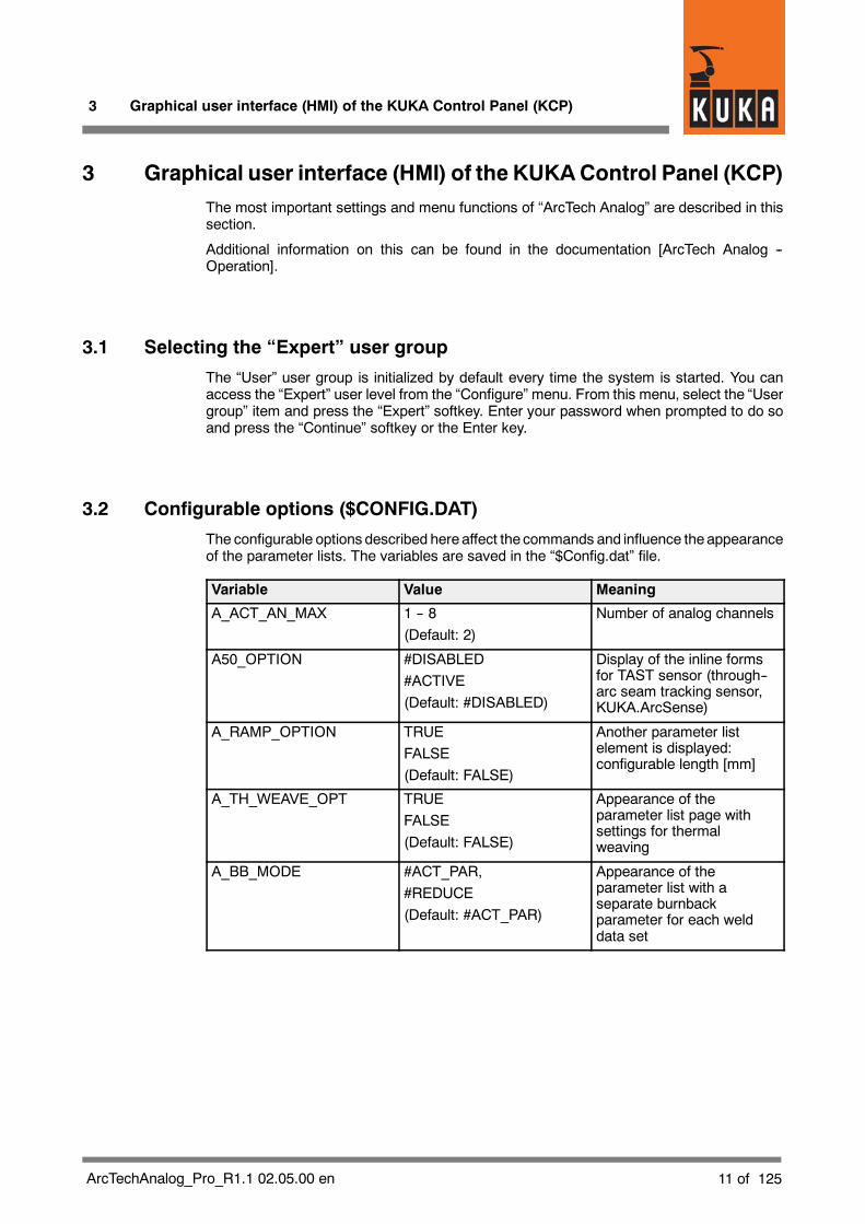
3 Graphical user interface (HMI) of the KUKAControl Panel (KCP)The most important settings and menu functions of “ArcTech Analog” are described in thissection.
Additional information on this can be found in the documentation [ArcTech Analog --Operation].
3.1 Selecting the “Expert” user group
The “User” user group is initialized by default every time the system is started. You canaccess the “Expert” user level from the “Configure” menu. From this menu, select the “Usergroup” item and press the “Expert” softkey. Enter your password when prompted to do soand press the “Continue” softkey or the Enter key.
3.2 Configurable options ($CONFIG.DAT)
The configurable options described hereaffect the commands and influence theappearanceof the parameter lists. The variables are saved in the “$Config.dat” file.
Variable Value Meaning
A_ACT_AN_MAX 1 -- 8(Default: 2)
Number of analog channels
A50_OPTION #DISABLED#ACTIVE(Default: #DISABLED)
Display of the inline formsfor TAST sensor (through--arc seam tracking sensor,KUKA.ArcSense)
A_RAMP_OPTION TRUEFALSE(Default: FALSE)
Another parameter listelement is displayed:configurable length [mm]
A_TH_WEAVE_OPT TRUEFALSE(Default: FALSE)
Appearance of theparameter list page withsettings for thermalweaving
A_BB_MODE #ACT_PAR,#REDUCE(Default: #ACT_PAR)
Appearance of theparameter list with aseparate burnbackparameter for each welddata set

KUKA.ArcTech Analog -- Configuration
12 of 125 ArcTechAnalog_Pro_R1.1 02.05.00 en
3.3 Configurable options (A10.DAT)
The configurable options described hereaffect the commands and influence theappearanceof the parameter lists. The variables are saved in the “A10.dat” file. If the system is shut downand rebooted using the variable RE_INITIALIZE=TRUE, the analog channels listed abovehave new units and increments.
Variable Value Meaning
HIDE_BB_TIME TRUEFALSE(Default: FALSE)
Parameter list element forburnback is no longer visiblein the weld data and craterfilling parameter lists
RE_INITIALIZE=TRUE TRUEFALSE(Default: FALSE)
When set to TRUE, theconfigured values shown inthe following tables will betaken over into the inlineforms or the parameter listsnext time the system isbooted.
Configuration: Analog channels
Variable Value Meaning
CHANNEL_INFO[1] {UNIT[]”volts”,STEP[]”0.1”} Analog channel 1 (weldvoltage, increment 0.1 ),default: active
CHANNEL_INFO[2] {UNIT[]”m/min”,STEP[]”0.1”} Analog channel 2 (wirefeed, increment 0.1 m/s),default: active
CHANNEL_INFO[3] {UNIT[]”%”,STEP[]”0.1”} Analog channel 3(default: not active)
CHANNEL_INFO[4] {UNIT[]”s”,STEP[]”0.1”} Analog channel 4(default: not active)
CHANNEL_INFO[5] {UNIT[]”Hz”,STEP[]”0.1”} Analog channel 5(default: not active)
CHANNEL_INFO[6] {UNIT[]”ms”,STEP[]”0.1”} Analog channel 6(default: not active)
CHANNEL_INFO[7] {UNIT[]”ms”,STEP[]”0.1”} Analog channel 7(default: not active)
CHANNEL_INFO[8] {UNIT[]”s”,STEP[]”0.1”} Analog channel 8(default: not active)

4 “KUKA.ArcTech Analog” programs
13 of 125ArcTechAnalog_Pro_R1.1 02.05.00 en
4 “KUKA.ArcTech Analog” programs
4.1 Program structure
The block diagram in Fig. 1 shows the program structure of the robot controller with the“KUKA.ArcTech Analog” technology package.
.DATARC_WEAVE.SRC
.DAT.DAT .DAT
CELL.SRC$CONFIG.DATARC WELDINGPACKAGEGlobal andapplication data
Autom./ExternalOrganizationprogram
A10.SRC
Arc weldingfunctions
IR_STOPM.SRC
Generalhandling ofrobot faults
FLT_SERV.SRC
Fault servicefunctionsdefined by theuser
P00.SRC
Functions forAutom./ExternalHandshakeCheck Home
Definition andparameters formechanical andthermal weaving
ArcTechAnaloginitialization
A10_INI.SRC
Functionsfor robotmotion
BAS.SRC
A50.SRC
A50 LIBO sensorfunctions(through--the--arcseam tracking)
CLEANER.SRC
-- Shutdown-- Torchcleaning afterfault situation
Generation ofuser--definederror messages
ARC_MSG.SRC
(optional)
A10.SRC
.DATA10_User.SRC
Customer--specificadaptation ofweldsequences
Fig. 1 “KUKA.ArcTech Analog” program structure

KUKA.ArcTech Analog -- Configuration
14 of 125 ArcTechAnalog_Pro_R1.1 02.05.00 en
4.2 Overview of files for “KUKA.ArcTech Analog”
The files listed below are included with “KUKA.ArcTech Analog.”
$CONFIG.DAT Contains data specific to ArcTech Analog within the sectionFOLD A10 GLOBALS
For additional entries, there is the file $CONFIG.DAT with the section; User--defined Variables
A10.SRC Main program for arc welding with “KUKA.ArcTech Analog.”
A10.DAT Contains local data for the program “A10.SRC” anderror message texts.
A10_INI.SRC “KUKA.ArcTech Analog” initialization program.It sets the binary outputs to the initialization values.
-- Prepares the weld controller; activates the CYC flags;sets the ARC variables;
-- defines the FIFO stack;
-- defines handling of faults in case of restarts.
A10_INI.DAT Contains local data for the program A10_INI.SRC as well aserror message data and, to a certain extent, configuration data.
FLT_SERV.SRC Program for user--defined fault strategies,including ignition faults. Fault service function(additional START error).
FLT_SERV.DAT Contains local data list for the program FLT_SERV.SRC.
ARC_MSG.SRC Routines for generation of user--specific error messages
ARC_WEAVE.SRC Definition of the patterns for mechanical and thermal weaving.

4 “KUKA.ArcTech Analog” programs (continued)
15 of 125ArcTechAnalog_Pro_R1.1 02.05.00 en
SPS.SUBProgram running at the controller level (PLC task) for monitoring and error handling in theevent of an interpreter stop.
Assured deactivation and reactivation after an interpreter stop.
This subroutine is used tomanually control (bymeans of the left--hand KCPstatus keys)wirefeed (WFD) and welding (hot/cold) as well as switching off after an interpreter stop (red“STOP” button).
The symbols illustrated below are to be found at various points in this documentation; theyindicate whether or not manual changes are permitted in the section of a file beingdescribed.
CLEANER.SRCTorch cleaning package that can be integrated as an option (not included with“KUKA.ArcTech Analog”); integration of cleaning device deactivation in the event of a faultleading to an interpreter stop or robot STOPMESS reaction.

KUKA.ArcTech Analog -- Configuration
16 of 125 ArcTechAnalog_Pro_R1.1 02.05.00 en

5 Adaptation to the periphery, configurable options
17 of 125ArcTechAnalog_Pro_R1.1 02.05.00 en
5 Adaptation to the periphery, configurable options
This section describes the definition of the interfaces from “KUKA.ArcTech Analog” to theperiphery, their specific adaptation as well as configurable options:
G Analog outputs Analog reference voltages from the robot controller to theweld controller, e.g. weld voltage, wire feed;
G Digital outputs Digital control signals from the robot controller to theweld controller -- e.g. “Gas preflow”, “Welding start”;
G Digital inputs Digital control signals from the weld controller to therobot controller -- e.g. “Current flowing”, “Seam fault”.
Options in the form of index and signal tables are stored in variables that are defined in the“FOLD ARCTECHANALOG GLOBALS” block in the “$config.dat” file. Settings that aremade are stored in that file. You can use an editor to set or change the values of the variablesin “$config.dat”.
Menu--prompted viewing and modification of the variable values is possible via the menu“Monitor -- Variable -- Single.” The current value is shown when the variable name is entered.This value can be changed.
A syntax check is not performed (for example, MIN and MAX values) when entries aremade using themenu function “Monitor -- Variable -- Single” or when the file is edited.
5.1 Digital outputs and inputs
5.1.1 Overview and purpose
The KRC interface is used to monitor safety and welding conditions (e.g. power source orgas ready), and also to control the connected devices. A flexible concept is required in orderto be able to communicate with the wide range of different devices.
To facilitate this, all digital inputs andoutputs of thephysical interface canbe freely configuredusing the index table. A second table, the so--called signal table, enables the interlinking ofthe physical inputs and outputs. This is necessary, for example, if a controller output is tocontrol different peripheral devices with different signal types (level, pulse) in parallel. Thisso--called “induced addressing” uses two linking tables.
Physicalinterface
Index tableassignment
Linking with signaltable
Bus system
ControllerPower sourceGasPeriphery
Fig. 2 Induced addressing -- linking tables

KUKA.ArcTech Analog -- Configuration
18 of 125 ArcTechAnalog_Pro_R1.1 02.05.00 en
Index tables for configuring physical outputs and inputs
For the purpose of configuring the physical outputs and inputs, two index tables areprovided in the $config.dat file. The assignment of the electrical interface is definedhere:
G Digital outputs FOLD ArcTech OutputsA_WLD_OUT[ ] ...Digital control signals from the robot controller to theweld controller -- e.g. “Gas preflow”, “Welding start”...
G Digital outputs FOLD ArcTech InputsA_WLD_IN[ ] ...Digital control signals from the weld controller to therobot controller -- e.g. “Current flowing”, “Seam fault”,
In these index tables the assignment of the physical outputs and inputs is defined andreferences are made to the corresponding signal tables of the controller.This has the advantage that if the terminal assignments for the periphery are changed, allthat is needed is to alter the index tables accordingly.
Signal tables for linking digital inputs and outputs
The interface concepts are variable; this means that links between existing physicalinputs and outputs can be freely programmed in this signal table.
Configuring peripheral outputs and inputs by means of signal tables (“triple groups”) allowsprocesses to run synchronously. The option of setting or scanning several signals allowsvarious weld controllers to be adapted and timing to be optimized.
G Digital outputs A_O ...Signal names of a group beginning with “A_O...”designate digital outputs;
G Digital inputs A_I ...Signal names of a group beginning with “A_I...”designate digital inputs.
The signal table links (inputs and outputs) are preconfigured by the manufacturer soit only remains necessary to adapt the index table to define the physical inputs andoutputs!

5 Adaptation to the periphery, configurable options (continued)
19 of 125ArcTechAnalog_Pro_R1.1 02.05.00 en
5.1.2 Index table for physical digital outputs
A total of 16 digital outputs (A_WLD_OUT[1] ... A_WLD_OUT[16]) are available; theirphysical assignment (OUT_NRn) is freely definable. All “OUT_NR” array elements are setto “0” at the factory, meaning they are inactive. For the purpose of assigning the physicaloutputs, you can enter their corresponding numbers in the “FOLD ArcTech Outputs” indextable in the $config.dat file:
;FOLD ArcTech OutputsDECL CTRL_OUT_T A_WLD_OUT[16]A_WLD_OUT[1]={OUT_NR 0,INI FALSE,NAME_NAT[] “WELD_START “A_WLD_OUT[2]={OUT_NR 0,INI FALSE,NAME_NAT[] “GAS PREFLOW “}A_WLD_OUT[3]={OUT_NR 0,INI FALSE,NAME_NAT[] “WELD_MODE PS/MM”}A_WLD_OUT[4]={OUT_NR 0,INI FALSE,NAME_NAT[] “CLEANER “}A_WLD_OUT[5]={OUT_NR 0,INI FALSE,NAME_NAT[] “RECEIPT ERRORS “}A_WLD_OUT[6]={OUT_NR 0,INI FALSE,NAME_NAT[] “ERROR MSG_SIGNAL”}A_WLD_OUT[7]={OUT_NR 0,INI FALSE,NAME_NAT[] “START ERROR “}A_WLD_OUT[8]={OUT_NR 0,INI FALSE,NAME_NAT[] “APPL_ERROR “}A_WLD_OUT[9]={OUT_NR 0,INI FALSE,NAME_NAT[] “INTERPRETER-STOP”}A_WLD_OUT[10]={OUT_NR 0,INI FALSE,NAME_NAT[] “ “}A_WLD_OUT[11]={OUT_NR 0,INI FALSE,NAME_NAT[] “ “}A_WLD_OUT[12]={OUT_NR 0,INI FALSE,NAME_NAT[] “ “}A_WLD_OUT[13]={OUT_NR 0,INI FALSE,NAME_NAT[] “ “}A_WLD_OUT[14]={OUT_NR 0,INI FALSE,NAME_NAT[] “ “}A_WLD_OUT[15]={OUT_NR 0,INI FALSE,NAME_NAT[] “WFD + “}A_WLD_OUT[16]={OUT_NR 0,INI FALSE,NAME_NAT[] “WFD - “}
Physical outputs Comment (signal name)
Initialization state
$config.dat
Fig. 3 Index table for physical digital outputs ($config.dat)
If you make any changes to the “NAME_NAT” comments (signal names) directly in the file$CONFIG.DAT, please ensure that the string between the quotation marks (“ ”) has amaximum length of 20 characters.
All “OUT_NR” array elements are set to “0” at the factory, meaning they are inactive. The“INI” element defines the state to which the respective “OUT_NR” physical output is to beset on initialization. The value “FALSE” sets the output to “LOW”, the value “TRUE” sets itto “HIGH”.
Example of corresponding entries using the menu function “Monitor -- Variable -- Single”:
Variable Type Characteristics
A_WLD_OUT[1].OUT_NR INT Assignment of the physical output,e.g. “10” (default: 0)
A_WLD_OUT[1].INI BOOL
State after initialization(ARC--INIT command)(default: FALSE)FALSE = LOWTRUE = HIGH
A_WLD_OUT[1].NAME_NAT[ ] STRING
20 characters between “ ”; pleasebear in mind that when making alter-ations, any characters in the string notoverwritten (e.g. not visible in themonitor window) will be retained.

KUKA.ArcTech Analog -- Configuration
20 of 125 ArcTechAnalog_Pro_R1.1 02.05.00 en
The example illustrated inFig. 4 shows the assignment of thephysical outputs and the signalstates after initialization.
Output 10LOW (logic 0)
Output 15HIGH (logic 1)
;FOLD ArcTech Outputs
State afterinitialization:
A_WLD_OUT[1]={OUT_NR 10,INI FALSE,NAME_NAT[] “...”}
A_WLD_OUT[7]={OUT_NR 15,INI TRUE,NAME_NAT[] “...”}
$config.dat
Fig. 4 Assignment of physical outputs and signal states after initialization
Array “A_WLD_OUT[n] INI” contains the initial value when the INIT routine is running beforereaching the block coincidence movement.

5 Adaptation to the periphery, configurable options (continued)
21 of 125ArcTechAnalog_Pro_R1.1 02.05.00 en
5.1.3 Signal tables for digital outputs
Definition
Configuring peripheral outputs with so--called “triple groups” allows processes to runsynchronously; depending on the way the system has been configured, severalconfigurations can be set or checked. This enables different weld power sources andinterface concepts to be adapted and the timing to be optimized.
Up to three outputs can be controlled and for each of these outputs the following parameterscan be defined.
Output parameters Characteristics
{NO ’H0’,PULS_TIME 0.0,STATE TRUE} Output disabled (ignored)
{NO ’H1’,PULS_TIME 0.0,STATE TRUE}
Address in the index table(A_WLD_OUT[1]). *)“TIME 0.0” = static signal withHIGH level (logic 1)
{NO ’H2’,PULS_TIME 0.0,STATE FALSE}
Address in the index table(A_WLD_OUT[2]). *)“TIME 0.0” = static signal withLOW level (logic 0)
{NO ’H9’,PULS_TIME 1.0,STATE TRUE}
Address in the index table(A_WLD_OUT[9]). *)“TIME 1.0” = pulse signal (1 s) withHIGH level (logic 1)
{NO ’HC’,PULS_TIME 0.5,STATE FALSE}
Address in the index table(A_WLD_OUT[12]). *)“TIME 0.5” = pulse signal (0.5 s) withLOW level (logic 0)
*) The value for the “NO” element can be entered as a decimal number (without “H” forHEX). Because of internal system requirements, this value is converted to the correspond-ing hexadecimal value when the data are loaded into the controller.Example: ...{NO ’10’...
becomes...{NO ’HA’
If “NO” is set to “0” (zero), the output is deactivated and is ignored during execution of theprogram.
Fig. 5 shows an example of a signal table from the file $config.dat for a digital output. TheA_O_MODE[1] element with the value ’H3’ refers to array 3 in the “DIGITAL OUTPUTS”index table (A_WLD_OUT[16]) and thus to the physical output configured in it.

KUKA.ArcTech Analog -- Configuration
22 of 125 ArcTechAnalog_Pro_R1.1 02.05.00 en
; outputs for MODE1 weldingDECL A_FCT_OUT_T A_O_MODE1[3]A_O_MODE1[1]={NO ’H3’,PULS_TIME 0.0,STATE TRUE}A_O_MODE1[2]={NO ’H0’,PULS_TIME 0.0,STATE FALSE}A_O_MODE1[3]={NO ’H0’,PULS_TIME 0.0,STATE FALSE}
Pulse duration(“0.0” = static)
Signal name
Index for addressingin index table “A_WLD_OUT[ ]”
State (TRUE)
$config.dat
Fig. 5 Example of signal table for a physical digital output ($config.dat)
An output can be static (PULSE_TIME 0.0) or can be output in the form of a pulse, in whichcase the pulse duration is programmed in seconds. For example, PULSE_TIME 0.3corresponds to a pulse duration of 0.3 seconds.
Example of the entries using the menu function “Monitor -- Variable -- Single”:
Variable Type Characteristics
A_O_MODE1[1].NO INT Assignment to element in index table,e.g. “1” (default: 0)
A_O_MODE1[1].PULS_TIME REAL Pulse duration in secondsDefault: 0.0 (static)
A_O_MODE1[1].STATE BOOL Active stateDefault: FALSE
Signal states for digital outputs
The following table shows the possible states of the physical outputs resulting from thesetting of the initialization value in the “FOLD ArcTech Outputs” index table and afteractivation.
Entry in index table Entry in signal table Physical output state afterEntry in index table“A_WLD_OUT[n].INI”
Entry in signal table“<Signal name>.NO” Initialization Activation
FALSE FALSE LOW LOW
FALSE TRUE LOW HIGH
TRUE FALSE HIGH LOW
TRUE TRUE HIGH HIGH
5 Adaptation to the periphery, configurable options (continued)
23 of 125ArcTechAnalog_Pro_R1.1 02.05.00 en
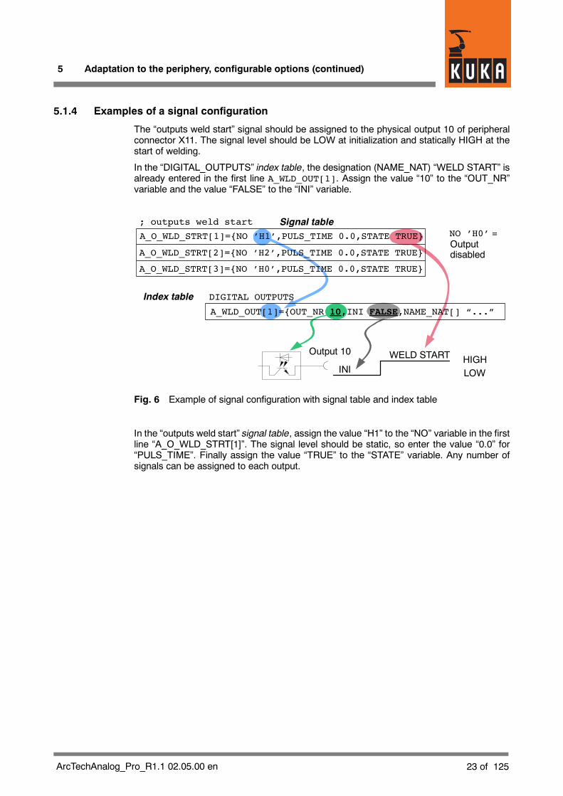
5.1.4 Examples of a signal configuration
The “outputs weld start” signal should be assigned to the physical output 10 of peripheralconnector X11. The signal level should be LOW at initialization and statically HIGH at thestart of welding.
In the “DIGITAL_OUTPUTS” index table, the designation (NAME_NAT) “WELD START” isalready entered in the first line A_WLD_OUT[1]. Assign the value “10” to the “OUT_NR”variable and the value “FALSE” to the “INI” variable.
A_O_WLD_STRT[2]={NO ’H2’,PULS_TIME 0.0,STATE TRUE}
A_O_WLD_STRT[3]={NO ’H0’,PULS_TIME 0.0,STATE TRUE}
A_WLD_OUT[1]={OUT_NR 10,INI FALSE,NAME_NAT[] “...”
Output 10
; outputs weld start
DIGITAL OUTPUTSIndex table
Signal table
Outputdisabled
INI
WELD START
NO ’H0’ =
LOWHIGH
A_O_WLD_STRT[1]={NO ’H1’,PULS_TIME 0.0,STATE TRUE}
Fig. 6 Example of signal configuration with signal table and index table
In the “outputs weld start” signal table, assign the value “H1” to the “NO” variable in the firstline “A_O_WLD_STRT[1]”. The signal level should be static, so enter the value “0.0” for“PULS_TIME”. Finally assign the value “TRUE” to the “STATE” variable. Any number ofsignals can be assigned to each output.

KUKA.ArcTech Analog -- Configuration
24 of 125 ArcTechAnalog_Pro_R1.1 02.05.00 en
Fig. 7 shows the linking of the A_WLD_OUT[1] output to the signals A_O_WLD_STRT[1](weld start) and O_FLT_ARC_ON[1] (fault during the ARC ON command):
A_O_FLT_ON[1]={NO ’H1’,PULS_TIME 0.0,STATE FALSE}
A_O_FLT_ON[2]={NO ’H2’,PULS_TIME 0.0,STATE FALSE}
A_O_FLT_ON[3]={NO ’H7’,PULS_TIME 0.0,STATE TRUE}
Output 10
; outputs weld start
; outputs fault while arc on
DIGITAL OUTPUTS Index table
Signal table
Signal table
Status table:
A_O_FLT_ON[1]
A_O_WLD_STRT[1]
InitializationHIGHLOW
LOW
A_O_WLD_STRT[2]={NO ’H2’,PULS_TIME 0.0,STATE TRUE}
A_O_WLD_STRT[3]={NO ’H0’,PULS_TIME 0.0,STATE TRUE}
A_O_WLD_STRT[1]={NO ’H1’,PULS_TIME 0.0,STATE TRUE}
A_WLD_OUT[1]={OUT_NR 10,INI FALSE,NAME_NAT[] “WELD...”
Fig. 7 Example of signal configuration with signal table and index table
The signal tables provide theoption of definingup to three signals, i.e. of activatingup to threedifferent physical outputs with different signal levels by means of one event.
In the event of absent or incorrect peripheral interface signals, entries in the index and signaltables (addresses, value assignments) should always be checked first, before carrying out anextensive search for faults in the hardware.
5 Adaptation to the periphery, configurable options (continued)
25 of 125ArcTechAnalog_Pro_R1.1 02.05.00 en
5.1.5 Index table for physical digital inputs
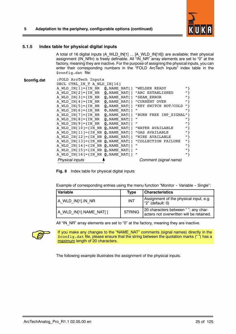
A total of 16 digital inputs (A_WLD_IN[1] ... [A_WLD_IN[16]) are available; their physicalassignment (IN_NRn) is freely definable. All “IN_NR” array elements are set to “0” at thefactory, meaning they are inactive. For the purpose of assigning the physical inputs, you canenter their corresponding numbers in the “FOLD ArcTech Inputs” index table in the$config.dat file:
;FOLD ArcTech InputsDECL CTRL_IN_T A_WLD_IN[16]A_WLD_IN[1]={IN_NR 0,NAME_NAT[] “WELDER READY “}A_WLD_IN[2]={IN_NR 0,NAME_NAT[] “ARC ESTABLISHED “}A_WLD_IN[3]={IN_NR 0,NAME_NAT[] “SEAM_ERROR “}A_WLD_IN[4]={IN_NR 0,NAME_NAT[] “CURRENT OVER “}A_WLD_IN[5]={IN_NR 0,NAME_NAT[] “KEY SWITCH HOT/COLD “}A_WLD_IN[6]={IN_NR 0,NAME_NAT[] “ “}A_WLD_IN[7]={IN_NR 0,NAME_NAT[] “BURN FREE INP_SIGNAL”}A_WLD_IN[8]={IN_NR 0,NAME_NAT[] “ “}A_WLD_IN[9]={IN_NR 0,NAME_NAT[] “ “}A_WLD_IN[10]={IN_NR 0,NAME_NAT[] “WATER AVAILABLE “}A_WLD_IN[11]={IN_NR 0,NAME_NAT[] “GAS AVAILABLE “}A_WLD_IN[12]={IN_NR 0,NAME_NAT[] “WIRE AVAILABLE “}A_WLD_IN[13]={IN_NR 0,NAME_NAT[] “COLLECTION FAILURE “}A_WLD_IN[14]={IN_NR 0,NAME_NAT[] “ “}A_WLD_IN[15]={IN_NR 0,NAME_NAT[] “ “}A_WLD_IN[16]={IN_NR 0,NAME_NAT[] “ “}
Physical inputs Comment (signal name)
$config.dat
Fig. 8 Index table for physical digital inputs
Example of corresponding entries using the menu function “Monitor -- Variable -- Single”:
Variable Type Characteristics
A_WLD_IN[1].IN_NR INT Assignment of the physical input, e.g.“2” (default: 0)
A_WLD_IN[1].NAME_NAT[ ] STRING 20 characters between “ ”; any char-acters not overwritten will be retained.
All “IN_NR” array elements are set to “0” at the factory, meaning they are inactive.
If you make any changes to the “NAME_NAT” comments (signal names) directly in the$config.dat file, please ensure that the string between the quotation marks (“ ”) has amaximum length of 20 characters.
The following example illustrates the assignment of the physical inputs.
KUKA.ArcTech Analog -- Configuration
26 of 125 ArcTechAnalog_Pro_R1.1 02.05.00 en
;FOLD ArcTech Inputs
Input 2
Input 12
Signals at:IN_NR 0 = input disabled
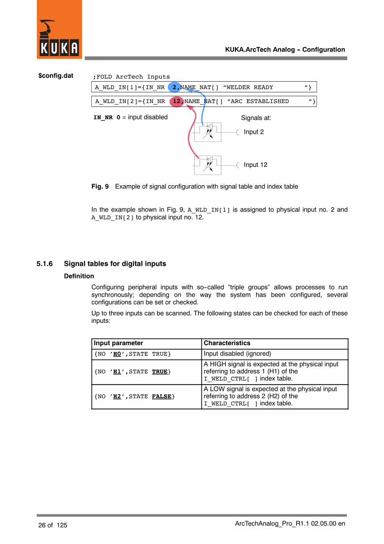
A_WLD_IN[2]={IN_NR 12,NAME_NAT[] “ARC ESTABLISHED “}
A_WLD_IN[1]={IN_NR 2,NAME_NAT[] “WELDER READY “}
$config.dat
Fig. 9 Example of signal configuration with signal table and index table
In the example shown in Fig. 9, A_WLD_IN[1] is assigned to physical input no. 2 andA_WLD_IN[2] to physical input no. 12.
5.1.6 Signal tables for digital inputs
Definition
Configuring peripheral inputs with so--called “triple groups” allows processes to runsynchronously; depending on the way the system has been configured, severalconfigurations can be set or checked.
Up to three inputs can be scanned. The following states can be checked for each of theseinputs:
Input parameter Characteristics
{NO ’H0’,STATE TRUE} Input disabled (ignored)
{NO ’H1’,STATE TRUE}A HIGH signal is expected at the physical inputreferring to address 1 (H1) of theI_WELD_CTRL[ ] index table.
{NO ’H2’,STATE FALSE}A LOW signal is expected at the physical inputreferring to address 2 (H2) of theI_WELD_CTRL[ ] index table.

5 Adaptation to the periphery, configurable options (continued)
27 of 125ArcTechAnalog_Pro_R1.1 02.05.00 en
The followingexample shows the signal table for a digital input. TheA_I_WLD_COND[1].NOelement with the value ’H1’ refers to field 1 of the “FOLD ArcTech Inputs” index table(A_WLD_IN[ ]) and thus to the physical input configured in it.
;inputs as condition before weld can startDECL FCT_IN_T A_I_WLD_COND[3]A_I_WLD_COND[1]={NO 1,STATE TRUE} ; source okA_I_WLD_COND[2]={NO 10,STATE TRUE} ; water availableA_I_WLD_COND[3]={NO 11,STATE TRUE} ; gas available
Signal name
Index for addressing in“A_WLD_IN[16]” index table
State
$config.dat
Fig. 10 Example of signal table for a digital input
Example of corresponding entries using the menu function “Monitor -- Variable -- Single”:
Variable Type Characteristics
A_I_WLD_COND[1].NO INT Assignment of the physical input, e.g. “1”(default: 0)
A_I_WLD_COND[1].STATE BOOL Active stateDefault setting: FALSE
The value for the “NO” element can be entered as a decimal number (without “H” forHEX). Because of internal system requirements, this value is converted to the corres-ponding hexadecimal value when the data are loaded into the controller, for example:
...{NO 10 ...
becomes...{NO ’HA’ ...
The wait time for digital input signals is limited by the value of the “A_TIME_OUT1” variable.
REAL A_TIME_OUT1=200.0 ; TIMEOUT for digital input[10 ms * 200 -> 2.0 sec]
After this configurable wait time, the program is stopped and a corresponding error messageis displayed in the message window.
Entries using the menu function “Monitor -- Variable -- Single”:
Variable Type Characteristics
A_TIME_OUT1 REAL Wait time 10 milliseconds [ms]For value 200 = [10 ms * 200] = 2000 ms = 2 s
$config.dat

KUKA.ArcTech Analog -- Configuration
28 of 125 ArcTechAnalog_Pro_R1.1 02.05.00 en
Signal states for digital inputs
The signal tables provide the option of assigning up to three input signals to a condition. Thefollowing example shows the “Inputs as condition before weld can start” signal table.I_WELD_COND[1] here refers to the A_WLD_IN[1] field in the “FOLD ArcTech Inputs”index table, in which the physical input 2 is defined by “IN_NR 2”. The system waits for aHIGH signal at this input in accordance with the definition “STATE TRUE”.
Two other input signals are defined in this example as the second and third conditions thathave to be met before welding can be started.
A_I_WLD_COND[1]={NO 1,STATE TRUE}
A_I_WLD_COND[2]={NO 11,STATE TRUE}
A_I_WLD_COND[3]={NO 12,STATE FALSE}
Signal table
Input 2HIGH signal
Input 12HIGH signal
Input 17LOW signal
Signals expected at:
NO 0 = input disabled
Index table
; inputs as condition before weld can start
A_WLD_IN[1]={IN_NR 2,NAME_NAT[] “WELDER READY...”}
A_WLD_IN[11]={IN_NR 12,NAME_NAT[] “2nd condition ...
A_WLD_IN[12]={IN_NR 17,NAME_NAT[] “3rd condition ...
;FOLD ArcTech Inputs
Fig. 11 Example of signal table for a digital input
Other signal tables may also contain references to the “ArcTech Inputs” index table.

5 Adaptation to the periphery, configurable options (continued)
29 of 125ArcTechAnalog_Pro_R1.1 02.05.00 en
5.2 Customer--specific adaptation of weld sequences
The files “A10_User.src” and “A10_User.dat” in the directory “C:\KRC\ROBOTER\KRC\R1\TP\ArcTechAnalog” are available for the adaptation of commands in the “KUKA.ArcTechAnalog” technology package to specific process requirements, or for adaptation to specificpower sources, etc.
Editing the file “A10_User.src” requires sound knowledge of the KRL programminglanguage and the “KUKA.ArcTech Analog” technology package.
Following installation of the software, the directory “C:\KRC\ROBOTER\KRC\R1\TP” hasthe attribute “Hidden”, i.e. it is not visible. In order to be able to access the files in thisdirectory, the Folder Options must be adapted accordingly (“Hidden files and folders” !“Show hidden files and folders”).
The user can adapt andmodify the subroutines in the file “A10_User.src” using a text editor.In addition to this, a number of error handling routines are available.
Commands are divided into an advance run section and amain run section, with switchingof the weld parameters always occurring in the main run.It is important to note that theadvance run sectionsmust not containcommands that triggeran advance run stop.
5.2.1 Subroutines for weld commands
A10_USR_INIT
The routine “A10_USR_INIT” is called in the “ARC_INIT” command.
GLOBAL DEF A10_USR_INIT ();*************************;* Call by ARC_INIT () *;*************************
END ;(A10_USR_INIT)

KUKA.ArcTech Analog -- Configuration
30 of 125 ArcTechAnalog_Pro_R1.1 02.05.00 en
A10_USR_PreArcOn
The routine “A10_USR_PreArcOn” is called in the advance run section of the “ARC ON”command.
GLOBAL DEF A10_USR_PreArcOn(WELD_MODE:IN,GAS_PRE_TIM:IN,ARC_CMD:IN);*************************;* Call by Pre_Arc_ON *;*************************DECL A_CMD_T ARC_CMD ;Arc command type #ARC_START..REAL GAS_PRE_TIM ;Gas preflow timeINT WELD_MODE ;Pulse or MigMag mode
END ;(A10_USR_PreArcOn)
A10_USR_START1
The routine “A10_USR_START1” can be called before any weld start, i.e. when the “ARCON” command is executed or in the case of a restart following a fault. The ignition data setis accessed via “A_S_PARA_ACT” elements (file type A_STRT_T).
GLOBAL DEF A10_USR_START1(CMD:IN,ARC_CMD:IN);**********************************************************;* Call by ARC_START before Weldstart-Signal activated *;* or by other restart circumstances e.g. from interrupt *;**********************************************************INT CMD ;Arc condition (ARC_ON, from Techstop ...)DECL A_CMD_T ARC_CMD ;Arc command type #ARC_START..
END ;(A10_USR_START1)
A10_USR_START2
The routine “A10_USR_START2” can be called before any weld start, i.e. when the “ARCON” command is executed or in the case of a restart following a fault.
GLOBAL DEF A10_USR_START2(CMD:IN,ARC_CMD:IN);********************************************************;* Call by ARC_START after Weldstart-Signal activated *;********************************************************INT CMD ;Arc condition (ARC_ON, from Techstop ...)DECL A_CMD_T ARC_CMD ;Arc command type #ARC_START..
END ;(A10_USR_START2)

5 Adaptation to the periphery, configurable options (continued)
31 of 125ArcTechAnalog_Pro_R1.1 02.05.00 en
A10_USR_PreArcSwi
The routine “A10_USR_PreArcSwi” is called in the advance run section of the “ARC SWI”command.
GLOBAL DEF A10_USR_PreArcSwi(CMD:IN,WELD_MODE:IN,W:IN);********************************************;* Call by PRE_ARC_SWI command *;********************************************DECL A_WELD_T W ;Weld setDECL A_CMD_T CMD ;Arc command type #PRE_ARC_OFF,#PRE_ARC.INT WELD_MODE ;Pulse or MigMag
END ;(A10_USR_PreArcSwi)
A10_USR_ArcSeam
The routine “A10_Usr_ArcSeam” canbe called in the “ARCSWI” and “ARCOFF”commandsby means of the trigger integrated into the technology package, i.e. on the weld path to theend point. The weld data set is accessed via “A_W_PARA_ACT” elements (file typeA_WELD_T).
GLOBAL DEF A10_USR_ArcSeam(ARC_CMD:IN);*************************************;* Call by ARC_SWI-Trigger command *;* Task on every welding seam *;* access by A_W_PARA_ACT data *;*************************************DECL A_CMD_T ARC_CMD ;Arc command type #ARC_OFF,#ARC_SWI
END ;(A10_USR_ArcSeam)
A10_USR_PreArcOff
The routine “A10_USR_PreArcOff” is called in the advance run section of the “ARC OFF”command.
GLOBAL DEF A10_USR_PreArcOff(CMD:IN,WELD_MODE:IN,W:IN);********************************************;* Call by PRE_ARC_OFF command *;********************************************DECL A_WELD_T W ;Weld setDECL A_CMD_T CMD ;Arc command type #PRE_ARC_OFF,#PRE_ARC.INT WELD_MODE ;Pulse or MigMag
END ;(A10_USR_PreArcOff)

KUKA.ArcTech Analog -- Configuration
32 of 125 ArcTechAnalog_Pro_R1.1 02.05.00 en
A10_USR_ArcOff1
The routine “A10_USR_ArcOff1” is called immediately before the weld start signal is with-drawn in the “ARC OFF” command at the end of the seam. The end data set is accessedvia “A_E_PARA_ACT” elements (file type A_END_T).
GLOBAL DEF A10_USR_ArcOff1();****************************;* Call by Finish_Seam *;* before switch off welding*;****************************
END ;(A10_USR_ArcOff1)
A10_USR_ArcOff2
The routine “A10_USR_ArcOff2” is called immediately before the weld start signal is with-drawn in the “ARC OFF” command.
GLOBAL DEF A10_USR_ArcOff2();****************************;* Call by Finish_Seam *;* after switch off welding *;****************************
END ;(A10_USR_ArcOff2)

5 Adaptation to the periphery, configurable options (continued)
33 of 125ArcTechAnalog_Pro_R1.1 02.05.00 en
5.2.2 Error handling routines
Submit interpreter task
Two error handling routines are available for the Submit interpreter task:“A10_USR_PLC_INIT” and “A10_USR_PLC_Task”.
A10_USR_PLC_INIT
This routine is called in the initialization section of the Submit interpreter. The necessarydeclarations must be made in the file “A10_User.dat”.
GLOBAL DEF A10_USR_PLC_INIT();*************************;* Call by A10(#PLC_INIT *;*************************
END ;(A10_USR_PLC_INIT)
A10_USR_PLC_Task
This routine is permanently called in a loop (Call by A10(#PLC_LOOP).
GLOBAL DEF A10_USR_PLC_Task();*************************;* Call by A10(#PLC_LOOP *;*************************
END ;(A10_USR_PLC_Task)
Robot error
A10_USR_IRSTOPMESS
This routine is called if the robot is switched off (IR_STOPMESS reaction, such as drives off,safety gate open, etc.)
GLOBAL DEF A10_USR_IRSTOPMESS ();****************************;* Call by IR_STOPMESS STOP *;* before switch off welding*;****************************
END ;(A10_USR_IRSTOPMESS)
KUKA.ArcTech Analog -- Configuration
34 of 125 ArcTechAnalog_Pro_R1.1 02.05.00 en
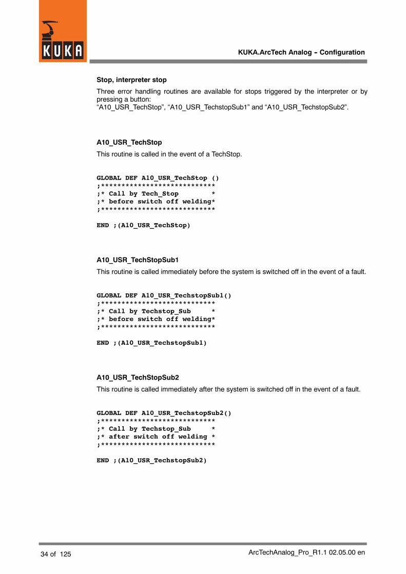
Stop, interpreter stop
Three error handling routines are available for stops triggered by the interpreter or bypressing a button:“A10_USR_TechStop”, “A10_USR_TechstopSub1” and “A10_USR_TechstopSub2”.
A10_USR_TechStop
This routine is called in the event of a TechStop.
GLOBAL DEF A10_USR_TechStop ();****************************;* Call by Tech_Stop *;* before switch off welding*;****************************
END ;(A10_USR_TechStop)
A10_USR_TechStopSub1
This routine is called immediately before the system is switched off in the event of a fault.
GLOBAL DEF A10_USR_TechstopSub1();****************************;* Call by Techstop_Sub *;* before switch off welding*;****************************
END ;(A10_USR_TechstopSub1)
A10_USR_TechStopSub2
This routine is called immediately after the system is switched off in the event of a fault.
GLOBAL DEF A10_USR_TechstopSub2();****************************;* Call by Techstop_Sub *;* after switch off welding *;****************************
END ;(A10_USR_TechstopSub2)

5 Adaptation to the periphery, configurable options (continued)
35 of 125ArcTechAnalog_Pro_R1.1 02.05.00 en
Seam error
A10_USR_SeamError
This routine is called in the event of a seam error.
GLOBAL DEF A10_USR_SeamError();****************************;* Call by Seam_Error *;* before switch off welding*;****************************
END ;(A10_USR_SeamError)

KUKA.ArcTech Analog -- Configuration
36 of 125 ArcTechAnalog_Pro_R1.1 02.05.00 en

6 Description of the weld commands
37 of 125ArcTechAnalog_Pro_R1.1 02.05.00 en
6 Description of the weld commands
6.1 Controlling welding and wire feed with the status keys on the KUKA Control Panel
After the menu function “Configure” -- “Status keys” -- “ArcTech Analog” has been activated,the KCP provides a number of status keys specifically for “KUKA.ArcTech Analog”.
In addition, the robot controller allows the welding process to be switched on or off manuallywith the left--hand status keys (hot/cold)while aweldingprogram is running. It is also possibleto control wire feed andwire retractionmanually. Ignition andwelding are only possible whenthe operating mode “DRY” is inactive (the status key “DRY” has not been pressed).
The states of the “HOT/COLD” status keys and the “wire forwards” and “wire backwards”status keys are scannedcyclically during theendless loop. The submit interpreter recognizeswhether a key has been pressed in the course of a loop.
6.1.1 Manual activation and deactivation of the weld process (FLY ARC)
During a running welding process it is possible to switch welding on or off with the status keyHOT/COLD; the controller monitoring functions (as well as the keyswitch) remain active.
When it detects actuation of the status keyHOT/COLD, the submit interpreter triggers apulsecommand, thereby triggering Interrupt 5 at the R1 level. The current status is used to detectwhether welding should be switched on or off.
Options
The following options are available for activation/deactivation of the weld process while awelding program is running ($config.dat):
DECL A_APPL_T A_APPLICAT=#THIN ;#thin,#thick
DECL A_BOOL_T A_STRT_BRAKE=#ACTIVE ;BRAKE option at ARC_START(HPU control)
DECL A_BOOL_T A_END_BRAKE=#ACTIVE ; BRAKE option at ARC_OFF(HPU control)
Corresponding entries using the menu function “Monitor -- Variable -- Single”:
Variable Value Characteristics
A APPLICAT#THIN (default) Ignition without weld parameters
A_APPLICAT#THICK Ignition with ignition parameters
A STRT BRAKE#ACTIVE (default) Robot stops during the ignition process
A_STRT_BRAKE#IDLE Ignition process executed without stop
A END BRAKE#ACTIVE (default) Robot stops during the burnback process
A_END_BRAKE#IDLE Burnback process executed without stop
$config.dat
KUKA.ArcTech Analog -- Configuration
38 of 125 ArcTechAnalog_Pro_R1.1 02.05.00 en
Manual switch--off (COLD)
It is possible to switch off the welding process using the status key (COLD) in any phase ofa running welding program.
If the A_END_BRAKE=#ACTIVE option has been set, robot motion is interrupted duringburnback.
Manual switch--on (HOT)
To switch on (HOT) welding, the normal welding conditions must be satisfied. The torchmayonly be activated on the weld path.
If the A_STRT_BRAKE=#ACTIVE option has been set, robot motion is interrupted duringignition.
Controlling welding (HOT/COLD)
The two status keys HOT/COLD and DRY have a toggle function with reciprocal lockout. Itis not possible to switch directly from HOT (welding on) to DRY or vice versa.
The screenshot on the left shows the state Welding OFF, as indicated by the crossed--outwelding torch icon. In this state, the systemonly executes themotions of theweldingprogramand the weave motions. The robot will move at welding velocity, but welding will not beperformed.
Fast test run
Weaving is deactivated so the robot can run through the program at a relatively high velocity.When the DRY status key is activated, the robot moves at a higher velocity. Theweld processand weaving are not executed. Any weaving that may have been programmed isdeactivated. The velocity is determined by the maximum permissible values for T1/T2.
When the “DRY” status key is activated, the robot moves at a higher velocity (in accordancewith the default setting DRY_RN_Vel Default = 0.15 m/s in the “$config.dat” file).
Wire feed and wire retraction
These keys can be used to position the welding wire when the weld keys are not active.
A physical output must be set for this in A_WLD_OUT[15] + [16].
;WIREFEED CONTROL
DECL FCT_OUT_T A_O_WRFEDP={NO 15,PULS_TIME 0.2,STATE TRUE}DECL FCT_OUT_T A_O_WRFEDN={NO 16,PULS_TIME 0.2,STATE TRUE}
A_WLD_OUT[15]={OUT_NR 0,INI FALSE,NAME_NAT[ ] “WFD+ “}A_WLD_OUT[16]={OUT_NR 0,INI FALSE,NAME_NAT[ ]”WFD-- “}
All statuskeysaredeactivated inExternalmode (or if theSubmit interpreter isstopped)for safety reasons!
6 Description of the weld commands (continued)
39 of 125ArcTechAnalog_Pro_R1.1 02.05.00 en
6.2 Activating the welding package
The A10_OPTION must always be activated when executing “KUKA.ArcTech Analog”applications.
DECL A_TECH_STS_T A10_OPTION=#ACTIVE; #active, #disabled
Variable Value for ArcTech Analog Characteristics
A10_OPTION #ACTIVE KUKA.ArcTech Analogactivated
#DISABLED (default) KUKA.ArcTech Analogdeactivated
6.3 Initialization (ARC--INIT)
All settings are checked when the ARC--INIT command is executed in order to ensure safeoperation. These include:
G The resetting of all weld technology outputs and analog outputs.
G Calculation of the welding rectifier characteristic.
G Checking of the offset override if an operating mode other than EXTERNAL is requiredwith an override<> 100%. If this is the case, theuser is prompted to confirm this setting.This query is not generated in External mode.
G Checking of further settings along with any necessary adaptation and transformation.
6.3.1 Checking the specified Submit routine
This check must be carried out in order to ensure safe operation of the Arc--specific softkeysand a safe system response in the event of an interpreter stop.
Variable File Default Value
$PRO_I_O[ ] STEU/MADA/$CUS-TOM.DAT
/R1/SPS( ) /R1/SPS( )
6.3.2 Setting the cyclical analog channel for ONLINE optimizing
During ONLINE OPTIMIZING, the system checks that the cyclical analog channels areactivated, as information is written to these coefficients of the cyclical analog outputs.
Variable File Default Value
A_WEAV_GEN[3] $CONFIG.DAT 3 30: Static analog channels

KUKA.ArcTech Analog -- Configuration
40 of 125 ArcTechAnalog_Pro_R1.1 02.05.00 en
6.3.3 Required setting for reduced velocity in T1
The setting $RED_T1_OV_CP=FALSE, in conjunction with the variable PROC_IN_T1=TRUE,enables welding in Test1 operating mode. Up to a certain velocity level, the velocity is thenidentical to that in Test2 mode. Safety conditions are observed, i.e. the weld velocity cannever exceed the maximum permissible Test1 path velocity. The welding results wouldotherwise be unusable.
Variable File Default Value
$RED_T1_OV_CP steu\mada\
$CUSTOM.DAT
TRUE FALSE
6.3.4 Required settings for backward motion of a welding application
These settings can be made using the offline tool BW_INI.EXE during run time; this meansthat although the program must be reselected, it is not necessary to reinitialize the HMI.
Variable File Default Value
SET_TO_FALSE ..\KRC\RO-BOTER\BACK-WARD.INI
FALSE TRUE
RESTORE ..\KRC\RO-BOTER\BACK-WARD.INI
AT_BWD AT_FWD

6 Description of the weld commands (continued)
41 of 125ArcTechAnalog_Pro_R1.1 02.05.00 en
6.4 ARC ON commandThe “ARC ON” command contains the parameters for moving the welding torch (type ofmotion, speed, etc.) from the home position to the start point of the seam, and all the ignitionparameters. The options set in the $CONFIG.DAT file are taken into account. While the“ARC ON” programphase is beingexecuted, the systemconstantly checkswhether theweldconditions are satisfied. “ARC ON” ends after ignition has been successfully completed.
The movement from the home position to the start point of the seam can be executed as a“PTP”, “LIN” or “CIRC”motion. Approximationof the ignition position is not possible; the torchis stopped exactly at the start of the seam. The point before the ignition position may,however, be approximated.
6.4.1 Welding constraints
Program run mode
Welding is only possible in the $MODE_OP=#GO program run mode. All other operatingmodes would be meaningless. Other settings for hot welding result in error messages.
Keyswitch with/without welding
A configured keyswitch can be used to prevent activation of an arc process.
The default setting of the software is configured without a keyswitch!
The keyswitch is always evaluated during ignition in the default configuration as long as theARC button has been set to ACTIVE.
DECL FCT_IN_T A_I_EN_W_EXT={NO 5, STATE TRUE}
(NO 5 refers to index A_WLD_IN[5] )
A_WLD_IN[5]={IN_NR 37, NAME_NAT[ ]”KEY SWITCH HOT/COLD”}
In External mode, an active welding symbol is expected on the KCP at all times. Theexternalkeyswitch allows a cold run of the application at thenext ignition process (even from acontrolroom). In all other operating modes, the state of the keyswitch is checked in the event of hotwelding and, where appropriate, a corresponding error message is generated.
The keyswitch can also be configured in such a way that the system can instantly beswitched off during operation.
Other welding conditions
Condition Variable
Robot on the path $ON_PATH=TRUE *
Process enabledOptions bits
PROC_ENABLE=TRUE
(general enable)
Process enabled in T1Options bits
PROC_IN_T1=TRUE
(only relevant in T1 mode)
Keyswitch See description “ARC ON”
ArcTech OPTION A10_OPTION=#ACTIVE
(default: #DISABLED)
KUKA.ArcTech Analog -- Configuration
42 of 125 ArcTechAnalog_Pro_R1.1 02.05.00 en
Block coincidence $MOVE_BCO=FALSE*
Arc--specific status key(ICON symbol “hot”)
A_HOT_WELD=#ACTIVE
Robot on weld seam TECH_MOTION=TRUE
Program run mode $MODE_OP=#GO
*Set automatically during program execution.
The results of thewelding conditions are reflected in the variables A_F_WLD_COND(#IDLE,#ACTIVE).
6.4.2 Gas preflow
Every activation process is preceded by gas preflow. Depending on the gas preflow optionthat has been set, this can be configured parallel to the motion, in particular the positioningmotion to the ignition position.
Condition Variable Meaning
A_PR_GAS_OPT TRUE (Default)
FALSE
Gas preflow “on the fly”parallel to the positioningmotion to the ignition posi-tion, with correspondinggas preflow timeGas preflow at the ignitionposition
The ignition parameters, weld mode, and power source readiness are specified in theadvance run.

6 Description of the weld commands (continued)
43 of 125ArcTechAnalog_Pro_R1.1 02.05.00 en
6.4.3 Configuration: monitoring the weld power source
This function checks that the power source is ready and that the cooling water and shieldinggas are available. Amessage is generated in the event of an error. Thismonitoring is ignoredwhenmoving along seamswith the torch deactivated (so--called “cold state”). It is configuredin the $CONFIG.DAT input group A_I_WLD_COND[ ]:
;input as condition before weld can start
DECL FCT_IN_T A_I_WLD_COND[3]
A_I_WLD_COND[1]={NO 1, STATE TRUE}; source ok
A_I_WLD_COND[2]={NO 10,STATE TRUE}; water available
A_I_WLD_COND[3]={NO 11,STATE TRUE}; gas available
In this example, physical inputs 1 (source ok), 10 (water available), and 11 (gas available)are checked. The weld process is only enabled once all three inputs are set to HIGH. IN_NRcontains the physical input number for each.
A_WLD_IN[1]={IN_NR 1,NAME_NAT[ ]”WELDER_READY “}
A_WLD_IN[10]={IN_NR 10,NAME_NAT[ ]”WATER AVAILABLE “}
A_WLD_IN[11]={IN_NR 11,NAME_NAT[ ]”GAS AVAILABLE “}
6.4.4 Configuration: robot motion start after weld start
This signal group links the input conditions which, combined, enable robot motion. In thisexample, the motion begins as soon as the “Current flowing” signal is present.
;inputs start moving
DECL FCT_IN_T A_I_STRT_MOV[3]
A_I_STRT_MOV[1]={NO ’H2’,STATE TRUE}
A_I_STRT_MOV[1]={NO ’H0’,STATE TRUE}
A_I_STRT_MOV[1]={NO ’H0’,STATE TRUE}
The condition in this example is met as soon as input no. 11 is set to HIGH. No other inputsare checked.
A_WLD_IN[2]={IN_NR 11,NAME_NAT[ ]”ARC ESTABLISHED “}

KUKA.ArcTech Analog -- Configuration
44 of 125 ArcTechAnalog_Pro_R1.1 02.05.00 en
6.4.5 Configuration of the weld modes
This signal group toggles the weld modes in all ArcTech commands (inline form settings: PSor MM).
Mode1 (pulse, inline form: PS)
;outputs for MODE1 welding (--> Pulse)
DECL FCT_OUT_T A_O_MODE1[3]
A_O_MODE1[1]={NO ’H3’, PULS_TIME 0.0, STATE TRUE)
A_O_MODE1[2]={NO ’H0’, PULS_TIME 0.0, STATE TRUE)
A_O_MODE1[3]={NO ’H0’, PULS_TIME 0.0, STATE TRUE)
The link set out above sets physical output no. 7 to TRUE. No other outputs are activated.
A_WLD_OUT[3]={OUT_NR 7,INI FALSE,NAME_NAT[ ]”WELD MODE PS/MM “}
Mode2 (MIG / MAG, inline form: MM)
;outputs for MODE2 welding (--> Mig/Mag)
A_O_MODE2[1]={NO ’H3’, PULS_TIME 0.0, STATE FALSE)
A_O_MODE2[2]={NO ’H0’, PULS_TIME 0.0, STATE FALSE)
A_O_MODE2[3]={NO ’H0’, PULS_TIME 0.0, STATE FALSE)
The link set out above sets output no. 7 to FALSE. No other outputs are activated.
A_WLD_OUT[3]={OUT_NR 7,INI FALSE,NAME_NAT[ ]”WELD MODE PS/MM “}
6.4.6 Configuration of the WELD start signal
Once the ignition position has been reachedand thegas preflow time has elapsed, thepowersource is activated and the wire is fed and ignited. As soon as the “Current flowing” signalis detected, the torch is moved away from the ignition position.
This signal group initiates the weld process. In this example, the gas preflow is activated inparallel.
;outputs for weld start
DECL FCT_OUT_T A_O_WLD_STRT[3]
A_O_WLD_STRT[1]={NO ’H1’, PULS_TIME 0.0, STATE TRUE}
A_O_WLD_STRT[2]={NO ’H2’, PULS_TIME 0.0, STATE TRUE}
A_O_WLD_STRT[3]={NO ’H0’, PULS_TIME 0.0, STATE TRUE}
Physical output 2 activates the weld start while physical output 4 activates the gas flow.
A_WLD_OUT[1]={OUT_NR 2,INI FALSE,NAME_NAT[ ]”WELD START “}
A_WLD_OUT[2]={OUT_NR 4,INI FALSE,NAME_NAT[ ]”GAS PREFLOW “}
6 Description of the weld commands (continued)
45 of 125ArcTechAnalog_Pro_R1.1 02.05.00 en
6.4.7 Configuration of the error handling for an ignition failure
Configuration: ignition failure
With this configuration, the weld start and gas flow are aborted in the event of an ignitionfailure. It is also possible to set a corresponding ignition fault output for a connected PLC.
DECL FCT_OUT_T A_O_FLT_ON[3]
A_O_FLT_ON[1]={NO’H1’,PULS_TIME 0.0, STATE FALSE};reset weldstart
A_O_FLT_ON[2]={NO ’H2’,PULS_TIME 0.0, STATE FALSE};disconnectgas
A_O_FLT_OM[3]={NO ’H7’,PULS_TIME 0.0, STATE TRUE};indicate igni-tion fault
Three physical outputs are set here in parallel: output 3 to LOW, output 8 to LOW, andoutput 9 to HIGH:
A_WLD_OUT[1]={OUT_NR 3, INI FALSE, NAME_NAT[ ]”WELD START “}
A_WLD_OUT[2]={OUT_NR 8, INI FALSE, NAME_NAT[ ]”GAS PREFLOW “}
A_WLD_OUT[7]={OUT_NR 9, INI FALSE, NAME_NAT[ ]”START ERROR “}
Configuration: general fault output
This signal indicates a general fault, irrespective of whether it is an ignition fault, a peripheryfault, or a seam fault.
DECL FCT_OUT_T A_O_FLT_SIGN={NO ’H6’,PULS_TIME 0.0,STATE TRUE}
In this example, the signal is switched through to output no. 8:
A_WLD_OUT[6]={OUT_NR 8, INI FALSE, NAME_NAT[]ERR MESSG_SIGNAL “}

KUKA.ArcTech Analog -- Configuration
46 of 125 ArcTechAnalog_Pro_R1.1 02.05.00 en
6.4.8 Configuration of gas postflow
This signal group is permanently activated when the weld process has been deactivated inorder to enable shieldinggas postflow. Thegas postflow time is defined in theweldparameterlist of the last ARC OFF command.
;outputs gas post flow ends
DECL FCT_OUT_T A_O_POST_OFF[3]
A_O_POST_OFF[1]={’H2’,PULS_TIME 0.2, STATE TRUE}
A_O_POST_OFF[1]={’H0’,PULS_TIME 0.2, STATE TRUE}
A_O_POST_OFF[1]={’H0’,PULS_TIME 0.2, STATE TRUE}
The signal is generated here as a HIGH pulse at physical output no. 4:
A_WLD_OUT[2]={OUT_NR 4,INI FALSE, NAME_NAT[ ] “GAS PREFLOW “}
The postflow time is defined in the end crater parameter list.
6.4.9 Configuration of necessary acknowledgement signals
Power sources from certain manufacturers must be acknowledged before a new weldprocess is started. An additional output can be configured in the KRC for this purpose:
;outputs acknowledge fault
DECL FCT_OUT_T A_O_ACK_FLT[3]
A_O_ACK_FLT[1]=(NO ’H5’,PULS_TIME 0.5,STATE TRUE}
A_O_ACK_FLT[1]=(NO ’H0’,PULS_TIME 0.5,STATE TRUE}
A_O_ACK_FLT[1]=(NO ’H0’,PULS_TIME 0.5,STATE TRUE}
A 0.5 s HIGH pulse is generated at physical output no. 9:
A_WLD_OUT[5]={OUT_NR 9, INI FALSE;NAME_NAT[ ]”RECEIPT ERRORS “}

6 Description of the weld commands (continued)
47 of 125ArcTechAnalog_Pro_R1.1 02.05.00 en
6.4.10 Activating the ramp function
The ramp function (see Fig. 12) enables modification of the ignition and weld parametersafter the weld start. To do so, the variable:
A_RAMP_OPTION=TRUE (default: FALSE) must be modified in the $config.dat file.
In order to complete activation of the ramp function, the HMI then has to be reinitialized.
WELDSET 1
WELDSET 2
Distance
RampsIgnition voltage/Wire feed
Ramp length
Fig. 12 Ramp function
Setting the ramp length with the option active:
Ramp length
0 to 25 mm
Ramp function Ramp function
Ramp length
Select the ramp length so that the distance to the following point is long enough.If the distance between the points is not long enough, the ramp will ”break” and the output willtake on unexpected values.
This function may not be used during sensor operation with “KUKA.ArcSense”(TRACK command); here, the ramp length has to be set to 0 or the ramp function hasto be switched off (A_RAMP_OPTION=FALSE).Whenweldingwith short distances between points, approximate positioningmay no longerbe possible. The ramp function should also be deactivated in this case.
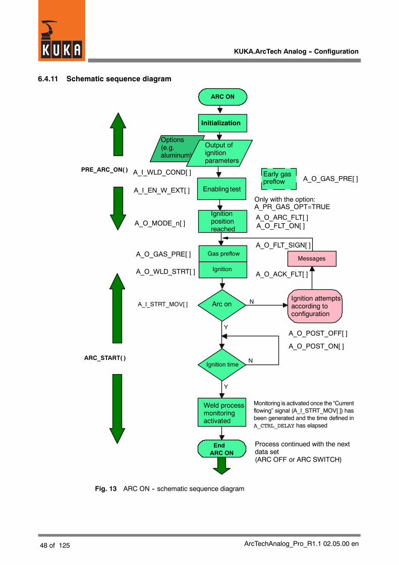
KUKA.ArcTech Analog -- Configuration
48 of 125 ArcTechAnalog_Pro_R1.1 02.05.00 en
6.4.11 Schematic sequence diagram
Options(e.g.aluminum)
Initialization
Ignition
Arc onIgnition attemptsaccording toconfiguration
Messages
Weld processmonitoringactivated
EndARC ON
ARC ON
N
Y
Process continued with the nextdata set(ARC OFF or ARC SWITCH)
Y
N
Output ofignitionparameters
Gas preflow
Ignition time
PRE_ARC_ON( )
ARC_START( )
A_I_STRT_MOV[ ]
Ignitionpositionreached
Monitoring is activated once the “Currentflowing” signal (A_I_STRT_MOV[ ]) hasbeen generated and the time defined inA_CTRL_DELAY has elapsed
Early gaspreflow
Only with the option:A_PR_GAS_OPT=TRUE
A_I_WLD_COND[ ]
A_O_MODE_n[ ]
Enabling test
A_O_GAS_PRE[ ]
A_O_ARC_FLT[ ]A_O_FLT_ON[ ]
A_I_EN_W_EXT[ ]
A_O_WLD_STRT[ ]
A_O_GAS_PRE[ ]
A_O_FLT_SIGN[ ]
A_O_ACK_FLT[ ]
A_O_POST_OFF[ ]
A_O_POST_ON[ ]
Fig. 13 ARC ON -- schematic sequence diagram
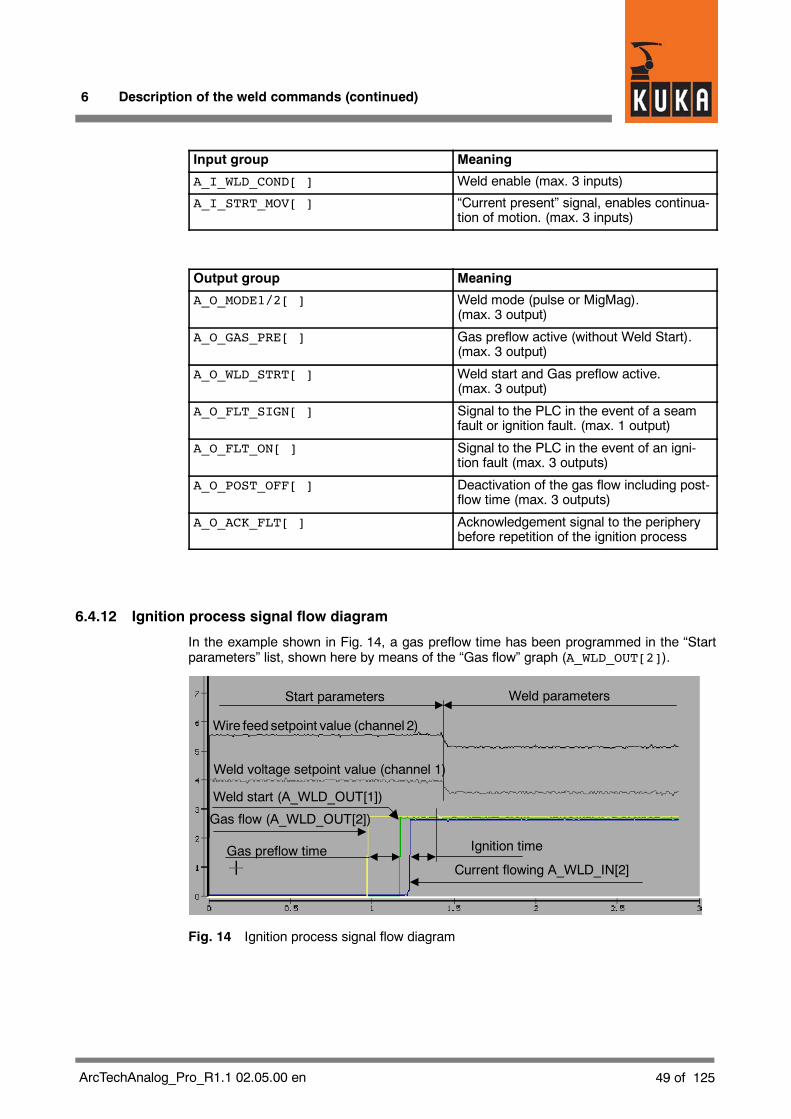
6 Description of the weld commands (continued)
49 of 125ArcTechAnalog_Pro_R1.1 02.05.00 en
Input group Meaning
A_I_WLD_COND[ ] Weld enable (max. 3 inputs)
A_I_STRT_MOV[ ] “Current present” signal, enables continua-tion of motion. (max. 3 inputs)
Output group Meaning
A_O_MODE1/2[ ] Weld mode (pulse or MigMag).(max. 3 output)
A_O_GAS_PRE[ ] Gas preflow active (without Weld Start).(max. 3 output)
A_O_WLD_STRT[ ] Weld start and Gas preflow active.(max. 3 output)
A_O_FLT_SIGN[ ] Signal to the PLC in the event of a seamfault or ignition fault. (max. 1 output)
A_O_FLT_ON[ ] Signal to the PLC in the event of an igni-tion fault (max. 3 outputs)
A_O_POST_OFF[ ] Deactivation of the gas flow including post-flow time (max. 3 outputs)
A_O_ACK_FLT[ ] Acknowledgement signal to the peripherybefore repetition of the ignition process
6.4.12 Ignition process signal flow diagram
In the example shown in Fig. 14, a gas preflow time has been programmed in the “Startparameters” list, shown here by means of the “Gas flow” graph (A_WLD_OUT[2]).
Start parameters Weld parameters
Wire feed setpoint value (channel 2)
Weld voltage setpoint value (channel 1)
Ignition time
Current flowing A_WLD_IN[2]
Gas flow (A_WLD_OUT[2])
Gas preflow time
Weld start (A_WLD_OUT[1])
Fig. 14 Ignition process signal flow diagram

KUKA.ArcTech Analog -- Configuration
50 of 125 ArcTechAnalog_Pro_R1.1 02.05.00 en
Beside it you see the signal for weld start (A_WLD_OUT[1]) -- this is the point in time at whichwire feed is activated -- followed by the “Current flowing” signal from the peripheral interface(A_I_STRT_MOV[ ]), meaning that the arc is now established following successful ignition.
At the conclusion of the ignition time, a transition is made from the start parameters to theweld parameters, as you can see from the curves for both analog channels (setpoint valuesfor weld voltage and wire feed -- channels 1 and 2). The weld parameters (W parameters)are contained in theweld data set of the “ARCOFF” or “ARCSWITCH”command that followsthe “ARC ON” command.
6.4.13 Activation of delayed weld process monitoring after ignition
If an arc is established following ignition, the weld process monitoring function is activatedafter a time delay set bymeans of the A_CTRL_DELAY variable. The “Current flowing” signal(A_I_STRT_MOVL) from the weld power source is decisive for this. The default time is 1200milliseconds.
The default time can be changed with the menu function “Monitor -- Variable -- Single”.
Variable Default (ms)
A_CTRL_DELAY 1200
To avoid disruptions, this value should not be too low. If the setting is too high, the peripheralinterface signals cannot be monitored during this time.
6.5 ARC SWITCH command
The “ARC SWITCH” command is always used between the “ARC ON” and “ARC OFF”commands whenever the seam is divided into several sections with different motion and/orweld parameters. Fig. 15 shows the schematic sequence diagram.
The command contains themotion andweld parameters for the current section of the seam,including the parameters for mechanical and thermal weaving. The parameter sets can beused repeatedly. The command is to be used if the seam is to bedivided up into several seamsections, even if the parameters do not need modification.
Functional principle
The ARC_SWI command switches from one weld data set to the next. In addition tomechanical weaving, thermal weaving or the through--the--arc seam tracking sensor(KUKA.ArcSense) can also be started here, or triggered for a new reference run. The weldmode can be changed in the controller.

6 Description of the weld commands (continued)
51 of 125ArcTechAnalog_Pro_R1.1 02.05.00 en
6.5.1 Schematic sequence diagram
ARC SWITCH
Initialization
Weld modePS / MM
PRE_ARC( )
A_O_MODE1[]A_O_MODE2[]
WELD_ON_SEAM( )
Preparation ofparameters forwelding,mechanicaland thermalweaving
Filling of FIFO buffer,precalculation
Task at start of motionon seam section
Retrieve data fromFIFO buffer
Output ofweldparameters
Mechanicalweaving on *)
Thermalweaving on *)
Activate cyclicalanalog output
End ARCSWITCH
Process continued with thenext data set (ARC OFF orARC SWITCH)
*) If configured accordingly
Fig. 15 ARC SWITCH sequence diagram

KUKA.ArcTech Analog -- Configuration
52 of 125 ArcTechAnalog_Pro_R1.1 02.05.00 en
Input group Meaning
A_O_MODE1/2[ ] Configuration of the weld mode(max. 3 inputs), PULSE or MIG/MAG
Approximate positioning should be used for motions in “ARCSWITCH” commands if exactpositioning between individual seam sections is not absolutely essential.
6.5.2 Signal diagrams
Switching weld parameters
Fig. 16 shows examples of the following:
G Weld start (ignition parameters, signals for weld start, current flowing, and gas flow)
G Weld parameters of weld data set 1 for the analog channels “Wire feed setpoint” and“Weld voltage setpoint”
G Weld parameters of weld data set 2 for the analog channels “Wire feed setpoint” and“Weld voltage setpoint”
Weld parameters
Weld voltage setpoint value
Gas flow
Weld start
Current flowing
Wire feed setpoint valueAnalogchannels
Weld data set 1 Weld data set 2
Ignitionparameters
Fig. 16 Diagram: switching weld parameters
You can recognize the changes to the analog channel setpoint values (wire feed, weldvoltage) during the transitions from “ignition parameters” to “weld data set 1”, as well as from“weld data set 1” to “weld data set 2”.
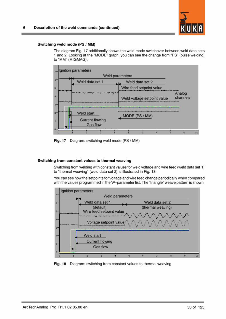
6 Description of the weld commands (continued)
53 of 125ArcTechAnalog_Pro_R1.1 02.05.00 en
Switching weld mode (PS / MM)
The diagram Fig. 17 additionally shows the weld mode switchover between weld data sets1 and 2. Looking at the “MODE” graph, you can see the change from “PS” (pulse welding)to “MM” (MIGMAG).
Weld parameters
Weld voltage setpoint value
Gas flow
Weld start
Current flowing
Wire feed setpoint valueAnalogchannels
Weld data set 1 Weld data set 2
Ignition parameters
MODE (PS / MM)
Fig. 17 Diagram: switching weld mode (PS / MM)
Switching from constant values to thermal weaving
Switching from welding with constant values for weld voltage andwire feed (weld data set 1)to “thermal weaving” (weld data set 2) is illustrated in Fig. 18.
You can see how the setpoints for voltage andwire feed change periodically when comparedwith the values programmed in theW--parameter list. The “triangle” weave pattern is shown.
Weld parameters
Voltage setpoint value
Gas flow
Weld start
Current flowing
Wire feed setpoint value
Weld data set 1 Weld data set 2
Ignition parameters
(thermal weaving)(default)
Fig. 18 Diagram: switching from constant values to thermal weaving
KUKA.ArcTech Analog -- Configuration
54 of 125 ArcTechAnalog_Pro_R1.1 02.05.00 en
6.5.3 Signal tables
There are no specific additional signal tables for ARC SWITCH.
6.6 ARC OFF command
The command is available with LIN and CIRC variants. The weld command ARC OFFcontains motion and weld parameters for a single seam from the start of a weld to the endof the seam, at which point the parameters for crater filling take effect.
A single seam therefore requires two commands: ARC_ON and ARC_OFF
If a seam consists of several seamsections with different motionand/or weldingparameters,the command ARC OFF is used for the last seam section. ARC_SWI commands are usedbetween ARC_ON and ARC_OFF.
Functionality:
To start with, the same actions are carried out in the motion to the seam end position as withan ARC_SWI command. Once this position is reached, the end crater is filled, the wireburnback is carried out, the welding torch is deactivated, and the gas postflow is initiated.With the appropriate configuration, it is possible to force a burnfree procedure.
If a Track command (ARC_OFF with weave sensor) has been used, this is now deactivatedor the sensor offset is frozen.
Approximate positioning is not possible for “ARC OFF”; motions are exactly positioned toeach point.

6 Description of the weld commands (continued)
55 of 125ArcTechAnalog_Pro_R1.1 02.05.00 en
6.6.1 Signal tables
A maximum of three signals can be defined for each table. These signal tables contain thesignal name, an index for addressing in the array, and the pulse duration, where“PULS_TIME 0.0” designates a static output.
The relevant signal groups are described in the following.
Configuration: deactivation of welding (signal output)
This configuration deactivates the weld start once the end of the seam has been reached.
; outputs burn back startsDECL A_FCT_OUT_T A_O_SEAM_END[3]
A_O_SEAM_END[1]={NO ’H1’,PULS_TIME 0.0,STATE FALSE}A_O_SEAM_END[2]={NO ’H0’,PULS_TIME 0.0,STATE FALSE}A_O_SEAM_END[3]={NO ’H0’,PULS_TIME 0.0,STATE FALSE}
A_WLD_OUT[1]={OUT_NR 0,INI FALSE;NAME_NAT[ ]”WELD START “}
Configuration: early gas postflow (signal output)
This signal enables postflow with extra shielding gas.
; outputs gas post flow startsDECL FCT_OUT_T A_O_POST_ON[3]
A_O_POST_ON[1]={NO ’H2’,PULS_TIME 0.15,STATE TRUE}A_O_POST_ON[2]={NO ’H0’,PULS_TIME 0.15,STATE TRUE}A_O_POST_ON[3]={NO ’H0’,PULS_TIME 0.15,STATE TRUE}
A_WLD_OUT[2]={OUT_NR 0,INI FALSE,NAME_NAT[ ]”GAS PREFLOW “}
Configuration: gas postflow (signal output)
This function corresponds to normal gas postflow (default).
; outputs gas post flow endsDECL FCT_OUT_T A_O_POST_OFF[3]
A_O_POST_OFF[1]={NO ’H2’,PULS_TIME 0.2,STATE TRUE}A_O_POST_OFF[2]={NO ’H0’,PULS_TIME 0.2,STATE TRUE}A_O_POST_OFF[3]={NO ’H0’,PULS_TIME 0.2,STATE TRUE}
A_WLD_OUT[2]={OUT_NR 0,INI FALSE,NAME_NAT[ ]”GAS PREFLOW “}
$config.dat
$config.dat
$config.dat
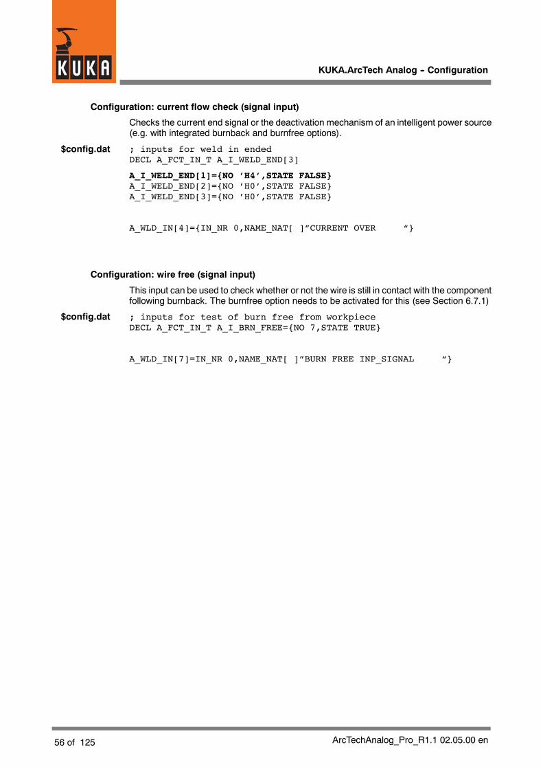
KUKA.ArcTech Analog -- Configuration
56 of 125 ArcTechAnalog_Pro_R1.1 02.05.00 en
Configuration: current flow check (signal input)
Checks the current end signal or the deactivation mechanism of an intelligent power source(e.g. with integrated burnback and burnfree options).
; inputs for weld in endedDECL A_FCT_IN_T A_I_WELD_END[3]
A_I_WELD_END[1]={NO ’H4’,STATE FALSE}A_I_WELD_END[2]={NO ’H0’,STATE FALSE}A_I_WELD_END[3]={NO ’H0’,STATE FALSE}
A_WLD_IN[4]={IN_NR 0,NAME_NAT[ ]”CURRENT OVER “}
Configuration: wire free (signal input)
This input can be used to check whether or not the wire is still in contact with the componentfollowing burnback. The burnfree option needs to be activated for this (see Section 6.7.1)
; inputs for test of burn free from workpieceDECL A_FCT_IN_T A_I_BRN_FREE={NO 7,STATE TRUE}
A_WLD_IN[7]=IN_NR 0,NAME_NAT[ ]”BURN FREE INP_SIGNAL “}
$config.dat
$config.dat

6 Description of the weld commands (continued)
57 of 125ArcTechAnalog_Pro_R1.1 02.05.00 en
6.7 Burnfree options
6.7.1 Configuration: burnfree
In cases when the wire does not separate from the workpiece at the end of the weldingprocess, the burnfree option can be used to attempt to bring about separation. This optioncan only be used when welding controllers are used that are capable of supplying acorresponding signal (BURN FREE INP_SIGNAL) to the robot controller.
The following settings are required to activate the burnfree option (which is not active in thedefault configuration):
DECL A_BOOL_T A_BRN_FR_OPT=#ACTIVE ; Burnfree Option
Corresponding entry using the menu function “Monitor -- Variable -- Single”:
Variable Value Characteristics
A_BRN_FR_OPT #ACTIVE Default: #IDLE
If the wire is not separated from the workpiece at the conclusion of the welding process, thepower source issues the A_I_BRN_FREE signal to the physical input (here A_WLD_IN[7]).This triggers the process for burning the wire free.
The burnfree data must also be set. This variable is located in the A10.DAT file:
DECL A_ANA_SET_T8 A_BRN_FREE={CH1 26.0, CH2 8.0, CH3 0.0, CH40.0, CH5 0.0, CH6 0.0, CH7 0.0, CH8 0.0}
In this example, the burnfree voltage is set to 26.0 volts and the wire feed to 8 m/min inchannel 1. The other channels are not configured here and remain available for furtherapplications.
6.7.2 Burnfree duration and number of burnfree attempts
Corresponding entry using the menu function “Monitor -- Variable -- Single” in the“$config.dat” file:
Variable Value Characteristics
A_BRN_FREE_T 0.2 Pulse duration in seconds (default: 0.2)
A_BRN_FR_LIM 3 Number of burnback attempts (default: 3)
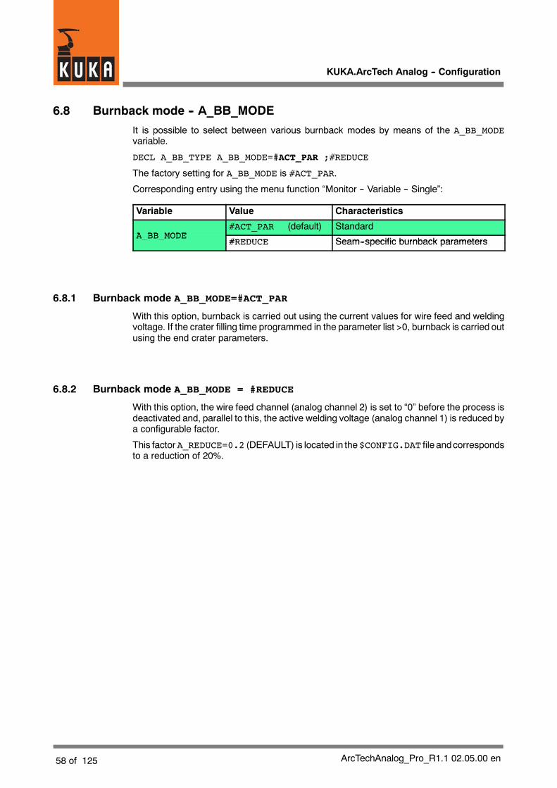
KUKA.ArcTech Analog -- Configuration
58 of 125 ArcTechAnalog_Pro_R1.1 02.05.00 en
6.8 Burnback mode -- A_BB_MODE
It is possible to select between various burnback modes by means of the A_BB_MODEvariable.
DECL A_BB_TYPE A_BB_MODE=#ACT_PAR ;#REDUCE
The factory setting for A_BB_MODE is #ACT_PAR.
Corresponding entry using the menu function “Monitor -- Variable -- Single”:
Variable Value Characteristics
A BB MODE#ACT_PAR (default) Standard
A_BB_MODE#REDUCE Seam--specific burnback parameters
_ _#REDUCE Seam--specific burnback parameters
6.8.1 Burnback mode A_BB_MODE=#ACT_PAR
With this option, burnback is carried out using the current values for wire feed and weldingvoltage. If the crater filling time programmed in the parameter list >0, burnback is carried outusing the end crater parameters.
6.8.2 Burnback mode A_BB_MODE = #REDUCE
With this option, the wire feed channel (analog channel 2) is set to “0” before the process isdeactivated and, parallel to this, the active welding voltage (analog channel 1) is reduced bya configurable factor.
This factorA_REDUCE=0.2 (DEFAULT) is located in the$CONFIG.DAT file andcorrespondsto a reduction of 20%.

6 Description of the weld commands (continued)
59 of 125ArcTechAnalog_Pro_R1.1 02.05.00 en
6.8.3 Schematic sequence diagram
Initialization
ARC OFF
A_O_POST_ON[ ]
ADV. RUN STOP
Crater time >0
Y
N
(EK time = end crater time)(BB time = burnback time)
WELD_ON_SEAM( )
FINISH_SEAM( )
PRE_ARC( )(advance run section)
[1--2]
A_O_MODE [1]A_O_MODE[2]
Robotmotion
Target position reached
Preparation ofparameters forwelding,mechanicaland thermalweaving
Filling of FIFO buffer,precalculation
Weld modePS / MM
Output ofweldparameters
Synchronization withrobot motion, retrievedata from FIFO buffer
Mechanicalweaving on *)
Thermalweaving on *)
Calculation ofearly activation ofgas postflow time
Output ofend craterparameters
*) If configured accordingly
Fig. 19 ARC OFF sequence diagram (page 1 of 2 pages)

KUKA.ArcTech Analog -- Configuration
60 of 125 ArcTechAnalog_Pro_R1.1 02.05.00 en
EndARC Off
Welding off
Burnbacktime
[1--2]
A_WLD_ACTIV=#ACTIVEFlag
Gas postflow on
Initialization$TIMER[2]
Arc offFault routine
(Pulse command)
A_I_WELD_END[ ]
Burnfreeoption
Burnfree
N
Y
Wire free/ Cancel
Initialization andreset flags
Gas postflow
N
Y
A_O_POST_ON[ ]
A_O_POST_OFF[ ]
A_WLD_ACTIV=#IDLEA_COLD_SEAM=#IDLE
N
Y
N
FINISH_SEAM( )
A_O_SEAM_END[ ]
Fig. 20 ARC OFF sequence diagram (page 2 of 2 pages)

6 Description of the weld commands (continued)
61 of 125ArcTechAnalog_Pro_R1.1 02.05.00 en
Explanation of the variables:
Input groups
A_I_WELD_END[ ] Current end / power source deactivationprocess
A_I_BRN_FREE Checks that wire is free or forces burnfreeif option is active(A_BRN_FR_OPT=#ACTIVE)
Output groups
A_O_MODE1/2[ ] Weld mode (pulse/MigMag),max. 3 outputs
A_O_POST_ON[ ] Early activation of gas postflow(max. 3 outputs)
A_O_POST_OFF[ ] Configuration of gas postflow(max. 3 outputs)
A_O_SEAM_END[ ] Initiates power source deactivation
A_O_FLT_SIGN[ ] Fault signal
A_O_ACK_FLT[ ] Acknowledge fault
A_O_WLD_STRT[ ] WELDSTART generated in event of forcedburnfree procedure
Standard mode, with end crater, burnback, and gas postflow
The diagramFig. 21 shows the end parameters with end crater, burnback, and gas postflow.
End parametersWeld parameters
Weld voltage setpoint value
Gas flowWeld start
Current flowing
Wire feed setpoint value
Burnback time
Crater time Gas postflow time
STOP robot motion
Analogchannels
Fig. 21 Diagram: standard mode, with end crater, burnback, and gas postflow

KUKA.ArcTech Analog -- Configuration
62 of 125 ArcTechAnalog_Pro_R1.1 02.05.00 en
On the left in the weld parameter range, the constant setpoint values for wire feed and weldvoltage are shown. In the following end parameter range, the setpoint values of the analogreference voltages increase in accordancewith the values programmed in the parameter list.The end parameter range is divided into three sections:
G Crater time
G Burnback time and
G Postflow time
Wire feed is switched off at the falling edge of the “Weld start” signal. As a result, the arc goesout, as can be seen from the falling edge of the “Current flowing” signal, which is delayed byapproximately 0.1 second.
In accordance with the parameter settings, gas flow is still maintained for a specific time.
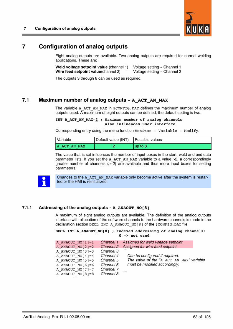
7 Configuration of analog outputs
63 of 125ArcTechAnalog_Pro_R1.1 02.05.00 en
7 Configuration of analog outputsEight analog outputs are available. Two analog outputs are required for normal weldingapplications. These are:
Weld voltage setpoint value (channel 1) Voltage setting -- Channel 1Wire feed setpoint value(channel 2) Voltage setting -- Channel 2
The outputs 3 through 8 can be used as required.
7.1 Maximum number of analog outputs -- A_ACT_AN_MAX
The variable A_ACT_AN_MAX in $CONFIG.DAT defines the maximum number of analogoutputs used. A maximum of eight outputs can be defined; the default setting is two.
INT A_ACT_AN_MAX=2 ; Maximum number of analog channelsalso influences user interface
Corresponding entry using the menu function Monitor - Variable - Modify:
Variable Default value (INT) Possible values
A_ACT_AN_MAX 2 up to 8
The value that is set influences the number of input boxes in the start, weld and end dataparameter lists. If you set the A_ACT_AN_MAX variable to a value >2, a correspondinglygreater number of channels (n--2) are available and thus more input boxes for settingparameters.
Changes to the A_ACT_AN_MAX variable only become active after the system is restar-ted or the HMI is reinitialized.
7.1.1 Addressing of the analog outputs -- A_ANAOUT_NO[8]
A maximum of eight analog outputs are available. The definition of the analog outputsinterface with allocation of the software channels to the hardware channels is made in thedeclaration section DECL INT A_ANAOUT_NO[8] of the $CONFIG.DAT file.
DECL INT A_ANAOUT_NO[8] ; Indexed addressing of analog channels:0 -> not used
A_ANAOUT_NO[1]=1 Channel 1 Assigned for weld voltage setpointA_ANAOUT_NO[2]=2 Channel 2 Assigned for wire feed setpointA_ANAOUT_NO[3]=3 Channel 3A_ANAOUT_NO[4]=4 Channel 4A_ANAOUT_NO[5]=5 Channel 5A_ANAOUT_NO[6]=6 Channel 6A_ANAOUT_NO[7]=7 Channel 7A_ANAOUT_NO[8]=8 Channel 8
Can be configured if required.The value of the “A_ACT_AN_MAX” variablemust be modified accordingly.
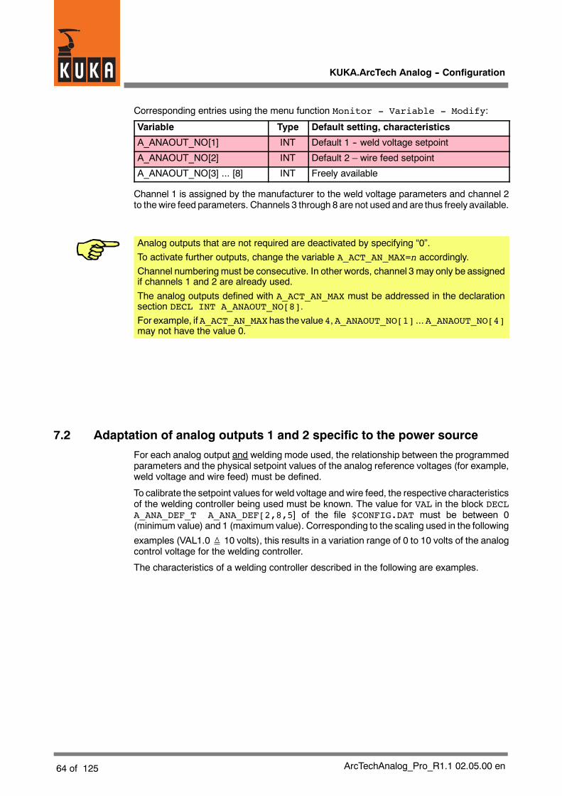
KUKA.ArcTech Analog -- Configuration
64 of 125 ArcTechAnalog_Pro_R1.1 02.05.00 en
Corresponding entries using the menu function Monitor - Variable - Modify:
Variable Type Default setting, characteristics
A_ANAOUT_NO[1] INT Default 1 -- weld voltage setpoint
A_ANAOUT_NO[2] INT Default 2 – wire feed setpoint
A_ANAOUT_NO[3] ... [8] INT Freely available
Channel 1 is assigned by the manufacturer to the weld voltage parameters and channel 2to thewire feed parameters. Channels 3 through 8 are not used and are thus freely available.
Analog outputs that are not required are deactivated by specifying “0”.To activate further outputs, change the variable A_ACT_AN_MAX=n accordingly.Channel numbering must be consecutive. In other words, channel 3 may only be assignedif channels 1 and 2 are already used.The analog outputs defined with A_ACT_AN_MAX must be addressed in the declarationsection DECL INT A_ANAOUT_NO[8].For example, ifA_ACT_AN_MAXhas the value4,A_ANAOUT_NO[1] ...A_ANAOUT_NO[4]may not have the value 0.
7.2 Adaptation of analog outputs 1 and 2 specific to the power source
For each analog output and welding mode used, the relationship between the programmedparameters and the physical setpoint values of the analog reference voltages (for example,weld voltage and wire feed) must be defined.
To calibrate the setpoint values for weld voltage andwire feed, the respective characteristicsof the welding controller being used must be known. The value for VAL in the block DECLA_ANA_DEF_T A_ANA_DEF[2,8,5] of the file $CONFIG.DAT must be between 0(minimum value) and 1 (maximum value). Corresponding to the scaling used in the following
examples (VAL1.0≙ 10 volts), this results in a variation range of 0 to 10 volts of the analogcontrol voltage for the welding controller.
The characteristics of a welding controller described in the following are examples.

7 Configuration of analog outputs (continued)
65 of 125ArcTechAnalog_Pro_R1.1 02.05.00 en
7.2.1 Number of characteristic points
A linear characteristic is determined by two points. In the case of a non--linear characteristic,the relationship between parameters and control voltage can be defined with five points.
The number of required characteristic points required must be entered in the block DECLINT A_ANA_MAX_D[2,8] of the file $CONFIG.DAT for each analog channel used.
Number of characteristic pointsModeChannel
A_ANA_MAX_D[1,1]=2
In the following example, two characteristic points (corresponding to a linear characteristic)each are defined for channels 1 (voltage) and 2 (wire feed) for mode 1 (pulse welding) andfor mode 2 (MIGMAG) welding.
DECL INT A_ANA_MAX_D[2,8] ;maximum number of points to definea controller line
A_ANA_MAX_D[1,1]=2 Mode 1; Channel 1; 2 characteristic pointsA_ANA_MAX_D[1,2]=2 Mode 1; Channel 2; 2 characteristic points...A_ANA_MAX_D[1,8]=2 Mode 1; Channel 8; 2 characteristic points
A_ANA_MAX_D[2,1]=2 Mode 2; Channel 1; 2 characteristic pointsA_ANA_MAX_D[2,2]=2 Mode 2; Channel 2; 2 characteristic points...A_ANA_MAX_D[2,8]=2 Mode 2; Channel 8; 2 characteristic points
Corresponding entry using the menu function Monitor - Variable - Modify:
Variable Type Characteristics ,default setting
A_ANA_MAX_D[1,1] INT Mode 1; channel 1; 2 characteristic points (default)
A_ANA_MAX_D[1,2] INT Mode 1; channel 2; 2 characteristic points (default)
If only one welding mode (either pulse or MIGMAG) is going to be used, we recommendmaking all configuration entries and parameter settings for mode 1 and mode 2 identicalin the $CONFIG.DAT file.In this way you ensure that accidentally switching from the welding mode “PS” to “MM” orvice versa while programming inline forms does not result in errors.

KUKA.ArcTech Analog -- Configuration
66 of 125 ArcTechAnalog_Pro_R1.1 02.05.00 en
7.2.2 Linear characteristic
The following example (channel 1, set weld voltage) is based on a linear characteristic withthe values:
Point Control voltage(volts)
Weld voltage setpoint(volts)
1 0.369 0
2 8.062 80
Thenext example shows the characteristicwith assignment of theparametersPARAandVALin the file $CONFIG.DAT. PARA is the value Voltage for the weld voltage (S, W and Eparameter lists), and VAL corresponds to 1/10 of the analog control voltage.
0
1
2
0
VAL 1.0≙ 10 volts
U (volts)
DECL A_ANA_DEF_T A_ANA_DEF[2,8,5];WELD_Mode,Channel,Points of controller line;Mode1 Channel1 command valueA_ANA_DEF[1,1,1]={PARA 0.0,VAL 0.0369}A_ANA_DEF[1,1,2]={PARA 80.0,VAL 0.8062}
0.8062
0.0369
8.062
0.369
1.00 10.000VAL
PARA
80 (volts)
($CONFIG.DAT)
Fig. 22 Voltage characteristic (example) -- Channel 1, characteristic points (1,2)
A further example shows a linear characteristic for thewire feed (channel 2). Here, the value(VAL) of 0.0631 at characteristic point 1 corresponds to a control voltage of 0.631 volts,resulting in a wire feed rate of 50 inch/min and the value (VAL) 0.9511 at characteristic point2 corresponds to a control voltage of 9.511 volts for a wire feed rate of 770 inch/min.
Point Control voltage(volts)
Wire feed(inches/minute)
1 0.631 50
2 9.511 770The next example shows the corresponding characteristic with assignment of theparameters PARA and VAL in the file $CONFIG.DAT. In this case PARA is the Wire Feedvalue for the wire feed rate in inch/min (S, W and E parameter lists); “VAL” corresponds to1/10 of the analog control voltage.

7 Configuration of analog outputs (continued)
67 of 125ArcTechAnalog_Pro_R1.1 02.05.00 en
0
1
2
VAL 1.0≙ 10 volts
DECL A_ANA_DEF_T A_ANA_DEF[2,8,5]...;Mode1 Channel2 wire feed [IPM]A_ANA_DEF[1,2,1]={PARA 50.0,VAL 0.0631}A_ANA_DEF[1,2,2]={PARA 770.0,VAL 0.9511}
U (volts)1.00 10.000VAL
(inches/minute)77050
0.9511
0.0631
9.511
0.631 PARA
($CONFIG.DAT)
Fig. 23 Wire feed characteristic (example) -- Channel 2, characteristic points (1,2)
Parameters are set for the individual characteristic points in the block DECL A_ANA_DEF_TA_ANA_DEF... of the $CONFIG.DAT file. In the above example with two characteristicpoints, the following must be entered for channel 1 (voltage) and channel 2 (wire feed):
DECL A_ANA_DEF_T A_ANA_DEF[2,8,5] ;WELD_Mode,Channel,Points of controller line
(For the weld voltage);Mode1 Channel1 command valueA_ANA_DEF[1,1,1]={PARA 0.0,VAL 0.0369}A_ANA_DEF[1,1,2]={PARA 80.0,VAL 0.8062}A_ANA_DEF[1,1,3]={PARA 40.0,VAL 0.0} (*)A_ANA_DEF[1,1,4]={PARA 41.0,VAL 0.0} (*)A_ANA_DEF[1,1,5]={PARA 42.0,VAL 0.0} (*)...
(For the wire feed);Mode1 Channel2 wire feed [IPM]A_ANA_DEF[1,2,1]={PARA 50.0,VAL 0.0631}A_ANA_DEF[1,2,2]={PARA 770.0,VAL 0.9511}A_ANA_DEF[1,2,3]={PARA 1001.0,VAL 0.0} (*)A_ANA_DEF[1,2,4]={PARA 1002.0,VAL 0.0} (*)A_ANA_DEF[1,2,5]={PARA 1003.0,VAL 0.0} (*)
...
Explanation
ModeChannel
Characteristic pointWeld voltage setpoint1/10 control voltage
A_ANA_DEF[1,1,2]={PARA 80.0,VAL 0.8062}
(*)If, as in this example, the number of characteristic points (A_ANA_MAX_D[...,...])had been defined as 2, the values contained in the lines A_ANA_DEF[...,...,3] throughA_ANA_DEF[...,...,5] would have no effect. These values are set by the program tovalues that are greater than the highest value (of characteristic point 2 in this case).

KUKA.ArcTech Analog -- Configuration
68 of 125 ArcTechAnalog_Pro_R1.1 02.05.00 en
The parameters of the characteristic points must be entered in ascending order.
Example of the entry of the characteristic parameters PARA and VAL with the menu functionMonitor - Variable - Modify:
Variable Type Characteristics, value
A_ANA_D_DEF[1,1,2].PARA REAL Value for “PARA”, e.g.: 80.0
A_ANA_D_DEF[1,1,2].VAL REAL Value for “VAL”, e.g.: 0.8062
7.2.3 Non--linear characteristic
In the case of non--linear characteristics, several characteristic points (max. 5) must bedefined as shown in the following example:
00
1.00
1
2
3
45
10,00
VAL 1.0≙ 10 volts
U (volts)
($CONFIG.DAT)DECL A_ANA_DEF_T A_ANA_DEF[2,8,5];Mode1 Channel1 command valueA_ANA_DEF[1,1,1]={PARA 0.0,VAL 0.02}A_ANA_DEF[1,1,2]={PARA 6.5,VAL 0.26}A_ANA_DEF[1,1,3]={PARA 24.0,VAL 0.5}A_ANA_DEF[1,1,4]={PARA 51.0,VAL 0.72}A_ANA_DEF[1,1,5]={PARA 80.0,VAL 0.85}
8.507.20
5.00
2.60
0.20
0.850.72
0.50
0.26
0.02
6.5 24 51 80 (volts)
PARA
VAL
Fig. 24 Voltage characteristic (example) -- 5 characteristic points (1,5)
DECL INT A_ANA_MAX_D[2,8]
A_ANA_MAX_D[1,1]=5
Accordingly, the following must be entered for channel 1 in the block DECL A_ANA_DEF_TA_ANA_DEF[ ] of the file $CONFIG.DAT:
DECL A_ANA_DEF_T A_ANA_DEF[2,8,5] ;WELD_Mode,Channel,Points ofcontroller line
;Mode1 Channel1 command value
A_ANA_DEF[1,1,1]={PARA 0.0,VAL 0.02}A_ANA_DEF[1,1,2]={PARA 6.5,VAL 0.26}A_ANA_DEF[1,1,3]={PARA 24.0,VAL 0.5}A_ANA_DEF[1,1,4]={PARA 51.0,VAL 0.72}A_ANA_DEF[1,1,5]={PARA 80.0,VAL 0.85}
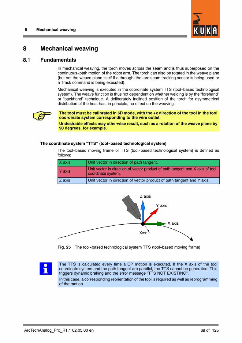
8 Mechanical weaving
69 of 125ArcTechAnalog_Pro_R1.1 02.05.00 en
8 Mechanical weaving
8.1 Fundamentals
In mechanical weaving, the torch moves across the seam and is thus superposed on thecontinuous--path motion of the robot arm. The torch can also be rotated in the weave plane(but not the weave plane itself if a through--the--arc seam tracking sensor is being used ora Track command is being executed).
Mechanical weaving is executed in the coordinate system TTS (tool--based technologicalsystem). The weave function is thus not dependent on whether welding is by the “forehand”or “backhand” technique. A deliberately inclined position of the torch for asymmetricaldistribution of the heat has, in principle, no effect on the weaving.
The tool must be calibrated in 6D mode, with the +x direction of the tool in the toolcoordinate system corresponding to the wire outlet.Undesirable effects may otherwise result, such as a rotation of the weave plane by90 degrees, for example.
The coordinate system “TTS” (tool--based technological system)
The tool--based moving frame or TTS (tool--based technological system) is defined asfollows:
X axis Unit vector in direction of path tangent.
Y axis Unit vector in direction of vector product of path tangent and X axis of toolcoordinate system.
Z axis Unit vector in direction of vector product of path tangent and Y axis.
Xwz
Y axis
X axis
Z axis
Fig. 25 The tool--based technological system TTS (tool--based moving frame)
The TTS is calculated every time a CP motion is executed. If the X axis of the toolcoordinate system and the path tangent are parallel, the TTS cannot be generated. Thistriggers dynamic braking and the error message “TTS NOT EXISTING”.In this case, a corresponding reorientation of the tool is required as well as reprogrammingof the motion.

KUKA.ArcTech Analog -- Configuration
70 of 125 ArcTechAnalog_Pro_R1.1 02.05.00 en
8.2 Weave patterns
Theweave patterns shown in Fig. 26 and Fig. 27 are includedwith “KUKA.ArcTech Analog”:
No weave
Double triangle
Double trapezoid
Unsym.trapezoid
Weld direction
s
s
Triangle
Trapezoid
Spiral *)
Double 8
Weave amplitudeWeave length
Fig. 26 Weave patterns for mechanical weaving (1 of 2)
*) In order to achieve circular weave motions with the Spiral weave pattern selected, theweave amplitude needs to be half the set weave length.

8 Mechanical weaving (continued)
71 of 125ArcTechAnalog_Pro_R1.1 02.05.00 en
Edge weave top
Edge weave
Weave length
Weave length
s
s
s
s
Weld direction
Weld direction
z x
y
bottom
Fig. 27 Weave patterns for mechanical weaving (2 of 2)
Block selection responseWeaving is deactivated at every block selection asmechanicalweaving can force the robotinto critical motions. Reactivation is however assured.
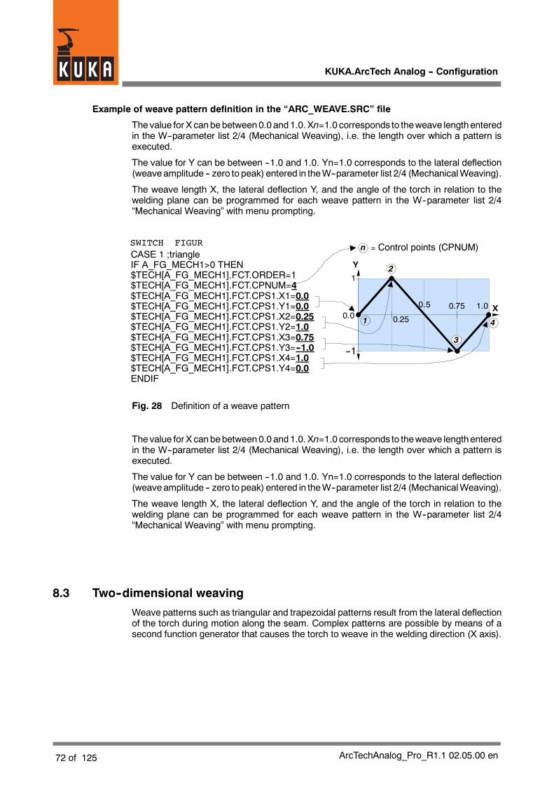
KUKA.ArcTech Analog -- Configuration
72 of 125 ArcTechAnalog_Pro_R1.1 02.05.00 en
Example of weave pattern definition in the “ARC_WEAVE.SRC” file
Thevalue for X canbebetween0.0 and1.0. Xn=1.0 corresponds to theweave lengthenteredin the W--parameter list 2/4 (Mechanical Weaving), i.e. the length over which a pattern isexecuted.
The value for Y can be between --1.0 and 1.0. Yn=1.0 corresponds to the lateral deflection(weaveamplitude -- zero to peak) entered in theW--parameter list 2/4 (MechanicalWeaving).
The weave length X, the lateral deflection Y, and the angle of the torch in relation to thewelding plane can be programmed for each weave pattern in the W--parameter list 2/4“Mechanical Weaving” with menu prompting.
CASE 1 ;triangleIF A_FG_MECH1>0 THEN$TECH[A_FG_MECH1].FCT.ORDER=1$TECH[A_FG_MECH1].FCT.CPNUM=4$TECH[A_FG_MECH1].FCT.CPS1.X1=0.0$TECH[A_FG_MECH1].FCT.CPS1.Y1=0.0$TECH[A_FG_MECH1].FCT.CPS1.X2=0.25$TECH[A_FG_MECH1].FCT.CPS1.Y2=1.0$TECH[A_FG_MECH1].FCT.CPS1.X3=0.75$TECH[A_FG_MECH1].FCT.CPS1.Y3=--1.0$TECH[A_FG_MECH1].FCT.CPS1.X4=1.0$TECH[A_FG_MECH1].FCT.CPS1.Y4=0.0ENDIF
1
--1
0.0 0.25
0.5 0.75 1.0 X
Y 2
1
=n
3
4
SWITCH FIGUR Control points (CPNUM)
Fig. 28 Definition of a weave pattern
The value for X canbebetween0.0 and1.0. Xn=1.0 corresponds to theweave lengthenteredin the W--parameter list 2/4 (Mechanical Weaving), i.e. the length over which a pattern isexecuted.
The value for Y can be between --1.0 and 1.0. Yn=1.0 corresponds to the lateral deflection(weaveamplitude -- zero to peak) entered in theW--parameter list 2/4 (MechanicalWeaving).
The weave length X, the lateral deflection Y, and the angle of the torch in relation to thewelding plane can be programmed for each weave pattern in the W--parameter list 2/4“Mechanical Weaving” with menu prompting.
8.3 Two--dimensional weaving
Weave patterns such as triangular and trapezoidal patterns result from the lateral deflectionof the torch during motion along the seam. Complex patterns are possible by means of asecond function generator that causes the torch to weave in the welding direction (X axis).

8 Mechanical weaving (continued)
73 of 125ArcTechAnalog_Pro_R1.1 02.05.00 en
Two practical functions (for thin sheet welding, for example), namely spiral weaving andfigure--eight weaving, are already included in the technology package. You can also developyour own patterns. The following diagram illustrates the mode of operation of the functiongenerator using the example of spiral weaving.
$TECH[A_FG_MECH1].FCT.CPS1.X =$TECH[A_FG_MECH1].FCT.CPS1.Y =
n x (0.0 ... 1.0)n y (--1.0 ... 1.0)
$TECH[A_FG_MECH2].FCT.CPS1.X =$TECH[A_FG_MECH2].FCT.CPS1.Y =
n x (0.0 ... 1.0)n y (--1.0 ... 1.0)
(WEAV_DEF.SRC)
1) Lateral deflection (amplitude) = half weave width
2) Deflection in direction of path = ¦ weave length
Torch
Deflection in the direction of the path 2)
Lateral deflection (amplitude) 1)
Lateral deflection(amplitude) 1)
Weave width
(--Y’) (Y’)
(--Y)
(Y)
Path tangent, X axis
Weave length
Fig. 29 Two--dimensional weaving
The magnitude of the deflection in the welding direction (...FCTCTRL.SCALE_IN) inrelation to the weave length (W.WEAVLEN_MECH) is set in the file “A10.SRC” at a ratio of 1:1.The lateral deflection (...FCTRL.SCALE_OUT) corresponds to the value set for half theweave width (W.WEAVAMP_MECH).
IF A_WEAV_GEN[N]>0 THEN$TECH_C[A_WEAV_GEN[N]].FCTCTRL.SCALE_IN=W.WEAVLEN_MECH$TECH_C[A_WEAV_GEN[N]].FCTCTRL.SCALE_OUT=W.WEAVAMP_MECH
ENDIF
The “Weave amplitude” value is defined as “zero to peak”, i.e. it corresponds to half theweave width (peak to peak).
8.3.1 Creating the “Spiral” weave pattern
Fig. 30 shows creation of the “Spiral” weave pattern. As a result of the superposition of alateral weavemotion “sin(x)” with an orthogonally--actingweavemotion (in weldingdirection)of the same frequency “cos(x)”, the torch describes a motion in the form of a circle (with thesame amplitude) or of an ellipse (with different amplitudes).

KUKA.ArcTech Analog -- Configuration
74 of 125 ArcTechAnalog_Pro_R1.1 02.05.00 en
The spiral form results because the torch is moved by the amount of the weave length (fromX=0 to X=1) during one period (360°) in the direction of welding.
sin(x) cos(x)
0 101
Superposition of sine and cosineWithout continuous--pathmotion
With continuous--pathmotion
Weld direction
Fig. 30 Creating the “Spiral” weave pattern
Fig. 31 shows the curve shapes of the function generators derived from the sine function.This is approximately a sine for the lateral deflection ($TECH[A_FG_MECH1]...) and acosine for the deflection in the direction of the path ($TECH[A_FG_MECH2]...). Thecorresponding control point parameters are stored under CASE6;spiral in the“Arc_weave.src” file. The spiral pattern results from the superpositioning of these twomotions.
1’ 2’
3’ 4’
5’ 6’--1
1Y
0X1,0
Y
01
2 3
4 5
6
--1
1
X1,0
$TECH[A_FG_ ]...(X 1 ... 6 ; Y 1 ... 6)
MECH1
$TECH[A_FG_ ]...(X 1 ... 6 ; Y 1 ... 6)
MECH2
1
1’
2’32
6, 6’
3’
4’
5
5’
4--1
1
Y
0X
(--Y’) (Y’)
Deflection in thedirection of the path
Lateral deflection (amplitude)
Resulting spiral
Weave length
Fig. 31 ”Spiral” weave pattern -- control points

8 Mechanical weaving (continued)
75 of 125ArcTechAnalog_Pro_R1.1 02.05.00 en
Thecontrol points for the “Spiral” weavepattern are defined in the “Arc_weave.src” file. Theparameters for the lateral deflection are stored in the first block (...MECH1...).
CASE 6 ;spiralIF A_FG_MECH1>0 THEN$TECH[A_FG_MECH1].FCT.ORDER=1$TECH[A_FG_MECH1].FCT.CPNUM=6$TECH[A_FG_MECH1].FCT.CPS1.X1=0.0$TECH[A_FG_MECH1].FCT.CPS1.Y1=0.0$TECH[A_FG_MECH1].FCT.CPS1.X2=0.166666$TECH[A_FG_MECH1].FCT.CPS1.Y2=1.0$TECH[A_FG_MECH1].FCT.CPS1.X3=0.333333$TECH[A_FG_MECH1].FCT.CPS1.Y3=1.0$TECH[A_FG_MECH1].FCT.CPS1.X4=0.666666$TECH[A_FG_MECH1].FCT.CPS1.Y4=-1.0$TECH[A_FG_MECH1].FCT.CPS1.X5=0.833333$TECH[A_FG_MECH1].FCT.CPS1.Y5=-1.0$TECH[A_FG_MECH1].FCT.CPS1.X6=1.0$TECH[A_FG_MECH1].FCT.CPS1.Y6=0.0ENDIF
The second block (A_FG_MECH2...) contains the parameters for the deflection in thedirection of the welding path:
IF A_FG_MECH2>0 THEN$TECH[A_FG_MECH2].FCT.ORDER=1$TECH[A_FG_MECH2].FCT.CPNUM=6$TECH[A_FG_MECH2].FCT.CPS1.X1=0.0$TECH[A_FG_MECH2].FCT.CPS1.Y1=-1.0$TECH[A_FG_MECH2].FCT.CPS1.X2=0.083333$TECH[A_FG_MECH2].FCT.CPS1.Y2=-1.0$TECH[A_FG_MECH2].FCT.CPS1.X3=0.416666$TECH[A_FG_MECH2].FCT.CPS1.Y3=1.0$TECH[A_FG_MECH2].FCT.CPS1.X4=0.58$TECH[A_FG_MECH2].FCT.CPS1.Y4=1.0$TECH[A_FG_MECH2].FCT.CPS1.X5=0.916666$TECH[A_FG_MECH2].FCT.CPS1.Y5=-1.0$TECH[A_FG_MECH2].FCT.CPS1.X6=1.0$TECH[A_FG_MECH2].FCT.CPS1.Y6=-1.0ENDIF
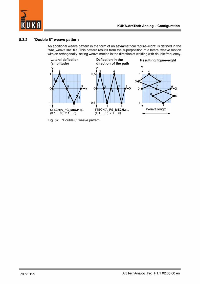
KUKA.ArcTech Analog -- Configuration
76 of 125 ArcTechAnalog_Pro_R1.1 02.05.00 en
8.3.2 “Double 8” weave pattern
An additional weave pattern in the form of an asymmetrical “figure--eight” is defined in the“Arc_weave.src” file. This pattern results from the superposition of a lateral weave motionwith an orthogonally--acting weave motion in the direction of welding with double frequency.
0 1
--0,5
0,5
Y Y
0 X
--1
1
X
$TECH[A_FG_ ]...(X 1 ... 6 ; Y 1 ... 6)
MECH1 $TECH[A_FG_ ]...(X 1 ... 6 ; Y 1 ... 6)
MECH2
--1
1
Y
0 X
2
3
4
5
6
7
8
91
2
3
4
5
6
7
8
91
23
4
5
6
7
8
9
Lateral deflection(amplitude)
Deflection in thedirection of the path
Resulting figure--eight
Weave length
Fig. 32 “Double 8” weave pattern

8 Mechanical weaving (continued)
77 of 125ArcTechAnalog_Pro_R1.1 02.05.00 en
8.4 Changing and creating patterns for mechanical weaving
User--defined weave patterns are possible in “Arc_weave.src” and can be programmeddirectly on the user interface (Listbox--Inhalt_Anw.Def).
8.4.1 Changing existing weave patterns
You can adapt the weave patterns defined in the “Arc_weave.src” file to your ownrequirements by changing the number of control points and their parameters.
You want to shift the “Triangle” pattern -- contained in the “Arc_weave.src” file -- by 180° inthe phase angle. This might be necessary as a result of the combined application ofmechanical and thermal weaving.
The settings for the “Triangle” weave pattern are contained in the “Arc_weave.src” file:
CASE 1 ;triangleIF A_FG_MECH1>0 THEN$TECH[A_FG_MECH1].FCT.ORDER=1$TECH[A_FG_MECH1].FCT.CPNUM=4$TECH[A_FG_MECH1].FCT.CPS1.X1=0.0$TECH[A_FG_MECH1].FCT.CPS1.Y1=0.0$TECH[A_FG_MECH1].FCT.CPS1.X2=0.25$TECH[A_FG_MECH1].FCT.CPS1.Y2=1.0$TECH[A_FG_MECH1].FCT.CPS1.X3=0.75$TECH[A_FG_MECH1].FCT.CPS1.Y3=-1.0$TECH[A_FG_MECH1].FCT.CPS1.X4=1.0$TECH[A_FG_MECH1].FCT.CPS1.Y4=0.0ENDIF
This is shown graphically in Fig. 33.
1
--1
0.00.25 0.5 0.75 1.0
X
Y2
1
=n
3
4
Control points (CPNUM)
Fig. 33 Changing an existing weave pattern

KUKA.ArcTech Analog -- Configuration
78 of 125 ArcTechAnalog_Pro_R1.1 02.05.00 en
In order to achieve a phase shift of 180°, it is merely necessary to change the parametersfor control points Y2 and Y3. The required changes have been made in the following list andare underlined for ready identification.
CASE 1 ;triangle (phi = 180 degrees)IF A_FG_MECH1>0 THEN$TECH[A_FG_MECH1].FCT.ORDER=1$TECH[A_FG_MECH1].FCT.CPNUM=4$TECH[A_FG_MECH1].FCT.CPS1.X1=0.0$TECH[A_FG_MECH1].FCT.CPS1.Y1=0.0$TECH[A_FG_MECH1].FCT.CPS1.X2=0.25$TECH[A_FG_MECH1].FCT.CPS1.Y2=-1.0$TECH[A_FG_MECH1].FCT.CPS1.X3=0.75$TECH[A_FG_MECH1].FCT.CPS1.Y3=1.0$TECH[A_FG_MECH1].FCT.CPS1.X4=1.0$TECH[A_FG_MECH1].FCT.CPS1.Y4=0.0ENDIF
1
--1
0.00.25 0.5 0.75 1.0
X
Y
1
=n
3
4
2
Control points (CPNUM)
Fig. 34 Changing an existing weave pattern
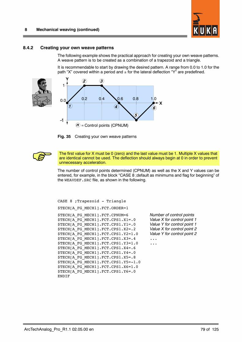
8 Mechanical weaving (continued)
79 of 125ArcTechAnalog_Pro_R1.1 02.05.00 en
8.4.2 Creating your own weave patterns
The following example shows the practical approach for creating your own weave patterns.A weave pattern is to be created as a combination of a trapezoid and a triangle.
It is recommendable to start by drawing the desired pattern. A range from 0.0 to 1.0 for thepath “X” covered within a period and ± for the lateral deflection “Y” are predefined.
1
--1
0.0 0.4X
Y 32
=n
41
5
6
0.60.2 0.8 1.0
Control points (CPNUM)
Fig. 35 Creating your own weave patterns
The first value for X must be 0 (zero) and the last value must be 1. Multiple X values thatare identical cannot be used. The deflection should always begin at 0 in order to preventunnecessary acceleration.
The number of control points determined (CPNUM) as well as the X and Y values can beentered, for example, in the block “CASE 8 ;default as minimums and flag for beginning” ofthe WEAVDEF.SRC file, as shown in the following.
CASE 8 ;Trapezoid - Triangle
$TECH[A_FG_MECH1].FCT.ORDER=1
$TECH[A_FG_MECH1].FCT.CPNUM=6 Number of control points$TECH[A_FG_MECH1].FCT.CPS1.X1=.0 Value X for control point 1$TECH[A_FG_MECH1].FCT.CPS1.Y1=.0 Value Y for control point 1$TECH[A_FG_MECH1].FCT.CPS1.X2=.2 Value X for control point 2$TECH[A_FG_MECH1].FCT.CPS1.Y2=1.0 Value Y for control point 2$TECH[A_FG_MECH1].FCT.CPS1.X3=.4 ...$TECH[A_FG_MECH1].FCT.CPS1.Y3=1.0 ...$TECH[A_FG_MECH1].FCT.CPS1.X4=.6$TECH[A_FG_MECH1].FCT.CPS1.Y4=.0$TECH[A_FG_MECH1].FCT.CPS1.X5=.8$TECH[A_FG_MECH1].FCT.CPS1.Y5=-1.0$TECH[A_FG_MECH1].FCT.CPS1.X6=1.0$TECH[A_FG_MECH1].FCT.CPS1.Y6=.0ENDIF
KUKA.ArcTech Analog -- Configuration
80 of 125 ArcTechAnalog_Pro_R1.1 02.05.00 en
8.5 Notes on mechanical weaving
The quality of a seam welded with mechanical weaving is influenced by a variety of physicaland mechanical factors, such as the mechanical play in the gears, axis torsion, robotposition, path tangent, etc. In addition, interdependencies with the interpolation cycle as wellas the set robot--specific $Filter value also exist.
The weavemotion is superposed on the path motion. In the case of weave patterns such as“Trapezoid” or “Spiral”, this leads to an irregular welding speed during a period. This can varybetween the set path velocity and a multiple of it, depending on the relation of the weavelength (frequency) to the lateral deflection (amplitude).
The maximum weave frequency for mechanical weaving is – depending on the robot typeconcerned – influenced by several factors, for example by the resonant frequency of the“robot/tool” mechanical unit. Weave frequencies of up to 3 Hz (corresponding, for example,to a weave length of 3.33 mm at a travel speed of 0.6 m/min) are possible without causingproblems, according to previous experience.
With higher weave frequencies, undesirable effects are liable to result under certaincircumstances (depending on the tool design and/or tool orientation). With weavefrequencies > 4 Hz, the motion characteristics of the robot should therefore be individuallytested in each case.

8 Mechanical weaving (continued)
81 of 125ArcTechAnalog_Pro_R1.1 02.05.00 en
8.5.1 Weave frequency, weave length, path velocity (travel speed)
Of significance for the correct functioning of the robot is the weave frequency, whichresults from the programmed path velocity (travel speed) and the weave length. Thefollowing relationships exist between these parameters:
Weave frequency f =
Weave length s =
Path velocity v =
Path velocity [m/min] ¯ 1000Weave length [mm] ¯ 60
[Hz]
Path velocity [m/min] ¯ 1000Weave frequency [Hz] ¯ 60
Weave frequency [Hz] ¯Weave length [mm] ¯ 601000
[mm]
[m/min] *)
Fig. 36 Weave frequency -- Weave length -- Weld velocity
These relationships are depicted graphically in the nomogram shown in Fig. 37.
0 0.5 1.0 1.5 2.0Weld velocity v m/min *)
0
5
10
Weave length s[mm]
3.5
6.5
5.0
4.0
3.02.52.01.51.0 1.250.750.50.3
Non--permissible range
.1
11
1.5
.1.2
12
.2.3
3
.3.4
4
.4.6
6
.6.7
7
.7.8
8
.8.9
9
.9
For weave frequencies > 4 Hz,see explanation in text.
2
Weave frequency f[Hz]
Fig. 37 Relationship between weave frequency -- weave length -- weld velocity
*) Theweld velocity can also be entered in the inline forms in inch/min (after consultation withKUKA). The unit m/min is always used for internal storage and calculations, however.

KUKA.ArcTech Analog -- Configuration
82 of 125 ArcTechAnalog_Pro_R1.1 02.05.00 en
8.5.2 Rotation of the weave plane
In certain applications it may be necessary to rotate the weave plane (e.g. to improve thedistribution of heat). The range of possible settings is --180 to +180 degrees, so the weavepattern can start on either the left--hand or right--hand side of the path.
Weave angle 0 degrees
Torch
Weave plane(weave angle)Component
plane
90 degrees
Torch planeWeave amplitude
Mechanical weaving
Weave Angle
Fig. 38 Rotation of the weave plane

8 Mechanical weaving (continued)
83 of 125ArcTechAnalog_Pro_R1.1 02.05.00 en

KUKA.ArcTech Analog -- Configuration
84 of 125 ArcTechAnalog_Pro_R1.1 02.05.00 en
9 Thermal weaving
Thermalweavingmaynotbeused in conjunctionwith the “KUKA.ArcSense” through--the--arc tracking sensor option.
9.1 Fundamentals
In conventional welding processes, the values for the weld voltage and the wire feed rateremain constant. Thermal weaving can be used for certain applications. The weld voltageand the wire feed rate are periodically and synchronously altered in this instance, thusproducing a seam with weld metal that varies periodically according to these changes.
The robot--specific “Thermal weaving” mode has nothing in common with the “Pulsing”option offered by welding equipment.
A precondition for the “Thermal weaving” function is that the value of the variableA_TH_WEAVE_OPT is set to TRUE.
Variable Value Characteristics
FALSE Thermal weaving deactivated (default).
A_TH_WEAVE_OPTTRUE
Thermal weaving activated. The parameter listis expanded to include the page: Thermalweaving settings, Analog channels, Weavelength, and Weave pattern.
In order to ensure synchronization betweenmechanical and thermal weaving, the variable$TECH_ANA_OFF[B] must be set to TRUE in \STEU\MADA\$CUSTOM.DAT.
9.1.1 Weave patterns
Two patterns (triangle and trapezoid) are predefined by themanufacturer, with the possibilityof two further user--defined patterns. These are defined in the parameter list (thermalweaving) under the settings
G Usr. def. pattern 1
G Usr. def. pattern 2

9 Thermal weaving (continued)
85 of 125ArcTechAnalog_Pro_R1.1 02.05.00 en
Weld direction Weld direction
Weld direction Weld direction
Max. feed(setting in“Wn”, page 1)
Min. feed(setting in“Wn”, page 3)
Wire feed(inches/minute)
Max. feed(setting in“Wn”, page 1)
Min. feed(setting in“Wn”, page 3)
Wire feed(inches/minute)
Length(1 period)
Length(1 period)Weld voltage
(volts)Weld voltage
(volts)
Max. voltage(setting in“Wn”, page 1)Min. voltage(setting in“Wn”, page 3)
Max. voltage(setting in“Wn”, page 1)
Min. voltage(setting in“Wn”, page 3)
Thermal weaving
Trapezoid(Trapezoid)
Triangle(Triangle)
Fig. 39 Thermal weaving

KUKA.ArcTech Analog -- Configuration
86 of 125 ArcTechAnalog_Pro_R1.1 02.05.00 en
9.1.2 Example of a signal diagram
Weld parameters
Voltage setpoint value
Gas flow
Weld start
Current flowing
Wire feed setpoint value
Weld data set 1 Weld data set 2
Ignition parameters
(Thermal weaving)(default)
Fig. 40 Example of signal flow diagram
9.2 Combined mechanical and thermal weaving
Mechanical and thermal weaving can be combined for use together. With the same weavelength (frequency), the function generators for mechanical weaving and the periodic changeof the weld voltage and wire feed have synchronous phases.
9.2.1 Combination possibilities
By defining the control point coordinates X and Y in the file WEAV_DEF.SRC as the situationrequires, you candefine any phase shift and relationship you desire between the frequencies(weave lengths) for mechanical and thermal weaving.
Two combination possibilities are shown in Fig. 41. In the combination shown in diagram a),the frequency and the phase angle for mechanical and thermal weaving are the same. Indiagram b), the frequency for thermal weaving is double the mechanical weave frequency,and the phase relation is 270° (--90°).

9 Thermal weaving (continued)
87 of 125ArcTechAnalog_Pro_R1.1 02.05.00 en
(1.0) (1.0)
(--1.0) (--1.0)
(0.0) (0.0)X
X
X
X
X
X
Y Y
Y (1.0)
Y (1.0)
--Y (--1.0)
--Y (--1.0)
i
Y (1.0)
--Y (--1.0)
--Y --Y
(0°) (0°)
(0°) (0°)
(-- 90°)
a) Combination with the same frequency(weave length) and phase angle
b) Combination with different frequencyand phase angle
Mechanicalweaving
Mechanicalweaving
Thermal weavingDouble frequency (half mechanical weavelength), phase angle 270° (--90°)
Weld voltage(volts)
Max. voltage
Min. voltage
Weld voltage
Max. voltage
Min. voltage
(volts)
Wire feed(inches/minute)
Max. feed
Min. feed
Y (1.0)
--Y (--1.0)
Wire feed(inches/minute)
Max. feed
Min. feed
Direction of path(X axis)
Direction of path(X axis)
Thermal weavingSame frequency (weavelength), same phase angle
Weavelength
Weave plane Weave plane(1 period) (1 period)
Fig. 41 Examples of combining mechanical and thermal weaving

KUKA.ArcTech Analog -- Configuration
88 of 125 ArcTechAnalog_Pro_R1.1 02.05.00 en
9.2.2 Practical application possibilities (examples)
Fig. 42 shows thepractical application of combined triangular and trapezoidal weaving takenfrom the lefthand side in the example above. By synchronizing the mechanical and thermalweave curves, the weld voltage and the wire feed rate are greater on the side of the thickersheet than on that of the thin sheet.
+
--
Max. voltage,max. wire feed
Min. voltage,min. wire feed
Mechanical weavingThermal weaving
Mechanical: Triangle ϕ = 0°Thermal: Triangle ϕ = 0°
Trapezoid ϕ = 0°Trapezoid ϕ = 0°
Max. voltage,max. wire feed
Min. voltage,min. wire feed
Fig. 42 Combining triangular and trapezoidal weaving
If the phase of the thermal weave curve is shifted by 180° in relation to themechanicalweavecurve, the combination shown in Fig. 43 will result:
+
--
Max. voltage,max. wire feed
Min. voltage,min. wire feed
Mechanical weavingThermal weaving
Mechanical: Triangle ϕ = 180°Thermal: Triangle ϕ = 0°
Trapezoid ϕ = 180°Trapezoid ϕ = 0°
Fig. 43 Combining triangular and trapezoidal weaving
Here, either the thermal weave curve or the mechanical weave curve can be changed in the“WEAV_DEF.SRC” file.
Fig. 44 shows another possible combination.

9 Thermal weaving (continued)
89 of 125ArcTechAnalog_Pro_R1.1 02.05.00 en
+
00
Max. voltage,max. wire feed Max. voltage,
max. wire feed
Max. voltage,max. wire feedMin. voltage,
min. wire feed
Min. voltage,Min. wirefeed
Mechanical weavingThermal weaving
Mechanical: Triangle ϕ = 0°Thermal: Double triangle ϕ = 270°
Trapezoid ϕ = 0°Double triangle ϕ = 270°
Fig. 44 Combining triangular and trapezoidal weaving
Compared to themechanical weave frequency, the thermal weave frequency is twice as highand shifted in phase by 270° ⟨--90°). In this way, the weld voltage and wire feed rate changein the course of one period according to the curves shown. In the areas of maximummechanical lateral deflection, welding is executed using the parameters entered in theW--parameter list 1/4 “Primary Weld” (max. voltage and wire feed) whereas the parametersentered in theW--parameter list 3/4 “ThermalWeaving” (min. voltageandwire feed) are usedin the area of the weld root.
Fig. 45 shows another example in which the thermal weave frequency is twice as high as themechanical weave frequency and shifted in phase by 90°.
+
--
0 0
Max. voltage,max. wire feed
Min. voltage,min. wire feed
Min. voltage,min. wire feed
Min. voltage,min. wire feed
Max. voltage,Max. wirefeed
Mechanical weavingThermal weaving
Mechanical: Triangle ϕ = 0°Thermal: Double triangle ϕ = 90°
Trapezoid ϕ = 0°Double triangle ϕ = 90°
Fig. 45 Combining triangular and trapezoidal weaving
In the area of the weld root, welding is executed using the parameters entered in theW--parameter list 1/4 “Primary Weld” (max. voltage and wire feed), while the parametersentered in theW--parameter list 3/4 “ThermalWeaving” (min. voltageandwire feed) are usedin the areas of maximum mechanical lateral deflection.

KUKA.ArcTech Analog -- Configuration
90 of 125 ArcTechAnalog_Pro_R1.1 02.05.00 en
10 “KUKA.ArcTech Analog” settings
10.1 Power source characteristic settings
INT A_ACT_AN_MAX=2 ;Maximum of analog channels to see parameterlists
In the following section, the setting A_ACT_AN_MAX=2 (default setting) is assumed.The characteristic curves are assumed to be linear. These are configured identically for bothPULSE and MIGMAG.
DECL INT A_ANA_MAX_D[2,8];maximum number of points to define a controller line
A_ANA_MAX_D[1,1]=2 (DEFAULT)A_ANA_MAX_D[1,2]=2 (DEFAULT)
A_ANA_MAX_D[2,1]= 2 (DEFAULT)A_ANA_MAX_D[2,2]= 2 (DEFAULT)
DECL A_ANA_DEF_T A_ANA_DEF[2,8,5];WELD_Mode,Channel,Points of controller line 1:pulse/2:MigMag;Mode1 Channel1 command value
A_ANA_DEF[1,1,1]={PARA 0.0,VAL 0.0}; 0..80 voltsA_ANA_DEF[1,1,2]={PARA 80.0,VAL 1.0};Mode1 Channel2 wire feed [m/min]A_ANA_DEF[1,2,1]={PARA 0.0,VAL 0.0} ;0..25 m/minA_ANA_DEF[1,2,2]={PARA 25.0,VAL 1.0};Mode2 Channel1 command valueA_ANA_DEF[2,1,1]={PARA 0.0,VAL 0.0};0..80 voltsA_ANA_DEF[2,1,2]={PARA 80.0,VAL 1.0};Mode2 Channel2 wire feed [m/min]
A_ANA_DEF[2,2,1]={PARA 0.0,VAL 0.0};0..25 m/minA_ANA_DEF[2,2,2]={PARA 25.0,VAL 1.0}
$config.dat

10 “KUKA.ArcTech Analog” settings (continued)
91 of 125ArcTechAnalog_Pro_R1.1 02.05.00 en
10.2 Configuration of the physical interface ($CONFIG.DAT)
10.2.1 Physical outputsIO-Mapping of physical outputsDECL CTRL_OUT_T A_WLD_OUT[16]
A_WLD_OUT[1]={OUT_NR 33,INI FALSE,NAME_NAT[] ”WELD_START ”}A_WLD_OUT[2]={OUT_NR 34,INI FALSE,NAME_NAT[] ”GAS PREFLOW ”}A_WLD_OUT[3]={OUT_NR 0,INI FALSE,NAME_NAT[] ”WELD_MODE PS/MM ”}A_WLD_OUT[4]={OUT_NR 0,INI FALSE,NAME_NAT[] ”CLEANER ”}A_WLD_OUT[5]={OUT_NR 0,INI FALSE,NAME_NAT[] ”RECEIPT ERRORS ”}A_WLD_OUT[6]={OUT_NR 0,INI FALSE,NAME_NAT[] ”ERR MESSG_SIGNAL”}A_WLD_OUT[7]={OUT_NR 0,INI FALSE,NAME_NAT[] ”START ERROR ”}A_WLD_OUT[8]={OUT_NR 0,INI FALSE,NAME_NAT[] ”APPL_ERROR ”}A_WLD_OUT[9]={OUT_NR 0,INI FALSE,NAME_NAT[] ”INTERPRETER-STOP”}A_WLD_OUT[10]={OUT_NR 0,INI FALSE,NAME_NAT[] ” ”}A_WLD_OUT[11]={OUT_NR 0,INI FALSE,NAME_NAT[] ” ”}A_WLD_OUT[12]={OUT_NR 0,INI FALSE,NAME_NAT[] ” ”}A_WLD_OUT[13]={OUT_NR 0,INI FALSE,NAME_NAT[] ” ”}A_WLD_OUT[14]={OUT_NR 0,INI FALSE,NAME_NAT[] ” ”}A_WLD_OUT[15]={OUT_NR 0,INI FALSE,NAME_NAT[] ”WFD + ”}A_WLD_OUT[16]={OUT_NR 0,INI FALSE,NAME_NAT[] ”WFD - ”}
10.2.2 Configuration of the physical inputsRelating to this configuration (only the current is monitored!)
DECL FCT_IN_T A_FLT_CYCFLG[4]
A_FLT_CYCFLG[1]={NO 13,STATE TRUE } ;e.g. collection failureA_FLT_CYCFLG[2]={NO 2,STATE TRUE} ;e.g. currentA_FLT_CYCFLG[3]={NO 11,STATE TRUE} ;e.g. gasA_FLT_CYCFLG[4]={NO 10,STATE TRUE} ;e.g. water
Configuration of error collection as indication of operational readiness, of current flow for startof robot motion, and of seam fault.
;FOLD IO-Mapping of physical inputsDECL CTRL_IN_T A_WLD_IN[16]
A_WLD_IN[1]={IN_NR 33,NAME_NAT[] ”WELDER READY ”}A_WLD_IN[2]={IN_NR 34,NAME_NAT[] ”ARC ESTABLISHED ”}A_WLD_IN[3]={IN_NR 0,NAME_NAT[] ”
”}A_WLD_IN[4]={IN_NR 0,NAME_NAT[] ”CURRENT OVER ”}A_WLD_IN[5]={IN_NR 0,NAME_NAT[] ”KEY SWITCH HOT/COLD ”}A_WLD_IN[6]={IN_NR 0,NAME_NAT[] ” ”}A_WLD_IN[7]={IN_NR 0,NAME_NAT[] ”BURN FREE INP_SIGNAL”}A_WLD_IN[8]={IN_NR 0,NAME_NAT[] ” ”}A_WLD_IN[9]={IN_NR 0,NAME_NAT[] ” ”}A_WLD_IN[10]={IN_NR 0,NAME_NAT[] ”WATER AVAILABLE ”}A_WLD_IN[11]={IN_NR 0,NAME_NAT[] ”GAS AVAILABLE ”}A_WLD_IN[12]={IN_NR 0,NAME_NAT[] ”WIRE AVAILABLE ”}A_WLD_IN[13]={IN_NR 0,NAME_NAT[] ”COLLECTION FAILURE ”}A_WLD_IN[14]={IN_NR 0,NAME_NAT[] ” ”}A_WLD_IN[15]={IN_NR 0,NAME_NAT[] ” ”}A_WLD_IN[16]={IN_NR 0,NAME_NAT[] ” ”}
KUKA.ArcTech Analog -- Configuration
92 of 125 ArcTechAnalog_Pro_R1.1 02.05.00 en
10.3 Settings in the file A10.DAT
Settings for COLD START
BOOL RE_INITIALIZE=TRUE
;TRUE: TPARC.DLL forced to new initialization MIN/MAX and control-ler line parameters
Units and increments in the parameter lists:
CHANNEL_INFO[1]={UNIT[] ”volts”,STEP[] ”0.1”}CHANNEL_INFO[2]={UNIT[] ”m/min”,STEP[] ”0.1”}
After the above settings have beenmade, the HMI has to be reinitialized or a cold start hasto be forced.

10 “KUKA.ArcTech Analog” settings (continued)
93 of 125ArcTechAnalog_Pro_R1.1 02.05.00 en

KUKA.ArcTech Analog -- Configuration
94 of 125 ArcTechAnalog_Pro_R1.1 02.05.00 en
11 Default data sets, resource distribution
11.1 Setting the default data sets
In the case of an ignition data set, programming is carried out via an ARC_ON command inwhich the name “DEFAULT” is entered instead of data set “S”. In the case of weld data setsor enddata sets, this name is to beused in theARC_OFForARC_SWI command. If changesare made here, the data sets in the $CONFIG.DAT file listed below are also modified.
Advantage of this procedure: as soon as a new program is generated, the data manipulatedhere are preset with exactly these values. The power source and welding wire diameter canbe adapted.
The following data can, of course, also be changed directly in the $CONFIG.DAT file.
Ignition DEFAULT data set
DECL A_STRT_T A10BDEFAULT={GAS_PRE_T 0.1,START_T 0.2,ANA124.0,ANA2 450.0,ANA3 0.0,ANA4 0.0,ANA5 0.0,ANA6 0.0,ANA70.0,ANA8 0.0}
End DEFAULT data set
DECL A_END_T A10EDEFAULT={END_TI 0.1,BURNBACK_T 0.05,GAS_POST_T0.2,ANA1_E 22.0,ANA2_E 400.0,ANA3_E 0.0,ANA4_E 0.0,ANA5_E0.0,ANA6_E 0.0,ANA7_E 0.0,ANA8_E 0.0}
Weld DEFAULT data set
DECL A_WELD_T A10WDEFAULT={VEL 0.5,ANA1 22.5,ANA2 430.0,ANA30.0,ANA4 0.0,ANA5 0.0,ANA6 0.0,ANA7 0.0,ANA8 5.0,WEAVFIG_MECH’H0’,WEAVLEN_MECH 14.0,WEAVAMP_MECH 2.0,WEAVANG_MECH 0.0,WEAV-FIG_THER ’H0’,ANA1_THERM 0.0,ANA2_THERM 0.0,WEAVLEN_THER4.0,BURNBACK_T 0.3

11 Default data sets, resource distribution (continued)
95 of 125ArcTechAnalog_Pro_R1.1 02.05.00 en
11.2 KUKA.ArcTech Analog resource distribution
The resources described in Sections 11.2.2, 11.2.3 and 11.2.4 can be customized.
11.2.1 Interrupt definitions at R1 level (all ARC versions)
;FOLD ARCTECH ANALOG_INIIF A10_OPTION==#ACTIVE THENINTERRUPT DECL A_Arc_Control_Intr WHEN
$CYCFLAG[A_CycFlagIndex1]==FALSE DO A10 (#APPL_ERROR)INTERRUPT DECL A_Arc_Swi_Intr WHEN A_ARC_SWI==#ACTIVE
DO A10 (#ARC_SEAM)INTERRUPT DECL A_Arc_HPU_Intr WHEN A_FLY_ARC==TRUE
DO A10 (#HPU_ARC)INTERRUPT ON A_Arc_HPU_IntrA10_INI ( )ENDIF;ENDFOLD (ARCTECH ANALOG_INI)
11.2.2 $CYCFLAG indices
CycFlagIndex1=2 ;indexed cycflagsINT A_CycFlagindex2=4 Seam fault monitoringINT A_CycFlagIndex3=5 Seam fault monitoring
11.2.3 $TIMER indices
TimerIndex1=15 Ignition process monitoringINT A_TimerIndex2=16 Gas postflow monitoring
11.2.4 Interrupt indices
INT A_Arc_Control_Intr=4 ;ISR index Seam controlINT A_Arc_Swi_Intr=7 ;ISR index Arc_SWI commandINT A_Arc_HPU_Intr=5 ;ISR index HPU Statuskey
ProgramFOLD “INI”
$config.dat
$config.dat
$config.dat

KUKA.ArcTech Analog -- Configuration
96 of 125 ArcTechAnalog_Pro_R1.1 02.05.00 en
12 Fault situations and fault service functionsIf a weldingor robot fault occurs during ignition or welding, theweldingprocess is interrupted.Due to the variety of causes and types of faults, different fault service functions are required.In addition to the standard measures included in the technology package, the user canconfigure fault service functions tailored to specific requirements.
Types of faults and causes
A distinction is made between application--specific seam faults caused by peripheralequipment and faults attributable to the robot controller (e.g. IR_STOPMESS faults).
The possible causes of faults may be, for example:
G Ignition and seam faults resulting from unreliable operating states of the torch and/orwelding equipment;
G Media faults (e.g. shielding gas, welding wire, cooling);
G Ignition and seam faults resulting from workpiece characteristics (dirt, gap, etc.);
G Controller faults (e.g. IR_STOPMESS faults, EMERGENCY STOP actuation);
G Operator control function “Interpreter STOP”
12.1 Ignition faults
12.1.1 Configuration: number of permissible ignition attempts ($CONFIG.DAT)
Variable Value Characteristics
A_MAX_RETRY 3 (default) Number of ignition attempts before an ac-knowledgement message is generated
12.1.2 Setting the ignition fault option ($CONFIG.DAT)
Variable Value Characteristics
#RESTART (default)
The ignition process is repeated with the torchposition unchanged and with the same startparameters until either ignition is successfulor the value programmed in A_MAX_RETRY(default: 3) is reached.
A_S_ERR_OPT
#USR_START
In accordance with the procedure defined inFLT_SERV.SRC, the torch moves away fromthe component between ignition attempts untileither ignition is successful or the value pro-grammed in A_MAX_RETRY (default: 3) isreached.
A statusmessage appears in themessagewindowafter every ignition attempt. If the numberof ignition attempts (value defined in A_MAX_RETRY) is exceeded, an acknowledgementmessage appears.
12 Fault situations and fault service functions (continued)
97 of 125ArcTechAnalog_Pro_R1.1 02.05.00 en
12.1.3 Special features of user--defined ignition fault service functions (#USR_START)
The fault service function #USR_START is used to call up the fault routine programFLT_SERV.SRC, which then calls up specific fault service functions.
The selection of the fault service function to be used is made in the file $CONFIG.DAT bymeans of the variable “A_FLT_SV_FCT” (default setting: 0):
INT A_FLT_SV_FCT=0 ; Number of user-defined FLT_SERV subroutine
Variable Value Characteristics
A_FLT_SV_FCT 0 (default) Definition of the fault service function
The entry A_FLT_SV_FCT=0 corresponds to the “CASE 0” fault service function in theFLT_SERV.SRC file. This procedure is suitable, for instance, for cutting through insulatingoxide layers (for example during aluminum welding) when the wire contacts the workpiecein order to allow a fault--free ignition process in a restart.
SWITCH A_FLT_SV_FCT;===========================================; FAULT SERVICE FUNCTION (additional START-Error );===========================================
CASE 0IF A10_OPTION ==#ACTIVE THENIF ARC_ON_FLT==#ACTIVE THEN
MOVE_TCP ({X --20.0,Y 0.001,Z 0.001} )IF ((A_RETRY_COUNT< A_MAX_RETRY) OR (A_S_ERR_OPT<>#USR_START))
THENMOVE_TCP ({X 20.0,Y --0.001,Z --0.001} )ENDIF
ELSEMOVE_TCP ({X -20.0,Y 0.001,Z 0.001} )
ENDIFENDIF
;*****************; local subroutine;*****************
DEF MOVE_TCP (TCP_IN :IN )
DECL TCP_TYP TCP_IN
F=$NULLFRAMEF.X=TCP_IN.XF.Y=TCP_IN.YF.Z=TCP_IN.Z
LIN $POS_ACT:F
END

KUKA.ArcTech Analog -- Configuration
98 of 125 ArcTechAnalog_Pro_R1.1 02.05.00 en
The following illustration shows the mode of operation.
MOVE _TCP({X-20.0,Y1.0,Z1.0}) LIN POS_RET
X
X
*) Depending on the position of theX axis in the tool coordinate system
*)*) *)
Gas nozzle axis
Allow clearance frompossible obstacles!
Fig. 46 Fault service function -- torch retraction
If this fault service function is implemented, it is essential to make sure that thereis sufficient clearance for the torch to be retracted.If this is not possible, reduce the distance “X” accordingly -- MOVE_TCP ({X -20.0,Y1.0,Z 1.0} ).
When torch angles are measured, the position of the gas nozzle axis (tip of the torch) isthe crucial value for establishing a proper reference plane (important, for example, inmechanical weaving).
The toolmust becalibrated in such away that thecurrent nozzlewith theprotrudingwire corresponds to the+Xdirection in the tool coordinatesystem.Otherwise, thereis the risk of a collision with the workpiece.
12.1.4 Ignition fault signals
Output group Meaning
A_O_FLT_SIGN[ ] Signal to the PLC in the event of a seamfault or ignition fault. (max. 1 output)
A_O_FLT_ON[ ] Signal to the PLC in the event of an ignitionfault (max. 3 outputs)
A_O_ACK_FLT[ ] Acknowledgement signal to the peripherybefore repetition of the ignition process

12 Fault situations and fault service functions (continued)
99 of 125ArcTechAnalog_Pro_R1.1 02.05.00 en
12.2 Media faults of periphery faults
Seam faults are application--specific faults. Monitoring devices in the peripheral equipmentand robot controller recognize incorrect function sequences (for example, an interruption intheweld current) and generate the corresponding fault signals that are then evaluated by therobot controller.
During the initialization phase, the corresponding CYCFLAGS are activated in theARC_INIT command. By means of this routine, whose mode of operation is comparable tothat of anautonomous programmable controller, theweldingprocess is constantlymonitoredfollowing proper ignition and a delay time set with the variable A_CTRL_DELAY.
Variable Value
A_CTRL_DELAY 1200 ms (default) Monitoring delay
12.2.1 Configuring the monitoring functions
The following configuration example shows the assignment of A_FLT_CYCFLG[1]...[4]to the input table (digital inputs). In this example the following peripheral interface signals aremonitored:
-- Group fault
-- Current fault
-- Gas fault
-- Water fault
Configuration: Monitoring functions
DECL FCT_IN_T A_FLT_CYCFLG[4]
A_FLT_CYCFLG[1]={NO 13,STATE TRUE} ;e.g. group faultA_FLT_CYCFLG[2]={NO 2,STATE TRUE} ;e.g. currentA_FLT_CYCFLG[3]={NO 11,STATE TRUE} ;e.g. gasA_FLT_CYCFLG[4]={NO 10,STATE TRUE} ;e.g. water
DECL CTRL_IN_T A_WLD_IN[16]
A_WLD_IN[2]={IN_NR 0,NAME_NAT[] “ARC ESTABLISHED “}A_WLD_IN[10]={IN_NR 0,NAME_NAT[] “WATER AVAILABLE “}A_WLD_IN[11]={IN_NR 0,NAME_NAT[] “GAS AVAILABLE “}A_WLD_IN[13]={IN_NR 0,NAME_NAT[] “GROUP FAULT “}
The available peripheral interface signals depend on the type of welding controller being used.The entered signal states (STATE “TRUE” or “FALSE”) must each correspond to the set“GOOD” status that exists during troublefree operation.

KUKA.ArcTech Analog -- Configuration
100 of 125 ArcTechAnalog_Pro_R1.1 02.05.00 en
12.2.2 Ignoring temporary interrupts (A_SWINDL_OPT)
Another configurable option, A_SWINDL_OPT, allows you to ignore temporary interruptionsin current, such as those that can occur during “harsh” welding operations (for example, inCO2 processes). After the time elapses that has been set with A_SWINDL_TIM, the state ofthe $CYCFLAG is read again. If the fault state still exists after this set time, the deactivationprocedure is executed. Otherwise the process is continued.
Configuration using the menu function Monitor - Variable - Modify
($CONFIG.DAT):
Variable Value Characteristics
A_SWINDL_OPT #ACTIVE (default) #IDLE = deactivated
A_SWINDL_TIM 0.05 (default) Wait time in seconds
The toolmust becalibrated in such away that thecurrent nozzlewith theprotrudingwire corresponds to the+Xdirection in the tool coordinatesystem.Otherwise, thereis the risk of a collision with the workpiece.
12.3 Robot faults (IR_STOPMESS faults)
This term refers to all faults triggered by the robot system itself. Examples include:
G Drives OFF
G Operating mode switchover
G Enabling switches
G EMERGENCY STOP
G Faulty program (e.g. division by 0)
Voltage dips in the mains voltage supply are also monitored using this interrupt routine.
12.3.1 Deactivation
Once the robot fault is detected, the fault signal A_O_FLT_SIGN[ ] is set during welding.If a torch cleaning process activated by the flag A_CLEANER=#ACTIVE is detected at thesame time, this is deactivated in accordance with the signal group A_O_FLT_APPL[ ].
The current is disconnected, shielding gas continues to flow and the mechanical weaving isinterrupted. The fault signal A_O_FLT_APPL[ ] is also set (only in the case of hot welding).
The weld fault counter is incremented and an error message is generated; this message isdeleted once it has been manually acknowledged. A_O_ACK_FLT[ ] also triggers anacknowledgement pulse and repositions the robot to $POS--RET.
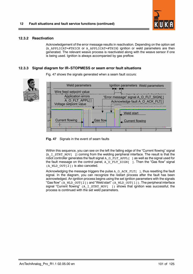
12 Fault situations and fault service functions (continued)
101 of 125ArcTechAnalog_Pro_R1.1 02.05.00 en
12.3.2 Reactivation
Acknowledgement of the error message results in reactivation. Depending on the option set(A_APPLICAT=#THICK or A_APPLICAT=#THIN) ignition or weld parameters are thengenerated. The relevant weave process is reactivated along with the weave sensor if oneis being used. Ignition is always accompanied by gas preflow.
12.3.3 Signal diagram for IR--STOPMESS or seam error fault situations
Fig. 47 shows the signals generated when a seam fault occurs:
Voltage setpoint value
Wire feed setpoint value
Weld parameters
Gas flowCurrent flowing
Weld start
Current flowing
“Error message” signal A_O_FLT_SIGN[ ]
Weld parameters Ignition parameters
Application errors
Acknowledge fault A_O_ACK_FLT[ ]A_O_FLT_APPL[ ]
Fig. 47 Signals in the event of seam faults
Within this sequence, you can see on the left the falling edge of the “Current flowing” signal(A_I_STRT_MOV[ ]) coming from the welding peripheral interface. The result is that therobot controller generates the fault signal A_O_FLT_APPL[ ] as well as the signal used forthe fault message on the control panel, A_O_FLT_SIGN[ ]. Then the “Gas flow” signal(A_WLD_OUT[2]) is also canceled.
Acknowledging the message triggers the pulse A_O_ACK_FLT[ ], thus resetting the faultsignal. In the diagram, you can recognize the restart process after the fault has beenacknowledged. An ignition process begins using the set ignition parameters with the signals“Gas flow” (A_WLD_OUT[2]) and “Weld start” (A_WLD_OUT[1]). The peripheral interfacesignal “Current flowing” (A_I_STRT_MOV[ ]) shows that ignition was successful; theprocess is continued with the set weld parameters.

KUKA.ArcTech Analog -- Configuration
102 of 125 ArcTechAnalog_Pro_R1.1 02.05.00 en
12.4 TechStop faults
These include, for example, pressing the red Stop button on the KCP. The robot isimmediately brought to a standstill on the path and the process is stopped. If the Start keyis pressed again, an Interrupt is triggered that reactivates the process (and weaving ifapplicable).
Triggering is carried out bymeans of a pulse command at the A_FLY_ARC signal whichmay,under certain circumstances, need to be allocated to a different IO range (default: $OUT[817]).
12.4.1 Description of the subroutine SPS.SUB
The subroutine SPS.SUB is a program (PLC task) that runs at the controller level. Thisassures reliable switching off and on following an interpreter stop.
With the aid of this subroutine, manual wire feed (WFD) and welding (hot/cold) arecontrolled by means of the left--hand KCP status keys, the welding process is interrupted asa result of an interpreter stop (red “STOP” button pressed), and the process is restarted.
12.4.2 Interruption of the welding process after interpreter stop
An interpreter stop (also called “TECH STOP”) is triggered by pressing the “STOP” buttonlocated on the left of the KUKA Control Panel. This operator action -- not to be confusedwiththe “IR_STOPMESS” fault resulting from a fault situation (see Section 12) -- stops the robot(ramp--down braking) and, if the welding process is active, terminates welding and interruptsthe flow of gas. The corresponding routine at the controller level is triggered by means ofInterrupt 21.
A corresponding signal (A_O_IR_STOP) is given for the duration of an interpreter stopcommand that occurs during the welding process, and is reset when the state that causedthe signal is terminated. This is configured in the file $CONFIG.DAT.
; output for interpreter stopDECL FCT_OUT_T A_O_IR_STOP={NO ’H9’,PULS_TIME 0.0,STATE TRUE}
The physical output to the periphery is also configured in the file $CONFIG.DAT:
;Digital outputs;----------------------------------DECL CTRL_OUT_T A_WLD_OUT[16]A_WLD_OUT[9]={OUT_NR 9,INI FALSE,NAME_NAT[] “INTERPRETER-STOP”}
Physical digital output
In this example A_O_IR_STOP.NO is a reference to A_WLD_OUT[9].
Variable Value
A O IR STOP NO 9A_O_IR_STOP.NO 9

12 Fault situations and fault service functions (continued)
103 of 125ArcTechAnalog_Pro_R1.1 02.05.00 en
Fig. 48 shows the control signals for weld start, current flowing, and gas flow when aninterpreter stop is triggered with a subsequent restart. The interpreter stop signal(A_O_IR_STOP) is also shown. The change from the weld parameters to the ignitionparameters and back again is evident from the characteristics of the analog signals for thewire feed setpoint and voltage setpoint.
Voltage setpointvalue
Wire feed setpoint value
Weld parameters
Gasflow
Weld start
Current flowing
Weld start
Current flowing
Interpreter stop signal(A_O_IR_STOP)
Weld parameters Ignition parameters
Fig. 48 Signals in the event of interpreter stop
Characteristic features of an interpreter stop:
G If theweldingprocess is performedwith thermalweaving, the setpoint values for wire feedand weld voltage that are current at the time of the interpreter stop are retained until therestart.
G The counter for the number of ignition attempts is set to zero.
G The outputs to the periphery are deactivated by means of the configured groupA_O_DISBL_P if the welding process was active at the time of the interpreter stop(A_WLD_ACTIV=#ACTIVE) and/or gas was flowing (A_GAS_FLOW=#ACTIVE).
12.4.3 Restart after an interpreter stop
If the welding process was interrupted by an interpreter stop, it can be restarted by pressingthe green start button on the KUKA Control Panel. If the process was interrupted duringwelding (A_HOT_WELD=#ACTIVE), ignition is immediate.
The ignition process is initiated either with the programmed ignition parameters or weldparameters, depending on how the option A_APPLICAT (“#THICK” or “#THIN”) is set. Whenthe thick plate range is set (A_APPLICAT=THICK), ignition is always with the ignitionparameters. In this way, with thermal weaving a normal ignition process is ensured even ifthe values for weld voltage and wire feed were at the minimum point of the weave curve atthe time of the interpreter stop.
The restart described above is not possible if another fault situation or fault service functionis active at the same time, or has not been properly concluded.
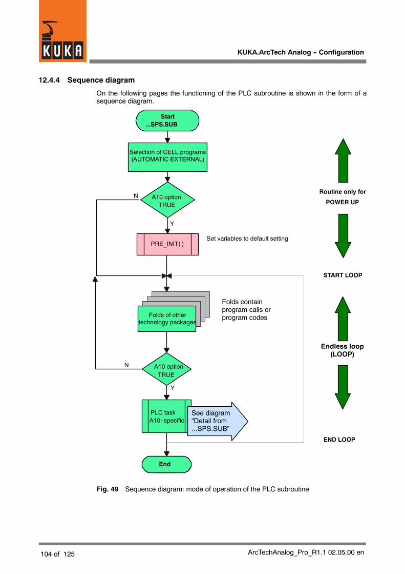
KUKA.ArcTech Analog -- Configuration
104 of 125 ArcTechAnalog_Pro_R1.1 02.05.00 en
12.4.4 Sequence diagram
On the following pages the functioning of the PLC subroutine is shown in the form of asequence diagram.
Start...SPS.SUB
A10 optionTRUE
PRE_INIT( )
A10 optionTRUE
PLC taskA10--specific
End
START LOOP
END LOOP
Y
N
Y
N
POWER UP
Endless loop(LOOP)
Set variables to default setting
Routine only for
Selection of CELL programs(AUTOMATIC EXTERNAL)
Folds containprogram calls orprogram codesFolds of other
technology packages
See diagram“Detail from...SPS.SUB”
Fig. 49 Sequence diagram: mode of operation of the PLC subroutine

12 Fault situations and fault service functions (continued)
105 of 125ArcTechAnalog_Pro_R1.1 02.05.00 en
12.4.5 Details of the routine in the Submit interpreter (SPS.SUB)
PLC task
Set flag “Hot weld”A--HOT_T_STOP = #ACTIVE
R1 interpreteractive
A_TCHSTP_STS=#IDLE
Y
ProgramSTOP
Y
“HOT/COLD”status keypressed
Program active
“Triggering” flagA_OLD_WELD=A_HOT_WELD
“Key pressed” flag:A_ISR_ACTION=#IDLE
Y
Detail from“...SPS.SUB”
Detail from“...SPS.SUB”continued 1/2
N
N
A_TSTOP_CONT=#ACTIVE
A_HOT_T_STOP=#ACTIVE
A_RETRY_COUNT=0
WELD_AGAIN( )Initiation of a restart
“HOT/COLD” statuskey enabled
State of “HOT/COLD”status key saved
A_TSTOP_CONT=#IDLE
N
(Only detection ofstatus key activation)
Stop key pressed &weld commandactive & gas flow /weld power sourceactive
Reset ignitionretry counter
Restart after interruption of thewelding process due tointerpreter stop (no other faultservice function active)
Fig. 50 Sequence diagram: Submit interpreter routine (page 1 of 3)

KUKA.ArcTech Analog -- Configuration
106 of 125 ArcTechAnalog_Pro_R1.1 02.05.00 en
Manual wirefeed
Programmedweld command
active
“HOT”status keypressed
Detail from“...SPS.SUB”continued 1/2
Y
Status key+ or --pressed
Pulse command“Wire feed”
N
Y
Trigger ISR 5 (R1):A_FLY_ARC=TRUE
Precondition: Welding inactive,wire feed enabled
Preconditions:-- manual welding enabled-- restart process afterinterpreter stop not active.-- weld process not active.
Flag:A_ISR_ACTION= #ACTIVE
Marking the runninginterrupt
Pulse commandfor signal declaration in$CONFIG.DAT
N
N
Y
N
Y
Pulse command“Wire retract”
Detail from“...SPS.SUB”continued 2/3
Fig. 51 Sequence diagram: Submit interpreter routine (page 2 of 3)

12 Fault situations and fault service functions (continued)
107 of 125ArcTechAnalog_Pro_R1.1 02.05.00 en
EndPLC task
Trigger ISR5:A_FLY_ARC=TRUE
“COLD”status keypressed
Weldingand/or gasflow active
FlagA_ISR_ACTION=#ACTIVE
Refreshing of thefunction
generator data
Y
Y
N
Precondition:ignition routinesinactive
Marking the runninginterrupt
N
Detail from“...SPS.SUB”continued 2/3
Fig. 52 Sequence diagram: Submit interpreter routine (page 3 of 3)
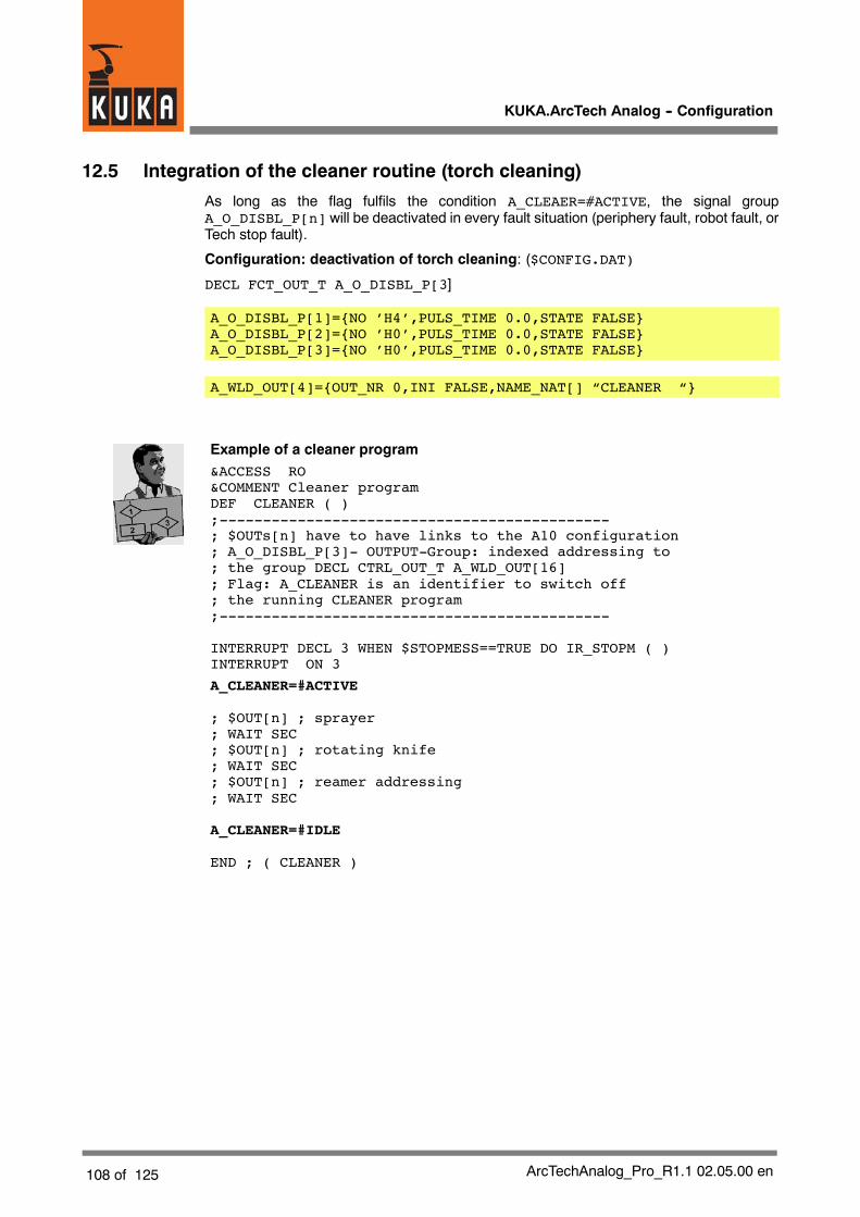
KUKA.ArcTech Analog -- Configuration
108 of 125 ArcTechAnalog_Pro_R1.1 02.05.00 en
12.5 Integration of the cleaner routine (torch cleaning)
As long as the flag fulfils the condition A_CLEAER=#ACTIVE, the signal groupA_O_DISBL_P[n] will be deactivated in every fault situation (periphery fault, robot fault, orTech stop fault).
Configuration: deactivation of torch cleaning: ($CONFIG.DAT)
DECL FCT_OUT_T A_O_DISBL_P[3]
A_O_DISBL_P[1]={NO ’H4’,PULS_TIME 0.0,STATE FALSE}A_O_DISBL_P[2]={NO ’H0’,PULS_TIME 0.0,STATE FALSE}A_O_DISBL_P[3]={NO ’H0’,PULS_TIME 0.0,STATE FALSE}
A_WLD_OUT[4]={OUT_NR 0,INI FALSE,NAME_NAT[] “CLEANER “}
Example of a cleaner program&ACCESS RO&COMMENT Cleaner programDEF CLEANER ( );---------------------------------------------; $OUTs[n] have to have links to the A10 configuration; A_O_DISBL_P[3]- OUTPUT-Group: indexed addressing to; the group DECL CTRL_OUT_T A_WLD_OUT[16]; Flag: A_CLEANER is an identifier to switch off; the running CLEANER program;---------------------------------------------
INTERRUPT DECL 3 WHEN $STOPMESS==TRUE DO IR_STOPM ( )INTERRUPT ON 3
A_CLEANER=#ACTIVE
; $OUT[n] ; sprayer; WAIT SEC; $OUT[n] ; rotating knife; WAIT SEC; $OUT[n] ; reamer addressing; WAIT SEC
A_CLEANER=#IDLE
END ; ( CLEANER )
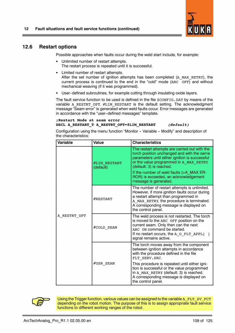
12 Fault situations and fault service functions (continued)
109 of 125ArcTechAnalog_Pro_R1.1 02.05.00 en
12.6 Restart optionsPossible approaches when faults occur during the weld start include, for example:
G Unlimited number of restart attempts.The restart process is repeated until it is successful.
G Limited number of restart attempts.After the set number of ignition attempts has been completed (A_MAX_RETRY), thecurrent process is continued to the end in the “cold” mode (ARC OFF) and withoutmechanical weaving (if it was programmed).
G User--defined subroutines, for example cutting through insulating oxide layers.
The fault service function to be used is defined in the file $CONFIG.DAT by means of thevariable A_RESTRT_OPT. #LIM_RESTART is the default setting. The acknowledgmentmessage “Seam error” is generated when weld faults occur. Error messages are generatedin accordance with the “user--defined messages” template.
;Restart Mode at seam errorDECL A_RESTART_T A_RESTRT_OPT=#LIM_RESTART (default)
Configuration using the menu function “Monitor -- Variable -- Modify” and description ofthe characteristics:
Variable Value Characteristics
#LIM_RESTART(default)
The restart attempts are carried out with thetorch position unchanged and with the sameparameters until either ignition is successfulor the value programmed in A_MAX_RETRY(default: 3) is reached.If the number of weld faults (>A_MAX ER-ROR) is exceeded, an acknowledgementmessage is generated.
#RESTART
The number of restart attempts is unlimited.However, if more ignition faults occur duringa restart attempt than programmed inA_MAX_RETRY, the procedure is terminated.A corresponding message is displayed onthe control panel.
A_RESTRT_OPT
#COLD_SEAM
The weld process is not restarted. The torchis moved to the ARC OFF position on thecurrent seam. Only then can the nextARC ON command be started.If no restart occurs, the A_O_FLT_APPL[ ]signal remains active.
#USR_SEAM
The torch moves away from the componentbetween ignition attempts in accordancewith the procedure defined in the fileFLT_SERV.SRC.This procedure is repeated until either igni-tion is successful or the value programmedin A_MAX_RETRY (default: 3) is reached.A corresponding message is displayed onthe control panel.
Using the Trigger function, various values can be assigned to the variable A_FLT_SV_FCTdepending on the robot motion. The purpose of this is to assign appropriate fault servicefunctions to different working ranges of the robot.

KUKA.ArcTech Analog -- Configuration
110 of 125 ArcTechAnalog_Pro_R1.1 02.05.00 en
12.6.1 Fault service functions defined by the user (#USR_SEAM)
The particular feature here is that the robot remains positioned away from the seam so thatthe seamorweldingwire canbe reworkedby theoperator. Once the errormessage has beenacknowledged the robot is repositioned and ignition process is carried out.
The file FLT_SERV.SRC contains a fault service function with the designation “CASE 0” aswell as five other examples (CASE 1 ... 5) that can be freely configured.
The fault service function to be used is selected using the variable A_FLT_SV_FCT. Thevalue “0” is the default setting for “CASE 0”.
FAULT SERVICE FUNCTION (additional START error)CASE 0IF ARC_ON_FLT==#ACTIVE THENINTERRUPT OFF 3 ; IR_STOPMESS()
MOVE_TCP ({X -20.0,Y 1.0,Z 1.0} )
INTERRUPT ON 3
ELSE In the case of an error duringwelding,
MOVE_TCP ({X -50.0,Y 1.0,Z 1.0} ) the torch is moved backby X=50 mm *)
HALTLIN POS_RET The torch is moved back to theENDIF start position.
Applies to ignition faults only.
The robot stops 50 mm away from the seam. This makes it possible to work on the wirewithout having to move the robot away.
If this fault service function is implemented, it is essential to make sure that thereis sufficient clearance for the torch to be retracted.If this is not possible, reduce the distance “X” accordingly -- MOVE_TCP ({X -50.0,Y1.0,Z 1.0} ).
The toolmust becalibrated in such away that thecurrent nozzlewith theprotrudingwire corresponds to the+Xdirection in the tool coordinatesystem.Otherwise, thereis the risk of a collision with the workpiece.

12 Fault situations and fault service functions (continued)
111 of 125ArcTechAnalog_Pro_R1.1 02.05.00 en
12.6.2 Number of restart attempts
The number of permissible restart attempts is programmed with the variable A_MAX_RETRY.(default value = 3)
12.6.3 Fault signals
Configuration: general fault signal ($CONFIG.DAT); output for fault message
DECL FCT_OUT_T A_O_FLT_SIGN={NO ’H6’,PULS_TIME 0.0,STATE TRUE}
A_WLD_OUT[6]={OUT_NR 0,INI FALSE,NAME_NAT[] “ERR MESSG_SIGNAL”}
Configuration: application fault signal ($CONFIG.DAT)
; output for fault application error message
DECL FCT_OUT_T A_O_FLT_APPL={NO ’H8’,PULS_TIME 0.0,STATE TRUE}
A_WLD_OUT[8]={OUT_NR 0,INI FALSE,NAME_NAT[] “APPL_ERROR “}
12.6.4 Block selection response
If the $CONFIG variable is set to A_HOT_SELECT=#ACTIVE (default= #IDLE), the weldprocess is started in the middle of the seam in the event of a block selection to anARC_SWITCH or TRACK_SWITCH command with sensor as long as the weld conditionsare met. Weaving is initially switched off for the motion and is reinitialized if necessary.

KUKA.ArcTech Analog -- Configuration
112 of 125 ArcTechAnalog_Pro_R1.1 02.05.00 en
13 Customized messagesIn addition to the standard error messages, the KCPcan alsodisplay customized informationin the message window. The message texts and the signal inputs to which they are linkedcan be determined by the customer. This results in enhanced operating convenience andsimpler location of faults. This type of error message is only generated for periphery faults.
13.1 Message program
When the file ...\R1\TP\ArcTechAnalog\ARC_MSG.SRC is opened, the window shown inFig. 53 is displayed.
Fig. 53 ARC_MSG.SRC program

13 Customized messages (continued)
113 of 125ArcTechAnalog_Pro_R1.1 02.05.00 en
When the fold PREPARED SYSTEM INPUTS is opened, the window shown in Fig. 54 isdisplayed.
Fig. 54 ARC_MSG.SRC program -- FOLD “PREPARED SYSTEM INPUTS”
The system inputs in question are the signal groups defined in A_FLT_CYCFLAG for weldseam monitoring.
In the event of a fault, a bit--coded fault marker is generated in the variable TMP_WLD_CTRLin order to generate a cause--specific message after deactivation. Four inputs arepreprogrammed in $CONFIG.DAT:
These four configured inputs can trigger a periphery error:
A_FLT_CYCFLAG[1]={NO 13,STATE TRUE}; group fault
A_FLT_CYCFLAG[2]={NO 2,STATE TRUE}; current
A_FLT_CYCFLAG[3]={NO 11,STATE TRUE}; gas
A_FLT_CYCFLAG[4]={NO 10,STATE TRUE}; water
In addition to the four predefinedmessages, other preparedmessages (e.g. for KPI systems)are displayed when the fold USER ERROR MESSAGES is opened. The length of the text maynot exceed 7 characters!
You can enter your own texts from line S_MSG[5]...... (Fig. 55) onwards. The length ofthe text must be entered in the structure at “LENGTH.”

KUKA.ArcTech Analog -- Configuration
114 of 125 ArcTechAnalog_Pro_R1.1 02.05.00 en
Fig. 55 ARC_MSG.SRC program -- entering your own text
Fig. 56 ARC_MSG.SRC program -- FOLD “Coding of fault information”
Fig. 56 shows how the fault information is coded in the variable TMP_WLD_CTRL_B. Theposition of the set bit in the bit sequence (from the right) determines which text is generated.The bit sequence B00100000 thus refers to error message S_MSG[6]... in USER ERRORMESSAGES. The total number of bits which can be set in this way is 12. The bit sequenceB100000000000 thus refers to the message S_MSG[12]....
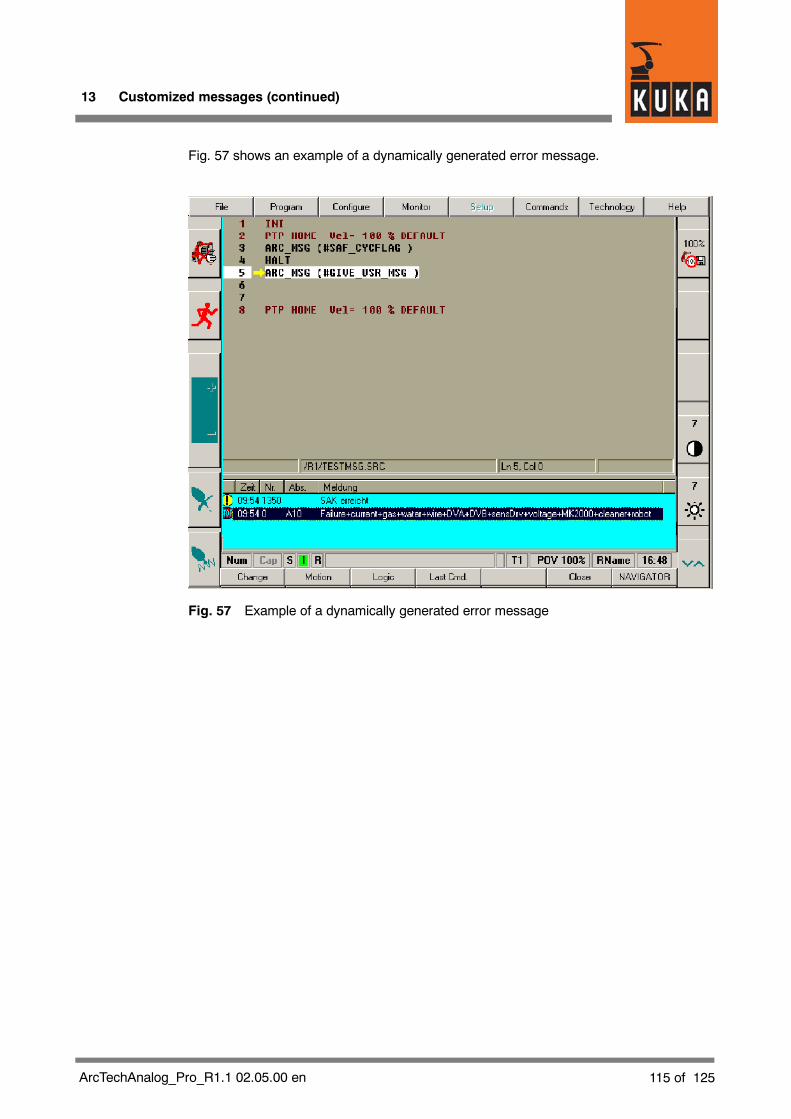
13 Customized messages (continued)
115 of 125ArcTechAnalog_Pro_R1.1 02.05.00 en
Fig. 57 shows an example of a dynamically generated error message.
Fig. 57 Example of a dynamically generated error message
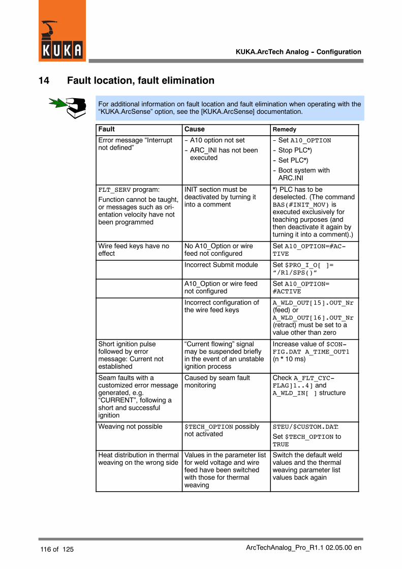
KUKA.ArcTech Analog -- Configuration
116 of 125 ArcTechAnalog_Pro_R1.1 02.05.00 en
14 Fault location, fault elimination
For additional information on fault location and fault elimination when operating with the“KUKA.ArcSense” option, see the [KUKA.ArcSense] documentation.
Fault Cause Remedy
Error message “Interruptnot defined”
-- A10 option not set-- ARC_INI has not beenexecuted
-- Set A10_OPTION-- Stop PLC*)-- Set PLC*)-- Boot system withARC.INI
FLT_SERV program:Function cannot be taught,or messages such as ori-entation velocity have notbeen programmed
INIT section must bedeactivated by turning itinto a comment
*) PLC has to bedeselected. (The commandBAS(#INIT_MOV) isexecuted exclusively forteaching purposes (andthen deactivate it again byturning it into a comment).)
Wire feed keys have noeffect
No A10_Option or wirefeed not configured
Set A10_OPTION=#AC-TIVE
Incorrect Submit module Set $PRO_I_O[ ]=“/R1/SPS()”
A10_Option or wire feednot configured
Set A10_OPTION=#ACTIVE
Incorrect configuration ofthe wire feed keys
A_WLD_OUT[15].OUT_Nr(feed) orA_WLD_OUT[16].OUT_Nr(retract) must be set to avalue other than zero
Short ignition pulsefollowed by errormessage: Current notestablished
“Current flowing” signalmay be suspended brieflyin the event of an unstableignition process
Increase value of $CON-FIG.DAT A_TIME_OUT1(n * 10 ms)
Seam faults with acustomized error messagegenerated, e.g.“CURRENT”, following ashort and successfulignition
Caused by seam faultmonitoring
Check A_FLT_CYC-FLAG]1..4] andA_WLD_IN[ ] structure
Weaving not possible $TECH_OPTION possiblynot activated
STEU/$CUSTOM.DAT:Set $TECH_OPTION toTRUE
Heat distribution in thermalweaving on the wrong side
Values in the parameter listfor weld voltage and wirefeed have been switchedwith those for thermalweaving
Switch the default weldvalues and the thermalweaving parameter listvalues back again

14 Fault location, fault elimination (continued)
117 of 125ArcTechAnalog_Pro_R1.1 02.05.00 en
Fault Cause Remedy
Spiral weaving results instrange weave patterns
Weave pattern onlyvaguely resembles a spiral
Set weave amplitude tohalf weave length, andobserve frequencydependence and amplitude
Absence of phasesynchronization duringthermal weaving
Heat distribution on theworkpiece material some-times sporadic andchangeable
Set $CUSTOM.DAT:$TECH_ANA_FLT_OFF[3]=TRUE; the weave motionfiltering is manipulated
Thermal weaving has noeffect
A static analog value isgenerated
Activate cyclical analogchannels.A_WEAV_GEN[3]=3Reinitialize HMI; restartSubmit and applicationprogram
Wire feed keys pressed.Wire is fed at unsuitablespeed
With some power sources,the analog channel for wirefeed must first be set.If this has been adapted tothe wire feed channel using$ANOUT[2], this maynonetheless remain withouteffect if cyclical analogchannels have been used.Default setting:A_WEAV_GEN[3]=3
Once activation of the wirefeed key has beendetected, setA_TH2_ACT_G=0 in thePLC and setA_TH2_ACT_O to avelocity--proportional valuebetween 0.0 and 0.1. Avalue < 0.2 is suitable here(i.e. 20% of the max. wirefeed velocity).This is a customer--specificadaptation.
After a short, successfulignition process the errormessage “Seam fault” or aprogrammed customizedmessage is generated.
The monitoring delay valuehas been set too low.
-- Set the variableA_CTRL_DELAY in$CONFIG.DAT to ahigher value (default:1200 [ms])
-- Check the configuration:the signal to be monitoredon the seam is missing.
*) Depending onwhether the “KUKA.ArcSense” option has been installed andactivated.
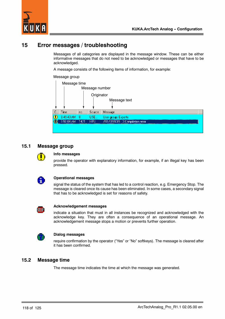
KUKA.ArcTech Analog -- Configuration
118 of 125 ArcTechAnalog_Pro_R1.1 02.05.00 en
15 Error messages / troubleshootingMessages of all categories are displayed in the message window. These can be eitherinformative messages that do not need to be acknowledged or messages that have to beacknowledged.
A message consists of the following items of information, for example:
Message group
Message timeMessage number
OriginatorMessage text
15.1 Message group
Info messages
provide the operator with explanatory information, for example, if an illegal key has beenpressed.
Operational messages
signal the status of the system that has led to a control reaction, e.g. Emergency Stop. Themessage is cleared once its cause has been eliminated. In some cases, a secondary signalthat has to be acknowledged is set for reasons of safety.
Acknowledgement messages
indicate a situation that must in all instances be recognized and acknowledged with theacknowledge key. They are often a consequence of an operational message. Anacknowledgement message stops a motion or prevents further operation.
Dialog messages
require confirmation by the operator (“Yes” or “No” softkeys). The message is cleared afterit has been confirmed.
15.2 Message time
The message time indicates the time at which the message was generated.
15 Error messages / troubleshooting (continued)
119 of 125ArcTechAnalog_Pro_R1.1 02.05.00 en
15.3 Message number
With the aid of the message number, the corresponding cause, effect, and remedy canquickly be located in the list of error messages.
15.4 Originator
The origin of the error is indicated in this field.
15.5 Message text
The text of the error message is shown here.
15.6 List of error messages
To make it easier to find error messages in the following list, the message number is shownfirst, unlike on the display. By referring to this message number, it is possible to obtain furtherinformation on an error and the appropriate remedial action. This information is subdividedinto:
Message text
is the actual text of the error message as displayed.
Cause
gives a detailed description of the cause of the error.
Monitor
indicates when the message is generated.
Effect
describes how the controller reacts to the error.
Remedy
describes what action the user can take to eliminate the error.
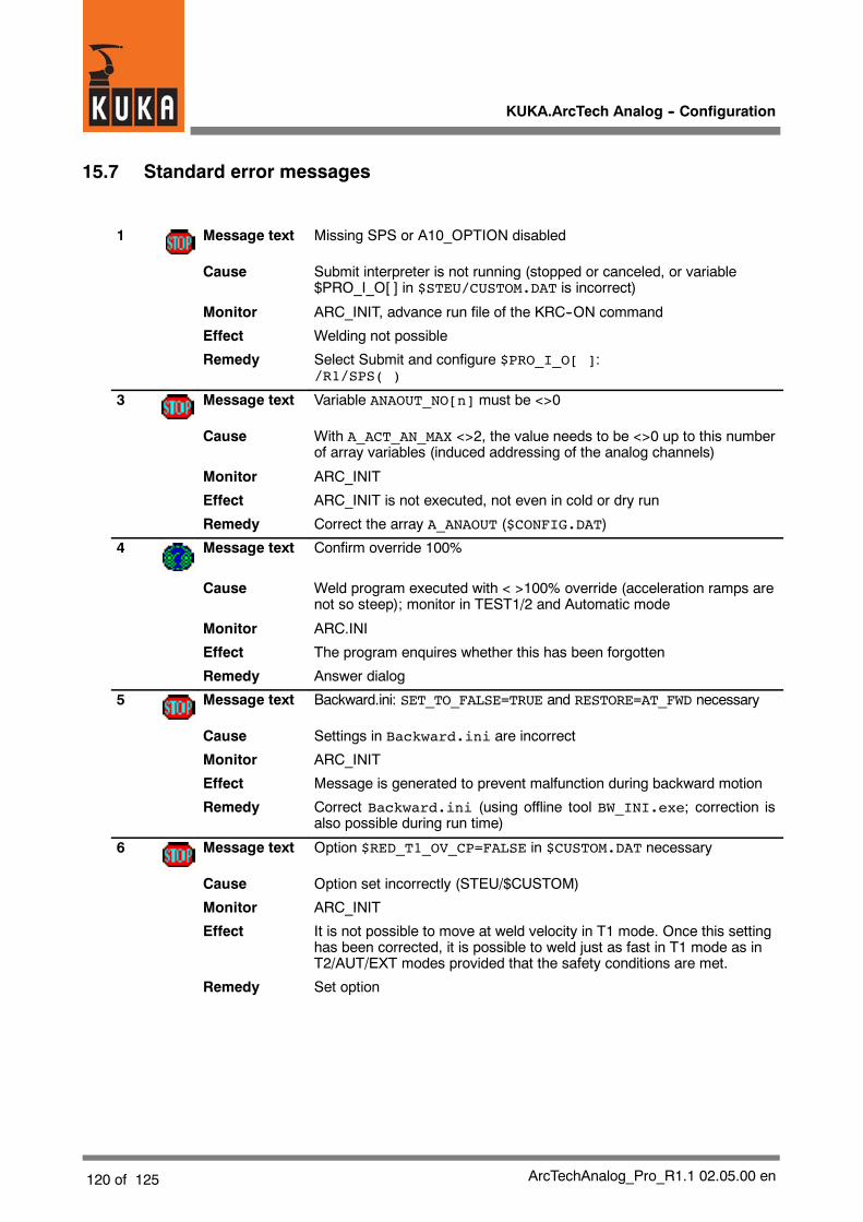
KUKA.ArcTech Analog -- Configuration
120 of 125 ArcTechAnalog_Pro_R1.1 02.05.00 en
15.7 Standard error messages
1 Message text Missing SPS or A10_OPTION disabled
Cause Submit interpreter is not running (stopped or canceled, or variable$PRO_I_O[ ] in $STEU/CUSTOM.DAT is incorrect)
Monitor ARC_INIT, advance run file of the KRC--ON command
Effect Welding not possible
Remedy Select Submit and configure $PRO_I_O[ ]:/R1/SPS( )
3 Message text Variable ANAOUT_NO[n] must be <>0
Cause With A_ACT_AN_MAX <>2, the value needs to be <>0 up to this numberof array variables (induced addressing of the analog channels)
Monitor ARC_INIT
Effect ARC_INIT is not executed, not even in cold or dry run
Remedy Correct the array A_ANAOUT ($CONFIG.DAT)
4 Message text Confirm override 100%
Cause Weld program executed with < >100% override (acceleration ramps arenot so steep); monitor in TEST1/2 and Automatic mode
Monitor ARC.INI
Effect The program enquires whether this has been forgotten
Remedy Answer dialog
5 Message text Backward.ini: SET_TO_FALSE=TRUE and RESTORE=AT_FWD necessary
Cause Settings in Backward.ini are incorrect
Monitor ARC_INIT
Effect Message is generated to prevent malfunction during backward motion
Remedy Correct Backward.ini (using offline tool BW_INI.exe; correction isalso possible during run time)
6 Message text Option $RED_T1_OV_CP=FALSE in $CUSTOM.DAT necessary
Cause Option set incorrectly (STEU/$CUSTOM)
Monitor ARC_INIT
Effect It is not possible to move at weld velocity in T1 mode. Once this settinghas been corrected, it is possible to weld just as fast in T1 mode as inT2/AUT/EXT modes provided that the safety conditions are met.
Remedy Set option

15 Error messages / troubleshooting (continued)
121 of 125ArcTechAnalog_Pro_R1.1 02.05.00 en
7 Message text Process not enabled: A_PROC_ENABLE
Cause Option is deactivated (disabled for unauthorized personnel)
Monitor ARC_INIT
Effect Welding not possible
Remedy Set variable back to default value:A_PROC_ENABLE=TRUE ($CONFIG.DAT)
8 Message text Controller characteristics configuration error
Cause Characteristic incorrectly defined
Monitor ARC_INIT
Effect Correction vital
Remedy Set the configuration correctly:Cancel Submit --> Reselect --> Cold start necessarySet A10.DAT: REINITIALIZE=TRUE before cold start
9 Message text Cyclic analog channels are necessary for online optimizing
Cause No cyclical analog outputs are active
Monitor ARC_INIT
Effect Thermal weaving and online optimizing not possible
Remedy A_WEAV_GEN[3]=3 then cold start necessary
10 Message text RUN Mode necessary for welding
Cause Program run mode is not set to RUN and welding is to be carried out
Monitor Advance run section of ARC_ON command or ARC_INIT
Effect Program remains in this loop as long as hot welding is meant to betaking place and the program run mode has not been set to #GO
Remedy Correct the program run mode or activate a cold or dry run
11 Message text Power source not ready
Cause Power source readiness not detected (signal group A_I_WLD_COND[])
Monitor Ignition attempt only carried out in hot mode
Effect Welding not possible
Remedy Check the configuration of A_I_WLD_COND[ ] and A_WLD_OUT[ ] andensure that the power source is switched on

KUKA.ArcTech Analog -- Configuration
122 of 125 ArcTechAnalog_Pro_R1.1 02.05.00 en
12 Message text Current not established
Cause No weld current detected during the timeout following the ignitionattempt.
Monitor After every ignition attempt
Effect Welding is not possible
Remedy Check A_I_STRT_MOV[ ] signal configuration and A_WLD_OUT[ ]signal tableCheck components, gap, and dirt
13 Message text 1. 2.3..... Retry of start procedure
Cause An ignition error has occurred
Monitor Failure of ARC_ON command
Effect Weld process deactivated, renewed ignition attempt
Remedy -- Check A_I_STRT_MOV[ ] signal configuration and A_WLD_OUT[ ]signal table
-- Check components, gap, and dirt
14 Message text Too many retries: continuing cold
Cause Too many failed ignition attempts
Monitor Failure of ARC_ON command
Effect Weld process deactivated
Remedy Check components, gap, and dirt
15 Message text “Current flowing” signal still active
Cause Current off signal not detected within the configured timeout(A_TIME_OUT) (only if burnfree option is not active)
Monitor ARC OFF command
Effect Process is deactivated anyway
Remedy Check the signal group A_I_WLD_END[ ]
16 Message text Wire still connected to work piece!
Cause Burnfree input not detected (only if burnfree option not active)
Monitor ARC OFF command
Effect Acknowledgement message appears so that burnback can also beoptimized if required. This is intended to be seen as an optimization
Remedy It may also be appropriate to modify the variable #QUIT to #NOTIFY inA10.DAT (do not configure this input for applications where cycle timesare critical!)
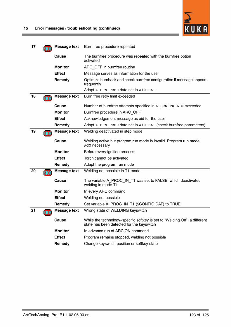
15 Error messages / troubleshooting (continued)
123 of 125ArcTechAnalog_Pro_R1.1 02.05.00 en
17 Message text Burn free procedure repeated
Cause The burnfree procedure was repeated with the burnfree optionactivated
Monitor ARC_OFF in burnfree routine
Effect Message serves as information for the user
Remedy Optimize burnback and check burnfree configuration if message appearsfrequentlyAdapt A_BRN_FREE data set in A10.DAT
18 Message text Burn free retry limit exceeded
Cause Number of burnfree attempts specified in A_BRN_FR_LIM exceeded
Monitor Burnfree procedure in ARC_OFF
Effect Acknowledgement message as aid for the user
Remedy Adapt A_BRN_FREE data set in A10.DAT (check burnfree parameters)
19 Message text Welding deactivated in step mode
Cause Welding active but program run mode is invalid. Program run mode#GO necessary
Monitor Before every ignition process
Effect Torch cannot be activated
Remedy Adapt the program run mode
20 Message text Welding not possible in T1 mode
Cause The variable A_PROC_IN_T1 was set to FALSE, which deactivatedwelding in mode T1
Monitor In every ARC command
Effect Welding not possible
Remedy Set variable A_PROC_IN_T1 ($CONFIG.DAT) to TRUE
21 Message text Wrong state of WELDING keyswitch
Cause While the technology--specific softkey is set to “Welding On”, a differentstate has been detected for the keyswitch
Monitor In advance run of ARC ON command
Effect Program remains stopped, welding not possible
Remedy Change keyswitch position or softkey state

KUKA.ArcTech Analog -- Configuration
124 of 125 ArcTechAnalog_Pro_R1.1 02.05.00 en
22 Message text Wrong state of WELDING keyswitch
Cause A setting has been detected in T1 / T2 mode which would allowimmediate welding if the HOT button were pressed
Monitor Advance run section of the ARC ON command (irrespective of whetherwelding is set for cold or hot)
Effect Program remains stopped, welding not possible
Remedy Adapt icon or keyswitch position
23 Message text Active sensor simulation --> Path deviation of the robot
Cause Sensor driver is set to simulation mode (Service mode!)
Monitor A50_SENSOR_ON
Effect Robot deviating from programmed path --> risk of crash
Remedy A robot will never bedelivered in this operatingmode. If this is not the case,please contact KUKA Roboter GmbH Technical Support
24 Message text Sensor offset is still available
Cause Sensor offset has been frozen
Monitor A50.SDC, ARC OFF, or TRACK OFF command if message is active(message only appears in T1/T2 mode)
Effect Sensor offset remains in place. PTP motions are not permissible in thisstate as it is impossible to predict where the robot will move
Remedy As this is not a fault, butmerely amixedeffect, the user needonly beawareof this possible situation

15 Error messages / troubleshooting (continued)
125 of 125ArcTechAnalog_Pro_R1.1 02.05.00 en
1

Index
Index -- i
Symbols
#ACT_PAR, 58#COMPLETE, 58#USR_SEAM, 109$CONFIG.DAT, 11, 14$CYCFLAG indices, 94$TECH[A_FG_MECH1], 72$TECH_ANA_OFF[B], 83$TIMER indices, 94
A
A_ACT_AN_MAX, 63A_ANA_DEF[2,8,5], 64A_ANA_MAX_D[ ], 65A_ANA_MAX_D[1,1], 68A_ANAOUT_NO[ ], 64A_APPLICAT, 37, 102A_BB_MODE, 58A_BRN_FR_OPT, 57A_CLEAER=#ACTIVE, 107A_CTRL_DELAY, 50, 98A_END_BRAKE, 37A_FLT_CYCFLG[ ], 98A_FLT_SV_FCT, 96, 109A_GAS_FLOW, 102A_HOT_WELD, 102A_I_BRN_FREE, 57A_I_STRT_MOV[ ], 50, 100A_I_WELD_END[ ], 56A_MAX_RETRY, 110A_O_ACK_FLT[ ], 100A_O_DISBL_P, 102A_O_FLT_SIGN, 100A_O_IR_STOP, 101A_O_IR_STOP_NO, 101A_O_POST_OFF[ ], 55A_O_POST_ON[ ], 55A_O_SEAM_END[ ], 55A_PR_GAS_OPT, 42A_RESTRT_OPT, 108A_STRT_BRAKE, 37A_SWINDL_OPT, 99A_SWINDL_TIM, 99A_TH_WEAVE_OPT, 83A_WLD_ACTIV, 102
A_WLD_IN[ ], 25A_WLD_OUT[ ], 19A_WLD_OUT[1], 50, 100A_WLD_OUT[1].INI, 19A_WLD_OUT[1].NAME_NAT[ ], 19A_WLD_OUT[1].OUT_NR, 19A_WLD_OUT[2], 49, 100A10.DAT, 12, 14A10.SRC, 14, 73A10_INI.DAT, 14A10_INI.SRC, 14A10_USR_ArcOff1, 32A10_USR_ArcOff2, 32A10_USR_ArcSeam, 31A10_USR_INIT, 29A10_USR_IRSTOPMESS, 33A10_USR_PLC_INIT, 33A10_USR_PLC_Task, 33A10_USR_PreArcOff, 31A10_USR_PreArcOn, 30A10_USR_PreArcSwi, 31A10_USR_SeamError, 35A10_USR_START1, 30A10_USR_START2, 30A10_USR_TechStop, 34A10_USR_TechStopSub1, 34A10_USR_TechStopSub2, 34Adaptation of analog outputs 1 and 2, 64Adaptation to the periphery, 17Addressing of the analog outputs, 63Approximate positioning, 54ARC OFF sequence diagram, 59, 60ARC ON -- schematic sequence diagram, 48ARC SWITCH sequence diagram, 51ARC_INIT, 29ARC_MSG.SRC, 14, 111ARC_WEAVE.SRC, 14Arc_weave.src, 77ARCSPS.SUB, 15
B
Burnback, 58Burnback mode, 58Burnback parameters, seam--specific, 58

Index
Index -- ii
C
Changing existing weave patterns, 77Characteristic, voltage, 68Cleaner routine, 107Combined mechanical and thermal weaving,85Configurable options, 17Configuring the monitoring functions, 98Control points (CPNUM), 72Creating your own weave patterns, 79Current flowing, 50Customer--specific adaptation of weld se-quences, 29Customized messages, 111
D
Digital inputs, 18Digital outputs, 18Double 8, 70
E
Error handling routines, 33
F
FAULT SERVICE FUNCTION, 96Fault service functions, 95, 109Fault situations, 95FCTCTRL.SCALE_IN, 73FCTCTRL.SCALE_OUT, 73Figure--eight weave pattern, 76Figure--eight weaving, 70FLT_SERV.DAT, 14FLT_SERV.SRC, 14, 96FLY ARC, 37
G
Graphical user interface of the KUKA ControlPanel, 11
IIgnition faults, 95Ignoring temporary interrupts, 99IN_NR, 25Index table for physical digital inputs, 25Index table for physical outputs, 19Index tables, 18Interpreter stop, 101Interrupt 21, 101Interrupt 5, 37Interrupt indices, 94
KKeyswitch, 41KRL programming language, 7
LLateral deflection (weave amplitude), 72Linear characteristic, 66
M
Manual activation and deactivation of the weldprocess, 37Max. no. of analog outputs, 63Maximum weave frequency, 80Motion characteristics of the robot, 80
N
NAME_NAT, 19, 25Non--linear characteristic, 68Notes on mechanical weaving, 80Number of characteristic points, 65
PPARA (characteristic analog output), 66Path velocity, 80Program structure, 13PULS_TIME, 21PULSE_TIME 0.0, 22
Index
Index -- iii
R
Resonant frequency, 80
Resource distribution, 94
Restart after an interpreter stop, 102
Robot error, 33
Robot motion interrupted, 38
Rotation of the weave plane, 81
S
Seam error, 35
Signal states for digital outputs, 22
Signal tables, 55
Signal tables for digital inputs, 26
Signal tables for digital outputs, 21
Signal tables for digital outputs and inputs, 18
Spiral weave pattern, 73
Spiral weaving, 70
SPS.SUB, 101
STATE, 21
Status key ”DRY”, 38
Submit interpreter task, 33
Submit routine, 39
Subroutines for weld commands, 29
Switching from constant values to thermalweaving, 53
TThrough--the--arc seam tracking, 13Tool--based technological system TTS, 69Trapezoidal weaving, 70Triangular weaving, 70Triple groups, 18, 21, 26Two--dimensional weaving, 72Types of faults and causes, 95
V
VAL (characteristic analog output), 66Voltage, 66Voltage characteristic, 66
W
Weave frequency, 80Weave frequency nomogram, 81Weave length, 72, 80Weave patterns (mechanical weaving), 70Weave patterns, changing, 77Weave patterns, creation, 79Weave patterns, thermal weaving, 83Weaving, mechanical and thermal, 69Weaving, mechanical and thermal combined,85Weaving, two--dimensional, 72Weld process monitoring, 50Weld voltage, 66Wire feed, 37, 66Wire feed characteristic, 67