VIO 4K - Analog Way
237
1 www.analogway.com PROGRAMMER’S GU USER MANUAL VIO 4K Ref. V701 USER MANUAL
-
Upload
khangminh22 -
Category
Documents
-
view
0 -
download
0
Transcript of VIO 4K - Analog Way
1
www.analogway.com
PROGRAMMER’S GU
USER MANUAL
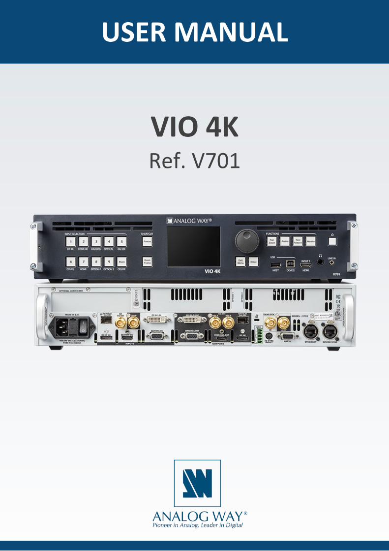
VIO 4K Ref. V701
USER MANUAL
2
www.analogway.com
PROGRAMMER’S GU
USER MANUAL
Information contained in this document, in particular data, pictures, information, trademarks and logos are exclusive property of Analog Way and are protected by copyrights and other intellectual property rights.
2016, Analog Way, all rights reserved – 09/2020
Consequently, any representation and/or reproduction, in part or in full, is prohibited and would be considered a violation of Analog Way’s copyright and other intellectual property rights.
Visual representations (diagrams, photos, icons, pictograms, screenshots, spare parts, etc.) are not contractual.

3
www.analogway.com
PROGRAMMER’S GU
USER MANUAL
1 Introduction ................................................................................................................... 7
1.1 Why use the VIO 4K? ............................................................................................................................ 7 1.2 VIO 4K at a glance ................................................................................................................................. 7 1.3 Key features .......................................................................................................................................... 8 1.4 Inputs .................................................................................................................................................... 8 1.5 Outputs ................................................................................................................................................. 8 1.6 Frames .................................................................................................................................................. 9 1.7 Control .................................................................................................................................................. 9 1.8 Universal system for format conversion .............................................................................................. 9 1.9 Technical specifications ...................................................................................................................... 10 1.10 Environmental specification ............................................................................................................... 10
2 Safety instructions ...................................................................................................... 11
2.1 English ................................................................................................................................................. 11 2.2 French ................................................................................................................................................. 12 2.3 Italian .................................................................................................................................................. 13 2.4 German ............................................................................................................................................... 14 2.5 Spanish ................................................................................................................................................ 15
3 Physical description ................................................................................................... 17
3.1 Front panel.......................................................................................................................................... 17 3.2 Rear panel ........................................................................................................................................... 18
4 Quick setup & operation ............................................................................................. 19
4.1 Front panel control ............................................................................................................................. 19
4.1.1 Navigating the menus ................................................................................................................. 19
4.1.2 Operating from the front panel .................................................................................................. 20
4.2 Web RCS interface .............................................................................................................................. 23
4.2.1 Connecting to the Web RCS (LAN) .............................................................................................. 23
4.2.2 Connecting to the Web RCS (USB) .............................................................................................. 25
4.2.3 Operating from the Web RCS interface ...................................................................................... 28
5 Device management ................................................................................................... 31
5.1 Powering-up ....................................................................................................................................... 31
Table of Contents
4
www.analogway.com
PROGRAMMER’S GU
USER MANUAL
5.2 Sending the device to standby ........................................................................................................... 31 5.3 Adjusting the front panel .................................................................................................................... 32 5.4 Setting up the LAN connection ........................................................................................................... 37 5.5 Enabling the USB device connection .................................................................................................. 39 5.6 Using the GPO connection .................................................................................................................. 42
5.6.1 What are GPOs? .......................................................................................................................... 42
5.6.2 ON/OFF pins description ............................................................................................................. 42
5.6.3 GPO pins description ................................................................................................................... 42
5.6.4 GPO modes ................................................................................................................................. 43
5.7 Resetting the unit ............................................................................................................................... 44 5.8 Creating backups ................................................................................................................................ 47 5.9 Erasing the device memories .............................................................................................................. 53 5.10 Updating the device ............................................................................................................................ 58
6 Output management ................................................................................................... 60
6.1 What is an output? ............................................................................................................................. 60 6.2 Supported outputs (formats and signals) ........................................................................................... 60
6.2.1 Additional outputs supported with video expansion interfaces ................................................ 62
6.3 Checking the output status ................................................................................................................. 62 6.4 Setting up the output ......................................................................................................................... 64
6.4.1 Checking the plug status ............................................................................................................. 64
6.4.2 Setting up the plug ...................................................................................................................... 66
6.4.3 Setting up the format .................................................................................................................. 74
6.4.4 Adjusting the AOI (Area of Interest) ........................................................................................... 81
6.4.5 Rotating the output .................................................................................................................... 84
6.4.6 Correcting the image................................................................................................................... 85
6.4.7 Using test patterns ...................................................................................................................... 87
6.5 Monitoring the output ........................................................................................................................ 90 6.6 Freezing the output ............................................................................................................................ 91 6.7 Capturing the output .......................................................................................................................... 92 6.8 Using the Genlock reference .............................................................................................................. 92 6.9 Enabling loop mode ............................................................................................................................ 94
7 Input management ...................................................................................................... 96
7.1 What is an input? ................................................................................................................................ 96

5
www.analogway.com
PROGRAMMER’S GU
USER MANUAL
7.2 Supported inputs (formats and signals) ............................................................................................. 96 7.3 Checking your inputs status ................................................................................................................ 98 7.4 Auto-setting all inputs ...................................................................................................................... 100 7.5 Setting up an input ........................................................................................................................... 101
7.5.1 Auto-setting the input ............................................................................................................... 102
7.5.2 Setting up the plug .................................................................................................................... 102
7.5.3 Adjusting the image .................................................................................................................. 121
7.5.4 Adjusting the view .................................................................................................................... 138
7.6 Monitoring input sources ................................................................................................................. 147 7.7 Capturing the input ........................................................................................................................... 149 7.8 Looping-through inputs .................................................................................................................... 149
8 Frame management .................................................................................................. 150
8.1 What is a frame? ............................................................................................................................... 150 8.2 Supported frame formats ................................................................................................................. 150 8.3 Importing and exporting frames ....................................................................................................... 150 8.4 Creating frame captures ................................................................................................................... 154 8.5 Using frames as transitions ............................................................................................................... 155 8.6 Using frames as quick frames ........................................................................................................... 158
9 Screen management ................................................................................................. 163
9.1 What is a screen? .............................................................................................................................. 163 9.2 Adjusting the view ............................................................................................................................ 163 9.3 Customizing the transition effect ..................................................................................................... 166 9.4 Controlling the screen ...................................................................................................................... 168
1 0 Audio management ................................................................................................... 172
10.1 Audio inputs and outputs ................................................................................................................. 172 10.2 Supported audio ............................................................................................................................... 172 10.3 A/V mapping inputs and outputs ..................................................................................................... 173 10.4 Selecting the sampling rate .............................................................................................................. 178 10.5 Adjusting the input audio ................................................................................................................. 179 10.6 Adjusting the output audio ............................................................................................................... 189 10.7 Adjusting the XLR audio .................................................................................................................... 201 10.8 Prelistening to audio content ........................................................................................................... 205
1 1 Custom formats ........................................................................................................ 207
11.1 What are custom formats? ............................................................................................................... 207

6
www.analogway.com
PROGRAMMER’S GU
USER MANUAL
11.2 Creating custom formats .................................................................................................................. 207 11.3 Using custom formats ....................................................................................................................... 211
1 2 Presets ....................................................................................................................... 212
12.1 What is a preset? .............................................................................................................................. 212 12.2 Creating presets ................................................................................................................................ 212
1 3 EDID support ............................................................................................................. 216
13.1 What is an EDID ................................................................................................................................ 216 13.2 Supported EDIDs ............................................................................................................................... 216 13.3 Managing EDIDs ................................................................................................................................ 217
1 4 HDCP support ........................................................................................................... 225
14.1 HDCP detection ................................................................................................................................. 225 14.2 HDCP negotiation ............................................................................................................................. 225 14.3 Managing HDCP ................................................................................................................................ 226
1 5 Expansion interfaces ................................................................................................ 230
15.1 Audio expansion interfaces .............................................................................................................. 230
15.1.1 Dante™ audio expansion interface ........................................................................................... 230
15.1.2 XLR audio expansion interface .................................................................................................. 230
15.2 Video cards ....................................................................................................................................... 231
15.2.1 Extra output expansion interface ............................................................................................. 231
15.2.2 4K@60P expansion interface .................................................................................................... 231
15.2.3 4K@60P + SDI expansion interface ........................................................................................... 232
15.3 Multi-Outputs support ...................................................................................................................... 233
15.3.1 Extra screen ............................................................................................................................... 233
15.3.2 Pitch compensation .................................................................................................................. 234

7
www.analogway.com
PROGRAMMER’S GU
USER MANUAL
1.1 Why use the VIO 4K?
The VIO 4K has been designed to convert any content (AV content like a live video, a Power Point presentation, a DVD) from one format to another.
With the VIO 4K, you can fully control and operate the conversion environment in a world of multiple possibilities. You may for example set up your outputs before plugging-in your sources, or add additional cards to obtain a full 4K resolution display.
• The "all in one" solution for any conversion • User-friendly and intuitive graphic interface • Diverse selection of option cards for video and audio system expansion • Flexible Audio/Stereo switching capability following the video input • High performance scaling and video processing • Advanced LED Wall functionalities • 10-bit processing 4:4:4
1 Introduction
1.2 VIO 4K at a glance

8
www.analogway.com
PROGRAMMER’S GU
USER MANUAL
1.3 Key features
• Up to 9 inputs and 3 independent outputs (7/1 of which native, +2 with the expansion interfaces) • 2 slots for video option card system expansion • 1 slot for audio option card system expansion • The source can be positioned anywhere on the screen, and up to 100% outside the screen in any
direction • Easy Area Of Interest (AOI) management and pixel pitch management • Genlock: Analog HD Black and Black Burst (Loopthrough) • All Genlock timings meet broadcast ITU/SMPTE standards • Output rotation: 90°, 180° and 270° per output • Unlimited layer sizing and scaling • Live monitoring of sources and outputs on the 3.5'' Color TFT LCD Display • Output and screen patterns: Crosshatch, moving, scalable, output ID and other dynamic patterns • New audio management: 8 channels up to 96kHz (Digital audio, AES) • Audio Delay compensation up to 400ms • Memory space for 2 uncompressed frames in 4K • USB Host: mass storage • USB Device link • Import/export device configuration • DVI, HDMI & HD15 output plugs available as video loop-through
1.4 Inputs
7 inputs + 1 audio line in:
• DisplayPort up to 4K@30Hz • HMDI up to 4K@30Hz • SDI (3G Level A & B) • Universal Analog • DVI Dual-Link up to 2560x1600@60Hz • Video Optical SFP Module cage • HDMI up to 2k 1080p (Front panel - Input #7) • 3.5mm jack for stereo audio in (front panel)
1 standard output with 6 output plugs + 1 headphone output:
• DisplayPort up to 4K@30Hz • HMDI up to 4K@30Hz • SDI (6G Level A & B) • Universal Analog • DVI Dual-Link up to 2560x1600@60Hz • Video Optical SFP Module cage
1.5 Outputs

9
www.analogway.com
PROGRAMMER’S GU
USER MANUAL
• 6.35mm stereo jack for Headphone • DVI, HDMI & HD15 output plugs available as video loop-through
1.6 Frames
• Up to 50 frame memories – Fully resizable • Download/upload via Web RCS • Capture from live inputs/outputs
1.7 Control
• Web RCS: On-board intuitive web based user interface • TCP protocol and AMX/Crestron drivers
1.8 Universal system for format conversion
• Upscale conversion (Scaler) • Downscale conversion (Scan converter) • Transcoder • Coder • Aspect ratios • Multi-format Analog Genlock • Dynamic test patterns • Pan & Zoom functions • Freeze Frame • Aperture correction • Advanced LED Wall functionalities • Audio and Video monitoring directly from the Front Panel • Output rotation • Custom formats • EDID Management • Genlock/Framelock • Gamma correction and color temperature settings
10
www.analogway.com
PROGRAMMER’S GU
USER MANUAL
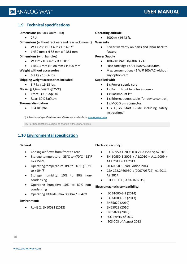
1.9 Technical specifications
Dimensions (in Rack Units - RU) • 2RU
Dimensions (without rack ears and rear rack mount) • W 17.28’’ x H 3.46’’ x D 14.82’’ • L 439 mm x H 88 mm x P 381 mm
Dimensions (with handles) • W 19’’ x H 3.46’’ x D 15.81’’ • L 482.1 mm x H 88 mm x P 406 mm
Weight without accessories • 6.2 kg / 13.66 lbs.
Shipping weight accessories included • 8.7 kg / 19.18 lbs.
Noise (@1,6m height @25°C) • Front: 39 DBa@1m • Rear: 39 DBa@1m
Thermal dissipation • 154 BTU/hr.
Operating altitude • 3000 m / 9842 ft.
Warranty • 3-year warranty on parts and labor back to
factory Power Supply
• 100-240 VAC 50/60Hz 3.2A • Fuse cartridge F4AH 250VAC 5x20mm • Max consumption: 45 W@100VAC without
any option card Supplied with
• 1 x Power supply cord • 1 x Pair of front handles + screws • 1 x Rackmount kit • 1 x Ethernet cross cable (for device control) • 1 x MCO 5 pin connector • 1 x Quick Start Guide including safety
instructions* (*) All technical specifications and videos are available on analogway.com
NOTE: Specifications subject to change without prior notice.
1.10 Environmental specification
General:
• Cooling air flows from front to rear • Storage temperature: -25°C to +70°C (-13°F
to +158°F) • Operating temperature: 0°C to +40°C (+32°F
to +104°F) • Storage humidity: 10% to 80% non-
condensing • Operating humidity: 10% to 80% non-
condensing • Operating altitude: max 3000m / 9842ft
Environment:
• RoHS 2: EN50581 (2012)
Electrical security:
• IEC 60950-1:2005 (ED.2); A1:2009; A2:2013 • EN 60950-1:2006 + A1:2010 + A11:2009 +
A12:2011 + A2:2013 • UL 60950-1, 2nd Edition 2014 • CSA C22.2#60950-1 (2007/03/27), A1:2011;
A2:2014 • ETL LISTED (CANADA & US)
Electromagnetic compatibility:
• IEC 61000-3-2 (2014) • IEC 61000-3-3 (2013) • EN55022 (2010) • EN55022 (2010) • EN55024 (2010) • FCC Part15 of 2012 • IECS-003 of August 2012

11
www.analogway.com
PROGRAMMER’S GU
USER MANUAL
2 Safety instructions
2.1 English
For optimal use of this device, read all safety and operating instructions before use. Keep the safety and operating instructions for future reference. Please follow all of the warnings on this product and its operating instructions.
• WARNING: To prevent the risk of electric shock and fire, do not expose this device to rain, humidity or intense heat sources (such as heaters and direct sunlight). Slots and openings in the device are provided for ventilation and to avoid overheating. Make sure the device is never placed near a textile surface that could block the openings. Also keep away from excessive dust, vibrations and shocks.
• POWER: Only use the power supply indicated on the device of the power source. The device must be connected to a power network overvoltage category 2 (Transient). The device is intended to be connected to a distribution system network: TT, TN and IT (230V for Norway). In no way should this grounding be modified, avoided or suppressed. Connection of equipment to main supply must be after branch circuit breaker of the building installation.
• POWER CORD: The device is equipped with a detachable power cord. To remove mains, switch off the device and disconnect the power cord at appliance coupler.
Caution: The power cord constitutes the only mean to completely disconnect the equipment from the main power.
Apply the following guidelines:
- The equipment connected to the network must have a release system easily accessible and located outside the unit.
- Unplug the power cord; do not pull on the power cord but always on the plug itself.
- The outlet should always be near the device and easily accessible.
- Power supply cords should be routed so that they are not likely to be walked on or pinched by items placed upon or against them.
If the power supply cord is damaged, unplug the device. Using the device with a damaged power supply cord may expose your device to electric shocks or other hazards. Verify the condition of the power supply cords once in a while. Contact your dealer or service center for replacement if damaged.
• CONNECTIONS: All inputs and outputs (except for the power input) are Safety Extra Low Voltage (SELV) circuits as defined in UL/IEC 60950-1.
• SERVICING: Do not attempt to service this product yourself by opening or removing covers and screws since it may expose your device to electric shocks or other hazards. Refer all problems to qualified service personnel.
• OPENINGS: Never push objects of any kind into this product through the openings. If liquids have been spilled or objects have fallen into the device, unplug it immediately and have it checked by a qualified technician.

12
www.analogway.com
PROGRAMMER’S GU
USER MANUAL
2.2 French
Pour une utilisation optimale de cet appareil, nous vous conseillons de bien lire toutes les consignes de sécurité et de fonctionnement avant utilisation. Conservez les instructions de sécurité et de fonctionnement afin de pouvoir les consulter ultérieurement. Respectez toutes les consignes marquées dans la documentation, sur le produit et sur ce document.
• ATTENTION : Afin de prévenir tout risque de choc électrique et d’incendie, ne pas exposer cet appareil à la pluie, à l’humidité ou à des sources de chaleur intense.
• INSTALLATION : Veillez à assurer une circulation d’air suffisante pour éviter toute surchauffe à l’intérieur de l’appareil. Ne placez pas l’appareil sur ou à proximité d’une surface textile susceptible d’obstruer les orifices de ventilation. N’installez pas l’appareil à proximité de sources de chaleur comme un radiateur ou une poche d’air chaud, ni dans un endroit exposé au rayonnement solaire direct, à des poussières excessives, à des vibrations ou à des chocs mécaniques. Ceci pourrait provoquer un mauvais fonctionnement et un accident.
• ALIMENTATION : Ne faire fonctionner l’appareil qu’avec la source d’alimentation indiquée sur l’appareil. L’appareil doit être branché sur un réseau électrique de catégorie de surtension II (transitoire). L’appareil est prévu pour connecter à un système de réseau de distribution : TT, TN et IT (230V pour la Norvège). En aucun cas cette liaison de terre ne devra être modifiée, contournée ou supprimée. Le raccordement des équipements à l’alimentation principale doit être postérieur au disjoncteur de branchement de l’installation électrique du bâtiment.
• CORDON D’ALIMENTATION : Les appareils sont équipés d’un cordon d’alimentation détachable. La mise hors tension se fait sur appareil éteint en débranchant ce cordon de l’appareil.
Attention : Le cordon d’alimentation constitue le seul moyen de débrancher l’appareil totalement de l’alimentation secteur. Pour être certain que l’appareil n’est plus alimenté, ce cordon doit être débranché de la prise murale.
Appliquer les consignes suivantes :
- Le matériel relié à demeure au réseau, doit avoir un dispositif de sectionnement facilement accessible qui doit être incorporé à l’extérieur de l’appareil.
- Débrancher le cordon d’alimentation de la prise murale si vous prévoyez de ne pas utiliser l’appareil pendant quelques jours ou plus.
- Pour débrancher le cordon, tirez-le par la fiche. Ne tirez jamais sur le cordon proprement dit.
- La prise d’alimentation doit se trouver à proximité de l’appareil et être aisément accessible.
- Ne laissez pas tomber le cordon d’alimentation et ne posez pas d’objets lourds dessus.
Si le cordon d’alimentation est endommagé, débranchez-le immédiatement de la prise murale. Il est dangereux de faire fonctionner un appareil avec un cordon endommagé ; un câble abîmé peut provoquer un risque d’incendie ou un choc électrique. Vérifiez le câble d’alimentation de temps en temps. Contactez votre revendeur ou le service après-vente pour un remplacement.
• CONNEXIONS : Toutes les entrées et sorties (exceptée l’entrée d’alimentation) sont des circuits de très basse tension de sécurité (TBTS) tels que définis dans UL / IEC 60950-1.

13
www.analogway.com
PROGRAMMER’S GU
USER MANUAL
• RÉPARATION ET MAINTENANCE : L’utilisateur ne doit en aucun cas essayer de procéder aux opérations de dépannage. L’ouverture des appareils par retrait des capots ou de toutes autres pièces constituant les boîtiers ainsi que le dévissage des vis apparentes à l’extérieur, risquent d’exposer l’utilisateur à des chocs électriques ou autres dangers. Contactez le service après-vente, votre revendeur ou adressez-vous à un personnel qualifié uniquement.
• OUVERTURES ET ORIFICES : Les appareils peuvent comporter des ouvertures (aération, fentes, etc.), veuillez ne jamais y introduire d’objets et ne jamais obstruer ses ouvertures. Si un liquide ou un objet pénètre à l’intérieur de l’appareil, débranchez immédiatement l’appareil et faites-le contrôler par un personnel qualifié avant de le remettre en service.
2.3 Italian
Per un utilizzo ottimale dell’apparecchio, leggere tutte le istruzioni di sicurezza e di utilizzo prima dell’uso. Conservare le istruzioni di sicurezza e di funzionamento al fine di poterle consultare ulteriormente. Seguire tutti i consigli indicati su questo manuale e sull’apparecchiatura.
• ATTENZIONE: Al fine di prevenire qualsiasi rischio di shock elettrico e d’incendio, non esporre l’apparecchiatura a pioggia, umidità e a sorgenti di eccessivo calore.
• INSTALLAZIONE: Assicuratevi che vi sia una sufficiente circolazione d’aria per evitare qualsiasi surriscaldamento all’interno dell’apparecchiatura. Non collocare l’apparecchiatura in prossimità o su superfici tessili suscettibili di ostruire il funzionamento della ventilazione. Non installate l’apparecchiatura in prossimità di sorgenti di calore come un radiatore o una fuoruscita d’aria calda, né in un posto esposto direttamente ai raggi del sole, a polvere eccessiva, a vibrazioni o a shock meccanici. Ció potrebbe provocare un erroneo funzionamento e un incidente.
• ALIMENTAZIONE: Far funzionare l’apparecchiatura solo con la sorgente d’alimentazione indicata sull’apparecchiatura. Il dispositivo deve essere collegato a una categoria di sovratensione di rete di alimentazione 2 (Transient). Il dispositivo è destinato ad essere collegato ad una rete di sistema di distribuzione : TT , TN e IT (230V per la Norvegia). In nessun caso questo collegamento potrà essere modificato, sostituito o eliminato. Connessione delle apparecchiature alla rete elettrica deve essere successiva interruttore di circuito dell’impianto dell’edificio
• CAVO DI ALIMENTAZIONE: Questo apparecchio e’ equipaggiato con un cavo di alimentazione . Per rimuoverlo, spegnete l’apparecchio e disconnettere il cavo di alimentazione dalla presa di corrente.
Attenzione: il cavo di alimentazione è il solo modo di disconnettere l’apparecchio dell’alimentazione. Per assicurarsi che totalemente l’apparecchio non è più collegato, il cavo deve essere disconesso della presa murale.
Seguire le instruzioni seguenti:
- Il materiale collegato a residenza alla rete, deve avere un dispositivo di sezionamento facile da raggiongere eche deve essere inserito all’esterno del apparecchio.
- Disconnettere l’apparecchiatura dalla presa murale se si prevede di non utilizzarla per qualche giorno.
- Per disconnettere il cavo tirare facendo forza sul connettore.
- La presa d’alimentazione deve trovarsi in prossimità dell’apparecchiatura ed essere facilmente accessibile.

14
www.analogway.com
PROGRAMMER’S GU
USER MANUAL
- Non far cadere il cavo di alimentazione né appoggiarci sopra degli oggetti pesanti. Se il cavo di alimentazione é danneggiato, spegnere immediatamente l’apparecchiatura.
E’ pericoloso far funzionare questa apparecchiatura con un cavo di alimentazione danneggiato, un cavo graffiato puó provocare un rischio di incendio o uno shock elettrico. Verificare il cavo di alimentazione spesso. Contattare il vostro rivenditore o il servizio assistenza per una sostituzione.
• CONNESSIONE: Tutti gli ingressi e le uscite (tranne che per la potenza in ingresso) sono bassissima tensione di sicurezza (SELV) circuiti definiti UL / IEC 60950-1.
• RIPARAZIONI E ASSISTENZA: L’utilizzatore non deve in nessun caso cercare di riparare l’apparecchiatura, poiché con l’apertura del coperchio metallico o di qualsiasi altro pezzo costituente la scatola metallica, nonché svitare le viti che appaiono esteriormente, poiché ció puó provocare all’utilizzatore un rischio di shock elettrico o altri rischi.
• APERTURE DI VENTILAZIONE: Le apparecchiature possono comportare delle aperture di ventilazione, si prega di non introdurre mai oggetti o ostruire le sue fessure. Se un liquido o un oggetto penetra all’interno dell’apparecchiatura, disconnetterla e farla controllare da personale qualificato prima di rimetterla in servizio.
2.4 German
Zum optimalen Gebrauch dieses Gerätes lesen Sie bitte vorher alle Sicherheits- und Bedienhinweise. Diese Sicherheits- und Betriebsanweisungen für einen späteren Gebrauch sicher aufbewahren. Alle in den Unterlagen, an dem Gerät und hier angegebenen Sicherheitsanweisungen einhalten.
• ACHTUNG: um jegliches Risiko eines Stromschlags oder Feuers zu vermeiden, das Gerät nicht Regen, Feuchtigkeit oder intensiven Wärmequellen aussetzen.
• EINBAU: Eine ausreichende Luftzufuhr sicherstellen, um jegliche Überhitzung im Gerät zu vermeiden. Das Gerät muss an eine Stromnetzüberspannungskategorie2 (Transient) angeschlossen werden. Die Vorrichtung soll sich auf ein Verteilungssystem -Netzwerk angeschlossen werden: TT, TN und IT (230V für Norwegen). Das Gerät nicht in Nähe von Wärmequellen, wie z.B. Heizkörper oder Warmluftkappe, aufstellen und es nicht dem direkten Sonnenlicht, übermäßigem Staub, Vibrationen oder mechanischen Stößen aussetzen. Dies kann zu Betriebsstörungen und Unfällen führen.
• STROMVERSORGUNG: Das Gerät nur mit der auf dem Gerät bezeichnete Stromquelle betreiben. Gerät mit geerdeter Hauptstromversorgung muss an eine Stromquelle mit effizienter Erdung angeschlossen werden. Diese Erdung darf auf keinen Fall geändert, umgangen oder entfernt werden. Anschluss von Geräten ans Stromnetz muss nach Abzweigschalter des Gebäudes Installation
• NETZKABEL: Das Gerät ist mit einem entfernbaren Netzkabel ausgestattet. Um das Gerät vollständig vom Netz zu trennen, schalten Sie es aus und ziehen Sie das Netzkabel ab.
Achtung: Das Netzkabel stellt die einzige Möglichkeit dar, das Gerät vollständig vom Netzanschluss zu trennen. Um sicherzustellen, dass das Gerät nicht mehr versorgt wird, muss dieses Kabel aus der Netzsteckdose ausgesteckt werden.
Bitte beachten Sie die folgenden Hinweise:
- Wenn Geräte dauerhaft am Netz bleiben, müssen sie über eine leicht zugängliche Trennvorrichtung verfügen, die außen am Gerät angebracht sei muss.

15
www.analogway.com
PROGRAMMER’S GU
USER MANUAL
- Das Kabel mittels dem Stecker herausziehen. Niemals am Stromkabel selbst ziehen.
- Die Steckdose muß sich in der Nähe des Geräts befinden und leicht zugänglich sein.
- Das Stromkabel nicht fallen lassen und keine schweren Gegenstände auf es stellen.
Wenn das Stromkabel beschädigt ist, das Gerät sofort abschalten. Es ist gefährlich das Gerät mit einem beschädigten Stromkabel zu betreiben; ein abgenutztes Kabel kann zu einem Feuer oder Stromschlag führen. Das Stromkabel regelmäßig untersuchen. Für den Ersatz, wenden Sie sich an Ihren Verkäufer oder Kundendienststelle.
• ANSCHLÜSSE: Alle Eingänge und Ausgänge (mit Ausnahme der Stromversorgung) sind Safety Extra Low Voltage (SELV) Schaltungen wie in UL / IEC 60950-1 definiert.
• REPARATUR UND WARTUNG: Der Benutzer darf keinesfalls versuchen das Gerät selbst zu reparieren, die Öffnung des Geräts durch Abnahme der Abdeckhaube oder jeglichen anderen Teils des Gehäusessowie die Entfernung von außen sichtbaren Schrauben zu Stromschlägen oder anderen Gefahren für den Benutzer führen kann. Wenden Sie sich an Ihren Verkäufer, Ihre Kundendienststelle oder an qualifizierte Fachkräfte.
• ÖFFNUNGEN UND MUNDUNGEN: Die Geräte können über Öffnungen verfügen (Belüftung, Schlitze, usw.). Niemals Gegenstände in die Öffnungen einführen oder die Öffnungen verschließen. Wenn eine Flüssigkeit oder ein Gegenstand in das Gerät gelangt, den Stecker herausziehen und es vor einer neuen Inbetriebnahme von qualifiziertem Fachpersonal überprüfen lassen.
2.5 Spanish
Para un uso óptimo de este equipo, lea las instrucciones de seguridad y operación antes de utilizarlo. Conserve las instrucciones de seguridad y de funcionamiento para que pueda consultarlas posteriormente. Respete todas las consignas indicadas en la documentación, relacionadas con el producto y este documento.
• CUIDADO: Para prevenir cualquier riesgo de choque eléctrico y de incendio, no exponga este aparato a la lluvia, a la humedad ni a fuentes de calor intensas.
• INSTALACIÓN: Cerciórese de que haya una circulación de aire suficiente para evitar cualquier sobrecalentamiento al interior del aparato. No coloque el aparato cerca ni sobre una superficie textil que pudiera obstruir los orificios de ventilación. No instale el aparato cerca de fuentes de calor como radiador o boca de aire caliente, ni en un lugar expuesto a los rayos solares directos o al polvo excesivo, a las vibraciones o a los choques mecánicos. Esto podría provocar su mal funcionamiento o un accidente.
• ALIMENTACIÓN: Ponga a funcionar el aparato únicamente con la fuente de alimentación que se indica en el aparato. El dispositivo debe estar conectado a una categoría de sobretensión red eléctrica 2 (transitoria). El dispositivo está diseñado para ser conectado a una red de sistema de distribución: TT, TN e IT (230V para Noruega). Por ningún motivo este enlace de tierra deberá ser modificado, cambiado o suprimido. Conexión del equipo a la red eléctrica debe ser posterior del interruptor de circuitos derivados de la instalación del edificio
• CABLE DE CORRIENTE: El equipo se suministra con un cable de alimentación desmontable. Para desconectar de la red eléctrica, apague primero el equipo y después, desconecte el cable de alimentación de la red eléctrica.

16
www.analogway.com
PROGRAMMER’S GU
USER MANUAL
Atención: El cable de alimentación constituye el único medio de desconectar el aparato totalmente de la red eléctrica. Para estar seguro de que el aparato no está más alimentado, este cable debe de ser desconectado de la toma de corriente.
Aplicar las siguientes consignas:
- El material conectado a residencia a la red informática, debe de tener un dispositivo de seccionamiento fácilmente accesible que debe de ser incorporado al exterior del aparato.
- Desconectar el aparato del enchufe mural si no piensa utilizarlo durante varios días.
- Para desconectar el cable, tire de la clavija. No tire nunca del cable propiamente dicho.
- El enchufe de alimentación debe estar cerca del aparato y ser de fácil acceso.
- No deje caer el cable de alimentación ni coloque objetos pesados encima de él.
Si el cable de alimentación sufriera algún daño, ponga el aparato inmediatamente fuera de tensión. Es peligroso hacer funcionar este aparato con un cable averiado, ya que un cable dañado puede provocar un incendio o un choque eléctrico. Verifique el estado del cable de alimentación de vez en cuando. Póngase en contacto con su distribuidor o con el servicio de posventa si necesita cambiarlo.
• CONEXIONES: Todas las entradas y salidas (a excepción de la entrada de alimentación) son de tensión extra baja de seguridad (SELV) circuitos definidos en UL / IEC 60950-1.
• REPARACIÓN Y MANTENIMIENTO: Por ningún motivo, el usuario deberá tratar de efectuar operaciones de reparación, ya que si abre los aparatos retirando el capó o cualquier otra pieza que forma parte de las cajas o si destornilla los tornillos aparentes exteriores, existe el riesgo de producirse una explosión, choques eléctricos o cualquier otro incidente. Contacte el servicio de posventa, a su distribuidor o dirigirse con personal cualificado únicamente.
• ABERTURAS Y ORIFICIOS: Los aparatos pueden contener aberturas (aireación, ranuras, etc.). No introduzca allí ningún objeto ni obstruya nunca estas aberturas. Si un líquido o un objeto penetra al interior del aparato, desconéctelo y hágalo revisar por personal cualificado antes de ponerlo nuevamente en servicio.

17
www.analogway.com
PROGRAMMER’S GUIDE
USER MANUAL USER MANUAL
3.1 Front panel
3 Physical description

18
www.analogway.com
PROGRAMMER’S GUIDE
USER MANUAL USER MANUAL
3.2 Rear panel
19
www.analogway.com
PROGRAMMER’S GU
USER MANUAL
4 Quick setup & operation
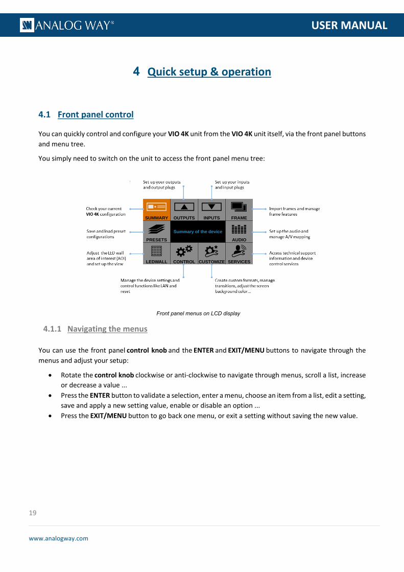
4.1 Front panel control
You can quickly control and configure your VIO 4K unit from the VIO 4K unit itself, via the front panel buttons and menu tree.
You simply need to switch on the unit to access the front panel menu tree:
Front panel menus on LCD display
You can use the front panel control knob and the ENTER and EXIT/MENU buttons to navigate through the menus and adjust your setup:
• Rotate the control knob clockwise or anti-clockwise to navigate through menus, scroll a list, increase or decrease a value ...
• Press the ENTER button to validate a selection, enter a menu, choose an item from a list, edit a setting, save and apply a new setting value, enable or disable an option ...
• Press the EXIT/MENU button to go back one menu, or exit a setting without saving the new value.
4.1.1 Navigating the menus

20
www.analogway.com
PROGRAMMER’S GU
USER MANUAL
OUTPUT MENU
Enter the OUTPUTS menu and select STANDARD OUTPUT to set up the output.
Output format and rate:
• Choose the format and rate generation mode and then adjust the format settings accordingly. • Go to the CUSTOMIZE menu and create your own custom format when the required format is not
available in the list of predefined output formats.
TIP: Try to use native resolution of your screens/projectors to avoid additional scaling.
Area of interest:
Adjust the active area of your display in the output format.
Image corrections:
• Adjust the gamma correction of your output image (especially useful if setting up a LED Wall). • Use the advanced color adjustments like color temperature, brightness and contrast to truly fine-
tune your output image.
INPUT MENU
• Enter the INPUTS menu to have an overview of all your inputs and their status. • Select AUTOSET ALL to launch the automatic detection of all plugs of all inputs.
Input settings:
• Select an input to set up the input individually. • Enter the Plug Settings menu to select the type of input signal by plug, enable or disable HDCP
support on the sources connected to the input plug, and manage the plug's EDID format. • Select the Image Settings menu to optimize the input image signal and correct for the image aspect
ratio and size.
TIP: Crop the image and use a predefined display aspect ratio to correct for the image aspect ratio after crop.
AUDIO MANAGEMENT
Audio in & out settings:
Set up the audio independently of the video content:
• Manage up to 4 embedded channel pairs per input/output. • Configure the auxiliary audio for each audio pair. • Set up an audio prelist and pre-listen to your content on the headphone output.
4.1.2 Operating from the front panel

21
www.analogway.com
PROGRAMMER’S GU
USER MANUAL
A/V mapping:
Select an A/V mapping mode to map an audio stream to the output (embedded audio by A/V mapping):
• Follow mapping mode: use the audio of the input selected at runtime (A/V mapping by video source selection);
• Direct routing mode: use a specifically set audio source (A/V mapping by audio embedded in video source selection).
TIP: Use the Follow mapping mode to also map audio streams to input sources.
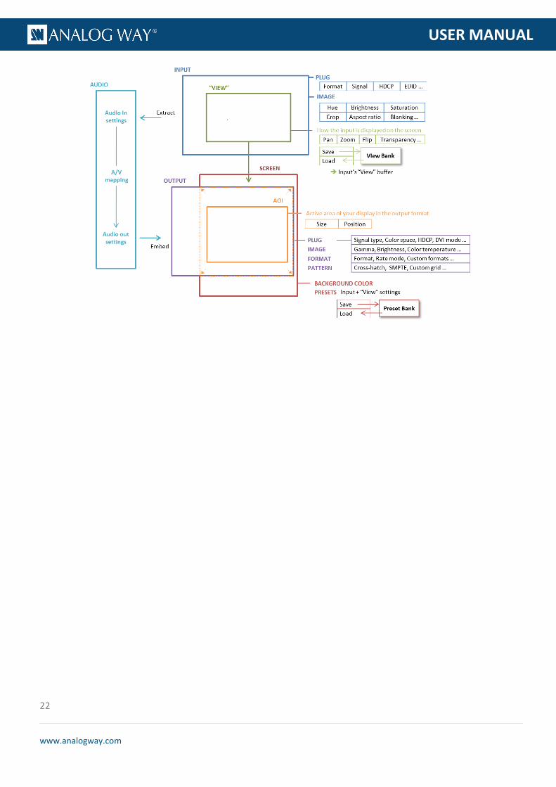
VIEW SETTINGS
Control how each input appears in the screen by setting up the input's "view":
• Use Pan and Zoom to size and position the input in the screen. • Apply a color Effect or enable a Flip movement on the live input. • Save the input view settings and recall them later on any input via the View Bank. • Create Presets of your input and view settings and load them readily at runtime.
TIP: Double-click on an input selection button to access the input setup and view settings menu.
SOURCE CONTROL
• Freeze the output and Monitor inputs and outputs on the front panel LCD display. • Customize the Transition Type and the Transition Duration to smoothly transition between sources. • Use Frames to transition through frame or activate the Quick Frame function to quickly display a
foreground frame on the output. • Select the input to display on the output by choosing the corresponding INPUT SELECTION button.
TIP: Enable the Safe Input Select control function (CONTROL > Front Panel) to disable the selection of inputs without signal.
BUTTON COLOR USAGE
• RED: Active input, function or shortcut. • GREEN: Available input, function or shortcut. • BLINKING: Device initializing. • OFF: Not available input, function or shortcut.
TIP: Check out the front panel physical description and visit the VIO 4K - Menu Tree for a complete description of all available buttons and menus.
The following graph also provides a quick overview of the VIO 4K operational environment:
22
www.analogway.com
PROGRAMMER’S GU
USER MANUAL

23
www.analogway.com
PROGRAMMER’S GU
USER MANUAL
The Web RCS is a web-based remote control software that allows you to control and configure a VIO 4K unit from a PC or tablet via LAN and/or USB.
The Web RCS comes embedded in your VIO 4K and you simply need AW Browser and a standard LAN network (or an Ethernet over USB connection) to connect.
You can easily connect to the Web RCS client of your VIO 4K unit using a standard LAN network.
AUTOMATIC LAN SETUP
- Download AW Browser on www.analogway.com to use the Web RCS.
To connect to the Web RCS of your VIO 4K using a standard LAN network:
1. Connect your computer to the VIO 4K using the provided Ethernet cable. 2. Open AW Browser and enter the IP address of your VIO 4K (displayed in the front panel LCD
screen).
The Web RCS connection should start.
NOTE: The VIO 4K unit must be ON and operating (i.e. not in standby mode) to be able to connect to the Web RCS client embedded
in the device.
4.2 Web RCS interface
4.2.1 Connecting to the Web RCS (LAN)
24
www.analogway.com
PROGRAMMER’S GU
USER MANUAL
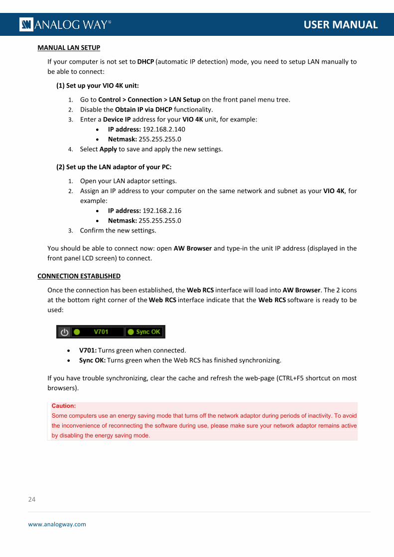
MANUAL LAN SETUP
If your computer is not set to DHCP (automatic IP detection) mode, you need to setup LAN manually to be able to connect:
(1) Set up your VIO 4K unit:
1. Go to Control > Connection > LAN Setup on the front panel menu tree. 2. Disable the Obtain IP via DHCP functionality. 3. Enter a Device IP address for your VIO 4K unit, for example:
• IP address: 192.168.2.140 • Netmask: 255.255.255.0
4. Select Apply to save and apply the new settings.
(2) Set up the LAN adaptor of your PC:
1. Open your LAN adaptor settings. 2. Assign an IP address to your computer on the same network and subnet as your VIO 4K, for
example: • IP address: 192.168.2.16 • Netmask: 255.255.255.0
3. Confirm the new settings.
You should be able to connect now: open AW Browser and type-in the unit IP address (displayed in the front panel LCD screen) to connect.
CONNECTION ESTABLISHED
Once the connection has been established, the Web RCS interface will load into AW Browser. The 2 icons at the bottom right corner of the Web RCS interface indicate that the Web RCS software is ready to be used:
• V701: Turns green when connected. • Sync OK: Turns green when the Web RCS has finished synchronizing.
If you have trouble synchronizing, clear the cache and refresh the web-page (CTRL+F5 shortcut on most browsers).
Caution: Some computers use an energy saving mode that turns off the network adaptor during periods of inactivity. To avoid the inconvenience of reconnecting the software during use, please make sure your network adaptor remains active by disabling the energy saving mode.

25
www.analogway.com
PROGRAMMER’S GU
USER MANUAL
TROUBLESHOOTING
• Check that you are using the correct network cable (crossover or straight cable as required) and that it is free from defects.
• Check the IP address of your control computer: the IP address of the computer must be unique on the same network as your VIO 4K unit.
• Temporarily disable any other networks on the computer, such as turning off the Wi-Fi connection. • Refresh your Web RCS. • Restart AW Browser.
/!\ MINIMUM REQUIREMENTS
Recommended requirements:
• 1Gb Ram • 200Mb of free space • 100Mb Network adaptor or above • 1920x1080 optimized screen resolution • 1366x768 as the minimum screen resolution
Operating system:
• Windows XP SP3 or above • Mac OS v10.7 or above • Ubuntu v10 or above • Linux OS 11 or above
Web-browser support:
• AW Browser (available on www.analogway.com)
NOTE: Starting 31-DEC-2020, AW Browser is the only recommended web browser to use the Web RCS.
You can connect to the Web RCS client of your VIO 4K unit using an Ethernet over USB connection.
NOTE (Windows users only): You need to install the Ethernet over USB device driver before plugging in the USB cable.
MAC & LINUX USERS
(1) Connect your computer to the VIO 4K:
1. Plug-in the USB type B connector to the front panel USB device port. 2. Plug-in the USB type A connector to your computer USB port.
(2) Enable the Ethernet over USB device connection:
1. Go to the CONTROL > USB Device menu on the front panel interface. 2. Select Connection Mode > ETHERNET to enabled the Ethernet over USB connection.
(3) Connect to the Web RCS:
4.2.2 Connecting to the Web RCS (USB)

26
www.analogway.com
PROGRAMMER’S GU
USER MANUAL
1. Open AW Browser and type in the VIO 4K virtual IP address (available from the CONTROL > USB Device menu).
The Web RCS interface should load into AW Browser.
WINDOWS XP USERS
(1) Enable the mass storage USB device connection:
1. Go to the CONTROL > USB Device menu on the front panel interface. 2. Select Connection Mode > MASS STORAGE to enable the mass storage device mode connection.
(2) Connect your computer to the VIO 4K:
1. Plug-in the USB type B connector to the front panel USB device port. 2. Plug-in the USB type A connector to your computer USB port.
(3) Copy the Ethernet over USB driver to your computer:
1. Open the VIO 4K_USB driver. 2. Go to the Drivers/Windows folder and select XP. 3. Copy the file AW_VIO4K_EtherOverUsb.inf to your computer.
(4) Enable the Ethernet over USB device connection:
1. Go to the CONTROL > USB Device menu on the front panel interface. 2. Select Connection Mode > ETHERNET to enabled the Ethernet over USB connection.
The Add New Hardware assistant should pop up.
(5) Add the new hardware:
The Add new hardware assistant automatically pops up when enabling the Ethernet over USB device connection with the VIO 4K unit connected to your Windows computer:
1. Uncheck the Use Windows Update box and click next. 2. Select Install from folder and browse for the AW_VIO4K_EtherOverUsb.inf file.
NOTE: The driver will work even if not certified for Windows XP.
(6) Connect to the Web RCS:
1. Open AW Browser and type in the VIO 4K virtual IP address (available from the CONTROL > USB Device menu).
The Web RCS interface should load into AW Browser.
W7/W8/W8.1/W10 USERS
(1) Enable the mass storage USB device connection:
1. Go to the CONTROL > USB Device menu on the front panel interface. 2. Select Connection Mode > MASS STORAGE to enable the mass storage device mode connection.
(2) Connect your computer to the VIO 4K:
27
www.analogway.com
PROGRAMMER’S GU
USER MANUAL
1. Plug-in the USB type B connector to the front panel USB device port. 2. Plug-in the USB type A connector to your computer USB port.
(3) Install the driver:
1. Open the VIO 4K_USB driver. 2. Go to the Drivers/Windows folder and select your platform. 3. Double-click on AW_VIO4K_Driver_EtherOverUSB.exe to start the driver installation. 4. Accept to install a Network Card type driver if asked during the installation.
(4) Enable the Ethernet over USB device connection:
1. Go to the CONTROL > USB Device menu on the front panel interface. 2. Select Connection Mode > ETHERNET to enabled the Ethernet over USB connection.
(5) Connect to the Web RCS:
1. Open AW Browser type in the VIO 4K virtual IP address (available from the CONTROL > USB Device menu).
The Web RCS interface should load into AW Browser.
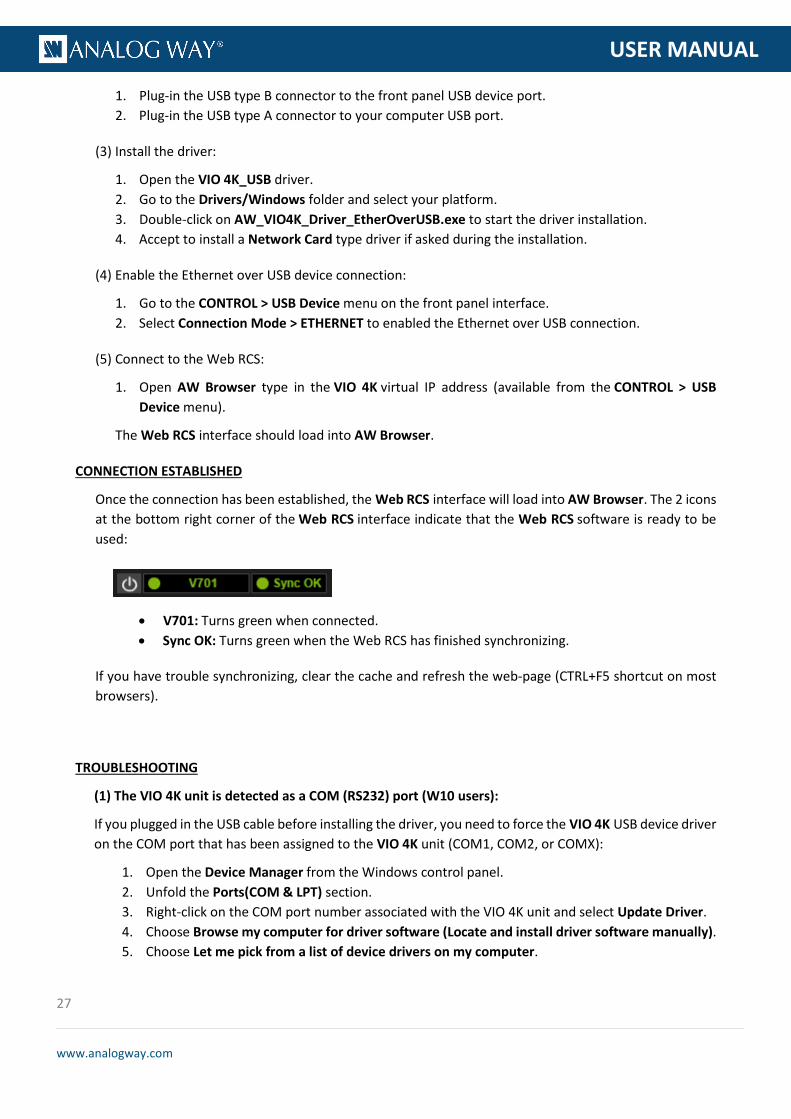
CONNECTION ESTABLISHED
Once the connection has been established, the Web RCS interface will load into AW Browser. The 2 icons at the bottom right corner of the Web RCS interface indicate that the Web RCS software is ready to be used:
• V701: Turns green when connected. • Sync OK: Turns green when the Web RCS has finished synchronizing.
If you have trouble synchronizing, clear the cache and refresh the web-page (CTRL+F5 shortcut on most browsers).
TROUBLESHOOTING
(1) The VIO 4K unit is detected as a COM (RS232) port (W10 users):
If you plugged in the USB cable before installing the driver, you need to force the VIO 4K USB device driver on the COM port that has been assigned to the VIO 4K unit (COM1, COM2, or COMX):
1. Open the Device Manager from the Windows control panel. 2. Unfold the Ports(COM & LPT) section. 3. Right-click on the COM port number associated with the VIO 4K unit and select Update Driver. 4. Choose Browse my computer for driver software (Locate and install driver software manually). 5. Choose Let me pick from a list of device drivers on my computer.

28
www.analogway.com
PROGRAMMER’S GU
USER MANUAL
6. By default, the Show compatible hardware option is enabled and allows you to select two drivers: • USB serial peripheral • VIO4K USB Ethernet/RNDIS Gadget
7. Select the VIO4K USB Ethernet/RNDIS Gadget driver and click Next.
NOTE: You will need to install the driver if the VIO4K USB Ethernet/RNDIS gadget is not available.
The driver is now associated to your VIO 4K unit and the VIO 4K will always be recognized as a USB device from now on.
/!\ MINIMUM REQUIREMENTS
Recommended requirements:
• 1Gb Ram • 200Mb of free space • 100Mb Network adaptor or above • 1920x1080 optimized screen resolution • 1366x768 as the minimum screen resolution
Operating system:
• Windows XP SP3 or above • Mac OS v10.7 or above • Ubuntu v10 or above • Linux OS 11 or above
Web-browser support:
• AW Browser (available on www.analogway.com)
NOTE: Starting 31-DEC-2020, AW Browser is the only recommended web browser to use the Web RCS.
29
www.analogway.com
PROGRAMMER’S GU
USER MANUAL
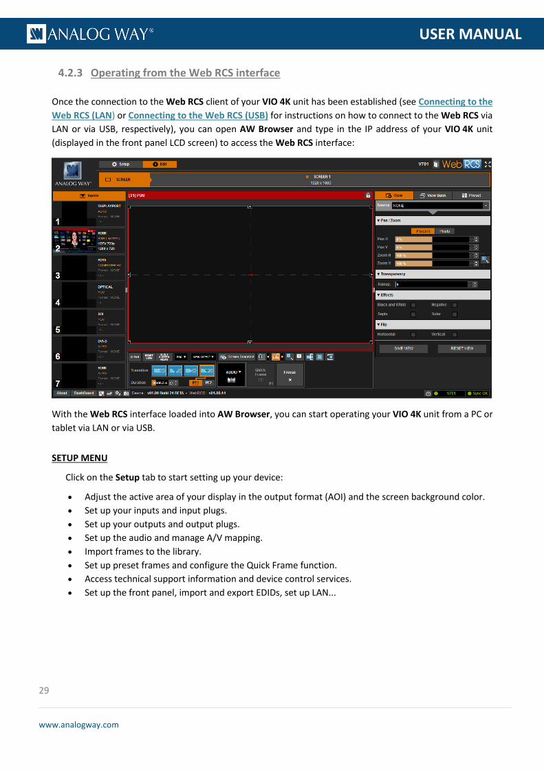
Once the connection to the Web RCS client of your VIO 4K unit has been established (see Connecting to the Web RCS (LAN) or Connecting to the Web RCS (USB) for instructions on how to connect to the Web RCS via LAN or via USB, respectively), you can open AW Browser and type in the IP address of your VIO 4K unit (displayed in the front panel LCD screen) to access the Web RCS interface:
With the Web RCS interface loaded into AW Browser, you can start operating your VIO 4K unit from a PC or tablet via LAN or via USB.
SETUP MENU
Click on the Setup tab to start setting up your device:
• Adjust the active area of your display in the output format (AOI) and the screen background color. • Set up your inputs and input plugs. • Set up your outputs and output plugs. • Set up the audio and manage A/V mapping. • Import frames to the library. • Set up preset frames and configure the Quick Frame function. • Access technical support information and device control services. • Set up the front panel, import and export EDIDs, set up LAN...
4.2.3 Operating from the Web RCS interface

30
www.analogway.com
PROGRAMMER’S GU
USER MANUAL
TIP: Use the PRECONFIG > Setup Assistant to get started with your setup.
EDIT MENU
Once your setup is complete, click on the Edit tab to start putting it all together in the screen:
• Select the input to display on the output • Set up the View for each input • Create Presets of your input and view settings • Freeze and control the output • Customize the transition effect when switching sources • Manage the screen layout ...
TIP: Use Presets to save all your screen configurations and quickly recall them at runtime.
TIP: Carry on reading this documentation to find out more about all and the many possibilities available on your VIO 4K unit.

31
www.analogway.com
PROGRAMMER’S GU
USER MANUAL
The VIO 4K is equipped with a power AC Main switch with Fuse (cartridge 5x20 4A Fast 250VAC) that allows you to easily connect and disconnect the unit from the mains.
To power-up your device:
1. Plug-in the power supply cord to the VIO 4K (SEE: Rear panel physical description). 2. Switch on the VIO 4K power supply button located on the rear panel.
NOTE: The VIO 4K will start up in standby mode if you shut down the device in standby mode with the back to standby power
loss function enabled (SEE: Back to standby function for details). If required, press the front panel ON/OFF button for about 3
seconds to wake up the device.
The VIO 4K is equipped with a low power consumption standby mode that you can quickly activate and deactivate using the Front Panel ON/OFF button.
To send the device to standby:
1. Press the VIO 4K front panel ON/OFF button. 2. When asked for confirmation, select YES to send the device to standby or NO to cancel the action.
NOTE: The VIO 4K will start up in standby mode if you shut down the device with the back to standby power loss function enabled
(SEE: Alternative method below for more details).
Alternative method (Front Panel):
1. Enter the CONTROL menu on the Front Panel interface. 2. Select Functions to access the device functions menu. 3. Select Standby Settings to access the device standby settings menu. 4. Select the Standby power loss behavior option if required to choose the behavior of the standby
function in case of power loss while in standby: • REMAIN ON STDBY will keep the device in standby mode. • REBOOT will start up the device in wake up mode.
5. Finally, select Standby request to send the device to standby. 6. When asked for confirmation, select YES to send the device to standby or NO to cancel the action.
5 Device management
5.1 Powering-up
5.2 Sending the device to standby

32
www.analogway.com
PROGRAMMER’S GU
USER MANUAL
To wake up the device:
Press the ON/OFF button for about 3 seconds.
The front panel allows you to control and configure the VIO 4K framework directly from the VIO 4K unit itself, via the front panel buttons and the menu tree on the LCD display.
To adjust the LCD display brightness:
Front Panel
1. Enter the CONTROL menu on the Front Panel interface. 2. Scroll down and select Front Panel to access the front panel settings menu. 3. Select LCD Brightness and rotate the control knob left or right to adjust the brightness of the front
panel LCD display: • Select ENTER to save the new value. • Select EXIT-MENU to restore the last saved value.
Web RCS
1. Go to the Setup menu on the Web RCS interface. 2. Click on the CONTROL tab to access the device settings and control functions. 3. In the left side toolbar, select Front Panel to access the front panel settings page. 4. Under LCD Brightness, click and drag the LCD brightness control bar right or left to adjust the
brightness of the front panel LCD display.
5.3 Adjusting the front panel

33
www.analogway.com
PROGRAMMER’S GU
USER MANUAL
To select the LCD timeout before standby:
Caution: Disabling the LCD Standby may shorten the LCD backlight lifespan.
Front Panel
1. Enter the CONTROL menu on the Front Panel interface. 2. Scroll down and select Front Panel to access the front panel settings menu. 3. Select LCD Standby and select the front panel LCD display timeout before standby.
List of possible front panel LCD timeouts:
5 Minutes Standby after 5 minutes of inactivity
15 Minutes Standby after 15 minutes of inactivity
30 Minutes Standby after 30 minutes of inactivity
1 Hour Standby after 1 hour of inactivity
DISABLE No standby
Web RCS
1. Go to the Setup menu on the Web RCS interface. 2. Click on the CONTROL tab to access the device settings and control functions. 3. In the left side toolbar, select Front Panel to access the front panel settings page. 4. Under Auto Standby In, select the front panel LCD display timeout before standby.
List of possible front panel LCD timeouts:
5 Minutes Standby after 5 minutes of inactivity
15 Minutes Standby after 15 minutes of inactivity
30 Minutes Standby after 30 minutes of inactivity
1 Hour Standby after 1 hour of inactivity
DISABLE No standby

34
www.analogway.com
PROGRAMMER’S GU
USER MANUAL
To disable the menu page timeout:
Front Panel
1. Enter the CONTROL menu on the Front Panel interface. 2. Scroll down and select Front Panel to access the front panel settings menu. 3. Uncheck the Enable Menu Page Timeout check-box to stay on the current menu page whatever the
timeout.
Web RCS
1. Go to the Setup menu on the Web RCS interface. 2. Click on the CONTROL tab to access the device settings and control functions. 3. In the left side toolbar, select Front Panel to access the front panel settings page. 4. Uncheck the Timeout check-box to stay on the current menu page whatever the timeout.
To adjust the key buttons brightness:
Front Panel
1. Enter the CONTROL menu on the Front Panel interface. 2. Scroll down and select Front Panel to access the front panel settings menu. 3. Select Key Brightness and rotate the control knob left or right to adjust the brightness of the front
panel key buttons: • Select ENTER to save the new value. • Select EXIT-MENU to restore the last saved value.
35
www.analogway.com
PROGRAMMER’S GU
USER MANUAL
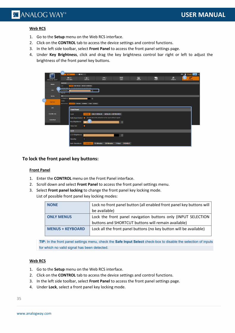
Web RCS
1. Go to the Setup menu on the Web RCS interface. 2. Click on the CONTROL tab to access the device settings and control functions. 3. In the left side toolbar, select Front Panel to access the front panel settings page. 4. Under Key Brightness, click and drag the key brightness control bar right or left to adjust the
brightness of the front panel key buttons.
To lock the front panel key buttons:
Front Panel
1. Enter the CONTROL menu on the Front Panel interface. 2. Scroll down and select Front Panel to access the front panel settings menu. 3. Select Front panel locking to change the front panel key locking mode.
List of possible front panel key locking modes:
NONE Lock no front panel button (all enabled front panel key buttons will be available)
ONLY MENUS Lock the front panel navigation buttons only (INPUT SELECTION buttons and SHORTCUT buttons will remain available)
MENUS + KEYBOARD Lock all the front panel buttons (no key button will be available)
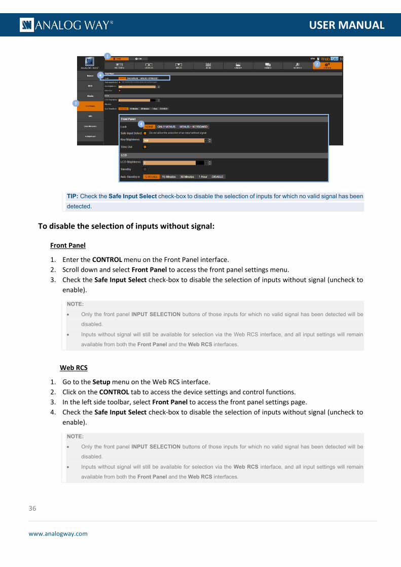
TIP: In the front panel settings menu, check the Safe Input Select check-box to disable the selection of inputs for which no valid signal has been detected.
Web RCS
1. Go to the Setup menu on the Web RCS interface. 2. Click on the CONTROL tab to access the device settings and control functions. 3. In the left side toolbar, select Front Panel to access the front panel settings page. 4. Under Lock, select a front panel key locking mode.
36
www.analogway.com
PROGRAMMER’S GU
USER MANUAL
TIP: Check the Safe Input Select check-box to disable the selection of inputs for which no valid signal has been detected.
To disable the selection of inputs without signal:
Front Panel
1. Enter the CONTROL menu on the Front Panel interface. 2. Scroll down and select Front Panel to access the front panel settings menu. 3. Check the Safe Input Select check-box to disable the selection of inputs without signal (uncheck to
enable).
NOTE:
• Only the front panel INPUT SELECTION buttons of those inputs for which no valid signal has been detected will be
disabled.
• Inputs without signal will still be available for selection via the Web RCS interface, and all input settings will remain
available from both the Front Panel and the Web RCS interfaces.
Web RCS
1. Go to the Setup menu on the Web RCS interface. 2. Click on the CONTROL tab to access the device settings and control functions. 3. In the left side toolbar, select Front Panel to access the front panel settings page. 4. Check the Safe Input Select check-box to disable the selection of inputs without signal (uncheck to
enable).
NOTE:
• Only the front panel INPUT SELECTION buttons of those inputs for which no valid signal has been detected will be
disabled.
• Inputs without signal will still be available for selection via the Web RCS interface, and all input settings will remain
available from both the Front Panel and the Web RCS interfaces.
37
www.analogway.com
PROGRAMMER’S GU
USER MANUAL
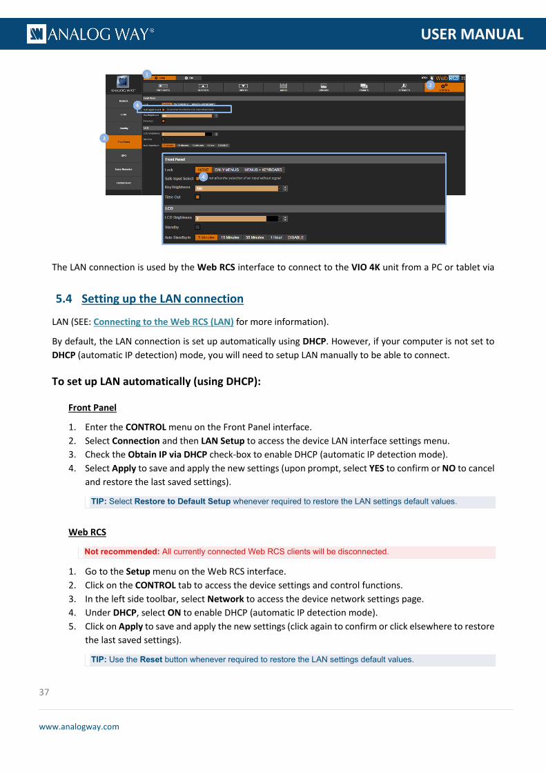
The LAN connection is used by the Web RCS interface to connect to the VIO 4K unit from a PC or tablet via
LAN (SEE: Connecting to the Web RCS (LAN) for more information).
By default, the LAN connection is set up automatically using DHCP. However, if your computer is not set to DHCP (automatic IP detection) mode, you will need to setup LAN manually to be able to connect.
To set up LAN automatically (using DHCP):
Front Panel
1. Enter the CONTROL menu on the Front Panel interface. 2. Select Connection and then LAN Setup to access the device LAN interface settings menu. 3. Check the Obtain IP via DHCP check-box to enable DHCP (automatic IP detection mode). 4. Select Apply to save and apply the new settings (upon prompt, select YES to confirm or NO to cancel
and restore the last saved settings).
TIP: Select Restore to Default Setup whenever required to restore the LAN settings default values.
Web RCS
Not recommended: All currently connected Web RCS clients will be disconnected.
1. Go to the Setup menu on the Web RCS interface. 2. Click on the CONTROL tab to access the device settings and control functions. 3. In the left side toolbar, select Network to access the device network settings page. 4. Under DHCP, select ON to enable DHCP (automatic IP detection mode). 5. Click on Apply to save and apply the new settings (click again to confirm or click elsewhere to restore
the last saved settings).
TIP: Use the Reset button whenever required to restore the LAN settings default values.
5.4 Setting up the LAN connection
38
www.analogway.com
PROGRAMMER’S GU
USER MANUAL
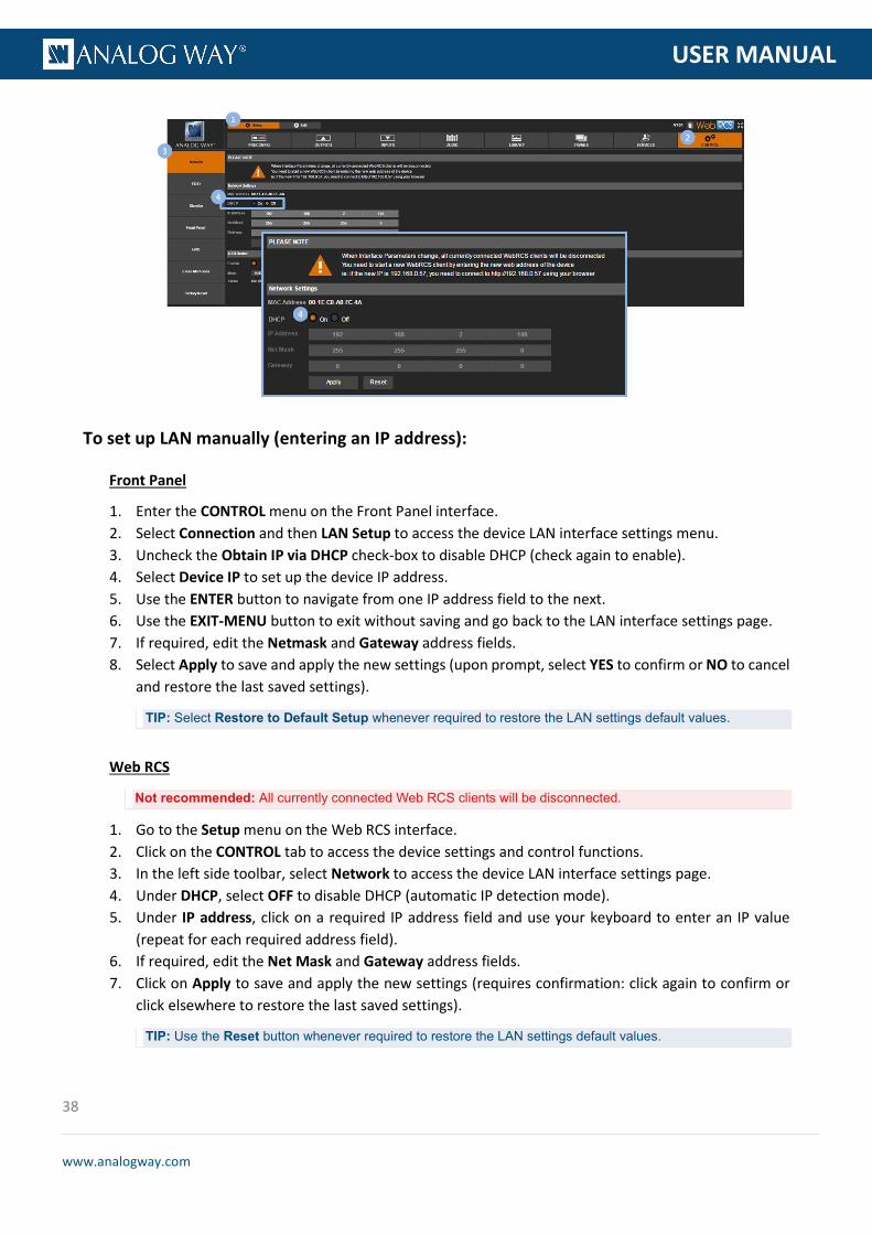
To set up LAN manually (entering an IP address):
Front Panel
1. Enter the CONTROL menu on the Front Panel interface. 2. Select Connection and then LAN Setup to access the device LAN interface settings menu. 3. Uncheck the Obtain IP via DHCP check-box to disable DHCP (check again to enable). 4. Select Device IP to set up the device IP address. 5. Use the ENTER button to navigate from one IP address field to the next. 6. Use the EXIT-MENU button to exit without saving and go back to the LAN interface settings page. 7. If required, edit the Netmask and Gateway address fields. 8. Select Apply to save and apply the new settings (upon prompt, select YES to confirm or NO to cancel
and restore the last saved settings).
TIP: Select Restore to Default Setup whenever required to restore the LAN settings default values.
Web RCS
Not recommended: All currently connected Web RCS clients will be disconnected.
1. Go to the Setup menu on the Web RCS interface. 2. Click on the CONTROL tab to access the device settings and control functions. 3. In the left side toolbar, select Network to access the device LAN interface settings page. 4. Under DHCP, select OFF to disable DHCP (automatic IP detection mode). 5. Under IP address, click on a required IP address field and use your keyboard to enter an IP value
(repeat for each required address field). 6. If required, edit the Net Mask and Gateway address fields. 7. Click on Apply to save and apply the new settings (requires confirmation: click again to confirm or
click elsewhere to restore the last saved settings).
TIP: Use the Reset button whenever required to restore the LAN settings default values.

39
www.analogway.com
PROGRAMMER’S GU
USER MANUAL
Related topics:
• Connecting to the Web RCS (LAN) • Connecting to the Web RCS (USB)
5.5 Enabling the USB device connection
The USB device connection is used by the Web RCS interface to connect to the VIO 4K unit from a PC or tablet via USB (SEE: Connecting to the Web RCS (USB) for more information).
By default, the USB device connection is disabled on the VIO 4K. You can enable it to control your VIO 4K unit from a PC or tablet via USB.
To enable the mass storage USB device connection:
Information: It is strongly recommended to read the section Connecting to the Web RCS (USB) before you start.
Front Panel
1. Enter the CONTROL menu on the Front Panel interface. 2. Select USB Device. 3. Uncheck the Disable Interface check-box to enable the USB device interface connection. 4. Select Connection Mode >MASS STORAGE to connect to the unit as a mass storage device.

40
www.analogway.com
PROGRAMMER’S GU
USER MANUAL
Web RCS
1. Go to the Setup menu on the Web RCS interface. 2. Click on the CONTROL tab to access the device settings and control functions. 3. In the left side toolbar, select Network to access the device network settings page. 4. Under USB Device, check the Enable check-box to enable the USB device interface connection. 5. Click on MASS STORAGE to connect to the unit as a mass storage device.
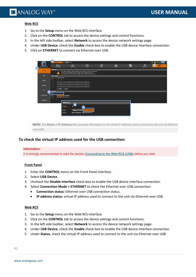
To enable the Ethernet over USB device connection:
Information: It is strongly recommended to read the section Connecting to the Web RCS (USB) before you start.
Front Panel
1. Enter the CONTROL menu on the Front Panel interface. 2. Select USB Device. 3. Uncheck the Disable Interface check-box to enable the USB device interface connection. 4. Select Connection Mode >ETHERNET to connect via Ethernet over USB.
NOTE: The Status > IP Address field provides information on the virtual IP address used to connect to the unit via Ethernet
over USB.
41
www.analogway.com
PROGRAMMER’S GU
USER MANUAL
Web RCS
1. Go to the Setup menu on the Web RCS interface. 2. Click on the CONTROL tab to access the device settings and control functions. 3. In the left side toolbar, select Network to access the device network settings page. 4. Under USB Device, check the Enable check-box to enable the USB device interface connection. 5. Click on ETHERNET to connect via Ethernet over USB.
NOTE: The Status > IP Address field provides information on the virtual IP address used to connect to the unit via Ethernet
over USB.
To check the virtual IP address used for the USB connection:
Information: It is strongly recommended to read the section Connecting to the Web RCS (USB) before you start.
Front Panel
1. Enter the CONTROL menu on the Front Panel interface. 2. Select USB Device. 3. Uncheck the Disable Interface check-box to enable the USB device interface connection. 4. Select Connection Mode > ETHERNET to check the Ethernet over USB connection:
• Connection status: Ethernet over USB connection status. • IP address status: virtual IP address used to connect to the unit via Ethernet over USB.
Web RCS
1. Go to the Setup menu on the Web RCS interface. 2. Click on the CONTROL tab to access the device settings and control functions. 3. In the left side toolbar, select Network to access the device network settings page. 4. Under USB Device, check the Enable check-box to enable the USB device interface connection. 5. Under Status, check the virtual IP address used to connect to the unit via Ethernet over USB.

42
www.analogway.com
PROGRAMMER’S GU
USER MANUAL
Related topics:
• Connecting to the Web RCS (LAN) • Connecting to the Web RCS (USB)
GPOs are a set of outputs that can be used to control a VIO 4K unit from external devices (automation).
Pins 1 and 2 are dedicated to turn on and off the device when a switch is placed in-between.
This switch works like the front panel switch:
• When the device is on, closing the switch requests the device to power down. If the switch remains closed more than 5 seconds, a forced power down is performed.
• When the device is off, closing the switch turns on the device.
NOTE:
• Only a wire with a simple switch can be connected.
• No voltage should be applied on on/off pins.
GPO pins are optically isolated MOSFET working as mechanical relays.
They all have a common pin (used as GPO return).
The polarity of each GPO needs to be configured as normally opened or normally closed (SEE: GPO Modes).
5.6 Using the GPO connection
5.6.1 What are GPOs?
5.6.2 ON/OFF pins description
5.6.3 GPO pins description
43
www.analogway.com
PROGRAMMER’S GU
USER MANUAL
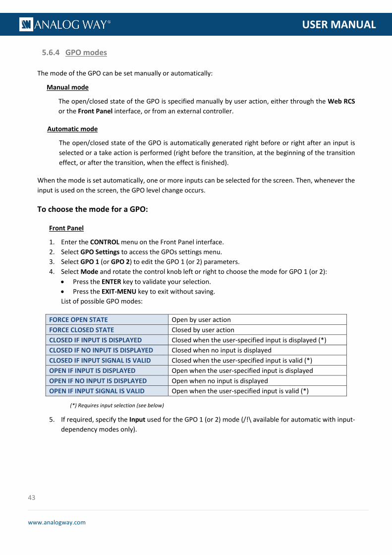
The mode of the GPO can be set manually or automatically:
Manual mode
The open/closed state of the GPO is specified manually by user action, either through the Web RCS or the Front Panel interface, or from an external controller.
Automatic mode
The open/closed state of the GPO is automatically generated right before or right after an input is selected or a take action is performed (right before the transition, at the beginning of the transition effect, or after the transition, when the effect is finished).
When the mode is set automatically, one or more inputs can be selected for the screen. Then, whenever the input is used on the screen, the GPO level change occurs.
To choose the mode for a GPO:
Front Panel
1. Enter the CONTROL menu on the Front Panel interface. 2. Select GPO Settings to access the GPOs settings menu. 3. Select GPO 1 (or GPO 2) to edit the GPO 1 (or 2) parameters. 4. Select Mode and rotate the control knob left or right to choose the mode for GPO 1 (or 2):
• Press the ENTER key to validate your selection. • Press the EXIT-MENU key to exit without saving. List of possible GPO modes:
(*) Requires input selection (see below)
5. If required, specify the Input used for the GPO 1 (or 2) mode (/!\ available for automatic with input-dependency modes only).
5.6.4 GPO modes
FORCE OPEN STATE Open by user action FORCE CLOSED STATE Closed by user action CLOSED IF INPUT IS DISPLAYED Closed when the user-specified input is displayed (*) CLOSED IF NO INPUT IS DISPLAYED Closed when no input is displayed CLOSED IF INPUT SIGNAL IS VALID Closed when the user-specified input is valid (*) OPEN IF INPUT IS DISPLAYED Open when the user-specified input is displayed OPEN IF NO INPUT IS DISPLAYED Open when no input is displayed OPEN IF INPUT SIGNAL IS VALID Open when the user-specified input is valid (*)

44
www.analogway.com
PROGRAMMER’S GU
USER MANUAL
Web RCS
1. Go to the Setup menu on the Web RCS interface. 2. Click on the CONTROL tab to access the device settings and control functions. 3. In the left side toolbar, select GPO to access the GPOs settings page. 4. Under GPO 1 (or GPO 2), choose the mode for GPO 1 (or 2).
List of possible GPO modes:
(*) Requires input selection (see below)
5. If required, specify the input used for the GPO 1 (or 2) mode (/!\ available for automatic with input-dependency modes only).
If you are using the VIO 4K for the first time, you can reset the device to factory settings (as-is out of the box) to start enjoying the unit as a brand new device.
You can also simply reset the unit to its configuration default values to keep the Frame Library and the current configuration of your Network, Web RCS and Link settings.
FORCE OPEN STATE Open by user action FORCE CLOSED STATE Closed by user action CLOSED IF INPUT IS DISPLAYED Closed when the user-specified input is displayed (*) CLOSED IF NO INPUT IS DISPLAYED Closed when no input is displayed CLOSED IF INPUT SIGNAL IS VALID Closed when the user-specified input is valid (*) OPEN IF INPUT IS DISPLAYED Open when the user-specified input is displayed OPEN IF NO INPUT IS DISPLAYED Open when no input is displayed OPEN IF INPUT SIGNAL IS VALID Open when the user-specified input is valid (*)
5.7 Resetting the unit
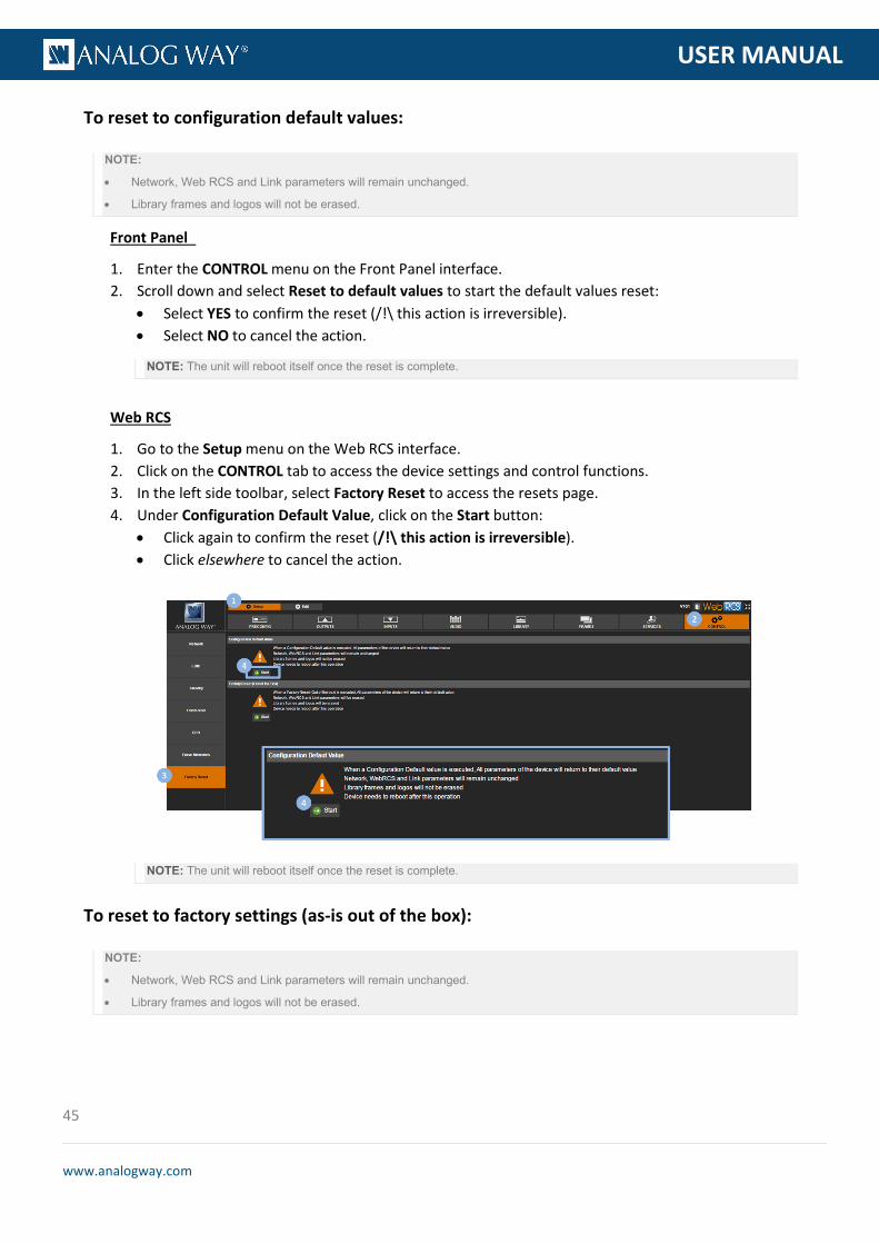
45
www.analogway.com
PROGRAMMER’S GU
USER MANUAL
To reset to configuration default values:
NOTE:
• Network, Web RCS and Link parameters will remain unchanged.
• Library frames and logos will not be erased.
Front Panel
1. Enter the CONTROL menu on the Front Panel interface. 2. Scroll down and select Reset to default values to start the default values reset:
• Select YES to confirm the reset (/!\ this action is irreversible). • Select NO to cancel the action.
NOTE: The unit will reboot itself once the reset is complete.
Web RCS
1. Go to the Setup menu on the Web RCS interface. 2. Click on the CONTROL tab to access the device settings and control functions. 3. In the left side toolbar, select Factory Reset to access the resets page. 4. Under Configuration Default Value, click on the Start button:
• Click again to confirm the reset (/!\ this action is irreversible). • Click elsewhere to cancel the action.
NOTE: The unit will reboot itself once the reset is complete.
To reset to factory settings (as-is out of the box):
NOTE:
• Network, Web RCS and Link parameters will remain unchanged.
• Library frames and logos will not be erased.
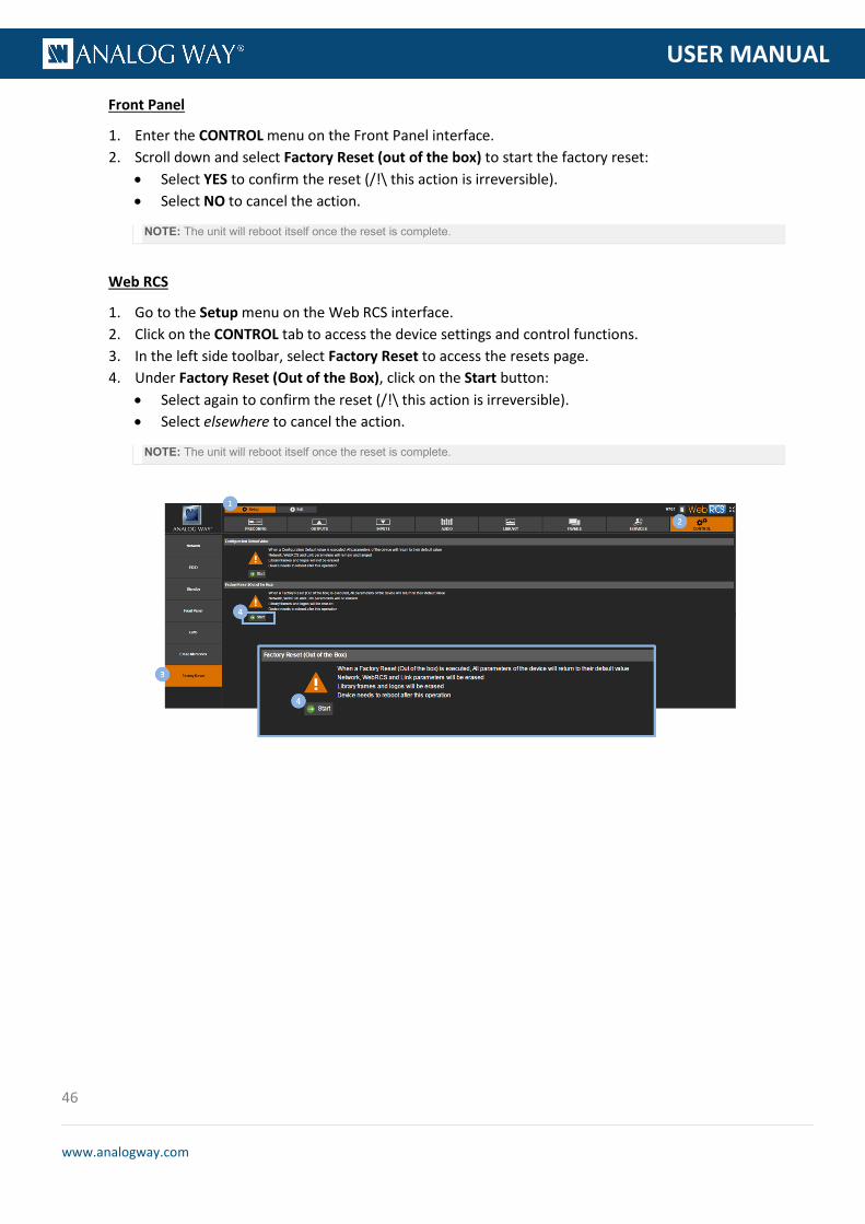
46
www.analogway.com
PROGRAMMER’S GU
USER MANUAL
Front Panel
1. Enter the CONTROL menu on the Front Panel interface. 2. Scroll down and select Factory Reset (out of the box) to start the factory reset:
• Select YES to confirm the reset (/!\ this action is irreversible). • Select NO to cancel the action.
NOTE: The unit will reboot itself once the reset is complete.
Web RCS
1. Go to the Setup menu on the Web RCS interface. 2. Click on the CONTROL tab to access the device settings and control functions. 3. In the left side toolbar, select Factory Reset to access the resets page. 4. Under Factory Reset (Out of the Box), click on the Start button:
• Select again to confirm the reset (/!\ this action is irreversible). • Select elsewhere to cancel the action.
NOTE: The unit will reboot itself once the reset is complete.

47
www.analogway.com
PROGRAMMER’S GU
USER MANUAL
The VIO 4K allows you to save and export your device configurations, for example to create backup copies of your settings, or to import these settings into other VIO 4K units in order to quickly have a new unit up and running.
To save a configuration:
NOTE: The configuration of your device will persist through reboot, no action required.
Front Panel
1. Enter the SERVICES menu on the Front Panel interface. 2. Select Device Config to access the device configuration menu. 3. Select Device Storage to manage the device storage. 4. Select Save to select the categories to be saved.
Available save categories include:
General configuration General configuration Front Panel configuration Front Panel configuration Communication interfaces Communication interfaces Input parameters Input parameters Output parameters Output parameters Audio parameters Audio parameters GPO parameters GPO parameters Frames library All the frame library WebRCS settings WebRCS settings Current preset parameters Current preset parameters Custom formats library Custom format library Preset and view library Preset and view library EDID library EDID library Input EDID Input EDID Device logs Device logs All All categories
5. Scroll down and select Save to start saving the current configuration of your device to the device storage.
NOTE: The device storage can only store one configuration at a time. If a configuration has already been saved to the device
storage, saving again will overwrite the stored configuration file. Export the stored configuration file first before saving again
if required (SEE: Exporting a configuration).
TIP: Go back to the Device Storage menu to load, review or erase the configuration stored in the device storage.
5.8 Creating backups

48
www.analogway.com
PROGRAMMER’S GU
USER MANUAL
Web RCS
1. Go to the Setup menu on the Web RCS interface. 2. Click on the SERVICES tab to access services available on the device. 3. In the left side toolbar, select Import/Export to access the device configuration page. 4. Under the EXPORT BACKUP FILE section, select the categories to export.
Available export categories include:
General configuration General configuration Front Panel configuration Front Panel configuration Communication interfaces Communication interfaces Input parameters Input parameters Output parameters Output parameters Audio parameters Audio parameters GPO parameters GPO parameters Frames library All the frame library WebRCS settings WebRCS settings Current preset parameters Current preset parameters Custom formats library Custom format library Preset and view library Preset and view library EDID library EDID library Input EDID Input EDID Device logs Device logs All All categories
5. Click on Generate backup and save it to device storage to save your current device configuration to the device storage.
NOTE: The device storage can only store one configuration at a time. If a configuration has already been saved to the device
storage, saving again will overwrite the stored configuration file. Export the stored configuration file first before saving again
if required (SEE: Exporting a configuration).
TIP: Go to the DEVICE STORAGE section to review or erase the configuration stored in the device storage.

49
www.analogway.com
PROGRAMMER’S GU
USER MANUAL
To export a configuration:
Front Panel
1. Enter the SERVICES menu on the Front Panel interface. 2. Select Device Config to access the device configuration menu. 3. Select Export and choose the export type.
Available export types include:
FROM DEVICE Export the current device configuration FROM DEVICE STORAGE
Export the configuration that is currently stored in the device storage (SEE: Saving a configuration to the device storage)
4. Select the categories to export if required.
Available export categories include:
General configuration General configuration Front Panel configuration Front Panel configuration Communication interfaces Communication interfaces Input parameters Input parameters Output parameters Output parameters Audio parameters Audio parameters GPO parameters GPO parameters Frames library All the frame library WebRCS settings WebRCS settings Current preset parameters Current preset parameters Custom formats library Custom format library Preset and view library Preset and view library EDID library EDID library Input EDID Input EDID Device logs Device logs All All categories
NOTE: The selection of categories to export is not available when exporting the configuration that is currently stored in the
device storage.
5. Scroll down and select Select Path to access the USB device browser.
TIP: Use the ENTER and EXIT-MENU keys to navigate through folders.
6. Finally, select EXPORT TO THIS FOLDER to export the selected folder. 7. Select Confirm to start the export or Cancel to cancel the action.

50
www.analogway.com
PROGRAMMER’S GU
USER MANUAL
Web RCS
1. Go to the Setup menu on the Web RCS interface. 2. Click on the SERVICES tab to access services available on the device. 3. In the left side toolbar, select Import/Export to access the device configuration page. 4. Under the EXPORT BACKUP FILE section, select the categories to export.
Available export categories include:
General configuration General configuration Front Panel configuration Front Panel configuration Communication interfaces Communication interfaces Input parameters Input parameters Output parameters Output parameters Audio parameters Audio parameters GPO parameters GPO parameters Frames library All the frame library WebRCS settings WebRCS settings Current preset parameters Current preset parameters Custom formats library Custom format library Preset and view library Preset and view library EDID library EDID library Input EDID Input EDID Device logs Device logs All All categories
5. Click on the Generate backup and save it on your disk button to export and save your current device configuration to your disk.
NOTE: You will need to click on the Download button to choose the save location and complete the save process.
6. Alternatively, you can click on the Generate backup and save to device storage button to save the current device configuration to the device storage. SEE: Saving a configuration to the device storage.

51
www.analogway.com
PROGRAMMER’S GU
USER MANUAL
To import a configuration:
Information: Your device will automatically reboot once the import is complete.
Front Panel
NOTE: You will need a USB key to import a configuration via the front panel.
Before you start:
• Plug-in a USB key into the USB HOST port (located in the front panel).
• Wait until the device is properly recognized and then proceed to import your configuration as described below.
1. Enter the SERVICES menu on the Front Panel interface. 2. Select Device Config to access the device configuration menu. 3. Select Import and choose the import type.
Available import types include:
TO DEVICE Import a configuration and load it on the device TO DEVICE STORAGE Import a configuration and save it to the device storage
(SEE also: Saving a configuration to the device storage) 4. Use the USB device browser to select the configuration to import.
TIP: Use the ENTER and EXIT-MENU keys to navigate through folders.
5. Select the categories to import if required and then select Import Config. Available import categories include:
General configuration General configuration Front Panel configuration Front Panel configuration Communication interfaces Communication interfaces Input parameters Input parameters Output parameters Output parameters Audio parameters Audio parameters GPO parameters GPO parameters WebRCS settings WebRCS settings Current preset parameters Current preset parameters Custom formats library Custom format library Preset and view library Preset and view library EDID library EDID library Input EDID Input EDID Device logs Device logs All All categories
6. Select Confirm to start the import.
NOTE:
• When importing to the device, this action will restore your device with the selected categories.
• The selection of categories to import is not available when importing a configuration to the device storage.
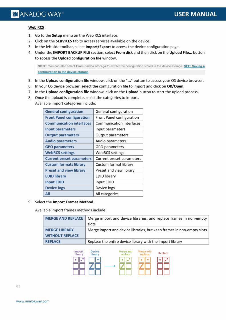
52
www.analogway.com
PROGRAMMER’S GU
USER MANUAL
Web RCS
1. Go to the Setup menu on the Web RCS interface. 2. Click on the SERVICES tab to access services available on the device. 3. In the left side toolbar, select Import/Export to access the device configuration page. 4. Under the IMPORT BACKUP FILE section, select From disk and then click on the Upload File... button
to access the Upload configuration file window.
NOTE: You can also select From device storage to extract the configuration stored in the device storage. SEE: Saving a
configuration to the device storage.
5. In the Upload configuration file window, click on the "..." button to access your OS device browser. 6. In your OS device browser, select the configuration file to import and click on OK/Open. 7. In the Upload configuration file window, click on the Upload button to start the upload process. 8. Once the upload is complete, select the categories to import.
Available import categories include:
General configuration General configuration Front Panel configuration Front Panel configuration Communication interfaces Communication interfaces Input parameters Input parameters Output parameters Output parameters Audio parameters Audio parameters GPO parameters GPO parameters WebRCS settings WebRCS settings Current preset parameters Current preset parameters Custom formats library Custom format library Preset and view library Preset and view library EDID library EDID library Input EDID Input EDID Device logs Device logs All All categories
9. Select the Import Frames Method.
Available import frames methods include:
MERGE AND REPLACE Merge import and device libraries, and replace frames in non-empty slots
MERGE LIBRARY WITHOUT REPLACE
Merge import and device libraries, but keep frames in non-empty slots
REPLACE Replace the entire device library with the import library

53
www.analogway.com
PROGRAMMER’S GU
USER MANUAL
10. Select Load to Device to load the imported configuration on the device.
NOTE: This action will restore your device with the selected categories. Alternatively, you can select Save configuration to
device storage to save the imported configuration to the device storage without loading it on the device. SEE also: Saving
a configuration to the device storage.
The device memories are settings that have been saved to the device either automatically (like input settings memories) or by user action (like frames and user EDIDs, or preset, view and custom format memories).
To erase all input settings memories:
Front Panel
1. Enter the CONTROL menu on the Front Panel interface. 2. Scroll down and select Reset/Erase to access the reset and erase menu. 3. Select Reset Input Settings Memories to start clearing up input settings memories:
• Select YES to confirm (/!\ this action is irreversible). • Select NO to cancel.
Web RCS
1. Go to the Setup menu on the Web RCS interface.
5.9 Erasing the device memories

54
www.analogway.com
PROGRAMMER’S GU
USER MANUAL
2. Click on the CONTROL tab to access the device settings and control functions. 3. In the left side toolbar, select Erase Memories to access the erase memories page. 4. Under Erase Input Settings Memories, click on the Start button:
• Click again to confirm (/!\ this action is irreversible). • Click elsewhere to cancel the action.
To erase all view memories:
Front Panel
1. Enter the CONTROL menu on the Front Panel interface. 2. Scroll down and select Reset/Erase to access the reset and erase menu. 3. Select Reset View Memories to start clearing up the view bank:
• Select YES to confirm (/!\ this action is irreversible). • Select NO to cancel.
Web RCS
1. Go to the Setup menu on the Web RCS interface. 2. Click on the CONTROL tab to access the device settings and control functions. 3. In the left side toolbar, select Erase Memories to access the erase memories page. 4. Under Erase View Bank, click on the Start button:
• Click again to confirm (/!\ this action is irreversible). • Click elsewhere to cancel the action.
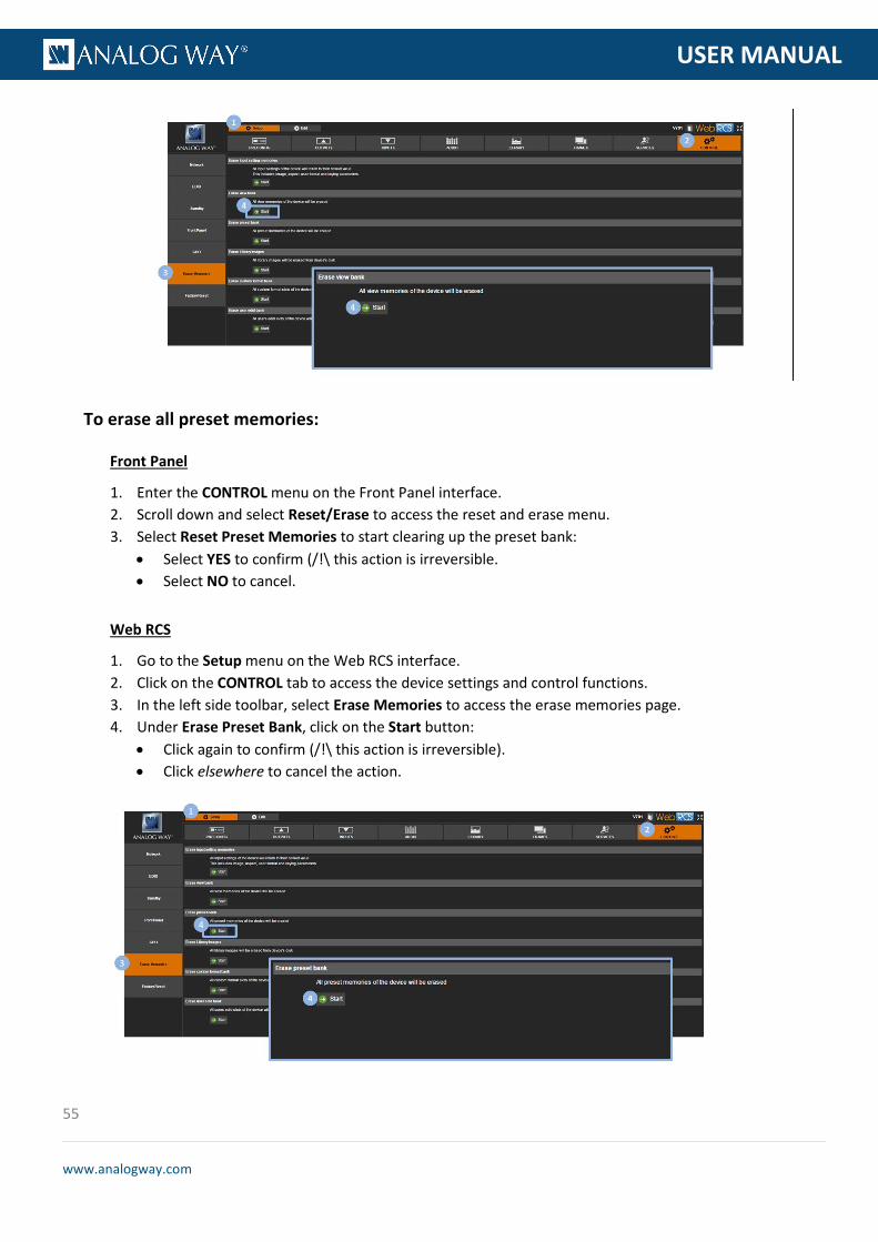
55
www.analogway.com
PROGRAMMER’S GU
USER MANUAL
To erase all preset memories:
Front Panel
1. Enter the CONTROL menu on the Front Panel interface. 2. Scroll down and select Reset/Erase to access the reset and erase menu. 3. Select Reset Preset Memories to start clearing up the preset bank:
• Select YES to confirm (/!\ this action is irreversible. • Select NO to cancel.
Web RCS
1. Go to the Setup menu on the Web RCS interface. 2. Click on the CONTROL tab to access the device settings and control functions. 3. In the left side toolbar, select Erase Memories to access the erase memories page. 4. Under Erase Preset Bank, click on the Start button:
• Click again to confirm (/!\ this action is irreversible). • Click elsewhere to cancel the action.

56
www.analogway.com
PROGRAMMER’S GU
USER MANUAL
To erase all frames in the library:
Front Panel
1. Enter the CONTROL menu on the Front Panel interface. 2. Scroll down and select Reset/Erase to access the reset and erase menu. 3. Select Erase Frame Library to start clearing up the library:
• Select YES to confirm (/!\ this action is irreversible). • Select NO to cancel.
Web RCS
1. Go to the Setup menu on the Web RCS interface. 2. Click on the CONTROL tab to access the device settings and control functions. 3. In the left side toolbar, select Erase Memories to access the erase memories page. 4. Under Erase Library Images, click on the Start button:
• Click again to confirm (/!\ this action is irreversible). • Click elsewhere to cancel the action.
To erase all custom format memories:
Front Panel
1. Enter the CONTROL menu on the Front Panel interface. 2. Scroll down and select Reset/Erase to access the reset and erase menu. 3. Select Reset Custom Format Memories to start clearing up the custom format bank:
• Select YES to confirm (/!\ this action is irreversible). • Select NO to cancel.

57
www.analogway.com
PROGRAMMER’S GU
USER MANUAL
Web RCS
1. Go to the Setup menu on the Web RCS interface. 2. Click on the CONTROL tab to access the device settings and control functions. 3. In the left side toolbar, select Erase Memories to access the erase memories page. 4. Under Erase Custom Format Bank, click on the Start button:
• Click again to confirm the reset (/!\ this action is irreversible). • Click elsewhere to cancel the action.
To erase all user EDIDs:
Front Panel
1. Enter the CONTROL menu on the Front Panel interface. 2. Scroll down and select Reset/Erase to access the reset and erase menu. 3. Select Erase EDID Library to start clearing up the user EDID bank:
• Select YES to confirm (/!\ this action is irreversible). • Select NO to cancel.
Web RCS
1. Go to the Setup menu on the Web RCS interface. 2. Click on the CONTROL tab to access the device settings and control functions. 3. In the left side toolbar, select Erase Memories to access the erase memories page. 4. Under Erase User EDID Bank, click on the Start button:
• Click again to confirm (/!\ this action is irreversible). • Click elsewhere to cancel the action.

58
www.analogway.com
PROGRAMMER’S GU
USER MANUAL
You can update your VIO 4K unit to enjoy the latest firmware on the device.
The updater release information includes:
• Updater version; • Executable file name; • Creation date; • Version and Checksums of the different programmable components; • List of the implemented functional evolutions (evolution ID and title in English); • List of the corrected bugs (bug ID and bug title, in English).
5.10 Updating the device

59
www.analogway.com
PROGRAMMER’S GU
USER MANUAL
To update your device:
Caution: Do not switch off the unit during the update. The VIO 4K unit will reboot itself once the update is complete.
Front Panel
NOTE: Before you start:
• Back up your settings if necessary.
• Download the latest firmware from http://www.analogway.com/
• Copy the downloaded AW Firmware Updater (AWP) file into a USB key (root folder).
• Plug-in the USB key into the unit USB HOST port (located on the front panel).
• Wait until the device is properly recognized and proceed as explained below.
1. Enter the CONTROL menu on the Front Panel interface. 2. Select USB Host. 3. Select Scan For Updater. 4. Select Confirm to start the update.
Web RCS
NOTE: Back up your settings and download the latest firmware from http://www.analogway.com/ before you start.
1. Go to the Setup menu on the Web RCS interface. 2. Click on the SERVICES tab to access services available on the device. 3. In the left side toolbar, select Update to access the device update page. 4. Click on Select a file... to open the Upload Update File window. 5. In the Upload Update File window, click on the "..." button and browse for the downloaded AW
Firmware Updater (AWP) file. 6. Click on the Upload button to load the firmware on the device. 7. Click on Start and confirm to start the update.

60
www.analogway.com
PROGRAMMER’S GU
USER MANUAL
An output is a group of plugs that deliver the same video content under various signal types.
By default, each VIO 4K unit is equipped with one standard output that contains the following plugs:
The following table provides information on the list of supported output formats and signals:
Plug type Formats Signals Universal Analog (HD15)
SDTV YCbCr ITU-R BT.601 EDTV YCbCr ITU-R BT.601 HDTV YCbCr ITU-R BT.709 Computer RGBHV
RGBs RGsB
DVI-D Dual-Link EDTV YCbCr ITU-R BT.601 RGB Full scale (0-255) RGB Limited scale (16-235)
HDTV YCbCr ITU-R BT.709 RGB Full scale (0-255) RGB Limited scale (16-235)
Computer YCbCr ITU-R BT.601 RGB Full scale (0-255) RGB Limited scale (16-235)
6 Output management
6.1 What is an output?
6.2 Supported outputs (formats and signals)

61
www.analogway.com
PROGRAMMER’S GU
USER MANUAL
Plug type Formats Signals HDMI 1.4a SDTV YCbCr ITU-R BT.601
RGB Full scale (0-255) RGB Limited scale (16-235)
EDTV YCbCr ITU-R BT.601 RGB Full scale (0-255) RGB Limited scale (16-235)
HDTV YCbCr ITU-R BT.709 RGB Full scale (0-255) RGB Limited scale (16-235)
UHDTV/4K (up to 30Hz)
YCbCr ITU-R BT.709 RGB Full scale (0-255) RGB Limited scale (16-235)
Computer YCbCr ITU-R BT.601 RGB Full scale (0-255) RGB Limited scale (16-235)
DisplayPort 1.2 SDTV YCbCr ITU-R BT.601 RGB Full scale (0-255) RGB Limited scale (16-235)
EDTV YCbCr ITU-R BT.601 RGB Full scale (0-255) RGB Limited scale (16-235)
HDTV YCbCr ITU-R BT.709 RGB Full scale (0-255) RGB Limited scale (16-235)
UHDTV/4K (up to 30Hz)
YCbCr ITU-R BT.709 RGB Full scale (0-255) RGB Limited scale (16-235)
Computer YCbCr ITU-R BT.601 RGB Full scale (0-255) RGB Limited scale (16-235)
3G-SDI SDTV SMPTE 259M-C (YCbCr ITU-R BT.601 4:2:2) HDTV SMPTE ST296 (720p YCbCr ITU-R BT.709 4:2:2)
SMPTE 274M (1080i/1080p YCbCr ITU-R BT.709 4:2:2) SMPTE ST2048 (2K YCbCr ITU-R BT.709 4:2:2)
6G-SDI UHDTV/4K (up to 30Hz)
SMPTE ST2036 (2K YCbCr ITU-R BT.709, ITU-R BT.2020 4:2:2) SMPTE ST2048 (4K YCbCr ITU-R BT.709, ITU-R BT.2020 4:2:2)
OPTICAL SFP Slot (NMSA)
SDTV SMPTE 259M-C (YCbCr ITU-R BT.601 4:2:2) HDTV SMPTE ST296 (720p YCbCr ITU-R BT.709 4:2:2)
SMPTE 274M (1080i/1080p YCbCr ITU-R BT.709 4:2:2) SMPTE ST2048 (2K YCbCr ITU-R BT.709 4:2:2)
UHDTV/4K (up to 30Hz)
SMPTE ST2036 (2K YCbCr ITU-R BT.709, ITU-R BT.2020 4:2:2) SMPTE ST2048 (4K YCbCr ITU-R BT.709, ITU-R BT.2020 4:2:2)

62
www.analogway.com
PROGRAMMER’S GU
USER MANUAL
SEE also: Custom Formats
Plug type Formats Signals HDMI 2.0 UHDTV/4K
(up to 60Hz) YCbCr ITU-R BT.601, ITU-R BT.709, ITU-R BT.2020 RGB Full scale (0-255) RGB Limited scale (16-235)
DisplayPort 1.2 UHDTV/4K (up to 60Hz)
YCbCr ITU-R BT.601, ITU-R BT.709, ITU-R BT.2020 RGB Full scale (0-255) RGB Limited scale (16-235)
12G-SDI UHDTV/4K (up to 60Hz)
SMPTE ST2036 (2K YCbCr ITU-R BT.709, ITU-R BT.2020 4:2:2) SMPTE ST2048 (4K YCbCr ITU-R BT.709, ITU-R BT.2020 4:2:2)
OPTICAL SFP Slot (NMSA)
UHDTV/4K (up to 60Hz)
SMPTE ST2036 (2K YCbCr ITU-R BT.709, ITU-R BT.2020 4:2:2) SMPTE ST2048 (4K YCbCr ITU-R BT.709, ITU-R BT.2020 4:2:2)
Related topics:
• Expansion interfaces
The output status provides information on the current output configuration.
Available output status information includes:
• Format Mode: Current mode used to set up the format. Possible output format modes include:
INTERNAL REF. Internal reference format mode AUTO EDID FORMAT
Automatic format mode based on EDID
FRAMELOCK Framelock format mode GENLOCK Genlock format mode
• Format: Currently applied format. • Rotation: Current output rotation. • AOI: Current active area of your display in the output format.
− Size: AOI horizontal x vertical dimensions (in pixels). − Position: AOI horizontal, vertical start offset (in pixels).
• Plug Status: Output plug status. List of possible status for each plug include:
NOT AVAILABLE Plug is not available for this output ACTIVE Plug is active for this output ACTIVE (WARNING EDID INVALID) Plug is active but monitor EDID is invalid DISABLED FOR HDCP REASON Plug is disabled for this output because it does not have the
HDCP capability
6.2.1 Additional outputs supported with video expansion interfaces
6.3 Checking the output status

63
www.analogway.com
PROGRAMMER’S GU
USER MANUAL
FORMAT NOT SUPPORTED Plug disabled for this output because the format is not supported
NO DISPLAY DETECTED Plug is disabled because there is no display detected CONNECTION FAILED (CHECK CABLE)
Plug disabled because connection has failed
REFERENCE SIGNAL INCOMPATIBLE
Plug disabled because reference used is not compatible with plug standard
FORMAT NOT SUPPORTED BY DISPLAY
Plug is disabled because the display is not compatible with the format parameters
To check the status of your outputs:
Front Panel
1. Enter the OUTPUTS menu on the Front Panel interface. 2. Select STANDARD OUTPUT to access the standard output setup menu. 3. Select Output Status to check the output status information.
Alternative method:
1. Enter the SUMMARY menu on the Front Panel interface. 2. Under STANDARD OUTPUT, check the standard output status information.
Web RCS
1. Go to the Setup menu on the Web RCS interface. 2. Click on the OUTPUTS tab to access the outputs setup page. 3. In the left side toolbar, select STANDARD OUTPUT to access the standard output setup page. 4. Check the output status information next to the output preview window.

64
www.analogway.com
PROGRAMMER’S GU
USER MANUAL
Alternative method:
1. Go to the Setup menu on the Web RCS interface. 2. Click on the OUTPUTS tab to access the outputs setup page. 3. In the left side toolbar, select General to access the general outputs setup page. 4. Check the output status information next to the output preview window.
You can truly control your output format conversion environment by setting up the output format and plug.
You can also adjust the active area of your display in the output format (i.e. the output Area of Interest), correct the output image, or use patterns to control the final rendering of the output in the screen.
The output plug status provides information on the current configuration of your output plugs.
Available plug status information includes:
• Status: Output plug status. List of possible status for each plug include:
NOT AVAILABLE Plug is not available for this output ACTIVE Plug is active for this output ACTIVE (WARNING EDID INVALID)
Plug is active but monitor EDID is invalid
DISABLED FOR HDCP REASON
Plug is disabled for this output because it does not have the HDCP capability
FORMAT NOT SUPPORTED
Plug disabled for this output because the format is not supported
NO DISPLAY DETECTED
Plug is disabled because there is no display detected
CONNECTION FAILED (CHECK CABLE)
Plug disabled because connection has failed
REFERENCE SIGNAL INCOMPATIBLE
Plug disabled because reference used is not compatible with plug standard
6.4 Setting up the output
6.4.1 Checking the plug status

65
www.analogway.com
PROGRAMMER’S GU
USER MANUAL
FORMAT NOT SUPPORTED BY DISPLAY
Plug is disabled because the display is not compatible with the format parameters
• Signal Type: Currently applied signal type (analog plugs). List of possible output signal types (analog plugs):
YUV YUV signal 0-700mV RGsB RGB signal with synchro on green (SOG) RGBs RGB signal with a TTL composite synchro RGBHV RGB signal with separate TTL H/V synchro
• Color Space: Currently applied color space (digital plugs). List of possible output color spaces (digital plugs):
AUTO Automatic color space selection RGB FULL (0-255) RGB Full scale (0-255) RGB LIMITED (16-235) RGB Limited scale (16-235) YCbCr 4:4:4 YCbCr 4:4:4 ( ITU-R BT.601 or ITU-R BT.709) YCbCr 4:2:2 YCbCr 4:2:2 ( ITU-R BT.601 or ITU-R BT.709)
• Color Depth: Current color depth status. List of possible signal color depths:
18 BITS (6 bpc) 18 bits for a pixel, 6 bits for each color 24 BITS (8 bpc) 24 bits for a pixel, 8 bits for each color 30 BITS (10 bpc) 30 bits for a pixel, 10 bits for each color
• HDCP Status: Current HDCP status for the plug. • Monitor: Current monitor name (if detected on the plug). • HDMI Mode: Current HDMI mode status (/!\ in DVI mode no audio can be transmitted). • Audio Mode: (SDI and Optical plugs only) Current audio mode selected for the output plug. • Module Detected: SFP module detection status. • ID: SFP module identifier. • Bitrate: SFP module nominal bitrate. • Vendor Name: SFP module vendor name. • Part Number: SFP module part number. • Module Status: SFP module support status. • Standard: SDI standard/transport used to output the signal.
To check the status of an output plug:
Front Panel
1. Enter the OUTPUTS menu on the Front Panel interface. 2. Select STANDARD OUTPUT to access the standard output setup menu. 3. Select Plug Status. 4. Check the plug status information for each output plug.

66
www.analogway.com
PROGRAMMER’S GU
USER MANUAL
Web RCS
1. Go to the Setup menu on the Web RCS interface. 2. Click on the OUTPUTS tab to access the outputs setup page. 3. In the left side toolbar, select STANDARD OUTPUT to access the standard output setup page. 4. Disable the Hide all plugs button if required to show output plugs.
TIP: Enable the Hide plugs with no display button to show active plugs only.
5. Check the plug status information right below each output plug.
You can optimize the output by setting up each output plug.
You can select the signal type on a plug for example, enable/disable HDCP detection on the plug, force the DVI mode of HDMI plugs, choose the audio mode of SDI/optical plugs, enable the loop mode of HDMI, DVI and analog plugs, etc.
Both the signal type and the color space depend on the plug type:
• On analog plugs, the color space is implicit to the signal type and you may simply select the signal type for the plug.
• On digital plugs, the signal type is always digital and you may simply select the color space for the plug.
6.4.2 Setting up the plug
6.4.2.1 Selecting the signal type

67
www.analogway.com
PROGRAMMER’S GU
USER MANUAL
To select the signal type for an analog plug:
Front Panel
1. Enter the OUTPUTS menu on the Front Panel interface. 2. Select STANDARD OUTPUT to access the standard output setup menu. 3. Select Plug Settings to access the plug setup menu for the output. 4. Select a plug to access the selected plug setup menu. 5. Select Signal Type and choose the signal type for the plug (analog plugs only).
Available signal types include:
YUV YUV signal 0-700mV RGsB RGB signal with synchro on green (SOG) RGBs RGB signal with a TTL composite synchro RGBHV RGB signal with separate TTL H/V synchro
Web RCS
1. Go to the Setup menu on the Web RCS interface. 2. Click on the OUTPUTS tab to access the outputs setup page. 3. In the left side toolbar, select STANDARD OUTPUT to access the standard output setup page. 4. Disable the Hide all plugs button if required to show the output plugs. 5. Click on the Show plugs settings button to access the plug settings for each output plug. 6. Locate the plug to set up. 7. Under Signal Type, select the signal type for the plug (analog plugs only).
Available signal types include:
YUV YUV signal 0-700mV RGsB RGB signal with synchro on green (SOG) RGBs RGB signal with a TTL composite synchro RGBHV RGB signal with separate TTL H/V synchro

68
www.analogway.com
PROGRAMMER’S GU
USER MANUAL
To select the color space for a digital plug:
Front Panel
1. Enter the OUTPUTS menu on the Front Panel interface. 2. Select STANDARD OUTPUT to access the standard output setup menu. 3. Select Plug Settings to access the plug setup menu for the output. 4. Select a plug to access the selected plug setup menu. 5. Select Color Space and choose the color space for the plug (digital plugs only).
Available color spaces include:
AUTO Automatic color space selection RGB FULL (0-255) RGB Full scale (0-255) RGB LIMITED (16-235) RGB Limited scale (16-235) YCbCr 4:4:4 YCbCr 4:4:4 ( ITU-R BT.601 or ITU-R BT.709) YCbCr 4:2:2 YCbCr 4:2:2 ( ITU-R BT.601 or ITU-R BT.709)
Web RCS
1. Go to the Setup menu on the Web RCS interface. 2. Click on the OUTPUTS tab to access the outputs setup page. 3. In the left side toolbar, select STANDARD OUTPUT to access the standard output setup page. 4. Disable the Hide all plugs button if required to show the output plugs. 5. Click on the Show plugs settings button to access the plug settings for each output plug. 6. Locate the plug to set up. 7. Under Color Space, select the color space for the plug (digital plugs only).

69
www.analogway.com
PROGRAMMER’S GU
USER MANUAL
To select the color depth for a digital plug:
Front Panel
1. Enter the OUTPUTS menu on the Front Panel interface. 2. Select STANDARD OUTPUT to access the standard output setup menu. 3. Select Plug Settings to access the plug setup menu for the output. 4. Select a plug to access the selected plug setup menu. 5. Select Color Depth and choose the color space for the plug (digital plugs only).
Web RCS
1. Go to the Setup menu on the Web RCS interface. 2. Click on the OUTPUTS tab to access the outputs setup page. 3. In the left side toolbar, select STANDARD OUTPUT to access the standard output setup page. 4. Disable the Hide all plugs button if required to show the output plugs. 5. Click on the Show plugs settings button to access the plug settings for each output plug. 6. Locate the plug to set up. 7. Under Color Depth, select the color depth for the plug (digital plugs only).
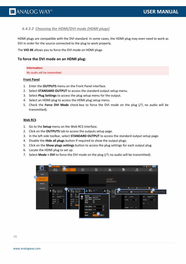
70
www.analogway.com
PROGRAMMER’S GU
USER MANUAL
HDMI plugs are compatible with the DVI standard. In some cases, the HDMI plug may even need to work as DVI in order for the source connected to the plug to work properly.
The VIO 4K allows you to force the DVI mode on HDMI plugs.
To force the DVI mode on an HDMI plug:
Information: No audio will be transmitted.
Front Panel
1. Enter the OUTPUTS menu on the Front Panel interface. 2. Select STANDARD OUTPUT to access the standard output setup menu. 3. Select Plug Settings to access the plug setup menu for the output. 4. Select an HDMI plug to access the HDMI plug setup menu. 5. Check the Force DVI Mode check-box to force the DVI mode on the plug (/!\ no audio will be
transmitted).
Web RCS
1. Go to the Setup menu on the Web RCS interface. 2. Click on the OUTPUTS tab to access the outputs setup page. 3. In the left side toolbar, select STANDARD OUTPUT to access the standard output setup page. 4. Disable the Hide all plugs button if required to show the output plugs. 5. Click on the Show plugs settings button to access the plug settings for each output plug. 6. Locate the HDMI plug to set up. 7. Select Mode > DVI to force the DVI mode on the plug (/!\ no audio will be transmitted).
6.4.2.2 Choosing the HDMI/DVI mode (HDMI plugs)
71
www.analogway.com
PROGRAMMER’S GU
USER MANUAL
SDI/Optical plugs can work in 2 levels:
• Level A: 1 channel + 1 complete image. • Level B: 1 image in 2 parts (= 2 signals).
By choosing the SDI level of the plug (SDI and Optical plugs only), you can specify the standard used to transport 3G formats.
To select the SDI level of an SDI/Optical plug:
Front Panel
1. Enter the OUTPUTS menu on the Front Panel interface. 2. Select STANDARD OUTPUT to access the standard output setup menu. 3. Select Plug Settings to access the plug setup menu for the output. 4. Select the SDI/OPTICAL plug to access the SDI/OPTICAL plug setup menu. 5. Select 3G Transport Mode and choose the SDI level (SDI/Optical plugs only).
Available SDI levels include:
LEVEL A Transport in 1 x 3G Level A coax LEVEL B Transport in 1 x 3G Level B coax
6. If required, select the SDI audio output mode (SEE also: Audio management: SDI audio).
NOTE: The chosen 3G transport and audio modes affect both SDI and OPTICAL plugs.
Web RCS
1. Go to the Setup menu on the Web RCS interface. 2. Click on the OUTPUTS tab to access the outputs setup page. 3. In the left side toolbar, select STANDARD OUTPUT to access the standard output setup page. 4. Disable the Hide all plugs button if required to show the output plugs. 5. Click on the Show plugs settings button to access the plug settings for each output plug. 6. Locate the SDI/OPTICAL plug to set up. 7. Under 3G Transp., choose the SDI level (SDI/Optical plugs only).
Available SDI levels include:
LEVEL A Transport in 1 x 3G Level A coax LEVEL B Transport in 1 x 3G Level B coax
8. If required, select the SDI audio output mode (SEE also: Audio management: SDI audio).
NOTE: The chosen 3G transport and audio modes affect both SDI and OPTICAL plugs.
6.4.2.3 Choosing the 3G transport mode (SDI and Optical plugs)

72
www.analogway.com
PROGRAMMER’S GU
USER MANUAL
6.4.2.4 Managing the HDCP detection
The VIO 4K is compliant with the HDCP specification for DVI, HDMI and DisplayPort inputs.
If an input source is HDCP-encrypted, the output availability is then negotiated according to the following criteria:
HDCP source(*) Non-HDCP source
HDCP output peripheral
Output content is available only if HDCP is enabled on both the input and output plugs.
Output content is available, whichever the status on the output plug.
Non-HDCP output peripheral
Output is blackened even if HDCP is enabled on the output plug.
(*) Only on video plugs standard that support HDCP (HDMI, DisplayPort, DVI).
By enabling and disabling HDCP, you can thus relatively control the whole HDCP stream:
Input control
• With HDCP enabled (default), the HDCP negotiation is maintained even if the DVI, HDMI or DisplayPort plug is not the current plug (active input).
• With HDCP disabled, none of the HDCP sources can be displayed (the sources will see the VIO 4K inputs as non-HDCP compliant).
Output control
• With HDCP enabled (default), the HDCP encryption is maintained whether the screen is compliant or not.
• With HDCP disabled, all screens are seen as non-HDCP compliant.
TIP: Disable HDCP as much as possible, especially if not using HDCP-encrypted sources.

73
www.analogway.com
PROGRAMMER’S GU
USER MANUAL
To enable/disable HDCP on an output plug:
Front Panel
1. Enter the OUTPUTS menu on the Front Panel interface. 2. Select STANDARD OUTPUT to access the standard output setup menu. 3. Select Plug Settings to access the plug setup menu for the output. 4. Select a plug to access the selected plug setup menu. 5. Check the HDCP Detection check-box to enable the HDCP negotiation on the output plug (uncheck
to disable).
NOTE:
• With HDCP enabled (default), the HDCP encryption is maintained whether the screen is compliant or not.
• With HDCP disabled, all screens are seen as non-HDCP compliant.
TIP: Go to the CUSTOMIZE menu and select HDCP Manager to manage HDCP on all output plugs.
Web RCS
1. Go to the Setup menu on the Web RCS interface. 2. Click on the OUTPUTS tab to access the outputs setup page. 3. In the left side toolbar, select STANDARD OUTPUT to access the standard output setup page. 4. Disable the Hide all plugs button if required to show the output plugs. 5. Click on the Show plugs settings button to access the plug settings for each output plug. 6. Locate the plug to set up. 7. Check the HDCP check-box to enable the HDCP negotiation on the output plug (uncheck to disable).
NOTE:
• With HDCP enabled (default), the HDCP encryption is maintained whether the screen is compliant or not.
• With HDCP disabled, all screens are seen as non-HDCP compliant.
TIP: Use the Quick Setup button (located at the bottom of the Web RCS interface) to manage HDCP on all output plugs.
74
www.analogway.com
PROGRAMMER’S GU
USER MANUAL
SEE also: Enabling/disabling HDCP support on an input plug
The output format determines the final resolution and rate of the output.
On the VIO 4K, you can set up the format using one of the following format and rate generation modes:
Internal reference mode (default)
The internal reference mode allows you to choose the required output format from a list of compatible formats (including predefined formats and custom formats), and then choose the rate from a list of compatible rates (system clock).
Auto EDID format mode
The Auto EDID format mode selects an output plug and applies the preferred format read in its EDID to the output format.
If the plug EDID is not available or corrupted, the applied output format is the one determined in the format and rate menus.
Framelock mode
The Framelock/video mode allows you to choose a 0.5x, 1x or 2x rate mode while using the output or one of its inputs as a video reference and a rate multiplier to set up the format.
You can also fine-tune the pixel and line offsets.
Genlock mode
The Genlock mode allows you to set up the format using a Genlock reference.
You can also fine-tune the pixel and line offsets.
NOTE: The output format and rate must be supported by the signal. Available formats will thus depend on the chosen format setup
mode. SEE: Supported outputs for more information.
TIP: Use the auto EDID format mode to auto-set the format.
6.4.3 Setting up the format

75
www.analogway.com
PROGRAMMER’S GU
USER MANUAL
To use the internal (clock) reference (default):
Front Panel
1. Enter the OUTPUTS menu on the Front Panel interface. 2. Select Standard Output to access the standard output setup menu. 3. Select Format to access the standard output format setup menu. 4. Select INTERNAL REF. to use the system clock as a reference to set up the format. 5. Select a Format from the list of formats compatible with the chosen format mode.
Available output formats include:
SDTV PAL 4:3 SDTV PAL 16:9 SDTV NTSC 4:3 SDTV NTSC 16:9 CEA-861 480i 4:3 CEA-861 480i 16:9 EDTV 480p 4:3 EDTV 480p 16:9 EDTV 576p 4:3 EDTV 576p 16:9 HDTV 720p HDTV 1035i HDTV 1080i HDTV 1080sF HDTV 1080p DCDM 2K (2048x1080) UHDTV 2160p (3840x2160) DCDM 4K (4096x2160) DMT 640x480 (4:3 VGA) 800x480 (15:9 WVGA) DMT 800x600 (4:3 SVGA) DMT 848x480 (16:9 WVGA) DMT 1024x768 (4:3 XGA) 1088x817 (4:3) DMT 1152x864 (4:3) DMT 1280x720 (16:9 720p) DMT 1280x768 (15:9 WXGA) DMT 1280x800 (16:9 WXGA2) DMT 1280x960 (4:3) DMT 1280x1024 (5:4 SXGA) DMT 1360x768 (16:9) DILA 1360x1024 (4:3) DMT 1366x768 (16:9 WXGA) 1366x800 (15:9 WXGA) DMT 1400x1050 (4:3 SXGAP) DMT 1440x900 (16:10 900p) DMT 1440x1080 (4:3) DMT 1600x900 (16:9) DMT 1600x1200 (4:3 UXGA) DMT 1680x1050 (16:10 WSXGA+) DMT 1792x1344 (4:3) DMT 1856x1392 (4:3) DMT 1920x1080 (16:9 FHD) DMT 1920x1200 (16:10 WUXGA) DMT 1920x1440 (4:3) 1920x2160 (UHD Side/Side) 2048x1080 (2K) DMT 2048x1152 (16:9) DILA 2048x1536 (4:3 QXGA) 2048x2160 (4K Side/Side) CEA-861 2560x1080 (21:9) CVT 2560x1440 (16:9 QHD) DMT 2560x1600 (16:10 WQXGA) CVT 2560x2048 (4:3 QSXGA) CVT 3440x1440 (21:9) 3840x1080 (UHD Top/Bottom) 4096x1080 (4K Top/Bottom) COMPUTER CUSTOM 1 … 64
6. Select a Rate from a list of rates compatible with the chosen format mode. 7. Wait for the Format generation in progress screen to check the new format settings. 8. Once the setup is complete, press the EXIT-MENU button to return to the output setup menu.

76
www.analogway.com
PROGRAMMER’S GU
USER MANUAL
Web RCS
1. Go to the Setup menu on the Web RCS interface. 2. Click on the OUTPUTS tab to access the outputs setup page. 3. In the left side toolbar, select Standard Output to access the standard output setup page. 4. Click on the Signal tab to access the output format setup page. 5. Under SIGNAL > Format Mode, select INTERNAL REF. to use the system clock as a reference to set
up the format. 6. Select a Format from the list of formats compatible with the internal reference mode.
Available output formats include:
SDTV PAL 4:3 SDTV PAL 16:9 SDTV NTSC 4:3 SDTV NTSC 16:9 CEA-861 480i 4:3 CEA-861 480i 16:9 EDTV 480p 4:3 EDTV 480p 16:9 EDTV 576p 4:3 EDTV 576p 16:9 HDTV 720p HDTV 1035i HDTV 1080i HDTV 1080sF HDTV 1080p DCDM 2K (2048x1080) UHDTV 2160p (3840x2160) DCDM 4K (4096x2160) DMT 640x480 (4:3 VGA) 800x480 (15:9 WVGA) DMT 800x600 (4:3 SVGA) DMT 848x480 (16:9 WVGA) DMT 1024x768 (4:3 XGA) 1088x817 (4:3) DMT 1152x864 (4:3) DMT 1280x720 (16:9 720p) DMT 1280x768 (15:9 WXGA) DMT 1280x800 (16:9 WXGA2) DMT 1280x960 (4:3) DMT 1280x1024 (5:4 SXGA) DMT 1360x768 (16:9) DILA 1360x1024 (4:3) DMT 1366x768 (16:9 WXGA) 1366x800 (15:9 WXGA) DMT 1400x1050 (4:3 SXGAP) DMT 1440x900 (16:10 900p) DMT 1440x1080 (4:3) DMT 1600x900 (16:9) DMT 1600x1200 (4:3 UXGA) DMT 1680x1050 (16:10 WSXGA+) DMT 1792x1344 (4:3) DMT 1856x1392 (4:3) DMT 1920x1080 (16:9 FHD) DMT 1920x1200 (16:10 WUXGA) DMT 1920x1440 (4:3) 1920x2160 (UHD Side/Side) 2048x1080 (2K) DMT 2048x1152 (16:9) DILA 2048x1536 (4:3 QXGA) 2048x2160 (4K Side/Side) CEA-861 2560x1080 (21:9) CVT 2560x1440 (16:9 QHD) DMT 2560x1600 (16:10 WQXGA) CVT 2560x2048 (4:3 QSXGA) CVT 3440x1440 (21:9) 3840x1080 (UHD Top/Bottom) 4096x1080 (4K Top/Bottom) COMPUTER CUSTOM 1 ... 64
7. Select a Rate from a list of rates compatible with the chosen format. 8. Select APPLY to save and apply the new settings.

77
www.analogway.com
PROGRAMMER’S GU
USER MANUAL
To auto-set the format using EDIDs:
Front Panel
1. Enter the OUTPUTS menu on the Front Panel interface. 2. Select STANDARD OUTPUT to access the standard output setup menu. 3. Select Format to access the standard output format setup menu. 4. Select AUTO EDID FORMAT to auto-set the format using a plug's EDID preferred format. 5. Select the plug used for auto EDID and wait for the Format generation in progress screen. 6. Once the setup is complete, press the EXIT-MENU button to return to the output setup menu.
Web RCS
1. Go to the Setup menu on the Web RCS interface. 2. Click on the OUTPUTS tab to access the outputs setup page. 3. In the left side toolbar, select STANDARD OUTPUT to access the standard output setup page. 4. Click on the Signal tab to access the output format setup page. 5. Under SIGNAL > Format Mode, select AUTO EDID FORMAT. to auto-set the format using a plug's
EDID preferred format. 6. Click on Plug to select the plug used for auto EDID. 7. Select APPLY to save and apply the new settings.
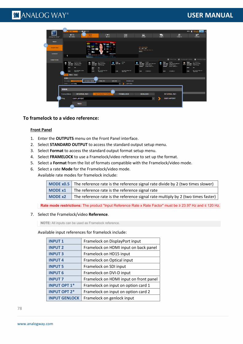
78
www.analogway.com
PROGRAMMER’S GU
USER MANUAL
To framelock to a video reference:
Front Panel
1. Enter the OUTPUTS menu on the Front Panel interface. 2. Select STANDARD OUTPUT to access the standard output setup menu. 3. Select Format to access the standard output format setup menu. 4. Select FRAMELOCK to use a Framelock/video reference to set up the format. 5. Select a Format from the list of formats compatible with the Framelock/video mode. 6. Select a rate Mode for the Framelock/video mode.
Available rate modes for framelock include:
MODE x0.5 The reference rate is the reference signal rate divide by 2 (two times slower) MODE x1 The reference rate is the reference signal rate MODE x2 The reference rate is the reference signal rate multiply by 2 (two times faster)
Rate mode restrictions: The product "Input Reference Rate x Rate Factor" must be ≥ 23.97 Hz and ≤ 120 Hz.
7. Select the Framelock/video Reference.
NOTE: All inputs can be used as Framelock reference.
Available input references for framelock include:
INPUT 1 Framelock on DisplayPort input INPUT 2 Framelock on HDMI input on back panel INPUT 3 Framelock on HD15 input INPUT 4 Framelock on Optical input INPUT 5 Framelock on SDI input INPUT 6 Framelock on DVI-D input INPUT 7 Framelock on HDMI input on front panel INPUT OPT 1* Framelock on input on option card 1 INPUT OPT 2* Framelock on input on option card 2 INPUT GENLOCK Framelock on genlock input

79
www.analogway.com
PROGRAMMER’S GU
USER MANUAL
8. Wait for the Format generation in progress screen to check the new format settings. 9. Once the setup is complete, press the EXIT-MENU button to return to the output setup menu.
TIP: Go to the output setup menu and select Framelock Tune to adjust the vertical and horizontal offsets to apply to the output signal. • Offset H: Offset in pixels (ratio of 1 line) to apply to the output signal. • Offset V: Offset in lines (ratio of 1 frame) to apply to the output signal.
Web RCS
1. Go to the Setup menu on the Web RCS interface. 2. Click on the OUTPUTS tab to access the outputs setup page. 3. In the left side toolbar, select STANDARD OUTPUT to access the standard output setup page. 4. Click on the Signal tab to access the output format setup page. 5. Under SIGNAL > Format Mode, select FRAMELOCK to use a Framelock/video reference to set up the
format. 6. Click on Format and select a format from the list of formats compatible with the Framelock/video
mode. 7. Click on Reference and select the Framelock/video reference.
NOTE: All inputs can be used as Framelock reference.
Available input references for framelock include:
INPUT 1 Framelock on DisplayPort input INPUT 2 Framelock on HDMI input on back panel INPUT 3 Framelock on HD15 input INPUT 4 Framelock on Optical input INPUT 5 Framelock on SDI input INPUT 6 Framelock on DVI-D input INPUT 7 Framelock on HDMI input on front panel INPUT OPT 1 Framelock on input on option card 1 INPUT OPT 2 Framelock on input on option card 2 INPUT GENLOCK Framelock on genlock input
8. Under Mode, select the rate mode multiplier. Available rate modes for framelock include:
MODE x0.5 The reference rate is the reference signal rate divide by 2 (two times slower) MODE x1 The reference rate is the reference signal rate MODE x2 The reference rate is the reference signal rate multiply by 2 (two times faster)
Rate mode restrictions: The product "Input Reference Rate x Rate Factor" must be ≥ 23.97 Hz and ≤ 120 Hz.
9. If required, adjust the vertical and horizontal offsets to apply to the output signal: • Offset H: Offset in pixels (ratio of 1 line) to apply to the output signal. • Offset V: Offset in lines (ratio of 1 frame) to apply to the output signal.
10. Select APPLY to save and apply the new settings.
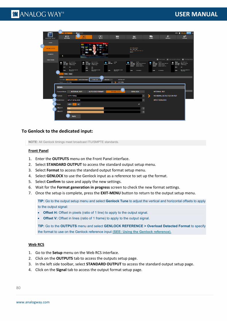
80
www.analogway.com
PROGRAMMER’S GU
USER MANUAL
To Genlock to the dedicated input:
NOTE: All Genlock timings meet broadcast ITU/SMPTE standards.
Front Panel
1. Enter the OUTPUTS menu on the Front Panel interface. 2. Select STANDARD OUTPUT to access the standard output setup menu. 3. Select Format to access the standard output format setup menu. 4. Select GENLOCK to use the Genlock input as a reference to set up the format. 5. Select Confirm to save and apply the new settings. 6. Wait for the Format generation in progress screen to check the new format settings. 7. Once the setup is complete, press the EXIT-MENU button to return to the output setup menu.
TIP: Go to the output setup menu and select Genlock Tune to adjust the vertical and horizontal offsets to apply to the output signal: • Offset H: Offset in pixels (ratio of 1 line) to apply to the output signal. • Offset V: Offset in lines (ratio of 1 frame) to apply to the output signal.
TIP: Go to the OUTPUTS menu and select GENLOCK REFERENCE > Overload Detected Format to specify the format to use on the Genlock reference input (SEE: Using the Genlock reference).
Web RCS
1. Go to the Setup menu on the Web RCS interface. 2. Click on the OUTPUTS tab to access the outputs setup page. 3. In the left side toolbar, select STANDARD OUTPUT to access the standard output setup page. 4. Click on the Signal tab to access the output format setup page.

81
www.analogway.com
PROGRAMMER’S GU
USER MANUAL
5. Under SIGNAL > Format Mode, select GENLOCK to use the Genlock input as a reference to set up the format.
6. If required, adjust the vertical and horizontal offsets to apply to the output signal: • Offset H: Offset in pixels (ratio of 1 line) to apply to the output signal. • Offset V: Offset in lines (ratio of 1 frame) to apply to the output signal.
7. Select APPLY to save and apply the new settings.
TIP: Select Genlock Ref In the left side toolbar and click on Overload Detected Format to specify the format to use on the Genlock reference input (SEE: Using the Genlock reference).
Related topics:
• Using the Genlock reference
The Area of Interest (AOI) defines the active area of your display in the output format.
The AOI can be thought of as your screen: anything positioned outside the AOI will be ignored in the processing, and only the AOI content will be displayed to the spectator.
6.4.4 Adjusting the AOI (Area of Interest)

82
www.analogway.com
PROGRAMMER’S GU
USER MANUAL
To automatically fit the AOI to the output format:
Front Panel
1. Enter the OUTPUTS menu on the Front Panel interface. 2. Select STANDARD OUTPUT to access the standard output setup menu. 3. Select Area of Interest to access the AOI setup menu. 4. Check the Fit Format Resolution check-box to automatically fit the AOI to the output format. 5. If required, adjust the Overscan Compensation (as percentage of the output format size).
Web RCS
1. Go to the Setup menu on the Web RCS interface. 2. Click on the PRECONFIG tab to access the setup assistant. 3. If the Screens page is active, click on the Previous button to access the area of interest setup page. 4. Check the Fit to Output's Active Area check-box to automatically fit the AOI to the output format.

83
www.analogway.com
PROGRAMMER’S GU
USER MANUAL
5. If required, adjust the Overscan Compensation (as percentage of the output format size).
To manually adjust the AOI size and position:
Front Panel
1. Enter the OUTPUTS menu on the Front Panel interface. 2. Select STANDARD OUTPUT to access the standard output setup menu. 3. Select Area of Interest to access the AOI setup menu. 4. Uncheck the Fit Format Resolution check-box to access the AOI size and position adjustments.
NOTE: Enabling/disabling the automatic fit format option will not erase the manual AOI size and position settings.
5. Adjust the following parameters: • H Position: AOI vertical start offset compared to the output format (in pixels). • H Size: AOI horizontal size (in pixels). • V Position: AOI vertical start offset compared to the output format (in pixels). • V Size: AOI vertical size (in pixels).
TIP: Use the Reset command if required to reset the AOI size and position to its default values.
Web RCS
1. Go to the Setup menu on the Web RCS interface. 2. Click on the PRECONFIG tab to access the setup assistant. 3. If the Screens page is active, click on the Previous button to access the area of interest setup page. 4. Uncheck the Fit to Output's Active Area check-box to access the AOI size and position adjustments.
NOTE: Enabling/disabling the automatic fit format option will not erase the manual AOI size and position settings (use the
Reset button instead if required).
5. Adjust the following parameters: • H Position: AOI vertical start offset compared to the output format (in pixels). • H Size: AOI horizontal size (in pixels).

84
www.analogway.com
PROGRAMMER’S GU
USER MANUAL
• V Position: AOI vertical start offset compared to the output format (in pixels). • V Size: AOI vertical size (in pixels).
TIP: Click on the AOI finder and drag the handles to adjust the AOI size and position.
Related topics:
• AOI status
You can rotate the output content by an angle of ±90°.
Rotating the output content can be very useful to adapt to a landscape display installed with a portrait orientation for example.
To rotate the output content:
Front Panel
1. Enter the OUTPUTS menu on the Front Panel interface. 2. Select STANDARD OUTPUT to access the standard output setup menu. 3. Select Rotation to select the ±90° rotation of the output content.
Web RCS
1. Go to the Setup menu on the Web RCS interface. 2. Click on the PRECONFIG tab to access the setup assistant. 3. If the Screens page is active, click on the Previous button to access the output preconfig setup page. 4. Under Rotation, select the ±90° rotation of the output content.
6.4.5 Rotating the output
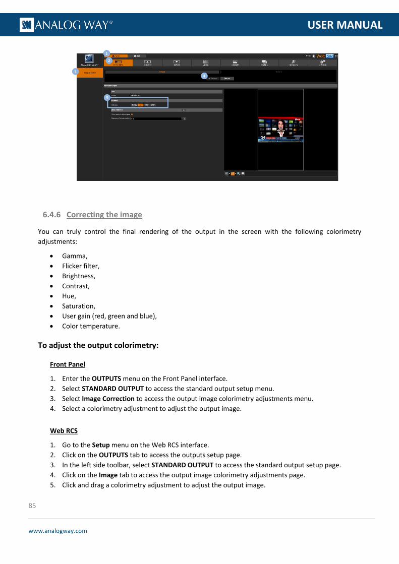
85
www.analogway.com
PROGRAMMER’S GU
USER MANUAL
You can truly control the final rendering of the output in the screen with the following colorimetry adjustments:
• Gamma, • Flicker filter, • Brightness, • Contrast, • Hue, • Saturation, • User gain (red, green and blue), • Color temperature.
To adjust the output colorimetry:
Front Panel
1. Enter the OUTPUTS menu on the Front Panel interface. 2. Select STANDARD OUTPUT to access the standard output setup menu. 3. Select Image Correction to access the output image colorimetry adjustments menu. 4. Select a colorimetry adjustment to adjust the output image.
Web RCS
1. Go to the Setup menu on the Web RCS interface. 2. Click on the OUTPUTS tab to access the outputs setup page. 3. In the left side toolbar, select STANDARD OUTPUT to access the standard output setup page. 4. Click on the Image tab to access the output image colorimetry adjustments page. 5. Click and drag a colorimetry adjustment to adjust the output image.
6.4.6 Correcting the image
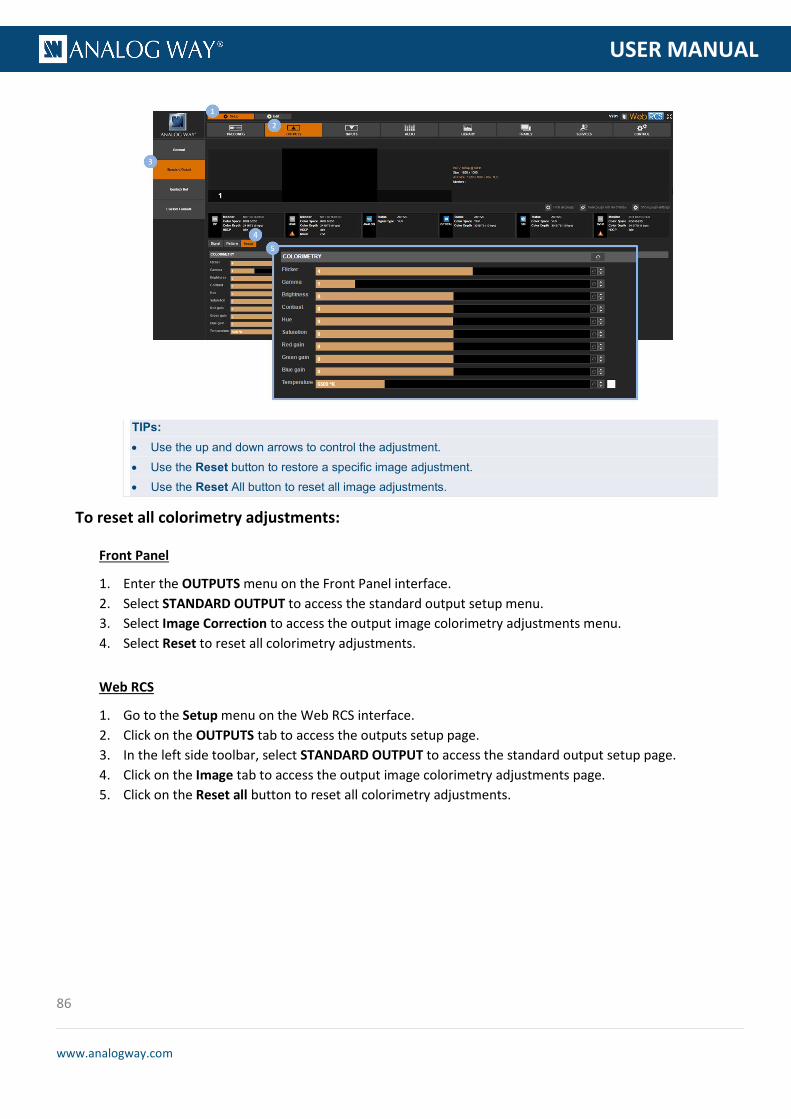
86
www.analogway.com
PROGRAMMER’S GU
USER MANUAL
TIPs: • Use the up and down arrows to control the adjustment. • Use the Reset button to restore a specific image adjustment. • Use the Reset All button to reset all image adjustments.
To reset all colorimetry adjustments:
Front Panel
1. Enter the OUTPUTS menu on the Front Panel interface. 2. Select STANDARD OUTPUT to access the standard output setup menu. 3. Select Image Correction to access the output image colorimetry adjustments menu. 4. Select Reset to reset all colorimetry adjustments.
Web RCS
1. Go to the Setup menu on the Web RCS interface. 2. Click on the OUTPUTS tab to access the outputs setup page. 3. In the left side toolbar, select STANDARD OUTPUT to access the standard output setup page. 4. Click on the Image tab to access the output image colorimetry adjustments page. 5. Click on the Reset all button to reset all colorimetry adjustments.

87
www.analogway.com
PROGRAMMER’S GU
USER MANUAL
You can use patterns to test and control how your output appears in the screen.
Available patterns include:
COLOR Color pattern VERTICAL GRAY SCALE Vertical gray scale HORIZONTAL GRAY SCALE Horizontal gray scale VERTICAL COLOR BAR Vertical color bar HORIZONTAL COLOR BAR Horizontal color bar GRID 16x16 Grid composed of 16 rectangles in height and width GRID 32x32 Grid composed of 32 rectangles in height and width GRID CUSTOM Grid composed of user custom rectangle size SMPTE SMPTE HORIZONTAL BURST Horizontal burst VERTICAL BURST Vertical burst VERTICAL GRADIENT Vertical gradient HORIZONTAL GRADIENT Horizontal gradient CROSSHATCH Crosshatch CHECKERBOARD Checkerboard
The custom grid pattern for example can be very useful to adjust in real time the tiling area of a LED Wall configuration, by displaying an ID inside the grid to identify each LED Wall tile.
6.4.7 Using test patterns

88
www.analogway.com
PROGRAMMER’S GU
USER MANUAL
To configure a pattern:
Front Panel
1. Enter the OUTPUTS menu on the Front Panel interface. 2. Select STANDARD OUTPUT to access the standard output setup menu. 3. Select Pattern to access the output pattern setup menu.
NOTE: You can also use the front panel Test Pattern key button to access the output pattern setup menu directly.
4. Uncheck the Inhibit Output Pattern check-box to enable pattern display on the output.
NOTE: You can enable and disable pattern display whenever required by checking/unchecking the Inhibit Output Pattern
check-box. All pattern adjustments will be remembered when enabling/disabling pattern display.
5. Select Pattern and choose the pattern to display on the output. 6. If required, adjust the pattern settings.
Available pattern settings include: • Inhibit Colorimetry: Check to disable the output colorimetry adjustments on the pattern
(uncheck to enable). • Motion: Check to enable a live movement on the pattern. • Pattern Area: Area where the pattern applies.
Possible pattern areas include:
FORMAT Fit pattern in all format resolution AOI Fit pattern in all AOI
• Format Raster Box: Check to display a dotted line all around the format. • AOI Raster Box: Check to display a dotted line all around the AOI area.
Web RCS
1. Go to the Setup menu on the Web RCS interface. 2. Click on the OUTPUTS tab to access the outputs setup page. 3. In the left side toolbar, select STANDARD OUTPUT to access the standard output setup page. 4. Click on the Patterns tab to access the output pattern settings page. 5. Uncheck the Hide check-box to enable pattern display on the output.
NOTE: You can enable and disable pattern display whenever required by checking/unchecking the Hide check-box. All pattern
adjustments will be remembered when enabling/disabling pattern display.
6. Under Pattern, select the pattern to display on the output. 7. If required, adjust the pattern settings.
Available pattern settings include: • Inhibit Colorimetry: Check to disable the output colorimetry adjustments on the pattern
(uncheck to enable). • Motion: Check to enable a live movement on the pattern.

89
www.analogway.com
PROGRAMMER’S GU
USER MANUAL
• Pattern Area: Area where the pattern applies. Possible pattern areas include:
FORMAT Fit pattern in all format resolution AOI Fit pattern in all AOI
• Format Raster Box: Check to display a dotted line all around the format. • AOI Raster Box: Check to display a dotted line all around the AOI area.
To hide the pattern:
Front Panel
1. Enter the OUTPUTS menu on the Front Panel interface. 2. Select STANDARD OUTPUT to access the standard output setup menu. 3. Select Pattern to access the output pattern setup menu.
NOTE: You can also use the front panel Test Pattern key to access the output pattern setup menu directly.
4. Check the Inhibit Output Pattern check-box to hide the pattern.
NOTE: You can disable pattern display whenever required by checking the Inhibit Output Pattern check-box. All pattern
adjustments will be remembered when enabling/disabling pattern display.
Web RCS
1. Go to the Setup menu on the Web RCS interface. 2. Click on the OUTPUTS tab to access the outputs setup page. 3. In the left side toolbar, select STANDARD OUTPUT to access the standard output setup page. 4. Click on the Patterns tab to access the output pattern settings page. 5. Check the Hide check-box to hide the pattern.
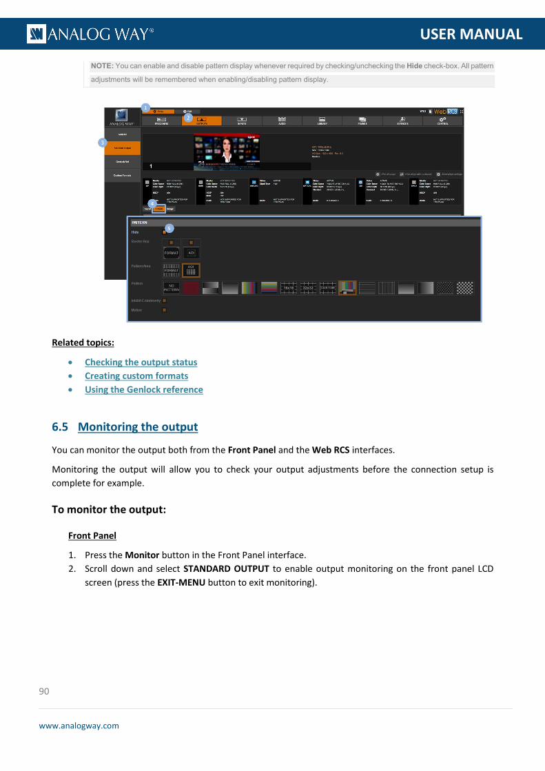
90
www.analogway.com
PROGRAMMER’S GU
USER MANUAL
NOTE: You can enable and disable pattern display whenever required by checking/unchecking the Hide check-box. All pattern
adjustments will be remembered when enabling/disabling pattern display.
Related topics:
• Checking the output status • Creating custom formats • Using the Genlock reference
You can monitor the output both from the Front Panel and the Web RCS interfaces.
Monitoring the output will allow you to check your output adjustments before the connection setup is complete for example.
To monitor the output:
Front Panel
1. Press the Monitor button in the Front Panel interface. 2. Scroll down and select STANDARD OUTPUT to enable output monitoring on the front panel LCD
screen (press the EXIT-MENU button to exit monitoring).
6.5 Monitoring the output

91
www.analogway.com
PROGRAMMER’S GU
USER MANUAL
Alternative method:
1. Enter the OUTPUTS menu on the Front Panel interface. 2. Select STANDARD OUTPUT to access the standard output setup menu. 3. Scroll down the output setup menu and select Monitor on LCD to enable output monitoring on
the front panel LCD screen (press the EXIT-MENU button to exit monitoring).
Web RCS
1. Go to the Edit menu on the Web RCS interface. 2. Select the MON. STREAM tab to access the monitoring page. 3. Go to the Properties toolbar on right-hand side. 4. Under Setup > Source, scroll down and select STANDARD OUTPUT. 5. If required, select the Quality of the monitoring stream.
TIP: Use the Play and Fullscreen buttons at the bottom of the monitoring screen to control the monitoring stream playback and display size.
NOTE: You can also disable the Audio > Mute button to monitor the headphone output directly from your PC or tablet (SEE:
Prelistening to audio content for more information).
You can freeze the live content of your output to make some adjustments on the currently selected input while hiding them to the spectator, for example.
6.6 Freezing the output

92
www.analogway.com
PROGRAMMER’S GU
USER MANUAL
To freeze the output:
Front Panel
Press the Freeze SHORTCUT button to freeze the output (click again or select another input to unfreeze).
Web RCS
1. Go to the Edit menu on the Web RCS interface. 2. Click on the Freeze button at the bottom of the screen to freeze the output (click again or select
another input to unfreeze).
SEE: Creating frame captures
The Genlock input can be used as a reference and a rate multiplier to set up the output format (SEE: Setting up the format).
If the Genlock input allows it, you can further specify the format to use on the Genlock reference input by choosing from the list of formats detected on the Genlock input.
6.7 Capturing the output
6.8 Using the Genlock reference
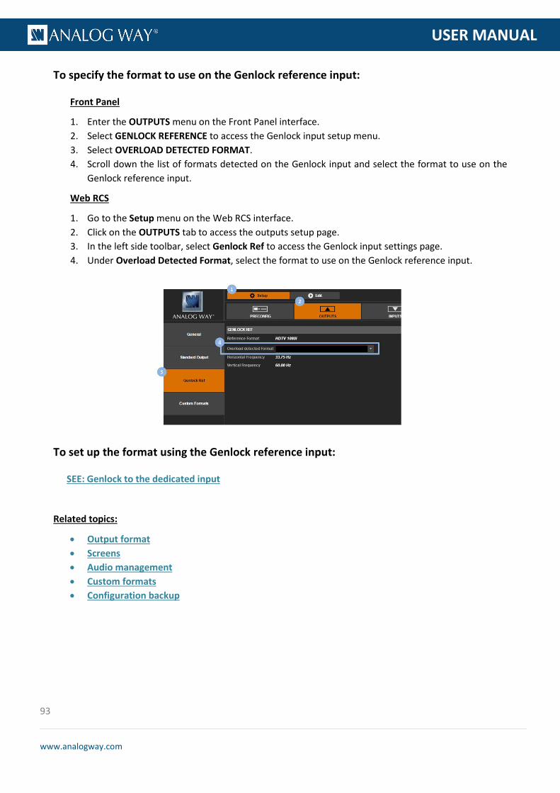
93
www.analogway.com
PROGRAMMER’S GU
USER MANUAL
To specify the format to use on the Genlock reference input:
Front Panel
1. Enter the OUTPUTS menu on the Front Panel interface. 2. Select GENLOCK REFERENCE to access the Genlock input setup menu. 3. Select OVERLOAD DETECTED FORMAT. 4. Scroll down the list of formats detected on the Genlock input and select the format to use on the
Genlock reference input.
Web RCS
1. Go to the Setup menu on the Web RCS interface. 2. Click on the OUTPUTS tab to access the outputs setup page. 3. In the left side toolbar, select Genlock Ref to access the Genlock input settings page. 4. Under Overload Detected Format, select the format to use on the Genlock reference input.
To set up the format using the Genlock reference input:
SEE: Genlock to the dedicated input
Related topics:
• Output format • Screens • Audio management • Custom formats • Configuration backup

94
www.analogway.com
PROGRAMMER’S GU
USER MANUAL
The VIO 4K allows you to enable the loop mode of an output plug to loop-through your inputs, for example to connect an additional device or for local monitoring.
The following table illustrates the VIO 4K loop-through capabilities of each plug:
Output plug Looped input plug HDMI, DVI or both HDMI or DVI Analog (HD15) HD15 Other None
NOTE:
• When loop mode is enabled, the video signal is automatically passed from the input to the output plug without scaling or
additional processing. The corresponding output plug thus becomes an unscaled loop of the selected input and it is no longer
available as a standard scaled output.
• HDMI and DVI loops share the same hardware resources. This means both the HDMI and DVI output plugs will be affected when
enabling loop mode and will display the same looped input signal.
• On SDI plugs, the loop capability is directly implemented in the hardware (SEE: Rear panel description).
To enable loop mode on an output plug:
Information: No audio will be transmitted.
Front Panel
1. Enter the OUTPUTS menu on the Front Panel interface. 2. Select STANDARD OUTPUT to access the standard output setup menu. 3. Select Plug Settings to access the plug setup menu for the output. 4. Select a plug to access the selected plug setup menu. 5. On Analog (HD15) plugs, check the Enable Loop of Input 3 (HD15) box to loop HD15 input plug
through HD15 output plug (uncheck to disable).
6.9 Enabling loop mode

95
www.analogway.com
PROGRAMMER’S GU
USER MANUAL
On HDMI/DVI plugs, select Loop Mode Selection and select the input plug to loop through:
INPUT 2 (HDMI) Loop HDMI input plug through HDMI and/or DVI output plug INPUT 6 (DVI) Loop DVI input plug through HDMI and/or DVI output plug NONE Disable loop mode
NOTE: The selected looped input plug affects both HDMI and DVI output plugs.
Web RCS
1. Go to the Setup menu on the Web RCS interface. 2. Click on the OUTPUTS tab to access the outputs setup page. 3. In the left side toolbar, select STANDARD OUTPUT to access the standard output setup page. 4. Disable the Hide all plugs button if required to show the output plugs. 5. Click on the Show plugs settings button to access the plug settings for each output plug. 6. Locate the plug to set up. 7. Check/uncheck the Loop Mode box to enable/disable loop mode on the plug. 8. On HDMI/DVI plugs, select also the Input (plug) to loop through:
INPUT 2 (HDMI) Loop HDMI input plug through HDMI and/or DVI output plug INPUT 6 (DVI) Loop DVI input plug through HDMI and/or DVI output plug
NOTE: The selected looped input plug affects both HDMI and DVI output plugs.
Related topics:
• HDCP support • Checking the plug status
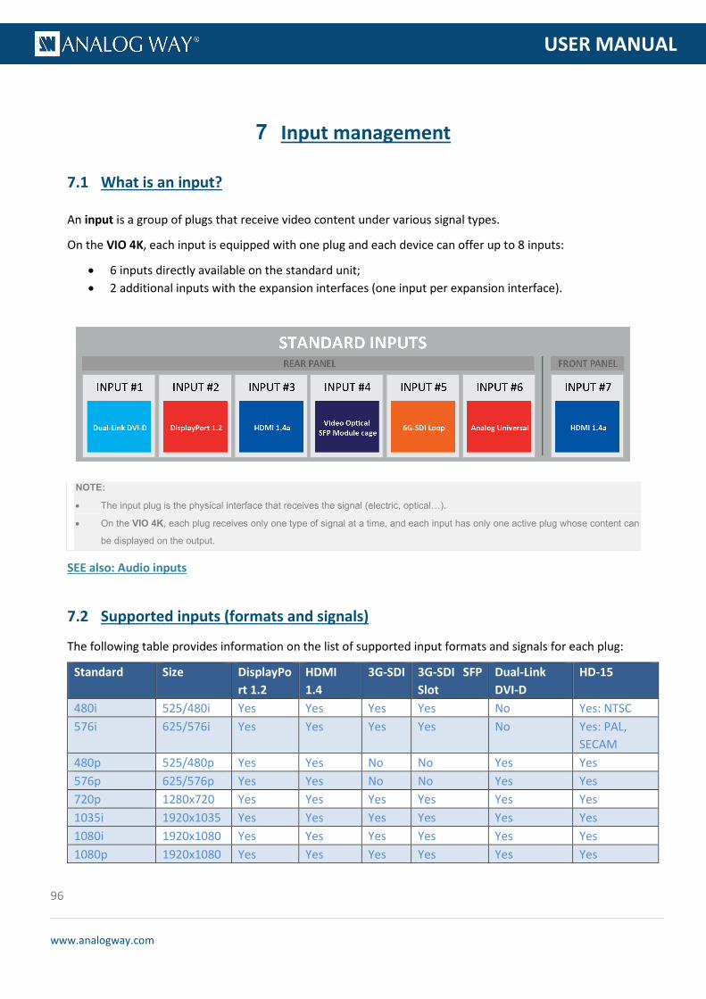
96
www.analogway.com
PROGRAMMER’S GU
USER MANUAL
An input is a group of plugs that receive video content under various signal types.
On the VIO 4K, each input is equipped with one plug and each device can offer up to 8 inputs:
• 6 inputs directly available on the standard unit; • 2 additional inputs with the expansion interfaces (one input per expansion interface).
NOTE:
• The input plug is the physical interface that receives the signal (electric, optical…).
• On the VIO 4K, each plug receives only one type of signal at a time, and each input has only one active plug whose content can
be displayed on the output.
SEE also: Audio inputs
The following table provides information on the list of supported input formats and signals for each plug:
Standard Size DisplayPort 1.2
HDMI 1.4
3G-SDI 3G-SDI SFP Slot
Dual-Link DVI-D
HD-15
480i 525/480i Yes Yes Yes Yes No Yes: NTSC 576i 625/576i Yes Yes Yes Yes No Yes: PAL,
SECAM 480p 525/480p Yes Yes No No Yes Yes 576p 625/576p Yes Yes No No Yes Yes 720p 1280x720 Yes Yes Yes Yes Yes Yes 1035i 1920x1035 Yes Yes Yes Yes Yes Yes 1080i 1920x1080 Yes Yes Yes Yes Yes Yes 1080p 1920x1080 Yes Yes Yes Yes Yes Yes
7 Input management
7.1 What is an input?
7.2 Supported inputs (formats and signals)

97
www.analogway.com
PROGRAMMER’S GU
USER MANUAL
1080sF 1920x1080 Yes Yes Yes Yes Yes Yes 1080p 1920x1080 Yes Yes Yes Yes Yes Yes 2160p 3840x2160 Yes Yes Yes Yes Yes Yes DCDM 2048x1080 Yes Yes Yes Yes Yes Yes UHDTV 3840x2160 Yes Yes No No Yes No DCI 4K 4096x2160 Yes Yes No No Yes No VGA 640x480 Yes Yes No No Yes Yes 800x480 800x480 Yes Yes No No Yes Yes SVGA 800x600 Yes Yes No No Yes Yes WVGA 848x480 Yes Yes No No Yes Yes XGA 1024x768 Yes Yes No No Yes Yes 1152x864 1152x864 Yes Yes No No Yes Yes 1280x600 1280x600 Yes Yes No No Yes Yes 720p RGB 1280x720 Yes Yes No No Yes Yes 800p RGB 1280x800 Yes Yes No No Yes Yes WXGA 1280x768 Yes Yes No No Yes Yes 960p RGB 1280x960 Yes Yes No No Yes Yes SXGA 1280x1024 Yes Yes No No Yes Yes SWXGA 1360x768 Yes Yes No No Yes Yes 1366x768 1366x768 Yes Yes No No Yes Yes SWXGA+ 1366x800 Yes Yes No No Yes Yes 1360x1024 1360x1024 Yes Yes No No Yes Yes DILA4/3 1364x1024 Yes Yes No No Yes Yes SXGA+ 1400x1050 Yes Yes No No Yes Yes 900p RGB 1440x900 Yes Yes No No Yes Yes 1600x900 1600x900 Yes Yes No No Yes Yes UXGA 1600x1200 Yes Yes No No Yes Yes WSXGA+ 1680x1050 Yes Yes No No Yes Yes
1792x1344 Yes Yes No No Yes Bad quality (2) 1856x1392 Yes Yes No No Yes Bad quality (2)
DMT 1080p 1920x1080 Yes Yes No No Yes Yes(1) WUXGA 1920x1200 Yes Yes No No Yes Yes (1) 1920x1440 1920x1440 Yes Yes No No Yes Bad quality(2) QXGA 2048x1536 Yes Yes No No Yes No WQHD 2560x1440 Yes Yes No No Yes No WQXGA 2560x1600 Yes Yes No No Yes No
(1) Reduced blanking
(2) The signal is under-sampled: the image cannot be reproduced on 1:1 scaling (i.e. a 1920x1440 signal is under-sampled and then
stretched horizontally to fit on a 1920x1440 PiP. The quality is worse than it should be with a properly sampled 1920x1440 signal)
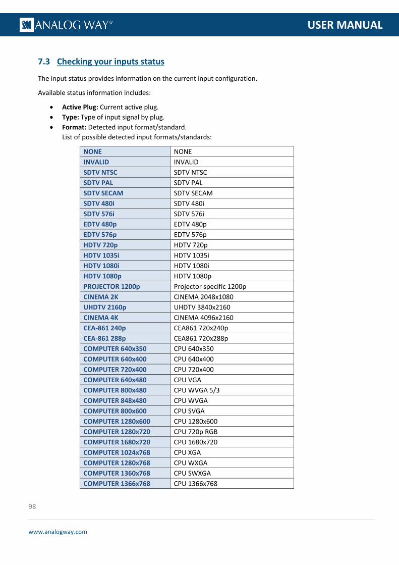
98
www.analogway.com
PROGRAMMER’S GU
USER MANUAL
The input status provides information on the current input configuration.
Available status information includes:
• Active Plug: Current active plug. • Type: Type of input signal by plug. • Format: Detected input format/standard.
List of possible detected input formats/standards:
NONE NONE INVALID INVALID SDTV NTSC SDTV NTSC SDTV PAL SDTV PAL SDTV SECAM SDTV SECAM SDTV 480i SDTV 480i SDTV 576i SDTV 576i EDTV 480p EDTV 480p EDTV 576p EDTV 576p HDTV 720p HDTV 720p HDTV 1035i HDTV 1035i HDTV 1080i HDTV 1080i HDTV 1080p HDTV 1080p PROJECTOR 1200p Projector specific 1200p CINEMA 2K CINEMA 2048x1080 UHDTV 2160p UHDTV 3840x2160 CINEMA 4K CINEMA 4096x2160 CEA-861 240p CEA861 720x240p CEA-861 288p CEA861 720x288p COMPUTER 640x350 CPU 640x350 COMPUTER 640x400 CPU 640x400 COMPUTER 720x400 CPU 720x400 COMPUTER 640x480 CPU VGA COMPUTER 800x480 CPU WVGA 5/3 COMPUTER 848x480 CPU WVGA COMPUTER 800x600 CPU SVGA COMPUTER 1280x600 CPU 1280x600 COMPUTER 1280x720 CPU 720p RGB COMPUTER 1680x720 CPU 1680x720 COMPUTER 1024x768 CPU XGA COMPUTER 1280x768 CPU WXGA COMPUTER 1360x768 CPU SWXGA COMPUTER 1366x768 CPU 1366x768
7.3 Checking your inputs status
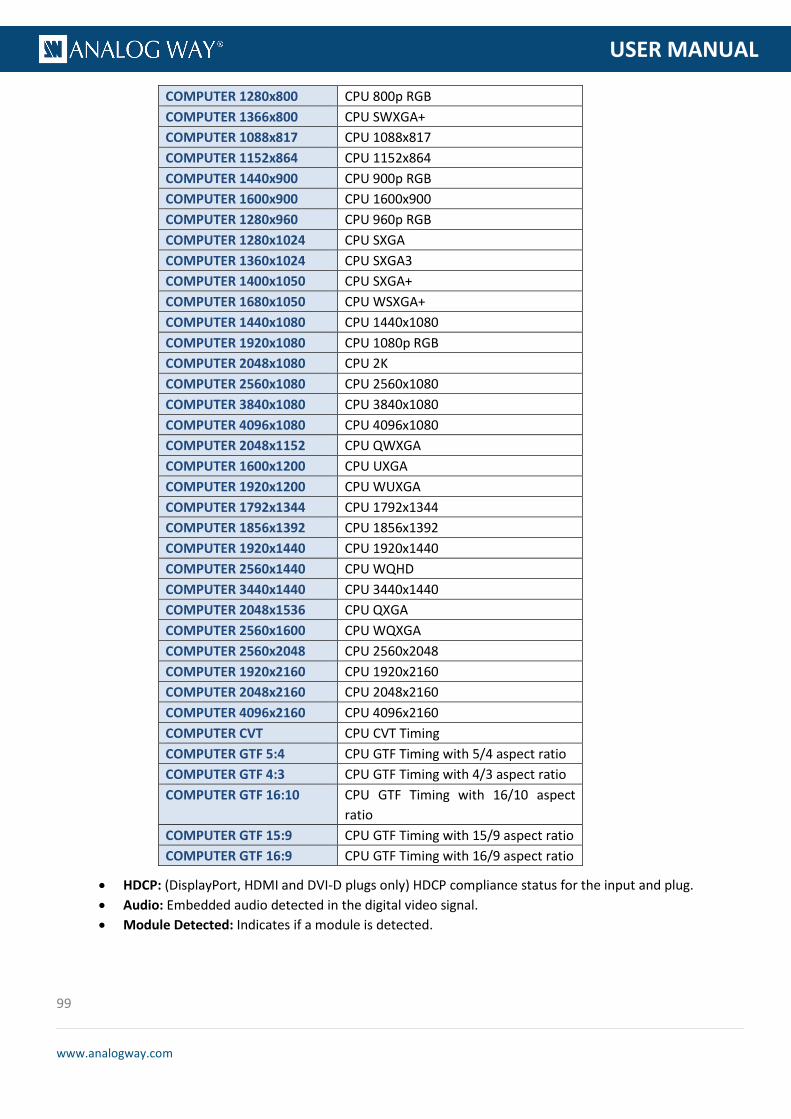
99
www.analogway.com
PROGRAMMER’S GU
USER MANUAL
COMPUTER 1280x800 CPU 800p RGB COMPUTER 1366x800 CPU SWXGA+ COMPUTER 1088x817 CPU 1088x817 COMPUTER 1152x864 CPU 1152x864 COMPUTER 1440x900 CPU 900p RGB COMPUTER 1600x900 CPU 1600x900 COMPUTER 1280x960 CPU 960p RGB COMPUTER 1280x1024 CPU SXGA COMPUTER 1360x1024 CPU SXGA3 COMPUTER 1400x1050 CPU SXGA+ COMPUTER 1680x1050 CPU WSXGA+ COMPUTER 1440x1080 CPU 1440x1080 COMPUTER 1920x1080 CPU 1080p RGB COMPUTER 2048x1080 CPU 2K COMPUTER 2560x1080 CPU 2560x1080 COMPUTER 3840x1080 CPU 3840x1080 COMPUTER 4096x1080 CPU 4096x1080 COMPUTER 2048x1152 CPU QWXGA COMPUTER 1600x1200 CPU UXGA COMPUTER 1920x1200 CPU WUXGA COMPUTER 1792x1344 CPU 1792x1344 COMPUTER 1856x1392 CPU 1856x1392 COMPUTER 1920x1440 CPU 1920x1440 COMPUTER 2560x1440 CPU WQHD COMPUTER 3440x1440 CPU 3440x1440 COMPUTER 2048x1536 CPU QXGA COMPUTER 2560x1600 CPU WQXGA COMPUTER 2560x2048 CPU 2560x2048 COMPUTER 1920x2160 CPU 1920x2160 COMPUTER 2048x2160 CPU 2048x2160 COMPUTER 4096x2160 CPU 4096x2160 COMPUTER CVT CPU CVT Timing COMPUTER GTF 5:4 CPU GTF Timing with 5/4 aspect ratio COMPUTER GTF 4:3 CPU GTF Timing with 4/3 aspect ratio COMPUTER GTF 16:10 CPU GTF Timing with 16/10 aspect
ratio COMPUTER GTF 15:9 CPU GTF Timing with 15/9 aspect ratio COMPUTER GTF 16:9 CPU GTF Timing with 16/9 aspect ratio
• HDCP: (DisplayPort, HDMI and DVI-D plugs only) HDCP compliance status for the input and plug. • Audio: Embedded audio detected in the digital video signal. • Module Detected: Indicates if a module is detected.

100
www.analogway.com
PROGRAMMER’S GU
USER MANUAL
To check the status of your inputs:
Front Panel
1. Enter the INPUTS menu on the Front Panel interface. 2. Select INPUTS STATUS to access the inputs status menu. 3. Check the input status right below each input status menu.
Web RCS
1. Go to the Setup menu on the Web RCS interface. 2. Click on the INPUTS tab to access the inputs setup page. 3. In the left side toolbar, select General to access the general inputs setup page. 4. Check the input status next to each input preview window.
You can request the automatic setup of all inputs.
The automatic request will scan all inputs and plugs, and automatically select the active plugs for each input.
NOTE: You can also individually request the automatic setup of just one input. SEE: Auto-setting the input.
To request the automatic setup of all inputs and plugs:
Information: • Displayed inputs may flicker. • Input plugs may change temporarily.
7.4 Auto-setting all inputs

101
www.analogway.com
PROGRAMMER’S GU
USER MANUAL
Front panel
1. Enter the INPUTS menu on the Front Panel interface. 2. Select AUTOSET ALL INPUTS to request the automatic setup of all plugs of all inputs.
• Select YES to confirm (/!\ displayed inputs may flicker and input plugs may change temporarily). • Select NO to cancel the request.
Web RCS
1. Go to the Setup menu on the Web RCS interface. 2. Click on the INPUTS tab to access the inputs setup page. 3. In the left side toolbar, select General to access the general inputs setup page. 4. Click on the Autoset All button to request the automatic setup of all plugs of all inputs.
TIP: • On the Front Panel interface, double-click on an input selection key button to access the input setup menu.
NOTE: this action will also select the input. • On the Web RCS interface, hover over an input preview and click on the Setup button to access the input setup
menu.
7.5 Setting up an input

102
www.analogway.com
PROGRAMMER’S GU
USER MANUAL
You can request the automatic setup of just one input (SEE also: Auto-setting all inputs).
The automatic request will scan all input plugs and automatically select the active plug.
To request the automatic setup of an input and plugs:
NOTE:
• If displayed, the input may flicker.
• Input plugs may change temporarily.
Front Panel
1. Enter the INPUTS menu on the Front Panel interface. 2. Scroll down and select an input to access the selected input setup menu.
TIP: Double-click on an INPUT SELECTION button to shortcut to the input setup menu directly.
3. Select Autoset Input to request the automatic setup of the input plug. • Select YES to confirm (/!\ if displayed, the input may flicker and the plug may change temporarily). • Select NO to cancel the request.
Web RCS
SEE: Auto-detecting the signal type
You can control the sources connected to a plug by setting up the input plug.
7.5.1 Auto-setting the input
7.5.2 Setting up the plug

103
www.analogway.com
PROGRAMMER’S GU
USER MANUAL
The input plug status provides information on the current input plug configuration.
Available plug status information includes:
CONFIGURATION:
• Type: Current input signal type/color space. List of possible input signal types (analog plugs):
SDTV COMPOSITE Composite signal 0-700mV SDTV YC Y/C signal 0-700mV VIDEO RGBS RGBs signal with a TTL composite synchro (only video
format) VIDEO RGSB RGB signal with synchro on green (SOG) (only video
format) VIDEO YUV YUV signal 0-700mV COMPUTER SOG RGB signal with synchro on green (SOG) COMPUTER BW Only Green signal with synchro (SOG) converted to grey
level COMPUTER HV RGB signal with separate TTL H/V synchro COMPUTER TTL COMPOSITE
RGB signal with a TTL composite synchro
COMPUTER ANA COMPOSITE
RGB signal with an analog composite synchro
List of possible input color spaces (digital plugs):
AUTO Automatic color space selection YUV YUV (YCbCr ITU-R BT.601 or YCbCr BT.709) RGB FULL (0-255) RGB Full scale (0-255) RGB LIMITED (16-235) RGB Limited scale (16-235)
• HDCP Detection: (DisplayPort, HDMI and DVI-D plugs only) HDCP compliance enabled/disabled. • Plug: Plug selection enabled/disabled.
STATUS:
• Format: Detected input format/standard. • HDCP: HDCP compatibility status for the input plug. • Audio: Embedded audio detected in the digital video signal. • Audio Type: Type of audio signal (/!\ only PCM is supported). • Audio Sampling Rate: Audio sampling frequency (in kHz). • Audio Copyright: Copyright status of the audio stream. • Module Detected: Indicates if a module is detected.
7.5.2.1 Checking the plug status

104
www.analogway.com
PROGRAMMER’S GU
USER MANUAL
FORMAT:
(All plugs):
• Image Size: Current image size (width x height) (/!\ signal aspect ratio and predefined crop settings are taken into account). Width - in pixels; Height - in lines.
• Format Size: Useful signal format size (width x height). Width - in pixels; Height - in lines. • Field Frequency: Frame frequency (in Hz). • Line Frequency: Line frequency (in Hz). • Sync Polarities: Positive H sync and V sync polarities. • Scan Type: Interleaving type.
List of possible interleaving types:
PROGRESSIVE Progressive INTERLACED TOP FIELD FIRST Interlaced, Top field first INTERLACED BOTTOM FIELD FIRST Interlaced, Bottom field first SEGMENTED FRAME Segmented frame
• Settings Memory Slot: Memory slot used for the input settings (0 means that no slot is used or that default settings are used).
(HDMI/DVI plugs):
• HDMI mode: HDMI mode status (in DVI mode no audio can be transmitted).
(All except HD15):
• Repeat Coefficient: (DVI and HDMI signals only) Repetition coefficient for pixel. • Color Space: Color space of the signal.
List of possible input color spaces (digital plugs):
AUTO Automatic color space selection YUV YUV (YCbCr ITU-R BT.601 or YCbCr BT.709) RGB FULL (0-255) RGB Full scale (0-255) RGB LIMITED (16-235) RGB Limited scale (16-235)
• Color Depth: Color depth of the signal. List of possible signal color depths:
18 BITS (6 bpc) 18 bits for a pixel, 6 bits for each color 24 BITS (8 bpc) 24 bits for a pixel, 8 bits for each color 30 BITS (10 bpc) 30 bits for a pixel, 10 bits for each color 36 BITS (12 bpc) 36 bits for a pixel, 12 bits for each color
• Lane: (DisplayPort plug only) Number of lanes. List of possible DisplayPort lanes:
1 LANE 1 lane 2 LANES 2 lanes 4 LANES 4 lanes

105
www.analogway.com
PROGRAMMER’S GU
USER MANUAL
• Link Rate: (DisplayPort plug only) Link rate. List of possible DisplayPort link rates:
RBR RBR (1.62Gbps) HBR HBR (2.7Gbps) HBR2 HBR2 (5.4Gbps)
• Module Detected: Indicates if a module is detected. • ID: ID of SFP module. • Bitrate: SFP module nominal bitrate. • Vendor Name: SFP module vendor name. • Module Status: SFP module support status. • Standard: (Optical and SDI plugs only) Detected SDI standard.
List of possible SDI standards:
SD-SDI SD SDI standard HD-SDI HD SDI standard 3G-SDI LEVEL A 3G SDI Level A standard 3G-SDI LEVEL B 3G SDI Level B standard 6G UHD-SDI* 6G SDI standard 12G UHD-SD* 12G SDI standard
(*) Available with the optional video card
To check the status of an input plug:
Front Panel
1. Enter the INPUTS menu on the Front Panel interface. 2. Scroll down and select an input to access the selected input setup menu.
TIP: Double-click on an INPUT SELECTION button to shortcut to the input setup menu directly.
3. Select the plug settings to access the input plug settings menu. 4. Select Status to check the input plug status. 5. If required, rotate the control knob clockwise to scroll the page and see further status information.
Web RCS
1. Go to the Setup menu on the Web RCS interface. 2. Click on the INPUTS tab to access the inputs setup page. 3. In the left side toolbar, select an input to access the selected input setup page. 4. Select the Signal tab to access the plug settings page. 5. Under STATUS, check the status of the input and plug. 6. If required, click on the Show details button to access further status information.

106
www.analogway.com
PROGRAMMER’S GU
USER MANUAL
The easiest way to select the signal type for a plug is to auto-detect the signal type on the sources connected to the plug. If the auto-detected signal type does not seem right, you can always force the signal type to use on the plug.
To auto-detect the signal type on a plug:
NOTE:
• If displayed, the input may flicker.
• The input plug may change temporarily.
Front Panel
1. Enter the INPUTS menu on the Front Panel interface. 2. Scroll down and select an input to access the selected input setup menu.
TIP: Double-click on an INPUT SELECTION button to shortcut to the input setup menu directly.
3. Select Plug Settings to access the plug settings menu for the selected input. 4. Select Autoset to start the signal auto-detection process:
• Select YES to confirm. • Select NO to cancel the action.
7.5.2.2 Selecting the signal type

107
www.analogway.com
PROGRAMMER’S GU
USER MANUAL
Web RCS
1. Go to the Setup menu on the Web RCS interface. 2. Click on the INPUTS tab to access the inputs setup page. 3. In the left side toolbar, select an input to access the selected input setup page. 4. Click on the Auto Detect button to start the signal auto-detection process.
To select a specific signal type on a plug:
Front Panel
1. Enter the INPUTS menu on the Front Panel interface. 2. Scroll down and select an input to access the selected input setup menu.
TIP: Double-click on an INPUT SELECTION button to shortcut to the input setup menu directly.
3. Select the plug settings to access the input plug settings menu. 4. Select Type to select the signal type/color space for the plug.
List of possible input signal types (analog plugs):
SDTV COMPOSITE Composite signal 0-700mV SDTV YC Y/C signal 0-700mV VIDEO RGBS RGBs signal with a TTL composite synchro (only video format) VIDEO RGSB RGB signal with synchro on green (SOG) (only video format) VIDEO YUV YUV signal 0-700mV COMPUTER SOG RGB signal with synchro on green (SOG) COMPUTER BW Only Green signal with synchro (SOG) converted to grey level COMPUTER HV RGB signal with separate TTL H/V synchro COMPUTER TTL COMPOSITE RGB signal with a TTL composite synchro COMPUTER ANA COMPOSITE
RGB signal with an analog composite synchro
List of possible input color spaces (digital plugs):
AUTO Automatic color space selection YUV YUV (YCbCr ITU-R BT.601 or YCbCr BT.709) RGB FULL (0-255) RGB Full scale (0-255) RGB LIMITED (16-235) RGB Limited scale (16-235)

108
www.analogway.com
PROGRAMMER’S GU
USER MANUAL
TIP: Use AUTO to automatically select the signal type
Web RCS
1. Go to the Setup menu on the Web RCS interface. 2. Click on the INPUTS tab to access the inputs setup page. 3. In the left side toolbar, select an input to access the selected input setup page. 4. Select Signal to access the input plug settings page. 5. Under SIGNAL > Type, select the input signal type/color space for the plug.
List of possible input signal types (analog plugs):
SDTV COMPOSITE Composite signal 0-700mV SDTV YC Y/C signal 0-700mV VIDEO RGBS RGBs signal with a TTL composite synchro (only video format) VIDEO RGSB RGB signal with synchro on green (SOG) (only video format) VIDEO YUV YUV signal 0-700mV COMPUTER SOG RGB signal with synchro on green (SOG) COMPUTER BW Only Green signal with synchro (SOG) converted to grey level COMPUTER HV RGB signal with separate TTL H/V synchro COMPUTER TTL COMPOSITE RGB signal with a TTL composite synchro COMPUTER ANA COMPOSITE
RGB signal with an analog composite synchro
List of possible input color spaces (digital plugs):
AUTO Automatic color space selection YUV YUV (YCbCr ITU-R BT.601 or YCbCr BT.709) RGB FULL (0-255) RGB Full scale (0-255) RGB LIMITED (16-235) RGB Limited scale (16-235)
TIP: Use AUTO to automatically select the signal type
Related topics:
• Plug status

109
www.analogway.com
PROGRAMMER’S GU
USER MANUAL
All input plugs, together with the sources connected to each input plug, are enabled by default on the device. If a plug is not used however, you can manually disable the plug to hide the unused sources connected to the plug.
To disable a plug:
Front Panel
1. Enter the INPUTS menu on the Front Panel interface. 2. Scroll down and select an input to access the selected input setup menu.
TIP: Double-click on an INPUT SELECTION button to shortcut to the input setup menu directly.
3. Select the plug settings to access the input plug settings menu. 4. Uncheck the Enabled check-box to disable the plug (check to enable).
NOTE: Disabling the plug will also disable the sources connected to the plug, and the input itself will no longer be available
for selection.
Web RCS
1. Go to the Setup menu on the Web RCS interface. 2. Click on the INPUTS tab to access the inputs setup page. 3. In the left side toolbar, select an input to access the selected input setup page. 4. Select Signal to access the input plug settings page. 5. Under SIGNAL, uncheck the Enable check-box to disable the plug (check to enable).
NOTE: Disabling the plug will also disable the sources connected to the plug, and the input itself will no longer be available
for selection.
7.5.2.3 Enabling the plug
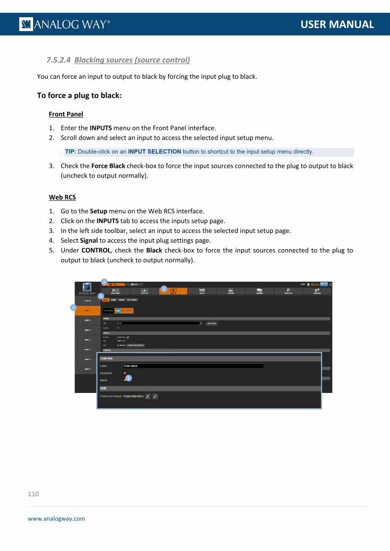
110
www.analogway.com
PROGRAMMER’S GU
USER MANUAL
You can force an input to output to black by forcing the input plug to black.
To force a plug to black:
Front Panel
1. Enter the INPUTS menu on the Front Panel interface. 2. Scroll down and select an input to access the selected input setup menu.
TIP: Double-click on an INPUT SELECTION button to shortcut to the input setup menu directly.
3. Check the Force Black check-box to force the input sources connected to the plug to output to black (uncheck to output normally).
Web RCS
1. Go to the Setup menu on the Web RCS interface. 2. Click on the INPUTS tab to access the inputs setup page. 3. In the left side toolbar, select an input to access the selected input setup page. 4. Select Signal to access the input plug settings page. 5. Under CONTROL, check the Black check-box to force the input sources connected to the plug to
output to black (uncheck to output normally).
7.5.2.4 Blacking sources (source control)

111
www.analogway.com
PROGRAMMER’S GU
USER MANUAL
The VIO 4K automatically detects and assigns the plug's EDID preferred format to the input plug. You may however specify the format to use on the plug by changing the EDID preferred format used on the plug.
Available preferred formats for EDID include:
640x350 85Hz 640x400 85Hz 720x400 85Hz 640x480 59.94Hz 640x480 72Hz 640x480 75Hz 640x480 85Hz 720x480 59.94Hz 800x480 60Hz 720x576 50Hz 800x600 50Hz 800x600 56Hz 800x600 60Hz 800x600 72Hz 800x600 75Hz 800x600 85Hz 800x600 120Hz REDUCED BLANKING 848x480 50Hz 848x480 60Hz 1024x768 50Hz 1024x768 60Hz 1024x768 70Hz 1024x768 75Hz 1024x768 85Hz 1024x768 120Hz REDUCED BLANKING 1088x817 50Hz 1088x817 60Hz 1152x864 50Hz 1152x864 60Hz 1152x864 75Hz 1280x600 50Hz 1280x600 60Hz 1280x720 23.976Hz 1280x720 24Hz 1280x720 25Hz 1280x720 29.97Hz 1280x720 30Hz 1280x720 50Hz 1280x720 59.94Hz 1280x720 60Hz 1280x720 100Hz 1280x720 119.88Hz 1280x720 120Hz 1280x768 50Hz 1280x768 60Hz REDUCED BLANKING 1280x768 60Hz 1280x768 75Hz 1280x768 85Hz 1280x768 120Hz REDUCED BLANKING 1280x800 50Hz 1280x800 60Hz REDUCED BLANKING 1280x800 60Hz 1280x800 75Hz 1280x800 85Hz 1280x800 120Hz REDUCED BLANKING 1280x960 50Hz 1280x960 60Hz 1280x960 85Hz 1280x960 120Hz REDUCED BLANKING 1280x1024 50Hz 1280x1024 60Hz 1280x1024 75Hz 1280x1024 85Hz 1280x1024 120Hz REDUCED BLANKING 1360x768 50Hz 1360x768 60Hz 1360x768 120Hz REDUCED BLANKING 1360x1024 50Hz 1360x1024 60Hz 1360x1024 72Hz
7.5.2.5 Managing the EDID preferred format

112
www.analogway.com
PROGRAMMER’S GU
USER MANUAL
1360x1024 75Hz 1366x768 50Hz 1366x768 60Hz REDUCED BLANKING 1366x768 60Hz 1366x800 50Hz 1366x800 60Hz 1400x1050 50Hz 1400x1050 60Hz REDUCED BLANKING 1400x1050 60Hz 1400x1050 75Hz 1400x1050 85Hz 1400x1050 120Hz REDUCED BLANKING 1440x900 50Hz 1440x900 60Hz REDUCED BLANKING 1440x900 60Hz 1440x900 75Hz 1440x900 85Hz 1440x900 120Hz REDUCED BLANKING 1440x1080 50Hz 1440x1080 60Hz 1600x900 50Hz 1600x900 60Hz REDUCED BLANKING 1600x1200 50Hz 1600x1200 60Hz 1600x1200 65Hz 1600x1200 70Hz 1600x1200 75Hz 1600x1200 85Hz 1600x1200 120Hz REDUCED BLANKING 1680x720 23.976Hz 1680x720 24Hz 1680x720 25Hz 1680x720 29.97Hz 1680x720 30Hz 1680x720 50Hz 1680x720 59.94Hz 1680x720 60Hz 1680x720 100Hz 1680x720 119.88Hz 1680x720 120Hz 1680x1050 50Hz 1680x1050 60Hz REDUCED BLANKING 1680x1050 60Hz 1680x1050 75Hz 1680x1050 85Hz 1680x1050 120Hz REDUCED BLANKING 1792x1344 50Hz 1792x1344 60Hz 1856x1392 50Hz 1856x1392 60Hz 1920x1080 23.976Hz 1920x1080 24Hz 1920x1080 25Hz 1920x1080 29.97Hz 1920x1080 30Hz 1920x1080 47.95Hz 1920x1080 48Hz 1920x1080 50Hz 1920x1080 59.94Hz 1920x1080 60Hz 1920x1080 100Hz 1920x1080 119.88Hz 1920x1080 120Hz 1920x1200 50Hz 1920x1200 60Hz REDUCED BLANKING 1920x1440 50Hz 1920x1440 60Hz 1920x2160 23.976Hz 1920x2160 24Hz 1920x2160 25Hz 1920x2160 29.97Hz 1920x2160 30Hz 1920x2160 47.95Hz 1920x2160 48Hz 1920x2160 50Hz 1920x2160 59.94Hz 1920x2160 60Hz 2048x1080 23.976Hz 2048x1080 24Hz 2048x1080 25Hz 2048x1080 29.97Hz 2048x1080 30Hz 2048x1080 47.95Hz 2048x1080 48Hz
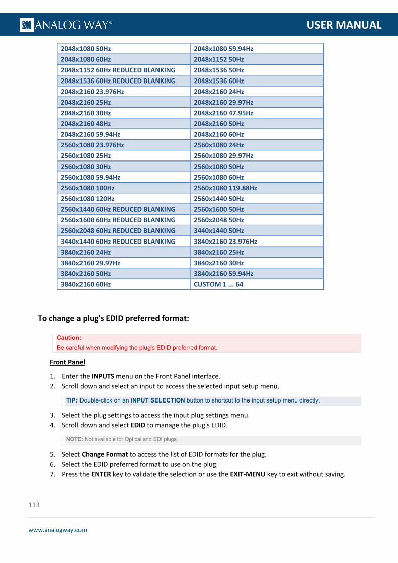
113
www.analogway.com
PROGRAMMER’S GU
USER MANUAL
2048x1080 50Hz 2048x1080 59.94Hz 2048x1080 60Hz 2048x1152 50Hz 2048x1152 60Hz REDUCED BLANKING 2048x1536 50Hz 2048x1536 60Hz REDUCED BLANKING 2048x1536 60Hz 2048x2160 23.976Hz 2048x2160 24Hz 2048x2160 25Hz 2048x2160 29.97Hz 2048x2160 30Hz 2048x2160 47.95Hz 2048x2160 48Hz 2048x2160 50Hz 2048x2160 59.94Hz 2048x2160 60Hz 2560x1080 23.976Hz 2560x1080 24Hz 2560x1080 25Hz 2560x1080 29.97Hz 2560x1080 30Hz 2560x1080 50Hz 2560x1080 59.94Hz 2560x1080 60Hz 2560x1080 100Hz 2560x1080 119.88Hz 2560x1080 120Hz 2560x1440 50Hz 2560x1440 60Hz REDUCED BLANKING 2560x1600 50Hz 2560x1600 60Hz REDUCED BLANKING 2560x2048 50Hz 2560x2048 60Hz REDUCED BLANKING 3440x1440 50Hz 3440x1440 60Hz REDUCED BLANKING 3840x2160 23.976Hz 3840x2160 24Hz 3840x2160 25Hz 3840x2160 29.97Hz 3840x2160 30Hz 3840x2160 50Hz 3840x2160 59.94Hz 3840x2160 60Hz CUSTOM 1 ... 64
To change a plug's EDID preferred format:
Caution: Be careful when modifying the plug's EDID preferred format.
Front Panel
1. Enter the INPUTS menu on the Front Panel interface. 2. Scroll down and select an input to access the selected input setup menu.
TIP: Double-click on an INPUT SELECTION button to shortcut to the input setup menu directly.
3. Select the plug settings to access the input plug settings menu. 4. Scroll down and select EDID to manage the plug's EDID.
NOTE: Not available for Optical and SDI plugs.
5. Select Change Format to access the list of EDID formats for the plug. 6. Select the EDID preferred format to use on the plug. 7. Press the ENTER key to validate the selection or use the EXIT-MENU key to exit without saving.
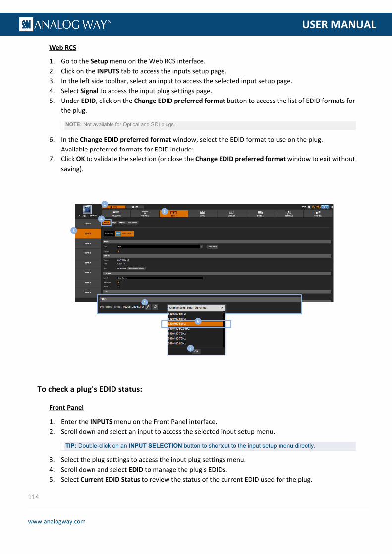
114
www.analogway.com
PROGRAMMER’S GU
USER MANUAL
Web RCS
1. Go to the Setup menu on the Web RCS interface. 2. Click on the INPUTS tab to access the inputs setup page. 3. In the left side toolbar, select an input to access the selected input setup page. 4. Select Signal to access the input plug settings page. 5. Under EDID, click on the Change EDID preferred format button to access the list of EDID formats for
the plug.
NOTE: Not available for Optical and SDI plugs.
6. In the Change EDID preferred format window, select the EDID format to use on the plug. Available preferred formats for EDID include:
7. Click OK to validate the selection (or close the Change EDID preferred format window to exit without saving).
To check a plug's EDID status:
Front Panel
1. Enter the INPUTS menu on the Front Panel interface. 2. Scroll down and select an input to access the selected input setup menu.
TIP: Double-click on an INPUT SELECTION button to shortcut to the input setup menu directly.
3. Select the plug settings to access the input plug settings menu. 4. Scroll down and select EDID to manage the plug's EDIDs. 5. Select Current EDID Status to review the status of the current EDID used for the plug.

115
www.analogway.com
PROGRAMMER’S GU
USER MANUAL
Available EDID status information includes: • Product Name: Current EDID product name. • Hash Code: Hash code of the current data in physical EDID memory. • Preferred Format: EDID preferred format. • CEA-861 Extension: CEA861 extension presence status. • HDMI Compatible: EDID HDMI compatibility status. • Audio Compatible: EDID audio compatibility status.
Web RCS
1. Go to the Setup menu on the Web RCS interface. 2. Click on the INPUTS tab to access the inputs setup page. 3. In the left side toolbar, select an input to access the selected input setup page. 4. Select the Signal tab to access the plug settings page. 5. Under EDID, click on the Current EDID status button to review the status of the current EDID used
for the plug. Available EDID status information includes: • Product Name: Current EDID product name. • Hash Code: Hash code of the current data in physical EDID memory. • Preferred Format: EDID preferred format. • CEA-861 Extension: CEA861 extension presence status. • HDMI Compatible: EDID HDMI compatibility status. • Audio Compatible: EDID audio compatibility status.
Related topics:
• EDID management

116
www.analogway.com
PROGRAMMER’S GU
USER MANUAL
The VIO 4K is compliant with the HDCP specification for DVI, HDMI and DisplayPort inputs.
If an input source is HDCP-encrypted, the output availability is then negotiated according to the following criteria:
HDCP source(*) Non-HDCP source
HDCP output peripheral
Output content is available only if HDCP is enabled on both the input and output plugs.
Output content is available, whichever the status on the output plug.
Non-HDCP output peripheral
Output is blackened even if HDCP is enabled on the output plug.
(*) Only on video plugs standard that support HDCP (HDMI, DisplayPort, DVI).
By enabling and disabling HDCP, you can thus relatively control the whole HDCP stream:
Input control:
• With HDCP enabled (default), the HDCP negotiation is maintained even if the DVI, HDMI or DisplayPort plug is not the current plug (active input).
• With HDCP disabled, none of the HDCP sources can be displayed (the sources will see the VIO 4K inputs as non-HDCP compliant).
Output control:
• With HDCP enabled (default), the HDCP encryption is maintained whether the screen is compliant or not.
• With HDCP disabled, all screens are seen as non-HDCP compliant.
TIP: Disable HDCP as much as possible, especially if not using HDCP-encrypted sources.
To enable/disable HDCP on an input plug:
Front Panel
1. Enter the INPUTS menu on the Front Panel interface. 2. Scroll down and select an input to access the selected input setup menu.
TIP: Double-click on an INPUT SELECTION button to shortcut to the input setup menu directly.
3. Select the plug settings to access the input plug settings menu. 4. Scroll down and uncheck the HDCP check-box to disable HDCP on the input plug (check to enable).
NOTE:
• With HDCP enabled (default), the HDCP negotiation is maintained even if the DVI, HDMI or DisplayPort plug is not the
current plug (active input).
• With HDCP disabled, none of the HDCP sources can be displayed.
7.5.2.6 Managing the HDCP support

117
www.analogway.com
PROGRAMMER’S GU
USER MANUAL
TIP: Go to the CUSTOMIZE menu and select HDCP Manager to manage HDCP on all input plugs.
Web RCS
1. Go to the Setup menu on the Web RCS interface. 2. Click on the INPUTS tab to access the inputs setup page. 3. In the left side toolbar, select an input to access the selected input setup page. 4. Select the Signal tab to access the plug settings page. 5. Under HDCP, uncheck the Enable check-box to disable HDCP on the input plug (check to enable).
NOTE:
• With HDCP enabled (default), the HDCP negotiation is maintained even if the DVI, HDMI or DisplayPort plug is not the
current plug (active input).
• With HDCP disabled, none of the HDCP sources can be displayed.
TIP: Use the Quick Setup button (located at the bottom of the Web RCS interface) to manage HDCP on all input plugs.
To check the HDCP status of an input plug:
Front Panel
1. Enter the INPUTS menu on the Front Panel interface. 2. Scroll down and select an input to access the selected input setup menu.
TIP: Double-click on an INPUT SELECTION button to shortcut to the input setup menu directly.
3. Select the plug settings to access the input plug settings menu. 4. Select Status to check the input plug status. 5. Under Format > HDCP, check the HDCP status of the input plug.
TIP: Go to the CUSTOMIZE menu and select HDCP Manager to manage HDCP on all input plugs.

118
www.analogway.com
PROGRAMMER’S GU
USER MANUAL
Web RCS
1. Go to the Setup menu on the Web RCS interface. 2. Click on the INPUTS tab to access the inputs setup page. 3. In the left side toolbar, select an input to access the selected input setup page. 4. Select the Signal tab to access the plug settings page. 5. Under HDCP, check the HDCP status of the input plug.
TIP: Use the Quick Setup button (located at the bottom of the Web RCS interface) to manage HDCP on all input plugs.
Related topics:
• HDCP support • Plug status
The SD stability specifies the stability of an SDTV signal, sometimes required to configure the hardware accordingly.
On the HD15 input (SDTV signals only), you can specify the stability mode to use for the input signal.
Available input source stability modes include:
STABLE Stable source (DVD) VCR VCR Source
7.5.2.7 Selecting the SD stability (HD15 plug only)

119
www.analogway.com
PROGRAMMER’S GU
USER MANUAL
To enable the VCR mode:
Front Panel
1. Enter the INPUTS menu on the Front Panel interface. 2. Scroll down and select an input to access the selected input setup menu.
TIP: Double-click on an INPUT SELECTION button to shortcut to the input setup menu directly.
3. Select the plug settings to access the input plug settings menu. 4. Check the VCR Mode check-box to enable the VCR stability mode (uncheck to disable).
Web RCS
1. Go to the Setup menu on the Web RCS interface. 2. Click on the INPUTS tab to access the inputs setup page. 3. In the left side toolbar, select an input to access the selected input setup page. 4. Select Signal to access the input plug settings page.
The SD comb filter allows you to reduce the cross-color effect on analog signals (SDTV composite only), by applying a delayed version of the signal to itself.
To enable the SD comb filter:
Front Panel
1. Enter the INPUTS menu on the Front Panel interface. 2. Scroll down and select an input to access the selected input setup menu.
TIP: Double-click on an INPUT SELECTION button to shortcut to the input setup menu directly.
3. Select the plug settings to access the input plug settings menu. 4. Select 3D Comb Filter and choose a 3D comb filter mode (/!\ available only if the signal type is SDTV
composite). Available 3D comb filter modes include:
DISABLE Filter is disabled. DEFAULT Filter is enabled when possible with default parameters. LOW FILTERING
Filter is enabled when possible with very sensitive motion detection parameters (less effective but very few possibilities to introduce motion error).
HIGH FILTERING
Filter is enabled when possible with not much sensitive motion detection parameters (very effective but significative possibilities to introduce motion error).
Web RCS
1. Go to the Setup menu on the Web RCS interface.
7.5.2.8 Enabling the SD comb filter
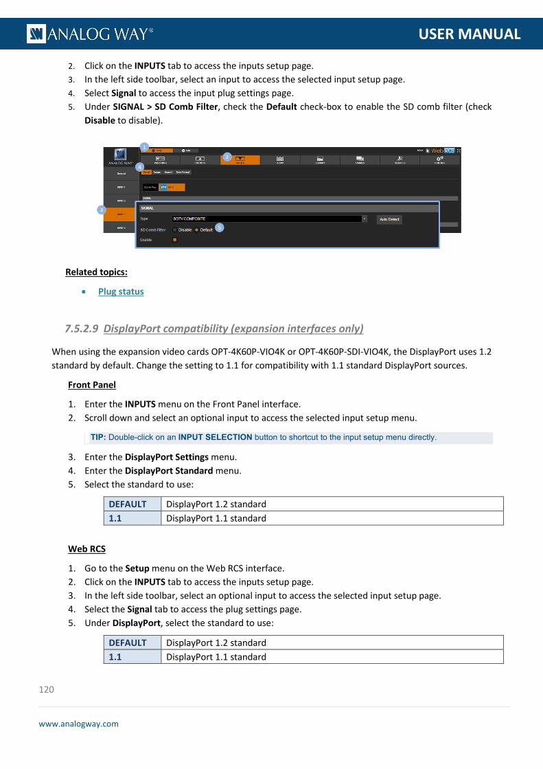
120
www.analogway.com
PROGRAMMER’S GU
USER MANUAL
2. Click on the INPUTS tab to access the inputs setup page. 3. In the left side toolbar, select an input to access the selected input setup page. 4. Select Signal to access the input plug settings page. 5. Under SIGNAL > SD Comb Filter, check the Default check-box to enable the SD comb filter (check
Disable to disable).
Related topics:
• Plug status
When using the expansion video cards OPT-4K60P-VIO4K or OPT-4K60P-SDI-VIO4K, the DisplayPort uses 1.2 standard by default. Change the setting to 1.1 for compatibility with 1.1 standard DisplayPort sources.
Front Panel
1. Enter the INPUTS menu on the Front Panel interface. 2. Scroll down and select an optional input to access the selected input setup menu.
TIP: Double-click on an INPUT SELECTION button to shortcut to the input setup menu directly.
3. Enter the DisplayPort Settings menu. 4. Enter the DisplayPort Standard menu. 5. Select the standard to use:
DEFAULT DisplayPort 1.2 standard 1.1 DisplayPort 1.1 standard
Web RCS
1. Go to the Setup menu on the Web RCS interface. 2. Click on the INPUTS tab to access the inputs setup page. 3. In the left side toolbar, select an optional input to access the selected input setup page. 4. Select the Signal tab to access the plug settings page. 5. Under DisplayPort, select the standard to use:
DEFAULT DisplayPort 1.2 standard 1.1 DisplayPort 1.1 standard
7.5.2.9 DisplayPort compatibility (expansion interfaces only)

121
www.analogway.com
PROGRAMMER’S GU
USER MANUAL
Related topics:
• Expansion interfaces
You can truly optimize the input by adjusting the colorimetry and sharpness detected in the image signal.
You can also use crop to crop the image before applying the display aspect ratio after crop (very useful to correct for formats with non-square pixels, for example).
The VIO 4K allows you to control the input image with the following colorimetry adjustments:
• Brightness, • Contrast, • Hue, • Saturation.
To adjust the colorimetry of the input image:
Front Panel
1. Enter the INPUTS menu on the Front Panel interface. 2. Scroll down and select an input to access the selected input setup menu.
TIP: Double-click on an INPUT SELECTION button to shortcut to the input setup menu directly.
3. Select Image Settings to access the input image settings menu. 4. Select Color Adjustments to access the image colorimetry adjustments. 5. Select a colorimetry setting and rotate the control knob left or right to adjust the input image
colorimetry setting: • Select ENTER to save the new value. • Select EXIT-MENU to restore the last saved value.
Web RCS
1. Go to the Setup menu on the Web RCS interface. 2. Click on the INPUTS tab to access the inputs setup page. 3. In the left side toolbar, select an input to access the selected input setup page. 4. Select the Image tab to access the input image settings page. 5. Under COLORIMETRY, click and drag a colorimetry setting control bar to adjust the input image
colorimetry.
7.5.3 Adjusting the image
7.5.3.1 Adjusting colorimetry

122
www.analogway.com
PROGRAMMER’S GU
USER MANUAL
SEE also: User gain
To reset colorimetry:
Front Panel
1. Enter the INPUTS menu on the Front Panel interface. 2. Scroll down and select an input to access the selected input setup menu.
TIP: Double-click on an INPUT SELECTION button to shortcut to the input setup menu directly.
3. Select Image Settings to access the input image settings menu. 4. Select Color Adjustments to access the image colorimetry adjustments. 5. Scroll down and select Reset to reset all colorimetry adjustments:
• Select Confirm to confirm the reset. • Select Cancel to cancel the reset and keep your adjustments.
NOTE: Both the colorimetry and the user gain adjustments will be reset.
Web RCS
1. Go to the Setup menu on the Web RCS interface. 2. Click on the INPUTS tab to access the inputs setup page. 3. In the left side toolbar, select an input to access the selected input setup page. 4. Select the Image tab to access the input image settings page. 5. Click on the reset button next to COLORIMETRY to reset all colorimetry adjustments.
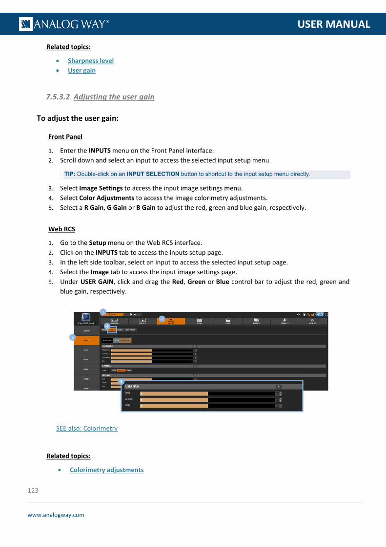
123
www.analogway.com
PROGRAMMER’S GU
USER MANUAL
Related topics:
• Sharpness level • User gain
To adjust the user gain:
Front Panel
1. Enter the INPUTS menu on the Front Panel interface. 2. Scroll down and select an input to access the selected input setup menu.
TIP: Double-click on an INPUT SELECTION button to shortcut to the input setup menu directly.
3. Select Image Settings to access the input image settings menu. 4. Select Color Adjustments to access the image colorimetry adjustments. 5. Select a R Gain, G Gain or B Gain to adjust the red, green and blue gain, respectively.
Web RCS
1. Go to the Setup menu on the Web RCS interface. 2. Click on the INPUTS tab to access the inputs setup page. 3. In the left side toolbar, select an input to access the selected input setup page. 4. Select the Image tab to access the input image settings page. 5. Under USER GAIN, click and drag the Red, Green or Blue control bar to adjust the red, green and
blue gain, respectively.
SEE also: Colorimetry
Related topics:
• Colorimetry adjustments
7.5.3.2 Adjusting the user gain

124
www.analogway.com
PROGRAMMER’S GU
USER MANUAL
• Sharpness level
To select the sharpness level:
Front Panel
1. Enter the INPUTS menu on the Front Panel interface. 2. Scroll down and select an input to access the selected input setup menu.
TIP: Double-click on an INPUT SELECTION button to shortcut to the input setup menu directly.
3. Select Image Settings to access the input image settings menu. 4. Select Sharpness to choose the image sharpness level.
List of possible sharpness levels:
LOW Low sharpness MEDIUM Medium sharpness HIGH High sharpness
Web RCS
1. Go to the Setup menu on the Web RCS interface. 2. Click on the INPUTS tab to access the inputs setup page. 3. In the left side toolbar, select an input to access the selected input setup page. 4. Select the Image tab to access the input image settings page. 5. Under SHARPNESS, select the image sharpness level.
List of possible sharpness levels:
LOW Low sharpness MEDIUM Medium sharpness HIGH High sharpness
TIP: Click on the Reset All button to reset your adjustment (click again to confirm).
Related topics:
7.5.3.3 Selecting the sharpness level

125
www.analogway.com
PROGRAMMER’S GU
USER MANUAL
• Colorimetry adjustments • User gain
Adjusting the image aspect ratio and size can be very useful to correct formats with non-square pixels, for example.
With the VIO 4K, you can correct the aspect ratio detected in the image signal, and then use crop to crop the image before applying the wanted display aspect ratio after crop.
To correct the signal aspect ratio:
Front Panel
1. Enter the INPUTS menu on the Front Panel interface. 2. Scroll down and select an input to access the selected input setup menu.
TIP: Double-click on an INPUT SELECTION button to shortcut to the input setup menu directly.
3. Select Image Settings to access the input image settings menu. 4. Select Signal Aspect Ratio to force the aspect ratio of the input image signal.
Available signal aspect ratios include:
NATIVE Detected aspect ratio 5:4 5/4 (1.25 : 1) aspect ratio 4:3 4/3 (1.33 : 1) aspect ratio 16:10 16/10 (1.6 : 1) aspect ratio 15:9 15/9 (1.66 : 1) aspect ratio 16:9 16/9 (1.77 : 1) aspect ratio 21:9 21/9 (2.33 : 1) aspect ratio
Web RCS
1. Go to the Setup menu on the Web RCS interface. 2. Click on the INPUTS tab to access the inputs setup page. 3. In the left side toolbar, select an input to access the selected input setup page. 4. Click on the Aspect tab to access the input image aspect and size settings page. 5. Under ASPECT RATIO, select a Signal aspect ratio to force the aspect ratio of the input image signal.
Available signal aspect ratios include:
NATIVE Detected aspect ratio 5:4 5/4 (1.25 : 1) aspect ratio
7.5.3.4 Adjusting the image aspect ratio and size
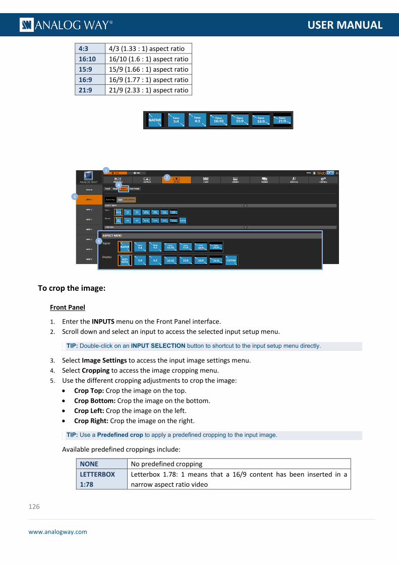
126
www.analogway.com
PROGRAMMER’S GU
USER MANUAL
4:3 4/3 (1.33 : 1) aspect ratio 16:10 16/10 (1.6 : 1) aspect ratio 15:9 15/9 (1.66 : 1) aspect ratio 16:9 16/9 (1.77 : 1) aspect ratio 21:9 21/9 (2.33 : 1) aspect ratio
To crop the image:
Front Panel
1. Enter the INPUTS menu on the Front Panel interface. 2. Scroll down and select an input to access the selected input setup menu.
TIP: Double-click on an INPUT SELECTION button to shortcut to the input setup menu directly.
3. Select Image Settings to access the input image settings menu. 4. Select Cropping to access the image cropping menu. 5. Use the different cropping adjustments to crop the image:
• Crop Top: Crop the image on the top. • Crop Bottom: Crop the image on the bottom. • Crop Left: Crop the image on the left. • Crop Right: Crop the image on the right.
TIP: Use a Predefined crop to apply a predefined cropping to the input image.
Available predefined croppings include:
NONE No predefined cropping LETTERBOX 1:78
Letterbox 1.78: 1 means that a 16/9 content has been inserted in a narrow aspect ratio video

127
www.analogway.com
PROGRAMMER’S GU
USER MANUAL
LETTERBOX 1:85
Letterbox 1.85: 1 means that a cinema 1.85 : 1 content has been inserted in a narrow aspect ratio video
LETTERBOX 2:35
Letterbox 2.35: 1 means that a cinema 2.35 : 1 content has been inserted in a narrow aspect ratio video
PILLARBOX 1:33
Pillarbox 1.33: 1 means that a 4/3 content has been inserted in a wider aspect ratio video
TIP: Use the Reset command to reset all cropping adjustments.
Web RCS
1. Go to the Setup menu on the Web RCS interface. 2. Click on the INPUTS tab to access the inputs setup page. 3. In the left side toolbar, select an input to access the selected input setup page. 4. Click on the Aspect tab to access the input image aspect ratio and size settings page. 5. Under CROPPING, use the different cropping adjustments to crop the image:
• Crop Top: Crop the image on the top. • Crop Bottom: Crop the image on the bottom. • Crop Left: Crop the image on the left. • Crop Right: Crop the image on the right.
TIP: Select a Predefined cropping to apply a predefined cropping to the input image.
Available predefined croppings include:
NONE No predefined cropping LETTERBOX 1:78
Letterbox 1.78: 1 means that a 16/9 content has been inserted in a narrow aspect ratio video
LETTERBOX 1:85
Letterbox 1.85: 1 means that a cinema 1.85 : 1 content has been inserted in a narrow aspect ratio video
LETTERBOX 2:35
Letterbox 2.35: 1 means that a cinema 2.35 : 1 content has been inserted in a narrow aspect ratio video
PILLARBOX 1:33
Pillarbox 1.33: 1 means that a 4/3 content has been inserted in a wider aspect ratio video
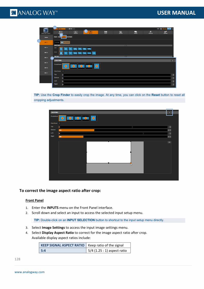
128
www.analogway.com
PROGRAMMER’S GU
USER MANUAL
TIP: Use the Crop Finder to easily crop the image. At any time, you can click on the Reset button to reset all cropping adjustments.
To correct the image aspect ratio after crop:
Front Panel
1. Enter the INPUTS menu on the Front Panel interface. 2. Scroll down and select an input to access the selected input setup menu.
TIP: Double-click on an INPUT SELECTION button to shortcut to the input setup menu directly.
3. Select Image Settings to access the input image settings menu. 4. Select Display Aspect Ratio to correct for the image aspect ratio after crop.
Available display aspect ratios include:
KEEP SIGNAL ASPECT RATIO Keep ratio of the signal 5:4 5/4 (1.25 : 1) aspect ratio

129
www.analogway.com
PROGRAMMER’S GU
USER MANUAL
4:3 4/3 (1.33 : 1) aspect ratio 16:10 16/10 (1.6 : 1) aspect ratio 15:9 15/9 (1.66 : 1) aspect ratio 16:9 16/9 (1.77 : 1) aspect ratio 21:9 21/9 (2.33 : 1) aspect ratio CUSTOM Custom ratio
Web RCS
1. Go to the Setup menu on the Web RCS interface. 2. Click on the INPUTS tab to access the inputs setup page. 3. In the left side toolbar, select an input to access the selected input setup page. 4. Click on the Aspect tab to access the input image aspect ratio and size settings page. 5. Under ASPECT RATIO, select a Display aspect ratio to correct for the image aspect ratio after crop.
Available display aspect ratios include:
KEEP SIGNAL ASPECT RATIO Keep ratio of the signal 5:4 5/4 (1.25 : 1) aspect ratio 4:3 4/3 (1.33 : 1) aspect ratio 16:10 16/10 (1.6 : 1) aspect ratio 15:9 15/9 (1.66 : 1) aspect ratio 16:9 16/9 (1.77 : 1) aspect ratio 21:9 21/9 (2.33 : 1) aspect ratio CUSTOM Custom ratio
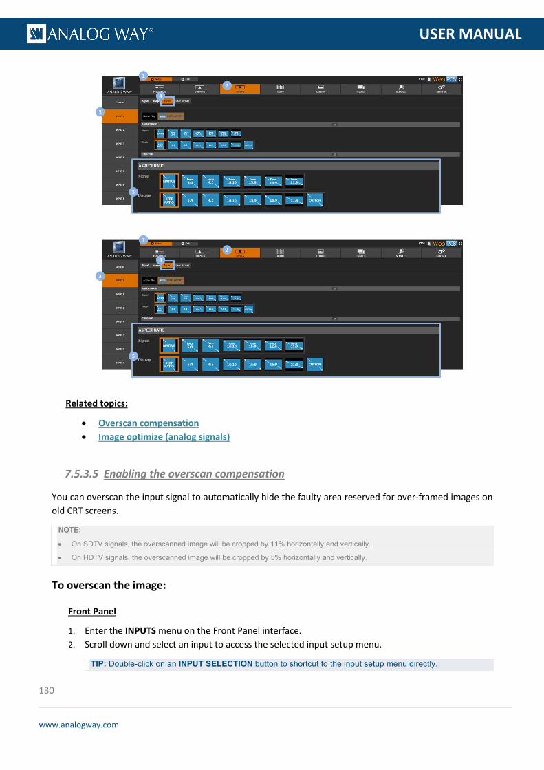
130
www.analogway.com
PROGRAMMER’S GU
USER MANUAL
Related topics:
• Overscan compensation • Image optimize (analog signals)
You can overscan the input signal to automatically hide the faulty area reserved for over-framed images on old CRT screens.
NOTE:
• On SDTV signals, the overscanned image will be cropped by 11% horizontally and vertically.
• On HDTV signals, the overscanned image will be cropped by 5% horizontally and vertically.
To overscan the image:
Front Panel
1. Enter the INPUTS menu on the Front Panel interface. 2. Scroll down and select an input to access the selected input setup menu.
TIP: Double-click on an INPUT SELECTION button to shortcut to the input setup menu directly.
7.5.3.5 Enabling the overscan compensation

131
www.analogway.com
PROGRAMMER’S GU
USER MANUAL
3. Select Image Settings to access the input image settings menu. 4. Select Under/Overscan > Overscan to enable the overscan compensation on the input signal (select
Underscan to disable).
Web RCS
1. Go to the Setup menu on the Web RCS interface. 2. Click on the INPUTS tab to access the inputs setup page. 3. In the left side toolbar, select an input to access the selected input setup page. 4. Click on the Aspect tab to access the input image aspect ratio and size settings page. 5. Under CROPPING, check the Overscan check-box to enable the overscan compensation on the input
signal (uncheck to disable).
Related topics:
• Aspect ratio and size • Image optimize (analog signals)
On analog signals, you can optimize the image by defining the pixel frequency (total number of pixels per line) and the phase.
You can also request an auto-centering procedure to automatically manage the pixel frequency, the phase and/or the blankings:
• Automatic clock frequency recognition (total number of pixels per line); • Automatic phase recognition; • Automatic edge detection (find the blanking that best suits the signal).
NOTE: The auto-centering procedure is expected to last about 10 seconds and can be performed on different inputs separately
(simultaneously or not).
7.5.3.6 Optimizing the image (analog signals)

132
www.analogway.com
PROGRAMMER’S GU
USER MANUAL
TIP: • Once the auto-centering procedure is complete, go the Image Setting menu and select Analog Blanking
Adjustments to correct for small centering problems. • Use a format raster-box pattern on the input when possible to help you adjust the pixel frequency, the phase and/or
the blankings.
To request auto-centering:
Information: The auto-centering procedure is not 100% reliable and results may depend on the signal quality and the image contrast.
Front Panel
1. Enter the INPUTS menu on the Front Panel interface. 2. Scroll down and select an input to access the selected input setup menu.
TIP: Double-click on an INPUT SELECTION button to shortcut to the input setup menu directly.
3. Select Image Settings to access the input image settings menu 4. Select Autocentering and choose an auto-centering request
Available autocentering requests include:
QUICK Automatic management of the phase and the blankings (but not the pixel frequency).
ADVANCED Automatic management of the pixel frequency, the phase and the blankings.
Web RCS
1. Go to the Setup menu on the Web RCS interface. 2. Click on the INPUTS tab to access the inputs setup page. 3. In the left side toolbar, select an input to access the selected input setup page. 4. Click on the Image tab to access the input image settings page. 5. Under OPTIMIZE, select an AutoCenter request.
Available auto centering requests include:
QUICK Automatic management of the phase and the blankings (but not the pixel frequency).
ADVANCED Automatic management of the pixel frequency, the phase and the blankings.

133
www.analogway.com
PROGRAMMER’S GU
USER MANUAL
To adjust the clock frequency (number of pixels per line):
Front Panel
1. Enter the INPUTS menu on the Front Panel interface. 2. Scroll down and select an input to access the selected input setup menu.
TIP: Double-click on an INPUT SELECTION button to shortcut to the input setup menu directly.
3. Select Image Settings to access the input image settings menu. 4. Select Analog Optimize to access the analog optimize menu. 5. Select H Total to adjust the clock frequency (input signal offset of total pixel per line).
Web RCS
1. Go to the Setup menu on the Web RCS interface. 2. Click on the INPUTS tab to access the inputs setup page. 3. In the left side toolbar, select an input to access the selected input setup page. 4. Click on the Image tab to access the input image settings page. 5. Under OPTIMIZE, click and drag the Clock control bar to adjust the clock frequency (number of pixels
per line).

134
www.analogway.com
PROGRAMMER’S GU
USER MANUAL
To adjust the phase:
Front Panel
1. Enter the INPUTS menu on the Front Panel interface. 2. Scroll down and select an input to access the selected input setup menu.
TIP: Double-click on an INPUT SELECTION button to shortcut to the input setup menu directly.
3. Select Image Settings to access the input image settings menu. 4. Select Analog Optimize to access the analog optimize menu. 5. Select Phase to specify the input signal phase.
Web RCS
1. Go to the Setup menu on the Web RCS interface. 2. Click on the INPUTS tab to access the inputs setup page. 3. In the left side toolbar, select an input to access the selected input setup page. 4. Click on the Image tab to access the input image settings page. 5. Under OPTIMIZE, click and drag the Phase control bar to specify the signal phase.

135
www.analogway.com
PROGRAMMER’S GU
USER MANUAL
To adjust the blanking:
Front Panel
1. Enter the INPUTS menu on the Front Panel interface 2. Scroll down and select an input to access the selected input setup menu
TIP: Double-click on an INPUT SELECTION button to shortcut to the input setup menu directly.
3. Select Image Settings to access the input image settings menu. 4. Select Analog Blanking Adjustments to access the blanking adjustments menu.
Adjust the following parameters: • H Start: Adjust the input signal horizontal position. • V Start: Adjust the input signal vertical position. • H Size: Adjust the input signal horizontal size. • V Size: Adjust the input signal vertical size.
Web RCS
1. Go to the Setup menu on the Web RCS interface. 2. Click on the INPUTS tab to access the inputs setup page. 3. In the left side toolbar, select an input to access the selected input setup page. 4. Click on the Aspect tab to access the input image aspect and size settings page.

136
www.analogway.com
PROGRAMMER’S GU
USER MANUAL
5. Under BLANKING ADJUSTEMENTS, adjust the following parameters: • H Position: Adjust the input signal horizontal position. • H Size: Adjust the input signal horizontal size. • V Position: Adjust the input signal vertical position. • V Size: Adjust the input signal vertical size.
Related topics:
• Overscan compensation • Aspect ratio and size
By default, the deinterlacing process used for interlaced input signals does not add any extra frame delay.
You can however disable low latency to improve the image quality, and enable or disable 2:2 and 3:2 pull-down to optimize the progressive image reconstruction process.
To adjust the deinterlacer options:
Front Panel
1. Enter the INPUTS menu on the Front Panel interface. 2. Scroll down and select an input to access the selected input setup menu.
TIP: Double-click on an INPUT SELECTION button to shortcut to the input setup menu directly.
3. Select Image Settings to access the input image settings menu. 4. Select Deinterlacer to access the deinterlacer options. 5. Uncheck Low Latency to disable low latency.
NOTE: Disabling low latency will add an extra frame latency.
6. If required, uncheck the 2:2 Pulldown/3:2 Pulldown check-boxes to optimize the progressive image reconstruction process: • Uncheck 2:2 Pulldown to disable the detection of 2:2 sequences for 50Hz interlaced formats.
7.5.3.7 Adjusting the deinterlacer options (interfaced sources)

137
www.analogway.com
PROGRAMMER’S GU
USER MANUAL
• Uncheck 3:2 Pulldown to disable the detection of 3:2 sequences for 59.94Hz/60Hz interlaced formats.
Web RCS
1. Go to the Setup menu on the Web RCS interface. 2. Click on the INPUTS tab to access the inputs setup page. 3. In the left side toolbar, select an input to access the selected input setup page. 4. Select the Image tab to access the input image settings page. 5. Under DEINTERLACER, uncheck Low Latency to disable low latency.
NOTE: Disabling low latency will add an extra frame latency.
6. If required, uncheck the 2:2 Pulldown/3:2 Pulldown check-boxes to optimize the progressive image reconstruction process: • Uncheck 2:2 Pulldown to disable the detection of 2:2 sequences for 50Hz interlaced formats. • Uncheck 3:2 Pulldown to disable the detection of 3:2 sequences for 59.94Hz/60Hz interlaced
formats.
The image settings of an input are automatically recalled via the input settings memory when the input meets all the following characteristics:
• Source number (either input number or matrix source number); • Line and line sync widths; • Frame and frame sync widths; • H and V sync polarities.
You can however reset all image settings without erasing the input settings memory.
7.5.3.8 Resetting the image
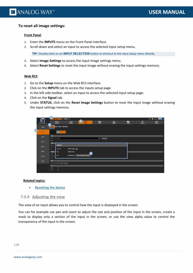
138
www.analogway.com
PROGRAMMER’S GU
USER MANUAL
To reset all image settings:
Front Panel
1. Enter the INPUTS menu on the Front Panel interface. 2. Scroll down and select an input to access the selected input setup menu.
TIP: Double-click on an INPUT SELECTION button to shortcut to the input setup menu directly.
3. Select Image Settings to access the input image settings menu. 4. Select Reset Settings to reset the input image without erasing the input settings memory.
Web RCS
1. Go to the Setup menu on the Web RCS interface. 2. Click on the INPUTS tab to access the inputs setup page. 3. In the left side toolbar, select an input to access the selected input setup page. 4. Click on the Signal tab. 5. Under STATUS, click on the Reset Image Settings button to reset the input image without erasing
the input settings memory.
Related topics:
• Resetting the device
The view of an input allows you to control how the input is displayed in the screen.
You can for example use pan and zoom to adjust the size and position of the input in the screen, create a mask to display only a section of the input in the screen, or use the view alpha value to control the transparency of the input in the screen.
7.5.4 Adjusting the view

139
www.analogway.com
PROGRAMMER’S GU
USER MANUAL
To pan / zoom the view:
Front Panel
1. Enter the INPUTS menu on the Front Panel interface. 2. Scroll down and select an input to access the selected input setup menu.
TIP: Double-click on an INPUT SELECTION button to shortcut to the input setup menu directly.
3. Select "View" Settings to access the input's view settings menu. 4. Select Units to choose the units used to pan and zoom the view:
• Select PERCENT to set up the view using relative (percent) units • Select PIXELS to set up the view using absolute (pixel) units
NOTE: These units will also be used to mask the view.
5. Scroll down and edit the Pan H and Pan V parameters to position the input in the screen (from the center of the screen).
6. Scroll down and edit the Zoom H and Zoom V parameters to resize the input in the screen.
TIP: • Select Zoom H/V to zoom the view while keeping the current aspect ratio. • Select Pan/Zoom Template to automatically adjust the view size and position to the screen (SEE: Screen fill
templates for more information). • At any time, you can select Reset Pan/Zoom to reset all pan and zoom settings.
Web RCS
1. Go to the Edit menu on the Web RCS interface. 2. Select the SCREEN tab to access the screen edit page. 3. In the left side toolbar, select an INPUT to load the input view settings. 4. In the right side toolbar, select the View tab to access the input's view settings. 5. Under Pan/Zoom, select the units used to pan and zoom the view:
• Select PERCENT to set up the view using relative (percent) units. • Select PIXELS to set up the view using absolute (pixel) units.
6. Edit the Pan H and Pan V parameters to position the input in the screen (from the center of the screen).
7. Edit the Zoom H and Zoom V parameters to resize the input in the screen.
TIP: Use the Keep aspect ratio button to zoom the view while keeping the current aspect ratio.

140
www.analogway.com
PROGRAMMER’S GU
USER MANUAL
TIP: • Use the POS. button (located at the bottom of the Web RCS interface) to automatically position the view to the
screen • Use the VIEW ASPECT button (located at the bottom of the Web RCS interface) to automatically adjust the
view to the screen (SEE: Screen fill templates for more information).
To flip the view:
Front Panel
1. Enter the INPUTS menu on the Front Panel interface. 2. Scroll down and select an input to access the selected input setup menu.
TIP: Double-click on an INPUT SELECTION button to shortcut to the input setup menu directly.
3. Select "View" Settings to access the input's view settings menu. 4. Select Flip and select the flip movement to apply to the live input.
Available flip movements include:
NONE No flip HORIZONTAL Horizontal flip VERTICAL Vertical flip BOTH Both
Web RCS
1. Go to the Edit menu on the Web RCS interface. 2. Select the SCREEN tab to access the screen edit page. 3. In the left side toolbar, select an INPUT to load the input view settings. 4. In the right side toolbar, select View to access the input's View settings.
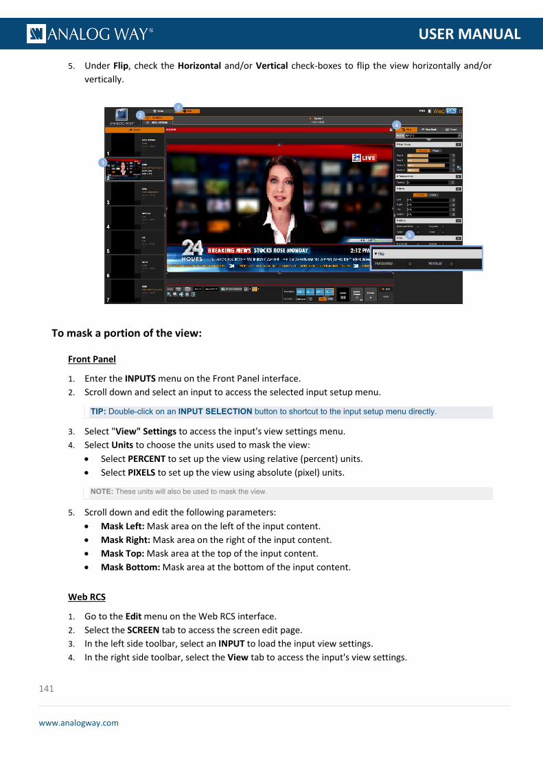
141
www.analogway.com
PROGRAMMER’S GU
USER MANUAL
5. Under Flip, check the Horizontal and/or Vertical check-boxes to flip the view horizontally and/or vertically.
To mask a portion of the view:
Front Panel
1. Enter the INPUTS menu on the Front Panel interface. 2. Scroll down and select an input to access the selected input setup menu.
TIP: Double-click on an INPUT SELECTION button to shortcut to the input setup menu directly.
3. Select "View" Settings to access the input's view settings menu. 4. Select Units to choose the units used to mask the view:
• Select PERCENT to set up the view using relative (percent) units. • Select PIXELS to set up the view using absolute (pixel) units.
NOTE: These units will also be used to mask the view.
5. Scroll down and edit the following parameters: • Mask Left: Mask area on the left of the input content. • Mask Right: Mask area on the right of the input content. • Mask Top: Mask area at the top of the input content. • Mask Bottom: Mask area at the bottom of the input content.
Web RCS
1. Go to the Edit menu on the Web RCS interface. 2. Select the SCREEN tab to access the screen edit page. 3. In the left side toolbar, select an INPUT to load the input view settings. 4. In the right side toolbar, select the View tab to access the input's view settings.

142
www.analogway.com
PROGRAMMER’S GU
USER MANUAL
5. Under Mask, select the units used to mask the view: • Select PERCENT to set up the view using relative (percent) units. • Select PIXELS to set up the view using absolute (pixel) units.
6. Edit the following parameters: • Mask Left: Mask area on the left of the input content. • Mask Right: Mask area on the right of the input content. • Mask Top: Mask area at the top of the input content. • Mask Bottom: Mask area at the bottom of the input content.
TIP: Use the Reset button if required to reset the mask (no mask).
To control the transparency:
Front Panel
1. Enter the INPUTS menu on the Front Panel interface. 2. Scroll down and select an input to access the selected input setup menu.
TIP: Double-click on an INPUT SELECTION button to shortcut to the input setup menu directly.
3. Select "View" Settings to access the input's view settings menu. 4. Select Alpha to adjust the transparency of the input in the screen (use max alpha for min
transparency).
Web RCS
1. Go to the Edit menu on the Web RCS interface. 2. Select the SCREEN tab to access the screen edit page. 3. In the left side toolbar, select the INPUT to display on the output. 4. In the right side toolbar, select the View tab to access the input's view settings.

143
www.analogway.com
PROGRAMMER’S GU
USER MANUAL
5. Under Transparency, adjust the alpha transparency of the input in the screen (use max transparency for min alpha).
To apply a color effect:
Front Panel
1. Enter the INPUTS menu on the Front Panel interface. 2. Scroll down and select an input to access the selected input setup menu.
TIP: Double-click on an INPUT SELECTION button to shortcut to the input setup menu directly.
3. Select "View" Settings to access the input's view settings menu. 4. Select Effect to access the color effects menu. 5. Check the appropriate check-box to enable a color effect on the live input (uncheck to disable).
Available color effects include:
NONE No effect BLACK AND WHITE Black and White NEGATIVE Negative SEPIA Sepia SOLAR Solar ALL All (when possible)
Web RCS
1. Go to the Edit menu on the Web RCS interface. 2. Select the SCREEN tab to access the screen edit page. 3. In the left side toolbar, select an INPUT to load the input view settings. 4. In the right side toolbar, select the View tab to access the input's view settings.
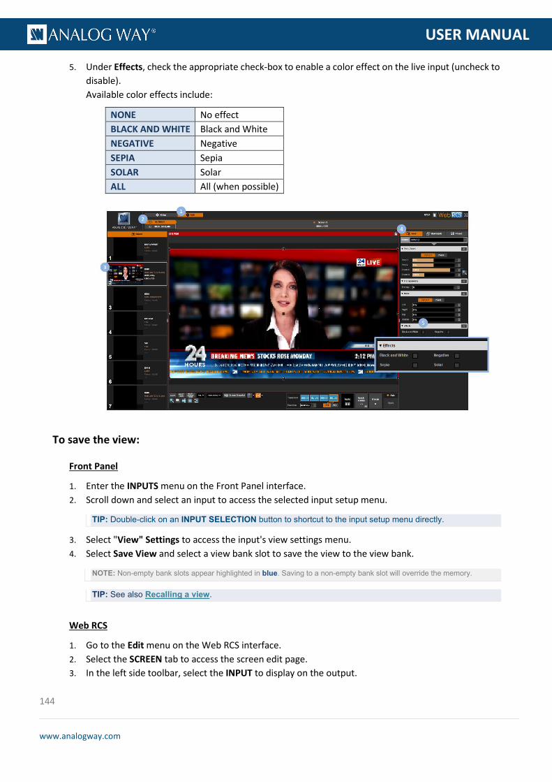
144
www.analogway.com
PROGRAMMER’S GU
USER MANUAL
5. Under Effects, check the appropriate check-box to enable a color effect on the live input (uncheck to disable). Available color effects include:
NONE No effect BLACK AND WHITE Black and White NEGATIVE Negative SEPIA Sepia SOLAR Solar ALL All (when possible)
To save the view:
Front Panel
1. Enter the INPUTS menu on the Front Panel interface. 2. Scroll down and select an input to access the selected input setup menu.
TIP: Double-click on an INPUT SELECTION button to shortcut to the input setup menu directly.
3. Select "View" Settings to access the input's view settings menu. 4. Select Save View and select a view bank slot to save the view to the view bank.
NOTE: Non-empty bank slots appear highlighted in blue. Saving to a non-empty bank slot will override the memory.
TIP: See also Recalling a view.
Web RCS
1. Go to the Edit menu on the Web RCS interface. 2. Select the SCREEN tab to access the screen edit page. 3. In the left side toolbar, select the INPUT to display on the output.

145
www.analogway.com
PROGRAMMER’S GU
USER MANUAL
4. In the right side toolbar, select the View tab to access the input's View settings. 5. Click on the SAVE VIEW button to switch to the view bank save mode (click again to confirm). 6. On the View Bank tab, select a view bank slot to save the view to the view bank (or click on the
blinking SAVE MODE button to cancel and exit save mode).
NOTE:
• Non-empty bank slots appear highlighted in blue. Saving to a non-empty bank slot will override the memory.
• The first available (non-empty) bank slot is highlighted by a white rectangle.
• Saving to a non-empty bank slot will override the memory.
TIP: See also Recalling a view.
To recall a view:
Front Panel
1. Enter the INPUTS menu on the Front Panel interface. 2. Scroll down and select an input to access the selected input setup menu.
TIP: Double-click on an INPUT SELECTION button to shortcut to the input setup menu directly.
3. Select "View" Settings to access the input's view settings menu. 4. Select Recall View and select a view bank slot to recall the view bank memory on the selected input.
TIP: SEE also Saving a view
Web RCS
1. Go to the Edit menu on the Web RCS interface. 2. Select the SCREEN tab to access the screen edit page.

146
www.analogway.com
PROGRAMMER’S GU
USER MANUAL
3. In the left side toolbar, select an INPUT to load the input view settings. 4. In the right side toolbar, select the View Bank tab to access the view bank. 5. Click on a view bank slot to recall the view bank memory on the selected input.
TIP: SEE also Saving a view
To reset the view:
Front Panel
1. Enter the INPUTS menu on the Front Panel interface. 2. Scroll down and select an input to access the selected input setup menu.
TIP: Double-click on an INPUT SELECTION button to shortcut to the input setup menu directly.
3. Select "View" Settings to access the input's view settings menu. 4. Select Flip > NONE to reset flip. 5. Select Alpha and adjust the alpha value at 255. 6. Select Effect > Reset > Confirm to disable all color effects. 7. Select Reset Pan/Zoom > Confirm to reset all pan and zoom settings.
Web RCS
1. Go to the Edit menu on the Web RCS interface. 2. Select the SCREEN tab to access the screen edit page. 3. In the left side toolbar, select an INPUT to load the input view settings. 4. In the right side toolbar, select the View tab to access the input's view settings. 5. Click on the RESET VIEW button to reset all view settings (click again to confirm the reset).
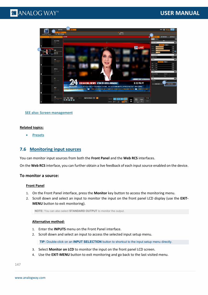
147
www.analogway.com
PROGRAMMER’S GU
USER MANUAL
SEE also: Screen management
Related topics:
• Presets
You can monitor input sources from both the Front Panel and the Web RCS interfaces.
On the Web RCS interface, you can further obtain a live feedback of each input source enabled on the device.
To monitor a source:
Front Panel
1. On the Front Panel interface, press the Monitor key button to access the monitoring menu. 2. Scroll down and select an input to monitor the input on the front panel LCD display (use the EXIT-
MENU button to exit monitoring).
NOTE: You can also select STANDARD OUTPUT to monitor the output.
Alternative method:
1. Enter the INPUTS menu on the Front Panel interface. 2. Scroll down and select an input to access the selected input setup menu.
TIP: Double-click on an INPUT SELECTION button to shortcut to the input setup menu directly.
3. Select Monitor on LCD to monitor the input on the front panel LCD screen. 4. Use the EXIT-MENU button to exit monitoring and go back to the last visited menu.
7.6 Monitoring input sources

148
www.analogway.com
PROGRAMMER’S GU
USER MANUAL
Web RCS
1. Go to the Edit menu on the Web RCS interface. 2. Select the MON. STREAM tab to access the monitoring page. 3. Go to the Properties toolbar on right-hand side. 4. Under Setup > Source, select the input to monitor.
NOTE: You can also select the input from the Inputs tab on the left-hand toolbar.
5. If required, select the Quality of the monitoring stream. Available monitoring qualities include:
320x240@30Hz 640x480@30Hz 1280x720@30Hz
TIP: Use the Play and Fullscreen buttons at the bottom of the monitoring screen to control the monitoring stream playback and display size.
To enable/disable the live feedback:
Front Panel
NOTE: This function is not available via the front panel.
Web RCS
1. Go to the Setup menu on the Web RCS interface. 2. Click on the INPUTS tab to access the inputs setup page.

149
www.analogway.com
PROGRAMMER’S GU
USER MANUAL
3. In the left side toolbar, select an input to access the selected input setup page. 4. Select Signal to access the input plug settings page. 5. Under CONTROL, check the Spanshot check-box to enable a live feedback of the input sources
connected to the input plug (uncheck to disable).
TIP: Use the Label field to provide a name for the source.
SEE: Creating frame captures
SEE: Enabling loop mode (output plug)
Related topics:
• Presets • Audio management • Configuration backup
7.7 Capturing the input
7.8 Looping-through inputs
150
www.analogway.com
PROGRAMMER’S GU
USER MANUAL
A Frame is a 24-bit RGB still picture whose maximum pixel size is 8192x4320 pixels.
You can use frames to:
• Capture the active input or the output (capture video); • Display a foreground frame (quick-frame function); • Create a nice transition effect (frame transitions); • Display a background when no input source is selected (black frame).
The currently supported frame formats are:
• BMP, • JPEG, • PNG.
You can import and export frames to and from the device via the Frame Library:
• Importing frames will allow you to use frames directly available on the device; • Exporting frames will allow you to transfer frames to other devices.
You can also create frame captures from your video inputs and outputs (SEE: Creating frame captures).
To import a frame to the library:
Front Panel
NOTE: You will need to a USB key to import frames via the front panel.
Before you start:
• Prepare a USB key with the frames you wish to import.
• Plug-in the USB key into the USB HOST port (located on the front panel).
• Wait until the device is properly recognized and then proceed to import frames as described below.
1. Enter the FRAME menu on the Front Panel interface. 2. Select IMPORT to access USB device browser. 3. In the USB device browser, browse for the file to import.
TIP: Use the ENTER and EXIT-MENU keys to navigate through folders.
8 Frame management
8.1 What is a frame?
8.2 Supported frame formats
8.3 Importing and exporting frames

151
www.analogway.com
PROGRAMMER’S GU
USER MANUAL
4. Select the file to import and press the ENTER key to import the file to the library.
NOTE: You can also use the EXIT-MENU key to go back to the USB device browser without importing the file.
TIP: Select a slot range to import to a specific frame library slot.
Web RCS
1. Go to the Setup menu on the Web RCS interface. 2. Click on the LIBRARY tab to access the frame library management page. 3. Click on the Upload new files button to access the Upload new images to library window. 4. In the Upload new images to library window, click on the "..." button to access your OS device
browser. 5. In your OS device browser, select the file(s) to import and click OK/Open to load them into the
Upload new image to library window.
TIP: Select more than one file to import several files at once.
6. In the Upload new image to library window, click on the Upload button to start importing the selected file(s) to the device.
TIP: Before you import your file(s), you can select a file(s) and click on the Remove selected files button to cancel the import of the selected file(s).
7. Wait for the import files process to be complete and click on the "X" button to close the Upload new image to library window.

152
www.analogway.com
PROGRAMMER’S GU
USER MANUAL
To export a frame from the library:
Front Panel
NOTE: You will need to a USB key to export frames via the front panel.
Before you start:
• Plug-in a USB key into the USB HOST port (located on the front panel).
• Wait until the device is properly recognized and then proceed to export frames as described below.
1. Enter the FRAME menu on the Front Panel interface. 2. Select LIBRARY to access the frame library management menu. 3. Select the frame to export and press the ENTER key to access the frame detail menu. 4. Scroll down and select Export to... to access the USB device browser. 5. In the USB device browser, browse for the folder to export to.
TIP: Use the ENTER and EXIT-MENU keys to navigate through folders.
6. Finally, select EXPORT TO THIS FOLDER to export the frame to the selected folder.
Web RCS
1. Go to the Setup menu on the Web RCS interface. 2. Click on the LIBRARY tab to access the frame library management page. 3. Hover over the frame to export and click on the Download file on your computer button. 4. In the Download image from library window, click on the Download button to access your OS device
browser. 5. In your OS device browser, browse for the folder to export to and click on OK/Open button to export
the frame to the selected folder.
NOTE: Your OS device browser will not pop up if the Web RCS interface is in full screen mode.

153
www.analogway.com
PROGRAMMER’S GU
USER MANUAL
To delete a frame from the library:
Front Panel
1. Enter the FRAME menu on the Front Panel interface. 2. Select LIBRARY to access the frame library management menu. 3. Select the frame to delete and press the ENTER key to access the frame detail menu. 4. Scroll down and select Delete Frame to permanently delete the frame from the device.
Web RCS
1. Go to the Setup menu on the Web RCS interface. 2. Click on the LIBRARY tab to access the frame library management page. 3. Hover over the frame to delete and click on the Erase button to permanently delete the frame from
the device.
Information: No confirmation is required.
To delete all frames in the library:
SEE: Erasing the library

154
www.analogway.com
PROGRAMMER’S GU
USER MANUAL
You can create a frame capture from a live stream (video input or output) directly into the Frame Library (library slot) or into an external USB drive (file directory).
To create a frame capture in the library:
Front Panel
1. Enter the FRAME menu on the Front Panel interface. 2. Select Capture to access the create frame capture menu. 3. Select Destination type > LIBRARY to create the new frame capture directly into the frame library. 4. Select Select library slot to change the default slot if required.
NOTE: By default, new frame captures are saved to the first library slot.
5. Select File format to change the new frame capture file format if required. 6. Select Capture from to choose the video source for the capture.
NOTE: You can choose to capture the active input or the output.
7. Select Start the capture when ready to create a new frame capture directly into the frame library.
NOTE: The new frame capture will be available in the selected library slot.
Web RCS
1. Go to the Setup menu on the Web RCS interface. 2. Click on the LIBRARY tab to access the frame library management page. 3. Select a File Format for the new frame capture file. 4. Click on the Capture active input or Capture output button to create a new frame capture from the
active input or the output, respectively.
NOTE: The new frame capture will be saved to the first available library slot.
8.4 Creating frame captures

155
www.analogway.com
PROGRAMMER’S GU
USER MANUAL
To create a frame capture in an external USB drive:
Front Panel
1. Enter the FRAME menu on the Front Panel interface. 2. Select Capture to access the create frame capture menu. 3. Select Destination type > FILE to create the new frame capture as an external USB drive file. 4. Select Select directory to browse folders in the USB drive if required. 5. Select File format to change the new frame capture file format if required. 6. Select File creation mode to change the file creation mode if required.
Available file creation modes include:
INCREMENTAL Increase the file number when capturing the same stream OVERWRITE Overwrite the file
7. Select Capture from to choose the video source for the capture.
NOTE: You can choose to capture the active input or the output.
8. Select Start the capture when ready to create a new frame capture as an external USB drive file.
Web RCS
1. Follow the steps described in Creating a frame capture in the library. 2. Export the new capture to a USB drive as described in Exporting frames from the library.
Frames can be used to transition through frame when switching sources.
The transition through frame is then performed in 3 steps of equal duration:
1. Fade transition from the initial source to the chosen frame; 2. Frame display; 3. Fade transition from the frame to the new source.
The VIO 4K allows you to preset two frames to transition through frame in the screen, and quickly select either preset frame to transition through frame when switching sources.
8.5 Using frames as transitions
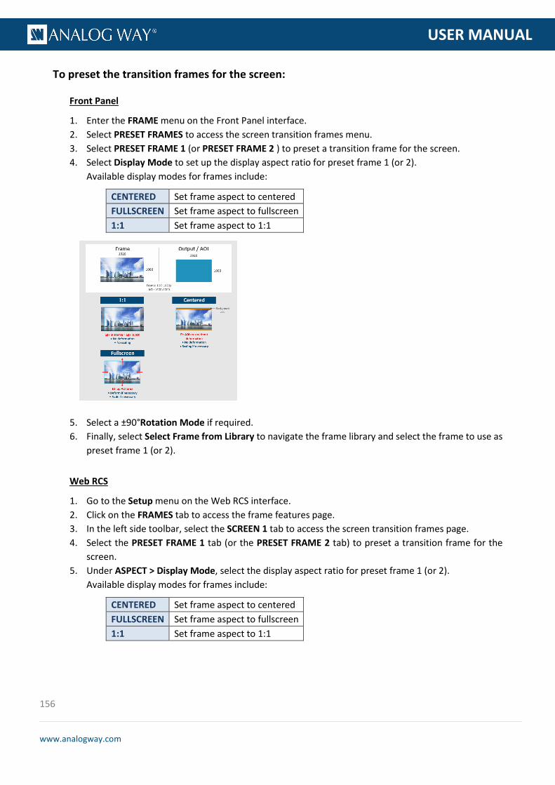
156
www.analogway.com
PROGRAMMER’S GU
USER MANUAL
To preset the transition frames for the screen:
Front Panel
1. Enter the FRAME menu on the Front Panel interface. 2. Select PRESET FRAMES to access the screen transition frames menu. 3. Select PRESET FRAME 1 (or PRESET FRAME 2 ) to preset a transition frame for the screen. 4. Select Display Mode to set up the display aspect ratio for preset frame 1 (or 2).
Available display modes for frames include:
CENTERED Set frame aspect to centered FULLSCREEN Set frame aspect to fullscreen 1:1 Set frame aspect to 1:1
5. Select a ±90°Rotation Mode if required. 6. Finally, select Select Frame from Library to navigate the frame library and select the frame to use as
preset frame 1 (or 2).
Web RCS
1. Go to the Setup menu on the Web RCS interface. 2. Click on the FRAMES tab to access the frame features page. 3. In the left side toolbar, select the SCREEN 1 tab to access the screen transition frames page. 4. Select the PRESET FRAME 1 tab (or the PRESET FRAME 2 tab) to preset a transition frame for the
screen. 5. Under ASPECT > Display Mode, select the display aspect ratio for preset frame 1 (or 2).
Available display modes for frames include:
CENTERED Set frame aspect to centered FULLSCREEN Set frame aspect to fullscreen 1:1 Set frame aspect to 1:1
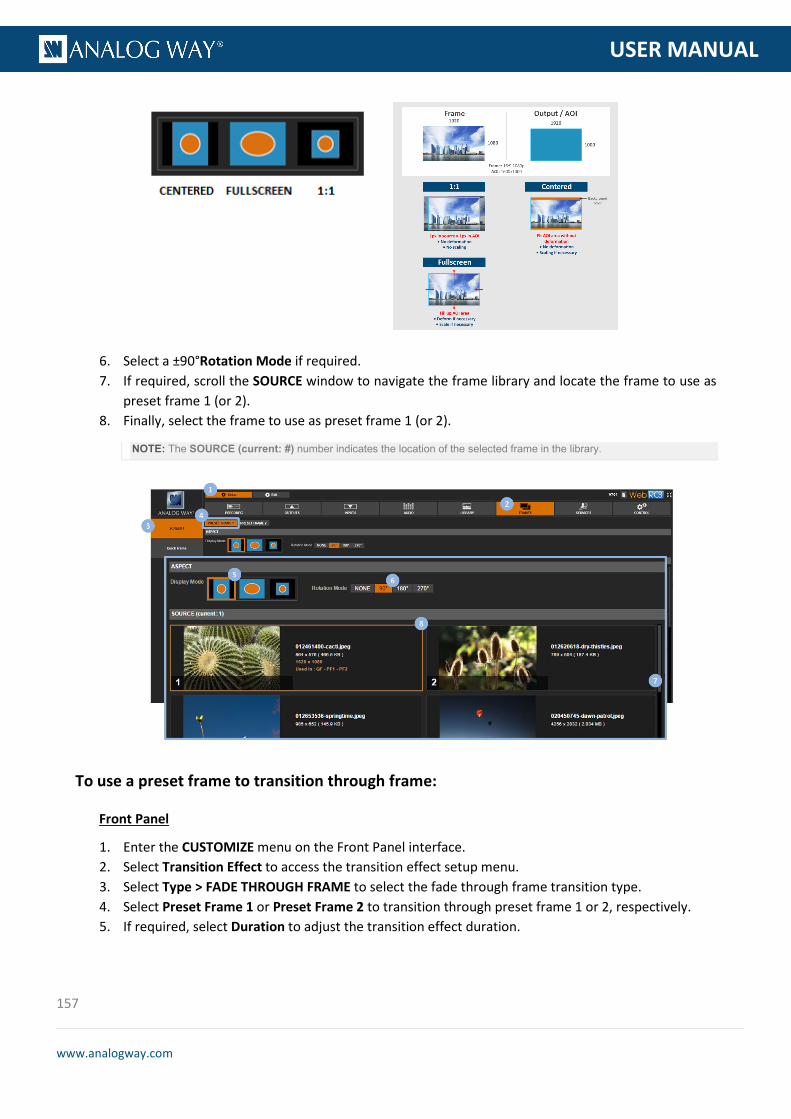
157
www.analogway.com
PROGRAMMER’S GU
USER MANUAL
6. Select a ±90°Rotation Mode if required. 7. If required, scroll the SOURCE window to navigate the frame library and locate the frame to use as
preset frame 1 (or 2). 8. Finally, select the frame to use as preset frame 1 (or 2).
NOTE: The SOURCE (current: #) number indicates the location of the selected frame in the library.
To use a preset frame to transition through frame:
Front Panel
1. Enter the CUSTOMIZE menu on the Front Panel interface. 2. Select Transition Effect to access the transition effect setup menu. 3. Select Type > FADE THROUGH FRAME to select the fade through frame transition type. 4. Select Preset Frame 1 or Preset Frame 2 to transition through preset frame 1 or 2, respectively. 5. If required, select Duration to adjust the transition effect duration.

158
www.analogway.com
PROGRAMMER’S GU
USER MANUAL
Web RCS
1. Go to the Edit menu on the Web RCS interface. 2. Select the SCREEN tab to access the screen edit page. 3. On the screen control toolbar (located at the bottom of the screen), select Transition > FADE
THROUGH FRAME. 4. Select PF1 or PF2 to transition through frame using preset frame 1 or 2, respectively. 5. If required, click and drag the Duration control bar to adjust the transition effect duration.
SEE also: Screen management
The Quick Frame function allows you to quickly display a frame in the screen foreground, for example to cover underneath layers in case of emergency.
You can manage your Quick Frame function by setting up the quick frame (i.e. the frame to display whenever the Quick Frame function is active), and then enable or disable the Quick Frame function whenever required.
To set up the quick frame function:
Front Panel
1. Enter the FRAME menu on the Front Panel interface. 2. Select QUICK FRAME to access the quick frame function management menu. 3. Select Display Mode to select the aspect ratio used to display the quick frame.
Available display modes for frames include:
CENTERED Set frame aspect to centered FULLSCREEN Set frame aspect to fullscreen 1:1 Set frame aspect to 1:1
8.6 Using frames as quick frames
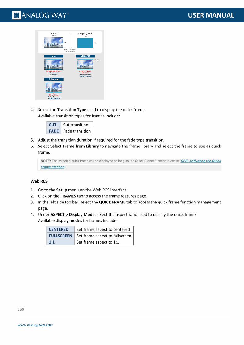
159
www.analogway.com
PROGRAMMER’S GU
USER MANUAL
4. Select the Transition Type used to display the quick frame. Available transition types for frames include:
CUT Cut transition FADE Fade transition
5. Adjust the transition duration if required for the fade type transition. 6. Select Select Frame from Library to navigate the frame library and select the frame to use as quick
frame.
NOTE: The selected quick frame will be displayed as long as the Quick Frame function is active (SEE: Activating the Quick
Frame function).
Web RCS
1. Go to the Setup menu on the Web RCS interface. 2. Click on the FRAMES tab to access the frame features page. 3. In the left side toolbar, select the QUICK FRAME tab to access the quick frame function management
page. 4. Under ASPECT > Display Mode, select the aspect ratio used to display the quick frame.
Available display modes for frames include:
CENTERED Set frame aspect to centered FULLSCREEN Set frame aspect to fullscreen 1:1 Set frame aspect to 1:1

160
www.analogway.com
PROGRAMMER’S GU
USER MANUAL
5. Select also the Transition type used to display the quick frame Available transition types for frames include:
CUT Cut transition FADE Fade transition
NOTE: For the fade type transition, adjust the transition duration if required.
6. If required, scroll the SOURCE window to navigate the frame library and locate the frame to use as preset frame 1 (or 2).
NOTE: The SOURCE (current: #) number indicates the location of the selected frame in the library.
7. Finally, select the frame to use as quick frame.
NOTE: The quick frame is displayed whenever the Quick Frame function is active (SEE: Activating the Quick Frame
function).

161
www.analogway.com
PROGRAMMER’S GU
USER MANUAL
To activate the quick frame function:
Front Panel
1. Enter the FRAME menu on the Front Panel interface. 2. Select QUICK FRAME to access the quick frame function management menu.
TIP: Select Status to check the current quick frame status information (location of the frame in the library, display mode, size...).
3. Select Display Frame to activate the quick frame function (display the quick frame).
TIP: Check the Enable Front Panel Shortcut check-box to enable the activation of the Quick Frame function via the front panel QUICK FRAME button (uncheck to disable).
Web RCS
1. Go to the Edit menu on the Web RCS interface. 2. Select the SCREEN tab to access the screen edit page. 3. On the screen control toolbar (located at the bottom of the screen), click on the Quick Frame button
to activate the Quick Frame function (display the quick frame).
NOTE:
• The number next to Quick Frame # indicates the location of the frame in the library.
• The Quick Frame button will blink orange if the Quick Frame function is active.
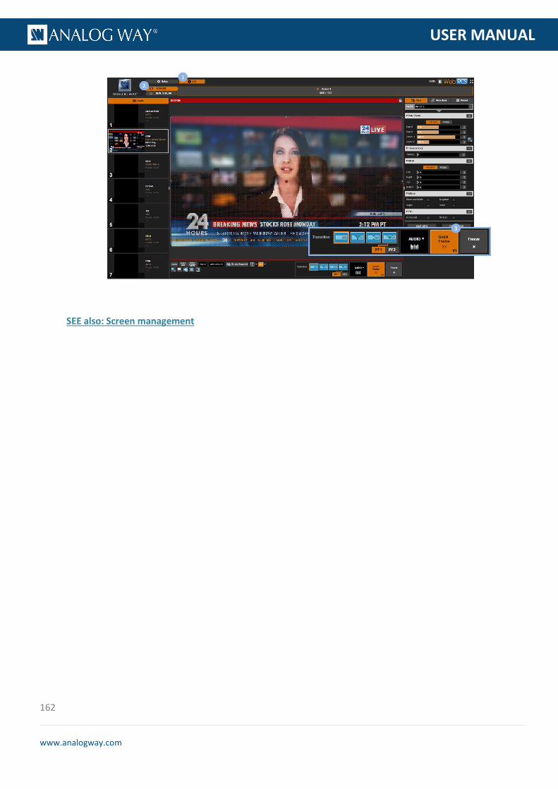
162
www.analogway.com
PROGRAMMER’S GU
USER MANUAL
SEE also: Screen management

163
www.analogway.com
PROGRAMMER’S GU
USER MANUAL
9 Screen management
9.1 What is a screen?
A screen is the video content that will be displayed to the spectator.
You can manage the screen content by selecting the input to display on the output, loading a preset, displaying a Quick Frame, or freezing the output.
The VIO 4K also allows you to control how each input appears in the screen by adjusting the input's "view", and you can further customize the screen background color and the transition effect used when switching sources.
9.2 Adjusting the view
The VIO 4K allows you to control how an input is displayed in the screen by adjusting the input's "view" (SEE: Adjusting the view).
You can also use the predefined screen layouts and fill templates that come embedded in your VIO 4K to automatically adjust the view size and position in the screen.
To automatically adjust the view in the screen:
Front Panel
1. Enter the INPUTS menu on the Front Panel interface. 2. Scroll down and select an INPUT to access the input setup menu.
TIP: Double-click on the INPUT SELECTION button to shortcut to the input setup menu directly.
3. Select "View" Settings to access the input's view settings menu. 4. Select Pan/Zoom template to access the screen fill templates. 5. Select a screen fill template to automatically adjust the view size and position in the screen.
Available screen fill templates include:
1:1 Set the view aspect to 1:1 CENTERED Set the view aspect to centered FULLSCREEN Set the view aspect to fullscreen CROPPED Set the view aspect to cropped
NOTE: When using fill templates, the view aspect is forced to adapt to the screen, and scaling and/or deformation of the view
may be necessary.

164
www.analogway.com
PROGRAMMER’S GU
USER MANUAL
Web RCS
1. Go to the Edit menu on the Web RCS interface. 2. Select the SCREEN tab to access the screen edit page. 3. In the left side toolbar, select an INPUT to load the input view settings. 4. In the screen toolbar (located at the bottom of the Web RCS interface), select VIEW ASPECT to access
the screen fill templates. 5. Select a screen fill template to automatically adjust the view size and position in the screen.
Available screen fill templates include:
1:1 Set the view aspect to 1:1 CENTERED Set the view aspect to centered FULLSCREEN Set the view aspect to fullscreen CROPPED Set the view aspect to cropped
NOTE: When using fill templates, the view aspect is forced to adapt to the screen, and scaling and/or deformation of the view
may be necessary.

165
www.analogway.com
PROGRAMMER’S GU
USER MANUAL
To quickly position the view in the screen:
Front Panel
NOTE: This function is not available via the front panel.
Web RCS
1. Go to the Edit menu on the Web RCS interface. 2. Select the SCREEN tab to access the screen edit page. 3. In the left side toolbar, select an INPUT to load the input view settings.
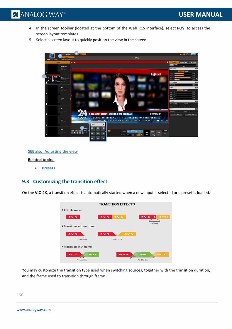
166
www.analogway.com
PROGRAMMER’S GU
USER MANUAL
4. In the screen toolbar (located at the bottom of the Web RCS interface), select POS. to access the screen layout templates.
5. Select a screen layout to quickly position the view in the screen.
SEE also: Adjusting the view
Related topics:
• Presets
9.3 Customizing the transition effect
On the VIO 4K, a transition effect is automatically started when a new input is selected or a preset is loaded.
You may customize the transition type used when switching sources, together with the transition duration, and the frame used to transition through frame.

167
www.analogway.com
PROGRAMMER’S GU
USER MANUAL
To customize the transition effect:
Front Panel
1. Enter the CUSTOMIZE menu on the Front Panel interface. 2. Select Transition Effect to customize the transition effect used when switching sources. 3. Select Type to choose the transition type.
Available transitions types include:
CLEANCUT Clean cut transition FADE THROUGH BLACK Sequenced fade transition CLEAN FADE Clean fade transition FADE THROUGH FRAME Clean fade transition using a frame
4. Select Frame to select a preset frame for the fade through frame transition if required (SEE: Using frames as transitions).
5. Select Duration to adjust the transition duration if required (fade type transitions).
Web RCS
1. Go to the Edit menu on the Web RCS interface. 2. Select the SCREEN tab to access the screen edit page. 3. In the screen toolbar (located at the bottom of the Web RCS interface), select the Transition type
used when switching sources. Available transitions types include:
CLEANCUT Clean cut transition FADE THROUGH BLACK Sequenced fade transition CLEAN FADE Clean fade transition FADE THROUGH FRAME Clean fade transition using a frame
4. Select a Preset Frame if required for the fade through frame transition (SEE: Using frames as transitions).
5. Click and drag the Duration control bar to adjust the transition duration if required (fade type transitions).

168
www.analogway.com
PROGRAMMER’S GU
USER MANUAL
SEE also: Using frames as transitions
9.4 Controlling the screen
You can select the input to display on the output and then adjust the input view settings accordingly, or you can use Presets to quickly recall on the screen the input and its view configuration.
The VIO 4K also allows you to freeze the output to make some adjustments on an input while hiding them to the spectator, or display a Quick Frame to cover underneath layers in case of emergency.
To select the input to display on the output:
Front Panel
Click on the INPUT SELECTION button corresponding to the input to display on the output.
NOTE: All input settings (including plug, image and view settings) will be loaded when selecting the input.
TIP:
• Click twice on an INPUT SELECTION button to access the input setup menu.
• Use the BLACK button to output to the screen background color.
Web RCS
1. Go to the Edit menu on the Web RCS interface. 2. Select the SCREEN tab to access the screen edit page. 3. Under the INPUTS tab (the left side toolbar), select an input to display on the output.

169
www.analogway.com
PROGRAMMER’S GU
USER MANUAL
TIP: Use the CLEAR button (located at the bottom of the screen toolbar) to clear the selection (display no input and output to the screen background color).
To load a preset:
Front Panel
1. Enter the PRESETS menu on the Front Panel interface. 2. Select Load Preset to access the preset memories bank. 3. Select a bank slot to recall the preset memory contained in the selected slot.
Web RCS
1. Go to the Edit menu on the Web RCS interface. 2. Select the SCREEN tab to access the screen edit page. 3. In the right side toolbar, select Preset to access the preset memories bank. 4. Click on a bank slot to recall the preset memory contained in the selected slot.
TIP: • Hover over a slot to have an overview of the preset memory contained in the slot. • SHIFT+click on a slot to freeze the preset Memories Overview box and label the preset memory contained
in the slot. • Use the Show memories label button to show preset labels directly on the view bank slots.

170
www.analogway.com
PROGRAMMER’S GU
USER MANUAL
SEE also: Presets
To freeze the output:
SEE: Freezing the output
To display a quick frame:
SEE: Using frames as quick frames
To control the audio:
Front Panel
1. Click on the AUDIO button to access the output level meter. 2. Rotate the control knob and select an output channel pair to adjust the channel pair.
TIP: Select Listen on the Headphone to prelisten to the channel pair on the headphone output.
Web RCS
1. Go to the Edit menu on the Web RCS interface. 2. Select the SCREEN tab to access the screen edit page. 3. In the screen toolbar, click on the Audio button to access the Quick Audio control window. 4. In the Quick Audio window, adjust the output audio (master volume/mute).
TIP: Select a headphone mode to prelisten to your inputs and outputs.
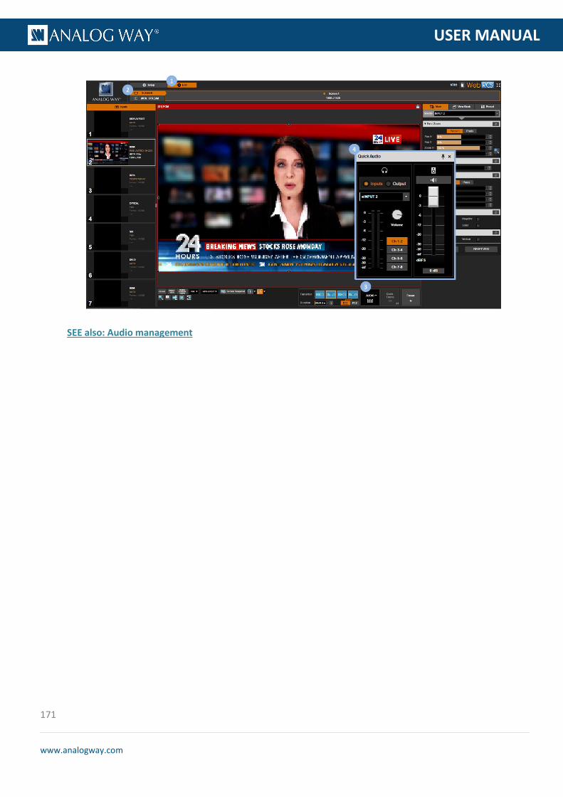
171
www.analogway.com
PROGRAMMER’S GU
USER MANUAL
SEE also: Audio management

172
www.analogway.com
PROGRAMMER’S GU
USER MANUAL
With its enhanced audio capabilities, the VIO 4K allows you to manage up to 8 mono audio channels (4 stereo pairs) per input/output independently of the video content.
The following diagram provides a quick overview of all the audio capabilities that come with your VIO 4K:
EMBEDDED AUDIO
The VIO 4K supports embedded audio for all HDMI, DP and SDI inputs, and two additional audio inputs are available on the front panel:
10 Audio management
10.1 Audio inputs and outputs
10.2 Supported audio
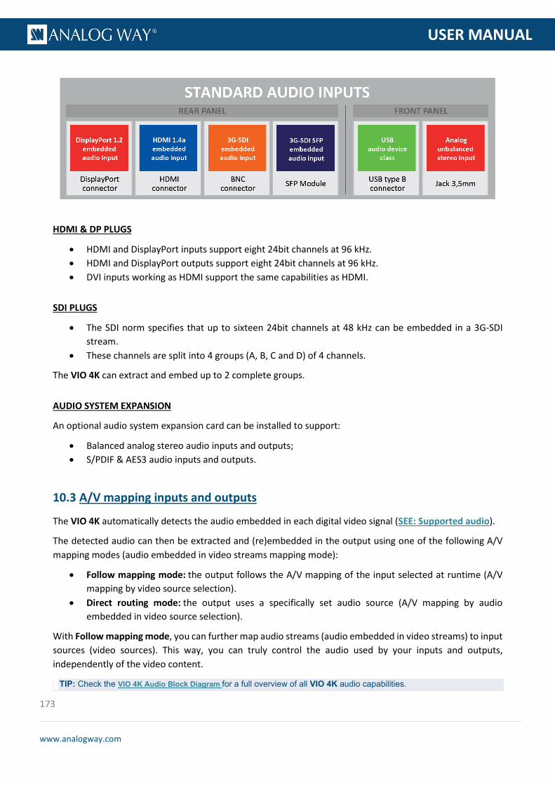
173
www.analogway.com
PROGRAMMER’S GU
USER MANUAL
HDMI & DP PLUGS
• HDMI and DisplayPort inputs support eight 24bit channels at 96 kHz. • HDMI and DisplayPort outputs support eight 24bit channels at 96 kHz. • DVI inputs working as HDMI support the same capabilities as HDMI.
SDI PLUGS
• The SDI norm specifies that up to sixteen 24bit channels at 48 kHz can be embedded in a 3G-SDI stream.
• These channels are split into 4 groups (A, B, C and D) of 4 channels.
The VIO 4K can extract and embed up to 2 complete groups.
AUDIO SYSTEM EXPANSION
An optional audio system expansion card can be installed to support:
• Balanced analog stereo audio inputs and outputs; • S/PDIF & AES3 audio inputs and outputs.
The VIO 4K automatically detects the audio embedded in each digital video signal (SEE: Supported audio).
The detected audio can then be extracted and (re)embedded in the output using one of the following A/V mapping modes (audio embedded in video streams mapping mode):
• Follow mapping mode: the output follows the A/V mapping of the input selected at runtime (A/V mapping by video source selection).
• Direct routing mode: the output uses a specifically set audio source (A/V mapping by audio embedded in video source selection).
With Follow mapping mode, you can further map audio streams (audio embedded in video streams) to input sources (video sources). This way, you can truly control the audio used by your inputs and outputs, independently of the video content.
TIP: Check the VIO 4K Audio Block Diagram for a full overview of all VIO 4K audio capabilities.
10.3 A/V mapping inputs and outputs
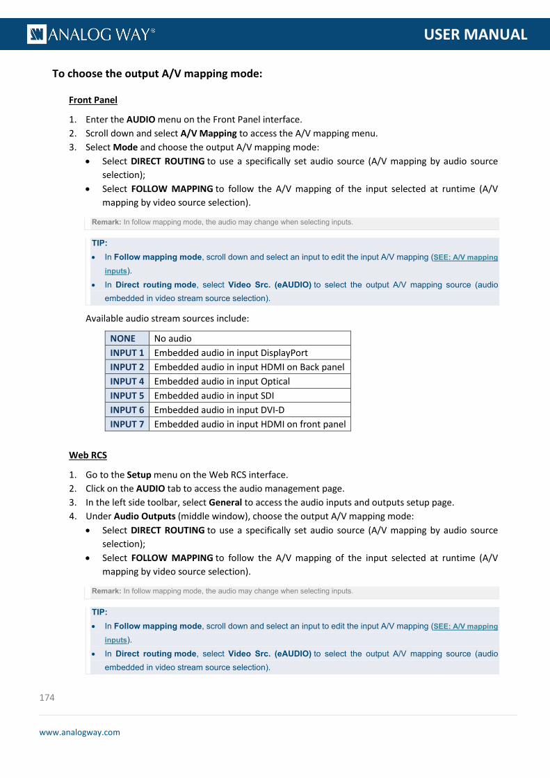
174
www.analogway.com
PROGRAMMER’S GU
USER MANUAL
To choose the output A/V mapping mode:
Front Panel
1. Enter the AUDIO menu on the Front Panel interface. 2. Scroll down and select A/V Mapping to access the A/V mapping menu. 3. Select Mode and choose the output A/V mapping mode:
• Select DIRECT ROUTING to use a specifically set audio source (A/V mapping by audio source selection);
• Select FOLLOW MAPPING to follow the A/V mapping of the input selected at runtime (A/V mapping by video source selection).
Remark: In follow mapping mode, the audio may change when selecting inputs.
TIP: • In Follow mapping mode, scroll down and select an input to edit the input A/V mapping (SEE: A/V mapping
inputs). • In Direct routing mode, select Video Src. (eAUDIO) to select the output A/V mapping source (audio
embedded in video stream source selection).
Available audio stream sources include:
NONE No audio INPUT 1 Embedded audio in input DisplayPort INPUT 2 Embedded audio in input HDMI on Back panel INPUT 4 Embedded audio in input Optical INPUT 5 Embedded audio in input SDI INPUT 6 Embedded audio in input DVI-D INPUT 7 Embedded audio in input HDMI on front panel
Web RCS
1. Go to the Setup menu on the Web RCS interface. 2. Click on the AUDIO tab to access the audio management page. 3. In the left side toolbar, select General to access the audio inputs and outputs setup page. 4. Under Audio Outputs (middle window), choose the output A/V mapping mode:
• Select DIRECT ROUTING to use a specifically set audio source (A/V mapping by audio source selection);
• Select FOLLOW MAPPING to follow the A/V mapping of the input selected at runtime (A/V mapping by video source selection).
Remark: In follow mapping mode, the audio may change when selecting inputs.
TIP: • In Follow mapping mode, scroll down and select an input to edit the input A/V mapping (SEE: A/V mapping
inputs). • In Direct routing mode, select Video Src. (eAUDIO) to select the output A/V mapping source (audio
embedded in video stream source selection).
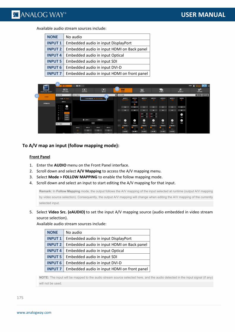
175
www.analogway.com
PROGRAMMER’S GU
USER MANUAL
Available audio stream sources include:
NONE No audio INPUT 1 Embedded audio in input DisplayPort INPUT 2 Embedded audio in input HDMI on Back panel INPUT 4 Embedded audio in input Optical INPUT 5 Embedded audio in input SDI INPUT 6 Embedded audio in input DVI-D INPUT 7 Embedded audio in input HDMI on front panel
To A/V map an input (follow mapping mode):
Front Panel
1. Enter the AUDIO menu on the Front Panel interface. 2. Scroll down and select A/V Mapping to access the A/V mapping menu. 3. Select Mode > FOLLOW MAPPING to enable the follow mapping mode. 4. Scroll down and select an input to start editing the A/V mapping for that input.
Remark: In Follow Mapping mode, the output follows the A/V mapping of the input selected at runtime (output A/V mapping
by video source selection). Consequently, the output A/V mapping will change when editing the A/V mapping of the currently
selected input.
5. Select Video Src. (eAUDIO) to set the input A/V mapping source (audio embedded in video stream source selection). Available audio stream sources include:
NONE No audio INPUT 1 Embedded audio in input DisplayPort INPUT 2 Embedded audio in input HDMI on Back panel INPUT 4 Embedded audio in input Optical INPUT 5 Embedded audio in input SDI INPUT 6 Embedded audio in input DVI-D INPUT 7 Embedded audio in input HDMI on front panel
NOTE: The input will be mapped to the audio stream source selected here, and the audio detected in the input signal (if any)
will not be used.

176
www.analogway.com
PROGRAMMER’S GU
USER MANUAL
TIP: Select NONE to use no audio for the input in Follow mapping mode.
6. Uncheck the Direct Channel Mapping check-box if required to change the audio source for a channel pair. Available channel pair audio sources include:
NONE No audio INPUT CH 1&2 Embedded pair 1 and 2 INPUT CH 3&4 Embedded pair 3 4 INPUT CH 5&6 Embedded pair 5 6 INPUT CH 7&8 Embedded pair 7 8 LINE IN Audio Jack on front panel AUDIO OPT CH 1&2 (*) Audio card option pair 1 2 (*) AUDIO OPT CH 3&4 (*) Audio card option pair 3 4 (*) AUDIO OPT CH 5&6 (*) Audio card option pair 5 6 (*) AUDIO OPT CH 7&8 (*) Audio card option pair 7 8 (*)
(*) Available with the optional audio card
TIP: Use the Reset command to (re)map the input with the audio detected in the input signal.
Web RCS
1. Go to the Setup menu on the Web RCS interface. 2. Click on the AUDIO tab to access the audio management page. 3. In the left side toolbar, select A/V Mapping to access the input and output A/V mapping page. 4. Check the Follow Mapping check-box in the right side window if required to enable follow mapping
mode.
Remark: In Follow Mapping mode, the output follows the A/V mapping of the input selected at runtime (output A/V mapping
by video source selection). Consequently, the output A/V mapping will change when editing the A/V mapping of the currently
selected input.
5. Click on an input's Audio Source column to set the A/V mapping source (audio embedded in video stream source selection). Available audio stream sources include:
NONE No audio INPUT 1 Embedded audio in input DisplayPort INPUT 2 Embedded audio in input HDMI on Back panel INPUT 4 Embedded audio in input Optical INPUT 5 Embedded audio in input SDI INPUT 6 Embedded audio in input DVI-D INPUT 7 Embedded audio in input HDMI on front panel
NOTE: The input will be mapped to the audio stream source selected here, and the audio detected in the input signal (if any)
will not be used.
TIP: Select NONE to use no audio for the input in Follow mapping mode.
6. Disable the ByPass button if required to change the audio source for a channel pair

177
www.analogway.com
PROGRAMMER’S GU
USER MANUAL
Available channel pair audio sources include:
NONE No audio INPUT CH 1&2 Embedded pair 1 and 2 INPUT CH 3&4 Embedded pair 3 4 INPUT CH 5&6 Embedded pair 5 6 INPUT CH 7&8 Embedded pair 7 8 LINE IN Audio Jack on front panel AUDIO OPT CH 1&2 (*) Audio card option pair 1 2 (*) AUDIO OPT CH 3&4 (*) Audio card option pair 3 4 (*) AUDIO OPT CH 5&6 (*) Audio card option pair 5 6 (*) AUDIO OPT CH 7&8 (*) Audio card option pair 7 8 (*)
(*) Available with the optional audio card
TIP: • Click on the Line In button to automatically map the line in stream to the first channel pair only. • Use the Set to Default button to (re)map the input with the audio detected in the input signal.
178
www.analogway.com
PROGRAMMER’S GU
USER MANUAL
The VIO 4K allows you to choose the output/processing sampling rate used to process the audio (both for inputs and outputs).
The selected output/processing sampling rate will then be used throughout the whole audio processing, from input extract to output embed (SEE also: VIO 4K Audio Block Diagram).
To select the output/processing sampling rate:
Front Panel
1. Enter the AUDIO menu on the Front Panel interface. 2. Select Output Settings to set up the audio output. 3. Select Sampling Frequency to select the output/processing sampling frequency.
Possible sampling frequencies include:
32 kHz 44.1 kHz 48 kHz 96 kHz
4. Press the ENTER key to save and apply the new settings or use the EXIT-MENU button to go back to the audio output setup menu without saving
Web RCS
1. Go to the Setup menu on the Web RCS interface. 2. Click on the AUDIO tab to access the audio management page. 3. In the left side toolbar, select General to access the audio inputs and outputs setup page.
NOTE: You can also access the audio outputs setup page via the A/V Mapping tab.
4. Under Main Audio (bottom left side window), click on the current sampling frequency to access the Sample Rate window.
5. In the Sample Rate window, click on the current sampling frequency and select the output/processing sampling frequency. Possible sampling frequencies include:
32 kHz 44.1 kHz 48 kHz 96 kHz
6. Click on OK to save and apply the new settings.
10.4 Selecting the sampling rate

179
www.analogway.com
PROGRAMMER’S GU
USER MANUAL
TIP: Check the VIO 4K Audio Block Diagram for a full overview of all VIO 4K audio capabilities.
The VIO 4K allows you to adjust up to 8 audio mono channels (4 stereo pairs) per input independently of the video content.
You can for example add a delay to the audio to synchronize with the video, or enable the equalizer on a channel pair to adjust the treble, mid and bass gains.
TIP: Link channel pairs to use the first channel pair settings for all pairs.
To link channel pairs:
Front Panel
1. Enter the AUDIO menu on the Front Panel interface. 2. Select Input Settings and select an input to set up the audio input. 3. Select a Settings Mode to set up the audio:
• Select BASIC to link channel pairs and use the first channel pair settings for all pairs; • Select ADVANCED to unlink channel pairs and set up channel pairs individually.
10.5 Adjusting the input audio
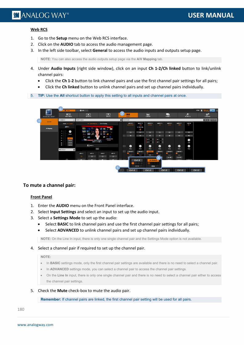
180
www.analogway.com
PROGRAMMER’S GU
USER MANUAL
Web RCS
1. Go to the Setup menu on the Web RCS interface. 2. Click on the AUDIO tab to access the audio management page. 3. In the left side toolbar, select General to access the audio inputs and outputs setup page.
NOTE: You can also access the audio outputs setup page via the A/V Mapping tab.
4. Under Audio Inputs (right side window), click on an input Ch 1-2/Ch linked button to link/unlink channel pairs: • Click the Ch 1-2 button to link channel pairs and use the first channel pair settings for all pairs; • Click the Ch linked button to unlink channel pairs and set up channel pairs individually.
5. TIP: Use the All shortcut button to apply this setting to all inputs and channel pairs at once.
To mute a channel pair:
Front Panel
1. Enter the AUDIO menu on the Front Panel interface. 2. Select Input Settings and select an input to set up the audio input. 3. Select a Settings Mode to set up the audio:
• Select BASIC to link channel pairs and use the first channel pair settings for all pairs; • Select ADVANCED to unlink channel pairs and set up channel pairs individually.
NOTE: On the Line In input, there is only one single channel pair and the Settings Mode option is not available.
4. Select a channel pair if required to set up the channel pair.
NOTE:
• In BASIC settings mode, only the first channel pair settings are available and there is no need to select a channel pair.
• In ADVANCED settings mode, you can select a channel pair to access the channel pair settings.
• On the Line In input, there is only one single channel pair and there is no need to select a channel pair either to access
the channel pair settings.
5. Check the Mute check-box to mute the audio pair.
Remember: If channel pairs are linked, the first channel pair setting will be used for all pairs.

181
www.analogway.com
PROGRAMMER’S GU
USER MANUAL
Web RCS
1. Go to the Setup menu on the Web RCS interface. 2. Click on the AUDIO tab to access the audio management page. 3. In the left side toolbar, select General to access the audio inputs and outputs setup page.
NOTE: You can also access the audio outputs setup page via the A/V Mapping tab.
4. Under Audio Inputs (right side window), locate the input to adjust and click on the Ch 1-2/Ch linked button if required to link/unlink channel pairs: • Click on the Ch 1-2 button to link channel pairs and use the first channel pair settings for all pairs; • Click on the Ch linked button to unlink channel pairs and set up channel pairs individually.
NOTE: On the Line In input, there is only one single channel pair and the link option is not available.
5. Select a channel pair if required to set up the channel pair.
NOTE:
• When channel pairs are linked, only the first channel pair settings are available and there is no need to select a channel
pair.
• When channel pairs are not linked, you can select a channel pair to access the channel pair settings.
• On the Line In input, there is only one single channel pair and there is no need to select a channel pair either to access
the channel pair settings.
6. Click on the CH Volume/Mute button to mute the audio pair (click again to unmute).
Remember: If channel pairs are linked, the first channel pair setting will be used for all pairs.
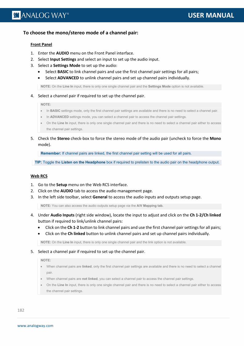
182
www.analogway.com
PROGRAMMER’S GU
USER MANUAL
To choose the mono/stereo mode of a channel pair:
Front Panel
1. Enter the AUDIO menu on the Front Panel interface. 2. Select Input Settings and select an input to set up the audio input. 3. Select a Settings Mode to set up the audio:
• Select BASIC to link channel pairs and use the first channel pair settings for all pairs; • Select ADVANCED to unlink channel pairs and set up channel pairs individually.
NOTE: On the Line In input, there is only one single channel pair and the Settings Mode option is not available.
4. Select a channel pair if required to set up the channel pair.
NOTE:
• In BASIC settings mode, only the first channel pair settings are available and there is no need to select a channel pair.
• In ADVANCED settings mode, you can select a channel pair to access the channel pair settings.
• On the Line In input, there is only one single channel pair and there is no need to select a channel pair either to access
the channel pair settings.
5. Check the Stereo check-box to force the stereo mode of the audio pair (uncheck to force the Mono mode).
Remember: If channel pairs are linked, the first channel pair setting will be used for all pairs.
TIP: Toggle the Listen on the Headphone box if required to prelisten to the audio pair on the headphone output.
Web RCS
1. Go to the Setup menu on the Web RCS interface. 2. Click on the AUDIO tab to access the audio management page. 3. In the left side toolbar, select General to access the audio inputs and outputs setup page.
NOTE: You can also access the audio outputs setup page via the A/V Mapping tab.
4. Under Audio Inputs (right side window), locate the input to adjust and click on the Ch 1-2/Ch linked button if required to link/unlink channel pairs: • Click on the Ch 1-2 button to link channel pairs and use the first channel pair settings for all pairs; • Click on the Ch linked button to unlink channel pairs and set up channel pairs individually.
NOTE: On the Line In input, there is only one single channel pair and the link option is not available.
5. Select a channel pair if required to set up the channel pair.
NOTE:
• When channel pairs are linked, only the first channel pair settings are available and there is no need to select a channel
pair.
• When channel pairs are not linked, you can select a channel pair to access the channel pair settings.
• On the Line In input, there is only one single channel pair and there is no need to select a channel pair either to access
the channel pair settings.

183
www.analogway.com
PROGRAMMER’S GU
USER MANUAL
6. Click on the Mono button to force the mono mode of the audio pair (click again to disable mono mode and enable stereo mode).
Remember: If channel pairs are linked, the first channel pair setting will be used for all pairs.
TIP: Use the All shortcut button to apply this setting to all inputs and channel pairs at once.
TIP: Click on the Headphone button if required (located under the input) to prelisten to the selected audio pair on the headphone output.
To adjust the balance of a channel pair:
Front Panel
1. Enter the AUDIO menu on the Front Panel interface. 2. Select Input Settings and select an input to set up the audio input. 3. Select a Settings Mode to set up the audio:
• Select BASIC to link channel pairs and use the first channel pair settings for all pairs; • Select ADVANCED to unlink channel pairs and set up channel pairs individually.
NOTE: On the Line In input, there is only one single channel pair and the Settings Mode option is not available.
4. Select a channel pair if required to set up the channel pairs.
NOTE:
• In BASIC settings mode, only the first channel pair settings are available and there is no need to select a channel pair.
• In ADVANCED settings mode, you can select a channel pair to access the channel pair settings.
• On the Line In input, there is only one single channel pair and there is no need to select a channel pair either to access
the channel pair settings.
5. Select Balance to adjust the balance of the audio pair.
Remember: If channel pairs are linked, the first channel pair setting will be used for all pairs.
TIP: Toggle the Listen on the Headphone box if required to prelisten to the audio pair on the headphone output.

184
www.analogway.com
PROGRAMMER’S GU
USER MANUAL
Web RCS
1. Go to the Setup menu on the Web RCS interface. 2. Click on the AUDIO tab to access the audio management page. 3. In the left side toolbar, select General to access the audio inputs and outputs setup page.
NOTE: You can also access the audio outputs setup page via the A/V Mapping tab.
4. Under Audio Inputs (right side window), locate the input to adjust and click on the Ch 1-2/Ch linked button if required to link/unlink channel pairs: • Click on the Ch 1-2 button to link channel pairs and use the first channel pair settings for all pairs; • Click on the Ch linked button to unlink channel pairs and set up channel pairs individually.
NOTE: On the Line In input, there is only one single channel pair and the link option is not available.
5. Select a channel pair if required to set up the channel pair.
NOTE:
• When channel pairs are linked, only the first channel pair settings are available and there is no need to select a channel
pair.
• When channel pairs are not linked, you can select a channel pair to access the channel pair settings.
• On the Line In input, there is only one single channel pair and there is no need to select a channel pair either to access
the channel pair settings.
6. Click and drag the Balance control bar to adjust the balance of the audio pair.
Remember: If channel pairs are linked, the first channel pair setting will be used for all pairs.
TIP: Toggle the Listen on the Headphone box if required to prelisten to the audio pair on the headphone output.
7. TIP: Use the Reset All shortcut button to reset all inputs and channel pairs at once.
TIP: Click on the Headphone button if required (located under the input) to prelisten to the selected audio pair on the headphone output.

185
www.analogway.com
PROGRAMMER’S GU
USER MANUAL
To adjust the level of a channel pair:
Front Panel
1. Enter the AUDIO menu on the Front Panel interface. 2. Select Input Settings and select an input to set up the audio input. 3. Select a Settings Mode to set up the audio:
• Select BASIC to link channel pairs and use the first channel pair settings for all pairs; • Select ADVANCED to unlink channel pairs and set up channel pairs individually.
NOTE: On the Line In input, there is only one single channel pair and the Settings Mode option is not available.
4. Select a channel pair if required to set up the channel pair.
NOTE:
• In BASIC settings mode, only the first channel pair settings are available and there is no need to select a channel pair.
• In ADVANCED settings mode, you can select a channel pair to access the channel pair settings.
• On the Line In input, there is only one single channel pair and there is no need to select a channel pair either to access
the channel pair settings.
5. Select Level to adjust the gain of the audio pair (after digitalization for analog signals).
Remember: If channel pairs are linked, the first channel pair setting will be used for all pairs.
TIP: Toggle the Listen on the Headphone box if required to prelisten to the audio pair on the headphone output.
Web RCS
1. Go to the Setup menu on the Web RCS interface. 2. Click on the AUDIO tab to access the audio management page. 3. In the left side toolbar, select General to access the audio inputs and outputs setup page.
NOTE: You can also access the audio outputs setup page via the A/V Mapping tab.
4. Under Audio Inputs (right side window), locate the input to adjust and click on the Ch 1-2/Ch linked button if required to link/unlink channel pairs. • Click on the Ch 1-2 button to link channel pairs and use the first channel pair settings for all pairs; • Click on the Ch linked button to unlink channel pairs and set up channel pairs individually.
NOTE: On the Line In input, there is only one single channel pair and the link option is not available.
5. Select a channel pair if required to set up the channel pair.
NOTE:
• When channel pairs are linked, only the first channel pair settings are available and there is no need to select a channel
pair.
• When channel pairs are not linked, you can select a channel pair to access the channel pair settings.
• On the Line In input, there is only one single channel pair and there is no need to select a channel pair either to access
the channel pair settings.
6. Click and drag the Level control bar to adjust the gain of the audio pair (after digitalization for analog signals).

186
www.analogway.com
PROGRAMMER’S GU
USER MANUAL
Remember: Use the Reset All shortcut button to reset all inputs and channel pairs at once.
TIP: Click on the Headphone button if required (located under the input) to prelisten to the selected audio pair on the headphone output.
To enable the equalizer:
Front Panel
1. Enter the AUDIO menu on the Front Panel interface. 2. Select Input Settings and select an input to set up the audio input. 3. Select a Settings Mode to set up the audio:
• Select BASIC to link channel pairs and use the first channel pair settings for all pairs. • Select ADVANCED to unlink channel pairs and set up channel pairs individually.
NOTE: On the Line In input, there is only one single channel pair and the Settings Mode option is not available.
4. Select a channel pair if required to set up the channel pair:
NOTE:
• In BASIC settings mode, only the first channel pair settings are available and there is no need to select a channel pair.
• In ADVANCED settings mode, you can select a channel pair to access the channel pair settings.
• On the Line In input, there is only one single channel pair and there is no need to select a channel pair either to access
the channel pair settings.
5. Select Equalizer and check the Enable check-box to enable the equalizer on the audio pair (uncheck to disable).
6. Select TREBLE, MID or BASS to adjust the treble, mid or bass gain, respectively.

187
www.analogway.com
PROGRAMMER’S GU
USER MANUAL
Remember: If channel pairs are linked, the first channel pair setting will be used for all pairs.
TIP: Toggle the Listen on the Headphone box if required to prelisten to the audio pair on the headphone output.
Web RCS
1. Go to the Setup menu on the Web RCS interface. 2. Click on the AUDIO tab to access the audio management page. 3. In the left side toolbar, select General to access the audio inputs and outputs setup page.
NOTE: You can also access the audio outputs setup page via the A/V Mapping tab.
4. Under Audio Inputs (right side window), locate the input to adjust and click on the Ch 1-2/Ch linked button if required to link/unlink channel pairs: • Click on the Ch 1-2 button to link channel pairs and use the first channel pair settings for all pairs • Click on the Ch linked button to unlink channel pairs and set up channel pairs individually
NOTE: On the Line In input, there is only one single channel pair and the link option is not available.
5. Select a channel pair if required to set up the channel pair.
NOTE:
• When channel pairs are linked, only the first channel pair settings are available and there is no need to select a channel
pair.
• When channel pairs are not linked, you can select a channel pair to access the channel pair settings.
• On the Line In input, there is only one single channel pair and there is no need to select a channel pair either to access
the channel pair settings.
6. Click on the Eq On button to enable the equalizer on the audio pair (click again to disable).
TIP: Use the All shortcut button to enable the equalizer on all inputs and channel pairs at once.
7. Drag the T, M and B control bars to adjust the treble, mid and bass gains, respectively.
Remember: If channel pairs are linked, the first channel pair setting will be used for all pairs.
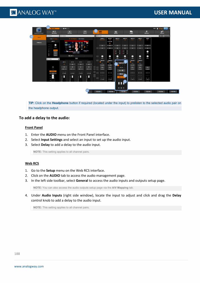
188
www.analogway.com
PROGRAMMER’S GU
USER MANUAL
TIP: Click on the Headphone button if required (located under the input) to prelisten to the selected audio pair on the headphone output.
To add a delay to the audio:
Front Panel
1. Enter the AUDIO menu on the Front Panel interface. 2. Select Input Settings and select an input to set up the audio input. 3. Select Delay to add a delay to the audio input.
NOTE: This setting applies to all channel pairs.
Web RCS
1. Go to the Setup menu on the Web RCS interface. 2. Click on the AUDIO tab to access the audio management page. 3. In the left side toolbar, select General to access the audio inputs and outputs setup page.
NOTE: You can also access the audio outputs setup page via the A/V Mapping tab.
4. Under Audio Inputs (right side window), locate the input to adjust and click and drag the Delay control knob to add a delay to the audio input.
NOTE: This setting applies to all channel pairs.

189
www.analogway.com
PROGRAMMER’S GU
USER MANUAL
Related topics:
• VIO 4K Audio Block Diagram • Prelistening to audio content
The VIO 4K allows you to adjust up to 8 audio mono channels (4 stereo pairs) per output independently of the video content.
You can for example add a delay to the audio to synchronize with the video, or apply a sine tone oscillator to a channel pair test the channel pair.
TIP: Link channel pairs to use the first channel pair settings for all pairs.
To link channel pairs:
Front Panel
1. Enter the AUDIO menu on the Front Panel interface. 2. Select Output Settings to set up the audio output. 3. Select a Settings Mode to set up the audio:
• Select BASIC to link channel pairs and use the first channel pair settings for all pairs. • Select ADVANCED to unlink channel pairs and set up channel pairs individually.
Web RCS
1. Go to the Setup menu on the Web RCS interface. 2. Click on the AUDIO tab to access the audio management page. 3. In the left side toolbar, select General to access the audio inputs and outputs setup page.
NOTE: You can also access the audio outputs setup page via the A/V Mapping tab.
4. Under Audio Outputs (middle window), enable/disable the Link button to link/unlink channel pairs: • Enable Link to link channel pairs and use the first channel pair settings for all pairs. • Disable Link to unlink channel pairs and set up channel pairs individually.
10.6 Adjusting the output audio

190
www.analogway.com
PROGRAMMER’S GU
USER MANUAL
To adjust the volume of an audio pair:
Front Panel
1. Enter the AUDIO menu on the Front Panel interface. 2. Select Output Settings to set up the audio output. 3. Scroll down and select a Settings Mode to set up the audio:
• Select BASIC to link channel pairs and use the first channel pair settings for all pairs. • Select ADVANCED to unlink channel pairs and set up channel pairs individually.
4. Select a channel pair if required to set up the channel pair.
NOTE:
• In BASIC settings mode, only the first channel pair settings are available and there is no need to select a channel pair.
• In ADVANCED settings mode, you can select a channel pair to access the channel pair settings.
TIP: Press the AUDIO button and select a channel pair to access the channel pair settings directly.
5. Select Volume to adjust the channel pair volume.
Remember: If channel pairs are linked, the first channel pair setting will be used for all pairs.
TIP: Toggle the Listen on the Headphone box if required to prelisten to the audio pair on the headphone output.
Web RCS
1. Go to the Setup menu on the Web RCS interface. 2. Click on the AUDIO tab to access the audio management page. 3. In the left side toolbar, select General to access the audio inputs and outputs setup page.

191
www.analogway.com
PROGRAMMER’S GU
USER MANUAL
NOTE: You can also access the audio outputs setup page via the A/V Mapping tab.
4. Under Audio Outputs (middle window), enable/disable the Link button if required to link/unlink channel pairs: • Enable Link to link channel pairs and use the first channel pair settings for all pairs. • Disable Link to unlink channel pairs and set up channel pairs individually.
5. Locate the channel pair to adjust if required.
NOTE: If channel pairs are linked, only the first channel pair settings are available.
6. Click and drag the Volume control bar to adjust the volume of the channel pair.
Remember: If channel pairs are linked, the first channel pair setting will be used for all pairs.
TIP: Click on the Headphone button if required (located under the input) to prelisten to the selected audio pair on the headphone output.

192
www.analogway.com
PROGRAMMER’S GU
USER MANUAL
To mute a channel pair:
Front Panel
1. Enter the AUDIO menu on the Front Panel interface. 2. Select Output Settings to set up the audio output. 3. Scroll down and select a Settings Mode to set up the audio:
• Select BASIC to link channel pairs and use the first channel pair settings for all pairs • Select ADVANCED to unlink channel pairs and set up channel pairs individually
4. Select a channel pair if required to set up the channel pair.
NOTE:
• In BASIC settings mode, only the first channel pair settings are available and there is no need to select a channel pair.
• In ADVANCED settings mode, you can select a channel pair to access the channel pair settings.
TIP: Press the AUDIO button and select a channel pair to access the channel pair settings directly.
5. Check the Mute check-box to mute the audio pair.
Remember: If channel pairs are linked, the first channel pair setting will be used for all pairs.
Web RCS
1. Go to the Setup menu on the Web RCS interface. 2. Click on the AUDIO tab to access the audio management page. 3. In the left side toolbar, select General to access the audio inputs and outputs setup page.
NOTE: You can also access the audio outputs setup page via the A/V Mapping tab.
4. Under Audio Outputs (middle window), enable/disable the Link button if required to link/unlink channel pairs: • Enable Link to link channel pairs and use the first channel pair settings for all pairs. • Disable Link to unlink channel pairs and set up channel pairs individually.
5. Locate the channel pair to adjust if required.
NOTE: If channel pairs are linked, only the first channel pair settings are available.
6. Click on the Volume/Mute button to mute the audio pair (click again to unmute).
Remember: If channel pairs are linked, the first channel pair setting will be used for all pairs.
TIP: Use the Mute All button to mute all channel pairs at once.

193
www.analogway.com
PROGRAMMER’S GU
USER MANUAL
To adjust the balance of an audio pair:
Front Panel
1. Enter the AUDIO menu on the Front Panel interface. 2. Select Output Settings to set up the audio output. 3. Scroll down and select a Settings Mode to set up the audio:
• Select BASIC to link channel pairs and use the first channel pair settings for all pairs. • Select ADVANCED to unlink channel pairs and set up channel pairs individually.
4. Select a channel pair if required to set up the channel pair.
NOTE:
• In BASIC settings mode, only the first channel pair settings are available and there is no need to select a channel pair.
• In ADVANCED settings mode, you can select a channel pair to access the channel pair settings.
TIP: Press the AUDIO button and select a channel pair to access the channel pair settings directly.
5. Select Balance to adjust the balance of the audio pair.
Remember: If channel pairs are linked, the first channel pair setting will be used for all pairs.
TIP: Toggle the Listen on the Headphone box if required to prelisten to the audio pair on the headphone output.
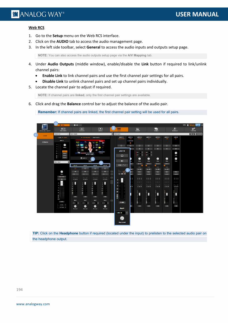
194
www.analogway.com
PROGRAMMER’S GU
USER MANUAL
Web RCS
1. Go to the Setup menu on the Web RCS interface. 2. Click on the AUDIO tab to access the audio management page. 3. In the left side toolbar, select General to access the audio inputs and outputs setup page.
NOTE: You can also access the audio outputs setup page via the A/V Mapping tab.
4. Under Audio Outputs (middle window), enable/disable the Link button if required to link/unlink channel pairs: • Enable Link to link channel pairs and use the first channel pair settings for all pairs. • Disable Link to unlink channel pairs and set up channel pairs individually.
5. Locate the channel pair to adjust if required.
NOTE: If channel pairs are linked, only the first channel pair settings are available.
6. Click and drag the Balance control bar to adjust the balance of the audio pair.
Remember: If channel pairs are linked, the first channel pair setting will be used for all pairs.
TIP: Click on the Headphone button if required (located under the input) to prelisten to the selected audio pair on the headphone output.
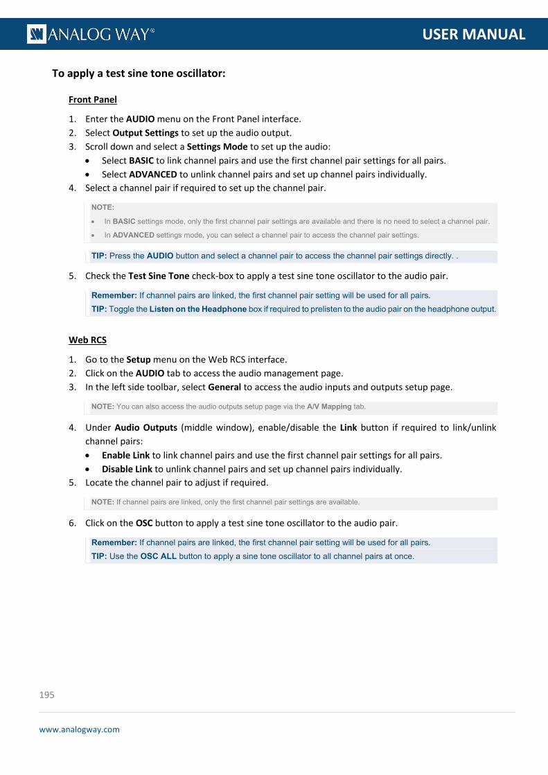
195
www.analogway.com
PROGRAMMER’S GU
USER MANUAL
To apply a test sine tone oscillator:
Front Panel
1. Enter the AUDIO menu on the Front Panel interface. 2. Select Output Settings to set up the audio output. 3. Scroll down and select a Settings Mode to set up the audio:
• Select BASIC to link channel pairs and use the first channel pair settings for all pairs. • Select ADVANCED to unlink channel pairs and set up channel pairs individually.
4. Select a channel pair if required to set up the channel pair.
NOTE:
• In BASIC settings mode, only the first channel pair settings are available and there is no need to select a channel pair.
• In ADVANCED settings mode, you can select a channel pair to access the channel pair settings.
TIP: Press the AUDIO button and select a channel pair to access the channel pair settings directly. .
5. Check the Test Sine Tone check-box to apply a test sine tone oscillator to the audio pair.
Remember: If channel pairs are linked, the first channel pair setting will be used for all pairs. TIP: Toggle the Listen on the Headphone box if required to prelisten to the audio pair on the headphone output.
Web RCS
1. Go to the Setup menu on the Web RCS interface. 2. Click on the AUDIO tab to access the audio management page. 3. In the left side toolbar, select General to access the audio inputs and outputs setup page.
NOTE: You can also access the audio outputs setup page via the A/V Mapping tab.
4. Under Audio Outputs (middle window), enable/disable the Link button if required to link/unlink channel pairs: • Enable Link to link channel pairs and use the first channel pair settings for all pairs. • Disable Link to unlink channel pairs and set up channel pairs individually.
5. Locate the channel pair to adjust if required.
NOTE: If channel pairs are linked, only the first channel pair settings are available.
6. Click on the OSC button to apply a test sine tone oscillator to the audio pair.
Remember: If channel pairs are linked, the first channel pair setting will be used for all pairs. TIP: Use the OSC ALL button to apply a sine tone oscillator to all channel pairs at once.
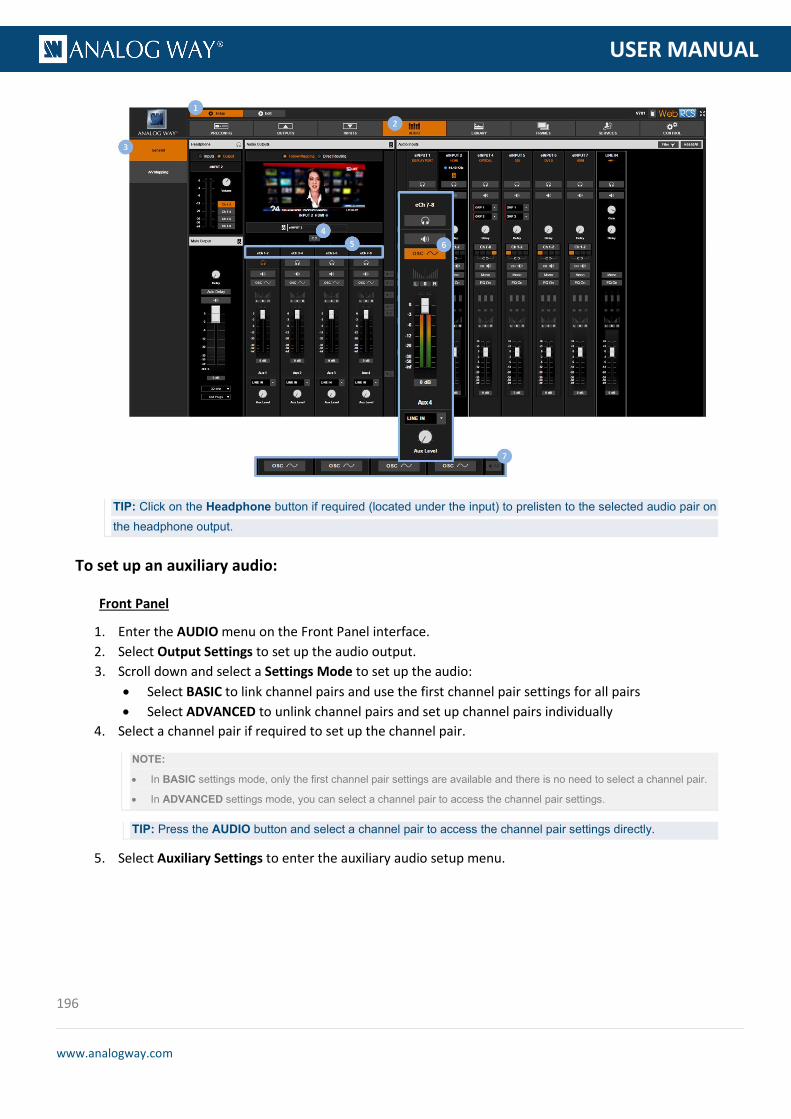
196
www.analogway.com
PROGRAMMER’S GU
USER MANUAL
TIP: Click on the Headphone button if required (located under the input) to prelisten to the selected audio pair on the headphone output.
To set up an auxiliary audio:
Front Panel
1. Enter the AUDIO menu on the Front Panel interface. 2. Select Output Settings to set up the audio output. 3. Scroll down and select a Settings Mode to set up the audio:
• Select BASIC to link channel pairs and use the first channel pair settings for all pairs • Select ADVANCED to unlink channel pairs and set up channel pairs individually
4. Select a channel pair if required to set up the channel pair.
NOTE:
• In BASIC settings mode, only the first channel pair settings are available and there is no need to select a channel pair.
• In ADVANCED settings mode, you can select a channel pair to access the channel pair settings.
TIP: Press the AUDIO button and select a channel pair to access the channel pair settings directly.
5. Select Auxiliary Settings to enter the auxiliary audio setup menu.
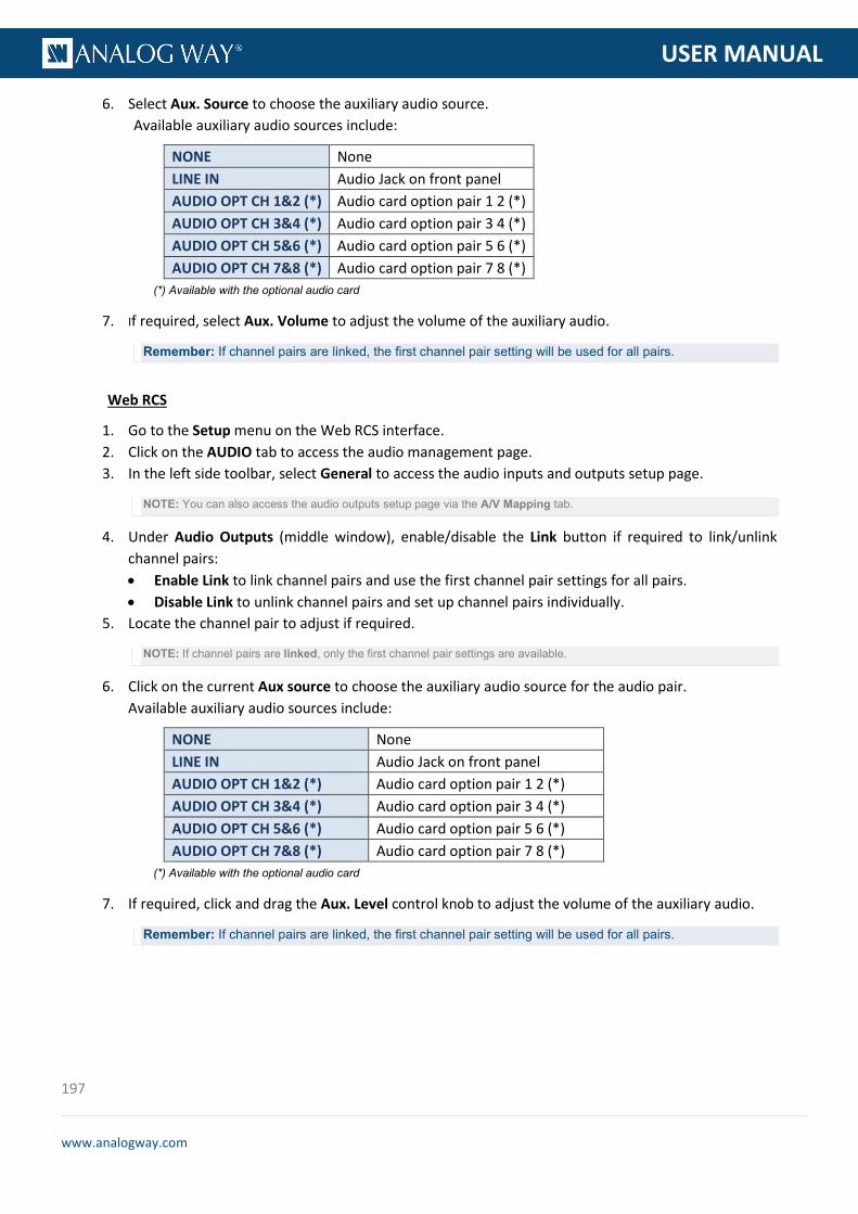
197
www.analogway.com
PROGRAMMER’S GU
USER MANUAL
6. Select Aux. Source to choose the auxiliary audio source. Available auxiliary audio sources include:
NONE None LINE IN Audio Jack on front panel AUDIO OPT CH 1&2 (*) Audio card option pair 1 2 (*) AUDIO OPT CH 3&4 (*) Audio card option pair 3 4 (*) AUDIO OPT CH 5&6 (*) Audio card option pair 5 6 (*) AUDIO OPT CH 7&8 (*) Audio card option pair 7 8 (*)
(*) Available with the optional audio card
7. If required, select Aux. Volume to adjust the volume of the auxiliary audio.
Remember: If channel pairs are linked, the first channel pair setting will be used for all pairs.
Web RCS
1. Go to the Setup menu on the Web RCS interface. 2. Click on the AUDIO tab to access the audio management page. 3. In the left side toolbar, select General to access the audio inputs and outputs setup page.
NOTE: You can also access the audio outputs setup page via the A/V Mapping tab.
4. Under Audio Outputs (middle window), enable/disable the Link button if required to link/unlink channel pairs: • Enable Link to link channel pairs and use the first channel pair settings for all pairs. • Disable Link to unlink channel pairs and set up channel pairs individually.
5. Locate the channel pair to adjust if required.
NOTE: If channel pairs are linked, only the first channel pair settings are available.
6. Click on the current Aux source to choose the auxiliary audio source for the audio pair. Available auxiliary audio sources include:
NONE None LINE IN Audio Jack on front panel AUDIO OPT CH 1&2 (*) Audio card option pair 1 2 (*) AUDIO OPT CH 3&4 (*) Audio card option pair 3 4 (*) AUDIO OPT CH 5&6 (*) Audio card option pair 5 6 (*) AUDIO OPT CH 7&8 (*) Audio card option pair 7 8 (*)
(*) Available with the optional audio card
7. If required, click and drag the Aux. Level control knob to adjust the volume of the auxiliary audio.
Remember: If channel pairs are linked, the first channel pair setting will be used for all pairs.

198
www.analogway.com
PROGRAMMER’S GU
USER MANUAL
To add a delay to the audio:
Front Panel
1. Enter the AUDIO menu on the Front Panel interface. 2. Select Output Settings to set up the audio output. 3. If required, uncheck the Auto Delay check-box to disable the automatic computation of the audio
delay. 4. Select Delay to adjust the audio delay.
Web RCS
1. Go to the Setup menu on the Web RCS interface. 2. Click on the AUDIO tab to access the audio management page. 3. In the left side toolbar, select General to access the audio inputs and outputs setup page.
NOTE: You can also access the audio outputs setup page via the A/V Mapping tab.
4. Under Main Audio (bottom left side window), click on the Auto Delay button if required to disable the automatic computation of the audio delay.
5. Click and drag the Delay control knob to manually adjust the audio delay.

199
www.analogway.com
PROGRAMMER’S GU
USER MANUAL
To control the volume (master volume):
Front Panel
1. Enter the AUDIO menu on the Front Panel interface. 2. Select Output Settings to set up the audio output. 3. Select Master Volume to adjust the volume of the output audio.
Web RCS
1. Go to the Setup menu on the Web RCS interface. 2. Click on the AUDIO tab to access the audio management page. 3. In the left side toolbar, select General to access the audio inputs and outputs setup page.
NOTE: You can also access the audio outputs setup page via the A/V Mapping tab.
4. Under Main Audio (bottom left side window), click and drag the Volume control bar to adjust the master volume.
TIP: Enable/disable the Master Mute button to mute/unmute the output audio (all channel pairs at once).
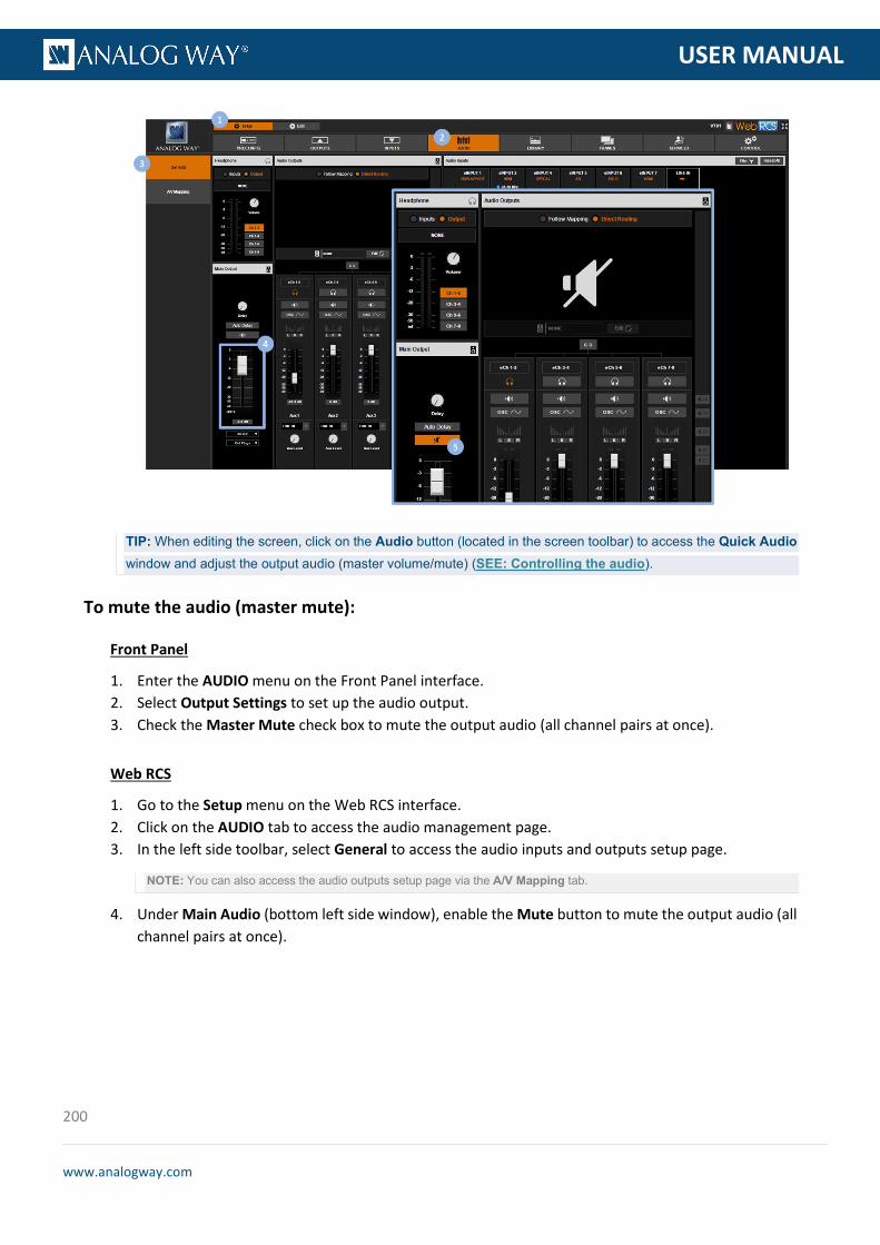
200
www.analogway.com
PROGRAMMER’S GU
USER MANUAL
TIP: When editing the screen, click on the Audio button (located in the screen toolbar) to access the Quick Audio window and adjust the output audio (master volume/mute) (SEE: Controlling the audio).
To mute the audio (master mute):
Front Panel
1. Enter the AUDIO menu on the Front Panel interface. 2. Select Output Settings to set up the audio output. 3. Check the Master Mute check box to mute the output audio (all channel pairs at once).
Web RCS
1. Go to the Setup menu on the Web RCS interface. 2. Click on the AUDIO tab to access the audio management page. 3. In the left side toolbar, select General to access the audio inputs and outputs setup page.
NOTE: You can also access the audio outputs setup page via the A/V Mapping tab.
4. Under Main Audio (bottom left side window), enable the Mute button to mute the output audio (all channel pairs at once).

201
www.analogway.com
PROGRAMMER’S GU
USER MANUAL
TIP: When editing the screen, click on the Audio button (located in the screen toolbar) to access the Quick Audio window and adjust the output audio (master volume/mute) (SEE: Controlling the audio).
Related topics:
• VIO 4K Audio Block Diagram • Prelistening to audio content • Selecting the SDI audio output mode
The VIO 4K allows you to add an optional XLR audio system interface expansion card to create new S/PDIF and AES3 audio inputs. This way you can take the most of XLR audio systems directly available on your VIO 4K unit.
To adjust the XLR audio input settings:
Front Panel
1. Enter the AUDIO menu on the Front Panel interface. 2. Select the Option Card Settings meu. 3. Select the XLR In Mode for the optional XLR card.
10.7 Adjusting the XLR audio

202
www.analogway.com
PROGRAMMER’S GU
USER MANUAL
Available XLR input modes include:
NONE No input 2x DIGITAL Digital double stereo (2 pairs) 2x ANALOG XLR Analog XLR balanced (1 pair) 2x ANALOG JACK MONO Analog stereo split on two mono jacks (1 pair) 2x MICRO. - MODE1 Analog double mono microphone on XLR (2 pair) 2x MICRO. - MODE2 Analog microphone stereo split on two XLR (1 pair) 1x JACK STEREO & 1x DIG Analog stereo on jack 1 and Digital on XLR 2 (2 pair) 1x MICRO. & 1x DIG Analog mono mic on XLR 1 and Digital on XLR 2 (2 pair)
4. If required, select also the Digital Input Mode. Available digital input modes include:
AES3 Digital mode AES S/PDIF Digital mode SPDIF
Web RCS
1. Go to the Setup menu on the Web RCS interface. 2. Click on the AUDIO tab to access the audio management page. 3. In the left side toolbar, select the XLR Card tab to access the XLR audio inputs and outputs setup page. 4. Under the XLR Card section (right-side window), select the XLR Input Mode.
Available XLR input modes include:
NONE No input 2x DIGITAL Digital double stereo (2 pairs) 2x ANALOG XLR Analog XLR balanced (1 pair) 2x ANALOG JACK MONO Analog stereo split on two mono jacks (1 pair) 2x MICRO. - MODE1 Analog double mono microphone on XLR (2 pair) 2x MICRO. - MODE2 Analog microphone stereo split on two XLR (1 pair) 1x JACK STEREO & 1x DIG Analog stereo on jack 1 and Digital on XLR 2 (2 pair) 1x MICRO. & 1x DIG Analog mono mic on XLR 1 and Digital on XLR 2 (2 pair)
5. If required, select also the Digital Input Mode.

203
www.analogway.com
PROGRAMMER’S GU
USER MANUAL
Available digital input modes include:
AES3 Digital mode AES S/PDIF Digital mode SPDIF
To adjust the XLR audio output settings:
NOTE: AES3 is the only supported Digital output.
Front Panel
1. Enter the AUDIO menu on the Front Panel interface. 2. Scroll down and select Option Card Settings to access the audio optional card settings. 3. Select XLR Out Mode to choose the XLR card output mode.
Available XLR output modes include:
NONE No output DIGITAL Digital double AES ANALOG BALANCED Analog stereo balanced
4. If required, select the XLR Output Pair 1. 5. If required, select the XLR Output Pair 2.

204
www.analogway.com
PROGRAMMER’S GU
USER MANUAL
Web RCS
1. Go to the Setup menu on the Web RCS interface. 2. Click on the AUDIO tab to access the audio management page. 3. In the left side toolbar, select the XLR Card tab to access the XLR audio inputs and outputs setup page. 4. Under the XLR card section (right-side window), select the XLR Output Mode.
Available XLR output modes include:
NONE No output DIGITAL Digital double AES ANALOG BALANCED Analog stereo balanced
5. If required, select the XLR Output Pair 1. 6. If required, select the XLR Output Pair 2.
Related topics:
• Expansion interfaces
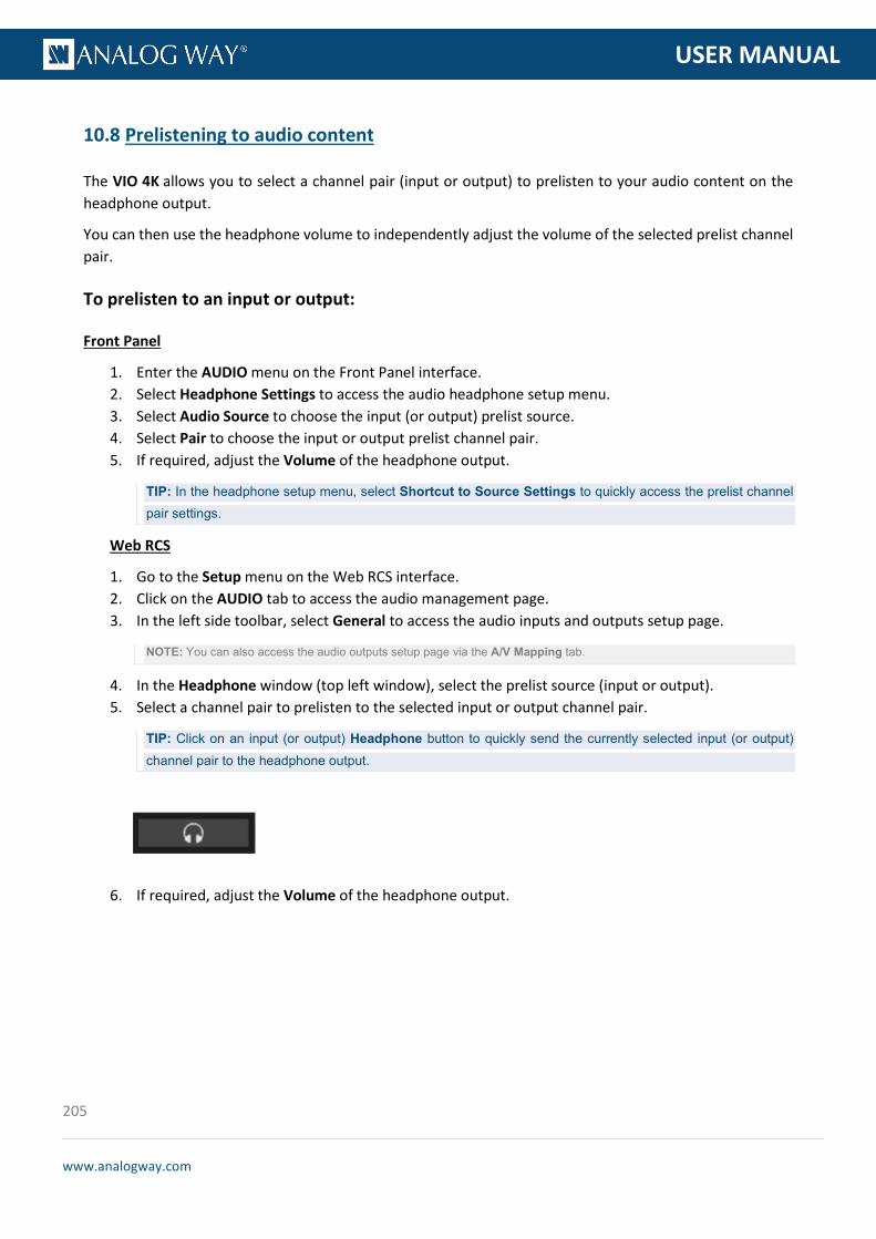
205
www.analogway.com
PROGRAMMER’S GU
USER MANUAL
The VIO 4K allows you to select a channel pair (input or output) to prelisten to your audio content on the headphone output.
You can then use the headphone volume to independently adjust the volume of the selected prelist channel pair.
To prelisten to an input or output:
Front Panel
1. Enter the AUDIO menu on the Front Panel interface. 2. Select Headphone Settings to access the audio headphone setup menu. 3. Select Audio Source to choose the input (or output) prelist source. 4. Select Pair to choose the input or output prelist channel pair. 5. If required, adjust the Volume of the headphone output.
TIP: In the headphone setup menu, select Shortcut to Source Settings to quickly access the prelist channel pair settings.
Web RCS
1. Go to the Setup menu on the Web RCS interface. 2. Click on the AUDIO tab to access the audio management page. 3. In the left side toolbar, select General to access the audio inputs and outputs setup page.
NOTE: You can also access the audio outputs setup page via the A/V Mapping tab.
4. In the Headphone window (top left window), select the prelist source (input or output). 5. Select a channel pair to prelisten to the selected input or output channel pair.
TIP: Click on an input (or output) Headphone button to quickly send the currently selected input (or output) channel pair to the headphone output.
6. If required, adjust the Volume of the headphone output.
10.8 Prelistening to audio content

206
www.analogway.com
PROGRAMMER’S GU
USER MANUAL
TIP: Use the MON. STREAM tab (Edit menu) to prelisten to your headphone output directly from your PC or tablet.

207
www.analogway.com
PROGRAMMER’S GU
USER MANUAL
Custom Formats are computer formats that you can define by yourself to support any required non-standard output format.
The custom formats capability thus adds a layer of format compatibility to the CVT (version 1.1) and DMT (version 1.0) format standards supported by default by the VIO 4K, by allowing you to define your own custom computer formats whenever required and keep them directly on the device.
The VIO 4K provides a list of predefined output formats that you can freely use to set up your outputs.
If the required output format is not available however, you can still build up the list of available formats by creating your own custom computer format.
To create a custom computer format:
Front Panel
1. Enter the CUSTOMIZE menu on the Front Panel interface. 2. Select CUSTOM FORMATS > Create New Format to access the custom format edit menu. 3. Select a Mode to edit the custom format:
• Select CVT to set the width, height and rate of the format, and indicate whether the format has reduced blanking intervals or not. The remaining custom format parameters will be computed by the system according to the CVT 1.1 standard.
• Select Full to set all the parameters of the format: H&V front porch, H&V sync, H&V back porch, width, height, sync polarity...
4. Edit the custom format parameters in the selected edit mode Depending on the selected mode, the custom format parameters may include: • Frame Rate: Select the frame frequency (in Hz). • H Active: Select the number of pixel in a line (in pixels). • H Front Porch: Set the horizontal front porch (in pixels). • H Back Porch: Set the horizontal back porch (in pixels). • H Sync: Set the synchro H size (in pixels). • H Positive Polarity: Enable the synchro horizontal polarity. • V Active: Select the number of lines (frame 0) (in pixels). • V Front Porch: Set the vertical front porch (frame 0) (in pixels).
11 Custom formats
11.1 What are custom formats?
11.2 Creating custom formats

208
www.analogway.com
PROGRAMMER’S GU
USER MANUAL
• V Back Porch: Set the vertical back porch (frame 0) (in pixels). • V Sync: Set the synchro vertical size (in pixels). • V Positive Polarity: Enable the synchro vertical polarity.
TIP: • Select Load from Template to load the parameter values of a predefined output format. • Select Load from Custom Format Bank to load the parameter values of an already created custom format. • Use Reset to reset all custom format parameters to their default (edit mode) value.
5. Once you have finished editing the custom format parameters, select Check to check that the new custom format settings are valid. Check result information may include: • (ERROR STATUS): (Only if format is not valid) Format error status.
List of possible format error status:
PIXEL FREQUENCY TOO HIGH The custom format is invalid because its pixel frequency is too high PIXEL FREQUENCY TOO LOW The custom format is invalid because its pixel frequency is too low LINE FREQUENCY TOO HIGH The custom format is invalid because its line frequency is too high TOTAL PIXEL PER LINE IS TOO LOW
The custom format is invalid because the number of pixels per line is too low
• H Total: Number of pixel in a line (in pixels). • V Total: Number of lines in a frame (in pixels). • Pixel Frequency: Signal pixel frequency (in Hz). • Line Frequency: Signal line frequency (in kHz).
6. If the custom format is valid, select Save as to save the new custom format settings
NOTE: You will be asked to select a custom format bank slot to save your custom format:
• Available (empty) bank slots will appear in black.
• Not available (occupied) bank slots will appear in blue.
7. Select a bank slot to contain the format and press the ENTER key to confirm (or use the EXIT-MENU key to go back to edit mode without saving the format)
Web RCS
1. Go to the Setup menu on the Web RCS interface. 2. Click on the OUTPUTS tab to access the outputs setup page. 3. In the left side toolbar, select Custom Formats to access the custom formats page. 4. In the SLOT #1-64 window, select a custom format bank slot to contain your format.
TIP: • Select an empty bank slot to create a new custom format. • Select a non-empty bank slot to edit the custom format contained in the selected slot.
5. In the right side window, click on the Edit button to access the custom format parameters in edit mode.
6. Select a Mode to edit the custom format parameters:
209
www.analogway.com
PROGRAMMER’S GU
USER MANUAL
• Select CVT to set the width, height and rate of the format, and indicate whether the format has reduced blanking intervals or not. The remaining custom format parameters will be computed by the system according to the CVT 1.1 standard.
• Select Full to set all the parameters of the format: H&V front porch, H&V sync, H&V back porch, width, height, sync polarity...
7. Edit the custom format parameters in the selected edit mode. Depending on the selected mode, the custom format parameters may include: • Frame Rate: Select the frame frequency (in Hz). • H Active: Select the number of pixel in a line (in pixels). • H Front Porch: Set the horizontal front porch (in pixels). • H Back Porch: Set the horizontal back porch (in pixels). • H Sync: Set the synchro H size (in pixels). • H Positive Polarity: Enable the synchro horizontal polarity. • V Active: Select the number of line (frame 0) (in pixels). • V Front Porch: Set the vertical front porch (frame 0) (in pixels). • V Back Porch: Set the vertical back porch (frame 0) (in pixels). • V Sync: Set the synchro vertical size (in pixels). • V Positive Polarity: Enable the synchro vertical polarity.
TIP: • Click on the Load from predefined format button to load the parameter values of a predefined output format. • Click on the Load from custom format button to load the parameter values of an already created custom
format. • Use the Reset button to reset all custom format parameters to their default (edit mode) value.
8. Once you have finished editing the custom format parameters, click on the Check button to check that the new custom format settings are valid. Check result information may include: • (ERROR STATUS): (Only if format is not valid) Format error status.
List of possible format error status:
PIXEL FREQUENCY TOO HIGH The custom format is invalid because its pixel frequency is too high PIXEL FREQUENCY TOO LOW The custom format is invalid because its pixel frequency is too low LINE FREQUENCY TOO HIGH The custom format is invalid because its line frequency is too high TOTAL PIXEL PER LINE IS TOO LOW
The custom format is invalid because the number of pixels per line is too low
• H Total: Number of pixel in a line (in pixels). • V Total: Number of lines in a frame (in pixels). • Pixel Frequency: Signal pixel frequency (in Hz). • Line Frequency: Signal line frequency (in kHz).
9. If the custom format is valid, click on the Save button to save the new custom format settings to the selected custom format bank slot.
TIP: Click elsewhere or disable Edit mode to exit without saving.
Information: The new custom format settings will not be saved if you exit without saving.

210
www.analogway.com
PROGRAMMER’S GU
USER MANUAL
To delete a custom computer format:
Front Panel
1. Enter the CUSTOMIZE menu on the Front Panel interface. 2. Select CUSTOM FORMATS > Delete Custom Format to access the list of already created custom
formats (custom format bank). 3. Select the custom format to delete and press the ENTER key to confirm.
Information: This action is irreversible.
Web RCS
1. Go to the Setup menu on the Web RCS interface. 2. Click on the OUTPUTS tab to access the outputs setup page. 3. In the left side toolbar, select Custom Formats to access the custom formats page. 4. In the SLOT #1-64 window, select the custom format bank slot containing the custom format to
delete. 5. In the right side window, click on the Delete button to delete the format contained in the selected
bank slot.
Information: This action is irreversible.
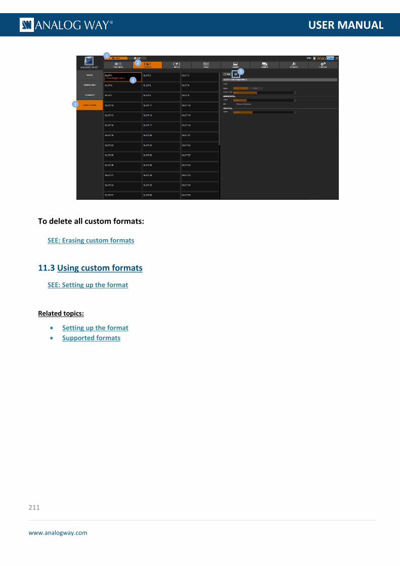
211
www.analogway.com
PROGRAMMER’S GU
USER MANUAL
To delete all custom formats:
SEE: Erasing custom formats
SEE: Setting up the format
Related topics:
• Setting up the format • Supported formats
11.3 Using custom formats

212
www.analogway.com
PROGRAMMER’S GU
USER MANUAL
A Preset is the memory of an input and its view.
You can use presets to quickly recall on the screen the input to display on the output together with how the input should be displayed in the screen.
This way, you can readily select and display sources by recalling presets at runtime.
Presets allow you to save and recall the input to display on the output together with how the input should be displayed in the screen.
You can thus create a preset of an input and its view and then load the preset at runtime to readily select and display the input.
This way, you can simply switch sources by loading presets at runtime.
To create a preset of an input and its view:
Front Panel
1. Enter the PRESETS menu on the Front Panel interface. 2. Select Save as Preset to access the preset bank. 3. Select a preset bank slot and press the ENTER key to create a preset memory of the currently selected
input and its view.
NOTE:
• Available (empty) bank slots appear in black.
• Not available (occupied) bank slots appear in blue.
TIP: Press the EXIT-MENU key to go back one page and exit without creating the preset memory.
Web RCS
1. Go to the Edit menu on the Web RCS interface. 2. Select the SCREEN tab to access the screen edit page. 3. In the left side toolbar, select the input to display on the output. 4. In the right side toolbar, click on the View tab if required to edit the input view settings (SEE also:
Setting up the view). 5. Once you have finished editing the view settings, select the Preset tab to access the preset bank. 6. Click on the SAVE MODE button to activate the preset bank save mode.
12 Presets
12.1 What is a preset?
12.2 Creating presets

213
www.analogway.com
PROGRAMMER’S GU
USER MANUAL
TIP: Double-click on the SAVE MODE button to lock save mode when creating several presets (click again to exit save mode).
7. Finally, select a slot to create a preset memory of the current input and its view.
NOTE: Non-empty bank slots are highlighted in orange. Saving to a non-empty bank slot will override the memory contained
in the selected bank slot.
To recall a preset:
Front Panel
1. Enter the PRESETS menu on the Front Panel interface. 2. Select Load Preset to access the preset bank. 3. Select a preset bank slot to recall the preset memory contained in the selected bank slot.
Web RCS
1. Go to the Edit menu on the Web RCS interface. 2. Select the SCREEN tab to access the screen edit page. 3. In the right side toolbar, select Preset to access the preset bank. 4. Click on a preset bank slot to recall the preset memory contained in the selected bank slot.
TIP: • Hover over a preset bank slot to have an overview of the preset memory contained in the slot. • SHIFT+click on a preset bank slot to freeze the preset Memories Overview box and label the preset memory
if necessary. • Use the Show memories label button to show preset labels instead of bank slot numbers in the preset bank
window.

214
www.analogway.com
PROGRAMMER’S GU
USER MANUAL
To delete a preset:
Front Panel
1. Enter the PRESETS menu on the Front Panel interface. 2. Select Delete Preset to access the preset bank. 3. Select a preset bank slot to delete the preset memory contained in the selected slot.
Information: No confirmation is required. Press the EXIT-MENU button if required to go back one menu without deleting the preset memory.
Web RCS
1. Go to the Edit menu on the Web RCS interface. 2. Select the SCREEN tab to access the screen edit page. 3. In the right side toolbar, select Preset to access the preset memories bank. 4. Shift + click on a preset bank slot to access the preset Memories Overview box. 5. Click on the Erase memory button to delete the preset memory contained in the selected bank slot.

215
www.analogway.com
PROGRAMMER’S GU
USER MANUAL
Related topics:
• Erasing the device memories

216
www.analogway.com
PROGRAMMER’S GU
USER MANUAL
An EDID (Extended Display Identification Data) is a data structure containing the characteristics and capabilities of a digital display, such as its graphic card or set-top box.
The EDID of a display is provided by the display itself to the video source, so that the source can identify the kind of monitor it is connected to.
Different EDID versions exist, but the information contained in the EDID includes:
• Manufacturer name and serial number; • Product type; • Phosphor or filter type; • Timings supported by the display; • Display size; • Luminance data and (for digital displays only); • Pixel mapping data.
13.2 Supported EDIDs
The VIO 4K has been designed to be able to read the EDID version 1.3 and 1.4 from devices connected to the VIO 4K plugs that support EDID management.
These plugs include:
• DP plugs, • HDMI plugs, • Analog plugs, • DVI-D plugs.
The VIO 4K can then extract the information contained in the read file, and store it in a 256-byte array that can be retrieved using the Web RCS and the Front Panel interfaces.
The extracted information includes the following data, and it can be used to match the output EDID to the input EDID:
• Display product name • Preferred format (used for format autoconfiguration).
SEE: Managing EDIDs for more information.
NOTE: You can also use the AW EDID Editor for EDID analysis and modification (SEE: AW EDID Editor for more information).
13 EDID support
13.1 What is an EDID

217
www.analogway.com
PROGRAMMER’S GU
USER MANUAL
13.3 Managing EDIDs
You can use the VIO 4K read/write EDID capabilities to match input and output EDIDs:
• Output EDIDs are EDIDs read by the VIO 4K from output devices such as video projectors or monitors. They cannot be modified but they can be saved to the VIO 4K EDID Library (User EDID bank) to update input EDIDs.
• Input EDIDs are EDIDs provided by the VIO 4K to the input sources connected to the device. They are used by the VIO 4K inputs and they can be modified (updated) with EDIDs stored in the Library (User EDID bank or AW Predefined bank).
• AW Predefined EDIDs are read-only EDIDs used by default by the VIO 4K inputs. They are stored in the EDID Library (AW Predefined bank) and, although they cannot be modified, they can be exported (downloaded) from the device.
• User EDIDs are EDIDs that you can store in the VIO 4K Library (User EDID bank) to update the EDIDs used by the VIO 4K inputs. You can define them by saving input, output and AW predefined EDIDs to the User EDID bank, or by importing your own EDIDs into the device.
By saving, importing and updating EDIDs you can thus match input and output EDIDs, required in some cases to make the input and the output compliant to each other (when using a specific format for example).
TIP: To match an input EDID to the output EDID:
1. Save the required output EDID(s) to EDID Library (user EDID bank). 2. Update the required input EDID(s) with the user EDID(s) created in (1).
To import an EDID:
Front Panel
NOTE: You will need a USB key to import EDIDs via the front panel. Before you start:
• Plug-in the USB key into the unit USB HOST port (located on the front panel).
• Wait until the device is properly recognized and proceed as explained below .

218
www.analogway.com
PROGRAMMER’S GU
USER MANUAL
1. Enter the CUSTOMIZE menu in the Front Panel interface. 2. Scroll down and select EDID Manager to access the EDID management menu. 3. Select IMPORT to access the USB device browser. 4. In the USB device browser, browse for the EDID file to import.
TIP: Use the ENTER and EXIT-MENU keys to navigate through folders.
5. Select the EDID file to import and press the ENTER key to review the EDID information contained in the file.
6. Press the ENTER key again to save the selected EDID file to the library (user EDID bank).
NOTE: You will be asked to select a user EDID bank slot to contain your EDID:
• Available (empty) slots will appear in black.
• Not available (occupied) slots will appear in blue.
• Use the EXIT-MENU key if required to go back to the USB device browser without importing the file.
Web RCS
1. Go to the Setup menu on the Web RCS interface. 2. Click on the CONTROL tab to access the device settings and control functions. 3. In the left side toolbar, select EDID to access the EDID management page. 4. In the EDID Library > USER EDID BANK window, hover over a user EDID bank slot (slots #1-64) and
click on the Upload EDID file from your computer button to open the Upload EDID file to library window.
5. In the Upload EDID file to library window, click on the "..." button to access your OS device browser. 6. In your OS device browser, select the EDID file to import (.bin extension) and click OK/Open to load
it into the Upload EDID file to library window. 7. In the Upload EDID to library window, review the EDID information contained in the file to import
and click on the Upload button to save the EDID file to the library (user EDID bank).
NOTE:
• The number in the Upload EDID file to library # window reminds you of the user EDID bank slot where the EDID will be
stored once the import is complete.
• Close the window before starting the import to exit without saving and select another user EDID bank slot if required.

219
www.analogway.com
PROGRAMMER’S GU
USER MANUAL
To save the EDID of an output:
Front Panel
1. Enter the CUSTOMIZE menu in the Front Panel interface. 2. Scroll down and select EDID Manager to access the EDID management menu. 3. Select STANDARD OUTPUT to access the VIO 4K output EDIDs. 4. Select an output and press the ENTER key to save the EDID of the selected output to the library (user
EDID bank).
NOTE: You will be asked to select a user EDID bank slot to contain your EDID:
• Available (empty) slots will appear in black.
• Not available (occupied) slots will appear in blue.
Use the EXIT-MENU key if required to go back to the output EDIDs menu without saving the EDID.
Web RCS
1. Go to the Setup menu on the Web RCS interface. 2. Click on the CONTROL tab to access the device settings and control functions. 3. In the left side toolbar, select EDID to access the EDID management page. 4. In the Outputs > STANDARD OUTPUT window, select the output whose EDID is to be saved to the
library and drag and drop it to the EDID Library > USER EDID BANK window.
TIP: Use the Outputs > Refresh/Refresh All button before dragging to update the output EDID information before the EDID is saved.
NOTE: You will need to select a user EDID bank slot for the drop (slots #1-64): select the slot where the output EDID is to be
saved.
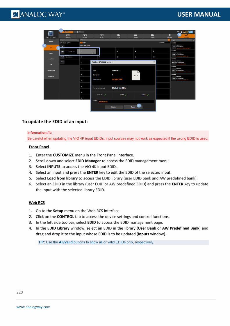
220
www.analogway.com
PROGRAMMER’S GU
USER MANUAL
To update the EDID of an input:
Information /!\: Be careful when updating the VIO 4K input EDIDs: input sources may not work as expected if the wrong EDID is used.
Front Panel
1. Enter the CUSTOMIZE menu in the Front Panel interface. 2. Scroll down and select EDID Manager to access the EDID management menu. 3. Select INPUTS to access the VIO 4K input EDIDs. 4. Select an input and press the ENTER key to edit the EDID of the selected input. 5. Select Load from library to access the EDID library (user EDID bank and AW predefined bank). 6. Select an EDID in the library (user EDID or AW predefined EDID) and press the ENTER key to update
the input with the selected library EDID.
Web RCS
1. Go to the Setup menu on the Web RCS interface. 2. Click on the CONTROL tab to access the device settings and control functions. 3. In the left side toolbar, select EDID to access the EDID management page. 4. In the EDID Library window, select an EDID in the library (User Bank or AW Predefined Bank) and
drag and drop it to the input whose EDID is to be updated (Inputs window).
TIP: Use the All/Valid buttons to show all or valid EDIDs only, respectively.
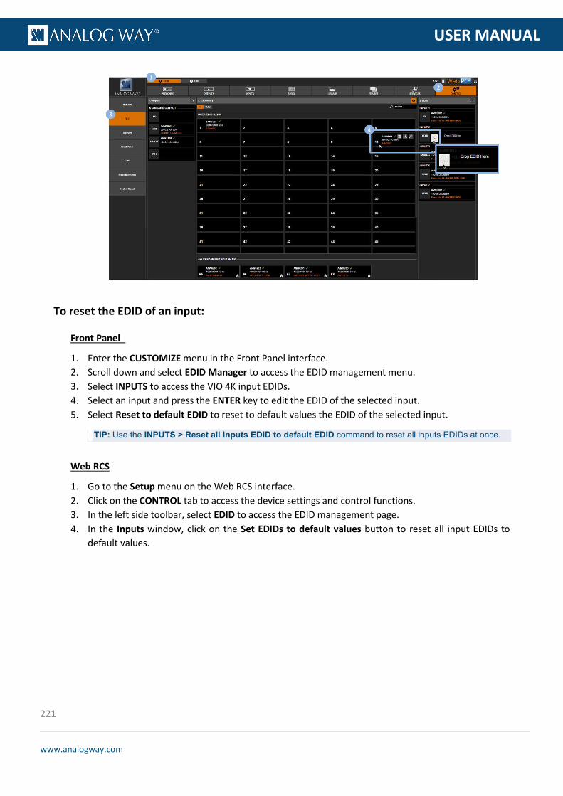
221
www.analogway.com
PROGRAMMER’S GU
USER MANUAL
To reset the EDID of an input:
Front Panel
1. Enter the CUSTOMIZE menu in the Front Panel interface. 2. Scroll down and select EDID Manager to access the EDID management menu. 3. Select INPUTS to access the VIO 4K input EDIDs. 4. Select an input and press the ENTER key to edit the EDID of the selected input. 5. Select Reset to default EDID to reset to default values the EDID of the selected input.
TIP: Use the INPUTS > Reset all inputs EDID to default EDID command to reset all inputs EDIDs at once.
Web RCS
1. Go to the Setup menu on the Web RCS interface. 2. Click on the CONTROL tab to access the device settings and control functions. 3. In the left side toolbar, select EDID to access the EDID management page. 4. In the Inputs window, click on the Set EDIDs to default values button to reset all input EDIDs to
default values.

222
www.analogway.com
PROGRAMMER’S GU
USER MANUAL
To export an EDID:
Front Panel
NOTE: You will need a USB key to export EDIDs via the front panel.
Before you start:
• Plug-in the USB key into the unit USB HOST port (located on the front panel)
• Wait until the device is properly recognized and proceed as explained below
1. Enter the CUSTOMIZE menu in the Front Panel interface. 2. Scroll down and select EDID Manager to access the EDID management menu. 3. Select LIBRARY to access the VIO 4K EDID library. 4. Select an EDID in the library and press the ENTER key to access the EDID details menu. 5. Select Export to... to access the USB device browser. 6. In the USB device browser, browse for the folder to export to.
TIP: Use the ENTER and EXIT-MENU keys to navigate through folders.
7. Finally, select EXPORT TO THIS FOLDER to export the EDID to the selected folder.
Web RCS
1. Go to the Setup menu on the Web RCS interface. 2. Click on the CONTROL tab to access the device settings and control functions. 3. In the left side toolbar, select EDID to access the EDID management page. 4. In the EDID Library window, hover over the EDID to export (user EDID or AW predefined EDID) and
click on the Download file to your computer button to access your OS device browser.
TIP: Use the All/Valid buttons to show all or valid EDIDs only, respectively.

223
www.analogway.com
PROGRAMMER’S GU
USER MANUAL
5. In your OS device browser, browse for the folder to export to and click on OK/Open button to export the EDID to the selected folder.
NOTE: Your OS device browser will not pop up if the Web RCS interface is in full screen mode.
To delete an EDID:
Front Panel
1. Enter the CUSTOMIZE menu in the Front Panel interface. 2. Scroll down and select EDID Manager to access the EDID management menu. 3. Select LIBRARY to access the VIO 4K EDID library. 4. Select an EDID in the library (user EDIDs only) and press the ENTER key to access the EDID details
menu. 5. Select Delete EDID to delete the EDID (/!\ requires confirmation: select YES to delete or NO to cancel
the action).
Web RCS
1. Go to the Setup menu on the Web RCS interface. 2. Click on the CONTROL tab to access the device settings and control functions. 3. In the left side toolbar, select EDID to access the EDID management page. 4. In the EDID Library window, hover over the EDID to delete (user EDIDs only) and click on the Erase
EDID from library button to delete (/!\ requires confirmation: select Yes to delete or No to cancel the action).
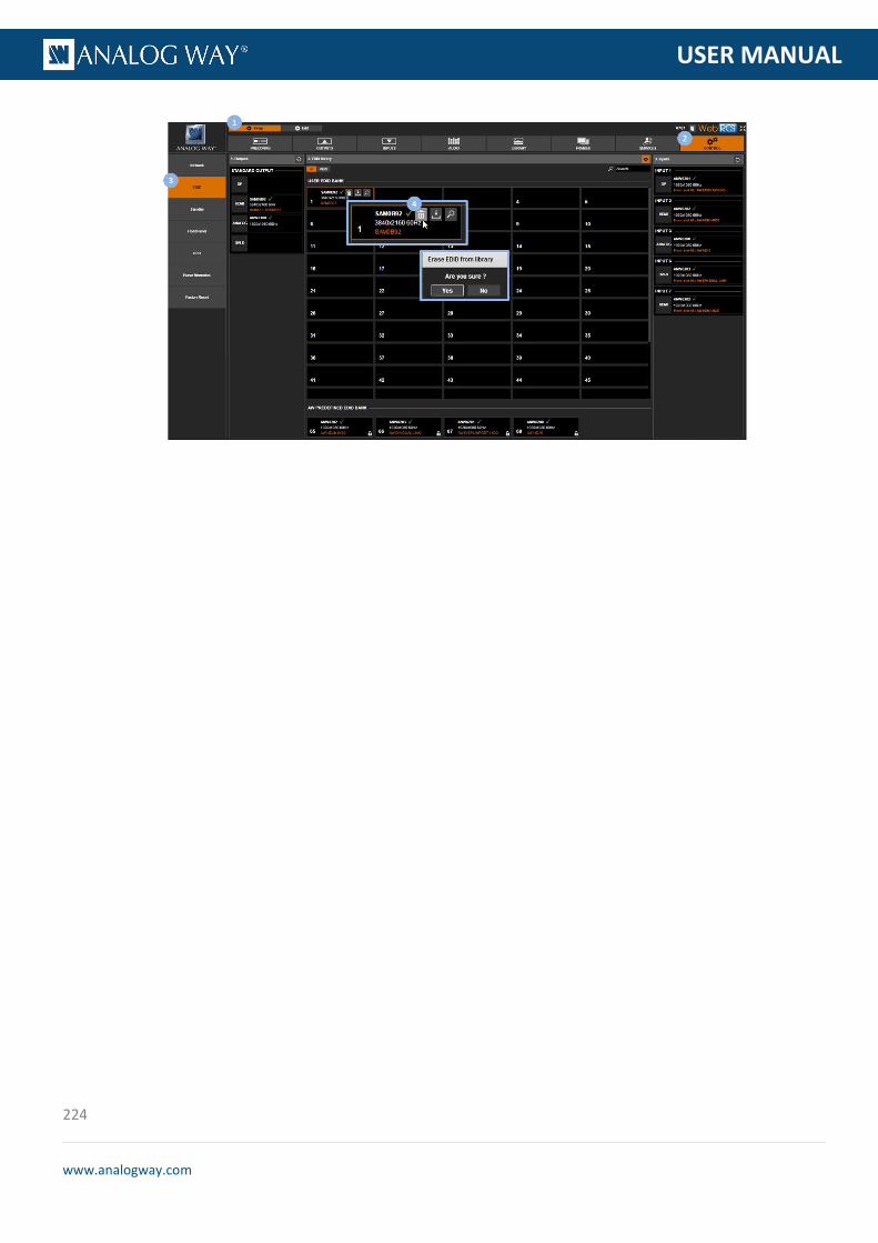
224
www.analogway.com
PROGRAMMER’S GU
USER MANUAL

225
www.analogway.com
PROGRAMMER’S GU
USER MANUAL
The VIO 4K is compliant with the HDCP specification for DVI, HDMI and DisplayPort input and output plugs.
INPUT DETECTION
On DVI, HDMI and DisplayPort input plugs, the HDCP detection is automatically managed by the input components.
OUTPUT DETECTION
On DVI-I (digital part only), HDMI and DisplayPort output plugs, the HDCP detection is automatically managed according to one of the following criteria:
• Hot plug • 3-second period attempt
By default, the HDCP detection is enabled on all input and output plugs that support the HDCP specification (SEE: HDCP detection).
If an input source is HDCP-encrypted, the output availability is then negotiated according to the following criteria:
HDCP source(*) Non-HDCP source
HDCP output peripheral
Output content is available only if HDCP is enabled on both the input and output plugs.
Output content is available, whichever the status on the output plug.
Non-HDCP output peripheral
Output is blackened even if HDCP is enabled on the output plug.
(*) Only on video plugs standard that support HDCP (HDMI, DisplayPort, DVI).
By enabling and disabling HDCP, you can thus relatively control the whole HDCP stream:
Input control
• With HDCP enabled (default), the HDCP negotiation is maintained even if the DVI, HDMI or DisplayPort plug is not the current plug (active input).
• With HDCP disabled, none of the HDCP sources can be displayed (the sources will see the VIO 4K inputs as non-HDCP compliant).
14 HDCP support
14.1 HDCP detection
14.2 HDCP negotiation

226
www.analogway.com
PROGRAMMER’S GU
USER MANUAL
Output control
• With HDCP enabled (default), the HDCP encryption is maintained whether the screen is compliant or not.
• With HDCP disabled, all screens are seen as non-HDCP compliant.
TIP: Disable HDCP as much as possible, especially if not using HDCP-encrypted sources.
To check the HDCP status of an input plug:
Front Panel
1. Enter the INPUTS menu on the Front Panel interface. 2. Scroll down and select an input to access the selected input setup menu.
TIP: Double-click on an INPUT SELECTION button to shortcut to the input setup menu directly.
3. Select the plug settings to access the input plug settings menu. 4. Select Status to check the input plug status. 5. Under Format > HDCP, check the HDCP status of the input plug.
TIP: Go to the CUSTOMIZE menu and select HDCP Manager to manage HDCP on all input plugs.
Web RCS
1. Go to the Setup menu on the Web RCS interface. 2. Click on the INPUTS tab to access the inputs setup page. 3. In the left side toolbar, select an input to access the selected input setup page. 4. Select the Signal tab to access the plug settings page. 5. Under HDCP, check the HDCP status of the input plug.
14.3 Managing HDCP

227
www.analogway.com
PROGRAMMER’S GU
USER MANUAL
TIP: Use the Quick Setup button (located at the bottom of the Web RCS interface) to manage HDCP on all input plugs.
To enable/disable HDCP on an input plug:
NOTE:
• With HDCP enabled (default), the HDCP negotiation is maintained even if the DVI, HDMI or DisplayPort plug is not the
current plug (active input).
• With HDCP disabled, none of the HDCP sources can be displayed.
Front Panel
1. Enter the INPUTS menu on the Front Panel interface. 2. Scroll down and select an input to access the selected input setup menu.
TIP: Double-click on an INPUT SELECTION button to shortcut to the input setup menu directly.
3. Select the plug settings to access the input plug settings menu. 4. Scroll down and uncheck the HDCP check-box to disable HDCP on the input plug (check to enable).
TIP: Go to the CUSTOMIZE menu and select HDCP Manager to manage HDCP on all input plugs.
Web RCS
1. Go to the Setup menu on the Web RCS interface. 2. Click on the INPUTS tab to access the inputs setup page. 3. In the left side toolbar, select an input to access the selected input setup page. 4. Select the Signal tab to access the plug settings page. 5. Under HDCP, uncheck the Enable check-box to disable HDCP on the input plug (check to enable).

228
www.analogway.com
PROGRAMMER’S GU
USER MANUAL
TIP: Use the Quick Setup button (located at the bottom of the Web RCS interface) to manage HDCP on all input plugs.
To enable/disable HDCP on an output plug:
NOTE:
• With HDCP enabled (default), the HDCP encryption is maintained whether the screen is compliant or not.
• With HDCP disabled, all screens are seen as non-HDCP compliant.
Front Panel
1. Enter the OUTPUTS menu on the Front Panel interface. 2. Select STANDARD OUTPUT to access the standard output setup menu. 3. Select Plug Settings to access the plug setup menu for the output. 4. Select a plug to access the selected plug setup menu. 5. Check the HDCP Detection check-box to enable the HDCP negotiation on the output plug (uncheck
to disable).
TIP: Go to the CUSTOMIZE menu and select HDCP Manager to manage HDCP on all input plugs.
Web RCS
1. Go to the Setup menu on the Web RCS interface. 2. Click on the OUTPUTS tab to access the outputs setup page. 3. In the left side toolbar, select STANDARD OUTPUT to access the standard output setup page. 4. Disable the Hide all plugs button if required to show the output plugs. 5. Click on the Show plugs settings button to access the plug settings for each output plug. 6. Locate the plug to set up. 7. Check the HDCP check-box to enable the HDCP negotiation on the output plug (uncheck to disable).
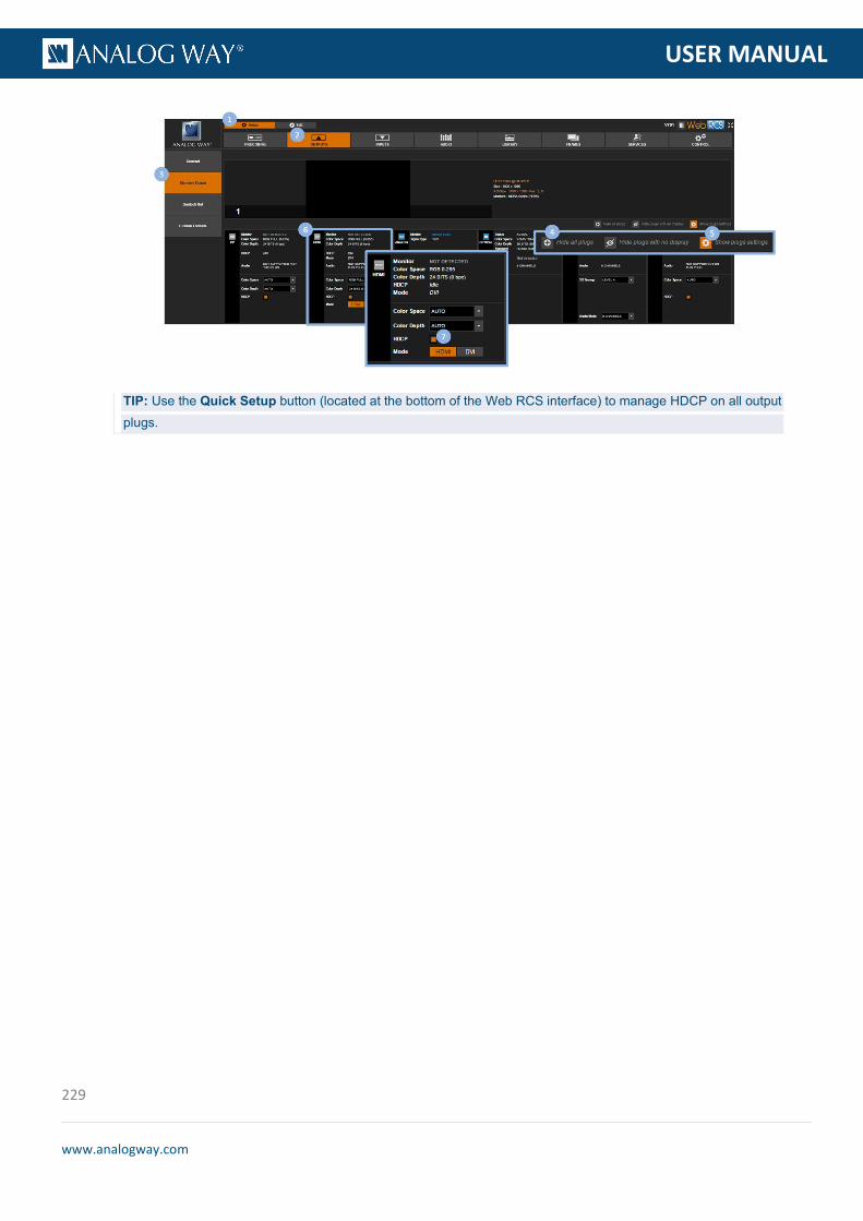
229
www.analogway.com
PROGRAMMER’S GU
USER MANUAL
TIP: Use the Quick Setup button (located at the bottom of the Web RCS interface) to manage HDCP on all output plugs.

230
www.analogway.com
PROGRAMMER’S GU
USER MANUAL
The VIO 4K can be upgraded with optional expansion cards. Five cards are currently supported, but only up to three optional expansion cards can be installed (one audio card and two video cards).
15.1 Audio expansion interfaces
You can add one expansion audio card on the VIO 4K, two different audio cards are supported.
Ref. OPT-AUDIODANTE-VIO4K
The Dante audio expansion interface can instantly Dante-enable your VIO 4K multi-format converter. It provides 8 bidirectional audio channels and full Dante network audio redundancy over Gigabit Ethernet. The Dante audio expansion interface supports the sample frequencies of 44.1 KHz, 48 KHz and 96 KHz.
Ref. OPT-AUDIOXLR-VIO4K
The XLR audio expansion interface adds S/PDIF and AES3 inputs to your VIO 4K (4 channels – 2 stereo pairs). It supports AES/EBU & i3D Digital Audio (XLR) as well as Analog Stereo Balanced audio (XLR).
SEE: Adjusting the XLR audio
15 Expansion interfaces
15.1.1 Dante™ audio expansion interface
15.1.2 XLR audio expansion interface

231
www.analogway.com
PROGRAMMER’S GU
USER MANUAL
15.2 Video cards
You can add up to two expansion video cards on the VIO 4K, three different video cards are supported. Expansion video cards allows extra inputs or outputs.
The VIO 4K can only process one input at a time, and therefore even when equipped with additional expansion interfaces, the device can only output three independent scaling of the same source, and cannot output three different sources.
Ref. OPT-OUT-VIO4K
The OPT-OUT-VIO4K expansion card is an output only video interface for the VIO 4K able to support formats up to 4K@30 4:4:4 10 bits, featuring Dual-Link DVI, DisplayPort, HDMI, Optical, component and 6G-SDI connectivity.
Ref. OPT-4K60P-VIO4K
The OPT-4K60P-VIO4K expansion card is a high-performance I/O video interface for the VIO 4K able to support formats up to UHD/4K60Hz 4:4:4 and featuring DisplayPort 1.2 and HDMI 2.0 connectivity.
HDMI 2.0 supports up to 18Gbps of bandwidth allowing resolutions up to UHD/4K@60 4:4:4 8 bits, 2560x1440@60 4:4:4 10 bits or 2560x1440@120 4:4:4 8 bits. HDMI 2.0 is compliant with HDCP 1.4 and HDCP 2.2 and supports RGB444, YCbCr ITU-R BT.601, ITU-R BT.709 and ITU-R BT.2020 color spaces.
DisplayPort 1.2 supports up to 21.6Gbps of bandwidth allowing resolutions up to UHD/4K@60 4:4:4 10 bits. DP 1.2 is compliant with HDCP 1.3 and supports RGB444, YCbCr ITU-R BT.601 and ITU-R BT.709.
15.2.1 Extra output expansion interface
15.2.2 4K@60P expansion interface

232
www.analogway.com
PROGRAMMER’S GU
USER MANUAL
Ref. OPT-4K60P-SDI-VIO4K
The OPT-4K60P-SDI-VIO4K expansion card is a high-performance I/O video interface for the VIO 4K able to support formats up to UHD/4K60Hz 4:4:4 and featuring DisplayPort 1.2, HDMI 2.0, 12G-SDI, 12G-SFP and Quad-Link 3G-SDI connectivity.
HDMI 2.0 supports up to 18Gbps of bandwidth allowing resolutions up to UHD/4K@60 4:4:4 8 bits, 2560x1440@60 4:4:4 10 bits or 2560x1440@120 4:4:4 8 bits. HDMI 2.0 is compliant with HDCP 1.4 and HDCP 2.2 and supports RGB444, YCbCr ITU-R BT.601, ITU-R BT.709 and ITU-R BT.2020 color spaces.
DisplayPort 1.2 supports up to 21.6Gbps of bandwidth allowing resolutions up to UHD/4K@60 4:4:4 10 bits. DP 1.2 is compliant with HDCP 1.3 and supports RGB444, YCbCr ITU-R BT.601 and ITU-R BT.709.
Quad 3G-SDI connections (four quadrants or SMPTE 425-5) can be used either as an input or as an output and support resolutions up to 2160p60 (4:2:2 10 bits).
12G-SDI and 12G-SFP connections can be used either as an input or as an output and support resolutions up to 2160p60 (4:2:2 10 bits).
TIP: When equipped with one of the 4K60P expansion video card, the VIO 4K may deliver or receive UHDTV formats using the YCbCr ITU-R BT.2020 color space instead of the YCbCr ITU-R BT.709 color space used for HDTV formats. Choose the internal processing color standard to optimize the color space gamut and limit useless color space conversions.
15.2.3 4K@60P + SDI expansion interface

233
www.analogway.com
PROGRAMMER’S GU
USER MANUAL
Each time a video expansion card is installed, a new output is available. The Area of Interest (AOI) and the rotation of each output are totally independent from those set for the other outputs.
Each time a video expansion card is installed, a new screen is available. If two video cards are installed then three screens and three output resources are available.
15.3 Multi-Outputs support
15.3.1 Extra screen

234
www.analogway.com
PROGRAMMER’S GU
USER MANUAL
Each screen is enabled as soon as it has at least one output resource assigned.
You can drag and drop an output to assign it from one screen to another one. You can also assign all the output resources to the same screen, disabling all the other screens.
Once an output is assigned to a screen, enable the Clone checkbox to display the entire screen scaled to the output resolution.
The screen size can be determined according to two modes:
Auto: the screen is automatically computed according to the max area required to display all the AOI (the horizontal and vertical positions of the AOI are used for screen size computation).
Custom: manually set the size of the screen in pixels.
In both modes, the AOI of an output can be moved everywhere inside the screen but not outside the screen. The position can be adjusted using the horizontal and vertical position settings (in pixels) of the AOI.
A screen pattern is available to help the positioning of several outputs in the screen. This pattern contains various settings such as crosshatch lines, circles, tiles border, IDs, etc.
For LED wall applications mixing several tile pitches inside the same screen, a pitch compensation system is available for each output. This system is based on a reference screen pitch equals to 100%. The differing pitches are percentages of this reference screen pitch.
To enable pitch compensation:
Example with a 8000x2000 LED wall and a VIO 4K with two side by side outputs with different resolutions:
- Standard Output 4000x2000 - Option 1 Output 3000x1500
In this example, the reference pitch is the pitch of the standard output and the compensation ratio is 133.3% for the Option 1 output.
Front Panel
1. Enter the OUTPUTS menu on the Front Panel interface. 2. Select Screen Management. 3. Select Output Assignment and assign Option 1 Output to Screen 1. 4. Go back to Screen Management and select Screen 1 Settings. 5. Select Size Mode: CUSTOM and set the H Size and V Size (i.e. 8000x2000). 6. Select Option 1 Output Configuration and set the H Position and V Position.
15.3.2 Pitch compensation
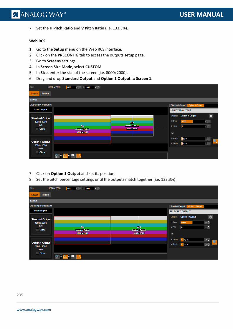
235
www.analogway.com
PROGRAMMER’S GU
USER MANUAL
7. Set the H Pitch Ratio and V Pitch Ratio (i.e. 133,3%).
Web RCS
1. Go to the Setup menu on the Web RCS interface. 2. Click on the PRECONFIG tab to access the outputs setup page. 3. Go to Screens settings. 4. In Screen Size Mode, select CUSTOM. 5. In Size, enter the size of the screen (i.e. 8000x2000). 6. Drag and drop Standard Output and Option 1 Output to Screen 1.
7. Click on Option 1 Output and set its position. 8. Set the pitch percentage settings until the outputs match together (i.e. 133,3%)

236
www.analogway.com
PROGRAMMER’S GU
USER MANUAL
CONTACT INFORMATION
The Americas Europe, Middle East & Africa Asia Pacific
Analog Way SAS - Headquarters
Tel.: +33 (0)1 81 89 08 60
2/4 rue Georges Besse
92160 Antony
FRANCE
Analog Way Inc.
Tel.: +1 (678) 487 6644
Toll free: +1 855 353 4988
3047 Summer Oak Place
Buford, GA 30518
USA
Analog Way Pte Ltd
Tel.: +65 6292 5800
152 Beach Road
#15-03 Gateway East
SINGAPORE 189721
Sales/General information:
Sales/General information:
Sales/General information:
Technical support:
Tel.: +33 (0)1 81 89 08 76
Technical support:
Technical support:
Analog Way Germany
Tel.: +49 (0)160 90 624 624
Tel.: +49 (0)160 97 539 542
Analog Way Italy
Tel.: +39 02 39493943
Analog Way UK
Tel.: +44 (0) 7774 143472
Tel.: +44 (0) 7946 303271

237
www.analogway.com
PROGRAMMER’S GU
USER MANUAL