Kollmorgen Automation and Motion Control
140
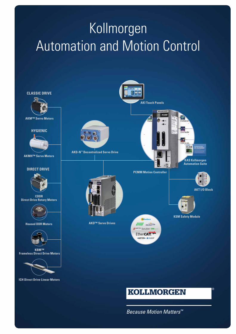
Kollmorgen Automation and Motion Control AKM™ Servo Motors ICH Direct Drive Linear Motors KBM™ Frameless Direct Drive Motors AKD™ Servo Drives KSM Safety Module AKT I/O Block KAS Kollmorgen Automation Suite PCMM Motion Controller AKD-N ™ Decentralized Servo Drive AKI Touch Panels CLASSIC DRIVE Housed DDR Motors HYGIENIC AKMH™ Servo Motors CDDR Direct Drive Rotary Motors DIRECT DRIVE
-
Upload
khangminh22 -
Category
Documents
-
view
1 -
download
0
Transcript of Kollmorgen Automation and Motion Control
KollmorgenAutomation and Motion Control
AKM™ Servo Motors
ICH Direct Drive Linear Motors
KBM™ Frameless Direct Drive Motors
AKD™ Servo Drives
KSM Safety Module
AKT I/O Block
KAS Kollmorgen Automation Suite
PCMM Motion Controller
AKD-N™ Decentralized Servo Drive
AKI Touch Panels
CLASSIC DRIVE
Housed DDR Motors
HYGIENIC
AKMH™ Servo Motors
CDDR Direct Drive Rotary Motors
DIRECT DRIVE

K O L L M O R G E N 2
Kollmorgen: Your partner. In Motion.Every solution comes from a real understanding of the challenges facing machine designers and users.Innovators consistently rate Kollmorgen as one of their best motion systems manufacturing partners. Whether you are looking for classic servo motors, direct-drive servo motors, stepper motors, drives & amplifiers, gearing, actua-tion, or CNC & multi-axis motion controllers, Kollmorgen is one of the few com-panies in the world whom actually design and manufacture all of these products.
Our customers are leaders in many industries such as Aerospace & Defense, Printing, Packaging & Converting, Food & Beverage Processing, Medical Imaging, Invitro Diagnostics & Laboratory Automation, Pharmaceutical Manufacturing, Material Forming and Cutting, Oil & Gas, and Robotics. Kollmorgen is also a leader in Warehouse Automation, including complete AGV systems, software, awareness and autonomy.
Our Automation Solutions can be found on Mars and in space, ships and sub-marines, O&G drilling and metrology, Surgical robots and laser eye surgery, even inside of artificial hearts. These are just a few applications that demand high-performance and high-quality while satisfying their specific needs.
Because motion matters, it’s our focus: Motion can distinctly differentiate a machine and deliver a marketplace advantage by increasing its performance and dramatically improving overall equipment effectiveness (OEE).
High-performance motion can make your customer’s machine more reliable and energy-efficient, enhance accuracy and improve operator safety. Motion also represents endless possibilities for innovation.
We’ve always understood this potential, and thus have kept motion at our core and in our Vison, Mission & Values, relentlessly developing products that offer precise control of torque, velocity and position accuracy in machines that rely on complex motion.

Table of ContentsAutomation and Motion Control Overview 4Kollmorgen Automation Suite 6u PLC Software and Drive Programming 14u AKD PDMM Drive-Resident Controller 16u PCMM Stand-Alone Controller 18u Real-time Motion Bus 20u HMI Human Machine Interface (HMI) 21u AKT I/O Terminals 24u Kollmorgen Developer Network 25Servo Drives 26u AKD Servo Drive 26u AKD Basic Servo Drive 36u AKD PDMM Drive-Resident Controller 38u AKD-N Decentralized Servo Drive 42u S700 Servo Drives 50Safe Motion 56u Kollmorgen Motion Safety Concept 58u KSM compact, KSM modular 61Servo Motors 62u AKM Brushless Servo Motor 66u AKM Washdown and Washdown Food 68u AKMH Hygienic Stainless Steel Servo Motor 74u ERD Hygienic Stainless Steel Linear Actuator 84Linear Direct Drives 88u ICH linear motors 90Rotary Direct Drives 96u Cartridge DDR Rotary Direct Drive 98u Housed Direct Drive Rotary (DDR) Motors 102u KBM Frameless Brushless Motors 104u TBM Frameless Motors 114u Direct Drive Technology 116KCM Energy Storage Devices 118u KCM-S Dynamic Storage Device 120u KCM-P Static Energy Storage 122Motioneering Online 124Accessories 125Model Nomenclature 126
3w w w. k o l l m o r g e n . c o m
K O L L M O R G E N A U T O M A T I O N A N D M O T I O N C O N T R O L
Removing the Barriers of Design, Sourcing, and Time At Kollmorgen, we know that OEM engineers can achieve a lot more when obstacles aren’t in the way. So, we clear obstacles in three important ways:
Integrating Standard and Custom Products The optimal solution is often not clear-cut. Our applica-tion expertise allows us to modify standard products or develop totally custom solutions across our whole product portfolio so that designs can take flight.
Providing Motion Solutions, Not Just Components As companies reduce their supplier base and have less engineering manpower, they need a total system supplier with a wide range of integrated solutions. Kollmorgen of-fers complete solutions as well as motion subsystems that combine programming software, engineering services and best-in-class motion components.
Global Footprint With direct sales, engineering support, manufacturing facilities, and distributors spanning the Americas, Europe, Middle East, and Asia, we’re close to OEMs worldwide. Our proximity helps speed delivery and lend support where and when they’re needed.
Financial and Operational Stability A key driver in the growth of all Kollmorgen divisions is the Business System, which relies on the principle of “kaizen” – or continuous improvement. Using world-class tools, cross-disciplinary teams of exceptional people evalu-ate processes and develop plans that result in superior performance.
Kollmorgen: Your partner. In Motion.

K O L L M O R G E N 4
KO
LL
MO
RG
EN
A
UT
OM
AT
IO
N
AN
D
MO
TI
ON
C
ON
TR
OL
Automation and Motion Control
Kollmorgen’s comprehensive line of control software and hardware, drives and motors enables you to complete your solutions with one supplier:
Whether you want a stand-alone controller or drive-resident, Kollmorgen’s KAS can coordinate up to 128 axes, and synchronize the path of up to 32 axes per control engine. We offer standard languages according to IEC61131 -3, as well as C, C+, C++, C#, .NET, and our industry-leading graphical programming language, Pipe Network.
Our broad range of motor- and drive technologies and gearing and actuation products interface seamlessly with our KAS.
Comprehensive Line of Products Offering Complete System Solutions
AKD-N™ Decentralized Servo Drive
AKD-C Power Supply Module
KBM Frameless MotorAKM® Servo MotorCartridge DDR Motor AKMH™ Servo Motor
AKI touch panelsoperate and display
Supported System Bus Protocols
Flexible single or multi-axis drive solutions in decentralized and central architectures with AKD-PCMM and the Kollmorgen Automation Suite
SERVO MOTORS
DECENTRALIZED SERVO DRIVES
PROGRAMMABLE
CONTROL
System programming with the Pipe-NetworkTM or PLCopen
PCMMMotion Controller

5w w w. k o l l m o r g e n . c o m
KO
LL
MO
RG
EN
A
UT
OM
AT
IO
N
AN
D
MO
TI
ON
C
ON
TR
OL
Diverse and Scalable Drive Solutions
Need more axes? Different motor types? Linear direct drives here, direct drives with no housing there? No problem! With the EtherCAT® system bus you can connect more AKD servo drives and add motors of all performance classes from the Kollmorgen product range.
Interfaces are frequently the bottleneck in system design. Not so with the Kollmorgen Automation Suite. With the IO Advanced Kollmorgen Terminals (AKT) and the EtherCAT® bus coupler, you possess a flexible interface system which meets all of your requirements.
Control and monitor the processes on the machine with the AKI series touch panels. With the Kollmorgen Visualization Builder (KVB), you can program ergonomic user interfaces which guarantee safe handling and which display machine data clearly.
AKD™ Servo Drives
ICH Direct Drive Linear Motor
Stepper Motor
P-Series Stepper Drives
AKM® Servo Motor
TBM Frameless MotorHoused DDR Motor
Interface diversity: I/O bus terminalsAKT - Advanced Kollmorgen Terminals
System bus
Interface expansion with the EtherCAT® system bus
PCMM: Motion Control without expensive IPCPCMM is a motion controller, which represents a genuine alternative to expensive and complex IPCs. These devices have an additional sequence control system for motion control and can coordinate up to 128 axles in sync. If cycle time of less than 250 μs is required in the course of continuous path control, thanks to its excellent processing performance, the PCMM is capable of processing up to 32 servo drive axles in a deterministic process.
The PCMM can be seamlessly integrated into the machine configuration by selecting communication via TCP/IP, Modbus TCP , Ethernet/IP or ProfiNet with simple settings in the software. For high-performance motion control and axle synchronization, the PCMM takes on the role of the EtherCAT Master. The digital inputs and outputs of the device support EtherCAT-based additions to the inputs and outputs, as well as the connection of other EtherCAT components.
Both the PLC and motion control are programmed in the standardized IEC 61131-3 languages and rounded off with an integrated Web server for remote maintenance and status queries. All devices settings and motion control programming are saved on an SD card, which represents a real advantage in terms of service
SERVO MOTORS
SERVO DRIVES
STEPPERSYSTEMS
Micron TRUE™ GearboxesAKMH™ Servo Motor

K O L L M O R G E N 6
KO
LL
MO
RG
EN
A
UT
OM
AT
IO
N
SU
IT
E
Kollmorgen Automation Suite™Get to market faster while reducing costs with innovative drive solutions! The Kollmorgen Automation Suite supports you with harmonized software and hardware components. Whether it is a simple single-axis drive or a complex multi-axis drive system: With the Kollmorgen Automation Suite you quickly achieve comprehensive machine automation solutions.
The Kollmorgen Automation Suite is based on three pillars – the integrated development environment, the hardware (such as multi-axis controllers, interface and safety modules), and a broad portfolio of servo motors, as well as engineering support from Kollmorgen in the development of special drive solutions. The integrated development environment offers all the tools for PLC and drive programming, for the user interface display, and extensive offline test and debugging tools. All drive components communicate with each other via the fast EtherCAT system bus, and fieldbus protocols are available for connecting to higher-level systems. With Kollmorgen's wide range of servo motors – be they rotary or linear – you'll see incredible motion.
Do not make compromises when designing your drive and give us a call! There have been thousands of occasions where customer-specific modifi-cations of existing products or new developments have turned a drive into the perfect drive. The Kollmorgen engineering team is highly capable of turning the seemingly impossible into reality.

KO
LL
MO
RG
EN
A
UT
OM
AT
IO
N
SU
IT
E
The Advantages of Kollmorgen Automation Suite™
• High machine performance • Up to 25% greater throughput
• Up to 50% scrap reduction
• Improved accuracy
• Advanced drive technology for machines with outstanding performance
• Fast to market • Up to 30% reduction in development time
• Services available for program development, training, start-up, and support
• Industry standard programming environment and industrial networks
• Enhanced ease-of-use and integration • Single integrated programming environment for automation, drive technology, and all hardware
• Drag-and-drop motion programming
• Certified components that are tested to work together
• Seamless integration and configuration of amplifiers for optimal set-up
• A demonstrated solution • The result of many years of permanent optimization of programming and implementing automation and drive solutions
• Provides the diverse experience of a great number of suppliers and platforms that form today's Kollmorgen
• Used successfully for many years
7w w w. k o l l m o r g e n . c o m
KO
LL
MO
RG
EN
A
UT
OM
AT
IO
N
SU
IT
E
Basic Operation Single-Axis Programming
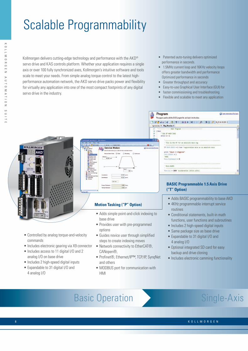
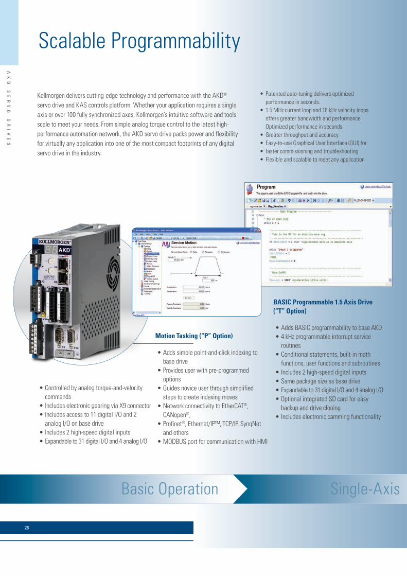
Kollmorgen delivers cutting-edge technology and performance with the AKD® servo drive and KAS controls platform. Whether your application requires a single axis or over 100 fully synchronized axes, Kollmorgen’s intuitive software and tools scale to meet your needs. From simple analog torque control to the latest high-performance automation network, the AKD servo drive packs power and flexibility for virtually any application into one of the most compact footprints of any digital servo drive in the industry.
• Patented auto-tuning delivers optimized performance in seconds.
• 1.5MHz current loop and 16KHz velocity loops offers greater bandwidth and performance Optimized performance in seconds
• Greater throughput and accuracy• Easy-to-use Graphical User Interface (GUI) for • faster commissioning and troubleshooting• Flexible and scalable to meet any application
• Controlled by analog torque-and-velocity commands
• Includes electronic gearing via X9 connector• Includes access to 11 digital I/O and 2
analog I/O on base drive• Includes 2 high-speed digital inputs• Expandable to 31 digital I/O and
4 analog I/O
Motion Tasking (“P” Option)
• Adds simple point-and-click indexing to base drive
• Provides user with pre-programmed options
• Guides novice user through simplified steps to create indexing moves
• Network connectivity to EtherCAT®, CANopen®,
• Profinet®, Ethernet/IP™, TCP/IP, SynqNet and others
• MODBUS port for communication with HMI
BASIC Programmable 1.5 Axis Drive (“T” Option)
• Adds BASIC programmability to base AKD• 4KHz programmable interrupt service
routines• Conditional statements, built-in math
functions, user functions and subroutines• Includes 2 high-speed digital inputs• Same package size as base drive• Expandable to 31 digital I/O and
4 analog I/O• Optional integrated SD card for easy
backup and drive cloning• Includes electronic camming functionality
Scalable Programmability
K O L L M O R G E N 8

KO
LL
MO
RG
EN
A
UT
OM
AT
IO
N
SU
IT
E
R ANGE OF KOLLMORGEN AUTOMATION SUITE CAPABILITIES
AKD Servo Drive AKD Servo Drive AKT I/O
Multi-Axis Programming
AKI HMI AKD PDMM AKT I/O
Pipe Network provides a one-to-one translation of a mechanical system into a logical world as shown in the Vertical Form Fill and Seal machine above. Click and build your motion program in minutes, or contact Kollmorgen for examples of common machine architectures to further accelerate your development.
2
4
5
3
Programmable Drive Multi-Axis Master PDMM (“M” Option)
• Scalable solution for use as a single-axis drive with integrated programmable auto-mation controller
• Choose from all five IEC 61131-3 languages for soft PLC process programming
• Program motion using your choice of PLCopen for motion or our innovative Pipe Network™
• 4KHz PLC scan rate and EtherCAT® updates•Complete line of HMI panels with integrated
software to simplify GUI development• Exclusive function blocks, such as “wait,”
enable your program to act as a scanning or sequential language
•On-board I/O includes 17 digital (with 2 high speed inputs) and 2 analog
• Connects to AKT™ network I/O for nearly unlimited expandability
1
• Accelerate development by programmingtasks in hours that would otherwise take weeks
• Improved coding quality through visualprogramming and by using pre-built modulesthat have been thoroughly tested and optimized
• Easy knowledge transfer, replacing pages of complex code with easily understood graphical representations
• Available on PDMM controllers
Seamlessly add additional axes and AKD PDMM serves as a high-performance multi-axis machine controller
• SD card for easy backup and system up-dates
• Integrated webserver for diagnostics and troubleshooting from any computer or mobile device
• Provide true synchronized-path control of up to 32 axes *
• Reduce cabinet size and wiring require-ments with a single, compact package
• Easily manage remote I/O and the I/O of all attached drives via EtherCAT®
• Use industry standard PLCopen for mo-tion, or step up to Kollmorgen’s Pipe Network™ to program sophisticated cam-ming and gearing applications in a matter of minutes
Visual Programming for Motion
Pipe NetworkKollmorgen Visual Programming for Motion
™
Pipe NetworkKollmorgen Visual Motion Programming
™
Pipe Network™
Single-Axis Programming
*Maximum axis count depends on motion/automation complexity and performance (8 axes nominal based on medium complexity at 4 kHz network update rate)
9w w w. k o l l m o r g e n . c o m

KO
LL
MO
RG
EN
A
UT
OM
AT
IO
N
SU
IT
E
Development
Integrated Development Environment (IDE)
•Our fully integrated programming environment incorporates standard IEC61131-3 compliant too• Use our network configurator and predefined user blocks to streamline development and ensure programming quality.
Our IDE offers two powerful programming methods and a complete set of tools for simulating, testing and optimizing motion.
A fully integrated development environment (IDE) provides the tools you need to develop everything from PLC and motion programs to HMI and device setup – all in one place. It’s easier to learn and use, eliminates the need for multiple programs and data stores, and helps you bring a higher-quality machine to market faster.
One-click motion simulation using virtual axes alongside real axes for quick develop-ment and implementation.
Scope motion parameters to fine-tune performance and synchronization, portrayed with up to eight channels and flexible map-ping of variables.
Complete motion system configuration from one location with embedded AKD Workbench allows configuration of all servo drives over EtherCat®.
Embedded wiring diagrams and one-click IO variable mapping makes drive integra-tion easy.
Integrated ToolsEmbedded Motion
Choose PLCopen for motion if you already use this industry standard in your existing products, and want to continue using it within the Kollmor-gen Automation Suite programming environment.
. Choose Kollmorgen’s exclusive Pipe Network™ for the quickest, easi-est way to represent mechanical systems in software – using drag-and-drop tools to create an intuitive visual representation.
Visual Programming for Motion
Pipe NetworkKollmorgen Visual Programming for Motion
™
Pipe NetworkKollmorgen Visual Motion Programming
™
Pipe Network™
K O L L M O R G E N 10

KO
LL
MO
RG
EN
A
UT
OM
AT
IO
N
SU
IT
E
Lifecycle
Kollmorgen is committed to helping you maximize the productivity and profitability of your machine across an ex-tended lifecycle. Design and build today, with confidence for a full return on investment for years to come.
Continual Development Testing Kollmorgen develops, tests, and continually validates all new products to ensure compatibility and performance, in the Kollmorgen ecosystem.
Software and Hardware Security Password protection for source code and hardware connectivity provides security for both OEMs and end-users.
Protect source code Protect network access
Maintenance Support Tools Our tools give end-users the ability to remotely verify con-tinuous operation and communicate issues effectively.
Built-in, mobile-ready webserver provides performance information with no software required
11w w w. k o l l m o r g e n . c o m

KO
LL
MO
RG
EN
A
UT
OM
AT
IO
N
SU
IT
E
Software PLC
All five IEC 61131-3 PLC languages are supported
Ladder Diagram (LD)
Sequential Function Chart (SFC)
Function Block Diagram (FBD)
Structured Text (ST)
Instruction List (IL)
• Kollmorgen Automation Suite™ offers a set of tools that is familiar to automation programs, but has enhancements like predefined motion blocks and visual diagnostics tools.
• The environment for developing PLC programs has been created with an emphasis on speed. Recognize and configure motion control components to accelerate systems development. With auto-recognize and auto-configure features, testing efforts are reduced.
• Once an application or a function block has been created for a given application, the user can store this as a “user-defined function block” to promote reuse of tested software in subsequent projects to save time.
• Maintain your standards in corporate programming languages by using any of the IEC 61131-3 languages. In fact, enhance it further by mixing and matching languages to deliver the best solution for the application.
• IEC-61131-3 engine
• Re-compile while running animated variables
• Industry and application Specific Function Blocks
• PID temperature control block
• Debugger Tools with Watch window
• 8-channel Real-Time Oscilliscope
IEC 61131-3 Toolkit Features
Easy-to-Use, Auto-Discover, Auto-Recognize, Auto-Configure, Scope, CAM,
IEC 61131-3 PLC
K O L L M O R G E N 12

KO
LL
MO
RG
EN
A
UT
OM
AT
IO
N
SU
IT
E
Simulator with PLC simulation and motion
Automatic I/O variable creation with scope definitions
Adding bus couplers with I/Os onto a motion network topology
Graphical environment for creating CAMs
• Standard debugging features like “step into”, “step over”, etc. are available to troubleshoot programs. In addition, debug your code using the softoscilloscope and continuously plot up to 8 variables at network update rates – the display can also be configured to suit the scale that the developer desires.
• Our CAM editor lets you create complex CAM profiles using a graphical interface. When converting, it is also possible to import existing CAM profile points into the CAM editor to allow you to seamlessly reuse your existing profiles.
• CAM-on-the-Fly lets you change CAM profiles based on network inputs or changes in machine conditions.
•Kollmorgen Automation Suite’s integrated development environment (IDE) allows the developer to create solutions without having to connect a single device by using the offline simulator. Start creating systems before the first hardware component is delivered. Simply configure your system network in “offline development” mode and change the status of the devices one-by-one when you actually connect them.
13w w w. k o l l m o r g e n . c o m
KO
LL
MO
RG
EN
A
UT
OM
AT
IO
N
SU
IT
E
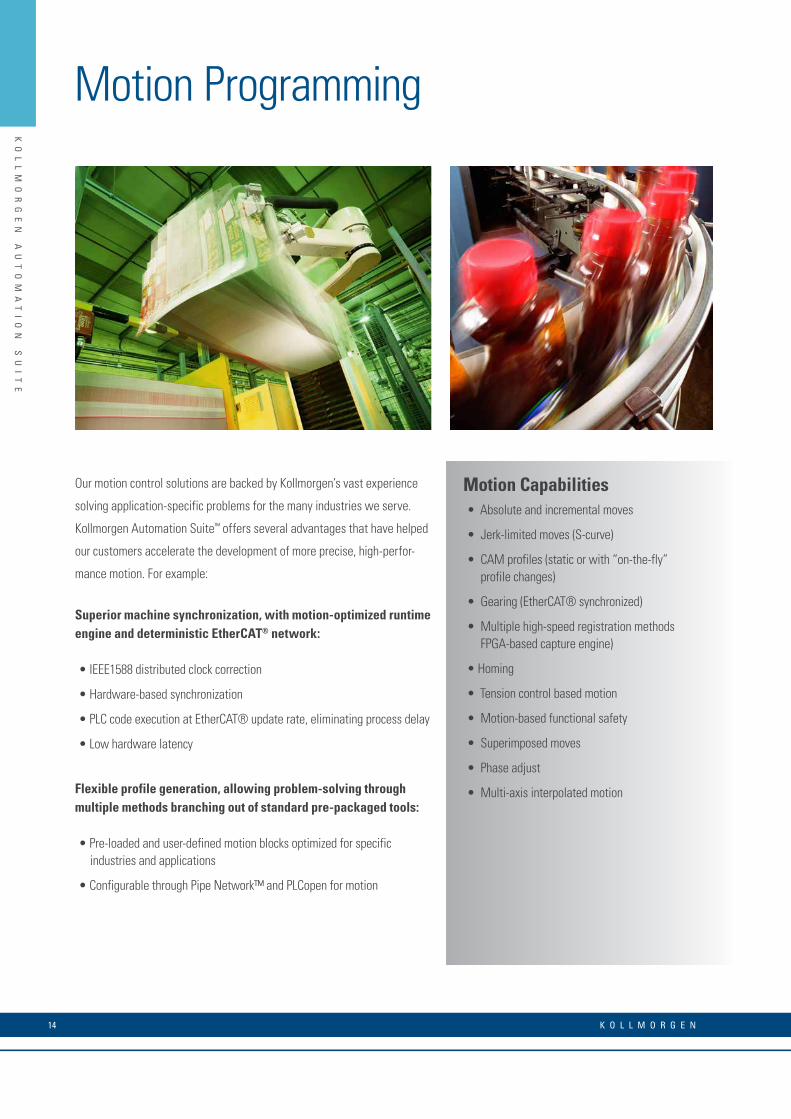
Motion Programming
Motion Capabilities• Absolute and incremental moves
• Jerk-limited moves (S-curve)
• CAM profiles (static or with “on-the-fly” profile changes)
• Gearing (EtherCAT® synchronized)
• Multiple high-speed registration methods FPGA-based capture engine)
• Homing
• Tension control based motion
• Motion-based functional safety
• Superimposed moves
• Phase adjust
• Multi-axis interpolated motion
Our motion control solutions are backed by Kollmorgen’s vast experience
solving application-specific problems for the many industries we serve.
Kollmorgen Automation Suite™ offers several advantages that have helped
our customers accelerate the development of more precise, high-perfor-
mance motion. For example:
Superior machine synchronization, with motion-optimized runtime engine and deterministic EtherCAT® network:
• IEEE1588 distributed clock correction
• Hardware-based synchronization
• PLC code execution at EtherCAT® update rate, eliminating process delay
• Low hardware latency
Flexible profile generation, allowing problem-solving through multiple methods branching out of standard pre-packaged tools:
• Pre-loaded and user-defined motion blocks optimized for specific industries and applications
• Configurable through Pipe Network™ and PLCopen for motion
K O L L M O R G E N 14
KO
LL
MO
RG
EN
A
UT
OM
AT
IO
N
SU
IT
E
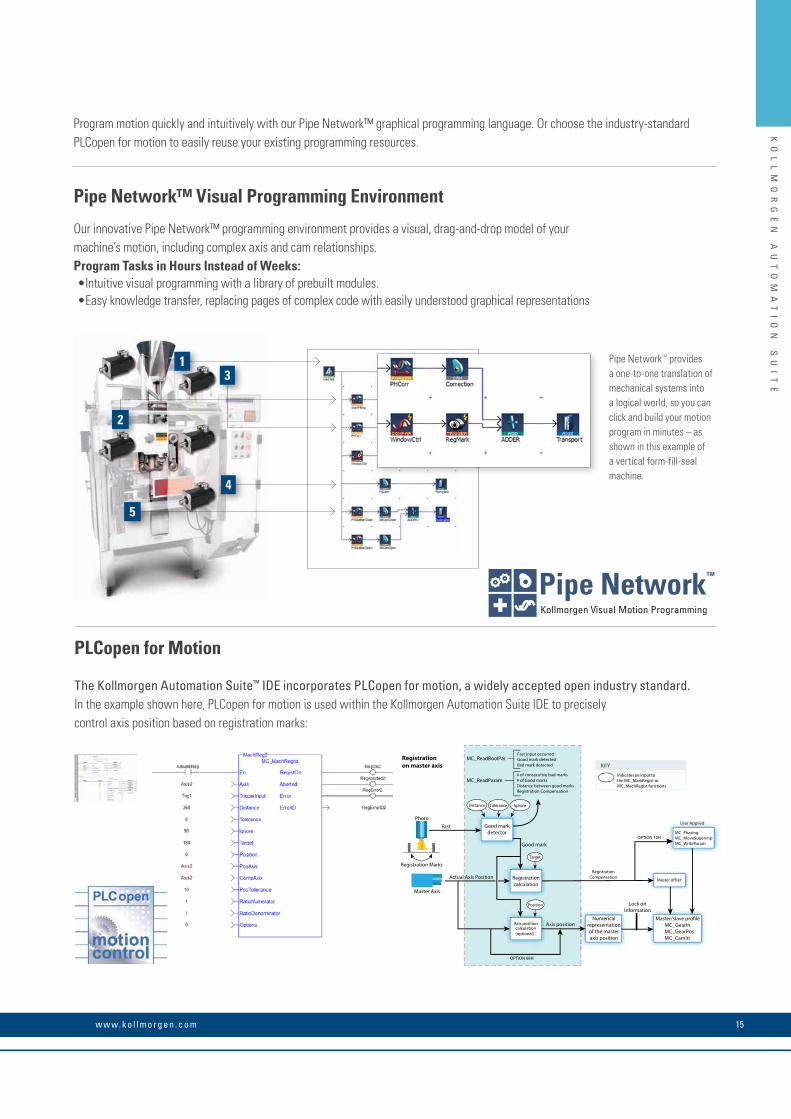
Program motion quickly and intuitively with our Pipe Network™ graphical programming language. Or choose the industry-standard PLCopen for motion to easily reuse your existing programming resources.
Pipe Network™ Visual Programming Environment
Our innovative Pipe Network™ programming environment provides a visual, drag-and-drop model of your machine’s motion, including complex axis and cam relationships.Program Tasks in Hours Instead of Weeks:•Intuitive visual programming with a library of prebuilt modules.• Easy knowledge transfer, replacing pages of complex code with easily understood graphical representations
PLCopen for Motion The Kollmorgen Automation Suite™ IDE incorporates PLCopen for motion, a widely accepted open industry standard. In the example shown here, PLCopen for motion is used within the Kollmorgen Automation Suite IDE to precisely control axis position based on registration marks:
Pipe NetworkTM provides a one-to-one translation of mechanical systems into a logical world, so you can click and build your motion program in minutes – as shown in this example of a vertical form-fill-seal machine.
Good markdetector
Registrationcalculation
Axis positioncalculation(optional)
Master o�set
Numericalrepresentationof the masteraxis position
MC_GearInMC_GearPosMC_CamIn
Registration Marks
Master Axis
MC_ReadBoolParBad mark detected
MC_ReadParam
Axis position
Lock onInformation
Fast
Actual Axis Position
Photo
Good mark
Registrationon master axis
Distance Tolerance Ignore
Indicates an input to the MC_MarkRegist or MC_MachRegist functions
KEY
Target
Position
OPTION 08H
RegistrationCompensation
OPTION 10HMC_PhasingMC_MoveSuperimpMC_WriteParam
User Applied
# of consecutive bad marks# of Good marksDistance between good marksRegistration Compensation
Fast input occurredGood mark detected
13
4
5
2
Visual Programming for Motion
Pipe NetworkKollmorgen Visual Programming for Motion
™
Pipe NetworkKollmorgen Visual Motion Programming
™
Pipe Network™
15w w w. k o l l m o r g e n . c o m

KO
LL
MO
RG
EN
A
UT
OM
AT
IO
N
SU
IT
E
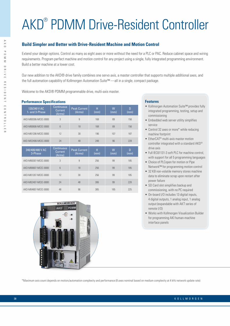
Features• Kollmorgen Automation Suite™ provides
fully integrated programming, testing, setup and commissioning
• Embedded web server utility simplifies service
• Control 32 axes or more* while reducing machine footprint
• EtherCAT® multi-axis master motion controller integrated with a standard AKD® drive axis
• Full IEC61131-3 soft PLC for machine control, with support for all 5 programming languages
• Choice of PLCopen for motion or Pipe Network™ for programming motion control
• 32 KB non-volatile memory stores machine data to eliminate scrap upon restart after power failure
• SD Card slot simplifies backup and commissioning, with no PC required
• On-board I/O includes 13 digital inputs, 4 digital outputs, 1 analog input, 1 analog output (expandable with AKT series of remote I/O)
• Works with Kollmorgen Visualization Builder for programming AKI human-machine interface panels
Build Simpler and Better with Drive-Resident Machine and Motion Control
Extend your design options. Control as many as eight axes or more without the need for a PLC or PAC. Reduce cabinet space and wiring requirements. Program perfect machine and motion control for any project using a single, fully integrated programming environment. Build a better machine at a lower cost.
Our new addition to the AKD® drive family combines one servo axis, a master controller that supports multiple additional axes, and the full automation capability of Kollmorgen Automation Suite™ —all in a single, compact package.
Welcome to the AKD® PDMM programmable drive, multi-axis master.
*Maximum axis count depends on motion/automation complexity and performance (8 axes nominal based on medium complexity at 4 kHz network update rate)
Performance Specifications
120/240 V AC1- and 3-Phase
Continuous Current (Arms)
Peak Current (Arms)
H(mm)
W(mm)
D(mm)
AKD-M00306-MCEC-0000 3 9 168 89 156
AKD-M00606-MCEC-0000 6 18 168 89 156
AKD-M01206-MCEC-0000 12 30 196 107 187
AKD-MO2406-MCEC-0000 24 48 248 96 228
240/400/480 V AC3-Phase
Continuous Current (Arms)
Peak Current (Arms)
H(mm)
W(mm)
D(mm)
AKD-M00307-MCEC-0000 3 9 256 99 185
AKD-M00607-MCEC-0000 6 18 256 99 185
AKD-M01207-MCEC-0000 12 30 256 99 185
AKD-M02407-MCEC-0000 24 48 306 99 228
AKD-M04807-MCEC-0000 48 96 385 185 225
AKD® PDMM Drive-Resident Controller
K O L L M O R G E N 16

KO
LL
MO
RG
EN
A
UT
OM
AT
IO
N
SU
IT
E
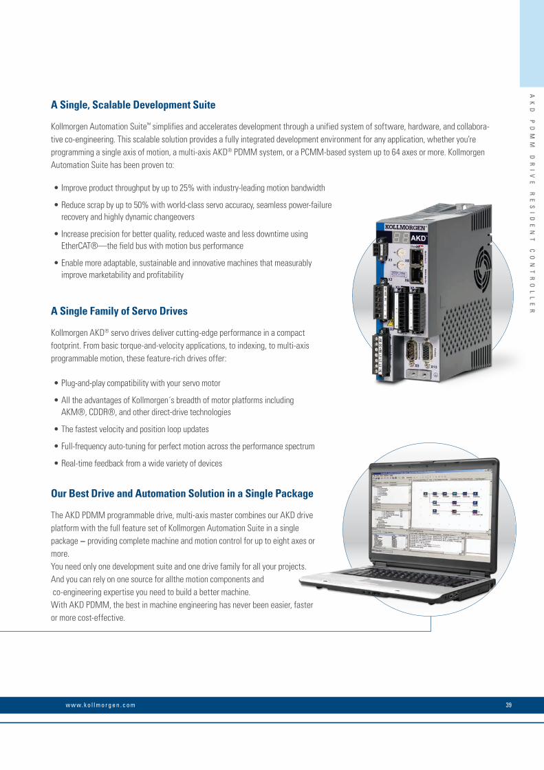
A Single, Scalable Development Suite
Kollmorgen Automation Suite™ simplifies and accelerates development through a unified system of software, hardware, and collabora-tive co-engineering. This scalable solution provides a fully integrated development environment for any application, whether you’re programming a single axis of motion, a multi-axis AKD® PDMM system, or a PCMM-based system up to 64 axes or more. Kollmorgen Automation Suite has been proven to:
• Improve product throughput by up to 25% with industry-leading motion bandwidth
• Reduce scrap by up to 50% with world-class servo accuracy, seamless power-failure recovery and highly dynamic changeovers
• Increase precision for better quality, reduced waste and less downtime using EtherCAT®—the field bus with motion bus performance
• Enable more adaptable, sustainable and innovative machines that measurably improve marketability and profitability
A Single Family of Servo Drives
Kollmorgen AKD® servo drives deliver cutting-edge performance in a compact footprint. From basic torque-and-velocity applications, to indexing, to multi-axis programmable motion, these feature-rich drives offer:
• Plug-and-play compatibility with your servo motor
• All the advantages of Kollmorgen´s breadth of motor platforms including AKM®, CDDR®, and other direct-drive technologies
• The fastest velocity and position loop updates
• Full-frequency auto-tuning for perfect motion across the performance spectrum
• Real-time feedback from a wide variety of devices
Our Best Drive and Automation Solution in a Single Package
The AKD PDMM programmable drive, multi-axis master combines our AKD drive platform with the full feature set of Kollmorgen Automation Suite in a single package − providing complete machine and motion control for up to eight axes or more.You need only one development suite and one drive family for all your projects. And you can rely on one source for allthe motion components and co-engineering expertise you need to build a better machine.With AKD PDMM, the best in machine engineering has never been easier, faster or more cost-effective.
17w w w. k o l l m o r g e n . c o m
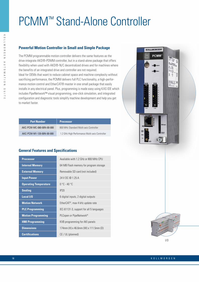
General Features and Specifications
Processor Available with 1.2 GHz or 800 MHz CPU
Internal Memory 64 MB Flash memory for program storage
External Memory Removable SD card (not included)
Input Power 24 V DC @ 1.25 A
Operating Temperature 0 °C - 40 °C
Sealing IP20
Local I/O 6 digital inputs, 2 digital outputs
Motion Network EtherCAT®, max 4 kHz update rate
PLC Programming IEC-61131-3, support for all 5 languages
Motion Programming PLCopen or PipeNetwork®
HMI Programming KVB programming for AKI panels
Dimensions 174mm (H) x 46.6mm (W) x 111.5mm (D)
Certifications CE / UL (planned)
KO
LL
MO
RG
EN
A
UT
OM
AT
IO
N
SU
IT
E
The PCMM programmable motion controller delivers the same features as the drive-integrate AKD®-PDMM controller, but in a stand-alone package that offers flexibility when used with AKD®-N/C decentralized drives and for machines where the benefits of an integrated drive and controller are not required. Ideal for OEMs that want to reduce cabinet space and machine complexity without sacrificing performance, the PCMM delivers full PLC functionality, a high-perfor-mance motion control and EtherCAT® master in one small package that easily installs in any electrical panel. Plus, programming is made easy using KAS IDE which includes PipeNetwork™ visual programming, one-click simulation, and integrated configuration and diagnostic tools simplify machine development and help you get to market faster.
Powerful Motion Controller in Small and Simple Package
I/O
Part Number Processor
AKC-PCM-MC-080-00N-00-000 800 MHz Standard Multi-axis Controller
AKC-PCM-M1-120-00N-00-000 1.2 GHz High Performance Multi-axis Controller
PCMM™ Stand-Alone Controller
K O L L M O R G E N 18

KO
LL
MO
RG
EN
A
UT
OM
AT
IO
N
SU
IT
E
PCMM™ Hardware Features
• Up to 1.2GHz CPU meets the performance requirements for a broad range of machines
• Control 1 to 32 or more axes with a single controller• 100BaseT connection supporting TCP/IP, MODBUS®, EthernetIP®,
Profinet® to host PLC, computer, or network to easily interface with most manufacturing systems
• Cycle times as low as 250 µs• Alphanumeric display for fast diagnostics and system
troubleshooting • Removable SD memory card for simple backup/restore and file
storage• On-board digital I/O with support for expansion I/O via EtherCAT®
• Compact size reduces cabinet space and cost
PCMM™ Software Features
• IEC 61131-3 programmable automation and motion controller• EtherCAT® master for high-performance motion and device
synchronization• PipeNetwork™ motion engine for visual programming• Embedded RTOS for guaranteed performance and stability• Integrated webserver for remote diagnostics and status checking • Ideal design for modular machines and flexible manufacturing
systems
PCMM™ System Integration
• Seamless integration with Kollmorgen’s AKD® servo drives, AKM® rotary servo motors , AKI HMIs, and AKT fieldbus I/O modules for complete automation solution
• Network communication via OPC UA, MODBUS®, TCP/IP, UDP, and common fieldbus for fast integration into your machine or factory
• Intuitive EtherCAT® configuration tools built into KAS IDE simplifies network configuration
• Integrated Kollmorgen Workbench for rapid servo tuning and machine optimization
HMIAKM® Servo Motor AKD®-N Servo Drive AKD® Servo Drive
X37SD Card
X124 Vdc Supply
X6EtherCAT® Master
X35/X36Digital I/O
X32TCP/IP Ethernet
PROFINET®
Ethernet/IP®
Modbus®/TCP
19w w w. k o l l m o r g e n . c o m
KO
LL
MO
RG
EN
A
UT
OM
AT
IO
N
SU
IT
E
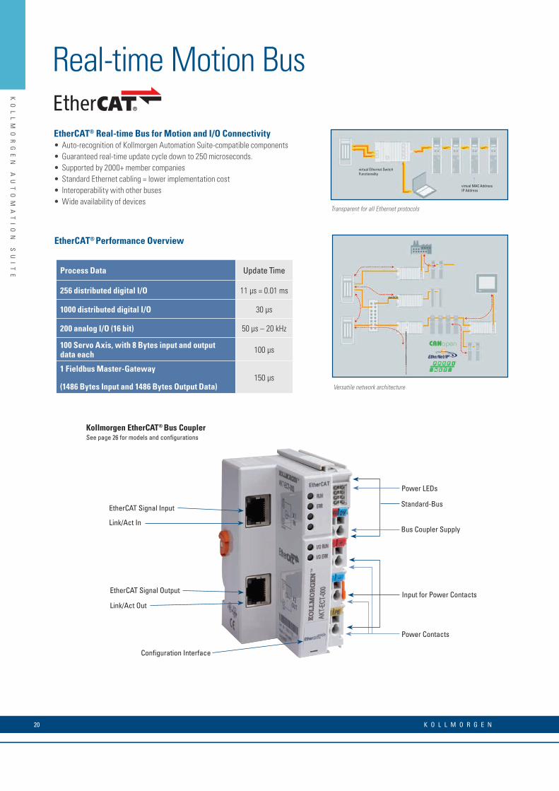
EtherCAT® Real-time Bus for Motion and I/O Connectivity• Auto-recognition of Kollmorgen Automation Suite-compatible components• Guaranteed real-time update cycle down to 250 microseconds.• Supported by 2000+ member companies• Standard Ethernet cabling = lower implementation cost• Interoperability with other buses• Wide availability of devices
Real-time Motion Bus
Transparent for all Ethernet protocols
Versatile network architecture
EtherCAT® Performance Overview
Kollmorgen EtherCAT® Bus Coupler
Process Data Update Time
256 distributed digital I/O 11 µs = 0.01 ms
1000 distributed digital I/O 30 µs
200 analog I/O (16 bit) 50 µs – 20 kHz
100 Servo Axis, with 8 Bytes input and output data each 100 µs
1 Fieldbus Master-Gateway
(1486 Bytes Input and 1486 Bytes Output Data)150 µs
switch
virtual MAC AddressIP Address
virtual Ethernet SwitchFunctionality
EtherCAT Signal Input
Power LEDs
Standard-Bus
Bus Coupler Supply
Input for Power Contacts
Power Contacts
EtherCAT Signal Output
Configuration Interface
Link/Act In
Link/Act Out
See page 26 for models and configurations
K O L L M O R G E N 20

KO
LL
MO
RG
EN
A
UT
OM
AT
IO
N
SU
IT
E
Kollmorgen HMI Panels
With Kollmorgen HMI’s visualization projects can be scaled for different size screens and performance demands without having to re-write code or learn different tools.
• Choose from 5”, 7”, and 12” displays• IP65 protection class screen for easy cleaning• Rugged Plastic or Aluminum Housing
Human Machine Interface (HMI)
5”, 7” Touchscreen HMI
Our basic industrial HMI offers a high resolution touch-screen and modern design. The panel combine IP65 corrosion resistant plastic housing with the full version of Kollmorgen Visualization Builder, providing a cost-effective yet advanced HMI solution for small to medium applications. The basic AKI2G model is the obvious choice when requiring a cost-efficient, high value, reliable HMI panel.
7”, 12” Touchscreen HMI
Our advanced AKI2G series HMIs offers a range of high performance industrial panels designed for demanding applications. All with high performance ARM Cortex-A9 processors, the latest screen technology and a wide range of connectivity options to cover all your automation needs. We recommend our advanced HMI with high-performance for all applications.
HMI Software Tools
Kollmorgen Automation Suite Visualization Builder™ HMI Software
AKI2G-CDA Series AKI2G-CDB Series
HMI developer environment
Kollmorgen Automation Suite Visualization Builder operates from within the Kollmorgen Automation Suite integrated development environment making it quick and easy to create your HMI program and transfer it to the panel.
Features include
• Automatic mapping transfers PLC variables to HMI tags avoiding
mistakes and saving time.
• Multi-screen navigation
• Trending/Data Logging
• Recipes
• Alarm management
• Drag and Drop programming
• Password Protection
AKI2G-CDA 5” and 7” AKI2G-CDB 7” and 12”
21w w w. k o l l m o r g e n . c o m

KO
LL
MO
RG
EN
A
UT
OM
AT
IO
N
SU
IT
E
KO
LL
MO
RG
EN
A
UT
OM
AT
IO
N
SU
IT
E
Human Machine Interface (HMI)
AKI2G-CDB Series
Specifications 7 inch AKI2G-CDB-MOD-07T-000 12 inch AKI2G-CDB-MOD-12T-000General Description
Part number 630000205 640000205Certifications
General CE, FCC, KCCMarine DNV, KR, GL, LR, ABS, CCSUL UL 61010-2-201
MechanicalMechanical size 204 × 143 × 50 mm 340 × 242 × 57 mmTouch type ResistiveCut-out size 189 × 128mm 324 × 226mmWeight 0.8 kg 2.6 kgHousing material Powder-coated aluminum, Gray
Power
Input voltage24 V DC (18 to 32 VDC) CE: The power supply must conform with the requirements according to IEC 60950 and IEC 61558-2-4. UL and cUL: The power supply must conform with the requirements for class II power supplies.
Power consumption 14.4W 28.8WInput fuse Internal DC fuse
SystemCPU i.MX6Solo Single Cortex-A9 1.0GHz 512kBL2cache i.MX6DualLite, Dual Cortex-A9 1.0GHz 512kBL2cacheRAM 512 MB 1 GBFLASH 2GB SSD(eMMC), 1.5GB free for application storage
DisplaySize diagonal 7" diagonal 12.1" diagonalResolution 800 × 480 pixelsBacklight LED BacklightBacklight life time 20 000 hours 50 000 hoursBacklight brightness 350 cd/m² 400 cd/m²Backlight dimming Industrial DimmingDisplay type TFT-LCD with LED backlightDisplay pixel error Class I (ISO9241-307)
Communication SerialNumber of serial ports 1 Port 9pin DSUBSerial port 1 RS 232 (RTS/CTS)Serial port 2 RS422/485Serial port 3 RS485 (only if COM 2 is RS485)
Ethernet CommunicationNumber of ethernet ports 1 2Ethernet port 1 1 × 10/100 Base-T (shielded RJ45)Ethernet port 2 – 1 × 10/100 Base-T (shielded RJ45)
Expansion interfaceExpansion port Yes, ciX expansion moduleSD card SD and SDHCUSB 1 × USB 2.0 500mA 2 × USB 2.0 500mAEnvironmentalOperating temperature -10°C to +60°CStorage temperature -20° to +70°CShock 15g, half-sine, 11ms according to IEC60068-2-27Vibration 1g, according to IEC 60068-2-6, Test FcSealing front IP65, NEMA 4X/12 and UL Type 4X/12Sealing back IP20Humidity 5% – 85% non-condensed
AKI2G-CDA Series
Specifications 5 inch AKI2G-CDA-MOD-05T-000 7 inch AKI2G-CDA-MOD-07T-000General Description
Part number 630005105 630005205Certifications
General CE, FCC, KCCMarine –UL UL 61010-2-201
MechanicalMechanical size 170 × 107 × 49 mm 196 × 146 × 52 mmTouch type ResistiveCut-out size 161 × 93 mm 186 × 136 mmWeight 0.5 kg 0.7 kgHousing material Plastic (PC+ABS), Gray
Power
Input voltage24 V DC (18 to 32 VDC) CE: The power supply must conform with the requirements according to IEC 60950 and IEC 61558-2-4. UL and cUL: The power supply must conform with the requirements for class II power supplies.
Power consumption 6W 9.6WInput fuse Internal DC fuse
SystemCPU ARM9 400 MHzRAM 128 MBFLASH 256 MB, 200 MB free for application storage
DisplaySize diagonal 5" diagonal 7" diagonalResolution 800 × 480 pixelsBacklight LED BacklightBacklight life time 20 000 hoursBacklight brightness 300 cd/m² 400 cd/m²Backlight dimming Industrial DimmingDisplay type TFT-LCD with LED backlightDisplay pixel error Class I (ISO9241-307)
Communication SerialNumber of serial ports 2 Port 9pin DSUBSerial port 1 RS 232 (RTS/CTS)Serial port 2 RS422/485Serial port 3 RS 232Serial port 4 RS 485
Ethernet CommunicationNumber of ethernet ports 1Ethernet port 1 1 × 10/100 Base-T (shielded RJ45)Ethernet port 2 –
Expansion interfaceExpansion port NoSD card NoUSB 1 × USB 2.0 500mAEnvironmentalOperating temperature -10°C to +50°CStorage temperature -20° to +60°CShock 15g, half-sine, 11ms according to IEC60068-2-27Vibration 1g, according to IEC 60068-2-6, Test FcSealing front IP65Sealing back IP20Humidity 5% – 85% non-condensed
K O L L M O R G E N 22

KO
LL
MO
RG
EN
A
UT
OM
AT
IO
N
SU
IT
E
AKI2G-CDB Series
Specifications 7 inch AKI2G-CDB-MOD-07T-000 12 inch AKI2G-CDB-MOD-12T-000General Description
Part number 630000205 640000205Certifications
General CE, FCC, KCCMarine DNV, KR, GL, LR, ABS, CCSUL UL 61010-2-201
MechanicalMechanical size 204 × 143 × 50 mm 340 × 242 × 57 mmTouch type ResistiveCut-out size 189 × 128mm 324 × 226mmWeight 0.8 kg 2.6 kgHousing material Powder-coated aluminum, Gray
Power
Input voltage24 V DC (18 to 32 VDC) CE: The power supply must conform with the requirements according to IEC 60950 and IEC 61558-2-4. UL and cUL: The power supply must conform with the requirements for class II power supplies.
Power consumption 14.4W 28.8WInput fuse Internal DC fuse
SystemCPU i.MX6Solo Single Cortex-A9 1.0GHz 512kBL2cache i.MX6DualLite, Dual Cortex-A9 1.0GHz 512kBL2cacheRAM 512 MB 1 GBFLASH 2GB SSD(eMMC), 1.5GB free for application storage
DisplaySize diagonal 7" diagonal 12.1" diagonalResolution 800 × 480 pixelsBacklight LED BacklightBacklight life time 20 000 hours 50 000 hoursBacklight brightness 350 cd/m² 400 cd/m²Backlight dimming Industrial DimmingDisplay type TFT-LCD with LED backlightDisplay pixel error Class I (ISO9241-307)
Communication SerialNumber of serial ports 1 Port 9pin DSUBSerial port 1 RS 232 (RTS/CTS)Serial port 2 RS422/485Serial port 3 RS485 (only if COM 2 is RS485)
Ethernet CommunicationNumber of ethernet ports 1 2Ethernet port 1 1 × 10/100 Base-T (shielded RJ45)Ethernet port 2 – 1 × 10/100 Base-T (shielded RJ45)
Expansion interfaceExpansion port Yes, ciX expansion moduleSD card SD and SDHCUSB 1 × USB 2.0 500mA 2 × USB 2.0 500mAEnvironmentalOperating temperature -10°C to +60°CStorage temperature -20° to +70°CShock 15g, half-sine, 11ms according to IEC60068-2-27Vibration 1g, according to IEC 60068-2-6, Test FcSealing front IP65, NEMA 4X/12 and UL Type 4X/12Sealing back IP20Humidity 5% – 85% non-condensed
23w w w. k o l l m o r g e n . c o m

KO
LL
MO
RG
EN
A
UT
OM
AT
IO
N
SU
IT
E
Available Motion Bus Coupler Model
AKT-ECT-000-000 EtherCAT® Bus Coupler
Available Analog Input Terminal Models
AKT-AN-410-000 4 channel analog input module, 0-10 Vdc
AKT-AN-420-000 4 channel analog input module, 0-20 ma
AKT-AN-810-000 8 channel analog input module, 0-10 Vdc
AKT-AN-820-000 8 channel analog input module, 0-20 ma
AKT-AN-200-000 2 channel thermocouple input module
AKT-AN-400-000 4 channel thermocouple input module
Available Analog Output Terminal Models
AKT-AT-220-000 2 channel analog output module, 0-20 ma
AKT-AT-410-000 4 channel analog output module, 0-10 Vdc
AKT-AT-420-000 4 channel analog output module, 0-20 ma
AKT-AT-810-000 8 channel analog output module, 0-10 Vdc
AKT-AT-820-000 8 channel analog output module, 0-20 ma
Available Digital Output Terminal Models
AKT-DT-004-000 4 channel digital output module, 0.5A
AKT-DT-008-000 8 channel digital output module, 0.5A
AKT-DT-2RT-000 2 channel relay output module, 2.0A, N/O
I/O Terminals
Advanced Kollmorgen Terminal (AKT)
The Kollmorgen Automation Suite™ includes an array of I/O options for applications that need more I/O than can be provided by the onboard I/O of the drives or for applications that need specialized functionality such as thermocouple management through I/O. The DIN rail mount IP20 terminals simply slide together and connect to the system’s EtherCAT® bus where they are auto-recognized for easy configuration.
I/O
Typical Bus Coupler
EtherCAT® bus coupler Front wiring view Side label view
Typical I/O Terminal
Available Digital Input Terminal Models
AKT-DN-004-000 4 channel digital input module, 3ms
AKT-DNH-004-000 4 channel digital input module, .2ms
AKT-DN-008-000 8 channel digital input module, 3ms
AKT-DNH-008-000 8 channel digital input module, .2ms
Available Specialty Terminal Models
AKT-EM-000-000 End module
AKT-IM-000-000 Isolation module
AKT-PS-024-000 Bus feed terminal, 24 Vdc
AKT-PSF-024-000 Bus feed terminal, 24 Vdc, fused
Available Field Bus Coupler Models
AKT-PRB-000-000 Profibus Bus Coupler
AKT-ENP-000-000 Ethernet/IP Bus Coupler
Stepper Driver
AKT-SM-L15-000 Stepper Module, 24 Vdc, 1.5 A
AKT-SM-L50-000 Stepper Module, 50 Vdc, 5 A
K O L L M O R G E N 24
KO
LL
MO
RG
EN
A
UT
OM
AT
IO
N
SU
IT
E
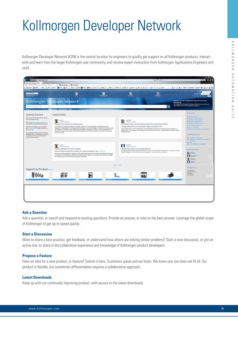
Kollmorgen Developer Network
Ask a QuestionAsk a question, or search and respond to existing questions. Provide an answer, or vote on the best answer. Leverage the global scope of Kollmorgen to get up to speed quickly.
Start a DiscussionWant to share a best practice, get feedback, or understand how others are solving similar problems? Start a new discussion, or join an active one, to share in the collabrative experience and knowledge of Kollmorgen product developers.
Propose a FeatureHave an idea for a new product, or feature? Submit it here. Customers speak and we listen. We know one size does not fit all. Our product is flexible, but sometimes differentiation requires a collaborative approach.
Latest DownloadsKeep up with our continually improving product, with access to the latest downloads.
Kollmorgen Developer Network (KDN) is the central location for engineers to quickly get support on all Kollmorgen products, interact with and learn from the larger Kollmorgen user community, and receive expert instruction from Kollmorgen Applications Engineers and staff.
25w w w. k o l l m o r g e n . c o m

K O L L M O R G E N 26
AKD® Servo DriveOur AKD series is a complete range of Ethernet-based servo drives that are fast, feature-rich, flexible and integrate quickly and easily into any application. AKD ensures plug-and-play commissioning for instant, seamless access to everything in your machine. And, no matter what your application de-mands, AKD offers industry-leading servo performance, communication options, and power levels, all in a smaller footprint.
This robust, technologically advanced family of drives delivers optimized performance when paired with our best-in-class components, producing higher quality results at greater speeds and more up-time. With Kollmorgen servo components, we can help you increase your machine’s OEE by 50%.
AK
D
SE
RV
O
DR
IV
ES
The Benefits of AKD Servo Drive• Optimized Performance in Seconds • Auto-tuning is one of the best and fastest in the industry
• Automatically adjusts all gains, including observers
• Immediate and adaptive response to dynamic loads
• Precise control of all motor types
• Compensation for stiff and compliant transmission and couplings
• Greater Throughput and Accuracy • Up to 27-bit-resolution feedback yields unmatched precision and excellent repeatability
• Very fast settling times result from a powerful dual processor system that executes industry-leading and patent pending servo algorithms with high resolution
• Advanced servo techniques such as high-order observer and bi-quad filters yield industry-leading machine performance
• Highest bandwidth torque-and-velocity loops. Fastest digital current loop in the market
• Easy-to-use Graphical User Interface (GUI) for Faster Commissioning and Troubleshooting
• Six-channel real-time software oscilloscope commissions and diagnoses quickly
• Multi-function Bode Plot allows users to quickly evaluate performance
• Auto-complete of programmable commands saves looking up parameter names
• One-click capture and sharing of program plots and parameter settings allow you to send machine performance data instantly
• Widest range of programming options in the industry
• Flexible and Scalable to Meet any Application • 3 Arms to 48 Arms continuous current; 9 Arms to 96 Arms peak
• Very high power density enables an extremely small package
• True plug-and-play with all standard Kollmorgen servo motors and actuators
• Supports a variety of single and multi-turn feedback devices— Smart Feedback Device (SFD), EnDat2.2, EnDat 2.1, BiSS, analog Sine/Cos encoder, incremental encoder, HIPERFACE®, and resolver
• Single cable feedback with digital resolvers (SFD3) and HIPERFACE® DSL
• Tightly integrated Ethernet motion buses without the need to add large hardware: EtherCAT®, SynqNet®, Modbus® TCP, EtherNet/IP™, PROFINET®, SERCOS® III, and CANopen®
• Scalable programmability from base torque-and-velocity through multi-axis master
AK
D
SE
RV
O
DR
IV
ES
27w w w. k o l l m o r g e n . c o m
K O L L M O R G E N 28
AK
D
SE
RV
O
DR
IV
ES
Basic Operation Single-Axis Programming
Kollmorgen delivers cutting-edge technology and performance with the AKD® servo drive and KAS controls platform. Whether your application requires a single axis or over 100 fully synchronized axes, Kollmorgen’s intuitive software and tools scale to meet your needs. From simple analog torque control to the latest high-performance automation network, the AKD servo drive packs power and flexibility for virtually any application into one of the most compact footprints of any digital servo drive in the industry.
• Patented auto-tuning delivers optimized performance in seconds.
• 1.5 MHz current loop and 16 kHz velocity loops offers greater bandwidth and performance Optimized performance in seconds
• Greater throughput and accuracy• Easy-to-use Graphical User Interface (GUI) for • faster commissioning and troubleshooting• Flexible and scalable to meet any application
• Controlled by analog torque-and-velocity commands
• Includes electronic gearing via X9 connector• Includes access to 11 digital I/O and 2
analog I/O on base drive• Includes 2 high-speed digital inputs• Expandable to 31 digital I/O and 4 analog I/O
Motion Tasking (“P” Option)
• Adds simple point-and-click indexing to base drive
• Provides user with pre-programmed options
• Guides novice user through simplified steps to create indexing moves
• Network connectivity to EtherCAT®, CANopen®,
• Profinet®, Ethernet/IP™, TCP/IP, SynqNet and others
• MODBUS port for communication with HMI
BASIC Programmable 1.5 Axis Drive (“T” Option)
• Adds BASIC programmability to base AKD• 4 kHz programmable interrupt service
routines• Conditional statements, built-in math
functions, user functions and subroutines• Includes 2 high-speed digital inputs• Same package size as base drive• Expandable to 31 digital I/O and 4 analog I/O• Optional integrated SD card for easy
backup and drive cloning• Includes electronic camming functionality
Scalable Programmability

29w w w. k o l l m o r g e n . c o m
AK
D
SE
RV
O
DR
IV
ES
R ANGE OF KOLLMORGEN AUTOMATION SUITE CAPABILITIES
AKD Servo Drive AKD Servo Drive AKT I/O
Multi-Axis Programming
AKI HMI AKD PDMM AKT I/O
Pipe Network provides a one-to-one translation of a mechanical system into a logical world as shown in the Vertical Form Fill and Seal machine above. Click and build your motion program in minutes, or contact Kollmorgen for examples of common machine architectures to further accelerate your development.
2
4
5
3
Programmable Drive Multi-Axis Master PDMM (“M” Option)
• Scalable solution for use as a single-axis drive with integrated programmable automation controller
• Choose from all five IEC 61131-3 languages for soft PLC process programming
• Program motion using your choice of PLCopen for motion or our innovative Pipe Network™
• 4 kHz PLC scan rate and EtherCAT® updates• Complete line of HMI panels with integrated
software to simplify GUI development• Exclusive function blocks, such as “wait,”
enable your program to act as a scanning or sequential language
•On-board I/O includes 17 digital (with 2 high speed inputs) and 2 analog
• Connects to AKT™ network I/O for nearly unlimited expandability
1
• Accelerate development by programmingtasks in hours that would otherwise take weeks
• Improved coding quality through visualprogramming and by using pre-built modulesthat have been thoroughly tested and optimized
• Easy knowledge transfer, replacing pages of complex code with easily understood graphical representations
• Available on PDMM and PCMM controllers
Seamlessly add additional axes and AKD PDMM serves as a high-performance multi-axis machine controller
• SD card for easy backup and system updates
• Integrated webserver for diagnostics and troubleshooting from any computer or mobile device
• Provide true synchronized-path control of up to 32 axes*
• Reduce cabinet size and wiring require-ments with a single, compact package
• Easily manage remote I/O and the I/O of all attached drives via EtherCAT®
• Use industry standard PLCopen for motion, or step up to Kollmorgen’s Pipe Network™ to program sophisticated camming and gearing applications in a matter of minutes
Visual Programming for Motion
Pipe NetworkKollmorgen Visual Programming for Motion
™
Pipe NetworkKollmorgen Visual Motion Programming
™
Pipe Network™
Single-Axis Programming
*Maximum axis count depends on motion/automation complexity and performance (8 axes nominal based on medium complexity at 4 kHz network update rate)

K O L L M O R G E N 30
AK
D
SE
RV
O
DR
IV
ES
The AKD servo drive delivers cutting-edge technology and performance with one of the most compact footprints in the industry. These feature-rich drives provide a solution for nearly any application, from basic torque-and-velocity applications, to indexing, to multi-axis programmable motion with embedded Kollmorgen Automation Suite. The versatile AKD sets the standard for power density and per-formance.
Best-in-Class Components AKD works seamlessly with Kollmorgen motors and actuators – well-known for quality, reliability, and performance.
AKD® Servo Drive
Control of motors with AKD® PDMM programmable multi-axis master
AKD®-N Decentralized Servo Drive
AKM® 2G Servo Motors
Housed DDR™ Motors
Cartridge DDR™ Motors
AKD® Servo Drive
AKMH™ HygienicStainless Steel Motors
ICH Direct Drive Linear Motors
Frameless BrushlessDirect Drive Motors
ERD Hygienic Stainless SteelLinear Actuators

31w w w. k o l l m o r g e n . c o m
AK
D
SE
RV
O
DR
IV
ES
120 / 240 V AC 1 & 3 Phase (85 -265 V)
Continuous Current (A rfms)
Peak Current
(Arms)
Drive Continuous Output Power
Capacity (Watts)
Internal Regen (Watts) (Ohms)
Height mm
Width mm
Depth mm
Depth with Cable Bend Radius
mm
AKD-00306 3 9 1100 0 0 168 59 156 184
AKD-00606 6 18 2000 0 0 168 59 156 184
AKD-01206 12 30 4000 100 15 196 78 187 215
AKD-02406 24 48 8000 200 8 248 100 228 265
240/480 V AC 3 Phase
(187-528 V)
Continuous Current
(Arms)
Peak Current
(Arms)
Drive Continuous Output Power
Capacity (Watts)
Internal Regen (Watts) (Ohms)
Height mm
Width mm
Depth mm
Depth with Cable Bend Radius
mm
AKD-00307 3 9 2000 100 33 256 70 185 221
AKD-00607 6 18 4000 100 33 256 70 185 221
AKD-01207 12 30 8000 100 33 256 70 185 221
AKD-02407 24 48 16,000 200 23 306 105 228 264
AKD-04807 48 96 35,000 – – 385 185 225 260
Industry-leading power density
General Specifications
/TCP
H
W
D
® ®

K O L L M O R G E N 32
AK
D
SE
RV
O
DR
IV
ES
When you pair the AKD servo drive with any of our Kollmorgen motors or linear actuators, you’ll achieve optimized performance. From 3 Arms to 48 Arms continuous current and 9 Arms to 96 Arms peak current, the feature-rich AKD provides a solution for nearly any applica-tion.
Range of Coverage
Continuous Torque at Stall - Nm AKM Compatible Micron Gearboxes available up to 5,000 Nm
Kollm
orge
n Ro
tary
Mot
ors
0 10 100 1,000 10,000
AKM
AKMH
DDR
CDDR
KBM
TBM
Continuous
Peak
10 36
1,200
1,070
1,340
92
324
538
510
339
22 [195]
180
AKD’s Kollmorgen Rotary Motor Coverage
AKD
Ser
vo D
rive
1 100 10,000 100,000
Drive Output Power (Watts)
1,00010
240 V AC
480 V AC
Continuous
Peak
55,000
16,000
AKD Power Range
AKD® Servo Drive

33w w w. k o l l m o r g e n . c o m
AK
D
SE
RV
O
DR
IV
ES
AKD® servo drive is specifically designed with the versatility, communications, and power you need to expand machine performance and increase integration speeds. Motor set-up is plug-and-play and multiple Ethernet connectivity options provide both open and closed protocols. Online troubleshooting and data verification enable faster, bug-proof programming. And a broad power range in a smaller, compact design allows you to use these robust drives with a single interface while experiencing industry-leading, high-performance servo loops.
AKD Specifications
Standard Drive With I/O expansion *
Encoder Output or AUX Encoder Input 2.5 MHz Maximum line frequency
Feedback Smart Feedback Device (SFD), EnDat 2.2, EnDat 2.1, BiSS, analog Sine/Cos encoder, incremental encoder, HIPERFACE®, and resolver
Logic supply 24 V DC
Digital input (24 Vdc) 8 (1 dedicated to enable)
20 (1 dedicated to enable)
Digital output (24 Vdc) 3 (1 dedicated to fault relay)
13 (1 dedicated to fault relay)
Analog input (+/- 10 Vdc, 16-bit) 1 2
Analog output (+/- 10 Vdc, 16-bit) 1 2
Programmable inputs 7 19
Programmable outputs 2 12
Sink/Source inputs/outputs Yes Yes
Note: Only with AKD-T
Feedback & I/O

K O L L M O R G E N 34
AK
D
SE
RV
O
DR
IV
ES
Ethernet Connectivity
• Ethernet-based AKD servo drive provides the user with multiple bus choices
• EtherCAT® (DSP402 protocol), Modbus® TCP, SynqNet®, EtherNet/IP™, PROFINET®, SERCOS III, and CANopen®
• No option cards are required
Industrial Design
• Rugged circuit design and compact enclosure for space-saving, modern appearance – minimizes electrical noise emission and susceptibility
• Full fault protection • UL, cUL listed, and CE• No external line filters needed (480 V AC units) for CE & UL
compliance• Removable screw terminal connectors for easy connections• DC Bus sharing
Safe-Torque-Off (STO)
(IEC 61800 SIL2)
• Switches off the power stage to ensure personnel safety and prevents an unintended restart of the drive, even in fault condition
• Allows logic and communication to remain on during power stage shut down
Internal Regenerative Braking Resistor(All powers except 120/240 V AC 3 Arms and 6 Arms)
• Simplifies system components• Saves overhead of managing external regeneration when
internal regeneration is sufficient
Performance Servo Tuner (PST)
• Exclusive patent pending auto-tuner reaches optimized set-up in seconds
•Handles inertia mismatches up to 1000:1•Industry leading bandwidth under compliant and stiff load
conditions, no matter the mechanical bandwidth of the machine
Plug-and-Play with Kollmorgen Motors and Actuators• Electronic motor nameplates allow parameters to automatically load for fast commissioning
• Motion in seconds
• Custom motor parameters easily entered
AKD® Servo Drive
/TCP
I/O (Base Drive)
• 8 digital inputs (1 dedicated to enable)
•2 high-speed digital inputs (maximum time delay of 1.0 μs)
•3 digital outputs (1 dedicated to fault relay)
•1 analog input - 16 bit•1 analog output - 16 bit

35w w w. k o l l m o r g e n . c o m
AK
D
SE
RV
O
DR
IV
ES
X1 24 V DC Supply
STO Enable IEC 61508 SIL2
X9 Encoder
Emulation
X10 Feedback
X7 / X8 I/O
X3 (4 Pin) DC Bus
Brake Resistor (DC Bus Sharing Mating
Connector Option Shown)
X5/ X6 Motion Bus EtherCAT®
SynqNet®
Motor Holding Brake
(Cable Clamp Option Shown)
X1 24 V DC Supply
STO Enable IEC 61508 SIL2
X9 Encoder
EmulationX10
Feedback
X7 / X8 I/O
X3 (7 Pin) Power Supply
DC Bus Brake Resistor
X5/ X6 Motion Bus EtherCAT®
SynqNet®
X2 Motor
Holding Brake
X11 Service Channel Modbus®/TCP EtherNet/IP™ PROFINET®RT
X12 / X13 CANopen®
(CiA certified)
AKD 120/240 V AC Connector Layout
AKD 240/480 V AC Connector Layout
X12 / X13 CANopen®
(CiA certified)
X11 Service Channel Modbus®/TCP EtherNet/IP™ PROFINET®RT
X4 Power Supply
Physical Earth (PE) Ground Stud
Physical Earth (PE) Ground Stud
AK
D
BA
SI
C
DR
IV
ES
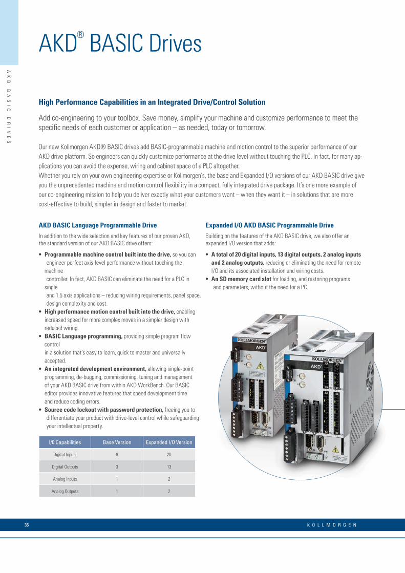
AKD BASIC Language Programmable Drive
In addition to the wide selection and key features of our proven AKD, the standard version of our AKD BASIC drive offers:
• Programmable machine control built into the drive, so you can engineer perfect axis-level performance without touching the machine controller. In fact, AKD BASIC can eliminate the need for a PLC in single and 1.5 axis applications – reducing wiring requirements, panel space, design complexity and cost.
• High performance motion control built into the drive, enabling increased speed for more complex moves in a simpler design with reduced wiring.
• BASIC Language programming, providing simple program flow control in a solution that’s easy to learn, quick to master and universally accepted.
• An integrated development environment, allowing single-point programming, de-bugging, commissioning, tuning and management of your AKD BASIC drive from within AKD WorkBench. Our BASIC editor provides innovative features that speed development time and reduce coding errors.
• Source code lockout with password protection, freeing you to differentiate your product with drive-level control while safeguarding your intellectual property.
Expanded I/O AKD BASIC Programmable Drive
Building on the features of the AKD BASIC drive, we also offer an expanded I/O version that adds:
• A total of 20 digital inputs, 13 digital outputs, 2 analog inputs and 2 analog outputs, reducing or eliminating the need for remote I/O and its associated installation and wiring costs.
• An SD memory card slot for loading, and restoring programs and parameters, without the need for a PC.
High Performance Capabilities in an Integrated Drive/Control Solution
Add co-engineering to your toolbox. Save money, simplify your machine and customize performance to meet the specific needs of each customer or application – as needed, today or tomorrow.
Our new Kollmorgen AKD® BASIC drives add BASIC-programmable machine and motion control to the superior performance of our AKD drive platform. So engineers can quickly customize performance at the drive level without touching the PLC. In fact, for many ap-plications you can avoid the expense, wiring and cabinet space of a PLC altogether.Whether you rely on your own engineering expertise or Kollmorgen’s, the base and Expanded I/O versions of our AKD BASIC drive give you the unprecedented machine and motion control flexibility in a compact, fully integrated drive package. It’s one more example of our co-engineering mission to help you deliver exactly what your customers want – when they want it – in solutions that are more cost-effective to build, simpler in design and faster to market.
I/0 Capabilities Base Version Expanded I/O Version
Digital Inputs 8 20
Digital Outputs 3 13
Analog Inputs 1 2
Analog Outputs 1 2
AKD® BASIC Drives
K O L L M O R G E N 36

AK
D
BA
SI
C
DR
IV
ES
1
2 3
4
57
8
6
1 Integrated axis setup2 Code snippets simplify formatting3 Auto-complete helps speed coding and reduce errors4 Automatic color coding makes it easy to distinguish comments, parameters, print statements and other types of code5 Full debugger accelerates development6 Packaged program console provides instant program status7 Menu-driven navigation provides intuitive look and feel8 Window pinning maximizes workspace
Development Tools that Speed Programming and Improve Quality
Co-engineering is a powerful tool. To make it easy for you to provide better solutions for your customers, we pro-vide an innovative BASIC programming environment within Kollmorgen WorkBench. So there’s only one software package to use for all of your drive setup, configuration, tuning and management tasks in addition to motion and machine control programming.
Pre-built code templates give your application a head-start, while automatic formatting, highlighting and other ease-of-use features increase programming speed and accuracy. Complete access to all programming capabilities and drive features within a single environ-ment helps speed your development of complete, optimally engineered solutions.
Novice users will enjoy a short ramp-up time to productive coding, while experienced users will discover well-designed tools that take their programming skills to new levels of speed and quality.
37w w w. k o l l m o r g e n . c o m
AK
D
PD
MM
D
RI
VE
R
ES
ID
EN
T
CO
NT
RO
LL
ER
Features• Kollmorgen Automation Suite™ provides fully
integrated programming, testing, setup and commissioning
• Embedded web server utility simplifies service
• Control 32 axes or more* while reducing machine footprint
• EtherCAT® multi-axis master motion controller integrated with a standard AKD® drive axis
• Full IEC61131-3 soft PLC for machine control, with support for all 5 programming languages
• Choice of PLCopen for motion or Pipe Network™ for programming motion control
• 32 KB non-volatile memory stores machine data to eliminate scrap upon restart after power failure
• SD Card slot simplifies backup and commissioning, with no PC required
• On-board I/O includes 13 digital inputs, 4 digital outputs, 1 analog input, 1 analog output (expandable with AKT series of remote I/O)
• Works with Kollmorgen Visualization Builder for programming AKI human-machine interface panels
Build Simpler and Better with Drive-Resident Machine and Motion Control
Extend your design options. Control as many as eight axes or more without the need for a PLC or PAC. Reduce cabinet space and wiring requirements. Program perfect machine and motion control for any project using a single, fully integrated programming environment. Build a better machine at a lower cost.
Our new addition to the AKD® drive family combines one servo axis, a master controller that supports multiple additional axes, and the full automation capability of Kollmorgen Automation Suite™ —all in a single, compact package.
Welcome to the AKD® PDMM programmable drive, multi-axis master.
*Maximum axis count depends on motion/automation complexity and performance (8 axes nominal based on medium complexity at 4 kHz network update rate)
Performance Specifications
120/240 V AC1- and 3-Phase
Continuous Current (Arms)
Peak Current (Arms)
H(mm)
W(mm)
D(mm)
AKD-M00306-MCEC-0000 3 9 168 89 156
AKD-M00606-MCEC-0000 6 18 168 89 156
AKD-M01206-MCEC-0000 12 30 196 107 187
AKD-MO2406-MCEC-0000 24 48 248 96 228
240/400/480 V AC3-Phase
Continuous Current (Arms)
Peak Current (Arms)
H(mm)
W(mm)
D(mm)
AKD-M00307-MCEC-0000 3 9 256 99 185
AKD-M00607-MCEC-0000 6 18 256 99 185
AKD-M01207-MCEC-0000 12 30 256 99 185
AKD-M02407-MCEC-0000 24 48 306 99 228
AKD-M04807-MCEC-0000 48 96 385 185 225
AKD® PDMM Drive-Resident Controller
K O L L M O R G E N 38
AK
D
PD
MM
D
RI
VE
R
ES
ID
EN
T
CO
NT
RO
LL
ER
A Single, Scalable Development Suite
Kollmorgen Automation Suite™ simplifies and accelerates development through a unified system of software, hardware, and collabora-tive co-engineering. This scalable solution provides a fully integrated development environment for any application, whether you’re programming a single axis of motion, a multi-axis AKD® PDMM system, or a PCMM-based system up to 64 axes or more. Kollmorgen Automation Suite has been proven to:
• Improve product throughput by up to 25% with industry-leading motion bandwidth
• Reduce scrap by up to 50% with world-class servo accuracy, seamless power-failure recovery and highly dynamic changeovers
• Increase precision for better quality, reduced waste and less downtime using EtherCAT®—the field bus with motion bus performance
• Enable more adaptable, sustainable and innovative machines that measurably improve marketability and profitability
A Single Family of Servo Drives
Kollmorgen AKD® servo drives deliver cutting-edge performance in a compact footprint. From basic torque-and-velocity applications, to indexing, to multi-axis programmable motion, these feature-rich drives offer:
• Plug-and-play compatibility with your servo motor
• All the advantages of Kollmorgen´s breadth of motor platforms including AKM®, CDDR®, and other direct-drive technologies
• The fastest velocity and position loop updates
• Full-frequency auto-tuning for perfect motion across the performance spectrum
• Real-time feedback from a wide variety of devices
Our Best Drive and Automation Solution in a Single Package
The AKD PDMM programmable drive, multi-axis master combines our AKD drive platform with the full feature set of Kollmorgen Automation Suite in a single package − providing complete machine and motion control for up to eight axes or more.You need only one development suite and one drive family for all your projects. And you can rely on one source for allthe motion components and co-engineering expertise you need to build a better machine.With AKD PDMM, the best in machine engineering has never been easier, faster or more cost-effective.
39w w w. k o l l m o r g e n . c o m

KO
LL
MO
RG
EN
W
OR
KB
EN
CH
Kollmorgen Workbench
Our simple Graphical User Interface (GUI), Kollmorgen WorkBench, is designed to expedite and streamline the user’s experience with the AKD® servo drive. From easy application selection and reduced math, to a sleek six-channel scope; the user interface is extremely easy to use. Kollmorgen WorkBench supports intuitive access to the exclusive Performance Servo Tuner (PST) available inside AKD. The patent pending PST makes auto-tuning the AKD high-performance servo drive with world-class Kollmorgen motors very simple.
User-Friendly Environment
Logical flow, colorful icons and easy access simplify interactions with the AKD servo drive. The folder structure allows for instant identification and easy navigation.
Sleek Six-Channel “Real-Time” Software Oscilloscope
The easy-to-use AKD servo drive interface has a sleek digital oscilloscope that provides a comfortable environment for users to monitor performance. There are multiple options to share data in the format you prefer at the click of a button.• Save as an image• Load to an e-mail• Print
K O L L M O R G E N 40

KO
LL
MO
RG
EN
W
OR
KB
EN
CH
Nip Roller Application Selection
Application Selection
Simplifies set-up by allowing use of machine or application-based units. Nip roller and rack and pinion set-ups shown.
Data-Sharing
The ease-of-sharing continues in the parameters window. Kollmorgen WorkBench provides the user the easy options of printing or emailing the parameter values at the click of a button.
Rack and Pinion Application Selection
41w w w. k o l l m o r g e n . c o m

K O L L M O R G E N 42
The new decentralized AKD-N servo drives from Kollmorgen can be placed in the immediate vicinity of the motor thanks to its robust, compact construction and protection class IP67, plug-in connections, excellent motor compatibility and high degree of integrated functionality. With the decentralized AKD-N servo drives, you can develop drive and automation architectures that are easily comprehensible, and integrate with the central AKD servo drives. Using EtherCAT® as a system bus, we reduce complexity further since the AKD-N can collect I/O signals on the axis and pass them on in bundled form.
Improved Overall Equipment Effectiveness (OEE)
With AKD-N you increase the effectiveness beyond the entire life cycle of your machine (OEE, Overall Equipment Effectiveness). The design configuration and simple connection technology decrease the time for assembly, installation, and start-up. During the operating phase, the AKD-N plays a valuable part in energy savings due to the integrated DC connection. Further advantages in production are faster cleaning cycles, thanks to a higher protection class, as well as fewer cables in combination with a space-saving switch cabinet superstructure. Moreover, the assembly and connection technology increases the availability – and thereby productivity – because maintenance and service tasks are completed faster.
AKD®-N Decentralized Servo Drive

43w w w. k o l l m o r g e n . c o m
AK
D-
N
DE
CE
NT
RA
LI
ZE
D
SE
RV
O
DR
IV
ES
• Reduced costs • Reduced cabling because DC and network, power supply, I/O level as well as safety (STO) run in one cable
• Faster and simple assembly, even without special knowledge, through ready-made and tested cables
• Lack of derating enables smaller motor and servo drive combinations compared to integrated system with the same output power
• Compacter machines • Smaller and therefore more easily integrated switch cabinets
• Servo drives in the immediate vicinity of the motor
• Robust construction in Protection class IP67 makes protective enclosures superfluous
• Faster startup • Plug connectors in IP67 for connection without tools
• At only eleven millimeters, the thin hybrid cable can be laid in a space-saving manner – even in tight machine corners, thanks to a small bending radius
• Simple connection of I/O systems or networks directly to the drive
• Parameterization with the tools of the Kollmorgen WorkBench
• Higher machine effectiveness (OEE)
• Design supports fast and effective cleaning
• High operating safety through robust construction
• Precision through digital feedback
• Everything at a glance: Status display on servo drive
• More flexibility in machine design • Compatible with all motors from Kollmorgen with single-cable, or dual-cable, connection
• Simple combination of central and decentralized controllers within the comprehensive AKD family
• Faster modification and upgrade options through linear topology as well as I/O and network interfaces at the axis
The Advantages of Decentralized Servo Drives

K O L L M O R G E N 44
AK
D-
N
DE
CE
NT
RA
LI
ZE
D
SE
RV
O
DR
IV
ES
Kollmorgen Automation Suite™
• Scalable automation solution for drive-dominant
applications
• Graphic motion programming
• Compatible with IEC 61131-3 and PLCopen Motion
Control
AKD-C Central Power Supply Module
• Power supply for up to 16 AKD-N
• Complete integration in the AKD family
• EtherCAT® Network
• 2 STO inputs SIL 2 / PLd
• 1 each digital input and output, 1 relay output
AKD-N Distributed Servo Amplifier
• Less cabling through single-cable solution
• Fast installation, simple assembly and connection
• IP65/IP67, UL design 4x
• Options: local EtherCAT® interface or local STO
(SIL2 / PLd), connection for feedback systems
PCMM
• High-performance motion controller
• Functional scope of the Kollmorgen Automation Suite™
• EtherCAT®, Profinet®, Ethernet/IP™ and Modbus®
TCP standard
KCM Condenser Modules
• Reduces the energy costs and prevents downtime
• Simple implementation
• No harmonics in the power cables
• Scalable capacity
KSM safety controller
• Machine and motion safety in one device
• More than 200 verified safety functions
• Flexible – scalable from 1 to 12 secure axes
• High safety standard – Safety Level SIL 3 / PLe
AKD®-N Decentralized Servo Drives
Next gen design requires the perfect interplay of standardized drive and automation components. Selection of a functional, freely scalable solution ultimately ensures the highest degree of design freedom in building machines that operate efficiently without complexity.

45w w w. k o l l m o r g e n . c o m
AK
D-
N
DE
CE
NT
RA
LI
ZE
D
SE
RV
O
DR
IV
ES
AKM® Servo Motors
• High torque density
• High precision and dynamics
• Produced in Europe, US and Asia regions
AKM Washdown Servo Motors
• Applications with regular cleaning
• Housing coating is Ecolab®-certified
AKM Washdown Food Servo Motors
• For use in the food and beverage industry
• Protection class IP67, FDA compliant
AKMH™ Hygienic Stainless Steel Servo Motors
• For the highest hygienic requirements
• Protection class IP69K
• Fulfills EHEDG directive
AKM Food-Grade Gearmotors
• The highest hygienic requirements
• High efficiency
• Single-cable connection
Cartridge Direct Drive Rotary® DDR
• Direct load coupling without gears or belts
• High precision, low noise generation
KBM Direct Drives with No Housing
• Low weight, exceptionally compact
• Modular system
ICH Direct Drive Linear Motors
• High power density
• Large dynamics (>10g)
• Patented anti-cogging design

K O L L M O R G E N 46
AK
D-
N
DE
CE
NT
RA
LI
ZE
D
SE
RV
O
DR
IV
ES
A single cable with 11 mm diameter for DC bus, electrical supply, EtherCAT® network and STO reduces cabling outlay, increases the reliability and enables flexible machine design
Simple connection of local I/O
Startup with the Kollmorgen WorkBench
IP67 / UL type 4x housing reduces cleaning times and makes special protective enclosures redundant.
Hybrid motor cable for simplified cabling, faster installation and higher reliability
Simple and fast attachment
Status LED forsimple diagnosis
Options like tertiary network and local STO offer maximal flexibility
Decentralized solution reduces effort and costs for switch cabinet
Complete integration in the AKD family
Advantage: Lower machine complexityAdvantage: Greater freedom of designAdvantage: Higher OEE (Overall Equipment Effectiveness)
Connection of external additional components
A single AKD-C supplies up to 16 AKD-N
MotionBus (EtherCAT®) for connection to automation systems
Our Way of Making Machines Simpler and More Efficient
Compatible with all motors from Kollmorgen
AKD®-N Decentralized Servo Drives

47w w w. k o l l m o r g e n . c o m
AK
D-
N
DE
CE
NT
RA
LI
ZE
D
SE
RV
O
DR
IV
ES
Imagine your machine includes eight axes each with a distance of three meters. The switch cabinet is 5 meters away and on each axis there is also a switch. With this thoroughly realistic example, that equates to a total of 372 meter of cable – with our AKD-N it would have been 42 meter. The decentralized servo technology of the AKD-N saves 330 meter here! That is cable that does not have to be purchased or laid and which does not require any space in the machine construction. We find that these are very good grounds for starting the comparison. We combine the AKD-N servo controllers and their power supply modules with pre-assembled and tested system cables – it doesn't get much simpler than this.
Regardless of which Motor: Plug and PlayOur AKD-N decentralized servo controllers work optimally with every motor. Within our Kollmorgen system, you can also thoroughly use all advantages of the single-cable connection technology individually.
Why Lay 372 m of Cable when 42 m Will Suffice?
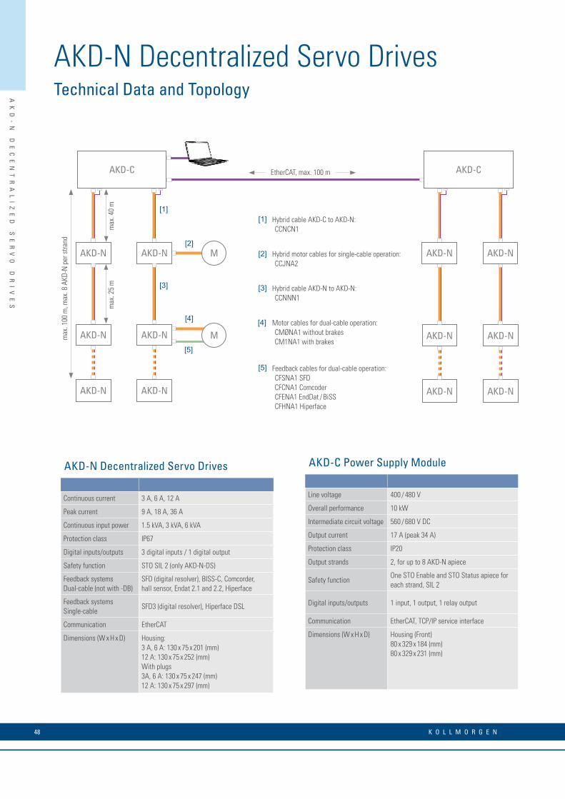
K O L L M O R G E N 48
AK
D-
N
DE
CE
NT
RA
LI
ZE
D
SE
RV
O
DR
IV
ES
Hybrid cable AKD-N to AKD-N:CCNNN1
M
M
AKD-C
max
. 100
m, m
ax. 8
AKD
-N p
er s
trand
max
. 40
mm
ax. 2
5 m
AKD-N
AKD-NAKD-N
AKD-N AKD-N
AKD-N
EtherCAT, max. 100 m
[1]
[2]
[3]
[5]
[4]
AKD-C
AKD-N AKD-N
AKD-NAKD-N
AKD-N AKD-N
[1]
[2]
[3]
[5]
[4]
Hybrid cable AKD-C to AKD-N:CCNCN1
Hybrid motor cables for single-cable operation:CCJNA2
Feedback cables for dual-cable operation:CFSNA1 SFDCFCNA1 ComcoderCFENA1 EndDat / BiSSCFHNA1 Hiperface
Motor cables for dual-cable operation:CMØNA1 without brakesCM1NA1 with brakes
AKD-N Decentralized Servo DrivesTechnical Data and Topology
AKD-N Decentralized Servo Drives
Continuous current 3 A, 6 A, 12 A
Peak current 9 A, 18 A, 36 A
Continuous input power 1.5 kVA, 3 kVA, 6 kVA
Protection class IP67
Digital inputs/outputs 3 digital inputs / 1 digital output
Safety function STO SIL 2 (only AKD-N-DS)
Feedback systemsDual-cable (not with -DB)
SFD (digital resolver), BISS-C, Comcorder, hall sensor, Endat 2.1 and 2.2, Hiperface
Feedback systemsSingle-cable
SFD3 (digital resolver), Hiperface DSL
Communication EtherCAT
Dimensions (W x H x D) Housing:3 A, 6 A: 130 x 75 x 201 (mm)12 A: 130 x 75 x 252 (mm)With plugs3A, 6 A: 130 x 75 x 247 (mm)12 A: 130 x 75 x 297 (mm)
AKD-C Power Supply Module
Line voltage 400 / 480 V
Overall performance 10 kW
Intermediate circuit voltage 560 / 680 V DC
Output current 17 A (peak 34 A)
Protection class IP20
Output strands 2, for up to 8 AKD-N apiece
Safety functionOne STO Enable and STO Status apiece for each strand, SIL 2
Digital inputs/outputs 1 input, 1 output, 1 relay output
Communication EtherCAT, TCP/IP service interface
Dimensions (W x H x D) Housing (Front)80 x 329 x 184 (mm)80 x 329 x 231 (mm)
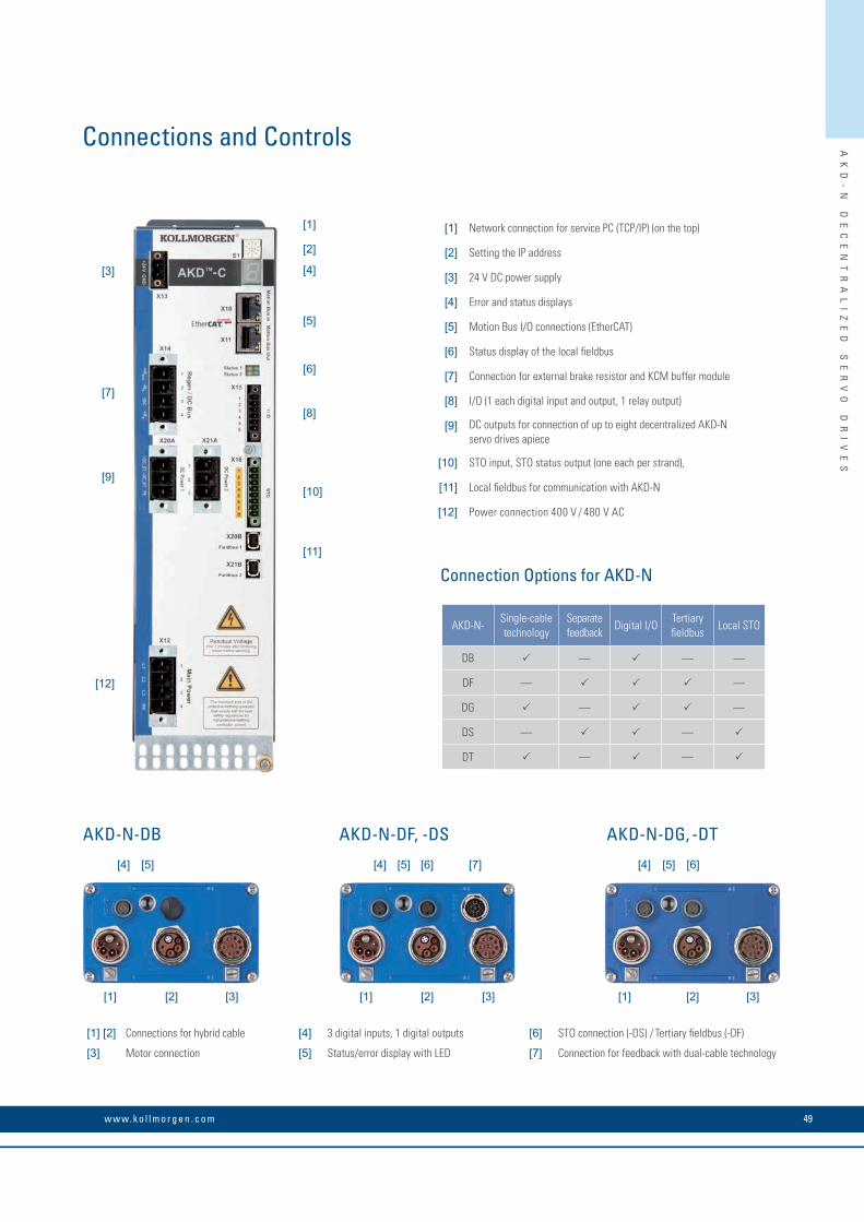
49w w w. k o l l m o r g e n . c o m
AK
D-
N
DE
CE
NT
RA
LI
ZE
D
SE
RV
O
DR
IV
ES
[1]
[4]
[2]
[5]
[6]
[8]
[10]
[11]
[3]
[7]
[9]
[12]
Connections and Controls
[1] Network connection for service PC (TCP/IP) (on the top)
[2] Setting the IP address
[3] 24 V DC power supply
[4] Error and status displays
[5] Motion Bus I/O connections (EtherCAT)
[6] Status display of the local fieldbus
[7] Connection for external brake resistor and KCM buffer module
[8] I/O (1 each digital input and output, 1 relay output)
[9] DC outputs for connection of up to eight decentralized AKD-N servo drives apiece
[10] STO input, STO status output (one each per strand),
[11] Local fieldbus for communication with AKD-N
[12] Power connection 400 V / 480 V AC
[1] [2] Connections for hybrid cable [4] 3 digital inputs, 1 digital outputs [6] STO connection (-DS) / Tertiary fieldbus (-DF)
[3] Motor connection [5] Status/error display with LED [7] Connection for feedback with dual-cable technology
Connection Options for AKD-N
AKD-N-DB
[1]
[2] [2] [2]
[4] [4][4] [5] [5] [5][6] [6][7]
[1] [1] [1] [3][3][3]
AKD-N-DF, -DS AKD-N-DG, -DT
AKD-N-Single-cable technology
Separate feedback
Digital I/OTertiary fieldbus
Local STO
DB — — —
DF — —
DG — —
DS — —
DT — —

K O L L M O R G E N 50
S700 Servo DrivesIntegrated safety functions contribute to increased machine availability and therefore increase productivity. The S700 models include a verified STO (Safe Torque Off) function as standard. The optional safety enhancement cards enable numerous safety functions such as "Safe Stop", "Safe Limited Speed", and "Safe Direction" for SIL2 or SIL3 applications.
All S700 servo drives use standardized, high-performance control technology. Rapid current, speed, and position control offers maximum performance and ensures that all axes are optimally synchronized at all times. Very quick and precise control allows for shorter work cycles and therefore considerable increases in productivity.
Specific application tasks and functions can be programmed with the integrated macro language (IEC 61131). The Macrostar development tool enables the implementation of expanded processes for individual axes.
Practical functions such as autotuning, Bode plots, and cogging suppression simplify optimization, both for applications with high dynamics and also those with high precision.
S7
00
S
ER
VO
D
RI
VE
S

S7
00
S
ER
VO
D
RI
VE
S
The Advantages of S700 Servo Drives• Higher productivity • Very quick current, speed, and position control increase machine
cycle rates
• SIL2 and SIL3 safety functions in accordance with IEC 61508 increase machine availability
• Many reference run methods
• 200 motion tasks can be saved
• Integrated macro language for high-performing drive tasks
• A version for all applications • Multi-interface
• Multi-feedback
• Synchronous servo motors
• Direct drives, rotary and linear drives
• Asynchronous motors
• HF motors
• DC motors
• Smaller switch cabinets • Integrated EMC filters
• Mains supply integrated
• Brake resistor integrated for up to 24 A of nominal current
• No mains choke usually necessary
• Faster start-up • Memory card for parameter and firmware updates
• All connections via connectors
• Autotuning
• User-friendly • Specific setup depending on the type of application
• SI units calculator
• Context-sensitive online help
• Wiki system for technical background information
51w w w. k o l l m o r g e n . c o m

S7
00
S
ER
VO
D
RI
VE
S
Gearheads
ERD Linear Actuators
Asynchronous Motors,*DC Motors*
AKMTM Washdown Food AKMHTM Hygienic Stainless Steel Servo Motors
Cartridge DDR Rotary Motor DrivesTM
ICH Linear Direct Drives
HF Motors*
*Third-party motor types
Series-produced bus options: RS232
Option / expansion card:
AKMTM Servo Motors
S700 Servo DrivesUniversal with Optional Safety Functions
The S700 range of servo drives has been designed for universal use with synchronous servo motors, asynchronous motors, DC motors, HF motors, and rotary and linear direct drives. The S700 offers a function for suppressing cogging torques within defined traverse distances. This function has been specifically designed for applications with the toughest synchronism requirements. Even linear motors can be operated at extremely low speeds with a high degree of synchronous accuracy. For all application options, the DriveGUI setup software offers a wide range of tools for easy start-up.
K O L L M O R G E N 52

S7
00
S
ER
VO
D
RI
VE
S
D
W
H
D
W
H
W
H
D
S701 - 712 S724 S748 / 772
Rated data DIM S701 S703 S706 S712 S712S* S724 S724S* S748 S772
Rated line voltage V AC 1 x 110 V to 230 V, 3 x 208 V -10% to 3 x 480 V +10% 3 x 208 V to 3 x 480 V
Rated line power for S1 operation kVA 1.1 2.2 4.5 9 9 18 18 35 50
Auxiliary supply V DC 24
Rated DC-link voltage V DC 290 to 675
Rated output current
At 1 x 110 V Arms 1.5 3 6 7 7 10 10
It is also referred to as Commutation Alignment and Pole
Locking.
It is also referred to as Commutation Alignment and Pole
Locking.
At 3 x 110 V Arms 2.5 5 6 12 12 24 24
It is also referred to as Commutation Alignment and Pole
Locking.
It is also referred to as Commutation Alignment and Pole
Locking.
At 1 x 230 V Arms 1.5 3 6 8 8 11 11
It is also referred to as Commutation Alignment and Pole
Locking.
It is also referred to as Commutation Alignment and Pole
Locking.
At 3 x 230 V Arms 2 4 6 12 12 24 24 48 72
At 3 x 400 V Arms 1.5 3 6 12 12 24 24 48 72
At 3 x 480 V Arms 1.5 3 6 12 12 24 24 48 72
Peak output current Arms 4.5 9 18 24 30 48 72 96 140
* Higher peak current
General Specifications
S700 series digital servo drives are available in rated current options of 1.5 A, 3 A, 6 A, 12 A, 24 A, 48 A, and 72 A. Customers can benefit from a consistent servo concept from a single source, which enables time and cost savings in project development, installation, and start-up. The finely staged scaling of the drive powers allow optimum adjustment to the requirements of each individual axis in the system, resulting in outstanding overall machine performance.
DIM S701 S703 S706 S712 S712S S724 S724S S748 S772
(H) Height incl. fan mm 345 348 385
(W) Width mm 70 100 190
(D) Depth incl. connector mm 285 285
Dimensions (mm)
53w w w. k o l l m o r g e n . c o m

S7
00
S
ER
VO
D
RI
VE
S
The S700 can read data from a wide range of feedback systems and evaluate three different systems in parallel. This ensures a high level of flexibility where integration the S700 into various applications is concerned. Control without a feedback system is also supported, e.g. in the case of asynchronous motors.
S700 Servo DrivesFeatures
SinCos encoder with BiSS
SinCos encoder with EnDat 2.2, EnDat 2.1
SinCos encoder with HIPERFACE
SinCos encoder without data track
SinCos encoder with hall-effect sensors
Hall-effect sensor
Digital Resolver SFD3 with HIPERFACE DSL
Incremental encoder (AquadB) 5 V
Incremental encoder (AquadB) 5 V + hall-effect sensor
Incremental encoder (AquadB) 24 V
Incremental encoder (AquadB) 24 V + hall-effect sensor
Pulse / direction, 24 V
Optional: SSI absolute encoder pulse / direction 5 V
2 to 36-pin resolvers
Simple Configuration with DriveGUI Setup SoftwareWith the graphic-based DriveGUI setup tool, you have access to all the S700 functions and parameters. You can therefore quickly configure all S700 interfaces, select all connected devices (e.g. motor type, feedback system, fieldbus) and the autotuning functions can be launched. The four-channel oscilloscope and Bode plot function ensure optimum display of the autotuning results.
Integrated Macro ProgrammingThe Macro Language forms part of the S700 firmware and enables independent, single-axis programmable positioning. Missing functions in the standard amplifier firmware can be programmed with IEC 61131 structured text. The MacroStardevelopment tool supports the quick programming of functions with integrated variables and command catalogs.
• 62.5 µs / 250 µs / 1 ms / 4 ms / 16 ms / IDLE / IRQ
• 128 kByte code memory
• 400 simple instructions every 62.5 µs
• CAN objects for multi-axis control
K O L L M O R G E N 54

S7
00
S
ER
VO
D
RI
VE
S
Safety expansion card S1-2
Safety expansion card S2-2
From a Drive to a Safe Drive: Safety Expansion Cards
Category Function S700 S700 + S1-2 S700 + S2-2
Si level SIL2/PL d SIL3 / PL e SIL2 / PL d
Safe stop functions
STO
SS1 —
SS2 —
SOS —
Safe speed functionsSSR —
SLS —
Safe direction functions SDI —
Safe brake control SBC — —
Safe position functionsSLI —
SLP — —
The S700 safety concept is designed for level SIL3 or PL e. The use of standard hardware components enables flexible and cost-optimized solutions which can achieve a cost saving of up to 25% per axis due to the omission of customer-specific adjustments. Due to the secure processes, machine availability and, consequently, productivity increase by up to 20%.
The safety expansion cards equip the S700 with important safety functions that are activated by an external safety logic. The upgrade is very simple: The cards are simply inserted into the connector sockets provided on the S700 servo drive and then configured with the SafetyGUI configuration tool. Finished!
Safety Solutions with the S700 Safety Concept
• Easy integration • Hardwired, compatible with almost every safe control system
• Ideal for upgrading existing safety solutions
• No external safety logic necessary
• Flexible • Upgradeable option cards
• Maximum safety functionality • Extensive safety functions are included
• Very short response time thanks to direct access to the control electronics
Extensive Safety Functions
55w w w. k o l l m o r g e n . c o m

K O L L M O R G E N 56
SA
FE
M
OT
IO
N
Why should a whole production line be brought to a standstill during user interventions when only one part of it is affected? Kollmorgen has put the idea of building drives with safe motion instead of safe standstill into practice with its Motion Safety solution that integrates the safety logic and monitoring within the drive. Without compromising on safety, drives utilizing or using Motion Safety achieve considerably higher productivity and offer more flexibility when adjusting to new requirements.
Kollmorgen offers safety expansion cards for installation in the S700 servo drive and the KSM compact and KSM modular safety control systems.
Safe Motion

SA
FE
M
OT
IO
N
Make the Most of the Advantages of the Kollmorgen Motion Safety Strategy
• Higher productivity •Motion Safety enables user interventions in running processes
•Safe motion instead of safe deactivation
•Risk-dependent triggering of safety functions
• Low system costs •Optimal adjustment to requirements due to modular structure
•Wide range of standard products
•Safety control and drive monitoring in one device
• Flexible •Modular concept and simple upgrade of existing drives
•Seamless transition from hardwired to configurable safety logic
• Simple and fast implementation •Important motion-related safety functions are integrated
•Predefined safety function blocks
•Intuitive tools for programming and parameterization in the field by the customer
57w w w. k o l l m o r g e n . c o m

SA
FE
M
OT
IO
N
Motion Safety
Safety logic Drive monitoring
With Motion SafetyConventional safety technology
Up to 15% productivity gain with Motion Safety
User intervention
User intervention
Time
Prod
uctio
n qu
antit
y
Safe MotionSafety Logic and Drive Monitoring Integrated within the Drive
Kollmorgen – your Competent Partner for Safe Drive SolutionsAs the leading manufacturer of electrical drive technology, Kollmorgen boasts extensive expertise gained from thousands of drive projects around the world. Safety logic, servo drives, motors, through to complete automation solutions – Kollmorgen sup-plies coordinated components for safe drive solutions, all from one source. Whether it is a standard implementation or a new development as part of a co-engineering project, make use of Kollmorgen's innovative capacity and experience for developing your safe drive.
With Motion Safety: Safe Motion Instead of Safe StandstillMotion Safety combines the safety logic and the drive monitoring in the drive. Conventional safety technology keeps the user away from areas with dangerous motion. By contrast, drives with Motion Safety work according to the safe motion principle and permit user interventions without interrupting the process. The safety logic in the drive controls motion sequences so that no danger can result from them and the process is not interrupted.
Productivity Gains with Motion SafetySafety functions for areas with dangerous motion are activated when intervening in a running process. With intelligent safety functions, motion sequences are controlled so that each motion is safe. For example, this is performed through position monitoring and restricting the range of motion or by increasing the cycle times. Parts of the machine that do not constitute a risk to the user are not affected. The graph clearly shows the productivity gains when using Kollmorgen's Motion Safety technology.
Motion Safety – innovative safety technology from Kollmorgen. Motion Safety means: safe processing of sensor and actuator signals, safe motion monitoring, and safe communication directly in the drive. The result: significantly higher productivity when compared to conventional safety technology thanks to safe drive solutions.
K O L L M O R G E N 58

SA
FE
M
OT
IO
N
n
Fieldbus
SensorsSafety device
S700 servo drive with S2-2 safety card
PLC or control system e.g. Kollmorgen KAS
Safety logic and drive monitoring
KSM compact safety control
Sensors
AKD servo drive
KSM 100 basic device with expansion modules
Up to 12 axes
Fieldbus
Sensors
AKD servo drive
PLC or control system e.g. Kollmorgen KAS
Compact, Simple Safety Solution for up to 2 Axes KSM compact safety control system with AKD servo drive for drives with up to 2 axes and up to 32 secure I/O
Safe Single-axis Drive with Minimum Response TimeS700 safety concept: The optional S1-2 S2-2 safety expansion cards equip the S700 servo drive with safety functions
High-Performance Safety Control System for Demanding Safety RequirementsKSM modular: The modular safety control system for demanding, safe drives with up to 12 axes and up to 200 secure I/O
Demanding Safety Solutions Realized efficiently
59w w w. k o l l m o r g e n . c o m

SA
FE
M
OT
IO
N
STO (Safe Torque Off) SS1 (Safe Stop 1)
t
v STO safely interrupts the power supply to the motor in
the servo drive. The motor becomes torque-free.
t
vThe drive is brought to a standstill by controlled braking. Then the power supply to the motor is safely interrupted and the motor becomes torque-free.
SS2 (Safe Stop 2) SOS (Safe Operating Stop)
t
vThe drive is brought to a standstill by controlled braking and subsequently remains in controlled standstill. The control functions of the drive are maintained.
t
v
P
Monitors the stop position reached and triggers SS1 in the event of deviations beyond the specified limits. The control functions of the drive remain active.
SDI (Safe Direction) SSR (Safe Speed Range) 1
t
v
The SDI function ensures that the drive can only move in a defined direction. In the event of an error, SS1 is triggered.
t
vv2
v1
Monitors that the drive observes a defined speed limit. In the event of an error, SS1 is triggered.
SLS (Safe Limited Speed) SBC (Safe Brake Control), SBT
t
v
vmax
Monitors that the drive observes a defined speed limit. In the event of an error, SS1 is triggered.
t
v
D
SBT (Safe Brake Test) (non-standardized)Test function for external brakes and the internal motor holding brake
SLP (Safe Limited Position) SLI (Safe Limited Increments)
t
vP
Monitors the absolute position of the drive. If the limit value is reached or the brake torque is too low to keep the drive within the limit value, SS1 is triggered.
t
v
P
Monitors the relative position of the drive with respect to the current position when activating the SLI function. SS1 is triggered when the prescribed limit value is reached.
Safe MotionExtensive Safety Functions for Safe Motion
K O L L M O R G E N 60

SA
FE
M
OT
IO
N
• For 1 or 2 axes
• Up to 2 expansion modules
• Basic module with 16 safe inputs/outputs
• Expandable to up to 60 safe inputs/outputs
• 1 safe relay output, expandable
• 2 pulse and 2 message outputs
• Expandable to up to 6 pulse and 6 message outputs
• Up to 800 function blocks
• Space-saving, compact design
• Up to 12 axes
• Up to 8 expansion modules
• Basic module with to up to 56 safe inputs/outputs
• Expandable to up to 200 safe inputs/outputs
• 1 safe relay output, expandable
• 2 pulse and up to 10 message outputs
• Expandable to up to 14 pulse and 22 message outputs
• Up to 3000 function blocks
• For applications with many interfaces
Safety functions for PL e and SIL 3• Safe stop functions: STO, SS1, SS2, SOS• Safe speed functions: SLS, SSM, SSR, SMS• Safe position functions: SLP, SCA, SLI• Safe direction functions: SDI• Safe braking functions: SBC
KSM modular: Scalable safety control system for up to 12 axes
KSM compact: single module for up to 2 axes
KSM Safety Control SystemThe Safety Chain for Motion from the Sensor to the Drive
Safe drive solutions with higher productivity: The KSM safety control system achieves SIL 3 / PL e and perfectly meets the requirements of modern safety concepts thanks to its modular structure. From safe dual-axis drives with just a few safe I/O through to a 12-axis drive with 100 or more safe I/O, in combination with AKD servo drives and Kollmorgen automation solutions, you can develop expandable, safe drives that offer more power and higher productivity with lower system costs.
KSM Compact Safety Control With KSM compact you can turn a drive into a safe one in next to no time. Important safety and monitoring functions for motion and function blocks for the processing of sensor and actuator signals are already integrated.
KSM Modular Safety Control System / Safety PLC KSM modular is designed for drive solutions with complex safety functions and a large number of interfaces. With up to 3000 function blocks, KSM modular offers the functionality of a safety PLC.
61w w w. k o l l m o r g e n . c o m
K O L L M O R G E N 62
AKM® Servo MotorsWhen you need precise position control, choose from Kollmorgen’s broad portfolio of servo system components. Our unparalleled product line breadth provides great flexibility for any application. Whether it’s any combination of motors and drives, cables, controller, electric cylinders or gearboxes, all components are plug-and-play for easy, seamless integration. These best-in-class servo systems can be matched with single-axis or multi-axis motion controllers for a system solution that’s precise, reliable and durable.
AK
M
SE
RV
O
MO
TO
RS
AK
M
SE
RV
O
MO
TO
RS
The Advantages of AKM® Servo Motors• With the same size, the AKM offers more power on the motor shaft
than before
• Amplifier and motor dimensions reduced
• Lower system costs
• Optimized AKM and direct drive motor windings for the AKD servo drive
• Quicker start-up of all servo systems
• Immediate and adaptive reaction to dynamic loads optimizes performance within seconds
• Precise regulation of all motor types
• Compensation for stiff and compatible gearboxes and clutches
• Start-up of amplifiers with plug-and-play detection for AKM and Cartridge DDR series motors
• More precise machines due to higher resolution and improved accuracy
• With multi-turn absolute encoders: reduced cycle times and lower costs for sensors and cabling through the omission of conventional reference run methods
• New, cost-efficient multi-turn feedback option
• Machine design independent of motor size
• Installation of motors in the tightest space
• Motors with the highest power densities in the whole industry
• Over 500,000 standard motor versions available in various mounting, connection, and feedback variants, as well as further options
• Our flexible products deliver a perfectly suited solution to your application
• Simplifies mechanical modifications and design adjustments or renders them totally superfluous
• AKM offers 28 housing and design length combinations, as well as 120 different standard windings for a single motor series
• AKM Washdown and AKM Washdown Food also offer maximum reliability and a long service life for the most demanding industrial applications
• IP67 option for AKM
63w w w. k o l l m o r g e n . c o m

AK
M
SE
RV
O
MO
TO
RS
Model Product Family Applications
AKM® Servo Motors AKM
Designed with industry leading torque density and configurability. The AKM line includes more than 500,000 standard models to fit applications from general automation to applications that require IP67 sealing.
AKMH IP69K Hygienic Motors
AKMH
The AKMH meets the food industry’s strictest hygienic design criteria while being rugged enough to withstand the toughest of daily washdown regimens. Perfect for Food Processing, Primary Food Packaging, Pharmaceutical and Medical applications.
Cartridge Direct Drive
Servo MotorsCDDR
The CDDR is designed to provide the benefit of embedded frameless motor technology in an easy-to-integrate package. Perfect for applications in Printing, Packaging and Converting.
Housed Direct Drive
Servo MotorsHDDR
Housed DDR motors are designed for precise positioning of larger loads without the use of a mechanical transmission. Increasing OEE through the removal of belts and gearboxes that fail unexpectedly or require frequent maintenance.
KBM Frameless Direct
Drive MotorsKBM
With a wide variety of sizes and an extensive range of torque and speed options the KBM frameless direct drive motors are engineered to provide the high-performance, long life and simple installation that today’s design engineers demand.
TBM Frameless Direct
Drive MotorsTBM
The Kollmorgen TBM frameless direct direct drive motors are designed for applications that require high power in a small, compact form factor with minimized weight and inertia. These motors provide the highest performance in applications such as robotic joints, medical robotics, sensor gimbals, guidance systems and other motion-critical applications.
Direct Drive Linear
Servo MotorsICH
Ideal for applications requiring very low bearing friction, high acceleration of lighter loads, and for maximizing constant velocity, even at ultra low speeds.
Kollmorgen offers a comprehensive range of servo motors including electric cylinders, rodless actuators, and precision tables to meet a wide range of application requirements. For actuator products not included in this catalog go to www.kollmorgen.com for information about other Kollmorgen linear positioning products.
Kollmorgen Servo Motor Overview
K O L L M O R G E N 64

AK
M
SE
RV
O
MO
TO
RS
Model Product Family Features
AKM Servo Motors AKMDesigned to deliver precise motion and more power for your money. More than 500,000 standard configurations that include various feedback, connector, paint and sealing options.
AKMH IP69K Hygienic Motor
AKMH
The AKMH is designed to withstand the toughest of daily washdown regimens without the need for covers. The AKMH’s hygienic design makes it easy to clean, keeping your machine running and protecting your brand. Designed with a single cable that combines power, feedback and an innovative venting feature that extends the life of the motor.
Cartridge Direct Drive
Servo MotorsCDDR
The CDDR is a patented design that allows for this torque dense frameless motor to be installed on your machine in 5 minutes. The CDDR lowers your machines maintenance, increases your machines uptime and increase your machines peformance.
Housed Direct Drive
Servo MotorsHDDR
Housed DDR motors are maintenance free and run more quietly and with better dynamics than systems that use gears, belts, cams or other mechanical transmission components.
KBM Frameless Direct
Drive MotorsKBM
KBM motors cover a range of frameless motor solutions across a variety of applications. KBM is engineered to provide the high-performance, long life and simple installation that today’s design engineers demand.
TBM Frameless Direct
Drive MotorsTBM
Typical applications include robotic joints, weapon stations, sensor gimbals, sight systems, UAV propulsion and guidance, as well as many others.
Direct Drive Linear
Servo MotorsICH
Kollmorgen linear motors provide precise placement of product by directly coupling to your load and eliminating the backlash associated with high maintenance linear transmission components.
65w w w. k o l l m o r g e n . c o m

AK
M
SE
RV
O
MO
TO
RS
Over 500,000 standard configurations
Smaller and lighter motors due to high torque densities
Robust: Housing and front flange produced from one casting
Motor design that cuts to the chase – with customer-specific windings or modifications.
Numerous feedback options such as the SFD3 digital resolver, single-turn and multi-turn absolute encoders and resolver
Small but impressive:
AKM1 is one of the smallest servo motors on the market
High degree of accuracy thanks to digital feedback systems (optional)
Heavy-duty shaft, optionally with reinforced bearings (only AKM8)
Worldwide availability and user support through the international Kollmorgen sales and support network
Numerous connection options
• 8 frame sizes from 40 to 260 mm• 28 housing and design length combinations• 117 standard windings for 120/240/400/480 V• Winding options for low DC voltage
• Numerous flange and shaft options• Minimal cogging and high degree of efficiency• Extensive customization options with special
windings and shafts
The AKM® brushless servo motor stands alone in the marketplace in terms of flexibility and performance advantages. Kollmorgen’s culture of continuous improvement has paid dividends again. The AKM servo motor’s innovative design has been polished and optimized. With the new AKD amplifier, the distinguished AKM servo motor sets a new standard of refined servo performance, designed to deliver precise motion and more power for your money. Nowhere else will you find a more versatile and complete servo family to meet your needs and exceed your expectations.
AKM® Brushless Servo Motor
K O L L M O R G E N 66

AK
M
SE
RV
O
MO
TO
RS
High Accuracy
AKM Motor
Single-turn absolute Multi-turn absolute
Accu
racy
(a
rc-m
in)
Reso
lutio
n (b
its)
Mot
or k
ey
Accu
racy
(a
rc-m
in)
Reso
lutio
n (b
its)
Mot
or k
ey
Valu
e lin
e AKM1 16 24 CA – – –
AKM2 - AKM3 9 24 CA 8 18 LB
AKM4 - AKM8 9 24 CA 4.66 18 LB
Perfo
rman
ce li
ne AKM1 7.2 9 GP 7.2 9 GR
AKM2 - AKM4 1.0 20 DA 1.0 20 DB
AKM5 - AKM8 0.333 20 DA 0.333 20 DB
The AKM1 – one of the smallest servo motors on the market offers outstanding power density despite its compact design
Power RangeAKM frame sizes 1 to 8, standstill torques of 0.16 to 180 Nm, speed range 1000 to 8000 rpm, voltages 75 V DC, 120, 240, 400, 480 V AC.
Application CriteriaUniversally deployable, brushless servo motors for all positioning and motion tasks with normal and high requirements and with accuracy and speed in a torque range between 0.16 Nm and 180 Nm.
Feedback Systems and ConnectivityStandard with SFD3 and HIPERFACE DSL single-cable options. In addition, AKM supports dual-cable feedback options such as Resolver, Encoder, EnDAT, BiSS; Hiperface, Safe Feedback and Drive Cliq.
Protection ClassIP65 with optional Teflon® shaft seal, IP67 in the Washdown or Washdown Food version (page 51). Standard version IP40.
Smooth Running and Long Service LifeVery smooth running due to minimal cogging. The single-cast stator ensures high stability and improved heat dissipation from the motor. Front flange and motor housing are produced from a single cast. This ensures a high degree of sealing and strength and a long service life.
67w w w. k o l l m o r g e n . c o m

AK
M
SE
RV
O
MO
TO
RS
AKM® Washdown and Washdown FoodServo Motors suitable regular Washdown
WashdownWashdown Food
Housing design with rounded edges prevents contamination traps
Extensive range of options allows up to 150000 variants!
Dual-component epoxy coating
High grade stainless steel shaft
Chemical-resistant Teflon® shaft seal
Lubricants suitable for use with food and shaft seal as per FDA requirements (Washdown Food)
Protection class IP67 allows for regular wet cleaning
Less weight due to stainless-steel-free housing
More durable in washdown conditions than standard AKM motors, lighter and more cost-effective than stainless-steel servo motors: In many applications with demanding environmental requirements, the AKM Washdown and Washdown Food versions are good alternatives to costly stainless steel motors or expensive protective enclosures.
Specially for applications with demanding environmental requirements in the
• Packaging industry• Pharmaceutical industry• Food industry
• Beverage industry• Laboratory automation• Medical device technology
K O L L M O R G E N 68

AK
M
SE
RV
O
MO
TO
RS
Also proven in harsh environments: The AKM Washdown Food is resistant to most acids and bases, as well as aggressive substances.
Power RangeAKM frame sizes 2 to 6 with standstill torques of 1 to 25 Nm, supply voltages of 75 to 480 V, large selection of different construction lengths, winding variants, as well as feedback systems and connection technologies.
Application CriteriaDesigned for environments with acids, bases, or aggressive substances such as frequent cleaning with cleaning agents with pH values of between 2 and 12.
Housing CoatingThe coating material of the AKM Washdown Food motors is resistant to acids and bases and aggressive substances and meets the global migration requirement of the FDA. The rounded and smooth surfaces prevent hazardous contamination traps and germ formation.
Seals and BearingsBoth Washdown versions meet the IP67 protection rating. The proven AKM PTFE shaft seal is used. For the AKM Washdown Food version, the shaft seal meets FDA requirements and only food-safe lubricants are used.
Connectors and CablesEach in size 1 with special stainless steel design and smooth surface. Cables with special mating connectors are used from stainless steel or a material appropriate for maintaining food quality. The cables are clamped using a special clamping method.
International StandardsUL, CE, EAC, FDA*, RoHS
* Global migration requirement
69w w w. k o l l m o r g e n . c o m

AK
M
SE
RV
O
MO
TO
RS
AKM® Servo MotorsAKM, AKM Washdown, and AKM Washdown Food
Performance Data
AKM
Ser
vo M
otor
Flan
ge s
ize [m
m]
Cont
. Tor
que
at S
tall
Tcs
[Nm
]
Cont
inuo
us C
urre
nt I 0 [A
]
Peak
Torq
ue a
t sta
ll Tp
s [N
m] 75 V DC 115 V 230 V 400 V 480 V
Iner
tia (J
m) [
kg∙c
m2 ]
Wei
ght [
kg]
Rate
d Sp
eed
Nrtd
[RPM
]
Rate
d To
rque
Trtd
[Nm
]
Rate
d Po
wer
Prtd
[kW
]
Rate
d Sp
eed
Nrtd
[RPM
]
Rate
d To
rque
Trtd
[Nm
]
Rate
d Po
wer
Prtd
[kW
]
Rate
d Sp
eed
Nrtd
[RPM
]
Rate
d To
rque
Trtd
[Nm
]
Rate
d Po
wer
Prtd
[kW
]
Rate
d Sp
eed
Nrtd
[RPM
]
Rate
d To
rque
Trtd
[Nm
]
Rate
d Po
wer
Prtd
[kW
]
Rate
d Sp
eed
Nrtd
[RPM
]
Rate
d To
rque
Trtd
[Nm
]
Rate
d Po
wer
Prtd
[kW
]
11B 40 0.18 1.16 0.61 – – – 4000 0.18 0.08 8000 0.17 0.14 – – – – – – 0.017 0.35
11C 40 0.18 1.45 0.61 – – – 6000 0.18 0.11 – – – – – – – – – 0.017 0.35
11E 40 0.18 2.91 0.61 6000 0.18 0.11 – – – – – – – – – – – – 0.017 0.35
12C 40 0.31 1.51 1.08 – – – 4000 0.30 0.13 8000 0.28 0.23 – – – – – – 0.031 0.49
12E 40 0.31 2.72 1.08 3000 0.31 0.10 8000 0.28 0.23 – – – – – – – – – 0.031 0.49
13C 40 0.41 1.48 1.46 – – – 3000 0.41 0.13 8000 0.36 0.30 – – – – – – 0.045 0.63
13D 40 0.40 2.40 1.44 2000 0.40 0.08 7000 0.36 0.27 – – – – – – – – – 0.045 0.63
21C 60 0.48 1.58 1.47 – – – 2500 0.46 0.12 8000 0.39 0.32 – – – – – – 0.11 0.82
21E 60 0.50 3.11 1.49 2000 0.48 0.10 7000 0.41 0.30 – – – – – – – – – 0.11 0.82
21G 60 0.50 4.87 1.51 4000 0.46 0.19 – – – – – – – – – – – – 0.11 0.82
22C 60 0.84 1.39 2.73 – – – 1000 0.83 0.09 3500 0.78 0.29 8000 0.68 0.57 8000 0.68 0.57 0.16 1.10
22E 60 0.87 2.73 2.76 1000 0.85 0.09 3500 0.81 0.30 8000 0.70 0.59 – – – – – – 0.16 1.10
22G 60 0.88 4.82 2.79 2500 0.83 0.22 7000 0.74 0.54 – – – – – – – – – 0.16 1.10
23C 60 1.13 1.41 3.77 – – – 1000 1.11 0.12 2500 1.08 0.28 5500 0.99 0.57 7000 0.95 0.70 0.22 1.38
23D 60 1.16 2.19 3.84 – – – 1500 1.12 0.18 5000 1.03 0.54 8000 0.92 0.77 8000 0.92 0.77 0.22 1.38
23F 60 1.18 4.31 3.88 1500 1.15 0.18 4500 1.07 0.50 8000 0.94 0.79 – – – – – – 0.22 1.38
24C 60 1.38 1.42 4.67 – – – – – – 2000 1.32 0.28 4500 1.25 0.59 5500 1.22 0.70 0.27 1.66
24D 60 1.41 2.21 4.76 – – – 1500 1.36 0.21 4000 1.29 0.54 8000 1.11 0.93 8000 1.11 0.93 0.27 1.66
24F 60 1.42 3.89 4.82 1000 1.39 0.15 3000 1.33 0.42 8000 1.12 0.94 – – – – – – 0.27 1.66
31C 80 1.15 1.37 3.88 – – – – – – 2500 1.12 0.29 5000 1.00 0.52 6000 0.91 0.57 0.33 1.55
31E 80 1.20 2.99 4.00 750 1.19 0.09 2500 1.17 0.31 6000 0.95 0.60 – – – – – – 0.33 1.55
31H 80 1.23 5.85 4.06 2000 1.20 0.25 6000 0.97 0.61 – – – – – – – – – 0.33 1.55
32C 80 2.00 1.44 6.92 – – – – – – 1500 1.95 0.31 3000 1.86 0.58 3500 1.83 0.67 0.59 2.23
32D 80 2.04 2.23 7.10 – – – 1000 2.00 0.21 2500 1.93 0.51 5500 1.65 0.95 6000 1.58 0.99 0.59 2.23
32E 80 2.04 2.82 7.11 – – – – – – 3500 1.87 0.69 7000 1.41 1.03 7000 1.22 1.02 0.59 2.23
32H 80 2.10 5.50 7.26 1200 2.06 0.26 3000 1.96 0.62 7000 1.45 1.06 – – – – – – 0.59 2.23
33C 80 2.71 1.47 9.76 – – – – – – 1000 2.64 0.28 2000 2.54 0.53 2500 2.50 0.65 0.85 2.9
33E 80 2.79 2.58 9.96 – – – – – – 2000 2.62 0.55 4500 2.34 1.10 5000 2.27 1.19 0.85 2.9
33H 80 2.88 5.62 10.22 800 2.82 0.24 2500 2.66 0.70 5500 2.27 1.31 – – – – – – 0.85 2.9
41C 90 1.95 1.46 6.12 – – – – – – 1200 1.88 0.24 3000 1.77 0.56 3500 1.74 0.64 0.81 2.44
41E 90 2.02 2.85 6.28 – – – 1200 1.94 0.24 3000 1.82 0.57 6000 1.58 0.99 6000 1.58 0.99 0.81 2.44
41H 90 2.06 5.6 6.36 1000 1.99 0.21 3000 1.86 0.58 6000 1.62 1.02 – – – – – – 0.81 2.44
42C 90 3.35 1.40 11.3 – – – – – – – – – 1500 3.10 0.49 2000 3.02 0.63 1.5 3.39
42E 90 3.42 2.74 11.3 – – – – – – 1800 3.12 0.59 3500 2.81 2.35 4000 2.72 1.14 1.5 3.39
42G 90 3.53 4.80 11.5 – – – – – – 3500 2.90 1.06 6000 2.35 1.48 6000 2.35 1.48 1.5 3.39
42J 90 3.56 8.4 11.6 – – – 3000 3.03 0.95 6000 2.36 1.50 – – – – – – 1.5 3.39
43E 90 4.70 2.76 15.9 – – – – – – 1500 4.24 0.67 2500 3.92 1.03 3000 3.76 1.18 2.1 4.35
43G 90 4.80 4.87 16.1 – – – – – – 2500 4.00 1.05 5000 3.01 1.58 6000 2.57 1.61 2.1 4.35
43K 90 4.90 9.60 16.4 – – – 2500 4.08 1.07 6000 2.62 1.65 – – – – – – 2.1 4.35
44E 90 5.76 2.90 19.9 – – – – – – 1200 5.22 0.66 2000 4.80 1.01 2500 4.56 1.19 2.7 5.3
44G 90 5.88 5.00 20.3 – – – – – – 2000 4.90 1.03 4000 3.76 1.57 5000 3.19 1.67 2.7 5.3
44J 90 6.00 8.80 20.4 – – – – – – 4000 3.84 1.61 6000 2.75 1.73 6000 2.75 1.73 2.7 5.3
51E 115 4.70 2.75 11.6 – – – – – – 1200 4.41 0.55 2500 3.98 1.04 3000 3.80 1.19 3.4 4.2
51G 115 4.75 4.84 11.7 – – – – – – 2500 4.02 1.05 5000 2.62 1.37 6000 1.94 1.22 3.4 4.2
51H 115 4.79 6.00 11.7 – – – – – – 3000 3.87 1.22 6000 1.95 1.23 6000 1.95 1.23 3.4 4.2
51K 115 4.90 9.40 11.9 – – – 2500 4.15 1.09 5500 2.35 1.35 – – – – – – 3.4 4.2
K O L L M O R G E N 70

AK
M
SE
RV
O
MO
TO
RS
Performance Data
AKM
Ser
vo M
otor
Fram
e si
ze [m
m]
Cont
. Tor
que
at S
tall
Tcs
[Nm
]
Cont
inuo
us C
urre
nt I 0 [A
]
Peak
Torq
ue a
t sta
ll Tp
s [N
m] 230 V 400 V 480 V
Iner
tia (J
m) [
kg∙c
m2 ]
Wei
ght [
kg]
Rate
d Sp
eed
Nrtd
[RPM
]
Rate
d To
rque
Trtd
[Nm
]
Rate
d Po
wer
Prtd
[kW
]
Rate
d Sp
eed
Nrtd
[RPM
]
Rate
d To
rque
Trtd
[Nm
]
Rate
d Po
wer
Prtd
[kW
]
Rate
d Sp
eed
Nrtd
[RPM
]
Rate
d To
rque
Trtd
[Nm
]
Rate
d Po
wer
Prtd
[kW
]
52E 115 8.34 2.99 21.3 – – – 1500 7.61 1.20 2000 7.28 1.52 6.2 5.8
52G 115 8.43 4.72 21.5 1200 7.69 1.21 2500 7.06 1.85 3000 6.66 2.09 6.2 5.8
52H 115 8.48 5.90 21.6 1800 7.53 1.42 3500 6.26 2.30 4000 5.77 2.42 6.2 5.8
52K 115 8.60 9.30 21.9 3000 6.80 2.14 5500 3.90 2.25 6000 3.25 2.04 6.2 5.8
52M 115 8.60 13.1 21.9 4500 5.20 2.45 – – – – – – 6.2 5.8
53G 115 11.4 4.77 29.7 1000 10.7 1.12 2000 9.85 2.06 2400 9.50 2.39 9.1 7.4
53H 115 11.5 6.60 30.0 – – – 3000 8.63 2.77 3500 8.23 3.02 9.1 7.4
53K 115 11.6 9.40 30.3 2000 10.1 2.12 4000 7.65 3.20 4500 6.85 3.23 9.1 7.4
53M 115 11.4 13.4 29.7 3000 8.72 2.74 – – – – – – 9.1 7.4
53P 115 11.4 19.1 29.8 5000 5.88 3.08 – – – – – – 9.1 7.4
54G 115 14.3 5.00 38.0 – – – 1500 12.9 2.03 2000 12.3 2.57 12 9
54H 115 14.2 5.50 37.5 – – – 1500 12.6 2.38 2000 12.2 2.56 12 9
54K 115 14.4 9.7 38.4 1800 12.7 2.39 3500 10.0 3.68 4000 9.25 3.87 12 9
54L 115 14.1 12.5 37.5 2500 11.5 3.00 4500 8.13 3.83 – – – 12 9
54N 115 14.1 17.8 37.6 3500 9.85 3.61 – – – – – – 12 9
62G 142 11.9 4.9 29.7 – – – 1800 10.4 1.96 2000 10.2 2.14 17 8.9
62K 142 12.2 9.6 30.2 2000 10.4 2.18 3500 9.00 3.30 4500 8.00 3.77 17 8.9
62M 142 12.2 13.4 30.2 3000 9.50 2.98 6000 5.70 3.58 6000 5.70 3.58 17 8.9
62P 142 12.3 18.8 30.3 4500 8.10 3.82 – – – – – – 17 8.9
63G 142 16.5 4.5 42.1 – – – 1200 14.9 1.87 1500 14.6 2.29 24 11.1
63K 142 16.8 9.9 42.6 1500 14.9 2.34 3000 12.9 4.05 3500 12.0 4.40 24 11.1
63M 142 17.0 13.8 43.0 2000 14.3 2.99 4000 11.3 4.73 4500 10.5 4.95 24 11.1
63N 142 17.0 17.4 43.0 3000 13.0 4.08 5000 9.60 5.03 6000 7.00 4.40 24 11.1
64K 142 20.8 9.2 53.5 1200 18.8 2.36 2000 17.2 3.60 2500 16.3 4.27 32 13.3
64L 142 21.0 12.8 54.1 1500 18.4 2.89 3000 15.6 4.90 3500 14.4 5.28 32 13.3
64P 142 20.4 18.6 52.9 2500 16.0 4.19 4500 11.9 5.62 5500 9.00 5.18 32 13.3
64Q 142 20.0 20.7 53.2 3000 15.3 4.81 5000 10.7 6.45 6000 7.40 4.65 32 13.3
65K 142 24.8 9.8 64.5 1000 22.8 2.39 2000 20.2 4.23 2200 19.7 4.54 40 15.4
65M 142 25.0 13.6 65.2 1500 21.9 3.44 2500 19.2 5.03 3000 18.1 5.69 40 15.4
65N 142 24.3 17.8 63.7 2000 19.8 4.15 3500 16.0 5.86 4000 14.7 6.16 40 15.4
65P 142 24.5 19.8 64.1 2400 19.1 4.8 4000 14.9 6.24 5000 11.6 6.08 40 15.4
72K 180 29.7 9.3 79.4 – – – 1500 25.1 3.94 1800 24.0 4.52 65 19.7
72M 180 30.0 13.0 79.8 – – – 2000 23.6 4.94 2500 22.1 5.79 65 19.7
72P 180 29.4 18.7 78.5 1800 23.8 4.49 3000 20.1 6.31 3500 18.2 6.67 65 19.7
72Q 180 29.5 23.5 78.4 2000 23.2 4.89 4000 16.3 6.83 4500 14.1 6.65 65 19.7
73M 180 42.0 13.6 112 – – – 1500 33.8 5.31 1800 32.1 6.05 92 26.7
73P 180 41.6 19.5 111 1300 34.7 4.72 2400 28.5 7.16 2800 26.3 7.71 92 26.7
73Q 180 41.5 24.5 111 1500 33.4 5.25 3000 25.2 7.92 3500 22 8.07 92 26.7
74L 180 53.0 12.9 143 – – – 1200 43.5 5.47 1400 41.5 6.08 120 33.6
74P 180 52.5 18.5 142 – – – 1800 39.6 7.46 2000 35.9 7.52 120 33.6
74Q 180 52.2 26.1 141 1300 41.9 5.71 2500 31.5 8.25 3000 27.3 8.58 120 33.6
82T 260 75 48 210 – – – 2500 47.5 12.4 3000 38.0 11.9 172 49
83T 260 130 62 456 – – – 2200 70.0 16.1 2500 60.0 15.7 334 73
83V 260 130 91 304 3000 65 20.4 – – – 334 73
84T 260 180 67 668 – – – 1800 105 19.8 2000 93.0 19.5 495 97
71w w w. k o l l m o r g e n . c o m

AK
M
SE
RV
O
MO
TO
RS
AKM® Brushless Servo Motor
B
ØD
4XØC
Y
Z
X
Measure Y: Without holding brakeMeasure Z: With holding brake
AKM, AKM Washdown, and AKM Washdown Food
Model with Power and Signal Connector
Dimensional drawing for AKM11 - AKM84
Model X Resolvers Comcoder Biss/Endat Hiperface DriveCliq Flange Bolt circle Bore
diameterCentering
collar
Y Z Y Z Y Z Y Z Y Z B ∅W ∅C ∅D
AKM11 56.1 69.6 106.6 79.0 – – – 79 116 – – 40 46 4.3 30
AKM12 75.1 88.6 125.6 98.0 – – – 98 135 – – 40 46 4.3 30
AKM13 94.1 107.6 144.6 117.0 – – – 117 154 – – 40 46 4.3 30
AKM21 76.1 95.4 129.5 95.4 129.5 95.4 129.5 113.4 147.1 – – 58 63 4.8 40
AKM22 95.1 114.4 148.5 114.4 148.5 114.4 148.5 132.4 166.1 – – 58 63 / 65 (1) 4.8 40
AKM23 114.1 133.4 167.5 133.4 167.5 133.4 167.5 151.4 185.1 – – 58 63 / 65 (1) 4.8 40
AKM24 135.1 152.4 186.5 152.4 186.5 152.4 186.5 170.4 204.1 – – 58 63 / 65 (1) 4.8 40
AKM31 87.9 109.8 141.3 109.8 141.3 109.8 141.3 125.3 159.3 – – 70 75 / 85 (2) 5.8 60
AKM32 118.9 140.8 172.3 140.8 172.3 140.8 172.3 156.3 190.3 – – 70 75 / 85 (2) 5.8 60
AKM33 149.9 171.8 203.3 171.8 203.3 171.8 203.3 187.3 221.3 – – 70 75 / 85 (2) 5.8 60
AKM41 96.4 118.8 152.3 118.8 152.3 118.8 152.3 136.8 170.3 152.3 170.3 84 90 / 100 (3) 7 60 / 80 (3)
AKM42 125.5 147.8 181.3 147.8 181.3 147.8 181.3 165.8 199.3 181.3 199.3 84 90 / 100 (3) 7 60 / 80 (3)
AKM43 154.4 176.8 210.3 176.8 210.3 176.8 210.3 194.8 228.3 210.3 228.3 84 90 / 100 (3) 7 60 / 80 (3)
AKM44 183.4 205.8 239.3 205.8 239.3 205.8 239.3 223.8 257.3 239.3 257.3 84 90 / 100 (3) 7 60 / 80 (3)
AKM51 105.3 127.5 172.5 127.5 172.5 145.0 189.0 145.0 189.0 146.0 189.0 108 115 / 130 (4) 7 95 / 110 (4)
AKM52 136.3 158.5 203.5 158.5 203.5 177.0 220.0 177.0 220.0 177.0 220.0 108 115 / 130 (4) 7 95 / 110 (4)
AKM53 167.3 189.5 234.5 189.5 234.5 208.0 251.0 208.0 251.0 208.0 251.0 108 115 / 130 (4) 7 95 / 110 (4)
AKM54 198.3 220.5 265.5 220.5 265.5 239.0 282.0 239.0 282.0 239.0 282.0 108 115 / 130 (4) 7 95 / 110 (4)
AKM62 130.5 153.7 200.7 153.7 200.7 172.2 219.7 172.2 219.7 172.2 219.7 138 165 11 130
AKM63 155.5 178.7 225.7 178.7 225.7 197.2 244.7 197.2 244.7 197.2 244.7 138 165 11 130
AKM64 180.5 203.7 250.7 203.7 250.7 222.2 269.7 222.2 269.7 222.2 269.7 138 165 11 130
AKM65 205.5 228.7 275.7 228.7 275.7 247.2 294.7 247.2 294.7 247.2 294.7 138 165 11 130
AKM72 164.5 192.5 234.5 192.5 234.5 192.5 234.5 192.5 234.5 201.7 253.3 188 215 13,5 180
AKM73 198.5 226.5 268.5 226.5 268.5 235.7 287.3 235.7 287.3 235.7 287.3 188 215 13,5 180
AKM74 232.5 260.5 302.5 260.5 302.5 269.7 321.3 269.7 321.3 269.7 321.3 188 215 13,5 180
AKM82 170 267 333 267 333 267 333 267 333 – – 260 300 18.5 250
AKM83 250.5 347.5 413.5 347.5 413.5 347.5 413.5 347.5 413.5 – – 260 300 18.5 250
AKM84 331 428 494 428 494 428 494 428 494 – – 260 300 18.5 250
(1) ∅W = 63 mm AKM2xx-Ax∅W = 65 mm AKM2xx-Dx
(2)∅W = 75 mm AKM3xx-Ax∅W = 85 mm AKM3xx-Cx
(3)∅W = 100 mm, ∅V = 80 mm AKM4xx-Ax∅W = 90 mm, ∅V = 60 mm AKM4xx-Cx
(4) ∅W = 130 mm ∅V = 110 mm AKM5xx-Ax∅W = 115 mm ∅V = 95 mm AKM5xx-Ax
All measurement specifications in mm Measure Y: Measurement without holding brake, Measure Z: Measurement with holding brake
K O L L M O R G E N 72

AK
M
SE
RV
O
MO
TO
RS
The Design Features of AKM in the 3D Model
The modular brake prevents contamination of the friction surface and faulty air-gap configuration during brake assembly.
Multiple feedback systems for a wide variety of requirements.
The robust powder coating and O-ring seals offer reliable protection for the motor in harsh environments.
The housing design allows for installation in the tightest of spaces.
Optimized electromagnetic design for high torque density and minimum cogging.
The gearing in the shaft prevents the loosening of the brake hub.
The encapsulated front bearing prevents axial backlash.
The integrated front bearing shield increases stability and ensures improved sealing.
73w w w. k o l l m o r g e n . c o m

K O L L M O R G E N 74
AK
MH
H
YG
IE
NI
C
ST
AI
NL
ES
S
ST
EE
L
SE
RV
O
MO
TO
RS
For more than 70 years, Kollmorgen has been developing special motors for use in difficult environments. For example, the remotely controlled submarine vehicle called the Jason Jr. discovered the wreck of the Titanic with the help of Kollmorgen motors developed especially for this purpose.
Reduced recall risk. In the food production industry extremely strict hygiene regulations apply so that public health is not compromised. The stainless-steel AKMH servo motors meet the most demanding requirements in relation to hygiene standards and reduce the risk of product contamination and costly recalls.
Faster cleaning and reduced maintenance times. The stainless steel AKMH servo motors are designed to protection class IP69K and satisfy the requirements of the EHEDG and 3A hygiene regulations. Only materials are used that are FDA-approved and suitable for use with food. These characteristics of the AKMH series enable quick, hygienic cleaning, reduce maintenance times, and therefore increase the overall equipment effectiveness of your production line.
The bottom line. The stainless steel AKMH series of motors has been designed for hygienic machine applications. The large product range with 19 standard motor frame sizes, multiple standard windings, and numerous connection, brake, and cable options makes it easier to choose a motor that satisfies the requirements of the highest standards in the food, beverage, and pharmaceutical industries.
AKMHTM Hygienic Stainless Steel Servo Motors

AK
MH
H
YG
IE
NI
C
ST
AI
NL
ES
S
ST
EE
L
SE
RV
O
MO
TO
RS
The Advantages of AKMH Hygienic Stainless Steel Servo Motors
Increase in Overall Equipment Effectiveness (OEE)
Faster and environmentally friendly cleaning • Open, hygienic machine design without protective housings• Considerably lower consumption of cleaning agents; less dirty water
No machine downtimes as a result of cleaning or corrosion
• Protection class IP69K for motor housing, cable gland, and shaft seal• Designed for regular high-pressure and high-temperature cleaning• Cable and sealing components are resistant to common cleaning agents• No corrosion inside the motor: Pressure compensation through the cable prevents moisture in the motor
Lower operating costs • Higher machine availability due to quicker cleaning• Faster cleaning reduces the consumption of cleaning agents and energy• High energy efficiency due to motor / servo drive combination with a high degree of efficiency
Higher throughput • Quick and precise drives in combination with the AKD servo drives• Process monitoring and optimization with Kollmorgen's software tools
Lower risk of recalls
Hygiene-optimized housing design • Housing is 1.4404 stainless steel 316L with smooth surface prevents the build-up of pathogens• Fluids drained with vertical installation thanks to convex cover• No place for pathagens to hide - no nooks and crannies in housing design• Thanks to a laser annealed nameplate, the surface finish is undisturbed
Use of approved hygienic components • Bearing lubrication and shaft seals FDA-approved• Observance of the EHEDG and 3A Sanitary Certificate hygienic regulations
Hygienic cable technology • Silicon tubing option provides an FDA-approved cable option suitable for use with food • Low cabling costs due to single-cable technology - no need for expensive stainless steel conduit• Non absorbant cabling prevent pathogens from hiding in the cable jacket material
Reduced development times and design freedom
Ideal motor design • Large selection of standard motors allowing customers to optimize their motor selection• 19 frame sizes, flange and shaft measurements as per IEC and NEMA• Continuous torques up to 22 Nm, peak torques up to 92 Nm• Speeds up to 8000 rpm-1
• SFD3 and Hiperface DSL digital feedback systems• Brake and cable options
Simple start-up and parameterization • Plug-and-play connection with pre-assembled connectable cables, no screw connections• Simple machine architecture due to single-cable and decentralized connection technology• Digital nameplate for quick start-up• Software tools for parameterization and drive monitoring
Low energy consumption • High efficiency due to permanent magnet technology• 20% less derating due to special motor design
Kollmorgen support • Kollmorgen’s global support team has wealth of industry knowledge to help optimize your machine
Co-engineering • Kollmorgen welcomes customization to help optimize your motor/drive solution
75w w w. k o l l m o r g e n . c o m

The new stainless steel AKMH motors have been designed for hygienic machine applications in wet areas with food contact in accordance with the EHEDG regulations and they comply with 3A, USDA and NFS hygiene standards. Shorter cleaning times and high reliability ensure noticeably greater overall equipment effectiveness.
AKMH Hygienic Stainless Steel Servo Motors
Washdown
Ideal in harsh washdown environments where frequent cleaning with caustic chemicals and high pressure water are required.
Extremely durable, even with frequent, intensive cleaning processes
Specially suited to applications where contact with food is possible
Specially for applications in the food, beverage, and packaging industry, as well as in medical devices
*
K O L L M O R G E N 76
AK
MH
H
YG
IE
NI
C
ST
AI
NL
ES
S
ST
EE
L
SE
RV
O
MO
TO
RS

AK
MH
H
YG
IE
NI
C
ST
AI
NL
ES
S
ST
EE
L
SE
RV
O
MO
TO
RS
Thanks to the open machine design without protective housings, machines can also be cleaned quickly and safely using high-pressure and high-temperature processes.
Higher Productivity Due to Quicker Cleaning
• Ideal for machines with an open design
• No costly protective equipment; no hidden spaces to trap pathogens
• Quick, easy, yet safe cleaning
Reduced Recall Risk
• Lubricants and seals meet FDA standards.
• Round, stainless steel housing with a roughness of < 0.8 µm and the design of all edges with radii of R1.5 prevent dirt deposits
Higher Machine Uptime
• IP69K: Motor is protected for water pressures up to 100 Bar
• Cable is directly mounted to motor; no connectors to fail or trap pathogens
• Single-cable technology with digital feedback (SFD3 or HIPERFACE® DSL digital resolvers); less cabling to clean
Outstanding Efficiency Thanks to Novel Motor Design
• Torque derating under 20%
• High speeds of up to 8000 RPM offer more flexibility for gearbox attachment and higher productivity due to higher output speeds with the same torque
• AKMH2 is the most compact hygienic servo motor on the market
Optimized Motion Thanks to 19 Frame Sizes
• 5 sizes each with 4 rotor lengths and winding options for perfect adapta-tion to servo drives
• Two housing shapes for front and flange mounting
One Source for Your Complete Automation Solution
• The Kollmorgen Automation Suite provides all the tools for motion and PLC programming and for drive management in operation
• AKD-PDMM multi-axis controller: The 3-in-1 solution combines servo drive, motion controller, and PLC in one device
77w w w. k o l l m o r g e n . c o m
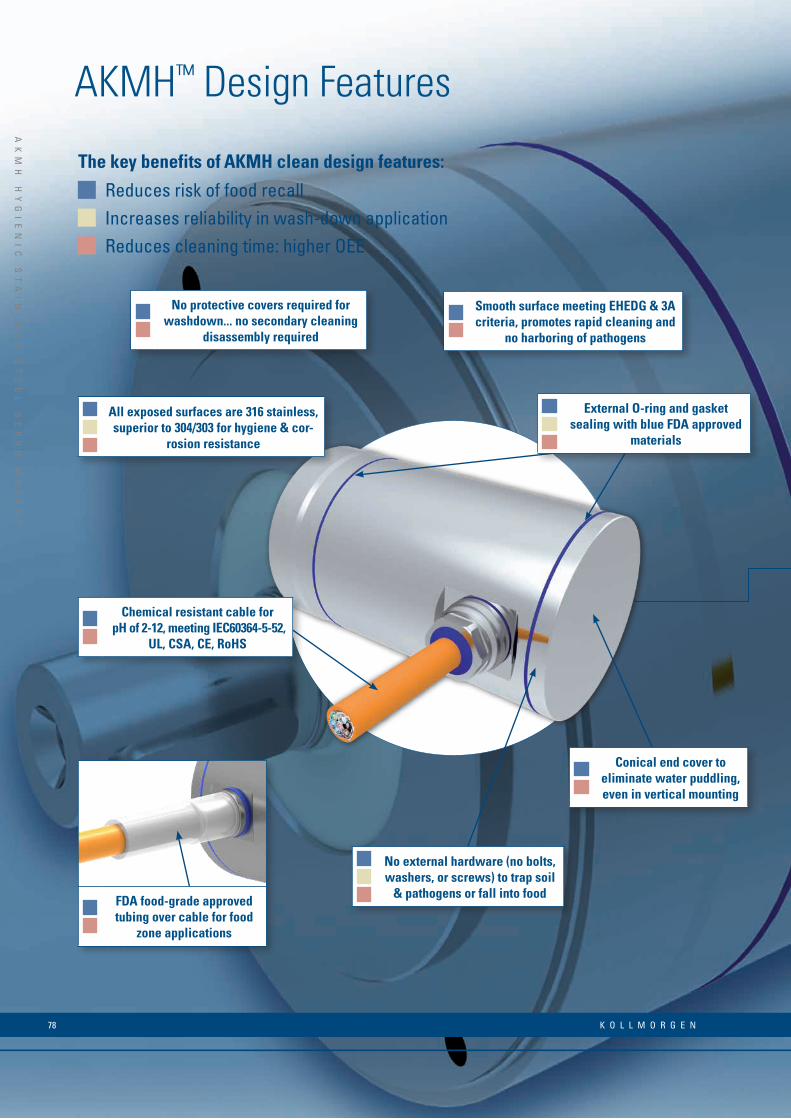
AKMH™ Design Features
Reduces risk of food recallIncreases reliability in wash-down applicationReduces cleaning time: higher OEE
The key benefits of AKMH clean design features:
n n
Smooth surface meeting EHEDG & 3A criteria, promotes rapid cleaning and
no harboring of pathogens
n n n
All exposed surfaces are 316 stainless, superior to 304/303 for hygiene & cor-
rosion resistance
n n
No protective covers required for washdown... no secondary cleaning
disassembly required
n n
Conical end cover to eliminate water puddling, even in vertical mounting
n n
Chemical resistant cable for pH of 2-12, meeting IEC60364-5-52,
UL, CSA, CE, RoHS
n n
FDA food-grade approved tubing over cable for food
zone applications
n n n
External O-ring and gasket sealing with blue FDA approved
materials
n n n
No external hardware (no bolts, washers, or screws) to trap soil
& pathogens or fall into food
K O L L M O R G E N 78
AK
MH
H
YG
IE
NI
C
ST
AI
NL
ES
S
ST
EE
L
SE
RV
O
MO
TO
RS
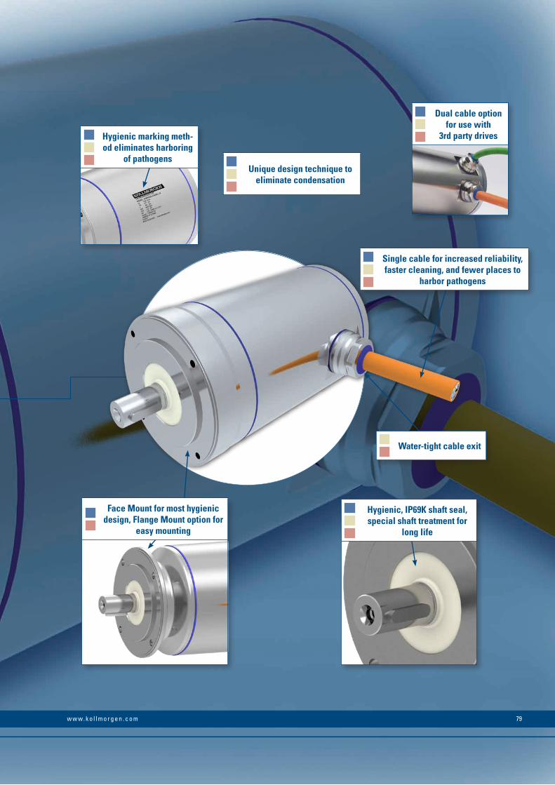
AK
MH
H
YG
IE
NI
C
ST
AI
NL
ES
S
ST
EE
L
SE
RV
O
MO
TO
RS
n n n
External O-ring and gasket sealing with blue FDA approved
materials
n n n
Single cable for increased reliability, faster cleaning, and fewer places to
harbor pathogens
n n
Water-tight cable exit
n n n
Hygienic, IP69K shaft seal, special shaft treatment for
long life
n n n
Unique design technique to eliminate condensation
n n n
Hygienic marking meth-od eliminates harboring
of pathogens
n n n
Dual cable option for use with
3rd party drives
n n
Face Mount for most hygienic design, Flange Mount option for
easy mounting
79w w w. k o l l m o r g e n . c o m

AKMH Hygienic Stainless Steel Servo Motors
Performance Data
AKM
H Se
rvo
Mot
or
Cont
. Tor
que
at S
tall
Tcs
[Nm
]
Cont
inuo
us C
urre
nt I 0 [A
]
Peak
Torq
ue a
t sta
ll Tp
s [N
m]
160 V DC 320 V DC V 560 V DC 640 V DC
Iner
tia (J
m) [
kg∙c
m2 ]
Wei
ght [
kg]
Rate
d Sp
eed
Nrtd
[RPM
]
Rate
d To
rque
Trtd
[Nm
]
Rate
d Po
wer
Prtd
[kW
]
Rate
d Sp
eed
Nrtd
[RPM
]
Rate
d To
rque
Trtd
[Nm
]
Rate
d po
wer
Pn [k
W]
Rate
d Sp
eed
Nrtd
[RPM
]
Rate
d To
rque
Trtd
[Nm
]
Rate
d Po
wer
Prtd
[kW
]
Rate
d Sp
eed
Nrtd
[RPM
]
Rate
d To
rque
Trtd
[Nm
]
Rate
d Po
wer
Prtd
[kW
]
21C 0.31 1.37 1.76 2500 0.33 0.09 8000 0.22 0.18 8000 0.21 0.18 8000 0.21 0.18 0.11 3.6
21E 0.36 2.67 1.81 7000 0.26 0.19 – – – – – – – – – 0.11 3.6
21G 0.37 4.10 1.60 – – – – – – – – – – – – 0.11 3.6
22C 0.61 1.19 3.16 1000 0.63 0.07 3500 0.60 0.22 8000 0.41 0.34 8000 0.40 0.34 0.16 4.1
22E 0.65 2.32 3.23 3500 0.61 0.22 8000 0.60 0.22 – – – – – – 0.16 4.1
22G 0.64 3.98 3.27 7000 0.47 0.34 – – – – – – – – – 0.16 4.1
23D 0.83 1.88 4.37 1500 0.87 0.14 5000 0.73 0.38 8000 0.49 0.41 8000 0.46 0.39 0.22 4.6
23E 0.90 2.39 4.43 2500 0.86 0.23 6500 0.66 0.45 – – – – – – 0.22 4.6
23F 0.88 3.63 4.46 4500 0.78 0.37 8000 0.48 0.40 – – – – – – 0.22 4.6
24D 1.10 1.96 5.35 1500 1.10 0.17 4000 0.97 0.41 8000 0.52 0.44 8000 0.47 0.39 0.27 5.1
24E 1.15 2.52 5.36 2000 1.10 0.23 5500 0.88 0.51 – – – – – – 0.27 5.1
24F 1.12 3.42 5.39 3000 1.04 0.33 8000 0.53 0.44 – – – – – – 0.27 5.1
31C 0.91 1.24 3.76 – – – 2500 0.86 0.23 5000 0.72 0.38 6000 0.5 0.41 0.33 4.1
31E 0.96 2.64 3.88 2500 0.91 0.24 6000 0.68 0.43 – – – – – – 0.33 4.1
31H 0.99 5.04 3.95 6000 0.71 0.45 – – – – – – – – – 0.33 4.1
32C 1.68 1.30 6.92 – – – 1500 1.62 0.25 3000 1.47 0.46 3500 1.41 0.52 0.59 5.0
32E 1.69 2.49 7.06 – – – 3500 1.53 0.53 7000 0.71 0.52 8000 0.22 0.18 0.59 5.0
32H 1.77 4.81 7.21 3000 1.61 0.51 7000 0.71 0.52 – – – – – – 0.59 5.0
33C 2.46 1.37 9.94 – – – 1000 2.42 0.25 2000 2.29 0.48 2500 2.22 0.58 0.85 5.9
33E 2.51 2.34 10.19 – – – 2000 2.38 0.50 4500 1.85 0.87 5000 1.68 0.88 0.85 5.9
33H 2.60 5.00 10.43 2500 2.41 0.63 5500 1.56 0.90 – – – – – – 0.85 5.9
41C 1.77 1.46 5.75 – – – 1500 1.73 0.27 3000 1.61 0.51 3500 1.56 0.57 0.81 6.1
41E 1.75 2.73 5.84 1500 1.77 0.28 3000 1.64 0.52 6000 1.26 0.79 6000 1.22 0.77 0.81 6.1
41H 1.83 5.34 5.92 3000 1.71 0.54 6000 1.29 0.81 – – – – – – 0.81 6.1
42C 3.15 1.41 10.62 – – – – – – 1500 3.02 0.47 2000 2.94 0.62 1.45 7.4
42E 3.12 2.64 10.79 – – – 2000 2.97 0.62 3500 2.60 0.95 4000 2.43 1.02 1.45 7.4
42H 3.15 5.64 11.04 2000 3.15 0.66 4500 2.40 1.13 6000 0.82 0.52 6000 0.46 0.29 1.45 7.4
42J 3.37 8.11 11.08 3000 3.02 0.95 6000 1.27 0.80 – – – – – – 1.45 7.4
43E 4.38 2.61 15.50 – – – 1500 4.25 0.67 2500 3.89 1.02 3000 3.65 1.15 2.09 8.8
43H 4.55 5.22 15.65 – – – 3000 3.94 1.24 6000 0,12 0.08 6000 0.82 0.47 2.09 8.8
43L 4.02 9.92 15.58 3000 3.48 1.09 5500 0.45 0.26 – – – – – – 2.09 8.8
44E 5.41 2.70 19.77 – – – 1000 5.29 0.55 2000 4.83 1.01 2500 4.56 1.19 2.73 10.2
44H 5.40 5.23 19.73 – – – 2500 4.72 1.24 5000 1.96 1.03 5000 1.27 0.66 2.73 10.2
44K 5.42 9.41 19.75 2000 4.96 1.04 5000 1.83 0.96 – – – – – – 2.73 10.2
51E 3.92 2.61 10.09 – – – 1500 3.83 0.60 2500 3.58 0.94 3000 3.44 1.08 3.42 8.9
51H 3.80 5.45 10.17 – – – 3000 3.44 1.08 5500 2.20 1.27 5500 2.05 1.18 3.42 8.9
51L 3.89 10.58 10.33 3000 3.54 1.11 5500 2.16 1.24 – – – – – – 3.42 8.9
Motor winding excess temperature, ∆T = 100 K with ambient temperature = 40°C
All specifications refer to sinusoidal supply
Rated data with reference flange (aluminum, dims (mm): AKMH2, AKMH3, AKMH4: 254 x 254 x 6.35 AKMH5: 305 x 305 x 12.7 AKMH6: 457 x 457 x 12.7)
K O L L M O R G E N 80
AK
MH
H
YG
IE
NI
C
ST
AI
NL
ES
S
ST
EE
L
SE
RV
O
MO
TO
RS
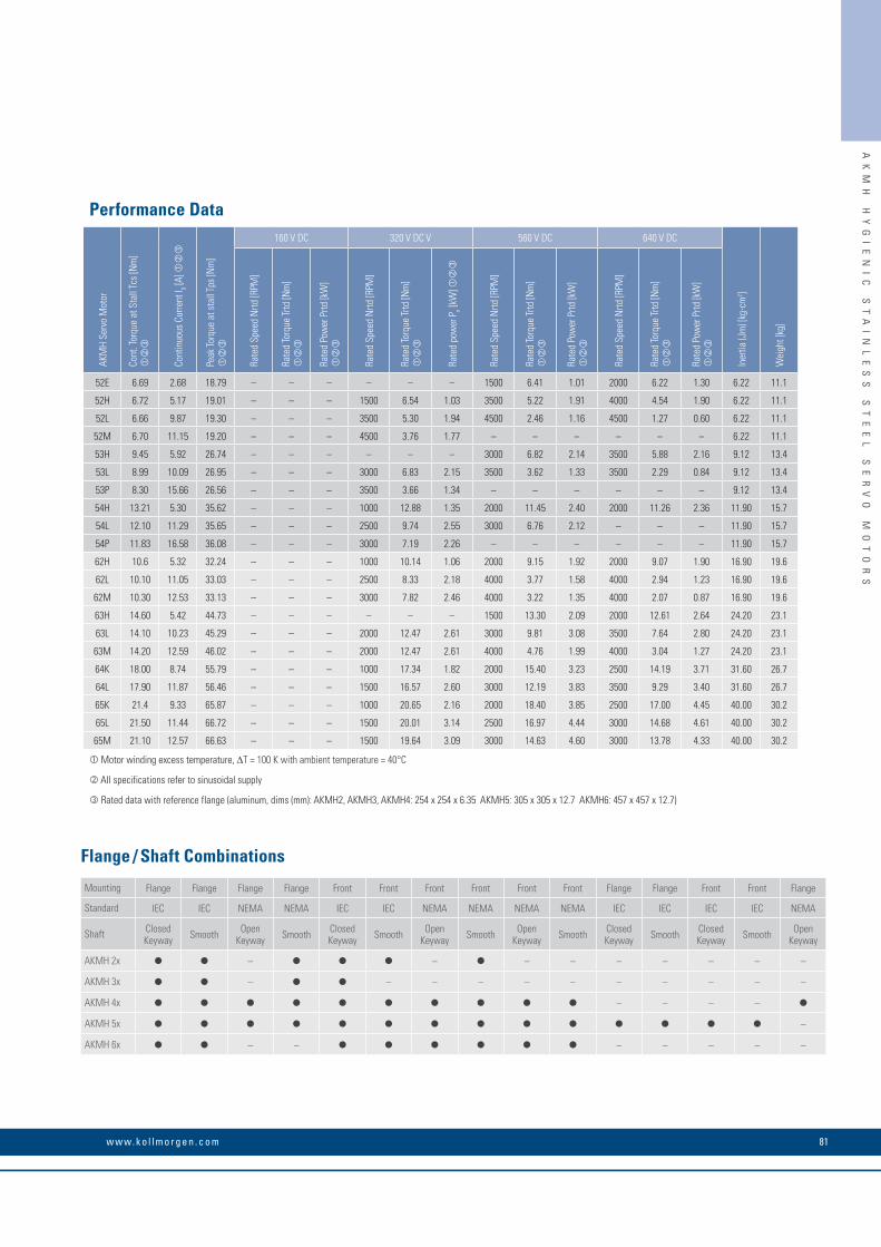
AK
MH
H
YG
IE
NI
C
ST
AI
NL
ES
S
ST
EE
L
SE
RV
O
MO
TO
RS
Mounting Flange Flange Flange Flange Front Front Front Front Front Front Flange Flange Front Front Flange
Standard IEC IEC NEMA NEMA IEC IEC NEMA NEMA NEMA NEMA IEC IEC IEC IEC NEMA
Shaft Closed Keyway Smooth Open
Keyway Smooth Closed Keyway Smooth Open
Keyway Smooth Open Keyway Smooth Closed
Keyway Smooth Closed Keyway Smooth Open
Keyway
AKMH 2x – – – – – – – – –
AKMH 3x – – – – – – – – – – –
AKMH 4x – – – –
AKMH 5x –
AKMH 6x – – – – – – –
Flange / Shaft Combinations
Performance Data
AKM
H Se
rvo
Mot
or
Cont
. Tor
que
at S
tall
Tcs
[Nm
]
Cont
inuo
us C
urre
nt I 0 [A
]
Peak
Torq
ue a
t sta
ll Tp
s [N
m]
160 V DC 320 V DC V 560 V DC 640 V DC
Iner
tia (J
m) [
kg∙c
m2 ]
Wei
ght [
kg]
Rate
d Sp
eed
Nrtd
[RPM
]
Rate
d To
rque
Trtd
[Nm
]
Rate
d Po
wer
Prtd
[kW
]
Rate
d Sp
eed
Nrtd
[RPM
]
Rate
d To
rque
Trtd
[Nm
]
Rate
d po
wer
Pn [k
W]
Rate
d Sp
eed
Nrtd
[RPM
]
Rate
d To
rque
Trtd
[Nm
]
Rate
d Po
wer
Prtd
[kW
]
Rate
d Sp
eed
Nrtd
[RPM
]
Rate
d To
rque
Trtd
[Nm
]
Rate
d Po
wer
Prtd
[kW
]
52E 6.69 2.68 18.79 – – – – – – 1500 6.41 1.01 2000 6.22 1.30 6.22 11.1
52H 6.72 5.17 19.01 – – – 1500 6.54 1.03 3500 5.22 1.91 4000 4.54 1.90 6.22 11.1
52L 6.66 9.87 19.30 – – – 3500 5.30 1.94 4500 2.46 1.16 4500 1.27 0.60 6.22 11.1
52M 6.70 11.15 19.20 – – – 4500 3.76 1.77 – – – – – – 6.22 11.1
53H 9.45 5.92 26.74 – – – – – – 3000 6.82 2.14 3500 5.88 2.16 9.12 13.4
53L 8.99 10.09 26.95 – – – 3000 6.83 2.15 3500 3.62 1.33 3500 2.29 0.84 9.12 13.4
53P 8.30 15.66 26.56 – – – 3500 3.66 1.34 – – – – – – 9.12 13.4
54H 13.21 5.30 35.62 – – – 1000 12.88 1.35 2000 11.45 2.40 2000 11.26 2.36 11.90 15.7
54L 12.10 11.29 35.65 – – – 2500 9.74 2.55 3000 6.76 2.12 – – – 11.90 15.7
54P 11.83 16.58 36.08 – – – 3000 7.19 2.26 – – – – – – 11.90 15.7
62H 10.6 5.32 32.24 – – – 1000 10.14 1.06 2000 9.15 1.92 2000 9.07 1.90 16.90 19.6
62L 10.10 11.05 33.03 – – – 2500 8.33 2.18 4000 3.77 1.58 4000 2.94 1.23 16.90 19.6
62M 10.30 12.53 33.13 – – – 3000 7.82 2.46 4000 3.22 1.35 4000 2.07 0.87 16.90 19.6
63H 14.60 5.42 44.73 – – – – – – 1500 13.30 2.09 2000 12.61 2.64 24.20 23.1
63L 14.10 10.23 45.29 – – – 2000 12.47 2.61 3000 9.81 3.08 3500 7.64 2.80 24.20 23.1
63M 14.20 12.59 46.02 – – – 2000 12.47 2.61 4000 4.76 1.99 4000 3.04 1.27 24.20 23.1
64K 18.00 8.74 55.79 – – – 1000 17.34 1.82 2000 15.40 3.23 2500 14.19 3.71 31.60 26.7
64L 17.90 11.87 56.46 – – – 1500 16.57 2.60 3000 12.19 3.83 3500 9.29 3.40 31.60 26.7
65K 21.4 9.33 65.87 – – – 1000 20.65 2.16 2000 18.40 3.85 2500 17.00 4.45 40.00 30.2
65L 21.50 11.44 66.72 – – – 1500 20.01 3.14 2500 16.97 4.44 3000 14.68 4.61 40.00 30.2
65M 21.10 12.57 66.63 – – – 1500 19.64 3.09 3000 14.63 4.60 3000 13.78 4.33 40.00 30.2
Motor winding excess temperature, ∆T = 100 K with ambient temperature = 40°C
All specifications refer to sinusoidal supply
Rated data with reference flange (aluminum, dims (mm): AKMH2, AKMH3, AKMH4: 254 x 254 x 6.35 AKMH5: 305 x 305 x 12.7 AKMH6: 457 x 457 x 12.7)
81w w w. k o l l m o r g e n . c o m

4X Ø C 45°
EØ
BØ
Ø D
Z maxK
ØJ
Z maxK
ØJ
K Z max
ØJ
AKMH Hygienic Stainless Steel Servo Motors
Dimensions (mm)
N
Open keyway (BK, CN, DK versions)
T
Closed keyway (AC, BN, GC, HC versions)
AKMH flange mounting AKMH front mounting Only AKMH5x front mounting
Model
Z max.SFD3 digital resolver
Z max.Hiperface DSL Flange
without brake with brake without brake with brake ØB
AKMH21 167.2 201.2 180.2 214.2 79
AKMH22 186.2 220.2 199.2 233.2 79
AKMH23 205.2 239.2 218.2 252.2 79
AKMH24 224.2 258.2 237.2 271.2 79
AKMH31 166.5 198.0 182.5 214.0 89
AKMH32 197.5 229.0 213.5 245.0 89
AKMH33 228.5 260.0 244.5 276.0 89
AKMH41 166.7 201.0 182.7 217.0 113
AKMH42 195.7 230.0 211.7 246.0 113
AKMH43 224.7 259.0 240.7 275.0 113
AKMH44 253.7 288.0 269.7 304.0 113
AKMH51 187.4 229.4 198.4 240.4 148
AKMH52 218.4 260.4 229.4 271.4 148
AKMH53 249.4 291.4 260.4 302.4 148
AKMH54 280.4 322.4 291.4 333.4 148
AKMH61 209.9 256.5 220.9 267.5 186
AKMH62 234.9 281.5 245.9 292.5 186
AKMH63 259.9 306.5 270.9 317.5 186
AKMH64 284.9 331.5 295.9 342.5 186
K O L L M O R G E N 82
AK
MH
H
YG
IE
NI
C
ST
AI
NL
ES
S
ST
EE
L
SE
RV
O
MO
TO
RS
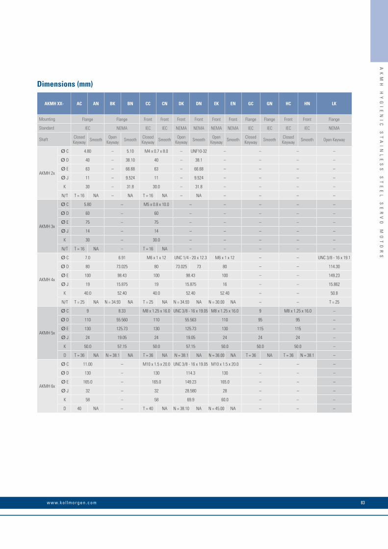
AK
MH
H
YG
IE
NI
C
ST
AI
NL
ES
S
ST
EE
L
SE
RV
O
MO
TO
RS
AKMH XX- AC AN BK BN CC CN DK DN EK EN GC GN HC HN LK
Mounting Flange Flange Front Front Front Front Front Front Flange Flange Front Front Flange
Standard IEC NEMA IEC IEC NEMA NEMA NEMA NEMA IEC IEC IEC IEC NEMA
Shaft Closed Keyway Smooth Open
Keyway Smooth Closed Keyway Smooth Open
Keyway Smooth Open Keyway Smooth Closed
Keyway Smooth Closed Keyway Smooth Open Keyway
AKMH 2x
Ø C 4.80 – 5.10 M4 x 0.7 x 8.0 – UNF10-32 – – – –
Ø D 40 – 38.10 40 – 38.1 – – – –
Ø E 63 – 66.68 63 – 66.68 – – – –
Ø J 11 – 9.524 11 – 9.524 – – – –
K 30 – 31.8 30.0 – 31.8 – – – –
N/T T = 16 NA – NA T = 16 NA – NA – – – –
AKMH 3x
Ø C 5.80 – M5 x 0.8 x 10.0 – – – – –
Ø D 60 – 60 – – – – –
Ø E 75 – 75 – – – – –
Ø J 14 – 14 – – – – –
K 30 – 30.0 – – – – –
N/T T = 16 NA – T = 16 NA – – – – –
AKMH 4x
Ø C 7.0 6.91 M6 x 1 x 12 UNC 1/4 - 20 x 12.3 M6 x 1 x 12 – – UNC 3/8 - 16 x 19.1
Ø D 80 73.025 80 73.025 73 80 – – 114.30
Ø E 100 98.43 100 98.43 100 – – 149.23
Ø J 19 15.875 19 15.875 16 – – 15.862
K 40.0 52.40 40.0 52.40 52.40 – – 50.8
N/T T = 25 NA N = 34.93 NA T = 25 NA N = 34.93 NA N = 30.00 NA – – T = 25
AKMH 5x
Ø C 9 8.33 M8 x 1.25 x 16.0 UNC 3/8 - 16 x 19.05 M8 x 1.25 x 16.0 9 M8 x 1.25 x 16.0 –
Ø D 110 55.560 110 55.563 110 95 95 –
Ø E 130 125.73 130 125.73 130 115 115 –
Ø J 24 19.05 24 19.05 24 24 24 –
K 50.0 57.15 50.0 57.15 50.0 50.0 50.0 –
D T = 36 NA N = 38.1 NA T = 36 NA N = 38.1 NA N = 36.00 NA T = 36 NA T = 36 N = 38.1 –
AKMH 6x
Ø C 11.00 – M10 x 1.5 x 20.0 UNC 3/8 - 16 x 19.05 M10 x 1.5 x 20.0 – – –
Ø D 130 – 130 114.3 130 – – –
Ø E 165.0 – 165.0 149.23 165.0 – – –
Ø J 32 – 32 28.580 28 – – –
K 58 – 58 69.9 60.0 – – –
D 40 NA – T = 40 NA N = 38.10 NA N = 45.00 NA – – –
Dimensions (mm)
83w w w. k o l l m o r g e n . c o m
K O L L M O R G E N 84
ER
D
HY
GI
EN
IC
S
TA
IN
LE
SS
S
TE
EL
A
CT
UA
TO
RS
Reduce cleaning times without compromising on performance and space. Kollmorgen combines a stainless-steel AKMH motor with a linear actuator into a hygienic linear drive that is ready-for-installation: ideal for applications such as lifting units, dosing units or format adjustments in the packaging, food processing, and pharmaceutical industries. Extremely compact linear actuators can be supplied as in-line or reverse units in various motor/spindle combinations.
ERD Hygienic Stainless Steel Linear Actuators

ER
D
HY
GI
EN
IC
S
TA
IN
LE
SS
S
TE
EL
A
CT
UA
TO
RS
The Advantages of ERD Stainless Steel Linear Actuators• Substantially improved Overall Equipment
Effectiveness (OEE)• Fast cleaning thanks to open machine design without protective housings
• High degree of reliability with regular high-pressure and high-temperature cleaning
• Higher throughput thanks to quick and precise motion control with AKD
• Process monitoring and optimization with Kollmorgen's software tools
• 20% less derating due to special motor design
• High degree of product safety with significantly reduced risk of recalls
• Complies with USDA, 3A, NSF hygiene regulations
• Hygienic housing design with stainless steel for safe cleaning
• Single-cable technology with FDA-approved, sheathing suitable for use with food (optional)
• Simple machine design and quick start-up • Plug-and-play connection with pre-assembled, connectable cables
• Robust version in IP69K with high power density and overload capacity
• Control with the AKD, AKD-PDMM, and AKD-N servo drives
• Extensive software tools for parameterization and drive monitoring
• Simple drive design with the Kollmorgen Automation Suite
85w w w. k o l l m o r g e n . c o m
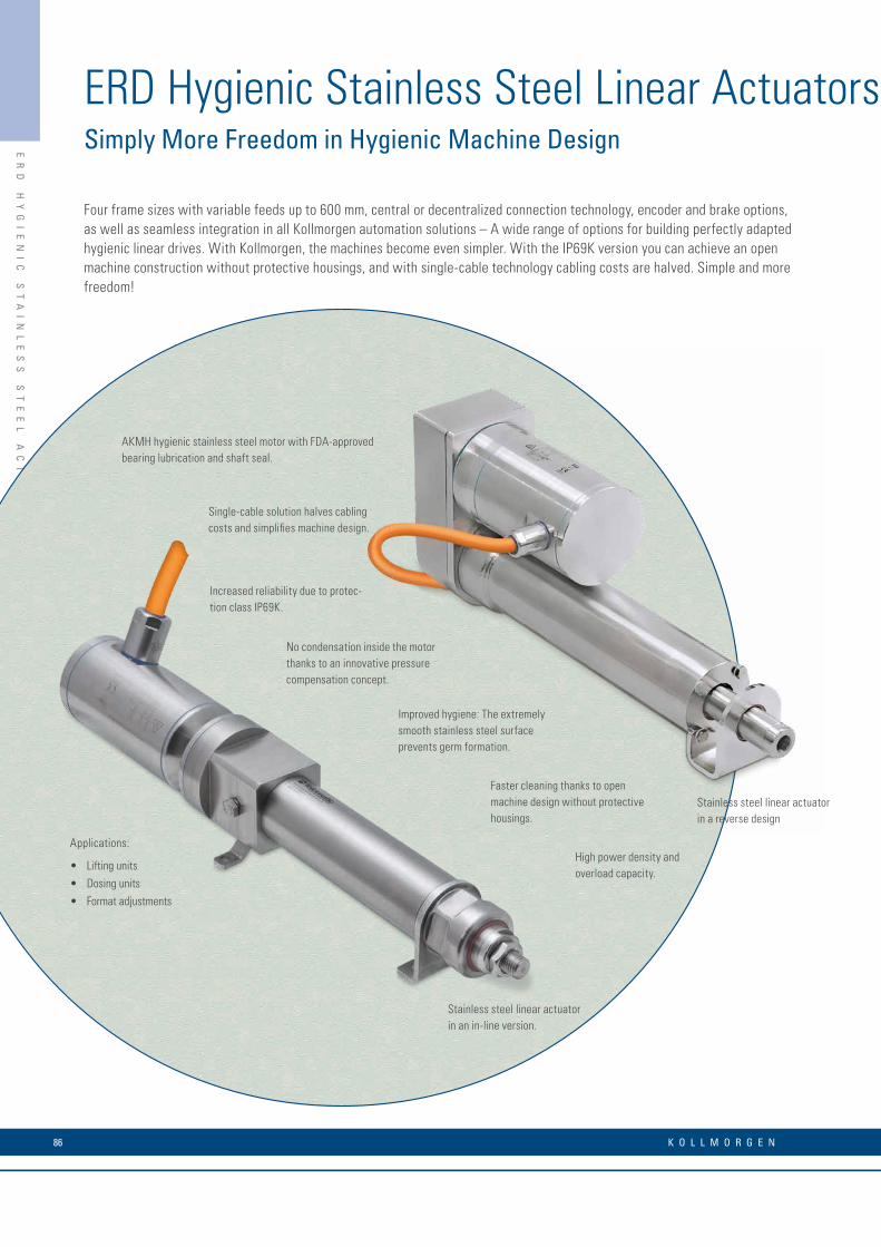
ER
D
HY
GI
EN
IC
S
TA
IN
LE
SS
S
TE
EL
A
CT
UA
TO
RS
ERD Hygienic Stainless Steel Linear ActuatorsSimply More Freedom in Hygienic Machine Design
Four frame sizes with variable feeds up to 600 mm, central or decentralized connection technology, encoder and brake options, as well as seamless integration in all Kollmorgen automation solutions – A wide range of options for building perfectly adapted hygienic linear drives. With Kollmorgen, the machines become even simpler. With the IP69K version you can achieve an open machine construction without protective housings, and with single-cable technology cabling costs are halved. Simple and more freedom!
Stainless steel linear actuator in an in-line version.
Stainless steel linear actuator in a reverse design
Increased reliability due to protec-tion class IP69K.
Single-cable solution halves cabling costs and simplifies machine design.
Faster cleaning thanks to open machine design without protective housings.
High power density and overload capacity.
No condensation inside the motor thanks to an innovative pressure compensation concept.
Improved hygiene: The extremely smooth stainless steel surface prevents germ formation.
Applications:
• Lifting units• Dosing units• Format adjustments
AKMH hygienic stainless steel motor with FDA-approved bearing lubrication and shaft seal.
K O L L M O R G E N 86

ER
D
HY
GI
EN
IC
S
TA
IN
LE
SS
S
TE
EL
A
CT
UA
TO
RS
ERD Hygienic Stainless Steel Linear ActuatorsSimply More Freedom in Hygienic Machine Design Highest Product Safety and Overall Equipment Effectiveness
• Hygienic housing design prevents germ formation and contamination traps • Quick and simple cleaning thanks to open machine design without protective housings• High degree of reliability even with frequent high-pressure and high-temperature cleaning thanks to stainless steel
housing in IP69K• Single-cable connection halves cabling costs and improves hygiene• High degree of product safety in accordance with USDA, 3A, and NSF requirements ensured
Performance Data
Stainless steel linear actuator AKMH2/ERD15 AKMH3/ERD20 AKMH4/ERD25 AKMH5/ERD30
Protection class / hygiene standards IP69k / USDA, 3A, NSF
Connection technology / servo drive Single-cable technology / AKD (central) or AKD-N (decentralized)
Encoder options Digital resolver SFD3, Hiperface DSL
Motor diameter mm 74.0 85.0 113.0 132.0
Actuator diameter mm 42 52 89 89
Feed (max) mm 600 600 600 600
Feed speed (max) mm/s 1016 495 1448 813
Feed force kN 0.89 2.224 14.679 20.017
87w w w. k o l l m o r g e n . c o m
K O L L M O R G E N 88
IC
H
LI
NE
AR
D
IR
EC
T
DR
IV
ES
High throughput, high precision, and maintenance-free: Linear direct drives from Kollmorgen set the standard for performance and effectiveness. These are brushless 3-phase servo motors with no housing and an iron core impress due to their high power density and extremely quiet running. The motor design ensures minimum cogging values that result in motion profiles with low fluctuation in terms of power and speed.
Linear Direct Drives
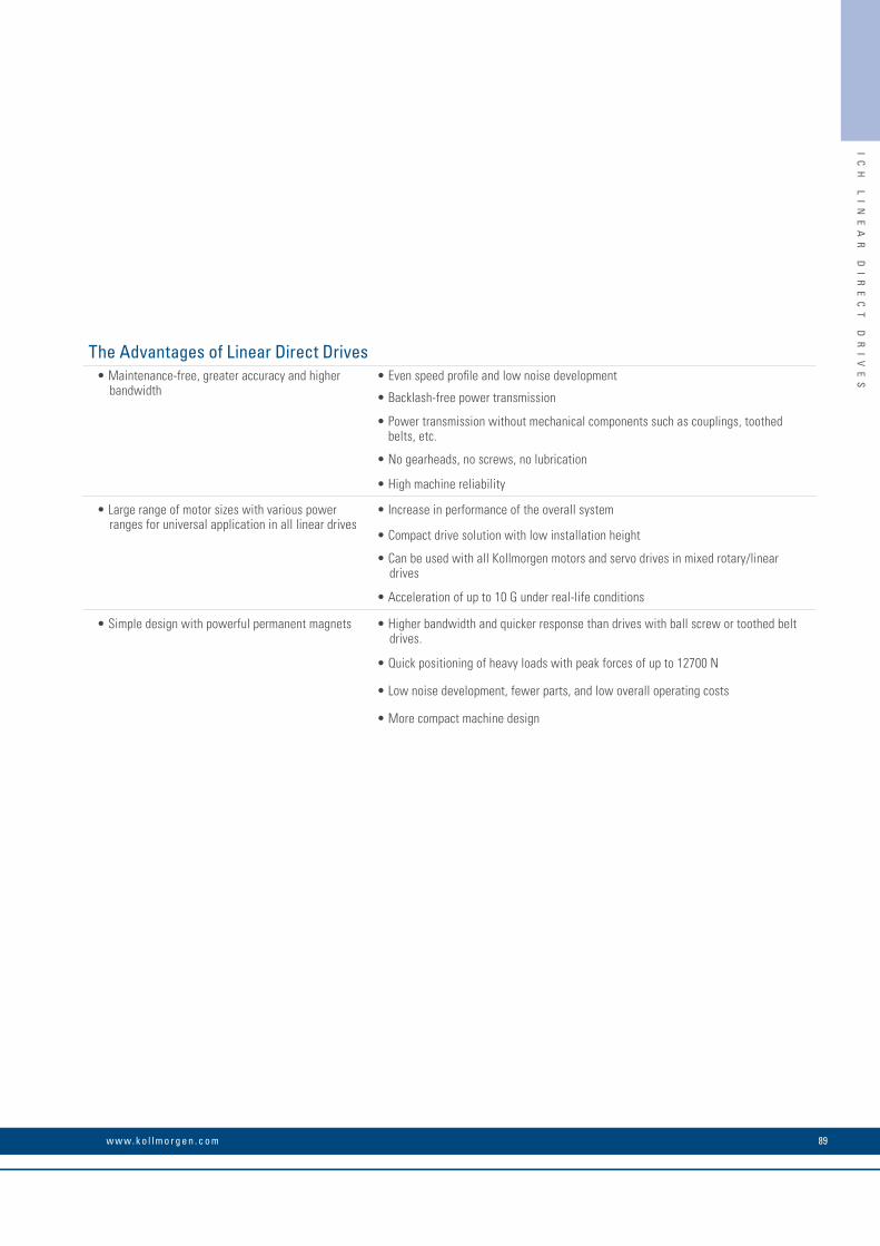
IC
H
LI
NE
AR
D
IR
EC
T
DR
IV
ES
The Advantages of Linear Direct Drives• Maintenance-free, greater accuracy and higher
bandwidth• Even speed profile and low noise development
• Backlash-free power transmission
• Power transmission without mechanical components such as couplings, toothed belts, etc.
• No gearheads, no screws, no lubrication
• High machine reliability
• Large range of motor sizes with various power ranges for universal application in all linear drives
• Increase in performance of the overall system
• Compact drive solution with low installation height
• Can be used with all Kollmorgen motors and servo drives in mixed rotary/linear drives
• Acceleration of up to 10 G under real-life conditions
• Simple design with powerful permanent magnets • Higher bandwidth and quicker response than drives with ball screw or toothed belt drives.
• Quick positioning of heavy loads with peak forces of up to 12700 N
• Low noise development, fewer parts, and low overall operating costs
• More compact machine design
89w w w. k o l l m o r g e n . c o m

IC
H
LI
NE
AR
D
IR
EC
T
DR
IV
ES
ICH Linear Direct DrivesPowerful Precision – As Much As You Want
Increase productivity and reduce operating costs – with the ICH linear motors from Kollmorgen you considerably improve overall equipment effectiveness. Cross the costs for maintenance work out of your calculations! Linear direct drives from Kollmorgen increase throughput compared with other drive systems by up to 40% and enable smaller, lighter machines with high energy efficiency due to their compact design.
ICH Linear Direct Drives• Maintenance-free iron-core linear motors with high power density
• Direct power transmission without mechanical components
• Special motor design ensures very quiet running
• Feed force of 405 N to 12726 N (peak) and 175 N to 5341 N (continuous operation)
• Optional digital hall effect sensors
• Compatible with all servo drives and safety and energy-saving modules
• Comprehensive development support from the Kollmorgen support team
K O L L M O R G E N 90

IC
H
LI
NE
AR
D
IR
EC
T
DR
IV
ES
Wide Range of Speed – from µm/s to km/h Slower than 1 µm/s or faster than 5 m/s – the ICH linear motors from Kollmorgen move the load at all speeds precisely and with extremely low speed variations.
High System Dynamics Over 10 GICH linear motors are distinguished by their quick and powerful acceleration. The larger motors typically achieve values between 3 G and 5 G; smaller motors more than 10 G. The primary limiting factor is the machine's management system.
Low Power Fluctuation and High SynchronizationIron-core linear motors boast high power density, but also a certain degree of cogging depending on the system. The motor design from Kollmorgen reduces cogging to a minimum. The ICH linear motors thus impress with their high power density with low power fluctuation and precise synchronization.
Precise Positioning to Fractions of a µmPositioning accuracy is limited by the resolution of the feedback system. In combination with the AKD servo drives from Kollmorgen you can develop linear drives that position quickly and precisely.
Unlimited TravelThe secondary parts can be supplied in lengths 64, 128, 256, and 512 mm and can be combined into travel distances as long as you wish.
Simple Drive Design with Few PartsDrives with linear motors with no housing require fewer parts and are considerably simpler in structure than rotary motors. The ICH linear motors from Kollmorgen merely require an air gap of 0.9 mm. Moreover, no critical adjustments are necessary.
91w w w. k o l l m o r g e n . c o m

IC
H
LI
NE
AR
D
IR
EC
T
DR
IV
ES
ICH Linear Direct Drives
Primary Part
Secondary PartPermanent Magnet
Rotary Motor Linear Motor
Air Gap
Rotor
Windings
Stator
SN
Functional Principle
Linear motors function according to the same principle as conventional rotary motors. Rotor and stator are rolled out flat and are no longer connected together mechanically. They then form the two components "primary part" (stator, coil part) and "secondary part" (rotor, magnet section). The load is coupled directly to the moving part – usually the primary part – while the secondary part is fixed to the machine as a magnet guide. However, in special applications the primary part may be fixed while the secondary part moves. The functional principle remains the same.
Feedback System All brushless motors require a feedback system for the commutation. Kollmorgen offers digital hall effect sensors which are used in the same way as with rotary servo motors from the servo drive to the commutation. In applications with particularly demanding synchronization requirements, digital hall effect sensors are used and the servo drive supplies sinusoidal currents.
For exact position determination, linear encoders – whose signals are simultaneously used for the commutation – are frequently employed. The signals of the hall effect sensors can be used during the start phase in addition to the commutation.
Options• Hall effect sensors (digital)• Thermal overload protection PTC+KTY• Different cable options
Applications Lurking Everywhere!The ICH linear motors can be used in almost all motion tasks in many industries:
• Machine tools: Tool positioning for drilling, milling, grinding, and laser cutting
• Semi-conductor industry: Handling, checking and separating wafers, wire bonding, TAB, ion implantation, lithography
• Textile industry: Tufting machines
• Metrology: Coordinate measuring devices
• Assembly production: Placement machinery, screen prints, glue dispensers, drilling and checking printed circuits
• Medical devices: Patient positioning systems
• Preform injection molding machinery
• Plasma cutting machinery
• Flight simulators
• Acceleration slides, catapults
K O L L M O R G E N 92

IC
H
LI
NE
AR
D
IR
EC
T
DR
IV
ES
ICH Linear Direct DrivesICH Series Performance Overview
1000
2000
3000
4000
5000
6000
7000
8000
9000
1000
0
1100
0
1200
0
1300
0
1400
0
1500
0
1600
0 Max feed force (N)
Continuous Peak
ICH11-030 175 405
ICH11-050 299 674
ICH11-075 455 1012
ICH11-100 612 1349
ICH11-150 894 1909
ICH11-200 1200 2545
ICH11-250 1507 3182
ICH22-030 342 710
ICH22-050 584 1184
ICH22-075 889 1775
ICH22-100 1203 2367
ICH22-150 1823 3551
ICH22-200 2445 4734
ICH22-250 3067 5918
ICH33-030 511 1065
ICH33-050 769 1909
ICH33-075 1171 2863
ICH33-100 1575 3818
ICH33-150 2387 5727
ICH33-200 3201 7636
ICH33-250 4016 9545
ICH44-030 600 1527
ICH44-050 1023 2545
ICH44-075 1557 3818
ICH44-100 2095 5090
ICH44-150 3175 7636
ICH44-200 4258 10181
ICH44-250 5341 12726
Continuous operation Feed force: Peak value
Newtons
93w w w. k o l l m o r g e n . c o m

IC
H
LI
NE
AR
D
IR
EC
T
DR
IV
ES
Performance Data
Model Winding 2)
Feed force [N] Current [A] Weight primary part
[kg]
Secondary part type
Weight secondary part [kg/m]Peak Continu-
ous 1)Peak Continuous
ICH11-030A1
405 1758,9 2,9
2.5 MCH-030 5.4A5 15.5 5.0
ICH11-050A1
674 2998.9 2,9
3.5 MCH-050 7.6A5 15.5 5.1
ICH11-075A1
1012 4558.9 3,0
4.8 MCH-075 10.4A5 15,2 5.2
ICH11-100A1
1349 6128.9 3,0
5.2 MCH-100 13.2A5 15.3 5.2
ICH11-150A1
1909 89417.9 6.1
8.6 MCH-150 18.8A5 26.5 9.0
ICH11-200A1
2545 120030.6 5.2
11.2 MCH-200 24.4A5 26.5 9.0
ICH11-250A1
3182 150715,3 5.2
13.8 MCH-250 30.0A5 26.5 9.1
ICH22-030A1
710 3428.9 2.8
4.9 MCH-030 5.4A5 15.5 4.9
ICH22-050A1
1184 5848.9 2,9
6.8 MCH-050 7.6A5 15.5 5.0
ICH22-075A1
1775 88917.9 5.9
9.3 MCH-075 10.4A5 30,9 10.2
ICH22-100A1
2367 120330.6 10.2
11.8 MCH-100 13.2A5 53.0 17.0
ICH22-150A1
3551 182330.6 10.4
16.8 MCH-150 18.8A5 53.0 17.9
ICH22-200A1
4734 244530.6 10.4
21.7 MCH-200 24.4A5 53.0 18.0
ICH22-250A1
5918 306730.6 10.5
26.7 MCH-250 30.0A5 53.0 18.1
ICH33-030A1
1065 5118.9 2.8
7.2 MCH-030 5.4A5 15.5 4.9
ICH33-050A1
1909 76930.6 8.8
10.2 MCH-050 7.6A5 53.0 15.2
ICH33-075A1
2863 117130.6 8.9
13.8 MCH-075 10.4A5 53.0 15.5
ICH33-100A1
3818 157530.6 9.0
17.5 MCH-100 13.2A5 53.0 15.6
ICH33-150A1
5727 238730.6 9.1
24.9 MCH-150 18.8A5 53.0 15.8
ICH33-200A1
7636 320145.9 13.8
32.2 MCH-200 24.4A5 79.5 23.8
ICH33-250A1
9545 401645.9 13.8
39.7 MCH-250 30.0A5 79.5 23.9
ICH44-030A1
1527 60015.3 4.3
9.6 MCH-030 5.4A5 26,5 7.4
ICH44-050A1
2545 102315.3 4.4
13.5 MCH-050 7.6A5 26,5 7.6
ICH44-075A1
3818 155730.6 8.9
18.3 MCH-075 10.4A5 53.0 15.4
ICH44-100A1
5090 209530.6 9.0
23.2 MCH-100 13.2A5 53.0 15.6
ICH44-150A1
7636 317561.2 18.2
33.1 MCH-150 18.8A5 106.0 31.5
ICH44-200A1
10181 425861.2 18.3
42.8 MCH-200 24.4A5 106.0 31.7
ICH44-250A1
12726 534161.2 18.4
52.6 MCH-250 30.0A5 106.0 31.8
1) Continuous feed force with maximum winding temperature 2) Other windings are possible – please ask us about them
ICH Linear Direct DrivesIron-core Linear Motors
K O L L M O R G E N 94
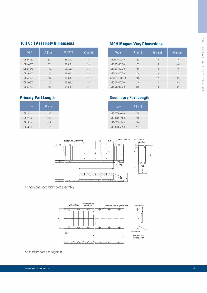
IC
H
LI
NE
AR
D
IR
EC
T
DR
IV
ES
25,1
D
75
"C"
MOTOR (PRIMARY PART)
"B"
"A"
43,3
9,5
1515
"B"
MAGNETWAY (SECONDARY PART)
F
64 ±0,1
E 32
Stainless Steel Magnet Cover Mounting HolesØ 7/Ø 12x5,5 H
G
Ø7/
Ø12
x5,5
Stainless SteelMagnet Cover
ICH Coil Assembly Dimensions MCH Magnet Way Dimensions
Type A [mm] B [mm] C [mm] Type F [mm] G [mm] H [mm]
ICH xx -030 60 58.6 ±0.1 16 MCH030-XXX-01 60 10 14.4
ICH xx -050 80 58.6 ±0.1 36 MCH050-XXX-01 80 10 14.4
ICH xx -075 105 58.6 ±0.1 32 MCH075-XXX-01 105 10 14.4
ICH xx -100 130 58.6 ±0.1 36 MCH100-XXX-01 130 10 14.4
ICH xx -150 180 60.6 ±0.1 32 MCH-150-XXX-01 180 12 16.4
ICH xx -200 230 60.6 ±0.1 36 MCH200-XXX-01 230 12 16.4
ICH xx -250 280 62.6 ±0.1 32 MXH250-XXX-01 280 14 18.4
Primary Part Length Secondary Part Length
Type D [mm] Type E [mm]
ICH11-xxx 190 MCHXXX-064-01 64
ICH22-xxx 365 MCHXXX-128-01 128
ICH33-xxx 542 MCHXXX-256-01 256
ICH44-xxx 718 MCHXXX-512-01 512
Primary and secondary part assembly
Secondary part per segment
95w w w. k o l l m o r g e n . c o m

K O L L M O R G E N 96
Rotary Direct DrivesKollmorgen offers a comprehensive selection of direct drives in different sizes and performance ranges. Direct drives are characterized by their high precision, reliability, and above all being maintenance-free.Mechanical components for power transmission such as belts or gearheads are not necessary – you just need the motor and bolts for mounting.
The Cartridge DDR™ (Cartridge Direct Drive Rotary) drives combine the performance advantages of direct drives with no housing with the simple installation and the handling advantages of conventionally housed motors. By contrast the KBM™ series direct drives with no housing can be perfectly tailored to the application thanks to a unique construction kit principle.
All drives can be combined with AKD or ADK PDMM series servo drives, and the powerful Kollmorgen Automation Suite development environment is available for application programming.
Regardless which drive technology you decide on, Kollmorgen provides right solution and optimum support during the development phase.
RO
TA
RY
D
IR
EC
T
DR
IV
ES

The Advantages of Rotary Direct Drives• Superb performance data • Maximum torque density thanks to innovative, electromagnetic
design minimizes the motor's spatial requirements.
• Extremely quiet running with low cogging values and low harmonic distortion (THD)
• Wide speed range and high acceleration values
• Reliable and safe operation through careful construction • Doubly secured magnet mounting on the rotor of the high-speed models through bonding and additional Kevlar® tape overlay
• 155°C-approved internal winding temperature and thermistor overtemperature protection guarantee safe continuous operation in demanding applications
• Insulation materials with UL approval facilitate the certification of higher-level assemblies
• All materials are RoHS-compliant
• Configurable design reduces the time-to-solution to a minimum • KBM series offers 14 frame sizes with several design lengths
• Cartridge DDR series offers 5 frame sizes with several design lengths
• Standard sensor feedback with hall effect sensors
• Insulation types for high and low voltage
• Several winding options with customer-specific windings upon request
• Changes to the mechanical connection are easy to perform
RO
TA
RY
D
IR
EC
T
DR
IV
ES
97w w w. k o l l m o r g e n . c o m

CA
RT
RI
DG
E
DD
R
RO
TA
RY
D
IR
EC
T
DR
IV
ES
Cartridge DDR Rotary Direct DrivesHigh Performance in Small Spaces
Advantages of the Cartridge DDR Motors Performance Overview• Quick assembly within 5 minutes • 5 frame sizes from 108 to 350 mm
• Direct power transmission without mechanical components reduces operating and maintenance costs
• 17 different lengths and 52 standard windings
• Continuous torques of 4.57 Nm to 510 Nm
• Low cogging and thus smooth running at low speeds
• The backlash-free design improves the system's response characteristics
• Speeds up to 2500 rpm
• Integrated, high-resolution sinus encoder (optional)
Less spatial requirements and huge performance benefits: Compared to conventional servo motors, the Cartridge DDR motors offer a power density of up to 50% higher, yet are just as easy to install as housing motors. The rotor of the Cartridge DDR motor rests on the machine's bearings and is connected to the machine shaft through an innovative clamp coupling. Mechanical components for power transmission which limit performance and reliability and increase operating costs are omitted completely.
Up to 50% higher torque density than conven-tional servo motors
Simple machine shaft connection due to patented clamp coupling
Installation onto machine flange, no bearings
Hollow shaft opening for continuous motor shafts
(optional)Simple attachment with 4 bolts
Repeatability improved by up to 60 times compared with
motor/gearhead combinations
K O L L M O R G E N 98
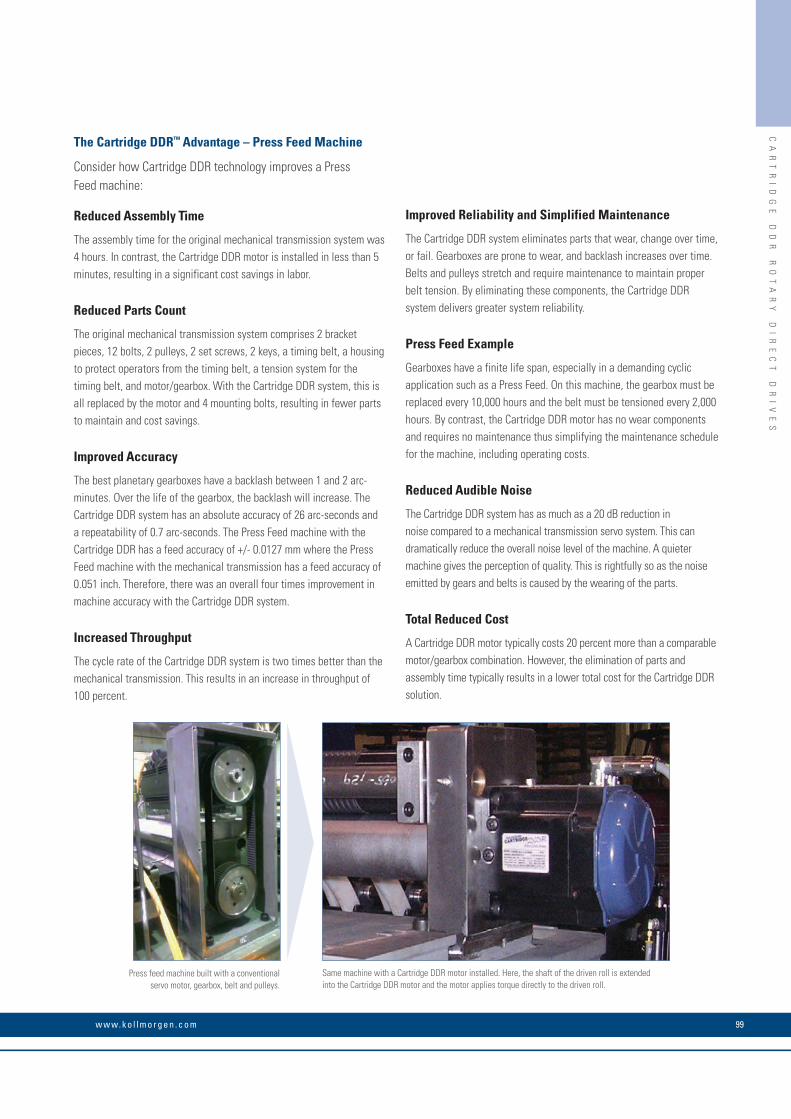
CA
RT
RI
DG
E
DD
R
RO
TA
RY
D
IR
EC
T
DR
IV
ES
The Cartridge DDR™ Advantage – Press Feed Machine
Consider how Cartridge DDR technology improves a Press Feed machine:
Reduced Assembly Time
The assembly time for the original mechanical transmission system was 4 hours. In contrast, the Cartridge DDR motor is installed in less than 5 minutes, resulting in a significant cost savings in labor.
Reduced Parts Count
The original mechanical transmission system comprises 2 bracket pieces, 12 bolts, 2 pulleys, 2 set screws, 2 keys, a timing belt, a housing to protect operators from the timing belt, a tension system for the timing belt, and motor/gearbox. With the Cartridge DDR system, this is all replaced by the motor and 4 mounting bolts, resulting in fewer parts to maintain and cost savings.
Improved Accuracy
The best planetary gearboxes have a backlash between 1 and 2 arc-minutes. Over the life of the gearbox, the backlash will increase. The Cartridge DDR system has an absolute accuracy of 26 arc-seconds and a repeatability of 0.7 arc-seconds. The Press Feed machine with the Cartridge DDR has a feed accuracy of +/- 0.0127 mm where the Press Feed machine with the mechanical transmission has a feed accuracy of 0.051 inch. Therefore, there was an overall four times improvement in machine accuracy with the Cartridge DDR system.
Increased Throughput
The cycle rate of the Cartridge DDR system is two times better than the mechanical transmission. This results in an increase in throughput of 100 percent.
Improved Reliability and Simplified Maintenance
The Cartridge DDR system eliminates parts that wear, change over time, or fail. Gearboxes are prone to wear, and backlash increases over time. Belts and pulleys stretch and require maintenance to maintain proper belt tension. By eliminating these components, the Cartridge DDR system delivers greater system reliability.
Press Feed Example
Gearboxes have a finite life span, especially in a demanding cyclic application such as a Press Feed. On this machine, the gearbox must be replaced every 10,000 hours and the belt must be tensioned every 2,000 hours. By contrast, the Cartridge DDR motor has no wear components and requires no maintenance thus simplifying the maintenance schedule for the machine, including operating costs.
Reduced Audible Noise
The Cartridge DDR system has as much as a 20 dB reduction in noise compared to a mechanical transmission servo system. This can dramatically reduce the overall noise level of the machine. A quieter machine gives the perception of quality. This is rightfully so as the noise emitted by gears and belts is caused by the wearing of the parts.
Total Reduced Cost
A Cartridge DDR motor typically costs 20 percent more than a comparable motor/gearbox combination. However, the elimination of parts and assembly time typically results in a lower total cost for the Cartridge DDR solution.
Same machine with a Cartridge DDR motor installed. Here, the shaft of the driven roll is extended into the Cartridge DDR motor and the motor applies torque directly to the driven roll.
Press feed machine built with a conventional servo motor, gearbox, belt and pulleys.
99w w w. k o l l m o r g e n . c o m

CA
RT
RI
DG
E
DD
R
RO
TA
RY
D
IR
EC
T
DR
IV
ES
240 Vac Performance Data
Cartridge DDR Motor Servo DriveFrame Size Continuous Torque Peak Torque Maximum Speed Weight Inertia (Jm)
mm Nm Nm RPM kg kg-cm2
C041A AKD-X00306 108 4.57 12.3 1750 4.08 5.86 C041B AKD-X00606 108 4.52 12.2 2500 4.08 5.86 C042A AKD-X00606 108 8.25 22.2 1700 5.67 8.87 C042B AKD-X01206 108 8.45 22.8 2500 5.67 8.87 C043A AKD-X00606 108 11.1 30.0 1250 7.26 11.9 C043B AKD-X01206 108 11.2 30.2 2500 7.26 11.9 C044A AKD-X00606 108 13.9 37.4 1050 8.84 14.9 C044B AKD-X01206 108 14.1 37.9 2150 8.84 14.9 C051A AKD-X00606 138 11.7 30.2 1200 8.39 27.4 C051B AKD-X01206 138 11.9 30.6 2450 8.39 27.4 C052C AKD-X00606 138 19.0 43.1 950 10.7 35.9 C052D AKD-X01206 138 16.5 42.3 2050 10.7 35.9 C053A AKD-X01206 138 21.0 54.1 1350 13.2 44.3 C053B AKD-X02406 138 20.2 50.1 2500 13.2 44.3 C054A AKD-X01206 138 24.9 63.8 1200 15.4 52.8 C054B AKD-X02406 138 23.8 61.2 2500 15.4 52.8 C061A AKD-X01206 188 33.8 86.8 900 18.6 94.1 C061B AKD-X02406 188 32.6 75.6 1950 18.6 94.1 C062C AKD-X01206 188 48.4 117 700 23.6 126 C062B AKD-X02406 188 44.6 102 1400 23.6 126 C063C AKD-X01206 188 61.8 157 550 29.0 157 C063B AKD-X02406 188 59.0 136 1050 29.0 157 C091A AKD-X02406 246 50.2 120 600 27.7 280 C092C AKD-X02406 246 102 231 450 41.3 470 C093C AKD-X02406 246 139 317 350 54.4 660 C131C AKD-X02406 350 189 395 250 63.5 1240 C132C AKD-X02406 350 362 818 120 101 2250 C133C AKD-X02406 350 499 1070 100 132 3020
400/480 Vac Systems Performance Data
Cartridge DDR Motor Servo DriveFrame Size Continuous Torque Peak Torque Maximum Speed Weight Inertia (Jm)
mm Nm NmRPM
kg kg-cm2
400 Vac 480 VacCH041A AKD-X00307 108 4.56 11.3 2500 2500 4.08 5.86 CH042A AKD-X00607 108 8.26 19.0 2500 2500 5.67 8.87 CH043A AKD-X00607 108 11.1 25.3 2250 2500 7.26 11.9 CH044A AKD-X00607 108 13.9 31.6 1850 2250 8.84 14.9 CH051A AKD-X00607 138 11.7 28.0 2100 2500 8.39 27.4 CH052C AKD-X00607 138 16.9 43.1 1750 2100 10.7 35.9 CH053A AKD-X01207 138 21.0 54.1 2350 2500 13.2 44.3 CH054A AKD-X01207 138 24.9 63.8 2100 2500 15.4 52.8 CH061A AKD-X01207 188 33.8 86.8 1600 1900 18.6 94.1 CH062C AKD-X01207 188 48.4 117 1250 1550 23.6 126 CH063C AKD-X01207 188 61.8 157 950 1150 29.0 157 CH063B AKD-X02407 188 59.0 136 1850 2200 29.0 157 CH091A AKD-X02407 246 50.2 120 1200 1500 27.7 280 CH092C AKD-X02407 246 102 231 800 1000 41.3 470 CH093C AKD-X02407 246 139 317 700 800 54.4 660 CH131C AKD-X02407 350 189 395 500 600 63.5 1240 CH131B AKD-X04807 350 190 396 800 1000 63.5 1240 CH132C AKD-X02407 350 362 818 250 300 101 2250 CH132B AKD-X04807 350 361 759 400 500 101 2250 CH133C AKD-X02407 350 499 1070 200 250 132 3020 CH133B AKD-X04807 350 510 1016 350 400 132 3020
Cartridge DDR Rotary Direct Drives
K O L L M O R G E N 100

CA
RT
RI
DG
E
DD
R
RO
TA
RY
D
IR
EC
T
DR
IV
ES
Cartridge DDR Motor A mm
B mm
C mm
D mm
C(H)091 204 246 149 182
C(H)092 253 246 149 182
C(H)093 302 246 149 182
C(H)131 231 350 200 256
C(H)132 301 350 200 256
C(H)133 370 350 200 256
A
B
D
C
A
Cartridge DDR C04, C05 and C06 Dimensions
Cartridge DDR Motor A mm
B mm
C mm
D mm
C(H)041 171 108 59 93
C(H)042 202 108 59 93
C(H)043 233 108 59 93
C(H)044 264 108 59 93
C(H)051 195 138 76 108
C(H)052 220 138 76 108
C(H)053 245 138 76 108
C(H)054 270 138 76 108
C(H)061 226 188 99 133
C(H)062 260 188 99 133
C(H)063 294 188 99 133
D
C
B Optional through bore
O-ring provided
Cartridge DDR C09 and C13 Dimensions
101w w w. k o l l m o r g e n . c o m
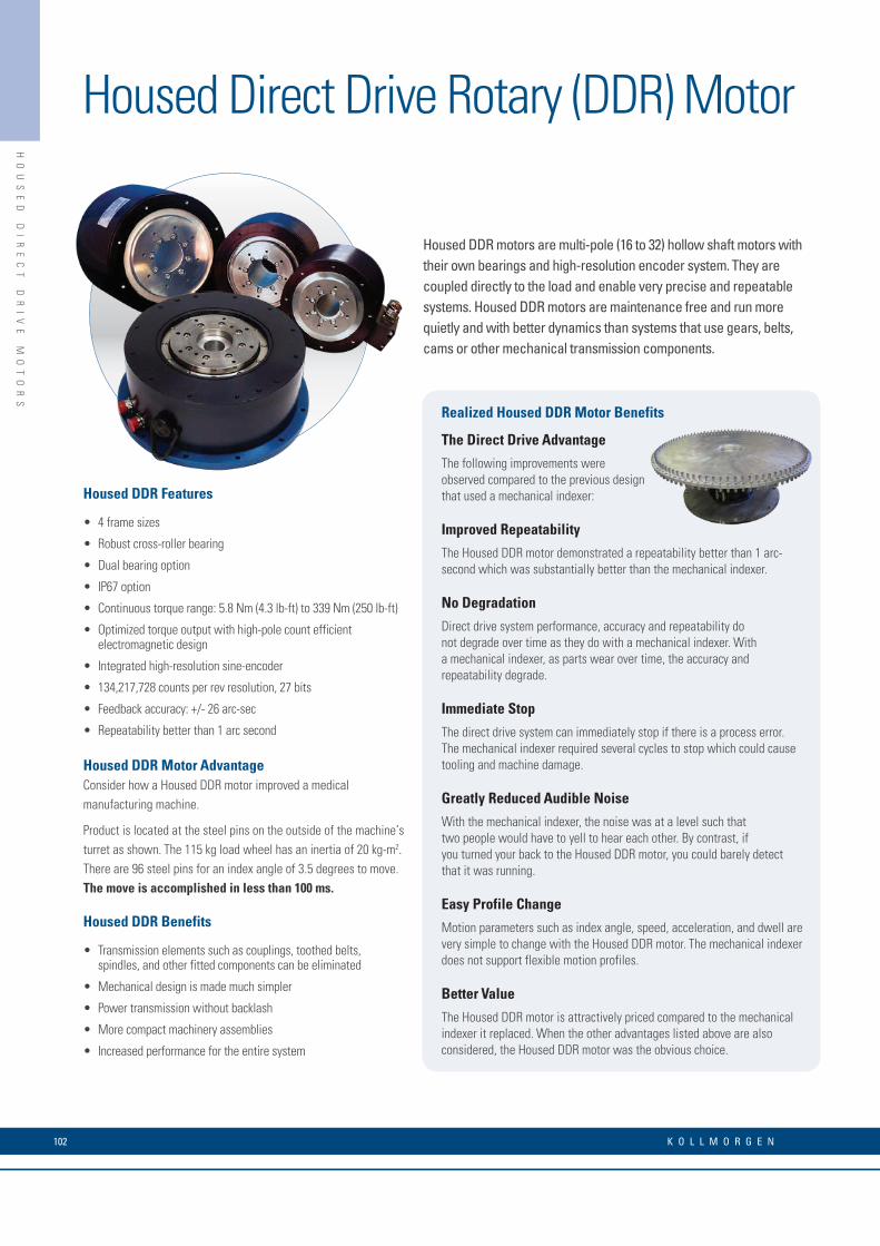
HO
US
ED
D
IR
EC
T
DR
IV
E
MO
TO
RS
Housed Direct Drive Rotary (DDR) Motor
Housed DDR motors are multi-pole (16 to 32) hollow shaft motors with their own bearings and high-resolution encoder system. They are coupled directly to the load and enable very precise and repeatable systems. Housed DDR motors are maintenance free and run more quietly and with better dynamics than systems that use gears, belts, cams or other mechanical transmission components.
Housed DDR Features
• 4 frame sizes
• Robust cross-roller bearing
• Dual bearing option
• IP67 option
• Continuous torque range: 5.8 Nm (4.3 lb-ft) to 339 Nm (250 lb-ft)
• Optimized torque output with high-pole count efficient electromagnetic design
• Integrated high-resolution sine-encoder
• 134,217,728 counts per rev resolution, 27 bits
• Feedback accuracy: +/- 26 arc-sec
• Repeatability better than 1 arc second
Housed DDR Motor AdvantageConsider how a Housed DDR motor improved a medical manufacturing machine.
Product is located at the steel pins on the outside of the machine’s turret as shown. The 115 kg load wheel has an inertia of 20 kg-m2. There are 96 steel pins for an index angle of 3.5 degrees to move. The move is accomplished in less than 100 ms.
Housed DDR Benefits
• Transmission elements such as couplings, toothed belts, spindles, and other fitted components can be eliminated
• Mechanical design is made much simpler
• Power transmission without backlash
• More compact machinery assemblies
• Increased performance for the entire system
Realized Housed DDR Motor Benefits
The Direct Drive Advantage
The following improvements were observed compared to the previous design that used a mechanical indexer:
Improved Repeatability
The Housed DDR motor demonstrated a repeatability better than 1 arc-second which was substantially better than the mechanical indexer.
No Degradation
Direct drive system performance, accuracy and repeatability do not degrade over time as they do with a mechanical indexer. With a mechanical indexer, as parts wear over time, the accuracy and repeatability degrade.
Immediate Stop
The direct drive system can immediately stop if there is a process error. The mechanical indexer required several cycles to stop which could cause tooling and machine damage.
Greatly Reduced Audible Noise
With the mechanical indexer, the noise was at a level such that two people would have to yell to hear each other. By contrast, if you turned your back to the Housed DDR motor, you could barely detect that it was running.
Easy Profile Change
Motion parameters such as index angle, speed, acceleration, and dwell are very simple to change with the Housed DDR motor. The mechanical indexer does not support flexible motion profiles.
Better Value
The Housed DDR motor is attractively priced compared to the mechanical indexer it replaced. When the other advantages listed above are also considered, the Housed DDR motor was the obvious choice.
K O L L M O R G E N 102

HO
US
ED
D
IR
EC
T
DR
IV
E
MO
TO
RS
Housed DDR Performance Data and Dimensions
240 V AC Performance Data
Housed DDR Motor
AKD Servo DriveFrame Size
mmContinuous Torque
NmPeak Torque
Nm Maximum Speed
[RPM]Weight
kgInertia (Jm)
kg•cm2
D061 AKD-X00606 175 5.3 16.9 500 9.4 61
D062 AKD-X00606 175 9.8 33.5 500 11.3 71
D063 AKD-X00606 175 17.7 64.4 500 13.8 86
D081 AKD-X00606 217 15.9 45.0 500 17.9 144
D082 AKD-X00606 217 25.9 92.2 300 21.5 194
D083 AKD-X00606 217 50.4 160 250 28.8 301
D101 AKD-X00606 280 34.6 129 300 31.5 693
D102 AKD-X00606 280 63.4 227 200 43.8 992
D103 AKD-X01206 280 115 501 120 60.8 1750
D141 AKD-X01206 362 108 367 200 59.4 1630
D142 AKD-X01206 362 183 519 120 86.6 2740
D143 AKD-X02406 362 339 1340 60 146 5420
400 / 480 V AC Performance Data
Housed DDR Motor
AKD Servo DriveFrame Size
mmContinuous Torque
NmPeak Torque
NmMaximum Speed
RPMWeight
kgInertia (Jm)
kg•cm2
DH061 AKD-X00607 175 5.3 16.9 800 9.4 61
DH062 AKD-X00607 175 9.8 33.5 800 11.3 71
DH063 AKD-X00607 175 17.7 64.4 800 13.8 86
DH081 AKD-X00607 217 15.9 45.0 500 17.9 144
DH082 AKD-X00607 217 25.9 92.2 500 21.5 194
DH083 AKD-X00607 217 50.4 160 500 28.8 301
DH101 AKD-X00607 280 34.6 129 300 31.5 693
DH102 AKD-X00607 280 63.4 227 300 43.8 992
DH103 AKD-X01207 280 115 501 250 60.8 1750
DH141 AKD-X01207 362 108 367 300 59.4 1630
DH142 AKD-X01207 362 183 519 300 86.6 2740
DH143 AKD-X02407 362 339 1340 120 146.0 5420
Dimensions
DDR A mm
B mm
C mm
D mm
D[H]061 130 175 220 126
D[H]062 140 175 220 126
D[H]063 164 175 220 126
D[H]081 145 217 260 147
D[H]082 165 217 260 147
D[H]083 206 217 260 147
D[H]101 153 280 330 181
D[H]102 185 280 330 181
D[H]103 248 280 330 181
D[H]141 153 362 406 218
D[H]142 217 362 406 218
D[H]143 344 362 406 218
Ø 42.9 (1.69) Thru Bore(Sine Encoder)
Flange Mount Face Mount
D
B
A
C
103w w w. k o l l m o r g e n . c o m

KB
M
SE
RV
O
MO
TO
RS
Custom Application SolutionsFor customized features, contact Kollmorgen to help us understand exactly what you need and how we can further optimize any KBM or engineer a new custom motor solution for the unique requirements of your application. We are experts in providing optimized solutions such as special winding configurations, tailored mounting features, diameter and stack length dimensional adjustments, or material variations.
KBM Series Frameless Brushless Motor
The KBM frameless motor series is our newest direct drive technology.
KBM frameless brushless motor models are engineered to provide the high-performance, long life and simple installation that today’s design engineers demand. Optional latching digital Hall effect sensors are pre-aligned and factory installed with added axial rotor length to achieve proper triggering. Choice of insulation allows operation over a wide range of line input voltage. Our detailed selection guide provides a variety of pre-engineered options and configurations that are currently available.
K O L L M O R G E N 104

KB
M
SE
RV
O
MO
TO
RS
The Benefits of KBM Frameless Motors• Industry-Leading Frameless Motor Performance • Advanced electromagnetic designs deliver maximum torque
density which minimizes required motor space envelope• Extremely smooth rotation with minimal cogging and low total
harmonic distortion (THD)• Broad operating speed range and rapid acceleration
• Quality Construction Ensures Reliability and Safe Operation • Redundant magnet attachment to rotor on high-speed models – adhesive bonding and high-strength banding
• 155°C motor winding temperature rating with integral thermistor allows continuous safe operation for demanding applications
• Designed with UL-recommended insulation systems to simplify system regulatory approval
• RoHS compliant material selection• Compliant with Harmonized Type C Standards EN60034- 1:2010
(rotating electrical machines) and where appropriate in accordance to the Low Voltage Directive 2014/35/EC
• Highly Configurable Design Minimizes Time to Solution • 14 frame sizes with multiple stack lengths• Standard sensor feedback using Hall effect sensors• Standard high and low voltage insulation• Multiple standard windings with custom windings available upon
request• Mechanical interface changes easily accommodated
105w w w. k o l l m o r g e n . c o m

KB
M
SE
RV
O
MO
TO
RS
KBM Series Overview
Quality Construction
• Fully encapsulated stator windings
• 155°C internal winding temperature continuous capability
• PTC thermistor (avalanche-type) overload protection
• High performance magnets
• Fail-safe bands over rotor magnets
• RoHS compliant
Available Options (No engineering fees apply)
Sensor Feedback (KBMS models) Latching digital hall effect sensors are pre-aligned and factory installed
on the lead end of the stator. Wiring instructions and electrical timing
diagrams are included in this selection guide. KBMS models include
added axial rotor length to achieve proper sensor triggering.
Insulation System S (standard) − acceptable for applications up to 240 V AC drive amplifier
supply.
H (high voltage) – required for applications >240 V AC and up to
480 V AC drive amplifier supply.
Allowed Modifications (Engineering fees apply)
Consult Kollmorgen Customer Support for guidance or to obtain a
quotation. Unit price increase may apply, depending upon extent of
modification.)
Special Windings
Motor windings may be optimized to provide desired speed and torque
performance according to the unique voltage and current requirements
of a customer’s application. Kollmorgen engineers must confirm
electrical feasibility and manufacturability of each special winding
arrangement prior to quotation.
Special Rotor Hub Dimensions
Rotor hubs may be provided with special customer-designated hole
patterns, mounting features or smaller inner bore diameters. Standard
KBM(S) models shown within this selection guide include the largest
available inner rotor bore diameter.
Rotor Hub Material Standard configuration KBM(S) rotor hubs are constructed from non-
plated cold rolled steel. If special plating, coating, cleaning or alternate
material is desired, Kollmorgen engineers must confirm feasibility and
pricing adjustment prior to quotation.
Stator Sleeve Material Standard configuration KBM(S)-10, 14, 17, 25, 35, 45, 163 and 260 size
stators are designed with uncoated aluminum sleeves around the stator
lamination stack. If special coating or plating is desired for the aluminum
stator sleeve, Kollmorgen engineers must confirm feasibility and pricing
adjustment prior to quotation. Stator sleeves are only utilized for the
sizes listed above.
Agency UL Information
KBM(S) motors are designed to facilitate UL certification in the
customer’s higher-level assembly. Stator insulation systems are
constructed entirely from agency-approved materials and are designed
in full compliance with agency creepage and clearance dimensional
guidelines. Dielectric strength between winding circuit and grounded
metal stator surface is tested at agency-specified voltage level. Because
a frameless motor’s compliance with agency requirements is dependent
upon correct installation and proper design of the surrounding enclosure
by the user, KBM(S) series products are not formally labeled or agency-
approved at the frameless motor level.
8
("
Machine housing
KBM stator
Stator clamping ring
K O L L M O R G E N 106

KB
M
SE
RV
O
MO
TO
RS
Tc in Nm
KBM(S)-10XXX-X
KBM(S)-14XXX-X
KBM(S)-17XXX-X
KBM(S)-25XXX-X
KBM(S)-35XXX-X
KBM(S)-43XXX-X
KBM(S)-45XXX-X
KBM(S)-57XXX-X
KBM(S)-60XXX-X
KBM(S)-79XXX-X
KBM(S)-88XXX-X
KBM(S)-118XXX-X
KBM(S)-163XXX-X
KBM(S)-260XXX-X
01 stack
02 stack
03 stack
04 stack
05 stack
00 stack
01 stack
02 stack
04 stack
03 stack
05 stack
KBM(S) Continuous Torque OverviewSelect from our wide variety of sizes and torque ranges to suit your application needs.
0.10 10.00 100.001.00
10 1000 10000100
KBM
Ser
ies
Fram
eles
s M
otor
s
For more detailed information please visit: http://www.kollmorgen.com/en-gb/products/motors/direct-drive/kbm-series-frameless/
107w w w. k o l l m o r g e n . c o m

KB
M
SE
RV
O
MO
TO
RS
Performance Data
KBM(S)-Continuous
standstill torque1) [Nm]
Continuous standstill
current [A]
Peak standstill moment 2) [Nm]
Peak current [A]
Rated speed [rpm-1]
Rated power1),3)
[W]
Weight KBM / KBMS
[kg]
Moment of inertia
KBM / KBMS [kg•m²]
10H01-A 0.487 1.73 1.17 4.33 15200 550 0.379 / 0.425 4.92E-6 / 1.03E-510H01-B 0.509 3.37 1.19 8.70 18500 600 0.379 / 0.425 4.92E-6 / 1.03E-510H01-C 0.492 5.21 1.23 13.8 18600 575 0.379 / 0.425 4.92E-6 / 1.03E-510H02-A 0.876 1.53 2.33 4.33 11000 740 0.658 / 0.703 1.03E-5 / 1.49E-510H02-B 0.899 3.00 2.48 8.65 15200 785 0.658 / 0.703 1.03E-5 / 1.49E-510H02-C 0.868 5.14 2.24 15.5 17000 710 0.658 / 0.703 1.03E-5 / 1.49E-510H03-A 1.16 1.54 3.46 4.86 8500 780 0.943 / 0.990 1.55E-5 / 2.02E-510H03-B 1.16 2.40 3.53 7.73 14300 740 0.943 / 0.990 1.55E-5 / 2.02E-510H03-C 1.19 3.10 3.58 9.72 14500 725 0.943 / 0.990 1.55E-5 / 2.02E-510H03-D 1.18 4.66 3.69 15.5 13000 850 0.943 / 0.990 1.55E-5 / 2.02E-510H04-A 1.45 1.60 4.66 5.46 7050 820 1.22 / 1.26 2.01E-5 / 2.55E-510H04-B 1.41 2.40 4.75 8.70 11500 860 1.22 / 1.26 2.01E-5 / 2.55E-510H04-C 1.44 3.10 4.80 10.9 12000 835 1.22 / 1.26 2.01E-5 / 2.55E-510H04-D 1.41 4.21 4.91 15.5 9500 910 1.22 / 1.26 2.01E-5 / 2.55E-514H01-A 1.22 1.53 3.28 4.32 7950 735 0.898 / 1.00 2.41E-5 / 3.36E-514H01-B 1.25 3.25 3.43 9.63 12000 700 0.898 / 1.00 2.41E-5 / 3.36E-514H01-C 1.21 6.25 3.59 19.4 13500 915 0.898 / 1.00 2.41E-5 / 3.36E-514H02-A 2.08 1.59 6.67 5.39 4900 845 1.59 / 1.68 4.88E-5 / 5.56E-514H02-B 2.08 2.42 6.83 8.57 7700 1000 1.59 / 1.68 4.88E-5 / 5.56E-514H02-C 2.11 3.10 6.98 10.9 10250 / 8000 585 / 1000 1.59 / 1.68 4.88E-5 / 5.56E-514H02-D 2.17 5.97 7.31 21.8 8900 975 1.59 / 1.68 4.88E-5 / 5.56E-514H03-A 2.82 1.64 10.1 6.12 3600 875 2.98 / 3.08 7.31E-5 / 8.81E-514H03-B 2.87 2.81 10.5 10.9 6500 / 5225 1215 / 1175 2.98 / 3.08 7.31E-5 / 8.81E-514H03-C 2.92 6.04 10.5 24.5 6600 1230 2.98 / 3.08 7.31E-5 / 8.81E-517H01-A 2.08 1.65 5.95 5.45 4650 810 1.05 / 1.16 5.12E-5 / 8.62E-517H01-B 2.06 3.11 6.14 10.9 9600 / 8125 715 / 955 1.05 / 1.16 5.12E-5 / 8.62E-517H01-C 2.07 6.10 6.35 21.8 9050 855 1.05 / 1.16 5.12E-5 / 8.62E-517H02-A 3.58 1.59 12.2 6.08 2600 835 1.87 / 1.97 9.45E-5 / 1.28E-417H02-B 3.52 3.00 12.3 12.2 5450 1270 1.87 / 1.97 9.45E-5 / 1.28E-417H02-C 3.57 5.27 12.7 21.9 7560 790 1.87 / 1.97 9.45E-5 / 1.28E-417H02-D 3.58 6.25 12.8 24.5 5600 1290 1.87 / 1.97 9.45E-5 / 1.28E-417H03-A 4.89 3.06 18.5 13.8 3950 1440 2.65 / 2.76 1.42E-4 / 1.75E-417H03-B 4.90 5.32 18.8 24.4 6500 890 2.65 / 2.76 1.42E-4 / 1.75E-417H03-C 5.00 6.14 18.8 27.2 6480 965 2.65 / 2.76 1.42E-4 / 1.75E-417H03-D 5.00 10.4 19.0 48.0 6100 1275 2.65 / 2.76 1.42E-4 / 1.75E-417H04-A 6.20 3.26 23.7 14.5 3350 1520 3.62 / 3.72 2.03E-4 / 2.40E-417H04-B 6.12 5.53 23.7 25.0 5700 1075 3.62 / 3.72 2.03E-4 / 2.40E-417H04-C 5.90 6.20 23.7 28.1 5775 975 3.62 / 3.72 2.03E-4 / 2.40E-417H04-D 5.90 9.56 24.0 44.0 5000 1550 3.62 / 3.72 2.03E-4 / 2.40E-425H01-A 4.90 3.10 14.4 10.9 3800 1110 1.79 / 2.02 2.66E-4 / 4.34E-425H01-B 4.96 5.34 14.6 19.3 4900 730 1.79 / 2.02 2.66E-4 / 4.34E-425H01-C 4.85 6.45 15.0 27.6 4225 1025 1.79 / 2.02 2.66E-4 / 4.34E-425H01-D 4.75 7,95 14.9 34.3 4000 1100 1.79 / 2.02 2.66E-4 / 4.34E-425H02-A 8.70 3.33 29.4 13.9 2300 1765 3.27 / 3.50 5.15E-4 / 6.78E-425H02-B 8.75 5.18 29.7 22.0 4000 2545 3.27 / 3.50 5.15E-4 / 6.78E-425H02-C 8.75 6.50 29.7 27.8 5000 2535 3.27 / 3.50 5.15E-4 / 6.78E-425H02-D 8.62 8.00 29.8 35.1 6000 1790 3.27 / 3.50 5.15E-4 / 6.78E-425H02-E 8.85 10.20 29.8 43.3 6000 1850 3.27 / 3.50 5.15E-4 / 6.78E-425H03-A 11.6 5.30 42.2 23.9 2900 2700 4.72 / 4.90 7.66E-4 / 9.31E-425H03-B 11.9 7.27 42.3 33.0 4150 2890 4.72 / 4.90 7.66E-4 / 9.31E-425H03-C 11.9 8.20 42.4 37.0 4725 2585 4.72 / 4.90 7.66E-4 / 9.31E-425H03-D 11.9 10.2 42.6 47.0 2700 2605 4.72 / 4.90 7.66E-4 / 9.31E-425H04-A 14.8 5.50 54.4 25.0 2400 2865 6.17 / 6.35 1.02E-3 / 1.18E-325H04-B 14.9 6.25 53.8 27.5 2700 3090 6.17 / 6.35 1.02E-3 / 1.18E-325H04-C 15.0 8.70 54.4 38.5 3850 3255 6.17 / 6.35 1.02E-3 / 1.18E-325H04-D 14.9 10.7 54.8 48.5 4700 1990 6.17 / 6.35 1.02E-3 / 1.18E-325H04-E 14.6 13.8 53.8 62.5 4700 1940 6.17 / 6.35 1.02E-3 / 1.18E-3
1) Winding temperature = 155°C in continuous standstill and rated power and as per the power curves 2) With winding temperature at 25°C 3) With ambient temperature at 25°C
KBM Frameless Direct Drives
K O L L M O R G E N 108

KB
M
SE
RV
O
MO
TO
RS
Performance Data
KBM(S)-Continuous
standstill torque1) [Nm]
Continuous standstill current
[A]
Peak standstill moment 2)
[Nm]
Peak current [A]
Rated speed [rpm-1]
Rated power1),3)
[W]
Weight KBM / KBMS
[kg]
Moment of inertia
KBM / KBMS [kg•m²]
35H01-A 12.6 5.41 40.9 21.9 2700 2970 4.68 / 5.17 1.52E-3 / 2.17E-335H01-B 12.7 6.10 40.8 24.5 2900 3100 4.68 / 5.17 1.52E-3 / 2.17E-335H01-C 12.4 8.32 41.1 34.7 4200 3885 4.68 / 5.17 1.52E-3 / 2.17E-335H01-D 12.7 10.6 41.2 43.5 5800 3750 4.68 / 5.17 1.52E-3 / 2.17E-335H01-E 12.2 12.9 41.1 55.4 6125 3200 4.68 / 5.17 1.52E-3 / 2.17E-335H02-A 17.3 4.97 58.8 22.5 1750 2750 6.76 / 7.21 2.28E-3 / 2.94E-335H02-B 17.6 6.30 58.8 28.0 2200 3415 6.76 / 7.21 2.28E-3 / 2.94E-335H02-C 17.5 8.70 59.2 39.2 3200 4395 6.76 / 7.21 2.28E-3 / 2.94E-335H02-D 17.5 10.9 59.4 49.5 4300 4750 6.76 / 7.21 2.28E-3 / 2.94E-335H02-E 17.1 12.1 59.4 55.4 3765 4610 6.76 / 7.21 2.28E-3 / 2.94E-335H03-A 21.8 10.2 76.1 46.1 3100 5025 8.80 / 9.34 3.04E-3 / 3.70E-335H03-B 21.7 14.0 76.6 64.0 4800 5160 8.80 / 9.34 3.04E-3 / 3.70E-335H03-C 20.7 20.2 75.2 93.1 5000 2985 8.80 / 9.34 3.04E-3 / 3.70E-335H03-D 20.0 21.5 75.7 104 3400 4735 8.80 / 9.34 3.04E-3 / 3.70E-335H04-A 25.6 10.9 92.3 49.0 2800 5400 10.9 / 11.3 3.81E-3 / 4.46E-335H04-B 25.9 13.3 93.0 61.0 3400 5750 10.9 / 11.3 3.81E-3 / 4.46E-335H04-C 25.3 14.7 93.0 68.0 4150 4870 10.9 / 11.3 3.81E-3 / 4.46E-335H04-D 24.7 19.2 91.5 89.0 4250 4500 10.9 / 11.3 3.81E-3 / 4.46E-343H01-A 6.11 5.10 18.0 18.0 4750 1230 2.26 / 2.66 1.94E-3 / 2.85E-343H01-B 6.24 8.60 18.0 32.2 4750 1230 2.26 / 2.66 1.94E-3 / 2.85E-343H01-C 6.11 18.4 18.0 64.6 4750 1230 2.26 / 2.66 1.94E-3 / 2.85E-343H02-A 11.6 5.10 34.6 18.0 3000 2160 3.49 / 3.89 2.85E-3 / 3.73E-343H02-B 11.6 18.3 34.6 64.6 2650 2160 3.49 / 3.89 2.85E-3 / 3.73E-343H02-C 11.9 6.10 34.6 22.8 3000 2160 3.49 / 3.89 2.85E-3 / 3.73E-343H02-D 11.9 10.2 34,6 36,2 3000 2160 3.49 / 3.89 2.85E-3 / 3.73E-343H03-A 21.0 4.78 64.5 18.0 1500 2520 5.96 / 6.35 4.75E-3 / 5.69E-343H03-B 20.7 13.8 64.5 51.2 2275 2875 5.96 / 6.35 4.75E-3 / 5.69E-343H03-C 20.9 5.73 64.5 22.8 1500 2520 5.96 / 6.35 4.75E-3 / 5.69E-343H03-D 20.9 19.2 64.5 72.5 1500 2520 5.96 / 6.35 4.75E-3 / 5.69E-343H04-A 35.1 4.78 113 18.0 830 2600 8.85 / 9.25 6.44E-3 / 6.85E-343H04-B 35.1 5.60 113 22.8 830 2600 8.85 / 9.25 6.44E-3 / 6.85E-343H04-C 35.1 9.20 113 36,2 830 2600 8.85 / 9.25 6.44E-3 / 6.85E-343H05-A 44.2 4.50 153 18.0 620 3500 11.80 / 12.20 8.54E-3 / 9.44E-343H05-B 44.2 4.50 153 22.8 620 2550 11.80 / 12.20 8.54E-3 / 9.44E-343H05-C 44.2 4.50 153 36,2 620 2500 11.80 / 12.20 8.54E-3 / 9.44E-345H01-A 30.7 10.2 119 46.5 2100 5200 12.2 / 13.2 6.10E-3 / 8.35E-345H01-B 30.2 12.5 119 57.5 2650 5750 12.2 / 13.2 6.10E-3 / 8.35E-345H01-C 31.3 14.3 119 65.0 3100 6045 12.2 / 13.2 6.10E-3 / 8.35E-345H01-D 29.7 20.2 118 93.5 3700 4930 17.5 / 18.5 9.22E-3 / 1.15E-245H02-A 43.7 13.3 170 60,5 1950 6655 17.5 / 18.5 9.22E-3 / 1.15E-245H02-B 43.5 14.9 171 68.0 2350 7200 17.5 / 18.5 9.22E-3 / 1.15E-245H02-C 41.9 21.1 168 97.2 3500 / 2830 4525 / 6500 23.1 / 24.2 1.22E-2 / 1.45E-245H03-A 54.6 14.1 218 64.5 1700 7270 23.1 / 24.2 1.22E-2 / 1.45E-245H02-B 53.0 19.9 215 92.5 2600 / 2050 7580 / 7670 23.1 / 24.2 1.22E-2 / 1.45E-257H01-A 18.8 5.68 60.0 23.4 2050 2310 4.54 / 5.31 6.56E-3 / 9.49E-357H01-B 18.8 6.90 60.0 27.9 2050 2310 4.54 / 5.31 6.56E-3 / 9.49E-357H01-C 18.8 11.4 60.0 47.0 2050 2310 4.54 / 5.31 6.56E-3 / 9.49E-357H02-A 33.5 5.23 115 23.4 1015 2660 7.89 / 8.62 1.18E-2 / 1.49E-257H02-B 33.5 6.24 115 27.9 1015 2660 7.89 / 8.62 1.18E-2 / 1.49E-257H02-C 33.5 11.0 115 47.0 1015 2660 7.89 / 8.62 1.18E-2 / 1.49E-257H03-A 60.0 5.47 2108 26.1 580 3000 14.5 / 15.4 2.21E-2 / 2.52E-257H03-B 60.0 6.70 218 32.9 580 3000 14.5 / 15.4 2.21E-2 / 2.52E-257H03-C 60.0 11.0 218 52.4 580 3000 14.5 / 15.4 2.21E-2 / 2.52E-257H04-A 85.3 5.20 332 26.1 375 2880 22.0 / 22.9 3.44E-2 / 3.78E-257H04-B 85.3 6.50 332 32.9 375 2880 22.0 / 22.9 3.44E-2 / 3.78E-257H04-C 85.3 10.6 332 52.4 375 2880 22.0 / 22.9 3.44E-2 / 3.78E-2
1) Winding temperature = 155°C in continuous standstill and rated power and as per the power curves 2) With winding temperature at 25°C 3) With ambient temperature at 25°C
109w w w. k o l l m o r g e n . c o m

KB
M
SE
RV
O
MO
TO
RS
Performance Data
KBM(S)-Continuous
standstill torque1) [Nm]
Continuous standstill current
[A]
Peak standstill moment 2)
[Nm]
Peak current [A]
Rated speed [rpm-1]
Rated power1),3)
[W]
Weight KBM / KBMS
[kg]
Moment of inertia
KBM / KBMS [kg•m²]
57H05-A 109 5.00 441 26.1 265 2675 29.2 / 30.1 4.58E-2 / 4.91E-257H05-B 109 6.20 441 32.9 265 2675 29.2 / 30.1 4.58E-2 / 4.91E-257H05-C 109 10.0 441 52.4 265 2675 29.2 / 30.1 4.58E-2 / 4.91E-260H00-A 29.4 13.7 69.1 40.0 1700 2960 8.3 0/ 10.4 9.53E-3 / 1.88E-260H00-B 29.4 16.8 69.1 50.4 1700 2960 8.3 0/ 10.4 9.53E-3 / 1.88E-260H00-C 29.4 22.5 69.1 63.6 1700 2960 8.3 0/ 10.4 9.53E-3 / 1.88E-260H01-A 53.9 13.7 127 40.0 1600 4165 13.2 / 15.3 1.63E-2 / 2.56E-260H01-B 53.9 16.9 127 50.4 1600 4165 13.2 / 15.3 1.63E-2 / 2.56E-260H01-C 53.9 22.7 127 78.0 1600 4165 13.2 / 15.3 1.63E-2 / 2.56E-260H02-A 108 16.3 243 50.4 885 6985 25.2 / 27.9 3.17E-2 / 4.20E-260H02-B 108 19.6 243 60.4 885 6985 25.2 / 27.9 3.17E-2 / 4.20E-260H03-A 154 18.6 393 63.3 720 8350 37.2 / 39.8 4.75E-2 / 5.29E-260H03-B 154 24.0 393 76.8 730 8420 37.2 / 39.8 4.75E-2 / 5.29E-279H01-A 43.5 4.95 152 20,8 730 2585 9.21 / 10.7 3.25E-2 / 4.45E-279H01-B 43.5 6.00 152 25.3 730 2585 9.21 / 10.7 3.25E-2 / 4.45E-279H01-C 43.5 10.0 152 41,7 730 2585 9.21 / 10.7 3.25E-2 / 4.45E-279H02-A 79.6 5.40 319 26.1 430 2920 16.9 / 18.4 5.97E-2 / 7.15E-279H02-B 79.6 6.50 319 31.4 430 2920 16.9 / 18.4 5.97E-2 / 7.15E-279H02-C 79.6 11.0 319 52.4 430 2920 16.9 / 18.4 5.97E-2 / 7.15E-279H03-A 143 6.76 637 36.7 300 3750 32.1 / 33.5 0.114 / 0.12579H03-B 143 8.00 637 46.3 300 3750 32.1 / 33.5 0.114 / 0.12579H03-C 143 13.2 637 73.7 290 3640 32.1 / 33.5 0.114 / 0.12579H04-A 180 6.60 858 36.7 215 3540 44.0 / 45.3 0.152 / 0.16479H04-B 180 7.80 858 46.3 215 3540 44.0 / 45.3 0.152 / 0.16479H04-C 180 12.8 858 73.7 215 3540 44.0 / 45.3 0.152 / 0.16479H05-A 222 6.30 1075 36.7 165 3330 54.9 / 56.2 0.191 / 0.20279H05-B 222 7.50 1075 46.3 165 3330 54.9 / 56.2 0.191 / 0.20279H05-C 222 12.1 1075 73.7 165 3330 54.9 / 56.2 0.191 / 0.20288H00-A 102 17.0 197 40.0 1000 5460 15.7 / 21.0 5.26E-2 / 0.10388H00-B 102 20.5 197 48.3 1000 5460 15.7 / 21.0 5.26E-2 / 0.10388H00-C 102 34.0 197 80.2 1000 5460 15.7 / 21.0 5.26E-2 / 0.10388H01-A 205 17,1 390 40.0 520 8250 37.6 / 42.6 9.84E-2 / 0.14688H01-B 209 32.1 390 75.4 940 6600 37.6 / 42.6 9.84E-2 / 0.14688H01-C 205 7.50 390 17.8 205 3870 37.6 / 42.6 9.84E-2 / 0.14688H01-D 207 40.2 390 94.7 940 6600 37.6 / 42.6 9.84E-2 / 0.14688H02-A 385 15.1 789 40.0 235 7950 72.6 / 77.6 0.198 / 0.24788H02-B 385 32.1 789 75.4 550 13430 72.6 / 77.6 0.198 / 0.24788H02-C 385 37.9 789 89.0 550 13430 72.6 / 77.6 0.198 / 0.24788H03-A 538 18.2 1200 53.1 225 10450 106 / 111 0.298 / 0.31588H03-B 545 35.5 1200 106 425 16000 106 / 111 0.298 / 0.31588H03-C 545 45.2 1200 134 425 16000 106 / 111 0.298 / 0.315
118H00-A 172 21.6 498 67.0 830 7780 18.9 / 21.2 0.129 / 0.176118H00-B 172 27.0 498 84.0 830 7780 18.9 / 21.2 0.129 / 0.176118H00-C 172 40.2 498 135 830 7780 18.9 / 21.2 0.129 / 0.176118H01-A 325 43.7 994 151 785 9000 37.1 / 39.2 0.267 / 0.315118H01-B 325 76.5 994 265 785 9000 37.1 / 39.2 0.267 / 0.315118H02-A 446 47.0 1451 171 710 10350 53.4 / 56.2 0.396 / 0.403118H02-B 446 57.0 1451 206 710 10350 53.4 / 56.2 0.396 / 0.403118H02-C 446 94.5 1255 343 710 10350 53.4 / 56.2 0.396 / 0.403118H03-A 560 44.0 1932 171 535 17000 71.7 / 73.9 0.542 / 0591118H03-B 560 54.0 1932 206 535 17000 71.7 / 73.9 0.542 / 0591118H03-C 560 89.5 1661 343 535 17000 71.7 / 73.9 0.542 / 0591118H04-A 672 42.8 2400 171 420 19850 88.5 / 90.7 0.648 / 0.698118H04-B 672 51.5 2400 206 420 19850 88.5 / 90.7 0.648 / 0.698118H04-C 672 86.0 2068 343 420 19850 88.5 / 90.7 0.648 / 0.698
1) Winding temperature = 155°C in continuous standstill and rated power and as per the power curves 2) With winding temperature at 25°C 3) With ambient temperature at 25°C
KBM Frameless Direct Drives
K O L L M O R G E N 110

KB
M
SE
RV
O
MO
TO
RS
"A"STATOR "B"
ROTOR
"D"
"C"
"A"STATOR
"B"ROTOR
"D"
"C"
"E"
"F"
"A"
"E"
"C"
"D""B"
"C"
"D"
"F"
"A"
"E"
"B"
"A"
"B"
"C"
"D"
"E"
"A"
"B"
"C"
"D"
"E"
Performance Data
KBM(S)-Continuous
standstill torque1) [Nm]
Continuous standstill current
[A]
Peak standstill moment 2)
[Nm]
Peak current [A]
Rated speed [rpm-1]
Rated power1),3)
[W]
Weight KBM / KBMS
[kg]
Moment of inertia
KBM / KBMS [kg•m²]
163H01-A 764 41.5 1966 140 375 17300 90.7 / 96.2 1.06 / 1.23163H01-B 764 47.0 1966 158 350 17400 90.7 / 96.2 1.06 / 1.23163H01-C 764 74.5 1966 253 335 17300 90.7 / 96.2 1.06 / 1.23163H02-A 1084 39.5 2915 140 245 20100 131 / 136 1.57 / 1.72163H02-B 1084 44.0 2915 158 225 19120 131 / 136 1.57 / 1.72163H02-C 1084 73.0 2915 253 215 18065 131 / 136 1.57 / 1.72163H03-A 1329 38.6 3932 140 180 20100 161 / 166 1.68 / 1.83163H03-B 1329 44.0 3932 157 165 18810 161 / 166 1.68 / 1.83163H03-C 1329 70.0 3932 253 160 17420 161 / 166 1.68 / 1.83260H01-A 1932 33.1 6494 147 105 18500 170 / 177 4.88 / 5.45260H01-B 1932 39.0 6494 171 100 17675 170 / 177 4.88 / 5.45260H01-C 1932 58.0 6494 257 90 16100 170 / 177 4.88 / 5.45260H02-A 2706 31.0 9742 147 68 17150 249 / 257 7.19 / 7.86260H02-B 2706 36.5 9742 171 65 16400 249 / 257 7.19 / 7.86260H02-C 2706 54.5 9742 257 58 14715 249 / 257 7.19 / 7.86260H03-A 3445 29.5 12812 147 50 16200 329 / 336 9.56 / 10.2260H03-B 3445 34.5 12812 171 48 15570 329 / 336 9.56 / 10.2260H03-C 3445 52.0 12812 262 42 13710 329 / 336 9.56 / 10.2
1) Winding temperature = 155°C in continuous standstill and rated power and as per the power curves 2) With winding temperature at 25°C 3) With ambient temperature at 25°C
Image 1: KBM 10,14,17,25,35,45 Image 2: KBMS 10,14,17,25,35,45
Dimensional drawings
Image 3: KBM 43,57,60,88 Image 4: KBMS 43,57,60,88
Image 5: KBM 79,118,163,260 Image 6: KBMS 79,118,163,260
111w w w. k o l l m o r g e n . c o m

KB
M
SE
RV
O
MO
TO
RS
Dimensions (mm)
KBM(S)- A B (KBM)
B (KBMS) C D E
(KBM)E
(KBMS) F Dimensional drawing
10H01 46.00 20.14 38.17
59.97 16.01 – 5.75 – Image 1/210H02 65.00 39.02 57.0510H03 84.00 57.89 75.9210H04 103.00 76.77 94.8014H01 58.00 32.16 50.19
74.97 20.01 – 5.75 – Image 1/214H02 89.00 63.04 81.0814H03 120.00 93.93 111.9617H01 57.80 30.15 49.07
84.93 30.01 – 5.75 – Image 1/217H02 86.30 59.03 77.9517H03 115.80 87.91 106.8317H04 144.80 116.79 135.7125H01 62.70 32.16 51.97
109.97 50.01 – 5.75 – Image 1/225H02 93.70 63.05 82.8625H03 124.70 93.93 113.7425H04 155.70 124.82 144.6335H01 83.74 51.00 71.83
139.97 65.01 – 5.75 – Image 1/235H02 108.74 75.87 96.7035H03 133.74 100.74 121.5635H04 158.74 125.60 146.4343H01 11.43 18.54 30.35
159.78 76.28 20.32 12.32 12.32 Image 3/443H02 22.86 29.97 41.7843H03 45.72 52.83 64.6443H04 80.26 87.38 99.1943H05 108.97 116.08 127.8945H01 107.06 69.04 92.41
189.96 85.02 – 5.75 – Image 1/245H02 141.06 102.92 126.2945H03 175.05 136.81 160.1757H01 20.32 25.40 38.23
202.90 104.17 12.32 20.32 12.32 Image 3/457H02 40.64 45.72 58.5457H03 81.79 88.36 99.4457H04 123.82 129.16 141.9857H05 166.37 171.70 184.5360H00 26.62 29.39 57.53
229.85 105.05 30.48 33.65 25.15 Image 3/460H01 48.11 50.88 78.9960H02 97.71 100.48 128.7860H03 147.32 150.09 178.3179H01 31.75 38.10 52.07
259.63 152.43 13.34 21.20 13.34 Image 5/679H02 63.50 69.85 83.8279H03 127.00 133.35 147.0779H04 170.94 177.29 191.2679H05 214.89 221.49 235.4688H00 33.66 36.37 71.37
331.46 155.01 37.59 40.64 27.43 Image 3/488H01 67.56 70.36 105.4188H02 136.65 139.44 174.6388H03 205.74 208.53 243.84
118H00 50.80 50.71 72.39
361.11 225.04 21.59 26.03 22.23 Image 5/6118H01 101.60 104.14 123.83118H02 152.40 155.58 175.26118H03 203.20 207.26 226.70118H04 254.00 258.69 278.13163H01 142.54 106.93 126.24
605.00 315.50 537.08 537.08 – Image 5/6163H02 193.34 160.02 179.32163H03 244.14 213.11 232.41260H01 172.62 132.08 156.21
850.00 557.85 781.81 781.81 – Image 5/6260H02 237.39 196.85 220.98260H03 302.16 261.62 285.75
KBM Frameless Direct Drives
K O L L M O R G E N 112

113w w w. k o l l m o r g e n . c o m
Notes

TB
M
FR
AM
EL
ES
S
MO
TO
R
The TBM frameless motor is a new series of direct drive torque motors designed for applications that require high power in a small, compact form factor with minimized weight and inertia.
Typical applications include robotic joints, weapon stations, sensor gimbals, sight systems, UAV propulsion and guidance, as well as many others.
TBM(S) Product Features
• 3 frame sizes ranging from 60mm up to 129mm
• 3 stacks lengths per frame
• 2 standard winding options per frame
• Latching Hall Effects (pre-aligned / factory installed)
• Low Cogging designs
• Stainless Steel Yokes for maximum corrosion protection
• RoHS Compliant
• Banded Rotors
• Laser Marked Armatures
For non-standard requests Kollmorgen provides a variety of standard options and configurations.
If higher levels of customization are required, contact Kollmorgen to help us understand exactly what you need.
TBM Series Frameless Motors
K O L L M O R G E N 114

TB
M
FR
AM
EL
ES
S
MO
TO
R
TBM(S) Specifications OverviewSpecifications
ModelDiameter
(mm)
Continuous Stall Torque Tc
*
(Nm)
Continuous Current Ic
(A)
Peak Stall Torque Tp
* (Nm)
Peak Current Ip (A)
Design Voltage (V DC)
Rated Speed (Umin-1)
Weight Wt*
(kg)Inertia* (Jm)
(kg•m2)
TBM(S)-6013-A 60,30 0,415 5,51 1,39 19 48 4000 0,221 1,41E-05
TBM(S)-6013-B 60,30 0,390 8,30 1,23 27 24 3540 0,221 1,41E-05
TBM(S)-6025-A 60,30 0,727 5,58 2,82 21 48 2630 0,398 2,52E-05
TBM(S)-6025-B 60,30 0,694 9,33 2,56 34 24 2250 0,398 2,52E-05
TBM(S)-6051-A 60,30 1,080 6,54 5,08 30 48 2065 0,571 4,75E-05
TBM(S)-6051-B 60,30 0,925 9,33 3,53 34 24 1600 0,571 4,75E-05
TBM(S)-7615-A 75,92 0,939 10,50 3,04 36 48 3930 0,435 3,04E-05
TBM(S)-7615-B 75,92 0,918 14,30 2,22 36 24 2560 0,435 3,04E-05
TBM(S)-7631-A 75,92 1,650 10,90 5,37 36 48 2300 0,738 5,64E-05
TBM(S)-7631-B 75,92 1,640 13,00 4,60 36 24 1210 0,738 5,64E-05
TBM(S)-7646-A 75,92 2,180 11,80 6,74 36 48 1850 1,079 8,19E-05
TBM(S)-7646-B 75,92 2,130 14,40 5,51 36 24 1025 1,079 8,19E-05
TBM(S)-12913-A 128,88 2,870 12,50 11,00 57 100 2490 1,320 2,71E-04
TBM(S)-12913-B 128,88 2,890 20,80 7,36 57 48 2505 1,320 2,71E-04
TBM(S)-12941-A 128,88 8,300 17,00 27,10 57 100 1520 3,170 7,21E-04
TBM(S)-12941-B 128,88 7,660 18,30 24,40 57 48 580 3,170 7,21E-04
TBM(S)-12995-A 128,88 10,400 16,30 36,20 57 100 1190 4,050 9,37E-04
TBM(S)-12995-B 128,88 9,880 18,10 31,00 57 48 625 4,050 9,37E-04
* Notes:
1) Continuous Stall Torque assumes ambient temperature of 25 °C
2) Inertia and weight assume max thru-bore
3) Some peak and continuous torques may be limited by lead wire
115w w w. k o l l m o r g e n . c o m

Direct Drive Rotary MotorsConventional servo systems commonly have a mechanical transmission which can consist of gears, gearboxes, belts/pulleys or cams connected between the motor and the load. With Direct Drive Rotary Motors, the mechanical transmission is eliminated and the motor is coupled directly to the load.
Why Use Direct Drive Rotary Motors?
Increased Accuracy and Repeatability
A “precision” planetary gearbox could have a backlash of 1 arc-minute. This can result in the load moving by 1 arc-minute with an absolutely stationary drive motor. Kollmorgen’s standard direct drive rotary (DDR™) servo motors have repeatability better than 1 arc-second. Therefore, a direct drive motor can hold a position 60 times better than a conventional motor/gearbox.
The increased accuracy of direct drive rotary motors results in a higher quality product out of the machine:
• Print registration is more accurate• Cut or feed lengths can be held more precisely• Coordination with other machine axes is more accurate• Indexing location is more exact• Tuning issues due to backlash are eliminated
Higher Bandwidth
Mechanical transmission components impose a limit on how fast a machine can start and stop and also extend the required settling time. These factors limit the possible throughput of a machine.
Direct drive rotary motors remove these limitations and allows for much faster start/stop cycles and also provide greatly reduced settling time. This will allow a greater throughput from the machine Users of direct drive systems have reported up to a 2X increase in throughput.
Servo Motor and Gearbox
Direct Drive Motor
Improved Repeatability
Increased Throughput
Improved Reliability and Zero Maintenance
Gears, belts, and other mechanical transmission parts break. By eliminating these parts and using DDR™ motors, the reliability of the machine is improved. Gearboxes require periodic lubrication and/or replacement in aggressive start/stop applications. Belts require periodic tightening. There are no time-wear components in a direct drive motor and consequently they require zero maintenance.
Fewer Parts
With direct drive motors, all you need is the motor and the mounting bolts. This often replaces many parts including brackets, guards, belts, pulleys, tensioners, couplings, and bolts, resulting in:
• Fewer parts on the BOM. Less parts to purchase, schedule, inventory and control, and less parts to assemble.
• Assembly time of the servo drops from several hours with the mechanical transmission to several minutes with the DDR™.
• Reduced cost. Although a direct drive motor may carry a small price-premium compared to a motor/gearbox with the same torque, consider that there is an overall cost reduction when eliminating the parts and labor of all the extra components required in a servo system with mechanical transmission.
No Inertia Matching
Servo systems with mechanical transmissions require inertia matching that limits the reflected load inertia at 5 to 10 times the motor inertia. If this limitation is not met, the system becomes difficult to control due to instability issues. Inertia matching limitations of mechanical transmission systems often force machine designers to use a larger motor than would otherwise be required just to satisfy the inertia matching requirement.
Such sizing conventions are not required with direct drive rotary motors. Since the motor is directly connected to the load, the inertia of the motor and the load become a common inertia. Therefore, no inertia matching is required when using DDR. DDR applications have run with inertia ratios greater than 11,000:1.
Reduced Audible Noise
Machines with DDR motors have audible noise levels as low as 20 dB less than the same machine with a mechanical transmission.
DI
RE
CT
D
RI
VE
R
OT
AR
Y
MO
TO
RS
Gearbox
Servo Motor
Fr
Gearbox
Motor
Conventional Rotary Servo with Mechanical Transmission
DDR Motors O�er higher Throughput without Start/Stop-Limitations
Gearbox Backlash
DDRRepeatability60 Times Better
ARCminutes
1
0
-1
K O L L M O R G E N 116
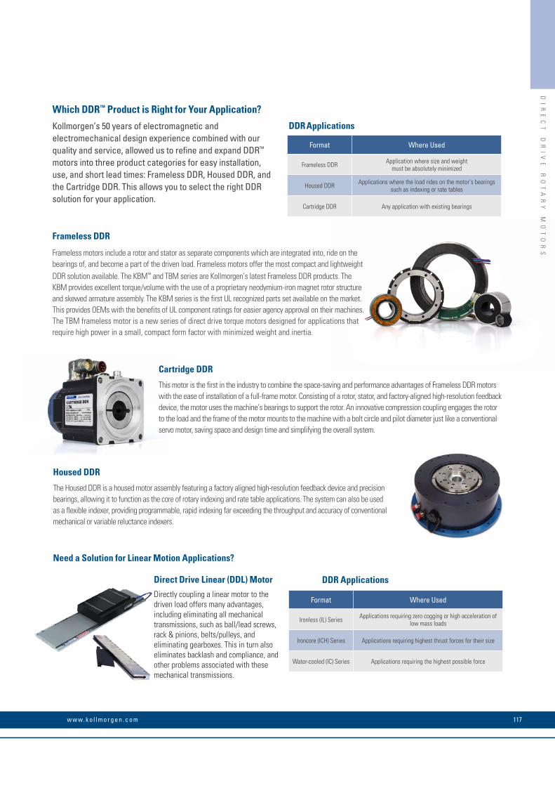
Format Where Used
Frameless DDR Application where size and weight must be absolutely minimized
Housed DDR Applications where the load rides on the motor’s bearings such as indexing or rate tables
Cartridge DDR Any application with existing bearings
Format Where Used
Ironless (IL) Series Applications requiring zero cogging or high acceleration of low mass loads
Ironcore (ICH) Series Applications requiring highest thrust forces for their size
Water-cooled (IC) Series Applications requiring the highest possible force
DDR Applications
DDR Applications
Which DDR™ Product is Right for Your Application?
Kollmorgen’s 50 years of electromagnetic and electromechanical design experience combined with our quality and service, allowed us to refine and expand DDR™ motors into three product categories for easy installation, use, and short lead times: Frameless DDR, Housed DDR, and the Cartridge DDR. This allows you to select the right DDR solution for your application.
Need a Solution for Linear Motion Applications?
Cartridge DDR
This motor is the first in the industry to combine the space-saving and performance advantages of Frameless DDR motors with the ease of installation of a full-frame motor. Consisting of a rotor, stator, and factory-aligned high-resolution feedback device, the motor uses the machine’s bearings to support the rotor. An innovative compression coupling engages the rotor to the load and the frame of the motor mounts to the machine with a bolt circle and pilot diameter just like a conventional servo motor, saving space and design time and simplifying the overall system.
Housed DDR
The Housed DDR is a housed motor assembly featuring a factory aligned high-resolution feedback device and precision bearings, allowing it to function as the core of rotary indexing and rate table applications. The system can also be used as a flexible indexer, providing programmable, rapid indexing far exceeding the throughput and accuracy of conventional mechanical or variable reluctance indexers.
Frameless DDR
Frameless motors include a rotor and stator as separate components which are integrated into, ride on the bearings of, and become a part of the driven load. Frameless motors offer the most compact and lightweight DDR solution available. The KBM™ and TBM series are Kollmorgen’s latest Frameless DDR products. The KBM provides excellent torque/volume with the use of a proprietary neodymium-iron magnet rotor structure and skewed armature assembly. The KBM series is the first UL recognized parts set available on the market. This provides OEMs with the benefits of UL component ratings for easier agency approval on their machines. The TBM frameless motor is a new series of direct drive torque motors designed for applications that require high power in a small, compact form factor with minimized weight and inertia.
Direct Drive Linear (DDL) Motor
Directly coupling a linear motor to the driven load offers many advantages, including eliminating all mechanical transmissions, such as ball/lead screws, rack & pinions, belts/pulleys, and eliminating gearboxes. This in turn also eliminates backlash and compliance, and other problems associated with these mechanical transmissions.
DI
RE
CT
D
RI
VE
R
OT
AR
Y
MO
TO
RS
117w w w. k o l l m o r g e n . c o m

K O L L M O R G E N 118
Sustainable drive design and protection of man and machine at fail-ures are important design goals at Kollmorgen. The KCM energy stor-age modules achieve great effects with little effort: KCM-S reduces operating costs and protects the environment through the recovery of braking energy, especially in applications with many short start-stop cycles. KCM-P bridges short power failures and eliminates machine downtime and costly restarting or ensures that the machine is brought to a defined state after a power failure. Connection and commissioning are simple - simply connect to the DC-link, no adjustment is needed. Save money and enjoy protection immediately!
KC
M
EN
ER
GY
S
TO
RA
GE
D
EV
IC
E
KCM Energy Storage Device

KC
M
EN
ER
GY
S
TO
RA
GE
D
EV
IC
E
Benefits Features
• Reduces operating costs • Energy savings through intelligent energy feedback
• No machine stop at short power failures
• Higher safety • Controlled braking after power failures
• Protection of man and machine through controlled standstill
• Easy commisioning • Easy connection to the DC link with two cables
• No adjustment needed, ready for use immediately
• No circuit feedback
• Nearly unlimited capacity thanks to expansion modules
119w w w. k o l l m o r g e n . c o m
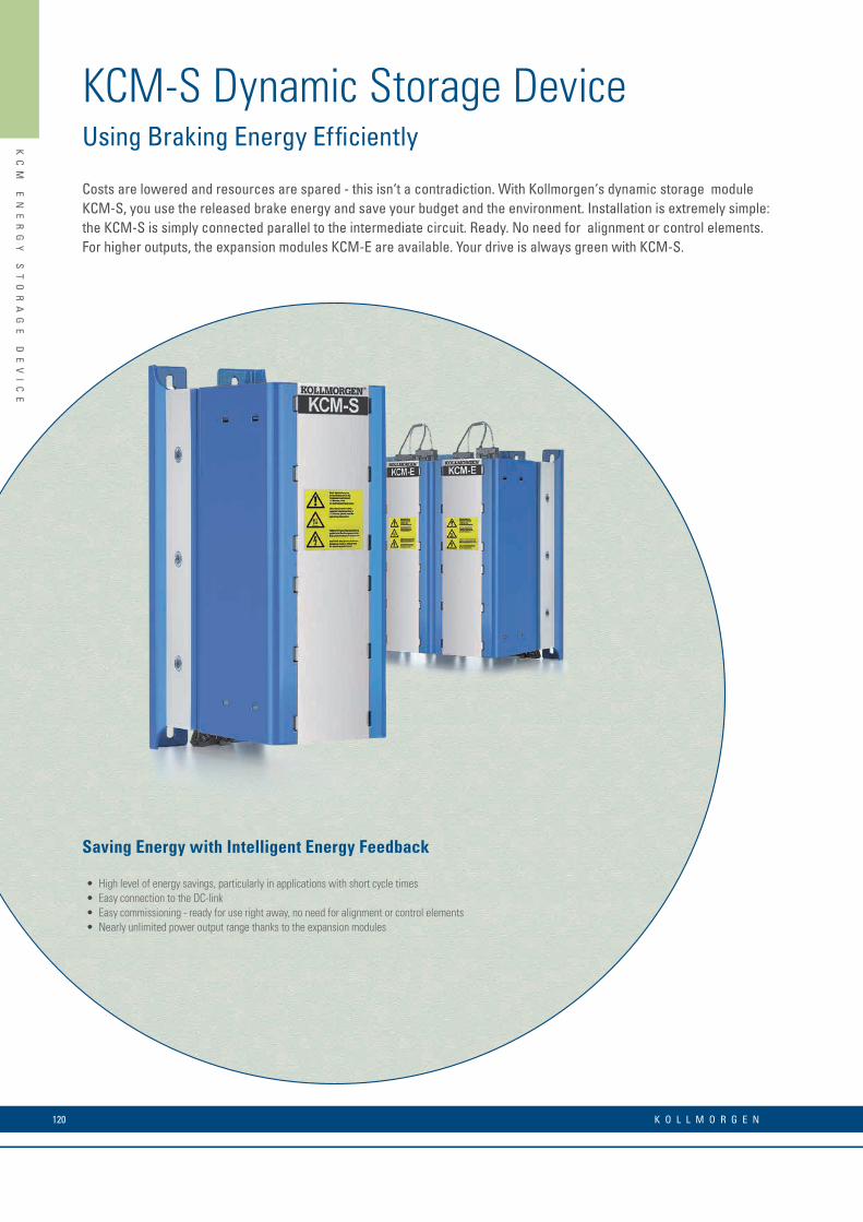
KC
M
EN
ER
GY
S
TO
RA
GE
D
EV
IC
E
Costs are lowered and resources are spared - this isn‘t a contradiction. With Kollmorgen‘s dynamic storage module KCM-S, you use the released brake energy and save your budget and the environment. Installation is extremely simple: the KCM-S is simply connected parallel to the intermediate circuit. Ready. No need for alignment or control elements. For higher outputs, the expansion modules KCM-E are available. Your drive is always green with KCM-S.
Saving Energy with Intelligent Energy Feedback
KCM-S Dynamic Storage DeviceUsing Braking Energy Efficiently
• High level of energy savings, particularly in applications with short cycle times • Easy connection to the DC-link • Easy commissioning - ready for use right away, no need for alignment or control elements• Nearly unlimited power output range thanks to the expansion modules
K O L L M O R G E N 120

KC
M
EN
ER
GY
S
TO
RA
GE
D
EV
IC
E
Higher Efficiency and Lower Operational Costs
In order to increase the total capacity, the expansion modules KCM-E are simply connected in parallel. A discharge resistor is integrated.
KCM-S is simply connected to the DC-link. An internal PTC brake resistor safely absorbs energy peaks.
Saving Energy with KCM-S
with KCM-Swithout / Saving energy
P [W]
Time
Voltage Curve in the DC-Link
without KCM-S with KCM-S
UBRC
UKCM
UNETZ
U [V DC]
Time
Energy Hub- / Cycle Time Diagramat 40 °C ambient temperature
2,0
1,8
1,6
1,4
1,2
1,0
0,8
0,6
0,4
0,2
0,0 200 400 600 800 1000 1200 1400 1600
Energy Consumption in Ws
Cycle Time in Seconds
The active dynamic braking energy storage device KCM-S will only be energized and charged when the brake is applied on the drive. As there is no connection to the mains supply on the input side, circuit feedback is ruled out. KCM-S automatically calculates the value of the use-voltage UKCM. Energy that would lead to an increase in voltage higher than this threshold value will be stored in the KCM-S buffer module. If the voltage in the intermediate circuit falls below the threshold value, the KCM-S pumps energy back which would be pulled from the network without KCM-S. At this point energy is saved. If the level of energy falls below the dynamic set charging voltage, KCM-S switches itself off and waits for the next instance of braking, when the capacitor is loaded once again. The shorter the cycle time, the more efficiently KCM-S works.
The expansion module KCM-E increases the capacity by 2000 Ws or 4000 Ws in each case. Several expansion modules can easily be connected to each other via the reverse polarity protected connection cable provided.
Performance DataKCM-S KCM-E20 KMC-E40
Electrical storage capacity 1600 Ws 2000 Ws 4000 Ws
Continuous voltage of the DC-link circuit max. 850 V DC
Peak voltage of the DC-link circuit max. 950 V DC (30 s in 6 minutes)
Maximum output 18 kW 18 kW 18 kW
Protection type IP20
Dimensions H x W x D 300 x 100 x 201 (mm)
Weight 6,9 kg 4,1 kg 6,2 kg
258
58 21
21
100
300
Dimensions in mm
For High Energy Requirements: Expansion Modules KCM-E
121w w w. k o l l m o r g e n . c o m

KC
M
EN
ER
GY
S
TO
RA
GE
D
EV
IC
E
KCM-P Static Energy Storage DeviceThe Power Insurance for Your Machine
A stable power supply is the basis for the safe operation of machines, for high productivity and first-class quality. The Kollmorgen static energy storage device KCM-P bridges temporary power failures or provides the drive with energy for controlled run down in the defined operating stop. Minimal downtime and protection of the machine and the workpiece from damage: KCM-P is the back-up energy for single and multi-axis drives.
• Secures productivity through uninterrupted operation during short-term power failures
• The machine restarts quickly: KCM-P provides the drive with energy after a power failure until the machine has reached a defined state after stop.
• Easy system integration: A power failure signal is emitted on the digital interface for evaluation by the machine control
• Easy connection to the DC-link with two cables.
• Easy commissioning - ready for use right away, no need for alignment or control elements
• The smooth loading routine doesn‘t strain the converter and doesn‘t generate any circuit feedback
• Nearly unlimited power output range due to cascadable expansion modules
KCM-P: The static energy store reduces downtimes and increases productivity
K O L L M O R G E N 122

KC
M
EN
ER
GY
S
TO
RA
GE
D
EV
IC
E
258
58 21
21
100
300
without KCM-P
with KCM-P
Voltage on the DC-Link During Power Failure
UZK
Power failure Time
The Energy Reserve Ensures Safe Operation
The expansion module KCM-E is connected parallel to KCM-P, and increases the capacity by 2000 Ws or 4000 Ws in each case. Several expansion modules can easily be connected to each other via the reverse polarity protected connection cable provided.
The static energy storage device KCM-P expands the capacity of the converter in the DC-link. It holds a certain amount of energy that keeps the voltage on the DClink to an operational level for a defined amount of time during power failures. After switching on the converter the energy store is charged in a controlled manner by a loading routine and is ready for use after around 8 seconds. The smooth loading routine does not strain the converter‘s charging connection and does not generate any negative circuit feedback. During power failures, the digital interface emits a signal for evaluation and introducing more measures by the machine control.
The energy reserves can increase almost unlimitedly with the expansion modules KCM-E. A discharge resistor is integrated into every module. The connection is made to connectors on the top side of the module using the cable protected against polarity reversal that is supplied.
KCM-P is simply connected in parallel to the DC-link of the converter. During power failures, a signal is emitted on the digital interface for evaluation by the machine control.
For High Energy Requirements: Expansion Modules KCM-E
Performance DataKCM-P KCM-E20 KMC-E40
Electrical storage capacity 2000 Ws 2000 Ws 4000 s
Continuous voltage of the DC-link circuit max. 850 V DC
Peak voltage of the DC-link circuit max. 950 V DC (30 s in 6 minutes)
Inception voltage from the factory 470 V DC
Maximum output 18 kW 18 kW 18 kW
Protection type IP20
Dimensions H x W x D 300 x 100 x 201 (mm)
Weight 6,9 kg 4,1 kg 6,2 kgDimensions in mm
123w w w. k o l l m o r g e n . c o m

MO
TI
ON
EE
RI
NG
A
PP
LI
CA
TI
ON
E
NG
IN
E
MOTIONEERING® Online Features:
• Inertia Calculator - lets you build up inertia based on odd shapes by additive or subtractive methods• Custom Motion Profile - easy to add entire segments or copy segments to repeat• Environmental Factor - takes into account your ambient temperature• Project by Project Units - You can tailor your units on a project by project basis, or use the global units settings
MOTIONEERING Online Supported Browsers
• IE, Chrome, Firefox, Safari
MOTIONEERING® Online
MOTIONEERING® Online – Kollmorgen has revamped, modernized and put online one of the most respected applications sizing programs of the last 20 years. You now can access this application sizing and selection tool wherever you have access to the internet. MOTIONEERING Online is just a start of a series of releases that will empower you to optimize solutions for your toughest applications. Sizing frameless motors and drive systems has never been easier. Using a mechanism project concept for collecting and saving multiple axes of load information, MOTIONEERING® Online can automatically calculate application results and compare against a catalog of systems - recommending the most optimized set of Kollmorgen system solutions available.Versatile units-of-measure selection options for mechanism and motion profile data-entry, with the ability to convert data into other available units, makes this a convenient international tool. A user-friendly Help file teaches program functions and algorithms used to provide results.
Mechanism Projects
•Direct drive entry, lead screw, conveyor•Rack and pinion, nip rolls•Direct Drive Rotary•Electric Cylinder•Direct data entry
Solution Set Search Screen
•Color-coded indication of system’s ability to meet application requirements•Review system components specifications•Save, print, or create a pdf application report•Evaluate system performance curve with application points
K O L L M O R G E N 124

AC
CE
SS
OR
IE
S
Mating connectors
Accessories
Supply filter Motor choke
Chokes and Filters
Mains filters increase reliability and extend the service life of the machine in environments with unstable power supplies. Motor chokes reduce radiated disturbances.
Connection Cables
Shielded PUR industrial cable with RJ45 connections for demanding industrial environments with increased requirements for EMC, durability, and service life. The motor connection and feedback cable are designed as shielded PUR industrial cables with CE and UL approval that are capable of being towed.
Mating Connectors and Shielding Kit
Kollmorgen's servo drives are equipped with screwable mating connectors. Alternative connectors for common DC, bus, and mains ports are also available. We offer shielding kits for our flexible cables for use in environments with strong interference.
Braking Resistors
Braking resistors with up to 6000 Watt of power are available in numerous sizes and form factors. The impedance of the braking resistors is tailored to the Kollmorgen servo drives.
You can find additional information on our accessories at www.kollmorgen.com
Cable clampsShielding kit
125w w w. k o l l m o r g e n . c o m

MO
DE
LL
N
OM
EN
CL
AT
UR
E
Version
B = Base driveC = Central power supply for AKD-N (Requires CB Extention)N = Decentralized drive (Requires DB, DF, or DS Extention) P = Position indexer (motion tasking)T = AKD BASIC Language Programmable drive (Requires IC or NB Extention)M = Multi-axis Master Drive (Requires MC Extension option, and EC Connectivity option)
AKD Series
Connectivity*AN = Analog command
CN = CANopen®
EC = EtherCAT®
EI = EtherNet/IP™PN - PROFINET®
SQ = SynqNet®
B, P, TPC, M, N, PPPB
Voltage
06 = 120 / 240 V AC 1Ø/3Ø (24 Amp Drive: 240 V AC 3Ø only)
07 = 240 / 480 V AC 3Ø (Version C: 07 = 400 / 480 V AC 3Ø - Version N: 07 = 560/680 V DC)
Extension
CB = without extention (AKD-C version only)DB = hybrid motor cable (AKD-N version only)DF = additional EtherCAT® port + feedback connector (AKD-N version only)DS = local STO + feedback connector (AKD-N version only)IC = Expanded I/O version and SD card slot (AKD-T version only)
NB = Without extensions
Current Rating003 = 3 A
006 = 6 A
010 = 10 kW (for AKD-C, this field refers to power.)
012 = 12 A
024 = 24 A
048 = 48 A
AKD – B 003 06 – NB AN – 0000
Variants
0000 = Standard
*Motion Tasking is included as a free upgrade with CN, EC, EI and PN
Drive VersionAvailability
Model Nomenclature
AKD / AKD-N SERVO DRIVE
K O L L M O R G E N 126

MO
DE
LL
N
OM
EN
CL
AT
UR
E
Note: Options in blue type refer to standard products.
VersionC Central Power Supply IP20
Power Class010 10 kW (17 kW @ 570 V DC)020 20 kW (34 kW @ 570 V DC) (available in 2016)
Voltage Class07 400 to 480 V AC, 3-ph
AKD Series
AKD – C 010 07 – CB EC – E000
ExpansionsCB No expansion
Connection OptionEC EtherCAT
Customizationx000 Standard (x = language)
VersionN Near servo drive IP65/67
Voltage Class07 700 V DC
AKD Series
Current Class003 3 Arms006 6 Arms012 12 Arms
AKD – N 003 07 – DB EC – E000
Connection OptionEC EtherCAT
ExpansionsDB Hybrid motor cable
DF Feedback connector and tertiary fieldbus
DG Hybrid motor cable and tertiary fieldbus
DS Feedback connector and individual STO
DT Hybrid motor cable and individual STO
Customizationx000 Standard (x = language)
127w w w. k o l l m o r g e n . c o m
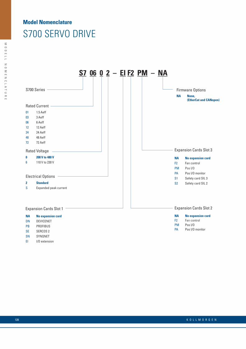
MO
DE
LL
N
OM
EN
CL
AT
UR
E
Model Nomenclature
S700 SERVO DRIVE
Rated Current
S700 Series
Expansion Cards Slot 2
NA No expansion cardF2 Fan controlPM Pos I/OPA Pos I/O monitor
Electrical Options2 Standard
S Expanded peak current
Expansion Cards Slot 1
NA No expansion card
DN DEVICENET
PB PROFIBUS
SE SERCOS 2
SN SYNQNET
EI I/O extension
01 1.5 Aeff
03 3 Aeff
06 6 Aeff
12 12 Aeff
24 24 Aeff
48 48 Aeff
72 72 Aeff
0 208 V to 480 V
6 110 V to 230 V
Rated Voltage
S7 06 0 2 – EI F2 PM – NA
Expansion Cards Slot 3
NA No expansion card
F2 Fan control
PM Pos I/O
PA Pos I/O monitor
S1 Safety card SIL 3
S2 Safety card SIL 2
Firmware OptionsNA None,
(EtherCat and CANopen)
K O L L M O R G E N 128

MO
DE
LL
N
OM
EN
CL
AT
UR
E
NOTES
129w w w. k o l l m o r g e n . c o m
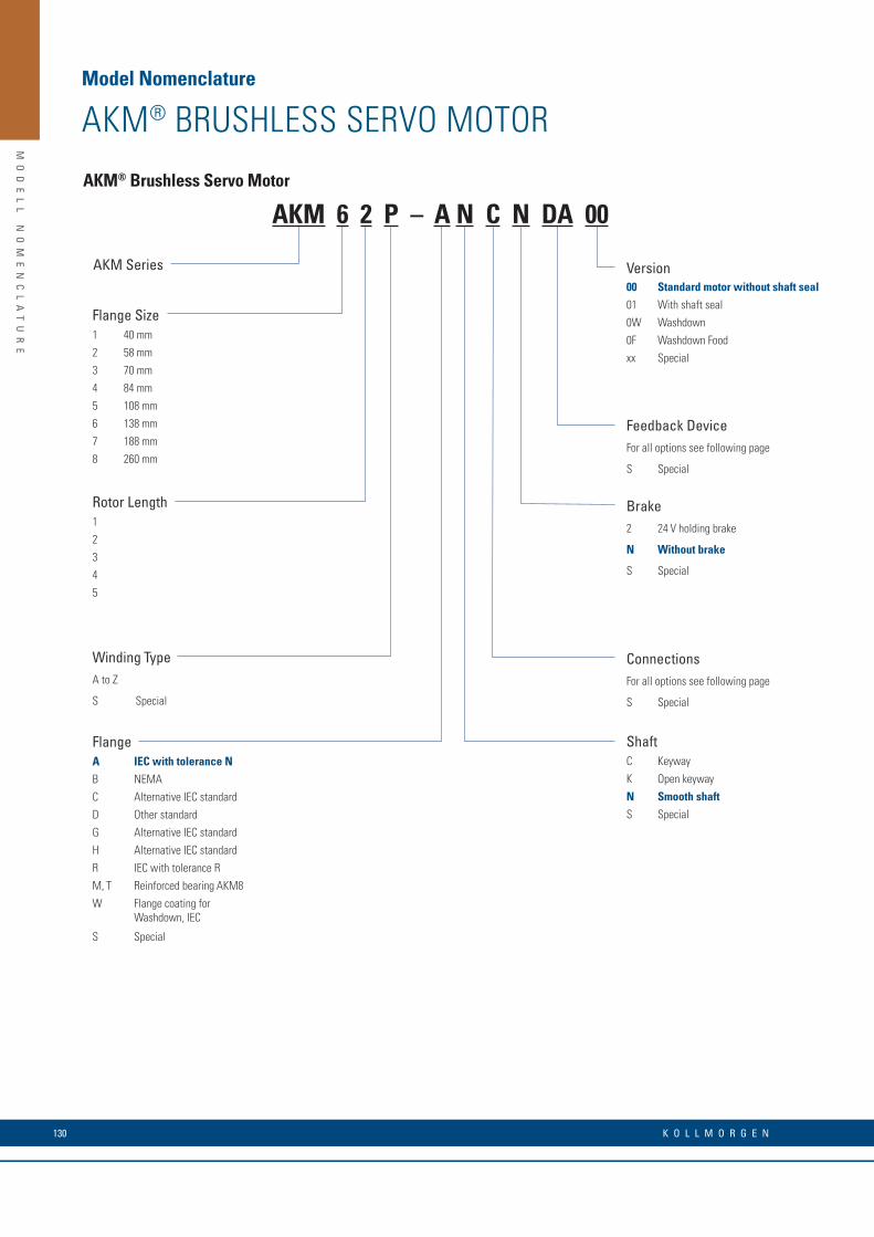
MO
DE
LL
N
OM
EN
CL
AT
UR
E
AKM® Brushless Servo Motor
Winding TypeA to Z
S Special
Flange Size1 40 mm
2 58 mm
3 70 mm
4 84 mm
5 108 mm
6 138 mm
7 188 mm
8 260 mm
AKM Series Version00 Standard motor without shaft seal
01 With shaft seal
0W Washdown
0F Washdown Food
xx Special
Brake2 24 V holding brake
N Without brake
S Special
ConnectionsFor all options see following page
S Special
Feedback DeviceFor all options see following page
S Special
Rotor Length1
2
3
4
5
FlangeA IEC with tolerance N
B NEMA
C Alternative IEC standard
D Other standard
G Alternative IEC standard
H Alternative IEC standard
R IEC with tolerance R
M, T Reinforced bearing AKM8
W Flange coating for Washdown, IEC
S Special
ShaftC Keyway
K Open keyway
N Smooth shaft
S Special
AKM 6 2 P – A N C N DA 00
Model Nomenclature
AKM® BRUSHLESS SERVO MOTOR
K O L L M O R G E N 130

Code Description Type Remarks Lines per Revolution Number of Revolutions Usable with Drives
1- Comcorder EPC 15T Single-turn, optical 1024 1 All2- Comcorder EPC 15T Single-turn, optical 2048 1 AllAA BiSS B Encoder AD34/AD58 Single-turn, optical 2048 1 AllAB BiSS B Encoder AD34/AD58 Multi-turn, optical 2048 4096 AllC- SFD Smart Feedback Device Size 10/15/21 Single-turn, inductive, 4-pole 11 Bit 1 AKDCA SFD3 Smart Feedback Device Size 10/15/21 Single-turn, inductive, 2-pole 11 Bit 1 AKD, S700DA EnDAT 2.1 Encoder ECN 1113/1313 Single-turn. optical 512/2048 (*1) 1 AllDB EnDAT 2.1 Encoder EQN 1125/1325 Multi-turn, optical 512/2048 (*1) 4096 AllLA EnDAT 2.1 Encoder ECI 1118/1319 Single-turn, inductive 16/32 (*2) 1 AllLB EnDAT 2.1 Encoder ECI 1130/1331 Multi-turn, inductive 16/32 (*2) 4096 AllMA Drive-CliQ Enocder ECN1324S Safety Single-turn, optical 24 Bit 1 SiemensMB Drive-CliQ Encoder EQN1336S Safety Multi-turn, optical 24 Bit 4096 SiemensGA HIPERFACE Encoder SKS36 Single-turn, optical 128 1 SxGB HIPERFACE Encoder SKM36 Multi-turn, optical 128 4096 SxGC HIPERFACE Encoder SEK34 Single-turn, capacitive 16 1 SxGD HIPERFACE Encoder SEL34 Multi-turn, capacitive 16 4096 SxGE HIPERFACE DSL-Encoder EKS36 Single-turn, optical 18 Bit 1 AKD, S700GF HIPERFACE DSL-Encoder EKM36 Multi-turn, optical 18 Bit + 12 Bit 4096 AKD, S700GJ HIPERFACE Encoder SKS36 Single-turn, optical 128 1 AKDGK HIPERFACE Encoder SKM36 Multi-turn, optical 128 4096 AKDGM Safe HIPERFACE Encoder SKS36S Safety, wie GJ, SIL2, PL d, CAT 3 128 (*3) 1 AKDGN Safe HIPERFACE Encoder SKM36S Saftey, wie GK, SIL2, PL d, CAT 3 128 (*3) 4096 AKDGP HIPERFACE Encoder SEK34 Single-turn, capacitive 16 1 AKDGR HIPERFACE Encoder SEL34 Multi-turn, capacitive 16 4096 AKDR- Resolver Size 10/15/21 Single-turn, inductive 2-pole 1 All *1: x/y data for AKM2-4/AKM5-8
*2: x/y data for AKM2-3/AKM4-8
*3: Certificates for safety feedbacks: see Kollmorgen Developer Network (Approvals) or Kollmorgen website.
MO
DE
LL
N
OM
EN
CL
AT
UR
E
Feedback Unit Options
131w w w. k o l l m o r g e n . c o m

MO
DE
LL
N
OM
EN
CL
AT
UR
E
Motor Frame Size
AKMH SeriesAKMH Hygienic Stainless Steel Washdown Motor
1, 2, 3, 4, 5
2, 3, 4, 5, 6
Brake2 = 24 V DC holding brakeN = No brakeS = Special
A, B, C, D, etc.
S = Special
Winding Type
Mount
ShaftA = Flange mounting IEC
B, E = Flange mounting NEMA
C = Face mounting IEC
D = Face mounting NEMA
L = NEMA 56 face mount
C = Closed keyway
K = Open keyway
N = Smooth shaft
Cable Connection
B = Cable with IP67 Speedtec connector
G = Cable with IP67 Speedtec connector in silicone tube
K = Pre-assembled cable for connection to AKD
L = Dual-cable version with open cable ends
M = Dual-cable version with open cable ends in silicone tube
R = Dual cable with IP67 non-stainless steel, non-hygienic, vented connector with air pressure compensation
T = Pre-assembled cable in silicone tube for connection to AKD
V = Cable with IP69 Speedtec connector
W = Cable with IP69 Speedtec connector in silicone tube
SealK = IP69K shaft seal
Rotor Stack Length
Feedback DeviceC- = SFD2CA = Smart Feedback Device (SFD3) DA = EnDAT 2.1 single-turn, opticalDB = EnDAT 2.1 multi-turn, opticalGA = Hiperface SKS36 single-turnGB = Hiperface SKM36 multi-turnGE = Hiperface DSL encoder single-turnGF = Hiperface DSL encoder multi-turnRA = Single-turn absolute HIPERFACE SRS50-S21 encoderRB = Multi-turn absolute HIPERFACE SRM-S21 encoder)RC = single-turn absolute HIPERFACE SRS50-K21 encoderRD = multi-turn absolute HIPERFACE SRM50-K21 encoderLA = EnDAT 2.1 single-turn, inductiveLB = EnDAT 2.1 multi-turn, inductiveR = Resolver2- = Comcoder 2048 incr./rev
Cable Length1 to F (1 to 15 meters)
AKMH 4 2 E – AN K N CA 1 K
Base Model
Mount-ShaftAC AN BK BN CC CN DK DN EK EN LK
AKMH2x • • • • • •AKMH3x • • • •AKMH4x • • • • • • • • • • •AKMH5x • • • • • • • • • •AKMH6x • • • • • • • •
FeedbackDevice
Cable ConnectionK T B G V W L M R
C-, CA • • • • • •GE, GF • • • • • •2-, R- • • • • • •
DA, DB • • • • • •GA, GB • • • • • •LA, LB • • • • • •RA, RB • •RC, RD • •
Feedback and Connection Availability
Mount-Shaft Availability
Note: LK mount requires 2 weeks additional lead time for the first product order.Note: Ex mounts are only available if Rx feedback devices are selected.
C- feedback is not available with brake.
Rx feedback device options are mapped for connection to third-party servo drives
Model Nomenclature
AKMH BRUSHLESS SERVO MOTOR
K O L L M O R G E N 132

MO
DE
LL
N
OM
EN
CL
AT
UR
E
ERD Series
Motor / Actuator Combination and Actuator Size15 AKMH2 with ERD15
20 AKMH3 with ERD20
25 AKMH4 with ERD25
30 AKMH5 with ERD30
Version0 Foot Mount FM21 Front flange mount FFG2 Trunnion mount TRR3 Rear clevis mountPCDS Special
Ball Nut LeadBNM05 5 mm
BNM10 10 mm
+ ERD 25 BNM05 SM150 LMI - 0
FeedSM150 150 mm (configurable in 10 mm steps from 150 mm to 600 mm)
Actuator TypeLMI Motor in-line
RP1 Motor reverse (transmission ratio 1:1)
133w w w. k o l l m o r g e n . c o m
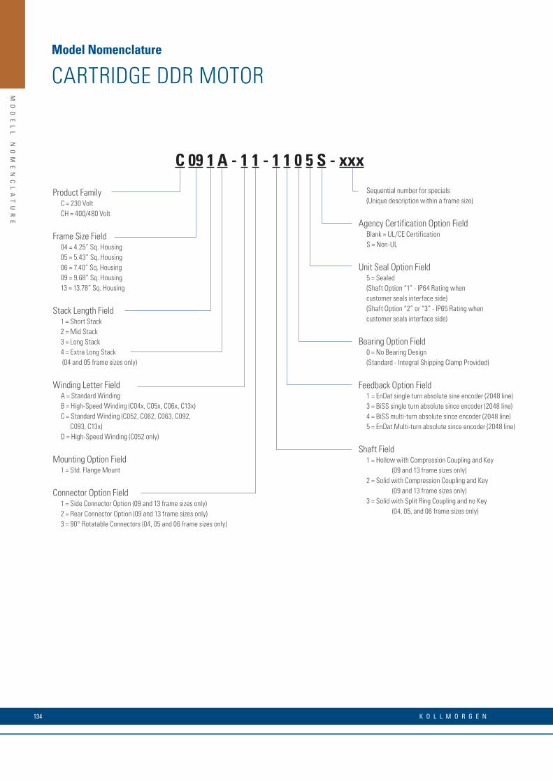
MO
DE
LL
N
OM
EN
CL
AT
UR
E
Product FamilyC = 230 VoltCH = 400/480 Volt
Frame Size Field04 = 4.25” Sq. Housing05 = 5.43” Sq. Housing06 = 7.40” Sq. Housing09 = 9.68” Sq. Housing13 = 13.78” Sq. Housing
Stack Length Field1 = Short Stack 2 = Mid Stack 3 = Long Stack 4 = Extra Long Stack (04 and 05 frame sizes only)
Winding Letter FieldA = Standard WindingB = High-Speed Winding (C04x, C05x, C06x, C13x)C = Standard Winding (C052, C062, C063, C092, C093, C13x)D = High-Speed Winding (C052 only)
Mounting Option Field1 = Std. Flange Mount
Connector Option Field1 = Side Connector Option (09 and 13 frame sizes only)2 = Rear Connector Option (09 and 13 frame sizes only)3 = 90° Rotatable Connectors (04, 05 and 06 frame sizes only)
Sequential number for specials (Unique description within a frame size)
Agency Certification Option Field Blank = UL/CE CertificationS = Non-UL
Unit Seal Option Field5 = Sealed (Shaft Option “1” - IP64 Rating when customer seals interface side)(Shaft Option “2” or “3” - IP65 Rating when customer seals interface side)
Bearing Option Field0 = No Bearing Design (Standard - Integral Shipping Clamp Provided)
Feedback Option Field1 = EnDat single turn absolute sine encoder (2048 line)3 = BiSS single turn absolute since encoder (2048 line)4 = BiSS multi-turn absolute since encoder (2048 line)5 = EnDat Multi-turn absolute since encoder (2048 line)
Shaft Field1 = Hollow with Compression Coupling and Key (09 and 13 frame sizes only)2 = Solid with Compression Coupling and Key (09 and 13 frame sizes only)3 = Solid with Split Ring Coupling and no Key (04, 05, and 06 frame sizes only)
C 09 1 A - 1 1 - 1 1 0 5 S - xxx
Model Nomenclature
CARTRIDGE DDR MOTOR
K O L L M O R G E N 134

MO
DE
LL
N
OM
EN
CL
AT
UR
E
Direct Drive SeriesD = 115/230 VAC windingDH = 400/480 VAC winding
Motor Frame Size06 = 6.93” O.D.08 = 8.60” O.D.10 = 11.19” O.D.14 = 14.25” O.D.
Rotor Stack Length1 = Short stack2 = Mid stack3 = Long stack
Winding TypeA = Std. w/ resolver1M = Std. w/ sine encoder
Mounting Option1 = Face mount2 = Flange mount
Designated for Specials
Unit Seal0 = Non-sealed unit5 = IP652 - length increase7 = IP672 - length increase
Bearing Option1 = Single bearing design2 = Dual bearing design3
Feedback Device2 = Resolver (“A” Winding Type)13 = Sine Encoder (“M” Winding Type)
Shaft Option1= Straight thru bore w/ face coupling
Connector Type2 = Straight3 = 90°, rotatable
Notes:
1. Not available on D14x & DH14x.2. Encoder sealed motors have increased length. See outline drawing. 3. Standard on D143 & DH143 models.4. Options shown in bold blue text are considered standard.
DH 08 1 M - 1 2 - 1 3 1 0 - xxx
Model Nomenclature
HOUSED DDR MOTOR
135w w w. k o l l m o r g e n . c o m
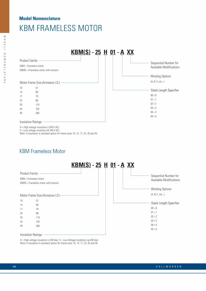
MO
DE
LL
N
OM
EN
CL
AT
UR
E
Sequential Number for Available Modifications
KBM(S) - 25 H 01 - A XXProduct Family
Stack Length Specifier00 = 0
01 = 1
02 = 2
03 = 3
04 = 4
05 = 5
(A, B, C, etc...)
Winding Options
Motor Frame Size (Armature I.D.)10 57
14 60
17 79
25 88
35 118
43 163
45 260
Insulation Ratings
KBM = Frameless motor
KBMS = Frameless motor with sensors
H = High voltage insulation (>240 V AC)S = Low voltage insulation (≤ 240 V AC)Note: H insulation is standard option for frame sizes 10, 14, 17, 25, 35 and 45
Sequential Number for Available Modifications
KBM(S) - 25 H 01 - A XXProduct Family
Stack Length Specifier00 = 0
01 = 1
02 = 2
03 = 3
04 = 4
05 = 5
(A, B, C, etc...)
Winding Options
Motor Frame Size (Armature I.D.)10 57
14 60
17 79
25 88
35 118
43 163
45 260
Insulation Ratings
KBM = Frameless motor
KBMS = Frameless motor with sensors
H = High voltage insulation (>240 Vac), S = Low-Voltage insulation (≤240 Vac)Note: H insulation is standard option for frame sizes 10, 14, 17, 25, 35 and 45.
Model Nomenclature
KBM FRAMELESS MOTOR
KBM Frameless Motor
K O L L M O R G E N 136
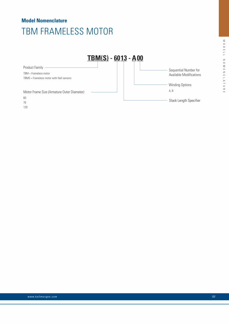
MO
DE
LL
N
OM
EN
CL
AT
UR
E
Model Nomenclature
TBM FRAMELESS MOTOR
Sequential Number for Available Modifications
TBM(S) - 60 13 - A 00Product Family
Stack Length Specifier
A, B
Winding Options
Motor Frame Size (Armature Outer Diameter)60
76
129
TBM = Frameless motor
TBMS = Frameless motor with Hall sensors
137w w w. k o l l m o r g e n . c o m

MO
DE
LL
N
OM
EN
CL
AT
UR
E
ICH SeriesIron Core High Voltage
Magentic Way Type
MCH Ironcore
Magnet Way Width
Model Nomenclature
ICH LINEAR DIRECT DRIVES
MCH MAGNETIC WAY
Design Length Identifier11, 22, 33, 44
Thermal ProtectionTY PTC and KTY
(Standard)
Reserved for Customizations00, 01, 02, etc.
Coil Width030, 050, 075, 100150, 200, 250
WindingA1, A5
ICH 22 - 050 - A1 - TY - C1 - 0
MCH 050 - 512 - 01
Cable OptionsOpen ends
C1 400 mm
C2 200 mm
C3 100 mm
C4 1200 mm
With connected connector
P1 400 mm
P2 200 mm
P3 100 mm
P4 1200 mm
Magnet Assembly Way Length
030 30 mm
050 50 mm
075 75 mm
100 100 mm
150 150 mm
200 200 mm
250 250 mm
064 64 mm
128 128 mm
256 256 mm
512 512 mm
Reserved for Customization00, 01, 02, etc.
ICH LINEAR DIRECT DRIVES - HALL SENSORS(Order code for hall sensors when ordered seperatly)
Hall-OptionHD = Digital
Winding Phase ConnectionY = Y (Star) Winding D = ∆ (Triangle) Winding
Cable Options
Px - Cable with Sub-D connector P1 = 400 mm P2 = 200 mm P3 = 100 mm P4 = 1200 mm
HD - Y - Px
K O L L M O R G E N 138

MO
DE
LL
N
OM
EN
CL
AT
UR
E
Open ends
C1 400 mm
C2 200 mm
C3 100 mm
C4 1200 mm
With connected connector
P1 400 mm
P2 200 mm
P3 100 mm
P4 1200 mm
Cable Options
Px - Cable with Sub-D connector P1 = 400 mm P2 = 200 mm P3 = 100 mm P4 = 1200 mm
NOTES
139w w w. k o l l m o r g e n . c o m

Radford
Sao Paulo
BostonMarengo
Ratingen
Gothenburg
BrnoMilan
Istanbul
MumbaiHongkong
ShanghaiShenzhen
BeijingTianjin
NagoyaTokio
SeoulSanta BarbaraTijuana
About Kollmorgen
Kollmorgen is a leading provider of drive systems and components for machine engineering. Through world-class knowledge in motion, industry-leading quality and deep expertise in linking and integrating standard and custom products, Kollmorgen delivers breakthrough solutions unmatched in performance, reliability and ease-of-use, giving machine builders an irrefutable marketplace advantage.
For assistance with your application needs, visit www.kollmorgen.com for a global contact list.
Application Centers
Worldwide Development and Production Locations
Worldwide Production Locations
KOLLMORGEN Europe GmbH Pempelfurtstraße 140880 RatingenGermanyTelephone: +49 (0) 2102 9394 0 Fax: +49 (0) 2102 9394 3155
©2018 Kollmorgen Corporation. All rights reserved. KM_C_00069_RevF_UK Subject to change. It is the user's responsibility to decide whether the product is suitable for a particular application. All trademarks are the property of their respective owners.