
Oscilloscopes Remote Control and Automation Manual - Mouser
402
Oscilloscopes Remote Control and Automation Manual
-
Upload
khangminh22 -
Category
Documents
-
view
0 -
download
0
Transcript of Oscilloscopes Remote Control and Automation Manual - Mouser

OscilloscopesRemote Control andAutomation Manual

© 2019 Teledyne LeCroy, Inc. All rights reserved.
Unauthorized duplication of Teledyne LeCroy documentation materials is strictly prohibited. Customers arepermitted to duplicate and distribute Teledyne LeCroy documentation for their own internal educational purposes.
Teledyne LeCroy is a trademark of Teledyne LeCroy, Inc. Other product or brand names are trademarks orrequested trademarks of their respective holders. Information in this publication supersedes all earlier versions.Specifications are subject to change without notice.
925131 Rev CApril 2019
Introduction
IntroductionThis manual documents the requirements for remote control of Teledyne LeCroy's MAUI™ oscilloscopesusing either traditional IEEE 488.2 (GPIB) commands or Windows® Component Object Model (COM)Automation commands.
The manual is divided into the following sections:
Part 1: Making the Remote Connection describes all the methods for gaining access to a MAUI oscilloscope(device) from a remote computer (controller). It details the software and hardware requirements for eachmethod.
Part 2: Automation Programming Reference describes the MAUI COM architecture and explains how touse Automation to control the oscilloscope remotely using manual methods or remote control programs.
Part 3: Automation Control Variable Reference details the MAUI COM architecture for configuring andcontrolling the oscilloscope. It is most useful for developers of remote control applications.
Part 4: Automation Result Interface Reference details the MAUI COM architecture for reading back datafrom the oscilloscope. It is most useful for developers of remote control applications.
Part 5: IEEE 488.2 Programming Reference describes the LeCroy legacy remote control implementationand provides an overview of GPIB programming conventions. It also provides information for understandingMAUI waveform transfer and the waveform template.
Part 6: IEEE 488.2 Command Reference details the legacy remote control commands supported by MAUIoscilloscopes.
i

MAUI Oscilloscopes Remote Control and Automation Manual
ResourcesTeledyne LeCroy provides many free resources to help you receive the greatest value from your instrument.Most of the software and documentation mentioned in this manual can be downloaded from our website;links are provided to other sites where relevant. In addition, many manuals and code examples for furtherreference are installed when you install our software.
SoftwareDownload software from: teledynelecroy.com/support/softwaredownload.
Under Oscilloscope Downloads, click the link to Software Utilities and browse the list of tools.
ManualsDownload manuals, application notes, and lab briefs from: teledynelecroy.com/support/techlib.
Use the sidebar at the left of the page to select the document category, then browse the list of links.
Technical SupportRegistered users can contact their local Teledyne LeCroy service center at the number listed on ourwebsite.
You can also submit Technical Support requests via the website at:
teledynelecroy.com/support/techhelp
Select the oscilloscope model you are using and the category into which your question falls.
ii
Notational Conventions
Notational Conventions
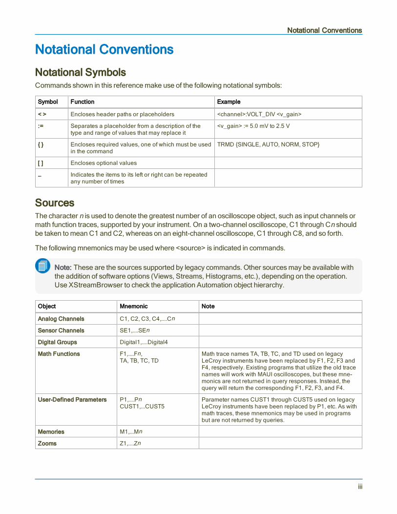
Notational SymbolsCommands shown in this reference make use of the following notational symbols:
Symbol Function Example
< > Encloses header paths or placeholders <channel>:VOLT_DIV <v_gain>
:= Separates a placeholder from a description of thetype and range of values that may replace it
<v_gain> := 5.0 mV to 2.5 V
Encloses required values, one of which must be usedin the command
TRMD SINGLE, AUTO, NORM, STOP
[ ] Encloses optional values
… Indicates the items to its left or right can be repeatedany number of times
SourcesThe character n is used to denote the greatest number of an oscilloscope object, such as input channels ormath function traces, supported by your instrument. On a two-channel oscilloscope, C1 through Cn shouldbe taken to mean C1 and C2, whereas on an eight-channel oscilloscope, C1 through C8, and so forth.
The following mnemonics may be used where <source> is indicated in commands.
Note: These are the sources supported by legacy commands. Other sources may be available withthe addition of software options (Views, Streams, Histograms, etc.), depending on the operation.Use XStreamBrowser to check the application Automation object hierarchy.
Object Mnemonic Note
Analog Channels C1, C2, C3, C4,....Cn
Sensor Channels SE1,....SEn
Digital Groups Digital1,....Digital4
Math Functions F1,....Fn,TA, TB, TC, TD
Math trace names TA, TB, TC, and TD used on legacyLeCroy instruments have been replaced by F1, F2, F3 andF4, respectively. Existing programs that utilize the old tracenames will work with MAUI oscilloscopes, but these mne-monics are not returned in query responses. Instead, thequery will return the corresponding F1, F2, F3, and F4.
User-Defined Parameters P1,....PnCUST1,...CUST5
Parameter names CUST1 through CUST5 used on legacyLeCroy instruments have been replaced by P1, etc. As withmath traces, these mnemonics may be used in programsbut are not returned by queries.
Memories M1,...Mn
Zooms Z1,....Zn
iii

MAUI Oscilloscopes Remote Control and Automation Manual
UnitsNumeric values can be expressed in code as numeric fixed point or exponential. However, only the fixedpoint value is displayed in tables and on descriptor boxes.
Note: This manual reflects the units supported in MAUI XStreamDSO software v.8.5.0.0 and later.Many, but not all, of the units listed here are supported in earlier versions of XStreamDSO.
Table of MnemonicsUnits may be expressed using the following mnemonics.
Note: Specify only the base unit in code, do not add prefixes. Units are automatically scaled up ordown within the list of standard, SI prefixes (atto to Exa) based on the relative size of the sourcesignal(s). For example a 1000 V reading is shown as 1 kV, while a .1 V reading is shown as 100 mV.When the multiplication factor is 1 V = 1 Pascal, a 1 millivolt (mV) reading is displayed as 1 mParather than .001 Pa or 100e-3 Pa.
Note: Time and Dimensionless units are available only for certain measurements and acquisitioncommands.
Category Unit Mnemonic
Mass gram G
slug SLUG
Volume liter L
cubic meter M3
cubic inch IN3
cubic foot FT3
cubic yard YARD3
Angle radian RAD
arcdegree DEG
arcminute MNT
arcsecond SEC
cycle CYCLE
revolution REV
turn TURN
iv

Notational Conventions
Category Unit Mnemonic
Force/Weight Newton N
grain GR
ounce OZ
pound LB
Velocity meter/second M/S
inch/second IN/S
foot/second FT/S
yard/second YARD/S
mile/second MILE/S
Acceleration meter/second2 M/S2
inch/second2 IN/S2
foot/second2 FT/S2
standard gravity GN
Pressure Pascal PAL
bar BAR
atmosphere, technical AT
atmosphere, standard ATM
Torr TORR
pound/square inch PSI
Temperature degree Kelvin K
degree Celsius CEL
degree Fahrenheit FAR
Energy Joule J
British Thermal Unit BTU
calorie CAL
v

MAUI Oscilloscopes Remote Control and Automation Manual
Category Unit Mnemonic
Rotating Machine radian/second RADPS
frequency (Hertz) HZ
revolution/second RPS
revolution/minute RPM
torque N•m NM
torque in•oz INOZ
torque in•lb INLB
torque ft•lb FTLB
power, mechanical (Watt) W
horsepower HP
Magnetic Weber WB
Tesla T
inductance (Henry) H
magnetic field strength A/M
permeability HENRYPM
Electrical Ampere A
Volt V
Watt W
power, apparent VA
power, reactive VAR
power factor PF
capacitance (Farad) F
Coulomb C
Ohm OHM
Siemen SIE
electrical field strength V/M
electrical displacement field CPM2
permittivity FARADPM
conductivity SIEPM
Time second S
minute MIN
hour HOUR
day DAY
week WEEK
vi

Notational Conventions
Category Unit Mnemonic
Dimensionless percent PCT
percent min-max PCTMNMX
decibel DB
decibel milliwatt DBM
decibel Volt DBV
decibel millivolt DBMV
decibel microvolt DBUV
decibel microampere DBUA
decibel referred to carrier DBC
decade DECADE
unit interval UI
Q-scale Q
bit BIT
byte BYTE
baud BAUD
least significant bit LSB
poise POISE
parts per million PPM
pixel PIXEL
division DIV
event EVENT
sample SAMPLE
segment SEG
sweep SWEEP
Combining UnitsSI units may be combined following these rules:
l For the quotient of two units, use the character " / "
l For the product of two units, use the character " . "
l For exponents, append the digit to the unit with no space (e.g., " S2 " for seconds squared).
Note: Some units are converted to simple units (e.g., " V.A " becomes " W ").
vii

MAUI Oscilloscopes Remote Control and Automation Manual
viii

Part 1: Making the Remote Connection
Part 1: Making the Remote ConnectionYou can fully control your instrument remotely using either:
l COM Automation commands
l IEEE 488.2 General Purpose Interface Bus (GPIB) commands
The remote connection can be made over a variety of physical interfaces such as ENET, GPIB, LSIB, orUSBTMC, using several interface drivers and protocols.
This section describes the software tools for remote control and procedures for making the remoteconnection from a controller to an oscilloscope.
Understanding Remote Control Layers 1-2
Software Tools for Remote Control 1-3
Connecting via ENET 1-5
Connecting via USBTMC 1-10
Connecting via GPIB 1-11
Connecting via LSIB 1-12
Configuring DCOM Connections 1-13
Testing the Remote Connection 1-21
Remote Control Assistant 1-22
ActiveDSO 1-23
VISA 1-26
WaveStudio 1-29
1-1

MAUI Oscilloscopes Remote Control and Automation Manual
Understanding Remote Control LayersIt is helpful to understand some high-level concepts regarding how the oscilloscope is operated throughremote control and the terminology employed throughout this section.
From bottom to top, the components interact in the following manner:
The cable is the physical conduit between the controller (usually a PC) and the oscilloscope, connected oneither end to the hardware interface. Interfaces vary based on oscilloscope model and include ENET (oftenlabeled LAN on the oscilloscope), USBTMC, GPIB, and LSIB.
Depending on the interface selected, you may require a PC adapter in order to connect the cable. This isparticularly true for LSIB and GPIB. ENET ports are typically standard and do not require special adapters.
The oscilloscope may also require an oscilloscope adapter to make the connection.
Different protocols can be used for transmitting messages between the controller and the oscilloscope. Thisselection again depends on the hardware interface. Available protocols include VICP (based on TCP/IP),VXI-11 (for the LXI standard), USBTMC, GPIB, and LSIB.
PC instrument drivers are programs that enable the controller to interface with the oscilloscope, such asActiveDSO, VISA drivers, IVI drivers and LabVIEW drivers. They are the software complement to thehardware interface. These programs do the work of encapsulating your programs messages into therequisite interface messages that manage the exchange between device and controller.
The oscilloscope Remote Control Manager includes the drivers needed to make the software interfacefrom the oscilloscope side. Teledyne LeCroy oscilloscopes are shipped with everything necessary forremote control functionality pre-installed. All you have to do to is select which protocol you want to use forremote control from the instrument's Remote dialog.
The oscilloscope application (XStreamDSO) is the program that displays, transforms, and measuresdigitized input signals and enables you to control the instrument. It is also the program that exchangesinformation with the PC applications over the remote connection.
PC applications are programs residing on the controller that exchange data with the oscilloscopeapplication or function as a remote command console, such as WaveStudio, LabVIEW, MATLAB, andcustom applications.
1-2

Part 1: Making the Remote Connection
Software Tools for Remote ControlMany free software tools are available to help you make and manage the remote connection. SeeResources for download information. This software is to be installed on the PC/controller. Teledyne LeCroyoscilloscopes are pre-installed with all necessary software for remote control.
Interface Drivers
ActiveDSOBased on Microsoft's ActiveX technology, ActiveDSO simplifies programming for Teledyne LeCroyoscilloscopes within the Microsoft environment. ActiveDSO provides interface drivers and a client library tomake the remote connection over ENET, GPIB or USBTMC interfaces. It also supports many Automationfeatures besides remote control. See ActiveDSO.
VISAVISA-compliant drivers also provide the necessary software interface for remote control over ENET, GPIB,or USBTMC. Add-on tools like NI-VISA handle device communications for many programming languages,such as C++, LabVIEW, and Python. An installation of NI-VISA (or a VISA driver that behaves exactly likeit) is required if you cannot use ActiveX technologies such as ActiveDSO or WaveStudio. NI-VISA is alwaysrequired if you are uisng the USBTMC interface for remote control.
LeCroy VICP Passport and VICP Client LibraryThe VICP Passport was developed specifically for those using NI-VISA with the Teledyne LeCroy VICPprotocol. It provides the requisite VISA Passport functions for VICP communications.
Not technically a driver, the VICP Client Library provides the necessary toolkit for developing a VICPinterface to the oscilloscope from machines that are not running Windows.
LeCroyScope IVI DriverThe VISA-based LeCroyScope IVI Driver is an Interchangeable Virtual Instrument technology that providesa standard API for communication with instruments. Provided to meet LXI standard requirements, the driverstrictly adheres to the IVI-Scope instrument class and includes both IVI-C and IVI-COM drivers. SeeIntroducing the LXI Interface for instructions on using the driver.
Note: Although provided for LXI compliance, you can use the IVI Driver even if your remote controlsetting is TCP/IP (VICP), rather than LXI (VXI-11).
LabVIEW DriversThe LeCroy_Wave_Series driver, created using the LabVIEW project architecture, is available for Windowsusers who wish to control their oscilloscope through a National Instruments LabVIEW™ program. Thelcwave driver, an llb LabView library, is available for those using pre-Windows oscilloscope models. Bothdrivers can be used over an ENET, GPIB, or USBTMC connection. See Lab Brief WM832: Getting Startedwith the "lcwave" and "LeCroy Wave Series" LabVIEW Drivers for instructions.
1-3

MAUI Oscilloscopes Remote Control and Automation Manual
Connectivity Tools
XStreamBrowserThe XStreamBrowser utility enables you to view, copy, and modify the COM object hierarchy of theconnected oscilloscope application. See XStreamBrowser.
WaveStudioFor PCs running Windows 10, 7, VISTA, or XP, WaveStudio is a remote control console that provides agraphical user interface for oscilloscope setup, waveform inspection, and data transfer. It supports TCPIP,LXI, GPIB, LSIB, or USBTMC/USB488 connections. See WaveStudio.
ScopeExplorerFor PCs running Windows 2000 or XP, ScopeExplorer is a connectivity tool that interfaces legacy modelTeledyne LeCroy oscilloscopes (e.g., LCxxx, LTxxx, 93xx) to the Windows desktop.
1-4

Part 1: Making the Remote Connection
Connecting via ENETTeledyne LeCroy oscilloscopes employ a standard Ethernet interface for utilizing the TCP/IP transportlayer.
HardwareFor purposes of remote control, you may either:
l Connect the oscilloscope to a LAN port or hub using a straight Ethernet (ENET) cable
l Connect the oscilloscope directly to the controller using a crossover cable or a straight cable capableof directional switching (most modern, standard ENET cables do this).
Tip: If you are concerned mainly with system throughput, a LAN connection is not recommended asnetwork traffic may slow down oscilloscope data transfer rates. Use a direct connection, or considerusing LSIB if your oscilloscope supports it.
IP AddressThe oscilloscope is preset to accept DHCP addressing. Be sure the controller and the oscilloscope are onthe same subnet.
The oscilloscope is delivered with a default IP address, which is pulled from our network prior to shipment.You can find this address by navigating to Utilities > Utilities Setup > Remote. Keep in mind this address willlikely change as soon as the instrument is connected to your network.
You may also address the oscilloscope using the hostname. The default hostname is the serial numberprinted on the back of the instrument and on the registration card. If your network is served by a DNS server,the hostname must be the instrument name that is recognizable to the name server. For direct (coaxial orstraight ENET) connections, it may be easiest to make the initial connection using the hostname.
You may optionally assign a static IP address to the oscilloscope using the standard Windows networkingdialogs .
Tip: To access the Windows control panel, choose File > Minimize or go to Utilities > Utilities Setup> Remote and select Net Connections.
Protocol SelectionThere are two protocol options for remote control via ENET:
l VICP, for which you select the TCP/IP remote control setting
l VXI-11, for which you select the LXI remote control setting
1-5

MAUI Oscilloscopes Remote Control and Automation Manual
Connecting with VICPThe TCP/IP (VICP) remote control setting uses port 1861 and the proprietary VICP protocol for transmittingmessages.
Note: LabVIEW programmers should use the TCP/IP (VICP) setting with an installation of NI-VISAand VICP Passport to communicate with Teledyne LeCroy oscilloscopes.
Controller Set UpOpen port 1861 on the controller for TCP/IP communications.
If the controller runs Windows, install NI-VISA to manage the interface functions of the VICP connection. NI-VISA users should also install the VICP Passport.
Those who are not running Windows should install the LeCroyVICP Client Library. This library can bedownloaded free of charge from www.SourceForge.net. You will need to use the library to program yourown VICP interface.
If you are running Windows and can utilize ActiveX controls, we highly recommend installing ActiveDSO onthe controller to simplify communications with the oscilloscope.
Optionally, install the LeCroyScope IVI driver or a LabVIEW driver.
Oscilloscope Set UpGo to Utilities > Utilities Setup > Remote and choose TCP/IP (VICP).
Record the instrument's IP address for use in VISA resource strings and function calls.
VICP ProtocolVICP is the Versatile Instrument Control Protocol, the proprietary protocol used by the TCP/IP (VICP)remote control setting on Teledyne LeCroy oscilloscopes. This protocol aims to emulate IEEE488.2 andincludes operation bits corresponding to SRQ, EOI, Clear, and others in a header that is defined by theVICP protocol.
VICP is registered with IANA to communications port 1861.
Code to parse VICP packets is publicly available at: http://www.SourceForge.net.
See the Application Brief LAB_WM827: Understanding VICP and the VICP Passport.
1-6

Part 1: Making the Remote Connection
VICP HeadersThe format of the header sent before each data block of a VICP transmission, both to and from theinstrument, is set out in the following table:
Byte Number Purpose
0 Operation
1 Header Version
2 Sequence Number*
3 Spare (reserved for future expansion)
4 Block Length, (bytes of data), MSB
5 Block Length (bytes of data)
6 Block Length (bytes of data)
7 Block Length, (bytes of data), LSB
* The sequence number is used to synchronize write/read operations to simulate 488.2 “discard unread response”behavior. Valid range is 1 to 255 (zero is omitted intentionally).
VICP Operation BitsOperation bits are as follows:
Data Bit Mnemonic Purpose
D7 DATA Data block (D0 indicates termination with/without EOI)
D6 REMOTE Remote Mode
D5 LOCKOUT Local Lockout (Lock out front panel)
D4 CLEAR Device Clear (if sent with data, clear occurs before data block is passed to parser)
D3 SRQ SRQ (Device to PC only)
D2 SERIAL POLL Request a serial poll
D1 Reserved Reserved for future expansion
D0 EOI Block terminated in EOILogic 1 = use EOI terminatorLogic 0 = no EOI terminator
VISA AddressingCode strings such as "TCPIP::<IP address>::1861::SOCKET" may or may not work when using VICPdepending on how the application handles instrument responses. The data returned will include headerinformation that needs to be parsed, and allowances must be made to trap situations where a transfer is notcomplete, or where there is an unread response from the instrument. SOCKET connections should workproperly if you are using the VICP Client Library.
Teledyne LeCroy developed the VICP Passport to handle socket connections more reliably when using NI-VISA. Instead of "TCPIP::<IP address> . . .", use "VICP::<IP address>" to make the connection.
1-7

MAUI Oscilloscopes Remote Control and Automation Manual
Connecting With VXI-11LXI is an industry-standard specification for LAN-based instruments that utilizes the VXI-11 protocol forTCP/IP communications and instrument discovery. For information, visit www.lxistandard.org.
Teledyne LeCroy oscilloscopes are LXI Class-C compliant. We have implemented a full-featured stack thatallows any command or query to be sent using the VXI-11 protocol, beyond the LXI requirements fordiscovery and execution of simple *IDN? queries.
Note: You can use the VXI-11 protocol for remote control of Teledyne LeCroy oscilloscopes even ifyour network is not LXI compliant. For those who cannot utilize ActiveX or are programming innewer languages such as C#, LXI (VXI-11) is the best remote control setting.
Note: If your oscilloscope runs on Windows 10, you must run from the Administrative User accountin order to use LXI for remote control.
ResourcesThe LXI specification stipulates that vendors supply:
l An IVI driver for the instrument.
Note: Some newer versions of NI-VISA install with IVI drivers. The LeCroyScope IVI driveris required to connect to MATLAB applications using LXI (VXI-11). See Resources.
l A web server to simplify remote control configuration. To access this page from the controlling PC,enter the oscilloscope IP address in URL field of a browser.
Controller SetupOpen port 111 on the controller for TCP/IP communications.
Install NI-VISA to manage the interface functions of the underlying TCP/IP connection.
If you are running Windows and can utilize ActiveX controls, we highly recommend installing ActiveDSO onthe controller to simplify communications with the oscilloscope.
Optionally, install the LeCroyScope IVI driver or LabVIEW driver.
Oscilloscope SetupIf the oscilloscope runs on Windows 10, change to the Administrative User:
1. Choose File > Exit to stop the oscilloscope application and show the desktop.
2. From the Windows Start menu , hover over the Teledyne LeCroy logo and select userLCRYADMIN. Enter the administrative password SCOPEADMIN (all uppercase).
3. Double-click the StartDSO icon to restart the oscilloscope application.
1-8

Part 1: Making the Remote Connection
Go to Utilities > Utilities Setup > Remote and choose LXI (VXI-11).
We recommend that you modify the password for LAN access. The default username is lxi.lecroyuser andpassword is lxi. You can reset to these defaults by pressing LAN Configuration Reset.
Record the instrument's IP address for use in VISA resource strings and function calls.
1-9
MAUI Oscilloscopes Remote Control and Automation Manual
Connecting via USBTMCUSBTMC is a protocol built on top of USB that allows GPIB-like communication with USB devices. TheUSBTMC protocol supports service requests, triggers, and other GPIB-specific operations.
Some (not all) MAUI oscilloscopes offer a USBTMC remote control setting. Check your product datasheetto confirm if this is supported.
HardwareConnect a USB A-B cable from any host port on the controller to the device port on the oscilloscope, whichis usually specifically marked USBTMC.
Controller Set UpInstall NI-VISA v 3.0 or later on the controller PC.
Note: NI-VISA is always required for the USBTMC connection.
If you are running Windows and can utilize ActiveX controls, we highly recommend installing ActiveDSO onthe controller to simplify communications with the oscilloscope.
Optionally, install a LabVIEW driver.
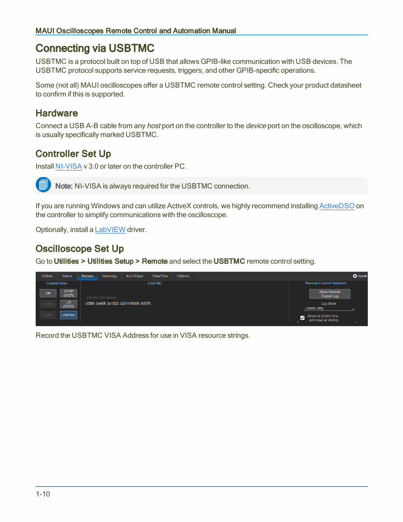
Oscilloscope Set UpGo to Utilities > Utilities Setup > Remote and select the USBTMC remote control setting.
Record the USBTMC VISA Address for use in VISA resource strings.
1-10
Part 1: Making the Remote Connection
Connecting via GPIBThe IEEE 488.2 General Purpose Interface Bus, or GPIB, interconnects independent devices by means of acable bus. Although largely replaced by other serial buses, Teledyne LeCroy's IEEE 488.2 command set isstill supported by all MAUI oscilloscopes. See the IEEE 488.2 Command Reference.
GPIB is offered as an optional, factory-installed interface on most MAUI oscilloscopes over 350 MHzbandwidth. You can send Automation commands over the GPIB interface using the VBS command, it is notrestricted to the IEEE 488.2 commands.
Caution: Do not install third-party GPIB driver software on Teledyne LeCroy oscilloscopes; this canresult in a non-functional GPIB interface. The only GPIB driver designed to operate on theinstrument is included with your oscilloscope's firmware.
The optional USB2-GPIB Converter enables you to take advantage of high-speed transfer from theoscilloscope using the USB2 interface on newer MAUI oscilloscopes. However, this is still treated as a GPIBconnection in VISA resource strings. See the USB2-GPIB Converter User's Manual.
HardwareIf both controller and oscilloscope have a GPIB port, connect them using a GPIB cable.
If using the USB2-GPIB Converter, connect the converter from the GPIB port on the controller to a USB2port on the oscilloscope. On the first connection, accept and install the device driver. The driver is located at:C:\Program files\LeCroy\XStream\Drivers_X86(or X64)\GPIB2USB. The installer is called dpinst.exe.
Reboot the instruments.
Controller Set UpInstall NI-VISA to manage the interface functions of the GPIB connection.
If you are running Windows and can utilize ActiveX controls, we highly recommend installing ActiveDSO onthe controller to simplify communications with the oscilloscope.
Optionally, install a LabVIEW driver.
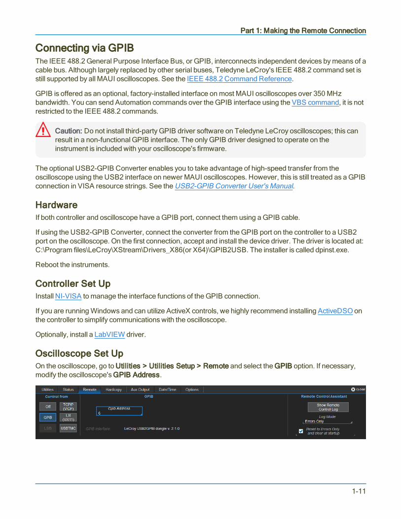
Oscilloscope Set UpOn the oscilloscope, go to Utilities > Utilities Setup > Remote and select the GPIB option. If necessary,modify the oscilloscope's GPIB Address.
1-11

MAUI Oscilloscopes Remote Control and Automation Manual
Connecting via LSIBThe LeCroy Serial Interface Bus, or LSIB, is a proprietary standard for high-speed data transfer from theoscilloscope with speeds up to 325 MB/s. Teledyne LeCroy’s exclusive LSIB solution is based on the wiredPCI Express standard that uses a 4-lane bus for remote data transfer. An LSIB API is published.
While LSIB offers significant improvements in data transfer rate over 100Base-T ENET, USBTMC, andGPIB, the LSIB API is geared toward waveform and data transfer and does not provide for many othercommon remote control functions such as remote set up, "hardcopy" screen capture, etc.
LSIB is an optional, factory-installed interface on WavePro, WaveMaster, and LabMaster seriesoscilloscopes.
HardwareInstall the LSIB host board or host card on the controller PC, then connect the controller to the oscilloscopeusing the LSIB cable.
See the LSIB Host Interfaces Operator's Manual for instructions on making the LSIB connection.
Controller Set UpRun the LSIB installer for Windows or Linux on the controller. After installation, the online LSIB API (LSIB-API-Ref-OLH-E.chm), can be found in:
C:\Program Files\LeCroy\XStream\LSIB\Docs
Oscilloscope Set UpOn the oscilloscope, go to Utilities > Utilities Setup > Remote and select the LSIB remote control option.
Shut down both the oscilloscope and the controller. Restart the oscilloscope first, followed by the controller.You do not have to wait for the oscilloscope's boot cycle to complete to restart the controller.
1-12

Part 1: Making the Remote Connection
Configuring DCOM ConnectionsThe Windows Distributed Component Object Model (DCOM) permits the distribution of differentcomponents of a single application across two or more networked computers, supporting the remote displayand control of applications. Accessing a networked oscilloscope remotely via DCOM is equivalent to loggingon to the oscilloscope itself and executing programs "locally."
A DCOM connection is necessary to execute remote control programs, unless you use ActiveDSO or NI-VISA to handle the remote message interface. It is also required to control the oscilloscope from a remotePC using XStreamBrowser.
Caution: DCOM connections to Teledyne LeCroy oscilloscopes running Windows 10 are notcurrently supported. We cannot guarantee the behavior of the MAUI firmware (XStreamDSO)when operated through such a connection. Use ActiveDSO or NI-VISA to manage the remoteinterface to these oscilloscopes, and use the local copy of XStreamBrowser to view the Automationhierarchy. You can safely use DCOM to connect from a Windows 10 PC to a Windows 7oscilloscope.
Note: DCOM is pre-configured on WaveSurfer 3000 oscilloscopes, which run the Windows CEplatform and do not allow access to a desktop; you can omit performing these connectionprocedures. Install WaveStudio instead of XStreamBrowser on the remote PC to view theAutomation hierarchy.
To complete this process, you will:
1. Confirm the Windows OS on controller and oscilloscope: go to the Windows desktop, right-click onthe My Computer icon and choose Properties. Follow the procedures below indicated for youroperating system.
2. Confirm the NT domain of both controller and oscilloscope.
3. Configure the remote PC to permit DCOM connections.
4. Configure the oscilloscope DCOM settings, including creating user accounts (if required).
5. Test the connection.
Note: You must have Administrator privileges on both the PC and the oscilloscope to completeDCOM configuration.
Confirm Network Domain and User AccountsIf the oscilloscope is not on the same NT domain as the controller PC, you will need to set up an account forthe PC user in the oscilloscope domain using the exact same user name and password as on the PC.That same user must also be allowed into the oscilloscope DCOM section. Before proceeding, consult yourNetwork Administrator regarding your network configuration.
1-13

MAUI Oscilloscopes Remote Control and Automation Manual
If the machines are on different domains, verify the user name and password for each user account that willbe used to send Automation commands to the oscilloscope. You will need this information to complete theconfiguration on the oscilloscope.
Windows 7 and 10 DCOM Configuration
On the ControllerFollow these steps if the PC is running the Windows 7 or Windows 10 operating system.
1. Go to the Windows Start menu and type dcomcnfg.exe in Search programs and files.
2. Expand Component Services until you see My Computer. Right-click on My Computer and chooseProperties.
3. On the Options tab, enter 0 for Transaction timeout, then click Apply.
1-14

Part 1: Making the Remote Connection
4. Open the Default Properties tab. Make sure Enable distributed COM on this computer is checked.If not check it and click Apply.
On the Oscilloscope
Note: These steps are only for oscilloscopes running Windows 7. Do not use DCOM to interfacewith oscilloscopes running Windows 10, use ActiveDSO or NI-VISA.
We recommend connecting a keyboard and mouse to the oscilloscope before beginning this procedure. Useany USB ports.
Create Users
1. Choose File > Minimize to display the Windows desktop.
2. Windows 7: Go to Start > Control Panel > User Accounts > Manage User Accounts.
Windows 10: Go to Start > Settings > Accounts > Other People.
3. For each user that is to access the oscilloscope remotely, Add a user ("Another work or family user")with the same user name and password as on the PC. Be sure the user is created as a LocalAdministrator.
Configure DCOM Settings
1. Go to the Windows Start menu and enter dcomcnfg.exe in Search programs and files.
2. Expand Component Services until you see My Computer. Right-click on My Computer and chooseProperties.
1-15

MAUI Oscilloscopes Remote Control and Automation Manual
3. On the Options tab, enter 0 for Transaction timeout, then click Apply.
4. Open the Default Properties tab. Make sure Enable distributed COM on this computer is checked.If not check it and click Apply. Close the dialog when done.
1-16
Part 1: Making the Remote Connection
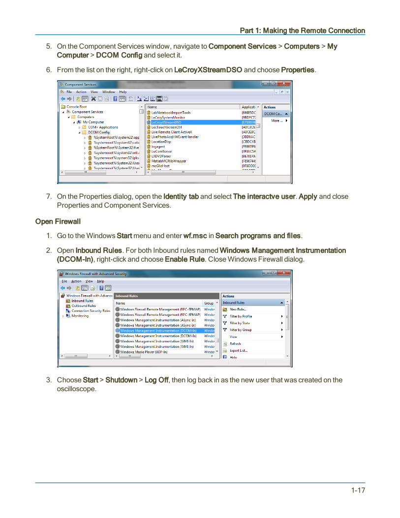
5. On the Component Services window, navigate to Component Services > Computers > MyComputer > DCOM Config and select it.
6. From the list on the right, right-click on LeCroyXStreamDSO and choose Properties.
7. On the Properties dialog, open the Identity tab and select The interactve user. Apply and closeProperties and Component Services.
Open Firewall
1. Go to the Windows Start menu and enter wf.msc in Search programs and files.
2. Open Inbound Rules. For both Inbound rules named Windows Management Instrumentation(DCOM-In), right-click and choose Enable Rule. Close Windows Firewall dialog.
3. Choose Start > Shutdown > Log Off, then log back in as the new user that was created on theoscilloscope.
1-17

MAUI Oscilloscopes Remote Control and Automation Manual
Windows XP or Vista DCOM Configuration
On the ControllerFollow these steps if the controller PC is running Windows XP or Vista operating system.
1. Go to Start > Run, enter dcomcnfg.exe and click OK.
Note: If Run is not in your Start menu, open a terminal and run dcomcnfg.exe.
2. Expand Component Services > Computers.
3. If you see a Windows Security Alert pop-up, click Unblock.
4. In the Computers folder, right-click My Computer and choose Properties.
5. On the Properties dialog, open the Options tab and change Transaction Timeout to 0. Click Apply.
On the OscilloscopeFollow these steps if your oscilloscope is running Windows XP or Vista operating system.
Contact Technical Support for assistance if your oscilloscope is running Windows XP Embedded.
Open Firewall
1. Go to Start > Control Panel > Firewall. For Vista machines, click Change Settings.
2. On the Windows Firewall dialog, open the Exceptions tab.
3. Select LeCroyXStreamDSO Main Application.
4. Click Add Port.
5. On the Add Port dialog, make the following settings, then click OK:
l Name: DCOM
l Port number: 135
l TCP: selected
1-18

Part 1: Making the Remote Connection
Turn Off Simple File Sharing
1. Go to Start > Control Panel > Folder Options.
2. On the Folder Options dialog, open the View tab and clear the checkbox Use simple file sharing.
3. Click OK.
Create UsersIf the oscilloscope is on the same NT domain as the controller, you can skip this procedure.
If the oscilloscope is not on the same NT domain as the controller, each PC user that is to send Automationcommands to the oscilloscope must have a corresponding user account on the oscilloscope, configured withthe identical user name and password. Both accounts must have Administrator privileges.
1. On the Windows desktop, right-click on My Computer and choose Manage.
2. Expand the hierarchy to display Local Users and Groups > Users. Select Users
3. Right-click on a blank area of the dialog and choose New User.
4. Enter the User name and Password exactly as they appear on the controller PC. Confirm password.
5. Deselect User must change password at next logon.
6. Click Close.
Configure DCOM Settings
1. Go to Start > Run, enter dcomcnfg.exe and click OK.
Note: If Run is not in your Start menu, open a terminal and run dcomcnfg.exe.
2. Expand Component Services.
3. If a Windows Security Alert pop-up appears, click Unblock.
4. Expand Computers, right-click on My Computer, and select Properties.
5. Open the Options tab and set the Transaction timeout to 0. Click Apply.
6. Open the Default Properties tab, select Enable Distributed COM on this computer, and choose aDefault Authentication Level of Connect.
7. Open the COM Security tab and under Launch and Activation Permission click Edit Limits.
8. On the Launch Permission dialog, click Add.
1-19

MAUI Oscilloscopes Remote Control and Automation Manual
9. On the Select Users… dialog:
l If the PC and oscilloscope are on the same NT domain, select the PC user account.
l If the PC and oscilloscope are not on the same NT domain, enter the PC user account nameand click Check Names.
Click OK.
10. On the Launch Permissions dialog, check Allow for all permissions. Click OK.
11. On the Component Services window, expand My Computer > DCOM Config. Right-click onLeCroyXStreamDSO and choose Properties.
12. Open the Identity tab and select The interactive user.
13. Open the Security tab, under Launch and Activation Permissions select Customize, then click Edit.
14. On the Select Users… dialog:
l If the PC and oscilloscope are on the same NT domain, select the PC user account.
l If the PC and oscilloscope are not on the same NT domain, enter the PC user account nameand click Check Names.
Click OK.
15. On the Launch Permissions dialog, check Allow for all permissions. Click OK.
16. On the Security tab, under Access Permissions, select Customize and click Edit. Repeat Steps 14and 15.
17. Choose Start > Shut Down > Restart to reboot the oscilloscope.
Testing the DCOM ConnectionDownload the free XStreamBrowser from the Oscilloscope Software Utilities page at:
http://teledynelecroy.com/support/softwaredownload/
Install it on the PC and use it to Connect to Remote Instrument (DCOM).
If the DCOM connection is properly configured, you should now see the oscilloscope application objecthierarchy appear in the XStreamBrowser window.
Note: WaveSurfer 3000 users should instead install the WaveStudio software, which will display theCOM hierarchy of a connected device when Automation Browser is selected.
1-20
Part 1: Making the Remote Connection
Testing the Remote ConnectionOnce you have completed all the steps required to make the remote connection to your oscilloscope, testthat you can "see" it from the controller and send remote commands.
Using WaveStudioThe free WaveStudio software is capable of testing several types of remote connection as well as serving asa remote command terminal for controlling the oscilloscope. A trial copy is installed on the oscilloscope, andanother may be installed on Windows-based PCs. For download information, see Resources.
Follow these steps to test the connection:
1. Click the Add Scope button on My Scope Explorer or the Scope menu ribbon.
2. On the Add Device dialog, select the remote connection type.
3. Enter the oscilloscope's network name or address and click OK.
If the oscilloscope is found, an entry is added to the My Scope Explorer window. The status should indicatethe device is "Alive." This confirms the connection is working.
If the oscilloscope is found but cannot be connected, after a brief time out an entry is added to My ScopeExplorer indicating the selected device is "Dead." Check the address and physical connection again. If youstill cannot connect, consult with your Network Administrator.
Using the PING CommandFor LAN users, both the physical cable connection and proper host TCP/IP configuration can be verifiedusing the Ping command.
Note: PING is a good way to check the network connection, but it doesn't guarantee the socketconnection to the oscilloscope at port 1861. Connecting via WaveStudio or XStreamBrowser is abetter test.
At an MS-DOS prompt, type:
ping <IP_address>
where <IP_address> is the address assigned to the oscilloscope.
The Command Prompt window shows an exchange similar to that below if the Ping is successful. TheEthernet connection is shown as established and the ping command has sent a message to the instrumentand waited for a response. If a timeout occurs, the IP address used for the destination (the oscilloscope) isincorrect or not within the subnet mask of the host's IP.
1-21

MAUI Oscilloscopes Remote Control and Automation Manual
Successful ping showing reply.
Remote Control AssistantThe Remote Control Assistant (RCA) feature of MAUI oscilloscopes maintains a log of remote controlcommands received and responses issued (which would include Automation controls sent within the VBScommand), allowing the programmer to receive feedback on errors in his or her source code.
The RCA has several modes of operation: Off, Errors Only, and Full Dialog.
l In Errors Only mode (the default), the RCA will keep a log of any mistakes in the commandsreceived, and display the error detected.
l In Full Dialog mode, all commands and responses are logged.
This selection can be made by going to Utilities > Utilities Setup > Remote on the oscilloscope.
Touch Show Remote Control Log on the Remote dialog to pop up a window showing the log file. Fromthere you can clear the log or save it as a text file.
The RCA can also be set by using the remote commands COMM_HELP (CHLP) andCOMM_HELP_LOG (CHL).
1-22

Part 1: Making the Remote Connection
ActiveDSOActiveDSO is a proprietary ActiveX™ control that enables Teledyne LeCroy oscilloscopes to be controlled byand exchange data with a variety of Windows applications that support the ActiveX standard. MicrosoftOffice suite, Internet Explorer, Visual Basic, Visual C++, and Visual Java are a few of the many applicationsand languages that support ActiveX controls.
ActiveDSO hides the intricacies of programming in ActiveX and provides a simple and consistent interface tothe controlling application. The ActiveDSO control may be used as either:
l An "invisible" object accessed via a scripting language, for example, VBS.
l A visible object embedded in an OLE Automation compatible client, such as a VBA macro launchedby a Windows application button.
Note: Many of our Automation examples utilize Visual Basic Script (VBS), the "built in" Automationlanguage, as it is syntactically identical to our LeCroy Setup Script (.LSS). Do not confuse VBS withVisual Basic for Applications (VBA), a subset of Visual Basic used extensively within Windowsapplications, such as Excel, as a macro "programming" language. Some things that work in VBS donot work in VBA.
A great benefit of ActiveDSO is that it is completely independent of the remote hardware interface. Theconnection via ENET (TCP/IP), GPIB, or USBTMC is made by a single command near the start of aprogram. It may be used to send Automation commands or legacy IEEE 488.2 remote control commands.
Download the ActiveDSO software free of charge from our website (see Resources) and install ActiveDSOon the controller PC. The driver installs with the ActiveDSO Developer's Guide. This manual documents allthe methods and properties used to program ActiveDSO objects. Following are some simple examples.More extensive examples are installed in the ActiveDSO program folder.
Instantiating the ActiveDSO ControlThe control's external name is always: LeCroy.ActiveDSOCtrl.1
The control's CLSID is 450A9897-D9C9-11D1-9966-0000F840FC5E
Following are instantiations of the control as an "invisible" object used to pass remote commands in severalcommonly used languages. In each case, the control is aliased as "dso", although for this you may substitutewhatever you wish.
Language
VBA Dim dso As ObjectSet dso = CreateObject("LeCroy.ActiveDSOCtrl.1")
Python import win32com.clientdso=win32com.client.Dispatch("LeCroy.ActiveDSOCtrl.1")
Visual C++ CActiveDSO dso;RECT dummyRect;dso.Create("LeCroy.ActiveDSOCtrl.1","HiddenWindowForDSOControl",0,dummyRect,this,0);
1-23

MAUI Oscilloscopes Remote Control and Automation Manual
ActiveDSO Methods for Remote ControlFollowing are several ActiveDSO methods that are particularly useful for remote control. See theActiveDSO Developer's Guide for an explanation of all ActiveDSO methods.
MakeConnectionThis method establishes the connection from controller to oscilloscope. It is a single line of code that requiresonly that you pass the oscilloscope interface an address to which to connect.
The following table shows the MakeConnection string for each remote interface type.
Interface Syntax Example
TCP/IP MakeConnection("IP: <IP address>") MakeConnection("IP: 172.25.9.22")
LXI MakeConnection("VXI11: <IP address>") MakeConnection("VXI11: 172.25.9.22")
GPIB MakeConnection("GPIB[x]: <GPIB address>")x:= 0 to 3 (optional)
MakeConnection("GPIB: 4")
USBTMC MakeConnection("USBTMC: <VISA resource string>") MakeConnection("USBTMC:USB0::0x05FF::0x1023::2807N59057::INSTR")
Note: When the VISA resource string is used with ActiveDSO for remote control, it is preceded by asingle colon space instead of the double colon used with a VISA driver.
DisconnectThe Disconnect method disconnects the control from the device. This method performs the necessarytermination functions, which will cleanup and disconnect the interface connection.
WriteStringThe WriteString method sends a command string to the connected device with or without a terminating EOI(End or Identify). It can be used with Automation or legacy remote commands.
WriteString follows the syntax:
<controlName>.WriteString("<textString>", <EOI Boolean>)
<controlName>:= name used to instantiate the ActiveDSO control
<textString>:= command string sent to the device
<EOI Boolean>:= 1, 0
If EOI is set to 1 (TRUE), the command terminates with EOI, and the device interprets the command rightaway. This is normally the desired behavior.
If EOI is set to 0 (FALSE), a command may be sent in several parts with the device starting to interpret thecommand only when it receives the final part, which should have EOI set to TRUE.
1-24
Part 1: Making the Remote Connection
ReadStringThe ReadString method reads a string response from the instrument and can be used to read the results ofqueries.
' Read the amplitude parameter measurement, store in cell L3 of Excel worksheet
Call o.WriteString("c1:pava? ampl", 1)Worksheets("Sheet1").Cells(3, 12).Value = o.ReadString(500)
' Read the rise time parameter measurement into variable
Call o.WriteString("c1:pava? rise", 1)RiseTime = o.ReadString(500)
1-25

MAUI Oscilloscopes Remote Control and Automation Manual
VISAVISA refers to the Virtual Instrument Software Architecture, an API widely used in Test & Measurement forcommunicating with instruments from a PC. With the installation of a VISA driver, the programmer needsonly provide a VISA resource string to create a connection to a remote instrument, and VISA passessubsequent write or read data requests and the corresponding VISA passport to the instrument.
A VISA driver that behaves exactly like NI-VISA is required for remote connection to Teledyne LeCroyoscilloscopes over the ENET, USBTMC, and GPIB interfaces if you cannot utilize ActiveX technology (suchas ActiveDSO and WaveStudio) on your network. Programmers should download and read the IVI VISAspecification document for their programming language to fully understand the VISA API. It is always a goodidea to install the IVI VISA API in order to decouple your Automation program from the driver used.
We have tested our instruments with National Instrument's implementation of VISA, NI-VISA, andrecommend an installation of this if you are making the remote connection from a Windows machine. NI-VISA can be downloaded from: https://www.ni.com/visa/
Note: For NI-VISA licensing requirements and fees, see https://www.ni.com/visa/license.htm.
Unless you install NI-VISA, you will have to program your own remote control interface. We supply the VICPClient Library for those who wish to use the VICP protocol but cannot use NI-VISA because they are notworking in the Windows environment.
VICP Passport for NI-VISAThose using NI-VISA for VICP connections in the Windows environment should install the VICP Passport.The passport is a plug-in DLL for NI-VISA that provides a translation layer between the standard NI-VISAAPI and Teledyne LeCroy's VICP protocol. See the Application Brief LAB_WM827: Understanding VICPand the VICP Passport for more information.
Note: NI-VISA provides the necessary VISA passports for LXI, GPIB, and USBTMC connections;VICP Passport is only necessary if you're using VICP protocol.
Download VICP Passport from teledynelecroy.com. See Resources.
1-26
Part 1: Making the Remote Connection
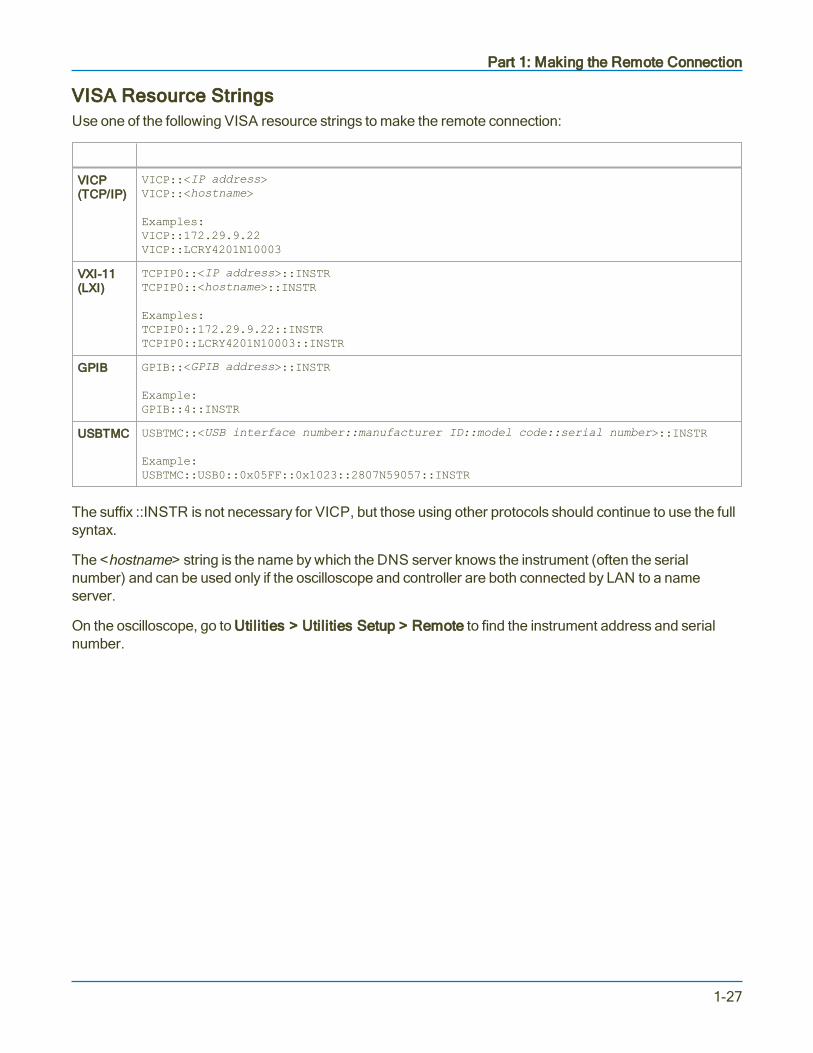
VISA Resource StringsUse one of the following VISA resource strings to make the remote connection:
Protocol VISA Resource String
VICP(TCP/IP)
VICP::<IP address>VICP::<hostname>
Examples:VICP::172.29.9.22VICP::LCRY4201N10003
VXI-11(LXI)
TCPIP0::<IP address>::INSTRTCPIP0::<hostname>::INSTR
Examples:TCPIP0::172.29.9.22::INSTRTCPIP0::LCRY4201N10003::INSTR
GPIB GPIB::<GPIB address>::INSTR
Example:GPIB::4::INSTR
USBTMC USBTMC::<USB interface number::manufacturer ID::model code::serial number>::INSTR
Example:USBTMC::USB0::0x05FF::0x1023::2807N59057::INSTR
The suffix ::INSTR is not necessary for VICP, but those using other protocols should continue to use the fullsyntax.
The <hostname> string is the name by which the DNS server knows the instrument (often the serialnumber) and can be used only if the oscilloscope and controller are both connected by LAN to a nameserver.
On the oscilloscope, go to Utilities > Utilities Setup > Remote to find the instrument address and serialnumber.
1-27

MAUI Oscilloscopes Remote Control and Automation Manual
Using VISA AliasesFor LXI (VXI-11), GPIB, and USBTMC connections, VISA aliases can be used instead of the full VISAresource string, allowing you to decouple your remote control programs from DHCP changes or long,cumbersome device addresses.
Note: VISA aliases cannot be used with the VICP protocol.
Tools like NI-MAX (Measurement & Automation Explorer) make it very easy to assign aliases to any devicein your system, which are automatically updated whenever the address is changed.
Once the alias is assigned, simply replace the full VISA connect string with the alias in your code. Forexample, in this Python script, instead of:
import visarm = visa.ResourceManager()lecroy = rm.open_resource("TCPIP0::HDO-LCRY::inst0::INSTR")
You could send:
import visarm = visa.ResourceManager()lecroy = rm.open_resource("HDO6104MS")
1-28

Part 1: Making the Remote Connection
WaveStudioWaveStudio is a PC-based connectivity tool that interfaces a Teledyne LeCroy oscilloscope to a WindowsXP, Vista, 7 or 10 operating system, with support for 32- and 64-bits. It is a fast and easy way to analyzeacquired waveforms offline, or to remotely control an oscilloscope from your desktop. WaveStudio is alsoused to access the Automation hierarchy of WaveSurfer 3000 model oscilloscopes.
Unlike XStreamBrowser, which works solely within the Windows COM architecture, WaveStudio canconnect to a device over most of the available remote interfaces, making it a good way to test differentremote connections.
Note: WaveStudio does not support LSIB connections to the instrument. Choose another remoteconnection if you wish to use WaveStudio for remote control.
Setting PermissionsWaveStudio is preset so that only users with Administrator rights can run it. If you wish to use WaveStudiofrom a PC that does not have Administrator privileges:
1. Navigate to C:\Program Files\LeCroy\XStream\WaveStudio.exe, then right-click and chooseProperties.
2. Open the Compatibility tab and deselect Run this program as an Administrator.
Connecting to a DeviceTo use WaveStudio to make the remote connection to an oscilloscope:
1. Configure both the PC running WaveStudio and the oscilloscope to support the remote controlmethod you wish to use.
2. Launch WaveStudio and click the Add Scope icon either on the Scope ribbon or at the top of theMy Scope Explorer window.
3. Select the remote control method in use.
4. Enter the oscilloscope's domain name or address, depending on the remote connection type (e.g.,IP address for TCP/IP, GPIB address for GPIB).
5. The device should now appear in the My Scope Explorer window with a status of Alive.
If it does not appear or is not Alive, select it and click the Edit icon . Check that you have enteredthe correct name or address. Change it if necessary.
Tip: Go to Utilities > Utilities Setup > Remote on the oscilloscope to check the remote controlmethod and the device name or address. These must match what is entered in WaveStudio.If DHCP is in use, the address may have changed since the oscilloscope was originallyadded to WaveStudio.
1-29

MAUI Oscilloscopes Remote Control and Automation Manual
Sending Remote CommandsWaveStudio includes a terminal window from which you can execute IEEE 488.2 remote controlcommands. Use the VBS command to send Automation commands.
1. Follow the procedure above to connect to the oscilloscope. If the device is already added to MyScope Explorer, just select it from the list.
2. When the connection is Alive, select Terminal from the list of objects/folders belonging to the devicein My Scope Explorer.
3. At the top of the Terminal window, immediately below the words "LeCroy WaveStudio," enter theremote command or query and Return.
Replies to queries appear in the bottom section of the Terminal window.
Automation Browser for WaveSurfer 3000For WaveSurfer3000 oscilloscopes, WaveStudio includes an Automation Browser feature that exposes theinstrument's COM object hierarchy, the same as does XStreamBrowser for other oscilloscope models.
1-30

Part 2: Automation Programming Reference
Part 2: Automation Programming ReferenceThis section is a guide to the Automation capabilities of Teledyne LeCroy’s MAUI™ (also known asXStream) oscilloscopes.
While Teledyne LeCroy has always striven to maximize compatibility, the underlying technologies used byAutomation require the Microsoft Windows® operating system (minimum 32-bit), and this system wasintroduced only with our MAUI instruments. Automation is not available on the older oscilloscope families.These instruments can be controlled remotely using legacy IEEE 488.2 remote control commands.
Automation Overview 2-2
XStreamBrowser 2-4
Viewing XStreamDSO Objects 2-6
VBS Command 2-10
Approach 1: Control from XStreamBrowser 2-11
Approach 2: Program in VBS 2-13
Approach 3: Program Using ActiveDSO 2-17
Approach 4: Program Using VISA 2-20
Control Variables 2-24
Result Interfaces 2-27
Synchronization 2-39
Application Interactions 2-41
Early and Late Binding 2-42
Automation Programming Conventions 2-43
Using Programming Variables 2-46
Automation in MATLAB 2-47
Automation in Python 2-50
Automation in C# 2-53
2-1

MAUI Oscilloscopes Remote Control and Automation Manual
Automation OverviewAutomation (formerly referred to as “OLE Automation”) is a Microsoft technology that is primarily used toenable cross-application macro programming. It is based upon the Component Object Model (COM), whichis similar in nature to CORBA more commonly found in the UNIX world. In addition to supporting the familiarASCII-based remote commands that have been used to control all Teledyne LeCroy oscilloscopes for manyyears, all Windows-based MAUI instruments fully support control by Automation interfaces.
Using COM, the controlling application can run directly on the instrument without requiring an externalcontroller. Alternatively, it can run from a remote, networked computer using Microsoft’s distributed COMstandard (DCOM).
It is important to note that Automation itself is not language dependent; it can be performed using anyprogramming language that supports COM.
General ArchitectureAn application that “exposes Automation objects” is referred to as an “Automation server.” Automationobjects expose “Automation interfaces” to the controlling “Automation client.” The oscilloscope applicationon MAUI oscilloscopes (XStreamDSO) is an Automation server that can be controlled locally or remotely byAutomation clients.
Automation objects can take the form of:
l Invisible "objects" created by script, such as a Visual Basic script to change oscilloscope settings andread back the new measurement results
l Visible objects embedded in an application, such as a button that launches a macro containing anAutomation subroutine
Uses of AutomationAutomation has many uses:
l Instrument setup (panel files)
l Remote control from external Windows applications
l Exposing waveform data and measurement results to external Windows applications
l Custom math/measurement processing and user interface customizations (with XDEV)
This section concentrates on using Automation for remote set up, control, and waveform/data transfer, thefunctions traditionally performed by GPIB remote control.
2-2

Part 2: Automation Programming Reference
Automation Compared to IEEE 488.2 Remote ControlAutomation does not necessarily replace the IEEE 488.2 legacy remote command set, which is alsosupported by MAUI instruments (and will continue to be). Rather, it augments it and allows another class ofapplication to be created that can be executed locally or remotely.
Automation, however, can be considered as the “native language” of MAUI instruments. All of theinstrument’s controls and features are available to the Automation client, whereas only some of theinstrument features have been implemented in the 488.2 remote command set.
The following table summarizes the differences between the two approaches to remote control:
IEEE 488.2 Remote Control Automation Remote Control
Physical transport TCP/IP and LXI over Ethernet, GPIB,LSIB, or USBTMC*
Inter-process using COM, inter-PC usingDCOM (TCP/IP)
Textual parsing of instrumentresponses required
Yes, all instrument responses need‘parsing’ to extract useful information
No, each element in the Automationhierarchy appears as a “variable” to theAutomation client
Compatibility with legacyprograms/instruments
Yes, in most cases remote controlapplications written for legacyinstruments will work withoutmodification
No, Automation is a standard firstintroduced with MAUI (XStreamDSO)
Ability to control the oscilloscopeapplication from “inside the box”
Yes, by using the VICP (TCP/IP) protocolto talk to the “localhost”
Yes, natively
Ease of use Not trivial, although easier using a toolsuch as ActiveDSO** that hides some ofthe complexities
Very easy with scripting languages andMS Office productivity tools
Format of waveform results Binary or ASCII; both require parsingbefore use
Arrays of floating point values
Control from MS Office suite Possible via ActiveDSO utility Yes, natively
* Not all interfaces available on all models. GPIB and LSIB available with hardware option.
** ActiveDSO is an ActiveX based driver for Teledyne LeCroy oscilloscopes
2-3
MAUI Oscilloscopes Remote Control and Automation Manual
XStreamBrowserThe XStreamBrowser utility enables you to view, copy, and modify the COM object hierarchy of a Windows-based MAUI™ oscilloscope from a remote PC. It is essential for writing Automation programs, as it alwaysshows all the Automation objects on the instrument at the exact current configuration—including thoseobjects belonging to software options. It can also be used as a remote control console, enabling you todirectly alter the configuration of Automation control variables.
XStreamBrowser is installed on all MAUI oscilloscopes for local browsing, but it may also be installed on anyPC for remote control. You must first allow a DCOM connection between the PC and oscilloscope, thenconnect the XStreamBrowser to the device. The browser window is populated when the DCOM connectionis successful.
Note: If using WaveSurfer 3000 or any oscilloscope running on the Windows 10 operating system,install the WaveStudio software instead of XStreamBrowser. The COM object hierarchy of aconnected device is shown in the WaveStudio Automation Browser.
Caution: The version of XStreamBrowser available for download on our website is a 32-bit versionthat will run on 64-bit machines. It is intended only for installation on remote PCs, not onoscilloscopes. A 64-bit version of XStreamBrowser is already installed on 64-bit MAUIoscilloscopes. Installing the 32-bit version over this will cause registry conflicts. Likewise, if you haveinstalled the 64-bit MAUI firmware on your PC, you already have a copy of the 64-bitXStreamBrowser. If it was uninstalled, reinstall the MAUI firmware, rather than install the 32-bitversion of XStreamBrowser.
Connecting to a Local DeviceTo launch XStreamBrowser on the oscilloscope:
1. Choose File->Minimize to display the Windows desktop.
2. Double-click the XStreamBrowser icon.
3. Select the connection icon.
Connecting to a Remote Device
1. Be sure the oscilloscope is configured to allow a DCOM connection from the PC.
2. Launch XStreamBrowser on the PC.
3. Select the connection icon.
4. Enter the network IP Address of the oscilloscope, then click OK.
2-4
Part 2: Automation Programming Reference
Note: It is best to use the IP Address, not the DNS or UNC name. If the oscilloscope application isnot running, initiating the connection from XStreamBrowser will start it; however, it will not power ona device that is powered off. Be sure the device is turned on before connecting.
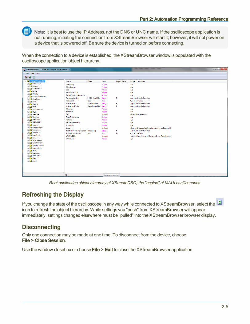
When the connection to a device is established, the XStreamBrowser window is populated with theoscilloscope application object hierarchy.
Root application object hierarchy of XStreamDSO, the "engine" of MAUI oscilloscopes.
Refreshing the Display
If you change the state of the oscilloscope in any way while connected to XStreamBrowser, select theicon to refresh the object hierarchy. While settings you "push" from XStreamBrowser will appearimmediately, settings changed elsewhere must be "pulled" into the XStreamBrowser browser display.
DisconnectingOnly one connection may be made at one time. To disconnect from the device, chooseFile > Close Session.
Use the window closebox or choose File > Exit to close the XStreamBrowser application.
2-5

MAUI Oscilloscopes Remote Control and Automation Manual
Viewing XStreamDSO ObjectsThe number of different objects in a complete oscilloscope setup is obviously large and changes with theinstallation of new firmware and software options. XStreamBrowser helps you quickly find the object pathand valid values corresponding to any instrument control.
The object hierarchy exposed by MAUI instruments is rooted at the Application object. This object is alwaysnamed LeCroy.XStreamDSO.
All major instrument subsystems are available from this object, and many of these subsystems themselvesmay be broken down further. As new software options are activated on the oscilloscope, these subsystemsare added to the Application object hierarchy.
Anything exposed by the object hierarchy can be controlled or read back via Automation.
Object HierarchyThe left-hand pane of the XStreamBrowser window contains anexpandable navigation "tree." The object hierarchy is tiered; forexample, the Acquisition subsystem is comprised of a variety ofobjects, each with child objects.
The right-hand pane shows the Control Variables or Propertiesrelated to the object selected from the navigation tree.
Control VariablesThe majority of the items you will find as you expand the navigation tree are Control Variables, or CVARs forshort. These are shown as yellow folders in the XStreamBrowser window.
CVARs provide an interface for accessing scope configurations and for executing methods and actions.When viewed from XStreamBrowser, many CVARs appear to be properties, but are actually objects withproperties such as Name, Value, and Type, to name a few. See Control Variables for a description ofCVAR Types, Properties, and Methods.
2-6
Part 2: Automation Programming Reference
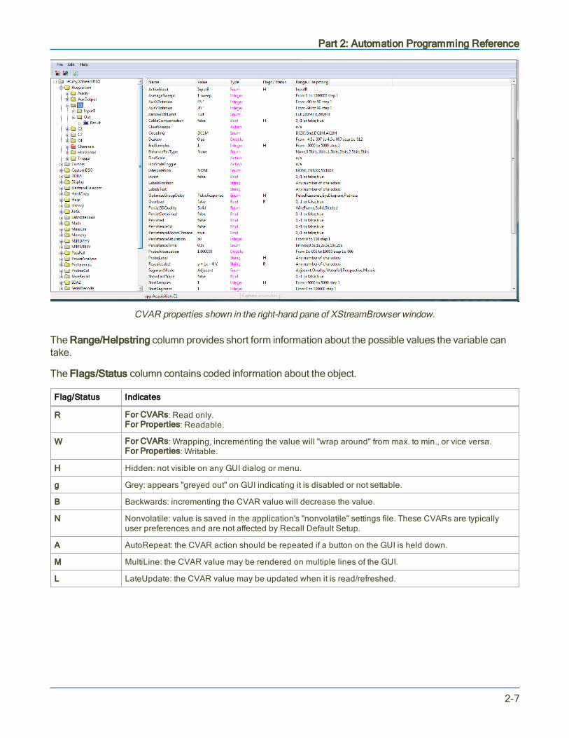
CVAR properties shown in the right-hand pane of XStreamBrowser window.
The Range/Helpstring column provides short form information about the possible values the variable cantake.
The Flags/Status column contains coded information about the object.
Flag/Status Indicates
R For CVARs: Read only.For Properties: Readable.
W For CVARs: Wrapping, incrementing the value will "wrap around" from max. to min., or vice versa.For Properties: Writable.
H Hidden: not visible on any GUI dialog or menu.
g Grey: appears "greyed out" on GUI indicating it is disabled or not settable.
B Backwards: incrementing the CVAR value will decrease the value.
N Nonvolatile: value is saved in the application's "nonvolatile" settings file. These CVARs are typicallyuser preferences and are not affected by Recall Default Setup.
A AutoRepeat: the CVAR action should be repeated if a button on the GUI is held down.
M MultiLine: the CVAR value may be rendered on multiple lines of the GUI.
L LateUpdate: the CVAR value may be updated when it is read/refreshed.
2-7

MAUI Oscilloscopes Remote Control and Automation Manual
Actions and MethodsBesides the configuration CVARs, automation also provides for Actions that may be applied at theapplication or subsystem level.
For example, to clear sweeps for all subsystems, the Automation command would be:
app.ClearSweeps
Methods are similar to Actions but may take parameters from the caller and may possibly return a value,whereas, Actions do not support any parameters or return values. An example of a Method isapp.Acquisition.Acquire, which takes both "timeout" and "force trigger" arguments.
Result InterfacesThe grey folders are Result Interfaces. Result Interfaces contain more than just the basic results ofoscilloscope operations, such as waveform data and measurement values; they include information abouthorizontal and vertical resolution, event times, number of sweeps, histogram peaks, etc. The Type columnof the XStreamBrowser window shows the result interface type. See Result Interfaces for a description ofthe Types and Variables.
CollectionsCollections, which are shown as pink folders in XStreamBrowser, contain sets of similar objects. Forexample, the app.Acquisition.Channels collection contains input channel objects (C1, C2, etc.). Objects inCollections folders are dynamically linked to those in the yellow folders; changing the value in either placechanges it everywhere. Collection subfolders are referenced by indexing the collection name with thesubfolder name.
2-8

Part 2: Automation Programming Reference
Copying from XStreamBrowserWhen a variable is selected from the right-hand pane, the message bar at the bottom of the screen showsthe full object path in correct notation for sending as an Automation command:
Right-click and choose Copy Path. The text is automatically placed in the clipboard, from where it can beeasily copied into remote control programs.
2-9

MAUI Oscilloscopes Remote Control and Automation Manual
VBS CommandFor users who wish to harness the power of Automation, but are currently using “traditional” GPIB remotecontrol commands, there is a solution: the VBS command. This will enable you to control the advancedfeatures of MAUI oscilloscopes that are not supported by GPIB commands.
VBS is also used to encapsulate Automation commands whenever there is a remote connection to theoscilloscope other than DCOM (ActiveDSO, VISA driver, etc.).
Below are two, equivalent methods for setting the V/Div of Channel 1. The first examples uses a GPIBcommand, VDIV; the second uses the VBS command:
C1:VDIV 0.5
VBS 'app.Acquisition.C1.VerScale = 0.5'
In its query form, the following are equivalent:
C1:VDIV?
VBS? 'return = app.Acquisition.C1.VerScale'
Note: For the query form, including 'return = object' is important, as it indicates which value you wishto be returned to the caller.
The VBS Command/Query is documented in more detail in the GPIB command reference.
2-10

Part 2: Automation Programming Reference
Approach 1: Control from XStreamBrowserWhen a PC has a DCOM connection to a networked oscilloscope, a copy of XStreamBrowser running onthe PC has the same read/write capabilities as the version that is running locally on the oscilloscope. Theoscilloscope's entire XStreamDSO object hierarchy is exposed and editable from XStreamBrowser. This isperhaps the simplest way to remotely control the oscilloscope.
This exercise modifies the oscilloscope channel C1 Vertical Scale setting directly from XStreamBrowserinstalled on the PC.
Make the Connection
1. Connect the oscilloscope to your LAN, or directly to the PC using a cross-over cable.
2. Turn on the oscilloscope and go to Utilities > Utilities Setup > Remote and choose control fromTCP/IP.
3. Create a DCOM connection to the oscilloscope.
4. Download and install a copy of XStreamBrowser on the PC.
5. Open XStreamBrowser on the PC and connect to the oscilloscope.
6. When the oscilloscope appears in the Devices list, click on it to show the application hierarchy.
Find and Modify the ObjectThe Vertical settings associated with channels are part of the Acquisition subsystem, as they control thecharacteristics of the ADCs at the input, directly affecting acquisition.
Since we're looking to modify a setting that affects the Acquisition subsystem, expand the Acquisition folderto display the C1 object. Select the C1 object folder so that the C1 CVARs appear in the right-hand windowpane.
As you scroll down, you'll see the VerScale CVAR, showing whatever value was last set for that channel onthe oscilloscope, in this example, 50.0 mV.
XStreamBrowser tell us the following about this control:
l The Type column shows it is a DoubleLockstep
l The Flags/Status column shows B, meaning it is Backwards and incrementing the CVAR willdecrease the value.
2-11

MAUI Oscilloscopes Remote Control and Automation Manual
l The Range/Helpstring column shows an acceptable range of 0.002 to 1 step 0.0005. meaning it canbe set anywhere from 0.002 to 1 in increments as small as .0005. If Variable Gain is left on, the nextvalue possible is 0.0025.
l The additional statement that it is "locked to 1 2 5, fine grain..." is fully visible if we right-click on theVerScale line and choose Copy to display the Set Control Variable dialog:
While fine grain (Variable Gain) adjustments are allowed on this oscilloscope (true), the Var. Gainsetting is currently off (on=false), so the control would adjust in stepped increments of 1, 2, or 5 units(in sequence) were it being operated from the oscilloscope touch screen. Starting at 0.002, the nextvalue would be 0.005.
Enter a new Value of 100 mV and choose to Set this value.
Back on the XStreamBrowser window, you will see that the C1 VerScale setting has changed:
And the oscilloscope immediately reflects this change, as well:
Note that here we can see the Var. Gain setting is deselected.
That's all that is required to remotely set up a MAUI oscilloscope from your PC.
2-12

Part 2: Automation Programming Reference
Approach 2: Program in VBSSetup (or Panel) files, which are used to save and recall the state of the instrument between sessions, aretraditionally binary files with an internal structure that is neither documented nor obvious to the user. In MAUIoscilloscopes, however, this is not the case. Setups are ASCII text files that contain a complete Visual BasicScript “program”. In effect, each time a panel is saved, the instrument writes a program that, when executed,returns the instrument to the saved state.
VBS programs function like Setup files that are written and executed remotely.
Note: Customization and setup files stored by the instrument have file extension “.lss”(LeCroy Setup Script). These files are syntactically identical to Microsoft VBS files, which have a“.vbs” extension.
In this exercise, we'll create and execute a simple VBS program on the PC that:
l Connects to a networked oscilloscopel Performs an AutoSetupl Changes the oscilloscope grid model Reads back the Grid Mode and Vertical Scalel Disconnects
Preliminary Setup
1. As with Exercise 1, it is assumed there is a DCOM connection between the PC and an oscilloscopeon the same network, and that XStreamBrowser is installed on the PC.
2. On the oscilloscope, go to Utilities > Utilities Setup > Remote and confirm that the TCP/IP (VICP)setting is selected. Note the oscilloscope's IP address.
3. Open XStreamBrowser and NotePad or another text editor on the PC.
Program
Note: Characters in angle brackets are placeholders. Omit the brackets from your code.
ConnectCreateObject is the Visual Basic function that creates an instance of a COM Server. The argument“LeCroy.XStreamDSO” refers to the oscilloscope application. Once it has instantiated (connected to) theoscilloscope application, it requires some kind of ‘handle’ (pointer) so that it can later be used tocommunicate with the instrument. CreateObject returns a handle, which is stored in the app variable.
In the text editor, write the VBS connect string:
Set app = CreateObject("LeCroy.XStreamDSO")
2-13
MAUI Oscilloscopes Remote Control and Automation Manual
Note: Only a single instance of the XStreamDSO software can run on a system at one time. If thesoftware is already running when CreateObject is called, a handle to that running instance isreturned. If XStreamDSO is not running, it will be started.
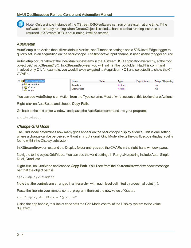
AutoSetupAutoSetup is an Action that utilizes default Vertical and Timebase settings and a 50% level Edge trigger toquickly set up an acquisition on the oscilloscope. The first active input channel is used as the triggger source.
AutoSetup occurs "above" the individual subsystems in the XStreamDSO application hierarchy, at the rootobject LeCroy.XStreamDSO. In XStreamBrowser, you will find it in the root folder. Had this commandinvolved only C1, for example, you would have navigated to Acquisition > C1 and selected it to show the C1CVARs.
You can see AutoSetup is an Action from the Type column. Most of what occurs at this top level are Actions.
Right-click on AutoSetup and choose Copy Path.
Go back to the text editor window, and paste the AutoSetup command into your program:
app.AutoSetup
Change Grid ModeThe Grid Mode determines how many grids appear on the oscilloscope display at once. This is one settingwhere a change can be perceived without an input signal. Grid Mode affects the oscilloscope display, so it isfound within the Display subsystem.
In XStreamBrowser, expand the Display folder until you see the CVARs in the right-hand window pane.
Navigate to the object GridMode. You can see the valid settings in Range/Helpstring include Auto, Single,Dual, Quad, etc.
Right-click on GridMode and choose Copy Path. You'll see from the XStreamBrowser window messagebar that the object path is:
app.Display.GridMode
Note that the controls are arranged in a hierarchy, with each level delimited by a decimal point ( . ).
Paste the line into your remote control program, then set the new value of Quattro:
app.Display.GridMode = “Quattro”
Using the app handle, this line of code sets the Grid Mode control of the Display system to the value“Quattro”.
2-14
Part 2: Automation Programming Reference
Note: WaveSurfer 3000, WaveSurfer 10, and HDO4000 oscilloscopes only support Auto, Single,and XY Grid Modes. You can choose any of these for the exercise, but note that if you go from Autoto Single, the change will only be evident by looking at the Display setup dialog.
Read Back Grid Mode and Vertical ScaleCreate a variable to read back the value currently set in the equivalent control. In the text editor, write theline:
myGridMode = app.Display.GridMode
This line of code retrieves the current value of the app.Display.GridMode CVAR and stores it within thevariable myGridMode.
Note: In VBS it is not necessary to dimension variables before using them (for example, usingstatements like “Dim myVerScale as Double”).
To get the value of the C1 Vertical Scale, create a new line for the variable myVerScale.
In XStreamBrowser, navigate to the Acquisition > C1 folder and click on it to show the CVARs. Right clickon VerScale and Copy Path. Paste it behind the "myVerScale" variable:
myVerScale = app.Acquisition.C1.VerScale
For this exercise, the "read back" method will be the standard Visual Basic Message Box dialog. Add twolines using the MsgBox function to display the values of the two variables you created:
MsgBox myGridModeMsgBox myVerScale
DisconnectAdd a line of code to end the program and close the connection to the oscilloscope:
Set app = Nothing
2-15
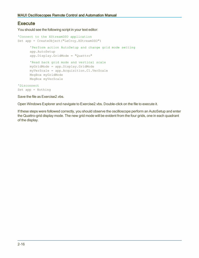
MAUI Oscilloscopes Remote Control and Automation Manual
ExecuteYou should see the following script in your text editor:
'Connect to the XStreamDSO applicationSet app = CreateObject("LeCroy.XStreamDSO")
'Perform action AutoSetup and change grid mode settingapp.AutoSetupapp.Display.GridMode = "Quattro"
'Read back grid mode and vertical scalemyGridMode = app.Display.GridModemyVerScale = app.Acquisition.C1.VerScaleMsgBox myGridModeMsgBox myVerScale
'DisconnectSet app = Nothing
Save the file as Exercise2.vbs.
Open Windows Explorer and navigate to Exercise2.vbs. Double-click on the file to execute it.
If these steps were followed correctly, you should observe the oscilloscope perform an AutoSetup and enterthe Quattro-grid display mode. The new grid mode will be evident from the four grids, one in each quadrantof the display.
2-16

Part 2: Automation Programming Reference
Approach 3: Program Using ActiveDSOAs not all controllers can utilize the Windows DCOM architecture, there is another simplified method forremote control of the XStreamDSO application: ActiveDSO, Teledyne LeCroy's proprietary Active-Xcontrol. ActiveDSO can be used for much more than just remote control programs, but this exercise showshow the same Automation commands used for remote control in Exercise 2 could be sent using ActiveDSO,instead.
ActiveDSO also has the advantage of working with programming languages besides Visual Basic, such asPython and Visual C++, making it easy to utilize as a remote control/waveform transfer subroutine withinother programs, or as part of a custom remote control interface. For more information, see the ActiveDSOtopic in the "Making the Remote Connection" section.
Preliminary Setup
1. Download ActiveDSO from teledynelecroy.com (see Resources) and install it on the PC.
2. Open XStreamBrowser and NotePad or another text editor on the PC.
3. Turn on the oscilloscope. For this exercise, we'll continue to use VBS and a LAN connection, soconfirm the oscilloscope is connected to LAN (or has a cross-over connection to your PC).
4. Go to Utilities > Utilities Setup > Remote and confirm the TCP/IP (VICP) setting.
5. Note the oscilloscope's IP address.
Program
Note: Characters in angle brackets are placeholders. Omit the brackets from your code.
ConnectIn the text editor, instantiate the ActiveDSO control:
Set dso = CreateObject("LeCroy.ActiveDSOCtrl.1")
Then, invoke the MakeConnect method, in this case using the oscilloscope's IP address:
Call dso.MakeConnection("IP:<IP address>")
This method could have used USBTMC, GPIB, or any other supported connection type. You would want tobe sure to choose control from that same interface on the oscilloscope Remote dialog.
AutoSetupBesides the instantiation method, the most obvious difference between using native VBS and usingActiveDSO is in how commands are sent. With ActiveDSO, Automation controls are nested within the VBScommand. Write the line:
Call dso.WriteString("VBS 'app.AutoSetup'", 1)
The Boolean "1" is telling the XStreamDSO application to interpret the command immediately.
2-17
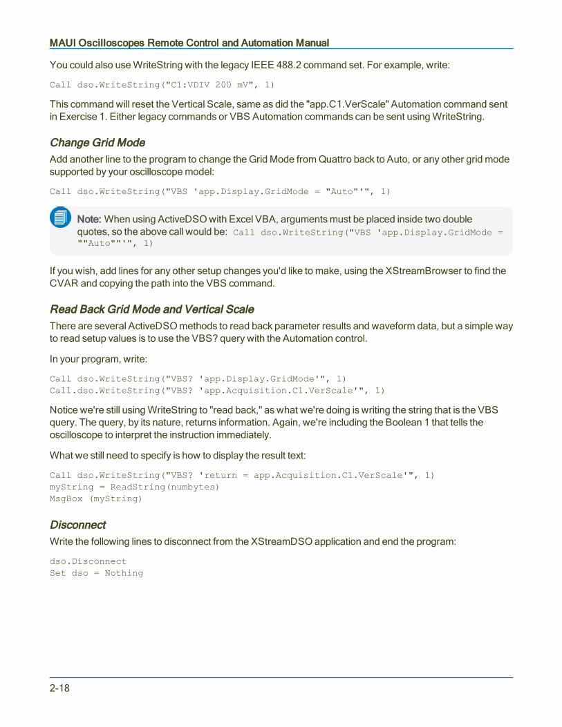
MAUI Oscilloscopes Remote Control and Automation Manual
You could also use WriteString with the legacy IEEE 488.2 command set. For example, write:
Call dso.WriteString("C1:VDIV 200 mV", 1)
This command will reset the Vertical Scale, same as did the "app.C1.VerScale" Automation command sentin Exercise 1. Either legacy commands or VBS Automation commands can be sent using WriteString.
Change Grid ModeAdd another line to the program to change the Grid Mode from Quattro back to Auto, or any other grid modesupported by your oscilloscope model:
Call dso.WriteString("VBS 'app.Display.GridMode = "Auto"'", 1)
Note: When using ActiveDSO with Excel VBA, arguments must be placed inside two doublequotes, so the above call would be: Call dso.WriteString("VBS 'app.Display.GridMode =""Auto""'", 1)
If you wish, add lines for any other setup changes you'd like to make, using the XStreamBrowser to find theCVAR and copying the path into the VBS command.
Read Back Grid Mode and Vertical ScaleThere are several ActiveDSO methods to read back parameter results and waveform data, but a simple wayto read setup values is to use the VBS? query with the Automation control.
In your program, write:
Call dso.WriteString("VBS? 'app.Display.GridMode'", 1)Call.dso.WriteString("VBS? 'app.Acquisition.C1.VerScale'", 1)
Notice we're still using WriteString to "read back," as what we're doing is writing the string that is the VBSquery. The query, by its nature, returns information. Again, we're including the Boolean 1 that tells theoscilloscope to interpret the instruction immediately.
What we still need to specify is how to display the result text:
Call dso.WriteString("VBS? 'return = app.Acquisition.C1.VerScale'", 1)myString = ReadString(numbytes)MsgBox (myString)
DisconnectWrite the following lines to disconnect from the XStreamDSO application and end the program:
dso.DisconnectSet dso = Nothing
2-18

Part 2: Automation Programming Reference
ExecuteYou should now see the following program, or similar, in your text editor:
'Connect to the XStreamDSO applicationDim dso As ObjectSet dso = CreateObject("LeCroy.ActiveDSOCtrl.1")Call dso.MakeConnection("IP:<IP address>")
'Send commands to AutoSetup, change grid mode and vertical scaleCall dso.WriteString("VBS 'app.AutoSetup'", 1)Call dso.WriteString("C1:VDIV 200 mV", 1)Call dso.WriteString("VBS 'app.Display.GridMode = "Auto"'", 1)
'Query grid mode and vertical scale, show result in Message BoxCall dso.WriteString("VBS? 'app.Display.GridMode'", 1)Call.dso.WriteString("VBS? 'app.Acquisition.C1.VerScale'", 1)Call dso.WriteString("VBS? 'return = app.Acquisition.C1.VerScale'", 1)myString = ReadString(numbytes)MsgBox (myString)
'Disconnectdso.DisconnectSet dso = Nothing
Save the file as Exercise3.vbs.
Open Windows Explorer and navigate to Exercise3.vbs. Double-click on the file to execute it.
If these steps were followed correctly, you should again observe the oscilloscope perform an AutoSetupthen change display mode and vertical scale. Check the C1 descriptor box to see that the Vertical Scale haschanged.
2-19

MAUI Oscilloscopes Remote Control and Automation Manual
Approach 4: Program Using VISAIf you do not wish to utilize ActiveX controls like ActiveDSO, any programming language that can connectthrough VISA can be used to send Automation commands. Teledyne LeCroy oscilloscopes are designed towork with VISA drivers for ENET, USBTMC, or GPIB remote connections. It is not necessary to have aDCOM connection when you are using a VISA driver.
In this exercise, we'll create a Python script designed to connect over the LAN, as in the previous exercise,but using LXI remote control settings.
Note: All the code examples given here use the LXI VISA resource string, not the TCP/IP VISAresource string. Both the TCP/IP and LXI settings utilize the TCP/IP layer, but the higher-levelprotocol is different, as is the VISA resource string. You can use the LXI option to communicate withoscilloscopes even if your network is not set up to be LXI compliant.
Preliminary SetupThis exercise requires a bit more setup than the previous, but by doing so, it will better demonstrate how youmay use Automation to set up and retrieve measurement data.
1. On the PC, install a VISA driver , Python, and the compatible Python for Windows extensions.
2. Turn on the oscilloscope. Be sure it is connected to your LAN.
3. Connect one of the passive probes delivered with your oscilloscope to the Cal Out/Aux Out on thefront of the instrument (what it is named will vary by model) and the C1 input.
4. Go to Utilities > Utilities Setup > Aux Output and choose to output a 1 KHz, 1 Volt Square Waveor whatever is the default selection for your oscilloscope (there should be a button).
5. Adjust your timebase until you see a stable pulse on the oscilloscope.
6. Go to Utilities > Utilities Setup > Remote and select the LXI (VXI-11) setting. Note theoscilloscope's IP address.
7. On the PC, open XStreamBrowser and Notepad or another text editor.
2-20
Part 2: Automation Programming Reference
Program
Note: Characters in angle brackets are placeholders. Omit the brackets from your code.
Connect to the OscilloscopeIn your text editor, write these lines to make the remote connection to VISA and to the oscilloscope:
import visarm = visa.ResourceManager()lecroy = rm.open_resource("TCPIP0::<hostname|IP address>::INSTR")lecroy.timeout = 5000lecroy.clear()
If your oscilloscope and PC are both known to the same network name server, you can use the hostnamesyntax (e.g., "TCPIP0::LCRY0450N70355::INSTR") instead of the actual IP address.
The timeout of 5000 milliseconds ensures the oscilloscope will wait 5000 milliseconds for operations tocomplete whenever writing commands or reading responses. Reading continues until the entire response isreceived (EOI is reached) or for 5 full seconds. After 5 seconds, there will be a "time out" error.
The clear is intended to clear out the buffers on the oscilloscope listing the commands sent to it and alsoresponses sent from it. Clear removes anything leftover from a previous use and is a good practice as a firststep in any program.
Several other preliminary settings can be made to prepare the general oscilloscope "environment" prior towriting new setups or reading measurements. In your program, type:
lecroy.write("COMM_HEADER OFF")lecroy.write(r"""vbs 'app.settodefaultsetup' """)
The command "COMM_HEADER OFF" is a legacy 488.2 command that tells the oscilloscope "don't returnthe command header with query result." This helps to read back values in a format that is more friendly tobeing viewed on screen or imported into other programs.
Recalling the default setup, while not required, ensures that all setups are at a known baseline value beforeyou begin.
Notice that the method 'app.settodefaultsetup' is the first actual Automation command being passed to theoscilloscope. It is enclosed in the VBS command wrapper, as are all Automation commands sent by remoteconnection, rather than through a COM/DCOM connection.
Note: The three double-quotes around the VBS command are required because the double-quotesaround the arguments within the command could be interpreted by Python as the end of thecommand string. You would probably create a function to put the VBS wrapper around whateverautomation commands you wanted to send. Here, we're showing each full line of code fordemonstration.
2-21

MAUI Oscilloscopes Remote Control and Automation Manual
Timing and SynchronizationIn any remote control program, it is important to set up "checks," periodically querying that processes arecomplete before starting new ones, or that old measurements are cleared before taking new ones, etc.Querying the 'app.WaitUntilIdle' method can tell your program when it is safe to proceed.
In your program, enter the query:
r = lecroy.query(r"""vbs? 'return=app.WaitUntilIdle(5)' """)
This will inform the program when the Recall Default setup has been completed and the oscilloscopeapplication is idle for 5 seconds (the default unit for this command) before going on to set up the newacquisition.
Set Up AcquisitionEvery program that is to acquire new data, whether raw waveform data or post-processing measurementresults, must set up an acquisition. It is important before taking any new acquisition to stop the previous one.Failure to do this is a principal reason for inaccurate measurements. Add the line:
lecroy.write(r"""vbs 'app.acquisition.triggermode = "stopped" ' """)
Using XStreamBrowser, find suitable replacements for <value> in following acquisition CVARs, and addthese lines to your program:
lecroy.write(r"""vbs 'app.acquisition.trigger.edge.level = <value>' """)lecroy.write(r"""vbs 'app.acquisition.triggermode = "single" ' """)lecroy.write(r"""vbs 'app.acquisition.horizontal.maximize = "<value>" ' """)
Note: Be sure not to forget the double-quotes around those values that are String or Enum types.
Set Up MeasurementsAs with the default setup, it is a good idea to clear all measurement definitions and previous sweeps beforeproceeding with new measurements:
lecroy.write(r"""vbs 'app.measure.clearall ' """)lecroy.write(r"""vbs 'app.measure.clearsweeps ' """)
As you may have noticed by now, Automation commands are more granular than legacy 488.2 commands.Generally, more lines of code must be sent to achieve the same end result, because every relevantapplication object must be set to a particular state. However, this granularity is also what makes Automationmore powerful.
To set up measurements, we have to first turn on measurements, then turn on statistics, then turn on theparameter, then set what we want the parameter to measure, then set the parameter source (what input itwill measure), etc. Using XStreamBrowser, find a suitable <value> for 'app.measure.p1.paramengine'.
Tip: Select a single source measurement appropriate to your 1 KHz, 1 V pulse wave.
2-22

Part 2: Automation Programming Reference
lecroy.write(r"""vbs 'app.measure.showmeasure = true ' """)lecroy.write(r"""vbs 'app.measure.statson = true ' """)lecroy.write(r"""vbs 'app.measure.p1.view = true ' """)lecroy.write(r"""vbs 'app.measure.p1.paramengine = "<value>" ' """)lecroy.write(r"""vbs 'app.measure.p1.source1 = "C1" ' """)
AcquireNow write code to arm the acquisition. Again, timing is important: this example takes 10 acquisitions, forcinga trigger if none occurs after 0.1 seconds (the second and first arguments, respectively, of'app.acquisition.acquire'), then uses the 'app.WaitUnitIdle' method to wait for 5 seconds after all acquisitionprocessing is complete before measuring.
for i in range(0,10):r = lecroy.query(r"""vbs? 'return=app.acquisition.acquire( 0.1 , True )' """)r = lecroy.query(r"""vbs? 'return=app.WaitUntilIdle(5)' """)if r==0:
print "Time out from WaitUntilIdle, return = 0".format(r)
Read Back Measurement ResultsRead the Out.Result object of the P1 parameter into a variable of your choosing, and print the value.
Just as the Automation commands were sent within the VBS command wrapper, the Automation query issent within the VBS? query wrapper. For <var>, you can substitute the name of the measurement youchoose earlier.
<var> = lecroy.query(r"""vbs? 'return=app.measure.p1.out.result.value' """)print "<var> = 0".format(<var>)
DisconnectFinally, close the remote connections to the scope and to VISA, in the reverse of the order in which youopened them:
lecroy.close()rm.close()
ExecuteSave the file as Exercise4.py. Navigate to the file on your PC and execute it.
If these steps were followed correctly, you should observe the oscilloscope resume the Default Setup. TheMeasure table should appear below the waveform, showing the results of the measurement you set in P1.Meanwhile, the following should appear in your console:
Time out from WaitUntilIdle = <value><var> = <value>
2-23

MAUI Oscilloscopes Remote Control and Automation Manual
Control VariablesTraditionally, properties presented to an Automation client are simple “variables” with types such as Integer(int), String (BSTR), Floating Point (single, double), etc. However, on MAUI oscilloscopes, CVARs are anextension of the traditional Automation pattern, without affecting how they appear to most Automationclients (see the topic on early/late binding). This enables an Automation client to not only set and query thecurrent value of a control, but also to query its limits. This is useful in the generation of instrument-independent applications, or applications that present scope controls in a graphical user interface in whichlimits are required.
Setting Control VariablesAll CVARs have the default property of Value. A CVAR such as VerScale (Volts/Div) may be set in VBS asfollows:
app.Acquisition.C1.VerScale = 0.5
Its current value may be queried with:
CurrentValue = app.Acquisition.C1.VerScale
The following methods are also supported (for this CVAR type) :
double GetAdaptedValueSetRequestedValue(double)double GetRequestedValuedouble GetDefaultValuedouble GetGrainValuedouble GetMaxValuedouble GetMinValue
For example:
app.Acquisition.C1.VerScale.SetRequestedValue(1.0)minValue = app.Acquisition.C1.VerScale.GetMinValuemaxValue = app.Acquisition.C1.VerScale.GetMaxValue
The sample file D:\Scripts\Automation\ExampleCvarTypes.vbs contains code for querying and displayingCVAR properties for each type of control variable, including the status flags. Commands such as these areuseful for ascertaining the state of the oscilloscope prior to changing setups or taking other actions.
Note: In the sample file, after instantiating the app object, the programming variable "acq" was set totake the place of "app.acquisition" in all commands, and other variables are set at the beginning ofeach type, depending on the child objects being substituted (e.g., acqHorz replacesapp.Acquisition.Horizontal). This is to simplify coding.
2-24

Part 2: Automation Programming Reference
Control Variable TypesThe Type column of the XStreamBrowser window shows the control type. Control variable typedesignations are as follows:
Type Definition
Action Action (no arguments or value)
Bool Boolean value given as false| true or 0| -1
Color RGB value triplex "R,G,B"
Double Double-precision floating point value
DoubleLockstep Double-precision floating point value locked to a non- linear (e.g., 1, 2, 5) stepped sequence.
Enum List value. All lists begin with the zero element. Value may be specified by name in quotes orposition in the list, for example:
app.Acquisition.Horizontal.SampleMode = 0app.Acquisition.Horizontal.SampleMode = "RealTime"
FileName Legal DOS path
Integer 32-bit Integer value
String String value
Properties and MethodsThe properties and methods available for each control are type-specific. Below are the most common:
Type Properties and Methods
Integer VARIANT Value
Value(VARIANT)
int GetAdaptedValue
SetRequestedValue(int)
int GetRequestedValue
int GetDefaultValue
int GetGrain
int GetMax
int GetMin
Increment(int)
2-25

MAUI Oscilloscopes Remote Control and Automation Manual
Type Properties and Methods
Double VARIANT Value
Value(VARIANT)
double GetAdaptedValue
SetRequestedValue(double)
double GetRequestedValue
double GetDefaultValue
double GetGrainValue
double GetMaxValue
double GetMinValue
Increment(int)
DoubleLockstep See Double
Enum VARIANT Value
Value(VARIANT)
int GetAdaptedValue
SetRequestedValue(int)
int GetRequestedValue
int GetDefaultValue
int GetMax int GetMin
int GetNumberOfValueStates
Increment(int)
BSTR GetRangeStringScreen
BSTR GetRangeStringRemote
String VARIANT Value
Value(VARIANT)
int GetMaxLength
BSTR GetRequestedValue
BSTR GetAdaptedValue
SetRequestedValue(BSTR)
Bool VARIANT Value
Value(VARIANT)
BOOL GetAdaptedValue
BOOL GetRequestedValue
BOOL GetDefaultValue
Set
Clear
Action ActNow
2-26

Part 2: Automation Programming Reference
Result Interfaces
Tip: The sample scripts for exposing results that are referred to in this section are installed withXStreamDSO v.8.5.x.x. and later.
"Out.Result" properties are results of the last completed acquisition. They are not affected if other controlsare changed after that acquisition was completed. This distinction between "Out.Result" properties andother controls is most important when the trigger mode is Single or Stopped. Treat "Out.Result" propertiesas read-only.
Note: Although you can write the properties of a result, it is not advisable, as the result propertiesand data will be updated on next acquisition.
Caution: It is highly recommended that you STOP acquisitions before accessing result data. Mostremote control problems are caused by failure to follow this practice.
Several of the Out.Result properties mention the "frame": this is the term used to describe the visible portionof the trace, which is generally smaller than the acquired waveform. The frame could be used, for example,to display a 500 pt window onto a 1 Mpt trace, or show the center 10 mV of a 100 mV trace.
Several properties, most significantly the DataArray object, are Variants containing either a one- or two-dimensional array. Dimension the target variable as a Variant type, and assign the DataArray property to it.See DataArray for examples of its use within each of the Result interfaces.
Result Interface TypesResult Interface type designations are as follows:
Type Definition
Digital Digital (bi-state) waveform generated by mixed-signal oscilloscope.
Histogram Histogram trace.
Param Individual results and result arrays for measurement parameters and Pass/Fail test qualifiers.
Persist Eye diagrams or other waveshapes that are the result of overlaying multiple waveforms.
Table Tabular results primarily used in conjunction with the various low-speed serial decoding options.
Waveform Basic Voltage vs. Time waveforms.
XY XY waveforms.
DigitalThe Digital interface is found when using a mixed-signal input to generate digital (bi-state) waveforms.These waveforms are contained in the Digitaln trace name, where x = 1, 2, 3 etc. Each Digitaln trace is a busthat may contain multiple digital lines, with a maximum number dependent on the capabilities of the mixed-signal oscilloscope option. The key property in the Digital interface is the DataArray, which is a 2D arraycontaining the value of each sample of each digital line in the bus.
2-27
MAUI Oscilloscopes Remote Control and Automation Manual
Example paths to Digital Result interfaces:
app.LogicAnalyzer.Digital1.Out.Resultapp.LogicAnalyzer.Digital2.Out.Result
HistogramThe Histogram interface is used for all histogram traces. Histograms can be configured on mostoscilloscopes as a math function (Fn). Histograms are also used in various analysis modes, especially onSerial Data Analyzers, where the HTIE trace is the source data for the algorithm to calculate Total jitter (Tj).The key property is BinPopulations, which is a 1D array of the bin populations.
Example paths to HTIE Result interfaces:
app.Math.F1.Out.Resultapp.SDA.Htie.Out.Result
Note: This example assumes that F1 is set up as a Histogram.
ParamThe Parameter interface is used in the Measurement and Pass/Fail systems to hold both individual resultsand result arrays. The key properties for the Parameter interface are Value and ValueArray. Value holds thelast measurement or P/F result, while ValueArray holds all measurements taken for the last acquisition. Thisis an important distinction to remember depending on the measurement assigned to the parameter, as thevalues may or may not be the same. For example: if the source waveform is 1000 cycles of square wave,then the Frequency measurement will have 1000 values in the ValueArray and Value will be the same as the1000th (last). Whereas, Min or Max measurements on that same waveform will only have one value in theValueArray, and Value will be that same value.
Example paths to Param Result interfaces:
app.Measure.P1.Out.Resultapp.Measure.P1.Sdev.Resultapp.Measure.Measure("P1").Out.Result
PersistThe Persist interface is most often found when using software options that create eye diagrams or otherwaveshapes that are the result of overlaying multiple waveforms. (Note that this does not apply to thePersistence display mode.) The key property in the Persist interface is the DataArray, which is a 2D arraycontaining the population of each pixel of the persistance map.
Example paths to Persist Result interfaces:
app.SDA.Eye.Out.Resultapp.SDA.Eye2.Out.Result
2-28

Part 2: Automation Programming Reference
TableTable results interfaces are primarily used in conjunction with the various low-speed serial decoding options,such as CAN, I2C, SPI, UART, etc. When the table is displayed, the user has access to information aboutthe messages decoded for the last acquisition. Retrieving data from the Table interface involves someknowledge of the table’s structure, in terms of the columns that are displayed and the cell types. TheCellType and CellValue are the key properties to use to retrieve the table’s data. See the information in theCellValue property for more information.
Example paths to Table Result interfaces:
app.SerialDecode.Decode1.Out.Resultapp.SerialDecode.Objects("Decode2").Out.Result
WaveformWaveform Results interfaces can be found wherever there are basic Voltage vs. Time waveforms.Examples include channel (Cn), memory (Mn), math function (Fn) and zoom (Zn) traces, as well as othersthat are associated with specific analysis packages, such as the Power waveform used in the PAS package.In general, these waveforms are usual voltage vs time, unless a current probe or other method of changingthe vertical units (e.g., the Rescale Math function) is employed. The key property in the Waveform interfaceis the DataArray, which is a 1D array containing the value of each sample in the waveform.
Example paths to Waveform Result interfaces:
app.Acquisition.C1.Out.Resultapp.Acquisition.Channels("C1").Out.Resultapp.Math.F2.Out.Resultapp.Zoom.Z3.Out.Resultapp.SDA.Btub.Out.Result
Note: Traces like F2 and Z3 can hold plots, like histograms, which do not use the Waveforminterface.
XYThe XY interface is used on XY waveforms. Users can create an XY waveform by selecting this option in theDisplay Setup… screen. XY waveforms allow you to see how the signal on one channel moves in relation toanother. The key property is the DataArray, which is a 2D array that returns the voltages on the X and Ysources for each XY pair.
Example path to the XY Result interface:
app.Math.XY.Out.Result
2-29

MAUI Oscilloscopes Remote Control and Automation Manual
Result Variable TypesType Definition
Integer 16-bit signed integer
Long 32-bit signed integer
Double 8-byte floating point type
String Array of characters
Object Object with its own interface
Variant Variable that is dimensioned without indicating a variable type
Exposing WaveformsWaveform data is exposed as a simple array using app.Subsystem.Wfmn.Out.Result.Samples. Wfmn canbe any object defined within the XStreamDSO object hierarchy that produces a waveform trace (generallyCn, Fn, Mn, SEn, and Zn).
The sample script D:\Scripts\Automation\ExampleWaveform.vbs gets the sample points in analog traceC1 by accessing app.Acquisition.C1.Out.Result.Samples and dumps them into a text file.
Digital WaveformsDigital waveforms are two-dimensional arrays, the DataArray being the samples and the TimeArray beingthe time associated with the samples. As each digital bus may have up-to-18 lines (D0-D17), the DataArrayhas at least two columns, being the Sample Number and the Digital Line from which it was taken.
Each sample has a time, but it is not easily calculated from the timebase, as with analog waveforms, as thedigital pulses on each line may have different widths. To accurately expose a digital waveform, you mustaccess both arrays and correlate the times with the samples from each line.
The sample script D:\Scripts\Automation\ExampleDigital.vbs gets the arrays in a digital trace that hasbeen stored in M1, determines the number of lines in the bus, correlates the times with the samples, anddumps the results in a text file.
Tip: To see how this works, recall the Digital entry fromD:\Scripts\Automation\AutomationExamplesLabNotebook.lnb. This will copy a 3-line digital traceinto M1, which is accessed by the script.
Sequence Mode WaveformsIn MAUI firmware version 7.7.x.x and later, the segment index is supported as an argument to theOut.Result property. For example, the following commands return results for segment 1 of the respectivewaveform (which is a Sequence Mode acquisition):
set myResult = app.Acquisition.C1.Out.Result(1)set myResult = app.Math.F1.Out.Result(1)
Zero (0) or no argument returns the result related to the last segment. A segment index greater than the totalnumber of segments also returns the result related to the last segment.
2-30

Part 2: Automation Programming Reference
Waveform Status PropertyThe waveform result includes a Status property (bit-field) that reflects ‘warning’ and ‘error’ conditions. Thereis no bit for "valid."
Bit # Value Description
0 0x0000000000001 LEC_Invalid
1 0x0000000000002 LEC_Overflow
2 0x0000000000004 LEC_Underflow
3 0x0000000000008 LEC_ContainsUndefinedValues
4 0x0000000000010 LEC_LessThan
5 0x0000000000020 LEC_GreaterThan
6 0x0000000000040 LEC_NotAPulse
7 0x0000000000080 LEC_NotCyclic
8 0x0000000000100 LEC_Averaged
9 0x0000000000200 LEC_UnlockedPLL
10 0x0000000000400 LEC_OtherError
11 0x0000000000800 LEC_OtherWarning
12 0x0000000001000 LEC_OtherInfo
32 0x0000100000000 LEC_InputsIncompatible
33 0x0000200000000 LEC_AlgorithmLimitsReached
34 0x0000400000000 LEC_BadDefinition
35 0x0000800000000 LEC_TooFewData
36 0x0001000000000 LEC_TooManyData
37 0x0002000000000 LEC_UniformHorizIntervalRequired
38 0x0004000000000 LEC_BadUnits
39 0x0008000000000 LEC_DataRangeTooLow
40 0x0010000000000 LEC_DataUndersampled
41 0x0020000000000 LEC_PoorStatistics
42 0x0040000000000 LEC_SlowTransitionTime
43 0x0080000000000 LEC_DataResampled
44 0x0100000000000 LEC_DataInterpolated
45 0x0200000000000 LEC_MeasurementScaleImprecise
46 0x0400000000000 LEC_NoDataAvailable
47 0x0800000000000 LEC_SomeCummulatedResultsInvalid
48 0x1000000000000 LEC_InsufficientMemory
49 0x2000000000000 LEC_ChannelNotActive
50 0x4000000000000 LEC_UseStatusDescription
2-31

MAUI Oscilloscopes Remote Control and Automation Manual
Copying Waveform Data to ExcelThis Excel macro reads the number of samples in a waveform and places it in cell B1 of the spreadsheet,then reads all waveform sample values and copies them into column A (A1...Axx). The example is coded inVBA, and would be launched by a button in a spreadsheet.
Sub Button1_Click()
' Connect to the oscilloscopeSet app = CreateObject("LeCroy.XStreamDSO")
' Query the number of samples in C1 and store in cell "B1"numSamples = app.Acquisition.C1.Out.Result.SamplesCells(1, 2)Value = numSamples
' Access waveform data array, fill first column of the spreadsheetwave = app.Acquisition.C1.Out.Result.DataArrayFor i = 0 To numSamples - 1
Cells(i + 1, 1).Value = wave(i)Next i
End Sub
Note: Ensure that the record length is < 64 k samples, since Excel has a limit on the number of rowsin a spreadsheet. Ideally, start experimenting with short (500 point) records.
Storing Waveform Data in a Text FileThis VBScript example is very similar to the VBA macro example above, the most notable difference beingthe use of a standard system ActiveX control, Scripting.FileSystemObject, to enable the creation of filescontaining waveform data in ASCII format.
' Connect to the oscilloscopeSet app = CreateObject("LeCroy.XStreamDSO")
' Code to take acquisition and generate FFT in F1. . .
' Readout the FFTnumSamples = app.Math.F1.Out.Result.Samples
' Write the FFT power spectrum into the file, sample by sampleSet fso = CreateObject("Scripting.FileSystemObject")Set MyFile= fso.CreateTextFile("c:\XStreamFFT.txt", True)
wave = app.Math.F1.Out.Result.DataArrayFor i = 0 To numSamples - 1
MyFile.WriteLine(wave(i))Next
' Clean upMyFile.CloseSet fso = NothingSet app = Nothing
2-32

Part 2: Automation Programming Reference
Exposing MeasurementsMeasurement results are read similar to Waveforms, using the appropriate app.Measure.Pn.Out.Resultobject.
The Value is the default property of all Out.Results, so getting the above result delivers the last measuredvalue in the acquisition for that parameter.
StatisticsIn addition to the last measured value, statistics are available for each parameter using two different calls:
result = app.Measure.P1.mean.Result.Valueresult = app.Measure.P1.max.Result.Valueresult = app.Measure.P1.min.Result.Valueresult = app.Measure.P1.num.Result.Valueresult = app.Measure.P1.sdev.Result.Value
result = app.Measure.P1.Statistics("mean").Result.Valueresult = app.Measure.P1.Statistics("max").Result.Valueresult = app.Measure.P1.Statistics("min").Result.Valueresult = app.Measure.P1.Statistics("num").Result.Valueresult = app.Measure.P1.Statistics("sdev").Result.Value
The data used to display the Histicon is available using the “histo” statistic. For example:
Set app = CreateObject("LeCroy.XStreamDSO")bins = app.Measure.P5.Statistics("histo").Result.BinPopulationsnumBins = app.Measure.P5.Statistics("histo").Result.bins
For i = 0 To numBins - 1Cells(i + 1, 4).Value = bins(i)
Next I
Set app = Nothing
Measurements on Sequence Mode WaveformsIn MAUI firmware version 7.7.x.x and later, the segment index is supported as an argument to theapp.Measure.Pn.Out.Result property. For example:
set myResult = app.Measure.P1.Out.Result(1)
returns the result of the measurement on segment 1 of the P1 source waveform (which is a Sequence Modeacquisition).
Zero (0) or no argument returns the result related to last segment. A segment index greater than the totalnumber of segments also returns the result related to last segment.
2-33

MAUI Oscilloscopes Remote Control and Automation Manual
The following code from the sample file D:\Scripts\Automation\ExampleMeasureSeg.vbs loops over eachparameter specified, returning the result for each segment:
numSegs = 10for iSeg = 1 to numSegs
set p1Result = app.Measure.P1.Out.Result(iSeg)set p2Result = app.Measure.P2.Out.Result(iSeg)set p3Result = app.Measure.P3.Out.Result(iSeg)outputFile.Write iSeg & "," & p1Result.Value & "," & p2Result.Value & "," &
p3Result.Value & "," & VbCrLf
next
Tip: To see how this works, recall the MeasureSegs entry fromD:\Scripts\Automation\AutomationExamplesLabNotebook.lnb. This will set up P1-P3 and copy asegment trace into measurement source C1.
Reading from the Measure TableThe sample file D:\Scripts\Automation\ExampleTableMeasure.vbs contains code for iterating over theMeasure table to read results for all active parameters.
Similar code is available for iterating over the Pass/Fail table inD:\Scripts\Automation\ExampleTablePassFail.vbs, and the WaveScan table inD:\Scripts\Automation\ExampleTableWaveScan.vbs.
Tip: To see how these work, recall the Table WaveScan, Measure, PassFail entry fromD:\Scripts\Automation\AutomationExamplesLabNotebook.lnb. This will copy a source trace intoC1, set up P1-P6, a Pass/Fail test, and the WaveScan table view.
2-34
Part 2: Automation Programming Reference
Copying Measurements to ExcelThe following Excel macro enables the Standard Vertical parameters, then transfers the eight measurementvalues into cells C1 to C8. The example is coded in VBA, and would be launched by a button in aspreadsheet.
' Create Button in Excel
Sub Button1_Click()
' Connect to the oscilloscopSet app = CreateObject("LeCroy.XStreamDSO")
' Enable Standard Vertical Parametersapp.Measure.MeasureMode = "StdVertical"
' Transfer the 8 parameter values into the spreadsheetCells(1, 3).Value = app.Measure.P1.Out.Result.ValueCells(2, 3).Value = app.Measure.P2.Out.Result.ValueCells(3, 3).Value = app.Measure.P3.Out.Result.ValueCells(4, 3).Value = app.Measure.P4.Out.Result.ValueCells(5, 3).Value = app.Measure.P5.Out.Result.ValueCells(6, 3).Value = app.Measure.P6.Out.Result.ValueCells(7, 3).Value = app.Measure.P7.Out.Result.ValueCells(8, 3).Value = app.Measure.P8.Out.Result.Value
' Clean upSet app = Nothing
End Sub
2-35

MAUI Oscilloscopes Remote Control and Automation Manual
Exposing Table DataTables are data arrays that may be one- or two-dimensional, and this is impossible to tell from looking at thetable as it is presented in MAUI.
Many tables have Variant cell types, which may contain other tables that also need to be indexed in order tosee the correct values. For example, were you to send this simple VBS query to get results from theSpectrum Analyzer table:
vbs? 'return =app.SpecAnalyzer.SpecAnTable.Out.Result.CellValue(3,2)'
(3,2) represents the table (row,column) to return, but to specifically return the frequency value, you'd have tosend something like:
vbs? 'return =app.SpecAnalyzer.SpecAnTable.Out.Result.CellValue(3,2)(0,0)'
The first index indicates the row of table data wanted (3) from the Frequency column (2), but that single cellcontains an array of the Amplitude value (0,0), Start Frequency (1,0) and Stop Frequency (2,0). You have toindex first the principle table then the array inside that particular cell, hence the extra (0,0) to get theamplitude value.
Likewise, the table that presents the results of any serial decoder software,app.SerialDecode.Decoden.Out.Result, is a table with a table in each cell that you need to index at(line,col). However, it only has a numeric value in (0,0) that needs to be indexed, as well.
Note: If the data in a cell of the Serial Decoder Result table is a string, there is no (datatype,dataidx);if it is a number, there is an array to be indexed and it is always at (0,0).
The Serial Decode table presents a number of challenges in exposing results. See the sample scriptD:\Scripts\Automation\ExampleTableSerialDecode.vbs, which iterates over the Serial Decode table anddumps the data to a text file.
Tip: To see how this works, recall the Table Serial Decode entry fromD:\Scripts\Automation\AutomationExamplesLabNotebook.lnb. This will copy two waveforms intoM1 and M2 and apply the USB2 decoder to them.
Handling Different Cell TypesThere are four cell "types" that may appear in a table. Each type must be handled differently in code.
l CellType 0 is a Variant (as in the Spectrum Analyzer and Serial Decoder tables). These cells mayhold different things, such as other table arrays, which may be either one- or two-dimensional.
l CellType 2 is a Param result (as in the Measure table). These are cells with single values.
l CellType 3 is a Boolean result. These are cells containing single, Boolean values, either 1|0 orTrue|False.
l CellType 4 is the histicon cell of the Measure table. This not commonly used.
2-36

Part 2: Automation Programming Reference
Each of the D:\Scripts\Automation\ExampleTable*.vbs scripts contain code used to iterate over a table todetermine its actual structure and cell types. We recommend that you adapt this code to your programswhenever accessing results from table objects.
Tip: The file D:\Scripts\TableExport.lss also includes code for determining whether CellType 0 cellscontain an array and uses the appropriate method for reading the data.
Error Handling for Table ResultsError handling is especially important for tables with Parameter and Boolean cell types, as an error isgenerated if a cell has no data. The following snippet shows the use of VBS function "on error resume next"applied to table data:
' get the Parameter or Boolean Value property (handle error case if no data in thevalue)strThisVal = "-"on error resume nextset cellVal = myResult.CellValue(rowIdx, columnIdx)strThisVal = cellVal.valueon error goto 0 ' Reset Error handling statestrRowData = strRowData & strThisVal
Discovering Number of Array DimensionsYou can discover the number of dimensions in a table array by adding the following helper function toVBScripts:
function getArrayDims(arr1)dimensions = 0if IsArray(arr1) then
on error resume nextErr.cleardo while Err.number = 0
dimensions = dimensions + 1UBound arr1, dimensions
loopErr.cleardimensions = dimensions - 1
end if
getArrayDims = dimensionsend function
Tip: This function appears at the end of the sample scriptsD:\Scripts\Automation\ExampleTable*.vbs, from which you can copy it.
Note: This function will not work in VBA scripts.
2-37

MAUI Oscilloscopes Remote Control and Automation Manual
Using Join to Read from TablesThe VBS query Join can be used to read table value arrays into a comma-delimited list of values. Forexample, sending the following command from the terminal in WaveStudio returns a list of all the specifiedvalues for the measurement parameter P2:
VBS? 'return=join(app.Measure.P2.Out.Result.ValueArray(-1,0,1), chr(44))
2-38
Part 2: Automation Programming Reference
SynchronizationSynchronization—or, more specifically, knowing when to read results—is critical when operating a digitaloscilloscope remotely (it is just as important for Automation as for GPIB remote control ). This is especiallytrue when working with an oscilloscope that uses a multithreaded architecture.
A classic problem seen in the majority of custom applications that control Teledyne LeCroy oscilloscopes isthat the scope is left to free-run in Auto-trigger mode, while simultaneously (and asynchronously) results arequeried.
Several techniques can be used to guarantee the synchronization and consistency of results, whether theybe waveform or parameter measurements, when using the Automation interface.
Synchronizing Triggers Using TimeoutsThe Acquire method arms the acquisition system and waits a user-specified time for a trigger. The secondargument, an optional Boolean, specifies whether or not to force a trigger then return the value if a triggerdoesn’t arrive within the allotted time period.
Note: The Acquire method is equivalent to setting the Trigger Mode to “Single”, then executingWaitUntilIdle.The return of the Boolean causes the method to function logically like a query andrequires it to be read into a variable, whether or not the returned value is actually displayed.
The following Excel VBA macro example demonstrates the use of a timeout, a useful technique for ensuringsynchronization.
Sub Button1_Click()
' Connect to the oscilloscopeSet app = CreateObject("LeCroy.XStreamDSO")
' Enable Standard Vertical parametersapp.Measure.MeasureMode = "StdVertical"
' Stop the free-running trigger and take a single acquisition' Use a 10 second timeout in case the acquisition is not completeapp.Acquisition.TriggerMode = "Stopped"
Dim Acquired as BooleanAcquired = app.Acquisition.Acquire (10, True)
' Read the first parameter value and transfer into the spreadsheet' Display the Acquired value to show the oscilloscope has triggered
Cells(1, 3).Value = app.Measure.P1.Out.Result.ValueMsgBox Acquired
End Sub
2-39

MAUI Oscilloscopes Remote Control and Automation Manual
Synchronizing SetupsAnother scenario where synchronization is necessary is between changing settings and reading results,even when no acquisition took place. For this the WaitUntilIdle method is used. This method is a “blocking”mechanism and will not return control until the setup request has completed.
An example of WaitUntilIdle usage follows.
Note: WaitUntilIdle is not for use when in Normal or Auto trigger mode.
Sub Button1_Click()
' Connect to the oscilloscopeSet app = CreateObject("LeCroy.XStreamDSO")
' Enable Standard Vertical parametersapp.Measure.MeasureMode = "StdVertical"
' Wait for the change to take place for a max. of 5 secondsapp.WaitUntilIdle(5)
' Read the value of P1 (pkpk) and transfer into the spreadsheetCells(1, 2).Value = app.Measure.P1.Out.Result.Value
' Enable Standard Horizontal parametersapp.Measure.MeasureMode = "StdHorizontal"
' Wait for the change to take place for a max. of 5 secondsapp.WaitUntilIdle(5)
' Read the value of P1 and transfer into the spreadsheetCells(1, 3).Value = app.Measure.P1.Out.Result.Value
End Sub
Best Practices for Synchronization
l In almost all Automation applications, it is highly recommended that you stop acquisitions beforeaccessing result data. Most synchronization problems are caused by failure to follow this practice.
l Use the app.SetToDefaultSetup action to restore the instrument to its default state before setting thecontrols required by an application. This eliminates any dependency on the previous configuration ofthe instrument. Teledyne LeCroy strives to ensure that the default state of the instrument is constantfrom one software release to the next.
l When using a result object, verify that the status is valid to ensure that the acquisition and/orprocessing was valid.
2-40

Part 2: Automation Programming Reference
Application InteractionsIt is not possible to run two simultaneous instances of the oscilloscope application. More than onesimultaneous connection to the instrument via Automation will be accepted, but simultaneous connectionsare not recommended. When the final client has been disconnected from the instrument (server), theoscilloscope application will remain running and will accept further client connections.
Operations that cause Modal Dialogs to appear in the instrument’s display will, by default, disrupt accessfrom Automation. This behavior can be changed using the controls:
l app.SystemControl.ModalDialogTimeout
l app.SystemControl.EnableMessageBox
The instrument application can be minimized in order to allow the controlling application to take over thedisplay and touch panel by means of the app.Minimize control. It can also be resized and repositioned on thedisplay by means of the app.Top, app.Left, app.Bottom, and app.Right controls.
When an application is running locally on the instrument and requests a connection to the oscilloscope viaAutomation, one of two things will happen:
l If the oscilloscope application is already running, the object returned will be a “pointer” to the runningapplication.
l If the oscilloscope application is not running, it will be started.
2-41

MAUI Oscilloscopes Remote Control and Automation Manual
Early and Late BindingThe COM standard on which Automation is built supports two kinds of “binding” between client and server:early (static), and late (dynamic, dispatch). Static binding usually involves a type library and is used primarilyby compiled languages such as C++. In this case, function entry points are resolved at compile time.Dynamic binding (also known as late binding) involves resolving method and property calls at run time, asopposed to compile time.
The Automation interfaces in XStreamDSO based instruments use primarily dynamic binding. From manyprogramming languages (VB, VBScript, etc.) this is transparent. But when you are developing applicationsin C++, which does not provide late-binding natively, the use of a “helper” class is required. This isdemonstrated below:
#include "stdafx.h"#include "AtlBase.h" CComModule _Module;#include "AtlCom.h"
CComPtr<IDispatch> spDso;// dispatch ptr. to root of object model (app)CComDispatchDriver ddDso;
int main(int argc, char* argv[])
printf("Hello XStream World!\n");
::CoInitialize(NULL);
HRESULT hr = spDso.CoCreateInstance(L"LeCroy.XStreamDSO");if(SUCCEEDED(hr))
ddDso = spDso;
// perform an Auto-Setup (app.Autosetup)hr = ddDso.Invoke0(L"AutoSetup");
// retrieve a Dispatch ptr. to the app.Display objectCComVariant displayPtr;hr = ddDso.GetPropertyByName(L"Display", &displayPtr);CComDispatchDriver ddDisplay(displayPtr.pdispVal);
// enter Dual-grid mode(app.Display.GridMode = "Dual")hr = ddDisplay.PutPropertyByName(L"GridMode", &CComVariant("Dual"));
return 0;
2-42

Part 2: Automation Programming Reference
Automation Programming ConventionsFollow these guidelines when writing Automation programs for remote control. See Control Variables andResult Interfaces for more information about the types and supported methods.
Variables are indicated by italicized placeholder text in the examples below.
ValuesEnum, String, and Color type values must have double quotes around them, for example:
app.Display.GridMode = "Quad"
Integer, Double, DoubleLockstep, and Bool values do not require quotes:
app.Display.Persisted = falseapp.Acquisition.Horizontal.NumSegments = 10
Where objects take multiple arguments, values are given in comma-delimited lists:
app.Acquisition.Acquire(5,true)app.Acquisition.C1.LabelsText = "Hello,World"
The first Acquisition object above is a Method with both Integer and Bool type arguments; the second is aCVAR with a multi-value String argument.
To see the correct format and syntax, query the object's current setting. This command can be sent veryeasily using the WaveStudio Terminal with a remote connection to the oscilloscope:
VBS? 'return = object'
UnitsGenerally, units are optional when giving Automation commands, as units are already determined by theinput trace and type of any math functions applied to the trace. An exception is the Rescale math function,which creates a second trace that explicitly changes the vertical units in which the source trace is calculated,and therefore requires that a unit be specified:
app.Math.Fn.Equation = rescale(trace)app.Math.Fn.Operator1Setup.Unit = "menemonic"
See the list of acceptable mnemonics in Units.
The vertical unit of analog and sensor input channels (Cn and SEn) can be changed by setting the CVARUnit to "Other":
app.Acquisition.Cn.Unit = "OTHER"app.AcquisitionPMU.SEn.Unit = "OTHER"
Then, follow with the unit Type (category) and displayed Units. For example:
app.Acquisition.Cn.Type = "MASS"app.Acquisition.Cn.Units = "SLUG"
2-43

MAUI Oscilloscopes Remote Control and Automation Manual
Note: You can only select Units from the list of values that appears following the Type selection.
EquationsCVARs app.Math.Fn.Equation, app.Math.Fn.EquationRemote, andapp.Measure.Pn.Equation are text Strings containing the summary of the math or measure operation. Theycan be used to query the current settings, but not to set the function or parameter.
To set up a Math function, use the CVARs app.Math.Fn.Sourcen and app.Math.Fn.Operatorn, and anyobjects in the app.Math.F1.OperatornSetup folders.
To set up a Parameter, use the CVARs app.Measure.Pn.Sourcen andapp.Measure.Pn.ParamEngine, plus any objects in the app.Measure.Pn.Operator subfolder.
LabelsThe CVARs LabelsText and LabelsPosition (which appear in the hierarchy for any waveform object)specify the text and position of custom labels placed on a waveform. LabelsText takes a single Stringargument for which you can specify a comma-delimited list of values each representing a separate label:
app.Acquisition.C1.LabelsText = "Hello,World"
The above control creates two labels, "Hello" and "World." Note that later sending the same control with onlya single value will erase all but the first label in the list (which will remain at its current position), changing it tothe new text string.
LabelsPosition is also a String where each list value is a pipe-delimited pair specifying the horizontal andvertical position of the corresponding label in the LabelsText string. Placing parentheses around the verticalvalue in the pair turns on "Use Trace Vertical Position". The following control would position both labels"Hello" and "World", placing "Hello" adjacent to the trace, and "World" at the vertical position specified:
app.Acquisition.C1.LabelsPosition = "0.000002|(0.02),0.000002|0.01"
ColorsColor type CVARs set/query the color of traces and other display objects, using a number in the range 0 toFFFFFF in hexadecimal. The possible colors are made from any combination of the primary colors, whichare set in hexadecimal as Blue = &HFF0000, Green = &HFF00, Red = &HFF. For example:
app.Display.C1Color = "255,255,0"
The value may be entered in decimal or in hexadecimal, though hexadecimal is usually more convenient.Note that if the intensity of a color is to be reduced or increased by a numerical factor, an AND operationmust be used afterwards, to prevent corruption of other primary colors.
File NamesCVARs of the Filename type generally do not require the full path to be given as part of the value, but in mostcases, the directory in which the files will be saved is set using a separate CVAR, which does require the fullpath. Check the parent objects within the subsystem in XStreamBrowser to find the CVAR for setting the filepath.
2-44

Part 2: Automation Programming Reference
PersistenceWhen applied to any trace, the CVARs Persisted, PersistDotJoined, Persistence3D, Persist3DQuality,PersistenceMonochrome, and PersistenceSaturation determine the status and appearance of thepersistence display.
Persistence sets/queries the persistence state. If the Display.LockPersistence CVAR is set to 'AllLocked'then the persisted state of all displayed waveforms will be the same. If the Display.LockPersistence controlis set to 'PerTrace' then the persisted state of each waveform may be independently controlled.
If PersistDotJoined is False (the default state), samples are put into the persistence map as dots. Theadvantage of that is that any lit pixel in the pmap actually corresponds to a sample of the data taken at thattime. The disadvantage of dots is that there is no way to associate a dot with any other dot; there is no historyof which dots were part of the same acquisition. If this control is set True, then each acquisition draws linesinto the persistence map that connect the dots at the sample positions. Clearly the advantage of that is that itis now possible to see if some outlier samples were all part of the same acquisition, or not. The disadvantageis that lit points in the persistence map no longer correspond to actual samples, the lines between thesamples are also lit.
If the persistence map is going to be analyzed it is probably preferable to leave Dot Joined off so that onlyactual samples are considered in the analysis. If there are very few points in a persistence map, there maycolumns with no points, that is, there are gaps horizontally between points. In that case, Dot Joined willconnect them starting with the last trace, and for all subsequence traces accumulated.
The action of turning on or off Dot Joined clears the accumulated persistence map.
Persistence3D puts the persistence display into a 3D surface map.
Persistence3DQuality selects the 3D quality, which determines how the display is rendered. This CVAR isonly relevant when Persistence3D is True.
If PersistenceMonoChrome is set True, the display will be monochromatic, regardless of whether 2D or3D.
PlaceholdersIn some cases, the value that appears in XStreamBrowser is only a placeholder that will appear on theoscilloscope GUI until you make an actual setting. Placeholders will usually be indicated by angle bracketssurrounding the text string. For example, the Value of app.Utility.Remote.AllowControlFrom is <ipAddr, ordnsName>, which appears inside the control on the GUI indicating you should substitute the remote client IPaddress or DNS name. If you provided an actual IP address or DNS name, that node would have exclusiveremote control of the oscilloscope.
Visible Serial Decoder Table ColumnsThe CVAR app.SerialDecode.Decodex.Decode.ColumnState contains a pipe-delimited list of all the tablecolumns that are selected for display. For example:
app.SerialDecode.Decode1.Decode.ColumnState = "Idx=On|Time=On|Data=On|..."
If you wish to change the table configuration by hiding or displaying columns, send the full string with thestate changed from "on" to "off", or vice versa, rather than remove any column from the list.
2-45

MAUI Oscilloscopes Remote Control and Automation Manual
Note: Even though columns are hidden, they are still calculated in the decoding, and any time youaccess the Out.Result objects of serial decode tables, all the columns are returned. If you seek toaccess a specific column, use the getDataArray function to first determine the depth and order of thetable and the actual number of the column.
Using Programming VariablesOne way to increase the readability and simplicity of your source code is to use variables to referenceobjects that are at each level of the hierarchy. For example, here is the VB code to read out the Sweepsproperty for C1:
Dim numSweeps as LongnumSweeps = app.Acquisition.C1.Out.Result.Sweeps
If you are reading out more than just the Sweeps property, you might find it easier to read the following:
Dim C1Res as ObjectDim C1 as ObjectDim numSweeps as LongDim HorizontalOffset As DoubleDim HorizontalPerStep As DoubleDim VerticalOffset As DoubleDim VerticalPerStep As DoubleDim wform
C1 = app.Acquisition.C1C1.AverageSweeps = 200 numSweeps = C1Res.Sweeps HorizontalOffset = C1Res.HorizontalOffset HorizontalPerStep = C1Res.HorizontalPerStep VerticalOffset = C1Res.VerticalOffset VerticalPerStep = C1Res.VerticalPerStep
The panel setup files make heavy use of object variables, making them far more readable and editable:
Set Acquisition = XStreamDSO.AcquisitionSet C1 = Acquisition.C1C1.View = TrueC1.UseGrid = "YT1"C1.Persisted = FalseC1.PersistenceSaturation = 50C1.PersistenceMonoChrome = TrueC1.Persistence3d = False. . .
2-46
Part 2: Automation Programming Reference
Automation in MATLABOn instruments equipped with the CustomDSO (XDEV) option, MATLAB applications can use Automationto control and exchange data with the oscilloscope application. For more information, see Lab 831: X-Stream COM Object Programming with MATLAB and Using LeCroy Digital Oscilloscopes with MATLAB.
Note: An installation of MATLAB is required on the controller for remote execution of MATLABscripts. An installation of MATLAB is required both on the controller and oscilloscope whenimplementing custom MATLAB math and measurements in the processing of remote controlprograms. If you have a site license, the oscilloscope will occupy one seat when connected. Forindividual licenses, the oscilloscope can be one of the three allowed installations.
Connecting and DisconnectingThe LeCroy-MATLAB interface is based on Active X technology and is greatly assisted by using theActiveDSO library. MATLAB applications use the actxserver keyword to connect to the instrument overTCP/IP, for example:
app = actxserver('LeCroy.XstreamDSO.1', '<IP address>')
Note: Use address 127.0.0.1 when the MATLAB application accessing the oscilloscope applicationis running locally on the oscilloscope, rather than remotely.
To disconnect, end with:
Set app = Nothing
Creating Object VariablesGiven the complexity of MATLAB's syntax for handling multi-tiered Automation objects, it is highlyrecommended to create object variables ("handles") at each level of the hierarchy. For example:
% creation of object variables 1 level down from top-levelacq = app.Object.Item('Acquisition');math = app.Object.Item('Math');meas = app.Object.Item('Measure');PF = app.Object.Item('PassFail');
% creation of object variables 1 level furtherc1 = acq.Object.Item('C1');f1 = math.Object.Item('F1');p1 = meas.Object.Item('P1');p1Operator = p1.Object.Item('Operator')
% creation of object variables to resultsc1_results = c1.Out.Result;f1_results = f1.Out.Result;p1_results = p1.Out.Result;
2-47
MAUI Oscilloscopes Remote Control and Automation Manual
Accessing Control Variables (CVARs)These instructions apply to CVARs (object selected from a yellow folder in XStreamBrowser).
Using the syntax:
<handle> = Object.Item('<object>')
Create an object variable for each level in the object hierarchy. For example, the following lines of code drillinto the hierarchy of the VerScale CVAR:
acq = app.Object.Item('Acquisition');c1 = acq.Object.Item ('C1');
The result is a convenient set of handles to use rather than long and clumsy lines of code. Note that each lineabove uses the object variable created in the line above it.
For CVARs that you can read or write, use the get and set functions to access properties of the CVAR. TheValue property is most frequently used, but others are available, including Range. Here are examples ofgetting and setting the VerScale CVAR:
% read the value of the VerScale CVARC1VDiv = get(c1.Item('VerScale'), 'Value')
% read the Range and Type properties of the VerScale CVARrange = get(c1.Item('VerScale'), 'Range')type = get(c1.Item('VerScale'), 'Type')
% set VerScale to 0.789 V/divset(c1.Item('VerScale'), 'Value', 0.789)
For CVARs that are Actions, use the invoke function:
% execute an application-level Clear Sweeps actionapp.invoke('ClearSweeps','ActNow');
% execute an AutoSetup actionapp.invoke('AutoSetup','ActNow');
% execute the ResetAll action for the Math system (only)math.invoke('ResetAll','ActNow');
Action CVARs have an interface called ActNow that can be referenced, but this isn't required.
For CVARs that are Methods, use the invoke function and include the arguments required to perform themethod:
% execute the Acquire method with 5s timeout, no forced triggeracq.invoke('Acquire', 5, false);
2-48

Part 2: Automation Programming Reference
Accessing Out.Result ObjectsThese instructions apply to items that appear when selecting an object from a Result Interface folder inXStreamBrowser.
For each level of the object hierarchy up to but not including the item’s parent object, create an objectvariable using the syntax:
<handle> = Object.Item('<object>')
For example, the following lines of code drill into the P1 object hierarchy up to the parent "Out.Result":
meas = app.Object.Item('Measure');p1 = meas.Object.Item('P1');
Create an object variable for "Out.Result" using this syntax:
p1_results = p1.Out.Result
To read properties within the Out.Result object, use either of the following:
p1_<handle> = p1_results.<property>p1 = get(p1_results,'<property>')
For example, to read the Value property:
p1_val = p1_results.Value
Or
p1 = get(p1_results,'Value')
To read back multi-valued items such as ValueArray and DataArray, use the get function:
P1_array = get(p1_results, 'ValueArray', -1, 0, 1)C1_data = get(c1_results, 'DataArray', -1, -1, 0, 1)
ValueArray, which returns all measured values for a parameter, and DataArray, which returns waveformdata, are actually interfaces that require several arguments to determine the number of values to return,what kind of values, etc. See ValueArray and DataArray.
2-49

MAUI Oscilloscopes Remote Control and Automation Manual
Automation in PythonThe oscilloscope can be controlled by Automation from applications written in the Python language. Pythonprograms may be designed to execute locally using COM, or remotely using either the ActiveDSO driver or aVISA driver. See the Python example in Remote Control Program Using VISA.
You will need the Python for Windows Extensions and Python installed wherever the program is to run. If itruns locally, the libraries must be installed on the oscilloscope; if it connects remotely, they must be installedon the controller. The version of Python for Windows Extensions should match your version of Python.
For remote control, you will also need an installation of ActiveDSO or a VISA driver on the controller.
With COMCOM is the most direct way to send Automation commands to the oscilloscope in Python.
Note: Any COM program should be able to run from a remote computer that has a DCOMconnection to the oscilloscope.
ConnectingThe initial connection imports the win32com.client, needed for any COM Automation, and any Pythonextensions to be used. It then connects to the oscilloscope application, "LeCroy.XStreamDSO," here aliasedas "h":
import win32com.clientimport matplotlib.pyplot as plth = win32com.client.Dispatch("LeCroy.XStreamDSO")
Accessing Control VariablesThe current value of any CVARs (yellow folder objects) can be read by placing the object into a variable.This example gets the current sample period of the variable "deltat", then prints it following the string"Sample Period":
deltat = h.Acquisition.Horizontal.TimePerPointprint "Sample Period = ", deltat
Shortcuts can be created to simplify references to any Automation object. This gets the vertical scale of C1,using the shortcut c1 to refer to the full object path "h.Acquisition.C1":
c1 = h.Acquisition.C1vdiv = c1.VerScaleprint "Channel 1 Volts per Division Setting = ", vdiv
To change the setup of a CVAR, set the object (or its shortcut) equal to the new value:
c1.VerScale = .1
2-50

Part 2: Automation Programming Reference
Accessing Out.Result ObjectsTo read a single measured property of a waveform, place the object (or its shortcut) into a variable:
numsamples = h.Acquisition.C1.Out.Result.Samplesprint(numsamples)
To access the entire waveform, use the DataArray object. For example, to plot the C1 waveform:
wave = h.Acquisition.C1.Out.Result.DataArrayplt.plot(wave)plt.show()
With ActiveDSOFor more examples, see the Technical Brief: Using Python with ActiveDSO for Remote Communication.
Connect and DisconnectConnecting to the oscilloscope using ActiveDSO similarly calls the win32com.client then instantiates theActiveDSO control "LeCroy.ActiveDSOCtrl.1", here aliased as "scope". The MakeConnection string makesthe remote connection to the oscilloscope:
import win32com.clientscope=win32com.client.Dispatch("LeCroy.ActiveDSOCtrl.1")scope.MakeConnection("<connection string>")
The <connection string> is whatever you would normally enter in the ActiveDSO MakeConnection methodto specify the interface, for example "IP: 172.0.0.31".
To disconnect, send:
scope.Disconnect()
Accessing Control VariablesFor CVARs that you can read or write (yellow folder objects), use WriteString to send commands. The<command string> is the remote command, either in the legacy 488.2 format, or an Automation control sentwithin the VBS command.
scope.WriteString("<command string>", <Boolean EOI>)
For example, to set the C1 V/div to 20 mV using Automation, you would send:
scope.WriteString("""VBS 'app.Acquisition.C1.VDIV=".02 V" ' """, 1)
Note: The triple quotes around the command string are required because the double quotes aroundthe value ".02 V" are part of the Automation control embedded within the VBS command.Otherwise, Python would interpret the first double quote as the end of the command string.
2-51

MAUI Oscilloscopes Remote Control and Automation Manual
Accessing Out.Result ObjectsTo read Out.Result objects, use WriteString with the VBS? query (to access the result value) followed by theReadString method to return it in the desired format. The following code queries the result of the P1parameter, reading a maximum of 80 bytes, and prints the results to the Interactive Window:
scope.WriteString("VBS? 'return=app.Measure.P1.Out.Result.Value' ",1)value = scope.ReadString(80)print(value)
2-52

Part 2: Automation Programming Reference
Automation in C#Newer programming languages like C# are not supported by the ActiveDSO control or the VICP protocol.We recommend that those writing Automation programs in C# should do the following:
l Connect to the oscilloscope over ENET, either through your LAN or a direct connection.
l On the oscilloscope, choose the LXI (VXI-11) remote control setting.
l On the controller, install an VISA-compliant driver and the IVI C# VISA API to decouple yourAutomation program from the driver.
The following C# program uses the above configuration to make a remote connection to the oscilloscopeand perform the same tasks as the Python script in Program Using VISA.
Note: Characters in angle brackets are placeholders. Omit the brackets from your code.
using System;using Ivi.Visa;
namespace LeCroy.ScopeVisaExample
public class ScopeExample
public void DoExample()
// Open session to scope
var session = (IMessageBasedSession)GlobalResourceManager.Open("TCPIP0::<hostname|IP address>::INSTR");
session.TimeoutMilliseconds = 5000;session.Clear();
// Don't return command header with query result
session.FormattedIO.WriteLine("COMM_HEADER OFF");
// Recall default setup
session.FormattedIO.WriteLine("vbs 'app.settodefaultsetup'");
// Wait until scope is done with recall default
session.FormattedIO.WriteLine("vbs? 'return=app.WaitUntilIdle(5)'");session.FormattedIO.ReadString();
// Set up acquisition trigger and timebase
session.FormattedIO.WriteLine("vbs 'app.acquisition.triggermode =\"stopped\"'");
session.FormattedIO.WriteLine("vbs 'app.acquisition.trigger.edge.level =1.0'");
session.FormattedIO.WriteLine("vbs 'app.acquisition.triggermode =\"Single\"'");
session.FormattedIO.WriteLine("vbs 'app.acquisition.horizontal.maximize =\"FixedSampleRate\"'");
2-53
MAUI Oscilloscopes Remote Control and Automation Manual
// Clear all current measurement definitions and set up new measurement
session.FormattedIO.WriteLine("vbs 'app.measure.clearall'");session.FormattedIO.WriteLine("vbs 'app.measure.showmeasure = true'");session.FormattedIO.WriteLine("vbs 'app.measure.statson = true'");session.FormattedIO.WriteLine("vbs 'app.measure.p1.view = true'");session.FormattedIO.WriteLine("vbs 'app.measure.p1.paramengine = \"mean\"'");session.FormattedIO.WriteLine("vbs 'app.measure.p1.source1 = \"C1\"'");
// Reset the parameter statistics
session.FormattedIO.WriteLine("vbs 'app.measure.clearsweeps'");
// Arm acquisition, forcing a trigger if there is none after 0.1 seconds.// Take 10 acquisitions, find the mean value and print it to the console.
for (int i = 0; i < 10; ++i)
session.FormattedIO.WriteLine("vbs? 'return=app.acquisition.acquire( 0.1 , True )'");
// Wait until all processing is done; check if timed out
session.FormattedIO.WriteLine("vbs? 'return=app.WaitUntilIdle(5)'");var success = session.FormattedIO.ReadInt64();
if (success == 0)throw new TimeoutException($"Time out from WaitUntilIdle, return =
success");
// Read result in P1 measurement parameter, write it to the console
session.FormattedIO.WriteLine("vbs?'return=app.measure.p1.out.result.value'");
var mean = session.FormattedIO.ReadDouble();Console.WriteLine($"Mean = mean");
// Close session and disconnect from scope
session.Dispose();
2-54

Part 3: Automation Control Variable Reference
Part 3: Automation Control Variable ReferenceThis section describes the Actions and Methods that may be applied to XStreamDSO standard objects.
Many more CVARs are available in the XStreamDSO application than are documented here. UseXStreamBrowser to view the entire app object hierarchy of your oscilloscope and the acceptable valueranges for other types of CVARs. Also see the various software option manuals.
app 3-3
app.Acquisition 3-6
app.Acquisition.Cn 3-7
app.Acquisition.Trigger 3-8
app.Cursors 3-9
app.CustomDSO 3-10
app.Display 3-11
app.Hardcopy 3-12
app.History 3-13
app.LabNotebook 3-14
app.LogicAnalyzer 3-15
app.Math 3-16
app.Math.Fn and app.Math.XY 3-17
app.Measure 3-18
app.Measure.Pn 3-19
app.Memory 3-20
app.Memory.Mn 3-20
app.PassFail 3-21
app.PassFail.Qn 3-22
app.Preferences 3-23
app.ProbesCal 3-24
app.SpecAnalyzer 3-25
app.SaveRecall 3-26
app.SaveRecall.Remote 3-27
app.SaveRecall.Setup 3-28
3-1

MAUI Oscilloscopes Remote Control and Automation Manual
app.SaveRecall.Table 3-28
app.SaveRecall.Utilities 3-29
app.SaveRecall.Waveform 3-29
app.TriggerScan 3-30
app.Utility 3-31
app.WaveScan 3-32
app.WebEditor 3-33
app.Zoom 3-35
3-2

Part 3: Automation Control Variable Reference
appapp is the root of the XStreamDSO automation hierarchy; all other nodes are accessed from this point.
Nested within the app object are the principal XStreamDSO subsystems. Standard and optionalsubsystems are arranged alphabetically.
Child ObjectsObject Description
app.Acquisition Subsystems related to the acquisition and digitization of signal: allinputs, Timebase (Horizontal), and Trigger.
app.Cursors Cursor (measure) subsystem.
app.CustomDSO Custom DSO (XDEV) option. Standard on WavePro, WaveMaster, andLabMaster oscilloscopes and equivalent DDA/SDA models.
app.Display Display subsystem.
app.DriveAnalysis Disk Drive Analyzer option. Standard on DDA model oscilloscopes.
app.EyeDr Eye Doctor II option. Standard on SDA model oscilloscopes with SDA III.
app.HardCopy Hardcopy (Print) subsystem.
app.Help Online Help subsystem.
app.History History Mode subsystem.
app.LabNotebook LabNotebook subsystem.
app.Math Math (Function) subsystem.
app.MotorDriveAnalysis Motor Drive Analyzer option. Standard on MDA800 oscilloscopes.
app.Measure Measure (Parameter) subsystem.
app.Memory Internal memory (storage) subsystem.
app.OMA Optical Modulation Analysis option. Standard on OMA systems.
app.PassFail Pass/Fail testing subsystem.
app.Preferences Application preferences subsystem.
app.ProbesCal Probe calibration subsystem.
app.SaveRecall Save Recall (File) subsystem.
app.SDA2 or app.SDA3 SDA II and SDA III options. Standard on SDA model oscilloscopes.
app.SpecAnalyzer Spectrum Analyzer option. Standard on HDO6000, HDO8000, andMDA800 oscilloscopes.
app.SystemControl Mouse/pointer control subsystem.
app.TriggerScan TriggerScan subsystem.
app.Utility Utilities subsystem.
app.VirtualProbe Virtual Probe option. Standard on SDA model oscilloscopes with SDA III.
app.WaveScan WaveScan subsystem.
3-3

MAUI Oscilloscopes Remote Control and Automation Manual
Object Description
app.WebEditor WebEditor subsystem.
app.XPort Report output subsystem.
app.Zoom Zoom ("expansion trace") subsystem.
ActionsAction Description
app.AutoSetup Starts an AutoSetup operation. When input channels are visible,AutoSetup operates only on those visible channels. If no channels arevisible, all channels are affected by AutoSetup. With more than onechannel visible, the first visible channel in numerical order that has adetectable signal applied to it is automatically set up for edge triggering.
app.ClearSweeps Clears all accumulated sweeps for all subsystems. These includeChannel Pre-Processing, Math,Measure, and Display Persistence. Notethat subsystem-specific ClearSweeps controls affect only the individualsubsystem.
app.Exit Equivalent to app.Quit() method.
app.FindAllVerScaleAtCurrentTimebase Rescales all channel traces to occupy most of the full vertical scalerange, but without changing the timebase. A better adjustment will bemade if Var Gain is also enabled, in which case the traces will be adjus-ted to occupy +/- 3.3 divisions.
app.Maximize Maximizes window to fill desktop. Equivalent to app.WindowState = 1.
app.Minimize Minimizes window to reveal underlying desktop. It will display a smallwindow in the corner of the display that when clicked restores thewindow to full-screen mode. To programmatically restore the window,refer to app.WindowState.
app.ResetPreferences Resets all application preferences to their default states. This includesthe remote communications port, the color palette settings, etc. but doesnot include controls such as V/Div, T/Div, etc. These main instrumentcontrols can be reset using the SetToDefaultSetup control.
app.Restore Restores the instrument display to its position and size before the lastminimize request.
app.SetToDefaultSetup Restores all instrument panel setups to the factory default state. Userpreference settings such as the remote communications port, colorpalette, etc. will not be restored to the default state. These may be resetusing the ResetPreferences action.
app.Shutdown Powers off the instrument.
app.Windowed Places the application window in the upper-part of the display screenwith a sizable border.
3-4

Part 3: Automation Control Variable Reference
Methodsapp.Quit
Closes the XStreamDSO application. User will be prompted to confirm. Until the user responds, control viaAutomation is blocked.
app.Sleep([in] double timeoutMilliseconds)
Causes the main execution thread of the instrument application to sleep for the specified time period,defined in milliseconds.
' Sleep for ten seconds
app.Sleep(10000)
WaitUntilIdle([in] double timeoutSeconds)
Waits until either the application is idle or the specified timeout expires, specified in seconds. This evaluatesto True if the application completes before the timeout expires, and to False if a timeout occurs.
When Trigger mode is Auto or Run, the application is never Idle. In this case the call to WaitUntilIdle returnsafter the next acquisition and any configured processing.
' Wait with a timeout of five seconds
app.WaitUntilIdle(5)
3-5
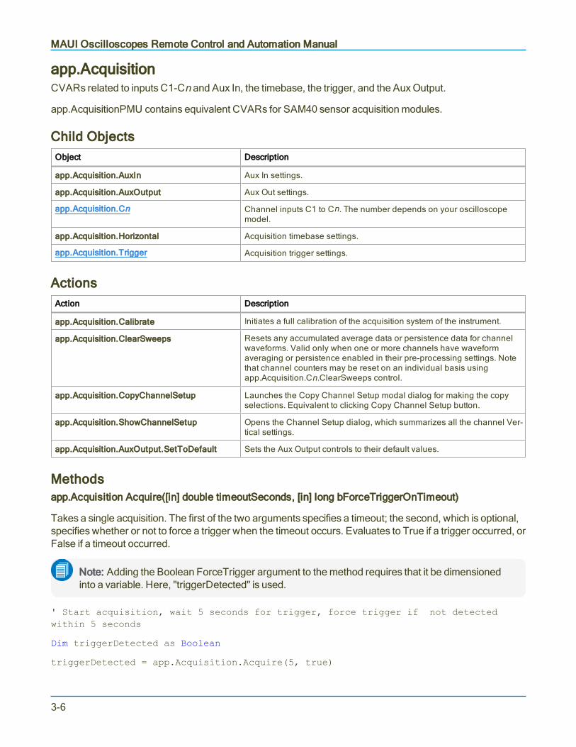
MAUI Oscilloscopes Remote Control and Automation Manual
app.AcquisitionCVARs related to inputs C1-Cn and Aux In, the timebase, the trigger, and the Aux Output.
app.AcquisitionPMU contains equivalent CVARs for SAM40 sensor acquisition modules.
Child ObjectsObject Description
app.Acquisition.AuxIn Aux In settings.
app.Acquisition.AuxOutput Aux Out settings.
app.Acquisition.Cn Channel inputs C1 to Cn. The number depends on your oscilloscopemodel.
app.Acquisition.Horizontal Acquisition timebase settings.
app.Acquisition.Trigger Acquisition trigger settings.
ActionsAction Description
app.Acquisition.Calibrate Initiates a full calibration of the acquisition system of the instrument.
app.Acquisition.ClearSweeps Resets any accumulated average data or persistence data for channelwaveforms. Valid only when one or more channels have waveformaveraging or persistence enabled in their pre-processing settings. Notethat channel counters may be reset on an individual basis usingapp.Acquisition.Cn.ClearSweeps control.
app.Acquisition.CopyChannelSetup Launches the Copy Channel Setup modal dialog for making the copyselections. Equivalent to clicking Copy Channel Setup button.
app.Acquisition.ShowChannelSetup Opens the Channel Setup dialog, which summarizes all the channel Ver-tical settings.
app.Acquisition.AuxOutput.SetToDefault Sets the Aux Output controls to their default values.
Methodsapp.Acquisition Acquire([in] double timeoutSeconds, [in] long bForceTriggerOnTimeout)
Takes a single acquisition. The first of the two arguments specifies a timeout; the second, which is optional,specifies whether or not to force a trigger when the timeout occurs. Evaluates to True if a trigger occurred, orFalse if a timeout occurred.
Note: Adding the Boolean ForceTrigger argument to the method requires that it be dimensionedinto a variable. Here, "triggerDetected" is used.
' Start acquisition, wait 5 seconds for trigger, force trigger if not detectedwithin 5 seconds
Dim triggerDetected as Boolean
triggerDetected = app.Acquisition.Acquire(5, true)
3-6
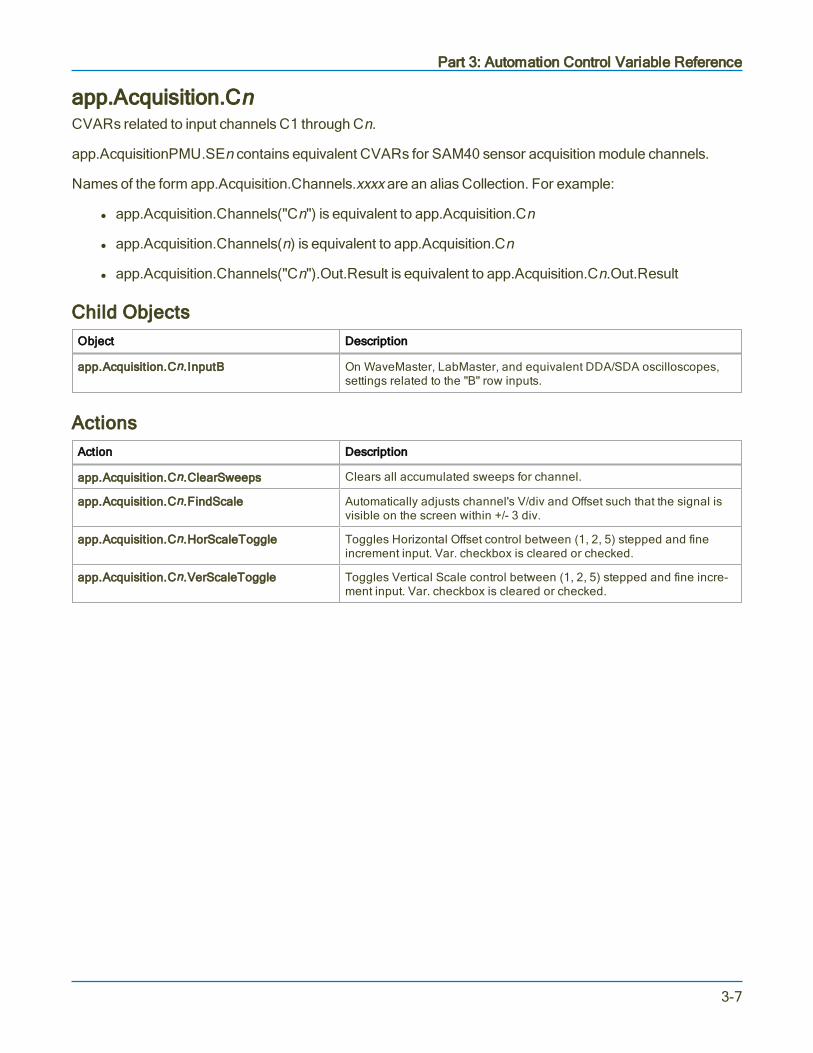
Part 3: Automation Control Variable Reference
app.Acquisition.CnCVARs related to input channels C1 through Cn.
app.AcquisitionPMU.SEn contains equivalent CVARs for SAM40 sensor acquisition module channels.
Names of the form app.Acquisition.Channels.xxxx are an alias Collection. For example:
l app.Acquisition.Channels("Cn") is equivalent to app.Acquisition.Cn
l app.Acquisition.Channels(n) is equivalent to app.Acquisition.Cn
l app.Acquisition.Channels("Cn").Out.Result is equivalent to app.Acquisition.Cn.Out.Result
Child ObjectsObject Description
app.Acquisition.Cn.InputB On WaveMaster, LabMaster, and equivalent DDA/SDA oscilloscopes,settings related to the "B" row inputs.
ActionsAction Description
app.Acquisition.Cn.ClearSweeps Clears all accumulated sweeps for channel.
app.Acquisition.Cn.FindScale Automatically adjusts channel's V/div and Offset such that the signal isvisible on the screen within +/- 3 div.
app.Acquisition.Cn.HorScaleToggle Toggles Horizontal Offset control between (1, 2, 5) stepped and fineincrement input. Var. checkbox is cleared or checked.
app.Acquisition.Cn.VerScaleToggle Toggles Vertical Scale control between (1, 2, 5) stepped and fine incre-ment input. Var. checkbox is cleared or checked.
3-7

MAUI Oscilloscopes Remote Control and Automation Manual
app.Acquisition.TriggerCVARs related to acquisition trigger.
Child ObjectsObject Description
app.Acquisition.Trigger.<Type> Currently selected acquisition trigger type(e.g., app.Acquisition.Trigger.Edge). The settings within the <Type>object will change depending on what is selected. Most trigger types sup-port the Action FindLevel.
app.Acquisition.SoftwareAssistedTrigger Settings related to Software Assisted Trigger feature. Not available onWaveSurfer and HDO4000 oscilloscopes.
ActionsAction Description
app.Acquisition.Trigger.<Type>.FindLevel Automatically sets trigger level to signal mean.
3-8

Part 3: Automation Control Variable Reference
app.CursorsCVARs related to the selection and placement of measurement cursors.
Child ObjectsObject Description
app.Cursors.XYCursorsMgr Settings related to the placement and tracking of relative cursors.
3-9

MAUI Oscilloscopes Remote Control and Automation Manual
app.CustomDSOCVARs related to the CustomDSO (XDEV) option. Standard on WavePro, WaveMaster, and LabMasteroscilloscopes, available as an option on WaveRunner and most HDO oscilloscopes. Not available onHDO4000 and WaveSurfer 3000 oscilloscopes.
ActionsAction Description
app.CustomDSO.PlugIn1Install Installs custom program
app.CustomDSO.PlugIn1Remove Removes custom program
3-10

Part 3: Automation Control Variable Reference
app.DisplayCVARs related to the oscilloscope touch screen display and the appearance of waveform traces.
ActionsAction Description
app.Display.ClearSweeps Clears sweeps only for persistence traces.
app.Display.DisableExternalMonitor Exit external monitor display; resume default touch screen display.
app.Display.EnableExternalMonitor Enter external monitor display.
app.Display.FactoryDefault Equivalent to SetToDefault.
app.Display.OpenMonitorControls Opens dialog for external monitor setup.
app.Display.PreviewPrintColors Shows the instrument display in the currently selected print color palette.
app.Display.ResetAll Turns off display persistence on any trace where it has been set.
3-11

MAUI Oscilloscopes Remote Control and Automation Manual
app.HardcopyCVARs related to the oscilloscope Print function. This includes hardcopy print as well as print to file, send toemail, and copy to clipboard.
Note: In the 64-bit XStreamDSO v.8.4.0.0 and later, many former Hardcopy CVARs have beenmoved to the File > Print and File > Save Screen Image dialogs. There is no longer a HardcopyPreferences dialog in MAUI. See app.SaveRecall.
ActionsAction Description
app.Hardcopy.EjectPaper Sends eject command to connected printer. This action is only relevant ifapp.Hardcopy.Destination is set to Printer.
app.Hardcopy.Print Initiates the print action; opens modal dialog for completing printselections.
app.Hardcopy.PrintToRemote Performs the same action as the above command, but useful for pro-gramming languages where ending a command with the word "print" isproblematic.
app.Hardcopy.ShowEmailMenu Displays dialog for configuring Email settings.
3-12

Part 3: Automation Control Variable Reference
app.HistoryCVARs related to the oscilloscope History Mode feature. Not available on Zi series oscilloscopes.
Child ObjectsObject Description
app.History.HistoryTable Settings related to the History Mode tabular display.
ActionsAction Description
app.History.Next Displays next acquisition in history.
app.History.Previous Displays previous acquisition in history.
app.History.HistoryTable.ClearSweeps Clears history buffer.
3-13

MAUI Oscilloscopes Remote Control and Automation Manual
app.LabNotebookCVARs related to the LabNotebook documentation tool.
Note: In MAUI, LabNotebook CVARS have been moved to the File > Save and File > Recalldialogs. See app.SaveRecall.
ActionsAction Description
app.LabNotebook.CreateReport Outputs selected Notebook Entries in report format.
app.LabNotebook.DeleteAll Deletes all Notebook Entries.
app.LabNotebook.DeleteRecord Deletes selected Notebook Entries.
app.LabNotebook.DeviceChanged Used internally by MAUI to propagate Windows "DeviceChanged" notifications to LabNotebook. Do not use.
app.LabNotebook.EmailRecord Emails selected Notebook Entries.
app.LabNotebook.ExtractAttachmentsNow Extracts external files attached to selected LabNotebook topath set in app.LabNotebook.ExtractFilepath.
app.LabNotebook.ExtractFilesNow Extracts screen capture (.PNG), setup (.LSS) and trace (.TRC)files that make up the Notebook Entry into separate files.
app.LabNotebook.FilterRecords Applies search filters to list of Notebook Entries.
app.LabNotebook.FlashBackToRecord Invokes Flashback Recall of selected Notebook Entry. Theflashback restores the screen image, waveforms, and setupssaved with the entry.
app.LabNotebook.InternalView Opens the Labnotebook Report Viewer, displaying the selec-ted entry in the report format.
app.LabNotebook.NextRecord Displays the next Notebook Entry
app.LabNotebook.PreviousRecord Displays the previous Notebook Entry
app.LabNotebookPrintRecord Sends selected Notebook Entry to connected printer.
app.LabNotebook.Refresh Refreshes the list of Notrbook Entries for the selected LabNote-book file. Primarily used by legacy LabNotebook forWaveSurfer and WaveRunner Xi oscilloscopes.
app.LabNotebook.ReportGenRefreshFromCurrentState Generates report using current state of oscilloscope (allsetups, visible waveforms, visible table data, etc.).
app.LabNotebook.Save Saves current state of oscilloscope to new Notebook Entry.
app.LabNotebook.SaveReport Saves contents of report window to file using currentapp.LabNotebook.Report* settings.
app.LabNotebook.ShowEditDescription Displays pop-up of Notebook Entry Description for editing.
app.LabNotebook.ShowEMailMenu Displays Email & Report Settings dialog.
app.LabNotebook.ShowScreenImageSettings Displays pop-up of Screen Image settings for editing (linked toArea/Color Preferences button).
app.LabNotebook.ViewRecord Displays selected Notebook Entry in report window.
3-14

Part 3: Automation Control Variable Reference
app.LogicAnalyzerCVARs related to digital logic analyzer functions. Standard on -MS/MSO model oscilloscopes, or with anoptional external Mixed-Signal input device.
Child ObjectsObject Description
app.LogicAnalyzer.Digitalx Digital logic group settings.
app.LogicAnalyzer.Pattern Custom logic pattern settings.
3-15

MAUI Oscilloscopes Remote Control and Automation Manual
app.MathCVARs related to Math functions F1-Fn.
Names of the form app.Math.Functions("Fn").xxxx are an alias Collection. For example:
l app.Math.Functions("Fn") is equivalent to app.Math.Fn
l app.Math.Functions("Fn").Out.Result is equivalent to app.Math.Fn.Out.Result
l app.Math.Functions("Fn").Zoom is equivalent to app.Math.Zoom.Fn
Child ObjectsObject Description
app.Math.Fn Math functions F1 to Fn.
app.Math.XY CVARs controlling the display of data in X vs. Y mode. Only Valid whenthe instrument is in XY, XYSingle, or XYDual display modes.
ActionsAction Description
app.Math.ClearSweeps Clears sweeps for history functions such as average, histogram andtrend.
app.Math.ResetAll Resets all math functions to default state; all function definitions arecleared.
app.Math.ShowZoomMenu Displays the Zoom dialog for rescaling functions.
3-16

Part 3: Automation Control Variable Reference
app.Math.Fn and app.Math.XYCVARs related to individual math functions F1-Fn and XY trace.
Child ObjectsObject Description
app.Math.Fn.OperatornSetup This node is dynamically created and will contain the controls for theoperator currently selected into Operatorn.
app.Math.Fn.Zoom Function zoom scale settings.
ActionsAction Description
app.Math.Fn.ClearSweeps
app.Math.XY.ClearSweeps
Clears accumulated data for single function trace.
Clears persistence X-Y plot.
app.Math.Fn.DoResetZoom Resets scale of Fn trace to 1:1.
app.Math.Fn.DoStoreToMemoryTrace Stores Fn trace to corresponding internal memory (e.g., F1 to M1).
app.Math.Fn.FPHit Opens/closes the Fn dialog display. Each successive invocation of thecommand acts like a toggle.
app.Math.Fn.ShowProcessingWeb Open WebEditor window to create processing web to run in function.Not available on WaveSurfer and HDO4000 oscilloscopes.
app.Math.Fn.OperatornSetup.DownFactor For those operators that involve a sampling factor (such as Inter-polation), decreases the sample value by one step.
app.Math.Fn.OperatornSetup.UpFactor For those operators that involve a sampling factor (such as Inter-polation), increases the sample value by one step.
3-17
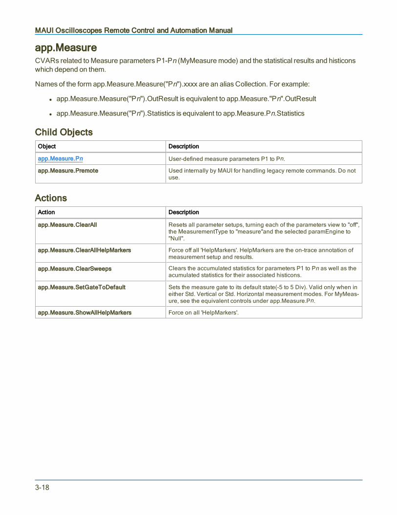
MAUI Oscilloscopes Remote Control and Automation Manual
app.MeasureCVARs related to Measure parameters P1-Pn (MyMeasure mode) and the statistical results and histiconswhich depend on them.
Names of the form app.Measure.Measure("Pn").xxxx are an alias Collection. For example:
l app.Measure.Measure("Pn").OutResult is equivalent to app.Measure."Pn".OutResult
l app.Measure.Measure("Pn").Statistics is equivalent to app.Measure.Pn.Statistics
Child ObjectsObject Description
app.Measure.Pn User-defined measure parameters P1 to Pn.
app.Measure.Premote Used internally by MAUI for handling legacy remote commands. Do notuse.
ActionsAction Description
app.Measure.ClearAll Resets all parameter setups, turning each of the parameters view to "off",the MeasurementType to "measure"and the selected paramEngine to"Null".
app.Measure.ClearAllHelpMarkers Force off all 'HelpMarkers'. HelpMarkers are the on-trace annotation ofmeasurement setup and results.
app.Measure.ClearSweeps Clears the accumulated statistics for parameters P1 to Pn as well as theacumulated statistics for their associated histicons.
app.Measure.SetGateToDefault Sets the measure gate to its default state(-5 to 5 Div). Valid only when ineither Std. Vertical or Std. Horizontal measurement modes. For MyMeas-ure, see the equivalent controls under app.Measure.Pn.
app.Measure.ShowAllHelpMarkers Force on all 'HelpMarkers'.
3-18

Part 3: Automation Control Variable Reference
app.Measure.PnCVARs related to individual measure parameters P1-Pn.
Child ObjectsObject Description
app.Measure.Pn.Accept Measurement result filter settings.
app.Measure.Pn.Operator Settings related to selected measurement.
ActionsAction Description
app.Measure.Pn.HistogramThis Draws histogram plot of measurement results.
app.Measure.Pn.ShowProcessingWeb Opens Web Editor window to create processing web to run in parameter.Not available on WaveSurfer and HDO4000 oscilloscopes.
app.Measure.Pn.TrackThis Draws track plot of measurement results.
app.Measure.Pn.TrendThis Draws trend plot of measurement results.
app.Measure.Pn.Accept.FindLevel Automatically sets filter level based on signal characteristics.
app.Measure.Pn.Accept.FindRange Automatically sets filter level range based on signal characteristics.
app.Measure.Pn.Operator.FindLevel Automatically finds measurement level based on signal characteristics.
3-19
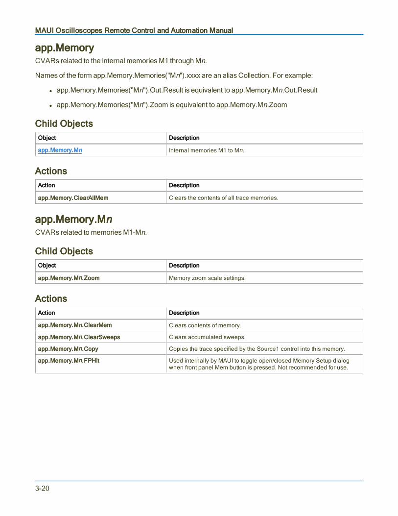
MAUI Oscilloscopes Remote Control and Automation Manual
app.MemoryCVARs related to the internal memories M1 through Mn.
Names of the form app.Memory.Memories("Mn").xxxx are an alias Collection. For example:
l app.Memory.Memories("Mn").Out.Result is equivalent to app.Memory.Mn.Out.Result
l app.Memory.Memories("Mn").Zoom is equivalent to app.Memory.Mn.Zoom
Child ObjectsObject Description
app.Memory.Mn Internal memories M1 to Mn.
ActionsAction Description
app.Memory.ClearAllMem Clears the contents of all trace memories.
app.Memory.MnCVARs related to memories M1-Mn.
Child ObjectsObject Description
app.Memory.Mn.Zoom Memory zoom scale settings.
ActionsAction Description
app.Memory.Mn.ClearMem Clears contents of memory.
app.Memory.Mn.ClearSweeps Clears accumulated sweeps.
app.Memory.Mn.Copy Copies the trace specified by the Source1 control into this memory.
app.Memory.Mn.FPHit Used internally by MAUI to toggle open/closed Memory Setup dialogwhen front panel Mem button is pressed. Not recommended for use.
3-20

Part 3: Automation Control Variable Reference
app.PassFailCVARs related to Pass/Fail testing and test Qualifiers Q1-Qn.
Names of the forms app.PassFail.PassFail("Qremote").xxxx and app.PassFail.PassFail("Qn").xxxx arealias Collections. For example:
l app.PassFail.PassFail("Qremote").Operator is equivalent to app.PassFail.Qremote.Operator
l app.PassFail.PassFail("Qn").Out.Result is equivalent to app.PassFail.Qn.Out.Result
Child ObjectsObject Description
app.PassFail.Qn Settings related to test qualifier.
app.PassFail.LastPass Returns last passed result. See Result Interface reference.
app.PassFail.NumPass Returns number of results passed. See Result Interface reference.
app.PassFail.Rate Returns Pass Fail rate. See Result Interface reference.
ActionsAction Description
app.PassFail.ClearSweeps Clears accumulated data for single function trace.
3-21

MAUI Oscilloscopes Remote Control and Automation Manual
app.PassFail.QnCVARs related to individual Pass/Fail test qualifiers Q1-Qn. Not available on WaveSurfer and HDO4000oscilloscopes.
Child ObjectsObject Description
app.PassFail.Qn.Operator Settings related to test operator.
ActionsAction Description
app..PassFail.Qn.ClearSweeps Clears sweeps.
app..PassFail.Qn.Operator.ClearSweeps Clears sweeps.
app.PassFail.Qn.Operator.FindLimit When qualifier is performing a parameter comparison(Condition = Param compare), sets the maximum value inOperator Limit field.
app.PassFail.Qn.Operator.FindLimitUsingnSigma When qualifier is performing a parameter comparison(Condition = Param compare), sets the value in OperatorLimit field using n Sigma. n:= 1, 3, 5
3-22

Part 3: Automation Control Variable Reference
app.PreferencesThis set of CVARs controls user preferences for the instrument setup and operation.
Note: In MAUI, many email CVARs have been moved to the File > File Sharing and Email &Reports Settings dialogs. There is no longer an Email Preferences dialog. See app.SaveRecall.
Child ObjectsObject Description
app.Preferences.Display Touch screen display and color preferences.
app.Preferences.Email Email preferences.
ActionsAction Description
app.Preferences.LanguageIcon Displays language selection icon. This action is only valid on oscil-loscope models that allow language selection.
app.Preferences.Display.ClearSweeps Same as app.Display.ClearSweeps. Clear accumulated sweeps if Per-sistence display is enabled.
app.Preferences.Display.FactoryDefault Restores all Display color CVARs to factory default settings. Linked toPreferences > Color > Factory default colors button.
app.Preferences.Display.OpenMonitorControls Open Windows display panel for external monitor configuration.
app.Preferences.Display.PreviewPrintColors Opens preview window of image using print color palette.
app.Preferences.Display.ResetAll Returns all display settings to factory default.
app.Preferences.Email.ComposeMail Launches dialog to compose cover email when file "printed" to email.
app.Preferences.Email.SendMail Sends email message.
app.Preferences.Email.SendTestMail Sends a message by e-mail to test the system.
3-23

MAUI Oscilloscopes Remote Control and Automation Manual
app.ProbesCalCVARs related to probe calibration feature. Not available on WaveSurfer and HDO4000 oscilloscopes.
ActionsAction Description
app.ProbesCal.CalibrateAlln Initiates full calibration of corresponding channel n, which includesGain/Offset, and deskew.
app.ProbesCal.Clearn Clears all calibration coefficients for corresponding channel n.
app.ProbesCal.DcCaln Initiates a DC calibration (Gain/Offset) of corresponding channel n.
app.ProbesCal.Deskewn Initiates a deskew calibration of corresponding channel n.
app.ProbesCal.RecallCalSetup Whenever a probe calibration is applied, the scope saves the inform-ation in a file on the disk. If the scope must be rebooted for any reason,the probe calibration information is always cleared, but can be recalledusing this control.
3-24

Part 3: Automation Control Variable Reference
app.SpecAnalyzerCVARs related to the Spectrum Analyzer option. Standard on HDO6000, HDO8000, and MDA800 seriesoscilloscopes.
Child ObjectsObject Description
app.SpecAnalyzer.SpecAn Post-processing spectrum trace.
app.SpecAnalyzer.SpecAnTable Spectrum measurement table.
app.SpecAnalyzer.Spectro Spectrogram plot.
app.SpecAnalyzer.SpecWindow Spectrum Analyzer window.
app.SpecAnalyzer.SpIn Spectrum source trace.
ActionsAction Description
app.SpecAnalyzer.AllMarkersOff Turns off all markers.
app.SpecAnalyzer.MarkerToCenterFreq Moves marker to center frequency.
app.SpecAnalyzer.MarkerToRefLevel Moves marker to reference level.
app.SpecAnalyzer.SetDefaultMarkers Places default markers on SpecAn trace.
app.SpecAnalyzer.SetHarmonicsMarkers Places harmonic frequency markers on SpecAn trace.
app.SpecAnalyzer.SetPeaksMarkers Places peaks markers on SpecAn trace.
app.SpecAnalyzer.SpecAn.ClearSweeps Clears any accumulated result data for SpecAn trace.
app.SpecAnalyzer.SpecAnTable.ClearSweeps Clears any accumulated result data used in computation ofSpecAn table.
app.SpecAnalyzer.Spectro.ClearSweeps Clears any accumulated result data for spectrogram plot.
app.SpecAnalyzer.SpecWindow.ClearSweeps Clears any accumulated result data for "window" of gated spec-trum trace.
app.SpecAnalyzer.SpIn.ClearSweeps Clears any accumulated result data for spectrum source trace.
3-25

MAUI Oscilloscopes Remote Control and Automation Manual
app.SaveRecallCVARs related to saving or recalling setups, waveforms, and tabular data.
Child ObjectsObject Description
app.SaveRecall.Remote Controls defining the scope and format of exported waveform data.
app.SaveRecall.Setup Controls related to setup panel data.
app.SaveRecall.Table Controls related to table data.
app.SaveRecall.Utilities Controls related to the file directory structure.
app.SaveRecall.Waveform Controls related to waveform data.
ActionsAction Description
app.SaveRecall.DisableAutoSave Turn OFF AutoSave feature/confirm disable AutoSave. (Turn ONAutoSave by setting Enum app.SaveRecall.AutoSave to Wrap or Fill.
app.SaveRecall.ShowAutoSave Display AutoSave dialog.
app.SaveRecall.ShowDiskUtilities Display Disk Utilities dialog.
app.SaveRecall.ShowEmailReportSettings Display Email & Report Settings dialog.
app.SaveRecall.ShowLSIBExport Display LSIB export dialog. (Only works when LSIB option installed.)
app.SaveRecall.ShowPrint Display Print dialog.
app.SaveRecall.ShowRecall Display Recall dialog.
app.SaveRecall.ShowRecallLabNotebook Display LabNotebook settings on Recall dialog.
app.SaveRecall.ShowRecallSetup Display Setup settings on Recall dialog.
app.SaveRecall.ShowRecallWaveform Display Waveform settings on Recall dialog.
app.SaveRecall.ShowReportGenerator Display Report Generator dialog.
app.SaveRecall.ShowSave Display Save dialog.
app.SaveRecall.ShowSaveLabNotebook Display LabNotebook settings on Save dialog.
app.SaveRecall.ShowSaveScreenImage Display Screen Image settings on Save dialog.
app.SaveRecall.ShowSaveSetup Display Setup settings on Save dialog.
app.SaveRecall.ShowSaveTable Display Table settings on Save dialog.
app.SaveRecall.ShowSaveWaveform Display Waveform settings on Save dialog.
app.SaveRecall.ShowSharing Display File Sharing dialog.
3-26

Part 3: Automation Control Variable Reference
app.SaveRecall.RemoteCVARs defining the scope and format of exported waveform data.
ActionsAction Description
app.SaveRecall.Remote.DoExport Used internally by MAUI to implement legacy style remote waveformtransfer. Do not use.
app.SaveRecall.Remote.DoImport Used internally by MAUI to implement legacy style remote waveformtransfer. Do not use.
3-27
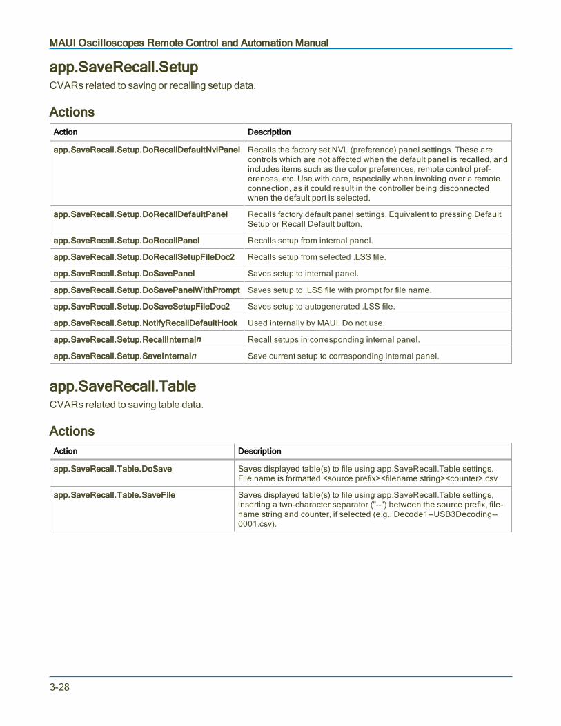
MAUI Oscilloscopes Remote Control and Automation Manual
app.SaveRecall.SetupCVARs related to saving or recalling setup data.
ActionsAction Description
app.SaveRecall.Setup.DoRecallDefaultNvlPanel Recalls the factory set NVL (preference) panel settings. These arecontrols which are not affected when the default panel is recalled, andincludes items such as the color preferences, remote control pref-erences, etc. Use with care, especially when invoking over a remoteconnection, as it could result in the controller being disconnectedwhen the default port is selected.
app.SaveRecall.Setup.DoRecallDefaultPanel Recalls factory default panel settings. Equivalent to pressing DefaultSetup or Recall Default button.
app.SaveRecall.Setup.DoRecallPanel Recalls setup from internal panel.
app.SaveRecall.Setup.DoRecallSetupFileDoc2 Recalls setup from selected .LSS file.
app.SaveRecall.Setup.DoSavePanel Saves setup to internal panel.
app.SaveRecall.Setup.DoSavePanelWithPrompt Saves setup to .LSS file with prompt for file name.
app.SaveRecall.Setup.DoSaveSetupFileDoc2 Saves setup to autogenerated .LSS file.
app.SaveRecall.Setup.NotifyRecallDefaultHook Used internally by MAUI. Do not use.
app.SaveRecall.Setup.RecallInternaln Recall setups in corresponding internal panel.
app.SaveRecall.Setup.SaveInternaln Save current setup to corresponding internal panel.
app.SaveRecall.TableCVARs related to saving table data.
ActionsAction Description
app.SaveRecall.Table.DoSave Saves displayed table(s) to file using app.SaveRecall.Table settings.File name is formatted <source prefix><filename string><counter>.csv
app.SaveRecall.Table.SaveFile Saves displayed table(s) to file using app.SaveRecall.Table settings,inserting a two-character separator ("--") between the source prefix, file-name string and counter, if selected (e.g., Decode1--USB3Decoding--0001.csv).
3-28

Part 3: Automation Control Variable Reference
app.SaveRecall.UtilitiesCVARs related to file directory structure.
ActionsAction Description
app.SaveRecall.Utilities.CopyDir Copies all files from path set in app.SaveRecall.Util-ities.Directory
app.SaveRecall.Utilities.CopyFile Copies file in path app.SaveRecall.Utilities.SelectedFiles
app.SaveRecall.Utilities.CreateDir Creates path set in app.SaveRecall.Utilities.DestDirectory
app.SaveRecall.Utilities.DeleteAll Deletes all files from path set in app.SaveRecall.Util-ities.Directory
app.SaveRecall.Utilities.DeleteFile Deletes file from path set in app.SaveRecall.Util-ities.SelectedFiles
app.SaveRecall.Utilities.EmailSelectedFilesNow Emails files from path set inapp.SaveRecall.Utilities.SelectedFiles
app.SaveRecall.Utilities.NextFile Shows next file in path set in app.SaveRecall.Utilities.Directory
app.SaveRecall.Utilities.PrevFile Shows prev. file in path set in app.SaveRecall.Utilities.Directory
app.SaveRecall.Utilities.SaveSelectedFilesToZipNow Zips files in path set in app.SaveRecall.Utilities.SelectedFiles
app.SaveRecall.WaveformCVARs related to saving waveform data to external files and recalling waveform files.
ActionsAction Description
app.SaveRecall.Waveform.DoRecall Recall waveform from internal Memory.(Use app.SaveRecall.Remote.DoImport to import from remote directory.)
app.SaveRecall.Waveform.NextFile Display next waveform file in directory.
app.SaveRecall.Waveform.PrevFile Display previous waveform file in directory.
app.SaveRecall.Waveform.SaveFile Save active waveform to file using app.SaveRecall.Waveform settings,inserting a two-character separator ("--") between the source prefix, file-name string and counter, if selected (e.g.,C1--MyTrace--0001.trc).(Use app.SaveRecall.Remote.DoExport to save to remote directory.)
3-29

MAUI Oscilloscopes Remote Control and Automation Manual
app.TriggerScanCVARs related to the TriggerScan feature. Not available on WaveSurfer and HDO4000 oscilloscopes.
ActionsAction Description
app.TriggerScan.AddNewSetup Appends the current trigger setup to the list of TriggerScan triggers.
app.TriggerScan.DeleteAll Deletes all stored trigger setups from the trigger list.
app.TriggerScan.DeleteSelected Deletes the selected trigger setup from the trigger list.
app.TriggerScan.LoadSelected Loads the trigger setup selected in the trigger list into the current triggersetup.
app.TriggerScan.LoadSetup Loads the trigger list from the file specified in the SetupFileName control.
app.TriggerScan.SaveSetup Saves the current trigger list into the file specified in the SetupFileNamecontrol.
app.TriggerScan.StartScan Starts scanning. Places the scope in Normal trigger mode, and startswalking down the list of trigger setups.
app.TriggerScan.StartTraining Starts training. This will take an acquisition on the channel specified inthe TrainerSource control, and depending upon the state of theTrainEdges, TrainGlitches, TrainIntervals, TrainRunts, TrainWidths con-trols, creates a list of trigger setups.
app.TriggerScan.StopScan Stops scanning.
app.TriggerScan.UpdateSelected Updates the currently selected TriggerScan setup with the current triggersetup.
3-30

Part 3: Automation Control Variable Reference
app.UtilityCVARs related to oscilloscope Utilities dialog settings.
Child ObjectsObject Description
app.Utility.DateTimeSetup Data/Time controls.
app.Utility.Options Option key installation/activation controls.
app.Utility.Remote Remote control settings.
ActionsAction Description
app.Utility.DateTimeSetup.AddOneHour Adds one hour to current time.
app.Utility.DateTimeSetup.BackOneHour Removes one hour from current time.
app.Utility.DateTimeSetup.SetFromSNTP Sets the real time clock from the simple network time pro-tocol.
app.Utility.DateTimeSetup.ShowProperties Launches modal dialog showing current date/time settings.
app.Utility.DateTimeSetup.Validate Validates any new settings. This action is equivalent to click-ing 'Validate Changes' on the Date/Time page.
3-31

MAUI Oscilloscopes Remote Control and Automation Manual
app.WaveScanCVARs related to the WaveScan feature.
Child ObjectsObject Description
app.WaveScan.ScanDecode Scan Decode table view controls.
app.WaveScan.ScanHisto Scan Histogram view controls.
app.WaveScan.ScanOverlay Scan Overlay (marker) view controls.
ActionsAction Description
app.WaveScan.FindRarenSigma Presets the filter limit and delta to find rare events. Uses the his-tory of measurements since the last Clear Sweeps, or controlchange, to set the limit and delta to capture +/- n sigma events. n:=1,3,5
app.WaveScan.FindSelectRarest Presets the filter to find rarest event in acquisition.
app.WaveScan.FindUseMean Setup the filter to find measurements with values > the current stat-istical mean.
app.WaveScan.ScanDecode.ClearSweeps Clears any accumulated result data.
app.WaveScan.ScanHisto.ClearSweeps Clears any accumulated result data.
app.WaveScan.ScanHisto.Histogram.ClearSweeps Clears any accumulated result data.
app.WaveScan.ScanHisto.Histogram.FindScale Automatically determine an appropriate horizontal scale for thehistogram, using the values currently in the histogram buffer.
app.WaveScan.ScanHisto.Zoom.ResetZoom Resets the zoom settings to their default values.
app.WaveScan.ScanOverlay.ClearSweeps Clears any accumulated result data.
3-32

Part 3: Automation Control Variable Reference
app.WebEditorCVARs related to the WebEditor, which is used to create custom processing chains ("webs") associatedwith a single function, parameter, or Pass/Fail qualifier.
Tip: The easiest way to determine the proper syntax for WedEditor objects is to set up theWebEditor on the oscilloscope as you would like, then save a setup file. The .lss file will embed theAutomation objects for that WebEditor function. This tip can be applied to any type of setup you wishto perform remotely.
ActionsAction Description
app.WebEditor.ClearSweeps Clears any accumulated data for nodes such as Average, Persistence,etc. that reside in the processing web.
Methodsapp.WebEditor.AddConnection([in] VARIANT destProcessor, [in] VARIANT destInputPin, [in]VARIANT sourceProcessor, [in] VARIANT sourceOutputPin)
Adds a connection between two 'pins' of nodes placed within the Web Editor. Pins are described by thename of the node, and the zero-based index of the pin on that node.
app.WebEditor.AddPreview([in] VARIANT sourceProcessor, [in] VARIANT sourcePin, [in] BSTRpreviewName, [in] double xPosition, [in] double yPosition, [in] BSTR associatedExecName)
Adds a Preview to the specified pin of the specified node. The coordinates specify where the preview willappear on the Web, with 0,0 being the top left-hand corner.
app.WebEditor.AddProcessor([in] VARIANT processorOrClassId, [in] BSTR requestedName, [in]double xPosition, [in] double yPosition)
Adds a named 'processor' to the web. To determine the name of a processor just place it on the web usingthe GUI and hover the mouse over the node. The 'ProgID' of the node, in the format LeCroy.<procName>'will appear. Note that when adding processors from automation there is no distinction between Measure,Math, and Pass/Fail processors.
' Create a Waveform Averager, name it "MyAvg", and place it at x=200, y=30
app.WebEditor.AddProcessor "LeCroy.Average", "MyAvg", 200, 30
3-33

MAUI Oscilloscopes Remote Control and Automation Manual
app.WebEditor.GetProcessor([in] VARIANT processor)
Retrieves a reference to a processor that has been added to the Web. This reference may then be used toaccess the processor's controls.
' Retrieve a pointer to the MyAvg averager and set it's number of sweepsto the value 1234
set myAverager = app.WebEditor.GetProcessor("MyAvg")myAverager.Sweeps = 1234
app.WebEditor.RemoveAll()
Removes all processors from the web.
' Show the WebEditor and remove all processors from it
app.ActiveView = "WebEdit"app.WebEditor.RemoveAll
app.WebEditor.RemoveConnection([in] VARIANT destProcessor, [in] VARIANT destInputPin)
Removes a connection between two pins on the web.
app.WebEditor.RemovePreview([in] VARIANT processor)
Removes the named preview display.
app.WebEditor.RemoveProcessor([in] VARIANT processor)
Removes the named processor from the Web.
3-34

Part 3: Automation Control Variable Reference
app.ZoomCVARs related to Zoom (Zn) traces.
Child ObjectsObject Description
app.Zoom.Zn Zooms Z1 to Zn. The number depends on your oscilloscope model.
ActionsAction Description
app.Zoom.GoToEnd When in MultiZoom mode, scroll to the end of the source waveform,whose last point will be centered on the graticule.
app.Zoom.GoToStart When in MultiZoom mode, scroll to the start of the source waveform,whose first point will be centered on the graticule.
app.Zoom.HorZoomIn Horizontally zoom in all the traces included in MultiZoom.
app.Zoom.HorZoomOut Horizontally zoom out all the traces included in MultiZoom.
app.Zoom.ResetAll Reset all zoom traces to their default settings.
app.Zoom.ResetZoom Resets the general zoom settings to their default values.
app.Zoom.Zn.ClearSweeps Clears any accumulated result data for individual zoom trace Zn.
app.Zoom.Zn.DoStoreToMemoryTrace Stores the content of Zn into the corresponding memory (Mn).
3-35

MAUI Oscilloscopes Remote Control and Automation Manual
3-36

Part 4: Automation Result Interface Reference
Part 4: Automation Result Interface ReferenceThe following result interfaces (Out.Result objects) appear throughout the XStreamDSO object hierarchy.Their properties will generally be the same regardless of the subsystem to which they apply.
Base 4-4
BinPopulations 4-4
Bins 4-4
BinWidth 4-5
BusName 4-5
CellType 4-5
CellValue 4-6
Columns 4-7
DataArray 4-8
ExtendedStatus 4-11
FirstEventTime 4-12
FirstPopulatedBin 4-12
HorizontalFrameStart 4-13
HorizontalFrameStop 4-13
HorizontalOffset 4-13
HorizontalPerColumn 4-13
HorizontalPerStep 4-14
HorizontalResolution 4-14
HorizontalUnits 4-14
HorizontalVarianceArray 4-14
HorizontalVariances 4-14
IndexOfFirstSampleInFrame 4-15
LastEventTime 4-15
LastPopulatedBin 4-15
Levels 4-15
LineAliasName 4-15
4-1

MAUI Oscilloscopes Remote Control and Automation Manual
LineName 4-16
Lines 4-16
Max 4-16
MaxPopulation 4-16
MaxPopulationBin 4-16
MaxPopulationInRectangle 4-17
Mean 4-17
Min 4-17
NumFrameDimensions 4-18
NumSamplesInFrame 4-18
OffsetAtLeftEdge 4-18
Peaks 4-19
PeakInfo 4-19
PopulationInside 4-20
PopulationOfRectangle 4-20
PopulationOver 4-20
PopulationUnder 4-21
RMS 4-21
Rows 4-21
Samples 4-21
Sdev 4-21
Status 4-22
StatusDescription 4-23
Sweeps 4-24
Top 4-24
UniformInterval 4-24
UpdateTime 4-24
Value 4-25
ValueArray 4-26
4-2

Part 4: Automation Result Interface Reference
VerticalFrameStart 4-27
VerticalFrameStop 4-27
VerticalMaxPossible 4-27
VerticalMinPossible 4-27
VerticalOffset 4-27
VerticalPerRow 4-28
VerticalPerStep 4-28
VerticalResolution 4-28
VerticalUnits 4-28
XFrameStart 4-28
XFrameStop 4-29
XMaxPossible 4-29
XMinPossible 4-29
XOffset 4-29
XPerStep 4-29
XResolution 4-30
XUnits 4-30
YFrameStart 4-30
YFrameStop 4-30
YMaxPossible 4-30
YMinPossible 4-31
YOffset 4-31
YPerStep 4-31
YResolution 4-31
YUnits 4-31
4-3

MAUI Oscilloscopes Remote Control and Automation Manual
BaseHorizontal coordinate of the leftmost of the two most populated histogram peaks. It is equivalent to theparamater hbase.
Applies to: Histogram
Dim hbase as Doublehbase = app.Math.F1.Out.Result.Base
BinPopulationsVariant array containing the populations of each bin. Bin 0 is the first bin. Index the array to retrieve thenumber of counts in a given bin.
Applies to: Histogram
Read out BinPopulations by indexing the array using the FirstPopulatedBin and LastPopulatedBinproperties as boundaries Also shows code for determining coordinate of bin centers.
Const STARTROW = 5Dim i As IntegerDim BinPopsDim FirstPopulatedBin, LastPopulatedBin As IntegerDim OffsetAtLeftEdge As DoubleDim BinWidth As Double
BinPops = app.Math.F1.Out.Result.BinPopulationsFirstPopulatedBin = app.Math.F1.Out.Result.FirstPopulatedBinLastPopulatedBin = app.Math.F1.Out.Result.LastPopulatedBinOffsetAtLeftEdge = app.Math.F1.Out.Result.OffsetAtLeftEdgeBinWidth = app.Math.F1.Out.Result.BinWidth
For i = FirstPopulatedBin To LastPopulatedBinCells(i - FirstPopulatedBin + STARTROW + 1, 7) = iCells(i - FirstPopulatedBin + STARTROW + 1, 8) = OffsetAtLeftEdge +(BinWidth / 2) + BinWidth * iCells(i - FirstPopulatedBin + STARTROW + 1, 9) = BinPops(i)Next i
BinsNumber of bins in the histogram.
Applies to: Histogram
Dim Bins as IntegerBins = app.Math.F1.Out.Result.Bins
4-4
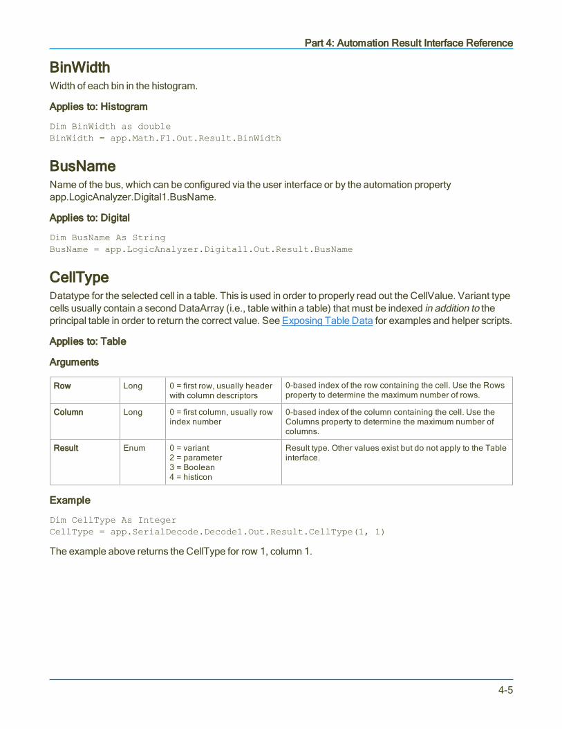
Part 4: Automation Result Interface Reference
BinWidthWidth of each bin in the histogram.
Applies to: Histogram
Dim BinWidth as doubleBinWidth = app.Math.F1.Out.Result.BinWidth
BusNameName of the bus, which can be configured via the user interface or by the automation propertyapp.LogicAnalyzer.Digital1.BusName.
Applies to: Digital
Dim BusName As StringBusName = app.LogicAnalyzer.Digital1.Out.Result.BusName
CellTypeDatatype for the selected cell in a table. This is used in order to properly read out the CellValue. Variant typecells usually contain a second DataArray (i.e., table within a table) that must be indexed in addition to theprincipal table in order to return the correct value. See Exposing Table Data for examples and helper scripts.
Applies to: Table
Arguments
Row Long 0 = first row, usually headerwith column descriptors
0-based index of the row containing the cell. Use the Rowsproperty to determine the maximum number of rows.
Column Long 0 = first column, usually rowindex number
0-based index of the column containing the cell. Use theColumns property to determine the maximum number ofcolumns.
Result Enum 0 = variant2 = parameter3 = Boolean4 = histicon
Result type. Other values exist but do not apply to the Tableinterface.
Example
Dim CellType As IntegerCellType = app.SerialDecode.Decode1.Out.Result.CellType(1, 1)
The example above returns the CellType for row 1, column 1.
4-5

MAUI Oscilloscopes Remote Control and Automation Manual
CellValueThe value for the selected cell in a table. The method for reading back CellValue depends on the cell’sCellType property:
CellType = 0 (Variant), CellValue is probably an array with the last sample value plus other results, whichmust be indexed in addition to the principal table. See Exposing Table Data.
CellType = 2, CellValue is Parameter result with a discrete value.
CellType = 3, CellValue is a Boolean result.
CellType = 4, CellValue is a histicon.
Applies to: Table
Arguments
Row Long 0 = first row 0-based index of the row containing the cell. Use the Rowsproperty to determine the maximum number of rows.
Column Long 0 = first column 0-based index of the column containing the cell. Use theColumns property to determine the maximum number ofcolumns.
Example
When the CellType = 0, read out the value of a numeric cell by adding (0,0) to the cell index, as in:
Dim CellValueCellValue = app.SerialDecode.Decode1.Out.Result.CellValue(3,2)(0, 0)
The above would return the value shown in row 3, column, 2 of the Serial Decode table.
Tip: Oscilloscopes that have a serial decoder option installed include the fileD:\Scripts\TableExport.lss, a VBScript for determining the decoder table structure and outputtingthe decoded values.
When the CellType = 2, read out the value as follows:
Dim DecoderTableResult As ObjectSet DecoderTableResult = app.SerialDecode.Decode1.Out.ResultDim CellValueOb As ObjectSet CellValueOb = DecoderTableResult.CellValue(1, 2)CellValue = CellValueOb.Value
4-6

Part 4: Automation Result Interface Reference
ColumnsNumber of columns in the DataArray. Typically equal to 1000 for Persist waveforms. For Tables, the resultcan vary depending on the application.
Applies to: Persist, Table
Persist Example
Dim Columns As IntegerColumns = app.SDA.Eye.Out.Result.Columns
Table Example
Dim Columns As IntegerColumns = app.SerialDecode.Decode1.Out.Result.Columns
4-7

MAUI Oscilloscopes Remote Control and Automation Manual
DataArrayVariant array containing data for a trace. The implementation depends on the type of waveform.
Applies to: Digital, Persist, Waveform, XY
XY InterfaceArguments (optional)
arrayValuesScaled Boolean 1 (TRUE) = data is scaled0 (FALSE) = data is raw
Determines whether returned values are scaled orraw. Passing TRUE indicates scaled data; FALSEindicates raw data. Default is TRUE. Scaled valuesare double precision; raw values are 16-bit signedintegers. See the properties XVerticalPerStep, XVer-ticalResolution and XVerticalOffset(and the cor-responding Y coordinate) for more information.
numSamples Long -1 = retrieve all data Number of samples to retrieved. Default is -1.
startIndex Long 0 = first sample Index of the first sample to be retrieved. Default is 0.
sparsingFactor Long 1 = no sparsing Determines the sparsing factor to use. Default is 1. Asparsing factor of 5 means to retrieve every 5th point.Use the math function Sparse to configure sparsingoffset.
ExampleReads values to use for DataArray arguments from a spreadsheet, then loops through the retrieved array,saving the data to the spreadsheet along with sample index and sample time.
Const ROWOFFSET = 10Const COLOFFSET = 7Dim HorizontalPerStep As DoubleDim HorizontalOffset As DoubleDim ScaleArray As BooleanDim nSamples As LongDim startIndex As LongDim sparseFactor As LongDim XYwform
ScaleArray = Cells(9, 5) nSamples = Cells(10, 5) startIndex = Cells(11, 5)sparseFactor = Cells(12, 5)XYwform = app.Math.XY.Out.Result.DataArrayHorizontalPerStep = app.Math.XY.Out.Result.HorizontalPerStepHorizontalOffset = app.Math.XY.Out.Result.HorizontalOffset
For i = 0 To UBound(XYwform)For j = 0 To 1 Cells(i + ROWOFFSET, COLOFFSET) = iCells(i + ROWOFFSET, COLOFFSET + 1) = HorizontalPerStep * i HorizontalOffsetCells(i + ROWOFFSET, COLOFFSET + 2) = XYwform(i, 0)Cells(i + ROWOFFSET, COLOFFSET + 3) = XYwform(i, 1)Next jNext i
4-8

Part 4: Automation Result Interface Reference
Waveform InterfaceArguments (optional)
arrayValuesScaled Boolean 1 (TRUE) = data is scaled0 (FALSE) = data is raw
Determines whether returned values are scaled or raw.Passing TRUE indicates scaled data; FALSE indicatesraw data. Default is TRUE. Scaled values are doubleprecision; raw values are 16-bit signed integers. See theproperties VerticalPerStep, VerticalResolution andVerticalOffset for more information.
numSamples Long -1 = retrieve all data Number of samples to retrieve. Default is -1.
startIndex Long 0 = first sample Index of the first sample to be retrieved. Default is 0.
sparsingFactor Long 1 = no sparsing Determines the sparsing factor to use. Default is 1. Forexample, a sparsing factor of 5 means to retreive every5th point. Use the math function Sparse in order toconfigure sparsing offset.
ExampleReads values to use for DataArray arguments from a spreadsheet, then loops through the retrieved array,saving the data to the spreadsheet along with sample index and sample time.
Const ROWOFFSET = 10Const COLOFFSET = 7Dim HorizontalPerStep As DoubleDim HorizontalOffset As DoubleDim ScaleArray As BooleanDim nSamples As LongDim startIndex As LongDim sparseFactor As LongDim wform
ScaleArray = Cells(9, 5) nSamples = Cells(10, 5) startIndex = Cells(11, 5)sparseFactor = Cells(12, 5)wform = app.Acquisition.C1.Out.Result.DataArrayHorizontalPerStep = app.Acquisition.C1.Out.Result.HorizontalPerStepHorizontalOffset = app.Acquisition.C1.Out.Result.HorizontalOffset
For i = 0 To UBound(wform)Cells(i + ROWOFFSET, COLOFFSET) = iCells(i + ROWOFFSET, COLOFFSET +1) = HorizontalPerStep * i +HorizontalOffsetCells(i + ROWOFFSET, COLOFFSET+2) = wform(i)Next i
4-9
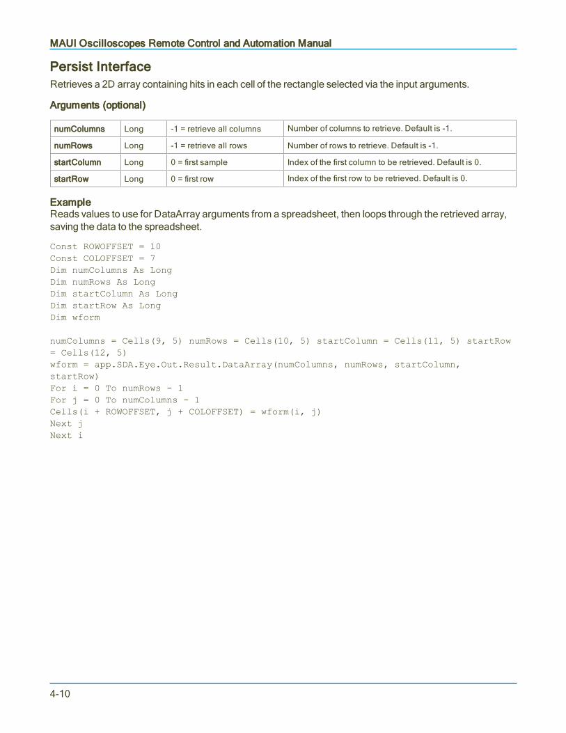
MAUI Oscilloscopes Remote Control and Automation Manual
Persist InterfaceRetrieves a 2D array containing hits in each cell of the rectangle selected via the input arguments.
Arguments (optional)
numColumns Long -1 = retrieve all columns Number of columns to retrieve. Default is -1.
numRows Long -1 = retrieve all rows Number of rows to retrieve. Default is -1.
startColumn Long 0 = first sample Index of the first column to be retrieved. Default is 0.
startRow Long 0 = first row Index of the first row to be retrieved. Default is 0.
ExampleReads values to use for DataArray arguments from a spreadsheet, then loops through the retrieved array,saving the data to the spreadsheet.
Const ROWOFFSET = 10Const COLOFFSET = 7Dim numColumns As LongDim numRows As LongDim startColumn As LongDim startRow As LongDim wform
numColumns = Cells(9, 5) numRows = Cells(10, 5) startColumn = Cells(11, 5) startRow= Cells(12, 5)wform = app.SDA.Eye.Out.Result.DataArray(numColumns, numRows, startColumn,startRow)For i = 0 To numRows - 1For j = 0 To numColumns - 1Cells(i + ROWOFFSET, j + COLOFFSET) = wform(i, j)Next jNext i
4-10
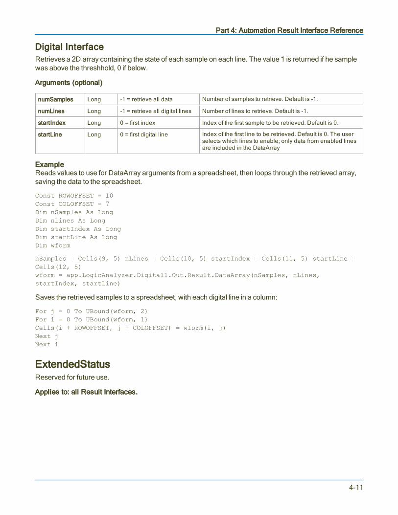
Part 4: Automation Result Interface Reference
Digital InterfaceRetrieves a 2D array containing the state of each sample on each line. The value 1 is returned if he samplewas above the threshhold, 0 if below.
Arguments (optional)
numSamples Long -1 = retrieve all data Number of samples to retrieve. Default is -1.
numLines Long -1 = retrieve all digital lines Number of lines to retrieve. Default is -1.
startIndex Long 0 = first index Index of the first sample to be retrieved. Default is 0.
startLine Long 0 = first digital line Index of the first line to be retrieved. Default is 0. The userselects which lines to enable; only data from enabled linesare included in the DataArray
ExampleReads values to use for DataArray arguments from a spreadsheet, then loops through the retrieved array,saving the data to the spreadsheet.
Const ROWOFFSET = 10Const COLOFFSET = 7Dim nSamples As LongDim nLines As LongDim startIndex As LongDim startLine As LongDim wform
nSamples = Cells(9, 5) nLines = Cells(10, 5) startIndex = Cells(11, 5) startLine =Cells(12, 5)wform = app.LogicAnalyzer.Digital1.Out.Result.DataArray(nSamples, nLines,startIndex, startLine)
Saves the retrieved samples to a spreadsheet, with each digital line in a column:
For j = 0 To UBound(wform, 2)For i = 0 To UBound(wform, 1)Cells(i + ROWOFFSET, j + COLOFFSET) = wform(i, j)Next jNext i
ExtendedStatusReserved for future use.
Applies to: all Result Interfaces.
4-11

MAUI Oscilloscopes Remote Control and Automation Manual
FirstEventTimeAbsolute trigger time of the acquisition, or the time of the first trigger in an acquisition that utilizes multiplesweeps. Examples of multi-sweep acquisitions are Sequence Mode and when a source channel isconfigured for pre-processor averaging. Times are returned encoded as a currency value (VT_CY) within avariant, which allows the use of the full 64-bit resolution of the timestamp value. Values are referenced to 1stJan 2000, with 1ns resolution. Note that VT_CY values are stored as 64-bit (8 byte) two's complementintegers, scaled by 10,000 to give a fixed-point number with 15 digits to the left of the decimal point, and 4digits after. See the example for details on decoding FirstEventTime as well as other properties that returntimes, such as LastEventTime and UpdateTime.
Applies to: all Result Interfaces
Dim FirstEventTimeDim TimeString as StringFirstEventTime = app.Acquisition.C1.Out.Result.FirstEventTimetimeString = DecodeTimeProperty(FirstEventTime)
' Decode the FirstEventTime, LastEventTime and UpdateTime properties.
Function DecodeTimeProperty(ByVal EventTime) As String
Dim days, thedate, hours, thehour, minutes, theminute, secondsDim outstring As Stringdays = EventTime / (86400 * 100000#)thedate = DateAdd("d", days, "1-Jan-00")hours = (days - Int(days)) * 24thehour = Int(hours)minutes = (hours - thehour) * 60theminute = Int(minutes)seconds = (minutes - theminute) * 60
' Format output string:
DecodeTimeProperty = thedate & " " & thehour & ":" & theminute & ":" &seconds
End Function
FirstPopulatedBinIndex of the first populated bin. (The first bin of the histogram is bin 0).
Applies to: Histogram
Dim FirstPopulatedBin as IntegerFirstPopulatedBin = app.Math.F1.Out.Result.FirstPopulatedBin
4-12

Part 4: Automation Result Interface Reference
HorizontalFrameStartCoordinate of the left edge of the graticule containing the trace relative to the trigger time, which is at time =0.
Applies to: Digital, Histogram, Persist, Waveform, XY
Dim XFrameStart As DoubleXFrameStart = app.Acquisition.C1.Out.Result.HorizontalFrameStart
HorizontalFrameStopCoordinate of the right edge of the graticule containing the trace relative to the trigger time, which is at time =0.
Applies to: Digital, Histogram, Persist, Waveform, XY
Dim XFrameStop As DoubleXFrameStop = app.Acquisition.C1.Out.Result.HorizontalFrameStop
HorizontalOffsetTime of the first sample. Note that the first sample is typically just off screen, to the left of the grid. Use thisvalue when calculating the time for each sample.
Applies to: Digital, Histogram, Persist, Waveform, XY
Dim HorizontalOffset As DoubleHorizontalOffset = app.Acquisition.C1.Out.Result.HorizontalOffset
Dim HorizontalPerStep As DoubleHorizontalPerStep = app.Acquisition.C1.Out.Result.HorizontalPerStep
Dim SampleTime as DoubleDim i as LongFor i = 0 to numPoints-1SampleTime = HorizontalPerStep * i + HorizontalOffsetNext
For a more complete example, see the Waveform example in DataArray as well as the functionGetDataArray_Click.
HorizontalPerColumnDifference in the horizontal coordinate of adjacent columns (typically in seconds). UseHorizontalPerColumn to determine the timing information for each column of the DataArray.
Applies to: Persist
Dim HorizontalPerColumn As DoubleHorizontalPerColumn = app.SDA.Eye.Out.Result.HorizontalPerColumn
4-13

MAUI Oscilloscopes Remote Control and Automation Manual
HorizontalPerStepTime between samples, otherwise known as the sample interval. This is the inverse of the SampleRate.
Applies to: Digital, Histogram, Persist, Waveform, XY
Dim HorizontalPerStep As DoubleHorizontalPerStep = app.Acquisition.C1.Out.Result.HorizontalPerStep
HorizontalResolutionResolution of the readout of horizontal values. Not directly related to the sample period.
Applies to: Digital, Histogram, Persist, Waveform, XY
Dim HorizontalResolution As DoubleHorizontalResolution = app.Acquisition.C1.Out.Result.HorizontalResolution
HorizontalUnitsResolution of the readout of horizontal values. Not directly related to the sample period.
Applies to: Digital, Histogram, Persist, Waveform, XY
Dim HorizontalUnits As StringHorizontalUnits = app.Acquisition.C1.Out.Result.HorizontalUnits
HorizontalVarianceArrayVariant array with the variances from the nominal sample times. Used on WaveExpert oscilloscopes.
Applies to: Waveform, XY
Dim HorizontalUnits As DoubleHorizontalUnits = app.Acquisition.C1.Out.Result.HorizontalUnits
HorizontalVariancesNumber of elements in HorizontalVarianceArray. Used on WaveExpert oscilloscopes.
Applies to: Waveform, XY
Dim HorizontalVarianceArrayHorizontalVarianceArray =app.Acquisition.C1.Out.Result.HorizontalVarianceArray
4-14
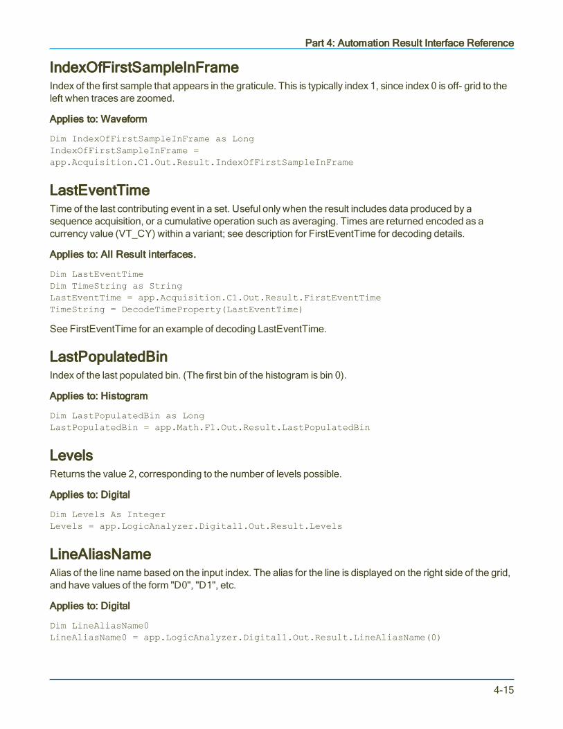
Part 4: Automation Result Interface Reference
IndexOfFirstSampleInFrameIndex of the first sample that appears in the graticule. This is typically index 1, since index 0 is off- grid to theleft when traces are zoomed.
Applies to: Waveform
Dim IndexOfFirstSampleInFrame as LongIndexOfFirstSampleInFrame =app.Acquisition.C1.Out.Result.IndexOfFirstSampleInFrame
LastEventTimeTime of the last contributing event in a set. Useful only when the result includes data produced by asequence acquisition, or a cumulative operation such as averaging. Times are returned encoded as acurrency value (VT_CY) within a variant; see description for FirstEventTime for decoding details.
Applies to: All Result interfaces.
Dim LastEventTimeDim TimeString as StringLastEventTime = app.Acquisition.C1.Out.Result.FirstEventTimeTimeString = DecodeTimeProperty(LastEventTime)
See FirstEventTime for an example of decoding LastEventTime.
LastPopulatedBinIndex of the last populated bin. (The first bin of the histogram is bin 0).
Applies to: Histogram
Dim LastPopulatedBin as LongLastPopulatedBin = app.Math.F1.Out.Result.LastPopulatedBin
LevelsReturns the value 2, corresponding to the number of levels possible.
Applies to: Digital
Dim Levels As IntegerLevels = app.LogicAnalyzer.Digital1.Out.Result.Levels
LineAliasNameAlias of the line name based on the input index. The alias for the line is displayed on the right side of the grid,and have values of the form "D0", "D1", etc.
Applies to: Digital
Dim LineAliasName0LineAliasName0 = app.LogicAnalyzer.Digital1.Out.Result.LineAliasName(0)
4-15

MAUI Oscilloscopes Remote Control and Automation Manual
LineNameName of the line. This can be modified via the user interface or via the propertyapp.LogicAnalyzer.Digital1.LineNames.
Applies to: Digital
Dim LineName0
LineName0 = app.LogicAnalyzer.Digital1.Out.Result.LineName(0)
LinesNumber of lines in the digital bus.
Applies to: Digital
Dim Lines
Lines = app.LogicAnalyzer.Digital1.Out.Result.Lines
MaxHorizontal coordinate of the left edge of the last populated bin. It is equivalent to the hmax parameter.
Applies to: Histogram
Dim Max as doubleMax = app.Math.F1.Out.Result.Max
MaxPopulationMode of the histogram (population of the bin with the most hits).
Applies to: Histogram
Dim MaxPopulation as LongMaxPopulation = app.Math.F1.Out.Result.MaxPopulation
MaxPopulationBinIndex of the bin with the highest population. (The first bin of the histogram is bin 0).
Applies to: Histogram
Dim MaxPopulationBin as IntegerMaxPopulationBin = app.Math.F1.Out.Result.MaxPopulationBin
4-16

Part 4: Automation Result Interface Reference
MaxPopulationInRectanglePopulation of the largest element in the selected rectangle.
Applies to: Persist
Arguments
numColumns Long -1 = use all columns Number of columns to use. Default is -1.
numRows Long -1 = use all rows Number of rows to use. Default is -1.
startColumn Long 0 = first sample Index of the first column. Default is 0.
startRow Long 0 = first row Index of the first row. Default is 0.
ExampleDetermining the maximum population in the rectangle.
Dim numColumns As LongDim numRows As LongDim startColumn As LongDim startRow As LongDim MaxPopulationInRectangle As Long
numColumns = Cells(9, 5)numRows = Cells(10, 5)startColumn = Cells(11, 5)startRow = Cells(12, 5)MaxPopulationInRectangle =app.SDA.Eye.Out.Result.MaxPopulationInRectangle(numColumns,numRows,startColumn,startRow)
Use no arguments to select the full rectangle:
MaxPopulationInRectangle = app.SDA.Eye.Out.Result.MaxPopulationInRectangle
MeanReturns the mean value of the histogam. It is equivalent to the hmean parameter.
Applies to: Histogram
Dim hmean as doublehmean = app.Math.F1.Out.Result.Mean
MinHorizontal coordinate of the left edge of the first populated bin. It is equivalent to the hmin parameter.
Applies to: Histogram
Dim hmin as doublehmin = app.Math.F1.Out.Result.Min
4-17
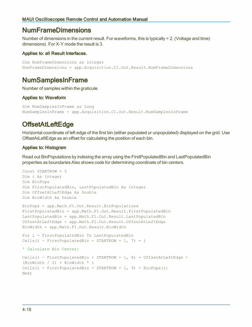
MAUI Oscilloscopes Remote Control and Automation Manual
NumFrameDimensionsNumber of dimensions in the current result. For waveforms, this is typically = 2, (Voltage and time)dimensions). For X-Y mode the result is 3.
Applies to: all Result Interfaces.
Dim NumFrameDimensions as IntegerNumFrameDimensions = app.Acquisition.C1.Out.Result.NumFrameDimensions
NumSamplesInFrameNumber of samples within the graticule.
Applies to: Waveform
Dim NumSamplesInFrame as LongNumSamplesInFrame = app.Acquisition.C1.Out.Result.NumSamplesInFrame
OffsetAtLeftEdgeHorizontal coordinate of left edge of the first bin (either populated or unpopulated) displayed on the grid. UseOffsetAtLeftEdge as an offset for calculating the position of each bin.
Applies to: Histogram
Read out BinPopulations by indexing the array using the FirstPopulatedBin and LastPopulatedBinproperties as boundaries Also shows code for determining coordinate of bin centers.
Const STARTROW = 5Dim i As IntegerDim BinPopsDim FirstPopulatedBin, LastPopulatedBin As IntegerDim OffsetAtLeftEdge As DoubleDim BinWidth As Double
BinPops = app.Math.F1.Out.Result.BinPopulationsFirstPopulatedBin = app.Math.F1.Out.Result.FirstPopulatedBinLastPopulatedBin = app.Math.F1.Out.Result.LastPopulatedBinOffsetAtLeftEdge = app.Math.F1.Out.Result.OffsetAtLeftEdgeBinWidth = app.Math.F1.Out.Result.BinWidth
For i = FirstPopulatedBin To LastPopulatedBinCells(i - FirstPopulatedBin + STARTROW + 1, 7) = i
' Calculate Bin Center:
Cells(i - FirstPopulatedBin + STARTROW + 1, 8) = OffsetAtLeftEdge +(BinWidth / 2) + BinWidth * iCells(i - FirstPopulatedBin + STARTROW + 1, 9) = BinPops(i)Next
4-18
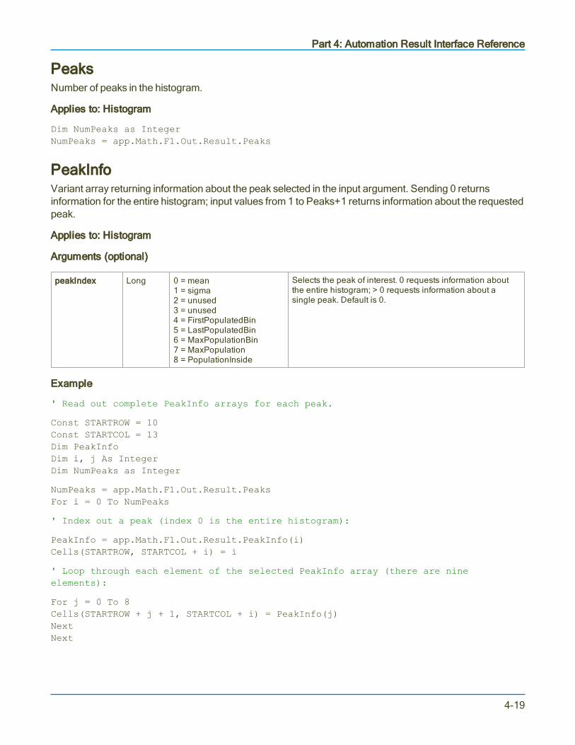
Part 4: Automation Result Interface Reference
PeaksNumber of peaks in the histogram.
Applies to: Histogram
Dim NumPeaks as IntegerNumPeaks = app.Math.F1.Out.Result.Peaks
PeakInfoVariant array returning information about the peak selected in the input argument. Sending 0 returnsinformation for the entire histogram; input values from 1 to Peaks+1 returns information about the requestedpeak.
Applies to: Histogram
Arguments (optional)
peakIndex Long 0 = mean1 = sigma2 = unused3 = unused4 = FirstPopulatedBin5 = LastPopulatedBin6 = MaxPopulationBin7 = MaxPopulation8 = PopulationInside
Selects the peak of interest. 0 requests information aboutthe entire histogram; > 0 requests information about asingle peak. Default is 0.
Example
' Read out complete PeakInfo arrays for each peak.
Const STARTROW = 10Const STARTCOL = 13Dim PeakInfoDim i, j As IntegerDim NumPeaks as Integer
NumPeaks = app.Math.F1.Out.Result.PeaksFor i = 0 To NumPeaks
' Index out a peak (index 0 is the entire histogram):
PeakInfo = app.Math.F1.Out.Result.PeakInfo(i)Cells(STARTROW, STARTCOL + i) = i
' Loop through each element of the selected PeakInfo array (there are nineelements):
For j = 0 To 8Cells(STARTROW + j + 1, STARTCOL + i) = PeakInfo(j)NextNext
4-19

MAUI Oscilloscopes Remote Control and Automation Manual
PopulationInsidePopulation of the histogram for events contained within the number of bins configured.
Applies to: Histogram
Dim PopInside as LongPopInside = app.Math.F1.Out.Result.PopulationInside
PopulationOfRectanglePopulation of the selected rectangle.
Applies to: Persist
Arguments
numColumns Long -1 = retrieve all columns Number of columns to retrieve. Default is -1.
numRows Long -1 = retrieve all rows Number of rows to retrieve. Default is -1.
startColumn Long 0 = first sample Index of the first column to be retrieved. Default is 0.
startRow Long 0 = first row Index of the first row to be retrieved. Default is 0.
Example
Dim numColumns As LongDim numRows As LongDim startColumn As LongDim startRow As LongDim PopulationOfRectangle As Long
numColumns = Cells(9, 5)numRows = Cells(10, 5)startColumn = Cells(11, 5)startRow = Cells(12, 5)
PopulationOfRectangle =app.SDA.Eye.Out.Result.PopulationOfRectangle(numColumns,numRows,startColumn,startRow)PopulationOfRectangle = app.SDA.Eye.Out.Result.PopulationOfRectangle(numColumns,numRows,startColumn,startRow)
PopulationOverPopulation of the events greater than the last bin.
Applies to: Histogram
Dim PopOver as LongPopOver = app.Math.F1.Out.Result.PopulationOver
4-20

Part 4: Automation Result Interface Reference
PopulationUnderPopulation of the events less than the first bin.
Applies to: Histogram
Dim PopUnder as LongPopUnder = app.Math.F1.Out.Result.PopulationUnder
RMSRMS value of the histogram. Equivalent to the parameter hrms.
Applies to: Histogram
Dim hRMS as DoublehRMS = app.Math.F1.Out.Result.RMS
RowsNumber of rows in the DataArray (Persist) or in the table. Typically equal to 256 for Persist waveforms. ForTables, the result can vary depending on the application.
Applies to: Persist, Table
Dim Rows As IntegerRows = app.SDA.Eye.Out.Result.Rows
SamplesNumber of samples in the waveform. For the Waveform and XY interface, this is typically the number ofsamples configured for the acquisition (e.g. 500) plus 2. The additional two points are off-grid, one on eachside. For the Digital interface, this is the number of samples in each digital line + 1.
Applies to: Digital, Waveform, XY
Dim Samples as LongSamples = app.Acquisition.C1.Out.Result.Samples
SdevStandard deviation of the histogram. Equivalent to the parameter hsdev.
Applies to: Histogram
Dim hsdev as Doublehsdev = app.Math.F1.Out.Result.Sdev
4-21

MAUI Oscilloscopes Remote Control and Automation Manual
StatusResult status. Status is returned as a decimal value, but should be treated like a register with the following bitvalues. See the example for decoding the Status result.
64-bit Hex VT_Decimal Status Description
Value shown inXStreamBrowser
Value returnedfrom Statusproperty
0x1 0.0001 Invalid result Indicate that this Result cannot be used for anycalculation.
0x2 0.0002 Data overflow Result contains Overflow data or is calculated from aResult containing Overflows.
0x4 0.0004 Data underflow Result contains Underflow data or is calculated froma Result containing Underflows.
0x8 0.0008 Some values areundefined
Result contains some values or data that areundefined.
0x10 0.0016 Less than Actual value is likely to be less than the calculatedvalue. Mostly used for parameter measurements.
0x20 0.0032 Greater than Actual value is likely to be greater than the calculatedvalue. Mostly used for parameter measurements.
0x40 0.0064 Not a pulse Analyzed signal is not recognized as a pulse; mostlyused for pulse parameter measurements.
0x80 0.0128 Not cyclic Contains some values measured on non-cyclicsignal.
0x100 0.0256 Data averaged Calculated value is the result of an average ofmultiple measurements.
0x200 0.0512 Unlocked PLL Unlocked PLL
0x400 0.1024 Other error Indicates some other error condition, usuallyaccompanied by a processor-specific statusdescription.
0x800 0.2048 Other warning Indicates some other warning condition, usuallyaccompanied by a processor-specific statusdescription.
0x1000 0.4096 Other info Indicates some other informative condition, usuallyaccompanied by a processor-specific statusdescription.
0x2000 0.8192 Cumulative result Cumulative processing somewhere in the chain
0x4000 to0x200000
1.6384 to209.7152
Reserved
0x400000 419.4304 Not an NRZ Eye Not an NRZ Eye
0x800000 838.8608 Not an RZ Eye Not an RZ Eye
0x1000000 to0x80000000
1677.7216 to214748.3648
Reserved
4-22

Part 4: Automation Result Interface Reference
64-bit Hex VT_Decimal Status Description
0x100000000 429496.7296 Inputs incompatible Some incompatibility exists between inputs (e.g.units, frame, sample rate)
0x200000000 858993.4592 Algorithm limitsreached
Algorithm couldn't converge or some otheralgorithmic limitation reached.
0x400000000 1717986.918 Bad settings Combination of settings isn't correct.
0x800000000 3435973.837 Too little data Not enough data to accurately perform calculation.
0x1000000000 6871947.674 Too much data Too much data to perform calculation.
0x2000000000 13743895.35 Requires uniformhorizontal interval
Uniform horizontal interval required.
0x4000000000 27487790.69 Bad units Incorrect or invalid units
0x8000000000 54975581.39 Data range too low Range of data values is too close to the resolution(e.g. bad signal to noise ratio).
0x10000000000 109951162.8 Data undersampled Sample rate too low
0x20000000000 219902325.6 Poor statistics Too few samples (e.g., to populate a data histogramto have enough statistics).
0x40000000000 439804651.1 Slow transition time Transition time too slow (e.g., JTA time measurementaccuracy for clock that requires fast edges).
0x80000000000 879609302.2 Data resampled Data is resampled
0x100000000000 1759218604 Data interpolated Data is interpolated (e.g., interpolating missing pointsin RIS).
0x200000000000 3518437209 Measurement scaleimprecise
If all the data falls in the same histogram bin, one linefor trend, one pixel for XY, etc.
0x400000000000 7036874418 No data available Data not available (e.g., processing inputsdisconnected or clear sweeps on cumulativeprocessing).
0x800000000000 14073748836 Some accumulatedresults invalid
One or more results or values within the accumulatedresult were invalid and were skipped.
0x1000000000000 28147497671 Insufficient Memory Memory limitations reached, attempted allocationsfailed.
0x2000000000000 56294995342 Channel not active Source channel inactive.
0x4000000000000 1.1259E+11 Use status description (custom string)
0x8000000000000 to0x8000000000000000
Reserved
StatusDescriptionDescription for each status code. See the above table.
4-23

MAUI Oscilloscopes Remote Control and Automation Manual
SweepsNumber of sweeps used for results that are based on multiple sweeps, such as averages, histograms, eyediagrams, etc.
Applies to: Digital, Histogram, Persist, Waveform, XY
Dim Sweeps as LongSweeps = app.Acquisition.C1.Out.Result.Sweeps
TopHorizontal coordinate of the rightmost of the two most populated histogram peaks. It is equivalent to theparamater htop.
Applies to: Histogram
Dim htop as Doublehtop = app.Math.F1.Out.Result.Top
UniformIntervalReturns if the samples are evenly spaced in time. Currently always true.
Applies to: Digital
UpdateTimeIndicates the time that particular result was most recently updated. Often, this property will show the samevalue as LastEventTime, but for traces such as memories (M1, M2, etc) this will be the time that thewaveform was stored to the memory trace. Times are returned encoded as a currency value (VT_CY)within a variant; see description for FirstEventTime for decoding details.
Applies to: all Result Interfaces.
Dim UpdateTimeDim TimeString as StringUpdateTime = app.Memory.M1.Out.Result.UpdateTimeTimeString = DecodeTimeProperty(UpdateTime)
See FirstEventTime for the code for the function DecodeTimeProperty, which is the example of decodingUpdateTime.
4-24

Part 4: Automation Result Interface Reference
ValueValue of a parameter or of a statistic in the measurement system. When the scope has no result, it will show"---" in the measure table. When this is displayed, the Value property is not accessible. Error handling shouldbe employed to catch errors that may occur.
Use the On Error Resume Next statement to handle situations where a measurement is not available, suchas attempting to read back the frequency of a DC level, or trying to read the Sdev statistic when there is only1 measurement.
Applies to: Param
' Readout all elements of the measurement parameter for P1On Error Resume NextDim Value, Mean, Min, Max, Sdev, Num As DoubleValue = app.measure.p1.out.Result.ValueMean = app.measure.p1.Mean.Result.ValueMin = app.measure.p1.Min.Result.ValueMax = app.measure.p1.Max.Result.ValueSdev = app.measure.p1.Sdev.Result.ValueNum = app.measure.p1.Num.Result.Value
4-25

MAUI Oscilloscopes Remote Control and Automation Manual
ValueArrayApplies to: Param
Description: Retrieves a 1D array of values, typically used to return measurement results for multi-valueparameters such as Period, Frequency, TIE@level, etc. ValueArray can also return the start time, stop time,and status (edge polarity) of each measurement taken in the sweep.
Arguments
numSamples Long -1 = retrieve all data Number of results to be retrieved. Default is -1.
startIndex Long 0 = first result Index of the first result to be retrieved. Default is 0.
valueType Integer(enum)
1 = parameter value2 = measurement start time4 = measurement stop time8 = status value
Determines the value to read back. Default is 1. Use Status(8) to determine if edge measurements are of positive ornegative polarity.
Example
To return multiple properties for a given parameter, set the valueType argument to the sum of the desiredproperties. For example, to return both the parameter value (1) and the stop time (4), set valueType to 5.
Use the On Error Resume Next statement to handle situations where no measurements were taken. Thescope will show "---" when there is no result to read back.
Const ROWOFFSET = 16Const COLOFFSET = 2Dim numValues As LongDim startIndex As LongDim valueType As IntegerDim valArray
numValues = Cells(9, 5) startIndex = Cells(10, 5)
valArray = app.measure.p1.out.Result.ValueArray(numSamples,startIndex,1)
startTimes = app.measure.p1.out.Result.ValueArray(numSamples,startIndex,2)
stopTimes = app.measure.p1.out.Result.ValueArray(numSamples,startIndex,4)
statusVals = app.measure.p1.out.Result.ValueArray(numSamples,startIndex,8)
Dim Value, Mean, Min, Max, Sdev, Num As DoubleFor i = 0 To UBound(valArray)Cells(i + ROWOFFSET, COLOFFSET) = iCells(i + ROWOFFSET, COLOFFSET + 1) = valArray(i)Cells(i + ROWOFFSET, COLOFFSET + 2) = startTimes(i)Cells(i + ROWOFFSET, COLOFFSET + 3) = stopTimes(i)Cells(i + ROWOFFSET, COLOFFSET + 4) = statusVals(i)Next i
4-26
Part 4: Automation Result Interface Reference
VerticalFrameStartVertical coordinate of the bottom edge of the graticule containing the trace.
Applies to: Digital, Histogram, Persist, Waveform, XY
Dim YFrameStart As DoubleYFrameStart = app.Acquisition.C1.Out.Result.VerticalFrameStart
VerticalFrameStopVertical coordinate of the top edge of the graticule containing the trace.
Applies to: Digital, Histogram, Persist, Waveform, XY
Dim YFrameStop As DoubleYFrameStop = app.Acquisition.C1.Out.Result.VerticalFrameStop
VerticalMaxPossibleReturns the maximum voltage that can be returned.
Applies to: Waveform
Dim VerticalMaxPossible As DoubleVerticalMaxPossible = app.Acquisition.C1.Out.Result.VerticalMaxPossible
VerticalMinPossibleReturns the minimum voltage that can be returned.
Applies to: Waveform
Dim VerticalMinPossible As DoubleVerticalMinPossible = app.Acquisition.C1.Out.Result.VerticalMinPossible
VerticalOffsetPotential difference between ground and the center of the screen. With VerticalOffset = +50 mV, the centerof the screen represents -50 mV: with an offset of -21mV, the center represents +21 mV. (i.e., centerlinevoltage + VerticalOffset = 0)
Applies to: Persist, Waveform
Dim VerticalOffset As DoubleVerticalOffset = app.Acquisition.C1.Out.Result.VerticalOffset
4-27

MAUI Oscilloscopes Remote Control and Automation Manual
VerticalPerRowReturns the increment of the vertical coordinate between rows (typically in volts). Use VerticalPerRow todetermine the voltage information for each row of the DataArray.
Applies to: Persist
Dim VerticalPerRow As DoubleVerticalPerRow = app.SDA.Eye.Out.Result.VerticalPerRow
VerticalPerStepSmallest step size in the numerical values that can be read out from the DataArray, which utilizes 16-bitsigned integer values. Note that the vertical range is almost exactly 65536 * VerticalPerStep. (SeeVerticalMaxPossible and VerticalMinPossible.)
Applies to: Waveform
Dim VerticalPerStep as DoubleVerticalPerStep = app.Acquisition.C1.Out.Result.VerticalPerStep
VerticalResolutionVertical resolution of the Y coordinate, which is the actual smallest difference that can be practicallyresolved. Using averaging can improve the resolution by the square root of the number of sweeps in theaverage. For example, if 16 averages are set via pre-processor averaging or by using the Average mathfunction, the resolution is improved by a factor of 4. For 100 sweeps it improves by a factor of 10.
Applies to: Param, Waveform
Dim VerticalResolution as DoubleVerticalResolution = app.Acquisition.C1.Out.Result.VerticalResolution
VerticalUnitsUnits used for the vertical axis. Typically V for Volts, but other units are possible.
Applies to: Histogram, Param, Persist, Waveform
Dim VerticalUnits as StringVerticalUnits = app.Acquisition.C1.Out.Result.VerticalUnits
XFrameStartCoordinate of the left edge of the XY graticule.
Applies to: XY
Dim XFrameStart As DoubleXFrameStart = app.Math.XY.Out.Result.XFrameStart
4-28

Part 4: Automation Result Interface Reference
XFrameStopCoordinate of the right edge of the XY graticule.
Applies to: XY
Dim XFrameStop As DoubleXFrameStop = app.Math.XY.Out.Result.XFrameStop
XMaxPossibleMaximum possible value of the X coordinate
Applies to: XY
Dim XMaxPossible As DoubleXMaxPossible = app.Math.XY.Out.Result.XMaxPossible
XMinPossibleMinimum possible value of the X coordinate
Applies to: XY
Dim XMinPossible As DoubleXMinPossible = app.Math.XY.Out.Result.XMinPossible
XOffsetPotential difference between ground and the horizontal center of the XY grid. For example, withVerticalOffset of the X coordinate’s source trace = +50 mV, the center of the screen represents -50 mV: withan offset of -21mV, the center represents +21 mV. (I.e. centerline voltage + VerticalOffset = 0)
Applies to: XY
Dim XOffset As DoubleXOffset = app.Math.XY.Out.Result.XOffset
XPerStepSmallest step size in the numerical values that can be read out from the DataArray utilzing 16 bit signedinteger values. Note that the X range is just about 65536 * XPerStep. (See XMaxPossible andXMinPossible.)
Applies to: XY
Dim XPerStep As DoubleXPerStep = app.Math.XY.Out.Result.XPerStep
4-29

MAUI Oscilloscopes Remote Control and Automation Manual
XResolutionVertical resolution of the X coordinate, which is the actual smallest difference that can be practicallyresolved. Using averaging can improve the resolution by the square root of the number of sweeps in theaverage. For example, if 16 averages are set via pre-processor averaging or by using the Average mathfunction, the resolution is improved by a factor of 4. For 100 sweeps it improves by a factor of 10.
Applies to: XY
Dim XResolution As DoubleXResolution = app.Math.XY.Out.Result.XResolution
XUnitsUnits of the X coordinate. Typically V for Volts, unless a current probe is in use, in which case it is A forAmperes.
Applies to: XY
Dim XUnits As StringXUnits = app.Math.XY.Out.Result.XUnits
YFrameStartCoordinate of the bottom edge of the XY graticule.
Applies to: XY
Dim YFrameStart As DoubleYFrameStart = app.Math.XY.Out.Result.YFrameStart
YFrameStopCoordinate of the top edge of the XY graticule.
Applies to: XY
Dim YFrameStart As DoubleYFrameStart = app.Math.XY.Out.Result.YFrameStart
YMaxPossibleMinimum possible value of the Y coordinate.
Applies to: XY
Dim YMaxPossible As DoubleYMaxPossible = app.Math.XY.Out.Result.YMaxPossible
4-30

Part 4: Automation Result Interface Reference
YMinPossibleMinimum possible value of the Y coordinate.
Applies to: XY
Dim YMinPossible As DoubleYMinPossible = app.Math.XY.Out.Result.YMinPossible
YOffsetPotential difference between ground and the vertical center of the XY grid. For example, with VerticalOffsetof the Y coordinate’s source trace = +50 mV, the center of the screen represents -50 mV: with an offset of -21mV, the center represents +21 mV. (centerline voltage + VerticalOffset = 0)
Applies to: XY
Dim YOffset As DoubleYOffset = app.Math.XY.Out.Result.YOffset
YPerStepSmallest step size in the numerical values that can be read out from the DataArray utilzing 16 bit signedinteger values. Note that the Y range is just about 65536 * YPerStep. (See YMaxPossible andYMinPossible.)
Applies to: XY
Dim YPerStep As DoubleYPerStep = app.Math.XY.Out.Result.YPerStep
YResolutionVertical resolution of the Y coordinate, which is the actual smallest difference that can be practicallyresolved. Using averaging can improve the resolution by the square root of the number of sweeps in theaverage. If 16 sweeps are averaged via pre-processor averaging or by using the Average math function, theresolution is improved by a factor of 4; over 100 sweeps, it improves by a factor of 10.
Applies to: XY
Dim YResolution As DoubleYResolution = app.Math.XY.Out.Result.YResolution
YUnitsUnits of the Y coordinate. Typically V for Volts, Typically V for Volts, unless a current probe is in use, in whichcase it is A for Amperes.
Applies to: XY
Dim YUnits As StringYUnits = app.Math.XY.Out.Result.YUnits
4-31

MAUI Oscilloscopes Remote Control and Automation Manual
4-32
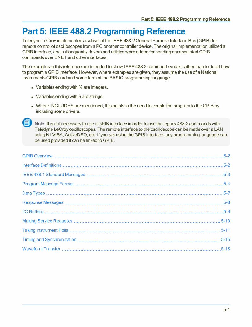
Part 5: IEEE 488.2 Programming Reference
Part 5: IEEE 488.2 Programming ReferenceTeledyne LeCroy implemented a subset of the IEEE 488.2 General Purpose Interface Bus (GPIB) forremote control of oscilloscopes from a PC or other controller device. The original implementation utilized aGPIB interface, and subsequently drivers and utilities were added for sending encapsulated GPIBcommands over ENET and other interfaces.
The examples in this reference are intended to show IEEE 488.2 command syntax, rather than to detail howto program a GPIB interface. However, where examples are given, they assume the use of a NationalInstruments GPIB card and some form of the BASIC programming language:
l Variables ending with % are integers.
l Variables ending with $ are strings.
l Where INCLUDES are mentioned, this points to the need to couple the program to the GPIB byincluding some drivers.
Note: It is not necessary to use a GPIB interface in order to use the legacy 488.2 commands withTeledyne LeCroy oscilloscopes. The remote interface to the oscilloscope can be made over a LANusing NI-VISA, ActiveDSO, etc. If you are using the GPIB interface, any programming language canbe used provided it can be linked to GPIB.
GPIB Overview 5-2
Interface Definitions 5-2
IEEE 488.1 Standard Messages 5-3
Program Message Format 5-4
Data Types 5-7
Response Messages 5-8
I/O Buffers 5-9
Making Service Requests 5-10
Taking Instrument Polls 5-11
Timing and Synchronization 5-15
Waveform Transfer 5-18
5-1

MAUI Oscilloscopes Remote Control and Automation Manual
GPIB OverviewThe IEEE 488.2 General Purpose Interface Bus (GPIB) is similar to a standard computer bus. While thecomputer interconnects circuit cards by means of a backplane bus, the GPIB interconnects independentdevices (oscilloscopes and computers, for example) by means of a cable bus.
The GPIB carries both interface and program messages.
l Interface messages manage the bus itself. They perform functions such as the initialization,addressing and unaddressing of devices, and the setting of remote and local modes.
l Program messages (often called device-dependent messages) contain programming instructions,status information, and data—such as oscilloscope set up instructions and measurement data.
Devices connected by GPIB can be listeners, talkers, or controllers. A talker sends program messages toone or more listeners, while a controller manages the flow of information on the bus by sending interfacemessages to the devices.
When GPIB is implemented with Teledyne LeCroy oscilloscopes, the oscilloscope can be a talker or listener,but not a controller. The controller functions are handled by another instrument, usually a PC. The hostcomputer must be able to play all three roles.
The details of how the controller configures the GPIB for different functions is specific to each GPIB interfaceand can be found in the GPIB interface manufacturer's manual.
Note: VISA and ActiveDSO drivers perform all GPIB interface functionality, so you do not need tolearn the lower-level details of the GPIB bus to use the IEEE 488.2 commands.
Interface DefinitionsTeledyne LeCroy oscilloscope interface capabilities include the following IEEE 488.1 definitions:
l AH1 - Complete Acceptor Handshakel SH1 - Complete Source Handshakel L4 - Partial Listener Functionl T5 - Complete Talker Functionl SR1 - Complete Service Request Functionl RL1 - Complete Remote/Local Functionl DC1 - Complete Device Clear Functionl DT1 - Complete Device Triggerl PP1 - Parallel Polling: remote configurablel C0 - No Controller Functionsl E2 - Tri-state Drivers
5-2

Part 5: IEEE 488.2 Programming Reference
IEEE 488.1 Standard MessagesThe IEEE 488.1 standard (of which IEEE 488.2 can be considered an extension) specifies not only themechanical and electrical aspects of the GPIB, but also the low-level transfer protocol. For instance, itdefines how a controller addresses devices, turns them into talkers or listeners, resets them, or puts them inthe remote state. Such interface messages are executed through the interface management lines of theGPIB, usually with ATN true. All these messages except GET are executed immediately upon receipt.
The Command Reference in this manual does not contain a command for clearing the input or outputbuffers or for setting the oscilloscope to the remote state because such commands are already specified asIEEE 488.1 standard messages. Refer to the GPIB interface manual of the host controller as well regardingits support programs, which should contain special calls for the execution of these messages.
Note: In addition to the IEEE 488.1 interface message standards, the IEEE 488.2 standardspecifies certain standardized program messages (or command headers). They are identified in theCommand Reference section with a leading asterisk * .
Remote Enable, RWLSTeledyne LeCroy oscilloscopes do not lock out any local controls when placed in the remote state, or inRWLS. They always accept remote and local control inputs (unless the remote control capability is turnedoff).
Device Clear, DCLIn response to a universal Device CLear (DCL) or a Selected Device Clear message (SDC), theoscilloscope clears the input or output buffers, cancels the interpretation of the current command (if any) andclears pending commands. However, status registers and status-enable registers are not cleared. AlthoughDCL will have an immediate effect, it can take several seconds to execute if the oscilloscope is busy.
Group Execute TriggerThe Group Execute Trigger message (GET) causes the oscilloscope to arm the trigger system, and isfunctionally identical to the *TRG command.
Interface Clear, IFCThe Interface Clear message (IFC) initializes the GPIB but has no effect on the operation of theoscilloscope.
5-3

MAUI Oscilloscopes Remote Control and Automation Manual
Program Message FormatGPIB program messages are composed of commands and/or queries separated by semicolons and endingwith a terminator:
<command/query>; . . . ;<command/query> <terminator>
Note: A terminator is required but is not shown in examples because usually it is automaticallyadded by the interface driver routine writing to GPIB.
The general form of a command or a query consists of an optional header path, followed by a commandheader, followed by one or several parameters:
[header path:]<header>[?] [<parameter>,...,<parameter>]
The following rules apply:
l There is a space between the header and the first parameter.
l Commas separate parameters.
l The question mark [?] is optional and turns the command into a query.
l You can use uppercase or lowercase characters, or both, in program messages; the oscilloscopedoes not distinguish between them. An exception is the MESSAGE command, which can faithfullytransmit strings containing both lowercase and uppercase letters.
Commands and queries are executed in the order in which they are received through remote transmission.
Commands and QueriesProgram messages are made up of one or more commands or queries:
o Commands direct the oscilloscope to change its state, for example, its timebase or verticalsensitivity.
o Queries ask the oscilloscope to return data, such as a measurement, register value or stateinformation. They are recognized by ? following the header.
Usually, you will use the same characters for a command and a query, the query being identified by "?" asthe final character. The portion of the header preceding the question mark is repeated as part of theresponse message.
For example, to change the timebase to 2 ms/div, send this command to the oscilloscope:
TIME_DIV 2E-3
To ask the oscilloscope about its timebase setting, send this query:
TIME_DIV?
5-4

Part 5: IEEE 488.2 Programming Reference
You will receive a response like:
TIME_DIV 2E-3 S
Tip: Querying can be a useful way of generating a command that is known to be correct, and theresponse copied straight into your program. The repeated header text can be suppressed with thecommand COMM_HEADER.
Header pathCertain commands or queries apply to a subsection of the oscilloscope, such as a single input channel ortrace. These commands must have their headers prefixed with a path name indicating the recipient of thecommand.
The header path normally consists of a two-letter path name followed by a colon : immediately precedingthe command header.
EXAMPLE: C1:OFST -300 MV is a command to set the offset of Channel 1 to -300 mV.
The target waveform trace is specified using the following header path names:
Header Path Name Waveform Trace
C1 to Cn Channels
M1 to Mn Memory traces
F1 to Fn Math function traces
TA, TB, TC, TD Equivalent to F1 through F4, for backward compatibility with legacy instruments
EX, EX10, EX5 External trigger
LINE LINE source for trigger
Note: When older trace names are used, such as TC, the oscilloscope response shows the newlabel equivalent. So, a TC header path query would return as an F3 header path response.
Header paths need only need be specified once until the path changes. Subsequent commands withoutheader paths are assumed to refer to the most recently defined path.
Although optional, it's recommended to always use header paths to minimize the risk of error if thecommand order changes.
5-5

MAUI Oscilloscopes Remote Control and Automation Manual
HeaderThe header is the mnemonic form of the operation to be performed by the oscilloscope, what we usuallythink of as the command or query. Most command and query headers have a long form, which allows themto be read more easily by people, and a short form for better transfer and decoding speed. The two are fullyequivalent and can be used interchangeably.
EXAMPLE: TRIG_MODE AUTO and TRMD AUTO are two separate but equivalent commands forswitching to the automatic trigger mode.
Some command or query mnemonics are imposed by the IEEE 488.2 standard. They are standardized sodifferent oscilloscopes present the same programming interface for similar functions. All these mnemonicsbegin with an asterisk *.
ParametersWhenever a command or query uses additional parameter values, the values are expressed as ASCIIcharacters.
ASCII data can take the form of character, numeric, string, or block data. See Data Types.
There is a single exception: the transfer of waveforms with the WAVEFORM command/query, where thewaveform can be expressed as a sequence of binary data values. Refer to the Waveform Transfer topic fordetails.
TerminatorThe oscilloscope does not decode an incoming program message before receiving its terminator unless themessage is longer than the 256 byte input buffer (at which point the oscilloscope starts analyzing themessage once the buffer is full).
Most interface driver software will send the program message with the required terminators. You do nothave to include them in your programs. See I/O Buffers for more information.
5-6
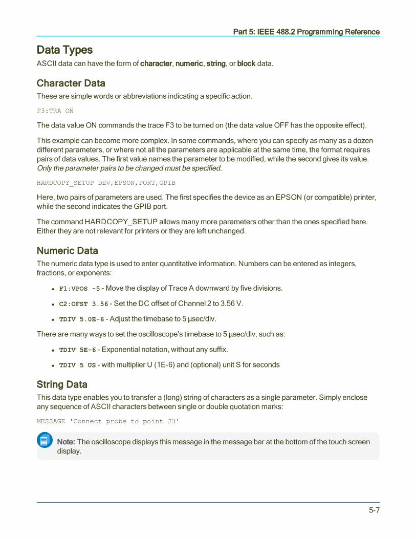
Part 5: IEEE 488.2 Programming Reference
Data TypesASCII data can have the form of character, numeric, string, or block data.
Character DataThese are simple words or abbreviations indicating a specific action.
F3:TRA ON
The data value ON commands the trace F3 to be turned on (the data value OFF has the opposite effect).
This example can become more complex. In some commands, where you can specify as many as a dozendifferent parameters, or where not all the parameters are applicable at the same time, the format requirespairs of data values. The first value names the parameter to be modified, while the second gives its value.Only the parameter pairs to be changed must be specified.
HARDCOPY_SETUP DEV,EPSON,PORT,GPIB
Here, two pairs of parameters are used. The first specifies the device as an EPSON (or compatible) printer,while the second indicates the GPIB port.
The command HARDCOPY_SETUP allows many more parameters other than the ones specified here.Either they are not relevant for printers or they are left unchanged.
Numeric DataThe numeric data type is used to enter quantitative information. Numbers can be entered as integers,fractions, or exponents:
l F1:VPOS -5 - Move the display of Trace A downward by five divisions.
l C2:OFST 3.56 - Set the DC offset of Channel 2 to 3.56 V.
l TDIV 5.0E-6 - Adjust the timebase to 5 µsec/div.
There are many ways to set the oscilloscope's timebase to 5 µsec/div, such as:
l TDIV 5E-6 - Exponential notation, without any suffix.
l TDIV 5 US - with multiplier U (1E-6) and (optional) unit S for seconds
String DataThis data type enables you to transfer a (long) string of characters as a single parameter. Simply encloseany sequence of ASCII characters between single or double quotation marks:
MESSAGE 'Connect probe to point J3'
Note: The oscilloscope displays this message in the message bar at the bottom of the touch screendisplay.
5-7
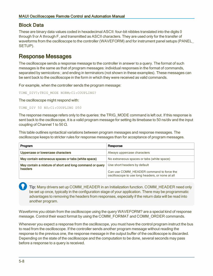
MAUI Oscilloscopes Remote Control and Automation Manual
Block DataThese are binary data values coded in hexadecimal ASCII: four-bit nibbles translated into the digits 0through 9 or A through F, and transmitted as ASCII characters. They are used only for the transfer ofwaveforms from the oscilloscope to the controller (WAVEFORM) and for instrument panel setups (PANEL_SETUP).
Response MessagesThe oscilloscope sends a response message to the controller in answer to a query. The format of suchmessages is the same as that of program messages: individual responses in the format of commands,separated by semicolons ; and ending in terminators (not shown in these examples). These messages canbe sent back to the oscilloscope in the form in which they were received as valid commands.
For example, when the controller sends the program message:
TIME_DIV?;TRIG_MODE NORM;C1:COUPLING?
The oscilloscope might respond with:
TIME_DIV 50 NS;C1:COUPLING D50
The response message refers only to the queries: the TRIG_MODE command is left out. If this response issent back to the oscilloscope, it is a valid program message for setting its timebase to 50 ns/div and the inputcoupling of Channel 1 to 50 Ω.
This table outlines syntactical variations between program messages and response messages. Theoscilloscope keeps to stricter rules for response messages than for acceptance of program messages.
Program Response
Uppercase or lowercase characters Always uppercase characters
May contain extraneous spaces or tabs (white space) No extraneous spaces or tabs (white space)
May contain a mixture of short and long command or queryheaders
Use short headers by default
Can use COMM_HEADER command to force theoscilloscope to use long headers, or none at all
Tip: Many drivers set up COMM_HEADER in an Initialization function. COMM_HEADER need onlybe set up once, typically in the configuration stage of your application. There may be programmaticadvantages to removing the headers from responses, especially if the return data will be read intoanother program.
Waveforms you obtain from the oscilloscope using the query WAVEFORM? are a special kind of responsemessage. Control their exact format by using the COMM_FORMAT and COMM_ORDER commands.
Whenever you expect a response from the oscilloscope, you must have the control program instruct the busto read from the oscilloscope. If the controller sends another program message without reading theresponse to the previous one, the response message in the output buffer of the oscilloscope is discarded.Depending on the state of the oscilloscope and the computation to be done, several seconds may passbefore a response to a query is received.
5-8

Part 5: IEEE 488.2 Programming Reference
Note: Remote command interpretation does not have priority over other oscilloscope activities. Setthe controller I/O timeout conditions to three or more seconds to give the oscilloscope time torespond. An incorrect query will not get a response, but a beep will sound if the Remote ControlAssistant is enabled.
I/O BuffersThe oscilloscope has 256-byte input and output buffers. An incoming program message is not decodedbefore a message terminator has been received.
Valid GPIB terminators are:
l <NL> - New line character, meaning, the ASCII new-line character (decimal value is 10).
l <NL><EOI> - New Line character with a simultaneous <EOI> signal.
l <EOI><EOI> - Signal together with the last character of the program message.
Note: Terminators are often not shown in examples because they are handled by the driversoftware, although they are required. The <NL> <EOI> terminator is always used in responsemessages sent by the oscilloscope to the controller.
However, if the input buffer becomes full (because the program message is longer than the buffer), theoscilloscope starts analyzing the message. In this case, data transmission is temporarily halted, and thecontroller may generate a timeout if the limit was set too low.
5-9

MAUI Oscilloscopes Remote Control and Automation Manual
Making Service RequestsWhen the oscilloscope is used in a remote application, events often occur asynchronously; meaning, atunpredictable times for the host computer. The most common example of this is a trigger wait after theoscilloscope is armed. In such a case, the controller must wait until the acquisition is finished before it canread the acquired waveform.
The simplest way of checking if a certain event has occurred is by either continuously or periodically readingthe status bit associated with it until the required transition is detected.
A more efficient way of detecting events occurring in the oscilloscope is to use Service Request (SRQ). ThisGPIB interrupt line can be used to interrupt program execution in the controller. The controller can thenexecute other programs while waiting for the oscilloscope.
The SRQ bit is latched until the controller reads the Status Byte Register (STB). The action of reading theSTB with the command *STB? clears the register contents except the MAV bit (bit 4) until a new eventoccurs. Service requesting can be disabled by clearing the SRE register with the *SRE 0 command.
Unfortunately, not all interface manufacturers support the programming of interrupt service routines. Inparticular, National Instruments supports only the SRQ bit within the ISTA% status word. This requires youto continuously or periodically check this word, either explicitly or with the function call IBWAIT.
Enabling SRQIn the default state, SRQ is disabled. To enable SRQ, set the Service Request Enable register with the*SRE command, specifying which event should generate an SRQ.
The oscilloscope then interrupts the controller when the selected event(s) occur by asserting the SRQinterface line. If several devices are connected to the GPIB, you may be required to identify whichoscilloscope caused the interrupt by serial polling the various devices.
INR and INBThis event is tracked by the INR register, which is reflected in the SRE register as the INB summary bit inposition 0. Since bit position 0 has the value 1, the command *SRE 1 enables the generation of SRQwhenever the INB summary bit is set.
In addition, the events of the INR register that may be summarized in the INB bit must be specified. Theevent "new signal acquired" corresponds to INE bit 0 (value 1) while the event "return-to-local" is assigned toINE bit 2 (value 4). The total sum is 1 + 4 = 5. So, the command INE 5 is needed:
CMD$ = "INE 5 ; *SRE 1" : CALL IBWRT (SCOPE%, CMD$)
5-10

Part 5: IEEE 488.2 Programming Reference
Taking Instrument PollsYou can regularly monitor state transitions within the oscilloscope by polling selected internal statusregisters.
Four basic polling methods are used to detect the occurrence of a given event: continuous, serial, parallel,and *IST. The simplest of these is continuous polling while the others are appropriate only when interrupt-service routines (servicing the SRQ line) are supported, or multiple devices on GPIB require constantmonitoring.
The following examples accomplish the same goal (determining whether a new acquisition has taken place)in order to emphasize the differences between the polling methods. The examples use board-level GPIBfunction calls. It is assumed that the controller (board) and the oscilloscope (device) are located ataddresses 0 and 4, respectively.
The listener and talker addresses for the controller and the oscilloscope are:
Logic Device Listener Address Talker Address
External Controller 32 (ASCII<space>) 64 (ASCII @)
Oscilloscope 32 + 4 = 36 (ASCII $) 64 + 4 = 68 (ASCII D)
Continuous PollingA status register is continuously monitored until a transition is observed. This is the most straightforwardmethod for detecting state changes, but may not be practical in certain situations, especially with multipledevice configurations.
In the following example, the event "new signal acquired" is observed by continuously polling the InternalState Change Register (INR) until the corresponding bit (in this case bit 0, or value 1) is non-zero, indicatinga new waveform has been acquired. Reading INR clears this at the same time, so there is no need for anadditional clearing action after a non-zero value is detected. The CHDR OFF command instructs theoscilloscope to omit any command headers when responding to a query, simplifying the decoding of theresponse. The oscilloscope then sends "1" instead of "INR 1" as follows:
Example: Continuous PollingCMD$ = "CHDR OFF"CALL IBWRT (SCOPE%, CMD$)MASK% = 1 ' New Signal Bit has value 1DOCMD$ = "INR?"CALL IBWRT (SCOPE%, CMD$)CALL IBRD (SCOPE%, RD$)NEWSIG% = VAL (RD$) AND MASK%LOOP UNTIL NEWSIG% = MASK%
5-11

MAUI Oscilloscopes Remote Control and Automation Manual
Serial PollingSerial polling takes place once the SRQ interrupt line has been asserted, and is only advantageous whenyou are using several oscilloscopes at once. The controller finds which oscilloscope has generated theinterrupt by inspecting the SRQ bit in the STB register of each. Because the service request is based on aninterrupt mechanism, serial polling offers a reasonable compromise in terms of servicing speed in multiple-device configurations.
The following example uses the command INE 1 to enable the event "new signal acquired" for reporting theINR to the INB bit of the status byte STB. The command *SRE 1 enables the INB of the status byte togenerate an SRQ whenever it is set. The function call IBWAIT instructs the computer to wait until one ofthree conditions occurs:
l &H8000 in the mask (MASK%) corresponds to a GPIB error.
l &H4000 to a timeout error.
l &H0800 to the detection of RQS (ReQuest for Service) generated by the SRQ bit.
Whenever IBWAIT detects RQS, it automatically performs a serial poll to find out which oscilloscopegenerated the interrupt. It only exits if a timeout occurs or if the oscilloscope (SCOPE%) generated SRQ.The additional function call IBRSP fetches the value of the status byte, which may be further interpreted. Towork properly, the value of "Disable Auto Serial Polling" must be set to "off" in the GPIB handler (useIBCONF.EXE to check).
Example: Serial PollingCMD$ = "*CLS ; INE 1;*SRE 1"CALL IBWRT (SCOPE%, CMD$)MASK% = &HC800CALL IBWAIT (SCOPE%, MASK%)IF (IBSTA% AND &HC000) <> 0 THEN PRINT "GPIB or Timeout Error" : STOPCALL IBRSP (SCOPE%, SPR%)PRINT "Status Byte =.", SPR%
After the serial poll is completed, the RQS bit in the STB status register is cleared. Note that the other STBregister bits remain set until they are cleared by means of a *CLS command or the oscilloscope is reset. Ifthese bits are not cleared, they cannot generate another interrupt.
5-12

Part 5: IEEE 488.2 Programming Reference
Parallel PollingLike serial polling, this is only useful when several oscilloscopes are connected. The controllersimultaneously reads the Individual STatus bit (IST) of all oscilloscopes to determine which one needsservice. This method allows up to eight different oscilloscopes to be polled at the same time.
When a parallel poll is initiated, each oscilloscope returns a status bit over one of the DIO data lines. Devicesmay respond either individually, using a separate DIO line, or collectively on a single data line. Data-lineassignments are made by the controller using a Parallel Poll Configure (PPC) sequence.
The following example uses the INE 1 command to enable the event "new signal acquired" in the INR forreporting to the INB bit of the status byte STB. The PaRallel poll Enable register (PRE) determines whichevents are summarized in the IST status bit. The command *PRE 1 enables the INB bit (when first set itself)to set the IST bit. Once parallel polling is established, the parallel-poll status is examined until a change ondata bus line DIO2 takes place.
Example: Parallel Polling, Stage 1Enable the INE and PRE registers; configure the controller for parallel poll; instruct the oscilloscope torespond on data line 2 (DIO2) using these commands:
CMD1$ = DSOListenPCTalk$ 'As defined earlierCALL IBCMD (BRD0%, CMD1$)CMD$ = "INE 1;*PRE 1"CALL IBWRT (BRD0%, CMD$)PPE$ = Chr$ (&H5) 'GPIB Parallel Poll EnableMSA9$ = Chr$ (&H69) 'GPIB Secondary Address 9CMD4$ = PPE$ + MSA9$ + UnListen$CALL IBCMD (BRD0%, CMD4$)
Example: Parallel Polling, Stage 2Parallel poll the oscilloscope until DIO2 is set using these commands:
DoCALL IBRPP (BRD0%, PPR%)Loop Until (PPR% AND &H2) = 2
Example: Parallel Polling, Stage 3Disable parallel polling (hex 15) and clear the parallel poll register using these commands:
PPU$ = Chr$ (&H15) 'GPIB Parallel Poll UnconfigureCALL IBCMD (BRD0%, PPU$)CALL IBCMD (BRD0%, CMD1$) 'As defined earlierCMD$ = "*PRE 0" : CALL IBWRT(BRD0%,CMD$):
5-13

MAUI Oscilloscopes Remote Control and Automation Manual
*IST PollingRead the state of the Individual STatus bit (IST) returned during parallel polling by sending the *IST? query.Enable this poll mode, by initializing the oscilloscope for parallel polling by writing into the PRE register.Since *IST emulates parallel polling, apply this method wherever parallel polling is not supported by thecontroller.
In the following example, the command INE 1 enables the event "new signal acquired" in the INR forreporting to the INB bit of the status byte STB. The command *PRE 1 enables the INB bit (when first setitself) to set the IST bit. The command CHDR OFF suppresses the command header in the oscilloscope'sresponse, simplifying the interpretation. The status of the IST bit is then continuously monitored until set bythe oscilloscope:
Example: *IST PollingCMD$ = "CHDR OFF; INE 1; *PRE 1"CALL IBWRT (SCOPE%, CMD$)DOCMD$ = "*IST?"CALL IBWRT (SCOPE%, CMD$)CALL IBRD (SCOPE%, RD$)LOOP UNTIL VAL (RD$) = 1
5-14

Part 5: IEEE 488.2 Programming Reference
Timing and SynchronizationDepending on how your remote program is written, it may be affected by timing changes between differentoscilloscopes. Most timing and synchronization problems are related to changing acquisitions, or thecompletion of analysis after an acquisition occurs.
Say that you change the Offset of C1 while the oscilloscope is in Auto trigger mode, and then use thePAVA? query to read a parameter computed on C1. In newer oscilloscopes, the processing is overlappedwith the next acquisition and, as a consequence, the PAVA? result may have come from the acquisition priorto the offset change.
There are several ways to ensure your program provides correct results when remotely controlling theoscilloscope.
Control the Trigger ModeWhen in Single trigger mode, acquisitions do not overlap. You can use the status registers available in theinstrument, or the *OPC? query and the WAIT command to detect acquisition and processing completion.
When you arm the oscilloscope by sending the TRMD SINGLE command, the instrument automaticallyperforms any necessary calibrations before it acquires any data. These calibrations may take severalseconds, so if you query the status immediately after sending the TRMD SINGLE command, set the GPIB(or remote) timeout to least 10 seconds and prevent a timeout before receiving the correct results.
A case where you may need to use Normal or Auto trigger mode involves the accumulation of manyacquisitions for averaging or histogramming functions. In this case, it is best to stop the acquisitions, set upthe oscilloscope, and then set the trigger mode to Normal when acquiring the data.
A possible alternative would be to use Sequence trigger mode. It is faster, but does require knowing howmany acquisitions to accumulate. This number can be specified and captured using sequence mode.
Reduce CalibrationsWhen operating in Dynamic Calibration mode, the default on older MAUI oscilloscopes, calibrations areperformed whenever your program changes some acquisition settings such as Volts/Div or the number ofactive channels. Calibrations are also performed if the oscilloscope temperature significantly changed. Thecalibrations may be disabled by sending the AUTO_CALIBRATE OFF command. While oscilloscopeperformance may be degraded if the temperature changes and does not self-calibrate, a calibration canalways be forced by issuing the *CAL? command.
Using this forced calibration technique allows you to control their timing so they do not interfere whileacquiring important data.
5-15

MAUI Oscilloscopes Remote Control and Automation Manual
Use Status RegistersStatus registers store a record of events and conditions occurring inside the oscilloscope. Some of theevents recorded include:
l The acquisition of new data
l When processing completes
l When printing (hardcopy) completes
l When an error occurs
Programmers can use the registers to sense the instrument's condition by polling until the desired status bitis set. A status register can be polled by querying its associated remote command (*STB, INR?, *ESR).Alternatively, the oscilloscope can request service from the controller by using the mask registers to selectthe events of interest.
The following procedure shows the steps necessary for acquiring data using the status registers forsynchronization.
1. STOP the acquisition.
2. (Commands to) set up the oscilloscope.
3. Clear status registers.
4. Set up mask register (if needed).
5. ARM or TRMD SINGLE to start the acquisition.
6. Poll status registers or wait for service request.
(Various commands/queries) to read data, cursors, and parameter measurements.
If the data has already been acquired and you want to perform further analysis (math, parameters, cursors),you can proceed as follows:
1. Clear status registers.
2. Set up mask register (if needed).
3. (Commands to) change math functions, parameters, cursors, etc. as required for analysis.
4. Poll status registers or wait for service request.
5. (Commands/queries to) read data, cursors, and parameter measurements.
5-16

Part 5: IEEE 488.2 Programming Reference
Use *OPC? and WAITThe acquisition WAIT command (not to be confused with the IEEE 488.2 standard *WAI command):
l Waits for the acquisition to complete, but does not wait for the processing.
l Allows you to specify an optional timeout so that if the oscilloscope does not trigger, your programdoes not hang.
Note: If you use the timeout method, it is strongly advised to then check the status registers with*OPC? to ensure the oscilloscope actually triggered and any processing has completed.
The *OPC? query returns a 1 when the previous commands have finished. This means you can use thisquery with the WAIT command to synchronize the oscilloscope with your controller, using the procedureshown here:
1. STOP the acquisition.
2. (Commands to) set up the oscilloscope.
3. ARM or TRMD SINGLE to start the acquisition.
4. WAIT for trigger and acquisition to complete.
5. *OPC? to ensure processing is complete.
6. (Commands/queries to) read data, cursors, and measurement parameters.
5-17
MAUI Oscilloscopes Remote Control and Automation Manual
Waveform TransferA waveform can be said to have two main parts:
l Its basic data array: raw data values from the oscilloscope's ADCs (Analog-to-Digital Converters)obtained during the waveform capture.
l The description accompanying this raw data: vertical and horizontal scale or time of day, for example,necessary for a full understanding of the information contained in the waveform.
When these parts are transmitted together, the descriptor comes first. You can access the waveformdescriptive information by remote control using the INSPECT? query, which interprets it in ASCII text form.
Waveform data can then be either:
l Read off the oscilloscope using the WAVEFORM? query
l Written back into the oscilloscope with the WAVEFORM command
Using the STORE and STORE_SETUP commands, you can also store waveform data in preformattedASCII output for popular spreadsheet and math processing packages.
Analog Waveform TemplateYour instrument contains a commented waveform template that provides a detailed description of howanalog waveform data is organized. Use the TEMPLATE? query to access the template file used by theoscilloscope. This can be done locally on the oscilloscope, with no need for a remote connection, using thesesteps:
1. Choose File > Minimize to show the Windows desktop.
2. Launch the WaveStudio software.
3. Add Scope using the Network connection. Enter "localhost" in the address field.
4. Open the Terminal and enter the query TEMPLATE?.
5. To save the contents of the window to a file:l Open Notepad.l In the WaveStudio Terminal window, right-click (touch-and-hold) and Select All.l Right-click again and Copy.l Paste the contents into NotePad and save as a .txt file.
Tip: If you have WaveStudio installed on a PC, the same can be done remotely using whateverconnection type is configured on the oscilloscope and the appropriate address.
Note: An older version of the waveform template file is installed on the oscilloscope inC:\Program Files\LeCroy\XStream\93XX.tpl. Despite the .TPL extension, this is an ASCII file thatcan be viewed with any text editor.
5-18

Part 5: IEEE 488.2 Programming Reference
Logical Data BlocksEach waveform normally contains at least a Waveform Descriptor block and one data array block. Additionalblocks may also be present in more complex waveforms.
l Waveform Descriptor block (WAVEDESC) - This includes all the information necessary toreconstitute the display of the waveform from the data, including hardware settings at the time ofacquisition, the exact time of the event, kinds of processing performed, your oscilloscope name andserial number, the encoding format used for the data blocks, and miscellaneous constants.
l Sequence Acquisition Times block (TRIGTIME) - This is needed for sequence mode acquisitionsto record the exact timing information for each segment. It contains the time of each trigger relative tothe trigger of the first segment, along with the time of the first data point of each segment relative to itstrigger.
l Random Interleaved Sampling times block (RISTIME) - This is required for RIS acquisitions torecord the exact timing information for each segment.
l First Data Array block (SIMPLE or DATA_ARRAY_1) - This is the basic integer data of thewaveform. It can be raw or corrected ADC data or the integer result of waveform processing.
l Second Data Array block (DATA_ARRAY_2) - This is a second data array, needed to hold theresults of processing functions such as the following Extrema of FFT math functions.
Array Extrema FFT
Data_Array_1 Roof trace Real part
Data_Array_2 Floor trace Imaginary part
Note: The waveform template may also describe an array named DUAL, but this is simply a way toallow the INSPECT? query to examine two data arrays together.
Inspecting Waveform ContentsUse the INSPECT? query to examine the contents of your waveform.
The waveform template explains the WAVEDESC block and other logical blocks that may be returned bythe INSPECT? query.
Tip: Use the TMPL? query to get a copy of the full waveform template on your oscilloscope.
You can access a readable translation of single entities in the Waveform Descriptor block by using the queryINSPECT? "<WAVEDESC variable>". A typical exchange might be:
Query: C1:INSPECT? "VERTICAL_OFFSET"
Response: "VERTICAL_OFFSET: -4.0000e-002"
Query: C1:INSPECT? "TRIGGER_TIME"
Response: "TRIGGER_TIME: Date = APR 8, 2016, Time = 10:29: 0.311462573"
5-19

MAUI Oscilloscopes Remote Control and Automation Manual
Also, use INSPECT? "SIMPLE" to examine the measured data values of a waveform. For example, thereply to an acquisition with 52 points would look like the following:
INSPECT? "SIMPLE"
C1:INSP "
0.0005225 0.0006475 -0.00029 -0.000915 2.25001E-05 0.000835
0.0001475 -0.0013525 -0.00204 -4E-05 0.0011475 0.0011475
-0.000915 -0.00179 -0.0002275 0.0011475 0.001085 -0.00079
-0.00179 -0.0002275 0.00071 0.00096 -0.0003525 -0.00104
0.0002725 0.0007725 0.00071 -0.0003525 -0.00129 -0.0002275
0.0005225 0.00046 -0.00104 -0.00154 0.0005225 0.0012725
0.001335 -0.0009775 -0.001915 -0.000165 0.0012725 0.00096
-0.000665 -0.001665 -0.0001025 0.0010225 0.00096 -0.0003525
-0.000915 8.50001E-05 0.000835 0.0005225
"
The numbers in the previous table are the fully-converted measurements in volts.
Depending on the application, you may prefer the to see the data using either a BYTE (8 bits) or a WORD(16 bits) for each data value. In that case, use either:
INSPECT? "SIMPLE",BYTEINSPECT? "SIMPLE",WORD
The examination of data values for waveforms with two data arrays can be performed as follows:
INSPECT? "DUAL" to get pairs of data values on a single lineINSPECT? "DATA_ARRAY_1" to get the values of the first data arrayINSPECT? "DATA_ARRAY_2" to get the values of the second data array
INSPECT? has its limitations; it is useful, but wordy. INSPECT? cannot be used to quickly transfer an entirewaveform to and from the oscilloscope. To do this, use the WAVEFORM? query and WAVEFORMcommand, instead. With WAVEFORM_SETUP, you can inspect a sparse form of the waveform.
If you are a BASIC user, you might also find it convenient to use INSPECT? and WAVEFORM? together toconstruct files containing a version of the Waveform Descriptor that both you and BASIC can read. Storedwaveforms can be read in a format suitable for retransfer to the instrument using:
C1:INSPECT? "WAVEDESC";WAVEFORM?
Place the response directly into a file.
5-20
Part 5: IEEE 488.2 Programming Reference
Using the Waveform QueryThe WAVEFORM? query is an effective way to transfer waveform data in block formats defined by the IEEE488.2 standard. The resulting files can be downloaded back into the instrument by using the WAVEFORMcommand.
All logical blocks in a waveform can be read with the simple query:
<trace>:WAVEFORM?
For example:
C1:WAVEFORM?
Your can also query for a single block by adding the block name as a parameter, for example:
C1:WAVEFORM? DAT1
The waveform template lists all the logical block names.
The response to the WAVEFORM? query of an oscilloscope in its default state will show the waveform datain hexadecimal format with an ASCII translation.
Note: Waveform data read using the WF? query can only be loaded back into oscilloscope internalmemory (M1 to Mn), from where it can be recalled to the display. It may be beneficial to removeheaders from the readout using the COMM_HEADER command so that the data in memory isready to be copied to a .TRC file and recalled as is. The response to a WF? query can easily containover 16 million bytes if in binary form and twice as much if the HEX option is used.
The WAVEFORM query can be used to read digital, as well as analog, waveforms simply by naming thedigital group to be accessed by the command, as in (the short form shown here):
DIGITAL1:WF?
While there is no digital waveform template file, the data can be interpreted as shown in Digital Waveforms.There is also a DigTraceUtility available for download from the Teledyne LeCroy website at:
http://teledynelecroy.com/support/softwaredownload/digtrace.aspx?capid=106&mid=533&smid=
This tool will allow you to view *.digXML files created using the WF? query (or the WaveML option on theoscilloscope GUI) and resave the data in several formats.
5-21

MAUI Oscilloscopes Remote Control and Automation Manual
WF? Response Compared to the TemplateThis example uses the result of the WAVEFORM? "WAVEDESC" query to show how the hexadecimalresponse to a WAVEFORM? query maps to the WAVEDESC block description in the waveform template(the response to TMPL?). Each element is numbered by raw byte and by offset, which is how it is identifiedin the waveform template (which starts at byte 0), and color keyed to match the ASCII translation.
Hexadecimal ASCII Translation
Bytes Offset Color Contain
0 to 8 pink Simple beginning of a query response, translated into ASCII.
9 to 19 yellow String #9002000348, signaling the beginning of a binary block where nineASCII integers are used to give the length of the block (2000348 bytes).
20 to 35 0 light blue Actual beginning of the waveform: 16-character block DESCRIPTOR_NAMEstring, in this case WAVEDESC.
36 to 51 16 green TEMPLATE_NAME string, translated to LECROY_2_3.
52 to 53 32 orange COMM_TYPE byte, byte (0) or word (1), in this case byte.
54 to 55 34 magenta COMM_ORDER byte, which gives the order of subsequent bytes in the file,high byte first (0) or low byte first (1), in this case low first. All subsequent read-ings of the file must use the information given by this byte.
56 to 59 36 dark blue Length in bytes of WAVEDESC block.
60 to 63 40 red Length in bytes of USERTEXT block.
64 to 67 44 olive Reserved.
68 to 97 48 grey Length in bytes of forthcoming data BLOCKS and ARRAYS.
96 to 111 76 salmon 16-character INSTRUMENT_NAME string, translated to LECROYWR640Zi.
In this way you can use the waveform template to interpret the WAVEFORM? query readout.
Tip: Be sure to get the waveform template from your oscilloscope using the TMPL? query beforebeginning to make the mapping.
5-22

Part 5: IEEE 488.2 Programming Reference
Interpreting Vertical DataKnowing now how to decipher the data, you may wish to convert it to the appropriate measured values. Thevertical reading for each data point depends on the vertical gain and the vertical offset given in thedescriptor. For acquisition waveforms, this corresponds to the volts/div and voltage offset selected afterconversion for the data representation being used.
The template tells us that the vertical gain and offset can be found at Bytes 156 and 160 and are stored asfloating point numbers in the IEEE 32-bit format. An ASCII string giving the vertical unit is found inVERTUNIT, byte 196 of the WAVEDESC block. The vertical value is given by the relationship:
value = VERTICAL_GAIN x data - VERTICAL_OFFSET
If the computer or the software available is not able to understand the IEEE floating point values, use thedescription in the template.
The data values in a waveform may not correspond to measured points. FIRST_VALID_PNT and LAST_VALID_PNT give the necessary information. The descriptor also records the SPARSING_FACTOR, theFIRST_POINT, and the SEGMENT_INDEX to aid interpretation if the options of the WAVEFORM_SETUPcommand have been used.
For sequence acquisitions, the data values for each segment are given in their normal order and thesegments are read out one after the other. The important descriptor parameters are the WAVE_ARRAY_COUNT and the SUBARRAY_COUNT, giving the total number of points and the number of segments.
For waveforms such as the extrema and the complex FFT there are two arrays (one after the other) for thetwo of the result.
Calculating the Horizontal Position of Data PointsEach vertical data value has a corresponding horizontal position, usually measured in time or frequencyunits. The calculation of this position depends on the type of waveform. Each data value has a position, i, inthe original waveform, with i = 0 corresponding to the first data point acquired. The descriptor parameterHORUNIT gives a string with the name of the horizontal unit.
Single Sweep Waveforms
x[i] = HORIZ_INTERVAL * i + HORIZ_OFFSET
For acquisition waveforms this time is from the trigger to the data point in question. Its different fromacquisition to acquisition since the HORIZ_OFFSET is measured for each trigger.
Sequence WaveformsThese are really many independent acquisitions, so each segment has its own horizontal offset. These canbe found in the TRIGTIME array.
For the nth segment:
x[i,n] = HORIZ_INTERVAL * i + TRIGGER_OFFSET[n]
The TRIGTIME array can contain up to 200 segments of timing information with two eight-byte doubleprecision floating point numbers for each segment.
5-23

MAUI Oscilloscopes Remote Control and Automation Manual
RIS WaveformsThese are composed of many acquisitions interleaved together. The descriptor parameter, RIS_SWEEPS,gives the number of acquisitions. The ith point belongs to the mth segment where:
m = i modulo (RIS_SWEEPS)
Has a value between 0 and RIS_SWEEPS -1.
Then with:
j = i - m
x[i] = x[j,m] = HORIZ_INTERVAL * j + RIS_OFFSET[m]
where the RIS_OFFSET can be found in the RISTIME array. There can be up to 100 eight-byte doubleprecision floating point numbers in this block. The instrument tries to acquire segments such that:
RIS_OFFSET[i] ≈ PIXEL_OFFSET + (i - 0.5) * HORIZ_INTERVAL
Decoding Floating Point NumbersSingle precision values are held in four bytes. If these are arranged in decreasing value order, we get thefollowing bits:
bit 31, bit 30, bit 29, bit 28 . . . . . bit 3, bit 2, bit 1, bit 0
Note: If the byte order command CORD is set for low byte first, the bytes as received in a waveformdescriptor are received in reverse order. However, within a byte the bits keep their order, highest atthe left, as expected.
From these bits we are to construct three numbers that are to be multiplied, S x E x F:
S = (-1)sE = 2(e - 127) F = 1 + f
S, E, and F are calculated directly from the 32 bits. The following diagram illustrates the calculation of thevertical gain example:
5-24

Part 5: IEEE 488.2 Programming Reference
In a way not following the byte boundaries, bits are then segregated as follows:
31, 30, 29 . . . . . . . . . . . . . . .24, 23, 22, 21 . . . . . . . . . . . . . . . . . 2, 1, 0
sign exponent bits . . . . . . . fractional bits . . . . . . . . . . . . . . . . bit 0.5, 0.25, 0.125 . . .
The sign bit s is 1 for a negative number and 0 for a positive number, so it is easy to construct the sign fromthis:
S = (-1)^s
The eight exponent bits have the following values:
Bit 23 is worth 1, bit 24 is worth 2 . . . bit 29àis worth 64, bit 30 is worth 128, so the resulting number canrange from 0 to 28 -1, which is 255.
127 is then subtracted from this value e creating a range from -127 to +128. This is then used as anexponent to raise two to a power that is 2^e, to create a value E.
Then we have to create the multiplying number. The values of the 23 bits are as follows:
Bit 22 is worth 0.5, 21 is worth 0.25, 20 is worth 0.125, 19 is worth 0.0625 . . . .
When all the bits are added together, we obtain a positive number f that can be very close to one, differingfrom it only by the value of the smallest bit, if all the bits are ones. (Generally the value will be much less thanone.) Then we add one to the result, obtaining 1 + f = F. The use of the added one extends the dynamicrange of the data. Another way of calculating f is to take the 23-bit number at face value, and divide it by2^24.
Finally we multiply together the sign, the value E, and the value F to create the final result:
Result = (-1)^s x 2^(e-127) x (1 + f) = S x E x F
5-25

MAUI Oscilloscopes Remote Control and Automation Manual
Using the Waveform CommandWaveforms read with the WAVEFORM? query can be loaded back into the instrument using WAVEFORMand related commands. Since the descriptor contains all of the necessary information, you don't need to beconcerned with communication format parameters. The oscilloscope learns all it needs to know from thewaveform.
Tip: Waveforms can only be sent back to the instrument internal memories (M1 to Mn). Considerusing the COMM_HEADER command to remove prefixes in the WFM? query response.
When synthesizing waveforms for display or comparison, always read out a waveform of the appropriatesize, and then replace the data with the desired values. This ensures the descriptor is coherent.
Here are some of the many ways to use WAVEFORM and its commands to simplify your work:
Partial Waveform ReadoutUse WAVEFORM_SETUP to specify a short part of a waveform for readout and to select a sparsing factorfor reading only every nth data point.
Byte SwappingThe COMM_ORDER command allows you to swap two bytes of data presented in 16-bit word format, in thedescriptor or in the data/time arrays, when sending the data via GPIB or LAN ports. Depending on thecomputer system used, this allows easier data interpretation.
For Intel-based computers, you should send the data with the LSB first; the command should be CORD LO.For Motorola-based computers, send the data with the MSB first (CORD HI), the default at power-up.
Note: Data written to the instrument's hard disk, USB, or floppy always remain in LSB first format(the default DOS format). You cannot use the CORD command in these cases, since it is onlymeant for data sent using GPIB and RS-232-C ports.
Data Length, Block Format, and EncodingCOMM_FORMAT gives you control over these parameters. If you do not need the extra precision of thelower order byte of the standard data value, the BYTE option enables you to save the amount of datatransferred or stored by a factor of two. If the computer you are using cannot read binary data, the HEXoption allows a response form where the value of each byte is given by a pair of hexadecimal digits.
Data-Only TransfersCOMM_HEADER OFF enables a response to WF? DAT1 with data only (the C1:WF DAT1 disappears). Ifyou have also specified COMM_FORMAT OFF,BYTE,BIN, the response is in binary bytes only (the#90000nnnnn translation disappears). Refer to Using the Waveform Query for more information.
5-26
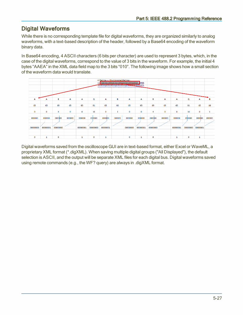
Part 5: IEEE 488.2 Programming Reference
Digital WaveformsWhile there is no corresponding template file for digital waveforms, they are organized similarly to analogwaveforms, with a text-based description of the header, followed by a Base64 encoding of the waveformbinary data.
In Base64 encoding, 4 ASCII characters (6 bits per character) are used to represent 3 bytes, which, in thecase of the digital waveforms, correspond to the value of 3 bits in the waveform. For example, the initial 4bytes “AAEA” in the XML data field map to the 3 bits “010”. The following image shows how a small sectionof the waveform data would translate.
Digital waveforms saved from the oscilloscope GUI are in text-based format, either Excel or WaveML, aproprietary XML format (*.digXML). When saving multiple digital groups ("All Displayed"), the defaultselection is ASCII, and the output will be separate XML files for each digital bus. Digital waveforms savedusing remote commands (e.g., the WF? query) are always in .digXML format.
5-27

MAUI Oscilloscopes Remote Control and Automation Manual
Transferring High-Speed WaveformsSeveral important factors must be considered to achieve maximum, continuous data transfer rates fromyour instrument to the external controller.
The single most important of these is to limit the amount of work done by the computer, meaning:
l Avoid writing data to disk wherever possible
l Minimize operations such as per-data-point computations
l Reduce the number of calls to the I/O system
To do this, try the following:
l Reduce the number of points to be transferred and the number of data bytes per point. The pulseparameter capability and the processing functions can save a great deal of computing and a lot ofdata transfer time if employed creatively.
l Attempt to overlap waveform acquisition with waveform transfer. The oscilloscope is capable oftransferring an already acquired or processed waveform after a new acquisition has been started.The total time the instrument takes to acquire events is considerably increased if it is set to wait fortriggers (live time).
l Minimize the number of waveform transfers by using Sequence mode to accumulate manytriggers for each transfer. This is preferable to using WAVEFORM_SETUP to reduce the number ofdata points for transfer. It also significantly reduces oscilloscope transfer overhead. For example, youcould use ARM; WAIT;C1:WF? to wait for the event, transfer the data, and then start a newacquisition. You could also loop this line in the program as soon as it has finished reading thewaveform.
5-28

Part 6: IEEE 488.2 Command Reference
Part 6: IEEE 488.2 Command ReferenceThroughout this reference, the full command header is listed first, followed by the short form, as inDOT_JOIN, DTJN. Either form may be used in commands and queries.
The solution to unavailable legacy commands is to use Automation commands integrated into a remotecontrol program using the VBS command.
Commands and Queries by Short Form 6-2
Commands and Queries by Subsystem 6-8
ACQUISITION Commands and Queries 6-15
AUTOMATION Commands and Queries 6-43
COMMUNICATION Commands and Queries 6-44
CURSOR Commands and Queries 6-50
DISPLAY Commands and Queries 6-75
FUNCTION Commands and Queries 6-90
HARDCOPY Commands and Queries 6-101
MISCELLANEOUS Commands and Queries 6-104
PROBE Commands 6-112
SAVE/RECALL SETUP Commands and Queries 6-119
STATUS Commands and Queries 6-126
STORAGE Commands and Queries 6-145
WAVEFORM TRANSFER Commands and Queries 6-147
DISK DRIVE ANALYSIS (Option) Commands and Queries 6-157
ET-PMT (Option) Commands and Queries 6-202
6-1
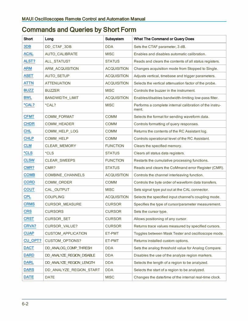
MAUI Oscilloscopes Remote Control and Automation Manual
Commands and Queries by Short FormShort Long Subsystem What The Command or Query Does
3DB DD_CTAF_3DB DDA Sets the CTAF parameter, 3 dB.
ACAL AUTO_CALIBRATE MISC Enables and disables automatic calibration.
ALST? ALL_STATUS? STATUS Reads and clears the contents of all status registers.
ARM ARM_ACQUISITION ACQUISITION Changes acquisition mode from Stopped to Single.
ASET AUTO_SETUP ACQUISITION Adjusts vertical, timebase and trigger parameters.
ATTN ATTENUATION ACQUISITION Selects the vertical attenuation factor of the probe.
BUZZ BUZZER MISC Controls the buzzer in the instrument.
BWL BANDWIDTH_LIMIT ACQUISITION Enables/disables bandwidth-limiting low-pass filter.
*CAL? *CAL? MISC Performs a complete internal calibration of the instru-ment.
CFMT COMM_FORMAT COMM Selects the format for sending waveform data.
CHDR COMM_HEADER COMM Controls formatting of query responses.
CHL COMM_HELP_LOG COMM Returns the contents of the RC Assistant log.
CHLP COMM_HELP COMM Controls operational level of the RC Assistant.
CLM CLEAR_MEMORY FUNCTION Clears the specified memory.
*CLS *CLS STATUS Clears all status data registers.
CLSW CLEAR_SWEEPS FUNCTION Restarts the cumulative processing functions.
CMR? CMR? STATUS Reads and clears the CoMmand error Register (CMR).
COMB COMBINE_CHANNELS ACQUISITION Controls the channel interleaving function.
CORD COMM_ORDER COMM Controls the byte order of waveform data transfers.
COUT CAL_OUTPUT MISC Sets signal type put out at the CAL connector.
CPL COUPLING ACQUISITION Selects the specified input channel's coupling mode.
CRMS CURSOR_MEASURE CURSOR Specifies the type of cursor/parameter measurement.
CRS CURSORS CURSOR Sets the cursor type.
CRST CURSOR_SET CURSOR Allows positioning of any cursor.
CRVA? CURSOR_VALUE? CURSOR Returns trace values measured by specified cursors.
CUAP CUSTOM_APPLICATION ET-PMT Toggles between Mask Tester and oscilloscope mode.
CU_OPT? CUSTOM_OPTIONS? ET-PMT Returns installed custom options.
DACT DD_ANALOG_COMP_THRESH DDA Sets the analog threshold value for Analog Compare.
DARD DD_ANALYZE_REGION_DISABLE DDA Disables the use of the analyze region markers.
DARL DD_ANALYZE_REGION_LENGTH DDA Selects the length of a region to be analyzed.
DARS DD_ANALYZE_REGION_START DDA Selects the start of a region to be analyzed.
DATE DATE MISC Changes the date/time of the internal real-time clock.
6-2

Part 6: IEEE 488.2 Command Reference
Short Long Subsystem What The Command or Query Does
DBIT DD_BITCELL DDA Enters the bit cell time of the head signal.
DBST DD_CTAF_BOOST DDA Sets the CTAF parameter, boost.
DBYT DD_BYTE_OFFSET DDA Moves the head trace to show the specified byte.
DDFC DD_CTAF_FC DDA Sets the CTAF parameter, cut-off frequency fc.
DDFM DD_FIND_METHOD DDA Selects the error-finding method.
DDR? DDR? STATUS Reads, clears the Device Dependent Register (DDR).
DDSI DD_SIGNAL_INPUT DDA Sends or reads out the association of a source with aparticular Disk Drive signal.
DEF DEFINE FUNCTION Specifies math expression for function evaluation.
DELF DELETE_FILE STORAGE Deletes a file from the currently selected directory.
DENC DD_ENCODING DDA Allows selection of the data-encoding ratio for locatingthe bytes by byte offset.
DERI? DD_ERR_INFO DDA Returns the measured value associated with the lasterror position selected, and a code specifying what thevalue contains.
DERR DD_ERR_NUM DDA Displays the section of waveform containing thespecified error number.
DFBIT DD_FIND_BITCELL DDA Looks at the head signal and attempts to determine thebit-cell time.
DFEN DD_FIR_ENABLE DDA Enables the FIR filter for PRML channel emulation.
DFER DD_FIND_ERROR DDA Commands the DDA to find errors.
DFGD DD_CTAF_GROUP_DELAY DDA Sets the CTAF parameter, group delay.
DFIR DD_FIR DDA Stores the setup that will be used if the FIR filter isenabled for use in the channel emulation.
DHSC DD_HEADSIGNAL_CHANNEL DDA Specifies the head signal source channel or memoryfor channel emulation and servo analysis.
DIGS DD_IGNORE_SAMPLES DDA Defines the number of samples to be ignored at theRead Gate signal end for channel emulation and ana-log compare.
DISP DISPLAY DISPLAY Controls the display screen.
DNER? DD_NUM_ERRORS DDA Returns the number of errors found.
DOVL DD_OVERLAP_REF DDA sets a state variable which determines re-estab-lishing the overlap of the head signal
DPA DD_PES_ANALYSIS DDA Starts or aborts PES analysis.
DPD? DD_PES_DATA DDA Reads out results of PES Analysis.
DPSD? DD_PES_SUMMARY_DATA DDA Summarizes PES Analysis results.
DPSU DD_PES_SETUP DDA Command sets parameters for PES Analysis. Thequery responds with the current state of specifiedkeywords.
6-3
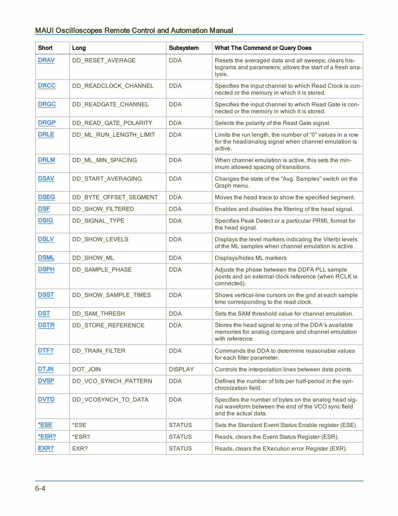
MAUI Oscilloscopes Remote Control and Automation Manual
Short Long Subsystem What The Command or Query Does
DRAV DD_RESET_AVERAGE DDA Resets the averaged data and all sweeps; clears his-tograms and parameters; allows the start of a fresh ana-lysis.
DRCC DD_READCLOCK_CHANNEL DDA Specifies the input channel to which Read Clock is con-nected or the memory in which it is stored.
DRGC DD_READGATE_CHANNEL DDA Specifies the input channel to which Read Gate is con-nected or the memory in which it is stored.
DRGP DD_READ_GATE_POLARITY DDA Selects the polarity of the Read Gate signal.
DRLE DD_ML_RUN_LENGTH_LIMIT DDA Limits the run length, the number of “0” values in a rowfor the head/analog signal when channel emulation isactive.
DRLM DD_ML_MIN_SPACING DDA When channel emulation is active, this sets the min-imum allowed spacing of transitions.
DSAV DD_START_AVERAGING DDA Changes the state of the “Avg. Samples” switch on theGraph menu.
DSEG DD_BYTE_OFFSET_SEGMENT DDA Moves the head trace to show the specified segment.
DSF DD_SHOW_FILTERED DDA Enables and disables the filtering of the head signal.
DSIG DD_SIGNAL_TYPE DDA Specifies Peak Detect or a particular PRML format forthe head signal.
DSLV DD_SHOW_LEVELS DDA Displays the level markers indicating the Viterbi levelsof the ML samples when channel emulation is active.
DSML DD_SHOW_ML DDA Displays/hides ML markers
DSPH DD_SAMPLE_PHASE DDA Adjusts the phase between the DDFA PLL samplepoints and an external clock reference (when RCLK isconnected).
DSST DD_SHOW_SAMPLE_TIMES DDA Shows vertical-line cursors on the grid at each sampletime corresponding to the read clock.
DST DD_SAM_THRESH DDA Sets the SAM threshold value for channel emulation.
DSTR DD_STORE_REFERENCE DDA Stores the head signal to one of the DDA’s availablememories for analog compare and channel emulationwith reference.
DTF? DD_TRAIN_FILTER DDA Commands the DDA to determine reasonable valuesfor each filter parameter.
DTJN DOT_JOIN DISPLAY Controls the interpolation lines between data points.
DVSP DD_VCO_SYNCH_PATTERN DDA Defines the number of bits per half-period in the syn-chronization field.
DVTD DD_VCOSYNCH_TO_DATA DDA Specifies the number of bytes on the analog head sig-nal waveform between the end of the VCO sync fieldand the actual data.
*ESE *ESE STATUS Sets the Standard Event Status Enable register (ESE).
*ESR? *ESR? STATUS Reads, clears the Event Status Register (ESR).
EXR? EXR? STATUS Reads, clears the EXecution error Register (EXR).
6-4
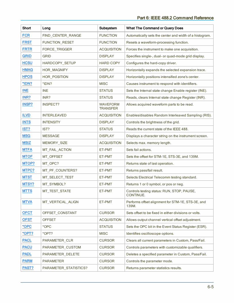
Part 6: IEEE 488.2 Command Reference
Short Long Subsystem What The Command or Query Does
FCR FIND_CENTER_RANGE FUNCTION Automatically sets the center and width of a histogram.
FRST FUNCTION_RESET FUNCTION Resets a waveform-processing function.
FRTR FORCE_TRIGGER ACQUISITION Forces the instrument to make one acquisition.
GRID GRID DISPLAY Specifies single-, dual- or quad-mode grid display.
HCSU HARDCOPY_SETUP HARD COPY Configures the hard-copy driver.
HMAG HOR_MAGNIFY DISPLAY Horizontally expands the selected expansion trace.
HPOS HOR_POSITION DISPLAY Horizontally positions intensified zone's center.
*IDN? *IDN? MISC Causes instrument to respond with identifiers.
INE INE STATUS Sets the Internal state change Enable register (INE).
INR? INR? STATUS Reads, clears Internal state change Register (INR).
INSP? INSPECT? WAVEFORMTRANSFER
Allows acquired waveform parts to be read.
ILVD INTERLEAVED ACQUISITION Enables/disables Random Interleaved Sampling (RIS).
INTS INTENSITY DISPLAY Controls the brightness of the grid.
IST? IST? STATUS Reads the current state of the IEEE 488.
MSG MESSAGE DISPLAY Displays a character string on the instrument screen.
MSIZ MEMORY_SIZE ACQUISITION Selects max. memory length.
MTFA MT_FAIL_ACTION ET-PMT Sets fail actions.
MTOF MT_OFFSET ET-PMT Sets the offset for STM-1E, STS-3E, and 139M.
MTOP? MT_OPC? ET-PMT Returns state of last operation.
MTPC? MT_PF_COUNTERS? ET-PMT Returns pass/fail result.
MTST MT_SELECT_TEST ET-PMT Selects Electrical Telecomm testing standard.
MTSY? MT_SYMBOL? ET-PMT Returns 1 or 0 symbol, or pos or neg.
MTTS MT_TEST_STATE ET-PMT Controls testing status: RUN, STOP, PAUSE,CONTINUE.
MTVA MT_VERTICAL_ALIGN ET-PMT Performs offset alignment for STM-1E, STS-3E, and139M.
OFCT OFFSET_CONSTANT CURSOR Sets offset to be fixed in either divisions or volts.
OFST OFFSET ACQUISITION Allows output channel vertical offset adjustment.
*OPC *OPC STATUS Sets the OPC bit in the Event Status Register (ESR).
*OPT? *OPT? MISC Identifies oscilloscope options.
PACL PARAMETER_CLR CURSOR Clears all current parameters in Custom, Pass/Fail.
PACU PARAMETER_CUSTOM CURSOR Controls parameters with customizable qualifiers.
PADL PARAMETER_DELETE CURSOR Deletes a specified parameter in Custom, Pass/Fail.
PARM PARAMETER CURSOR Controls the parameter mode.
PAST? PARAMETER_STATISTICS? CURSOR Returns parameter statistics results.
6-5

MAUI Oscilloscopes Remote Control and Automation Manual
Short Long Subsystem What The Command or Query Does
PAVA? PARAMETER_VALUE? CURSOR Returns current parameter, mask test values.
PECL PERSIST_COLOR DISPLAY Controls color rendering method of persistence traces.
PECS PER_CURSOR_SET CURSOR Positions one of the six independent cursors.
PELT PERSIST_LAST DISPLAY Shows the last trace drawn in a persistence data map.
PERS PERSIST DISPLAY Enables or disables the persistence display mode.
PESA PERSIST_SAT DISPLAY Sets the color saturation level in persistence.
PESU PERSIST_SETUP DISPLAY Selects display persistence duration.
PF PASS_FAIL CURSOR Sets up pass fail system.
PFDO PASS_FAIL_DO CURSOR Defines outcome and actions for Pass/Fail
PNSU PANEL_SETUP SAVE/RECALL Complements the *SAV/*RST commands.
*PRE *PRE STATUS Sets the PaRallel poll Enable register (PRE).
*RCL *RCL SAVE/RECALL Recalls one of five non-volatile panel setups.
RCLK REFERENCE_CLOCK ACQUISITION Toggles between internal clock and external clock.
RCPN RECALL_PANEL SAVE/RECALL Recalls a front panel setup from mass storage.
*RST *RST SAVE/RECALL Initiates a device reset.
*SAV *SAV SAVE/RECALL Stores current state in non-volatile internal memory.
SCDP SCREEN_DUMP HARD COPY Initiates a screen capture.
SCLK SAMPLE_CLOCK ACQUISITION Toggles between internal clock and external clock.
SEQ SEQUENCE ACQUISITION Controls the sequence mode of acquisition.
*SRE *SRE STATUS Sets the Service Request Enable register (SRE).
*STB? *STB? STATUS Reads the contents of the IEEE 488.
STO STORE WAVEFORMTRANSFER
Stores a trace in internal memory or mass storage.
STOP STOP ACQUISITION Immediately stops signal acquisition.
STPN STORE_PANEL SAVE/RECALL Stores front panel setup to mass storage.
STST STORE_SETUP WAVEFORMTRANSFER
Sets up waveform storage.
TDIV TIME_DIV ACQUISITION Modifies the timebase setting.
TMPL? TEMPLATE? WAVEFORMTRANSFER
Produces a complete waveform template copy.
TRA TRACE DISPLAY Enables or disables the display of a trace.
TRCP TRIG_COUPLING ACQUISITION Sets the coupling mode of the specified trigger source.
TRFL TRANSFER_FILE WAVEFORMTRANSFER
Transfers ASCII files to and from storage media, orbetween scope and computer.
TRDL TRIG_DELAY ACQUISITION Sets the time at which the trigger is to occur.
*TRG *TRG ACQUISITION Executes an ARM command.
TRLV TRIG_LEVEL ACQUISITION Adjusts the trigger level of the specified trigger source.
6-6

Part 6: IEEE 488.2 Command Reference
Short Long Subsystem What The Command or Query Does
TRMD TRIG_MODE ACQUISITION Specifies the trigger mode.
TRPA TRIG_PATTERN ACQUISITION Defines a trigger pattern.
TRSE TRIG_SELECT ACQUISITION Selects the condition that will trigger acquisition.
TRSL TRIG_SLOPE ACQUISITION Sets the trigger slope of the specified trigger source.
*TST? *TST? MISC Performs internal self-test.
VBS VBS AUTOMATION Sends an automation command.
VDIV VOLT_DIV ACQUISITION Sets the vertical sensitivity.
VMAG VERT_MAGNIFY DISPLAY Vertically expands the specified trace.
VPOS VERT_POSITION DISPLAY Adjusts the vertical position of the specified trace.
*WAI *WAI STATUS WAIt to continue - required by the IEEE 488.
WAIT WAIT ACQUISITION Prevents new analysis until current is completed.
WF WAVEFORM WAVEFORMTRANSFER
Transfers a waveform from controller to scope.
WFSU WAVEFORM_SETUP WAVEFORMTRANSFER
Specifies amount of waveform data to go to controller.
6-7
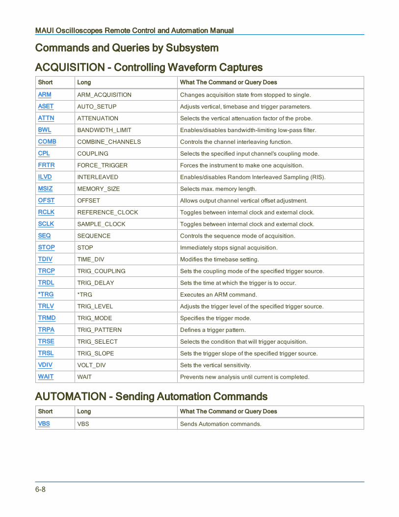
MAUI Oscilloscopes Remote Control and Automation Manual
Commands and Queries by Subsystem
ACQUISITION - Controlling Waveform CapturesShort Long What The Command or Query Does
ARM ARM_ACQUISITION Changes acquisition state from stopped to single.
ASET AUTO_SETUP Adjusts vertical, timebase and trigger parameters.
ATTN ATTENUATION Selects the vertical attenuation factor of the probe.
BWL BANDWIDTH_LIMIT Enables/disables bandwidth-limiting low-pass filter.
COMB COMBINE_CHANNELS Controls the channel interleaving function.
CPL COUPLING Selects the specified input channel's coupling mode.
FRTR FORCE_TRIGGER Forces the instrument to make one acquisition.
ILVD INTERLEAVED Enables/disables Random Interleaved Sampling (RIS).
MSIZ MEMORY_SIZE Selects max. memory length.
OFST OFFSET Allows output channel vertical offset adjustment.
RCLK REFERENCE_CLOCK Toggles between internal clock and external clock.
SCLK SAMPLE_CLOCK Toggles between internal clock and external clock.
SEQ SEQUENCE Controls the sequence mode of acquisition.
STOP STOP Immediately stops signal acquisition.
TDIV TIME_DIV Modifies the timebase setting.
TRCP TRIG_COUPLING Sets the coupling mode of the specified trigger source.
TRDL TRIG_DELAY Sets the time at which the trigger is to occur.
*TRG *TRG Executes an ARM command.
TRLV TRIG_LEVEL Adjusts the trigger level of the specified trigger source.
TRMD TRIG_MODE Specifies the trigger mode.
TRPA TRIG_PATTERN Defines a trigger pattern.
TRSE TRIG_SELECT Selects the condition that will trigger acquisition.
TRSL TRIG_SLOPE Sets the trigger slope of the specified trigger source.
VDIV VOLT_DIV Sets the vertical sensitivity.
WAIT WAIT Prevents new analysis until current is completed.
AUTOMATION - Sending Automation CommandsShort Long What The Command or Query Does
VBS VBS Sends Automation commands.
6-8

Part 6: IEEE 488.2 Command Reference
COMMUNICATION - Setting Communication CharacteristicsShort Long What The Command or Query Does
CFMT COMM_FORMAT Selects the format for sending waveform data.
CHDR COMM_HEADER Controls formatting of query responses.
CHL COMM_HELP_LOG Returns the contents of the RC Assistant log.
CHLP COMM_HELP Controls operational level of the RC Assistant.
CORD COMM_ORDER Controls the byte order of waveform data transfers.
CURSOR - Performing MeasurementsShort Long What The Command or Query Does
CRMS CURSOR_MEASURE Specifies the type of cursor/parameter measurement.
CRS CURSORS Sets the cursor type.
CRST CURSOR_SET Allows positioning of any cursor.
CRVA? CURSOR_VALUE? Returns trace values measured by specified cursors.
OFCT OFFSET_CONSTANT Sets offset to be fixed in either divisions or volts.
PACL PARAMETER_CLR Clears all current parameters in Custom, Pass/Fail.
PACU PARAMETER_CUSTOM Controls parameters with customizable qualifiers.
PADL PARAMETER_DELETE Deletes a specified parameter in Custom, Pass/Fail.
PARM PARAMETER Controls the parameter mode, Standard, Custom, etc.
PAST? PARAMETER_STATISTICS? Returns parameter statistics results.
PAVA? PARAMETER_VALUE? Returns current parameter, mask test values.
PECS PER_CURSOR_SET Positions one of the six independent cursors.
PF PASS_FAIL Sets up pass fail system.
PFDO PASS_FAIL_DO Defines outcome and actions for Pass/Fail tests.
DISPLAY - Displaying WaveformsShort Long What The Command or Query Does
DISP DISPLAY Controls the display screen.
DTJN DOT_JOIN Controls the interpolation lines between data points.
GRID GRID Specifies single-, dual- or quad-mode grid display.
HMAG HOR_MAGNIFY Horizontally expands the selected expansion trace.
HPOS HOR_POSITION Horizontally positions intensified zone's center.
INTS INTENSITY Controls the brightness of the grid.
MSG MESSAGE Displays a character string on the instrument screen.
PECL PERSIST_COLOR Controls color rendering method of persistence traces.
6-9
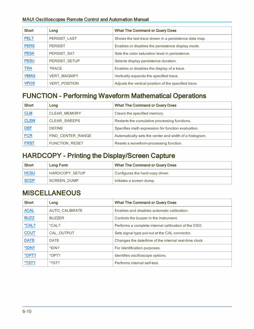
MAUI Oscilloscopes Remote Control and Automation Manual
Short Long What The Command or Query Does
PELT PERSIST_LAST Shows the last trace drawn in a persistence data map.
PERS PERSIST Enables or disables the persistence display mode.
PESA PERSIST_SAT Sets the color saturation level in persistence.
PESU PERSIST_SETUP Selects display persistence duration.
TRA TRACE Enables or disables the display of a trace.
VMAG VERT_MAGNIFY Vertically expands the specified trace.
VPOS VERT_POSITION Adjusts the vertical position of the specified trace.
FUNCTION - Performing Waveform Mathematical OperationsShort Long What The Command or Query Does
CLM CLEAR_MEMORY Clears the specified memory.
CLSW CLEAR_SWEEPS Restarts the cumulative processing functions.
DEF DEFINE Specifies math expression for function evaluation.
FCR FIND_CENTER_RANGE Automatically sets the center and width of a histogram.
FRST FUNCTION_RESET Resets a waveform-processing function.
HARDCOPY - Printing the Display/Screen CaptureShort Long Form What The Command or Query Does
HCSU HARDCOPY_SETUP Configures the hard-copy driver.
SCDP SCREEN_DUMP Initiates a screen dump.
MISCELLANEOUSShort Long What The Command or Query Does
ACAL AUTO_CALIBRATE Enables and disables automatic calibration.
BUZZ BUZZER Controls the buzzer in the instrument.
*CAL? *CAL? Performs a complete internal calibration of the DSO.
COUT CAL_OUTPUT Sets signal type put out at the CAL connector.
DATE DATE Changes the date/time of the internal real-time clock.
*IDN? *IDN? For identification purposes.
*OPT? *OPT? Identifies oscilloscope options.
*TST? *TST? Performs internal self-test.
6-10
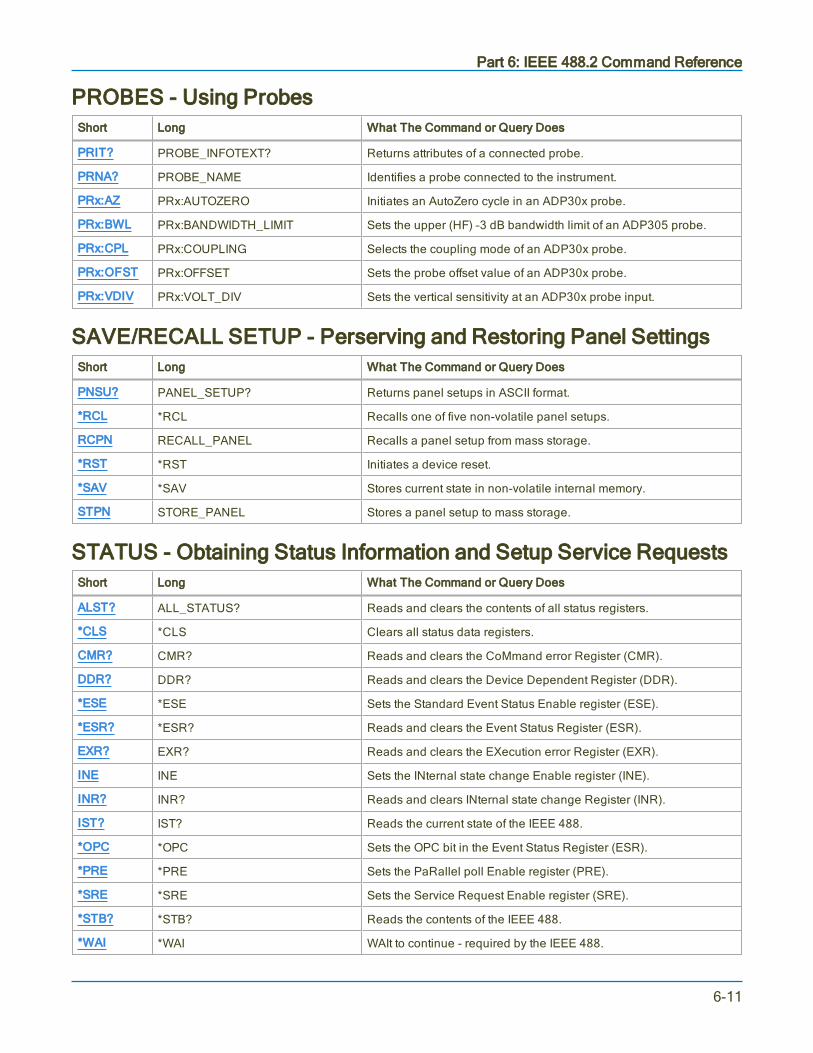
Part 6: IEEE 488.2 Command Reference
PROBES - Using ProbesShort Long What The Command or Query Does
PRIT? PROBE_INFOTEXT? Returns attributes of a connected probe.
PRNA? PROBE_NAME Identifies a probe connected to the instrument.
PRx:AZ PRx:AUTOZERO Initiates an AutoZero cycle in an ADP30x probe.
PRx:BWL PRx:BANDWIDTH_LIMIT Sets the upper (HF) –3 dB bandwidth limit of an ADP305 probe.
PRx:CPL PRx:COUPLING Selects the coupling mode of an ADP30x probe.
PRx:OFST PRx:OFFSET Sets the probe offset value of an ADP30x probe.
PRx:VDIV PRx:VOLT_DIV Sets the vertical sensitivity at an ADP30x probe input.
SAVE/RECALL SETUP - Perserving and Restoring Panel SettingsShort Long What The Command or Query Does
PNSU? PANEL_SETUP? Returns panel setups in ASCII format.
*RCL *RCL Recalls one of five non-volatile panel setups.
RCPN RECALL_PANEL Recalls a panel setup from mass storage.
*RST *RST Initiates a device reset.
*SAV *SAV Stores current state in non-volatile internal memory.
STPN STORE_PANEL Stores a panel setup to mass storage.
STATUS - Obtaining Status Information and Setup Service RequestsShort Long What The Command or Query Does
ALST? ALL_STATUS? Reads and clears the contents of all status registers.
*CLS *CLS Clears all status data registers.
CMR? CMR? Reads and clears the CoMmand error Register (CMR).
DDR? DDR? Reads and clears the Device Dependent Register (DDR).
*ESE *ESE Sets the Standard Event Status Enable register (ESE).
*ESR? *ESR? Reads and clears the Event Status Register (ESR).
EXR? EXR? Reads and clears the EXecution error Register (EXR).
INE INE Sets the INternal state change Enable register (INE).
INR? INR? Reads and clears INternal state change Register (INR).
IST? IST? Reads the current state of the IEEE 488.
*OPC *OPC Sets the OPC bit in the Event Status Register (ESR).
*PRE *PRE Sets the PaRallel poll Enable register (PRE).
*SRE *SRE Sets the Service Request Enable register (SRE).
*STB? *STB? Reads the contents of the IEEE 488.
*WAI *WAI WAIt to continue - required by the IEEE 488.
6-11
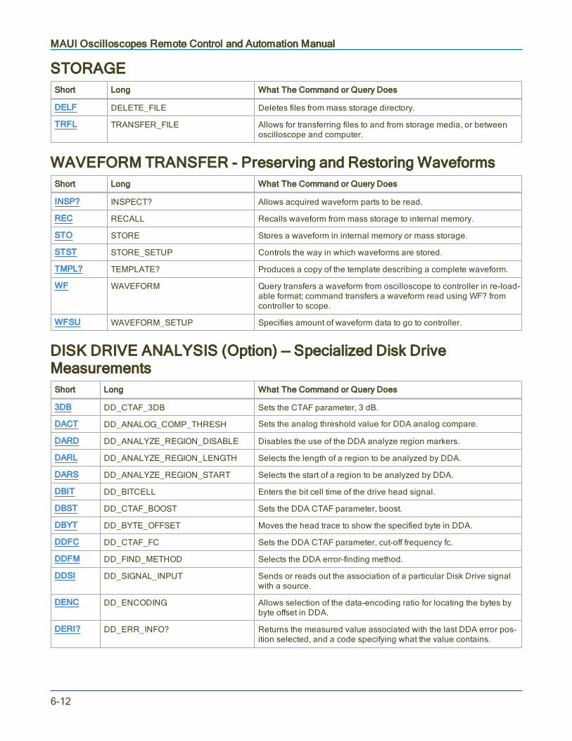
MAUI Oscilloscopes Remote Control and Automation Manual
STORAGEShort Long What The Command or Query Does
DELF DELETE_FILE Deletes files from mass storage directory.
TRFL TRANSFER_FILE Allows for transferring files to and from storage media, or betweenoscilloscope and computer.
WAVEFORM TRANSFER - Preserving and Restoring WaveformsShort Long What The Command or Query Does
INSP? INSPECT? Allows acquired waveform parts to be read.
REC RECALL Recalls waveform from mass storage to internal memory.
STO STORE Stores a waveform in internal memory or mass storage.
STST STORE_SETUP Controls the way in which waveforms are stored.
TMPL? TEMPLATE? Produces a copy of the template describing a complete waveform.
WF WAVEFORM Query transfers a waveform from oscilloscope to controller in re-load-able format; command transfers a waveform read using WF? fromcontroller to scope.
WFSU WAVEFORM_SETUP Specifies amount of waveform data to go to controller.
DISK DRIVE ANALYSIS (Option) — Specialized Disk DriveMeasurementsShort Long What The Command or Query Does
3DB DD_CTAF_3DB Sets the CTAF parameter, 3 dB.
DACT DD_ANALOG_COMP_THRESH Sets the analog threshold value for DDA analog compare.
DARD DD_ANALYZE_REGION_DISABLE Disables the use of the DDA analyze region markers.
DARL DD_ANALYZE_REGION_LENGTH Selects the length of a region to be analyzed by DDA.
DARS DD_ANALYZE_REGION_START Selects the start of a region to be analyzed by DDA.
DBIT DD_BITCELL Enters the bit cell time of the drive head signal.
DBST DD_CTAF_BOOST Sets the DDA CTAF parameter, boost.
DBYT DD_BYTE_OFFSET Moves the head trace to show the specified byte in DDA.
DDFC DD_CTAF_FC Sets the DDA CTAF parameter, cut-off frequency fc.
DDFM DD_FIND_METHOD Selects the DDA error-finding method.
DDSI DD_SIGNAL_INPUT Sends or reads out the association of a particular Disk Drive signalwith a source.
DENC DD_ENCODING Allows selection of the data-encoding ratio for locating the bytes bybyte offset in DDA.
DERI? DD_ERR_INFO? Returns the measured value associated with the last DDA error pos-ition selected, and a code specifying what the value contains.
6-12
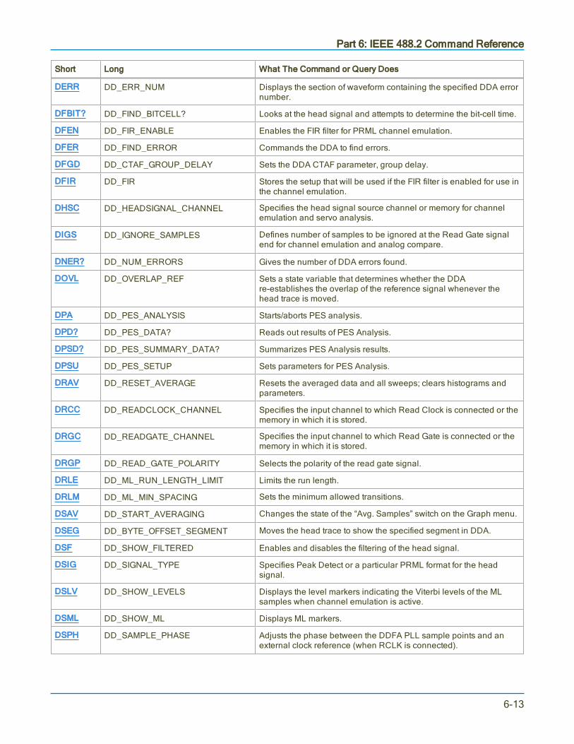
Part 6: IEEE 488.2 Command Reference
Short Long What The Command or Query Does
DERR DD_ERR_NUM Displays the section of waveform containing the specified DDA errornumber.
DFBIT? DD_FIND_BITCELL? Looks at the head signal and attempts to determine the bit-cell time.
DFEN DD_FIR_ENABLE Enables the FIR filter for PRML channel emulation.
DFER DD_FIND_ERROR Commands the DDA to find errors.
DFGD DD_CTAF_GROUP_DELAY Sets the DDA CTAF parameter, group delay.
DFIR DD_FIR Stores the setup that will be used if the FIR filter is enabled for use inthe channel emulation.
DHSC DD_HEADSIGNAL_CHANNEL Specifies the head signal source channel or memory for channelemulation and servo analysis.
DIGS DD_IGNORE_SAMPLES Defines number of samples to be ignored at the Read Gate signalend for channel emulation and analog compare.
DNER? DD_NUM_ERRORS Gives the number of DDA errors found.
DOVL DD_OVERLAP_REF Sets a state variable that determines whether the DDAre-establishes the overlap of the reference signal whenever thehead trace is moved.
DPA DD_PES_ANALYSIS Starts/aborts PES analysis.
DPD? DD_PES_DATA? Reads out results of PES Analysis.
DPSD? DD_PES_SUMMARY_DATA? Summarizes PES Analysis results.
DPSU DD_PES_SETUP Sets parameters for PES Analysis.
DRAV DD_RESET_AVERAGE Resets the averaged data and all sweeps; clears histograms andparameters.
DRCC DD_READCLOCK_CHANNEL Specifies the input channel to which Read Clock is connected or thememory in which it is stored.
DRGC DD_READGATE_CHANNEL Specifies the input channel to which Read Gate is connected or thememory in which it is stored.
DRGP DD_READ_GATE_POLARITY Selects the polarity of the read gate signal.
DRLE DD_ML_RUN_LENGTH_LIMIT Limits the run length.
DRLM DD_ML_MIN_SPACING Sets the minimum allowed transitions.
DSAV DD_START_AVERAGING Changes the state of the “Avg. Samples” switch on the Graph menu.
DSEG DD_BYTE_OFFSET_SEGMENT Moves the head trace to show the specified segment in DDA.
DSF DD_SHOW_FILTERED Enables and disables the filtering of the head signal.
DSIG DD_SIGNAL_TYPE Specifies Peak Detect or a particular PRML format for the headsignal.
DSLV DD_SHOW_LEVELS Displays the level markers indicating the Viterbi levels of the MLsamples when channel emulation is active.
DSML DD_SHOW_ML Displays ML markers.
DSPH DD_SAMPLE_PHASE Adjusts the phase between the DDFA PLL sample points and anexternal clock reference (when RCLK is connected).
6-13

MAUI Oscilloscopes Remote Control and Automation Manual
Short Long What The Command or Query Does
DSST DD_SHOW_SAMPLE_TIMES Shows vertical-line cursors on the grid at each sample timecorresponding to the read clock.
DST DD_SAM_THRESH Sets the SAM threshold value for channel emulation.
DSTR DD_STORE_REFERENCE Stores the head signal to one of the DDA’s available memories foranalog compare and channel emulation with reference.
DTF DD_TRAIN_FILTER Commands the DDA to determine reasonable values for each filterparameter.
DVSP DD_VCO_SYNCH_PATTERN Defines the number of bits per half-period in the synchronizationfield.
DVTD DD_VCOSYNCH_TO_DATA Specifies the number of bytes on the analog head signal waveformbetween the end of the VCO sync field and the actual data.
ET-PMT (Option) - Electrical Telecomm Pulse Mask TestingShort Long What The Command or Query Does
CU_OPT? CUSTOM_OPTIONS? Returns installed custom options.
CUAP CUSTOM_APPLICATION Toggles between Mask Tester mode and oscilloscope mode.
MTFA MT_FAIL_ACTION Sets fail actions.
MTOF MT_OFFSET Sets the offset for STM-1E, STS-3E, and 139M.
MTOP? MT_OPC? Returns state of last operation.
MTPC? MT_PF_COUNTERS? Returns pass/fail result.
MTST MT_SELECT_TEST Selects Electrical Telecomm testing standard.
MTSY? MT_SYMBOL? Returns 1 or 0 symbol, or pos or neg.
MTTS MT_TEST_STATE Controls testing status: RUN, STOP, PAUSE, CONTINUE.
MTVA MT_VERTICAL_ALIGN Performs offset alignment for STM-1E, STS-3E, and 139M.
6-14

Part 6: IEEE 488.2 Command Reference
ACQUISITION Commands and Queries
ARM_ACQUISITION, ARM
DescriptionThe ARM_ACQUISITION command arms the scope and forces a single acquisition if it is already armed.
Command Syntax
ARM_ACQUISITION
Example (GPIB)The following instruction enables signal acquisition:
CMD$="ARM": CALL IBWRT(SCOPE%,CMD$)
Related CommandsSTOP, *TRG, TRIG_MODE, WAIT, FRTR
6-15

MAUI Oscilloscopes Remote Control and Automation Manual
AUTO_SETUP, ASET
DescriptionThe AUTO_SETUP command attempts to display the input signal(s) by adjusting the vertical, timebase andtrigger parameters. AUTO_SETUP operates only on the channels whose traces are currently turned on. Ifno traces are turned on, AUTO_SETUP operates on all channels.
If signals are detected on several channels, the lowest numbered channel with a signal determines theselection of the timebase and trigger source.
If only one input channel is turned on, the timebase will be adjusted for that channel.
The AUTO_SETUP FIND command adjusts gain and offset only for the specified channel.
Command Syntax
<channel>:AUTO_SETUP [FIND]
<channel>:= <C1 to Cn>
If the FIND keyword is present, gain and offset adjustments are performed only on the specified channel. Ifno <channel> prefix is added, an auto-setup is performed on the channel used on the last ASET FINDremote command.
In the absence of the FIND keyword, the normal auto-setup is performed, regardless of the <channel>prefix.
Example (GPIB)The following instructs the oscilloscope to perform an auto-setup:
CMD$="C1:ASET": CALL IBWRT(SCOPE%,CMD$)
6-16

Part 6: IEEE 488.2 Command Reference
ATTENUATION, ATTN
DescriptionThe ATTENUATION command selects the vertical attenuation factor of the probe. Values up to 10000 canbe specified.
The ATTENUATION? query returns the attenuation factor of the specified channel.
Command Syntax
<channel>:ATTENUATION <attenuation>
<channel>:= <C1 to Cn, EX, EX10>
<attenuation>:= 1, 2, 5, 10, 20, 25, 50, 100, 200, 500, 1000, 10000
Query Syntax
<channel>:ATTENUATION?
Response Format
<channel>:ATTENUATION <attenuation>
Example (GPIB)The following instruction sets the attenuation factor of C1to 100:
CMD$="C1:ATTN 100": CALL IBWRT(SCOPE%,CMD$)
6-17

MAUI Oscilloscopes Remote Control and Automation Manual
BANDWIDTH_LIMIT, BWL
DescriptionThe BANDWIDTH_LIMIT command enables or disables the bandwidth-limiting low-pass filter on a per-channel basis. When the <channel> argument is omitted, the BWL command applies to all channels.
The response to the BANDWIDTH_LIMIT? query shows the bandwidth filter setting for each channel.
Command Syntax
BANDWIDTH_LIMIT [<channel>,]<mode>[,<channel>,<mode>...]
<channel>:= <C1 to Cn>
<mode>:= OFF, 20MHZ, 200MHZ, 500MHZ, 1GHZ, 2GHZ, 3GHZ, 4GHZ, 6GHZ
Per channel bandwidth may be set incrementally.
The <mode> setting is limited to the bandwidth filters available on your oscilloscope model. 500MHZ and2GHZ filters available on HDO9000 models only. More settings are available for WaveMaster andLabMaster models. See the product datasheet for specifications.
Query Syntax
BANDWIDTH_LIMIT?
Response Format
BANDWIDTH_LIMIT <channel>,<mode>[,<channel>,<mode>...]
Example (GPIB)The following turns off bandwidth limit filters for all channels:
CMD$="BWL OFF": CALL IBWRT(SCOPE%, CMD$)
The following turns on the 200 MHz bandwidth filter for C1 only:
CMD$="BWL C1,200MHZ": CALL IBWRT(SCOPE%, CMD$)
The following is the response to the BWL? query following the last two commands:
BWL C1,200MHZ,C2,OFF,C3,OFF,C4,OFF
6-18
Part 6: IEEE 488.2 Command Reference
COMBINE_CHANNELS, COMB
DescriptionThe COMBINE_CHANNELS command controls the channel interleaving function of the acquisition system.The COMBINE_CHANNELS? query returns the channel interleaving function's current status.
Command Syntax
COMBINE_CHANNELS <state>
<state> : = 1, 2, AUTO
Where 1 = no interleaving; 2 = two interleaved pairs; AUTO = oscilloscope determines based on the activechannels.
Query Syntax
COMBINE_CHANNELS?
Response Format
COMB <state>
Example (GPIB)The following instruction engages channel interleaving of C1 and C2, and C3 and C4:
CMD$="COMB 2": CALL IBWRT(SCOPE%,CMD$)
The following instruction sets Auto-Combine mode:
CMD$="COMB AUTO": CALL IBWRT(SCOPE%,CMD$)
Related CommandsTDIV
6-19

MAUI Oscilloscopes Remote Control and Automation Manual
COUPLING, CPL
DescriptionThe COUPLING command selects the coupling mode of the specified input.
The COUPLING? query returns the coupling mode of the specified channel.
Command Syntax
<channel>:COUPLING <coupling>
<channel>:= <C1 to Cn, EX, EX10, ETM10>
<coupling>:= A1M, D1M, D50, GND
The selected coupling value must be one that is available on the oscilloscope. Not all values are supportedby all instruments.
A1M and D1M attenuation pertains only to instruments with a probe connected.
Query Syntax
<channel>:COUPLING?
Response Format
<channel>:COUPLING <coupling>
<coupling>:= A1M, D1M, D50, GND, OVL
OVL is returned in the event of signal overload while in DC 50 Ω coupling. In this condition, the oscilloscopewill disconnect the input.
Example (GPIB)The following instruction sets the coupling of C2 to 50 Ω DC:
CMD$="C2:CPL D50": CALL IBWRT(SCOPE%,CMD$)
The following instruction sets of the coupling of the EXT input to DC 1 Mohm:
CMD$="EX:CPL D1M": CALL IBWRT(SCOPE%,CMD$)
6-20

Part 6: IEEE 488.2 Command Reference
FORCE_TRIGGER, FRTR
DescriptionCauses the instrument to make one acquisition.
Command Syntax
FORCE_TRIGGER
Example (GPIB)Either of the following programs forces the oscilloscope to make one acquisition:
CMD$="TRMD SINGLE;ARM;FRTR"
CALL IBWRT(Scope%, CMD$)
CMD$ = "TRMD STOP;ARM;FRTR"
CALL IBWRT(Scope%, CMD$)
6-21

MAUI Oscilloscopes Remote Control and Automation Manual
INTERLEAVED, ILVD
DescriptionThe INTERLEAVED command enables or disables random interleaved sampling (RIS) for timebasesettings where both single shot and RIS mode are available.
RIS is not available for sequence mode acquisitions. If sequence mode is on, ILVD ON turns it off.
The response to the INTERLEAVED? query indicates whether the oscilloscope is in RIS mode.
Command Syntax
INTERLEAVED <mode>
<mode>:= ON, OFF
Query Syntax
INTERLEAVED?
Response Format
INTERLEAVED <mode>
Example (GPIB)The following instructs the oscilloscope to use RIS mode:
CMD$="ILVD ON": CALL IBWRT(SCOPE%,CMD$)
Related CommandsTIME_DIV, TRIG_MODE, MEMORY_SIZE, SEQUENCE
6-22

Part 6: IEEE 488.2 Command Reference
MEMORY_SIZE, MSIZ
DescriptionOn most models where this command/query is available, MEMORY_SIZE allows selection of the memorylength used for acquisition. Refer to the product datasheet at teledynelecroy.com for maximum memoryspecifications.
The MEMORY_SIZE? query returns the current maximum memory length used to capture waveforms.
Command Syntax
MEMORY_SIZE <size>
<size>:= <500, 1e+3, …, 2.5e+6, 5e+6, 1e+7, etc.>
Or, alternatively:
<size>: = <500, 1000, 2500, 5000, 10K, 25K, 50K, 100K, 250K, 500K, 1MA, 2.5MA, 5MA,10MA, 25MA, etc.>
Values other than those listed here are recognized by the oscilloscope as numeric data. For example, theoscilloscope recognizes 1.0M as 1 millisample. However, it recognizes 1MA as 1 megasample.
Note: The oscilloscope adapts to the closest valid memory size according to available channelmemory. Reducing the number of data points results in faster throughput.
Query SyntaxMSIZ?
Response FormatMEMORY_SIZE <size>
Example (GPIB)The following instruction sets the oscilloscope to acquire at most 10,000 data samples per single-shot or RISacquisition:
CMD$="MSIZ 10K": CALL IBWRT(SCOPE%,CMD$)
CMD$="MSIZ 10e+3": CALL IBWRT(SCOPE%,CMD$)
Related CommandsTDIV
6-23

MAUI Oscilloscopes Remote Control and Automation Manual
OFFSET, OFST
DescriptionThe OFFSET command allows adjustment of the vertical offset of the specified input channel at the probetip.
Note: The offset takes into the account the attenuation factor (set by command ATTN, default 1.0)and the sensitivity of the probe attached to the channel input, if any.
The maximum ranges depend on the fixed sensitivity setting. Refer to the product datasheet atteledynelecroy.com for maximum offset specifications.
If an out-of-range value is entered, the oscilloscope is set to the closest possible value and the VAB bit (bit 2)in the STB register is set.
The OFFSET? query returns the DC offset value of the specified channel at the probe tip.
Command Syntax
<channel>:OFFSET <offset>[V]
<channel>:= <C1 to Cn>
<offset>:= <any valid value>
The unit V is optional.
Query Syntax
<channel>:OFFSET?
Response Format
<channel>:OFFSET <offset>
Example (GPIB)The following instruction sets the offset of C2 to -3 V:
CMD$="C2:OFST -3V": CALL IBWRT(SCOPE%,CMD$)
6-24

Part 6: IEEE 488.2 Command Reference
REFERENCE_CLOCK, RCLK
DescriptionThe REFERENCE_CLOCK command allows for selection of either internal or external reference clock.
Command Syntax
REFERENCE_CLOCK <state>
<state>:= INTERNAL, EXTERNAL
Query Syntax
REFERENCE_CLOCK?
Response Format
REFERENCE_CLOCK <state>
Example (GPIB)The following instruction sets the instrument to use an external reference clock:
CMD$="RCLK EXTERNAL":CALL IBWRT(SCOPE%,CMD$)
6-25
MAUI Oscilloscopes Remote Control and Automation Manual
SAMPLE_CLOCK, SCLK
DescriptionThe SAMPLE_CLOCK command selects for an internal or external sample clock.
Command Syntax
SAMPLE_CLOCK <state>
<state>:= INTERNAL, EXTERNAL
Query Syntax
SAMPLE_CLOCK?
Response Format
SAMPLE_CLOCK <state>
Example (GPIB)The following instruction sets the instrument to use an external sample clock:
CMD$="SCLK EXTERNAL":CALL IBWRT(SCOPE%,CMD$)
6-26

Part 6: IEEE 488.2 Command Reference
SEQUENCE, SEQ
DescriptionThe SEQUENCE command sets the conditions for the sequence mode acquisition. The response to theSEQUENCE? query gives the conditions for the sequence mode acquisition.
When Sequence mode is turned by using this command, SMART memory is automatically enabled and thememory length is set to the user-supplied <max_size> value. The argument <max_size> can be expressedeither as numeric fixed point, exponential, or using standard suffixes.
Sequence mode cannot be used at the same time as random interleaved sampling (RIS). If RIS is on, thecommand SEQ ON turns RIS off.
Refer to the product datasheet at teledynelecroy.com for Sequence mode specifications.
Command SyntaxSEQUENCE <mode>[,<number segments>[,<max_size>]]
<mode> : = OFF, ON
<number segments> : = <any valid value>
<max_size> : = <any valid value, e.g., 10e+3 , 5K, 1M, etc.>
Note: The oscilloscope adapts the requested <max_size> to the closest valid value.
Query SyntaxSEQUENCE?
Response Format
SEQUENCE <mode>,<number segments>,<max_size>
Example (GPIB)The following instruction sets the segment count to 43, the maximum segment size to 250 samples, andturns the sequence mode on:
CMD$="SEQ ON,43,250": CALL IBWRT(SCOPE%,CMD$)
Related CommandsTRIG_MODE
6-27

MAUI Oscilloscopes Remote Control and Automation Manual
STOP
DescriptionThe STOP command immediately stops the acquisition of a signal. If the trigger mode is AUTO or NORM,STOP places the oscilloscope in Stopped trigger mode to prevent further acquisition.
Command Syntax
STOP
Example (GPIB)The following instruction stops the acquisition process:
CMD$ ="STOP": CALL IBWRT(SCOPE%,CMD$)
Related CommandsARM_ACQUISITION, TRIG_MODE, WAIT, FORCE_TRIGGER
6-28

Part 6: IEEE 488.2 Command Reference
TIME_DIV, TDIV
DescriptionThe TIME_DIV command modifies the timebase setting. The timebase setting can be specified with units:NS for nanoseconds, US for microseconds, MS for milliseconds, S for seconds, or KS for kiloseconds.Alternatively, you can use exponential notation: 10E-6, for example. An out-of-range value causes the VABbit (bit 2) in the STB register to be set. Refer to the STB table in the *STB?- *STB? topic for moreinformation.
The TIME_DIV? query returns the current timebase setting.
Refer to the product datasheet at teledynelecroy.com for timebase specifications.
Command Syntax
TIME_DIV <value>[KS,S,MS,US,NS]
<value>:= <any valid value>
The unit is optional.
Query Syntax
TIME_DIV?
Response Format
TIME_DIV <value>
Example (GPIB)The following instruction sets the timebase to 500 µs/div:
CMD$="TDIV 500US": CALL IBWRT(SCOPE%,CMD$)
The following instruction sets the timebase to 2 msec/div:
CMD$="TDIV 0.002": CALL IBWRT(SCOPE%,CMD$)
Related CommandsTRIG_DELAY, TRIG_MODE
6-29

MAUI Oscilloscopes Remote Control and Automation Manual
TRIG_COUPLING, TRCP
DescriptionThe TRIG_COUPLING command sets the coupling mode of the specified trigger source.
The TRIG_COUPLING? query returns the trigger coupling of the selected source.
Note: The TRCP command affects only the coupling of the signal path to the trigger circuit,regardless of input impedance or coupling settings. To set the coupling on the input, use theCOUPLING command.
Command Syntax
<trig_source>:TRIG_COUPLING <trig_coupling>
<trig_source>:= <C1 to Cn, EX, EX10, ETM10>
<trig_coupling>:= AC, DC, HFREJ, LFREJ
Query Syntax
<trig_source>:TRIG_COUPLING?
Response Format
<trig_source>:TRIG_COUPLING <trig_coupling>
Example (GPIB)The following instruction sets the trigger coupling of the trigger source C2 to AC:
CMD$="C2:TRCP AC": CALL IBWRT(SCOPE%,CMD$)
Related CommandsCOUPLING, TRIG_DELAY, TRIG_LEVEL, TRIG_MODE, TRIG_SELECT, TRIG_SLOPE
6-30

Part 6: IEEE 488.2 Command Reference
TRIG_DELAY, TRDL
DescriptionThe TRIG_DELAY command sets the time at which the trigger is to occur with respect to the nominal zerodelay position, which defaults to the center of the grid. This is also referred to as Horizontal Delay.
The response to the TRIG_DELAY? query indicates the trigger time with respect to the first acquired datapoint. Setting a trigger delay value of zero places the trigger indicator at the center of the grid.
Note: MAUI oscilloscopes support programming the trigger delay in units of time; the legacyargument PCT (of grid) is no longer supported. Positive values move the trigger position to the rightof the nominal zero delay position, and increase the portion of the waveform before the trigger point.Negative values move the trigger point in the opposite direction.
Command Syntax
TRIG_DELAY <value>
The <value> is given in time and may be anywhere in the ranges:
Negative delay: ( 0 to -10,000) x Time/div
Postive delay: (0 to +10) x Time/div
If a value outside these ranges is specified, the trigger time is set to the nearest limit and the VAB bit (bit 2) isset in the STB register.
Query Syntax
TRIG_DELAY?
Response Format
TRIG_DELAY <value>
Example (GPIB)The following instruction sets a post-trigger delay of -20 S:
CMD$="TRDL -20S": CALL IBWRT(SCOPE%,CMD$)
Related CommandsTIME_DIV, TRIG_COUPLING, TRIG_LEVEL, TRIG_MODE, TRIG_SELECT, TRIG_SLOPE
6-31

MAUI Oscilloscopes Remote Control and Automation Manual
*TRG
DescriptionThe *TRG command executes an ARM command. *TRG is the equivalent of the 488.1 GET (GroupExecute Trigger) message.
Command Syntax
*TRG
Example (GPIB)The following instruction enables signal acquisition:
CMD$="*TRG": CALL IBWRT(SCOPE%,CMD$)
Related CommandsARM_ACQUISITION, STOP, WAIT, FORCE_TRIGGER
6-32
Part 6: IEEE 488.2 Command Reference
TRIG_LEVEL, TRLV
DescriptionThe TRIG_LEVEL command adjusts the trigger level of the specified trigger source. An out-of-range valuewill be adjusted to the closest legal value and will cause the VAB bit (bit 2) in the STB register to be set.
The TRIG_LEVEL? query returns the current trigger level.
Command Syntax
<trig_source>:TRIG_LEVEL <trig_level>V
<trig_source>:= <C1 to Cn, EX, EX10, ETM10>
The <trig_source> value is optional.
Query Syntax
<trig_source>:TRIG_LEVEL?
Response Format
<trig_source>:TRIG_LEVEL <trig_level>
Example (GPIB)The following instruction adjusts the trigger level of C2 to -3.4 V:
CMD$="C2:TRLV -3.4V": CALL IBWRT(SCOPE%,CMD$)
Related CommandsTRIG_COUPLING, TRIG_DELAY, TRIG_MODE, TRIG_SELECT, TRIG_SLOPE
6-33

MAUI Oscilloscopes Remote Control and Automation Manual
TRIG_MODE, TRMD
DescriptionThe TRIG_MODE command specifies the trigger mode.
The TRIG_MODE? query returns the current trigger mode.
Command Syntax
TRIG_MODE <mode>
<mode>:= AUTO, NORM, SINGLE, STOP
Note: Some older model oscilloscopes force an acquisition by sending the command TRMDSINGLE with the oscilloscope armed. You can achieve the same effect on current oscilloscopemodels by sending the FORCE_TRIGGER command.
Query Syntax
TRIG_MODE?
Response Format
TRIG_MODE <mode>
Example (GPIB)The following instruction selects the normal mode:
CMD$="TRMD NORM": CALL IBWRT(SCOPE%,CMD$)
Related CommandsARM_ACQUISITION, FORCE_TRIGGER, STOP, TRIG_SELECT, SEQUENCE, TRIG_COUPLING,TRIG_LEVEL, TRIG_SLOPE
6-34

Part 6: IEEE 488.2 Command Reference
TRIG_PATTERN, TRPA
DescriptionThe TRIG_PATTERN command defines a trigger pattern. The command specifies the logic level of thesources C1 to C4 and External, and the states under which logic pattern a trigger can occur. This commandcan be used even if the Pattern trigger is not activated.
The TRIG_PATTERN? query returns the current trigger pattern.
Command Syntax
TRIG_PATTERN [<source>,<state>,...<source>,<state>],STATE,<condition>
<source>:= <C1 to Cn, EX>
<state>:= L, H
<condition>:= AND, OR, NAND, NOR
While optional, at least one source state parameter should be set, otherwise there will be no meaningfulpattern. If a source state is not specified in the command, the source is set to the "X" (Don't Care) state.
Query Syntax
TRIG_PATTERN? [<source>,<state>,...<source>,<state>],STATE,<condition>
Response Format
TRIG_PATTERN [<source>,<state>,...<source>,<state>],STATE,<condition>
The response sends back only L (Low) or H (High) source states and ignores the X states.
Example (GPIB)The following instruction configures the triggering logic pattern as CH 1 = H, CH 2 = L, CH 3 = X, CH 4 = Hand defines the condition binding them as NOR.
CMD$=“TRPA C1,H,C2,L,C4,H,STATE,NOR”: CALL IBWRT(SCOPE%,CMD$)
Related CommandsTRIG_COUPLING, TRIG_DELAY, TRIG_LEVEL, TRIG_MODE, TRIG_SELECT, TRIG_SLOPE
6-35

MAUI Oscilloscopes Remote Control and Automation Manual
TRIG_SELECT, TRSE
DescriptionThe TRIG_SELECT command selects the conditions that trigger the acquisition of waveforms. Dependingon the trigger type, additional parameters may need to be specified. These additional parameters aregrouped in pairs. The first in the pair names the variable for modification, while the second gives the newvalue for assignment. Pairs may be given in any order and restricted only to the variables to be changed.
The oscilloscope interprets the "Hold Type" (HT) parameter as instruction to hold the trigger for a givenamount of time or number of events, or until a certain trigger source or qualifier source condition is achieved(e.g., a pulse of a given width). The "Hold Value" (HV) parameter provides the value that satisfies the HTcondition; they are always used together.
State Qualified and Edge Qualified triggers should use the Qualifier Source (QL) parameter and include anyHT conditions to be observed on the qualifying signal.
The level used for the Edge and Edge Qualified trigger types is supplied with the TRIG_LEVEL command,and the slope with the TRIG_SLOPE command. These are not set using the HT parameter.
To set logic pattern triggers, use the Automation commands or the GPIB command TRIG_PATTERN. Thereceipt of the TRIG_PATTERN command overrides the TRIG_SELECT settings until another TRIG_SELECT is sent.
Use the Automation commands to set any trigger not shown here. See the product datasheet for the triggerssupported by your model.
Command SyntaxFor all but the TV trigger, the command syntax for standard triggers is:
TRIG_SELECT <trig_type>,SR,<source>[,QL,<source>,HT,<hold_type>,HV,<hold_value>,HV2,<hold value>]
See table below for valid parameter values.
The trigger sources available depend on your oscilloscope model. See the product datasheet forspecifications.
When specifying <hold_value>, the unit S (seconds) is optional; other units should be specified using thenotation shown in Units and Multipliers.
6-36

Part 6: IEEE 488.2 Command Reference
The following table shows the command notation used to create the parameter-value pairs.
Parameters Mnemonic Values Mnemonic Notes
Trigger Type Dropout DROP
Edge EDGE
Glitch GLIT
Interval INTV
Pattern PA
Runt RUNT
Slew Rate SLEW
State Qualified SQ Add Qualifier Source parameter
Edge Qualified TEQ
Qualified First TEQ1
TV TV Unique syntax, see below
Single-source SNG For backward compatibility with leg-acy oscilloscopes
Standard STD
Trigger Source SR C1 through Cn C1...Cn For best results, use C1 throughC4 only. Use C2 and C3 for DBIacquisitions.
Auxilliary Line In LINE
External Trigger EX , EX5, EX10,ETM10
See product datasheet for avail-able external trigger inputs.
Qualifier Source QL See Trigger Source
Hold Type HT Time greater than TI Holdoff is not available for SNGand STD triggers.
Time less than TL
Events EV
Pulse larger than PL
Pulse smaller than PS
Pulse width P2 Add HV and HV2
Interval larger than IL
Interval smaller than IS
Interval width I2 Add HV and HV2
No hold-off on wait OFF
First Hold Value HV <value><unit> Holdoff is not available for SNGand STD triggers.
Second Hold Value HV2 <value><unit>
6-37

MAUI Oscilloscopes Remote Control and Automation Manual
TV Trigger SyntaxTV trigger syntax is:
TRIG_SELECT TV,SR,<source>,FLDC,<field_count>,FLD,<trigger_field>,CHAR,<characteristics>,LPIC,<lpic>,ILAC,<ilace>,LINE,<trigger_line>
<source>:= <C1 to Cn, LINE, EX, EX5, EX10, ETM10>
<field_count>:= 1, 2, 4, 8
<trigger_field>:= 1 to field_count
<characteristics>:= NTSC, PALSEC, CUST50, CUST60
<lpic>:= 1 to 1500
<ilace>:= 1, 2, 4, 8
<trigger_line>:= 1 to 1500, or 0 for any line
DDA Trigger SyntaxDDA models and oscilloscopes with the DDA software option installed include the following disk driveanalysis trigger types:
Read Gate Trigger
TRIG_SELECT READ,SR,<read gate source>,WIDTH,<min. read gate pulse width>
Sector Pulse Trigger
TRIG_SELECT SECTOR,SR,<sector source>,QL,<index source>NUM,<sector number>
Servo Gate Trigger
TRIG_SELECT SERVO,SR,<servo gate source>,QL,<index source>,FIRST,<servo burst afterindex for first trigger>,SKIP,<skip number of bursts before next trigger>
PES Window Trigger
TRIG_SELECT PESWIN,SR,<PES source>,QL,<servo gate source>,WINDOW,<window size>
See the DDA Reference Manual for more information about the operation of these triggers.
6-38
Part 6: IEEE 488.2 Command Reference
Query Syntax
TRIG_SELECT?
Response Format
TRIG_SELECT <trig_type>,SR,<source>,HT,<hold_type>,HV,<hold_value>
The HV2 value is returned only if <hold_type> is P2 or I2.
Example (GPIB)The following instruction selects the Single-Source trigger with C1 as trigger source. Hold type condition isthe occurrence of a "pulse smaller than" the hold value of 20 ns:
CMD$="TRSE SNG,SR,C1,HT,PS,HV,20NS": CALL IBWRT(SCOPE%,CMD$)
Related CommandsTRIG_LEVEL, TRIG_SLOPE, TRIG_PATTERN
6-39

MAUI Oscilloscopes Remote Control and Automation Manual
TRIG_SLOPE, TRSL
DescriptionThe TRIG_SLOPE command sets the slope/polarity of the selected trigger source.
The TRIG_SLOPE? query returns the trigger slope/polarity of the selected source.
Command Syntax
<trig_source>:TRIG_SLOPE <trig_slope>
<trig_source>:= C1, C2, C3, C4, LINE, EX, EX10, ETM10
<trig_slope>:= NEG, POS
Query Syntax
<trig_source>:TRIG_SLOPE?
Response Format
<trig_source>:TRIG_SLOPE <trig_slope>
Example (GPIB)The following instruction sets the trigger to the negative slope of C2:
CMD$="C2:TRSL NEG": CALL IBWRT(SCOPE%,CMD$)
Related CommandsTRIG_COUPLING, TRIG_DELAY, TRIG_LEVEL, TRIG_MODE, TRIG_SELECT, TRIG_SLOPE
6-40

Part 6: IEEE 488.2 Command Reference
VOLT_DIV, VDIV
DescriptionThe VOLT_DIV command sets the vertical sensitivity in Volts/div. Refer to the product datasheet atteledynelecroy.com for a list of valid ranges.
The vertical sensitivity includes the attenuation factor (set by the command ATTN, default 1.0) and thesensitivity of the probe attached to the channel input, if any.
If an out-of-range value is entered, the VAB bit (bit 2) in the STB register is set. Refer to the STB table in the*STB? topic for more information.
The VOLT_DIV? query returns the vertical sensitivity of the specified channel at the probe tip.
Command Syntax
<channel>:VOLT_DIV <v_gain>
<channel>:= <C1 to Cn>
<v_gain>:= <any valid value><unit>
When specifying <v_gain>, the unit V is optional. Other units should be specified using the notation in Unitsand Multipliers.
Query Syntax
<channel>:VOLT_DIV?
Response Format
<channel>:VOLT_DIV <v_gain>
Example (GPIB)The following instruction sets the vertical sensitivity of channel 1 to 50 mV/div:
CMD$="C1:VDIV 50MV": CALL IBWRT(SCOPE%,CMD$)
6-41

MAUI Oscilloscopes Remote Control and Automation Manual
WAIT
DescriptionThe WAIT command prevents your instrument from analyzing new commands until the current acquisitionhas been completed. The optional argument specifies the timeout (in seconds) after which the scope stopswaiting for new acquisitions. If a timeout value (<t>) is not given, or if <t> = 0.0, the scope waits indefinitely.
Command Syntax
WAIT [<t>]
<t>:= time in seconds
Example (GPIB)
send: "TRMD SINGLE"
loop send:"ARM;WAIT;*OPC;C1:PAVA? MAX"
read response
process response
This example finds the maximum amplitudes of several signals acquired one after another. ARM starts anew data acquisition. The WAIT command ensures that the maximum is evaluated for the newly acquiredwaveform.
The query "C1:PAVA? MAX" instructs the oscilloscope to evaluate the maximum data value in the Channel 1waveform.
Related Commands*TRG, TRIG_MODE, ARM
6-42

Part 6: IEEE 488.2 Command Reference
AUTOMATION Commands and Queries
VBS, VBS
DescriptionThe VBS command allows Automation commands to be sent in the context of an existing program.
The Automation command must be placed within single quotation marks.
The equal sign (=) within the automation command may be flanked by optional spaces for clarity.
Tip: See XStreamBrowser for instructions on accessing the Automation hierarchy.
Command SyntaxVBS '<automation command>'
Query SyntaxVBS? 'Return=<automation command>'
ExamplesThe following examples show the use of the VBS command to send an automation command. The secondcolumn shows the equivalent GPIB-only command.
Command VBS with Embedded Automation Equivalent GPIB-only Command
Set C1 vertical scale to 50 mV/div VBS 'app.Acquisition.C1.VerScale=0.05' C1:VDIV 50 MV
Set horizontal scale to 500 ns/div VBS 'app.Horizontal.HorScale = 500e-9' TDIV 0.5e-6
Change grid mode to Dual VBS 'app.Display.GridMode = Dual' GRID DUAL
Query the vertical scale of C1 VBS? 'Return-n=app.Acquisition.C1.VerScale'
C1:VDIV?
6-43

MAUI Oscilloscopes Remote Control and Automation Manual
COMMUNICATION Commands and Queries
COMM_FORMAT, CFMT
DescriptionThe COMM_FORMAT command selects the format the oscilloscope uses to send waveform data. Theavailable options allow the block format, the data type and the encoding mode to be modified from thedefault settings.
Initial settings (after power-on) are: block format DEF9; data type WORD; encoding BIN.
The COMM_FORMAT? query returns the currently selected waveform data format.
Command Syntax
COMM_FORMAT <block_format>,<data_type>,<encoding>
<block_format>:= DEF9, OFF
<data_type>:= BYTE, WORD
<encoding>:= BIN
Block FormatThe IEEE 488.2 definite length arbitrary block response data format is specified using DEF. The digit 9indicates that the byte count consists of 9 digits. The data block directly follows the byte count field.
For example, a data block consisting of three data bytes would be sent as:
WF DAT1,#9000000003<DAB><DAB><DAB><NL^END>
<DAB> represents an eight-bit binary data byte.
<NL^END> (new line with EOI) signifies the block transmission has ended.
Note: The block format OFF does not conform to the IEEE 488.2 standard and is only provided forspecial applications where the absolute minimum of data transfer may be important.
Data TypeBYTE transmits the waveform data as 8-bit signed integers (one byte).
WORD transmits the waveform data as 16-bit signed integers (two bytes).
Note: The data type BYTE transmits only the high-order bits of the internal 16-bit representation. Theprecision contained in the low-order bits is lost.
6-44

Part 6: IEEE 488.2 Command Reference
EncodingBIN specifies Binary encoding. This is the only type of waveform data encoding supported by TeledyneLeCroy oscilloscopes.
Query Syntax
COMM_FORMAT?
Response Format
COMM_FORMAT <block_format>,<data_type>,<encoding>
Example (GPIB)The following instruction redefines the transmission format of waveform data as a block of definite length, 9-digit data count field, data encoded in binary and represented as 8-bit signed integers.
CMD$="CFMT DEF9,BYTE,BIN": CALL IBWRT(SCOPE%,CMD$)
Related CommandsWAVEFORM
6-45

MAUI Oscilloscopes Remote Control and Automation Manual
COMM_HEADER, CHDR
DescriptionThe COMM_HEADER command controls the way the oscilloscope formats responses to queries. Thereare three response formats; unless you request otherwise, the short response format is used.
This command does not affect the interpretation of messages sent to the oscilloscope, only responses toqueries. Headers can be sent in long or short form regardless of the COMM_HEADER setting.
Command Syntax
COMM_HEADER <mode>
<mode>:= SHORT, LONG, OFF
Format Example Response
LONG Responses start with the long form of the header word C1:VOLT_DIV 200E-3 V
SHORT Responses start with the short form of the header word C1:VDIV 200E-3 V
OFF Headers are omitted from the response and units are suppressed 200E-3
Query Syntax
COMM_HEADER?
Response Format
COMM_HEADER <mode>
Example (GPIB)The following code sets the response header format to LONG:
CMD$="CHDR LONG": CALL IBWRT(SCOPE%,CMD$)
Related CommandsCOMM_HELP_LOG
6-46
Part 6: IEEE 488.2 Command Reference
COMM_HELP_LOG?, CHL?
DescriptionThe COMM_HELP_LOG query returns the current contents of the log generated by the Remote ControlAssistant. If the optional parameter CLR is specified, the log is cleared after the transmission; otherwise, itskept.
Query Syntax
COMM_HEADER_LOG? [CLR]
Response FormatCOMM_HEADER_LOG <string containing the logged text>
Example (GPIB)The following instruction reads and prints the remote control log:
CMD$="CHL?": CALL IBWRT(SCOPE%,CMD$)PRINT
Related CommandsCOMM_HELP
6-47

MAUI Oscilloscopes Remote Control and Automation Manual
COMM_HELP, CHLP
DescriptionThe COMM_HELP command controls the level of operation of the Remote Control Assistant, which assistsin debugging remote control programs. This diagnostics utility is selected on the instrument's Utilities dialog.Remote Control Assistant can log all message transactions occurring between the external controller andthe oscilloscope (full dialog), or errors only. You can view the log at any time on-screen.
Command Syntax
COMM_HELP <level>,<reset at power on>
<level>:= OFF, EO, FD
<reset at power on>:= NO, YES
LEVELS OPERATION
OFF Don't assist at all
EO Log detected Errors Only
FD Log the Full Dialog between the controller and the oscilloscope
If <reset at power on> is set to YES, at power-on the logging level is set to EO and the log is cleared. If set toNO, the user-set logging level is preserved and the log is not cleared.
Setting <reset at power on> to NO is useful when logging command sequences to include rebooting theoscilloscope.
The default level is EO, and reset at power on is YES.
Query Syntax
COMM_HELP?
Response Format
COMM_HELP<level>,<reset at power on>
Example (GPIB)After sending this command, all the following commands and responses are logged:
CMD$="CHLP FD": CALL IBWRT(SCOPE%,CMD$)
Related CommandsCOMM_HELP_LOG
6-48
Part 6: IEEE 488.2 Command Reference
COMM_ORDER, CORD
DescriptionThe COMM_ORDER command controls the byte order of waveform data transfers. Waveform data can besent with the most significant byte (MSB) or the least significant byte (LSB) in the first position. The defaultmode is to send the MSB first. COMM_ORDER applies equally to the waveform's descriptor and timeblocks. In the descriptor some values are 16 bits long (word), 32 bits long (long or float), or 64 bits long(double). In the time block all values are floating values, meaning, 32 bits long. When COMM_ORDER HI isspecified, the MSB is sent first; when COMM_ORDER LO is specified, the LSB is sent first.
The COMM_ORDER ? query returns the byte transmission order in current use.
Command Syntax
COMM_ORDER <mode>
<mode>:= HI, LO
Query Syntax
COMM_ORDER?
Response Format
COMM_ORDER <mode>
Example (GPIB)The order of transmission of waveform data depends on the data type. The following table illustrates thedifferent possibilities:
Data Type COMM ORDER HI COMM ORDER LO
Word <MSB><LSB> <LSB><MSB>
Long or Float <MSB><byte2><byte3><LSB> <LSB><byte3><byte2><MSB>
Double <MSB><byte2>...<byte7><LSB> <LSB><byte7>...<byte2><MSB>
Related CommandsWAVEFORM
6-49

MAUI Oscilloscopes Remote Control and Automation Manual
CURSOR Commands and Queries
CURSOR_MEASURE, CRMS
DescriptionThe CURSOR_MEASURE command specifies the type of cursor or parameter measurements to bedisplayed and is the main command for displaying parameters and Pass/Fail test results.
The CURSOR_MEASURE? query indicates which cursors or parameter measurements are currentlydisplayed.
Command Syntax
CURSOR_MEASURE <mode>[,<submode>]
<mode>:= CUST, FAIL, HABS, HPAR, HREL, OFF, PASS, VABS, VPAR, VREL
<submode>:= STAT, ABS, DELTA, SLOPE
Where:
l CUST[,STAT] shows user-defined (My Measure) parameters.
l FAIL shows measurements failing Pass/Fail test.
l HABS shows Horizontal Absolute cursors.
l HPAR[,STAT] shows Standard Horizontal parameters.
l HREL[,ABS,DELTA,SLOPE] shows Horizontal Relative cursors.
l OFF turns off cursor and parameter display.
l PASS shows measurements passing Pass/Fail test.
l VABS shows Vertical Absolute cursors.
l VPAR[,STAT]shows Standard Vertical parameters.
l VREL[,ABS,DELTA] shows Vertical Relative cursors.
The submode STAT is optional with modes CUST, HPAR, and VPAR. If present, STAT turns on parameterstatistics display. Absence of STAT turns off parameter statistics.
The submodes ABS and DELTA are optional with modes HREL or VREL. If present, ABS reads absoluteposition of relative cursors, whereas DELTA reads the delta of the two cursors. Absence of keyword selectsthe DELTA.
The modes PARAM, SHOW DASH, and LIST used with some legacy LeCroy instruments are not availableon MAUI instruments.
6-50
Part 6: IEEE 488.2 Command Reference
Query Syntax
CURSOR_MEASURE?
Response Format
CURSOR_MEASURE <mode>
Example (GPIB)The following instruction switches on the Vertical relative cursors:
CMD$="CRMS VREL": CALL IBWRT(SCOPE%,CMD$)
The following instruction determines which cursor is currently turned on:
CMDS$=“CRMS?”: CALL IBWRT(SCOPE%,CMD$): CALL IBRD(SCOPE%,RD$): PRINT RD$
Example response message:
CRMS OFF
Related CommandsCURSOR_SET, PARAMETER_STATISTICS, PARAMETER_VALUE, CURSORS, PARAMETER,PASS_FAIL
6-51

MAUI Oscilloscopes Remote Control and Automation Manual
CURSORS, CRS
DescriptionSets the type of cursor to be used and the readout. Unlike CRMS, this command does not change the stateof parameters or pass/fail.
Command Syntax
CURSORS <type>[,<readout>]
<type>:= OFF, HREL, HABS, VREL, VABS
<readout>:= ABS, SLOPE, DELTA
The SLOPE argument is used with the Horizontal Relative (HREL) cursor only.
Query Syntax
CURSORS? or CRS?
Example (GPIB)The following instruction sets the cursors to horizontal relative, and readout to the difference between them.
CMD$="CRS HREL,DELTA": CALL IBWRT(SCOPE%,CMD$)
Related CommandsCURSOR_MEASURE
6-52

Part 6: IEEE 488.2 Command Reference
CURSOR_SET, CRST
DescriptionThe CURSOR_SET command allows you to position any one of the independent cursors at a given gridlocation.
When setting a cursor position, you must specify the trace on which the cursor is positioned. This means thetrace must be turned on, a requirement not applicable to all legacy LeCroy instruments.
The legacy commands PREF and PDIF are not supported on MAUI instruments.
The CURSOR_SET? query indicates the current position of the cursor(s). The values returned depend onthe type selected.
Command Syntax
<trace>:CURSOR_SET <cursor>,<position>[. . .,<cursor>,<position>]
<trace>:= C1 to Cn, F1 to Fn, M1 to Mn, TA, TB, TC, TD
<cursor>:= HABS, HREF, HDIF, VABS, VREF, VDIF
<position>:= 0 to 10 DIV horizontal or -3.99 to 3.99 DIV vertical
Note: TA through TD are for backward compatibility. Although accepted, they are not returned byqueries.
Parameters are grouped in pairs. The first parameter specifies the cursor to be modified and the second oneindicates its new value. Parameter pairings can be listed in any order and restricted to those items to bechanged.
Cursor types are:
l HABS - Horizontal Absolute cursor
l HREF - Reference cursor of Horizontal Relative cursor pair
l HDIF - Difference cursor of Horizontal Relative cursor pair
l VABS - Vertical Absolute cursor
l VREF - Reference cursor of Vertical Relative cursor pair
l VDIF - Difference cursor of Vertical Relative cursor pair
The unit DIV is optional when specifying the position.
Tip: You can change the trace on which cursors are placed without repositioning the cursors byusing the CURSOR_SET command with no arguments (for example, F2:CRST).
6-53

MAUI Oscilloscopes Remote Control and Automation Manual
Query Syntax
CURSOR_SET? [<cursor>]
<cursor>:= HABS, HREF, HDIF, VABS, VREF, VDIF, ALL
Response Format
<trace>:CURSOR_SET <cursor>,<position>[...,<cursor>,<position>]
If <cursor> is not specified, ALL will be assumed. If the position of a cursor cannot be determined in aparticular situation, its position will be indicated as UNDEF.
Example (GPIB)The following instruction positions the VREF and VDIF cursors at +3 DIV and -2 DIV respectively on traceF1:
CMD$="F1:CRST VREF,3DIV,VDIF,-2DIV" :CALL IBWRT(SCOPE%,CMD$)
Related CommandsCURSOR_MEASURE, CURSOR VALUE, PARAMETER_VALUE
6-54

Part 6: IEEE 488.2 Command Reference
CURSOR_VALUE?, CRVA?
DescriptionThe CURSOR_VALUE? query returns the values measured by the specified cursors for a given trace.
There are important differences in the function of this query between MAUI instruments and legacy LeCroyinstruments:
l The keyword ALL should not be used; neither should multiple keywords. If they are used, the wordUNDEF is returned.
l The specified trace must be visible (turned on), and the cursor mode currently set on that trace mustbe the same as in the query. If it is not the same, UNDEF is returned.
Tip: Use the PARAMETER_VALUE? query to obtain measurement parameter values.
Query Syntax
<trace>:CURSOR_VALUE? [<mode>]
<trace>:= C1 to Cn, F1 to Fn, M1 to Mn, TA to TD
<mode>:= HABS, HREL, VABS, VREL
Note: TA through TD are for backward compatibility. Although accepted, they are not returned byqueries.
Cursor modes are:
l HABS - Horizontal Absolute cursor
l HREL - Horizontal Relative cursors
l VABS - Vertical Absolute cursor
l VREL - Vertical Relative cursors
Response Format
<trace>:CURSOR_VALUE HABS,<abs_hor>
<trace>:CURSOR_VALUE HREL,<delta_hor>,<abs hor_ref>,<abs hor_dif>,<slope>
<trace>:CURSOR_VALUE VABS,<abs_vert>
<trace>:CURSOR_VALUE VREL,<delta_vert>,<abs vert_ref>,<abs vert_dif>
Note: The dV/dt value <slope> is displayed in the appropriate trace descriptor box.
6-55

MAUI Oscilloscopes Remote Control and Automation Manual
For horizontal cursors, both horizontal and vertical values are given. For vertical cursors only vertical valuesare given.
Example (GPIB)The following query reads the measured value of the Horizontal Absolute cursor (HABS) on Channel 2:
CMD$=“C2:CRVA? HABS”: CALL IBWRT(SCOPE%,CMD$)
Response message:
C2:CRVA HABS,34.2E-6 S,244 E-3 V
6-56

Part 6: IEEE 488.2 Command Reference
OFFSET_CONSTANT, OFCT
DescriptionAs you change the gain, this command allows for keeping the vertical offset level indicator stationary (whenDIV is selected) or to have it move with the actual voltage level (when VOLTS is selected). The advantage ofselecting DIV is that the waveform remains on the grid as the gain is increased; whereas, with VOLTSselected, the waveform could move off the grid.
Regardless of which is selected, the Offset value shown on the oscilloscope Channel setup dialog is alwaysgiven in volts. However, DIV is selected for the Offset Control, the offset in volts is scaled proportional to thechange in gain, thereby keeping the grid placement constant.
Command Syntax
OFFSET_CONSTANT <constant>
<constant>:= VOLTS, DIV
Query Syntax
OFCT?
Response Format
OFCT VOLTS
Example (GPIB)
CMD$ = "OFCT VOLTS": CALL IBWRT(SCOPE%, CMD$)
6-57

MAUI Oscilloscopes Remote Control and Automation Manual
PARAMETER_CLR, PACL
DescriptionThe PARAMETER_CLR command clears all the current parameters in the user-defined (My Measure) andPass/Fail sets.
Command Syntax
PARAMETER_CLEAR
Related CommandsPARAMETER_DELETE, PARAMETER_VALUE
6-58
Part 6: IEEE 488.2 Command Reference
PARAMETER_CUSTOM, PACU
DescriptionThe PARAMETER_CUSTOM command configures user-defined parameters (My Measure) in locations P1through Pn.
Tip: Use PAVA? to read the measured value of a parameter that was set up with PACU. The bestway to learn the required command syntax is to set up the measurement as desired on theoscilloscope and run the Pn: PACU? query. The response will be formatted exactly as required,especially if you have set the oscilloscope to suppress command headers using COMM_HEADER.
Command Syntax
PARAMETER_CUSTOM <parameter>,<measurement>,<qualifier>[,<qualifier>,...]
<parameter>:= 1 to n, CUST1 to CUST8
<measurement>:= mnemonic from table below or listed by the PAVA? query
<qualifier>:= qualifier(s) for each parameter shown in the tables below
Note: n represents the highest number parameter slot on your instrument. CUST1 through CUST8are included for backward compatibility; they are accepted but not returned by queries.
Query Syntax
PACU? <parameter>
Response Format
PACU <parameter>,<measurement>,<qualifier>[,<qualifier>,...]
Related CommandsPARAMETER_DELETE, PARAMETER_VALUE
6-59

MAUI Oscilloscopes Remote Control and Automation Manual
Measurements
Note: Measurements listed here may not be available on all instruments. If you do not already haveaccess to the measurement on the oscilloscope (Measure Setup selector), you will not have it viaremote control. See the product datasheet at teledynelecroy.com for a list of availablemeasurements.
Qualifiers shown in the tables below may take the following values and units. Notate the units as shown (V,PCT, DIV, HZ, etc.).
<source>:= Header Paths and Sources. For histogram measurements, use histogram function Fn.
<level>:= value PCT or V
<slope>:= POS, NEG
<hysteresis>:= 0.01 to 8 DIV
<frequency>:= 10 to 1e9 HZ (Narrow Band center frequency)
<signaltype>:= CLOCK, DATA
<outputin>:= TIME, UI
<referencetype>:= STANDARD, CUSTOM
All MAUI OscilloscopesThese measurements are standard on all MAUI oscilloscopes running XStreamDSO v. 8.0.0 or higher.
Measurement Mnemonic Qualifiers
Amplitude AMPL <source>
Area AREA <source>
Base BASE <source>
Delay DLY <source>
Duty cycle DUTY <source>
Fall time 90% to 10% FALL <source>
Fall time 80% to 20% FALL82 <source>
Frequency FREQ <source>
Maximum value MAX <source>
Mean value MEAN <source>
Minimum value MIN <source>
None/cleared NULL <source>
Overshoot negative OVSN <source>
Overshoot positive OVSP <source>
6-60

Part 6: IEEE 488.2 Command Reference
Measurement Mnemonic Qualifiers
Peak to peak PKPK <source>
Period PER <source>
Phase difference PHASE <source>
Rise time 10% to 90% RISE <source>
Rise time 20% to 80% RISE28 <source>
Root mean square RMS <source>
Time clock to clock edge SKEW <clocksource1>,<clockslope1>,<clocklevel1 PCT | V>,<clocksource2>,<clockslope2>,<clocklevel2 PCT | V>,<clockhysteresis1>,<clockhysteresis2>
Standard deviation SDEV <source>
Top TOP <source>
Width 50% positive slope WID <source>
Width 50% negative slope WIDN <source>
HDO4000 and Higher Bandwidth OscilloscopesThese measurements are standard on all HDO, MDA, WaveRunner, WavePro, WaveMaster andLabMaster oscilloscopes running XStreamDSO v. 8.0.0 or higher.
Measurement Mnemonic Qualifiers
Delta period @ level DPLEV <signaltype>,<slope>,<level PCT | V>,<hysteresis DIV>,<referencetype>,<-3dBfrequency HZ>,<frequency HZ>
Delta time @ level DTLEV <source1>,<slope1>,<level1 PCT | V>,<hysteresis1 DIV><source2>,<slope2>,<level2 PCT | V>,<hysteresis2 DIV>
Duty cycle @ level DULEV <source>
Edge @ level EDLEV <source>,<slope>,<level PCT | level V>,<hysteresis DIV>
Frequency @ level FREQLEV <signaltype>,<slope>,<level PCT | V>,<hysteresis DIV>,<referencetype>,<-3dBfrequency HZ>,<frequency HZ>
Period @ level PLEV <signaltype>,<slope>,<level PCT | V>,<hysteresis DIV>,<refer-encetype>,<-3dBfrequency HZ>,<frequency HZ>
Time @ level TLEV <source>,<slope>,<level PCT | V>,<hysteresis DIV>
6-61

MAUI Oscilloscopes Remote Control and Automation Manual
HDO6000 and Higher Bandwidth OscilloscopesThese measurements are standard on HDO6000 and higher, MDA, WaveRunner, WavePro, WaveMasterand LabMaster series oscilloscopes running XStreamDSO v. 8.0.0 or higher.
Measurement Mnemonic Qualifiers
Histogram Mean AVG <source>
Math on Parameters CALCx <measure1>,<source1>,<operator>,<measure2>,<source2>
<operator>:= ADD, SUB, MUL, DIV
Cycles on screen CYCL <source>
Delta delay DDLY <source>
Delta trigger time DTRIG <source>
Delta width @ level DWIDLEV <source>,<slope>,<level PCT | level V>,<hysteresis DIV>
Duration of acquisition DUR <source>
Excel parameter EXCELPARAM <source1var>,<source2var>,<outputvar>,<source1headervar>,<source2headervar>,<outputheadervar>,<withheader>,<outputenable>,<source1enable>,<source2enable>,<newsheet>,<advanced>,'<worksheetfilename>'
Fall @ level FLEV <source>,<highlevel PCT | V>,<lowlevel PCT | V>
First (left-most) sample inmeasure gate
FRST <source>
Histogram FWHM FWHM <source>
Histogram peak FW @level
FWxx <source>,<%maxpopulation PCT>
<%maxpopulation>:= value PCT of max population at which tomeasure Full-Width
Half Period HPER <source>,<slope>,<level PCT | V>,<hysteresis DIV>
Histogram amplitude HAMPL <source>
Histogram base level HBASE <source>
Histogram right bin; sameas Histogram maximum
HIGH <source>
Histogram mean HMEAN <source>
Histogram median HMEDI <source>
Time clock edge to dataedge @ level
HOLDLEV /HOLDTIME
<clocksource>,<clockslope>,<clocklevel PCT | V>,<datasource>,<dataslope>datalevel PCT | V>,<clockhysteresis DIV>,<datahysteresis DIV>
Histogram rms HRMS <source>
Histogram top level HTOP <source>
Last (right-most) sample inmeasure gate
LAST <source>
Histogram left bin; same asHistogram minimum.
LOW <source>
6-62

Part 6: IEEE 488.2 Command Reference
Measurement Mnemonic Qualifiers
Mathcad parameter MATHCADPARAMARITH <source>,'<function>'
MATLAB parameter MATLABPARAM <source>,'<function>'
Histogram maximumpopulation
MAXP <source>
Median MEDI <source>
Histogram mode MODE <source>
Narrow Band phase NBPH <source><frequency HZ>
Narrow Band power NBPW <source><frequency HZ>
N cycle jitter NCYCLE <source>
VBS script parameter PARAMSCRIPT <source>,'<code>'
Histogram percentile PCTL <source>
Number of peaks PKS <source>
Number of points PNTS <source>
Population of histogram binat x
POPATX <source>,<cursorposition V>
<cursorposition>:= value V representing histogram bin at whichto measure population
Histogram range RANGE <source>
Rise time @ level RLEV <source>,<lowlevel PCT | V>,<highlevel PCT | V>
Data edge to clock edge SETUP <clocksource>,<clockslope>,<clocklevel PCT | V>,<datasource>,<dataslope>datalevel PCT | V>,<clockhysteresis DIV>,<datahysteresis DIV>
Histogram standarddeviation
SIGMA <source>
Time Interval Error @ level TIELEV <signaltype>,<slope>,<level PCT | V>,<outputin>,<hysteresisDIV>,<referencetype>,<-3db@frequency HZ>,<frequency HZ>
Histogram total population TOTP <source>
Width @ level WIDLV <source>,<slope>,<level PCT | V>,<hysteresis DIV>
Pos of max. data value XMAX <source>
Pos of min. data value XMIN <source>
Histogram Nth highestpeak
XAPK <source>
6-63

MAUI Oscilloscopes Remote Control and Automation Manual
XMath/SDA Option MeasurementsThese measurements are included on SDA 7 Zi and SDA 8 Zi series oscilloscopes running XStreamDSOv. 8.0.0 or higher, or become available with the installation of an XMath or SDA option.
Note: In these cases, you will only be able to set the measurement and source using the PACUcommand. Other qualifiers must be set manually or using Automation. Select an Eye Diagram asthe source for eye measurements.
Measurement Mnemonic Qualifiers
Edge displacement EDGEDA <source>
Pattern time PATTERNTIME <source>
Ring back high/low RING <source>
Lane-to-lane skew SD2SKEW <source>
Strip DDj from source STRIPDDJ <source>
Eye diagram zero level ZEROLVL <source>
SDA Option MeasurementsThese measurements are included on SDA 7 Zi and SDA 8 Zi series oscilloscopes running XStreamDSOv. 8.0.0 or higher, or become available with the installation of an SDA option. As with the measurements inthe table above, you may not be able to set all necessary qualifiers using the PACU command.
Measurement Mnemonic Qualifiers
Eye AC rms EYEACRMS <source>
Eye power level ratio EXTRATIO <source>
Eye amplitude EYEAMPL <source>
Eye bit error rate estimate EYEBER <source>
Eye bit rate EYEBITRATE <source>
Eye bit time EYEBITTIME <source>
Eye crossing EYECROSSING <source>
Eye negative crossing EYECROSSN <source>
Eye positive crossing EYECROSSP <source>
Eye cyc area EYECYCAREA <source>
Eye delay EYEDELAY <source>
Eye delta delay EYEDELTDLY <source>
Eye fall time EYEFALLTIME <source>
Eye height EYEHEIGHT <source>
Eye mean EYEMEAN <source>
Eye one level EYEONE <source>
6-64

Part 6: IEEE 488.2 Command Reference
Measurement Mnemonic Qualifiers
Eye opening factor EYEOPENFAC <source>
Eye negative overshoot EYEOVERN <source>
Eye positive overshoot EYEOVERP <source>
Eye peak noise EYEPKNOISE <source>
Eye peak-to-peak jitter EYEPKPKJIT <source>
Eye pulse width EYEPULSEWID <source>
Eye Q factor EYEQ <source>
Eye rise time EYERISETIME <source>
Eye RMS jitter EYERMSJIT <source>
Eye std. deviation noise EYESDNOISE <source>
Eye signal to noise EYESGTONOISE <source>
Eye suppression ratio EYESUPRATIO <source>
Eye width EYEWIDTH <source>
Jitter per duty-cycledistortion
PERDCD <source>
Persistence duty-cycle PERDUTYCYC <source>
Per pulse symmetry PERPULSESYM <source>
PCIe misc. measurements PCIEMISC <source>
Note: This measurement will need additional setup to return any-thing but the default min. pulse time measurement.
PCIe min. pulse width TMNPLS <source>
PCIe uncorrelated pulsewidth DJ
UPWJDD <source>
PCIe uncorrelated pulsewidth TJ
UPWTJ <source>
Note: For a description of other measurements installed by option key, download the softwareoption manual from our website (see Resources). The best test of compatibility is to set up themeasurement as desired on the oscilloscope, then run the PACU? query on that parameter.Whatever qualifiers are returned by the PACU? query are what can be set using the PACUcommand. These may not be sufficient to fully configure the measurement. Use Automation with theVBS command to set missing qualifiers.
6-65

MAUI Oscilloscopes Remote Control and Automation Manual
PARAMETER_DELETE, PADL
DescriptionThe PARAMETER_DELETE command deletes a parameter/qualifier from the table of results shown forcustom measurements or Pass/Fail testing.
Command Syntax
PARAMETER_DELETE <column>
<column>:= 1 through x
x represents the highest number parameter slot on your instrument.
Example (GPIB)The following instruction deletes the third parameter in the set:
CMD$="PADL 3": CALL IBWRT(SCOPE%,CMD$)
Related CommandsPARAMETER_CLR, PARAMETER_VALUE
6-66

Part 6: IEEE 488.2 Command Reference
PARAMETER, PARM
DescriptionThis command turns statistics and histicons on or off.
Unlike CRMS, the PARM command does not change the state of cursors or pass/fail.
Command Syntax
PARM <type>,[readout]
Type:= CUST, HPAR, VPAR, OFF
Readout:= STAT, HISTICON, BOTH, OFF
Without argument, the state of histograms and statistics is unchanged.
Query Syntax
PARAMETER? or PARM?
Response Format
PARM <type>,<readout>
Example (GPIB)The following instruction turns on histicons:
CMD$="PARM CUST,HISTICON";CALL IBWRT(SCOPE%,CMD$)
6-67

MAUI Oscilloscopes Remote Control and Automation Manual
PARAMETER_STATISTICS?, PAST?
DescriptionThe PARAMETER_STATISTICS? query returns all current measurement statistics for the specifiedparameter set. By using the optional <statistic> and <param> arguments, the query returns either the singlespecified statistic for all measurements in the parameter set, or all statistics for the single specifiedparameter.
Query Syntax
PARAMETER_STATISTICS? <mode>[,<statistic>][,<param>]
<mode>:= CUST, HPAR, VPAR
<statistic>:= AVG, LOW, HIGH, SIGMA, SWEEPS, LAST, PARAM
<param>:= P1 to Px
The <mode> must correspond to the currently configured mode on the oscilloscope. Use:
l CUST when the measure mode is set to My Measure
l VPAR when set to Std Vertical
l HPAR when set to Std Horizontal
If the <mode> does not match the one set on the oscilloscope, the query returns UNDEF.
If the <statistics> keyword PARAM is specified when in CUST mode, the query returns the list of the<parameter_name>,<source> pairs configured in the custom set, along with the statistical values.
Note: The <statistics> and <param> arguments should not be used together.
Mnemonics
CUST Custom parameters. Use when measure mode is My Measure.
HPAR Horizontal standard parameters. Use when measure mode is Std Horizontal.
VPAR Vertical standard parameters. Use when measure mode is Std Vertical.
AVG Average value (mean row in statistics table)
HIGH highest value (max row in statistics table)
LOW lowest value (min row in statistics table)
PARAM parameter definition for each line
SIGMA sigma (standard deviation)
SWEEPS number of measurements accumulated for each line
6-68

Part 6: IEEE 488.2 Command Reference
Example A (GPIB)The following instruction reads the average values for all custom parameters:
CMD$ = "PAST? CUST,AVG" CALL IBWRT (SCOPE%,CMD$) CALL IBRD(SCOPE%,RD$)
The oscilloscope responds with:
PAST CUST,AVG,290.718E-3 V,389.25E-12 V.S,-144.589E-3 V,93.76604E-9 S,290.725E-3 V,389.25E-12 V.S,-144.589E-3 V,229E-9 V
Example B (GPIB)The following instruction reads all statistical values for parameter P2:
CMD$ = "PAST? CUST,P2" CALL IBWRT (SCOPE%,CMD$) CALL IBRD(SCOPE%,RD$)
The oscilloscope responds with:
PAST CUST,P1,AMPL,C1,AVG,290.718E-3 V,HIGH,297.5E-3 V,LAST,294.2E-3 V,LOW,278.2E-3 V,SIGMA,3.047E-3 V,SWEEPS,182
6-69

MAUI Oscilloscopes Remote Control and Automation Manual
PARAMETER_VALUE?, PAVA?
DescriptionThe PARAMETER_VALUE query returns the current values of the waveform parameters for the specifiedtrace. Traces do not need to be displayed to obtain the values reported by PAVA?.
Query SyntaxTo query measurement parameters:
<trace>:PAVA? [<parameter>...,<parameter>]
<parameter>:= any standard or user-defined parameter set with PACU
Note: TA through TD are for backward compatibility. Although accepted, they are not returned byqueries.
Response Format
<trace>:PAVA? <parameter>,<value>,<state>
Note: If <parameter> is not specified, or is equal to ALL, all standard voltage and time parametersare returned followed by their values and states.
6-70

Part 6: IEEE 488.2 Command Reference
In addition to the standard and user-defined parameter values, the following states may be returned:
State Description
AV Averaged over several periods
GT Greater than given value
IV Invalid value (insufficient data provided)
LT less than given value
NP No pulse waveform
OF Signal partially in overflow
OK Deemed to be determined without problem
OU Signal partially in overflow and underflow
PT Window has been period truncated
UF Signal partially in underflow
Example (GPIB)The following instruction reads the rise time of trace C1:
CMD$="C1:PAVA? RISE": CALL IBWRT(SCOPE%,CMD$):
CALL IBRD (SCOPE%,RD$): PRINT RD$
Response message:
RISE,3.6E-9S,OK
Related CommandsCURSOR_MEASURE, CURSOR_SET, PARAMETER_CUSTOM, PARAMETER_STATISTICS
6-71

MAUI Oscilloscopes Remote Control and Automation Manual
PER_CURSOR_SET, PECS
DescriptionThe PER_CURSOR_SET command allows you to position one or more of the six independent cursors at agiven grid location. Cursors must be turned on for the PECS command or query to work.
Command Syntax
<trace>:PER_CURSOR_SET <cursor>,<position>[…,<cursor>,<position>]
<trace>:= C1 to Cn, F1 to Fn, M1 to Mn, TA to TD
<cursor>:= HABS, HDIF, HREF, VABS, VDIF, VREF
Note: TA through TD are for backward compatibility. Although accepted, they are not returned byqueries.
xREF and xDIF are the left and right cursors in a relative cursor pair (HREL or VREL). The readout willshow the absolute position of each and the delta between them.
Query Syntaxj
<trace>:PER_CURSOR_SET?
Example (GPIB)The following instruction positions the HREF and HDIF cursors at +2.6 DIV and +7.4 DIV respectively onthe C2 trace:
CMD$="C2:PECS HREF,2.6 DIV,HDIF,7.4 DIV" CALL IBWRT(SCOPE%,CMD$)
Related CommandsCURSOR_MEASURE, CURSOR_SET, PER_CURSOR_VALUE
6-72

Part 6: IEEE 488.2 Command Reference
PASS_FAIL, PF
DescriptionThe PASS_FAIL command sets up the Pass/Fail test system.
The PASS_FAIL? query returns the Pass/Fail setup.
Command Syntax
PASS_FAIL <state>,<logic>[,<stop after>]
<state>:= ON, OFF
<logic>:= AllTrue, AllFalse, AnyTrue, AnyFalse, AllQ1ToQ4, AllQ5ToQ8, AllQ9ToQ12,AnyQ1ToQ4, AnyQ5ToQ8, AnyQ9TOQ12
<stop after>:= 1 to 1,000,000,000 sweeps
The <logic> argument specifies which set of conditions must be satisfied to constitute a "pass."
Note: The logic accepted by this command depends on the Pass/Fail functionality available on yourinstrument. WaveSurfer and HDO4000 oscilloscopes that do not allow you to define individual PFqualifier conditions do not support the arguments AllQxToQy and AnyQxToQy. These instrumentsonly support the logic AllTrue.
Query Syntax
PASS_FAIL?
Example (GPIB)The following instruction sets the test to pass only if all qualifier conditions are false, and to stop after 20acquisitions:
CMD$="PF ON,ALLFALSE,20": CALL IBWRT(SCOPE%,CMD$)
Related CommandsCRMS
6-73

MAUI Oscilloscopes Remote Control and Automation Manual
PASS_FAIL_DO, PFDO
DescriptionThe PASS_FAIL_DO command defines the actions to be performed in the event of the specified outcome ofa Pass/Fail test.
The PASS_FAIL_DO? query indicates which actions are currently selected. If none, no parameters arereturned.
Command Syntax
Pass_Fail_DO <outcome>,<act>[,<act> …]
<outcome>:= PASS, FAIL
<act>:= ALARM, BEEP, PRINT, SCDP, PULSE, PULS, SAVE, STO, STOP
Where:
ALARM or BEEP = sound a beep.
PRINT or SCDP = send to printer.
PULSE or PULS = emit a pulse from the Aux Out connector.
SAVE or STO = store in currently selected mass storage.
STOP = stop acquisition.
Note: BEEP, SCDP, PULS and STO are provided for backward compatibility. Only the new formatsare returned in queries.
Query Syntax
Pass_Fail_DO?
Response Format
Pass_Fail_DO [<pass_fail>,<act>[,<act> …]]
Example (GPIB)The following instruction forces the instrument to stop acquiring when the test passes:
CMD$="PFDO PASS,STOP" CALL IBWRT(SCOPE%,CMD$)
Related CommandsBUZZER, CURSOR_MEASURE, CURSOR_SET, INR, PARAMETER_VALUE, PASS_FAIL_MASK
6-74

Part 6: IEEE 488.2 Command Reference
DISPLAY Commands and Queries
DISPLAY, DISP
DescriptionThe DISPLAY command controls the display screen of the oscilloscope. When remotely controlling theoscilloscope, and if you do not need to use the display, it can be useful to switch off the display via theDISPLAY OFF command. This improves oscilloscope response time, since the waveform graphicgeneration procedure is suppressed.
In addition, when the oscilloscope is in the DISPLAY OFF mode, certain LEDs and the periodic backup ofthe oscilloscope settings are disabled to avoid unnecessary interruptions.
The response to the DISPLAY? query indicates the display state of the oscilloscope.
Note: When you set the display to OFF, the screen does not actually go blank. Instead, the real-timeclock and the message field are continuously updated. but waveforms and associated text arefrozen.
Command Syntax
DISPLAY <state>
<state>:= ON or OFF
Query Syntax
DISPLAY?
Response Format
DISPLAY <state>
Example (GPIB)The following instruction turns off the display:
CMD$="DISP OFF": CALL IBWRT(SCOPE%,CMD$)
6-75

MAUI Oscilloscopes Remote Control and Automation Manual
DOT_JOIN, DTJN
DescriptionThe DOT_JOIN command controls the interpolation lines between data points. Setting DOT_JOIN ONselects a continuous Line; DOT_JOIN OFF selects a series of Points.
Command Syntax
DOT_JOIN <state>
<state>:= ON, OFF
Query Syntax
DOT_JOIN?
Response Format
DOT_JOIN <state>
Example (GPIB)The following instruction turns off the interpolation lines:
CMD$="DTJN OFF": CALL IBWRT(SCOPE%,CMD$)
6-76

Part 6: IEEE 488.2 Command Reference
GRID
DescriptionThe GRID command defines the style of the grid used in the display.
The GRID? query returns the grid style currently in use.
The grid value must correspond to a grid style available on your oscilloscope. See your product datasheet,XStreamBrowser, or the oscilloscope Display Setup dialog for options.
Command Syntax
GRID <grid>
<grid>:= AUTO, SINGLE, DUAL, QUAD, OCTAL, XY, XYSINGLE, XYDUAL, TANDEM, QUATTRO,TWELVE, SIXTEEN, TRIPLE, HEX
Query Syntax
GRID?
Response Format
GRID <grid>
Example (GPIB)The following instruction sets the screen display to dual grid mode:
CMD$="GRID DUAL": CALL IBWRT(SCOPE%,CMD$)
6-77

MAUI Oscilloscopes Remote Control and Automation Manual
HOR_MAGNIFY, HMAG
DescriptionThe HOR_MAGNIFY command horizontally expands a zoom math function trace (a.k.a., expansion trace)by the specified factor. Magnification factors not within the range of permissible values will be rounded off tothe nearest legal value.
The VAB bit (bit 2) in the STB register table is set when a factor outside the legal range is specified.
The HOR_MAGNIFY? query returns the current magnification factor for the specified expansion function.
Command Syntax
<trace>:HOR_MAGNIFY <factor>
<trace>:= F1 to Fn, TA to TD
<factor>: = 1 to 20000
Note: TA through TD are for backward compatibility. Although accepted, they are not returned byqueries.
Query Syntax
<exp_source>:HOR_MAGNIFY?
Response Format
<exp_source>:HOR_MAGNIFY <factor>
Example (GPIB)The following instruction horizontally magnifies trace F1 by a factor of 5:
CMD$="F1:HMAG 5": CALL IBWRT(SCOPE%,CMD$)
6-78

Part 6: IEEE 488.2 Command Reference
HOR_POSITION, HPOS
DescriptionThe HOR_POSITION command horizontally positions the geometric center of the intensified (zoomed)zone represented by a zoom math function trace. Allowed positions range from division 0 through 10. If thesource trace was acquired in sequence mode, horizontal shifting will only apply to a single segment at atime.
If multi-zoom is enabled, the difference in horizontal position (or segment viewed for sequence modeacquisitions) is applied to all zoom traces. The VAB bit (bit 2) in the STB register table is set if a value outsidethe legal range is specified.
The HOR_POSITION? query returns the position of the geometric center of the intensified zone.
Command Syntax
<trace>:HOR_POSITION <hor_position>,<segment>
<trace>:= F1 to Fn, M1 to Mn, TA to TD
<hor_position>:= 0 to 10 [DIV]
<segment>:= 0 to max segments
Note: TA through TD are for backward compatibility. Although accepted, they are not returned byqueries.
The segment number is only relevant for waveforms acquired in sequence mode; it is ignored in singlewaveform acquisitions. When segment number is 0, all segments are shown at default magnification.
Query Syntax
<trace>:HOR_POSITION?
Response Format
<trace>:HOR_POSITION <hor_position | segment>
Note: The segment number is only returned for sequence waveforms.
Example (GPIB)The following instruction positions the center of the intensified zone on trace F1 at division 3:
CMD$="F1:HPOS 3": CALL IBWRT(SCOPE%,CMD$)
6-79

MAUI Oscilloscopes Remote Control and Automation Manual
INTENSITY, INTS
DescriptionThe INTENSITY command sets the intensity level of the grid. The argument "TRACE,<value>" is acceptedfor backward compatibility, but the actual trace intensity is always 100%.
Command Syntax
INTENSITY GRID,<value>,TRACE,<value>
Query Syntax
INTENSITY?
Response Format
INTENSITY TRACE,<value>,GRID,<value>
Example (GPIB)The following example sets the grid intensity to 70%.
CMD$="INTS GRID,70" : CALL IBWRT(SCOPE%,CMD$)
6-80

Part 6: IEEE 488.2 Command Reference
MESSAGE, MSG
DescriptionThe MESSAGE command displays a string of characters in the message field at the bottom of theinstrument screen.
Command Syntax
MESSAGE "<string>"
<string>:= up to 49 characters
Longer strings are truncated to 49 characters, but the original string is retained and returned by the MSG?Query. The quotation mark delimiters are required.
Query Syntax
MESSAGE?
Response Format
MESSAGE "<string>"
Example (GPIB)The following command causes the message 'Touch Probe 2 to Test Point 7' to appear in the oscilloscopemessage bar.
CMD$=MSG "'Touch Probe 2 to Test Point 7'": CALL IBWRT(SCOPE%, CMD$)
6-81

MAUI Oscilloscopes Remote Control and Automation Manual
PERSIST_COLOR, PECL
DescriptionThe PERSIST_COLOR command controls the color rendering method of persistence traces: ANALOG,COLOR_GRADED, or 3D. Refer to the datasheet specification for your instrument for availability.
The response to the PERSIST_COLOR? query indicates the color rendering method in use.
Command Syntax
PERSIST_COLOR <state>
<state> : = ANALOG, COLOR_GRADED, 3D
Query Syntax
PERSIST_COLOR?
Response Format
PERSIST_COLOR <state>
Example (GPIB)The following instruction sets the persistence trace color to an intensity-graded range of the selected tracecolor:
CMD$="PECL ANALOG": CALL IBWRT(SCOPE%,CMD$)
Related CommandsPERSIST, PERSIST_LAST, PERSIST_SAT, PERSIST_SETUP
6-82

Part 6: IEEE 488.2 Command Reference
PERSIST_LAST, PELT
DescriptionThe PERSIST_LAST command controls whether or not the last trace drawn in a persistence data map isshown. This command marks or un-marks the "Show Last Trace" checkbox on the Persistence dialog.
Command Syntax
PERSIST_LAST <state>
<state>:= ON, OFF
Query Syntax
PERSIST_LAST?
Response Format
PERSIST_LAST <state>
Example (GPIB)The following instruction ensures the last trace is visible within its persistence data map:
CMD$="PELT ON": CALL IBWRT(SCOPE%,CMD$)
Related CommandsPERSIST, PERSIST_COLOR, PERSIST_SAT, PERSIST_SETUP
6-83

MAUI Oscilloscopes Remote Control and Automation Manual
PERSIST, PERS
DescriptionThe PERSIST command enables or disables the persistence display mode.
Command Syntax
PERSIST <mode>
<mode>:= ON, OFF
Query Syntax
PERSIST?
Response Format
PERSIST <mode>
Example (GPIB)The following instruction turns the persistence display ON:
CMD$="PERS ON": CALL IBWRT(SCOPE%,CMD$)
Related CommandsPERSIST_COLOR, PERSIST_LAST, PERSIST_SAT, PERSIST_SETUP
6-84

Part 6: IEEE 488.2 Command Reference
PERSIST_SAT, PESA
DescriptionThe PERSIST_SAT command sets the saturation level of the persistence color spectrum. The level isspecified in terms of percentage (PCT) of the total persistence data map population. A level of 100 PCTcorresponds to the color spectrum being spread across the entire depth of the persistence data map. Atlower values, the spectrum saturates (brightest value) at the specified percentage value. The unit PCT isoptional.
The response to the PERSIST_SAT? query indicates the saturation level of the persistence maps.
Command Syntax
PERSIST_SAT <trace>,<value>[...,<trace>,<value>]
<trace>:= C1 to Cn, F1 to Fn, TA to TD
<value>:= 0 to 100
Note: TA through TD are for backward compatibility. Although accepted, they are not returned byqueries.
Query Syntax
PERSIST_SAT?
Response Format
PERSIST_SAT <trace>,<value>
Example (GPIB)The following instruction sets the saturation level of the persistence data map for channel 3 to 60%. Thismeans 60% of the data points are displayed with the color spectrum, and the remaining 40% saturated in thebrightest color:
CMD$="PESA C3,60": CALL IBWRT(SCOPE%,CMD$)
Related CommandsPERSIST, PERSIST_COLOR, PERSIST_PERS, PERSIST_SETUP
6-85

MAUI Oscilloscopes Remote Control and Automation Manual
PERSIST_SETUP, PESU
DescriptionThe PERSIST_SETUP command selects the persistence duration of the display, in seconds, in persistencemode. The persistence can also be set on either all traces or only the top two shown on the screen.
The PERSIST_SETUP? query indicates the current status of the persistence.
Command Syntax
PERSIST_SETUP <time>,<mode>
<time>:= 0.5, 1, 2, 5, 10, 20, infinite
<mode>:= PERTRACE, ALL
Note: This command does not support the argument Top2 of legacy instruments.
Query Syntax
PERSIST_SETUP?
Response Format
PERSIST_SETUP <time>,<mode>
Example (GPIB)The following instruction sets the variable persistence to 10 seconds on all traces:
CMD$="PESU 20,ALL": CALL IBWRT(SCOPE%,CMD$)
Related Commands
PERSIST, PERSIST_COLOR, PERSIST_PERS, PERSIST_SAT
6-86

Part 6: IEEE 488.2 Command Reference
TRACE, TRA
DescriptionThe TRACE command enables or disables the display of a trace. An environment error is set if an attempt ismade to display more than four waveforms. Refer to the EXR table in the EXR? topic for more information.
The TRACE? query indicates whether or not the specified trace is displayed.
Command Syntax
<trace>:TRACE <mode>
<trace>:= C1 to Cn, F1 to Fn, TA to TD
<mode>:= ON, OFF
Note: TA through TD are for backward compatibility. Although accepted, they are not returned byqueries.
Query Syntax
<trace>:TRACE?
Response Format
<trace>:TRACE <mode>
Example (GPIB)The following instruction displays Trace F1:
CMD$="F1:TRA ON": CALL IBWRT(SCOPE%,CMD$)
6-87

MAUI Oscilloscopes Remote Control and Automation Manual
VERT_MAGNIFY, VMAG
DescriptionThe VERT_MAGNIFY command vertically expands the specified trace. The command is executed even ifthe trace is not displayed. The maximum magnification allowed depends on the number of significant bitsassociated with the data of the trace.
The VERT_MAGNIFY? query returns the magnification factor of the specified trace.
Command Syntax
<trace>:VERT_MAGNIFY <factor>
<trace>:= F1 to Fn, TA to TD
<factor>:= 100E-3 to 181
Note: TA through TD are for backward compatibility. Although accepted, they are not returned byqueries.
Query Syntax
<trace>:VERT_MAGNIFY?
Response Format
<trace>:VERT_MAGNIFY <factor>
Example (GPIB)The following instruction enlarges the vertical amplitude of Trace A by a factor of 3.45 with respect to itsoriginal amplitude:
CMD$="TA:VMAG 3.45": CALL IBWRT(SCOPE%,CMD$)
Related CommandsVERT_POSITION
6-88

Part 6: IEEE 488.2 Command Reference
VERT_POSITION, VPOS
DescriptionThe VERT_POSITION command adjusts the vertical position of the specified trace on the screen. It doesnot affect the original offset value obtained at acquisition time.
The VERT_POSITION? query returns the current vertical position of the specified trace.
Note: The VPOS command and query can only be applied to math function and memory traces. Itdoes not apply to channel inputs.
Command Syntax
<trace>:VERT_POSITION <display_offset>
<trace>:= F1 to Fn, M1 to Mn, TA to TD
<display_offset>:= -5900 to +5900 DIV
Note: TA through TD are for backward compatibility. Although accepted, they are not returned byqueries.
The unit DIV is optional. The limits depend on the current magnification factor, the number of grids on thedisplay, and the initial position of the trace.
Query Syntax
<trace>:VERT_POSITION?
Response Format
<trace>:VERT_POSITION <display_offset>
Example (GPIB)The following instruction shifts trace F1 upwards by +3 divisions relative to the position at the time ofacquisition:
CMD$="F1:VPOS 3DIV": CALL IBWRT(SCOPE%,CMD$)
Related CommandsVERT_MAGNIFY
6-89

MAUI Oscilloscopes Remote Control and Automation Manual
FUNCTION Commands and Queries
CLEAR_MEMORY, CLM
DescriptionThe CLEAR_MEMORY command clears the specified memory. Data previously stored in this memory areerased and memory space is returned to the free memory pool.
Command Syntax
CLEAR_MEMORY <memory>
<memory>:= M1 to Mn
Example (GPIB)The following instruction clears the memory M2.
CMD$="CLM M2": CALL IBWRT(SCOPE%,CMD$)
Related CommandsSTORE
6-90

Part 6: IEEE 488.2 Command Reference
CLEAR_SWEEPS, CLSW
DescriptionThe CLEAR_SWEEPS command restarts the cumulative processing functions: summed or continuousaverage, extrema, FFT power average, histogram, pulse parameter statistics, Pass/Fail counters, andpersistence.
Command Syntax
CLEAR_SWEEPS
Example (GPIB)The following example restarts the cumulative processing:
CMD$="CLSW": CALL IBWRT(SCOPE%,CMD$)
Related CommandsINR
6-91

MAUI Oscilloscopes Remote Control and Automation Manual
FUNCTION - DEFINE, DEF
DescriptionThe DEFINE command specifies the mathematical expression to be evaluated by a function. This commandis used to control all math tools in the standard oscilloscope along with those in the optional math softwarepackages.
Only functions available on your instrument may be specified as parameters.
Refer to your oscilloscope Operator's Manual for details regarding the standard operators. See softwareoption manuals for other math operators.
Command Syntax
<function>:DEFINE <parameter>,<value>[,<parameter>,<value>,...]
<function>:= F1 to Fn
Parameters are specified in pairs. The first in the pair names the parameter to be modified, <param_name>,while the second one gives the new value to be assigned. As many pairs may be added as are needed.Pairs can be given in any order and restricted to the variables to be changed.
See the Equation Notation and following tables for formatting of the <equation> value and additionalparameters related to each operation. Space characters inside equations are optional.
Tip: The best way to learn the required syntax is to set up the function as desired on the oscilloscopeand run the Fn: DEF? query. The response will be formatted exactly as required, especially if youhave set the oscilloscope to suppress command headers using COMM_HEADER.
Query Syntax
<function>:DEFINE?
Response Format
<function>:DEFINE EQN,'<equation>'[,<parameter>,<value>,...]
Function ParametersAt least one of the following parameter pairs is required for the command. Generally, this is the EQNparameter, but other parameters shown can be sent as incremental changes to current EQN.
Parameters Values Description
EQN '<equation>' Mathematical operation to perform. Enclose the operation in quotes. Followwith additional parameter pairs as needed. See table below.
BITS <num bits> Number of bits to interpolate in ERES equation.
CENTER <time or div> Horizontal center position for Histogram function.
6-92

Part 6: IEEE 488.2 Command Reference
Parameters Values Description
LENGTH <length> Number of points to use from first waveform in Correlate function.
MAXEVENTS <#events> Number of events computed in Histogram function. See product datasheet formaximum value.
MAXBINS <#bins> Number of bins used to compute Histogram.
START <start> Starting point in second waveform for Correlate function.
SWEEPS <#sweeps> Number of sweeps used to compute function. See the product datasheet formaximum value.
UNITS <unit> Physical unit in which to express function result. See table of unit mnemonics.
VERT <vert_scale> Vertical scaling type.
WEIGHT <weight> Continuous Average function weighting factor.
WIDTH <width> Width of histogram display.
WINDOW <window_type> FFT window function. See FFT operator for list of window types.
Equation NotationThe equation value is a string comprised of the math operator followed immediately by the source(s) inparentheses. Enclose the entire equation string in quotes. Follow the equation pair with any additionalparameter pairs relevant to the operation. For example:
F1:DEFINE EQN,'AVG(C1)',AVERAGETYPE,SUMMED
Include text in caps and special characters (e.g., parentheses) as shown in the tables below. Substitutevariable text shown here in angle brackets with acceptable values. Use one of the values listed in curlybrackets.
All MAUI OscilloscopesThese operators are standard on all MAUI oscilloscopes running XStreamDSO v. 8.0.0 or higher.
Operators Additional Parameters Description
ABS( <source>) Absolute Value
AVG (<source>) AVERAGETYPE,SUMMED,CONTINUOUSWEIGHT,<value>
Average of single waveform.Specify WEIGHT for ContinuousAveraging.
DERI(<source>) VERSCALE,<verscale>VEROFFSET,<veroffset>ENABLEAUTOSCALE,ON, OFF
Derivative of waveform using subtractionof adjacent samples.
<source1>–<source2> Difference between two waveforms.
6-93

MAUI Oscilloscopes Remote Control and Automation Manual
Operators Additional Parameters Description
FFT(<source>) TYPE,REAL, IMAGINARY,MAGNITUDE, PHASE,POWERSPECTRUM,POWERDENSITY WINDOW,BLACKMANHARRIS,FLATTOP, HAMMING, RECTANGULAR,VONHANNALGORITHM,LEASTPRIME, POWER2FILLTYPE,TRUNCATE, ZEROFILLSUPPRESSDC,ON, OFF
Fast Fourier Transform of waveform.
For FFT average of power spectrum andFFT power average of power density, usethe summed average of thecorresponding FFT type, e.g.:EQN,"AVG(FFT(C1))",TYPE,POWERSPECTRUM,AVERAGETYPE,SUMMED
ERES(<source>) BITS,0.5, 1.0, 1.5, 2.0, 2.5, 3.0 Smoothing function defined by extra bitsof resolution.
FLOOR(<source>) SWEEPS,<value> Lowest vertical value at each X value inN sweeps.
INTG(<source>) MULTIPLIER,< 0.0 to 1e15>ADDER,<0.0 to 1e15>VERSCALE,<value>VEROFFSET,<value>
Integral
INVERT(-<source>) Inversion (negation) of waveform.
PRODUCT <source1>*<source2> Product of two waveforms.
RATIO <source1>/<source2> Ratio of two waveforms.
RECIPROCAL 1/<source> Reciprocal of a waveform.
RESC(<source>) MULTIPLIER,< 0.0 to 1e15>ADDER,<0.0 to 1e15>UNIT,value
Rescale waveform as Out = A*Wave(In) +B. See list of Units below for values.
ROOF(<source>) SWEEPS,<value> Highest Y value at each X in a set ofwaveforms.
SQR(<source>) Square of waveform values.
SQRT(<source>) Square root of waveform values.
SUM<source1>+<source2> Sum of two waveforms.
TREND(<source>) AUTOFINDSCALE,ON, OFFVERSCALE,<value>CENTER,<time or div>
Trend of the values of a parameter.
ZOOMONLY(<source>) VERSCALE,<value>HORSCALE,<value>
Zoom of waveform
HDO6000 and Higher Bandwidth OscilloscopesThese operators are standard on HDO6000 and higher, MDA, WaveRunner, WavePro, WaveMaster, andLabMaster series oscilloscopes running XStreamDSO v. 8.0.0 or higher.
Operators Additional Parameters Description
CORR(<source1>,<source2>) LENGTH,<length>START,<start point>
Correlation of two waveforms with spe-cified correlation length and start point insecond waveform.
6-94

Part 6: IEEE 488.2 Command Reference
Operators Additional Parameters Description
DESKEW(<source>) WAVEDESKEW,<value> Shift waveform in time by a specifiedamount.
EXP(<source>) Exponential (power of e).
EXP10(<source>) Exponential (power of 10).
EXTR(<source>) SWEEPS,<value> Extrema (Roof and Floor) of waveform.Same as Envelope.
HIST(<source>) BINS,<value>MAXEVENTS,<value>HORSCALE,<value>CENTER,<value>VERSCALETYPE,LINEAR,LINCONSTMAXAUTOFINDSCALE,ON, OFF
Histogram of parameter values wheusing Pn source; Histogram of waveformdata when using Cn source.
INTRP(<source>) INTERPOLATETYPE,LINEAR,QUADRATIC, SINXXEXPAND,ON, OFF
Interpolate extra points in waveform.
LN(<source>) Natural logarithm of waveform.
LOG10(<source>) Base 10 logarithm of waveform.
PERHIST(<source>) VERCUTCENTER,<value>VERCUTWIDTH,<value>HORCUTCENTER,<value>HORCUTWIDTH,<value>CUTDIRECTION,<value>CUTTYPE,<value>CUTWIDTH,<value>
Phistogram: histogram of a slice througha persistence map.
PMEAN(<source>) Waveform derived from the mean of a per-sistence map.
PRANGE(<source>) PCTPOPULATION,<value> Waveform derived from the range of apersistence map.
PSIGMA(<source>) SIGMA,<value> Waveform derived from the st dev of apersistence map.
PHSHIFT(<source>) PHASE,<value> Change the phase of a set of complexdata.
SEG(<source>) SELECTEDSEGMENT,<value> Select one segment from a sequenceacquisition.
SINX(<source>) Ten times interpolation using sin(x)/x.
SLICE(<source1>,<source2>) FREQUENCY,<value>PRIORPERIODS,<value>POSTPERIODS,<value>
Slices source2 waveform to make manywaveforms, using wf 1.
SPACK(<source>) Magnitude of complex result.
SPARSE(<source>) SPARSINGFACTOR,<value>SPARSINGPHASE,<value>
Produces as waveform with fewer pointsthan the input.
TRACK(<source>) AUTOFINDSCALE,ON, OFFVERSCALE,<value>CENTER,<time or div>
Track of the values of a parameter.
6-95

MAUI Oscilloscopes Remote Control and Automation Manual
Operators Available with XDEV OptionThese operators are standard on DDA/SDA/WavePro 7 Zi, and DDA/SDA/WaveMaster 8 Zi, andLabMaster series oscilloscopes running XStreamDSO v. 8.0.0 or higher. They are available elsewhere withthe installation of the XDEV option.
Operator Additional Parameters Description
EXCELMATH(<source1>,<-source2>)
SOURCE1CELL,<cell>SOURCE2CELL,<cell>OUTPUTCELL,<cell>SOURCE1HEADERCELL,<cell>SOURCE2HEADERCELL,<cell>OUTPUTHEADERCELL,<cell>WITHHEADER, ON, OFFOUTPUTENABLE, ON, OFFSOURCE1ENABLE, ON, OFFSOURCE2ENABLE, ON, OFFNEWSHEET, ON, OFFADVANCED, ON, OFFSCALING, AUTOMATIC, MANUAL,FROMSHEETAUTOMATIC,MANUAL,FROMSHEETSPREADSHEETFILENAME,<file.xls>
Produces a waveform using a customExcel function, and outputs results toExcel spreadsheet.
Use full path to spreadsheet file name.
FASTWAVEPORT(<source>) MAXSIZE,<value SAMPLE>,TIMEOUT,<value S>,PORTNAME,FASTWAVEPORT1
Produces a waveform using an external,user-defined function.
MATLAB(<source1>,<source2>) MATLABCODE,<formula>MATLABPLOT, ON, OFFMATLABZEROOFFSET,<value>MATLABSCALEPERDIV,<value>
Produces a waveform using customMATLAB function.
MCAD(<source1>,<source2>) SOURCE1VAR,<value>SOURCE2VAR,<value>OUTPUTVAR,<value>SOURCE1HEADERVAR,<value>SOURCE2HEADERVAR,<value>OUTPUTHEADERVAR,<value>WITHHEADER,ON, OFF
Produces a waveform using customMathCad function.
SCRIPT(<source1>,<source2) LANGUAGE,VBSCRIPT.CODE,<VBScript code>,TIMEOUT,<value>
Produces waveform from applied VBSfunction.
6-96

Part 6: IEEE 488.2 Command Reference
Operators Available with DFP OptionThese operators are available with the installation of the Digital Filter Package option.
Operators Additional Parameters Description
FILTER(<source>) FIRORIIR,FIR, IIRFILTERKIND,LOWPASS, HIPASS,PASSBANDFILTERTYPE,BESSEL,BUTTERWORTH, CHEBYSHEV,INVCHEBYSHEVKAISERBETA,<value> PCTGAUSSIANBT,<value> PCTCOSINEBETA,<value> PCTTRANSITIONWIDTH,<value> HZF3DBWIDTH,<value> HZSTOPBANDATTENUATION,<value> DBPASSBANDRIPPLE,<value> DB,PASSBANDATTENUATION,<value> DBLOWFREQSTOP,<value> HZLOWFREQPASS,<value> HZHIGHFREQSTOP,<value> HZHIGHFREQPASS,<value> HZF3DBFREQ,<value> HZCORNERFREQ,<value> HZCENTERFREQ,<value> HZROLLOFF,<value>NUMBEROFTAPS,<value>NUMBEROFSTAGES,<value>ADVANCED,ON, OFFAUTOLENGTH,ON, OFF
Digital filter, available with DFP option.
FIR(<source>) FTYPE,LOWPASS, HIPASS,BANDPASS, BANDSTOP, RAISEDCOS,RSDROOTCOS, GAUSSIAN, CUSTOMFREQ,<lower or only corner freq. in HZ>UFREQ,<upper corner freq.≥lfreq in HZ>FWIDTH,<transition region in HZ>FBETA,<0 to 100% >MCOEFF,<M1 to Mn>
Finite Impulse Response filter, availablewith DFP option.
FWIDTH must be >0.3% of sample rate.<lfreq> - <fwidth> must be 0.1% ofsample rate.
For raised cos and raised root cos,FBETA is % of <lfreq> + and - over whichtransition region extends. For Guassian,% of <lfreq> at which response is 3dBdown from DC.
ExamplesThe following instruction defines F1 to compute the summed average of C1 over 200 sweeps:
F1:DEF EQN,'AVG(C1)',AVRAGETYPE,SUMMED,SWEEPS,200
The following instruction defines F1 to compute the product of C1 and C2:
F1:DEF EQN,'C1*C2'
The following instruction defines F1 to compute the Power Spectrum of the FFT of C1. The window functionis Rectangular.
F1:DEF EQN,'PS(FFT(C1))',WINDOW,RECT
6-97

MAUI Oscilloscopes Remote Control and Automation Manual
The following instruction defines F2 to compute the Power Average of the Power Spectrum of C1 over 244sweeps.
F2:DEF EQN,'AVG(FFT(C1)'TYPE,POWERSPECTRUM,WINDOW,RECT,ALGORITHM,POWER2,FILLTYPE,TRUNCATE,SUPPRESSDC,ON,AVERAGETYPE,SUMMED,SWEEPS,244
The following instructions define F3 to construct the histogram of the P2 rise time measurements. Thehistogram has a linear vertical scaling, accumulates up to 1000 parameter values, and rescalesautomatically. The rise time parameter values are binned into 100 bins.
F3:DEF EQN,'HIST(P2)',VALUES,1000,BINS,100,HORSCALE,1 S,CENTER,0E-12 S,VERSCALETYPE,LINEAR,AUTOFINDSCALE,ON
The following instruction defines F1 to correlate C1 and C2 for 5 divisions starting at division
F1:DEF EQN,"CORR(C1,C2)",CORRLENGTH,5 DIV,CORRSTART,0E-3 DIV
The following instruction defines F1 to take the derivative of C1:
F1:DEF EQN,"DERI(C1)",VERSCALE,1E+6 V/S,VEROFFSET,48E+3 V/S,ENABLEAUTOSCALE,ON
The following instruction defines F1 to Enhance Resolution of the C1 trace by interpolating .5 bits betweeneach sample point:
F1:DEF EQN,"ERES(C1)",BITS,0.5
Related CommandsFIND_CTR_RANGE, FUNCTION_RESET, INR?, PARAMETER_CUSTOM, PARAMETER_VALUE?,PASS_FAIL_CONDITION
6-98
Part 6: IEEE 488.2 Command Reference
FIND_CTR_RANGE, FCR
DescriptionThe FIND_CTR_RANGE command automatically sets the center and width of a histogram to best displaythe accumulated events.
FIND_CTR_RANGE is only available with an option installed that includes Histograms.
Command Syntax
<function>:FIND_CTR_RANGE
<function>:= TA to TD, F1 to Fn
Example (GPIB)Assuming that Trace A (TA) has been defined as a histogram of one of the custom parameters, the followingexample determines the best center and width, and then rescales the histogram:
CMD$="TA:FCR": CALL IBWRT(SCOPE%,CMD$)
Related CommandsDEFINE, PARAMETER_CUSTOM
6-99
MAUI Oscilloscopes Remote Control and Automation Manual
FUNCTION_RESET, FRST
DescriptionThe FUNCTION_RESET command resets a waveform processing function. The number of sweeps is resetto zero and the process restarted.
Command Syntax
<function>:FUNCTION_RESET
<function>:= F1 to Fn, TA to TD
Example (GPIB)Assuming that Trace F1 has been defined as the summed average of Channel 1, the following will restartthe averaging process:
CMD$="F1:FRST": CALL IBWRT(SCOPE%,CMD$)
Related CommandsINR
6-100

Part 6: IEEE 488.2 Command Reference
HARDCOPY Commands and Queries
HARDCOPY_SETUP, HCSU
DescriptionThe HARDCOPY_SETUP command specifies the device type and transmission mode of the instrument'sprint driver. This can be the instrument clipboard, hard drive or email, as well as a printer.
One or more individual settings can be changed by specifying the appropriate keywords, together with thenew values. If you send contradictory values within a command, the result is governed by the last one sent.
The HARDCOPY_SETUP query returns the oscilloscope's current print settings.
Command Syntax
HARDCOPY_SETUP DEV,<device>,FORMAT,<format>,BCKG,<bckg>,DEST,<destination>,DIR,"<directory>",AREA,<hardcopyarea>[,FILE,"<filename>",PRINTER,"<printername>",PORT,<portname>]
<device>:= BMP, JPEG, PNG, TIFF
<format>:= PORTRAIT, LANDSCAPE
<bckg>:= BLACK, WHITE
<destination>:= PRINTER, CLIPBOARD, EMAIL, FILE, REMOTE
<area>:= GRIDAREAONLY, DSOWINDOW, FULLSCREEN
<directory>:= legal DOS path, for FILE mode only
<filename>:= filename string, no extension, for FILE mode only
<printername>:= valid printer name, for PRINTER mode only
<portname>:= GPIB, NET
Hardcopy command parameters are grouped in pairs. The first in the pair names the variable to be modified,while the second gives the new value to be assigned. Pairs can be given in any order and can be restrictedto those variables to be changed. Omitted variables remain unaffected.
The <device> types PSD and BMPCOMP are not supported on MAUI oscilloscopes.
Strings representing the names of directories, files, or printers that may contain spaces and other non-alphanumeric characters must be enclosed in quotes.
An autoincremented number is appended to the <filename> string with each successive capture.
The <portname> is included for backward compatibility and sets DEST, REMOTE regardless of what else isspecified in the HCSU command.
Query Syntax
HCSU?
6-101

MAUI Oscilloscopes Remote Control and Automation Manual
Response FormatIf preceded, for example, by HCSU DEST,FILE with CHDR OFF:
DEV,PNG,FORMAT,PORTRAIT,BCKG,BLACK,DEST,REMOTE,DIR,"C:\LECROY\XSTREAM\HARDCOPY",FILE,"IRHCP1.PNG",AREA,GRIDAREAONLY,PRINTER,"GENEVSVRHP4050RD"
Example (GPIB)The following example selects output to the printer named "Local Printer":
CMD$="HCSU DEST,PRINTER,PRINTER,"Local Printer"" :CALL IBWRT(SCOPE%,CMD$)
Related CommandsSCREEN_DUMP
6-102

Part 6: IEEE 488.2 Command Reference
SCREEN_DUMP, SCDP
DescriptionThe SCREEN_DUMP command causes the instrument to send the screen contents to the currenthardcopy device. The time-and-date stamp corresponds to the time of the command.
Command SyntaxSCREEN_DUMP
Query SyntaxSCREEN_DUMP?
Response FormatSCREEN_DUMP <status>
Example (GPIB)The following instruction initiates a screen dump:
CMD$="SCDP": CALL IBWRT(SCOPE%,CMD$)
Related CommandsINR, HARDCOPY_SETUP
6-103

MAUI Oscilloscopes Remote Control and Automation Manual
MISCELLANEOUS Commands and Queries
AUTO_CALIBRATE, ACAL
DescriptionThe AUTO_CALIBRATE command is used to enable or disable the automatic calibration of yourXStreamDSO oscilloscope. At power-up, auto-calibration is turned ON, i.e. all input channels areperiodically calibrated for the current input amplifier and timebase settings, whether the instrument has beenadjusted or not.
Whenever you adjust a gain or offset, however, the instrument performs a calibration. This action occurswhatever the current state of ACAL, and it does not change the state of ACAL.
Automatic calibration can be disabled by means of the command ACAL OFF. But whenever convenient, youcan issue a *CAL? query to fully calibrate the oscilloscope. When the oscilloscope is returned to localcontrol, periodic calibrations are resumed if the last ACAL value was ON. That is, the command *CAL? hasno effect on the ACAL status.
The response to the AUTO_CALIBRATE? query indicates whether auto-calibration is enabled or disabled.
Command Syntax
AUTO_CALIBRATE <state>
<state> : = ON, OFF
Query Syntax
AUTO_CALIBRATE?
Response Format
AUTO_CALIBRATE <state>
Example (GPIB)The following instruction disables auto-calibration:
CMD$="ACAL OFF": CALL IBWRT(SCOPE%,CMD$)
Related Commands*CAL?
6-104

Part 6: IEEE 488.2 Command Reference
BUZZER, BUZZ
DescriptionThe buzzer command controls the built-in buzzer. By means of the BEEP argument, the buzzer can beactivated for short beeps. The value ON has the same effect as BEEP, unlike the behavior with earlierinstruments. ON and OFF are accepted only for compatibility. OFF has no effect.
Command Syntax
BUZZer <state>
<state>:= BEEP, ON, OFF
Example (GPIB)Sending the following will cause the instrument to sound two short tones:
CMD$="BUZZ BEEP;BUZZ BEEP":
CALL IBWRT(SCOPE%<CMD$)
6-105
MAUI Oscilloscopes Remote Control and Automation Manual
*CAL?
DescriptionThe *CAL? query causes the oscilloscope to perform an internal self-calibration and generates a responsethat indicates whether or not the calibration completed without error. This internal calibration sequence isthe same as that which occurs at power-up. At the end of the calibration, after the response, the oscilloscopereturns to the state it was in just prior to the calibration cycle. This includes the AUTO_CALIBRATE status,which is not affected by the use of *CAL?; the *CAL? query may be used whether AUTO_CALIBRATE hasbeen set on or off.
Query Syntax
*CAL?
Response Format
*CAL? <diagnostics>
<diagnostics>:= diagnostic code 0 through 512
Code 4-CH Oscilloscope 8-CH Oscilloscope
0 Calibration successful Calibration successful
1 C1 calibration error C1 calibration error
2 C2 calibration error C2 calibration error
4 C3 calibration error C3 calibration error
8 C4 calibration error C4 calibration error
16 TDC failure C5 calibration error
32 Trigger failure C6 calibration error
64 Other C7 calibration error
128 N/A C8 calibration error
256 N/A TDC failure
512 Trigger failure
Example (GPIB)The following instruction forces a self-calibration:
CMD$="*CAL?": CALL IBWRT(SCOPE%,CMD$): CALL IBRD(SCOPE%,RD$): PRINT RD$
Response message if no failure:
*CAL 0
Related CommandsAUTO_CALIBRATE
6-106

Part 6: IEEE 488.2 Command Reference
CAL_OUTPUT, COUT
DescriptionThe CAL_OUTPUT command is used to set the type of signal put out through the instrument front panel'sCAL BNC connector.
Command Syntax
CAL_OUTPUT <mode>[,<level>[,<rate>]]
CAL_OUTPUT PULSE[,<width>]
<mode> : = OFF, CALSQ, PF, TRIG, LEVEL, ENABLED
<level> : = 50 mV to 1 V into 1 MΩ
<rate> : = 500 Hz to 1 MHz.
CALSQ provides a square signal; PF sets the pulse for Pass/Fail mode; TRIG sets the pulse for triggeroutput; LEVEL provides a DC signal at the requested level; PULSE provides a single pulse
Query Syntax
CAL_OUTPUT?
Response Format
CAL_OUTPUT <mode>,<level>[,<rate>]
Example (GPIB)The following instruction sets the calibration signal to give a 0 to 0.2 volt 10 kHz square wave:
CMD$="COUT CALSQ,0.2 V,10 kHz":
CALL IBWRT(SCOPE%,CMD$)
Related CommandsPASS_FAIL_DO
6-107

MAUI Oscilloscopes Remote Control and Automation Manual
DATE
DescriptionThe command sets the date and time of the real-time clock in the instrument. The query reads back theinstrument timestamp.
Command SyntaxUsing this command to set the clock from the Internet will work on MAUI oscilloscopes that have an internetconnection, but you must Validate Changes on the oscilloscope itself for them to take effect. To set the dateand the time from the internet:
DATE SNTP
Query Syntax
DATE?
6-108

Part 6: IEEE 488.2 Command Reference
*IDN?
DescriptionThe *IDN? query causes the instrument to identify itself. The response comprises manufacturer,oscilloscope model, serial number, and firmware revision level.
Query Syntax
*IDN?
Response Format
*IDN LECROY,<model>,<serial_number>,<firmware_level>
<model>:= A six- or seven-character model identifier
<serial_number>:= A nine- or 10-digit decimal code
<firmware_level>:= version number
The version number is in dotted decimal format: two digit major release number, one digit minor releasenumber, one digit update number (xx.y.z).
Example (GPIB)This issues an identification request to the oscilloscope:
CMD$="*IDN?": CALL IBWRT(SCOPE%,CMD$):
CALL IBRD(SCOPE%,RSP$): PRINT RSP$
Response message:
*IDN LECROY,WAVEMASTER,WM01000,3.3.0
6-109

MAUI Oscilloscopes Remote Control and Automation Manual
*OPT?
DescriptionThe *OPT? query identifies oscilloscope options: installed software or hardware that is additional to thestandard instrument configuration. The response consists of a series of response fields listing all theinstalled options.
Query Syntax
*OPT?
Response Format
*OPT <option_1>,<option_2>,..,<option_N>
<option_n>:= A three- or four-character ASCII string
Note: If no option is present, the character 0 is returned.
Example (GPIB)The following instruction queries the installed options:
CMD$="*OPT?": CALL IBWRT(SCOPE%,CMD$):
CALL IBRD(SCOPE%,RSP$): PRINT RSP$
If, for example, the waveform processing options DFP2, SDM, JTA2, and GPIB are installed, the responseis returned as:
* DFP2,SDM,JTA2,GPIB
Response message if no options are installed:
*OPT 0
6-110
Part 6: IEEE 488.2 Command Reference
*TST?
DescriptionThe *TST? query performs an internal self-test, the response indicating whether the self-test has detectedany errors. The self-test includes testing the hardware of all channels, the timebase and the trigger circuits.
Hardware failures are identified by a unique binary code in the returned <status> number. A status of 0indicates that no failures occurred.
Query Syntax
*TST?
Response Format
*TST <status>
Example (GPIB)The following causes a self-test to be performed:
CMD$="*TST?": CALL IBWRT(DDA%,CMD$):
CALL IBRD(DDA%,RD$): PRINT RD$
Response message (if no failure):
*TST 0
Related Commands*CAL
6-111

MAUI Oscilloscopes Remote Control and Automation Manual
PROBE Commands
PROBE_INFOTEXT?, PRIT?
DescriptionThe PROBE_INFOTEXT query returns informative text about a probe connected to the oscilloscope.
Query Syntax<channel>:PROBE_INFOTEXT?
<channel>:= C1 to Cn, EX, EX5
Response Format<channel>:PRIT "<info>"
Related CommandsPROBE_CAL?, PROBE_DEGAUSS?
6-112

Part 6: IEEE 488.2 Command Reference
PROBE_NAME?, PRNA?
DescriptionThe PROBE_NAME? query returns the name of a probe connected to the instrument. Passive probes areidentified by their attenuation factor.
Query Syntax<channel>:PROBE_NAME?
<channel>:= C1 to Cn, EX, EX5
Response Format<channel>:PROBE_NAME <name>
Related CommandsPROBE_CAL?, PROBE_DEGAUSS?
6-113

MAUI Oscilloscopes Remote Control and Automation Manual
PRx:AUTOZERO, PRx:AZ
DescriptionThe PRx:AUTOZERO command initiates an auto zero cycle in the ADP30x probe to remove any offset drift.The probe input can remain connected to the test circuit during the auto zero cycle.
Command Syntax
<channel>:AUTOZERO
<channel>:= PR1, PR2, PR3, PR4
Example (GPIB)The following command initiates an AutoZero of an ADP30x probe attached to channel 1:
CMD$= "PR1:AZ" : CALL IBWRT(SCOPE%,CMD$)
6-114

Part 6: IEEE 488.2 Command Reference
PRx:BANDWIDTH_LIMIT, PRx:BWL
DescriptionThe PRx:BANDWIDTH_LIMIT command sets the upper (HF) –3 dB bandwidth limit of the ADP305 probe.The arguments are in Hz.
The PRx:BANDWIDTH_LIMIT query returns the upper bandwidth limit setting for the differential probeconnected to the specified channel.
The PRx:BANDWIDTH_LIMIT command/query is not available with model ADP300.
Command Syntax
<channel>:BWL <upper bandwidth>
<channel>:= PR1, PR2, PR3, PR4
<upper bandwidth>:= OFF, 20M
Query Syntax
<channel>:BWL?
Response Format
<channel>:BWL <upper bandwidth>
Example (GPIB)The following instruction sets the upper bandwidth of an ADP305 connected to channel 1 to 20 MHz.
CMD$= "PR1:BWL 20M" :CALL IBWRT(SCOPE%,CMD$)
6-115

MAUI Oscilloscopes Remote Control and Automation Manual
PRx:COUPLING, PRx:CPL
DescriptionThe PRx:COUPLING command selects the coupling mode of the ADP30x probe.
The PRx:COUPLING? query returns the coupling mode of the selected channel.
Command Syntax
<channel>:COUPLING <coupling>
<channel>:= PR1, PR2, PR3, PR4
<coupling>:= DC, GND
Query Syntax
<channel>:CPL?
Response Format
<channel>:CPL <coupling>
ExampleThe following instruction sets the coupling to DC in a ADP30x probe connected to channel 2.
CMD$= "PR2:CPL DC" : CALL IBWRT(SCOPE%,CMD$)
6-116
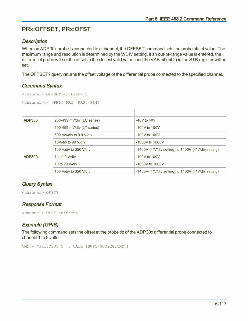
Part 6: IEEE 488.2 Command Reference
PRx:OFFSET, PRx:OFST
DescriptionWhen an ADP30x probe is connected to a channel, the OFFSET command sets the probe offset value. Themaximum range and resolution is determined by the V/DIV setting. If an out-of-range value is entered, thedifferential probe will set the offset to the closest valid value, and the VAB bit (bit 2) in the STB register will beset.
The OFFSET? query returns the offset voltage of the differential probe connected to the specified channel.
Command Syntax
<channel>:OFFSET <offset>[V]
<channel>:= PR1, PR2, PR3, PR4
V/Div Range Offset Ranges
ADP305 200-499 mV/div (LC series) -40V to 40V
200-499 mV/div (LT series) -100V to 100V
500 mV/div to 9.9 V/div -100V to 100V
10V/div to 99 V/div -1000V to 1000V
100 V/div to 350 V/div -1400V-(4*V/div setting) to 1400V-(4*V/div setting)
ADP300 1 to 9.9 V/div -100V to 100V
10 to 99 V/div -1000V to 1000V
100 V/div to 350 V/div -1400V-(4*V/div setting) to 1400V-(4*V/div setting)
Query Syntax
<channel>:OFST?
Response Format
<channel>:OFST <offset>
Example (GPIB)The following command sets the offset at the probe tip of the ADP30x differential probe connected tochannel 1 to 5 volts:
CMD$= "PR1:OFST 5" : CALL IBWRT(SCOPE%,CMD$)
6-117

MAUI Oscilloscopes Remote Control and Automation Manual
PRx:VOLT_DIV, PRx:VDIV
DescriptionThe PRx:VOLT_DIV command sets the vertical sensitivity at the ADP30x input. The effective gain of thedifferential probe is factored into the vertical sensitivity.
The valid range of arguments is fixed by the probe type. If an out-of-range value is entered, the oscilloscopewill set the vertical sensitivity to the closest value and set the VAB bit (bit 2) in the STB register.
The PRx:VOLT_DIV? query returns the vertical sensitivity at the probe input of the specified channel.
Command Syntax
<channel>:VOLT_DIV <sensitivity> [V]
<channel>:= PR1, PR2, PR3, PR4
<sensitivity>:= 200 mV to 350 V for ADP350; 1 V to 350 V for ADP300.
The suffix V is optional.
Query Syntax
<channel>:VOLT_DIV?
Response Format
<channel>:VDIV <sensitivity>
Example (GPIB)The following command sets the vertical sensitivity at the probe tip of an ADP30x probe connected tochannel 3 to 2 Volts/div:
CMD$= "PR3:VDIV 2" :CALL IBWRT(SCOPE%,CMD$)
6-118

Part 6: IEEE 488.2 Command Reference
SAVE/RECALL SETUP Commands and Queries
PANEL_SETUP, PNSU
DescriptionThe PANEL_SETUP command sends a data buffer to the scope that is a panel setup file. The oscilloscopeloads the <data> (see below) as it would when recalling a panel setup file locally on the scope.
The PANEL_SETUP query returns all oscilloscope setups in ASCII format, which can be saved to an .LSSfile to be recalled to the oscilloscope using RECALL_SETUP.
Only setup data previously read by the PNSU? query or saved using the STORE_PANEL command can berecalled into the oscilloscope. A panel setup error is generated if the setup data block contains invalid data.See the Execution Error Status Register (EXR) table in EXR? for more information.
Note: The communication parameters (modified by commands CFMT, CHDR, CHLP, CORD andWFSU) and the enable registers associated with the status reporting system (SRE, PRE, ESE,INE) are not saved by this command.
Command Syntax
PANEL_SETUP #9<nnnnnnnn><data><crc>
<nnnnnnnnn>:= size in bytes (<data> size + <crc> size)
<data>:= panel setup file contents (arbitrary data block)
<crc>:= reserved for 32-bit CRC plus 8-byte CRC trailer
Note: Command syntax is not checked by the oscilloscope, however, the 8-byte CRC trailer string isrequired when sending a file to the oscilloscope, and supplied when receiving a file from theoscilloscope. The ASCII string 'ffffffff' is normally used as the trailer string.
Query Syntax
PANEL_SETUP?
Response Format
PANEL_SETUP <setup>
The PNSU? query returns data that includes both a prefix and suffix that are required when seeking totransmit the panel setup when using the PNSU command.
The prefix is the communications header and the DEF9 string, which are the characters #9 followed by thenumber of bytes contained in the panel setup file. This byte count includes the CRC trailer, which is the eight'ffffffff' characters.
6-119

MAUI Oscilloscopes Remote Control and Automation Manual
If you wish to save the data received by the PNSU? query to disk as a setup file that can be used with theoscilloscope's “Recall Setup” feature, be sure to strip the DEF9 header and CRC trailer.
PNSU? Query ExampleThe <setup> contents shown below are shortened for brevity, and replaced by “…contents omitted…”
The data uses ‘\ codes’ for the whitespace characters: \s is a space character, \n = newline, \r = return
COMM_HEADER programmed to OFF:
<setup>: #9001243634'\sXStreamDSO\sConfigurationVBScript\s...\r\n'\sLECROY,MCM-Zi-A,…contents omitted…ffffffff
COMM_HEADER programmed to SHORT:
<setup>:PNSU\s#9001243634'\sXStreamDSO\sConfigurationVBScript\s...\r\n'\sLECROY,MCM-Zi-A,…contents omitted…ffffffff
Note: You can interpret from the DEF9 header that the panel setup file size is 1243634 bytes,including the ffffffff CRC trailer.
Related Commands*RCL, *SAV
6-120

Part 6: IEEE 488.2 Command Reference
*RCL (Recall Setup)
DescriptionThe *RCL command sets the instrument state by recalling one of the non-volatile setup panels (Setup 0 toSetup x).
The *RCL command produces an effect the opposite of the *SAV command.
If the specified setup is not acceptable, the Execution Error Status Register (EXR) is set and the EXE bit ofthe standard Event Status Register (ESR) is set.
Command Syntax
*RCL <panel_setup>
<panel_setup>:= 0 to x
0 is the factory default panel setup.
1 to x are the corresponding setup panels available on your oscilloscope. The maximum value of x will be thehighest number setup (e.g., 6 indicating Setup 6).
Example (GPIB)The following instruction recalls the instrument setup previously stored in Setup 3:
CMD$="*RCL 3": CALL IBWRT(SCOPE%,CMD$)
Related CommandsRECALL_PANEL, PANEL_SETUP, *SAV, ESR, EXR
6-121

MAUI Oscilloscopes Remote Control and Automation Manual
RECALL_PANEL, RCPN
DescriptionThe RECALL_PANEL command recalls panel setups from a file saved (using PNSU? orSTORE_PANEL) on the instrument data drive (D:) or a connected mass storage device. The device and thefile name are given as two-value parameter pairs.
Command Syntax
RECALL_PANEL DISK,<device>,FILE,'<file name>'
<device>:= HDD, USB, MICRO
<file name>:= full path to file with the extension .LSS
The file name string may be up to eight characters. Use the full path to the directory, including the driveletter, enclosed in single quotes. Be sure there are no spaces before the directory string.
Note: The hard drive selection (HDD) always points to drive D, which is the data drive on MAUIoscilloscopes. An external USB drive is usually named drive E; check your oscilloscope file system.The device type MICRO applies only to instruments that utilize Micro-SD card data storage, such asWaveSurfer 3000.
Example (GPIB)The following instruction recalls the panel setup from file CHIRP_MEAS.LSS on the instrument D: drive:
CMD$="RCPN DISK,HDD,FILE,'D:\Applications\USB2\Setups\CHIRP_MEAS.LSS'": CALL IBWRT(SCOPE%,CMD$)
The following instruction recalls the panel setup from file CHIRP_MEAS.LSS on a USB drive connected tothe instrument, where the file is stored in the \USB2\Setups subfolders:
CMD$="RCPN DISK,USB,FILE,'E:\USB2\Setups\CHIRP_MEAS.LSS'": CALL IBWRT(SCOPE%,CMD$)
The following instruction recalls the panel setup from file P012.LSS on a USB drive:
CMD$="RCPN DISK,USB,FILE,'P012.LSS'": CALL IBWRT(SCOPE%,CMD$)
Related CommandsPANEL_SETUP, *SAV, STORE_PANEL, *RCL
6-122

Part 6: IEEE 488.2 Command Reference
*RST (Reset)
DescriptionThe *RST command initiates a device reset. *RST sets all traces to the GND line and recalls the factorydefault panel setup (0), with the trigger in STOP mode (0).
Note: The Recall Default button on the oscilloscope GUI will recall the factory default panel in AUTOtrigger mode. To replicate this functionality via remote control, use the Automation command:app.SaveRecall.Setup.DoRecallDefaultPanelWithTriggerModeAuto. You may send this commandnested within the VBS command when using a legacy 488.2 script.
Command Syntax
*RST
Example (GPIB)The following instruction resets the oscilloscope:
CMD$="*RST": CALL IBWRT(SCOPE%,CMD$)
Related Commands*CAL, *RCL
6-123

MAUI Oscilloscopes Remote Control and Automation Manual
*SAV (Save Setup)
DescriptionThe *SAV command stores the current state of your instrument one of the non-volatile setup panels (Setup0 to Setup x). The *SAV command stores the complete setup of the oscilloscope at the time the command isissued.
Note: The communication parameters (modified by commands CFMT, CHDR, CHLP, CORD andWFSU) and the enable registers associated with the status reporting system (SRE, PRE, ESE,INE) are not saved by this command.
Command Syntax
*SAV <panel_setup>
<panel_setup>:= 1 to x
1 to x are the corresponding setup panels available on your oscilloscope. The maximum value of x will be thehighest number setup (e.g., 6 indicating Setup 6).
Example (GPIB)The following instruction saves the current instrument setup in Setup 3:
CMD$="*SAV 3": CALL IBWRT(SCOPE%,CMD$)
Related CommandsPANEL_SETUP, *RCL
6-124

Part 6: IEEE 488.2 Command Reference
STORE_PANEL, STPN
DescriptionThe STORE_PANEL command stores the complete panel setup of the oscilloscope in a file on theinstrument data drive (D:) or a connected mass storage device. The device and the file name are given astwo-value parameter pairs.
Note: The communication parameters (modified by commands CFMT, CHDR, CHLP, CORD andWFSU) and the enable registers associated with the status reporting system (SRE, PRE, ESE,INE) are not saved by this command.
If no file name (or an empty string) is supplied, the oscilloscope generates a file name according to itsinternal rules. Autogenerated file names are numbered sequentially.
This command is the complement of RECALL_PANEL.
Command Syntax
STORE_PANEL DISK,<device>,FILE,'<filename>'
<device>:= HDD, USB, MICRO
<filename>:= full path to file
The file name string may be up to eight characters. Use the full path to the directory, including the driveletter, enclosed in single quotes. Be sure there are no spaces before the directory string. The file extension.LSS will be appended automatically.
Note: The hard drive selection (HDD) always points to drive D, which is the data drive on mostTeledyne LeCroy oscilloscopes. An external USB drive is usually named drive E; check youroscilloscope file system. The device type MICRO applies only to instruments that utilize Micro-SDcard data storage, such as WaveSurfer 3000.
Example (GPIB)The following instruction saves the current oscilloscope setup to USB drive in a file called DIODE.LSS:
CMD$="STPN DISK,USB,FILE,'DIODE.LSS'": CALL IBWRT(SCOPE%,CMD$)
Related CommandsPNSU, *SAV, RECALL_PANEL, *RCL
6-125

MAUI Oscilloscopes Remote Control and Automation Manual
STATUS Commands and Queries
ALL_STATUS?, ALST?
DescriptionThe ALL_STATUS? query reads and clears the contents of all status registers: STB, ESR, INR, DDR,CMR, EXR and URR except for the MAV bit (bit 6) of the STB register. For an interpretation of the contentsof each register, refer to the appropriate status register.
The query is useful to obtain a complete overview of the state of your oscilloscope.
Query Syntax
ALL_STATUS?
Response Format
ALL_STATUS STB,<n>,ESR,<n>,INR,<n>,DDR,<n>,CMR,<n>,EXR,<n>,URR,<n>
<n> : = 0 to 65535
ExampleThe following instruction reads the contents of all the status registers:
CMD$="ALST?": CALL IBWRT(SCOPE%,CMD$):
CALL IBRD(SCOPE%,RSP$): PRINT RSP$
Response message:
ALST F2,000000,ESR,000052,INR,000005,DDR,000000,CMR,000004,EXR,000024,URR,000000
Related Commands*CLS, CMR?, DDR?, *ESR?, EXR?, *STB?, URR?
6-126

Part 6: IEEE 488.2 Command Reference
*CLS
DescriptionThe *CLS command clears all status data registers.
Command Syntax
*CLS
Example (GPIB)The following instruction causes all the status data registers to be cleared:
CMD$="*CLS": CALL IBWRT(SCOPE%,CMD$)
Related CommandsALL_STATUS, CMR, DDR, *ESR, EXR, *STB, URR
6-127
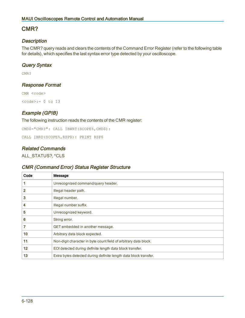
MAUI Oscilloscopes Remote Control and Automation Manual
CMR?
DescriptionThe CMR? query reads and clears the contents of the Command Error Register (refer to the following tablefor details), which specifies the last syntax error type detected by your oscilloscope.
Query Syntax
CMR?
Response Format
CMR <code>
<code>:= 0 to 13
Example (GPIB)The following instruction reads the contents of the CMR register:
CMD$="CMR?": CALL IBWRT(SCOPE%,CMD$):
CALL IBRD(SCOPE%,RSP$): PRINT RSP$
Related CommandsALL_STATUS?, *CLS
CMR (Command Error) Status Register Structure
Code Message
1 Unrecognized command/query header.
2 Illegal header path.
3 Illegal number.
4 Illegal number suffix.
5 Unrecognized keyword.
6 String error.
7 GET embedded in another message.
10 Arbitrary data block expected.
11 Non-digit character in byte count field of arbitrary data block.
12 EOI detected during definite length data block transfer.
13 Extra bytes detected during definite length data block transfer.
6-128

Part 6: IEEE 488.2 Command Reference
DDR?
DescriptionThe DDR? query reads and clears the contents of the Device Dependent or Device Specific Error Register(DDR). In the case of a hardware failure, the DDR register specifies the origin of the failure.
Query Syntax
DDR?
Response Format
DDR <value>
<value>:= 0 to 65535
DDR (Device Dependent) Status Register Structure
Bit Value Meaning
15...14 Reserved.
13 8192 Timebase hardware failure detected.
12 4096 Trigger hardware failure detected.
11 2048 Channel 4 hardware failure detected.
10 1024 Channel 3 hardware failure detected.
9 512 Channel 2 hardware failure detected.
8 256 Channel 1 hardware failure detected.
7 128 External input overload condition detected.
6...4 Reserved.
3 8 Channel 4 overload condition detected.
2 4 Channel 3 overload condition detected.
1 2 Channel 2 overload condition detected.
0 1 Channel 1 overload condition detected.
6-129

MAUI Oscilloscopes Remote Control and Automation Manual
*ESE
DescriptionThe *ESE command sets the standard Event Status Enable Register (ESE). This command allows one ormore events in the ESR register to be reflected in the ESB summary message bit (bit 5) of the STB register.For an overview of the ESB defined events, refer to the ESR table.
The *ESE? query reads the contents of the ESE register.
Command Syntax
*ESE <value>
<value>:= 0 to 255
Query Syntax
*ESE?
Response Format
*ESE <value>
Example (GPIB)The following instruction allows the ESB bit to be set if a user request (URQ bit 6, decimal 64) and/or adevice dependent error (DDE bit 3, decimal 8) occurs. Summing these values yields the ESE register mask64+8=72.
CMD$="*ESE 72": CALL IBWRT(SCOPE%,CMD$)
Related Commands*ESR
6-130
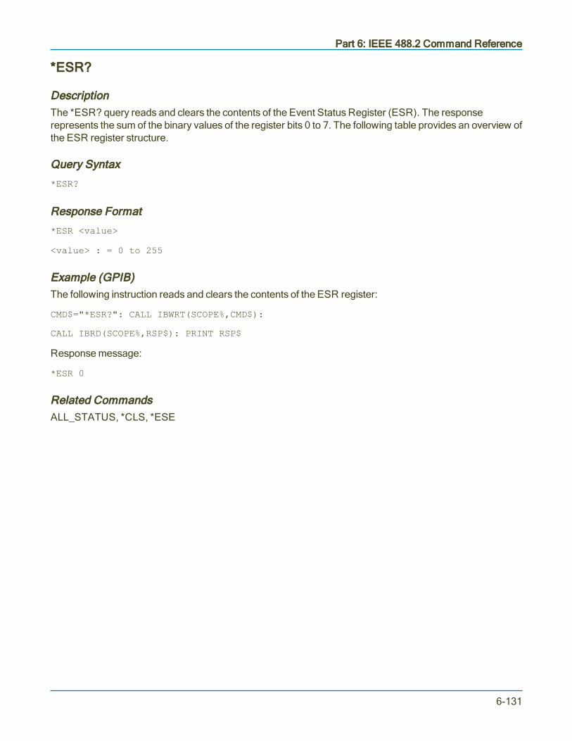
Part 6: IEEE 488.2 Command Reference
*ESR?
DescriptionThe *ESR? query reads and clears the contents of the Event Status Register (ESR). The responserepresents the sum of the binary values of the register bits 0 to 7. The following table provides an overview ofthe ESR register structure.
Query Syntax
*ESR?
Response Format
*ESR <value>
<value> : = 0 to 255
Example (GPIB)The following instruction reads and clears the contents of the ESR register:
CMD$="*ESR?": CALL IBWRT(SCOPE%,CMD$):
CALL IBRD(SCOPE%,RSP$): PRINT RSP$
Response message:
*ESR 0
Related CommandsALL_STATUS, *CLS, *ESE
6-131
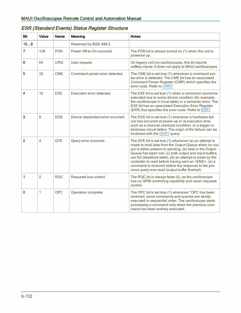
MAUI Oscilloscopes Remote Control and Automation Manual
ESR (Standard Events) Status Register Structure
Bit Value Name Meaning Notes
15...8 Reserved by IEEE 488.2.
7 128 PON Power Off-to-On occurred. The PON bit is always turned on (1) when the unit ispowered up.
6 64 URQ User request. On legacy LeCroy oscilloscopes, this bit reportssoftkey inputs. It does not apply to MAUI oscilloscopes.
5 32 CME Command parser error detected. The CME bit is set true (1) whenever a command syn-tax error is detected. The CME bit has an associatedCommand Parser Register (CMR) which specifies theerror code. Refer to CMR?
4 16 EXE Execution error detected. The EXE bit is set true (1) when a command cannot beexecuted due to some device condition (for example,the oscilloscope in local state) or a semantic error. TheEXE bit has an associated Execution Error Register(EXR) that specifies the error code. Refer to EXR?
3 8 DDE Device dependent error occurred. The DDE bit is set true (1) whenever a hardware fail-ure has occurred at power-up or at execution time,such as a channel overload condition, or a trigger ortimebase circuit defect. The origin of the failure can belocalized with the DDR? query.
2 4 QYE Query error occurred. The QYE bit is set true (1) whenever (a) an attempt ismade to read data from the Output Queue when no out-put is either present or pending, (b) data in the OutputQueue has been lost, (c) both output and input buffersare full (deadlock state), (d) an attempt is made by thecontroller to read before having sent an <END>, (e) acommand is received before the response to the pre-vious query was read (output buffer flushed).
1 2 RQC Requests bus control. The RQC bit is always false (0), as the oscilloscopehas no GPIB controlling capability and never requestscontrol.
0 1 OPC Operation complete. The OPC bit is set true (1) whenever *OPC has beenreceived, since commands and queries are strictlyexecuted in sequential order. The oscilloscope startsprocessing a command only when the previous com-mand has been entirely executed.
6-132

Part 6: IEEE 488.2 Command Reference
EXR?
DescriptionThe EXR? query reads and clears the contents of the Execution Error Register (EXR). The EXR registerspecifies the type of the last error detected during execution. Refer to the following table for moreinformation.
Query Syntax
EXR?
Response Format
EXR? <code>
<code>:= 21 to 64
Example (GPIB)The following instruction reads the contents of the EXR register:
CMD$="EXR?": CALL IBWRT(SCOPE%,CMD$):
CALL IBRD(SCOPE%,RSP$): PRINT RSP$
Response message (if no fault):
EXR 0
Related CommandsALL_STATUS, *CLS
6-133

MAUI Oscilloscopes Remote Control and Automation Manual
EXR (Execution Error) Status Register StructureThe following table lists the error codes that may be returned with the EXR query. Codes marked with anasterisk (*) are valid only on instruments with a removable hard drive or memory card.
Code Description
21 Permission error. The command cannot be executed in local mode.
22 Environment error. The oscilloscope is not configured to correctly process a command. For instance, the oscil-loscope cannot be set to RIS at a slow timebase.
23 Option error. The command applies to an option which has not been installed.
24 Unresolved parsing error.
25 Parameter error. Too many parameters specified.
26 Non-implemented command.
27 Parameter missing. A parameter was expected by the command.
30 Hex data error. A non-hexadecimal character has been detected in a hex data block.
31 Waveform error. The amount of data received does not correspond to descriptor indicators.
32 Waveform descriptor error. An invalid waveform descriptor has been detected.
33 Waveform text error. A corrupted waveform user text has been detected.
34 Waveform time error. Invalid RIS or TRIG time data has been detected.
35 Waveform data error. Invalid waveform data have been detected.
36 Panel setup error. An invalid panel setup data block has been detected.
50* No mass storage present when user attempted to access it.
51* Mass storage not formatted when user attempted to access it.
53* Mass storage was write protected when user attempted to create a file, to delete a file, or to format the device.
54* Bad mass storage detected during formatting.
55* Mass storage root directory full. Cannot add directory.
56* Mass storage full when user attempted to write to it.
57* Mass storage file sequence numbers exhausted (999 reached).
58* Mass storage file not found.
59* Requested directory not found.
61* Mass storage file name not DOS compatible, or illegal file name.
62* Cannot write on mass storage because file name already exists.
6-134
Part 6: IEEE 488.2 Command Reference
INE
DescriptionThe INE command sets the Internal State Change Enable register (INE). This command allows one or moreevents in the INR register to be reflected in the INB summary message bit (bit 0) of the STB register. For anoverview of the INR defined events, refer to the Internal State Register Structure (INR) table in the INR?topic for more information.
The INE? query reads the contents of the INE register.
Command Syntax
INE <value>
<value>:= 0 to 65535
Query Syntax
INE?
Response Format
INE <value>
Example (GPIB)The following instruction allows the INB bit to be set whenever a screen dump has finished (bit 1, forexample decimal 2), or a waveform is acquired (bit 0, for example decimal 1), or both of these. Summingthese two values yields the INE mask 2+1=3.
CMD$="INE 3": CALL IBWRT(SCOPE%,CMD$)
Related CommandsINR?
6-135

MAUI Oscilloscopes Remote Control and Automation Manual
INR?
DescriptionThe INR? query reads and clears the contents of the Internal State Change Register (INR). The INRregister (table below) records the completion of various internal operations and state transitions.
Query Syntax
INR?
Response Format
INR <state>
<state>:= 0 to 65535
Example (GPIB)The following instruction reads the contents of the INR register:
CMD$="INR?": CALL IBWRT(SCOPE%,CMD$)
The response message represents the summed bit value of the internal state changes:
INR 1026
Meaning, waveform processing in math function F3 (1024) and a screen dump (2) have both terminated.
Related CommandsALL_STATUS, *CLS, INE
6-136
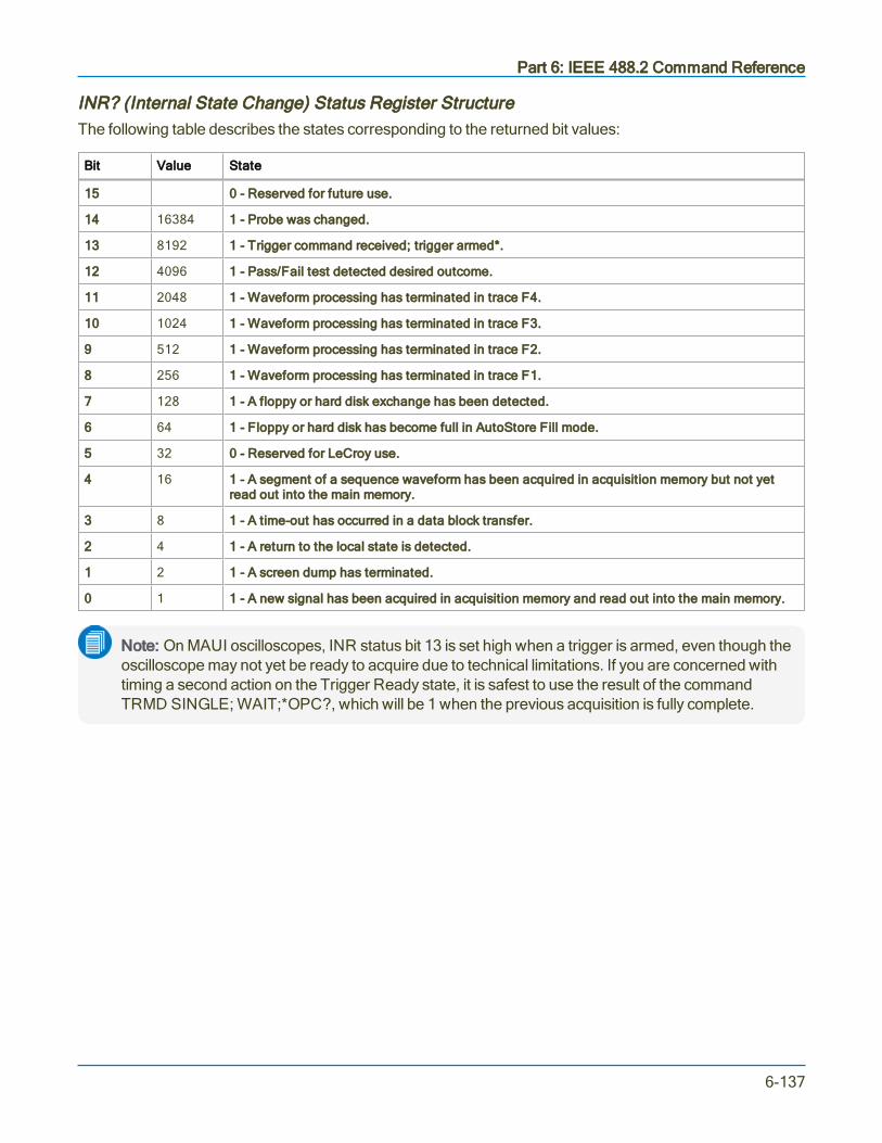
Part 6: IEEE 488.2 Command Reference
INR? (Internal State Change) Status Register StructureThe following table describes the states corresponding to the returned bit values:
Bit Value State
15 0 - Reserved for future use.
14 16384 1 - Probe was changed.
13 8192 1 - Trigger command received; trigger armed*.
12 4096 1 - Pass/Fail test detected desired outcome.
11 2048 1 - Waveform processing has terminated in trace F4.
10 1024 1 - Waveform processing has terminated in trace F3.
9 512 1 - Waveform processing has terminated in trace F2.
8 256 1 - Waveform processing has terminated in trace F1.
7 128 1 - A floppy or hard disk exchange has been detected.
6 64 1 - Floppy or hard disk has become full in AutoStore Fill mode.
5 32 0 - Reserved for LeCroy use.
4 16 1 - A segment of a sequence waveform has been acquired in acquisition memory but not yetread out into the main memory.
3 8 1 - A time-out has occurred in a data block transfer.
2 4 1 - A return to the local state is detected.
1 2 1 - A screen dump has terminated.
0 1 1 - A new signal has been acquired in acquisition memory and read out into the main memory.
Note: On MAUI oscilloscopes, INR status bit 13 is set high when a trigger is armed, even though theoscilloscope may not yet be ready to acquire due to technical limitations. If you are concerned withtiming a second action on the Trigger Ready state, it is safest to use the result of the commandTRMD SINGLE; WAIT;*OPC?, which will be 1 when the previous acquisition is fully complete.
6-137

MAUI Oscilloscopes Remote Control and Automation Manual
*IST?
DescriptionThe *IST? (Individual STatus) query reads the current state of the IEEE 488.1-defined IST local message.The IST individual status message is the status bit sent during a parallel poll operation.
Query Syntax
*IST?
Response Format
*IST <value>
<value>:= 0 or 1
Example (GPIB)The following instruction causes the contents of the IST bit to be read:
CMD$="*IST?": CALL IBWRT(SCOPE%,CMD$):
CALL IBRD(SCOPE%,RSP$): PRINT RSP$
Response message:
*IST 0
Related Commands*PRE
6-138
Part 6: IEEE 488.2 Command Reference
*OPC
DescriptionThe *OPC (Operation Complete) command sets the OPC bit (bit 0) to "true" in the standard Event StatusRegister (ESR).
The *OPC? query always responds with the ASCII character 1 because the oscilloscope only responds tothe query when the previous commands are entirely executed. Since *OPC? executes only whenprocessing is complete, it is recommended for synchronization purposes. See Timing and Synchronization.
Command Syntax
*OPC
Query Syntax
*OPC?
Response Format
1
Related Commands*WAI
6-139

MAUI Oscilloscopes Remote Control and Automation Manual
*PRE
DescriptionThe *PRE command sets the PaRallel poll Enable register (PRE). The lowest eight bits of the Parallel PollRegister (PPR) are composed of the STB bits. *PRE allows you to specify which bit(s) of the parallel pollregister affect the IST (Individual Status Bit).
The *PRE? query reads the contents of the PRE register. The response is a decimal number correspondingto the binary sum of the register bits.
Command Syntax
PRE <value>
<value>:= 0 to 65535
Query Syntax
*PRE?
Response Format
*PRE <value>
Example (GPIB)The following instruction causes the IST status bit to become 1 as soon as the MAV bit (bit 4 of STB,meaning decimal 16) is set, and yields the PRE value 16:
CMD$="*PRE 16": CALL IBWRT(SCOPE%,CMD$)
Related Commands*IST
6-140

Part 6: IEEE 488.2 Command Reference
*SRE
DescriptionThe *SRE command sets the Service Request Enable register (SRE). This command allows you to specifywhich summary message bit or bits in the STB register generate a service request. Refer to the table onpage 225 for an overview of the available summary messages.
A summary message bit is enabled by writing a 1 into the corresponding bit location. Conversely, writing a 0into a given bit location prevents the associated event from generating a service request (SRQ). Clearingthe SRE register disables SRQ interrupts.
The *SRE? query returns a value that, when converted to a binary number, represents the bit settings of theSRE register. Note that bit 6 (MSS) cannot be set and its returned value is always zero.
Command Syntax
*SRE <value>
<value>:= 0 to 255
Query Syntax
*SRE?
Response Format
*SRE <value>
Example (GPIB)The following instruction allows an SRQ to be generated as soon as the MAV summary bit (bit 4, forexample decimal 16) or the INB summary bit (bit 0, for example decimal 1) in the STB register, or both, areset. Summing these two values yields the SRE mask 16 + 1 = 17.
CMD$="*SRE 17": CALL IBWRT(SCOPE%,CMD$)
6-141

MAUI Oscilloscopes Remote Control and Automation Manual
*STB?
DescriptionThe *STB? query reads the contents of the 488.1 defined Status Byte Register (STB) and Master SummaryStatus (MSS). The response represents the values of bits 0 to 5 and 7 of the STB register and the MSSsummary message.
The response to a *STB? query is identical to the response of a serial poll except that the MSS summarymessage appears in bit 6 in place of the RQS message.
Query Syntax
*STB?
Response Format
*STB? <value>
<value>:= 0 to 255
Example (GPIB)The following instruction reads the Status Byte Register:
CMD$="*STB?": CALL IBWRT(SCOPE%,CMD$):
CALL IBRD(SCOPE%,RSP$): PRINT RSP$
Response message:
*STB 0
Related CommandsALL_STATUS, *CLS, *PRE, *SRE
6-142

Part 6: IEEE 488.2 Command Reference
STB (Status Byte) Status Register Structure
Bit Value Name Description Notes
7 128 DIO7 Reserved forfuture use.
6 64 MSS/RQSMSS = 1RQS = 1
At least 1 bit inSTB masked bySRE is 1, ser-vice is reques-ted.
The Master Summary Status (MSS) indicates the oscilloscoperequests service, while the Service Request status (when set)specifies the oscilloscope issued a service request. Bit position 6depends on the polling method:
MSS if an *STB? query is receivedRQS if serial polling is conducted
Example:If SRE = 10 and STB = 10, then MSS = 1.If SRE = 010 and STB = 100 then MSS = 0.
5 32 ESB An ESRenabled eventhas occurred.
The Event Status Bit (ESB) indicates whether or not one or moreof the enabled IEEE 488.2 events occurred since the last readingor clearing of the Standard Event Status Register (ESR). ESB isset if an enabled event becomes true (1).
4 16 MAV Output queue isnot empty.
The Message AVailable bit (MAV) indicates whether or not theOutput queue is empty. The MAV summary bit is set true (1)whenever a data byte resides in the Output queue.
3 8 DIO3 Reserved.
2 4 VAB A commanddata value hasbeen adapted.
The Value Adapted Bit (VAB) is set true (1) whenever a datavalue in a command is adapted to the nearest legal value. Forinstance, the VAB bit would be set if the timebase is redefined as2.5 µs/div since the adapted value is 2 µs/div.
1 2 DIO1 Reserved.
0 1 INB An enabledinternal statechangeoccurred.
The Internal State Bit (INB) is set true (1) whenever certainenabled internal states are entered. For further information, referto the INR? query.
6-143

MAUI Oscilloscopes Remote Control and Automation Manual
*WAI
DescriptionThe *WAI (Wait to continue) command, required by the IEEE 488.2 standard, has no effect on theoscilloscope, as the instrument only starts processing a command when the previous command has beenentirely executed.
Command Syntax
*WAI
6-144

Part 6: IEEE 488.2 Command Reference
STORAGE Commands and Queries
DELETE_FILE, DELF
DescriptionThe DELETE_FILE command deletes a file from the currently selected directory.
Command Syntax
DELETE_FILE DISK,<medium>,FILE,'<filename>'
<medium>: = HDD, USB, MICRO
The file name must be enclosed in single quotes. Use the full path to the directory, including the drive letter.Be sure there are no spaces before the directory string.
Note: The hard drive selection (HDD) always points to drive D, which is the data drive on MAUIoscilloscopes. An external USB drive is usually named drive E; check your oscilloscope file system.The device type MICRO applies only to instruments that utilize Micro-SD card data storage, such asWaveSurfer 3000.
Example (GPIB)The following instruction deletes a panel setup file from the hard drive:
CMD$="DELF DISK,HDD,FILE,'D:\SETUPS\TESTRUN.LSS'
CALL IBWRT(SCOPE%,CMD$)
6-145

MAUI Oscilloscopes Remote Control and Automation Manual
TRANSFER_FILE, TRFL
DescriptionThis command allows you to transfer files to and from storage media, or between oscilloscope andcomputer. The command format is used to transfer files from the computer to storage media. The queryformat is used to transfer files from storage media to computer.
Command Syntax
TRANSFER_FILE DISK,<device>,FILE,'<filepath>',#9<nnnnnnnnn><data><crc>
<device>:=HDD, USB, MICRO
<filepath>:= legal DOS path to file
<nnnnnnnnn>:= file size in bytes (<data> size + <crc> size)
<data>:= file data (arbitrary data block)
<crc>:= reserved for 32-bit CRC plus 8-byte CRC trailer
The path name must be enclosed in single quotes. Use the full path to the directory, including the drive letter.Be sure there are no spaces before the directory string.
Note: The hard drive selection (HDD) always points to drive D, which is the data drive on MAUIoscilloscopes. An external USB drive is usually named drive E; check your oscilloscope file system.The device type MICRO applies only to instruments that utilize Micro-SD card data storage, such asWaveSurfer 3000.
Note: CRC checking is not performed by the scope, however the 8-byte CRC trailer string isrequired when sending a file to the scope, and supplied when receiving a file from the scope. TheASCII string 'ffffffff' is normally used as trailer string.
Query Syntax
TRFL? DISK,<device>,FILE,'<filepath>'
Response Format
TRFL #9nnnnnnnnn<data><crc>
Example (GPIB)The following instruction reads the file FAVORITE.DSO from the hard drive:
CMD$=TRFL DISK,HDD,FILE,'FAVORITE.DSO' CALL IBWRT(SCOPE%,CMD$)
Related CommandsDIRECTORY
6-146

Part 6: IEEE 488.2 Command Reference
WAVEFORM TRANSFER Commands and Queries
INSPECT?, INSP?
DescriptionThe INSPECT? query allows you to read parts of an acquired waveform in intelligible form. The command isbased on the explanation of the format of a waveform given by the Waveform Template (use theTEMPLATE? query to obtain an up-to-date copy of the template).
Any logical block of a waveform can be inspected using this query by giving its name enclosed in quotes asthe first parameter (refer to the template itself for more details).
The special logical block named WAVEDESC can also be inspected in more detail. By giving the name of avariable in the WAVEDESC block as the first parameter, it is possible to inspect only the value of that oneentity.
Query Syntax
<trace>:INSPECT? '<WAVEDESC variable|logical block>',[<data_type>]
<trace>:= C1 to Cn, F1 to Fn, M1 to Mn, TA to TD
<WAVEDESC_variable>:= any variable listed in the WAVEDESC block of theoscilloscope's Waveform Template
<logical_block>:= TRIGTIME,RISTIME,SIMPLE,DATA_ARRAY_1,DATA_ARRAY_2,
<data_type>:= BYTE, WORD, FLOAT
Note: TA through TD are for backward compatibility. Although accepted, they are not returned byqueries.
You may use single or double quotation marks in the query, but the reply always uses double quotes.
The optional parameter <data_type> applies only to inspection of data arrays. It selects the representationof the data. The default <data_type> is FLOAT.
Data Type Descriptions
BYTE Raw data as integers (truncated to 8 most significant bits).
FLOAT Normalized data (gain, offset applied) as floating point numbers (gives measured values in volts orunits).
WORD Raw data as integers (truncated to 16 most significant bits).
6-147

MAUI Oscilloscopes Remote Control and Automation Manual
Block WAVEDESC contains several variables related to scaling of data values. Values of these variablesdepend on the current setting of the command COMM_FORMAT (CFMT). The following example showshow the values returned by INSP? change when you modify the CFMT setting from BYTE (default) toWORD:
CFMT Set to BYTE CFMT Set to WORD
VERTICAL_GAIN : 3.1250e-003VERTICAL_OFFSET : -2.0600e-001MAX_VALUE : 1.2700e+002MIN_VALUE : -1.2800e+002
VERTICAL_GAIN : 1.2207e-005VERTICAL_OFFSET : -2.0600e-001MAX_VALUE : 3.2512e+004MIN_VALUE : -3.2768e+004
Response Format
<trace>:INSPECT "<WAVEDESC_variable|logical_block>: <value>"
Examples (GPIB)The following instruction reads the value of the timebase at which the last waveform in Channel 1 wasacquired:
CMD$="C1:INSP? 'TIMEBASE'"
CALL IBWRT(SCOPE%,CMD$)
CALL IBRD(SCOPE%,RSP$)
PRINT RSP$
Response message:
C1:INSP "TIMEBASE: 500 US/DIV"
The following instruction reads the entire contents of the waveform descriptor block:
CMD$="C1:INSP? 'WAVEDESC'"
Related CommandsCOMM_FORMAT, TEMPLATE, WAVEFORM_SETUP
6-148

Part 6: IEEE 488.2 Command Reference
RECALL, REC
DescriptionThe RECALL command recalls a waveform file from the current directory on mass storage into any of theinternal memories (M1 to Mn).
Only waveforms stored in binary format (.trc) can be recalled.
Command Syntax
<memory>:RECALL DISK,<device>,FILE,'<file name>'
<device>:= HDD, USB, MICRO
<memory>:= M1 to Mn
<file name>:= full path to .trc file
The file path must be enclosed in single quotes. Use the full path to the directory, including the drive letter.Be sure there are no spaces before the directory string.
Note: The hard drive selection (HDD) always points to drive D, which is the data drive on MAUIoscilloscopes. An external USB drive is usually named drive E; check your oscilloscope file system.The device type MICRO applies only to instruments that utilize Micro-SD card data storage, such asWaveSurfer 3000.
Example (GPIB)The following instruction recalls the waveform file 'C2Trace00000.trc' into Memory 1:
CMD$="<M1:REC DISK,HDD,FILE,'D:\Waveforms\C2Trace00000.trc'": CALL IBWRT(SCOPE%,CMD$)
Related CommandsSTORE, INR?
6-149

MAUI Oscilloscopes Remote Control and Automation Manual
STORE, STO
DescriptionThe STORE command stores the specified waveform data in one of the internal memories (M1 to Mn) or inthe current directory in mass storage. The files are saved in binary with the .trc extension.
The complement to the STORE command is the RECALL command, which recalls waveforms saved toexternal files into one of the oscilloscope internal memories.
Set the current directory (where files are stored) with the DIR command.
Command Syntax
STORE [<trace>,<dest>]
<trace>:= C1 to Cn, F1 to Fn, TA to TD, or ALL_DISPLAYED
<dest>:= M1 to Mn, or FILE
Note: TA through TD are for backward compatibility. Although accepted, they are not returned byqueries.
When storing traces to FILE, files are saved with the .trc extension in the directory last set with the DIRcommand. File names are autogenerated.
If you send the STORE command without an argument, the current Storage Setup operation will be stored.Modify this setup using STORE_SETUP.
Example (GPIB)The following instruction stores the Channel 4 (C4) waveform into Memory 1 (M1):
CMD$="STO C4,M1": CALL IBWRT(SCOPE%,CMD$)
The following instruction stores all currently displayed waveforms onto the hard drive:
CMD$="STO ALL_DISPLAYED,FILE": CALL IBWRT(SCOPE%,CMD$)
The following instruction executes the storage operation currently defined in the Storage Setup:
CMD$="STO": CALL IBWRT(SCOPE%,CMD$)
Related CommandsDIR, RECALL, STORE_SETUP
6-150

Part 6: IEEE 488.2 Command Reference
STORE_SETUP, STST
DescriptionThe STORE_SETUP command controls the way in which traces are stored. Any one trace or all displayedtraces can be set up for storage, either by turning on AUTO store or using the STORE command.
Two modes are available when using AUTO store: FILL, which stops when the storage medium is full, andWRAP, which replaces the oldest trace by the latest one. Wrap mode overwrites any trace file, whether ornot it was made during the current session or records the same trace.
Command Syntax
STORE_SETUP [<trace>,<dest>][,AUTO,<mode>][,FORMAT,<type>]
<trace>:= C1 to Cn, F1 to Fn, M1 to Mn, TA to TD, ALL_DISPLAYED
<dest>:= M1 to Mn, HDD
<mode>:= OFF, FILL, WRAP
<type>:= ASCII, BINARY, EXCEL,MATHCAD, MATLAB
Note: TA through TD are for backward compatibility. Although accepted, they are not returned byqueries.
Query Syntax
STORE_SETUP?
Response Format
STORE_SETUP <trace>,<dest>,AUTO,<mode>
Example (GPIB)The following instruction enables AUTO store for Channel 1, to be performed until insufficient spaceremains for another file.
CMD$="STST C1,HDD,AUTO,FILL" CALL IBWRT("SCOPE%", CMD$)
Related CommandsSTORE, INR
6-151

MAUI Oscilloscopes Remote Control and Automation Manual
TEMPLATE?, TMPL?
DescriptionThe TEMPLATE? query produces a copy of the template that describes the various logical entities makingup a complete waveform. In particular, the template describes in full detail the variables contained in thedescriptor part of a waveform.
Query Syntax
TEMPLATE?
Response Format
TEMPLATE? "<template>"
<template>:= Variable length string detailing the structure of a waveform.
Related CommandsINSPECT?
6-152

Part 6: IEEE 488.2 Command Reference
WAVEFORM, WF
DescriptionA WAVEFORM command transfers a waveform from the controller to an oscilloscope internal memory forfuture recall and display, whereas a WAVEFORM? query transfers a waveform from the oscilloscopedisplay to the controller in file format.
WAVEFORM stores an external waveform back into the oscilloscope's internal memory. A waveformconsists of several distinct entities:
l The waveform descriptor (DESC)
l The user text (TEXT)
l The time descriptor (TIME)
l The data block (DAT1)
l An optional second data block (DAT2)
The WAVEFORM? query instructs the oscilloscope to transmit a waveform to the controller. The entitiescan be queried independently. If the ALL parameter is specified, all four or five entities are transmitted in oneblock in the order shown above.
Note: Only complete waveforms transmitted with the WAVEFORM? ALL query can be restored tothe oscilloscope.
The format of the waveform data depends on the current settings specified by the last WAVEFORM_SETUP, COMM_ORDER and COMM_FORMAT commands.
Command Syntax
<memory>:WAVEFORM ALL <waveform_data_block>
<memory>:= M1 to Mn
<waveform_data_block>:= arbitrary data block
Query Syntax
<trace>:WaveForm? <block>
<trace>:= C1 to Cn, F1 to Fn, M1 to Mn, TA to TD
<block>:= DESC, TEXT, TIME, DAT1, DAT2, ALL
Note: TA through TD are for backward compatibility. Although accepted, they are not returned byqueries.
If you do not provide a <block> parameter, ALL is assumed.
6-153

MAUI Oscilloscopes Remote Control and Automation Manual
Response Format
<trace>:WAVEFORM <block>,<waveform_data_block>
Tip: It may be convenient to disable the response header if the waveform is to be restored to theoscilloscope. See the COMM_HEADER topic for more information.
Examples (GPIB)The following instruction reads the block DAT1 from Memory 1 and saves it in the file "MEM1.DAT". Thepath header "M1:" is saved together with the data.
FILE$ = "MEM1.DAT"CMD$ = "M1:WF? DAT1"CALL IBWRT(SCOPE%,CMD$)CALL IBRDF(SCOPE%,FILE$)
In the following example, the entire contents of Channel 1 are saved in the file "CHAN1.DAT". The pathheader "C1:" is skipped to ensure that the data can later be recalled into the oscilloscope.
FILE$="CHAN1.DAT":RD$=SPACE$(3)CMD$="CHDR SHORT; C1:WF?"CALL IBWRT(SCOPE%,CMD$)CALL IBRD(SCOPE%,RD$) ' Skip first 3 characters "C1:"CALL IBRDF(SCOPE%,FILE$) ' Save data in file "CHAN1.DAT"
The following instruction illustrates how the waveform data saved in the preceding example can be recalledinto Memory 1:
FILE$ = "CHAN1.DAT"CMD$ ="M1:"CALL IBEOT(SCOPE%,0) ' disable EOICALL IBWRT(SCOPE%,CMD$)CALL IBEOT(SCOPE%,1) ' re-enable EOICALL IBWRTF(SCOPE%,FILE$)
The "M1:" command ensures the active waveform is "M1". When the data file is sent to the oscilloscope, itfirst sees the header "WF" (the characters "C1:" having been skipped when reading the file) and assumesthe default destination "M1".
Related CommandsINSPECT, COMM_FORMAT, COMM_ORDER, FUNCTION_STATE, TEMPLATE, WAVEFORM_SETUP, WAVEFORM_TEXT
6-154

Part 6: IEEE 488.2 Command Reference
WAVEFORM_SETUP, WFSU
DescriptionThe WAVEFORM_SETUP command specifies the amount of data in a waveform to be transmitted to thecontroller.
The WAVEFORM_SETUP? query returns the transfer parameters currently in use.
Command Syntax
WAVEFORM_SETUP SP,<sparsing>,NP,<number>,FP,<first point>,SN,<segment>
Note: After power-on, all values are set to 0 (meaning, entire waveforms are transmitted withoutsparsing). Parameters are grouped in pairs. The first of the pair names which variable is modified,while the second provides the new value for assignment. Pairs can be given in any order andrestricted to the variables for change.
Sparsing (SP)The sparsing parameter defines the interval between data points. For example:
SP = 0 sends all data points.
SP = 1 sends all data points.
SP = 4 sends every 4th data point.
Number of Points (NP)The number of points parameter indicates how many points should be transmitted. For example:
NP = 0 sends all data points.
NP = 1 sends 1 data point.
NP = 50 sends a maximum of 50 data points.
NP = 1001 sends a maximum of 1001 data points.
First Point (FP)The first point parameter specifies the address of the first data point to be sent. For waveforms acquired insequence mode, this refers to the relative address in the given segment. For example:
FP = 0 corresponds to the first data point.
FP = 1 corresponds to the second data point.
FP = 5000 corresponds to data point 5001.
6-155

MAUI Oscilloscopes Remote Control and Automation Manual
Segment Number (SN)The segment number parameter indicates which segment should be sent if the waveform was acquired insequence mode. This parameter is ignored for non-segmented waveforms. For example:
SN = 0 all segments.
SN = 1 first segment.
SN = 23 segment 23.
Query Syntax
WAVEFORM_SETUP?
Response Format
WAVEFORM_SETUP SP,<sparsing>,NP,<number>,FP,<first point>,SN,<segment>
Example (GPIB)The following instructs every 3rd data point (SP = 3) starting at address 200 for transfer:
CMD$="WFSU SP,3,FP,200": CALL IBWRT(SCOPE%,CMD$)
Related CommandsINSPECT, WAVEFORM, TEMPLATE
6-156
Part 6: IEEE 488.2 Command Reference
DISK DRIVE ANALYSIS (Option) Commands and Queries
DD_ANALOG_COMP_THRESH, DACT
DescriptionSets the analog threshold value for Analog Compare.
Command Syntax
DD_ANALOG_COMPARE_THRESHOLD <threshold>
<threshold >:= float in range 0.0 to 1.0. Analog Compare error threshold in units offull-scale error.
Query Syntax
DD_ANALOG_COMPARE_THRESHOLD?
Response Format
DD_ANALOG_COMPARE_THRESHOLD <threshold>
Related CommandsDD_FIND_ERROR, DD_FIND_METHOD
6-157

MAUI Oscilloscopes Remote Control and Automation Manual
DD_ANALYZE_REGION_DISABLE, DARD
DescriptionDisables the use of the analyze region markers, which means the entire waveform will be analyzed in analogcompare and channel emulation.
Command Syntax
DD_ANALYZE_REGION_DISABLE
The analyze region is enabled whenever DD_ANALYZE_REGION_START or DD_ANALYZE_REGION_LENGTH are set.
Related CommandsDD_ANALYZE_REGION_START, DD_ANALYZE_REGION_LENGTH
6-158
Part 6: IEEE 488.2 Command Reference
DD_ANALYZE_REGION_LENGTH, DARL
DescriptionSelects the length of a region to be analyzed.
Command Syntax
DD_ANALYZE_REGION_LENGTH <time >
<time>:= time in seconds
Query Syntax
DD_ANALYZE_REGION_LENGTH?
Response Format
DD_ANALYZE_REGION_LENGTH <time >
Related CommandsDD_ANALYZE_REGION_START, DD_ANALYZE_REGION_DISABLE
6-159

MAUI Oscilloscopes Remote Control and Automation Manual
DD_ANALYZE_REGION_START, DARS
DescriptionSelects the start of a region to be analyzed.
Command Syntax
DD_ANALYZE_REGION_START <time >
<time>:= time in seconds
Query Syntax
DD_ANALYZE_REGION_START?
Response Format
DD_ANALYZE_REGION_START <time >
Related CommandsDD_ANALYZE_REGION_LENGTH, DD_ANALYZE_REGION_DISABLE
6-160

Part 6: IEEE 488.2 Command Reference
DD_BITCELL, DBIT
DescriptionEnters the bit cell time of the head signal.
Command Syntax
DD_BITCELL <bittime>
<bittime>:= time in range 0.10–99.99 ns
Query Syntax
DD_BITCELL?
Response Format
DD_BITCELL <bittime>
6-161

MAUI Oscilloscopes Remote Control and Automation Manual
DD_BYTE_OFFSET, DBYT
DescriptionMoves the head trace to show the specified byte. Channel must be configured.
Command Syntax
DD_BYTE_OFFSET <bytenum>
<bytenum>:= integer in range 20 to 50,000
Query Syntax
DD_BYTE_OFFSET?
Response Format
DD_BYTE_OFFSET <bytenum>
Related CommandsDD_BYTE_OFFSET, DD_VCOSYNCH_TO_DATA, DD_BITCELL, DD_ENCODING, DD_SIGNAL_INPUT
6-162

Part 6: IEEE 488.2 Command Reference
DD_BYTE_OFFSET_SEGMENT, DSEG
DescriptionMoves the head trace to show the specified segment.
Command Syntax
DD_BYTE_OFFSET _SEGMENT <segnum>
<segnum>:= integer in range 1 to 999
Query Syntax
DD_BYTE_OFFSET _SEGMENT?
Response Format
DD_BYTE_OFFSET _SEGMENT <segnum>
Related CommandsDD_BYTE_OFFSET
6-163

MAUI Oscilloscopes Remote Control and Automation Manual
DD_CTAF_3DB, D3D
DescriptionSets the CTAF (Continuous Time Analog Filter) parameter, 3 dB.
Command Syntax
DD_CTAF_3DB <3 dB point>
<3 dB point>:= frequency in range 0.1 to 1.0 * sampling frequency
Query Syntax
DD_CTAF_3DB?
Response Format
DD_CTAF_3DB <3 dB point>
Related CommandsDD_CTAF_FC, DD_CTAF_BOOST, DD_CTAF_GROUP_DELAY, DD_TRAIN_FILTER
6-164
Part 6: IEEE 488.2 Command Reference
DD_CTAF_BOOST, DBST
DescriptionSets the CTAF (Continuous Time Analog Filter) parameter, boost.
Command Syntax
DD_CTAF_BOOST <boost>
<boost>:= gain (in dB) in range 0.0–13.0 dB
Query Syntax
DD_CTAF_BOOST?
Response Format
DD_CTAF_BOOST <boost>
Related CommandsDD_CTAF_FC, DD_CTAF_3DB, DD_CTAF_GROUP_DELAY, DD_TRAIN_FILTER
6-165

MAUI Oscilloscopes Remote Control and Automation Manual
DD_CTAF_FC, DDFC
DescriptionSets the CTAF (Continuous Time Analog Filter) parameter, cut-off frequency fc.
Command Syntax
DD_CTAF_FC <fc>
<fc>:= frequency in range 0.1 to 1.0 * sampling freq.
Query Syntax
DD_CTAF_FC?
Response Format
DD_CTAF_FC <fc>
Related CommandsDD_CTAF_3DB, DD_CTAF_BOOST, DD_CTAF_GROUP_DELAY, DD_TRAIN_FILTER
6-166

Part 6: IEEE 488.2 Command Reference
DD_CTAF_GROUP_DELAY, DFGD
DescriptionSets the CTAF (Continuous Time Analog Filter) parameter, group delay.
Command Syntax
DD_CTAF_GROUP_DELAY <gdpercent>
<gdpercent>:= value in range -30.0% to +30.0%
Query Syntax
DD_CTAF_GROUP_DELAY?
Response Format
DD_CTAF_GROUP_DELAY <gdpercent>
Related CommandsDD_TRAIN_FILTER, DD_CTAF_FC DD_CTAF_3DB, DD_CTAF_BOOST
6-167

MAUI Oscilloscopes Remote Control and Automation Manual
DD_ENCODING, DENC
DescriptionAllows selection of the data-encoding ratio for locating the bytes by byte offset.
Command Syntax
DD_ENCODING <m>,<n>
<m>:= integer in range 1 to 32
<n>:= integer in range <m> to 32
Query Syntax
DD_ENCODING?
Response Format
DD_ENCODING <m>,<n>
Related CommandsDD_BYTE_OFFSET
6-168

Part 6: IEEE 488.2 Command Reference
DD_ERR_INFO?, DERI?
DescriptionReturns the measured value associated with the last error position selected, and a code specifying what thevalue contains.
Query Syntax
DD_ERR_INFO?
Response FormatShown with short header, the default query response state:
DERI <code>,<value>
The first number is the code, the second is the value. The meaning of the code is:
0 = invalid, never selected an error position yet
1 = SAM from channel emulation without reference(always greater than 0)
2 = Run Length Limit violation from channel emulation, the value is the number of bit cells without a magnetictransition.
3 = Analog Distance (normalized, proportional to Volts squared) from analog compare
4 = SAM from channel emulation with reference (can be negative, if a different path should have beentaken)
ExampleDERI? might return "DERI 1,1.7683".
Related CommandsDD_NUM_ERRORS, DD_FIND_ERRO, DD_ERR_NUM
6-169

MAUI Oscilloscopes Remote Control and Automation Manual
DD_ERR_NUM, DERR
DescriptionDisplays the section of waveform containing the specified error number.
Command Syntax
DD_ERR_NUM <errnum>
<errnum>:= integer in range 1 to #errors found
If there are no errors, any invocation produces error status. An <errnum> greater than #errors foundproduces an error.
Related CommandsDD_FIND_ERROR, DD_ERR_INFO,DD_NUM_ERRORS
6-170

Part 6: IEEE 488.2 Command Reference
DD_FIND_BITCELL?, DFBIT?
DescriptionLooks at the head signal and attempts to determine the bit-cell time. To be successful, the user must havepositioned the Analyze Region Start cursor inside the synch field or have read gate setup.
Query Syntax
DD_FIND_BITCELL?
Response Format
DD_FIND_BITCELL <bool>
<bool>:= 0, 1
1 if successful; 0 if not successful.
Related CommandsDD_ANALYZE_REGION_START, DD_ANALYZE_REGION_LENGTH, DD_BITCELL, DD_VCO_SYNCH_PATTERN
6-171

MAUI Oscilloscopes Remote Control and Automation Manual
DD_FIND_ERROR, DFER
DescriptionCommands the DDA to find errors.
Command Syntax
DD_FIND_ERROR <bool>
<bool>:= OFF, ON
Query Syntax
DD_FIND_ERROR?
Response Format
DD_FIND_ERROR <bool>
Related CommandsDD_FIND_METHOD
6-172

Part 6: IEEE 488.2 Command Reference
DD_FIND_METHOD, DDFM
DescriptionSelects the error-finding method.
Command Syntax
DD_FIND_METHOD <method>
<method>:= ANALOG_COMPARE, ML_DISTANCE, ML_COMPARE
ML_DISTANCE emulates a PRML channel without a reference signal, whereas ML_COMPARE uses areference.
Query Syntax
DD_FIND_METHOD?
Response Format
DD_FIND_METHOD <method>
Related CommandsDD_FIND_ERROR, DD_SAM_THRESH, DD_ANALOG_COMP_THRESH
6-173

MAUI Oscilloscopes Remote Control and Automation Manual
DD_FIR, DFIR
DescriptionStores the setup that will be used if the FIR filter is enabled for use in the channel emulation.
Command Syntax
DD_FIR <num>,<coef_0>,<coef_1>,<coef_2>,.....,<coef_n+1>
Query Syntax
DD_FIR?
Response Format
DD_FIR <num>,<coef_0>,<coef_1>,<coef_2>,.....,<coef_n+1>
Where <num> can be 1 to 21. The sum of the coefficients must be greater than 0.1. If the sum of thecoefficients is greater than 1.0, the coefficients will be scaled so that they sum to 1.0.
Related CommandsDD_FIR_ENABLE
6-174

Part 6: IEEE 488.2 Command Reference
DD_FIR_ENABLE, DFEN
DescriptionEnable/disables the FIR filter for PRML channel emulation. It is always possible to disable the FIR.Requests to enable the FIR only succeed if the following conditions are true:
l Number of coefficients is > 0 and < 21l At least one of the coefficients is non-zero
These conditions will be met if the DD_FIR command was ever executed successfully. The setupestablished by DD_FIR is not affected by DD_FIR_ENABLE: the FIR filter may be enabled and disabledwithout having to reestablish the setup.
Command Syntax
DD_FIR_ENABLE <bool>
<bool>:= YES, NO
Query Syntax
DD_FIR_ENABLE?
Response Format
DD_FIR_ENABLE <bool>
Related CommandsDD_FIR
6-175

MAUI Oscilloscopes Remote Control and Automation Manual
DD_HEADSIGNAL_CHANNEL, DHSC
DescriptionSpecifies the head signal source channel or memory for channel emulation and servo analysis.
Command Syntax
DD_HEADSIGNAL_CHANNEL <channel>
<channel>:= NONE, C1 to Cn, M1 to Mn
Query Syntax
DD_HEADSIGNAL_CHANNEL?
Response Format
DD_HEADSIGNAL_CHANNEL <channel>
Related CommandsDD_SIGNAL_INPUT
6-176
Part 6: IEEE 488.2 Command Reference
DD_IGNORE_SAMPLES, DIGS
DescriptionDefines the number of samples to be ignored at the Read Gate signal end for channel emulation and analogcompare.
Command Syntax
DD_IGNORE_SAMPLES <samples>
<samples>:= integer in range 0 to 999.
Query Syntax
DD_IGNORE_SAMPLES?
Response Format
DD_IGNORE_SAMPLES <samples>
Related CommandsDD_READGATE_CHANNEL
6-177

MAUI Oscilloscopes Remote Control and Automation Manual
DD_ML_MIN_SPACING, DRLM
DescriptionWhen channel emulation is active, this sets the minimum allowed spacing of transitions. Minimum allowedspacing of transitions affects PR4, EPR4 and E2PR4.
Command Syntax
DD_ML_MIN_SPACING <d>
<d>:= integer in range 0 to 2
0 means adjacent transitions are allowed; 1 means there must be at least one non-transition between eachtransition; 2 is only valid for E2PR4.
Query Syntax
DD_ML_MIN_SPACING?
Response Format
DD_ML_MIN_SPACING <d>
Related CommandsDD_FIND_ERROR, DD_ML_RUN_LENGTH_LIMIT
6-178

Part 6: IEEE 488.2 Command Reference
DD_ML_RUN_LENGTH_LIMIT, DRLE
DescriptionLimits the run length, the number of “0” values in a row for the head/analog signal when channel emulation isactive.
Command Syntax
DD_ML_RUN_LENGTH_LIMIT <k>
<k>:= integer in the range 0 to 99.
Maximum allowed run of non-transitions. If zero, then RLL checking is disabled.
Query Syntax
DD_ML_RUN_LENGTH_LIMIT?
Response Format
DD_ML_RUN_LENGTH_LIMIT <k>
Related CommandsDD_FIND_ERROR, DD_ML_MIN_SPACING
6-179
MAUI Oscilloscopes Remote Control and Automation Manual
DD_NUM_ERRORS?, DNER?
DescriptionReturns the number of errors found.
Query Syntax
DD_NUM_ERRORS?
Response Format
DD_NUM_ERRORS <errorcount>
<errorcount>: = number of errors found
Related CommandsDD_FIND_EROR, DD_ERR_NUM, DD_ERR_INFO, DD_NUM_ERRORS
6-180

Part 6: IEEE 488.2 Command Reference
DD_OVERLAP_REF, DOVL
DescriptionThis command sets a state variable which determines whether Byte Offset (when jumping to a "WorstSAM #" or an NRZ mismatch position) or other disk-drive related features re-establish the overlap of thereference signal whenever they move the head trace. To re-establish overlap, they calculate correlationover a window around the expected match position, and overlap the waveform at the sample where thecorrelation is highest. The size of the window is limited to the width of the head trace display or to a fixednumber of bytes, whichever is smaller. If the waveform is greatly different within the window, the mostcorrelated position may not be meaningful, and the waveforms will not appear overlapped. This should beclear on the display.
The command DD_OVERLAP_REF ON does not cause the reference to be displayed. The next change ofByte Offset, etc, causes the reference to be displayed, correctly overlapped.
The command DD_OVERLAP_REF OFF does not cause the reference trace to be turned off. It may beturned off, or repositioned as desired by the user. Subsequent changes to Byte Offset, etc, do not move thereference and do not cause it to be displayed.
Command Syntax
DD_OVERLAP_REF <bool>
<bool>: = OFF, ON
Query Syntax
DD_OVERLAP_REF?
Response Format
DD_OVERLAP_REF <bool>
6-181

MAUI Oscilloscopes Remote Control and Automation Manual
DD_PES_ANALYSIS, DPA
DescriptionStarts or aborts PES analysis. The query returns status of the analysis.
Command Syntax
DD_PES_ANALYSIS <command>
<command>:= START, ABORT
Query Syntax
DD_PES_ANALYSIS?
Response Format
DD_PES_ANALYSIS <state>
<state>:= 1 = running, 0 = stopped
Related CommandsDD_PES_DATA, DD_PES_SETUP
6-182

Part 6: IEEE 488.2 Command Reference
DD_PES_DATA?, DPD?
DescriptionReads out results of PES Analysis.
Query Syntax
DD_PES_DATA? [<sort order>]
<sort_order>:= WEDGE, RRO, IRO, MAX, MIN, SIGMA
<sort_order> is an optional parameter that specifies how data is sorted on output. Data can be sorted by:WEDGE, RRO (Repetitive Runout), IRO (Instantaneous Runout), MAX (Maximum Runout), MIN(Minimum Runout), or SIGMA (Runout Standard Deviation).
Response Format
DD_PES_DATA? “<wedge_1>,<IRO_1>,<RRO_1>,<MAX_1>,<MIN_1>,<SIGMA_1>,…,<wedge_N>,…”
Related CommandsDD_PES_ANALYSIS, DD_PES_SETUP, DD_PES-SUMMARY_DATA
6-183
MAUI Oscilloscopes Remote Control and Automation Manual
DD_PES_SUMMARY_DATA?, DPSD?
DescriptionSummarizes PES Analysis results. Returns average and sigma (Runout Standard Deviation) of all wedgeRROs (Repetitive Runouts), as well as the average of sigma for each wedge’s RRO.
Note: IRO = instantaneous run out, from one observation of the PES signal; RRO = repeatable runout, the average of multiple IRO values at the same position.
Query Syntax
DD_PES_SUMMARY_DATA?
Response Format
DD_PES_SUMMARY_DATA? <avgRO>,<sigmaRO>,<avgSigma>
<avgRO> : = Average of all wedges’ RROs
<sigmaRO> : = Sigma of all wedges’ RROs in % of track separation
<avgSigma> : = Average sigma of all wedges' RROs
<avgRO> is the average distance of the head from the track, as a percentage of track separation.
<sigmaRO> Reflects the width of the distribution of all RRO values from all wedges. If the track is circularand the head still, this should be zero.
<avgSigma> reflects the width of the distribution of IRO values that contributed to that wedge’s RRO. Thisvalue, also given as a percentage of track separation, is increased by non-repeatable runout.
Related CommandsDD_PES_ANALYSIS, DD_PES_DATA, DD_PES_SETUP
6-184

Part 6: IEEE 488.2 Command Reference
DD_READ_GATE_POLARITY, DRGP
DescriptionSelects the polarity of the read gate signal.
Command Syntax
DD_READ_GATE_POLARITY <polarity>
<polarity>:= POS, NEG
Query Syntax
DD_READ_GATE_POLARITY?
Response Format
DD_READ_GATE_POLARITY <polarity>
Related CommandsDD_READGATE_CHANNEL, DD_SIGNAL_INPUT
6-185
MAUI Oscilloscopes Remote Control and Automation Manual
DD_READCLOCK_CHANNEL, DRCC
DescriptionSpecifies the input channel to which Read Clock is connected or the memory in which it is stored.
Command Syntax
DD_READCLOCK_CHANNEL <channel>
<channel>:= NONE, C1 to Cn, M1 to Mn
Query Syntax
DD_READCLOCK_CHANNEL?
Response Format
DD_READCLOCK_CHANNEL <channel>
Related CommandsDD_SIGNAL_INPUT
6-186

Part 6: IEEE 488.2 Command Reference
DD_READGATE_CHANNEL, DRGC
DescriptionSpecifies the input channel to which Read Gate is connected or the memory in which it is stored.
Command Syntax
DD_READGATE_CHANNEL <channel>
<channel>:= NONE, C1 to Cn, M1 to Mn
Query Syntax
DD_READGATE_CHANNEL?
Response Format
DD_READGATE_CHANNEL <channel>
Related CommandsDD_SIGNAL_INPUT, DD_READ_GATE_POLARITY
6-187

MAUI Oscilloscopes Remote Control and Automation Manual
DD_RESET_AVERAGE, DRAV
DescriptionResets the averaged data and all sweeps; clears histograms and parameters; allows the start of a freshanalysis.
Command Syntax
DD_RESET_AVERAGE
6-188

Part 6: IEEE 488.2 Command Reference
DD_SAM_THRESH, DST
DescriptionSets the SAM threshold value for channel emulation.
Command Syntax
DD_SAM_THRESH <threshold>
<threshold>:= float (range depends on signal type)
Channel emulation error threshold is in units of Sequenced Amplitude Margin (SAM). The minimumthreshold is 0.0 channel emulation without reference and –1.0 for channel emulation with reference.Maximum allowed thresholds are:
Signal Type Maximum SAM Threshold
PR 42.00
EPR 41.00
E2PR 41.11
Query Syntax
DD_SAM_THRESH?
Response Format
DD_SAM_THRESH <threshold>
Related CommandsDD_FIND_ERROR, DD_FIND_METHOD
6-189

MAUI Oscilloscopes Remote Control and Automation Manual
DD_SAMPLE_PHASE, DSPH
DescriptionAdjusts the phase between the DDFA PLL sample points and an external clock reference (when RCLK isconnected).
Command Syntax
DD_SAMPLE_PHASE <phase>
<phase>:= degrees in the range -180 to +180, where the bit cell time is 360 degrees
Query Syntax
DD_SAMPLE_PHASE?
Response Format
DD_SAMPLE_PHASE <phase>
Related CommandsDD_READCLOCK_CHANNEL, DD_SIGNAL_INPUT, DD_SHOW _SAMPLE_TIMES
6-190

Part 6: IEEE 488.2 Command Reference
DD_SHOW_FILTERED, DSF
DescriptionThe DD_SHOW_FILTERED command enables and disables the filtering of the head signal. Whenenabled, the filtered version will be displayed in the next open function trace (Fn).
Command Syntax
DD_SHOW_FILTERED <bool>
<bool>:= OFF, ON
Query Syntax
DD_SHOW_FILTERED?
Response Format
DD_SHOW_FILTERED <bool>
Related CommandsDD_TRAIN_FILTER
6-191

MAUI Oscilloscopes Remote Control and Automation Manual
DD_SHOW_LEVELS, DSLV
DescriptionDisplays the level markers indicating the Viterbi levels of the ML samples when channel emulation is active.
Command Syntax
DD_SHOW_LEVELS <bool>
<bool>:= OFF, ON
Query Syntax
DD_SHOW_LEVELS?
Response Format
DD_SHOW_LEVELS <bool>
Related CommandsDD_FIND_ERROR, DD_FIND_METHOD
6-192

Part 6: IEEE 488.2 Command Reference
DD_SHOW_ML, DSML
DescriptionDisplays/hides ML markers, cursors indicating the times and levels of the Viterbi detector ML samples,which are available when channel emulation or NRZ compare is enabled.
Command Syntax
DD_SHOW_ML <bool>
<bool>:= OFF, ON
Query Syntax
DD_SHOW_ML?
Response Format
DD_SHOW_ML <bool>
Related CommandsDD_FIND_ERROR, DD_FIND_METHOD
6-193
MAUI Oscilloscopes Remote Control and Automation Manual
DD_SHOW_SAMPLE_TIMES, DSST
DescriptionShows vertical-line cursors on the grid at each sample time corresponding to the read clock.
Command Syntax
DD_SHOW_SAMPLE_TIMES <bool>
<bool>:= OFF, ON
Query Syntax
DD_SHOW_SAMPLE_TIMES?
Response Format
DD_SHOW_SAMPLE_TIMES <bool>
Related CommandsDD_SIGNAL_INPUT, DD_READCLOCK_CHANNEL, DD_SAMPLE_PHASE
6-194

Part 6: IEEE 488.2 Command Reference
DD_SIGNAL_INPUT, DDSI
DescriptionSends or reads out the association of a source with a particular Disk Drive signal. This signal can be used bydisk drive triggers, servo analysis, analog compare, and channel emulation.
Command Syntax
DD_SIGNAL_INPUT <signal_name>,<source>[,<polarity>]
<signal_name>:= HEAD, READ_GATE, READ_CLOCK, INDEX, SERVO_GATE,SECTOR_PULSE, PES, ON_TRACK, WRITE_GATE
<source>:= None, C1 to Cn, EX, M1 to Mn
<polarity>:= POS, NEG
HEAD and PES have no polarity.
EX source is not valid for HEAD, READ_GATE or READ_CLOCK signals.
M1 through Mn not valid for SERVO_GATE, SECTOR_PULSE, PES, ON_TRACK or WRITE_GATE.
Query Syntax
DD_SIGNAL_INPUT?
Response Format
DD_SIGNAL_INPUT <signal_name>,<source>[,<polarity>]
Related CommandsDD_HEADSIGNAL_CHANNEL, DD_READGATE_CHANNEL, DD_READCLOCK_CHANNEL,DD_READ_GATE_POLARITY
6-195

MAUI Oscilloscopes Remote Control and Automation Manual
DD_SIGNAL_TYPE, DSIG
DescriptionSpecifies Peak Detect or a particular PRML format for the head signal.
Command Syntax
DD_SIGNAL_TYPE <sigtype>
<sigtype>:= PEAK, PR4, EPR4, EEPR4
Query Syntax
DD_SIGNAL_TYPE?
Response Format
DD_SIGNAL_TYPE <sigtype>
6-196
Part 6: IEEE 488.2 Command Reference
DD_START_AVERAGING, DSAV
DescriptionChanges the state of the “Avg. Samples” switch on the Graph menu. When set to yes, all subsequentacquisitions will be averaged and noise analysis calculations will be carried on.
Command Syntax
DD_START_AVERAGING <bool>
<bool>:= YES, NO
Query Syntax
DD_START_AVERAGING?
Response Format
DD_START_AVERAGING <bool>
6-197

MAUI Oscilloscopes Remote Control and Automation Manual
DD_STORE_REFERENCE, DSTR
DescriptionStores the head signal to one of the DDA’s available memories for analog compare and channel emulationwith reference.
Command Syntax
DD_STORE_REFERENCE
Related CommandsDD_FIND_ERROR, DD_OVERLAP_REF
6-198

Part 6: IEEE 488.2 Command Reference
DD_TRAIN_FILTER?, DTF?
DescriptionCommands the Disk Drive Analyzer to determine reasonable values for each filter parameter. A head signalable to be analyzed is required on which to train the filter.
Query Syntax
DD_TRAIN_FILTER?
Response Format
DD_TRAIN_FILTER <success>
<success> : = 0 or 1
Related CommandsDD_CTAF_3DB, DD_CTAF_BOOST, DD_CTAF_FC, DD_CTAF_GROUP_DELAY
6-199

MAUI Oscilloscopes Remote Control and Automation Manual
DD_VCO_SYNCH_PATTERN, DVSP
DescriptionDefines the number of bits per half-period in the synchronization field.
Command Syntax
DD_VCO_SYNCH_PATTERN <pattern>
<pattern>:= integer in the range 1–4 indicating type of VCO synch pattern (1T, 2T, etc.)
Query Syntax
DD_VCO_SYNCH_PATTERN?
Response Format
DD_VCO_SYNCH_PATTERN <pattern>
Related ComamndsDD_VCO_SYNCH_TO_DATA, DD_FIND_BITCELL
6-200
Part 6: IEEE 488.2 Command Reference
DD_VCOSYNCH_TO_DATA, DVTD
DescriptionSpecifies the number of bytes on the analog head signal waveform between the end of the VCO sync fieldand the actual data.
Command Syntax
DD_VCOSYNCH_TO_DATA <numbytes>
<numbytes>:= integer in the range 1 to 32
Query Syntax
DD_VCOSYNCH_TO_DATA?
Response Format
DD_VCOSYNCH_TO_DATA <numbytes>
Related CommandsDD_VCO_SYNCH_PATTERN, DD_BYTE_OFFSET
6-201

MAUI Oscilloscopes Remote Control and Automation Manual
ET-PMT (Option) Commands and Queries
CUSTOM_OPTIONS?, CU_OPT?
DescriptionThe CU_OPT? query identifies ET-PMT options currently enabled due to the presence of a PP100. Theseoptions can also be enabled by the normal option key mechanism. If so, they are reported by the *OPT?query instead of CU_OPT?. The response to CU_OPT? consists of a series of response fields listing all theoptions enabled due to the presence of a PP100.
Query Syntax
CU_OPT?
Response Format
<option_1>, [<option_n>]
<option_n> := MT01, MT02
The parameter <option_n> is for compatibility with older oscilloscopes.
Related CommandsCUSTOM_APPLICATION, MT_FAIL_ACTIONS, MT_OPC?, MT_PF_COUNTERS?, MT_SELECT_TEST, MT_SYMBOL?
6-202

Part 6: IEEE 488.2 Command Reference
CUSTOM_APPLICATION, CUAP
DescriptionThe CUSTOM_APPLICATION command toggles the oscilloscope application between ET-PMT MaskTester mode and standard oscilloscope mode.
The CUSTOM_APPLICATION query returns the current setting.
Command SyntaxCUAP <state>
<state> := [OFF, MASK_TESTER]
For compatibility with older oscilloscopes, either argument is acceptable.
Query Syntax
CUAP?
Response Format
CUAP <state>
Related CommandsCUSTOM_OPTIONS?, MT_FAIL_ACTIONS, MT_OPC?, MT_PF_COUNTERS?, MT_SELECT_TEST,MT_SYMBOL?
6-203

MAUI Oscilloscopes Remote Control and Automation Manual
MT_FAIL_ACTION, MTFA
DescriptionThis command sets the ET-PMT mask test actions to occur whenever a waveform does not meet the passcriteria.
The query form of this command returns the current action settings.
Command Syntax
MTFA <action>,[...,<action>]
<action> := STOP, STORE, DUMP, BEEP, PULSE
Query Syntax
MTFA?
Response Format
MTFA <action>[,...,<action>]
Related CommandsCUSTOM_APPLICATION, CUSTOM_OPTIONS?, MT_OPC?, MT_PF_COUNTERS?, MT_SELECT_TEST, MT_SYMBOL?
6-204

Part 6: IEEE 488.2 Command Reference
MT_OFFSET, MTOF
DescriptionThe MT_OFFSET command sets the ET-PMT mask offset value for STM-1E, STS-3E and 139M.
The MT_OFFSET query returns the offset value.
Command Syntax
MTOF <offset_value>
<offset_value>:= -50 mV to +50 mV
Query Syntax
MTOF?
Response Format
MTOF <offset_value> mV
Related CommandsCUSTOM_APPLICATION, CUSTOM_OPTIONS?, MT_OPC?, MT_PF_COUNTERS?, MT_SELECT_TEST, MT_SYMBOL?
6-205

MAUI Oscilloscopes Remote Control and Automation Manual
MT_OPC?, MTOP?
DescriptionThis query returns the state of the last ET-PMT operation. Its functionality is similar to the *OPC? (operationcomplete) query.
Query Syntax
MTOP?
Response Format
MTOP <state>
<state> := 0, 1
where 1 signifies "complete."
Related CommandsCUSTOM_APPLICATION, CUSTOM_OPTIONS?, MT_FAIL_ACTIONS, MT_PF_COUNTERS?, MT_SELECT_TEST, MT_SYMBOL?
6-206

Part 6: IEEE 488.2 Command Reference
MT_PF_COUNTERS?, MTPC?
DescriptionThis query returns the number of passed waveforms out of the total number tested and the percent fail ratefor the last ET-PMT mask test.
Query Syntax
MTPC?
Response Format
MT_PF_COUNTERS PASS,<value>,OF,<value>,FAIL_RATE,<percent value>
Related CommandsCUSTOM_APPLICATION, CUSTOM_OPTIONS?, MT_FAIL_ACTIONS, MT_OPC?, MT_SELECT_TEST, MT_SYMBOL?
6-207

MAUI Oscilloscopes Remote Control and Automation Manual
MT_SELECT_TEST, MTST
DescriptionThe MT_SELECT_TEST command selects the ET-PMT signal/test type, and performs AUTOALIGN orHORIZONTAL ALIGN actions automatically on the signal.
MT_SELECT_TEST query returns the current test settings.
Command Syntax
MTST <test_name>,<channel>,<averaging>
<test_name>:= NO_TEST,E1TP,E1COAX,E2,E3,E4,STM1E,DS1,DS3,STS1,STS3E
<channel>:= C1, C2, C3, C4
<averaging>:= 0 to 128
Query Syntax
MTST?
Response Format
MTST <test_name>, <channel>, <averaging>
Related CommandsCUSTOM_APPLICATION, CUSTOM_OPTIONS?, MT_FAIL_ACTIONS, MT_OPC?, MT_PF_COUNTERS?, MT_SYMBOL?
6-208

Part 6: IEEE 488.2 Command Reference
MT_SYMBOL?, MTSY?
DescriptionFor STM-1E, STS-3E and 139 M tests, returns the 1 or 0 symbol.
For DS1, DS3 and STS1, returns the POS or NEG pulse.
Query Syntax
MTSY?
Response Format
MTSY <bit_value>
<bit_value>:= 1 or 0, POS or NEG
Related CommandsCUSTOM_APPLICATION, CUSTOM_OPTIONS?, MT_FAIL_ACTIONS, MT_OPC?, MT_PF_COUNTERS?, MT_SELECT_TEST
6-209
MAUI Oscilloscopes Remote Control and Automation Manual
MT_TEST_STATE, MTTS
DescriptionThe command controls the ET-PMT test execution: RUN/STOP or PAUSE/CONTINUE.
The query returns the current ET-PMT test state.
Command Syntax
MT_TEST_STATE <test_state>
<test_state>:= RUN, STOP, CONTINUE, PAUSE
Query Syntax
MTTS?
Response Format
MTTS <test_state>
<test_state> := RUN, STOP, CONTINUE, PAUSE
Related CommandsCUSTOM_APPLICATION, CUSTOM_OPTIONS?, MT_FAIL_ACTIONS, MT_OPC?, MT_PF_COUNTERS?, MT_SYMBOL?
6-210

Part 6: IEEE 488.2 Command Reference
MT_VERTICAL_ALIGN, MTVA
DescriptionPerforms offset alignment for ET-PMT masks STM-1E, STS-3E and 139M.
Command Syntax
MT_VERTICAL_ALIGN
Related CommandsCUSTOM_APPLICATION, CUSTOM_OPTIONS?, MT_FAIL_ACTIONS, MT_OPC?, MT_PF_COUNTERS?, MT_SYMBOL?
6-211