Keysight Infiniium V-Series Oscilloscopes - TestUnlimited
156
Keysight Infiniium V-Series Oscilloscopes Service Guide
-
Upload
khangminh22 -
Category
Documents
-
view
3 -
download
0
Transcript of Keysight Infiniium V-Series Oscilloscopes - TestUnlimited

Keysight Infiniium V-Series Oscilloscopes
Service Guide

Notices© Keysight Technologies 2015
No part of this manual may be reproduced in any form or by any means (including elec-tronic storage and retrieval or translation into a foreign language) without prior agree-ment and written consent from Keysight Technologies, Inc. as governed by United States and international copyright laws.
Manual Part Number54919-97001
Ed itionFirst edition, March 2015
Available in electronic format only
Published by: Keysight Technologies, Inc. 1900 Garden of the Gods Rd. Colorado Springs, CO 80907 USA
Warranty
The material contained in this docu-ment is provided “as is,” and is subject to being changed, without notice, in future ed itions. Further, to the maxi-mum extent permitted by applicable law, Keysight d isclaims all warranties, either express or implied, with regard to this manual and any information contained herein, includ ing but not l imited to the implied warranties of merchantabil ity and fitness for a par-ticular purpose. Keysight shall not be l iable for errors or for incidental or consequential damages in connection with the furnishing, use, or perfor-mance of this document or of any infor-mation contained herein. Should Keysight and the user have a separate written agreement with warranty terms covering the material in this document that confl ict with these terms, the war-ranty terms in the separate agreement shall control.
Technology Licenses The hardware and/or software described in this document are furnished under a license and may be used or copied only in accor-dance with the terms of such license.
Restricted Rights LegendIf software is for use in the performance of a U.S. Government prime contract or subcon-tract, Software is delivered and licensed as “Commercial computer software” as defined in DFAR 252.227-7014 (June 1995), or as a “commercial item” as defined in FAR
2.101(a) or as “Restricted computer soft-ware” as defined in FAR 52.227-19 (June 1987) or any equivalent agency regulation or contract clause. Use, duplication or disclo-sure of Software is subject to Keysight Tech-nologies’ standard commercial license terms, and non-DOD Departments and Agencies of the U.S. Government will receive no greater than Restricted Rights as defined in FAR 52.227-19(c)(1-2) (June 1987). U.S. Government users will receive no greater than Limited Rights as defined in FAR 52.227-14 (June 1987) or DFAR 252.227-7015 (b)(2) (November 1995), as applicable in any technical data.
Safety Notices
CAUTION
A CAUTION notice denotes a hazard. It calls attention to an operating procedure, practice, or the like that, if not correctly performed or adhered to, could result in damage to the product or loss of important data. Do not proceed beyond a CAU-TION notice until the indicated con-ditions are fully understood and met.
WARNING
A WARNING notice denotes a haz-ard. It calls attention to an operat-ing procedure, practice, or the l ike that, if not correctly performed or adhered to, could resul t in personal injury or death. Do not proceed beyond a WARNING notice until the ind icated cond itions are fully understood and met.
For more safety information, refer to the For Your Safety booklet included with your Infiniium oscilloscope.

Infiniium V-Series Oscilloscopes Service Guide 3
Contents
1 General Information / 5
Instruments Covered by this Service Guide / 6
Accessories Supplied / 6
Specifications and Characteristics / 7
2 Calibration / 9
What is a Calibration? / 10
Running an Environmental Calibration / 11Equipment Required / 11Procedure / 11
Running a User Calibration / 13Equipment Required / 13Procedure / 14
3 Testing Performance / 17
Verifying System Performance / 18Performance Test Interval / 18Performance Test Record / 18Test Order / 18Test Equipment / 18
Vertical Performance Verification / 19
Performance Test Record / 41
4 Troubleshooting / 47
Service Strategy / 48
Verifying Basic Operation / 49Power Up the Oscilloscope / 49Check the display / 50Run the oscilloscope self-tests / 50Run the keyboard, LED, and touch screen self tests / 50Run a user calibration / 53Verify system performance / 53

4 Infiniium V-Series Oscilloscopes Service Guide
Power Supply Troubleshooting / 54If the L-ACQ TEMP FAIL or U-ACQ TEMP FAIL LED is lit / 59If the FP SUPPLY FAIL LED is lit / 60If the MAIN FAN FAIL LED is lit / 63If the PRED FAN FAIL LED is lit / 64
Setting Up the BIOS / 66
Motherboard Verification / 67
Display Troubleshooting / 69
Acquisition/Backplane Assembly Troubleshooting / 70
Keyboard Troubleshooting / 71
Front Panel LED Troubleshooting / 72
Touch Screen Troubleshooting / 73
Checking Probe Power Outputs / 74
MSO Assembly Troubleshooting / 75
Hardware Serial Trigger Assembly Troubleshooting / 77
Before You Contact Keysight / 78
5 Replacing Assemblies / 79
Replacing Assemblies / 80
6 Replaceable Parts / 125
7 Theory of Operation / 137
Theory of Operation / 139

5
Keysight Infiniium V-Series OscilloscopesService Guide
1 General Information
Instruments Covered by this Service Guide 6Accessories Supplied 6Specifications and Characteristics 7
6 V-Series Oscilloscopes Service Guide
1 General Information
Instruments Covered by this Service Guide
Oscilloscopes manufactured after the date this manual was released may be different from those described in this manual. The release date of this manual is shown on the back of the title page. This manual will be revised when necessary.
If you have an oscilloscope that was manufactured after the release of this manual, please check the Keysight Technologies website at www.keysight.com to see whether a newer version of this manual is available.
The following V-Series oscilloscopes are covered in this guide.
The oscilloscope model can be identified by the product number on the front or rear panel.
Accessories Supplied
The following accessories are supplied with the oscilloscope:
• Mouse
• Keyboard
• Front panel cover
• Calibration cable
• Connector saver collars (10)
• Connector savers (f-f) (5)
• Power cord
• ESD wrist strap
• Digital channels cable (MSO models only)
• MSO calibrator board assembly (MSO models only)
Model Band wid th
MSOV/DSOV/DSAV 084A 8 GHz bandwidth
MSOV/DSOV/DSAV 134A 13 GHz bandwidth
MSOV/DSOV/DSAV 164A 16 GHz bandwidth
MSOV/DSOV/DSAV 204A 20 GHz bandwidth
MSOV/DSOV/DSAV 254A 25 GHz bandwidth
MSOV/DSOV/DSAV 334A 32 GHz bandwidth

General Information 1
V-Series Oscilloscopes Service Guide 7
Specifications and Characteristics
The following table contains a partial list of specifications and characteristics for the Keysight Infiniium V-Series oscilloscopes. For a complete list, see the data sheet at www.keysight.com/find/V-series.
Specifications that are pertinent to each test are in Chapter 3, “Testing Performance”. Specifications are valid after a 30-minute warm-up period, and within ± 5° C from the temperature at which the last self-calibration was performed.
Environment Indoor use only.
Ambient Temperature Operating 5 °C to +40 °C Non-operating –40 °C to +65 °C
Humidity Operating: up to 95% relative humidity (non-condensing) at +40 °CNon-operating: up to 90% relative humidity at +65 °C
Altitude Operating: up to 4,000 meters (12,000 feet) Non-operating: up to 15,300 meters (50,000 feet)
Installation Category II
Weight 52.2 lbs.
Dimensions 10.5 in. tall (27 cm), 17.2 in. wide (44 cm), and 20.2 in. deep (51 cm)
Safety IEC 61010-1:2010/EN 61010-1 3rd editionCAN/CSA-c22.2 No. 61010-1-12UL 61010-1 3rd edition
Power Requirements 100-240 VAC ±10% at 50/60 Hz; Input power not to exceed 800 W
Voltage Fluctuations The mains supply voltage fluctuations are not to exceed ± 10% of the nominal supply voltage.
Pollution Degree The Infiniium V-Series oscilloscopes may be operated in environments of Pollution Degree 2.
Pollution Degree Definitions Pollution Degree 1: No pollution or only dry, non-conductive pollution occurs. The pollution has no influence. Example: A clean room or climate-controlled office environment.
Pollution Degree 2. Normally only dry non-conductive pollution occurs. Occasionally a temporary conductivity caused by condensation may occur. Example: General indoor environment.
Pollution Degree 3: Conductive pollution occurs, or dry, non-conductive pollution occurs which becomes conductive due to condensation which is expected. Example: Sheltered outdoor environment.

8 V-Series Oscilloscopes Service Guide
1 General Information

9
Keysight Infiniium V-Series OscilloscopesService Guide
2 Calibration
What is a Calibration? 10 Running an Environmental Calibration 11 Running a User Calibration 13

10 V-Series Oscilloscopes Service Guide
2 Calibration
What is a Calibration?
A calibration is simply an oscilloscope self-adjustment. The purpose of a calibration is performance optimization.
There are four levels of calibrating an Infiniium V-Series oscilloscope, with each successive level being a superset of the previous one:
• An environmental calibration is a quick fine-tune of response. It includes a minimum set of calibrations and should be run when there are changes to the operating environment around the oscilloscope, such as changes in air flow, temperature, humidity, or the placement of other instruments near the oscilloscope. It can also be run prior to making critical measurements where absolute best accuracy is required. The environmental calibration takes only a few minutes to run, and is easily accessible through a button in the Calibration dialog box. Users can run this cal.
• A user calibration, also known as a self calibration, is a more rigorous set of cals that can be run by oscilloscope users. It includes the environmental cal.
With a user calibration, you may optionally choose to run time scale calibrations and interleave correction calibrations. These cals do not run by default, and they require additional equipment. A user calibration takes about 2-1/4 hours, including the time required to change cables from channel to channel.
• A service calibration is performed only by Keysight Service Center technicians. With a service calibration the 50 Ω input resistance calibration is performed, in addition to everything calibrated with the user calibration. The time scale and interleave correction calibrations are run by default, though they can be turned off. Additional equipment is required to run a service calibration. A service calibration takes about 2-1/2 hours.
• A factory calibration includes the complete set of calibrations, including time scale and interleave correction, plus other calibrations. A factory calibration is normally performed only once, during production of the oscilloscope. All of the factory calibration factors are stored into flash RAM on the acquisition board so that the calibration factors determined by the factory calibration are preserved even if the hard drive is replaced or reformatted.

Calibration 2
V-Series Oscilloscopes Service Guide 11
Running an Environmental Calibration
The environmental calibration uses signals generated in the oscilloscope to calibrate response.
When to perform an environmental calibration:
• You can perform a quick environmental cal rather than a full user cal when there are changes to the operating environment around the oscilloscope, such as changes in air flow, temperature, humidity, or the placement of other instruments near the oscilloscope. For example, you would run the quick environmental cal if the oscilloscope is moved to a test rack or chamber.
Equipment Required
Procedure
1 Let the oscilloscope warm up before running the self calibration.
The environmental calibration should be done only after the oscilloscope has run for 30 minutes at ambient temperature. Calibration of an oscilloscope that has not warmed up may result in inaccurate calibration.
2 Choose Util ities > Calibration....
3 Uncheck the Cal Memory Protect box. You cannot run a self calibration if this box is checked.
NOTE The oscilloscope must be warmed up (with the oscilloscope application running) for at least 30 minutes at ambient temperature before starting the calibration procedure. Failure to allow warm up may result in inaccurate calibration.
Equipment Critical Specifications Keysight Part Number
Connector savers (5 supplied with oscilloscope)
3.5 mm (f) to 3.5 mm (f) Keysight 54916-68717 (for 20, 25, and 33 GHz models)
Keysight 54916-68716 (for 8, 13, and 16 GHz models)
Cable (supplied with oscilloscope)
No substitute Keysight 54916-61626

12 V-Series Oscilloscopes Service Guide
2 Calibration
4 Click Start Quick Env Cal, then follow the instructions on the screen. The routine will prompt you to follow these steps:
a Disconnect everything from all inputs and Cal Out.
b Connect the calibration cable from Cal Out to channel 1.You must use the 54916-61626 cable assembly with two connector saver adapters. Failure to use the appropriate calibration cable will result in an inaccurate calibration.
c Connect the calibration cable from Cal Out to each channel input as requested.
d A Passed/Failed indication appears for each calibration section. If any section fails, click the Enable Details box for information on the failures. Also check the calibration cables.
Clear this check boxbefore beginningcalibration
Click here to run a quick environmentalcalibration

Calibration 2
V-Series Oscilloscopes Service Guide 13
Running a User Calibration
The user calibration uses signals generated in the oscilloscope to calibrate channel scale, offsets, and trigger parameters. When running a user calibration, you can choose to run optional time scale and interleave response correction calibrations.
If your oscilloscope is an MSO model or has been upgraded to add MSO capability, you can choose to calibrate only the digital channels rather than both the analog and digital channels.
When to perform a user calibration:
• When it has been more than 1 year since the last time scale calibration, perform the time scale portion.
• When the oscilloscope’s operating temperature (after the 30-minute warm-up period) is more than ±5 °C different from that of the last calibration, perform the interleave response correction portion.
Equipment Required
NOTE The oscilloscope must be warmed up (with the oscilloscope application running) for at least 30 minutes at ambient temperature before starting the calibration procedure. Failure to allow warm up may result in inaccurate calibration.
Equipment Critical Specifications Keysight Part Number
Connector savers (5 supplied with oscilloscope)
3.5 mm (f) to 3.5 mm (f) Keysight 54916-68717 (for 20, 25, and 33 GHz models)
Keysight 54916-68716 (for 8, 13, and 16 GHz models)
Cable assembly 50 Ω characteristic impedance BNC (m) connectors, 36 inches (91 cm) to 48 inches (122 cm) long
Keysight 8120-1840
Adapter SMA (m) to BNC (f) Keysight 1250-1200
Cable (supplied with oscilloscope)
No substitute Keysight 54916-61626
Digital channels cable (MSO models only)
No substitute Keysight N2815-68701
MSO calibrator (MSO models only)
No substitute Keysight N2834-68703

14 V-Series Oscilloscopes Service Guide
2 Calibration
Procedure
1 Let the oscilloscope warm up before running the self calibration.
The self calibration should be done only after the oscilloscope has run for 30 minutes at ambient temperature. Calibration of an oscilloscope that has not warmed up may result in inaccurate calibration.
2 Choose Util ities > Calibration....
3 Uncheck the Cal Memory Protect box. You cannot run a self calibration if this box is checked.
4 Click Start Full User Cal, then follow the instructions on the screen. The routine will prompt you to follow these steps:
a Disconnect everything from all inputs and Cal Out.
b Indicate whether you want to run time scale and interleave response correction calibrations. For a list of equipment required to perform the time scale calibration, refer to the Time Scale Accuracy (TSA) Test section in the next chapter. The interleave correction calibration requires a sine wave generator and a ≥ 67 GHz cable with 1.85 mm male connectors on each end. You will also need to use the two supplied 1.85 mm (f)-(f) connector savers. To learn more about both calibration options, click Help from the Calibration Options dialog box.
c Connect the calibration cable from Cal Out to channel 1.You must use the 54916-61626 cable assembly with two connector saver adapters. Failure to use the appropriate calibration cable will result in an inaccurate calibration.
Clear this check boxbefore beginningcalibration
Click here to starta user calibration

Calibration 2
V-Series Oscilloscopes Service Guide 15
d Connect the calibration cable from Cal Out to each channel input as requested.
e When instructed, connect the calibration cable from the Cal Out on the front panel of the oscilloscope to the 1250-1200 SMA(m) to BNC(f) adapter and then connect the other end of the 1250-1200 adapter to the 8120-1840 BNC cable. Connect the other end of the BNC cable to the Trig In on the rear of the oscilloscope.
f A Passed/Failed indication appears for each calibration section. If any section fails, click the Enable Details box for information on the failures. Also check the calibration cables.
5 If you are calibrating an MSO model oscilloscope, follow the prompts to connect the digital channels cable to the accessory I/O connector on the rear of the oscilloscope and to the calibration connector on the MSO calibrator.
6 When the calibration procedure is complete, click Close.
CAUTION Be sure to orient the digital channels cable with the Keysight part number facing downward as shown on the rear of the oscilloscope.
CAUTION Insert the digital channels cable carefully into the MSO calibrator to prevent damage to the pins. Use the notches on the cable and the MSO calibrator to orient the cable correctly.

16 V-Series Oscilloscopes Service Guide
2 Calibration

17
Keysight Infiniium V-Series OscilloscopesService Guide
3 Testing Performance
Verifying System Performance 18Vertical Performance Verification 19
Offset Accuracy Test 20DC Gain Accuracy Test 27Analog Bandwidth—Maximum Frequency Test 31Time Scale Accuracy (TSA) Test 38
Performance Test Record 41
Full performance verification for V-Series oscilloscopes consists of three main procedures:
1 Performing the internal oscilloscope self tests to ensure the measurement system is functioning properly. To perform the self tests, Click Util ities > Sel f Test.... Then select Scope Sel fTest from the Available Sel f Test drop-down list box, click Start, and follow the instructions on the screen. If any of the self tests fail, ensure that the failure is diagnosed and repaired before calibrating and testing performance.
2 Calibrating the oscilloscope, as described in chapter 2.
3 Testing the oscilloscope to ensure that it is performing to specification. This chapter describes the performance test procedures.
18 V-Series Oscilloscopes Service Guide
3 Testing Performance
Verifying System Performance
This chapter describes performance test procedures.
Performance Test Interval
The procedures in this section may be performed for incoming inspection and should be performed periodically to verify that the oscilloscope is operating within specification. The recommended test interval is once per year or after 2000 hours of operation. Performance should also be tested after repairs or major upgrades.
Performance Test Record
A test record form is provided at the end of this section. This record lists performance tests and test limits, and provides space to record test results.
Test Order
The tests in this section may be performed in any order. However, it is recommended to conduct the tests in the order presented as it represents an incremental approach to performance verification. This approach may be useful if you are trying to troubleshoot a suspected problem.
Test Equipment
Lists of equipment needed to conduct each test are provided for each test procedure. The procedures are written to minimize the number and types of equipment and accessories required. The test equipment in these lists are currently available for sale by Keysight at the time this document was written. In some cases, the test procedures use features specific to the test equipment in the recommended equipment list. However, other equipment, cables, and accessories that satisfy the critical specifications in these lists may be substituted for the recommended models with some modification to the test procedures.
Contact Keysight Technologies for more information about the Keysight products in these lists.

Testing Performance 3
V-Series Oscilloscopes Service Guide 19
Vertical Performance Verification
This section describes the following vertical performance verification tests:
• Offset Accuracy Test
• DC Gain Accuracy Test
• Analog Bandwidth—Maximum Frequency Test
• Time Scale Accuracy (TSA) Test

20 V-Series Oscilloscopes Service Guide
3 Testing Performance
Offset Accuracy Test
Specifications
Equipment Required
CAUTION Ensure that the input voltage to the oscilloscope never exceeds ±5 V.
NOTE The oscilloscope under test must be warmed up (with the oscilloscope application running) for at least 30 minutes prior to the start of any performance test.
Offset Accuracy ≤ 3.5 V: ±(2% of channel offset + 1% of full scale + 1 mV)>3.5 V: ±(2% of channel offset + 1% of full scale)
Full scale is defined as 8 vertical divisions. Magnification is used below 7.5 mV/div. Below 7.5 mV/div, full scale is defined as 60 mV. The major scale settings are 1 mV/div, 2 mV/div, 5 mV/div, 10 mV/div, 20 mV/div, 50 mV/div, 100 mV/div, 200 mV/div, 500 mV/div, and 1 V/div.
Equipment Critical Specifications Recommended Model/Part #
Digital Multimeter DC voltage measurement accuracy better than ±0.1% of reading
Keysight 34411A or Keysight 3458A
Cable Assembly (2 required)
50 Ω characteristic impedance, BNC (m) connectors
Keysight 8120-1840
Adapter BNC Tee (m)(f)(f) Keysight 1250-0781
Adapter BNC (f) to dual banana Keysight 1251-2277
Connector Savers (5 supplied with oscilloscope)
3.5 mm (f) - (f) Keysight 54919-68717 (for oscilloscope models ≥ 20 GHz)
Keysight 54916-68716 (for oscilloscope models ≤ 16 GHz )
Adapter(2 required)
BNC (f) to SMA (m) adapter Keysight 1250-1200
NOTE The offset accuracy specification has two terms: ± (offset gain + zero error). The offset gain specification is ±2% of channel offset, while the zero error specification is ±(1% of full scale + 1mV) for ≤ 3.5 V, and 1% of full scale for > 3.5 V. The offset accuracy test procedure tests each of these terms individually.

Testing Performance 3
V-Series Oscilloscopes Service Guide 21
Zero Error Test Procedure
1 Disconnect all cables from the oscilloscope channel inputs.
2 Press [Defaul t Setup].
3 Click Setup > Acquisition.... In the Acquisition dialog box, enable averaging and set # of Averages to 256.
4 Configure the oscilloscope to measure the average voltage (V avg) on channel 1 as follows:
a Change the vertical scale of channel 1 to 10 mV/div.
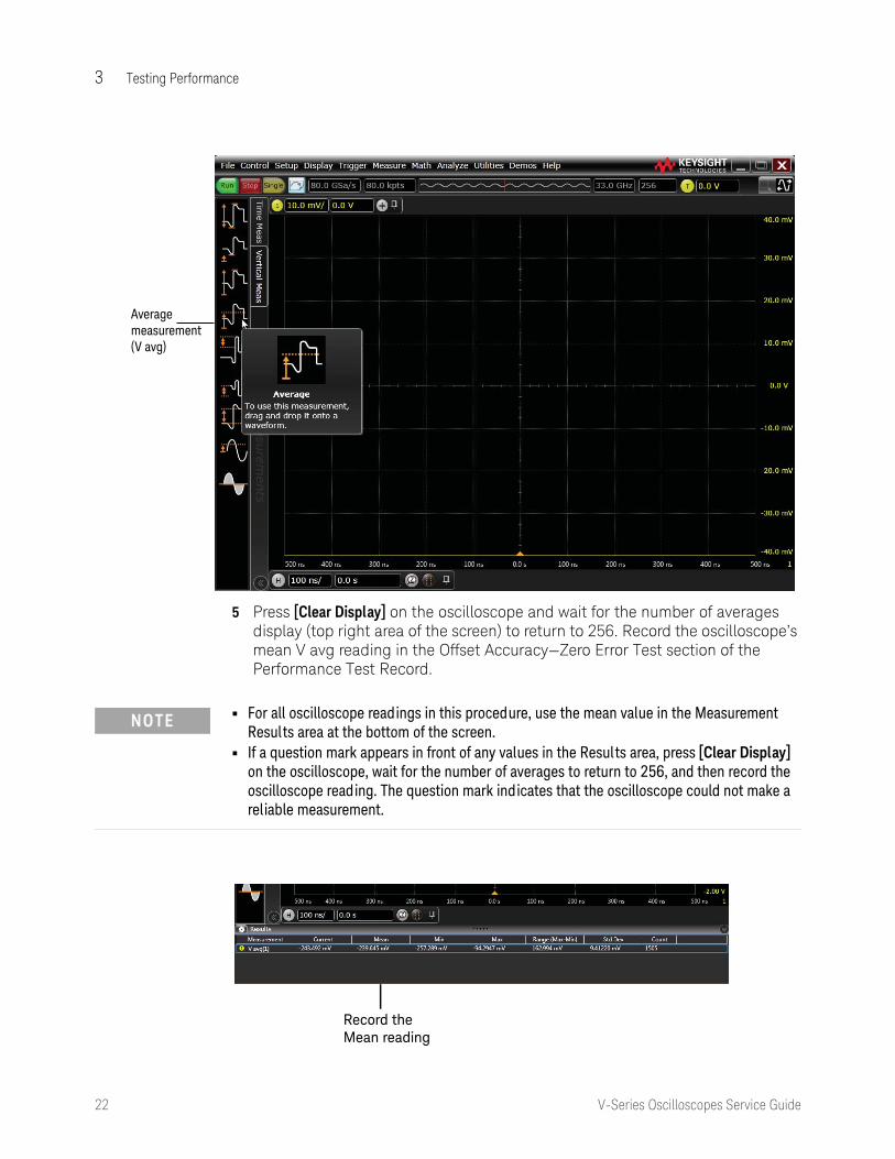
b Click the Vertical Meas tab on the left side of the waveform window, then drag and drop the Average measurement icon onto the channel 1 waveform.
22 V-Series Oscilloscopes Service Guide
3 Testing Performance 5 Press [Clear Display] on the oscilloscope and wait for the number of averages
display (top right area of the screen) to return to 256. Record the oscilloscope’s mean V avg reading in the Offset Accuracy—Zero Error Test section of the Performance Test Record.
Average measurement(V avg)
NOTE • For all oscilloscope readings in this procedure, use the mean value in the Measurement Results area at the bottom of the screen.
• If a question mark appears in front of any values in the Results area, press [Clear Display] on the oscilloscope, wait for the number of averages to return to 256, and then record the oscilloscope reading. The question mark indicates that the oscilloscope could not make a reliable measurement.
Record theMean reading
Testing Performance 3
V-Series Oscilloscopes Service Guide 23
6 Change the vertical scale of channel 1 to 20 mV/div, wait for the number of averages to return to 256, and then record the V avg reading in the Offset Accuracy—Zero Error Test section of the Performance Test Record.
7 Repeat step 6 for the remaining vertical scale settings for channel 1 in the Zero Error Test section of the Performance Test Record.
8 Press [Defaul t Setup], then turn off channel 1 and turn the channel 2 display on.
9 Configure the oscilloscope to measure the average voltage on channel 2 as follows:
a Click Setup > Acquisition.... In the Acquisition dialog box, enable averaging and set # of Averages to 256.
b Change the vertical scale of channel 2 to 10 mV/div.
c Drag and drop the Average voltage measurement icon from the left side of the screen onto the channel 2 waveform.
10 Press [Clear Display] on the oscilloscope, wait for the number of averages to return to 256, and then record the oscilloscope’s mean V avg reading in the Offset Accuracy—Zero Error Test section of the Performance Test Record.
11 Repeat steps 9b and 10 for the remaining vertical scale settings for channel 2.
12 Repeat steps 8 through 11 for channels 3 and 4.

24 V-Series Oscilloscopes Service Guide
3 Testing Performance
Offset Gain Test Procedure
1 Make the connections to oscilloscope channel 1 as shown below.
2 Set up the DMM to perform DC voltage measurements.
3 Press [Defaul t Setup] to default to channel 1.
Cal Out on Oscilloscope Front Panel
Oscilloscope Channel Input
BNC (f) to SMA (m) adapter
BNC (f) to SMA (m) adapter
Connector Saver
Connector Saver
NOTE • Where the BNC Tee adapter is used, it is important to connect it directly to the oscilloscope channel input using the BNC (f) to SMA (m) adapter and the connector savers to minimize ground potential differences and to ensure that the DMM measures the input voltage to the oscilloscope channel as accurately as possible. Differences in ground potential can be a significant source of measurement error, particularly at high scope sensitivities.
• It also helps to reduce ground potential differences if the oscilloscope and DMM are connected to the same AC supply circuit.
• 256 averages are used in the oscilloscope measurements of this section to reduce measurement noise and to reduce the measurement error due to resolution.

Testing Performance 3
V-Series Oscilloscopes Service Guide 25
4 Set the Cal Out voltage (VCal Out) to +400.0 mV as follows:
a Click Utilities > Calibration Output....
b Change the Signal Output function to DC.
c Set the Level to 400.0 mV.
5 Configure the oscilloscope to measure the average voltage on the channel under test as follows:
a Make sure the channel under test is enabled.
b Click Setup > Acquisition.... In the Acquisition dialog box, enable averaging and set # of Averages to 256.
c Change the vertical scale to 10 mV/div.
d Set the offset value of the channel under test to 400 mV.
e Drag and drop the Average voltage measurement icon onto the waveform.
6 Press [Clear Display] on the oscilloscope, wait for the number of averages to return to 256, and then record the DMM voltage reading as VDMM+ and the scope V avg reading as VScope+ in the Offset Accuracy—Offset Gain Test section of the Performance Test Record.
7 Change the offset value of the channel under test to -400.0 mV.
8 Set the Cal Out voltage to -400.0 mV.
9 Change the vertical scale to 10 mV/div.
10 Press [Clear Display] on the oscilloscope, wait for the number of averages to return to 256, and then record the DMM voltage reading as VDMM- and the scope V avg reading as VScope- in the Offset Accuracy—Offset Gain Test section of the Performance Test Record.
11 Change the offset value of the channel under test to 0 mV.
12 Set the Cal Out voltage to 0 mV.
13 Press [Clear Display] on the oscilloscope, wait for the number of averages to return to 256, and then record the DMM voltage reading as VDMM0 and the scope V avg reading as VScope0 in the Offset Accuracy—Offset Gain Test section of the Performance Test Record.

26 V-Series Oscilloscopes Service Guide
3 Testing Performance
14 Calculate the offset gain error using the following expressions and record the value in the Offset Accuracy—Offset Gain Test section of the Performance Test Record. The offset gain error is the greater (maximum magnitude) of either:
or
15 Repeat steps 4, 5c, 5d, and 6 to 14 for the remaining vertical scale settings for the channel under test. Record the results in the Offset Accuracy—Offset Gain Test section of the Performance Test Record. For each measurement, set both the Cal Out voltage (VCal Out) and the Channel offset voltage to the positive VCal
Out value and then to the negative VCal Out value in the “VCal Out Setting” column of the Offset Accuracy—Offset Gain Test table in the Performance Test Record for each of the vertical scale settings.
16 Move the Tee connector to the next channel input and repeat steps 4 to 14 for channels 2 to 4.
Vscope+ – Vscope0VDMM+ – VDMM0--------------------------------------------- 1–
100
Vscope- – Vscope0VDMM- – VDMM0------------------------------------------- 1–
100

Testing Performance 3
V-Series Oscilloscopes Service Guide 27
DC Gain Accuracy Test
CAUTION Ensure that the input voltage to the oscilloscope never exceeds ±5 V.
NOTE The oscilloscope under test must be warmed up (with the oscilloscope application running) for at least 30 minutes prior to the start of any performance test.
Specifications
DC Gain Accuracy ±2% of full scale at full resolution channel scale (±2.5% for ≤ 5 mV/div).
Full scale is defined as 8 vertical divisions. Magnification is used below 7.5 mV/div. Below 7.5 mV/div, full scale is defined as 60 mV. The major scale settings are 1 mV/div, 2 mV/div, 5 mV/div, 10 mV/div, 20 mV/div, 50 mV/div, 100 mV/div, 200 mV/div, 500 mV/div, and 1 V/div.
Equipment Required
Description Critical Specifications Recommended Model/ Part #
Digital Multimeter DC voltage measurement accuracy better than ±0.1% of reading
Keysight 34411A
Cable Assembly (2 required)
50 Ω characteristic impedance, BNC (m) connectors
Keysight 8120-1840
Adapter BNC Tee (m)(f)(f) Keysight 1250-0781
Adapter BNC (f) to dual banana Keysight 1251-2277
Connector Saver 3.5 mm (f)-(f), shipped with each V-Series oscilloscope
2.4 mm (f) to 3.5 mm (f) adapter
Keysight 54919-68717 (for oscilloscope models ≥ 20 GHz)
Keysight 54916-68716 (for oscilloscope models ≤ 16 GHz)
Adapter (2 required)
BNC (f) to SMA (m) adapter Keysight 1250-1200

28 V-Series Oscilloscopes Service Guide
3 Testing Performance
Procedure
1 Make the connections to oscilloscope channel 1 as shown below.
NOTE • Where the BNC Tee adapter is used, it is important to connect it directly to the oscilloscope channel input using the BNC (f) to SMA (m) adapter and the connector saver to minimize ground potential differences and to ensure that the DMM measures the input voltage to the oscilloscope channel as accurately as possible. Differences in ground potential can be a significant source of measurement error, particularly at high scope sensitivities.
• It also helps to reduce ground potential differences if the oscilloscope and DMM are connected to the same AC supply circuit.
• 256 averages are used in the oscilloscope measurements of this section to reduce measurement noise and to reduce the measurement error due to resolution.
Oscilloscope Channel Input
Cal Out on Oscilloscope Front Panel
BNC (f) to SMA (m) adapter
BNC (f) to SMA (m) adapterConnector Saver
Connector Saver

Testing Performance 3
V-Series Oscilloscopes Service Guide 29
2 Press [Defaul t Setup], then configure the oscilloscope as follows:
a Click Setup > Acquisition....
a In the Acquisition dialog box, enable averaging and set # of Averages to 256.
3 Set the Cal Out voltage (VCal Out) to +30 mV as follows:
a Click Utilities > Calibration Output....
b Change the Signal Output function to DC.
c Set the Level to 30 mV.
4 Set the vertical scale of the channel under test to 10 mV/div.
5 Drag and drop the Average voltage measurement icon onto the channel 1 waveform.
6 Press [Clear Display] on the oscilloscope, wait for the number of averages to return to 256, and then record the DMM voltage reading as VDMM+ and the scope V avg reading as VScope+ in the DC Gain Accuracy Test section of the Performance Test Record.
7 Change the Cal Out voltage to -30 mV.
NOTE • For all oscilloscope readings in this procedure, use the mean value in the Results area at the bottom of the screen.
• If a question mark appears in front of any of the values in the Results area, press [Clear Display] on the oscilloscope, wait for the number of averages to return to 256, and then record the oscilloscope reading. The question mark indicates that the oscilloscope could not make a reliable measurement.
Record theMean reading

30 V-Series Oscilloscopes Service Guide
3 Testing Performance
8 Press [Clear Display] on the oscilloscope, wait for the number of averages to return to 256, and then record the DMM voltage reading as VDMM- and the scope V avg reading as VScope- in the DC Gain Accuracy Test section of the Performance Test Record.
9 Calculate the DC gain using the following expression and record this value in the Calculated DC Gain Error column of the DC Gain Accuracy Test section of the Performance Test Record.
For vertical scale values < 1 V use the following equation:
For vertical scale values = 1 V use the following equation:
10 Repeat steps 3 to 9 for the remaining channel 1 vertical scale settings in the DC Gain Test section of the Performance Test Record. For each measurement, set the Cal Out voltage (VCalOut) to the positive VCalOut value and then to the negative VCalOut value in the “VCalOut Setting” column of the DC Gain Accuracy Test table in the Performance Test Record for each of the vertical scale settings.
11 Move the Tee connector to the next channel input and repeat steps 2 to 10 for channels 2 to 4.
DCGainError = ΔVoutΔVin--------------- =
Vscope+ – Vscope-VDMM+ – VDMM--------------------------------------------- 1–
75
DCGainError = ΔVoutΔVin--------------- =
Vscope+ – Vscope-VDMM+ – VDMM--------------------------------------------- 1–
60

Testing Performance 3
V-Series Oscilloscopes Service Guide 31
Analog Bandwidth—Maximum Frequency Test
CAUTION Ensure that the input voltage to the oscilloscope never exceeds ±5 V.
NOTE The oscilloscope under test must be warmed up (with the oscilloscope application running) for at least 30 minutes prior to the start of any performance test.
Specifications
Analog Bandwidth (-3 dB)
MSO/DSO/DSAV084A 8.0 GHz
MSO/DSO/DSAV134A 13.0 GHz
MSO/DSO/DSAV164A 16.0 GHz
MSO/DSO/DSAV204A 20.0 GHz
MSO/DSO/DSAV254A 25.0 GHz
MSO/DSO/DSAV334A 32.0 GHz
Equipment Required
Description Critical Specifications Recommended Model/Part #
Microwave CW Generator
Maximum Frequency ≥ 32 GHz Power range: -20 dBm to +16 dBm into 50 Ω Output resistance = 50 Ω
Keysight E8257D with Opt 540
Power Splitter 2 Resistor Power Splitter Max Frequency ≥ 32 GHz
Keysight 11667C
Power Meter Keysight E-series with power sensor compatibility
Keysight E4418B or E4419B
Power Sensor Maximum Frequency ≥ 32 GHz Power range: -24 dBm to +16 dBm
Keysight 8487A, or E4413B with 8485A-033
Microwave Cable
50 Ω Characteristic Impedance 2.4 mm (m) to 2.4 mm (m) connectors Max Frequency ≥ 32 GHz
Keysight N5180-60204
Adapter 2.4 mm (m) to 3.5 mm (m) (qty. 1) Keysight 11901A
Adapter 2.4 mm (m) to 3.5 mm (f) (qty. 2) Keysight 11901C
Connector Saver
3.5 mm (f)-(f), shipped with oscilloscope Keysight 54919-68717 (for 20, 25, and 33 GHz models)
Keysight 54916-68716 (for 8, 13, and 16 GHz models)

32 V-Series Oscilloscopes Service Guide
3 Testing Performance
Connections
Procedure
1 Preset the power meter.
2 Ensure that the power sensor is disconnected from any source and zero the meter.
3 Connect the power sensor to the power meter's Power Ref connector and calibrate the meter.
4 Make the connections to oscilloscope channel 1 as shown in the preceding connection diagram.
5 Set up the power meter to display measurements in units of Watts.
NOTE • Connect output 1 of the 11667C splitter to the scope channel N input directly using the 11901A adapter and a connector saver, without any additional cabling or adapters.
• Connect the power sensor directly to output 2 of the power splitter using the 11901C adapter without any additional cabling or adapters.
• Connect the microwave cable directly to output 3 of the power splitter using the 11901C adapter without any additional cabling or adapters.
• Minimize the use of other adapters.• Ensure the connectors are tightened properly to 8 in-lbs (90 N-cm).
Power sensor cable
Power sensor E4413A
Power splitter 11667C
11901C adapter
11901A adapter
Microwave cable
Microwave CW Generator E8257D
Power meter E4418A or E4419A
connector saver
Oscilloscope

Testing Performance 3
V-Series Oscilloscopes Service Guide 33
6 Press [Defaul t Setup], then configure the oscilloscope as follows:
a Ensure the channel under test is displayed and all other channels are turned off.
b Set the vertical scale of the channel under test to 10 mV/div.
c Set the horizontal scale to 16 ns/div (to display 8 cycles of a 50 MHz waveform).
d Click Setup > Acquisition... and make sure the acquisition parameters are set up as follows:
• Memory Depth = Automatic• Sampling rate = 80 GSa/s (maximum)• Sin(x)/x Interpolation = Auto• Averaging = Disablede Click Measure > Add Measurement....
f In the Add Measurement dialog box, select the Vertical RMS measurement and configure it as follows:
• Source = Channel 1• Measurement Area = Entire Display• RMS Type = AC
Enter horizontalscale

34 V-Series Oscilloscopes Service Guide
3 Testing Performance
7 Set the generator to apply a 50 MHz sine wave with a peak-to-peak amplitude of about four divisions.
Use the following table to determine the approximate required signal amplitude.
The amplitude values in the tables are not absolutely required. If your generator is unable to produce the recommended amplitude, then set the generator to the highest value that does not produce a vertically clipped signal on the oscilloscope.
Nominal Generator Amplitude Settings
8 Measure the input power to the oscilloscope channel and convert this measurement to Volts RMS using the expression:
For example, if the power meter reading is 4.0 μW, then Vin = (4.0*10-6 * 50 Ω)1/2 = 14.1 mVrms.
Record the RMS voltage in the Analog Bandwidth—Maximum Frequency Check section of the Performance Test Record (Vin @ 50 MHz).
9 Press [Clear Display] on the oscilloscope and record the scope V rms reading in the Analog Bandwidth—Maximum Frequency Check section of the Performance Test Record (Vout @ 50 MHz).
10 Calculate the reference gain as follows:
Oscilloscope Vertical Scale
Generator Signal Amplitude (Vp-p)
Generator Signal Amplitude (dBm)
10 mV/div 0.08 -18
20 mV/div 0.16 -12
50 mV/div 0.4 -4
100 mV/div 0.8 +2
200 mV/div 1.6 +8
500 mV/div 4.0 +16
1 V/div 6.3 +20
Vin Pmeas 50Ω×=
NOTE For all oscilloscope readings in this procedure, use the mean value in the Results area at the bottom of the screen.

Testing Performance 3
V-Series Oscilloscopes Service Guide 35
Record this value in the Calculated Gain @50 MHz column in the Analog Bandwidth—Maximum Frequency Check section of the Performance Test Record.
11 Change the generator frequency to the maximum value for the model being tested as shown in the table below. It is not necessary to adjust the signal amplitude at this point in the procedure.
12 Change the oscilloscope horizontal scale to the value for the model under test in the preceding table.
13 Measure the input power to the oscilloscope channel at the maximum frequency and convert this measurement to Volts RMS using the expression:
For example, if the power meter reading is 4.0 μW, then Vin = (4.0*10-6 * 50Ω)1/2 = 14.1 mVrms.
Record the RMS voltage in the Analog Bandwidth—Maximum Frequency Check section of the Performance Test Record (Vin @ Max Freq).
14 Press [Clear Display] on the oscilloscope and record the scope V rms reading in the Analog Bandwidth—Maximum Frequency Check section of the Performance Test Record (Vout @ Max Freq).
Gain50 MHzVout @50 MHz Vin @50 MHz ----------------------------------=
Setting Model
DSOV084A DSAV084A MSOV084A
DSOV134A DSAV134A MSOV134A
DSOV164A DSAV164A MSOV164A
DSOV204A DSAV204A MSOV204A
DSOV254A DSAV254A MSOV254A
DSOV334A DSAV334A MSOV334A
Maximum Frequency
8 GHz 13 GHz 16 GHz 20 GHz 25 GHz 32 GHz
Scope Horizontal Scale
50 ps/div 50 ps/div 50 ps/div 50 ps/div 50 ps/div 50 ps/div
Enter horizontal scale
Vin Pmeas 50Ω×=

36 V-Series Oscilloscopes Service Guide
3 Testing Performance
15 Calculate the gain at the maximum frequency using the expression:
For example, if (Vout @ Max Frequency) = 13.825 mV, (Vin @ Max Frequency) = 13.461 mV and Gain @ 50MHz = 1.0023, then:
Record this value in the Calculated Gain @Max Freq column in the Analog Bandwidth—Maximum Frequency Check section of the Performance Test Record. To pass this test, this value must be greater than -3.0 dB.
16 Change the oscilloscope setup as follows:
a Change the channel vertical scale to 20 mV/div.
b Reset the horizontal scale to 16 ns/div (to display 8 cycles of a 50 MHz waveform).
17 Change the generator output as follows:
a Reset the generator frequency to 50 MHz.
b Change the amplitude to the value suggested for this scale setting in the Nominal Generator Amplitude Settings table.
18 Repeat steps 8, 9, and 10 to measure the reference gain at 50 MHz for this scale setting.
19 Repeat steps 11 through 14 to measure the gain at maximum frequency for this scale setting.
20 Repeat steps 15 through 19 to complete measuring gains for remaining scale settings for channel 1 in the Analog Bandwidth—Maximum Frequency Check section of the Performance Test Record.
21 Move the splitter to channel 2 and change the oscilloscope configuration as follows:
a Press [Defaul t Setup].
b Ensure Channel 2 is displayed and all other channels are turned off.
c Set the vertical scale of channel 2 to 10 mV/div.
d Set the horizontal scale to 16 ns/div (to display 8 cycles of a 50 MHz waveform).
e Click Trigger > Setup Trigger... and change the source to channel 2.
f Click Measure > Add Measurement.... Select the RMS voltage measurement, Channel 2 as the source, Entire Display as the Measurement Area, and AC for the RMS Type.
22 Repeat steps 7 to 20 to complete measuring gains for channel 2.
Gain Max Freq 20 log10 Vout Max Freq ( ) Vin Max Freq ( )⁄
Gain 50 MHz------------------------------------------------------------------------------------=
Gain Max Freq 20 log10 13.825 mV 13.461 mV ⁄
1.0023------------------------------------------------------------- 0.212 dB==

Testing Performance 3
V-Series Oscilloscopes Service Guide 37
23 Move the splitter to channel 3 and change the oscilloscope configuration as follows:
a Press [Defaul t Setup].
b Ensure channel 3 is displayed and all other channels are turned off.
c Set the vertical scale of channel 3 to 10 mV/div.
d Set the horizontal scale to 16 ns/div (to display 8 cycles of a 50 MHz waveform).
e Click Trigger > Setup Trigger... and change the source to channel 3.
f Click Measure > Add Measurement.... Select the RMS voltage measurement, Channel 3 as the source, the Entire Display as the Measurement Area, and AC for the RMS Type.
24 Repeat steps 7 to 20 to complete measuring gains for channel 3.
25 Move the splitter to channel 4 and change the oscilloscope configuration as follows.
a Press [Defaul t Setup].
b Ensure Channel 4 is displayed and all other channels are turned off.
c Set the vertical scale of channel 4 to 10 mV/div.
d Set the horizontal scale to 16 ns/div (to display 8 cycles of a 50 MHz waveform).
e Click Trigger > Setup Trigger... and change the source to Channel 4.
f Click Measure > Add Measurement.... Select the RMS voltage measurement, Channel 4 as the source, the Entire Display as the Measurement Area, and AC for the RMS Type.
26 Repeat steps 7 to 20 to complete measuring gains for channel 4.

38 V-Series Oscilloscopes Service Guide
3 Testing Performance
Time Scale Accuracy (TSA) Test
This procedure verifies the maximum TSA specification for the oscilloscope.
Description
TSA refers to the absolute accuracy of an oscilloscope’s time scale. Because TSA depends directly on frequency of a crystal oscillator, it is comprised of two components: an initial accuracy component and an aging component.
The initial accuracy component applies to the oscilloscope’s accuracy immediately after a time base calibration, whether performed at the factory, by a customer, or by a Keysight service center. The aging component scales linearly from the time since the last time base calibration, and adds to the initial accuracy component.
Equipment Required
Description Critical Specifications Recommended Model/Part #
Synthesized sine wave source
Output Frequency: ≥ 10 MHzOutput Amplitude: 0 dBmFrequency Resolution: 0.1 Hz
Keysight E8257D PSG
10 MHz frequency reference
Output Frequency: 10 MHzAbsolute Freq. Error: < ±0.0275 ppm
Keysight 53132A opt. 012 frequency counter
RF cable 50 Ω characteristic impedance (no substitute) BNC (m) connectorsMax Frequency: ≥ 50 MHz
Keysight 8120-1840
Adapters, assorted 3.5 mm (f) to Precision BNC (m)3.5 mm (f) to 3.5 mm (f)
Keysight 54855-67604Keysight 83059B

Testing Performance 3
V-Series Oscilloscopes Service Guide 39
Connections
Connect the equipment as shown here.
Procedure
1 Configure the sine wave source to output a 0 dBm (600 mVpp) sine wave into 50 ohms with a frequency of 10.00002000 MHz.
2 Adjust the source amplitude such that the displayed sine wave is 600 mVpp.
3 Press [Defaul t Setup] on the oscilloscope.
4 Set the vertical scale of channel 1 to 100 mV/div.
5 Set the oscilloscope’s sampling rate to 100 kSa/s.
6 Set the oscilloscope's horizontal scale to 20 ms/div.
7 Set the measurement thresholds for all waveforms to a fixed voltage level of 0 V and ±20 mV hysteresis:
a Click Measure > Thresholds....
b Select Custom: level +/- hysteresis from the Thresholds drop-down list box.
c Enter 20 mV in the Hysteresis field and 0 V in the Threshold Level field.
8 Enable a frequency measurement on channel 1.
9 On the oscilloscope, press [Stop].
10 Press [Clear Display].
11 Press [Run], wait until 10 acquisitions have accumulated, and then press [Stop].
12 Convert the average frequency value to time scale error by subtracting 20 Hz and dividing by 10 Hz/ppm. Record the result in the Measured Time Scale Error (ppm) column of the Time Scale Accuracy table.

40 V-Series Oscilloscopes Service Guide
3 Testing Performance
13 Record the time since calibration (in years) in the table. The calibration date can be found in the Calibration window (Utilities > Calibration...).
14 Calculate the test limits using the following formula and record them in the table.
Test Limits = ±(0.100 + 0.100 x Years Since Calibration)
15 Record the results in the Performance Test Record.

Testing Performance 3
V-Series Oscilloscopes Service Guide 41
Performance Test Record
Keysight Technologies Keysight Infiniium V-Series Oscilloscopes
Model Number _____________________ Tested by________________________
Serial Number ___________________________ Work Order No.___________________
Recommended Test Interval—1 Year/2000 hours Date_____________________________
Recommended next test date ___________________ Ambient temperature ______________
Offset Accuracy—Zero Error Test
Vertical Scale Test Limits Channel 1 Channel 2 Channel 3 Channel 410 mV/div -1.8 mV to +1.8 mV20 mV/div -2.6 mV to +2.6 mV50 mV/div -5.0 mV to +5.0 mV100 mV/div -9.0 mV to +9.0 mV200 mV/div -17.0 mV to +17.0 mV500 mV/div -41.0 mV to +41.0 mV1 V/div -81.0 mV to +81.0 mV

42 V-Series Oscilloscopes Service Guide
3 Testing Performance
Offset Accuracy—Offset Gain Test
Vertical Scale VCal OutSetting
VDMM+ VScope+ VDMM- VScope- VDMM0 VScope
0
Calc. Offset Gain Error
Offset Gain Error Test Limits
Channel 110 mV/div ±400 mV ±2 %20 mV/div ±400 mV ±2 %50 mV/div ±700 mV ±2 %100 mV/div ±1.2 V ±2 %200 mV/div ±2.2 V ±2 %500 mV/div ±2.4 V ±2 %1 V/div ±2.4 V ±2 %Channel 210 mV/div ±400 mV ±2 %20 mV/div ±400 mV ±2 %50 mV/div ±700 mV ±2 %100 mV/div ±1.2 V ±2 %200 mV/div ±2.2 V ±2 %500 mV/div ±2.4 V ±2 %1 V/div ±2.4 V ±2 %Channel 310 mV/div ±400 mV ±2 %20 mV/div ±400 mV ±2 %50 mV/div ±700 mV ±2 %100 mV/div ±1.2 V ±2 %200 mV/div ±2.2 V ±2 %500 mV/div ±2.4 V ±2 %1 V/div ±2.4 V ±2 %Channel 410 mV/div ±400 mV ±2 %20 mV/div ±400 mV ±2 %50 mV/div ±700 mV ±2 %100 mV/div ±1.2 V ±2 %200 mV/div ±2.2 V ±2 %500 mV/div ±2.4 V ±2 %1 V/div ±2.4 V ±2 %

Testing Performance 3
V-Series Oscilloscopes Service Guide 43
DC Gain Accuracy Test
Vertical Scale VCal OutSetting
VDMM+ VScope+ VDMM- VScope- Calc. DC Gain Error
DC Gain Error Test Limits
Channel 110 mV/div ±30 mV ±2 %20 mV/div ±60 mV ±2 %50 mV/div ±150 mV ±2 %100 mV/div ±300 mV ±2 %200 mV/div ±600 mV ±2 %500 mV/div ±1.5 V ±2 %1 V/div ±2.4 V ±2 %Channel 210 mV/div ±30 mV ±2 %20 mV/div ±60 mV ±2 %50 mV/div ±150 mV ±2 %100 mV/div ±300 mV ±2 %200 mV/div ±600 mV ±2 %500 mV/div ±1.5 V ±2 %1 V/div ±2.4 V ±2 %Channel 310 mV/div ±30 mV ±2 %20 mV/div ±60 mV ±2 %50 mV/div ±150 mV ±2 %100 mV/div ±300 mV ±2 %200 mV/div ±600 mV ±2 %500 mV/div ±1.5 V ±2 %1 V/div ±2.4 V ±2 %Channel 410 mV/div ±30 mV ±2 %20 mV/div ±60 mV ±2 %50 mV/div ±150 mV ±2 %100 mV/div ±300 mV ±2 %200 mV/div ±600 mV ±2 %500 mV/div ±1.5 V ±2 %1 V/div ±2.4 V ±2 %

44 V-Series Oscilloscopes Service Guide
3 Testing Performance
Max frequency:MSO/DSO/DSAV084A = 8 GHz, MSO/DSO/DSAV134A = 13 GHz, MSO/DSO/DSAV164A = 16 GHz, MSO/DSO/DSAV204A = 20 GHz, MSO/DSO/DSAV254A = 25 GHz, MSO/DSO/DSAV334A = 32 GHz,
Analog Bandwidth—Maximum Frequency Check
Vertical Scale
MeasurementVin @ 50 MHz
Vout @ 50 MHz
Calculated Gain @ 50 MHz
Vin @ Max Freq
Vout @ Max Freq
Calculated Gain @ Max Freq Test Limit = greater than -3 dB
Channel 110 mV/div20 mV/div50 mV/div100 mV/div200 mV/div500 mV/div1 V/divChannel 210 mV/div20 mV/div50 mV/div100 mV/div200 mV/div500 mV/div1 V/divChannel 310 mV/div20 mV/div50 mV/div100 mV/div200 mV/div500 mV/div1 V/divChannel 410 mV/div20 mV/div50 mV/div100 mV/div200 mV/div500 mV/div1 V/div

Testing Performance 3
V-Series Oscilloscopes Service Guide 45
Time Scale Accuracy
Measured Time ScaleError (ppm)
Years Since Cal ibration (years)
Low Test Limit (ppm)
High Test Limit (ppm)
Pass/Fail
___________ ___________ ___________ ___________ ___________

46 V-Series Oscilloscopes Service Guide
3 Testing Performance

47
Keysight Infiniium V-Series OscilloscopesService Guide
4 Troubleshooting
Service Strategy 48Verifying Basic Operation 49Power Supply Troubleshooting 54Setting Up the BIOS 66Motherboard Verification 67Display Troubleshooting 69Acquisition/Backplane Assembly Troubleshooting 70Keyboard Troubleshooting 71Front Panel LED Troubleshooting 72Touch Screen Troubleshooting 73Checking Probe Power Outputs 74MSO Assembly Troubleshooting 75Hardware Serial Trigger Assembly Troubleshooting 77Before You Contact Keysight 78

48 V-Series Oscilloscopes Service Guide
4 Troubleshooting
Service Strategy
The service strategy for troubleshooting Infiniium V-Series oscilloscopes is to isolate problems to a faulty assembly, then use the disassembly and assembly procedures in the "Replacing Assemblies" chapter to replace the defective assembly.
Read the Safety booklet that came with the oscilloscope before servicing the oscilloscope. Before performing any procedure, review it for any cautions and warnings.
The only equipment you need for troubleshooting to the assembly level is basic electronic troubleshooting tools such as a digital multimeter. If you need to remove and replace any assemblies, refer to the "Replacing Assemblies" chapter.
A default setup is provided to return the oscilloscope to a known state. You can use the default setup to undo previous setups so they do not interfere with the current measurement. Use the default setup when a procedure requires it by pressing [Defaul t Setup] on the front panel.
WARNING INJURY CAN RESULT! Use caution when the oscilloscope fan blades are exposed as they can cause injury.
CAUTION AVOID ESD DAMAGE TO COMPONENTS! Electrostatic discharge (ESD) can damage electronic components. Use proper ESD precautions when doing any of the procedures in this chapter. Failure to follow proper ESD procedures may cause immediate failure or latent damage. Latent damage may result in equipment failure after a period of time. As a minimum, place the oscilloscope on a properly grounded ESD mat and wear a properly grounded ESD strap.
WARNING SHOCK HAZARD! Maintenance should be performed by trained service personnel. Lack of training and awareness could resul t in electrical shock or other injury. When maintenance can be performed without power applied, the power cord should be removed from the oscilloscope.

Troubleshooting 4
V-Series Oscilloscopes Service Guide 49
Verifying Basic Operation
Follow the procedures in this section to verify the basic operation of the oscilloscope. Where problems occur, you are directed to the section that provides detailed troubleshooting help.
Power Up the Oscilloscope
1 Connect the power cord to the rear of the oscilloscope, then to a suitable AC voltage source.
Ensure that you have the correct power cord (see Chapter 6, “Replaceable Parts List”). The power cord provided is matched to the country of origin.
2 Press the power button in the lower left corner of the front panel. If the oscilloscope is working properly, it will take several minutes to start up. The LEDs on the front panel should all illuminate brightly for several seconds, then dim. If the LEDs do not light up, refer to “Front Panel LED Troubleshooting" later in this chapter.
When the system is done starting up, the grid will appear on the screen. The exact appearance may look slightly different than shown below, depending on the setup selected before the oscilloscope was turned off.
Power-on display

50 V-Series Oscilloscopes Service Guide
4 Troubleshooting
If the oscilloscope turns off without you pressing the front panel power button, go to the “Power Supply Troubleshooting" section of this chapter.
If the oscilloscope does not start up at all, unplug the oscilloscope, wait 30 seconds, plug the oscilloscope back in, and turn the power on. If it still does not start up, go to the “Setting Up the BIOS" and “Motherboard Verification" sections of this chapter.
Check the display
If the screen is black or has a scrambled display, go to the “Display Troubleshooting" section of this chapter.
If the display shows MEMCON1, MEMCON2, MEMCON3, or MEMCON4 errors during boot-up of the oscilloscope software, the lower acquisition board (channels 1 and 2) is faulty and requires replacement. MEMCON5, MEMCON6, MEMCON7, and MEMCON8 errors indicate the upper acquisition board (channels 3 and 4) is faulty and requires replacement.
Run the oscilloscope self-tests
Running the oscilloscope self-tests performs a series of internal procedures to verify that the oscilloscope is working properly.
1 Click Utilities > Self Test....
2 Select Scope Sel fTest from the Available Self Tests drop-down list box.
3 Click Start and follow the instructions on the screen.
If any of the self tests fail, go to the “Acquisition/Backplane Assembly Troubleshooting" section of this chapter for further troubleshooting.
Run the keyboard, LED, and touch screen self tests
To verify correct keyboard operation:
1 Click Utilities > Self Test....
2 Select Keyboard Test from the Self Test drop-down list box, then click Start.
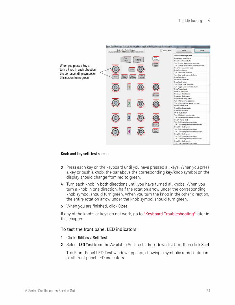
The Front Panel Keyboard Test window appears, showing a symbolic representation of the keyboard.
Troubleshooting 4
V-Series Oscilloscopes Service Guide 51
3 Press each key on the keyboard until you have pressed all keys. When you press a key or push a knob, the bar above the corresponding key/knob symbol on the display should change from red to green.
4 Turn each knob in both directions until you have turned all knobs. When you turn a knob in one direction, half the rotation arrow under the corresponding knob symbol should turn green. When you turn the knob in the other direction, the entire rotation arrow under the knob symbol should turn green.
5 When you are finished, click Close.
If any of the knobs or keys do not work, go to “Keyboard Troubleshooting" later in this chapter.
To test the front panel LED indicators:
1 Click Utilities > Self Test....
2 Select LED Test from the Available Self Tests drop-down list box, then click Start.
The Front Panel LED Test window appears, showing a symbolic representation of all front panel LED indicators.
Knob and key self-test screen

52 V-Series Oscilloscopes Service Guide
4 Troubleshooting 3 Repeatedly press the [Single] button on the front panel to step through and
highlight each LED symbol in the test screen. You can also step through the LEDs by pressing the << Prev or Next >> buttons on the screen. Verify that the corresponding LEDs on the front panel are the only ones illuminated. Pressing the [Multi Purpose] button on the front panel illuminates all the LEDs, and pressing the [Clear Display] button on the front panel turns off all the LEDs.
4 When you are finished, click Close.
If any of the LEDs do not work, go to “Front Panel LED Troubleshooting” later in this chapter.
To verify correct touch screen operation:
1 Click Utilities > Self Test....
2 Select Touch Screen Test from the Available Self Tests drop-down list box, then click Start and follow the on-screen instructions.
3 If the touch screen is not working properly, go to “Touch Screen Troubleshooting” in this chapter.
LED test screen

Troubleshooting 4
V-Series Oscilloscopes Service Guide 53
Run a user calibration
1 Complete a user calibration by following the procedures in chapter 2.
2 If the calibration test fails, look at the details to find the channel associated with the failure.
• If the failure is associated with channel 1, look at the specific calibration that failed. If it was a trigger cal, a time scale cal, or an interpolator gain cal, replace the backplane board because it is likely the problem. If the cal still fails, replace the bottom acquisition board.
• If the failure is associated with channel 1 but is not a trigger cal, a time scale cal, or an interpolator gain cal, replace the bottom acquisition board. If the cal still fails, replace the backplane board.
• If the failure is not associated with channel 1, replace the acquisition board associated with that channel (where channels 1 and 2 = bottom acquisition board, channels 3 and 4 = top acquisition board).
• If all four channels have cal failures, the problem may be with the calibrator located on the backplane board, so replace that board first.
Verify system performance
After you have verified the basic operation of the oscilloscope, you need to verify that it meets all warranted specifications by following the procedures in the “Testing Performance” chapter.

54 V-Series Oscilloscopes Service Guide
4 Troubleshooting
Power Supply Troubleshooting
This section provides information to help you isolate the problem to the assembly level when the power system is not operating properly.
There are three main types of faults:
• Under-voltage faults
• Over-temperature faults
• Over-voltage faults
To determine what type of fault is occurring, and what assembly needs to be replaced, follow these steps:
1 Unplug the oscilloscope so the +5 V standby power supply can fully discharge.
2 Wait 30 seconds.
3 Plug the oscilloscope back in.
4 Wait 5 seconds.
5 Press the front panel power button and count how many seconds it takes for the oscilloscope to lose power again. Keep the oscilloscope plugged in when it loses power.
• If it takes about 2 seconds for the oscilloscope to lose power, you likely have an under-voltage fault.
• If it takes 4 seconds or more for the oscilloscope to lose power, you likely have an over-temperature fault.
• If the oscilloscope never powers up, or flickers then shuts off immediately, you likely have an over-voltage fault or a defective bulk +12 V power supply.
There are two sets of LEDs on the backplane assembly and one set on each acquisition assembly. Seeing which of these LEDs are illuminated will help you identify the reason for the power failure.
To locate all four sets of LEDs, remove the top panel to expose the motherboard cavity and top edges of the backplane assembly.
WARNING SHOCK HAZARD! The maintenance described in this section is performed with power supplied to the oscilloscope and with the protective covers removed. Only trained service personnel who are aware of the hazards invol ved should perform the maintenance. Failure to observe safety precautions may resul t in electric shock.
WARNING SHOCK HAZARD! Once the bulk +12 V power supply is removed from the oscilloscope, two AC leads located on the supply are exposed and severe shock can resul t if touched. Extreme care should be taken to avoid contact with these leads when removing or testing the bulk +12 V power supply.

Troubleshooting 4
V-Series Oscilloscopes Service Guide 55
The first set of LEDs is located in the upper right corner of the backplane assembly (see the following two figures). Six of the LEDs indicate an under-voltage fault, and four indicate an over-temperature fault. Another LED in this group is BULK SUPPLY FAIL, located below NEG SUPPLY FAIL. It lights up if the bulk supply needs replacing.
Under-voltage, over-temperature, and bulk supply indicators on backplane assembly

56 V-Series Oscilloscopes Service Guide
4 Troubleshooting
The other three groups of LEDs indicate over-voltage faults. One group is located near the center of the top edge of the backplane assembly just above the blue and red SATA cables (see the two figures below).
Over-voltage indicator LEDs on backplane assembly
If any of these LEDs are lit, the backplane assembly must be replaced.

Troubleshooting 4
V-Series Oscilloscopes Service Guide 57
Locate the other two groups of over-voltage fault LEDs along the edges of the two acquisition assemblies. They are visible through the bottom fan opening located on the left side of the oscilloscope, nearest the rear panel (see the following figures).
Over-voltage indicator LEDs on acquisition assembly behind fan
Over-voltage indicator LEDs with fan removed
The acquisition assembly nearest the bottom of the oscilloscope is the channels 1 and 2 acquisition assembly and the one above it is the channels 3 and 4 acquisition assembly. If you look through the fan and see any of the over-voltage LEDs lit, that acquisition assembly needs to be replaced.

58 V-Series Oscilloscopes Service Guide
4 Troubleshooting
The following tables show each LED, the type of fault it indicates, and what to do if that LED indicator is illuminated.
Table 1 Group of 11 LEDs on backplane assembly
LED Typs of Faul t What To Do
L-ACQ TEMP FAIL Over-temperature Go to “If the L-ACQ TEMP FAIL or U-ACQ TEMP FAIL LED is lit"
L-ACQ SUPPLY FAIL Under-voltage Replace channels 1 and 2 acquisition assembly (lower acq)
FP SUPPLY FAIL Under-voltage Go to “If the FP SUPPLY FAIL LED is lit"
U-ACQ SUPPLY FAIL Under-voltage Replace channels 3 and 4 acquisition assembly (upper acq)
FPGA SUPPLY FAIL Under-voltage Replace backplane assembly
NEG SUPPLY FAIL Under-voltage Replace backplane assembly
U-ACQ TEMP FAIL Over-temperature Go to “If the L-ACQ TEMP FAIL or U-ACQ TEMP FAIL LED is lit"
MAIN FAN FAIL Over-temperature Go to “If the MAIN FAN FAIL LED is lit"
PRED FAN FAIL Over-temperature Go to “If the PRED FAN FAIL LED is lit"
BP POL FAIL Under-voltage Replace backplane assembly
BULK SUPPLY FAIL Replace bulk supply
Table 2 Group of 7 LEDs on backplane assembly
LED Typs of Faul t What To Do
FPGA +1.2 V Over-voltage Replace backplane assembly
FPGA +1.8 V Over-voltage Replace backplane assembly
FPGA +2.5 V Over-voltage Replace backplane assembly
+3.3 V POL Over-voltage Replace backplane assembly
FPGA +3.3 V Over-voltage Replace backplane assembly
+5 V POL Over-voltage Replace backplane assembly
ADC_VDO POL Over-voltage Replace backplane assembly

Troubleshooting 4
V-Series Oscilloscopes Service Guide 59
If the L-ACQ TEMP FAIL or U-ACQ TEMP FAIL LED is lit
If the oscilloscope shuts down and either the L-ACQ TEMP FAIL or U-ACQ TEMP FAIL indicator LEDs is lit, then one of the scope channels is getting too hot or the temperature sensing circuitry has failed. Normally, you would have to turn the oscilloscope on and leave it on for awhile before you would see a shutdown caused by temperature problems. If all the fans are turning, it is unlikely that the oscilloscope would shut down due to temperature unless the airflow is being restricted or the input air is already too hot to cool the insides of the oscilloscope.
It is possible that all the case fans and the trigger ICs are working, but the oscilloscope still shuts down because of temperature due to one or more of the channels malfunctioning and drawing too much current. If so, you would need to replace the indicated acquisition assembly. It is also possible for one of the heat sinks on one of the acquisition assemblies' critical parts to become detached and cause that part to overheat and shut down the oscilloscope.
Table 3 LEDs on each acquisition board
LED Typs of Faul t What To Do
U1101 oV Over-voltage Replace acquisition assembly
U303L oV Over-voltage Replace acquisition assembly
U1600 oV Over-voltage Replace acquisition assembly
U1100 oV Over-voltage Replace acquisition assembly
U300 3.3 V oV Over-voltage Replace acquisition assembly
U300 2.5 V oV Over-voltage Replace acquisition assembly
U303R oV Over-voltage Replace acquisition assembly
U1601 oV Over-voltage Replace acquisition assembly

60 V-Series Oscilloscopes Service Guide
4 Troubleshooting
If the FP SUPPLY FAIL LED is lit
If the FP SUPPLY FAIL LED is the only one lit, there might be a problem with one of the supplies that goes to the front panel assembly, or a problem on the front panel assembly. Unplug the front panel power connector (see cable connector circled below) and turn the oscilloscope on again. If no other under-voltage indicator LEDs on the backplane assembly turn on, the fault is on the front panel assembly and it should be replaced. If either the BP POL FAIL or NEG SUPPLY FAIL LEDs turn on, then replace the backplane assembly and confirm that the fault goes away with the front panel power reconnected to the backplane assembly.
If the oscilloscope turns off again and no under-voltage fault indicator LEDs are lit, the bulk +12 V supply may be defective and may need to be replaced.
Before replacing the supply, be sure to verify the operation of the AC OK and DC OK signals. The AC OK signal indicates that the applied AC signal is within the specified input range (TTL high logic level indicates that AC input is good). It is possible for this signal to indicate that the AC input is not within the requested range even though it is correct. The DC OK signal indicates whether the main output from the supply (+12.6 V) is good (TTL high logic level indicates the DC output is good). It is possible for this output to be false even though the supply output is correct.
Front panel power cable connector

Troubleshooting 4
V-Series Oscilloscopes Service Guide 61
It is also possible that there is a short circuit on the bulk +12 V supply trace somewhere in the system, which would also cause the unit not to power on. If so, you need to isolate the assembly that is shorted. You do not need to remove the acquisition or backplane assemblies to perform the following steps.
1 With the power turned off, disconnect the bulk +12 V supply, but do not remove the supply from the oscilloscope.
2 On the backplane assembly, measure the resistance across the FET (Q1409, located in the upper right corner of the backplane) between +12 V and ground as shown below, or measure the resistance across the bulk supply input pins on the backplane assembly. Make sure the red lead is plugged into the HI output and the black lead is plugged into the LO or COMMON input of the DVM. On a good backplane assembly, you should measure about 700 ohms. If there is a short on this board, you would measure something very near 0 ohms.
Power supply disconnect
Measuring the backplane assembly resistance between +12 V and ground across Q1409

62 V-Series Oscilloscopes Service Guide
4 Troubleshooting
3 If there is a short, disconnect the power cable to the front panel and redo the resistance measurement.
4 If the short is gone, replace the front panel assembly and verify that the oscilloscope now powers on.
5 If there is still a short circuit, disconnect the two large connectors that provide power to the motherboard (J1201 and J1202) from the backplane assembly as shown below and redo the resistance measurements across the FET (Q1409) or the bulk supply input pins on the backplane assembly.
I
6 If the short is gone, replace the motherboard assembly and confirm that the unit powers on.
7 If there is still a short circuit, remove both acquisition boards and unplug them from the backplane assembly.
8 Measure each assembly individually to see if there is a short between the +12 V trace and ground (see following figure). You should see a resistance of about 2000 ohms between the +12 V trace and ground on a good acquisition assembly. Make sure you make the measurement using a DVM with the red lead plugged into the HI input and the black lead plugged into the LO or COMMON input of the DVM. If there is a short between these two traces, the reading you get will be very low (near 0 ohms). Replace either assembly if needed.
Cable connection into backplane

Troubleshooting 4
V-Series Oscilloscopes Service Guide 63
If no shorts are found on the bulk +12 V supply trace or if you have fixed all the shorts and the oscilloscope still will not turn on, follow these steps, which include replacing parts with known good parts until you discover the problem.
1 Replace the bulk +12 V power supply with a known good supply.
2 If the oscilloscope still does not power on, replace the motherboard with a known good one.
3 If the oscilloscope still does not power on, then the backplane assembly is causing the problem and must be replaced.
4 Once the faulty board or switch is discovered, be sure to reinstall all other parts that were removed, as they were not the cause of the problem.
If the MAIN FAN FAIL LED is lit
If the MAIN FAN FAIL LED is lit, the problem is a cooling system failure.
Three fans are located on the left side of the oscilloscope to cool it. The circuitry that generates the reference potential for the fans may have failed. This circuitry failure would cause the fans to stop turning and the oscilloscope to shut down.
It is unlikely that all three case fans would become faulty simultaneously and stop turning. It is more likely that the high side drive circuitry for the case fans failed.
Measuring the acquisition assembly resistance between +12 V and ground

64 V-Series Oscilloscopes Service Guide
4 Troubleshooting
Follow these steps to diagnose a main fan failure:
1 Reset the sensing and shutdown logic by removing the AC power until the green LED on the motherboard goes out (or just wait 30 seconds).
2 Move to the left side of the oscilloscope so you can see the case fans.
3 Apply AC power to the oscilloscope and turn it on if it does not start up automatically. Visually check to see if any of the fans are not turning. If none of the fans are turning, it is likely a problem with the high side drive circuitry for the case fans. In that case, you would replace the backplane assembly.
If any of the fans are turning, then they are probably not the cause of your shutdown problem. (You should still replace any fans that are not turning, however.)
If the oscilloscope still shuts down, follow these steps:
1 Replace all the case fans.
2 Reset the logic by removing AC power for 30 seconds and make all of the case fans so they cannot rotate. For example, have two people hold the four fan hubs or insert an object between the blades of each of the fans.
3 Power the oscilloscope back on. If it shuts down again, the fan sensing and shutdown function is operating properly. Replace the backplane.
If the PRED FAN FAIL LED is lit
In addition to three case fans, there is also a single fan attached to the backplane assembly that cools the trigger ICs. It is possible that this fan failed, or that the rotation sensor for the fan failed. This sensor lets the oscilloscope know that the fan is turning. If the sensor is faulty, the oscilloscope may think the fan is not working when it actually is.
If the PRED FAN FAIL indicator LED on the backplane assembly is lit, the system thinks there is a trigger ICs fan failure. To check, reset the sensing and shutdown logic by removing the AC power until the green LED on the motherboard goes out (or just wait 30 seconds). Then position yourself so you can see the trigger ICs fan on the backplane assembly. Because this fan is on the bottom of the backplane it is somewhat hidden by the acquisition assembly. Look down the backplane board to see it from above. (See the following figure.)
WARNING INJURY CAN RESULT! The following procedure requires you to touch fan hubs with objects or to use objects to stop the fan blades from moving. Use caution when working near the fan blades with the cover removed from the oscilloscope. The cooling fan blades are exposed on one side and can be hazardous. Be careful not to let the moving fan blades come in contact with any part of your body.

Troubleshooting 4
V-Series Oscilloscopes Service Guide 65
Apply AC power and turn the oscilloscope on if it does not start up on its own. Notice whether the trigger ICs fan is turning. If it is not, replace it and redo this part of the diagnostic test. If it is turning and the oscilloscope still turns off again, then consider these possibilities:
• If the trigger ICs fan was turning, the problem is most likely that the rotation sensor on the ICs fan is defective. Replace the trigger ICs fan and redo this part of the diagnostic test.
• If the oscilloscope stays on after you reset the shutdown logic (by removing AC power for 30 seconds) and powered it back on, then you have fixed the shutdown problem.
• If the oscilloscope shuts down again after you have replaced the trigger ICs fan, then the problem could be that the rotation sensor for all the fans located on the backplane assembly failed, so replace the backplane assembly and redo this part of the diagnostic test.
Trigger ICs fan on backplane assembly

66 V-Series Oscilloscopes Service Guide
4 Troubleshooting
Setting Up the BIOS
If the BIOS settings become corrupt, the Infiniium oscilloscope PC motherboard will not recognize the hard drive and the oscilloscope may not start. To configure the motherboard BIOS parameters to the default settings, follow these steps:
1 Connect the power cable to the oscilloscope.
2 Connect the external keyboard to the rear panel.
3 Press [Delete] as soon as the following prompt appears on the bottom of the screen:
Press DEL to enter SETUP, F12 to select boot device.
If the prompt does not appear, or the oscilloscope does not appear to be functioning, check the J1201 and J1202 motherboard power cable connectors. Otherwise, continue with the next step.
4 Go to F3 Optimized Defaults and press [Enter]. Select Yes to load the defaults, then press [Enter].
5 Go to the Save and Exit Setup option and press [Enter], to save and exit the setup. Select Yes, then press [Enter].

Troubleshooting 4
V-Series Oscilloscopes Service Guide 67
Motherboard Verification
If you have been through the Power Supply Troubleshooting section of this chapter and the oscilloscope still does not stay powered up, the problem may be with the motherboard. To diagnose this problem, follow these steps.
1 Remove the top panel.
2 Turn the oscilloscope on.
If the unit beeps once after about 5 to 10 seconds but fails to boot up, the motherboard is defective and needs to be replaced.
If the unit fails to beep after it is powered on, then measure the potential relative to the chassis at pin 9 of J1201 on the backplane board (see figure below). Pin 9 is the reset line for the motherboard and is controlled by the backplane. You should measure about 3.3 V. If the potential you measure is correct, but the unit still has not beeped and started up, the motherboard is defective and needs to be replaced.
3 If the potential you measure is not correct, shut the oscilloscope down and unplug the AC cord from the rear of the instrument.
4 Unplug the front panel power cable, the two large power cables that go to the motherboard (J1201 and J1202), and the red and blue SATA cables (J900 and J901) from the PCIe-to-SATA adapter board on the backplane assembly. Do not allow the two SATA cables to touch the backplane assembly and cause a short circuit.
5 Plug the AC power back into the oscilloscope and turn the unit on if it does not come on automatically.
6 Measure the potential relative to the chassis at pin 9 of J1201 again.
If you measure the required 3.3 V, the motherboard is defective and needs to be replaced.
If you did not measure the correct voltage, the backplane assembly is defective and must be replaced.
Measure potential relative to chassis at pin 9 of J1201

68 V-Series Oscilloscopes Service Guide
4 Troubleshooting
7 Be aware that there could be a fault on the motherboard that caused the backplane assembly to fail, so before you plug the motherboard cables back into the PCIe-to-SATA converter on the new backplane assembly, measure the resistance to the chassis from the pin 9 contact in the connector that plugs into J1201. If you measure a very low resistance or a short circuit to the chassis, replace the motherboard and then assemble the instrument and confirm the unit beeps and boots up properly.

Troubleshooting 4
V-Series Oscilloscopes Service Guide 69
Display Troubleshooting
Display troubleshooting flowchart
NOTE When you connect an external monitor the first time, it may display the start-up BIOS information and then go blank when Windows starts up. If so, use the Windows settings to enable the external monitor.

70 V-Series Oscilloscopes Service Guide
4 Troubleshooting
Acquisition/Backplane Assembly Troubleshooting
This section describes which board assembly to replace if any of the scope self tests fail. A self-test error message file is generated and is sent to this location:
C:\ProgramData\Infiniium\selftest\SelfTestLog.txt
The error message usually indicates the channel with the error. When identifying which acquisition assembly to replace, remember that the acquisition assembly nearest the bottom of the oscilloscope is for channels 1 and 2. Channels 3 and 4 are on the upper acquisition assembly. Replace the acquisition assembly that has the error.
If the error message does not indicate a channel, refer to the following table to determine which assembly to replace.
Test Group Test Name Error Type Assembly to Replace
Timebase Timebase Interpolator Test Backplane
ADC ADC Register Tests ADC1, ADC2, ADC3, ADC4 Lower acquisition
ADC5, ADC6, ADC7, ADC8 Upper acquisition
ADC Voltage Test Points ADC1, ADC2, ADC3, ADC4 Lower acquisition
ADC5, ADC6, ADC7, ADC8 Upper acquisition
Acquisition Memory Hedwig MBIST
Hedwig Register
Hedwig-DDR2 ADDR & Data MEMCON_1, MEMCON_2, MEMCON_3, MEMCON_4,
Lower acquisition
MEMCON_5, MEMCON_6, MEMCON_7, MEMCON_8,
Upper acquisition
Hedwig DDR2 Stress Memory Controller 1-4 Lower acquisition
Memory Controller 1-8 Upper acquisition
Hedwig DDR2 Interface Hedwig1, Hedwig2, Hedwig3, Hedwig4
Lower acquisition
Hedwig5, Hedwig6, Hedwig7, Hedwig8
Upper acquisition
Misc. Scope Temp Sensor Hedwig0, Hedwig1, Hedwig2, Hedwig3, Oak0
Lower acquisition
Hedwig4, Hedwig5, Hedwig6, Hedwig7, Oak2
Upper acquisition
Pred1, Pred2, MainFPGA Backplane
Acq Flash RAM Test is not currently being run.

Troubleshooting 4
V-Series Oscilloscopes Service Guide 71
Keyboard Troubleshooting
Use this procedure only if you had keyboard failures in the keyboard self-test procedure. If any knobs fail, replace the front panel board.
1 Remove the front panel assembly. (See Chapter 5, “Replacing Assemblies” for instructions.)
2 Unclip the front panel board from the keyboard assembly.
3 Separate the elastomeric keypad from the keyboard assembly.
4 Visually inspect the keypad, checking for missing black “pills” or contamination that may prevent proper contact.
• If the elastomeric keypad has any damage, replace it.
• If the elastomeric keypad is not damaged, replace the front panel board.
CAUTION CONTAMINATION CAN CAUSE INTERMITTENT OPERATION! Be careful not to contaminate the key side of the PC board or the keypads. Dust and fingerprints on these parts may cause intermittent key operation.

72 V-Series Oscilloscopes Service Guide
4 Troubleshooting
Front Panel LED Troubleshooting
If you see a failure with the on/off switch backlight LED, replace the On/Off board. If the LED will still not illuminate, replace the motherboard and see if this fixes the problem. If the LED still does not work, check the on/off cable connecting the On/Off board to the motherboard, and check the connections of all cables on the on/off board and the motherboard.
If any of the other LEDs on the front panel are not working, the first step is to troubleshoot the acquisition assemblies to make sure they are working. If they are working, replace the keyboard assembly and see if the LEDs will illuminate. If the LEDs will not illuminate, the last step is to reload the oscilloscope software.
When reassembling the oscilloscope, be sure to reinstall all boards that were replaced, but that were not causing the problem.

Troubleshooting 4
V-Series Oscilloscopes Service Guide 73
Touch Screen Troubleshooting
Touch screen troubleshooting flowchart

74 V-Series Oscilloscopes Service Guide
4 Troubleshooting
Checking Probe Power Outputs
Probe power outputs are on the front panel, in the lower left corner of the 3.5 mm inputs.
Refer to the following figure to check the power output at the connectors. Measure the voltages with respect to the ground terminal on the front panel. Measure the voltages at pins 2 and 5 only (+12 V and -12 V).
AutoProbe II pins

Troubleshooting 4
V-Series Oscilloscopes Service Guide 75
MSO Assembly Troubleshooting
This section describes problems that may occur when an MSO assembly is installed, and how to troubleshoot them. The MSO printed circuit assembly is located below the lower acquisition board, with the components facing downward.
LEDs on MSO assemblies
The MSO printed circuit board has two sets of LEDs. One set is visible from the right side of the oscilloscope, and the other set is visible from the left side.
MSO LEDs on the right side of the oscilloscope To see the LEDs on the right side, look straight in through the vent holes and see the lights pointed toward the bottom of the oscilloscope. These two red LEDs turn on when the oscilloscope is turned on, indicating that the comparators are off. The LEDs stay on until the FPGA is programmed by the scope application software; then the software turns the LEDs off when it turns the comparators on.
If the LEDs turn on after the application is running, a thermal problem likely was detected. A warning appears. To resolve the problem, shut down the scope and allow it to cool. Make sure the fan holes are not blocked, and allow at least 4 inches of space next to the oscilloscope. Restart the scope and verify that all fans are working.
MSO LEDs on the left side of the oscilloscope The LEDs on the left side can be seen only as a reflection in the lower sheet metal as you look through the fans. These LEDs are off until the FPGA is programmed successfully, which occurs shortly after the scope application starts.
One of the LEDs turns on and remains on after the FPGA is programmed. The other LED will start blinking steadily at about 1.6 Hz if the 250 MHz clock coming from the backplane board is working properly. If the LED is not blinking steadily, verify that the backplane board was modified correctly to be used with the MSO board. That is, in the clock area on the top side of the backplane board, R352 and R353 should be loaded with 0 ohm resistors. The same area on the bottom side of the board should not have resistors on R330 and R332. If this clock rework has not been done, you will see an error message indicating an option card DAC failure when the application starts up.

76 V-Series Oscilloscopes Service Guide
4 Troubleshooting
MSO Cable Connection
When the MSO cable is connected it must be oriented as shown on the label on the back of the oscilloscope (see the following figure). If the cable is upside-down, the pins may bend and cause a faulty connection. Make sure the cable is connected properly and that the pins remain straight.
MSO cable direction

Troubleshooting 4
V-Series Oscilloscopes Service Guide 77
Hardware Serial Trigger Assembly Troubleshooting
This section describes problems that may occur when an optional hardware serial trigger assembly is installed, and how to troubleshoot them.
If a signal appears on screen but the eye scan diagram consists of only a solid blue box, check the semi-rigid cable connections from the acquisition boards to the serial trigger assembly. Make sure the cables are seated securely.

78 V-Series Oscilloscopes Service Guide
4 Troubleshooting
Before You Contact Keysight
If you have read this troubleshooting chapter and have unresolved questions about troubleshooting the oscilloscope, be ready to provide system information such as the current software version and installed options. This information will be useful when you contact Keysight Technologies.
To find and save system information, follow these steps:
1 Click Help > About Infiniium....
A dialog box similar to this one appears.
2 Click Copy to Clipboard.
3 Bring up a text editor, such as Notepad, and paste the copied information into the editor.
4 Save the text editor file.

79
Keysight Infiniium V-Series OscilloscopesService Guide
5 Replacing Assemblies
Returning the oscilloscope to Keysight Technologies for service 81Removing and replacing the top panel and bottom panel 82Removing and replacing the front panel assembly 84Removing and replacing front panel assembly parts 90Removing and replacing the motherboard 94Removing and replacing the acquisition boards/backplane/MSO assembly 99Removing the backplane assembly from the acquisition assembly 106Replacing the backplane board 111Replacing an acquisition board 116Setting the calibration factors after replacing an acquisition board 119Removing and replacing the hard disk drive 120Removing and replacing the power supply 121Removing and replacing fans 122Removing and replacing the optional GPIB port 124

80 V-Series Oscilloscopes Service Guide
5 Replacing Assemblies
Replacing Assemblies
Use the procedures in this chapter when removing and replacing assemblies and parts in the Infiniium V-Series oscilloscopes.
The pictures in this chapter are representative of the oscilloscope at the time of this printing. Your unit may look different.
Tools required
The following tools are required for these procedures.
• Torx drivers: T10, T20
• Socket wrench: 5/8 inch
• Torque wrench: 5/16 inch (8 in-lbs)
• Flat-blade screwdriver: medium size (3/16 inch)
• Power driver vertical with T-20 bit (18 in-lbs)
• Power driver vertical with T-10 bit (5 in-lbs)
• Needle-nosed pliers
Safety precautions
When using any of the procedures in this chapter you must use proper ESD precautions. As a minimum you must place the oscilloscope on a properly grounded ESD mat and wear a properly grounded ESD wrist strap.
CAUTION Failure to implement proper antistatic measures may result in damage to the oscilloscope.
CAUTION Remove power before removing or replacing assemblies.
Do not remove or replace any circuit board assemblies in this oscilloscope while power is applied. The assemblies contain components that may be damaged if the assembly is removed or replaced while power is connected to the oscilloscope.
WARNING To avoid electric shock, adhere closely to the following procedures. Also, after d isconnecting the power cable, wait at least 3 minutes for the capacitors on the power supply to d ischarge before servicing this oscilloscope.
WARNING Use caution when the oscilloscope fan blades are exposed as they can cause injury.

Replacing Assemblies 5
V-Series Oscilloscopes Service Guide 81
Returning the oscilloscope to Keysight Technologies for service
Before shipping the oscilloscope, contact Keysight Technologies for more details.
1 Write the following information on a tag and attach it to the oscilloscope.
• Name and address of owner
• Oscilloscope model number
• Oscilloscope serial number
• Description of the service required or failure indications
2 Remove all accessories from the oscilloscope.
Accessories include all cables. Do not include accessories unless they are associated with the failure symptoms.
3 Protect the oscilloscope by wrapping it in plastic or heavy paper.
4 Pack the oscilloscope in foam or other shock-absorbing material and place it in a strong shipping container.
If the original shipping materials are not available, place 8 to 10 cm (3 to 4 inches) of shock-absorbing material around the oscilloscope and place it in a box that does not allow movement during shipping.
5 Seal the shipping container securely.
6 Mark the shipping container as FRAGILE.
In any correspondence, refer to the oscilloscope by model number and full serial number.

82 V-Series Oscilloscopes Service Guide
5 Replacing Assemblies
Removing and replacing the top panel and bottom panel
1 Disconnect the power cable, all probes and BNC input cables, and any other cables including those for a mouse, keyboard, printer, USB, and LAN.
2 Remove the four M3 screws from the rear edge of the top panel. When replacing, use a Torx T10 to torque to 5 in-lbs.
3 Slide the top panel back 1 to 2 inches and then lift it off.
4 To remove the bottom panel, flip the oscilloscope upside down and remove the three M3 screws from the rear of the bottom panel.
5 Remove the remaining 13 screws from the bottom panel and lift the bottom panel off the chassis.
Figure 1
Figure 2

Replacing Assemblies 5
V-Series Oscilloscopes Service Guide 83
To replace the top and bottom panels, reverse this procedure.
NOTE All sheet metal holes that are supposed to have screws placed in them are marked by lines on four sides of the hole.
Figure 3

84 V-Series Oscilloscopes Service Guide
5 Replacing Assemblies
Removing and replacing the front panel assembly
1 Disconnect the power cable and remove the top panel as described earlier.
2 Disconnect the on/off cable and the display cable from the motherboard.
3 Disconnect the USB 3.0 cable from the motherboard.
Figure 4
Figure 5

Replacing Assemblies 5
V-Series Oscilloscopes Service Guide 85
4 Disconnect the USB front touch screen cable from the USB connector on the motherboard.
5 Disconnect the display cable’s 4-pin connector from the connector on the rear of the front panel board.
Figure 6
Figure 7

86 V-Series Oscilloscopes Service Guide
5 Replacing Assemblies
6 Remove the two screws from the front panel deck.
7 Turn the oscilloscope upside down and remove the three M3 screws from the rear of the bottom panel. Remove the remaining 13 screws from the bottom panel and lift the bottom panel off the chassis.
8 Disconnect the two Cal Out/Aux Out cables from the backplane board. Pull the cables straight back to remove them from the backplane board.
Figure 8
CAUTION Be sure to pull the cables straight back to avoid bending or breaking the connection to the backplane board.
Figure 9

Replacing Assemblies 5
V-Series Oscilloscopes Service Guide 87
9 Disconnect each input cable. (When reconnecting, you can determine the appropriate connections by matching the colored o-ring to the bezel color. Tighten to 8 in-lbs using a calibrated 5/16” open end torque wrench.)
10 Remove the attenuator power cable from each input channel attenuator as shown below. Then route the entire cable through the backplane board. The attenuators are keyed to match the connectors.
Figure 10
Figure 11

88 V-Series Oscilloscopes Service Guide
5 Replacing Assemblies
11 Remove the probe comp cable from the backplane board.
12 Remove the two M3 screws that attach the bottom of the chassis and the front panel assembly.
Figure 12
Figure 13
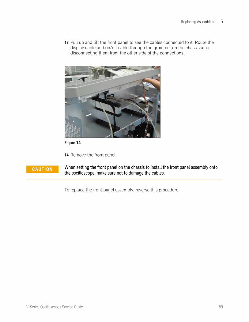
Replacing Assemblies 5
V-Series Oscilloscopes Service Guide 89
13 Pull up and tilt the front panel to see the cables connected to it. Route the display cable and on/off cable through the grommet on the chassis after disconnecting them from the other side of the connections.
14 Remove the front panel.
To replace the front panel assembly, reverse this procedure.
Figure 14
CAUTION When setting the front panel on the chassis to install the front panel assembly onto the oscilloscope, make sure not to damage the cables.

90 V-Series Oscilloscopes Service Guide
5 Replacing Assemblies
Removing and replacing front panel assembly parts
To replace any of the front panel assembly parts, first remove the front panel assembly as described in the previous section.
Removing front panel clutches, bezel, and keyboard
1 Use a thin item such as a ribbon to protect the oscilloscope from scratches, and pull on the dark gray plastic clutches to pop them off the oscilloscope.
2 The front panel bezel has two tabs on each side, one tab on top, and one tab on the bottom. Pop these tabs with your fingers to dislodge the front panel bezel. When re-attaching the front panel bezel, carefully pull out the top and bottom tabs slightly to prevent damaging the tabs.
3 Disconnect the cables and remove the two screws shown below from the board.
WARNING This step will ruin the clutches. You will need to replace them with new ones.
Figure 15
Figure 16

Replacing Assemblies 5
V-Series Oscilloscopes Service Guide 91
4 To remove the keyboard, unlatch the two clips from the back of the front panel deck and unsnap the board from the deck, pulling out the side closest to the display first, as shown below.
5 If you are replacing the keyboard or keypad, grasp and pull all of the knobs off of the front panel.
Figure 17
Figure 18

92 V-Series Oscilloscopes Service Guide
5 Replacing Assemblies
6 Disengage the four tabs holding the board to the keypad as shown below.
To reassemble the front panel board, reverse these steps.
Removing the display assembly
1 Remove the front panel assembly and front panel bezel as described previously.
2 Remove the four screws connecting the display to the deck.
Figure 19
Figure 20

Replacing Assemblies 5
V-Series Oscilloscopes Service Guide 93
3 Disconnect the backlight cable from the controller assembly.
4 Disconnect any cables connected to the display.
Figure 21
NOTE If you are replacing the display, you may need to loosen the four screws in back to align the display with the bezel. Then tighten the screws.

94 V-Series Oscilloscopes Service Guide
5 Replacing Assemblies
Removing and replacing the motherboard
1 Disconnect the power cable and remove the top panel as described previously.
2 Disconnect the blue and red SATA cables from the PCIe-to-SATA adapter board. When replacing the motherboard, be careful to reconnect the blue SATA cable to the connector marked BLUE on the adapter board, and the red cable to the other SATA connector.
3 Disconnect the screw that connects the PCIe cover plate to the chassis and then remove the PCIe-to-SATA adapter board.
Figure 22
Figure 23

Replacing Assemblies 5
V-Series Oscilloscopes Service Guide 95
4 If the instrument has the optional GPIB board, remove it from the PCIe slot.
)
5 Disconnect the USB front touch screen cable from the USB connector on the motherboard.
)
6 Disconnect the other connector (with the red wire) from the USB connector on the motherboard.
)
Figure 24
Figure 25
Figure 26

96 V-Series Oscilloscopes Service Guide
5 Replacing Assemblies
7 Disconnect the PC power cable 4-pin connector from the motherboard.
)
8 Disconnect the largest connector of the PC power cable from the connector on the motherboard.
)
9 Disconnect the solid state drive SATA cable from the SATA connector on the motherboard.
)
Figure 27
Figure 28
Figure 29

Replacing Assemblies 5
V-Series Oscilloscopes Service Guide 97
10 Disconnect the on/off cable and the display cable from the motherboard.
11 Disconnect the USB 3.0 cable from the motherboard.
Figure 30
Figure 31

98 V-Series Oscilloscopes Service Guide
5 Replacing Assemblies
12 Remove the six screws from the motherboard. When replacing, torque the screws to 5 in-lbs using a power driver and T-10 bit.
)
13 Slide the motherboard out, away from the chassis.
14 Remove the support bracket from the bottom of the motherboard.
)
To replace the motherboard, reverse these procedures.
Figure 32
Figure 33

Replacing Assemblies 5
V-Series Oscilloscopes Service Guide 99
Removing and replacing the acquisition boards/backplane/MSO assembly
1 Disconnect the power cable, top panel, and bottom panel as described previously.
2 From the top side of the oscilloscope, remove the eight cables connected to the backplane board. One of these cables is the IC fan cable, circled in the photo below. It is toward the bottom of the backplane board, so look down the board to see it and then follow the cable up to where you can disconnect it.
)
3 Remove the four screws on top of the backplane board.
)
Figure 34
Figure 35

100 V-Series Oscilloscopes Service Guide
5 Replacing Assemblies
4 Using a hand screwdriver first and then a torque driver, loosen the two screws located at the bottom of the power supply and then push the power supply to the side to disengage its connection to the backplane board. With it pushed to the side, use a hand screwdriver to carefully start the screws back down into a set of new holes to keep the power supply in place when you flip the oscilloscope over in an upcoming step.
)
)
Figure 36
Figure 37

Replacing Assemblies 5
V-Series Oscilloscopes Service Guide 101
5 Loosen the two screws near the motherboard and rear panel. One of the screws is circled below.
)
6 Turn the oscilloscope upside down and remove the SMA connections to the bottom of the backplane board. When reconnecting, route these cables underneath the input cables. The cables and the connections on the backplane board are labeled to help in connecting each cable to its correct location.
)
Figure 38
Figure 39

102 V-Series Oscilloscopes Service Guide
5 Replacing Assemblies
7 Disconnect the two Cal Out / Aux Out cables from the backplane board. Pull the cables straight back to remove them from the backplane board.
When reconnecting these cables, you will hear two snap sounds when each cable is fully engaged.
)
8 Disconnect each input cable and carefully route them through the openings in the backplane. (When reconnecting, you can determine the correct connections by matching the colored o-ring to the channel color on the bezel. Tighten to 8 in-lbs using a calibrated 5/16-inch open-end torque wrench.)
)
CAUTION Be sure to pull the cables straight back to avoid bending or breaking the connection to the backplane board.
Figure 40
Figure 41

Replacing Assemblies 5
V-Series Oscilloscopes Service Guide 103
9 Remove the attenuator power cable from each input channel attenuator and route the cable through the grommet in the backplane. The attenuators are keyed to match the connectors.
)
10 Remove the rear panel BNCs. The bottom figure shows the rear panel of a DSO/DSA model with the hardware serial trigger option.
)
Figure 42
Figure 43

104 V-Series Oscilloscopes Service Guide
5 Replacing Assemblies
11 Remove the two M4 screws from the top of the backplane board and two M4 screws from the rear of the oscilloscope.
)
12 Ensure all cables are disconnected from the backplane board. Look from both the top and bottom of the oscilloscope to see and reach them all.
13 Lift the entire acquisition/backplane assembly out of the chassis.
))
Figure 44
Figure 45

Replacing Assemblies 5
V-Series Oscilloscopes Service Guide 105
The following figures show the removed assemblies in DSOV and DSAV models (first photo) and MSOV models (second photo).
)
)
Figure 46
Figure 47
Acquisition boards
Backplane board
Digital channels(MSO) board

106 V-Series Oscilloscopes Service Guide
5 Replacing Assemblies
Removing the backplane assembly from the acquisition assembly
1 Remove the entire acquisition/backplane/MSO assembly as described in the previous section.
2 Remove the four M4 screws (two on each side) from the rear panel of the assembly (six M4 screws if the oscilloscope has the hardware serial trigger option or is an MSO model, as shown below). When replacing the screws, torque to 18 in-lbs.
)
3 Remove the rear panel.
4 Loosen both ends of the two semi-rigid cables at the clock splitter. When tightening them, torque to 8 in-lbs.
)
Figure 48
Figure 49

Replacing Assemblies 5
V-Series Oscilloscopes Service Guide 107
5 Disconnect the two attenuator cables shown below.
)
6 Disconnect the two semi-rigid cables from the acquisition boards, circled below.
)
Figure 50
Figure 51

108 V-Series Oscilloscopes Service Guide
5 Replacing Assemblies
7 Remove the four M4 screws (two per acquisition assembly) on the side of the backplane assembly (six M4 screws if the oscilloscope has the hardware serial trigger option or is an MSO model, as shown below).
)
8 Remove the top acquisition board (channels 3 and 4) first, carefully guiding the input cables through the slots.
Use the handles on the acquisition tray to separate the backplane assembly from each of the acquisition assemblies. This step requires some force as the assemblies have numerous connections and pins.
)
Figure 52
Figure 53

Replacing Assemblies 5
V-Series Oscilloscopes Service Guide 109
The following figure shows a DSO model with the top acquisition assembly removed.
)
9 For oscilloscopes with the hardware serial trigger option, disconnect both of the SMP/SMP cables from the connectors on the serial trigger board and the acquisition board. When reconnecting to the serial trigger board, you will hear a double click when the connectors are fully seated.
)
Figure 54
Figure 55

110 V-Series Oscilloscopes Service Guide
5 Replacing Assemblies
)
10 Remove the bottom acquisition board (channels 1 and 2) from the backplane frame assembly.
To reassemble the backplane/acquisition assembly, reverse this procedure.
Figure 56

Replacing Assemblies 5
V-Series Oscilloscopes Service Guide 111
Replacing the backplane board
The new backplane board does not come with an oscillator and splitter assembly or a backplane frame, so you will need to remove them from the old board and place them on the new board.
1 Remove the backplane assembly from the acquisition assembly as described in the previous section.
2 Remove the clock splitter/oscillator assembly bracket from the old backplane board.
3 Remove the 8 screws connecting the old backplane board to the bracket and use them to connect the new backplane board to the bracket. Torque to 5 in-lbs.
)
Figure 57

112 V-Series Oscilloscopes Service Guide
5 Replacing Assemblies
4 Remove the 2 or 3 guide posts (3 for MSO and serial trigger boards) from the old backplane board using an open-end wrench. Install them onto the new board and torque to 5 in-lbs.
)
5 Install the oscillator assembly into the backplane board, using the bracket to guide the orientation. Start the 3 screws through the oscillator bracket and into the backplane bracket in the order shown below.
)
Figure 58
Figure 59

Replacing Assemblies 5
V-Series Oscilloscopes Service Guide 113
6 Connect the cable from the oscillator to connector J303 on the backplane board.
)
7 Connect the SR oscillator reference cable to its connector on the oscillator Reference IN connector. Torque to 8 in-lbs using a hand torque wrench.
)
Figure 60
Figure 61

114 V-Series Oscilloscopes Service Guide
5 Replacing Assemblies
8 Connect one end of the semi-rigid SR Backplane Clock Out cable to connector J300 on the backplane board, and the other end to the clock splitter as shown. Torque both ends to 8 in-lbs. The semi-rigid cable must be installed correctly as shown below.
)
)
Figure 62
Figure 63

Replacing Assemblies 5
V-Series Oscilloscopes Service Guide 115
9 Connect the SR Clock CH1 + CH2 cable to its connector closest to the edge of the splitter. Finger tighten. Connect the SR Clock CH3 + CH4 cable to its connector on the splitter, closest to the fan. Finger tighten.
)
10 Dress both cables toward the outside edge.
Figure 64

116 V-Series Oscilloscopes Service Guide
5 Replacing Assemblies
Replacing an acquisition board
New acquisition boards do not come with input cables or an acquisition frame, so you will need to remove them from the old board and place them on the new one.
1 Remove the acquisition assembly from the backplane assembly as described earlier.
2 Remove the 9 screws from the old acquisition board and save them to attach the new board to the frame. Remove the board from the frame.
3 Place the new acquisition board onto the acquisition frame, ensuring that the board is seated into the guide pins.
)
4 Replace the 9 screws.
)
Figure 65
Figure 66

Replacing Assemblies 5
V-Series Oscilloscopes Service Guide 117
5 Slide the heat shrink with the cable part number toward the SMPM connector as far as it will go for cable input.
)
6 Carefully remove the input cables from the old acquisition board.
7 Insert the right-angle SMPM end of the first input cable through the bottom of the acquisition tray assembly. The cables route through the plastic grommet and through the oval hole in the acquisition board as shown.
)
Figure 67
CAUTION For the following steps, be careful not to crimp or pinch the input cables. Also, to ensure the weight of the assembly does not rest on the cables, support the tray from underneath.
Figure 68

118 V-Series Oscilloscopes Service Guide
5 Replacing Assemblies
8 Snap the SMPM connector into its mating connector on the Oak module (U34000). Use needle-nosed pliers to guide the right-angle SMPM into place. You will hear a double-snap sound when the connector is properly seated.
)
9 Repeat the previous step for the second input cable.
)
10 Press the cables gently to relieve possible strain on the connections.
)
11 Repeat the previous steps for the second acquisition assembly.
Figure 69
Figure 70
Figure 71

Replacing Assemblies 5
V-Series Oscilloscopes Service Guide 119
Setting the calibration factors after replacing an acquisition board
After replacing an acquisition board you must perform a service calibration, including the interleave response correction, and then perform a self test procedure. Refer to Chapter 2, “Calibration”, for details.
NOTE The oscilloscope under test must be warmed up (with the oscilloscope application running) for at least 30 minutes prior to the start of any calibration or test.

120 V-Series Oscilloscopes Service Guide
5 Replacing Assemblies
Removing and replacing the hard disk drive
1 Loosen the two screws on back of the hard disk drive.
)
2 Pull the hard drive out.
)
3 Remove the four screws connecting the disk drive to the plate.
To replace the hard disk drive, reverse this procedure. Torque the four screws to 5 in-lbs.
Figure 72
Figure 73

Replacing Assemblies 5
V-Series Oscilloscopes Service Guide 121
Removing and replacing the power supply
1 Disconnect the power cable and remove the top panel as described previously.
2 Disconnect the AC power cable from the bulk 12 V power supply.
)
3 Follow the remaining instructions on the power supply to remove it.
)
WARNING SHOCK HAZARD! If the power supply is defective it could have a dangerous charge on some capacitors. This charge could remain for many days after removing power from the supply.
Figure 74
Figure 75

122 V-Series Oscilloscopes Service Guide
5 Replacing Assemblies
Removing and replacing fans
1 Remove the top panel, bottom panel, and front panel as described earlier.
2 Remove the four M3 screws (2 from each side) connected to the fan bracket.
3 Disconnect the fan harness cables from the fans you want to replace.
)
4 Clip off the end of the top two fan mounts from the fan as shown, leaving the bottom mounts attached, and slide the fan out. Repeat for each fan that needs to be replaced.
)
WARNING AVOID INJURY! The fan blades are exposed both inside and outside the chassis. Disconnect the power cable before working around the fan.
Figure 76
Figure 77

Replacing Assemblies 5
V-Series Oscilloscopes Service Guide 123
To replace a fan, reverse this procedure.
CAUTION AVOID OVERHEATING THE OSCILLOSCOPE. When replacing the fan, be sure the direction of the fan air flow is coming from the inside to the outside of the oscilloscope. Check the flow arrows on the fan and check for proper flow once power is applied to the oscilloscope. Improper air flow can overheat the oscilloscope.

124 V-Series Oscilloscopes Service Guide
5 Replacing Assemblies
Removing and replacing the optional GPIB port
1 Disconnect the power cable and remove the top panel.
2 Remove the screw from the top edge of the chassis.
3 Pull the port out of the slot.
)
Figure 78

125
Keysight Infiniium V-Series OscilloscopesService Guide
6 Replaceable Parts
Ordering Replaceable Parts 126Exploded Views 127Replaceable Parts List 131
This chapter describes how to order replaceable assemblies and parts for the Infiniium V-Series oscilloscopes. Service support for this oscilloscope is replacement of parts to the assembly level.

126 V-Series Oscilloscopes Service Guide
6 Replaceable Parts
Ordering Replaceable Parts
Listed Parts
To order a part in the parts list, quote the Keysight Technologies part number, indicate the quantity desired, and address the order to the nearest Keysight Technologies Sales Office.
Unlisted Parts
To order a part not listed in the parts list, include the oscilloscope part number, oscilloscope serial number, a description of the part (including its function), and the number of parts required. Address the order to the nearest Keysight Technologies Sales Office.
Direct Mail Order System
Within the USA, Keysight Technologies can supply parts through a direct mail order system. There are several advantages to this system:
• Direct ordering and shipping from the Keysight Technologies parts center in California, USA.
• No maximum or minimum on any mail order. (There is a minimum amount for parts ordered through a local Keysight Technologies Sales Office when the orders require billing and invoicing.)
• Prepaid transportation. (There is a small handling charge for each order.)
• No invoices.
For Keysight Technologies to provide these advantages, please send a check or money order with each order.
Mail order forms and specific ordering information are available through your local Keysight Technologies Sales Office. Addresses and telephone numbers are located in a separate document shipped with the manuals.
Exchange Assemblies
Exchange assemblies have been set up for Keysight Service Center use only.

Replaceable Parts 6
V-Series Oscilloscopes Service Guide 127
Exploded Views
Front frame and front panel
MP15MP14MP13MP12
MP16MP11MP10MP9
MP7MP8M6
W1
MP3
MP1
MP4MP5
MP2
A5
A4
A3
A1
A2MP20
MP21
A6
A7
MP17 MP18 MP19

128 V-Series Oscilloscopes Service Guide
6 Replaceable Parts
Fan and acquisition assembly
W7
MP26
A9
A14W3W2
MP24
MP25
A11
W5
A10
W6
MP28
A12
A13
W4
MP23
MP22
MP27
A8

Replaceable Parts 6
V-Series Oscilloscopes Service Guide 129
Power supply and PC motherboard
A18
W9W10
W8
MP31
MP29
A17
A16
A15
A20
A19
MP30
MP32

130 V-Series Oscilloscopes Service Guide
6 Replaceable Parts
External parts
MP35MP34
MP33
MP40
MP38
MP39
MP36
MP37
MP41

Replaceable Parts 6
V-Series Oscilloscopes Service Guide 131
Replaceable Parts List
The following table is a list of replaceable parts. The information given for each part includes:
• Reference designation in exploded views
• Keysight Technologies part number
• Total quantity (QTY) in the oscilloscope or an assembly
• Description of the part
Replaceable parts
Ref. Des Keysight Part Number
Qty Description
A1 2090-1099 1 Display - LCD 12.1-in. backlit w/capacitive touch screen
A2 08673-67601 1 Connector assembly - output
A3 54919-66406 1 PCA - On/off board
A4 54916-66414 1 PCA - Autoprobe board
A5 5062-1247 1 Assembly - 3.5 mm connector
A6 54919-66405 1 PCA - keyboard
A7 33325-60019 1 Step attenuator - front panel (RoHS version of 33325-60013)
A8 54919-00104 1 Chassis
A9 54919-66521 2 Acquisition PCA, usable for up to and including 33 GHz - tested
A9 54919-69521 2 Acquisition PCA, usable for up to and including 33 GHz - exchange
A9 54919-66531 1 Tested acquisition board, usable for 25, 20, 16, 13, or 8 GHz
A9 54919-69531 1 Tested acquisition board, usable for 25, 20, 16, 13, or 8 GHz - exchange
A9 54916-00502 2 Frame for acquisition assembly
A10 N2834-66501 1 Printed circuit board for MSO models - loaded and tested
A10 N2834-69501 1 Printed circuit board for MSO models - exchange
A11 54919-66501 1 Hardware serial trigger PCA - tested
A11 54919-69501 1 Hardware serial trigger PCA - exchange
A12 54916-66522 1 Backplane PCA - tested
A12 54916-66722 1 Backplane PCA for MSO models - tested
A12 54916-69722 1 Backplane PCA for MSO models - exchange
A13 54913-68710 1 Fan replacement kit 120 mm

132 V-Series Oscilloscopes Service Guide
6 Replaceable Parts
A14 1813-2449 1 Crystal - oscillator 10 GHz with cable
A15 54919-66413 1 PCA - PCIe to SATA paddle board
A16 3160-4454 1 Fan with heat sink
A17 54919-66514 1 Motherboard - 16 GB with modified BIOS bits
A18 54932-83503 1 Imaged 480 GB SSD
A18 54932-83504 1 Imaged 960 GB SSD
A18 54904-04101 1 Plate - Removable hard disk drive (RHDD)
A19 54916-66403 1 PCA - Power supply bridge
A20 54916-68704 1 Power supply assembly
MP1 54919-42201 1 Bezel
MP2 54919-94310 1 Label - DSOV084A
MP2 54919-94311 1 Label - DSOV134A
MP2 54919-94312 1 Label - DSOV164A
MP2 54919-94313 1 Label - DSOV204A
MP2 54919-94314 1 Label - DSOV254A
MP2 54919-94315 1 Label - DSOV334A
MP2 54919-94320 1 Label - DSAV084A
MP2 54919-94321 1 Label - DSAV134A
MP2 54919-94322 1 Label - DSAV164A
MP2 54919-94323 1 Label - DSAV204A
MP2 54919-94324 1 Label - DSAV254A
MP2 54919-94325 1 Label - DSAV334A
MP2 54919-94330 1 Label - MSOV084A
MP2 54919-94331 1 Label - MSOV134A
MP2 54919-94332 1 Label - MSOV164A
MP2 54919-94333 1 Label - MSOV204A
MP2 54919-94334 1 Label - MSOV254A
MP2 54919-94335 1 Label - MSOV334A
MP3 54916-07101 1 Input connector ground spring
MP4 54916-45001 1 Inner clutch
Replaceable parts
Ref. Des Keysight Part Number
Qty Description

Replaceable Parts 6
V-Series Oscilloscopes Service Guide 133
MP5 54916-47401 1 Outer clutch
MP6 54916-42001 1 Casting - probe mate
MP7 54932-47450 1 Knob - 18 mm slate plain
MP8 54932-47410 1 Knob - 18 mm slate yellow
MP9 54932-47420 1 Knob - 18 mm slate green
MP10 54932-47430 1 Knob - 18 mm slate blue
MP11 54932-47440 1 Knob - 18 mm slate red
MP12 54932-47411 1 Knob - 12 mm slate yellow
MP13 54932-47422 1 Knob - 12 mm slate green
MP14 54932-47403 1 Knob - 12 mm slate blue
MP15 54932-47404 1 Knob - 12 mm slate red
MP16 54932-47405 4 Knob - 12 mm slate plain
MP17 54919-48001 1 Label - control panel
MP18 54919-40201 1 Panel - control
MP19 54919-41901 1 Switch - control panel and on/off
MP20 54919-01206 1 Bracket - cal connectors
MP21 54919-00101 1 Deck - front panel
MP22 54919-00204 1 Panel - rear
MP23 54916-07102 1 MSO probe ground spring
MP24 54916-00506 1 Frame for MSO board
MP25 54919-00501 1 Tray - serial trigger
MP26 54916-01205 1 Bracket - oscillator
MP27 54919-21202 1 Bracket - fans
MP28 54916-00501 1 Backplane frame
MP29 54916-94309 1 Label - PC I/O
MP30 54904-01201 1 Bracket - RHDD
MP31 54932-21204 1 Bracket - motherboard
MP32 54904-41202 2 Clamp - SATA
MP33 54919-21002 2 Foot - rear
MP34 54919-04108 1 Cover - serial trigger
Replaceable parts
Ref. Des Keysight Part Number
Qty Description

134 V-Series Oscilloscopes Service Guide
6 Replaceable Parts
MP35 54916-04107 1 Cover - serial (blank)
MP36 54919-24902 1 Handle
MP37 54919-00206 1 Panel - bottom
MP38 54916-41001 4 Foot - tilt base
MP39 54916-41002 2 Foot - tilt lever
MP40 54919-44101 1 Cover - front
MP41 54919-00203 1 Panel - top
W1 54916-61615 1 Cable - attenuator
W2 54916-61621 1 Cable - SR Clock Ch3 + Ch4
W3 54916-61620 1 Cable - SR Clock Ch1 + Ch2
W4 54916-61601 1 Cable - input
W5 54919-61629 1 Cable - SMP/SMP
W6 54919-61624 1 Cable - Step/Aux Out
W7 54916-61619 1 Cable - oscillator reference
W8 54916-61622 4 Cable - Aux BNC/SMA
W9 54919-61631 2 Cable - SMA/BNC
W10 54919-61630 1 Cable - SMA/SMA
54916-61637 1 Cable - Autoprobe
54916-61618 1 Cable - SR backplane Clock Out
54918-61603 1 Cable - PC power
54919-61604 1 Cable - on/off
54919-61605 1 Cable - front power
54919-61608 1 Cable - display
54919-61606 1 Cable - USB front/touch screen
54916-61626 1 Cable - calibration
54919-61628 1 Cable - probe compensation, SMA to MCX
54919-61611 1 Cable - fan
54904-61614 1 Cable - hard disk power
N2815-68701 1 Cable - serial card
8121-2445 1 Cable - SATA straight to straight, red
Replaceable parts
Ref. Des Keysight Part Number
Qty Description

Replaceable Parts 6
V-Series Oscilloscopes Service Guide 135
8121-2446 1 Cable - SATA straight to straight, blue
54919-61607 1 Cable - USB 3.0
54919-61609 1 Cable - backlight
54919-61618 1 Cable - AC input
54916-68716 5 Connector assembly - SMA female to female (kit of 5)
54916-68717 5 Connector assembly - 3.5 mm female to female (kit of 5)
54916-60003 10 Connector saver collars for 20, 25, and 33 GHz models
54916-60004 10 Connector saver collars for 8, 13, and 16 GHz models
1400-3191 1 Clip - latching, snap-in pressure sensitive
N2834-68703 1 MSO calibrator board assembly
54916-94337 1 Label - MSO cable direction
54919-94340 1 Label - bandwidth upgrade, 13 GHz
54919-94341 1 Label - bandwidth upgrade, 16 GHz
54919-94342 1 Label - bandwidth upgrade, 20 GHz
54919-94343 1 Label - bandwidth upgrade, 25 GHz
54919-94344 1 Label - bandwidth upgrade, 33 GHz
54911-94307 1 Label -RHDD tray
8120-5392 1 Power cord - United Kingdom
8120-5393 1 Power cord - Australia and New Zealand
8120-5336 1 Power cord - Continental Europe
8120-5395 1 Power cord - United States and Canada
8120-5397 1 Power cord - Switzerland
8120-5398 1 Power cord - Denmark
8120-5399 1 Power cord - India and South Africa
8120-5400 1 Power cord - Japan
8120-0955 1 Power cord - Israel
8120-8390 1 Power cord - Argentina
8120-8389 1 Power cord - Chile
8120-1632 1 Power cord - China
Replaceable parts
Ref. Des Keysight Part Number
Qty Description

136 V-Series Oscilloscopes Service Guide
6 Replaceable Parts
8121-1660 1 Power cord - Thailand
8121-1858 1 Power cord- Brazil
8121-1636 1 Power cord - Taiwan
8121-1640 1 Power cord - Cambodia
Replaceable parts
Ref. Des Keysight Part Number
Qty Description

137
Keysight Infiniium V-Series OscilloscopesService Guide
7 Theory of Operation
Motherboard assembly 140Acquisition assembly 141Backplane assembly 143Front Panel Assembly 149Power Supply Assembly 150MSO assembly 151Hardware Serial Trigger Assembly 153

138 V-Series Oscilloscopes Service Guide
7 Theory of Operation
V-Series oscilloscope block diagram

Theory of Operation 7
V-Series Oscilloscopes Service Guide 139
Theory of Operation
This chapter describes the basic structure of the Infiniium V-Series oscilloscope and how the parts interact.
The oscilloscopes are comprised of five or six main assemblies, depending on the model: a motherboard assembly, an acquisition assembly, a backplane assembly, a front panel assembly, and a power supply assembly for all models, plus a Mixed Signal Oscilloscope (MSO) assembly for all MSO models. DSA and DSO models may also have the optional hardware serial trigger assembly.
The figure on the previous page shows a block diagram of the Infiniium V-Series oscilloscope.

140 V-Series Oscilloscopes Service Guide
7 Theory of Operation
Motherboard assembly
The motherboard assembly provides all system control and interface functions for the oscilloscope. The motherboard contains a microprocessor, a hard disk drive interface, ROM, RAM, keyboard and mouse interfaces, connections to the front panel board, and serial and parallel interfaces.
Pressing the on/off button sends a signal to the motherboard. The motherboard then signals the backplane assembly, which in turn sends a signal to tell the bulk 12 V power supply to turn on. When the power supply turns on, the remaining power supplies are enabled and powered on. Then the main FPGA (field-programmable gate array) on the backplane assembly gets self-configured from its PROM. Once it is configured, the main FPGA asserts a signal to tell the motherboard to power up and become fully functional. The following figure illustrates this system start-up process.
It is common for the motherboard to be revised during the life of the oscilloscope, so if a motherboard is replaced during a repair procedure, check to make sure it matches the image on the hard drive. It is important for the hard disk drive image to match the motherboard. If they do not match, the oscilloscope may not have the correct Windows software drivers.
The hard disk drive is a high-capacity (480 GB), removable, solid state, shock-resistant unit that stores the oscilloscope operating system, the oscilloscope application, compliance application information, calibration data, other data files, drivers for the boards and oscilloscope, and user data files. The hard disk drive can also be used to store and recall oscilloscope setups and waveforms.
Power-up sequence

Theory of Operation 7
V-Series Oscilloscopes Service Guide 141
Acquisition assembly
The acquisition assembly consists of two identical acquisition boards. These two boards connect to the backplane board as shown below.
The upper acquisition board circuitry samples, digitizes, and stores the signals for channels 3 and 4; the lower acquisition board does the same for channels 1 and 2. Both acquisition boards contain the Oak B module (a full-custom ball grid array multi-chip module), the Onboard ADC, clock distribution, data management ASICs, external acquisition memory, ADCs, communication and programming FPGAs, and supporting power supply circuitry. The following figure shows a block diagram of the acquisition boards including the Oak B module.
Acquisition and backplane assemblies
Acquisition boards
Backplane assembly
Top: Ch 3 & 4
Bottom: Ch 1 & 2

142 V-Series Oscilloscopes Service Guide
7 Theory of Operation The acquisition front end starts at the front panel input connectors, then goes
through the attenuators, cabling, and Oak B module. The differential outputs from Oak B then go into one differential input pair of the ADC. Each ADC has two sets of differential inputs.
Oak B module and acquisition components

Theory of Operation 7
V-Series Oscilloscopes Service Guide 143
Backplane assembly
The backplane assembly is a device on the PCI Express (PCIe) bus connected by two SATA cables that connect to a PCIe-to SATA adapter board that is connected to the motherboard. The backplane assembly receives +12 V DC power through a power interface board from the bulk supply, and all voltages are derived from switching power regulators and other circuitry. Most of the switching and circuitry are on the backplane board, with some distribution and generation done on the acquisition boards. The following figure shows a block diagram of the functions contained on the backplane assembly.
Backplane block diagram
The colors in the diagram represent different signal groups. The backplane provides power (red), clock generation (pink), trigger (green), and calibrator (yellow) functions to the oscilloscope, as well as communications and control for the PC software (blue). The PC connects to the measurement system through PCIe to the main FPGA. Connections to all other circuits go through the main FPGA.

144 V-Series Oscilloscopes Service Guide
7 Theory of Operation
Main FPGA
The main FPGA is the only communication link from the oscilloscope hardware to the PC system. All system controls and data pass through the main FPGA. The following figure shows the connections to the main FPGA.
During a successful power-up, a PROM configures the FPGA over an 8-bit bus. The PROM comes pre-loaded with the required bits, but can be re-programmed through its JTAG port with software or through a Xilinx programming cable plugged into a normally no-loaded connector.
Once the FPGA is configured, the FPGA controls the power sequencing system, which allows the rest of the system to power up and become fully functional. When everything is ready the FPGA sends a reset to the PC motherboard so that Windows and the oscilloscope software can start up.
The FPGA is a device on the PCIe bus (x1) interfaced with an external Philips PHY. The PHY drives the PCIe signals out two SATA connectors. Two SATA cables are required to connect the backplane board to the motherboard, through a PCIe-to-SATA adapter board. When Windows is booted up, the main communication FPGA must show up in the device listing (as Infiniium Acquisition) for the oscilloscope application to run and control the oscilloscope hardware.
Main communication FPGA connections

Theory of Operation 7
V-Series Oscilloscopes Service Guide 145
The main FPGA can be used to control peripherals and fan speed, configure and communicate with other FPGAs, and pass sampled data to the PC for reconstruction of the measured waveform on the oscilloscope display. In addition, the FPGA generates PCI interrupts for all oscilloscope-related special events such as a front-end overload or a stopped cooling fan.
The main FPGA uses three identical buses to communicate with three different downstream FPGAs. The buses are 8-bit parallel buses with miscellaneous control signals. One bus is used to control the trigger functions in the backplane board and one bus connects to each of the two acquisition boards. A separate bus for each FPGA minimizes timing problems and reflections. The FPGAs on the acquisition assemblies are used to control the oscilloscope functions on each of those assemblies. On power-up, after the PC software recognizes the two acquisition assemblies, it loads the trigger FPGA and the acquisition FPGAs using these buses. When programming is complete, the PC communicates with the downstream FPGA over the same buses.
The main FPGA provides access to the memory controllers over a separate bus to each acquisition board. The acquired data is retrieved from the acquisition boards over these buses.
Timebase system
The oscilloscope timebase system generates and distributes all of the clock signals that control or are synchronized to waveform acquisition. The following figure shows the timebase system including its circuitry.

146 V-Series Oscilloscopes Service Guide
7 Theory of Operation
The fundamental sample clock is a single-ended 10 GHz signal distributed to each Oak module and the Wahoo timebase IC through semi-rigid coax. In each case, the single-ended signal is converted to a differential signal using a bandpass filtered 180° phase splitter implemented using microwave structures on shielded inner layers of the PCB.
The Wahoo timebase IC divides the 10 GHz CW clock down into multiple 1 GHz and 250 MHz clocks. The 1 GHz DigClk clocks are gated by DigRun so that the ADCs can be synchronized with each other. Wahoo also performs some of the time interpolator functionality by synchronizing the system trigger to the 1 GHz DigClk and generating the first two MSBs of the trigger interpolation value.
The 10 GHz SampClk 10G signal is divided down to 1 GHz for use as TbClk and DigClk. TbClk is divided by four to generate RefClk, which drives the memory controllers and the calibrator chip. These four 250 MHz outputs are phased in quadrature to minimize the coupling of sub-harmonics into the DigClk signals. The RefClk signal that goes to the calibrator chip must be disabled when not in used by the calibrator system.
Time base circuitry

Theory of Operation 7
V-Series Oscilloscopes Service Guide 147
SysTrig is the primary output from the trigger system. It is synchronous to the trigger event and asynchronous to the time base clock, TbClk. Wahoo synchronizes SysTrig to the timebase clock with low probability of metastability, producing the TbTrig signal. TbTrig pulses high once immediately after every rising edge of SysTrig.
Wahoo also produces a trigger signal that is synchronous to RefClk. This signal, RefTrig, pulses high once immediately after every rising edge of SysTrig. RefTrig tells the memory controller when a trigger event has occurred. It is important to note that although DigRun and RefTrig are both synchronous to RefClk, their phase relationship to RefClk s not important. As long as their phase relationship is consistent, the memory controller can adjust for it. Finally Wahoo records the phase relationship between RefTrig and TbTrig, and provides it as the 2-bit digital value, Nosc. Nosc[0] is driven by the 500 MHz clock and Nosc[1] is driven by the 250 MHz clock.
10 GHz clock generation The fundamental frequency reference of the oscilloscope's timebase clock is a low-noise precision 10 MHz signal. This 10 MHz reference can originate from the internal oven-controlled crystal oscillator or from an external 10 MHz reference signal. Fine frequency adjustment of the internal crystal oscillator is possible with a DAC line (OSC_FREQ_ADJ). During calibration you can use a precision 10 MHz source to tune the frequency. A bandpass-filtered, AC-coupled copy of either the internal 10 MHz reference or a user-selectable external 10 MHz reference is sent through a cable to a rear-panel BNC connector for use as a reference source for some other instrument. This connection is a 50 Ohm output designed to drive a single 50 Ohm input. When phase-locking multiple instruments, the 10 MHz references are usually daisy-chained together. The following figure shows a block diagram showing clock generation.
The external 10 MHz reference is applied through a rear-panel BNC connector and runs to the backplane assembly. Users can select between an internal and external reference through a dialog box in the oscilloscope application. A detector
10 GHz clock generation

148 V-Series Oscilloscopes Service Guide
7 Theory of Operation
circuit consisting of a detector diode and a non-inverting op-amp gain stage followed by a window comparator ensures the user supplies a 10 MHz signal of the correct amplitude (-5 dBm minimum to +10 dBm maximum). The detector circuit produces a warning if the external reference input signal is too small or too large, but not if the signal is within the specified operating range. The frequency of this external reference must be very close to 10 MHz (typically +-20 ppm) or the 100 MHz oscillator will not be able to lock to it.
The internal and external reference inputs are applied to each input of a very high isolation RF switch. The isolation between the two inputs is greater than 100 dB to prevent the internal and external 10 MHz clocks from interfering with each other. This 10 MHz reference, either internal or external, is split into two signal paths. One path goes to the rear panel as described earlier for use as a reference for some other instrument, and the second path is limited and filtered for use as the reference input to the 100 MHz phase-locked oscillator. The signal that goes to the rear panel is very close to the same amplitude as either the internal reference oscillator output amplitude or the input amplitude of the external signal applied to the external reference input connector, depending on which one the user selected. The reference signal that goes to the 100 MHz oscillator input is a sine wave of amplitude 0 dBm +/-3 dB.
The actual 10 GHz sample clock is generated with a DRO that is phase-locked to the 100 MHz oscillator output.
Trigger system
The trigger system contains an FPGA that is used to coordinate the trigger system operation and two trigger ICs. The FPGA uses a 212.5 MHz clock that is synchronous to the main communication FPGA clock. The trigger ICs are the main trigger-handling chips, programmed with a serial interface from the main communication FPGA. Each trigger IC also receives two DAC signals that set the internal clock and data timers. The trigger IC is used for setting the timing for the logic trigger from 0.3 ns to 20 ns. The trigger FPGA is used for times greater than 20 ns.

Theory of Operation 7
V-Series Oscilloscopes Service Guide 149
Front Panel Assembly
The front panel assembly consists of a front panel board, on/off board, display board, touch screen and controller, AutoProbe II interface board for probe power and probe control, backlight inverter board, front panel connectors, and cabling connectors for the AutoProbe II interface.
Front Panel Board
The front panel board provides the main user interface to the instrument through dedicated knobs and pushbuttons. It also provides power and communication to the probe interface. The front panel board receives power from the backplane board through a dedicated cable. The communication link to the board is USB to the motherboard.
The following figure shows a simplified block diagram of the oscilloscope front panel.
On/Off board
The on/off board interfaces with the motherboard to provide the on/off switch function, and with the backplane to provide the probe compensation output. Power indicator LEDs backlight the on/off pushbutton and are driven by the motherboard. The on/off button stays yellow when the oscilloscope is in standby mode (plugged in but not powered on). The probe compensation lugs connect to the calibrator output on the backplane through an SMB connector coax cable. An ESD protection diode sits on the on/off board, connecting the signal and ground probe compensation lugs.
AutoProbe II Board
The AutoProbe II board uses an I2C interface to communicate with the probes.
Front panel block diagram

150 V-Series Oscilloscopes Service Guide
7 Theory of Operation
Power Supply Assembly
The power supply assembly consists of a power interface board and a bulk +12 V power supply. The power interface board does filtering and provides a 60 Hz line trigger to the oscilloscope.

Theory of Operation 7
V-Series Oscilloscopes Service Guide 151
MSO assembly
The MSO assembly consists of a printed circuit assembly that fits below the lower acquisition board. It provides digital channel capability.
The first figure below shows the circuitry of the MSO board. The second figure shows how the FPGA on the MSO board communicates with the Main FPGA on the backplane board.
MSO printed circuit assembly

152 V-Series Oscilloscopes Service Guide
7 Theory of Operation
MSO board FPGA

Theory of Operation 7
V-Series Oscilloscopes Service Guide 153
Hardware Serial Trigger Assembly
The optional hardware serial trigger assembly consists of a printed circuit assembly that fits below the lower acquisition board. Available for DSO and DSA models, it provides the capability for users to trigger on a specific portion of a serial stream of data at up to 12.5 Gbps.
Hardware serial trigger assembly block diagram

154 V-Series Oscilloscopes Service Guide
7 Theory of Operation


This information is subject to change without notice.
© Keysight Technologies 2015
March 2015
*54919-97001*54919-97001www.keysight.com