Motion control for a single-motor robot with an undulatory locomotion system
Upload
khangminh22Category
view
1download
0
Right choice for ultimate yield LSIS strives to maximize customers' profit in gratitude of choosing us for your partner.
Programmable Logic Controller
Motion Control Module User’s Manual
Read this manual carefully before installing, wiring, operating, servicing or inspecting this equipment.
Keep this manual within easy reach for quick reference.
XGT Series
www.lsis.com
XGF-M32E

Safety Instruction
Before using the product …
For your safety and effective operation, please read the safety instructions thoroughly before using the product.
► Safety Instructions should always be observed in order to prevent accidentor risk with the safe and proper use the product.
► Instructions are separated into “Warning” and “Caution”, and the meaning ofthe terms is as follows;
This symbol indicates the possibility of serious injury or death if some applicable instruction is violated
This symbol indicates the possibility of slight injury or damage to products if some applicable instruction is violated
► The marks displayed on the product and in the user’s manual have thefollowing meanings.
Be careful! Danger may be expected.
Be careful! Electric shock may occur.
► The user’s manual even after read shall be kept available and accessible toany user of the product.
Warning
Caution

Safety Instruction
Safety Instructions when designing
Please, install protection circuit on the exterior of PLC to protect the whole control system from any error in external power or PLC
module. Any abnormal output or operation may cause serious problem in safety of the whole system. - Install applicable protection unit on the exterior of PLC to protect
the system from physical damage such as emergent stop switch, protection circuit, the upper/lowest limit switch, forward/reverse operation interlock circuit, etc.
- If any system error (watch-dog timer error, module installation error, etc.) is detected during CPU operation in PLC, the whole output is designed to be turned off and stopped for system safety. However, in case CPU error if caused on output device itself such as relay or TR can not be detected, the output may be kept on, which may cause serious problems. Thus, you are recommended to install an addition circuit to monitor the output status.
Never connect the overload than rated to the output module nor allow the output circuit to have a short circuit, which may cause a fire.
Never let the external power of the output circuit be designed to be On earlier than PLC power, which may cause abnormal output or operation.
In case of data exchange between computer or other external equipment and PLC through communication or any operation of PLC (e.g. operation mode change), please install interlock in the sequence program to protect the system from any error. If not, it may cause abnormal output or operation.
Warning

Safety Instruction
Safety Instructions when designing
Safety Instructions when designing
I/O signal or communication line shall be wired at least 100mm away from a high-voltage cable or power line. If not, it may cause
abnormal output or operation.
Caution
Use PLC only in the environment specified in PLC manual or general standard of data sheet. If not, electric shock, fire, abnormal operation of the product or flames may be caused.
Before installing the module, be sure PLC power is off. If not, electric shock or damage on the product may be caused.
Be sure that each module of PLC is correctly secured. If the product is installed loosely or incorrectly, abnormal operation, error or dropping may be caused.
Be sure that I/O or extension connecter is correctly secured. If not, electric shock, fire or abnormal operation may be caused.
If lots of vibration is expected in the installation environment, don’t let PLC directly vibrated. Electric shock, fire or abnormal operation may be caused.
Don’t let any metallic foreign materials inside the product, which may cause electric shock, fire or abnormal operation.
Caution

Safety Instruction
Safety Instructions when wiring
Prior to wiring, be sure that power of PLC and external power is turned off. If not, electric shock or damage on the product may be caused.
Before PLC system is powered on, be sure that all the covers of the terminal are securely closed. If not, electric shock may be caused
Warning
Let the wiring installed correctly after checking the voltage rated of each product and the arrangement of terminals. If not, fire, electric shock or abnormal operation may be caused.
Secure the screws of terminals tightly with specified torque when wiring. If the screws of terminals get loose, short circuit, fire or abnormal operation may be caused.
Surely use the ground wire of Class 3 for FG terminals, which is exclusively used for PLC. If the terminals not grounded correctly, abnormal operation may be caused.
Don’t let any foreign materials such as wiring waste inside the module while wiring, which may cause fire, damage on the product or abnormal operation.
Caution

Safety Instruction
Safety Instructions for test-operation or repair
Safety Instructions for waste disposal
Don’t touch the terminal when powered. Electric shock or abnormal operation may occur.
Prior to cleaning or tightening the terminal screws, let all the external power off including PLC power. If not, electric shock or abnormal operation may occur.
Don’t let the battery recharged, disassembled, heated, short or soldered. Heat, explosion or ignition may cause injuries or fire.
Warning
Don’t remove PCB from the module case nor remodel the module. Fire, electric shock or abnormal operation may occur.
Prior to installing or disassembling the module, let all the external power off including PLC power. If not, electric shock or abnormal operation may occur.
Keep any wireless installations or cell phone at least 30cm away from PLC. If not, abnormal operation may be caused.
Caution
Product or battery waste shall be processed as industrial waste. The waste may discharge toxic materials or explode itself.
Caution

Revision History
Revision History
Version Date Remark Revised position
V 1.0 ’13.9 First Edition -
V 1.1
1. Domain name is changed2. CI is changed3. General specifications changed by reason of changed IEC specifications 2-1
’16.9 1. Chapet 01 Note added2. Chapet 04 Note added3. Chapet 05 Parameter changed by adding function4. Chapet 06 Motion function block example added5. Chapet 08 Functions’s explanation & example added
1-9, 1-10 4-3, 4-4, 4-12
5-10~5-14, 5-24~5-30 6-14~6-147
8-44~8-56, 8-72~8-103
※ The number of User’s manual is indicated right part of the back cover.
ⓒ LSIS Co., Ltd 2016 All Rights Reserved.
- -

Table of Contents
◎ Table of Contents ◎
Chapter 1 Overview…………………………...............................………………...........……………………… 1-1 ~ 1-10 1.1 Characteristics ...........................................................................................................................................1 - 1 1.2 Signal Flow of Positioning Module ...........................................................................................................1 - 3
1.3 Function Overview of Motion Control module ............................................................................................1 - 4 1.3.1 Positioning Control ...........................................................................................................................1 - 4 1.3.2 Interpolation Control ........................................................................................................................1 - 5 1.3.3 Speed Control ..................................................................................................................................1 - 9 1.3.4 Torque Control ...............................................................................................................................1 - 10
Chapter 2 Specification………………………….............................................………………………………. 2-1 ~ 2-9 2.1 General Specification .................................................................................................................................2 - 1 2.2 Performance Specifications .......................................................................................................................2 - 2
2.2.1 Function Specifications ................................................................................................................. 2 - 2 2.2.2 Communication specifications .........................................................................................................2 - 3 2.2.3 Internal input/output specifications ..................................................................................................2 - 4 2.2.4 Encoder Input Specifications .........................................................................................................2 - 5
2.3 The Name of Each Part ...........................................................................................................................2 - 6 2.3.1 The Name of Each Part .................................................................................................................2 - 5 2.3.2 Specification of interface with external device ................................................................................2 - 7
Chapter 3 Operation Order and Installation……………........................................................……………… 3-1 ~ 3-8 3.1 Operation Order .........................................................................................................................................3 - 1 3.2 Installation ..................................................................................................................................................3 - 2
3.2.1 Installation Environment ................................................................................................................ 3 - 2 3.2.2 Notice in Handling ..........................................................................................................................3 - 2
3.3 Notice in Wiring ...................................................................................................................................... 3 - 3 3.3.1 Notice in Wiring ..........................................................................................................................3 - 3 3.3.2 Connection Example of Servo and Stepping Motor Drive Machine.................................................3 - 4
3.3.3 Encoder Input (DC 5V Voltage Output) Wiring Example ............................................................... 3 - 7 3.3.4 Encoder Input (DC 5V Line Driver Output) Wiring Example ..........................................................3 - 8
Chapter 4 Motion Control Operation ……...……………........................................................……………… 4-1 ~ 4-13 4.1 Structure of Motion Control Module ........................................................................................................ 4 - 1 4.2 Configuration of Motion Control .............................................................................................................. 4 - 2 4.3 Motion Control Task ..................................................................................................................................4 - 3
4.3.1 Types of Tasks ..............................................................................................................................4 - 3 4.3.2 Task motion .....................................................................................................................................4 - 4 4.3.3 Execution of Motion Commands .....................................................................................................4 - 7
4.4 EtherCAT Communication ......................................................................................................................4 - 8
1

Table of Contents
4.4.1 What is EtherCAT ...........................................................................................................................4 - 8 4.4.2 COE(CANopen over EtherCAT) ......................................................................................................4 - 8 4.4.3 EtherCAT State Machine.................................................................................................................4 - 9 4.4.4 EtherCAT Process Data Objective(PDO)......................................................................................4 - 10 4.4.5 Specification of Motion Control Module EtherCAT Communication ..............................................4 - 11
4.5 Motion Control Program ......................................................................................................................... 4 - 12 4.5.1 Program Execution ......................................................................................................................4 - 12 4.5.2 Operation Modes ...........................................................................................................................4 - 12
Chapter 5 Memory and Parameter, I/O Signal …………................................................…………………… 5-1 ~ 5-44 5.1 Memory ....................................................................................................................................................5 - 1
5.1.1 Flag ................................................................................................................................................5 - 1 5.1.2 Device ............................................................................................................................................5 - 8 5.1.3 Parameter ......................................................................................................................................5 - 15
5.2 I/O Signal .............................................................................................................................................5 - 42 5.2.1 Contents of I/O Signal ...................................................................................................................5 - 42 5.2.2 Use of I/O Signal ...........................................................................................................................5 - 44
Chapter 6 Function Blocks…..…………………………................................................…………………… 6-1 ~ 6-147 6.1 Common Elements of Motion Function Blocks ...................................................................................... 6 - 1
6.1.1 The State of axis............................................................................................................................ 6 - 1 6.1.2 The state of Group ......................................................................................................................... 6 - 3 6.1.3 Basic I/O Variable .......................................................................................................................... 6 - 4 6.1.4 BufferMode Input ........................................................................................................................... 6 - 7 6.1.5 Changes in Parameters during Execution of Motion Function Block ............................................ 6 - 7 6.1.6 Group Operation Route Change Settings ...................................................................................... 6 - 7 6.1.7 Motion Function Block Errors ...................................................................................................... 6 - 11
6.2 Motion Function Block ..........................................................................................................................6 - 13 6.3 Single-Axis Motion Function Blocks .....................................................................................................6 - 14 6.4 Multi-Axis Motion Function Blocks .......................................................................................................6 - 57 6.5 Group Motion Function Blocks .............................................................................................................6 - 79 6.6 Exclusive Function Blocks .................................................................................................................6 - 108
Chapter 7 Program……………………………….................................................………………………..…… 7-1 ~ 7-34 7.1 Structure of the Program ....................................................................................................................... 7 - 1 7.2 Status Information Reading .....................................................................................................................7 - 2 7.3 Discrete Motion Program .......................................................................................................................7 - 3
7.3.1 Preparation for operation ............................................................................................................... 7 - 3 7.3.2 Homing operation .......................................................................................................................... 7 - 4
7.3.3 Absolute Position/Relative Position Operation .............................................................................. 7 - 6 7.3.4 Speed/Torque Control Operation .................................................................................................. 7 - 9 7.3.5 Axis Stop ...................................................................................................................................... 7 -12 7.3.6 Error Processing .......................................................................................................................... 7 -14 7.3.7 Change in Operation .................................................................................................................... 7 -16
2

Table of Contents
7.3.8 Parameter Write/Read ................................................................................................................. 7 -18 7.4 Multi-Axis Operation Program ...............................................................................................................7 - 23
7.4.1 Linear Interpolation Operation ..................................................................................................... 7 - 23 7.4.2 Circular Interpolation Operation .................................................................................................. 7 - 25 7.4.3 Synchronous Operation ............................................................................................................... 7 - 27 7.4.4 CAM Operation ............................................................................................................................ 7 - 30 7.4.5 Axis Group Processing ................................................................................................................ 7 - 31
7.5 I/O Processing Program ........................................................................................................................7 - 34 7.5.1 Input Signal Processing ............................................................................................................... 7 - 34 7.5.2 Output Signal Processing ............................................................................................................ 7 - 34
Chapter 8 Functions…………………………………………………......................................………………… 8-1 ~ 8-61 8.1 Origin Determination ................................................................................................................................8 - 1
8.1.1 Origin Determination ........................................................................................................................8 - 1 8.1.2 Homing ............................................................................................................................................8 - 2
8.2 Type of Control Operation ......................................................................................................................8 - 9 8.2.1 Single-axis Position Control .............................................................................................................8 - 9 8.2.2 Single-axis Speed Control .............................................................................................................8 - 14
8.2.3 Single-axis Torque Control ............................................................................................................8 - 16 8.2.4 Specified Velocity Operation after Position Operation ..................................................................8 - 18 8.2.5 Switching Control ..........................................................................................................................8 - 20 8.2.6 Axis Group Control ........................................................................................................................8 - 22 8.2.7 Linear Interpolation Control .........................................................................................................8 - 24 8.2.8 Circular Interpolation Control .........................................................................................................8 - 29 8.2.9 Axis Control Buffer Mode ..............................................................................................................8 - 38 8.2.10 Axis Group Control Buffer Mode and Transition Mode ...............................................................8 - 41 8.2.11 Synchronous Control ...................................................................................................................8 - 43 8.2.12 Manual Control ........................................................................................................................... 8 – 51 8.2.13 SuperImposed operation .............................................................................................................8 - 53 8.2.14 Phase correction control .............................................................................................................8 - 55
8.3 Other Functions ...................................................................................................................................8 - 57 8.3.1 Functions to Change Control.........................................................................................................8 - 57 8.3.2 Auxiliary Function of Control .........................................................................................................8 - 64 8.3.3 Data Management Function ..........................................................................................................8 - 70 8.3.4 EtherCAT communication diagnosis function ...............................................................................8 - 75 8.3.5 Cable duplication function .............................................................................................................8 - 81 8.3.6 Replace function during connection ..............................................................................................8 - 82
8.4 Coordinate system operation function .................................................................................................8 - 83 8.4.1 Summary of the coordinate systems operation .............................................................................8 - 83 8.4.2 ACS/MCS/PCS/TCP .....................................................................................................................8 - 83 8.4.3 PCS setting ...................................................................................................................................8 - 84 8.4.4 Machine information setting ..........................................................................................................8 - 85 8.4.5 Work space setting .......................................................................................................................8 - 88 8.4.6 Coordinate system absolute position time linear interpolation operation ......................................8 - 90 8.4.7 Coordinate system circular interpolation operation .......................................................................8 - 93 8.4.8 Conveyor belt synchronized operation ........................................................................................8 - 101
3

Table of Contents
Appendix 1 Error Information & Solutions ……………................................................………………… A1-1~ A1-24
Appendix 2 Setting Example……………………………………………………………………...................A2-1~ A2-21
Appendix 3 Dimension ……………………………………………………………………............................A3-1
4

Chapter 1 Overview
Chapter 1 Overview This user’s manual describes the standard of Motion Control module, installation method, the method to use each function, programming and the wiring with external equipment.
1.1 Characteristics
The characteristics of Motion Control module are as follows.
(1) The Motion Control module is available for XGK/I/R Series.
(2) Various Motion Control function It has various functions needed for motion control system such as position control, speed control etc.
(a) It supports various motion control commands. 1) It supports a number of function blocks.2) It supports a number of motion function blocks compliant to PLCopen standards.3) Motion programs are supported in the form of LD or ST by using XG-PM.
(b) It can control actual axis of up to 32 axes, virtual axis of 4 axes and EtherCAT I/O (up to 256 points) of four units, and supports I/O of input 8 points and output 8 points and encoder input of two channels.
(c) Various sing-axis operations are available. 1) Position control2) Speed control3) Synchronous control4) Multi-axis simultaneous start
(d) Various multi-axis group operations are available. 1) Circular arc interpolation2) Linear interpolation3) Helical interpolation4) Group homing / Changes group position
(e) Switching control in operation is available. 1) Position/Speed control switching2) Position/Torque control switching3) Speed/Torque control switching
(f) Cam Control is available. It is available to create up to 32 kinds of cam data with various cam profile of XG-PM.
(g) Various Homing Control Function. As for a homing method, you can use Homing method supported by each servo drive model. (Refer to the instruction manual of each servo drive for more detailed homing methods and servo parameter settings)
(h) For the Acceleration/Deceleration method, trapezoidal acceleration/deceleration and S-shaped acceleration/deceleration is supported, and S-shaped acceleration/deceleration can be implemented by setting jerk on a motion function block.
(3) Speed-up of execution of the motion program Through realization of speed-up of processing at the time of start-up operation, the motion program set as main task can be performed at up to 1ms intervals. In addition, there is no delay time between axes in Simultaneous start and interpolation start.
1-1

Chapter 1 Overview
(4) Connection with the servo driver through EtherCAT*1 (a) Direct connection to servo drives of up to 32 units and EtherCAT I/O of up to 4 units can be achieved
through EtherCAT. (b) Since the connection between motion control module and servo drive is made using Ethernet cables.
So wiring is simple. (c) You can easily check and set up the servo driver information and parameter at the Motion Control
module (d) Max. connection distance is 100m.
(5) Able to realize the absolute position system You can realize the absolute position system just by connecting to the servo drive using the absolute position encoder and in case of ON/OFF, it can know the current position of the motor without homing.
(6) Easy maintenance As retain registers, parameters, cam data and location data are stored in MRAM (Magnetoresistive Random Access Memory) within the Motion Control module, data can be stored without delay, and there is no limited number of writes.
(7) There are no restrictions in the quantity of the Motion Control module used in the base of XGK/I system. (However, they have to be used within the capacity of power module. The XGR system is limited to two units.)
(8) Self-diagnosis, monitoring and test are available with strong software package, XG-PM. (a) Monitoring function (Module & Servo driver) (b) Trace function (c) Trend function (d) Reading and saving module program/parameter (e) Reading and saving servo parameter (f) Creation of CAM data (g) Providing details about errors and the solution for it (h) Print function of various forms
(9) Applicable XGK/I/R CPU version for Motion Control module.
XGT CPU Module Type Version XGK CPU Module V4.10 or above XGI CPU Module V3.70 or above XGR CPU Module V2.50 or above
Note 1. What is EtherCAT?
EtherCAT, Open Industrial Ethernet Solution, is developed by Beckhoff at 2002 and at 2003, NovemberEtherCAT Technology Group (ETG-http://www.ethercat.org) is organized and it opens its technology. At2005, February, that is authorized as IEC standard specification. Because of fast control speed andeasiness for use and maintenance, it is widely used in the industrial field and conforming its performanceIn our positioning module, data communication with service driver is done with master-slave methodthrough EtherCAT, and electric Ethernet Cable is used.
1-2

Chapter 1 Overview
1.2 Signal Flow of Positioning Module
The flow of PLC system using the Motion Control module is as follows.
PLC CPU
Motion Control moduleXGF-M32E
Servo Drive
Motor
Working
XG5000
XG-PM
External signal
Encoder 1/2
Writing sequence Program
Working by Servo drive
Setting for control- Motion program- Operation parameter- Cam data- Servo parameter
Test Operation- Connection/Disconnection- Servo On/Off- Absolute/Incremental position control- Jog Operation, etc
Monitoring operation of Motion Control module & Servo drive and executing test
Command position/speed/torqueSlave parameter setting value, etc
Motor positionp speedp servo parameterp external IsO signalp etc
External signal
Connected with Motion Control module through EtherCAT
EtherCAT I/O External signal
1-3

Chapter 1 Overview
1.3 Function overview of Motion Control module
Describe Representative functions of Motion Control module (Coordinate & Linear Interpolation, Circular Interpolation & Stop) briefly.
1.3.1 Position Control Execute positioning control for the designated axis from starting position(current position) to goal position(the position to move to).
(1) Control by Absolute coordinates
(a) Execute positioning control from starting position to goal position designated in motion function block (b) Positioning control is executed based on home position designated in homing (c) Moving direction is decided by starting position and goal position.
1) Starting Position < Goal Position : Forward Positioning Operation2) Starting Position > Goal Position : Reverse Positioning Operation
[ Example ] 1) Starting Position : 10002) Target Position : 8000
Value of Forward movement is 7000 (7000=8000-1000)
1000
Starting Position Goal Position
0 8000
Movement Value 7000
(2) Control by Incremental Coordinates
(a) Execute positioning control from starting position as much as goal movement value. The difference from absolute coordinates control is that the goal position is movement value, not position value.
(b) Moving direction depends on sign of movement value. 1) Positive value (+ or 0) : Positioning operation with forward direction2) Negative value (-) : Positioning operation with reverse direction
Starting Position
Reverse Forward
Negative value Positive value
1-4

Chapter 1 Overview
[ Example ] 1) Starting Position : 50002) Target Position : -7000
In this condition, it moves reversely and stops at -2000.
-2000
Target position Starting Positon
0 5000
Reverse positioning control(movement value -7000)
1.3.2 Interpolation Control
(1) Linear Interpolation Control Execute Linear interpolation control with designated axis at start position (Current position). Combination of interpolation axis is unlimited and it is available to execute max. 4 axis Linear interpolation control.
(a) Linear interpolation by absolute coordinates 1) Execute Linear interpolation from starting position to goal position designated by positioning data.2) Positioning control is executed based on home position designated in homing.3) Movement direction is designated by starting position & goal position of each axis.
a) Starting position < Goal position : Positioning operation with forward directionb) Starting position > Goal position : Positioning operation with reverse direction
Y axis Forward direction
X axis Forward direction
Y1
Y2
X1 X2X axis movement value
Y axis movement
value
X axis Reverse direction
Y axis Reverse direction
Target position(X2, Y2)Starting position(X1, Y1)
Operating by linear interpolation
[ Example ] a) Starting Position (1000, 4000)b) Target Position (10000, 1000)
In this condition, operation is as follows.
1-5

Chapter 1 Overview
0
Target position
(Y axis)
X axis
Starting position
1000 5000 10000
X axis movement value (10000-1000=9000)
1000
4000
Y axis movement value(1000-4000=-3000)
(b) Linear Interpolation by incremental coordinates 1) Goal value becomes movement value2) Moving direction depends on movement value is positive or negative.
a) Positive value (+ or 0) : Positioning operation with forward directionb) Negative value (-) : Positioning operation with reverse direction
Y axis Forward direction
X axis Forward direction
Y1
Y2
X1 X2X axis movement value
Y axis movement
value
X axis Reverse direction
Y axis Reverse direction
Linear interpolation end position(X2, Y2)
Starting position(X1, Y1)
Movement by Linear interpolation
[ Example ] a) Starting position (1000, 4000)b) Target position (9000, -3000)
In this condition, operation is as follows.
0
Linear interpolation end
position
(Y axis)
(X axis)
Starting position
1000 5000 10000
X axis movement value(9000)
1000
4000
Y axis movement value
(-3000)
1-6

Chapter 1 Overview
(2) Circular Interpolation Control Execute interpolation operation along the trace of circle with 2 axes in forward direction that already
designated for each axis. Circular interpolation has 3 types according to auxiliary point, Middle point method passing auxiliary point,
Center point method using auxiliary point as center of circle and Radius method using auxiliary point as radius of circle. The combination of 2 axes that used in circular interpolation is unlimited. Any of the two axes from the actual axes (1-axis to 32-axis) or virtual axes (37-axis to 40-axis) can be used.)
(a) Middle Point Specified Circular interpolation 1) Starts operating at starting position and executes circular interpolation through the designated
middle point. 2) There will be a circular arc whose center point is crossing point of perpendicular bisection
between starting position and middle point or middle point and goal position.
Reversedirection
Forward direction
Forwarddirection
Origin
Center point of circular arc
Target point
Middle point
Start point
Reverse direction
3) Movement direction is automatically designated by goal position and auxiliary point of circularinterpolation.
(b) Center Point Specified Circular interpolation 1) Starts operating from starting position and execute circular interpolation along trace of circle that
has distance from starting point to designated center point as radius.
Reverse Direction
Forward Direction
Forward Direction
Origin
Center point of circular arc
Target pointOperation by circular interpolation
Reverse Direction
Radius
Start point
1-7

Chapter 1 Overview
2) If the goal position is same as starting position, it is available to have an operation like a circlethat has distance from starting point to auxiliary point as its radius.
Reverse Direction
Forward Direction
Forward Direction
Origin
Center point of the circle
Start point& Target point
Operating by circular interpolation
Reverse Direction
3) The direction of movement is determined according to the selection of paths (CW, CCW) to be setat the time of motion function block.
(C) Radius Specified Circular interpolation 1) Starts operating from starting position and execute circular interpolation along trace of circular arc
that has value designated in auxiliary point of main axis as it radius. An arc whose central point varies depending on the sign of the radius is drawn.
Reverse Direction
Forward Direction
Forward Direction
Origin
Center point
Operation by circular interpolation when the sign of the radius < 0
Reverse Direction Center point
Circular angle < 180°
Circular angle >= 180°
Operat ion by ci rcular in terpolation when the sign of the radius > 0
Start Point
2) In radius designation form, goal position can not be set the same as starting position.3) The operational directions and the size of the arc are determined by the path selection (CW,
CCW) of circular interpolation commands and the sign of the radius.
1-8

Chapter 1 Overview
(3) Helical Interpolation (a) Moves along the designated trace of circular arc depending on circular arc interpolation setting and
executes Linear interpolation synchronously. (b) There is no limit to the combination of axes to be used in helical interpolation, and three axes from
actual axis (1 axis to 32 axes) or virtual axis (37 axes to 40 axes) are used.
(c) Helical interpolation control is possible using the MC_MoveCircularAbsolute, MC_MoveCircularRelative commands.
(d) The figure below shows the starting position of helical interpolation control, which is the command position of the point in time when the command is executed.
(e) EndPoint, which is the input variables of MC_CircularAbsolute, MC_MoveCircularRelativecommands sets the end position of the figure below. EndPoint[0] corresponds to X-axis, EndPoint[1] Y-axis, and EndPoint[2]Z-axis coordinates.
1.3.3 Speed Control
(1) Execution is made by speed control commands, and the operation proceeds at the established rate until buffer commands are executed, or stop commands are entered.
(2) Speed control has forward operation and reverse operation. (a) Forward run: In case of velocity > 0 and forward direction, or velocity < 0 and reverse direction (b) Reverse run: In case velocity > 0 and reverse direction, or velocity < 0 and reverse direction.
+Z
+X
+Y
Straight interpolation
Part
Center Position
Starting Position Circular interpolation part
Helical Interpolation
End position
1-9

Chapter 1 Overview
(3) Operating Timing
1.3.4 Torque Control
(1) The execution is made by the torque control command, and the operation is done in the set torque until the buffer command or stop command is entered.
(2) Torque control includes forward operation and a reverse operation. (a) Forward operation: When direction input setting is ‘1-forward’ direction (b) Reverse operation: When direction input setting is 2-reverse’ direction.
(3) Operating Timing
It will not be ON even though stop
Time
Speed
OperationCommand
In Operation
Signal of positioning complete
Stop command
It will not be ON even though stop
Time
Torque
OperationCommand
In Operation
Signal of positioning complete
Stop command
1-10

Chapter 2 Specifications
Chapter 2 Specifications
2.1 General Specifications
The following table shows the general specification of XGT series.
No. Item Specifications Related specifications
1 Ambient temperature 0 ~ 55 °C -
2 Storage temperature −25 ~ +70 °C -
3 Ambient humidity 5 ~ 95%RH (Non-condensing) -
4 Storage humidity 5 ~ 95%RH (Non-condensing) -
5 Vibration resistance
Occasional vibration - - Frequency Acceleration Amplitude How many times
IEC61131-2
5 ≤ f < 8.4Hz - 3.5mm
10 times each directions (X, Y and Z)
8.4 ≤ f ≤ 150Hz 9.8㎨ (1G) - For continuous vibration
Frequency Acceleration Amplitude 5 ≤ f < 8.4Hz - 1.75mm
8.4 ≤ f ≤ 150Hz 4.9㎨ (0.5G) -
6 Shock resistance •Peak acceleration: 147 m/s2(15G)•Duration: 11ms•Half-sine, 3 times each direction per each axis
IEC61131-2
7 Noise resistance
Square wave Impulse noise
AC: ± 1,500V DC: ± 900V
LSIS standard
Electrostatic discharge
Voltage : 4kV (contact discharging) IEC 61131-2, IEC 61000-4-2
Radiated electromagnetic
field noise 80 ~ 1,000 MHz, 10V/m IEC 61131-2,
IEC 61000-4-3
Fast transient /bust noise
Segment Power supply
module Digital/analog input/output communication
interface IEC 61131-2, IEC 61000-4-4
Voltage 2kV 1kV 8 Environment Free from corrosive gasses and excessive dust - 9 Altitude Up to 2,000 ms -
10 Pollution degree Less than equal to 2 - 11 Cooling Air-cooling -
Note 1. IEC (International Electrotechnical Commission):
An international nongovernmental organization which promotes internationally cooperated standardization in electric/electronic field, publishes international standards and manages applicable estimation system related with.
2. Pollution degree:An index indicating pollution degree of the operating environment which decides insulation performance of the devices. For instance, Pollution degree 2 indicates the state generally that only non-conductive pollution occurs. However, this state contains temporary conduction due to dew produced.
2-1

Chapter 2 Specifications
2.2 Performance Specifications
The following table shows the performance specifications of XGT Positioning Module.
2.2.1 Function Specifications
Items Specification
No. of control axis 32 axis(Real axis), 4 axis(Virtual axis), 4 axis(EtherCAT I/O)
Communication EtherCAT (CoE: CANopen over EtherCAT)
Communication period 1ms, 2ms, 4ms (Same with main task period)
Servo drive Servo drive to support EtherCAT CoE
Control period 1ms, 2ms, 4ms (Same with main task period)
Control unit pulse, mm, inch, degree
I/O Internal Input 8 point, Output 8 point
External EtherCAT I/O 4 EA(Maximum 256 point)
Motion
program
No. of program Maximum 256 EA
Capacity Maximum 1MB
Language LD(FB), ST
Position data Specifying available (6400 Point/All axis)
Control method Position, Velocity, Torque(Servo drive support) control, Synchronous control,
Interpolation control
Range of position ± LREAL, 0
Range of velocity ± LREAL, 0
Torque unit Rated torque % designation
Acc./Dec. process Trapezoid type, S-type
(Setting to specify the Jerk at function block)
Rage of Acc./Dec. ± LREAL, -
Manual operation JOG operation
CAM operation 32 blocks
Absolute System Available (When using absolute encoder type servo drive)
Encoder input
Channel 2 channels
Max. input 500 Kpps
Input method Line drive input (RS-422A IEC specification)
Open collector output type encoder
Input type CW/CCW, Pulse/Dir, Phase A/B
Max. distance 100m
2-2

Chapter 2 Specifications
Items Specification
Communication cable Over CAT.5 STP(Shielded Twisted-pair) cable
Error indication Indicated by LED
Communication status indication Indicated by LED
Occupied point I/O Variable: 16points, Fixed: 64points
Consumable current 900mA
Weight 122g
Note 1. LREAL range: -1.7976931348623157e+308 ~ -2.2250738585072014e-308 or 0 or 2.2250738585072014e-308 ~
1.7976931348623157e+3082. Jerk: Change rate of acceleration, which is index, how fast acceleration increasing or decreasing
2.2.2 Communication specifications
Item Specification Communication
protocol EtherCAT
Support specification CoE(CANopen over EtherCAT)
Physical layer 100BASE-TX
Communication speed 100Mbps
Topology Daisy Chain
Communication cable Over Cat. 5 STP(Shielded Twisted-pair) cable
No. of maximum slave 36
Communication period 1ms/2ms/4ms
Synchronous Jitter Within 1㎲
Synchronous communication PDO(Process Data Object) Mapping through CoE
Non-synchronous communication SDO(Service Data Object) communication through CoE
Communication setting Set the communication configuration using XG-PM
2-3

Chapter 2 Specifications
2.2.3 Internal input/output specifications
1. Input specifications (source/sink type)
Item Specification
Input point 8 point
Insulation method Photo-coupler insulation
Rated input voltage 24V
Rated output voltage About 4mA
Used voltage range DC20.4V~28.8V(within ripple rate 5%)
On voltage/On current DC19V or above / 3mA or above
Off voltage/Off current DC11V or less / 1.7mA or less
Input resistance About 5.6㏀
Response time 1ms or less
Working voltage AC560Vrms/3 Cycle (Altitude 2000m)
Insulation resistance Insulation resistance 10㏁ or more
COMM method 8point / COM
2. Output specifications (sink type)
Item Specification
Output point 8 point
Insulation method Photo-coupler insulation
Rated load voltage DC 12V / 24V
Used load voltage range DC10.2V~26.4V
Maximum load current 0.5A / 1 point, 2A / 1COM
Off leakage current 0.1mA or less
Maximum inrush current 4A / 10ms or less
Maximum voltage drop(On) DC 0.3V or less
Surge absorber Zener diode
Response time OffOn 1ms or less
OnOff 1ms or less(Rated load, resistive load)
COM method 8 point /1COM
External power Voltage DC 12/24V ±10% (ripple voltage 4Vp-p or less)
Current 10mA or less (DC 24V connection)
2-4

Chapter 2 Specifications
2.2.4 Encoder Input Specification
Item Specification
Input voltage 5V (4.5V ~ 5.5V)
In accordance with RS-422A Line Driver Level
Input current 7㎃ ~ 11㎃
Min. On guarantee voltage 4.1V
Max. Off guarantee voltage 1.7V
Input pulse
1) Pulse width
2) Phase difference
Over 2.5㎲
Over 1.25㎲ Over 1.25㎲
Over 0.625㎲
A phase
B phase
When A phase input pulse is ahead of B phase input pulse: Position value increases
When B phase input pulse is ahead of A phase input pulse: Position value decreases
2-5

Chapter 2 Specifications
2.3 The Name of Each Part
2.3.1 The name of each part
No. Name Description
① Module ready(RDY) On: Positioning module normal status Off: Power OFF or CPU module reset status
② RUN/STOP indicator On: Run user program Off: Stop user program Flicker: Write user program
③ Error display Off: User program normal execution status Flicker: Error occurs during user program executing/communiting wih servo drive
④ TRX status LED(ACT) On: Wiring with servo driver is done Off: Wiring with servo driver is not done Flicker: communicating with servo driver
⑤Wiring connector for encoder and internal
input/output Connector to connect with encoder and internal I/O signal
⑥ RJ-45 connector RJ-45 connector to connect with servo drive
○1○2 ○3 ○4
○5
○6
2-6

Chapter 2 Specifications
2.3.2 Specification of interface with external device
1. Pin arrangement of connector
Pin arrangement Pin no. Signal name Signal direction
1 ENC1A+ Encoder 1A+ input
Input 2 ENC1A- Encoder 1A- input 3 ENC1B+ Encoder 1B+ input 4 ENC1B- Encoder 1B- input
5 – 8 - N.C - 9 IN0 Input signal 0
Input
10 IN1 Input signal 1 11 IN2 Input signal 2 12 IN3 Input signal 3 13 IN4 Input signal 4 14 IN5 Input signal 5 15 IN6 Input signal 6 16 IN7 Input signal 7 17 - N.C -
18 COM Input signal Common Input
19 ENC2A+ Encoder 2 A+ input
Input 20 ENC2A- Encoder 2 A- input
21 ENC2B+ Encoder 2 B+ input
22 ENC2B- Encoder 2 B- input
23 – 26 - N.C -
27 OUT0 Output signal 0
Output
28 OUT1 Output signal 1
29 OUT2 Output signal 2
30 OUT3 Output signal 3
31 OUT4 Output signal 4
32 OUT5 Output signal 5
33 OUT6 Output signal 6
34 OUT7 Output signal 7
35 24V DC 24V Input
36 GND DC 24V GND
2-7

Chapter 2 Specifications
2. Encoder internal circuit
Item Pin No. Signal *Note1 1 ENC1A+ Encoder 1A+ input
2 ENC1A- Encoder 1 A- input
3 ENC1B+ Encoder 1 B+ input
4 ENC1B- Encoder 1 B- input *Note2 19 ENC2A+ Encoder 2 A+ input
20 ENC2A- Encoder 2 A- input
21 ENC2B+ Encoder 2 B+ input
22 ENC2B- Encoder 2 B- input
Note *Note1Wiring of encoder 1 is example about 5V voltage output type (open collector). When using 12V, 24V type MPG, change the input voltage from 5V to 12V or 24V and in case of 12V, connect 910Ω resistor to ENC1 A+(pin 1), ENC1 B+ (pin3), in case of 24V, 2.4㏀ resistor, before connecting the power source. (adding PULL-UP resistor is needed)
*Note2Wiring of encoder 2 is example about 5V voltage output type. (line driver)
This describes the internal circuit of the module when connecting the encoder.
Item Internal circuit No. Terminal Pin number
Signal name Encoder1
Encoder2
Input
① A+ 1 7 A phase pulse input +
② A- 2 8 A phase pulse input -
① B+ 3 9 B phase pulse input +
② B- 4 10 B phase pulse input -
①
②
DC5V
5V
0V
A+
A-
B+
B-
DC5V
5V
0V
A
B
2-8

Chapter 2 Specifications
3. Input internal circuit
R
R
내부회로
COM
9
16
DC3.3V
DC24V
18
4. Output internal circuit
DC12/24V
R
내부회로
27
34
DC3.3V
35
36
L
L
Internal
Circuit
Internal
Circuit
2-9

Chapter 3 Operation Order and Installation
Chapter 3 Operation Order and Installation
3.1 Operation Order
▶ Here describes the Operation order of Motion Control module.
External emergency stop signal External upper limit signal External lower limit signal Home signal DOG signal
Reading/Writing servo parameter and servo tuning are available by XG-PM
Allocate the axis number to each servo by using
XG-PM
Connect the motor and external signal to the servo
Write the servo parameter in the XG-PM and download it to servo
Connect Ethernet communication cable between positioning module and servo, and between servos
Write the motion program and parameter of Motoin Control module in the XG-PM and download it to the module
Set up the servo axis and establish communication between Servo and Motion Control module
Specify the number of axis to be connected
Specify the servo type and capacity
Install the XG5000 and XG-PM on the PC
Mount the Motion Control module on the base
Specify motion control operation method and control unit
Turn the PLC on
Connect the communication cable between USB ports (RS-232C) of PC and PLC CPU module
End
Start
Execute a test run by using XG-PM
Write the program for motion control operation through XG5000
Start the motion control operation
Max. Communication distance: 100m Communication cable: STP cable
Check whether RDY LED is ON or not
Basic parameter, axis group parameter, master parameter, common parameter, motion program
Check the operation status and modify the module parameter and servo parameter
Turn the Servo on
3-1

Chapter 3 Operation Order and Installation
3.2.1 Installation Environment
This machine has a good reliability regardless of installation environment but cares should be taken in the following items to guarantee the reliability and safety of the system.
1. Environment Condition
(1) Install the control panel available for water-proof, anti-vibration.(2) The place free from continuous impact or vibration.(3) The place not exposed to direct rays.(4) The place with no dew phenomena by rapid temperature change.(5) The place where surrounding temperature maintains 0-55℃.
2. Installation Construction
(1) In case of processing the screw hole or wiring, cares should be taken not to put the wiring remnantsto PLC inside.
(2) Install on the good place to operate.(3) Do not install the high voltage machine on the same Panel.(4) The distance from duct or surrounding module shall be more than 50mm.(5) Ground to the place where surrounding noise environment is good enough.
3.2.2 Notices in Handling
Here describes the notices in handling the positioning module from opening to installation.
(1) Do not fall down or apply the strong impact. (2) Do not remove PCB from the case. It may cause the failure. (3) In wiring, cares should be taken not to put the wiring remnants or foreign materials to the upper part
of module. If something entered, it should be removed. (4) The removal of module in the status of power ON is prohibited.
3.2 Installation
3-2

Chapter 3 Operation Order and Installation
3.3 Notices in Wiring
3.3.1 Notices in Wiring
(1) The length of connecting cable between positioning module and drive machine shall be as short as possible. (Max. length: 2m and 10m).
(2) For alternating current and external I/O signal of positioning module, it is required to use the separate cables to avoid the surge or induction noise generated from the alternating current.
(3) The wires should be selected considering surrounding temperature, allowable current and it is recommended to be more than max. size AWG22(0.3㎟).
(4) In wiring, if it is too close to the high temperature machine or material or it is directly contacted to the oil for a long time, the short-circuit will occur that may cause the damage or malfunction.
(5) Make sure to check the polarity before applying the external contact signal to the terminal board. (6) In case of wiring the high voltage cable and power cables together, the induction noise occurs that
may cause the malfunction or failure. (7) In case of wiring by the pipe, the grounding of pipe is required. (8) Connect the line between motion control module and EtherCAT slave device by using more than STP
CAT-5 in wiring between motion control module and drive unit. (9) When a communication error(0x0F50, 0x0F51, 0x1F00, 0x1011, 0x2011, etc.) occurs in operation of
motion control module, attach Ferrite Core to communication cable connecting motion control module to EtherCAT slave device and run the module because it may be caused by noise interference in wiring between motion control module and EtherCAT slave device.
(10) When using the wiring connector for encoder signal and external I/O signal, install it on the place where there is no dust or corrosive gas.
3-3

Chapter 3 Operation Order and Installation
3.3.2 Connection Example of Servo and Stepping Motor Drive Machine
(1) This is an example of wiring which connects EtherCAT servo drive/motor, the XDL-L7N Model of XGT Servo, in motion control module (XGF-M32E). Refer to manual of each drive for details on installation and wiring.
PCON 13
GAIN2 14
A-RST 12
HOME 11
P-OT 8
N-OT 7
PROBE1 9
PROBE2 10
ALARM+3
ALARM-4
READY+17
READY-18
6+24V IN
Digital InputDigital OutputDC 24V
3.3kΩ
INSPD**
INPOS**
(DI1)
(DI2)
(DI3)
(DI4)
(DI5)
(DI6)
(DO1)
(DO2)
WARN**
ZSPD+19
ZSPD-20
(DO3)
BRAKE+1
BRAKE-2
(DO4)
CN1
CN6
HWBB1- 4
3HWBB1+
Digital Input3.3kΩ
(DI1)
HWBB2- 6
5HWBB2+3.3kΩ
(DI2)
EDM+7
EDM-8
(DO1)
Digital Output
(DI7)
(DI8)
DC 24V
DC24V GND
XGF-M32E
OUT
DC 5V
ENC2 B+
ENC2 B-
CN4
CN3
ENC2 A+
ENC2 A-
ENC1 B+
ENC1 B-
ENC1 A+
ENC1 A-
5V
A+
A-
B+ 21
22
19
20
B-
Z+
Z-
0V
Encoder2
5V
A
B
Z
0V
Encoder1
3
4
1
2
+-
*Note1
*Note2
*Note3
Connect next servo drive.
Ethernet Cable
Regenerative resistor
U
VC1
C2
B+W
U
V
W
M
E
ENC
XGT Servo
XDL-L7NA004BXML-FB04AMK
L2
L3
B/Bl
PowerAC200~230V50/60㎐
NF
MC1NFB
R
S
T
RA
Main ONMain OFF
MC1 Ry1
*Note4
L1
*Note5
3-4

Chapter 3 Operation Order and Installation
Note *Note1Wiring of encoder 1 is an example about 5V voltage output (open collector) type. *Note2Wiring of encoder 2 is an example about 5V voltage output (line driver) type. *Note3When connecting more than 2 servo drivers, connect first servo driver’s IN to the positioning module’s OUT and for other servo drivers, connect previous servo driver’s OUT to next servo driver’s IN. last servo driver’s OUT doesn’t need to be connected. And connection order is not related with axis order. *Note4NF is abbreviation of Noise Filer. It is necessary to prevent the noise from coming in. *Note 5Use after making a short circuit between terminals B and BI as regenerative resistor of L7NA001B~L7NA004B (50[W], 100[Ω]), L7NA008B ~L7NA010B(100[W], 40[Ω]), L7NA020B~ L7NA035B(150[W], 13[Ω]) is contained inside. In case of a high regeneration capacity due to frequent acceleration/deceleration, open the shorting pin(B, BI) and connect external resistor to B and BI to use.
3-5

Chapter 3 Operation Order and Installation
(2) This is wiring example connecting SanMotion R Advanced Model EtherCAT servo drive/motor to
Motion Control module(XGF-M32E). For detail on installation and wiring, refer to the driver manual.
ENC1 B+
ENC1 A-
ENC1 B-4
2
3
ENC1 A+1
B
A
0V
5V
*Note1
5V+
-
XGF-M32E
ENC2 A+
ENC2 A-20
19
ENC2 B-22
ENC2 B+21
Z
A-
A+
0V
5V
B+
B-
Z+
Z-
*Note2
1~6OUTEthernet Cable
Connect to next servo driver *Note3
Encoder1
Encoder2
SanMotion R Advanced Modelwith EtherCAT Coe Interface
R
S
RB1
CN3
1
2
3
4
5
6
7
8
U
V
W
FG
+
-
Brake Power Input
U
V
W
FG
EN1/2
NFPower AC 200~230V 50/60Hz
MC1
Regenerative resistor
*Note4
Servo Motor
CN1(EtherCAT Output)
CN0(EtherCAT Input)
1~6
OUT1+
OUT1-
OUT2+
OUT2-
CONT1+
CONT1-
CONT2+
CONT2-
T
MCOperation
ON
RB2
OFF
Alarm Emergencystop
r
t
1
2
3
4
5
6
7
8
BAT+
BAT-
HWGOFF1+
HWGOFF1-
EDM+
EDM-
CN2
PG
9
10
HWGOFF2+
HWGOFF2-
1
2
3
4
5
6
7
8
9
10
NFB
*Note4
Note *Note1Wiring of encoder 1 is an example about 5V voltage output (open collector) type. *Note2Wiring of encoder 2 is an example about 5V voltage output (line driver) type. *Note3When connecting more than 2 servo drivers, connect first servo driver’s IN to the positioning module’s OUT and for other servo drivers, connect previous servo driver’s OUT to next servo driver’s IN. last servo driver’s OUT doesn’t need to be connected. And connection order is not related with axis order. *Note4NF is abbreviation of Noise Filer. It is necessary to prevent the noise from coming in.
3-6

Chapter 3 Operation Order and Installation
(3) This is wiring example connecting BeckHoff AX2000 servo drive/motor to Motion Control module
(XGF-M32E). For detail on installation and wiring, refer to the driver manual.
ENC1 B+
ENC1 A-
ENC1 B-4
2
3
ENC1 A+1
B
A
0V
5V
*Note1
5V+
-
XGF-M32E
ENC2 A+
ENC2 A-20
19
ENC2 B-22
ENC2 B+21
Z
A-
A+
0V
5V
B+
B-
Z+
Z-
*Note2
OUT
OUTEthernet Cable
Connect to the next servo driver *Note3
Encoder1
Encoder2
AX2000-B110 EtherCAT Drive
L1
L2 V
PE
M
B+
NF
MC1 Servo Motor
X11
IN
L3
NFB
6
5
4
3
B-
1
2
U
WW2
V2
U2
PE
BRAKE+
BRAKE-
X9
Resolver
Encoder
1
3
2
4
Regenerative resistor
When connecting external regenerative resistor, remove the
jumper
1
2
3
L1
L2
L3
Power AC 200~230V 50/60Hz
4 PE
1
2
X0A
3
4
X4
+24V
XGND
L1
L2
L3
1
2
3
4 PE
X0B
Connect to the next servo driver
24V DCPower supply
-+
4
5
1
6
7
10
-RBint
-RB
-RBext
-DC
X8
X2
X1
Analog-In 1+
Analog-In 1-
AGND
Analog-In 2+
Analog-In 2-
AGND
9Analog-Out 2
8Analog-Out 1
18
X3
DGND
13PSTOP
14NSTOP
11
12
DIGITAL-IN1
DIGITAL-IN2
15
16
17
ENABLE
DIGITAL-OUT1
DIGITAL-OUT2
2
3BTB/RTO
+24V
*주4
Note *Note1Wiring of encoder 1 is an example about 5V voltage output (open collector) type. *Note2Wiring of encoder 2 is an example about 5V voltage output (line driver) type. *Note3When connecting more than 2 servo drivers, connect first servo driver’s IN to the positioning module’s OUT and for other servo drivers, connect previous servo driver’s OUT to next servo driver’s IN. last servo driver’s OUT doesn’t need to be connected. And connection order is not related with axis order. *Note4NF is abbreviation of Noise Filer. It is necessary to prevent the noise from coming in.
3-7

Chapter 3 Operation Order and Installation
3.3.3 Encoder Input (DC 5V Voltage Output) Wiring Example
When Pulse Generator is a Voltage Output type, wiring example of positioning module and Encoder input part is
as follows.
In case pulse generator is totem-pole output and used as voltage output style, wiring is equal.
A phase +
A phase -
B phase +
B phase -
OUTA
OUTB
5V DC
F.G 0V 5V
XGF-M32E
Twisted shielded cable
Notes
Before Wiring, please consider maximum output distance of pulse generator.
3-8

Chapter 3 Operation Order and Installation
3.3.4 Encoder Input (5V Line Driver Output) Wiring Example
A phase +
A phase -
B phase +
B phase -
OUTA+
OUTB+
5V DC
F.G 0V 5V
XGF-M32E
OUTA-
OUTB-
Twisted shielded cable
Notes
Before Wiring, please consider maximum output distance of pulse generator.
3-9

Chapter 3 Operation Order and Installation
3.3.5 External Input Signal Wiring Example
3.3.6 External Output Signal Wiring Example
3-10

Chapter 4 Motion Control Operation
Chapter 4 Motion Control Operation
This chapter describes structure, parameter and device of Motion Control module.
4.1 Structure of Motion Control Module
This picture describes process of parameter and operation data saved in the module.
Parameter
Position data
CAM data
Servo parameter
Axis status
System status
Sdrun dasa rdad/vrisd
I/O dasa rdad/vrisd
Seruende dontrol dommands
Motion dontrol dommands
| Imsdrmal ateedr |
| FLASH | | MRAM |
Urdr orngral
O/S
CAM dataUser program
Parameter
Position data
Setain devide
EsgdrCAS larsdr
【 XGF-M32E 】
【 XGS COU 】
Seruende program XH-PM I/G
XG5000
XG-PM
Mnsinm cnmsrnl tmis
Sdmdimg dasa amd
cnllamdr
Rdadimg lnsinm rsastr
Eevide
Prodess data
*0
*0 : Cgamgimg sgrntgg sgd XG-OM amd trdr orngrla
4-1

Chapter 4 Motion Control Operation
XGF-M32E is motion control module of XGK/I/R series; it can control up to 32 axes of actual motor axis and 4
virtual axes through EtherCAT. Also, it can control up to 4 EtherCAT I/Os besides 8 points of input and 8 points of
output included inside. Motion control block diagram of motion control module is shown below.
a
Analysis of the motion program
Command and data
processing(Motion
algorithm)
Communication
processing
Feedbackcontrol
(position,velocity,torque control Loop)
M
XGF-M32EEtherCAT Servo
drive
EtherCATcommunication
EExternal input/output Encoder input 1/2
E
4.2 Configuration of Motion Control
4-2

Chapter 4 Motion Control Operation
4.3 Motion Control Tasks
The following describes tasks of the motion control module.
4.3.1 Types of Tasks There are 3 types of motion control tasks: main task, periodic task and initialization task.
The main task completes the motion within the period set by the user, and it performs I/O refresh,
program process, motion control and processes EtherCAT synchronous communication. The set period of
the main task is 1/2/4ms, and it can be set in the basic parameter of the motion control module.
The period of the periodic task can be set in multiples of the main task’s period set by the user, and the
periodic task is processed in the remaining time after the main task is completed during the period of each
task.
Therefore, the periodic task can be performed over a number of main task periods.
The initialization task is only performed once at the beginning when the motion control module is entering
the RUN mode, and it is normally used for setting the initial data of the system and the parameter.
Types of
Tasks
Number of
Programs Motions
Main task
Up to 256
· It performs I/O refresh, processing of programs assigned tomain task and motion control.
· It performs the above tasks at a time for each of the establishedcontrol period (main task cycle).
· It has higher priority than periodic task.· It uses programs that require synchronized control and high-
speed operation processing through allocation since it ispossible to process program fast.
· Period possible to be set: 1ms, 2ms, 4ms
Periodic task
· It performs processing of programs assigned to main task.· It is performed for the remaining time after implementation of
main task operation within the control period, and can beperformed over multiple cycles.
· Since it has lower priority than main task in the execution ofmotion control commands within main task program, the motioncontrol commands executed in the main task program areprocessed first.
· It uses programs of processing other monitoring data andcontrol of device that doesn’t require high-speed processingthrough allocation.
· Period possible to be set: 1ms ~ 100ms (Set to a multiple of themain task cycle)
Initialization
task
· It performs processing of programs assigned to the initializationtask after implementing I/O refresh.
· It is performed only once at the time of entering the RUN mode.
4-3

Chapter 4 Motion Control Operation
Note 1. If main task period exceeds setting range, an error 0x0051 occurs.2. If periodic task period is not set to a multiple of the main task period, an error 0x0052 occurs.3. Please check the task period if the above errors occur.
4.3.2 Task Operation
1. Overall task operation
The task is composed of the main task and periodic task. The main task performs I/O refresh and processes program as well as motion control motion according to the processing of the program during the control period. The periodic task is performed in the control period in the remaining time after the main task is completed and it can be completed after going through many control periods.
I/O refresh
ProgramMotion control
Program
I/O refresh
ProgramMotion control
Program
Main task period Main task period
Periodic task period
Perfrom main task
Perform periodic task
Stop
2. Main task operation
The main task must be performed in the set task period, and if the performance of the main task exceeds the set main task period, an error occurs and if motion control module is in RUN state, it is changed to STOP state.
(1) Performance time of main task ≤ Main task period
Outputdata
refresh
InputData
refresh
Processing program
Perform motion control
Main task period
Performance time fo main task
4-4

Chapter 4 Motion Control Operation
(2) Performance time of main task > Main task period
System management
Output data
refresh
Input data
refresh
Processing program
Perform motion control
Main task period
Performance time to main task
Main task period Main task period
Output data
refresh
Input data
refresh
Perform motion contrl
Performace timeto main task
RUN↓
STOP
3. Periodic task operation
The periodic task is performed in the remaining time after performing the main task in the set control period and it can be performed over many control periods depending on the performance time of the task. An error will occur if the performance of the periodic task exceeds the set period of the periodic task, but it does not change the RUN/STOP state of the motion control module.
4-5

Chapter 4 Motion Control Operation
(1) Performance time of periodic task ≤ Periodic task period
Processing program1
Periodic task period
Performance time to periodic task
Processing program2
Waiting
Waiting
(2) Performance time of periodic task > Periodic task period
System management
Periodic task period
Performance time to periodic task
Periodic task period Periodic task period
Performance time to periodic task
Waiting
Waiting
Waiting
Waiting
Waiting
Processing program2
Processing program3
Processing program
Processing program2
Processing program1
ERR
4. Initialization task operationThe initialization task is a task performed only once at the beginning when motion control module is entering the RUN mode. It is mainly used to set the initial data of the system and the parameter. The initialization task must be also performed in the set task period like the main task, and an error will occur if the performance of the initialization task exceeds the set period of the main task, and it is changed to stop state. When using the basic function block and motion function block in the initialization task program, the function of the relevant function block may be limited. This is because it is only performed once when it enters the RUN mode due to the characteristic of the initialization task, and in the case of function block, the output parameter is not updated. Therefore, when using the basic function block and motion function block in the initialization task program, the output of the relevant function block may be different to its real function, so please take caution when in use.
4-6

Chapter 4 Motion Control Operation
4.3.3 Execution of Motion Commands
1. Execution of motion commands in the main task
Execution of motion instruction of the main task is shown in the figure below. The input value of the slave and the system parameters are updated by the I/O refresh motion of the main task, and based on this information, the program is processed and motion control motion is performed. The outcome of the performance is output in slave module at the I/O refresh time of the next control period.
I/O refresh Program
Motion control
I/O refresh
ProgramMotion control
Control period Control period
Perform main task
Slave Slave
Update input status
Processing program
Update output satus
2. Execution of motion commands in the periodic task
Execution of motion instruction in the periodic task is shown in the figure below. According to the I/O refresh motion of the main task, the input value of slave and the system parameters are updated and motion control is performed in the main task based on this information. The program of the periodic task is performed by this result, and motion control is performed with this result while the main task is being performed in the control period after the performance of the periodic task. Also the outcome of this motion control performance is output in slave at the I/O refresh time of the next control period.
I/O refresh
ProgramMotion control
I/O refresh
ProgramMotion control
Main task period
Perform main task
Slave
Update input status
Processing related program
Main task period Main task period
ProgramProgram
I/O refresh
ProgramMotion control
Main task period
I/O refresh
ProgramMotion control
Slave
Periodic task period
Perform periodic task
4-7

Chapter 4 Motion Control Operation
4.4 EtherCAT Communication
The communication of EtherCAT(Ethernet for Control Automation Technology) is explained here.
4.4.1 What is EtherCAT EtherCAT is a high-performance industrial network system which uses Real-Time Ethernet based on the Ethernet
developed by Beckhoff Company in Germany. EhterCAT is a communication between the master and the slave,
and it provides a short communication cycle time by transmitting Ethernet Frame at a high speed between each
nodes. When data Frame transmitted from the master to the slave passes through the slave, EtherCAT
communication sends the received data to the relevant data Frame at the same time as the slave receives the
transmission data. In other words, EtherCAT does not transmit data to each slave nodes of the network but
passes one communication Frame to every slave in order, and each slave reads and writes Data in its relevant
area in the Frame when the communication Frame passes through each slave. The communication Frame
performs high speed data transmission with a structure where after going through the last slave, it turns back and
passes through every slave and is transmitted to the master.
XGF-M32E
OUT
IN
SLAVE1 SLAVE2SLAVE2 SLAVEn
IN OUT IN OUT IN OUT
Input data
Output data
Input data
Output data
Input data
Output data
4.4.2 CoE(CANopen over EtherCAT) Motion control module uses the slave and EtherCAT to communicate and uses CoE(CANopen over EtherCAT) as the protocol for information exchange. In CoE, parameter and data information of the slave are composed of Object Dictionary. Object Dictionary contains the information used in the configuration of the device and communication, and it is a group of the object (parameter) which can be accessed through the network. In the communication between master-slave using CoE, there are a communication which uses Process Data Object (PDO) and synchronously transmits information, and a Service Data Object (SDO) communication which occurs asynchronously. Motion control module regularly performs process data communication to receive and send input/output signal and to control the position of EtherCAT slave (servo drive). It also performs service data communication in terms of an error state in the slave and the parameter reading/writing whenever there is a request.
4-8

Chapter 4 Motion Control Operation
Types of communication Communication time Contents Process Data Communication
(PDO Communication) Synchronous
(main task period) servo drive position control data, input/output of data, etc.
Service Data Communication (SDO Communication)
Asynchronous (in request)
servo parameter reading/writing, servo error information reading, etc.
4.4.3 EtherCAT State Machine
The state and motion between states of EtherCAT communication are shown in the figure below.
Init
Pre-Operational
Safe-Operational
Operational
(OI)
(OP)
(PI) (IP)
(PS) (SP)
(SO) (OS)
(SI)
The communication between the master-slave of EtherCAT communication begins from the Initial state and progresses to the Operational state. In the motion control module, the slave servo drive can be controlled with a normal process data communication when it is in operational state. If a communication error occurs while the motion control module performs the slave and EhterCAT communication at operational state, the communication state is changed to the Initial state and the communication between the slaves is discontinued. In this case, the factor of communication error should be removed and reconnect with the slave to restart the communication.
4-9

Chapter 4 Motion Control Operation
4.4.4 EtherCAT Process Data Objective(PDO)
The synchronous data communication in EtherCAT communication of motion control module occurs through process data object (PDO). There are two types of process data: TxPDO which is transmitted from the slave to motion control module, and RxPDO which is transmitted from motion control module to the slave. In RxPDO and TxPDO, data which are going to be synchronous communication can be put together to be set as the example of the figure below shows among the data defined in the Object Dictionary.
Index Sub-Index Description Type
0x6040
0x6060
-
-
Control Word
Mode of Operation
UINT
BYTE
Index Sub-Index
0x607A - Target Position DINT
Object Dictionary
0x6040
0x6060
0x607A
0x00
0x00
0x00
RxPDO
Index Sub-Index Description Type
0x6041
0x6061
-
-
Status Word
Operation Display
UINT
BYTE
Index Sub-Index
0x6064 - Actual Position DINT
Object Dictionary
0x6040
0x6064
0x6061
0x00
0x00
0x00
TxPDO
Slave manufacturers sometimes set many RxPDO and TxPDO in advance and provide Slave Information File including this information in xml format. When initially setting and test operating this slave information file, it should be transmitted to the motion control module using the XG-PM. This slave information file should be analyzed and communicated to the PDO data which is optimized for controlling.
4-10

Chapter 4 Motion Control Operation
4.4.5 Specification of Motion Control Module EtherCAT Communication
Item Specification Communication
protocol EtherCAT
Support specification CoE(CANopen over EtherCAT)
Physical layer 100BASE-TX
Communication speed 100Mbps
Topology Daisy Chain
Communication cable Over Cat. 5 STP(Shielded Twisted-pair) cable
No. of maximum slave 36
Communication period 1ms/2ms/4ms
Synchronous Jitter Within 1㎲
Synchronous communication PDO(Process Data Object) Mapping through CoE
Non-synchronous communication SDO(Service Data Object) communication through CoE
Communication setting Set the communication configuration using XG-PM
4-11

Chapter 4 Motion Control Operation
4.5 Motion Control Program
4.5.1 Program Execution
1. Configuration of the programMotion control program is composed of functional elements needed in performing certain controls and it isperformed in the internal RAM of motion control module. The program is backed up in the flash memory.Programs with these functional elements are classified as follows.
Program Processing information
Main task program Process the command which is executed in every 'main task period'.
Periodic task program Process the command which is executed in every 'periodic task period'.
Initialization task program Execute the command which is executed once in case of motion control module RUN.
Note
Since the motion control program is stored in a flash memory, the number of program writes is limited to 100,000.
Be careful when using the pogrom.
4.5.2 Operation Modes
1. RUN modeThis is a mode which normally performs the motion program calculation. (1) Processing when changing the mode
Initialization is performed in the data area at the beginning, and possibility of performance is decided by examining the validity of the motion program.
(2) The contents of calculation processing Motion program, motion command calculation, input/output data processing, and EtherCAT
communication are performed.
2. STOP modeThis is a mode in stop state which does not perform the motion program calculation. (1) Processing when changing the mode
Every output data is in Off state. (2) The contents of operation processing
This performs EtherCAT communication.
4-12

Chapter 4 Motion Control Operation
3. TEST modeThis is a mode which does not perform the motion program calculation but executes the command performed in command window.
(1) Processing when changing the mode STOP mode is changed to TEST mode, and every output data is maintained in Off state.
(2) The contents of operation processing This executes the command performed in command window and performs EtherCAT communication.
4. Change in operation modesOperation mode of motion control module can be changed as follows.
PLC CPU Operation Mode
Motion Control Module Operation Mode
Remarks
In RUN RUN or STOP
Motion control module can be made to perform RUN/STOP/TEST using PLC program or XG-PM.(However, TEST mode is possible only in case motion control mode is in STOP mode in XG-PM.)
STOP RUN RUN If PLC CPU changes from STOP mode to RUN mode, motion control module is also changed from STOP mode to RUN mode.
RUN STOP STOP If PLC CPU changes from RUN mode to STOP mode, motion control module is also changed from RUN mode to STOP mode.
In STOP STOP
In case PLC CPU is in STOP mode, motion control module maintains STOP state. TEST mode can be switched only in case motion control module is in STOP mode in XG-PM.
4-13

Chapter 5 Memory and Parameter
Chapter 5 Memory and Parameter, I/O Signal
5.1 Memory
5.1.1 Flag
1. Types of flags(1) System flag
This flag indicates the motion, state, and information of motion control module.
Variable Data Type Address Description
_RUN BOOL %FX0 RUN mode
_STOP BOOL %FX1 STOP mode
_ERROR BOOL %FX2 ERROR mode
_RUN_EDIT_ST BOOL %FX5 Downloading program during online editing
_RUN_EDIT_CHK BOOL %FX6 Processing during online editing
_RUN_EDIT_DONE BOOL %FX7 Complete during online editing
_RUN_EDIT_NG BOOL %FX8 Abnormally complete during online editing
_FLASH_BUSY BOOL %FX9 Writing to FLASH
_FLASH_FAIL BOOL %FX10 Failed to write to FLASH
_FORCE_IN BOOL %FX11 Forced input status
_FORCE_OUT BOOL %FX12 Forced output status
_PB1 BOOL %FX14 Select program code 1
_PB2 BOOL %FX15 Select program code 2
_BPRM_ER BOOL %FX35 Basic parameter error
_COMPRM_ER BOOL %FX36 Common parameter error
_AXISPRM_ER BOOL %FX37 Axis parameter error
_AXESPRM_ER BOOL %FX38 Axis group parameter error
_NETPRM_ER BOOL %FX39 Network parameter error
_SDPRM_ER BOOL %FX40 Shared variable parameter error
_PGM_ER BOOL %FX41 Program error
_CODE_ER BOOL %FX42 Program code error
_SWDT_ER BOOL %FX45 Module abnormal termination error
_AB_SD_ER BOOL %FX64 Stop from abnormal operation
_PTASK_CYCLE_ER BOOL %FX67 Main task period error
_CTASK_CYCLE_ER BOOL %FX68 Periodic task period error
_T20MS BOOL %FX96 20ms cycle clock
5-1

Chapter 5 Memory and Parameter
Variable Data Type Address Description
_T100MS BOOL %FX97 100ms cycle clock
_T200MS BOOL %FX98 200ms cycle clock
_T1S BOOL %FX99 1s cycle clock
_T2S BOOL %FX100 2s cycle clock
_T10S BOOL %FX101 10s cycle clock
_T20S BOOL %FX102 20s cycle clock
_T60S BOOL %FX103 60s cycle clock
_ON BOOL %FX104 All time on bit
_OFF BOOL %FX105 All time off bit
_1ON BOOL %FX106 The only first scan on bit
_1OFF BOOL %FX107 The only first scan off bit
_STOG BOOL %FX108 Reversal at every scanning
_ERR BOOL %FX112 Operation error flag
_LER BOOL %FX113 Operation error latch flag
_ARY_IDX_ERR BOOL %FX114 Out of arrangement array index error flag
_ARY_IDX_LER BOOL %FX115 Out of arrangement array index latch error flag
_OS_VER DWORD %FD4 OS version
_OS_DATE DWORD %FD5 OS distribution date
_OS_VER_PATCH DWORD %FD6 OS patch version
_SCAN_MAX WORD %FW14 Main task – Maximum scan time
_SCAN_MIN WORD %FW15 Main task – minimum scan time
_SCAN_CUR WORD %FW16 Main task – Current scan time
_CTASK_SCAN_MAX WORD %FW17 Periodic task – Maximum scan time
_CTASK_SCAN_MIN WORD %FW18 Periodic task – minimum scan time
_CTASK_SCAN_CUR WORD %FW19 Periodic task – Current scan time
_PLC_TIME ARRAY[0..7] OF
BYTE %FB20 Current RTC time
_PLC_DATE DATE %FW24 Current RTC date
_PLC_TOD TIME_OF_DAY %FD13 Current time of RTC(ms unit)
_FLASH_WR_RATIO WORD %FW28 FLASH writing ratio
_FLASH_WR_CNT DWORD %FD16 Flash write count
_SCAN_WR BOOL %FX464 Initialize scan value
_CTASK_SCAN_WR BOOL %FX465 Periodic task – Initialize scan value
5-2

Chapter 5 Memory and Parameter
(2) Motion flag The flag displayed following are as follows. It displays the state and data of the Motion Control. The flag related to axis is displayed as “_AXxx_...”(xx indicates the relevant axis No.) and the flag related to axis group is displayed as “_AGxx_...”(xx indicates the axis group No.: 01 ~ 40).
Variable Type Address Comment
_RUN_MODE BOOL %JX0.0 RUN mode
_STOP_MODE BOOL %JX0.1 STOP mode
_TEST_MODE BOOL %JX0.2 TEST mode
_WARNING BOOL %JX0.3 Warning state
_ALARM BOOL %JX0.4 Alarm state
_LINKUP_INFO BOOL %JX0.5 Link up / down information
_COMM BOOL %JX0.6 Communication connecting state
_COMM_ERR BOOL %JX0.7 Communication timeout error
_COM_ERR BOOL %JX0.8 Common error exist
_ERR_CODE WORD %JW0.1 Axis error code
_AX_RDY ARRAY[0..32] OF
BOOL %JX0.32 Axis ready
_IO_RDY ARRAY[0..4] OF
BOOL %JX0.64 IO ready
_AX_NUM BYTE %JB0.10 The number of connected axes
_IO_NUM BYTE %JB0.11 The number of connected I/O
_AX_SDO_BUSY ARRAY[0..32] OF
BOOL %JX0.96 Axis SDO processing busy
_AX_SDO_ERR ARRAY[0..32] OF
BOOL %JX0.128 Axis SDO processing error
_IO_SDO_BUSY ARRAY[0..4] OF
BOOL %JX0.160 I/O SDO processing busy
_IO_SDO_ERR ARRAY[0..4] OF
BOOL %JX0.176 I/O SDO processing error
_AXxx_RDY BOOL %JXxx.0 Axis xx ready
_AXxx_WARNING BOOL %JXxx.1 Axis xx warning state
_AXxx_ALARM BOOL %JXxx.2 Axis xx alarm state
_AXxx_SV_ON BOOL %JXxx.3 Axis xx servo on/off state
_AXxx_SV_RDY BOOL %JXxx.4 Axis xx servo ready state
_AXxx_AX_TYPE BOOL %JXxx.5 Axis xx main axis/sub. axis state
_AXxx_MST_INFO BYTE %JBxx.1 Axis xx main axis information
5-3

Chapter 5 Memory and Parameter
Variable Type Address Comment
_AXxx_SVON_INCMPL BOOL %JXxx.16 Axis xx servo on incomplete
_AXxx_COMM_WARN BOOL %JXxx.17 Axis xx communication warning
_AXxx_DEV_WARN BOOL %JXxx.18 Axis xx abnormal deviation warning
_AXxx_SV_ERR BOOL %JXxx.32 Axis xx servo drive error
_AXxx_HW_POT BOOL %JXxx.33 Axis xx upper limit detection
_AXxx_HW_NOT BOOL %JXxx.34 Axis xx lower limit detection
_AXxx_SW_POT BOOL %JXxx.35 Axis xx S/W upper limit detection
_AXxx_SW_NOT BOOL %JXxx.36 Axis xx S/W lower limit detection
_AXxx_SV_OFF BOOL %JXxx.37 Axis xx execution error of operation command in
servo-off state
_AXxx_POS_OVR BOOL %JXxx.38 Axis xx exceeds the set range of positioning
movement amount
_AXxx_VEL_OVR BOOL %JXxx.39 Axis xx exceed the speed limit
_AXxx_DEV_ERR BOOL %JXxx.40 Axis xx deviation error alarm
_AXxx_HOME_INCMPL BOOL %JXxx.41 Axis xx execution of absolute position operation
command in the origin indetermination status
_AXxx_COMM_ERR BOOL %JXxx.42 Axis xx communication alarm
_AXxx_BUSY BOOL %JXxx.48 Axis xx motion command busy state
_AXxx_PAUSE BOOL %JXxx.49 Axis xx state of motion commands pause
(velocity is zero)
_AXxx_STOP BOOL %JXxx.50 Axis xx stop state by the stop command
_AXxx_FAIL BOOL %JXxx.51 Axis xx end state by command error
_AXxx_CMPL BOOL %JXxx.52 Axis xx command execution complete
_AXxx_DIR BOOL %JXxx.53 Axis xx operation direction
_AXxx_JOG BOOL %JXxx.54 Axis xx JOG operating
_AXxx_HOME BOOL %JXxx.55 Axis xx Home return operating
_AXxx_P_CTRL BOOL %JXxx.56 Axis xx position control operating
_AXxx_V_CTRL BOOL %JXxx.57 Axis xx velocity control operating
_AXxx_T_CTRL BOOL %JXxx.58 Axis xx torque control operating
_AXxx_LINTP BOOL %JXxx.59 Axis xx linear interpolation operating
_AXxx_CINTP BOOL %JXxx.60 Axis xx circular interpolation operating
_AXxx_POS_CMPL BOOL %JXxx.64 Axis xx positioning complete
_AXxx_INPOS BOOL %JXxx.65 Axis xx inposition detection
_AXxx_LATCH_CMPL BOOL %JXxx.66 Axis xx latch operation complete
_AXxx_HOME_CMPL BOOL %JXxx.67 Axis xx Home return complete
5-4

Chapter 5 Memory and Parameter
Variable Type Address Comment
_AXxx_Disabled BOOL %JXxx.80 Axis xx Disabled state
_AXxx_Standstill BOOL %JXxx.81 Axis xx Standstill state
_AXxx_Discrete BOOL %JXxx.82 Axis xx Discrete state
_AXxx_Continuous BOOL %JXxx.83 Axis xx Continuous state
_AXxx_Synchronized BOOL %JXxx.84 Axis xx Synchronized state
_AXxx_Homing BOOL %JXxx.85 Axis xx Homing state
_AXxx_Stopping BOOL %JXxx.86 Axis xx Stopping state
_AXxx_Errorstop BOOL %JXxx.87 Axis xx Errorstop state
_AXxx_TPOS LREAL %JLxx.2 Axis xx target position
_AXxx_CPOS LREAL %JLxx.3 Axis xx command position of current scan
_AXxx_CVEL LREAL %JLxx.4 Axis xx command velocity
_AXxx_ACCDEC LREAL %JLxx.5 Axis xx command acc./dec.
_AXxx_CJERK LREAL %JLxx.6 Axis xx command jerk
_AXxx_CTRQ LREAL %JLxx.7 Axis xx command torque
_AXxx_POS LREAL %JLxx.8 Axis xx current position
_AXxx_VEL LREAL %JLxx.9 Axis xx current velocity
_AXxx_TRQ LREAL %JLxx.10 Axis xx current torque
_AXxx_POS_DEV LREAL %JLxx.11 Axis xx position deviation
_AXxx_ALM BOOL %JXxx.768 Axis xx alarm state
_AXxx_SV_ON_STS BOOL %JXxx.770 Axis xx servo on status
_AXxx_POT BOOL %JXxx.771 Axis xx upper limit input
_AXxx_NOT BOOL %JXxx.772 Axis xx lower limit input
_AXxx_HOME_INPUT BOOL %JXxx.773 Axis xx home input
_AXxx_LATCH1 BOOL %JXxx.774 Axis xx LATCH1 input
_AXxx_LATCH2 BOOL %JXxx.775 Axis xx LATCH2 input
_AXxx_SVPARAM_BUSY BOOL %JXxx.776 Axis xx read/write operation of the servo parameters
_AXxx_DRV_IN DWORD %JDxx.25 Axis xx servo drive input
_AXxx_AX_ERR WORD %JWxx.52 Axis xx error code
_AXxx_DRV_ERR WORD %JWxx.53 Axis xx servo drive error code
_AGyy_RDY BOOL %CXyy.0 Axis group xx ready to execute
_AGyy_WARNING BOOL %CXyy.1 Axis group xx warning state
_AGyy_SV_ON BOOL %CXyy.3 Axis group xx servo on/off state
_AGyy_SV_RDY BOOL %CXyy.4 Axis group xx servo ready state
_AGyy_BUSY BOOL %CXyy.16 Axis group xx motion command busy state
5-5

Chapter 5 Memory and Parameter
Variable Type Address Comment
_AGyy_PAUSE BOOL %CXyy.17 Axis group xx state of motion commands
pause(velocity is zero)
_AGyy_STOP BOOL %CXyy.18 Axis group xx stop state by the stop command
_AGyy_FAIL BOOL %CXyy.19 Axis group xx command error exit status
_AGyy_CMPL BOOL %CXyy.20 Axis group xx command execution complete
_AGyy_LINTP BOOL %CXyy.21 Axis group xx linear interpolation operating
_AGyy_CINTP BOOL %CXyy.22 Axis group xx circular interpolation operating
_AGyy_POS_CMPL BOOL %CXyy.32 Axis group xx positioning complete
_AGyy_Disabled BOOL %CXyy.48 Axis group xx Disabled state
_AGyy_Standby BOOL %CXyy.49 Axis group xx Standby state
_AGyy_Moving BOOL %CXyy.50 Axis group xx Moving state
_AGyy_Homing BOOL %CXyy.51 Axis group xx Homing state
_AGyy_Stopping BOOL %CXyy.52 Axis group xx Stopping state
_AGyy_ErrorStop BOOL %CXyy.53 Axis group xx ErrorStop state
_AGyy_CMD_VEL LREAL %CLyy.1 Axis group xx target velocity
_AGyy_CMD_ACCDEC LREAL %CLyy.2 Axis group xx command acc./dec.
_AGyy_ACT_VEL LREAL %CLyy.3 Axis group xx current velocity
_AGyy_AX_NUM WORD %CWyy.17 Axis group xx number of axes
_AGyy_AX1 BYTE %CByy.36 Axis group xx composition axis number for Axis1
_AGyy_AX2 BYTE %CByy.37 Axis group xx composition axis number for Axis2
_AGyy_AX3 BYTE %CByy.38 Axis group xx composition axis number for Axis3
_AGyy_AX4 BYTE %CByy.39 Axis group xx composition axis number for Axis4
5-6

Chapter 5 Memory and Parameter
(3) I/O Flag The input/output flag indicates the embedded digital input and output values with embedded encoder values. In add, it indicates the PDO Data that is connected to the Motion Control Module under fixed-time communication. The below example displays the synchronized communication data flag when it is connected to L7N Servo Drive.
Variable Data Type Address Comment
_IN ARRAY[0..7] OF BOOL %IX0.0 Internal digital input
_ENC1 LREAL %IL0.1 Encoder1 input
_ENC2 LREAL %IL0.2 Encoder2 input
_OUT ARRAY[0..7] OF BOOL %QX0.0 Internal digital output
_SLx_Controlword UINT %QWx.0 Control word
_SLx_Target_Torque INT %QWx.1 Target torque
_SLx_Target_Position DINT %QDx.1 Target position
_SLx_Mode_of_Operation USINT %QBx.8 Operation mode
_SLx_Touch_Probe_Function UINT %QWx.5 Touch probe function
_SLx_Statusword UINT %IWx.0 Statusword
_SLx_Torque_Actual_Value INT %IWx.1 Actual torque value
_SLx_Position_Actual_Value DINT %IDx.1 Actual position value
_SLx_Following_Error_Actual_Value DINT %IDx.2 Following error’s actual value
_SLx_Digital_Inputs UDINT %IDx.3 Digital input
_SLx_Mode_of_Operation_Display USINT %IBx.16 Operation mode display
_SLx_Command_Speed(rpm) INT %IWx.9 Commanded speed
_SLx_Current_Speed(rpm) INT %IWx.10 Operating speed
_SLx_Touch_Probe_Status UINT %IWx.11 Touch probe status
_SLx_Touch_Probe_1_Positive_Edg
e_Position_Value DINT %IDx.6
Touch probe 1 forward’s position
value
5-7
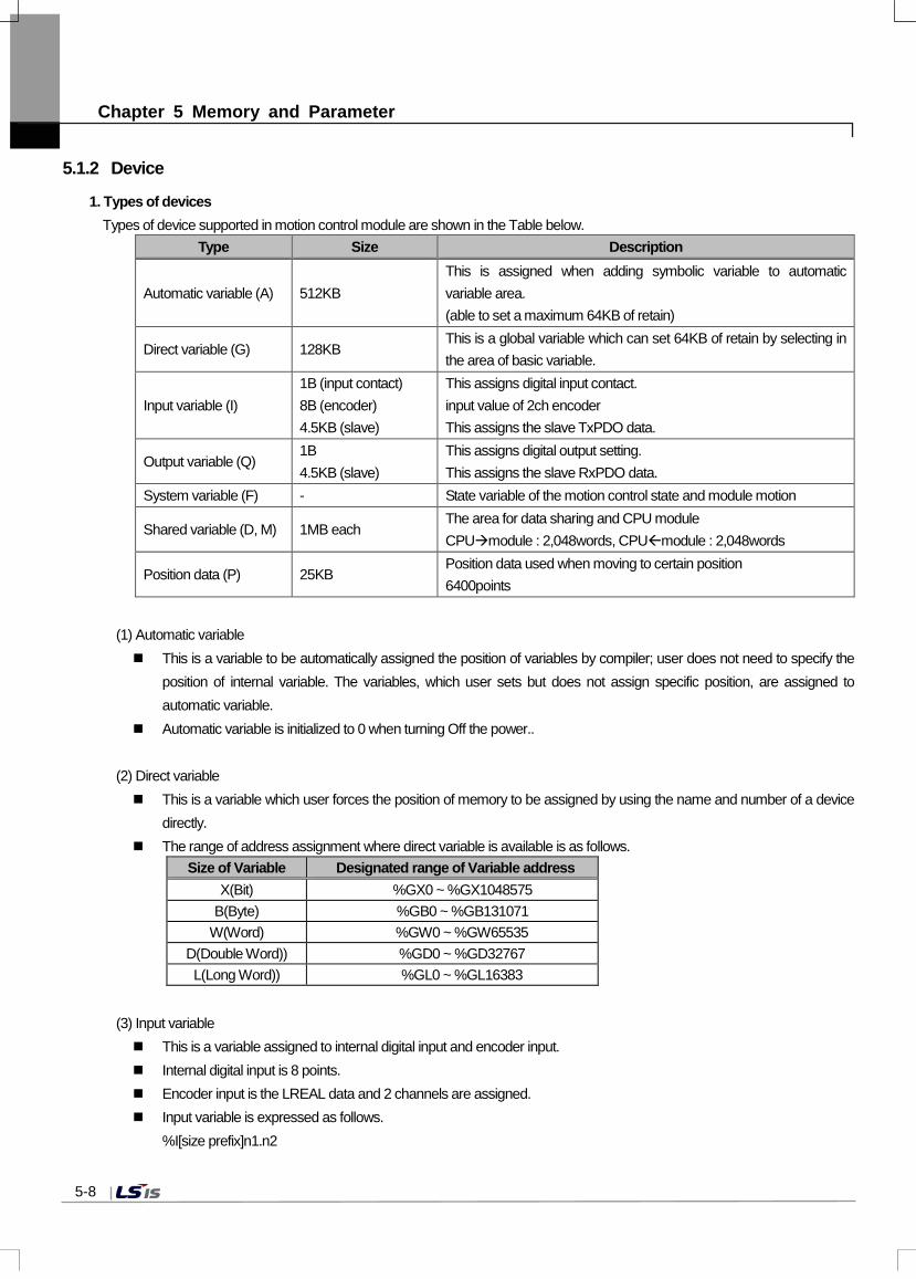
Chapter 5 Memory and Parameter
5.1.2 Device
1. Types of devicesTypes of device supported in motion control module are shown in the Table below.
Type Size Description
Automatic variable (A) 512KB This is assigned when adding symbolic variable to automatic variable area. (able to set a maximum 64KB of retain)
Direct variable (G) 128KB This is a global variable which can set 64KB of retain by selecting in the area of basic variable.
Input variable (I) 1B (input contact) 8B (encoder) 4.5KB (slave)
This assigns digital input contact. input value of 2ch encoder This assigns the slave TxPDO data.
Output variable (Q) 1B 4.5KB (slave)
This assigns digital output setting. This assigns the slave RxPDO data.
System variable (F) - State variable of the motion control state and module motion
Shared variable (D, M) 1MB each The area for data sharing and CPU module CPUmodule : 2,048words, CPUmodule : 2,048words
Position data (P) 25KB Position data used when moving to certain position 6400points
(1) Automatic variable This is a variable to be automatically assigned the position of variables by compiler; user does not need to specify the
position of internal variable. The variables, which user sets but does not assign specific position, are assigned toautomatic variable.
Automatic variable is initialized to 0 when turning Off the power..
(2) Direct variable This is a variable which user forces the position of memory to be assigned by using the name and number of a device
directly. The range of address assignment where direct variable is available is as follows.
Size of Variable Designated range of Variable address X(Bit) %GX0 ~ %GX1048575
B(Byte) %GB0 ~ %GB131071 W(Word) %GW0 ~ %GW65535
D(Double Word)) %GD0 ~ %GD32767 L(Long Word)) %GL0 ~ %GL16383
(3) Input variable This is a variable assigned to internal digital input and encoder input. Internal digital input is 8 points. Encoder input is the LREAL data and 2 channels are assigned. Input variable is expressed as follows.
%I[size prefix]n1.n2
5-8

Chapter 5 Memory and Parameter
Number Description
Size prefix X(1 bit), B(1 byte), W(1 word), D(1 double word), L(1 long word)
n1 0: internal input and internal encoder input
1~36: slave number (TxPDO of n1 slave parameter is mapped)
n2 n2 data based on [size prefix] among n1 data
Device depending on the input variable expression is assigned as follows.Address Description
%IX0.0 Internal Digital input 0 %IX0.1 Internal Digital input 1 %IX0.2 Internal Digital input 2 %IX0.3 Internal Digital input 3 %IX0.4 Internal Digital input 4 %IX0.5 Internal Digital input 5 %IX0.6 Internal Digital input 6 %IX0.7 Internal Digital input 7
%IL0.1 Encoder1 input %IL0.2 Encoder2 input
%IW1.0 ~ %IW1.63 TxPDO Mapping Data of Servo Drive 01 : :
%IW32.0 ~ %IW32.63 TxPDO Mapping Data of Servo Drive 32 %IW33.0 ~ %IW33.63 Input Data of EtherCAT IO Station 01(TxPDO Mapping Data)
: : %IW36.0 ~ %IW36.63 Input Data of EtherCAT IO Station 04(TxPDO Mapping Data)
For example, when the slave parameter of 3 axes servo drive is as follows, input flag is automatically assigned as follows.
5-9

Chapter 5 Memory and Parameter
Variable Data Type Address Description
_SL3_Statusword UINT %IW3.0 Statusword
_SL3_Torque_Actual_Value INT %IW3.1 Actual torque value
_SL3_Position_Actual_Value DINT %ID3.1 Actual position value
_SL3_Following_Error_Actual_Value DINT %ID3.2 Following error’s actual value
_SL3_Digital_Inputs UDINT %ID3.3 Digital input
_SL3_Mode_of_Operation_Display SINT %IB3.16 Operation mode display
_SL3_Command_Speed(rpm) INT %IW3.9 Commanded speed
_SL3_Current_Speed(rpm) INT %IW3.10 Operating speed
_SL3_Touch_Probe_Status UINT %IW3.11 Touch probe status
For example, 16 poists EtherCAT I/O is connected to the 33 axes in use, the input points is automatically assigned as follows.
Address Description
%IX33.0 EtherCAT I/O Digital input 0 %IX33.1 EtherCAT I/O Digital input 1 %IX33.2 EtherCAT I/O Digital input 2
: : %IX33.13 EtherCAT I/O Digital input 4 %IX33.14 EtherCAT I/O Digital input 5 %IX33.15 EtherCAT I/O Digital input 6
EtherCAT I/O can be added through a network slave automatic connection or slave data of the project. (Add item - Slave - I/O)
5-10

Chapter 5 Memory and Parameter
When EtherCAT I/O (digital input 16 points, digital output 16 points) is added in 33-axes
5-11

Chapter 5 Memory and Parameter
(4) Output variable This is a variable which is assigned to built-in digital output. Internal digital output is 8 points. Output variable is expressed as follows.
%I[size prefix]n1.n2
Number Description
Size prefix X(1 bit), B(1 byte), W(1 word), D(1 double word), L(1 long word)
n1 0: internal output
1~36: slave number (TxPDO of n1 slave parameter is mapped)
n2 n2 data based on [size prefix] among n1 data
Device depending on the output variable expression is assigned as follows.Address Description
%QX0.0 Internal Digital output 0 %QX0.1 Internal Digital output 1 %QX0.2 Internal Digital output 2 %QX0.3 Internal Digital output 3 %QX0.4 Internal Digital output 4 %QX0.5 Internal Digital output 5 %QX0.6 Internal Digital output 6 %QX0.7 Internal Digital output 7
%QW1.0 ~ %QW1.63 TxPDO Mapping Data of Servo Drive 01 : :
%QW32.0 ~ %QW32.63 TxPDO Mapping Data of Servo Drive 32 %QW33.0 ~ %QW33.63 Output Data of EtherCAT IO Station 01(TxPDO Mapping Data)
: : %QW36.0 ~ %QW36.63 Output Data of EtherCAT IO Station 04(TxPDO Mapping Data)
For example, when the slave parameter of 3-axis servo drive is as follows, input flag is automatically assigned as follows. .
5-12

Chapter 5 Memory and Parameter
Variable Data Type Address Description
_SLx_Controlword UINT %QWx.0 Controlword
_SLx_Target_Torque INT %QWx.1 Target torque
_SLx_Target_Position DINT %QDx.1 Target position
_SLx_Mode_of_Operation USINT %QBx.8 Operation mode
_SLx_Touch_Probe_Function UINT %QWx.5 Touch probe function
(5) System variable It is a variable that represents the operation status of module and motion control status. For details on the kinds of flags, refer to 1) System Flag of 5.1.1 Flag.
(6) Shared variable This is an area for data sharing between PLC CPU module and motion control module. Shared variable parameters can be set in XG5000, and XG-PM provides a function to check the shared variable
parameters. The data input to motion control module from PLC CPU module is up to 2,048 words. Common input variable is only
available for reading.Available devices when setting the shared input variables in XG5000 are as follows.
The data output to PLC CPU from the motion control module is up to 2,048 words. Common output variable isavailable for reading/writing.- XGK CPU : D, M, R, ZR- XGI/XGR CPU : M, R, W
The range of address assignment where shared variable is available is as follows.
Size of Variable Designated range of D Variable address
Designated range of M Variable address
X(Bit) %DX0 ~ %DX8388607 %MX0 ~ %MX8388607 B(Byte) %DB0 ~ %DB1048575 %MB0 ~ %MB1048575
W(Word) %DW0 ~ %DW524287 %MW0 ~ %MW524287 D(Double Word) %DD0 ~ %DD262143 %MD0 ~ %MD262143 L(Long Word) %DL0 ~ %DL131071 %ML0 ~ %ML131071
For detailed setting methods, refer to (2) Shared variable parameters of 5.1.3. Parameters
(7) Positioning data This is an area of position data which can be referred when wanting to operate to specific position by using motion
control module. This is not divided by each axis, and 6400 points can be assigned to every axis in common. Data are maintained even when turning Off the power. The range of address assignment where position data variable is available is as follows
Type of Variable Designated range of Variable address LREAL %PL0 ~ %PL6399
5-13

Chapter 5 Memory and Parameter
You can set the position values by selecting the position data in XG-PM project tree as below.
.
2. Retain settingDefault (automatic) variable retain is used when wanting to keep and use the data that occurs while operating or the data requiredfor an operation even in the case of restarting after the motion control module has stopped, and a certain part of the device in Garea can be used as retain area by setting the basic parameter. Characteristic table of the device which is available to set retain is shown below.
Device Retain setting Characteristic
Default O Enable retain setting when adding variable to automatical variable area
G O It is internal contact area and enable retain setting at parameter I X Internal digital input contact and internal encoder input contact Q X Internal digital output contact D X Available area for sharing data between PLC CPU and motion
control module M X
P X(Retain) Available for position data and maintain data value when power off(Always maintain retain, No user setting)
5-14

Chapter 5 Memory and Parameter
5.1.3 Parameter
1. Basic parameter
Explain Basic parameter of the motion control module.
(1) Basic motion setting
(a) Main task cycle
- Set the motion period of the main task. The period can be set by selecting one in 1ms/2ms/4ms.
- Set the control time of performing in the main task of motion control module considering the execution timeof program.
- When the execution time of the main task exceeds the main task period, an error occurs and if motion control module.
is in RUN state, it is changed to STOP state.
(b) Periodic task cycle
- Set the motion period of the periodic task. The period can be set in multiples of the main task between 1 ~ 100ms.
- The periodic task is performed in the remaining time after performing the main task in the control period, and therefore,
it can be performed through a number of control periods.
(c) Restart mode
Restart by PLC CPU reset or turning on the power after turning off is divided into cold restart and warm restart. With
regard to restart mode, variables can be set in 3 different types such as default, initialization, and retain; and the
initialization of variables set by restart mode is as follows.
5-15

Chapter 5 Memory and Parameter
Cold Restart Warm Restart
Default Initialize with ‘0’ ‘Initialize with ‘0’
Retain Initialize with ‘0’ Maintain previous value
Initialization Initialize with user setting value Initialize with user setting value
Retain & Initialization Initialize with user setting value Maintain previous value
(d) Output control setting
When an error occurs in module or changing the motion mode of module, decide whether to maintain the data output
or not.
Selection Operation
Maintain the output
in the event of an error
Decide whether to output the data normally when an error or certain
input occurs in the module.
Maintain the output when
switching from RUN to STOP
Decide whether to output the data normally during the operation mode
of the motion control module is switching from RUN to STOP.
Maintain the output when
switching from STOP to RUN
Decide whether to output the data normally during the operation mode
of motion control module is switching from STOP to RUN.
(2) Memory area setting
This is a parameter item which sets the retain area. Retain area can be set by checking the “G Area retain set" to activate
retain setting. Retain can be set up to 64Kbyte, and if the beginning and ending addresses are set to be retain in G area,
the value of relevant area is maintained even when turning off the power.
5-16

Chapter 5 Memory and Parameter
2. Shared variable parameter
1) Sharing variable parameter is explained as follows.(a) Data are shared between CPU and motion control module by using the exclusive shared variable. (b) User can set the size of reading/writing by parameter, and the maximum setting size is 2,048 words each. (c) User can select and set motion control module in I/O parameter of XG5000.
(d) Shared variable set is transmitted to motion control module when running PLC CPU, and it can be identified by reading
the shared variable parameter of motion control module in XG-PM.
5-17

Chapter 5 Memory and Parameter
3. Common parameter
Common parameter is explained as follows. Item Description Settings Initialize value
Encoder1 Unit Set display unit of encoder position.
0: pulse 1: mm 2: inch 3:degree
0: pulse
Encoder1 Pulses per rotation Set Encoder1 pulses per rotation 1 ~ 4294967295 8192 pls
Encoder1 Travel per rotation Set the movement amount of the load side moved per encoder 1 rotation.
0.000000001 ~ 4294967295
10 pls
Encoder1 Pulse input Set the input mode in accordance with the output shape of encoder.
0: CW/CCW (x1) 1: PULSE/DIR (x1) 2: PULSE/DIR (x2) 3: PHASE A/B (x1) 4: PHASE A/B (x2) 5: PHASE A/B (x4)
3: PHASE A/B (x1)
Encoder2 Unit Set display unit of encoder position.
0: pulse 1: mm 2: inch 3:degree
0: pulse
Encoder2 Pulses per rotation Set Encoder2 pulses per rotation 1 ~ 4294967295 8192 pls
Encoder2 Travel per rotation Set the movement amount of the load side moved per encoder 2 rotation.
0.000000001 ~ 4294967295
10 pls
Encoder2 Pulse input Set the input mode in accordance with the output shape of encoder.
0: CW/CCW (x1) 1: PULSE/DIR (x1) 2: PULSE/DIR (x2) 3: PHASE A/B (x1) 4: PHASE A/B (x2) 5: PHASE A/B (x4
3: PHASE A/B (x1)
Encoder1 Max. value
Set position display range of encoder. Long Real(LREAL)
2147483647 pls Encoder1 Min. value -2147483648 pls Encoder2 Max. value 2147483647 pls Encoder2 Min. value -2147483648 pls
Override Set the application method of the input value when executing override command.
0: Specified by ratio 1: Specified by unit
0: Specified by ratio
5-18

Chapter 5 Memory and Parameter
(1) Encoder unit
This is to set the display unit of encoder position, and each control target can be set by pulse, mm, inch, and degree. In
case of the synchronous operation having the encoder as a center, the unit must be set by the same unit with it of the
synchronous operation axis.
(2) Encoder Pulses per rotation
When using mm, inch, and degree for the encoder unit, set the number of purses per encoder rotation.
(3) Encoder Travel per rotation
When using mm, inch, and degree for the encoder unit, set the amount of movement of the load side moved per encoder
rotation.
[Setting Example]
When the machine which is moved by ball screw is connected to the encoder with gear, the setting of the encoder unit /
Encoder Pulses per rotation / Encoder Travel per rotation is as follows.
· Encoder unit: mm
· Encoder Pulses per rotation = Encoder resolution x
Encoder side gear ratio
= 4096 x 7
= 28672 pls
· Encoder Travel per rotation = Ball screw pitch x Machine
side gear ratio
= 10.0 mm x 5
= 50.0 mm
(4) Input encoder pulse
When wanting to use the encoder signal of servo drive or manual pulse generator as an input, the signal, which is right to
the output form of the encoder or manual pulse generator, can be selected to be used.
One among CW/CCW (x1), PULSE/DIR (x1), PULSE/DIR (x2), PHASE A/B (x1), PHASE A/B (x2), and PHASE A/B (x4)
must be selected and set for the encoder input signal.
(a) CW/CCW (x1)
Count operation is performed when A phase input pulse increases or B phase input pulse increases; and adding operation
is performed when A phase input pulse increases in the Low input of B phase input pulse; and subtraction operation is
performed when B phase input pulse increases in the Low input of A phase input pulse.
5-19

Chapter 5 Memory and Parameter
Add/Subtraction A phase input pulse High A phase input pulse Low
B phase input pulse High - Subtraction count B phase input pulse Low Add count -
(b) PULSE/DIR (x1)
Count operation is performed when A phase input pulse increases, whether to be added or subtracted is decided by
B phase. Add/Subtraction A phase input pulse High A phase input pulse Low
B phase input pulse Off Add count - B phase input pulse On Subtraction count -
(c) PULSE/ DIR (x2)
Count operation is performed when A phase input pulse increases and decreases, and whether to be added or
subtracted is decided by B phase.
5-20

Chapter 5 Memory and Parameter
Add/Subtraction A phase input pulse High A phase input pulse Low
B phase input pulse Off Add count Add count B phase input pulse On Subtraction count Subtraction count
(d) PHASE A/B (x1)
Add operation is performed in case of the increase in A phase pulse when the phase of A phase input pulse is ahead
of B phase input pulse, and subtraction operation is performed in case of the decrease in A phase pulse when the phase of
B phase input pulse is ahead.
(e) PHASE A/B (x2)
Count operation is performed when both increase and decrease in A phase input pulse. Add operation is performed
when the phase of A phase is input ahead of B phase, and subtraction operation is performed when the phase of B
phase is input ahead of A phase.
5-21

Chapter 5 Memory and Parameter
(f) PHASE A/B (x4)
Count operation is performed in case of the increase/decrease in A phase input pulse and the increase/decrease in B
phase; and add operation is performed when the phase of A phase is input ahead of B phase; and subtraction
operation is performed when the phase of B phase is input ahead of A phase.
(g) Maximum and minimum values of encoder
① The range of the encoder value is set to the maximum and minimum values of encoder when counting the input pulse
from the encoder signal of servo drive or manual pulse generator and indicating it to encoder value.
② Operations are as shown in the figure below.
- In case of the increase in the encoder value
- In case of the decrease in the encoder value
5-22

Chapter 5 Memory and Parameter
4. Axis group parameter Axis group parameter item is explained as follows.
Item Description Settings Initial value
Axis1
Set the axis which form axis group. None, 1Axis ~ 32Axis(real axis), 37Axis ~ 40Axis(virtual axis)
None Axis 2 None Axis 3 None Axis 4 None
Interpolation speed max
Set max speed of operation about axis group. Long Real(LREAL) Positive number
20000000 u/s
(1) Configuration axis setting Set the number of each axis which belongs to the relevant axis group. Each axis group can include up to 4 axes. Virtual axis can also be set in the axis group parameter. Axis setting must be set in order in axis group which executes circular interpolation or helical interpolation command. In other words, 「axis setting 1」 is X-axis of the arc, 「axis setting 2」 is Y-axis of the arc, and 「axis setting 3」 is Z-axis of helical interpolation. Therefore, if circular interpolation command is executed when setting the axis group, errors occur as follows.
- In case the axis group is comprised of 4 axes (error code: 0x20A9) - In case the set value of 「axis setting 1」 or 「axis setting 2」 is ‘none’ (error code: 0x20AA) - In case the set value of「axis setting 3」is 'none' and the remaining axes are set (error code: 0x20AA)
(2) Interpolation speed max This refers to the configurable maximum speed of interpolation control operation when controlling interpolation with axes which belongs to the relevant axis group. In case of interpolation operation of the relevant axis group, interpolation speed must be set below the set Interpolation speed max.
5-23

Chapter 5 Memory and Parameter
5. Coordinate system parameter Coordinate system parameter is explained as follows.
Part Description Setting range Initial value
Coordinate system
Set the type of robot that is applied in the
operation of coordinate system.
0: None 1: XYZ 2: Delta3
0: None
Coordinate system
parameter
Set the parameters of the machine
depending on the type of coordinate system. - -
(1) XYZ XYZ is a robot where the axis set in 「axis setting 1」 in X-axis, the axis set in 「axis setting2」in Y-axis, and the axis set in 「axis setting 3」in Z-axis make a one-to-one correspondence and move in Cartesian coordinate. If the type of coordinate system is set to XYZ, there is no need to set the coordinate system parameters.
(2) Delta3 Delta3 is a delta robot composed of 3-axes. If the type of coordinate system is set to Delta3, the four Rf/Rm/Lf/Lm coordinate system parameters should be set.
Rf
Rm
Parameter Description
Fixed frame radios(Rf) Distance from the center of a fixed frame to the link of the fixed frame (mm)
Fixed frame link length(Lf) Fixed frame’s link length (mm)
Moving frame link length
(Lm) Moving frame’s link length (mm)
Moving frame radios(Rm)
Distance from the center of a moving frame
to the link of the moving frame (mm)
(The left figure is a case where X, Y
coordinates of the fixed and moving frames
are the same.)
Rm
5-24

Chapter 5 Memory and Parameter
6. Tool setting parameter Tool setting parameter is explained as follows.
Part Description Setting range Initial value
X axis offset Set the X axis offset of the end (tool) of the
robot. LREAL 0
Y axis offset Set the Y axis offset of the end (tool) of the robot.
LREAL 0
Z axis offset Set the Z axis offset of the end (tool) of the robot.
LREAL 0
Tool setting parameter enables the position of a tool to be set in offset to ensure control of the end of the tool in cases where a separate tool is attached to the end of the robot for use.
7. Workspace parameter Workspace parameter is explained as follows.
Part Description Setting range Initial value
Workspace type Set the workspace type.
0: None 1: Rectangle 2: Cylinder 3: Delta 4: Sector
0
Workspace error check
It sets the occurrence of an error in the outside of workspace.
0: Prohibition 1: Permit
0
Workspace parameter
Set the parameter depending on the type of
workspace. LREAL 0
(1) Rectangle
Ymin
Ymax
XminXmax
X Axis
Y Axis
Parameter Value
Workspace parameter 1 X min(mm)
Workspace parameter 2 X max(mm)
Workspace parameter 3 Y min(mm)
Workspace parameter 4 Y max(mm)
Workspace parameter 5 Z min(mm)
Workspace parameter 6 Z max(mm)
- -
5-25

Chapter 5 Memory and Parameter
(2) Cylinder
Zmax
Zmin
Radius
X Axis
Z Axis
Parameter Value
Workspace parameter 1 Radius(mm)
Workspace parameter 2 Z min(mm)
Workspace parameter 3 Z max(mm)
- -
(3) Delta
Z Axis
YAxis
Zu
Hcy
Hco
Rco
Rcy
Parameter Value
Workspace parameter 1 Zu(mm)
Workspace parameter 2 Hcy(mm)
Workspace parameter 3 Hco(mm)
Workspace parameter 4 Rcy(mm)
Workspace parameter 5 Rco(mm)
- -
(4) Sector
X Axis
Y Axis
StartAngleEndAngle
Parameter Value
Workspace parameter 1 L start(mm)
Workspace parameter 2 L end(mm)
Workspace parameter 3 Z min(mm)
Workspace parameter 4 Z max(mm)
Workspace parameter 5 SartAngle(degree)
Workspace parameter 6 EndAngle(degree)
- -
5-26

Chapter 5 Memory and Parameter
8. PCS parameter PCS parameter is explained as follows.
Part Description Setting range Initial value
X axis movement value
Set the X axis movement distance from
the home position of MCS to that of PCS. LREAL 0 mm
Y axis movement value
Set the Y axis movement distance from the home position of MCS to that of PCS.
LREAL 0 mm
Z axis movement value
Set the X axis movement distance from the home position of MCS to that of PCS.
LREAL 0 mm
X axis rotation Set the X axis rotation value of PCS. -360~360 0 deg
Y axis rotation Set the Y axis rotation value of PCS. -360~360 0 deg Z axis rotation Set the Z axis rotation value of PCS. -360~360 0 deg
PCS parameter sets the home position to PCS to easily perform the operation of moving from the top of a specific object in the coordinate system operation. In the operation of PCS coordinate system, the coordinate system operation to make the set PCS as the home position is performed.
9. Network parameter The items related to EtherCAT network setting are explained here. In modifying network parameters, be sure to write master/slave parameter and slave data in Project Write menu before use.
(1) Master parameter Set master function related to EtherCAT slave connection when connecting network. Master parameter setting items are as follows.
Item Description Settings Initial value
Slave Revision Check
Specify whether to check Revision information of parameter matches the Revision value of actual slave at the time of network connection.
0: Don’t check 1: Check
0: Don’t check
Slave Serial Number Check
Specify whether to check serial number information of parameter matches the serial number value of actual slave at the time of network connection.
0: Don’t check 1: Check
0: Don’t check
Periodic communication time-out count
Specify the number of criteria that periodic communication time-out occurs.
1 ~ 8 2
(a) Slave Revision check Whether to proceed with the connection is determined by comparing the revision information set in the slave parameters at the time of network connection with that possessed by the slave which is actually connected. Motions according to the set values are as follows.
5-27

Chapter 5 Memory and Parameter
- ‘0:Don’t check’ The communication connection process is continued while not comparing the Revision information set in the slave parameter and the Revision information which the slave has.
- ‘1: Check’ Compare the Revision information set in the slave parameter and the Revision information which the connected slave has, and if it does not correspond, a network configuration mismatch error (error code: 0x0F1F) occurs and ends the communication connection process.
It may not operate normally if the Revision of the slave parameter and a slave with no compatibility are connected in case that you set the check standard of slave Revision to ‘0: Don’t check’. Therefore, use it after checking the availability of the compatibility between the Revisions
(b) Slave Serial Number Check When connecting to the network, decide whether or not to continue the connection process by comparing the serial number information set in the slave parameter and the serial number information which actually connected slave has.
Motions according to the set values are as follows. - ‘0: Don’t check’
The communication connection process is continued while not comparing the serial number information set in the slave parameter and the serial number information which the slave has.
- ‘1: Check’ Compare the serial number information set in the slave parameter and the serial number information which the connected slave has, and if it does not correspond, a network configuration mismatch error (error code: 0x0F1F) occurs and ends the communication connection process.
If the slave’s serial number check is set to ‘1: Check’, you are able to know the changes made to the network when the network configuration order is changed or when the slave is replaced, which is useful for maintaining and repairing such as resetting the slave parameter. Resetting of the serial number in XG-PM is required to connect to the changed network configuration.
(c) Periodic communication time-out count The standard number occurring time-out error is specified when it cannot receive the periodic data during execution of periodic communication between the motion control module and the slave device. When the communication time-out error occurs frequently from various noise environments (power surges, induction noise or noise interference between the motion control module and the wiring of the slave device), set the set value high. The available setting range is between 1 to 8 times.
(2) Slave data (a) Slave parameter Set the information of EtherCAT slave used when connecting to the network. The slave parameter can be identified in the slave information window which is displayed when adding the slave by executing [Slave data] – [Add item] – [Slave] in the XG-PM project tree. Or you can check it in the slave information window which is displayed after executing each slave’s ‘Properties' linked to the sub-tree of the [Slave data] on the XG-PM project tree
5-28

Chapter 5 Memory and Parameter
The setting items for the slave parameter are as follows.
Item Description Settings Initial value
Slave name Select the slave and displays the name of selected slave.
XML L7N
Number Set the number of station which is applied to the selected slave.
1 ~ 32 33 ~ 36
1 (Increase automatically when adding the slave)
Vendor The name of the selected slave supplier is automatically displayed.
Setting is not available
LS Mecapion
Version Revision of the selected slave is automatically displayed.
Setting is not available
#x00002
PDO Map RxPDO
RxPDO mapping information of the slave is automatically displayed.
XML 0x1600 PDO map information
TxPDO TxPDO mapping information of the slave is automatically displayed.
XML 0x1A00 PDO map information
DC Used Set the DC use of the slave. 0: Unused 1: Used
1: Used
Slave Replace Set the slave replace 0: Unused 1: Used
0: Unused
① Slave nameSelect the slave you want to connect to the motion control module, and display the name of the selected slave. L7N servo drive is selected for the initial value when adding the slave to the slave data.Display the supportable list by bringing the slave information from XML file which is in the folders below. - Korean version: ‘XG-PM setting folder’ > \l.kor\DriveInfo, \l.kor\IOInfo folder- English version: ‘XG-PM setting folder’ > \l.eng\DriveInfo, \l.eng\IOInfo folderWhen wanting to add new slave, copy the relevant XML file to the folders above and restart XG-PM.
② The number of stationSet the number of station which is applied to the selected slave. The set number of station is the slave number and IOdevice number. Setting ranges are as follows.- Servo drive: 1 ~ 32- EtherCAT I/O device: 33 ~ 36In the event of connecting servo drive automatically, axis order is automatically set in accordance with connection order.
③ SupplierThe name of the selected slave supplier is automatically displayed. User cannot arbitrarily change it.
④ VersionRevision information of the selected slave is automatically displayed. User cannot arbitrarily change it.
5-29

Chapter 5 Memory and Parameter
⑤ RxPDOSet the synchronous data which is transmitted from the motion control module to the slave in every communication period. RxPDO item supported by the relevant slave is automatically set when selecting a slave. Object that the user wants can be added or deleted by using the editing function. When editing the PDO object, the following objectives must be included as they are essential items used in the motion control module. - 0x6040:0 Controlword - 0x607A:0 Target position
The synchronous data assigned here is automatically registered as input/output flag and it can be referred in the user program. For example, ‘Controlworld’ object from RxPDO synchronous data of L7N servo drive which is linked to the slave 1 is registered as I/O flag, _SL1_Controlword (%QW1.0).
⑥ TxPDOSet the synchronous data which is read from the slave in the motion control module every communication period. When selecting the slave, the TxPDO item which is supported by the relevant slave is set automatically. Object that the userwants can be added or deleted by using the editing function.When editing the PDO object, the following objects must be included as they are essential items used in the motioncontrol module.
- 0x6041:0 Statusword - 0x6064:0 Position Actual Value
The synchronous data assigned here is automatically registered as I/O flag and it can be referred in the user program. For example, ‘Statusword’ object from TxPDO synchronous data of L7N servo drive which is linked to the slave 2 is registered as I/O flag, _SL1_Statusword (%IW1.0).
⑦ DC UsedIf the slave supports the DC function, it is automatically set form the XML file. If you do not want to use the DC function,select it to 0: Unused.DC(Distributed Clock) is a function used to synchronize the EtherCAT master and the EtherCAT slave, and it allowshigh-definition synchronous control between the Ethercat slaves.DC shares the time information between the EtherCAT master and EtherCAT slave; and adjusts the synchronizationbetween each slave. In order to share the time information, the first slave that is connected to the motion control module provides the Reference Clock. The Reference Clock distributes time information to each slave every communicationperiod.
(b) Servo configuration Servo configuration includes the object information that has alarm information/alarm history information/input signal information. The information is the content which is not defined in the xml file from the device manufacturer, and there it is set automatically when the servo driver is added. Since if the servo setting information does not match the actual device, there may be constraints on the device use, a user is required to modify the servo setting information in person.
5-30

Chapter 5 Memory and Parameter
(3) Operation parameter (a) Basic parameter
Basic parameter among operation parameters is explained as follows.
Item Description Settings Initial value
Unit Set the command position unit of the axis.
0: pulse 1: mm 2: inch 3:degree
0: pulse
Pulses per rotation Set the number of pulses per rotation of motor which corresponds encoder resolution.
1 ~ 4294967295 524288 pls
Travel per rotation Set the movement amount of the load side moved per rotation of motor.
0.000000001 ~ 4294967295
10 pls
Speed command unit
Set the command speed unit of the axis. 0: Unit/Time 1: rpm
0: Unit/Time
Speed limit Set the maximum speed in case of the speed command of each axis.
Long real(LREAL) Positive number
20000000 pls/s
Emergency stop deceleration
Set the deceleration used in the sudden stop conditions.
0 or Long real(LREAL) Positive number
0 pls/s2
Encoder select Set the type of encoder to be used. 0: Incremental Encoder 1: Absolute Encoder
0: Incremental Encoder
Gear ratio(Motor) Set the gear ratio between motor and load.
1~65535 1 Gear ratio(Machine) 1~65535 1
Operation mode of the reverse rotation
Specify the operation method in case operation direction is reversed in the input conditions of newly executed command.
0: E.Stop 1: Stop
0: E.Stop
① UnitThis is used to set the command unit during motion control, and depending on the control target, the unit of pulse, mm,
5-31

Chapter 5 Memory and Parameter
inch, and degree can be set for each axis. When changing the setting of the unit, other parameters or variable values are not changed. Therefore, when changing the units, the relevant parameters must be reset so that they can be adjusted to the setting range of the relevant unit.
② Pulses per rotation When using mm, inch, and degree for the motion control command units and indicating the speed in rpm, the number of pulses required per motor rotation is set to be used.
③ Travel per rotation Set the movement amount of the load side per motor rotation when using mm, inch and degree for motion controlcommand unit.How the machine moves from a rotation of motor is determined by the structure of the machine.
④ Speed command unit The base unit of the value of the speed used for the motion control command is set.If it is set to ‘0: unit/time’, it is applied by the rate of change per second form the position of the relevant unit set in the「unit」parameter. For example, if the setting of the 「unit」is in mm, the unit of the speed command is ‘mm/s’.If it is set to ‘1: rpm’, rpm is applied to the speed command unit. If the speed command unit is rpm and it is internallychanged to the unit speed, values set in the 「Pulses per rotation」and 「Travel per rotation」parameters are used. When changing the setting of the speed command unit, other parameters or variable values are not changed.Therefore, the related parameters must also be reset according to the setting range of the relevant unit.
⑤ Speed limit Speed limit refers to the maximum rate of the available setting of motion control operation.When operating the relevant axis, the operation speed should be set below the speed limit set.
⑥ Emergency stop deceleration
Deceleration in the event of a sudden stop sets the deceleration for situations where a sudden stop needs to be made while operating the axis due to internal or external factors.
Conditions for a emergency stop are as follows.
In case the software upper limit/lower limit is detected.
5-32

Chapter 5 Memory and Parameter
In case the operation speed of the serve axis exceeds the speed limit in synchronized operation. (gear, cam)
In case the setting for「error level of tracking error」is ‘1: alarm’ and the error of tracking error occurs.
In case the emergency stop command is executed during the test operation in XG-PM.
In case an error occurs in the command executed while axis is currently operating during the checking of execution
conditions.
(Except for occasions when restarting the command or ContinuousUpdate is activated.)
⑦ Encoder select
Set the type of encoder that is going to be used. When using the absolute position system, select 1: absolute encoder.The following shows the setting of “Encoder select”
Item Settings Description
Encoder select
0: Incremental Encoder After power on/off, the previous location of servo motor is not maintained. After power of/off, origin fix state is off.
1: Absolute Encoder The absolute position system is activated. After power on/off, the previous location of servo motor is maintained. Origin fix state maintain last condition before power on/off.
⑧ Gear ratio(Motor, Machine)Set gear ratio between the motor and the load. If it is a structure that the load side rotates n times when the motor side rotates m times, set the gear ratios as below.• Motor side gear ratio = m• Machine side gear ratio = nIf the 「unit」setting is ‘0: pulse’, this parameter is invalid.
[Setting Example] When the machine which is moved by ball screw is connected to the encoder with gear, the setting of the encoder unit/ Pulses per rotation/ travel per rotation is as follows.
· Unit: mm· Pulses per rotation = 524288 (19Bit Encoder)· Travel per rotation = Ball screw pitch
= 10.0 mm · Gear ratio(Motor) = 7· Gear ratio(Machine) = 5
5-33

Chapter 5 Memory and Parameter
Note If the unit from above ‘Setting example’ is set to ‘0’, it is moved to by a position corresponding to the encoder pulse, regardless of the motor
and machine gear ratio.
In other words, in order to move the 10mm it must make a command of the 524288 * 7/5 = 734003 pulse.
⑨ Operation mode of the reverse rotation
Specify the method of motion when the operation direction is reversed in the input conditions of newly executedcommands.When starting or restarting the command which the BufferMode is Aborting, or activating ConinuousUpdate, in casewhere the command condition and the current operating direction are in reverse of each other, stop it by following themethod set in the parameter, and start operation in the set speed. If the BufferMode is not Aborting, it is run in the specified continuous running method in the BufferMode rather than the method set in the parameter.
- ‘0: Deceleration stop’ When the operation direction is reversed by the condition of newly executed command, make a deceleration pause to 0 speed and continue accelerating to the target position or operate at the targeted speed.
- ‘1: Immediate stop' When the operation direction is reversed by the condition of newly executed command, stop immediately and continue operating in the opposite direction in the same operation speeds to the target position or at the targeted speed.
0: Deceleration stop 1: Immediate stop
5-34

Chapter 5 Memory and Parameter
(b) Extended parameter The following explains extended parameter of operation parameter
Item Description Settings Initial value
S/W upper limit Set the range of the software limit functions. Long real(LREAL)
2147483647 pls S/W lower limit -2147483648 pls
Infinite running repeat position Set the value of the repetitive position range in case infinite running repeat mode is used.
Long real(LREAL) Positive number
360 pls
Infinite running repeat Set the allowable status of infinite length repetitive operation functions.
0: Disable 1: Enable
0: Disable
Command inposition range Set the range where inposition signal is On before completion of positioning.
0 or Long real(LREAL) Positive number
0 pls
Tracking error over-range value
Set the value to detect more than position deviation.
0 or Long real(LREAL) Positive number
0
Current position compensation amount
Set the compensation threshold to indicate the current position value as the target position value.
0 or Long real(LREAL) Positive number
0
Current speed filter time constant
Set the time to calculate movement average of the current speed.
0 ~ 100 0
Error reset monitoring time Set the monitoring time when resetting error occurred in servo drive.
1 ~ 1000 100
S/W limit during speed control Set whether the soft limit is detected during the speed control.
0: Don’t detection 1: Detect
0: Don’t detection
Tracking error level Set the error level more than deviation. 0: Warning 1: Alarm
0: Warning
JOG high speed
Set the values of speed / acceleration / deceleration / jerk which is referred in jog operation command.
Long real(LREAL) Positive number
100000 pls/s JOG low speed 10000 pls/s JOG Acceleration 0 or
Long real(LREAL) Positive number
100000 pls/s2 JOG Deceleration 100000 pls/s2 JOG Jerk 0 pls/s3
① Software upper limit / Software lower limit
This is a function which sets the available range of the movement of the machine in the way of software by setting the upper limit & lower limit and allows the machine not to be operated beyond the set range. In other words, this is used to prevent a breakaway due to an error from setting the operation position and false operation that occurs from the user program error. Set the external input upper limit and lower limit beyond the range of the software upper limit and the software lower limit.
5-35

Chapter 5 Memory and Parameter
The range check of the software upper limit and lower limit is conducted at the beginning of operation and during the operation. If the soft upper limit and lower limit is detected, an error occurs and the module suddenly stops a motor. Therefore, check the cause of the error and use it after resetting the error when restarting the operation. If you set the software upper limit and lower limit to be the initial value (upper limit: 2,147,483,647, lower limit: -2,147,483,648) or the same value, the soft upper limit and lower limit is not be detected.
② Infinite running repeat positionWhen using in infinite running repeat mode, set the position value which is repeated.This is applied when the setting of extended parameter, 「Infinite running repeat」parameter, is ‘1:Enable’.When the 「Infinite running repeat」 parameter is ‘1:Enable’, the command position and current position is indicatedas "0~ (infinite running repeat position of -1). (「Unit」= 0: pulse based)
③ Infinite running repeatSet the function availability of infinite running repeat operation. If this parameter is set to ‘1: Enable’, the display of the command position and current position is updated periodicallyand automatically in the range set in the infinite length repetition position.You must set it to ‘0: Disable’ when you are not using the infinite running repeat operation function.
④ Command inposition rangeThis item sets the distance to the target position where inposition flag (_AXxx_INPOS) is On.When starting up the motion control, the in-position flag (_AXxx_INPOS) is Off, and it is On when the current positiongoes inside the「Command inposition range」from the target position. In-position flag can be used as a trigger whenexecuting other assistant work before completing the position control.
5-36

Chapter 5 Memory and Parameter
⑤ Exceeding value of tracking errorSet the value which will detect the value over position deviation. If a value exceeds this range, the 「Over deviationwarning (_AXxx_DEV_WARN)」 or 「Over deviation alarm(_AXxx_DEV_ERR)」flag is On.If this set value is 0, it won’t detect the value over the deviation. You can set whether you want it to be a warning or analarm for over deviation in the 「Error level of tracking error」of the expanded parameter.
⑥ Tracking error levelSet whether to make it a warning or an alarm when the value over deviation is detected.Operations according to the set values are as follows.- ‘0: Warning’
When an error occurs in tracking error, the 「Over deviation warning (_AXxx_DEV_WARN)」flag is On, and warning error of tracking error (error code: 0x101D)) occurs. The axis does not stop and keeps operation.
- ‘1: Alarm’ When an error occurs in tracking error, the 「Over deviation alarm (_AXxx_DEV_ERR)」flag is On, and the alarm error of tracking error (error code: 0x101C) occurs. The axis suddenly stops at the「Emergency stop deceleration」of basic parameter.
In the following situations, the error in tracking error is not examined. In case the「Tracking error over-range value」is 0. In case of the operation in homing or torque control. In case the 「Tracking error over-range value」is 0. In case of the operation in homing or torque control.
⑦ Current position compensation amount Current position compensation amount is a parameter unit used to display the current position value as the commandposition when the servo motor’s current position value is not displayed as a fixed value but changed slightly dependingon the personal setting of the user application and the servo drive. When it is not in operation and if the difference of the command position and the current position is within the amount ofcompensation in displaying current position, the current position value is displayed as a command position value. When it is in operation, Current position compensation amount is not reflected, and the actual position value is displayed. The following is an example of application of Current position compensation amount according to the value of Currentposition compensation amount when the command position is ‘0’.■ Current position compensation amount = 0 pls
Position value of the actual motor is displayed as the current position value even after the end of operation.
5-37

Chapter 5 Memory and Parameter
■ Current position compensation amount = 50 plsIf the current position value is within ±50 of command position after the end of operation, it is displayed as thecommand position value. .
5-38

Chapter 5 Memory and Parameter
■ Current position compensation amount = 100 plsIf the current position value is within ±100 of command position after the end of operation, it is displayed as thecommand position value.
⑧ Current speed filter time constantSet the time to calculate the average of movement at current speed. (unit: ms) Current speed filter time constant is not
applied if it is set to '0'. When the speed of axis is slow or there are wide variations in current speed (ex. 「unit」 setting is ‘0: pulse’, stable
speed can be achieved by applying the average of movement to the current speed. You can check the differences in current speed depending on the value of Current speed filter time constant in the list
below which traces command speed and current speed at 10 mm/s of command speed.
■ Current speed filter time constant = 0 ms
5-39

Chapter 5 Memory and Parameter
■ Current speed filter time constant = 50 ms
■ Current speed filter time constant = 100 ms
⑨ Error reset monitoring timeSet the monitoring time in the event of error reset occurred in the servo drive. (unit: ms) If the error which occurred inthe servo drive within the error reset monitoring time, error reset monitoring is terminated and error reset time out error of servo drive (error code: 0x1070) is occurred.
⑩ S/W limit during speed controlWhen software limit is detected during the operation at fixed speed by speed control, this is used to stop the motor.Operations according to the set values are as follows.- ‘0: Don’t detect’If it is under the speed control even when the software limit function is activated, software limit is not detected. - ‘1: Detect’If it is under the speed control even when the software limit function is activated, software limit is detected.
5-40

Chapter 5 Memory and Parameter
Even when the parameter value is set to '1: detect', if the software upper limit/lower limit is set to the initial value (upper limit: 2,147,483,647, lower limit: -2,147,483,648) or the same value, software limit is not detected.
⑪ JOG high speed / JOG low speed Jog speed is related to the speed when operating jog which is a type of manual operation. Jog operation is dividedinto JOG high speed and JOG low speed.Jog is operated in the pattern with the areas of acceleration, fixed speed, and deceleration. Therefore, the acceleration area is controlled by jog acceleration time and the deceleration area is controlled by jog deceleration time. Setting range of JOG high speed cannot exceed the speed limit. Also, JOG high speed must be the same with orbigger than JOG low speed.
⑫ JOG acceleration, JOG deceleration, JOG jerk Set the values of acceleration, deceleration, and jerk which are applied in the case of JOG high speed and JOG low speed operation. If JOG acceleration is 0, it is operated immediately at JOG set speed without acceleration area at the beginning of JOG operation. If JOG deceleration is 0, it is stopped immediately at 0 without deceleration area at the stop of JOG operation. If JOG jerk is 0, the form of acceleration/deceleration is in a linear as acceleration is fixed.
5-41

Chapter 5 Memory and Parameter
5.2 I/O signal
Explain about the contents and functions of the I/O signal for data exchange of Motion control module and XGK CPU module.
5.2.1 Contents of I/O Signal
1. I/O Signal of Motion control module use input 48Bit, output 16bit.
2. The operation preparation signal (Uxx.00.F) of motion control module is a signal which always remains On when the module is in a normal state by the way of hardware, and the module recognition process is completed normally by CPU. If PLC CPU operation mode is RUN and there is the initialization task program when turning the initial power On, the operation preparation signal is On after the initialization task program has ended. When an error related to the hardware occurs during the operation of motion control module, the operation preparation signal is Off.
3. The relevant Bit is On in only the connected axis when the operation preparation signal for each axis of the motion controlmodule is connected with EtherCAT communication between the motion control module and servo drive regardless of the operation mode of motion control module.
4. Output signalThe signal delivers from PLC CPU to Motion control module.
Axis
Signal direction: PLC CPU → Motion Control Module Output Signal Description
Common Uxx.03.0 RUN/STOP Command (0:RUN, 1:STOP)
- Uxx.03.1 Unused - Uxx.03.2 Unused - Uxx.03.3 Unused - Uxx.03.4 Unused - Uxx.03.5 Unused - Uxx.03.6 Unused - Uxx.03.7 Unused - Uxx.03.8 Unused - Uxx.03.9 Unused - Uxx.03.A Unused - Uxx.03.B Unused - Uxx.03.C Unused - Uxx.03.D Unused - Uxx.03.E Unused - Uxx.03.F Unused
5-42

Chapter 5 Memory and Parameter
5. Input signalThe signal delivers from Motion control module to PLC CPU.
Signal direction: Motion Control Module → PLC CPU
Axis Output Signal Description
Common Uxx.00.0 RUN/STOP state (0:RUN, 1:STOP)
Common Uxx.00.1 Error state Common Uxx.00.2 Communication state
- Uxx.00.3 Unused - Uxx.00.4 Unused - Uxx.00.5 Unused - Uxx.00.6 Unused - Uxx.00.7 Unused - Uxx.00.8 Unused - Uxx.00.9 Unused - Uxx.00.A Unused - Uxx.00.B Unused - Uxx.00.C Unused - Uxx.00.D Unused
Common Uxx.00.E Link up/down information
Common Uxx.00.F Operation ready of Motion control module
Signal direction: Motion Control Module → PLC CPU
Signal direction: Motion Control Module → PLC CPU
Axis Output Signal Description Axis Output
Signal Description
1 Axis Uxx.01.0 1Axis operation ready 17 Axis Uxx.02.0 17 Axis operation ready 2 Axis Uxx.01.1 2 Axis operation ready 18 Axis Uxx.02.1 18 Axis operation ready 3 Axis Uxx.01.2 3 Axis operation ready 19 Axis Uxx.02.2 19 Axis operation ready 4 Axis Uxx.01.3 4 Axis operation ready 20 Axis Uxx.02.3 20 Axis operation ready 5 Axis Uxx.01.4 5 Axis operation ready 21 Axis Uxx.02.4 21 Axis operation ready 6 Axis Uxx.01.5 6 Axis operation ready 22 Axis Uxx.02.5 22 Axis operation ready 7 Axis Uxx.01.6 7 Axis operation ready 23 Axis Uxx.02.6 23 Axis operation ready 8 Axis Uxx.01.7 8 Axis operation ready 24 Axis Uxx.02.7 24 Axis operation ready 9 Axis Uxx.01.8 9 Axis operation ready 25 Axis Uxx.02.8 25 Axis operation ready 10 Axis Uxx.01.9 10 Axis operation ready 26 Axis Uxx.02.9 26 Axis operation ready 11 Axis Uxx.01.A 11 Axis operation ready 27 Axis Uxx.02.A 27 Axis operation ready 12 Axis Uxx.01.B 12 Axis operation ready 28 Axis Uxx.02.B 28 Axis operation ready 13 Axis Uxx.01.C 13 Axis operation ready 29 Axis Uxx.02.C 29 Axis operation ready 14 Axis Uxx.01.D 14 Axis operation ready 30 Axis Uxx.02.D 30 Axis operation ready 15 Axis Uxx.01.E 15 Axis operation ready 31 Axis Uxx.02.E 31 Axis operation ready 16 Axis UXX.01.F 16 Axis operation ready 32 Axis UXX.02.F 32 Axis operation ready
5-43

Chapter 5 Memory and Parameter
5.2.2 Use of I/O Signal
1. Ready signal of axis operation(1) Ready signal of axis operation use EtherCAT communication to motion control module. Signal related to the connected
axis is on when connecting servo drive. (2) Can check the axis which is accessed to motion control module and performs EtherCAT communication. (3) When Disconnectiong the communication between the motion control module and servo drive by using the motion function
block, "LS_Disconnect", in the motion control program, the operation preparation signals of every axis become Off. (4) “Uxx.00.zz” indicate signal. ‘U’ is U of PLC CPU, ‘xx’ is installed position of motion control module, ‘zz’ is Bit of input signal.
2. Link up/down information(1) Link up/down information is on when network cable is physically connected at motion control module.
Link up/down information is off when network cable is physically disconnected at motion control module. (2) Can check the factor that causes an error by checking whether the network cable is connected.
3. RUN/STOP Command, RUN/STOP State(1) RUN/STOP command (Uxx.03.0) is a signal which changes the state of the motion control module into RUN or STOP.
When PLC CPU is RUN, the motion control module is RUN for the relevant signal 0 and STOP for the signal 1. (2) RUN/STOP state (Uxx.00.0) is a signal which communicates the current state of motion control module to PLC CPU.
If motion control module is RUN, this is 0 and if the module is STOP, this is 1.
.
5-44

Chapter 6 Function Blocks
Chapter 6 Function Blocks This chapter describes the basic function block library mentioned in the previous chapter and other application function block
library.
6.1 Common Elements of Motion Function Blocks
6.1.1 The State of axis Each axis in the motion control module is changed to the relevant state depending on the situation and command. The changing structure of each situation is shown in the figure below.
Synchronized Motion
Discrete Motion Continuous Motion
Stopping
Standstill Disabled
ErrorStop
Homing *5
*3
Done
*4
*2
*1
MC_Home
MC_Stop
Done
MC_MoveVelocityMC_TorqueControlMC_MoveContinousAbsoluteMC_MoveContinousRelative
MC_GearIn (Sub Axis)MC_GearInPos (Sub Axis)MC_CamIn (Sub Axis)
MC_MoveAbsoluteMC_MoveRelativeMC_MoveAdditiveMC_Halt
*6
*1 ErrorStop: in case axis error occurs regardless of the current state of axis.
*2 Disabled: in case MC_Power.Enable input is Off when axis error does not occur.
*3 ErrorStop Disabled: in case MC_Reset command has issued when MC_Power.Status output is Off.
*4 ErrorStop Standstill: in case MC_Reset command has issued when MC_Power.Status output is on and
MC_Power.Enable input is On.
*5 Disabled Standstill: in case of turning On MC_Power.Enable input when MC_Power.Status output is On.*6 Stopping Standstill: in case of turning Off MC_Stop.Execute input when MC_Stop.Done output is On.
6-1

Chapter 6 Function Blocks
The state of axis Description
Disabled
Disabled state indicates the state in which no command is given to a single axis, and no error occurs. In case there is no motion control module at the time of first operation, each axis begins in the disabled state. Afterwards, axis status is changed to standstill state in case servo-on status emerges when Enable input of servo On/Off (MC_Power) motion function block is On. The axis becomes disabled state when Enable input of serve On/Off (MC_Power) motion function block is Off in case of not being in ErrorStop state. In case there is motion function block which is currently being performed, the command is interrupted.(The CommandAborted output of the motion block function is On)
ErrorStop
No matter which state the current axis is in, it is changed to ErrorStop state when axis error occurs, and the axis decelerates to stop. In the state where error occurs, ErrorStop state is maintained even though servo On/Off (MC_Power) motion function block is executed. The motion axis which is in ErrorStop state maintains stationary state, and any command except for error reset is not executed.
StandStill When the power of axis is activated, there is no error in the axis and any command is not made, the axis state indicates StandStill state.
Homing Homing state indicates the axis is in homing operation.
Stopping
In case emergency stop (MC_Stop) function block is executed, the axis state is changed to stopping state. When the axis is in stopping state, other motion commands cannot be given to the axis until the Stop is completed (until Done output is activated). If Done output is On, and Execute input is On, the state is switched to Standstill status.
Continuous Motion It indicates state where operation continues until the current axis becomes operation stop status.
Discrete Motion It indicates reduced operating status with target position.
Synchronized Motion Synchronized motion indicates axis is in synchronized operation.
6-2

Chapter 6 Function Blocks
6.1.2 The State of GroupEach group in motion control module is changed to the relevant state depending on the situation and command. The changing structure of each state is shown in the figure below.
GroupMoving
GroupHomingGroupStopping
GroupStandby
*1 *3 GroupErrorStop
GroupDisabled
Done
MC_GroupEnable
Done
MC_GroupDisableMC_UngroupAllAxes
MC_RemoveAxisFromFroup*4
Error
MC_AddAxisToGroupMC_RemoveAxisFromGroup*5
MC_AddAxisToGroupMC_RemoveAxisFromGroup
MC_UngroupAllAxes
MC_GroupResetError
Error
*2
*2
Error
*1MC_GroupHalt
MC_GroupStop
MC_Grou
pStop
MC_GroupHome
MC_GroupStop
*1 GroupMoving: in case of performing the motion function block of general group operation.
*2 GroupStopping, GroupErrorStop
: The relevant motion function block is not performed when different motion function block is performed in
GroupStopping or GroupErrorStop state, and when MC_GroupReset function block is performed in GroupErrorStop
state, the state of the relevant group is changed to GroupStandby.
*3 GroupStopping GroupStandby
: when MC_GroupStop.DONE output is On and MC_SroupStop.EXECUTE input is Off.
*4 GroupStandby GroupDisabled
: in case there is no axis belonging to the group when performing the axis remove command.
(MC_RemoveAxisFromGroup, MC_UnGroupAllAxes)
*5 GroupStandby
: in case more than one axis belongs to the group when performing the axis add or remove command in group.
(MC_AddAxisToGroup, MC_RemoveAxisFromGroup)
*6 GroupDisabled
: When performing MC_GroupDisable or MC_UnGroupAllDisable function block, the relevant group is changed to
GroupDisabled state regardless of its current state.
6-3

Chapter 6 Function Blocks
6.1.3 Basic I/O Variable
1. Edge operation motion function block
Relationships of the basic I/O parameter in the Edge operation motion function block are as below.
Execute
Busy
Active
Done
Error
CommandAborted
(b)(a) (c) (d) (f)(e) (g) (h)(a) (a) (a)
Variable Description
Execute This is an input to run the relevant function block in Edge operation function block.
Function block is executed in the rising Edge. (Figure a state)
Busy
This is an output to indicate the relevant motion function block is currently running (= not
completed), and this indicates the output of motion function block can be changed.
Busy output is On in the rising Edge of Execute input (Figure a state), and it is Off when
Done output is On (Figure b state), CommandAborted output is On (Figure d state), or
Error output is On (Figure f state).
Active
This indicates the relevant motion function block is actually controlling axis.
When running many motion function block to one axis (in case only one motion function
block is controlling and other notion function blocks are Buffered), Active output is On in
only one motion function block which is controlling, and in motion function blocks which
are Buffered, Busy output is On.
Done
This is an output to indicate operation of the relevant motion function block has been
successfully completed.
If Done output is On, Busy and Active output is Off. (Figure d state)
Done output is Off when Execute input is Off (Figure e state), if Execute output was Off
when Done output became On, it remains On only during 1 scan (Figure h state).
Error
This is an output to indicate an error occurs while running motion function block.
Error output is Off when Execute input is Off (Figure f state). If Execute output was Off
when Error output became On, it remains On only during 1 scan (Figure h state).
6-4

Chapter 6 Function Blocks
Variable Description
ErrorID This outputs error code regarding the relevant error when an error occurs while running
motion function block. ErrorID output and elimination time are same with Error output.
CommandAborted
This indicates the relevant motion function block is interrupted by the other motion
function block. CommandAborted output is Off when Execute input is Off (Figure g
state). If Execute output was Off when Done output became On, it remains On only
during one scan.
※ When Execute input is On in Edge operation(Execute input) motion function block, depending on
the state of axis, one output in Busy, Done, Error, and CommandAborted output is On. Busy, Done,
Error, and CommandAborted output are available to be On one at a time, and if one output in four is
On, other three outputs become Off.
2. Motion function block for level motion
Enable
Busy
Vaild
Error
(b)(a) (c) (d) (e) (f) (g)
Variable Description
Enable
This is an input to run function block for level operation motion.
This runs motion function block in the rising Edge (Figure a state), and stops it in the
falling Edge(Figure b state).
Busy
This is an output to indicate the relevant motion function block is currently running ((= not
completed), and it indicates the output of motion function block can be changed. Busy
output is On in the rising Edge of Enable input (Figure b state), and it remains on while
motion function is in operation.
Valid
This is an output to indicate the relevant motion function block is successfully performed
and output & motion are valid.
Valid output is Off when Enable input is Off (Figure b state).
6-5

Chapter 6 Function Blocks
Variable Description
Error
This is an output to indicate an error occurs while running motion function block.
If an error which cannot be automatically restored occurs while motion function block is
in operation, Error output is On, Busy & Valid output is Off (Figure d state), and motion
function block stops operating.
Error output is Off when Enable input is Off (Figure e state).
If an error which can be automatically restored occurs while function block is in
operation, Error output is On and Valid input is Off (Figure f state).
When the error in the relevant motion function block is restored, Error output is Off, and
operation is resumed (Figure g state).
ErrorID This outputs error code regarding the relevant error when an error occurs while running
motion function block. ErrorID output and elimination time are same with Error output.
※ Valid and Error outputs are not On at the same time.
Note 1. Axis inputEach motion function block can be specified by Axis input to the axis which is subject to the relevant command. Motion control module can control 1-32 actual axes and 37~40 virtual axes, and 41-41 encoders can be used as main axis depending on motion function block. Therefore, values of 1~32, 37~40, and 41~42 can be input in Axis input depending on motion function block. When it is out of the range which is available to set in each motion function block, "error 0x0006”occurs.
2. JerkJerk sets the rate of acceleration/deceleration. A lower Jerk value results in an acceleration/deceleration close to a flat line. A higher Jerk value results in an acceleration/deceleration close to a sine curve.
speed
Time
speed
TimeAcc/Dec. Section is Sin Curve
< Jerk Acceleration / Deceleration >< Jerk = 0 >
Acc/Dec. Section is linear
6-6

Chapter 6 Function Blocks
6.1.4 BufferMode Input This is an input which can specify whether to wait until the existing command is completed or to cancel the existing motion function block and execute the command in case the axis is already running other motion function block when running motion function block in a certain axis. The number between 0-5 can be specified, and if it is out of the range, "error 0x101A” occurs in the axis command and "error 0x201A” occurs in the axis group command. The values which are available to be set in BufferMode are as below.
Number Buffer Mode Explanation
0 mcAborting Execute the command immediately. The existing command in operation is
interrupted.
1 mcBuffered Execute the command after the existing command in operation is completed.
2 mcBlendingLow Do combined operation to combine the speeds of the existing command and
command issuing to the low speed by comparing.
3 mcBlendingPrevious Do combined operation to combine the speeds of the existing command.
4 mcBlendingNext Do combined operation to combine the speeds of the command issuing.
5 mcBlendingHigh Do combined operation to combine the speeds of the existing command and
command giving to the high speed by comparing.
6.1.5 Changes in Parameters during Execution of Motion Function Block The parameter of the relevant command can be changed at the time motion function block is running, and the detailed operations are as below.
(1) When executing Edge operation motion function block in the Off state of ContinuousUpdate input (turn On the Execute input), the relevant motion function block is operated by application of the parameter at the time when Execute input was On (rising Edge). In this case, the change of the parameter input value in the middle of execution of motion function block does not affect operation. When wanting to change the parameter while the relevant motion function block is in operation, change the parameter and turn On Execute input again.
(2) When executing Edge operation motion function block in the On state of ContinuousUpdate input (turn On the Execute input), the parameter of the time when Execute input was On (rising Edge) is applied at first. When changing the parameter while ContinuousUpdate input is On, the relevant motion function block operates reflecting the every change in parameter. But, if you change the parameter at the completion or after the stop of the operation of the relevant motion function block (Busy output is Off), the change is not reflected any more. (Parameter changing operation using ContinuousUpdate does not rerun the motion function block which is completed or interrupted, In other words, ContinuousUpdate operation is applied only to the motion function block which is currently running.)
(3) For a function block without ContinuousUpdate input, the changed parameters can be applied by re-executing the function block (Execute input is On) before the command is completed.
(4) As for level operation motion function block, it is operated by the application of the parameter at the time when Enable input was On (rising Edge), and continuous change of parameter is available while Enable input is On.
(5) For MC_CAMIN function block, only the following inputs can be updated: MasterOffset, SlaveOffset,
MasterScaling, SlaveScaling, MasterStartDistance, and MasterSyncPosition(If InSync=On, only MasterOffset,
6-7

Chapter 6 Function Blocks
SlaveOffset, MasterScaling, and SlaveScaling are updated. )
(6) For MC_GEARIN function block, only the following inputs can be updated: RatioNumerator, RatioDenominator,
Acceleration, and Deceleration (If InGear=On, only RatioNumerator and RatioDenominator are updated.)
6.1.6 Group Operation Route Change Settings
When the axis group of the current motion control module is executing a command, other command can be issued to the
relevant axis group. At this point, the path, which the next command will achieve, can specify how the existing command will be
connected to the existing path. The parameter of connection track is specified in TransitionParameter input.
Number TRANSITION Mode Explanation
0 TMNone Do not generate a connection track.
3 TMCornerDistance Generate a connection track which specifies the corner distance of a connection track and draws circular arcs at the specified corner distance.
1. TransitionMode “TMNone”
Connection track is not generated. TransitionMode input is available only to “TMNone” in case BufferMode input of
motion function block is “Aborting” or “Buffered”.
The Figure below shows the case when running BufferMode of motion function block in the setting of ‘Aborting’. The
Figure in the left shows that motion function block ② is executed in the setting of ‘Aborting’ while motion function block
① is running. Motion function block ① is forced to be terminated at 'end point ① / starting point ②' without reaching
'end point ①'. The Figure in the right shows that deceleration pause is performed at the moment of the execution of
‘Aborting’ function block, and the next motion function block is executed.
<In case BufferMode is specified as “Aborting”>
6-8

Chapter 6 Function Blocks
The Figure below shows that the case when running BufferMode of motion function block in the setting of ‘Buffered’. The
Figure in the left shows that motion function block ② is executed in the setting of 'Buffered’ while motion function block
① is running. Motion function block ② is executed after motion function block ① has reached target position. The
Figure in the right shows that when ‘Buffered’ function block is executed, the next motion function block is executed after it
reaches original target position.
<In case BufferMode is specified as “Buffered”>
2. TransitionMode “TMCornerDistance”
The radius of a connection track is specified and the connection track which draws a circle having specified radius is output.
This mode is operated only when BufferMode is “BlendingXXXX”, and it is operated in “TMNone” when BufferMode is
“Aborting” or “Buffered”.
When drawing a connection track, the maximum speed of the path complies with the specified speed in BufferMode, and
the length of radius complies with the value specified in TransitionParameter.
The Figure below shows the generation of a connection track which draws radius circle in two linear interpolation
commands. The Figure in the left shows that motion function block ② is executed in the setting of “TMcornerDistance”
while motion function block ① is running. The original target position of motion function block ① was end point ① /
starting point ②, but straight-line motion is stopped and circular motion is started at the point ahead as far as radius 'd' (end
point ①). Circular operation starts at end point ① and finishes at starting point ②, and executes motion function block ②.
The Figure in the right shows that the speed does not stop in the middle of two function blocks and continues.
6-9

Chapter 6 Function Blocks
<In case BufferMode is specified as “BlendingLow” and TransitionMode is specified as “TMCornerDistance”>
6-10

Chapter 6 Function Blocks
6.1.7 Motion Function Block Errors Errors occurring in ErrorID variable of motion function block are as follows.
STAT Content Detailed Description
0x0000 Normal In case motion function block is normally executed, “O” is displayed on ErrorID.
0x0005 The current motion module does not support the motion function block.
The motion function block is not executed in the version of current module. Check the version in which the motion function block can be executed.
0x0006 Axis number of motion function block (Axis input) exceeded allowable range.
Check the axis that can implement allocation by motion function block, and set axis number to the areas of 1~32 and 37~40.
0x0007 Axis group number of motion function block (AxisGroup input) exceeded allowable range.
Set axis group number to a value between 1 and 16.
0x0012 Internal execution error of motion function block occurred during the execution of the motion function block.
Check the version of XG-PM and XGF-M32E.
0x0013 Motion response error occurred during the execution of motion function block.
Check the version of XG-PM and XGF-M32E.
0x0020 :
0x0FFF
It indicates a common error of the motion control module. For more details, refer to ‘error information and measures in APPENDIX 1’.
0x1000 :
0x1FFF
It indicates error that occurs in relation to axis control of motion control module. For more details, refer to ‘error information and measures in APPENDIX 1’.
0x2000 :
0x2FFF
It indicates error that occurs in relation to axis control of motion control module. For more details, refer to ‘error information and measures in APPENDIX ‘.
6-11

Chapter 6 Function Blocks
6.2 Motion Function Block
Name Description Movement
Condition
Single-axis Motion Command
1 MC_Power Servo On/OFF Level
2 MC_Home Perform the search home Edge
3 MC_Stop Stop immediately Edge
4 MC_Halt Stop Edge
5 MC_MoveAbsolute Absolute positioning operation Edge
6 MC_MoveRelative Relative positioning operation Edge
7 MC_MoveAdditive Additive positioning operation Edge
8 MC_MoveVelocity Specified velocity operation Edge
9 MC_MoveContinuousAbsolute Absolute position operation ending with specified
velocity operation Edge
10 MC_MoveContinuousRelative Relative position operation ending with specified
velocity operation Edge
11 MC_TorqueControl Torque control Edge
12 MC_SetPosition Setting the current position Edge
13 MC_SetOverride Velocity/Acceleration override Level
14 MC_ReadParameter Read Parameter Level
15 MC_WriteParameter Write Parameter Edge
16 MC_Reset Reset axis error Edge
17 MC_TouchProbe Touch probe Edge
18 MC_AbortTrigger Abort trigger events Edge
Multi-axis Command
19 MC_CamIn Camming run Edge
20 MC_CamOut Camming stop Edge
21 MC_GearIn Electrical gearing run Edge
22 MC_GearOut Electrical gearing disengage Edge
23 MC_GearInPos Electrical gearing by specifying the position Edge
Gourp Command
24 MC_AddAxisToGroup Adds one axis to a group in a structure AxesGroup Edge
6-12

Chapter 6 Function Blocks
Name Description Movement
Condition
25 MC_RemoveAxisFromGroup Removes one axis to a group in a structure
AxesGroup Edge
26 MC_UngroupAllAxes Removes all axes from the group AxesGroup Edge
27 MC_GroupEnable Changes the state for a group from GroupDisabled to
GroupEnable Edge
28 MC_GroupDisable Changes the state for a group to GroupDisabled Edge
29 MC_GroupHome The AxesGroup to perform the search home
sequence Edge
30 MC_GroupSetPosition Sets the Position of all axes in a group without
moving Edge
31 MC_GroupStop Stop a Group immediately Edge
32 MC_GroupHalt Stop a Group Edge
33 MC_GroupReset Reset a group error Edge
34 MC_MoveLinearAbsolute Absolute positioning linear interpolation operation Edge
35 MC_MoveLinearRelative Relative positioning linear interpolation operation Edge
36 MC_MoveCircularAbsolute Absolute positioning circular interpolation operation Edge
37 MC_MoveCircularRelative Relative positioning circular interpolation operation Edge
LS Command
38 LS_Connect Connect servo drives Edge
39 LS_Disconnect Disconnect servo drives Edge
40 LS_ReadServoParemeter Read servo parameters Edge
41 LS_WriteServoParameter Write servo parameters Edge
42 LS_EncoderPreset Encoder preset Edge
43 LS_Jog JOG operation Level
6-13

Chapter 6 Function Blocks
6.3 Single-Axis Motion Function Block
6.3.1 Servo on/off (MC_Power)
Motion Function Block
MC_Power
AxisAxisEnable Status
UINTUINTBOOL BOOL
Vaild BOOLError BOOL
ErrorID WORD
Input-Output
UINT Axis Specify the axis to be commanded (1~32: real axis, 37~40: virtual axis)
Input
BOOL Enable Servo motor of the relevant axis is servo On while input is activated.
Output
BOOL Status Indicate the power permission status of the relevant axis.
BOOL Valid Indicate the validity of motion function block output. (same with Status output here)
BOOL Error Indicate whether an error occurs or not.
WORD ErrorID Output the number of error occurred while motion function block is running.
(1) This motion function block is to give servo On/Off command to the relevant axis.
(2) When Enable input is On, Servo On command is given to the relevant axis, and when it is Off, servo Off
command is given.
(3) If servo On command is executed when the axis is in 'Disable' state, the axis state is 'StandStill', and failure in
servo On brings 'ErrorStop' state.
6-14

Chapter 6 Function Blocks
6.3.2 Perform the search home(MC_Home)
Motion Function Block
MC_Home
AxisAxisExecute Done
UINTUINTBOOL BOOL
LREAL PositionUINT BufferMode
Busy BOOLActive BOOL
CommandAborted BOOLError BOOL
ErrorID WORD
Input-Output
UINT Axis Specify the axis to be commanded (1~32: real axis, 37~40: virtual axis)
Input
BOOL Execute Start the homing operation in rising Edge.
LREAL Position Specify the absolute position of axis when reference signal is detected.
UINT BufferMode Specify the sequential operation setting of motion function block.
(Refer to 6.1.4.BufferMode)
Output
BOOL Done Indicate the completion state of motion function block.
BOOL Busy Indicate that execution of motion function block is not completed.
BOOL Active Indicate that the current motion function block is controlling the relevant axis.
BOOL CommandAborted Indicate that the current motion function block is interrupted by other command.
BOOL Error Indicate whether an error occurs or not.
WORD ErrorID Output the number of error occurred while motion function block is running.
(1) This motion function block is to give a homing command to the relevant axis.
(2) Homing method is operated as specified in the operation parameter of the relevant axis in advance.
(3) As for Position input, absolute position of axis is specified when Reference Signal is detected or homing is
completed.
(4) While this motion function block is running, the axis is 'Homing' state, and when the command is completed, it is
switched to 'Standstill'.
(5) The changed parameters can be applied by re-executing the function block (Execute input is On) before the
command is completed. Only Position input can be updated.
(6) Example program
This example shows execution of MC_HOME command when the current command position is 100,000.
6-15

Chapter 6 Function Blocks
(a) Function block setting
(b) Parameter setting
- Set the Homing method in SDO parameters to 33.
(c) Timing diagram
Velocity
Position
6-16

Chapter 6 Function Blocks
6.3.3 Stop immediately(MC_STOP)
Motion Function Block
MC_Stop
AxisAxisExecute Done
UINTUINTBOOL BOOL
LREAL DecelerationLREAL Jerk
Busy BOOLCommandAborted BOOL
Error BOOLErrorID WORD
Input-Output
UINT Axis Specify the axis to be commanded (1~32: real axis, 37~40: virtual axis)
Input
BOOL Execute Give immediate stop command to the relevant axis in the rising Edge.
LREAL Deceleration Specify deceleration in time of stop. [u/s2]
LREAL Jerk Specify the change rate of acceleration/deceleration. [u/s3]
Output
BOOL Done Indicate that the speed of the relevant axis reaches 0.
BOOL Busy Indicate that the execution of motion function block is not completed.
BOOL CommandAborted Indicate that the current motion function block is interrupted while it is running.
BOOL Error Indicate whether an error occurs or not.
WORD ErrorID Output the number of error occurred while motion function block is running.
(1) This motion function block is to give an emergency stop command to the relevant axis.
(2) When executing immediate stop (MC_Stop) motion function block, the existing motion function block being
executed in the relevant axis is stopped, and the axis state changed to 'Stopping'. When the relevant axis is in
'Stopping’ state, other motion function block cannot be executed in the relevant axis until the stopping is completed
(until the Done output is activated).
(3) CommandAborted output indicates that the current motion function block is interrupted while it is running. Other
motion function block cannot interrupt immediate stop (MC_Stop) motion function block while immediate stop
(MC_Stop) motion function block is running, therefore, CommandAborted output is On in general when the power
of servo is blocked or servo Off command is executed.
(4) If Execute input is On or the speed of axis is not 0, the axis is in 'Stopping' state, and when Done output is On and
Execute input is Off, it is switched to 'Standstill' state.
(5) The changed parameters can be applied by re-executing the function block (Execute input is On) before the
command is completed. Only Deceleration and Jerk input can be updated.
6-17

Chapter 6 Function Blocks
6.3.4 Stop(MC_Halt)
Motion Function Block
MC_Halt
AxisAxisExecute Done
UINTUINTBOOL BOOL
LREAL DecelerationLREAL Jerk
Busy BOOL
CommandAborted BOOLError BOOL
ErrorID WORD
UINT BufferModeActive BOOL
Input-Output
UINT Axis Specify the axis to be commanded (1~32: real axis, 37~40: virtual axis)
Input
BOOL Execute Give stop command to the relevant axis in the rising Edge.
LREAL Deceleration Specify deceleration in time of stop. [u/s2]
LREAL Jerk Specify the change rate of acceleration/deceleration. [u/s3]
UINT BufferMode Specify the sequential operation setting of motion function block.
(Refer to 6.1.4.BufferMode)
Output
BOOL Done Indicate that the speed of the relevant axis reaches 0.
BOOL Busy Indicate that the execution of motion function block is not completed.
BOOL Active Indicate that the current motion function block is controlling the relevant axis.
BOOL CommandAborted Indicate that the current motion function block is interrupted while it is running.
BOOL Error Indicate whether an error occurs or not.
WORD ErrorID Output the number of error occurred while motion function block is running.
(1) This motion function block is to give a stop command to the relevant axis.
(2) The axis is 'DiscreteMotion' state while this motion function block is running, and when the speed of the relevant
axis is 0, ‘Done’ output is On and changed to 'Standstill' state.
(3) BufferMode can be selected, unlike MC_Stop command. Halt command (MC_Halt) can be stopped by another
motion function block.
(4) The changed parameters can be applied by re-executing the function block (Execute input is On) before the
command is completed.
6-18

Chapter 6 Function Blocks
6.3.5 Absolute positioning operation (MC_MoveAbsolute)
Motion Function Block
MC_MoveAbsolute
AxisAxisExecute Done
UINTUINTBOOL BOOL
BOOL ContinuousUpdateLREAL Position
Busy BOOL
CommandAborted BOOLError BOOL
ErrorID WORD
LREAL VelocityActive BOOL
LREAL AccelerationLREAL DecelerationLREAL Jerk
UINT DirectionUINT BufferMode
Input-Output
UINT Axis Specify the axis to be commanded (1~32: real axis, 37~40: virtual axis)
Input
BOOL Execute Give an absolute position operation command to the relevant axis in the rising Edge.
BOOL ContinuousUpdate Specify the update setting of input value. (Refer to 6.1.5.Changes in Parameters during Execution of Motion Function Block)
LREAL Position Specify the target position.
LREAL Velocity Specify the maximum speed. [u/s]
LREAL Acceleration Specify the acceleration. [u/s2]
LREAL Deceleration Specify the deceleration. [u/s2]
LREAL Jerk Specify the change rate of acceleration/deceleration. [u/s3]
UINT Direction
Specify the operation direction. (0~4: 0-Not specified, 1-Forward direction, 2-Shortest distance, 3-Reverse direction, 4-Current direction)
UINT BufferMode Specify the sequential operation setting of motion function block. (Refer to 6.1.4.BufferMode)
Output
BOOL Done Indicate whether to reach the specified distance.
BOOL Busy Indicate that the execution of motion function block is not completed.
BOOL Active Indicate that the current motion function block is controlling the relevant axis.
BOOL CommandAborted Indicate that the current motion function block is interrupted while it is running.
BOOL Error Indicate whether an error occurs or not.
WORD ErrorID Output the number of error occurred while motion function block is running.
(1) This motion function block is to give the relevant absolute position operation commands. (2) Operation direction of the axis in Infinite length repetition operation is set in Direction input, and if Infinite length
repetition operation is set to Prohibited, Direction input is ignored. When Direction input is the shortest distance(=2),
6-19

Chapter 6 Function Blocks
the relevant axis doing Infinite length repetition operation automatically selects the direction which allows the shortest distance. The available range is 0-4 (0-Not specified, 1-Forward direction, 2-Shortest distance, 3-Reverse direction, 4-Current direction), and "error 0x1017” occurs in case of excess of the range.
(3) On condition that there is no motion function block is on standby after the current motion function block, If the speed is 0 after reaching the target point, operation is completed and Done output is On.
(4) The axis is in 'DiscreteMotion' state while this motion function block is running, and it is switched to 'Standstill' state when operation is completed.
(5) The changed parameters can be applied by re-executing the function block (Execute input is On) before the command is completed. Only Position, Velocity, Acceleration, Deceleration, Jerk, Direction input can be updated.
(6) Example program This example shows the movement from the current command position of 50,000,000 to the 100,000,000 position. (a) Function block setting
(b) Timing diagram
Velocity
Position
6-20

Chapter 6 Function Blocks
(7) Application example program This example shows the execution of another function block with BufferMode set to 1 while moving from the current command position of 50,000,000 to the 100,000,000 position, to move to the -100,000,000 position.
(a) Function block setting
(b) Timing diagram
Velocity
Position
6-21

Chapter 6 Function Blocks
6.3.6 Relative positioning operation(MC_MoveRelative)
Motion Function Block
Input-Output
UINT Axis Specify the axis to be commanded (1~32: real axis, 37~40: virtual axis)
Input
BOOL Execute Give an absolute position operation command to the relevant axis in the rising Edge.
BOOL ContinuousUpdate
Specify the update setting of input value. (Refer to 6.1.5.Changes in Parameters during Execution of Motion Function Block)
LREAL Distance Specify the target distance.
LREAL Velocity Specify the maximum speed. [u/s]
LREAL Acceleration Specify the acceleration. [u/s2]
LREAL Deceleration Specify the deceleration. [u/s2]
LREAL Jerk Specify the change rate of acceleration/deceleration. [u/s3]
UINT BufferMode Specify the sequential operation setting of motion function block. (Refer to 6.1.4.BufferMode)
Output
BOOL Done Indicate whether to reach the specified distance.
BOOL Busy Indicate that the execution of motion function block is not completed.
BOOL Active Indicate that the current motion function block is controlling the relevant axis.
BOOL CommandAborted Indicate that the current motion function block is interrupted while it is running.
BOOL Error Indicate whether an error occurs or not.
WORD ErrorID Output the number of error occurred while motion function block is running. (1) This motion function block is to give relative position operation command to the relevant axis. (2) Relative position motion (MC_MoveRelative) is the motion function block which moves as far as the target
distance specified in Distance input from the current position. (3) Moving direction is decided depending on the sign of the target distance specified in Distance input, and positive (+
or No sign) moving direction leads to the forward direction, and negative (-) moving direction leads to the reverse direction.
(4) If there is no motion function block is on standby after the current motion function block and the speed is 0 after
MC_MoveRelative
AxisAxisExecute Done BOOL
UINTBOOL
UINTBOOL ContinuousUpdate
LREAL DistanceBusy BOOL
CommandAborted BOOLError BOOL
ErrorID WORD
LREAL VelocityActive BOOL
LREAL AccelerationLREAL DecelerationLREAL Jerk
UINT BufferMode
6-22

Chapter 6 Function Blocks
moving to the target distance, operation is completed and Done output is On. (5) The axis is in "DiscreteMotion" state when this motion function block is running, and it is switched to "StandStill"
state when operation is completed. (6) The changed parameters can be applied by re-executing the function block (Execute input is On) before the
command is completed. Only Distance, Velocity, Acceleration, Deceleration, Jerk input can be updated. (7) Example program
This example shows the movement from the current command position of 50,000,000 to the 150,000,000 position by moving the distance corresponding to the set value (100,000,000). (a) Function block setting
(b) Timing diagram
Velocity
Position
6-23

Chapter 6 Function Blocks
(8) Application example program
This example shows the execution of another function block with BufferMode set to 1 while moving from the
current command position of 50,000,000 to the 150,000,000 position, to move to the 50,000,000 position.
(a) Function block setting
(b) Timing diagram
Velocity
Position
6-24

Chapter 6 Function Blocks
6.3.7 Additive positioning operation(MC_MoveAdditive)
Motion Function Block
MC_MoveAdditive
AxisAxisExecute Done
UINTUINTBOOL BOOL
BOOL ContinousUpdateLREAL Distance
Busy BOOL
CommandAborted BOOLError BOOL
ErrorID WORD
LREAL VelocityActive BOOL
LREAL AccelerationLREAL DecelerationLREAL Jerk
UINT BufferMode
Input-Output
UINT Axis Specify the axis to be commanded (1~32: real axis, 37~40: virtual axis)
Input
BOOL Execute Give an absolute position operation command to the relevant axis in the rising
Edge.
BOOL ContinuousUpdate
Specify the update setting of input value.
(Refer to 6.1.5.Changes in Parameters during Execution of Motion Function
Block)
LREAL Distance Specify the target distance.
LREAL Velocity Specify the maximum speed. [u/s]
LREAL Acceleration Specify the acceleration. [u/s2]
LREAL Deceleration Specify the deceleration. [u/s2]
LREAL Jerk Specify the change rate of acceleration/deceleration. [u/s3]
UINT BufferMode Specify the sequential operation setting of motion function block.
(Refer to 6.1.4.BufferMode)
Output
BOOL Done Indicate whether to reach the specified distance.
BOOL Busy Indicate that the execution of motion function block is not completed.
BOOL Active Indicate that the current motion function block is controlling the relevant axis.
BOOL CommandAborted Indicate that the current motion function block is interrupted while it is running.
BOOL Error Indicate whether an error occurs or not.
WORD ErrorID Output the number of error occurred while motion function block is running.
(1) This motion function block is to give the relevant additive position operation commands. (2) Additive position motion (MC_MoveAdditive) is the motion function block which additionally moves as far as the
position specified in Distance input from the final target position of the currently running motion function block or
6-25

Chapter 6 Function Blocks
the latest motion function block executed in 'DiscreteMotion' state. If the current axis is executing motion function block ‘ContinuousMotion’ state, it executes operation based on the position where additive position motion (MC_MoveAdditve) is executing.
(3) Moving direction is decided depending on the sign of the specified target distance in Distance input, and positive (+ or No sign) moving direction leads to forward direction, and negative (-) moving direction leads to reverse direction.
(4) When reaching the target position without motion function block on standby after the current motion function block, 'Done' output is On.
(5) The axis is in 'DiscreteMotion' state while this motion function block is running, and it is switched to 'Standstill' state when operation is completed.
(6) The changed parameters can be applied by re-executing the function block (Execute input is On) before the command is completed. Only Distance, Velocity, Acceleration, Deceleration, Jerk input can be updated.
(7) Example program This example shows the movement from the current command position of 50,000,000 to the 150,000,000 position by moving the distance corresponding to the set value (100,000,000). (a) Function block setting
(b) Timing diagram
Velocity
Position
6-26

Chapter 6 Function Blocks
(8) Application example program
This example shows the execution of MC_MOVEADDITIVE function block while moving from current command
position of 0 to the 50,000,000 position, to move an additional 100,000,000 to the 150,000,000 position.
(a) Function block setting
(b) Timing diagram
Velocity
Position
6-27

Chapter 6 Function Blocks
6.3.8 Specified velocity operation(MC_MoveVelocity)
Motion Function Block
Input-Output
UINT Axis Specify the axis to be commanded (1~32: real axis, 37~40: virtual axis)
Input
BOOL Execute Give an absolute position operation command to the relevant axis in the rising
Edge.
BOOL ContinuousUpdate
Specify the update setting of input value.
(Refer to 6.1.5.Changes in Parameters during Execution of Motion Function
Block)
LREAL Velocity Specify the maximum speed. [u/s]
LREAL Acceleration Specify the acceleration. [u/s2]
LREAL Deceleration Specify the deceleration. [u/s2]
LREAL Jerk Specify the change rate of acceleration/deceleration. [u/s3]
UINT Direction Specify the operation speed. (1 ~ 3 : 1-Forward direction, 2-Reverse direction, 3-
Current direction)
UINT BufferMode Specify the sequential operation setting of motion function block.
(Refer to 6.1.4.BufferMode)
Output
BOOL InVelocity Indicate whether to reach the specified speed.
BOOL Busy Indicate that the execution of motion function block is not completed.
BOOL Active Indicate that the current motion function block is controlling the relevant axis.
BOOL CommandAborted Indicate that the current motion function block is interrupted while it is running.
BOOL Error Indicate whether an error occurs or not.
WORD ErrorID Output the number of error occurred while motion function block is running.
(1) This motion function block is to give specified velocity operation command to the relevant axis. (2) Giving a stop command or execution of other motion function block allow to interrupt specified velocity motion.
MC_MoveVelocity
AxisAxisExecute InVelocity
UINTUINTBOOL BOOL
BOOL ContinuousUpdateLREAL Velocity
Busy BOOL
CommandAborted BOOLError BOOL
ErrorID WORD
LREAL AccelerationActive BOOL
LREAL DecelerationLREAL Jerk
UINT DirectionUINT BufferMode
6-28

Chapter 6 Function Blocks
(3) Specify the operation speed in Velocity input. Positive sign (+ or No sign) of the operation speed value leads to forward direction, and negative (-) sign leads to reverse direction.
(4) Specify the operation direction in Direction input. But, the operation direction is affected by the sign of the specified speed value by Velocity input. For example, if you specify the negative number for the Velocity value and reverse direction for Direction input, the relevant axis lastly does forward direction operation.
(5) Output InVelocity is On when the relevant axis reaches the specified speed, and it is Off when the specified speed operation is interrupted.
(6) The axis is in 'ContinuousMotion' state when this motion function block is running. (7) The changed parameters can be applied by re-executing the function block (Execute input is On) before the
command is completed. Only Distance, Velocity, Acceleration, Deceleration, Jerk, Direction input can be updated. (8) Example program
This example program shows the movement at a velocity of 10,000,000. Once the set velocity is reached, InVelocityoutput is on. (a) Function block setting
(b) Timing diagram
Velocity
Position
6-29

Chapter 6 Function Blocks
(9) Application example program
This example program shows that it stops running due to the execution of MC-Halt function block, while moving
in the reverse direction at a velocity of 10,000,000.
(a) Function block setting
(b) Timing diagram
Velocity
Position
6-30

Chapter 6 Function Blocks
6.3.9 Absolute position operation ending with specified velocity operation(MC_MoveContinuousAbsolute)
Motion Function Block
Input-Output
UINT Axis Specify the axis to be commanded (1~32: real axis, 37~40: virtual axis)
Input
BOOL Execute Give an absolute position operation command to the relevant axis in the rising edge.
BOOL ContinuousUpdate Specify the update setting of input value. (Refer to 6.1.5.Changes in Parameters during Execution of Motion Function Block)
LREAL EndVelocity Specify the operation speed after reaching the target position. [u/s]
LREAL Velocity Specify the maximum speed to reach the target position. [u/s]
LREAL Acceleration Specify the acceleration. [u/s2]
LREAL Deceleration Specify the deceleration. [u/s2]
LREAL Jerk Specify the change rate of acceleration/deceleration. [u/s3]
UINT Direction
Specify the operation direction. (0~4: 0-Not specified, 1-Forward direction, 2-Shortest distance, 3-Reverse direction, 4-Current direction)
UINT BufferMode Specify the sequential operation setting of motion function block. (Refer to 6.1.4.BufferMode)
Output
BOOL InEndVelocity Indicate the operation at the specified speed after reaching the target position.
BOOL Busy Indicate that the execution of motion function block is not completed.
BOOL Active Indicate that the current motion function block is controlling the relevant axis.
BOOL CommandAborted Indicate that the current motion function block is interrupted while it is running.
BOOL Error Indicate whether an error occurs or not.
WORD ErrorID Output the number of error occurred while motion function block is running.
MC_MoveContinousAbsolute
AxisAxisExecute InEndVelocity
UINTUINTBOOL BOOL
BOOL ContinousUpdateLREAL Position
Busy BOOL
CommandAborted BOOLError BOOL
ErrorID WORD
LREAL EndVelocityActive BOOL
LREAL VelocityLREAL AccelerationLREAL DecelerationLREAL Jerk
UINT DirectionUINT BufferMode
6-31

Chapter 6 Function Blocks
(1) This motion function block is to give Specified velocity operation after relative position operation command to the relevant axis.
(2) When executing MC_MoveContinuousAbsolute, the relevant axis moves to the position specified in Position and operates at the specified speed in EndVelocity if there is no motion function block is on standby.
(3) Giving a stop command or execution of other motion function block allow to interrupt speed operation. (4) Set the operation direction of the axis in infinite length repetition operation in Direction input, and if infinite length
repetition operation is set to Prohibited, Direction input is ignored. When Direction input is the shortest distance (=2), the relevant axis selects the direction which allows the shortest distance and operates if it does infinite length repetition operation. The range can be set to 0~4(0-No specified, 1-Forward direction, 2-Shortest distance, 3-Reverse direction, 4-Current direction), if the value outside the range is set and motion function block is executed, Error is On and “0x1017” occurs in ErrorID.
(5) Output InEndVelocity is on when the relevant axis starts speed operation after reaching the specified position, and when the specified operation is interrupted, it is Off.
(6) The axis is in 'ContinuousMotion' state while this command is executing. (7) The changed parameters can be applied by re-executing the function block (Execute input is On) before the
command is completed. Only Position, EndVelocity, Velocity, Acceleration, Deceleration, Jerk, Direction input can be updated. (However, in case of InEndVelocity=On, it is reflected only EndVelocity inputs.
(8) Example program This example program shows the operation at a speed of 20,000,000 after moving from the current command position of 50,000,000 to the 100,000,000 position. Once the set position is reached, InEndVelocityoutput is on. (a) Function block setting
6-32

Chapter 6 Function Blocks
(b) Timing diagram
(9) Application example program
This example program showsthe movement in the direction of the same speed when re-executing the function
block after stopping the execution of MC-Halt function block, while moving from thecurrent command position of
0 to the 50,000,000, then operating at a speed of 20,000,000.
(a) Function block setting
Velocity
Position
6-33

Chapter 6 Function Blocks
(b) Timing diagram
Velocity
Position
6-34

Chapter 6 Function Blocks
6.3.10 Relative position operation ending with specified velocity operation(MC_MoveContinuousRelative)
Motion Function Block
Input-Output
UINT Axis Specify the axis to be commanded (1~32: real axis, 37~40: virtual axis)
Input
BOOL Execute Give an absolute position motion command to the relevant axis in the rising Edge.
BOOL ContinuousUpdate
Specify the update setting of input value. (Refer to 6.1.5.Changes in Parameters during Execution of Motion Function Block)
LREAL Distance Specify the target distance.
LREAL EndVelocity Specify the operation speed after reaching the target position. [u/s]
LREAL Velocity Specify the maximum speed to reach the target position. [u/s]
LREAL Acceleration Specify the acceleration. [u/s2]
LREAL Deceleration Specify the deceleration. [u/s2]
LREAL Jerk Specify the change rate of acceleration/deceleration. [u/s3]
UINT BufferMode Specify the sequential operation setting of motion function block. (Refer to 6.1.4.BufferMode)
Output
BOOL InEndVelocity Indicate the operation at the specified speed after reaching the target position.
BOOL Busy Indicate that the execution of motion function block is not completed.
BOOL Active Indicate that the current motion function block is controlling the relevant axis.
BOOL CommandAborted Indicate that the current motion function block is interrupted while it is running.
BOOL Error Indicate whether an error occurs or not.
WORD ErrorID Output the number of error occurred while motion function block is running.
(1) This motion function block gives MC_MoveContinuousRelative command to the relevant axis.
MC_MoveContinousRelative
AxisAxisExecute InEndVelocity
UINTUINTBOOL BOOL
BOOL ContinousUpdateLREAL Distance
Busy BOOL
CommandAborted BOOLError BOOL
ErrorID WORD
LREAL EndVelocityActive BOOL
LREAL VelocityLREAL AccelerationLREAL DecelerationLREAL Jerk
UINT BufferMode
6-35

Chapter 6 Function Blocks
(2) When executing MC_MoveContinuousRelative, the relevant axis operates at the speed specified in EndVelocity after moving the distance specified in Distance if there is no motion function block is on standby.
(3) Giving a stop command or operation of other motion function block allow to interrupt specified velocity motion. (4) Output InEndVelocity is On when the relevant axis starts speed operation and reaches the specified speed after
moving the specified distance, and when specified velocity motion is interrupted, it is Off. (5) The axis is in 'ContinuousMotion' state while this motion function block is running. (6) The changed parameters can be applied by re-executing the function block (Execute input is On) before the
command is completed. Only Distance, EndVelocity, Velocity, Acceleration, Deceleration, Jerk input can be updated. (However, in case of InEndVelocity=On, it is reflected only EndVelocity inputs.
(7) Example program This example program shows the operation at a velocity of 20,000,000 after moving from the current command position of 50,000,000 to the 150,000,000 position by moving the distance corresponding to the set value (100,000,000). Once the set position is reached, InEndVelocity is on. (a) Function block setting
(b) Timing diagram
Velocity
Position
6-36
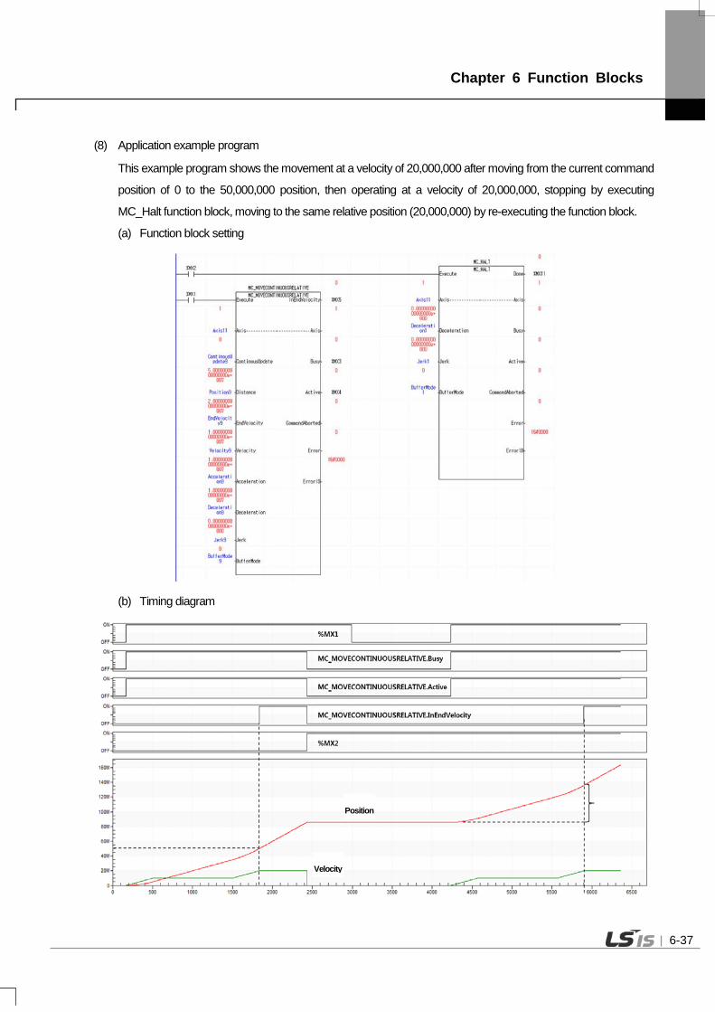
Chapter 6 Function Blocks
(8) Application example program
This example program shows the movement at a velocity of 20,000,000 after moving from the current command
position of 0 to the 50,000,000 position, then operating at a velocity of 20,000,000, stopping by executing
MC_Halt function block, moving to the same relative position (20,000,000) by re-executing the function block.
(a) Function block setting
(b) Timing diagram
Velocity
Position
6-37

Chapter 6 Function Blocks
6.3.11 Torque control(MC_TorqueControl)
Motion Function Block
Input-Output
UINT Axis Specify the axis to be commanded (1~32: real axis)
Input
BOOL Execute Give an absolute position operation command to the relevant axis in the rising Edge.
BOOL ContinuousUpdate
Specify the update setting of input value. (Refer to 6.1.5.Changes in Parameters during Execution of Motion Function Block)
LREAL Torque Specify the target torque. [u]
LREAL TorqueRamp Specify the ascending slope of torque. [u/s]
LREAL Velocity Unused
LREAL Acceleration Unused
LREAL Deceleration Unused
LREAL Jerk Unused
UINT Direction Specify the operation direction. (1~2 : 1-Forward direction, 2-Reverse direction)
UINT BufferMode Specify the sequential operation setting of motion function block. (Refer to 6.1.4.BufferMode)
Output
BOOL InTorque Indicate that the input torque value and currently operating torque value are same.
BOOL Busy Indicate that the execution of motion function block is not completed.
BOOL Active Indicate that the current motion function block is controlling the relevant axis.
BOOL CommandAborted Indicate that the current motion function block is interrupted while it is running.
BOOL Error Indicate whether an error occurs or not.
WORD ErrorID Output the number of error occurred while motion function block is running.
MC_TorqueControl
AxisAxisExecute InTorque
UINTUINTBOOL BOOL
BOOL ContinousUpdateLREAL Torque
Busy BOOL
CommandAborted BOOLError BOOL
ErrorID WORD
LREAL TorqueRampActive BOOL
LREAL VelocityLREAL AccelerationLREAL DecelerationLREAL Jerk
UINT DirectionUINT BufferMode
6-38

Chapter 6 Function Blocks
(1) This motion function block is to give torque control command to the relevant axis. (2) When executing torque control (MC_Torque), the relevant axis performs the control to keep the torque value
specified in Torque input. (3) Giving a stop command or operation of other motion function block allow to interrupt specified velocity motion. (4) Specify the gradient to reach the target torque value in TorqueRamp input. (5) Specify the operation direction in Direction input. When setting the value outside the range and executing
motion function block, Error is On and “0x1017” occurs in ErrorID. (6) Output InTorque is On when the relevant axis reaches the specified torque, and when torque control operation
is interrupted, it is Off. (7) The axis is in 'ContinuousMotion' state when this motion function block is running. (8) The changed parameters can be applied by re-executing the function block (Execute input is On) before the
command is completed. Only Torque, TorqueRamp, Direction input can be updated. (9) Timing diagram
Execute
InTorque
Velocity
Time
Torque(Target)
Target torque reach Stop command execution
Torque=Stop command deceleration
Stop command execution
Busy
Active
6-39

Chapter 6 Function Blocks
6.3.12 Setting the current position(MC_SetPosition)
Motion Function Block
MC_SetPosition
AxisAxisExecute Done
UINTUINTBOOL BOOL
LREAL PositionBOOL Relative
Busy BOOLError BOOL
ErrorID WORDUINT ExcutionMode
Input-Output
UINT Axis Specify the axis to be commanded (1~32: real axis, 37~40: virtual axis)
Input
BOOL Execute Specify the current position of the relevant axis in the rising Edge.
LREAL[ ] Position Specify the position.
BOOL Relative 0: Position value=Absolute position, 1: Position value=Relative position
UINT ExecuteMode 0: Immediately applied the position value,
1: Applied at the same point with ‘Buffered’ of Buffermode
Output
BOOL Done Indicate the state of motion function block completion.
BOOL Busy Indicate that the execution of motion function block is not completed.
BOOL Error Indicate whether an error occurs or not.
WORD ErrorID Output the number of error occurred while motion function block is running.
(1) This motion function block is to set the current position of the relevant axis. (2) Specify the position in Position input. When executing motion function block, if Relative input is Off, the position
of the relevant axis is replaced by the value of Position input, and if Relative input is On, the value of Position input is added to the current position of the relevant axis.
(3) ExcutionMode input specifies the setting point. 0 means to be set immediately after motion function block, and 1 means to be set at the same point with ‘Buffered’ in sequential operation setting. The value unable to be set causes "error0x101B”. 0 (mcImmediately): Change the parameter value immediately after executing function block (rising Edge in
Execute input). If the relevant axis is in running, operation can be affected. 1 (mcQueued): Changed at the same point with ‘Buffered’ in Buffermode. (Error! Reference Source Not
Found. Refer to input)
6-40

Chapter 6 Function Blocks
(4) Example program This example program shows the setting of the current position to 200,000,000 position by adding a relative position (Relative=1) corresponding to the set value (50,000,000) from the current position of 150,000,000. (a) Function block setting
(b) Timing diagram
Position
6-41

Chapter 6 Function Blocks
6.3.13 Velocity/Acceleration override(MC_SetOverride)
Motion Function Block
MC_SetOverride
AxisAxisExecute Enabled
UINTUINTBOOL BOOL
LREAL VelFactorLREAL AccFactor
Busy BOOLError BOOL
ErrorID WORDLREAL JerkFactor
Input-Output
UINT Axis Specify the axis to be commanded (1~32: real axis, 37~40: virtual axis)
Input
BOOL Enable Execute override operation in the relevant axis while input is activated.
LREAL VelFactor Specify the override rate of speed.
LREAL AccFactor Specify the override rate of acceleration/deceleration.
LREAL JerkFactor Specify the override rate of the change rate of acceleration.
Output
BOOL Enabled Indicate that override rate is successfully applied.
BOOL Busy Indicate that the execution of motion function block is not completed.
BOOL Error Indicate whether an error occurs or not.
WORD ErrorID Output the number of error occurred while motion function block is running.
(1) This motion function block is to override the speed of the relevant axis, acceleration, and the change rate of acceleration.
(2) Override rate which is applied to the relevant axis can be specified and changed while Enable input is On. If Enable input is Off, override rate right before the Off is maintained.
(3) Speed override rate is specified in VelFactor input. If the specified value is 0.0, the relevant axis stops but it is not changed to 'StandStill' state.
(4) Specify acceleration/deceleration and override rate of jerk (change rate of acceleration) in AccFactor and JerkFactor input respectively.
(5) Negative number cannot be input in each Facotr, and if it is input, "error 0x10C1” occurs. (6) Default of each override rate is 1.0, and it means 100% of the command speed of function block currently
running. (7) Override operation does not affect the serve axis of the relevant axis. (8) Example program (9) This example shows the operation by changing the current velocity to 2,000,000/ 3,000,000/ 4,000,000/
5,000,000 if VelFactor is changed to 2/3/4/5 at the current velocity of 1,000,000.
6-42

Chapter 6 Function Blocks
(a) Function block setting
(b) Timing diagram
Velocity
Position
6-43

Chapter 6 Function Blocks
6.3.14 Read Parameter(MC_ReadParameter)
Motion Function Block
MC_ReadParameter
AxisAxisEnable Vaild
UINTUINTBOOL BOOL
INT ParameterNumber Busy BOOLError BOOL
ErrorID WORDValue LREAL
Input-Output
UINT Axis Specify the axis to be commanded (1~32: real axis, 37~40: virtual axis)
Input
BOOL Enable Execute override operation in the relevant axis while input is activated.
INT ParameterNumber Specify the number of parameter to read. (0 ~ 25)
Output
BOOL Vaild Indicate whether the output of the current motion function block is valid.
BOOL Busy Indicate that the execution of motion function block is not completed.
BOOL Error Indicate whether an error occurs or not.
WORD ErrorID Output the number of error occurred while motion function block is running.
LREAL Value Output the value of parameter.
(1) This command is a motion function block which outputs parameter of the relevant axis. (2) The value of the relevant parameter is continuously output in Value while Enable input is On. (3) Specify the number of parameter to read in ParameterNumber input.
6-44

Chapter 6 Function Blocks
(4) The numbers of parameter are as below.
No Parameter Item Description
0
Basic
Parameter
Unit 0:pulse,1:mm,2:inch,3:degree
1 Purses per rotation 1 ~ 4,294,967,295 [pulse]
2 Travel per rotation 0.000000001 ~ 4,294,967,295 [Unit]
3 Speed command unit 0:Unit/Time, 1:rpm
4 Speed limit
LREAL Positive number [Unit/s, rpm]
(Change according to Unit, Pulses per rotation,
Travel per rotation, Speed command unit)
5 Emergency stop deceleration 0 or LREAL Positive number [Unit/s2]
6 Encoder select 0:Incremental Encoder,1:Absolute Encoder
7 Gear ratio(Motor) 1 ~ 65,535
8 Gear ratio(Machine) 1 ~ 65,535
9 Operating mode of the reverse rotation 0:E.Stop, 1:Stop
10
Extented
Parameter
S/W upper limit LREAL [Unit]
11 S/W lower limit LREAL [Unit]
12 Infinite running repeat position LREAL Positive number [Unit]
13 Infinite running repeat 0:Disable, 1:Enable
14 Command Inposition range 0 or LREAL Positive number [Unit]
15 Tracking error over-range value 0 or LREAL Positive number [Unit]
16 Current position compensation amount 0 or LREAL Positive number [Unit]
17 Current speed filter time constant 0 ~ 100
18 Error reset monitoring time 1 ~ 1000 [ms]
19 S/W limit during speed control 0:Don’t detect, 1:Detect
20 Tracking error level 0:Warning, 1:Alarm
21 JOG high Speed LREAL Positive number [Unit]
(Jog low speed ~speed limit ) [Unit/s]
22 JOG low Speed LREAL Positive number [Unit]
( < Jog high speed) [Unit/s]
23 JOG acceleration 0 or LREAL Positive number [Unit/ s2]
24 JOG deceleration 0 or LREAL Positive number [Unit/ s2]
25 JOG jerk 0 or LREAL Positive number [Unit/ s2]
6-45

Chapter 6 Function Blocks
100
Common
Parameter
Encorder1 unit 0: pulse, 1: mm, 2: inch, 3:degree
101 Encorder1 pulse per rotation 1 ~ 4294967295
102 Encorder1 travel per rotation 0.000000001 ~ 4294967295
103 Encorder1 pulse input
0:CW/CCW 1 multiplier, 1:PULSE/DIR 1 multiplier
2:PULSE/DIR 2 multiplier, 3:PHASE A/B 1 multiplier
4:PHASE A/B 2 multiplier, 5: PHASE A/B 4multiplier
104 Encorder2 unit 0: pulse, 1: mm, 2: inch, 3:degree
105 Encorder2 pulse per rotation 1 ~ 4294967295
106 Encorder2 travel per rotation 0.000000001 ~ 4294967295
107 Encorder2 pulse input
0:CW/CCW 1 multiplier, 1:PULSE/DIR 1 multiplier
2:PULSE/DIR 2 multiplier, 3:PHASE A/B 1 multiplier
4:PHASE A/B 2 multiplier, 5: PHASE A/B 4multiplier
108 Encorder1 max. value
LREAL numbers 109 Encorder1 min. value
110 Encorder2 max. value
111 Encorder2 min. value
112 Overide 0: Specified by ratio, 1: Specified by unit
*Remak1) LREAL range: 2.2250738585072e-308 ~ 1.79769313486232e+308
LREAL positive range: 0 < x ≤1.79769313486232e+308
6-46

Chapter 6 Function Blocks
6.3.15 Write Parameter(MC_WriteParameter)
Motion Function Block
MC_WriteParameter
AxisAxisExecute Vaild
UINTUINTBOOL BOOL
INT ParameterNumber Busy BOOLError BOOL
ErrorID WORDLREAL Value
UINT ExcutionMode
Input-Output
UINT Axis Specify the axis to be commanded (1~32: real axis, 37~40: virtual axis)
Input
BOOL Execute Rising Edge corresponding parameters of input is written.
INT ParameterNumber Specify the number of parameter to write. (0 ~ 25)
LREAL Value Specify the value of parameter to write.
UINT ExecutionMode Specify the time when parameter is written.
Output
BOOL Vaild Indicate whether parameter is successfully written.
BOOL Busy Indicate that the execution of motion function block is not completed.
BOOL Error Indicate whether an error occurs or not.
WORD ErrorID Output the number of error occurred while motion function block is running. (1) This motion function block is to write the value specified in parameter of the relevant axis. (2) Parameter is written in the rising Edge of Execute input. (3) Specify the number of parameter to write in ParameterNumber input. The value unable to be set causes "error
0x10F0”. (4) Specify the value to write in parameter for Value input. (5) In ExecutionMode, correct the time when parameter is written and the values below can be set. The value
unable to be set causes "error 0x101B".
0 (mcImmediately): Change the parameter value immediately after executing function block (rising Edge in
Execute input). If the relevant axis is in running, operation can be affected.
1 (mcQueued): Changed at the same point with ‘Buffered’ in Buffermode. (Error! Reference Source Not
Found. Refer to input )
6-47

Chapter 6 Function Blocks
(6) The numbers of parameter are as below.
No. Parameter Item Description
0
Basic
Parameter
Unit 0:pulse,1:mm,2:inch,3:degree
1 Purses per rotation 1 ~ 4,294,967,295 [pulse]
2 Travel per rotation 0.000000001 ~ 4,294,967,295 [Unit]
3 Speed command unit 0:Unit/Time, 1:rpm
4 Speed limit
LREAL Positive number [Unit/s, rpm]
(Change according to Unit, Pulses per rotation,
Travel per rotation, Speed command unit)
5 Emergency stop deceleration 0 or LREAL Positive number [Unit/s2]
6 Encoder select 0:Incremental Encoder,1:Absolute Encoder
7 Gear ratio(Motor) 1 ~ 65,535
8 Gear ratio(Machine) 1 ~ 65,535
9 Operating mode of the reverse rotation 0:E.Stop, 1:Stop
10
Extented
Parameter
S/W upper limit LREAL [Unit]
11 S/W lower limit LREAL [Unit]
12 Infinite running repeat position LREAL Positive number [Unit]
13 Infinite running repeat 0:Disable, 1:Enable
14 Command Inposition range 0 or LREAL Positive number [Unit]
15 Tracking error over-range value 0 or LREAL Positive number [Unit]
16 Current position compensation amount 0 or LREAL Positive number [Unit]
17 Current speed filter time constant 0 ~ 100
18 Error reset monitoring time 1 ~ 1000 [ms]
19 S/W limit during speed control 0:Don’t detect, 1:Detect
20 Tracking error level 0:Warning, 1:Alarm
21 JOG high Speed LREAL Positive number [Unit]
(Jog low speed ~speed limit ) [Unit/s]
22 JOG low Speed LREAL Positive number [Unit]
( < Jog high speed) [Unit/s]
23 JOG acceleration 0 or LREAL Positive number [Unit/ s2]
24 JOG deceleration 0 or LREAL Positive number [Unit/ s2]
25 JOG jerk 0 or LREAL Positive number [Unit/ s2]
6-48

Chapter 6 Function Blocks
100
Common
Parameter
Encorder1 unit 0: pulse, 1: mm, 2: inch, 3:degree
101 Encorder1 pulse per rotation 1 ~ 4294967295
102 Encorder1 travel per rotation 0.000000001 ~ 4294967295
103 Encorder1 pulse input
0:CW/CCW 1 multiplier, 1:PULSE/DIR 1 multiplier
2:PULSE/DIR 2 multiplier, 3:PHASE A/B 1 multiplier
4:PHASE A/B 2 multiplier, 5: PHASE A/B 4multiplier
104 Encorder2 unit 0: pulse, 1: mm, 2: inch, 3:degree
105 Encorder2 pulse per rotation 1 ~ 4294967295
106 Encorder2 travel per rotation 0.000000001 ~ 4294967295
107 Encorder2 pulse input
0:CW/CCW 1 multiplier, 1:PULSE/DIR 1 multiplier
2:PULSE/DIR 2 multiplier, 3:PHASE A/B 1 multiplier
4:PHASE A/B 2 multiplier, 5: PHASE A/B 4multiplier
108 Encorder1 max. value
LREAL numbers 109 Encorder1 min. value
110 Encorder2 max. value
111 Encorder2 min. value
112 Overide 0: Specified by ratio, 1: Specified by unit
*Remak1) LREAL range: 2.2250738585072e-308 ~ 1.79769313486232e+308
LREAL positive range: 0 < x ≤1.79769313486232e+308
6-49

Chapter 6 Function Blocks
6.3.16 Reset axis error(MC_Reset)
Motion Function Block
MC_Reset
AxisAxisExecute Done
UINTUINTBOOL BOOL
Busy BOOLError BOOL
ErrorID WORD
ErrorTypeBOOL
Input-Output
UINT Axis Specify the axis to be commanded (1~32: real axis, 37~40: virtual axis)
Input
BOOL Execute Reset the axis error in the rising Edge of input.
BOOL ErrorType The types of error to be reset (0: Axis error, 1: Common error)
Output
BOOL Done Indicate whether the axis error is successfully reset.
BOOL Busy Indicate that the execution of motion function block is not completed.
BOOL Error Indicate whether an error occurs or not.
WORD ErrorID Output the number of error occurred while motion function block is running.
(1) This motion function block is to reset the error of the relevant axis. When setting ErrorType to '0' and executing
motion function block in case the relevant axis is in ' ErrorStop' state, every axis error is reset and the axis state is
switched to 'StandStill' or 'Disabled' state.
(2) If ErrorType is set to ‘1’ and motion function block is executed, common error occurred in the relevant module is
reset.
(3) Motion function block is executed in the rising Edge of Execute input.
6-50

Chapter 6 Function Blocks
6.3.17 Touch Probe(MC_TouchProbe)
Motion Function Block
MC_TouchProbe
AxisAxisTriggerInput
DoneUINT
UINTUINT
BOOLBOOL Execute
BOOL WindowOnly Busy BOOL
Error BOOLErrorID WORD
RecordedPosition LREAL
LREAL FirstPosition CommandAborted BOOLLREAL LastPosition
TriggerInput UINT
Input-Output
UINT Axis Specify the axis to be commanded (1~32: real axis)
UINT TriggerInput Specify the signal to be used as a trigger. (0: TouchProbe 1, 1: TouchProbe 2)
Input
BOOL Execute TouchProbe function starts at the rising Edge of input.
BOOL WindowOnly Activate the window mode.
LREAL FirstPosition Specify the starting position of allowable area in the window mode.
LREAL LastPosition Specify the end position of allowable area in the window mode.
Output
BOOL Done Indicate that the trigger signal is successfully recorded.
BOOL Busy Indicate that the execution of motion function block is not completed.
BOOL CommandAborted Indicate that the current motion function block is interrupted by other command.
BOOL Error Indicate whether an error occurs or not.
WORD ErrorID Output the number of error occurred while motion function block is running.
REAL RecordedPosition Output the axis position where the trigger occurs. (1) This motion function block is to execute 'TouchProbe' function which records the axis position at the time when
the trigger event occurs. (2) TouchProbe function starts at the rising Edge of Execute input. (3) Specify the signal to be used as a trigger in TriggerInput. The value unable to be set causes "error 0x10E1”. (4) When activating the window mode, allowable area where accepts the trigger signal of axis can be set.
Operation timing of each signal when the window mode is activated is as below.
6-51
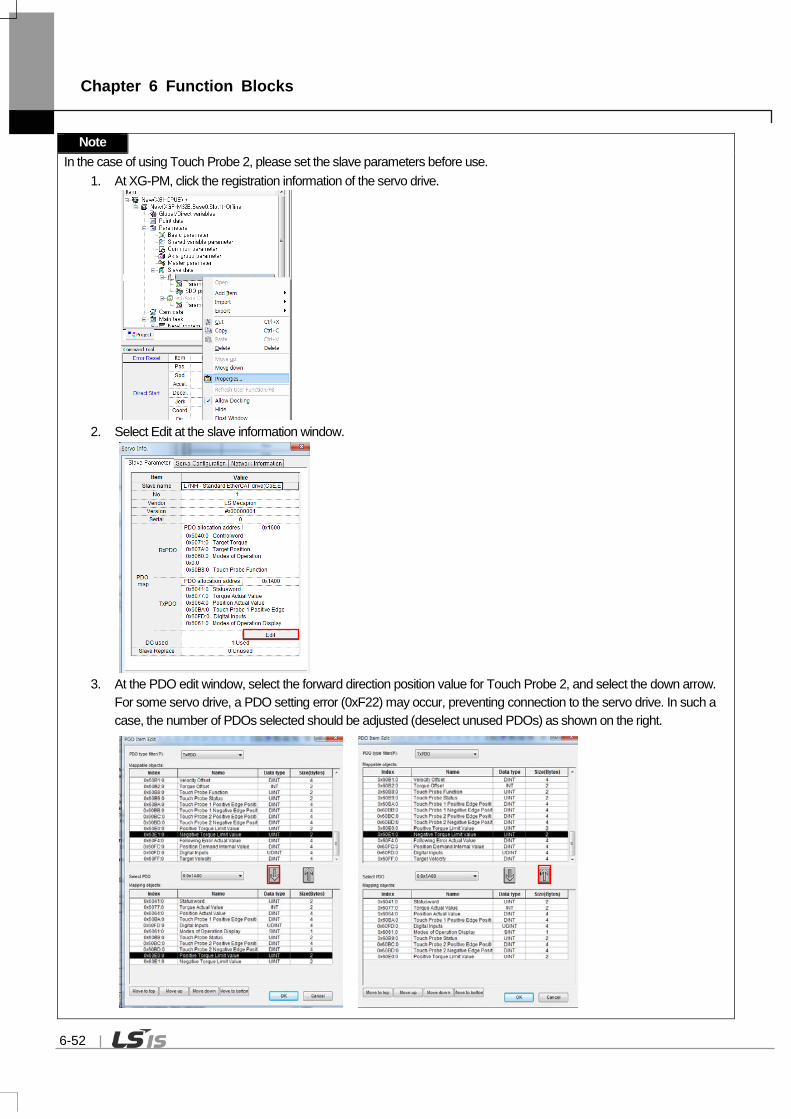
Chapter 6 Function Blocks
Note In the case of using Touch Probe 2, please set the slave parameters before use.
1. At XG-PM, click the registration information of the servo drive.
2. Select Edit at the slave information window.
3. At the PDO edit window, select the forward direction position value for Touch Probe 2, and select the down arrow. For some servo drive, a PDO setting error (0xF22) may occur, preventing connection to the servo drive. In such a case, the number of PDOs selected should be adjusted (deselect unused PDOs) as shown on the right.
6-52

Chapter 6 Function Blocks
< In case TouchProbe function is the window mode, Operation timing >
6-53

Chapter 6 Function Blocks
6.3.18 Abort trigger events(MC_AbortTrigger)
Motion Function Block
MC_AbortTrigger
AxisAxisTriggerInput
DoneUINT
UINTUINT
BOOLBOOL Execute
Busy BOOLError BOOL
ErrorID WORD
TriggerInput USINT
Input-Output
UINT Axis Specify the axis to be commanded (1~32: real axis)
UINT TriggerInput Specify the trigger signal to be disengaged. (0: TouchProbe 1, 1: TouchProbe 2)
Input
BOOL Execute The trigger on standby in the relevant axis in the rising Edge is disengaged.
Output
BOOL Done Indicate the state of motion function block completion.
BOOL Busy Indicate that the execution of motion function block is not completed.
BOOL Error Indicate whether an error occurs or not.
WORD ErrorID Output the number of error occurred while motion function block is running.
(1) This motion function block is to disengage the trigger which is on standby in the relevant axis. (2) Specify the trigger signal to be disengaged in TriggerInput. The value unable to be set causes "error 0x10E1”.
6-54

Chapter 6 Function Blocks
6.3.19 SuperImposed operation (MC_MoveSuperImposed)
Motion Function Block
MC_MoveSuperImposed
AxisAxisExecute Done BOOL
UINTBOOL
UINTBOOL ContinuousUpdate
LREAL DistanceBusy BOOL
CommandAborted BOOLError BOOL
ErrorID WORD
LREAL VelocityDiffActive BOOL
LREAL AccelerationLREAL DecelerationLREAL Jerk CoveredDistance LREAL
Input-Output
UINT Axis Specify the axis to be commanded (1~32: real axis)
Input
BOOL Execute Give a SuperImposed operation command to the relevant axis in the rising Edge.
BOOL ContinuousUpdate Specify the update setting of input value.
(Refer to 6.1.5.Changes in Parameters during Execution of Motion Function Block)
LREAL Distance Specify the target distance. [u]
LREAL VelocityDiff Specify the added velocity. [u/s]
LREAL Acceleration Specify the added acceleration. [u/s2]
LREAL Deceleration Specify the added deceleration. [u/s2]
LREAL Jerk Specify the added change rate of acceleration/deceleration. [u/s3]
Output
BOOL Done Indicate whether to reach the specified distance.
BOOL Busy Indicate that the execution of motion function block is not completed.
BOOL Active Indicate that the current motion function block is controlling the relevant axis.
BOOL CommandAborted Indicate that the current motion function block is interrupted by other command
BOOL Error Indicate whether an error occurs or not.
WORD ErrorID Output the number of error occurred while motion function block is running.
LREAL CoveredDistance Indicate the distance moved with SuperImposed operation after SuperImposed command.
(1) This motion function block is a command issuing aSuperImposed operation order to the relevant axis. (2) SuperImposed is a command ordering to move from the current position at the time of the command to the target
distance set by Distance input. (3) The direction of the movement is determined by the positivity/negativity of the set distance. Positive distance (+ or no
sign) means forward movement, and negative distance (-) means reverse movement. (4) After moving the target distance, when the velocity reaches 0, the command is completed and Doneoutput is on.
6-55

Chapter 6 Function Blocks
6.3.20 SuperImposed operation halt (MC_HaltSuperImposed)
모션 펑션 블록 형태
MC_HaltSuperImposed
AxisAxisExecute Done
UINTUINTBOOL BOOL
LREAL DecelerationLREAL Jerk
Busy BOOL
CommandAborted BOOLError BOOL
ErrorID WORD
Active BOOL
입력-출력
UINT Axis Specify the axis to be commanded (1~32: real axis)
입력
BOOL Execute Give a SuperImposed operation halt command to the relevant axis in the rising
Edge.
LREAL Deceleration Specify deceleration in time of stop. [u/s2]
LREAL Jerk Specify the change rate of acceleration/deceleration. [u/s3]
출력
BOOL Done Indicate that the speed of the relevant axis reaches 0.
BOOL Busy Indicate that the execution of function block is not completed.
BOOL Active Indicate that the current motion function block is controlling the relevant axis.
BOOL CommandAborted Indicate that the current motion function block is interrupted while it is running.
BOOL Error Output the number of error occurred while motion function block is running.
WORD ErrorID Indicate the distance moved with SuperImposed operation after SuperImposed command.
(1) This motion function block is a command issuing an order to halt SuperImposed operation to the relevant axis. (2) Halt command for SuperImposed operation is a command ordering to decelerate and halt at a given acceleration
and jerk at the time of performing the command. (3) After moving the target distance, when the velocity reaches 0, the command is completed and Done output is on.
6-56

Chapter 6 Function Blocks
6.4 Multi-Axis Motion Function Block
6.4.1 Camming run(MC_CamIn)
Motion Function Block
MC_CamIn
MasterMasterSlave Slave UINTUINT
UINT UINTBOOL Execute
LREAL ContinousUpdate
InSync BOOL
Busy BOOLActive BOOLLREAL MasterOffset
SlaveOffsetLREALLREAL MasterScalingLREAL SlaveScalingLREAL MasterStartDistance
MasterSyncPositionLREALUINT StartModeUINT MasterValueSourceUINT CamTableIDUINT BufferMode
CommandAborted BOOLError BOOL
ErrorID WORDEndOfProfile BOOL
Input-Output
UINT Master Set the main axis. (1~32: Actual axes, 37~40: Virtual axes, 41~42: Encoders)
UINT Slave Set the the serve axis. (1~32: Actual axes, 37~40: Virtual axes)
Input
BOOL Execute Give cam operation command to the relevant axis in the rising Edge.
BOOL ContinuousUpdate
Specify the update setting of input value.
(Refer to 10.1.5.Changes in Parameters during Execution of Motion Function
Block)
LREAL MasterOffset Set the offset value of the main axis.
LREAL SlaveOffset Set the offset value of the the serve axis cam table.
LREAL MasterScaling Specify the magnification of the main axis.
LREAL SlaveScaling Specify the magnification of the serve axis cam table.
LREAL MasterStartDistance Specify the position of the main axis where cam operation of the slave.
LREAL MasterSyncPosition Specify the starting point at cam table when cam operation starts.
UINT StartMode Set the cam operation mode.
0 : Cam table is applied as an absolute value (mcAbsolute)
6-57

Chapter 6 Function Blocks
1: Cam table is applied as a relative value based on the command starting point
(mcRelative)
UINT MasterValueSource
Select the source of the main axis for cam operation.
0 : Synchronized in the target value of the main axis.
1 : Synchronized in the current value of the serve axis.
UINT CamTableID Specify the cam table to operate.
UINT BufferMode Specify the sequential operation setting of motion function block.
(Refer to 10.1.4.BufferMode)
Output
BOOL InSync Indicate that cam operation is normally being fulfilled.
(Indicate that the serve axis is following the cam table.)
BOOL Busy Indicate that the execution of motion function block is not completed.
BOOL Active Indicate that the current motion function block is controlling the relevant axis.
BOOL CommandAborted Indicate that the current motion function block is interrupted while it is running.
BOOL Error Indicate whether an error occurs or not.
WORD ErrorID Output the number of error occurred while motion function block is running.
(1) This motion function block is to operate the serve axis cam depending on the main axis. (2) Cam operation command can be given to the serve axis even if the main axis is in stop state. (3) You must give cam operation abort (MC_CamOut) command to the serve axis or operate other motion function
block to stop cam operation. (4) The axis is in 'Synchronized Motion' while this motion function block is running. (5) Set the offset of cam table to be applied in MasterOffset and SlaveOffset. MasterOffset sets the offset with the
starting point of the main axis, and SlaveOffset sets the offset with the starting point of the serve axis. Refer to the Figure below.
Main axisPosition
Serve axisPosition
MasterOffset
Serve axisPosition
SlaveOffset
Before applying
After applying
Main axisPosition
Before applying
After applying
Main, Serve axis starting point
Main, Serve axis starting point
6-58

Chapter 6 Function Blocks
(6) Set the magnification of cam data to be applied in MasterScaling and SlaveScaling. Set the magnification of the main axis data in MasterScaling, and set the magnification of the the serve axis data. Refer to the Figure below.
SlaveScaling = 1.0
SlaveScaling = 2.0
MasterScaling = 1.0 MasterScaling = 2.0
After applying SlaveScaling
After applying MasterScaling
(7) MasterSyncPosition input specifies the position of the main axis within the table where the synchronization of actual cam operation is completed, and MasterStartDistance input specifies the relative position of the main axis where the synchronization starts. If unable to start synchronized operation at Cycle 1 as shown below (if the distance from the start position to the synchronized operation start position is shorter than MasterStartDistance), synchronized operation starts at Cycle 2.
Main axisPosition
Serve axisPosition
MasterStartDistance
MasterSyncPosition
MasterOffset
SlaveOffset
Camming run Start Position
Synchronizationsection
Synchronized Operation section
Cycle 1 Cycle 2 Cycle 3
In case MasterScaling is 1.0
Main axisPosition
Serve axisPosition
MasterStartDistance
MasterSyncPosition
MasterOffset
SlaveOffset
Camming runStart Position
Synchronizationsection
Synchronized Operation section
In case MasterScaling is 2.0
6-59

Chapter 6 Function Blocks
MasterSyncPosition position is based on the position within the cam table, and actual synchronization position is decided
by considering MasterOffset and MasterScale parameters.
The serve axis starts moving to the synchronization position from the distance of the input value away based on the
position where MasterSyncPosition is actually applied. If it is before starting moving, the serve axis waits at the relevant
position in stop state, and if the serve axis is already in the section to move to the synchronization position at the
beginning of the command, take back the position of the synchronization starting point by the length of a table until it
escapes the MasterStartDistance range.
Actual synchronization position can vary depending on MasterScaling and SlaveScaling because MasterSyncPosition is
a value based on the inside of cam table, but MasterOffset and MasterStartDistance value remain unaffected. (8) If the ContiunuousUpdate input is On, the changed parameter can be applied.
Only MasterOffset, SlaveOffset, MasterScaling, SlaveScaling, MasterStartDistance, MasterSyncPosition can be
updated (However, In InSync=On case, MasterOffset, SlaveOffset, MasterScaling, SlaveScaling can be
updated. (9) Once cam operation starts normally, InSync output is On, and EndOfProfile output is 1 scan On every time one cam
table operation is completed.
Time
Serve axisPosition
Main axisPosition
MasterStartDistance
MasterSyncPosition
InSync
Time
EndOfProfile
Synchronization section Synchronized operation section
1 Scan
(10) Cam operation mode is set in StartMode. Setting range is 0 or 1, and the input value outside the setting range causes an error.
(11) MasterValueSource selects the source of the main axis to be synchronized. If it is set to 0, the serve axis performs cam operation based on the command position of the main axis which is calculated in motion control module, and if it is set to 1, the serve axis performs cam operation based on the current position which is received by communication in servo drive of main axis.
(12) CamTableID sets the number of cam table to be applied to cam operation. Setting range is 1~32 , and the input value outside the setting range causes error "0x1115” in motion function block.
(13) The relevant axis is in "SynchronizedMotion" state while this motion function block is running.
6-60

Chapter 6 Function Blocks
(14) Example program
This example shows the movement of the main-axis from 0 to 200,000 positions after generating a cam profile
and then executing MC_CAMIN command on the sub-axis. (a) Function block setting
6-61

Chapter 6 Function Blocks
(b) Timing diagram
(15) Application example program
This example shows the movement of the main-axis from 0 to 200,000 positions after generating the same
profile and then executing C_CAMIN command where MasterSyncPosition and MasterSyncDistance are set to
80,000 in sub-axis.
(a) Function block setting
Velocity
Position
6-62

Chapter 6 Function Blocks
(b) Timing diagram
Master position
Master velocity
Slave velocity
Slave position
6-63

Chapter 6 Function Blocks
6.4.2 Camming stop(MC_CamOut)
Motion Function Block
MC_CamOut
SlaveSlaveExecute Done BOOL
UINTBOOL
UINTBusy BOOLError BOOL
ErrorID WORD
Input-Output
UINT Slave Set the the serve axis. (1~32: Actual axes, 37~40: Virtual axes)
Input
BOOL Execute Give cam operation stop command to the relevant axis in the rising Edge.
Output
BOOL Done Indicate the state of motion function block completion.
BOOL Busy Indicate that the execution of motion function block is not completed.
BOOL Error Indicate whether an error occurs or not.
WORD ErrorID Output the number of error occurred while motion function block is running. (1) This motion function block immediately disengages cam operation running in the serve axis. (2) If motion function block of which BufferMode is Aborting in the serve axis where cam operation is running, cam
operation is automatically disengaged and the relevant motion function block is executed. To execute cam operation abort (MC_CamOut) motion function block, the relevant axis do operation which keeps the speed at the time when cam operation is disengaged. If you want to completely stop the serve axis, use stop (MC_Halt) or immediate stop (MC_Stop) motion function block.
(3) When MC_CamOut motion function block is executed, the InSync output of MC_CamIn function block and the Synchronized status flag (_AXxx_Synchronized) is off.
(4) Example program This example shows generating a cam profile, executing MC_CAMIN command on the sub-axis, moving the main-axis to the 200,000 position, and then executing MC_CAMOUT. The sub-axis maintains the velocity at the time when the cam operation is terminated.
6-64

Chapter 6 Function Blocks
(a) Function block setting
6-65

Chapter 6 Function Blocks
(b) Timing diagram
Master position
Master velocity
Slave velocity
Slave position
6-66
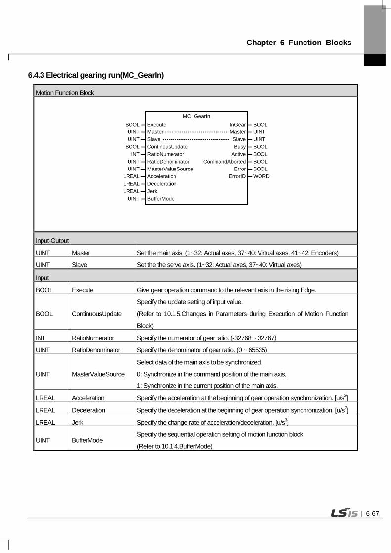
Chapter 6 Function Blocks
6.4.3 Electrical gearing run(MC_GearIn)
Motion Function Block
MC_GearIn
MasterMasterSlave
InGear BOOL
UINTUINT
UINT
BOOL Execute
BOOL ContinousUpdate Busy BOOL
CommandAborted BOOLError BOOL
ErrorID WORD
INT RatioNumerator Active BOOLUINT RatioDenominatorUINT MasterValueSource
LREAL AccelerationLREAL DecelerationLREAL Jerk
UINT BufferMode
SlaveUINT
Input-Output
UINT Master Set the main axis. (1~32: Actual axes, 37~40: Virtual axes, 41~42: Encoders)
UINT Slave Set the the serve axis. (1~32: Actual axes, 37~40: Virtual axes)
Input
BOOL Execute Give gear operation command to the relevant axis in the rising Edge.
BOOL ContinuousUpdate
Specify the update setting of input value.
(Refer to 10.1.5.Changes in Parameters during Execution of Motion Function
Block)
INT RatioNumerator Specify the numerator of gear ratio. (-32768 ~ 32767)
UINT RatioDenominator Specify the denominator of gear ratio. (0 ~ 65535)
UINT MasterValueSource
Select data of the main axis to be synchronized.
0: Synchronize in the command position of the main axis.
1: Synchronize in the current position of the main axis.
LREAL Acceleration Specify the acceleration at the beginning of gear operation synchronization. [u/s2]
LREAL Deceleration Specify the deceleration at the beginning of gear operation synchronization. [u/s2]
LREAL Jerk Specify the change rate of acceleration/deceleration. [u/s3]
UINT BufferMode Specify the sequential operation setting of motion function block.
(Refer to 10.1.4.BufferMode)
6-67

Chapter 6 Function Blocks
Output
BOOL InGear Indicate that gear operation is running by applying gear ration.
BOOL Busy Indicate that the execution of motion function block is not completed.
BOOL Active Indicate that the current motion function block is controlling the relevant axis.
BOOL CommandAborted Indicate that the current motion function block is interrupted while it is running.
BOOL Error Indicate whether an error occurs or not.
WORD ErrorID Output the number of error occurred while motion function block is running.
(1) This motion function block is an operation to synchronize the speed of the main axis and the serve axis depending on gear ratio which is set.
(2) Giving gear operation abort (MC_GearOut) commands to the relevant axis or execution of other motion function block allow to disengage gear operation.
(3) RatioNumerator and RatioDenominator set the numerator and denominator to be applied to the serve axis respectively. If the numerator is set to negative number, the rotation direction of the serve axis is the opposite of the main axis.
(4) MasterValueSource select the data of the main axis which is a standard of synchronization. If it is set to 0, synchronization operation is based on the command position of the main axis of motion control module, and if it is set to 1, synchronization operation is based on the current position. Other values set besides these two make Error of motion function block On and cause “0x1114” in ErrorID.
(5) When this motion function block is executed, the serve axis is synchronized with the main axis through acceleration/deceleration at the speed in synch with the relevant gear ratio.
(6) The serve axis is in 'SynchronizedMotion' while this motion function block is running.
(7) The changed parameters can be applied when ContinuousUpdate input is On. Only RatioNumerator, RatioDenominator, Acceleration, Deceleration input can be updated. (However, in case of InGear=On case, RatioNumerator, RatioDenominator input can be updated)
(8) Example program This example shows the operation of 2–axis up to 50,000,000 when moving 1-axis (main-axis) to 100,000,000 after executing MC_GearIn command on axis 2(sub-axis) at the current position of 0.
6-68

Chapter 6 Function Blocks
(a) Function block setting
(b) Timing diagram
1 Axis position
1 Axis velocity 2 Axis velocity
2 Axis position
6-69

Chapter 6 Function Blocks
6.4.4 Electrical gearing disengage(MC_GearOut)
Motion Function Block
MC_GearOut
SlaveSlaveExecute Done
UINTUINTBOOL BOOL
Busy BOOLError BOOL
ErrorID WORD
Input-Output
UINT Slave Set the the serve axis. (1~32: Actual axes, 37~40: Virtual axes)
Input
UINT BufferMode Specify the sequential operation setting of motion function block.
(Refer to 10.1.4.BufferMode)
Output
BOOL Done Indicate the state of motion function block completion.
BOOL Busy Indicate that the execution of motion function block is not completed.
BOOL Error Indicate whether an error occurs or not.
WORD ErrorID Output the number of error occurred while motion function block is running. (1) This motion function block immediately disengages gear operation running in the spindle. (2) If motion function block of which BufferMode is Aborting in the spindle where cam operation is running, gear
operation is automatically disengaged and the relevant motion function block is executed. If gear operation abort (MC_GearOut) motion function block is only to be executed, the relevant axis performs operation to maintain the speed at the time when gear operation is disengaged. To completely stop the spindle, use stop (MC_Halt) or immediate stop (MC_Stop) motion function block.
(3) Example program
After the execution of MC Gearln command in sub-axis at the current position of 0, ContinuousUpdate of main-
axis is set to 1, and then the velocity is gradually changed (1,000,000 2,000,000 3,000,000). This examples
show the operation to ensure that the velocity of sub-axis is no longer changed (b) by executing MC_GearOut
command when the velocity of main-axis is 2,000,000.
6-70
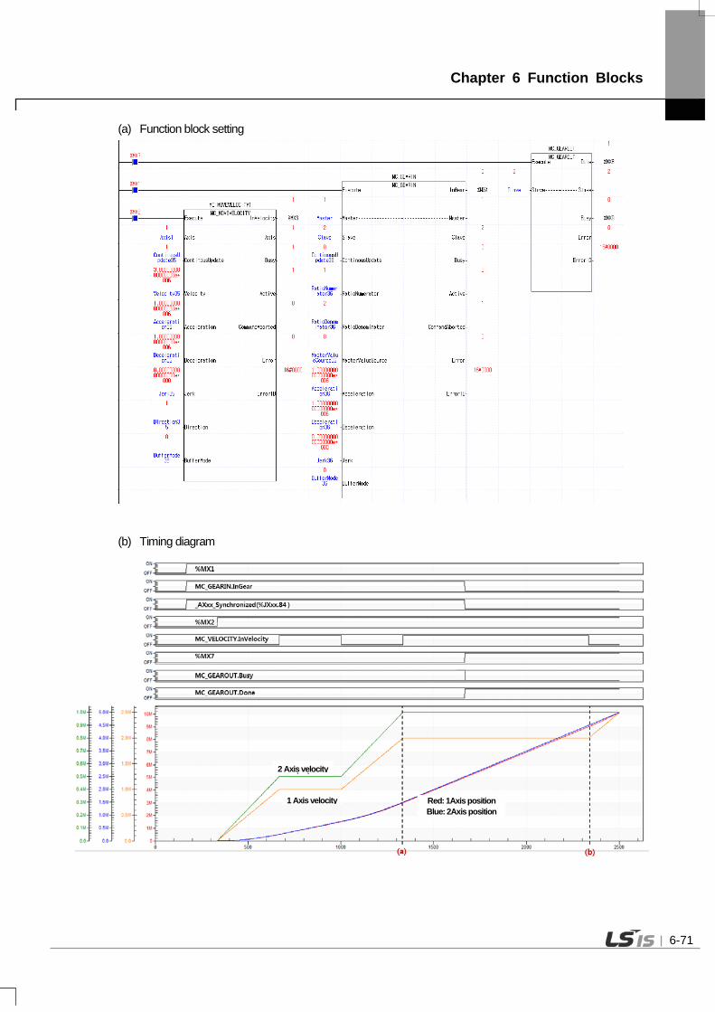
Chapter 6 Function Blocks
(a) Function block setting
(b) Timing diagram
Red: 1Axis position Blue: 2Axis position
2 Axis velocity
1 Axis velocity
6-71

Chapter 6 Function Blocks
6.4.5 Electrical gearing by specifying the position(MC_GearInPos)
Motion Function Block
Input-Output
UINT Master Set the main axis. (1~32: Actual axes, 37~40: Virtual axes, 41~42: Encoders)
UINT Slave Set the the serve axis. (1~32: Actual axes, 37~40: Virtual axes)
Input
BOOL Execute Give a gear operation command to the relevant axis in the rising Edge.
INT RatioNumerator Specify the numerator of gear ratio. (-32768~32767)
UINT RatioDenominator Specify the denominator of gear ratio. (0~65535)
UINT MasterValueSource
Select the standard of the main axis value to be synchronized.
0(mcSetValue): Synchronize in the target position of the main axis.
1(mcActualValue): Synchronize in the current position of the main axis.
LREAL MasterSyncPosition Specify the position of the main axis where gear operation starts.
LREAL SlaveSyncPosition Specify the position of the spindle where gear operation starts.
LREAL MasterStartDistance Specify the distance of the main axis where synchronization starts.
LREAL Velocity Specify the maximum speed of the spindle at the beginning of synchronization.
[u/s]
LREAL Acceleration Specify the maximum acceleration of the spindle at the beginning of
synchronization. [u/s2]
6-72

Chapter 6 Function Blocks
LREAL Deceleration Specify the maximum deceleration of the spindle at the beginning of
synchronization. [u/s2]
LREAL Jerk Specify the change rate of acceleration/deceleration. [u/s3]
UINT BufferMode Specify the sequential operation setting of motion function block.
(Refer to 10.1.4.BufferMode)
Output
BOOL InSync Indicate that gear operation is normally being fulfilled as the specified gear ratio is
applied.
BOOL StartSync Indicate synchronization is starting.
BOOL Busy Indicate that the execution of motion function block is not completed.
BOOL Active Indicate that the current motion function block is controlling the relevant axis.
BOOL CommandAborted Indicate that the current motion function block is interrupted while it is running.
BOOL Error Indicate whether an error occurs or not.
WORD ErrorID Output the number of error occurred while motion function block is running.
(1) This motion function block is an operation to synchronize the speed of the main axis and the spindle in the set position depending on gear ratio which is set in the specific position.
(2) Giving gear operation abort (MC_GearOut) commands to the spindle or operation of other motion function block allow to stop gear operation.
(3) RatioNumerator and RatioDenominator set the numerator and denominator of gear ratio to be applied to the spindle respectively. If the numerator is set to negative number, the rotation direction of the spindle goes into reverse of the main axis.
(4) MasterValueSource selects the source of the main axis to be synchronized. If it is set to 0 (mcSetValue), synchronization is performed by putting the target position of the main axis in the current motion control period as a source, and if it is set to 1(mcActualValue), synchronization is performed by putting the current position of the main axis got feedback from the current motion control period as a source. Other values set besides these two cause "error 0x10D1”.
(5) Input the positions of the main axis and the spindle where gear operation is completed synchronization in MasterSyncPosition input and SlaveSyncPosition input respectively. Input the distance where the spindle starts synchronization in MasterStartDistance input, and the spindle starts synchronization at the position away the distance set in MasterStartDistance input from the position set in MasterSyncPosition input.
(6) Once synchronization starts, StartSync output is On. When synchronization is completed and gear operation starts, StartSync output is Off and InSync output is On.
(7) The spindle is in 'SynchronizedMotion' while this motion function block is running.
6-73

Chapter 6 Function Blocks
(8) The changed parameters can be applied by re-executing the function block (Execute input is On) before the command is completed. Only RatioNumerator, RatioDenominator, MasterSyncPosition, SlaveSyncPosition, MasterStartDistance, Velocity, Acceleration, Deceleration input can be updated. (However, in case of InGear=On, RatioNumerator, RatioDenominator input can be updated.
(9) Example program This example program executes MC_GearInPos function block in which sub-axis starts synchronization from a position away as long as the distance of MasterStartDistance(500,000) from MasterSyncPosition(1,000,000), and executes MC_MoveRelative for relative movement to the 2,000,000 position. Once synchronization starts, StartSyncoutput is on (a) and when the synchronization is completed and gear operation starts, StartSync output is off, and InSyncoutput is on. (b)
6-74

Chapter 6 Function Blocks
(a) Function block setting
(b) Timing diagram
2 Axis velocity
1 Axis velocity
2 Axis position 1 Axis position
6-75

Chapter 6 Function Blocks
(10) Application example program This example program shows MC_GearInPos Active and InSync being off and gear operation being terminated when MC_GearOut command is issued on 2-axis at (a) position during the motion shown in the basic example program. (Gear operation termination can be verified by 1-axis that stopsand 2-axis that continues to operate)
(a) Function block setting
(b) Timing diagram
2 Axis velocity
1 Axis velocity
2 Axis position 1 Axis position
6-76

Chapter 6 Function Blocks
6.4.6 Phase compensation(MC_Phasing)
Motion Function Block
MC_Phasing
MasterMasterSlave
Done BOOL
UINTUINT
UINT
BOOL Execute
LREAL PhaseShift Busy BOOL
CommandAborted BOOLError BOOL
ErrorID WORD
Active BOOLLREAL VelocityLREAL AccelerationLREAL DecelerationLREAL Jerk
SlaveUINT
CoveredPhaseShift LREAL
Input-Output
UINT Master Set the main axis. (1~32: Actual axes, 37~40: Virtual axes, 41~42: Encoders)
UINT Slave Set the the serve axis. (1~32: Actual axes, 37~40: Virtual axes)
Input
BOOL Execute Give a phase compensation command to the relevant axis in the rising Edge
LREAL PhaseShift Specify the main axis compensation amount.
LREAL Velocity Specify the phase compensation velocity. [u/s]
LREAL Acceleration Specify the acceleration. [u/s2]
LREAL Deceleration Specify the deceleration. [u/s2]
LREAL Jerk Specify the change rate of acceleration/deceleration. [u/s3]
Output
BOOL Done Indicate whether to reach the specified phase compensation distance.
BOOL Busy Indicate that the execution of motion function block is not completed.
BOOL Active Indicate that the current motion function block is controlling the relevant axis.
BOOL CommandAborted Indicate that the current motion function block is interrupted while it is running.
BOOL Error Indicate whether an error occurs or not.
WORD ErrorID Output the number of error occurred while motion function block is running.
LREAL CoveredPhaseShift Continuously output the compensation amount reflected while the phase compensation is running.
(1) This motion function block performs phase correction of axis during synchronous control operation. Phase correction is performed on the main-axis position referred to by sub-axis in synchronous control operation, to perform synchronous control operation of the sub-axis to the corrected main-axis position.
6-77

Chapter 6 Function Blocks
(2) Once phase correction command is executed, the current position of the main-axis is phase-corrected using the phase shift setting at PhaseShift- Velocity / Acceleration /Deceleration / Jerk.
(3) Phase correction does not change the actual command position or current position of the main-axis. Phase correction is performed on the main-axis position referred to by sub-axis in synchronous control operation. In other words, the main-axis does not know that phase correction is executed by the sub-axis.
(4) Phase correction of the same amount can be performed again from the current position by re-executing the function block (Execute input is on) before the command is completed. In other words, phase shift is a relative value from the execution point.
(5) After executing phase correction command, when the phase shift is reached, Done output is on.
6-78

Chapter 6 Function Blocks
6.5 Group Motion Function Blocks
6.5.1 Adds one axis to a group in a structure AxesGroup(MC_AddAxisToGroup)
Motion Function Block
MC_AddAxisToGroup
AxisAxisAxesGroup AxesGroup
UINTUINTUINT UINT
BOOL Execute Done BOOL
Busy BOOLError BOOL
ErrorID WORD
IdentInGroupUINT
Input-Output
UINT AxesGroup Set the group where the relevant axis is added. (1 ~ 16 : Group 1 ~ Group 16)
UINT Axis Set the axis to be added to the relevant group. (1~32: Actual axes, 37~40: Virtual
axes)
Input
BOOL Execute Give group axis addition command to the relevant axis in the rising Edge.
UINT IdentInGroup Set the ID of the relevant axis to be used in the relevant group. (1 ~ 4)
Output
BOOL Done Indicate the state of motion function block completion.
BOOL Busy Indicate that the execution of motion function block is not completed.
BOOL Error Indicate whether an error occurs or not.
WORD ErrorID Output the number of error occurred while motion function block is running.
(1) This motion function block adds Axis specified axis to the axis group specified in AxesGroup input.
(2) ID in the axis group specified to IdentInGroup must have unique value for each axis. (ID of each axis must be
different.) Maximum 4 axes can be included in each axis group, axis ID can be specified in the range of 1-4. If
the specified axis number is outside the range, “error 0x0006” occurs, and if numbers in the axis group overlap,
“error 0x2051” occurs.
(3) Axis group setting can be performed in the same way at XG-PM axis group parameter setting.
6-79
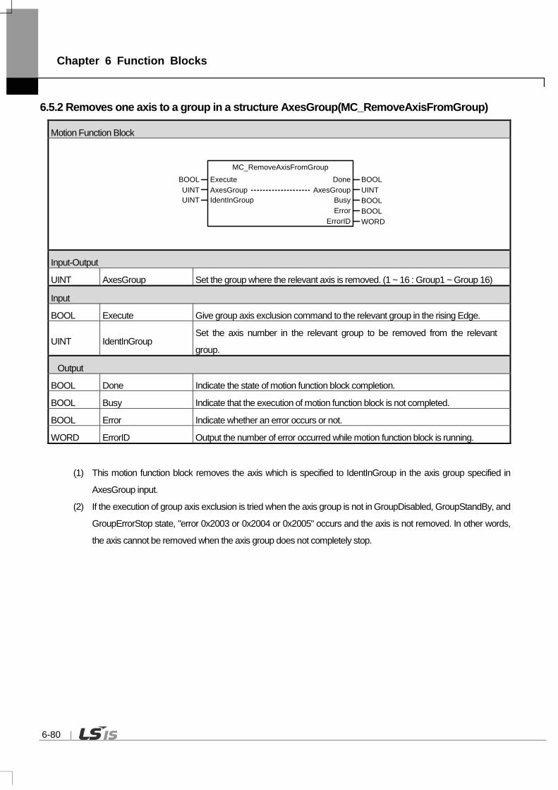
Chapter 6 Function Blocks
6.5.2 Removes one axis to a group in a structure AxesGroup(MC_RemoveAxisFromGroup)
Motion Function Block
MC_RemoveAxisFromGroup
AxesGroup AxesGroupUINT UINTBOOL Execute Done BOOL
Busy BOOLError BOOL
ErrorID WORD
IdentInGroupUINT
Input-Output
UINT AxesGroup Set the group where the relevant axis is removed. (1 ~ 16 : Group1 ~ Group 16)
Input
BOOL Execute Give group axis exclusion command to the relevant group in the rising Edge.
UINT IdentInGroup Set the axis number in the relevant group to be removed from the relevant
group.
Output
BOOL Done Indicate the state of motion function block completion.
BOOL Busy Indicate that the execution of motion function block is not completed.
BOOL Error Indicate whether an error occurs or not.
WORD ErrorID Output the number of error occurred while motion function block is running.
(1) This motion function block removes the axis which is specified to IdentInGroup in the axis group specified in
AxesGroup input.
(2) If the execution of group axis exclusion is tried when the axis group is not in GroupDisabled, GroupStandBy, and
GroupErrorStop state, "error 0x2003 or 0x2004 or 0x2005" occurs and the axis is not removed. In other words,
the axis cannot be removed when the axis group does not completely stop.
6-80

Chapter 6 Function Blocks
6.5.3 Removes all axes from the group AxesGroup(MC_UngroupAllAxes)
Motion Function Block
MC_UngroupAllAxes
AxesGroup AxesGroupUINT UINTBOOL Execute Done BOOL
Busy BOOLError BOOL
ErrorID WORD
Input-Output
UINT AxesGroup Set the group where every axis is to be removed. (1 ~ 16 : Group 1 ~ Group 16)
Input
BOOL Execute Give MC_UngroupAllAxes command to the relevant group in the rising Edge.
UINT IdentInGroup Set the axis number in the relevant group to be removed from the relevant
group.
Output
BOOL Done Indicate the state of motion function block completion.
BOOL Busy Indicate that the execution of motion function block is not completed.
BOOL Error Indicate whether an error occurs or not.
WORD ErrorID Output the number of error occurred while motion function block is running.
(1) This motion function block removes every axis which belongs to the axis group specified in AxesGroup input.
(2) If this motion function block is executed when the axis group is not in GroupDisabled, GroupStandBy, and
GroupErrorStop state, "error 0x2003 or 0x2004 or 0x2005" occurs and the axis is not removed. In other words,
the axis cannot be removed when the axis group does not completely stop.
(3) When the axis which belongs to the group is successfully removed, the relevant group is switched to
GroupDisabled state.
6-81

Chapter 6 Function Blocks
6.5.4 Changes the state for a group from GroupDisabled to GroupEnable(MC_GroupEnable)
Motion Function Block
MC_GroupEnable
AxesGroup AxesGroupUINT UINTBOOL Execute Done BOOL
Busy BOOLError BOOL
ErrorID WORD
Input-Output
UINT AxesGroup Set the group to be activated. (1 ~ 16 : Group 1 ~ Group 16)
Input
BOOL Execute Give group activation command to the relevant group in the rising Edge.
Output
BOOL Done Indicate the state of motion function block completion.
BOOL Busy Indicate that the execution of motion function block is not completed.
BOOL Error Indicate whether an error occurs or not.
WORD ErrorID Output the number of error occurred while motion function block is running.
(1) This motion function block is to activate the axis group specified in AxesGroup input.
(2) When giving this command to the axis group in GroupDisable state, the relevant axis group is switched to
GroupStandby state.
(3) This motion function block does not affect the power state of each axis in the relevant group.
6-82

Chapter 6 Function Blocks
6.5.5 Changes the state for a group to GroupDisabled(MC_GroupDisable)
Motion Function Block
MC_GroupDisable
AxesGroup AxesGroupUINT UINTBOOL Execute Done BOOL
Busy BOOLError BOOL
ErrorID WORD
Input-Output
UINT AxesGroup Set the group to be deactivated. (1 ~ 16 : Group 1 ~ Group 16)
Input
BOOL Execute Give group disablement command to the relevant group in the rising Edge.
Output
BOOL Done Indicate the state of motion function block completion.
BOOL Busy Indicate that the execution of motion function block is not completed.
BOOL Error Indicate whether an error occurs or not.
WORD ErrorID Output the number of error occurred while motion function block is running.
(1) This motion function block is to deactivate the axis group specified in AxesGroup input.
(2) The axis group which executes this motion function block is switched to GroupDisabled.
(3) This motion function block does not affect the power state of each axis in the relevant group.
6-83

Chapter 6 Function Blocks
6.5.6 The AxesGroup to perform the search home sequence(MC_GroupHome)
Motion Function Block
MC_GroupHomeDoneExecute
AxesGroup AxesGroupBOOLBOOL
UINT UINTLREAL[ ] Position
UINT BufferModeBusy BOOL
CommandAborted BOOLError BOOL
ErrorID WORD
Active BOOL
Input-Output
UINT AxesGroup Set the group returning to home. (1 ~ 16 : Group 1 ~ Group 16)
Input
BOOL Execute Give group homing command to the relevant group in the rising Edge.
LREAL[ ] Position Specify the absolute position of each axis when reference signal is detected.
UINT BufferMode Specify the sequential operation setting of motion function block.
(Refer to 10.1.4.BufferMode)
Output
BOOL Done Indicate the state of motion function block completion.
BOOL Busy Indicate that the execution of motion function block is not completed.
BOOL Active Indicate that the current motion function block is controlling the relevant axis.
BOOL CommandAborted Indicate that the current motion function block is interrupted while it is running.
BOOL Error Indicate whether an error occurs or not.
WORD ErrorID Output the number of error occurred while motion function block is running.
(1) This motion function block is to give homing command to the axis group specified in AxesGroup input.
(2) Homing method is operated as specified in servo parameter of the relevant axis in advance.
(3) In Position input, specify the absolute position to the array to be set when homing is completed or Reference
Signal is detected. Values in the array and the axis in the group correspond in the order of [1, 2, 3, 4]. (1~4 are
the axis ID in the axis group)
(4) The axis group is in 'GroupHoming' state while this motion function block is running, and it is switched to
'GroupStandby' state when motion function block is completed.
6-84

Chapter 6 Function Blocks
6.5.7 Sets the Position of all axes in a group without moving(MC_GroupSetPosition)
Motion Function Block
MC_GroupSetPositionDoneExecute
AxesGroup AxesGroupBOOLBOOL
UINT UINTPosition
BOOL RelativeBusy BOOL
CommandAborted BOOLError BOOL
ErrorID WORD
Active BOOLUINT ExecuteMode
Input-Output
UINT AxesGroup Select the group to set the current position. (1 ~ 16 : Group 1 ~ Group 16)
Input
BOOL Execute Give group current position setting command to the relevant group in the rising
Edge.
LREAL[ ] Position Specify the position.
BOOL Relative 0: Position value=Absolute position, 1: Position value=Relative position
UINT ExecuteMode 0: Immediately applied the position value,
1: Applied at the same point with ‘Buffered’ of Buffermode
Output
BOOL Done Indicate the state of motion function block completion.
BOOL Busy Indicate that the execution of motion function block is not completed.
BOOL Active Indicate that the current motion function block is controlling the relevant axis.
BOOL CommandAborted Indicate that the current motion function block is interrupted while it is running.
BOOL Error Indicate whether an error occurs or not.
WORD ErrorID Output the number of error occurred while motion function block is running.
(1) This motion function block sets the current position of the relevant axis group.
(2) Specify the position of each axis in the group to the array. When executing this motion function block, if Relative
input is Off, the position of the relevant axis is replaced by the Position input value, and if Relative input is On, the
Position input value is added to the current position of the relevant axis. Values in the array and the axis in the
group correspond in the order of [1, 2, 3, 4]. (1~4 are the axis ID in the axis group)
(3) ExcutionMode input specifies the setting point. If it is 0, it is set immediately after the execution of a command, If it is 1, it is set at the same point with ‘Buffered’ of sequential operation setting. The value unable to be set causes "error 0x201B”. 0 (mcImmediately): Change the value of parameter immediately after the execution of motion function block
6-85

Chapter 6 Function Blocks
(rising Edge in Execute input). If the relevant axis is running, the operation can be affected. 1 (mcQueued): Changed at the same point of ‘Buffered’ of Buffermode (Error! Reference Source Not Found.
Refer to input). (4) Example program
This example shows the change of the current position to position values (10,000,000/20,000,000/30,000,000) set in the position variables when executing MC_GroupSetPosition function block at the status where 1-axis, 2-axis and 3-axis are set as a single group. (a) Function block setting
(b) Timing diagram
2 Axis position
1 Axis position
3 Axis position
6-86

Chapter 6 Function Blocks
6.5.8 Stop a Group immediately(MC_GroupStop)
Motion Function Block
MC_GroupStop
DoneExecuteAxesGroup AxesGroup
BOOLBOOLUINT UINT
LREAL DecelerationLREAL Jerk
Busy BOOL
CommandAborted BOOLError BOOL
ErrorID WORD
Active BOOL
Input-Output
UINT AxesGroup Set the group to stop immediately. (1 ~ 16 : Group 1 ~ Group 16)
Input
BOOL Execute Give group immediate stop command to the relevant group in the rising Edge.
LREAL Deceleration Specify the deceleration in time of stop. [u/s2]
LREAL Jerk Specify the change rate of acceleration/deceleration. [u/s3]
Output
BOOL Done Indicate the state of motion function block completion.
BOOL Busy Indicate that the execution of motion function block is not completed.
BOOL Active Indicate that the current motion function block is controlling the relevant axis.
BOOL CommandAborted Indicate that the current motion function block is interrupted while it is running.
BOOL Error Indicate whether an error occurs or not.
WORD ErrorID Output the number of error occurred while motion function block is running.
(1) This motion function block is to give an emergency stop command to the relevant axis group.
(2) The relevant axis group moves on the route which it was following until it completely stops.
(3) When executing group immediate stop (MC_GroupStop) motion function block, motion function block which the
relevant axis group is performing is interrupted, and the axis is changed to 'GroupStopping'. When the relevant
axis group is in ‘GroupStopping’ state, other motion function block cannot be given to the relevant axis until the
stop is completed (until Done output is On).
(4) CommandAborted output indicates that the current motion function block is interrupted while it was executed.
Because other motion function block cannot interrupt group immediate stop (MC_GroupStop) command while
group immediate stop (MC_GroupStop) command is being executed, CommandAborted output is On when the
power of servo is cut, servo Off command is executed, or servo connection is disconnected.
(5) If Execute input is On or the speed of the axis is not 0, the axis is in ' GroupStopping' state, and if Done output is
On and Execute input is Off, the axis is switched to ' GroupStandBy' state.
6-87

Chapter 6 Function Blocks
6.5.9 Stop a Group(MC_GroupHalt)
Motion Function Block
MC_GroupHalt
DoneExecuteAxesGroup AxesGroup
BOOLBOOLUINT UINT
LREAL DecelerationLREAL Jerk
Busy BOOL
CommandAborted BOOLError BOOL
ErrorID WORD
Active BOOLUINT BufferMode
Input-Output
UINT AxesGroup Set the group to stop. (1 ~ 16 : Group 1 ~ Group 16)
Input
BOOL Execute Give group stop command to the relevant group in the rising Edge.
LREAL Deceleration Specify the deceleration in the time of stop. [u/s2]
LREAL Jerk Specify the change rate of acceleration/deceleration. [u/s3]
UINT BufferMode Specify the sequential operation setting of motion function block.
(Refer to 10.1.4.BufferMode)
Output
BOOL Done Indicate the state of motion function block completion.
BOOL Busy Indicate that the execution of motion function block is not completed.
BOOL Active Indicate that the current motion function block is controlling the relevant axis.
BOOL CommandAborted Indicate that the current motion function block is interrupted while it is running.
BOOL Error Indicate whether an error occurs or not.
WORD ErrorID Output the number of error occurred while motion function block is running.
(1) This motion function block is to give a stop command to the relevant axis.
(2) The relevant axis group moves on the route which it was following until it completely stops.
(3) The axis is in 'GroupMoving' state while this motion function block is running, and if the axis group completely
stops, 'Done' output is On and the group state is changed to 'GroupStandBy' state.
6-88

Chapter 6 Function Blocks
6.5.10 Reset a group error(MC_GroupReset)
Motion Function Block
MC_GroupResetDoneExecute
AxesGroup AxesGroupBOOLBOOL
UINT UINTBusy BOOL
ErrorID WORDError BOOL
Input-Output
UINT AxesGroup Set the group to do error reset. (1 ~ 16 : Group 1 ~ Group 16)
Input
BOOL Execute Give group error reset command to the relevant group in the rising Edge.
Output
BOOL Done Indicate the state of motion function block completion.
BOOL Busy Indicate that the execution of motion function block is not completed.
BOOL Error Indicate whether an error occurs or not.
WORD ErrorID Output the number of error occurred while motion function block is running.
(1) This motion function block is to reset the error of the relevant axis group. When the relevant axis is in
'GroupErrorStop', the execution of motion function block resets the error occurred in the current relevant axis and
switches the axis group to 'GroupStandBy' state.
(2) When executing this motion function block, every error occurred in each axis in the group is reset. (This has the
same effect with when executing the axis error reset (MC_Reset) command in each axis.)
6-89

Chapter 6 Function Blocks
6.5.11 Absolute positioning linear interpolation operation(MC_MoveLinearAbsolute)
Motion Function Block
MC_MoveLinearAbsoluteDoneExecute
AxesGroup AxesGroupBOOLBOOL
UINT UINTLREAL[ ] Position
LREAL VelocityBusy BOOL
CommandAborted BOOLError BOOL
ErrorID WORD
LREAL AccelerationActive BOOL
LREAL DecelerationLREAL Jerk
UINT BufferModeUINT TransitionMode
LREAL TransitionParameter
Input-Output
UINT AxesGroup Set the group to perform absolute position linear interpolation operation. (1 ~ 16:
Group 1 ~ Group 16)
Input
BOOL Execute Give absolute position linear interpolation operation command to the relevant group
in the rising Edge.
LREAL[ ] Position Specify the target position of each axis.
LREAL Velocity Specify the maximum speed of the route. [u/s]
LREAL Acceleration Specify the maximum acceleration. [u/s2]
LREAL Deceleration Specify the maximum deceleration. [u/s2]
LREAL Jerk Specify the change rate of acceleration/deceleration. [u/s3]
UINT BufferMode Specify the sequential operation setting of motion function block.
(Refer to 10.1.4.BufferMode)
UINT TransitionMode Specify the route change mode of group operation.
(Refer to 10.1.6.TransitionMode )
LREAL TransitionParameter Specify the parameter of the route change setting of group operation..
(Refer to 10.1.6.TransitionMode )
Output
BOOL Done Indicate whether to reach the specified position.
BOOL Busy Indicate that the execution of motion function block is not completed.
BOOL Active Indicate that the current motion function block is controlling the relevant axis.
BOOL CommandAborted Indicate that the current motion function block is interrupted while it is running.
BOOL Error Indicate whether an error occurs or not.
WORD ErrorID Output the number of error occurred while motion function block is running.
6-90

Chapter 6 Function Blocks
(1) This motion function block is to give an absolute position linear interpolation command to the axis group specified in
AxesGroup input.
(2) When this motion function block is executed, interpolation control is performed in a linear path from the current
position to the target position of each axis, and the moving direction is decided by the starting point and the target
point of each axis.
Beginning position < Target position: Forward direction operation
Beginning position > Target position: Reverse direction operation
(3) In Position input, specify the target position of each axis in the group as matrix. The values in the array and the axis
in the group correspond in the order of [1, 2, 3, 4].(1~4 are axis ID in the axis group).
(4) Specify the speed, acceleration, deceleration, and the change rate of acceleration/deceleration of interpolation route
in Velocity, Acceleration, Deceleration, and Jerk inputs respectively.
(5) Velocity is to set the interpolation speed of the axis group, and it indicates the integrated speed of each axis. Operation speeds of each configuration axis are calculated as follows.
Velocity thein specified speedTarget (F) speed ionInterpolat =
24
23
22
21 SSSS(S) amountmovement ionInterpolat +++=
(S)amountmovement ionInterpolat)(Samountmovement 1 axis ionConfigurat
(F) speed ionInterpolat)(V speed 1 axis ionConfigurat 11 ×=
(S)amountmovement ionInterpolat)(Samount movement 2 axis ionConfigurat
(F)speed ionInterpolat)(V speed 2 axis ionConfigurat 22 ×=
(S)amountmovement ionInterpolat)(Samountmovement 3 axis ionConfigurat
(F)speed ionInterpolat)(V speed 3 axis ionConfigurat 33 ×=
(S)amountmovement ionInterpolat)(Samountmovement 4 axis ionConfigurat
(F)speed ionInterpolat)(V speed 4 axis ionConfigurat 44 ×=
(6) Refer to chapter 8.2.6 linear interpolation control part in motion control module’s manual for more details.
(7) The changed parameters can be applied by re-executing the function block (Execute input is On) before the
command is completed. Only Velocity, Acceleration, Deceleration, Jerk, Position input can be updated.
(8) Example program
This example shows the linear interpolation to the target position (10000, 1000) when the current command position
is (1000, 4000).
6-91

Chapter 6 Function Blocks
(a) Function block setting
From start position to target position
0
Goal Position
(Y axis)
X axis
Starting position
1000 5000 10000
X axis movement value (10000-1000=9000)
1000
4000
Y axis movement value(1000-4000=-3000)
6-92

Chapter 6 Function Blocks
(b) Timing diagram
(c) XY graph
Y Axis velocity
X Axis velocity Y Axis position X Axis position
X Axis Y Axis
6-93

Chapter 6 Function Blocks
6.5.12 Relative positioning linear interpolation operation(MC_MoveLinearRelative)
Motion Function Block
MC_MoveLinearRelativeDoneExecute
AxesGroup AxesGroupBOOLBOOL
UINT UINTLREAL[ ] Distance
LREAL VelocityBusy BOOL
CommandAborted BOOLError BOOL
ErrorID WORD
LREAL AccelerationActive BOOL
LREAL DecelerationLREAL Jerk
UINT BufferModeUINT TransitionMode
LREAL TransitionParameter
Input-Output
UINT AxesGroup Set the group to do relative position linear interpolation operation. (1 ~ 16: Group 1
~ Group 16)
Input
BOOL Execute Give relative position linear interpolation operation command to the relevant group
in the rising Edge.
LREAL[ ] Distance Set the target distance of each axis.
LREAL Velocity Specify the maximum speed of the route. [u/s]
LREAL Acceleration Specify the maximum acceleration. [u/s2]
LREAL Deceleration Specify the maximum deceleration. [u/s2]
LREAL Jerk Specify the change rate of acceleration/deceleration. [u/s3]
UINT BufferMode Specify the sequential operation setting of motion function block.
(Refer to 10.1.4.BufferMode)
UINT TransitionMode Specify the route change mode of group operation.
(Refer to 10.1.6.TransitionMode )
LREAL TransitionParameter Specify the parameter of the route change setting of group operation..
(Refer to 10.1.6.TransitionMode )
Output
BOOL Done Indicate whether to reach the specified position.
BOOL Busy Indicate that the execution of motion function block is not completed.
BOOL Active Indicate that the current motion function block is controlling the relevant axis.
BOOL CommandAborted Indicate that the current motion function block is interrupted while it is running.
BOOL Error Indicate whether an error occurs or not.
WORD ErrorID Output the number of error occurred while motion function block is running.
6-94

Chapter 6 Function Blocks
(1) This motion function block is to give a relative position linear interpolation command to the axis group specified in
AxesGroup input.
(2) When this motion function block is executed, interpolation control performed in a linear path from the current position
to the target position of each axis, and the moving direction is decided by the sign of the target distance of each axis.
Target distance > 0: Forward direction operation
Target distance < 0: Reverse direction operation
(3) In Distance input, specify the target distance of each axis in the group as array. The specified array and the axis in
the group correspond in the order of specified axis ID [ID1 target distance, ID2 target distance, …].
(4) Set the speed, acceleration, deceleration, and the change rate of acceleration/deceleration of interpolation route in
Velocity, Acceleration, Deceleration, and Jerk inputs respectively.
(5) Velocity is to set the interpolation speed of the axis group, and it indicates the integrated speed of each axis. Operation speeds of each configuration axis are calculated as follows.
Velocity thein specified speedTarget (F) speed ionInterpolat =
24
23
22
21 SSSS(S) amountmovement ionInterpolat +++=
(S)amountmovement ionInterpolat)(Samountmovement 1 axis ionConfigurat
(F) speed ionInterpolat)(V speed 1 axis ionConfigurat 11 ×=
(S)amountmovement ionInterpolat)(Samount movement 2 axis ionConfigurat
(F)speed ionInterpolat)(V speed 2 axis ionConfigurat 22 ×=
(S)amountmovement ionInterpolat)(Samountmovement 3 axis ionConfigurat
(F)speed ionInterpolat)(V speed 3 axis ionConfigurat 33 ×=
(S)amountmovement ionInterpolat)(Samountmovement 4 axis ionConfigurat
(F)speed ionInterpolat)(V speed 4 axis ionConfigurat 44 ×=
(6) Refer to chapter 8.2.6 linear interpolation control part in motion control module’s manual for more details.
(7) The changed parameters can be applied by re-executing the function block (Execute input is On) before the
command is completed. Only Velocity, Acceleration, Deceleration, Jerk, Position input can be updated.
(8) Example program
This example shows the linear interpolation to the target position (10000, 1000) by moving the target distance (X-
axis: 9000, Y-axis: -3000) when the current command position is (1000, 4000).
6-95

Chapter 6 Function Blocks
(a) Function block setting
Move as much as target move amount
0
Linear interpolation end
position
(Y axis)
(X axis)
Starting position
1000 5000 10000
X axis movement value(9000)
1000
4000
Y axis movement value
(-3000)
6-96

Chapter 6 Function Blocks
(b) Timing diagram
(c) XY graph
Y Axis velocity
X Axis velocity Y Axis position X Axis position
6-97

Chapter 6 Function Blocks
6.5.13 Absolute positioning circular interpolation operation(MC_MoveCircularAbsolute)
Motion Function Block
MC_MoveCircularAbsoluteDoneExecute
AxesGroup AxesGroupBOOLBOOL
UINT UINTUINT CircMode
LREAL[ ] AuxPointBusy BOOL
CommandAborted BOOLError BOOL
ErrorID WORD
LREAL[ ] EndPointActive BOOL
UINT PathChoiceLREAL VelocityLREAL AccelerationLREAL DecelerationLREAL Jerk
UINT BufferModeUINT TransitionMode
LREAL TransitionParameter
Input-Output
UINT AxesGroup Set the group to do absolute position circular interpolation operation. (1 ~ 16: Group
1 ~ Group 16)
Input
BOOL Execute Give absolute position circular interpolation operation command to the relevant
group in the rising Edge.
UINT CirMode Circular interpolation method setting [0: Midpoint, 1: Central point, 2: Radius]
LREAL[ ] AuxPoint Specify the position of auxiliary point depending on the circular interpolation
method in an absolute coordinate.
LREAL[ ] EndPoint Specify the end point of circular arc in an absolute coordinate.
BOOL PathChoice Circular route selection
0: Clockwise, 1: Counterclockwise
LREAL Velocity Specify the maximum speed of the route. [u/s]
LREAL Acceleration Specify the maximum acceleration. [u/s2]
LREAL Deceleration Specify the maximum deceleration. [u/s2]
LREAL Jerk Specify the change rate of acceleration/deceleration. [u/s3]
UINT BufferMode Specify the sequential operation setting of motion function block.
(Refer to 10.1.4.BufferMode)
UINT TransitionMode Unused
LREAL TransitionParameter Unused
6-98

Chapter 6 Function Blocks
Output
BOOL Done Indicate whether to reach the specified position.
BOOL Busy Indicate that the execution of motion function block is not completed.
BOOL Active Indicate that the current motion function block is controlling the relevant axis.
BOOL CommandAborted Indicate that the current motion function block is interrupted while it is running.
BOOL Error Indicate whether an error occurs or not.
WORD ErrorID Output the number of error occurred while motion function block is running.
(1) This motion function block is to give an absolute position circular interpolation command to the axis group specified in AxesGroup input.
(2) When this motion function block starts, each axis performs circular path interpolation control which refers to the set auxiliary point, and the movement direction is decided by PathChoice input. When setting PathChoice input to 0, circular interpolation operation is done clockwise, and when setting it to 1, circular interpolation operation is done counterclockwise.
(3) Specify the absolute position of the auxiliary point to refer when doing circular interpolation of each axis in AuxPoint and EndPoint inputs as array. The entered array and the axis in the group correspond in the order of the specified axis ID [ID1, ID2, ID3, ∙∙∙ ]. (The 3 LEAL type sized array should be entered in Position input as there are 3 axes which comprise the group to give a circular interpolation operation command.)
(4) Specify the speed, acceleration, deceleration, and the change rate of acceleration of interpolation route in Velocity, Acceleration, Deceleration, and Jerk inputs respectively.
(5) Set the circular interpolation method in CircMode input. The circular interpolation methods which are different from the value specified in CircMode are as below.
(a) Circular interpolation of midpoint specifying method (BORDER, CircMode = 0)
In this method, operation starts at the starting point and it does circular interpolation through the specified position of the central point to the target position. The Figure below shows that the coordinate of the axis group at the beginning of a command corresponds to the starting point, the coordinate entered in AuxPoint corresponds to the central point, and the coordinate entered in EndPoint corresponds to the target position in an absolute value.
6-99

Chapter 6 Function Blocks
(b) Circular interpolation of central point specifying method
In this method, operation starts at the current position, and it does circular interpolation to the target position along the circular path, which has a radius of the distance to the specified central position. The Figure below shows that the coordinate of the axis group at the beginning of a command corresponds to the current position, the coordinate entered in AuxPoint corresponds to the central point, and the coordinate entered in EndPoint corresponds to the target point as an absolute value.
(c) Circular interpolation using the radius specifying method
In this method, operation starts at the current position, and it does circular interpolation to the target position along the circular path which has a radius of the value specified in the radius. The Figure below shows that the coordinate of the axis group at the beginning of a command corresponds to the current position, the value entered in X-axis of AuxPoint corresponds to the radius, and the coordinate entered in EndPoint corresponds to the target point in an absolute value.
(6) Refer to chapter 8.2.7 linear interpolation control part in motion control module’s manual for more details.
(7) The changed parameters can be applied by re-executing the function block (Execute input is On) before the
6-100

Chapter 6 Function Blocks
command is completed. Only Velocity, Acceleration, Deceleration, Jerk, AuxPoint, EndPoint input can be updated.
(8) Example program
This example shows the circular interpolation to the target position (1000, 1000) by moving clock-wise after
setting the center point (2000,2000) specification method when the current command position is (1000, 1000). (a) Function block setting
(b) Timing diagram
Y Axis position X Axis position
Start position
Middle point
Target position
X Axis Velocity
Y Axis Velocity
6-101

Chapter 6 Function Blocks
(c) XY graph
X Axis Y Axis
6-102

Chapter 6 Function Blocks
6.5.14 Relative positioning circular interpolation operation(MC_MoveCircularRelative)
Motion Function Block
MC_MoveCircularRelative
DoneExecuteAxesGroup AxesGroup
BOOLBOOLUINT UINTUINT CircMode
LREAL[ ] AuxPointBusy BOOL
CommandAborted BOOLError BOOL
ErrorID WORD
LREAL[ ] EndPointActive BOOL
USINT PathChoiceLREAL VelocityLREAL AccelerationLREAL DecelerationLREAL Jerk
UINT BufferModeUINT TransitionMode
LREAL TransitionParameter
Input-Output
UINT AxesGroup Set the group to do absolute position circular interpolation operation. (1 ~ 16: Group
1 ~ Group 16)
Input
BOOL Execute Give relative position circular interpolation operation command to the relevant
group in the rising Edge.
UINT CirMode Circular interpolation method setting [0: Midpoint, 1: Central point, 2: Radius]
LREAL[ ] AuxPoint Specify the position of auxiliary point depending on the circular interpolation
method as the relative coordinate based on the starting point.
LREAL[ ] EndPoint Specify the end point of circular arc as the relative coordinate based on the starting
point.
BOOL PathChoice Circular route selection
0: Clockwise, 1: Counterclockwise
LREAL Velocity Specify the maximum speed of the route. [u/s]
LREAL Acceleration Specify the maximum acceleration. [u/s2]
LREAL Deceleration Specify the maximum deceleration. [u/s2]
LREAL Jerk Specify the change rate of acceleration/deceleration. [u/s3]
UINT BufferMode Specify the sequential operation setting of motion function block.
(Refer to 10.1.4.BufferMode)
UINT TransitionMode Unused
LREAL TransitionParameter Unused
6-103

Chapter 6 Function Blocks
Output
BOOL Done Indicate whether to reach the specified position.
BOOL Busy Indicate that the execution of motion function block is not completed.
BOOL Active Indicate that the current motion function block is controlling the relevant axis.
BOOL CommandAborted Indicate that the current motion function block is interrupted while it is running.
BOOL Error Indicate whether an error occurs or not.
WORD ErrorID Output the number of error occurred while motion function block is running. (1) This motion function block is to give a relative position circular interpolation command to the axis group specified
in AxesGroup input. (2) When this motion function block starts, each axis performs circular path interpolation control which refers to the
set auxiliary point, and the movement direction is decided by PathChoice input. When setting PathChoice input to 0, circular interpolation operation is done clockwise, and when setting it to 1, circular interpolation operation is done counterclockwise.
(3) Specify the relative position of the auxiliary point to refer when doing circular interpolation of each axis in AuxPoint and EndPoint inputs as array. The entered array and the axis in the group correspond in the order of the specified axis ID [ID1, ID2, ID3, ∙∙∙ ]. (The 3 LEAL type sized array should be entered in Position input as there are 3 axes which comprise the group to give a circular interpolation operation command.)
(4) Specify the speed, acceleration, deceleration, and the change rate of acceleration of interpolation route in Velocity, Acceleration, Deceleration, and Jerk inputs respectively.
(5) Set the circular interpolation method in CircMode input. The circular interpolation methods which are different from the value specified in CircMode are as below.
(a) Circular interpolation of midpoint specifying method (BORDER, CircMode = 0)
In this method, operation starts at the current position and it does circular interpolation through the specified position of the central point to the target position. The Figure below shows that the coordinate of the axis group at the beginning of a command corresponds to the current position, the coordinate entered in AuxPoint corresponds to the central point, and the coordinate entered in EndPoint corresponds to the target position in a relative value.
6-104

Chapter 6 Function Blocks
(b) Circular interpolation of central point specifying method
In this method, operation starts at the current position, and it does circular interpolation to the target position along the circular path, which has a radius of the distance to the specified central position. The Figure below shows that the coordinate of the axis group at the beginning of a command corresponds to the current position, the coordinate entered in AuxPoint corresponds to the central point, and the coordinate entered in EndPoint corresponds to the target point as a relative value.
(c) Circular interpolation using the radius specifying method
In this method, operation starts at the current position, and it does circular interpolation to the target position along the circular path which has a radius of the value specified in the radius. The Figure below shows that the coordinate of the axis group at the beginning of a command corresponds to the current position, the value entered in X-axis of AuxPoint corresponds to the radius, and the coordinate entered in EndPoint corresponds to the target point in a relative value.
(6) Refer to linear interpolation control part in motion control module’s manual for more details.
6-105

Chapter 6 Function Blocks
(7) Example program This example is to set the center point specification method when the current command position is (1000, 1000) (set the relative position from the current position to the center point to set: 1000, 1000), and move clock-wise to perform circular interpolation to the target position (set the relative position from the current position to the target position: 0, 0). (a) Function block setting
(b) Timing diagram
Y Axis position X Axis position
Start position
Distance to the middle point
(Distance from the start position)
Distance to the target
(Distance from the start position)
X Axis Velocity
Y Axis Velocity
6-106

Chapter 6 Function Blocks
(c) XY graph X Axis Y Axis
6-107

Chapter 6 Function Blocks
6.6 Exclusive Function Blocks
6.6.1 Connect servo drives(LS_Connect)
Motion Function Block
LS_ConnectExecute DoneBOOL BOOL
Busy BOOLError BOOL
ErrorID WORD
Input
BOOL Execute Give communication connection command to the relevant module in the rising
Edge.
Output
BOOL Done Indicate whether to complete communication connection.
BOOL Busy Indicate that the execution of motion function block is not completed.
BOOL Error Indicate whether an error occurs or not.
WORD ErrorID Output the number of error occurred while motion function block is running.
(1) This motion function block is to give a command to connect communication with servo drive or external
input/output apparatus to the module.
(2) When slave devicees are normally connected, Done is On and Busy is Off.
(3) If an error occurs during the communication connection, Error is On and error number is output in ErrorID
according to the cause.
6-108

Chapter 6 Function Blocks
6.6.2 Disconnect servo drives(LS_Disconnect)
Motion Function Block
LS_DisonnectExecute DoneBOOL BOOL
Busy BOOLError BOOL
ErrorID WORD
Input
BOOL Execute Give communication disconnection command to the relevant module in the rising
Edge.
Output
BOOL Done Indicate whether to complete communication disconnection.
BOOL Busy Indicate that the execution of motion function block is not completed.
BOOL Error Indicate whether an error occurs or not.
WORD ErrorID Output the number of error occurred while motion function block is running.
(1) This motion function block gives a command which orders the module to disconnect the communication with
servo drive or external input/output apparatuses.
(2) If communication slave is disconnected, Done is On and Busy is off.
(3) If an error occurs during the execution of communication disconnection, Error is On and error number is output
in ErrorID according to the error situation.
6-109

Chapter 6 Function Blocks
6.6.3 Read servo parameters(LS_ReadServoParameter)
Motion Function Block
MC_ReadServoParameter
AxisAxisExecute Done
UINTUINTBOOL BOOL
UINT Index Busy BOOLError BOOL
ErrorID WORDUINT SubIndexUINT Length
DINTValue
Input-Output
UINT Axis Set the axis to be given a command. (1~32: Actual axes)
Input
BOOL Execute Give servo parameter reading command to the relevant axis in the rising Edge.
UINT Index Set the Index of servo parameter Object to be read. (0x0000~0x9FFF)
UINT SubIndex Set the SubIndex of servo parameter Object to be read. (0 ~ 255)
UINT Length Set the distance of servo parameter Object to be read by Byte. (1 ~ 4)
Output
BOOL Done Indicate that servo parameter is successfully read.
BOOL Busy Indicate that the execution of motion function block is not completed.
BOOL Error Indicate whether an error occurs or not.
WORD ErrorID Output the number of error occurred while motion function block is running.
LREAL Value Output the value of servo parameter.
(1) This motion function block is to read the parameter (CoE Object) value of servo drive in the relevant axis, and
reads the servo parameter value of the position specified in Index and SubIndex of the axis specified by Axis
input as much as the size of Length and indicates it on Value output.
(2) Value output is eliminated to 0 when motion function block is running, and it is output as the read value when the
running is completed (Done output is On).
(3) Index input can be set as below. If the value is set outside the range, "error 0x1F12” occurs.
Variable Description
16#0000 ~ 16#0FFF Data Type Description
16#1000 ~ 16#1FFF Communication objects
16#2000 ~ 16#5FFF Manufacturer Specific Profile Area
16#6000 ~ 16#9FFF Standardized Device Profile Area
6-110

Chapter 6 Function Blocks
(4) The value between 0~255 can be entered in SubIndex, and if the value is set outside the range, "error 0x1F12”
occurs.
(5) The value between 1~4 can be set in Length, which means 1~4 Byte. If the value is set outside the range, “error
0x1F12” occurs.
6-111

Chapter 6 Function Blocks
6.6.4 Write servo parameters(LS_WriteServoParameter)
Motion Function Block
MC_WriteServoParameter
AxisAxisExecute Done
UINTUINTBOOL BOOL
UINT Index Busy BOOLError BOOL
ErrorID WORDUINT SubIndexUINT LengthDINT Value
ExecutionModeUINT
Input-Output
UINT Axis Set the axis to be given a command. (1~32: Actual axes)
Input
BOOL Execute Give servo parameter writing command to the relevant axis in the rising Edge.
UINT Index Set the Index of servo parameter Object to be written. (0x0000~0x9FFF)
UINT SubIndex Set the SubIndex of servo parameter Object to be written. (0 ~ 255)
UINT Length Set the distance of servo parameter Object to be written by Byte. (1 ~ 4)
DINT Value Set the value to be written in servo parameter.
UINT ExecuteMode
Specify the time when performing servo parameter writing.
0: Immediately executed
1: Applied at the same time with ‘Buffered’ of BufferMode.
Output
BOOL Done Indicate that servo parameter is successfully read.
BOOL Busy Indicate that the execution of motion function block is not completed.
BOOL Error Indicate whether an error occurs or not.
WORD ErrorID Output the number of error occurred while motion function block is running.
(1) This motion function block is to write the parameter (CoE Object) value of the relevant axis servo drive, and it
writes the value entered in Value as the size of the Length in servo parameter of the position specified as Index
and SubIndex of the axis specified in Axis input.
(2) Index input can be set as below. When it is set to the value besides the set value, “error 0x1F12” occurs.
6-112

Chapter 6 Function Blocks
Value Description
16#0000 ~ 16#0FFF Data Type Description
16#1000 ~ 16#1FFF Communication objects
16#2000 ~ 16#5FFF Manufacturer Specific Profile Area
16#6000 ~ 16#9FFF Standardized Device Profile Area
(3) The value between the range of 0~255 can be entered in SubIndex, and if the value outside the range is set,
“error 0x1F12” occurs.
(4) The value between the range of 1~4 can be entered in Length, which means 1~4 Byte. If the value outside the
range is set, "error 0x1F12” occurs.
(5) The time when parameter is written is set in ExecutionMode, and values can be set as below. The value unable
to be set causes "error0x101B”.
(6) 0 (mcImmediately): Change the parameter value immediately after the execution of motion function block(rising
Edge in Execute input) If the relevant axis is running, operation can be affected.
(7) 1 (mcQueued): Changed at the same time with‘Buffered’of BufferMode. (Refer to 10.1.4. BufferMode input)
6-113

Chapter 6 Function Blocks
6.6.5 Encoder preset(LS_EncoderPreset)
Motion Function Block
LS_EncoerPreset
EncoderExecute Done
UINTBOOL BOOL
LREAL PositionBOOL Relative
Busy BOOLError BOOL
ErrorID WORD
Input
BOOL Execute Specify the position of the relevant encoder in the rising Edge.
UINT Encoder Set the encoder to set the position. (1~2: Encoder 1~Encoder 2)
LREAL Position Specify the position to set. [u]
BOOL Relative 0: Absolute coordinate position
1: Relative coordinate position
Output
BOOL Done Indicate the state of motion function block completion.
BOOL Busy Indicate that the execution of motion function block is not completed.
BOOL Error Indicate whether an error occurs or not.
WORD ErrorID Output the number of error occurred while motion function block is running.
(1) This motion function block is to set the current position of the relevant encoder. (2) Specify the position in Position input. When executing motion function command, if Relative input is Off, the
position of the current axis is replaced with the Position input value, and if the Relative input is On, the Position input value is added to the current position of the relevant axis.
6-114

Chapter 6 Function Blocks
6.6.6 JOG operation(LS_Jog)
Motion Function Block
LS_Jog
AxisAxisEnable Enabled
UINTUINTBOOL BOOL
BOOL Direction Busy BOOLError BOOL
ErrorID WORDBOOL Low/High
Input-Output
UINT Axis Set the axis to be given a command. (1~32: Actual axes)
Input
BOOL Enable Give jog command to the relevant axis while input is On.
BOOL Direction Set the rotation direction in jog (0: Forward direction, 1: Reverse direction)
BOOL Low/High Set the jog speed in jog.
(0: Jog low speed operation, 1: Jog high speed operation)
Output
BOOL Enabled Indicate that the relevant axis is in jog.
BOOL Busy Indicate that the execution of motion function block is not completed.
BOOL Error Indicate whether an error occurs or not.
WORD ErrorID Output the number of error occurred while motion function block is running.
(1) This motion function block is to make the relevant axis perform jog operation. (2) Jog is a manual operation function for test and is used to confirm the position address for system operation,
wiring condition check, and teaching. Jog can be used by dividing the speed into high speed and low speed. (3) When Enable input is On (in jog), if the value set in Low/High is changed, speed change occurs without stop in
jog, and if the value set in JOG_DIR is changed, Jog is continued by changing the direction after the deceleration pause.
(4) Example program
This example shows jog operation under the following settings when the current command position is 0. (a) Function block setting
6-115

Chapter 6 Function Blocks
(b) Timing diagram
1 Axis position
2 Axis Velocity
2 Axis position
1 Axis Velocity 3 Axis Velocity
3 Axis position
6-116

Chapter 6 Function Blocks
6.6.7 Cam data reading(LS_ReadCamData)
Motion Function Block
LS_ReadCamData
AxisAxisEnable Done
UINTUINTBOOL BOOL
UINT CamTable ID Busy BOOLError BOOL
ErrorID WORDLREAL MasterPointLREAL SlavePoint
StartSlopeEndSlope
CamPointNumCamCurveSel
LREALLREALUINTArray [4] of DWORD
입력-출력
UINT Axis Specify the axis to be commanded (1~32: real axis, 37~40: virtual axis)
입력
BOOL Enable Read the relevant cam data while input is On.
UINT CamTableID Specify the cam table to read. (1~32)
LREAL MasterPoint MasterPoint values of the cam table are displayed on the areas of which front
address is the set device.
LREAL SlavePoint SlavePoint values of the cam table are displayed on the areas of which front
address is the set device.
출력
BOOL Vaild Indicate the validity of motion function block output.
BOOL Busy Indicate that the execution of motion function block is not completed.
BOOL Error Indicate whether an error occurs or not.
WORD ErrorID Output the number of error occurred while motion function block is running.
LREAL StartSlope Output the StartSlope value of the relevant cam table.
LREAL EndSlope Output the EndtSlope value of the relevant cam table.
UINT CamPointNum Output the cam data point number of the relevant cam table.
DWORD[] CamCurveSel Cam curve formats of each point in each Bit are displayed.
(0: Linear, 1: Cubic)
(1) This function block displays the data of the cam table. (2) While Enable input is activated, the data values of the cam table are displayed in succession. (3) The first address of the variables to store "Main-axis Position" and "Sub-axis Position" read from the camp profile is
set at the MasterPoint and the SlavePoint. For example, to save the "Main-axis Position" to the array vairable called MainAxPos[100], and "Sub-axis Position" value to SubAsPos[100] array variable, MainAxPos[0] should be set at MasterPoint of the function block, and SubAsPos[0] should be set at SlavePoint.
6-117

Chapter 6 Function Blocks
(4) The curve type of the point is displayed for each bit in CamCurveSel[4].
CamCurveSel[0]
Bit 7 Bit 6 Bit 5 Bit 4 Bit 3 Bit 2 Bit 1 Bit 0
Point 8 Point 7 Point 6 Point 5 Point 4 Point 3 Point 2 Point 1
Bit 15 Bit 14 Bit 13 Bit 12 Bit 11 Bit 10 Bit 9 Bit 8
Point 16 Point 15 Point 14 Point 13 Point 12 Point 11 Point 10 Point 9
Bit 23 Bit 22 Bit 21 Bit 20 Bit 19 Bit 18 Bit 17 Bit 16
Point 24 Point 23 Point 22 Point 21 Point 20 Point 19 Point 18 Point 17
Bit 31 Bit 30 Bit 29 Bit 28 Bit 27 Bit 26 Bit 25 Bit 24
Point 32 Point 31 Point 30 Point 29 Point 28 Point 27 Point 26 Point 25
CamCurveSel[1]
Bit 7 Bit 6 Bit 5 Bit 4 Bit 3 Bit 2 Bit 1 Bit 0
Point 40 Point 39 Point 38 Point 37 Point 36 Point 35 Point 34 Point 33
Bit 15 Bit 14 Bit 13 Bit 12 Bit 11 Bit 10 Bit 9 Bit 8
Point 48 Point 47 Point 46 Point 45 Point 44 Point 43 Point 42 Point 41
Bit 23 Bit 22 Bit 21 Bit 20 Bit
1….09
Bit 18 Bit 17 Bit 16
Point 56 Point 55 Point 54 Point 53 Point 52 Point 51 Point 50 Point 49
Bit 31 Bit 30 Bit 29 Bit 28 Bit 27 Bit 26 Bit 25 Bit 24
Point 64 Point 63 Point 62 Point 61 Point 60 Point 59 Point 58 Point 57
CamCurveSel[2]
Bit 7 Bit 6 Bit 5 Bit 4 Bit 3 Bit 2 Bit 1 Bit 0
Point 72 Point 71 Point 70 Point 69 Point 68 Point 67 Point 66 Point 65
Bit 15 Bit 14 Bit 13 Bit 12 Bit 11 Bit 10 Bit 9 Bit 8
Point 80 Point 79 Point 78 Point 77 Point 76 Point 75 Point 74 Point 73
Bit 23 Bit 22 Bit 21 Bit 20 Bit 19 Bit 18 Bit 17 Bit 16
Point 88 Point 87 Point 86 Point 85 Point 84 Point 83 Point 82 Point 81
Bit 31 Bit 30 Bit 29 Bit 28 Bit 27 Bit 26 Bit 25 Bit 24
Point 96 Point 95 Point 94 Point 93 Point 92 Point 91 Point 90 Point 89
CamCurveSel[3]
Bit 7 Bit 6 Bit 5 Bit 4 Bit 3 Bit 2 Bit 1 Bit 0
Not used Point 100 Point 99 Point 98 Point 97
Bit 15 Bit 14 Bit 13 Bit 12 Bit 11 Bit 10 Bit 9 Bit 8
Not used
Bit 23 Bit 22 Bit 21 Bit 20 Bit 19 Bit 18 Bit 17 Bit 16
Not used
Bit 31 Bit 30 Bit 29 Bit 28 Bit 27 Bit 26 Bit 25 Bit 24
Not used
6-118

Chapter 6 Function Blocks
6.6.8 Cam data writing(LS_WriteCamData)
Motion Function Block
Input-Output
UINT Axis Specify the axis to be commanded. (1~32: real axis, 37~40: virtual axis)
Input
BOOL Execute Give the cam data writing command in the rising Edge of the input.
UINT CamTableID Specify the ID of the cam table to write. (1~32)
LREAL StartSlope Specify the StartSlope value of the cam table to write.
LREAL EndSlope Specify the StartSlope value of the cam table to write.
UINT CamPointNum Specify the cam data point number of the cam table to write.
DWORD[] CamCurveSel Of the cam data to write, set the cam curve format of each point by bit. (0: Linear, 1: Cubic)
LREAL MasterPoint Of the cam data to write, set the leading address of the device where Master Point value is stored.
LREAL SlavePoint Of the cam data to write, set the leading address of the device where Slave Point value is stored.
UINT ExecutionMode Set the timing to write the cam data. 0 - Immediately applied, 1: Applied at the same point with ‘Buffered’ of Buffermode
Output
BOOL Done This represents successful cam data writing.
BOOL Busy Indicate that the execution of motion function block is not completed.
BOOL Error Indicate whether an error occurs or not.
WORD ErrorID Output the number of error occurred while motion function block is running.
(1) This motion function block is a command to write the data value of the cam table. Of the cam table data set by CamTableID input, use the value of the device set at MasterPoint and Slave Point at the value set at StartSlope and EndSlope and the set number at CamPointNum as the MasterPoint and SlavePoint values.
(2) CamTableID input can be set to between 1 and 32. Setting a value outside the above range will cause "Error 16#000B".
LS_WriteCamData
AxisAxisExecute Done
UINTUINTBOOL BOOL
UINT CamTable ID Busy BOOLError BOOL
ErrorID WORDLREAL StartSlopeLREAL EndSlope
UINT CamPointNum
ExecutionModeUINT
Array[4] of DWORD CamCurveSelLREAL MasterPointLREAL SlavePoint
6-119

Chapter 6 Function Blocks
(3) CamPointNum input can be set to between 1 and 100. Setting a value outside the above range will cause "Error 16#000B".
(4) The curve type of the point can be set for each bit in CamCurveSel[4].
CamCurveSel[0]
Bit 7 Bit 6 Bit 5 Bit 4 Bit 3 Bit 2 Bit 1 Bit 0
Point 8 Point 7 Point 6 Point 5 Point 4 Point 3 Point 2 Point 1
Bit 15 Bit 14 Bit 13 Bit 12 Bit 11 Bit 10 Bit 9 Bit 8
Point 16 Point 15 Point 14 Point 13 Point 12 Point 11 Point 10 Point 9
Bit 23 Bit 22 Bit 21 Bit 20 Bit 19 Bit 18 Bit 17 Bit 16
Point 24 Point 23 Point 22 Point 21 Point 20 Point 19 Point 18 Point 17
Bit 31 Bit 30 Bit 29 Bit 28 Bit 27 Bit 26 Bit 25 Bit 24
Point 32 Point 31 Point 30 Point 29 Point 28 Point 27 Point 26 Point 25
CamCurveSel[1]
Bit 7 Bit 6 Bit 5 Bit 4 Bit 3 Bit 2 Bit 1 Bit 0
Point 40 Point 39 Point 38 Point 37 Point 36 Point 35 Point 34 Point 33
Bit 15 Bit 14 Bit 13 Bit 12 Bit 11 Bit 10 Bit 9 Bit 8
Point 48 Point 47 Point 46 Point 45 Point 44 Point 43 Point 42 Point 41
Bit 23 Bit 22 Bit 21 Bit 20 Bit 19 Bit 18 Bit 17 Bit 16
Point 56 Point 55 Point 54 Point 53 Point 52 Point 51 Point 50 Point 49
Bit 31 Bit 30 Bit 29 Bit 28 Bit 27 Bit 26 Bit 25 Bit 24
Point 64 Point 63 Point 62 Point 61 Point 60 Point 59 Point 58 Point 57
CamCurveSel[2]
Bit 7 Bit 6 Bit 5 Bit 4 Bit 3 Bit 2 Bit 1 Bit 0
Point 72 Point 71 Point 70 Point 69 Point 68 Point 67 Point 66 Point 65
Bit 15 Bit 14 Bit 13 Bit 12 Bit 11 Bit 10 Bit 9 Bit 8
Point 80 Point 79 Point 78 Point 77 Point 76 Point 75 Point 74 Point 73
Bit 23 Bit 22 Bit 21 Bit 20 Bit 19 Bit 18 Bit 17 Bit 16
Point 88 Point 87 Point 86 Point 85 Point 84 Point 83 Point 82 Point 81
Bit 31 Bit 30 Bit 29 Bit 28 Bit 27 Bit 26 Bit 25 Bit 24
Point 96 Point 95 Point 94 Point 93 Point 92 Point 91 Point 90 Point 89
CamCurveSel[3]
Bit 7 Bit 6 Bit 5 Bit 4 Bit 3 Bit 2 Bit 1 Bit 0
Not used Point 100 Point 99 Point 98 Point 97
Bit 15 Bit 14 Bit 13 Bit 12 Bit 11 Bit 10 Bit 9 Bit 8
Not used
Bit 23 Bit 22 Bit 21 Bit 20 Bit 19 Bit 18 Bit 17 Bit 16
Not used
Bit 31 Bit 30 Bit 29 Bit 28 Bit 27 Bit 26 Bit 25 Bit 24
Not used
(5) ExecutionMode input sets the setting timing. When the input is 0, setting is performed upon executing the command.
6-120

Chapter 6 Function Blocks
When the input is 1, setting is performed at the same time as "Buffered" at the sequential operation. Setting an incorrect value will cause "Error 16#000B".
0(mcImmediately) : Itchanges the (Upward Edge of Execute input) parameter value upon executing the function
block. If the axis is in operation, the motion may be affected.
1(mcQueued) : It is changed at the same point of time as in "Buffered" of Buffermode.
(6) Of the data to write to the cam table, the first address of the Main Ax. Pos and Sub Ax. Pos variables are set at MasterPoint and SlavePoint. For example, if Main Ax. Pos is set to the array variable called MainAxPos[100], and Sub Ax. Pos is set to the array variable called SubAxPos[100], MainAxPos[0]s should be set at the MasterPoint of the function block, and SubAxPos[0] should be set at the SlavePoint.
6-121

Chapter 6 Function Blocks
6.6.9 Servo parameter saving(LS_SaveServoParameter)
Motion Function Block
LS_SaveServoParameter
AxisAxisExecute Done
UINTUINTBOOL BOOL
UINT ExecutionMode Busy BOOLError BOOL
ErrorID WORD
Input-Output
UINT Axis Specify the axis to be commanded (1~32: 1 axis~ 32 axis)
Input
BOOL Execute Give the servo parameter saving command in the rising Edge of the input.
UINT ExecutionMode Set the timing to write the servo parameter.
0: Immediately applied the servo saving,
1: Applied at the same point with ‘Buffered’ of Buffermode
Output
BOOL Done This represents successful servo parameter saving.
BOOL Busy Indicate that the execution of motion function block is not completed.
BOOL Error Indicate whether an error occurs or not.
WORD ErrorID Output the number of error occurred while motion function block is running.
(1) This motion function block is a command to save the parameter of the servo driver of the designated axis to the EEPROM of the servodrive.
(2) ExecutionMode input sets the setting timing. When the input is 0, setting is performed upon executing the command. When the input is 1, setting is performed at the same time as "Buffered" at the sequential operation. Setting an incorrect value will cause "Error 16#000B".
0(mcImmediately) : It changes parameter values upon executing the function block(Upward Edge of Execute
input). If the axis is in operation, the motion may be affected.
1(mcQueued) : It is changed at the same point of time as in "Buffered" of Buffermode. (See 6. 1. 4. Command
Buffering: BufferMode)
6-122

Chapter 6 Function Blocks
6.6.10 ESC reading (LS_ReadEsc)
Motion Function Block
LS_ReadEsc
AdpAdo
Done BOOL
UINTUINT
BOOL Execute
UINT Length
Busy BOOLError BOOL
ErrorID WORDUINT EcatCmd Value UDINT
Wkc UINT
Input
BOOL Execute Give the ESC reading command to the slave controller in the rising Edge.
UINT Adp(Address position) Set the slave controller address according to the EcatCmd.
UINT Ado(Address offset) Set the slave controller ESC address.
UINT Length Set the data length to read. (1 ~ 4 Byte)
UINT EcatCmd Set the EtherCAT command. (1: APRD, 4: FPRD, 7: BRD)
Output
BOOL Done This represents successful ESC reading to complete normally.
BOOL Busy Indicate that the execution of motion function block is not completed.
BOOL Error Indicate whether an error occurs or not.
WORD ErrorID Output the number of error occurred while motion function block is running.
UDINT Value Output the ESC reading value of the slave controller.
UINT Wkc(Working Counter) After the execution of the command, Working Counter value is displayed. It increases by 1 if data is successfully read at the designated slave device.
(1) This motion function block is a function block to read the data of the address set from the ESC (EtherCAT Slave Controller) of the designated slave device.
(2) Value and Wkc(Working Counter) is displayed as 0 when the motion function block is executed. When the execution is completed (Done output is on), the read data value is displayed at Value, and the Working Counter value is displayed at Wkc.
(3) Adp(Address position) is designating the address of the EtherCAT slave device. The following values can be set depending on the EcatCmd setting. If EcatCmd setting is 7(BRD), Adp input value is ignored. If a value outside the range is set for Adp input, “Error 0x0F60” occurs.
6-123

Chapter 6 Function Blocks
EcatCmd Adp range
1 (APRD)
0x0000: The first slave connected(0) 0xFFFF: The second slave connected(65535) 0xFFFE: The third slave connected(65534)
: 0xFFDD: 36th slave connected(65501)
4 (FPRD) 1001 ~ 1032: 1 Axis ~ 32 Axis 1033 ~ 1036: 33 Axis IO ~ 36 Axis IO
7 (BRD) - (4) Length can be set to between 1 and 4, which means 1-4 bytes. Setting a value outside the above range will cause
"Error 0x0F61. " (5) At EcatCmd, set the type of command to use when reading ESC (EtherCAT Slave Controller). One of the following
commands can be used: Setting a value outside the above range at EcatCmd will cause "Error 0x0F62.” 1) 1 - APRD (Auto Increment Physical Read)
This command is used when reading the slave device data following the order of physical connection before normal communication connection by the master. A slave device receiving Adp with 0 value will read data of the size designated by Length. Adp of each slave device increases when EtherCAT frame is received. . For example, if EcatCmd is 1, and Adp is set to 0xFFFF, when executing ESC read function block, read motion is not performed because the Adp at the time of receiving EtherCAT frame from the first slave device is not 1, only increasing Adp by 1. When the second slve device receives EtherCAT frame, read motion is performed because the Adp value of the first slave value increased by 1 to 0. The Adp setting values depending on the slave device connection order are as follows.
Slave controller Setting value
The first slave connected 0
The second slave connected 0xFFFF
: :
36th slave connected 0xFFDD 2) 4 - FPRD (Configured Address Physical Read)
This order is used to read the data by designating the station address of the slave device after normalcommunication connection by the master. If the Station Address of the slave device set by EtherCAT mastermatches the transmitted Adp, the slave device reads data of the size designated by Length in the Ado area. TheStation Address of slave device set by the master are as follows.
Slave controller Setting value
1 Axis 1001
2 Axis 1002
: :
32 Axis 1032
33 Axis IO 1033
: :
36 Axis IO 1036
6-124

Chapter 6 Function Blocks
3) 7 – BRD (Broadcast Read)All connected slave devices read data of the size set by Length in the Ado area, and saves the result after Bitwise-OR (OR operation of each bit). The designated address value at Adp is ignored, and Wkc increase by 1due to all slaves that performed normal read operation.
(6) Wkc stands for Working Counter. If data is successfully read at the designated slave device, it increases by 1. If EcatCmd is 7(BRD), it increases by 1 due to all slaves that performed normal read operation.
(7) After the execution of ESC read command, if normal data read operation is executed from the designated slave device, Doneoutput is on.
(8) Please refer to 8. 3. 4 EtherCAT Communication Diagnosis Function for further details. (9) Please refer to EtherCAT Slave Controller (ESC) data sheet for detailed information on register and Process RAM.
6-125

Chapter 6 Function Blocks
(10) Example program 1) This example is to check communication link disconnection through ESC read command at a system connected
with 4 axes. 2) Function block setting
A. Set the Ado – 16#0130(ESC Register: AL Status), Length – 1, EcatCmd – 7 (Adp is Ignored if EcatCmd is BRD: 7)
B. If Wkc is 4, it means the 4 axes are safely connected. If Wkc is 3, the connection between the 3rd slave and the 4th slave should be checked.
C. Value 8 means normal operation state. As shown below, 20(16#00000014) means Safe-Operational state:4. Since the State is not set normally, it means Error Ind: 1.
6-126

Chapter 6 Function Blocks
6.6.11 ESC writing(LS_WriteEsc)
Motion Function Block
LS_WriteEsc
AdpAdo
Done BOOL
UINTUINT
BOOL Execute
UINT Length
Busy BOOLError BOOL
ErrorID WORDUINT EcatCmd Wkc UINT
UDINT Value
Input
BOOL Execute Give the ESC writing command to the slave controller in the rising Edge.
UINT Adp Set the slave controller address according to the EcatCmd.
UINT Ado Set the slave controller ESC address.
UINT Length Set the data length to write. (1 ~ 4 Byte)
UINT EcatCmd Set the EtherCAT command. (2: APWR, 5: FPWR, 8: BWR)
UDINT Value Output the ESC writing value of the slave controller
Output
BOOL Done This represents successful ESC writing to complete normally.
BOOL Busy Indicate that the execution of motion function block is not completed.
BOOL Error Indicate whether an error occurs or not.
WORD ErrorID Output the number of error occurred while motion function block is running.
UINT Wkc After the execution of the command, Working Counter value is displayed.
(1) This motion function block writes data using the address set by Ado to ESC (EtherCAT Slave Controller) of the slave device set by Adp.
(2) Wkc value is displayed as 0 when the motion function block is executed, and the Working Counter value is displayed when execution is completed (Done output is on). Wkc increases by 1 through each slave device designated by EcatCmd and Adp.
(3) Adp input designates the EtherCAT slave device address. The following values can be set depending on EcatCmd setting. If EcatCmd setting is 8(BWR), Adp input value is ignored. If a value outside the range is set for Adp input, “Error 0x0F70” occurs.
6-127

Chapter 6 Function Blocks
EcatCmd Adp range
2 (APWR)
0x0000: The first slave connected(0) 0xFFFF: The second slave connected(65535) 0xFFFE: The third slave connected(65534)
: 0xFFDD: 36th slave connected(65501)
5 (FPWR) 1001 ~ 1032: 1 Axis ~ 32 Axis 1033 ~ 1036: 33 Axis IO ~ 36 Axis IO
8 (BWR) -
(4) Length can be set to between 1 and 4, which means 1-4 bytes. Setting a value outside the above range will cause "Error 0x0F71".
(5) At EcatCmd, set the type of command to use when reading ESC (EtherCAT Slave Controller). The following write commands can be used. Setting a value outside the range at EcatCmd will cause "Error 0x0F72”. 1) 2 - APW (Auto Increment Physical Write)
This command is used when reading the slave device data following the order of physical connection before normal communication connection by the master. A slave device receiving Adp with 0 value will read data of the size designated by Length. Adp of each slave device increases when EtherCAT frame is received. . For example, if EcatCmd is 2, and Adp is set to 0xFFFF, when executing ESC read function block, reading is not performed because the Adp at the time of receiving EtherCAT frame from the first slave device is not 0, only increasing Adp by 1. When the second slave device receives EtherCAT frame, writing is performed because the Adp value of the first slave value increased by 1 to 0. The Adp values depending on the slave device connection order are as follows.
Slave controller Setting value
The first slave connected 0
The second slave connected 0xFFFF
: :
36th slave connected 0xFFDD
2) 5 - FPWR (Configured Address Physical Write)This order is used to write the data by designating the station address of the slave device after normalcommunication connection by the master. If the Station Address of the slave device set by EtherCAT mastermatches the transmitted Adp, the slave device writes data of the size designated by Length in the Ado area. TheStation Address of slave device set by the master is as follows.
Slave controller Setting value 1 Axis 1001
2 Axis 1002
: :
32 Axis 1032
33 Axis IO 1033
: :
36 Axis IO 1036 3) 8 –BWR, Broadcast Write
All connected slave devices write data of the size set by Length in the Ado area, and saves the result after
Bitwise-OR (OR operation of each bit). The designated address value at Adp is ignored, and Wkc increase by 1
6-128

Chapter 6 Function Blocks
due to all slaves that performed normal write operation. (6) Wkc stands for Working Counter. If data is successfully written at the designated slave device, it increases by 1. If
EcatCmd is 8(BWR), it increases by 1 due to all slaves that performed normal write operation. (7) After the execution of ESC write command, if normal data write operation is executed in the designated slave device,
Doneoutput is on. (8) Please refer to 8. 3. 4 EtherCAT Communication Diagnosis Function for further details. (9) Please refer to EtherCAT Slave Controller (ESC) data sheet for detailed information on register and Process RAM.
6-129

Chapter 6 Function Blocks
(10) Example program 1) This example is to check communication link disconnection through ESC read command at a system connected
with 4 axes. 2) Function block setting
A. Set the Ado – 16#0130(ESC Register: AL Status), Length – 1, EcatCmd – 7 (Adp is Ignored if EcatCmd is BRD: 7)
B. If Wkc is 4, it means the 4 axes are safely connected. If Wkc is 3, the connection between the 3rd slave and the 4th slave should be checked.
C. Value 8 means normal operation state. As shown below, 20(16#00000014) means Safe-Operational state:4. Since the State is not set normally, it means Error Ind: 1.
6-130

Chapter 6 Function Blocks
6.6.12 Cam skip (LS_CamSkip)
Motion Function Block
LS_CamSkip
SlaveSlaveUINT UINTBOOL Execute
UINT SkipCount
Done BOOL
Busy BOOL
Error BOOLErrorID WORD
Active BOOLCommandAborted BOOL
CoveredSkipCount UINT
Input - Output
UINT Slave Set the the serve axis. (1~32: Actual Axis, 37~40: Virtual Axis)
Input
BOOL Execute Give cam skip command on the axis in the rising Edge.
UINT SkipCount Set the number of cam cycles to skip.
Output
BOOL Done Indicate the completion state of cam skip operation.
BOOL Busy Indicate that the execution of motion function block is not completed.
BOOL Active Indicate that the current axis is controlling the cam skip.
BOOL CommandAborted Indicate that the current motion function block is interrupted while it is running.
BOOL Error Indicate whether an error occurs or not.
WORD ErrorID Output the number of error occurred while motion function block is running.
LREAL CoveredSkipcount Output the number of cam cycle skipped.
(1) This motion function block commands Cap Skip command which skip cam operation cycles as designated for the cam currently in operation.
(2) SkipCount determines the number of cam cycles to skip. If 0 is entered, SkipCount Error (Error 0x111E) is displayed. (3) When Cam Skip command is issued on a sub-axis during cam operation, the skip motion starts when the current
cam cycle is completed. During cam skip, the sub-axis is in stand-by at the end of the cam table. (4) CoveredSkipCount displays the number of cam cycles skipped. The count increases with each skpped cycle, and
becomes 0 when Done output is off after the function block motion is completed. (5) Done output is on when the set number of cycles are skipped after executing Cam Skip command.
6-131

Chapter 6 Function Blocks
6.7 Coordinate system operation function block
6.7.1 Machine information setting(MC_SetKinTransform)
Motion Function Block
MC_SetKinTransformDoneExecute
AxesGroup AxesGroupBOOLBOOL
UINT UINTUINT KinTypeUINT KinExtParam
Busy BOOL
CommandAborted BOOLError BOOL
ErrorID WORD
Active BOOLARRAY[0..12] OF LREAL[ ] KinParam
LREAL ToolOffsetXLREAL ToolOffsetY
UINT ToolOffsetZ
Input-Output
UINT AxesGroup Set the axes group to set the machine information.(1 ~ 16 : 1 group ~ 16 group)
Input
BOOL Execute Give the machine information setting command on the axis in the rising Edge.
UINT KinType Set the machine type.(0:XYZ, 1:Delta3)
UINT KinExtParam None
LREAL[] KinParam Set the machine information.
LREAL ToolOffsetX Set the X axis offset of at the end of the machine.
LREAL ToolOffsetY Set the Y axis offset of at the end of the machine.
LREAL ToolOffsetZ Set the Z axis offset of at the end of the machine.
Output
BOOL Done Indicate the machine information setting is successfully completed.
BOOL Busy Indicate that the execution of motion function block is not completed.
BOOL Active Indicate that machine information setting of the current axis is running.
BOOL CommandAborted Indicate that the current motion function block is interrupted while it is running.
BOOL Error Indicate whether an error occurs or not.
WORD ErrorID Output the number of error occurred while motion function block is running.
(1) This motion function block sets the ACS and MCS conversion based on the machine model defined in advance at
6-132

Chapter 6 Function Blocks
AxesGroup. (2) The same setting can be applied to the XG-PM group parameter settings. (3) KinType input is used to set the type of machine to either 0:XYZ or 1:Delta3. (4) KinParam input is used to set the machine information. (No setting is required for XYZ type). (5) ToolOffsetX/ToolOffsetY/ToolOffsedZ inputs set the offset at the end point of the machine. (6) Refer to chapter 8.4.4 machine information setting in motion control module’s manual for more details.
6-133

Chapter 6 Function Blocks
6.7.2 PCS setting (MC_SetCartesianTransform)
Motion Function Block
MC_SetCartesianTransformDoneExecute
AxesGroup AxesGroupBOOLBOOL
UINT UINTLREAL TransXLREAL TransY
Busy BOOL
CommandAborted BOOLError BOOL
ErrorID WORD
Active BOOLLREAL TransZLREAL RotAngleALREAL RotAngleBLREAL RotAngleC
Input-Output
UINT AxesGroup Set the axes group to set the PCS.(1 ~ 16 : 1 group ~ 16 group)
Input
BOOL Execute Give the PCS setting command on the axes group in the rising Edge.
LREAL TransX Movement from MCS to X Axis(mm)
LREAL TransY Movement from MCS to Y Axis(mm)
LREAL TransZ Movement from MCS to Z Axis(mm)
LREAL RotAngleA X Axis rotation amount (Degree)(reserved)
LREAL RotAngleB Y Axis rotation amount (Degree)(reserved)
LREAL RotAngleC Z Axis rotation amount (Degree)
Output
BOOL Done Indicate the PCS setting is successfully completed.
BOOL Busy Indicate that the execution of motion function block is not completed.
BOOL Active Indicate that machine information setting of the current axis is running.
BOOL CommandAborted Indicate that the current motion function block is interrupted while it is running.
BOOL Error Indicate whether an error occurs or not.
WORD ErrorID Output the number of error occurred while motion function block is running.
(1) This motion function block sets the perpendicular coordinate conversion between MCS and PCS at AxesGroup. (2) Axis group setting can be performed in the same way at XG-PM axis group parameter setting. (3) Refer to chapter 8.4.3 PCS setting in motion control module’s manual for more details.
6-134

Chapter 6 Function Blocks
6.7.3 Work space setting(LS_SetWorkspace)
Motion Function Block
LS_SetWorkspaceDoneExecute
AxesGroup AxesGroupBOOLBOOL
UINT UINTUINT WorkspaceType
BOOL WorkspaceErrorBusy BOOL
CommandAborted BOOLError BOOL
ErrorID WORD
Active BOOLARRAY[0..8] OF LREAL[ ] WorksapceParam
Input-Output
UINT AxesGroup Set the axes group to set the work space.(1 ~ 16 : 1 group ~ 16 group)
Input
BOOL Execute Give the work space setting command on the axes group in the rising Edge.
UINT WorkspaceType Set the work space type.
(1:Rectangle 2:Cylinder 3:Delta3 4:Sector)
BOOL WorkspaceError Set whether an error occurs or not when a coordinate system operation exceeds
the work space.
LREAL[] WorkspaceParam Set the parameter of the work space.
Output
BOOL Done Indicate the PCS setting is successfully completed.
BOOL Busy Indicate that the execution of motion function block is not completed.
BOOL Active Indicate that machine information setting of the current axis is running.
BOOL CommandAborted Indicate that the current motion function block is interrupted while it is running.
BOOL Error Indicate whether an error occurs or not.
WORD ErrorID Output the number of error occurred while motion function block is running.
(1) This motion function block sets the work space based on the coordiante system at the axes group designated by AxesGroup input.
(2) The same setting can be performed in XG-PM group parameter setting. (3) WorkspaceType can be selected from 4 types (1:Rectangle 2:Cylinder 3:Delta3 4:Sector). (4) WorkspaceError input determines whether an error occurs when a coordinate system operation exceeds the work
space. (5) WorkspaceParam input sets the parameters depending on the work space type. (6) Refer to chapter 8.4.5 Workspace setting in motion control module’s manual for more details.
6-135

Chapter 6 Function Blocks
6.7.4 Coordinate system absolute position time linear interpolation operation
(LS_MoveLinearTimeAbsolute)
Motion Function Block
LS_MoveLinearTimeAbsoluteDoneExecute
AxesGroup AxesGroupBOOLBOOL
UINT UINTUINT CoordSystem
ARRAY[0..6] OF LREAL[ ] PositionBusy BOOL
Active BOOLError BOOL
ErrorID WORDUINT TrajType
LREAL TrajTimeUINT BufferModeUINT TransitionMode
LREAL TransitionParameter
Input-Output
UINT AxesGroup Set the axes group to set the absolute position time linear interpolation.(1 ~ 16 : 1
group ~ 16 group)
Input
BOOL Execute Give the time linear interpolation command on the axes group in the rising Edge.
UINT CoordSystem Set the coordinate system type. (1:MCS 2:PCS)
LREAL[] Position Enter the target position of the end point of the machine.
UINT TrajType Enter the operation acc/dec type.(0:Trapezoid 1:Sine1 2:Sine2)
LREAL TrajTime Set the time taken to reach the target position.(msec)
UINT BufferMode Give the sequential operation of the motion function block.
(Refer to the 6.1.4 BufferMode input)
UINT TransitionMode None
LREAL TransitionParameter None
Output
BOOL Done Indicate the PCS setting is successfully completed.
BOOL Busy Indicate that the execution of motion function block is not completed.
BOOL Active Indicate that machine information setting of the current axis is running.
BOOL Error Indicate whether an error occurs or not.
WORD ErrorID Output the number of error occurred while motion function block is running.
(1) This motion function block issues absolute position/time linear interpolation command based on coordinate system on the axes group designated by AxesGroup input.
6-136

Chapter 6 Function Blocks
(2) When this motion function block is executed, interpolation control is performed in a linear trajectory from the machine end point of each axes group to the target position.
(3) TrajType inputs sets the type of velocity, acceleration, deceleration of interpolation trajectory. The type can be selected from three types: Trapezoid/Sine1/Sine2.
(4) TrajTime sets the time taken to reach the target position. (5) Please refer to 8. 4. 6 Coordinate System Absolute Position/Time Linear Interpolation Control for further details. (6) Example program
This example shows the linear interpolation to the target position of MCS (100, 200,-380) when thecurrent command position is 0,0,-380 of MCS coordinate system.
(a) Function block setting
Target position
(b) Timing diagram
%MX1
MC_MoveLinearTimeAbsolute.Busy
MC_MoveLinearTimeAbsolute.Done
MC_MoveLinearTimeAbsolute.Active
6-137

Chapter 6 Function Blocks
6.7.5 Coordinate system absolute position circular interpolation operation
(MC_MoveCircularAbsolute2D)
Motion Function Block
MC_MoveCircularAbsolute2DDoneExecute
AxesGroup AxesGroupBOOLBOOL
UINT UINTUINT CircMode
LREAL[ ] AuxPointBusy BOOL
CommandAborted BOOLError BOOL
ErrorID WORD
LREAL[ ] EndPointActive BOOL
UINT PathChoiceLREAL VelocityLREAL AccelerationLREAL DecelerationLREAL Jerk
UINT BufferModeUINT TransitionMode
LREAL TransitionParameter
UINT CoordSystem
Input-Output
UINT AxesGroup Set the axes group to set the absolute position circular interpolation.(1 ~ 16 : 1
group ~ 16 group)
Input
BOOL Execute Give the circular interpolation command on the axes group in the rising Edge.
UINT CircMode The way to set the circular interpolation. [0: Middle point Aux
point, 1: Center point, 2: Radius]
LREAL[ ] AuxPoint The auxiliary point position for circular interpolation is designated as an absolute coordinate.
LREAL[ ] EndPoint Set the circular end point as an absolute coordinate.
BOOL PathChoice Set the circular path.
0: clockwise direction, 1: counter-clockwise direction
LREAL Velocity Set the maximum velocity of the path. [u/s]
LREAL Acceleration Set the maximum acceleration. [u/s2]
LREAL Deceleration Set the minimum decleration. [u/s2]
LREAL Jerk Set the maximum acc/dec jerk. [u/s3]
UINT CoordSystem Set the coordinate system’s type. (1:MCS 2:PCS)
UINT BufferMode the sequential operation of the motion function block.
(Refer to the chapter 6.1.4 BufferMode input)
UINT TransitionMode None
6-138

Chapter 6 Function Blocks
LREAL TransitionParameter None
Output
BOOL Done Indicate whether to reach the specified point.
BOOL Busy Indicate that the execution of motion function block is not completed.
BOOL Active Indicate that whether or not motion function block is controlling the group.
BOOL CommandAborted Indicate that the current motion function block is interrupted while it is running.
BOOL Error Indicate whether an error occurs or not.
WORD ErrorID Output the number of error occurred while motion function block is running.
(1) This motion function block issues absolute position circular interpolation command based on coordinate system on theaxis group designated by AxesGroup input.
(2) When this motion function block starts, each axis performs circular trajectory interpolation control referring to the auxiliary point input, and the movement direction is determined by Path Choice input. If PathChoice input is set to 0, circular interpolation is operated in a clockwise direction, and if it is set to 1, circular interpolation is operated in a counter-clockwise direction.
(3) At AuxPoint and EndPoint input, designate the arrangement of the absolute position of auxiliary points to refer to for circular interpolation of each axis. The input corresponds in the order of X, Y, Z, unlike MC_MoveCircularAbsolute.
(4) Velocity, Acceleration, Deceleration, Jerk input sets the velocity, acceleration, deceleration, and acceleration/deceleration rate change of the interpolation path, respectively.
(5) CircMode input sets the circular interpolation method. The circular interpolation methods corresponding to CircMode values are as follows. (a) Circular Interpolation Using Midpoint Specification (CircMode = 0)
This method performs circular interpolation by starting operation at the start position, passing the designated midpoint, and reaching the target position. In the figure below, the start position corresponds to the axes group coordinate at the start of the command, the midpoint corresponds to the coordinate input for the AuxPoint, and the target position corresponds to the absolute coordinate input for the EndPoint.
StartPoint
X axis
Y axis
EndPoint
AuxPoint
6-139

Chapter 6 Function Blocks
(b) Circular Interpolation Using Center Point Specification (CircMode = 1) This method performs circular interpolation to the target position by starting operation at the current position, and following a circular trajectory of which diameter corresponds to the distance to the designated center point. In the figure below, the current position corresponds to the axes group coordinate at the start of the command, the center point corresponds to the coordinate input for the AuxPoint, and the target position corresponds to the absolute coordinate input for the EndPoint.
EndPoint
AuxPoint
CurrentPoint
X axis
Yaxis
(c) Circular Interpolation using Radius Speciation (CircMode = 2) This method performs circular interpolation to the target position by starting operation at the current position, and following a circular trajectory with a designated radius from the current position to the target position. In the figure below, the current position corresponds to the axes group coordinate at the start of the command, the radius corresponds to the X coordinate input for the AuxPoint, and the target position corresponds to the absolute coordinate input for the EndPoint.
EndPointRadius(AuxPoint)
CurrentPoint
X axis
Yaxis
(6) Refer to chapter 8.4.7 circular interpolation control in motion control module’s manual for more details. (7) The changed parameters are applied by re-executing the function block (Execute input is On) before the command is
completed. (8) Only, Velocity, Acceleration, Deceleration, Jerk, AuxPoint, Endpoint inpun can be updated.
6-140
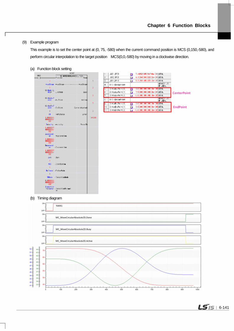
Chapter 6 Function Blocks
(9) Example program
This example is to set the center point at (0, 75, -580) when the current command position is MCS (0,150,-580), and
perform circular interpolation to the target position MCS(0,0,-580) by moving in a clockwise direction.
(a) Function block setting
CenterPoint
EndPoint
(b) Timing diagram
%MX1
MC_MoveCircularAbsolute2D.Busy
MC_MoveCircularAbsolute2D.Done
MC_MoveCircularAbsolute2D.Active
6-141

Chapter 6 Function Blocks
6.7.6 Coordinate system relative position circular interpolation operation
(MC_MoveCircularRelative2D)
Motion Function Block
MC_MoveCircularRelative2DDoneExecute
AxesGroup AxesGroupBOOLBOOL
UINT UINTUINT CircMode
LREAL[ ] AuxPointBusy BOOL
CommandAborted BOOLError BOOL
ErrorID WORD
LREAL[ ] EndPointActive BOOL
UINT PathChoiceLREAL VelocityLREAL AccelerationLREAL DecelerationLREAL Jerk
UINT BufferModeUINT TransitionMode
LREAL TransitionParameter
UINT CoordSystem
Input-Output
UINT AxesGroup Set the group to do relative position circular interpolation operation. (1 ~ 16: Group
1 ~ Group 16)
Input
BOOL Execute Give relative position circular interpolation operation command on the group in the
rising Edge.
UINT CircMode Circular interpolation method setting [0: Midpoint, 1: Central point, 2: Radius]
LREAL[ ] AuxPoint Specify the position of auxiliary point depending on the circular interpolation
method in a relative coordinate.
LREAL[ ] EndPoint Specify the end point of the circular trajectory as a relative coordinate from the start point.
BOOL PathChoice Set the circular path.
0: clockwise direction, 1: counter-clockwise direction
LREAL Velocity Set the maximum velocity of the path. [u/s]
LREAL Acceleration Set the maximum acceleration. [u/s2]
LREAL Deceleration Set the minimum decleration. [u/s2]
LREAL Jerk Set the maximum acc/dec jerk. [u/s3]
UINT CoordSystem Set the coordinate system’s type. (1:MCS 2:PCS)
UINT BufferMode the sequential operation of the motion function block.
6-142

Chapter 6 Function Blocks
(Refer to the chapter 6.1.4 BufferMode input)
UINT TransitionMode None
LREAL TransitionParameter None
Output
BOOL Done Indicate whether to reach the specified point.
BOOL Busy Indicate that the execution of motion function block is not completed.
BOOL Active Indicate that whether or not motion function block is controlling the group.
BOOL CommandAborted Indicate that the current motion function block is interrupted while it is running.
BOOL Error Indicate whether an error occurs or not.
WORD ErrorID Output the number of error occurred while motion function block is running. (1) This motion function block issues relative position circular interpolation command on the axes group designated by
AxesGroup input. (2) When this motion function block is executed, each axis performs circular interpolation control referring to the auxiliary
point input, and the direction is determined by Path Choice input. If PathChoiceinput is set to 0, circular interpolation is operated in a clockwise direction, and if it is set to 1, circular interpolation is operated in a counter-clockwise direction.
(3) At AuxPoint and EndPoint input, designate the arrangement of the relative position of auxiliary points to refer to for circular interpolation of each axis. The input arrangement and the axes of the group correspond to the designated axis IDs [ID1, ID2, ID3, ∙∙∙ ], in that order. (Since the number of axes comprising a group to issue circular interpolation command is 3, arrangements of three sizes should be input for the Position input.)
(4) In Velocity, Acceleration, Deceleration, Jerk inputs, the acceleration, deceleration, change rate of acceleration, velocity of the interpolation path are specified, respectively.
(5) CircMode input sets the circular interpolation method. The circular interpolation methods corresponding to CircMode values are as follows. (a) Circular Interpolation Using Midpoint Specification (BORDER, CircMode = 0)
This method is to perform the circular interpolation to the target position through the midpoint position after starting operation at the current position. In the figure below, the current position corresponds to the axes group coordinate at the start of the command, the midpoint corresponds to the coordinate input for the AuxPoint, and the target position corresponds to the relative coordinate input for the EndPoint.
StartPoint
X axis
Yaxis
EndPoint
AuxPoint
6-143

Chapter 6 Function Blocks
(b) Circular Interpolation Using Center Point Specification (CircMode = 1) This method is to perform the circular interpolation to the target position by starting operation at the start position, and following a circular trajectory of which diameter corresponds to the distance to the designated center point. In the figure below, the current position corresponds to the axes group coordinate at the start of the command, the center point corresponds to the coordinate input for the AuxPoint, and the target position corresponds to the relative coordinate input for the EndPoint.
EndPoint
AuxPoint
Start Point
X axis
Yaxis
(c) Circular Interpolation using Radius Speciation (CircMode = 2) This method is to perform the circular interpolation to the target position by starting operation at the current position, passing the designated center point, and reaching the target position. In the figure below, the current position corresponds to the axes group coordinate at the start of the command, the diameter corresponds to the X coordinate input for the AuxPoint, and the target position corresponds to the relative coordinate input for the EndPoint.
EndPoint
Radius(AuxPoint)
StartPoint
X axis
Yaxis
(6) Refer to chapter 8.4.7 circular interpolation control in motion control module’s manual for more details. (7) Example program
This example is to set the center point specification when the current command position is 1000, 1000 (set the relative position from the center point to set from the current position), and move clock-wise to perform circular interpolation to the target position (set the relative position to the target position from the current position: 0, 0).
6-144

Chapter 6 Function Blocks
(a) Function block setting
Center point
End point
(b) Timing diagram
%MX1
MC_MoveCircularRelative2D.Busy
MC_MoveCircularRelative2D.Done
MC_MoveCircularRelative2D.Active
6-145

Chapter 6 Function Blocks
6.7.7 Conveyor belt synchronized setting(MC_TrackConveyorBelt)
Motion Function Block
MC_TrackConveyorBeltDoneExecute
AxesGroup AxesGroupBOOLBOOL
UINT UINTUINT ConveyorAxis
ARRAY[0..6] OF LREAL[ ] ConveyorOriginBusy BOOL
Active BOOLError BOOL
ErrorID WORDARRAY[0..6] OF LREAL[ ] ObjectPosition
UINT CoordSystemUINT BufferMode
Input-Output
UINT AxesGroup Set the group to do conveyor belt synchronized setting.(1 ~ 16 : 1 group ~ 16
group)
Input
BOOL Execute Give the conveyor belt synchronized setting command on the axes group in the
rising Edge.
UINT ConveyorAixs Set the conveyor axis.(1 ~ 32 :1 Axis~32 Axis)
LREAL[] ConveyorOrigin Enter the position from the MCS home position to the conveyor origin point.
LREAL[] ObjectPosition Input the conveyor home position to the object to work on.
UINT CoordSystem Set the coordinate system type.( 2:PCS)
UINT BufferMode Set the sequential operation of the motion function block.
(Refer to the 6.1.4 BufferMode input)
Output
BOOL Done Indicate the PCS setting is successfully completed.
BOOL Busy Indicate that the execution of motion function block is not completed.
BOOL Active Indicate that machine information setting of the current axis is running.
BOOL Error Indicate whether an error occurs or not.
WORD ErrorID Output the number of error occurred while motion function block is running.
(1) This motion function block sets conveyor belt synchronized operation for the axes group designated by AxesGroup input.
(2) This motion function block is not directly involved in operation. When this function block is executed, the coordinate system operation using the PCS coordinate system is synchronized to the designated conveyor belt axis.
(3) ConveyorAxis can be set to between 1 and 32. An axis belonging to the axes group set as AxesGroup cannot be designated.
6-146

Chapter 6 Function Blocks
(4) The operation parameter of the axis designated as ConveyorAxis must be in mm/inch. (5) Infinite running repeat must be set for the operation parameter of the axis designated as ConveyorAxis. (6) Synchronized conveyor operation is terminated by performing coordinate system operation using the PCS coordinate
system or performing PCS setting with MC_SetCartesianTransform function block. (7) Refer to chapter 8.4.9 synchronized conveyor operation in motion control module’s manual for more details.
6-147

Chapter7 Program
7-1
Chapter7 Program
7.1 Structure of the Program
The program of the motion control module is divided into main task program, periodic task program and initialization task program. The features of each program in execution are as follows.
(1) Initialization task program: It is executed only once when motion control module enters the RUN.
(2) Main task program: It is executed in every main task cycle set in the motion control module. The main task cycle can be set in “main task period” of the basic parameters, and a period can be set through section among 1ms, 2ms, and 4ms. In case the execution time of main task program exceeds the set main task period, error occurs.
(3) Periodic task program: It is executed in every periodic task period set in the motion control module. The cycle of the periodic task can be set “periodic task period” of the basic parameters, and a multiple of the set main task period is to be set. The periodic task program is executed the remaining time after executing main task program by main task period in motion control module, and it is executed repeatedly in every periodic task period.
For information about the execution of main task program and periodic task program, refer to “4.3 motion control task”.

Chapter7 Program
7-2
7.2 Status Information Reading
In the program of motion control modules, each axis, status of axis group and operating status of the motion control module can be checked with the flag. Most of the program examples of chapter 7 is created using flags that indicate axis and status of axis group. Flags that indicate the status information can be used directly in the program, and can be delivered to PLC CPU by being assigned to a shared device of the motion control module. For more information on the types and functions of flags, refer to “5.1.1 flag”.
7.3 Discrete Motion Program
7.3.1 Preparation for operation
These are example programs that make access to servo drive connected with Ethernet cable and get the connected servo drive to be On to operate EtherCAT servo drive.

Chapter7 Program
7-3
(1) The above examples assume situation in which two axes of 1-axis and 2-axis are connected to the motion control module. (2) In case 1-axis and 2-axis are not connected when the motion control module enters the RUN, start the connection of EtherCAT
communication between motion control module and servo drive using motion function block for communication connection (LS_CONNECT).
(3) If the connection of EtherCAT communication between motion control modules and servo drives is normally performed, servo On/Off (MC_Power) command is issued to each axis by getting “SVON” contact to be On.
(4) In case there is no error in servo drive of the connected 1-axis and 2-axis, the servo is normally On, and it is ready to operate 1-axis and 2-axis.

Chapter7 Program
7-4
7.3.2 Homing operation
Homing is carried out to set the origin of the machine after the power is applied. Since homing is performed in the servo drive, homing methods may vary depending on servo drive manufacturers. In motion control module, the completion of homing command and error situation is monitored, and the position of the origin after homing is applied to control.
(1) Command condition : It is a condition to make the axis perform homing operation. (2) Axis connection state flag
: In case the axis to be operated is connected to motion control module, and EtherCAT communication with motion control module is normally performed, it is On.
(3) Axis error/Warning status flag : If there are errors and warnings in the axis, it is On. (4) Axis servo-on status flag : If the axis is in servo-on state, it is On, and servo-off state, it becomes Off.

Chapter7 Program
7-5
(5) Axis operation status flag : If the axis is in operation, it is On. (6) 1/2 axis homing command : In example programs, homing (MC_Home) motion function block is performed under the following conditions.
- Homing condition is On - The axis is normally connected - There should be no errors and warnings - Servo-on state - Not in operation
Conditions to perform motion function block may vary depending on systems. (7) Homing command input variables
: These are input variables to perform homing (MC_Home) motion function block. - Command-axis: It sets the axis in which motion function block is performed. - Position value after homing: It sets the position value when homing is completed. - Buffer mode: It sets the point of time when motion function block is executed. That is, it sets whether to execute
immediately or execute after the completion of commands which are currently being performed. For more details on Function Block execution mode, refer to “6.1.4 Buffer Mode input”.
(8) Homing command output variable : It is a variable to store output value generated when homing (MC_Home) motion function block is executed.
- Homing completed: If homing operation is completed, it is On. - Function Block in execution: If motion function block is being performed, it is On, and homing completion is On, it is Off. - Function Block axis control in operation: In case motion function block controls the axis, it is On. - Error occurrence state: In case error occurs while motion function block is being executed, it is On. - Error number: In case error occurs, the number that corresponds to error is generated. - For more details on the output of motion function block, refer to “Edge operation motion function block” of “6.1.3 basic I/O variable”.

Chapter7 Program
7-6
7.3.3 Absolute Position/Relative Position Operation
It is a program for absolute position and relative position operation using motion control module. The absolute positon is based on the origin and, and relative position the current position.

Chapter7 Program
7-7
(1) Command condition : It is a condition to make the axis perform position control operation.
(2) Axis connection state flag : If the axis to be operated is connected to motion control module, and EtherCAT communication with motion control module is
normally performed, it is On. (3) Axis error/Warning status flag
: If there are errors and warnings in the axis, it is On. (4) Axis servo-on status flag
: If the axis is in servo-on state, it is On, and servo-off state, it becomes Off. (5) Axis operation status flag
: If the axis is in operation, it is On. (6) 1-axis absolute position operation / 2-axis relative position operation commands
: In example programs, absolute position operation (MC_MoveAbsolute) is performed in 1-axis, and relative position operation (MC_MoveRelative) in 2-aixs under the following conditions. - The axis operation condition is On. - The axis is normally connected. - There should be no errors and warnings. - Servo-on state - Not in operation.
Conditions to perform motion function block may vary depending on systems. (7) Relative position operation command input variables
: These are input variables to perform relative position operation (MC_MoveRelative) motion function block. - Command-axis: It sets the axis in which motion function block is performed. - Changes in parameters during operation: It sets whether to apply to the operation by changing the input variables of motion
function block. For more information, refer to “6.1.5 Changes in parameters during execution of motion function block”.
- Operating distance: It sets distance to perform relative coordinate operation. Based on the current position, + value means forward direction, and – value means reverse direction value.
- Operating velocity: It sets velocity to perform relative coordinate operation. - Operating acceleration, operating deceleration, operating jerk: It sets values to be applied in relative coordinate operation
respectively. - Buffer mode: It sets the point of time when motion function block is executed. That is, it sets whether to execute immediately or execute after the completion of commands which are currently being performed. For more details, refer to “6.1.4 Buffer Mode input”.
(8) Absolute position operation command input variables : These are input variables to perform absolute position operation (MC_MoveAbsolute) motion function block. - Command-axis: It sets the axis in which motion function block is performed. - Changes in parameters during operation: It sets whether to apply to the operation by changing the input variables of motion function block. For more information, “6.1.5 Changes in parameters during execution of motion function block”.
- Target position: It sets the position that moves to absolute coordinate operation. - Operating velocity: It sets the velocity when absolute position operation is performed to the target position. - Operating acceleration, operating deceleration, operating jerk: It sets values to be applied in absolute coordinate operation respectively. - Operating direction: It sets direction when moving to the target position. In case of 1, movement to the target position is made
through forward direction operation, in case of 2, operation is made in the direction that can reach the target area in the shortest distance based on the current position, in case of 3, reverse direction, and in case of 4, movement to the target position is made through operation in the direction of the current operation.

Chapter7 Program
7-8
- Buffer mode: It sets the point of time when motion function block is executed. That is, it sets whether to execute immediately or execute after the completion of commands which are currently being performed. For more details, refer to “6.1.4 Buffer Mode input”.
(9) Absolute position operation command output variable : It is a variable to store output values generated when absolute position operation (MC_MoveAbsolute) motion function block
is executed. - Operation completed: When absolute coordinate operation is completed, it is On. - Function Block in execution: When motion function block is executed, it is On, and if operation completed is On, it is Off. - Function Block axis control in operation: In case motion function block is controlling the axis, it is On. - Error occurrence state: In case error occurs when motion function block is executed, it is On. - Error number: In case error occurs, the number that corresponds to error is generated. - For more details on the output of motion function, refer to “Edge operation motion function block” of “6.1.3 basic input and
output variables”.

Chapter7 Program
7-9
7.3.4 Speed/Torque Control Operation
These are example programs for speed control and torque control operation using motion control modules. In case of the torque control, torque control of servo drive is used, and in motion control module, command for executing torque control is issued, and execution completion and status is monitored.

Chapter7 Program
7-10
(1) Command condition : It is a condition to make the axis perform speed control/torque control operations. (2) Axis connection state flag : In case the axis to be operated is connected to motion control module, and EtherCAT communication with motion control
module is normally performed, it is On. (3) Axis error/Warning status flag : If there are errors and warnings in the axis, it is On. (4) Axis servo-on status flag : If the axis is in servo-on state, it is On, and servo-off state, it becomes Off. (5) Axis operation status flag : If the axis is in operation, it is On. (6) 1-axis speed control operation/ 2-axis torque control operation commands : In example programs, specified velocity operation (MC_MoveVelocity) motion function block is executed in 1-axis, and toque
control operation (MC_TorqueControl) motion function block is executed in 2-axis under the following conditions. - The axis operation condition is On. - The axis is normally connected. - There should be no errors and warnings. - Servo-on state - Not in operation Conditions to perform motion function block may vary depending on systems.
(7) Torque control operation command input variables : These are input variables to execute torque control operation (MC_TorqueControl) motion function block. - Command axis: It sets the axis in which motion function block is executed. - Changes in parameters during operation: It sets whether to apply to the operation by changing input variable values of the motion function block. For details, refer to “6.1.5 Changes in parameters during the execution of motion function block”.
- Operation torque: It sets torque values in torque control operation. - The maximum time to reach operation torque: It sets the maximum slope from the current torque until changed to the set torque. Its unit is [Unit/s].
-Maximum speed, maximum acceleration, maximum deceleration, maximum jerk: It sets values to be applied to respective torque control operation.
- Operating direction: It sets direction to be operated with torque control. In case of 1, it operates in forward direction, in case of 3, in reverse direction, and in case of 4, it operates in current operation direction.
- Buffer mode: It sets the point of time when motion function block is executed. That is, it sets whether to execute immediately or execute after the completion of commands which are currently being performed. For details, refer to “6.1.4 Buffer Mode input”.
(8) Speed control operation command input variables : These are input variables to execute specified velocity operation (MC_MoveVelocity) motion function block. - Command axis: It sets the axis in which motion function block is executed. - Changes in parameters during operation: It sets whether to apply to the operation by changing input variable values of the
motion function block. For details, refer to “6.1.5 Changes in parameters during execution of motion function block”. - Operating velocity: It sets velocity in speed control operation. - Operating acceleration, operating deceleration, operating jerk: It sets values to be applied in speed control operation respectively. - Operating direction: It sets directions in speed control operation. In case of 1, it operates in forward direction, in case of 3, in
reverse direction, and in case of 4, it operates in direction of the current operation. - Buffer mode: It sets the point of time when motion function block is executed. That is, it sets whether to execute immediately
or execute after the completion of commands which are currently being performed. For details, refer to “6.1.4 Buffer Mode input”.

Chapter7 Program
7-11
(9) Speed control operation command output variable : It is a variable to store output values generated when specified velocity operation (MC_MoveVelocity) motion function block is
executed. - Reaching the set speed completed: When the set speed is reached through speed control operation, it is On. - Function Block in execution: If motion function block is being performed, it is On, and operation is completed, it becomes Off. - Function Block axis control in operation: In case motion function block controls the axis, it is On. - Error occurrence state: In case error occurs while the motion function block is being executed, it is On. - Error number: In case error occurs, the number that corresponds to error is generated. - For more details on the output of function block, refer to “Edge operation motion function block” of “6.1.3 Basic input and
output variables”.

Chapter7 Program
7-12
7.3.5 Axis Stop It is an example program to stop the axis in operation. The motion function block to stop the axis in operation includes “Immediate
Stop (MC_Stop)” and “Halt (MC_Halt)”. As a command to implement emergency stop of the axis, “Immediate Stop (MC_Stop)” performs “Immediate Stop (MC_Stop)”, and other motion function blocks cannot be executed during the stop. As a command to stop the axis, “Halt (MC_Halt)” performs “Halt (MC_Halt)”, the stop status is aborted by other motion function blocks during the stop, and other motion function blocks can be executed. For more details, refer to “Chapter 6 Command”.

Chapter7 Program
7-13
(1) Command condition : It is a condition to give emergency stop/axis stop commands to the axis. (2) Axis connection state flag : In case the axis to be operated is connected to motion control module, and EtherCAT communication with motion control
module is normally performed, it is On. (3) Axis error/warning status flag : If there are errors and warning in the axis, it is On. (4) Axis operation status flag : If the axis is in operation, it is On. (5) 1-axis emergency stop / 2-axis axis stop commands : In example programs, immediate stop (MC_Stop) motion function block is executed in 1-axis, and halt (MC_Halt) motion
function block is executed in 2-axis under the following conditions. - The axis stop condition is On. - The axis is normally connected. - There should be no errors and warnings. - In operation Conditions to perform motion function block may vary depending on systems.
(6) Axis stop command input variables : These are input variables to execute Halt (MC_Halt) motion function block. - Command axis: It sets the axis in which motion function block is executed. - Stop deceleration: Its sets deceleration from operating speed at the time of axis stop to a stop. - Stop jerk: it sets the jerk at the stop time. - Buffer mode: It sets the point of time when motion function block is executed. That is, it sets whether to execute immediately
or execute after the completion of commands which are currently being performed. For details, refer to “6.1.4 Buffer Mode input”. (7) Emergency stop command output variables
: It is a variable to store output values generated when Immediate Stop (MC_Stop) motion function block is executed. - Execution completed: In case the axis stop, it is On. - Function Block in execution: If motion function block is being performed, it is On, and execution is completed, it becomes Off. - Error occurrence state: In case error occurs while the motion function block is being executed, it is On. - Error number: In case error occurs, the number that corresponds to error is generated. - For more details on the output of motion function block, refer to “Edge operation motion function block” of “6.1.3 Basic I/O
Variable.

Chapter7 Program
7-14
7.3.6 Error Processing
It is an example program to check the errors that occurred on the axis and conduct error reset.

Chapter7 Program
7-15
(1) Command condition : It is a condition to give error reset commands to the axis. (2) Axis connection status flag : In case the axis to be operated is connected to motion control module, and EtherCAT communication with motion control
module is normally performed, it is On. (3) Axis error/Warning status flag : If there are errors and warnings in the axis, it is On.
(4) Comparison of axis error number : In example programs, a case where the value of error number flag on the axis is not 0 is determined to be error reset condition
through a comparison. (5) Error reset command : In example programs, axis error reset (MC_Reset) motion function block is executed under the following conditions.
- The axis operation condition is On. - The axis is normally connected. - There should be error and warnings. - Error number is not 0. Conditions to perform motion function block may vary depending on systems.
(6) Error reset command input variables : These are input variables to execute axis error reset (MC_Reset) motion function block. - Command axis: It sets the axis in which motion function block is executed. - Error type: The type of error for error rest is set. 0 represents axis error, and 1 common error.
(7) Error reset command output variables : It is a variable to store output values generated when axis error reset (MC_Reset) motion function block is executed.
- Execution completed: The execution of motion function block is completed, it is On. - Function Block in execution: If motion function block is being performed, it is On, and execution is completed, it becomes Off. - Error occurrence state: In case error occurs while the motion function block is being executed, it is On. - Error number: In case error occurs, the number that corresponds to error is generated. - For details on the output of motion function block, refer to “Edge operation motion function block” of “6.1.3 Basic I/O Variable”.

Chapter7 Program
7-16
7.3.7 Change in Operation
It is an example program to change the current location of the axis and speed in operation.

Chapter7 Program
7-17
(1) Command condition : It is a condition to give current location change/operating speed change commands to the axis. (2) Axis connection state flag : In case the axis is to be operated is connected to motion control module, and EtherCAT communication with motion control
module is normally performed, it is On. (3) Axis error/Warning status flag : If there are errors and warnings in the axis, it is On. (4) Axis operation status flag : If the axis is in operation, it is On. (5) 1-axis current location change/2-axis speed override command : In the example program, the current location setting (MC_SetPosition) motion function block is executed under the following
conditions. - The current location change condition is On. - The axis is normally connected. - There should be no errors and warnings. - The axis is not in operation. In addition, speed/acceleration override (MC_SetOverride) motion function block is executed under the following conditions. - The operating speed change condition is On. - The axis is normally connected. - There should be no errors and warnings. - The axis is in operation. Conditions to execute motion function block may vary depending on systems.
(6) Speed override command input variables : These are input variables to execute speed/acceleration override (MC_SetOverride) motion function block. - Command axis: It set the axis in which motion function block is executed. - Speed override ratio: It sets the ratio of the speed to change in comparison with operating speed that is currently set. - Acceleration override ratio: It sets the ratio of the acceleration to change in comparison with acceleration value which is currently set.
- Jerk override ratio: It sets the ratio of the jerk to change in comparison with jerk value that is currently set. That is, if 2 is set to the value of the ratio, double the currently set value is set.
(7) Current location change command output variables : These are variables to store output values generated when the current location setting (MC_SetPosition) motion function
block is executed. - Execution completed: If the execution of motion function block is completed, it is On. - Function Block in execution: When motion function block is executed, it is On, and the execution is completed, It becomes Off. - Error occurrence state: In case error occurs while the motion function block is being executed, it is O. - Error number: In case error occurs, the number that corresponds to error is generated. - For details on the output of motion function block, refer to “Edge operation motion function block” of “6.1.3 Basic input and
output variables.

Chapter7 Program
7-18
7.3.8 Parameter Write/Read
Parameter read/write commands include “Parameter Write (MC_WriteParameter)” and Parameter Read (MC_ReadParameter)” as well as “Servo Parameter Write (LS_WriteServoParameter)” and “Servo Parameter Read (LS_ReadServoParameter)”. “Parameter Write (MC_WriteParameter)” and “Parameter Read (MC_ReadParameter)” are commands to read or write operation parameters of the axis, and “Servo Parameter Write (LS_WriteServoParameter)” and “Servo Parameter Read (LS_ReadServoParameter)” are commands to read or write parameters of the connected servo drive. The following shows examples of programs to read or change operation parameters and servo parameters using parameter read/write commands.
Parameter Read
(1) Command condition : It is a condition to read parameters and serve parameters of the axes. (2) Axis connection state flag : In case the axis to be operated is connected to motion control module, and EtherCAT communication with motion control
module is normally performed, it is On.

Chapter7 Program
7-19
(3) Axis error/Warning status flag : If there are errors and warnings in the axis, it is On. (4) Axis operation status flag : If the axis is in operation, it is On. (5) 1-axis parameter write/ 2-axis servo parameter read commands : In example programs, Parameter Read (MC_ReadParameter) motion function block is executed in 1-axis, and Servo
Parameter Read (LS_ReadServoParameter) motion function block is executed in 2-axis under the following conditions. - Parameter read condition is On. - The axis is normally connected. - There should be no errors and warnings. - Not in operation Conditions to execute motion function block may vary depending on systems.
(6) Parameter read command input variables : These input variables to execute Parameter Read (MC_ReadParameter) motion function block. - Command axis: It sets the axis in which motion function block is executed. - Parameter number: It sets the parameter numbers to read with motion function block.
Numbers by parameter are as follows. Number Parameter Item Settings
0
Basic Parameter
Unit 0:pulse, 1:mm, 2:inch, 3:degree
1 Pulses per rotation [pulse]
2 Travel per rotation [Unit]
3 Speed command unit 0:Unit/Time, 1:rpm
4 Speed limit [Unit/s, rpm]
5 Emergency stop deceleration [Unit/s2]
6 Encoder select 0:Incremental Encoder,1:Absolute Encoder
7 Gear ratio(Motor) 8 Gear ratio(Machine) 9 Operation mode of the reverse rotation 0:Disable, 1:Enaable
10
Extended Parameter
S/W upper limit [Unit]
11 S/W lower limit [Unit]
12 Infinite running repeat position [Unit]
13 Infinite running repeat 0:Disable, 1:Enable
14 Command inposition range [Unit]
15 Tracking error over-range value [Unit]
16 Current position compensation amount 17 Current speed filter time constant 18 Error reset monitoring time [ms]
19 S/W limit during speed control 0:Don’t detect, 1:Detect
20 Tracking error level 0:Warning, 1:Alarm
21 JOG high speed [Unit/s]
22 JOG low speed [Unit/s]
23 JOG Acceleration [Unit/s2]
24 JOG Deceleration [Unit/s2]
25 JOG Jerk [Unit/s3]

Chapter7 Program
7-20
(7) Servo parameter read command read input variables : These are input variables to execute Servo Parameter Read (LS_ReadServoParameter) motion function block.
- Command axis: It sets the axis in which motion function block is executed. - Servo parameter index number, SubIndex number, size: Each value is set in servo parameters to read. Refer to the instruction manual of the servo drive for index number, subindex number and size of servo parameters.
(8) Parameter read/Servo parameter read command output variables : These are variables to store output values generated when Parameter Read (MC_ReadParameter) and Servo Parameter
Read (LS_ReadServoParameter) motion function block is executed. - Operation completed: If values of parameters and servo parameters is read, it is On. - Function Block in execution: When motion function block is executed, it is On, and the operation completion is On, it
becomes Off. - Error occurrence state: In case error occurs while the motion function block is being executed, it is On. - Error number: In case error occurs, the number that corresponds to error is generated. - Read parameter values/Read servo parameter values: Values of parameters and servo parameters read by the execution of motion function block is stored.
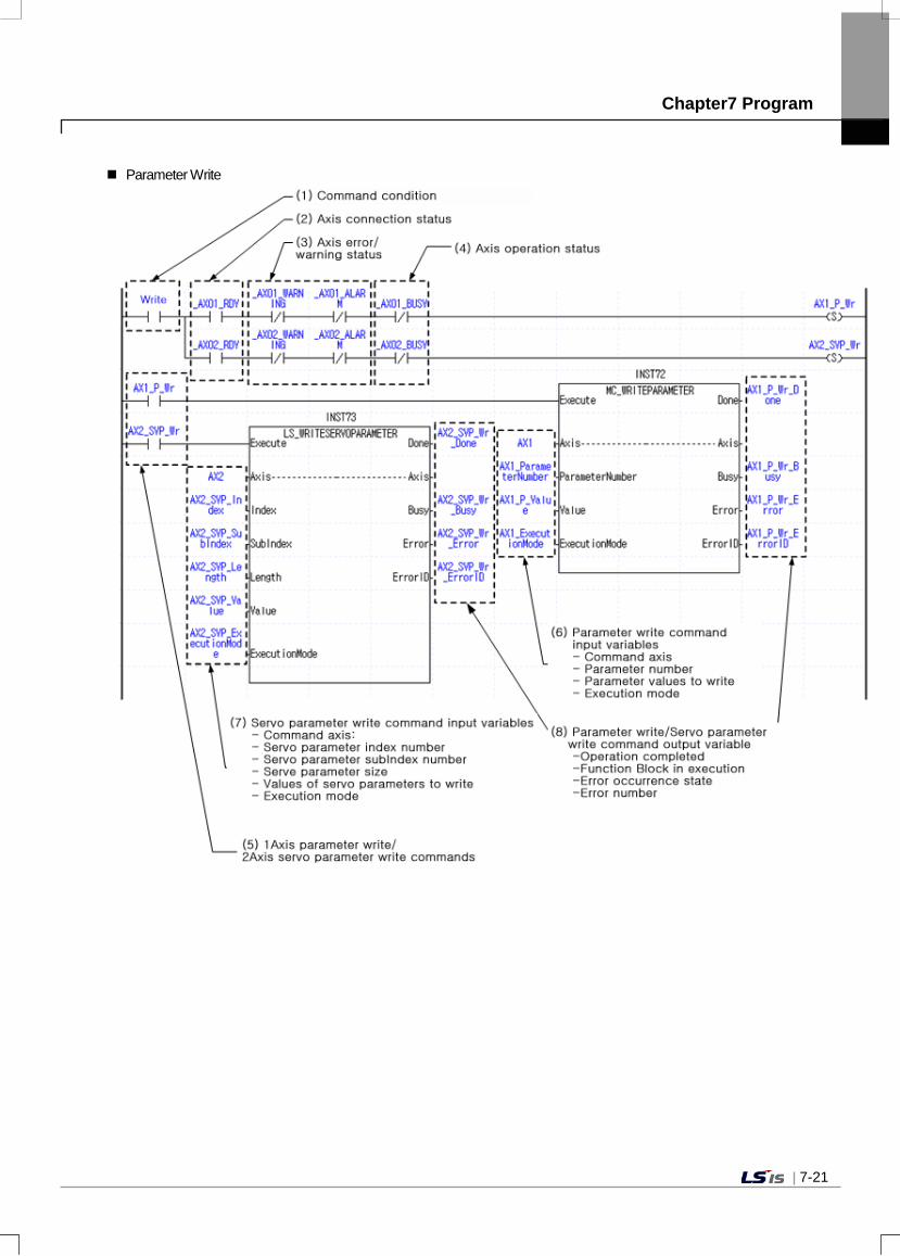
Chapter7 Program
7-21
Parameter Write

Chapter7 Program
7-22
(1) Command condition : It is a condition to write parameters and servo parameters of the axes. (2) Axis connection state flag : In case the axis to be operated is connected to motion control module, and EtherCAT communication with motion control
module is normally performed, it is On. (3) Axis error/Warning status flag : If there are errors and warnings in the axis, it is On. (4) Axis operation status flag : If the axis is in operation, it is On. (5) 1-axis parameter write/ 2-axis servo parameter write commands : In example programs, Parameter Write (MC_WriteParameter) motion function block is executed in 1-axis, and Servo
Parameter Write (LS_WriteServoParameter) motion function block is executed in 2-axis under the following conditions. - Parameter write condition is On - The axis is normally connected. - There should be no errors and warnings. - Not in operation Conditions to execute function block may vary depending on systems.
(6) Parameter write command input variables : These are input variables to execute Parameter Write (MC_WriteParameter) motion function block. - Command axis: It sets the axis in which motion function block is executed. - Parameter number: It set parameter numbers to write with the motion function block. - Parameter values to write: Values to write in the parameters are set. - Execution mode: It specifies the point of time when parameters are written. If it sets 0, it changes parameter values upon
executing motion function block. If it sets 1, it is changed to the same point of time with “Buffered” of BufferMode. (Refer to 6.1.4 BufferMode)
(7) Servo parameter write command input variables : These are input variables to execute Servo Parameter Write (LS_WriteServoParameter) motion function block. - Command axis: It sets the axis in which motion function block is executed. - Servo parameter index number, subIndex number, size: Each value is set according to servo parameters to write. Refer to
instruction manual of the servo drive for index number, subindex number and size of servo parameters.
- Values of servo parameters to write: Values to be written in the servo parameters is set. - Execution mode: it certifies the point of time when parameters are written. It is sets 0, it changes parameter values upon
executing motion function block. If it sets 1, it is changed to the same point o time with ‘Buffered’ of BufferMode. (Refer to 6.1.4 BufferMode)
(8) Parameter write/Servo parameter write command output variable : It is a variable to store output values generated when Parameter Write (MC_WriteParameter) and Servo Parameter Write (LS_WriteServoParameter) motion function block is executed. - Operation completed: If values of the parameters and servo parameters are written, it is On. - Function Block in execution: When motion function block is executed, it is On, and operation completion is On, it becomes Off. - Error occurrence state: In case error occurs while motion function block is being executed, it is On. As for error number, the
number that corresponds to error is generated in case error occurs.

Chapter7 Program
7-23
7.4 Multi-Axis Operation Program
7.4.1 Linear Interpolation Operation
It is an example program to operate linear interpolation with axes set to the same group. In the example program, 1-axis and 2-axis are assumed to be included in the same axis group. Refer to the example program of “7.4.5 Axis group processing” to include an axis in axis group or remove the axis from axis group.

Chapter7 Program
7-24
(1) Command condition : It is a condition to give linear interpolation command to the axis group.
(2) Axis group connection state flag : In case axes of the axis group to be operated are connected to motion control module, and EtherCAT communication with
motion control module is normally performed, it is On. (3) Axis group error/Warning status flag
: If there are errors and warnings in axes included in the axis group, it is On. (4) Axis group servo-on status
: If axes included in the axis group are in servo-on state, it is On. (5) Axis group operation status flag
: If axes of the axis group are in operation, it is On. (6) Axis group 1 absolute position linear interpolation/Axis group 2 relative position linear interpolation commands
: In example programs, absolute position linear interpolation operation (MC_MoveLinearAbsolute) is executed in axis group 1, and relative position linear interpolation operation (MC_MoveLinearRelative) motion function block in axis 2 under the following conditions. - Linear interpolation operation condition is On. - Axes included in the axis group are normally connected. - There should be no errors and warnings. - Axes of the axis group are not in operation. Conditions to execute motion function block may vary depending on systems.
(7) Linear interpolation command input variables : These are input variables to execute absolute position linear interpolation operation (MC_MoveLinearAbsolute) and relative
position linear interpolation operation (MC_MoveLinearRelative) motion function block. - Command axis group: It sets axis group in which motion function block is executed. - Target position by axis: Array variables are set, and linear interpolation operation target position of axes included in axis group is set in order.
- Linear interpolation speed: It sets target speed to execute linear interpolation, when the speed refers to the interpolation speed.
- Linear interpolation acceleration, deceleration, jerk: they set values to be applied when performing linear interpolation. - Buffer mode: It sets the point of time when motion function block is executed. That is, it sets whether to execute immediately or execute after the completion of commands which are currently being performed. For details, refer to “6.1.4 Buffer Mode Input”. - Group operation route change mode and group operation route change parameter: It specifies in which way the axis group in operation is connected to the trace the existing commands describe when linear interpolation command is given. Refer to “6.1.6 Group operation route change settings”.
(8) Linear interpolation command output variable : It is a variable to store output values generated when absolute position linear interpolation operation
(MC_MoveLinearAbsolute) and relative position linear interpolation operation (MC_MoveLinearRelative) motion function block is executed.
- Execution completed: When the execution of function block is completed, it is On. - Function Block in execution: When motion function block is executed, it is On, and the execution is completed, it becomes Off. - Error occurrence state: In case error occurs as the motion function block is executed, it is On. - Error number: In case error occurs, the number that corresponds to error is generated. - For details on the output of motion function block, refer to “Edge operation motion function block” of “6.1.3 Basic I/O Variable”.

Chapter7 Program
7-25
7.4.2 Circular Interpolation Operation
It is an example program to operate circular interpolation operation with axes set to the same group. In the example program, 1-axis and 2-axis are assumed to be included in the same axis group. Refer to “7.4.5 Axis group processing” to include an axis in axis group or remove axis from axis group.

Chapter7 Program
7-26
(1) Command condition : It is a condition to give circular interpolation command to the axis group.
(2) Axis group connection state flag : In case axes of the axis group to be operated is connected to motion control module, and EtherCAT communication with
motion control module is normally performed, it is On. (3) Axis group error/Warning status flag
: If there are errors and warnings in axes included in the axis group, it is On. (4) Axis group servo-on status
: If axes included in the axis group are in servo-on state, it is On. (5) Axis group operation status flag
: If axes of the axis group are in operation, it is On. (6) Axis group 1 absolute position circular interpolation/Axis group 2 relative position circular interpolation commands
: In example programs, absolute position circular interpolation operation (MC_MoveCircularAbsolute) is executed in axis group 1, and relative position circular interpolation operation (MC_MoveCircularRelative) motion function block in axis 2 under the following conditions. - Circular interpolation operation condition is On. - Axes included in the axis group are normally connected. - There should be no errors and warnings. - Axes of the axis group are not in operation.
Conditions to execute motion function block may vary depending on systems. (7) Circular interpolation command input variables
: These are input variables to execute absolute position circular interpolation operation (MC_MoveCircularAbsolute) and relative position circular interpolation operation (MC_MoveCircularRelative) motion function block. - Command axis group: It sets axis group in which motion function block is to be executed. - Target position by axis: Array variables are set, and linear interpolation operation target position of axes included in axis group is set in order.
- Circular interpolation method: It sets a method to execute circular interpolation through selection among mid-point method, center point method and radius method.
- Axis-specific circular interpolation auxiliary point: It takes a form of array and sets auxiliary point required for circular interpolation in the order of axes included in axis group.
- Axis-specific circular interpolation target point: It takes a form of array and sets target position in the order of axes included in axis group.
- Circular interpolation velocity: It sets target speed to execute circular interpolation, when the speed refers to interpolation speed.
- Circular interpolation acceleration, deceleration, jerk: Values to be applied when circular interpolation is performed are set. - Buffer mode: It sets the point of time when motion function block is executed. That is, it set whether to execute immediately or execute after the completion of commands which are currently being performed. For details, refer to “6.1.4 Buffer Mode Input”.
(8) Circular interpolation command output variable : It is a variable to store output values generated when absolute position circular interpolation operation
(MC_MoveCircularAbsolute) and relative position circular interpolation operation (MC_MoveCircularRelative) motion function block is executed. - Execution completed: When the execution of motion function block is completed, it is On. - Function Block in execution: When motion function block is executed, it is On, and the execution is completed, it becomes Off. - The axis group being controlled by function block: When motion function block controls the axis group, it is On. - Error occurrence state: In case error occurs as the motion function block is executed, it is On. - Error number: In case error occurs, the number that corresponds to error is generated. - For details on the output of motion function block, refer to “Edge motion commands” of “6.1.3 Basic I/O Variable”.

Chapter7 Program
7-27
7.4.3 Synchronous Operation
It is an example program on the synchronous operation in which serve axis moves in synchronization ratio set in the main axis.

Chapter7 Program
7-28
(1) Command condition : It is a condition to give synchronous operation/synchronous operation cancellation commands to the axis.
(2) Axis connection state flag : When axis to be operated is connected to motion control module, and EtherCAT communication with motion control module is
normally performed, it is On. (3) Axis error/Warning state flag
: If there are errors and warning in the axis, it is On. (4) Axis operation status flag
: If the axis is in operation, it is On. (5) 2Axis synchronous operation/Synchronous operation cancellation commands
: In the example program, electronic gear operation (MC_GearIn) motion function block is executed under the following conditions.
- Synchronous operation condition is On. - The axis and main axis is normally connected. - There should be no errors and warnings. - The axis is not in operation. In addition, electronic gear cancellation (MC_GearOut) motion function block is executed under the following conditions. - Synchronous operation cancellation condition is On. - The axis is normally connected. - There should be no errors and warnings. - The axis is in operation. Conditions to execute motion function block may vary depending on systems.
(6) Synchronous command input variables : These are input variables to execute electronic gear operation (MC_GearIn) motion function block. - Main axis: It sets serve axis of synchronous operation. - Serve axis: It sets the axis in which synchronous operation is to be performed. - Changes in parameters during operation: It sets whether to apply to the operation by changing input variable values of the function block. For details, refer to “6.1.5 Changes in parameters during execution of motion function block”.
- Synchronization ratio numerator: It sets numerator value among synchronization ratio to be operated by synchronization of the operation of main axis.
- Synchronization ratio denominator: It sets denominator among synchronization ratio to be operated by synchronization of the operation of main axis.
- The speed of serve axis in a state of gear operation (InGear) is set as follows.
Serve axis speed = Main axis speed x (Synchronization ratio numerator/Synchronization denominator)
- Main axis data selection: It selects whether the data of main axis is set to command speed or current speed. In case command speed is set, synchronization is achieved based on the speed of main axis calculated in motion control module. In case current speed is set, synchronization is achieved by using speed data of main axis servo drive transmitted through the communication.
- Acceleration, deceleration, jerk: Each value is set in synchronous operation. - Buffer mode: It sets the point of time when motion function block is executed. That is, it sets whether to execute immediately or execute after the completion of commands which are currently being performed. For details, refer to “6.1.4 Buffer Mode Input”.

Chapter7 Program
7-29
(7) Synchronous operation command output variable : It is a variable to store output values generated when electronic gear operation (MC_GearIn) motion function block is
executed. - Synchronous operation: When serve axis is normally synchronized in main axis after the execution of motion function block, it
is On. - Function Block in execution: When motion function block is executed, it is On, and the execution is completed, it becomes Off. - The axis group being controlled by function block: When motion function block controls the axis group, it is On. - Error occurrence state: In case error occurs as the motion function block is executed, it is On. - Error number: In case error occurs, the number that corresponds to error is generated. - For details on the output of motion function block, refer to “Edge motion commands” of “6.1.3 Basic I/O Variable”.

Chapter7 Program
7-30
7.4.4 CAM Operation
It is an example program on the cam operation that moves in synchronization based on cam (CAM) profile in which serve axis is set.

Chapter7 Program
7-31
(1) Command condition : It is a condition to give cam operation/cam operation cancellation commands to the axis.
(2) Axis connection state flag : When the axis to be operated is connected to motion control module, and EtherCAT communication with motion control
module is normally performed, it is On. (3) Axis error/Warning status flag
: If there are errors and warnings in the axis, it is On. (4) Axis operation status flag: If the axis is in operation, it is On.
(5) 2-axis cam operation/Cam operation cancellation commands : In the example program, cam operation (MC_CamIn) motion function block is executed under the following conditions.
- Cam operation condition is On. - The axis and main axis are normally connected. - There should be no errors and warnings. - The axis is not in operation. In addition, cam operation cancellation (MC_CamOut) motion function block is executed under the following conditions. - Cam operation cancellation condition is On. - The axis is normally connected. - There should be no errors and warnings. - The axis is in operation. Conditions to execute motion function block may vary depending on systems.
(6) Cam operation command input variables : These are input variables to execute cam operation (MC_CamIn) motion function block. - Main axis: It sets main axis of cam operation. - Serve axis: It sets the axis in which cam operation is executed. - Changes in parameters during operation: It sets whether to apply to the operation by changing input variable values of the function block. For details, refer to “6.1.5 Changes in parameters during execution of motion function block”.
- Main axis offset: It sets offset values of main axis data to be used when cam table data is applied. - Serve axis offset: It sets offset values of serve axis data to be used when cam table data is applied. - Main axis magnification: It sets magnification of main axis data to be used when cam table data is applied. - Serve axis magnification: It sets magnification of serve axis data to be used when cam table data is applied. - Cam operation starting point: It sets the position of main axis which will be the starting point of cam table. - Distance of main axis for starting cam operation: It sets the distance of main axis in which actual cam operation starts. - Main axis data selection for cam operation: It selects main axis data which will be a basis of cam operation among main axis command position and main axis current position. - Cam table number: It sets cam data number to conduct cam operation. - For details on cam operation command input variables, refer to “6.4.1 Cam operation (MC_CamIn)”. - Changes in parameters during operation: It sets whether to apply to the operation by changing input variable values of the
function block. For details, refer to “6.1.5 Changes in parameters during execution of motion function block”. - Buffer mode: It sets the point of time when motion function block is executed. That is, it sets whether to execute immediately
or execute after the completion of commands which are currently being performed. For details, refer to “6.1.4 Buffer Mode Input”.
(7) Cam operation command output variable : It is a variable to store output values generated when cam operation (MC_CamIn) motion function block is executed. - Cam operation: It is on when serve axis is synchronized in main axis according to cam data after the execution of motion function block.
- Function Block in execution: When motion function block is executed, it is On, and the execution is completed, it becomes Off. - Function Block axis control in operation: In case motion function block controls the axis, it is On. - Error occurrence state: In case error occurs as the motion function block is executed, it is On. - Error number: In case error occurs, the number that corresponds to error is generated. - For details on the output of motion function block, refer to “Edge motion commands” of “6.1.3 Basic I/O Variable”.

Chapter7 Program
7-32
7.4.5 Axis Group Processing

Chapter7 Program
7-33
(1) Command condition : It is a condition to give add axis to group/remove axis from group commands to the axis.
(2) Axis connection status flag : In case the axis to be operated is connected to motion control module, and EtherCAT communication with motion control
module is normally performed, it is On. (3) Axis error/Warning status flag
: If there ae errors and warning in the axis, it is On. (4) Axis operation status flag
: If the axis is in operation, it is On. (5) 1-axis add axis to group/2-axis remove axis from group commands
: In the example program, add axis to group (MC_AddAxisToGroup) motion function block is executed under the following conditions. - Add axis to group condition is On. - The axis is normally connected. - There should be no errors and warnings. - The axis is not in operation. In addition, group axis exclusion (MC_RemoveAxisFromGroup) motion function block is executed under the following conditions. - Remove axis from group condition is On. - The axis is normally connected. - There should be no errors and warnings. - The axis is not in operation. Conditions to execute motion function block may vary depending on systems.
(6) Remove axis from group command input variables : These are variables to execute group axis exclusion (MC_RemoveAxisFromGroup) motion function block. - Axis group: It sets the group to exclude the axis. - The axis ID on axis group ID: It sets ID values granted when the axis is included in axis group.
(7) Add axis to group command output variable : It is a variable to store output values generated when add axis to group (MC_AddAxisToGroup) motion function block is executed. - Execution completed: When motion function block is normally executed, it is On. - Function Block in execution: When motion function block is executed, it is On, and the execution is completed, it becomes Off. - Error occurrence state: In case error occurs as the motion function block is executed, it is On. - Error number: In case error occurs, the number that corresponds to error is generated. - For details on the output of motion function block, refer to “Edge motion commands” of “6.1.3 Basic I/O Variable”.

Chapter7 Program
7-34
7.5 I/O Processing Program
Motion control module has the input of 8 points and output of 8 points internal, and it can expand input and output points using external EtherCAT input/output modules. EtherCAT input and EtherCAT output modules possible to be mounted on the outside can be expanded up to 4 stations and up to 256points.
7.5.1 Input Signal Processing Internal input signals and signals inputted in external input module can be used in the program using an internal flag of the motion control module.
For details on the kinds and functions of flags, refer to “5.1.1 Flag”.
7.5.2 Output Signal Processing
Internal output signals and signals inputted in external output module can be used in the program using an internal flag of the motion control module. For details on the kinds and functions of flags, refer to “5.1.1 Flag”.

Chapter8 Functions
Chapter8 Functions 8.1 Origin Determination
In case the position control function of motion control module is used, the origin must be determined first to execute commands based on the absolute coordinate position. The position value of absolute coordinates is the distance based on the predetermined origin(0 position). The origin determination means setting the origin of the machine for position control using absolute coordinates.
8.1.1 Origin Determinaton
1. Methods to determine the originThere are two methods to determine the origin of the machine as below.
(1) Homing It is a method to determine the origin of the machine by moving the machine using a sensor connected to servo drive with homing (MC_Home) motion function block. When homing command is executed, the origin determination becomes the origin indetermination status, and homing is successfully completed, it becomes the origin determination status.
(2) Current position setting After moving the machine to a certain position by using JOG operation (LS_Jog) or relative coordinate position control (MC_MoveRelative) motion function block, the position can be set to the specific position with the current position location setting (MC_Setposition) motion function block. In this case, the position is recognized as an absolute coordinate and becomes origin determination status. The origin determination status of axis can be identified with motion axis flag AXxx_HOME_CMOL (%JXxx.67) . (xx: axis numer)
2. Origin determination when using absolute encodersIn case of using absolute encoder in servo drive, absolute data value is maintained by battery backup even if the power is off. Motion control module can continue to maintain the origin determination status by reading the current position from the value of absolute encoder and calculating absolute coordinate position when it is connected to servo drive. To this end, the encoder selection of basic parameters among operating parameters should be set to ‘1: Absolute encoder’ in case of using absolute encoder. Even though the power of motion control module and servo drive is off after the establishment of origin determination status, the previous origin determination status is maintained by calculating absolute coordinate position when servo drive is connected in case encoder selection parameter is ‘1: Absolute encoder’ when the power is re-applied. In absolute coordinate system using absolute encoder as above, the absolute coordinate position can be controlled without the origin determination even after power off/on.
8-1

Chapter8 Functions
3. Change to the origin indetermination statusThe absolute position control operation cannot be performed since motion control module becomes the origin indetermination status in the following cases. (1) In case of re-connection after servo drive power off when using an incremental encoder. (2) In case of re-connection after PLC power off/on when using an incremental encoder. (3) In case homing is not normally completed after the execution of homing command. In case of the origin indetermination status as above, the origin determination should be executed for absolute coordinate position control operation.
8.1.2 Homing
1. OperationHoming is performed to establish the origin of the machine after the power is applied. Before performing the homing, parameters related to the homing of servo drive must be set in each axis. When the origin position is determined by homing, the origin detection signal is not recognized during the motion control operation. The contact performed at the time of homing is entered through connector of servo drive (EtherCAT CoE support servo drive). Typical wiring is as follows.
For the performance of homing, a method suitable for the system of users for homing operation mode (EtherCAT CoE support drives: Refer to instruction manual for the relevant drive) should be selected. In motion control module, actual operation after starting homing is performed in servo drive, and homing method to support complies with servo drive. Before setting the homing, homing-related parameters are to be set in servo parameters of the axis.
8-2

Chapter8 Functions
■ Example of setting homing parameters
Relevant motion function block
Name Description Operation Condition MC_Home Perform homing Edge
MC_Home
AxisAxisExecute Done
UINTUINTBOOL BOOL
LREAL PositionUINT BufferMode
Busy BOOLActive BOOL
CommandAborted BOOLError BOOL
ErrorID WORD
Name Description Operation Condition MC_GroupHome Perform group homing Edge
MC_GroupHomeDoneExecute
AxesGroup AxesGroupBOOLBOOL
UINT UINTLREAL[ ] Position
UINT BufferModeBusy BOOL
CommandAborted BOOLError BOOL
ErrorID WORD
Active BOOL
8-3

Chapter8 Functions
1. XDL- N Series servo drive homing parameters and operationThe following figure shows input and output definitions of homing-related XDL N series servo drive parameters. The velocity, acceleration and homing methods can be specified. Here, the origin (Home) offset gets the origin of user coordinate systemapplied as the origin.
(1) Parameter related to homing
Index Sub Name Data Type Unit
0x6040 - Controlword UINT -
0x6041 - Statusword UINT -
0x607C - Homing Offset DINT [pls]
0x6098 - Homing Method SINT -
0x6099 - Homing Speeds - -
0 Item Number USINT -
1 Speed during search for switch UDINT [pls/s]
2 Speed during search for zero UDINT [pls/s]
0x607D - Software Position Limit - -
0 Item Number USINT -
1 Min position limit DINT [pls]
2 Max position limit DINT [pls]
0x609A - Homing acceleration UDINT [pls/s2]
8-4

Chapter8 Functions
(2) Homing Method(0x6098) Value Description
0 No Homing 1, 2 (1) If NOT switch is Off, the initial movement direction becomes forward direction CW. If NOT switch is On, change
of direction is made. The location that meets the first index pulse during operation in reverse direction CCW after NOT switch is On becomes the Home position. (2) If POT switch is Off, the initial movement direction becomes reverse direction CCW. If POT switch is On, change of direction is made. The location that meets the first index pulse during operation in forward direction CW after POT switch is On becomes the Home position.
7~10 Through (7) to (10) methods, the origin position is determined by the Home switch and POT switch. (7) Upper figure: If POT switch is Off, operation is made at switch search velocity, and the initial movement direction
becomes reverse direction CCW. If the Home switch is On, change of direction is made. Afterwards, the location that meets the first index pulse during operation in forward direction CW becomes the Home position, and operation is made at Zero search velocity.
(7) Middle figure: If POT switch is Off, and the Home switch is On, operation is made at switch search velocity, and the initial movement direction becomes forward direction CW. If the Home switch is Off, the speed is changed to Zero search velocity. Afterwards, the location that meets the index pulse first during operation in forward direction CW becomes the Home position.
(7) Lower figure: If POT switch is Off, and the Home switch is On, operation is made at switch search speed, and the initial movement direction becomes reverse direction CCW. If POT switch is On, change of direction is made. When the Home switch is changed from On to Off, operation is made at Zero search velocity, and the location where that meets index pulse first during continuous operation in forward direction CW becomes the Home position.
(8) to (10) methods have the same positioning concept in homing with the above (7) method except for the initial operational direction and motions according to the Home switch polarity. Refer to the figure below.
8-5

Chapter8 Functions
Value Description 7~10
11~14 The methods described for 11 to 14 determines the Home position using the Home switch and the NOT switch. (11) Upper figure: If the NOT switch is Off, then the drive operates at switch search speed and rotates CW. If the Home switch is turned on at this time, it changes the direction of rotation, and the position that the first index pulse encounters while driving CCW at zero search speed becomes the Home position. (11) Middle figure: If the NOT switch is Off and the Home switch is On, then the drive operates at switch search speed and rotates CCW. If the Home switch is turned off at this time, it transfers to zero search speed. After the Home switch is turned off, the position that the frist index pulse encounters while driving in the CCW direction becomes the Home position. (11) Lower figure: If the NOT switch is Off, then the drive operates at switch search speed and rotates CW. If the NOT switch is turned on at this time, it changes the direction and continues to drive CCW at switch search speed. If the Home switch is changed from On to Off, then it transfers to zero search speed, and the position that the first index pulse encounters becomes the Home position. The methods from 12 to 14 are identical to the methods for 11 in terms of how they determine the Home position. The only differecnces are the initial driving direction and Home switch polarity. Refer to the following figure.
8-6

Chapter8 Functions
Value Description
24 (8) The Home position is determined as in (8) method, but index pulse is not used. In addition, the point where
the Home switch is On/Off becomes the Home position.
8-7

Chapter8 Functions
Value Description 28
(12) The Home position is determined as in (12) method, but index pulse is not used. In addition, the point where
the Home switch is On/Off becomes the Home position.
33, 34 The location that meets index pulse first during movement in the reverse direction CCW/forward direction CW becomes the Home position.
35 Homing operation starting point becomes the Home position. Note) ▬ : Speed during search for switch (0x6099:01), → : Speed during search for zero (0x6099:02)
8-8

Chapter8 Functions
8.2 Type of Control Operation
Motion control modules execute control through programs set in motion control program. Kinds of motion control operations include speed position control, speed velocity control, speed torque control, interpolation control, switching control between position/velocity, switching control between position/torque, and switching control between velocity/torque.
8.2.1 Single-axis Position Control
It conducts position control of the axis specified after the execution by motion function block (「Relative position operation (MC_MoveRelative)」and 「Absolute position operation (MC_MoveAbsolute)」) from starting position (current stop position) to target position (position of the point to move)
1. Control by absolute coordinate method (「Absolute position operation (MC_MoveAbsolute)」)(1) It conducts position control from starting position to target position (location specified in ‘Position’ of absolute
position operation command). (2) The position control is carried out based on the position (the origin position) specified in the homing. (3) In direction (Direction) input, the direction to be operated is specified. It is valid only if operation parameter 「Infinite running repetition」setting is ‘1: Enable’.
Setting value: 0-Not specified, 1–Forward direction, 2–Shortest distance direction, 3–Reverse direction, 4–Current direction.
When the shortest direction distance is specified, the operation is made by selecting the direction that can go to theshortest direction automatically depending on the form of the axis.
Motions according to the direction (Direction) input are as follows.
(a) 0- Not specified The position value that exceeds repetitive length repetition position can be specified. In case of setting the position value that exceeds the infinite running repetition position, the difference from target position to current position becomes positioning distance. The command position after the absolute position operation is calculated by the following equation.
Command position = Target position – (Infinite running repetition position x n) (n: Integer value in which infinite running repetition position x n does not exceed the target position)
[Example] The absolute position operation is executed with the following settings. - Infinite running repetition position: 100.0 - Starting position: 40.0 - Target position: 120.0 - Command position after the absolute position operation = 120.0 – (100.0 x 1) = 20.0
8-9

Chapter8 Functions
(b) 1-Forward direction Positioning is executed toward the absolute position of forward direction. In case the target position is set with the range that exceeds infinite running repetition position, error (error code: 0x1081) occurs.
[Example] The absolute position operation is executed with the following settings. - Infinite running repetition position: 100.0 - Starting position: 60.0 - Target position: 40.0
8-10

Chapter8 Functions
(c) 2-Shortest distance direction Positioning is executed by automatically determining the direction of rotation possible to move through shorter distance from the starting position to target position. That is, positioning toward closer direction to target position based on the starting position is carried out. In case the target position is set with the range that exceeds infinite running repetition position, error (error code: 0x1081) occurs. [Example] The absolute position operation is executed with the following settings. - Infinite running repetition position: 360.0 - Starting position: 45.0 - Target position: 270.0 - Since the movement distance is 225.0°in case of the operation in forward direction, and 135.0°in case of the
operation in reverse direction, operation is made in reverse direction, the shortest distance direction.
(d) 3-Reverse direction Positioning is executed toward the absolute position of reverse direction. In case the target position is set with the range that exceeds infinite running repetition position, error (error code: 0x1081) occurs. [Example] The absolute position operation is executed with the following settings. - Infinite running repetition position: 100.0 - Starting position: 15.0 - Target position: 70.0
8-11

Chapter8 Functions
(e) 4- Current direction Positioning is executed depending on the current operating direction. In case the current operating direction is forward, operation is made in the same way as in Direction=‘1-forward direction’ setting. In case the current operating direction is reverse, operation is made in the same way as in Direction=‘3 reverse direction’ setting.
(4) In case operation parameter 「Infinite running repetition」setting is ‘0: disable’, operating direction is determined as follows. - Starting position < target position: Positioning operation in forward direction - Starting position > target position: Positioning operation in reverse direction
[Example] Executes Absolute coordinate, single-axis position control with the following setting ▷Start position: 1000, ▷Target position: 8000 The moving amount to forward direction is 7000 (7000=8000-1000).
1000
Starting position Target position
0 8000
Moving amount : 7000
■ Relevant motion function blockName Description Operation Condition
MC_MoveAbsolute Absolute positioning
operation Edge
MC_MoveAbsolute
AxisAxisExecute Done
UINTUINTBOOL BOOL
BOOL ContinuousUpdateLREAL Position
Busy BOOL
CommandAborted BOOLError BOOL
ErrorID WORD
LREAL VelocityActive BOOL
LREAL AccelerationLREAL DecelerationLREAL Jerk
UINT DirectionUINT BufferMode
8-12

Chapter8 Functions
2. Control by Incremental method (「Relative positioning operation(MC_MoveRelative)」)(1) It moves the object as much as the target moving amount from start position. Unlike the target position of the absolute
coordinate, the value specified on target position is not position value. That is a transfer amount from the starting position. (2) Transfer direction is determined by the sign of moving amount.
▷ Transfer direction (+) or no sign: forward direction positioning (starting position increases) ▷ Transfer direction ( - ) : reverse direction positioning (starting position decreases)
Starting position
Reverse Forward
Amount of movement is - Amount of movement is +
[ Example ] Executes Absolute coordinate, single-axis position control with the following setting ▷ Start position: 5000, ▷ Target position: -7000 It goes to reverse direction and stops at the –2000.
-2000
Target position Starting position
0 5000
Position control to reverse direction(Amount of movement -7000)
■ Relevant motion function blockName Description Operation Condition
MC_MoveRelative Relative positioning
operation Edge
MC_MoveRelative
AxisAxisExecute Done BOOL
UINTBOOL
UINTBOOL ContinuousUpdate
LREAL DistanceBusy BOOL
CommandAborted BOOLError BOOL
ErrorID WORD
LREAL VelocityActive BOOL
LREAL AccelerationLREAL DecelerationLREAL Jerk
UINT BufferMode
8-13

Chapter8 Functions
8.2.2 Single-axis Speed Control
Execution is made by motion function block(「Specified velocity operation (MC_MoveVelocity)」), and operation is performed at the set velocity until stop condition is inputted.
1. Features of Control(1) Speed control operation of the specified axis is executed using specified velocity and acceleration/deceleration.
The velocity control is executed through a method to transmit the target position value that corresponds to the target velocity using position control of servo drive.
(2) In direction input, the direction to operate is specified. (However, the forward direction is based on the operating direction specified with the target velocity (Velocity) input. For example, if a negative value is specified in target velocity (Velocity) value, and reverse direction in direction (Direction) input, the axis is finally operated in forward direction.) ■ Setting value: 1-Forward, 2-Reverse, 3-Curent direction
(3) Negative number can be set for target velocity (Velocity) input value. In case the target velocity setting value is negative number, operating direction becomes the opposite direction of the previously specified direction.
■ Forward operation - Velocity > 0, Direction=1: Forward- Velocity < 0, Direction=2: Reverse
■ Reverse operation
(4) After reaching the target velocity, InVelocity output of the function block is On (On). If there is a pending command, the pending command is executed after InVelocity output is On.
(5) The speed control which is currently being executed is stopped with halt (MC_Halt) or immediate stop (MC_Stop) motion function block.
2. Relevant motion function blockName Description Operation Condition
MC_MoveVelocity Specified velocity
operation Edge
MC_MoveVelocity
AxisAxisExecute InVelocity
UINTUINTBOOL BOOL
BOOL ContinuousUpdateLREAL Velocity
Busy BOOL
CommandAborted BOOLError BOOL
ErrorID WORD
LREAL AccelerationActive BOOL
LREAL DecelerationLREAL Jerk
UINT DirectionUINT BufferMode
8-14

Chapter8 Functions
3. Operation Timing
8-15

Chapter8 Functions
8.2.3 Single-axis Torque Control
If motion function block(「Torque control(MC_TorqueControl)」) is executed, torque control of the axis is made with the set torque value.
1. Features of Control(1) Torque control of the specified axis is made using target torque value and torque rising slope. (2) Torque rising slope (TorqueRamp) is the rate of change in torque per second to the target torque, and time to reach the target torque can be calculated as follows.
Time to reach the target torque(s) = target torque (Torque) / torque rising slope (TorqueRamp)
(3) Torque control mode is executed using torque control mode of servo drive. (4) Target torque values are rounded to two decimals and reflected in [0.1%] unit. (5) In Direction input, the direction to be operated is specified.
(However, the forward direction is based on the operating direction specified with the Torque input. For example, if a negative value is specified in Torque value, and reverse direction in direction (Direction) input, the axis is finally operated in forward direction.) ■ Setting value: 1-Forward, 2-Reverse, 3-Current direction
(6) Negative number can be set for Torque (target torque) input value. In case the target torque setting value is negative number, operating direction becomes the opposite direction of the previously specified direction.
■ Forward operation- Torque > 0, Direction=1: Forward- Torque < 0, Direction=2: Reverse
■ Reverse operation- Torque > 0, Direction=2: Reverse- Torque < 0, Direction=1: Forward
(7) The setting range of the torque values are as follows. -1000.0 % ~ 1000 %
(8) After reaching the target torque, Intorque output of function block is On. In case there is a pending command, the pending command is executed after InTorque output is On. (9) Torque control which is currently being executed is stopped with halt(MC_Halt) or immediate stop (MC_Stop) motion function block.
8-16

Chapter8 Functions
2. Relevant motion function blockName Description Operation Condition
MC_TorqueControl Torque Control Edge
MC_TorqueControl
AxisAxisExecute InTorque
UINTUINTBOOL BOOL
BOOL ContinousUpdateLREAL Torque
Busy BOOL
CommandAborted BOOLError BOOL
ErrorID WORD
LREAL TorqueRampActive BOOL
LREAL VelocityLREAL AccelerationLREAL DecelerationLREAL Jerk
UINT DirectionUINT BufferMode
3. Operation Timing
8-17

Chapter8 Functions
8.2.4 Specified Velocity Operation after Position Operation
Speed control of the axis specified after being executed by motion function block (「Specified speed operation after relative position operation (MC_MoveContinuousRelative)」 and 「Specified speed operation after absolute position operation (MC_MoveContinuousAbsolute)」) is carried out after the execution of position control that ends with end rate specified from starting position (current stop position) to target position (position of point to move) at the rate specified in end velocity (EndVelocity) if there are no pending commands.
1. Features of Control(1) Position control that ends with end rate specified from staring position to target position is carried out. . (2) Position control is executed based on position (the origin position) specified in the homing. (3) In case of 「Specified speed operation after the absolute position operation (MC_MoveContinuousAbsolute)」, the
direction to operate is specified in Direction input, which is valid only if operation parameter 「Infinite running repetition」is set to ‘1: Enable’. Setting value: 0-Not specified, 1–Forward, 2–Shortest distance direction, 3–Reverse, 4–Current direction
(4) The end rate is reached after the completion of position control operation to target position, InEndVelocity output of function block is On. If there is a pending command, the pending command is executed after InEndVelocity output is On.
2. Relevant motion function blockName Description Operation Condition
MC_ MoveContinuousAbsolute Specified velocity operation after
Absolute position operation Edge
MC_MoveContinousAbsolute
AxisAxisExecute InEndVelocity
UINTUINTBOOL BOOL
BOOL ContinousUpdateLREAL Position
Busy BOOL
CommandAborted BOOLError BOOL
ErrorID WORD
LREAL EndVelocityActive BOOL
LREAL VelocityLREAL AccelerationLREAL DecelerationLREAL Jerk
UINT DirectionUINT BufferMode
8-18

Chapter8 Functions
Name Description Operation Condition
MC_ MoveContinuousRelative Specified velocity operation after
Relative position operation Edge
MC_MoveContinousRelative
AxisAxisExecute InEndVelocity
UINTUINTBOOL BOOL
BOOL ContinousUpdateLREAL Distance
Busy BOOL
CommandAborted BOOLError BOOL
ErrorID WORD
LREAL EndVelocityActive BOOL
LREAL VelocityLREAL AccelerationLREAL DecelerationLREAL Jerk
UINT BufferMode
3. Operation Timing
8-19

Chapter8 Functions
8.2.5 Switching Control
In motion control module, switching control means real-time control switch between position control / velocity control / torque control. In case the control mode that is currently being executed (position control, velocity control, torque control) are intended to change to a different control mode immediately, BufferMode of commands is to be set to Aborting, and relevant motion function block is to be executed.
1. Position-velocity switching controlWhen specified speed operation (MC_MoveVelocity) is executed in the axis in absolute/relative position operation, the position control is switched to velocity control. The velocity at the time of being changed to velocity control is operated continuously from the velocity operated with the previous position control to the target velocity of the currentvelocity control. The next operation can be continued by conducting halt (MC_Halt) during operation with velocity control, performing operation stop with immediate stop (MC_Stop) motion function block or executing other motion function block. .
2. Velocity-position switching controlWhen absolute/relative/additive position control (MC_MoveAbsolute, MC_MoveRelative, MC_MoveAdditive) motion function block is executed in the axis in specified speed operation during velocity control, the velocity control is switched to position control. The velocity at the time of being changed to position control is operated continuously from the velocity operated with the previous velocity control to the target velocity of the current position control. The next operation can be continued by conducting halt (MC_Halt) during operation with position control, performing operation stop with immediate stop (MC_Stop) motion function block or executing other motion function block.
3. Position-torque switching controlWhen torque control (MC_TorqueControl) motion function block is executed in the axis in absolute/relative position operation during position control, the position control is switched to torque control. The torque at the time of being changed to torque control is operated continuously from the current torque value operated with the previous position control to the target torque of the torque control. The next operation can be continued by conducting halt (MC_Halt) during operation with torque control, performing operation stop with immediate stop (MC_Stop) motion function block or executing other motion function block.
4. Torque-position switching controlWhen absolute/relative/additive position control(MC_MoveAbsolute, MC_MoveRelative, MC_MoveAdditive) motion function block is executed in the axis in torque control operation, the torque control is switched to position control, when torque value is reduced to 0, and position control continues to operate after a stop. The next operation can be continued by conducting halt (MC_Halt) during operation with position control, performing operation stop with immediate stop (MC_Stop) motion function block or executing other motion function block.
5. Velocity –torque switching controlWhen torque control (MC_TorqueControl) motion function block is executed in the axis in specified speed operation during velocity control, the velocity control is switched to torque control. The torque at the time of being changed to torque control is operated continuously from the current torque value operated with the previous velocity control to the target torque of the torque control. The next operation can be continued by conducting halt (MC_Halt) during operation with torque control, performing operation stop with immediate stop (MC_Stop) motion function block or executing other motion function block.
6. Torque- velocity switching controlWhen specified speed operation (MC_MoveVelocity) motion function block is executed in the axis in torque control operation during speed control, the torque control is switched to velocity control, when torque value is reduced to 0, and velocity control continues to operate after a stop. The next operation can be continued by conducting halt (MC_Halt) during operation with velocity control, performing operation stop with immediate stop (MC_Stop) motion function block or executing other motion function block.
8-20

Chapter8 Functions
7. Example of using switching control
Time
Execute
Done
CommandAborted
Test
Finish
Position Control Velocity Control
0
3000
2000
First
Second
Velocity
0
Position
8-21

Chapter8 Functions
8.2.6 Axis Group Control Axis group control is a function to control the trajectory of moving objects by setting involved multiple axes into one axis group. For axis group control, axis group is to be set. Axis group operation includes linear interpolation, circular interpolation and helical interpolation. As for coordinate system in which axis group control is operated, only Cartesian coordinate system is supported
1. Axis group settingsFor axis group control, axis group should be set and enabled prior to the execution of operation. Configuration axis can be specified, and axis group is set using XG-PM. In addition, the use of motion function block makes it possible to add axes to axis group or remove them from it. When axis group is configured, axis group operation can be executed after enabling the axis group.
(1) Add axis to group It means adding an axis to the axis group. The configuration axis specified into IdentlnGroup is added to the axis group specified in AxesGroup input. It can be executed only in case where the axis group is in group disablement (GroupDisabled) and group standby (GroupStandBy) state.
Name Description Operation Condition MC_AddAxisToGroup Add axis to group Edge
MC_AddAxisToGroup
AxisAxisAxesGroup AxesGroup
UINTUINTUINT UINT
BOOL Execute Done BOOL
Busy BOOLError BOOL
ErrorID WORD
IdentInGroupUINT
(2) Remove axis from group It means removing an axis from the axis group. The configuration axis specified into IdentlnGroup is removed from the axis group specified in AxesGroup input. It can be executed only in case where the axis group is in group disablement (GroupDisabled) and group standby (GroupStandBy) state. In case there are no remaining axes in the axis group, the axis group is changed to disabled state.
Name Description Operation Condition MC_RemoveAxisToGroup Remove axis from group Edge
MC_RemoveAxisFromGroup
AxesGroup AxesGroupUINT UINTBOOL Execute Done BOOL
Busy BOOLError BOOL
ErrorID WORD
IdentInGroupUINT
8-22

Chapter8 Functions
(3) Remove all axes from group It means removing all axes from the axis group.
Name Description Operation Condition MC_UngroupAllAxes Remove all axes from group Edge
MC_UngroupAllAxes
AxesGroup AxesGroupUINT UINTBOOL Execute Done BOOL
Busy BOOLError BOOL
ErrorID WORD
(4) Enable Group It changes the status to enabled state in which axis group command can be executed. The axis group cannot be enabled in the following cases. - In case there is no axis group configuration axis, or axes included in the axis group is not connected to
network - In case the configuration axis of the axis group to be enabled belongs to other enabled axis group - In case there is an axis in operation among configuration axes in the axis group - In case the ‘unit’ of configuration axes in the axis group is not the same
Name Description Operation Condition MC_GroupEnable Enable group Edge
MC_GroupEnable
AxesGroup AxesGroupUINT UINTBOOL Execute Done BOOL
Busy BOOLError BOOL
ErrorID WORD
(5) Disable Group It changes the axis group to be group disabled state. In case the axis group is in operation, the axis group is changed to be disabled state after the immediate stop.
Name Description Operation Condition MC_GroupDisable Disable group Edge
MC_GroupDisable
AxesGroup AxesGroupUINT UINTBOOL Execute Done BOOL
Busy BOOLError BOOL
ErrorID WORD
8-23

Chapter8 Functions
8.2.7 Linear Interpolation Control
Interpolation of multiple axes from staring point (current stop position) to target position is performed with linear trajectory by using relevant axes set in the axis group. Linear interpolation can be performed up to 4 axes.
1. Linear interpolation control with absolute coordinates (「Absolute positioning linear interpolation operation(MC_MoveLinearAbsolute)」)
(1) Executes linear interpolation from starting position to the target position designated on positioning data. Positioning control is carried out based on the position specified from homing.
(2) The direction of movement depends on the starting position and the target position for each axis. ■ Starting position < target position: Positioning operation in forward■ Starting position > target position: Positioning operation in reverse
Y Forward
X Forward
Y1
Y2
X1 X2
Moving amount of X axis
Moving amount of Y axis
X Reverse
Y Reverse
Goal position(X2, Y2)
Starting positon(X1, Y1)
Action by linear interpolation
(3) Interpolation that is currently being executed is stopped with group halt (MC_GroupHalt) or group immediate stop (MC_GroupStop) motion function block.
(4) The speed value set in absolute position liner interpolation operation (MC_MoveLinearAbsolute) motion function block means synthesis rate of axes that make up the axis group.
8-24

Chapter8 Functions
Speed of each-axis and operating speed are as follows.
aositiondatpeedsetinpOperationsFinspeedInterpolat =)(
222)( zyx SSSSmountingmovingaInterpolat ++=
)()(
)()(SmountingmovingaInterpolat
SamountaxismovingMainFingspeedInterpolatVeedMainaxissp x
x ×=
)()(1
)()( speed 1SmountingmovingaInterpolat
SntmovingamouaxisSubFingspeedInterpolatVaxisSub y
y
−×=−
)()(2
)()( speed 2SmountingmovingaInterpolat
SntmovingamouaxisSubFingspeedInterpolatVaxisSub z
z−
×=−
(5) Relevant motion function block Name Description Operation Condition
MC_MoveLinearAbsolute Absolute positioning linear interpolation operation
Edge
MC_MoveLinearAbsoluteDoneExecute
AxesGroup AxesGroupBOOLBOOL
UINT UINTLREAL[ ] Position
LREAL VelocityBusy BOOL
CommandAborted BOOLError BOOL
ErrorID WORD
LREAL AccelerationActive BOOL
LREAL DecelerationLREAL Jerk
UINT BufferModeUINT TransitionMode
LREAL TransitionParameter
(6) Restrictions Linear interpolation by absolute coordinate system cannot be executed in the following cases. • In case there is an axis which is in the origin indetermination state among configuration axes (error code: 0x2090)• In case the operation speed of configuration axis exceeds the speed limit of each axis (error code: 0x2091)• In case there is an axis in infinite running repetition operation among configuration axes (error code: 0x2094)
8-25

Chapter8 Functions
(7) Operation Timing - Starting position: (1000.0, 4000.0) - Target position: (10000.0, 1000.0) - Target velocity: 10000.0
※ Velocity of each configuration axis is approximate estimate.
8-26

Chapter8 Functions
2. Linear interpolation control with relative coordinates(「Relative positioning interpolation operation (MC_MoveLinearRelative)」)
(1) Linear interpolation is executed from starting position to movement direction targeted by each axis and position t hat includes movement direction. Positioning control is based on the current stop position.
(2) Movement direction is determined by the sign set in the target position (movement distance) of each axis. ■ When the sign of movement distance is positive (+ or no sign): Positioning operation in forward direction (starting position
increase direction) ■ When the sign of movement distance is negative ( - ):Positioning operation in reverse direction (starting position
decrease direction)
Y Forward
X Forward
Y1
Y2
X1 X2
Moving amount of X axis
Moving amount of Y axis
X Reverse
Y Reverse
Goal position(X2, Y2)
Starting positon(X1, Y1)
Action by linear interpolation
(3) Interpolation that is currently being executed is stopped with group halt (MC_GroupHalt) or group immediate stop (MC_GroupStop) motion function block.
(4) The speed value set in relative position liner interpolation operation (MC_MoveLinearRelative) motion function block means interpolation speed.
The operation speed of each configuration axis is calculated as follows.
aositiondatpeedsetinpOperationsFinspeedInterpolat =)(
222)( zyx SSSSmountingmovingaInterpolat ++=
)()(
)()(SmountingmovingaInterpolat
SamountaxismovingMainFingspeedInterpolatVeedMainaxissp x
x ×=
)()(1
)()( speed 1SmountingmovingaInterpolat
SntmovingamouaxisSubFingspeedInterpolatVaxisSub y
y
−×=−
)()(2
)()( speed 2SmountingmovingaInterpolat
SntmovingamouaxisSubFingspeedInterpolatVaxisSub z
z−
×=−
8-27

Chapter8 Functions
(5) Relevant motion function block Name Description Operation Condition
MC_MoveLinearRelative Relative positioning linear
interpolation operation Edge
MC_MoveLinearRelativeDoneExecute
AxesGroup AxesGroupBOOLBOOL
UINT UINTLREAL[ ] Distance
LREAL VelocityBusy BOOL
CommandAborted BOOLError BOOL
ErrorID WORD
LREAL AccelerationActive BOOL
LREAL DecelerationLREAL Jerk
UINT BufferModeUINT TransitionMode
LREAL TransitionParameter
(6) Restrictions Linear interpolation by relative coordinate system cannot be executed in the flowing cases. • In case there is an axis in infinite running repetition operation among configuration axes. (error code: 0x2094)• In case the operation speed of configuration axis exceeds the speed limit of each axis. (error code: 0x2091)
8-28

Chapter8 Functions
8.2.8 Circular Interpolation Control Interpolation operation is performed along the trajectory of the circle in the direction of axis progress set by using two axes set in the axis group. There are three kinds of methods for circular interpolation such as midpoint method that passes through the position specified in auxiliary point, center point method that considers the position specified in auxiliary point as center point and radius method that takes the value specified in auxiliary point as the radius of an arc depending on ‘CircMode’ settings and auxiliary points.
The interpolation that is currently being executed is stopped with group halt (MC_GroupHalt) or group immediate stop (MC_GroupStop) motion function block.
1. Circular interpolation using midpoint specification method(1) Circular interpolation is executed from starting position to target position through midpoint position set in auxiliary point.
(2) The trajectory of the arc that takes an intersecting point caused by the vertical bisection of starting position and midpoint position, and midpoint position and target position is created.
(3) Movement direction is automatically determined in accordance with the set target position and auxiliary point of circular interpolation.
(4) Restrictions Circular interpolation by midpoint specification method cannot be executed in the following cases. • In case there is an axis which is in the origin undetermined state among configuration axes at the time of absolutecoordinate circular interpolation operation (error code: 0x20A0)
• In case the midpoint specified as auxiliary point is the same as the starting position or target position (error code: 0x20A4)• In case starting position is the same as the target position (error code: 0x20A5)• In case the calculated radius of the arc exceeds 2147483647pls (error code: 0x20A6)• In case starting position, auxiliary point position and target position are in a straight line (error code: 0x20A7)• In case there is an axis in infinite running repetition operation among configuration axes (error code: 0x20A8)• In case the number of configuration axes in the axis group is four (error code: 0x20A9)• In case axis group configuration settings are not set in order (error code: 0x20AA)
8-29

Chapter8 Functions
(5) Operation pattern - Starting positon: (0.0, 0.0) - Target position: (10000.0, 6000.0) - Middle point: (2000.0, 6000.0) - Method(CircMode): Mid point(0) - Direction(PathChoice): - (Ignored in mid point method)
8-30

Chapter8 Functions
2. Circular interpolation using center point specification method(1) Circular interpolation is performed from starting position to target position along the trajectory of the arc that takes the
distance to the specified center point position as radius. (2) Movement direction is determined by the direction set in “PathChoice” of absolute position circular interpolation operation
(MC_MoveCircularAbsolute) or relative position circular interpolation operation (MC_MoveCircularRelative) motion function block.
▪ 0: 「CW」 - Circular interpolation is executed from the starting position in a clockwise direction.▪ 1: 「CCW」- Circular interpolation is executed from the starting position in a counterclockwise direction.
(3) If target position is same as start position, you can execute circular interpolation whose circle radius is distance from center point to starting position.
8-31

Chapter8 Functions
(4) Restrictions Circular interpolation by center point specification method cannot be executed in the following cases. • In case there is an axis which is in the origin undetermined state among configuration axes at the time of absolute
coordinate circular interpolation operation. (error code: 0x20A0)• In case the midpoint specified as auxiliary point is the same as the starting position or target position. (error code:
0x20A4)• In case starting position is the same as the target position. (error code: 0x20A5)• In case the calculated radius of the arc exceeds 2147483647pls. (error code: 0x20A6)• In case starting position, auxiliary point position and target position are in a straight line. (error code: 0x20A7)• In case there is an axis in infinite running repetition operation among configuration axes. (error code: 0x20A8)• In case the number of configuration axes in the axis group is four. (error code: 0x20A9)• In case axis group configuration settings are not set in order. (error code: 0x20AA)
(5) Operation pattern - Starting position: (0.0, 0.0) - Target position: (0.0, 0.0) - Serve position: (1000.0, 1000.0) - Method(CircMode): Center point(1) - Direction(PathChoice): CW(0)
8-32

Chapter8 Functions
3. Circular interpolation using radius specification method(1) Circular interpolation is performed from starting position to target position along the trajectory of the arc that takes the
value set in circular interpolation auxiliary point. The arc that has center point depending on the sign of radius ((+): arc angle <180°, (-): arc angle>=180°) is drawn.
Centerpoint
중심점
Arc < 180°
Arc >= 180°
「CW, Arc<180°」 Circular interpolation
action
Starting position
Radius
Radius
「CW, Arc>=180°」 Circular interpolation action
Sub-axisForward
Main-axisForward
Origin
Center point
Arc < 180°
Radius
Sub-axisForward
Main-axis Forward
OriginCenter point
「CCW, Arc>=180°」 Circular interpolation
action
Center point
Arc>=180°
「CCW, Arc<180°」 Circular interpolation action
Starting position
Radius
Goal position
Goal position
CW, Arc<180° CW, Arc>=180° CCW, Arc<180° CCW, Arc>=180°
(2) In circular interpolation of radius specification method, the target position cannot be set the same as starting position. (3) Movement direction and the size of the arc is determined by the sign of auxiliary point and directions (CW, C
CW) set in “PathChoice” of absolute position circular interpolation operation (MC_MoveCircularAbsolute) or relative position interpolation operation (MC_MoveCircularRelative) motion function block.
(4) Restrictions Circular interpolation by radius specification method cannot be executed in the following cases. • In case there is an axis which is in the origin undetermined state among configuration axes at the time of absolute
coordinate circular interpolation operation. (error code: 0x20A0)• In case starting position is the same as the target position. (error code: 0x20A5)• In case the calculated radius of the arc exceeds 2147483647pls. (error code: 0x20A6)• In case starting position, auxiliary point position and target position are in a straight line. (error code: 0x20A7)• In case there is an axis in infinite running repetition operation among configuration axes. (error code: 0x20A8)• In case the number of configuration axes in the axis group is four. (error code: 0x20A9)• In case axis group configuration settings are not set in order. (error code: 0x20AA)
8-33

Chapter8 Functions
(5) Operation patterns - Starting position: (1000.0, 1000.0) - Target position: (9000.0, 1000.0) - Serve position: (5000.0, 0.0) - Method(CircMode): Radius(2) - Direction(PathChoice): CW(0)
Sub-axisForward
Goal position(9000,1000)
Main-axisReverse
Sub-axisReverse
Main-axisForward
Starting position(1000,1000)
0 90005000u000
u000
Arc’s degree< 180°Center
Radius=5000
-u000
-2000
「CW, Arc<180°」 Circular interpolation action
8-34

Chapter8 Functions
4. Relevant motion function block(1) Absolute positioning circular interpolation operation
Name Description Operation Condition
MC_MoveCircularAbsolute Absolute positioning circular
interpolation operation Edge
MC_MoveCircularAbsoluteDoneExecute
AxesGroup AxesGroupBOOLBOOL
UINT UINTUINT CircMode
LREAL[ ] AuxPointBusy BOOL
CommandAborted BOOLError BOOL
ErrorID WORD
LREAL[ ] EndPointActive BOOL
UINT PathChoiceLREAL VelocityLREAL AccelerationLREAL DecelerationLREAL Jerk
UINT BufferModeUINT TransitionMode
LREAL TransitionParameter
(2) Relative positioning circular interpolation operation Name Description Operation Condition
MC_MoveCircularRelative Relative positioning circular
interpolation operation Edge
MC_MoveCircularRelative
DoneExecuteAxesGroup AxesGroup
BOOLBOOLUINT UINTUINT CircMode
LREAL[ ] AuxPointBusy BOOL
CommandAborted BOOLError BOOL
ErrorID WORD
LREAL[ ] EndPointActive BOOL
USINT PathChoiceLREAL VelocityLREAL AccelerationLREAL DecelerationLREAL Jerk
UINT BufferModeUINT TransitionMode
LREAL TransitionParameter
8-35

Chapter8 Functions
5. Helical interpolation(1) Three axes are used in the execution of circular interpolation commands(「Absolute positioning circular interpolation
operation (MC_MoveCircularAbsolute) 」 , 「 Relative positioning circular interpolation operation (MC_MoveCircularRelative)」). That is, two axes move the trajectory of the arc depending on circular interpolation settings, and one axis performs linear interpolation in synchronization with circular interpolation motion.
(2) Linear axis is the third axis of the circular interpolation axis group. (3) For the execution of helical interpolation, the axis group of circular interpolation command needs to be set to 3-axis, and
linear interpolation target position is to be set in the third axis of ‘EndPoint’.
Z
X
Y
Linear interpolation part
Center
Starting position (x1, y1, z1)
Circular interpolation part
Helical interpolationGoal Position(x2, y2, z2)
(4) Restrictions The restrictions of helical interpolation are the same as those of circular interpolation according to the set circular interpolation modes.
8-36

Chapter8 Functions
(5) Operation pattern - Starting position: (650.0, 400.0, 0) - Target position: (400.0, 1200.350) - Center position: (400.0, 800.0, 0) - Method(CircMode): Center point(1) - Direction(PathChoice): CCW(1)
Z
X
Y
Linear interpolation partCenter point(400, 800, 0)
Starting position ( 650, 400,0)
Circular interpolation part
Helical interpolation action
Goal position(400,1200,350)
700
400
800u00 u200400
300
0
600
400
8-37

Chapter8 Functions
8.2.9 Axis Control Buffer mode
Cancellation of the existing axis motions and continued or continuous operation of them can be carried out by executing other motion function block while the axis is in operation. The motions are specified by entering buffer mode (BufferMode) in motion function block. In axis control the maximum number of runs that can be queued in the buffer is 10. In case of executing commands with buffer mode which has more than that, error (error code: 0x1022) occurs.
Values that can be set in Buffer Mode are as follows. Buffer Mode Descripton
Aborting It executes commands immediately. The existing commands in operation are aborted.
Buffered It executes commands after the completion of the existing command in operation.
BlendingLow It conducts a combination operation that helps blend into side with lower velocity by comparing the velocity of the existing command and the command to make.
BlendingPrevious It conducts a combination operation that makes the combination with velocity of the existing commands.
BlendingNext It conducts a combination operation that makes the combination with velocity of commands to make.
BlendingHigh It conducts a combination operation that helps blend into side with higher velocity by comparing the velocity of the existing command and the command to make.
1. Buffer Mode “Aborting”
It aborts the existing commands in execution immediately and executes the next command. CommandAborted output of theexisting motion function blocks is On.
8-38

Chapter8 Functions
2. Buffer Mode “Buffered”
It execute the next command after the completion of the existing commands in execution (Done output is On).
3. Buffer Mode “BlendingLow”
It combines operation so that operation can be made at lower velocity in a comparison between the target velocity of the existing commands in execution at the time of command completion and that of buffered command.
4. Buffer Mode “BlendingPrevious”
It executes the next command after acceleration/deceleration of the velocity to the target velocity of the next command buffered after maintaining the velocity of commands in execution at the point of time when the exiting commands are competed.
8-39

Chapter8 Functions
5. Buffer Mode “BlendingNext”
It executes the next command after acceleration/deceleration so that operation can be performed at the target velocity of the next command at the point of time when the existing commands in execution are completed.
6. Buffer Mode “BlendingHigh”
It combines operation so that operation can be made at higher velocity in a comparison between the target velocity of the existing commands in execution at the time of command completion and that of buffered command.
8-40

Chapter8 Functions
8.2.10 Axis Group Control Buffer Mode and Transition Mode In axis group control as in speed control, motion commands can be executed continuously by using buffer mode, and the maximum number of runs that can be queued in the buffer is 10. In case of executing commands with buffer mode which is more than that, error (error code: 0x2022) occurs. In addition, operation is possible by inserting curve between the two linear trajectories using transition mode.
1. ‘BufferMode’(1) Aborting
It aborts the motion that is currently running, and executes a new motion immediately.
(2) Buffered It executes the next command after completing motion operation that is being currently executed. ‘TransitionMode’ is not reflected.
(3) Blending There is no stop between the two operations since the current motion is mixed with the next motion. The velocity may vary depending on blending modes (BlendingLow, BendingPrevious, BlendingNext, BlendingHigh).
※ Motions in case of the BlendingNext
8-41

Chapter8 Functions
2. ‘TransitionMode’(1) TMNone
Motion trajectory is not changed, and curve is not inserted between the two operations. In case buffer mode is Blending in this setting, Buffered mode is operated. Motions according to the buffer mode are the same as the above Aborting and Buffered.
(2) TMCornerDistance Ther curve can be inserted by specifying the distance of two motion block corners. The conversion velocity is specified by the BufferMode.
※ Motions in case of the BlendingNext ※ d: Curve insertion distance at the corner
(3) TransitionMode Comparison
8-42

Chapter8 Functions
8.2.11 Synchronous Control 1. Gear operation
(1) Gear operation makes speed synchronization of main axis (or encoder) and serve axis depending on the set ratio. (2) Gear operation can be aborted with gear operation cancellation command. (3) Gear ratio (=velocity synchronization ratio) is calculated as follows.
Gear ratio = Main axis ratio/Serve axis ratio
※ Main axis ratio < serve axis ratio can also be set. (4) Rotation direction of serve axis is based on the forward direction of the main axis. In case gear ratio is positive (>0),
rotation is made in forward direction, and that is negative (< 0), in reverse direction. (5) The final operating velocity of serve axis is calculated as follows.
Operation speed of serve axis = Operation speed of main axis X Gear ratio = Operation speed of main axis X Main axis ratio/Serve axis ratio
(6) Acceleration/deceleration from the start of gear operation to target velocity can be set by using Acceleration and Deceleration input.
(7) Relevant motion function block Name Description Operation Condition
MC_GearIn Gearing run Edge
MC_GearIn
MasterMasterSlave
InGear BOOL
UINTUINT
UINT
BOOL Execute
BOOL ContinousUpdate Busy BOOL
CommandAborted BOOLError BOOL
ErrorID WORD
INT RatioNumerator Active BOOLUINT RatioDenominatorUINT MasterValueSource
LREAL AccelerationLREAL DecelerationLREAL Jerk
UINT BufferMode
SlaveUINT
8-43

Chapter8 Functions
Name Description Operation Condition MC_GearOut Gearing disengage Edge
MC_GearOut
SlaveSlaveExecute Done
UINTUINTBOOL BOOL
Busy BOOLError BOOL
ErrorID WORD
2. Positioning gear operation(1) Positioning gear operation makes speed synchronization of main axis (or encoder) and serve axis depending on the
ratio set the same as in gear operation basically. (2) The starting position in which main axis and serve axis are synchronized can be specified. (3) Methods for operation are as follows.
8-44

Chapter8 Functions
(4) Relevant motion function block Name Description Operation Condition
MC_GearInPos Gearing by specifying the position
Edge
MC_GearInPos
MasterMasterSlave
InSync UINT
UINTUINT
BOOL
BOOL Execute
Busy BOOL
CommandAborted BOOLError BOOL
ErrorID WORD
INT RatioNumerator
Active BOOLUINT RatioDenominatorUINT MasterValueSource
LREAL MasterSyncPosition
LREAL DecelerationLREAL Jerk
UINT BufferMode
SlaveUINT
LREAL SlaveSyncPositionUINT SyncMode
LREAL VelocityLREAL MasterStartDistance
StartSync BOOL
LREAL Acceleration
3. Cam operation(1) CAM operation controls cams by converting mechanical cam motion to the cam data set at the cam profile and
synchronizing the data to the position of the motor designated as the main-axis. (2) Mechanical cam operation in the past can be replaced with software cam motion using the cam data at the cam profiles.
서보모터
캠 데이터
(3) A total of 32 cam profiles can be generated, each of which can be applied to each axis regardless of their order. (4) Each cam profile consists of 100 cam data. (5) To halt cam operation, MC_CamOut command should be issued on the sub-axis, or another motion function block
should be operated (in case of Aborting).
Cam data
Servo motor
8-45

Chapter8 Functions
(6) Cam operation command’s secondary data Variable Description
Master Set the master Axis (1~32: Real Axis, 37~40: Virtual Axis, 41~42: Encoder),
MasterOffset Set the master Axis offset value.
SlaveOffset Set the offset value of the slave cam table.
MasterScaling Specify the magnification of the main axis.
SlaveScaling Specify the magnification of the serve axis cam table.
MasterStartDistance Specify the position of the main-axis where the cam operation of the main-axis starts.
MasterSyncPosition When cam operation starts, specify the start position at the cam table.
StartMode
Set the cam operation mode. 0 : Cam table is applied as an absolute value. (mcAbsolute) 1 : Cam table is applied as a relative value based on the command start position. (mcRelative)
MasterValueSource Select the source of the main axis for cam operation. 0 : Synchronized in the target value of the main axis. 1 : Synchronized in the current value of the serve axis.
CamTableID Specify the cam table to operate.
(a) At MasterOffset and SlaveOffset, set the cam table offset to apply. MasterOffset determines the offset from the main-axis start point, and Slaveoffset determines the offset from the sub-axis start point. Please refer to the figure below. Using offset may change the start position for cam operation, causing an abrupt operation. In such a case, MasterSyncPosition, MasterStartDistance should be used.
(b) At MasterScaling and SlaveScaling, set the scale rate of the cam data to apply. MasterScaling determines the scale rate of the main-axis data, and SlaveScaling determines the scale rate of the sub-axis data. Please refer to the figure below.
Main axisPosition
Serve axisPosition
MasterOffset
Serve axisPosition
SlaveOffset
Before applying
After applying
Main axisPosition
Before applying
After applying
Main, Serve axis starting point
Main, Serve axis starting point
8-46

Chapter8 Functions
(c) MasterSyncPosition input specifies the position of the main axis within the table where the synchronization of actual cam operation is completed, and MasterStartDistance input specifies the relative position of the main axis where the synchronization starts. If unable to start synchronized operation at Cycle 1 as shown below (if the distance from the start position to the synchronized operation start position is shorter than MasterStartDistance), synchronized operation starts at Cycle 2.
Main axisPosition
Serve axisPosition
MasterStartDistance
MasterSyncPosition
MasterOffset
SlaveOffset
Camming run Start Position
Synchronizationsection
Synchronized Operation section
Cycle 1 Cycle 2 Cycle 3
In case MasterScaling is 1.0
Main axisPosition
Serve axisPosition
MasterStartDistance
MasterSyncPosition
MasterOffset
SlaveOffset
Camming runStart Position
Synchronizationsection
Synchronized Operation section
In case MasterScaling is 2.0 MasterSyncPosition position is based on the position within the cam table, and actual synchronization position is decided by considering MasterOffset and MasterScale parameters. The serve axis starts moving to the synchronization position from the distance of the input value away based on the position where MasterSyncPosition is actually applied. If it is before starting moving, the serve axis waits at the relevant position in stop state, and if the serve axis is already in the section to move to the synchronization position at the beginning of the command, take back the position of the synchronization starting point by the length of a table until it escapes the MasterStartDistance range.
SlaveScaling = 1.0
SlaveScaling = 2.0
MasterScaling = 1.0 MasterScaling = 2.0
After applying SlaveScaling
After applying MasterScaling
8-47

Chapter8 Functions
Actual synchronization position can vary depending on MasterScaling and SlaveScaling because MasterSyncPosition is a value based on the inside of cam table, but MasterOffset and MasterStartDistance value remain unaffected.
(d) InSyncoutput is on when cam operation starts the synchronization. 1 scan of EndOfProfileoutput is on whenever a single cam table operation is completed.
Time
Serve axisPosition
Main axisPosition
MasterStartDistance
MasterSyncPosition
InSync
Time
EndOfProfile
Synchronization section Synchronized operation section
1 Scan
(e) At StartMode, the cam operation mode is set. The setting range is either 0 or 1. If the input value exceeds the setting range, an error occurs. If it is set to 0, the cam table start position is set to the main-axis position of 0. If it is set to 1, the cam table start position is set to the current position of the main-axis.
(f) MasterValueSource selects the source for the main-axis to synchronize. If set to 0, sub-axis performs the cam operation based on the main-axis command position calculated by the motion control module, and it set to 1, it performs the cam operation based on the current position received through the communication from from the main-axis servo drive.
(g) CamTableID sets the number of the cam table to be applied to the cam operation. The setting range is from 1 to 32. If the input value exceeds the setting range, an error "0x1115" occurs at the motion function block.
(7) Cam profile Parts Description
CAM data
Main axis position Set the sub-axis cam position corresponding to the main-axis
Slave axis position
Interpolation type Set the characteristic curve between the cam data. (Linear, Cubic)
Start slope If the interpolation type for the first or the last section is set to ‘Cubic’, set the start inclination and the end inclination for the Cubic operation. End slope
8-48

Chapter8 Functions
(8) Motion function block
Function block Description Operation condition
MC_CamIn Cam operation Edge
MC_CamIn
MasterMasterSlave Slave UINTUINT
UINT UINTBOOL Execute
LREAL ContinousUpdate
InSync BOOL
Busy BOOLActive BOOLLREAL MasterOffset
SlaveOffsetLREALLREAL MasterScalingLREAL SlaveScalingLREAL MasterStartDistance
MasterSyncPositionLREALUINT StartModeUINT MasterValueSourceUINT CamTableIDUINT BufferMode
CommandAborted BOOLError BOOL
ErrorID WORDEndOfProfile BOOL
Function block Description Operation condition
MC_CamOut Cam operation out Edge
MC_CamOut
SlaveSlaveExecute Done BOOL
UINTBOOL
UINTBusy BOOLError BOOL
ErrorID WORD
8-49

Chapter8 Functions
4. Cam skip(1) This function skips the cam operation as many as the number of cam operation cycles that user wants in the axis where
cam operation is underway. (2) When Cam Skip command is issued on a sub-axis where cam operation is underway,the current cam cycle ends, and the
skip operation starts. The sub-axis is in stand-by at the end position of the cam table inthe cam skip motion.
Master position
Slave position
EndOfProfile
Execute
Cam period 3 times skip
Done
FB2
FB1
Active
CoveredSkipCount
3
2
1
(3) After the execution of cam motion by MC_CamIn command (FB1), if three cycles are skipped using LS_CamSkip command (FB2), the output of each function block FB1 and FB2and the motion of the cam sub-axis are as displayed as shown in the figure below.
(4) If Cam Skip command is re-executed during cam skip motion, or cam skip motion is aborted by another Cam Skip command, the SkimCount of the latter Cam Skip command applies, and a new cam skip motion starts from the beginning. In such a case, the number of cycles skipped at the time of re-execution is included in the cycles skipped after the re-execution. Therefore, the CoveredSkipCount value is 1 point larger than the SkipCount set by the user.
(5) Even if the execute contact point is off before the end of the executed cap skip motion, the active contact point is on until the operation is completed. Done and CoveredKipCount are only applied for the scans performed after completing the operation.
(6) Motion function block
Function block Description Operation condition
LS_CamSkip Cam skip Edge
LS_CamSkip
SlaveSlaveUINT UINTBOOL Execute
UINT SkipCount
Done BOOL
Busy BOOL
Error BOOLErrorID WORD
Active BOOLCommandAborted BOOL
CoveredSkipCount UINT
8-50

Chapter8 Functions
8.2.12 Manual Control
1. Jog operation(1) Jog operation makes positioning control by manual jog commands of users. (2) Jog operation is possible even in the state in which the origin of the axis is not determined. (3) Jog commands are executed even in the origin determined or undetermined status, which makes it possible to monitor
changes in position values of the axis. (4) Acceleration/deceleration processing and jog speed
For processing acceleration and deceleration, acceleration and deceleration control is made based on the value set in Jog Acceleration/Deceleration/Jerk among [Operation parameter – expansion parameter] setting items.
Jog speed is set in Jog high-speed and Jog low-speed among [Operation parameter – expansion parameter] setting items. (5) Jog high-speed should be set to at the speed limit or less or at least Jog low-speed among [Operation parameter – basic
parameter] setting items. (6) Parameter setting
Item Settings Initial Value
JOG High Speed Long Real(LREAL) Positive number
100000 pls/s JOG Low Speed 10000 pls/s JOG Acceleration
0 or Long Real(LREAL) Positive number 100000 pls/s2
JOG Deceleration 100000 pls/s2 JOG jerk 0 pls/s3
(7) Motion function block Name Description Operation Condition
MC_Jog JOG operation Level LS_Jog
AxisAxisEnable Enabled
UINTUINTBOOL BOOL
BOOL Direction Busy BOOLError BOOL
ErrorID WORDBOOL Low/High
8-51

Chapter8 Functions
(8) Operation Timing
8-52

Chapter8 Functions
8.2.13 SuperImposed operation
SuperImposed operation executes the positioning controladditionally as much as the moving distance designated in the current motion operation.
1. Features of control(1) When SuperImposed operation command is executed, the axis moves from the point at the time of command execution
to the target distance specified in the Distance input. (2) The moving distance is determined depending on the signs of the target distance specified in the Distance input, and if
the moving direction is positive (+ or no sign), it means forward movement, and if it is negative (-), it means reverse movement.
(3) The existing motion is not canceled, but its operation overlaps with SuperImposed operation. (4) Even when the existing motion is completed, SuperImposed operation continues unlessthe amount of movement does
not reach the one specified in the SuperImposedoperation. (5) If the axis is not in operation, but in "StandStill" status, SuperImposed operation works the same way as
MC_MoveRelative operation. (6) The current SuperImposed operation can be halted with the MC_HaltSuperImposed command. After executing the
command, SuperImposed operation decelerates and stops at the given acceleration and jerk. The existing motion which is currently being executed is not affected.
2. Motion function block
Name Description Operation Condition MC_MoveSuperImposed SuperImposed operation Edge
MC_MoveSuperImposed
AxisAxisExecute Done BOOL
UINTBOOL
UINTBOOL ContinuousUpdate
LREAL DistanceBusy BOOL
CommandAborted BOOLError BOOL
ErrorID WORD
LREAL VelocityDiffActive BOOL
LREAL AccelerationLREAL DecelerationLREAL Jerk CoveredDistance LREAL
Name Description Operation Condition MC_HaltSuperImposed SuperImposed operation halt Edge
MC_HaltSuperImposed
AxisAxisExecute Done
UINTUINTBOOL BOOL
LREAL DecelerationLREAL Jerk
Busy BOOL
CommandAborted BOOLError BOOL
ErrorID WORD
Active BOOL
8-53

Chapter8 Functions
3. LimitationIn the following cases, SuperImposed operation cannot be performed due to errors.
(1) SuperImposed command is executed during velocity control or torque control operation. (Error Code: 0x1082) (2) MC_HaltSuperImposed command is executed when SuperImposed operation is not being performed. (Error Code:
0x1083)
4. Operation timing
Go_Rel
Time
MC_MoveRelative
AxisAxisExecute Done
······ ContinuousUpdate
5000 DistanceBusy
CommandAbortedError
ErrorID
300 VelocityAct ive
100 Acceleration100 Deceleration
1000 Jerk··· BufferMode
Go_Rel
Go_Sup MC_MoveSuperimposed
AxisAxisExecute Done
ContinuousUpdateDistance
Busy
CommandAbortedError
ErrorID
VelocityDiffAct ive
AccelerationDecelerationJerk
······
10001005050
1000 CoveredDistance
FB_Move1
FB_Sup1
FB_Move1
Done
Time
Go_Sup
Time
FB_Sup1
Done
Time
0
5000
7000
Velocity
Position
0
300400
Time
Time
Motion operationVelocityDiff
Distance
8-54

Chapter8 Functions
8.2.14 Phase corrention control
Phase correction control performs phase correction for the main-axis of the axes during synchronization control operation. It performs a virtual movement of the position of the main-axis which the sub-axis refers to in synchronization control operation, and the sub-axis performs synchronized operation to the moved main-axis position.
1. Control features(1) Phase correction order can be executed with respect to the axes where synchronized operation is underway as in gear
operation or cam operation. (2) Phase correction does not change the actual command position or current position of the main-axis, and phase correction
is performed on the main-axis position referred to by sub-axis in synchronous control operation. In other words, the main-axis does not know that phase correction is executed by the sub-axis. Phase correction velocity is relative to the velocity of the current main-axis operation.
(3) If the main-axis is encoder, when phase correction control is executed, the operation uses the velocity limit of the sub-axis. (4) The main-axis position which the sub-axis refers to during synchronized operation is "actual main-axis position + phase
correction control position.” (5) If the command is re-executed during the phase correction operation, phase correction is performed again from the
current position. In other words, PhaseShift is operated in a relative value. (6) If re-executing phase correction by setting PhaseShiftto 0 during the phase correction operation, the existing phase
correction operation stops immediately.
2. Motion function block
Name Description Operation Condition MC_Phasing Phase correction Edge
MC_Phasing
MasterMasterSlave
Done BOOL
UINTUINT
UINT
BOOL Execute
LREAL PhaseShift Busy BOOL
CommandAborted BOOLError BOOL
ErrorID WORD
Active BOOLLREAL VelocityLREAL AccelerationLREAL DecelerationLREAL Jerk
SlaveUINT
CoveredPhaseShift LREAL
3. LimitationIn the following cases, Phase correction cannot be performed due to errors.
(1) Sub-axis is not performing synchronization control operation. (Error Code: 0x1130) (2) The designated main-axis is the main-axis of the actual synchronized operation. (Error Code: 0x1131) (3) PhaseShift is outside the pulse unit position expression range (INT). (Error Code: 0x1132) (4) Velocity setting is less than0, or exceeds the velocity limit for the main-axis. (Error Code: 0x1133) (5) Acceleration setting is less than 0. (Error Code: 0x1014) (6) Deceleration setting is less than 0. (Error Code: 0x1015) (7) Jerk setting is less than 0. (Error Code: 0x1016)
8-55

Chapter8 Functions
4. Operation timing
Time
Master axis position
Master axisexectute
command
Slave axisCam operation
command
Slave axis is running
Phase corretion amount
Real master axis position
Master ax is referenced from the slave axis
Master axis velocity
Time
Slave axis position
Time
MC_Phasing.Active
MC_Phasing.Execute
Cam operation reflected from the phase correction
Cam operation while phase correction is not executing
Target velocity
Phase corretion velocity
MC_Phasing.Done
8-56

Chapter8 Functions
8.3 Other Functions
8.3.1 Functions to change control
1. Changes in input variables of motion function block in execution(1) In case there is no ContinuousUpdate input in motion function block, or execution (Execute input enabled) is made
when ContinuousUpdate input is Off, the motion function block is operated with the input at the time when Execute input is On(rising Edge) applied. To operate by changing the input of the motion function block during operation, get the Execute input to be On after changing input value, and the changed value is immediately applied for operation.
[Example] Input variable update of motion control command by re-execution of Execute
8-57

Chapter8 Functions
(2) In case ContinuousUpdate input is On in Edge operation motion function block, the input at the time when Execute input is On (rising Edge) is applied to the motion function block if Execute input is On, and the motion function block makes a motion to reflect the change if the input is changed while ContinuousUpdate input is On. However, changes in input are no longer reflected after the operation of the motion function block is completed or stopped (Busy output disabled).
[Example]Input variable update of the motion control command when ContinuousUpdate is On
(3) In case of the level operation motion function block, input variables at the time when Enable input is On (rising Edge) are applied to operate, and input variables can be changed continuously while Enable input is On.
8-58

Chapter8 Functions
2. Position override(1) It is a function to override the target position of the axis in position operation. Override function is enabled by suing
ContinuousUpdate input of the position operation motion function block. When the position operation motion function block is being executed, the position operation to reflect changed objectives is performed by tuning Execute input On again by changing the target position after turning ContinuousUpdate input of the motion function block On.
(2) In case the target position changed at the point in time when changes in the target position are reflected is greater than the position in case of the velocity being reduced to stop from the current velocity, positioning is made in the direction of the current movement. On the contrary, in case the changed position is smaller than the position in case of the velocity being reduced to stop from the current velocity, positioning is made in the direction of the target position by operating to the opposite direction after deceleration stop.
[Example] Position override using ContinuousUpdate
8-59

Chapter8 Functions
3. Velocity, Acceleration/Deceleration, Jerk override(1) It is a function to conduct velocity, acceleration/deceleration and jerk override of the specified axis (2) It can override velocity, acceleration/deceleration, jerk to absolute value using ContinuousUpdate input of the motion
function block in operation. When the operation motion function block is being executed, the operation to reflect changed velocity and acceleration is performed by tuning Execute input On again by changing the velocity and acceleration after turning ContinuousUpdate input of the motion function block On.
(3) For the execution of speed override operation at the rate on the current command speed, not an absolute value override (MC_SetOverride) motion function block is used for the override. - In case the value is 1.0, the current operating speed, acceleration/deceleration, jerk is the same as before. - In case VelFactor value specified is 0.0, the axis comes to a stop, but it cannot be changed to ‘StandStil’ state. - If AccFactor value is 0.0, the changed velocity value is immediately applied without acceleration/deceleration. - If JerkFactor value is 0.0, the acceleration/deceleration rate is immediately applied, and therefore the command
velocity linearly accelerates/decelerates. - The meaning of Factor value specified of override (MC_SetOverride) motion function block differs depending on
the override item value of common parameters.
0: percentage specified – Factor value operates at the rate on the current command speed 1: unit value specified – Factor value is an absolute unit specified value of the set item
(4) Motion function block Name Description Operation Condition
MC_SetOverride Velocity override level
MC_SetOverride
AxisAxisEnable Enabled
UINTUINTBOOL BOOL
LREAL VelFactorLREAL AccFactor
Busy BOOLError BOOL
ErrorID WORDLREAL JerkFactor
8-60

Chapter8 Functions
[Example] Changes in velocity using override (MC_SetOverride) motion function block
8-61

Chapter8 Functions
4. Changes in the current position(1) It is a function to change the current position of the axis to the value specified by users. (2) In Position input, the position is specified. In case Relative input is Off state when command is executed, the position of
the axis is replaced with the Position input value, and in case Relative input is On state, Position input value is added to the current position of the axis. - 0: Absolute coordinate position - 1: Relative coordinate position
(3) Set point can be specified with ExcutionMode input. When the input value is 0, the set value is set immediately after the execution of commands, and in case it is 1, it is set in the same time with ‘Buffered’ in a sequential operation setting. - 0: Position value applied immediately - 1: Applied in the same time with ‘Buffered’ of Buffermode
(4) Relevant motion function block Name Description Operation Condition
MC_SetPosition Setting the current position Edge
MC_SetPosition
AxisAxisExecute Done
UINTUINTBOOL BOOL
LREAL PositionBOOL Relative
Busy BOOLError BOOL
ErrorID WORDUINT ExcutionMode
5. Encoder preset(1) It is a function to change the current encoder position value to any position value specified by users. (2) In Encoder input, encoder to be changed is specified.
- 1: Encoder 1 - 2: Encoder 2
(3) In Position input, the encoder position is specified. In case Relative input is Off state when command is executed, the encoder position of the axis is replaced with the Position input value, and in case Relative input is On state, Position input value is added to the current position of the encoder. - 0: Absolute coordinate position - 1: Relative coordinate positionEncoder
-
(4) Relevant motion function block Name Description Operation Condition
LS_EncoderPreset Encoder preset Edge
LS_EncoerPreset
EncoderExecute Done
UINTBOOL BOOL
LREAL PositionBOOL Relative
Busy BOOLError BOOL
ErrorID WORD
8-62

Chapter8 Functions
6. Infinite running operation(1) Infinite running repetition function is to perform periodic updates on the display values of the command position and
current position automatically with values set in ‘infinite running repetition position’ among expansion parameters of operating parameters. The use of infinite running repetition positioning function makes it possible to determine the position with repeated position value on the same direction.
(2) The instant ‘infinite running repetition’ parameter among expansion parameters of operating parameters is set to Allow, the current position is automatically changed to value within the infinite running repletion position in case it is the value other than the range of infinite running repletion position. [Example 1] In case the current position is -32100 and infinite running repetition position 10000
When infinite running repetition “1: Allow” is set, the current position becomes 7900. [Example 2] In case the current position is 15000, and infinite running repetition position 10000
When infinite running repetition “1: Allow” is set, the current position becomes 5000.
(3) Infinite running repetition setting of driving axis can be made by using software package or axis parameter change function.
(4) Relevant parameter setting
Item Description Settings Initial Value
Infinite running repetition position
Set repeated position range value in case of being used as infinite running repetition mode
Long Real (LREAL) Positive 360 pls
Infinite running repetition
Set whether to allow infinite running repetition operation function
0: Disable 1: Enable
0: prohibited
8-63

Chapter8 Functions
8.3.2 Auxiliary Function of Control
1. Hardware high/low limit(1) It is used to make a sudden stop of servo drive before reaching lower limit/upper limit of the machine side by
installing high/low limit switch in the inside of the high/low limit, the physical operating range of the machine side. In this case, the range is out of the upper limit, error ‘0x1200’ occurs, and lower limit, error ‘0x1201’.
(2) Input of hardware high/low limit switch is connected to each servo drive, and operation is stopped by servo drive at the time of high/low limit detection, and module immediately terminates the motion which is currently being operated.
(3) In case of the stop due to the detection of hardware high/low limit signals, it is required to move inside the controllable range of motion control module with jog operation of the opposite direction of the detected signals.
(4) Hardware high/low limit motions are as follows.
8-64

Chapter8 Functions
2. Soft high/low limit(1) Software stroke high/low limit is a function that does not perform the operation in out of the range of soft high/low limit set
by users. (2) Software stroke high/low limit of each driving axis can be set by using software package or axis parameter change
function. (3) If the axis is outside the range of stroke, axis error occurs. (4) When the axis is positioned outside the range of stroke, operation of the axis is impossible except for jog. Operation can
be resumed by moving it inside the range of stroke through jog operation or resetting the current position to the inside the stroke range.
(5) Software high/low limit are don’t detecte in the following cases. • In case soft upper limit value and lower limit value are set to the initial value. ( upper limit: 2147483647, lower limit: -
2147483648) • Software upper limit value and lower limit value are set to the same value. (software upper limit = software lower limit)• In case of the operation with speed control when expansion parameter “S/W limits during speed control” is set to ” 0:
Don’t detect”.
(6) Relevant parameter setting Item Description Settings Initial Value
S/W upper limit Set the range of software limit function Long Real(LREAL)
2147483647 pls S/W lower limit -2147483648 pls
8-65

Chapter8 Functions
3. Position tracking error(1) It is a function to output an error when driving axis is in position operation, or the actual position read from the axis is
further beyond tracking tolerance than the target position of the position operation instruction profile. (2) Position tracking tolerance of each driving axis can be set by using software package or axis parameter change function.
(3) Whether to set abnormality to a warning or an alarm in case of the occurrence of tracking error can be set in Tracking Error Level of expansion parameter.
Motions according to the set value are as follows. - ‘0: warning’
When tracking error occurs, 「Above deviation alarm(_AXxx_DEV_WARN)」flag becomes On, and tracking error warning error (error code: 0x101D) occurs. The axis continues to operate without stopping.
- ‘1: alarm’ When tracking error occurs, 「Above deviation alarm(_AXxx_DEV_ERR)」flag becomes On, and tracking error alarm error (error code: 0x101C) occurs. The axis makes a sudden stop at 「Sudden stop deceleration」.
(4) Inspection on tracking error is not performed in the following cases. • In case 「Tracking error exceeding value」is 0• In case of operation with homing or torque control
(5) Relevant parameter setting Item Description Settings Initial Value
Tracking error exceeding value
Set the value to detect more than the position deviation
0 or Long Real(LREAL) Positive
0
Tracking error level Set the above deviation error level
0: warning 1: alarm
0: warning
8-66

Chapter8 Functions
4. Latch(Touch Probe)(1) It is a function to record the position of the axis when specific situation (Trigger event) occurs in the axis.(2) Touch probe 1 and 2 can be selected to use according to trigger input (TriggerInput) settings.
- Trigger input (TriggerInput)=0 : Latch function is performed when touch probe 1 signal is Off->On . - Trigger input (TriggerInput)=1 : Latch function is performed when touch probe 2 signal is Off->On .
(3) The area in which latch (touch probe) function is operated can be specified. - When permitted area is specified, operation can be made only within the specified area. - In case of the infinite running repetition operation (rotary axis), the relationship of latch (touch probe) operating area
according to the beginning and end of the permitted area is as follows.
(4) For the use of latch (touch probe) function, the following objects should be included in PDO setting of slave parameter. Trigger input RxPDO TxPDO
Touch Probe1 0x60B8:0 Touch probe function 0x60B9:0 Touch probe status 0x60BA:0 Forward direction positon value of touch probe1
Touch Probe2 0x60B8:0 Touch probe function 0x60B9:0 Touch probe status 0x60BC:0 Forward direction positon value of touch probe1
In case there are not above objects, an error (error code: 0x10E0) occurs when latch (touch probe) command is used.
8-67

Chapter8 Functions
(5) Operation timing
(6) Relevant motion function block Name Description Operation Condition
MC_TouchProbe Touch probe Edge
MC_TouchProbe
AxisAxisTriggerInput
DoneUINT
UINTUINT
BOOLBOOL Execute
BOOL WindowOnly Busy BOOL
Error BOOLErrorID WORD
RecordedPosition LREAL
LREAL FirstPosition CommandAborted BOOLLREAL LastPosition
TriggerInput UINT
Name Description Operation Condition MC_AbortTrigger Abort trigger Edge
MC_AbortTrigger
AxisAxisTriggerInput
DoneUINT
UINTUINT
BOOLBOOL Execute
Busy BOOLError BOOL
ErrorID WORD
TriggerInput USINT
8-68

Chapter8 Functions
5. Error reset monitoring(1) In case an error occurs in servo drive at the time of resetting error that occurs in the axis due to error reset commands,
whether servo drive error is properly reset can be verified by setting error reset monitoring time. (2) If monitoring time is exceeded, error reset is not executed any more even if the error of the drive is not reset. (3) Error reset monitoring time of each driving axis can be set by using software package or axis parameter change function. (4) Relevant parameter setting
Item Description Settings Initial Value
Error reset monitoring time Set the monitoring time in case of resetting error that occurs in servo drive
1 ~ 1000 ms 100 ms
8-69

Chapter8 Functions
8.3.3 Data Management Function
1. Parameter management(1) It is a function to read or change axis parameters stored in the module. (2) It can change desired parameter values by specifying axis number and corresponding parameter number. (3) Parameter value modified with parameter-write function is automatically stored in backup.ram in case there is no error. (4) For parameters to be set in “ParameterNumber”, refer to the motion function block item. (5) Relevant motion function block
Name Description Operation Condition MC_ReadParameter Read parameter Level
MC_ReadParameter
AxisAxisEnable Vaild
UINTUINTBOOL BOOL
INT ParameterNumber Busy BOOLError BOOL
ErrorID WORDValue LREAL
Name Description Operation Condition MC_WriteParameter Write parameter Edge
MC_WriteParameter
AxisAxisExecute Vaild
UINTUINTBOOL BOOL
INT ParameterNumber Busy BOOLError BOOL
ErrorID WORDLREAL Value
UINT ExcutionMode
2. Changes in position data(1) Position data can be changed in the way that downloads modules by setting position data in XG-PM or directly writes
position data variables in user program. (2) In case of the position data, outage is directly maintained without data storage command. (3) The addressing range of position data variables available is as follows.
Variable Type Selecting range of Variable address LREAL %PL0 ~ %PL6399
8-70

Chapter8 Functions
3. Cam data managementIt is able to read and change the cam data in program by the cam data Cam data reading/writing command.
(1) Cam data reading ■ CmDataRead command reads the cam profile data designated by CamTable ID when Enable input is enabled, and
saves the data to the data area specified as MasterPoint and SlavePoint. ■ The first address of the variables to store "Main-axis Position" and "Sub-axis Position" read from the camp profile is
set at the MasterPoint and the SlavePoint. For example, to save the "Main-axis Position" to the array vairable calledMainAxPos[100], and "Sub-axis Position" value to SubAsPos[100] array variable, MainAxPos[0] should be set atMasterPoint of the function block, and SubAsPos[0] should be set at SlavePoint.
■ At CamCurveSel[4], the interpolation typesof the applicable points for each bit are stored.
CamCurveSel[0]
Bit 7 Bit 6 Bit 5 Bit 4 Bit 3 Bit 2 Bit 1 Bit 0 Point 8 Point 7 Point 6 Point 5 Point 4 Point 3 Point 2 Point 1 Bit 15 Bit 14 Bit 13 Bit 12 Bit 11 Bit 10 Bit 9 Bit 8 Point 16 Point 15 Point 14 Point 13 Point 12 Point 11 Point 10 Point 9 Bit 23 Bit 22 Bit 21 Bit 20 Bit 19 Bit 18 Bit 17 Bit 16 Point 24 Point 23 Point 22 Point 21 Point 20 Point 19 Point 18 Point 17 Bit 31 Bit 30 Bit 29 Bit 28 Bit 27 Bit 26 Bit 25 Bit 24 Point 32 Point 31 Point 30 Point 29 Point 28 Point 27 Point 26 Point 25
CamCurveSel[1]
Bit 7 Bit 6 Bit 5 Bit 4 Bit 3 Bit 2 Bit 1 Bit 0 Point 40 Point 39 Point 38 Point 37 Point 36 Point 35 Point 34 Point 33 Bit 15 Bit 14 Bit 13 Bit 12 Bit 11 Bit 10 Bit 9 Bit 8 Point 48 Point 47 Point 46 Point 45 Point 44 Point 43 Point 42 Point 41 Bit 23 Bit 22 Bit 21 Bit 20 Bit
1….09 Bit 18 Bit 17 Bit 16
Point 56 Point 55 Point 54 Point 53 Point 52 Point 51 Point 50 Point 49 Bit 31 Bit 30 Bit 29 Bit 28 Bit 27 Bit 26 Bit 25 Bit 24 Point 64 Point 63 Point 62 Point 61 Point 60 Point 59 Point 58 Point 57
CamCurveSel[2]
Bit 7 Bit 6 Bit 5 Bit 4 Bit 3 Bit 2 Bit 1 Bit 0 Point 72 Point 71 Point 70 Point 69 Point 68 Point 67 Point 66 Point 65 Bit 15 Bit 14 Bit 13 Bit 12 Bit 11 Bit 10 Bit 9 Bit 8 Point 80 Point 79 Point 78 Point 77 Point 76 Point 75 Point 74 Point 73 Bit 23 Bit 22 Bit 21 Bit 20 Bit 19 Bit 18 Bit 17 Bit 16 Point 88 Point 87 Point 86 Point 85 Point 84 Point 83 Point 82 Point 81 Bit 31 Bit 30 Bit 29 Bit 28 Bit 27 Bit 26 Bit 25 Bit 24 Point 96 Point 95 Point 94 Point 93 Point 92 Point 91 Point 90 Point 89
CamCurveSel[3]
Bit 7 Bit 6 Bit 5 Bit 4 Bit 3 Bit 2 Bit 1 Bit 0 Not used Point 100 Point 99 Point 98 Point 97
Bit 15 Bit 14 Bit 13 Bit 12 Bit 11 Bit 10 Bit 9 Bit 8 Not used
Bit 23 Bit 22 Bit 21 Bit 20 Bit 19 Bit 18 Bit 17 Bit 16 Not used
Bit 31 Bit 30 Bit 29 Bit 28 Bit 27 Bit 26 Bit 25 Bit 24 Not used
8-71

Chapter8 Functions
(2) Cam data writing ■ CamDataWrite command writes the value set in StartSlope and EndSlope of the cam profile designated by
CamTable ID and the device value set in MasterPoint and SlavePoint in the number designated by CamPointNumas "Main-axis Position" and "Sub-axis Position" when Execute input is on.
■ At CamCurveSel[4], the interpolation types of the applicable points for each bit can be set.
CamCurveSel[0]
Bit 7 Bit 6 Bit 5 Bit 4 Bit 3 Bit 2 Bit 1 Bit 0 Point 8 Point 7 Point 6 Point 5 Point 4 Point 3 Point 2 Point 1 Bit 15 Bit 14 Bit 13 Bit 12 Bit 11 Bit 10 Bit 9 Bit 8 Point 16 Point 15 Point 14 Point 13 Point 12 Point 11 Point 10 Point 9 Bit 23 Bit 22 Bit 21 Bit 20 Bit 19 Bit 18 Bit 17 Bit 16 Point 24 Point 23 Point 22 Point 21 Point 20 Point 19 Point 18 Point 17 Bit 31 Bit 30 Bit 29 Bit 28 Bit 27 Bit 26 Bit 25 Bit 24 Point 32 Point 31 Point 30 Point 29 Point 28 Point 27 Point 26 Point 25
CamCurveSel[1]
Bit 7 Bit 6 Bit 5 Bit 4 Bit 3 Bit 2 Bit 1 Bit 0 Point 40 Point 39 Point 38 Point 37 Point 36 Point 35 Point 34 Point 33 Bit 15 Bit 14 Bit 13 Bit 12 Bit 11 Bit 10 Bit 9 Bit 8 Point 48 Point 47 Point 46 Point 45 Point 44 Point 43 Point 42 Point 41 Bit 23 Bit 22 Bit 21 Bit 20 Bit
1….09 Bit 18 Bit 17 Bit 16
Point 56 Point 55 Point 54 Point 53 Point 52 Point 51 Point 50 Point 49 Bit 31 Bit 30 Bit 29 Bit 28 Bit 27 Bit 26 Bit 25 Bit 24 Point 64 Point 63 Point 62 Point 61 Point 60 Point 59 Point 58 Point 57
CamCurveSel[2]
Bit 7 Bit 6 Bit 5 Bit 4 Bit 3 Bit 2 Bit 1 Bit 0 Point 72 Point 71 Point 70 Point 69 Point 68 Point 67 Point 66 Point 65 Bit 15 Bit 14 Bit 13 Bit 12 Bit 11 Bit 10 Bit 9 Bit 8 Point 80 Point 79 Point 78 Point 77 Point 76 Point 75 Point 74 Point 73 Bit 23 Bit 22 Bit 21 Bit 20 Bit 19 Bit 18 Bit 17 Bit 16 Point 88 Point 87 Point 86 Point 85 Point 84 Point 83 Point 82 Point 81 Bit 31 Bit 30 Bit 29 Bit 28 Bit 27 Bit 26 Bit 25 Bit 24 Point 96 Point 95 Point 94 Point 93 Point 92 Point 91 Point 90 Point 89
CamCurveSel[3]
Bit 7 Bit 6 Bit 5 Bit 4 Bit 3 Bit 2 Bit 1 Bit 0 Not used Point 100 Point 99 Point 98 Point 97
Bit 15 Bit 14 Bit 13 Bit 12 Bit 11 Bit 10 Bit 9 Bit 8 Not used
Bit 23 Bit 22 Bit 21 Bit 20 Bit 19 Bit 18 Bit 17 Bit 16 Not used
Bit 31 Bit 30 Bit 29 Bit 28 Bit 27 Bit 26 Bit 25 Bit 24 Not used
■ CamTableID input can set the range of 1~32. The setting value outside the setting range causes error "16#000B”.■ CamPointNum can set the range of 1~100. The setting value outside the setting range causes error "16#000B”.
8-72

Chapter8 Functions
(3) Motion function block ■ Cam data reading
Name Description Operation Condition LS_ReadCamData Cam data reading Level
LS_ReadCamData
AxisAxisEnable Done
UINTUINTBOOL BOOL
UINT CamTable ID Busy BOOLError BOOL
ErrorID WORDLREAL MasterPointLREAL SlavePoint
StartSlopeEndSlope
CamPointNumCamCurveSel
LREALLREALUINTArray [4] of DWORD
■ Cam data writingName Description Operation Condition
LS_WriteCamData Cam data writing Edge
LS_WriteCamData
AxisAxisExecute Done
UINTUINTBOOL BOOL
UINT CamTable ID Busy BOOLError BOOL
ErrorID WORDLREAL StartSlopeLREAL EndSlope
UINT CamPointNum
ExecutionModeUINT
Array[4] of DWORD CamCurveSelLREAL MasterPointLREAL SlavePoint
8-73

Chapter8 Functions
4. SDO parameter management(1) This function reads or changes SDO parameters of slave devices connected via network. (2) Parameter values for a certain axis number and the corresponding object number can be read or changed. Parameter
number is specified by Index and SubIndex. Parameter size is specified by Length. (3) Index input can be set as follows. If it is not set as the setting value, "Error 0x1F12" occurs.
(4) In Subindex, values ranging from 0 to 255 can be entered, and if set outside the range, "Error 0x1F12. " occurs. (5) In Length, values ranging from 1 to 4 can be entered, which mean 1 to 4 bytes. Setting the value outside the above
range will cause "Error 0x1F12.” (6) The parameter values changed by servo parameter write function are not automatically stored to the ROM of the slave
device. In order to store the changed parameters to the servo drive EEPROM, please use ServoParameterSave command.
(7) Motion function block ■ Servo parameter reading
Name Description Operation Condition MC_ReadServoParameter Servo parameter reading Level
MC_ReadServoParameter
AxisAxisExecute Done
UINTUINTBOOL BOOL
UINT Index Busy BOOLError BOOL
ErrorID WORDUINT SubIndexUINT Length
DINTValue
■ Servo parameter writingName Description Operation Condition
MC_WriteServoParameter Servo parameter writing Edge
MC_WriteServoParameter
AxisAxisExecute Done
UINTUINTBOOL BOOL
UINT Index Busy BOOLError BOOL
ErrorID WORDUINT SubIndexUINT LengthDINT Value
ExecutionModeUINT
■ Servo parameter savingName Description Operation Condition
MC_SaveServoParameter Servo parameter saving Edge
LS_SaveServoParameter
AxisAxisExecute Done
UINTUINTBOOL BOOL
UINT ExecutionMode Busy BOOLError BOOL
ErrorID WORD
설정값 내용 16#0000 ~ 16#0FFF Data Type Description 16#1000 ~ 16#1FFF Communication objects 16#2000 ~ 16#5FFF Manufacturer Specific Profile Area 16#6000 ~ 16#9FFF Standardized Device Profile Area
8-74

Chapter8 Functions
8.3.4 EtherCAT communication diagnosis function EtherCAT slave devices performsEtherCAT communication using ASIC, FPGA, or EtherCAT Slave Controller (ESC) included in the standard micro controller. The communication diagnosis function of EtherCAT reads and writes the ECS (EtherCAT Slave Controller) registers and memories of the slave device, allowing the user to check EtherCAT communication status and errors. EtherCAT communication diagnosis function can be used whether communication is normal or disconnected.
1. EtherCAT Slave Controller (ESC)(1) ECS is configured as follows. Diagnosis function commands can be used to read and write in the ESC address spaces
shown in the block diagram below.
(2) ESC address space is configured as follows.
Address Define Remarks
0x0000 ESC Register
ESC Information, FMMU, SyncManager, Distributed Clocks(DC).
: 0x0FFF 0x1000
Process Data RAM Digital I/O Input Data, Process Data RAM (1KB ~ 60KB)
: 0xFFFF ※ Please refer to EtherCAT Slave Controller (ESC) data sheet for detailed information on register and Process RAM.
8-75

Chapter8 Functions
2. ESC reading(1) This function reads data in ESC of the slave devices connected via network. (2) Adp(Address position) is designating the address of the EtherCAT slave device. The following values can be set
depending on the EcatCmd setting. If EcatCmd setting is 7(BRD), Adp input value is ignored. EcatCmd Adp range
1 (APRD)
0x0000: The first slave connected 0xFFFF: The second slave connected 0xFFFE: The third slave connected
: 0xFFDD: 36th slave connected
4 (FPRD) 1001 ~ 1032: 1 Axis ~ 32 Axis 1033 ~ 1036: 33 Axis IO ~ 36 Axis IO
7 (BRD) - (3) In Length, values ranging from 1 to 4 can be entered, which means 1-4 bytes. (4) At EcatCmd, the type of command to use when reading ESC (EtherCAT Slave Controller) is specified. The following
three commands can be used: 1) 1- APRD(Auto Increment Physical Read)
This command is used when reading the slave device data following the order of physical connection before normal communication connection by the master. The slave device receiving Adp with 0 value will read the data of the size designated by Length. Adp of each slave device increases when EtherCAT frame is received. . For example, if EcatCmd is 1, and Adp is set to 0xFFFF, when executing ESC read function block, reading is not performed because the Adp at the time of receiving EtherCAT frame from the first slave device is not 1, only increasing Adp by 1. When the second slve device receives EtherCAT frame, reading is performed because the Adp value of the first slave value increased by 1 to 0. The Adp values depending on the slave device connection order are as follows.
Slave controller Setting value
The first slave connected 0
The second slave connected 0xFFFF
: :
36th slave connected 0xFFDD
2) 4 - FPRD (Configured Address Physical Read)This order is used to read the data by designating the station address of the slave device after normal communication connection by the master. If the Station Address of the slave device set by EtherCAT master matches the transmitted Adp, the slave device reads data of the size designated by Length in the Ado area. The Station Address of slave device set by the master are as follows.
Slave controller Setting value
1 Axis 1001
2 Axis 1002
: :
32 Axis 1032
33 Axis IO 1033
: :
36 Axis IO 1036
8-76

Chapter8 Functions
3) 7 – BRD (Broadcast Read)All connected slave devices read data of the size set by Length in the Ado area, and saves the result after Bitwise-OR. The designated address value at Adp is ignored, and Wkc increase by 1due to all slaves that performed normal read operation.
(5) Value and Wkc is displayed as 0 when the motion function block is executed. When the execution is completed (Done output is on), the read data value is displayed at Value, and the Working Counter value is displayed at Wkc.
(6) Wkc stands for Working Counter. If data is successfully written at the designated slave device, it increases by 1. If EcatCmd is 7(BRD), it increases by 1 due to all slaves that performed normal reading operation.
(7) After the execution of ESC read command, if normal data read operation is executed from the designated slave device, Doneoutput is on.
(8) ESC read comand and ESC write command cannot be simultaneously executed. If they are executed at the same time, the command of the program last executed is executed, and an error (0x1021) occurs in the preceding command.
(9) Function block Name Description Operation Condition
LS_ReadEsc ESC reading Edge
LS_ReadEsc
AdpAdo
Done BOOL
UINTUINT
BOOL Execute
UINT Length
Busy BOOLError BOOL
ErrorID WORDUINT EcatCmd Value UDINT
Wkc UINT
(10) In the following cases, ESC reading cannot be performed due to errors, properly. 1) No slave device is connected to module. (Error Code: 0x0F09)2) Adp setting value is outside the range. (Error Code: 0x0F60)3) Length setting value is outside the range .(Error Code: 0x0F61)4) EcatCmd setting value is outside the range. (Error Code: 0x0F62)5) No response to ESC read command. (Error Code: 0x0F63)
8-77

Chapter8 Functions
3. ESC writing(1) This function writes data in ESC of the slave devices connected via network. (2) Adp input specifies the EtherCAT slave device address, and the following values can be set depending on EcatCmd
settings. If EcatCmd setting is 8(BWR), Adp input value is ignored.
EcatCmd Adp range
2 (APWR)
0x0000: The first slave connected 0xFFFF: The second slave connected 0xFFFE: The third slave connected
: 0xFFDD: 36th slave connected
5 (FPWR) 1001 ~ 1032: 1 Axis ~ 32 Axis 1033 ~ 1036: 33 Axis IO ~ 36 Axis IO
8 (BWR) - (3) Adp input specifies the EtherCAT slave device address, and the following values can be set depending on EcatCmd settings. If EcatCmd setting is 8(BWR), Adp input value is ignored.
(4) At EcatCmd, the type of command to use when readingESC (EtherCAT Slave Controller) is specified. The following three read commands can be used: 1) 2- APWR( Auto Increment Physical Write)
This command is used when reading the slave device data following the order of physical connection before normal communication connection by the master. A slave device receiving Adp with 0 value will read data of the sizedesignated by Length. Adp of each slave device increases when EtherCAT frame is received. . For example, ifEcatCmd is 2, and Adp is set to 0xFFFF, when executing ESC read function block, reading is not performedbecause the Adp at the time of receiving EtherCAT frame from the first slave device is not 0, only increasing Adp by 1. When the second slave device receives EtherCAT frame, writing is performed because the Adp value of the firstslave value increased by 1 to 0. The Adp values depending on the slave device connection order are as follows.
Slave controller Setting value
The first slave connected 0
The second slave connected 0xFFFF
: :
36th slave connected 0xFFDD
2) 5 – FPWR(Configured Address Physical Write)This order is used to write the data by designating the station address of the slave device after normalcommunication connection by the master. If the Station Address of the slave device set by EtherCAT mastermatches the transmitted Adp, the slave device writes data of the size designated by Length in the Ado area. TheStation Address of slave device set by the master is as follows.
Slave controller Setting value 1 Axis 1001
2 Axis 1002
: :
32 Axis 1032
33 Axis IO 1033
: :
36 Axis IO 1036
8-78

Chapter8 Functions
3) 8 – BWR(Broadcast Write)All connected slave devices write data of the size set by Length in the Ado area. The designated address value atAdp is ignored, and Wkc increase by 1 due to all slaves that performed normal write operation.
(5) Wkc value is displayed as 0 when the motion function block is executed, and the Working Counter value is displayed when execution is completed (Done output is on). Wkc increases by 1through each slave device specified in EcatCmd and Adp.
(6) Wkc stands for Working Counter. If data is successfully written at the designated slave device, it increases by 1. If EcatCmd is 8(BWR), it increases by 1 through each slave device that performed normal write operation.
(7) After the execution of ESC write command, if normal data write operation is executed in the specified slave device, Done output is on.
(8) Slave devices use ESC to perform EtherCAT communication. Therefore, changing ESC register values while executing connection/disconnection command or during normal EtherCAT communication may prevent the slave device from maintaining existing motions or cause communication errors. Therefore, using the following ESC Register causes an error without executing write motion. (Error Code: 0x0F74)
Ado range Define
0x0010 ~ 0x0011 Configured Station Address
0x0020 ~ 0x0021 Write Protection
0x0030 ~ 0x0031
0x0040 ESC Reset ECAT
0x0100 ~ 0x0103 DL Control
0x0120 ~ 0x0121 AL Control
0x0600 ~ 0x06FF FMMU
0x0800 ~ 0x087F SyncManager
0x0900 ~ 0x09FF Distributed Clocks
※ 0x0120 (AL Control) register can be written after the connection of normal communication, not the execution of connection/disconnection command.
(9) ESC read command and ESC write command cannot be simultaneously executed. If they are executed at the same time, the command of the program last executed is executed, and an error (0x1021) occurs for the preceding command.
(10) Motion function block Name Description Operation Condition
LS_WriteEsc ESC writing Edge
LS_WriteEsc
AdpAdo
Done BOOL
UINTUINT
BOOL Execute
UINT Length
Busy BOOLError BOOL
ErrorID WORDUINT EcatCmd Wkc UINT
UDINT Value
(11) In the following cases, ESC writing cannot be performed due to errors, properly.
8-79

Chapter8 Functions
1) No slave device is connected to module. (Error Code: 0x0F09)2) Adp setting value is outside the range. (Error Code: 0x0F70)3) Length setting value is outside the range. (Error Code: 0x0F71)4) EcatCmd setting value is outside the range. (Error Code: 0x0F72)5) No response to ESC read command. (Error Code: 0x0F73)6) Ado setting value is not correct. (Error Code: 0x0F74)
4. Ado(Address offset)
Address Define
0x0110:0x0111 ESC DL Status
0x0300 CRC A
0x0302 CRC B
0x0304 CRC C
0x0306 CRC D
0x0308 Forw. CRC A/B
0x030A Forw. CRC C/D
0x030C Proc. CRC/PDI Err
0x0310 Link Lost A/B
0x0312 Link Lost C/D
0x0130 AL Status
0x0134 AL Status Code
8-80

Chapter8 Functions
8.3.5 Cable duplication function It provides cable duplication function using port multiplier. Constructing a ring topology using port multiplier will prevent the network between slaves from disconnecting even in case of a cable disconnection on one side. When the disconnected cable is re-connected, it is recovered to the original communication method.
Open
CableTx dataRx data
Port ltltiplier
※ Port multiplier of up to 1 can be used. In case of using a port multiplier, it occupies an IO slave number. Therefore, a caution is required when using since the use of the port multiplier reduces the number of IO slaves available.
8-81

Chapter8 Functions
8.3.6 Replace function during connection While using the cable duplication function, if a slave device previously not in operation due to network disconnection or a failure is restored and connected to the network, this function detects the connection and connects to the network of the individual slave device without having to reconnect the overall network.
1. Replace function during connection settingTo set the slave device to use the function to replace slaves during connection, the "In-connection Replacement Function" at the slave information should be set to Enabled. In case of a slave for which the replacement function is not set to use, if the slave is removed from the network, the removal is regarded as a network error, which stops the entire network.
2. Master parameter setting When using the in-connection replacement function, the slaves being replaced should be identical to the replacing slave. To determine whether the slaves being replaced are identical, check whether the manufacturer/product codes match. In addition, check whether the revision/serial numbers are identical, depending on the master parameter settings.
.
3. The way of slave exchange during connection(1) Remove the input/output cable of the slave to be replaced during the network connection. (2) Shut off the power of the slave. (3) Apply the power to the slave to be replaced.(4) Connect the cable of one side of the port. (5) Connect the cable of one side of the port.
(The simultaneous connection of input/output cables may prevent normal replacement.) (6) When the slave communication is restored, connect the cable of the other side.
8-82

Chapter8 Functions
8.4 Coordinate systems operation function
8.4.1 Summary of the coordinate systems operation Different coordinate systems define various ways specifying certain positions or directions in the space. The figure below shows how
to represent a certain TCP through each coordinate system. In the ACS coordinate system, TCP is represented as the rotation angle of a robot joint consisting of two links. In the MCS coordinate system, TCP position is represented based on the home position of MCS. In the PCS coordinate system, TCP position is represented based on the home position of TCP. TCP represented as PCS/MCS cannot be delivered to the motor connected to the robot for operation. To operate the motor connected to the robot, the values converted to ACS should be used, as it represents the actual movement of the motor. Therefore, for operation in a coordinate system, convert PCS to MCS coordinates through the Cartesian coordinate conversion, and convert the MCS coordinates to ACS coordinates through inverse kinematics conversion, and deliver the CA values to each motor to begin operation.
Y mcs
X mcs
8.4.2 ACS/MCS/PCS/TCP ACS: Axes Coordinate System (ACS) represents the actual movement of the physical motors.
MCS: Machine Coordinate System (MCS) is related with machines (robots). It is the fixed home position of the mechanical system represented as the Cartesiancoordinate system.
PCS: Product Coordinate System based on MCS represents the position of products being moved or rotated. PCS is linked to the products through a program, and a user can be changed.
TCP:ToolCenterPoint is the center or end point of the tool as a position to which a machine (robot) is moved by the command. In case of operation using MCS or PCS, the target position is represented by TCP. TCP consists of 6 RotC data: Px,Py,Pz, representing movement along XYZ axes; RotA representing rotation along X axis; RotB representing rotation along Y axis; and RotC representing rotation along Z axis.
8-83

Chapter8 Functions
8.4.3 PCS setting PCS represents TCP on the work stand. TCP is defined by rotation and movement from the origin point. The parameter to convert PCS into MCS can be set using MC_SetCartesianTransform function block or setting axes group parameter. In MC_SetCartesianTransform, TransX/TransY/TransZ represent the distance of movement from the MCS origin point to the PCS origin point. RotA/RotB/RotCare rotation values for PCS. RotA represents PCS rotation along X-axis. RotB represents PCS rotation along Y-axis. RotC represents PCS rotation along Z-axisPCS rotation is performed in the following order: RotC->RotB->RotA.
X mcs
Z mcs
Y mcs Y pcsZ pcs
X pcs
TransY
TransX
TransZ
RotC
Ypcs
Zpcs=Z`pcs
Y`pcs
X`pcs
Y`pcs=Y``pcsRotB
Z`pcsZ``pcs
X`pcs X``pcs
Y``pcs
X```pcs=X``pcs
RotA
Y```pcs
Z``pcsZ```pcs
1. Function blockName Description Operation Condition
MC_SetCartesianTransform PCS설정 Edge
MC_SetCartesianTransformDoneExecute
AxesGroup AxesGroupBOOLBOOL
UINT UINTLREAL TransXLREAL TransY
Busy BOOL
CommandAborted BOOLError BOOL
ErrorID WORD
Active BOOLLREAL TransZLREAL RotAngleALREAL RotAngleBLREAL RotAngleC
8-84

Chapter8 Functions
8.4.4 Machine information setting To operate the robot using coordinate system operation, the type of the robot (machine) and the machine parameters should be set at the axes group parameter in advance. Machine parameters can be set using MC_SetKinTransform function block. XG-PM axes group parameters can be set using the same.
1. Machine information, machine type settingIn the machine type settings, select the type of machine (robot) to perform coordinate system operation. Either XYZ or Delta3 can be selected as the robot type.
(1) XYZ(Cartesian coordinates) robot XYZ is a robot type with servo motors connected to X/Y/Z axes, which can perform the operation in Cartesian coordinates, and it does not require additional kinematic analysis between ACS and MCS.
(2) Delta3 MCS of the Delta robot In case of a Delta robot, the center of Fixed Frame is defined as MCS, and the relationship between each axis connected to Delta and MCS are as shown below.
X mcs
Y mcs
Axis1
Axis2
Axis3
X mcs
Y mcsZ mcs
TCP
Axis2
Axis1
Axis3
ACS of the Delta robot The direction of the link connected to Delta's fixed frame facing the floor is defined as the forward direction of the axis operating the link, and the other direction is defined as the opposite direction.
Fixed frameFixed frame link
Moving frame link
Forward
0
Reverse
8-85

Chapter8 Functions
2. Machine information, machine parameter setting
(1) XYZXYZ robot does not require separate machine parameters, as the position of each axis matches the XYZ coordinates of TCP.
(2) Delta3
Rf
Rm
Parameter Description KinParam[0] Lf:Link length of the fixed frame(mm) KinParam[1] Lm: Link length of the moving frame(mm) KinParam[2] Rf: Length from the center of the fixed frame to
the link of the fixed frame(mm) KinParam[3] Rm: Length from the center of the moving frame
to the link of the moving frame(mm)
3. Machine information, tool offset setting
A tool offset function is provided in addition to the machine information, as additional equipment may be connected to theend of the robot's TCP. Activating tool offset applies the offset to the TCP target position applied to the coordinate systemoperation.
TCP
TCP applied with Offset
Y mcs
X mcsZ mcs
Axis1
Axis3
Axis2
ToolOffsetY
ToolOffsetXToolOffsetZ
8-86

Chapter8 Functions
4. Axis group, axis configuration settingTo perform coordinate system operation, the axes should be set to suit the machine type. Coordinate system operation is not performed if the number of axes or the axis unit does not match.
Machine type Axis number EA
1 Axis 2 Axis 3 Axis 4 Axis XYZ 3 Axes mm mm mm -
Delta3 3 Axes degree degree degree -
5. Function block
Name Description Operation Condition MC_SetKinTransform Machine information setting Edge
MC_SetKinTransformDoneExecute
AxesGroup AxesGroupBOOLBOOL
UINT UINTUINT KinTypeUINT KinExtParam
Busy BOOL
CommandAborted BOOLError BOOL
ErrorID WORD
Active BOOLARRAY[0..12] OF LREAL[ ] KinParam
LREAL ToolOffsetXLREAL ToolOffsetY
UINT ToolOffsetZ
8-87

Chapter8 Functions
8.4.5 Work space setting For coordinate system operation, in order to prevent machine damage or safety accident caused by the robot performing impossible motion, a work space function is provided to prevent the robot from going out of the preset work space. Coordinate system operation is not performed if the robot's current position or target position is outside the work space. Work space setting can be performed using LS_SetWorkspace function block. XG-PM axes group parameters can be set using the same.
1. Work space settingPerform work space settings, and the occurrence of work space error can be set. Set the workspace type set in the WorkspaceType as the work space parameter set in the WorkspaceParam in the axis group specified in the set AxesGroup inputIf WorksaceError value is set to 0, the operation continues without errors even when it goes out of the work space. Work space settings cannot be performed while the axes group is in operation.
Name Description Operation Condition LS_SetWorkspace Work space setting Edge
LS_SetWorkspaceDoneExecute
AxesGroup AxesGroupBOOLBOOL
UINT UINTUINT WorkspaceType
BOOL WorkspaceErrorBusy BOOL
CommandAborted BOOLError BOOL
ErrorID WORD
Active BOOLARRAY[0..8] OF LREAL[ ] WorksapceParam
2. Work space type and parameterThe work space type supports 4 types of Rectangle/Cylinder/Delta/Sector.
Rectangle
Ymin
Ymax
XminXmax
X Axis
Y Axis
Parameter Value WorkspaceParam[0] X max(mm) WorkspaceParam[1] X min(mm) WorkspaceParam[2] Y max(mm) WorkspaceParam[3] Y min(mm) WorkspaceParam[4] Z max(mm) WorkspaceParam[5] Z min(mm)
8-88

Chapter8 Functions
Cylinder
Zmax
Zmin
Radius
X Axis
Z Axis
Parameter Value WorkspaceParam[0] Radius(mm) WorkspaceParam[1] Z max(mm) WorkspaceParam[2] Z min(mm)
Delta
Z Axis
YAxis
Zu
Hcy
Hco
Rco
Rcy
Parameter Value WorkspaceParam[0] Zu(mm) WorkspaceParam[1] Hcy(mm) WorkspaceParam[2] Hco(mm) WorkspaceParam[3] Rcy(mm) WorkspaceParam[4] Rco(mm) WorkspaceParam[5] -
Sector
X Axis
Y Axis
StartAngleEndAngle
Parameter Value WorkspaceParam[0] L end (mm) WorkspaceParam[1] L start(mm) WorkspaceParam[2] Z max(mm) WorkspaceParam[3] Z min(mm) WorkspaceParam[4] EndAngle(degree) WorkspaceParam[5] StartAngle(degree)
8-89

Chapter8 Functions
8.4.6 Coordinate system absolute position time linear interpolation operation
Use the related axes set in the axes group to perform interpolation control by moving the TCP from the current position to the target position in the set time in a linear trajectory.
1. Perform linear interpolation from the start position to the target position (position designated by the positioningdata). Positioning control is based on the position designated at return to origin point.
2. Set Position[] to define the TCP target position.
Variable Define Unit Position[0] X Axis position mm Position[1] Y Axis position mm Position[2] Z Axis position mm Position[3] X Axis rotation amount degree Position[4] Y Axis rotation amount degree Position[5] Z Axis rotation amount degree
3. Depending on the robot type, some Position variable areas may not be applied. Data input in the unapplied areas is notreflected in coordinate system operation.
Variable Define
XYZ Delta3 Position[0] Applied AppliedPosition[1] Applied AppliedPosition[2] Applied AppliedPosition[3] Not applied Not appliedPosition[4] Not applied Not appliedPosition[5] Not applied Not applied
4. Perform linear interpolation to reach the target TCP in the time set in TrajTime. 5. TrajType input determines the type of acceleration/deceleration for reaching the interpolation trajectory. Three types of 0:
Trapezoid/Sine1/Sine2are available.
Trapezoid Operation profile of basic trapezoidal linear acceleration/deceleration
8-90

Chapter8 Functions
Sine1 The velocity profile of this operation type consists of sine curves. It is suitable for low-load high-velocity operation, and reduces impact on the motor caused by load changes.
Sine2(Sine With Constant) This velocity profile of this operation type consists of sine curves and constant speed sections. It is suitable for high-load, medium-velocity operation.
6. When CoordSystem input is set to 1, the robot operates using the Position values as MCS coordinates. When it is set to 2,the robot operates using the Position values as PCS coordinate system.
7. To stop the current interpolation control, use MC_GroupHalt or MC_GroupStop motion function block. 8. Function block
Name Description Operation Condition
MC_MoveLinearTimeAbsolute Coordinate system absolute position
time linear interpolation operation Edge
LS_MoveLinearTimeAbsoluteDoneExecute
AxesGroup AxesGroupBOOLBOOL
UINT UINTUINT CoordSystem
ARRAY[0..6] OF LREAL[ ] PositionBusy BOOL
Active BOOLError BOOL
ErrorID WORDUINT TrajType
LREAL TrajTimeUINT BufferModeUINT TransitionMode
LREAL TransitionParameter
8-91

Chapter8 Functions
9. LimitationCoordinate system absolute positiontime linear interpolation control cannot be performed in case of the following errors • CoordSystem input is set to a value other than 1 or 2. (Error Code: 0x20BC)• The operation parameter unit of the component axes is not compatible with the coordinate system type. (Error
Code: 0x2063)• Of the component axes, an axis where the home position is not determined exists. (Error Code: 0x20B0)• The operation velocity of the component axes exceeds the velocity limit of each axis. (Error Code: 0x20B9)• Of the component axes, there is an axis being executed with the infinite running repeat operation. (Error Code:
0x20BA)
(2) Opertaion timing - Start point: (100.0, 400.0, 0.0) - Target point: (1000.0, 100.0, 0.0) - Target time: 4000msec - Operation type : 0
0
Target point
Y Axis
X Axis
Start point
100 500 1000
100
400
Execute
Busy
Act ive
Done
Interpolation velocity
Time(msec)040001000 3000
8-92

Chapter8 Functions
8.4.7 Coordinate system circular interpolation operation Coordinate system-based circular interpolation operation is performed, where the TCP moves in a circular trajectory on the XY plane using the designated axis in the axes group. Coordinate system absolute position circular interpolation control involves the same setting and motion except that it is based on a coordinate system. There are three types of circular interpolation: center point method, where the TCP passes the position designated by the auxiliary point following the CircMode setting and the auxiliary point; center point method where the position designated by the auxiliary point is the center point; and diameter method where the value set as the auxiliary point is the diameter of the arc. To stop the current interpolation control use MC_GroupHalt or MC_GroupStop motion function block.
1. EndPoint/AuxPointIn case of coordinate system circular interpolation control, enter the Px,Py,Pz of TCP to EndPoint/AuxPoint. The RotA, RotB, RotC values, which determine the TCP posture, is not entered, instead maintaining the values at the start position.
2. Circular interpolation using midpoint specification(1) Circular interpolation is performed by starting at the start position, passing the center point set as the auxiliary
point, and moving to the target position. (2) A circular trajectory is created of which the center point is the crossing point of the perpendicular bisectors bet
ween the start position and the mid position, and the mid position and the target position. (3) The movement direction is automatically determined by the set target position and the auxiliary point for circular
interpolation.
Y axis
Center point
Target point
Start point
X axis
Middle point
(4) Limitation Circular interpolation control using mid-point specification method cannot be performed in case of the following errors. • During absolute coordinate circular interpolation, home position has not been determined in one or more of the
component axes. (Error Code: 0x20A0) • The midpoint specified as the auxiliary point is the same as the start or target position. (Error Code: 0x20A4)• The start point is the same as the target point. (Error Code: 0x20A5)• The calculated radius of the arc exceeds 2147483647pls. (Error Code: 0x20A6)• The start point, the auxiliary point, and the target point are on the same straight line. (Error Code: 0x20A7)• One or more of the component axes is performing the infinite running repeat operation. (Error Code: 0x20A8)
8-93

Chapter8 Functions
(5) Operation pattern - Start point: (0.0, 0.0,0.0) - Target point: (100.0, 60.0,0.0) - Mid point: (20.0, 60.0) - CircMode: Mid point(0) - PathChoice: - (Ignore in the circular Interpolation using midpoint)
Y axis
Center point
Target point(100, 60)
Middle point(20, 60)
Operation by the circular interpolation
X axis
Start point (0, 0)
200 u00
60
8-94

Chapter8 Functions
3. Circular interpolation using center point specification
(1) Circular interpolation is performed by starting at the start position, and reaching the target position in a circular trajectory of which the diameter is the distance to the designated center point.
(2) The movement direction is determined as the direction set in the absolute position circular interpolation operation (MC_MoveCircularAbsolute2D), the relative position circular interpolation operation (MC_MoveCircularRelative2D), or “PathChoice” of the motion function block.
▪ 0:「CW」 - perform circular interpolation in the clockwise direction from the start position.▪ 1:「CCW」- perform circular interpolation in the counter-clockwise direction from the start position.
Origin
Center pointof the circle
Target pointOperation by the circular interpolation
Radius
Start point
X axis
Y axis
Origin
Target point
Operation by the circular interpolation
Radius
X axis
Y axis
Center pointof the circle
Start point
Center point, CW Center point, CCW
(3) Setting the target position to be the same as the start position creates a proper circle trajectory for the circular interpolation, of which the diameter is the distance between the start position and the center point of the circle.
Origin
Operation by the circular interpolation
Y axis
Center point of the circle
X axis
Start point = Target point
8-95

Chapter8 Functions
(4) Limitation Circular interpolation control using center point specification method cannot be performed in case of the following errors. • During absolute coordinate circular interpolation, home position has not been determined in one or more of the
component axes. (Error Code: 0x20A0)• The center point set as the auxiliary point is the same as the start or target position. (Error Code: 0x20A4)• The calculated radius of the arc exceeds 2147483647pls. (Error Code: 0x20A6)• The start position, the auxiliary point, and the target position are on the same straight line. (Error Code: 0x20A7)• One or more of the component axes is performing infinite running repeat operation. (Error Code: 0x20A8)
(5) Operation pattern - Start point: (0.0, 0.0,0.0) - Target point: (0.0, 0.0, 0.0) - Aux point: (100.0, 100.0, 0.0) - CircMode: Center point(1) - PathChoice: - CW(0)
100
100
0
Center point(100,100)
X axis
Y axis
8-96

Chapter8 Functions
4. Circular interpolation using radius specification
(1) Circular interpolation is performed by starting at the start point, and reaching the target point in a circular trajectory of which the diameter is the distance set by the auxiliary point for the circular interpolation. The center point arc varies depending on the positivity/negativity of radius. ((+): arc angle <180°, (-): arc angle>=180°).
Center point
중심점
Arc angle < 180°
Arc angle >= 180°
「CW, Arc<180° 」 Circular interpolat ion
operat ionStart point
Radius
Radius
「CW, Arc>=180°」 Circular interpolat ion
operat ion
Y axis
X axis
Origin
Center point
Arc angle < 180°
Radius
Y axis
X axis
OriginCenter point
「CCW, Arc>=180°」 Circular interpolat ion
operat ion
Center point
Arc angle>=180°
「CCW, Arc<180° 」 Circular interpolat ion
operat ion
Start point
Radius
Target pointTarget point
CW, Arc<180° CW, Arc>=180° CCW, Arc<180° CCW, Arc>=180°
(2) In case of designating the diameter, the target position cannot be identical to the start position. (3) The movement direction and the size of the arc are determined by the signs of the auxiliary point and the dir
ection set in the absolute position coordinate system circular interpolation operation (MC_MoveCircularAbsolute2D), the relative position coordinate system circular interpolation operation (MC_MoveCircularRelative2D), or “PathChoice” of the motion function block.
(4) Limitation Circular interpolation control by radius specification method cannot be performed in case of the following errors. • During absolute coordinate circular interpolation, home position has not been determined in one or more of the
component axes. (Error Code: 0x20A0)• The start position is the same as the target position. (Error Code: 0x20A5)• The calculated radius of the arc exceeds 2147483647pls. (Error Code: 0x20A6)• The start position, the auxiliary point, and the target position are on the same straight line. (Error Code: 0x20A7)• One or more of the component axes is performing infinite running repeat operation. (Error Code: 0x20A8)
8-97

Chapter8 Functions
(5) Operation pattern
- Start point: (100.0, 100.0, 0.0) - Target point: (900.0, 100.0) - Aux point: (500.0, 0.0) - CircMode: Radius(2) - PathChoice: - CW(0)
Y axis
Target point(900,100)
X axis
Start point (100,100)
0 900500100
100
Arc angle < 180°Center point
Radius=500
-100
-200
「CW, Arc<180° 」 Circular interpolat ion
operat ion
8-98

Chapter8 Functions
5. Function block(1) Absolute position coordinate system circular interpolation operation
Name Description Operation Condition
MC_MoveCircularAbsolute2D Absolute position circular interpolation operation
Edge
MC_MoveCircularAbsolute2DDoneExecute
AxesGroup AxesGroupBOOLBOOL
UINT UINTUINT CircMode
LREAL[ ] AuxPointBusy BOOL
CommandAborted BOOLError BOOL
ErrorID WORD
LREAL[ ] EndPointActive BOOL
UINT PathChoiceLREAL VelocityLREAL AccelerationLREAL DecelerationLREAL Jerk
UINT BufferModeUINT TransitionMode
LREAL TransitionParameter
UINT CoordSystem
(2) Relative position coordinate system circular interpolation operation Name Description Operation Condition
MC_MoveCircularRelative2D Relative position circular interpolation operation
Edge
MC_MoveCircularRelative2DDoneExecute
AxesGroup AxesGroupBOOLBOOL
UINT UINTUINT CircMode
LREAL[ ] AuxPointBusy BOOL
CommandAborted BOOLError BOOL
ErrorID WORD
LREAL[ ] EndPointActive BOOL
UINT PathChoiceLREAL VelocityLREAL AccelerationLREAL DecelerationLREAL Jerk
UINT BufferModeUINT TransitionMode
LREAL TransitionParameter
UINT CoordSystem
8-99

Chapter8 Functions
6. Helical interpolation
(1) When circular interpolation commands (absolute position coordinate system circular interpolation operation (MC_MoveCircularAbsolute2D), relative position coordinate system circular interpolation operation (MC_MoveCircularRelati ve2D)) are executed, circular interpolation is performed by moving in a circular trajectory on the XY plane, while li near interpolation synchronized to the circular interpolation motion is performed with respect to Z-axis.
(2) To perform helical interpolation, set the target position for linear interpolation at Pz of ‘EndPoint’.
Z axis
X axis
Y axis
Linear interpolation line
Center point
Start point (x1, y1, z1) Circular interpolat ion
line
Helical interpolation operat ion
Target point(x2, y2, z2)
(3) Limitation The restrictions for the circular interpolation mode designated for helical interpolation also apply to the helical interpolation.
(4) Operation pattern - Start point: (65.0, 40.0, 0.0) - Target point: (40.0, 120.0, 35.0) - Center point: (40.0, 80.0, 0.0) - CircMode: Center point(1) - PathChoice: - CCW(1)
Z axis
Xaxis
Y axis
Linear interpolation line
Center point(40,80,0)
Start point (65,40,0) Circular
interpolation line
Circular interpolat ion operat ion
Target point(40,120,35)
70
40
8010 12040
30
0
60
40
8-100

Chapter8 Functions
8.4.8 Conveyor belt synchronized operation In a coordinate-based operation, one of the axes group is designated as the conveyor axis, and the objects moving on the conveyor in a straight line are tracked.
ConveyorAxis
Y mcs
X mcsZ mcs
Y mcs
X mcsZ mcs
Xconveyor
Yconveyor
ConveyorOrgin
ObjectPosition
1. Setting and disable of the conveyor belt synchronized operationMC_TrackConveyorBelt function block performs the setting for conveyor belt synchronized operation. It is not directly involved in operation. After performing the setting for conveyor belt synchronization with MC_TrackConveyorBelt function block, coordinate system-based motion function blocks where the CoordSystem performed after the setting is set to PCS are synchronized to the conveyor belt for operation. After completing synchronized conveyor belt operation, to perform PCS operation which does not perform conveyor belt synchronized operation, the synchronized conveyor belt operation should be disabled. In order to disable synchronized conveyor belt operation by performing MCS operation or using MC_TrackConveyorBelt function block, the PCS coordinate system should be reset using MC_SetCartesian function block.
2. Function block(1) Conveyor belt synchronized setting
Name Description Operation Condition MC_TrackConveyorBelt Conveyor belt synchronized setting Edge
MC_TrackConveyorBeltDoneExecute
AxesGroup AxesGroupBOOLBOOL
UINT UINTUINT ConveyorAxis
ARRAY[0..6] OF LREAL[ ] ConveyorOriginBusy BOOL
Active BOOLError BOOL
ErrorID WORDARRAY[0..6] OF LREAL[ ] ObjectPosition
UINT CoordSystemUINT BufferMode
8-101

Chapter8 Functions
(2) Conveyor belt synchronized setting disable(PCS setting) Name Description Operation Condition
MC_SetCartesianTransform PCS setting Edge
MC_SetCartesianTransformDoneExecute
AxesGroup AxesGroupBOOLBOOL
UINT UINTLREAL TransXLREAL TransY
Busy BOOL
CommandAborted BOOLError BOOL
ErrorID WORD
Active BOOLLREAL TransZLREAL RotAngleALREAL RotAngleBLREAL RotAngleC
(3) Conveyor belt synchronized function operation example The conveyor belt synchronization function begins with setting conveyor synchronization using MC_TrackConveryorBelt function block. For MC_TrackConveyorBelt function block, enter conveyor axis value at the ConveryoAxis input, enter the conveyor belt position from the robot's origin point at the ConveryoAxisinoput, and enter the position of the product origin point from the conveyor origin point at the ConveyorOrigin input. Once MC_TrackConveyorBelt function block setting is complete, LS_MoveLinearTimeAbsolute function block where the subsequently applied CoordSystem input is set to PCS is operated in sync with the conveyor. Synchronized conveyor operation performs an operation of drawing a triangle on a product. After synchronized conveyor belt operation is completed, execute LS_MoveLinearTimeAbsolute function block where the CoordSystem is set to MCS to return to the previous status where the conveyor work is not yet performed.
ConveyorAxis
Xconveyor
Yconveyor
Trans[conveyororigin]
Trans[objectposition]
Y mcs
X mcs
Rot[ConveyorOrgin]
Rot[objectposition]InitTCP(-240,0,-380)
FunctionBlock CoordSystem Position[] Description MoveLinearTimeAbsolute1 PCS 0,0,0 Move to ConveyorOrigin MoveLinearTimeAbsolute2 PCS 40,0,0 Draw a triangle1 MoveLinearTimeAbsolute3 PCS 20,36.64,0 Draw a triangle2 MoveLinearTimeAbsolute4 PCS 0,0,0 Draw a triangle3 MoveLinearTimeAbsolute5 MCS -240,0,-380 Move the robot to its initial position
8-102

Chapter8 Functions
MC_TrackConveyorBelt
DoneExecuteAxesGroup AxesGroup1
4 ConveyorAxisConveyorOrigin ConveyorOrigin
BusyActiveError
ErrorID
ObjectPosition ObjectPositionPCS CoordSystem
Buffered BufferMode
LS_MoveLinearTimeAbsolute1
DoneExecuteAxesGroup AxesGroup1
PCS CoordSystem0,0,0,0,0,0 Position
BusyActiveError
ErrorID
1 TrajType300
0 TrajTimeBuffered BufferMode
0 TransitionMode0 TransitionParameter
Start operation
LS_MoveLinearTimeAbsolute2
DoneExecuteAxesGroup AxesGroup1
PCS CoordSystem40,0,0,0,0,
0 PositionBusy
ActiveError
ErrorID
1 TrajType300
0 TrajTimeBuffered BufferMode
0 TransitionMode0 TransitionParameter
LS_MoveLinearTimeAbsolute3
DoneExecuteAxesGroup AxesGroup1
PCS CoordSystem20,36.64,0,0,0,0 Position
BusyActiveError
ErrorID
1 TrajType300
0 TrajTimeBuffered BufferMode
0 TransitionMode0 TransitionParameter
LS_MoveLinearTimeAbsolute4
DoneExecuteAxesGroup AxesGroup1
PCS CoordSystemPosition
BusyActiveError
ErrorID
1 TrajType300
0 TrajTimeBuffered BufferMode
0 TransitionMode0 TransitionParameter
0,0,0,0,0,0
LS_MoveLinearTimeAbsolute5
DoneExecuteAxesGroup AxesGroup1
MCS CoordSystemPosition
BusyActiveError
ErrorID
1 TrajType300
0 TrajTimeBuffered BufferMode
0 TransitionMode0 TransitionParameter
-240,0,-380,0,0,0
(4) Limitation Conveyor belt synchronization cannot be set in the case of the following errors. • Value other than 2 is set in CoordSystem and performed. (Error Code: 0x20BC)• Axis set in ConveyorAxis is not connected. (Error Code: 0x20C3)• The unit of operation parameter of the axis set in ConveyorAxis is not mm/inch. (Error Code: 0x20C2)• Axis set in ConveyorAxis is not set as the infinite running repeat operation. (Error Code: 0x20C6)• Axis set in ConveyorAxis is the component axis in the applicable axis group. (Error Code: 0x20C1)• Of component axes, an axis where home position is not determined exists. (Error Code 0x20B0)• Of component axes, there is an axis being executed in infinite running repeat operation. (Error Code: 0x20BA)
8-103

Appendix1 Error Information & Solutions
A1-1
Appendix 1 Error Information & Solutions Here describes the information error types and its solutions.
(1) Function block error information Error code
Error Description Solutions Hex Dec
0005 5 Motion Control module does not support this function block.
The relevant command is not performed in the current version of the module. Please contact customer support team of our company after check the version in which the relevant command can be performed.
0006 6 Axis or encoder number of the function block exceeds the range.
Set axis number to be 1 ~ 32 or 37 ~ 40. (Encoder number: 1 ~ 2)
0007 7 Axis group number of the function block (AxisGroup input) exceeds the range.
Set axis group number to be between 1 and 16.
0012 18 Function block internal execution error was occurred.
The problem can be generated in a version of current module. Please check support version of XG-PM and module.
0013 19 Motion response error was occurred during function block executing.
The problem can be generated in a version of current module. Please check support version of XG-PM and module.
(2) Program operation related error information Error code
Error Description Solutions Hex Dec
0020 32 Execution time of main task exceeded that setting time of main task period.
Module let RUN after set main task period of basic parameter to be longer than current setting value.
0021 33 Execution time of periodic task exceeded that setting time of periodic task period.
Module let RUN after set periodic task period of basic parameter to be longer than current setting value.
0022 34 Because abnormal basic parameter or program data, it is not possible to change to the RUN mode.
The problem can be generated in a version of current module. Please check support version of XG-PM and module.
0025 37 Interface error of XG-PM data writing has occurred.
The problem can be generated in a version of current module. Please check support version of XG-PM and module.
0026 38 Interface error of XG-PM data reading has occurred.
The problem can be generated in a version of current module. Please check support version of XG-PM and module.
0027 39 An attempt was made to change the device that can not be changed in XG-PM device monitor.
The problem can be generated in a version of current module. Please check support version of XG-PM and module.
0028 40 Command data value that sent from XG-PM exceeded allowable range.
Please execute the test operation in XG-PM after changing module to STOP status.
0029 41 XG-PM test operation function can not execute while module is RUN mode.
The problem can be generated in a version of current module. Please check support version of XG-PM and module.
002A 42 CPU test operation command can not execute while module is RUN mode.
Please execute the test operation in XG-PM after changing module to STOP status.
002B 43 Axis setting value exceeds allowable range of CPU test operation command.
Please set axis number in the range of 1~32, 37~40.
002D 45 Can not be processed EXCEPTION occurred while motion program executing.
Please request A/S if an error repeats after downloading the program again in XG-PM.
002E 46 Can not be processed EXCEPTION occurred while motion is operating.
Please request A/S if an error repeats after downloading the program again in XG-PM.

Appendix1 Error Information & Solutions
A1-2
002F 47 Module is restarted by abnormal termination. Please take action after checking module error history.
(3) Data-write related error information Error code
Error Description Solutions Hex Dec
0030 48 It is not possible to write basic parameter when module is in RUN mode or network connection state.
Please execute writing common parameter after changing module to STOP status and disconnecting network status.
0031 49 It is not possible to write program data when module is in RUN mode.
Please execute writing program data after changing module to STOP status.
0032 50 It is not possible to write position data when module is in RUN mode.
Please execute writing position data after changing module to STOP status.
0033 51 It is not possible to initialize the module when module is in RUN mode.
Please initialize the module after changing module to STOP status.
0034 52 It is not possible to write CAM data when some axis is in operation.
Please write cam data in state that all axis isn’t operating status.
0035 53 It is not possible to write common parameter when some axis is in operation.
Please write common parameter in state that all axis isn’t operating status.
0036 54 It is not possible to write network parameter when EtherCAT communication is connected.
Please write network data after disconnecting EtherCAT communication.
0037 55 After the data written, backup abnormal error of Flash(BAK_QUEUE_FULL) occurred.
The problem can be generated in a version of current module. Please check support version of XG-PM and module.
0038 56 After the data is written, backup abnormal error of Flash(BAK_INCOMPLETE) occurred.
The problem can be generated in a version of current module. Please check support version of XG-PM and module.
(4) Program data related error information Error code
Error Description Solutions Hex Dec
0040 64 Program data(task table, program table, upload table) is abnormal.
Please exchange module, if an error happens again after downloading the data in XG-PM again and reloading.
0043 67 Upload information data is abnormal. Please request A/S, if an error happens again after downloading the program in XG-PM again.
0044 68 Information data of online editing(CODE_TABLE) is abnormal.
Please request A/S, if an error happens again after downloading the program in XG-PM again.
0045 69 Information data of online editing(FUNC_TABLE) is abnormal.
Please request A/S, if an error happens again after downloading the program in XG-PM again.
(5) Basic parameter data related error information Error code
Error Description Solutions Hex Dec
0050 80 Basic parameter data is abnormal. Please exchange module, if an error happens again after downloading the data in XG-PM again and reloading.
0051 81 Main task period of basic parameter exceeded the range.
Please check range of main task period in basic parameter.
0052 82 Periodic task period of basic parameter exceeded the range.
Please check range of periodic task period in basic parameter. Must be set as integer multiple of main task period.

Appendix1 Error Information & Solutions
A1-3
(6) Common parameter data related error information Error code
Error Description Solutions Hex Dec
0060 96 Common parameter data is abnormal. Please exchange module, if an error happens again after downloading the data in XG-PM again and reloading.
0061 97 Encoder pulse input type of common parameter exceeded the setting range.
Please set encoder pulse input in common parameter within 0~5.
0062 98 Encoder1 maximum value of common parameter is out of range the expression value of pulse unit.
Please set encoder1 maximum value in common parameter over 1 in pulse unit.
0063 99 Encoder1 minimum value of common parameter is out of range the expression value of pulse unit.
Please set encoder1 minimum value in common parameter over 1 in pulse unit.
0064 100 The encoder1 maximum value, minimum value in common parameter exceeded a range.
Please set encoder1 minimum value in common parameter to less than maximum value. And setting that range of minimum value and maximum value include encoder1 current position.
0065 101 The encoder pulse input type in encoder exceeded a range.
Please set encoder pulse input in common parameter within 0~5.
0066 102 The encoder2 maximum value in common parameter exceeded a range in pulse unit.
Please set encoder2 maximum value in common parameter over 1 in pulse unit.
0067 103 The encoder2 minimum value in common parameter exceeded a range in pulse unit.
Please set encoder2 minimum value in common parameter over 1 in pulse unit.
0068 104 The encoder2 maximum value, minimum value in common parameter exceeded a range.
Please set encoder2 minimum value in common parameter to less than maximum value. And setting that range of minimum value and maximum value include encoder2 current position.
0069 105 It is not possible to set the encoder input because of abnormal encoder setting in common parameter.
Please set the value within range, after checking encoder relevant item in common parameter.
006A 106 Setting value of the encoder1 pulses per rotation in common parameter exceeded a range.
Please set the encoder1 pulses per rotation in common parameter to more than 0 and less than 4294967295.
006B 107 Setting value of the encoder1 travel per rotation in common parameter exceeded a range.
Please set the encoder1 travel per rotation in common parameter to more than 0. 000000001 and less than 4294967295.
006C 108 Setting value of the encoder2 pulses per rotation in common parameter exceeded a range.
Please set the encoder2 pulses per rotation in common parameter to more than 0 and less than 4294967295.
006D 109 Setting value of the encoder2 travel per rotation in common parameter exceeded a range.
Please set the encoder2 travel per rotation in common parameter to more than 0. 000000001 and less than 4294967295.
(7) Network parameter data related error information Error code
Error Description Solutions Hex Dec
0070 112 The network parameter data is abnormal. Please exchange module, if an error happens again after downloading the data in XG-PM again and reloading.
0071 113 The periodic communication time-out count in network parameter exceeded a range.
Please set The periodic communication time-out count in network parameter within 1~8.

Appendix1 Error Information & Solutions
A1-4
(8) Shared variable parameter data related error information Error code
Error Description Solutions Hex Dec
0080 128 The shared variable parameter data is abnormal. Please set the shared variable parameter again in I/O parameter of XG-5000. Please exchange module, if an error happens again.
0081 129 The transmission data size in shared variable parameter exceeded a range.
The transmission data size in shared variable parameter exceeded 2048 word. Please set the transmission data size within 2048 word.
0082 130 The transmission CPU device type in shared variable parameter exceeded a range.
Please set the transmission CPU device type in shared variable parameter in the range of [0:D, 1:M, 2:R, 3:ZR] for XGK, [0:M, 1:R, 2:W] for XGI/R.
0083 131 The transmission module device type in shared variable parameter exceeded a range.
Please set the transmission module device type in shared variable parameter within 0~1[0:D,1:M].
0084 132 The transmission CPU address of the shared variable parameter exceeded a range.
The transmission CPU address in shared variable parameter exceeded module device range. Please set within the value of device address range after checking address range of CPU device which will be shared.
0085 133 The transmission module address of the shared variable parameter exceeded a range.
The transmission module address in shared variable parameter exceeded module device range. Please set within the value of device address range after checking address range of module device which will be shared.
0086 134 The reception data size in shared variable parameter exceeded a range.
The reception data size in shared variable parameter exceeded 2048 word. Please set the reception data size within 2048 word.
0087 135 The reception CPU device type in shared variable parameter exceeded a range.
Please set the reception CPU device type in shared variable parameter in the range of [0:D, 1:M, 2:R, 3:ZR] for XGK, [0:M, 1:R, 2:W] for XGI/R.
0088 136 The reception module device type in shared variable parameter exceeded a range.
Please set the reception module device type in shared variable parameter within 0~1[0:D,1:M].
0089 137 The reception CPU address in shared variable parameter exceeded a range.
The reception CPU address in shared variable parameter exceeded module device range. Please set within the value of device address range after checking address range of CPU device which will be shared.
008A 138 The reception module address in shared variable parameter exceeded a range.
The reception module address in shared variable parameter exceeded module device range. Please set within the value of device address range after checking address range of module device which will be shared.
(9) Network connecting command related error information Error code
Error Description Solutions Hex Dec
0090 144 It is not possible to execute the connection command because of abnormal network parameter.
Please set again after checking network parameter.
0091 145 Network connect command is operating. Please check whether network connect command was not entered again during operating network connect command.
0092 146 Network disconnect command is operating. Please check whether network disconnect command was not entered again during operating network disconnect command.
0093 147 It isn’t possible to execute the connect/disconnect command because of change mode.
Please check that network connect/disconnect command was not entered during change mode.

Appendix1 Error Information & Solutions
A1-5
(10) Encoder preset command related error information Error code
Error Description Solutions Hex Dec
00A0 160 It is not possible to execute the encoder preset command because of abnormal common parameter.
By using XG-PM, set a common parameter to the normal value, after checking whether it was set up as the value in the range by confirming the encoder related item of common parameter.
00A1 161 It is not possible to execute preset command because there is axis operating relevant encoder as main axis.
Please check that encoder preset command was entered to relevant encoder when there is axis operating relevant encoder as main axis.
00A2 162 The encoder preset position exceeded a range of maximum or minimum of relevant encoder.
Please set encoder preset position to more than or equal to minimum value of relevant encoder and to less than or equal to maximum value.
00A3 163 The encoder selection of encoder preset command exceeded a range.
Please set encoder selection within 0~1(0: Encoder1, 1:Encoder2).
(11) EtherCAT communication related error information Error code
Error Description Solutions Hex Dec
0F00 3840 Failed to change to the EtherCAT INIT status.
Please check connection status of communication cable and operation status(power-on and error occurrence or not) of slave, and etc. And please check whether communication cable is exposed to noise, too.
0F01 3841 It is EtherCAT INIT status initialization (PORT_INIT) error.
Please check connection status of communication cable and operation status(power-on and error occurrence or not) of slave, and etc. And please check whether communication cable is exposed to noise, too.
0F02 3842 It is EtherCAT INIT status initialization (ESC_RD) error.
Please check connection status of communication cable and operation status(power-on and error occurrence or not) of slave, and etc. And please check whether communication cable is exposed to noise, too.
0F03 3843 It is EtherCAT INIT status initialization (ST_ADDR_RD) error.
Please check connection status of communication cable and operation status(power-on and error occurrence or not) of slave, and etc. And please check whether communication cable is exposed to noise, too.
0F04 3844 It is EtherCAT INIT status initialization (FMMU_CLEAR) error.
Please check connection status of communication cable and operation status(power-on and error occurrence or not) of slave, and etc. And please check whether communication cable is exposed to noise, too.
0F05 3845 It is EtherCAT INIT status initialization (SM_CLEAR) error.
Please check connection status of communication cable and operation status(power-on and error occurrence or not) of slave, and etc. And please check whether communication cable is exposed to noise, too.
0F06 3846 It is EtherCAT INIT status initialization (DC_INIT) error.
Please check connection status of communication cable and operation status(power-on and error occurrence or not) of slave, and etc. And please check whether communication cable is exposed to noise, too.

Appendix1 Error Information & Solutions
A1-6
Error code Error Description Solutions
Hex Dec
0F07 3847 It is EtherCAT INIT status initialization (AL_CR_WR) error.
Please check connection status of communication cable and operation status(power-on and error occurrence or not) of slave, and etc. And please check whether communication cable is exposed to noise, too.
0F08 3848 It is EtherCAT INIT status initialization (AL_SR_RD) error.
Please check connection status of communication cable and operation status(power-on and error occurrence or not) of slave, and etc. And please check whether communication cable is exposed to noise, too.
0F09 3849 There is no EtherCAT slave which is connected module.
Please check whether the connection cable is normally installed between EtherCAT slave and the power is normally supplied, and communication cable is exposed to noise if there is slave which is connected to module.
0F0A 3850 It exceeded maximum connection slave number. Please check whether number of EtherCAT slave that is connected to the module does not exceed 36.
0F10 3856 Failed to change to the EtherCAT PREOP status.
Please check connection status of communication cable and operation status(power-on and error occurrence or not) of slave, and etc. And please check whether communication cable is exposed to noise, too.
0F11 3857 It is EtherCAT PREOP status initialization (SII_CONFIG) error.
Please check connection status of communication cable and operation status(power-on and error occurrence or not) of slave, and etc. And please check whether communication cable is exposed to noise, too.
0F12 3858 It is EtherCAT PREOP status initialization (SII_DATA(V)_RD) error.
Please check connection status of communication cable and operation status(power-on and error occurrence or not) of slave, and etc. And please check whether communication cable is exposed to noise, too.
0F13 3859 It is EtherCAT PREOP status initialization (SII_DATA(P)_RD) error.
Please check connection status of communication cable and operation status(power-on and error occurrence or not) of slave, and etc. And please check whether communication cable is exposed to noise, too.
0F14 3860 It is EtherCAT PREOP status initialization (SII_DATA(R)_RD) error.
Please check connection status of communication cable and operation status(power-on and error occurrence or not) of slave, and etc. And please check whether communication cable is exposed to noise, too.
0F15 3861 It is EtherCAT PREOP status initialization (RX_ERR_CLEAR) error.
Please check connection status of communication cable and operation status(power-on and error occurrence or not) of slave, and etc. And please check whether communication cable is exposed to noise, too.
0F16 3862 It is EtherCAT PREOP status initialization (ST_ADDR_WR) error.
Please check connection status of communication cable and operation status(power-on and error occurrence or not) of slave, and etc. And please check whether communication cable is exposed to noise, too.
0F17 3863 It is EtherCAT PREOP status initialization (SM0_SET) error.
Please check connection status of communication cable and operation status(power-on and error occurrence or not) of slave, and etc. And please check whether communication cable is exposed to noise, too.
0F18 3864 It is EtherCAT PREOP status initialization (SM1_SET) error.
Please check connection status of communication cable and operation status(power-on and error occurrence or not) of slave,

Appendix1 Error Information & Solutions
A1-7
and etc. And please check whether communication cable is exposed to noise, too.
0F19 3865 It is EtherCAT PREOP status initialization (AL_CR_WR) error.
Please check connection status of communication cable and operation status(power-on and error occurrence or not) of slave, and etc. And please check whether communication cable is exposed to noise, too.
0F1A 3866 It is EtherCAT PREOP status initialization (AL_SR_RD) error.
Please check connection status of communication cable and operation status(power-on and error occurrence or not) of slave, and etc. And please check whether communication cable is exposed to noise, too.
Error code Error Description Solutions
Hex Dec
0F1B 3867 It exceeded maximum connection servo drive number.
Please check whether number of EtherCAT servo drive that is connected to the module does not exceed 32.
0F1C 3868 It exceeded maximum connection I/O number. Please check whether number of EtherCAT I/O that is connected to the module does not exceed 32.
0F1D 3869 There is no information about slave which is connected.
Please check whether information file which is connected to slave is in “l.eng\DriveInfo” or “l.eng\IOInfo”folder of XG-PM installation folder and it was transmitted to a module.
0F1E 3870 There is no network setting data. Please transmit slave parameter to module by using XG-PM.
0F1F 3871 The slave which was connected with network setting data is different.
Please transmit slave parameter after connecting slave by Network Slave Autoconnect of XG-PM.
0F20 3872 Failed to change to the EtherCAT SAFEOP status.
Please check connection status of communication cable and operation status(power-on and error occurrence or not) of slave, and etc. And please check whether communication cable is exposed to noise, too.
0F21 3873 It is EtherCAT SAFEOP status initialization (DRV_MODE_RD) error.
Please check connection status of communication cable and operation status(power-on and error occurrence or not) of slave, and etc. And please check whether communication cable is exposed to noise, too.
0F22 3874 It is EtherCAT SAFEOP status initialization (PDO_SET) error.
Please check connection status of communication cable and operation status(power-on and error occurrence or not) of slave, and etc. And please check whether communication cable is exposed to noise, too.
0F23 3875 It is EtherCAT SAFEOP status initialization (DC_START) error.
Please check connection status of communication cable and operation status(power-on and error occurrence or not) of slave, and etc. And please check whether communication cable is exposed to noise, too.
0F24 3876 It is EtherCAT SAFEOP status initialization (SM2_SET) error.
Please check connection status of communication cable and operation status(power-on and error occurrence or not) of slave, and etc. And please check whether communication cable is exposed to noise, too.
0F25 3877 It is EtherCAT SAFEOP status initialization (SM3_SET) error.
Please check connection status of communication cable and operation status(power-on and error occurrence or not) of slave, and etc. And please check whether communication cable is exposed to noise, too.

Appendix1 Error Information & Solutions
A1-8
0F26 3878 It is EtherCAT SAFEOP status initialization (FMMU0_SET) error.
Please check connection status of communication cable and operation status(power-on and error occurrence or not) of slave, and etc. And please check whether communication cable is exposed to noise, too.
0F27 3879 It is EtherCAT SAFEOP status initialization (FMMU1_SET) error.
Please check connection status of communication cable and operation status(power-on and error occurrence or not) of slave, and etc. And please check whether communication cable is exposed to noise, too.
0F28 3880 It is EtherCAT SAFEOP status initialization (AL_CR_WR) error.
Please check connection status of communication cable and operation status(power-on and error occurrence or not) of slave, and etc. And please check whether communication cable is exposed to noise, too.
0F29 3881 It is EtherCAT SAFEOP status initialization (AL_SR_WR) error.
Please check connection status of communication cable and operation status(power-on and error occurrence or not) of slave, and etc. And please check whether communication cable is exposed to noise, too.
0F30 3888 Failed to change to the EtherCAT OP status.
Please check connection status of communication cable and operation status(power-on and error occurrence or not) of slave, and etc. And please check whether communication cable is exposed to noise, too.
0F31 3889 It is EtherCAT OP status initialization (AL_CR_WR) error.
Please check connection status of communication cable and operation status(power-on and error occurrence or not) of slave, and etc. And please check whether communication cable is exposed to noise, too.
Error code Error Description Solutions
Hex Dec
0F32 3890 It is EtherCAT OP status initialization(AL_SR_RD) error.
Please check connection status of communication cable and operation status(power-on and error occurrence or not) of slave, and etc. And please check whether communication cable is exposed to noise, too.
0F40 3904 Failed to change EtherCAT OP status to INIT status.
Please check connection status of communication cable and operation status(power-on and error occurrence or not) of slave, and etc. And please check whether communication cable is exposed to noise, too.
0F41 3905 It is INIT status initialization(AL_CR_WR) error from EtherCAT OP status.
Please check connection status of communication cable and operation status(power-on and error occurrence or not) of slave, and etc. And please check whether communication cable is exposed to noise, too.
0F42 3906 It is INIT status initialization(AL_SR_RD) error from EtherCAT OP status.
Please check connection status of communication cable and operation status(power-on and error occurrence or not) of slave, and etc. And please check whether communication cable is exposed to noise, too.
0F43 3907 It is INIT status initialization(DC_INIT) error from EtherCAT OP status.
Please check connection status of communication cable and operation status(power-on and error occurrence or not) of slave, and etc. And please check whether communication cable is exposed to noise, too.

Appendix1 Error Information & Solutions
A1-9
0F50 3920 There is no response from communication connection status.
Please check connection status of communication cable and operation status(power-on and error occurrence or not) of slave, and etc. And please check whether communication cable is exposed to noise, too.
0F51 3921
Periodic communication error occurred.(The communication error exceeding the parameter periodic communication time-out number occurred.)
Please check whether power of servo is off in communication, communication cable is normally installed and communication cable is exposed to noise.
(12) Hardware failure related error information Error code
Error Description Solutions Hex Dec
0FF0 4080 It is not possible to execute the normal operation with module H/W problem (ASIC_RESET).
Please request A/S if an error repeats when turning on the power again.
0FF1 4081 It is not possible to execute the normal operation with module H/W problem (ASIC_CRAM).
Please request A/S if an error repeats when turning on the power again.
0FF2 4082 It is not possible to execute the normal operation with module H/W problem (ASIC_HSC).
Please request A/S if an error repeats when turning on the power again.
0FF3 4083 It is not possible to execute the normal operation with module H/W problem (FLASH).
Please request A/S if an error repeats when turning on the power again.
0FF4 4084 It is not possible to execute the normal operation with module H/W problem (ASIC_V_AREA).
Please request A/S if an error repeats when turning on the power again.
0FF5 4085 It is not possible to execute the normal operation with module H/W problem (ASIC_F_AREA).
Please request A/S if an error repeats when turning on the power again.
0FF6 4086 It is not possible to execute the normal operation with module H/W problem (ASIC_R_AREA).
Please request A/S if an error repeats when turning on the power again.
0FF7 4087 It is not possible to execute the normal operation with module H/W problem (FRAM).
Please request A/S if an error repeats when turning on the power again.
0FF8 4088 Fail to read the information (TIME_DATE) from CPU.
Please check whether it is CPU version which a module can support. Please request A/S if an error repeats when turning on the power again in case of CPU which support motion control module.
0FF9 4089 Fail to read the information (SPARAM) from CPU.
Please check whether it is CPU version which a module can support. Please request A/S if an error repeats when turning on the power again in case of CPU which support motion control module.
0FFE 4094 Fail to device backup by abnormal operation(module detachment).
Please operate after checking whether data which should be backed up in the previous operation is normal.
0FFF 4095 Backup ram data was damaged. Please operate after transmitting data again by XG-PM. Please exchange module if an error happens again.

Appendix1 Error Information & Solutions
A1-10
(13) Axis status related error information Error code
Error Description Solutions Hex Dec
1000 4096 The axis is not ready for operation. (Not connected to the network.)
Please execute command when axis is ready for operation.
1001 4097 It can’t be executed in “Disabled” state. Please execute command in the condition that can operate the relevant command after checking the axis condition that can operate the relevant command.
1002 4098 It can’t be executed in “Standstill” state. Please execute command in the condition that can operate the relevant command after checking the axis condition that can operate the relevant command.
1003 4099 It can’t be executed in “Discrete” state. Please execute command in the condition that can operate the relevant command after checking the axis condition that can operate the relevant command.
1004 4100 It can’t be executed in “Continuous” state. Please execute command in the condition that can operate the relevant command after checking the axis condition that can operate the relevant command.
1005 4101 It can’t be executed in “Synchronized” state. Please execute command in the condition that can operate the relevant command after checking the axis condition that can operate the relevant command.
1006 4102 It can’t be executed in “Homing” state. Please execute command in the condition that can operate the relevant command after checking the axis condition that can operate the relevant command.
1007 4103 It can’t be executed in “Stopping” state. Please execute command in the condition that can operate the relevant command after checking the axis condition that can operate the relevant command.
1008 4104 It can’t be executed in “Errorstop” state. Please execute command in the condition that can operate the relevant command after checking the axis condition that can operate the relevant command.
100A 4106 It is not possible to execute the motion command when assigned axis group is enable state.
Please execute the command after changing axis group to GroupDisabled state by axis group disable command.
100B 4107 It is a command which can’t issue to virtual axis. The relevant command can’t be executed in virtual axis. Please check whether the relevant command was not executed in virtual axis.

Appendix1 Error Information & Solutions
A1-11
(14) Common operation related error information Error code
Error Description Solutions Hex Dec
1010 4112 It can’t continue a operation because a module is changed to STOP state
Please check whether module was not changed to STOP state while the axis operates.
1011 4113 It can’t continue a operation because the network is disconnected.
Please check network disconnection because of slave power disorder, network cable disorder, noise inflow to the network cable while the axis operates.
1012 4114 The position setting value of the command is out of range from pulse unit representation value.
When converting the command position value to the pulse unit, It is out of range from 32 Bit domains. When converting the command position value into the pulse, Please set in -2147483648 ~ 2147483647 ranges.
1013 4115 The operation speed value was 0 or less, or exceeded the maximum speed value.
Please set the operation speed value to the bigger value than 0,or smaller than or equal to the maximum speed value which is set up in the relevant axis.
1014 4116 The acceleration was set up as the negative number.
Please set the acceleration value to more than 0.
1015 4117 The deceleration was set up as the negative number.
Please set the deceleration value over 0.
1016 4118 The jerk was set up as the negative number. Please set the jerk value over 0.
1017 4119 The direction appointment exceeded a range. Please set the value within a range, after checking a range of direction setting value of relevant command. (Refer to chapter6. Motion function block)
1018 4120 The torque setting value exceeded a range. Please set the torque setting value within 1000%. 1019 4121 The torque lamp setting value exceeded a range. Please set the torque lamp setting value over 0.
Error code Error Description Solutions
Hex Dec
101A 4122 Buffer Mode setting value exceeded a input range.
Please set value(0-5) can be set in the Buffer Mode.
101B 4123 Execution Mode setting value exceeded a input range.
Please set value(0~1) can be set in the Execution Mode.
101C 4124 You can’t operate continuously because tracking error over-range alarm occurred.
Deviation between command position and current position exceeded ‘Tracking error over-range value’. In order that an alarm doesn’t happen, tune servo drive or set ‘Tracking error over-range value’ to more than existing value.
101D 4125 Tracking error over-range warning occurred.
Deviation between command position and current position exceeded ‘Tracking error over-range value’. In order that an alarm doesn’t happen, tune servo drive or set ‘Tracking error over-range value’ to more than existing value.
101F 4127 The command position value transmitted to the servo drive is out of range from the pulse unit representation value.
When converting the command position value to the pulse unit, It is out of range from 32 Bit domains. When converting the command position value into the pulse, Please set in -2147483648 ~ 2147483647 ranges.

Appendix1 Error Information & Solutions
A1-12
(15) Function block execution related error information Error code
Error Description Solutions Hex Dec
1020 4128 It is the axis command that is not defined.
The relevant command is not performed in the current version of the module. Please contact customer support team of our company after check the version in which the relevant command can be performed.
1021 4129 The executed command was canceled because same command was executed.
Please check whether the relevant command was not again performed among the same command operation.
1022 4130 It exceeded the number of commands which can operate Buffered command.
You can’t perform a command because the command buffer of the relevant axis group is full. The number of commands which can be operated with Buffered command is 10. Please control the command operation timing.
(16) Axis parameter-write related error information Error code
Error Description Solutions Hex Dec
1030 4144 You can’t write axis parameter when the axis is in operation.
Please execute writing parameter when the axis is not operating.
(17) Axis parameter data related error information Error code
Error Description Solutions Hex Dec
1040 4160 Data of the axis parameter is abnormal. Please exchange module, if an error happens again after downloading the data in XG-PM again and reloading.
1041 4161 It is not possible to execute operation because of parameter error of axis.
Please set again after confirming axis parameter.
1042 4162 You can’t set speed limit of axis parameter to the value less than 0.
Please set speed limitation of basic parameter over1 in pulse unit.
1043 4163 Soft upper/lower limit value of axis parameter exceeded a range.
Soft upper limit value of axis parameter is more than or equals to soft lower limit value.
Error code Error Description Solutions
Hex Dec
1044 4164 Current speed filter time constant value of axis parameter is out of range.
Please set the parameter setting value to 1~100.
1045 4165 Error reset monitoring time of axis parameter is out of range.
Please set the parameter setting value to 1~1000.
1046 4166 Setting value of travel per rotation exceeded a range.
Please set the parameter setting value to more than 0. 000000001 and less than 4294967295.
1047 4167 Setting value of infinite running repeat position exceeded a range.
Please set the parameter setting value to more than 0 and less than 2147483647 in pulse unit.
1048 4168 Setting value of command inposition range exceeded a range.
Please set the parameter setting value to more than 0 and less than 2147483647 in pulse unit.
1049 4169 Setting value of tracking error over-range exceeded a range.
Please set the parameter setting value to more than 0 and less than 2147483647 in pulse unit.
104A 4170 Setting value of current position compensation amount exceeded a range.
Please set the parameter setting value to more than 0 and less than 2147483647 in pulse unit.

Appendix1 Error Information & Solutions
A1-13
104B 4171 Setting value of jog high speed exceeded a range.
Please set the parameter setting value to more than 0 and jog low speed, less than speed limitation.
104C 4172 Setting value of jog low speed exceeded a range.
Please set the parameter setting value to more than 0 and less than jog high speed and speed limitation.
104D 4173 Setting value of jog acceleration exceeded a range.
Please set the parameter setting value over 0.
104E 4174 Setting value of jog deceleration exceeded a range.
Please set the parameter setting value over 0.
104F 4175 Setting value of jog jerk exceeded a range. Please set the parameter setting value over 0.
1050 4176 Setting value of gear ratio(Motor) exceeded a range.
Please set the parameter setting value to 1~65535.
1051 4177 Setting value of gear ratio(Machine) exceeded a range.
Please set the parameter setting value to 1~65535.
1052 4178 Setting value of pulses per rotation exceeded a range.
Please set the parameter setting value to more than 0 and less than 4294967295 in pulse unit.
(18) Servo On/Off related error information Error code
Error Description Solutions Hex Dec
1060 4192 It is not possible to execute the servo on due to error occurrence of servo drive.
Please execute servo-on, after checking the error factor of the servo drive and removing the error of the servo drive.
1061 4193 It execute servo-on perform command again in the middle of processing servo-on.
Please check whether the servo-on command was not performed again in the middle of processing servo-on in program or XG-PM.
1062 4194 It is not possible to complete the servo-on because it can’t change servo drive to “ReadyToSwitchON” status.
Please check the status of the servo drive. In certain circumstances, it may be servo-on command is not executed.
1063 4195 It is not possible to complete the servo-on because it can’t change servo drive to “Switched on” status.
Please check the status of the servo drive. In certain circumstances, it may be servo-on command is not executed.
1064 4196 It is not possible to complete the servo-on because it can’t change servo drive to “Operation enabled” status.
Please check the status of the servo drive. In certain circumstances, it may be servo-on command is not executed.
1065 4197 It is not possible to complete the servo-on because “Quick Stop” function of servo drive is enabled.
Please check the status of the servo drive. In certain circumstances, it may be servo-on command is not executed.
Error code Error Description Solutions
Hex Dec
1066 4198 It execute servo-off perform command again in the middle of processing servo-off.
Please check whether the servo-off command was not performed again in the middle of processing servo-off in program or XG-PM.
1067 4199 The servo-off perform command was not completed.
Please check status of servo drive.

Appendix1 Error Information & Solutions
A1-14
(19) Servo error reset related error information Error code
Error Description Solutions Hex Dec
1070 4208 It exceeded the servo error reset monitoring time.
The error of the servo drive is not removed while error reset monitoring time which is set in axis parameter goes by. Please execute the error reset command again, after removing error factor of servo drive.
(20) Position control operation related error information Error code
Error Description Solutions Hex Dec
1080 4224 Command that use absolute coordinate can’t be executed in absolute coordinate of the state of undetermined origin.
Please execute absolute coordinate operation command after making determined origin state with homing command and setting current position command.
1081 4225
In the state of Infinite running repeat enable, target position is beyond the range of infinite running repeat position from relevant direction appointment.
Please set target position within infinite running repeat position frm relevant direction appointment.
(21) Current position change related error information Error code
Error Description Solutions Hex Dec
1090 4240 The position value of the current position change command exceeded a range.
Please execute preset current position preset command after setting position setting value to more than soft lower limit value of extended parameter and less than soft upper limit value.
1091 4241
In case it is operating with homing, speed synchronization, cam, torque control it is not possible to execute current position change command.
Please execute current position change command when relevant axis is not one during operation among homing, can, torque control.
(22) Torque control related error information Error code
Error Description Solutions Hex Dec
10A0 4256 The servo drive doesn’t support the torque control mode.
By using the servo drive supporting the CST mode of EtherCAT CoE, Execute the torque control.
(23) Homing related error information Error code
Error Description Solutions Hex Dec
10B0 4272 The servo drive doesn’t support homing mode. By using the servo drive which supports the CST mode of EtherCAT CoE, Execute homing.
10B1 4273 An error occurred during the execution of the homing of the servo drive.
Please execute homing, after checking the error factor of the servo drive and removing the error of the servo drive,

Appendix1 Error Information & Solutions
A1-15
(24) Override related error information Error code
Error Description Solutions Hex Dec
10C0 4288 It is not possible to execute override command if it isn’t operated in position/speed control.
Please execute the override command during operation with position control or speed control.
10C1 4289 The override Factor of override command exceeded range.
Please execute the override command after setting the VelFactor, AccFactor, JerkFactor value of override over 0.
10C2 4290 The operation speed value after applying Factor of override command exceeded maximum speed value.
Please execute override in the range that doesn’t exceed the maximum speed value of the relevant axis.
(25) Gear operation related error information Error code
Error Description Solutions Hex Dec
10D0 4304 The gear ratio denominator value can’t become 0 in gear operation.
Please execute the command after setting the gear ratio denominator to a value not 0.
10D1 4305 The MasterValueSource setting value is out of range in gear operation.
Please execute the command after setting the gear ratio numerator to a value not 0.
10D2 4306 The Main axis setting is out of range in gear operation.
Please execute the command after setting the main axis in the range of 1~32, 37~42.
10D3 4307 The main axis setting is identical with the serve axis in gear operation.
Please execute command after setting the main axis to the different axis from serve axis(command axis).
10D4 4308 The main axis was not ready. Please execute command when main axis is ready state.
10D5 4309
In case the gear operation main axis is set up as an encoder, You will not be able to execute the command with common parameter error occurrence.
By using XG-PM, set a common parameter to the normal value, after checking whether it was set up as the value in the range by confirming the encoder related item of common parameter.
10D6 4310 It is not possible to execute MC_GearInPos command when main axis is operated in the torque control..
Please execute the MC_GearInPos command when main axis is not operating in torque control.
10D7 4311 Serve axis speed of gear operation exceeded speed limitation.
Please lower main axis speed or change gear ratio lest serve axis in gear operation should exceed speed limitation or end point speed that was set on the serve axis.
10D8 4312 It is not possible to execute GEAROUT command if it is not gear operation.
GEAROUT command is available only in case of gear operation.
10D9 4313
You will not be able to execute the command because target speed setting value of MC_GearInPos command is less than current operation speed or gear operation speed.
Please execute the command, after setting target speed setting value of MC_GearInPos command to more than current operation speed or gear operation speed.
10DA 4314
It will not be able to reach the serve axis synchronization position in the time when the main axis operates till the main axis synchronization position during MC_GearInPos operation.
Please execute the command, after increasing the setting value of the target speed of MC_GearInPos command or adjusting MasterStartDistance in order that serve axis moves till serve axis synchronization position in the time when main axis operates till the main axis synchronization position.

Appendix1 Error Information & Solutions
A1-16
(26) Touch probe related error information Error code
Error Description Solutions Hex Dec
10E0 4320 There is no object set which can execute relevant touch probe to PDO entry set in slave parameter.
Please send to the module, after setting the object to support the touch probe to PDO entry in slave parameter by XG-PM
10E1 4321 The TriggerInput input setting value is out of range.
Please set TriggerInput setting value to 0(Touch Probe1) or 1(Touch Probe2).
(27) Parameter read/write Error code
Error Description Solutions Hex Dec
10F0 4336 The parameter number setting value of command to read/write axis parameter is out of range.
Please execute command after setting parameter setting value of command to read/write axis parameter to 0~ 25.
10F1 4337 Parameter data setting value of command to write axis parameter is out of range.
Please check data setting range of axis parameter which want to set.
(28) JOG Error code
Error Description Solutions Hex Dec
1100 4352 You can’t execute jog operation command in case the axis is operating.
Please execute jog command when axis is stop state.
(29) Cam operation Error code
Error Description Solutions Hex Dec
1110 4368 There is an error in the MasterScaling input value of CAM operation.
You can’t put 0 in the MasterScaling input value.
1111 4369 There is an error in the MasterStartDistance input value of CAM operation.
Set the MasterStartDistance input value to more than 0 values and execute an command.
1112 4370 There is an error in the MasterSyncPosition input value of CAM operation.
Set the MasterSyncPosition input value to more than 0 values and execute a command.
1113 4371 The StartMode input value of CAM operation exceeded range.
Set the StartMode input value to the value between 0~1 and execute a command.
1114 4372 The MasterValueSource input value of CAM operation exceeded range.
Set the MasterValueSource input value to the value between 0~1 and execute a command.
1115 4373 The designated cam table doesn’t exist. Please execute command after adjusting the table number to the effective number.
1116 4374 The main axis setting of CAM operation exceeded range.
Set the main axis to the value between 1~32, 37~42 and execute a command.
1117 4375 The main axis setting of CAM operation is same as serve axis.
Please execute command after setting the main axis to the different axis from serve axis(command axis).
1118 4376 The main axis was not ready. Please execute command when main axis is ready state.
1119 4377 In case the main axis is set up as an encoder, it can’t execute command with common parameter error occurrence.
By using XG-PM, set a common parameter to the normal value, after checking whether it was set up as the value in the range by confirming the encoder related item of common parameter.

Appendix1 Error Information & Solutions
A1-17
111A 4378 Servo speed of CAM operation exceeded speed limitation.
Please operate by decreasing the speed of the main axis or adjusting the CAM table lest speed of serve axis in CAM operating should exceed speed limitation which was set on the serve axis or end point speed.
111B 4379 It can’t execute CAMOUT command in case it is not CAM operation.
You can use the CAMOUT command only if CAM is operating.
(30) Servo drive input signal related error information Error code
Error Description Solutions Hex Dec
1200 4608 The hardware upper limit error occurred. Please remove error with error reset command after breaking away outside upper limit range by using reverse jog command.
1201 4609 The hardware lower limit error occurred. Please remove error with error reset command after breaking away outside lower limit range by using forward jog command.
1203 4611 The command can’t be executed because of servo drive error occurrence during operation.
Please remove servo error with error reset command after removing an servo error factor.
1204 4612 The command can’t be executed because of servo off during operation.
Please re-execute command after changing command axis to servo on state with servo on command.
1205 4613 The software upper limit error occurred. Please remove error with error reset command after breaking away software upper limit range by using reverse jog command.
1206 4614 The software lower limit error occurred. Please remove error with error reset command after breaking away software lower limit range by using forward jog command.
(31) Network communication related error information Error code
Error Description Solutions Hex Dec
1F00 7936
The periodic communication error occurred.(The communication error exceeding the parameter periodic communication time-out number occurred.)
Please check whether power of servo is off in communication, communication cable is normally installed and communication cable is exposed to noise.

Appendix1 Error Information & Solutions
A1-18
(32) Servo parameter write/save related error information Error code
Error Description Solutions Hex Dec
1F10 7952 SDO command can’t be executed any more because of SDO processing fail of servo drive that is executed previously.
Please reset connection after checking whether status of servo drive is normal.
1F11 7953 Writing SDO parameter command can’t be executed during operation state.
Please execute command to write SDO parameter when relevant axis isn’t operating.
1F12 7954 It is out of range from the value of which data range of the SDO parameter Index, SubIndex and etc. is allowed.
Please execute writing SDO parameter after set SDO parameter Index to 0x2000~0x9FFF, SubIndex to 0x00~0xFF, data size within 4 words.
1F13 7955 Abort occurred in the middle of command to write SDO parameter.
It canceled in the middle of writing SDO parameter in servo drive. Please check status of servo drive.
1F14 7956 There is no response of the servo drive about the command to write SDO parameter.
There is no response of servo drive in the middle of writing SDO parameter. Please check status of servo drive.
1F16 7958 Abort occurred in the middle of save SDO parameter EEPROM.
It canceled in the middle of saving SDO parameter EEPROM. Please check status of servo drive.
1F17 7959 There is no response of the servo drive about the command to save SDO parameter EEPROM.
There is no response of servo drive in the middle of saving SDO parameter EEPROM. Please check status of servo drive.
1F19 7961 It can’t execute the other command in the middle of write SDO parameter or save SDO parameter EEPROM.
Please execute other command after saving SDO parameter EEPROM is completed.
(33) Servo parameter read command related error information Error code
Error Description Solutions Hex Dec
1F19 7968 The Abort occurred in the middle of command to read the servo parameter.
It canceled in the middle of reading servo parameter in servo drive. Please check state of servo drive.
1F20 7969 There is no response of the servo drive about the command to read servo parameter.
There is no response in the middle of reading servo parameter in servo drive. Please check state of servo drive.
1F22 7970 It can’t execute the command to read/write servo parameter in the middle of command to read/write servo parameter.
Please execute the command after the parameter reading which is being performed is completed.
(34) EtherCAT state change related error information Error code
Error Description Solutions Hex Dec
1F33 7987 It couldn’t change the operation mode of servo drive to the position control(CSP) mode.
Please check state of servo drive, after checking that relevant servo drive supports EtherCAT CoE CSP Mode.
1F34 7988 It couldn’t change the operation mode of servo drive to the homing(Homing) mode.
Please check state of servo drive, after checking that relevant servo drive supports EtherCAT CoE Homing Mode.
1F35 7989 It couldn’t change the operation mode of servo drive to the torque control(CST) mode.
Please check state of servo drive, after checking that relevant servo drive supports EtherCAT CoE CST Mode.
(35) Manual tuning related error information Error code
Error Description Solutions Hex Dec
1F50 8016 It can’t execute manual tuning function of XG-PM in case that module is the RUN state.
Please execute manual tuning of XG-PM after changing module to STOP state.

Appendix1 Error Information & Solutions
A1-19
(36) Axis group common related error information Error code
Error Description Solutions Hex Dec
2000 8192 The axis group didn’t become the operation ready state.
Please execute command when axis group is operation ready state.
2001 8193 The axis group can’t be executed in “Disabled” state.
Please execute command in the condition that can operate the relevant command after checking the axis group condition that can operate the relevant command.
2002 8194 The axis group can’t be executed in “Standby” state.
Please execute command in the condition that can operate the relevant command after checking the axis group condition that can operate the relevant command.
2003 8195 The axis group can’t be executed in “Moving” state.
Please execute command in the condition that can operate the relevant command after checking the axis group condition that can operate the relevant command.
2004 8196 The axis group can’t be executed in “Homing” state.
Please execute command in the condition that can operate the relevant command after checking the axis group condition that can operate the relevant command.
2005 8197 The axis group can’t be executed in “Stopping” state.
Please execute command in the condition that can operate the relevant command after checking the axis group condition that can operate the relevant command.
2006 8198 The axis group can’t be executed in “Errorstop” state.
Please execute command in the condition that can operate the relevant command after checking the axis group condition that can operate the relevant command.
2007 8199 The configuration axis of the axis group is not servo on state.
Please execute command in the condition that can operate the relevant command after checking the axis group condition that can operate the relevant command.

Appendix1 Error Information & Solutions
A1-20
(37) Axis group function block execution related error information Error code
Error Description Solutions Hex Dec
2010 8208 It can’t continue a operation because a module is changed to STOP state
Please check whether module was not changed to STOP state while the axis operates.
2011 8209 It can’t continue a operation because the network is disconnected.
Please check network disconnection because of slave power disorder, network cable disorder, noise inflow to the network cable while the axis operates.
2012 8210 The position setting value of the command is out of range from pulse unit representation value.
When converting the command position value to the pulse unit, It is out of range from 32 Bit domains. When converting the command position value into the pulse, Please set in -2147483648 ~ 2147483647 ranges.
2013 8211 The operation speed value was 0 or less, or exceeded the maximum speed value.
Please set the operation speed value to the bigger value than 0,or smaller than or equal to the maximum speed value which is set up in the relevant axis group.
2014 8212 The acceleration was set up as the negative number.
Please set the acceleration value to more than 0.
2015 8213 The deceleration was set up as the negative number.
Please set the deceleration value to more than 0.
2016 8214 The jerk was set up as the negative number. Please set the jerk value to more than 0. 201A 8218 Buffer Mode setting value exceeded a range. Please set the value which can be set(0~5) in the Buffer Mode.
201B 8219 Execution Mode setting value exceeded a input range.
Please set the value which can be set(0~1) in Execution Mode.
201C 8220 Transition Mode setting value exceeded a range. Please set the value which can be set(0~1) in Transition Mode in relevant command.
201D 8221 Transition parameter setting value exceeded a range.
Please set the value which can be se in Transition Parameter in relevant command.
201E 8222 The axis group operation was stopped due to the error occurrence of axis group configuration axis.
Please execute command after removing an error factor and removing an error with the axis or the axis group error reset command.
201F 8223 The command position value transmitted to the servo drive is out of range from the pulse unit representation value.
When converting the command position value to the pulse unit, It is out of range from 32 Bit domains. When converting the command position value into the pulse, Please set in -2147483648 ~ 2147483647 ranges.

Appendix1 Error Information & Solutions
A1-21
(38) Axis group function block related error information Error code
Error Description Solutions Hex Dec
2020 8224 It is undefined the axis group command.
The relevant command is not performed in the current version of the module. Please contact customer support team of our company after check the version in which the relevant command can be performed.
2021 8225 The executed command was canceled because same command was executed.
Please check whether the relevant command was not again performed among the same command operation.
2022 8226 It exceeded the number of commands which can operate Buffered command.
You can’t perform a command because the command buffer of the relevant axis group is full. The number of commands which can be operated with Buffered command is 10. Please control the command operation timing.
(39) Axis group parameter write related error information Error code
Error Description Solutions Hex Dec
2030 8240 You can’t write the axis group parameter in case the axis group is operating.
Please execute writing parameter when the axis group is not operating.
(40) Axis group parameter data related error information Error code
Error Description Solutions Hex Dec
2040 8256 Data of axis group parameter is abnormal. Please exchange module, if an error happens again after downloading the data in XG-PM again and reloading.
2041 8257 It is not possible to execute operation because of parameter error of axis group.
Please set again after confirming parameter of axis group
2042 8258 You can’t set speed limit of axis group parameter to the value less than 0.
Please set the speed limitation over 1 in pulse unit.
2043 8259 Configuration axis number setting value of axis group parameter exceeded a range.
Please set configuration axis of axis group within 1~32, 37~40 range.
(41) Axis group Add/Remove command related error information Error code
Error Description Solutions Hex Dec
2051 8273 The axis which you are going to add is already registered in the axis group.
Please set another group after checking whether the axis number is in the relevant axis group.
2052 8274 Now, Axis group is active and the axis which you are going to add is already included in the other activated axis group.
Please execute command after changing the activated axis group in which the relevant axis is included to GroupDisabled status.
2053 8275 The IdentInGroup setting value of axis group add/remove command exceeded a range.
Please set IdentInGroup setting value to range of 1~4.

Appendix1 Error Information & Solutions
A1-22
(42) Axis group Enable/Disable command related error information Error code
Error Description Solutions Hex Dec
2060 8288 There are not axis setting at designed axis group of axis group enable/disable command.
Please execute command after setting axis at least 1 at relevant axis group.
2061 8289 It can’t enable axis group because there are axis during operation among current configuration axis of axis group.
Please execute command when it isn’t operating all axis belongs to a relevant axis group.
2062 8290 It can’t be activate axis group specified because configuration of current axis group is added at another activated axis group.
Please check that axis belongs to a group of the relevant axis group is not added at another axis group activated.
2063 8291 It can’t be enabled axis group because unit of axis group configuration axis is different from each other.
Please set same unit of configuration axis belongs to axis group.
2064 8292 The axis group can’t be enabled activate because parameter disorder of axis group configuration axis.
Please set parameter of configuration belongs to axis group within normal range.
(43) Axis group homing command related error information Error code
Error Description Solutions Hex Dec
2070 8304 The servo drive of configuration axis not support homing mode.
After confirm that relevant servo drive supports EtherCAT CoE CSP mode, confirm servo drive status.
2071 8305 There is axis that is not completed homing normally among configuration axis.
Please execute again after confirm error code of configuration axis and eliminate error factor of relevant axis.
2072 8306 It is not possible to execute axis group homing command if axis group is during operation.
Please execute again homing command in GroupStandby state after axis group stop operation.
(44) Axis group current position setting command related error information Error code
Error Description Solutions Hex Dec
2080 8320 There is axis with error among configuration axis in setting current position.
Please execute again after confirm error code of configuration axis and eliminate error factor of relevant axis.
(45) Linear interpolation command related error information Error code
Error Description Solutions Hex Dec
2090 8336 It is not possible to execute absolute coordinate linear interpolation command if configuration axis is undetermined origin state.
Please execute command after making determined origin state with homing command and setting current position command.
2091 8337 It exceeded speed limit value of the configuration axis of linear interpolation.
Please execute the command at a lower command speed so as not to exceed the speed limit of the configuration axis.
2092 8338
In case of specified corner distance transition, It is not possible to execute transition operation because moving distance to target distance is bigger than corner distance designation value.
Please set corner distance value at transition parameter to smaller than moving distance to target position
2093 8339
In case of specified corner distance transition, It is not possible to execute transition operation because inserted circular radius exceeds 2147483647pulse.
Please reset target position in order that two lines not located in a straight line, or execute linear interpolation after changing transition mode.

Appendix1 Error Information & Solutions
A1-23
2094 8340 You can’t execute linear interpolation when infinite running repeat of main axis and serve axis is “Enable” status.
Please execute command after changing infinite running repeat of main axis and serve axis to “0: Disable”.
(46) Circular interpolation command related error information Error code
Error Description Solutions Hex Dec
20A0 8352 It is not possible to execute circular interpolation command if configuration axis is undetermined origin state.
Please execute command after making determined origin state with homing command and setting current position command.
20A1 8353 The mode setting value of circular interpolation exceeded a range.
Please set Mode setting of circular interpolation to 0~2(0: serve point, 1: center point, 2: radius)
20A2 8354 The setting value of circular interpolation pass selecting exceeded a range.
Please set pass select setting of circular interpolation to 0~1(0:CW, 1:CCW)
20A3 8355 The radius setting exceeded a range in circular interpolation radius method.
Please set radius setting value of main operation date in circular interpolation to half of the length from the starting point to the end to be more than 80%.
20A4 8356
You can’t execute operation if ‘starting point =center point(midpoint) or center point(midpoint)=end point’ in circular interpolation.
Please execute circular interpolation after setting center point(midpoint) to another location with starting point(or end point).
20A5 8357 For midpoint( or radius) method, Starting point and end point can’t be the same in circular interpolation.
If you set circular interpolation to center point(or radius), please execute circular interpolation after setting starting point to another location with end point.
20A6 8358 It is radius error in circular interpolation.
Radius of the circle that Circular interpolation operation can be performed is more than 0 and less than 2147483647pulse. Please execute command after setting input value that can be calculated within setting range.
20A7 8359 It is not possible to execute operation because linear profile occurred in circular interpolation.
For using midpoint method, Please execute circular interpolation after changing that the midpoint of the starting point and end point isn’t located on a straight line.
20A8 8360 You can’t execute circular interpolation when infinite running repeat of main axis and serve axis is “Enable” status
Please execute command after changing infinite running repeat of main axis and serve axis to “0: Disable”.
20A9 8361 You can’t circular interpolation if there are 4 configuration axis number of axis group.
Please set up axis group as 2axis in circular interpolation, 3axis in helical interpolation.
Error code Error Description Solutions
Hex Dec
20AA 8362 When it is not composed of axis configuration of axis group in regular sequence, you don’t execute circular interpolation.
For circular interpolation, Please set configuration axis in regular sequence.
20AB 8363 It exceeded speed limitation of the configuration axis of circular interpolation.
Please execute the command at a lower command speed so as not to exceed the speed limitation of the configuration axis.

Appendix 2 Setting Example
A2-1
Appendix2 Setting Example It describes how to set when using the motion control module at the beginning.
(1) Install the servo driver. Connect the power and motor to the servo driver and connect external signal as necessary.
(2) Install PLC. Install PLC and mount the motion control module. And at the beginning of test-run, for safety’s sake, make sure PLC CPU is STOP mode.
(3) Connect the motion control module and servo driver. Connect the motion control module and first servo driver by using Ethernet cable. And connect other servo drivers. At this time, check the I/O direction of communication port of the servo driver distinctly. Below is a list of servo drive which fundamentally has network setting information in the connection and module when servo drive and EtherCAT I/O are connected to Motion control module.
Verdor Applicable servo drive LS Mecapion APD-L7N Beckhoff Automation GmbH AX2000-B110 EtherCAT Drive Danaher Motion GmbH (KOLLMORGEN)
S300/S400/S600/S700 EtherCAT Drive AKD EtherCAT Drive(CoE)
Sanyodenki Co., Ltd R ADVANCED MODEL with EtherCAT Coe Interface Yaskawa Electric Corporation SGDV-E1 EtherCAT(CoE) SERVOPACK Rev1, Rev2, Rev3

Appendix2 Setting Example
A2-2
Notes When the installation of servo drive has completed, make sure to check the following points by using dedicated setting TOOL provided by the servo drive manufacturer; failure to meet the standards requires reset to meet the actual user condition. 1. Power supply
Check if the power connected to servo drive and the allowable power conditions are the same. (There are instances where no power setting is in parameter depending on the type of servo drive.)
2. The type of motor and encoder(feedback) Set the parameter according to the type of encoder and motor connected to actual servo drive.)
3. Command position unit setting If it is possible to set the command position unit by servo drive parameter, make sure to set it by pulse unit (Inc. or Counts), and set the encoder resolution value per motor rotation according to the bit number of encoder used. (There are instances where no separate setting item exists depending on the type of servo drive.)
(4) Install XG5000 at the PC.
(5) Execute XG5000 and XG-PM by selecting “Tools – Position control”. (XG-PM is used to set or monitor the program & operation parameter of initial motion control module and the parameter of servo drive.)
(6) If XG-PM is executed, create motion control project by selecting “Project – New Project”.

Appendix 2 Setting Example
A2-3
(7) In the figure below, set up Project name, PLC series, CPU type, Module name, Module type, Module position to create new project.
(8) If you set up as the figure above, the project will be created as follows.
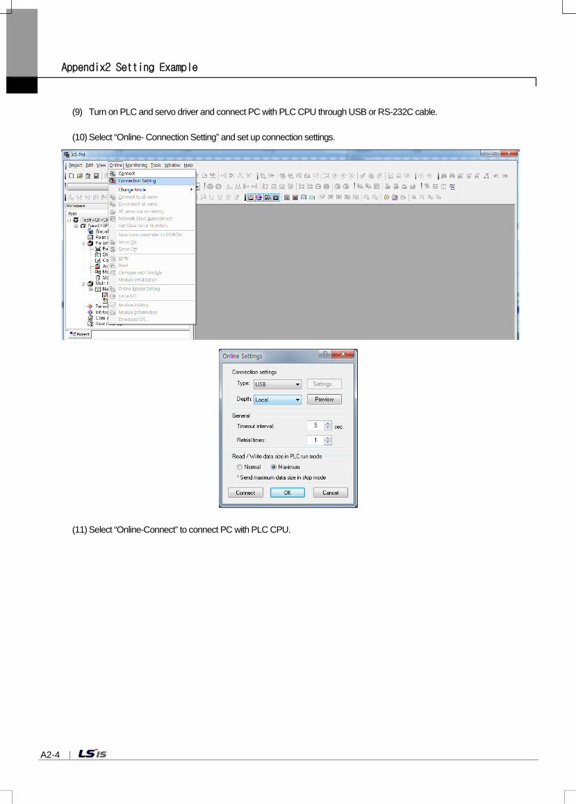
Appendix2 Setting Example
A2-4
(9) Turn on PLC and servo driver and connect PC with PLC CPU through USB or RS-232C cable.
(10) Select “Online- Connection Setting” and set up connection settings.
(11) Select “Online-Connect” to connect PC with PLC CPU.

Appendix 2 Setting Example
A2-5
(12) If connection is complete, the module will be shown in ‘Online’ as follows.
(13) If the module doesn’t become “Online” and keeps “Offline”, check whether the module is mounted, position or type is correct.
(14) Check if motion control module is in STOP state. If motion control module is in RUN state, change it to STOP state and execute the next steps.
(15) Writing must be executed in the motion control module after setting the servo drive actually connected to the network parameter in order to execute the connection with servo drive. First, check if the relevant module is in off-line state to set network parameter. If it is in on-line state, execute "Online -Disconnect" to change it to off-line state.
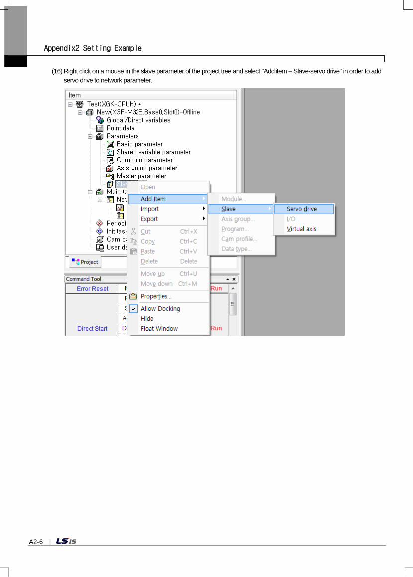
Appendix2 Setting Example
A2-6
(16) Right click on a mouse in the slave parameter of the project tree and select "Add item – Slave-servo drive" in order to add servo drive to network parameter.

Appendix 2 Setting Example
A2-7
(17) When the slave information window comes up, click the“…” button next to the slave name.
(18) Select the servo drive connected first to motion control module in the servo drive selection window and click OK.

Appendix2 Setting Example
A2-8
(19) Set the axis number of servo drive which was selected in the slave information window. Connection order is not associated with the axis number. The axis number set here becomes the command axis of command/function block when making motion program.
(20) When the axis number setting is completed, the servo drive added earlier is indicated in network parameter.

Appendix 2 Setting Example
A2-9
Notes When the types of drive connected to network are the same, "Copy" and "Paste " can be used. While the first drive is added, select
the "Copy(C)" menu as follows and right click on a mouse in network parameter to execute "Paste ".
When executing as above, the identical servo drive of which the axis number has increased by 1 is added to slave parameter.

Appendix2 Setting Example
A2-10
(21) Execute the servo drive addition in the same way for the other servo drives. This is the screen to show all the servo drives actually connected to slave parameter are added. It is indicated by gray color until whole servo connection command is executed, and positioning module and servo drive are connected normally.
(22) After adding all the servo drives connected to slave parameter, execute "Online-Connection” first and execute "Online-Write" to write network parameter in motion control module.
(Network parameter is not indicated in the project tree.)

Appendix 2 Setting Example
A2-11
(23) When the project writing window comes up, check in the network parameter and check OK to execute writing. This is the screen to show the whole execution process of project writing.

Appendix2 Setting Example
A2-12
(24) Select "Online –Connect to all servo” to execute communication link between motion control module and servo drive.
(25) When the link is completed, the servo drive name of slave parameter is activated to black from gray. Execute the "View-view Network …" in the menu to check the servo drive connection.

Appendix 2 Setting Example
A2-13
Notes When connecting the network for the first time after the system configuration using XGF-M32E, use "Network slave auto connection" to conveniently execute connection to servo drive without setting the slave parameter.
1. Execute the “Online -Network slave auto connection ” menu.
2. Popup notification message appears as follows. This is an alert message notifying when executing network slave autoconnection, the network parameter set in the current XG-PM and motion control module is initialized and so the servo parameter in XG-PM is. Check the message and click OK.
3. Slave connection message appears, and if the connection is completed normally, completion message is indicated.
4. When executing the “Network slave auto connection" command, the EtherCAT slave information currently connected to the slave parameter of XG-PM is automatically registered if the connection command is completed normally.

Appendix2 Setting Example
A2-14
5. When executing the connection with the “Network slave auto connection” command, the axis numbers are automaticallyallocated in the order of connection to motion control module. In other words, the servo drive primarily connected to motion control module becomes Axis 1, and the other servo drives become Axis 2 to Axis 32 in the order. When wanting to change the axis number, execute network parameter writing by disconnecting the link and change the axis number only in off-line state, and execute the connection with "Online- Connect to all servo” command.
(26) Read slave parameter to set operation parameter and servo parameter. Select “Online -Read”in the menu and select the item to be read.

Appendix 2 Setting Example
A2-15
(27) Following is the reading of servo parameter content of L7N servo drive. The content of servo parameter can differ depending on the types of servo drive. Refer to the instruction manuals of each servo drive for details.

Appendix2 Setting Example
A2-16
(28) Servo parameter can be set in two ways. First method is only to change the value of one item of servo parameter (SDO parameter); select the 'Allow Servo Parameter(Individual) Change during Operation' checkbox and set the servo parameter (SDO parameter) value that you want to change, then the set value is applied to servo drive immediately. Reflection of the modified value to the 'current value' column of servo parameter means the value is transmitted normally.
In order to keep the data after turn on/off the power of servo drive, execute the "Online-Save slave parameter to EEPROM" command because modifying the parameter in operation of servo parameter (individual) is only valid when the power is currently on. Second method is to set all the servo parameter you want to modify and execute 'Online -Write ' to write the whole SDO parameter in servo drive at a time.
When writing the whole SDO parameter, "Save slave parameter to EEPROM" command is automatically executed.

Appendix 2 Setting Example
A2-17
Therefore, you do not need to execute "Save slave parameter to EEPROM" separately. Refer to the instruction manual of the relevant servo drive because sometimes modified set value is applied after the power is on/off depending on the item of servo parameter.
(29) When finishing the servo parameter setting, set the operation parameter of each axis and select the operation parameter of the relevant axis in "Online-Write " to write in module.
(30) If you turned off the power of servo drive and turned it on again in the step (28), execute "Online-Connect to all servo” again to connect module and servo drive.

Appendix2 Setting Example
A2-18
(31) After selecting the command axis and turning on the servo of the relevant axis, check if the relevant axis is in servo on state and check the motor operation by operating the motor using jog or others.
(32) If vibration or noise is generated when motor is operating, adjust the responsibility, inertia ratio, and gain values of servo parameter and transmit them to servo drive. Use the dedicated setting TOOL of servo drive for detailed setting such as auto tuning.
① ②
③
④ ⑤

Appendix 2 Setting Example
A2-19
(33) Create motion program. The exercise below is for the case that 2 servos are set to 1 & 2 axes using XGK CPU, and LS_CONNECT is used for connection and the connected axis is servo on by using MC_Power. The rest of the exercise can be added as user's need. Motion task can be divided into main task, periodic task, and initialization task. You can add program to the relevant task of the project tree depending on the character of the program.

Appendix2 Setting Example
A2-20
(34) Create PLC Program by using XG5000. (a) Create new project. Select "Project -New project " in the menu, and set the name of project and others.
(b) Release the online connection between PLC CPU and XG-PM. If XG5000 is connected while XG-PM is linked, a dialog box appears as below and PLC function might be limited. But if you connect XG5000 first and then connect XG-PM, there is nothing to worry about it.
(c) Select "Online -Connection settings”in XG5000 to choose the connection method, and select "Online -Connect" to connect with PLC CPU.
(d) Keep PLC CPU in the "STOP" state.

Appendix 2 Setting Example
A2-21
(e) Select “Online -I/O information ”to check the currently built-in I/O information of PLC.
(f) Check if the installation information of XGF-M32E is correctly displayed on the information window. If you want to view the version information of the relevant module and others, select the relevant module and click the "Details " button.

Appendix2 Setting Example
A2-22
(g) Click the "I/O synchronization" button to set I/O parameter.
(h) Select "Edit –Register U Device" in the menu to register U device automatically.
(i) Set device sharing between PLC CPU and motion control module as necessary. Device sharing can be set in I/O parameter in the project tree window.

Appendix3 Dimension
A3-1
Appendix3 Dimension
Appendix3.1 Dimension of XGF-M32E

Warranty and Environmental Policy
Warranty
1. Warranty Period The product you purchased will be guaranteed for 18 months from the date of manufacturing.
2. Scope of Warranty Any trouble or defect occurring for the above-mentioned period will be partially replaced or repaired. However, please note the following cases will be excluded from the scope of warranty.
(1) Any trouble attributable to unreasonable condition, environment or handling otherwise specified in the manual, (2) Any trouble attributable to others’ products, (3) If the product is modified or repaired in any other place not designated by the company, (4) Due to unintended purposes (5) Owing to the reasons unexpected at the level of the contemporary science and technology when delivered. (6) Not attributable to the company; for instance, natural disasters or fire
3. Since the above warranty is limited to PLC unit only, make sure to use the product considering the safety for system configuration orapplications.
Environmental Policy
LSIS Co., Ltd supports and observes the environmental policy as below.
LSIS considers the environmental preservation as the preferential management subject and every staff of LSIS use the reasonable endeavors for the pleasurably environmental preservation of the earth.
LSIS’ PLC unit is designed to protect the environment. For the disposal, separate aluminum, iron and synthetic resin (cover) from the product as they are reusable.
Environmental Management About Disposal

■ LS Hukai Electric(Hubei) Co., Ltd./CHINA No. 100, Tanjiahe Road, Dianjun District, Yichang City, Hubei Province, P.R. China Tel : 86-717-667-7536 Fax : 86-717-667-7222 E-Mail : [email protected]
■ LS-VINA Industrial Systems Co., Ltd./VIETNAM Room 1311, 13th, M3-M4 Building 91 Nguyen Chi Thanh street, Hanoi, Vietnam Tel : 84-4-6275-8055 Fax : 86-21-5237-7189
■ LSIS(ME) FZE/U.A.E.LOB 19-205, JAFZA View Tower, Jebel Ali Free Zone, Dubai, United Arab Emirates Tel : 971-4-886-5360 Fax : 971-4-886-5361 E-Mail : [email protected]
■ LSIS Europe B.V./NETHERLANDS1st. Floor, Tupolevlaan 48, 1119NZ,Schiphol-Rijk, The Netherlands Tel : 31-20-654-1420 Fax : 31-20-654-1429 E-Mail : [email protected]
■ LSIS Japan Co., Ltd./JAPAN16th, Higashi-Kan, Akasaka Twin Tower, 2-17-22, Akasaka, Minato-ku, Tokyo, Japan Tel : 81-3-3582-9128 Fax : 81-3-3582-2667 E-Mail : [email protected]
■ LSIS USA Inc./U.S.A 2000 Millbrook Drive, Lincolnshire, Chicago, IL 60069, United States of America Tel : 847-941-8240 Fax : 847-941-8259 E-Mail : [email protected]
■ LSIS Gurgaon Office/INDIA 109 First Floor, Park Central, Sector-30, Gurgaon- 122 002, Haryana, India Tel : +0091-124-493-0070 Fax : 91-1244-930-066 E-Mail : [email protected]
■ HEAD OFFICELS Tower, 127, LS-ro, Dongan-gu, Anyang-si, Gyeonggi-Do, 431-848, Korea
Tel : (82-2)2034-4870/Fax : 82-2-2034-4648 E-mail : [email protected] -Southeast Asia +82-2-2034-4888 [email protected] (Charles Hwang) -Europe +82-2-2034-4676 [email protected] (Brian Choi) -Turkey/Israel/CIS +82-2-2034-4879 [email protected] (Daniel Kim) -Oceania +82-2-2034-4394 [email protected] (Kendra Cho)
-North/Latin America +82-2-2034-4286 [email protected] (Hank Raul Chung) -Southwest Asia/Africa +82-2-2034-4467 [email protected] (Henry Lee)
-Middle East +971-4-886-5360 [email protected] (Lambert Choi)
■ LSIS(Shanghai) Co., Ltd. /CHINA 32nd Room 1~4, 32/F, Great Wall Building, No.3000 North Zhongshan Road, Putuo District, Shanghai, P.R. China Tel : 86-21-5237-9977(609) Fax : 86-21-5237-7189
■ LSIS(Dalian) Co., Ltd. /CHINA No. 15, Liaohexi 3-Road, Economic and Technical Development zone, Dalian, P.R. China Tel : 86-411-8731-7542 Fax : 86-411-8730-7560 E-Mail : [email protected]
■ LSIS(Wuxi) Co., Ltd./CHINA 102-A, National High & New Tech Industrial Development Area, Wuxi, Jiangsu, P.R.China Tel : 86-510-8534-6666 Fax : 86-510-8534-4078 E-Mail : [email protected]
※ LSIS constantly endeavors to improve its product so that information in this manual is subject to change without notice. ⓒ LSIS Co., Ltd. 2016 All Rights Reserved.
2016. 09
LS values every single customers.
Quality and service come first at LSIS.
Always at your service, standing for our customers.
Copyright © 2022 FDOKUMEN