CC-Link IE Field Network Temperature Control Module User's ...
388
CC-Link IE Field Network Temperature Control Module User's Manual -NZ2GF2B-60TCTT4 -NZ2GF2B-60TCRT4
-
Upload
khangminh22 -
Category
Documents
-
view
3 -
download
0
Transcript of CC-Link IE Field Network Temperature Control Module User's ...
CC-Link IE Field Network Temperature Control ModuleUser's Manual
-NZ2GF2B-60TCTT4-NZ2GF2B-60TCRT4

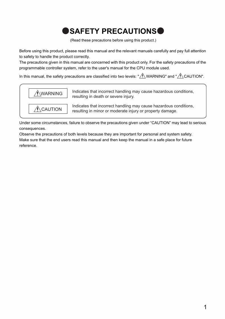
SAFETY PRECAUTIONS(Read these precautions before using this product.)
Before using this product, please read this manual and the relevant manuals carefully and pay full attention
to safety to handle the product correctly.
The precautions given in this manual are concerned with this product only. For the safety precautions of the
programmable controller system, refer to the user's manual for the CPU module used.
In this manual, the safety precautions are classified into two levels: " WARNING" and " CAUTION".
Under some circumstances, failure to observe the precautions given under “CAUTION” may lead to serious
consequences.
Observe the precautions of both levels because they are important for personal and system safety.
Make sure that the end users read this manual and then keep the manual in a safe place for future
reference.
WARNING
CAUTION
Indicates that incorrect handling may cause hazardous conditions,resulting in death or severe injury.
Indicates that incorrect handling may cause hazardous conditions, resulting in minor or moderate injury or property damage.
1
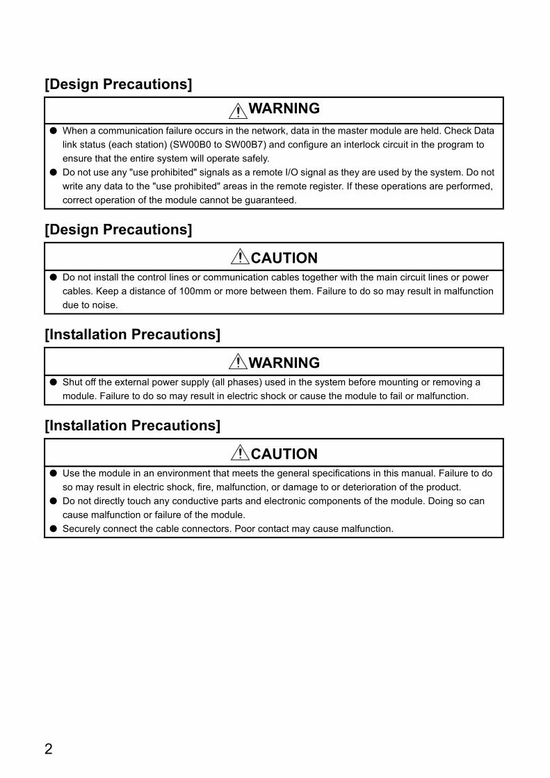
[Design Precautions]
[Design Precautions]
[Installation Precautions]
[Installation Precautions]
WARNING● When a communication failure occurs in the network, data in the master module are held. Check Data
link status (each station) (SW00B0 to SW00B7) and configure an interlock circuit in the program to
ensure that the entire system will operate safely.
● Do not use any "use prohibited" signals as a remote I/O signal as they are used by the system. Do not
write any data to the "use prohibited" areas in the remote register. If these operations are performed,
correct operation of the module cannot be guaranteed.
CAUTION● Do not install the control lines or communication cables together with the main circuit lines or power
cables. Keep a distance of 100mm or more between them. Failure to do so may result in malfunction
due to noise.
WARNING● Shut off the external power supply (all phases) used in the system before mounting or removing a
module. Failure to do so may result in electric shock or cause the module to fail or malfunction.
CAUTION● Use the module in an environment that meets the general specifications in this manual. Failure to do
so may result in electric shock, fire, malfunction, or damage to or deterioration of the product.
● Do not directly touch any conductive parts and electronic components of the module. Doing so can
cause malfunction or failure of the module.
● Securely connect the cable connectors. Poor contact may cause malfunction.
2
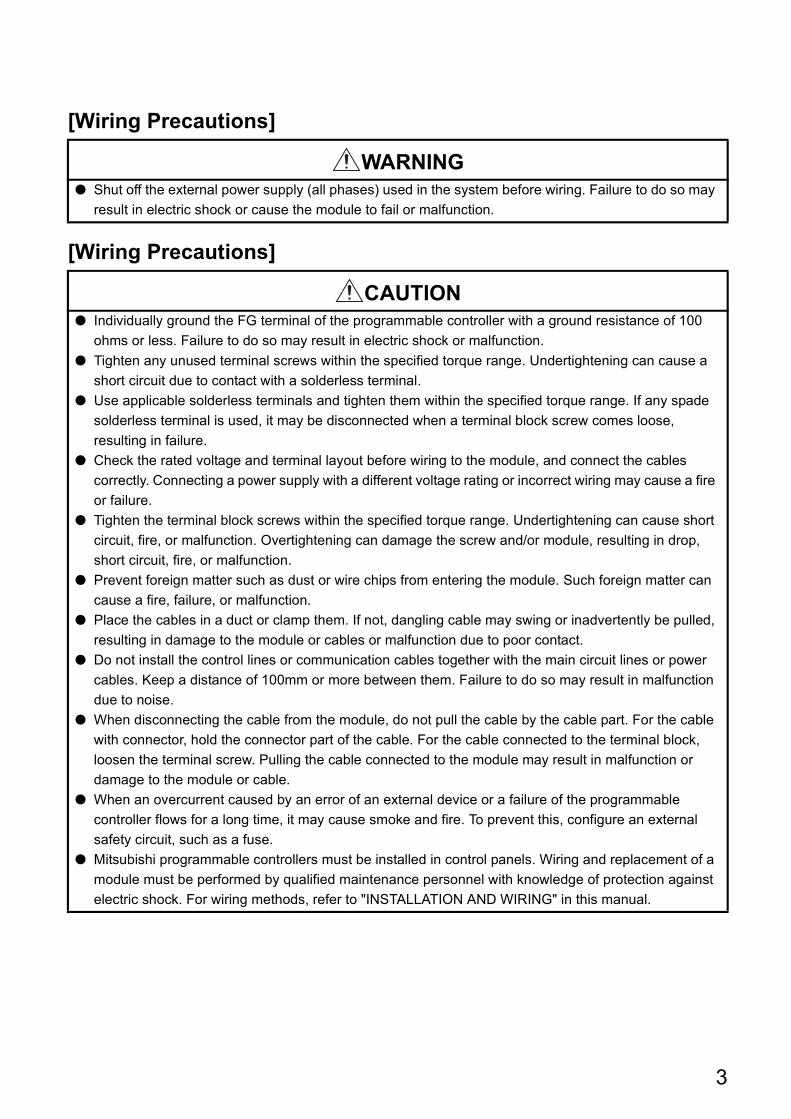
[Wiring Precautions]
[Wiring Precautions]
WARNING● Shut off the external power supply (all phases) used in the system before wiring. Failure to do so may
result in electric shock or cause the module to fail or malfunction.
CAUTION● Individually ground the FG terminal of the programmable controller with a ground resistance of 100
ohms or less. Failure to do so may result in electric shock or malfunction.
● Tighten any unused terminal screws within the specified torque range. Undertightening can cause a
short circuit due to contact with a solderless terminal.
● Use applicable solderless terminals and tighten them within the specified torque range. If any spade
solderless terminal is used, it may be disconnected when a terminal block screw comes loose,
resulting in failure.
● Check the rated voltage and terminal layout before wiring to the module, and connect the cables
correctly. Connecting a power supply with a different voltage rating or incorrect wiring may cause a fire
or failure.
● Tighten the terminal block screws within the specified torque range. Undertightening can cause short
circuit, fire, or malfunction. Overtightening can damage the screw and/or module, resulting in drop,
short circuit, fire, or malfunction.
● Prevent foreign matter such as dust or wire chips from entering the module. Such foreign matter can
cause a fire, failure, or malfunction.
● Place the cables in a duct or clamp them. If not, dangling cable may swing or inadvertently be pulled,
resulting in damage to the module or cables or malfunction due to poor contact.
● Do not install the control lines or communication cables together with the main circuit lines or power
cables. Keep a distance of 100mm or more between them. Failure to do so may result in malfunction
due to noise.
● When disconnecting the cable from the module, do not pull the cable by the cable part. For the cable
with connector, hold the connector part of the cable. For the cable connected to the terminal block,
loosen the terminal screw. Pulling the cable connected to the module may result in malfunction or
damage to the module or cable.
● When an overcurrent caused by an error of an external device or a failure of the programmable
controller flows for a long time, it may cause smoke and fire. To prevent this, configure an external
safety circuit, such as a fuse.
● Mitsubishi programmable controllers must be installed in control panels. Wiring and replacement of a
module must be performed by qualified maintenance personnel with knowledge of protection against
electric shock. For wiring methods, refer to "INSTALLATION AND WIRING" in this manual.
3
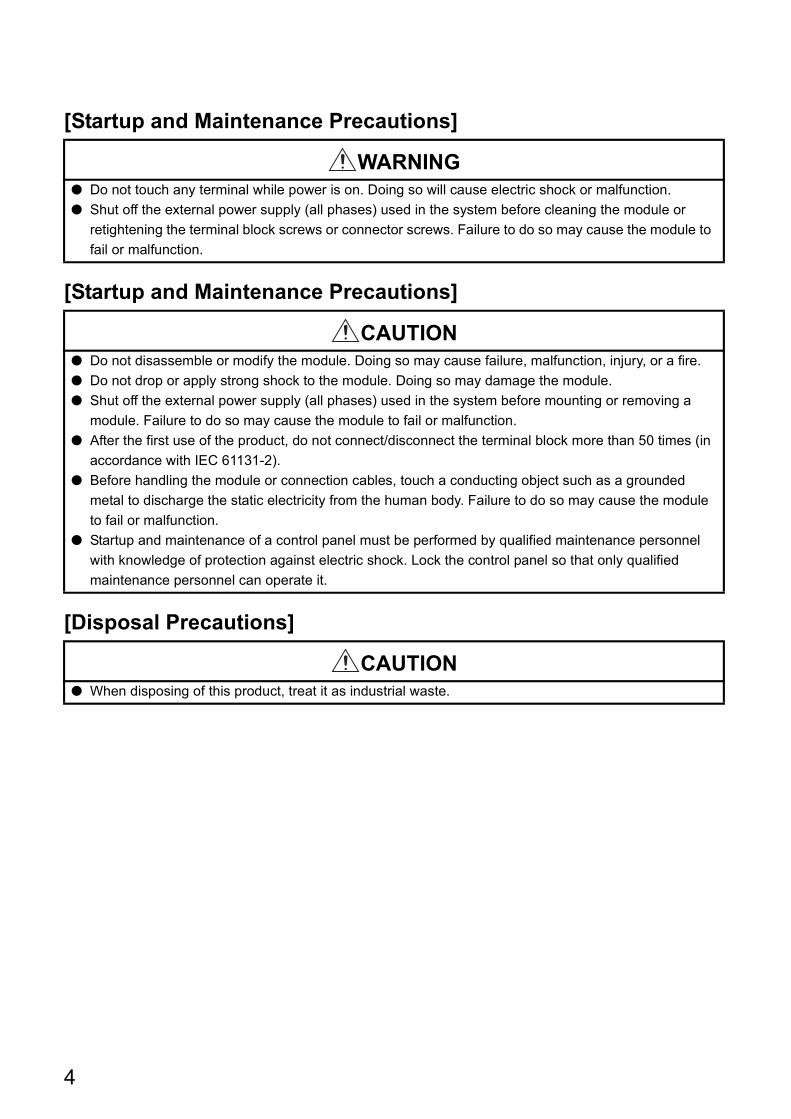
[Startup and Maintenance Precautions]
[Startup and Maintenance Precautions]
[Disposal Precautions]
WARNING● Do not touch any terminal while power is on. Doing so will cause electric shock or malfunction.
● Shut off the external power supply (all phases) used in the system before cleaning the module or
retightening the terminal block screws or connector screws. Failure to do so may cause the module to
fail or malfunction.
CAUTION● Do not disassemble or modify the module. Doing so may cause failure, malfunction, injury, or a fire.
● Do not drop or apply strong shock to the module. Doing so may damage the module.
● Shut off the external power supply (all phases) used in the system before mounting or removing a
module. Failure to do so may cause the module to fail or malfunction.
● After the first use of the product, do not connect/disconnect the terminal block more than 50 times (in
accordance with IEC 61131-2).
● Before handling the module or connection cables, touch a conducting object such as a grounded
metal to discharge the static electricity from the human body. Failure to do so may cause the module
to fail or malfunction.
● Startup and maintenance of a control panel must be performed by qualified maintenance personnel
with knowledge of protection against electric shock. Lock the control panel so that only qualified
maintenance personnel can operate it.
CAUTION● When disposing of this product, treat it as industrial waste.
4
CONDITIONS OF USE FOR THE PRODUCT
(1) Mitsubishi programmable controller ("the PRODUCT") shall be used in conditions;
i) where any problem, fault or failure occurring in the PRODUCT, if any, shall not lead to any major
or serious accident; and
ii) where the backup and fail-safe function are systematically or automatically provided outside of
the PRODUCT for the case of any problem, fault or failure occurring in the PRODUCT.
(2) The PRODUCT has been designed and manufactured for the purpose of being used in general
industries.
MITSUBISHI SHALL HAVE NO RESPONSIBILITY OR LIABILITY (INCLUDING, BUT NOT
LIMITED TO ANY AND ALL RESPONSIBILITY OR LIABILITY BASED ON CONTRACT,
WARRANTY, TORT, PRODUCT LIABILITY) FOR ANY INJURY OR DEATH TO PERSONS OR
LOSS OR DAMAGE TO PROPERTY CAUSED BY the PRODUCT THAT ARE OPERATED OR
USED IN APPLICATION NOT INTENDED OR EXCLUDED BY INSTRUCTIONS, PRECAUTIONS,
OR WARNING CONTAINED IN MITSUBISHI'S USER, INSTRUCTION AND/OR SAFETY
MANUALS, TECHNICAL BULLETINS AND GUIDELINES FOR the PRODUCT.
("Prohibited Application")
Prohibited Applications include, but not limited to, the use of the PRODUCT in;
• Nuclear Power Plants and any other power plants operated by Power companies, and/or any
other cases in which the public could be affected if any problem or fault occurs in the PRODUCT.
• Railway companies or Public service purposes, and/or any other cases in which establishment of
a special quality assurance system is required by the Purchaser or End User.
• Aircraft or Aerospace, Medical applications, Train equipment, transport equipment such as
Elevator and Escalator, Incineration and Fuel devices, Vehicles, Manned transportation,
Equipment for Recreation and Amusement, and Safety devices, handling of Nuclear or
Hazardous Materials or Chemicals, Mining and Drilling, and/or other applications where there is a
significant risk of injury to the public or property.
Notwithstanding the above, restrictions Mitsubishi may in its sole discretion, authorize use of the
PRODUCT in one or more of the Prohibited Applications, provided that the usage of the PRODUCT
is limited only for the specific applications agreed to by Mitsubishi and provided further that no
special quality assurance or fail-safe, redundant or other safety features which exceed the general
specifications of the PRODUCTs are required. For details, please contact the Mitsubishi
representative in your region.
5
INTRODUCTION
Thank you for purchasing the CC-Link IE Field Network temperature control module (hereafter abbreviated as
temperature control module). This manual describes the procedures, system configuration, parameter settings,
functions, and troubleshooting of a temperature control module.
Before using this product, please read this manual and the relevant manuals carefully and develop familiarity with the
functions and performance of the temperature control module to handle the product correctly. When applying the
program examples introduced in this manual to an actual system, ensure the applicability and confirm that it will not
cause system control problems.
Relevant module: NZ2GF2B-60TCTT4, NZ2GF2B-60TCRT4
Remark
Unless otherwise specified, this manual describes the program examples in which the remote I/O signals and remote registers are assigned for a temperature control module as follows.
• Remote input signal: RX0 to RX3F• Remote output signal: RY0 to RY3F• Remote register: RWr0 to RWr1F, RWw0 to RWw1F
For the assignment of remote I/O signals and remote registers, refer to the following. User's manual for the master/local module used
6
RELEVANT MANUALS
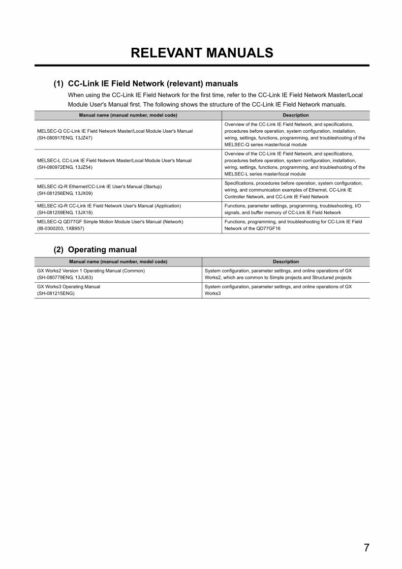
(1) CC-Link IE Field Network (relevant) manualsWhen using the CC-Link IE Field Network for the first time, refer to the CC-Link IE Field Network Master/Local
Module User's Manual first. The following shows the structure of the CC-Link IE Field Network manuals.
(2) Operating manual
Manual name (manual number, model code) Description
MELSEC-Q CC-Link IE Field Network Master/Local Module User's Manual
(SH-080917ENG, 13JZ47)
Overview of the CC-Link IE Field Network, and specifications,
procedures before operation, system configuration, installation,
wiring, settings, functions, programming, and troubleshooting of the
MELSEC-Q series master/local module
MELSEC-L CC-Link IE Field Network Master/Local Module User's Manual
(SH-080972ENG, 13JZ54)
Overview of the CC-Link IE Field Network, and specifications,
procedures before operation, system configuration, installation,
wiring, settings, functions, programming, and troubleshooting of the
MELSEC-L series master/local module
MELSEC iQ-R Ethernet/CC-Link IE User's Manual (Startup)
(SH-081256ENG, 13JX09)
Specifications, procedures before operation, system configuration,
wiring, and communication examples of Ethernet, CC-Link IE
Controller Network, and CC-Link IE Field Network
MELSEC iQ-R CC-Link IE Field Network User's Manual (Application)
(SH-081259ENG, 13JX18)
Functions, parameter settings, programming, troubleshooting, I/O
signals, and buffer memory of CC-Link IE Field Network
MELSEC-Q QD77GF Simple Motion Module User's Manual (Network)
(IB-0300203, 1XB957)
Functions, programming, and troubleshooting for CC-Link IE Field
Network of the QD77GF16
Manual name (manual number, model code) Description
GX Works2 Version 1 Operating Manual (Common)
(SH-080779ENG, 13JU63)
System configuration, parameter settings, and online operations of GX
Works2, which are common to Simple projects and Structured projects
GX Works3 Operating Manual
(SH-081215ENG)
System configuration, parameter settings, and online operations of GX
Works3
7
CONTENTS
8
CONTENTS
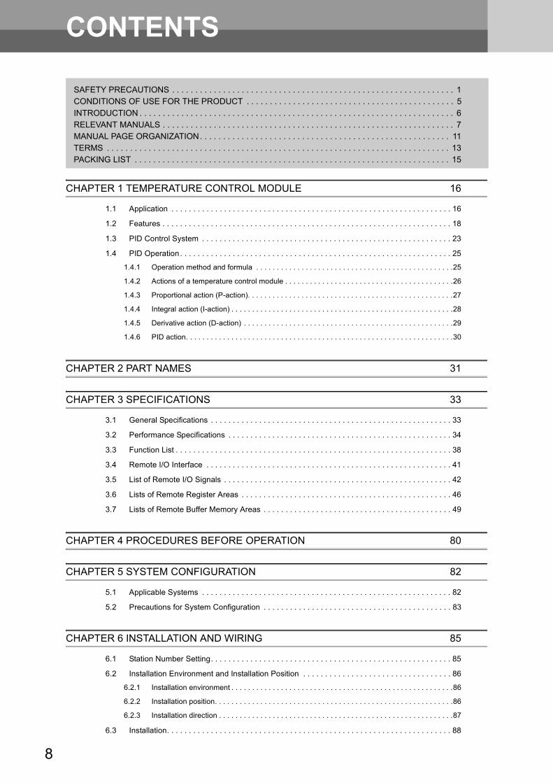
SAFETY PRECAUTIONS . . . . . . . . . . . . . . . . . . . . . . . . . . . . . . . . . . . . . . . . . . . . . . . . . . . . . . . . . . . . . 1CONDITIONS OF USE FOR THE PRODUCT . . . . . . . . . . . . . . . . . . . . . . . . . . . . . . . . . . . . . . . . . . . . . 5
INTRODUCTION . . . . . . . . . . . . . . . . . . . . . . . . . . . . . . . . . . . . . . . . . . . . . . . . . . . . . . . . . . . . . . . . . . . . 6RELEVANT MANUALS . . . . . . . . . . . . . . . . . . . . . . . . . . . . . . . . . . . . . . . . . . . . . . . . . . . . . . . . . . . . . . . 7MANUAL PAGE ORGANIZATION. . . . . . . . . . . . . . . . . . . . . . . . . . . . . . . . . . . . . . . . . . . . . . . . . . . . . . 11TERMS . . . . . . . . . . . . . . . . . . . . . . . . . . . . . . . . . . . . . . . . . . . . . . . . . . . . . . . . . . . . . . . . . . . . . . . . . . 13PACKING LIST . . . . . . . . . . . . . . . . . . . . . . . . . . . . . . . . . . . . . . . . . . . . . . . . . . . . . . . . . . . . . . . . . . . . 15
CHAPTER 1 TEMPERATURE CONTROL MODULE 16
1.1 Application . . . . . . . . . . . . . . . . . . . . . . . . . . . . . . . . . . . . . . . . . . . . . . . . . . . . . . . . . . . . . . . . 16
1.2 Features . . . . . . . . . . . . . . . . . . . . . . . . . . . . . . . . . . . . . . . . . . . . . . . . . . . . . . . . . . . . . . . . . . 18
1.3 PID Control System . . . . . . . . . . . . . . . . . . . . . . . . . . . . . . . . . . . . . . . . . . . . . . . . . . . . . . . . . 23
1.4 PID Operation. . . . . . . . . . . . . . . . . . . . . . . . . . . . . . . . . . . . . . . . . . . . . . . . . . . . . . . . . . . . . . 25
1.4.1 Operation method and formula . . . . . . . . . . . . . . . . . . . . . . . . . . . . . . . . . . . . . . . . . . . . . . . .25
1.4.2 Actions of a temperature control module . . . . . . . . . . . . . . . . . . . . . . . . . . . . . . . . . . . . . . . . .26
1.4.3 Proportional action (P-action). . . . . . . . . . . . . . . . . . . . . . . . . . . . . . . . . . . . . . . . . . . . . . . . . .27
1.4.4 Integral action (I-action) . . . . . . . . . . . . . . . . . . . . . . . . . . . . . . . . . . . . . . . . . . . . . . . . . . . . . .28
1.4.5 Derivative action (D-action) . . . . . . . . . . . . . . . . . . . . . . . . . . . . . . . . . . . . . . . . . . . . . . . . . . .29
1.4.6 PID action. . . . . . . . . . . . . . . . . . . . . . . . . . . . . . . . . . . . . . . . . . . . . . . . . . . . . . . . . . . . . . . . .30
CHAPTER 2 PART NAMES 31
CHAPTER 3 SPECIFICATIONS 33
3.1 General Specifications . . . . . . . . . . . . . . . . . . . . . . . . . . . . . . . . . . . . . . . . . . . . . . . . . . . . . . . 33
3.2 Performance Specifications . . . . . . . . . . . . . . . . . . . . . . . . . . . . . . . . . . . . . . . . . . . . . . . . . . . 34
3.3 Function List . . . . . . . . . . . . . . . . . . . . . . . . . . . . . . . . . . . . . . . . . . . . . . . . . . . . . . . . . . . . . . . 38
3.4 Remote I/O Interface . . . . . . . . . . . . . . . . . . . . . . . . . . . . . . . . . . . . . . . . . . . . . . . . . . . . . . . . 41
3.5 List of Remote I/O Signals . . . . . . . . . . . . . . . . . . . . . . . . . . . . . . . . . . . . . . . . . . . . . . . . . . . . 42
3.6 Lists of Remote Register Areas . . . . . . . . . . . . . . . . . . . . . . . . . . . . . . . . . . . . . . . . . . . . . . . . 46
3.7 Lists of Remote Buffer Memory Areas . . . . . . . . . . . . . . . . . . . . . . . . . . . . . . . . . . . . . . . . . . . 49
CHAPTER 4 PROCEDURES BEFORE OPERATION 80
CHAPTER 5 SYSTEM CONFIGURATION 82
5.1 Applicable Systems . . . . . . . . . . . . . . . . . . . . . . . . . . . . . . . . . . . . . . . . . . . . . . . . . . . . . . . . . 82
5.2 Precautions for System Configuration . . . . . . . . . . . . . . . . . . . . . . . . . . . . . . . . . . . . . . . . . . . 83
CHAPTER 6 INSTALLATION AND WIRING 85
6.1 Station Number Setting. . . . . . . . . . . . . . . . . . . . . . . . . . . . . . . . . . . . . . . . . . . . . . . . . . . . . . . 85
6.2 Installation Environment and Installation Position . . . . . . . . . . . . . . . . . . . . . . . . . . . . . . . . . . 86
6.2.1 Installation environment . . . . . . . . . . . . . . . . . . . . . . . . . . . . . . . . . . . . . . . . . . . . . . . . . . . . . .86
6.2.2 Installation position. . . . . . . . . . . . . . . . . . . . . . . . . . . . . . . . . . . . . . . . . . . . . . . . . . . . . . . . . .86
6.2.3 Installation direction . . . . . . . . . . . . . . . . . . . . . . . . . . . . . . . . . . . . . . . . . . . . . . . . . . . . . . . . .87
6.3 Installation. . . . . . . . . . . . . . . . . . . . . . . . . . . . . . . . . . . . . . . . . . . . . . . . . . . . . . . . . . . . . . . . . 88
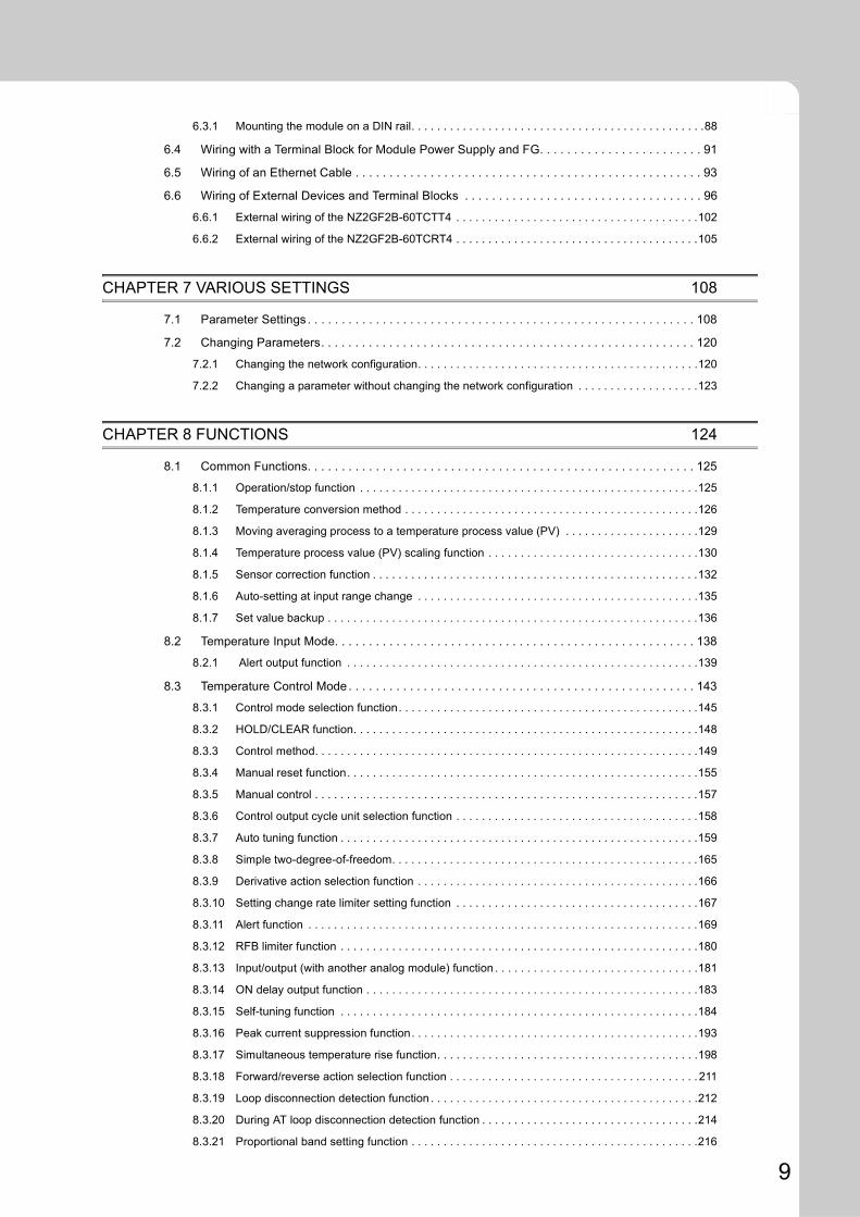
6.3.1 Mounting the module on a DIN rail. . . . . . . . . . . . . . . . . . . . . . . . . . . . . . . . . . . . . . . . . . . . . .88
6.4 Wiring with a Terminal Block for Module Power Supply and FG. . . . . . . . . . . . . . . . . . . . . . . . 91
6.5 Wiring of an Ethernet Cable . . . . . . . . . . . . . . . . . . . . . . . . . . . . . . . . . . . . . . . . . . . . . . . . . . . 93
6.6 Wiring of External Devices and Terminal Blocks . . . . . . . . . . . . . . . . . . . . . . . . . . . . . . . . . . . 96
6.6.1 External wiring of the NZ2GF2B-60TCTT4 . . . . . . . . . . . . . . . . . . . . . . . . . . . . . . . . . . . . . .102
6.6.2 External wiring of the NZ2GF2B-60TCRT4 . . . . . . . . . . . . . . . . . . . . . . . . . . . . . . . . . . . . . .105
CHAPTER 7 VARIOUS SETTINGS 108
7.1 Parameter Settings . . . . . . . . . . . . . . . . . . . . . . . . . . . . . . . . . . . . . . . . . . . . . . . . . . . . . . . . . 108
7.2 Changing Parameters. . . . . . . . . . . . . . . . . . . . . . . . . . . . . . . . . . . . . . . . . . . . . . . . . . . . . . . 120
7.2.1 Changing the network configuration. . . . . . . . . . . . . . . . . . . . . . . . . . . . . . . . . . . . . . . . . . . .120
7.2.2 Changing a parameter without changing the network configuration . . . . . . . . . . . . . . . . . . .123
CHAPTER 8 FUNCTIONS 124
8.1 Common Functions. . . . . . . . . . . . . . . . . . . . . . . . . . . . . . . . . . . . . . . . . . . . . . . . . . . . . . . . . 125
8.1.1 Operation/stop function . . . . . . . . . . . . . . . . . . . . . . . . . . . . . . . . . . . . . . . . . . . . . . . . . . . . .125
8.1.2 Temperature conversion method . . . . . . . . . . . . . . . . . . . . . . . . . . . . . . . . . . . . . . . . . . . . . .126
8.1.3 Moving averaging process to a temperature process value (PV) . . . . . . . . . . . . . . . . . . . . .129
8.1.4 Temperature process value (PV) scaling function . . . . . . . . . . . . . . . . . . . . . . . . . . . . . . . . .130
8.1.5 Sensor correction function . . . . . . . . . . . . . . . . . . . . . . . . . . . . . . . . . . . . . . . . . . . . . . . . . . .132
8.1.6 Auto-setting at input range change . . . . . . . . . . . . . . . . . . . . . . . . . . . . . . . . . . . . . . . . . . . .135
8.1.7 Set value backup . . . . . . . . . . . . . . . . . . . . . . . . . . . . . . . . . . . . . . . . . . . . . . . . . . . . . . . . . .136
8.2 Temperature Input Mode. . . . . . . . . . . . . . . . . . . . . . . . . . . . . . . . . . . . . . . . . . . . . . . . . . . . . 138
8.2.1 Alert output function . . . . . . . . . . . . . . . . . . . . . . . . . . . . . . . . . . . . . . . . . . . . . . . . . . . . . . .139
8.3 Temperature Control Mode . . . . . . . . . . . . . . . . . . . . . . . . . . . . . . . . . . . . . . . . . . . . . . . . . . . 143
8.3.1 Control mode selection function. . . . . . . . . . . . . . . . . . . . . . . . . . . . . . . . . . . . . . . . . . . . . . .145
8.3.2 HOLD/CLEAR function. . . . . . . . . . . . . . . . . . . . . . . . . . . . . . . . . . . . . . . . . . . . . . . . . . . . . .148
8.3.3 Control method. . . . . . . . . . . . . . . . . . . . . . . . . . . . . . . . . . . . . . . . . . . . . . . . . . . . . . . . . . . .149
8.3.4 Manual reset function. . . . . . . . . . . . . . . . . . . . . . . . . . . . . . . . . . . . . . . . . . . . . . . . . . . . . . .155
8.3.5 Manual control . . . . . . . . . . . . . . . . . . . . . . . . . . . . . . . . . . . . . . . . . . . . . . . . . . . . . . . . . . . .157
8.3.6 Control output cycle unit selection function . . . . . . . . . . . . . . . . . . . . . . . . . . . . . . . . . . . . . .158
8.3.7 Auto tuning function . . . . . . . . . . . . . . . . . . . . . . . . . . . . . . . . . . . . . . . . . . . . . . . . . . . . . . . .159
8.3.8 Simple two-degree-of-freedom. . . . . . . . . . . . . . . . . . . . . . . . . . . . . . . . . . . . . . . . . . . . . . . .165
8.3.9 Derivative action selection function . . . . . . . . . . . . . . . . . . . . . . . . . . . . . . . . . . . . . . . . . . . .166
8.3.10 Setting change rate limiter setting function . . . . . . . . . . . . . . . . . . . . . . . . . . . . . . . . . . . . . .167
8.3.11 Alert function . . . . . . . . . . . . . . . . . . . . . . . . . . . . . . . . . . . . . . . . . . . . . . . . . . . . . . . . . . . . .169
8.3.12 RFB limiter function . . . . . . . . . . . . . . . . . . . . . . . . . . . . . . . . . . . . . . . . . . . . . . . . . . . . . . . .180
8.3.13 Input/output (with another analog module) function . . . . . . . . . . . . . . . . . . . . . . . . . . . . . . . .181
8.3.14 ON delay output function . . . . . . . . . . . . . . . . . . . . . . . . . . . . . . . . . . . . . . . . . . . . . . . . . . . .183
8.3.15 Self-tuning function . . . . . . . . . . . . . . . . . . . . . . . . . . . . . . . . . . . . . . . . . . . . . . . . . . . . . . . .184
8.3.16 Peak current suppression function. . . . . . . . . . . . . . . . . . . . . . . . . . . . . . . . . . . . . . . . . . . . .193
8.3.17 Simultaneous temperature rise function. . . . . . . . . . . . . . . . . . . . . . . . . . . . . . . . . . . . . . . . .198
8.3.18 Forward/reverse action selection function . . . . . . . . . . . . . . . . . . . . . . . . . . . . . . . . . . . . . . . 211
8.3.19 Loop disconnection detection function . . . . . . . . . . . . . . . . . . . . . . . . . . . . . . . . . . . . . . . . . .212
8.3.20 During AT loop disconnection detection function . . . . . . . . . . . . . . . . . . . . . . . . . . . . . . . . . .214
8.3.21 Proportional band setting function . . . . . . . . . . . . . . . . . . . . . . . . . . . . . . . . . . . . . . . . . . . . .216
9
10
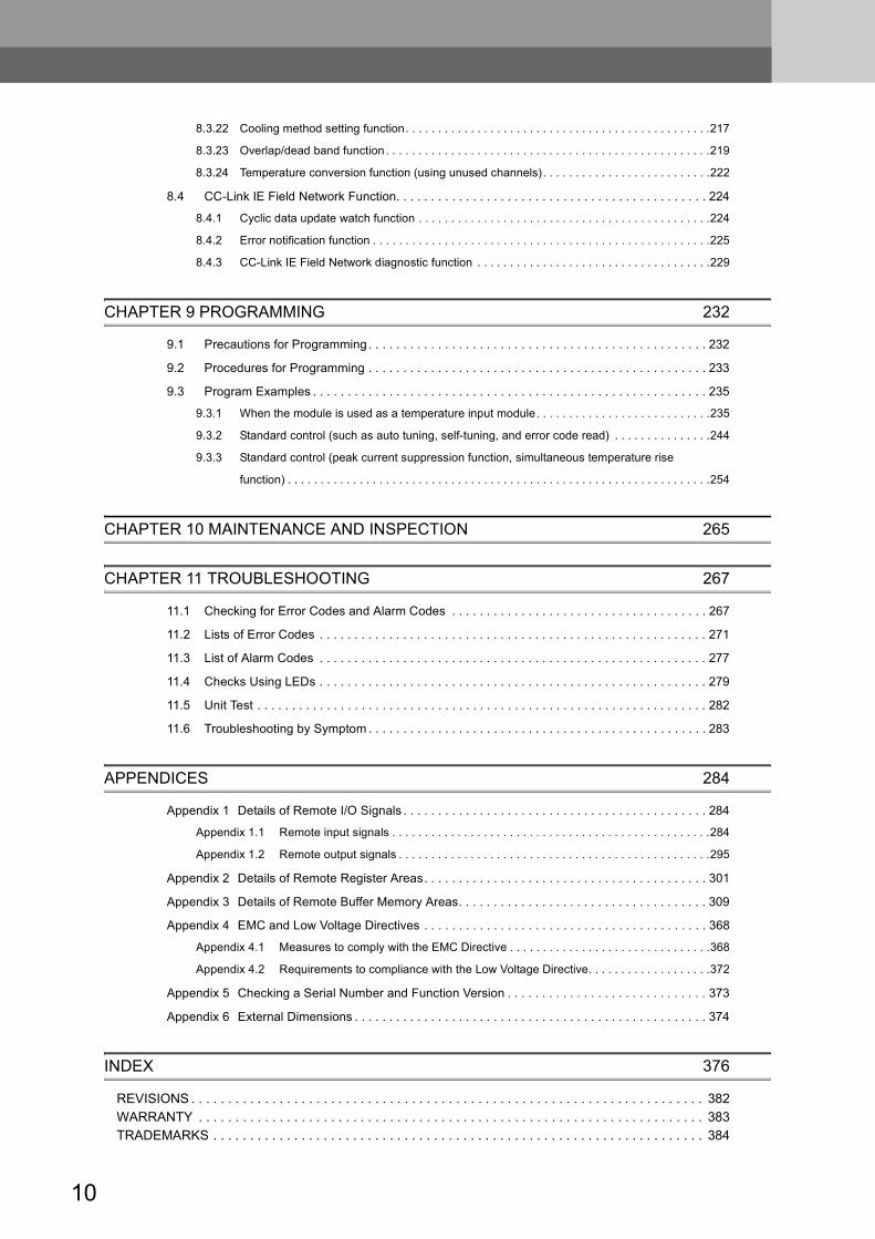
8.3.22 Cooling method setting function. . . . . . . . . . . . . . . . . . . . . . . . . . . . . . . . . . . . . . . . . . . . . . .217
8.3.23 Overlap/dead band function . . . . . . . . . . . . . . . . . . . . . . . . . . . . . . . . . . . . . . . . . . . . . . . . . .219
8.3.24 Temperature conversion function (using unused channels). . . . . . . . . . . . . . . . . . . . . . . . . .222
8.4 CC-Link IE Field Network Function. . . . . . . . . . . . . . . . . . . . . . . . . . . . . . . . . . . . . . . . . . . . . 224
8.4.1 Cyclic data update watch function . . . . . . . . . . . . . . . . . . . . . . . . . . . . . . . . . . . . . . . . . . . . .224
8.4.2 Error notification function . . . . . . . . . . . . . . . . . . . . . . . . . . . . . . . . . . . . . . . . . . . . . . . . . . . .225
8.4.3 CC-Link IE Field Network diagnostic function . . . . . . . . . . . . . . . . . . . . . . . . . . . . . . . . . . . .229
CHAPTER 9 PROGRAMMING 232
9.1 Precautions for Programming . . . . . . . . . . . . . . . . . . . . . . . . . . . . . . . . . . . . . . . . . . . . . . . . . 232
9.2 Procedures for Programming . . . . . . . . . . . . . . . . . . . . . . . . . . . . . . . . . . . . . . . . . . . . . . . . . 233
9.3 Program Examples . . . . . . . . . . . . . . . . . . . . . . . . . . . . . . . . . . . . . . . . . . . . . . . . . . . . . . . . . 235
9.3.1 When the module is used as a temperature input module. . . . . . . . . . . . . . . . . . . . . . . . . . .235
9.3.2 Standard control (such as auto tuning, self-tuning, and error code read) . . . . . . . . . . . . . . .244
9.3.3 Standard control (peak current suppression function, simultaneous temperature rise
function) . . . . . . . . . . . . . . . . . . . . . . . . . . . . . . . . . . . . . . . . . . . . . . . . . . . . . . . . . . . . . . . . .254
CHAPTER 10 MAINTENANCE AND INSPECTION 265
CHAPTER 11 TROUBLESHOOTING 267
11.1 Checking for Error Codes and Alarm Codes . . . . . . . . . . . . . . . . . . . . . . . . . . . . . . . . . . . . . 267
11.2 Lists of Error Codes . . . . . . . . . . . . . . . . . . . . . . . . . . . . . . . . . . . . . . . . . . . . . . . . . . . . . . . . 271
11.3 List of Alarm Codes . . . . . . . . . . . . . . . . . . . . . . . . . . . . . . . . . . . . . . . . . . . . . . . . . . . . . . . . 277
11.4 Checks Using LEDs . . . . . . . . . . . . . . . . . . . . . . . . . . . . . . . . . . . . . . . . . . . . . . . . . . . . . . . . 279
11.5 Unit Test . . . . . . . . . . . . . . . . . . . . . . . . . . . . . . . . . . . . . . . . . . . . . . . . . . . . . . . . . . . . . . . . . 282
11.6 Troubleshooting by Symptom . . . . . . . . . . . . . . . . . . . . . . . . . . . . . . . . . . . . . . . . . . . . . . . . . 283
APPENDICES 284
Appendix 1 Details of Remote I/O Signals . . . . . . . . . . . . . . . . . . . . . . . . . . . . . . . . . . . . . . . . . . . . 284
Appendix 1.1 Remote input signals . . . . . . . . . . . . . . . . . . . . . . . . . . . . . . . . . . . . . . . . . . . . . . . . .284
Appendix 1.2 Remote output signals . . . . . . . . . . . . . . . . . . . . . . . . . . . . . . . . . . . . . . . . . . . . . . . .295
Appendix 2 Details of Remote Register Areas. . . . . . . . . . . . . . . . . . . . . . . . . . . . . . . . . . . . . . . . . 301
Appendix 3 Details of Remote Buffer Memory Areas. . . . . . . . . . . . . . . . . . . . . . . . . . . . . . . . . . . . 309
Appendix 4 EMC and Low Voltage Directives . . . . . . . . . . . . . . . . . . . . . . . . . . . . . . . . . . . . . . . . . 368
Appendix 4.1 Measures to comply with the EMC Directive . . . . . . . . . . . . . . . . . . . . . . . . . . . . . . .368
Appendix 4.2 Requirements to compliance with the Low Voltage Directive. . . . . . . . . . . . . . . . . . .372
Appendix 5 Checking a Serial Number and Function Version . . . . . . . . . . . . . . . . . . . . . . . . . . . . . 373
Appendix 6 External Dimensions . . . . . . . . . . . . . . . . . . . . . . . . . . . . . . . . . . . . . . . . . . . . . . . . . . . 374
INDEX 376
REVISIONS . . . . . . . . . . . . . . . . . . . . . . . . . . . . . . . . . . . . . . . . . . . . . . . . . . . . . . . . . . . . . . . . . . . . . . 382WARRANTY . . . . . . . . . . . . . . . . . . . . . . . . . . . . . . . . . . . . . . . . . . . . . . . . . . . . . . . . . . . . . . . . . . . . . 383TRADEMARKS . . . . . . . . . . . . . . . . . . . . . . . . . . . . . . . . . . . . . . . . . . . . . . . . . . . . . . . . . . . . . . . . . . . 384
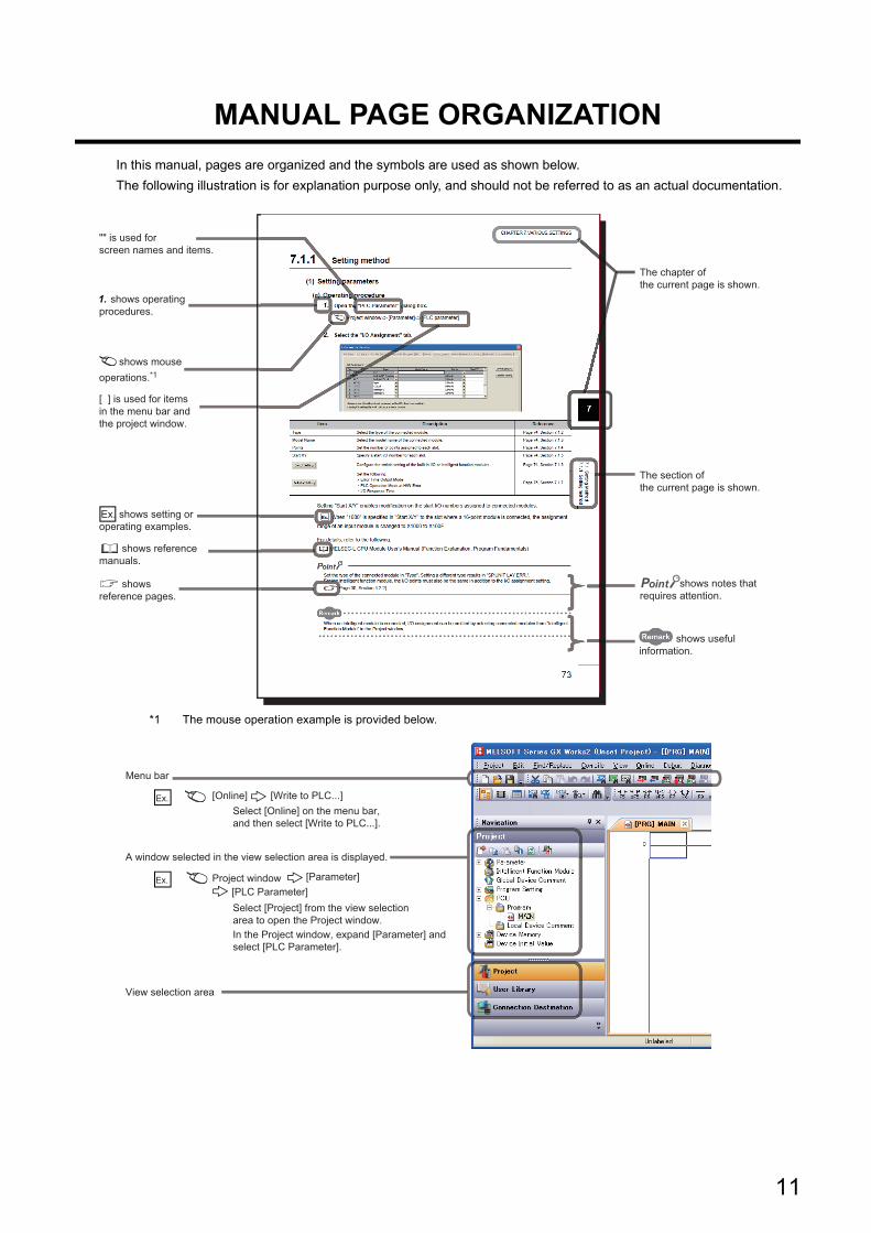
MANUAL PAGE ORGANIZATION
In this manual, pages are organized and the symbols are used as shown below.
The following illustration is for explanation purpose only, and should not be referred to as an actual documentation.
*1 The mouse operation example is provided below.
The section of the current page is shown.
The chapter of the current page is shown.
"" is used for screen names and items.
[ ] is used for items in the menu bar and the project window.
shows operating procedures.
shows reference manuals.
shows notes that requires attention.
shows mouse operations.*1
shows reference pages.
shows setting or operating examples.Ex.
shows useful information.
A window selected in the view selection area is displayed.
View selection area
[Online] [Write to PLC...]Select [Online] on the menu bar, and then select [Write to PLC...].
Project window [Parameter][PLC Parameter]Select [Project] from the view selection area to open the Project window.
Menu bar
Ex.
Ex.
In the Project window, expand [Parameter] and select [PLC Parameter].
11
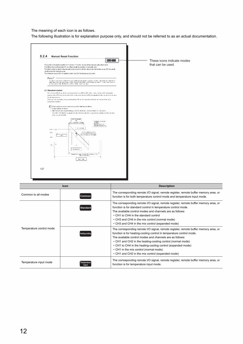
The meaning of each icon is as follows.
The following illustration is for explanation purpose only, and should not be referred to as an actual documentation.
Icon Description
Common to all modesThe corresponding remote I/O signal, remote register, remote buffer memory area, or
function is for both temperature control mode and temperature input mode.
Temperature control mode
The corresponding remote I/O signal, remote register, remote buffer memory area, or
function is for standard control in temperature control mode.
The available control modes and channels are as follows:
• CH1 to CH4 in the standard control
• CH3 and CH4 in the mix control (normal mode)
• CH3 and CH4 in the mix control (expanded mode)
The corresponding remote I/O signal, remote register, remote buffer memory area, or
function is for heating-cooling control in temperature control mode.
The available control modes and channels are as follows:
• CH1 and CH2 in the heating-cooling control (normal mode)
• CH1 to CH4 in the heating-cooling control (expanded mode)
• CH1 in the mix control (normal mode)
• CH1 and CH2 in the mix control (expanded mode)
Temperature input modeThe corresponding remote I/O signal, remote register, remote buffer memory area, or
function is for temperature input mode.
These icons indicate modes that can be used.
Common
Standard
Heating-cooling
TemperatureInput
12

TERMS
Unless otherwise specified, this manual uses the following terms.
Term Description
Buffer memoryA memory in an intelligent function module, where data (such as setting values and monitoring values) exchanged
with a CPU module are stored
CC-Link IE Field Network A high-speed and large-capacity open field network that is based on Ethernet (1000BASE-T)
Control method A generic term for two-position control, P control, PI control, PD control, and PID control
Control mode
A generic term for the modes when using the temperature control module in temperature control mode: the standard
control, heating-cooling control (normal mode), heating-cooling control (expanded mode), mix control (normal mode),
and mix control (expanded mode)
Cyclic transmissionA function by which data are periodically exchanged among stations on the same network using link devices (RX, RY,
RWw, and RWr)
Data link A generic term for cyclic transmission and transient transmission
Dedicated instruction An instruction that simplifies programming for using functions of intelligent function modules
Disconnection A process of stopping data link if a data link error occurs
Extension module
A remote module with no CC-Link IE Field Network communication function. This module cannot be used as a single
module. However, connecting the module to the main module will increase the number of I/O points per station.
The module cannot be connected to the temperature control module.
Fixed value action A control action when the set value (SV) is maintained at a fixed value
Full scale The width of an input range. For example, if the selected input range is -200.0 to 400.0, the full scale is 600.0.
GX Works2The product name of the software package for the MELSEC programmable controllers
GX Works3
Intelligent device station
A station that exchanges I/O signals (bit data) and I/O data (word data) with another station by cyclic transmission.
This station responds to a transient transmission request from another station and also issues a transient
transmission request to another station.
Link device A device (RX, RY, RWr, or RWw) in a module on CC-Link IE Field Network
Link special register (SW) Word data that indicates the operating status and data link status of a module on CC-Link IE Field Network
Link special relay (SB) Bit data that indicates the operating status and data link status of a module on CC-Link IE Field Network
Local stationA station that performs cyclic transmission and transient transmission with the master station and other local stations.
The station is controlled by programs in the CPU module or other equivalent modules on the station.
Main moduleA module with the CC-Link IE Field Network communication function, which can be used as a single remote module.
The temperature control module belongs to this type.
Master stationA station that controls the entire network. This station can perform cyclic transmission and transient transmission with
all stations. Only one master station can be used in a network.
Master/local module The abbreviation for the CC-Link IE Field Network master/local module
Network module
A generic term for the following modules:
• CC-Link IE Field Network module
• CC-Link IE Controller Network module
• Ethernet interface module
• MELSECNET/H module
• MELSECNET/10 module
Number of loops
The number of feedback control systems (closed-loop control systems) that can be configured using one temperature
control module. In the standard control, one loop consists of one input and one output. In the heating-cooling control,
one loop consists of one input and two outputs.
PID constants A generic term for the proportional band (P), integral time (I), and derivative time (D)
Ramp action A control action when the set value (SV) is continuously changed
Relay stationA station that includes two or more network modules. Data are passed through this station to stations on other
networks.
REMFR
The abbreviation for ZP.REMFR.
This dedicated instruction is used in the master/local module. The instruction reads data (in units of words) from the
buffer memory of the intelligent device station/remote device station.
User's manual for the master/local module used
Remote buffer memory Buffer memory in a remote device station
Remote device stationA station that exchanges I/O signals (bit data) and I/O data (word data) with another station by cyclic transmission.
This station responds to a transient transmission request from another station.
Remote I/O station A station that exchanges I/O signals (bit data) with the master station by cyclic transmission
13
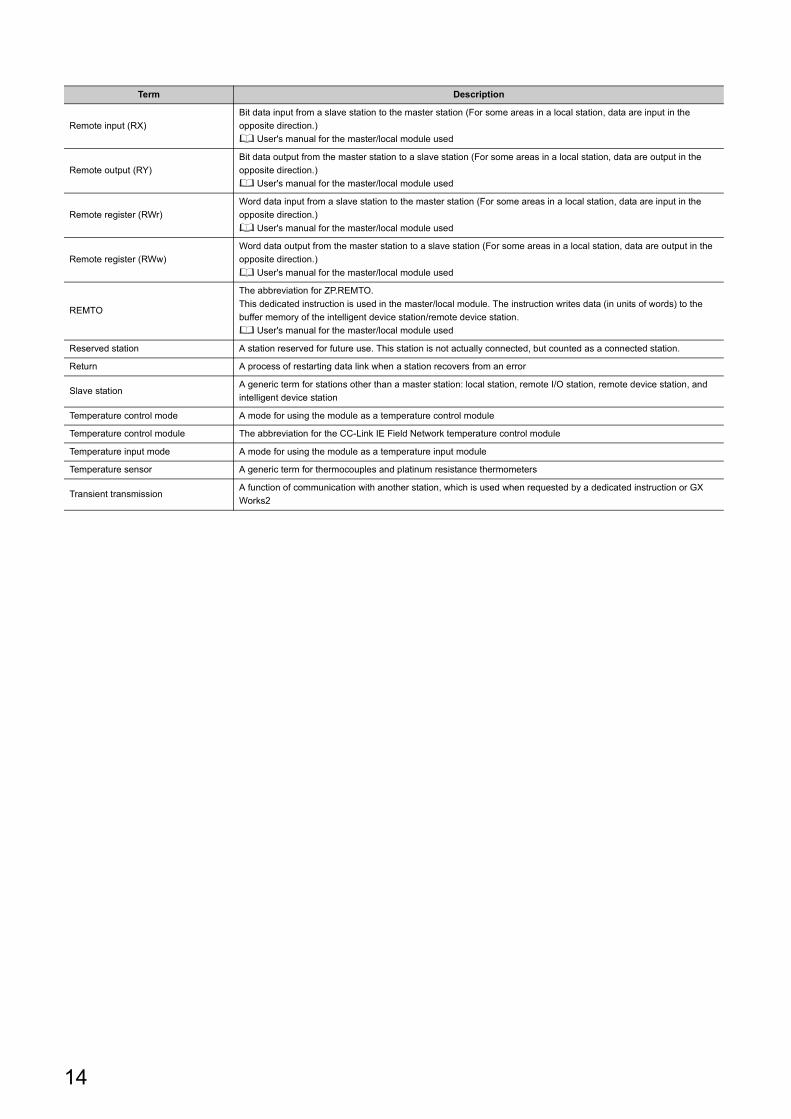
Remote input (RX)
Bit data input from a slave station to the master station (For some areas in a local station, data are input in the
opposite direction.)
User's manual for the master/local module used
Remote output (RY)
Bit data output from the master station to a slave station (For some areas in a local station, data are output in the
opposite direction.)
User's manual for the master/local module used
Remote register (RWr)
Word data input from a slave station to the master station (For some areas in a local station, data are input in the
opposite direction.)
User's manual for the master/local module used
Remote register (RWw)
Word data output from the master station to a slave station (For some areas in a local station, data are output in the
opposite direction.)
User's manual for the master/local module used
REMTO
The abbreviation for ZP.REMTO.
This dedicated instruction is used in the master/local module. The instruction writes data (in units of words) to the
buffer memory of the intelligent device station/remote device station.
User's manual for the master/local module used
Reserved station A station reserved for future use. This station is not actually connected, but counted as a connected station.
Return A process of restarting data link when a station recovers from an error
Slave stationA generic term for stations other than a master station: local station, remote I/O station, remote device station, and
intelligent device station
Temperature control mode A mode for using the module as a temperature control module
Temperature control module The abbreviation for the CC-Link IE Field Network temperature control module
Temperature input mode A mode for using the module as a temperature input module
Temperature sensor A generic term for thermocouples and platinum resistance thermometers
Transient transmissionA function of communication with another station, which is used when requested by a dedicated instruction or GX
Works2
Term Description
14

PACKING LIST
The following items are included in the package of this product. Before use, check that all the items are included.
Temperature control module
Temperature control module Before Using the Product
15
CHAPTER 1 TEMPERATURE CONTROL MODULE
This chapter describes the applications and features of a temperature control module.
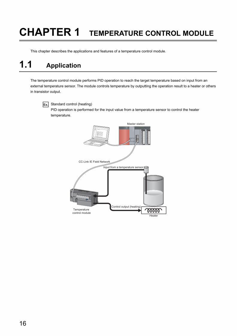
1.1 Application
The temperature control module performs PID operation to reach the target temperature based on input from an
external temperature sensor. The module controls temperature by outputting the operation result to a heater or others
in transistor output.
Ex. Standard control (heating)
PID operation is performed for the input value from a temperature sensor to control the heater
temperature.
Input from a temperature sensor
Control output (heating)
Heater
Master station
CC-Link IE Field Network
Temperature control module
16
CHAPTER 1 TEMPERATURE CONTROL MODULE
1
1.1
Ap
plica
tion
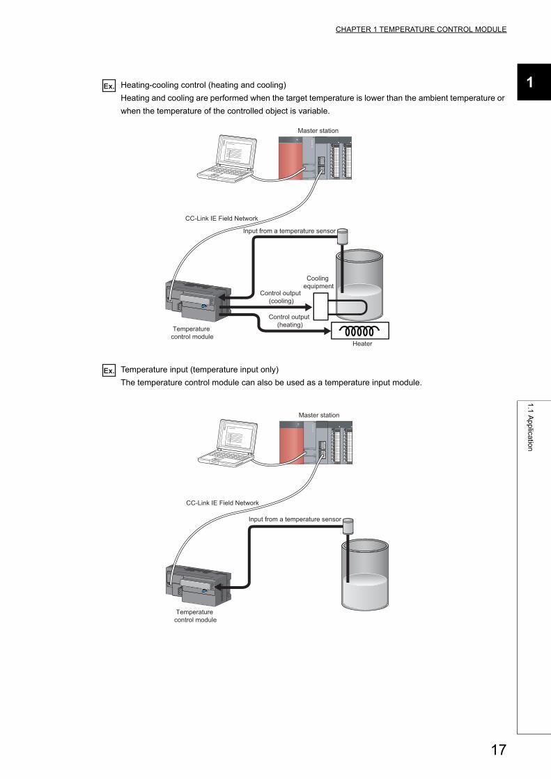
Ex. Heating-cooling control (heating and cooling)
Heating and cooling are performed when the target temperature is lower than the ambient temperature or
when the temperature of the controlled object is variable.
Ex. Temperature input (temperature input only)
The temperature control module can also be used as a temperature input module.
Input from a temperature sensor
Control output (heating)
Control output (cooling)
Heater
Cooling equipment
CC-Link IE Field Network
Master station
Temperature control module
Input from a temperature sensor
CC-Link IE Field Network
Master station
Temperature control module
17
1.2 Features
This section describes the features of the temperature control module.
Remark
For functions not described in this section, refer to the following.Page 38, Section 3.3
(1) Cost reduction (shortening of the sensor cable)In the standard modules (such as the L series temperature control modules), an extension of the sensor cable is
required to control a remote object, which has been costly. Since the temperature control module can be installed
near the controlled object, the sensor cable can be shortened, resulting in the cost reduction.
(2) Easy station number settingSetting and checking the station number are easy because a rotary switch for the setting is located on the front of
the module.
(3) Optimum temperature adjustment control (PID control)• The temperature control module performs temperature adjustment control automatically by simply setting
PID constants necessary for PID operation (proportional band (P), integral time (I), and derivative time (D)),
and temperature set value (SV). No special instruction is needed to perform PID control.
• The auto tuning function or self-tuning function enables the temperature control module to set PID constants
automatically. No complicated PID operation expression is needed to set PID constants.
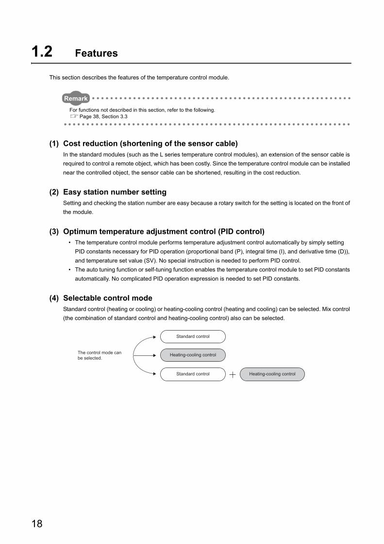
(4) Selectable control modeStandard control (heating or cooling) or heating-cooling control (heating and cooling) can be selected. Mix control
(the combination of standard control and heating-cooling control) also can be selected.
Standard control
Standard control
Heating-cooling control
Heating-cooling control
The control mode can be selected.
18
CHAPTER 1 TEMPERATURE CONTROL MODULE
1
1.2
Fe
atu
res
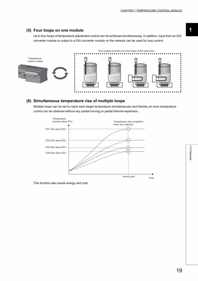
(5) Four loops on one moduleUp to four loops of temperature adjustment control can be achieved simultaneously. In addition, input from an A/D
converter module or output to a D/A converter module on the network can be used for loop control.
(6) Simultaneous temperature rise of multiple loopsMultiple loops can be set to reach each target temperature simultaneously and thereby an even temperature
control can be obtained without any partial burning or partial thermal expansion.
This function also saves energy and cost.
Temperature control module
One module controls up to four loops at the same time.
CH1 Set value (SV)
Temperature rise completion times are matched.
Arrival point
Temperatureprocess value (PV)
Time
CH2 Set value (SV)
CH3 Set value (SV)
CH4 Set value (SV)
19
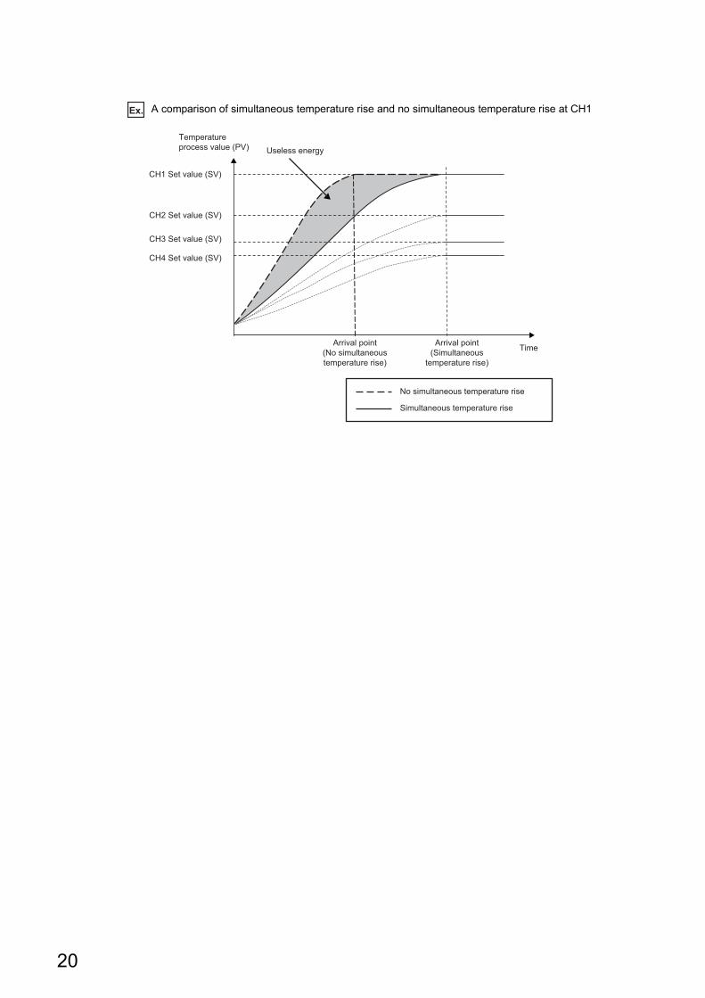
Ex. A comparison of simultaneous temperature rise and no simultaneous temperature rise at CH1
CH1 Set value (SV)
Arrival point(Simultaneous
temperature rise)
Arrival point(No simultaneoustemperature rise)
No simultaneous temperature rise
Simultaneous temperature rise
Useless energyTemperatureprocess value (PV)
Time
CH2 Set value (SV)
CH3 Set value (SV)
CH4 Set value (SV)
20
CHAPTER 1 TEMPERATURE CONTROL MODULE
1
1.2
Fe
atu
res
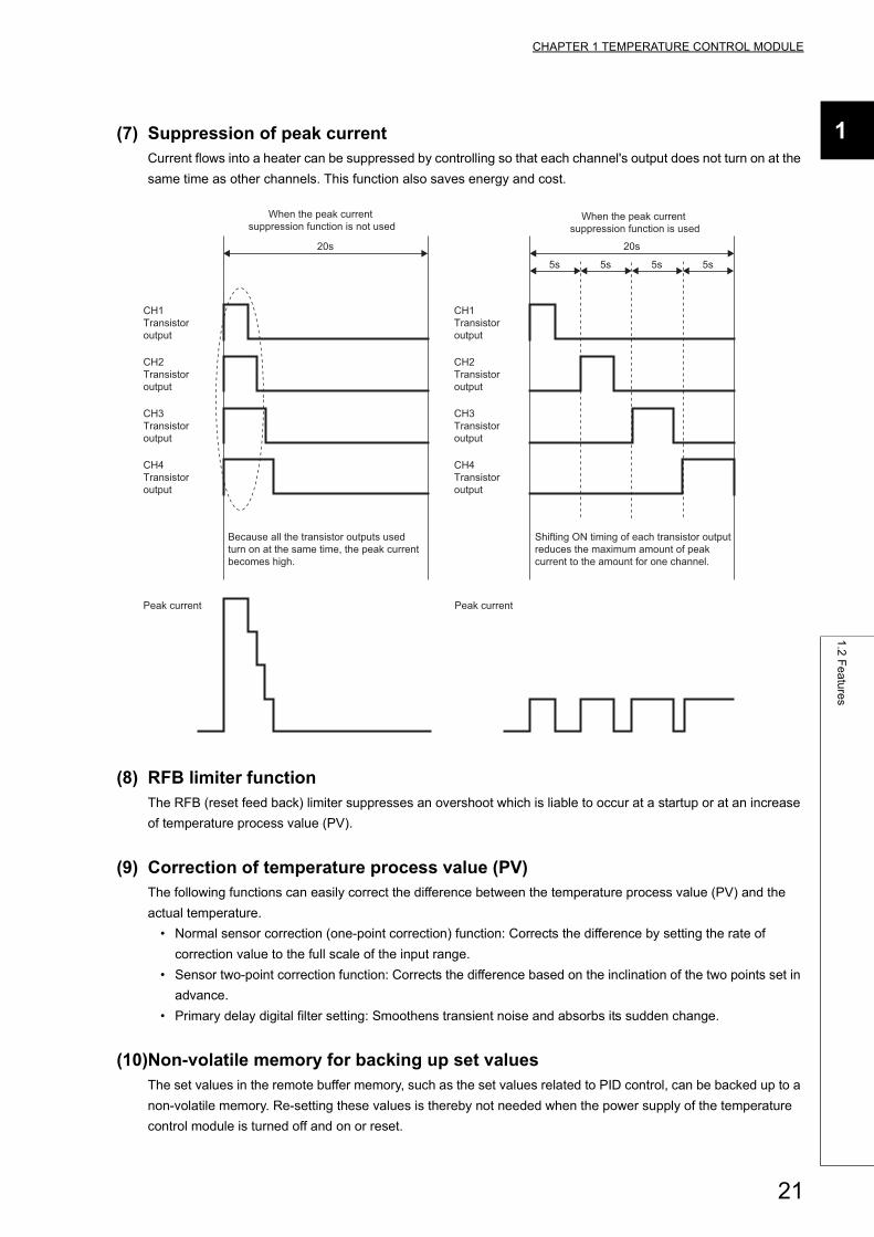
(7) Suppression of peak currentCurrent flows into a heater can be suppressed by controlling so that each channel's output does not turn on at the
same time as other channels. This function also saves energy and cost.
(8) RFB limiter functionThe RFB (reset feed back) limiter suppresses an overshoot which is liable to occur at a startup or at an increase
of temperature process value (PV).
(9) Correction of temperature process value (PV)The following functions can easily correct the difference between the temperature process value (PV) and the
actual temperature.
• Normal sensor correction (one-point correction) function: Corrects the difference by setting the rate of
correction value to the full scale of the input range.
• Sensor two-point correction function: Corrects the difference based on the inclination of the two points set in
advance.
• Primary delay digital filter setting: Smoothens transient noise and absorbs its sudden change.
(10)Non-volatile memory for backing up set valuesThe set values in the remote buffer memory, such as the set values related to PID control, can be backed up to a
non-volatile memory. Re-setting these values is thereby not needed when the power supply of the temperature
control module is turned off and on or reset.
20s
5s
20s
5s 5s 5s
CH1 Transistor output
CH2 Transistor output
CH3 Transistor output
CH4 Transistor output
Peak current Peak current
CH1 Transistor output
CH2 Transistor output
CH3 Transistor output
CH4 Transistor output
Because all the transistor outputs used turn on at the same time, the peak current becomes high.
Shifting ON timing of each transistor output reduces the maximum amount of peak current to the amount for one channel.
When the peak current suppression function is not used
When the peak current suppression function is used
21
(11)Detection of disconnectionThe loop disconnection detection function can simply detect a heater disconnection.
(12)Selectable sampling cycleThe module can be applied to a wide range of systems because the sampling cycle can be selected from
250ms/4 channels or 500ms/4 channels.
(13)Usable as a temperature input moduleThe temperature control module can also be used as a temperature input module. The switching to a
temperature input module can be easily controlled in the setting.
The primary delay digital filter and the alert output can also be set to temperature input.
Page 138, Section 8.2
(14)Checking the error historyThe past history of 15 errors and occurrence time is stored in the temperature control module. The error history
facilitates investigation of the causes when a problem occurs.
(15)Easy setting with the CC IE Field configuration of the engineering toolThe CC IE Field configuration of the engineering tool allows the parameters to be set on the window, resulting in
reducing the number of programs. The setting status of a module can also be checked easily. The setting status
of a module can also be checked easily.
(16)Checking the status of the CC-Link IE Field NetworkThe status of the CC-Link IE Field Network can be checked with the engineering tool. The engineering tool can
display the faulty areas, faulty causes, and event history, resulting in shortening the time to recover from an error.
22
CHAPTER 1 TEMPERATURE CONTROL MODULE
1
1.3
PID
Co
ntro
l Syste
m
1.3 PID Control System
This section describes the PID control system of the temperature control module.
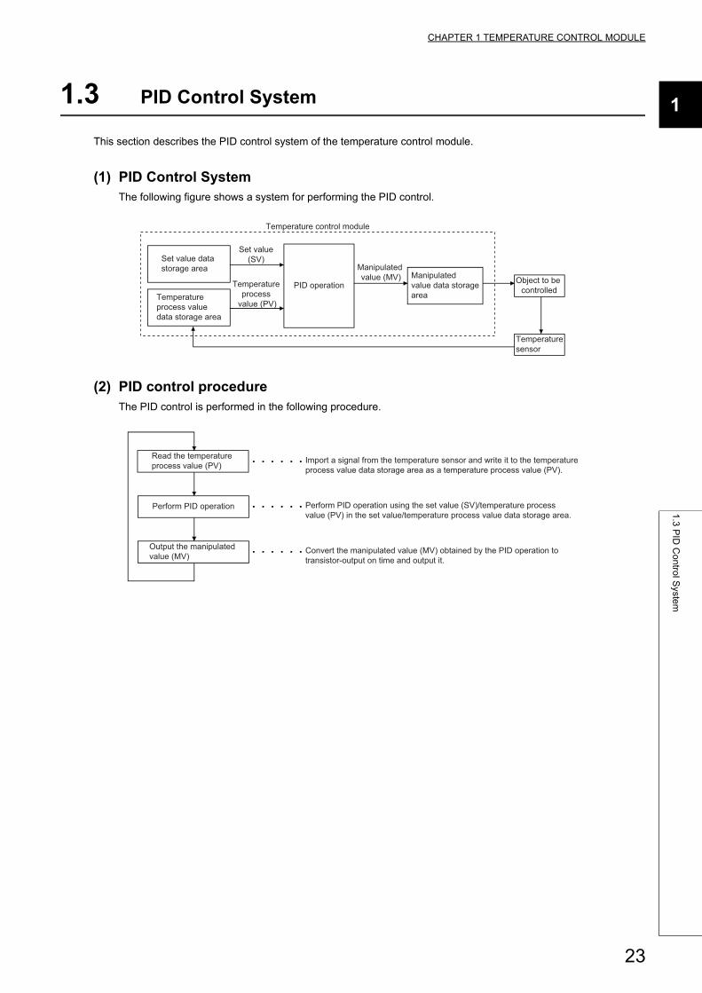
(1) PID Control SystemThe following figure shows a system for performing the PID control.
(2) PID control procedureThe PID control is performed in the following procedure.
Set value data storage area
Temperatureprocess value data storage area
PID operationManipulated value data storagearea
Temperaturesensor
Object to be controlled
Set value(SV)
Temperature process
value (PV)
Manipulated value (MV)
Temperature control module
Import a signal from the temperature sensor and write it to the temperature process value data storage area as a temperature process value (PV).
Perform PID operation using the set value (SV)/temperature process value (PV) in the set value/temperature process value data storage area.
Convert the manipulated value (MV) obtained by the PID operation to transistor-output on time and output it.
Read the temperature process value (PV)
Perform PID operation
Output the manipulated value (MV)
23
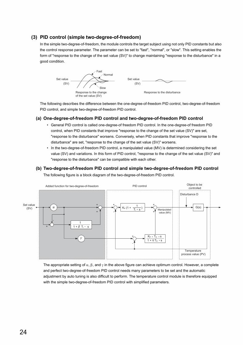
(3) PID control (simple two-degree-of-freedom)In the simple two-degree-of-freedom, the module controls the target subject using not only PID constants but also
the control response parameter. The parameter can be set to "fast", "normal", or "slow". This setting enables the
form of "response to the change of the set value (SV)" to change maintaining "response to the disturbance" in a
good condition.
The following describes the difference between the one-degree-of-freedom PID control, two-degree-of-freedom
PID control, and simple two-degree-of-freedom PID control.
(a) One-degree-of-freedom PID control and two-degree-of-freedom PID control
• General PID control is called one-degree-of freedom PID control. In the one-degree-of freedom PID
control, when PID constants that improve "response to the change of the set value (SV)" are set,
"response to the disturbance" worsens. Conversely, when PID constants that improve "response to the
disturbance" are set, "response to the change of the set value (SV)" worsens.
• In the two-degree-of-freedom PID control, a manipulated value (MV) is determined considering the set
value (SV) and variations. In this form of PID control, "response to the change of the set value (SV)" and
"response to the disturbance" can be compatible with each other.
(b) Two-degree-of-freedom PID control and simple two-degree-of-freedom PID control
The following figure is a block diagram of the two-degree-of-freedom PID control.
The appropriate setting of , , and in the above figure can achieve optimum control. However, a complete
and perfect two-degree-of-freedom PID control needs many parameters to be set and the automatic
adjustment by auto tuning is also difficult to perform. The temperature control module is therefore equipped
with the simple two-degree-of-freedom PID control with simplified parameters.
Set value(SV)
NormalFast
SlowResponse to the change of the set value (SV)
Set value(SV)
Response to the disturbance
PID control Object to be controlled
Disturbance D
11 + TI s
1 + TD sKP TD s
1TI s
KP (1 + )
Added function for two-degree-of-freedom
Manipulated value (MV)
Set value (SV) G(s)
Temperature process value (PV)
-
+
-
+
+
+
+
+
+
-
24
CHAPTER 1 TEMPERATURE CONTROL MODULE
1
1.4
PID
Op
era
tion
1.4 PID Operation
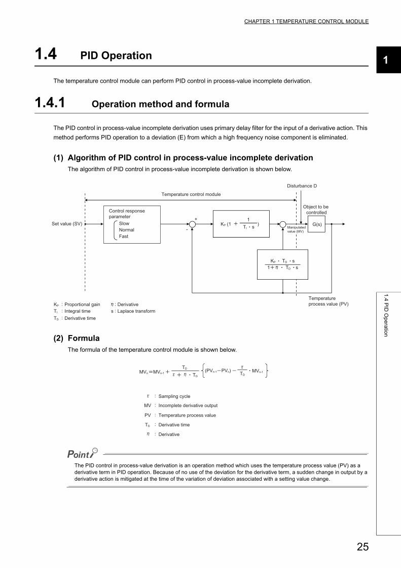
The temperature control module can perform PID control in process-value incomplete derivation.
1.4.1 Operation method and formula
The PID control in process-value incomplete derivation uses primary delay filter for the input of a derivative action. This
method performs PID operation to a deviation (E) from which a high frequency noise component is eliminated.
(1) Algorithm of PID control in process-value incomplete derivationThe algorithm of PID control in process-value incomplete derivation is shown below.
(2) FormulaThe formula of the temperature control module is shown below.
The PID control in process-value derivation is an operation method which uses the temperature process value (PV) as a derivative term in PID operation. Because of no use of the deviation for the derivative term, a sudden change in output by a derivative action is mitigated at the time of the variation of deviation associated with a setting value change.
Object to be controlled
SlowNormalFast
1
Disturbance D
G(s)
Temperature process value (PV)
Laplace transformDerivativeProportional gain
Integral timeDerivative time
Set value (SV) KP (1 )
Control responseparameter
KP
TI
TD
s
Manipulated value (MV)
::
::
:
TI s
KP TD s1 TD s
+
-
Temperature control module
Sampling cycle
Incomplete derivative output
Temperature process value
Derivative time
Derivative
MVn MVn-1
TD (PVn-1 PVn) TD
MVn-1
MV
PV
TD
TD
25
1.4.2 Actions of a temperature control module
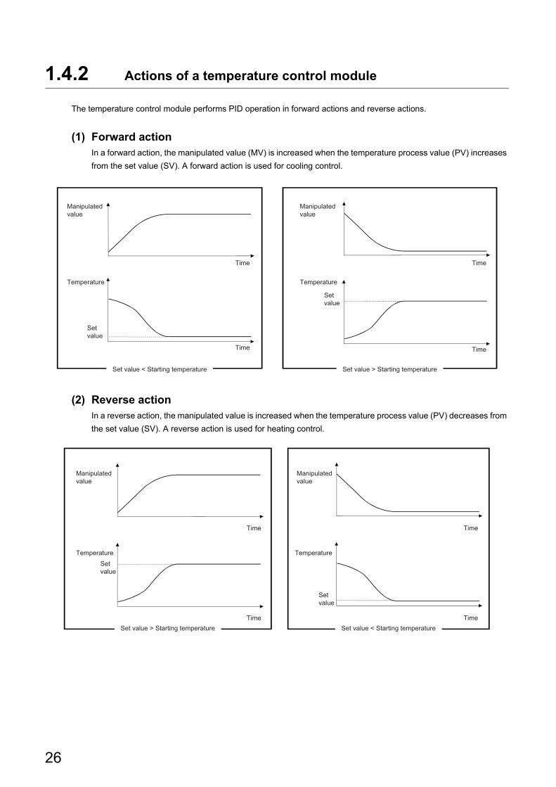
The temperature control module performs PID operation in forward actions and reverse actions.
(1) Forward actionIn a forward action, the manipulated value (MV) is increased when the temperature process value (PV) increases
from the set value (SV). A forward action is used for cooling control.
(2) Reverse actionIn a reverse action, the manipulated value is increased when the temperature process value (PV) decreases from
the set value (SV). A reverse action is used for heating control.
Manipulatedvalue
Manipulatedvalue
Temperature Temperature
Time
Time
Time
Time
Set value < Starting temperature Set value > Starting temperature
Setvalue
Setvalue
Manipulatedvalue
Temperature
Time
Time
Time
Time
Manipulatedvalue
TemperatureSetvalue
Set value > Starting temperature Set value < Starting temperature
Setvalue
26
CHAPTER 1 TEMPERATURE CONTROL MODULE
1
1.4
PID
Op
era
tion
1.4.3 Proportional action (P-action)
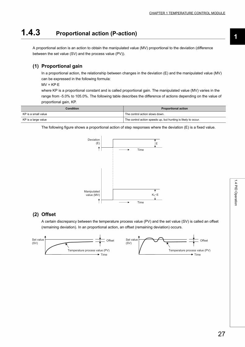
A proportional action is an action to obtain the manipulated value (MV) proportional to the deviation (difference
between the set value (SV) and the process value (PV)).
(1) Proportional gainIn a proportional action, the relationship between changes in the deviation (E) and the manipulated value (MV)
can be expressed in the following formula:
MV = KPE
where KP is a proportional constant and is called proportional gain. The manipulated value (MV) varies in the
range from -5.0% to 105.0%. The following table describes the difference of actions depending on the value of
proportional gain, KP.
The following figure shows a proportional action of step responses where the deviation (E) is a fixed value.
(2) OffsetA certain discrepancy between the temperature process value (PV) and the set value (SV) is called an offset
(remaining deviation). In an proportional action, an offset (remaining deviation) occurs.
Condition Proportional action
KP is a small value The control action slows down.
KP is a large value The control action speeds up, but hunting is likely to occur.
E
Time
Time
Deviation(E)
Manipulatedvalue (MV) KP E
Set value(SV)
Set value(SV)
Temperature process value (PV) Temperature process value (PV)Time Time
Offset Offset
27
1.4.4 Integral action (I-action)
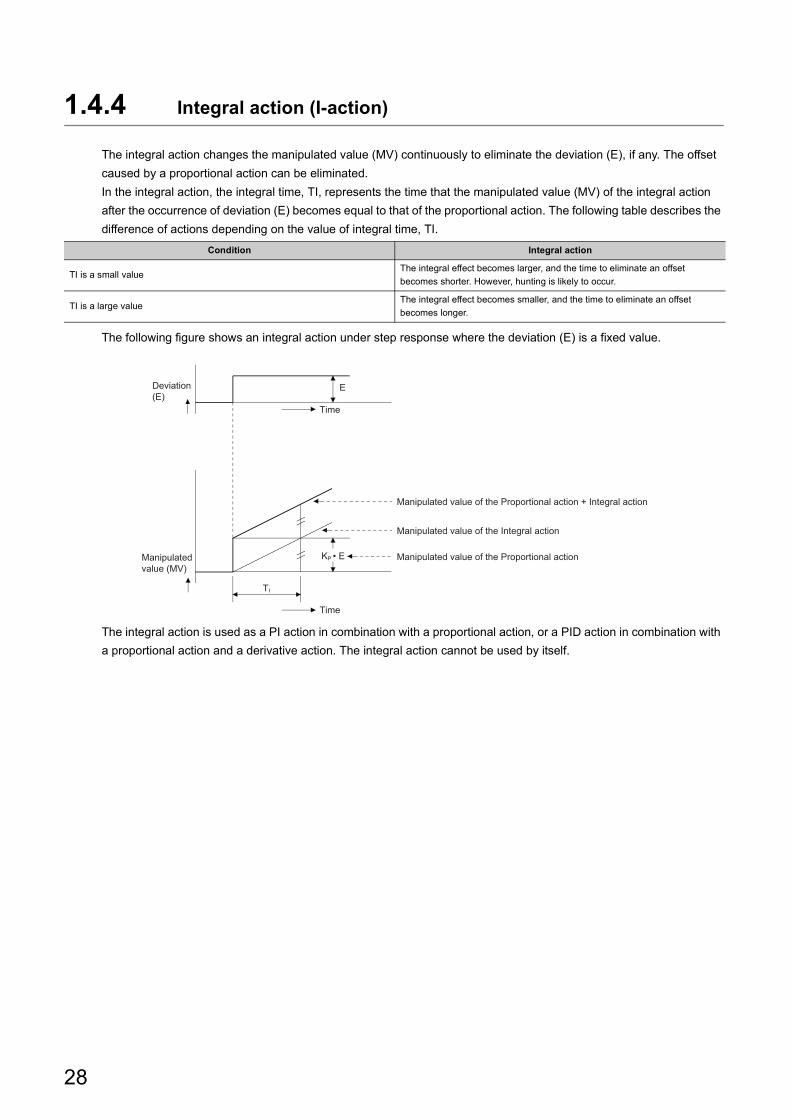
The integral action changes the manipulated value (MV) continuously to eliminate the deviation (E), if any. The offset
caused by a proportional action can be eliminated.
In the integral action, the integral time, TI, represents the time that the manipulated value (MV) of the integral action
after the occurrence of deviation (E) becomes equal to that of the proportional action. The following table describes the
difference of actions depending on the value of integral time, TI.
The following figure shows an integral action under step response where the deviation (E) is a fixed value.
The integral action is used as a PI action in combination with a proportional action, or a PID action in combination with
a proportional action and a derivative action. The integral action cannot be used by itself.
Condition Integral action
TI is a small valueThe integral effect becomes larger, and the time to eliminate an offset
becomes shorter. However, hunting is likely to occur.
TI is a large valueThe integral effect becomes smaller, and the time to eliminate an offset
becomes longer.
Manipulated value of the Proportional action
Manipulated value of the Integral action
Manipulated value of the Proportional action + Integral action
Time
TI
Deviation(E)
Manipulatedvalue (MV)
KP • E
E
Time
28
CHAPTER 1 TEMPERATURE CONTROL MODULE
1
1.4
PID
Op
era
tion
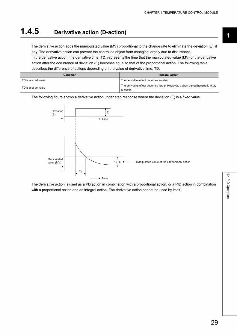
1.4.5 Derivative action (D-action)
The derivative action adds the manipulated value (MV) proportional to the change rate to eliminate the deviation (E), if
any. The derivative action can prevent the controlled object from changing largely due to disturbance.
In the derivative action, the derivative time, TD, represents the time that the manipulated value (MV) of the derivative
action after the occurrence of deviation (E) becomes equal to that of the proportional action. The following table
describes the difference of actions depending on the value of derivative time, TD.
The following figure shows a derivative action under step response where the deviation (E) is a fixed value.
The derivative action is used as a PD action in combination with a proportional action, or a PID action in combination
with a proportional action and an integral action. The derivative action cannot be used by itself.
Condition Integral action
TD is a small value The derivative effect becomes smaller.
TD is a large valueThe derivative effect becomes larger. However, a short period hunting is likely
to occur.
E
Manipulated value of the Proportional action
TD
Time
Time
Deviation(E)
Manipulatedvalue (MV) KP • E
29
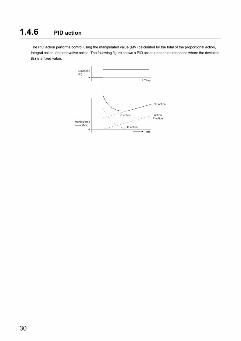
1.4.6 PID action
The PID action performs control using the manipulated value (MV) calculated by the total of the proportional action,
integral action, and derivative action. The following figure shows a PID action under step response where the deviation
(E) is a fixed value.
PID action
I actionP action
Deviation(E)
Manipulatedvalue (MV)
Time
Time
PI action
D action
30
CHAPTER 2 PART NAMES
2
CHAPTER 2 PART NAMES
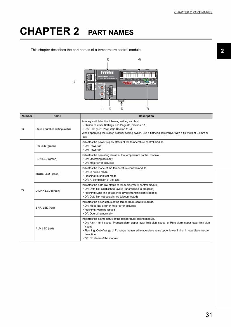
This chapter describes the part names of a temperature control module.
Number Name Description
1) Station number setting switch
A rotary switch for the following setting and test.
• Station Number Setting ( Page 85, Section 6.1)
• Unit Test ( Page 282, Section 11.5)
When operating the station number setting switch, use a flathead screwdriver with a tip width of 3.5mm or
less.
2)
PW LED (green)
Indicates the power supply status of the temperature control module.
• On: Power-on
• Off: Power-off
RUN LED (green)
Indicates the operating status of the temperature control module.
• On: Operating normally
• Off: Major error occurred
MODE LED (green)
Indicates the mode of the temperature control module.
• On: In online mode
• Flashing: In unit test mode
• Off: At completion of unit test
D LINK LED (green)
Indicates the data link status of the temperature control module.
• On: Data link established (cyclic transmission in progress)
• Flashing: Data link established (cyclic transmission stopped)
• Off: Data link not established (disconnected)
ERR. LED (red)
Indicates the error status of the temperature control module.
• On: Moderate error or major error occurred
• Flashing: Warning issued
• Off: Operating normally
ALM LED (red)
Indicates the alarm status of the temperature control module.
• On: Alert 1 to 4 issued, Process alarm upper lower limit alert issued, or Rate alarm upper lower limit alert
issued
• Flashing: Out of range of PV range measured temperature value upper lower limit or in loop disconnection
detection
• Off: No alarm of the module
3)
2)
1) 4) 5) 7)
6)
31
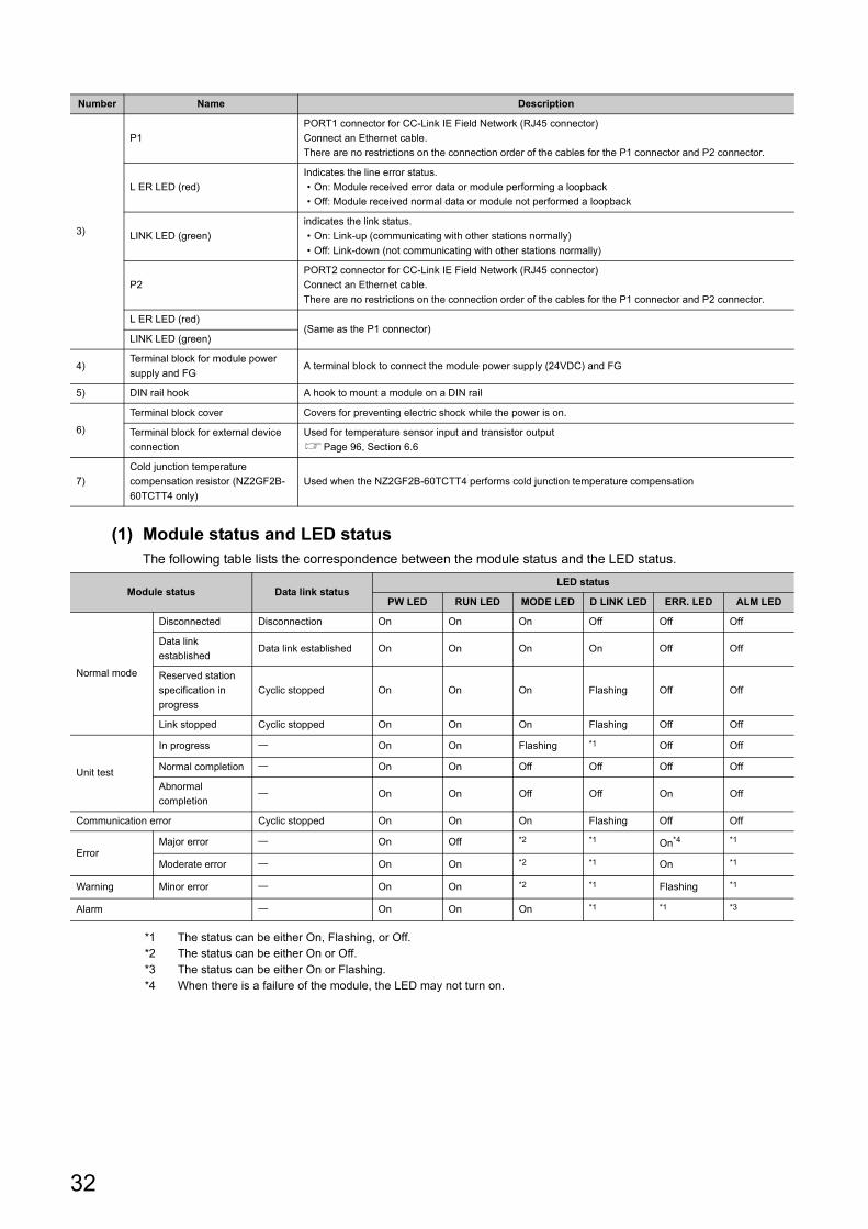
(1) Module status and LED statusThe following table lists the correspondence between the module status and the LED status.
*1 The status can be either On, Flashing, or Off.*2 The status can be either On or Off.*3 The status can be either On or Flashing. *4 When there is a failure of the module, the LED may not turn on.
3)
P1
PORT1 connector for CC-Link IE Field Network (RJ45 connector)
Connect an Ethernet cable.
There are no restrictions on the connection order of the cables for the P1 connector and P2 connector.
L ER LED (red)
Indicates the line error status.
• On: Module received error data or module performing a loopback
• Off: Module received normal data or module not performed a loopback
LINK LED (green)
indicates the link status.
• On: Link-up (communicating with other stations normally)
• Off: Link-down (not communicating with other stations normally)
P2
PORT2 connector for CC-Link IE Field Network (RJ45 connector)
Connect an Ethernet cable.
There are no restrictions on the connection order of the cables for the P1 connector and P2 connector.
L ER LED (red)(Same as the P1 connector)
LINK LED (green)
4)Terminal block for module power
supply and FGA terminal block to connect the module power supply (24VDC) and FG
5) DIN rail hook A hook to mount a module on a DIN rail
6)
Terminal block cover Covers for preventing electric shock while the power is on.
Terminal block for external device
connection
Used for temperature sensor input and transistor output
Page 96, Section 6.6
7)
Cold junction temperature
compensation resistor (NZ2GF2B-
60TCTT4 only)
Used when the NZ2GF2B-60TCTT4 performs cold junction temperature compensation
Module status Data link statusLED status
PW LED RUN LED MODE LED D LINK LED ERR. LED ALM LED
Normal mode
Disconnected Disconnection On On On Off Off Off
Data link
establishedData link established On On On On Off Off
Reserved station
specification in
progress
Cyclic stopped On On On Flashing Off Off
Link stopped Cyclic stopped On On On Flashing Off Off
Unit test
In progress On On Flashing *1 Off Off
Normal completion On On Off Off Off Off
Abnormal
completion On On Off Off On Off
Communication error Cyclic stopped On On On Flashing Off Off
ErrorMajor error On Off *2 *1 On*4 *1
Moderate error On On *2 *1 On *1
Warning Minor error On On *2 *1 Flashing *1
Alarm On On On *1 *1 *3
Number Name Description
32
CHAPTER 3 SPECIFICATIONS
3
3.1
Ge
ne
ral S
pe
cificatio
ns
CHAPTER 3 SPECIFICATIONS
This chapter describes the specifications of the temperature control module.
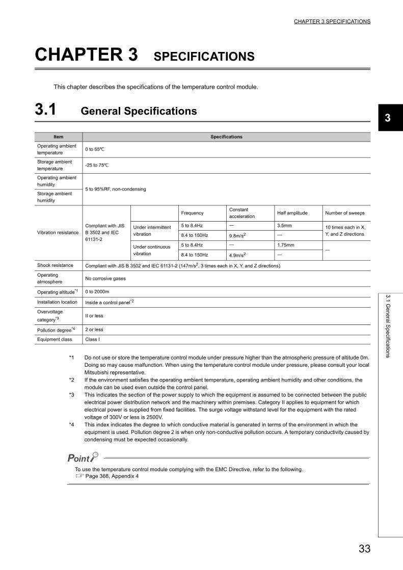
3.1 General Specifications
*1 Do not use or store the temperature control module under pressure higher than the atmospheric pressure of altitude 0m. Doing so may cause malfunction. When using the temperature control module under pressure, please consult your local Mitsubishi representative.
*2 If the environment satisfies the operating ambient temperature, operating ambient humidity and other conditions, the module can be used even outside the control panel.
*3 This indicates the section of the power supply to which the equipment is assumed to be connected between the public electrical power distribution network and the machinery within premises. Category II applies to equipment for which electrical power is supplied from fixed facilities. The surge voltage withstand level for the equipment with the rated voltage of 300V or less is 2500V.
*4 This index indicates the degree to which conductive material is generated in terms of the environment in which the equipment is used. Pollution degree 2 is when only non-conductive pollution occurs. A temporary conductivity caused by condensing must be expected occasionally.
To use the temperature control module complying with the EMC Directive, refer to the following.Page 368, Appendix 4
Item Specifications
Operating ambient
temperature0 to 55
Storage ambient
temperature-25 to 75
Operating ambient
humidity5 to 95%RF, non-condensing
Storage ambient
humidity
Vibration resistance
Compliant with JIS
B 3502 and IEC
61131-2
FrequencyConstant
accelerationHalf amplitude Number of sweeps
Under intermittent
vibration
5 to 8.4Hz 3.5mm 10 times each in X,
Y, and Z directions8.4 to 150Hz 9.8m/s2
Under continuous
vibration
5 to 8.4Hz 1.75mm
8.4 to 150Hz 4.9m/s2
Shock resistance Compliant with JIS B 3502 and IEC 61131-2 (147m/s2, 3 times each in X, Y, and Z directions)
Operating
atmosphereNo corrosive gases
Operating altitude*1 0 to 2000m
Installation location Inside a control panel*2
Overvoltage
category*3II or less
Pollution degree*4 2 or less
Equipment class Class I
33
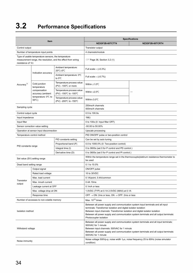
3.2 Performance Specifications
ItemSpecifications
NZ2GF2B-60TCTT4 NZ2GF2B-60TCRT4
Control output Transistor output
Number of temperature input points 4 channels/module
Type of usable temperature sensors, the temperature
measurement range, the resolution, and the effect from wiring
resistance of 1Page 36, Section 3.2 (1)
Accuracy*1
Indication accuracy
Ambient temperature:
255Full scale (0.3%)
Ambient temperature: 0
to 5Full scale (0.7%)
Cold junction
temperature
compensation
accuracy (ambient
temperature: 0 to
55)
Temperature process value
(PV): -100 or moreWithin 1.0
Temperature process value
(PV): -150 to -100Within 2.0
Temperature process value
(PV): -200 to -150Within3.0
Sampling cycle250ms/4 channels
500ms/4 channels
Control output cycle 0.5 to 100.0s
Input impedance 1M
Input filter 0 to 100s (0: Input filter OFF)
Sensor correction value setting -50.00 to 50.00%
Operation at sensor input disconnection Upscale processing
Temperature control method PID ON/OFF pulse or two-position control
PID constants range
PID constants setting Can be set by auto tuning.
Proportional band (P) 0.0 to 1000.0% (0: Two-position control)
Integral time (I) 0 to 3600s (set 0 for P control and PD control.)
Derivative time (D) 0 to 3600s (set 0 for P control and PI control.)
Set value (SV) setting rangeWithin the temperature range set in the thermocouple/platinum resistance thermometer to
be used
Dead band setting range 0.1 to 10.0%
Transistor
output
Output signal ON/OFF pulse
Rated load voltage 10 to 30VDC
Max. load current 0.1A/point, 0.4A/common
Max. inrush current 0.4A 10ms
Leakage current at OFF 0.1mA or less
Max. voltage drop at ON 1.0VDC (TYP) at 0.1A 2.5VDC (MAX) at 0.1A
Response time OFF ON: 2ms or less, ON OFF: 2ms or less
Number of accesses to non-volatile memory Max. 1012 times
Isolation method
Between all power supply and communication system input terminals and all input
terminals: Transformer isolation and digital isolator isolation
Between input channels: Transformer isolation and digital isolator isolation
Between all power supply and communication system terminals and all output terminals:
Photocoupler isolation
Withstand voltage
Between all power supply and communication system terminals and all input terminals:
500VAC for 1 minute
Between input channels: 500VAC for 1 minute
Between all power supply and communication system terminals and all output terminals:
500VAC for 1 minute
Noise immunityNoise voltage 500Vp-p, noise width 1s, noise frequency 25 to 60Hz (noise simulator
condition)
34
CHAPTER 3 SPECIFICATIONS
3
3.2
Pe
rform
an
ce S
pe
cificatio
ns
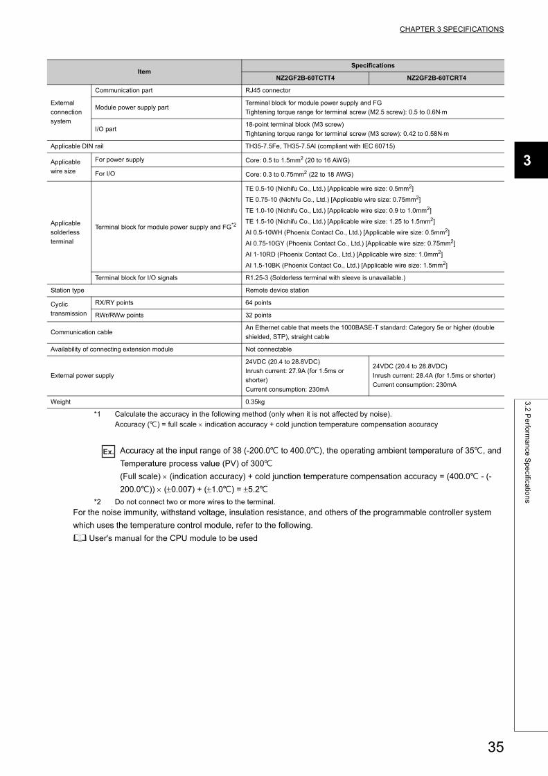
*1 Calculate the accuracy in the following method (only when it is not affected by noise).Accuracy () = full scale indication accuracy + cold junction temperature compensation accuracy
Ex. Accuracy at the input range of 38 (-200.0 to 400.0), the operating ambient temperature of 35, and
Temperature process value (PV) of 300
(Full scale) (indication accuracy) + cold junction temperature compensation accuracy = (400.0 - (-
200.0)) (0.007) + (1.0) = 5.2
*2 Do not connect two or more wires to the terminal.
For the noise immunity, withstand voltage, insulation resistance, and others of the programmable controller system
which uses the temperature control module, refer to the following.
User's manual for the CPU module to be used
External
connection
system
Communication part RJ45 connector
Module power supply partTerminal block for module power supply and FG
Tightening torque range for terminal screw (M2.5 screw): 0.5 to 0.6Nm
I/O part18-point terminal block (M3 screw)
Tightening torque range for terminal screw (M3 screw): 0.42 to 0.58Nm
Applicable DIN rail TH35-7.5Fe, TH35-7.5Al (compliant with IEC 60715)
Applicable
wire size
For power supply Core: 0.5 to 1.5mm2 (20 to 16 AWG)
For I/O Core: 0.3 to 0.75mm2 (22 to 18 AWG)
Applicable
solderless
terminal
Terminal block for module power supply and FG*2
TE 0.5-10 (Nichifu Co., Ltd.) [Applicable wire size: 0.5mm2]
TE 0.75-10 (Nichifu Co., Ltd.) [Applicable wire size: 0.75mm2]
TE 1.0-10 (Nichifu Co., Ltd.) [Applicable wire size: 0.9 to 1.0mm2]
TE 1.5-10 (Nichifu Co., Ltd.) [Applicable wire size: 1.25 to 1.5mm2]
AI 0.5-10WH (Phoenix Contact Co., Ltd.) [Applicable wire size: 0.5mm2]
AI 0.75-10GY (Phoenix Contact Co., Ltd.) [Applicable wire size: 0.75mm2]
AI 1-10RD (Phoenix Contact Co., Ltd.) [Applicable wire size: 1.0mm2]
AI 1.5-10BK (Phoenix Contact Co., Ltd.) [Applicable wire size: 1.5mm2]
Terminal block for I/O signals R1.25-3 (Solderless terminal with sleeve is unavailable.)
Station type Remote device station
Cyclic
transmission
RX/RY points 64 points
RWr/RWw points 32 points
Communication cableAn Ethernet cable that meets the 1000BASE-T standard: Category 5e or higher (double
shielded, STP), straight cable
Availability of connecting extension module Not connectable
External power supply
24VDC (20.4 to 28.8VDC)
Inrush current: 27.9A (for 1.5ms or
shorter)
Current consumption: 230mA
24VDC (20.4 to 28.8VDC)
Inrush current: 28.4A (for 1.5ms or shorter)
Current consumption: 230mA
Weight 0.35kg
ItemSpecifications
NZ2GF2B-60TCTT4 NZ2GF2B-60TCRT4
35
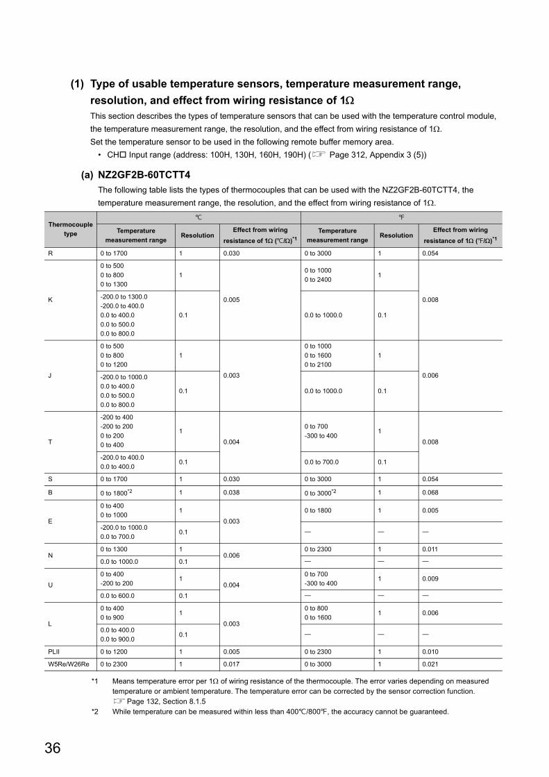
(1) Type of usable temperature sensors, temperature measurement range,
resolution, and effect from wiring resistance of 1This section describes the types of temperature sensors that can be used with the temperature control module,
the temperature measurement range, the resolution, and the effect from wiring resistance of 1.
Set the temperature sensor to be used in the following remote buffer memory area.
• CH Input range (address: 100H, 130H, 160H, 190H) ( Page 312, Appendix 3 (5))
(a) NZ2GF2B-60TCTT4
The following table lists the types of thermocouples that can be used with the NZ2GF2B-60TCTT4, the
temperature measurement range, the resolution, and the effect from wiring resistance of 1.
*1 Means temperature error per 1 of wiring resistance of the thermocouple. The error varies depending on measured temperature or ambient temperature. The temperature error can be corrected by the sensor correction function.Page 132, Section 8.1.5
*2 While temperature can be measured within less than 400/800, the accuracy cannot be guaranteed.
Thermocouple
type
Temperature
measurement rangeResolution
Effect from wiring
resistance of 1 (/)*1Temperature
measurement rangeResolution
Effect from wiring
resistance of 1 (/)*1
R 0 to 1700 1 0.030 0 to 3000 1 0.054
K
0 to 500
0 to 800
0 to 1300
1
0.005
0 to 1000
0 to 24001
0.008-200.0 to 1300.0
-200.0 to 400.0
0.0 to 400.0
0.0 to 500.0
0.0 to 800.0
0.1 0.0 to 1000.0 0.1
J
0 to 500
0 to 800
0 to 1200
1
0.003
0 to 1000
0 to 1600
0 to 2100
1
0.006-200.0 to 1000.0
0.0 to 400.0
0.0 to 500.0
0.0 to 800.0
0.1 0.0 to 1000.0 0.1
T
-200 to 400
-200 to 200
0 to 200
0 to 400
1
0.004
0 to 700
-300 to 4001
0.008
-200.0 to 400.0
0.0 to 400.00.1 0.0 to 700.0 0.1
S 0 to 1700 1 0.030 0 to 3000 1 0.054
B 0 to 1800*2 1 0.038 0 to 3000*2 1 0.068
E
0 to 400
0 to 10001
0.003
0 to 1800 1 0.005
-200.0 to 1000.0
0.0 to 700.00.1
N0 to 1300 1
0.0060 to 2300 1 0.011
0.0 to 1000.0 0.1
U
0 to 400
-200 to 2001
0.004
0 to 700
-300 to 4001 0.009
0.0 to 600.0 0.1
L
0 to 400
0 to 9001
0.003
0 to 800
0 to 16001 0.006
0.0 to 400.0
0.0 to 900.00.1
PLII 0 to 1200 1 0.005 0 to 2300 1 0.010
W5Re/W26Re 0 to 2300 1 0.017 0 to 3000 1 0.021
36
CHAPTER 3 SPECIFICATIONS
3
3.2
Pe
rform
an
ce S
pe
cificatio
ns
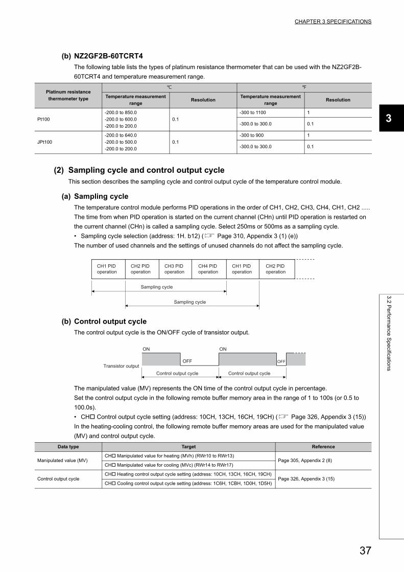
(b) NZ2GF2B-60TCRT4
The following table lists the types of platinum resistance thermometer that can be used with the NZ2GF2B-
60TCRT4 and temperature measurement range.
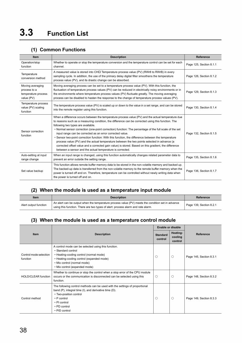
(2) Sampling cycle and control output cycleThis section describes the sampling cycle and control output cycle of the temperature control module.
(a) Sampling cycle
The temperature control module performs PID operations in the order of CH1, CH2, CH3, CH4, CH1, CH2 .....
The time from when PID operation is started on the current channel (CHn) until PID operation is restarted on
the current channel (CHn) is called a sampling cycle. Select 250ms or 500ms as a sampling cycle.
• Sampling cycle selection (address: 1H. b12) ( Page 310, Appendix 3 (1) (e))
The number of used channels and the settings of unused channels do not affect the sampling cycle.
(b) Control output cycle
The control output cycle is the ON/OFF cycle of transistor output.
The manipulated value (MV) represents the ON time of the control output cycle in percentage.
Set the control output cycle in the following remote buffer memory area in the range of 1 to 100s (or 0.5 to
100.0s).
• CH Control output cycle setting (address: 10CH, 13CH, 16CH, 19CH) ( Page 326, Appendix 3 (15))
In the heating-cooling control, the following remote buffer memory areas are used for the manipulated value
(MV) and control output cycle.
Platinum resistance
thermometer type
Temperature measurement
rangeResolution
Temperature measurement
rangeResolution
Pt100
-200.0 to 850.0
-200.0 to 600.0
-200.0 to 200.0
0.1
-300 to 1100 1
-300.0 to 300.0 0.1
JPt100
-200.0 to 640.0
-200.0 to 500.0
-200.0 to 200.0
0.1
-300 to 900 1
-300.0 to 300.0 0.1
Data type Target Reference
Manipulated value (MV)CH Manipulated value for heating (MVh) (RWr10 to RWr13)
Page 305, Appendix 2 (8)CH Manipulated value for cooling (MVc) (RWr14 to RWr17)
Control output cycleCH Heating control output cycle setting (address: 10CH, 13CH, 16CH, 19CH)
Page 326, Appendix 3 (15)CH Cooling control output cycle setting (address: 1C6H, 1CBH, 1D0H, 1D5H)
Sampling cycle
Sampling cycle
CH1 PID operation
CH2 PID operation
CH3 PID operation
CH4 PID operation
CH1 PID operation
CH2 PID operation
OFF
ON ON
OFF
Control output cycle Control output cycleTransistor output
37
3.3 Function List
(1) Common Functions
(2) When the module is used as a temperature input module
(3) When the module is used as a temperature control module
Item Description Reference
Operation/stop
function
Whether to operate or stop the temperature conversion and the temperature control can be set for each
channel.Page 125, Section 8.1.1
Temperature
conversion method
A measured value is stored into CH Temperature process value (PV) (RWr8 to RWrB) in every
sampling cycle. In addition, the use of the primary delay digital filter smoothens the temperature
process value (PV), and its drastic change can be absorbed.
Page 126, Section 8.1.2
Moving averaging
process to a
temperature process
value (PV)
Moving averaging process can be set to a temperature process value (PV). With this function, the
fluctuation of temperature process values (PV) can be reduced in electrically noisy environments or in
the environments where temperature process values (PV) fluctuate greatly. The moving averaging
process can be disabled to hasten the response to the change of temperature process values (PV).
Page 129, Section 8.1.3
Temperature process
value (PV) scaling
function
The temperature process value (PV) is scaled up or down to the value in a set range, and can be stored
into the remote register using this function.Page 130, Section 8.1.4
Sensor correction
function
When a difference occurs between the temperature process value (PV) and the actual temperature due
to reasons such as a measuring condition, the difference can be corrected using this function. The
following two types are available.
• Normal sensor correction (one-point correction) function: The percentage of the full scale of the set
input range can be corrected as an error corrected value.
• Sensor two-point correction function: With this function, the difference between the temperature
process value (PV) and the actual temperature between the two points selected in advance (a
corrected offset value and a corrected gain value) is stored. Based on this gradient, the difference
between a sensor and the actual temperature is corrected.
Page 132, Section 8.1.5
Auto-setting at input
range change
When an input range is changed, using this function automatically changes related parameter data to
prevent an error outside the setting range.Page 135, Section 8.1.6
Set value backup
This function allows remote buffer memory data to be stored in the non-volatile memory and backed up.
The backed-up data is transferred from the non-volatile memory to the remote buffer memory when the
power is turned off and on. Therefore, temperature can be controlled without newly writing data when
the power is turned off and on.
Page 136, Section 8.1.7
Item Description Reference
Alert output functionAn alert can be output when the temperature process value (PV) meets the condition set in advance
using this function. There are two types of alert: process alarm and rate alarm.Page 139, Section 8.2.1
Item Description
Enable or disable
ReferenceStandard
control
Heating-
cooling
control
Control mode selection
function
A control mode can be selected using this function.
• Standard control
• Heating-cooling control (normal mode)
• Heating-cooling control (expanded mode)
• Mix control (normal mode)
• Mix control (expanded mode)
Page 145, Section 8.3.1
HOLD/CLEAR function
Whether to continue or stop the control when a stop error of the CPU module
occurs or the communication is disconnected can be selected using this
function.
Page 148, Section 8.3.2
Control method
The following control methods can be used with the settings of proportional
band (P), integral time (I), and derivative time (D).
• Two-position control
• P control
• PI control
• PD control
• PID control
Page 149, Section 8.3.3
38
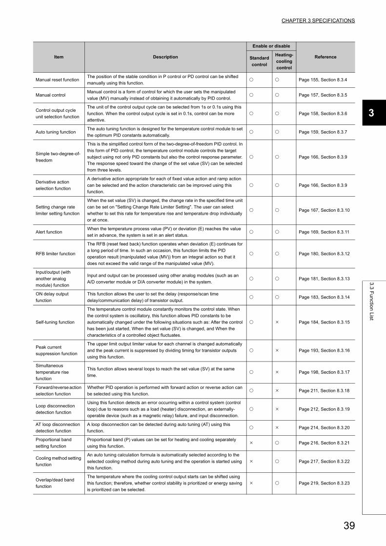
CHAPTER 3 SPECIFICATIONS
3
3.3
Fu
nctio
n L
ist
Manual reset functionThe position of the stable condition in P control or PD control can be shifted
manually using this function. Page 155, Section 8.3.4
Manual controlManual control is a form of control for which the user sets the manipulated
value (MV) manually instead of obtaining it automatically by PID control. Page 157, Section 8.3.5
Control output cycle
unit selection function
The unit of the control output cycle can be selected from 1s or 0.1s using this
function. When the control output cycle is set in 0.1s, control can be more
attentive.
Page 158, Section 8.3.6
Auto tuning functionThe auto tuning function is designed for the temperature control module to set
the optimum PID constants automatically. Page 159, Section 8.3.7
Simple two-degree-of-
freedom
This is the simplified control form of the two-degree-of-freedom PID control. In
this form of PID control, the temperature control module controls the target
subject using not only PID constants but also the control response parameter.
The response speed toward the change of the set value (SV) can be selected
from three levels.
Page 166, Section 8.3.9
Derivative action
selection function
A derivative action appropriate for each of fixed value action and ramp action
can be selected and the action characteristic can be improved using this
function.
Page 166, Section 8.3.9
Setting change rate
limiter setting function
When the set value (SV) is changed, the change rate in the specified time unit
can be set on "Setting Change Rate Limiter Setting". The user can select
whether to set this rate for temperature rise and temperature drop individually
or at once.
Page 167, Section 8.3.10
Alert functionWhen the temperature process value (PV) or deviation (E) reaches the value
set in advance, the system is set in an alert status. Page 169, Section 8.3.11
RFB limiter function
The RFB (reset feed back) function operates when deviation (E) continues for
a long period of time. In such an occasion, this function limits the PID
operation result (manipulated value (MV)) from an integral action so that it
does not exceed the valid range of the manipulated value (MV).
Page 180, Section 8.3.12
Input/output (with
another analog
module) function
Input and output can be processed using other analog modules (such as an
A/D converter module or D/A converter module) in the system. Page 181, Section 8.3.13
ON delay output
function
This function allows the user to set the delay (response/scan time
delay/communication delay) of transistor output. Page 183, Section 8.3.14
Self-tuning function
The temperature control module constantly monitors the control state. When
the control system is oscillatory, this function allows PID constants to be
automatically changed under the following situations such as: After the control
has been just started, When the set value (SV) is changed, and When the
characteristics of a controlled object fluctuates.
Page 184, Section 8.3.15
Peak current
suppression function
The upper limit output limiter value for each channel is changed automatically
and the peak current is suppressed by dividing timing for transistor outputs
using this function.
Page 193, Section 8.3.16
Simultaneous
temperature rise
function
This function allows several loops to reach the set value (SV) at the same
time. Page 198, Section 8.3.17
Forward/reverse action
selection function
Whether PID operation is performed with forward action or reverse action can
be selected using this function. Page 211, Section 8.3.18
Loop disconnection
detection function
Using this function detects an error occurring within a control system (control
loop) due to reasons such as a load (heater) disconnection, an externally-
operable device (such as a magnetic relay) failure, and input disconnection.
Page 212, Section 8.3.19
AT loop disconnection
detection function
A loop disconnection can be detected during auto tuning (AT) using this
function. Page 214, Section 8.3.20
Proportional band
setting function
Proportional band (P) values can be set for heating and cooling separately
using this function. Page 216, Section 8.3.21
Cooling method setting
function
An auto tuning calculation formula is automatically selected according to the
selected cooling method during auto tuning and the operation is started using
this function.
Page 217, Section 8.3.22
Overlap/dead band
function
The temperature where the cooling control output starts can be shifted using
this function; therefore, whether control stability is prioritized or energy saving
is prioritized can be selected.
Page 219, Section 8.3.23
Item Description
Enable or disable
ReferenceStandard
control
Heating-
cooling
control
39
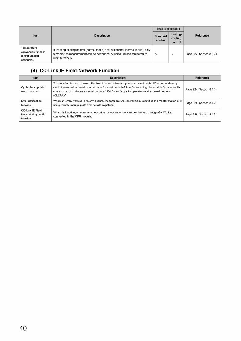
(4) CC-Link IE Field Network Function
Temperature
conversion function
(using unused
channels)
In heating-cooling control (normal mode) and mix control (normal mode), only
temperature measurement can be performed by using unused temperature
input terminals.
Page 222, Section 8.3.24
Item Description Reference
Cyclic data update
watch function
This function is used to watch the time interval between updates on cyclic data. When an update by
cyclic transmission remains to be done for a set period of time for watching, the module "continues its
operation and produces external outputs (HOLD)" or "stops its operation and external outputs
(CLEAR)".
Page 224, Section 8.4.1
Error notification
function
When an error, warning, or alarm occurs, the temperature control module notifies the master station of it
using remote input signals and remote registers.Page 225, Section 8.4.2
CC-Link IE Field
Network diagnostic
function
With this function, whether any network error occurs or not can be checked through GX Works2
connected to the CPU module.Page 229, Section 8.4.3
Item Description
Enable or disable
ReferenceStandard
control
Heating-
cooling
control
40
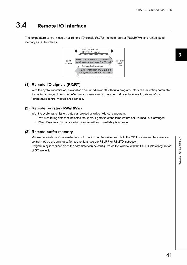
CHAPTER 3 SPECIFICATIONS
3
3.4
Re
mo
te I/O
Inte
rface
3.4 Remote I/O Interface
The temperature control module has remote I/O signals (RX/RY), remote register (RWr/RWw), and remote buffer
memory as I/O Interfaces.
(1) Remote I/O signals (RX/RY)With the cyclic transmission, a signal can be turned on or off without a program. Interlocks for writing parameter
for control arranged in remote buffer memory areas and signals that indicate the operating status of the
temperature control module are arranged.
(2) Remote register (RWr/RWw)With the cyclic transmission, data can be read or written without a program.
• Rwr: Monitoring data that indicates the operating status of the temperature control module is arranged.
• RWw: Parameter for control which can be written immediately is arranged.
(3) Remote buffer memoryModule parameter and parameter for control which can be written with both the CPU module and temperature
control module are arranged. To receive data, use the REMFR or REMTO instruction.
Programming is reduced since the parameter can be configured on the window with the CC IE Field configuration
of GX Works2.
•Remote register•Remote I/O signal
CPU module
Temperature control module
REMFR instruction or CC IE Field configuration window of GX Works2
REMTO instruction or CC IE Field configuration window of GX Works2
Remote buffer memory
41
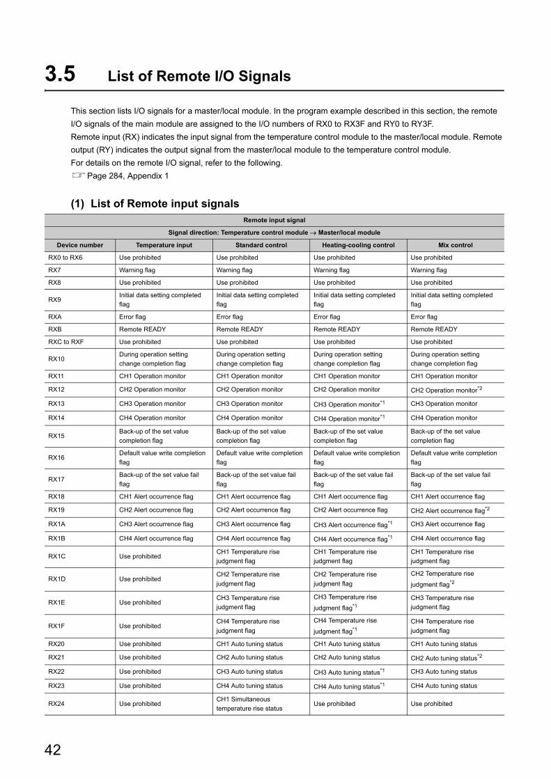
3.5 List of Remote I/O Signals
This section lists I/O signals for a master/local module. In the program example described in this section, the remote
I/O signals of the main module are assigned to the I/O numbers of RX0 to RX3F and RY0 to RY3F.
Remote input (RX) indicates the input signal from the temperature control module to the master/local module. Remote
output (RY) indicates the output signal from the master/local module to the temperature control module.
For details on the remote I/O signal, refer to the following.
Page 284, Appendix 1
(1) List of Remote input signalsRemote input signal
Signal direction: Temperature control module Master/local module
Device number Temperature input Standard control Heating-cooling control Mix control
RX0 to RX6 Use prohibited Use prohibited Use prohibited Use prohibited
RX7 Warning flag Warning flag Warning flag Warning flag
RX8 Use prohibited Use prohibited Use prohibited Use prohibited
RX9Initial data setting completed
flag
Initial data setting completed
flag
Initial data setting completed
flag
Initial data setting completed
flag
RXA Error flag Error flag Error flag Error flag
RXB Remote READY Remote READY Remote READY Remote READY
RXC to RXF Use prohibited Use prohibited Use prohibited Use prohibited
RX10During operation setting
change completion flag
During operation setting
change completion flag
During operation setting
change completion flag
During operation setting
change completion flag
RX11 CH1 Operation monitor CH1 Operation monitor CH1 Operation monitor CH1 Operation monitor
RX12 CH2 Operation monitor CH2 Operation monitor CH2 Operation monitor CH2 Operation monitor*2
RX13 CH3 Operation monitor CH3 Operation monitor CH3 Operation monitor*1 CH3 Operation monitor
RX14 CH4 Operation monitor CH4 Operation monitor CH4 Operation monitor*1 CH4 Operation monitor
RX15Back-up of the set value
completion flag
Back-up of the set value
completion flag
Back-up of the set value
completion flag
Back-up of the set value
completion flag
RX16Default value write completion
flag
Default value write completion
flag
Default value write completion
flag
Default value write completion
flag
RX17Back-up of the set value fail
flag
Back-up of the set value fail
flag
Back-up of the set value fail
flag
Back-up of the set value fail
flag
RX18 CH1 Alert occurrence flag CH1 Alert occurrence flag CH1 Alert occurrence flag CH1 Alert occurrence flag
RX19 CH2 Alert occurrence flag CH2 Alert occurrence flag CH2 Alert occurrence flag CH2 Alert occurrence flag*2
RX1A CH3 Alert occurrence flag CH3 Alert occurrence flag CH3 Alert occurrence flag*1 CH3 Alert occurrence flag
RX1B CH4 Alert occurrence flag CH4 Alert occurrence flag CH4 Alert occurrence flag*1 CH4 Alert occurrence flag
RX1C Use prohibitedCH1 Temperature rise
judgment flag
CH1 Temperature rise
judgment flag
CH1 Temperature rise
judgment flag
RX1D Use prohibitedCH2 Temperature rise
judgment flag
CH2 Temperature rise
judgment flag
CH2 Temperature rise
judgment flag*2
RX1E Use prohibitedCH3 Temperature rise
judgment flag
CH3 Temperature rise
judgment flag*1
CH3 Temperature rise
judgment flag
RX1F Use prohibitedCH4 Temperature rise
judgment flag
CH4 Temperature rise
judgment flag*1
CH4 Temperature rise
judgment flag
RX20 Use prohibited CH1 Auto tuning status CH1 Auto tuning status CH1 Auto tuning status
RX21 Use prohibited CH2 Auto tuning status CH2 Auto tuning status CH2 Auto tuning status*2
RX22 Use prohibited CH3 Auto tuning status CH3 Auto tuning status*1 CH3 Auto tuning status
RX23 Use prohibited CH4 Auto tuning status CH4 Auto tuning status*1 CH4 Auto tuning status
RX24 Use prohibitedCH1 Simultaneous
temperature rise statusUse prohibited Use prohibited
42
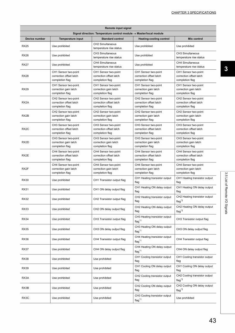
CHAPTER 3 SPECIFICATIONS
3
3.5
List o
f Re
mo
te I/O
Sig
na
ls
RX25 Use prohibitedCH2 Simultaneous
temperature rise statusUse prohibited Use prohibited
RX26 Use prohibitedCH3 Simultaneous
temperature rise statusUse prohibited
CH3 Simultaneous
temperature rise status
RX27 Use prohibitedCH4 Simultaneous
temperature rise statusUse prohibited
CH4 Simultaneous
temperature rise status
RX28
CH1 Sensor two-point
correction offset latch
completion flag
CH1 Sensor two-point
correction offset latch
completion flag
CH1 Sensor two-point
correction offset latch
completion flag
CH1 Sensor two-point
correction offset latch
completion flag
RX29
CH1 Sensor two-point
correction gain latch
completion flag
CH1 Sensor two-point
correction gain latch
completion flag
CH1 Sensor two-point
correction gain latch
completion flag
CH1 Sensor two-point
correction gain latch
completion flag
RX2A
CH2 Sensor two-point
correction offset latch
completion flag
CH2 Sensor two-point
correction offset latch
completion flag
CH2 Sensor two-point
correction offset latch
completion flag
CH2 Sensor two-point
correction offset latch
completion flag
RX2B
CH2 Sensor two-point
correction gain latch
completion flag
CH2 Sensor two-point
correction gain latch
completion flag
CH2 Sensor two-point
correction gain latch
completion flag
CH2 Sensor two-point
correction gain latch
completion flag
RX2C
CH3 Sensor two-point
correction offset latch
completion flag
CH3 Sensor two-point
correction offset latch
completion flag
CH3 Sensor two-point
correction offset latch
completion flag
CH3 Sensor two-point
correction offset latch
completion flag
RX2D
CH3 Sensor two-point
correction gain latch
completion flag
CH3 Sensor two-point
correction gain latch
completion flag
CH3 Sensor two-point
correction gain latch
completion flag
CH3 Sensor two-point
correction gain latch
completion flag
RX2E
CH4 Sensor two-point
correction offset latch
completion flag
CH4 Sensor two-point
correction offset latch
completion flag
CH4 Sensor two-point
correction offset latch
completion flag
CH4 Sensor two-point
correction offset latch
completion flag
RX2F
CH4 Sensor two-point
correction gain latch
completion flag
CH4 Sensor two-point
correction gain latch
completion flag
CH4 Sensor two-point
correction gain latch
completion flag
CH4 Sensor two-point
correction gain latch
completion flag
RX30 Use prohibited CH1 Transistor output flagCH1 Heating transistor output
flag
CH1 Heating transistor output
flag
RX31 Use prohibited CH1 ON delay output flagCH1 Heating ON delay output
flag
CH1 Heating ON delay output
flag
RX32 Use prohibited CH2 Transistor output flagCH2 Heating transistor output
flag
CH2 Heating transistor output
flag*2
RX33 Use prohibited CH2 ON delay output flagCH2 Heating ON delay output
flag
CH2 Heating ON delay output
flag*2
RX34 Use prohibited CH3 Transistor output flagCH3 Heating transistor output
flag*1CH3 Transistor output flag
RX35 Use prohibited CH3 ON delay output flagCH3 Heating ON delay output
flag*1CH3 ON delay output flag
RX36 Use prohibited CH4 Transistor output flagCH4 Heating transistor output
flag*1CH4 Transistor output flag
RX37 Use prohibited CH4 ON delay output flagCH4 Heating ON delay output
flag*1CH4 ON delay output flag
RX38 Use prohibited Use prohibitedCH1 Cooling transistor output
flag
CH1 Cooling transistor output
flag
RX39 Use prohibited Use prohibitedCH1 Cooling ON delay output
flag
CH1 Cooling ON delay output
flag
RX3A Use prohibited Use prohibitedCH2 Cooling transistor output
flag
CH2 Cooling transistor output
flag*2
RX3B Use prohibited Use prohibitedCH2 Cooling ON delay output
flag
CH2 Cooling ON delay output
flag*2
RX3C Use prohibited Use prohibitedCH3 Cooling transistor output
flag*1Use prohibited
Remote input signal
Signal direction: Temperature control module Master/local module
Device number Temperature input Standard control Heating-cooling control Mix control
43
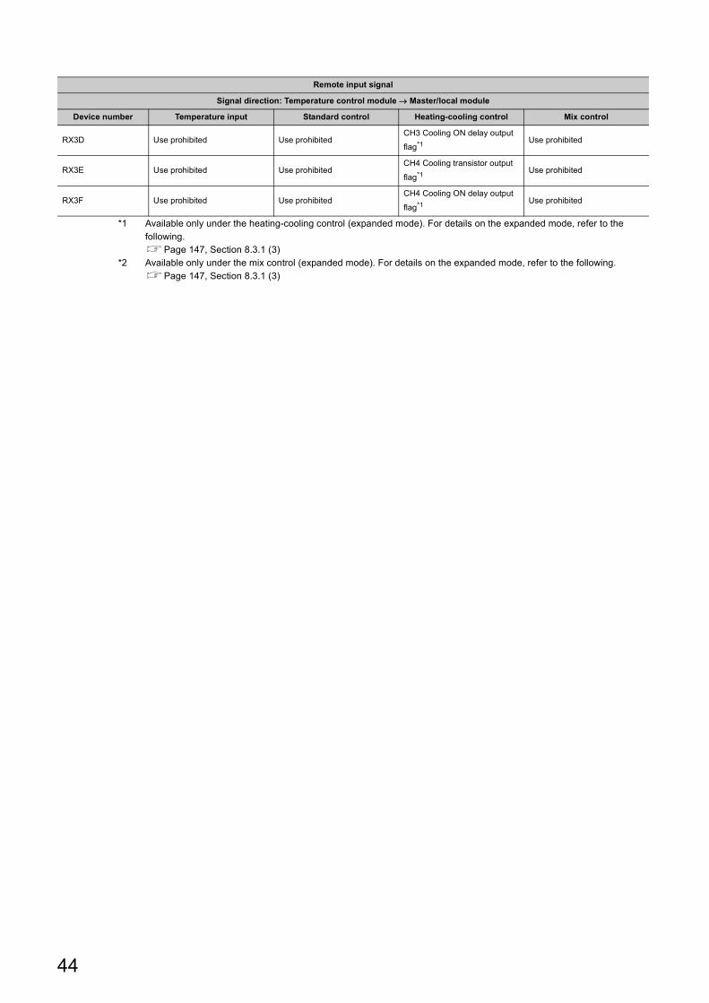
*1 Available only under the heating-cooling control (expanded mode). For details on the expanded mode, refer to the following.Page 147, Section 8.3.1 (3)
*2 Available only under the mix control (expanded mode). For details on the expanded mode, refer to the following.Page 147, Section 8.3.1 (3)
RX3D Use prohibited Use prohibitedCH3 Cooling ON delay output
flag*1Use prohibited
RX3E Use prohibited Use prohibitedCH4 Cooling transistor output
flag*1Use prohibited
RX3F Use prohibited Use prohibitedCH4 Cooling ON delay output
flag*1Use prohibited
Remote input signal
Signal direction: Temperature control module Master/local module
Device number Temperature input Standard control Heating-cooling control Mix control
44
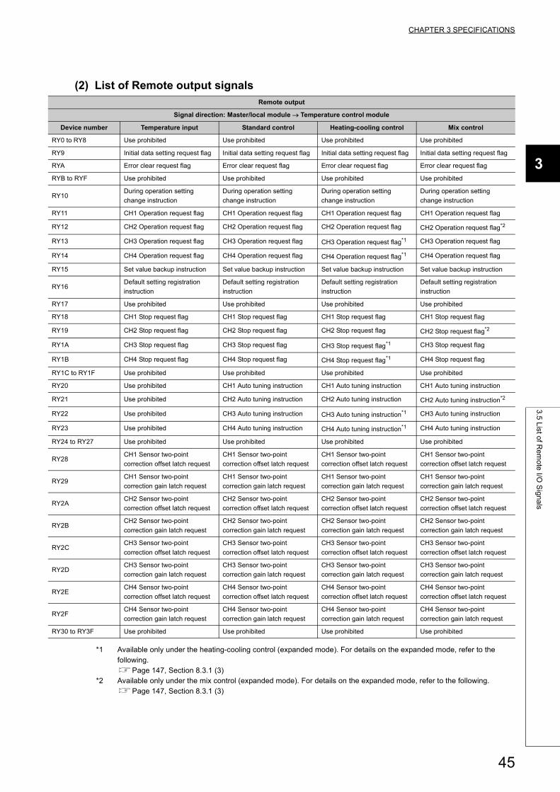
CHAPTER 3 SPECIFICATIONS
3
3.5
List o
f Re
mo
te I/O
Sig
na
ls
(2) List of Remote output signals
*1 Available only under the heating-cooling control (expanded mode). For details on the expanded mode, refer to the following.Page 147, Section 8.3.1 (3)
*2 Available only under the mix control (expanded mode). For details on the expanded mode, refer to the following.Page 147, Section 8.3.1 (3)
Remote output
Signal direction: Master/local module Temperature control module
Device number Temperature input Standard control Heating-cooling control Mix control
RY0 to RY8 Use prohibited Use prohibited Use prohibited Use prohibited
RY9 Initial data setting request flag Initial data setting request flag Initial data setting request flag Initial data setting request flag
RYA Error clear request flag Error clear request flag Error clear request flag Error clear request flag
RYB to RYF Use prohibited Use prohibited Use prohibited Use prohibited
RY10During operation setting
change instruction
During operation setting
change instruction
During operation setting
change instruction
During operation setting
change instruction
RY11 CH1 Operation request flag CH1 Operation request flag CH1 Operation request flag CH1 Operation request flag
RY12 CH2 Operation request flag CH2 Operation request flag CH2 Operation request flag CH2 Operation request flag*2
RY13 CH3 Operation request flag CH3 Operation request flag CH3 Operation request flag*1 CH3 Operation request flag
RY14 CH4 Operation request flag CH4 Operation request flag CH4 Operation request flag*1 CH4 Operation request flag
RY15 Set value backup instruction Set value backup instruction Set value backup instruction Set value backup instruction
RY16Default setting registration
instruction
Default setting registration
instruction
Default setting registration
instruction
Default setting registration
instruction
RY17 Use prohibited Use prohibited Use prohibited Use prohibited
RY18 CH1 Stop request flag CH1 Stop request flag CH1 Stop request flag CH1 Stop request flag
RY19 CH2 Stop request flag CH2 Stop request flag CH2 Stop request flag CH2 Stop request flag*2
RY1A CH3 Stop request flag CH3 Stop request flag CH3 Stop request flag*1 CH3 Stop request flag
RY1B CH4 Stop request flag CH4 Stop request flag CH4 Stop request flag*1 CH4 Stop request flag
RY1C to RY1F Use prohibited Use prohibited Use prohibited Use prohibited
RY20 Use prohibited CH1 Auto tuning instruction CH1 Auto tuning instruction CH1 Auto tuning instruction
RY21 Use prohibited CH2 Auto tuning instruction CH2 Auto tuning instruction CH2 Auto tuning instruction*2
RY22 Use prohibited CH3 Auto tuning instruction CH3 Auto tuning instruction*1 CH3 Auto tuning instruction
RY23 Use prohibited CH4 Auto tuning instruction CH4 Auto tuning instruction*1 CH4 Auto tuning instruction
RY24 to RY27 Use prohibited Use prohibited Use prohibited Use prohibited
RY28CH1 Sensor two-point
correction offset latch request
CH1 Sensor two-point
correction offset latch request
CH1 Sensor two-point
correction offset latch request
CH1 Sensor two-point
correction offset latch request
RY29CH1 Sensor two-point
correction gain latch request
CH1 Sensor two-point
correction gain latch request
CH1 Sensor two-point
correction gain latch request
CH1 Sensor two-point
correction gain latch request
RY2ACH2 Sensor two-point
correction offset latch request
CH2 Sensor two-point
correction offset latch request
CH2 Sensor two-point
correction offset latch request
CH2 Sensor two-point
correction offset latch request
RY2BCH2 Sensor two-point
correction gain latch request
CH2 Sensor two-point
correction gain latch request
CH2 Sensor two-point
correction gain latch request
CH2 Sensor two-point
correction gain latch request
RY2CCH3 Sensor two-point
correction offset latch request
CH3 Sensor two-point
correction offset latch request
CH3 Sensor two-point
correction offset latch request
CH3 Sensor two-point
correction offset latch request
RY2DCH3 Sensor two-point
correction gain latch request
CH3 Sensor two-point
correction gain latch request
CH3 Sensor two-point
correction gain latch request
CH3 Sensor two-point
correction gain latch request
RY2ECH4 Sensor two-point
correction offset latch request
CH4 Sensor two-point
correction offset latch request
CH4 Sensor two-point
correction offset latch request
CH4 Sensor two-point
correction offset latch request
RY2FCH4 Sensor two-point
correction gain latch request
CH4 Sensor two-point
correction gain latch request
CH4 Sensor two-point
correction gain latch request
CH4 Sensor two-point
correction gain latch request
RY30 to RY3F Use prohibited Use prohibited Use prohibited Use prohibited
45
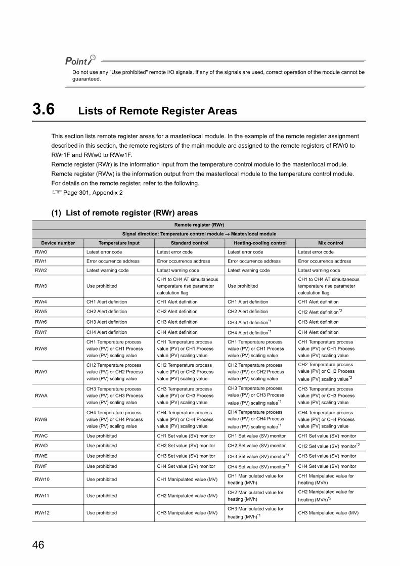
Do not use any "Use prohibited" remote I/O signals. If any of the signals are used, correct operation of the module cannot be guaranteed.
3.6 Lists of Remote Register Areas
This section lists remote register areas for a master/local module. In the example of the remote register assignment
described in this section, the remote registers of the main module are assigned to the remote registers of RWr0 to
RWr1F and RWw0 to RWw1F.
Remote register (RWr) is the information input from the temperature control module to the master/local module.
Remote register (RWw) is the information output from the master/local module to the temperature control module.
For details on the remote register, refer to the following.
Page 301, Appendix 2
(1) List of remote register (RWr) areasRemote register (RWr)
Signal direction: Temperature control module Master/local module
Device number Temperature input Standard control Heating-cooling control Mix control
RWr0 Latest error code Latest error code Latest error code Latest error code
RWr1 Error occurrence address Error occurrence address Error occurrence address Error occurrence address
RWr2 Latest warning code Latest warning code Latest warning code Latest warning code
RWr3 Use prohibited
CH1 to CH4 AT simultaneous
temperature rise parameter
calculation flag
Use prohibited
CH1 to CH4 AT simultaneous
temperature rise parameter
calculation flag
RWr4 CH1 Alert definition CH1 Alert definition CH1 Alert definition CH1 Alert definition
RWr5 CH2 Alert definition CH2 Alert definition CH2 Alert definition CH2 Alert definition*2
RWr6 CH3 Alert definition CH3 Alert definition CH3 Alert definition*1 CH3 Alert definition
RWr7 CH4 Alert definition CH4 Alert definition CH4 Alert definition*1 CH4 Alert definition
RWr8
CH1 Temperature process
value (PV) or CH1 Process
value (PV) scaling value
CH1 Temperature process
value (PV) or CH1 Process
value (PV) scaling value
CH1 Temperature process
value (PV) or CH1 Process
value (PV) scaling value
CH1 Temperature process
value (PV) or CH1 Process
value (PV) scaling value
RWr9
CH2 Temperature process
value (PV) or CH2 Process
value (PV) scaling value
CH2 Temperature process
value (PV) or CH2 Process
value (PV) scaling value
CH2 Temperature process
value (PV) or CH2 Process
value (PV) scaling value
CH2 Temperature process
value (PV) or CH2 Process
value (PV) scaling value*2
RWrA
CH3 Temperature process
value (PV) or CH3 Process
value (PV) scaling value
CH3 Temperature process
value (PV) or CH3 Process
value (PV) scaling value
CH3 Temperature process
value (PV) or CH3 Process
value (PV) scaling value*1
CH3 Temperature process
value (PV) or CH3 Process
value (PV) scaling value
RWrB
CH4 Temperature process
value (PV) or CH4 Process
value (PV) scaling value
CH4 Temperature process
value (PV) or CH4 Process
value (PV) scaling value
CH4 Temperature process
value (PV) or CH4 Process
value (PV) scaling value*1
CH4 Temperature process
value (PV) or CH4 Process
value (PV) scaling value
RWrC Use prohibited CH1 Set value (SV) monitor CH1 Set value (SV) monitor CH1 Set value (SV) monitor
RWrD Use prohibited CH2 Set value (SV) monitor CH2 Set value (SV) monitor CH2 Set value (SV) monitor*2
RWrE Use prohibited CH3 Set value (SV) monitor CH3 Set value (SV) monitor*1 CH3 Set value (SV) monitor
RWrF Use prohibited CH4 Set value (SV) monitor CH4 Set value (SV) monitor*1 CH4 Set value (SV) monitor
RWr10 Use prohibited CH1 Manipulated value (MV)CH1 Manipulated value for
heating (MVh)
CH1 Manipulated value for
heating (MVh)
RWr11 Use prohibited CH2 Manipulated value (MV)CH2 Manipulated value for
heating (MVh)
CH2 Manipulated value for
heating (MVh)*2
RWr12 Use prohibited CH3 Manipulated value (MV)CH3 Manipulated value for
heating (MVh)*1CH3 Manipulated value (MV)
46
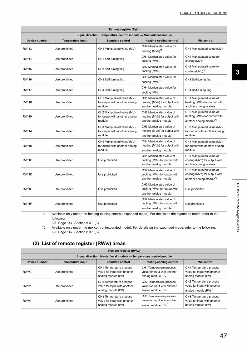
CHAPTER 3 SPECIFICATIONS
3
3.6
Lists o
f Re
mo
te R
eg
ister A
rea
s
*1 Available only under the heating-cooling control (expanded mode). For details on the expanded mode, refer to the following.Page 147, Section 8.3.1 (3)
*2 Available only under the mix control (expanded mode). For details on the expanded mode, refer to the following.Page 147, Section 8.3.1 (3)
(2) List of remote register (RWw) areas
RWr13 Use prohibited CH4 Manipulated value (MV)CH4 Manipulated value for
heating (MVh)*1CH4 Manipulated value (MV)
RWr14 Use prohibited CH1 Self-tuning flagCH1 Manipulated value for
cooling (MVc)
CH1 Manipulated value for
cooling (MVc)
RWr15 Use prohibited CH2 Self-tuning flagCH2 Manipulated value for
cooling (MVc)
CH2 Manipulated value for
cooling (MVc)*2
RWr16 Use prohibited CH3 Self-tuning flagCH3 Manipulated value for
cooling (MVc)*1CH3 Self-tuning flag
RWr17 Use prohibited CH4 Self-tuning flagCH4 Manipulated value for
cooling (MVc)*1CH4 Self-tuning flag
RWr18 Use prohibited
CH1 Manipulated value (MV)
for output with another analog
module
CH1 Manipulated value of
heating (MVh) for output with
another analog module
CH1 Manipulated value of
heating (MVh) for output with
another analog module
RWr19 Use prohibited
CH2 Manipulated value (MV)
for output with another analog
module
CH2 Manipulated value of
heating (MVh) for output with
another analog module
CH2 Manipulated value of
heating (MVh) for output with
another analog module*2
RWr1A Use prohibited
CH3 Manipulated value (MV)
for output with another analog
module
CH3 Manipulated value of
heating (MVh) for output with
another analog module*1
CH3 Manipulated value (MV)
for output with another analog
module
RWr1B Use prohibited
CH4 Manipulated value (MV)
for output with another analog
module
CH4 Manipulated value of
heating (MVh) for output with
another analog module*1
CH4 Manipulated value (MV)
for output with another analog
module
RWr1C Use prohibited Use prohibited
CH1 Manipulated value of
cooling (MVc) for output with
another analog module
CH1 Manipulated value of
cooling (MVc) for output with
another analog module
RWr1D Use prohibited Use prohibited
CH2 Manipulated value of
cooling (MVc) for output with
another analog module
CH2 Manipulated value of
cooling (MVc) for output with
another analog module*2
RWr1E Use prohibited Use prohibited
CH3 Manipulated value of
cooling (MVc) for output with
another analog module*1
Use prohibited
RWr1F Use prohibited Use prohibited
CH4 Manipulated value of
cooling (MVc) for output with
another analog module*1
Use prohibited
Remote register (RWw)
Signal direction: Master/local module Temperature control module
Device number Temperature input Standard control Heating-cooling control Mix control
RWw0 Use prohibited
CH1 Temperature process
value for input with another
analog module (PV)
CH1 Temperature process
value for input with another
analog module (PV)
CH1 Temperature process
value for input with another
analog module (PV)
RWw1 Use prohibited
CH2 Temperature process
value for input with another
analog module (PV)
CH2 Temperature process
value for input with another
analog module (PV)
CH2 Temperature process
value for input with another
analog module (PV)*2
RWw2 Use prohibited
CH3 Temperature process
value for input with another
analog module (PV)
CH3 Temperature process
value for input with another
analog module (PV)*1
CH3 Temperature process
value for input with another
analog module (PV)
Remote register (RWr)
Signal direction: Temperature control module Master/local module
Device number Temperature input Standard control Heating-cooling control Mix control
47
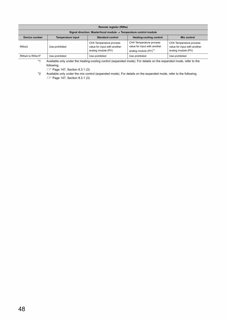
*1 Available only under the heating-cooling control (expanded mode). For details on the expanded mode, refer to the following.Page 147, Section 8.3.1 (3)
*2 Available only under the mix control (expanded mode). For details on the expanded mode, refer to the following.Page 147, Section 8.3.1 (3)
RWw3 Use prohibited
CH4 Temperature process
value for input with another
analog module (PV)
CH4 Temperature process
value for input with another
analog module (PV)*1
CH4 Temperature process
value for input with another
analog module (PV)
RWw4 to RWw1F Use prohibited Use prohibited Use prohibited Use prohibited
Remote register (RWw)
Signal direction: Master/local module Temperature control module
Device number Temperature input Standard control Heating-cooling control Mix control
48
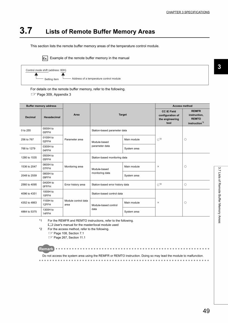
CHAPTER 3 SPECIFICATIONS
3
3.7
Lists o
f Re
mo
te B
uffe
r Me
mo
ry Are
as
3.7 Lists of Remote Buffer Memory Areas
This section lists the remote buffer memory areas of the temperature control module.
Ex. Example of the remote buffer memory in the manual
For details on the remote buffer memory, refer to the following.
Page 309, Appendix 3
*1 For the REMFR and REMTO instructions, refer to the following. User's manual for the master/local module used
*2 For the access method, refer to the following.Page 108, Section 7.1Page 267, Section 11.1
Remark
Do not access the system area using the REMFR or REMTO instruction. Doing so may lead the module to malfunction.
Buffer memory address
Area Target
Access method
Decimal Hexadecimal
CC IE Field
configuration of
the engineering
tool
REMFR
instruction,
REMTO
instruction*1
0 to 2550000H to
00FFH
Parameter area
Station-based parameter data
*2 256 to 7670100H to
02FFH Module-based
parameter data
Main module
768 to 12790300H to
04FFHSystem area
1280 to 15350500H to
05FFH
Monitoring area
Station-based monitoring data
1536 to 20470600H to
07FFH Module-based
monitoring data
Main module
2048 to 25590800H to
09FFHSystem area
2560 to 40950A00H to
0FFFHError history area Station-based error history data *2
4096 to 43511000H to
10FFH
Module control data
area
Station-based control data
4352 to 48631100H to
12FFH Module-based control
data
Main module
4864 to 53751300H to
14FFHSystem area
Setting item
Control mode shift (address: 80H)
Address of a temperature control module
49
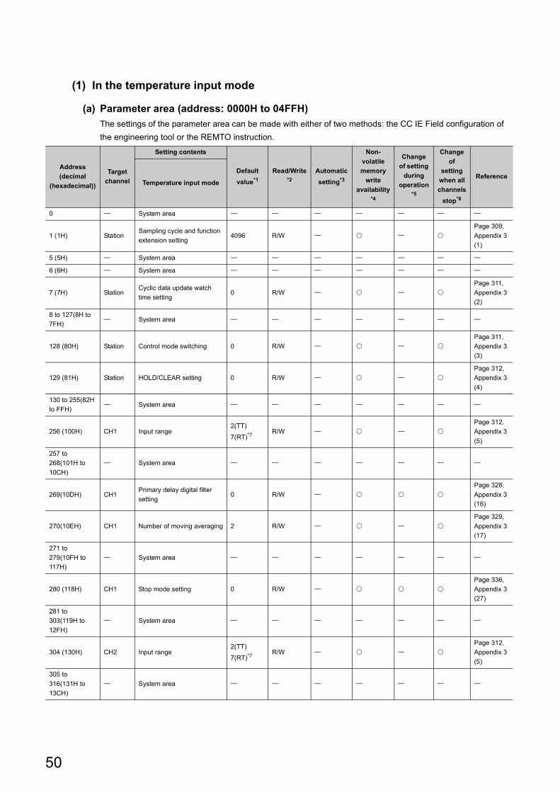
(1) In the temperature input mode
(a) Parameter area (address: 0000H to 04FFH)
The settings of the parameter area can be made with either of two methods: the CC IE Field configuration of
the engineering tool or the REMTO instruction.
Address
(decimal
(hexadecimal))
Target
channel
Setting contents
Default
value*1
Read/Write*2
Automatic
setting*3
Non-
volatile
memory
write
availability*4
Change
of setting
during
operation*5
Change
of
setting
when all
channels
stop*6
ReferenceTemperature input mode
0 System area
1 (1H) StationSampling cycle and function
extension setting4096 R/W
Page 309,
Appendix 3
(1)
5 (5H) System area
6 (6H) System area
7 (7H) StationCyclic data update watch
time setting0 R/W
Page 311,
Appendix 3
(2)
8 to 127(8H to
7FH) System area
128 (80H) Station Control mode switching 0 R/W
Page 311,
Appendix 3
(3)
129 (81H) Station HOLD/CLEAR setting 0 R/W
Page 312,
Appendix 3
(4)
130 to 255(82H
to FFH) System area
256 (100H) CH1 Input range2(TT)
7(RT)*7R/W
Page 312,
Appendix 3
(5)
257 to
268(101H to
10CH)
System area
269(10DH) CH1Primary delay digital filter
setting0 R/W
Page 328,
Appendix 3
(16)
270(10EH) CH1 Number of moving averaging 2 R/W
Page 329,
Appendix 3
(17)
271 to
279(10FH to
117H)
System area
280 (118H) CH1 Stop mode setting 0 R/W
Page 336,
Appendix 3
(27)
281 to
303(119H to
12FH)
System area
304 (130H) CH2 Input range2(TT)
7(RT)*7R/W
Page 312,
Appendix 3
(5)
305 to
316(131H to
13CH)
System area
50
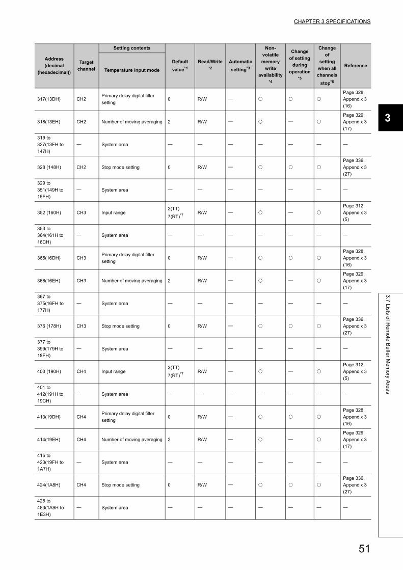
CHAPTER 3 SPECIFICATIONS
3
3.7
Lists o
f Re
mo
te B
uffe
r Me
mo
ry Are
as
317(13DH) CH2Primary delay digital filter
setting0 R/W
Page 328,
Appendix 3
(16)
318(13EH) CH2 Number of moving averaging 2 R/W
Page 329,
Appendix 3
(17)
319 to
327(13FH to
147H)
System area
328 (148H) CH2 Stop mode setting 0 R/W
Page 336,
Appendix 3
(27)
329 to
351(149H to
15FH)
System area
352 (160H) CH3 Input range2(TT)
7(RT)*7R/W
Page 312,
Appendix 3
(5)
353 to
364(161H to
16CH)
System area
365(16DH) CH3Primary delay digital filter
setting0 R/W
Page 328,
Appendix 3
(16)
366(16EH) CH3 Number of moving averaging 2 R/W
Page 329,
Appendix 3
(17)
367 to
375(16FH to
177H)
System area
376 (178H) CH3 Stop mode setting 0 R/W
Page 336,
Appendix 3
(27)
377 to
399(179H to
18FH)
System area
400 (190H) CH4 Input range2(TT)
7(RT)*7R/W
Page 312,
Appendix 3
(5)
401 to
412(191H to
19CH)
System area
413(19DH) CH4Primary delay digital filter
setting0 R/W
Page 328,
Appendix 3
(16)
414(19EH) CH4 Number of moving averaging 2 R/W
Page 329,
Appendix 3
(17)
415 to
423(19FH to
1A7H)
System area
424(1A8H) CH4 Stop mode setting 0 R/W
Page 336,
Appendix 3
(27)
425 to
483(1A9H to
1E3H)
System area
Address
(decimal
(hexadecimal))
Target
channel
Setting contents
Default
value*1
Read/Write*2
Automatic
setting*3
Non-
volatile
memory
write
availability*4
Change
of setting
during
operation*5
Change
of
setting
when all
channels
stop*6
ReferenceTemperature input mode
51
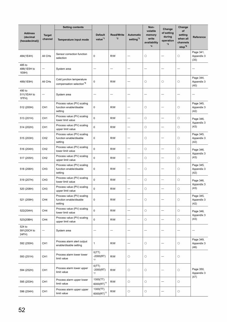
484(1E4H) All CHsSensor correction function
selection0 R/W
Page 341,
Appendix 3
(35)
485 to
488(1E5H to
1E8H)
System area
489(1E9H) All CHsCold junction temperature
compensation selection*80 R/W
Page 344,
Appendix 3
(40)
490 to
511(1EAH to
1FFH)
System area
512 (200H) CH1
Process value (PV) scaling
function enable/disable
setting
0 R/W
Page 345,
Appendix 3
(42)
513 (201H) CH1Process value (PV) scaling
lower limit value0 R/W Page 346,
Appendix 3
(43)514 (202H) CH1Process value (PV) scaling
upper limit value0 R/W
515 (203H) CH2
Process value (PV) scaling
function enable/disable
setting
0 R/W
Page 345,
Appendix 3
(42)
516 (204H) CH2Process value (PV) scaling
lower limit value0 R/W Page 346,
Appendix 3
(43)517 (205H) CH2Process value (PV) scaling
upper limit value0 R/W
518 (206H) CH3
Process value (PV) scaling
function enable/disable
setting
0 R/W
Page 345,
Appendix 3
(42)
519 (207H) CH3Process value (PV) scaling
lower limit value0 R/W Page 346,
Appendix 3
(43)520 (208H) CH3Process value (PV) scaling
upper limit value0 R/W
521 (209H) CH4
Process value (PV) scaling
function enable/disable
setting
0 R/W
Page 345,
Appendix 3
(42)
522(20AH) CH4Process value (PV) scaling
lower limit value0 R/W Page 346,
Appendix 3
(43)523(20BH) CH4Process value (PV) scaling
upper limit value0 R/W
524 to
591(20CH to
24FH)
System area
592 (250H) CH1Process alarm alert output
enable/disable setting1 R/W
Page 349,
Appendix 3
(46)
593 (251H) CH1Process alarm lower lower
limit value
0(TT)
-2000(RT)*7
R/W
Page 350,
Appendix 3
(47)
594 (252H) CH1Process alarm lower upper
limit value
0(TT)
-2000(RT)*7
R/W
595 (253H) CH1Process alarm upper lower
limit value
1300(TT)
6000(RT)*7R/W
596 (254H) CH1Process alarm upper upper
limit value
1300(TT)
6000(RT)*7R/W
Address
(decimal
(hexadecimal))
Target
channel
Setting contents
Default
value*1
Read/Write*2
Automatic
setting*3
Non-
volatile
memory
write
availability*4
Change
of setting
during
operation*5
Change
of
setting
when all
channels
stop*6
ReferenceTemperature input mode
52
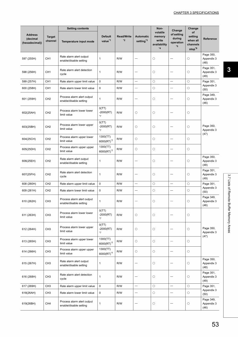
CHAPTER 3 SPECIFICATIONS
3
3.7
Lists o
f Re
mo
te B
uffe
r Me
mo
ry Are
as
597 (255H) CH1Rate alarm alert output
enable/disable setting1 R/W
Page 350,
Appendix 3
(48)
598 (256H) CH1Rate alarm alert detection
cycle1 R/W
Page 351,
Appendix 3
(49)
599 (257H) CH1 Rate alarm upper limit value 0 R/W Page 351,
Appendix 3
(50)600 (258H) CH1 Rate alarm lower limit value 0 R/W
601 (259H) CH2Process alarm alert output
enable/disable setting1 R/W
Page 349,
Appendix 3
(46)
602(25AH) CH2Process alarm lower lower
limit value
0(TT)
-2000(RT)*7
R/W
Page 350,
Appendix 3
(47)
603(25BH) CH2Process alarm lower upper
limit value
0(TT)
-2000(RT)*7
R/W
604(25CH) CH2Process alarm upper lower
limit value
1300(TT)
6000(RT)*7R/W
605(25DH) CH2Process alarm upper upper
limit value
1300(TT)
6000(RT)*7R/W
606(25EH) CH2Rate alarm alert output
enable/disable setting1 R/W
Page 350,
Appendix 3
(48)
607(25FH) CH2Rate alarm alert detection
cycle1 R/W
Page 351,
Appendix 3
(49)
608 (260H) CH2 Rate alarm upper limit value 0 R/W Page 351,
Appendix 3
(50)609 (261H) CH2 Rate alarm lower limit value 0 R/W
610 (262H) CH3Process alarm alert output
enable/disable setting1 R/W
Page 349,
Appendix 3
(46)
611 (263H) CH3Process alarm lower lower
limit value
0(TT)
-2000(RT)*7
R/W
Page 350,
Appendix 3
(47)
612 (264H) CH3Process alarm lower upper
limit value
0(TT)
-2000(RT)*7
R/W
613 (265H) CH3Process alarm upper lower
limit value
1300(TT)
6000(RT)*7R/W
614 (266H) CH3Process alarm upper upper
limit value
1300(TT)
6000(RT)*7R/W
615 (267H) CH3Rate alarm alert output
enable/disable setting1 R/W
Page 350,
Appendix 3
(48)
616 (268H) CH3Rate alarm alert detection
cycle1 R/W
Page 351,
Appendix 3
(49)
617 (269H) CH3 Rate alarm upper limit value 0 R/W Page 351,
Appendix 3
(50)618(26AH) CH3 Rate alarm lower limit value 0 R/W
619(26BH) CH4Process alarm alert output
enable/disable setting1 R/W
Page 349,
Appendix 3
(46)
Address
(decimal
(hexadecimal))
Target
channel
Setting contents
Default
value*1
Read/Write*2
Automatic
setting*3
Non-
volatile
memory
write
availability*4
Change
of setting
during
operation*5
Change
of
setting
when all
channels
stop*6
ReferenceTemperature input mode
53
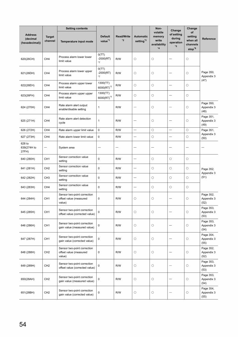
620(26CH) CH4Process alarm lower lower
limit value
0(TT)
-2000(RT)*7
R/W
Page 350,
Appendix 3
(47)
621(26DH) CH4Process alarm lower upper
limit value
0(TT)
-2000(RT)*7
R/W
622(26EH) CH4Process alarm upper lower
limit value
1300(TT)
6000(RT)*7R/W
623(26FH) CH4Process alarm upper upper
limit value
1300(TT)
6000(RT)*7R/W
624 (270H) CH4Rate alarm alert output
enable/disable setting1 R/W
Page 350,
Appendix 3
(48)
625 (271H) CH4Rate alarm alert detection
cycle1 R/W
Page 351,
Appendix 3
(49)
626 (272H) CH4 Rate alarm upper limit value 0 R/W Page 351,
Appendix 3
(50)627 (273H) CH4 Rate alarm lower limit value 0 R/W
628 to
639(274H to
27FH)
System area
640 (280H) CH1Sensor correction value
setting0 R/W
Page 352,
Appendix 3
(51)
641 (281H) CH2Sensor correction value
setting0 R/W
642 (282H) CH3Sensor correction value
setting0 R/W
643 (283H) CH4Sensor correction value
setting0 R/W
644 (284H) CH1
Sensor two-point correction
offset value (measured
value)
0 R/W
Page 352,
Appendix 3
(52)
645 (285H) CH1Sensor two-point correction
offset value (corrected value)0 R/W
Page 353,
Appendix 3
(53)
646 (286H) CH1Sensor two-point correction
gain value (measured value)0 R/W
Page 353,
Appendix 3
(54)
647 (287H) CH1Sensor two-point correction
gain value (corrected value)0 R/W
Page 354,
Appendix 3
(55)
648 (288H) CH2
Sensor two-point correction
offset value (measured
value)
0 R/W
Page 352,
Appendix 3
(52)
649 (289H) CH2Sensor two-point correction
offset value (corrected value)0 R/W
Page 353,
Appendix 3
(53)
650(28AH) CH2Sensor two-point correction
gain value (measured value)0 R/W
Page 353,
Appendix 3
(54)
651(28BH) CH2Sensor two-point correction
gain value (corrected value)0 R/W
Page 354,
Appendix 3
(55)
Address
(decimal
(hexadecimal))
Target
channel
Setting contents
Default
value*1
Read/Write*2
Automatic
setting*3
Non-
volatile
memory
write
availability*4
Change
of setting
during
operation*5
Change
of
setting
when all
channels
stop*6
ReferenceTemperature input mode
54
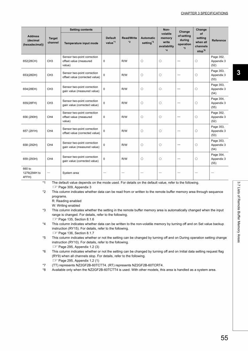
CHAPTER 3 SPECIFICATIONS
3
3.7
Lists o
f Re
mo
te B
uffe
r Me
mo
ry Are
as
*1 The default value depends on the mode used. For details on the default value, refer to the following.Page 309, Appendix 3
*2 This column indicates whether data can be read from or written to the remote buffer memory area through sequence programs.R: Reading enabledW: Writing enabled
*3 This column indicates whether the setting in the remote buffer memory area is automatically changed when the input range is changed. For details, refer to the following.Page 135, Section 8.1.6
*4 This column indicates whether data can be written to the non-volatile memory by turning off and on Set value backup instruction (RY15). For details, refer to the following.Page 136, Section 8.1.7
*5 This column indicates whether or not the setting can be changed by turning off and on During operation setting change instruction (RY10). For details, refer to the following.Page 295, Appendix 1.2 (3)
*6 This column indicates whether or not the setting can be changed by turning off and on Initial data setting request flag (RY9) when all channels stop. For details, refer to the following.Page 295, Appendix 1.2 (1)
*7 (TT) represents NZ2GF2B-60TCTT4. (RT) represents NZ2GF2B-60TCRT4.*8 Available only when the NZ2GF2B-60TCTT4 is used. With other models, this area is handled as a system area.
652(28CH) CH3
Sensor two-point correction
offset value (measured
value)
0 R/W
Page 352,
Appendix 3
(52)
653(28DH) CH3Sensor two-point correction
offset value (corrected value)0 R/W
Page 353,
Appendix 3
(53)
654(28EH) CH3Sensor two-point correction
gain value (measured value)0 R/W
Page 353,
Appendix 3
(54)
655(28FH) CH3Sensor two-point correction
gain value (corrected value)0 R/W
Page 354,
Appendix 3
(55)
656 (290H) CH4
Sensor two-point correction
offset value (measured
value)
0 R/W
Page 352,
Appendix 3
(52)
657 (291H) CH4Sensor two-point correction
offset value (corrected value)0 R/W
Page 353,
Appendix 3
(53)
658 (292H) CH4Sensor two-point correction
gain value (measured value)0 R/W
Page 353,
Appendix 3
(54)
659 (293H) CH4Sensor two-point correction
gain value (corrected value)0 R/W
Page 354,
Appendix 3
(55)
660 to
1279(294H to
4FFH)
System area
Address
(decimal
(hexadecimal))
Target
channel
Setting contents
Default
value*1
Read/Write*2
Automatic
setting*3
Non-
volatile
memory
write
availability*4
Change
of setting
during
operation*5
Change
of
setting
when all
channels
stop*6
ReferenceTemperature input mode
55
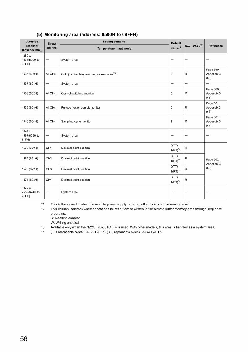
(b) Monitoring area (address: 0500H to 09FFH)
*1 This is the value for when the module power supply is turned off and on or at the remote reset.*2 This column indicates whether data can be read from or written to the remote buffer memory area through sequence
programs.R: Reading enabledW: Writing enabled
*3 Available only when the NZ2GF2B-60TCTT4 is used. With other models, this area is handled as a system area.*4 (TT) represents NZ2GF2B-60TCTT4. (RT) represents NZ2GF2B-60TCRT4.
Address
(decimal
(hexadecimal))
Target
channel
Setting contentsDefault
value*1 Read/Write*2 ReferenceTemperature input mode
1280 to
1535(500H to
5FFH)
System area
1536 (600H) All CHs Cold junction temperature process value*3 0 R
Page 359,
Appendix 3
(63)
1537 (601H) System area
1538 (602H) All CHs Control switching monitor 0 R
Page 360,
Appendix 3
(65)
1539 (603H) All CHs Function extension bit monitor 0 R
Page 361,
Appendix 3
(66)
1540 (604H) All CHs Sampling cycle monitor 1 R
Page 361,
Appendix 3
(67)
1541 to
1567(605H to
61FH)
System area
1568 (620H) CH1 Decimal point position0(TT)
1(RT)*4R
Page 362,
Appendix 3
(68)
1569 (621H) CH2 Decimal point position0(TT)
1(RT)*4R
1570 (622H) CH3 Decimal point position0(TT)
1(RT)*4R
1571 (623H) CH4 Decimal point position0(TT)
1(RT)*4R
1572 to
2559(624H to
9FFH)
System area
56
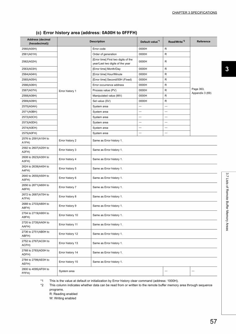
CHAPTER 3 SPECIFICATIONS
3
3.7
Lists o
f Re
mo
te B
uffe
r Me
mo
ry Are
as
(c) Error history area (address: 0A00H to 0FFFH)
*1 This is the value at default or initialization by Error history clear command (address: 1000H).*2 This column indicates whether data can be read from or written to the remote buffer memory area through sequence
programs.R: Reading enabledW: Writing enabled
Address (decimal
(hexadecimal))Description Default value*1 Read/Write*2 Reference
2560(A00H)
Error history 1
Error code 0000H R
Page 363,
Appendix 3 (69)
2561(A01H) Order of generation 0000H R
2562(A02H)[Error time] First two digits of the
year/Last two digits of the year0000H R
2563(A03H) [Error time] Month/Day 0000H R
2564(A04H) [Error time] Hour/Minute 0000H R
2565(A05H) [Error time] Second/00H (Fixed) 0000H R
2566(A06H) Error occurrence address 0000H R
2567(A07H) Process value (PV) 0000H R
2568(A08H) Manipulated value (MV) 0000H R
2569(A09H) Set value (SV) 0000H R
2570(A0AH) System area
2571(A0BH) System area
2572(A0CH) System area
2573(A0DH) System area
2574(A0EH) System area
2575(A0FH) System area
2576 to 2591(A10H to
A1FH)Error history 2 Same as Error history 1.
2592 to 2607(A20H to
A2FH)Error history 3 Same as Error history 1.
2608 to 2623(A30H to
A3FH)Error history 4 Same as Error history 1.
2624 to 2639(A40H to
A4FH)Error history 5 Same as Error history 1.
2640 to 2655(A50H to
A5FH)Error history 6 Same as Error history 1.
2656 to 2671(A60H to
A6FH)Error history 7 Same as Error history 1.
2672 to 2687(A70H to
A7FH)Error history 8 Same as Error history 1.
2688 to 2703(A80H to
A8FH)Error history 9 Same as Error history 1.
2704 to 2719(A90H to
A9FH)Error history 10 Same as Error history 1.
2720 to 2735(AA0H to
AAFH)Error history 11 Same as Error history 1.
2736 to 2751(AB0H to
ABFH)Error history 12 Same as Error history 1.
2752 to 2767(AC0H to
ACFH)Error history 13 Same as Error history 1.
2768 to 2783(AD0H to
ADFH)Error history 14 Same as Error history 1.
2784 to 2799(AE0H to
AEFH)Error history 15 Same as Error history 1.
2800 to 4095(AF0H to
FFFH)System area
57

(d) Module control data area (address: 1000H to 14FFH)
*1 The default value depends on the mode used. For details on the default value, refer to the following.Page 309, Appendix 3
*2 This column indicates whether data can be read from or written to the remote buffer memory area through sequence programs.R: Reading enabledW: Writing enabled
*3 This column indicates whether the setting in the remote buffer memory area is automatically changed when the input range is changed. For details, refer to the following.Page 135, Section 8.1.6
*4 This column indicates whether data can be written to the non-volatile memory by turning off and on Set value backup instruction (RY15). For details, refer to the following.Page 136, Section 8.1.7
*5 This column indicates whether or not the setting can be changed by turning off and on During operation setting change instruction (RY10). For details, refer to the following.Page 295, Appendix 1.2 (3)
*6 This column indicates whether or not the setting can be changed by turning off and on Initial data setting request flag (RY9) when all channels stop. For details, refer to the following.Page 295, Appendix 1.2 (1)
Address
(decimal
(hexadecimal))
Target
channel
Setting contents
Default
value*1
Read/Write*2
Automatic
setting*3
Non-volatile
memory
write
availability*4
Change of
setting
during
operation*5
Change
of setting
when all
channels
stop*6
ReferenceTemperature input mode
4096 (1000H) Station Error history clear command 0 R/W
Page 364,
Appendix 3
(70)
4097 (1001H) StationError history clear
completed0 R
Page 364,
Appendix 3
(71)
4098 to
5375(1002H to
14FFH)
System area
58

CHAPTER 3 SPECIFICATIONS
3
3.7
Lists o
f Re
mo
te B
uffe
r Me
mo
ry Are
as
(2) In the temperature control mode
(a) Parameter area (address: 0000H to 04FFH)
Address
(decimal
(hexa-
decimal))
Target
channel
Setting contents
Default
value*1
Read/
Write*2
Auto-
matic
setting*3
Non-
volatile
memory
write
avail-
ability*4
Change
of
setting
during
opera-
tion*5
Change
of setting
when all
channels
stop*6
ReferenceStandard
control
Heating-
cooling
control
Mix control
0 (0H) System area System area System area
1 (1H) Station
Sampling
cycle and
function
extension
setting
Sampling
cycle and
function
extension
setting
Sampling
cycle and
function
extension
setting
4096 R/W
Page 309,
Appendix
3 (1)
2 to 6(2H to
6H) System area System area System area
7 (7H) Station
Cyclic data
update watch
time setting
Cyclic data
update watch
time setting
Cyclic data
update watch
time setting
0 R/W
Page 311,
Appendix
3 (2)
8 to 127(8H
to 7FH) System area System area System area
128 (80H) StationControl mode
switching
Control mode
switching
Control mode
switching0 R/W
Page 311,
Appendix
3 (3)
129 (81H) Station
HOLD/
CLEAR
setting
HOLD/
CLEAR
setting
HOLD/
CLEAR
setting
0 R/W
Page 312,
Appendix
3 (4)
130 to
255(82H to
FFH)
System area System area System area
256 (100H) CH1 Input range Input range Input range2(TT)
7(RT)*7R/W
Page 312,
Appendix
3 (5)
257 (101H) CH1Set value
(SV) setting
Set value
(SV) setting
Set value
(SV) setting0 R/W
Page 317,
Appendix
3 (6)
258 (102H) CH1
Proportional
band (P)
setting
Heating
proportional
band (Ph)
setting
Heating
proportional
band (Ph)
setting
30 R/W
Page 318,
Appendix
3 (7)
259 (103H) CH1Integral time
(I) setting
Integral time
(I) setting
Integral time
(I) setting240 R/W
Page 320,
Appendix
3 (8)
260 (104H) CH1
Derivative
time (D)
setting
Derivative
time (D)
setting
Derivative
time (D)
setting
60 R/W
Page 320,
Appendix
3 (9)
261 (105H) CH1Upper limit
output limiter
Heating
upper limit
output limiter
Heating
upper limit
output limiter
1000 R/W
Page 321,
Appendix
3 (10)
262 (106H) CH1Lower limit
output limiterSystem area System area 0 R/W
Page 321,
Appendix
3 (10)
263 (107H) CH1
Output
variation
limiter setting
Output
variation
limiter setting
Output
variation
limiter setting
0 R/W
Page 323,
Appendix
3 (11)
59
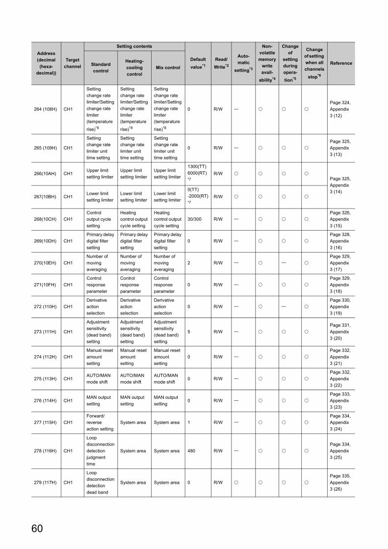
264 (108H) CH1
Setting
change rate
limiter/Setting
change rate
limiter
(temperature
rise)*8
Setting
change rate
limiter/Setting
change rate
limiter
(temperature
rise)*8
Setting
change rate
limiter/Setting
change rate
limiter
(temperature
rise)*8
0 R/W
Page 324,
Appendix
3 (12)
265 (109H) CH1
Setting
change rate
limiter unit
time setting
Setting
change rate
limiter unit
time setting
Setting
change rate
limiter unit
time setting
0 R/W
Page 325,
Appendix
3 (13)
266(10AH) CH1Upper limit
setting limiter
Upper limit
setting limiter
Upper limit
setting limiter
1300(TT)
6000(RT) *7
R/W Page 325,
Appendix
3 (14)267(10BH) CH1
Lower limit
setting limiter
Lower limit
setting limiter
Lower limit
setting limiter
0(TT)
-2000(RT) *7
R/W
268(10CH) CH1
Control
output cycle
setting
Heating
control output
cycle setting
Heating
control output
cycle setting
30/300 R/W
Page 326,
Appendix
3 (15)
269(10DH) CH1
Primary delay
digital filter
setting
Primary delay
digital filter
setting
Primary delay
digital filter
setting
0 R/W
Page 328,
Appendix
3 (16)
270(10EH) CH1
Number of
moving
averaging
Number of
moving
averaging
Number of
moving
averaging
2 R/W
Page 329,
Appendix
3 (17)
271(10FH) CH1
Control
response
parameter
Control
response
parameter
Control
response
parameter
0 R/W
Page 329,
Appendix
3 (18)
272 (110H) CH1
Derivative
action
selection
Derivative
action
selection
Derivative
action
selection
0 R/W
Page 330,
Appendix
3 (19)
273 (111H) CH1
Adjustment
sensitivity
(dead band)
setting
Adjustment
sensitivity
(dead band)
setting
Adjustment
sensitivity
(dead band)
setting
5 R/W
Page 331,
Appendix
3 (20)
274 (112H) CH1
Manual reset
amount
setting
Manual reset
amount
setting
Manual reset
amount
setting
0 R/W
Page 332,
Appendix
3 (21)
275 (113H) CH1AUTO/MAN
mode shift
AUTO/MAN
mode shift
AUTO/MAN
mode shift0 R/W
Page 332,
Appendix
3 (22)
276 (114H) CH1MAN output
setting
MAN output
setting
MAN output
setting0 R/W
Page 333,
Appendix
3 (23)
277 (115H) CH1
Forward/
reverse
action setting
System area System area 1 R/W
Page 334,
Appendix
3 (24)
278 (116H) CH1
Loop
disconnection
detection
judgment
time
System area System area 480 R/W
Page 334,
Appendix
3 (25)
279 (117H) CH1
Loop
disconnection
detection
dead band
System area System area 0 R/W
Page 335,
Appendix
3 (26)
Address
(decimal
(hexa-
decimal))
Target
channel
Setting contents
Default
value*1
Read/
Write*2
Auto-
matic
setting*3
Non-
volatile
memory
write
avail-
ability*4
Change
of
setting
during
opera-
tion*5
Change
of setting
when all
channels
stop*6
ReferenceStandard
control
Heating-
cooling
control
Mix control
60
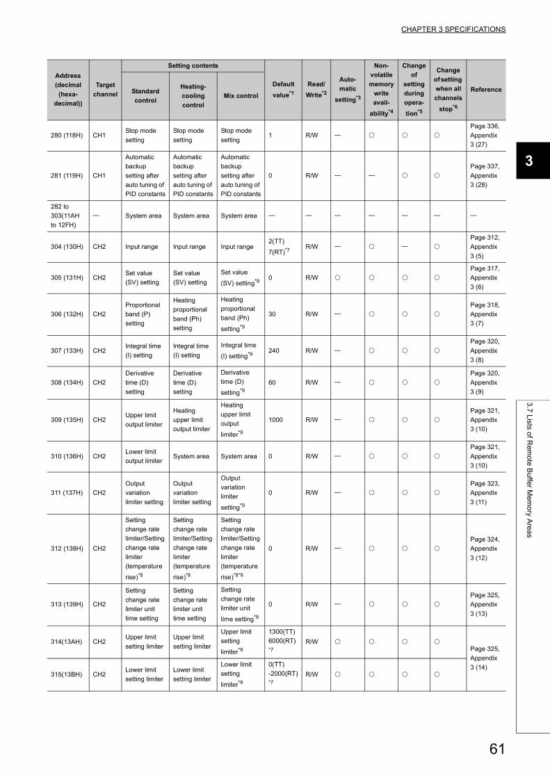
CHAPTER 3 SPECIFICATIONS
3
3.7
Lists o
f Re
mo
te B
uffe
r Me
mo
ry Are
as
280 (118H) CH1Stop mode
setting
Stop mode
setting
Stop mode
setting1 R/W
Page 336,
Appendix
3 (27)
281 (119H) CH1
Automatic
backup
setting after
auto tuning of
PID constants
Automatic
backup
setting after
auto tuning of
PID constants
Automatic
backup
setting after
auto tuning of
PID constants
0 R/W
Page 337,
Appendix
3 (28)
282 to
303(11AH
to 12FH)
System area System area System area
304 (130H) CH2 Input range Input range Input range2(TT)
7(RT)*7R/W
Page 312,
Appendix
3 (5)
305 (131H) CH2Set value
(SV) setting
Set value
(SV) setting
Set value
(SV) setting*90 R/W
Page 317,
Appendix
3 (6)
306 (132H) CH2
Proportional
band (P)
setting
Heating
proportional
band (Ph)
setting
Heating
proportional
band (Ph)
setting*9
30 R/W
Page 318,
Appendix
3 (7)
307 (133H) CH2Integral time
(I) setting
Integral time
(I) setting
Integral time
(I) setting*9240 R/W
Page 320,
Appendix
3 (8)
308 (134H) CH2
Derivative
time (D)
setting
Derivative
time (D)
setting
Derivative
time (D)
setting*9
60 R/W
Page 320,
Appendix
3 (9)
309 (135H) CH2Upper limit
output limiter
Heating
upper limit
output limiter
Heating
upper limit
output
limiter*9
1000 R/W
Page 321,
Appendix
3 (10)
310 (136H) CH2Lower limit
output limiterSystem area System area 0 R/W
Page 321,
Appendix
3 (10)
311 (137H) CH2
Output
variation
limiter setting
Output
variation
limiter setting
Output
variation
limiter
setting*9
0 R/W
Page 323,
Appendix
3 (11)
312 (138H) CH2
Setting
change rate
limiter/Setting
change rate
limiter
(temperature
rise)*8
Setting
change rate
limiter/Setting
change rate
limiter
(temperature
rise)*8
Setting
change rate
limiter/Setting
change rate
limiter
(temperature
rise)*8*9
0 R/W
Page 324,
Appendix
3 (12)
313 (139H) CH2
Setting
change rate
limiter unit
time setting
Setting
change rate
limiter unit
time setting
Setting
change rate
limiter unit
time setting*9
0 R/W
Page 325,
Appendix
3 (13)
314(13AH) CH2Upper limit
setting limiter
Upper limit
setting limiter
Upper limit
setting
limiter*9
1300(TT)
6000(RT) *7
R/W Page 325,
Appendix
3 (14)315(13BH) CH2
Lower limit
setting limiter
Lower limit
setting limiter
Lower limit
setting
limiter*9
0(TT)
-2000(RT) *7
R/W
Address
(decimal
(hexa-
decimal))
Target
channel
Setting contents
Default
value*1
Read/
Write*2
Auto-
matic
setting*3
Non-
volatile
memory
write
avail-
ability*4
Change
of
setting
during
opera-
tion*5
Change
of setting
when all
channels
stop*6
ReferenceStandard
control
Heating-
cooling
control
Mix control
61
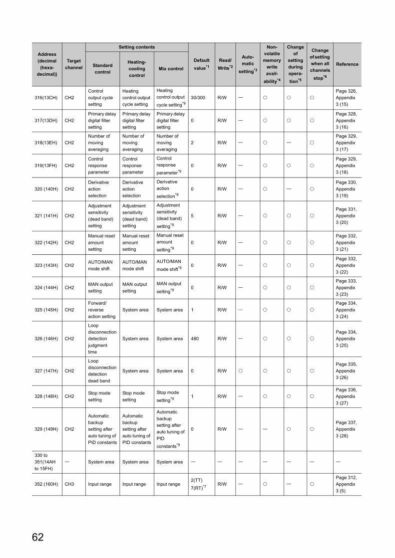
316(13CH) CH2
Control
output cycle
setting
Heating
control output
cycle setting
Heating
control output
cycle setting*9
30/300 R/W
Page 326,
Appendix
3 (15)
317(13DH) CH2
Primary delay
digital filter
setting
Primary delay
digital filter
setting
Primary delay
digital filter
setting
0 R/W
Page 328,
Appendix
3 (16)
318(13EH) CH2
Number of
moving
averaging
Number of
moving
averaging
Number of
moving
averaging
2 R/W
Page 329,
Appendix
3 (17)
319(13FH) CH2
Control
response
parameter
Control
response
parameter
Control
response
parameter*90 R/W
Page 329,
Appendix
3 (18)
320 (140H) CH2
Derivative
action
selection
Derivative
action
selection
Derivative
action
selection*9
0 R/W
Page 330,
Appendix
3 (19)
321 (141H) CH2
Adjustment
sensitivity
(dead band)
setting
Adjustment
sensitivity
(dead band)
setting
Adjustment
sensitivity
(dead band)
setting*9
5 R/W
Page 331,
Appendix
3 (20)
322 (142H) CH2
Manual reset
amount
setting
Manual reset
amount
setting
Manual reset
amount
setting*9
0 R/W
Page 332,
Appendix
3 (21)
323 (143H) CH2AUTO/MAN
mode shift
AUTO/MAN
mode shift
AUTO/MAN
mode shift*90 R/W
Page 332,
Appendix
3 (22)
324 (144H) CH2MAN output
setting
MAN output
setting
MAN output
setting*90 R/W
Page 333,
Appendix
3 (23)
325 (145H) CH2
Forward/
reverse
action setting
System area System area 1 R/W
Page 334,
Appendix
3 (24)
326 (146H) CH2
Loop
disconnection
detection
judgment
time
System area System area 480 R/W
Page 334,
Appendix
3 (25)
327 (147H) CH2
Loop
disconnection
detection
dead band
System area System area 0 R/W
Page 335,
Appendix
3 (26)
328 (148H) CH2Stop mode
setting
Stop mode
setting
Stop mode
setting*91 R/W
Page 336,
Appendix
3 (27)
329 (149H) CH2
Automatic
backup
setting after
auto tuning of
PID constants
Automatic
backup
setting after
auto tuning of
PID constants
Automatic
backup
setting after
auto tuning of
PID
constants*9
0 R/W
Page 337,
Appendix
3 (28)
330 to
351(14AH
to 15FH)
System area System area System area
352 (160H) CH3 Input range Input range Input range2(TT)
7(RT)*7R/W
Page 312,
Appendix
3 (5)
Address
(decimal
(hexa-
decimal))
Target
channel
Setting contents
Default
value*1
Read/
Write*2
Auto-
matic
setting*3
Non-
volatile
memory
write
avail-
ability*4
Change
of
setting
during
opera-
tion*5
Change
of setting
when all
channels
stop*6
ReferenceStandard
control
Heating-
cooling
control
Mix control
62
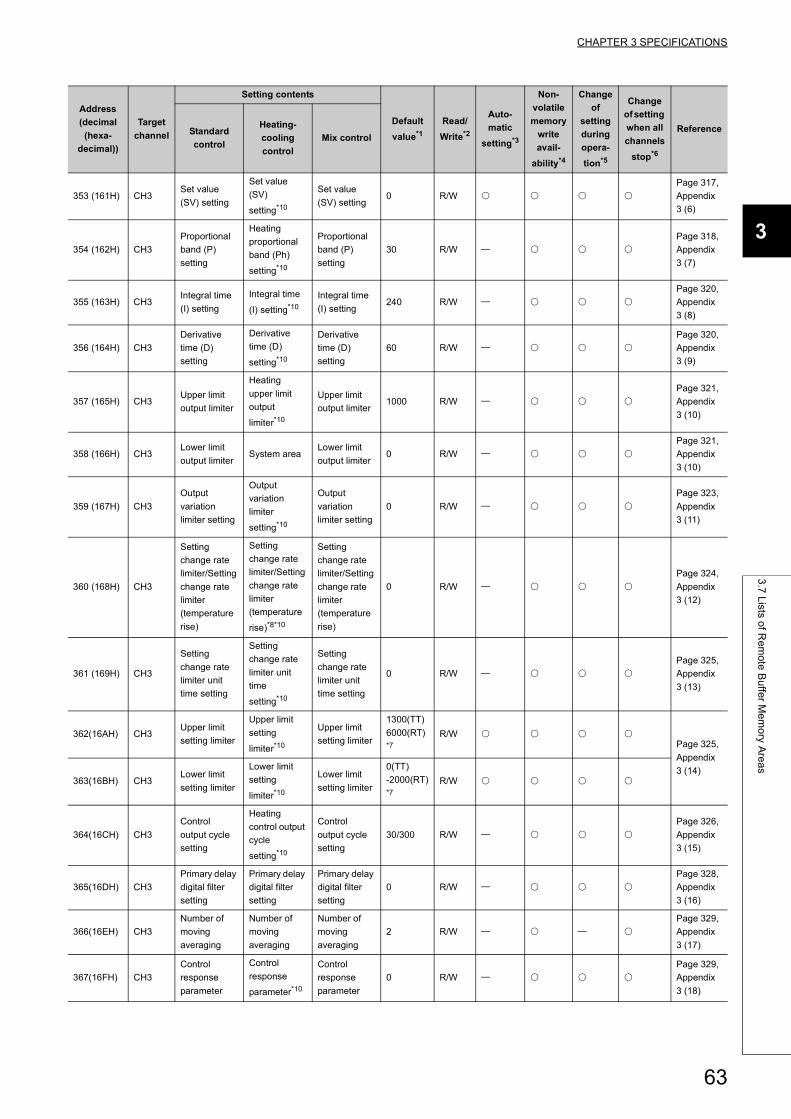
CHAPTER 3 SPECIFICATIONS
3
3.7
Lists o
f Re
mo
te B
uffe
r Me
mo
ry Are
as
353 (161H) CH3Set value
(SV) setting
Set value
(SV)
setting*10
Set value
(SV) setting0 R/W
Page 317,
Appendix
3 (6)
354 (162H) CH3
Proportional
band (P)
setting
Heating
proportional
band (Ph)
setting*10
Proportional
band (P)
setting
30 R/W
Page 318,
Appendix
3 (7)
355 (163H) CH3Integral time
(I) setting
Integral time
(I) setting*10
Integral time
(I) setting240 R/W
Page 320,
Appendix
3 (8)
356 (164H) CH3
Derivative
time (D)
setting
Derivative
time (D)
setting*10
Derivative
time (D)
setting
60 R/W
Page 320,
Appendix
3 (9)
357 (165H) CH3Upper limit
output limiter
Heating
upper limit
output
limiter*10
Upper limit
output limiter1000 R/W
Page 321,
Appendix
3 (10)
358 (166H) CH3Lower limit
output limiterSystem area
Lower limit
output limiter0 R/W
Page 321,
Appendix
3 (10)
359 (167H) CH3
Output
variation
limiter setting
Output
variation
limiter
setting*10
Output
variation
limiter setting
0 R/W
Page 323,
Appendix
3 (11)
360 (168H) CH3
Setting
change rate
limiter/Setting
change rate
limiter
(temperature
rise)
Setting
change rate
limiter/Setting
change rate
limiter
(temperature
rise)*8*10
Setting
change rate
limiter/Setting
change rate
limiter
(temperature
rise)
0 R/W
Page 324,
Appendix
3 (12)
361 (169H) CH3
Setting
change rate
limiter unit
time setting
Setting
change rate
limiter unit
time
setting*10
Setting
change rate
limiter unit
time setting
0 R/W
Page 325,
Appendix
3 (13)
362(16AH) CH3Upper limit
setting limiter
Upper limit
setting
limiter*10
Upper limit
setting limiter
1300(TT)
6000(RT) *7
R/W Page 325,
Appendix
3 (14)363(16BH) CH3
Lower limit
setting limiter
Lower limit
setting
limiter*10
Lower limit
setting limiter
0(TT)
-2000(RT) *7
R/W
364(16CH) CH3
Control
output cycle
setting
Heating
control output
cycle
setting*10
Control
output cycle
setting
30/300 R/W
Page 326,
Appendix
3 (15)
365(16DH) CH3
Primary delay
digital filter
setting
Primary delay
digital filter
setting
Primary delay
digital filter
setting
0 R/W
Page 328,
Appendix
3 (16)
366(16EH) CH3
Number of
moving
averaging
Number of
moving
averaging
Number of
moving
averaging
2 R/W
Page 329,
Appendix
3 (17)
367(16FH) CH3
Control
response
parameter
Control
response
parameter*10
Control
response
parameter
0 R/W
Page 329,
Appendix
3 (18)
Address
(decimal
(hexa-
decimal))
Target
channel
Setting contents
Default
value*1
Read/
Write*2
Auto-
matic
setting*3
Non-
volatile
memory
write
avail-
ability*4
Change
of
setting
during
opera-
tion*5
Change
of setting
when all
channels
stop*6
ReferenceStandard
control
Heating-
cooling
control
Mix control
63
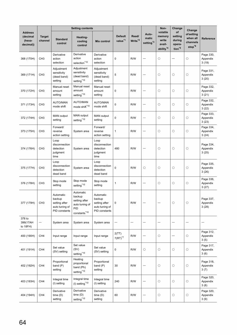
368 (170H) CH3
Derivative
action
selection
Derivative
action
selection*10
Derivative
action
selection
0 R/W
Page 330,
Appendix
3 (19)
369 (171H) CH3
Adjustment
sensitivity
(dead band)
setting
Adjustment
sensitivity
(dead band)
setting*10
Adjustment
sensitivity
(dead band)
setting
5 R/W
Page 331,
Appendix
3 (20)
370 (172H) CH3
Manual reset
amount
setting
Manual reset
amount
setting*10
Manual reset
amount
setting
0 R/W
Page 332,
Appendix
3 (21)
371 (173H) CH3AUTO/MAN
mode shift
AUTO/MAN
mode shift*10
AUTO/MAN
mode shift0 R/W
Page 332,
Appendix
3 (22)
372 (174H) CH3MAN output
setting
MAN output
setting*10
MAN output
setting0 R/W
Page 333,
Appendix
3 (23)
373 (175H) CH3
Forward/
reverse
action setting
System area
Forward/
reverse
action setting
1 R/W
Page 334,
Appendix
3 (24)
374 (176H) CH3
Loop
disconnection
detection
judgment
time
System area
Loop
disconnection
detection
judgment
time
480 R/W
Page 334,
Appendix
3 (25)
375 (177H) CH3
Loop
disconnection
detection
dead band
System area
Loop
disconnection
detection
dead band
0 R/W
Page 335,
Appendix
3 (26)
376 (178H) CH3Stop mode
setting
Stop mode
setting*10
Stop mode
setting1 R/W
Page 336,
Appendix
3 (27)
377 (179H) CH3
Automatic
backup
setting after
auto tuning of
PID constants
Automatic
backup
setting after
auto tuning of
PID
constants*10
Automatic
backup
setting after
auto tuning of
PID constants
0 R/W
Page 337,
Appendix
3 (28)
378 to
399(17AH
to 18FH)
System area System area System area
400 (190H) CH4 Input range Input range Input range2(TT)
7(RT)*7R/W
Page 312,
Appendix
3 (5)
401 (191H) CH4Set value
(SV) setting
Set value
(SV)
setting*10
Set value
(SV) setting0 R/W
Page 317,
Appendix
3 (6)
402 (192H) CH4
Proportional
band (P)
setting
Heating
proportional
band (Ph)
setting*10
Proportional
band (P)
setting
30 R/W
Page 318,
Appendix
3 (7)
403 (193H) CH4Integral time
(I) setting
Integral time
(I) setting*10
Integral time
(I) setting240 R/W
Page 320,
Appendix
3 (8)
404 (194H) CH4
Derivative
time (D)
setting
Derivative
time (D)
setting*10
Derivative
time (D)
setting
60 R/W
Page 320,
Appendix
3 (9)
Address
(decimal
(hexa-
decimal))
Target
channel
Setting contents
Default
value*1
Read/
Write*2
Auto-
matic
setting*3
Non-
volatile
memory
write
avail-
ability*4
Change
of
setting
during
opera-
tion*5
Change
of setting
when all
channels
stop*6
ReferenceStandard
control
Heating-
cooling
control
Mix control
64
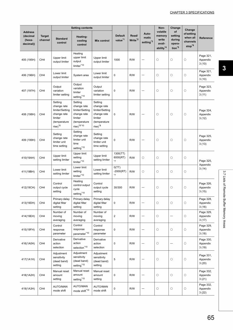
CHAPTER 3 SPECIFICATIONS
3
3.7
Lists o
f Re
mo
te B
uffe
r Me
mo
ry Are
as
405 (195H) CH4Upper limit
output limiter
Heating
upper limit
output
limiter*10
Upper limit
output limiter1000 R/W
Page 321,
Appendix
3 (10)
406 (196H) CH4Lower limit
output limiterSystem area
Lower limit
output limiter0 R/W
Page 321,
Appendix
3 (10)
407 (197H) CH4
Output
variation
limiter setting
Output
variation
limiter
setting*10
Output
variation
limiter setting
0 R/W
Page 323,
Appendix
3 (11)
408 (198H) CH4
Setting
change rate
limiter/Setting
change rate
limiter
(temperature
rise)*8
Setting
change rate
limiter/Setting
change rate
limiter
(temperature
rise)*8*10
Setting
change rate
limiter/Setting
change rate
limiter
(temperature
rise)*8
0 R/W
Page 324,
Appendix
3 (12)
409 (199H) CH4
Setting
change rate
limiter unit
time setting
Setting
change rate
limiter unit
time
setting*10
Setting
change rate
limiter unit
time setting
0 R/W
Page 325,
Appendix
3 (13)
410(19AH) CH4Upper limit
setting limiter
Upper limit
setting
limiter*10
Upper limit
setting limiter
1300(TT)
6000(RT) *7
R/W Page 325,
Appendix
3 (14)411(19BH) CH4
Lower limit
setting limiter
Lower limit
setting
limiter*10
Lower limit
setting limiter
0(TT)
-2000(RT) *7
R/W
412(19CH) CH4
Control
output cycle
setting
Heating
control output
cycle
setting*10
Control
output cycle
setting
30/300 R/W
Page 326,
Appendix
3 (15)
413(19DH) CH4
Primary delay
digital filter
setting
Primary delay
digital filter
setting
Primary delay
digital filter
setting
0 R/W
Page 328,
Appendix
3 (16)
414(19EH) CH4
Number of
moving
averaging
Number of
moving
averaging
Number of
moving
averaging
2 R/W
Page 329,
Appendix
3 (17)
415(19FH) CH4
Control
response
parameter
Control
response
parameter*10
Control
response
parameter
0 R/W
Page 329,
Appendix
3 (18)
416(1A0H) CH4
Derivative
action
selection
Derivative
action
selection*10
Derivative
action
selection
0 R/W
Page 330,
Appendix
3 (19)
417(1A1H) CH4
Adjustment
sensitivity
(dead band)
setting
Adjustment
sensitivity
(dead band)
setting*10
Adjustment
sensitivity
(dead band)
setting
5 R/W
Page 331,
Appendix
3 (20)
418(1A2H) CH4
Manual reset
amount
setting
Manual reset
amount
setting*10
Manual reset
amount
setting
0 R/W
Page 332,
Appendix
3 (21)
419(1A3H) CH4AUTO/MAN
mode shift
AUTO/MAN
mode shift*10
AUTO/MAN
mode shift0 R/W
Page 332,
Appendix
3 (22)
Address
(decimal
(hexa-
decimal))
Target
channel
Setting contents
Default
value*1
Read/
Write*2
Auto-
matic
setting*3
Non-
volatile
memory
write
avail-
ability*4
Change
of
setting
during
opera-
tion*5
Change
of setting
when all
channels
stop*6
ReferenceStandard
control
Heating-
cooling
control
Mix control
65

420(1A4H) CH4MAN output
setting
MAN output
setting*10
MAN output
setting0 R/W
Page 333,
Appendix
3 (23)
421(1A5H) CH4
Forward/
reverse
action setting
System area
Forward/
reverse
action setting
1 R/W
Page 334,
Appendix
3 (24)
422(1A6H) CH4
Loop
disconnection
detection
judgment
time
System area
Loop
disconnection
detection
judgment
time
480 R/W
Page 334,
Appendix
3 (25)
423(1A7H) CH4
Loop
disconnection
detection
dead band
System area
Loop
disconnection
detection
dead band
0 R/W
Page 335,
Appendix
3 (26)
424(1A8H) CH4Stop mode
setting
Stop mode
setting*10
Stop mode
setting1 R/W
Page 336,
Appendix
3 (27)
425(1A9H) CH4
Automatic
backup
setting after
auto tuning of
PID constants
Automatic
backup
setting after
auto tuning of
PID
constants*10
Automatic
backup
setting after
auto tuning of
PID constants
0 R/W
Page 337,
Appendix
3 (28)
426 to
447(1AAH
to 1BFH)
System area System area System area
448(1C0H) System area System area System area
449(1C1H) CH2 System area System area
Temperature
conversion
setting*11
0 R/W
Page 338,
Appendix
3 (29)
450(1C2H) CH3 System area
Temperature
conversion
setting*12
System area 0 R/W
451(1C3H) CH4 System area
Temperature
conversion
setting*12
System area 0 R/W
452(1C4H) CH1 System area
Cooling
proportional
band (Pc)
setting
Cooling
proportional
band (Pc)
setting
30 R/W
Page 318,
Appendix
3 (7)
453(1C5H) CH1 System area
Cooling upper
limit output
limiter
Cooling upper
limit output
limiter
1000 R/W
Page 325,
Appendix
3 (14)
454(1C6H) CH1 System area
Cooling
control output
cycle setting
Cooling
control output
cycle setting
30/300 R/W
Page 326,
Appendix
3 (15)
455(1C7H) CH1 System areaOverlap/dead
band setting
Overlap/dead
band setting0 R/W
Page 339,
Appendix
3 (30)
456(1C8H) CH1
Setting
change rate
limiter
(temperature
drop)*13
Setting
change rate
limiter
(temperature
drop)*13
Setting
change rate
limiter
(temperature
drop)*13
0 R/W
Page 324,
Appendix
3 (12)
Address
(decimal
(hexa-
decimal))
Target
channel
Setting contents
Default
value*1
Read/
Write*2
Auto-
matic
setting*3
Non-
volatile
memory
write
avail-
ability*4
Change
of
setting
during
opera-
tion*5
Change
of setting
when all
channels
stop*6
ReferenceStandard
control
Heating-
cooling
control
Mix control
66
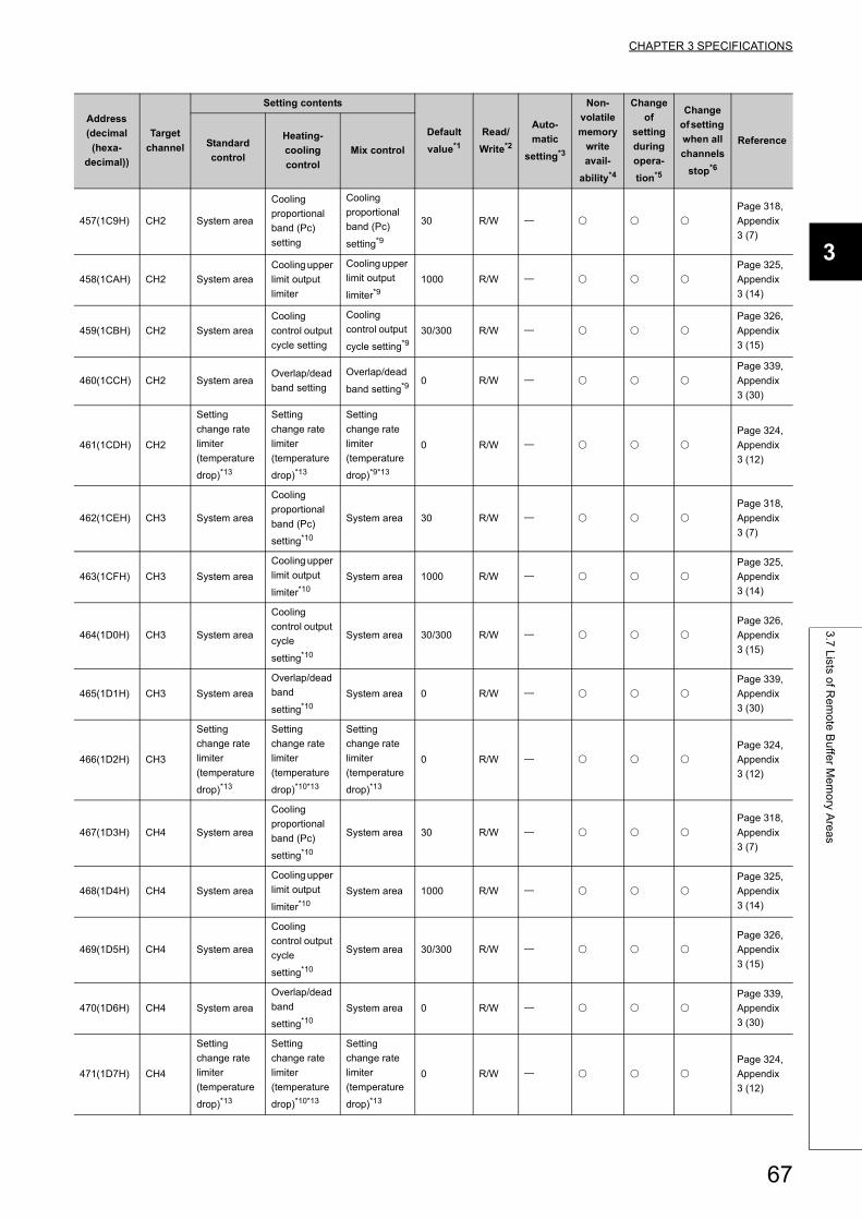
CHAPTER 3 SPECIFICATIONS
3
3.7
Lists o
f Re
mo
te B
uffe
r Me
mo
ry Are
as
457(1C9H) CH2 System area
Cooling
proportional
band (Pc)
setting
Cooling
proportional
band (Pc)
setting*9
30 R/W
Page 318,
Appendix
3 (7)
458(1CAH) CH2 System area
Cooling upper
limit output
limiter
Cooling upper
limit output
limiter*91000 R/W
Page 325,
Appendix
3 (14)
459(1CBH) CH2 System area
Cooling
control output
cycle setting
Cooling
control output
cycle setting*9
30/300 R/W
Page 326,
Appendix
3 (15)
460(1CCH) CH2 System areaOverlap/dead
band setting
Overlap/dead
band setting*90 R/W
Page 339,
Appendix
3 (30)
461(1CDH) CH2
Setting
change rate
limiter
(temperature
drop)*13
Setting
change rate
limiter
(temperature
drop)*13
Setting
change rate
limiter
(temperature
drop)*9*13
0 R/W
Page 324,
Appendix
3 (12)
462(1CEH) CH3 System area
Cooling
proportional
band (Pc)
setting*10
System area 30 R/W
Page 318,
Appendix
3 (7)
463(1CFH) CH3 System area
Cooling upper
limit output
limiter*10
System area 1000 R/W
Page 325,
Appendix
3 (14)
464(1D0H) CH3 System area
Cooling
control output
cycle
setting*10
System area 30/300 R/W
Page 326,
Appendix
3 (15)
465(1D1H) CH3 System area
Overlap/dead
band
setting*10
System area 0 R/W
Page 339,
Appendix
3 (30)
466(1D2H) CH3
Setting
change rate
limiter
(temperature
drop)*13
Setting
change rate
limiter
(temperature
drop)*10*13
Setting
change rate
limiter
(temperature
drop)*13
0 R/W
Page 324,
Appendix
3 (12)
467(1D3H) CH4 System area
Cooling
proportional
band (Pc)
setting*10
System area 30 R/W
Page 318,
Appendix
3 (7)
468(1D4H) CH4 System area
Cooling upper
limit output
limiter*10
System area 1000 R/W
Page 325,
Appendix
3 (14)
469(1D5H) CH4 System area
Cooling
control output
cycle
setting*10
System area 30/300 R/W
Page 326,
Appendix
3 (15)
470(1D6H) CH4 System area
Overlap/dead
band
setting*10
System area 0 R/W
Page 339,
Appendix
3 (30)
471(1D7H) CH4
Setting
change rate
limiter
(temperature
drop)*13
Setting
change rate
limiter
(temperature
drop)*10*13
Setting
change rate
limiter
(temperature
drop)*13
0 R/W
Page 324,
Appendix
3 (12)
Address
(decimal
(hexa-
decimal))
Target
channel
Setting contents
Default
value*1
Read/
Write*2
Auto-
matic
setting*3
Non-
volatile
memory
write
avail-
ability*4
Change
of
setting
during
opera-
tion*5
Change
of setting
when all
channels
stop*6
ReferenceStandard
control
Heating-
cooling
control
Mix control
67
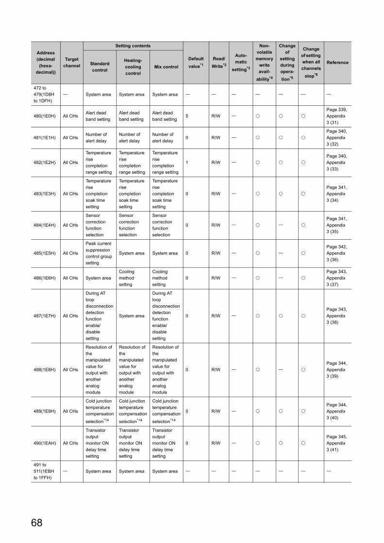
472 to
479(1D8H
to 1DFH)
System area System area System area
480(1E0H) All CHsAlert dead
band setting
Alert dead
band setting
Alert dead
band setting5 R/W
Page 339,
Appendix
3 (31)
481(1E1H) All CHsNumber of
alert delay
Number of
alert delay
Number of
alert delay0 R/W
Page 340,
Appendix
3 (32)
482(1E2H) All CHs
Temperature
rise
completion
range setting
Temperature
rise
completion
range setting
Temperature
rise
completion
range setting
1 R/W
Page 340,
Appendix
3 (33)
483(1E3H) All CHs
Temperature
rise
completion
soak time
setting
Temperature
rise
completion
soak time
setting
Temperature
rise
completion
soak time
setting
0 R/W
Page 341,
Appendix
3 (34)
484(1E4H) All CHs
Sensor
correction
function
selection
Sensor
correction
function
selection
Sensor
correction
function
selection
0 R/W
Page 341,
Appendix
3 (35)
485(1E5H) All CHs
Peak current
suppression
control group
setting
System area System area 0 R/W
Page 342,
Appendix
3 (36)
486(1E6H) All CHs System area
Cooling
method
setting
Cooling
method
setting
0 R/W
Page 343,
Appendix
3 (37)
487(1E7H) All CHs
During AT
loop
disconnection
detection
function
enable/
disable
setting
System area
During AT
loop
disconnection
detection
function
enable/
disable
setting
0 R/W
Page 343,
Appendix
3 (38)
488(1E8H) All CHs
Resolution of
the
manipulated
value for
output with
another
analog
module
Resolution of
the
manipulated
value for
output with
another
analog
module
Resolution of
the
manipulated
value for
output with
another
analog
module
0 R/W
Page 344,
Appendix
3 (39)
489(1E9H) All CHs
Cold junction
temperature
compensation
selection*14
Cold junction
temperature
compensation
selection*14
Cold junction
temperature
compensation
selection*14
0 R/W
Page 344,
Appendix
3 (40)
490(1EAH) All CHs
Transistor
output
monitor ON
delay time
setting
Transistor
output
monitor ON
delay time
setting
Transistor
output
monitor ON
delay time
setting
0 R/W
Page 345,
Appendix
3 (41)
491 to
511(1EBH
to 1FFH)
System area System area System area
Address
(decimal
(hexa-
decimal))
Target
channel
Setting contents
Default
value*1
Read/
Write*2
Auto-
matic
setting*3
Non-
volatile
memory
write
avail-
ability*4
Change
of
setting
during
opera-
tion*5
Change
of setting
when all
channels
stop*6
ReferenceStandard
control
Heating-
cooling
control
Mix control
68
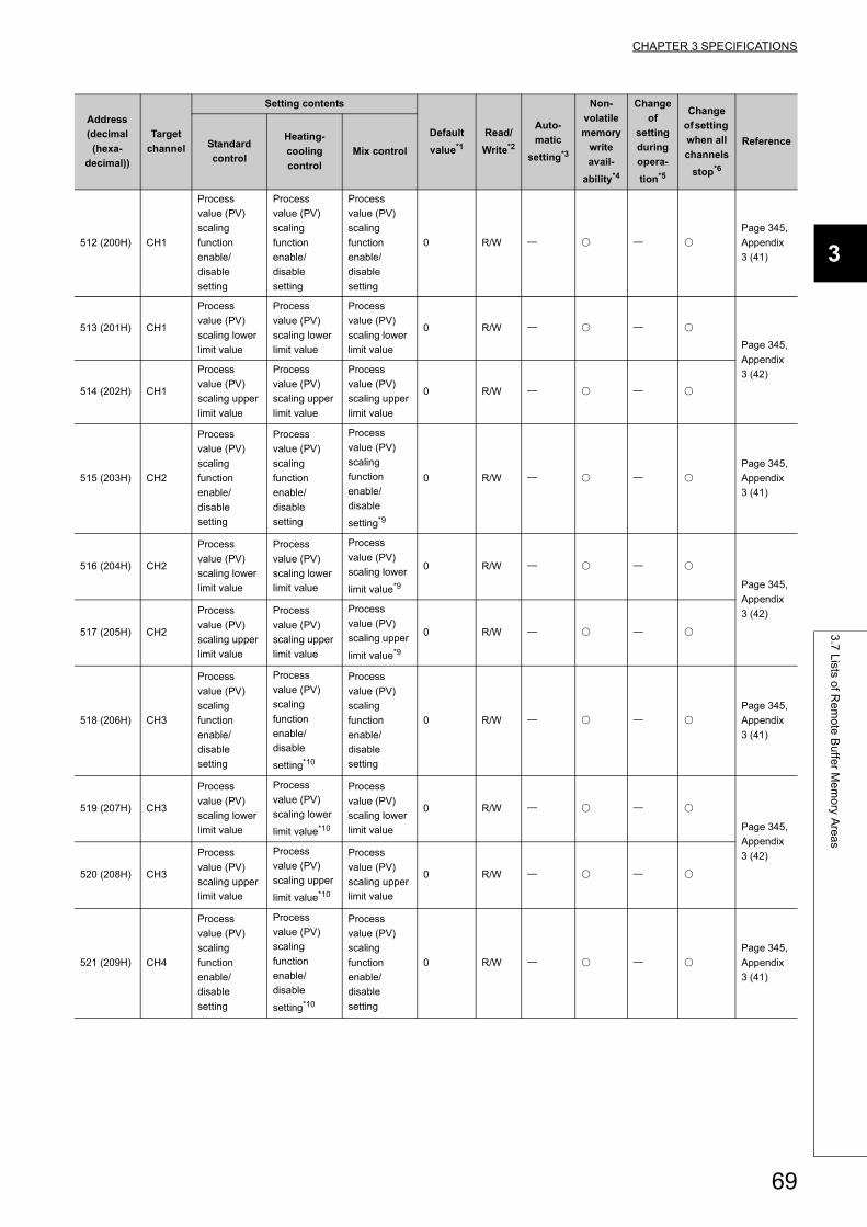
CHAPTER 3 SPECIFICATIONS
3
3.7
Lists o
f Re
mo
te B
uffe
r Me
mo
ry Are
as
512 (200H) CH1
Process
value (PV)
scaling
function
enable/
disable
setting
Process
value (PV)
scaling
function
enable/
disable
setting
Process
value (PV)
scaling
function
enable/
disable
setting
0 R/W
Page 345,
Appendix
3 (41)
513 (201H) CH1
Process
value (PV)
scaling lower
limit value
Process
value (PV)
scaling lower
limit value
Process
value (PV)
scaling lower
limit value
0 R/W
Page 345,
Appendix
3 (42)
514 (202H) CH1
Process
value (PV)
scaling upper
limit value
Process
value (PV)
scaling upper
limit value
Process
value (PV)
scaling upper
limit value
0 R/W
515 (203H) CH2
Process
value (PV)
scaling
function
enable/
disable
setting
Process
value (PV)
scaling
function
enable/
disable
setting
Process
value (PV)
scaling
function
enable/
disable
setting*9
0 R/W
Page 345,
Appendix
3 (41)
516 (204H) CH2
Process
value (PV)
scaling lower
limit value
Process
value (PV)
scaling lower
limit value
Process
value (PV)
scaling lower
limit value*9
0 R/W
Page 345,
Appendix
3 (42)
517 (205H) CH2
Process
value (PV)
scaling upper
limit value
Process
value (PV)
scaling upper
limit value
Process
value (PV)
scaling upper
limit value*9
0 R/W
518 (206H) CH3
Process
value (PV)
scaling
function
enable/
disable
setting
Process
value (PV)
scaling
function
enable/
disable
setting*10
Process
value (PV)
scaling
function
enable/
disable
setting
0 R/W
Page 345,
Appendix
3 (41)
519 (207H) CH3
Process
value (PV)
scaling lower
limit value
Process
value (PV)
scaling lower
limit value*10
Process
value (PV)
scaling lower
limit value
0 R/W
Page 345,
Appendix
3 (42)
520 (208H) CH3
Process
value (PV)
scaling upper
limit value
Process
value (PV)
scaling upper
limit value*10
Process
value (PV)
scaling upper
limit value
0 R/W
521 (209H) CH4
Process
value (PV)
scaling
function
enable/
disable
setting
Process
value (PV)
scaling
function
enable/
disable
setting*10
Process
value (PV)
scaling
function
enable/
disable
setting
0 R/W
Page 345,
Appendix
3 (41)
Address
(decimal
(hexa-
decimal))
Target
channel
Setting contents
Default
value*1
Read/
Write*2
Auto-
matic
setting*3
Non-
volatile
memory
write
avail-
ability*4
Change
of
setting
during
opera-
tion*5
Change
of setting
when all
channels
stop*6
ReferenceStandard
control
Heating-
cooling
control
Mix control
69
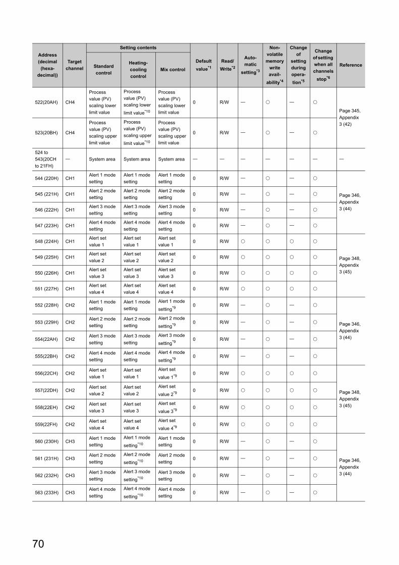
522(20AH) CH4
Process
value (PV)
scaling lower
limit value
Process
value (PV)
scaling lower
limit value*10
Process
value (PV)
scaling lower
limit value
0 R/W
Page 345,
Appendix
3 (42)
523(20BH) CH4
Process
value (PV)
scaling upper
limit value
Process
value (PV)
scaling upper
limit value*10
Process
value (PV)
scaling upper
limit value
0 R/W
524 to
543(20CH
to 21FH)
System area System area System area
544 (220H) CH1Alert 1 mode
setting
Alert 1 mode
setting
Alert 1 mode
setting0 R/W
Page 346,
Appendix
3 (44)
545 (221H) CH1Alert 2 mode
setting
Alert 2 mode
setting
Alert 2 mode
setting0 R/W
546 (222H) CH1Alert 3 mode
setting
Alert 3 mode
setting
Alert 3 mode
setting0 R/W
547 (223H) CH1Alert 4 mode
setting
Alert 4 mode
setting
Alert 4 mode
setting0 R/W
548 (224H) CH1Alert set
value 1
Alert set
value 1
Alert set
value 10 R/W
Page 348,
Appendix
3 (45)
549 (225H) CH1Alert set
value 2
Alert set
value 2
Alert set
value 20 R/W
550 (226H) CH1Alert set
value 3
Alert set
value 3
Alert set
value 30 R/W
551 (227H) CH1Alert set
value 4
Alert set
value 4
Alert set
value 40 R/W
552 (228H) CH2Alert 1 mode
setting
Alert 1 mode
setting
Alert 1 mode
setting*90 R/W
Page 346,
Appendix
3 (44)
553 (229H) CH2Alert 2 mode
setting
Alert 2 mode
setting
Alert 2 mode
setting*90 R/W
554(22AH) CH2Alert 3 mode
setting
Alert 3 mode
setting
Alert 3 mode
setting*90 R/W
555(22BH) CH2Alert 4 mode
setting
Alert 4 mode
setting
Alert 4 mode
setting*90 R/W
556(22CH) CH2Alert set
value 1
Alert set
value 1
Alert set
value 1*90 R/W
Page 348,
Appendix
3 (45)
557(22DH) CH2Alert set
value 2
Alert set
value 2
Alert set
value 2*90 R/W
558(22EH) CH2Alert set
value 3
Alert set
value 3
Alert set
value 3*90 R/W
559(22FH) CH2Alert set
value 4
Alert set
value 4
Alert set
value 4*90 R/W
560 (230H) CH3Alert 1 mode
setting
Alert 1 mode
setting*10
Alert 1 mode
setting0 R/W
Page 346,
Appendix
3 (44)
561 (231H) CH3Alert 2 mode
setting
Alert 2 mode
setting*10
Alert 2 mode
setting0 R/W
562 (232H) CH3Alert 3 mode
setting
Alert 3 mode
setting*10
Alert 3 mode
setting0 R/W
563 (233H) CH3Alert 4 mode
setting
Alert 4 mode
setting*10
Alert 4 mode
setting0 R/W
Address
(decimal
(hexa-
decimal))
Target
channel
Setting contents
Default
value*1
Read/
Write*2
Auto-
matic
setting*3
Non-
volatile
memory
write
avail-
ability*4
Change
of
setting
during
opera-
tion*5
Change
of setting
when all
channels
stop*6
ReferenceStandard
control
Heating-
cooling
control
Mix control
70
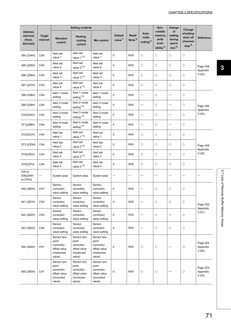
CHAPTER 3 SPECIFICATIONS
3
3.7
Lists o
f Re
mo
te B
uffe
r Me
mo
ry Are
as
564 (234H) CH3Alert set
value 1
Alert set
value 1*10
Alert set
value 10 R/W
Page 348,
Appendix
3 (45)
565 (235H) CH3Alert set
value 2
Alert set
value 2*10
Alert set
value 20 R/W
566 (236H) CH3Alert set
value 3
Alert set
value 3*10
Alert set
value 30 R/W
567 (237H) CH3Alert set
value 4
Alert set
value 4*10
Alert set
value 40 R/W
568 (238H) CH4Alert 1 mode
setting
Alert 1 mode
setting*10
Alert 1 mode
setting0 R/W
Page 346,
Appendix
3 (44)
569 (239H) CH4Alert 2 mode
setting
Alert 2 mode
setting*10
Alert 2 mode
setting0 R/W
570(23AH) CH4Alert 3 mode
setting
Alert 3 mode
setting*10
Alert 3 mode
setting0 R/W
571(23BH) CH4Alert 4 mode
setting
Alert 4 mode
setting*10
Alert 4 mode
setting0 R/W
572(23CH) CH4Alert set
value 1
Alert set
value 1*10
Alert set
value 10 R/W
Page 348,
Appendix
3 (45)
573 (23DH) CH4Alert set
value 2
Alert set
value 2*10
Alert set
value 20 R/W
574(23EH) CH4Alert set
value 3
Alert set
value 3*10
Alert set
value 30 R/W
575(23FH) CH4Alert set
value 4
Alert set
value 4*10
Alert set
value 40 R/W
576 to
639(240H
to 27FH)
System area System area System area
640 (280H) CH1
Sensor
correction
value setting
Sensor
correction
value setting
Sensor
correction
value setting
0 R/W
Page 352,
Appendix
3 (51)
641 (281H) CH2
Sensor
correction
value setting
Sensor
correction
value setting
Sensor
correction
value setting
0 R/W
642 (282H) CH3
Sensor
correction
value setting
Sensor
correction
value setting
Sensor
correction
value setting
0 R/W
643 (283H) CH4
Sensor
correction
value setting
Sensor
correction
value setting
Sensor
correction
value setting
0 R/W
644 (284H) CH1
Sensor two-
point
correction
offset value
(measured
value)
Sensor two-
point
correction
offset value
(measured
value)
Sensor two-
point
correction
offset value
(measured
value)
0 R/W
Page 352,
Appendix
3 (52)
645 (285H) CH1
Sensor two-
point
correction
offset value
(corrected
value)
Sensor two-
point
correction
offset value
(corrected
value)
Sensor two-
point
correction
offset value
(corrected
value)
0 R/W
Page 353,
Appendix
3 (53)
Address
(decimal
(hexa-
decimal))
Target
channel
Setting contents
Default
value*1
Read/
Write*2
Auto-
matic
setting*3
Non-
volatile
memory
write
avail-
ability*4
Change
of
setting
during
opera-
tion*5
Change
of setting
when all
channels
stop*6
ReferenceStandard
control
Heating-
cooling
control
Mix control
71
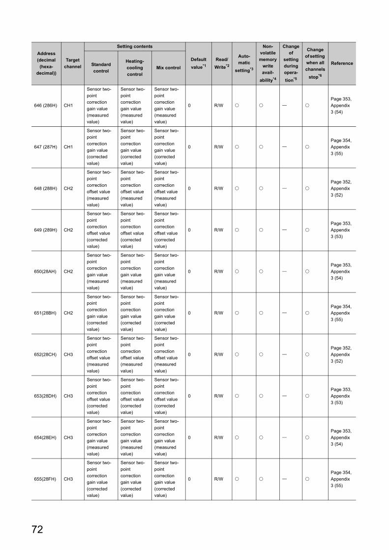
646 (286H) CH1
Sensor two-
point
correction
gain value
(measured
value)
Sensor two-
point
correction
gain value
(measured
value)
Sensor two-
point
correction
gain value
(measured
value)
0 R/W
Page 353,
Appendix
3 (54)
647 (287H) CH1
Sensor two-
point
correction
gain value
(corrected
value)
Sensor two-
point
correction
gain value
(corrected
value)
Sensor two-
point
correction
gain value
(corrected
value)
0 R/W
Page 354,
Appendix
3 (55)
648 (288H) CH2
Sensor two-
point
correction
offset value
(measured
value)
Sensor two-
point
correction
offset value
(measured
value)
Sensor two-
point
correction
offset value
(measured
value)
0 R/W
Page 352,
Appendix
3 (52)
649 (289H) CH2
Sensor two-
point
correction
offset value
(corrected
value)
Sensor two-
point
correction
offset value
(corrected
value)
Sensor two-
point
correction
offset value
(corrected
value)
0 R/W
Page 353,
Appendix
3 (53)
650(28AH) CH2
Sensor two-
point
correction
gain value
(measured
value)
Sensor two-
point
correction
gain value
(measured
value)
Sensor two-
point
correction
gain value
(measured
value)
0 R/W
Page 353,
Appendix
3 (54)
651(28BH) CH2
Sensor two-
point
correction
gain value
(corrected
value)
Sensor two-
point
correction
gain value
(corrected
value)
Sensor two-
point
correction
gain value
(corrected
value)
0 R/W
Page 354,
Appendix
3 (55)
652(28CH) CH3
Sensor two-
point
correction
offset value
(measured
value)
Sensor two-
point
correction
offset value
(measured
value)
Sensor two-
point
correction
offset value
(measured
value)
0 R/W
Page 352,
Appendix
3 (52)
653(28DH) CH3
Sensor two-
point
correction
offset value
(corrected
value)
Sensor two-
point
correction
offset value
(corrected
value)
Sensor two-
point
correction
offset value
(corrected
value)
0 R/W
Page 353,
Appendix
3 (53)
654(28EH) CH3
Sensor two-
point
correction
gain value
(measured
value)
Sensor two-
point
correction
gain value
(measured
value)
Sensor two-
point
correction
gain value
(measured
value)
0 R/W
Page 353,
Appendix
3 (54)
655(28FH) CH3
Sensor two-
point
correction
gain value
(corrected
value)
Sensor two-
point
correction
gain value
(corrected
value)
Sensor two-
point
correction
gain value
(corrected
value)
0 R/W
Page 354,
Appendix
3 (55)
Address
(decimal
(hexa-
decimal))
Target
channel
Setting contents
Default
value*1
Read/
Write*2
Auto-
matic
setting*3
Non-
volatile
memory
write
avail-
ability*4
Change
of
setting
during
opera-
tion*5
Change
of setting
when all
channels
stop*6
ReferenceStandard
control
Heating-
cooling
control
Mix control
72
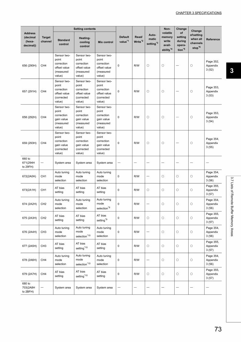
CHAPTER 3 SPECIFICATIONS
3
3.7
Lists o
f Re
mo
te B
uffe
r Me
mo
ry Are
as
656 (290H) CH4
Sensor two-
point
correction
offset value
(measured
value)
Sensor two-
point
correction
offset value
(measured
value)
Sensor two-
point
correction
offset value
(measured
value)
0 R/W
Page 352,
Appendix
3 (52)
657 (291H) CH4
Sensor two-
point
correction
offset value
(corrected
value)
Sensor two-
point
correction
offset value
(corrected
value)
Sensor two-
point
correction
offset value
(corrected
value)
0 R/W
Page 353,
Appendix
3 (53)
658 (292H) CH4
Sensor two-
point
correction
gain value
(measured
value)
Sensor two-
point
correction
gain value
(measured
value)
Sensor two-
point
correction
gain value
(measured
value)
0 R/W
Page 353,
Appendix
3 (54)
659 (293H) CH4
Sensor two-
point
correction
gain value
(corrected
value)
Sensor two-
point
correction
gain value
(corrected
value)
Sensor two-
point
correction
gain value
(corrected
value)
0 R/W
Page 354,
Appendix
3 (55)
660 to
671(294H
to 29FH)
System area System area System area
672(2A0H) CH1
Auto tuning
mode
selection
Auto tuning
mode
selection
Auto tuning
mode
selection
0 R/W
Page 354,
Appendix
3 (56)
673(2A1H) CH1AT bias
setting
AT bias
setting
AT bias
setting0 R/W
Page 355,
Appendix
3 (57)
674 (2A2H) CH2
Auto tuning
mode
selection
Auto tuning
mode
selection
Auto tuning
mode
selection*9
0 R/W
Page 354,
Appendix
3 (56)
675 (2A3H) CH2AT bias
setting
AT bias
setting
AT bias
setting*90 R/W
Page 355,
Appendix
3 (57)
676 (2A4H) CH3
Auto tuning
mode
selection
Auto tuning
mode
selection*10
Auto tuning
mode
selection
0 R/W
Page 354,
Appendix
3 (56)
677 (2A5H) CH3AT bias
setting
AT bias
setting*10
AT bias
setting0 R/W
Page 355,
Appendix
3 (57)
678 (2A6H) CH4
Auto tuning
mode
selection
Auto tuning
mode
selection*10
Auto tuning
mode
selection
0 R/W
Page 354,
Appendix
3 (56)
679 (2A7H) CH4AT bias
setting
AT bias
setting*10
AT bias
setting0 R/W
Page 355,
Appendix
3 (57)
680 to
703(2A8H
to 2BFH)
System area System area System area
Address
(decimal
(hexa-
decimal))
Target
channel
Setting contents
Default
value*1
Read/
Write*2
Auto-
matic
setting*3
Non-
volatile
memory
write
avail-
ability*4
Change
of
setting
during
opera-
tion*5
Change
of setting
when all
channels
stop*6
ReferenceStandard
control
Heating-
cooling
control
Mix control
73
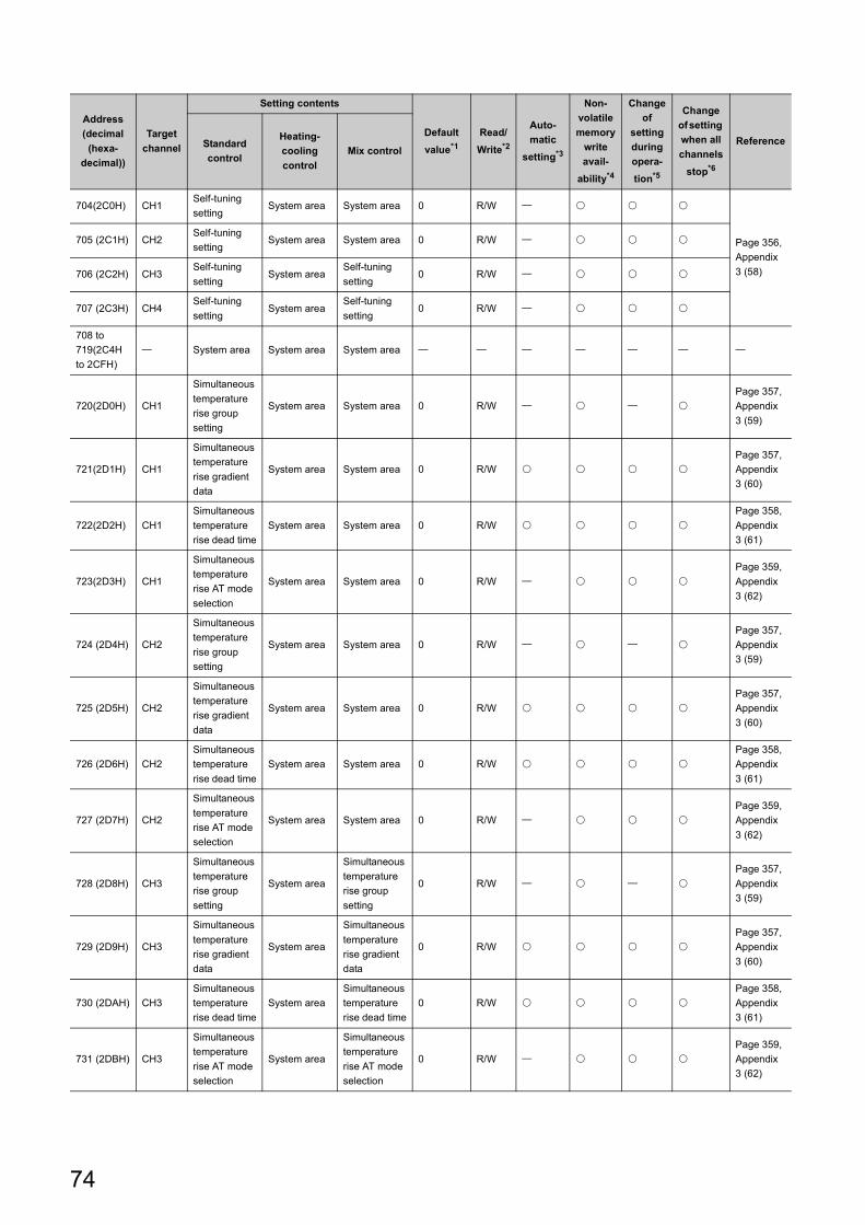
704(2C0H) CH1Self-tuning
settingSystem area System area 0 R/W
Page 356,
Appendix
3 (58)
705 (2C1H) CH2Self-tuning
settingSystem area System area 0 R/W
706 (2C2H) CH3Self-tuning
settingSystem area
Self-tuning
setting0 R/W
707 (2C3H) CH4Self-tuning
settingSystem area
Self-tuning
setting0 R/W
708 to
719(2C4H
to 2CFH)
System area System area System area
720(2D0H) CH1
Simultaneous
temperature
rise group
setting
System area System area 0 R/W
Page 357,
Appendix
3 (59)
721(2D1H) CH1
Simultaneous
temperature
rise gradient
data
System area System area 0 R/W
Page 357,
Appendix
3 (60)
722(2D2H) CH1
Simultaneous
temperature
rise dead time
System area System area 0 R/W
Page 358,
Appendix
3 (61)
723(2D3H) CH1
Simultaneous
temperature
rise AT mode
selection
System area System area 0 R/W
Page 359,
Appendix
3 (62)
724 (2D4H) CH2
Simultaneous
temperature
rise group
setting
System area System area 0 R/W
Page 357,
Appendix
3 (59)
725 (2D5H) CH2
Simultaneous
temperature
rise gradient
data
System area System area 0 R/W
Page 357,
Appendix
3 (60)
726 (2D6H) CH2
Simultaneous
temperature
rise dead time
System area System area 0 R/W
Page 358,
Appendix
3 (61)
727 (2D7H) CH2
Simultaneous
temperature
rise AT mode
selection
System area System area 0 R/W
Page 359,
Appendix
3 (62)
728 (2D8H) CH3
Simultaneous
temperature
rise group
setting
System area
Simultaneous
temperature
rise group
setting
0 R/W
Page 357,
Appendix
3 (59)
729 (2D9H) CH3
Simultaneous
temperature
rise gradient
data
System area
Simultaneous
temperature
rise gradient
data
0 R/W
Page 357,
Appendix
3 (60)
730 (2DAH) CH3
Simultaneous
temperature
rise dead time
System area
Simultaneous
temperature
rise dead time
0 R/W
Page 358,
Appendix
3 (61)
731 (2DBH) CH3
Simultaneous
temperature
rise AT mode
selection
System area
Simultaneous
temperature
rise AT mode
selection
0 R/W
Page 359,
Appendix
3 (62)
Address
(decimal
(hexa-
decimal))
Target
channel
Setting contents
Default
value*1
Read/
Write*2
Auto-
matic
setting*3
Non-
volatile
memory
write
avail-
ability*4
Change
of
setting
during
opera-
tion*5
Change
of setting
when all
channels
stop*6
ReferenceStandard
control
Heating-
cooling
control
Mix control
74
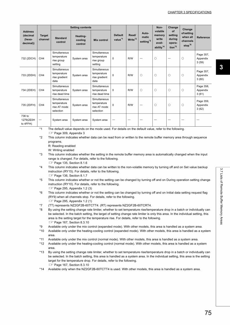
CHAPTER 3 SPECIFICATIONS
3
3.7
Lists o
f Re
mo
te B
uffe
r Me
mo
ry Are
as
*1 The default value depends on the mode used. For details on the default value, refer to the following.Page 309, Appendix 3
*2 This column indicates whether data can be read from or written to the remote buffer memory area through sequence programs.R: Reading enabledW: Writing enabled
*3 This column indicates whether the setting in the remote buffer memory area is automatically changed when the input range is changed. For details, refer to the following.Page 135, Section 8.1.6
*4 This column indicates whether data can be written to the non-volatile memory by turning off and on Set value backup instruction (RY15). For details, refer to the following.Page 136, Section 8.1.7
*5 This column indicates whether or not the setting can be changed by turning off and on During operation setting change instruction (RY10). For details, refer to the following.Page 295, Appendix 1.2 (3)
*6 This column indicates whether or not the setting can be changed by turning off and on Initial data setting request flag (RY9) when all channels stop. For details, refer to the following.Page 295, Appendix 1.2 (1)
*7 (TT) represents NZ2GF2B-60TCTT4. (RT) represents NZ2GF2B-60TCRT4.*8 By using the setting change rate limiter, whether to set temperature rise/temperature drop in a batch or individually can
be selected. In the batch setting, the target of setting change rate limiter is only this area. In the individual setting, this area is the setting target for the temperature rise. For details, refer to the following.Page 167, Section 8.3.10
*9 Available only under the mix control (expanded mode). With other models, this area is handled as a system area.*10 Available only under the heating-cooling control (expanded mode). With other models, this area is handled as a system
area.*11 Available only under the mix control (normal mode). With other models, this area is handled as a system area.*12 Available only under the heating-cooling control (normal mode). With other models, this area is handled as a system
area.*13 By using the setting change rate limiter, whether to set temperature rise/temperature drop in a batch or individually can
be selected. In the batch setting, this area is handled as a system area. In the individual setting, this area is the setting target for the temperature drop. For details, refer to the following.Page 167, Section 8.3.10
*14 Available only when the NZ2GF2B-60TCTT4 is used. With other models, this area is handled as a system area.
732 (2DCH) CH4
Simultaneous
temperature
rise group
setting
System area
Simultaneous
temperature
rise group
setting
0 R/W
Page 357,
Appendix
3 (59)
733 (2DDH) CH4
Simultaneous
temperature
rise gradient
data
System area
Simultaneous
temperature
rise gradient
data
0 R/W
Page 357,
Appendix
3 (60)
734 (2DEH) CH4
Simultaneous
temperature
rise dead time
System area
Simultaneous
temperature
rise dead time
0 R/W
Page 358,
Appendix
3 (61)
735 (2DFH) CH4
Simultaneous
temperature
rise AT mode
selection
System area
Simultaneous
temperature
rise AT mode
selection
0 R/W
Page 359,
Appendix
3 (62)
736 to
1279(2E0H
to 4FFH)
System area System area System area
Address
(decimal
(hexa-
decimal))
Target
channel
Setting contents
Default
value*1
Read/
Write*2
Auto-
matic
setting*3
Non-
volatile
memory
write
avail-
ability*4
Change
of
setting
during
opera-
tion*5
Change
of setting
when all
channels
stop*6
ReferenceStandard
control
Heating-
cooling
control
Mix control
75
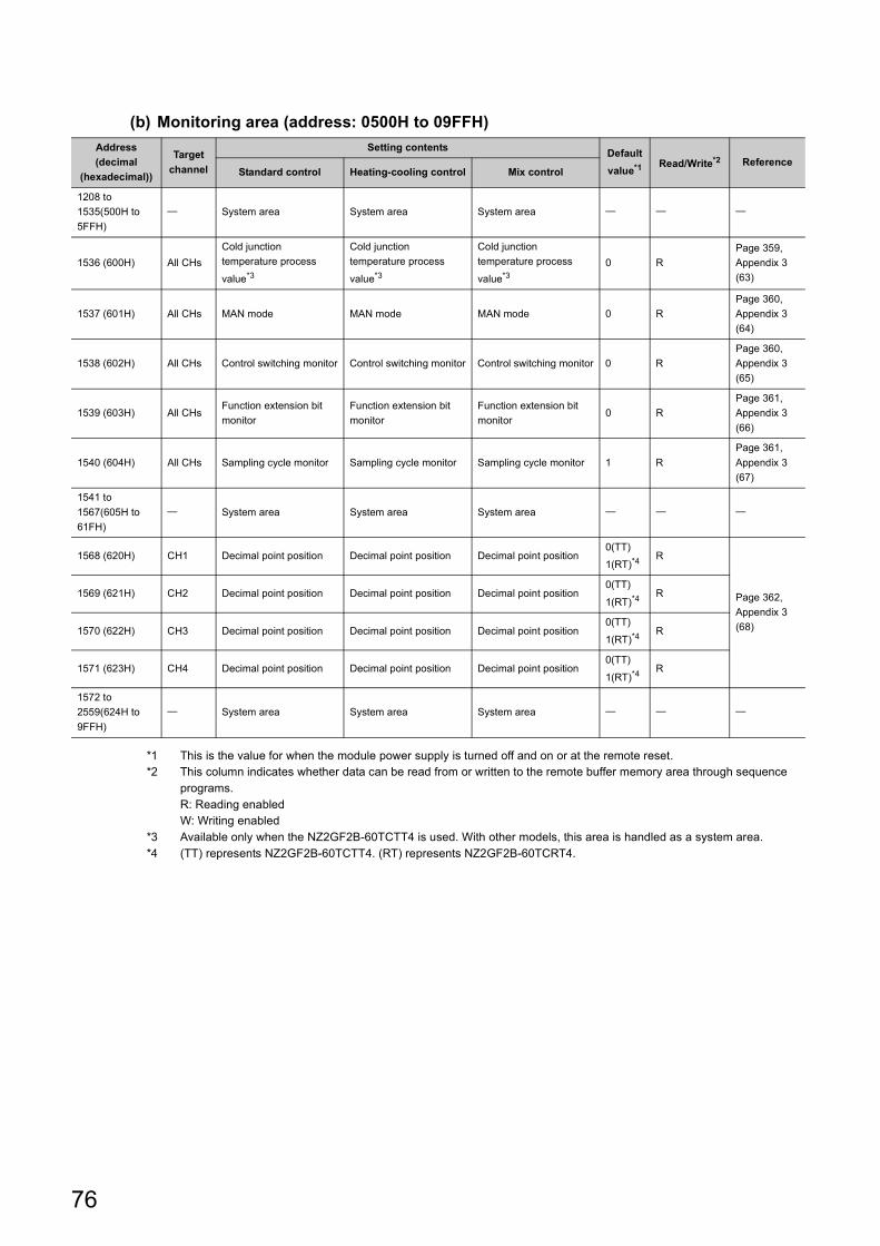
(b) Monitoring area (address: 0500H to 09FFH)
*1 This is the value for when the module power supply is turned off and on or at the remote reset.*2 This column indicates whether data can be read from or written to the remote buffer memory area through sequence
programs.R: Reading enabledW: Writing enabled
*3 Available only when the NZ2GF2B-60TCTT4 is used. With other models, this area is handled as a system area.*4 (TT) represents NZ2GF2B-60TCTT4. (RT) represents NZ2GF2B-60TCRT4.
Address
(decimal
(hexadecimal))
Target
channel
Setting contentsDefault
value*1 Read/Write*2 ReferenceStandard control Heating-cooling control Mix control
1208 to
1535(500H to
5FFH)
System area System area System area
1536 (600H) All CHs
Cold junction
temperature process
value*3
Cold junction
temperature process
value*3
Cold junction
temperature process
value*3
0 R
Page 359,
Appendix 3
(63)
1537 (601H) All CHs MAN mode MAN mode MAN mode 0 R
Page 360,
Appendix 3
(64)
1538 (602H) All CHs Control switching monitor Control switching monitor Control switching monitor 0 R
Page 360,
Appendix 3
(65)
1539 (603H) All CHsFunction extension bit
monitor
Function extension bit
monitor
Function extension bit
monitor0 R
Page 361,
Appendix 3
(66)
1540 (604H) All CHs Sampling cycle monitor Sampling cycle monitor Sampling cycle monitor 1 R
Page 361,
Appendix 3
(67)
1541 to
1567(605H to
61FH)
System area System area System area
1568 (620H) CH1 Decimal point position Decimal point position Decimal point position0(TT)
1(RT)*4R
Page 362,
Appendix 3
(68)
1569 (621H) CH2 Decimal point position Decimal point position Decimal point position0(TT)
1(RT)*4R
1570 (622H) CH3 Decimal point position Decimal point position Decimal point position0(TT)
1(RT)*4R
1571 (623H) CH4 Decimal point position Decimal point position Decimal point position0(TT)
1(RT)*4R
1572 to
2559(624H to
9FFH)
System area System area System area
76
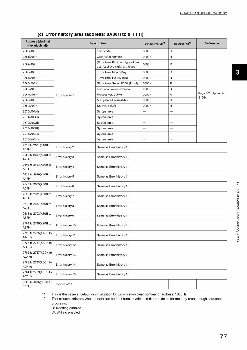
CHAPTER 3 SPECIFICATIONS
3
3.7
Lists o
f Re
mo
te B
uffe
r Me
mo
ry Are
as
(c) Error history area (address: 0A00H to 0FFFH)
*1 This is the value at default or initialization by Error history clear command (address: 1000H).*2 This column indicates whether data can be read from or written to the remote buffer memory area through sequence
programs.R: Reading enabledW: Writing enabled
Address (decimal
(hexadecimal))Description Default value*1 Read/Write*2 Reference
2560(A00H)
Error history 1
Error code 0000H R
Page 363, Appendix
3 (69)
2561(A01H) Order of generation 0000H R
2562(A02H)[Error time] First two digits of the
year/Last two digits of the year0000H R
2563(A03H) [Error time] Month/Day 0000H R
2564(A04H) [Error time] Hour/Minute 0000H R
2565(A05H) [Error time] Second/00H (Fixed) 0000H R
2566(A06H) Error occurrence address 0000H R
2567(A07H) Process value (PV) 0000H R
2568(A08H) Manipulated value (MV) 0000H R
2569(A09H) Set value (SV) 0000H R
2570(A0AH) System area
2571(A0BH) System area
2572(A0CH) System area
2573(A0DH) System area
2574(A0EH) System area
2575(A0FH) System area
2576 to 2591(A10H to
A1FH)Error history 2 Same as Error history 1.
2592 to 2607(A20H to
A2FH)Error history 3 Same as Error history 1.
2608 to 2623(A30H to
A3FH)Error history 4 Same as Error history 1.
2624 to 2639(A40H to
A4FH)Error history 5 Same as Error history 1.
2640 to 2655(A50H to
A5FH)Error history 6 Same as Error history 1.
2656 to 2671(A60H to
A6FH)Error history 7 Same as Error history 1.
2672 to 2687(A70H to
A7FH)Error history 8 Same as Error history 1.
2688 to 2703(A80H to
A8FH)Error history 9 Same as Error history 1.
2704 to 2719(A90H to
A9FH)Error history 10 Same as Error history 1.
2720 to 2735(AA0H to
AAFH)Error history 11 Same as Error history 1.
2736 to 2751(AB0H to
ABFH)Error history 12 Same as Error history 1.
2752 to 2767(AC0H to
ACFH)Error history 13 Same as Error history 1.
2768 to 2783(AD0H to
ADFH)Error history 14 Same as Error history 1.
2784 to 2799(AE0H to
AEFH)Error history 15 Same as Error history 1.
2800 to 4095(AF0H to
FFFH)System area
77
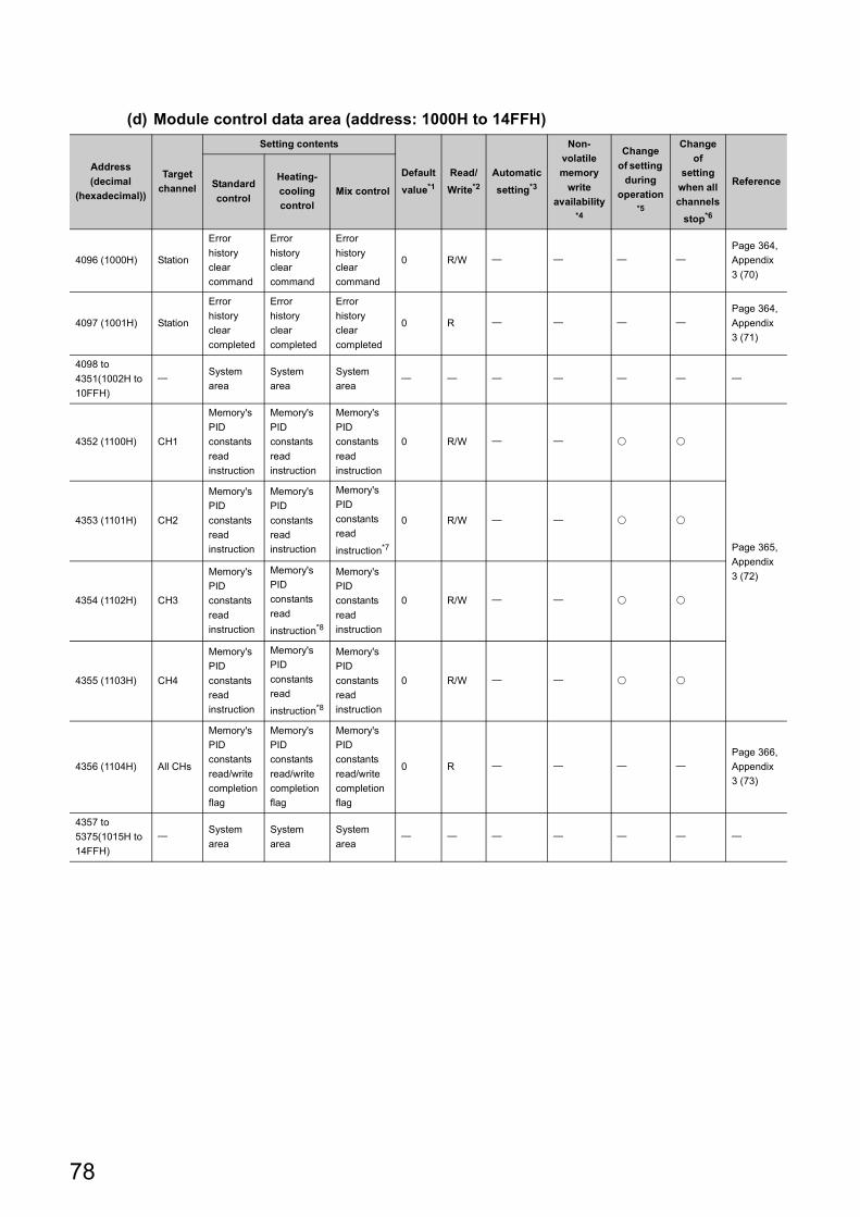
(d) Module control data area (address: 1000H to 14FFH)
Address
(decimal
(hexadecimal))
Target
channel
Setting contents
Default
value*1
Read/
Write*2
Automatic
setting*3
Non-
volatile
memory
write
availability*4
Change
of setting
during
operation*5
Change
of
setting
when all
channels
stop*6
ReferenceStandard
control
Heating-
cooling
control
Mix control
4096 (1000H) Station
Error
history
clear
command
Error
history
clear
command
Error
history
clear
command
0 R/W
Page 364,
Appendix
3 (70)
4097 (1001H) Station
Error
history
clear
completed
Error
history
clear
completed
Error
history
clear
completed
0 R
Page 364,
Appendix
3 (71)
4098 to
4351(1002H to
10FFH)
System
area
System
area
System
area
4352 (1100H) CH1
Memory's
PID
constants
read
instruction
Memory's
PID
constants
read
instruction
Memory's
PID
constants
read
instruction
0 R/W
Page 365,
Appendix
3 (72)
4353 (1101H) CH2
Memory's
PID
constants
read
instruction
Memory's
PID
constants
read
instruction
Memory's
PID
constants
read
instruction*7
0 R/W
4354 (1102H) CH3
Memory's
PID
constants
read
instruction
Memory's
PID
constants
read
instruction*8
Memory's
PID
constants
read
instruction
0 R/W
4355 (1103H) CH4
Memory's
PID
constants
read
instruction
Memory's
PID
constants
read
instruction*8
Memory's
PID
constants
read
instruction
0 R/W
4356 (1104H) All CHs
Memory's
PID
constants
read/write
completion
flag
Memory's
PID
constants
read/write
completion
flag
Memory's
PID
constants
read/write
completion
flag
0 R
Page 366,
Appendix
3 (73)
4357 to
5375(1015H to
14FFH)
System
area
System
area
System
area
78
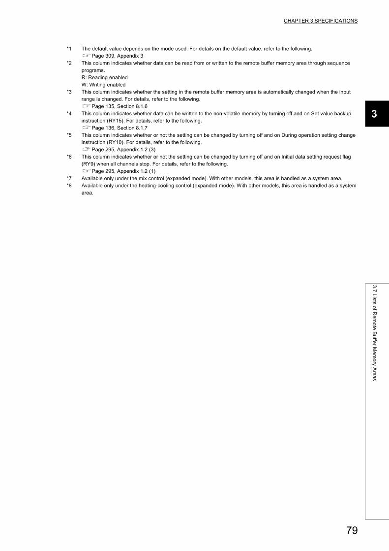
CHAPTER 3 SPECIFICATIONS
3
3.7
Lists o
f Re
mo
te B
uffe
r Me
mo
ry Are
as
*1 The default value depends on the mode used. For details on the default value, refer to the following.Page 309, Appendix 3
*2 This column indicates whether data can be read from or written to the remote buffer memory area through sequence programs.R: Reading enabledW: Writing enabled
*3 This column indicates whether the setting in the remote buffer memory area is automatically changed when the input range is changed. For details, refer to the following.Page 135, Section 8.1.6
*4 This column indicates whether data can be written to the non-volatile memory by turning off and on Set value backup instruction (RY15). For details, refer to the following.Page 136, Section 8.1.7
*5 This column indicates whether or not the setting can be changed by turning off and on During operation setting change instruction (RY10). For details, refer to the following.Page 295, Appendix 1.2 (3)
*6 This column indicates whether or not the setting can be changed by turning off and on Initial data setting request flag (RY9) when all channels stop. For details, refer to the following.Page 295, Appendix 1.2 (1)
*7 Available only under the mix control (expanded mode). With other models, this area is handled as a system area.*8 Available only under the heating-cooling control (expanded mode). With other models, this area is handled as a system
area.
79
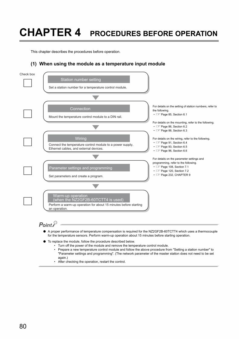
CHAPTER 4 PROCEDURES BEFORE OPERATION
This chapter describes the procedures before operation.
(1) When using the module as a temperature input module
● A proper performance of temperature compensation is required for the NZ2GF2B-60TCTT4 which uses a thermocouple for the temperature sensors. Perform warm-up operation about 15 minutes before starting operation.
● To replace the module, follow the procedure described below.• Turn off the power of the module and remove the temperature control module.• Prepare a new temperature control module and follow the above procedure from "Setting a station number" to
"Parameter settings and programming". (The network parameter of the master station does not need to be set again.)
• After checking the operation, restart the control.
For details on the setting of station numbers, refer to
the following.
• Page 85, Section 6.1
For details on the mounting, refer to the following.
• Page 86, Section 6.2
• Page 88, Section 6.3
For details on the wiring, refer to the following.
• Page 91, Section 6.4
• Page 93, Section 6.5
• Page 96, Section 6.6
For details on the parameter settings and
programming, refer to the following.
• Page 108, Section 7.1
• Page 120, Section 7.2
• Page 232, CHAPTER 9
Check box
Set a station number for a temperature control module.
Station number setting
Connection
Mount the temperature control module to a DIN rail.
Connect the temperature control module to a power supply, Ethernet cables, and external devices.
Parameter settings and programming
Set parameters and create a program.
Warm-up operation (when the NZ2GF2B-60TCTT4 is used)
Perform a warm-up operation for about 15 minutes before starting an operation.
Wiring
80
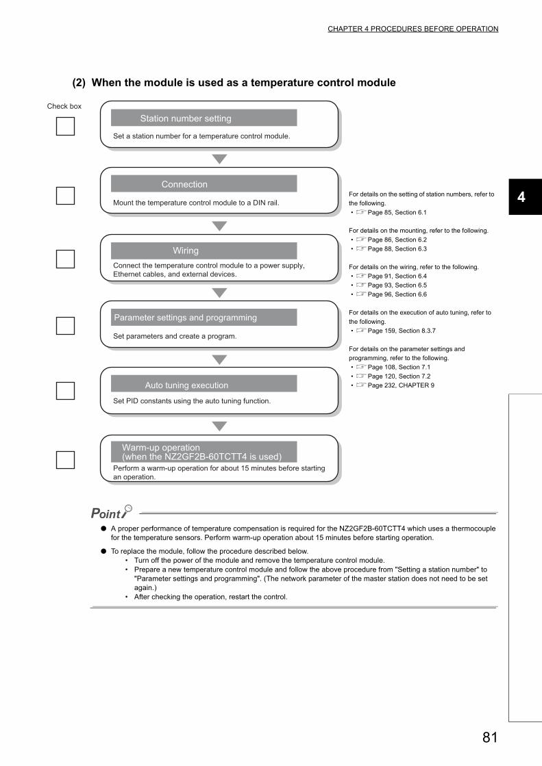
CHAPTER 4 PROCEDURES BEFORE OPERATION
4
(2) When the module is used as a temperature control module
● A proper performance of temperature compensation is required for the NZ2GF2B-60TCTT4 which uses a thermocouple for the temperature sensors. Perform warm-up operation about 15 minutes before starting operation.
● To replace the module, follow the procedure described below.• Turn off the power of the module and remove the temperature control module.• Prepare a new temperature control module and follow the above procedure from "Setting a station number" to
"Parameter settings and programming". (The network parameter of the master station does not need to be set again.)
• After checking the operation, restart the control.
For details on the setting of station numbers, refer to
the following.
• Page 85, Section 6.1
For details on the mounting, refer to the following.
• Page 86, Section 6.2
• Page 88, Section 6.3
For details on the wiring, refer to the following.
• Page 91, Section 6.4
• Page 93, Section 6.5
• Page 96, Section 6.6
For details on the execution of auto tuning, refer to
the following.
• Page 159, Section 8.3.7
For details on the parameter settings and
programming, refer to the following.
• Page 108, Section 7.1
• Page 120, Section 7.2
• Page 232, CHAPTER 9
Check box
Set a station number for a temperature control module.
Station number setting
Connection
Mount the temperature control module to a DIN rail.
Connect the temperature control module to a power supply, Ethernet cables, and external devices.
Auto tuning execution
Set PID constants using the auto tuning function.
Warm-up operation (when the NZ2GF2B-60TCTT4 is used)
Perform a warm-up operation for about 15 minutes before starting an operation.
Wiring
Set parameters and create a program.
Parameter settings and programming
81
CHAPTER 5 SYSTEM CONFIGURATION
This chapter describes the system configuration using a temperature control module.
For CC-Link IE Field Network configuration, refer to the following.
User's manual for the master/local module used
5.1 Applicable Systems
(1) Corresponding master stationWhen using the temperature control module, use the following products as a master station.
(2) Ethernet cableFor the specifications of the Ethernet cable, refer to the following.
User's manual for the master/local module used
(3) Compatible software packageConfiguring and diagnosing the temperature control module require GX Works2 or GX Works3. According to the
master station used, install the following version of GX Works2 or GX Works3.
When the latest profile of the temperature control module is necessary, please consult your local Mitsubishi representative.The profile is a setting file that stores information required for the start-up, operation, and maintenance of devices supporting the CC-Link family. A module is added to "Module List" of "CC IE Field Configuration" window by profile registration to GX Works2 or GX Works3. For the profile registration, refer to the following. GX Works2 Version 1 Operating Manual (Common)GX Works3 Operating Manual
(4) Temperature sensorFor the available temperature sensors, refer to the following.
Page 36, Section 3.2 (1)
Model First five digits of serial number
RJ71GF11-T2
RJ71EN71(no restriction)
QJ71GF11-T214102 or later
LJ71GF11-T2
QD77GF16 14111 or later
Engineering tool Software version
GX Works2 Version 1.501X or later
GX Works3 Version 1.000A or later
82
CHAPTER 5 SYSTEM CONFIGURATION
5
5.2
Pre
cau
tion
s for S
ystem
Co
nfig
ura
tion
5.2 Precautions for System Configuration
The temperature control module measures temperature based on the temperature of the terminal block. Some
operating environments therefore cause an uneven temperature distribution of the terminal block, which results in a
larger error in the measured temperature.
In such cases, the temperature error can be corrected by the sensor correction function. For details on the sensor
correction function, refer to the following.
Page 132, Section 8.1.5
83

Memo
84
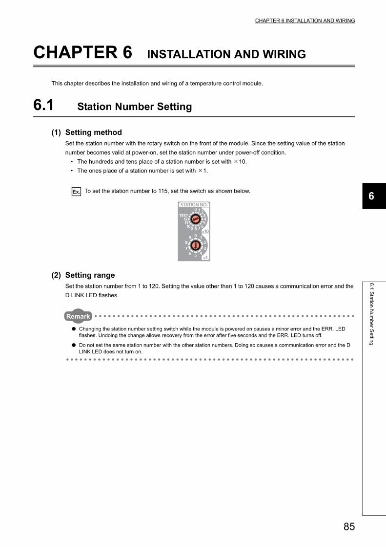
CHAPTER 6 INSTALLATION AND WIRING
6
6.1
Sta
tion
Nu
mb
er S
ettin
g
CHAPTER 6 INSTALLATION AND WIRING
This chapter describes the installation and wiring of a temperature control module.
6.1 Station Number Setting
(1) Setting methodSet the station number with the rotary switch on the front of the module. Since the setting value of the station
number becomes valid at power-on, set the station number under power-off condition.
• The hundreds and tens place of a station number is set with 10.
• The ones place of a station number is set with 1.
Ex. To set the station number to 115, set the switch as shown below.
(2) Setting rangeSet the station number from 1 to 120. Setting the value other than 1 to 120 causes a communication error and the
D LINK LED flashes.
Remark
● Changing the station number setting switch while the module is powered on causes a minor error and the ERR. LED flashes. Undoing the change allows recovery from the error after five seconds and the ERR. LED turns off.
● Do not set the same station number with the other station numbers. Doing so causes a communication error and the D LINK LED does not turn on.
85
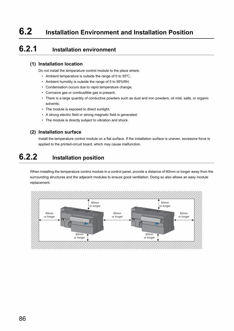
6.2 Installation Environment and Installation Position
6.2.1 Installation environment
(1) Installation locationDo not install the temperature control module to the place where:
• Ambient temperature is outside the range of 0 to 55;
• Ambient humidity is outside the range of 5 to 95%RH;
• Condensation occurs due to rapid temperature change;
• Corrosive gas or combustible gas is present;
• There is a large quantity of conductive powders such as dust and iron powders, oil mist, salts, or organic
solvents;
• The module is exposed to direct sunlight;
• A strong electric field or strong magnetic field is generated;
• The module is directly subject to vibration and shock.
(2) Installation surfaceInstall the temperature control module on a flat surface. If the installation surface is uneven, excessive force is
applied to the printed-circuit board, which may cause malfunction.
6.2.2 Installation position
When installing the temperature control module in a control panel, provide a distance of 60mm or longer away from the
surrounding structures and the adjacent modules to ensure good ventilation. Doing so also allows an easy module
replacement.
60mmor longer
60mmor longer
60mmor longer
60mmor longer
60mmor longer
60mmor longer
60mmor longer
86
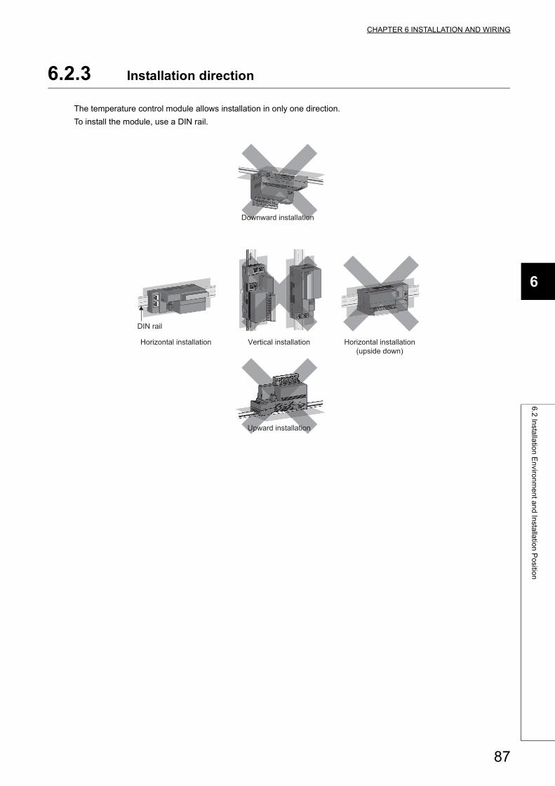
CHAPTER 6 INSTALLATION AND WIRING
6
6.2
Insta
llatio
n E
nviro
nm
en
t an
d In
stalla
tion
Po
sition
6.2.3 Installation direction
The temperature control module allows installation in only one direction.
To install the module, use a DIN rail.
Downward installation
DIN rail
Vertical installation Horizontal installation Horizontal installation(upside down)
Upward installation
87
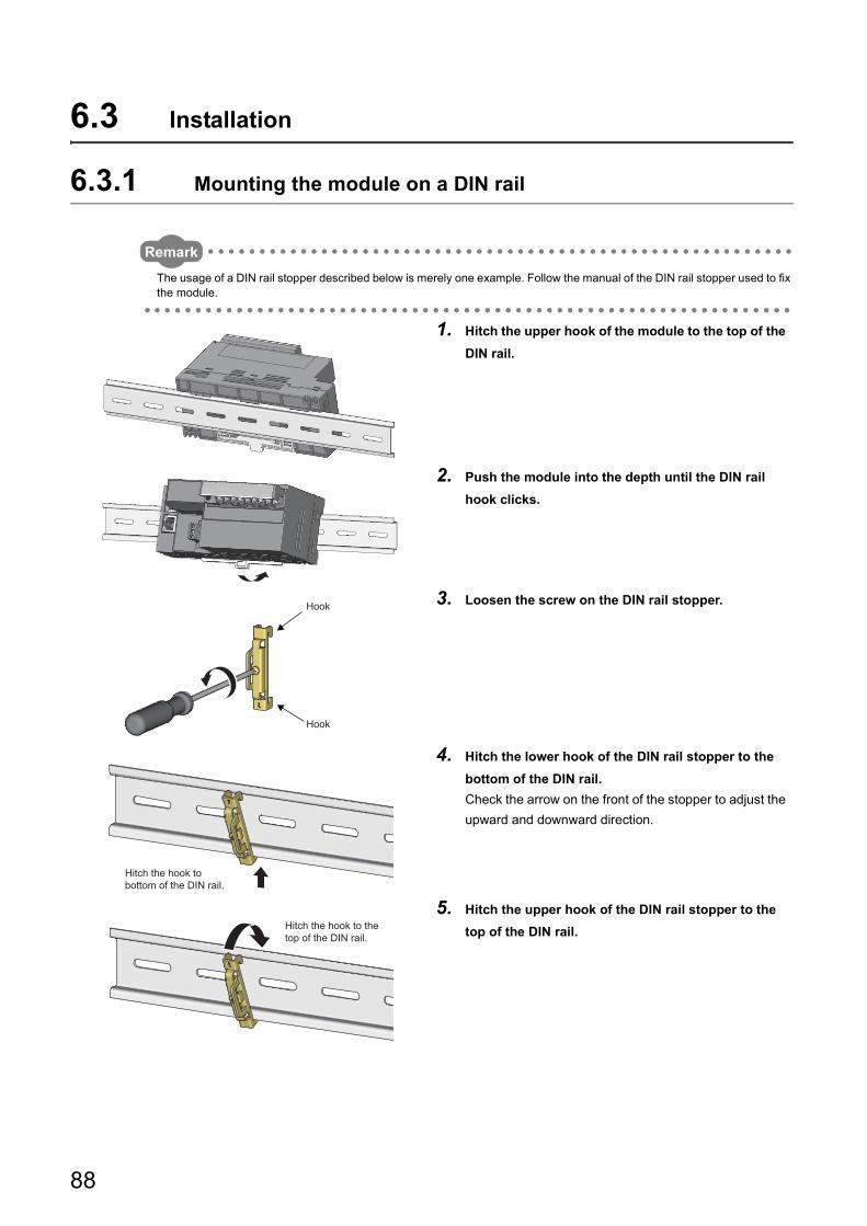
6.3 Installation
6.3.1 Mounting the module on a DIN rail
Remark
The usage of a DIN rail stopper described below is merely one example. Follow the manual of the DIN rail stopper used to fix the module.
1. Hitch the upper hook of the module to the top of the
DIN rail.
2. Push the module into the depth until the DIN rail
hook clicks.
3. Loosen the screw on the DIN rail stopper.
4. Hitch the lower hook of the DIN rail stopper to the
bottom of the DIN rail.
Check the arrow on the front of the stopper to adjust the
upward and downward direction.
5. Hitch the upper hook of the DIN rail stopper to the
top of the DIN rail.
Hook
Hook
Hitch the hook to bottom of the DIN rail.
Hitch the hook to the top of the DIN rail.
88
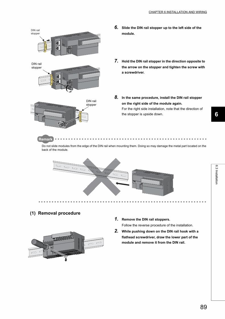
CHAPTER 6 INSTALLATION AND WIRING
6
6.3
Insta
llatio
n
Remark
Do not slide modules from the edge of the DIN rail when mounting them. Doing so may damage the metal part located on the back of the module.
(1) Removal procedure
6. Slide the DIN rail stopper up to the left side of the
module.
7. Hold the DIN rail stopper in the direction opposite to
the arrow on the stopper and tighten the screw with
a screwdriver.
8. In the same procedure, install the DIN rail stopper
on the right side of the module again.
For the right side installation, note that the direction of
the stopper is upside down.
1. Remove the DIN rail stoppers.
Follow the reverse procedure of the installation.
2. While pushing down on the DIN rail hook with a
flathead screwdriver, draw the lower part of the
module and remove it from the DIN rail.
DIN rail stopper
DIN rail stopper
DIN rail stopper
89
(2) Applicable DIN rail model (compliant with IEC 60715)• TH35-7.5Fe
• TH35-7.5Al
(3) Interval between DIN rail mounting screwsTighten the screws at intervals of 200mm or less.
(4) DIN rail stopperUse a stopper that is attachable to the DIN rail.
90

CHAPTER 6 INSTALLATION AND WIRING
6
6.4
Wirin
g w
ith a
Te
rmin
al B
lock fo
r Mo
du
le P
ow
er S
up
ply a
nd
FG
6.4 Wiring with a Terminal Block for Module Power Supply and FG
(1) Tightening torqueTighten the terminal block screws within the following specified torque range. Tightening the screws too much
may damage the module case.
(2) Wire to be usedThe following table describes the wire to be connected to the terminal block for module power supply and FG.
(3) Installing and removing the terminal blockTo remove the terminal block, loosen the terminal block fixing screw with a slotted screwdriver.
To install the terminal block, tighten the terminal block fixing screw.
Failure to secure the terminal block may cause drop, short circuit, malfunction.
Screw type Tightening torque range
Terminal block mounting screw (M2.5 screw) 0.2 to 0.3Nm
Terminal screw (M2.5 screw) 0.5 to 0.6Nm
Diameter Type Material Temperature rating
20 to 16 AWG Stranded Copper 75 or more
91
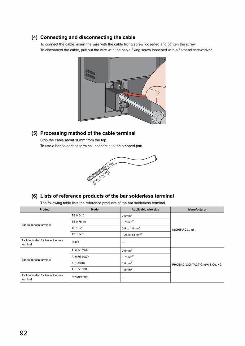
(4) Connecting and disconnecting the cableTo connect the cable, insert the wire with the cable fixing screw loosened and tighten the screw.
To disconnect the cable, pull out the wire with the cable fixing screw loosened with a flathead screwdriver.
(5) Processing method of the cable terminalStrip the cable about 10mm from the top.
To use a bar solderless terminal, connect it to the stripped part.
(6) Lists of reference products of the bar solderless terminalThe following table lists the reference products of the bar solderless terminal.
Product Model Applicable wire size Manufacturer
Bar solderless terminal
TE 0.5-10 0.5mm2
NICHIFU Co., ltd.
TE 0.75-10 0.75mm2
TE 1.0-10 0.9 to 1.0mm2
TE 1.5-10 1.25 to 1.5mm2
Tool dedicated for bar solderless
terminalNH79
Bar solderless terminal
AI 0.5-10WH 0.5mm2
PHOENIX CONTACT GmbH & Co. KG
AI 0.75-10GY 0.75mm2
AI 1-10RD 1.0mm2
AI 1.5-10BK 1.5mm2
Tool dedicated for bar solderless
terminalCRIMPFOX6
Cable
Around 10mm
92
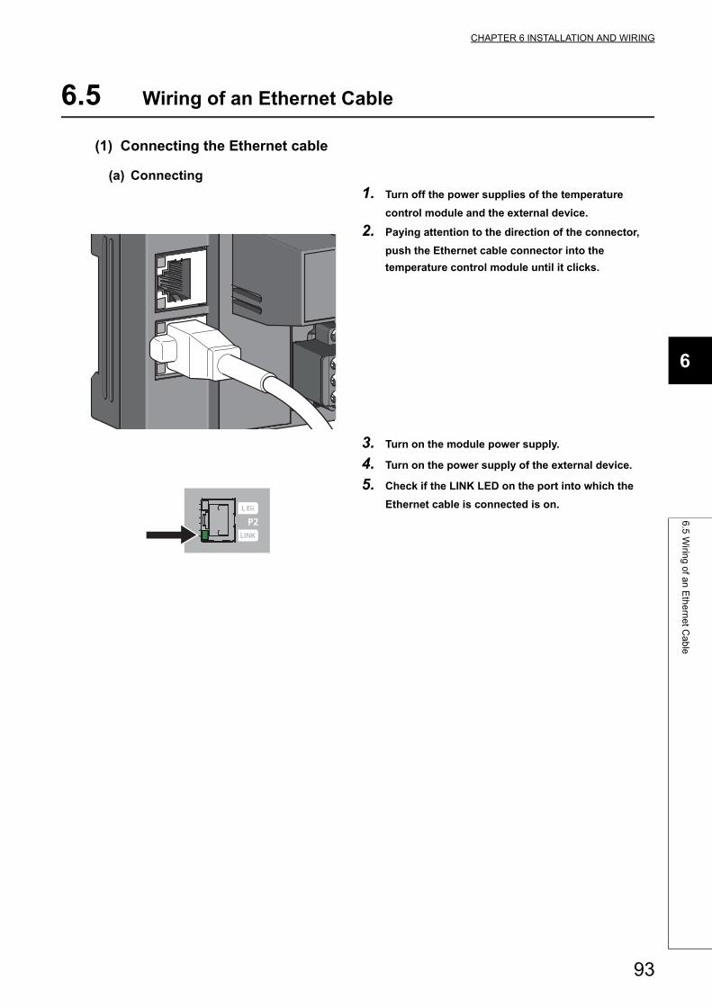
CHAPTER 6 INSTALLATION AND WIRING
6
6.5
Wirin
g o
f an
Eth
ern
et C
ab
le
6.5 Wiring of an Ethernet Cable
(1) Connecting the Ethernet cable
(a) Connecting
1. Turn off the power supplies of the temperature
control module and the external device.
2. Paying attention to the direction of the connector,
push the Ethernet cable connector into the
temperature control module until it clicks.
3. Turn on the module power supply.
4. Turn on the power supply of the external device.
5. Check if the LINK LED on the port into which the
Ethernet cable is connected is on.
93
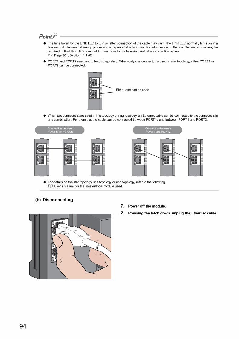
● The time taken for the LINK LED to turn on after connection of the cable may vary. The LINK LED normally turns on in a few second. However, if link-up processing is repeated due to a condition of a device on the line, the longer time may be required. If the LINK LED does not turn on, refer to the following and take a corrective action.Page 281, Section 11.4 (8)
● PORT1 and PORT2 need not to be distinguished. When only one connector is used in star topology, either PORT1 or PORT2 can be connected.
● When two connectors are used in line topology or ring topology, an Ethernet cable can be connected to the connectors in any combination. For example, the cable can be connected between PORT1s and between PORT1 and PORT2.
● For details on the star topology, line topology or ring topology, refer to the following. User's manual for the master/local module used
(b) Disconnecting
1. Power off the module.
2. Pressing the latch down, unplug the Ethernet cable.
Either one can be used.
Connection betweenPORT1s or PORT2s
Connection betweenPORT1 and PORT2
94

CHAPTER 6 INSTALLATION AND WIRING
6
6.5
Wirin
g o
f an
Eth
ern
et C
ab
le
(2) Precautions
(a) Laying Ethernet cables
• Place the Ethernet cable in a duct or clamp them. If not, dangling cable may swing or inadvertently be
pulled, resulting in damage to the module or cables or malfunction due to poor contact.
• Do not touch the core of the connector of the cable or the module, and protect it from dirt and dust. If any
oil from your hand, or any dirt or dust sticks to the core, it can increase transmission loss, causing data link
to fail.
• Check if there is a disconnection of the Ethernet cables used. In addition, check if there is a short or a
problem with the connector connection.
(b) Broken cable latch
Do not use Ethernet cables with broken latches. Doing so may cause the cable to unplug or malfunction.
(c) Connecting and disconnecting the Ethernet cable
Hold the connector part when connecting and disconnecting the Ethernet cable. Pulling the cable connected to
the module may result in damage to the module or cable or malfunction due to poor contact.
(d) Connectors without Ethernet cable
To prevent dust from entering the module, attach the provided connector cover.
(e) Maximum station-to-station distance (Maximum Ethernet cable length)
The maximum station-to-station distance is 100m. However, the distance may be shorter depending on the
operating environment of the cable. For details, contact the manufacturer of the cables used.
(f) Bending radius of the Ethernet cable
There are restrictions on the bending radius of the Ethernet cable. Check the bending radius in the
specifications of the Ethernet cables used.
95
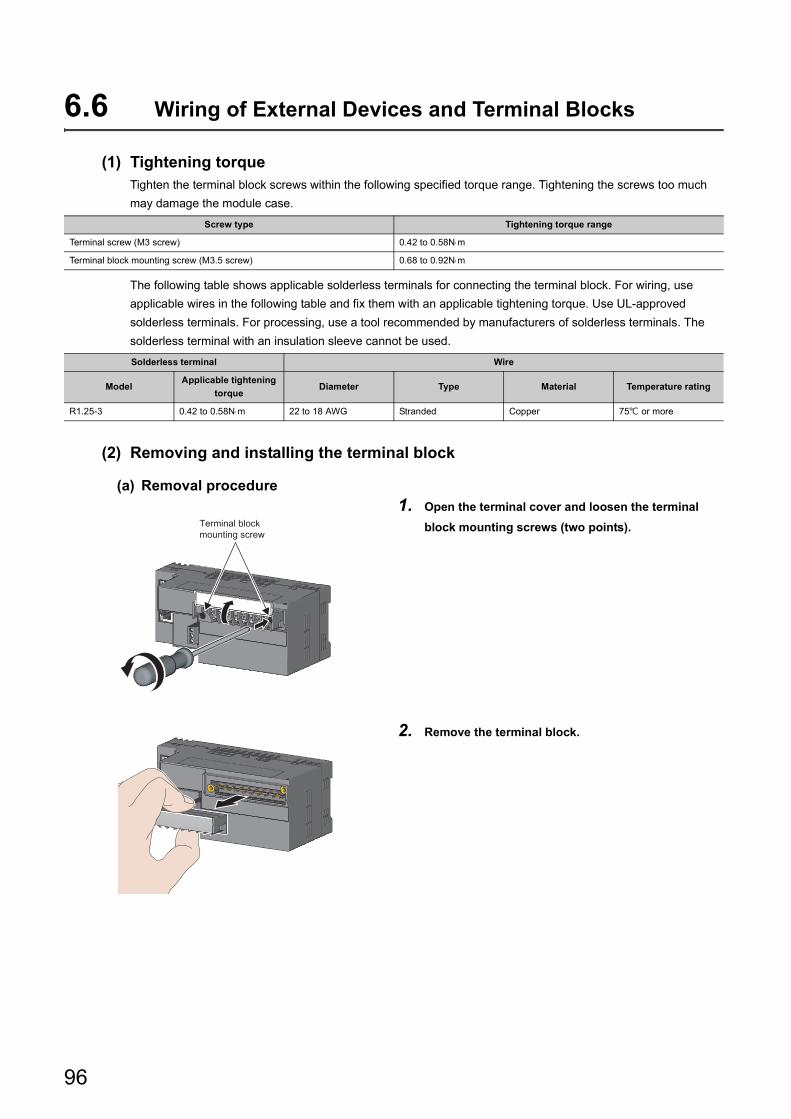
6.6 Wiring of External Devices and Terminal Blocks
(1) Tightening torqueTighten the terminal block screws within the following specified torque range. Tightening the screws too much
may damage the module case.
The following table shows applicable solderless terminals for connecting the terminal block. For wiring, use
applicable wires in the following table and fix them with an applicable tightening torque. Use UL-approved
solderless terminals. For processing, use a tool recommended by manufacturers of solderless terminals. The
solderless terminal with an insulation sleeve cannot be used.
(2) Removing and installing the terminal block
(a) Removal procedure
Screw type Tightening torque range
Terminal screw (M3 screw) 0.42 to 0.58Nm
Terminal block mounting screw (M3.5 screw) 0.68 to 0.92Nm
Solderless terminal Wire
ModelApplicable tightening
torqueDiameter Type Material Temperature rating
R1.25-3 0.42 to 0.58Nm 22 to 18 AWG Stranded Copper 75 or more
1. Open the terminal cover and loosen the terminal
block mounting screws (two points).
2. Remove the terminal block.
Terminal block mounting screw
96
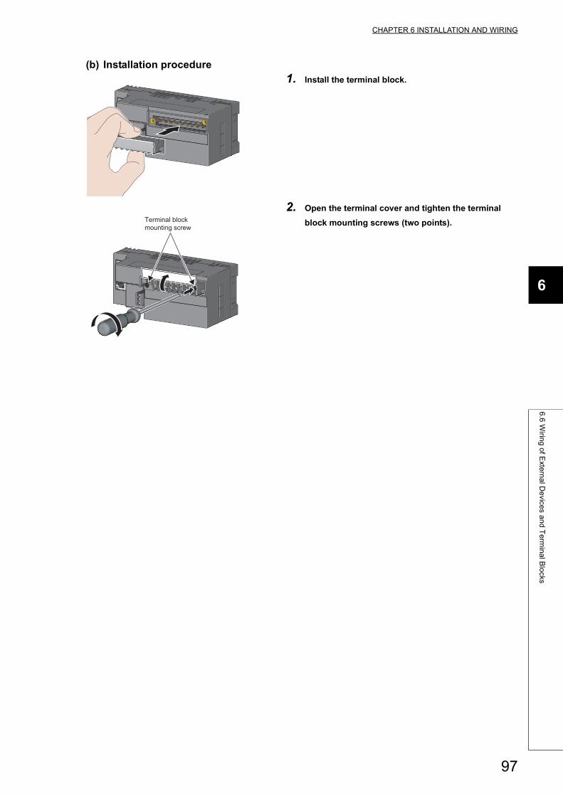
CHAPTER 6 INSTALLATION AND WIRING
6
6.6
Wirin
g o
f Exte
rna
l De
vices a
nd
Te
rmin
al B
locks
(b) Installation procedure
1. Install the terminal block.
2. Open the terminal cover and tighten the terminal
block mounting screws (two points).Terminal block mounting screw
97
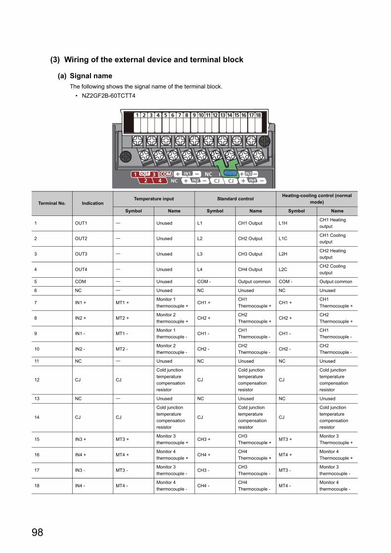
(3) Wiring of the external device and terminal block
(a) Signal name
The following shows the signal name of the terminal block.
• NZ2GF2B-60TCTT4
Terminal No. IndicationTemperature input Standard control
Heating-cooling control (normal
mode)
Symbol Name Symbol Name Symbol Name
1 OUT1 Unused L1 CH1 Output L1HCH1 Heating
output
2 OUT2 Unused L2 CH2 Output L1CCH1 Cooling
output
3 OUT3 Unused L3 CH3 Output L2HCH2 Heating
output
4 OUT4 Unused L4 CH4 Output L2CCH2 Cooling
output
5 COM Unused COM - Output common COM - Output common
6 NC Unused NC Unused NC Unused
7 IN1 + MT1 +Monitor 1
thermocouple +CH1 +
CH1
Thermocouple +CH1 +
CH1
Thermocouple +
8 IN2 + MT2 +Monitor 2
thermocouple +CH2 +
CH2
Thermocouple +CH2 +
CH2
Thermocouple +
9 IN1 - MT1 -Monitor 1
thermocouple -CH1 -
CH1
Thermocouple -CH1 -
CH1
Thermocouple -
10 IN2 - MT2 -Monitor 2
thermocouple -CH2 -
CH2
Thermocouple -CH2 -
CH2
Thermocouple -
11 NC Unused NC Unused NC Unused
12 CJ CJ
Cold junction
temperature
compensation
resistor
CJ
Cold junction
temperature
compensation
resistor
CJ
Cold junction
temperature
compensation
resistor
13 NC Unused NC Unused NC Unused
14 CJ CJ
Cold junction
temperature
compensation
resistor
CJ
Cold junction
temperature
compensation
resistor
CJ
Cold junction
temperature
compensation
resistor
15 IN3 + MT3 +Monitor 3
thermocouple +CH3 +
CH3
Thermocouple +MT3 +
Monitor 3
Thermocouple +
16 IN4 + MT4 +Monitor 4
thermocouple +CH4 +
CH4
Thermocouple +MT4 +
Monitor 4
Thermocouple +
17 IN3 - MT3 -Monitor 3
thermocouple -CH3 -
CH3
Thermocouple -MT3 -
Monitor 3
thermocouple -
18 IN4 - MT4 -Monitor 4
thermocouple -CH4 -
CH4
Thermocouple -MT4 -
Monitor 4
thermocouple -
98
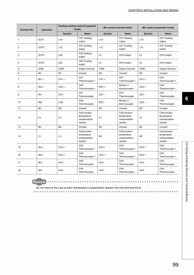
CHAPTER 6 INSTALLATION AND WIRING
6
6.6
Wirin
g o
f Exte
rna
l De
vices a
nd
Te
rmin
al B
locks
Remark
Do not remove the cold junction temperature compensation resistor from the terminal block.
Terminal No. Indication
Heating-cooling control (expanded
mode)Mix control (normal mode) Mix control (expanded mode)
Symbol Name Symbol Name Symbol Name
1 OUT1 L1HCH1 Heating
outputL1H
CH1 Heating
outputL1H
CH1 Heating
output
2 OUT2 L1CCH1 Cooling
outputL1C
CH1 Cooling
outputL1C
CH1 Cooling
output
3 OUT3 L2HCH2 Heating
outputL3 CH3 Output L3 CH3 Output
4 OUT4 L2CCH2 Cooling
outputL4 CH4 Output L4 CH4 Output
5 COM COM - Output common COM - Output common COM - Output common
6 NC NC Unused NC Unused NC Unused
7 IN1 + CH1 +CH1
Thermocouple +CH1 +
CH1
Thermocouple +CH1 +
CH1
Thermocouple +
8 IN2 + CH2 +CH2
Thermocouple +MT2 +
Monitor 2
thermocouple +CH2 +
CH2
Thermocouple +
9 IN1 - CH1 -CH1
Thermocouple -CH1 -
CH1
Thermocouple -CH1 -
CH1
Thermocouple -
10 IN2 - CH2 -CH2
Thermocouple -MT2 -
Monitor 2
thermocouple -CH2 -
CH2
Thermocouple -
11 NC NC Unused NC Unused NC Unused
12 CJ CJ
Cold junction
temperature
compensation
resistor
CJ
Cold junction
temperature
compensation
resistor
CJ
Cold junction
temperature
compensation
resistor
13 NC NC Unused NC Unused NC Unused
14 CJ CJ
Cold junction
temperature
compensation
resistor
NC
Cold junction
temperature
compensation
resistor
NC
Cold junction
temperature
compensation
resistor
15 IN3 + CH3 +CH3
Thermocouple +CH3 +
CH3
Thermocouple +CH3 +
CH3
Thermocouple +
16 IN4 + CH4 +CH4
Thermocouple +CH4 +
CH4
Thermocouple +CH4 +
CH4
Thermocouple +
17 IN3 - CH3 -CH3
Thermocouple -CH3 -
CH3
Thermocouple -CH3 -
CH3
Thermocouple -
18 IN4 - CH4 -CH4
Thermocouple -CH4 -
CH4
Thermocouple -CH4 -
CH4
Thermocouple -
99
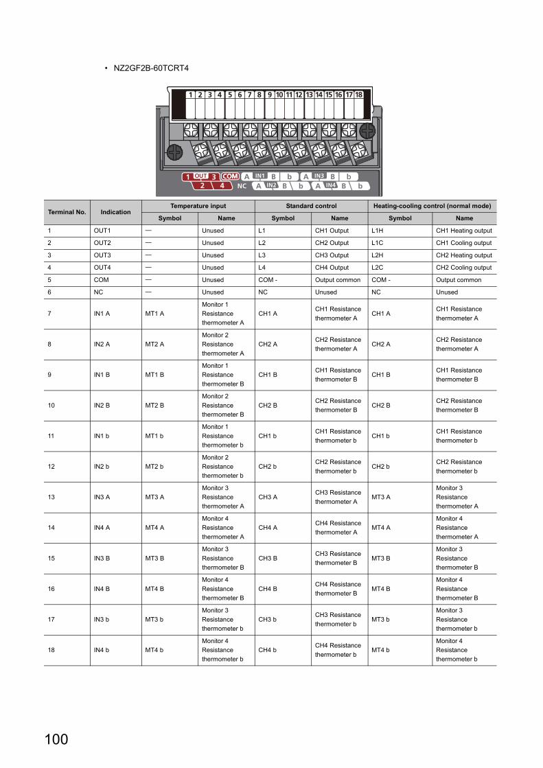
• NZ2GF2B-60TCRT4
Terminal No. IndicationTemperature input Standard control Heating-cooling control (normal mode)
Symbol Name Symbol Name Symbol Name
1 OUT1 Unused L1 CH1 Output L1H CH1 Heating output
2 OUT2 Unused L2 CH2 Output L1C CH1 Cooling output
3 OUT3 Unused L3 CH3 Output L2H CH2 Heating output
4 OUT4 Unused L4 CH4 Output L2C CH2 Cooling output
5 COM Unused COM - Output common COM - Output common
6 NC Unused NC Unused NC Unused
7 IN1 A MT1 A
Monitor 1
Resistance
thermometer A
CH1 ACH1 Resistance
thermometer ACH1 A
CH1 Resistance
thermometer A
8 IN2 A MT2 A
Monitor 2
Resistance
thermometer A
CH2 ACH2 Resistance
thermometer ACH2 A
CH2 Resistance
thermometer A
9 IN1 B MT1 B
Monitor 1
Resistance
thermometer B
CH1 BCH1 Resistance
thermometer BCH1 B
CH1 Resistance
thermometer B
10 IN2 B MT2 B
Monitor 2
Resistance
thermometer B
CH2 BCH2 Resistance
thermometer BCH2 B
CH2 Resistance
thermometer B
11 IN1 b MT1 b
Monitor 1
Resistance
thermometer b
CH1 bCH1 Resistance
thermometer bCH1 b
CH1 Resistance
thermometer b
12 IN2 b MT2 b
Monitor 2
Resistance
thermometer b
CH2 bCH2 Resistance
thermometer bCH2 b
CH2 Resistance
thermometer b
13 IN3 A MT3 A
Monitor 3
Resistance
thermometer A
CH3 ACH3 Resistance
thermometer AMT3 A
Monitor 3
Resistance
thermometer A
14 IN4 A MT4 A
Monitor 4
Resistance
thermometer A
CH4 ACH4 Resistance
thermometer AMT4 A
Monitor 4
Resistance
thermometer A
15 IN3 B MT3 B
Monitor 3
Resistance
thermometer B
CH3 BCH3 Resistance
thermometer BMT3 B
Monitor 3
Resistance
thermometer B
16 IN4 B MT4 B
Monitor 4
Resistance
thermometer B
CH4 BCH4 Resistance
thermometer BMT4 B
Monitor 4
Resistance
thermometer B
17 IN3 b MT3 b
Monitor 3
Resistance
thermometer b
CH3 bCH3 Resistance
thermometer bMT3 b
Monitor 3
Resistance
thermometer b
18 IN4 b MT4 b
Monitor 4
Resistance
thermometer b
CH4 bCH4 Resistance
thermometer bMT4 b
Monitor 4
Resistance
thermometer b
100
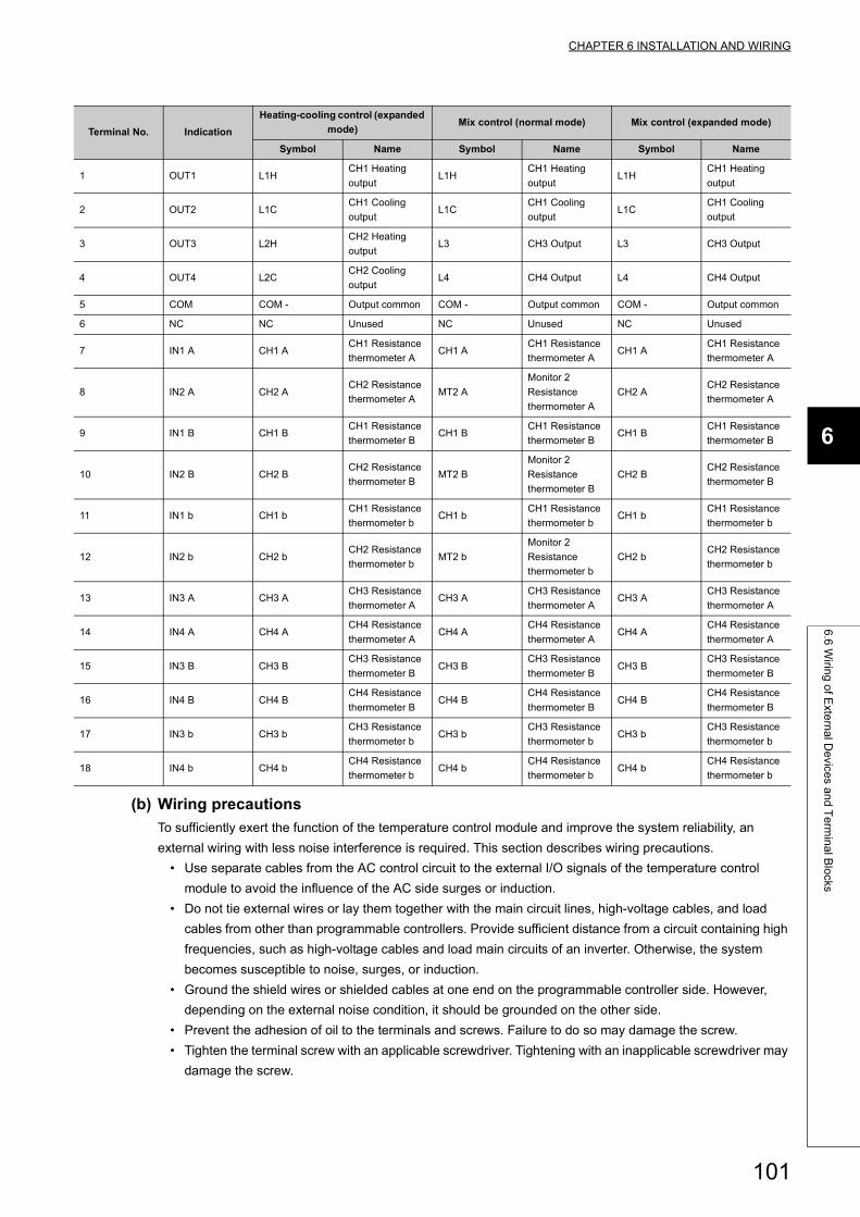
CHAPTER 6 INSTALLATION AND WIRING
6
6.6
Wirin
g o
f Exte
rna
l De
vices a
nd
Te
rmin
al B
locks
(b) Wiring precautions
To sufficiently exert the function of the temperature control module and improve the system reliability, an
external wiring with less noise interference is required. This section describes wiring precautions.
• Use separate cables from the AC control circuit to the external I/O signals of the temperature control
module to avoid the influence of the AC side surges or induction.
• Do not tie external wires or lay them together with the main circuit lines, high-voltage cables, and load
cables from other than programmable controllers. Provide sufficient distance from a circuit containing high
frequencies, such as high-voltage cables and load main circuits of an inverter. Otherwise, the system
becomes susceptible to noise, surges, or induction.
• Ground the shield wires or shielded cables at one end on the programmable controller side. However,
depending on the external noise condition, it should be grounded on the other side.
• Prevent the adhesion of oil to the terminals and screws. Failure to do so may damage the screw.
• Tighten the terminal screw with an applicable screwdriver. Tightening with an inapplicable screwdriver may
damage the screw.
Terminal No. Indication
Heating-cooling control (expanded
mode)Mix control (normal mode) Mix control (expanded mode)
Symbol Name Symbol Name Symbol Name
1 OUT1 L1HCH1 Heating
outputL1H
CH1 Heating
outputL1H
CH1 Heating
output
2 OUT2 L1CCH1 Cooling
outputL1C
CH1 Cooling
outputL1C
CH1 Cooling
output
3 OUT3 L2HCH2 Heating
outputL3 CH3 Output L3 CH3 Output
4 OUT4 L2CCH2 Cooling
outputL4 CH4 Output L4 CH4 Output
5 COM COM - Output common COM - Output common COM - Output common
6 NC NC Unused NC Unused NC Unused
7 IN1 A CH1 ACH1 Resistance
thermometer ACH1 A
CH1 Resistance
thermometer ACH1 A
CH1 Resistance
thermometer A
8 IN2 A CH2 ACH2 Resistance
thermometer AMT2 A
Monitor 2
Resistance
thermometer A
CH2 ACH2 Resistance
thermometer A
9 IN1 B CH1 BCH1 Resistance
thermometer BCH1 B
CH1 Resistance
thermometer BCH1 B
CH1 Resistance
thermometer B
10 IN2 B CH2 BCH2 Resistance
thermometer BMT2 B
Monitor 2
Resistance
thermometer B
CH2 BCH2 Resistance
thermometer B
11 IN1 b CH1 bCH1 Resistance
thermometer bCH1 b
CH1 Resistance
thermometer bCH1 b
CH1 Resistance
thermometer b
12 IN2 b CH2 bCH2 Resistance
thermometer bMT2 b
Monitor 2
Resistance
thermometer b
CH2 bCH2 Resistance
thermometer b
13 IN3 A CH3 ACH3 Resistance
thermometer ACH3 A
CH3 Resistance
thermometer ACH3 A
CH3 Resistance
thermometer A
14 IN4 A CH4 ACH4 Resistance
thermometer ACH4 A
CH4 Resistance
thermometer ACH4 A
CH4 Resistance
thermometer A
15 IN3 B CH3 BCH3 Resistance
thermometer BCH3 B
CH3 Resistance
thermometer BCH3 B
CH3 Resistance
thermometer B
16 IN4 B CH4 BCH4 Resistance
thermometer BCH4 B
CH4 Resistance
thermometer BCH4 B
CH4 Resistance
thermometer B
17 IN3 b CH3 bCH3 Resistance
thermometer bCH3 b
CH3 Resistance
thermometer bCH3 b
CH3 Resistance
thermometer b
18 IN4 b CH4 bCH4 Resistance
thermometer bCH4 b
CH4 Resistance
thermometer bCH4 b
CH4 Resistance
thermometer b
101
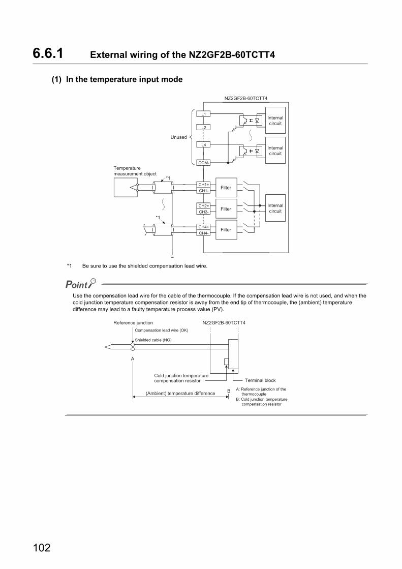
6.6.1 External wiring of the NZ2GF2B-60TCTT4
(1) In the temperature input mode
*1 Be sure to use the shielded compensation lead wire.
Use the compensation lead wire for the cable of the thermocouple. If the compensation lead wire is not used, and when the cold junction temperature compensation resistor is away from the end tip of thermocouple, the (ambient) temperature difference may lead to a faulty temperature process value (PV).
L1
L2
L4
COM-
CH1+CH1-
CH2+CH2-
CH4+CH4-
Filter
Filter
Filter
Internalcircuit
Internalcircuit
Internalcircuit
*1
*1
Temperature measurement object
Unused
NZ2GF2B-60TCTT4
NZ2GF2B-60TCTT4Reference junctionCompensation lead wire (OK)
Shielded cable (NG)
Cold junction temperature compensation resistor
(Ambient) temperature difference
Terminal block
A: Reference junction of the thermocoupleB: Cold junction temperature compensation resistor
A
B
102
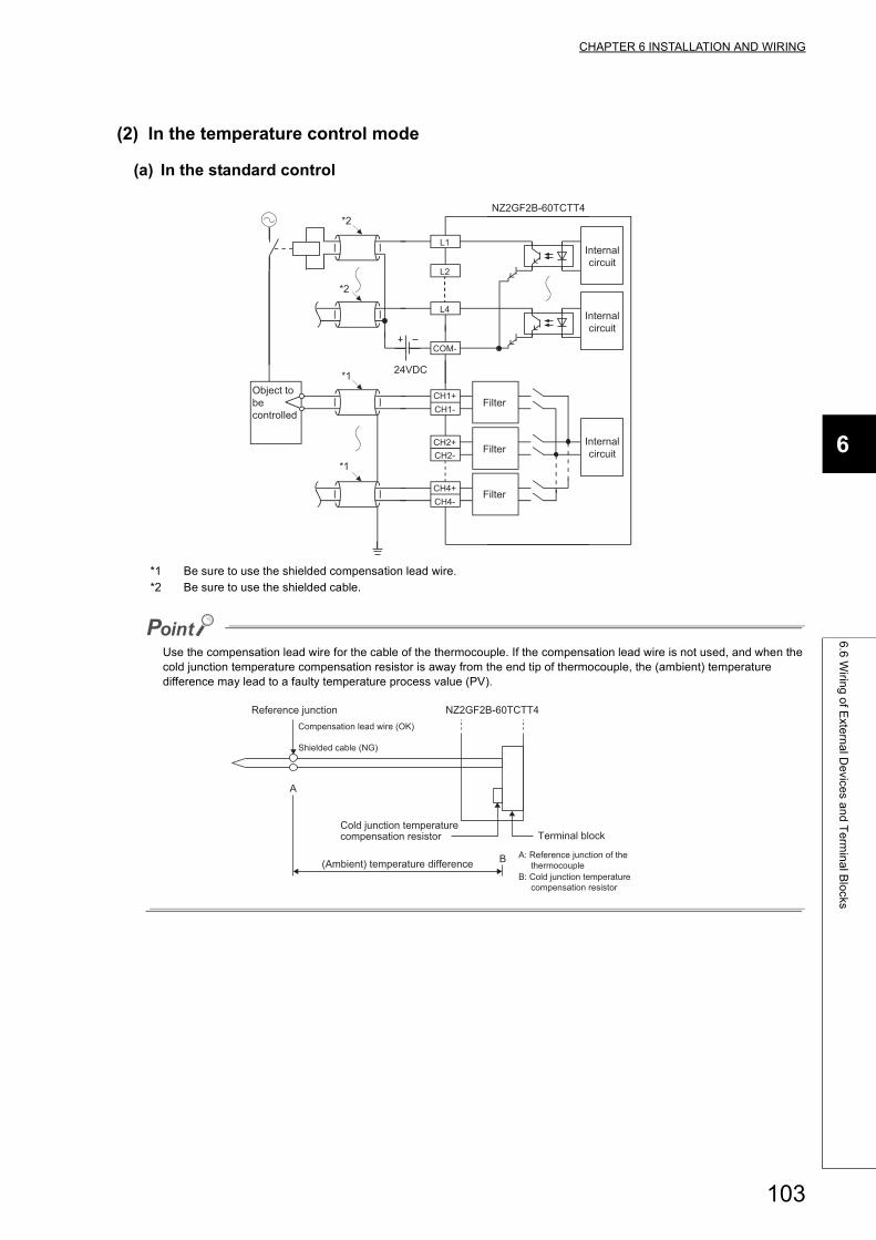
CHAPTER 6 INSTALLATION AND WIRING
6
6.6
Wirin
g o
f Exte
rna
l De
vices a
nd
Te
rmin
al B
locks
(2) In the temperature control mode
(a) In the standard control
*1 Be sure to use the shielded compensation lead wire.*2 Be sure to use the shielded cable.
Use the compensation lead wire for the cable of the thermocouple. If the compensation lead wire is not used, and when the cold junction temperature compensation resistor is away from the end tip of thermocouple, the (ambient) temperature difference may lead to a faulty temperature process value (PV).
L1
L2
L4
COM-
24VDC
CH1+CH1-
CH2+CH2-
CH4+CH4-
Object tobe controlled
Filter
Filter
Filter
Internalcircuit
Internalcircuit
Internalcircuit
*1
*1
*2
*2
NZ2GF2B-60TCTT4
NZ2GF2B-60TCTT4Reference junctionCompensation lead wire (OK)
Shielded cable (NG)
Cold junction temperature compensation resistor
(Ambient) temperature difference
Terminal block
A: Reference junction of the thermocoupleB: Cold junction temperature compensation resistor
A
B
103
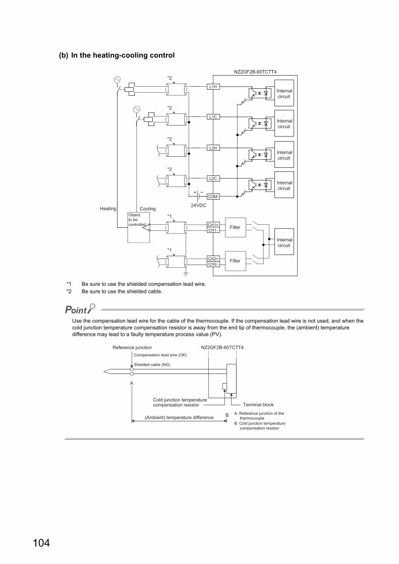
(b) In the heating-cooling control
*1 Be sure to use the shielded compensation lead wire.*2 Be sure to use the shielded cable.
Use the compensation lead wire for the cable of the thermocouple. If the compensation lead wire is not used, and when the cold junction temperature compensation resistor is away from the end tip of thermocouple, the (ambient) temperature difference may lead to a faulty temperature process value (PV).
Heating
L1H
L1C
CH1+CH1-
Filter
Filter CH2+CH2-
Objectto be controlled
*1
*1
*2
*2
*2NZ2GF2B-60TCTT4
Internalcircuit
Internalcircuit
Internalcircuit
L2H
COM-
*2
24VDC
Internalcircuit
L2C
Internalcircuit
Cooling
NZ2GF2B-60TCTT4Reference junctionCompensation lead wire (OK)
Shielded cable (NG)
Cold junction temperature compensation resistor
(Ambient) temperature difference
Terminal block
A: Reference junction of the thermocoupleB: Cold junction temperature compensation resistor
A
B
104
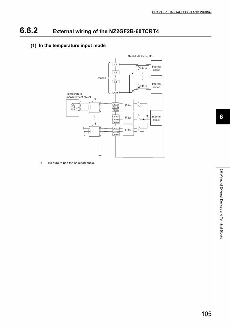
CHAPTER 6 INSTALLATION AND WIRING
6
6.6
Wirin
g o
f Exte
rna
l De
vices a
nd
Te
rmin
al B
locks
6.6.2 External wiring of the NZ2GF2B-60TCRT4
(1) In the temperature input mode
*1 Be sure to use the shielded cable.
L1
L2
L4
COM-
NZ2GF2B-60TCRT4
ABb
Internalcircuit
Internalcircuit
Internalcircuit
Filter
Filter
Filter
*1
*1
CH1 ACH1 B
CH2 ACH2 B
CH4 ACH4 B
CH2 b
CH4 b
CH1 b
Unused
Temperature measurement object
105

(2) In the temperature control mode
(a) In the standard control
*1 Be sure to use the shielded cable.
L1
L2
L4
COM-
NZ2GF2B-60TCRT4
ABb
24VDC
Internalcircuit
Internalcircuit
Internalcircuit
Filter
Filter
Filter
Object to be controlled
*1
*1
*1
*1
CH1 ACH1 B
CH2 ACH2 B
CH4 ACH4 B
CH2 b
CH4 b
CH1 b
106
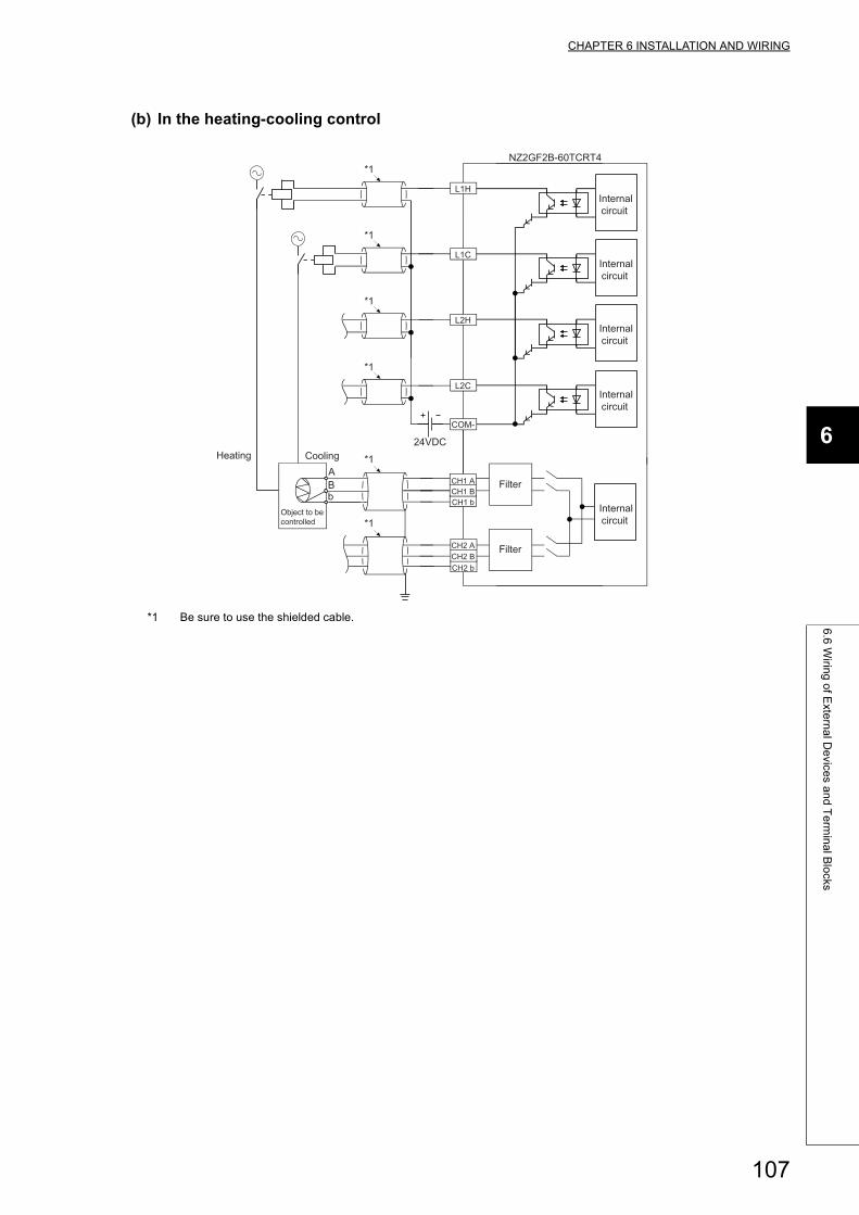
CHAPTER 6 INSTALLATION AND WIRING
6
6.6
Wirin
g o
f Exte
rna
l De
vices a
nd
Te
rmin
al B
locks
(b) In the heating-cooling control
*1 Be sure to use the shielded cable.
Heating
L1H
L1C
Filter
Filter
Object to be controlled
ABb
*1
*1
*1
*1
*1NZ2GF2B-60TCRT4
Internalcircuit
Internalcircuit
Internalcircuit
L2H
COM-
*1
24VDC
Internalcircuit
L2C
Internalcircuit
Cooling
CH1 ACH1 B
CH2 ACH2 BCH2 b
CH1 b
107

CHAPTER 7 VARIOUS SETTINGS
This chapter describes the setting procedures of a temperature control module.
7.1 Parameter Settings
Set the parameter of this module with the network parameter written to the CPU module of the master station. For the
setting procedure of the master station, refer to the following.
User's manual for the master/local module used
Remark
● Check in advance the box next to "Set network configuration setting in CC IE Field configuration window" in MELSECNET/CC IE/Ethernet Module Configuration window.
● Set the same number of points of the temperature control module to remote I/O signals and remote register. If the set points are less than the ones of the temperature control module, the cyclic transmission is performed only for the set points of data from the start, the temperature control module may not operate normally. In that case, an error does not occur.
108
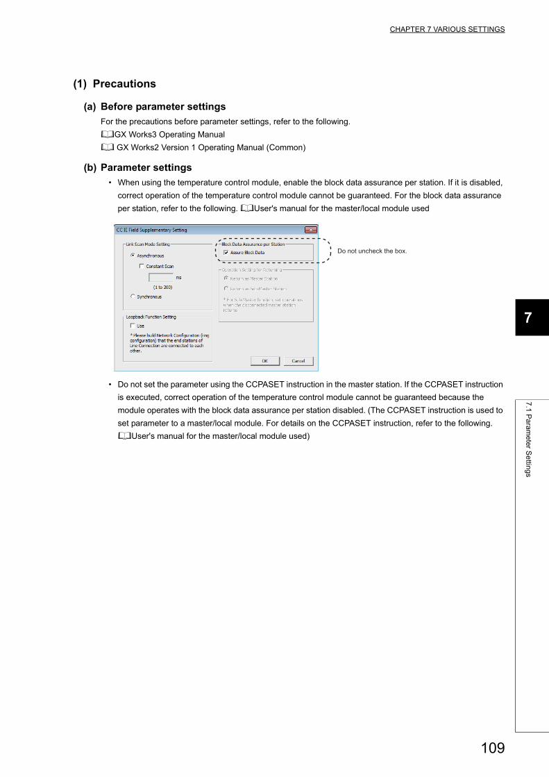
CHAPTER 7 VARIOUS SETTINGS
7
7.1
Pa
ram
ete
r Se
tting
s
(1) Precautions
(a) Before parameter settings
For the precautions before parameter settings, refer to the following.
GX Works3 Operating Manual
GX Works2 Version 1 Operating Manual (Common)
(b) Parameter settings
• When using the temperature control module, enable the block data assurance per station. If it is disabled,
correct operation of the temperature control module cannot be guaranteed. For the block data assurance
per station, refer to the following. User's manual for the master/local module used
• Do not set the parameter using the CCPASET instruction in the master station. If the CCPASET instruction
is executed, correct operation of the temperature control module cannot be guaranteed because the
module operates with the block data assurance per station disabled. (The CCPASET instruction is used to
set parameter to a master/local module. For details on the CCPASET instruction, refer to the following.
User's manual for the master/local module used)
Do not uncheck the box.
109
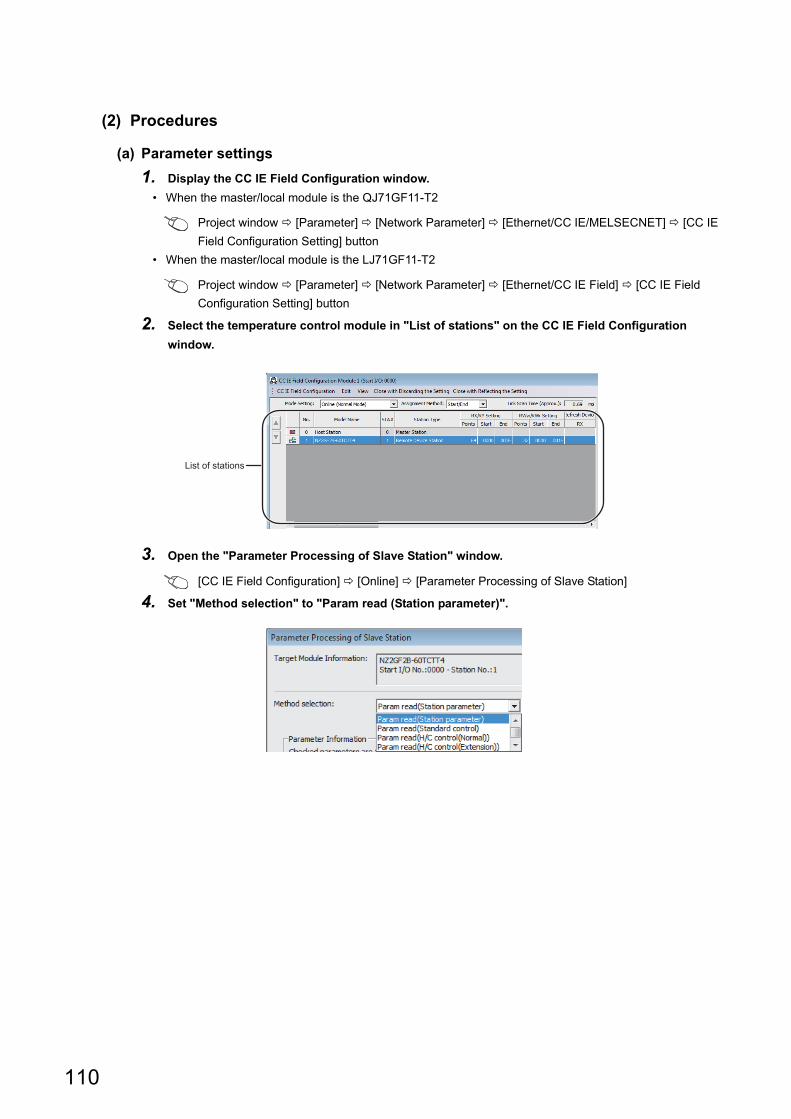
(2) Procedures
(a) Parameter settings
1. Display the CC IE Field Configuration window.
• When the master/local module is the QJ71GF11-T2
Project window [Parameter] [Network Parameter] [Ethernet/CC IE/MELSECNET] [CC IE
Field Configuration Setting] button
• When the master/local module is the LJ71GF11-T2
Project window [Parameter] [Network Parameter] [Ethernet/CC IE Field] [CC IE Field
Configuration Setting] button
2. Select the temperature control module in "List of stations" on the CC IE Field Configuration
window.
3. Open the "Parameter Processing of Slave Station" window.
[CC IE Field Configuration] [Online] [Parameter Processing of Slave Station]
4. Set "Method selection" to "Param read (Station parameter)".
List of stations
110
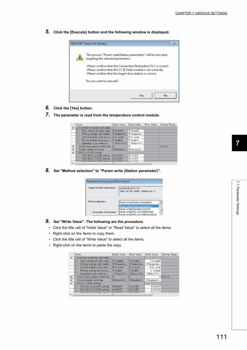
CHAPTER 7 VARIOUS SETTINGS
7
7.1
Pa
ram
ete
r Se
tting
s
5. Click the [Execute] button and the following window is displayed.
6. Click the [Yes] button.
7. The parameter is read from the temperature control module.
8. Set "Method selection" to "Param write (Station parameter)".
9. Set "Write Value". The following are the procedure.
• Click the title cell of "Initial Value" or "Read Value" to select all the items.
• Right-click on the items to copy them.
• Click the title cell of "Write Value" to select all the items.
• Right-click on the items to paste the copy.
111
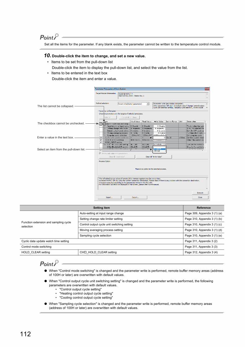
Set all the items for the parameter. If any blank exists, the parameter cannot be written to the temperature control module.
10.Double-click the item to change, and set a new value.
• Items to be set from the pull-down list
Double-click the item to display the pull-down list, and select the value from the list.
• Items to be entered in the text box
Double-click the item and enter a value.
● When "Control mode switching" is changed and the parameter write is performed, remote buffer memory areas (address of 100H or later) are overwritten with default values.
● When "Control output cycle unit switching setting" is changed and the parameter write is performed, the following parameters are overwritten with default values.
• "Control output cycle setting"• "Heating control output cycle setting"• "Cooling control output cycle setting"
● When "Sampling cycle selection" is changed and the parameter write is performed, remote buffer memory areas (address of 100H or later) are overwritten with default values.
Setting item Reference
Function extension and sampling cycle
selection
Auto-setting at input range change Page 309, Appendix 3 (1) (a)
Setting change rate limiter setting Page 310, Appendix 3 (1) (b)
Control output cycle unit switching setting Page 310, Appendix 3 (1) (c)
Moving averaging process setting Page 310, Appendix 3 (1) (d)
Sampling cycle selection Page 310, Appendix 3 (1) (e)
Cyclic data update watch time setting Page 311, Appendix 3 (2)
Control mode switching Page 311, Appendix 3 (3)
HOLD_CLEAR setting CH_HOLD_CLEAR setting Page 312, Appendix 3 (4)
Select an item from the pull-down list.
Enter a value in the text box.
The checkbox cannot be unchecked.
The list cannot be collapsed.
112
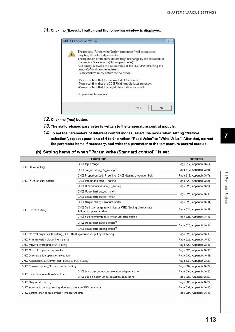
CHAPTER 7 VARIOUS SETTINGS
7
7.1
Pa
ram
ete
r Se
tting
s
11. Click the [Execute] button and the following window is displayed.
12.Click the [Yes] button.
13. The station-based parameter is written to the temperature control module.
14. To set the parameters of different control modes, select the mode when setting "Method
selection", repeat operations of 4 to 9 to reflect "Read Value" to "Write Value". After that, correct
the parameter items if necessary, and write the parameter to the temperature control module.
(b) Setting items of when "Param write (Standard control)" is set
Setting item Reference
CH Basic settingCH Input range Page 312, Appendix 3 (5)
CH Target value_SV_setting*1 Page 317, Appendix 3 (6)
CH PID Constant setting
CH Proportion belt_P_setting_CH Heating proportion belt Page 318, Appendix 3 (7)
CH Integration time_I_setting Page 320, Appendix 3 (8)
CH Differentiation time_D_setting Page 320, Appendix 3 (9)
CH Limiter setting
CH Upper limit output limiterPage 321, Appendix 3 (10)
CH Lower limit output limiter
CH Output change amount limiter Page 323, Appendix 3 (11)
CH Setting change rate limiter or CH Setting change rate
limiter_temperature risePage 324, Appendix 3 (12)
CH Setting change rate limiter unit time setting Page 325, Appendix 3 (13)
CH Upper limit setting limiter*1
Page 325, Appendix 3 (14)CH Lower limit setting limiter*1
CH Control output cycle setting_CH Heating control output cycle setting Page 326, Appendix 3 (15)
CH Primary delay digital filter setting Page 328, Appendix 3 (16)
CH Moving averaging count setting Page 329, Appendix 3 (17)
CH Control response parameter Page 329, Appendix 3 (18)
CH Differentiation operation selection Page 330, Appendix 3 (19)
CH Adjustment sensitivity_non-inductive belt_setting Page 331, Appendix 3 (20)
CH Forward action_Reverse action setting Page 334, Appendix 3 (24)
CH Loop disconnection detectionCH Loop disconnection detection judgment time Page 334, Appendix 3 (25)
CH Loop disconnection detection dead band Page 335, Appendix 3 (26)
CH Stop mode setting Page 336, Appendix 3 (27)
CH Automatic backup setting after auto tuning of PID constants Page 337, Appendix 3 (28)
CH Setting change rate limiter_temperature drop Page 324, Appendix 3 (12)
113
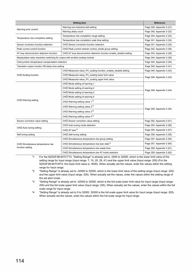
*1 For the NZ2GF2B-60TCTT4, "Setting Range" is already set to -2000 to 32000, which is the lower limit value of the setting range for Input range (Input range: 7, 10, 20, 29, 41) and the upper limit value (Input range: 205) (For the NZ2GF2B-60TCRT4, the lower limit value is -3000). When actually set the values, enter the values within the setting range for Input range.
*2 "Setting Range" is already set to -32000 to 32000, which is the lower limit value of the setting range (Input range: 205) and the upper limit value (Input range: 205). When actually set the values, enter the values within the setting range of the set alert mode.
*3 "Setting Range" is already set to -32000 to 32000, which is the full scale lower limit value for Input range (Input range: 205) and the full scale upper limit value (Input range: 205). When actually set the values, enter the values within the full scale range for Input range.
*4 "Setting Range" is already set to 0 to 32000. 32000 is the full scale upper limit value for Input range (Input range: 205). When actually set the values, enter the values within the full scale range for Input range.
Warning error controlWarning non-inductive belt setting Page 339, Appendix 3 (31)
Warning delay count Page 340, Appendix 3 (32)
Temperature rise completion settingTemperature rise completion range setting Page 340, Appendix 3 (33)
Temperature rise completion soak time setting Page 341, Appendix 3 (34)
Sensor correction function selection CH Sensor correction function selection Page 341, Appendix 3 (35)
Peak current control function CH Peak current restrain control_divide group setting Page 342, Appendix 3 (36)
AT loop disconnection detection function CH AT loop disconnection detection function enable_disable setting Page 343, Appendix 3 (38)
Manipulated value resolution switching for output with another analog module Page 344, Appendix 3 (39)
Cold junction temperature compensation selection Page 344, Appendix 3 (40)
Transistor output monitor ON delay time setting Page 345, Appendix 3 (41)
CH Scaling function
CH Measured value_PV_scaling function_enable_disable setting Page 345, Appendix 3 (42)
CH Measured value_PV_scaling lower limit valuePage 346, Appendix 3 (43)
CH Measured value_PV_scaling upper limit value
CH Warning setting
CH Mode setting of warning 1
Page 346, Appendix 3 (44)CH Mode setting of warning 2
CH Mode setting of warning 3
CH Mode setting of warning 4
CH Warning setting value 1*2
Page 348, Appendix 3 (45)CH Warning setting value 2*2
CH Warning setting value 3*2
CH Warning setting value 4*2
Sensor correction value setting CH Sensor correction value setting Page 352, Appendix 3 (51)
CH Auto tuning settingCH Auto tuning mode selection Page 354, Appendix 3 (56)
CH AT bias*3 Page 355, Appendix 3 (57)
Self tuning setting CH Self tuning setting Page 356, Appendix 3 (58)
CH Simultaneous temperature rise
function setting
CH Simultaneous temperature rise group setting Page 357, Appendix 3 (59)
CH Simultaneous temperature rise lean data*4 Page 357, Appendix 3 (60)
CH Simultaneous temperature rise waste time Page 358, Appendix 3 (61)
CH Simultaneous temperature rise AT mode selection Page 359, Appendix 3 (62)
Setting item Reference
114
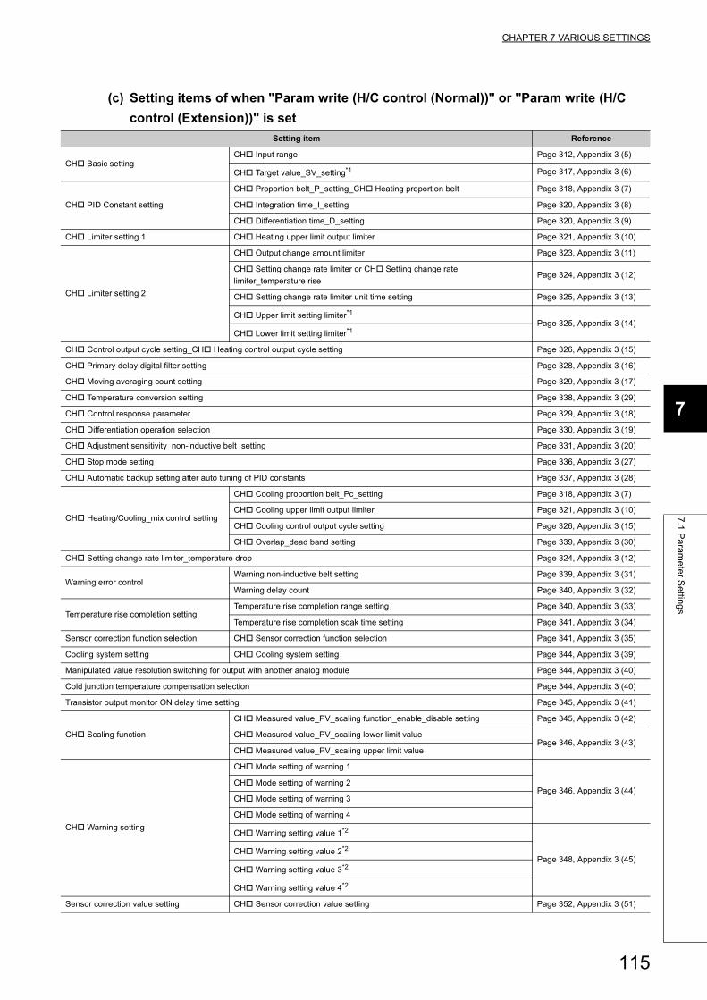
CHAPTER 7 VARIOUS SETTINGS
7
7.1
Pa
ram
ete
r Se
tting
s
(c) Setting items of when "Param write (H/C control (Normal))" or "Param write (H/C
control (Extension))" is set
Setting item Reference
CH Basic settingCH Input range Page 312, Appendix 3 (5)
CH Target value_SV_setting*1 Page 317, Appendix 3 (6)
CH PID Constant setting
CH Proportion belt_P_setting_CH Heating proportion belt Page 318, Appendix 3 (7)
CH Integration time_I_setting Page 320, Appendix 3 (8)
CH Differentiation time_D_setting Page 320, Appendix 3 (9)
CH Limiter setting 1 CH Heating upper limit output limiter Page 321, Appendix 3 (10)
CH Limiter setting 2
CH Output change amount limiter Page 323, Appendix 3 (11)
CH Setting change rate limiter or CH Setting change rate
limiter_temperature risePage 324, Appendix 3 (12)
CH Setting change rate limiter unit time setting Page 325, Appendix 3 (13)
CH Upper limit setting limiter*1
Page 325, Appendix 3 (14)CH Lower limit setting limiter*1
CH Control output cycle setting_CH Heating control output cycle setting Page 326, Appendix 3 (15)
CH Primary delay digital filter setting Page 328, Appendix 3 (16)
CH Moving averaging count setting Page 329, Appendix 3 (17)
CH Temperature conversion setting Page 338, Appendix 3 (29)
CH Control response parameter Page 329, Appendix 3 (18)
CH Differentiation operation selection Page 330, Appendix 3 (19)
CH Adjustment sensitivity_non-inductive belt_setting Page 331, Appendix 3 (20)
CH Stop mode setting Page 336, Appendix 3 (27)
CH Automatic backup setting after auto tuning of PID constants Page 337, Appendix 3 (28)
CH Heating/Cooling_mix control setting
CH Cooling proportion belt_Pc_setting Page 318, Appendix 3 (7)
CH Cooling upper limit output limiter Page 321, Appendix 3 (10)
CH Cooling control output cycle setting Page 326, Appendix 3 (15)
CH Overlap_dead band setting Page 339, Appendix 3 (30)
CH Setting change rate limiter_temperature drop Page 324, Appendix 3 (12)
Warning error controlWarning non-inductive belt setting Page 339, Appendix 3 (31)
Warning delay count Page 340, Appendix 3 (32)
Temperature rise completion settingTemperature rise completion range setting Page 340, Appendix 3 (33)
Temperature rise completion soak time setting Page 341, Appendix 3 (34)
Sensor correction function selection CH Sensor correction function selection Page 341, Appendix 3 (35)
Cooling system setting CH Cooling system setting Page 344, Appendix 3 (39)
Manipulated value resolution switching for output with another analog module Page 344, Appendix 3 (40)
Cold junction temperature compensation selection Page 344, Appendix 3 (40)
Transistor output monitor ON delay time setting Page 345, Appendix 3 (41)
CH Scaling function
CH Measured value_PV_scaling function_enable_disable setting Page 345, Appendix 3 (42)
CH Measured value_PV_scaling lower limit valuePage 346, Appendix 3 (43)
CH Measured value_PV_scaling upper limit value
CH Warning setting
CH Mode setting of warning 1
Page 346, Appendix 3 (44)CH Mode setting of warning 2
CH Mode setting of warning 3
CH Mode setting of warning 4
CH Warning setting value 1*2
Page 348, Appendix 3 (45)CH Warning setting value 2*2
CH Warning setting value 3*2
CH Warning setting value 4*2
Sensor correction value setting CH Sensor correction value setting Page 352, Appendix 3 (51)
115
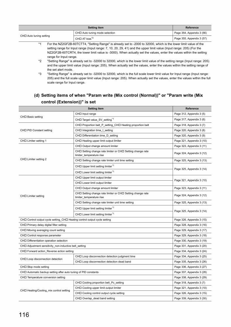
*1 For the NZ2GF2B-60TCTT4, "Setting Range" is already set to -2000 to 32000, which is the lower limit value of the setting range for Input range (Input range: 7, 10, 20, 29, 41) and the upper limit value (Input range: 205) (For the NZ2GF2B-60TCRT4, the lower limit value is -3000). When actually set the values, enter the values within the setting range for Input range.
*2 "Setting Range" is already set to -32000 to 32000, which is the lower limit value of the setting range (Input range: 205) and the upper limit value (Input range: 205). When actually set the values, enter the values within the setting range of the set alert mode.
*3 "Setting Range" is already set to -32000 to 32000, which is the full scale lower limit value for Input range (Input range: 205) and the full scale upper limit value (Input range: 205). When actually set the values, enter the values within the full scale range for Input range.
(d) Setting items of when "Param write (Mix control (Normal))" or "Param write (Mix
control (Extension))" is set
CH Auto tuning settingCH Auto tuning mode selection Page 354, Appendix 3 (56)
CH AT bias*3 Page 355, Appendix 3 (57)
Setting item Reference
CH Basic settingCH Input range Page 312, Appendix 3 (5)
CH Target value_SV_setting*1 Page 317, Appendix 3 (6)
CH PID Constant setting
CH Proportion belt_P_setting_CH Heating proportion belt Page 318, Appendix 3 (7)
CH Integration time_I_setting Page 320, Appendix 3 (8)
CH Differentiation time_D_setting Page 320, Appendix 3 (9)
CH Limiter setting 1 CH Heating upper limit output limiter Page 321, Appendix 3 (10)
CH Limiter setting 2
CH Output change amount limiter Page 323, Appendix 3 (11)
CH Setting change rate limiter or CH Setting change rate
limiter_temperature risePage 324, Appendix 3 (12)
CH Setting change rate limiter unit time setting Page 325, Appendix 3 (13)
CH Upper limit setting limiter*1Page 325, Appendix 3 (14)
CH Lower limit setting limiter*1
CH Limiter setting
CH Upper limit output limiterPage 321, Appendix 3 (10)
CH Lower limit output limiter
CH Output change amount limiter Page 323, Appendix 3 (11)
CH Setting change rate limiter or CH Setting change rate
limiter_temperature risePage 324, Appendix 3 (12)
CH Setting change rate limiter unit time setting Page 325, Appendix 3 (13)
CH Upper limit setting limiter*1
Page 325, Appendix 3 (14)CH Lower limit setting limiter*1
CH Control output cycle setting_CH Heating control output cycle setting Page 326, Appendix 3 (15)
CH Primary delay digital filter setting Page 328, Appendix 3 (16)
CH Moving averaging count setting Page 329, Appendix 3 (17)
CH Control response parameter Page 329, Appendix 3 (18)
CH Differentiation operation selection Page 330, Appendix 3 (19)
CH Adjustment sensitivity_non-inductive belt_setting Page 331, Appendix 3 (20)
CH Forward action_Reverse action setting Page 334, Appendix 3 (24)
CH Loop disconnection detectionCH Loop disconnection detection judgment time Page 334, Appendix 3 (25)
CH Loop disconnection detection dead band Page 335, Appendix 3 (26)
CH Stop mode setting Page 336, Appendix 3 (27)
CH Automatic backup setting after auto tuning of PID constants Page 337, Appendix 3 (28)
CH Temperature conversion setting Page 338, Appendix 3 (29)
CH Heating/Cooling_mix control setting
CH Cooling proportion belt_Pc_setting Page 318, Appendix 3 (7)
CH Cooling upper limit output limiter Page 321, Appendix 3 (10)
CH Cooling control output cycle setting Page 326, Appendix 3 (15)
CH Overlap_dead band setting Page 339, Appendix 3 (30)
Setting item Reference
116
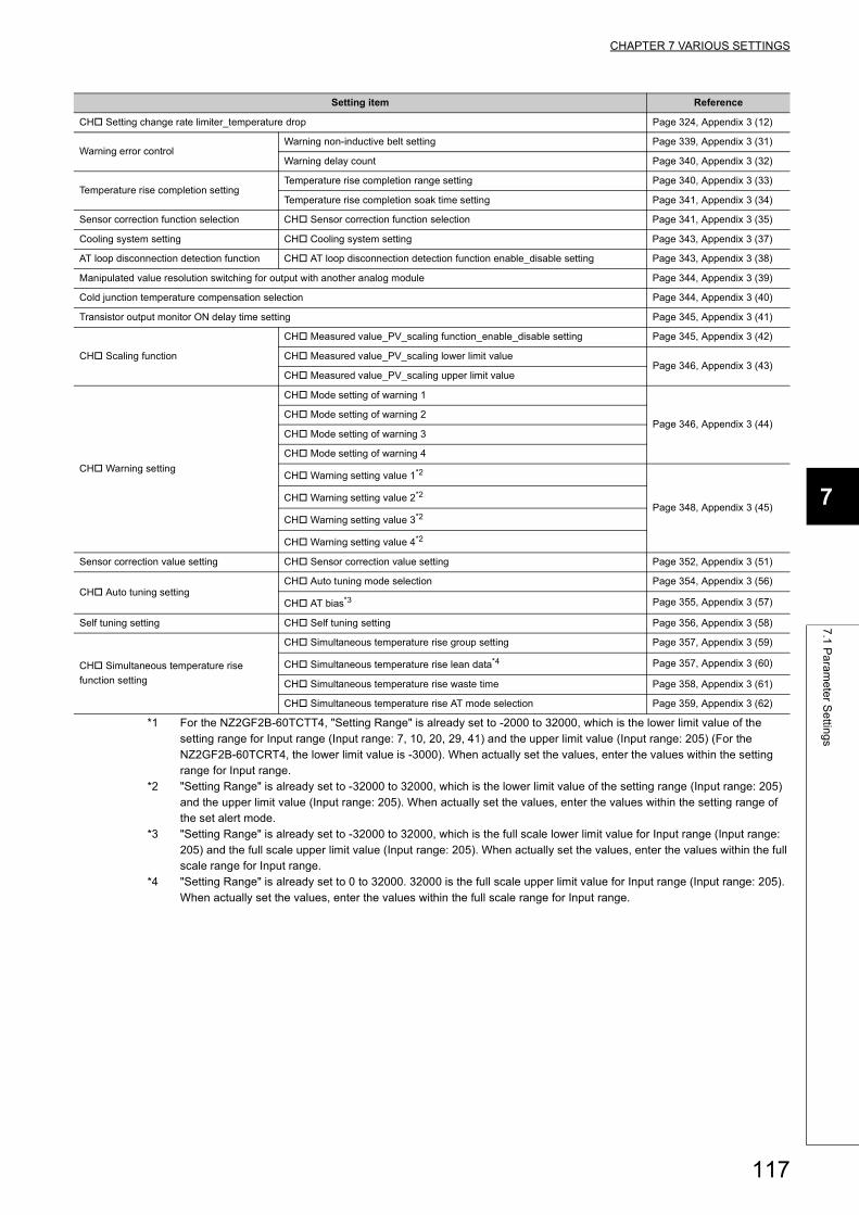
CHAPTER 7 VARIOUS SETTINGS
7
7.1
Pa
ram
ete
r Se
tting
s
*1 For the NZ2GF2B-60TCTT4, "Setting Range" is already set to -2000 to 32000, which is the lower limit value of the setting range for Input range (Input range: 7, 10, 20, 29, 41) and the upper limit value (Input range: 205) (For the NZ2GF2B-60TCRT4, the lower limit value is -3000). When actually set the values, enter the values within the setting range for Input range.
*2 "Setting Range" is already set to -32000 to 32000, which is the lower limit value of the setting range (Input range: 205) and the upper limit value (Input range: 205). When actually set the values, enter the values within the setting range of the set alert mode.
*3 "Setting Range" is already set to -32000 to 32000, which is the full scale lower limit value for Input range (Input range: 205) and the full scale upper limit value (Input range: 205). When actually set the values, enter the values within the full scale range for Input range.
*4 "Setting Range" is already set to 0 to 32000. 32000 is the full scale upper limit value for Input range (Input range: 205). When actually set the values, enter the values within the full scale range for Input range.
CH Setting change rate limiter_temperature drop Page 324, Appendix 3 (12)
Warning error controlWarning non-inductive belt setting Page 339, Appendix 3 (31)
Warning delay count Page 340, Appendix 3 (32)
Temperature rise completion settingTemperature rise completion range setting Page 340, Appendix 3 (33)
Temperature rise completion soak time setting Page 341, Appendix 3 (34)
Sensor correction function selection CH Sensor correction function selection Page 341, Appendix 3 (35)
Cooling system setting CH Cooling system setting Page 343, Appendix 3 (37)
AT loop disconnection detection function CH AT loop disconnection detection function enable_disable setting Page 343, Appendix 3 (38)
Manipulated value resolution switching for output with another analog module Page 344, Appendix 3 (39)
Cold junction temperature compensation selection Page 344, Appendix 3 (40)
Transistor output monitor ON delay time setting Page 345, Appendix 3 (41)
CH Scaling function
CH Measured value_PV_scaling function_enable_disable setting Page 345, Appendix 3 (42)
CH Measured value_PV_scaling lower limit valuePage 346, Appendix 3 (43)
CH Measured value_PV_scaling upper limit value
CH Warning setting
CH Mode setting of warning 1
Page 346, Appendix 3 (44)CH Mode setting of warning 2
CH Mode setting of warning 3
CH Mode setting of warning 4
CH Warning setting value 1*2
Page 348, Appendix 3 (45)CH Warning setting value 2*2
CH Warning setting value 3*2
CH Warning setting value 4*2
Sensor correction value setting CH Sensor correction value setting Page 352, Appendix 3 (51)
CH Auto tuning settingCH Auto tuning mode selection Page 354, Appendix 3 (56)
CH AT bias*3 Page 355, Appendix 3 (57)
Self tuning setting CH Self tuning setting Page 356, Appendix 3 (58)
CH Simultaneous temperature rise
function setting
CH Simultaneous temperature rise group setting Page 357, Appendix 3 (59)
CH Simultaneous temperature rise lean data*4 Page 357, Appendix 3 (60)
CH Simultaneous temperature rise waste time Page 358, Appendix 3 (61)
CH Simultaneous temperature rise AT mode selection Page 359, Appendix 3 (62)
Setting item Reference
117
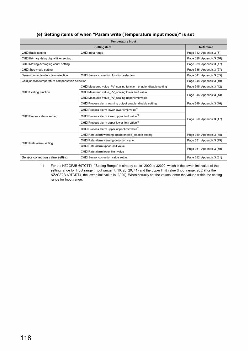
(e) Setting items of when "Param write (Temperature input mode)" is set
*1 For the NZ2GF2B-60TCTT4, "Setting Range" is already set to -2000 to 32000, which is the lower limit value of the setting range for Input range (Input range: 7, 10, 20, 29, 41) and the upper limit value (Input range: 205) (For the NZ2GF2B-60TCRT4, the lower limit value is -3000). When actually set the values, enter the values within the setting range for Input range.
Temperature input
Setting item Reference
CH Basic setting CH Input range Page 312, Appendix 3 (5)
CH Primary delay digital filter setting Page 328, Appendix 3 (16)
CH Moving averaging count setting Page 329, Appendix 3 (17)
CH Stop mode setting Page 336, Appendix 3 (27)
Sensor correction function selection CH Sensor correction function selection Page 341, Appendix 3 (35)
Cold junction temperature compensation selection Page 344, Appendix 3 (40)
CH Scaling function
CH Measured value_PV_scaling function_enable_disable setting Page 345, Appendix 3 (42)
CH Measured value_PV_scaling lower limit valuePage 346, Appendix 3 (43)
CH Measured value_PV_scaling upper limit value
CH Process alarm setting
CH Process alarm warning output enable_disable setting Page 349, Appendix 3 (46)
CH Process alarm lower lower limit value*1
Page 350, Appendix 3 (47)CH Process alarm lower upper limit value*1
CH Process alarm upper lower limit value*1
CH Process alarm upper upper limit value*1
CH Rate alarm setting
CH Rate alarm warning output enable_disable setting Page 350, Appendix 3 (48)
CH Rate alarm warning detection cycle Page 351, Appendix 3 (49)
CH Rate alarm upper limit valuePage 351, Appendix 3 (50)
CH Rate alarm lower limit value
Sensor correction value setting CH Sensor correction value setting Page 352, Appendix 3 (51)
118
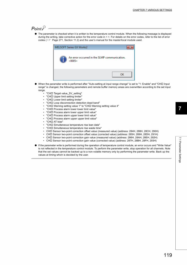
CHAPTER 7 VARIOUS SETTINGS
7
7.1
Pa
ram
ete
r Se
tting
s
● The parameter is checked when it is written to the temperature control module. When the following message is displayed during the writing, take corrective action for the error code in < >. For details on the error codes, refer to the list of error codes ( Page 271, Section 11.2) and the user’s manual for the master/local module used.
● When the parameter write is performed after "Auto-setting at input range change" is set to "1: Enable" and "CH Input range" is changed, the following parameters and remote buffer memory areas are overwritten according to the set input range.
• "CH Target value_SV_setting"• "CH Upper limit setting limiter"• "CH Lower limit setting limiter"• "CH Loop disconnection detection dead band"• "CH Warning setting value 1" to "CH Warning setting value 4"• "CH Process alarm lower lower limit value"• "CH Process alarm lower upper limit value"• "CH Process alarm upper lower limit value"• "CH Process alarm upper upper limit value"• "CH AT bias"• "CH Simultaneous temperature rise lean data"• "CH Simultaneous temperature rise waste time"• CH Sensor two-point correction offset value (measured value) (address: 284H, 288H, 28CH, 290H)• CH Sensor two-point correction offset value (corrected value) (address: 285H, 289H, 28DH, 291H)• CH Sensor two-point correction gain value (measured value) (address: 286H, 28AH, 28EH, 292H)• CH Sensor two-point correction gain value (corrected value) (address: 287H, 28BH, 28FH, 293H)
● If the parameter write is performed during the operation of temperature control module, an error occurs and "Write Value" is not reflected in the temperature control module. To perform the parameter write, stop operation for all channels. Note that the set values cannot be backed up to a non-volatile memory only by performing the parameter write. Back up the values at timing which is decided by the user.
119

7.2 Changing Parameters
This section describes the procedures to change parameters.
The precautions to take when changing parameters are same as the following.
• Precautions ( Page 109, Section 7.1 (1))
7.2.1 Changing the network configuration
When changing the network configuration using the created project, set the parameter in the following procedure.
1. Power off the module.
2. Connect the modules again according to the desired network configuration.
3. Power on the module.
4. Display the CC IE Field Configuration window.
• When the master/local module is the QJ71GF11-T2
Project window [Parameter] [Network Parameter] [Ethernet/CC IE/MELSECNET] [CC IE
Field Configuration Setting] button
• When the master/local module is the LJ71GF11-T2
Project window [Parameter] [Network Parameter] [Ethernet/CC IE Field] [CC IE Field
Configuration Setting] button
120
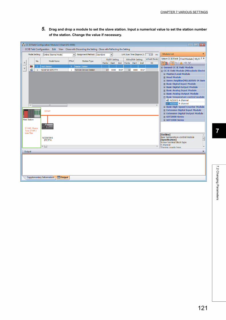
CHAPTER 7 VARIOUS SETTINGS
7
7.2
Ch
an
gin
g P
ara
me
ters
5. Drag and drop a module to set the slave station. Input a numerical value to set the station number
of the station. Change the value if necessary.
121
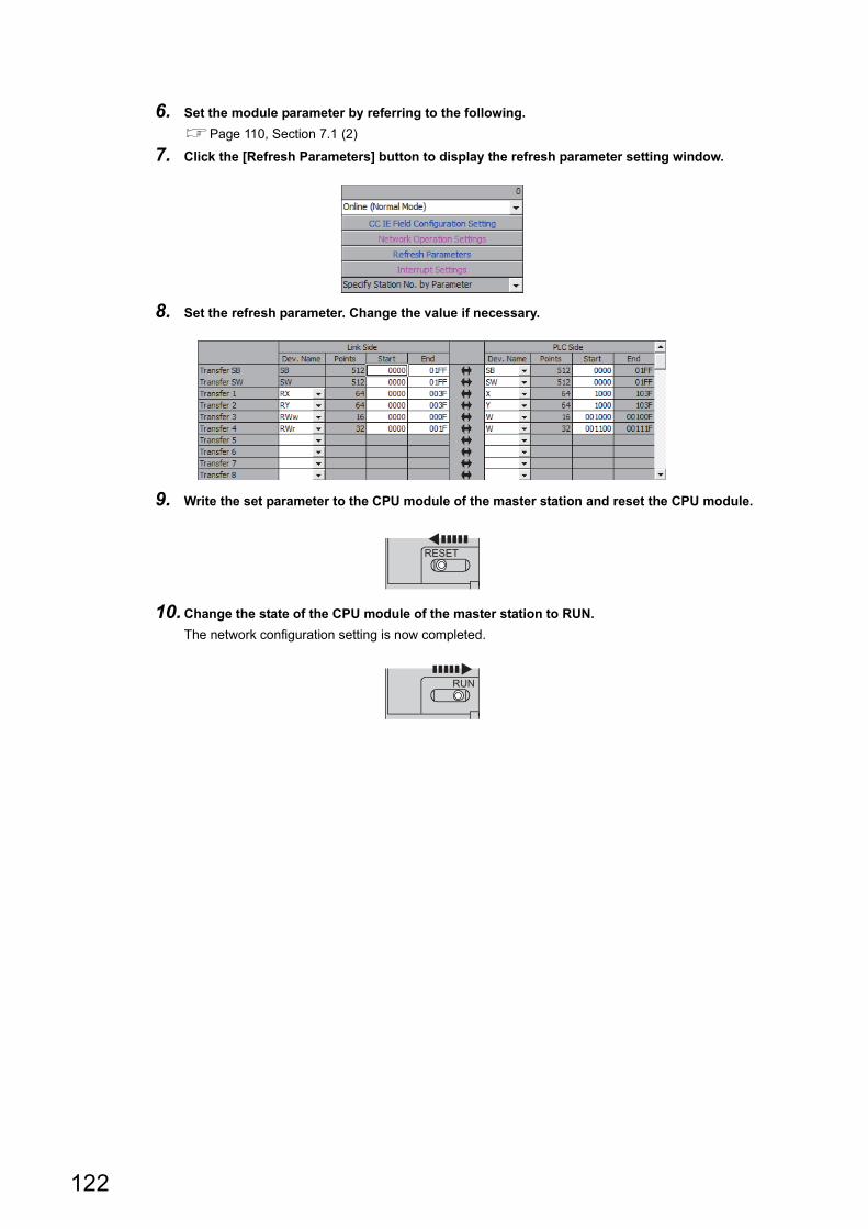
6. Set the module parameter by referring to the following.
Page 110, Section 7.1 (2)
7. Click the [Refresh Parameters] button to display the refresh parameter setting window.
8. Set the refresh parameter. Change the value if necessary.
9. Write the set parameter to the CPU module of the master station and reset the CPU module.
10.Change the state of the CPU module of the master station to RUN.
The network configuration setting is now completed.
RESET
RUN
122
CHAPTER 7 VARIOUS SETTINGS
7
7.2
Ch
an
gin
g P
ara
me
ters
7.2.2 Changing a parameter without changing the network configuration
To change only the created module parameter of the slave station without changing the network configuration, set the
parameter in the following procedure.
1. Display the CC IE Field Configuration window.
• When the master/local module is the QJ71GF11-T2
Project window [Parameter] [Network Parameter] [Ethernet/CC IE/MELSECNET] [CC IE
Field Configuration Setting] button
• When the master/local module is the LJ71GF11-T2
Project window [Parameter] [Network Parameter] [Ethernet/CC IE Field] [CC IE Field
Configuration Setting] button
2. Set the module parameter by referring to the following.
Page 110, Section 7.1 (2)
123
CHAPTER 8 FUNCTIONS
This chapter explains the details of the temperature control module and how to set each function.
For details on remote I/O signal, remote register, remote buffer memory, refer to the following.
• Details of Remote I/O Signals (Page 284, Appendix 1)
• Details of Remote Register Areas (Page 301, Appendix 2)
• Details of Remote Buffer Memory Areas (Page 309, Appendix 3)
● For the functions indicated with the icons and , or with , the following terms are used, unless
otherwise specified.• Proportional band (P): includes heating proportional band (Ph) and cooling proportional band (Pc).• Manipulated value (MV): includes manipulated value for heating (MVh) and manipulated value for cooling (MVc).• Manipulated value (MV) for output with another analog module: includes manipulated value of heating (MVh) for
output with another analog module and manipulated value of cooling (MVc) for output with another analog module.
• Transistor output: includes heating transistor output and cooling transistor output.• Upper limit output limiter value: includes heating upper limit output limiter value and cooling upper limit output
limiter value.• Control output cycle: includes heating control output cycle and cooling control output cycle.
● In the description of the "Parameter Processing of Slave Station" window in this chapter, only window settings are described. To enable the settings, they need to be written to the module. For the method of writing the settings to the module, refer to the following.Page 108, Section 7.1
Standard Heating-cooling Common
124
CHAPTER 8 FUNCTIONS
8
8.1
Co
mm
on
Fu
nctio
ns
8.1 Common Functions
This section explains the common functions between the temperature input mode and temperature control mode.
8.1.1 Operation/stop function
Whether to operate or stop the temperature conversion and the temperature control can be set for each channel. By
stopping unused channels, unnecessary disconnection detection or alert output can be prevented.
(1) Setting methodWhether to operate or stop the temperature conversion and the temperature control of each channel can be set
by CH Operation request flag (RY11 to RY14) and CH Stop request flag (RY18 to RY1B). For details, refer to
the following.
• CH Operation request flag (RY11 to RY14) ( Page 296, Appendix 1.2 (4))
• CH Stop request flag (RY18 to RY1B) ( Page 298, Appendix 1.2 (7))
(2) When the check on whether or not the temperature process value is within the
temperature measurement range is unnecessarySetting CH Stop mode setting (address: 118H, 148H, 178H, 1A8H) to Stop (0) controls error detection. For
details, refer to the following.
Page 336, Appendix 3 (27)
Common
125
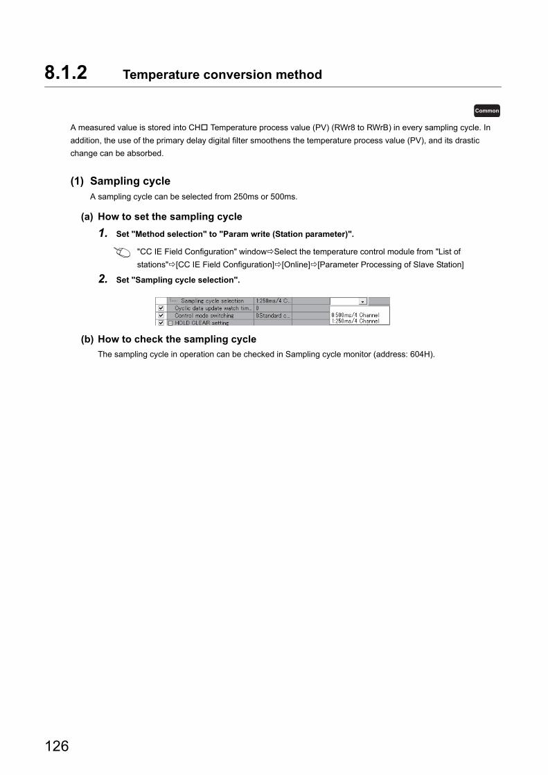
8.1.2 Temperature conversion method
A measured value is stored into CH Temperature process value (PV) (RWr8 to RWrB) in every sampling cycle. In
addition, the use of the primary delay digital filter smoothens the temperature process value (PV), and its drastic
change can be absorbed.
(1) Sampling cycleA sampling cycle can be selected from 250ms or 500ms.
(a) How to set the sampling cycle
1. Set "Method selection" to "Param write (Station parameter)".
"CC IE Field Configuration" windowSelect the temperature control module from "List of
stations"[CC IE Field Configuration][Online][Parameter Processing of Slave Station]
2. Set "Sampling cycle selection".
(b) How to check the sampling cycle
The sampling cycle in operation can be checked in Sampling cycle monitor (address: 604H).
Common
126
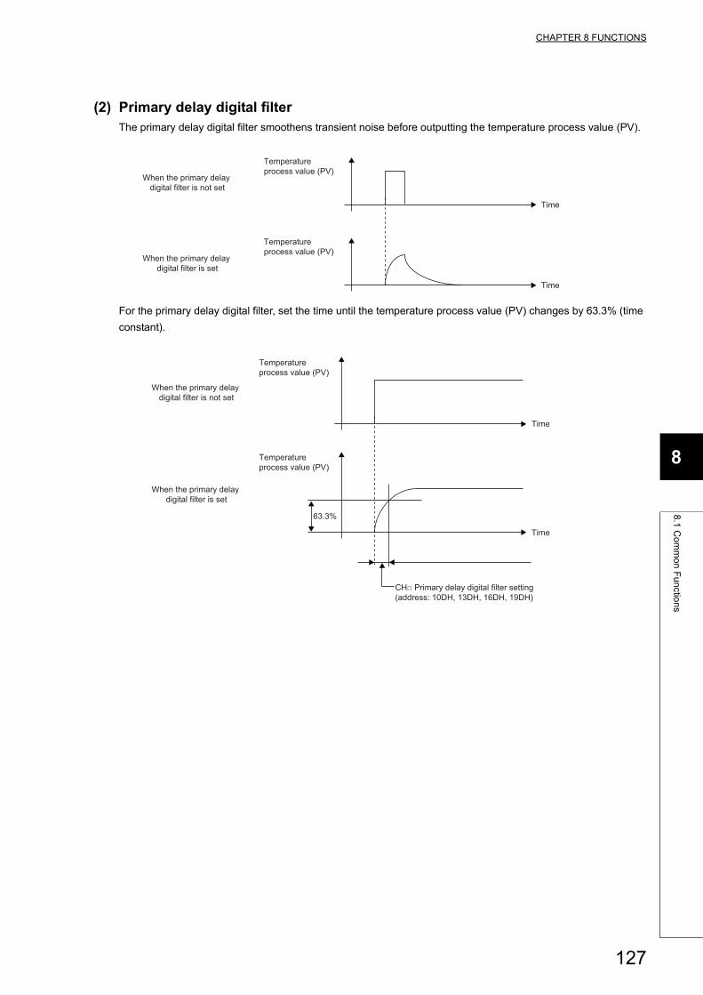
CHAPTER 8 FUNCTIONS
8
8.1
Co
mm
on
Fu
nctio
ns
(2) Primary delay digital filterThe primary delay digital filter smoothens transient noise before outputting the temperature process value (PV).
For the primary delay digital filter, set the time until the temperature process value (PV) changes by 63.3% (time
constant).
Time
Time
Temperature process value (PV)
Temperature process value (PV)
When the primary delay digital filter is not set
When the primary delay digital filter is set
Temperature process value (PV)
Time
Time
Temperature process value (PV)
63.3%
When the primary delay digital filter is not set
When the primary delay digital filter is set
CH□ Primary delay digital filter setting (address: 10DH, 13DH, 16DH, 19DH)
127
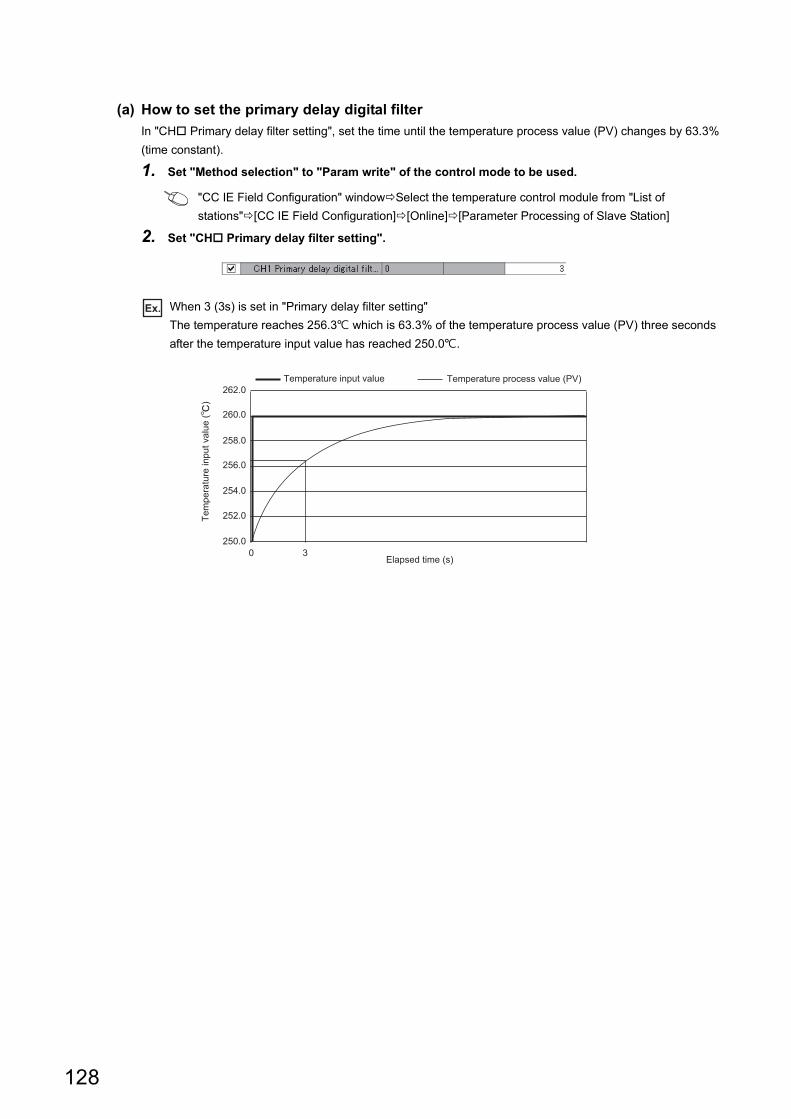
(a) How to set the primary delay digital filter
In "CH Primary delay filter setting", set the time until the temperature process value (PV) changes by 63.3%
(time constant).
1. Set "Method selection" to "Param write" of the control mode to be used.
"CC IE Field Configuration" windowSelect the temperature control module from "List of
stations"[CC IE Field Configuration][Online][Parameter Processing of Slave Station]
2. Set "CH Primary delay filter setting".
Ex. When 3 (3s) is set in "Primary delay filter setting"
The temperature reaches 256.3 which is 63.3% of the temperature process value (PV) three seconds
after the temperature input value has reached 250.0.
0 3250.0
252.0
254.0
256.0
258.0
260.0
262.0Temperature input value Temperature process value (PV)
Elapsed time (s)
Tem
pera
ture
inpu
t val
ue (
)
128
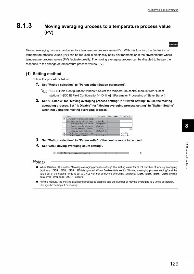
CHAPTER 8 FUNCTIONS
8
8.1
Co
mm
on
Fu
nctio
ns
8.1.3 Moving averaging process to a temperature process value (PV)
Moving averaging process can be set to a temperature process value (PV). With this function, the fluctuation of
temperature process values (PV) can be reduced in electrically noisy environments or in the environments where
temperature process values (PV) fluctuate greatly. The moving averaging process can be disabled to hasten the
response to the change of temperature process values (PV).
(1) Setting methodFollow the procedure below.
1. Set "Method selection" to "Param write (Station parameter)".
"CC IE Field Configuration" windowSelect the temperature control module from "List of
stations"[CC IE Field Configuration][Online][Parameter Processing of Slave Station]
2. Set "0: Enable" for "Moving averaging process setting" in "Switch Setting" to use the moving
averaging process. Set "1: Disable" for "Moving averaging process setting" in "Switch Setting"
when not using the moving averaging process.
3. Set "Method selection" to "Param write" of the control mode to be used.
4. Set "CH Moving averaging count setting".
● When Disable (1) is set for "Moving averaging process setting", the setting value for CH Number of moving averaging (address: 10EH, 13EH, 16EH, 19EH) is ignored. When Enable (0) is set for "Moving averaging process setting" and the value out of the setting range is set to CH Number of moving averaging (address: 10EH, 13EH, 16EH, 19EH), a write data error (error code: 0004H) occurs.
● For the module, the moving averaging process is enabled and the number of moving averaging is 2 times as default. Change the settings if necessary.
Common
129
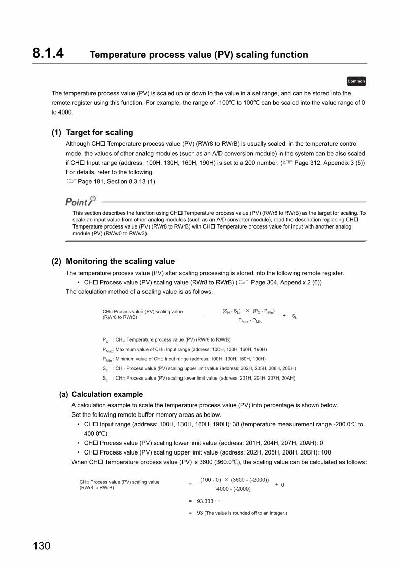
8.1.4 Temperature process value (PV) scaling function
The temperature process value (PV) is scaled up or down to the value in a set range, and can be stored into the
remote register using this function. For example, the range of -100 to 100 can be scaled into the value range of 0
to 4000.
(1) Target for scalingAlthough CH Temperature process value (PV) (RWr8 to RWrB) is usually scaled, in the temperature control
mode, the values of other analog modules (such as an A/D conversion module) in the system can be also scaled
if CH Input range (address: 100H, 130H, 160H, 190H) is set to a 200 number. (Page 312, Appendix 3 (5))
For details, refer to the following.
Page 181, Section 8.3.13 (1)
This section describes the function using CH Temperature process value (PV) (RWr8 to RWrB) as the target for scaling. To scale an input value from other analog modules (such as an A/D converter module), read the description replacing CH Temperature process value (PV) (RWr8 to RWrB) with CH Temperature process value for input with another analog module (PV) (RWw0 to RWw3).
(2) Monitoring the scaling valueThe temperature process value (PV) after scaling processing is stored into the following remote register.
• CH Process value (PV) scaling value (RWr8 to RWrB) ( Page 304, Appendix 2 (6))
The calculation method of a scaling value is as follows:
(a) Calculation example
A calculation example to scale the temperature process value (PV) into percentage is shown below.
Set the following remote buffer memory areas as below.
• CH Input range (address: 100H, 130H, 160H, 190H): 38 (temperature measurement range -200.0 to
400.0)
• CH Process value (PV) scaling lower limit value (address: 201H, 204H, 207H, 20AH): 0
• CH Process value (PV) scaling upper limit value (address: 202H, 205H, 208H, 20BH): 100
When CH Temperature process value (PV) is 3600 (360.0), the scaling value can be calculated as follows:
Common
= +(SH - SL) (PX - PMin)
PMax - PMinSL
: CH□ Temperature process value (PV) (RWr8 to RWrB)
: Maximum value of CH□ Input range (address: 100H, 130H, 160H, 190H)
: Minimum value of CH□ Input range (address: 100H, 130H, 160H, 190H)
: CH□ Process value (PV) scaling upper limit value (address: 202H, 205H, 208H, 20BH)
: CH□ Process value (PV) scaling lower limit value (address: 201H, 204H, 207H, 20AH)
PMax
PX
PMin
SH
SL
CH□ Process value (PV) scaling value (RWr8 to RWrB)
=
=
=
+(100 - 0)
93.333
93 (The value is rounded off to an integer.)
(3600 - (-2000))
4000 - (-2000)0CH□ Process value (PV) scaling value
(RWr8 to RWrB)
130
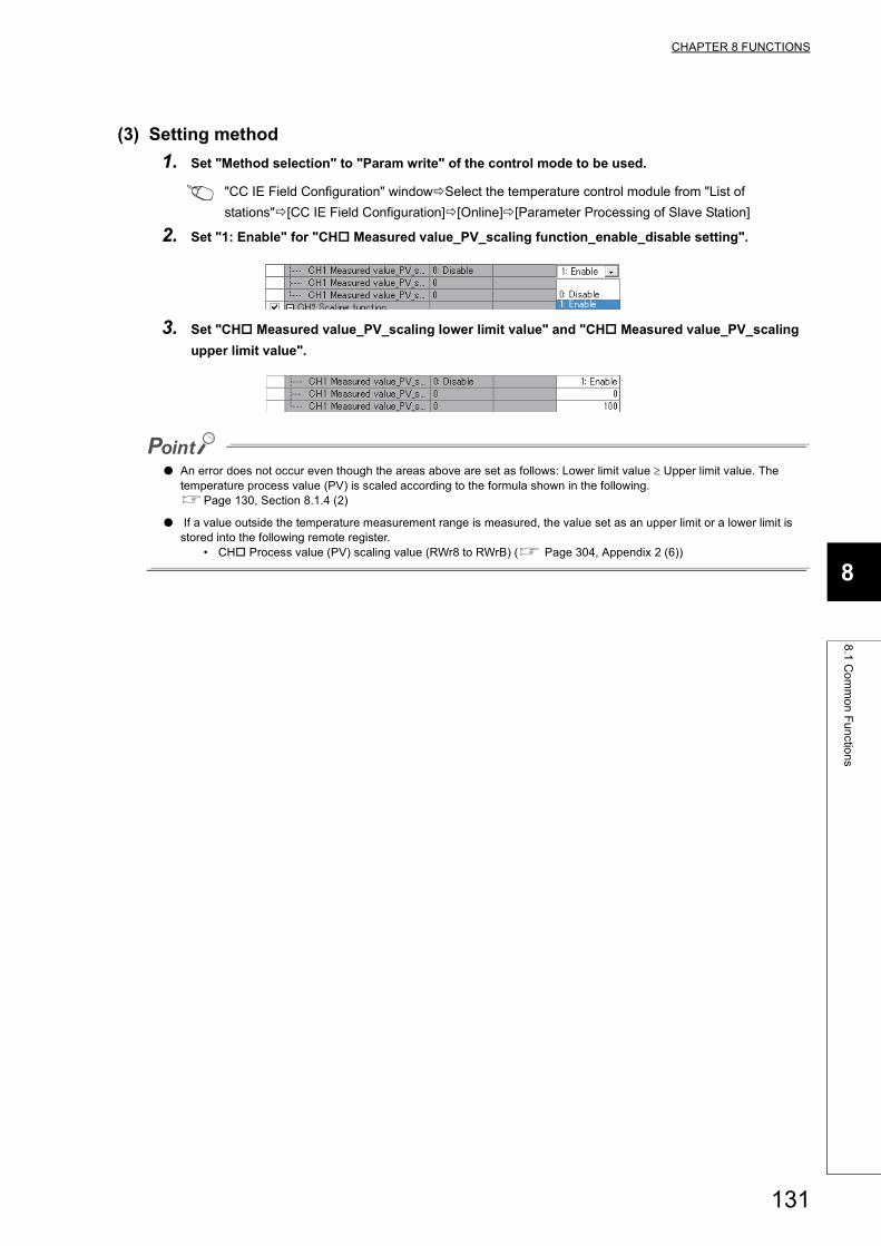
CHAPTER 8 FUNCTIONS
8
8.1
Co
mm
on
Fu
nctio
ns
(3) Setting method
1. Set "Method selection" to "Param write" of the control mode to be used.
"CC IE Field Configuration" windowSelect the temperature control module from "List of
stations"[CC IE Field Configuration][Online][Parameter Processing of Slave Station]
2. Set "1: Enable" for "CH Measured value_PV_scaling function_enable_disable setting".
3. Set "CH Measured value_PV_scaling lower limit value" and "CH Measured value_PV_scaling
upper limit value".
● An error does not occur even though the areas above are set as follows: Lower limit value Upper limit value. The temperature process value (PV) is scaled according to the formula shown in the following.Page 130, Section 8.1.4 (2)
● If a value outside the temperature measurement range is measured, the value set as an upper limit or a lower limit is stored into the following remote register.
• CH Process value (PV) scaling value (RWr8 to RWrB) ( Page 304, Appendix 2 (6))
131
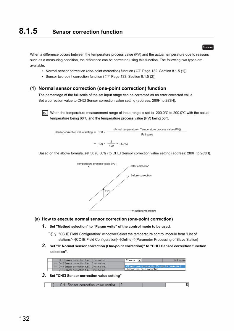
8.1.5 Sensor correction function
When a difference occurs between the temperature process value (PV) and the actual temperature due to reasons
such as a measuring condition, the difference can be corrected using this function. The following two types are
available.
• Normal sensor correction (one-point correction) function (Page 132, Section 8.1.5 (1))
• Sensor two-point correction function (Page 133, Section 8.1.5 (2))
(1) Normal sensor correction (one-point correction) functionThe percentage of the full scale of the set input range can be corrected as an error corrected value.
Set a correction value to CH Sensor correction value setting (address: 280H to 283H).
Ex. When the temperature measurement range of input range is set to -200.0 to 200.0 with the actual
temperature being 60 and the temperature process value (PV) being 58
Based on the above formula, set 50 (0.50%) to CH Sensor correction value setting (address: 280H to 283H).
(a) How to execute normal sensor correction (one-point correction)
1. Set "Method selection" to "Param write" of the control mode to be used.
"CC IE Field Configuration" windowSelect the temperature control module from "List of
stations"[CC IE Field Configuration][Online][Parameter Processing of Slave Station]
2. Set "0: Normal sensor correction (One-point correction)" to "CH Sensor correction function
selection".
3. Set "CH Sensor correction value setting"
Common
(Actual temperature - Temperature process value (PV))Sensor correction value setting =
Full scale
= 4002
100 ×
100 ×
= 0.5 (%)
After correction
Before correction
Input temperature
Temperature process value (PV)
2
132
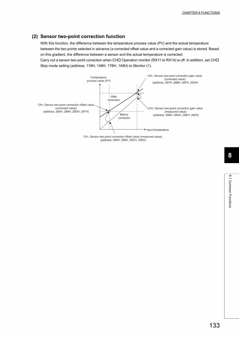
CHAPTER 8 FUNCTIONS
8
8.1
Co
mm
on
Fu
nctio
ns
(2) Sensor two-point correction functionWith this function, the difference between the temperature process value (PV) and the actual temperature
between the two points selected in advance (a corrected offset value and a corrected gain value) is stored. Based
on this gradient, the difference between a sensor and the actual temperature is corrected.
Carry out a sensor two-point correction when CH Operation monitor (RX11 to RX14) is off. In addition, set CH
Stop mode setting (address: 118H, 148H, 178H, 1A8H) to Monitor (1).
Beforecorrection
Input temperature
Temperature process value (PV)
Aftercorrection
CH□ Sensor two-point correction gain value (corrected value)
(address: 287H, 28BH, 28FH, 293H)
CH□ Sensor two-point correction offset value (corrected value)
(address: 285H, 289H, 28DH, 291H)
CH□ Sensor two-point correction offset value (measured value) (address: 284H, 288H, 28CH, 290H)
CH□ Sensor two-point correction gain value (measured value)
(address: 286H, 28AH, 28EH, 292H)
133
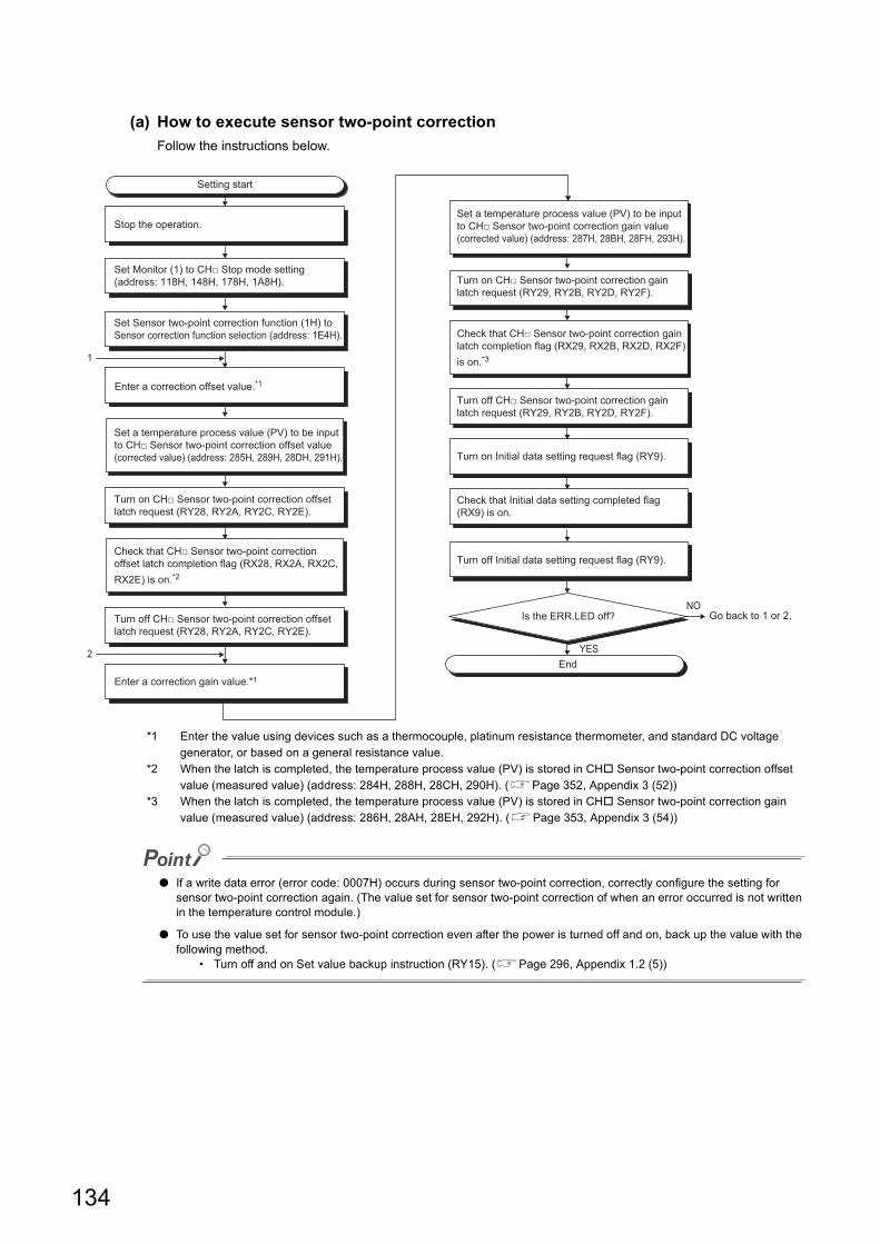
(a) How to execute sensor two-point correction
Follow the instructions below.
*1 Enter the value using devices such as a thermocouple, platinum resistance thermometer, and standard DC voltage generator, or based on a general resistance value.
*2 When the latch is completed, the temperature process value (PV) is stored in CH Sensor two-point correction offset value (measured value) (address: 284H, 288H, 28CH, 290H). (Page 352, Appendix 3 (52))
*3 When the latch is completed, the temperature process value (PV) is stored in CH Sensor two-point correction gain value (measured value) (address: 286H, 28AH, 28EH, 292H). (Page 353, Appendix 3 (54))
● If a write data error (error code: 0007H) occurs during sensor two-point correction, correctly configure the setting for sensor two-point correction again. (The value set for sensor two-point correction of when an error occurred is not written in the temperature control module.)
● To use the value set for sensor two-point correction even after the power is turned off and on, back up the value with the following method.
• Turn off and on Set value backup instruction (RY15). (Page 296, Appendix 1.2 (5))
Set Sensor two-point correction function (1H) to Sensor correction function selection (address: 1E4H).
Turn on Initial data setting request flag (RY9).
Set a temperature process value (PV) to be input to CH□ Sensor two-point correction gain value (corrected value) (address: 287H, 28BH, 28FH, 293H).
Check that Initial data setting completed flag (RX9) is on.
Turn off Initial data setting request flag (RY9).
Enter a correction offset value.*1
Enter a correction gain value.*1
Set a temperature process value (PV) to be input to CH□ Sensor two-point correction offset value (corrected value) (address: 285H, 289H, 28DH, 291H).
Turn on CH□ Sensor two-point correction offset latch request (RY28, RY2A, RY2C, RY2E).
Check that CH□ Sensor two-point correction offset latch completion flag (RX28, RX2A, RX2C, RX2E) is on.*2
Turn off CH□ Sensor two-point correction offset latch request (RY28, RY2A, RY2C, RY2E).
Turn on CH□ Sensor two-point correction gain latch request (RY29, RY2B, RY2D, RY2F).
Check that CH□ Sensor two-point correction gain latch completion flag (RX29, RX2B, RX2D, RX2F) is on.*3
Turn off CH□ Sensor two-point correction gain latch request (RY29, RY2B, RY2D, RY2F).
1
Set Monitor (1) to CH□ Stop mode setting (address: 118H, 148H, 178H, 1A8H).
Setting start
Stop the operation.
2End
Is the ERR.LED off? Go back to 1 or 2.
YES
NO
134
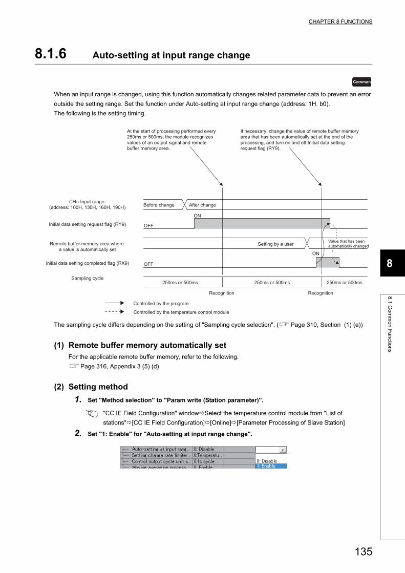
CHAPTER 8 FUNCTIONS
8
8.1
Co
mm
on
Fu
nctio
ns
8.1.6 Auto-setting at input range change
When an input range is changed, using this function automatically changes related parameter data to prevent an error
outside the setting range. Set the function under Auto-setting at input range change (address: 1H. b0).
The following is the setting timing.
The sampling cycle differs depending on the setting of "Sampling cycle selection". (Page 310, Section (1) (e))
(1) Remote buffer memory automatically setFor the applicable remote buffer memory, refer to the following.
Page 316, Appendix 3 (5) (d)
(2) Setting method
1. Set "Method selection" to "Param write (Station parameter)".
"CC IE Field Configuration" windowSelect the temperature control module from "List of
stations"[CC IE Field Configuration][Online][Parameter Processing of Slave Station]
2. Set "1: Enable" for "Auto-setting at input range change".
Common
Sampling cycle
Recognition
OFF
OFF
ON
ON
Before change After change
Setting by a user Value that has been automatically changed
Recognition
250ms or 500ms 250ms or 500ms 250ms or 500ms
Controlled by the program
CH□ Input range (address: 100H, 130H, 160H, 190H)
At the start of processing performed every 250ms or 500ms, the module recognizes values of an output signal and remote buffer memory area.
If necessary, change the value of remote buffer memory area that has been automatically set at the end of the processing, and turn on and off Initial data setting request flag (RY9).
Initial data setting request flag (RY9)
Remote buffer memory area where a value is automatically set
Initial data setting completed flag (RX9)
Controlled by the temperature control module
135
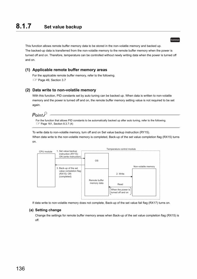
8.1.7 Set value backup
This function allows remote buffer memory data to be stored in the non-volatile memory and backed up.
The backed-up data is transferred from the non-volatile memory to the remote buffer memory when the power is
turned off and on. Therefore, temperature can be controlled without newly writing data when the power is turned off
and on.
(1) Applicable remote buffer memory areasFor the applicable remote buffer memory, refer to the following.
Page 49, Section 3.7
(2) Data write to non-volatile memoryWith this function, PID constants set by auto tuning can be backed up. When data is written to non-volatile
memory and the power is turned off and on, the remote buffer memory setting value is not required to be set
again.
For the function that allows PID constants to be automatically backed up after auto tuning, refer to the following.Page 161, Section 8.3.7 (4)
To write data to non-volatile memory, turn off and on Set value backup instruction (RY15).
When data write to the non-volatile memory is completed, Back-up of the set value completion flag (RX15) turns
on.
If data write to non-volatile memory does not complete, Back-up of the set value fail flag (RX17) turns on.
(a) Setting change
Change the settings for remote buffer memory areas when Back-up of the set value completion flag (RX15) is
off.
Common
Read
OS
CPU module
2. Write
Non-volatile memory
When the power is turned off and on
Temperature control module1. Set value backup instruction (RY15): ON (write instruction)
3. Back-up of the set value completion flag (RX15): ON (completed)
Remote buffer memory data
136
CHAPTER 8 FUNCTIONS
8
8.1
Co
mm
on
Fu
nctio
ns
(3) Data read from non-volatile memoryFollow the instructions below.
• Turn off and on the power.
• Set CH Memory's PID constants read instruction (address: 1100H to 1103H) to Requested (1). (Page
365, Appendix 3 (72)) Data to be read are the PID constants and loop disconnection detection judgment time
for the corresponding channel only. (Page 334, Appendix 3 (25))
137
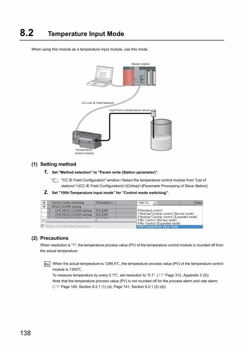
8.2 Temperature Input Mode
When using this module as a temperature input module, use this mode.
(1) Setting method
1. Set "Method selection" to "Param write (Station parameter)".
"CC IE Field Configuration" windowSelect the temperature control module from "List of
stations"[CC IE Field Configuration][Online][Parameter Processing of Slave Station]
2. Set "100h:Temperature input mode" for "Control mode switching".
(2) PrecautionsWhen resolution is "1", the temperature process value (PV) of the temperature control module is rounded off from
the actual temperature.
Ex. When the actual temperature is 1299.5, the temperature process value (PV) of the temperature control
module is 1300.
To measure temperature by every 0.1, set resolution to "0.1". (Page 312, Appendix 3 (5))
Note that the temperature process value (PV) is not rounded off for the process alarm and rate alarm.
(Page 140, Section 8.2.1 (1) (d), Page 141, Section 8.2.1 (2) (d))
Input from a temperature sensor
CC-Link IE Field Network
Master station
Temperature control module
138
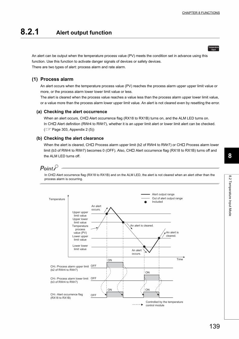
CHAPTER 8 FUNCTIONS
8
8.2
Te
mp
era
ture
Inp
ut M
od
e
8.2.1 Alert output function
An alert can be output when the temperature process value (PV) meets the condition set in advance using this
function. Use this function to activate danger signals of devices or safety devices.
There are two types of alert: process alarm and rate alarm.
(1) Process alarmAn alert occurs when the temperature process value (PV) reaches the process alarm upper upper limit value or
more, or the process alarm lower lower limit value or less.
The alert is cleared when the process value reaches a value less than the process alarm upper lower limit value,
or a value more than the process alarm lower upper limit value. An alert is not cleared even by resetting the error.
(a) Checking the alert occurrence
When an alert occurs, CH Alert occurrence flag (RX18 to RX1B) turns on, and the ALM LED turns on.
In CH Alert definition (RWr4 to RWr7), whether it is an upper limit alert or lower limit alert can be checked.
(Page 303, Appendix 2 (5))
(b) Checking the alert clearance
When the alert is cleared, CH Process alarm upper limit (b2 of RWr4 to RWr7) or CH Process alarm lower
limit (b3 of RWr4 to RWr7) becomes 0 (OFF). Also, CH Alert occurrence flag (RX18 to RX1B) turns off and
the ALM LED turns off.
In CH Alert occurrence flag (RX18 to RX1B) and on the ALM LED, the alert is not cleared when an alert other than the process alarm is occurring.
TemperatureInput
Alert output rangeOut of alert output rangeIncluded
Time
An alert is cleared.
An alert occurs.
Temperature
Upper upperlimit value
Upper lowerlimit value
Temperatureprocess
value (PV)Lower upper
limit value
Lower lowerlimit value
OFF
ON
ON ON
ON
OFF
OFF
An alert occurs.
An alert is cleared.
CH□ Process alarm upper limit (b2 of RWr4 to RWr7)
CH□ Process alarm lower limit (b3 of RWr4 to RWr7)
CH□ Alert occurrence flag (RX18 to RX1B)
Controlled by the temperature control module
139
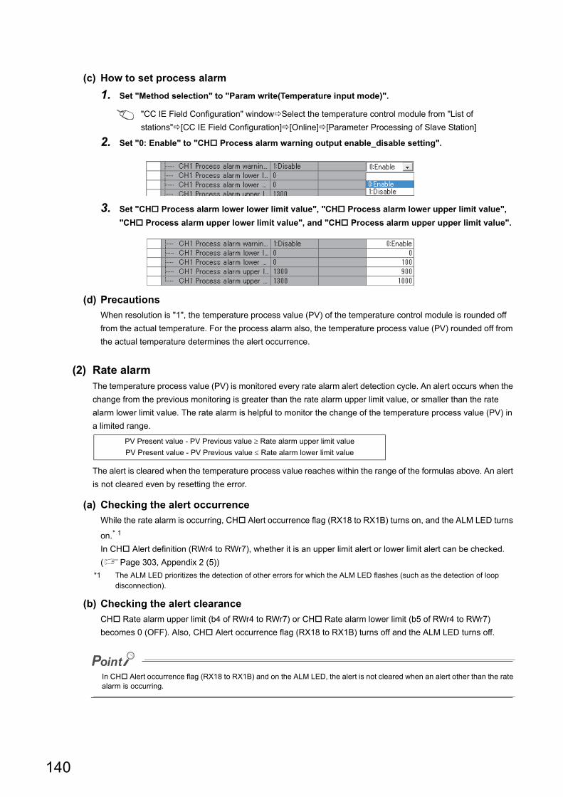
(c) How to set process alarm
1. Set "Method selection" to "Param write(Temperature input mode)".
"CC IE Field Configuration" windowSelect the temperature control module from "List of
stations"[CC IE Field Configuration][Online][Parameter Processing of Slave Station]
2. Set "0: Enable" to "CH Process alarm warning output enable_disable setting".
3. Set "CH Process alarm lower lower limit value", "CH Process alarm lower upper limit value",
"CH Process alarm upper lower limit value", and "CH Process alarm upper upper limit value".
(d) Precautions
When resolution is "1", the temperature process value (PV) of the temperature control module is rounded off
from the actual temperature. For the process alarm also, the temperature process value (PV) rounded off from
the actual temperature determines the alert occurrence.
(2) Rate alarmThe temperature process value (PV) is monitored every rate alarm alert detection cycle. An alert occurs when the
change from the previous monitoring is greater than the rate alarm upper limit value, or smaller than the rate
alarm lower limit value. The rate alarm is helpful to monitor the change of the temperature process value (PV) in
a limited range.
The alert is cleared when the temperature process value reaches within the range of the formulas above. An alert
is not cleared even by resetting the error.
(a) Checking the alert occurrence
While the rate alarm is occurring, CH Alert occurrence flag (RX18 to RX1B) turns on, and the ALM LED turns
on.* 1
In CH Alert definition (RWr4 to RWr7), whether it is an upper limit alert or lower limit alert can be checked.
(Page 303, Appendix 2 (5))
*1 The ALM LED prioritizes the detection of other errors for which the ALM LED flashes (such as the detection of loop disconnection).
(b) Checking the alert clearance
CH Rate alarm upper limit (b4 of RWr4 to RWr7) or CH Rate alarm lower limit (b5 of RWr4 to RWr7)
becomes 0 (OFF). Also, CH Alert occurrence flag (RX18 to RX1B) turns off and the ALM LED turns off.
In CH Alert occurrence flag (RX18 to RX1B) and on the ALM LED, the alert is not cleared when an alert other than the rate alarm is occurring.
PV Present value - PV Previous value Rate alarm upper limit value
PV Present value - PV Previous value Rate alarm lower limit value
140
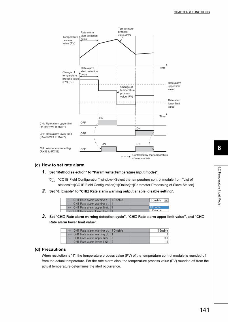
CHAPTER 8 FUNCTIONS
8
8.2
Te
mp
era
ture
Inp
ut M
od
e
(c) How to set rate alarm
1. Set "Method selection" to "Param write(Temperature input mode)".
"CC IE Field Configuration" windowSelect the temperature control module from "List of
stations"[CC IE Field Configuration][Online][Parameter Processing of Slave Station]
2. Set "0: Enable" to "CH Rate alarm warning output enable_disable setting".
3. Set "CH Rate alarm warning detection cycle", "CH Rate alarm upper limit value", and "CH
Rate alarm lower limit value".
(d) Precautions
When resolution is "1", the temperature process value (PV) of the temperature control module is rounded off
from the actual temperature. For the rate alarm also, the temperature process value (PV) rounded off from the
actual temperature determines the alert occurrence.
Temperatureprocessvalue (PV)
Time
Time
Rate alarm upper limit value
Rate alarm lower limit value
Change of temperature process value (PV)
Change of temperature process value (PV) (°C)
OFF
ON
ON
ON ON
OFF
OFF
Temperatureprocessvalue (PV)
Rate alarm alert detection cycle
Rate alarm alert detection cycle
CH□ Rate alarm upper limit (b4 of RWr4 to RWr7)
CH□ Rate alarm lower limit (b5 of RWr4 to RWr7)
CH□ Alert occurrence flag (RX18 to RX1B)
Controlled by the temperature control module
141
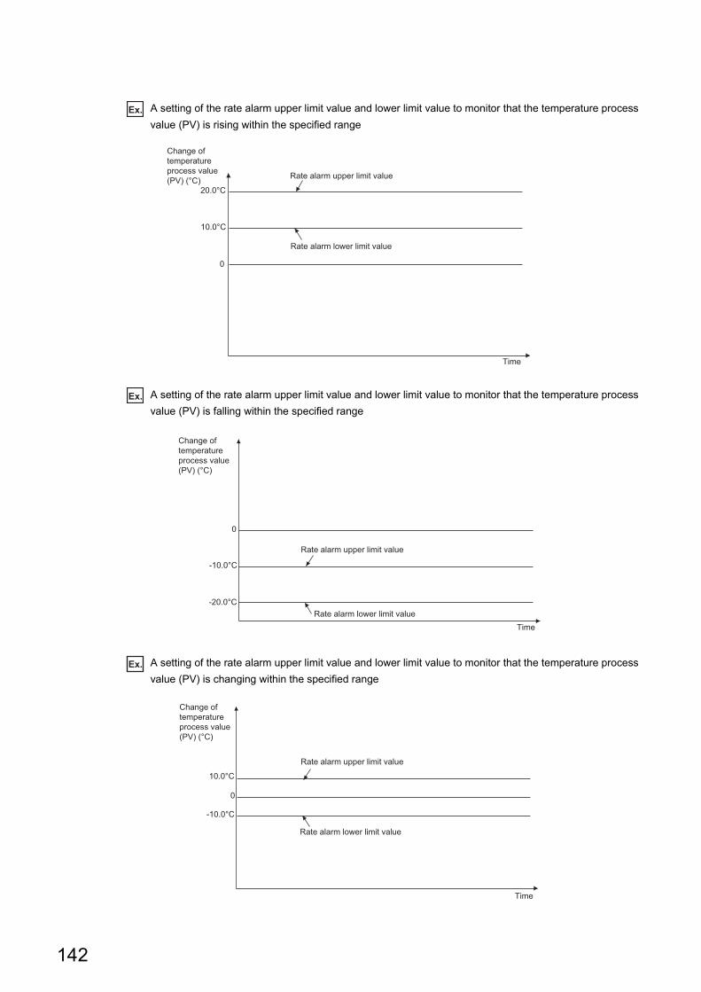
Ex. A setting of the rate alarm upper limit value and lower limit value to monitor that the temperature process
value (PV) is rising within the specified range
Ex. A setting of the rate alarm upper limit value and lower limit value to monitor that the temperature process
value (PV) is falling within the specified range
Ex. A setting of the rate alarm upper limit value and lower limit value to monitor that the temperature process
value (PV) is changing within the specified range
Rate alarm upper limit value
Rate alarm lower limit value
0
Time
Change oftemperatureprocess value(PV) (°C)
20.0°C
10.0°C
Change oftemperatureprocess value(PV) (°C)
Rate alarm upper limit value
Rate alarm lower limit valueTime
0
-10.0°C
-20.0°C
Change oftemperatureprocess value(PV) (°C)
0
-10.0°C
10.0°C
Rate alarm upper limit value
Rate alarm lower limit value
Time
142
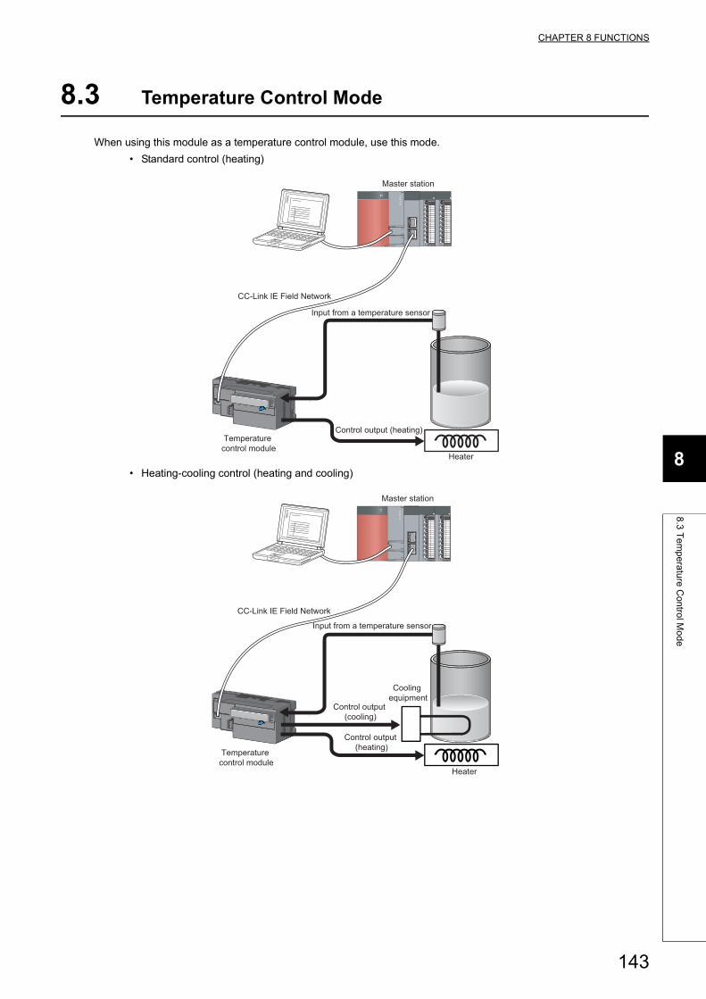
CHAPTER 8 FUNCTIONS
8
8.3
Te
mp
era
ture
Co
ntro
l Mo
de
8.3 Temperature Control Mode
When using this module as a temperature control module, use this mode.
• Standard control (heating)
• Heating-cooling control (heating and cooling)
Input from a temperature sensor
Control output (heating)
Heater
Master station
CC-Link IE Field Network
Temperature control module
Input from a temperature sensor
Control output (heating)
Control output (cooling)
Heater
Cooling equipment
CC-Link IE Field Network
Master station
Temperature control module
143

(1) Setting method
1. Set "Method selection" to "Param write (Station parameter)".
"CC IE Field Configuration" windowSelect the temperature control module from "List of
stations"[CC IE Field Configuration][Online][Parameter Processing of Slave Station]
2. Set any one of "0: Standard control", "1: Heating/Cooling control (Normal mode)", "2:
Heating/Cooling control (Expanded mode)", "3: Mix Control (Normal mode)", and "4: Mix Control
(Expanded mode)" to "Control mode switching".
144
CHAPTER 8 FUNCTIONS
8
8.3
Te
mp
era
ture
Co
ntro
l Mo
de
8.3.1 Control mode selection function
A control mode can be selected using this function.
This section explains selectable control modes of the temperature control module.
(1) Standard control and heating-cooling controlThere are two types of control modes in the temperature control module: standard control and heating-cooling
control.
(a) Standard control
The control method is either one of heating (reverse action) or cooling (forward action). When the control
method is heating, of a heater for example, cooling is controlled by simply turning off the heating. When the
control method is cooling, of cold water for example, heating is controlled by simply turning off the cooling.
(b) Heating-cooling control
The control method is both heating and cooling. To heat up the target subject, its heating mean is turned on,
and its cooling mean is turned off. To cool down the target subject, its heating mean is turned off, and its cooling
mean is turned on.
Standard Heating-cooling
145
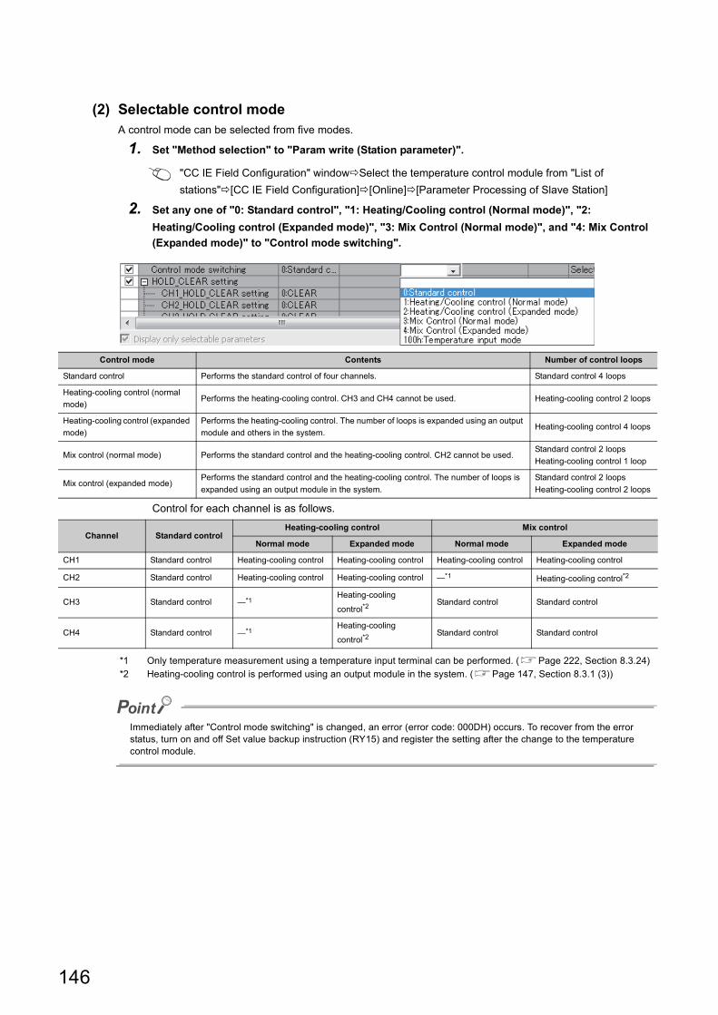
(2) Selectable control modeA control mode can be selected from five modes.
1. Set "Method selection" to "Param write (Station parameter)".
"CC IE Field Configuration" windowSelect the temperature control module from "List of
stations"[CC IE Field Configuration][Online][Parameter Processing of Slave Station]
2. Set any one of "0: Standard control", "1: Heating/Cooling control (Normal mode)", "2:
Heating/Cooling control (Expanded mode)", "3: Mix Control (Normal mode)", and "4: Mix Control
(Expanded mode)" to "Control mode switching".
Control for each channel is as follows.
*1 Only temperature measurement using a temperature input terminal can be performed. (Page 222, Section 8.3.24)*2 Heating-cooling control is performed using an output module in the system. (Page 147, Section 8.3.1 (3))
Immediately after "Control mode switching" is changed, an error (error code: 000DH) occurs. To recover from the error status, turn on and off Set value backup instruction (RY15) and register the setting after the change to the temperature control module.
Control mode Contents Number of control loops
Standard control Performs the standard control of four channels. Standard control 4 loops
Heating-cooling control (normal
mode)Performs the heating-cooling control. CH3 and CH4 cannot be used. Heating-cooling control 2 loops
Heating-cooling control (expanded
mode)
Performs the heating-cooling control. The number of loops is expanded using an output
module and others in the system.Heating-cooling control 4 loops
Mix control (normal mode) Performs the standard control and the heating-cooling control. CH2 cannot be used.Standard control 2 loops
Heating-cooling control 1 loop
Mix control (expanded mode)Performs the standard control and the heating-cooling control. The number of loops is
expanded using an output module in the system.
Standard control 2 loops
Heating-cooling control 2 loops
Channel Standard controlHeating-cooling control Mix control
Normal mode Expanded mode Normal mode Expanded mode
CH1 Standard control Heating-cooling control Heating-cooling control Heating-cooling control Heating-cooling control
CH2 Standard control Heating-cooling control Heating-cooling control *1 Heating-cooling control*2
CH3 Standard control *1Heating-cooling
control*2Standard control Standard control
CH4 Standard control *1Heating-cooling
control*2Standard control Standard control
146
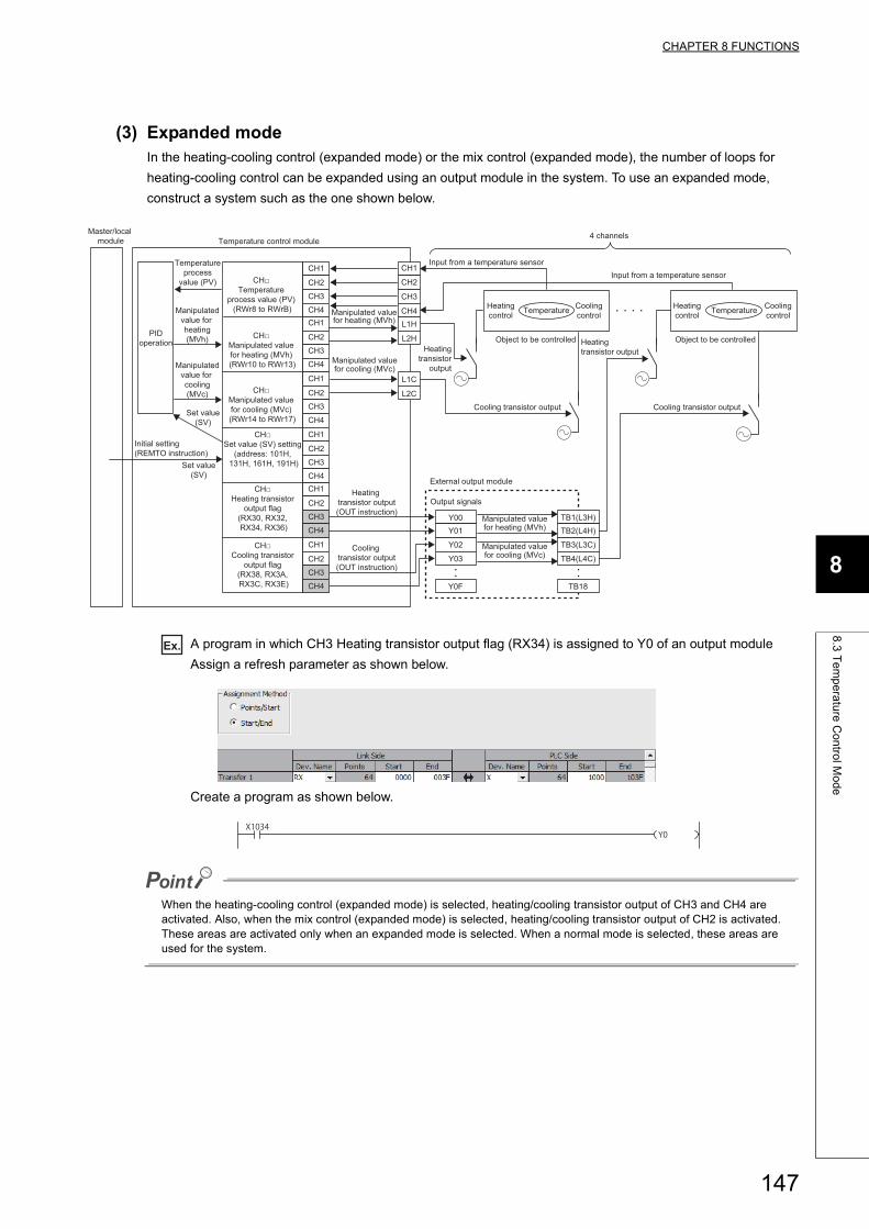
CHAPTER 8 FUNCTIONS
8
8.3
Te
mp
era
ture
Co
ntro
l Mo
de
(3) Expanded modeIn the heating-cooling control (expanded mode) or the mix control (expanded mode), the number of loops for
heating-cooling control can be expanded using an output module in the system. To use an expanded mode,
construct a system such as the one shown below.
Ex. A program in which CH3 Heating transistor output flag (RX34) is assigned to Y0 of an output module
Assign a refresh parameter as shown below.
Create a program as shown below.
When the heating-cooling control (expanded mode) is selected, heating/cooling transistor output of CH3 and CH4 are activated. Also, when the mix control (expanded mode) is selected, heating/cooling transistor output of CH2 is activated. These areas are activated only when an expanded mode is selected. When a normal mode is selected, these areas are used for the system.
Temperatureprocess
value (PV)
Manipulatedvalue for heating(MVh)
Output signals
Object to be controlled
Set value(SV)
Set value(SV)
Temperature
Object to be controlled
Manipulatedvalue for cooling(MVc)
Manipulated valuefor cooling (MVc)
Manipulated valuefor heating (MVh)
Manipulated valuefor cooling (MVc)
Manipulated valuefor heating (MVh)
PIDoperation
Input from a temperature sensorCH1
CH2
CH3
CH4L1H
L2H
Heatingcontrol
Coolingcontrol TemperatureHeating
controlCoolingcontrol
Cooling transistor output
Heating transistor output
Cooling transistor output
CH1
CH2
CH3
CH4CH1
CH2
CH3
CH4
CH1
CH2
CH3
CH4
CH1
CH2
CH3
CH4CH1
CH2
CH3
CH4
CH1
CH2
CH3
CH4
Heating transistor output(OUT instruction)
Cooling transistor output(OUT instruction)
L1C
L2C
Y00Y01
Y02
Y03
Y0F TB18
TB1(L3H)TB2(L4H)
TB3(L3C)
TB4(L4C)
Heatingtransistor
output
Input from a temperature sensor
4 channels
Initial setting (REMTO instruction)
CH□ Manipulated value for cooling (MVc) (RWr14 to RWr17)
CH□ Manipulated value for heating (MVh) (RWr10 to RWr13)
CH□ Set value (SV) setting
(address: 101H, 131H, 161H, 191H)
CH□ Temperature
process value (PV) (RWr8 to RWrB)
CH□ Heating transistor
output flag (RX30, RX32, RX34, RX36)
CH□ Cooling transistor
output flag (RX38, RX3A, RX3C, RX3E)
Master/local module Temperature control module
External output module
147
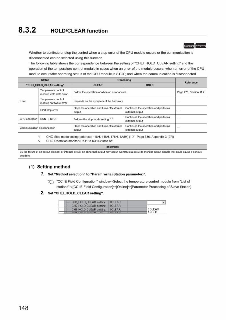
8.3.2 HOLD/CLEAR function
Whether to continue or stop the control when a stop error of the CPU module occurs or the communication is
disconnected can be selected using this function.
The following table shows the correspondence between the setting of "CH_HOLD_CLEAR setting" and the
operation of the temperature control module in cases when an error of the module occurs, when an error of the CPU
module occurs/the operating status of the CPU module is STOP, and when the communication is disconnected.
*1 CH Stop mode setting (address: 118H, 148H, 178H, 1A8H) ( Page 336, Appendix 3 (27))*2 CH Operation monitor (RX11 to RX14) turns off.
(1) Setting method
1. Set "Method selection" to "Param write (Station parameter)".
"CC IE Field Configuration" windowSelect the temperature control module from "List of
stations"[CC IE Field Configuration][Online][Parameter Processing of Slave Station]
2. Set "CH_HOLD_CLEAR setting".
Status ProcessingReference
"CH_HOLD_CLEAR setting" CLEAR HOLD
Error
Temperature control
module write data errorFollow the operation of when an error occurs Page 271, Section 11.2
Temperature control
module hardware errorDepends on the symptom of the hardware
CPU stop errorStops the operation and turns off external
output
Continues the operation and performs
external output
CPU operation RUN STOP Follows the stop mode setting*1*2Continues the operation and performs
external output
Communication disconnectionStops the operation and turns off external
output
Continues the operation and performs
external output
Important
By the failure of an output element or internal circuit, an abnormal output may occur. Construct a circuit to monitor output signals that could cause a serious
accident.
Standard Heating-cooling
148
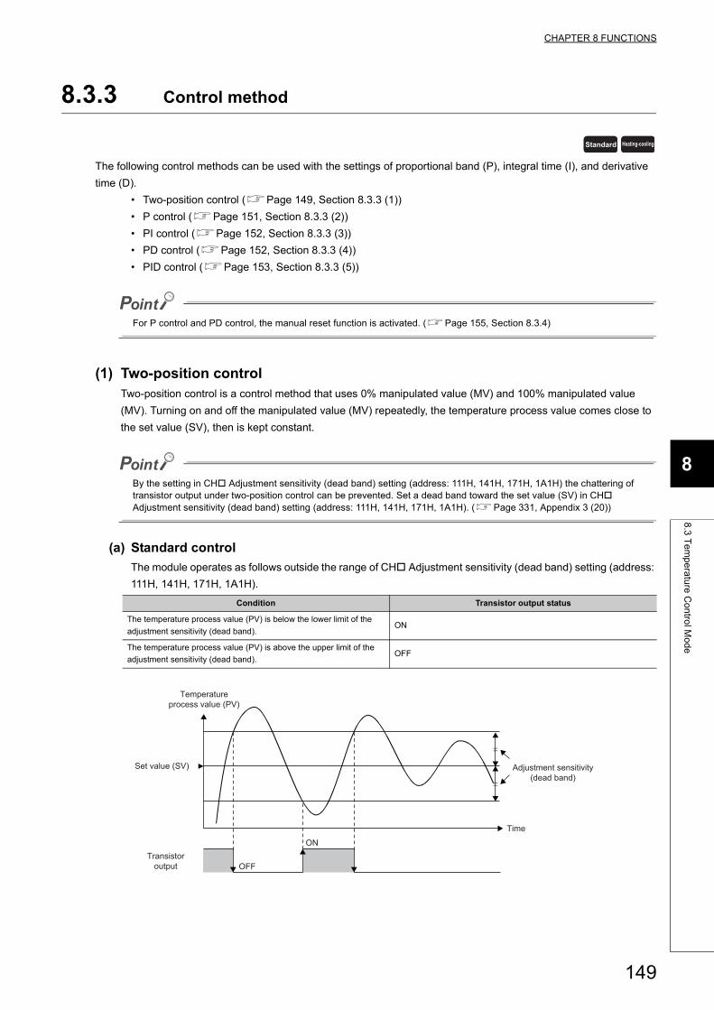
CHAPTER 8 FUNCTIONS
8
8.3
Te
mp
era
ture
Co
ntro
l Mo
de
8.3.3 Control method
The following control methods can be used with the settings of proportional band (P), integral time (I), and derivative
time (D).
• Two-position control (Page 149, Section 8.3.3 (1))
• P control (Page 151, Section 8.3.3 (2))
• PI control (Page 152, Section 8.3.3 (3))
• PD control (Page 152, Section 8.3.3 (4))
• PID control (Page 153, Section 8.3.3 (5))
For P control and PD control, the manual reset function is activated. (Page 155, Section 8.3.4)
(1) Two-position controlTwo-position control is a control method that uses 0% manipulated value (MV) and 100% manipulated value
(MV). Turning on and off the manipulated value (MV) repeatedly, the temperature process value comes close to
the set value (SV), then is kept constant.
By the setting in CH Adjustment sensitivity (dead band) setting (address: 111H, 141H, 171H, 1A1H) the chattering of transistor output under two-position control can be prevented. Set a dead band toward the set value (SV) in CH Adjustment sensitivity (dead band) setting (address: 111H, 141H, 171H, 1A1H). (Page 331, Appendix 3 (20))
(a) Standard control
The module operates as follows outside the range of CH Adjustment sensitivity (dead band) setting (address:
111H, 141H, 171H, 1A1H).
Condition Transistor output status
The temperature process value (PV) is below the lower limit of the
adjustment sensitivity (dead band).ON
The temperature process value (PV) is above the upper limit of the
adjustment sensitivity (dead band).OFF
Standard Heating-cooling
Temperatureprocess value (PV)
Time
Adjustment sensitivity(dead band)
Transistoroutput
Set value (SV)
OFF
ON
149
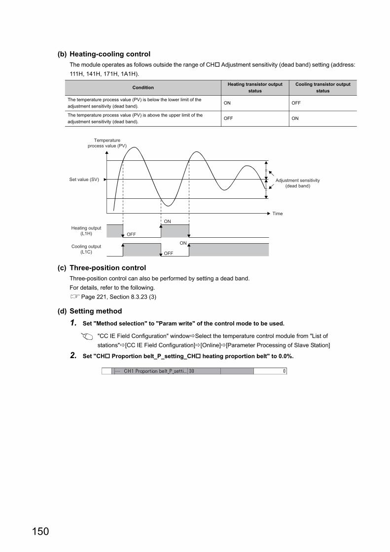
(b) Heating-cooling control
The module operates as follows outside the range of CH Adjustment sensitivity (dead band) setting (address:
111H, 141H, 171H, 1A1H).
(c) Three-position control
Three-position control can also be performed by setting a dead band.
For details, refer to the following.
Page 221, Section 8.3.23 (3)
(d) Setting method
1. Set "Method selection" to "Param write" of the control mode to be used.
"CC IE Field Configuration" windowSelect the temperature control module from "List of
stations"[CC IE Field Configuration][Online][Parameter Processing of Slave Station]
2. Set "CH Proportion belt_P_setting_CH heating proportion belt" to 0.0%.
ConditionHeating transistor output
status
Cooling transistor output
status
The temperature process value (PV) is below the lower limit of the
adjustment sensitivity (dead band).ON OFF
The temperature process value (PV) is above the upper limit of the
adjustment sensitivity (dead band).OFF ON
Temperatureprocess value (PV)
Time
Adjustment sensitivity(dead band)
Heating output(L1H)
Cooling output(L1C)
Set value (SV)
OFF
ON
ON
OFF
150
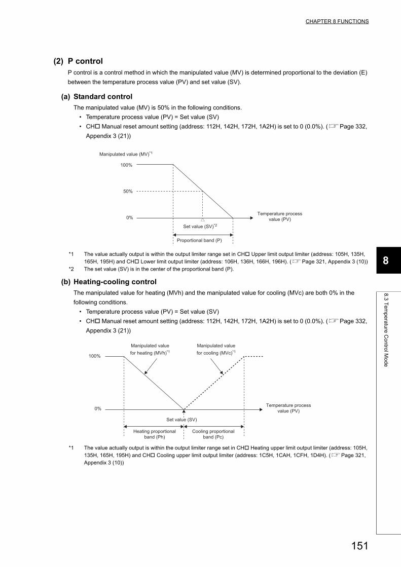
CHAPTER 8 FUNCTIONS
8
8.3
Te
mp
era
ture
Co
ntro
l Mo
de
(2) P controlP control is a control method in which the manipulated value (MV) is determined proportional to the deviation (E)
between the temperature process value (PV) and set value (SV).
(a) Standard control
The manipulated value (MV) is 50% in the following conditions.
• Temperature process value (PV) = Set value (SV)
• CH Manual reset amount setting (address: 112H, 142H, 172H, 1A2H) is set to 0 (0.0%). (Page 332,
Appendix 3 (21))
*1 The value actually output is within the output limiter range set in CH Upper limit output limiter (address: 105H, 135H, 165H, 195H) and CH Lower limit output limiter (address: 106H, 136H, 166H, 196H). (Page 321, Appendix 3 (10))
*2 The set value (SV) is in the center of the proportional band (P).
(b) Heating-cooling control
The manipulated value for heating (MVh) and the manipulated value for cooling (MVc) are both 0% in the
following conditions.
• Temperature process value (PV) = Set value (SV)
• CH Manual reset amount setting (address: 112H, 142H, 172H, 1A2H) is set to 0 (0.0%). (Page 332,
Appendix 3 (21))
*1 The value actually output is within the output limiter range set in CH Heating upper limit output limiter (address: 105H, 135H, 165H, 195H) and CH Cooling upper limit output limiter (address: 1C5H, 1CAH, 1CFH, 1D4H). (Page 321, Appendix 3 (10))
Manipulated value (MV)*1
100%
0%
50%
Set value (SV)*2
Proportional band (P)
Temperature processvalue (PV)
100%
0%
Set value (SV)
Heating proportionalband (Ph)
Temperature processvalue (PV)
Cooling proportionalband (Pc)
Manipulated valuefor heating (MVh)*1
Manipulated valuefor cooling (MVc)*1
151
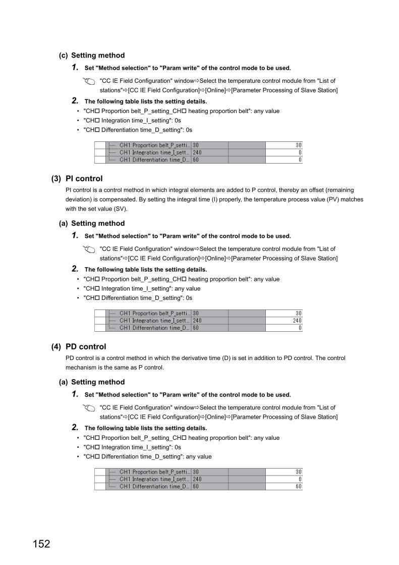
(c) Setting method
1. Set "Method selection" to "Param write" of the control mode to be used.
"CC IE Field Configuration" windowSelect the temperature control module from "List of
stations"[CC IE Field Configuration][Online][Parameter Processing of Slave Station]
2. The following table lists the setting details.
• "CH Proportion belt_P_setting_CH heating proportion belt": any value
• "CH Integration time_I_setting": 0s
• "CH Differentiation time_D_setting": 0s
(3) PI controlPI control is a control method in which integral elements are added to P control, thereby an offset (remaining
deviation) is compensated. By setting the integral time (I) properly, the temperature process value (PV) matches
with the set value (SV).
(a) Setting method
1. Set "Method selection" to "Param write" of the control mode to be used.
"CC IE Field Configuration" windowSelect the temperature control module from "List of
stations"[CC IE Field Configuration][Online][Parameter Processing of Slave Station]
2. The following table lists the setting details.
• "CH Proportion belt_P_setting_CH heating proportion belt": any value
• "CH Integration time_I_setting": any value
• "CH Differentiation time_D_setting": 0s
(4) PD controlPD control is a control method in which the derivative time (D) is set in addition to PD control. The control
mechanism is the same as P control.
(a) Setting method
1. Set "Method selection" to "Param write" of the control mode to be used.
"CC IE Field Configuration" windowSelect the temperature control module from "List of
stations"[CC IE Field Configuration][Online][Parameter Processing of Slave Station]
2. The following table lists the setting details.
• "CH Proportion belt_P_setting_CH heating proportion belt": any value
• "CH Integration time_I_setting": 0s
• "CH Differentiation time_D_setting": any value
152
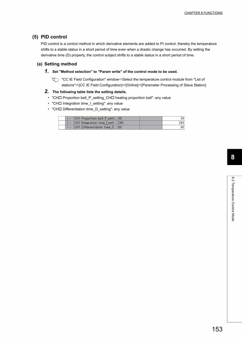
CHAPTER 8 FUNCTIONS
8
8.3
Te
mp
era
ture
Co
ntro
l Mo
de
(5) PID controlPID control is a control method in which derivative elements are added to PI control, thereby the temperature
shifts to a stable status in a short period of time even when a drastic change has occurred. By setting the
derivative time (D) properly, the control subject shifts to a stable status in a short period of time.
(a) Setting method
1. Set "Method selection" to "Param write" of the control mode to be used.
"CC IE Field Configuration" windowSelect the temperature control module from "List of
stations"[CC IE Field Configuration][Online][Parameter Processing of Slave Station]
2. The following table lists the setting details.
• "CH Proportion belt_P_setting_CH heating proportion belt": any value
• "CH Integration time_I_setting": any value
• "CH Differentiation time_D_setting": any value
153
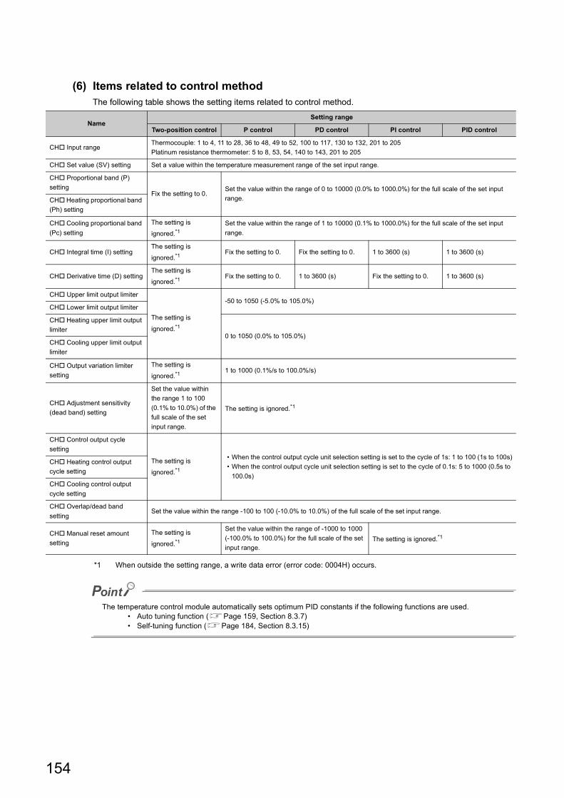
(6) Items related to control methodThe following table shows the setting items related to control method.
*1 When outside the setting range, a write data error (error code: 0004H) occurs.
The temperature control module automatically sets optimum PID constants if the following functions are used.• Auto tuning function (Page 159, Section 8.3.7)• Self-tuning function (Page 184, Section 8.3.15)
NameSetting range
Two-position control P control PD control PI control PID control
CH Input rangeThermocouple: 1 to 4, 11 to 28, 36 to 48, 49 to 52, 100 to 117, 130 to 132, 201 to 205
Platinum resistance thermometer: 5 to 8, 53, 54, 140 to 143, 201 to 205
CH Set value (SV) setting Set a value within the temperature measurement range of the set input range.
CH Proportional band (P)
settingFix the setting to 0.
Set the value within the range of 0 to 10000 (0.0% to 1000.0%) for the full scale of the set input
range.CH Heating proportional band
(Ph) setting
CH Cooling proportional band
(Pc) setting
The setting is
ignored.*1Set the value within the range of 1 to 10000 (0.1% to 1000.0%) for the full scale of the set input
range.
CH Integral time (I) settingThe setting is
ignored.*1Fix the setting to 0. Fix the setting to 0. 1 to 3600 (s) 1 to 3600 (s)
CH Derivative time (D) settingThe setting is
ignored.*1Fix the setting to 0. 1 to 3600 (s) Fix the setting to 0. 1 to 3600 (s)
CH Upper limit output limiter
The setting is
ignored.*1
-50 to 1050 (-5.0% to 105.0%)CH Lower limit output limiter
CH Heating upper limit output
limiter0 to 1050 (0.0% to 105.0%)
CH Cooling upper limit output
limiter
CH Output variation limiter
setting
The setting is
ignored.*11 to 1000 (0.1%/s to 100.0%/s)
CH Adjustment sensitivity
(dead band) setting
Set the value within
the range 1 to 100
(0.1% to 10.0%) of the
full scale of the set
input range.
The setting is ignored.*1
CH Control output cycle
setting
The setting is
ignored.*1
• When the control output cycle unit selection setting is set to the cycle of 1s: 1 to 100 (1s to 100s)
• When the control output cycle unit selection setting is set to the cycle of 0.1s: 5 to 1000 (0.5s to
100.0s)
CH Heating control output
cycle setting
CH Cooling control output
cycle setting
CH Overlap/dead band
settingSet the value within the range -100 to 100 (-10.0% to 10.0%) of the full scale of the set input range.
CH Manual reset amount
setting
The setting is
ignored.*1
Set the value within the range of -1000 to 1000
(-100.0% to 100.0%) for the full scale of the set
input range.The setting is ignored.*1
154
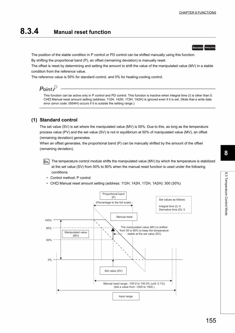
CHAPTER 8 FUNCTIONS
8
8.3
Te
mp
era
ture
Co
ntro
l Mo
de
8.3.4 Manual reset function
The position of the stable condition in P control or PD control can be shifted manually using this function.
By shifting the proportional band (P), an offset (remaining deviation) is manually reset.
The offset is reset by determining and setting the amount to shift the value of the manipulated value (MV) in a stable
condition from the reference value.
The reference value is 50% for standard control, and 0% for heating-cooling control.
This function can be active only in P control and PD control. This function is inactive when integral time (I) is other than 0. CH Manual reset amount setting (address: 112H, 142H, 172H, 1A2H) is ignored even if it is set. (Note that a write data error (error code: 0004H) occurs if it is outside the setting range.)
(1) Standard controlThe set value (SV) is set where the manipulated value (MV) is 50%. Due to this, as long as the temperature
process value (PV) and the set value (SV) is not in equilibrium at 50% of manipulated value (MV), an offset
(remaining deviation) generates.
When an offset generates, the proportional band (P) can be manually shifted by the amount of the offset
(remaining deviation).
Ex. The temperature control module shifts the manipulated value (MV) by which the temperature is stabilized
at the set value (SV) from 50% to 80% when the manual reset function is used under the following
conditions.
• Control method: P control
• CH Manual reset amount setting (address: 112H, 142H, 172H, 1A2H): 300 (30%)
Standard Heating-cooling
Set value (SV)
100%
0%
50%
Input range
Set values as follows: Integral time (I): 0Derivative time (D): 0
Manual reset
Manual reset range: -100.0 to 100.0% (unit: 0.1%)(Set a value from -1000 to 1000.)
80%
Proportional band(P)
(Percentage to the full scale)
Manipulated value(MV)
The manipulated value (MV) is shifted from 50 to 80% to keep the temperature
stable at the set value (SV).
155
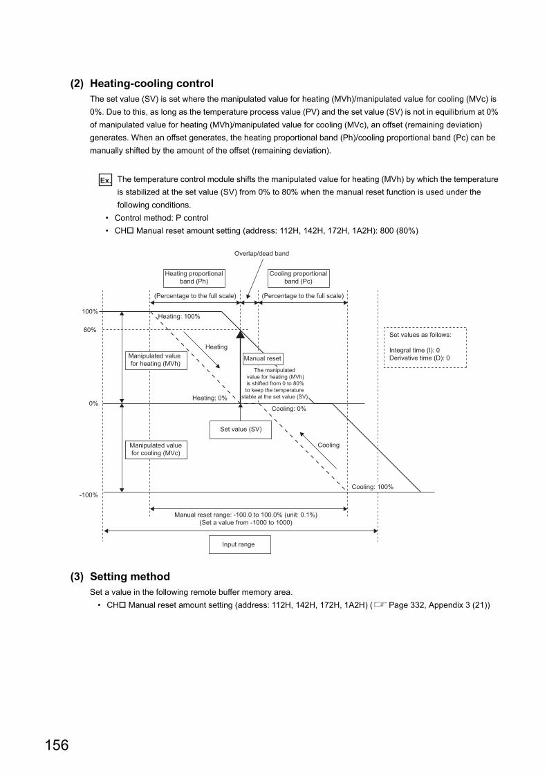
(2) Heating-cooling controlThe set value (SV) is set where the manipulated value for heating (MVh)/manipulated value for cooling (MVc) is
0%. Due to this, as long as the temperature process value (PV) and the set value (SV) is not in equilibrium at 0%
of manipulated value for heating (MVh)/manipulated value for cooling (MVc), an offset (remaining deviation)
generates. When an offset generates, the heating proportional band (Ph)/cooling proportional band (Pc) can be
manually shifted by the amount of the offset (remaining deviation).
Ex. The temperature control module shifts the manipulated value for heating (MVh) by which the temperature
is stabilized at the set value (SV) from 0% to 80% when the manual reset function is used under the
following conditions.
• Control method: P control
• CH Manual reset amount setting (address: 112H, 142H, 172H, 1A2H): 800 (80%)
(3) Setting methodSet a value in the following remote buffer memory area.
• CH Manual reset amount setting (address: 112H, 142H, 172H, 1A2H) (Page 332, Appendix 3 (21))
Manipulated valuefor cooling (MVc)
Heating
Set value (SV)
Cooling
100%
80%
0%
-100%
Manipulated value for heating (MVh)
Input range
Set values as follows: Integral time (I): 0Derivative time (D): 0
Overlap/dead band
Heating proportionalband (Ph)
Cooling proportionalband (Pc)
Manual reset
The manipulated value for heating (MVh)
is shifted from 0 to 80% to keep the temperature
stable at the set value (SV).
Manual reset range: -100.0 to 100.0% (unit: 0.1%)(Set a value from -1000 to 1000)
(Percentage to the full scale) (Percentage to the full scale)
Cooling: 100%
Cooling: 0%
Heating: 0%
Heating: 100%
156
CHAPTER 8 FUNCTIONS
8
8.3
Te
mp
era
ture
Co
ntro
l Mo
de
8.3.5 Manual control
Manual control is a form of control for which the user sets the manipulated value (MV) manually instead of obtaining it
automatically by PID control.
The manipulated value (MV) is checked every 250ms or 500ms*1, and is reflected to transistor output.
*1 This value differs depending on the setting under "Sampling cycle selection". (Page 310, Appendix 3 (1) (e))
(1) Setting methodFollow the following procedure for setting.
1. Shift to the MAN (manual) mode. (Set MAN (1) in CH AUTO/MAN mode shift (address: 113H,
143H, 173H, 1A3H).) (Page 332, Appendix 3 (22))
2. Check that MAN mode shift completed (1) is stored in MAN mode (address: 601H). (Page 360,
Appendix 3 (64))
3. Set the manipulated value (MV) in CH MAN output setting (address: 114H, 144H, 174H, 1A4H)*1.
(Page 333, Appendix 3 (23))*1 The setting range differs for standard control and heating-cooling control. In standard control: -50 to 1050 (-5.0 to
105.0%) In heating-cooling control: -1050 to 1050 (-105.0 to 105.0%)
Standard Heating-cooling
157
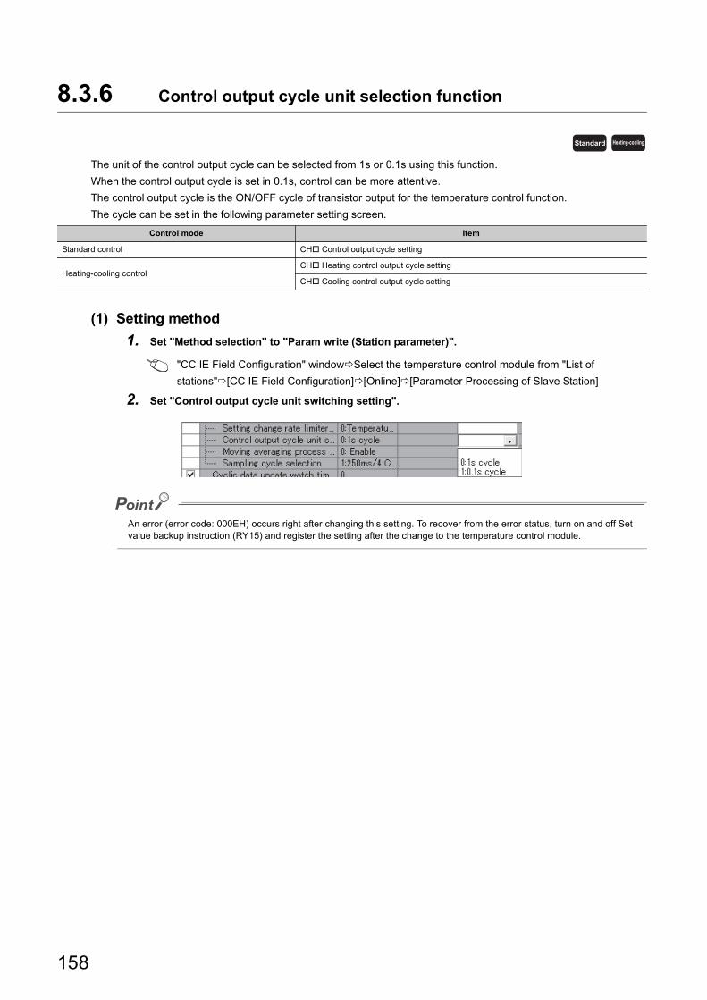
8.3.6 Control output cycle unit selection function
The unit of the control output cycle can be selected from 1s or 0.1s using this function.
When the control output cycle is set in 0.1s, control can be more attentive.
The control output cycle is the ON/OFF cycle of transistor output for the temperature control function.
The cycle can be set in the following parameter setting screen.
(1) Setting method
1. Set "Method selection" to "Param write (Station parameter)".
"CC IE Field Configuration" windowSelect the temperature control module from "List of
stations"[CC IE Field Configuration][Online][Parameter Processing of Slave Station]
2. Set "Control output cycle unit switching setting".
An error (error code: 000EH) occurs right after changing this setting. To recover from the error status, turn on and off Set value backup instruction (RY15) and register the setting after the change to the temperature control module.
Control mode Item
Standard control CH Control output cycle setting
Heating-cooling controlCH Heating control output cycle setting
CH Cooling control output cycle setting
Standard Heating-cooling
158
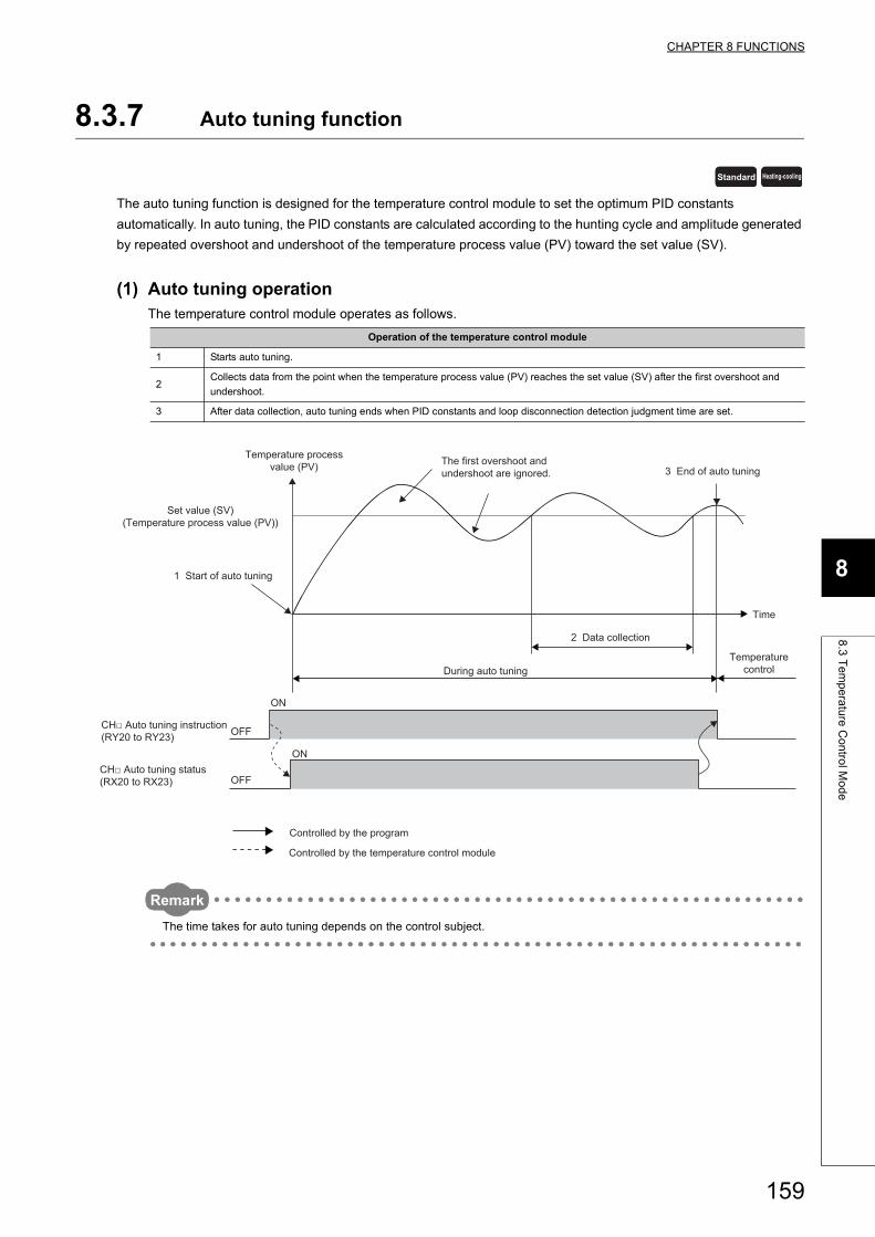
CHAPTER 8 FUNCTIONS
8
8.3
Te
mp
era
ture
Co
ntro
l Mo
de
8.3.7 Auto tuning function
The auto tuning function is designed for the temperature control module to set the optimum PID constants
automatically. In auto tuning, the PID constants are calculated according to the hunting cycle and amplitude generated
by repeated overshoot and undershoot of the temperature process value (PV) toward the set value (SV).
(1) Auto tuning operationThe temperature control module operates as follows.
Remark
The time takes for auto tuning depends on the control subject.
Operation of the temperature control module
1 Starts auto tuning.
2Collects data from the point when the temperature process value (PV) reaches the set value (SV) after the first overshoot and
undershoot.
3 After data collection, auto tuning ends when PID constants and loop disconnection detection judgment time are set.
Standard Heating-cooling
Set value (SV)(Temperature process value (PV))
Time
Temperature processvalue (PV)
1 Start of auto tuning
2 Data collection
During auto tuning
3 End of auto tuning
ON
OFF
ON
OFF
The first overshoot andundershoot are ignored.
Temperaturecontrol
Controlled by the program
CH□ Auto tuning instruction (RY20 to RY23)
CH□ Auto tuning status (RX20 to RX23)
Controlled by the temperature control module
159
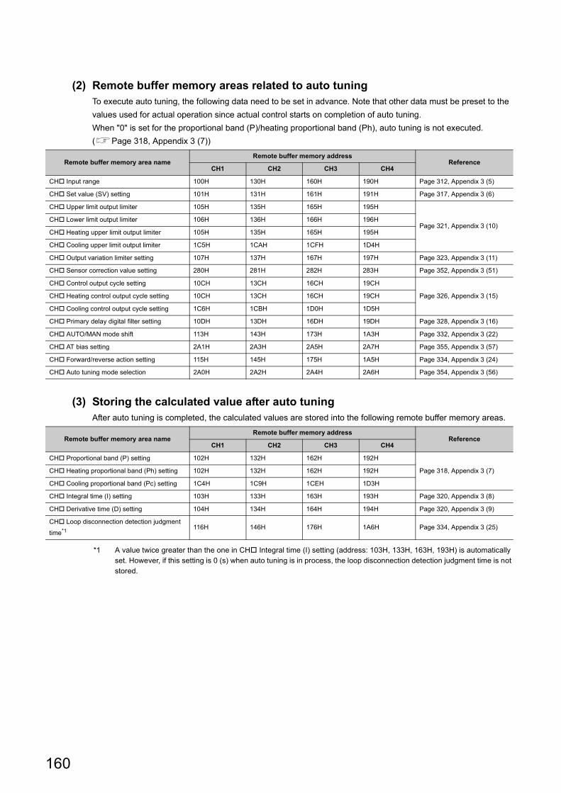
(2) Remote buffer memory areas related to auto tuningTo execute auto tuning, the following data need to be set in advance. Note that other data must be preset to the
values used for actual operation since actual control starts on completion of auto tuning.
When "0" is set for the proportional band (P)/heating proportional band (Ph), auto tuning is not executed.
(Page 318, Appendix 3 (7))
(3) Storing the calculated value after auto tuningAfter auto tuning is completed, the calculated values are stored into the following remote buffer memory areas.
*1 A value twice greater than the one in CH Integral time (I) setting (address: 103H, 133H, 163H, 193H) is automatically set. However, if this setting is 0 (s) when auto tuning is in process, the loop disconnection detection judgment time is not stored.
Remote buffer memory area nameRemote buffer memory address
ReferenceCH1 CH2 CH3 CH4
CH Input range 100H 130H 160H 190H Page 312, Appendix 3 (5)
CH Set value (SV) setting 101H 131H 161H 191H Page 317, Appendix 3 (6)
CH Upper limit output limiter 105H 135H 165H 195H
Page 321, Appendix 3 (10)CH Lower limit output limiter 106H 136H 166H 196H
CH Heating upper limit output limiter 105H 135H 165H 195H
CH Cooling upper limit output limiter 1C5H 1CAH 1CFH 1D4H
CH Output variation limiter setting 107H 137H 167H 197H Page 323, Appendix 3 (11)
CH Sensor correction value setting 280H 281H 282H 283H Page 352, Appendix 3 (51)
CH Control output cycle setting 10CH 13CH 16CH 19CH
Page 326, Appendix 3 (15)CH Heating control output cycle setting 10CH 13CH 16CH 19CH
CH Cooling control output cycle setting 1C6H 1CBH 1D0H 1D5H
CH Primary delay digital filter setting 10DH 13DH 16DH 19DH Page 328, Appendix 3 (16)
CH AUTO/MAN mode shift 113H 143H 173H 1A3H Page 332, Appendix 3 (22)
CH AT bias setting 2A1H 2A3H 2A5H 2A7H Page 355, Appendix 3 (57)
CH Forward/reverse action setting 115H 145H 175H 1A5H Page 334, Appendix 3 (24)
CH Auto tuning mode selection 2A0H 2A2H 2A4H 2A6H Page 354, Appendix 3 (56)
Remote buffer memory area nameRemote buffer memory address
ReferenceCH1 CH2 CH3 CH4
CH Proportional band (P) setting 102H 132H 162H 192H
Page 318, Appendix 3 (7)CH Heating proportional band (Ph) setting 102H 132H 162H 192H
CH Cooling proportional band (Pc) setting 1C4H 1C9H 1CEH 1D3H
CH Integral time (I) setting 103H 133H 163H 193H Page 320, Appendix 3 (8)
CH Derivative time (D) setting 104H 134H 164H 194H Page 320, Appendix 3 (9)
CH Loop disconnection detection judgment
time*1116H 146H 176H 1A6H Page 334, Appendix 3 (25)
160
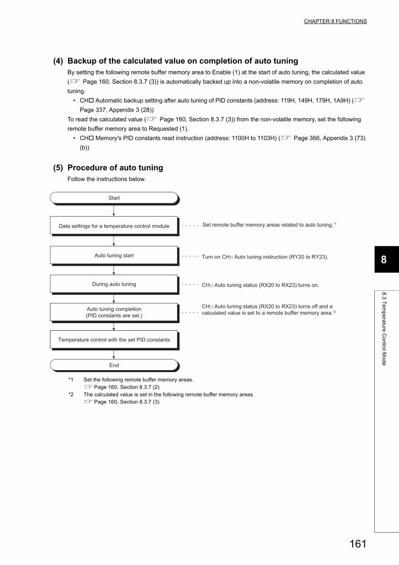
CHAPTER 8 FUNCTIONS
8
8.3
Te
mp
era
ture
Co
ntro
l Mo
de
(4) Backup of the calculated value on completion of auto tuningBy setting the following remote buffer memory area to Enable (1) at the start of auto tuning, the calculated value
( Page 160, Section 8.3.7 (3)) is automatically backed up into a non-volatile memory on completion of auto
tuning.
• CH Automatic backup setting after auto tuning of PID constants (address: 119H, 149H, 179H, 1A9H) (
Page 337, Appendix 3 (28))
To read the calculated value ( Page 160, Section 8.3.7 (3)) from the non-volatile memory, set the following
remote buffer memory area to Requested (1).
• CH Memory's PID constants read instruction (address: 1100H to 1103H) ( Page 366, Appendix 3 (73)
(b))
(5) Procedure of auto tuningFollow the instructions below.
*1 Set the following remote buffer memory areas.Page 160, Section 8.3.7 (2)
*2 The calculated value is set in the following remote buffer memory areas.Page 160, Section 8.3.7 (3)
Start
Auto tuning start
During auto tuning
Auto tuning completion(PID constants are set.)
Temperature control with the set PID constants
End
Data settings for a temperature control module Set remote buffer memory areas related to auto tuning.*1
Turn on CH□ Auto tuning instruction (RY20 to RY23).
CH□ Auto tuning status (RX20 to RX23) turns on.
CH□ Auto tuning status (RX20 to RX23) turns off and a calculated value is set to a remote buffer memory area.*2
161
(6) Conditions where auto tuning cannot be executedIf one of the following conditions applies, auto tuning cannot be executed.
(a) When the condition 1 or 2 applies
Auto tuning starts when the condition no longer applies.
(b) When the condition 3, 4, or 7 applies
Even though the temperature process value (PV) goes back within the temperature measurement range, auto
tuning does not start until CH Auto tuning instruction (RY20 to RY23) is turned on from off once again.
(c) When the condition 5 or 6 applies
Even though the internal processing of auto tuning is completed and PID constants are stored, CH Auto
tuning status (RX20 to RX23) does not turn off, therefore the auto tuning is not completed.
The request for auto tuning is received even when the operation status is stop (CH Operation monitor (RX11 to RX14) is off.). In this case, the operation status is changed to run (CH Operation monitor (RX11 to RX14)) when the auto tuning is completed.For details, refer to the following.Page 299, Appendix 1.2 (8) (a)
(7) Conditions where auto tuning ends in failureThe conditions are described below.
(a) Change of the operation status to stop
When CH Stop request flag (RY18 to RY1B) is turned off and on and CH Operation monitor (RX11 to
RX14) is turned STOP (OFF), the auto tuning ends in failure.
Conditions to start auto tuning Reference
1
In standard control, CH Proportional band (P) setting (address: 102H, 132H, 162H, 192H) is set to 0. (operating
in two-position control)Page 318, Appendix 3 (7)
In heating-cooling control, CH Heating proportional band (Ph) setting (address: 102H, 132H, 162H, 192H) is set
to 0. (operating in two-position control)
2 CH AUTO/MAN mode shift (address: 113H, 143H, 173H, 1A3H) is set to MAN (1). Page 332, Appendix 3 (22)
3 Hardware failure has occurred. (The ERR.LED is on.) Page 281, Section 11.4 (9)
4CH Temperature process value (PV) (RWr8 to RWrB) has exceeded the temperature measurement range. (CH
Input range upper limit (b0 of RWr4 to RWr7) or CH Input range lower limit (b1 of RWr4 to RWr7) is 1 (ON)).Page 303, Appendix 2 (5)
5 CH Memory's PID constants read instruction (address: 1100H to 1103H) is set to Requested (1). Page 365, Appendix 3 (72)
6 CH Write completion flag (address: b4 to b7 of 1104H) is on. Page 366, Appendix 3 (73)
7 CH Stop request flag (RY18 to RY1B) of a channel for auto tuning is on. Page 298, Appendix 1.2 (7)
162
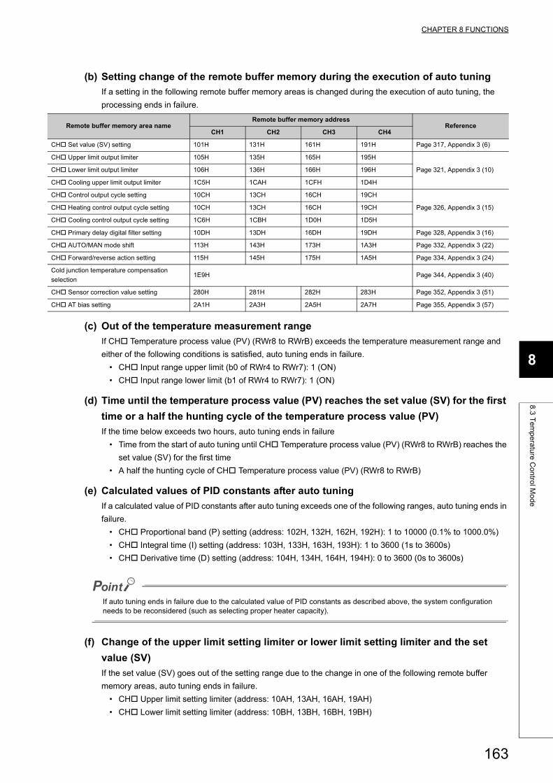
CHAPTER 8 FUNCTIONS
8
8.3
Te
mp
era
ture
Co
ntro
l Mo
de
(b) Setting change of the remote buffer memory during the execution of auto tuning
If a setting in the following remote buffer memory areas is changed during the execution of auto tuning, the
processing ends in failure.
(c) Out of the temperature measurement range
If CH Temperature process value (PV) (RWr8 to RWrB) exceeds the temperature measurement range and
either of the following conditions is satisfied, auto tuning ends in failure.
• CH Input range upper limit (b0 of RWr4 to RWr7): 1 (ON)
• CH Input range lower limit (b1 of RWr4 to RWr7): 1 (ON)
(d) Time until the temperature process value (PV) reaches the set value (SV) for the first
time or a half the hunting cycle of the temperature process value (PV)
If the time below exceeds two hours, auto tuning ends in failure
• Time from the start of auto tuning until CH Temperature process value (PV) (RWr8 to RWrB) reaches the
set value (SV) for the first time
• A half the hunting cycle of CH Temperature process value (PV) (RWr8 to RWrB)
(e) Calculated values of PID constants after auto tuning
If a calculated value of PID constants after auto tuning exceeds one of the following ranges, auto tuning ends in
failure.
• CH Proportional band (P) setting (address: 102H, 132H, 162H, 192H): 1 to 10000 (0.1% to 1000.0%)
• CH Integral time (I) setting (address: 103H, 133H, 163H, 193H): 1 to 3600 (1s to 3600s)
• CH Derivative time (D) setting (address: 104H, 134H, 164H, 194H): 0 to 3600 (0s to 3600s)
If auto tuning ends in failure due to the calculated value of PID constants as described above, the system configuration needs to be reconsidered (such as selecting proper heater capacity).
(f) Change of the upper limit setting limiter or lower limit setting limiter and the set
value (SV)
If the set value (SV) goes out of the setting range due to the change in one of the following remote buffer
memory areas, auto tuning ends in failure.
• CH Upper limit setting limiter (address: 10AH, 13AH, 16AH, 19AH)
• CH Lower limit setting limiter (address: 10BH, 13BH, 16BH, 19BH)
Remote buffer memory area nameRemote buffer memory address
ReferenceCH1 CH2 CH3 CH4
CH Set value (SV) setting 101H 131H 161H 191H Page 317, Appendix 3 (6)
CH Upper limit output limiter 105H 135H 165H 195H
Page 321, Appendix 3 (10)CH Lower limit output limiter 106H 136H 166H 196H
CH Cooling upper limit output limiter 1C5H 1CAH 1CFH 1D4H
CH Control output cycle setting 10CH 13CH 16CH 19CH
Page 326, Appendix 3 (15)CH Heating control output cycle setting 10CH 13CH 16CH 19CH
CH Cooling control output cycle setting 1C6H 1CBH 1D0H 1D5H
CH Primary delay digital filter setting 10DH 13DH 16DH 19DH Page 328, Appendix 3 (16)
CH AUTO/MAN mode shift 113H 143H 173H 1A3H Page 332, Appendix 3 (22)
CH Forward/reverse action setting 115H 145H 175H 1A5H Page 334, Appendix 3 (24)
Cold junction temperature compensation
selection1E9H Page 344, Appendix 3 (40)
CH Sensor correction value setting 280H 281H 282H 283H Page 352, Appendix 3 (51)
CH AT bias setting 2A1H 2A3H 2A5H 2A7H Page 355, Appendix 3 (57)
163

(g) Other conditions
In addition to the conditions described up until here, if any of the following conditions applies, auto tuning ends
in failure.
• Hardware failure has occurred.
• In standard control, CH Proportional band (P) setting (address: 102H, 132H, 162H, 192H) is changed to
0. (has been set to two-position control) (Page 318, Appendix 3 (7))
• In heating-cooling control, CH Heating proportional band (Ph) setting (address: 102H, 132H, 162H,
192H) is changed to 0. (has been set to two-position control or three-position control) (Page 318,
Appendix 3 (7))
(8) Operation on completion of auto tuning
(a) Normal completion
The temperature control module operates as follows.
• Turns off CH Auto tuning status (RX20 to RX23)
• Stores the PID constants in the remote buffer memory (Page 160, Section 8.3.7 (3))
• Stores a value in CH Loop disconnection detection judgment time (address: 116H, 146H, 176H, 1A6H)
(If this was set to 0 (s) at the start of auto tuning, the setting remains unchanged.)
(b) Abnormal completion
The temperature control module operates as follows.
• Turns off CH Auto tuning status (RX20 to RX23)
• Does not store the PID constants in the remote buffer memory. (Page 160, Section 8.3.7 (3))
(9) Checking the completion of auto tuningThe completion of auto tuning can be checked by the status change from on to off in CH Auto tuning status
(RX20 to RX23).
(10)Adjustment after auto tuningTo change the control response toward the PID constants calculated by auto tuning, change the setting in the
following remote buffer memory area.
• CH Control response parameter (address: 10FH, 13FH, 16FH, 19FH) ( Page 329, Appendix 3 (18))
In the system where the temperature rise rapidly, auto tuning may not be performed properly due to the excessive temperature rise during the auto tuning. Therefore, for a sequence program to perform auto tuning, incorporate the alert function so that the auto tuning will be stopped if an alert occurs.For details on the sequence program, refer to the following.Page 232, CHAPTER 9
(11)During auto tuning loop disconnection detection functionFor details on the during AT loop disconnection detection function, refer to the following.
Page 214, Section 8.3.20
164
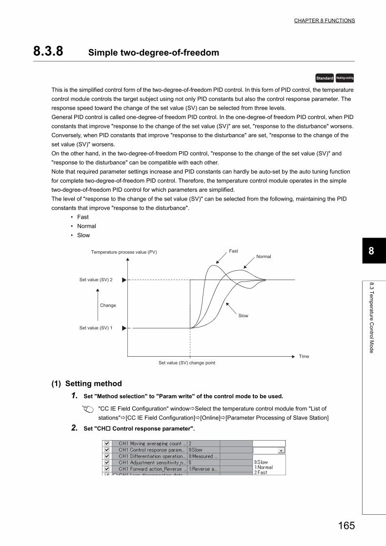
CHAPTER 8 FUNCTIONS
8
8.3
Te
mp
era
ture
Co
ntro
l Mo
de
8.3.8 Simple two-degree-of-freedom
This is the simplified control form of the two-degree-of-freedom PID control. In this form of PID control, the temperature
control module controls the target subject using not only PID constants but also the control response parameter. The
response speed toward the change of the set value (SV) can be selected from three levels.
General PID control is called one-degree-of freedom PID control. In the one-degree-of freedom PID control, when PID
constants that improve "response to the change of the set value (SV)" are set, "response to the disturbance" worsens.
Conversely, when PID constants that improve "response to the disturbance" are set, "response to the change of the
set value (SV)" worsens.
On the other hand, in the two-degree-of-freedom PID control, "response to the change of the set value (SV)" and
"response to the disturbance" can be compatible with each other.
Note that required parameter settings increase and PID constants can hardly be auto-set by the auto tuning function
for complete two-degree-of-freedom PID control. Therefore, the temperature control module operates in the simple
two-degree-of-freedom PID control for which parameters are simplified.
The level of "response to the change of the set value (SV)" can be selected from the following, maintaining the PID
constants that improve "response to the disturbance".
• Fast
• Normal
• Slow
(1) Setting method
1. Set "Method selection" to "Param write" of the control mode to be used.
"CC IE Field Configuration" windowSelect the temperature control module from "List of
stations"[CC IE Field Configuration][Online][Parameter Processing of Slave Station]
2. Set "CH Control response parameter".
Standard Heating-cooling
Time
Temperature process value (PV)
Set value (SV) 2
Set value (SV) 1
Change
Set value (SV) change point
FastNormal
Slow
165
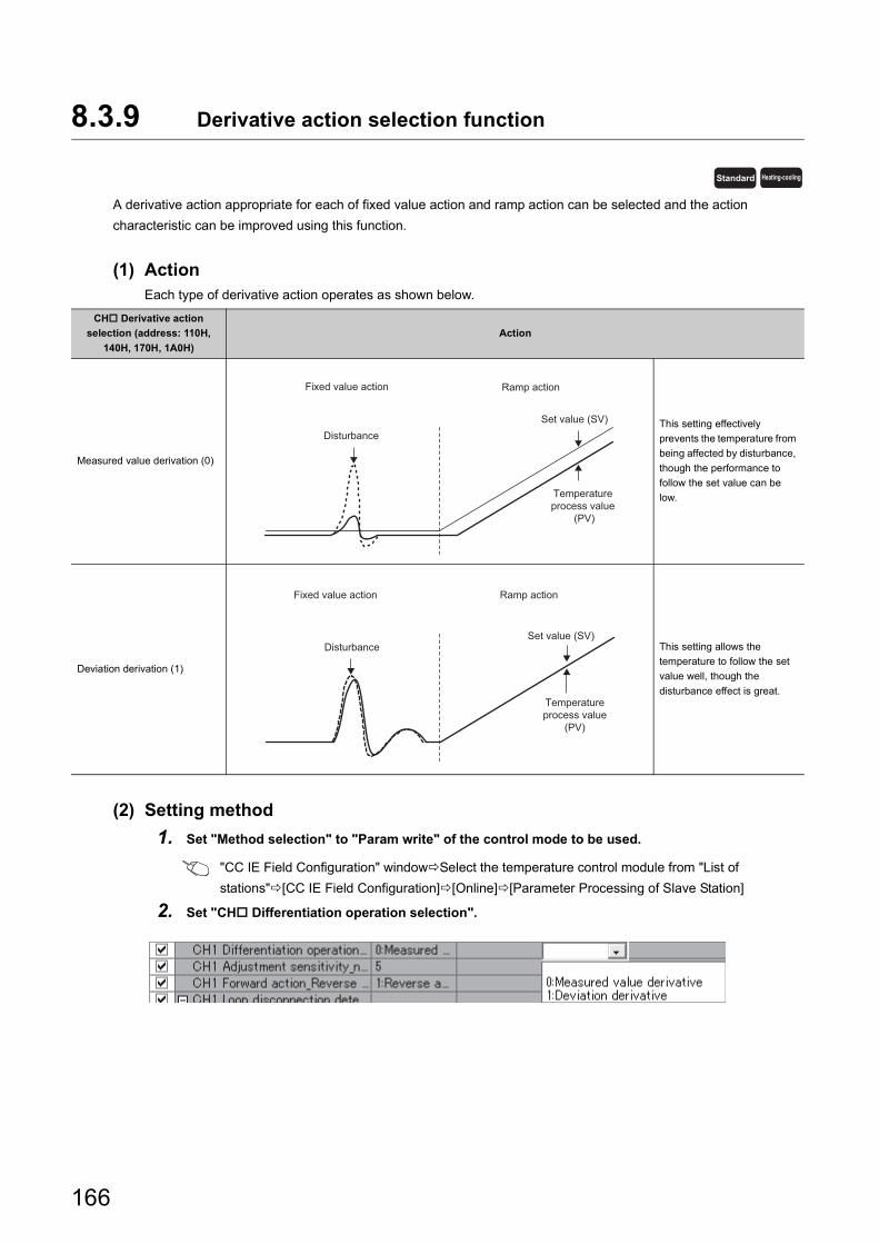
8.3.9 Derivative action selection function
A derivative action appropriate for each of fixed value action and ramp action can be selected and the action
characteristic can be improved using this function.
(1) ActionEach type of derivative action operates as shown below.
(2) Setting method
1. Set "Method selection" to "Param write" of the control mode to be used.
"CC IE Field Configuration" windowSelect the temperature control module from "List of
stations"[CC IE Field Configuration][Online][Parameter Processing of Slave Station]
2. Set "CH Differentiation operation selection".
CH Derivative action
selection (address: 110H,
140H, 170H, 1A0H)
Action
Measured value derivation (0)
This setting effectively
prevents the temperature from
being affected by disturbance,
though the performance to
follow the set value can be
low.
Deviation derivation (1)
This setting allows the
temperature to follow the set
value well, though the
disturbance effect is great.
Standard Heating-cooling
Ramp actionFixed value action
DisturbanceSet value (SV)
Temperature process value
(PV)
Temperatureprocess value
(PV)
Set value (SV)Disturbance
Fixed value action Ramp action
166
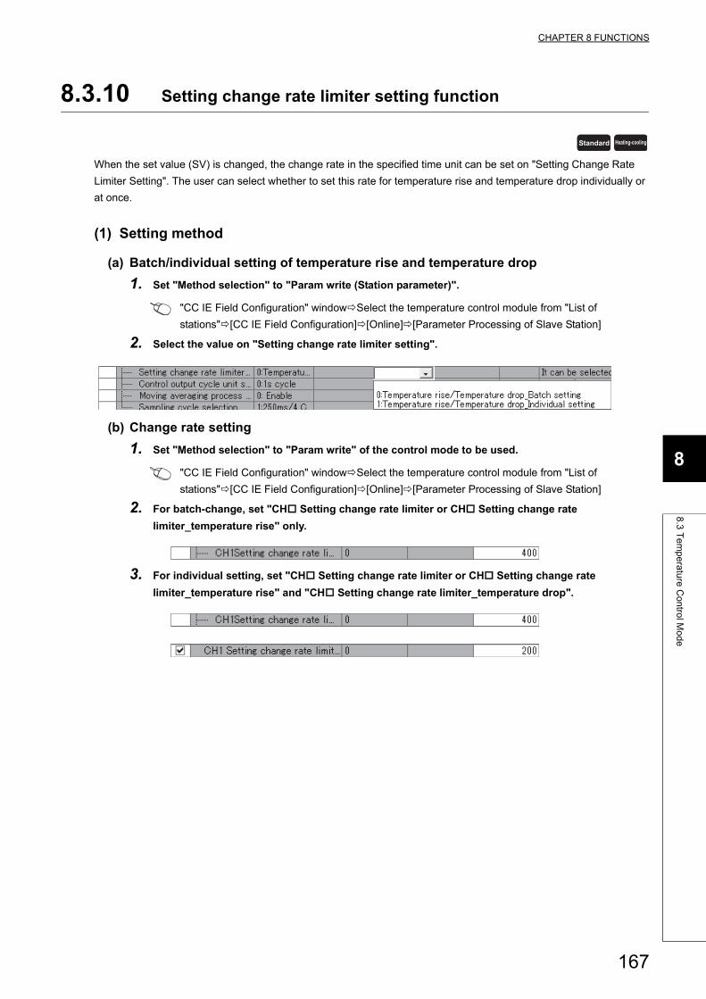
CHAPTER 8 FUNCTIONS
8
8.3
Te
mp
era
ture
Co
ntro
l Mo
de
8.3.10 Setting change rate limiter setting function
When the set value (SV) is changed, the change rate in the specified time unit can be set on "Setting Change Rate
Limiter Setting". The user can select whether to set this rate for temperature rise and temperature drop individually or
at once.
(1) Setting method
(a) Batch/individual setting of temperature rise and temperature drop
1. Set "Method selection" to "Param write (Station parameter)".
"CC IE Field Configuration" windowSelect the temperature control module from "List of
stations"[CC IE Field Configuration][Online][Parameter Processing of Slave Station]
2. Select the value on "Setting change rate limiter setting".
(b) Change rate setting
1. Set "Method selection" to "Param write" of the control mode to be used.
"CC IE Field Configuration" windowSelect the temperature control module from "List of
stations"[CC IE Field Configuration][Online][Parameter Processing of Slave Station]
2. For batch-change, set "CH Setting change rate limiter or CH Setting change rate
limiter_temperature rise" only.
3. For individual setting, set "CH Setting change rate limiter or CH Setting change rate
limiter_temperature rise" and "CH Setting change rate limiter_temperature drop".
Standard Heating-cooling
167
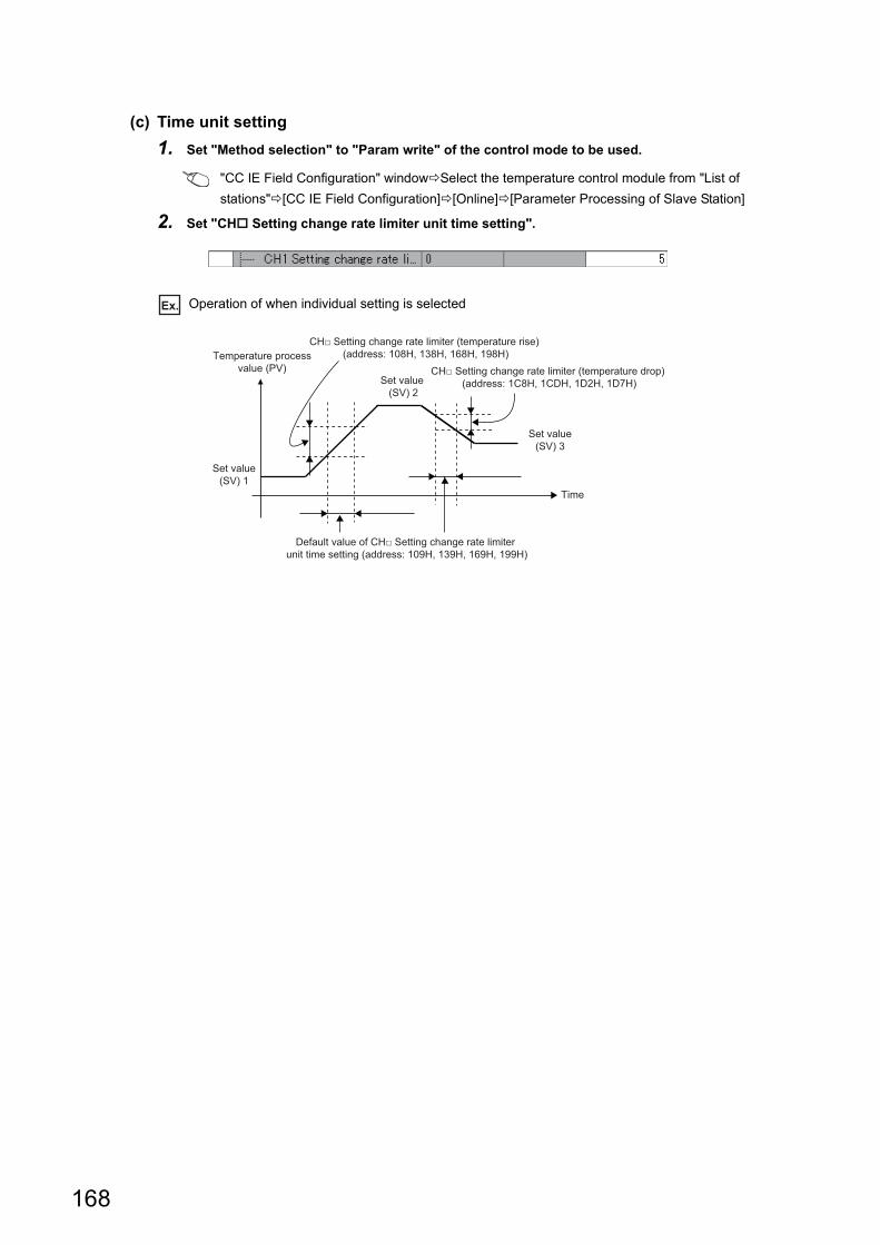
(c) Time unit setting
1. Set "Method selection" to "Param write" of the control mode to be used.
"CC IE Field Configuration" windowSelect the temperature control module from "List of
stations"[CC IE Field Configuration][Online][Parameter Processing of Slave Station]
2. Set "CH Setting change rate limiter unit time setting".
Ex. Operation of when individual setting is selected
Temperature processvalue (PV)
Time
Set value(SV) 3
Set value (SV) 2
Set value(SV) 1
CH□ Setting change rate limiter (temperature rise) (address: 108H, 138H, 168H, 198H)
CH□ Setting change rate limiter (temperature drop) (address: 1C8H, 1CDH, 1D2H, 1D7H)
Default value of CH□ Setting change rate limiter unit time setting (address: 109H, 139H, 169H, 199H)
168
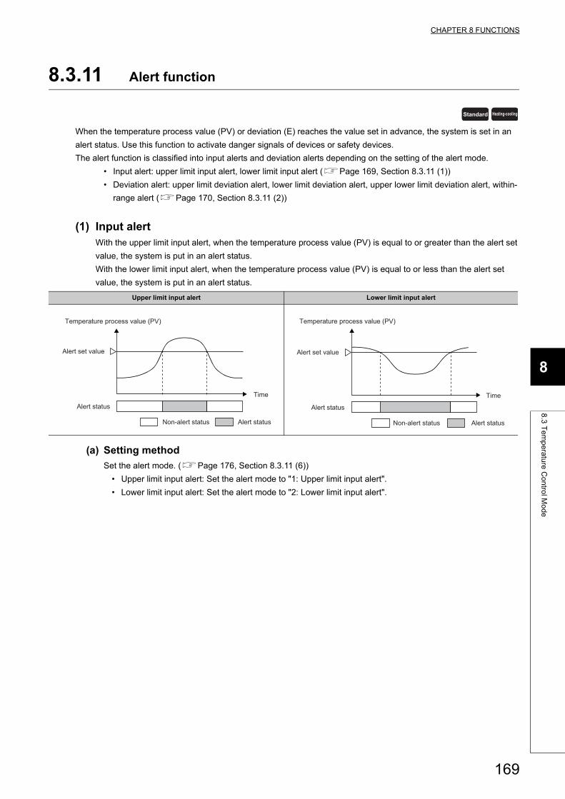
CHAPTER 8 FUNCTIONS
8
8.3
Te
mp
era
ture
Co
ntro
l Mo
de
8.3.11 Alert function
When the temperature process value (PV) or deviation (E) reaches the value set in advance, the system is set in an
alert status. Use this function to activate danger signals of devices or safety devices.
The alert function is classified into input alerts and deviation alerts depending on the setting of the alert mode.
• Input alert: upper limit input alert, lower limit input alert (Page 169, Section 8.3.11 (1))
• Deviation alert: upper limit deviation alert, lower limit deviation alert, upper lower limit deviation alert, within-
range alert (Page 170, Section 8.3.11 (2))
(1) Input alertWith the upper limit input alert, when the temperature process value (PV) is equal to or greater than the alert set
value, the system is put in an alert status.
With the lower limit input alert, when the temperature process value (PV) is equal to or less than the alert set
value, the system is put in an alert status.
(a) Setting method
Set the alert mode. (Page 176, Section 8.3.11 (6))
• Upper limit input alert: Set the alert mode to "1: Upper limit input alert".
• Lower limit input alert: Set the alert mode to "2: Lower limit input alert".
Upper limit input alert Lower limit input alert
Standard Heating-cooling
Non-alert status Alert status
Time
Temperature process value (PV)
Alert status
Alert set value
Non-alert status Alert status
Time
Temperature process value (PV)
Alert status
Alert set value
169
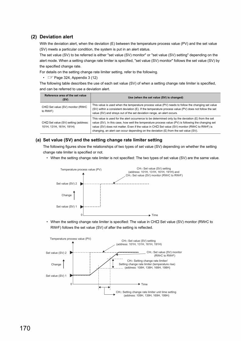
(2) Deviation alertWith the deviation alert, when the deviation (E) between the temperature process value (PV) and the set value
(SV) meets a particular condition, the system is put in an alert status.
The set value (SV) to be referred is either "set value (SV) monitor" or "set value (SV) setting" depending on the
alert mode. When a setting change rate limiter is specified, "set value (SV) monitor" follows the set value (SV) by
the specified change rate.
For details on the setting change rate limiter setting, refer to the following.
• Page 324, Appendix 3 (12)
The following table describes the use of each set value (SV) of when a setting change rate limiter is specified,
and can be referred to use a deviation alert.
(a) Set value (SV) and the setting change rate limiter setting
The following figures show the relationships of two types of set value (SV) depending on whether the setting
change rate limiter is specified or not.
• When the setting change rate limiter is not specified: The two types of set value (SV) are the same value.
• When the setting change rate limiter is specified: The value in CH Set value (SV) monitor (RWrC to
RWrF) follows the set value (SV) of after the setting is reflected.
Reference area of the set value
(SV)Use (when the set value (SV) is changed)
CH Set value (SV) monitor (RWrC
to RWrF)
This value is used when the temperature process value (PV) needs to follow the changing set value
(SV) within a consistent deviation (E). If the temperature process value (PV) does not follow the set
value (SV) and strays out of the set deviation range, an alert occurs.
CH Set value (SV) setting (address:
101H, 131H, 161H, 191H)
This value is used for the alert occurrence to be determined only by the deviation (E) from the set
value (SV). In this case, how well the temperature process value (PV) is following the changing set
value (SV) does not matter. Even if the value in CH Set value (SV) monitor (RWrC to RWrF) is
changing, an alert can occur depending on the deviation (E) from the set value (SV).
0
Set value (SV) 1
Change
Temperature process value (PV)
Time
Set value (SV) 2
CH□ Set value (SV) setting (address: 101H, 131H, 161H, 191H) and
CH□ Set value (SV) monitor (RWrC to RWrF)
0
Set value (SV) 1
Change
Temperature process value (PV)
Time
Set value (SV) 2
CH□ Set value (SV) setting (address: 101H, 131H, 161H, 191H)
CH□ Set value (SV) monitor (RWrC to RWrF)
CH□ Setting change rate limiter/Setting change rate limiter (temperature rise)
(address: 108H, 138H, 168H, 198H)
CH□ Setting change rate limiter unit time setting (address: 109H, 139H, 169H, 199H)
170
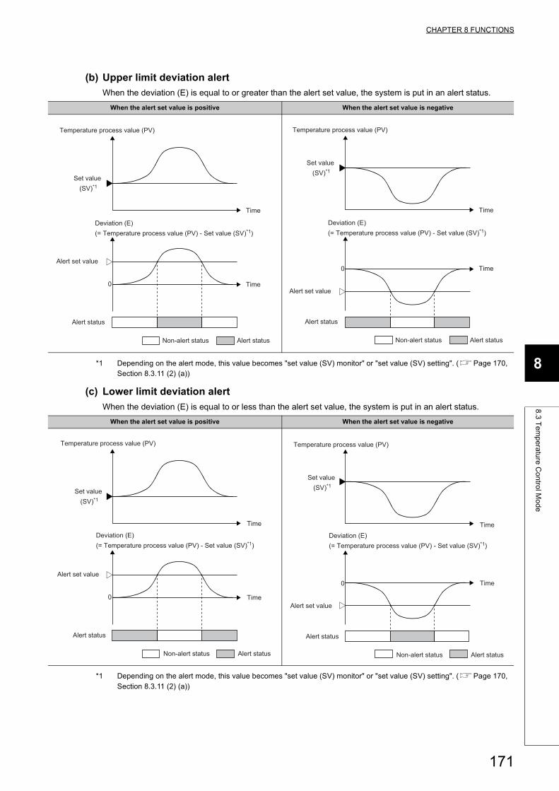
CHAPTER 8 FUNCTIONS
8
8.3
Te
mp
era
ture
Co
ntro
l Mo
de
(b) Upper limit deviation alert
When the deviation (E) is equal to or greater than the alert set value, the system is put in an alert status.
*1 Depending on the alert mode, this value becomes "set value (SV) monitor" or "set value (SV) setting". (Page 170, Section 8.3.11 (2) (a))
(c) Lower limit deviation alert
When the deviation (E) is equal to or less than the alert set value, the system is put in an alert status.
*1 Depending on the alert mode, this value becomes "set value (SV) monitor" or "set value (SV) setting". (Page 170, Section 8.3.11 (2) (a))
When the alert set value is positive When the alert set value is negative
When the alert set value is positive When the alert set value is negative
Non-alert status Alert status
Time
Deviation (E) (= Temperature process value (PV) - Set value (SV)*1)
Alert status
0
Alert set value
Time
Temperature process value (PV)
Set value (SV)*1
Non-alert status Alert status
Time
Deviation (E) (= Temperature process value (PV) - Set value (SV)*1)
Alert status
0
Alert set value
Time
Temperature process value (PV)
Set value (SV)*1
Non-alert status Alert status
Time
Deviation (E) (= Temperature process value (PV) - Set value (SV)*1)
Alert status
0
Alert set value
Time
Temperature process value (PV)
Set value (SV)*1
Non-alert status Alert status
Time
Deviation (E) (= Temperature process value (PV) - Set value (SV)*1)
Alert status
0
Alert set value
Time
Temperature process value (PV)
Set value (SV)*1
171
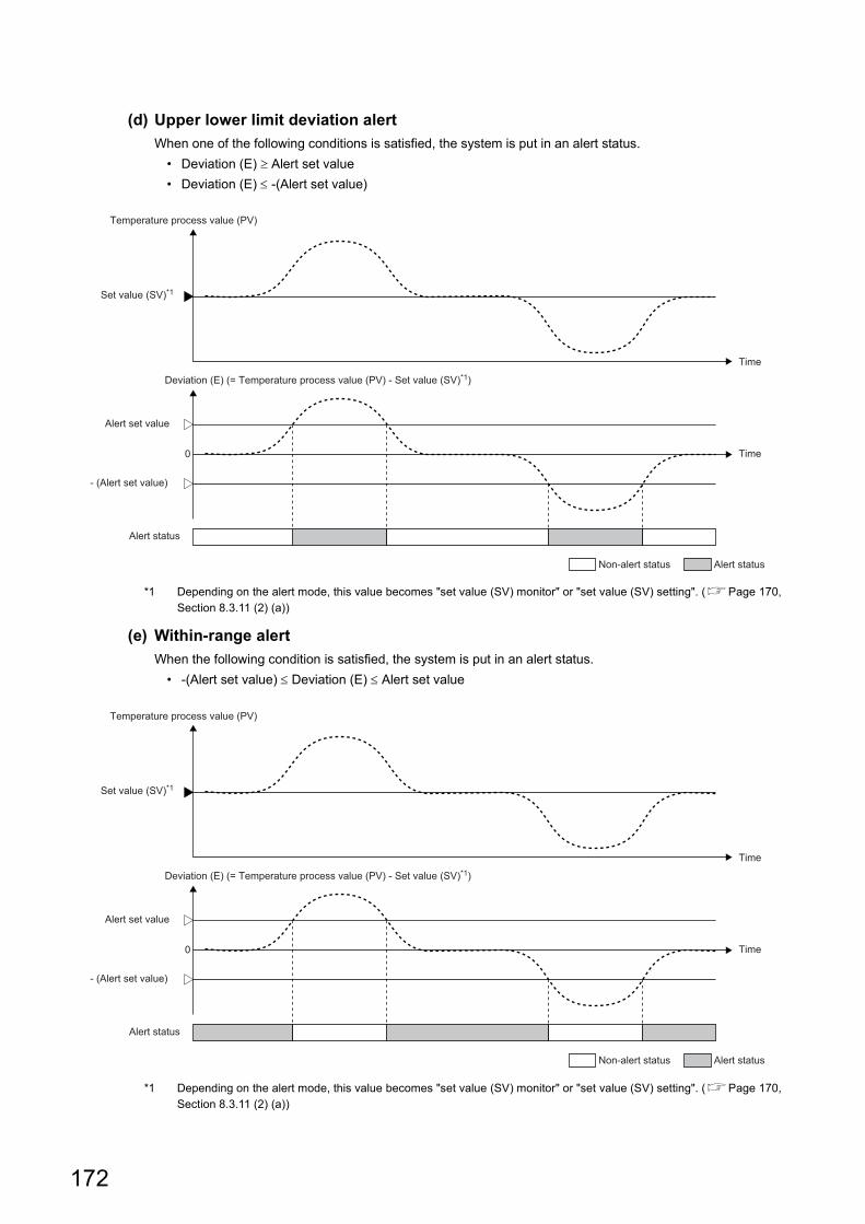
(d) Upper lower limit deviation alert
When one of the following conditions is satisfied, the system is put in an alert status.
• Deviation (E) Alert set value
• Deviation (E) -(Alert set value)
*1 Depending on the alert mode, this value becomes "set value (SV) monitor" or "set value (SV) setting". (Page 170, Section 8.3.11 (2) (a))
(e) Within-range alert
When the following condition is satisfied, the system is put in an alert status.
• -(Alert set value) Deviation (E) Alert set value
*1 Depending on the alert mode, this value becomes "set value (SV) monitor" or "set value (SV) setting". (Page 170, Section 8.3.11 (2) (a))
Non-alert status Alert status
Time
Deviation (E) (= Temperature process value (PV) - Set value (SV)*1)
Alert status
0
- (Alert set value)
Alert set value
Time
Temperature process value (PV)
Set value (SV)*1
Non-alert status Alert status
Time
Deviation (E) (= Temperature process value (PV) - Set value (SV)*1)
Alert status
0
- (Alert set value)
Alert set value
Time
Temperature process value (PV)
Set value (SV)*1
172
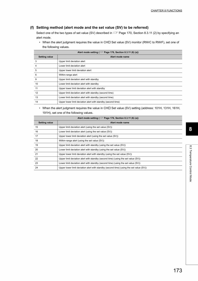
CHAPTER 8 FUNCTIONS
8
8.3
Te
mp
era
ture
Co
ntro
l Mo
de
(f) Setting method (alert mode and the set value (SV) to be referred)
Select one of the two types of set value (SV) described in Page 170, Section 8.3.11 (2) by specifying an
alert mode.
• When the alert judgment requires the value in CH Set value (SV) monitor (RWrC to RWrF), set one of
the following values.
• When the alert judgment requires the value in CH Set value (SV) setting (address: 101H, 131H, 161H,
191H), set one of the following values.
Alert mode setting (Page 176, Section 8.3.11 (6) (a))
Setting value Alert mode name
3 Upper limit deviation alert
4 Lower limit deviation alert
5 Upper lower limit deviation alert
6 Within-range alert
9 Upper limit deviation alert with standby
10 Lower limit deviation alert with standby
11 Upper lower limit deviation alert with standby
12 Upper limit deviation alert with standby (second time)
13 Lower limit deviation alert with standby (second time)
14 Upper lower limit deviation alert with standby (second time)
Alert mode setting (Page 176, Section 8.3.11 (6) (a))
Setting value Alert mode name
15 Upper limit deviation alert (using the set value (SV))
16 Lower limit deviation alert (using the set value (SV))
17 Upper lower limit deviation alert (using the set value (SV))
18 Within-range alert (using the set value (SV))
19 Upper limit deviation alert with standby (using the set value (SV))
20 Lower limit deviation alert with standby (using the set value (SV))
21 Upper lower limit deviation alert with standby (using the set value (SV))
22 Upper limit deviation alert with standby (second time) (using the set value (SV))
23 Lower limit deviation alert with standby (second time) (using the set value (SV))
24 Upper lower limit deviation alert with standby (second time) (using the set value (SV))
173
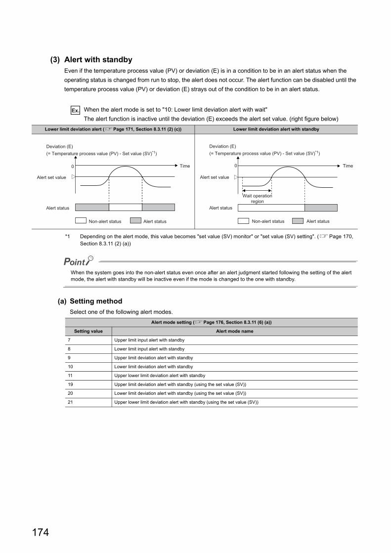
(3) Alert with standbyEven if the temperature process value (PV) or deviation (E) is in a condition to be in an alert status when the
operating status is changed from run to stop, the alert does not occur. The alert function can be disabled until the
temperature process value (PV) or deviation (E) strays out of the condition to be in an alert status.
Ex. When the alert mode is set to "10: Lower limit deviation alert with wait"
The alert function is inactive until the deviation (E) exceeds the alert set value. (right figure below)
*1 Depending on the alert mode, this value becomes "set value (SV) monitor" or "set value (SV) setting". (Page 170, Section 8.3.11 (2) (a))
When the system goes into the non-alert status even once after an alert judgment started following the setting of the alert mode, the alert with standby will be inactive even if the mode is changed to the one with standby.
(a) Setting method
Select one of the following alert modes.
Lower limit deviation alert (Page 171, Section 8.3.11 (2) (c)) Lower limit deviation alert with standby
Alert mode setting (Page 176, Section 8.3.11 (6) (a))
Setting value Alert mode name
7 Upper limit input alert with standby
8 Lower limit input alert with standby
9 Upper limit deviation alert with standby
10 Lower limit deviation alert with standby
11 Upper lower limit deviation alert with standby
19 Upper limit deviation alert with standby (using the set value (SV))
20 Lower limit deviation alert with standby (using the set value (SV))
21 Upper lower limit deviation alert with standby (using the set value (SV))
0
Non-alert status Alert status
Time
Alert status
Alert set value
Deviation (E) (= Temperature process value (PV) - Set value (SV)*1)
Non-alert status Alert status
Time
Alert status
Alert set value
Deviation (E) (= Temperature process value (PV) - Set value (SV)*1)
0
Wait operationregion
174
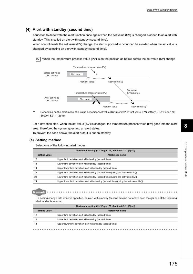
CHAPTER 8 FUNCTIONS
8
8.3
Te
mp
era
ture
Co
ntro
l Mo
de
(4) Alert with standby (second time)A function to deactivate the alert function once again when the set value (SV) is changed is added to an alert with
standby. This is called an alert with standby (second time).
When control needs the set value (SV) change, the alert supposed to occur can be avoided when the set value is
changed by selecting an alert with standby (second time).
Ex. When the temperature process value (PV) is on the position as below before the set value (SV) change
*1 Depending on the alert mode, this value becomes "set value (SV) monitor" or "set value (SV) setting". (Page 170, Section 8.3.11 (2) (a))
For a deviation alert, when the set value (SV) is changed, the temperature process value (PV) goes into the alert
area; therefore, the system goes into an alert status.
To prevent the case above, the alert output is put on standby.
(a) Setting method
Select one of the following alert modes.
Remark
If a setting change rate limiter is specified, an alert with standby (second time) is not active even though one of the following alert modes is selected.
Alert mode setting (Page 176, Section 8.3.11 (6) (a))
Setting value Alert mode name
12 Upper limit deviation alert with standby (second time)
13 Lower limit deviation alert with standby (second time)
14 Upper lower limit deviation alert with standby (second time)
22 Upper limit deviation alert with standby (second time) (using the set value (SV))
23 Lower limit deviation alert with standby (second time) (using the set value (SV))
24 Upper lower limit deviation alert with standby (second time) (using the set value (SV))
Alert mode setting (Page 176, Section 8.3.11 (6) (a))
Setting value Alert mode name
12 Upper limit deviation alert with standby (second time)
13 Lower limit deviation alert with standby (second time)
14 Upper lower limit deviation alert with standby (second time)
Alert set value Set value (SV)
Temperature process value (PV)
Alert areaBefore set value (SV) change
Alert set value Set value (SV)*1
Temperature process value (PV)
Alert areaAfter set value (SV) change
Set value (SV) change
175
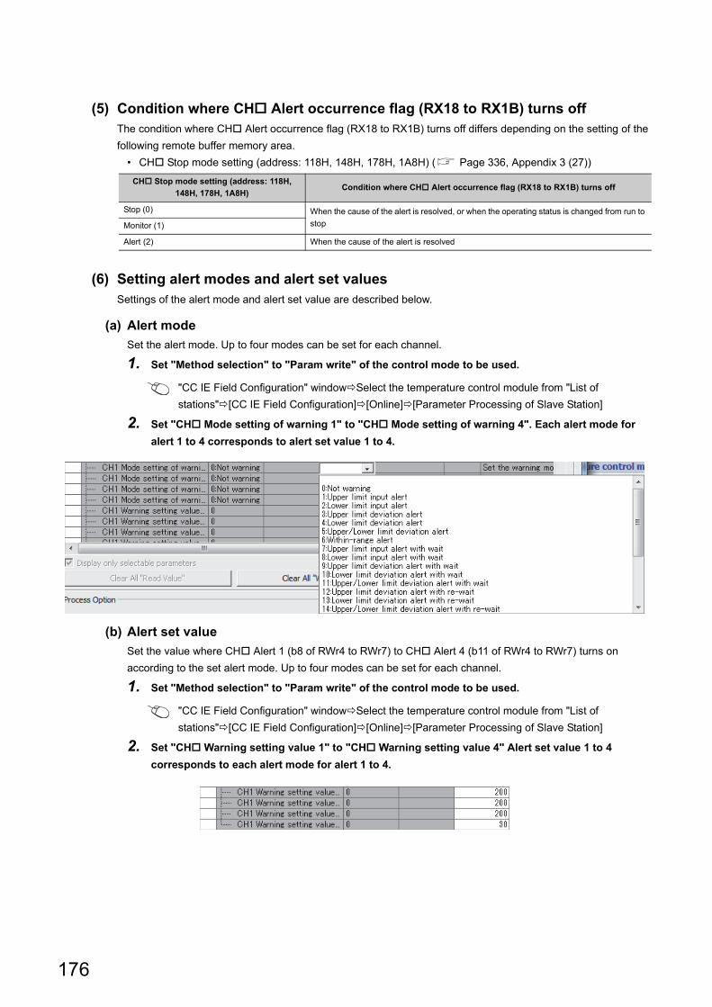
(5) Condition where CH Alert occurrence flag (RX18 to RX1B) turns offThe condition where CH Alert occurrence flag (RX18 to RX1B) turns off differs depending on the setting of the
following remote buffer memory area.
• CH Stop mode setting (address: 118H, 148H, 178H, 1A8H) ( Page 336, Appendix 3 (27))
(6) Setting alert modes and alert set valuesSettings of the alert mode and alert set value are described below.
(a) Alert mode
Set the alert mode. Up to four modes can be set for each channel.
1. Set "Method selection" to "Param write" of the control mode to be used.
"CC IE Field Configuration" windowSelect the temperature control module from "List of
stations"[CC IE Field Configuration][Online][Parameter Processing of Slave Station]
2. Set "CH Mode setting of warning 1" to "CH Mode setting of warning 4". Each alert mode for
alert 1 to 4 corresponds to alert set value 1 to 4.
(b) Alert set value
Set the value where CH Alert 1 (b8 of RWr4 to RWr7) to CH Alert 4 (b11 of RWr4 to RWr7) turns on
according to the set alert mode. Up to four modes can be set for each channel.
1. Set "Method selection" to "Param write" of the control mode to be used.
"CC IE Field Configuration" windowSelect the temperature control module from "List of
stations"[CC IE Field Configuration][Online][Parameter Processing of Slave Station]
2. Set "CH Warning setting value 1" to "CH Warning setting value 4" Alert set value 1 to 4
corresponds to each alert mode for alert 1 to 4.
CH Stop mode setting (address: 118H,
148H, 178H, 1A8H)Condition where CH Alert occurrence flag (RX18 to RX1B) turns off
Stop (0) When the cause of the alert is resolved, or when the operating status is changed from run to
stopMonitor (1)
Alert (2) When the cause of the alert is resolved
176
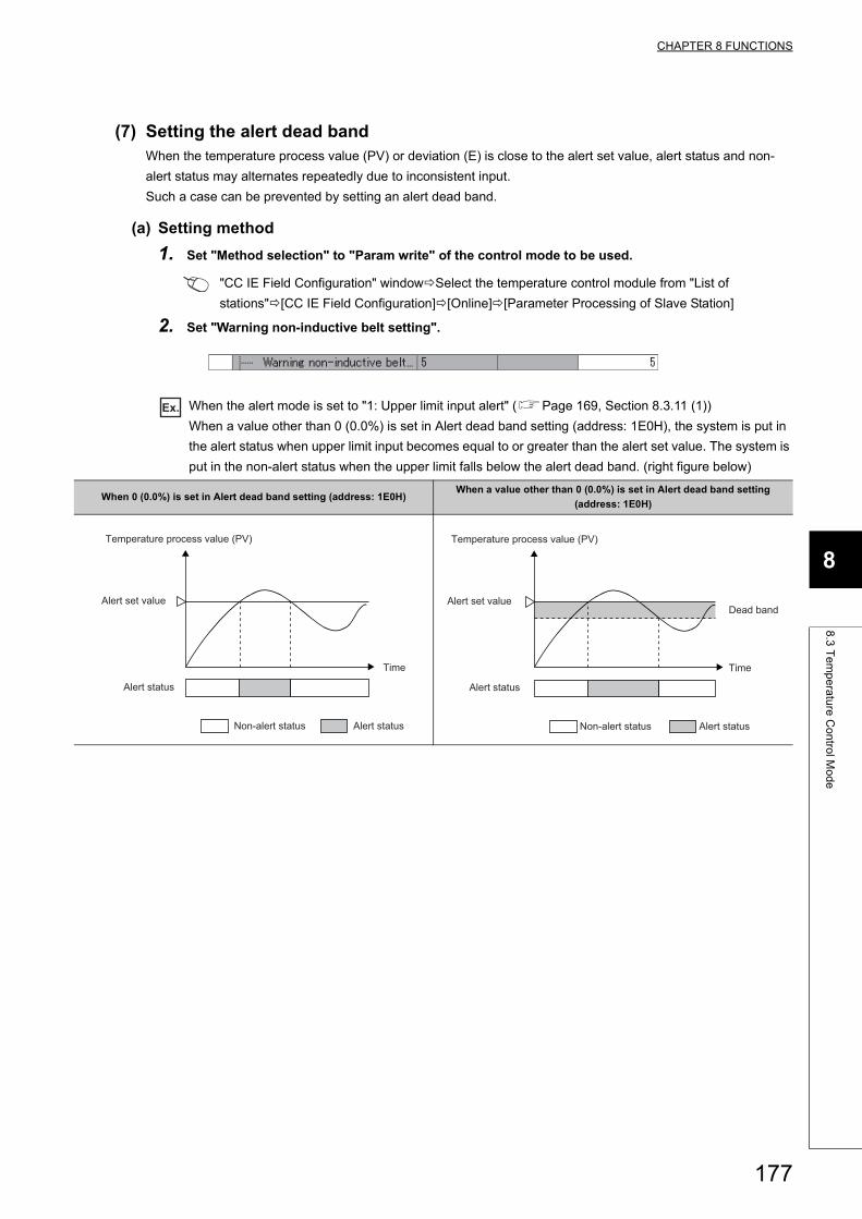
CHAPTER 8 FUNCTIONS
8
8.3
Te
mp
era
ture
Co
ntro
l Mo
de
(7) Setting the alert dead bandWhen the temperature process value (PV) or deviation (E) is close to the alert set value, alert status and non-
alert status may alternates repeatedly due to inconsistent input.
Such a case can be prevented by setting an alert dead band.
(a) Setting method
1. Set "Method selection" to "Param write" of the control mode to be used.
"CC IE Field Configuration" windowSelect the temperature control module from "List of
stations"[CC IE Field Configuration][Online][Parameter Processing of Slave Station]
2. Set "Warning non-inductive belt setting".
Ex. When the alert mode is set to "1: Upper limit input alert" (Page 169, Section 8.3.11 (1))
When a value other than 0 (0.0%) is set in Alert dead band setting (address: 1E0H), the system is put in
the alert status when upper limit input becomes equal to or greater than the alert set value. The system is
put in the non-alert status when the upper limit falls below the alert dead band. (right figure below)
When 0 (0.0%) is set in Alert dead band setting (address: 1E0H)When a value other than 0 (0.0%) is set in Alert dead band setting
(address: 1E0H)
Non-alert status Alert status
Time
Temperature process value (PV)
Alert status
Alert set value
Non-alert status Alert status
Time
Dead band
Temperature process value (PV)
Alert status
Alert set value
177
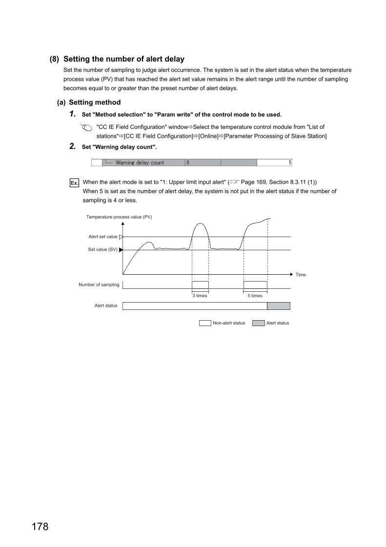
(8) Setting the number of alert delaySet the number of sampling to judge alert occurrence. The system is set in the alert status when the temperature
process value (PV) that has reached the alert set value remains in the alert range until the number of sampling
becomes equal to or greater than the preset number of alert delays.
(a) Setting method
1. Set "Method selection" to "Param write" of the control mode to be used.
"CC IE Field Configuration" windowSelect the temperature control module from "List of
stations"[CC IE Field Configuration][Online][Parameter Processing of Slave Station]
2. Set "Warning delay count".
Ex. When the alert mode is set to "1: Upper limit input alert" (Page 169, Section 8.3.11 (1))
When 5 is set as the number of alert delay, the system is not put in the alert status if the number of
sampling is 4 or less.
Non-alert status Alert status
Time
Temperature process value (PV)
Alert status
Number of sampling
Alert set value
3 times 5 times
Set value (SV)
178
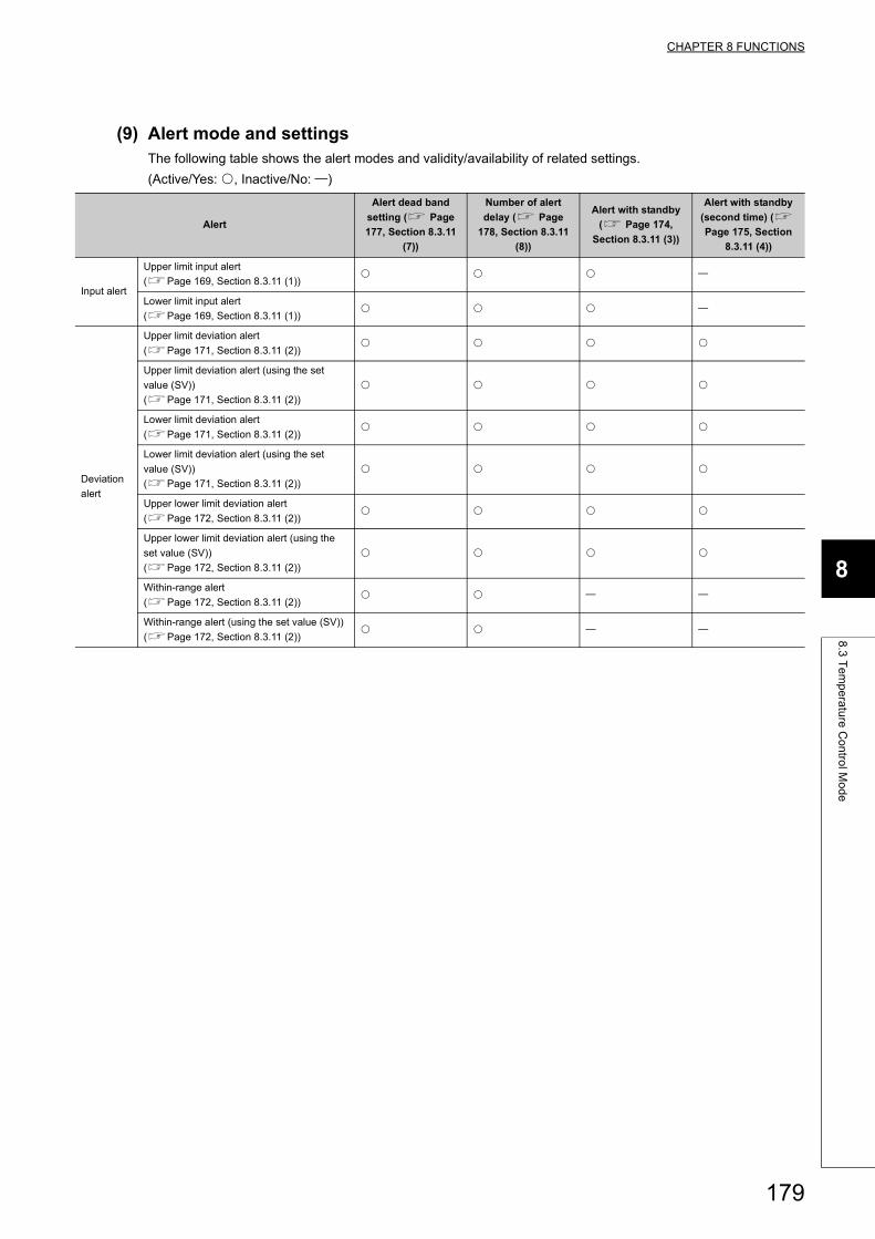
CHAPTER 8 FUNCTIONS
8
8.3
Te
mp
era
ture
Co
ntro
l Mo
de
(9) Alert mode and settingsThe following table shows the alert modes and validity/availability of related settings.
(Active/Yes: , Inactive/No: )
Alert
Alert dead band
setting ( Page
177, Section 8.3.11
(7))
Number of alert
delay ( Page
178, Section 8.3.11
(8))
Alert with standby
( Page 174,
Section 8.3.11 (3))
Alert with standby
(second time) (
Page 175, Section
8.3.11 (4))
Input alert
Upper limit input alert
(Page 169, Section 8.3.11 (1))
Lower limit input alert
(Page 169, Section 8.3.11 (1))
Deviation
alert
Upper limit deviation alert
(Page 171, Section 8.3.11 (2))
Upper limit deviation alert (using the set
value (SV))
(Page 171, Section 8.3.11 (2))
Lower limit deviation alert
(Page 171, Section 8.3.11 (2))
Lower limit deviation alert (using the set
value (SV))
(Page 171, Section 8.3.11 (2))
Upper lower limit deviation alert
(Page 172, Section 8.3.11 (2))
Upper lower limit deviation alert (using the
set value (SV))
(Page 172, Section 8.3.11 (2))
Within-range alert
(Page 172, Section 8.3.11 (2))
Within-range alert (using the set value (SV))
(Page 172, Section 8.3.11 (2))
179
8.3.12 RFB limiter function
The RFB (reset feed back) function operates when deviation (E) continues for a long period of time. In such an
occasion, this function limits the PID operation result (manipulated value (MV)) from an integral action so that it does
not exceed the valid range of the manipulated value (MV).
This function operates automatically on execution of PID control; therefore, a setting by the user is unnecessary.
Remark
When the PID operation result exceeds the upper limit output limiter value, the temperature control module operates as follows:
• The RFB function levels the manipulated value (MV) to the upper limit output limiter value by feeding back the exceeded value to the integral value.
When the PID operation result is below the lower limit output limiter value, the temperature control module operates as follows:
• The RFB function levels the manipulated value (MV) to the lower limit output limiter value by feeding back the lacking value to the integral value.
Standard Heating-cooling
180
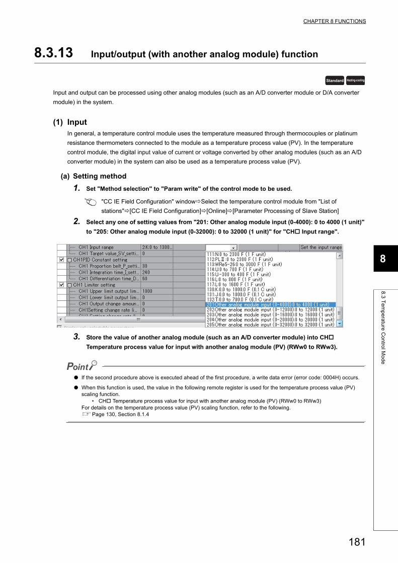
CHAPTER 8 FUNCTIONS
8
8.3
Te
mp
era
ture
Co
ntro
l Mo
de
8.3.13 Input/output (with another analog module) function
Input and output can be processed using other analog modules (such as an A/D converter module or D/A converter
module) in the system.
(1) InputIn general, a temperature control module uses the temperature measured through thermocouples or platinum
resistance thermometers connected to the module as a temperature process value (PV). In the temperature
control module, the digital input value of current or voltage converted by other analog modules (such as an A/D
converter module) in the system can also be used as a temperature process value (PV).
(a) Setting method
1. Set "Method selection" to "Param write" of the control mode to be used.
"CC IE Field Configuration" windowSelect the temperature control module from "List of
stations"[CC IE Field Configuration][Online][Parameter Processing of Slave Station]
2. Select any one of setting values from "201: Other analog module input (0-4000): 0 to 4000 (1 unit)"
to "205: Other analog module input (0-32000): 0 to 32000 (1 unit)" for "CH Input range".
3. Store the value of another analog module (such as an A/D converter module) into CH
Temperature process value for input with another analog module (PV) (RWw0 to RWw3).
● If the second procedure above is executed ahead of the first procedure, a write data error (error code: 0004H) occurs.
● When this function is used, the value in the following remote register is used for the temperature process value (PV) scaling function.
• CH Temperature process value for input with another analog module (PV) (RWw0 to RWw3)For details on the temperature process value (PV) scaling function, refer to the following.Page 130, Section 8.1.4
Standard Heating-cooling
181
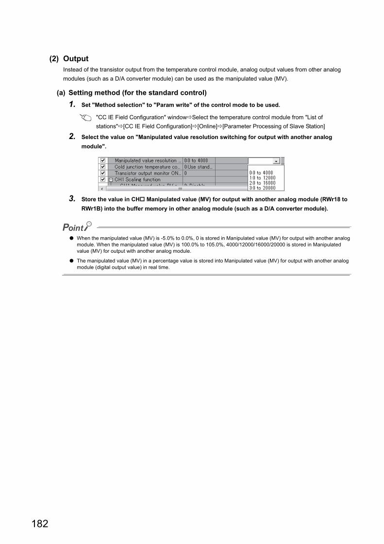
(2) OutputInstead of the transistor output from the temperature control module, analog output values from other analog
modules (such as a D/A converter module) can be used as the manipulated value (MV).
(a) Setting method (for the standard control)
1. Set "Method selection" to "Param write" of the control mode to be used.
"CC IE Field Configuration" windowSelect the temperature control module from "List of
stations"[CC IE Field Configuration][Online][Parameter Processing of Slave Station]
2. Select the value on "Manipulated value resolution switching for output with another analog
module".
3. Store the value in CH Manipulated value (MV) for output with another analog module (RWr18 to
RWr1B) into the buffer memory in other analog module (such as a D/A converter module).
● When the manipulated value (MV) is -5.0% to 0.0%, 0 is stored in Manipulated value (MV) for output with another analog module. When the manipulated value (MV) is 100.0% to 105.0%, 4000/12000/16000/20000 is stored in Manipulated value (MV) for output with another analog module.
● The manipulated value (MV) in a percentage value is stored into Manipulated value (MV) for output with another analog module (digital output value) in real time.
182
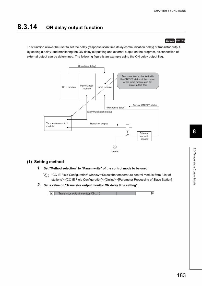
CHAPTER 8 FUNCTIONS
8
8.3
Te
mp
era
ture
Co
ntro
l Mo
de
8.3.14 ON delay output function
This function allows the user to set the delay (response/scan time delay/communication delay) of transistor output.
By setting a delay, and monitoring the ON delay output flag and external output on the program, disconnection of
external output can be determined. The following figure is an example using the ON delay output flag.
(1) Setting method
1. Set "Method selection" to "Param write" of the control mode to be used.
"CC IE Field Configuration" windowSelect the temperature control module from "List of
stations"[CC IE Field Configuration][Online][Parameter Processing of Slave Station]
2. Set a value on "Transistor output monitor ON delay time setting".
Standard Heating-cooling
(Scan time delay)
CPU module Input module
Disconnection is checked with the ON/OFF status of the contact
of the input module and ON delay output flag.
Sensor ON/OFF status
Transistor output
(Response delay)
External current sensor
Heater
Master/local module
Temperature control module
(Communication delay)
183
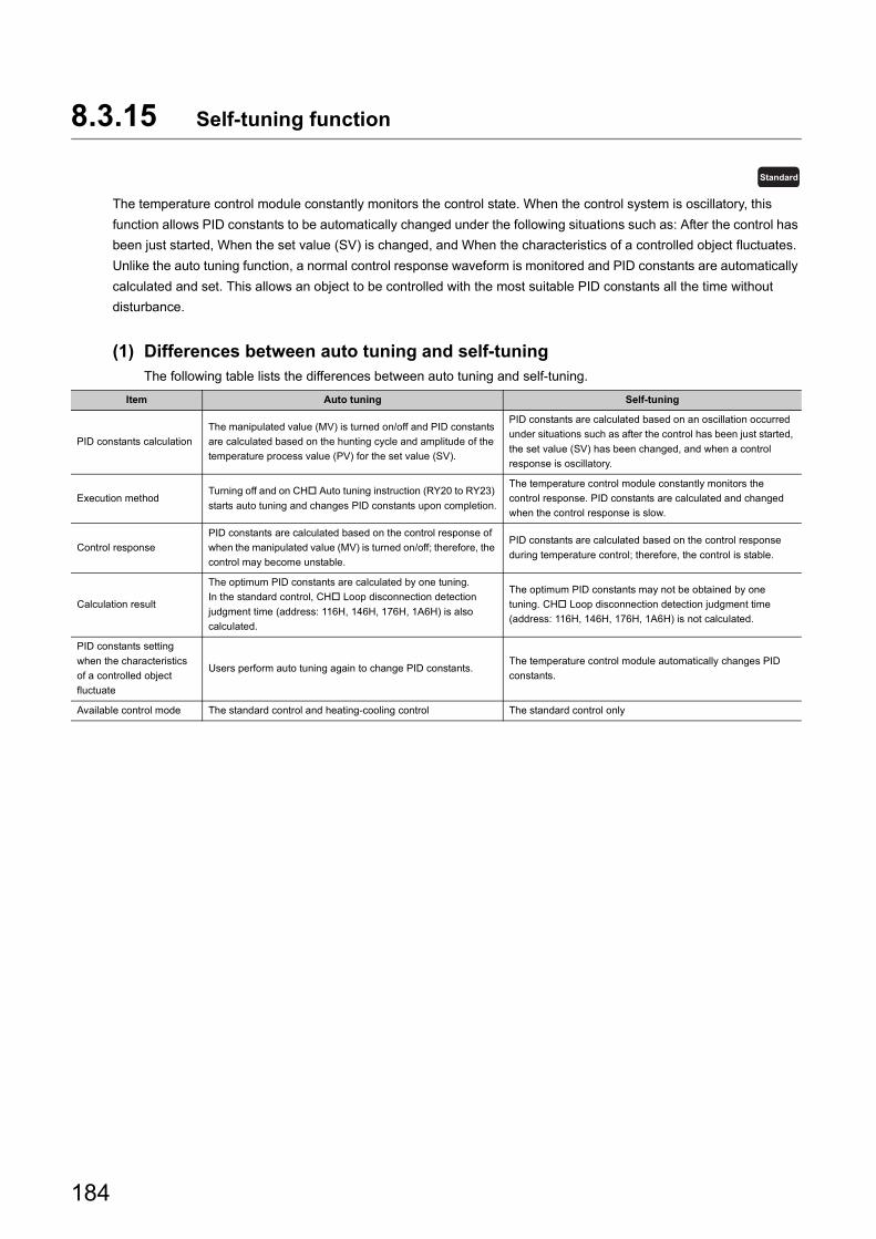
8.3.15 Self-tuning function
The temperature control module constantly monitors the control state. When the control system is oscillatory, this
function allows PID constants to be automatically changed under the following situations such as: After the control has
been just started, When the set value (SV) is changed, and When the characteristics of a controlled object fluctuates.
Unlike the auto tuning function, a normal control response waveform is monitored and PID constants are automatically
calculated and set. This allows an object to be controlled with the most suitable PID constants all the time without
disturbance.
(1) Differences between auto tuning and self-tuningThe following table lists the differences between auto tuning and self-tuning.
Item Auto tuning Self-tuning
PID constants calculation
The manipulated value (MV) is turned on/off and PID constants
are calculated based on the hunting cycle and amplitude of the
temperature process value (PV) for the set value (SV).
PID constants are calculated based on an oscillation occurred
under situations such as after the control has been just started,
the set value (SV) has been changed, and when a control
response is oscillatory.
Execution methodTurning off and on CH Auto tuning instruction (RY20 to RY23)
starts auto tuning and changes PID constants upon completion.
The temperature control module constantly monitors the
control response. PID constants are calculated and changed
when the control response is slow.
Control response
PID constants are calculated based on the control response of
when the manipulated value (MV) is turned on/off; therefore, the
control may become unstable.
PID constants are calculated based on the control response
during temperature control; therefore, the control is stable.
Calculation result
The optimum PID constants are calculated by one tuning.
In the standard control, CH Loop disconnection detection
judgment time (address: 116H, 146H, 176H, 1A6H) is also
calculated.
The optimum PID constants may not be obtained by one
tuning. CH Loop disconnection detection judgment time
(address: 116H, 146H, 176H, 1A6H) is not calculated.
PID constants setting
when the characteristics
of a controlled object
fluctuate
Users perform auto tuning again to change PID constants.The temperature control module automatically changes PID
constants.
Available control mode The standard control and heating-cooling control The standard control only
Standard
184
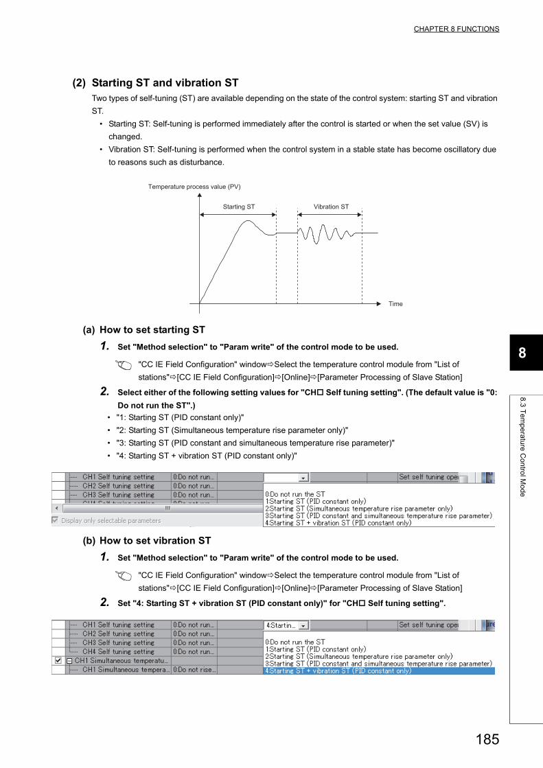
CHAPTER 8 FUNCTIONS
8
8.3
Te
mp
era
ture
Co
ntro
l Mo
de
(2) Starting ST and vibration STTwo types of self-tuning (ST) are available depending on the state of the control system: starting ST and vibration
ST.
• Starting ST: Self-tuning is performed immediately after the control is started or when the set value (SV) is
changed.
• Vibration ST: Self-tuning is performed when the control system in a stable state has become oscillatory due
to reasons such as disturbance.
(a) How to set starting ST
1. Set "Method selection" to "Param write" of the control mode to be used.
"CC IE Field Configuration" windowSelect the temperature control module from "List of
stations"[CC IE Field Configuration][Online][Parameter Processing of Slave Station]
2. Select either of the following setting values for "CH Self tuning setting". (The default value is "0:
Do not run the ST".)
• "1: Starting ST (PID constant only)"
• "2: Starting ST (Simultaneous temperature rise parameter only)"
• "3: Starting ST (PID constant and simultaneous temperature rise parameter)"
• "4: Starting ST + vibration ST (PID constant only)"
(b) How to set vibration ST
1. Set "Method selection" to "Param write" of the control mode to be used.
"CC IE Field Configuration" windowSelect the temperature control module from "List of
stations"[CC IE Field Configuration][Online][Parameter Processing of Slave Station]
2. Set "4: Starting ST + vibration ST (PID constant only)" for "CH Self tuning setting".
Time
Temperature process value (PV)
Starting ST Vibration ST
185
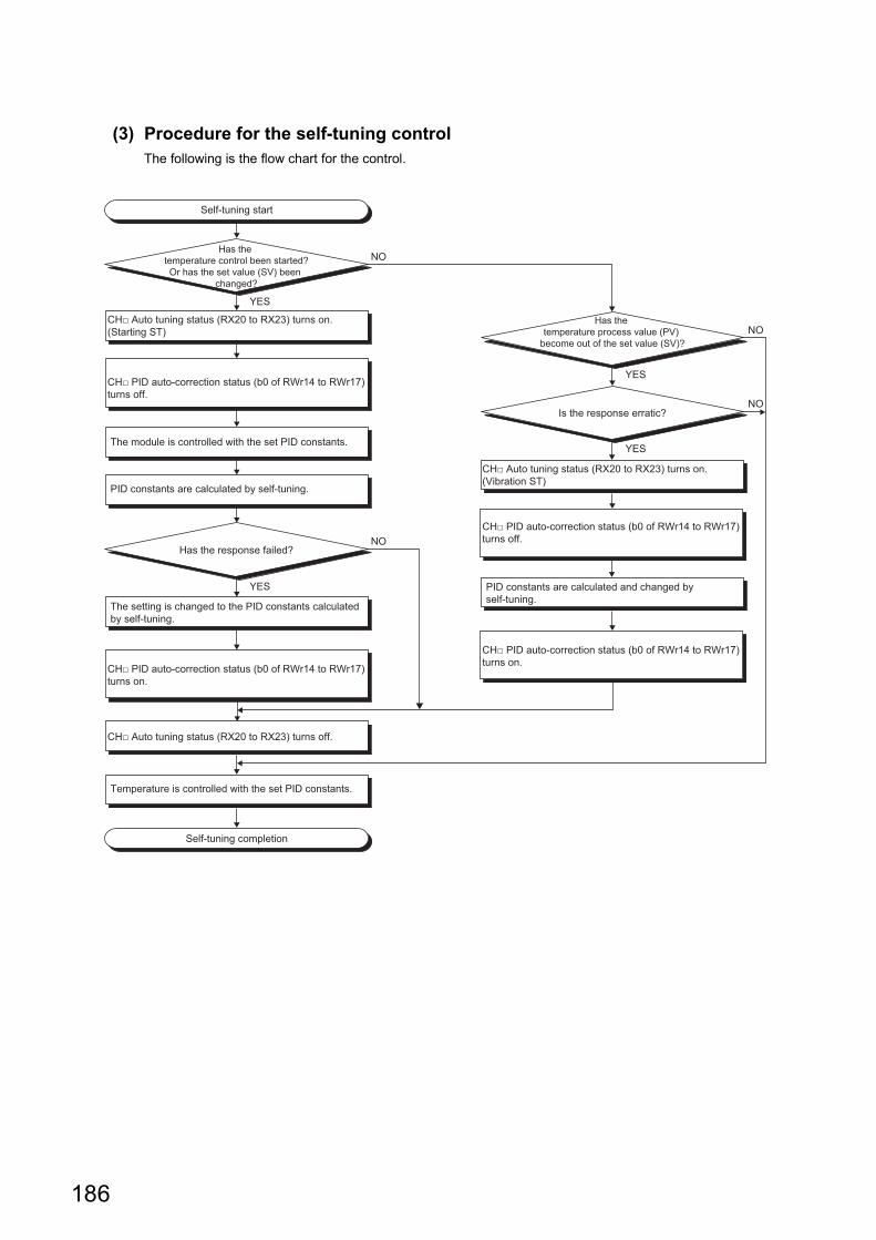
(3) Procedure for the self-tuning controlThe following is the flow chart for the control.
Self-tuning start
Self-tuning completion
PID constants are calculated and changed by self-tuning.
The module is controlled with the set PID constants.
PID constants are calculated by self-tuning.
The setting is changed to the PID constants calculated by self-tuning.
Temperature is controlled with the set PID constants.
Has the response failed?
YES
NO
Has the temperature control been started?Or has the set value (SV) been
changed?
YES
NO
Has the temperature process value (PV)
become out of the set value (SV)?
YES
YES
NO
NOIs the response erratic?
CH□ Auto tuning status (RX20 to RX23) turns on.(Starting ST)
CH□ Auto tuning status (RX20 to RX23) turns off.
CH□ PID auto-correction status (b0 of RWr14 to RWr17) turns off.
CH□ PID auto-correction status (b0 of RWr14 to RWr17) turns on.
CH□ Auto tuning status (RX20 to RX23) turns on.(Vibration ST)
CH□ PID auto-correction status (b0 of RWr14 to RWr17) turns off.
CH□ PID auto-correction status (b0 of RWr14 to RWr17) turns on.
186
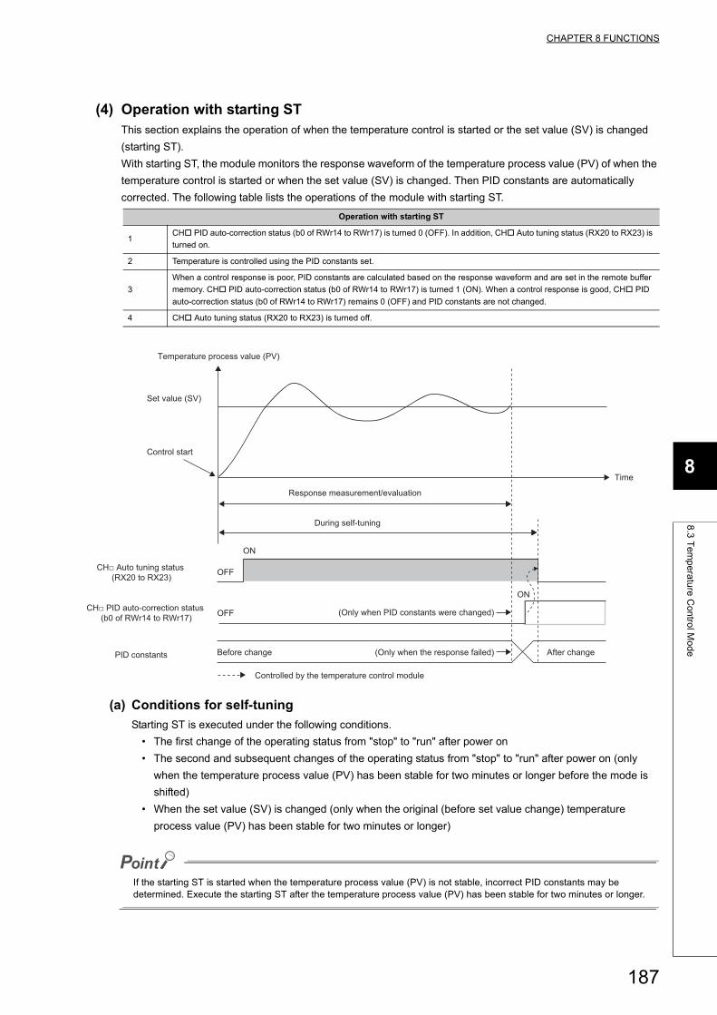
CHAPTER 8 FUNCTIONS
8
8.3
Te
mp
era
ture
Co
ntro
l Mo
de
(4) Operation with starting STThis section explains the operation of when the temperature control is started or the set value (SV) is changed
(starting ST).
With starting ST, the module monitors the response waveform of the temperature process value (PV) of when the
temperature control is started or when the set value (SV) is changed. Then PID constants are automatically
corrected. The following table lists the operations of the module with starting ST.
(a) Conditions for self-tuning
Starting ST is executed under the following conditions.
• The first change of the operating status from "stop" to "run" after power on
• The second and subsequent changes of the operating status from "stop" to "run" after power on (only
when the temperature process value (PV) has been stable for two minutes or longer before the mode is
shifted)
• When the set value (SV) is changed (only when the original (before set value change) temperature
process value (PV) has been stable for two minutes or longer)
If the starting ST is started when the temperature process value (PV) is not stable, incorrect PID constants may be determined. Execute the starting ST after the temperature process value (PV) has been stable for two minutes or longer.
Operation with starting ST
1CH PID auto-correction status (b0 of RWr14 to RWr17) is turned 0 (OFF). In addition, CH Auto tuning status (RX20 to RX23) is
turned on.
2 Temperature is controlled using the PID constants set.
3
When a control response is poor, PID constants are calculated based on the response waveform and are set in the remote buffer
memory. CH PID auto-correction status (b0 of RWr14 to RWr17) is turned 1 (ON). When a control response is good, CH PID
auto-correction status (b0 of RWr14 to RWr17) remains 0 (OFF) and PID constants are not changed.
4 CH Auto tuning status (RX20 to RX23) is turned off.
ON
OFF
OFF
ON
PID constants
Time
After change(Only when the response failed)Before change
Response measurement/evaluation
During self-tuning
(Only when PID constants were changed)
Temperature process value (PV)
Set value (SV)
Control start
CH□ PID auto-correction status (b0 of RWr14 to RWr17)
CH□ Auto tuning status (RX20 to RX23)
Controlled by the temperature control module
187
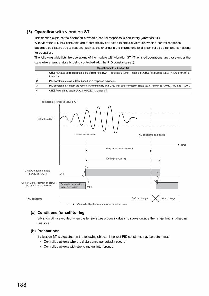
(5) Operation with vibration STThis section explains the operation of when a control response is oscillatory (vibration ST).
With vibration ST, PID constants are automatically corrected to settle a vibration when a control response
becomes oscillatory due to reasons such as the change in the characteristic of a controlled object and conditions
for operation.
The following table lists the operations of the module with vibration ST. (The listed operations are those under the
state where temperature is being controlled with the PID constants set.)
(a) Conditions for self-tuning
Vibration ST is executed when the temperature process value (PV) goes outside the range that is judged as
unstable.
(b) Precautions
If vibration ST is executed on the following objects, incorrect PID constants may be determined:
• Controlled objects where a disturbance periodically occurs
• Controlled objects with strong mutual interference
Operation with vibration ST
1CH PID auto-correction status (b0 of RWr14 to RWr17) is turned 0 (OFF). In addition, CH Auto tuning status (RX20 to RX23) is
turned on.
2 PID constants are calculated based on a response waveform.
3 PID constants are set in the remote buffer memory and CH PID auto-correction status (b0 of RWr14 to RWr17) is turned 1 (ON).
4 CH Auto tuning status (RX20 to RX23) is turned off.
OFF
ON
OFF
ON
Temperature process value (PV)
Set value (SV)
Oscillation detected PID constants calculated
Response measurementTime
Before change After change
During self-tuning
Depends on previous execution result
PID constants
CH□ PID auto-correction status (b0 of RWr14 to RWr17)
CH□ Auto tuning status (RX20 to RX23)
Controlled by the temperature control module
188
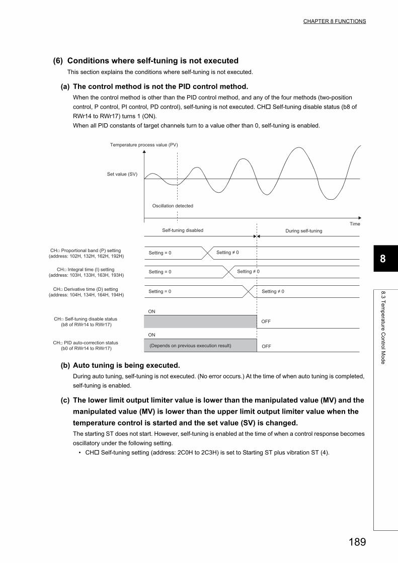
CHAPTER 8 FUNCTIONS
8
8.3
Te
mp
era
ture
Co
ntro
l Mo
de
(6) Conditions where self-tuning is not executedThis section explains the conditions where self-tuning is not executed.
(a) The control method is not the PID control method.
When the control method is other than the PID control method, and any of the four methods (two-position
control, P control, PI control, PD control), self-tuning is not executed. CH Self-tuning disable status (b8 of
RWr14 to RWr17) turns 1 (ON).
When all PID constants of target channels turn to a value other than 0, self-tuning is enabled.
(b) Auto tuning is being executed.
During auto tuning, self-tuning is not executed. (No error occurs.) At the time of when auto tuning is completed,
self-tuning is enabled.
(c) The lower limit output limiter value is lower than the manipulated value (MV) and the
manipulated value (MV) is lower than the upper limit output limiter value when the
temperature control is started and the set value (SV) is changed.
The starting ST does not start. However, self-tuning is enabled at the time of when a control response becomes
oscillatory under the following setting.
• CH Self-tuning setting (address: 2C0H to 2C3H) is set to Starting ST plus vibration ST (4).
ON
ON
OFF
OFF
Temperature process value (PV)
Time
Set value (SV)
Self-tuning disabled During self-tuning
Setting = 0 Setting ≠ 0
Setting = 0 Setting ≠ 0
(Depends on previous execution result)
Oscillation detected
Setting = 0 Setting ≠ 0
CH□ Proportional band (P) setting (address: 102H, 132H, 162H, 192H)
CH□ Derivative time (D) setting (address: 104H, 134H, 164H, 194H)
CH□ Self-tuning disable status (b8 of RWr14 to RWr17)
CH□ PID auto-correction status (b0 of RWr14 to RWr17)
CH□ Integral time (I) setting (address: 103H, 133H, 163H, 193H)
189
(d) The temperature process value (PV) is not within the temperature measurement
range.
The self-tuning is not executed. CH Self-tuning disable status (b8 of RWr14 to RWr17) turns 1 (ON).
(e) The value set in CH Output variation limiter setting (address: 107H, 137H, 167H,
197H) is not 0.
The self-tuning is not executed. CH Self-tuning disable status (b8 of RWr14 to RWr17) turns 1 (ON).
If the setting value is not 0, refer to the following.
Page 323, Appendix 3 (11)
(f) CH AUTO/MAN mode shift (address: 113H, 143H, 173H, 1A3H) is set to MAN (1).
The self-tuning is not executed. CH Self-tuning disable status (b8 of RWr14 to RWr17) turns 1 (ON).
If the setting is MAN (1), refer to the following.
Page 332, Appendix 3 (22)
(g) Values other than 0 (0.0%) have been set for the setting change rate limiter.
If the values other than 0 (0.0%) have been set to the following remote buffer memory areas, self-tuning is not
executed. CH Self-tuning disable status (b8 of RWr14 to RWr17) turns 1 (ON).
If the setting value is other than 0 (0.0%), refer to the following.
Page 325, Appendix 3 (13)
(h) The heating-cooling control has been selected for the control mode.
The self-tuning is not executed.
If the heating-cooling control has been selected, refer to the following.
Page 311, Appendix 3 (3)
(7) Discontinuation of self-tuningThe following operation during self-tuning discontinues the self-tuning operation.
• The setting in CH Self-tuning setting (address: 2C0H to 2C3H) has been changed to Do Not run the ST
(0).
The self-tuning operation in process is discontinued and self-tuning is not performed anymore after that. (An error
does not occur.)
Whether self-tuning is being executed can be checked in CH Auto tuning status (RX20 to RX23). (Page
291, Appendix 1.1 (12))
Remote buffer memory area nameRemote buffer memory address
CH1 CH2 CH3 CH4
CH Setting change rate limiter/Setting change rate limiter (temperature rise) 108H 138H 168H 198H
CH Setting change rate limiter (temperature drop) 1C8H 1CDH 1D2H 1D7H
190
CHAPTER 8 FUNCTIONS
8
8.3
Te
mp
era
ture
Co
ntro
l Mo
de
(8) Conditions where self-tuning does not complete due to errorsThe following operations and conditions cause an abend of self-tuning. At the abend, CH Self-tuning error (b10
of RWr14 to RWr17) turns 1 (ON).
• When 6000s (1 hour and 40 minutes) or longer passes after the start of ST
• When the change rate of the temperature process value (PV) during ST is less than 1.125 (/minute)
• When CH Temperature process value (PV) (RWr8 to RWrB) is outside the temperature measurement
range (Page 303, Appendix 2 (5))
• When the manipulated value (MV) does not reach the upper limit output limiter value or lower limit output
limiter value before the measurement is completed and necessary measurement data is not obtained
• When self-tuning is started with the starting ST and the temperature process value (PV) that is supposed to
rise drops by 1 () or more
• When self-tuning is started with the starting ST and the temperature process value (PV) that is supposed to
drop rises by 1 () or more
• When the setting for the remote buffer memory areas in the following table is changed during self-tuning
*1 Changing the setting causes an abend only during the activation of ST by start ST.
Remote buffer memory area nameRemote buffer memory address
ReferenceCH1 CH2 CH3 CH4
CH Set value (SV) setting*1 101H 131H 161H 191H Page 317, Appendix 3 (6)
CH Proportional band (P) setting 102H 132H 162H 192H Page 318, Appendix 3 (7)
CH Integral time (I) setting 103H 133H 163H 193H Page 320, Appendix 3 (8)
CH Derivative time (D) setting 104H 134H 164H 194H Page 320, Appendix 3 (9)
CH Upper limit output limiter 105H 135H 165H 195HPage 321, Appendix 3 (10)
CH Lower limit output limiter 106H 136H 166H 196H
CH Output variation limiter setting 107H 137H 167H 197H Page 323, Appendix 3 (11)
CH Setting change rate limiter 108H 138H 168H 198H Page 324, Appendix 3 (12)
CH Control output cycle setting 10CH 13CH 16CH 19CH Page 326, Appendix 3 (15)
CH Primary delay digital filter setting 10DH 13DH 16DH 19DH Page 328, Appendix 3 (16)
CH AUTO/MAN mode shift 113H 143H 173H 1A3H Page 334, Appendix 3 (24)
CH Forward/reverse action setting 115H 145H 175H 1A5H Page 334, Appendix 3 (24)
CH Sensor correction value setting 280H 281H 282H 283H Page 352, Appendix 3 (51)
191
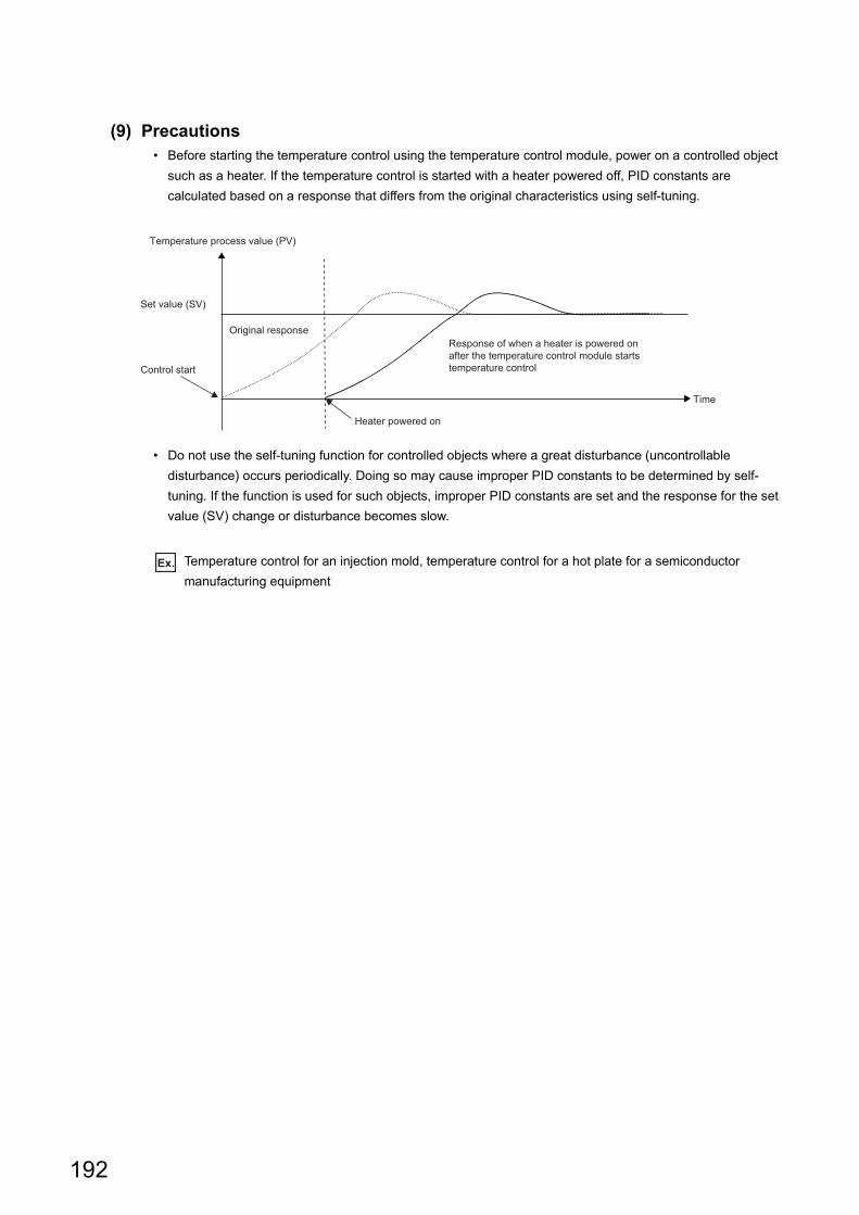
(9) Precautions• Before starting the temperature control using the temperature control module, power on a controlled object
such as a heater. If the temperature control is started with a heater powered off, PID constants are
calculated based on a response that differs from the original characteristics using self-tuning.
• Do not use the self-tuning function for controlled objects where a great disturbance (uncontrollable
disturbance) occurs periodically. Doing so may cause improper PID constants to be determined by self-
tuning. If the function is used for such objects, improper PID constants are set and the response for the set
value (SV) change or disturbance becomes slow.
Ex. Temperature control for an injection mold, temperature control for a hot plate for a semiconductor
manufacturing equipment
Temperature process value (PV)
Time
Set value (SV)
Control start
Heater powered on
Original responseResponse of when a heater is powered on after the temperature control module starts temperature control
192
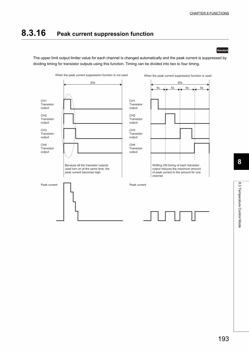
CHAPTER 8 FUNCTIONS
8
8.3
Te
mp
era
ture
Co
ntro
l Mo
de
8.3.16 Peak current suppression function
The upper limit output limiter value for each channel is changed automatically and the peak current is suppressed by
dividing timing for transistor outputs using this function. Timing can be divided into two to four timing.
Standard
20s
5s
20s
5s 5s 5s
CH1 Transistor output
CH2 Transistor output
CH3 Transistor output
CH4 Transistor output
Peak current Peak current
CH1 Transistor output
CH2 Transistor output
CH3 Transistor output
CH4 Transistor output
Because all the transistor outputs used turn on at the same time, the peak current becomes high.
Shifting ON timing of each transistor output reduces the maximum amount of peak current to the amount for one channel.
When the peak current suppression function is not used When the peak current suppression function is used
193
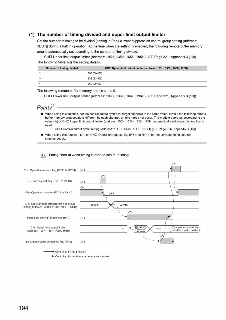
(1) The number of timing divided and upper limit output limiterSet the number of timing to be divided (setting in Peak current suppression control group setting (address:
1E5H)) during a halt in operation. At the time when the setting is enabled, the following remote buffer memory
area is automatically set according to the number of timing divided.
• CH Upper limit output limiter (address: 105H, 135H, 165H, 195H) (Page 321, Appendix 3 (10))
The following table lists the setting details.
The following remote buffer memory area is set to 0.
• CH Lower limit output limiter (address: 106H, 136H, 166H, 196H) (Page 321, Appendix 3 (10))
● When using this function, set the control output cycles for target channels to the same value. Even if the following remote buffer memory area setting is different by each channel, an error does not occur. The module operates according to the value (%) of CH Upper limit output limiter (address: 105H, 135H, 165H, 195H) automatically set when this function is used.
• CH Control output cycle setting (address: 10CH, 13CH, 16CH, 19CH) (Page 326, Appendix 3 (15))
● When using this function, turn on CH Operation request flag (RY11 to RY14) for the corresponding channel simultaneously.
Ex. Timing chart of when timing is divided into four timing
Number of timing divided CH Upper limit output limiter (address: 105H, 135H, 165H, 195H)
2 500 (50.0%)
3 333 (33.3%)
4 250 (25.0%)
ON
ON
ON
0
0000H 4321H
OFF
OFF
ON
OFF
OFF
ON
OFF
Controlled by the program
250 (25.0%)(Automatic
storing)
(Change the automatically-calculated result if needed.)
CH□ Stop request flag (RY18 to RY1B)
CH□ Operation request flag (RY11 to RY14)
CH□ Operation monitor (RX11 to RX14)
Initial data setting request flag (RY9)
Initial data setting completed flag (RX9)
CH□ Simultaneous temperature rise group setting (address: 2D0H, 2D4H, 2D8H, 2DCH)
CH□ Upper limit output limiter (address: 105H, 135H, 165H, 195H)
Controlled by the temperature control module
194
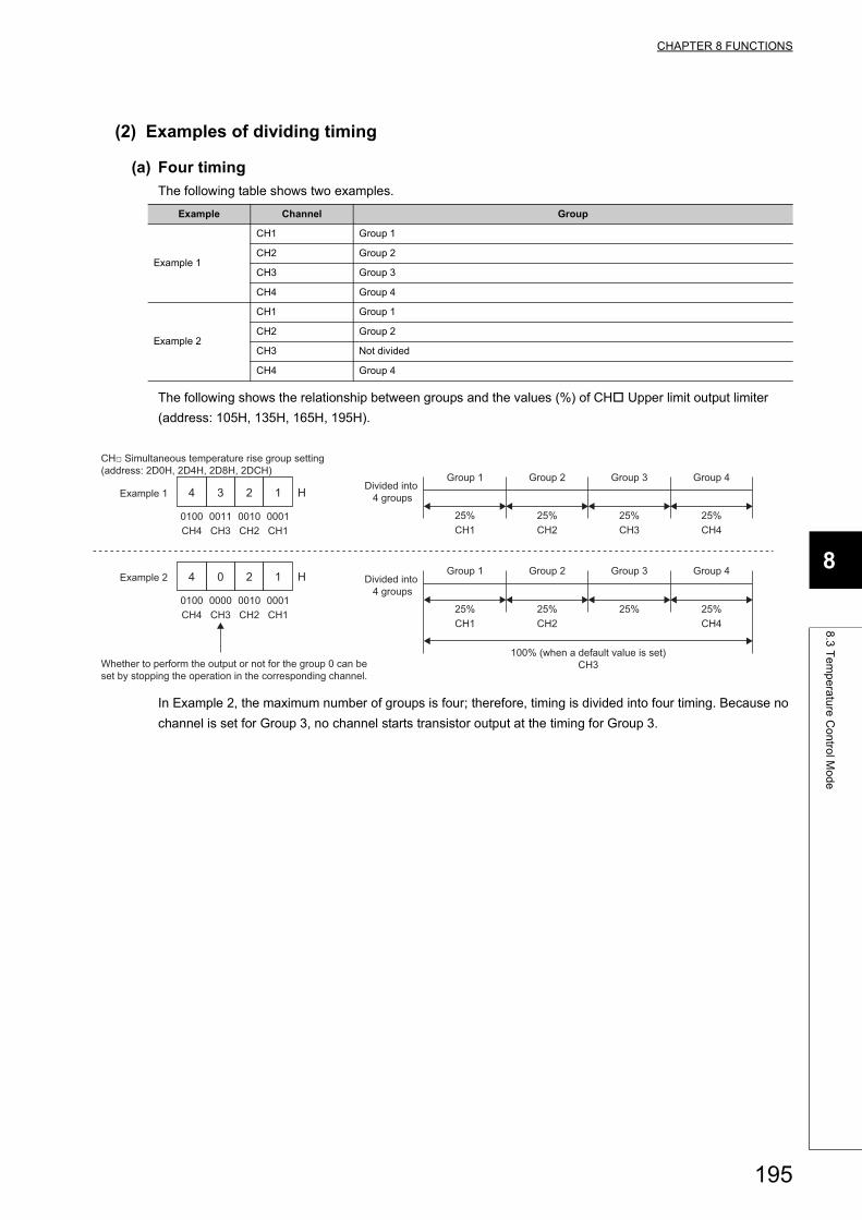
CHAPTER 8 FUNCTIONS
8
8.3
Te
mp
era
ture
Co
ntro
l Mo
de
(2) Examples of dividing timing
(a) Four timing
The following table shows two examples.
The following shows the relationship between groups and the values (%) of CH Upper limit output limiter
(address: 105H, 135H, 165H, 195H).
In Example 2, the maximum number of groups is four; therefore, timing is divided into four timing. Because no
channel is set for Group 3, no channel starts transistor output at the timing for Group 3.
Example Channel Group
Example 1
CH1 Group 1
CH2 Group 2
CH3 Group 3
CH4 Group 4
Example 2
CH1 Group 1
CH2 Group 2
CH3 Not divided
CH4 Group 4
4 3 2 1 H
4 0 2 1 H
Example 1
0100 0011 0010 0001
Group 1 Group 2 Group 3 Group 4
25% 25% 25% 25%CH1
Divided into 4 groups
CH2 CH3 CH4
Group 1 Group 2 Group 3 Group 4
25% 25% 25% 25%CH1
Divided into 4 groups
CH2
100% (when a default value is set)CH3
CH4
CH4 CH3 CH2 CH1
Example 2
0100 0000 0010 0001CH4 CH3 CH2 CH1
CH□ Simultaneous temperature rise group setting (address: 2D0H, 2D4H, 2D8H, 2DCH)
Whether to perform the output or not for the group 0 can be set by stopping the operation in the corresponding channel.
195
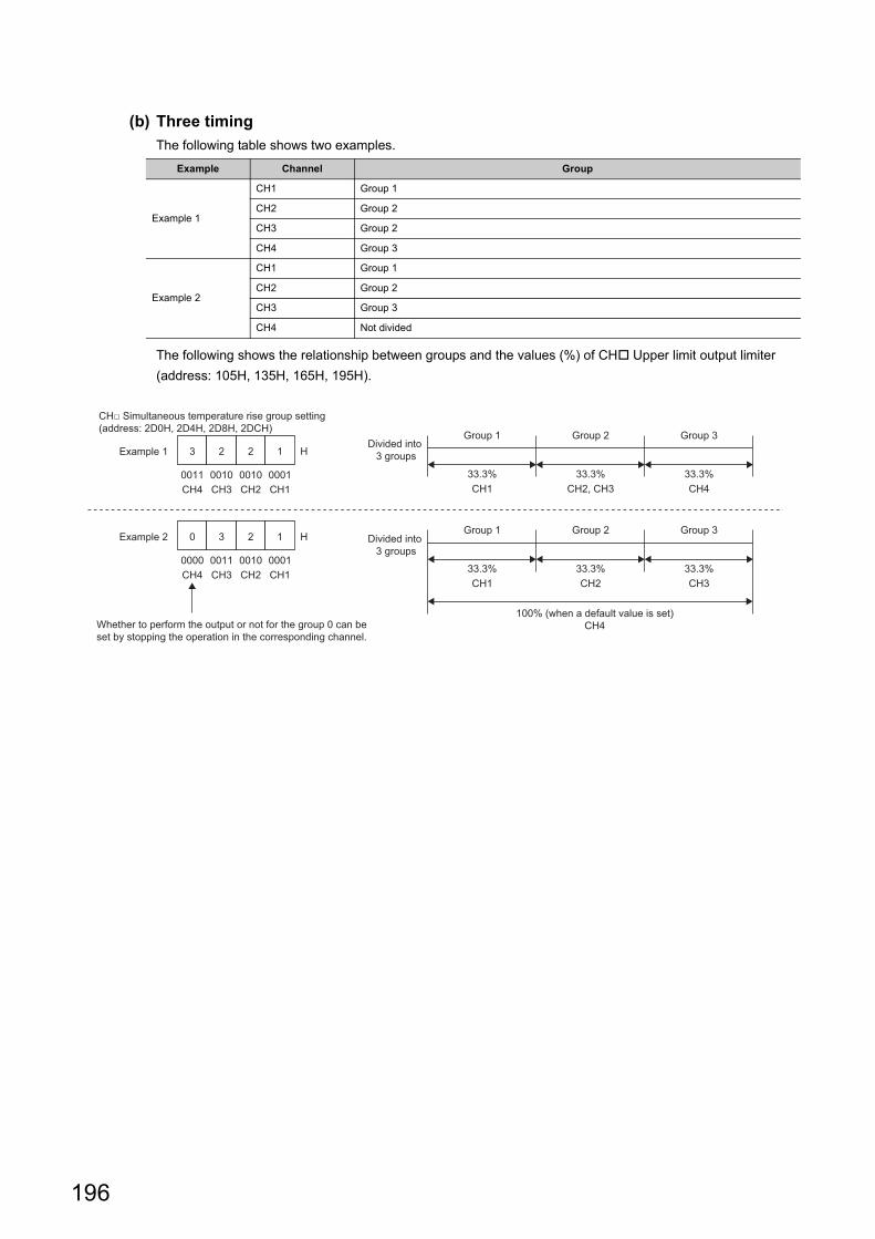
(b) Three timing
The following table shows two examples.
The following shows the relationship between groups and the values (%) of CH Upper limit output limiter
(address: 105H, 135H, 165H, 195H).
Example Channel Group
Example 1
CH1 Group 1
CH2 Group 2
CH3 Group 2
CH4 Group 3
Example 2
CH1 Group 1
CH2 Group 2
CH3 Group 3
CH4 Not divided
3 2 2 1 H
0 3 2 1 H
Example 1
0011 0010 0010 0001
Group 1 Group 2 Group 3
33.3% 33.3% 33.3%CH1
Divided into 3 groups
CH2, CH3 CH4
Group 1 Group 2 Group 3
33.3% 33.3% 33.3%CH1 CH2 CH3
Divided into 3 groups
100% (when a default value is set)CH4
CH4 CH3 CH2 CH1
Example 2
0000 0011 0010 0001CH4 CH3 CH2 CH1
CH□ Simultaneous temperature rise group setting (address: 2D0H, 2D4H, 2D8H, 2DCH)
Whether to perform the output or not for the group 0 can be set by stopping the operation in the corresponding channel.
196
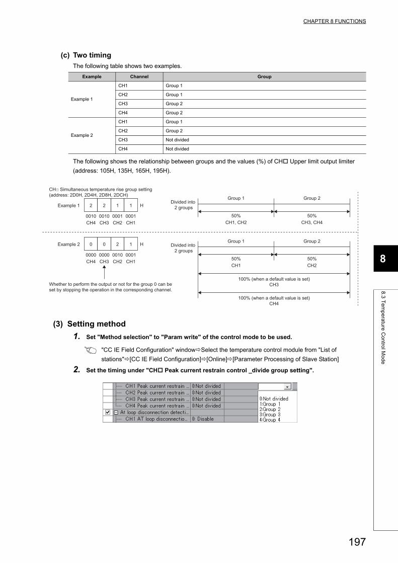
CHAPTER 8 FUNCTIONS
8
8.3
Te
mp
era
ture
Co
ntro
l Mo
de
(c) Two timing
The following table shows two examples.
The following shows the relationship between groups and the values (%) of CH Upper limit output limiter
(address: 105H, 135H, 165H, 195H).
(3) Setting method
1. Set "Method selection" to "Param write" of the control mode to be used.
"CC IE Field Configuration" windowSelect the temperature control module from "List of
stations"[CC IE Field Configuration][Online][Parameter Processing of Slave Station]
2. Set the timing under "CH Peak current restrain control _divide group setting".
Example Channel Group
Example 1
CH1 Group 1
CH2 Group 1
CH3 Group 2
CH4 Group 2
Example 2
CH1 Group 1
CH2 Group 2
CH3 Not divided
CH4 Not divided
2 2 1 1 H
0 0 2 1 H
Example 1
0010 0010 0001 0001
Group 1 Group 2
50% 50%CH1, CH2
Divided into 2 groups
CH3, CH4
Group 1 Group 2
50% 50%CH1 CH2
Divided into 2 groups
100% (when a default value is set)CH3
100% (when a default value is set)CH4
CH4 CH3 CH2 CH1
Example 2
0000 0000 0010 0001CH4 CH3 CH2 CH1
CH□ Simultaneous temperature rise group setting (address: 2D0H, 2D4H, 2D8H, 2DCH)
Whether to perform the output or not for the group 0 can be set by stopping the operation in the corresponding channel.
197
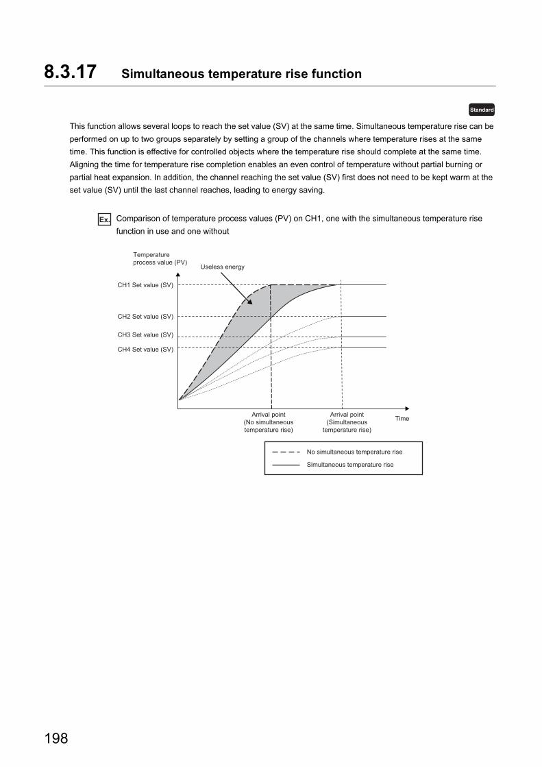
8.3.17 Simultaneous temperature rise function
This function allows several loops to reach the set value (SV) at the same time. Simultaneous temperature rise can be
performed on up to two groups separately by setting a group of the channels where temperature rises at the same
time. This function is effective for controlled objects where the temperature rise should complete at the same time.
Aligning the time for temperature rise completion enables an even control of temperature without partial burning or
partial heat expansion. In addition, the channel reaching the set value (SV) first does not need to be kept warm at the
set value (SV) until the last channel reaches, leading to energy saving.
Ex. Comparison of temperature process values (PV) on CH1, one with the simultaneous temperature rise
function in use and one without
Standard
CH1 Set value (SV)
Arrival point(Simultaneous
temperature rise)
Arrival point(No simultaneoustemperature rise)
No simultaneous temperature rise
Simultaneous temperature rise
Useless energy
Temperatureprocess value (PV)
Time
CH2 Set value (SV)
CH3 Set value (SV)
CH4 Set value (SV)
198
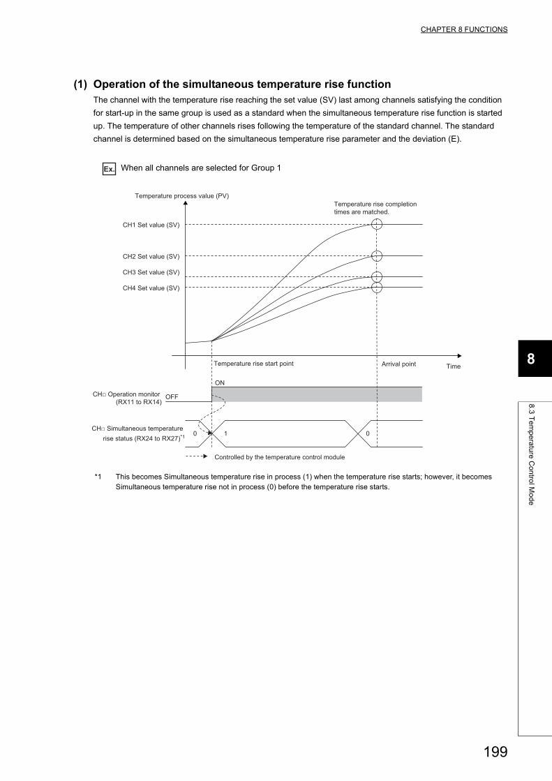
CHAPTER 8 FUNCTIONS
8
8.3
Te
mp
era
ture
Co
ntro
l Mo
de
(1) Operation of the simultaneous temperature rise functionThe channel with the temperature rise reaching the set value (SV) last among channels satisfying the condition
for start-up in the same group is used as a standard when the simultaneous temperature rise function is started
up. The temperature of other channels rises following the temperature of the standard channel. The standard
channel is determined based on the simultaneous temperature rise parameter and the deviation (E).
Ex. When all channels are selected for Group 1
*1 This becomes Simultaneous temperature rise in process (1) when the temperature rise starts; however, it becomes Simultaneous temperature rise not in process (0) before the temperature rise starts.
1 00
OFF
ON
CH1 Set value (SV)
Temperature rise completion times are matched.
Temperature process value (PV)
TimeArrival point
CH2 Set value (SV)
CH3 Set value (SV)
CH4 Set value (SV)
Temperature rise start point
CH□ Simultaneous temperature rise status (RX24 to RX27)*1
CH□ Operation monitor (RX11 to RX14)
Controlled by the temperature control module
199
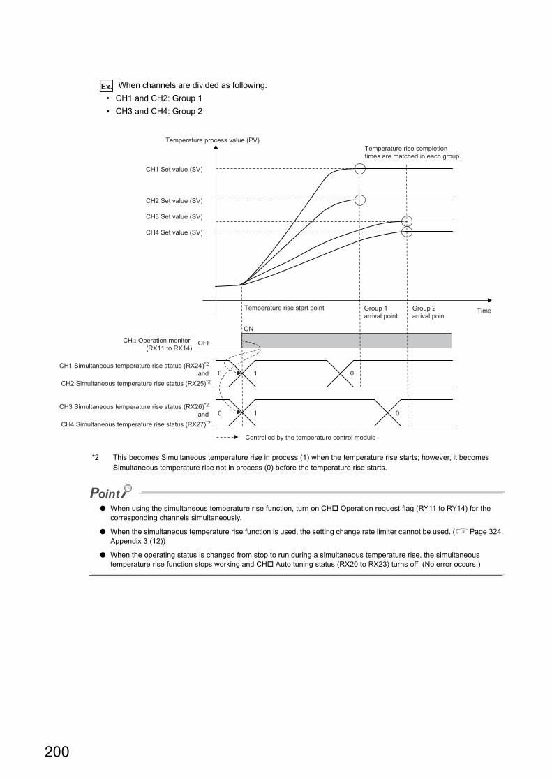
Ex. When channels are divided as following:
• CH1 and CH2: Group 1
• CH3 and CH4: Group 2
*2 This becomes Simultaneous temperature rise in process (1) when the temperature rise starts; however, it becomes Simultaneous temperature rise not in process (0) before the temperature rise starts.
● When using the simultaneous temperature rise function, turn on CH Operation request flag (RY11 to RY14) for the corresponding channels simultaneously.
● When the simultaneous temperature rise function is used, the setting change rate limiter cannot be used. (Page 324, Appendix 3 (12))
● When the operating status is changed from stop to run during a simultaneous temperature rise, the simultaneous temperature rise function stops working and CH Auto tuning status (RX20 to RX23) turns off. (No error occurs.)
1
0
00
10
ON
OFF
CH1 Set value (SV)
Temperature rise completion times are matched in each group.
Temperature process value (PV)
TimeGroup 2 arrival point
CH2 Set value (SV)
CH3 Set value (SV)
CH4 Set value (SV)
Temperature rise start point Group 1 arrival point
CH1 Simultaneous temperature rise status (RX24)*2 and
CH2 Simultaneous temperature rise status (RX25)*2
CH3 Simultaneous temperature rise status (RX26)*2 and
CH4 Simultaneous temperature rise status (RX27)*2
CH□ Operation monitor (RX11 to RX14)
Controlled by the temperature control module
200
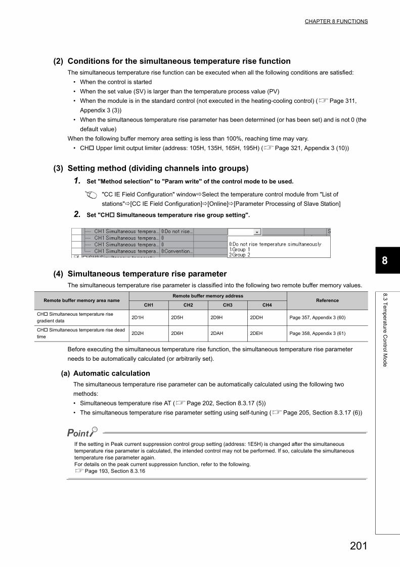
CHAPTER 8 FUNCTIONS
8
8.3
Te
mp
era
ture
Co
ntro
l Mo
de
(2) Conditions for the simultaneous temperature rise functionThe simultaneous temperature rise function can be executed when all the following conditions are satisfied:
• When the control is started
• When the set value (SV) is larger than the temperature process value (PV)
• When the module is in the standard control (not executed in the heating-cooling control) (Page 311,
Appendix 3 (3))
• When the simultaneous temperature rise parameter has been determined (or has been set) and is not 0 (the
default value)
When the following buffer memory area setting is less than 100%, reaching time may vary.
• CH Upper limit output limiter (address: 105H, 135H, 165H, 195H) (Page 321, Appendix 3 (10))
(3) Setting method (dividing channels into groups)
1. Set "Method selection" to "Param write" of the control mode to be used.
"CC IE Field Configuration" windowSelect the temperature control module from "List of
stations"[CC IE Field Configuration][Online][Parameter Processing of Slave Station]
2. Set "CH Simultaneous temperature rise group setting".
(4) Simultaneous temperature rise parameterThe simultaneous temperature rise parameter is classified into the following two remote buffer memory values.
Before executing the simultaneous temperature rise function, the simultaneous temperature rise parameter
needs to be automatically calculated (or arbitrarily set).
(a) Automatic calculation
The simultaneous temperature rise parameter can be automatically calculated using the following two
methods:
• Simultaneous temperature rise AT (Page 202, Section 8.3.17 (5))
• The simultaneous temperature rise parameter setting using self-tuning (Page 205, Section 8.3.17 (6))
If the setting in Peak current suppression control group setting (address: 1E5H) is changed after the simultaneous temperature rise parameter is calculated, the intended control may not be performed. If so, calculate the simultaneous temperature rise parameter again.For details on the peak current suppression function, refer to the following.Page 193, Section 8.3.16
Remote buffer memory area nameRemote buffer memory address
ReferenceCH1 CH2 CH3 CH4
CH Simultaneous temperature rise
gradient data2D1H 2D5H 2D9H 2DDH Page 357, Appendix 3 (60)
CH Simultaneous temperature rise dead
time2D2H 2D6H 2DAH 2DEH Page 358, Appendix 3 (61)
201
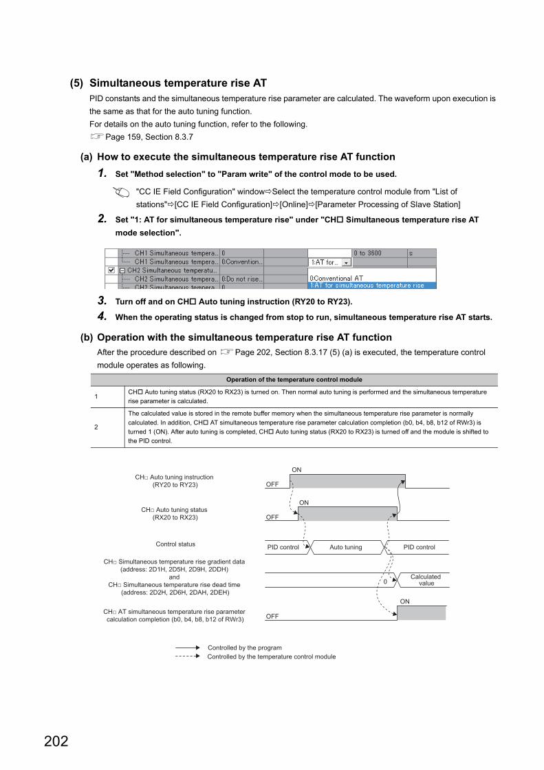
(5) Simultaneous temperature rise ATPID constants and the simultaneous temperature rise parameter are calculated. The waveform upon execution is
the same as that for the auto tuning function.
For details on the auto tuning function, refer to the following.
Page 159, Section 8.3.7
(a) How to execute the simultaneous temperature rise AT function
1. Set "Method selection" to "Param write" of the control mode to be used.
"CC IE Field Configuration" windowSelect the temperature control module from "List of
stations"[CC IE Field Configuration][Online][Parameter Processing of Slave Station]
2. Set "1: AT for simultaneous temperature rise" under "CH Simultaneous temperature rise AT
mode selection".
3. Turn off and on CH Auto tuning instruction (RY20 to RY23).
4. When the operating status is changed from stop to run, simultaneous temperature rise AT starts.
(b) Operation with the simultaneous temperature rise AT function
After the procedure described on Page 202, Section 8.3.17 (5) (a) is executed, the temperature control
module operates as following.
Operation of the temperature control module
1CH Auto tuning status (RX20 to RX23) is turned on. Then normal auto tuning is performed and the simultaneous temperature
rise parameter is calculated.
2
The calculated value is stored in the remote buffer memory when the simultaneous temperature rise parameter is normally
calculated. In addition, CH AT simultaneous temperature rise parameter calculation completion (b0, b4, b8, b12 of RWr3) is
turned 1 (ON). After auto tuning is completed, CH Auto tuning status (RX20 to RX23) is turned off and the module is shifted to
the PID control.
OFF
OFF
OFF
ON
ON
ON
0
Control status
Controlled by the program
PID control Auto tuning PID control
Calculated value
CH□ Simultaneous temperature rise gradient data (address: 2D1H, 2D5H, 2D9H, 2DDH)
and CH□ Simultaneous temperature rise dead time
(address: 2D2H, 2D6H, 2DAH, 2DEH)
CH□ AT simultaneous temperature rise parameter calculation completion (b0, b4, b8, b12 of RWr3)
CH□ Auto tuning status (RX20 to RX23)
CH□ Auto tuning instruction (RY20 to RY23)
Controlled by the temperature control module
202
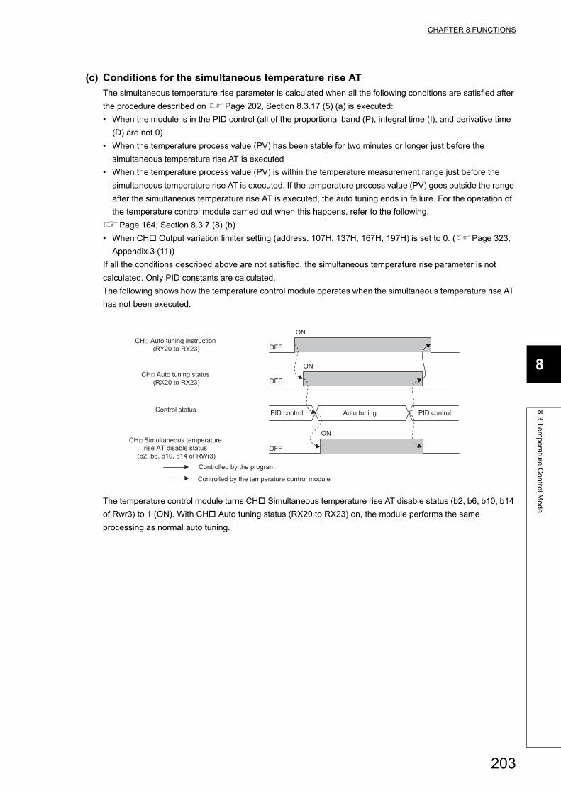
CHAPTER 8 FUNCTIONS
8
8.3
Te
mp
era
ture
Co
ntro
l Mo
de
(c) Conditions for the simultaneous temperature rise AT
The simultaneous temperature rise parameter is calculated when all the following conditions are satisfied after
the procedure described on Page 202, Section 8.3.17 (5) (a) is executed:
• When the module is in the PID control (all of the proportional band (P), integral time (I), and derivative time
(D) are not 0)
• When the temperature process value (PV) has been stable for two minutes or longer just before the
simultaneous temperature rise AT is executed
• When the temperature process value (PV) is within the temperature measurement range just before the
simultaneous temperature rise AT is executed. If the temperature process value (PV) goes outside the range
after the simultaneous temperature rise AT is executed, the auto tuning ends in failure. For the operation of
the temperature control module carried out when this happens, refer to the following.
Page 164, Section 8.3.7 (8) (b)
• When CH Output variation limiter setting (address: 107H, 137H, 167H, 197H) is set to 0. (Page 323,
Appendix 3 (11))
If all the conditions described above are not satisfied, the simultaneous temperature rise parameter is not
calculated. Only PID constants are calculated.
The following shows how the temperature control module operates when the simultaneous temperature rise AT
has not been executed.
The temperature control module turns CH Simultaneous temperature rise AT disable status (b2, b6, b10, b14
of Rwr3) to 1 (ON). With CH Auto tuning status (RX20 to RX23) on, the module performs the same
processing as normal auto tuning.
OFF
OFF
OFF
ON
ON
ON
Control status PID control Auto tuning PID control
Controlled by the program
CH□ Simultaneous temperature rise AT disable status
(b2, b6, b10, b14 of RWr3)
CH□ Auto tuning status (RX20 to RX23)
CH□ Auto tuning instruction (RY20 to RY23)
Controlled by the temperature control module
203
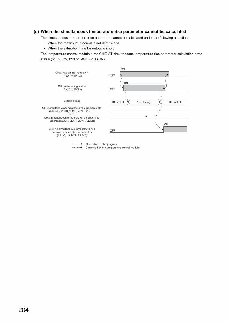
(d) When the simultaneous temperature rise parameter cannot be calculated
The simultaneous temperature rise parameter cannot be calculated under the following conditions:
• When the maximum gradient is not determined
• When the saturation time for output is short
The temperature control module turns CH AT simultaneous temperature rise parameter calculation error
status (b1, b5, b9, b13 of RWr3) to 1 (ON).
OFF
OFF
OFF
ON
ON
ON
0
Control status
Controlled by the program
PID control Auto tuning PID control
CH□ Simultaneous temperature rise gradient data (address: 2D1H, 2D5H, 2D9H, 2DDH)
and CH□ Simultaneous temperature rise dead time
(address: 2D2H, 2D6H, 2DAH, 2DEH)
CH□ AT simultaneous temperature rise parameter calculation error status
(b1, b5, b9, b13 of RWr3)
CH□ Auto tuning status (RX20 to RX23)
CH□ Auto tuning instruction (RY20 to RY23)
Controlled by the temperature control module
204
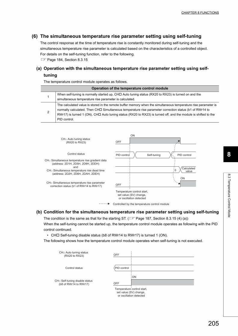
CHAPTER 8 FUNCTIONS
8
8.3
Te
mp
era
ture
Co
ntro
l Mo
de
(6) The simultaneous temperature rise parameter setting using self-tuningThe control response at the time of temperature rise is constantly monitored during self-tuning and the
simultaneous temperature rise parameter is calculated based on the characteristics of a controlled object.
For details on the self-tuning function, refer to the following.
Page 184, Section 8.3.15
(a) Operation with the simultaneous temperature rise parameter setting using self-
tuning
The temperature control module operates as follows.
(b) Condition for the simultaneous temperature rise parameter setting using self-tuning
The condition is the same as that for the starting ST. (Page 187, Section 8.3.15 (4) (a))
When the self-tuning cannot be started up, the temperature control module operates as following with the PID
control continued.
• CH Self-tuning disable status (b8 of RWr14 to RWr17) is turned 1 (ON).
The following shows how the temperature control module operates when self-tuning is not executed.
Operation of the temperature control module
1When self-tuning is normally started up, CH Auto tuning status (RX20 to RX23) is turned on and the
simultaneous temperature rise parameter is calculated.
2
The calculated value is stored in the remote buffer memory when the simultaneous temperature rise parameter is
normally calculated. Then CH Simultaneous temperature rise parameter correction status (b1 of RWr14 to
RWr17) is turned 1 (ON), CH Auto tuning status (RX20 to RX23) is turned off, and the module is shifted to the
PID control.
OFF
OFF
ON
ON
0
Control status
Calculated value
PID control Self-tuning PID control
Temperature control start, set value (SV) change, or oscillation detected
CH□ Simultaneous temperature rise gradient data (address: 2D1H, 2D5H, 2D9H, 2DDH)
and CH□ Simultaneous temperature rise dead time
(address: 2D2H, 2D6H, 2DAH, 2DEH)
CH□ Simultaneous temperature rise parameter correction status (b1 of RWr14 to RWr17)
CH□ Auto tuning status (RX20 to RX23)
Controlled by the temperature control module
OFF
OFF
ON
Control status PID control
Temperature control start, set value (SV) change, or oscillation detected
CH□ Self-tuning disable status (b8 of RWr14 to RWr17)
CH□ Auto tuning status (RX20 to RX23)
205
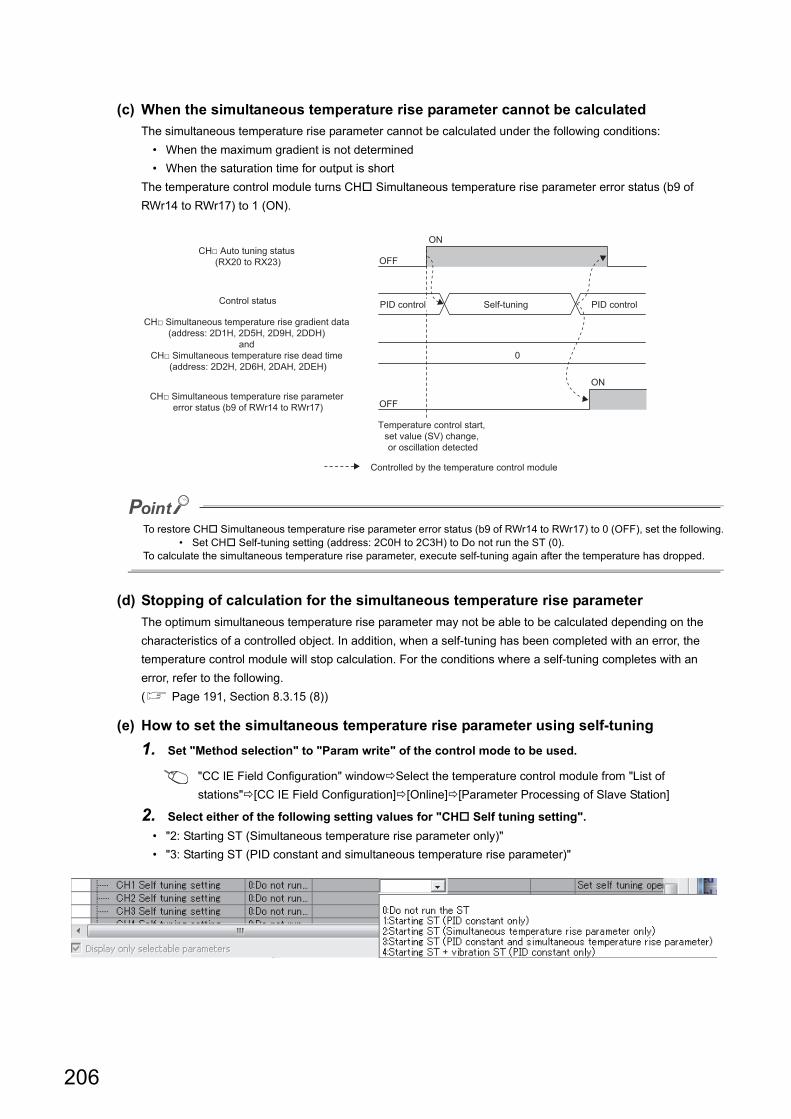
(c) When the simultaneous temperature rise parameter cannot be calculated
The simultaneous temperature rise parameter cannot be calculated under the following conditions:
• When the maximum gradient is not determined
• When the saturation time for output is short
The temperature control module turns CH Simultaneous temperature rise parameter error status (b9 of
RWr14 to RWr17) to 1 (ON).
To restore CH Simultaneous temperature rise parameter error status (b9 of RWr14 to RWr17) to 0 (OFF), set the following.• Set CH Self-tuning setting (address: 2C0H to 2C3H) to Do not run the ST (0).
To calculate the simultaneous temperature rise parameter, execute self-tuning again after the temperature has dropped.
(d) Stopping of calculation for the simultaneous temperature rise parameter
The optimum simultaneous temperature rise parameter may not be able to be calculated depending on the
characteristics of a controlled object. In addition, when a self-tuning has been completed with an error, the
temperature control module will stop calculation. For the conditions where a self-tuning completes with an
error, refer to the following.
( Page 191, Section 8.3.15 (8))
(e) How to set the simultaneous temperature rise parameter using self-tuning
1. Set "Method selection" to "Param write" of the control mode to be used.
"CC IE Field Configuration" windowSelect the temperature control module from "List of
stations"[CC IE Field Configuration][Online][Parameter Processing of Slave Station]
2. Select either of the following setting values for "CH Self tuning setting".
• "2: Starting ST (Simultaneous temperature rise parameter only)"
• "3: Starting ST (PID constant and simultaneous temperature rise parameter)"
OFF
OFF
ON
ON
0
Control status PID control Self-tuning PID control
Temperature control start, set value (SV) change, or oscillation detected
CH□ Simultaneous temperature rise gradient data (address: 2D1H, 2D5H, 2D9H, 2DDH)
and CH□ Simultaneous temperature rise dead time
(address: 2D2H, 2D6H, 2DAH, 2DEH)
CH□ Simultaneous temperature rise parameter error status (b9 of RWr14 to RWr17)
CH□ Auto tuning status (RX20 to RX23)
Controlled by the temperature control module
206
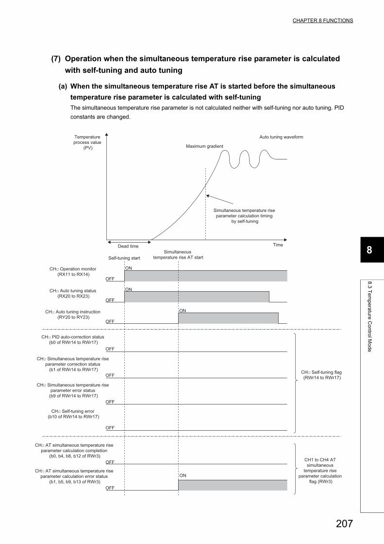
CHAPTER 8 FUNCTIONS
8
8.3
Te
mp
era
ture
Co
ntro
l Mo
de
(7) Operation when the simultaneous temperature rise parameter is calculated
with self-tuning and auto tuning
(a) When the simultaneous temperature rise AT is started before the simultaneous
temperature rise parameter is calculated with self-tuning
The simultaneous temperature rise parameter is not calculated neither with self-tuning nor auto tuning. PID
constants are changed.
ON
OFF
ON
OFF
ON
OFF
ON
OFF
OFF
OFF
OFF
OFF
OFF
Temperature process value
(PV) Maximum gradient
Dead time
Self-tuning startSimultaneous
temperature rise AT start
Time
Auto tuning waveform
Simultaneous temperature rise parameter calculation timing
by self-tuning
CH□ Operation monitor (RX11 to RX14)
CH□ Auto tuning status (RX20 to RX23)
CH□ Auto tuning instruction (RY20 to RY23)
CH□ PID auto-correction status (b0 of RWr14 to RWr17)
CH□ Simultaneous temperature rise parameter correction status
(b1 of RWr14 to RWr17)
CH□ Simultaneous temperature rise parameter error status
(b9 of RWr14 to RWr17)
CH□ AT simultaneous temperature rise parameter calculation completion
(b0, b4, b8, b12 of RWr3)
CH□ AT simultaneous temperature rise parameter calculation error status
(b1, b5, b9, b13 of RWr3)
CH1 to CH4 AT simultaneous
temperature rise parameter calculation
flag (RWr3)
CH□ Self-tuning flag (RWr14 to RWr17)
CH□ Self-tuning error (b10 of RWr14 to RWr17)
207
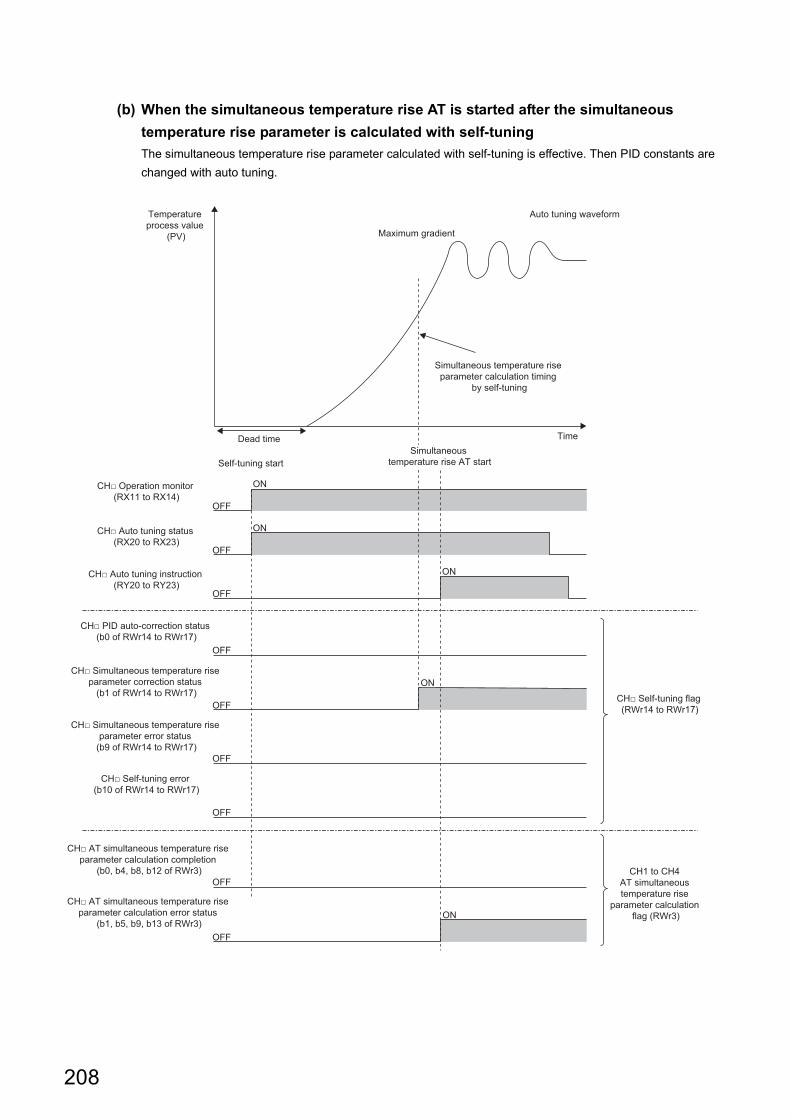
(b) When the simultaneous temperature rise AT is started after the simultaneous
temperature rise parameter is calculated with self-tuning
The simultaneous temperature rise parameter calculated with self-tuning is effective. Then PID constants are
changed with auto tuning.
ON
OFF
ON
OFF
ON
OFF
ON
OFF
ON
OFF
OFF
OFF
OFF
OFF
Temperature process value
(PV) Maximum gradient
Dead time
Self-tuning startSimultaneous
temperature rise AT start
Time
Auto tuning waveform
Simultaneous temperature rise parameter calculation timing
by self-tuning
CH□ Operation monitor (RX11 to RX14)
CH□ Auto tuning status (RX20 to RX23)
CH□ Auto tuning instruction (RY20 to RY23)
CH□ PID auto-correction status (b0 of RWr14 to RWr17)
CH□ Simultaneous temperature rise parameter correction status
(b1 of RWr14 to RWr17)
CH□ Simultaneous temperature rise parameter error status
(b9 of RWr14 to RWr17)
CH□ AT simultaneous temperature rise parameter calculation completion
(b0, b4, b8, b12 of RWr3)
CH□ AT simultaneous temperature rise parameter calculation error status
(b1, b5, b9, b13 of RWr3)
CH1 to CH4 AT simultaneous temperature rise
parameter calculation flag (RWr3)
CH□ Self-tuning flag (RWr14 to RWr17)
CH□ Self-tuning error (b10 of RWr14 to RWr17)
208
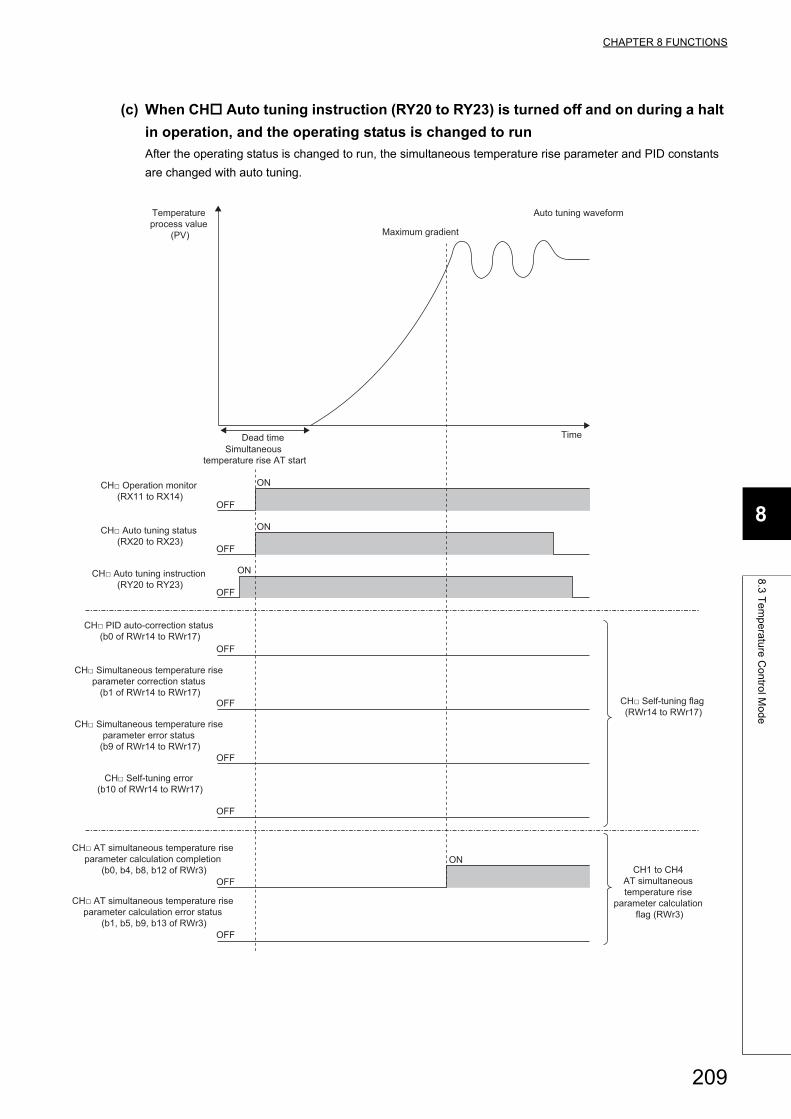
CHAPTER 8 FUNCTIONS
8
8.3
Te
mp
era
ture
Co
ntro
l Mo
de
(c) When CH Auto tuning instruction (RY20 to RY23) is turned off and on during a halt
in operation, and the operating status is changed to run
After the operating status is changed to run, the simultaneous temperature rise parameter and PID constants
are changed with auto tuning.
ON
OFF
ON
OFF
ON
OFF
ON
OFF
OFF
OFF
OFF
OFF
OFF
Temperature process value
(PV) Maximum gradient
Dead timeSimultaneous
temperature rise AT start
Time
Auto tuning waveform
CH□ Operation monitor (RX11 to RX14)
CH□ Auto tuning status (RX20 to RX23)
CH□ Auto tuning instruction (RY20 to RY23)
CH□ PID auto-correction status (b0 of RWr14 to RWr17)
CH□ Simultaneous temperature rise parameter correction status
(b1 of RWr14 to RWr17)
CH□ Simultaneous temperature rise parameter error status
(b9 of RWr14 to RWr17)
CH□ AT simultaneous temperature rise parameter calculation completion
(b0, b4, b8, b12 of RWr3)
CH□ AT simultaneous temperature rise parameter calculation error status
(b1, b5, b9, b13 of RWr3)
CH1 to CH4 AT simultaneous temperature rise
parameter calculation flag (RWr3)
CH□ Self-tuning flag (RWr14 to RWr17)
CH□ Self-tuning error (b10 of RWr14 to RWr17)
209
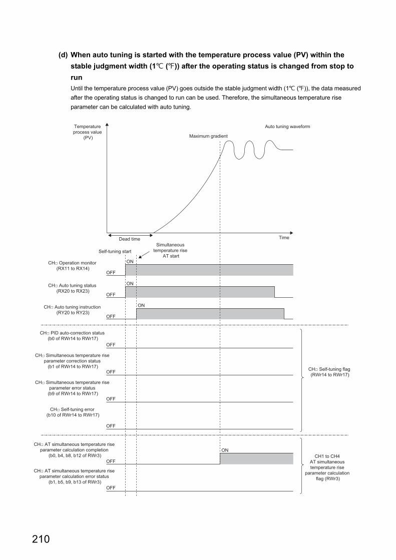
(d) When auto tuning is started with the temperature process value (PV) within the
stable judgment width (1 ()) after the operating status is changed from stop to
run
Until the temperature process value (PV) goes outside the stable judgment width (1 ()), the data measured
after the operating status is changed to run can be used. Therefore, the simultaneous temperature rise
parameter can be calculated with auto tuning.
ON
OFF
ON
OFF
ON
OFF
ON
OFF
OFF
OFF
OFF
OFF
OFF
Temperature process value
(PV) Maximum gradient
Dead time
Self-tuning startSimultaneous
temperature rise AT start
Time
Auto tuning waveform
CH□ Operation monitor (RX11 to RX14)
CH□ Auto tuning status (RX20 to RX23)
CH□ Auto tuning instruction (RY20 to RY23)
CH□ PID auto-correction status (b0 of RWr14 to RWr17)
CH□ Simultaneous temperature rise parameter correction status
(b1 of RWr14 to RWr17)
CH□ Simultaneous temperature rise parameter error status
(b9 of RWr14 to RWr17)
CH□ AT simultaneous temperature rise parameter calculation completion
(b0, b4, b8, b12 of RWr3)
CH□ AT simultaneous temperature rise parameter calculation error status
(b1, b5, b9, b13 of RWr3)
CH1 to CH4 AT simultaneous temperature rise
parameter calculation flag (RWr3)
CH□ Self-tuning flag (RWr14 to RWr17)
CH□ Self-tuning error (b10 of RWr14 to RWr17)
210
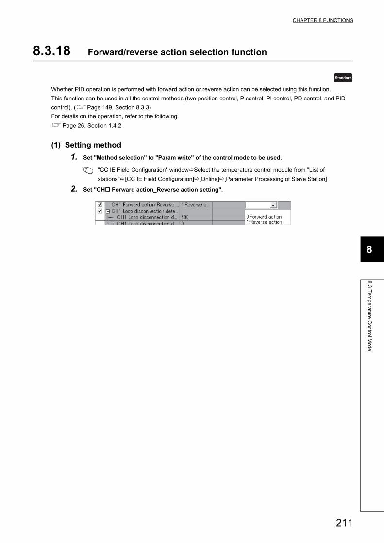
CHAPTER 8 FUNCTIONS
8
8.3
Te
mp
era
ture
Co
ntro
l Mo
de
8.3.18 Forward/reverse action selection function
Whether PID operation is performed with forward action or reverse action can be selected using this function.
This function can be used in all the control methods (two-position control, P control, PI control, PD control, and PID
control). (Page 149, Section 8.3.3)
For details on the operation, refer to the following.
Page 26, Section 1.4.2
(1) Setting method
1. Set "Method selection" to "Param write" of the control mode to be used.
"CC IE Field Configuration" windowSelect the temperature control module from "List of
stations"[CC IE Field Configuration][Online][Parameter Processing of Slave Station]
2. Set "CH Forward action_Reverse action setting".
Standard
211
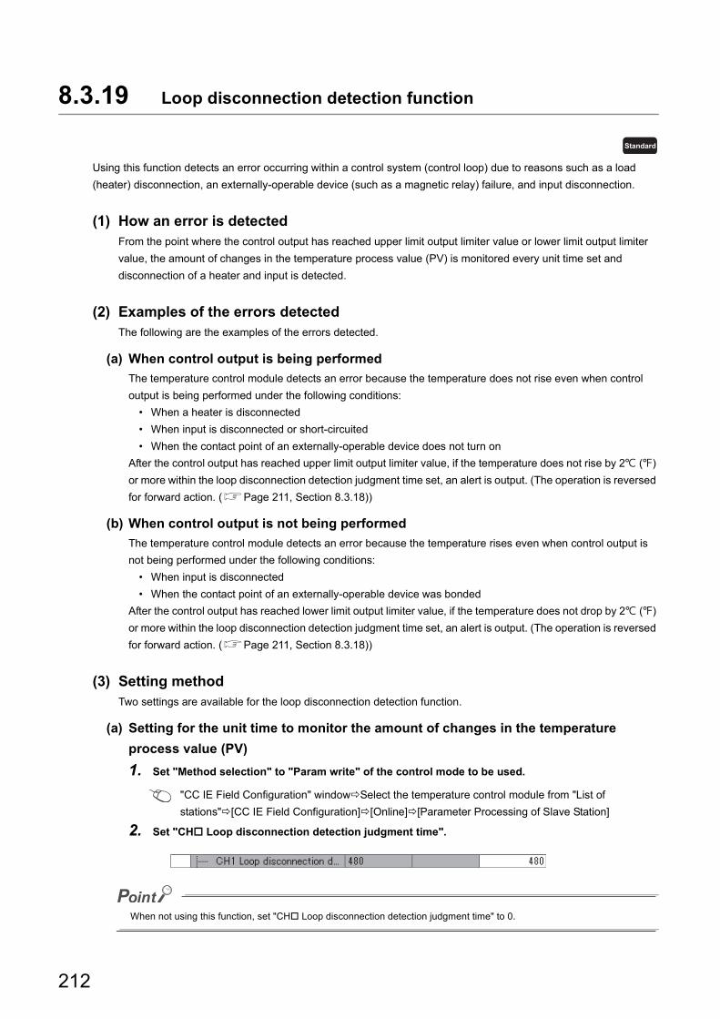
8.3.19 Loop disconnection detection function
Using this function detects an error occurring within a control system (control loop) due to reasons such as a load
(heater) disconnection, an externally-operable device (such as a magnetic relay) failure, and input disconnection.
(1) How an error is detectedFrom the point where the control output has reached upper limit output limiter value or lower limit output limiter
value, the amount of changes in the temperature process value (PV) is monitored every unit time set and
disconnection of a heater and input is detected.
(2) Examples of the errors detectedThe following are the examples of the errors detected.
(a) When control output is being performed
The temperature control module detects an error because the temperature does not rise even when control
output is being performed under the following conditions:
• When a heater is disconnected
• When input is disconnected or short-circuited
• When the contact point of an externally-operable device does not turn on
After the control output has reached upper limit output limiter value, if the temperature does not rise by 2 ()
or more within the loop disconnection detection judgment time set, an alert is output. (The operation is reversed
for forward action. (Page 211, Section 8.3.18))
(b) When control output is not being performed
The temperature control module detects an error because the temperature rises even when control output is
not being performed under the following conditions:
• When input is disconnected
• When the contact point of an externally-operable device was bonded
After the control output has reached lower limit output limiter value, if the temperature does not drop by 2 ()
or more within the loop disconnection detection judgment time set, an alert is output. (The operation is reversed
for forward action. (Page 211, Section 8.3.18))
(3) Setting methodTwo settings are available for the loop disconnection detection function.
(a) Setting for the unit time to monitor the amount of changes in the temperature
process value (PV)
1. Set "Method selection" to "Param write" of the control mode to be used.
"CC IE Field Configuration" windowSelect the temperature control module from "List of
stations"[CC IE Field Configuration][Online][Parameter Processing of Slave Station]
2. Set "CH Loop disconnection detection judgment time".
When not using this function, set "CH Loop disconnection detection judgment time" to 0.
Standard
212
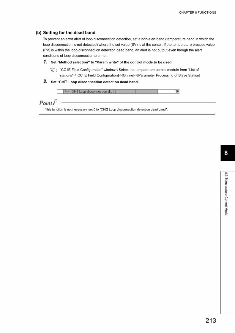
CHAPTER 8 FUNCTIONS
8
8.3
Te
mp
era
ture
Co
ntro
l Mo
de
(b) Setting for the dead band
To prevent an error alert of loop disconnection detection, set a non-alert band (temperature band in which the
loop disconnection is not detected) where the set value (SV) is at the center. If the temperature process value
(PV) is within the loop disconnection detection dead band, an alert is not output even though the alert
conditions of loop disconnection are met.
1. Set "Method selection" to "Param write" of the control mode to be used.
"CC IE Field Configuration" windowSelect the temperature control module from "List of
stations"[CC IE Field Configuration][Online][Parameter Processing of Slave Station]
2. Set "CH Loop disconnection detection dead band".
If this function is not necessary, set 0 to "CH Loop disconnection detection dead band".
213
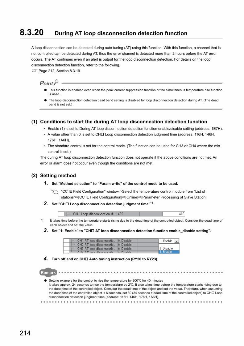
8.3.20 During AT loop disconnection detection function
A loop disconnection can be detected during auto tuning (AT) using this function. With this function, a channel that is
not controlled can be detected during AT, thus the error channel is detected more than 2 hours before the AT error
occurs. The AT continues even if an alert is output for the loop disconnection detection. For details on the loop
disconnection detection function, refer to the following.
Page 212, Section 8.3.19
● This function is enabled even when the peak current suppression function or the simultaneous temperature rise function is used.
● The loop disconnection detection dead band setting is disabled for loop disconnection detection during AT. (The dead band is not set.)
(1) Conditions to start the during AT loop disconnection detection function• Enable (1) is set to During AT loop disconnection detection function enable/disable setting (address: 1E7H).
• A value other than 0 is set to CH Loop disconnection detection judgment time (address: 116H, 146H,
176H, 1A6H).
• The standard control is set for the control mode. (The function can be used for CH3 or CH4 where the mix
control is set.)
The during AT loop disconnection detection function does not operate if the above conditions are not met. An
error or alarm does not occur even though the conditions are not met.
(2) Setting method
1. Set "Method selection" to "Param write" of the control mode to be used.
"CC IE Field Configuration" windowSelect the temperature control module from "List of
stations"[CC IE Field Configuration][Online][Parameter Processing of Slave Station]
2. Set "CH Loop disconnection detection judgment time"*1.
*1 It takes time before the temperature starts rising due to the dead time of the controlled object. Consider the dead time of each object and set the value.
3. Set "1: Enable" to "CH AT loop disconnection detection function enable_disable setting".
4. Turn off and on CH Auto tuning instruction (RY20 to RY23).
Remark
● Setting example for the control to rise the temperature by 200 for 40 minutesIt takes approx. 24 seconds to rise the temperature by 2. It also takes time before the temperature starts rising due to the dead time of the controlled object. Consider the dead time of the object and set the value. Therefore, when assuming the dead time of the controlled object is 6 seconds, set 30 (24 seconds + dead time of the controlled object) to CH Loop disconnection detection judgment time (address: 116H, 146H, 176H, 1A6H).
214
CHAPTER 8 FUNCTIONS
8
8.3
Te
mp
era
ture
Co
ntro
l Mo
de
(3) When an alert occurs, or does not occurIf an alert for the loop disconnection detection occurs, CH Alert occurrence flag (RX18 to RX1B) and CH
Loop disconnection detection (b13 of RWr4 to RWr7) turn on and Alarm code (03AH) is stored in Latest
warning code (RWr2). (Page 271, Section 11.2)
The occurrence of loop disconnection alert may due to an error in the control loop. Therefore, even if AT is normally completed, check the control loop and that the current Loop disconnection detection judgment time is correct.
(4) To clear the alert statusIf any of the following conditions is met, CH Alert occurrence flag (RX18 to RX1B) and CH Loop
disconnection detection (b13 of RWr4 to RWr7) turn off.
• When the operating status is changed from run to stop
• A manipulated value (MV) becomes greater than the lower limit output limiter value and smaller than the
upper limit output limiter value.
• Disable (0) is set to During AT loop disconnection detection function enable/disable setting (address: 1E7H).
• 0 is set to CH Loop disconnection detection judgment time (address: 116H, 146H, 176H, 1A6H).
• MAN (1) is set to CH AUTO/MAN mode shift (address: 113H, 143H, 173H, 1A3H).
215
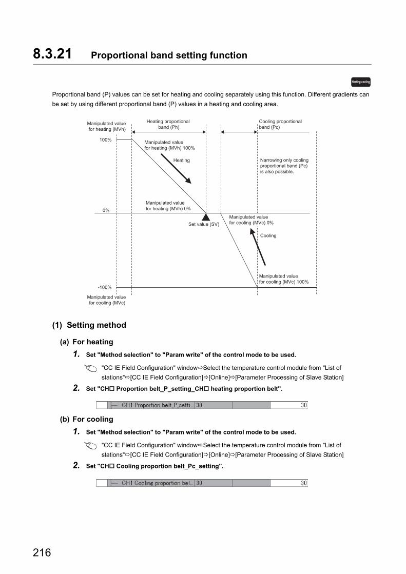
8.3.21 Proportional band setting function
Proportional band (P) values can be set for heating and cooling separately using this function. Different gradients can
be set by using different proportional band (P) values in a heating and cooling area.
(1) Setting method
(a) For heating
1. Set "Method selection" to "Param write" of the control mode to be used.
"CC IE Field Configuration" windowSelect the temperature control module from "List of
stations"[CC IE Field Configuration][Online][Parameter Processing of Slave Station]
2. Set "CH Proportion belt_P_setting_CH heating proportion belt".
(b) For cooling
1. Set "Method selection" to "Param write" of the control mode to be used.
"CC IE Field Configuration" windowSelect the temperature control module from "List of
stations"[CC IE Field Configuration][Online][Parameter Processing of Slave Station]
2. Set "CH Cooling proportion belt_Pc_setting".
Heating-cooling
100%
0%
-100%
Manipulated value for cooling (MVc) 100%
Manipulated value for heating (MVh) 0%
Manipulated value for heating (MVh) 100%
Manipulated value for cooling (MVc) 0%Set value (SV)
Heating proportional band (Ph)
Cooling
Heating
Cooling proportional band (Pc)
Narrowing only cooling proportional band (Pc) is also possible.
Manipulated value for heating (MVh)
Manipulated value for cooling (MVc)
216
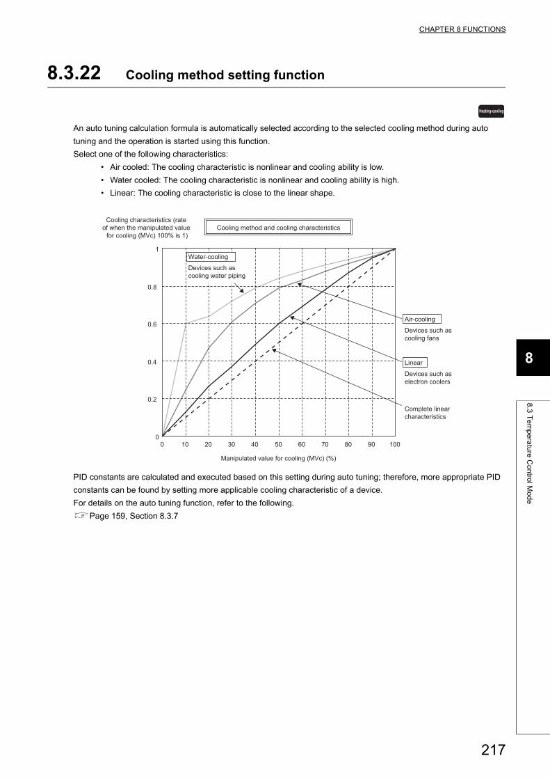
CHAPTER 8 FUNCTIONS
8
8.3
Te
mp
era
ture
Co
ntro
l Mo
de
8.3.22 Cooling method setting function
An auto tuning calculation formula is automatically selected according to the selected cooling method during auto
tuning and the operation is started using this function.
Select one of the following characteristics:
• Air cooled: The cooling characteristic is nonlinear and cooling ability is low.
• Water cooled: The cooling characteristic is nonlinear and cooling ability is high.
• Linear: The cooling characteristic is close to the linear shape.
PID constants are calculated and executed based on this setting during auto tuning; therefore, more appropriate PID
constants can be found by setting more applicable cooling characteristic of a device.
For details on the auto tuning function, refer to the following.
Page 159, Section 8.3.7
Heating-cooling
0
0.2
0.4
0.6
0.8
0 10 20 30 40 50 60 70 80 90 100
1
Cooling method and cooling characteristics
Manipulated value for cooling (MVc) (%)
Cooling characteristics (rate of when the manipulated value
for cooling (MVc) 100% is 1)
Complete linear characteristics
Devices such as cooling fans
Devices such as electron coolers
Air-cooling
Devices such as cooling water piping
Water-cooling
Linear
217
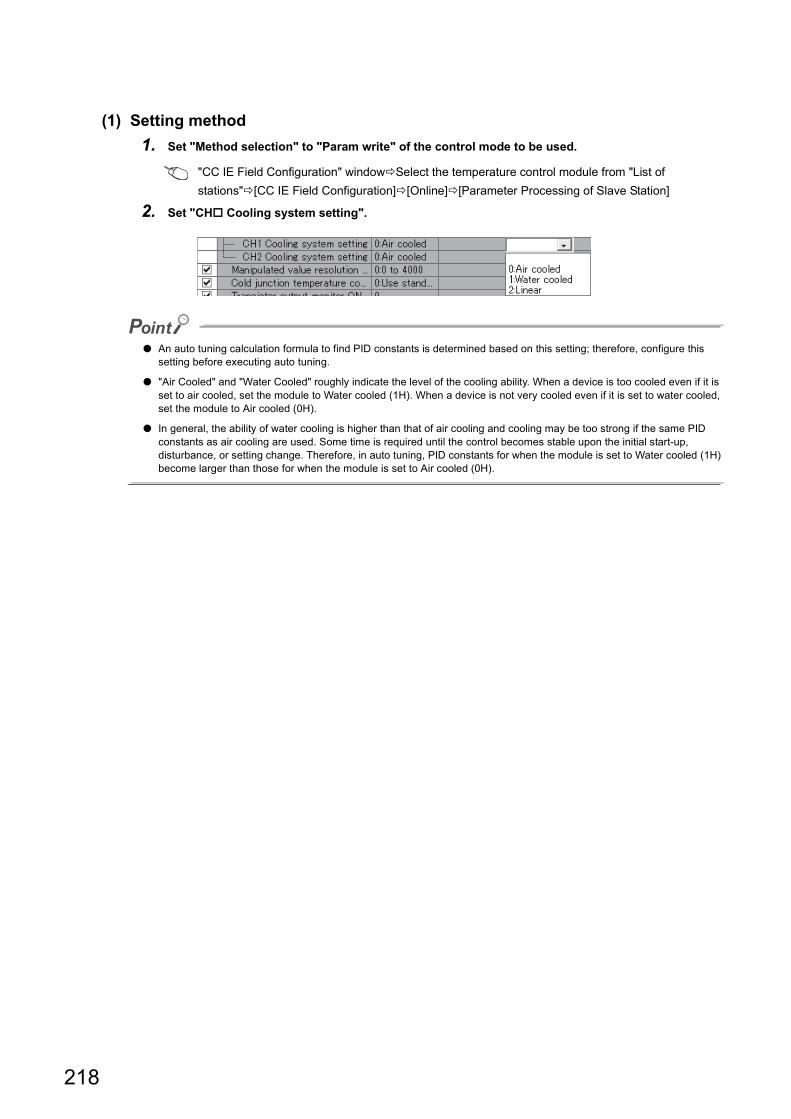
(1) Setting method
1. Set "Method selection" to "Param write" of the control mode to be used.
"CC IE Field Configuration" windowSelect the temperature control module from "List of
stations"[CC IE Field Configuration][Online][Parameter Processing of Slave Station]
2. Set "CH Cooling system setting".
● An auto tuning calculation formula to find PID constants is determined based on this setting; therefore, configure this setting before executing auto tuning.
● "Air Cooled" and "Water Cooled" roughly indicate the level of the cooling ability. When a device is too cooled even if it is set to air cooled, set the module to Water cooled (1H). When a device is not very cooled even if it is set to water cooled, set the module to Air cooled (0H).
● In general, the ability of water cooling is higher than that of air cooling and cooling may be too strong if the same PID constants as air cooling are used. Some time is required until the control becomes stable upon the initial start-up, disturbance, or setting change. Therefore, in auto tuning, PID constants for when the module is set to Water cooled (1H) become larger than those for when the module is set to Air cooled (0H).
218
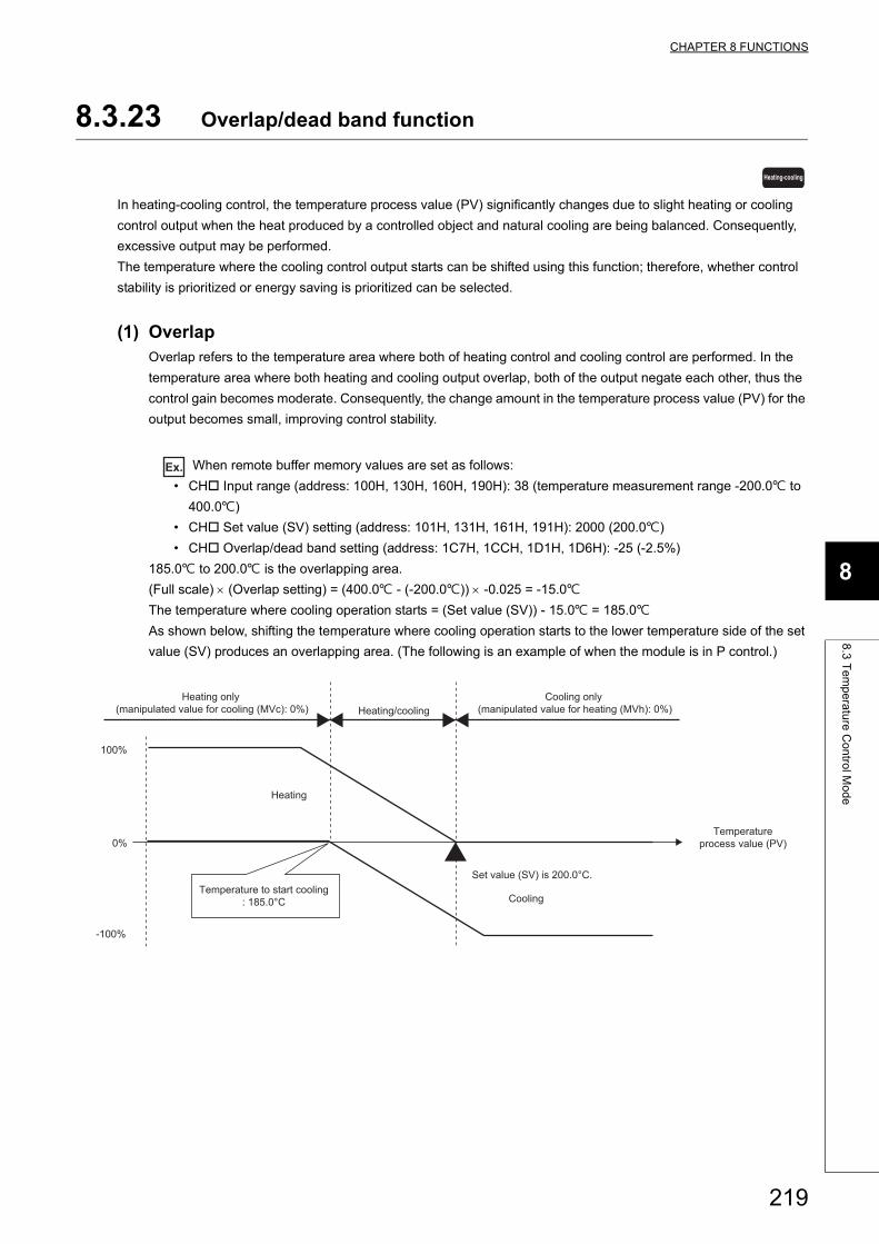
CHAPTER 8 FUNCTIONS
8
8.3
Te
mp
era
ture
Co
ntro
l Mo
de
8.3.23 Overlap/dead band function
In heating-cooling control, the temperature process value (PV) significantly changes due to slight heating or cooling
control output when the heat produced by a controlled object and natural cooling are being balanced. Consequently,
excessive output may be performed.
The temperature where the cooling control output starts can be shifted using this function; therefore, whether control
stability is prioritized or energy saving is prioritized can be selected.
(1) OverlapOverlap refers to the temperature area where both of heating control and cooling control are performed. In the
temperature area where both heating and cooling output overlap, both of the output negate each other, thus the
control gain becomes moderate. Consequently, the change amount in the temperature process value (PV) for the
output becomes small, improving control stability.
Ex. When remote buffer memory values are set as follows:
• CH Input range (address: 100H, 130H, 160H, 190H): 38 (temperature measurement range -200.0 to
400.0)
• CH Set value (SV) setting (address: 101H, 131H, 161H, 191H): 2000 (200.0)
• CH Overlap/dead band setting (address: 1C7H, 1CCH, 1D1H, 1D6H): -25 (-2.5%)
185.0 to 200.0 is the overlapping area.
(Full scale) (Overlap setting) = (400.0 - (-200.0)) -0.025 = -15.0
The temperature where cooling operation starts = (Set value (SV)) - 15.0 = 185.0
As shown below, shifting the temperature where cooling operation starts to the lower temperature side of the set
value (SV) produces an overlapping area. (The following is an example of when the module is in P control.)
Heating-cooling
100%
0%
-100%
Heating only (manipulated value for cooling (MVc): 0%) Heating/cooling
Cooling only (manipulated value for heating (MVh): 0%)
Heating
Set value (SV) is 200.0°C.
Cooling
Temperatureprocess value (PV)
Temperature to start cooling: 185.0°C
219
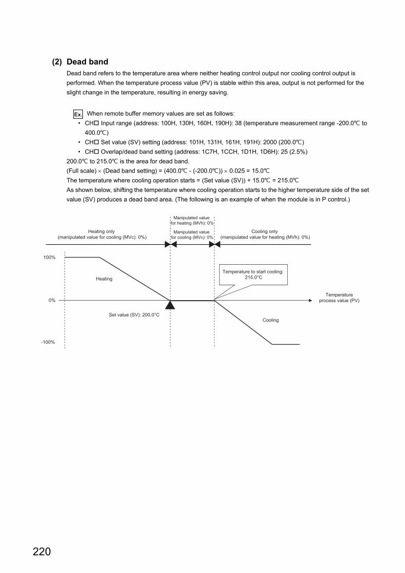
(2) Dead bandDead band refers to the temperature area where neither heating control output nor cooling control output is
performed. When the temperature process value (PV) is stable within this area, output is not performed for the
slight change in the temperature, resulting in energy saving.
Ex. When remote buffer memory values are set as follows:
• CH Input range (address: 100H, 130H, 160H, 190H): 38 (temperature measurement range -200.0 to
400.0)
• CH Set value (SV) setting (address: 101H, 131H, 161H, 191H): 2000 (200.0)
• CH Overlap/dead band setting (address: 1C7H, 1CCH, 1D1H, 1D6H): 25 (2.5%)
200.0 to 215.0 is the area for dead band.
(Full scale) (Dead band setting) = (400.0 - (-200.0)) 0.025 = 15.0
The temperature where cooling operation starts = (Set value (SV)) + 15.0 = 215.0
As shown below, shifting the temperature where cooling operation starts to the higher temperature side of the set
value (SV) produces a dead band area. (The following is an example of when the module is in P control.)
Heating only (manipulated value for cooling (MVc): 0%)
Cooling only (manipulated value for heating (MVh): 0%)
Heating
Set value (SV): 200.0°CCooling
Temperatureprocess value (PV)
Temperature to start cooling: 215.0°C
100%
0%
-100%
Manipulated value for heating (MVh): 0%
Manipulated value for cooling (MVc): 0%
220
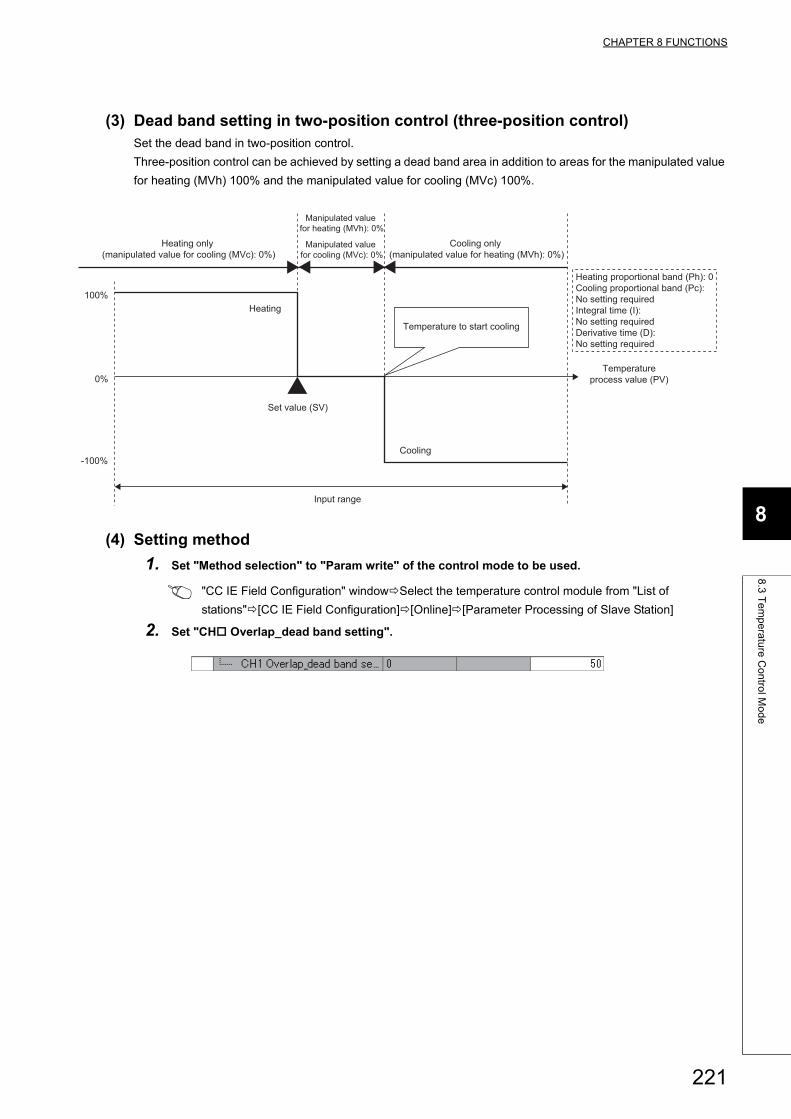
CHAPTER 8 FUNCTIONS
8
8.3
Te
mp
era
ture
Co
ntro
l Mo
de
(3) Dead band setting in two-position control (three-position control)Set the dead band in two-position control.
Three-position control can be achieved by setting a dead band area in addition to areas for the manipulated value
for heating (MVh) 100% and the manipulated value for cooling (MVc) 100%.
(4) Setting method
1. Set "Method selection" to "Param write" of the control mode to be used.
"CC IE Field Configuration" windowSelect the temperature control module from "List of
stations"[CC IE Field Configuration][Online][Parameter Processing of Slave Station]
2. Set "CH Overlap_dead band setting".
Heating only (manipulated value for cooling (MVc): 0%)
Cooling only (manipulated value for heating (MVh): 0%)
Heating
Set value (SV)
Cooling
Temperatureprocess value (PV)
Temperature to start cooling
100%
0%
-100%
Manipulated value for heating (MVh): 0%
Manipulated value for cooling (MVc): 0%
Heating proportional band (Ph): 0Cooling proportional band (Pc): No setting requiredIntegral time (I): No setting requiredDerivative time (D): No setting required
Input range
221
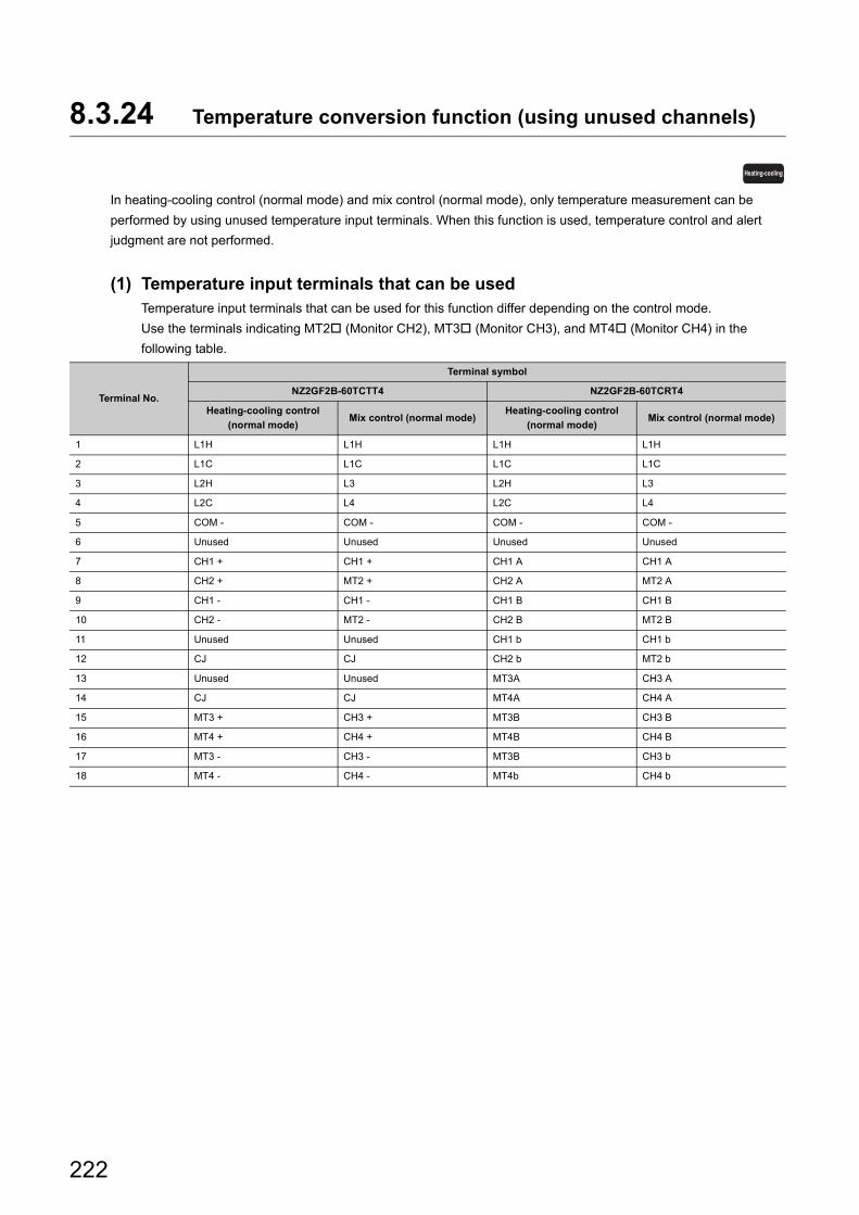
8.3.24 Temperature conversion function (using unused channels)
In heating-cooling control (normal mode) and mix control (normal mode), only temperature measurement can be
performed by using unused temperature input terminals. When this function is used, temperature control and alert
judgment are not performed.
(1) Temperature input terminals that can be usedTemperature input terminals that can be used for this function differ depending on the control mode.
Use the terminals indicating MT2 (Monitor CH2), MT3 (Monitor CH3), and MT4 (Monitor CH4) in the
following table.
Terminal No.
Terminal symbol
NZ2GF2B-60TCTT4 NZ2GF2B-60TCRT4
Heating-cooling control
(normal mode)Mix control (normal mode)
Heating-cooling control
(normal mode)Mix control (normal mode)
1 L1H L1H L1H L1H
2 L1C L1C L1C L1C
3 L2H L3 L2H L3
4 L2C L4 L2C L4
5 COM - COM - COM - COM -
6 Unused Unused Unused Unused
7 CH1 + CH1 + CH1 A CH1 A
8 CH2 + MT2 + CH2 A MT2 A
9 CH1 - CH1 - CH1 B CH1 B
10 CH2 - MT2 - CH2 B MT2 B
11 Unused Unused CH1 b CH1 b
12 CJ CJ CH2 b MT2 b
13 Unused Unused MT3A CH3 A
14 CJ CJ MT4A CH4 A
15 MT3 + CH3 + MT3B CH3 B
16 MT4 + CH4 + MT4B CH4 B
17 MT3 - CH3 - MT3B CH3 b
18 MT4 - CH4 - MT4b CH4 b
Heating-cooling
222
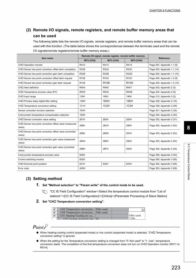
CHAPTER 8 FUNCTIONS
8
8.3
Te
mp
era
ture
Co
ntro
l Mo
de
(2) Remote I/O signals, remote registers, and remote buffer memory areas that
can be usedThe following table lists the remote I/O signals, remote registers, and remote buffer memory areas that can be
used with this function. (The table below shows the correspondences between the terminals used and the remote
I/O signals/remote registers/remote buffer memory areas.)
(3) Setting method
1. Set "Method selection" to "Param write" of the control mode to be used.
"CC IE Field Configuration" windowSelect the temperature control module from "List of
stations"[CC IE Field Configuration][Online][Parameter Processing of Slave Station]
2. Set "CH Temperature conversion setting".
● When heating-cooling control (expanded mode) or mix control (expanded mode) is selected, "CH Temperature conversion setting" is ignored.
● When the setting for the Temperature conversion setting is changed from "0: Not used" to "1: Use", temperature conversion starts. The completion of the first temperature conversion does not turn on CH Operation monitor (RX11 to RX14).
Item nameRemote I/O signal, remote register, remote buffer memory
ReferenceMT2 (CH2) MT3 (CH3) MT4 (CH4)
CH Operation monitor RX12 RX13 RX14 Page 287, Appendix 1.1 (6)
CH Sensor two-point correction offset latch completion RX28 RX2A RX2C Page 293, Appendix 1.1 (14)
CH Sensor two-point correction gain latch completion RX29 RX2B RX2D Page 293, Appendix 1.1 (15)
CH Sensor two-point correction offset latch request RY28 RY2A RY2C Page 300, Appendix 1.2 (9)
CH Sensor two-point correction gain latch request RY29 RY2B RY2D Page 300, Appendix 1.2 (10)
CH Alert definition RWr5 RWr6 RWr7 Page 303, Appendix 2 (5)
CH Temperature process value (PV) RWr9 RWrA RWrB Page 304, Appendix 2 (6)
CH Input range 130H 160H 190H Page 312, Appendix 3 (5)
CH Primary delay digital filter setting 13DH 16DH 19DH Page 328, Appendix 3 (16)
CH Temperature conversion setting 1C1H 1C2H 1C3H Page 338, Appendix 3 (29)
Sensor correction function selection 1E4H Page 341, Appendix 3 (35)
Cold junction temperature compensation selection 1E9H Page 344, Appendix 3 (40)
CH Sensor correction value setting 281H 282H 283H Page 352, Appendix 3 (51)
CH Sensor two-point correction offset value (measured
value)288H 28CH 290H Page 352, Appendix 3 (52)
CH Sensor two-point correction offset value (corrected
value)289H 28DH 291H Page 353, Appendix 3 (53)
CH Sensor two-point correction gain value (measured
value)28AH 28EH 292H Page 353, Appendix 3 (54)
CH Sensor two-point correction gain value (corrected
value)28BH 28FH 293H Page 354, Appendix 3 (55)
Cold junction temperature process value 600H Page 359, Appendix 3 (63)
Control switching monitor 602H Page 360, Appendix 3 (65)
CH Decimal point position 621H 622H 623H Page 362, Appendix 3 (68)
Error code A00H Page 363, Appendix 3 (69)
223
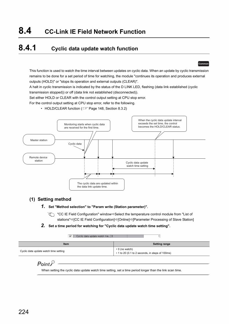
8.4 CC-Link IE Field Network Function
8.4.1 Cyclic data update watch function
This function is used to watch the time interval between updates on cyclic data. When an update by cyclic transmission
remains to be done for a set period of time for watching, the module "continues its operation and produces external
outputs (HOLD)" or "stops its operation and external outputs (CLEAR)".
A halt in cyclic transmission is indicated by the status of the D LINK LED, flashing (data link established (cyclic
transmission stopped)) or off (data link not established (disconnected)).
Set either HOLD or CLEAR with the control output setting at CPU stop error.
For the control output setting at CPU stop error, refer to the following.
• HOLD/CLEAR function (Page 148, Section 8.3.2)
(1) Setting method
1. Set "Method selection" to "Param write (Station parameter)".
"CC IE Field Configuration" windowSelect the temperature control module from "List of
stations"[CC IE Field Configuration][Online][Parameter Processing of Slave Station]
2. Set a time period for watching for "Cyclic data update watch time setting".
When setting the cyclic data update watch time setting, set a time period longer than the link scan time.
Item Setting range
Cyclic data update watch time setting• 0 (no watch)
• 1 to 20 (0.1 to 2 seconds, in steps of 100ms)
Common
Master station
Remote device station
The cyclic data are updated withinthe data link update time.
Cyclic data
When the cyclic data update interval exceeds the set time, the control becomes the HOLD/CLEAR status.
Monitoring starts when cyclic dataare received for the first time.
Cyclic data update watch time setting
224

CHAPTER 8 FUNCTIONS
8
8.4
CC
-Lin
k IE F
ield
Ne
two
rk Fu
nctio
n
8.4.2 Error notification function
When an error, warning, or alarm occurs, the temperature control module notifies the master station of it using remote
input signals and remote registers.
Remark
The notification of the error, warning, or alarm can be checked on the LED on the front of the module.For details, refer to the following.
• PART NAMES (Page 31, CHAPTER 2)
(1) Notification of an errorThe temperature control module notifies the master station of an error in the following method.
(a) Method for clearing an error
The method for clearing an error depends on the error type.
For details, refer to the following.
Lists of Error Codes (Page 271, Section 11.2)
(2) Notification of a warning or alarmThe temperature control module notifies that a warning or alarm occurs to the master station in the following
method.
Item Description Reference
Error flag (RXA) Turns on when a moderate error or major error occurs. Page 285, Appendix 1.1 (3)
Latest error code (RWr0)An error code is stored when a moderate error or major error (except
hardware failures) occurs.Page 301, Appendix 2 (1)
Error occurrence address (RWr1)The address of remote buffer memory area where an error has
occurred is stored.Page 301, Appendix 2 (2)
Item Description Reference
Warning flag (RX7) Turns on when a minor error occurs. Page 284, Appendix 1.1 (1)
Latest warning code (RWr2) The error code or alarm code is stored when a minor error occurs. Page 301, Appendix 2 (3)
Common
225
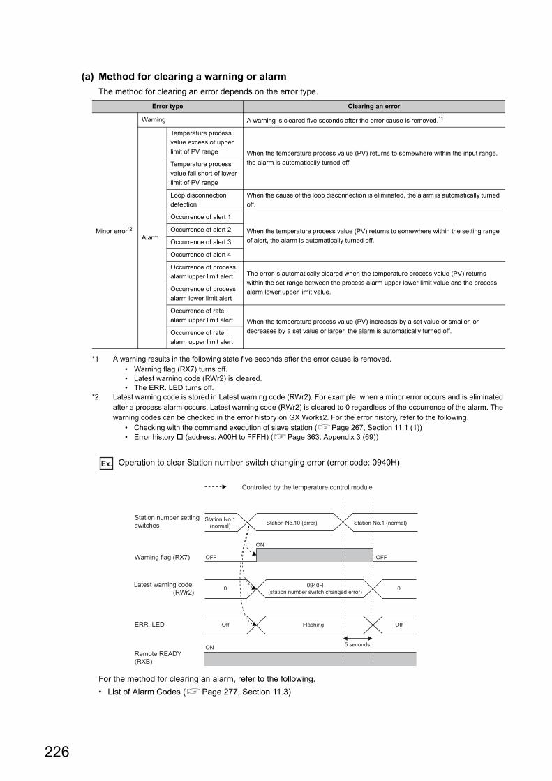
(a) Method for clearing a warning or alarm
The method for clearing an error depends on the error type.
*1 A warning results in the following state five seconds after the error cause is removed.• Warning flag (RX7) turns off.• Latest warning code (RWr2) is cleared.• The ERR. LED turns off.
*2 Latest warning code is stored in Latest warning code (RWr2). For example, when a minor error occurs and is eliminated after a process alarm occurs, Latest warning code (RWr2) is cleared to 0 regardless of the occurrence of the alarm. The warning codes can be checked in the error history on GX Works2. For the error history, refer to the following.
• Checking with the command execution of slave station (Page 267, Section 11.1 (1))• Error history (address: A00H to FFFH) (Page 363, Appendix 3 (69))
Ex. Operation to clear Station number switch changing error (error code: 0940H)
For the method for clearing an alarm, refer to the following.
• List of Alarm Codes (Page 277, Section 11.3)
Error type Clearing an error
Minor error*2
Warning A warning is cleared five seconds after the error cause is removed.*1
Alarm
Temperature process
value excess of upper
limit of PV range When the temperature process value (PV) returns to somewhere within the input range,
the alarm is automatically turned off.Temperature process
value fall short of lower
limit of PV range
Loop disconnection
detection
When the cause of the loop disconnection is eliminated, the alarm is automatically turned
off.
Occurrence of alert 1
When the temperature process value (PV) returns to somewhere within the setting range
of alert, the alarm is automatically turned off.
Occurrence of alert 2
Occurrence of alert 3
Occurrence of alert 4
Occurrence of process
alarm upper limit alert The error is automatically cleared when the temperature process value (PV) returns
within the set range between the process alarm upper lower limit value and the process
alarm lower upper limit value.Occurrence of process
alarm lower limit alert
Occurrence of rate
alarm upper limit alert When the temperature process value (PV) increases by a set value or smaller, or
decreases by a set value or larger, the alarm is automatically turned off.Occurrence of rate
alarm upper limit alert
Station No.1(normal) Station No.1 (normal)
ON
ON
OFFOFFWarning flag (RX7)
Station number settingswitches
ERR. LED
Remote READY(RXB)
Off
Station No.10 (error)
Off
0
Flashing
0
5 seconds
0940H(station number switch changed error)
Latest warning code (RWr2)
Controlled by the temperature control module
226

CHAPTER 8 FUNCTIONS
8
8.4
CC
-Lin
k IE F
ield
Ne
two
rk Fu
nctio
n
(3) Method for clearing an error by executing the command of the slave stationThe following shows how to clear an error by executing the command of the slave station.
1. Select the temperature control module in "List of
stations" on the CC IE Field Configuration window.
2. Open the "Command Execution of Slave Station"
window.
[CC IE Field Configuration] [Online]
[Command Execution of Slave Station]
3. Set "Method selection”" to "Error clear request" and
click the [Execute] button.
4. When the window shown on the left is displayed,
click the [Yes] button.
List ofstations
227
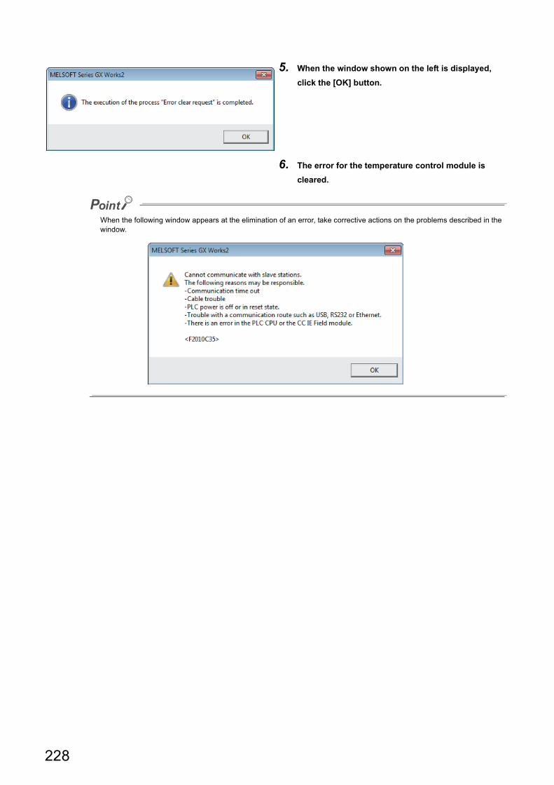
When the following window appears at the elimination of an error, take corrective actions on the problems described in the window.
5. When the window shown on the left is displayed,
click the [OK] button.
6. The error for the temperature control module is
cleared.
228
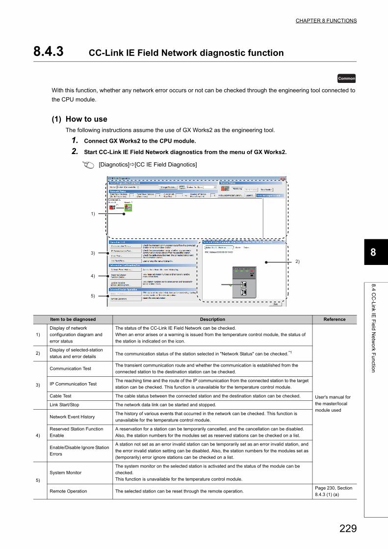
CHAPTER 8 FUNCTIONS
8
8.4
CC
-Lin
k IE F
ield
Ne
two
rk Fu
nctio
n
8.4.3 CC-Link IE Field Network diagnostic function
With this function, whether any network error occurs or not can be checked through the engineering tool connected to
the CPU module.
(1) How to useThe following instructions assume the use of GX Works2 as the engineering tool.
1. Connect GX Works2 to the CPU module.
2. Start CC-Link IE Field Network diagnostics from the menu of GX Works2.
[Diagnotics][CC IE Field Diagnotics]
Item to be diagnosed Description Reference
1)
Display of network
configuration diagram and
error status
The status of the CC-Link IE Field Network can be checked.
When an error arises or a warning is issued from the temperature control module, the status of
the station is indicated on the icon.
User's manual for
the master/local
module used
2)Display of selected-station
status and error detailsThe communication status of the station selected in "Network Status" can be checked.*1
3)
Communication TestThe transient communication route and whether the communication is established from the
connected station to the destination station can be checked.
IP Communication TestThe reaching time and the route of the IP communication from the connected station to the target
station can be checked. This function is unavailable for the temperature control module.
Cable Test The cable status between the connected station and the destination station can be checked.
Link Start/Stop The network data link can be started and stopped.
4)
Network Event HistoryThe history of various events that occurred in the network can be checked. This function is
unavailable for the temperature control module.
Reserved Station Function
Enable
A reservation for a station can be temporarily cancelled, and the cancellation can be disabled.
Also, the station numbers for the modules set as reserved stations can be checked on a list.
Enable/Disable Ignore Station
Errors
A station not set as an error invalid station can be temporarily set as an error invalid station, and
the error invalid station setting can be disabled. Also, the station numbers for the modules set as
(temporarily) error ignore stations can be checked on a list.
5)
System Monitor
The system monitor on the selected station is activated and the status of the module can be
checked.
This function is unavailable for the temperature control module.
Remote Operation The selected station can be reset through the remote operation.Page 230, Section
8.4.3 (1) (a)
Common
2)
1)
3)
4)
5)
229
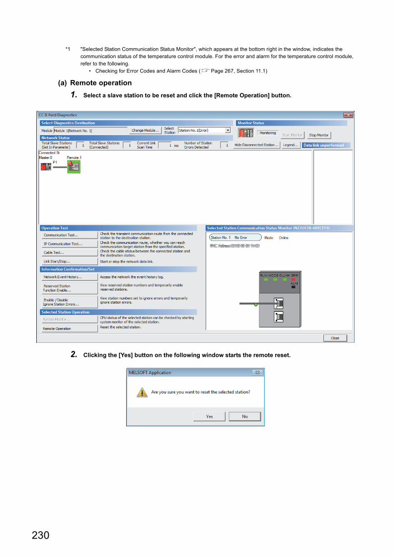
*1 "Selected Station Communication Status Monitor", which appears at the bottom right in the window, indicates the communication status of the temperature control module. For the error and alarm for the temperature control module, refer to the following.
• Checking for Error Codes and Alarm Codes (Page 267, Section 11.1)
(a) Remote operation
1. Select a slave station to be reset and click the [Remote Operation] button.
2. Clicking the [Yes] button on the following window starts the remote reset.
230
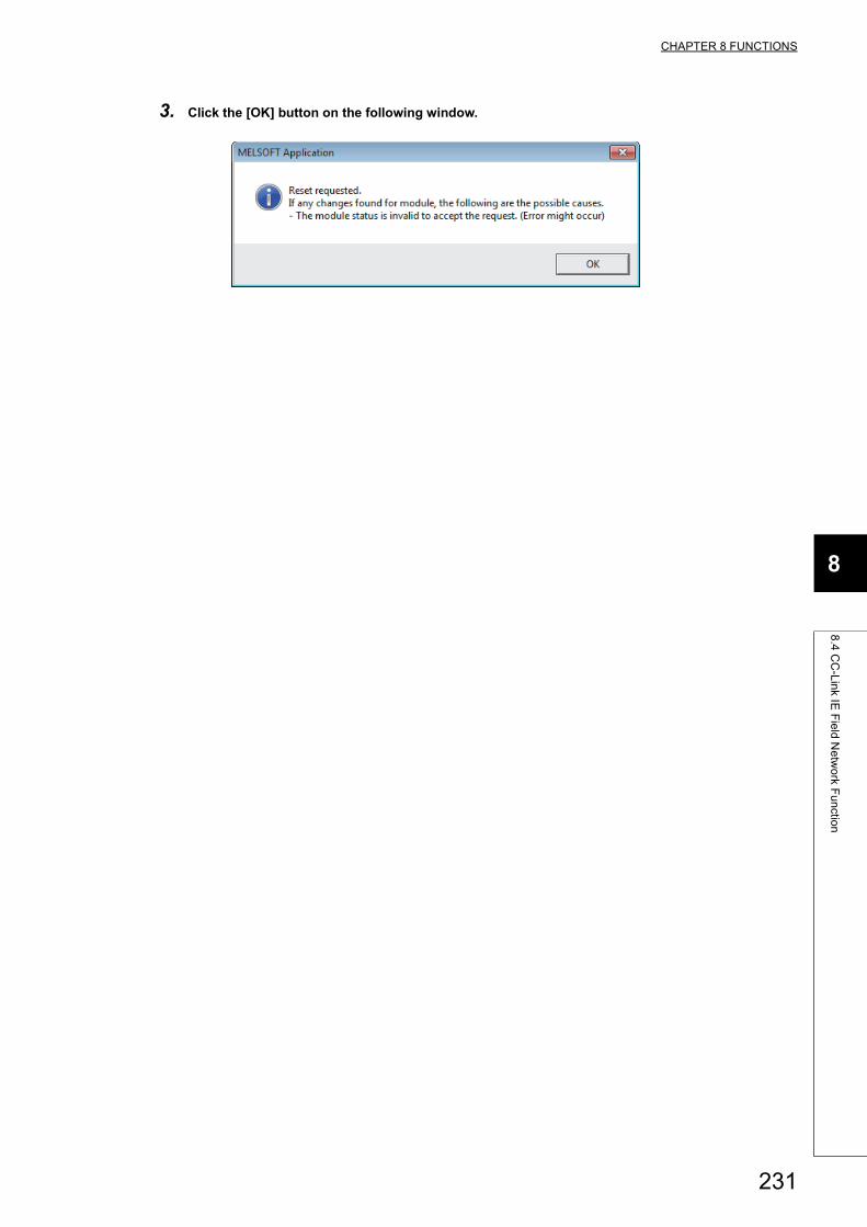
CHAPTER 8 FUNCTIONS
8
8.4
CC
-Lin
k IE F
ield
Ne
two
rk Fu
nctio
n
3. Click the [OK] button on the following window.
231
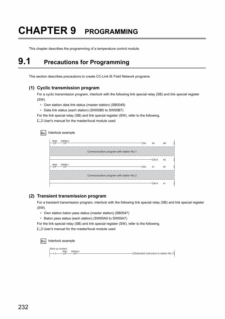
CHAPTER 9 PROGRAMMING
This chapter describes the programming of a temperature control module.
9.1 Precautions for Programming
This section describes precautions to create CC-Link IE Field Network programs.
(1) Cyclic transmission programFor a cyclic transmission program, interlock with the following link special relay (SB) and link special register
(SW).
• Own station data link status (master station) (SB0049)
• Data link status (each station) (SW00B0 to SW00B7)
For the link special relay (SB) and link special register (SW), refer to the following.
User's manual for the master/local module used
Ex. Interlock example
(2) Transient transmission programFor a transient transmission program, interlock with the following link special relay (SB) and link special register
(SW).
• Own station baton pass status (master station) (SB0047)
• Baton pass status (each station) (SW00A0 to SW00A7)
For the link special relay (SB) and link special register (SW), refer to the following.
User's manual for the master/local module used
Ex. Interlock example
Communication program with station No.1
Communication program with station No.2
Dedicated instruction to station No.1
Start-up contact
232
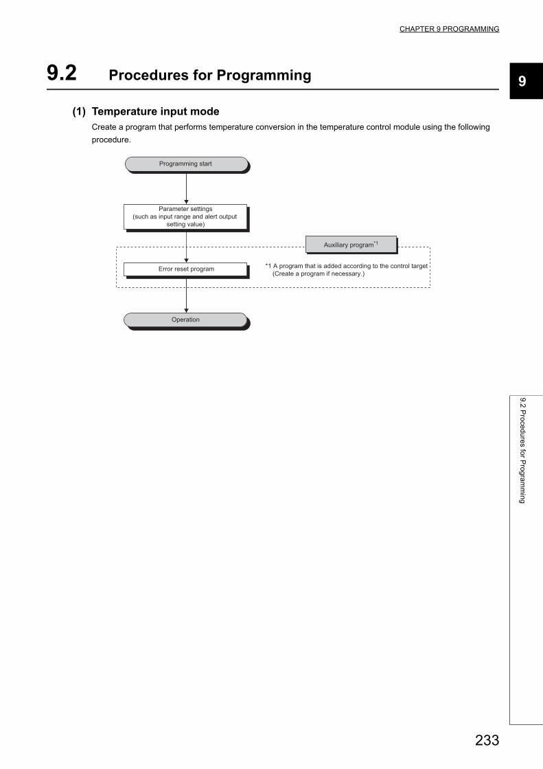
CHAPTER 9 PROGRAMMING
9
9.2
Pro
ced
ure
s for P
rog
ram
min
g
9.2 Procedures for Programming
(1) Temperature input modeCreate a program that performs temperature conversion in the temperature control module using the following
procedure.
Programming start
Error reset program
Auxiliary program*1
*1 A program that is added according to the control target (Create a program if necessary.)
Parameter settings(such as input range and alert output
setting value)
Operation
233
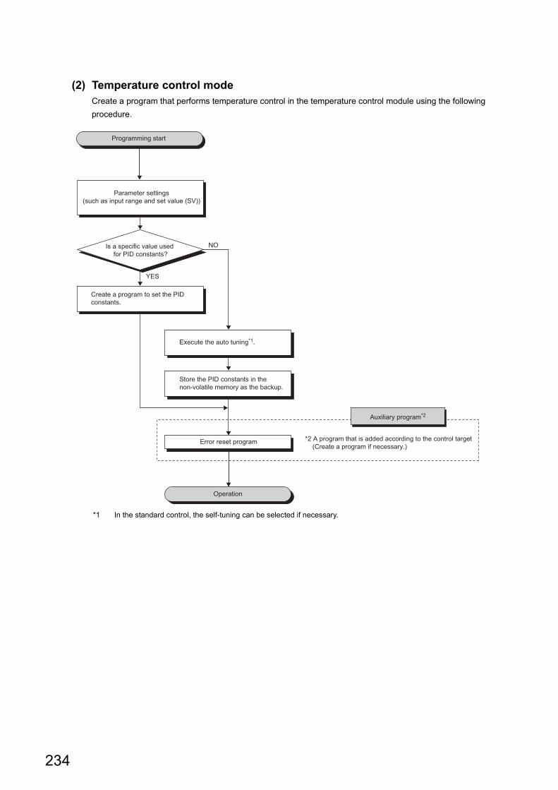
(2) Temperature control modeCreate a program that performs temperature control in the temperature control module using the following
procedure.
*1 In the standard control, the self-tuning can be selected if necessary.
Programming start
Error reset program
Auxiliary program*2
*2 A program that is added according to the control target (Create a program if necessary.)
Is a specific value used for PID constants?
YES
Create a program to set the PID constants.
NO
Execute the auto tuning*1.
Store the PID constants in the non-volatile memory as the backup.
Parameter settings(such as input range and set value (SV))
Operation
234
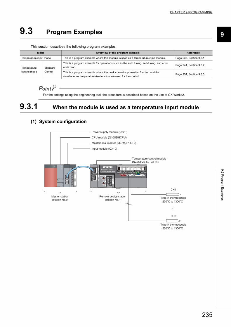
CHAPTER 9 PROGRAMMING
9
9.3
Pro
gra
m E
xam
ple
s
9.3 Program Examples
This section describes the following program examples.
For the settings using the engineering tool, the procedure is described based on the use of GX Works2.
9.3.1 When the module is used as a temperature input module
(1) System configuration
Mode Overview of the program example Reference
Temperature input mode This is a program example where this module is used as a temperature input module. Page 235, Section 9.3.1
Temperature
control mode
Standard
Control
This is a program example for operations such as the auto tuning, self-tuning, and error
code read.Page 244, Section 9.3.2
This is a program example where the peak current suppression function and the
simultaneous temperature rise function are used for the control.Page 254, Section 9.3.3
CH1
CH3
Type-K thermocouple-200°C to 1300°C
Type-K thermocouple-200°C to 1300°C
Remote device station (station No.1)
Master station (station No.0)
Master/local module (QJ71GF11-T2)
Input module (QX10)
Temperature control module (NZ2GF2B-60TCTT4)
CPU module (Q10UDHCPU)
Power supply module (Q62P)
235
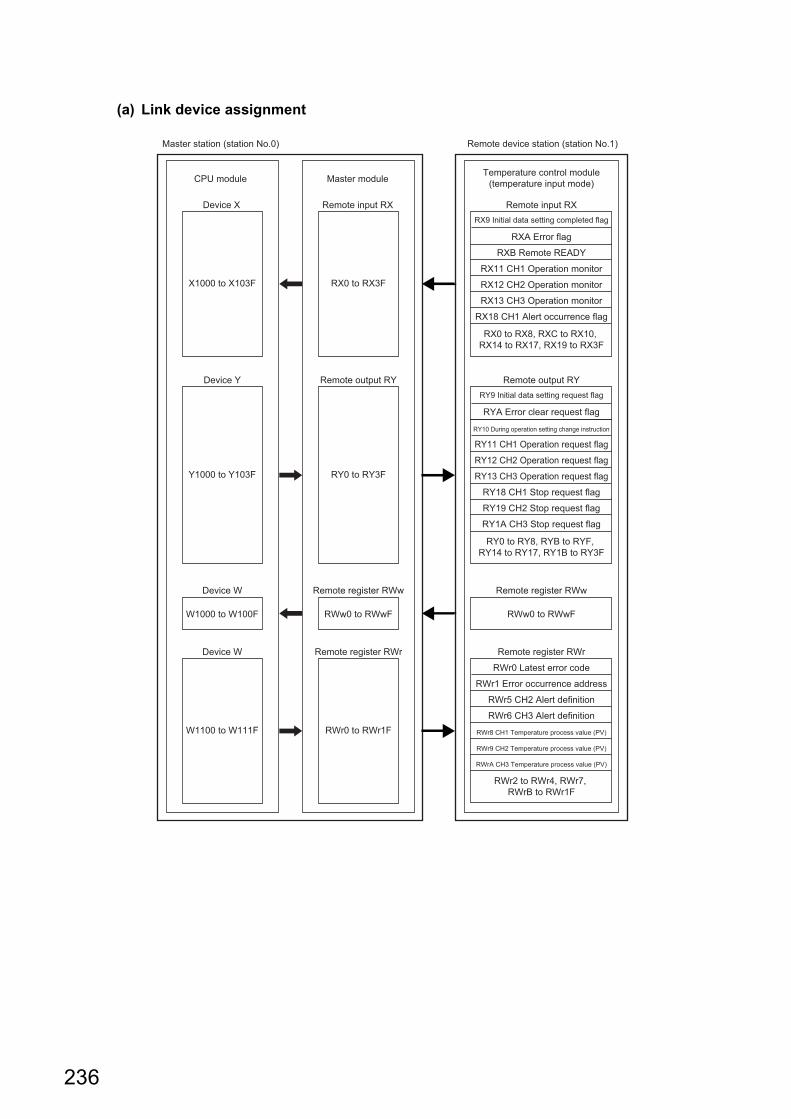
(a) Link device assignment
CPU module Master module
Remote input RX Remote input RXRX9 Initial data setting completed flag
RXA Error flag
RXB Remote READY
RX11 CH1 Operation monitor
RX12 CH2 Operation monitorRX0 to RX3F
RX13 CH3 Operation monitor
RX18 CH1 Alert occurrence flag
RX0 to RX8, RXC to RX10, RX14 to RX17, RX19 to RX3F
Remote register RWr
RWr0 Latest error code
Remote register RWr
RWr0 to RWr1F
RWr1 Error occurrence address
RWr5 CH2 Alert definition
RWr6 CH3 Alert definition
RWr8 CH1 Temperature process value (PV)
RWr9 CH2 Temperature process value (PV)
RWrA CH3 Temperature process value (PV)
RWr2 to RWr4, RWr7, RWrB to RWr1F
Remote output RY
RY10 During operation setting change instruction
RY11 CH1 Operation request flag
RY9 Initial data setting request flag
RYA Error clear request flag
Remote register RWw
RWw0 to RWwF
Remote register RWw
RWw0 to RWwF
RY12 CH2 Operation request flag
Remote output RY
RY0 to RY3F
Device X
X1000 to X103F
Device W
W1100 to W111F
Device W
W1000 to W100F
Device Y
Y1000 to Y103F RY13 CH3 Operation request flag
RY18 CH1 Stop request flag
RY19 CH2 Stop request flag
RY1A CH3 Stop request flag
RY0 to RY8, RYB to RYF, RY14 to RY17, RY1B to RY3F
Temperature control module(temperature input mode)
Master station (station No.0) Remote device station (station No.1)
236
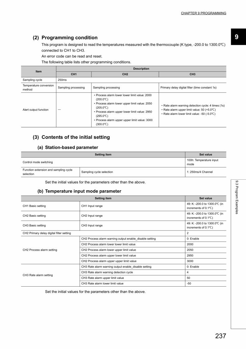
CHAPTER 9 PROGRAMMING
9
9.3
Pro
gra
m E
xam
ple
s
(2) Programming conditionThis program is designed to read the temperatures measured with the thermocouple (K type, -200.0 to 1300.0)
connected to CH1 to CH3.
An error code can be read and reset.
The following table lists other programming conditions.
(3) Contents of the initial setting
(a) Station-based parameter
Set the initial values for the parameters other than the above.
(b) Temperature input mode parameter
Set the initial values for the parameters other than the above.
ItemDescription
CH1 CH2 CH3
Sampling cycle 250ms
Temperature conversion
methodSampling processing Sampling processing Primary delay digital filter (time constant 1s)
Alert output function
• Process alarm lower lower limit value: 2000
(200.0)
• Process alarm lower upper limit value: 2050
(205.0)
• Process alarm upper lower limit value: 2950
(295.0)
• Process alarm upper upper limit value: 3000
(300.0)
• Rate alarm warning detection cycle: 4 times (1s)
• Rate alarm upper limit value: 50 (+5.0)
• Rate alarm lower limit value: -50 (-5.0)
Setting item Set value
Control mode switching100h: Temperature input
mode
Function extension and sampling cycle
selectionSampling cycle selection 1: 250ms/4 Channel
Setting item Set value
CH1 Basic setting CH1 Input range49: K: -200.0 to 1300.0 (in
increments of 0.1)
CH2 Basic setting CH2 Input range49: K: -200.0 to 1300.0 (in
increments of 0.1)
CH3 Basic setting CH3 Input range49: K: -200.0 to 1300.0 (in
increments of 0.1)
CH2 Primary delay digital filter setting 2
CH2 Process alarm setting
CH2 Process alarm warning output enable_disable setting 0: Enable
CH2 Process alarm lower lower limit value 2000
CH2 Process alarm lower upper limit value 2050
CH2 Process alarm upper lower limit value 2950
CH2 Process alarm upper upper limit value 3000
CH3 Rate alarm setting
CH3 Rate alarm warning output enable_disable setting 0: Enable
CH3 Rate alarm warning detection cycle 4
CH3 Rate alarm upper limit value 50
CH3 Rate alarm lower limit value -50
237
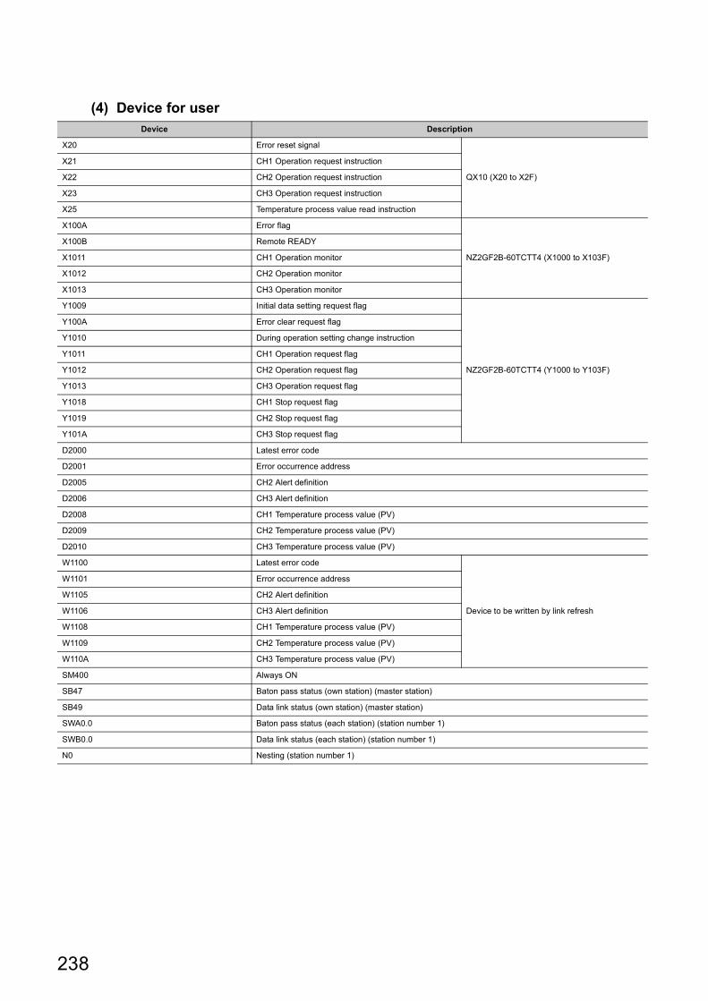
(4) Device for userDevice Description
X20 Error reset signal
QX10 (X20 to X2F)
X21 CH1 Operation request instruction
X22 CH2 Operation request instruction
X23 CH3 Operation request instruction
X25 Temperature process value read instruction
X100A Error flag
NZ2GF2B-60TCTT4 (X1000 to X103F)
X100B Remote READY
X1011 CH1 Operation monitor
X1012 CH2 Operation monitor
X1013 CH3 Operation monitor
Y1009 Initial data setting request flag
NZ2GF2B-60TCTT4 (Y1000 to Y103F)
Y100A Error clear request flag
Y1010 During operation setting change instruction
Y1011 CH1 Operation request flag
Y1012 CH2 Operation request flag
Y1013 CH3 Operation request flag
Y1018 CH1 Stop request flag
Y1019 CH2 Stop request flag
Y101A CH3 Stop request flag
D2000 Latest error code
D2001 Error occurrence address
D2005 CH2 Alert definition
D2006 CH3 Alert definition
D2008 CH1 Temperature process value (PV)
D2009 CH2 Temperature process value (PV)
D2010 CH3 Temperature process value (PV)
W1100 Latest error code
Device to be written by link refresh
W1101 Error occurrence address
W1105 CH2 Alert definition
W1106 CH3 Alert definition
W1108 CH1 Temperature process value (PV)
W1109 CH2 Temperature process value (PV)
W110A CH3 Temperature process value (PV)
SM400 Always ON
SB47 Baton pass status (own station) (master station)
SB49 Data link status (own station) (master station)
SWA0.0 Baton pass status (each station) (station number 1)
SWB0.0 Data link status (each station) (station number 1)
N0 Nesting (station number 1)
238

CHAPTER 9 PROGRAMMING
9
9.3
Pro
gra
m E
xam
ple
s
(5) Setting procedureConnect GX Works2 to the master station to configure the setting.
1. Create a project on GX Works2.
Select "QCPU (Q mode)" for "Series" and select "Q10UDH" for "Module Type".
[Project] [New...]
2. Display the network parameter setting window and configure the setting as follows.
Project window [Parameter] [Network Parameter] [Ethernet/CC IE/MELSECNET]
239
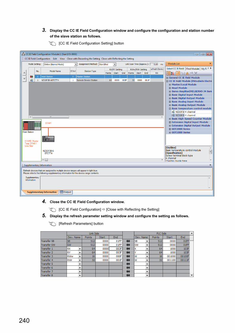
3. Display the CC IE Field Configuration window and configure the configuration and station number
of the slave station as follows.
[CC IE Field Configuration Setting] button
4. Close the CC IE Field Configuration window.
[CC IE Field Configuration] [Close with Reflecting the Setting]
5. Display the refresh parameter setting window and configure the setting as follows.
[Refresh Parameters] button
240
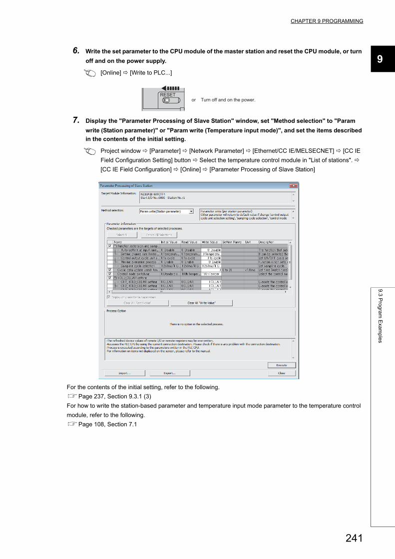
CHAPTER 9 PROGRAMMING
9
9.3
Pro
gra
m E
xam
ple
s
6. Write the set parameter to the CPU module of the master station and reset the CPU module, or turn
off and on the power supply.
[Online] [Write to PLC...]
7. Display the "Parameter Processing of Slave Station" window, set "Method selection" to "Param
write (Station parameter)" or "Param write (Temperature input mode)", and set the items described
in the contents of the initial setting.
Project window [Parameter] [Network Parameter] [Ethernet/CC IE/MELSECNET] [CC IE
Field Configuration Setting] button Select the temperature control module in "List of stations".
[CC IE Field Configuration] [Online] [Parameter Processing of Slave Station]
For the contents of the initial setting, refer to the following.
Page 237, Section 9.3.1 (3)
For how to write the station-based parameter and temperature input mode parameter to the temperature control
module, refer to the following.
Page 108, Section 7.1
RESETor Turn off and on the power.
241
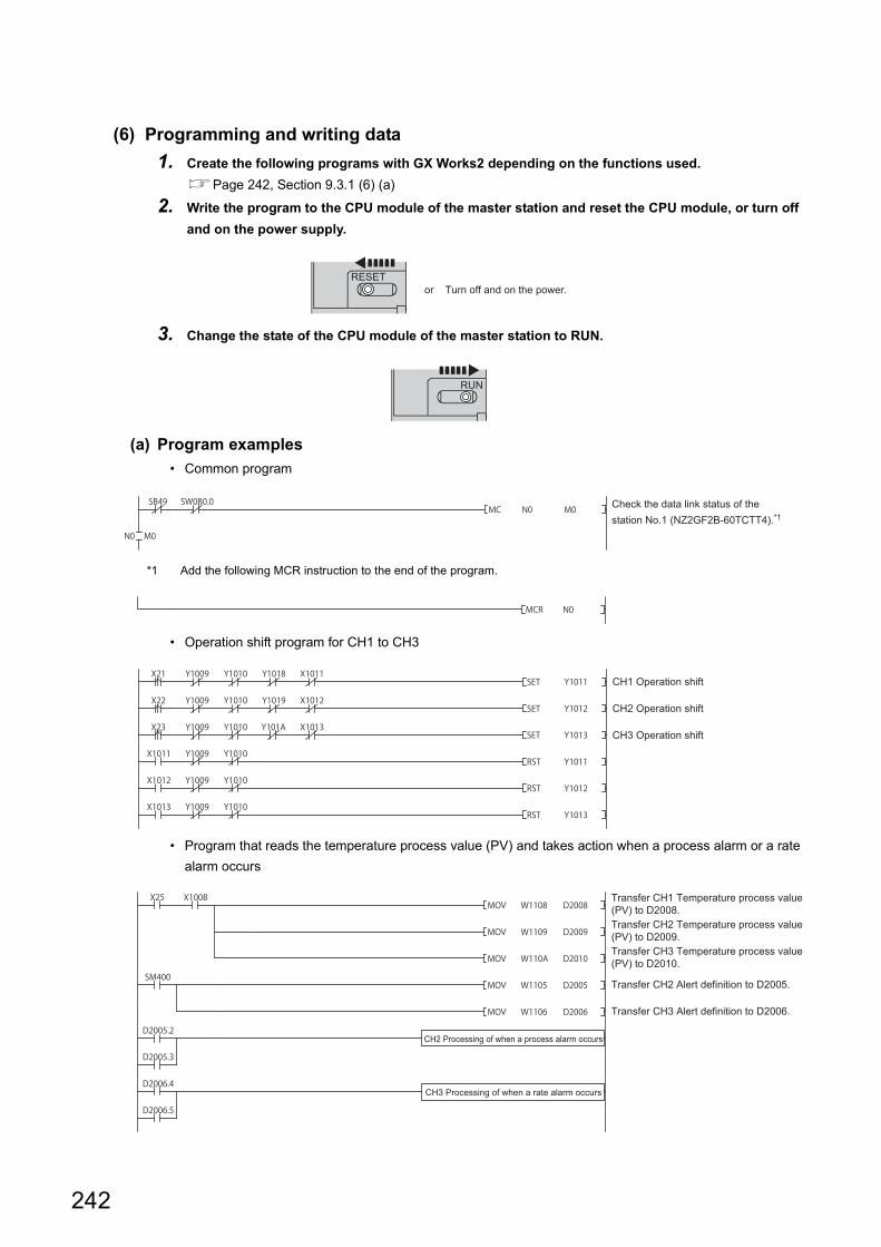
(6) Programming and writing data
1. Create the following programs with GX Works2 depending on the functions used.
Page 242, Section 9.3.1 (6) (a)
2. Write the program to the CPU module of the master station and reset the CPU module, or turn off
and on the power supply.
3. Change the state of the CPU module of the master station to RUN.
(a) Program examples
• Common program
*1 Add the following MCR instruction to the end of the program.
• Operation shift program for CH1 to CH3
• Program that reads the temperature process value (PV) and takes action when a process alarm or a rate
alarm occurs
RESETor Turn off and on the power.
RUN
Check the data link status of the station No.1 (NZ2GF2B-60TCTT4).*1
CH1 Operation shift
CH2 Operation shift
CH3 Operation shift
Transfer CH1 Temperature process value (PV) to D2008.Transfer CH2 Temperature process value (PV) to D2009.Transfer CH3 Temperature process value (PV) to D2010.
Transfer CH2 Alert definition to D2005.
Transfer CH3 Alert definition to D2006.
CH2 Processing of when a process alarm occurs
CH3 Processing of when a rate alarm occurs
242
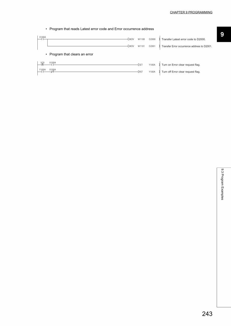
CHAPTER 9 PROGRAMMING
9
9.3
Pro
gra
m E
xam
ple
s
• Program that reads Latest error code and Error occurrence address
• Program that clears an error
Transfer Latest error code to D2000.
Transfer Error occurrence address to D2001.
Turn on Error clear request flag.
Turn off Error clear request flag.
243
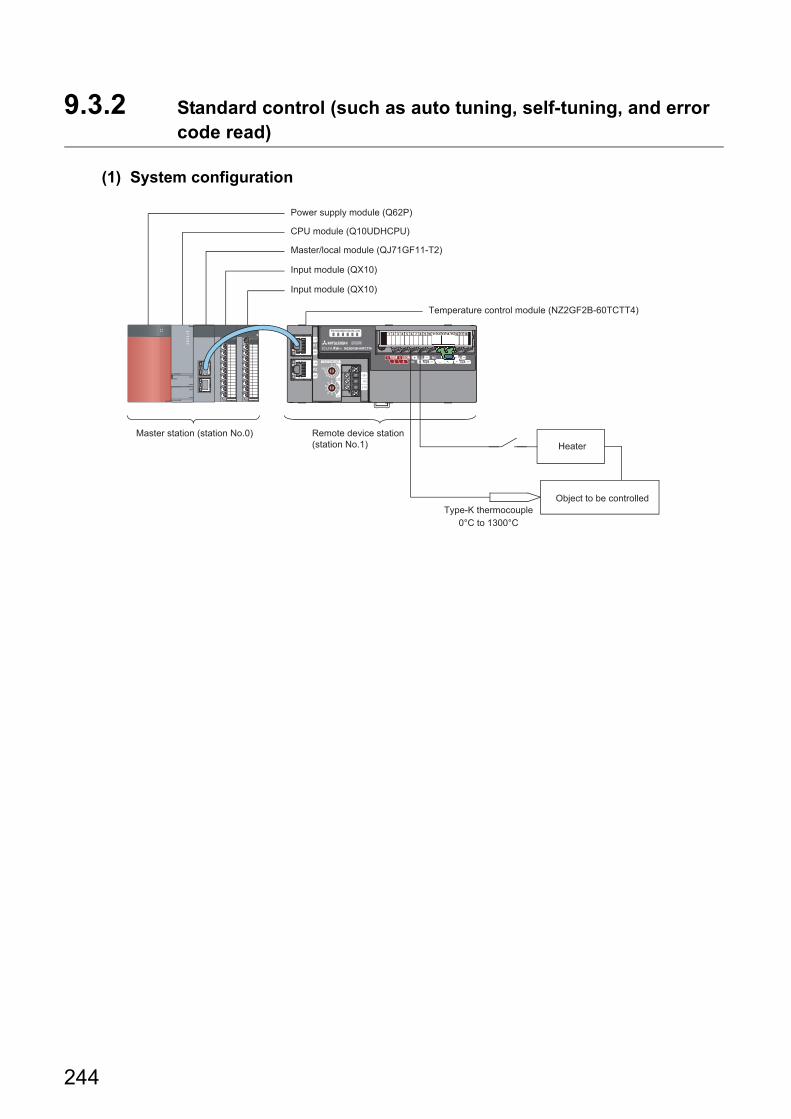
9.3.2 Standard control (such as auto tuning, self-tuning, and error code read)
(1) System configuration
Heater
Object to be controlledType-K thermocouple
0°C to 1300°C
Remote device station (station No.1)
Master station (station No.0)
Master/local module (QJ71GF11-T2)
Input module (QX10)
Input module (QX10)
Temperature control module (NZ2GF2B-60TCTT4)
CPU module (Q10UDHCPU)
Power supply module (Q62P)
244
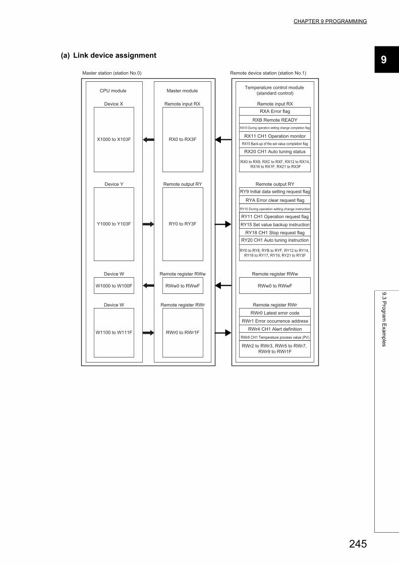
CHAPTER 9 PROGRAMMING
9
9.3
Pro
gra
m E
xam
ple
s
(a) Link device assignment
CPU module Master module
Remote input RX Remote input RXRXA Error flag
RXB Remote READYRX10 During operation setting change completion flag
RX11 CH1 Operation monitorRX15 Back-up of the set value completion flag
RX0 to RX3F
RX20 CH1 Auto tuning status
RX0 to RX9, RXC to RXF, RX12 to RX14, RX16 to RX1F, RX21 to RX3F
Remote register RWr
RWr0 Latest error code
Remote register RWr
RWr0 to RWr1F
RWr1 Error occurrence address
RWr4 CH1 Alert definition
RWr8 CH1 Temperature process value (PV)
RWr2 to RWr3, RWr5 to RWr7, RWr9 to RWr1F
Remote output RY
RY10 During operation setting change instruction
RY11 CH1 Operation request flag
RY9 Initial data setting request flag
RYA Error clear request flag
Remote register RWw
RWw0 to RWwF
Remote register RWw
RWw0 to RWwF
RY15 Set value backup instruction
Remote output RY
RY0 to RY3F
Device X
X1000 to X103F
Device W
W1100 to W111F
Device W
W1000 to W100F
Device Y
Y1000 to Y103F
RY18 CH1 Stop request flagRY20 CH1 Auto tuning instruction
RY0 to RY8, RYB to RYF, RY12 to RY14, RY16 to RY17, RY19, RY21 to RY3F
Temperature control module (standard control)
Master station (station No.0) Remote device station (station No.1)
245
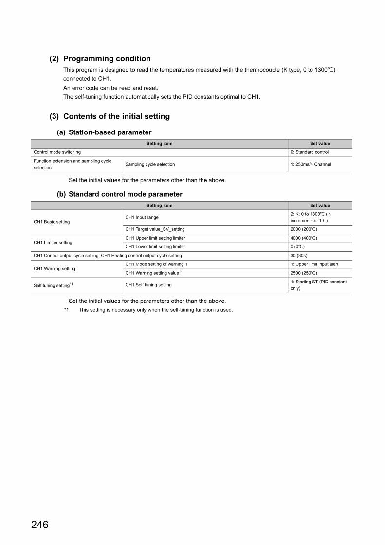
(2) Programming conditionThis program is designed to read the temperatures measured with the thermocouple (K type, 0 to 1300)
connected to CH1.
An error code can be read and reset.
The self-tuning function automatically sets the PID constants optimal to CH1.
(3) Contents of the initial setting
(a) Station-based parameter
Set the initial values for the parameters other than the above.
(b) Standard control mode parameter
Set the initial values for the parameters other than the above.
*1 This setting is necessary only when the self-tuning function is used.
Setting item Set value
Control mode switching 0: Standard control
Function extension and sampling cycle
selectionSampling cycle selection 1: 250ms/4 Channel
Setting item Set value
CH1 Basic settingCH1 Input range
2: K: 0 to 1300 (in
increments of 1)
CH1 Target value_SV_setting 2000 (200)
CH1 Limiter settingCH1 Upper limit setting limiter 4000 (400)
CH1 Lower limit setting limiter 0 (0)
CH1 Control output cycle setting_CH1 Heating control output cycle setting 30 (30s)
CH1 Warning settingCH1 Mode setting of warning 1 1: Upper limit input alert
CH1 Warning setting value 1 2500 (250)
Self tuning setting*1 CH1 Self tuning setting1: Starting ST (PID constant
only)
246
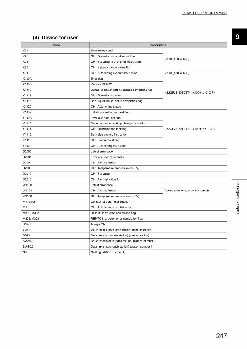
CHAPTER 9 PROGRAMMING
9
9.3
Pro
gra
m E
xam
ple
s
(4) Device for userDevice Description
X20 Error reset signal
QX10 (X20 to X2F)X21 CH1 Operation request instruction
X26 CH1 Set value (SV) change instruction
X2B CH1 Setting change instruction
X30 CH1 Auto tuning execute instruction QX10 (X30 to X3F)
X100A Error flag
NZ2GF2B-60TCTT4 (X1000 to X103F)
X100B Remote READY
X1010 During operation setting change completion flag
X1011 CH1 Operation monitor
X1015 Back-up of the set value completion flag
X1020 CH1 Auto tuning status
Y1009 Initial data setting request flag
NZ2GF2B-60TCTT4 (Y1000 to Y103F)
Y100A Error clear request flag
Y1010 During operation setting change instruction
Y1011 CH1 Operation request flag
Y1015 Set value backup instruction
Y1018 CH1 Stop request flag
Y1020 CH1 Auto tuning instruction
D2000 Latest error code
D2001 Error occurrence address
D2004 CH1 Alert definition
D2008 CH1 Temperature process value (PV)
D2012 CH1 Set value
D2013 CH1 Alert set value 1
W1100 Latest error code
Device to be written by link refreshW1104 CH1 Alert definition
W1108 CH1 Temperature process value (PV)
M1 to M2 Contact for parameter setting
M10 CH1 Auto tuning completion flag
M300, M302 REMTO instruction completion flag
M301, M303 REMTO instruction error completion flag
SM400 Always ON
SB47 Baton pass status (own station) (master station)
SB49 Data link status (own station) (master station)
SWA0.0 Baton pass status (each station) (station number 1)
SWB0.0 Data link status (each station) (station number 1)
N0 Nesting (station number 1)
247
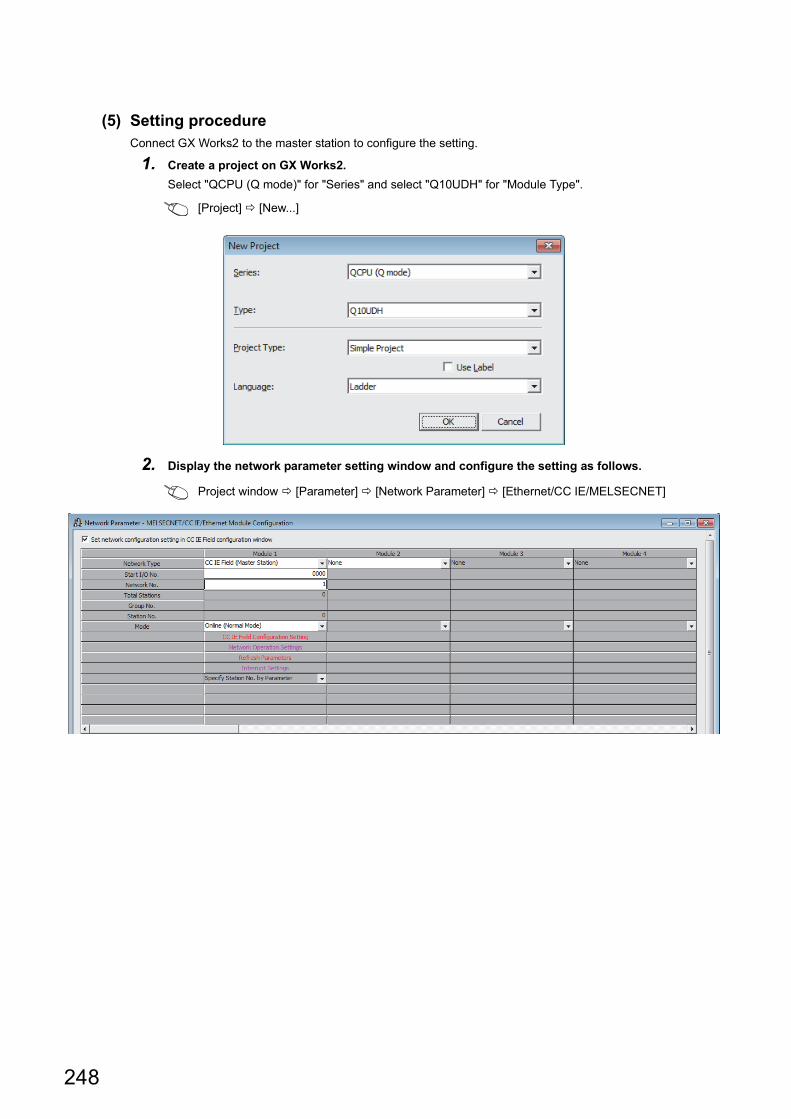
(5) Setting procedureConnect GX Works2 to the master station to configure the setting.
1. Create a project on GX Works2.
Select "QCPU (Q mode)" for "Series" and select "Q10UDH" for "Module Type".
[Project] [New...]
2. Display the network parameter setting window and configure the setting as follows.
Project window [Parameter] [Network Parameter] [Ethernet/CC IE/MELSECNET]
248
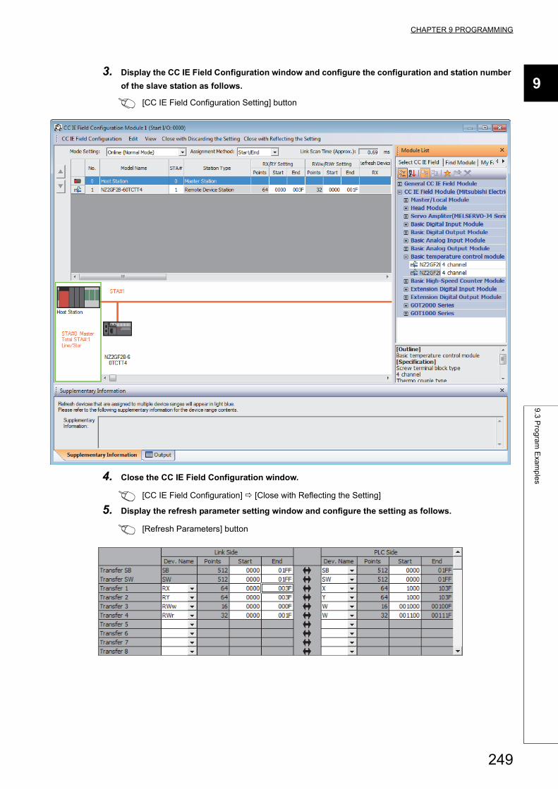
CHAPTER 9 PROGRAMMING
9
9.3
Pro
gra
m E
xam
ple
s
3. Display the CC IE Field Configuration window and configure the configuration and station number
of the slave station as follows.
[CC IE Field Configuration Setting] button
4. Close the CC IE Field Configuration window.
[CC IE Field Configuration] [Close with Reflecting the Setting]
5. Display the refresh parameter setting window and configure the setting as follows.
[Refresh Parameters] button
249

6. Write the set parameter to the CPU module of the master station and reset the CPU module, or turn
off and on the power supply.
[Online] [Write to PLC...]
7. Display the "Parameter Processing of Slave Station" window, set "Method selection" to "Param
write (Station parameter)" or "Param write (Standard control)", and set the items described in the
contents of the initial setting.
Project window [Parameter] [Network Parameter] [Ethernet/CC IE/MELSECNET] [CC IE
Field Configuration Setting] button Select the temperature control module in "List of stations".
[CC IE Field Configuration] [Online] [Parameter Processing of Slave Station]
RESETor Turn off and on the power.
250
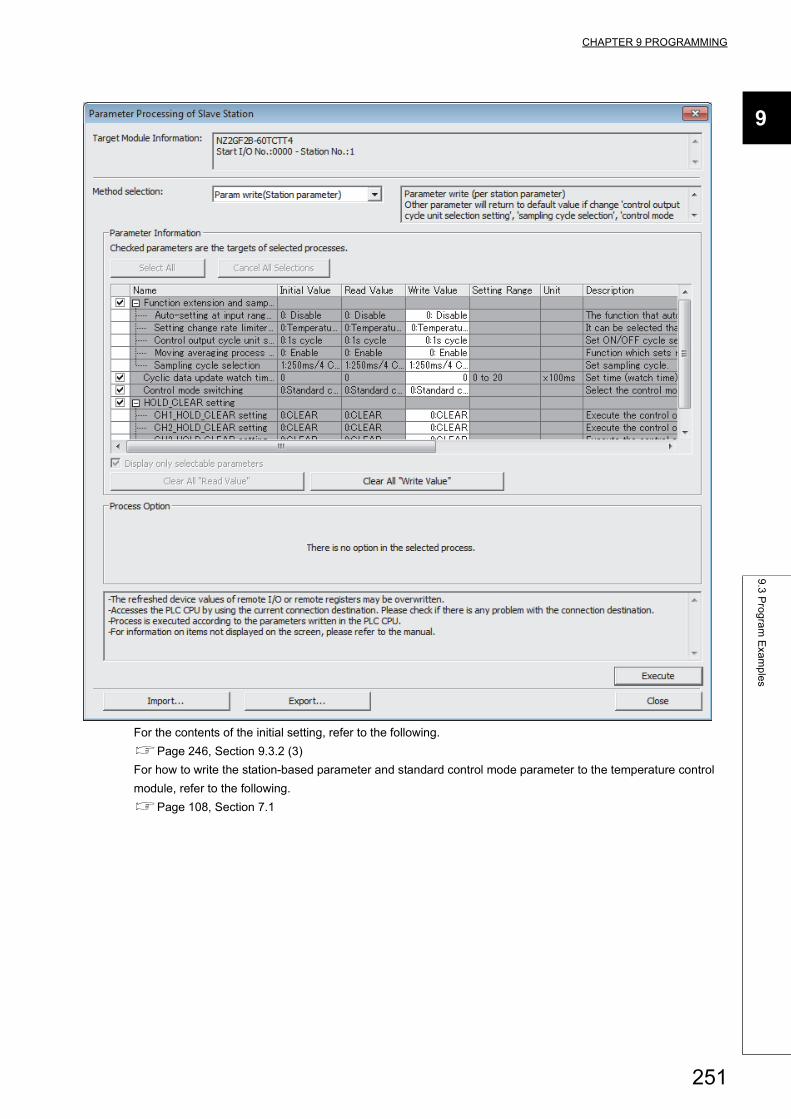
CHAPTER 9 PROGRAMMING
9
9.3
Pro
gra
m E
xam
ple
s
For the contents of the initial setting, refer to the following.
Page 246, Section 9.3.2 (3)
For how to write the station-based parameter and standard control mode parameter to the temperature control
module, refer to the following.
Page 108, Section 7.1
251
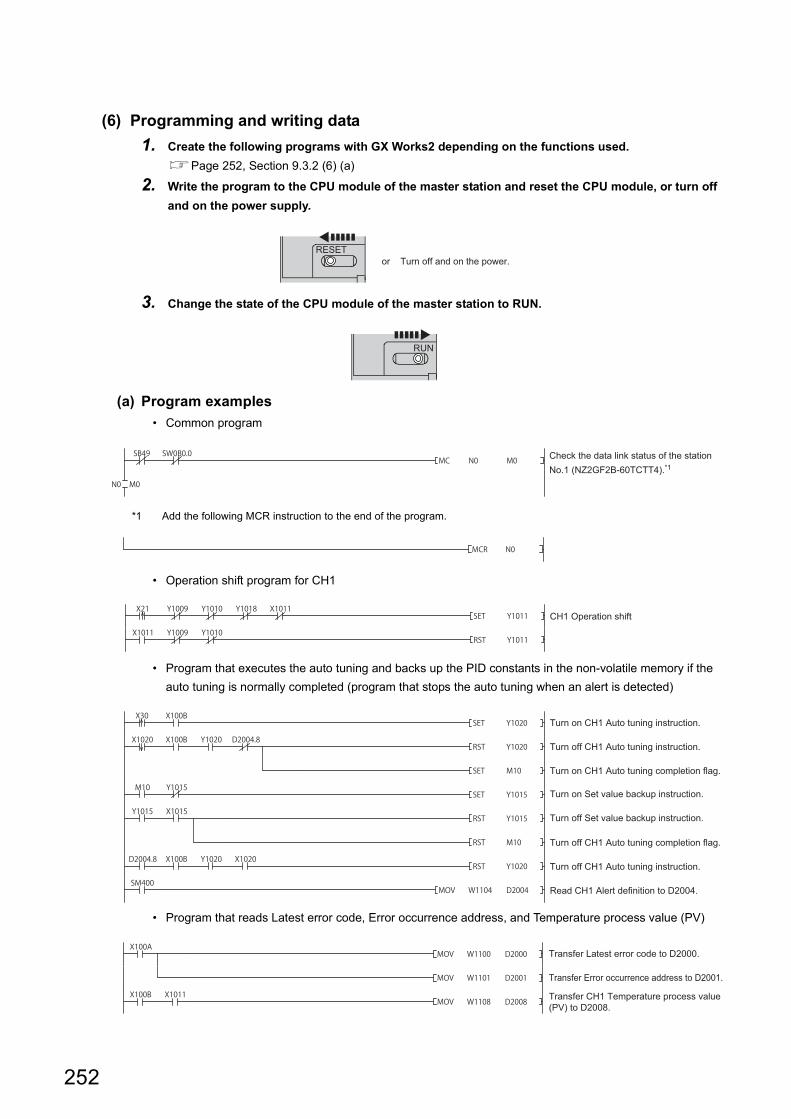
(6) Programming and writing data
1. Create the following programs with GX Works2 depending on the functions used.
Page 252, Section 9.3.2 (6) (a)
2. Write the program to the CPU module of the master station and reset the CPU module, or turn off
and on the power supply.
3. Change the state of the CPU module of the master station to RUN.
(a) Program examples
• Common program
*1 Add the following MCR instruction to the end of the program.
• Operation shift program for CH1
• Program that executes the auto tuning and backs up the PID constants in the non-volatile memory if the
auto tuning is normally completed (program that stops the auto tuning when an alert is detected)
• Program that reads Latest error code, Error occurrence address, and Temperature process value (PV)
RESETor Turn off and on the power.
RUN
Check the data link status of the station No.1 (NZ2GF2B-60TCTT4).*1
CH1 Operation shift
Turn on CH1 Auto tuning instruction.
Turn off CH1 Auto tuning instruction.
Turn on CH1 Auto tuning completion flag.
Turn on Set value backup instruction.
Turn off Set value backup instruction.
Turn off CH1 Auto tuning completion flag.
Turn off CH1 Auto tuning instruction.
Read CH1 Alert definition to D2004.
Transfer Latest error code to D2000.
Transfer Error occurrence address to D2001.
Transfer CH1 Temperature process value (PV) to D2008.
252
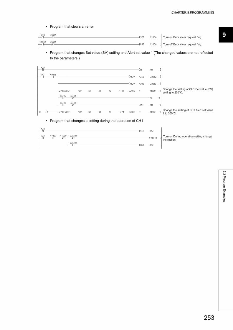
CHAPTER 9 PROGRAMMING
9
9.3
Pro
gra
m E
xam
ple
s
• Program that clears an error
• Program that changes Set value (SV) setting and Alert set value 1 (The changed values are not reflected
to the parameters.)
• Program that changes a setting during the operation of CH1
Turn on Error clear request flag.
Turn off Error clear request flag.
Change the setting of CH1 Set value (SV) setting to 250°C.
Change the setting of CH1 Alert set value 1 to 300°C.
Turn on During operation setting change instruction.
253
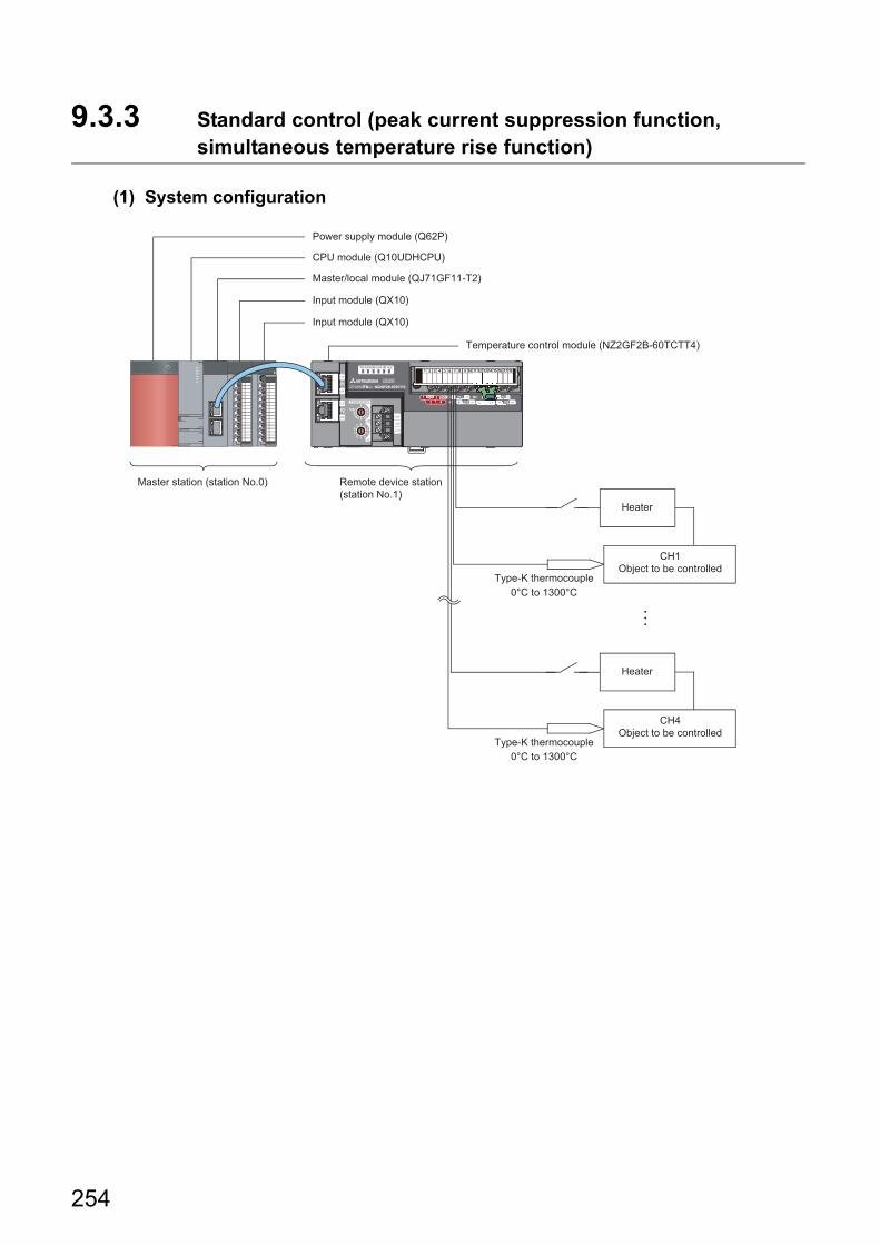
9.3.3 Standard control (peak current suppression function, simultaneous temperature rise function)
(1) System configuration
Heater
CH1Object to be controlled
CH4Object to be controlled
Heater
Type-K thermocouple0°C to 1300°C
Type-K thermocouple0°C to 1300°C
Remote device station (station No.1)
Master station (station No.0)
Master/local module (QJ71GF11-T2)
Input module (QX10)
Input module (QX10)
Temperature control module (NZ2GF2B-60TCTT4)
CPU module (Q10UDHCPU)
Power supply module (Q62P)
254
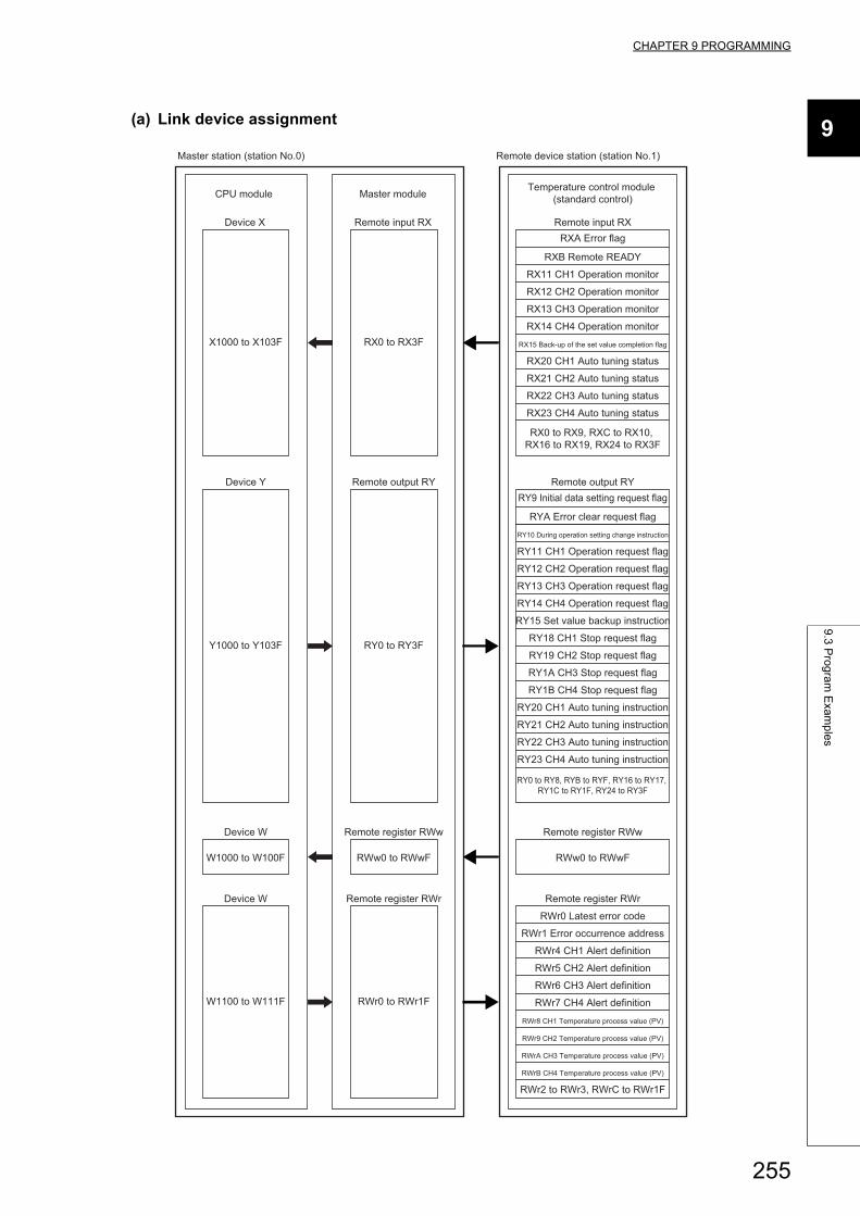
CHAPTER 9 PROGRAMMING
9
9.3
Pro
gra
m E
xam
ple
s
(a) Link device assignment
CPU module Master module
Remote input RX Remote input RXRXA Error flag
RXB Remote READY
RX11 CH1 Operation monitor
RX12 CH2 Operation monitor
RX13 CH3 Operation monitor
RX0 to RX3FRX14 CH4 Operation monitor
RX15 Back-up of the set value completion flag
RX20 CH1 Auto tuning status
RX21 CH2 Auto tuning status
RX22 CH3 Auto tuning status
RX23 CH4 Auto tuning status
RX0 to RX9, RXC to RX10, RX16 to RX19, RX24 to RX3F
Remote register RWr
RWr0 Latest error code
Remote register RWr
RWr0 to RWr1F
RWr1 Error occurrence address
RWr4 CH1 Alert definition
RWr5 CH2 Alert definition
RWr6 CH3 Alert definition
RWr7 CH4 Alert definition
RWr8 CH1 Temperature process value (PV)
RWr9 CH2 Temperature process value (PV)
RWrA CH3 Temperature process value (PV)
RWrB CH4 Temperature process value (PV)
RWr2 to RWr3, RWrC to RWr1F
Remote output RYRY9 Initial data setting request flag
RYA Error clear request flag
RY10 During operation setting change instruction
RY11 CH1 Operation request flag
RY12 CH2 Operation request flag
RY13 CH3 Operation request flag
RY14 CH4 Operation request flag
RY15 Set value backup instruction
RY18 CH1 Stop request flag
RY19 CH2 Stop request flag
RY1A CH3 Stop request flag
RY1B CH4 Stop request flag
RY20 CH1 Auto tuning instruction
RY21 CH2 Auto tuning instruction
RY22 CH3 Auto tuning instruction
RY23 CH4 Auto tuning instruction
RY0 to RY8, RYB to RYF, RY16 to RY17, RY1C to RY1F, RY24 to RY3F
Remote register RWw
RWw0 to RWwF
Remote register RWw
RWw0 to RWwF
Remote output RY
RY0 to RY3F
Device X
X1000 to X103F
Device W
W1100 to W111F
Device W
W1000 to W100F
Device Y
Y1000 to Y103F
Temperature control module (standard control)
Master station (station No.0) Remote device station (station No.1)
255
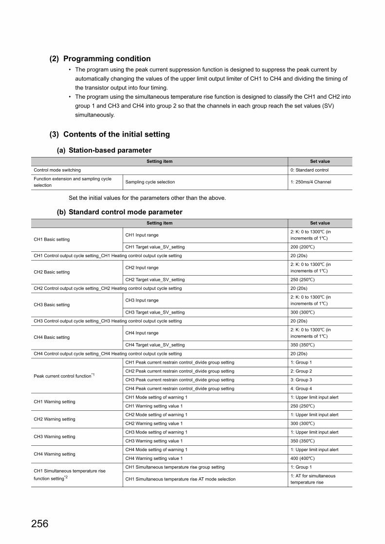
(2) Programming condition• The program using the peak current suppression function is designed to suppress the peak current by
automatically changing the values of the upper limit output limiter of CH1 to CH4 and dividing the timing of
the transistor output into four timing.
• The program using the simultaneous temperature rise function is designed to classify the CH1 and CH2 into
group 1 and CH3 and CH4 into group 2 so that the channels in each group reach the set values (SV)
simultaneously.
(3) Contents of the initial setting
(a) Station-based parameter
Set the initial values for the parameters other than the above.
(b) Standard control mode parameter
Setting item Set value
Control mode switching 0: Standard control
Function extension and sampling cycle
selectionSampling cycle selection 1: 250ms/4 Channel
Setting item Set value
CH1 Basic settingCH1 Input range
2: K: 0 to 1300 (in
increments of 1)
CH1 Target value_SV_setting 200 (200)
CH1 Control output cycle setting_CH1 Heating control output cycle setting 20 (20s)
CH2 Basic settingCH2 Input range
2: K: 0 to 1300 (in
increments of 1)
CH2 Target value_SV_setting 250 (250)
CH2 Control output cycle setting_CH2 Heating control output cycle setting 20 (20s)
CH3 Basic settingCH3 Input range
2: K: 0 to 1300 (in
increments of 1)
CH3 Target value_SV_setting 300 (300)
CH3 Control output cycle setting_CH3 Heating control output cycle setting 20 (20s)
CH4 Basic settingCH4 Input range
2: K: 0 to 1300 (in
increments of 1)
CH4 Target value_SV_setting 350 (350)
CH4 Control output cycle setting_CH4 Heating control output cycle setting 20 (20s)
Peak current control function*1
CH1 Peak current restrain control_divide group setting 1: Group 1
CH2 Peak current restrain control_divide group setting 2: Group 2
CH3 Peak current restrain control_divide group setting 3: Group 3
CH4 Peak current restrain control_divide group setting 4: Group 4
CH1 Warning settingCH1 Mode setting of warning 1 1: Upper limit input alert
CH1 Warning setting value 1 250 (250)
CH2 Warning settingCH2 Mode setting of warning 1 1: Upper limit input alert
CH2 Warning setting value 1 300 (300)
CH3 Warning settingCH3 Mode setting of warning 1 1: Upper limit input alert
CH3 Warning setting value 1 350 (350)
CH4 Warning settingCH4 Mode setting of warning 1 1: Upper limit input alert
CH4 Warning setting value 1 400 (400)
CH1 Simultaneous temperature rise
function setting*2
CH1 Simultaneous temperature rise group setting 1: Group 1
CH1 Simultaneous temperature rise AT mode selection1: AT for simultaneous
temperature rise
256
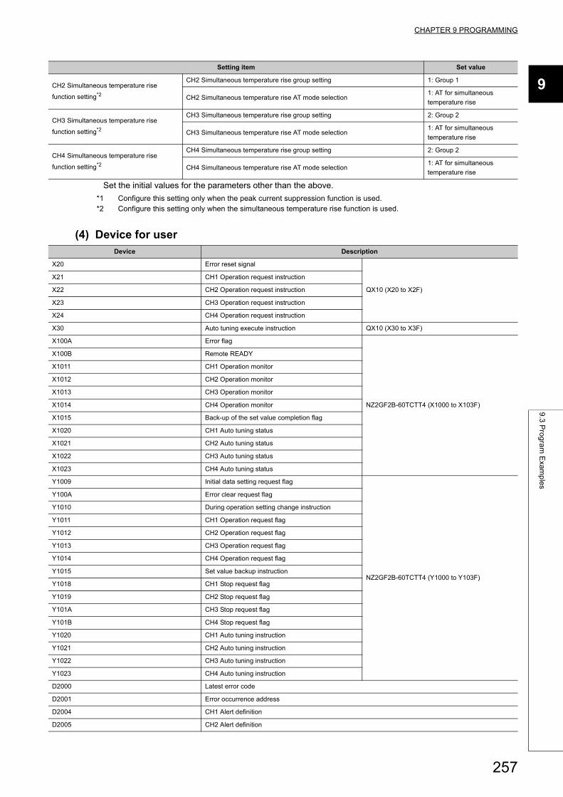
CHAPTER 9 PROGRAMMING
9
9.3
Pro
gra
m E
xam
ple
s
Set the initial values for the parameters other than the above.
*1 Configure this setting only when the peak current suppression function is used.*2 Configure this setting only when the simultaneous temperature rise function is used.
(4) Device for user
CH2 Simultaneous temperature rise
function setting*2
CH2 Simultaneous temperature rise group setting 1: Group 1
CH2 Simultaneous temperature rise AT mode selection1: AT for simultaneous
temperature rise
CH3 Simultaneous temperature rise
function setting*2
CH3 Simultaneous temperature rise group setting 2: Group 2
CH3 Simultaneous temperature rise AT mode selection1: AT for simultaneous
temperature rise
CH4 Simultaneous temperature rise
function setting*2
CH4 Simultaneous temperature rise group setting 2: Group 2
CH4 Simultaneous temperature rise AT mode selection1: AT for simultaneous
temperature rise
Device Description
X20 Error reset signal
QX10 (X20 to X2F)
X21 CH1 Operation request instruction
X22 CH2 Operation request instruction
X23 CH3 Operation request instruction
X24 CH4 Operation request instruction
X30 Auto tuning execute instruction QX10 (X30 to X3F)
X100A Error flag
NZ2GF2B-60TCTT4 (X1000 to X103F)
X100B Remote READY
X1011 CH1 Operation monitor
X1012 CH2 Operation monitor
X1013 CH3 Operation monitor
X1014 CH4 Operation monitor
X1015 Back-up of the set value completion flag
X1020 CH1 Auto tuning status
X1021 CH2 Auto tuning status
X1022 CH3 Auto tuning status
X1023 CH4 Auto tuning status
Y1009 Initial data setting request flag
NZ2GF2B-60TCTT4 (Y1000 to Y103F)
Y100A Error clear request flag
Y1010 During operation setting change instruction
Y1011 CH1 Operation request flag
Y1012 CH2 Operation request flag
Y1013 CH3 Operation request flag
Y1014 CH4 Operation request flag
Y1015 Set value backup instruction
Y1018 CH1 Stop request flag
Y1019 CH2 Stop request flag
Y101A CH3 Stop request flag
Y101B CH4 Stop request flag
Y1020 CH1 Auto tuning instruction
Y1021 CH2 Auto tuning instruction
Y1022 CH3 Auto tuning instruction
Y1023 CH4 Auto tuning instruction
D2000 Latest error code
D2001 Error occurrence address
D2004 CH1 Alert definition
D2005 CH2 Alert definition
Setting item Set value
257
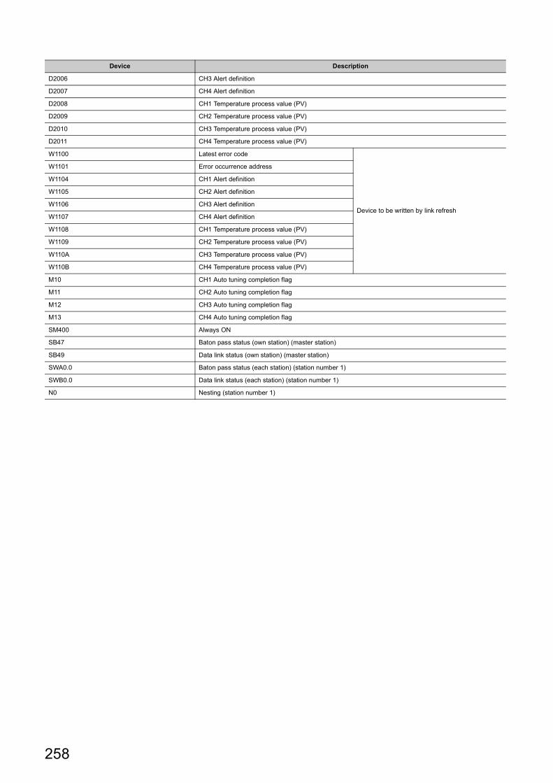
D2006 CH3 Alert definition
D2007 CH4 Alert definition
D2008 CH1 Temperature process value (PV)
D2009 CH2 Temperature process value (PV)
D2010 CH3 Temperature process value (PV)
D2011 CH4 Temperature process value (PV)
W1100 Latest error code
Device to be written by link refresh
W1101 Error occurrence address
W1104 CH1 Alert definition
W1105 CH2 Alert definition
W1106 CH3 Alert definition
W1107 CH4 Alert definition
W1108 CH1 Temperature process value (PV)
W1109 CH2 Temperature process value (PV)
W110A CH3 Temperature process value (PV)
W110B CH4 Temperature process value (PV)
M10 CH1 Auto tuning completion flag
M11 CH2 Auto tuning completion flag
M12 CH3 Auto tuning completion flag
M13 CH4 Auto tuning completion flag
SM400 Always ON
SB47 Baton pass status (own station) (master station)
SB49 Data link status (own station) (master station)
SWA0.0 Baton pass status (each station) (station number 1)
SWB0.0 Data link status (each station) (station number 1)
N0 Nesting (station number 1)
Device Description
258
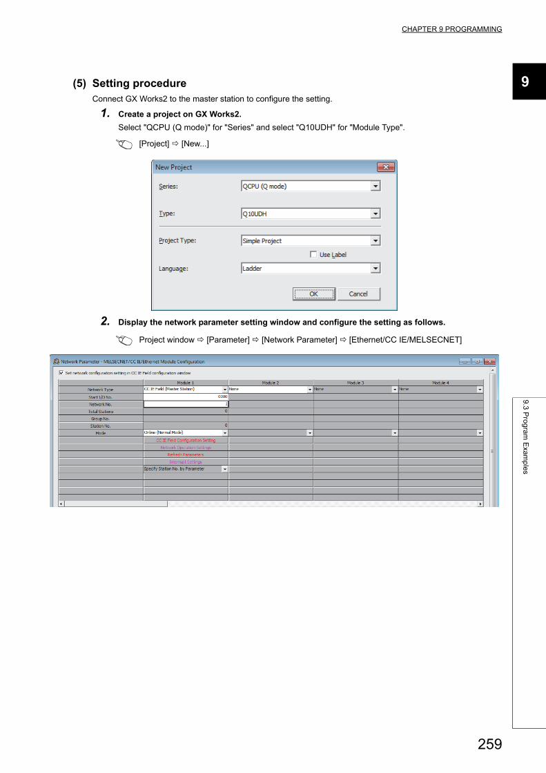
CHAPTER 9 PROGRAMMING
9
9.3
Pro
gra
m E
xam
ple
s
(5) Setting procedureConnect GX Works2 to the master station to configure the setting.
1. Create a project on GX Works2.
Select "QCPU (Q mode)" for "Series" and select "Q10UDH" for "Module Type".
[Project] [New...]
2. Display the network parameter setting window and configure the setting as follows.
Project window [Parameter] [Network Parameter] [Ethernet/CC IE/MELSECNET]
259
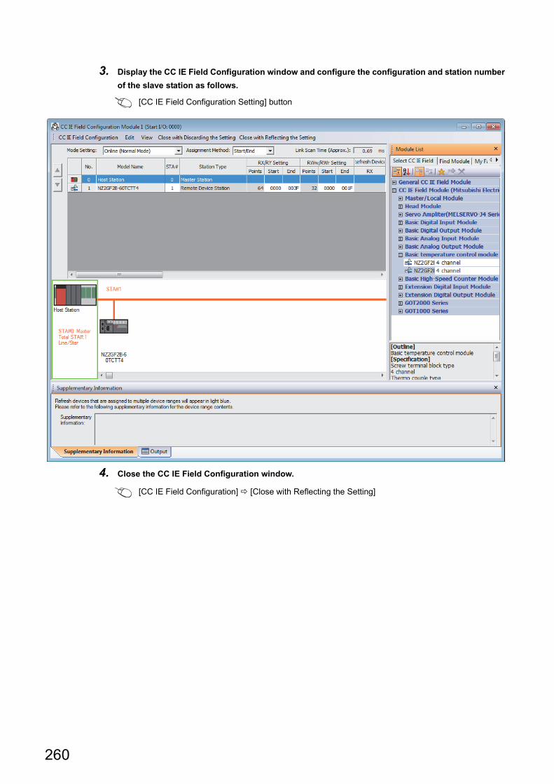
3. Display the CC IE Field Configuration window and configure the configuration and station number
of the slave station as follows.
[CC IE Field Configuration Setting] button
4. Close the CC IE Field Configuration window.
[CC IE Field Configuration] [Close with Reflecting the Setting]
260
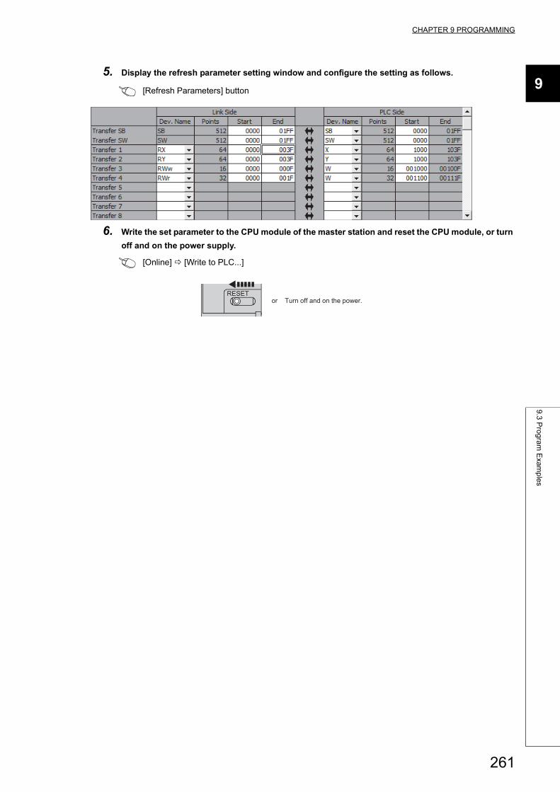
CHAPTER 9 PROGRAMMING
9
9.3
Pro
gra
m E
xam
ple
s
5. Display the refresh parameter setting window and configure the setting as follows.
[Refresh Parameters] button
6. Write the set parameter to the CPU module of the master station and reset the CPU module, or turn
off and on the power supply.
[Online] [Write to PLC...]
RESETor Turn off and on the power.
261
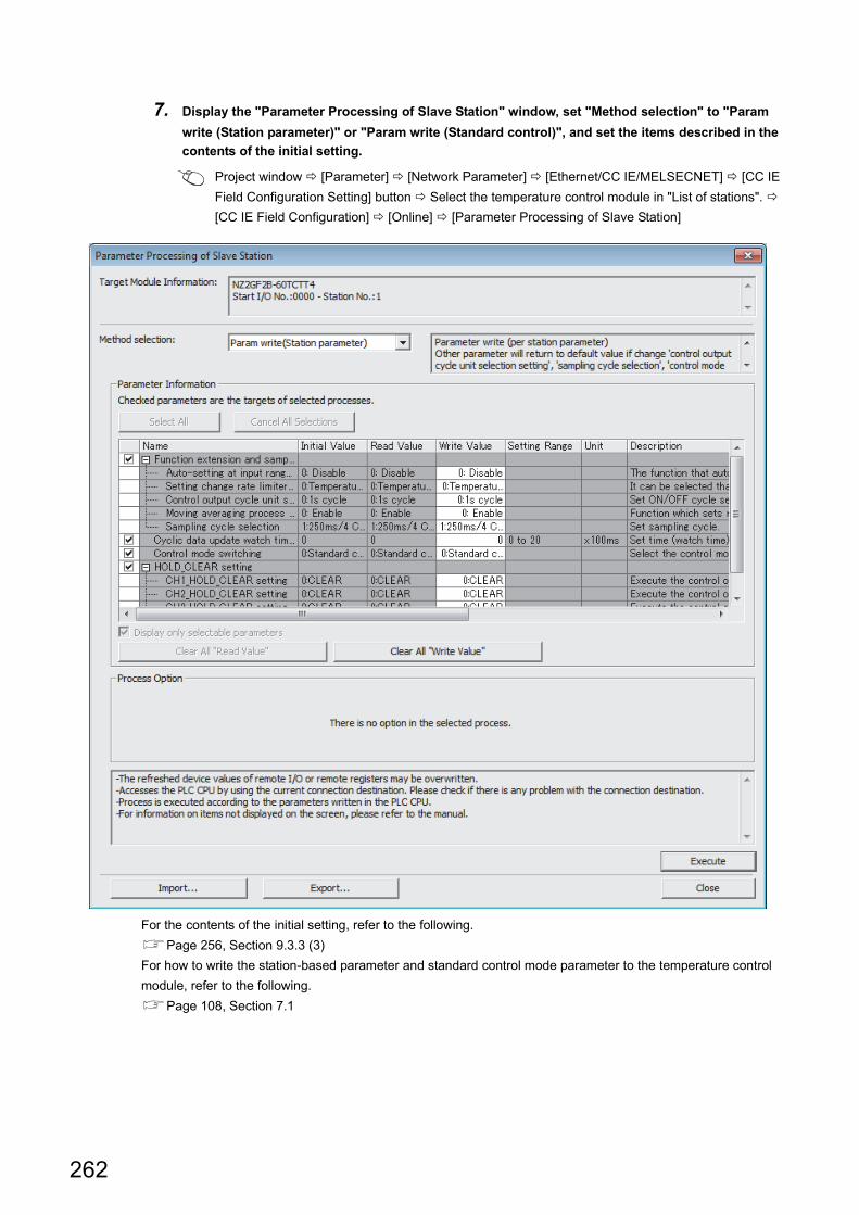
7. Display the "Parameter Processing of Slave Station" window, set "Method selection" to "Param
write (Station parameter)" or "Param write (Standard control)", and set the items described in the
contents of the initial setting.
Project window [Parameter] [Network Parameter] [Ethernet/CC IE/MELSECNET] [CC IE
Field Configuration Setting] button Select the temperature control module in "List of stations".
[CC IE Field Configuration] [Online] [Parameter Processing of Slave Station]
For the contents of the initial setting, refer to the following.
Page 256, Section 9.3.3 (3)
For how to write the station-based parameter and standard control mode parameter to the temperature control
module, refer to the following.
Page 108, Section 7.1
262
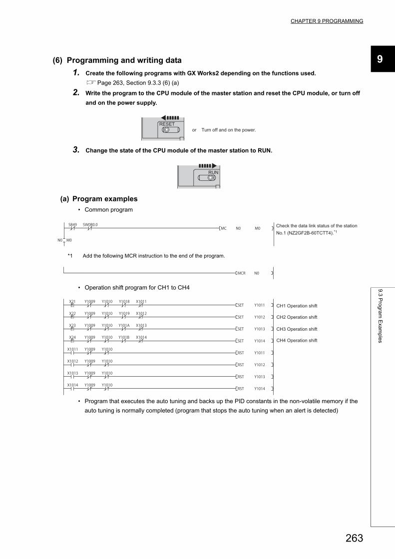
CHAPTER 9 PROGRAMMING
9
9.3
Pro
gra
m E
xam
ple
s
(6) Programming and writing data
1. Create the following programs with GX Works2 depending on the functions used.
Page 263, Section 9.3.3 (6) (a)
2. Write the program to the CPU module of the master station and reset the CPU module, or turn off
and on the power supply.
3. Change the state of the CPU module of the master station to RUN.
(a) Program examples
• Common program
*1 Add the following MCR instruction to the end of the program.
• Operation shift program for CH1 to CH4
• Program that executes the auto tuning and backs up the PID constants in the non-volatile memory if the
auto tuning is normally completed (program that stops the auto tuning when an alert is detected)
RESETor Turn off and on the power.
RUN
Check the data link status of the station No.1 (NZ2GF2B-60TCTT4).*1
CH2 Operation shift
CH1 Operation shift
CH4 Operation shift
CH3 Operation shift
263
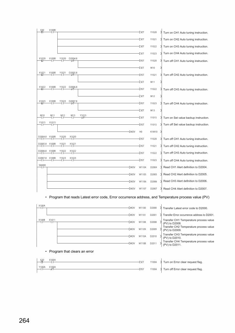
• Program that reads Latest error code, Error occurrence address, and Temperature process value (PV)
• Program that clears an error
Turn on CH2 Auto tuning instruction.
Turn on CH1 Auto tuning instruction.
Turn on CH4 Auto tuning instruction.
Turn on CH3 Auto tuning instruction.
Turn off CH2 Auto tuning instruction.
Turn off CH3 Auto tuning instruction.
Turn off CH4 Auto tuning instruction.
Turn on Set value backup instruction.
Turn off Set value backup instruction.
Turn off CH1 Auto tuning instruction.
Turn off CH1 Auto tuning instruction.
Turn off CH3 Auto tuning instruction.
Turn off CH2 Auto tuning instruction.
Turn off CH4 Auto tuning instruction.
Read CH1 Alert definition to D2004.
Read CH3 Alert definition to D2006.
Read CH2 Alert definition to D2005.
Read CH4 Alert definition to D2007.
Transfer Error occurrence address to D2001.
Transfer Latest error code to D2000.
Transfer CH2 Temperature process value (PV) to D2009.
Transfer CH1 Temperature process value (PV) to D2008.
Transfer CH4 Temperature process value (PV) to D2011.
Transfer CH3 Temperature process value (PV) to D2010.
Turn on Error clear request flag.
Turn off Error clear request flag.
264
CHAPTER 10 MAINTENANCE AND INSPECTION
10
CHAPTER 10 MAINTENANCE AND INSPECTION
The temperature control module has no special item to be inspected. However, to maintain the best condition of the
system, perform the inspection in accordance with the items described in the user's manual for the CPU module used.
In addition, to use CC-Link IE Field Network in the best condition, refer to the user's manual for the master/local
module used as well.
265

Memo
266
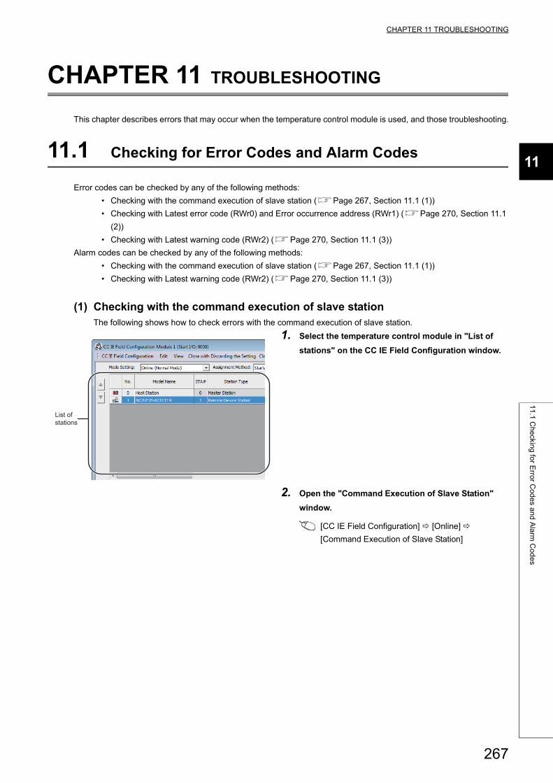
CHAPTER 11 TROUBLESHOOTING
11
11
.1 C
he
cking
for E
rror C
od
es a
nd
Ala
rm C
od
es
CHAPTER 11 TROUBLESHOOTING
This chapter describes errors that may occur when the temperature control module is used, and those troubleshooting.
11.1 Checking for Error Codes and Alarm Codes
Error codes can be checked by any of the following methods:
• Checking with the command execution of slave station (Page 267, Section 11.1 (1))
• Checking with Latest error code (RWr0) and Error occurrence address (RWr1) (Page 270, Section 11.1
(2))
• Checking with Latest warning code (RWr2) (Page 270, Section 11.1 (3))
Alarm codes can be checked by any of the following methods:
• Checking with the command execution of slave station (Page 267, Section 11.1 (1))
• Checking with Latest warning code (RWr2) (Page 270, Section 11.1 (3))
(1) Checking with the command execution of slave stationThe following shows how to check errors with the command execution of slave station.
1. Select the temperature control module in "List of
stations" on the CC IE Field Configuration window.
2. Open the "Command Execution of Slave Station"
window.
[CC IE Field Configuration] [Online]
[Command Execution of Slave Station]
List ofstations
267
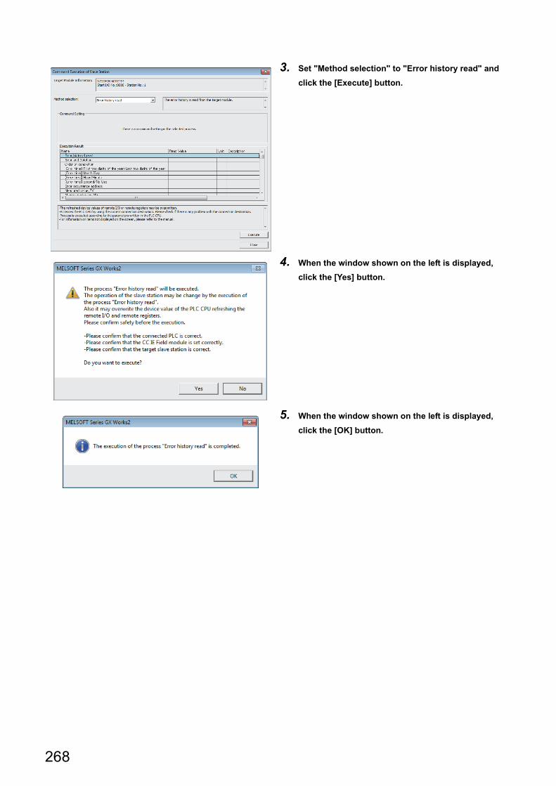
3. Set "Method selection" to "Error history read" and
click the [Execute] button.
4. When the window shown on the left is displayed,
click the [Yes] button.
5. When the window shown on the left is displayed,
click the [OK] button.
268
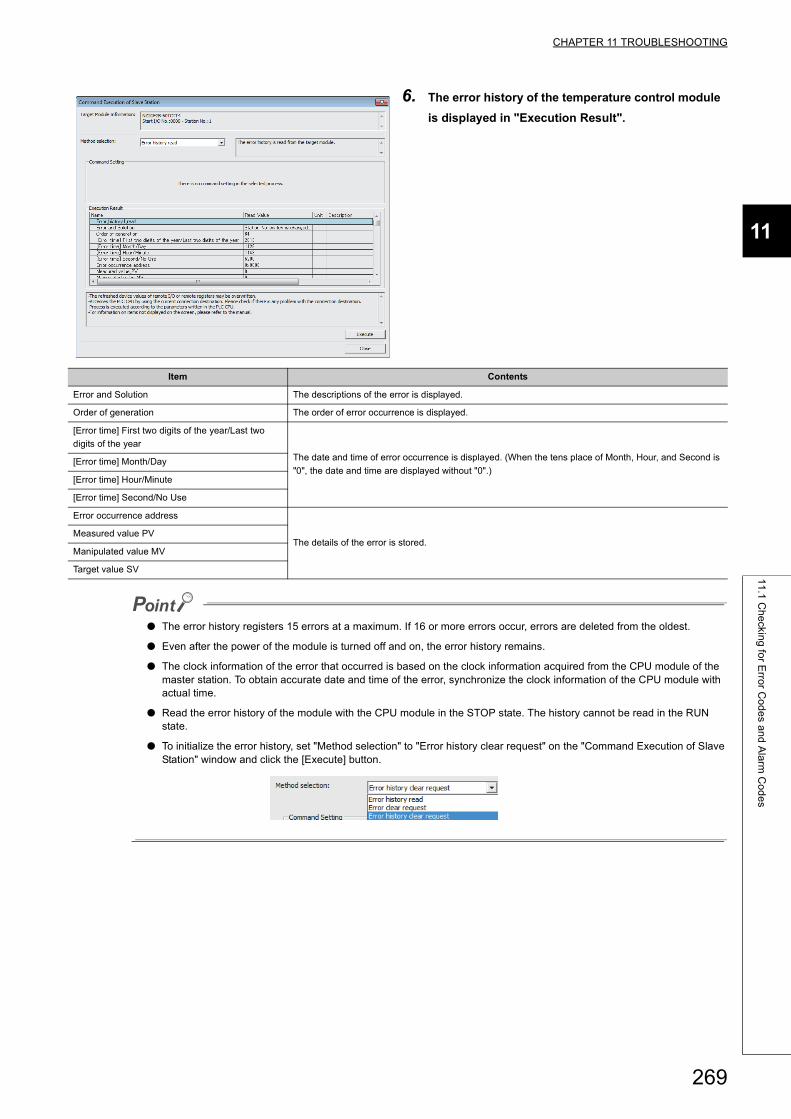
CHAPTER 11 TROUBLESHOOTING
11
11
.1 C
he
cking
for E
rror C
od
es a
nd
Ala
rm C
od
es
● The error history registers 15 errors at a maximum. If 16 or more errors occur, errors are deleted from the oldest.
● Even after the power of the module is turned off and on, the error history remains.
● The clock information of the error that occurred is based on the clock information acquired from the CPU module of the master station. To obtain accurate date and time of the error, synchronize the clock information of the CPU module with actual time.
● Read the error history of the module with the CPU module in the STOP state. The history cannot be read in the RUN state.
● To initialize the error history, set "Method selection" to "Error history clear request" on the "Command Execution of Slave Station" window and click the [Execute] button.
6. The error history of the temperature control module
is displayed in "Execution Result".
Item Contents
Error and Solution The descriptions of the error is displayed.
Order of generation The order of error occurrence is displayed.
[Error time] First two digits of the year/Last two
digits of the year
The date and time of error occurrence is displayed. (When the tens place of Month, Hour, and Second is
"0", the date and time are displayed without "0".)[Error time] Month/Day
[Error time] Hour/Minute
[Error time] Second/No Use
Error occurrence address
The details of the error is stored.Measured value PV
Manipulated value MV
Target value SV
269
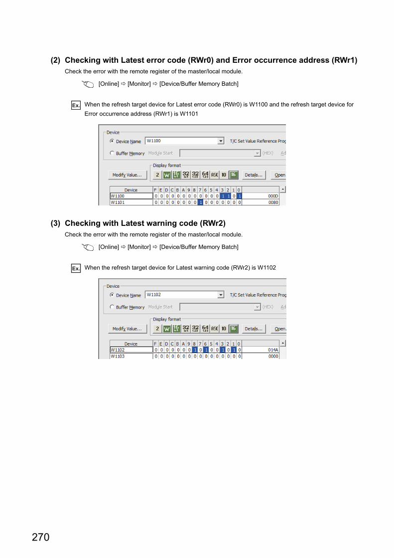
(2) Checking with Latest error code (RWr0) and Error occurrence address (RWr1)Check the error with the remote register of the master/local module.
[Online] [Monitor] [Device/Buffer Memory Batch]
Ex. When the refresh target device for Latest error code (RWr0) is W1100 and the refresh target device for
Error occurrence address (RWr1) is W1101
(3) Checking with Latest warning code (RWr2)Check the error with the remote register of the master/local module.
[Online] [Monitor] [Device/Buffer Memory Batch]
Ex. When the refresh target device for Latest warning code (RWr2) is W1102
270
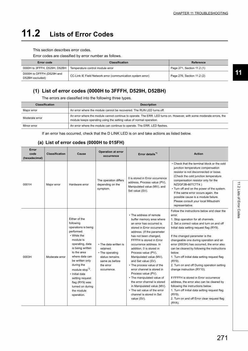
CHAPTER 11 TROUBLESHOOTING
11
11
.2 L
ists of E
rror C
od
es
11.2 Lists of Error Codes
This section describes error codes.
Error codes are classified by error number as follows.
(1) List of error codes (0000H to 3FFFH, D529H, D52BH)The errors are classified into the following three types.
If an error has occurred, check that the D LINK LED is on and take actions as listed below.
(a) List of error codes (0000H to 015FH)
Error code Classification Reference
0000H to 3FFFH, D529H, D52BH Temperature control module error Page 271, Section 11.2 (1)
D000H to DFFFH (D529H and
D52BH excluded)CC-Link IE Field Network error (communication system error) Page 276, Section 11.2 (2)
Classification Description
Major error An error where the module cannot be recovered. The RUN LED turns off.
Moderate errorAn error where the module cannot continue to operate. The ERR. LED turns on. However, with some moderate errors, the
module keeps operating using the setting value of normal operation.
Minor error An error where the module can continue to operate. The ERR. LED flashes.
Error
code
(hexadecimal)
Classification CauseOperation at error
occurrenceError details*1 Action
0001H Major error Hardware error
The operation differs
depending on the
symptom.
0 is stored in Error occurrence
address, Process value (PV),
Manipulated value (MV), and
Set value (SV).
• Check that the terminal block or the cold
junction temperature compensation
resistor is not disconnected or loose.
(Check the cold junction temperature
compensation resistor only for the
NZ2GF2B-60TCTT4.)
• Turn off and on the power of the system.
If the same error occurs again, the
possible cause is a module failure.
Please consult your local Mitsubishi
representative.
0003H Moderate error
Either of the
following
operations is being
performed.
• While the
module is
operating, data
is being written
to the area
where data can
be written only
during the
module stop*2.
• Initial data
setting request
flag (RY9) was
turned on during
the module
operation.
• The data written is
retained.
• The operating
status remains
same as before
the error
occurrence.
• The address of remote
buffer memory area where
an error has occurred is
stored in Error occurrence
address. (If the parameter
has not been changed,
FFFFH is stored in Error
occurrence address. In
addition, 0 is stored in
Process value (PV),
Manipulated value (MV),
and Set value (SV).
• The process value of the
error channel is stored in
Process value (PV).
• The manipulated value of
the error channel is stored
in Manipulated value (MV).
• The set value of the error
channel is stored in Set
value (SV).
Follow the instructions below and clear the
error.
1. Stop operation for all channels.
2. Set a correct value and turn on and off
Initial data setting request flag (RY9).
If the changed parameter is the
changeable one during operation and an
error (0003H) has occurred, the error also
can be cleared by following the instructions
below.
1. Turn off Initial data setting request flag
(RY9).
2. Turn on and off During operation setting
change instruction (RY10).
If FFFFH is stored in Error occurrence
address, the error also can be cleared by
following the instructions below.
1. Turn off Initial data setting request flag
(RY9).
2. Turn on and off Error clear request flag
(RYA).
271
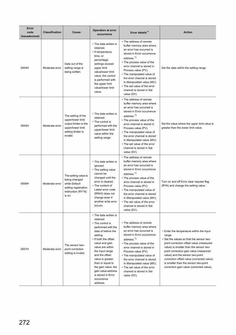
0004H Moderate error
Data out of the
setting range is
being written.
• The data written is
retained.
• If temperature,
time, or
percentage
settings exceed
upper limit
value/lower limit
value, the control
is performed with
the upper limit
value/lower limit
value.
• The address of remote
buffer memory area where
an error has occurred is
stored in Error occurrence
address.*3
• The process value of the
error channel is stored in
Process value (PV).
• The manipulated value of
the error channel is stored
in Manipulated value (MV).
• The set value of the error
channel is stored in Set
value (SV).
Set the data within the setting range.
0005H Moderate error
The setting of the
upper/lower limit
output limiter or the
upper/lower limit
setting limiter is
invalid.
• The data written is
retained.
• The control is
performed with the
upper/lower limit
value within the
setting range.
• The address of remote
buffer memory area where
an error has occurred is
stored in Error occurrence
address.*3
• The process value of the
error channel is stored in
Process value (PV).
• The manipulated value of
the error channel is stored
in Manipulated value (MV).
• The set value of the error
channel is stored in Set
value (SV).
Set the value where the upper limit value is
greater than the lower limit value.
0006H Moderate error
The setting value is
being changed
while Default
setting registration
instruction (RY16)
is on.
• The data written is
ignored.
• The setting value
cannot be
changed until the
error is cleared.
• The content of
Latest error code
(RWr0) does not
change even if
another write error
occurs.
• The address of remote
buffer memory area where
an error has occurred is
stored in Error occurrence
address.*3
• The process value of the
error channel is stored in
Process value (PV).
• The manipulated value of
the error channel is stored
in Manipulated value (MV).
• The set value of the error
channel is stored in Set
value (SV).
Turn on and off Error clear request flag
(RYA) and change the setting value.
0007H Moderate error
The sensor two-
point correction
setting is invalid.
• The data written is
retained.
• The control is
performed with the
data of before the
setting.
• If both the offset
value and gain
value are within
the input range
and the offset
value is greater
than or equal to
the gain value, the
gain value address
is stored in Error
occurrence
address.
• The address of remote
buffer memory area where
an error has occurred is
stored in Error occurrence
address.*3
• The process value of the
error channel is stored in
Process value (PV).
• The manipulated value of
the error channel is stored
in Manipulated value (MV).
• The set value of the error
channel is stored in Set
value (SV).
• Enter the temperature within the input
range.
• Set the values so that the sensor two-
point correction offset value (measured
value) is smaller than the sensor two-
point correction gain value (measured
value) and the sensor two-point
correction offset value (corrected value)
is smaller than the sensor two-point
correction gain value (corrected value).
Error
code
(hexadecimal)
Classification CauseOperation at error
occurrenceError details*1 Action
272
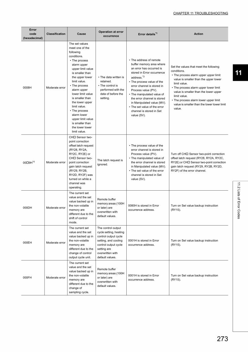
CHAPTER 11 TROUBLESHOOTING
11
11
.2 L
ists of E
rror C
od
es
0008H Moderate error
The set values
meet one of the
following
conditions.
• The process
alarm upper
upper limit value
is smaller than
the upper lower
limit value.
• The process
alarm upper
lower limit value
is smaller than
the lower upper
limit value.
• The process
alarm lower
upper limit value
is smaller than
the lower lower
limit value.
• The data written is
retained.
• The control is
performed with the
data of before the
setting.
• The address of remote
buffer memory area where
an error has occurred is
stored in Error occurrence
address.*3
• The process value of the
error channel is stored in
Process value (PV).
• The manipulated value of
the error channel is stored
in Manipulated value (MV).
• The set value of the error
channel is stored in Set
value (SV).
Set the values that meet the following
conditions.
• The process alarm upper upper limit
value is smaller than the upper lower
limit value.
• The process alarm upper lower limit
value is smaller than the lower upper
limit value.
• The process alarm lower upper limit
value is smaller than the lower lower limit
value.
009H*4 Moderate error
CH Sensor two-
point correction
offset latch request
(RY28, RY2A,
RY2C, RY2E) or
CH Sensor two-
point correction
gain latch request
(RY29, RY2B,
RY2D, RY2F) was
turned on while a
channel was
operating.
The latch request is
ignored.
• The process value of the
error channel is stored in
Process value (PV).
• The manipulated value of
the error channel is stored
in Manipulated value (MV).
• The set value of the error
channel is stored in Set
value (SV).
Turn off CH Sensor two-point correction
offset latch request (RY28, RY2A, RY2C,
RY2E) or CH Sensor two-point correction
gain latch request (RY29, RY2B, RY2D,
RY2F) of the error channel.
000DH Moderate error
The current set
value and the set
value backed up in
the non-volatile
memory are
different due to the
shift of control
mode.
Remote buffer
memory areas (100H
or later) are
overwritten with
default values.
0080H is stored in Error
occurrence address.
Turn on Set value backup instruction
(RY15).
000EH Moderate error
The current set
value and the set
value backed up in
the non-volatile
memory are
different due to the
change of control
output cycle unit.
The control output
cycle setting, heating
control output cycle
setting, and cooling
control output cycle
setting are
overwritten with
default values.
0001H is stored in Error
occurrence address.
Turn on Set value backup instruction
(RY15).
000FH Moderate error
The current set
value and the set
value backed up in
the non-volatile
memory are
different due to the
change of
sampling cycle.
Remote buffer
memory areas (100H
or later) are
overwritten with
default values.
0001H is stored in Error
occurrence address.
Turn on Set value backup instruction
(RY15).
Error
code
(hexadecimal)
Classification CauseOperation at error
occurrenceError details*1 Action
273
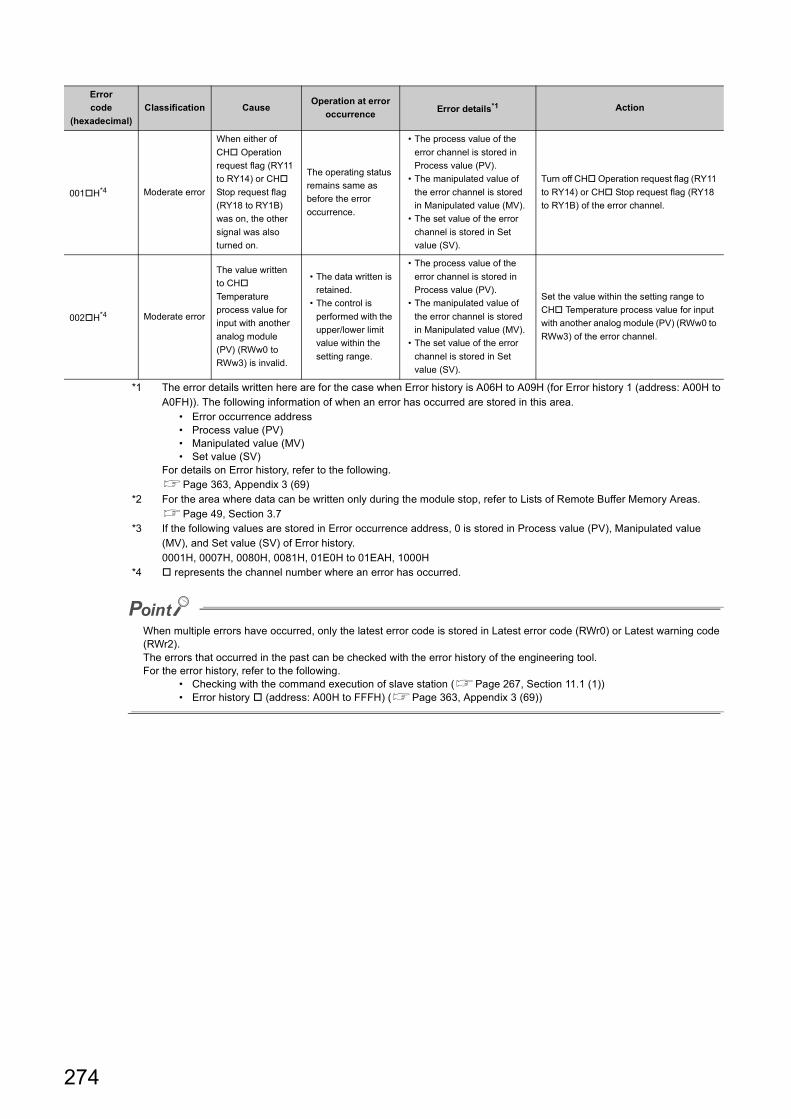
*1 The error details written here are for the case when Error history is A06H to A09H (for Error history 1 (address: A00H to A0FH)). The following information of when an error has occurred are stored in this area.
• Error occurrence address• Process value (PV)• Manipulated value (MV)• Set value (SV)
For details on Error history, refer to the following.Page 363, Appendix 3 (69)
*2 For the area where data can be written only during the module stop, refer to Lists of Remote Buffer Memory Areas.Page 49, Section 3.7
*3 If the following values are stored in Error occurrence address, 0 is stored in Process value (PV), Manipulated value (MV), and Set value (SV) of Error history.0001H, 0007H, 0080H, 0081H, 01E0H to 01EAH, 1000H
*4 represents the channel number where an error has occurred.
When multiple errors have occurred, only the latest error code is stored in Latest error code (RWr0) or Latest warning code (RWr2).The errors that occurred in the past can be checked with the error history of the engineering tool.For the error history, refer to the following.
• Checking with the command execution of slave station (Page 267, Section 11.1 (1))• Error history (address: A00H to FFFH) (Page 363, Appendix 3 (69))
001H*4 Moderate error
When either of
CH Operation
request flag (RY11
to RY14) or CH
Stop request flag
(RY18 to RY1B)
was on, the other
signal was also
turned on.
The operating status
remains same as
before the error
occurrence.
• The process value of the
error channel is stored in
Process value (PV).
• The manipulated value of
the error channel is stored
in Manipulated value (MV).
• The set value of the error
channel is stored in Set
value (SV).
Turn off CH Operation request flag (RY11
to RY14) or CH Stop request flag (RY18
to RY1B) of the error channel.
002H*4 Moderate error
The value written
to CH
Temperature
process value for
input with another
analog module
(PV) (RWw0 to
RWw3) is invalid.
• The data written is
retained.
• The control is
performed with the
upper/lower limit
value within the
setting range.
• The process value of the
error channel is stored in
Process value (PV).
• The manipulated value of
the error channel is stored
in Manipulated value (MV).
• The set value of the error
channel is stored in Set
value (SV).
Set the value within the setting range to
CH Temperature process value for input
with another analog module (PV) (RWw0 to
RWw3) of the error channel.
Error
code
(hexadecimal)
Classification CauseOperation at error
occurrenceError details*1 Action
274
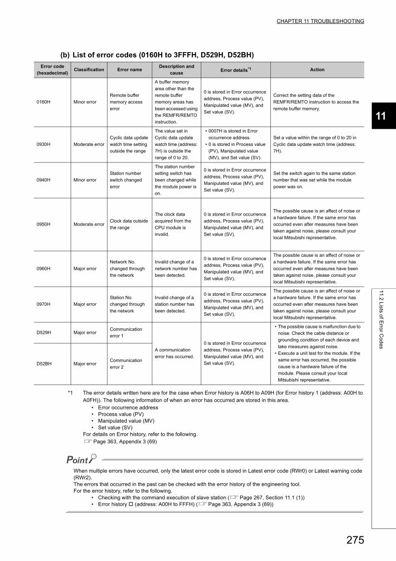
CHAPTER 11 TROUBLESHOOTING
11
11
.2 L
ists of E
rror C
od
es
(b) List of error codes (0160H to 3FFFH, D529H, D52BH)
*1 The error details written here are for the case when Error history is A06H to A09H (for Error history 1 (address: A00H to A0FH)). The following information of when an error has occurred are stored in this area.
• Error occurrence address• Process value (PV)• Manipulated value (MV)• Set value (SV)
For details on Error history, refer to the following.Page 363, Appendix 3 (69)
When multiple errors have occurred, only the latest error code is stored in Latest error code (RWr0) or Latest warning code (RWr2).The errors that occurred in the past can be checked with the error history of the engineering tool.For the error history, refer to the following.
• Checking with the command execution of slave station (Page 267, Section 11.1 (1))• Error history (address: A00H to FFFH) (Page 363, Appendix 3 (69))
Error code
(hexadecimal)Classification Error name
Description and
causeError details*1 Action
0160H Minor error
Remote buffer
memory access
error
A buffer memory
area other than the
remote buffer
memory areas has
been accessed using
the REMFR/REMTO
instruction.
0 is stored in Error occurrence
address, Process value (PV),
Manipulated value (MV), and
Set value (SV).
Correct the setting data of the
REMFR/REMTO instruction to access the
remote buffer memory.
0930H Moderate error
Cyclic data update
watch time setting
outside the range
The value set in
Cyclic data update
watch time (address:
7H) is outside the
range of 0 to 20.
• 0007H is stored in Error
occurrence address.
• 0 is stored in Process value
(PV), Manipulated value
(MV), and Set value (SV).
Set a value within the range of 0 to 20 in
Cyclic data update watch time (address:
7H).
0940H Minor error
Station number
switch changed
error
The station number
setting switch has
been changed while
the module power is
on.
0 is stored in Error occurrence
address, Process value (PV),
Manipulated value (MV), and
Set value (SV).
Set the switch again to the same station
number that was set while the module
power was on.
0950H Moderate errorClock data outside
the range
The clock data
acquired from the
CPU module is
invalid.
0 is stored in Error occurrence
address, Process value (PV),
Manipulated value (MV), and
Set value (SV).
The possible cause is an affect of noise or
a hardware failure. If the same error has
occurred even after measures have been
taken against noise, please consult your
local Mitsubishi representative.
0960H Major error
Network No.
changed through
the network
Invalid change of a
network number has
been detected.
0 is stored in Error occurrence
address, Process value (PV),
Manipulated value (MV), and
Set value (SV).
The possible cause is an affect of noise or
a hardware failure. If the same error has
occurred even after measures have been
taken against noise, please consult your
local Mitsubishi representative.
0970H Major error
Station No.
changed through
the network
Invalid change of a
station number has
been detected.
0 is stored in Error occurrence
address, Process value (PV),
Manipulated value (MV), and
Set value (SV).
The possible cause is an affect of noise or
a hardware failure. If the same error has
occurred even after measures have been
taken against noise, please consult your
local Mitsubishi representative.
D529H Major errorCommunication
error 1
A communication
error has occurred.
0 is stored in Error occurrence
address, Process value (PV),
Manipulated value (MV), and
Set value (SV).
• The possible cause is malfunction due to
noise. Check the cable distance or
grounding condition of each device and
take measures against noise.
• Execute a unit test for the module. If the
same error has occurred, the possible
cause is a hardware failure of the
module. Please consult your local
Mitsubishi representative.
D52BH Major errorCommunication
error 2
275
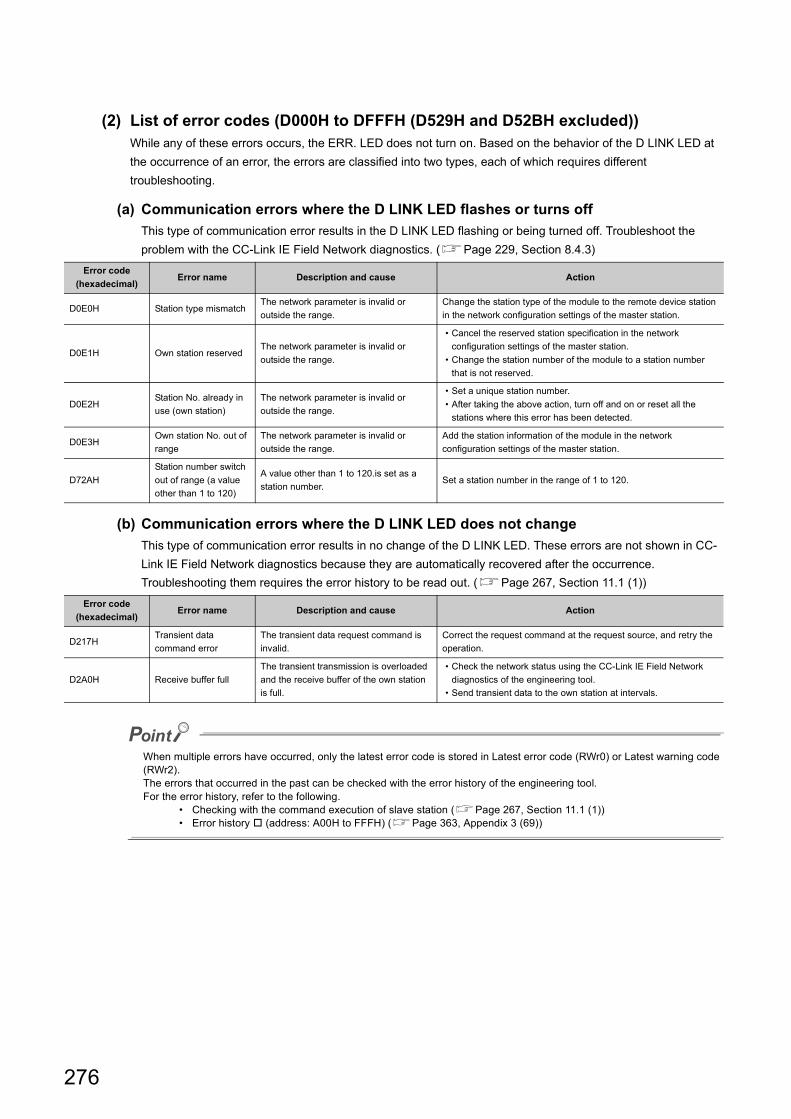
(2) List of error codes (D000H to DFFFH (D529H and D52BH excluded))While any of these errors occurs, the ERR. LED does not turn on. Based on the behavior of the D LINK LED at
the occurrence of an error, the errors are classified into two types, each of which requires different
troubleshooting.
(a) Communication errors where the D LINK LED flashes or turns off
This type of communication error results in the D LINK LED flashing or being turned off. Troubleshoot the
problem with the CC-Link IE Field Network diagnostics. (Page 229, Section 8.4.3)
(b) Communication errors where the D LINK LED does not change
This type of communication error results in no change of the D LINK LED. These errors are not shown in CC-
Link IE Field Network diagnostics because they are automatically recovered after the occurrence.
Troubleshooting them requires the error history to be read out. (Page 267, Section 11.1 (1))
When multiple errors have occurred, only the latest error code is stored in Latest error code (RWr0) or Latest warning code (RWr2).The errors that occurred in the past can be checked with the error history of the engineering tool.For the error history, refer to the following.
• Checking with the command execution of slave station (Page 267, Section 11.1 (1))• Error history (address: A00H to FFFH) (Page 363, Appendix 3 (69))
Error code
(hexadecimal)Error name Description and cause Action
D0E0H Station type mismatchThe network parameter is invalid or
outside the range.
Change the station type of the module to the remote device station
in the network configuration settings of the master station.
D0E1H Own station reservedThe network parameter is invalid or
outside the range.
• Cancel the reserved station specification in the network
configuration settings of the master station.
• Change the station number of the module to a station number
that is not reserved.
D0E2HStation No. already in
use (own station)
The network parameter is invalid or
outside the range.
• Set a unique station number.
• After taking the above action, turn off and on or reset all the
stations where this error has been detected.
D0E3HOwn station No. out of
range
The network parameter is invalid or
outside the range.
Add the station information of the module in the network
configuration settings of the master station.
D72AH
Station number switch
out of range (a value
other than 1 to 120)
A value other than 1 to 120.is set as a
station number.Set a station number in the range of 1 to 120.
Error code
(hexadecimal)Error name Description and cause Action
D217HTransient data
command error
The transient data request command is
invalid.
Correct the request command at the request source, and retry the
operation.
D2A0H Receive buffer full
The transient transmission is overloaded
and the receive buffer of the own station
is full.
• Check the network status using the CC-Link IE Field Network
diagnostics of the engineering tool.
• Send transient data to the own station at intervals.
276
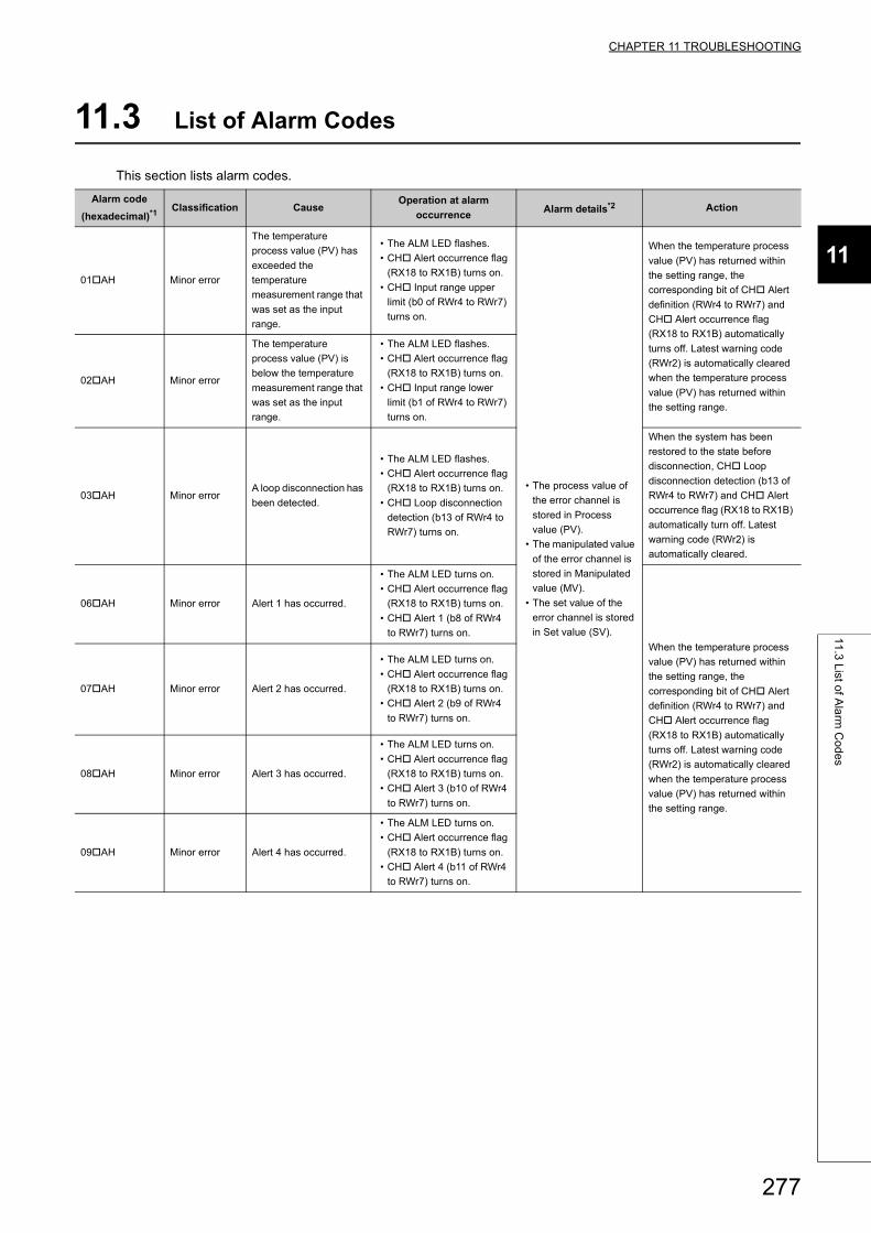
CHAPTER 11 TROUBLESHOOTING
11
11
.3 L
ist of A
larm
Co
de
s
11.3 List of Alarm Codes
This section lists alarm codes.
Alarm code
(hexadecimal)*1Classification Cause
Operation at alarm
occurrenceAlarm details*2 Action
01AH Minor error
The temperature
process value (PV) has
exceeded the
temperature
measurement range that
was set as the input
range.
• The ALM LED flashes.
• CH Alert occurrence flag
(RX18 to RX1B) turns on.
• CH Input range upper
limit (b0 of RWr4 to RWr7)
turns on.
• The process value of
the error channel is
stored in Process
value (PV).
• The manipulated value
of the error channel is
stored in Manipulated
value (MV).
• The set value of the
error channel is stored
in Set value (SV).
When the temperature process
value (PV) has returned within
the setting range, the
corresponding bit of CH Alert
definition (RWr4 to RWr7) and
CH Alert occurrence flag
(RX18 to RX1B) automatically
turns off. Latest warning code
(RWr2) is automatically cleared
when the temperature process
value (PV) has returned within
the setting range.
02AH Minor error
The temperature
process value (PV) is
below the temperature
measurement range that
was set as the input
range.
• The ALM LED flashes.
• CH Alert occurrence flag
(RX18 to RX1B) turns on.
• CH Input range lower
limit (b1 of RWr4 to RWr7)
turns on.
03AH Minor errorA loop disconnection has
been detected.
• The ALM LED flashes.
• CH Alert occurrence flag
(RX18 to RX1B) turns on.
• CH Loop disconnection
detection (b13 of RWr4 to
RWr7) turns on.
When the system has been
restored to the state before
disconnection, CH Loop
disconnection detection (b13 of
RWr4 to RWr7) and CH Alert
occurrence flag (RX18 to RX1B)
automatically turn off. Latest
warning code (RWr2) is
automatically cleared.
06AH Minor error Alert 1 has occurred.
• The ALM LED turns on.
• CH Alert occurrence flag
(RX18 to RX1B) turns on.
• CH Alert 1 (b8 of RWr4
to RWr7) turns on.
When the temperature process
value (PV) has returned within
the setting range, the
corresponding bit of CH Alert
definition (RWr4 to RWr7) and
CH Alert occurrence flag
(RX18 to RX1B) automatically
turns off. Latest warning code
(RWr2) is automatically cleared
when the temperature process
value (PV) has returned within
the setting range.
07AH Minor error Alert 2 has occurred.
• The ALM LED turns on.
• CH Alert occurrence flag
(RX18 to RX1B) turns on.
• CH Alert 2 (b9 of RWr4
to RWr7) turns on.
08AH Minor error Alert 3 has occurred.
• The ALM LED turns on.
• CH Alert occurrence flag
(RX18 to RX1B) turns on.
• CH Alert 3 (b10 of RWr4
to RWr7) turns on.
09AH Minor error Alert 4 has occurred.
• The ALM LED turns on.
• CH Alert occurrence flag
(RX18 to RX1B) turns on.
• CH Alert 4 (b11 of RWr4
to RWr7) turns on.
277
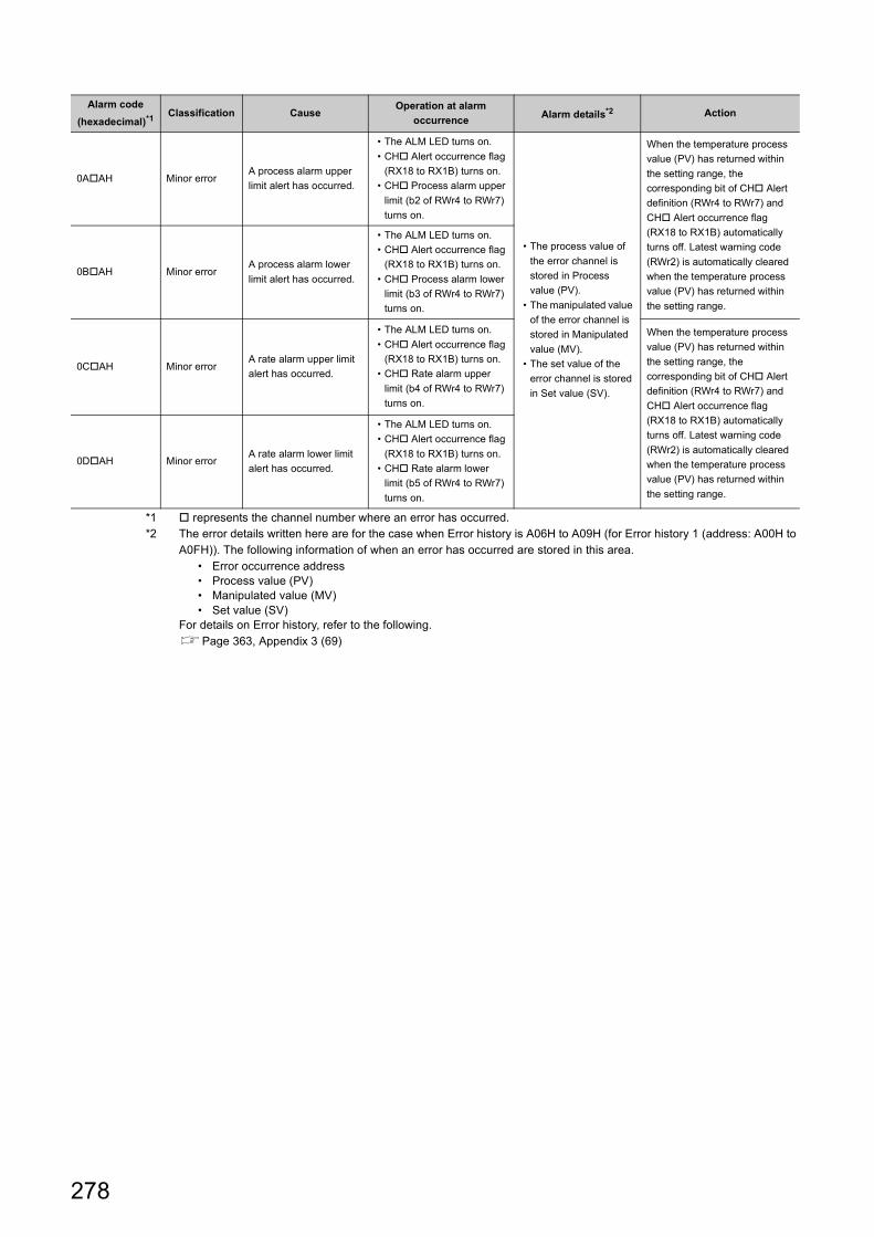
*1 represents the channel number where an error has occurred.*2 The error details written here are for the case when Error history is A06H to A09H (for Error history 1 (address: A00H to
A0FH)). The following information of when an error has occurred are stored in this area.• Error occurrence address• Process value (PV)• Manipulated value (MV)• Set value (SV)
For details on Error history, refer to the following.Page 363, Appendix 3 (69)
0AAH Minor errorA process alarm upper
limit alert has occurred.
• The ALM LED turns on.
• CH Alert occurrence flag
(RX18 to RX1B) turns on.
• CH Process alarm upper
limit (b2 of RWr4 to RWr7)
turns on.
• The process value of
the error channel is
stored in Process
value (PV).
• The manipulated value
of the error channel is
stored in Manipulated
value (MV).
• The set value of the
error channel is stored
in Set value (SV).
When the temperature process
value (PV) has returned within
the setting range, the
corresponding bit of CH Alert
definition (RWr4 to RWr7) and
CH Alert occurrence flag
(RX18 to RX1B) automatically
turns off. Latest warning code
(RWr2) is automatically cleared
when the temperature process
value (PV) has returned within
the setting range.
0BAH Minor errorA process alarm lower
limit alert has occurred.
• The ALM LED turns on.
• CH Alert occurrence flag
(RX18 to RX1B) turns on.
• CH Process alarm lower
limit (b3 of RWr4 to RWr7)
turns on.
0CAH Minor errorA rate alarm upper limit
alert has occurred.
• The ALM LED turns on.
• CH Alert occurrence flag
(RX18 to RX1B) turns on.
• CH Rate alarm upper
limit (b4 of RWr4 to RWr7)
turns on.
When the temperature process
value (PV) has returned within
the setting range, the
corresponding bit of CH Alert
definition (RWr4 to RWr7) and
CH Alert occurrence flag
(RX18 to RX1B) automatically
turns off. Latest warning code
(RWr2) is automatically cleared
when the temperature process
value (PV) has returned within
the setting range.
0DAH Minor errorA rate alarm lower limit
alert has occurred.
• The ALM LED turns on.
• CH Alert occurrence flag
(RX18 to RX1B) turns on.
• CH Rate alarm lower
limit (b5 of RWr4 to RWr7)
turns on.
Alarm code
(hexadecimal)*1Classification Cause
Operation at alarm
occurrenceAlarm details*2 Action
278
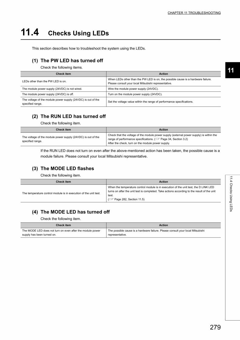
CHAPTER 11 TROUBLESHOOTING
11
11
.4 C
he
cks Usin
g L
ED
s
11.4 Checks Using LEDs
This section describes how to troubleshoot the system using the LEDs.
(1) The PW LED has turned offCheck the following items.
(2) The RUN LED has turned offCheck the following item.
If the RUN LED does not turn on even after the above-mentioned action has been taken, the possible cause is a
module failure. Please consult your local Mitsubishi representative.
(3) The MODE LED flashesCheck the following item.
(4) The MODE LED has turned offCheck the following item.
Check item Action
LEDs other than the PW LED is on.When LEDs other than the PW LED is on, the possible cause is a hardware failure.
Please consult your local Mitsubishi representative.
The module power supply (24VDC) is not wired. Wire the module power supply (24VDC).
The module power supply (24VDC) is off. Turn on the module power supply (24VDC).
The voltage of the module power supply (24VDC) is out of the
specified range.Set the voltage value within the range of performance specifications.
Check item Action
The voltage of the module power supply (24VDC) is out of the
specified range.
Check that the voltage of the module power supply (external power supply) is within the
range of performance specifications. (Page 34, Section 3.2)
After the check, turn on the module power supply.
Check item Action
The temperature control module is in execution of the unit test.
When the temperature control module is in execution of the unit test, the D LINK LED
turns on after the unit test is completed. Take actions according to the result of the unit
test.
(Page 282, Section 11.5)
Check item Action
The MODE LED does not turn on even after the module power
supply has been turned on.
The possible cause is a hardware failure. Please consult your local Mitsubishi
representative.
279
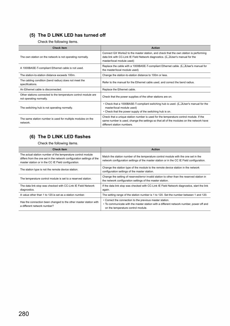
(5) The D LINK LED has turned offCheck the following items.
(6) The D LINK LED flashesCheck the following items.
Check item Action
The own station on the network is not operating normally.
Connect GX Works2 to the master station, and check that the own station is performing
data link with CC-Link IE Field Network diagnostics. (User's manual for the
master/local module used)
A 1000BASE-T-compliant Ethernet cable is not used.Replace the cable with a 1000BASE-T-compliant Ethernet cable. (User's manual for
the master/local module used)
The station-to-station distance exceeds 100m. Change the station-to-station distance to 100m or less.
The cabling condition (bend radius) does not meet the
specifications.Refer to the manual for the Ethernet cable used, and correct the bend radius.
An Ethernet cable is disconnected. Replace the Ethernet cable.
Other stations connected to the temperature control module are
not operating normally.Check that the power supplies of the other stations are on.
The switching hub is not operating normally.
• Check that a 1000BASE-T-compliant switching hub is used. (User's manual for the
master/local module used)
• Check that the power supply of the switching hub is on.
The same station number is used for multiple modules on the
network.
Check that a unique station number is used for the temperature control module. If the
same number is used, change the settings so that all of the modules on the network have
different station numbers.
Check item Action
The actual station number of the temperature control module
differs from the one set in the network configuration settings of the
master station or in the CC IE Field configuration.
Match the station number of the temperature control module with the one set in the
network configuration settings of the master station or in the CC IE Field configuration.
The station type is not the remote device station.Change the station type of the module to the remote device station in the network
configuration settings of the master station.
The temperature control module is set to a reserved station.Change the setting of reserved/error invalid station to other than the reserved station in
the network configuration settings of the master station.
The data link stop was checked with CC-Link IE Field Network
diagnostics.
If the data link stop was checked with CC-Link IE Field Network diagnostics, start the link
again.
A value other than 1 to 120.is set as a station number. The setting range of the station number is 1 to 120. Set the number between 1 and 120.
Has the connection been changed to the other master station with
a different network number?
• Correct the connection to the previous master station.
• To communicate with the master station with a different network number, power off and
on the temperature control module.
280
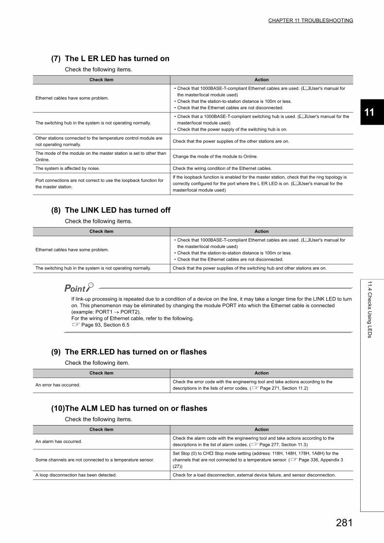
CHAPTER 11 TROUBLESHOOTING
11
11
.4 C
he
cks Usin
g L
ED
s
(7) The L ER LED has turned onCheck the following items.
(8) The LINK LED has turned offCheck the following items.
If link-up processing is repeated due to a condition of a device on the line, it may take a longer time for the LINK LED to turn on. This phenomenon may be eliminated by changing the module PORT into which the Ethernet cable is connected (example: PORT1 PORT2).For the wiring of Ethernet cable, refer to the following.Page 93, Section 6.5
(9) The ERR.LED has turned on or flashesCheck the following item.
(10)The ALM LED has turned on or flashesCheck the following items.
Check item Action
Ethernet cables have some problem.
• Check that 1000BASE-T-compliant Ethernet cables are used. (User's manual for
the master/local module used)
• Check that the station-to-station distance is 100m or less.
• Check that the Ethernet cables are not disconnected.
The switching hub in the system is not operating normally.
• Check that a 1000BASE-T-compliant switching hub is used. (User's manual for the
master/local module used)
• Check that the power supply of the switching hub is on.
Other stations connected to the temperature control module are
not operating normally.Check that the power supplies of the other stations are on.
The mode of the module on the master station is set to other than
Online.Change the mode of the module to Online.
The system is affected by noise. Check the wiring condition of the Ethernet cables.
Port connections are not correct to use the loopback function for
the master station.
If the loopback function is enabled for the master station, check that the ring topology is
correctly configured for the port where the L ER LED is on. (User's manual for the
master/local module used)
Check item Action
Ethernet cables have some problem.
• Check that 1000BASE-T-compliant Ethernet cables are used. (User's manual for
the master/local module used)
• Check that the station-to-station distance is 100m or less.
• Check that the Ethernet cables are not disconnected.
The switching hub in the system is not operating normally. Check that the power supplies of the switching hub and other stations are on.
Check item Action
An error has occurred.Check the error code with the engineering tool and take actions according to the
descriptions in the lists of error codes. (Page 271, Section 11.2)
Check item Action
An alarm has occurred.Check the alarm code with the engineering tool and take actions according to the
descriptions in the list of alarm codes. (Page 277, Section 11.3)
Some channels are not connected to a temperature sensor.
Set Stop (0) to CH Stop mode setting (address: 118H, 148H, 178H, 1A8H) for the
channels that are not connected to a temperature sensor. (Page 336, Appendix 3
(27))
A loop disconnection has been detected. Check for a load disconnection, external device failure, and sensor disconnection.
281
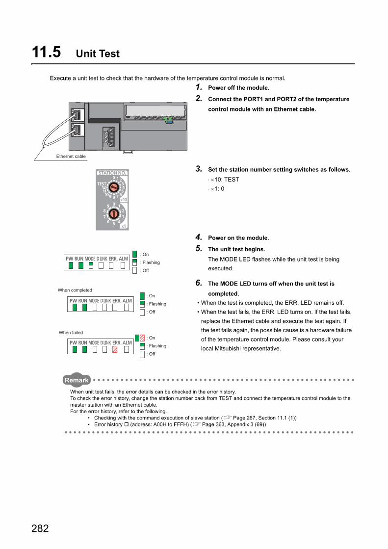
11.5 Unit Test
Execute a unit test to check that the hardware of the temperature control module is normal.
Remark
When unit test fails, the error details can be checked in the error history.To check the error history, change the station number back from TEST and connect the temperature control module to the master station with an Ethernet cable.For the error history, refer to the following.
• Checking with the command execution of slave station (Page 267, Section 11.1 (1))• Error history (address: A00H to FFFH) (Page 363, Appendix 3 (69))
1. Power off the module.
2. Connect the PORT1 and PORT2 of the temperature
control module with an Ethernet cable.
3. Set the station number setting switches as follows.
10: TEST
1: 0
4. Power on the module.
5. The unit test begins.
The MODE LED flashes while the unit test is being
executed.
6. The MODE LED turns off when the unit test is
completed.
• When the test is completed, the ERR. LED remains off.
• When the test fails, the ERR. LED turns on. If the test fails,
replace the Ethernet cable and execute the test again. If
the test fails again, the possible cause is a hardware failure
of the temperature control module. Please consult your
local Mitsubishi representative.
Ethernet cable
: Flashing
: Off
: On
When completed
When failed
: Flashing
: On
: Flashing
: On
: Off
: Off
282
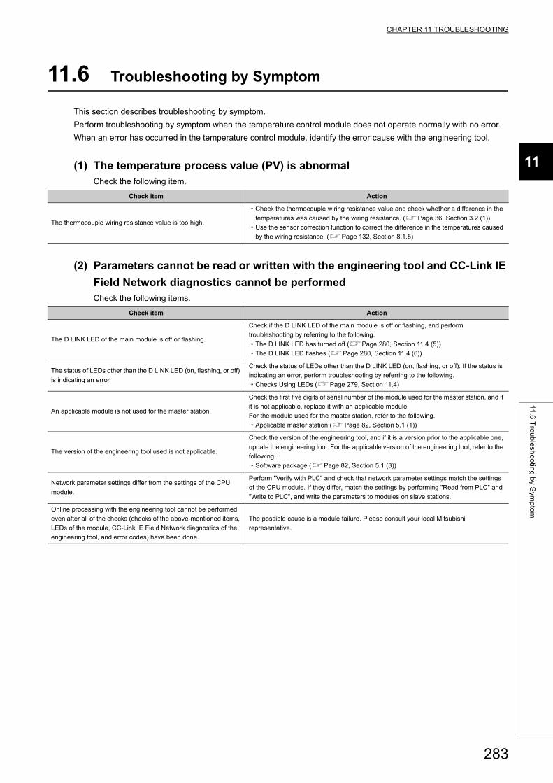
CHAPTER 11 TROUBLESHOOTING
11
11
.6 T
rou
ble
sho
otin
g b
y Sym
pto
m
11.6 Troubleshooting by Symptom
This section describes troubleshooting by symptom.
Perform troubleshooting by symptom when the temperature control module does not operate normally with no error.
When an error has occurred in the temperature control module, identify the error cause with the engineering tool.
(1) The temperature process value (PV) is abnormalCheck the following item.
(2) Parameters cannot be read or written with the engineering tool and CC-Link IE
Field Network diagnostics cannot be performedCheck the following items.
Check item Action
The thermocouple wiring resistance value is too high.
• Check the thermocouple wiring resistance value and check whether a difference in the
temperatures was caused by the wiring resistance. (Page 36, Section 3.2 (1))
• Use the sensor correction function to correct the difference in the temperatures caused
by the wiring resistance. (Page 132, Section 8.1.5)
Check item Action
The D LINK LED of the main module is off or flashing.
Check if the D LINK LED of the main module is off or flashing, and perform
troubleshooting by referring to the following.
• The D LINK LED has turned off (Page 280, Section 11.4 (5))
• The D LINK LED flashes (Page 280, Section 11.4 (6))
The status of LEDs other than the D LINK LED (on, flashing, or off)
is indicating an error.
Check the status of LEDs other than the D LINK LED (on, flashing, or off). If the status is
indicating an error, perform troubleshooting by referring to the following.
• Checks Using LEDs (Page 279, Section 11.4)
An applicable module is not used for the master station.
Check the first five digits of serial number of the module used for the master station, and if
it is not applicable, replace it with an applicable module.
For the module used for the master station, refer to the following.
• Applicable master station (Page 82, Section 5.1 (1))
The version of the engineering tool used is not applicable.
Check the version of the engineering tool, and if it is a version prior to the applicable one,
update the engineering tool. For the applicable version of the engineering tool, refer to the
following.
• Software package (Page 82, Section 5.1 (3))
Network parameter settings differ from the settings of the CPU
module.
Perform "Verify with PLC" and check that network parameter settings match the settings
of the CPU module. If they differ, match the settings by performing "Read from PLC" and
"Write to PLC", and write the parameters to modules on slave stations.
Online processing with the engineering tool cannot be performed
even after all of the checks (checks of the above-mentioned items,
LEDs of the module, CC-Link IE Field Network diagnostics of the
engineering tool, and error codes) have been done.
The possible cause is a module failure. Please consult your local Mitsubishi
representative.
283
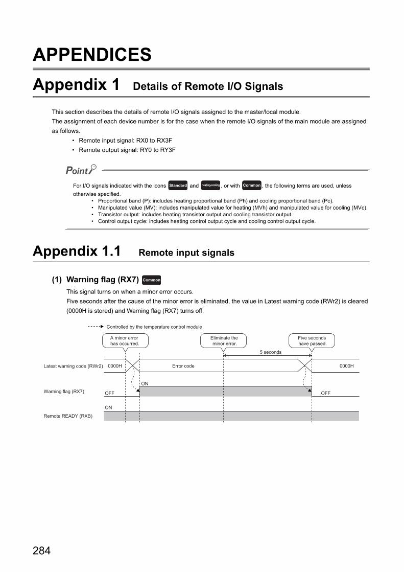
APPENDICES
Appendix 1 Details of Remote I/O Signals
This section describes the details of remote I/O signals assigned to the master/local module.
The assignment of each device number is for the case when the remote I/O signals of the main module are assigned
as follows.
• Remote input signal: RX0 to RX3F
• Remote output signal: RY0 to RY3F
For I/O signals indicated with the icons and , or with , the following terms are used, unless
otherwise specified.• Proportional band (P): includes heating proportional band (Ph) and cooling proportional band (Pc).• Manipulated value (MV): includes manipulated value for heating (MVh) and manipulated value for cooling (MVc).• Transistor output: includes heating transistor output and cooling transistor output.• Control output cycle: includes heating control output cycle and cooling control output cycle.
Appendix 1.1 Remote input signals
(1) Warning flag (RX7)
This signal turns on when a minor error occurs.
Five seconds after the cause of the minor error is eliminated, the value in Latest warning code (RWr2) is cleared
(0000H is stored) and Warning flag (RX7) turns off.
Standard Heating-cooling Common
Common
OFF
ON
ON
OFF
0000H0000H
Warning flag (RX7)
Latest warning code (RWr2)
Eliminate the minor error.
Error code
A minor error has occurred.
Remote READY (RXB)
Five seconds have passed.
5 seconds
Controlled by the temperature control module
284
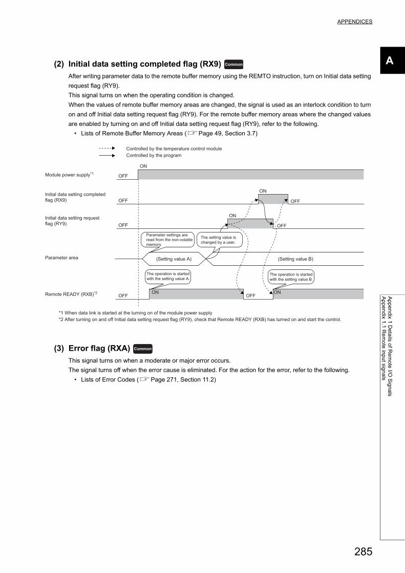
APPENDICES
A
Ap
pe
nd
ix 1 D
eta
ils of R
em
ote
I/O S
ign
als
Ap
pe
nd
ix 1.1
Re
mo
te in
pu
t sign
als
(2) Initial data setting completed flag (RX9)
After writing parameter data to the remote buffer memory using the REMTO instruction, turn on Initial data setting
request flag (RY9).
This signal turns on when the operating condition is changed.
When the values of remote buffer memory areas are changed, the signal is used as an interlock condition to turn
on and off Initial data setting request flag (RY9). For the remote buffer memory areas where the changed values
are enabled by turning on and off Initial data setting request flag (RY9), refer to the following.
• Lists of Remote Buffer Memory Areas (Page 49, Section 3.7)
(3) Error flag (RXA)
This signal turns on when a moderate or major error occurs.
The signal turns off when the error cause is eliminated. For the action for the error, refer to the following.
• Lists of Error Codes (Page 271, Section 11.2)
Common
ON
ON
ON
ONOFF
OFF
OFF
OFF
OFF
OFF
OFF
ON
Initial data setting completed flag (RX9)
(Setting value A) (Setting value B)
Module power supply*1
The operation is startedwith the setting value A.
Parameter settings are read from the non-volatile memory.
The setting value is changed by a user.
*1 When data link is started at the turning on of the module power supply
Initial data setting requestflag (RY9)
Remote READY (RXB)*2
Parameter area
*2 After turning on and off Initial data setting request flag (RY9), check that Remote READY (RXB) has turned on and start the control.
The operation is started with the setting value B.
Controlled by the temperature control moduleControlled by the program
Common
285
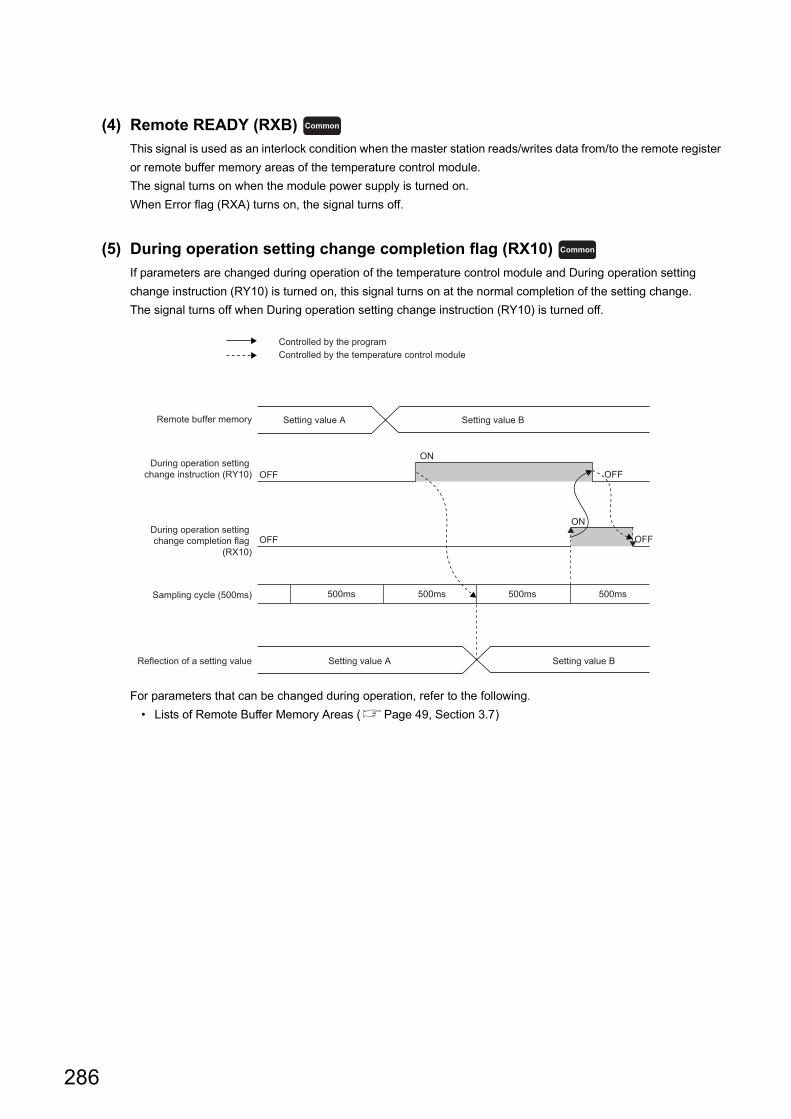
(4) Remote READY (RXB)
This signal is used as an interlock condition when the master station reads/writes data from/to the remote register
or remote buffer memory areas of the temperature control module.
The signal turns on when the module power supply is turned on.
When Error flag (RXA) turns on, the signal turns off.
(5) During operation setting change completion flag (RX10)
If parameters are changed during operation of the temperature control module and During operation setting
change instruction (RY10) is turned on, this signal turns on at the normal completion of the setting change.
The signal turns off when During operation setting change instruction (RY10) is turned off.
For parameters that can be changed during operation, refer to the following.
• Lists of Remote Buffer Memory Areas (Page 49, Section 3.7)
Common
Common
ON
OFF
OFF
OFF
OFF
ON
500ms500ms500ms500ms
During operation setting change instruction (RY10)
Remote buffer memory Setting value B
During operation setting change completion flag
(RX10)
Sampling cycle (500ms)
Reflection of a setting value Setting value A Setting value B
Controlled by the programControlled by the temperature control module
Setting value A
286
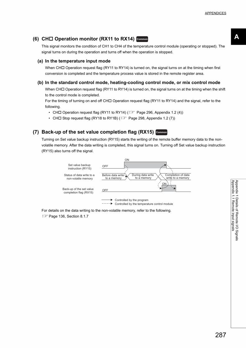
APPENDICES
A
Ap
pe
nd
ix 1 D
eta
ils of R
em
ote
I/O S
ign
als
Ap
pe
nd
ix 1.1
Re
mo
te in
pu
t sign
als
(6) CH Operation monitor (RX11 to RX14)
This signal monitors the condition of CH1 to CH4 of the temperature control module (operating or stopped). The
signal turns on during the operation and turns off when the operation is stopped.
(a) In the temperature input mode
When CH Operation request flag (RY11 to RY14) is turned on, the signal turns on at the timing when first
conversion is completed and the temperature process value is stored in the remote register area.
(b) In the standard control mode, heating-cooling control mode, or mix control mode
When CH Operation request flag (RY11 to RY14) is turned on, the signal turns on at the timing when the shift
to the control mode is completed.
For the timing of turning on and off CH Operation request flag (RY11 to RY14) and the signal, refer to the
following.
• CH Operation request flag (RY11 to RY14) ( Page 296, Appendix 1.2 (4))
• CH Stop request flag (RY18 to RY1B) ( Page 298, Appendix 1.2 (7))
(7) Back-up of the set value completion flag (RX15)
Turning on Set value backup instruction (RY15) starts the writing of the remote buffer memory data to the non-
volatile memory. After the data writing is completed, this signal turns on. Turning off Set value backup instruction
(RY15) also turns off the signal.
For details on the data writing to the non-volatile memory, refer to the following.
Page 136, Section 8.1.7
Common
Common
ON
OFF
ON
OFF
Before data write to a memory
During data write to a memory
Completion of data write to a memory
Status of data write to a non-volatile memory
Controlled by the program
Set value backup instruction (RY15)
Back-up of the set value completion flag (RX15)
Controlled by the temperature control module
287
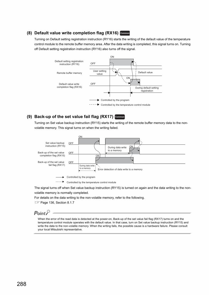
(8) Default value write completion flag (RX16)
Turning on Default setting registration instruction (RY16) starts the writing of the default value of the temperature
control module to the remote buffer memory area. After the data writing is completed, this signal turns on. Turning
off Default setting registration instruction (RY16) also turns off the signal.
(9) Back-up of the set value fail flag (RX17)
Turning on Set value backup instruction (RY15) starts the writing of the remote buffer memory data to the non-
volatile memory. This signal turns on when the writing failed.
The signal turns off when Set value backup instruction (RY15) is turned on again and the data writing to the non-
volatile memory is normally completed.
For details on the data writing to the non-volatile memory, refer to the following.
Page 136, Section 8.1.7
When the error of the read data is detected at the power-on, Back-up of the set value fail flag (RX17) turns on and the temperature control module operates with the default value. In that case, turn on Set value backup instruction (RY15) and write the data to the non-volatile memory. When the writing fails, the possible cause is a hardware failure. Please consult your local Mitsubishi representative.
Common
OFF
OFF
ON
ON
User settingvalue Default value
During default settingregistration
Controlled by the program
Default setting registration instruction (RY16)
Remote buffer memory
Default value write completion flag (RX16)
Controlled by the temperature control module
Common
OFF
OFF
OFF
ON
ON
ON
During data write to a memory
During data write to a memory
Error detection of data write to a memory
Controlled by the program
Set value backup instruction (RY15)
Back-up of the set value completion flag (RX15)
Back-up of the set value fail flag (RX17)
Controlled by the temperature control module
288
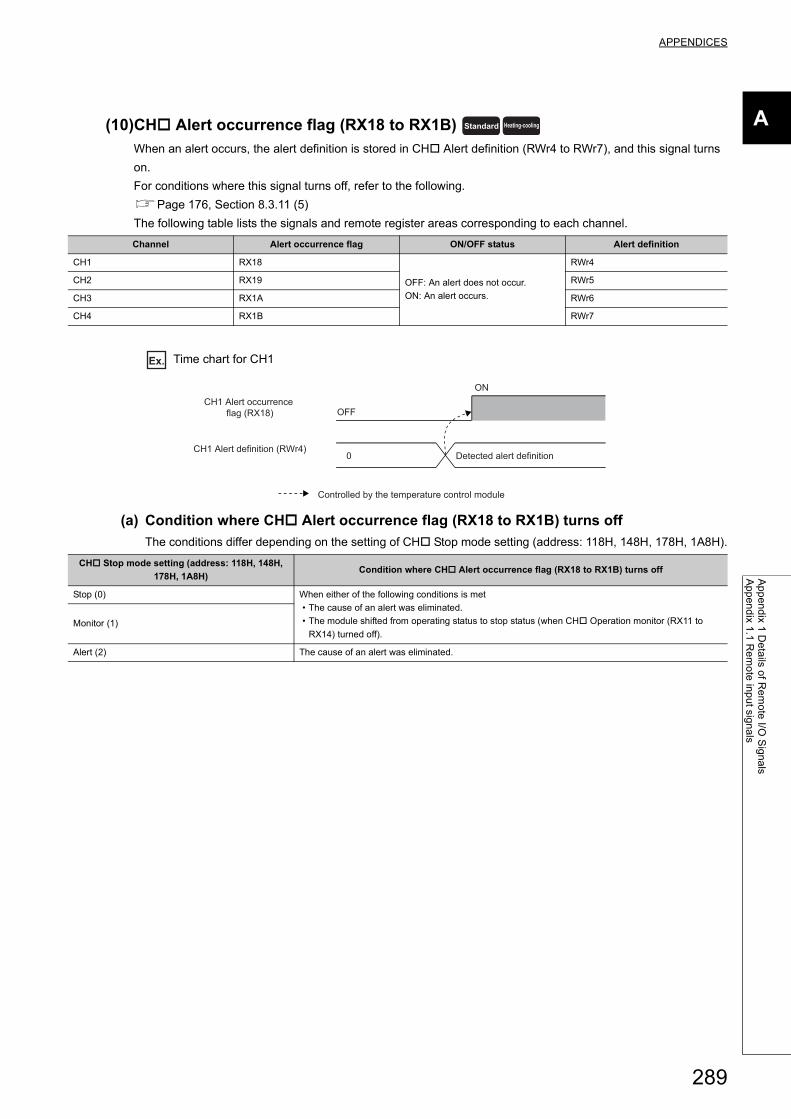
APPENDICES
A
Ap
pe
nd
ix 1 D
eta
ils of R
em
ote
I/O S
ign
als
Ap
pe
nd
ix 1.1
Re
mo
te in
pu
t sign
als
(10)CH Alert occurrence flag (RX18 to RX1B)
When an alert occurs, the alert definition is stored in CH Alert definition (RWr4 to RWr7), and this signal turns
on.
For conditions where this signal turns off, refer to the following.
Page 176, Section 8.3.11 (5)
The following table lists the signals and remote register areas corresponding to each channel.
Ex. Time chart for CH1
(a) Condition where CH Alert occurrence flag (RX18 to RX1B) turns off
The conditions differ depending on the setting of CH Stop mode setting (address: 118H, 148H, 178H, 1A8H).
Channel Alert occurrence flag ON/OFF status Alert definition
CH1 RX18
OFF: An alert does not occur.
ON: An alert occurs.
RWr4
CH2 RX19 RWr5
CH3 RX1A RWr6
CH4 RX1B RWr7
CH Stop mode setting (address: 118H, 148H,
178H, 1A8H)Condition where CH Alert occurrence flag (RX18 to RX1B) turns off
Stop (0) When either of the following conditions is met
• The cause of an alert was eliminated.
• The module shifted from operating status to stop status (when CH Operation monitor (RX11 to
RX14) turned off).Monitor (1)
Alert (2) The cause of an alert was eliminated.
Standard Heating-cooling
OFF
ON
0 Detected alert definition
CH1 Alert occurrence flag (RX18)
CH1 Alert definition (RWr4)
Controlled by the temperature control module
289
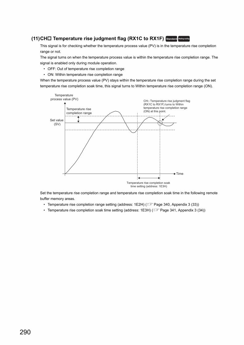
(11)CH Temperature rise judgment flag (RX1C to RX1F)
This signal is for checking whether the temperature process value (PV) is in the temperature rise completion
range or not.
The signal turns on when the temperature process value is within the temperature rise completion range. The
signal is enabled only during module operation.
• OFF: Out of temperature rise completion range
• ON: Within temperature rise completion range
When the temperature process value (PV) stays within the temperature rise completion range during the set
temperature rise completion soak time, this signal turns to Within temperature rise completion range (ON).
Set the temperature rise completion range and temperature rise completion soak time in the following remote
buffer memory areas.
• Temperature rise completion range setting (address: 1E2H) (Page 340, Appendix 3 (33))
• Temperature rise completion soak time setting (address: 1E3H) (Page 341, Appendix 3 (34))
Standard Heating-cooling
Set value (SV)
Temperature rise completion range
Temperature process value (PV)
Time
Temperature rise completion soak time setting (address: 1E3H)
CH□ Temperature rise judgment flag (RX1C to RX1F) turns to Within temperature rise completion range (ON) at this point.
290
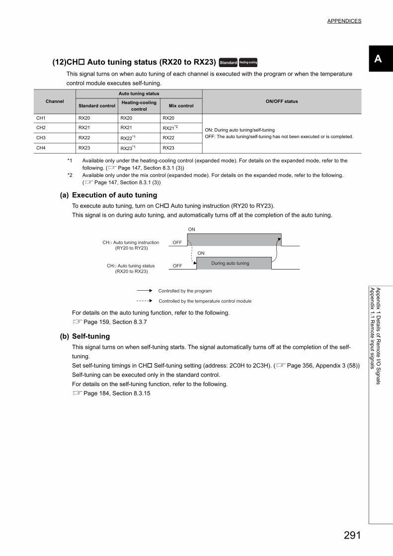
APPENDICES
A
Ap
pe
nd
ix 1 D
eta
ils of R
em
ote
I/O S
ign
als
Ap
pe
nd
ix 1.1
Re
mo
te in
pu
t sign
als
(12)CH Auto tuning status (RX20 to RX23)
This signal turns on when auto tuning of each channel is executed with the program or when the temperature
control module executes self-tuning.
*1 Available only under the heating-cooling control (expanded mode). For details on the expanded mode, refer to the following. (Page 147, Section 8.3.1 (3))
*2 Available only under the mix control (expanded mode). For details on the expanded mode, refer to the following. (Page 147, Section 8.3.1 (3))
(a) Execution of auto tuning
To execute auto tuning, turn on CH Auto tuning instruction (RY20 to RY23).
This signal is on during auto tuning, and automatically turns off at the completion of the auto tuning.
For details on the auto tuning function, refer to the following.
Page 159, Section 8.3.7
(b) Self-tuning
This signal turns on when self-tuning starts. The signal automatically turns off at the completion of the self-
tuning.
Set self-tuning timings in CH Self-tuning setting (address: 2C0H to 2C3H). (Page 356, Appendix 3 (58))
Self-tuning can be executed only in the standard control.
For details on the self-tuning function, refer to the following.
Page 184, Section 8.3.15
Channel
Auto tuning status
ON/OFF statusStandard control
Heating-cooling
controlMix control
CH1 RX20 RX20 RX20
ON: During auto tuning/self-tuning
OFF: The auto tuning/self-tuning has not been executed or is completed.
CH2 RX21 RX21 RX21*2
CH3 RX22 RX22*1 RX22
CH4 RX23 RX23*1 RX23
Standard Heating-cooling
ON
ON
OFF
OFF During auto tuning
Controlled by the program
CH□ Auto tuning instruction (RY20 to RY23)
CH□ Auto tuning status (RX20 to RX23)
Controlled by the temperature control module
291
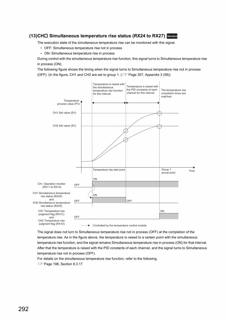
(13)CH Simultaneous temperature rise status (RX24 to RX27)
The execution state of the simultaneous temperature rise can be monitored with this signal.
• OFF: Simultaneous temperature rise not in process
• ON: Simultaneous temperature rise in process
During control with the simultaneous temperature rise function, this signal turns to Simultaneous temperature rise
in process (ON).
The following figure shows the timing when the signal turns to Simultaneous temperature rise not in process
(OFF). (In the figure, CH1 and CH2 are set to group 1. (Page 357, Appendix 3 (59))
The signal does not turn to Simultaneous temperature rise not in process (OFF) at the completion of the
temperature rise. As in the figure above, the temperature is raised to a certain point with the simultaneous
temperature rise function, and the signal remains Simultaneous temperature rise in process (ON) for that interval.
After that the temperature is raised with the PID constants of each channel, and the signal turns to Simultaneous
temperature rise not in process (OFF).
For details on the simultaneous temperature rise function, refer to the following.
Page 198, Section 8.3.17
Standard
ON
OFF
ON
OFF OFF
ON
OFF
CH1 Set value (SV)
The temperature rise completion times are matched.
Temperature is raised with the PID constants of each channel for this interval.
Temperature is raised with the simultaneous temperature rise function for this interval.
Temperature process value (PV)
Time
CH2 Set value (SV)
Temperature rise start point Group 1 arrival point
CH1 Simultaneous temperature rise status (RX24)
and CH2 Simultaneous temperature
rise status (RX25)
CH1 Temperature rise judgment flag (RX1C)
and CH2 Temperature rise judgment flag (RX1D)
CH□ Operation monitor (RX11 to RX14)
Controlled by the temperature control module
292
APPENDICES
A
Ap
pe
nd
ix 1 D
eta
ils of R
em
ote
I/O S
ign
als
Ap
pe
nd
ix 1.1
Re
mo
te in
pu
t sign
als
(14)CH Sensor two-point correction offset latch completion flag (RX28, RX2A,
RX2C, RX2E)
When a sensor two-point correction offset value is stored in a remote buffer memory area, this signal turns to
Latch completed (ON).
When CH Sensor two-point correction offset latch request (RY28, RY2A, RY2C, RY2E) is turned to No request
(OFF), the signal turns to No request (OFF). (Page 300, Appendix 1.2 (9))
For details on the sensor two-point correction function, refer to the following.
Page 133, Section 8.1.5 (2)
(15)CH Sensor two-point correction gain latch completion flag (RX29, RX2B,
RX2D, RX2F)
When a sensor two-point correction gain value is stored in a remote buffer memory area, this signal turns to
Latch completed (ON).
When CH Sensor two-point correction gain latch request (RY29, RY2B, RY2D, RY2F) is turned to No request
(OFF), the signal turns to No request (OFF). (Page 300, Appendix 1.2 (10))
For details on the sensor two-point correction function, refer to the following.
Page 133, Section 8.1.5 (2)
(16)CH Transistor output flag (RX30, RX32, RX34, RX36) , CH Heating
transistor output flag (RX30, RX32, RX34, RX36) , CH ON delay output
flag (RX31, RX33, RX35, RX37) , CH Heating ON delay output flag (RX31,
RX33, RX35, RX37) , CH Cooling transistor output flag (RX38, RX3A,
RX3C, RX3E) , CH Cooling ON delay output flag (RX39, RX3B, RX3D,
RX3F)
ON/OFF status of transistor output and ON delay output are stored in these signals. In the heating-cooling
control, ON/OFF status of transistor output/ON delay output for heating are stored in RX38 to RX3F.
Common
Common
Standard
Heating-cooling
Standard
Heating-cooling
Heating-cooling
Heating-cooling
293
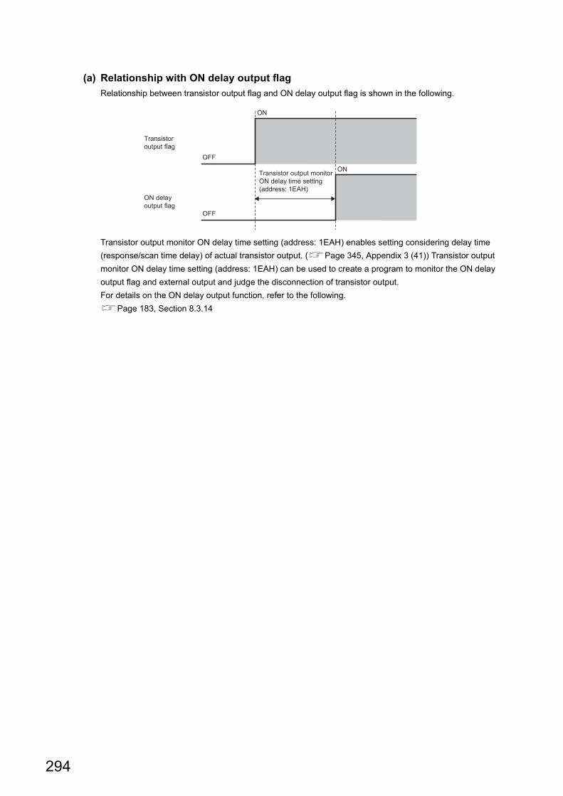
(a) Relationship with ON delay output flag
Relationship between transistor output flag and ON delay output flag is shown in the following.
Transistor output monitor ON delay time setting (address: 1EAH) enables setting considering delay time
(response/scan time delay) of actual transistor output. (Page 345, Appendix 3 (41)) Transistor output
monitor ON delay time setting (address: 1EAH) can be used to create a program to monitor the ON delay
output flag and external output and judge the disconnection of transistor output.
For details on the ON delay output function, refer to the following.
Page 183, Section 8.3.14
ON
ON
OFF
OFF
Transistor output flag
ON delay output flag
Transistor output monitor ON delay time setting (address: 1EAH)
294
APPENDICES
A
Ap
pe
nd
ix 1 D
eta
ils of R
em
ote
I/O S
ign
als
Ap
pe
nd
ix 1.2
Re
mo
te o
utp
ut sig
na
ls
Appendix 1.2 Remote output signals
(1) Initial data setting request flag (RY9)
Write parameter data to the remote buffer memory area and turn on this signal to set or change the operating
condition of the temperature control module with the program.
Initial data setting completed flag (RX9) turns on when the operating condition is changed.
For the parameters which the temperature control module can change with this signal, refer to the following.
• Lists of Remote Buffer Memory Areas (Page 49, Section 3.7)
The temperature control module accepts the signal only when all channels are stopped. Therefore, stop operations of all channels and turn on the signal.If the signal is turned on while even one channel is operating, an error occurs (error code: 0003H) and the signal is not accepted.
(2) Error clear request flag (RYA)
If this signal is turned on and off when the following errors have occurred, Error flag (RXA) turns off.
• Error code: 0003H, and Error occurrence address: FFFFH
• Error code: 0006H
(a) To clear an error history
An error history is not cleared by turning on this signal. To clear an error history, use Error history clear
command (address: 1000H). For Error history clear command (address: 1000H), refer to the following.
• Error history clear command (address: 1000H) (Page 364, Appendix 3 (70))
(3) During operation setting change instruction (RY10)
Turn on this signal to change parameters during operation of the temperature control module. If the setting
changes are normally completed, During operation setting change completion flag (RX10) turns on.
Changed values of parameters are enabled for channels where the operations are stopped.
The following table lists signals to be used for the parameter changes. ( indicates that the parameter changes
are enabled, and indicates that the parameter changes are disabled.)
*1 Parameters that can be changed only when all channels are stopped*2 Parameters that can be changed during channel operation as well
For changeable parameters when all channels are stopped or during channel operation, refer to the following.
• Lists of Remote Buffer Memory Areas (Page 49, Section 3.7)
Item
All channels are stopped.Stopped channels and operating channels are mixed.
All channels are operating.Stopped channel Operating channel
Stop
parameter*1
Operation
parameter*2
Stop
parameter*1
Operation
parameter*2
Stop
parameter*1
Operation
parameter*2
Stop
parameter*1
Operation
parameter*2
Initial data setting request
flag (RY9) Error (0003H) Error (0003H) Error (0003H) Error (0003H) Error (0003H) Error (0003H)
During operation setting
change instruction
(RY10)
Common
Common
Common
295
(4) CH Operation request flag (RY11 to RY14)
Turn on this signal to start operation for each channel.
• If the signal is turned on during the temperature control module stop, operation is started for the
corresponding channel and CH Operation monitor (RX11 to RX14) turns on. Check that CH Operation
monitor (RX11 to RX14) is on, and turn off the signal.
• If the signal is turned on during the module operation, the module keeps operating (CH Operation monitor
(RX11 to RX14) remains on). An error or an alarm is not output.
• If the signal is turned on when an error has occurred, the module operation is not started. Eliminate the error
cause and turn on the signal again.
• If CH Stop request flag (RY18 to RY1B) is turned on while the signal is on, an error occurs (error code:
001H).
(5) Set value backup instruction (RY15)
Use this signal to write the remote buffer memory data to the non-volatile memory. Turning on the signal starts the
data writing to the non-volatile memory.
For the remote buffer memory areas whose data is to be backed up, refer to the following.
Page 49, Section 3.7
(a) When data writing to the non-volatile memory has been normally completed
Back-up of the set value completion flag (RX15) turns on.
(b) When data writing to the non-volatile memory has not been normally completed
Back-up of the set value fail flag (RX17) turns on. When Back-up of the set value fail flag (RX17) turns on, turn
on this signal to write the data to the non-volatile memory again.
(c) Timings when this signal cannot be accepted
In the following timings, this signal cannot be accepted.
• 1: While PID constants are being written automatically after auto tuning
• 2: While PID constants are being read from the non-volatile memory
• 3: When a setting error has occurred
• 4: While a setting is being changed with Initial data setting request flag (RY9)
• 5: While a setting is being changed with During operation setting change instruction (RY10)
For 1 to 3 above, turn on this signal again after each condition is resolved. For 4 and 5, the data writing to the
non-volatile memory automatically starts after the condition is resolved.
For details on the data writing to the non-volatile memory, refer to the following.
Page 136, Section 8.1.7
Common
OFF OFF
OFF
ON
ON
CH□ Operation request flag (RY11 to RY14)
Module status
CH□ Operation monitor (RX11 to RX14)
Stop Operation shift processing Operating
Controlled by the program
Controlled by the temperature control module
Common
296
APPENDICES
A
Ap
pe
nd
ix 1 D
eta
ils of R
em
ote
I/O S
ign
als
Ap
pe
nd
ix 1.2
Re
mo
te o
utp
ut sig
na
ls
(6) Default setting registration instruction (RY16)
By turning on this signal, a value in remote buffer memory areas returns to a default value according to the
control output cycle unit selection setting and control mode setting.
Target data of the default return are module-based parameter data in parameter area (address: 100H to 4FFH),
and station-based control data and module based control data in module control data area (address 1000H to
14FFH). For details, refer to the following.
• Page 49, Section 3.7
After the data writing is completed, Default value write completion flag (RX16) turns on.
(a) Execution timing of this signal
Turn on the signal while the module is stopped (when CH Operation monitor (RX11 to RX14) is off). The
value does not return to the default even if the signal is turned on during module operation (when CH
Operation monitor (RX11 to RX14) is on). (An error does not occur.)
(b) Timing of setting change to a default
The setting is automatically changed to the default by turning on the signal.
After setting changes of remote buffer memory areas, turning on Initial data setting request flag (RY9) or During operation setting change instruction (RY10) is required to reflect the change. However, if Default setting registration instruction (RY16) is turned on, the change is reflected without turning on these signals.Therefore, after the setting change to the default, check that a set value is correct and start the control.
(c) When a control mode change error has occurred (error code: 000DH)
Default setting registration is performed according to the value stored in Control switching monitor (address:
602H).
Common
297
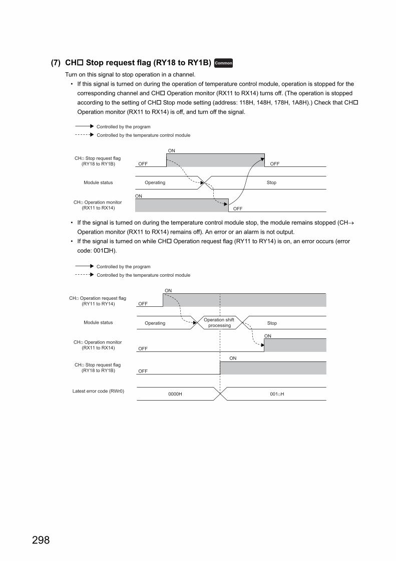
(7) CH Stop request flag (RY18 to RY1B)
Turn on this signal to stop operation in a channel.
• If this signal is turned on during the operation of temperature control module, operation is stopped for the
corresponding channel and CH Operation monitor (RX11 to RX14) turns off. (The operation is stopped
according to the setting of CH Stop mode setting (address: 118H, 148H, 178H, 1A8H).) Check that CH
Operation monitor (RX11 to RX14) is off, and turn off the signal.
• If the signal is turned on during the temperature control module stop, the module remains stopped (CH
Operation monitor (RX11 to RX14) remains off). An error or an alarm is not output.
• If the signal is turned on while CH Operation request flag (RY11 to RY14) is on, an error occurs (error
code: 001H).
Common
OFF OFF
OFF
ON
ON
CH□ Stop request flag (RY18 to RY1B)
Module status
CH□ Operation monitor (RX11 to RX14)
Operating Stop
Controlled by the program
Controlled by the temperature control module
OFF
OFF
OFF
ON
ON
ON
CH□ Operation request flag (RY11 to RY14)
Module status
CH□ Operation monitor (RX11 to RX14)
CH□ Stop request flag (RY18 to RY1B)
Latest error code (RWr0)
StopOperation shift
processingOperating
0000H 001□H
Controlled by the program
Controlled by the temperature control module
298
APPENDICES
A
Ap
pe
nd
ix 1 D
eta
ils of R
em
ote
I/O S
ign
als
Ap
pe
nd
ix 1.2
Re
mo
te o
utp
ut sig
na
ls
(8) CH Auto tuning instruction (RY20 to RY23)
Use this signal to start auto tuning for each channel. Turning on the signal starts auto tuning and CH Auto
tuning status (RX20 to RX23) turns on. After auto tuning is completed, CH Auto tuning status (RX20 to RX23)
turns off.
Keep the signal on during auto tuning and turn it off at the completion of the auto tuning. If the signal is turned off
during auto tuning, the auto tuning is stopped. If the auto tuning is stopped, PID constants in the remote buffer
memory area do not change.
● If proportional band (P)/heating proportional band (Ph) is set to 0, auto tuning cannot be executed. (Page 318, Appendix 3 (7))
● If CH Stop request flag (RY18 to RY1B) is turned on during auto tuning and CH Operation monitor (RX11 to RX14) turns off (stop status), the auto tuning is stopped. After that, if CH Operation request flag (RY11 to RY14) is turned on and CH Operation monitor (RX11 to RX14) turns on (operating status), the auto tuning is not resumed. To resume the auto tuning, turn off CH Auto tuning instruction (RY20 to RY23), and turn it on again.
For details on the auto tuning function, refer to the following.
Page 159, Section 8.3.7
(a) Auto tuning during stop status
The auto tuning instruction is also accepted during stop status. The following are the operations.
1: Turn on CH Auto tuning instruction (RY20 to RY23).
2: CH Operation monitor (RX11 to RX14) turns on (operating status).
3: Auto tuning is started.
4: Check that the auto tuning is completed (CH Auto tuning status (RX20 to RX23) is off), and turn off CH
Auto tuning instruction (RY20 to RY23).
5: CH Operation monitor (RX11 to RX14) remains on after the operation 4 is executed.
CH Operation monitor (RX11 to RX14) also remains on if CH Auto tuning instruction (RY20 to RY23) is
turned off during auto tuning.
Standard Heating-cooling
OFF
OFF OFF
OFF OFF
ON
ON
ON
CH□ Operation monitor (RX11 to RX14)
CH□ Auto tuning instruction (RY20 to RY23)
CH□ Auto tuning status (RX20 to RX23)
Controlled by the program
Controlled by the temperature control module
299
(9) CH Sensor two-point correction offset latch request (RY28, RY2A, RY2C,
RY2E)
This signal is to request for storing the temperature process value (PV) as a sensor two-point correction offset
value in the following remote buffer memory area.
• CH Sensor two-point correction offset value (measured value) (address: 284H, 288H, 28CH, 290H)
(Page 352, Appendix 3 (52))
For details on the sensor two-point correction function, refer to the following.
Page 133, Section 8.1.5 (2)
(a) Setting range
• OFF: No request
• ON: Latch request
(10)CH Sensor two-point correction gain latch request (RY29, RY2B, RY2D,
RY2F)
This signal is to request for storing the temperature process value (PV) as a sensor two-point correction gain
value in the following remote buffer memory area.
• CH Sensor two-point correction gain value (measured value) (address: 286H, 28AH, 28EH, 292H)
(Page 353, Appendix 3 (54))
For details on the sensor two-point correction function, refer to the following.
Page 133, Section 8.1.5 (2)
(a) Setting range
• OFF: No request
• ON: Latch request
Common
Common
300
APPENDICES
A
Ap
pe
nd
ix 2 D
eta
ils of R
em
ote
Re
giste
r Are
as
Appendix 2 Details of Remote Register Areas
This section describes details of remote register areas assigned to the master/local module.
The assignment of each device number is for the case when the remote register areas of the main module are
assigned to RWr0 to RWr1F and RWw0 to RWw1F.
For remote register areas indicated with the icons and , or with , the following terms are used,
unless otherwise specified.• Proportional band (P): includes heating proportional band (Ph) and cooling proportional band (Pc).• Manipulated value (MV): includes manipulated value for heating (MVh) and manipulated value for cooling (MVc).• Transistor output: includes heating transistor output and cooling transistor output.• Control output cycle: includes heating control output cycle and cooling control output cycle.
(1) Latest error code (RWr0)
An error code is stored when a moderate error or major error has occurred.
Turning on Error clear request flag (RYA) after eliminating the cause of the error clears the error code.
Errors that occurred in the past can be checked with Error history (address: A00H to FFFH). For the error
history, refer to the following.
• Error history (address: A00H to FFFH) (Page 363, Appendix 3 (69))
(2) Error occurrence address (RWr1)
The address of remote buffer memory area where an error has occurred is stored.
The contents of Error occurrence address (RWr1) differs depending on the error type. For details, refer to the
following.
• Lists of Error Codes (Page 271, Section 11.2)
(3) Latest warning code (RWr2)
An error code is stored when a minor error has occurred or an alarm code is stored when an alarm has occurred.
If a minor error has occurred, the error code is automatically cleared five seconds after the cause of the error is
eliminated.
If an alarm has occurred, the alarm code is automatically cleared after the cause of the alarm is eliminated.
Errors or alarms that occurred in the past can be checked with Error history (address: A00H to FFFH). For the
error history, refer to the following.
• Error history (address: A00H to FFFH) (Page 363, Appendix 3 (69))
Standard Heating-cooling Common
Common
Common
Common
301
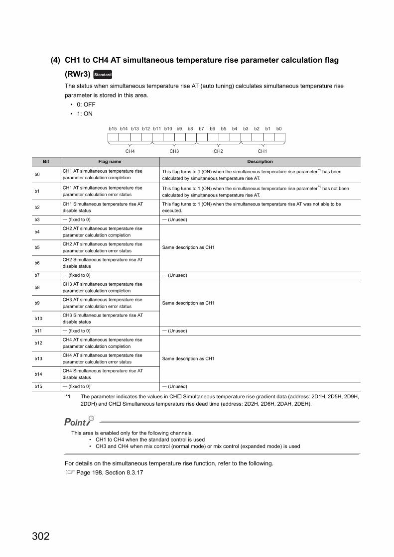
(4) CH1 to CH4 AT simultaneous temperature rise parameter calculation flag
(RWr3)
The status when simultaneous temperature rise AT (auto tuning) calculates simultaneous temperature rise
parameter is stored in this area.
• 0: OFF
• 1: ON
*1 The parameter indicates the values in CH Simultaneous temperature rise gradient data (address: 2D1H, 2D5H, 2D9H, 2DDH) and CH Simultaneous temperature rise dead time (address: 2D2H, 2D6H, 2DAH, 2DEH).
This area is enabled only for the following channels.• CH1 to CH4 when the standard control is used• CH3 and CH4 when mix control (normal mode) or mix control (expanded mode) is used
For details on the simultaneous temperature rise function, refer to the following.
Page 198, Section 8.3.17
Bit Flag name Description
b0CH1 AT simultaneous temperature rise
parameter calculation completionThis flag turns to 1 (ON) when the simultaneous temperature rise parameter*1 has been
calculated by simultaneous temperature rise AT.
b1CH1 AT simultaneous temperature rise
parameter calculation error statusThis flag turns to 1 (ON) when the simultaneous temperature rise parameter*1 has not been
calculated by simultaneous temperature rise AT.
b2CH1 Simultaneous temperature rise AT
disable status
This flag turns to 1 (ON) when the simultaneous temperature rise AT was not able to be
executed.
b3 (fixed to 0) (Unused)
b4CH2 AT simultaneous temperature rise
parameter calculation completion
Same description as CH1b5CH2 AT simultaneous temperature rise
parameter calculation error status
b6CH2 Simultaneous temperature rise AT
disable status
b7 (fixed to 0) (Unused)
b8CH3 AT simultaneous temperature rise
parameter calculation completion
Same description as CH1b9CH3 AT simultaneous temperature rise
parameter calculation error status
b10CH3 Simultaneous temperature rise AT
disable status
b11 (fixed to 0) (Unused)
b12CH4 AT simultaneous temperature rise
parameter calculation completion
Same description as CH1b13CH4 AT simultaneous temperature rise
parameter calculation error status
b14CH4 Simultaneous temperature rise AT
disable status
b15 (fixed to 0) (Unused)
Standard
b15 b14 b13 b12 b11 b10 b9 b8 b7 b6 b5 b4 b3 b2 b1 b0
CH4 CH3 CH2 CH1
302
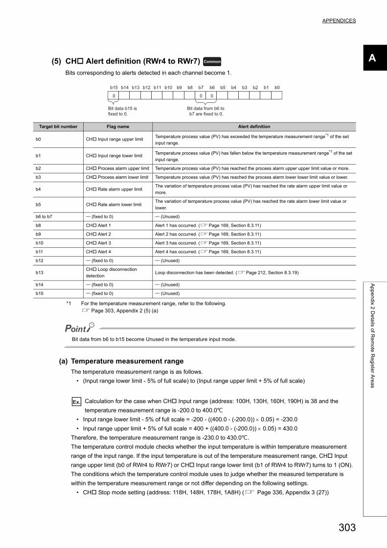
APPENDICES
A
Ap
pe
nd
ix 2 D
eta
ils of R
em
ote
Re
giste
r Are
as
(5) CH Alert definition (RWr4 to RWr7)
Bits corresponding to alerts detected in each channel become 1.
*1 For the temperature measurement range, refer to the following.Page 303, Appendix 2 (5) (a)
Bit data from b6 to b15 become Unused in the temperature input mode.
(a) Temperature measurement range
The temperature measurement range is as follows.
• (Input range lower limit - 5% of full scale) to (Input range upper limit + 5% of full scale)
Ex. Calculation for the case when CH Input range (address: 100H, 130H, 160H, 190H) is 38 and the
temperature measurement range is -200.0 to 400.0
• Input range lower limit - 5% of full scale = -200 - ((400.0 - (-200.0)) 0.05) = -230.0
• Input range upper limit + 5% of full scale = 400 + ((400.0 - (-200.0)) 0.05) = 430.0
Therefore, the temperature measurement range is -230.0 to 430.0.
The temperature control module checks whether the input temperature is within temperature measurement
range of the input range. If the input temperature is out of the temperature measurement range, CH Input
range upper limit (b0 of RWr4 to RWr7) or CH Input range lower limit (b1 of RWr4 to RWr7) turns to 1 (ON).
The conditions which the temperature control module uses to judge whether the measured temperature is
within the temperature measurement range or not differ depending on the following settings.
• CH Stop mode setting (address: 118H, 148H, 178H, 1A8H) ( Page 336, Appendix 3 (27))
Target bit number Flag name Alert definition
b0 CH Input range upper limitTemperature process value (PV) has exceeded the temperature measurement range*1 of the set
input range.
b1 CH Input range lower limitTemperature process value (PV) has fallen below the temperature measurement range*1 of the set
input range.
b2 CH Process alarm upper limit Temperature process value (PV) has reached the process alarm upper upper limit value or more.
b3 CH Process alarm lower limit Temperature process value (PV) has reached the process alarm lower lower limit value or lower.
b4 CH Rate alarm upper limitThe variation of temperature process value (PV) has reached the rate alarm upper limit value or
more.
b5 CH Rate alarm lower limitThe variation of temperature process value (PV) has reached the rate alarm lower limit value or
lower.
b6 to b7 (fixed to 0) (Unused)
b8 CH Alert 1 Alert 1 has occurred. (Page 169, Section 8.3.11)
b9 CH Alert 2 Alert 2 has occurred. (Page 169, Section 8.3.11)
b10 CH Alert 3 Alert 3 has occurred. (Page 169, Section 8.3.11)
b11 CH Alert 4 Alert 4 has occurred. (Page 169, Section 8.3.11)
b12 (fixed to 0) (Unused)
b13CH Loop disconnection
detectionLoop disconnection has been detected. (Page 212, Section 8.3.19)
b14 (fixed to 0) (Unused)
b15 (fixed to 0) (Unused)
Common
b15 b2 b1 b0b5 b4 b3b7 b6b8b9b10b11b12b13b14
0 0 0
Bit data b15 is fixed to 0.
Bit data from b6 to b7 are fixed to 0.
303
(6) CH Temperature process value (PV) or CH Process value (PV) scaling
value (RWr8 to RWrB)
The detected temperature value where sensor correction has been performed is stored in this area.
The value to be stored differs depending on the stored value in CH Decimal point position (address: 620H,
621H, 622H, 623H). (Page 362, Appendix 3 (68))
• No decimal place (0): The value is stored as it is.
• One decimal place (1): The value is stored after being multiplied by 10.
(a) When the scaling function is enabled
If the scaling function is set to be enabled with CH Process value (PV) scaling function enable/disable setting
(address: 200H, 203H, 206H, 209H), the value is stored in CH Process value (PV) scaling value (RWr8 to
RWrB).
The value is stored as it is regardless of the value in CH Decimal point position (address: 620H, 621H, 622H,
623H).
When a value measured by a temperature sensor exceeds the temperature measurement range, the following value is stored.
• When the measured value exceeds temperature measurement range: Input range upper limit + 5% of full scale• When the measured value falls below temperature measurement range: Input range lower limit - 5% of full scale
(7) CH Set value (SV) monitor (RWrC to RWrF)
Set value (SV) of each unit time set in CH Setting change rate limiter unit time setting (address: 109H, 139H,
169H, 199H) is stored in this area. (Page 325, Appendix 3 (13))
The set value (SV) can be monitored in real time.
Common
Standard Heating-cooling
304
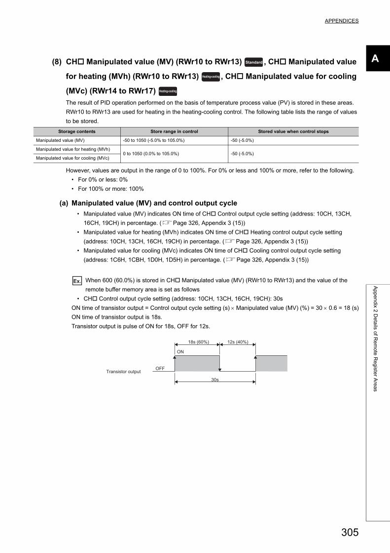
APPENDICES
A
Ap
pe
nd
ix 2 D
eta
ils of R
em
ote
Re
giste
r Are
as
(8) CH Manipulated value (MV) (RWr10 to RWr13) , CH Manipulated value
for heating (MVh) (RWr10 to RWr13) , CH Manipulated value for cooling
(MVc) (RWr14 to RWr17)
The result of PID operation performed on the basis of temperature process value (PV) is stored in these areas.
RWr10 to RWr13 are used for heating in the heating-cooling control. The following table lists the range of values
to be stored.
However, values are output in the range of 0 to 100%. For 0% or less and 100% or more, refer to the following.
• For 0% or less: 0%
• For 100% or more: 100%
(a) Manipulated value (MV) and control output cycle
• Manipulated value (MV) indicates ON time of CH Control output cycle setting (address: 10CH, 13CH,
16CH, 19CH) in percentage. (Page 326, Appendix 3 (15))
• Manipulated value for heating (MVh) indicates ON time of CH Heating control output cycle setting
(address: 10CH, 13CH, 16CH, 19CH) in percentage. (Page 326, Appendix 3 (15))
• Manipulated value for cooling (MVc) indicates ON time of CH Cooling control output cycle setting
(address: 1C6H, 1CBH, 1D0H, 1D5H) in percentage. (Page 326, Appendix 3 (15))
Ex. When 600 (60.0%) is stored in CH Manipulated value (MV) (RWr10 to RWr13) and the value of the
remote buffer memory area is set as follows
• CH Control output cycle setting (address: 10CH, 13CH, 16CH, 19CH): 30s
ON time of transistor output = Control output cycle setting (s) Manipulated value (MV) (%) = 30 0.6 = 18 (s)
ON time of transistor output is 18s.
Transistor output is pulse of ON for 18s, OFF for 12s.
Storage contents Store range in control Stored value when control stops
Manipulated value (MV) -50 to 1050 (-5.0% to 105.0%) -50 (-5.0%)
Manipulated value for heating (MVh)0 to 1050 (0.0% to 105.0%) -50 (-5.0%)
Manipulated value for cooling (MVc)
Standard
Heating-cooling
Heating-cooling
ON
OFF
30s
12s (40%)18s (60%)
Transistor output
305
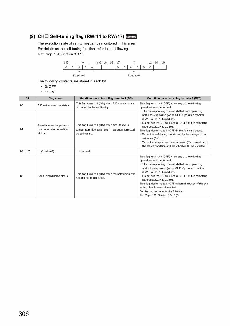
(9) CH Self-tuning flag (RWr14 to RWr17)
The execution state of self-tuning can be monitored in this area.
For details on the self-tuning function, refer to the following.
Page 184, Section 8.3.15
The following contents are stored in each bit.
• 0: OFF
• 1: ON
Bit Flag name Condition on which a flag turns to 1 (ON) Condition on which a flag turns to 0 (OFF)
b0 PID auto-correction statusThis flag turns to 1 (ON) when PID constants are
corrected by the self-tuning.
This flag turns to 0 (OFF) when any of the following
operations was performed.
• The corresponding channel shifted from operating
status to stop status (when CH Operation monitor
(RX11 to RX14) turned off).
• Do not run the ST (0) is set to CH Self-tuning setting
(address: 2C0H to 2C3H).
This flag also turns to 0 (OFF) in the following cases.
• When the self-tuning has started by the change of the
set value (SV)
• When the temperature process value (PV) moved out of
the stable condition and the vibration ST has started
b1
Simultaneous temperature
rise parameter correction
status
This flag turns to 1 (ON) when simultaneous
temperature rise parameter*1 has been corrected
by self-tuning.
b2 to b7 (fixed to 0) (Unused)
b8 Self-tuning disable statusThis flag turns to 1 (ON) when the self-tuning was
not able to be executed.
This flag turns to 0 (OFF) when any of the following
operations was performed.
• The corresponding channel shifted from operating
status to stop status (when CH Operation monitor
(RX11 to RX14) turned off).
• Do not run the ST (0) is set to CH Self-tuning setting
(address: 2C0H to 2C3H).
This flag also turns to 0 (OFF) when all causes of the self-
tuning disable were eliminated.
For the causes, refer to the following.
Page 189, Section 8.3.15 (6)
Standard
b15 b2 b1 b0b10 b9 b8 b7
0 0 0 0 0 0 0 0 0 0 0
Fixed to 0 Fixed to 0
to to
306
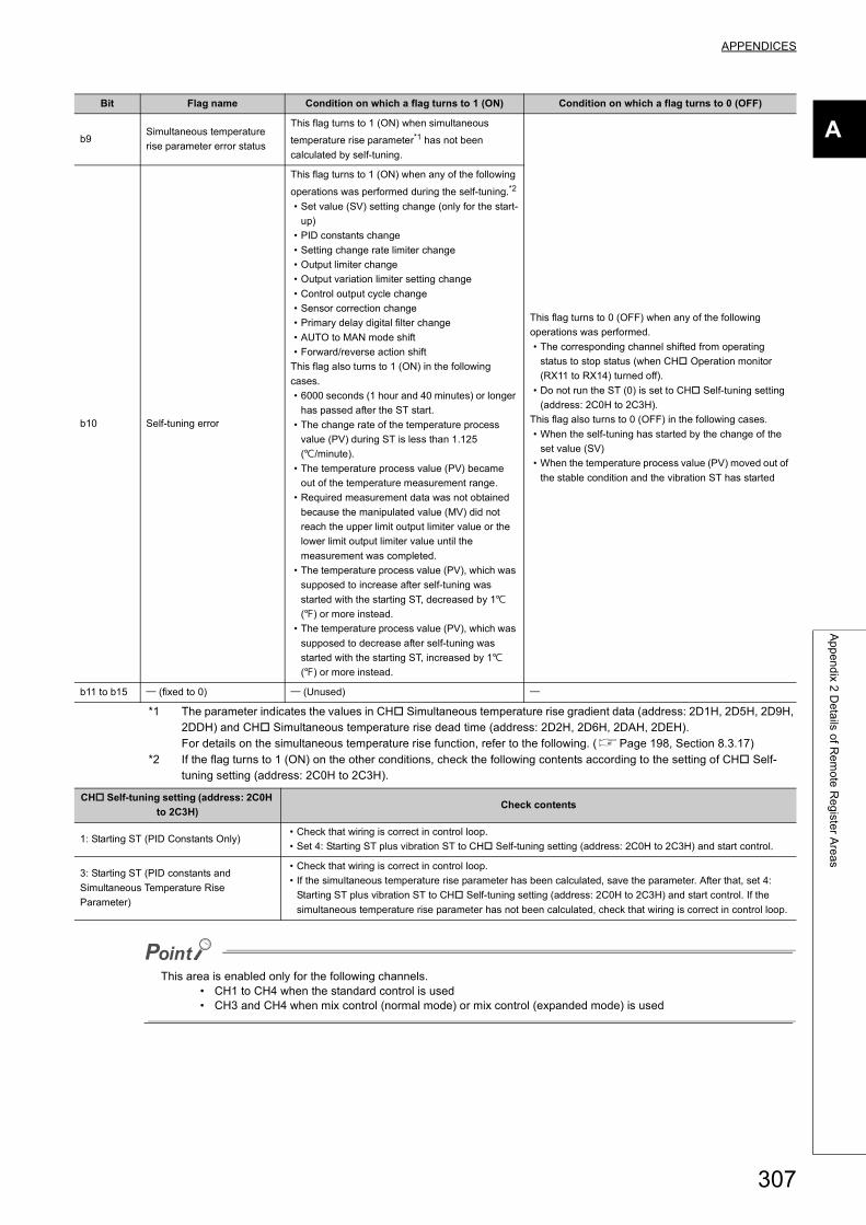
APPENDICES
A
Ap
pe
nd
ix 2 D
eta
ils of R
em
ote
Re
giste
r Are
as
*1 The parameter indicates the values in CH Simultaneous temperature rise gradient data (address: 2D1H, 2D5H, 2D9H, 2DDH) and CH Simultaneous temperature rise dead time (address: 2D2H, 2D6H, 2DAH, 2DEH).For details on the simultaneous temperature rise function, refer to the following. (Page 198, Section 8.3.17)
*2 If the flag turns to 1 (ON) on the other conditions, check the following contents according to the setting of CH Self-tuning setting (address: 2C0H to 2C3H).
This area is enabled only for the following channels.• CH1 to CH4 when the standard control is used• CH3 and CH4 when mix control (normal mode) or mix control (expanded mode) is used
b9Simultaneous temperature
rise parameter error status
This flag turns to 1 (ON) when simultaneous
temperature rise parameter*1 has not been
calculated by self-tuning.
This flag turns to 0 (OFF) when any of the following
operations was performed.
• The corresponding channel shifted from operating
status to stop status (when CH Operation monitor
(RX11 to RX14) turned off).
• Do not run the ST (0) is set to CH Self-tuning setting
(address: 2C0H to 2C3H).
This flag also turns to 0 (OFF) in the following cases.
• When the self-tuning has started by the change of the
set value (SV)
• When the temperature process value (PV) moved out of
the stable condition and the vibration ST has started
b10 Self-tuning error
This flag turns to 1 (ON) when any of the following
operations was performed during the self-tuning.*2
• Set value (SV) setting change (only for the start-
up)
• PID constants change
• Setting change rate limiter change
• Output limiter change
• Output variation limiter setting change
• Control output cycle change
• Sensor correction change
• Primary delay digital filter change
• AUTO to MAN mode shift
• Forward/reverse action shift
This flag also turns to 1 (ON) in the following
cases.
• 6000 seconds (1 hour and 40 minutes) or longer
has passed after the ST start.
• The change rate of the temperature process
value (PV) during ST is less than 1.125
(/minute).
• The temperature process value (PV) became
out of the temperature measurement range.
• Required measurement data was not obtained
because the manipulated value (MV) did not
reach the upper limit output limiter value or the
lower limit output limiter value until the
measurement was completed.
• The temperature process value (PV), which was
supposed to increase after self-tuning was
started with the starting ST, decreased by 1
() or more instead.
• The temperature process value (PV), which was
supposed to decrease after self-tuning was
started with the starting ST, increased by 1
() or more instead.
b11 to b15 (fixed to 0) (Unused)
CH Self-tuning setting (address: 2C0H
to 2C3H)Check contents
1: Starting ST (PID Constants Only)• Check that wiring is correct in control loop.
• Set 4: Starting ST plus vibration ST to CH Self-tuning setting (address: 2C0H to 2C3H) and start control.
3: Starting ST (PID constants and
Simultaneous Temperature Rise
Parameter)
• Check that wiring is correct in control loop.
• If the simultaneous temperature rise parameter has been calculated, save the parameter. After that, set 4:
Starting ST plus vibration ST to CH Self-tuning setting (address: 2C0H to 2C3H) and start control. If the
simultaneous temperature rise parameter has not been calculated, check that wiring is correct in control loop.
Bit Flag name Condition on which a flag turns to 1 (ON) Condition on which a flag turns to 0 (OFF)
307
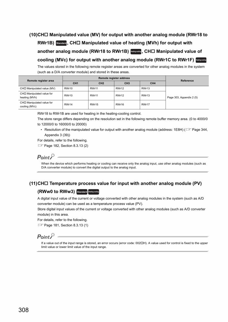
(10)CH Manipulated value (MV) for output with another analog module (RWr18 to
RWr1B) , CH Manipulated value of heating (MVh) for output with
another analog module (RWr18 to RWr1B) , CH Manipulated value of
cooling (MVc) for output with another analog module (RWr1C to RWr1F)
The values stored in the following remote register areas are converted for other analog modules in the system
(such as a D/A converter module) and stored in these areas.
RWr18 to RWr1B are used for heating in the heating-cooling control.
The store range differs depending on the resolution set in the following remote buffer memory area. (0 to 4000/0
to 12000/0 to 16000/0 to 20000)
• Resolution of the manipulated value for output with another analog module (address: 1E8H) (Page 344,
Appendix 3 (39))
For details, refer to the following.
Page 182, Section 8.3.13 (2)
When the device which performs heating or cooling can receive only the analog input, use other analog modules (such as D/A converter module) to convert the digital output to the analog input.
(11)CH Temperature process value for input with another analog module (PV)
(RWw0 to RWw3)
A digital input value of the current or voltage converted with other analog modules in the system (such as A/D
converter module) can be used as a temperature process value (PV).
Store digital input values of the current or voltage converted with other analog modules (such as A/D converter
module) in this area.
For details, refer to the following.
Page 181, Section 8.3.13 (1)
If a value out of the input range is stored, an error occurs (error code: 002H). A value used for control is fixed to the upper limit value or lower limit value of the input range.
Remote register areaRemote register address
ReferenceCH1 CH2 CH3 CH4
CH Manipulated value (MV) RWr10 RWr11 RWr12 RWr13
Page 303, Appendix 2 (5)
CH Manipulated value for
heating (MVh)RWr10 RWr11 RWr12 RWr13
CH Manipulated value for
cooling (MVc)RWr14 RWr15 RWr16 RWr17
Standard
Heating-cooling
Heating-cooling
Standard Heating-cooling
308
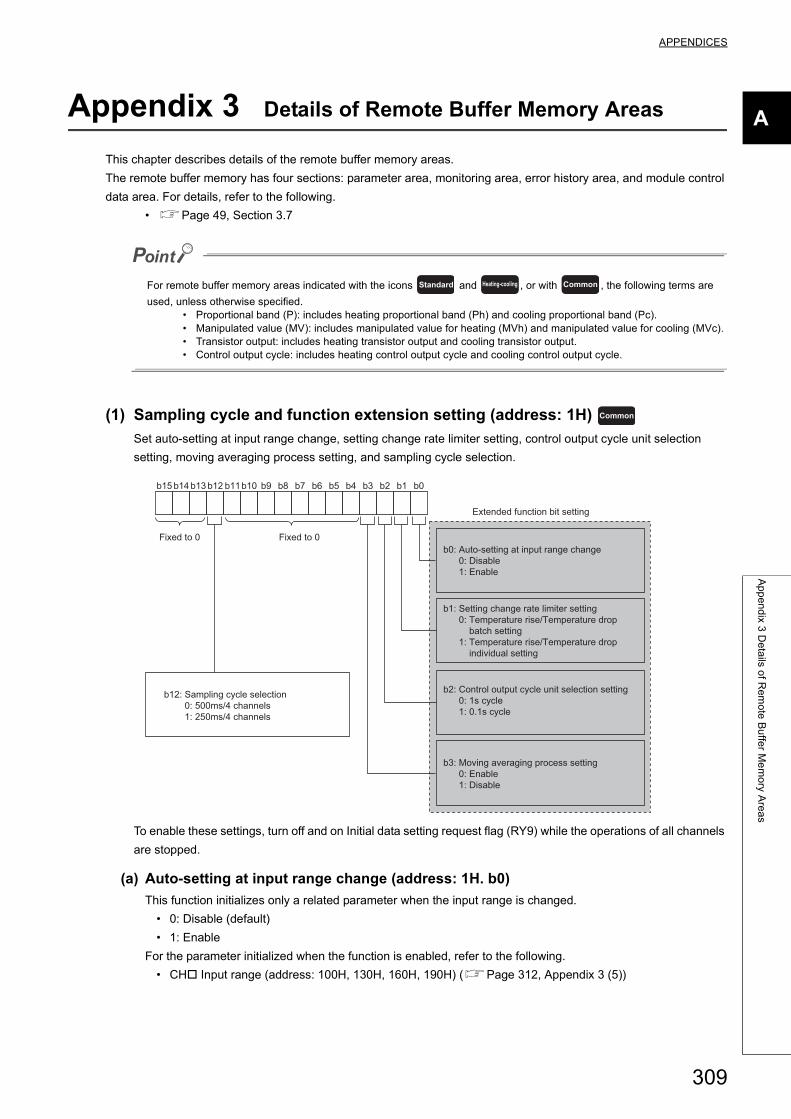
APPENDICES
A
Ap
pe
nd
ix 3 D
eta
ils of R
em
ote
Bu
ffer M
em
ory A
rea
s
Appendix 3 Details of Remote Buffer Memory Areas
This chapter describes details of the remote buffer memory areas.
The remote buffer memory has four sections: parameter area, monitoring area, error history area, and module control
data area. For details, refer to the following.
• Page 49, Section 3.7
For remote buffer memory areas indicated with the icons and , or with , the following terms are
used, unless otherwise specified.• Proportional band (P): includes heating proportional band (Ph) and cooling proportional band (Pc).• Manipulated value (MV): includes manipulated value for heating (MVh) and manipulated value for cooling (MVc).• Transistor output: includes heating transistor output and cooling transistor output.• Control output cycle: includes heating control output cycle and cooling control output cycle.
(1) Sampling cycle and function extension setting (address: 1H)
Set auto-setting at input range change, setting change rate limiter setting, control output cycle unit selection
setting, moving averaging process setting, and sampling cycle selection.
To enable these settings, turn off and on Initial data setting request flag (RY9) while the operations of all channels
are stopped.
(a) Auto-setting at input range change (address: 1H. b0)
This function initializes only a related parameter when the input range is changed.
• 0: Disable (default)
• 1: Enable
For the parameter initialized when the function is enabled, refer to the following.
• CH Input range (address: 100H, 130H, 160H, 190H) (Page 312, Appendix 3 (5))
Standard Heating-cooling Common
Common
b15 b14 b13 b12 b11b10 b9 b8 b7 b6 b5 b4 b3 b2 b1 b0
b0: Auto-setting at input range change 0: Disable 1: Enable
b3: Moving averaging process setting 0: Enable 1: Disable
b1: Setting change rate limiter setting 0: Temperature rise/Temperature drop batch setting 1: Temperature rise/Temperature drop individual setting
Fixed to 0Fixed to 0
Extended function bit setting
b2: Control output cycle unit selection setting 0: 1s cycle 1: 0.1s cycle
b12: Sampling cycle selection 0: 500ms/4 channels 1: 250ms/4 channels
309
(b) Setting change rate limiter setting (address: 1H. b1)
With this setting, the change rate of the set value (SV) per time unit in cases when the set value (SV) is
changed can be set. Select "batch" setting or "individual" setting for the variation limiter set value at
temperature rise and drop.
• 0: Disable (Temperature rise/Temperature drop batch setting) (default)
• 1: Enable (Temperature rise/Temperature drop individual setting)
For details, refer to the following.
• Setting change rate limiter setting function (Page 167, Section 8.3.10)
(c) Control output cycle unit selection setting (address: 1H. b2)
The control output cycle is the ON/OFF cycle of transistor output for the temperature control function.
The control output cycle is set in the following remote buffer memory areas.
• CH Control output cycle setting (address: 10CH, 13CH, 16CH, 19CH) (standard control)
• CH Heating control output cycle setting (address: 10CH, 13CH, 16CH, 19CH) (heating control)
• CH Cooling control output cycle setting (address: 1C6H, 1CBH, 1D0H, 1D5H) (heating-cooling control)
The unit of the above control output cycle can be selected from 1s or 0.1s using this bit.
The following shows the setting values.
• 0: 1s cycle (default)
• 1: 0.1s cycle
For details, refer to the following.
• Control output cycle unit selection function (Page 158, Section 8.3.6)
(d) Moving averaging process setting (address: 1H. b3)
Moving averaging process setting is the function to enable/disable the moving averaging process.
The following shows the setting values.
• 0: Enable (default)
• 1: Disable
For details, refer to the following.
• Moving averaging process to a temperature process value (PV) (Page 129, Section 8.1.3)
(e) Sampling cycle selection (address: 1H. b12)
The sampling cycle is the time period from the instant when a conversion starts on a channel to the instant
when the next conversion starts on the same channel.
The following shows the setting values.
• 0: 500ms/4CH
• 1: 250ms/4CH (default)
For details, refer to the following.
• Sampling cycle (Page 37, Section 3.2 (2) (a))
When the setting of Sampling cycle selection (address: 1H. b12) is changed, the remote buffer memory areas of address 100H and the following addresses are overwritten to their default value.Also, an error (error code: 000FH) occurs immediately after the setting of Sampling cycle selection (address: 1H. b12) is changed. To eliminate the error, turn on and off Set value backup instruction (RY15), and register a newly set parameter to the non-volatile memory.
310
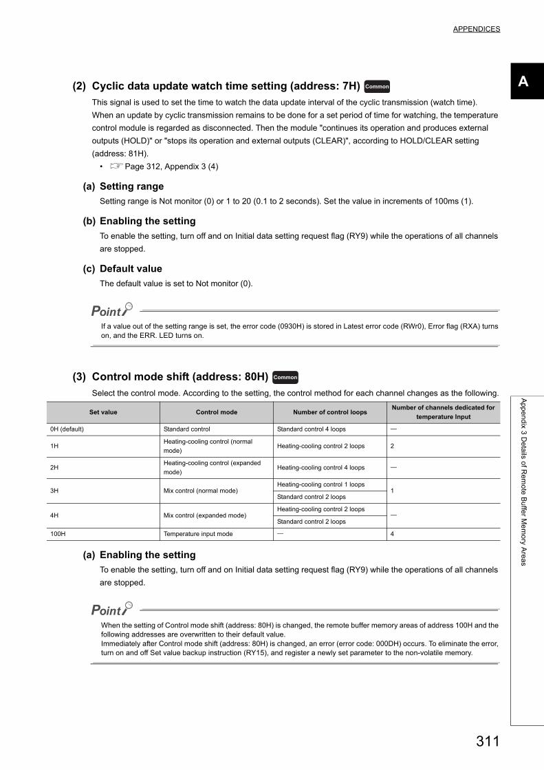
APPENDICES
A
Ap
pe
nd
ix 3 D
eta
ils of R
em
ote
Bu
ffer M
em
ory A
rea
s
(2) Cyclic data update watch time setting (address: 7H)
This signal is used to set the time to watch the data update interval of the cyclic transmission (watch time).
When an update by cyclic transmission remains to be done for a set period of time for watching, the temperature
control module is regarded as disconnected. Then the module "continues its operation and produces external
outputs (HOLD)" or "stops its operation and external outputs (CLEAR)", according to HOLD/CLEAR setting
(address: 81H).
• Page 312, Appendix 3 (4)
(a) Setting range
Setting range is Not monitor (0) or 1 to 20 (0.1 to 2 seconds). Set the value in increments of 100ms (1).
(b) Enabling the setting
To enable the setting, turn off and on Initial data setting request flag (RY9) while the operations of all channels
are stopped.
(c) Default value
The default value is set to Not monitor (0).
If a value out of the setting range is set, the error code (0930H) is stored in Latest error code (RWr0), Error flag (RXA) turns on, and the ERR. LED turns on.
(3) Control mode shift (address: 80H)
Select the control mode. According to the setting, the control method for each channel changes as the following.
(a) Enabling the setting
To enable the setting, turn off and on Initial data setting request flag (RY9) while the operations of all channels
are stopped.
When the setting of Control mode shift (address: 80H) is changed, the remote buffer memory areas of address 100H and the following addresses are overwritten to their default value.Immediately after Control mode shift (address: 80H) is changed, an error (error code: 000DH) occurs. To eliminate the error, turn on and off Set value backup instruction (RY15), and register a newly set parameter to the non-volatile memory.
Set value Control mode Number of control loopsNumber of channels dedicated for
temperature Input
0H (default) Standard control Standard control 4 loops
1HHeating-cooling control (normal
mode)Heating-cooling control 2 loops 2
2HHeating-cooling control (expanded
mode)Heating-cooling control 4 loops
3H Mix control (normal mode)Heating-cooling control 1 loops
1Standard control 2 loops
4H Mix control (expanded mode)Heating-cooling control 2 loops
Standard control 2 loops
100H Temperature input mode 4
Common
Common
311
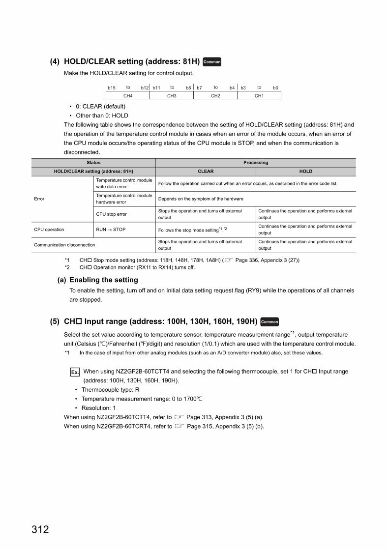
(4) HOLD/CLEAR setting (address: 81H)
Make the HOLD/CLEAR setting for control output.
• 0: CLEAR (default)
• Other than 0: HOLD
The following table shows the correspondence between the setting of HOLD/CLEAR setting (address: 81H) and
the operation of the temperature control module in cases when an error of the module occurs, when an error of
the CPU module occurs/the operating status of the CPU module is STOP, and when the communication is
disconnected.
*1 CH Stop mode setting (address: 118H, 148H, 178H, 1A8H) ( Page 336, Appendix 3 (27))*2 CH Operation monitor (RX11 to RX14) turns off.
(a) Enabling the setting
To enable the setting, turn off and on Initial data setting request flag (RY9) while the operations of all channels
are stopped.
(5) CH Input range (address: 100H, 130H, 160H, 190H)
Select the set value according to temperature sensor, temperature measurement range*1, output temperature
unit (Celsius ()/Fahrenheit ()/digit) and resolution (1/0.1) which are used with the temperature control module.
*1 In the case of input from other analog modules (such as an A/D converter module) also, set these values.
Ex. When using NZ2GF2B-60TCTT4 and selecting the following thermocouple, set 1 for CH Input range
(address: 100H, 130H, 160H, 190H).
• Thermocouple type: R
• Temperature measurement range: 0 to 1700
• Resolution: 1
When using NZ2GF2B-60TCTT4, refer to Page 313, Appendix 3 (5) (a).
When using NZ2GF2B-60TCRT4, refer to Page 315, Appendix 3 (5) (b).
Status Processing
HOLD/CLEAR setting (address: 81H) CLEAR HOLD
Error
Temperature control module
write data errorFollow the operation carried out when an error occurs, as described in the error code list.
Temperature control module
hardware errorDepends on the symptom of the hardware
CPU stop errorStops the operation and turns off external
output
Continues the operation and performs external
output
CPU operation RUN STOP Follows the stop mode setting*1.*2Continues the operation and performs external
output
Communication disconnectionStops the operation and turns off external
output
Continues the operation and performs external
output
Common
b15 b0b8 b7 b4 b3b11b12
CH4 CH3 CH2 CH1
to to to to
Common
312
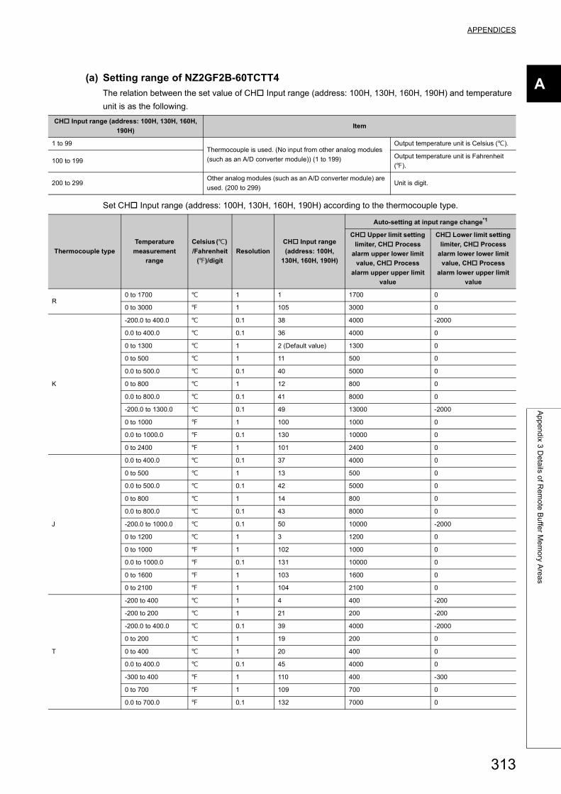
APPENDICES
A
Ap
pe
nd
ix 3 D
eta
ils of R
em
ote
Bu
ffer M
em
ory A
rea
s
(a) Setting range of NZ2GF2B-60TCTT4
The relation between the set value of CH Input range (address: 100H, 130H, 160H, 190H) and temperature
unit is as the following.
Set CH Input range (address: 100H, 130H, 160H, 190H) according to the thermocouple type.
CH Input range (address: 100H, 130H, 160H,
190H)Item
1 to 99Thermocouple is used. (No input from other analog modules
(such as an A/D converter module)) (1 to 199)
Output temperature unit is Celsius ().
100 to 199Output temperature unit is Fahrenheit
().
200 to 299Other analog modules (such as an A/D converter module) are
used. (200 to 299)Unit is digit.
Thermocouple type
Temperature
measurement
range
Celsius ()
/Fahrenheit
()/digit
Resolution
CH Input range
(address: 100H,
130H, 160H, 190H)
Auto-setting at input range change*1
CH Upper limit setting
limiter, CH Process
alarm upper lower limit
value, CH Process
alarm upper upper limit
value
CH Lower limit setting
limiter, CH Process
alarm lower lower limit
value, CH Process
alarm lower upper limit
value
R0 to 1700 1 1 1700 0
0 to 3000 1 105 3000 0
K
-200.0 to 400.0 0.1 38 4000 -2000
0.0 to 400.0 0.1 36 4000 0
0 to 1300 1 2 (Default value) 1300 0
0 to 500 1 11 500 0
0.0 to 500.0 0.1 40 5000 0
0 to 800 1 12 800 0
0.0 to 800.0 0.1 41 8000 0
-200.0 to 1300.0 0.1 49 13000 -2000
0 to 1000 1 100 1000 0
0.0 to 1000.0 0.1 130 10000 0
0 to 2400 1 101 2400 0
J
0.0 to 400.0 0.1 37 4000 0
0 to 500 1 13 500 0
0.0 to 500.0 0.1 42 5000 0
0 to 800 1 14 800 0
0.0 to 800.0 0.1 43 8000 0
-200.0 to 1000.0 0.1 50 10000 -2000
0 to 1200 1 3 1200 0
0 to 1000 1 102 1000 0
0.0 to 1000.0 0.1 131 10000 0
0 to 1600 1 103 1600 0
0 to 2100 1 104 2100 0
T
-200 to 400 1 4 400 -200
-200 to 200 1 21 200 -200
-200.0 to 400.0 0.1 39 4000 -2000
0 to 200 1 19 200 0
0 to 400 1 20 400 0
0.0 to 400.0 0.1 45 4000 0
-300 to 400 1 110 400 -300
0 to 700 1 109 700 0
0.0 to 700.0 0.1 132 7000 0
313
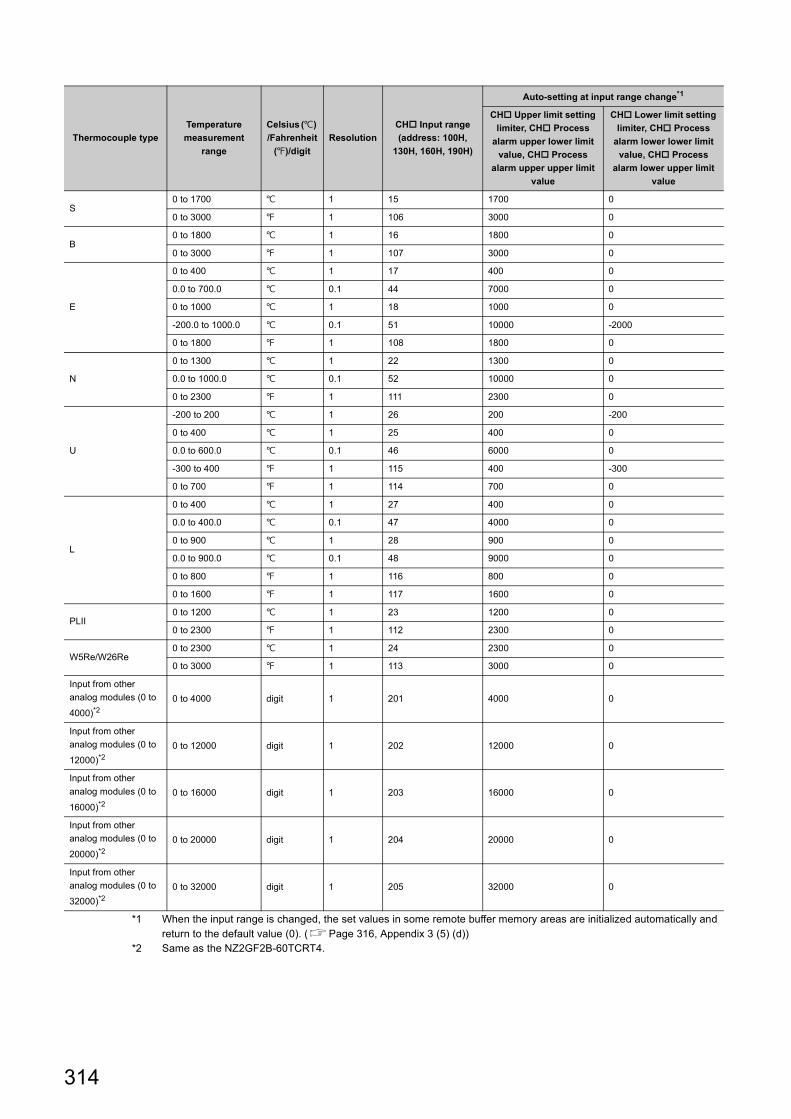
*1 When the input range is changed, the set values in some remote buffer memory areas are initialized automatically and return to the default value (0). (Page 316, Appendix 3 (5) (d))
*2 Same as the NZ2GF2B-60TCRT4.
S0 to 1700 1 15 1700 0
0 to 3000 1 106 3000 0
B0 to 1800 1 16 1800 0
0 to 3000 1 107 3000 0
E
0 to 400 1 17 400 0
0.0 to 700.0 0.1 44 7000 0
0 to 1000 1 18 1000 0
-200.0 to 1000.0 0.1 51 10000 -2000
0 to 1800 1 108 1800 0
N
0 to 1300 1 22 1300 0
0.0 to 1000.0 0.1 52 10000 0
0 to 2300 1 111 2300 0
U
-200 to 200 1 26 200 -200
0 to 400 1 25 400 0
0.0 to 600.0 0.1 46 6000 0
-300 to 400 1 115 400 -300
0 to 700 1 114 700 0
L
0 to 400 1 27 400 0
0.0 to 400.0 0.1 47 4000 0
0 to 900 1 28 900 0
0.0 to 900.0 0.1 48 9000 0
0 to 800 1 116 800 0
0 to 1600 1 117 1600 0
PLII0 to 1200 1 23 1200 0
0 to 2300 1 112 2300 0
W5Re/W26Re0 to 2300 1 24 2300 0
0 to 3000 1 113 3000 0
Input from other
analog modules (0 to
4000)*20 to 4000 digit 1 201 4000 0
Input from other
analog modules (0 to
12000)*20 to 12000 digit 1 202 12000 0
Input from other
analog modules (0 to
16000)*20 to 16000 digit 1 203 16000 0
Input from other
analog modules (0 to
20000)*20 to 20000 digit 1 204 20000 0
Input from other
analog modules (0 to
32000)*20 to 32000 digit 1 205 32000 0
Thermocouple type
Temperature
measurement
range
Celsius ()
/Fahrenheit
()/digit
Resolution
CH Input range
(address: 100H,
130H, 160H, 190H)
Auto-setting at input range change*1
CH Upper limit setting
limiter, CH Process
alarm upper lower limit
value, CH Process
alarm upper upper limit
value
CH Lower limit setting
limiter, CH Process
alarm lower lower limit
value, CH Process
alarm lower upper limit
value
314
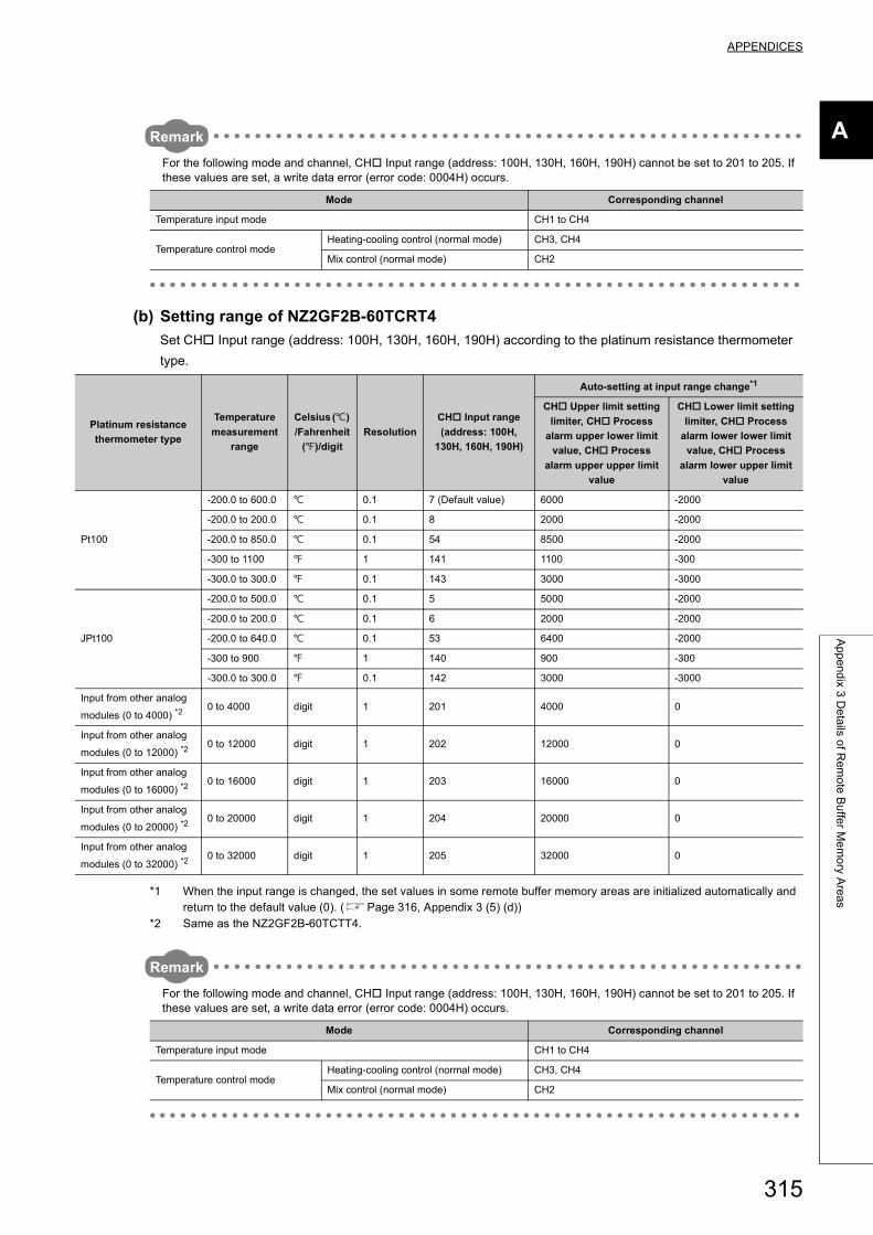
APPENDICES
A
Ap
pe
nd
ix 3 D
eta
ils of R
em
ote
Bu
ffer M
em
ory A
rea
s
Remark
For the following mode and channel, CH Input range (address: 100H, 130H, 160H, 190H) cannot be set to 201 to 205. If these values are set, a write data error (error code: 0004H) occurs.
(b) Setting range of NZ2GF2B-60TCRT4
Set CH Input range (address: 100H, 130H, 160H, 190H) according to the platinum resistance thermometer
type.
*1 When the input range is changed, the set values in some remote buffer memory areas are initialized automatically and return to the default value (0). (Page 316, Appendix 3 (5) (d))
*2 Same as the NZ2GF2B-60TCTT4.
Remark
For the following mode and channel, CH Input range (address: 100H, 130H, 160H, 190H) cannot be set to 201 to 205. If these values are set, a write data error (error code: 0004H) occurs.
Mode Corresponding channel
Temperature input mode CH1 to CH4
Temperature control modeHeating-cooling control (normal mode) CH3, CH4
Mix control (normal mode) CH2
Platinum resistance
thermometer type
Temperature
measurement
range
Celsius ()
/Fahrenheit
()/digit
Resolution
CH Input range
(address: 100H,
130H, 160H, 190H)
Auto-setting at input range change*1
CH Upper limit setting
limiter, CH Process
alarm upper lower limit
value, CH Process
alarm upper upper limit
value
CH Lower limit setting
limiter, CH Process
alarm lower lower limit
value, CH Process
alarm lower upper limit
value
Pt100
-200.0 to 600.0 0.1 7 (Default value) 6000 -2000
-200.0 to 200.0 0.1 8 2000 -2000
-200.0 to 850.0 0.1 54 8500 -2000
-300 to 1100 1 141 1100 -300
-300.0 to 300.0 0.1 143 3000 -3000
JPt100
-200.0 to 500.0 0.1 5 5000 -2000
-200.0 to 200.0 0.1 6 2000 -2000
-200.0 to 640.0 0.1 53 6400 -2000
-300 to 900 1 140 900 -300
-300.0 to 300.0 0.1 142 3000 -3000
Input from other analog
modules (0 to 4000) *20 to 4000 digit 1 201 4000 0
Input from other analog
modules (0 to 12000) *20 to 12000 digit 1 202 12000 0
Input from other analog
modules (0 to 16000) *20 to 16000 digit 1 203 16000 0
Input from other analog
modules (0 to 20000) *20 to 20000 digit 1 204 20000 0
Input from other analog
modules (0 to 32000) *20 to 32000 digit 1 205 32000 0
Mode Corresponding channel
Temperature input mode CH1 to CH4
Temperature control modeHeating-cooling control (normal mode) CH3, CH4
Mix control (normal mode) CH2
315
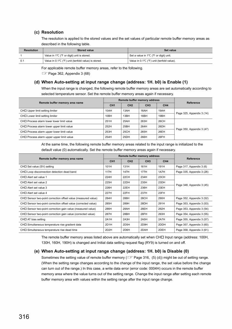
(c) Resolution
The resolution is applied to the stored values and the set values of particular remote buffer memory areas as
described in the following table.
For applicable remote buffer memory areas, refer to the following.
Page 362, Appendix 3 (68)
(d) When Auto-setting at input range change (address: 1H. b0) is Enable (1)
When the input range is changed, the following remote buffer memory areas are set automatically according to
selected temperature sensor. Set the remote buffer memory areas again if necessary.
At the same time, the following remote buffer memory areas related to the input range is initialized to the
default value (0) automatically. Set the remote buffer memory areas again if necessary.
The remote buffer memory areas listed above are automatically set when CH Input range (address: 100H,
130H, 160H, 190H) is changed and Initial data setting request flag (RY9) is turned on and off.
(e) When Auto-setting at input range change (address: 1H. b0) is Disable (0)
Sometimes the setting value of remote buffer memory (Page 316, (5) (d)) might be out of setting range.
(When the setting range changes according to the change of the input range, the set value before the change
can turn out of the range.) In this case, a write data error (error code: 0004H) occurs in the remote buffer
memory area where the value turns out of the setting range. Change the input range after setting each remote
buffer memory area with values within the setting range after the input range change.
Resolution Stored value Set value
1 Value in 1 ( or digit) unit is stored. Set a value in 1 ( or digit) unit.
0.1 Value in 0.1 () unit (tenfold value) is stored. Value in 0.1 () unit (tenfold value).
Remote buffer memory area nameRemote buffer memory address
ReferenceCH1 CH2 CH3 CH4
CH Upper limit setting limiter 10AH 13AH 16AH 19AHPage 325, Appendix 3 (14)
CH Lower limit setting limiter 10BH 13BH 16BH 19BH
CH Process alarm lower lower limit value 251H 25AH 263H 26CH
Page 350, Appendix 3 (47)CH Process alarm lower upper limit value 252H 25BH 264H 26DH
CH Process alarm upper lower limit value 253H 25CH 265H 26EH
CH Process alarm upper upper limit value 254H 25DH 266H 26FH
Remote buffer memory area nameRemote buffer memory address
ReferenceCH1 CH2 CH3 CH4
CH Set value (SV) setting 101H 131H 161H 191H Page 317, Appendix 3 (6)
CH Loop disconnection detection dead band 117H 147H 177H 1A7H Page 335, Appendix 3 (26)
CH Alert set value 1 224H 22CH 234H 23CH
Page 348, Appendix 3 (45)CH Alert set value 2 225H 22DH 235H 23DH
CH Alert set value 3 226H 22EH 236H 23EH
CH Alert set value 4 227H 22FH 237H 23FH
CH Sensor two-point correction offset value (measured value) 284H 288H 28CH 290H Page 352, Appendix 3 (52)
CH Sensor two-point correction offset value (corrected value) 285H 289H 28DH 291H Page 353, Appendix 3 (53)
CH Sensor two-point correction gain value (measured value) 286H 28AH 28EH 292H Page 353, Appendix 3 (54)
CH Sensor two-point correction gain value (corrected value) 287H 28BH 28FH 293H Page 354, Appendix 3 (55)
CH AT bias setting 2A1H 2A3H 2A5H 2A7H Page 355, Appendix 3 (57)
CH Simultaneous temperature rise gradient data 2D1H 2D5H 2D9H 2DDH Page 357, Appendix 3 (60)
CH Simultaneous temperature rise dead time 2D2H 2D6H 2DAH 2DEH Page 358, Appendix 3 (61)
316
APPENDICES
A
Ap
pe
nd
ix 3 D
eta
ils of R
em
ote
Bu
ffer M
em
ory A
rea
s
(f) Enabling the setting
To enable the setting, turn off and on Initial data setting request flag (RY9) while the operations of all channels
are stopped.
(6) CH Set value (SV) setting (address: 101H, 131H, 161H, 191H)
Set the target temperature value of PID control.
(a) Setting range
The setting range is identical to the temperature measurement range of the set input range. (Page 313,
Appendix 3 (5))
When a value which is out of the setting range is set, a write data error (error code: 0004H) and the following
situations occur.
• Error flag (RXA) turns on.
• The error code is stored to Latest error code (RWr0).
(b) Setting unit
The value to be set differs depending on the stored value in CH Decimal point position (address: 620H,
621H, 622H, 623H). (Page 362, Appendix 3 (68))
• No decimal place (0): Set a value in 1 ( or digit) unit.
• One decimal place (1): Set a value in 0.1 () unit (tenfold value).
(c) Enabling the setting
Enable the setting contents by either of the following.
• Turning off and on Initial data setting request flag (RY9) while the operations of all channels are stopped
• Turning off and on During operation setting change instruction (RY10)
(d) Default value
The default values are set to 0 in all channels.
Standard Heating-cooling
317
(7) CH Proportional band (P) setting (address: 102H, 132H, 162H, 192H) ,
CH Heating proportional band (Ph) setting (address: 102H, 132H, 162H,
192H) , CH Cooling proportional band (Pc) setting (address: 1C4H,
1C9H, 1CEH, 1D3H)
Set proportional band (P), heating proportional band (Ph), and cooling proportional band (Pc) to perform PID
control. (In the heating-cooling control, set heating proportional band (Ph) to 102H, 132H, 162H, 192H.)
(a) Setting range
Set the value within the following ranges for the full scale of the set input range. (Page 313, Appendix 3
(5))
• Proportional band (P) setting: 0 to 10000 (0.0% to 1000.0%)
• Heating proportional band (Ph) setting: 0 to 10000 (0.0% to 1000.0%)
• Cooling proportional band (Pc) setting: 1 to 10000 (0.1% to 1000.0%)
Ex. When remote buffer memory values are set as shown below, the proportional band (P) is 60.
• CH Input range (address: 100H, 130H, 160H, 190H): 38 (temperature measurement range -200.0 to
400.0)
• CH Proportional band (P) setting (address: 102H, 132H, 162H, 192H): 100 (10.0%)
(Full scale) (Proportional band (P) setting) = (400.0 - (-200.0)) 0.1 = 60
(b) Two-position control
Set the proportional band (P) and heating proportional band (Ph) to 0.
For details on Two-position control, refer to the following.
Page 149, Section 8.3.3
(c) Enabling the setting
Enable the setting contents by either of the following.
• Turning off and on Initial data setting request flag (RY9) while the operations of all channels are stopped
• Turning off and on During operation setting change instruction (RY10)
(d) Default value
The default values are set to 30 (3.0%) in all channels.
If the proportional band (P)/heating proportional band (Ph) is set to 0 (0.0%), the auto tuning cannot be performed. To perform the auto tuning, set proportional band (P)/heating proportional band (Ph) to other than 0.For details on the auto tuning function, refer to the following.Page 159, Section 8.3.7
Standard
Heating-cooling
Heating-cooling
318
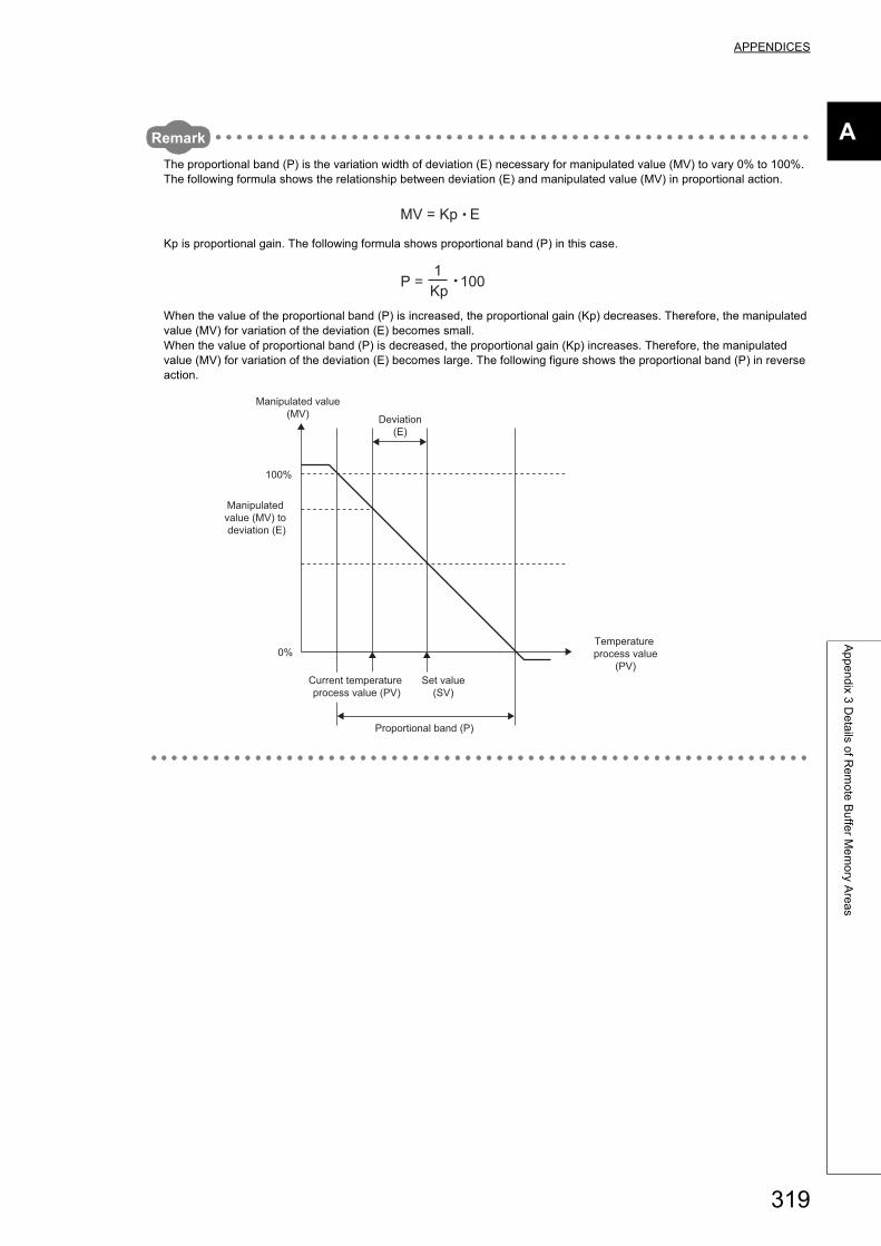
APPENDICES
A
Ap
pe
nd
ix 3 D
eta
ils of R
em
ote
Bu
ffer M
em
ory A
rea
s
Remark
The proportional band (P) is the variation width of deviation (E) necessary for manipulated value (MV) to vary 0% to 100%.The following formula shows the relationship between deviation (E) and manipulated value (MV) in proportional action.
Kp is proportional gain. The following formula shows proportional band (P) in this case.
When the value of the proportional band (P) is increased, the proportional gain (Kp) decreases. Therefore, the manipulated value (MV) for variation of the deviation (E) becomes small.When the value of proportional band (P) is decreased, the proportional gain (Kp) increases. Therefore, the manipulated value (MV) for variation of the deviation (E) becomes large. The following figure shows the proportional band (P) in reverse action.
MV = Kp E
P = 100Kp1
100%
0%
Deviation(E)
Manipulated value (MV) to deviation (E)
Manipulated value(MV)
Temperature process value
(PV)
Proportional band (P)
Current temperature process value (PV)
Set value(SV)
319
(8) CH Integral time (I) setting (address: 103H, 133H, 163H, 193H)
Set integral time (I) to perform PID control.
(a) Setting range
The setting range is 0 to 3600 (0 to 3600s).
(b) In the P control or PD control
Set this setting to 0.
For details on control methods, refer to the following.
Page 149, Section 8.3.3
(c) Enabling the setting
Enable the setting contents by either of the following.
• Turning off and on Initial data setting request flag (RY9) while the operations of all channels are stopped
• Turning off and on During operation setting change instruction (RY10)
(d) Default value
The default values are set to 240 (240s) in all channels.
(9) CH Derivative time (D) setting (address: 104H, 134H, 164H, 194H)
Set derivative time (D) to perform PID control.
(a) Setting range
The setting range is 0 to 3600 (0 to 3600s).
(b) In the P control or PI control
Set this setting to 0.
For details on control methods, refer to the following.
Page 149, Section 8.3.3
(c) Enabling the setting
Enable the setting contents by either of the following.
• Turning off and on Initial data setting request flag (RY9) while the operations of all channels are stopped
• Turning off and on During operation setting change instruction (RY10)
(d) Default value
The default values are set to 60 (60s) in all channels.
Common
Common
320
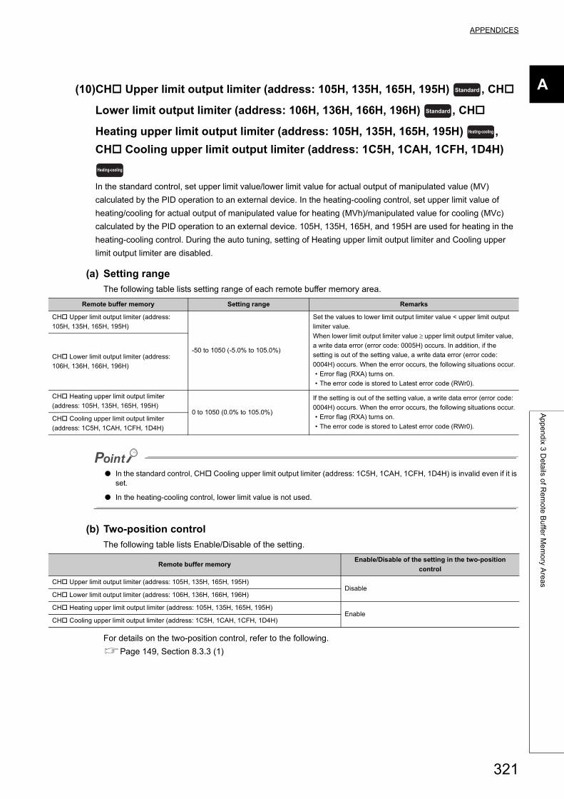
APPENDICES
A
Ap
pe
nd
ix 3 D
eta
ils of R
em
ote
Bu
ffer M
em
ory A
rea
s
(10)CH Upper limit output limiter (address: 105H, 135H, 165H, 195H) , CH
Lower limit output limiter (address: 106H, 136H, 166H, 196H) , CH
Heating upper limit output limiter (address: 105H, 135H, 165H, 195H) ,
CH Cooling upper limit output limiter (address: 1C5H, 1CAH, 1CFH, 1D4H)
In the standard control, set upper limit value/lower limit value for actual output of manipulated value (MV)
calculated by the PID operation to an external device. In the heating-cooling control, set upper limit value of
heating/cooling for actual output of manipulated value for heating (MVh)/manipulated value for cooling (MVc)
calculated by the PID operation to an external device. 105H, 135H, 165H, and 195H are used for heating in the
heating-cooling control. During the auto tuning, setting of Heating upper limit output limiter and Cooling upper
limit output limiter are disabled.
(a) Setting range
The following table lists setting range of each remote buffer memory area.
● In the standard control, CH Cooling upper limit output limiter (address: 1C5H, 1CAH, 1CFH, 1D4H) is invalid even if it is set.
● In the heating-cooling control, lower limit value is not used.
(b) Two-position control
The following table lists Enable/Disable of the setting.
For details on the two-position control, refer to the following.
Page 149, Section 8.3.3 (1)
Remote buffer memory Setting range Remarks
CH Upper limit output limiter (address:
105H, 135H, 165H, 195H)
-50 to 1050 (-5.0% to 105.0%)
Set the values to lower limit output limiter value < upper limit output
limiter value.
When lower limit output limiter value upper limit output limiter value,
a write data error (error code: 0005H) occurs. In addition, if the
setting is out of the setting value, a write data error (error code:
0004H) occurs. When the error occurs, the following situations occur.
• Error flag (RXA) turns on.
• The error code is stored to Latest error code (RWr0).
CH Lower limit output limiter (address:
106H, 136H, 166H, 196H)
CH Heating upper limit output limiter
(address: 105H, 135H, 165H, 195H)0 to 1050 (0.0% to 105.0%)
If the setting is out of the setting value, a write data error (error code:
0004H) occurs. When the error occurs, the following situations occur.
• Error flag (RXA) turns on.
• The error code is stored to Latest error code (RWr0).CH Cooling upper limit output limiter
(address: 1C5H, 1CAH, 1CFH, 1D4H)
Remote buffer memoryEnable/Disable of the setting in the two-position
control
CH Upper limit output limiter (address: 105H, 135H, 165H, 195H)Disable
CH Lower limit output limiter (address: 106H, 136H, 166H, 196H)
CH Heating upper limit output limiter (address: 105H, 135H, 165H, 195H)Enable
CH Cooling upper limit output limiter (address: 1C5H, 1CAH, 1CFH, 1D4H)
Standard
Standard
Heating-cooling
Heating-cooling
321
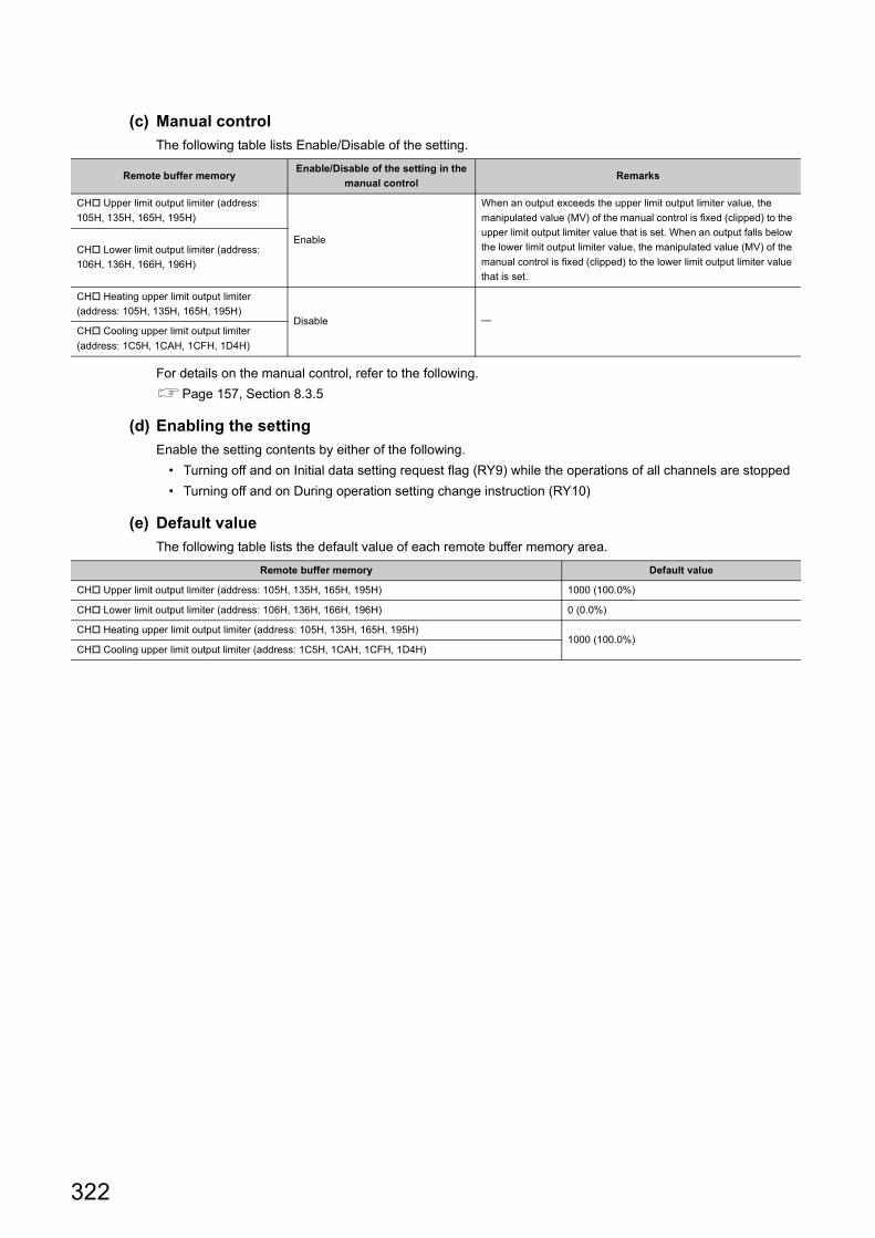
(c) Manual control
The following table lists Enable/Disable of the setting.
For details on the manual control, refer to the following.
Page 157, Section 8.3.5
(d) Enabling the setting
Enable the setting contents by either of the following.
• Turning off and on Initial data setting request flag (RY9) while the operations of all channels are stopped
• Turning off and on During operation setting change instruction (RY10)
(e) Default value
The following table lists the default value of each remote buffer memory area.
Remote buffer memoryEnable/Disable of the setting in the
manual controlRemarks
CH Upper limit output limiter (address:
105H, 135H, 165H, 195H)
Enable
When an output exceeds the upper limit output limiter value, the
manipulated value (MV) of the manual control is fixed (clipped) to the
upper limit output limiter value that is set. When an output falls below
the lower limit output limiter value, the manipulated value (MV) of the
manual control is fixed (clipped) to the lower limit output limiter value
that is set.
CH Lower limit output limiter (address:
106H, 136H, 166H, 196H)
CH Heating upper limit output limiter
(address: 105H, 135H, 165H, 195H)Disable
CH Cooling upper limit output limiter
(address: 1C5H, 1CAH, 1CFH, 1D4H)
Remote buffer memory Default value
CH Upper limit output limiter (address: 105H, 135H, 165H, 195H) 1000 (100.0%)
CH Lower limit output limiter (address: 106H, 136H, 166H, 196H) 0 (0.0%)
CH Heating upper limit output limiter (address: 105H, 135H, 165H, 195H)1000 (100.0%)
CH Cooling upper limit output limiter (address: 1C5H, 1CAH, 1CFH, 1D4H)
322
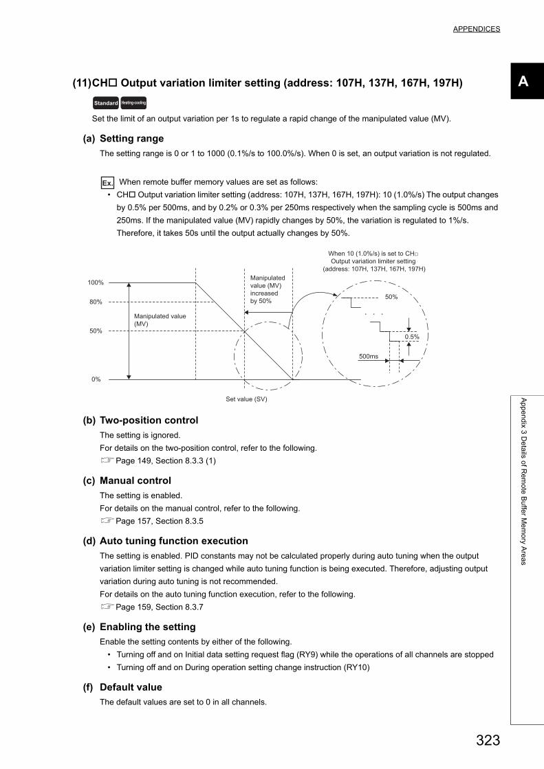
APPENDICES
A
Ap
pe
nd
ix 3 D
eta
ils of R
em
ote
Bu
ffer M
em
ory A
rea
s
(11)CH Output variation limiter setting (address: 107H, 137H, 167H, 197H)
Set the limit of an output variation per 1s to regulate a rapid change of the manipulated value (MV).
(a) Setting range
The setting range is 0 or 1 to 1000 (0.1%/s to 100.0%/s). When 0 is set, an output variation is not regulated.
Ex. When remote buffer memory values are set as follows:
• CH Output variation limiter setting (address: 107H, 137H, 167H, 197H): 10 (1.0%/s) The output changes
by 0.5% per 500ms, and by 0.2% or 0.3% per 250ms respectively when the sampling cycle is 500ms and
250ms. If the manipulated value (MV) rapidly changes by 50%, the variation is regulated to 1%/s.
Therefore, it takes 50s until the output actually changes by 50%.
(b) Two-position control
The setting is ignored.
For details on the two-position control, refer to the following.
Page 149, Section 8.3.3 (1)
(c) Manual control
The setting is enabled.
For details on the manual control, refer to the following.
Page 157, Section 8.3.5
(d) Auto tuning function execution
The setting is enabled. PID constants may not be calculated properly during auto tuning when the output
variation limiter setting is changed while auto tuning function is being executed. Therefore, adjusting output
variation during auto tuning is not recommended.
For details on the auto tuning function execution, refer to the following.
Page 159, Section 8.3.7
(e) Enabling the setting
Enable the setting contents by either of the following.
• Turning off and on Initial data setting request flag (RY9) while the operations of all channels are stopped
• Turning off and on During operation setting change instruction (RY10)
(f) Default value
The default values are set to 0 in all channels.
Standard Heating-cooling
100%
50%
0%
Set value (SV)
80%
500ms
0.5%
50%
Manipulated value (MV)
Manipulated value (MV) increased by 50%
When 10 (1.0%/s) is set to CH□ Output variation limiter setting
(address: 107H, 137H, 167H, 197H)
323
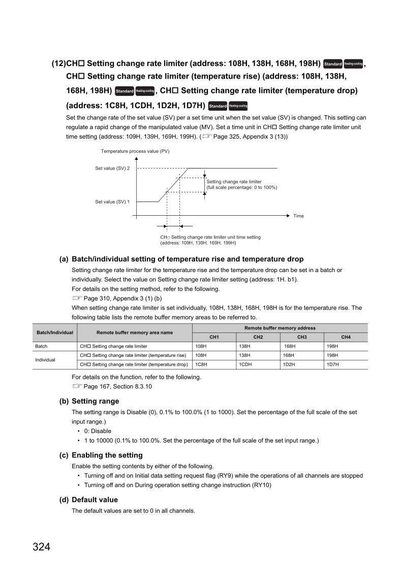
(12)CH Setting change rate limiter (address: 108H, 138H, 168H, 198H) ,
CH Setting change rate limiter (temperature rise) (address: 108H, 138H,
168H, 198H) , CH Setting change rate limiter (temperature drop)
(address: 1C8H, 1CDH, 1D2H, 1D7H)
Set the change rate of the set value (SV) per a set time unit when the set value (SV) is changed. This setting can
regulate a rapid change of the manipulated value (MV). Set a time unit in CH Setting change rate limiter unit
time setting (address: 109H, 139H, 169H, 199H). (Page 325, Appendix 3 (13))
(a) Batch/individual setting of temperature rise and temperature drop
Setting change rate limiter for the temperature rise and the temperature drop can be set in a batch or
individually. Select the value on Setting change rate limiter setting (address: 1H. b1).
For details on the setting method, refer to the following.
Page 310, Appendix 3 (1) (b)
When setting change rate limiter is set individually, 108H, 138H, 168H, 198H is for the temperature rise. The
following table lists the remote buffer memory areas to be referred to.
For details on the function, refer to the following.
Page 167, Section 8.3.10
(b) Setting range
The setting range is Disable (0), 0.1% to 100.0% (1 to 1000). Set the percentage of the full scale of the set
input range.)
• 0: Disable
• 1 to 10000 (0.1% to 100.0%. Set the percentage of the full scale of the set input range.)
(c) Enabling the setting
Enable the setting contents by either of the following.
• Turning off and on Initial data setting request flag (RY9) while the operations of all channels are stopped
• Turning off and on During operation setting change instruction (RY10)
(d) Default value
The default values are set to 0 in all channels.
Batch/Individual Remote buffer memory area nameRemote buffer memory address
CH1 CH2 CH3 CH4
Batch CH Setting change rate limiter 108H 138H 168H 198H
IndividualCH Setting change rate limiter (temperature rise) 108H 138H 168H 198H
CH Setting change rate limiter (temperature drop) 1C8H 1CDH 1D2H 1D7H
Standard Heating-cooling
Standard Heating-cooling
Standard Heating-cooling
Time
Temperature process value (PV)
Setting change rate limiter(full scale percentage: 0 to 100%)
Set value (SV) 2
Set value (SV) 1
CH□ Setting change rate limiter unit time setting (address: 109H, 139H, 169H, 199H)
324
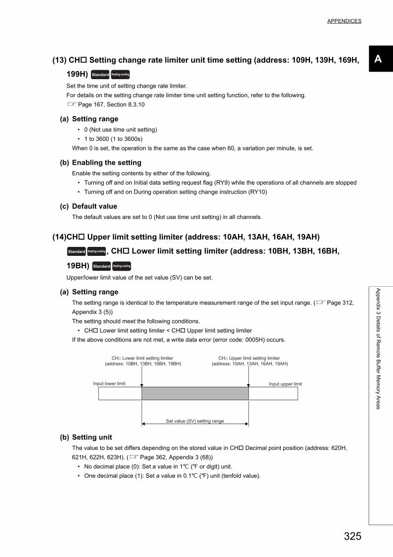
APPENDICES
A
Ap
pe
nd
ix 3 D
eta
ils of R
em
ote
Bu
ffer M
em
ory A
rea
s
(13) CH Setting change rate limiter unit time setting (address: 109H, 139H, 169H,
199H)
Set the time unit of setting change rate limiter.
For details on the setting change rate limiter time unit setting function, refer to the following.
Page 167, Section 8.3.10
(a) Setting range
• 0 (Not use time unit setting)
• 1 to 3600 (1 to 3600s)
When 0 is set, the operation is the same as the case when 60, a variation per minute, is set.
(b) Enabling the setting
Enable the setting contents by either of the following.
• Turning off and on Initial data setting request flag (RY9) while the operations of all channels are stopped
• Turning off and on During operation setting change instruction (RY10)
(c) Default value
The default values are set to 0 (Not use time unit setting) in all channels.
(14)CH Upper limit setting limiter (address: 10AH, 13AH, 16AH, 19AH)
, CH Lower limit setting limiter (address: 10BH, 13BH, 16BH,
19BH)
Upper/lower limit value of the set value (SV) can be set.
(a) Setting range
The setting range is identical to the temperature measurement range of the set input range. (Page 312,
Appendix 3 (5))
The setting should meet the following conditions.
• CH Lower limit setting limiter < CH Upper limit setting limiter
If the above conditions are not met, a write data error (error code: 0005H) occurs.
(b) Setting unit
The value to be set differs depending on the stored value in CH Decimal point position (address: 620H,
621H, 622H, 623H). (Page 362, Appendix 3 (68))
• No decimal place (0): Set a value in 1 ( or digit) unit.
• One decimal place (1): Set a value in 0.1 () unit (tenfold value).
Standard Heating-cooling
Standard Heating-cooling
Standard Heating-cooling
Input upper limit
Set value (SV) setting range
Input lower limit
CH□ Lower limit setting limiter (address: 10BH, 13BH, 16BH, 19BH)
CH□ Upper limit setting limiter (address: 10AH, 13AH, 16AH, 19AH)
325
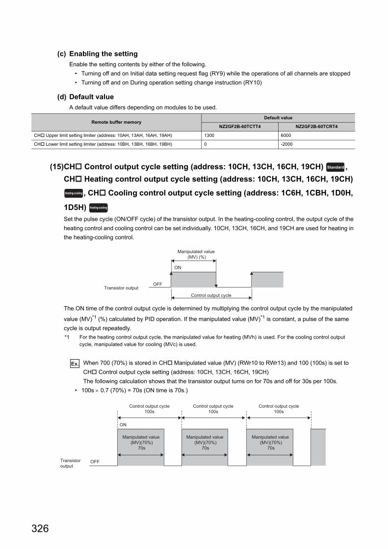
(c) Enabling the setting
Enable the setting contents by either of the following.
• Turning off and on Initial data setting request flag (RY9) while the operations of all channels are stopped
• Turning off and on During operation setting change instruction (RY10)
(d) Default value
A default value differs depending on modules to be used.
(15)CH Control output cycle setting (address: 10CH, 13CH, 16CH, 19CH) ,
CH Heating control output cycle setting (address: 10CH, 13CH, 16CH, 19CH)
, CH Cooling control output cycle setting (address: 1C6H, 1CBH, 1D0H,
1D5H)
Set the pulse cycle (ON/OFF cycle) of the transistor output. In the heating-cooling control, the output cycle of the
heating control and cooling control can be set individually. 10CH, 13CH, 16CH, and 19CH are used for heating in
the heating-cooling control.
The ON time of the control output cycle is determined by multiplying the control output cycle by the manipulated
value (MV)*1 (%) calculated by PID operation. If the manipulated value (MV)*1 is constant, a pulse of the same
cycle is output repeatedly.
*1 For the heating control output cycle, the manipulated value for heating (MVh) is used. For the cooling control output cycle, manipulated value for cooling (MVc) is used.
Ex. When 700 (70%) is stored in CH Manipulated value (MV) (RWr10 to RWr13) and 100 (100s) is set to
CH Control output cycle setting (address: 10CH, 13CH, 16CH, 19CH)
The following calculation shows that the transistor output turns on for 70s and off for 30s per 100s.
• 100s 0.7 (70%) = 70s (ON time is 70s.)
Remote buffer memoryDefault value
NZ2GF2B-60TCTT4 NZ2GF2B-60TCRT4
CH Upper limit setting limiter (address: 10AH, 13AH, 16AH, 19AH) 1300 6000
CH Lower limit setting limiter (address: 10BH, 13BH, 16BH, 19BH) 0 -2000
Standard
Heating-cooling
Heating-cooling
Control output cycle
ON
Manipulated value (MV) (%)
OFFTransistor output
ON
OFF
Control output cycle100s
Manipulated value (MV)(70%)
70s
Control output cycle100s
Manipulated value (MV)(70%)
70s
Control output cycle100s
Manipulated value (MV)(70%)
70s
Transistor output
326
APPENDICES
A
Ap
pe
nd
ix 3 D
eta
ils of R
em
ote
Bu
ffer M
em
ory A
rea
s
(a) Setting range
• When Control output cycle unit selection setting (address: 1H. b2) is set to the cycle of 1s: 1 to 100 (1s to
100s)
• When Control output cycle unit selection setting (address: 1H. b2) is set to the cycle of 0.1s: 5 to 1000
(0.5s to 100.0s)
For details on the control output cycle unit selection setting function, refer to the following.
Page 158, Section 8.3.6
(b) Two-position control
The setting is ignored.
For details on the two-position control, refer to the following.
Page 149, Section 8.3.3 (1)
(c) Enabling the setting
Enable the setting contents by either of the following.
• Turning off and on Initial data setting request flag (RY9) while the operations of all channels are stopped
• Turning off and on During operation setting change instruction (RY10)
(d) Default value
• When Control output cycle unit selection setting (address: 1H. b2) is set to the cycle of 1s: 30 (30s)
• When Control output cycle unit selection setting (address: 1H. b2) is set to the cycle of 0.1s: 300 (30.0s)
327
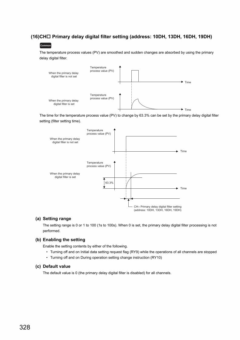
(16)CH Primary delay digital filter setting (address: 10DH, 13DH, 16DH, 19DH)
The temperature process values (PV) are smoothed and sudden changes are absorbed by using the primary
delay digital filter.
The time for the temperature process value (PV) to change by 63.3% can be set by the primary delay digital filter
setting (filter setting time).
(a) Setting range
The setting range is 0 or 1 to 100 (1s to 100s). When 0 is set, the primary delay digital filter processing is not
performed.
(b) Enabling the setting
Enable the setting contents by either of the following.
• Turning off and on Initial data setting request flag (RY9) while the operations of all channels are stopped
• Turning off and on During operation setting change instruction (RY10)
(c) Default value
The default value is 0 (the primary delay digital filter is disabled) for all channels.
Common
Time
Time
Temperature process value (PV)
Temperature process value (PV)
When the primary delay digital filter is not set
When the primary delay digital filter is set
Temperature process value (PV)
Time
Time
Temperature process value (PV)
63.3%
When the primary delay digital filter is not set
When the primary delay digital filter is set
CH□ Primary delay digital filter setting (address: 10DH, 13DH, 16DH, 19DH)
328
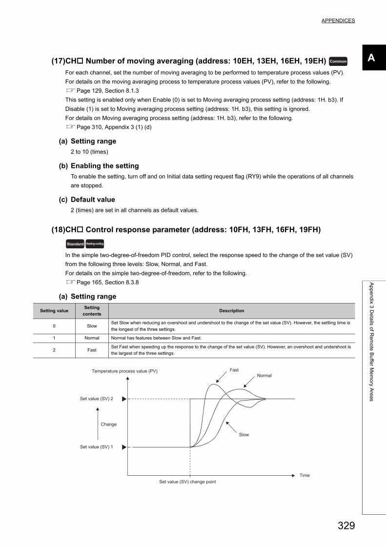
APPENDICES
A
Ap
pe
nd
ix 3 D
eta
ils of R
em
ote
Bu
ffer M
em
ory A
rea
s
(17)CH Number of moving averaging (address: 10EH, 13EH, 16EH, 19EH)
For each channel, set the number of moving averaging to be performed to temperature process values (PV).
For details on the moving averaging process to temperature process values (PV), refer to the following.
Page 129, Section 8.1.3
This setting is enabled only when Enable (0) is set to Moving averaging process setting (address: 1H. b3). If
Disable (1) is set to Moving averaging process setting (address: 1H. b3), this setting is ignored.
For details on Moving averaging process setting (address: 1H. b3), refer to the following.
Page 310, Appendix 3 (1) (d)
(a) Setting range
2 to 10 (times)
(b) Enabling the setting
To enable the setting, turn off and on Initial data setting request flag (RY9) while the operations of all channels
are stopped.
(c) Default value
2 (times) are set in all channels as default values.
(18)CH Control response parameter (address: 10FH, 13FH, 16FH, 19FH)
In the simple two-degree-of-freedom PID control, select the response speed to the change of the set value (SV)
from the following three levels: Slow, Normal, and Fast.
For details on the simple two-degree-of-freedom, refer to the following.
Page 165, Section 8.3.8
(a) Setting range
Setting valueSetting
contentsDescription
0 SlowSet Slow when reducing an overshoot and undershoot to the change of the set value (SV). However, the settling time is
the longest of the three settings.
1 Normal Normal has features between Slow and Fast.
2 FastSet Fast when speeding up the response to the change of the set value (SV). However, an overshoot and undershoot is
the largest of the three settings.
Common
Standard Heating-cooling
Time
Temperature process value (PV)
Set value (SV) 2
Set value (SV) 1
Change
Set value (SV) change point
FastNormal
Slow
329
(b) Enabling the setting
Enable the setting contents by either of the following.
• Turning off and on Initial data setting request flag (RY9) while the operations of all channels are stopped
• Turning off and on During operation setting change instruction (RY10)
(c) Default value
The default values are set to Slow (0) in all channels.
(19)CH Derivative action selection (address: 110H, 140H, 170H, 1A0H)
Select the type of derivative action. Dynamic performance can be improved by selecting the suitable derivative
action for the fixed value action and the ramp action. For details on the derivative action selection function, refer
to the following.
Page 166, Section 8.3.9
(a) Setting range
• 0: Measured value derivation
• 1: Deviation derivation
(b) Enabling the setting
To enable the setting, turn off and on Initial data setting request flag (RY9) while the operations of all channels
are stopped.
(c) Default value
All channels are set to Measured value derivation (0).
Standard Heating-cooling
330
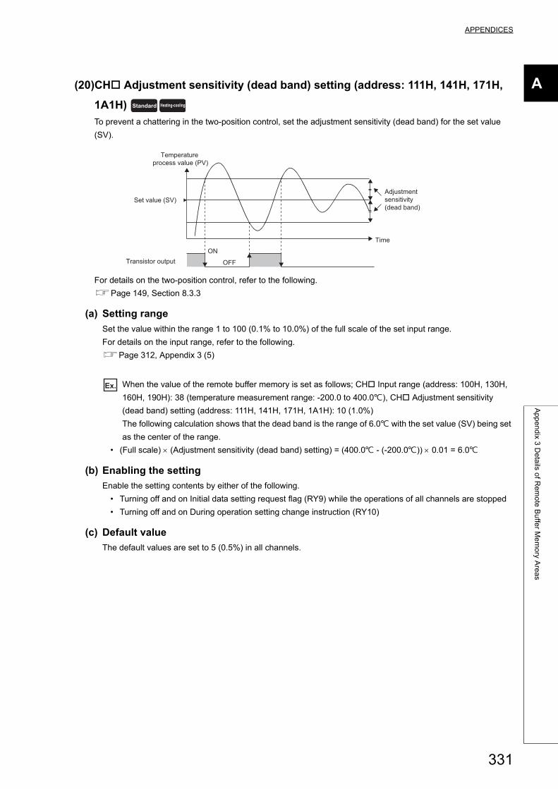
APPENDICES
A
Ap
pe
nd
ix 3 D
eta
ils of R
em
ote
Bu
ffer M
em
ory A
rea
s
(20)CH Adjustment sensitivity (dead band) setting (address: 111H, 141H, 171H,
1A1H)
To prevent a chattering in the two-position control, set the adjustment sensitivity (dead band) for the set value
(SV).
For details on the two-position control, refer to the following.
Page 149, Section 8.3.3
(a) Setting range
Set the value within the range 1 to 100 (0.1% to 10.0%) of the full scale of the set input range.
For details on the input range, refer to the following.
Page 312, Appendix 3 (5)
Ex. When the value of the remote buffer memory is set as follows; CH Input range (address: 100H, 130H,
160H, 190H): 38 (temperature measurement range: -200.0 to 400.0), CH Adjustment sensitivity
(dead band) setting (address: 111H, 141H, 171H, 1A1H): 10 (1.0%)
The following calculation shows that the dead band is the range of 6.0 with the set value (SV) being set
as the center of the range.
• (Full scale) (Adjustment sensitivity (dead band) setting) = (400.0 - (-200.0)) 0.01 = 6.0
(b) Enabling the setting
Enable the setting contents by either of the following.
• Turning off and on Initial data setting request flag (RY9) while the operations of all channels are stopped
• Turning off and on During operation setting change instruction (RY10)
(c) Default value
The default values are set to 5 (0.5%) in all channels.
Standard Heating-cooling
ON
OFF
Temperature process value (PV)
Set value (SV)
Transistor output
Time
Adjustment sensitivity (dead band)
331
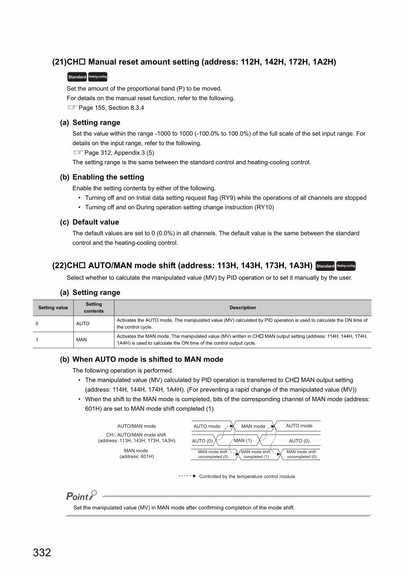
(21)CH Manual reset amount setting (address: 112H, 142H, 172H, 1A2H)
Set the amount of the proportional band (P) to be moved.
For details on the manual reset function, refer to the following.
Page 155, Section 8.3.4
(a) Setting range
Set the value within the range -1000 to 1000 (-100.0% to 100.0%) of the full scale of the set input range. For
details on the input range, refer to the following.
Page 312, Appendix 3 (5)
The setting range is the same between the standard control and heating-cooling control.
(b) Enabling the setting
Enable the setting contents by either of the following.
• Turning off and on Initial data setting request flag (RY9) while the operations of all channels are stopped
• Turning off and on During operation setting change instruction (RY10)
(c) Default value
The default values are set to 0 (0.0%) in all channels. The default value is the same between the standard
control and the heating-cooling control.
(22)CH AUTO/MAN mode shift (address: 113H, 143H, 173H, 1A3H)
Select whether to calculate the manipulated value (MV) by PID operation or to set it manually by the user.
(a) Setting range
(b) When AUTO mode is shifted to MAN mode
The following operation is performed.
• The manipulated value (MV) calculated by PID operation is transferred to CH MAN output setting
(address: 114H, 144H, 174H, 1A4H). (For preventing a rapid change of the manipulated value (MV))
• When the shift to the MAN mode is completed, bits of the corresponding channel of MAN mode (address:
601H) are set to MAN mode shift completed (1).
Set the manipulated value (MV) in MAN mode after confirming completion of the mode shift.
Setting valueSetting
contentsDescription
0 AUTOActivates the AUTO mode. The manipulated value (MV) calculated by PID operation is used to calculate the ON time of
the control cycle.
1 MANActivates the MAN mode. The manipulated value (MV) written in CH MAN output setting (address: 114H, 144H, 174H,
1A4H) is used to calculate the ON time of the control output cycle.
Standard Heating-cooling
Standard Heating-cooling
AUTO/MAN mode AUTO mode MAN mode
MAN mode shift uncompleted (0)
MAN mode shift uncompleted (0)
AUTO (0) AUTO (0)MAN (1)
MAN mode shift completed (1)
AUTO mode
CH□ AUTO/MAN mode shift (address: 113H, 143H, 173H, 1A3H)
MAN mode (address: 601H)
Controlled by the temperature control module
332
APPENDICES
A
Ap
pe
nd
ix 3 D
eta
ils of R
em
ote
Bu
ffer M
em
ory A
rea
s
(c) When performing auto tuning
Set to AUTO (0). If MAN (1) is set, the auto tuning is not performed.
(d) Enabling the setting
Enable the setting contents by either of the following.
• Turning off and on Initial data setting request flag (RY9) while the operations of all channels are stopped
• Turning off and on During operation setting change instruction (RY10)
(e) Default value
The default values are set to AUTO (0) in all channels.
(23)CH MAN output setting (address: 114H, 144H, 174H, 1A4H)
This remote buffer memory area is used for setting the manipulated value (MV) in the MAN mode.
(a) How to shift the mode
Shift the mode by the following remote buffer memory area.
• CH AUTO/MAN mode shift (address: 113H, 143H, 173H, 1A3H) (Page 332, Appendix 3 (22))
(b) Setting range
The setting range is different between the standard control and the heating-cooling control.
• In standard control: -50 to 1050 (-5.0 to 105.0%)
• In heating-cooling control: -1050 to 1050 (-105.0 to 105.0%)
(c) Enabling the setting
Enable the setting contents by either of the following.
• Turning off and on Initial data setting request flag (RY9) while the operations of all channels are stopped
• Turning off and on During operation setting change instruction (RY10)
Make sure the corresponding bit of MAN mode (address: 601H) has been set to 1 (ON) and write a value in the
MAN output setting. A value that is written when the corresponding bit of MAN mode (address: 601H) is 0
(OFF) will be replaced with the manipulated value (MV) calculated by PID operation by the system.
(d) Default value
The default values are set to 0 (0.0%) in all channels.
Standard Heating-cooling
333
(24)CH Forward/reverse action setting (address: 115H, 145H, 175H, 1A5H)
Select whether to use channels in the forward action or reverse action.
Select the forward action for the cooling control. Select the reverse action for the heating control.
For details on the forward/reverse action selection function, refer to the following.
Page 211, Section 8.3.18
(a) Setting range
• 0: Forward action
• 0: Reverse action
(b) Enabling the setting
Enable the setting contents by either of the following.
• Turning off and on Initial data setting request flag (RY9) while the operations of all channels are stopped
• Turning off and on During operation setting change instruction (RY10)
(c) Default value
The default values are set to Reverse action (1) in all channels.
(25)CH Loop disconnection detection judgment time (address: 116H, 146H,
176H, 1A6H)
Errors such as disconnection of resistors, malfunction of an external controller, and errors of the control system
due to troubles such as disconnection of the sensor can be detected by the loop disconnection detection function.
If temperature does not change by 2 () or more in the Loop disconnection detection judgment time, a loop
disconnection is detected.
For details on the loop disconnection detection function, refer to the following.
Page 212, Section 8.3.19
(a) Setting range
The setting range is 0 to 7200 (s).
Set a value that exceeds the time in which temperature changes by 2 ().
(b) When performing auto tuning
For this setting, the twice value of that of CH Integral time (I) setting (address: 103H, 133H, 163H, 193H) is
automatically set. (Page 320, Appendix 3 (8)) However, when this setting is set to 0 (s) at the start of the
auto tuning, Loop disconnection detection judgment time is not stored.
(c) Enabling the setting
Enable the setting contents by either of the following.
• Turning off and on Initial data setting request flag (RY9) while the operations of all channels are stopped
• Turning off and on During operation setting change instruction (RY10)
(d) Default value
The default values are set to 480 (s) in all channels.
Standard
Standard
334

APPENDICES
A
Ap
pe
nd
ix 3 D
eta
ils of R
em
ote
Bu
ffer M
em
ory A
rea
s
(26)CH Loop disconnection detection dead band (address: 117H, 147H, 177H,
1A7H)
To prevent an error alert of loop disconnection detection, set a non-alert band (temperature band in which the
loop disconnection is not detected) where the set value (SV) is at the center.
For details on the loop disconnection detection function, refer to the following.
Page 212, Section 8.3.19
(a) Setting range
The setting range is 0 to full scale.
Ex. When the value of the remote buffer memory is set as follows; CH Input range (address: 100H, 130H,
160H, 190H): 38 (Resolution: 0.1), CH Loop disconnection detection dead band (address: 117H, 147H,
177H, 1A7H): 50
The following calculation shows that within the range of the set value (SV) 5.0, Loop disconnection is
not detected.
• (Loop disconnection detection dead band set value) (resolution) = 50 0.1 = 5.0
(b) Setting unit
The value to be set differs depending on the stored value in CH Decimal point position (address: 620H,
621H, 622H, 623H). (Page 362, Appendix 3 (68))
• No decimal place (0): Set a value in 1 ( or digit) unit.
• One decimal place (1): Set a value in 0.1 () unit (tenfold value).
(c) Enabling the setting
Enable the setting contents by either of the following.
• Turning off and on Initial data setting request flag (RY9) while the operations of all channels are stopped
• Turning off and on During operation setting change instruction (RY10)
(d) Default value
The default values are set to 0 in all channels.
Standard
Time
Temperature process value (PV)
Set value (SV) Non-alert area
CH□ Loop disconnection detection dead band (address: 117H, 147H, 177H, 1A7H)(The area is equally set both above and below the set value (SV).)
335
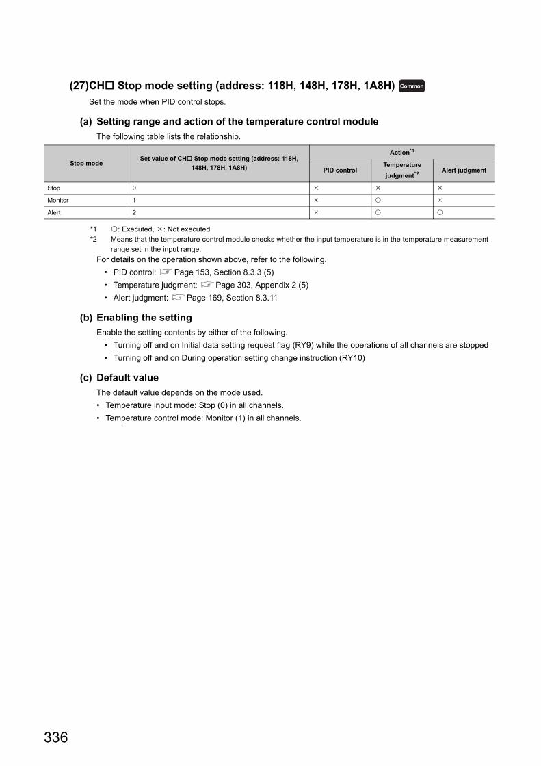
(27)CH Stop mode setting (address: 118H, 148H, 178H, 1A8H)
Set the mode when PID control stops.
(a) Setting range and action of the temperature control module
The following table lists the relationship.
*1 : Executed, : Not executed*2 Means that the temperature control module checks whether the input temperature is in the temperature measurement
range set in the input range.
For details on the operation shown above, refer to the following.
• PID control: Page 153, Section 8.3.3 (5)
• Temperature judgment: Page 303, Appendix 2 (5)
• Alert judgment: Page 169, Section 8.3.11
(b) Enabling the setting
Enable the setting contents by either of the following.
• Turning off and on Initial data setting request flag (RY9) while the operations of all channels are stopped
• Turning off and on During operation setting change instruction (RY10)
(c) Default value
The default value depends on the mode used.
• Temperature input mode: Stop (0) in all channels.
• Temperature control mode: Monitor (1) in all channels.
Stop modeSet value of CH Stop mode setting (address: 118H,
148H, 178H, 1A8H)
Action*1
PID controlTemperature
judgment*2Alert judgment
Stop 0
Monitor 1
Alert 2
Common
336

APPENDICES
A
Ap
pe
nd
ix 3 D
eta
ils of R
em
ote
Bu
ffer M
em
ory A
rea
s
(28)CH Automatic backup setting after auto tuning of PID constants (address:
119H, 149H, 179H, 1A9H)
The set value to be stored in the remote buffer memory is automatically backed up to a non-volatile memory by
using this function. By reading the set value that is backed up, when the power is turned off and on, another auto
tuning can be omitted.
For details on the auto tuning function, refer to the following.
Page 159, Section 8.3.7
(a) Remote buffer memory areas whose set value is backed up to a non-volatile
memory
The following table lists the remote buffer memory areas whose setting is backed up.
(b) Setting range
• 0: Disable
• 1: Enable
(c) Enabling the setting
Enable the setting contents by either of the following.
• Turning off and on Initial data setting request flag (RY9) while the operations of all channels are stopped
• Turning off and on During operation setting change instruction (RY10)
(d) Default value
The default values are set to Disable (0) in all channels.
(e) Precautions
When Enable (1) is set, do not perform the following operations. An incorrect value may be stored in the non-
volatile memory.
• Changing the set value of the remote buffer memory
• Memory back up (Page 136, Section 8.1.7)
• Default setting registration (Page 297, Appendix 1.2 (6))
• Change to Disable (0) during the auto tuning
Remote buffer memory area nameRemote buffer memory address
ReferenceCH1 CH2 CH3 CH4
CH Proportional band (P) setting 102H 132H 162H 192H
Page 318, Appendix 3 (7)CH Heating proportional band (Ph) setting 102H 132H 162H 192H
CH Cooling proportional band (Pc) setting 1C4H 1C9H 1CEH 1D3H
CH Integral time (I) setting 103H 133H 163H 193H Page 320, Appendix 3 (8)
CH Derivative time (D) setting 104H 134H 164H 194H Page 320, Appendix 3 (9)
CH Loop disconnection detection judgment time 116H 146H 176H 1A6H Page 334, Appendix 3 (25)
Standard Heating-cooling
337

(29)CH Temperature conversion setting (address: 1C1H to 1C3H)
In the heating-cooling control (normal mode) or the mix control (normal mode), only the temperature
measurement can be performed using temperature input terminals of unused channels.
The following table lists the settable remote buffer memory addresses for each control mode selection.
When the combination of the control mode and the remote buffer memory address is not the setting target in the
above list, the combination is invalid even if it is set.
(a) Setting range
• 0: Not use
• 1: Use
(b) Enabling the setting
Enable the setting contents by either of the following.
• Turning off and on Initial data setting request flag (RY9) while the operations of all channels are stopped
• Turning off and on During operation setting change instruction (RY10)
(c) Default value
The default values are set to Not use (0) in all channels.
● When CH Temperature conversion setting (address: 1C1H to 1C3H) is set to Use (1), the temperature conversion starts. This function does not turn on CH2 to CH4 Operation monitor (RX12 to RX14).
● When the following control mode is selected, this setting is invalid.• Standard control• Heating-cooling control (expanded mode)• Mix control (expanded mode)
Channel
Control mode
Standard controlHeating-cooling control
(normal mode)
Heating-cooling control
(expanded mode)
Mix control (normal
mode)
Mix control (expanded
mode)
CH1
CH2 1C1H
CH3 1C2H
CH4 1C3H
Heating-cooling
338
APPENDICES
A
Ap
pe
nd
ix 3 D
eta
ils of R
em
ote
Bu
ffer M
em
ory A
rea
s
(30)CH Overlap/dead band setting (address: 1C7H, 1CCH, 1D1H, 1D6H)
Configure the overlap/dead band setting.
For details on the overlap/dead band function, refer to the following.
Page 219, Section 8.3.23
(a) Setting range
Set the value within the following ranges for the full scale of the set input range. (Page 312, Appendix 3
(5))
• -100 to -1 (-10.0% to -0.1%): Overlap
• 0 (0.0%): None
• 1 to 100 (0.1% to 10.0%): Dead band
(b) Enabling the setting
Enable the setting contents by either of the following.
• Turning off and on Initial data setting request flag (RY9) while the operations of all channels are stopped
• Turning off and on During operation setting change instruction (RY10)
(c) Default value
The default values are set to 0 (0.0%) in all channels.
(31)Alert dead band setting (address: 1E0H)
This setting is for using the alarm function.
For details on the alert function, refer to the following.
Page 169, Section 8.3.11
(a) Setting range
Set the value within the range 0 to 100 (0.0% to 10.0%) of the full scale of the set input range.
For details on the input range, refer to the following.
Page 312, Appendix 3 (5)
Ex. When the value of the remote buffer memory is set as follows; CH Input range (address: 100H, 130H,
160H, 190H): 2 (temperature measurement range: 0 to 1300), Alert dead band setting (address:
1E0H): 5 (0.5%)
The following calculation shows that the dead band is the range of 6.5 with the alert set value being set
as the center of the range.
• (Full scale) (Alert dead band) = (1300 - 0) 0.005 = 6.5
(b) Enabling the setting
Enable the setting contents by either of the following.
• Turning off and on Initial data setting request flag (RY9) while the operations of all channels are stopped
• Turning off and on During operation setting change instruction (RY10)
(c) Default value
The default value is set to 5 (0.5%).
Heating-cooling
Standard Heating-cooling
339
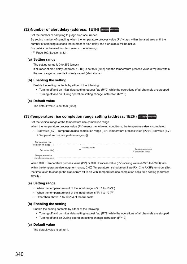
(32)Number of alert delay (address: 1E1H)
Set the number of sampling to judge alert occurrence.
By setting number of sampling, when the temperature process value (PV) stays within the alert area until the
number of sampling exceeds the number of alert delay, the alert status will be active.
For details on the alert function, refer to the following.
Page 169, Section 8.3.11
(a) Setting range
The setting range is 0 to 255 (times).
If Number of alert delay (address: 1E1H) is set to 0 (time) and the temperature process value (PV) falls within
the alert range, an alert is instantly raised (alert status).
(b) Enabling the setting
Enable the setting contents by either of the following.
• Turning off and on Initial data setting request flag (RY9) while the operations of all channels are stopped
• Turning off and on During operation setting change instruction (RY10)
(c) Default value
The default value is set to 0 (time).
(33)Temperature rise completion range setting (address: 1E2H)
Set the vertical range of the temperature rise completion range.
When the temperature process value (PV) meets the following conditions, the temperature rise is completed.
• (Set value (SV) - Temperature rise completion range (-)) Temperature process value (PV) (Set value (SV)
+ Temperature rise completion range (+))
When CH Temperature process value (PV) or CH Process value (PV) scaling value (RWr8 to RWrB) falls
within the temperature rise judgment range, CH Temperature rise judgment flag (RX1C to RX1F) turns on. (Set
the time taken to change the status from off to on with Temperature rise completion soak time setting (address:
1E3H).)
(a) Setting range
• When the temperature unit of the input range is : 1 to 10 ()
• When the temperature unit of the input range is : 1 to 10 ()
• Other than above: 1 to 10 (%) of the full scale
(b) Enabling the setting
Enable the setting contents by either of the following.
• Turning off and on Initial data setting request flag (RY9) while the operations of all channels are stopped
• Turning off and on During operation setting change instruction (RY10)
(c) Default value
The default value is set to 1.
Standard Heating-cooling
Standard Heating-cooling
Temperature rise completion range (+)
Set value (SV)
Temperature rise completion range (-)
Temperature rise judgment range
Setting value
340
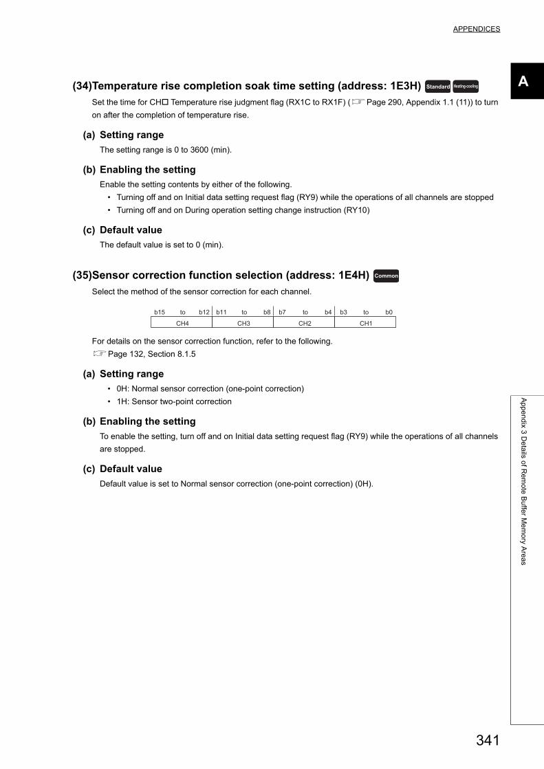
APPENDICES
A
Ap
pe
nd
ix 3 D
eta
ils of R
em
ote
Bu
ffer M
em
ory A
rea
s
(34)Temperature rise completion soak time setting (address: 1E3H)
Set the time for CH Temperature rise judgment flag (RX1C to RX1F) (Page 290, Appendix 1.1 (11)) to turn
on after the completion of temperature rise.
(a) Setting range
The setting range is 0 to 3600 (min).
(b) Enabling the setting
Enable the setting contents by either of the following.
• Turning off and on Initial data setting request flag (RY9) while the operations of all channels are stopped
• Turning off and on During operation setting change instruction (RY10)
(c) Default value
The default value is set to 0 (min).
(35)Sensor correction function selection (address: 1E4H)
Select the method of the sensor correction for each channel.
For details on the sensor correction function, refer to the following.
Page 132, Section 8.1.5
(a) Setting range
• 0H: Normal sensor correction (one-point correction)
• 1H: Sensor two-point correction
(b) Enabling the setting
To enable the setting, turn off and on Initial data setting request flag (RY9) while the operations of all channels
are stopped.
(c) Default value
Default value is set to Normal sensor correction (one-point correction) (0H).
Standard Heating-cooling
Common
b15 b0b8 b7 b4 b3b11b12
CH4 CH3 CH2 CH1
to to to to
341
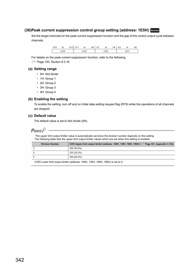
(36)Peak current suppression control group setting (address: 1E5H)
Set the target channels for the peak current suppression function and the gap of the control output cycle between
channels.
For details on the peak current suppression function, refer to the following.
Page 193, Section 8.3.16
(a) Setting range
• 0H: Not divide
• 1H: Group 1
• 2H: Group 2
• 3H: Group 3
• 4H: Group 4
(b) Enabling the setting
To enable the setting, turn off and on Initial data setting request flag (RY9) while the operations of all channels
are stopped.
(c) Default value
The default value is set to Not divide (0H).
The upper limit output limiter value is automatically set since the division number depends on this setting.The following table lists the upper limit output limiter values which are set when this setting is enabled.
CH Lower limit output limiter (address: 106H, 136H, 166H, 196H) is set to 0.
Division Number CH Upper limit output limiter (address: 105H, 135H, 165H, 195H) (Page 321, Appendix 3 (10))
2 500 (50.0%)
3 333 (33.3%)
4 250 (25.0%)
Standard
b15 b0b8 b7 b4 b3b11b12
CH4 CH3 CH2 CH1
to to to to
342
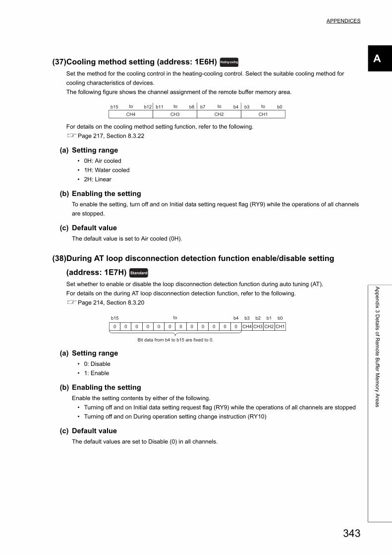
APPENDICES
A
Ap
pe
nd
ix 3 D
eta
ils of R
em
ote
Bu
ffer M
em
ory A
rea
s
(37)Cooling method setting (address: 1E6H)
Set the method for the cooling control in the heating-cooling control. Select the suitable cooling method for
cooling characteristics of devices.
The following figure shows the channel assignment of the remote buffer memory area.
For details on the cooling method setting function, refer to the following.
Page 217, Section 8.3.22
(a) Setting range
• 0H: Air cooled
• 1H: Water cooled
• 2H: Linear
(b) Enabling the setting
To enable the setting, turn off and on Initial data setting request flag (RY9) while the operations of all channels
are stopped.
(c) Default value
The default value is set to Air cooled (0H).
(38)During AT loop disconnection detection function enable/disable setting
(address: 1E7H)
Set whether to enable or disable the loop disconnection detection function during auto tuning (AT).
For details on the during AT loop disconnection detection function, refer to the following.
Page 214, Section 8.3.20
(a) Setting range
• 0: Disable
• 1: Enable
(b) Enabling the setting
Enable the setting contents by either of the following.
• Turning off and on Initial data setting request flag (RY9) while the operations of all channels are stopped
• Turning off and on During operation setting change instruction (RY10)
(c) Default value
The default values are set to Disable (0) in all channels.
Heating-cooling
b15 b0b8 b7 b4 b3b11b12CH4 CH3 CH2 CH1
to to to to
Standard
b15 b3 b2 b1 b0
0 0 0 0 0 0 0 0 0 0 0 0
b4
CH4 CH3 CH2 CH1
Bit data from b4 to b15 are fixed to 0.
to
343
(39)Resolution of the manipulated value for output with another analog module
(address: 1E8H)
Set the resolution of the following remote registers. (Page 305, Appendix 2 (8))
• CH Manipulated value (MV) (RWr10 to RWr13)
• CH Manipulated value for heating (MVh) (RWr10 to RWr13)
• CH Manipulated value for cooling (MVc) (RWr14 to RWr17)
For details, refer to the following.
Page 182, Section 8.3.13 (2)
(a) Setting range
• 0: 0 to 4000
• 1: 0 to 12000
• 2: 0 to 16000
• 3: 0 to 20000
The manipulated value (MV) reflecting the resolution is stored in the following remote registers. (Page 308,
Appendix 2 (10))
• CH Manipulated value (MV) for output with another analog module (RWr18 to RWr1B)
• CH Manipulated value of heating (MVh) for output with another analog module (RWr18 to RWr1B)
• CH Manipulated value of cooling (MVc) for output with another analog module (RWr1C to RWr1F)
(b) Enabling the setting
To enable the setting, turn off and on Initial data setting request flag (RY9) while the operations of all channels
are stopped.
(c) Default value
The default value is set to 0 to 4000 (0).
(40)Cold junction temperature compensation selection (address: 1E9H)
Select the method of the cold junction temperature compensation.
(a) Supported modules
Only NZ2GF2B-60TCTT4 can be used.
(b) Setting range
• 0: Use Standard Terminal Block
• 1: Use prohibited
• 2: Not use cold junction temperature compensation
(c) Enabling the setting
Enable the setting contents by either of the following.
• Turning off and on Initial data setting request flag (RY9) while the operations of all channels are stopped
• Turning off and on During operation setting change instruction (RY10)
(d) Default value
The default value is set to Use Standard Terminal Block (0).
Standard Heating-cooling
Common
344
APPENDICES
A
Ap
pe
nd
ix 3 D
eta
ils of R
em
ote
Bu
ffer M
em
ory A
rea
s
(41)Transistor output monitor ON delay time setting (address: 1EAH)
Set the delay time of the ON delay output flag.
Set this remote buffer memory area to perform the heater disconnection detection with an input module the
system involves.
For ON delay output flag, refer to the following.
Page 293, Appendix 1.1 (16)
For details on the ON delay output function, refer to the following.
Page 183, Section 8.3.14
(a) Setting range
The setting range is 0 or 1 to 50 (10 to 500ms).
When 0 is set, ON delay output flag is not set to 1 (ON).
(b) Enabling the setting
Enable the setting contents by either of the following.
• Turning off and on Initial data setting request flag (RY9) while the operations of all channels are stopped
• Turning off and on During operation setting change instruction (RY10)
(c) Default value
The default value is set to 0.
(42)CH Process value (PV) scaling function enable/disable setting (address:
200H, 203H, 206H, 209H)
Set enable/disable of the temperature process value (PV) scaling function.
For details on the temperature process value (PV) scaling function, refer to the following.
Page 130, Section 8.1.4
(a) Setting range
• 0: Disable
• 1: Enable
(b) Enabling the setting
To enable the setting, turn off and on Initial data setting request flag (RY9) while the operations of all channels
are stopped.
(c) Default value
The default values are set to Disable (0) in all channels.
Standard Heating-cooling
Common
345
(43)CH Process value (PV) scaling lower limit value (address: 201H, 204H, 207H,
20AH) , CH Process value (PV) scaling upper limit value (address:
202H, 205H, 208H, 20BH)
Set the upper limit value/lower limit value of the temperature process value (PV) scaling function.
For details on the temperature process value (PV) scaling function, refer to the following.
Page 130, Section 8.1.4
(a) Setting range
The setting is -32000 to 32000.
(b) Enabling the setting
To enable the setting, turn off and on Initial data setting request flag (RY9) while the operations of all channels
are stopped.
(c) Default value
The default values are set to 0 in all channels.
The setting where the lower limit value is not less than the upper limit value does not cause an error. The temperature process value (PV) is scaled according to the formula of Page 130, Section 8.1.4 (2).
(44)CH Alert 1 mode setting (address: 220H, 228H, 230H, 238H) , CH
Alert 2 mode setting (address: 221H, 229H, 231H, 239H) , CH Alert
3 mode setting (address: 222H, 22AH, 232H, 23AH) , CH Alert 4
mode setting (address: 223H, 22BH, 233H, 23BH)
Set the alert mode of alert 1 to 4.
For details on the alert function, refer to the following.
Page 169, Section 8.3.11
(a) Alert mode and alert set value
Any alert set value can be set in each alert mode of alert 1 to 4 selected in this setting. Set the alert set value 1
to 4 in the following remote buffer memory areas. Alert set values 1 to 4 respectively correspond to alert modes
of alert 1 to 4.
Remote buffer memory area
name
Remote buffer memory addressReference
CH1 CH2 CH3 CH4
CH Alert set value 1 224H 22CH 234H 23CH
Page 348, Appendix 3 (45)CH Alert set value 2 225H 22DH 235H 23DH
CH Alert set value 3 226H 22EH 236H 23EH
CH Alert set value 4 227H 22FH 237H 23FH
Common
Common
Standard Heating-cooling
Standard Heating-cooling
Standard Heating-cooling
Standard Heating-cooling
346
APPENDICES
A
Ap
pe
nd
ix 3 D
eta
ils of R
em
ote
Bu
ffer M
em
ory A
rea
s
(b) Setting range
The following table lists set values and setting ranges which are available for alert set values set in each alert
mode.
(c) Enabling the setting
To enable the setting, turn off and on Initial data setting request flag (RY9) while the operations of all channels
are stopped.
When the set value is out of the range, a write data error (error code: 0004H) occurs, and the temperature
control module operates with the previous set value.
(d) Default value
The default values are set to 0 in all channels.
Setting
valueAlert mode Setting range of alert set value
0 (no alert)
1 Upper limit input alert Within the temperature measurement range of the set input range
(Page 312, Appendix 3 (5))2 Lower limit input alert
3 Upper limit deviation alert(-(full scale)) to full scale
4 Lower limit deviation alert
5 Upper lower limit deviation alert0 to full scale
6 Within-range alert
7 Upper limit input alert with standby Within the temperature measurement range of the set input range
(Page 312, Appendix 3 (5))8 Lower limit input alert with standby
9 Upper limit deviation alert with standby(-(full scale)) to full scale
10 Lower limit deviation alert with standby
11 Upper lower limit deviation alert with standby 0 to full scale
12 Upper limit deviation alert with standby (second time)(-(full scale)) to full scale
13 Lower limit deviation alert with standby (second time)
14 Upper lower limit deviation alert with standby (second time) 0 to full scale
15 Upper limit deviation alert (using the set value (SV))(-(full scale)) to full scale
16 Lower limit deviation alert (using the set value (SV))
17 Upper lower limit deviation alert (using the set value (SV))0 to full scale
18 Within-range alert (using the set value (SV))
19 Upper limit deviation alert with standby (using the set value (SV))(-(full scale)) to full scale
20 Lower limit deviation alert with standby (using the set value (SV))
21Upper lower limit deviation alert with standby (using the set value
(SV))0 to full scale
22Upper limit deviation alert with standby (second time) (using the set
value (SV))(-(full scale)) to full scale
23Lower limit deviation alert with standby (second time) (using the set
value (SV))
24Upper lower limit deviation alert with standby (second time) (using
the set value (SV))0 to full scale
347
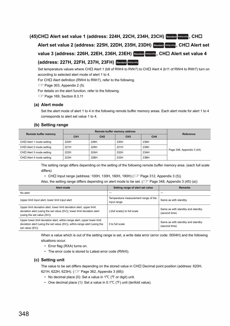
(45)CH Alert set value 1 (address: 224H, 22CH, 234H, 23CH) , CH
Alert set value 2 (address: 225H, 22DH, 235H, 23DH) , CH Alert set
value 3 (address: 226H, 22EH, 236H, 23EH) , CH Alert set value 4
(address: 227H, 22FH, 237H, 23FH)
Set temperature values where CH Alert 1 (b8 of RWr4 to RWr7) to CH Alert 4 (b11 of RWr4 to RWr7) turn on
according to selected alert mode of alert 1 to 4.
For CH Alert definition (RWr4 to RWr7), refer to the following.
Page 303, Appendix 2 (5)
For details on the alert function, refer to the following.
Page 169, Section 8.3.11
(a) Alert mode
Set the alert mode of alert 1 to 4 in the following remote buffer memory areas. Each alert mode for alert 1 to 4
corresponds to alert set value 1 to 4.
(b) Setting range
The setting range differs depending on the setting of the following remote buffer memory area. (each full scale
differs)
• CH Input range (address: 100H, 130H, 160H, 190H) (Page 312, Appendix 3 (5))
Also, the setting range differs depending on alert mode to be set. (Page 348, Appendix 3 (45) (a))
When a value which is out of the setting range is set, a write data error (error code: 0004H) and the following
situations occur.
• Error flag (RXA) turns on.
• The error code is stored to Latest error code (RWr0).
(c) Setting unit
The value to be set differs depending on the stored value in CH Decimal point position (address: 620H,
621H, 622H, 623H). (Page 362, Appendix 3 (68))
• No decimal place (0): Set a value in 1 ( or digit) unit.
• One decimal place (1): Set a value in 0.1 () unit (tenfold value).
Remote buffer memoryRemote buffer memory address
ReferenceCH1 CH2 CH3 CH4
CH Alert 1 mode setting 220H 228H 230H 238H
Page 346, Appendix 3 (44)CH Alert 2 mode setting 221H 229H 231H 239H
CH Alert 3 mode setting 222H 22AH 232H 23AH
CH Alert 4 mode setting 223H 22BH 233H 23BH
Alert mode Setting range of alert set value Remarks
No alert
Upper limit input alert, lower limit input alertTemperature measurement range of the
input rangeSame as with standby
Upper limit deviation alert, lower limit deviation alert, upper limit
deviation alert (using the set value (SV)), lower limit deviation alert
(using the set value (SV))
(-(full scale)) to full scaleSame as with standby and standby
(second time)
Upper lower limit deviation alert, within-range alert, upper lower limit
deviation alert (using the set value (SV)), within-range alert (using the
set value (SV))
0 to full scaleSame as with standby and standby
(second time)
Standard Heating-cooling
Standard Heating-cooling
Standard Heating-cooling
Standard Heating-cooling
348
APPENDICES
A
Ap
pe
nd
ix 3 D
eta
ils of R
em
ote
Bu
ffer M
em
ory A
rea
s
(d) Enabling the setting
Enable the setting contents by either of the following.
• Turning off and on Initial data setting request flag (RY9) while the operations of all channels are stopped
• Turning off and on During operation setting change instruction (RY10)
(e) Default value
The default values are set to 0 in all channels.
(46)CH Process alarm alert output enable/disable setting (address: 250H, 259H,
262H, 26BH)
Set whether to enable or disable alert output of process alarm. For details on the process alarm, refer to the
following.
Page 139, Section 8.2.1 (1)
(a) Setting range
• 0: Enable
• 1: Disable
(b) Enabling the setting
To enable the setting, turn off and on Initial data setting request flag (RY9) while the operations of all channels
are stopped.
(c) Default value
The default values are set to Disable (1) in all channels.
TemperatureInput
349
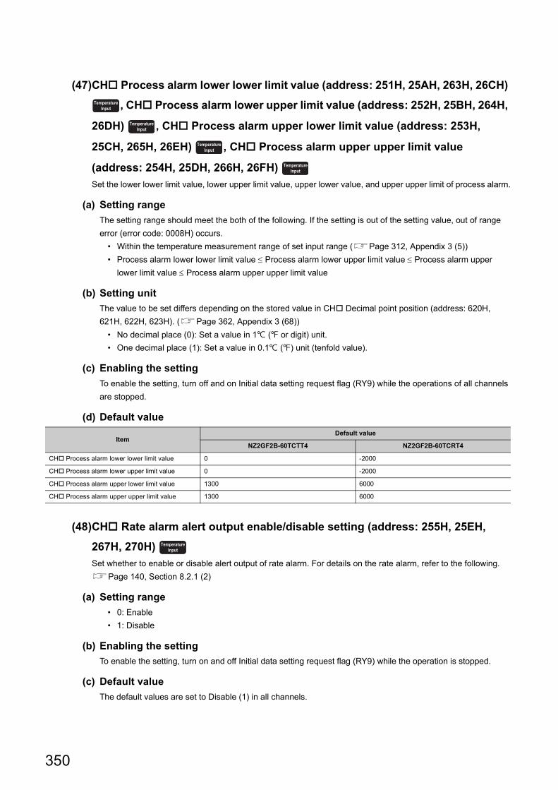
(47)CH Process alarm lower lower limit value (address: 251H, 25AH, 263H, 26CH)
, CH Process alarm lower upper limit value (address: 252H, 25BH, 264H,
26DH) , CH Process alarm upper lower limit value (address: 253H,
25CH, 265H, 26EH) , CH Process alarm upper upper limit value
(address: 254H, 25DH, 266H, 26FH)
Set the lower lower limit value, lower upper limit value, upper lower value, and upper upper limit of process alarm.
(a) Setting range
The setting range should meet the both of the following. If the setting is out of the setting value, out of range
error (error code: 0008H) occurs.
• Within the temperature measurement range of set input range (Page 312, Appendix 3 (5))
• Process alarm lower lower limit value Process alarm lower upper limit value Process alarm upper
lower limit value Process alarm upper upper limit value
(b) Setting unit
The value to be set differs depending on the stored value in CH Decimal point position (address: 620H,
621H, 622H, 623H). (Page 362, Appendix 3 (68))
• No decimal place (0): Set a value in 1 ( or digit) unit.
• One decimal place (1): Set a value in 0.1 () unit (tenfold value).
(c) Enabling the setting
To enable the setting, turn off and on Initial data setting request flag (RY9) while the operations of all channels
are stopped.
(d) Default value
(48)CH Rate alarm alert output enable/disable setting (address: 255H, 25EH,
267H, 270H)
Set whether to enable or disable alert output of rate alarm. For details on the rate alarm, refer to the following.
Page 140, Section 8.2.1 (2)
(a) Setting range
• 0: Enable
• 1: Disable
(b) Enabling the setting
To enable the setting, turn on and off Initial data setting request flag (RY9) while the operation is stopped.
(c) Default value
The default values are set to Disable (1) in all channels.
ItemDefault value
NZ2GF2B-60TCTT4 NZ2GF2B-60TCRT4
CH Process alarm lower lower limit value 0 -2000
CH Process alarm lower upper limit value 0 -2000
CH Process alarm upper lower limit value 1300 6000
CH Process alarm upper upper limit value 1300 6000
TemperatureInput
TemperatureInput
TemperatureInput
TemperatureInput
TemperatureInput
350
APPENDICES
A
Ap
pe
nd
ix 3 D
eta
ils of R
em
ote
Bu
ffer M
em
ory A
rea
s
(49)CH Rate alarm alert detection cycle (address: 256H, 25FH, 268H, 271H)
Set the check cycle of the temperature process value (PV) for the rate alarm. Set the frequency of checks in the
unit of sampling cycles.
The check cycle can be calculated from the following formula.
• Rate alarm alert detection cycle = Set value of Rate alarm alert detection cycle Sampling cycle
(a) Setting range
The setting range is 1 to 6000 (times).
(b) Enabling the setting
To enable the setting, turn off and on Initial data setting request flag (RY9) while the operations of all channels
are stopped.
(c) Default value
The default values are set to Every sampling cycle (1) in all channels.
(50)CH Rate alarm upper limit value (address: 257H, 260H, 269H, 272H) ,
CH Rate alarm lower limit value (address: 258H, 261H, 26AH, 273H)
Set the rate alarm upper limit value and lower limit value.
(a) Setting range
The setting is -32768 to 32767.
(b) Setting unit
The value to be set differs depending on the stored value in CH Decimal point position (address: 620H,
621H, 622H, 623H). (Page 362, Appendix 3 (68))
• No decimal place (0): Set a value in 1 ( or digit) unit.
• One decimal place (1): Set a value in 0.1 () unit (tenfold value).
(c) Enabling the setting
To enable the setting, turn off and on Initial data setting request flag (RY9) while the operations of all channels
are stopped.
(d) Default value
The default values are set to 0 in all channels.
TemperatureInput
TemperatureInput
TemperatureInput
351
(51)CH Sensor correction value setting (address: 280H to 283H)
Set the correction value when measured temperature and actual temperature are different.
For details on the sensor correction function, refer to the following.
Page 132, Section 8.1.5
(a) Setting range
• Set the value within the range -5000 to 5000 (-50.00% to 50.00%) of the full scale of the set input range. For
details on the input range, refer to Page 312, Appendix 3 (5).
• When Normal sensor correction (one-point correction) (0H) is set in Sensor correction function selection
(address: 1E4H), the setting content is enabled. (Page 341, Appendix 3 (35))
(b) Enabling the setting
Enable the setting contents by either of the following.
• Turning off and on Initial data setting request flag (RY9) while the operations of all channels are stopped
• Turning off and on During operation setting change instruction (RY10)
(c) Default value
The default values are set to 0 (0.00%) in all channels.
(52)CH Sensor two-point correction offset value (measured value) (address:
284H, 288H, 28CH, 290H)
The measured value of temperature corresponding to the offset value of the sensor two-point correction is stored
in this remote buffer memory area.
The value to be stored differs depending on the stored value in CH Decimal point position (address: 620H,
621H, 622H, 623H). (Page 362, Appendix 3 (68))
• No decimal place (0): The value is stored as it is.
• One decimal place (1): The value is stored after being multiplied by 10.
For details on the sensor two-point correction function, refer to the following.
Page 133, Section 8.1.5 (2)
(a) Enabling the stored value
To enable the setting, turn off and on Initial data setting request flag (RY9) while the operations of all channels
are stopped.
Common
Common
352
APPENDICES
A
Ap
pe
nd
ix 3 D
eta
ils of R
em
ote
Bu
ffer M
em
ory A
rea
s
(53)CH Sensor two-point correction offset value (corrected value) (address:
285H, 289H, 28DH, 291H)
Set the temperature of the offset value of the sensor two-point correction.
For details on the sensor two-point correction function, refer to the following.
Page 133, Section 8.1.5 (2)
(a) Setting range
The setting range is identical to the temperature measurement range of the set input range. (Page 312,
Appendix 3 (5))
(b) Setting unit
The value to be set differs depending on the stored value in CH Decimal point position (address: 620H,
621H, 622H, 623H). (Page 362, Appendix 3 (68))
• No decimal place (0): Set a value in 1 ( or digit) unit.
• One decimal place (1): Set a value in 0.1 () unit (tenfold value).
(c) Enabling the setting
To enable the setting, turn off and on Initial data setting request flag (RY9) while the operations of all channels
are stopped.
(d) Default value
The default values are set to 0 in all channels.
(54)CH Sensor two-point correction gain value (measured value) (address: 286H,
28AH, 28EH, 292H)
The measured value of temperature corresponding to the gain value of the sensor two-point correction is stored
in this remote buffer memory area.
The value to be stored differs depending on the stored value in CH Decimal point position (address: 620H,
621H, 622H, 623H). (Page 362, Appendix 3 (68))
• No decimal place (0): The value is stored as it is.
• One decimal place (1): The value is stored after being multiplied by 10.
For details on the sensor two-point correction function, refer to the following.
Page 133, Section 8.1.5 (2)
(a) Enabling the stored value
To enable the setting, turn off and on Initial data setting request flag (RY9) while the operations of all channels
are stopped.
Common
Common
353
(55)CH Sensor two-point correction gain value (corrected value) (address: 287H,
28BH, 28FH, 293H)
Set temperature of gain value of the sensor two-point correction.
For details on the sensor two-point correction function, refer to the following.
Page 133, Section 8.1.5 (2)
(a) Setting range
The setting range is identical to the temperature measurement range of the set input range. (Page 312,
Appendix 3 (5))
(b) Setting unit
The value to be set differs depending on the stored value in CH Decimal point position (address: 620H,
621H, 622H, 623H). (Page 362, Appendix 3 (68))
• No decimal place (0): Set a value in 1 ( or digit) unit.
• One decimal place (1): Set a value in 0.1 () unit (tenfold value).
(c) Enabling the setting
To enable the setting, turn off and on Initial data setting request flag (RY9) while the operations of all channels
are stopped.
(d) Default value
The default values are set to 0 in all channels.
(56)CH Auto tuning mode selection (address: 2A0H, 2A2H, 2A4H, 2A6H)
Select the auto tuning mode from the following two modes according to the controlled object to be used.
For details on the auto tuning function, refer to the following.
Page 159, Section 8.3.7
(a) Setting range
• 0: Standard mode
• 1: High response mode
(b) Enabling the setting
Enable the setting contents by either of the following.
• Turning off and on Initial data setting request flag (RY9) while the operations of all channels are stopped
• Turning off and on During operation setting change instruction (RY10)
(c) Default value
The default values are set to Standard mode (0) in all channels.
Auto tuning mode Description
Standard mode
The standard mode is appropriate for most controlled objects. This mode is especially suitable for controlled objects that
have an extremely slow response speed or can be affected by noise or disturbance. However, PID constants of slow
response (low gain) may be calculated from controlled objects whose ON time or OFF time in the auto tuning is only
around 10s. In this case, PID constants of fast response can be calculated by selecting the high response mode and
performing the auto tuning.
High response mode
This mode is suitable for controlled objects whose ON time or OFF time in the auto tuning is only around 10s. PID
constants of fast response (high gain) can be calculated. However, the temperature process value (PV) may oscillate near
the set value (SV) because of the too high gain of the PID constants calculated. In this case, select the normal mode and
perform the auto tuning.
Common
Standard Heating-cooling
354
APPENDICES
A
Ap
pe
nd
ix 3 D
eta
ils of R
em
ote
Bu
ffer M
em
ory A
rea
s
(57)CH AT bias setting (address: 2A1H, 2A3H, 2A5H, 2A7H)
The point set as the set value (SV) in the auto tuning can be rearranged by using this remote buffer memory area.
The auto tuning function determines each PID constant by performing the two-position control toward the set
value (SV) and making a temperature process value (PV) hunting.
Set CH AT bias setting (address: 2A1H, 2A3H, 2A5H, 2A7H) when an overshoot caused by the hunting is
improper.
The auto tuning is performed with having the AT point (the point rearranged by the setting) as its center. When
the auto tuning is completed, AT bias is not added and a control is performed toward the set value (SV).
For details on the auto tuning function, refer to the following.
Page 159, Section 8.3.7
Ex. When AT bias is set to minus value (reverse action)
(a) Setting range
The setting range is from (-(full scale)) to full scale. The setting range depends on the input range setting.
(Page 312, Appendix 3 (5))
Ex. When remote buffer memory values are set as following, the setting range is -6000 to 6000.
• CH Input range (address: 100H, 130H, 160H, 190H): 38 (temperature measurement range -200.0 to
400.0, resolution: 0.1)
(b) Setting unit
The value to be set differs depending on the stored value in CH Decimal point position (address: 620H,
621H, 622H, 623H). (Page 362, Appendix 3 (68))
• No decimal place (0): Set a value in 1 ( or digit) unit.
• One decimal place (1): Set a value in 0.1 () unit (tenfold value).
(c) Enabling the setting
Enable the setting contents by either of the following.
• Turning off and on Initial data setting request flag (RY9) while the operations of all channels are stopped
• Turning off and on During operation setting change instruction (RY10)
(d) Default value
The default values are set to 0 in all channels.
(e) Precautions
For CH AT bias setting (address: 2A1H, 2A3H, 2A5H, 2A7H), set the range where PID operation fluctuates
slightly and the control result get no effect.
Depending on the controlled object, accurate PID constants may not be obtained.
Standard Heating-cooling
Temperature process value (PV)
Time
Set value (SV)
AT point
CH□ AT bias setting (address: 2A1H, 2A3H, 2A5H, 2A7H)
355
(58)CH Self-tuning setting (address: 2C0H to 2C3H)
Perform operation setting of self-tuning with this remote buffer memory area.
For details on the self-tuning function, refer to the following.
Page 184, Section 8.3.15
(a) Setting range
• 0: Do not run the ST
• 1: Starting ST (PID constants only)
• 2: Starting ST (Simultaneous temperature rise parameter only*1)
• 3: Starting ST (PID constants and simultaneous temperature rise parameter*1)
• 4: Starting ST plus vibration ST (PID constants only)
*1 Indicates the values of CH Simultaneous temperature rise gradient data (address: 2D1H, 2D5H, 2D9H, 2DDH) and CH Simultaneous temperature rise dead time (address: 2D2H, 2D6H, 2DAH, 2DEH) to be used in the simultaneous temperature rise function.
For details on the simultaneous temperature rise function, refer to the following.
Page 198, Section 8.3.17
(b) Enabling the setting
Enable the setting contents by either of the following.
• Turning off and on Initial data setting request flag (RY9) while the operations of all channels are stopped
• Turning off and on During operation setting change instruction (RY10)
(c) Default value
The default values are set to Do not run the ST (0) in all channels.
This area is enabled only for the following channels.• CH1 to CH4 when the standard control is used• CH3 and CH4 when mix control (normal mode) or mix control (expanded mode) is used
Standard
356
APPENDICES
A
Ap
pe
nd
ix 3 D
eta
ils of R
em
ote
Bu
ffer M
em
ory A
rea
s
(59)CH Simultaneous temperature rise group setting (address: 2D0H, 2D4H,
2D8H, 2DCH)
Set a group to perform the simultaneous temperature rise function for each channel. The simultaneous
temperature rise function enables channels in the same group to complete the rise of temperature
simultaneously. When the control mode is the heating-cooling control, this setting is invalid.
For details on the simultaneous temperature rise function, refer to the following.
Page 198, Section 8.3.17
(a) Setting range of the standard control
• 0: No simultaneous temperature rise
• 1: Group 1 selection
• 2: Group 2 selection
(b) Setting range of the mix control
• 0: No simultaneous temperature rise
• 1: Simultaneous temperature rise
The setting range in the mix control does not include group selection because the mix control has only two
channels for the standard control.
(c) Enabling the setting
To enable the setting, turn off and on Initial data setting request flag (RY9) while the operations of all channels
are stopped.
(d) Default value
The default values are set to No simultaneous temperature rise (0) in all channels.
(60)CH Simultaneous temperature rise gradient data (address: 2D1H, 2D5H,
2D9H, 2DDH)
Set Simultaneous temperature rise gradient data (temperature rising per minute).
For details on the simultaneous temperature rise function, refer to the following.
Page 198, Section 8.3.17
(a) Setting range
The setting range is 0 to full scale.
(b) Setting unit
The value to be set differs depending on the stored value in CH Decimal point position (address: 620H,
621H, 622H, 623H). (Page 362, Appendix 3 (68))
• No decimal place (0): Set a value in 1 ( or digit) unit.
• One decimal place (1): Set a value in 0.1 () unit (tenfold value).
(c) Enabling the setting
Enable the setting contents by either of the following.
• Turning off and on Initial data setting request flag (RY9) while the operations of all channels are stopped
• Turning off and on During operation setting change instruction (RY10)
Standard
Standard
357
(d) Default value
The default values are set to 0 in all channels.
This setting can not only be set manually but also be calculated automatically. Automatic calculation is performed when the simultaneous temperature rise AT (auto tuning) or self-tuning (when the automatic calculation of the temperature rise parameter is set) is normally completed.
(61)CH Simultaneous temperature rise dead time (address: 2D2H, 2D6H, 2DAH,
2DEH)
Set Simultaneous temperature rise dead time (time taken for the temperature to start rising after the output is
turned on).
For details on the simultaneous temperature rise function, refer to the following.
Page 198, Section 8.3.17
(a) Setting range
The setting range is 0 to 3600 (s).
(b) Enabling the setting
Enable the setting contents by either of the following.
• Turning off and on Initial data setting request flag (RY9) while the operations of all channels are stopped
• Turning off and on During operation setting change instruction (RY10)
(c) Default value
The default values are set to 0 in all channels.
This setting can not only be set manually but also be calculated automatically. Automatic calculation is performed when the simultaneous temperature rise AT (auto tuning) or self-tuning (when the automatic calculation of the temperature rise parameter is set) is normally completed.
Standard
358
APPENDICES
A
Ap
pe
nd
ix 3 D
eta
ils of R
em
ote
Bu
ffer M
em
ory A
rea
s
(62)CH Simultaneous temperature rise AT mode selection (address: 2D3H, 2D7H,
2DBH, 2DFH)
Select mode of the auto tuning.
For details on the auto tuning function, refer to the following.
Page 159, Section 8.3.7
For details on the simultaneous temperature rise function, refer to the following.
Page 198, Section 8.3.17
(a) Setting range
• 0: Select normal auto tuning
• 1: Simultaneous temperature rise AT
(b) Enabling the setting
Enable the setting contents by either of the following.
• Turning off and on Initial data setting request flag (RY9) while the operations of all channels are stopped
• Turning off and on During operation setting change instruction (RY10)
(c) Default value
The default values are set to Select normal auto tuning (0) in all channels.
● This setting can be used with the setting of CH Auto tuning mode selection (address: 2A0H, 2A2H, 2A4H, 2A6H). (Page 354, Appendix 3 (56))
● If this setting is changed during the auto tuning, it is enabled in the next auto tuning.
(63)Cold junction temperature process value (address: 600H)
The measured temperature of cold junction temperature compensation resistor is stored in this remote buffer
memory area.
Values to be stored*1 vary depending on the temperature unit set in CH1 Input range (address: 100H). (Page
312, Appendix 3 (5))
• For other than : -10 to 100
• For : 14 to 212
*1 The operation of the temperature control module is guaranteed in the ambient temperature of 0 to 55.For the general specifications of the temperature control module, refer to the following.Page 33, Section 3.1
(a) Usable modules
• NZ2GF2B-60TCTT4
Standard
Common
359
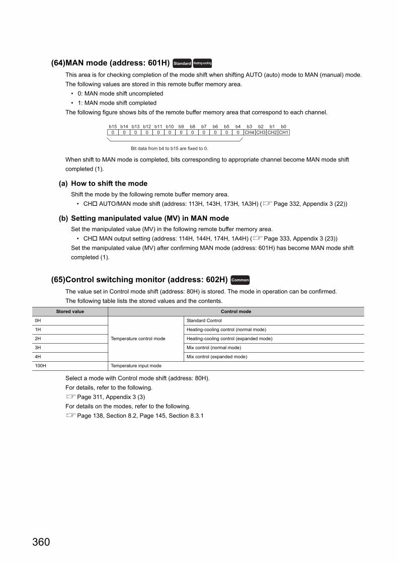
(64)MAN mode (address: 601H)
This area is for checking completion of the mode shift when shifting AUTO (auto) mode to MAN (manual) mode.
The following values are stored in this remote buffer memory area.
• 0: MAN mode shift uncompleted
• 1: MAN mode shift completed
The following figure shows bits of the remote buffer memory area that correspond to each channel.
When shift to MAN mode is completed, bits corresponding to appropriate channel become MAN mode shift
completed (1).
(a) How to shift the mode
Shift the mode by the following remote buffer memory area.
• CH AUTO/MAN mode shift (address: 113H, 143H, 173H, 1A3H) (Page 332, Appendix 3 (22))
(b) Setting manipulated value (MV) in MAN mode
Set the manipulated value (MV) in the following remote buffer memory area.
• CH MAN output setting (address: 114H, 144H, 174H, 1A4H) (Page 333, Appendix 3 (23))
Set the manipulated value (MV) after confirming MAN mode (address: 601H) has become MAN mode shift
completed (1).
(65)Control switching monitor (address: 602H)
The value set in Control mode shift (address: 80H) is stored. The mode in operation can be confirmed.
The following table lists the stored values and the contents.
Select a mode with Control mode shift (address: 80H).
For details, refer to the following.
Page 311, Appendix 3 (3)
For details on the modes, refer to the following.
Page 138, Section 8.2, Page 145, Section 8.3.1
Stored value Control mode
0H
Temperature control mode
Standard Control
1H Heating-cooling control (normal mode)
2H Heating-cooling control (expanded mode)
3H Mix control (normal mode)
4H Mix control (expanded mode)
100H Temperature input mode
Standard Heating-cooling
b150
b140
b130
b120
b110
b100
b90
b80
b70
b60
b50
b40
b3CH4
b2CH3
b1CH2
b0CH1
Bit data from b4 to b15 are fixed to 0.
Common
360
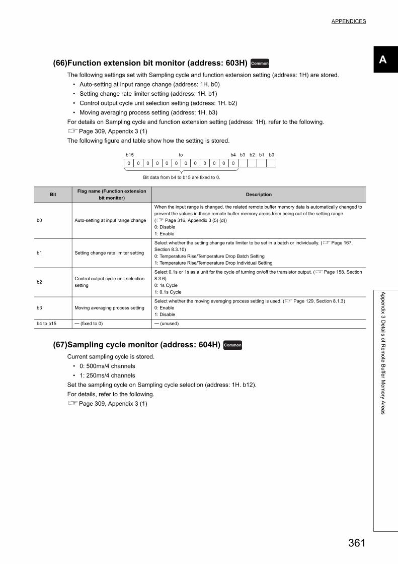
APPENDICES
A
Ap
pe
nd
ix 3 D
eta
ils of R
em
ote
Bu
ffer M
em
ory A
rea
s
(66)Function extension bit monitor (address: 603H)
The following settings set with Sampling cycle and function extension setting (address: 1H) are stored.
• Auto-setting at input range change (address: 1H. b0)
• Setting change rate limiter setting (address: 1H. b1)
• Control output cycle unit selection setting (address: 1H. b2)
• Moving averaging process setting (address: 1H. b3)
For details on Sampling cycle and function extension setting (address: 1H), refer to the following.
Page 309, Appendix 3 (1)
The following figure and table show how the setting is stored.
(67)Sampling cycle monitor (address: 604H)
Current sampling cycle is stored.
• 0: 500ms/4 channels
• 1: 250ms/4 channels
Set the sampling cycle on Sampling cycle selection (address: 1H. b12).
For details, refer to the following.
Page 309, Appendix 3 (1)
BitFlag name (Function extension
bit monitor)Description
b0 Auto-setting at input range change
When the input range is changed, the related remote buffer memory data is automatically changed to
prevent the values in those remote buffer memory areas from being out of the setting range.
(Page 316, Appendix 3 (5) (d))
0: Disable
1: Enable
b1 Setting change rate limiter setting
Select whether the setting change rate limiter to be set in a batch or individually. (Page 167,
Section 8.3.10)
0: Temperature Rise/Temperature Drop Batch Setting
1: Temperature Rise/Temperature Drop Individual Setting
b2Control output cycle unit selection
setting
Select 0.1s or 1s as a unit for the cycle of turning on/off the transistor output. (Page 158, Section
8.3.6)
0: 1s Cycle
1: 0.1s Cycle
b3 Moving averaging process setting
Select whether the moving averaging process setting is used. (Page 129, Section 8.1.3)
0: Enable
1: Disable
b4 to b15 (fixed to 0) (unused)
Common
b15
0 0 0 0 0 0 0 0 0 0 0 0
b2b3b4 b1 b0to
Bit data from b4 to b15 are fixed to 0.
Common
361
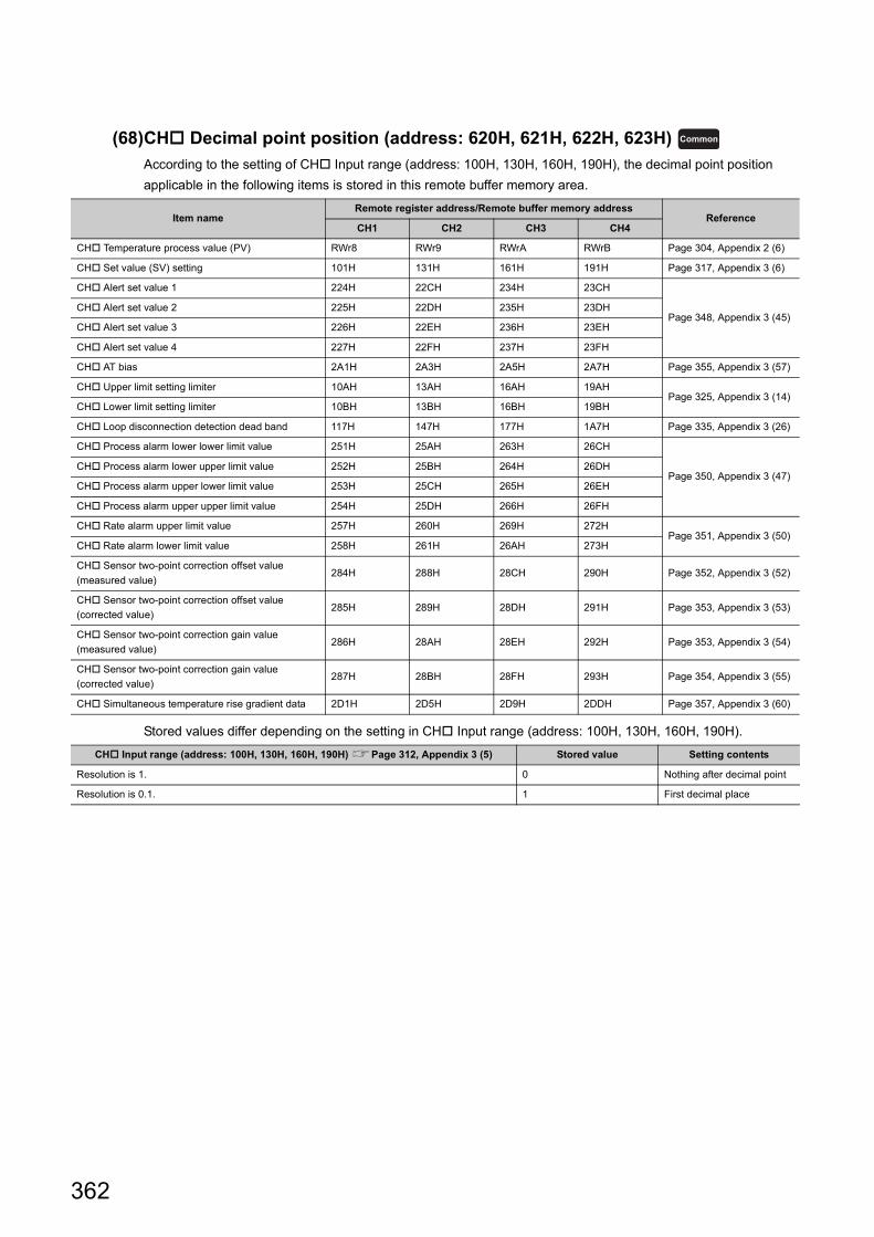
(68)CH Decimal point position (address: 620H, 621H, 622H, 623H)
According to the setting of CH Input range (address: 100H, 130H, 160H, 190H), the decimal point position
applicable in the following items is stored in this remote buffer memory area.
Stored values differ depending on the setting in CH Input range (address: 100H, 130H, 160H, 190H).
Item nameRemote register address/Remote buffer memory address
ReferenceCH1 CH2 CH3 CH4
CH Temperature process value (PV) RWr8 RWr9 RWrA RWrB Page 304, Appendix 2 (6)
CH Set value (SV) setting 101H 131H 161H 191H Page 317, Appendix 3 (6)
CH Alert set value 1 224H 22CH 234H 23CH
Page 348, Appendix 3 (45)CH Alert set value 2 225H 22DH 235H 23DH
CH Alert set value 3 226H 22EH 236H 23EH
CH Alert set value 4 227H 22FH 237H 23FH
CH AT bias 2A1H 2A3H 2A5H 2A7H Page 355, Appendix 3 (57)
CH Upper limit setting limiter 10AH 13AH 16AH 19AHPage 325, Appendix 3 (14)
CH Lower limit setting limiter 10BH 13BH 16BH 19BH
CH Loop disconnection detection dead band 117H 147H 177H 1A7H Page 335, Appendix 3 (26)
CH Process alarm lower lower limit value 251H 25AH 263H 26CH
Page 350, Appendix 3 (47)CH Process alarm lower upper limit value 252H 25BH 264H 26DH
CH Process alarm upper lower limit value 253H 25CH 265H 26EH
CH Process alarm upper upper limit value 254H 25DH 266H 26FH
CH Rate alarm upper limit value 257H 260H 269H 272HPage 351, Appendix 3 (50)
CH Rate alarm lower limit value 258H 261H 26AH 273H
CH Sensor two-point correction offset value
(measured value)284H 288H 28CH 290H Page 352, Appendix 3 (52)
CH Sensor two-point correction offset value
(corrected value)285H 289H 28DH 291H Page 353, Appendix 3 (53)
CH Sensor two-point correction gain value
(measured value)286H 28AH 28EH 292H Page 353, Appendix 3 (54)
CH Sensor two-point correction gain value
(corrected value)287H 28BH 28FH 293H Page 354, Appendix 3 (55)
CH Simultaneous temperature rise gradient data 2D1H 2D5H 2D9H 2DDH Page 357, Appendix 3 (60)
CH Input range (address: 100H, 130H, 160H, 190H) Page 312, Appendix 3 (5) Stored value Setting contents
Resolution is 1. 0 Nothing after decimal point
Resolution is 0.1. 1 First decimal place
Common
362
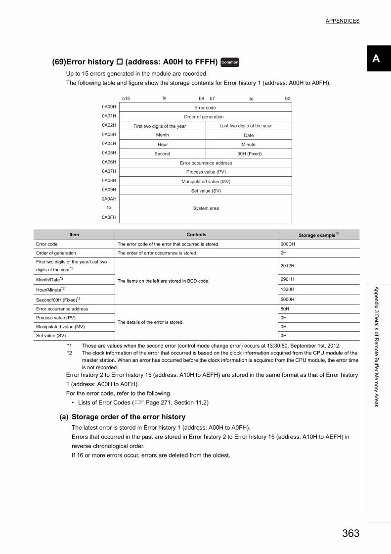
APPENDICES
A
Ap
pe
nd
ix 3 D
eta
ils of R
em
ote
Bu
ffer M
em
ory A
rea
s
(69)Error history (address: A00H to FFFH)
Up to 15 errors generated in the module are recorded.
The following table and figure show the storage contents for Error history 1 (address: A00H to A0FH).
*1 Those are values when the second error (control mode change error) occurs at 13:30:50, September 1st, 2012.*2 The clock information of the error that occurred is based on the clock information acquired from the CPU module of the
master station. When an error has occurred before the clock information is acquired from the CPU module, the error time is not recorded.
Error history 2 to Error history 15 (address: A10H to AEFH) are stored in the same format as that of Error history
1 (address: A00H to A0FH).
For the error code, refer to the following.
• Lists of Error Codes (Page 271, Section 11.2)
(a) Storage order of the error history
The latest error is stored in Error history 1 (address: A00H to A0FH).
Errors that occurred in the past are stored in Error history 2 to Error history 15 (address: A10H to AEFH) in
reverse chronological order.
If 16 or more errors occur, errors are deleted from the oldest.
Item Contents Storage example*1
Error code The error code of the error that occurred is stored. 000DH
Order of generation The order of error occurrence is stored. 2H
First two digits of the year/Last two
digits of the year*2
The items on the left are stored in BCD code.
2012H
Month/Date*2 0901H
Hour/Minute*2 1330H
Second/00H (Fixed)*2 5000H
Error occurrence address
The details of the error is stored.
80H
Process value (PV) 0H
Manipulated value (MV) 0H
Set value (SV) 0H
Common
b15 b8 b7 b0
0A00H
0A01H
0A02H
0A03H
0A04H
0A05H
0A06H
0A07H
0A08H
0A09H
0A0AH
0A0FH
to to
Error code
First two digits of the year Last two digits of the year
Month Date
Hour Minute
Second
Order of generation
00H (Fixed)
to
Error occurrence address
Manipulated value (MV)
Set value (SV)
Process value (PV)
System area
363
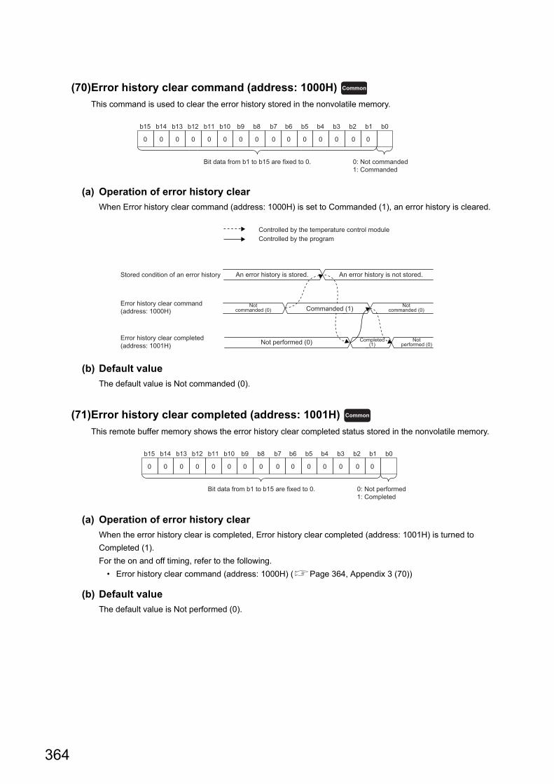
(70)Error history clear command (address: 1000H)
This command is used to clear the error history stored in the nonvolatile memory.
(a) Operation of error history clear
When Error history clear command (address: 1000H) is set to Commanded (1), an error history is cleared.
(b) Default value
The default value is Not commanded (0).
(71)Error history clear completed (address: 1001H)
This remote buffer memory shows the error history clear completed status stored in the nonvolatile memory.
(a) Operation of error history clear
When the error history clear is completed, Error history clear completed (address: 1001H) is turned to
Completed (1).
For the on and off timing, refer to the following.
• Error history clear command (address: 1000H) (Page 364, Appendix 3 (70))
(b) Default value
The default value is Not performed (0).
Common
b0b15 b14 b13 b12 b11 b10 b9 b8 b7 b6 b5 b4 b3 b2 b1
0 00 0 0 0 0 0 0 0 0 0 0 0 0
Bit data from b1 to b15 are fixed to 0. 0: Not commanded1: Commanded
Stored condition of an error history
Error history clear command (address: 1000H)
Error history clear completed(address: 1001H)
An error history is stored. An error history is not stored.
Notcommanded (0)
Notcommanded (0)Commanded (1)
Notperformed (0)Not performed (0) Completed
(1)
Controlled by the temperature control moduleControlled by the program
Common
b0b15 b14 b13 b12 b11 b10 b9 b8 b7 b6 b5 b4 b3 b2 b1
0 00 0 0 0 0 0 0 0 0 0 0 0 0
Bit data from b1 to b15 are fixed to 0. 0: Not performed1: Completed
364
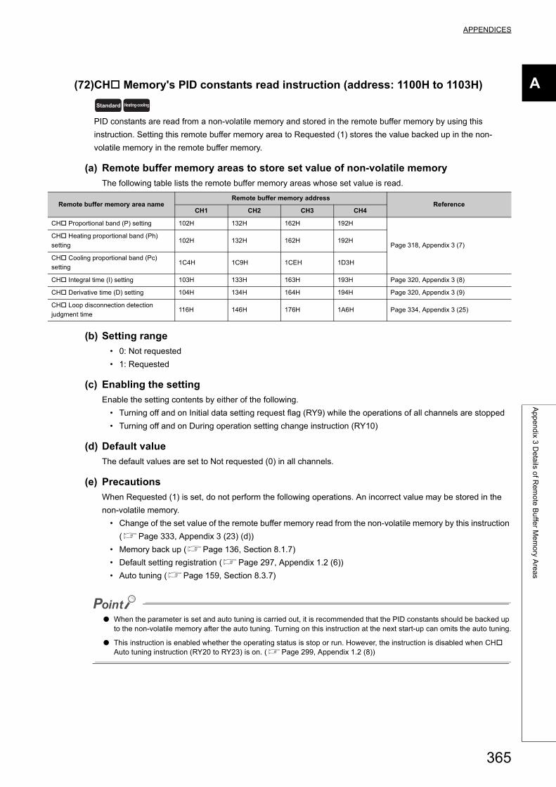
APPENDICES
A
Ap
pe
nd
ix 3 D
eta
ils of R
em
ote
Bu
ffer M
em
ory A
rea
s
(72)CH Memory's PID constants read instruction (address: 1100H to 1103H)
PID constants are read from a non-volatile memory and stored in the remote buffer memory by using this
instruction. Setting this remote buffer memory area to Requested (1) stores the value backed up in the non-
volatile memory in the remote buffer memory.
(a) Remote buffer memory areas to store set value of non-volatile memory
The following table lists the remote buffer memory areas whose set value is read.
(b) Setting range
• 0: Not requested
• 1: Requested
(c) Enabling the setting
Enable the setting contents by either of the following.
• Turning off and on Initial data setting request flag (RY9) while the operations of all channels are stopped
• Turning off and on During operation setting change instruction (RY10)
(d) Default value
The default values are set to Not requested (0) in all channels.
(e) Precautions
When Requested (1) is set, do not perform the following operations. An incorrect value may be stored in the
non-volatile memory.
• Change of the set value of the remote buffer memory read from the non-volatile memory by this instruction
(Page 333, Appendix 3 (23) (d))
• Memory back up (Page 136, Section 8.1.7)
• Default setting registration (Page 297, Appendix 1.2 (6))
• Auto tuning (Page 159, Section 8.3.7)
● When the parameter is set and auto tuning is carried out, it is recommended that the PID constants should be backed up to the non-volatile memory after the auto tuning. Turning on this instruction at the next start-up can omits the auto tuning.
● This instruction is enabled whether the operating status is stop or run. However, the instruction is disabled when CH Auto tuning instruction (RY20 to RY23) is on. (Page 299, Appendix 1.2 (8))
Remote buffer memory area nameRemote buffer memory address
ReferenceCH1 CH2 CH3 CH4
CH Proportional band (P) setting 102H 132H 162H 192H
Page 318, Appendix 3 (7)
CH Heating proportional band (Ph)
setting102H 132H 162H 192H
CH Cooling proportional band (Pc)
setting1C4H 1C9H 1CEH 1D3H
CH Integral time (I) setting 103H 133H 163H 193H Page 320, Appendix 3 (8)
CH Derivative time (D) setting 104H 134H 164H 194H Page 320, Appendix 3 (9)
CH Loop disconnection detection
judgment time116H 146H 176H 1A6H Page 334, Appendix 3 (25)
Standard Heating-cooling
365
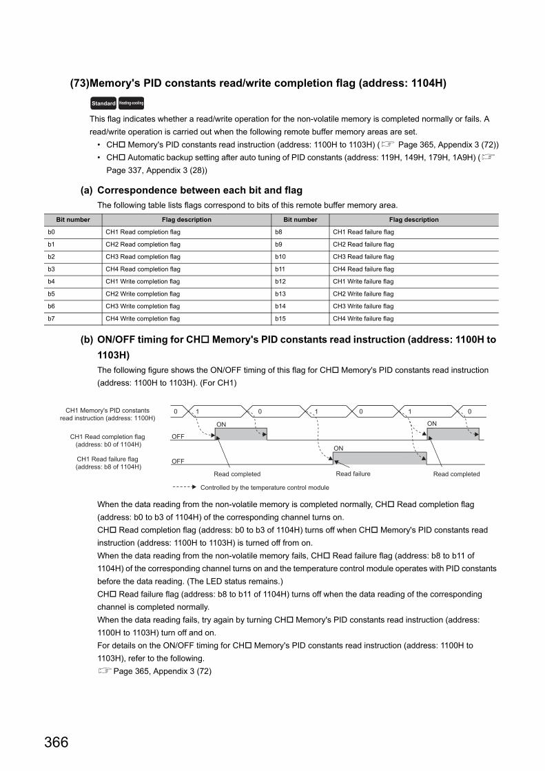
(73)Memory's PID constants read/write completion flag (address: 1104H)
This flag indicates whether a read/write operation for the non-volatile memory is completed normally or fails. A
read/write operation is carried out when the following remote buffer memory areas are set.
• CH Memory's PID constants read instruction (address: 1100H to 1103H) ( Page 365, Appendix 3 (72))
• CH Automatic backup setting after auto tuning of PID constants (address: 119H, 149H, 179H, 1A9H) (
Page 337, Appendix 3 (28))
(a) Correspondence between each bit and flag
The following table lists flags correspond to bits of this remote buffer memory area.
(b) ON/OFF timing for CH Memory's PID constants read instruction (address: 1100H to
1103H)
The following figure shows the ON/OFF timing of this flag for CH Memory's PID constants read instruction
(address: 1100H to 1103H). (For CH1)
When the data reading from the non-volatile memory is completed normally, CH Read completion flag
(address: b0 to b3 of 1104H) of the corresponding channel turns on.
CH Read completion flag (address: b0 to b3 of 1104H) turns off when CH Memory's PID constants read
instruction (address: 1100H to 1103H) is turned off from on.
When the data reading from the non-volatile memory fails, CH Read failure flag (address: b8 to b11 of
1104H) of the corresponding channel turns on and the temperature control module operates with PID constants
before the data reading. (The LED status remains.)
CH Read failure flag (address: b8 to b11 of 1104H) turns off when the data reading of the corresponding
channel is completed normally.
When the data reading fails, try again by turning CH Memory's PID constants read instruction (address:
1100H to 1103H) turn off and on.
For details on the ON/OFF timing for CH Memory's PID constants read instruction (address: 1100H to
1103H), refer to the following.
Page 365, Appendix 3 (72)
Bit number Flag description Bit number Flag description
b0 CH1 Read completion flag b8 CH1 Read failure flag
b1 CH2 Read completion flag b9 CH2 Read failure flag
b2 CH3 Read completion flag b10 CH3 Read failure flag
b3 CH4 Read completion flag b11 CH4 Read failure flag
b4 CH1 Write completion flag b12 CH1 Write failure flag
b5 CH2 Write completion flag b13 CH2 Write failure flag
b6 CH3 Write completion flag b14 CH3 Write failure flag
b7 CH4 Write completion flag b15 CH4 Write failure flag
Standard Heating-cooling
0 0 0 011 1
ON
OFF
OFF
ON
ON
Read completed Read failure Read completed
CH1 Memory's PID constants read instruction (address: 1100H)
CH1 Read completion flag (address: b0 of 1104H)
CH1 Read failure flag (address: b8 of 1104H)
Controlled by the temperature control module
366
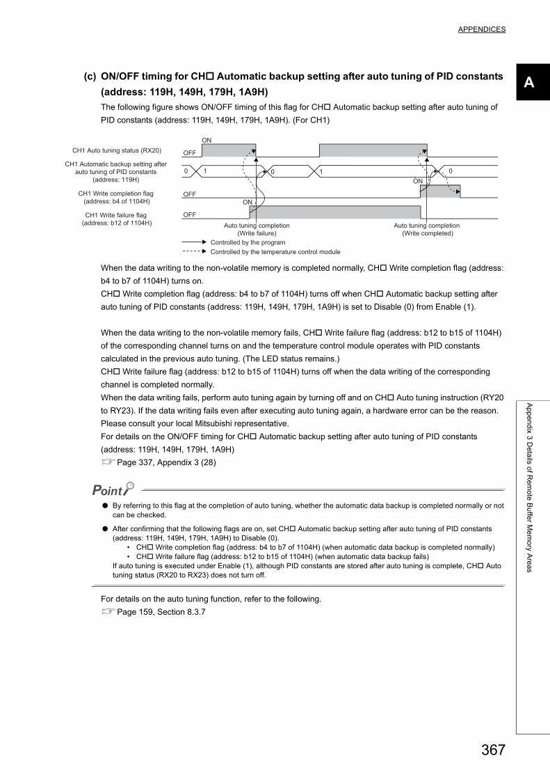
APPENDICES
A
Ap
pe
nd
ix 3 D
eta
ils of R
em
ote
Bu
ffer M
em
ory A
rea
s
(c) ON/OFF timing for CH Automatic backup setting after auto tuning of PID constants
(address: 119H, 149H, 179H, 1A9H)
The following figure shows ON/OFF timing of this flag for CH Automatic backup setting after auto tuning of
PID constants (address: 119H, 149H, 179H, 1A9H). (For CH1)
When the data writing to the non-volatile memory is completed normally, CH Write completion flag (address:
b4 to b7 of 1104H) turns on.
CH Write completion flag (address: b4 to b7 of 1104H) turns off when CH Automatic backup setting after
auto tuning of PID constants (address: 119H, 149H, 179H, 1A9H) is set to Disable (0) from Enable (1).
When the data writing to the non-volatile memory fails, CH Write failure flag (address: b12 to b15 of 1104H)
of the corresponding channel turns on and the temperature control module operates with PID constants
calculated in the previous auto tuning. (The LED status remains.)
CH Write failure flag (address: b12 to b15 of 1104H) turns off when the data writing of the corresponding
channel is completed normally.
When the data writing fails, perform auto tuning again by turning off and on CH Auto tuning instruction (RY20
to RY23). If the data writing fails even after executing auto tuning again, a hardware error can be the reason.
Please consult your local Mitsubishi representative.
For details on the ON/OFF timing for CH Automatic backup setting after auto tuning of PID constants
(address: 119H, 149H, 179H, 1A9H)
Page 337, Appendix 3 (28)
● By referring to this flag at the completion of auto tuning, whether the automatic data backup is completed normally or not can be checked.
● After confirming that the following flags are on, set CH Automatic backup setting after auto tuning of PID constants (address: 119H, 149H, 179H, 1A9H) to Disable (0).
• CH Write completion flag (address: b4 to b7 of 1104H) (when automatic data backup is completed normally)• CH Write failure flag (address: b12 to b15 of 1104H) (when automatic data backup fails)
If auto tuning is executed under Enable (1), although PID constants are stored after auto tuning is complete, CH Auto tuning status (RX20 to RX23) does not turn off.
For details on the auto tuning function, refer to the following.
Page 159, Section 8.3.7
0 0 01 1
OFF
OFF
OFF
ON
ON
ON
Auto tuning completion(Write failure)
Auto tuning completion (Write completed)
Controlled by the program
CH1 Automatic backup setting after auto tuning of PID constants
(address: 119H)
CH1 Write completion flag (address: b4 of 1104H)
CH1 Write failure flag (address: b12 of 1104H)
CH1 Auto tuning status (RX20)
Controlled by the temperature control module
367
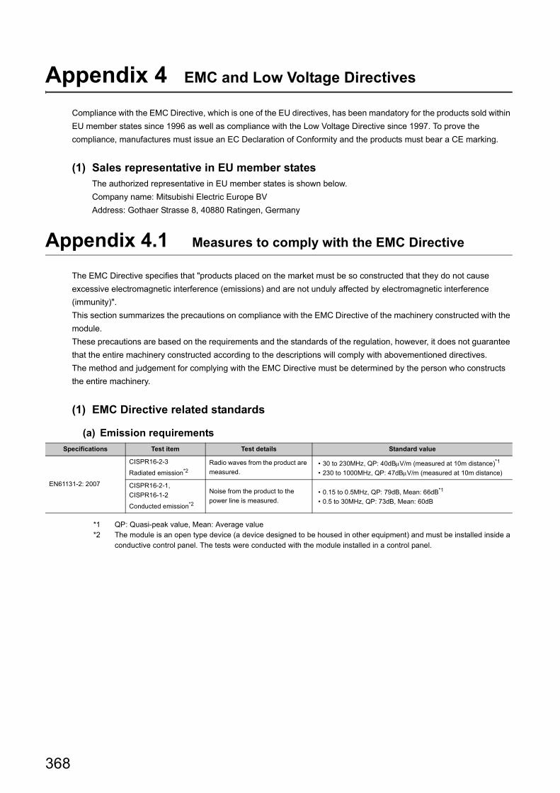
Appendix 4 EMC and Low Voltage Directives
Compliance with the EMC Directive, which is one of the EU directives, has been mandatory for the products sold within
EU member states since 1996 as well as compliance with the Low Voltage Directive since 1997. To prove the
compliance, manufactures must issue an EC Declaration of Conformity and the products must bear a CE marking.
(1) Sales representative in EU member statesThe authorized representative in EU member states is shown below.
Company name: Mitsubishi Electric Europe BV
Address: Gothaer Strasse 8, 40880 Ratingen, Germany
Appendix 4.1 Measures to comply with the EMC Directive
The EMC Directive specifies that "products placed on the market must be so constructed that they do not cause
excessive electromagnetic interference (emissions) and are not unduly affected by electromagnetic interference
(immunity)".
This section summarizes the precautions on compliance with the EMC Directive of the machinery constructed with the
module.
These precautions are based on the requirements and the standards of the regulation, however, it does not guarantee
that the entire machinery constructed according to the descriptions will comply with abovementioned directives.
The method and judgement for complying with the EMC Directive must be determined by the person who constructs
the entire machinery.
(1) EMC Directive related standards
(a) Emission requirements
*1 QP: Quasi-peak value, Mean: Average value*2 The module is an open type device (a device designed to be housed in other equipment) and must be installed inside a
conductive control panel. The tests were conducted with the module installed in a control panel.
Specifications Test item Test details Standard value
EN61131-2: 2007
CISPR16-2-3
Radiated emission*2
Radio waves from the product are
measured.• 30 to 230MHz, QP: 40dBV/m (measured at 10m distance)*1
• 230 to 1000MHz, QP: 47dBV/m (measured at 10m distance)
CISPR16-2-1,
CISPR16-1-2
Conducted emission*2
Noise from the product to the
power line is measured.• 0.15 to 0.5MHz, QP: 79dB, Mean: 66dB*1
• 0.5 to 30MHz, QP: 73dB, Mean: 60dB
368
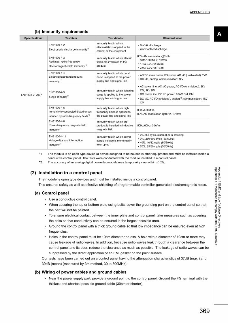
APPENDICES
A
Ap
pe
nd
ix 4 E
MC
an
d L
ow
Vo
ltag
e D
irective
sA
pp
en
dix 4
.1 M
ea
sure
s to co
mp
ly with
the
EM
C D
irective
(b) Immunity requirements
*1 The module is an open type device (a device designed to be housed in other equipment) and must be installed inside a conductive control panel. The tests were conducted with the module installed in a control panel.
*2 The accuracy of an analog-digital converter module may temporarily vary within 10%.
(2) Installation in a control panelThe module is open type devices and must be installed inside a control panel.
This ensures safety as well as effective shielding of programmable controller-generated electromagnetic noise.
(a) Control panel
• Use a conductive control panel.
• When securing the top or bottom plate using bolts, cover the grounding part on the control panel so that
the part will not be painted.
• To ensure electrical contact between the inner plate and control panel, take measures such as covering
the bolts so that conductivity can be ensured in the largest possible area.
• Ground the control panel with a thick ground cable so that low impedance can be ensured even at high
frequencies.
• Holes in the control panel must be 10cm diameter or less. A hole with a diameter of 10cm or more may
cause leakage of radio waves. In addition, because radio waves leak through a clearance between the
control panel and its door, reduce the clearance as much as possible. The leakage of radio waves can be
suppressed by the direct application of an EMI gasket on the paint surface.
Our tests have been carried out on a control panel having the attenuation characteristics of 37dB (max.) and
30dB (mean) (measured by 3m method, 30 to 300MHz).
(b) Wiring of power cables and ground cables
• Near the power supply part, provide a ground point to the control panel. Ground the FG terminal with the
thickest and shortest possible ground cable (30cm or shorter).
Specifications Test item Test details Standard value
EN61131-2: 2007
EN61000-4-2
Electrostatic discharge immunity*1
Immunity test in which
electrostatic is applied to the
cabinet of the equipment
• 8kV Air discharge
• 4kV Contact discharge
EN61000-4-3
Radiated, radio-frequency,
electromagnetic field immunity*1
Immunity test in which electric
fields are irradiated to the
product
80% AM modulation@1kHz
• 80M-1000MHz: 10V/m
• 1.4G-2.0GHz: 3V/m
• 2.0G-2.7GHz: 1V/m
EN61000-4-4
Electrical fast transient/burst
immunity*1
Immunity test in which burst
noise is applied to the power
supply line and signal line
• AC/DC main power, I/O power, AC I/O (unshielded): 2kV
• DC I/O, analog, communication: 1kV
EN61000-4-5
Surge immunity*1
Immunity test in which lightning
surge is applied to the power
supply line and signal line
• AC power line, AC I/O power, AC I/O (unshielded): 2kV
CM, 1kV DM
• DC power line, DC I/O power: 0.5kV CM, DM
• DC I/O, AC I/O (shielded), analog*2, communication: 1kV
CM
EN61000-4-6
Immunity to conducted disturbances,
induced by radio-frequency fields*1
Immunity test in which high
frequency noise is applied to
the power line and signal line
0.15M-80MHz,
80% AM modulation @1kHz, 10Vrms
EN61000-4-8
Power-frequency magnetic field
immunity*1
Immunity test in which the
product is installed in inductive
magnetic field
50Hz/60Hz, 30A/m
EN61000-4-11
Voltage dips and interruption
immunity*1
Immunity test in which power
supply voltage is momentarily
interrupted
• 0%, 0.5 cycle, starts at zero crossing
• 0%, 250/300 cycle (50/60Hz)
• 40%, 10/12 cycle (50/60Hz)
• 70%, 25/30 cycle (50/60Hz)
369
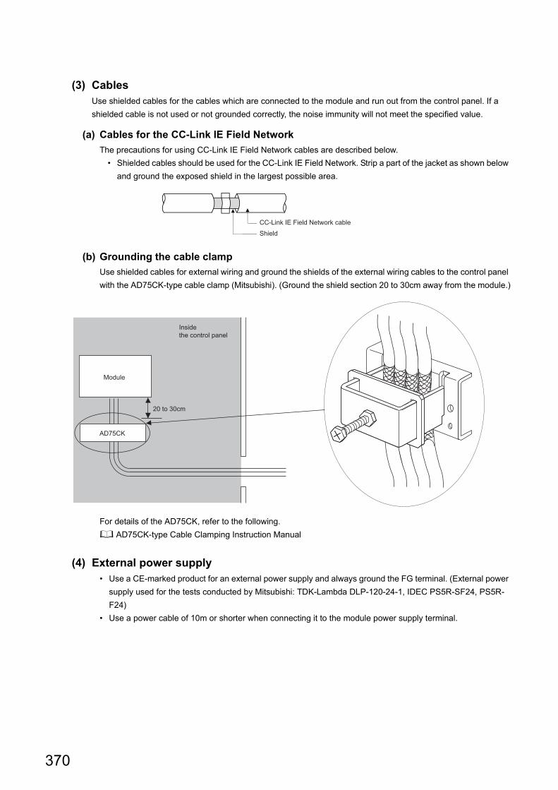
(3) CablesUse shielded cables for the cables which are connected to the module and run out from the control panel. If a
shielded cable is not used or not grounded correctly, the noise immunity will not meet the specified value.
(a) Cables for the CC-Link IE Field Network
The precautions for using CC-Link IE Field Network cables are described below.
• Shielded cables should be used for the CC-Link IE Field Network. Strip a part of the jacket as shown below
and ground the exposed shield in the largest possible area.
(b) Grounding the cable clamp
Use shielded cables for external wiring and ground the shields of the external wiring cables to the control panel
with the AD75CK-type cable clamp (Mitsubishi). (Ground the shield section 20 to 30cm away from the module.)
For details of the AD75CK, refer to the following.
AD75CK-type Cable Clamping Instruction Manual
(4) External power supply• Use a CE-marked product for an external power supply and always ground the FG terminal. (External power
supply used for the tests conducted by Mitsubishi: TDK-Lambda DLP-120-24-1, IDEC PS5R-SF24, PS5R-
F24)
• Use a power cable of 10m or shorter when connecting it to the module power supply terminal.
CC-Link IE Field Network cable
Shield
AD75CK
20 to 30cm
Inside the control panel
Module
370
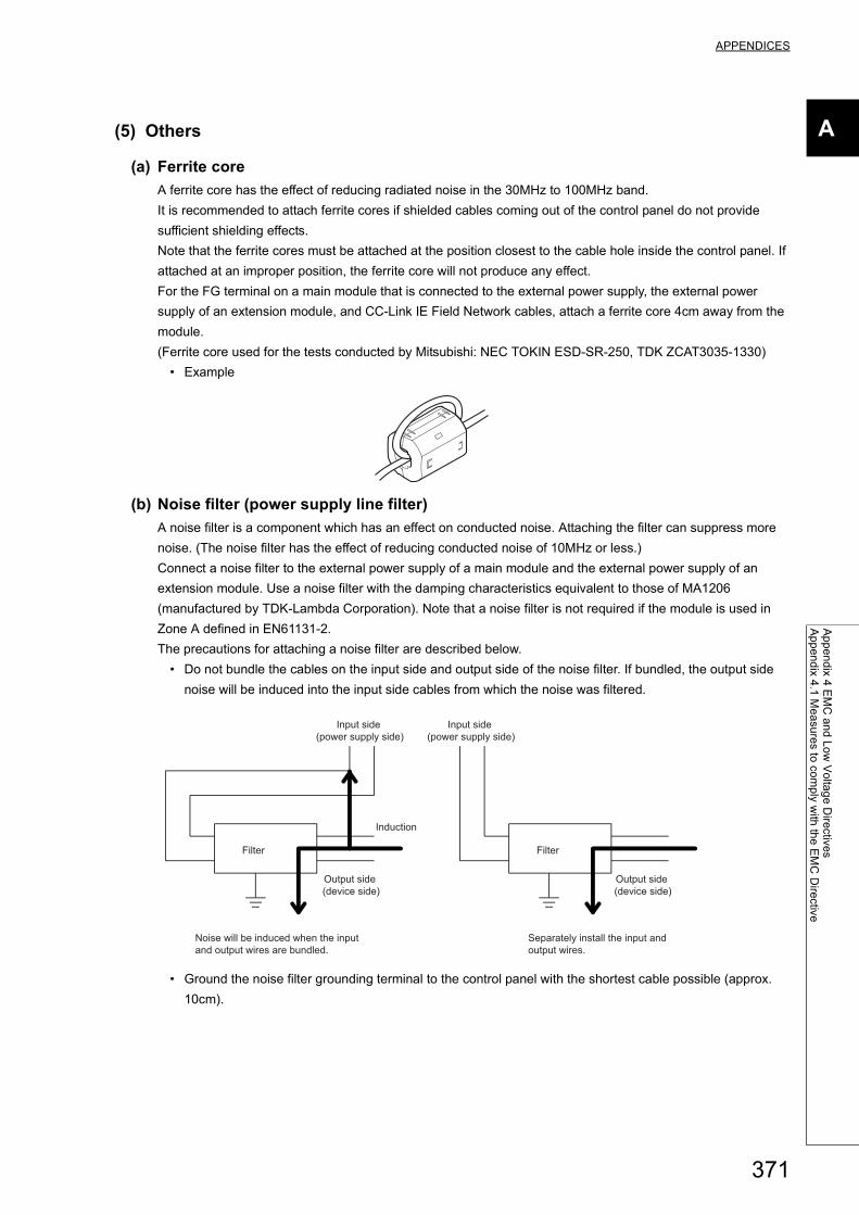
APPENDICES
A
Ap
pe
nd
ix 4 E
MC
an
d L
ow
Vo
ltag
e D
irective
sA
pp
en
dix 4
.1 M
ea
sure
s to co
mp
ly with
the
EM
C D
irective
(5) Others
(a) Ferrite core
A ferrite core has the effect of reducing radiated noise in the 30MHz to 100MHz band.
It is recommended to attach ferrite cores if shielded cables coming out of the control panel do not provide
sufficient shielding effects.
Note that the ferrite cores must be attached at the position closest to the cable hole inside the control panel. If
attached at an improper position, the ferrite core will not produce any effect.
For the FG terminal on a main module that is connected to the external power supply, the external power
supply of an extension module, and CC-Link IE Field Network cables, attach a ferrite core 4cm away from the
module.
(Ferrite core used for the tests conducted by Mitsubishi: NEC TOKIN ESD-SR-250, TDK ZCAT3035-1330)
• Example
(b) Noise filter (power supply line filter)
A noise filter is a component which has an effect on conducted noise. Attaching the filter can suppress more
noise. (The noise filter has the effect of reducing conducted noise of 10MHz or less.)
Connect a noise filter to the external power supply of a main module and the external power supply of an
extension module. Use a noise filter with the damping characteristics equivalent to those of MA1206
(manufactured by TDK-Lambda Corporation). Note that a noise filter is not required if the module is used in
Zone A defined in EN61131-2.
The precautions for attaching a noise filter are described below.
• Do not bundle the cables on the input side and output side of the noise filter. If bundled, the output side
noise will be induced into the input side cables from which the noise was filtered.
• Ground the noise filter grounding terminal to the control panel with the shortest cable possible (approx.
10cm).
Filter
Induction
Filter
Separately install the input and output wires.
Noise will be induced when the input and output wires are bundled.
Input side (power supply side)
Input side (power supply side)
Output side (device side)
Output side (device side)
371
Appendix 4.2 Requirements to compliance with the Low Voltage Directive
The module operates at the rated voltage of 24VDC.
The Low Voltage Directive is not applied to the modules that operate at the rated voltage of less than 50VAC and
75VDC.
372
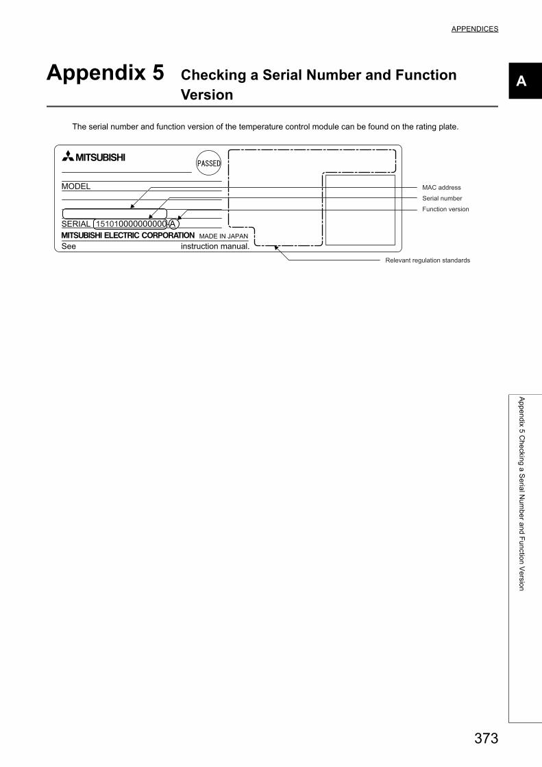
373
APPENDICES
A
Ap
pe
nd
ix 5 C
he
cking
a S
eria
l Nu
mb
er a
nd
Fu
nctio
n V
ersio
n
Appendix 5 Checking a Serial Number and Function Version
The serial number and function version of the temperature control module can be found on the rating plate.
See instruction manual.
MODEL
SERIALMADE IN JAPAN
15101
Serial number
Function version
Relevant regulation standards
MAC address
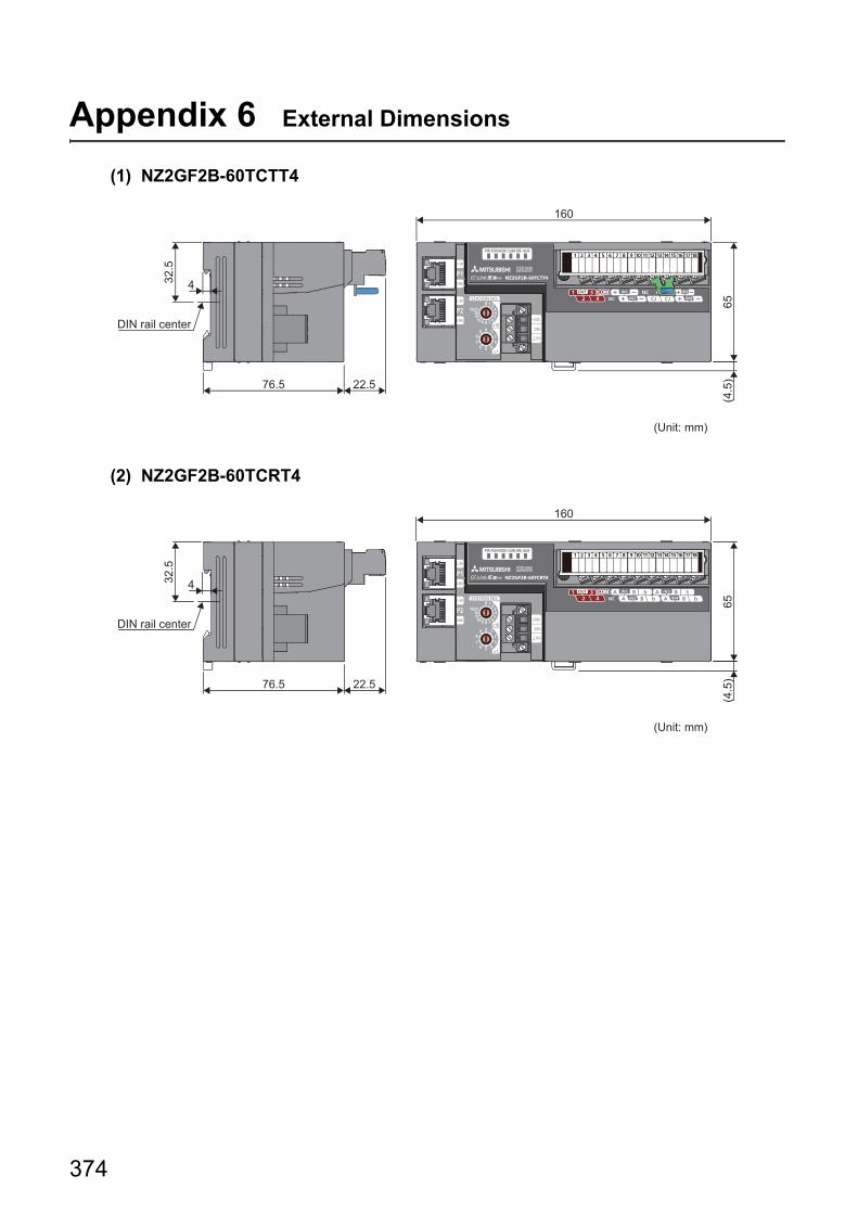
Appendix 6 External Dimensions
(1) NZ2GF2B-60TCTT4
(2) NZ2GF2B-60TCRT4
(Unit: mm)
DIN rail center
32.5
4
76.5
65(4
.5)
160
22.5
(Unit: mm)
DIN rail center
32.5
4
76.5
65(4
.5)
160
22.5
374
APPENDICES
A
Ap
pe
nd
ix 6 E
xtern
al D
ime
nsio
ns
Memo
375
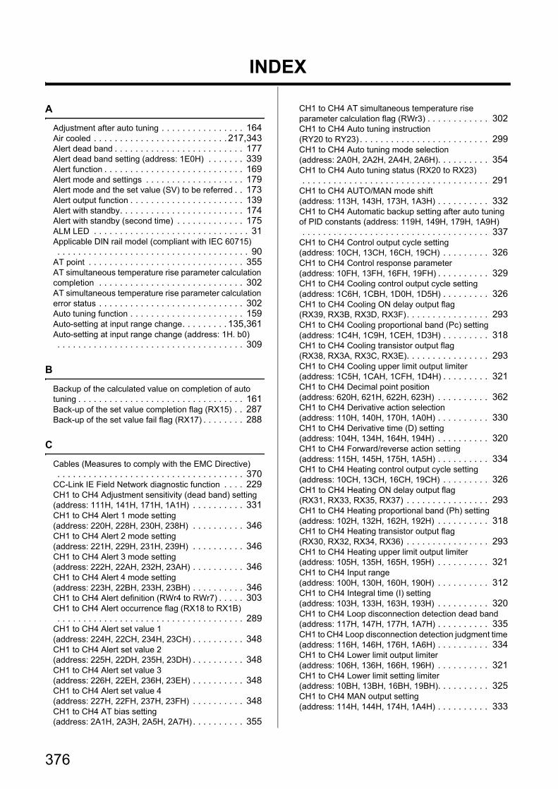
INDEX
A
Adjustment after auto tuning . . . . . . . . . . . . . . . . 164Air cooled . . . . . . . . . . . . . . . . . . . . . . . . . . 217,343Alert dead band . . . . . . . . . . . . . . . . . . . . . . . . . 177Alert dead band setting (address: 1E0H) . . . . . . . 339Alert function . . . . . . . . . . . . . . . . . . . . . . . . . . . 169Alert mode and settings . . . . . . . . . . . . . . . . . . . 179Alert mode and the set value (SV) to be referred . . 173Alert output function . . . . . . . . . . . . . . . . . . . . . . 139Alert with standby. . . . . . . . . . . . . . . . . . . . . . . . 174Alert with standby (second time) . . . . . . . . . . . . . 175ALM LED . . . . . . . . . . . . . . . . . . . . . . . . . . . . . . 31Applicable DIN rail model (compliant with IEC 60715) . . . . . . . . . . . . . . . . . . . . . . . . . . . . . . . . . . . . . 90AT point . . . . . . . . . . . . . . . . . . . . . . . . . . . . . . 355AT simultaneous temperature rise parameter calculation completion . . . . . . . . . . . . . . . . . . . . . . . . . . . . 302AT simultaneous temperature rise parameter calculation error status . . . . . . . . . . . . . . . . . . . . . . . . . . . . 302Auto tuning function . . . . . . . . . . . . . . . . . . . . . . 159Auto-setting at input range change. . . . . . . . . 135,361Auto-setting at input range change (address: 1H. b0) . . . . . . . . . . . . . . . . . . . . . . . . . . . . . . . . . . . . 309
B
Backup of the calculated value on completion of auto tuning . . . . . . . . . . . . . . . . . . . . . . . . . . . . . . . . 161Back-up of the set value completion flag (RX15) . . 287Back-up of the set value fail flag (RX17) . . . . . . . . 288
C
Cables (Measures to comply with the EMC Directive) . . . . . . . . . . . . . . . . . . . . . . . . . . . . . . . . . . . . 370CC-Link IE Field Network diagnostic function . . . . 229CH1 to CH4 Adjustment sensitivity (dead band) setting (address: 111H, 141H, 171H, 1A1H) . . . . . . . . . . 331CH1 to CH4 Alert 1 mode setting (address: 220H, 228H, 230H, 238H) . . . . . . . . . . 346CH1 to CH4 Alert 2 mode setting (address: 221H, 229H, 231H, 239H) . . . . . . . . . . 346CH1 to CH4 Alert 3 mode setting (address: 222H, 22AH, 232H, 23AH) . . . . . . . . . . 346CH1 to CH4 Alert 4 mode setting (address: 223H, 22BH, 233H, 23BH) . . . . . . . . . . 346CH1 to CH4 Alert definition (RWr4 to RWr7) . . . . . 303CH1 to CH4 Alert occurrence flag (RX18 to RX1B) . . . . . . . . . . . . . . . . . . . . . . . . . . . . . . . . . . . . 289CH1 to CH4 Alert set value 1 (address: 224H, 22CH, 234H, 23CH) . . . . . . . . . . 348CH1 to CH4 Alert set value 2 (address: 225H, 22DH, 235H, 23DH) . . . . . . . . . . 348CH1 to CH4 Alert set value 3 (address: 226H, 22EH, 236H, 23EH) . . . . . . . . . . 348CH1 to CH4 Alert set value 4 (address: 227H, 22FH, 237H, 23FH) . . . . . . . . . . 348CH1 to CH4 AT bias setting (address: 2A1H, 2A3H, 2A5H, 2A7H) . . . . . . . . . . 355
CH1 to CH4 AT simultaneous temperature rise parameter calculation flag (RWr3) . . . . . . . . . . . . 302CH1 to CH4 Auto tuning instruction (RY20 to RY23) . . . . . . . . . . . . . . . . . . . . . . . . . 299CH1 to CH4 Auto tuning mode selection (address: 2A0H, 2A2H, 2A4H, 2A6H). . . . . . . . . . 354CH1 to CH4 Auto tuning status (RX20 to RX23) . . . . . . . . . . . . . . . . . . . . . . . . . . . . . . . . . . . . 291CH1 to CH4 AUTO/MAN mode shift (address: 113H, 143H, 173H, 1A3H) . . . . . . . . . . 332CH1 to CH4 Automatic backup setting after auto tuning of PID constants (address: 119H, 149H, 179H, 1A9H) . . . . . . . . . . . . . . . . . . . . . . . . . . . . . . . . . . . . 337CH1 to CH4 Control output cycle setting (address: 10CH, 13CH, 16CH, 19CH) . . . . . . . . . 326CH1 to CH4 Control response parameter (address: 10FH, 13FH, 16FH, 19FH) . . . . . . . . . . 329CH1 to CH4 Cooling control output cycle setting (address: 1C6H, 1CBH, 1D0H, 1D5H) . . . . . . . . . 326CH1 to CH4 Cooling ON delay output flag (RX39, RX3B, RX3D, RX3F). . . . . . . . . . . . . . . . 293CH1 to CH4 Cooling proportional band (Pc) setting (address: 1C4H, 1C9H, 1CEH, 1D3H) . . . . . . . . . 318CH1 to CH4 Cooling transistor output flag (RX38, RX3A, RX3C, RX3E). . . . . . . . . . . . . . . . 293CH1 to CH4 Cooling upper limit output limiter (address: 1C5H, 1CAH, 1CFH, 1D4H) . . . . . . . . . 321CH1 to CH4 Decimal point position (address: 620H, 621H, 622H, 623H) . . . . . . . . . . 362CH1 to CH4 Derivative action selection (address: 110H, 140H, 170H, 1A0H) . . . . . . . . . . 330CH1 to CH4 Derivative time (D) setting (address: 104H, 134H, 164H, 194H) . . . . . . . . . . 320CH1 to CH4 Forward/reverse action setting (address: 115H, 145H, 175H, 1A5H) . . . . . . . . . . 334CH1 to CH4 Heating control output cycle setting (address: 10CH, 13CH, 16CH, 19CH) . . . . . . . . . 326CH1 to CH4 Heating ON delay output flag (RX31, RX33, RX35, RX37) . . . . . . . . . . . . . . . . 293CH1 to CH4 Heating proportional band (Ph) setting (address: 102H, 132H, 162H, 192H) . . . . . . . . . . 318CH1 to CH4 Heating transistor output flag (RX30, RX32, RX34, RX36) . . . . . . . . . . . . . . . . 293CH1 to CH4 Heating upper limit output limiter (address: 105H, 135H, 165H, 195H) . . . . . . . . . . 321CH1 to CH4 Input range (address: 100H, 130H, 160H, 190H) . . . . . . . . . . 312CH1 to CH4 Integral time (I) setting (address: 103H, 133H, 163H, 193H) . . . . . . . . . . 320CH1 to CH4 Loop disconnection detection dead band (address: 117H, 147H, 177H, 1A7H) . . . . . . . . . . 335CH1 to CH4 Loop disconnection detection judgment time (address: 116H, 146H, 176H, 1A6H) . . . . . . . . . . 334CH1 to CH4 Lower limit output limiter (address: 106H, 136H, 166H, 196H) . . . . . . . . . . 321CH1 to CH4 Lower limit setting limiter (address: 10BH, 13BH, 16BH, 19BH). . . . . . . . . . 325CH1 to CH4 MAN output setting (address: 114H, 144H, 174H, 1A4H) . . . . . . . . . . 333
376
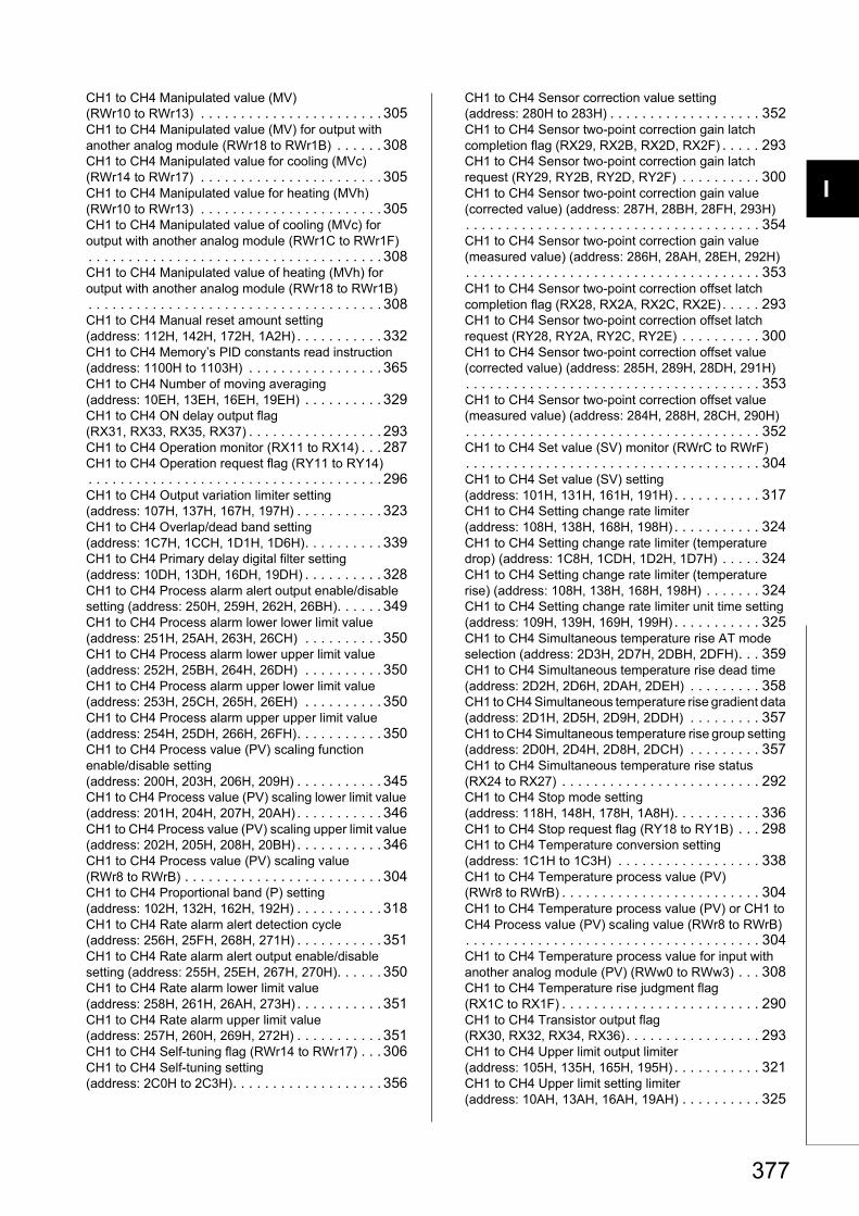
I
4
4
7
8
CH1 to CH4 Manipulated value (MV) (RWr10 to RWr13) . . . . . . . . . . . . . . . . . . . . . . . 305CH1 to CH4 Manipulated value (MV) for output with another analog module (RWr18 to RWr1B) . . . . . . 308CH1 to CH4 Manipulated value for cooling (MVc) (RWr14 to RWr17) . . . . . . . . . . . . . . . . . . . . . . . 305CH1 to CH4 Manipulated value for heating (MVh) (RWr10 to RWr13) . . . . . . . . . . . . . . . . . . . . . . . 305CH1 to CH4 Manipulated value of cooling (MVc) for output with another analog module (RWr1C to RWr1F). . . . . . . . . . . . . . . . . . . . . . . . . . . . . . . . . . . . . 308CH1 to CH4 Manipulated value of heating (MVh) for output with another analog module (RWr18 to RWr1B). . . . . . . . . . . . . . . . . . . . . . . . . . . . . . . . . . . . . 308CH1 to CH4 Manual reset amount setting (address: 112H, 142H, 172H, 1A2H) . . . . . . . . . . . 332CH1 to CH4 Memory’s PID constants read instruction (address: 1100H to 1103H) . . . . . . . . . . . . . . . . . 365CH1 to CH4 Number of moving averaging (address: 10EH, 13EH, 16EH, 19EH) . . . . . . . . . . 329CH1 to CH4 ON delay output flag (RX31, RX33, RX35, RX37) . . . . . . . . . . . . . . . . . 293CH1 to CH4 Operation monitor (RX11 to RX14) . . . 287CH1 to CH4 Operation request flag (RY11 to RY14). . . . . . . . . . . . . . . . . . . . . . . . . . . . . . . . . . . . . 296CH1 to CH4 Output variation limiter setting (address: 107H, 137H, 167H, 197H) . . . . . . . . . . . 323CH1 to CH4 Overlap/dead band setting (address: 1C7H, 1CCH, 1D1H, 1D6H). . . . . . . . . . 339CH1 to CH4 Primary delay digital filter setting (address: 10DH, 13DH, 16DH, 19DH) . . . . . . . . . . 328CH1 to CH4 Process alarm alert output enable/disable setting (address: 250H, 259H, 262H, 26BH). . . . . . 349CH1 to CH4 Process alarm lower lower limit value (address: 251H, 25AH, 263H, 26CH) . . . . . . . . . . 350CH1 to CH4 Process alarm lower upper limit value (address: 252H, 25BH, 264H, 26DH) . . . . . . . . . . 350CH1 to CH4 Process alarm upper lower limit value (address: 253H, 25CH, 265H, 26EH) . . . . . . . . . . 350CH1 to CH4 Process alarm upper upper limit value (address: 254H, 25DH, 266H, 26FH). . . . . . . . . . . 350CH1 to CH4 Process value (PV) scaling function enable/disable setting (address: 200H, 203H, 206H, 209H) . . . . . . . . . . . 345CH1 to CH4 Process value (PV) scaling lower limit value (address: 201H, 204H, 207H, 20AH) . . . . . . . . . . . 346CH1 to CH4 Process value (PV) scaling upper limit value (address: 202H, 205H, 208H, 20BH) . . . . . . . . . . . 346CH1 to CH4 Process value (PV) scaling value (RWr8 to RWrB) . . . . . . . . . . . . . . . . . . . . . . . . . 304CH1 to CH4 Proportional band (P) setting (address: 102H, 132H, 162H, 192H) . . . . . . . . . . . 318CH1 to CH4 Rate alarm alert detection cycle (address: 256H, 25FH, 268H, 271H) . . . . . . . . . . . 351CH1 to CH4 Rate alarm alert output enable/disable setting (address: 255H, 25EH, 267H, 270H). . . . . . 350CH1 to CH4 Rate alarm lower limit value (address: 258H, 261H, 26AH, 273H) . . . . . . . . . . . 351CH1 to CH4 Rate alarm upper limit value (address: 257H, 260H, 269H, 272H) . . . . . . . . . . . 351CH1 to CH4 Self-tuning flag (RWr14 to RWr17) . . . 306CH1 to CH4 Self-tuning setting (address: 2C0H to 2C3H). . . . . . . . . . . . . . . . . . . 356
CH1 to CH4 Sensor correction value setting (address: 280H to 283H) . . . . . . . . . . . . . . . . . . . 352CH1 to CH4 Sensor two-point correction gain latch completion flag (RX29, RX2B, RX2D, RX2F) . . . . . 293CH1 to CH4 Sensor two-point correction gain latch request (RY29, RY2B, RY2D, RY2F) . . . . . . . . . . 300CH1 to CH4 Sensor two-point correction gain value (corrected value) (address: 287H, 28BH, 28FH, 293H). . . . . . . . . . . . . . . . . . . . . . . . . . . . . . . . . . . . . 354CH1 to CH4 Sensor two-point correction gain value (measured value) (address: 286H, 28AH, 28EH, 292H). . . . . . . . . . . . . . . . . . . . . . . . . . . . . . . . . . . . . 353CH1 to CH4 Sensor two-point correction offset latch completion flag (RX28, RX2A, RX2C, RX2E). . . . . 293CH1 to CH4 Sensor two-point correction offset latch request (RY28, RY2A, RY2C, RY2E) . . . . . . . . . . 300CH1 to CH4 Sensor two-point correction offset value (corrected value) (address: 285H, 289H, 28DH, 291H). . . . . . . . . . . . . . . . . . . . . . . . . . . . . . . . . . . . . 353CH1 to CH4 Sensor two-point correction offset value (measured value) (address: 284H, 288H, 28CH, 290H). . . . . . . . . . . . . . . . . . . . . . . . . . . . . . . . . . . . . 352CH1 to CH4 Set value (SV) monitor (RWrC to RWrF). . . . . . . . . . . . . . . . . . . . . . . . . . . . . . . . . . . . . 304CH1 to CH4 Set value (SV) setting (address: 101H, 131H, 161H, 191H) . . . . . . . . . . . 317CH1 to CH4 Setting change rate limiter (address: 108H, 138H, 168H, 198H) . . . . . . . . . . . 324CH1 to CH4 Setting change rate limiter (temperature drop) (address: 1C8H, 1CDH, 1D2H, 1D7H) . . . . . 324CH1 to CH4 Setting change rate limiter (temperature rise) (address: 108H, 138H, 168H, 198H) . . . . . . . 324CH1 to CH4 Setting change rate limiter unit time setting (address: 109H, 139H, 169H, 199H) . . . . . . . . . . . 325CH1 to CH4 Simultaneous temperature rise AT mode selection (address: 2D3H, 2D7H, 2DBH, 2DFH). . . 359CH1 to CH4 Simultaneous temperature rise dead time (address: 2D2H, 2D6H, 2DAH, 2DEH) . . . . . . . . . 358CH1 to CH4 Simultaneous temperature rise gradient data (address: 2D1H, 2D5H, 2D9H, 2DDH) . . . . . . . . . 357CH1 to CH4 Simultaneous temperature rise group setting (address: 2D0H, 2D4H, 2D8H, 2DCH) . . . . . . . . . 357CH1 to CH4 Simultaneous temperature rise status (RX24 to RX27) . . . . . . . . . . . . . . . . . . . . . . . . . 292CH1 to CH4 Stop mode setting (address: 118H, 148H, 178H, 1A8H). . . . . . . . . . . 336CH1 to CH4 Stop request flag (RY18 to RY1B) . . . 298CH1 to CH4 Temperature conversion setting (address: 1C1H to 1C3H) . . . . . . . . . . . . . . . . . . 338CH1 to CH4 Temperature process value (PV) (RWr8 to RWrB) . . . . . . . . . . . . . . . . . . . . . . . . . 304CH1 to CH4 Temperature process value (PV) or CH1 to CH4 Process value (PV) scaling value (RWr8 to RWrB). . . . . . . . . . . . . . . . . . . . . . . . . . . . . . . . . . . . . 304CH1 to CH4 Temperature process value for input with another analog module (PV) (RWw0 to RWw3) . . . 308CH1 to CH4 Temperature rise judgment flag (RX1C to RX1F) . . . . . . . . . . . . . . . . . . . . . . . . . 290CH1 to CH4 Transistor output flag (RX30, RX32, RX34, RX36). . . . . . . . . . . . . . . . . 293CH1 to CH4 Upper limit output limiter (address: 105H, 135H, 165H, 195H) . . . . . . . . . . . 321CH1 to CH4 Upper limit setting limiter (address: 10AH, 13AH, 16AH, 19AH) . . . . . . . . . . 325
377
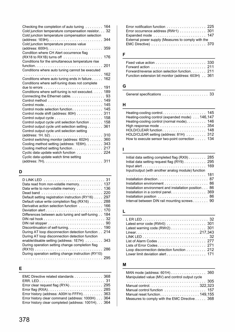
Checking the completion of auto tuning . . . . . . . . 164Cold junction temperature compensation resistor. . . 32Cold junction temperature compensation selection (address: 1E9H). . . . . . . . . . . . . . . . . . . . . . . . . 344Cold junction temperature process value (address: 600H) . . . . . . . . . . . . . . . . . . . . . . . . . 359Condition where CH Alert occurrence flag (RX18 to RX1B) turns off . . . . . . . . . . . . . . . . . . 176Conditions for the simultaneous temperature rise function. . . . . . . . . . . . . . . . . . . . . . . . . . . . . . . 201Conditions where auto tuning cannot be executed . . . . . . . . . . . . . . . . . . . . . . . . . . . . . . . . . . . . 162Conditions where auto tuning ends in failure . . . . . 162Conditions where self-tuning does not complete due to errors . . . . . . . . . . . . . . . . . . . . . . . . . . . 191Conditions where self-tuning is not executed. . . . . 189Connecting the Ethernet cable. . . . . . . . . . . . . . . . 93Control method . . . . . . . . . . . . . . . . . . . . . . . . . 149Control mode. . . . . . . . . . . . . . . . . . . . . . . . . . . 145Control mode selection function. . . . . . . . . . . . . . 145Control mode shift (address: 80H) . . . . . . . . . . . . 311Control output cycle . . . . . . . . . . . . . . . . . . . . . . 158Control output cycle unit selection function . . . . . . 158Control output cycle unit selection setting . . . . . . . 361Control output cycle unit selection setting (address: 1H. b2) . . . . . . . . . . . . . . . . . . . . . . . . 310Control switching monitor (address: 602H) . . . . . . 360Cooling method setting (address: 1E6H). . . . . . . . 343Cooling method setting function. . . . . . . . . . . . . . 217Cyclic data update watch function . . . . . . . . . . . . 224Cyclic data update watch time setting (address: 7H). . . . . . . . . . . . . . . . . . . . . . . . . . . 311
D
D LINK LED . . . . . . . . . . . . . . . . . . . . . . . . . . . . 31Data read from non-volatile memory. . . . . . . . . . . 137Data write to non-volatile memory . . . . . . . . . . . . 136Dead band . . . . . . . . . . . . . . . . . . . . . . . . . . . . 220Default setting registration instruction (RY16) . . . . 297Default value write completion flag (RX16) . . . . . . 288Derivative action selection function . . . . . . . . . . . 166Deviation alert . . . . . . . . . . . . . . . . . . . . . . . . . . 170Differences between auto tuning and self-tuning . . 184DIN rail hook . . . . . . . . . . . . . . . . . . . . . . . . . . . . 32DIN rail stopper . . . . . . . . . . . . . . . . . . . . . . . . . . 90Discontinuation of self-tuning. . . . . . . . . . . . . . . . 190During AT loop disconnection detection function . . 214During AT loop disconnection detection function enable/disable setting (address: 1E7H) . . . . . . . . 343During operation setting change completion flag (RX10) . . . . . . . . . . . . . . . . . . . . . . . . . . . . . . . 286During operation setting change instruction (RY10) . . . . . . . . . . . . . . . . . . . . . . . . . . . . . . . . . . . . 295
E
EMC Directive related standards . . . . . . . . . . . . . 368ERR. LED . . . . . . . . . . . . . . . . . . . . . . . . . . . . . . 31Error clear request flag (RYA) . . . . . . . . . . . . . . . 295Error flag (RXA) . . . . . . . . . . . . . . . . . . . . . . . . . 285Error history (address: A00H to FFFH) . . . . . . . . . 363Error history clear command (address: 1000H) . . . 364Error history clear completed (address: 1001H). . . 364
Error notification function . . . . . . . . . . . . . . . . . . 225Error occurrence address (RWr1) . . . . . . . . . . . . 301Expanded mode . . . . . . . . . . . . . . . . . . . . . . . . 147External power supply (Measures to comply with the EMC Directive) . . . . . . . . . . . . . . . . . . . . . . . . . 370
F
Fixed value action . . . . . . . . . . . . . . . . . . . . . . . 330Forward action . . . . . . . . . . . . . . . . . . . . . . . . . 211Forward/reverse action selection function. . . . . . . 211Function extension bit monitor (address: 603H) . . 361
G
General specifications . . . . . . . . . . . . . . . . . . . . . 33
H
Heating-cooling control. . . . . . . . . . . . . . . . . . . . 145Heating-cooling control (expanded mode) . . . 146,147Heating-cooling control (normal mode). . . . . . . . . 146High response mode . . . . . . . . . . . . . . . . . . . . . 354HOLD/CLEAR function. . . . . . . . . . . . . . . . . . . . 148HOLD/CLEAR setting (address: 81H) . . . . . . . . . 312How to execute sensor two-point correction . . . . . 134
I
Initial data setting completed flag (RX9) . . . . . . . . 285Initial data setting request flag (RY9) . . . . . . . . . . 295Input alert . . . . . . . . . . . . . . . . . . . . . . . . . . . . . 169Input/output (with another analog module) function . . . . . . . . . . . . . . . . . . . . . . . . . . . . . . . . . . . . 181Installation direction . . . . . . . . . . . . . . . . . . . . . . . 87Installation environment . . . . . . . . . . . . . . . . . . . . 86Installation environment and installation position . . . 86Installation in a control panel. . . . . . . . . . . . . . . . 369Installation position . . . . . . . . . . . . . . . . . . . . . . . 86Interval between DIN rail mounting screws . . . . . . . 90
L
L ER LED . . . . . . . . . . . . . . . . . . . . . . . . . . . . . . 32Latest error code (RWr0) . . . . . . . . . . . . . . . . . . 301Latest warning code (RWr2) . . . . . . . . . . . . . . . . 301Linear. . . . . . . . . . . . . . . . . . . . . . . . . . . . . 217,343LINK LED . . . . . . . . . . . . . . . . . . . . . . . . . . . . . . 32List of Alarm Codes . . . . . . . . . . . . . . . . . . . . . . 277Lists of Error Codes . . . . . . . . . . . . . . . . . . . . . . 271Loop disconnection detection function . . . . . . . . . 212Lower limit deviation alert . . . . . . . . . . . . . . . . . . 171
M
MAN mode (address: 601H) . . . . . . . . . . . . . . . . 360Manipulated value (MV) and control output cycle . . . . . . . . . . . . . . . . . . . . . . . . . . . . . . . . . . . . 305Manual control. . . . . . . . . . . . . . . . . . . . . . . 322,323Manual control function . . . . . . . . . . . . . . . . . . . 157Manual reset function. . . . . . . . . . . . . . . . . . 149,155Measures to comply with the EMC Directive . . . . . 368
378
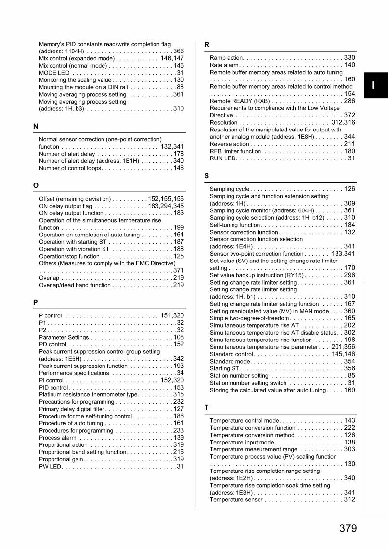
I
4
4
7
8
Memory’s PID constants read/write completion flag (address: 1104H) . . . . . . . . . . . . . . . . . . . . . . . . 366Mix control (expanded mode) . . . . . . . . . . . . 146,147Mix control (normal mode) . . . . . . . . . . . . . . . . . . 146MODE LED . . . . . . . . . . . . . . . . . . . . . . . . . . . . . 31Monitoring the scaling value . . . . . . . . . . . . . . . . . 130Mounting the module on a DIN rail . . . . . . . . . . . . . 88Moving averaging process setting. . . . . . . . . . . . . 361Moving averaging process setting (address: 1H. b3) . . . . . . . . . . . . . . . . . . . . . . . . 310
N
Normal sensor correction (one-point correction) function . . . . . . . . . . . . . . . . . . . . . . . . . . . 132,341Number of alert delay . . . . . . . . . . . . . . . . . . . . . 178Number of alert delay (address: 1E1H) . . . . . . . . . 340Number of control loops. . . . . . . . . . . . . . . . . . . . 146
O
Offset (remaining deviation) . . . . . . . . . . 152,155,156ON delay output flag . . . . . . . . . . . . . . . 183,294,345ON delay output function . . . . . . . . . . . . . . . . . . . 183Operation of the simultaneous temperature rise function . . . . . . . . . . . . . . . . . . . . . . . . . . . . . . . 199Operation on completion of auto tuning . . . . . . . . . 164Operation with starting ST . . . . . . . . . . . . . . . . . . 187Operation with vibration ST . . . . . . . . . . . . . . . . . 188Operation/stop function . . . . . . . . . . . . . . . . . . . . 125Others (Measures to comply with the EMC Directive). . . . . . . . . . . . . . . . . . . . . . . . . . . . . . . . . . . . . 371Overlap . . . . . . . . . . . . . . . . . . . . . . . . . . . . . . . 219Overlap/dead band function . . . . . . . . . . . . . . . . . 219
P
P control . . . . . . . . . . . . . . . . . . . . . . . . . . 151,320P1 . . . . . . . . . . . . . . . . . . . . . . . . . . . . . . . . . . . . 32P2 . . . . . . . . . . . . . . . . . . . . . . . . . . . . . . . . . . . . 32Parameter Settings . . . . . . . . . . . . . . . . . . . . . . . 108PD control . . . . . . . . . . . . . . . . . . . . . . . . . . . . . 152Peak current suppression control group setting (address: 1E5H) . . . . . . . . . . . . . . . . . . . . . . . . . 342Peak current suppression function . . . . . . . . . . . . 193Performance specifications . . . . . . . . . . . . . . . . . . 34PI control . . . . . . . . . . . . . . . . . . . . . . . . . . 152,320PID control . . . . . . . . . . . . . . . . . . . . . . . . . . . . . 153Platinum resistance thermometer type. . . . . . . . . . 315Precautions for programming . . . . . . . . . . . . . . . . 232Primary delay digital filter . . . . . . . . . . . . . . . . . . . 127Procedure for the self-tuning control . . . . . . . . . . . 186Procedure of auto tuning . . . . . . . . . . . . . . . . . . . 161Procedures for programming . . . . . . . . . . . . . . . . 233Process alarm . . . . . . . . . . . . . . . . . . . . . . . . . . 139Proportional action . . . . . . . . . . . . . . . . . . . . . . . 319Proportional band setting function. . . . . . . . . . . . . 216Proportional gain. . . . . . . . . . . . . . . . . . . . . . . . . 319PW LED. . . . . . . . . . . . . . . . . . . . . . . . . . . . . . . . 31
R
Ramp action. . . . . . . . . . . . . . . . . . . . . . . . . . . . 330Rate alarm. . . . . . . . . . . . . . . . . . . . . . . . . . . . . 140Remote buffer memory areas related to auto tuning. . . . . . . . . . . . . . . . . . . . . . . . . . . . . . . . . . . . . 160Remote buffer memory areas related to control method. . . . . . . . . . . . . . . . . . . . . . . . . . . . . . . . . . . . . 154Remote READY (RXB) . . . . . . . . . . . . . . . . . . . . 286Requirements to compliance with the Low Voltage Directive . . . . . . . . . . . . . . . . . . . . . . . . . . . . . . 372Resolution . . . . . . . . . . . . . . . . . . . . . . . . . 312,316Resolution of the manipulated value for output with another analog module (address: 1E8H) . . . . . . . . 344Reverse action . . . . . . . . . . . . . . . . . . . . . . . . . . 211RFB limiter function . . . . . . . . . . . . . . . . . . . . . . 180RUN LED. . . . . . . . . . . . . . . . . . . . . . . . . . . . . . . 31
S
Sampling cycle . . . . . . . . . . . . . . . . . . . . . . . . . . 126Sampling cycle and function extension setting (address: 1H) . . . . . . . . . . . . . . . . . . . . . . . . . . . 309Sampling cycle monitor (address: 604H) . . . . . . . . 361Sampling cycle selection (address: 1H. b12) . . . . . 310Self-tuning function . . . . . . . . . . . . . . . . . . . . . . . 184Sensor correction function . . . . . . . . . . . . . . . . . . 132Sensor correction function selection (address: 1E4H) . . . . . . . . . . . . . . . . . . . . . . . . . 341Sensor two-point correction function . . . . . . . 133,341Set value (SV) and the setting change rate limiter setting . . . . . . . . . . . . . . . . . . . . . . . . . . . . . . . . 170Set value backup instruction (RY15) . . . . . . . . . . . 296Setting change rate limiter setting. . . . . . . . . . . . . 361Setting change rate limiter setting (address: 1H. b1) . . . . . . . . . . . . . . . . . . . . . . . . 310Setting change rate limiter setting function . . . . . . 167Setting manipulated value (MV) in MAN mode . . . . 360Simple two-degree-of-freedom . . . . . . . . . . . . . . . 165Simultaneous temperature rise AT . . . . . . . . . . . . 202Simultaneous temperature rise AT disable status . . 302Simultaneous temperature rise function . . . . . . . . 198Simultaneous temperature rise parameter . . . 201,356Standard control . . . . . . . . . . . . . . . . . . . . . 145,146Standard mode. . . . . . . . . . . . . . . . . . . . . . . . . . 354Starting ST. . . . . . . . . . . . . . . . . . . . . . . . . . . . . 356Station number setting . . . . . . . . . . . . . . . . . . . . . 85Station number setting switch . . . . . . . . . . . . . . . . 31Storing the calculated value after auto tuning. . . . . 160
T
Temperature control mode. . . . . . . . . . . . . . . . . . 143Temperature conversion function . . . . . . . . . . . . . 222Temperature conversion method . . . . . . . . . . . . . 126Temperature input mode . . . . . . . . . . . . . . . . . . . 138Temperature measurement range . . . . . . . . . . . . 303Temperature process value (PV) scaling function. . . . . . . . . . . . . . . . . . . . . . . . . . . . . . . . . . . . . 130Temperature rise completion range setting (address: 1E2H) . . . . . . . . . . . . . . . . . . . . . . . . . 340Temperature rise completion soak time setting (address: 1E3H) . . . . . . . . . . . . . . . . . . . . . . . . . 341Temperature sensor . . . . . . . . . . . . . . . . . . . . . . 312
379
Temperature unit . . . . . . . . . . . . . . . . . . . . . . . . 312Terminal block cover . . . . . . . . . . . . . . . . . . . . . . 32Terminal block for external device connection . . . . . 32Terminal block for module power supply and FG . . . 32The simultaneous temperature rise parameter setting using self-tuning. . . . . . . . . . . . . . . . . . . . . . . . . 205Thermocouple type . . . . . . . . . . . . . . . . . . . . . . 313Three-position control . . . . . . . . . . . . . . . . . . . . . 221Time constant . . . . . . . . . . . . . . . . . . . . . . . . . . 127Transistor output monitor ON delay time setting (address: 1EAH) . . . . . . . . . . . . . . . . . . . . . . . . 345Two-position control . . . . . . . . . . . . 149,318,321,323
U
Unit Test . . . . . . . . . . . . . . . . . . . . . . . . . . . . . . 282Upper limit deviation alert . . . . . . . . . . . . . . . . . . 171Upper lower limit deviation alert . . . . . . . . . . . . . . 172
V
Vibration ST . . . . . . . . . . . . . . . . . . . . . . . . . . . 356
W
Warning flag (RX7). . . . . . . . . . . . . . . . . . . . . . . 284Water cooled . . . . . . . . . . . . . . . . . . . . . . . . 217,343When AUTO mode is shifted to MAN mode . . . . . 332When the measured value exceeds temperature measurement range . . . . . . . . . . . . . . . . . . . . . . 304When the measured value falls below temperature measurement range . . . . . . . . . . . . . . . . . . . . . . 304Wiring of an Ethernet cable . . . . . . . . . . . . . . . . . . 93Wiring of external devices and terminal blocks . . . . 96Wiring with a terminal block for module power supply and FG . . . . . . . . . . . . . . . . . . . . . . . . . . . . . . . . 91Within-range alert. . . . . . . . . . . . . . . . . . . . . . . . 172
380

I
4
4
7
8
381
Memo

382
REVISIONS
*The manual number is given on the bottom left of the back cover.
Japanese manual version SH-081210-C
2014 MITSUBISHI ELECTRIC CORPORATION
Print date *Manual number REVISIONS
January 2014 SH(NA)-081211ENG-A First edition
March 2016 SH(NA)-081211ENG-B
Added or modified parts
SAFETY PRECAUTIONS, RELEVANT MANUALS, TERMS, Section 1.2, CHAPTER 2,
Section 3.3, 3.7, 5.1, 6.5, 7.1, 7.2.1, 8.4.2, 9.3, 9.3.1 to 9.3.3, 11.1, 11.2, 11.4, 12.6
This manual confers no industrial property rights or any rights of any other kind, nor does it confer any patent licenses. Mitsubishi Electric
Corporation cannot be held responsible for any problems involving industrial property rights which may occur as a result of using the
contents noted in this manual.
383
WARRANTY
Please confirm the following product warranty details before using this product.
1. Gratis Warranty Term and Gratis Warranty RangeIf any faults or defects (hereinafter "Failure") found to be the responsibility of Mitsubishi occurs during use of the product within the gratis warranty term, the product shall be repaired at no cost via the sales representative or Mitsubishi Service Company.However, if repairs are required onsite at domestic or overseas location, expenses to send an engineer will be solely at the customer's discretion. Mitsubishi shall not be held responsible for any re-commissioning, maintenance, or testing on-site that involves replacement of the failed module.[Gratis Warranty Term]The gratis warranty term of the product shall be for one year after the date of purchase or delivery to a designated place.Note that after manufacture and shipment from Mitsubishi, the maximum distribution period shall be six (6) months, and the longest gratis warranty term after manufacturing shall be eighteen (18) months. The gratis warranty term of repair parts shall not exceed the gratis warranty term before repairs.[Gratis Warranty Range](1) The range shall be limited to normal use within the usage state, usage methods and usage environment, etc., which
follow the conditions and precautions, etc., given in the instruction manual, user's manual and caution labels on the product.
(2) Even within the gratis warranty term, repairs shall be charged for in the following cases.1. Failure occurring from inappropriate storage or handling, carelessness or negligence by the user. Failure caused
by the user's hardware or software design.2. Failure caused by unapproved modifications, etc., to the product by the user.3. When the Mitsubishi product is assembled into a user's device, Failure that could have been avoided if functions
or structures, judged as necessary in the legal safety measures the user's device is subject to or as necessary by industry standards, had been provided.
4. Failure that could have been avoided if consumable parts (battery, backlight, fuse, etc.) designated in the instruction manual had been correctly serviced or replaced.
5. Failure caused by external irresistible forces such as fires or abnormal voltages, and Failure caused by force majeure such as earthquakes, lightning, wind and water damage.
6. Failure caused by reasons unpredictable by scientific technology standards at time of shipment from Mitsubishi.7. Any other failure found not to be the responsibility of Mitsubishi or that admitted not to be so by the user.
2. Onerous repair term after discontinuation of production(1) Mitsubishi shall accept onerous product repairs for seven (7) years after production of the product is discontinued.
Discontinuation of production shall be notified with Mitsubishi Technical Bulletins, etc.(2) Product supply (including repair parts) is not available after production is discontinued.
3. Overseas serviceOverseas, repairs shall be accepted by Mitsubishi's local overseas FA Center. Note that the repair conditions at each FA Center may differ.
4. Exclusion of loss in opportunity and secondary loss from warranty liabilityRegardless of the gratis warranty term, Mitsubishi shall not be liable for compensation to:(1) Damages caused by any cause found not to be the responsibility of Mitsubishi.(2) Loss in opportunity, lost profits incurred to the user by Failures of Mitsubishi products.(3) Special damages and secondary damages whether foreseeable or not, compensation for accidents, and
compensation for damages to products other than Mitsubishi products.(4) Replacement by the user, maintenance of on-site equipment, start-up test run and other tasks.
5. Changes in product specificationsThe specifications given in the catalogs, manuals or technical documents are subject to change without prior notice.
384
TRADEMARKS
Ethernet is a registered trademark of Fuji Xerox Corporation in Japan.
The company names, system names and product names mentioned in this manual are either registered trademarks or
trademarks of their respective companies.
In some cases, trademark symbols such as '' or '' are not specified in this manual.
SH(NA)-081211ENG-B


SH(NA)-081211ENG-B(1603)MEE
MODEL: CCIEF-TC-U-E
MODEL CODE: 13JZ89
Specifications subject to change without notice.
When exported from Japan, this manual does not require application to theMinistry of Economy, Trade and Industry for service transaction permission.
HEAD OFFICE : TOKYO BUILDING, 2-7-3 MARUNOUCHI, CHIYODA-KU, TOKYO 100-8310, JAPANNAGOYA WORKS : 1-14 , YADA-MINAMI 5-CHOME , HIGASHI-KU, NAGOYA , JAPAN