Designing a Motion Control System for a Motorized Robot Arm (1DOF)
Upload
khangminh22Category
view
1download
0
CALIFORNIA STATE UNIVERSITY, NORTHRIDGE
Software Implementation
Of Motion Control Robotic Arm using Arduino
A graduate project submitted in partial fulfillment of the requirements
For the degree of Master of Science in Electrical Engineering
By Apurva Sinha
December 2019
ii
The graduate project of Apurva Sinha is approved:
__________________________ ` _______________ Dr. Ashley Geng Date
__________________________ _______________ Dr. Ramin Roosta Date
__________________________ _______________ Dr. Shahnam Mirzaei, Chair Date
California State University, Northridge

iii
iii
Acknowledgements
I would like to thank my graduate advisor at California State University Northridge, Dr. Mirzaei, for his guidance and inputs during the course of this project. My thanks also extends to Dr. Roosta, Dr. Geng, Javier Anguianu and Dr. Sembiam for helping me succeed in my education and project.
I also want to thank my parents and my in-laws for being an effective support system throughout my life and providing me opportunities to succeed.
Last but not least I want to thank my husband Mr. Anish Akhauri for believing in me, providing me with all the necessary support and allowing me to pursue my dream. I want to give credit to my daughter Advika Akhauri who allowed me to study and finish my course.

iv
Table of Contents
Signature Page ii
Acknowledgements iii
List of Figures vi
List of Tables vii
Abstract viii
1 Introduction to Embedded System 1 2 Hardware Used 2
2.1 The Arduino Board 2
2.1.1 Board Types 2
2.1.2 Arduino Board Description 2
2.1.3 Arduino Pins Function 3
2.2 Braccio Robotic Arm 5
2.3 Braccio Shield 6
2.4 Servo Motor 6 2.4.1 How is the servo controlled? 7
2.5 Infrared Remote Control and Receiver 8
3 The Software 9
3.1 The C Programming Language 9
Key Applications of C language 9
3.2 Functions 10
3.2.1 Structure of the functions: 10
3.2.2 Why do we need functions? 10 3.2.3 Function Declaration: 11
3.2.4 Parameter passing to functions 11
3.3 Switch Case 11
3.3.1 How does the switch statement work? 11
3.3.2 Switch Statement Flowchart 12
3.4 C programing Libraries 12
3.4.1 Servo Motor Library 13
3.4.2 IRremote Library 13
4 Block Diagram 14

v
v
5 Arduino IDE 15
5.1 Writing Sketches 15
5.2 Sketchbook 15
5.3 Uploading 15
5.4 Serial Monitor 15 5.5 Programing in Arduino 16
5.6 What is Variable Scope? 16
5.6.1 Local Variables 16
5.6.2 Global Variables 16
6 Flowchart 17
7 Flow of Program 18
7.1 BUTTON 0 - Set initial position 18
7.2 BUTTON 1 - Pick 0 18 7.3 BUTTON 2 - Pick 90 20
7.4 BUTTON 3 - Pick 180 21
7.5 BUTTON 4 - Drop 0 23
7.6 BUTTON 5 - Drop 90 24
7.7 BUTTON 6 - Drop 180 25
Work Cited 26
Appendix: Source Code 27

vi
List of Figures
Fig 1 - Block Diagram of an Embedded System 1 Fig 2 - An Arduino Uno Board 3 Fig 3 - A Braccio Robotic Arm 5 Fig 4 - A Braccio Shield 6 Fig 5 - The guts of a servo motor (L) and an assembled servo (R) 7 Fig 6 - Variable Pulse width control servo position 7 Fig 7 - Infrared Remote 8 Fig 8 - Flowchart for Switch case 12 Fig 9 - Block Diagram of the System 14 Fig 10 - Flowchart of the system 17 Fig 11.1 - Block diagram for Button 1 19 Fig 11.2 - Block Diagram for Button 2 21 Fig 11.3 - Block Diagram for Button 3 22 Fig 11.4 - Block Diagram for Button 4 23 Fig 11.5 - Block Diagram for Button 5 24 Fig 11.6 - Block Diagram for Button 6 25

vii
vii
List of Tables
Table 2.1 - Change in the position of motor on function call 19 Table 2.2 - Change in the position of motor on function call 20 Table 2.3 - Change in the position of motor on function call 22

viii
Abstract
Software Implementation of Motion Control Robotic Arm using Arduino.
By Apurva Sinha
Master of Science in Electrical Engineering
Robots are machines that can deal with an assortment of undertakings at fast and accuracy. Robots are utilized where work is hard for people, (for example, work in concoction and atomic reactors). The automated arm can be utilized from an assortment of motors. The most widely recognized kind of motor is the DC engine servo. There are a few different ways to control the servo engines of the DC. The motivation behind this paper is to control the arms of the robot utilizing the Arduino board.

1
1
1 Introduction to Embedded System
A hardware having software implanted inside it constitutes an Embedded system. The word embedded is a Latin word which means attachment of systems. Embedded systems normally comprise of a Microprocessor or Microcontroller, designed to perform a specific task. For ex-digital lock with the code will only open when the code entered matches with the dedicated code, a heater’s remote will only make the room warmer by pressing its button to get the desired temperature. Embedded system can be used as a stand-alone system or be integrated to a larger infrastructure.
Fig 1 - Block Diagram of an Embedded System
An Arduino Controlled Robot is also one of the examples of Embedded System. A robotic arm is a robot, which moves its arm to perform some specific tasks like picking and dropping some stuff by moving in a particular direction and at certain degrees.
The Arm has Servomotors inside it. The motors move according to the commands given to it by the Arduino board through Arduino IDE Software. The software run some specific code and interacts with the Servo Motors so that the Arm can perform desired task. In order to do so, specific hardware like Arduino board, Braccio Robotic Arm, IR Remote Control, Servo Motors and Trans receiver are required and the software used is Arduino IDE. Let's discuss them in detail.

2
2 Hardware Used
The different hardware used for perfect interaction of Robot Arm with Arduino is discussed below: -
2.1 The Arduino Board Arduino is open-source equipment consisting of two primary parts: initial, a programmable circuit board can be termed as a microcontroller and second, Arduino IDE (Integrated Development Environment) used for programming, in which the PC code can be composed and transferred to the physical board. There are many key highlights in Arduino Board. An info sign like simple or computerized can be perused by the Arduino sheets from various sensors and can be done to get wanted yield like turning LED ON/OFF, moving an engine, associating with mists and numerous other tasks. The Microcontroller on the board controls the elements of the board by sending a lot of explicit guidelines to it through Arduino IDE. Arduino needn't bother with an additional bit of equipment (called a programmer), unlike most past programmable circuit sheets, so as to stack another code onto the board. A straightforward USB link can be utilized. So as to gain proficiency with a program effectively the Arduino IDE utilizes a rearranged adaptation of C++. One of the standard structure components of Arduino is that it breaks the elements of the small-scale controller into an increasingly available bundle.
2.1.1 Board Types
Every Arduino board is unique depending upon the type of microcontroller being used. Some Arduino boards work with 3.7V battery, some work with 5V. Arduino boards differ by the sensors used for LED, speed, voltage used for operation etc.
2.1.2 Arduino Board Description The Arduino is shown in the following figure with description of pins. The figure is followed by an explanation of the task of each pin.

3
3
Fig 2 - An Arduino Uno Board
2.1.3 Arduino Pins Function
➢ Power USB The USB cable the computer is used to power an Arduino Board by connecting the USB cable to the USB connection (1) available in the board.
➢ Power (Barrel Jack) AC mains Power supply connects to Barrel Jack (2) . The Arduino itself as little power supply of about 3V to 5V, but inbuilt supply is not sufficient for this Project, so we seek outside power source.
➢ Voltage Regulator The voltage given to the Arduino Board is controlled by the Voltage Regulator. With the help of Processor and other elements, a DC Voltage is stabilized.

4
➢ Crystal Oscillator
When Arduino have any time issues, Crystal Oscillator helps it. Arduino Reset The button (17) allows the Program to start over again. Is usually pressed in case of errors or when the system is hang.
➢ Pins (3.3, 5, GND, Vin) 3.3V (6) and 5V (7): These are the inbuilt power supply. GND (8)(Ground): Connects to ground. Vin (9): Connect this pin with external power supply.
➢ Analog pins The pins A0 to A5 are used to read analog input signals and later are converted to digital form so that microprocessor can understand.
➢ Power LED pointer Every time the Arduino is connected to the power source the on board LED Light will turn ON, if not, then there is something wrong.
➢ AREF AREF stands for Analog Reference, for setting external reference voltage.
5
5
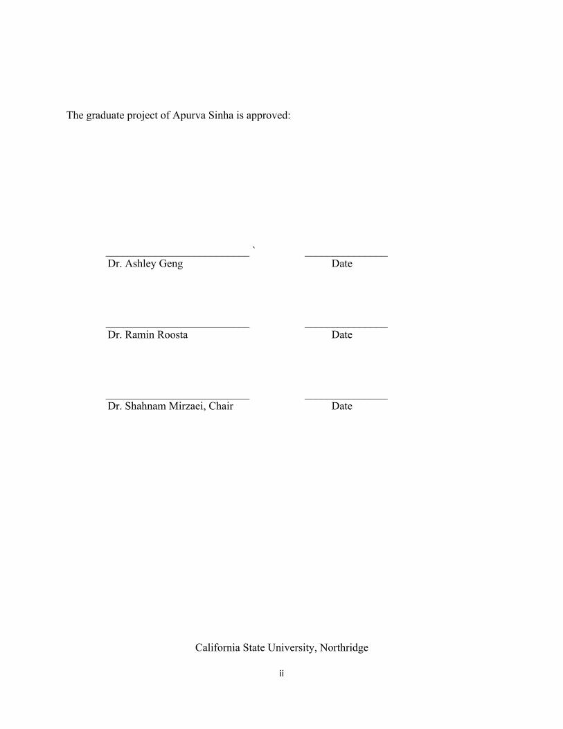
2.2 Braccio Robotic Arm The Arduino controls the Tinker Kit Braccio’s fully operational robotic arm. The Robotic Arm can be assembled in a variety of ways to perform multiple tasks such as moving objects. A camera or solar panel can also be attached to it.
Fig 3 - A Braccio Robotic Arm
6
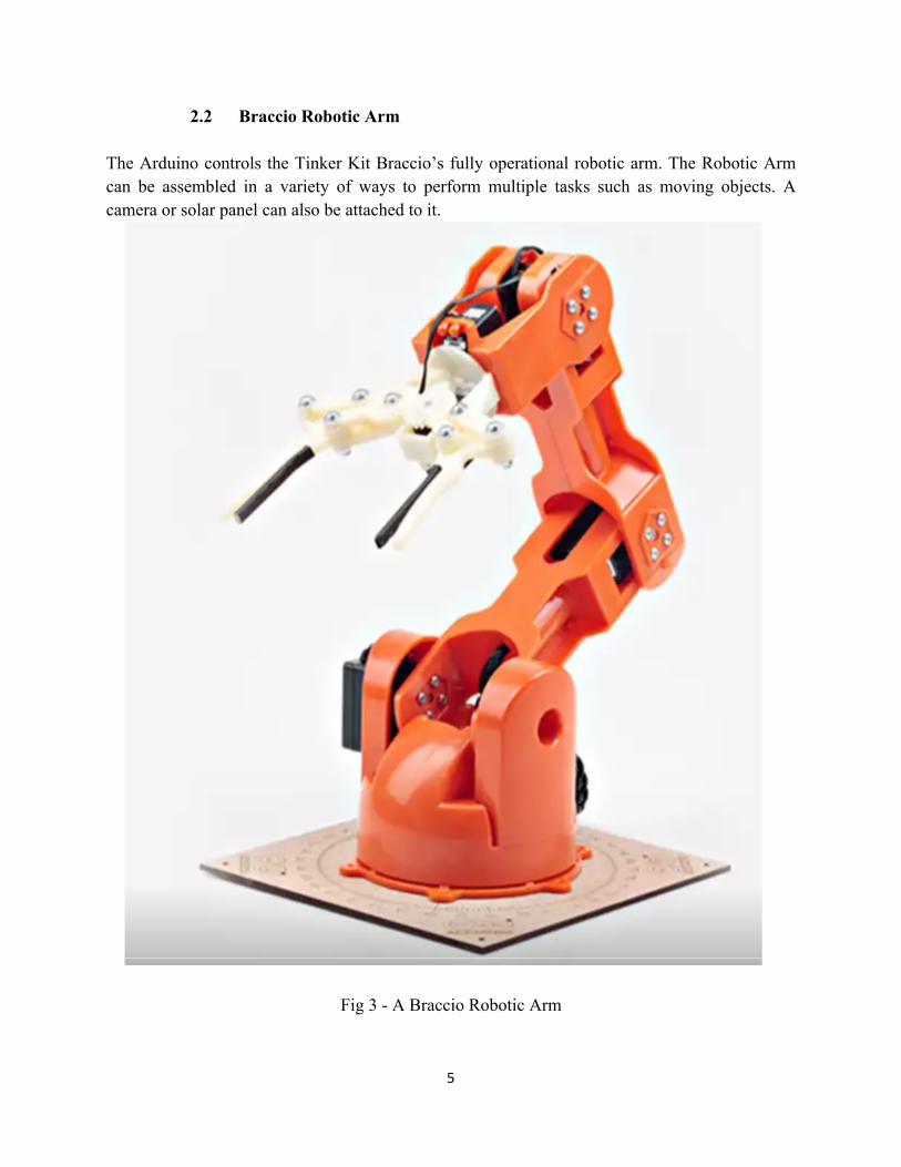
2.3 Braccio Shield In this project, we are not connecting the computer directly to the board but to the shield. The shield is put above the board. It has specific holes so that Arduino board can fully immerse in it. It has power connections for the six motors used, external power supply. It contains micropreocessor and inbuilt power supply.
Fig 4 - A Braccio Shield
2.4 Servo Motor A Servo Motor is used where rotation work is required. It contains a shaft which when given minimum amount of Pulse Signal is rotated in a desired direction. It is a closed loop system in which motor is coupled with a sensor for getting desired position .The drive used in the system controls precisely the rotatory position of the shaft and thus it can act as an alternative to Stepper Motors and AC Induction Motors.

7
7
2.4.1 How is the servo controlled?
Fig 5 – Inside of a servomotor (L) and an assembled servo (R) An electrical beat of variable width which is prevalently known as Pulse Width Modulation (PWM) are utilized to control servo engines. A servo engine can normally point 90° in either course for a total of 180° . The situation of the pole of the engine is controlled by the PWM sent to the engine and the rotor will go to the ideal position as sent by means of the wire. After each 20 millisecond (ms), the servo engine hopes to see a beat and how far the engine turns will be dictated by the length of the beat. For instance, the engine will go to the 90° position if a 1.5ms pulse is given to it. It will move in counter-clockwise course, around the 0° position, in the event that it gets beat shorter than 1.5ms. So as to move the engine a Clockwise way, towards the 180° position the beat longer than 1.5ms ought to be sent.
Fig 6 - Variable Pulse width control servo position

8
2.5 Infrared Remote Control and Receiver
An IR remote control uses light to send data from the transmitter to the receiver to perform the specific operation. In many cases both the transmitter and receiver should be in the line of sight. The signal travels in the infrared region as the name suggest. The operations performed are for example turning ON/OFF power, increasing decreasing volume, changing channels etc. .
Fig 7 - Infrared Remote

9
9
3 The Software The software used is Arduino IDE, in which, the C programming language is used to interact with the whole robotic Arm system. Let’s discuss C language in detail.
3.1 The C Programming Language C is a universally useful programming language. Various areas, for example, working frameworks, numerical figuring, graphical applications, and so on are customized utilizing the C language. C has 32 catchphrases so it is a little language. It gives elevated level organized programming builds, for example, explanation gathering, basic leadership, and circling, just as low-level abilities, for example, controlling bytes and addresses. C can be adapted rapidly and needs little space to be portrayed. A software engineer can sensibly hope to know and comprehend and for sure normally utilize the whole language. C accomplishes its smaller size by giving straightforward administrations inside the language legitimate, previous a large number of the more significant level highlights regularly implicit to different dialects. For instance, C furnishes no activities to manage composite items, for example, records or clusters. There are no memory the executive’s offices separated from static definition and stack-assignment of nearby factors and there are no info/yield offices, for example, for printing to the screen or keeping in touch with a document. A great part of the usefulness of C is given by method for programming schedules called capacities. The language is joined by a standard library of capacities that give an accumulation of generally utilized tasks. For instance, the standard capacity printf() prints content to the screen. The standard library will be utilized broadly all through this content; it is imperative to abstain from composing your very own code when a right and convenient execution as of now exists. Key Applications of C language
Ø Utilized in installed frameworks. Ø Utilized for creating framework applications. Ø Utilized for creating work area applications. Ø Google's Chromium and other creating program and their expansions are constructed
utilizing 'C' programming language. Ø Utilized for creating work area just as cell phone's working framework. Ø Utilized for compiler creation. Ø Utilized in IOT applications. Ø Used to create databases. For example SQL is assembled utilizing 'C'. Ø Working frameworks, for example, all major Operating Systems are created utilizing 'C'
language.

10
3.2 Functions
3.2.1 Structure of the functions:
A function takes some information; perform particular calculation and gives answer. Rather than composing a similar code over and over for various information sources, a function can be called on boundless occasions. Breaking of huge registering errands into littler ones is the thing that a function does. A suitable function explains the entire program and facilitates the agony to make changes by concealing the subtleties of activity from parts of the program that don't have to think about them. So as to make functions productive and simple to utilize, C has been structured. A program may dwell in at least one-source records. Alongside recently aggregate functions from libraries, source documents are incorporated independently and stacked together, Function presentation and definition is where the ANSI standard has rolled out the most improvements to C. At the point when a function is announced the contentions can likewise be pronounced in the enclosures. At the point when contentions are appropriately proclaimed, explicit activities can be performed consequently. The contentions can be passed in nonexclusive manner or as a source of perspective parameters. In the event that need to change the estimation of the parameter passed, it ought to be passed as a kind of perspective to the address. A Function could conceivably have return type. On the off chance that a function is restoring some worth it needs a variable to store it.
3.2.2 Why do we need functions?
Ø Aides in diminishing code excess. Assume a function is required at various places in a specific program. Then instead of composing a similar code over and over, a function call is made and it is utilized all over. On the off chance that a function should be changed in the usefulness, it very well may be done effectively in one spot. Along these lines it likewise helps in upkeep.
Ø Functions help in Data Encapsulation. Consider a major record having numerous lines of codes. In the event that the code is partitioned into capacities. It turns out to be extremely easy to peruse and utilize the code.
Ø Capacities give Data Abstraction. For instance, while utilizing library capacities, one
doesn't need to stress over the inner working of extraordinary projects.

11
11
3.2.3 Function Declaration:
Declaring a function is typically telling the function the details function posses. Through this, the compiler get to know the return type of the function, the argument passed to the function and the number of parameter passed to the function.
3.2.4 Parameter passing to functions
Actual Parameters are the parameters, which are passed to a function where as Formal Parameters are the parameters gotten by work. The parameters can be passed by value or by reference.
3.3 Switch Case
In the switch statement, one code block can be executed among many different alternatives. Although the same thing can be done with the if-else, but the syntax of switch statement is simple to understand and write.
3.3.1 How does the switch statement work?
The articulation or proclamation is assessed once. It is then contrasted and the estimations of each case name. In the event that the announcement is genuine, the comparing proclamations are executed. For instance, if the estimation of the articulation is equivalent to variable 1, explanations after case variable 1: are executed until "break" is experienced. On the off chance that the announcement is false, the cursor will continue checking the following articulations until the genuine condition is acquired.
All announcements will be executed on the off chance that we don't utilize break. The default proviso inside the switch explanation is discretionary.

12
3.3.2 Switch Statement Flowchart The flowchart for The Switch Statement is as follows: -
Fig 8 - Flowchart for Switch case
3.4 C programing Libraries
C Standard library are inbuilt functions in C programming. The model and information meanings of these libraries are available in their separate header files. In request to utilize the function, one needs to incorporate the header document in the program. For instance, if we need to utilize the b work, the header record <stdio.h> ought to be included. If we attempt to utilize printf() without including the stdio.h header document, we will get an error. In this Project, we have utilized Servo Motor Library and IR Remote control library, which are talked about in detail as pursues: -

13
13
3.4.1 Servo Motor Library
The Servo Motor Library allows to control the servo motors through an Arduino Board. There is a certain range of angles of the shaft (i.e. between 0 degree to 180 degrees) at which the shaft can be positioned. The internal parts of Servo contain gears and shafts, which can be precisely controlled. For ex in the rotating servo, the shaft can be spinned at various controlled speeds.
The Servo Library allows up to 12 motors on various Arduino Boards. If we use the library than we don't have to define and write code for each and every function related to servos again and again. For example there are certain inbuilt, which needs to be called again and again by the servo. So we can use servo library, which already has their function definition, and thus a tiresome job of explaining and rewriting the function definition is saved.
3.4.2 IRremote Library
IRremote enables one to get or transmit Infrared Remote Control codes. You can make your undertakings constrained by a remote, or make them control different gadgets like TVs and stereo segments. IRremote has 2 libraries: one for sending and one for accepting. Coming up next are a few directions utilized in the IR Remote Library: - IRrecv irrecv(receivePin) - Creates the recipient object. The name can be picked by the individual. Irrecv.enableIRIn() - It denotes the start of the accepting procedure. This clock hinder is empowered which, in each 50 µs, expends a modest quantity of CPU. Irrecv.decode(& results) - Used for getting an IR code. Returns genuine if a code was gotten, or false if nothing got at this point. Data is put away into "results" , when a code is gotten.

14
4 Block Diagram
Fig 9 - Block Diagram of the System
15
15
5 Arduino IDE
Ab Arduino Integrated Development Environment has the following components: -
• A text editor - It is used to write the program, • A text console - It is a toolbar containing buttons to perform some normal operations • A message area • A series of menus - Interact with Arduino to upload and exchange information with
programs
5.1 Writing Sketches
The programs that we write are called Sketches. We can Cut, Copy and paste inside the sketch. When the sketch is uploaded it is compiled to check if there is any error message or not. If there is any error or warning it is displayed at the bottom of the sketch. It contains toolbar buttons to create, open and save sketches, upload programs and serial monitor.
5.2 Sketchbook
A sketchbook is used to store the programs. All the files are stored with .ino extension name. If you want to open the sketch, go to File and under File go to Sketchbook menu or else there is a button on the toolbar namely open, just click the button.
5.3 Uploading
An Arduino Bootloader is utilized for uploading the sketch. An Arduino Bootloader (software stuffed on to the microcontroller) and all this process without an extra piece of hardware. When you press the reset button, the bootloader gets activated for a few seconds and then it eventually will upload the most recent sketch to the Microcontroller by blinking the onboard Led Pin, which at pin 13.
5.3 Serial Monitor
When we send serial data from Arduion Board over USB, it is displayed on Serial Monitor .In this project , when we press button from IR Remote , it is received as HEX number on the Serial Monitor. The HEX is converted into its Decimal equivalent in order to use it in a program .The baud rate is selected to transmit the desired number of bits per second so as to get desired amount of speed.

16
5.4 Programing in Arduino
An Arduino program has 3 main parts:
1. Structure 2. Values (variables and constants) 3. Functions.
Arduino IDE Software has 2 functions:
1. Setup() 2. Loop()
When we open a sketch and start writing program, the setup function gets activated. It contains that part of program, which doesn’t require any loop as it run only once. It contained general information of the program line Pinmode, variable initialization, declaring initial value etc. If we write to write a set of programs which need repetition, we can write that in loop() function. It allows program to run consecutively n times and if the condition is true it will be executed several times .It should be used to actively control the Arduino board.
5.5 What is Variable Scope?
In C, the scope is a region of the program where variables can be declared. Following are the three places where the variables are declared. They are:
1. Within a function body called local variables. 2. Function parameters definition called formal parameters. 3. Outside every function called global variables.
5.5.1 Local Variables
A local variable has a scope limited to the function or method inside which it is defined. It cannot be used all through the program.
5.5.2 Global Variables
Typically pronounced at the highest point of the program, Global variables are characterized outside of the considerable number of functions. The worldwide factors will hold their incentive for the duration of the lifetime of the program. In simple words, a global variable is accessible all through the program.

17
17
6 Flowchart
Fig 10 - Flowchart of the system?

18
7 Flow of Program
The Arduino Uno board is connected to the Robotic Arm in which 6 servo motors are attached. When the buttons in the IR Remote is pressed following things happen in the program: -
7.1 BUTTON 0 - Set initial position
When button 0 is pressed signal is received by transmitter. Its hex decimal is converted and can be seen on Serial Monitor. The function SetInitialPosition() is executed in which the servo motors take the following position:-
➢ Base - 90° ➢ Shoulder - 45° ➢ Elbow - 180° ➢ Vertical Wrist - 0° ➢ Horizontal Wrist - 0° ➢ Gripper - 73°
7.2 BUTTON 1 - Pick 0
The following happens when button 1 is pressed
➢ When button 1 is pressed through IR Remote, the corresponding signal is received by transmitter. The signal is converted into its hexadecimal, which can be seen on Serial Monitor.
➢ A series of functions are called and executed. The first function being called is Robotic Movement (90, step_base, 90, 90, 0, 0, 73). The parameters passed are showing the delay and current position of the servo motor. The next function is baseMovement (90, 0). This function allows the base servo motor to change its position from the initial position (step_base) to 0 degrees.
➢ The function RobotMovement() is called again. This time the parameters passed are different. All the positions of the motors are changed, which is shown in the table below

19
19
Table 2.1 - Change in the position of motor on function call
Motor position initial position (in degrees) current position (in degrees)
base step_base 0
elbow 90 60
shoulder 90 45
vertical wrist 0 0
horizontal wrist 0 60
gripper 73 10
This function is followed by function GripperMovement (90, 73) and at last shoulderMovement (90, 90) which sets the final position of gripper and shoulder to 73 degrees and 90 degrees respectively.
Fig 11.1 - Block diagram for Button 1

20
7.3 BUTTON 2 - Pick 90
The following happens when button 1 is pressed
➢ When button 2 is pressed through IR Remote, the corresponding signal is received by transmitter. The signal is converted into its hexadecimal, which can be seen on Serial Monitor.
➢ A series of functions are called and executed. The first function being called is Robotic Movement (90, step_base, 90, 90, 0, 0, 73). The parameters passed are showing the delay and current position of the servo motor. The next function is baseMovement (90, 90). This function allows the base servo motor to change its position from the initial position (step_base) to 90 degrees.
➢ The function RobotMovement() is called again. This time the parameters passed are different. All the positions of the motors are changed, which is shown in the table below
Table 2.2 - Change in the position of motor on function call
Motor position Initial Position (In Degrees) Current Position (In Degrees)
base step_base 90
elbow 90 60
shoulder 90 45
vertical wrist 0 0
horizontal wrist 0 60
gripper 73 10
This function is followed by function GripperMovement (90, 73) and at last shoulderMovement (90, 90) which sets the final position of gripper and shoulder to 73 degrees and 90 degrees respectively.

21
21
Fig 11.2 - Block Diagram for Button 2
7.4 BUTTON 3 - Pick 180 The following happens when button 3 is pressed
➢ When button 3 is pressed through IR Remote, the corresponding signal is received by transmitter. The signal is converted into its hexadecimal, which can be seen on Serial Monitor.
➢ A series of functions are called and executed. The first function being called is Robotic Movement (90, step_base, 90, 90, 0, 0, 73). The parameters passed are showing the delay and current position of the servo motor. The next function is baseMovement (90, 180). This function allows the base servo motor to change its position from the initial position (step_base) to 180 degrees.
➢ The function RobotMovement() is called again. This time the parameters passed are different. All the positions of the motors are changed, which is shown in the table below.

22
Table 2.3 - Change in the position of motor on function call
Motor position initial position (in degrees) current position( in degrees)
base step_base 180
elbow 90 60
shoulder 90 45
vertical wrist 0 0
horizontal wrist 0 60
gripper 73 10
This function is followed by function GripperMovement (90, 73) and at last shoulderMovement (90, 90) which sets the final position of gripper and shoulder to 73 degrees and 90 degrees respectively.
Fig 11.3 - Block Diagram for Button 3

23
23
7.5 BUTTON 4 - Drop 0 The following happens when button 4 is pressed
➢ When button 4 is pressed through IR Remote, the corresponding signal is received by transmitter. The signal is converted into its hexadecimal, which can be seen on Serial Monitor.
➢ A series of functions are called and executed. The functionbaseMovement (90, 90) is called which sets the current position of base from initial position to 90 degrees, followed by the robot Movement (90, 90, 60, 45, 0, 60, 73).
➢ This function is followed by function GripperMovement (90, 10) and at last shoulderMovement (90, 90) which sets the final position of gripper and shoulder to 10 degrees and 90 degrees respectively.
Fig 11.4 - Block diagram for Button 4
24
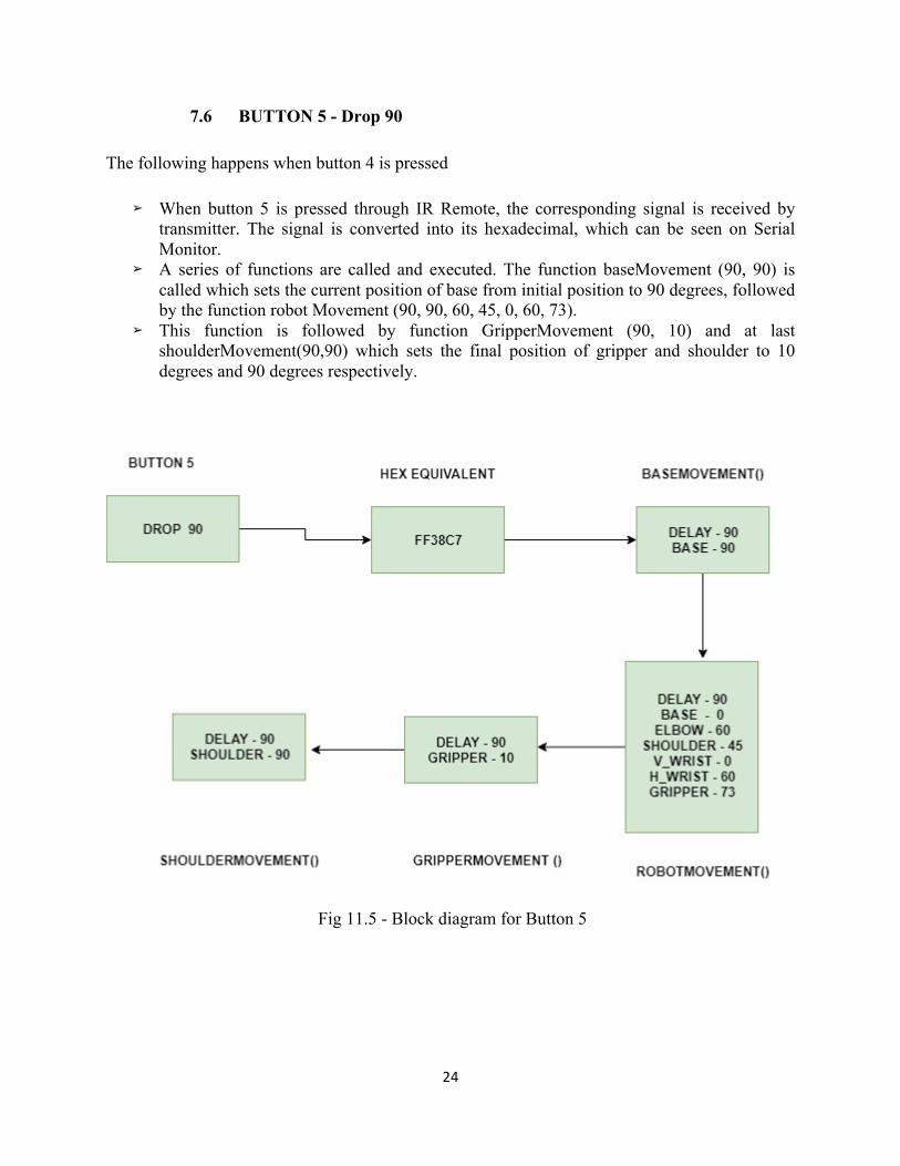
7.6 BUTTON 5 - Drop 90 The following happens when button 4 is pressed
➢ When button 5 is pressed through IR Remote, the corresponding signal is received by transmitter. The signal is converted into its hexadecimal, which can be seen on Serial Monitor.
➢ A series of functions are called and executed. The function baseMovement (90, 90) is called which sets the current position of base from initial position to 90 degrees, followed by the function robot Movement (90, 90, 60, 45, 0, 60, 73).
➢ This function is followed by function GripperMovement (90, 10) and at last shoulderMovement(90,90) which sets the final position of gripper and shoulder to 10 degrees and 90 degrees respectively.
Fig 11.5 - Block diagram for Button 5

25
25
7.7 BUTTON 6 - Drop 180 The following happens when button 6 is pressed
➢ When button 6 is pressed through IR Remote, the corresponding signal is received by transmitter. The signal is converted into its hexadecimal, which can be seen on Serial Monitor.
➢ A series of functions are called and executed. The function baseMovement (90, 180) is called which sets the current position of base from initial position to 180 degrees, followed by the robot Movement (90, 180, 60, 45, 0, 60, 73).
➢ This function is followed by function GripperMovement (90, 10) and at last shoulderMovement (90, 90), which sets the final position of gripper and shoulder to 10 degrees and 90 degrees respectively.
Fig 11.6 - Block diagram for Button 6

26
Work Cited
[1] S. Mark, H. Seth, M. Vidyasagar, Robot modeling and control, John Wiley & Sons, 2006.
[2] Jamshed Iqbal, Razaul Islam, Hamza Khan, "Modeling and Analysis of a 6 DOF Robotic A Manipulator", Canadian Journal on Electrical and Electronics Engineering, vol. 3, no. 6, pp. 300-306, July 2012.
[3] Edwin Basil Mathew et al., "Robotic arm control through human arm movement detection using potentiometers", International Conference on recent developments in control Automation and power Engineering, 2015.
[4] Michael Margolis: Make an Arduino Controlled Robot, O’Reilly, 1999. [5] Random Nerd Tutorials., “Arduino - Control LED's with IR Remote Control”, 2017. [6] Joseph L. Jones: Robot Programing- A Practical Guide to Behaviour Based Robotics, Mc
Graw Hill, 2004. [7] Ken. Shirrif “IRremote Library, Send & Receive Infrared Remote Control”, 2013
[8] www.arduino.cc [9] https://github.com/z3t0/Arduino-IRremote

27
27
Appendix: Source Code
#include <Servo.h> #include <IRremote.h> // IR Remote Control const int RECV_PIN = 7; IRrecv irrecv(RECV_PIN); decode_results results; // Low and High Limit Timeout for the Software PWM #define LOW_LIMIT_TIMEOUT 2000 #define HIGH_LIMIT_TIMEOUT 6000 // Low and High limit for the delay #define LOW_DELAY_LIMIT 10 #define HIGH_DELAY_LIMIT 100 // IR Remote values #define zero 16738455 #define one 16724175 #define two 16718055 #define three 16743045 #define four 16716015 #define five 16726215 #define six 16734885 //#define seven 16728765 //#define eight 16728765 //#define nine 16732845 // The software PWM is conncected to PIN 12. You cannot use the pin 12 if you are using // a Braccio shield V4 or newer const int SOFT_START_CONTROL_PIN = 12; // Motor Servo base; // M1 Servo shoulder; // M2 Servo elbow; // M3 Servo wrist_ver; // M4 Servo wrist_rot; // M5 Servo gripper; // M6 // Initial Position int initial_base = 90; int initial_shoulder = 45; int initial_elbow = 180;
28
int initial_wrist_ver = 0; int initial_wrist_rot = 0; int initial_gripper = 73; // Position of Servo Motors int step_base, step_shoulder, step_elbow, step_wrist_ver, step_wrist_rot, step_gripper; // Function Definition void robotSetup(); void setInitialMotorPosition(); void setCurrentMotorPosition(); void pick0(); void pick90(); void pick180(); void drop0(); void drop90(); void drop180(); void softStart(); void softwarePWM(int high_time_limit, int low_time_limit); void robotMovement(int step_delay, int v_base, int v_shoulder, int v_elbow, int v_wrist_ver, int v_wrist_rot, int v_gripper); void baseMovement(int step_delay, int v_base); void shoulderMovement(int step_delay, int v_shoulder); void elbowMovement(int step_delay, int v_elbow); void wrist_verMovement(int step_delay, int v_wrist_ver); void wrist_rotMovement(int step_delay, int v_wrist_rot); void gripperMovement(int step_delay, int v_gripper); void setup() { // put your setup code here, to run once: Serial.begin(9600); irrecv.enableIRIn(); irrecv.blink13(true); robotSetup(); } void loop() { if (irrecv.decode(&results)){ Serial.println(results.value, HEX); // Switch case to use the selected remote control button switch (results.value) { case zero: // When 0 is Pressed setInitialMotorPosition(); break; case one: // When 1 is Pressed

29
29
pick0(); break; case two: // When 2 is Pressed pick90(); break; case three: // When 3 is Pressed pick180(); break; case four: // When 4 is Pressed drop0(); break; case five: // When 5 is Pressed drop90(); break; case six: // When 6 is Pressed drop180(); break; default: setCurrentMotorPosition(); } // Receives the next value from the button irrecv.resume(); } } /* Braccio Robotic Arm initialization and set initial position */ void robotSetup() { pinMode(SOFT_START_CONTROL_PIN, OUTPUT); digitalWrite(SOFT_START_CONTROL_PIN, LOW); // Initialization pin Servo motors base.attach(11); shoulder.attach(10); elbow.attach(9); wrist_ver.attach(6); wrist_rot.attach(5); gripper.attach(3); // For each step motor this set up the initial degree setInitialMotorPosition(); // Previous step motor position setCurrentMotorPosition(); //Serial.print(step_base);

30
softStart(); } /* Function to set up all servo motors to initial degree */ void setInitialMotorPosition(){ robotMovement(100, initial_base, initial_shoulder, initial_elbow, initial_wrist_ver, initial_wrist_rot, initial_gripper); } /* Function to set all servo motors position to current */ void setCurrentMotorPosition(){ step_base = base.read(); step_shoulder = shoulder.read(); step_elbow = elbow.read(); step_wrist_ver = wrist_ver.read(); step_wrist_rot = wrist_rot.read(); step_gripper = gripper.read(); } /* Function to pick at 0 degree */ void pick0(){ robotMovement(90, step_base, 90, 90, 0, 0, 73); baseMovement(90, 0); robotMovement(90, 0, 60, 45, 0, 60, 10); gripperMovement(90, 73); shoulderMovement(90, 90); } /* Function to pick at 90 degree */ void pick90(){ robotMovement(90, step_base, 90, 90, 0, 0, 73); baseMovement(90, 90); robotMovement(90, 90, 60, 45, 0, 60, 10); gripperMovement(90, 73); shoulderMovement(90, 90); } /* Function to pick at 180 degree */ void pick180(){ robotMovement(90, step_base, 90, 90, 0, 0, 73); baseMovement(90, 180); robotMovement(90, 180, 60, 45, 0, 60, 10); gripperMovement(90, 73); shoulderMovement(90, 90);

31
31
} /* Function to drop at 0 degree */ void drop0(){ baseMovement(90, 0); robotMovement(90, 0, 60, 45, 0, 60, 73); gripperMovement(90, 10); shoulderMovement(90, 90); } /* Function to drop at 90 degree */ void drop90(){ baseMovement(90, 90); robotMovement(90, 90, 60, 45, 0, 60, 73); gripperMovement(90, 10); shoulderMovement(90, 90); } /* Function to drop at 180 degree */ void drop180(){ baseMovement(90, 180); robotMovement(90, 180, 60, 45, 0, 60, 73); gripperMovement(90, 10); shoulderMovement(90, 90); } /* * Sofware implementation of the PWM for the SOFT_START_CONTROL_PIN, HIGH * high_time: The time in the logic level high * low_time: The time in the logic level low */ void softwarePWM(int high_time, int low_time){ digitalWrite(SOFT_START_CONTROL_PIN, HIGH); delayMicroseconds(high_time); digitalWrite(SOFT_START_CONTROL_PIN, LOW); delayMicroseconds(low_time); } /* * This function, used only with the Braccio Shield V4 and greater, * turn ON the Braccio softly and save it from brokes. * The SOFT_START_CONTROL_PIN is used as a software PWM * soft_start_level: The minimum value is -70, default value is 0, default value is used */ void softStart(){ int soft_start_level = 0;

32
long int tmp = millis(); while (millis() - tmp < LOW_LIMIT_TIMEOUT) softwarePWM(80+soft_start_level, 450-soft_start_level); // The sum should be 530usec while (millis() - tmp < HIGH_LIMIT_TIMEOUT) softwarePWM(75+soft_start_level, 430-soft_start_level); // The sum should be 505usec digitalWrite(SOFT_START_CONTROL_PIN, HIGH); } /* * This function allows you to control all the servo motors * step_delay: The Delay between servo movement * v_base: Next base servo motor degree * v_shoulder: Next shoulder servo motor degree * v_elbow: Next elbow servo motor degree * v_wrist_ver: Next wrist vertical servo motor degree * v_wrist_rot: Next wrist rotation servo motor degree * v_gripper: Next gripper servo motor degree */ void robotMovement(int step_delay, int v_base, int v_shoulder, int v_elbow, int v_wrist_ver, int v_wrist_rot, int v_gripper){ int exit = 1; // set previous step motor position setCurrentMotorPosition(); // Check values, to avoid dangerous positions for the Braccio if (step_delay < LOW_DELAY_LIMIT) step_delay = LOW_DELAY_LIMIT; if (step_delay > HIGH_DELAY_LIMIT) step_delay = HIGH_DELAY_LIMIT; if (v_base < 0) v_base = 0; if (v_base > 180) v_base = 180; if (v_shoulder < 15) v_shoulder = 15; if (v_shoulder > 180) v_shoulder = 180; if (v_elbow < 0) v_elbow = 0; if (v_elbow > 180) v_elbow = 180; if (v_wrist_ver < 0) v_wrist_ver = 0; if (v_wrist_ver > 180) v_wrist_ver = 180; if (v_wrist_rot < 0) v_wrist_rot = 0; if (v_wrist_rot > 180) v_wrist_rot = 180; if (v_gripper < 10) v_gripper = 10; if (v_gripper > 73) v_gripper = 73; // Until all the motors are in the desired position while (exit)

33
33
{ // For each servo motor if next degree is not the same as the previous then do the movement if (v_base != step_base) { base.write(step_base); // One step ahead if (v_base > step_base) { step_base++; } // One step beyond if (v_base < step_base) { step_base--; } } if (v_shoulder != step_shoulder) { shoulder.write(step_shoulder); // One step ahead if (v_shoulder > step_shoulder) { step_shoulder++; } // One step beyond if (v_shoulder < step_shoulder) { step_shoulder--; } } if (v_elbow != step_elbow) { elbow.write(step_elbow); // One step ahead if (v_elbow > step_elbow) { step_elbow++; } // One step beyond if (v_elbow < step_elbow) { step_elbow--; } } if (v_wrist_ver != step_wrist_ver) { wrist_ver.write(step_wrist_ver); // One step ahead if (v_wrist_ver > step_wrist_ver) {

34
step_wrist_ver++; } // One step beyond if (v_wrist_ver < step_wrist_ver) { step_wrist_ver--; } } if (v_wrist_rot != step_wrist_rot) { wrist_rot.write(step_wrist_rot); // One step ahead if (v_wrist_rot > step_wrist_rot) { step_wrist_rot++; } // One step beyond if (v_wrist_rot < step_wrist_rot) { step_wrist_rot--; } } if (v_gripper != step_gripper) { gripper.write(step_gripper); // One step ahead if (v_gripper > step_gripper) { step_gripper++; } // One step beyond if (v_gripper < step_gripper) { step_gripper--; } } // Delay between each movement delay(step_delay); // Check if all the servo motors are in the desired position if ((v_base == step_base) && (v_shoulder == step_shoulder) && (v_elbow == step_elbow) && (v_wrist_ver == step_wrist_ver) && (v_wrist_rot == step_wrist_rot) && (v_gripper == step_gripper)) { step_base = v_base;
35
35
step_shoulder = v_shoulder; step_elbow = v_elbow; step_wrist_ver = v_wrist_ver; step_wrist_rot = v_wrist_rot; step_gripper = v_gripper; exit = 0; } else exit = 1; } } /* This function aloow you to control the base servo motor */ void baseMovement(int step_delay, int v_base){ setCurrentMotorPosition(); robotMovement(step_delay, v_base, step_shoulder, step_elbow, step_wrist_ver, step_wrist_rot, step_gripper); } /* This function aloow you to control the shoulder servo motor */ void shoulderMovement(int step_delay, int v_shoulder){ setCurrentMotorPosition(); robotMovement(step_delay, step_base, v_shoulder, step_elbow, step_wrist_ver, step_wrist_rot, step_gripper); } /* This function aloow you to control the elbow servo motor */ void elbowMovement(int step_delay, int v_elbow){ setCurrentMotorPosition(); robotMovement(step_delay, step_base, step_shoulder, v_elbow, step_wrist_ver, step_wrist_rot, step_gripper); } /* This function aloow you to control the wrist_ver servo motor */ void wrist_verMovement(int step_delay, int v_wrist_ver){ setCurrentMotorPosition(); robotMovement(step_delay, step_base, step_shoulder, step_elbow, v_wrist_ver, step_wrist_rot, step_gripper); } /* This function aloow you to control the wrist_rot motor */ void wrist_rotMovement(int step_delay, int v_wrist_rot){ setCurrentMotorPosition(); robotMovement(step_delay, step_base, step_shoulder, step_elbow, step_wrist_ver, v_wrist_rot, step_gripper); }
36
/* This function aloow you to control the gripper servo motor */ void gripperMovement(int step_delay, int v_gripper){ setCurrentMotorPosition(); robotMovement(step_delay, step_base, step_shoulder, step_elbow, step_wrist_ver, step_wrist_rot, v_gripper); }
Copyright © 2022 FDOKUMEN