
Compact Product Suite Control products for process automation
370
Compact Product Suite Control products for process automation
-
Upload
khangminh22 -
Category
Documents
-
view
1 -
download
0
Transcript of Compact Product Suite Control products for process automation

Compact Product SuiteControl products for process automation

2 ABB Compact Product Suite
Compact Product Suite Intuitive automation products for the process industry
The Compact Product Suite is a comprehensive family of automation and control products for your system integration and OEM business. It is the keystone to any automation task in the process industry where engineers like to build their own solutions.
These products can be combined as a tailored solution or, as standalones to complement an existing solution. However you use them, ABB will ensure that you receive maximum benefit.
The Compact Product Suite is a set of automation building blocks that help you achieve the quality and productivity your production site deserves. It helps you focus on the missing block/component to add value to the production cell or simply get it going.
Whether it’s process controllers, recorders, field interfaces, HMI’s or safety controllers, our comprehensive suite of products enables automation with seamless perfection. When it comes to finding the best solution for your process, ABB’s Compact Product Suite is your answer.
Every product in the Compact Product Suite portfolio provides the highest level of performance, security, connectivity and reliability in its class. This is the result of ABB’s 50 plus years of proven expertise in automation control and technologies in the process Industry.
From the process field, to panels, to your central operator room, Compact Product Suite will support all your automation needs.
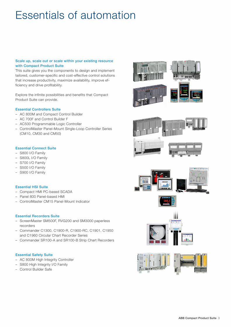
ABB Compact Product Suite 3
Scale up, scale out or scale within your existing resource with Compact Product SuiteThis suite gives you the components to design and implement tailored, customer-specific and cost-effective control solutions that increase productivity, maximize availability, improve ef-ficiency and drive profitability.
Explore the infinite possibilities and benefits that Compact Product Suite can provide.
Essential Controllers Suite – AC 800M and Compact Control Builder – AC 700F and Control Builder F – AC500 Programmable Logic Controller – ControlMaster Panel-Mount Single-Loop Controller Series
(CM10, CM30 and CM50)
Essential Connect Suite – S800 I/O Family – S800L I/O Family – S700 I/O Family – S500 I/O Family – S900 I/O Family
Essential HSI Suite – Compact HMI PC-based SCADA – Panel 800 Panel-based HMI – ControlMaster CM15 Panel-Mount Indicator
Essential Recorders Suite – ScreenMaster SM500F, RVG200 and SM3000 paperless
recorders – Commander C1300, C1900-R, C1900-RC, C1901, C1950
and C1960 Circular Chart Recorder Series – Commander SR100-A and SR100-B Strip Chart Recorders
Essential Safety Suite – AC 800M High Integrity Controller – S800 High Integrity I/O Family – Control Builder Safe
Essentials of automation

4 ABB Compact Product Suite
Essential ControllersAC 800M, AC 700F, AC500 and ControlMaster CM10, CM30 and CM50
AC 800MThe AC 800M is a Programmable Application Controller, de-signed to achieve high availability for control applications in the process industry. The rich function block library includes several types of control loops, including advanced control and auto- tune capabilities as well as integration for ABB drives and motors. The controller communication by means of Ether-net includes on board RNRP redundancy along with a broad set of communication modules to connect to third-party de-vices. A superior redundancy concept allows for fast switch-over times and topologically separated CPU-modules. Several CPU modules are available, varying in terms of processing power, memory size and redundancy support. Priority con-trolled, time-based tasks allow the highest stability in even complex control tasks.
Supporting standard IEC 61131-3 programming languages, Compact Control Builder is the tool for engineering the control code and the hardware layout of AC 800M. It creates logic, sequential and analog control-intensive automation solutions for all existing controllers in the automation system to be han-dled in one database. The flash memory card allows loading applications without the need to utilize the engineering tool to support OEM and remote solutions.
AC 700F Although it comes in a PLC shape, the AC 700F controller has the true DCS background of ABB‘s Freelance process control system. It’s small footprint allows it to be used in smallest housings of your skid or OEM solution. It can easily connect to other controllers to build an integrated system. This makes it perfect when it comes to a modular concept, where one or several of the same skids are used in one application. The high signal density of S700 I/O gives an excellent value for money and space used. The S700 I/O modules can be di-rectly plugged to the CPU module, with as many as eight direct modules connected to one controller. Serial and Profi-bus communication completes this controller. AC 700F also offers expanded flexibility via a pluggable SD card for control-ler backup, firmware updates and application download with-out engineering tool. Engineering with IEC61131-3 includes a broad process automation library plus the ability for user de-fined function blocks. In case operator stations are needed, an integrated Operation and Monitoring software called Digi-Vis can be utilized.
AC 800M
AC 700F

ABB Compact Product Suite 5
AC500 Programmable Logic ControllerSometimes the application requires open and close loop con-trol for machines or smaller and remote units. The AC500 family delivers a universal controller in a small form factor with a broad range of communication means designed for the manufacturing environment. Along with the small form factor and the very versatile and cost efficient S500 I/O family, it offers different performance levels and is the ideal choice for high availability, extreme environments as well as safety solu-tions. The AC500Eco series offers the most cost efficient solution, whereas the AC500 S safety controller supports SIL3 Safety levels.
ControlMaster Panel-Mount Single-Loop Controller: CM10, CM30 and CM50This is a range of easy-to-use yet powerful universal process controllers. Each instrument provides a comprehensive dis-play of process status using crystal clear, full color, TFT tech-nology. The simple-to-use user interface delivers clear text prompts that make installation, commissioning and operation quick and easy. Suitable for basic through to demanding ap-plications, its functionality includes cascade, feed forward, adaptive, predictive and ratio control strategies. The faceplate has IP66 and NEMA 4X environmental protection rating and communication options includes Ethernet, RS485, Modbus TCP/RTU and a web server for remote process monitoring.
AC500
ControlMaster series

6 ABB Compact Product Suite
Essential ConnectS800, S800L, S700, S500 and S900 I/O Family
S800The S800 I/O is a distributed, highly modularized and flexible I/O system with an efficient design, providing easy installation of the I/O modules, process cabling and connection to drives systems. It provides high precision and comfort for process automation tasks. A tight integration into AC 800M and Freelance Engineering tool provide extra benefit to the user over standard Profibus I/O. Redundancy can be reached on all levels and the modules can easily be exchanged and reconfigured while under operation. S800 offers highest accuracy analog modules.
S800LS800L I/O modules are both cost-effective and space-saving. They connect to any PLC or controller via Profibus. The S800L I/O is also fully integrated with the AC 800M advanced process controller. In addition, its modules can be freely combined with high-performance S800 I/O modules to bring advanced field interface functionality into any S800L configuration. Its cost-effective design at an installation depth of 59 mm makes it an economic and space saving choice for PLC applications in the process industry.
S700The S700 I/O is meant for applications where PLC I/Os have been traditionally used. The small footprint and flexible functionality per module allows cost-efficient automation solution. The AC 700F controller permits comfortable configuration and diagnostics in the Control Builder F engineering tool and in its DigiVis operator console. S700 I/O can be used as direct I/O together with the AC 700F controller, as well as remote I/O to any PLC with a Profibus master module. The equivalent S500 I/O Family provides even more communication means including Profinet functionality, but less integration into the controllers Engineering Tools and operator consoles.
S800
S800L
S700

ABB Compact Product Suite 7
S500The high signal density of S500 I/O gives an excellent value for money and space used. The S500 I/O modules can be directly plugged to an AC500 CPU, with as many as ten direct modules connected to one controller. It is an ideal solution for System Integrators and OEMs in machine automation. Used as a remote IO, a field- bus-neutral communication is pro-vided by the patented ABB Fieldbus Plug to connect to virtu-ally any desired field bus. The compact size and the variety of modules with combined functionality means substantial space savings in the control panel and a cost efficient design.
S900The S900 remote I/O system is designed for applications in the chemical, pharmaceutical and oil and gas industries. It can be mounted directly in process areas classified explosion hazard zone 1(ATEX), significantly reducing installation costs. It communicates with controllers by means of redundant Profibus communication powered by a redundant power supply. Further savings can be achieved through S900’s extended diagnostics and the use of HART®- compliant field devices. A field mounted IP66 variant with temperature range -20 to 60 °C is available.
S500
S900

8 ABB Compact Product Suite
Essential HMICompact HMI, Panel 800 and ControlMaster CM15
Compact HMIThis SCADA system lets you use the latest ergonomic design to take full control of your process. Based on the premium technology of ABB‘s System 800xA DCS it can economically scale from applications with just 50 signals and one operator workplace to applications with up to ten workplaces and 10,000 signals. Compact HMI runs on PCs with MS Windows® 7 or Windows® Server 2008/2008 R2 (32-bit and 64-bit versions). A High Performance Graphics library and options for alarm management, text messaging and read-only remote access via ABB‘s Smart Client technology complete the offering.
Panel 800 Version 6Panel 800 Version 6 is a user-friendly, intuitive and ergonomic operator panel that combines slim, space-saving dimensions with a comprehensive range of advanced functions. Explore modern controlling using scroll and swipe gestures to make your application intuitive and more efficient to navigate. Also - save a lot of screen space while you’re at it.
On top of the standard panels PP871, PP874 and PP877, Panel 800 has two high-performance panels: PP882 and PP885, offering more power, functionality and flexibility. The panel supports online language switch and includes simplified traditional Chinese. The communication includes protocol conversion and secure separation of Ethernet networks.
ControlMaster CM15This panel-mount indicator is a feature-packed 1/8 DIN universal process indicator. A crystal-clear, full-color, TFT display shows operators exactly the information they need to know and provides operation and configuration menus in full text, making the CM15 intuitive to use and very quick to install and commission.
Available as a basic indication-only model, or enhanced through plug and play function keys and I/O modules, the CM15 offers totalization, level, math, logic, counter and alarm functions, making it extremely flexible and able to solve many tricky application requirements. Modbus and Ethernet communication options ensure easy integration and connectivity to supervisory or control systems.
Compact HMI
Panel 800
CM15

ABB Compact Product Suite 9
SM500FThe SM500F is probably the world’s first field-mountable paperless data recorder. Featuring seven process inputs, seven recording channels and it is available with wall, panel and pipe mounting options. It‘s fully sealed IP66 and FNEMA 4X enclosure means it is ideal for use in even the most hostile environments, including hosedown and dusty applications.
RVG200The RVG200 recorder takes the established operating and security benefits of the ScreenMaster range one step further. Features include touchscreen ‘swipe’ operation, front and rear USB ports for connecting peripheral devices, including a barcode scanner and keyboard, and Ethernet and RS485 communications.
SM3000Using the SM3000, up to 36 channels can be recorded, with data arranged in a variety of views to provide users with a tailored view of their process. Six process groups are provided, allowing channels to be grouped together and individual displays created for different processes.
DataManager ProThis PC-based analysis software provides the complete data collection, analysis and storage solution for data recorded by a ScreenMaster recorder. Via Ethernet communications, Data-Manager Pro can be integrated with any number of Screen-Master recorders to create a fully automatic data gathering and storage system.
Commander Circular Chart Recorders: C1300, C1900-R, C1900-RC, C1901, C1950 and C1960With over 100 years experience in the industry ABB’s circular chart recorder offering is world class. Our range is extremely easy to use, offers up to four pens, NEMA 4X and IP66 envi-ronmental protection, integrated PID control and data logging.
– C1901: Basic functionality single pen circular chart record-er
– C1900: 1 to 4 pen general purpose circular chart recorder with integrated PID control
– C1960: Circular chart recorder/controller for profile control applications
– C1900R: 1 to 4 pen general purpose circular chart recorder – C1950: Circular chart recorder/controller for pasteurization
applications – C1300: 1 to 4 pen advanced circular chart recorder
SM500F
Essential RecordersScreenMaster Paperless Recorders and Commander Circular Chart Recorders
RVG200
SM3000
DataManager Pro
C1900

10 ABB Compact Product Suite
AC 800M HIThe AC 800M HI offers a SIL3 TÜV certified control environment for combining safety and business critical process control in one controller without sacrificing safety integrity.
The AC 800M High Integrity controller is achieved by combining the processor module (PM865) with the safety module (SM811). When configured as a SIL1-2 system, the AC 800M HI is realized in a 1oo1D structure by combining application execution in the PM865 with diagnostic and monitoring functions in the SM811/SM810. As a SIL3 system, it is achieved in a 1oo2D structure in both PM865 and SM811.
S800 I/O High IntegrityS800 I/O is a distributed, highly modularized and flexible I/O system, providing easy installation of I/O modules and process cabling. S800 I/O modules and its termination units can be mounted and combined in many different configurations to fit any space requirements or meet any application needs. A comprehensive assortment of I/O modules and accessories are available for safety critical and non- critical use. Within the S800 I/O family, there are SIL3 compliant modules that can be used for safety critical applications.
The High Integrity I/O is certified for IEC 61508-SIL3, DIN V 19250/DIN V VDE 0801-AK6 and EN954-1 Category 4. The High Integrity I/O are used together with a certified controller to comply with the standards. There are three modules that belong to the High Integrity I/O family that are certified for these standards, AI880/AI880A, DI880 and DO880. The modules are supported by the AC 800M controller PM865 only and have to use the optical ModuleBus modem TB840 when adding optical clusters.
Control Safe EngineeringControl Safe Engineering is a TUV-certified engineering tool for the programming of SIL applications including certified libraries, IEC61131-3 programming languages, access and override (force) control and difference reports.
The object oriented engineering environment with SIL compliant function libraries efficiently supports the entire safety lifecycle. The engineering environment includes safeguards against non-SIL compliant configurations. The engineering system will automatically limit user configuration choices and will prevent download if SIL requirements are not met.
AC 800M HI
Essential SafetyAC 800M High Integrity Controller and S800 I/O High Integrity
S800 I/O High Integrity

ABB Compact Product Suite 11
Lifecycle services
A comprehensive customer service is worth goldService means a profitable investment in continually maximizing and optimizing the availability, performance, quality and security of a plant. ABB and our authorized value providers support covers the following areas:
– Customer Support Services – Training – Spare Parts & Logistics, Repair Shops – Process, Application & Consulting Services – Service agreements – Extensions, upgrades and retrofits
Through the resulting specialization of our employees, we guarantee maximum competence for each task we perform. Whether it’s more traditional service support such as commis-sioning and maintenance or individual consulting services – the result is measurable customer benefits.
Our comprehensive Life Cycle Services enable us to increase the value of your plant over its entire lifetime. The convention-al, reactive service can reduce production downtimes, while the use of new technologies offers an increased number of capabilities for preventive service measures to identify and avoid cost-intensive faults at an early stage. Proactive ser-vices such as asset management or ongoing modernization increase the value of our customers’ plants and give them a distinct competitive edge.
Life cycle managementWe offer an unrivalled Life Cycle commitment to our customers: Our products are designed to last and to be taken to the next level when technology moves ahead. We will always thrive to offer you compatible, next-generation parts so that you can keep your control code without having to make major changes to it as you move to the next generation.
Moreover, ABB offers Automation Sentinel for selected software products, which is the essential life cycle management and support program for your control system from ABB. With this program, you can keep your control system up-to-date and maintain a flexible path to new technology. Automation Sentinel helps manage automation software assets with timely delivery of the latest releases, thus providing you with better productivity, lower support cost and simpler software management.
ABB’s ‘Evolution without obsolescence’ policy provides for incremental, planned steps, adding new technologies or up-grading technologies in existing systems while protecting installed asset investments.
For more information about Automation Sentinel please refer to Automation Sentinel Program - Lifecycle Management Pro-gram for Control Systems (3BDD015294).

System 800xA 5.1 and feature releasesImproved user, system and plant performance
System 800xA is ABB’s flagship Collaborative Process Automation System (CPAS) offering for all major industrial process manufacturing facilities globally. Since its intro-duction in 2004, nearly 9,000 systems have been installed across 100 countries. This large and growing installed base has helped make ABB the #1 DCS supplier in the world.
System 800xA serves as the foundation for a number of unique industry-specific automation applications. Remov-ing the barriers in traditional distributed control systems, it provides unparalleled capacity to embed enterprise and plant systems, applications and devices, enabling plant-wide col-laboration between people, systems and equipment.
System 800xA has been shown to improve engineering, oper-ations, control and maintenance while reducing total cost of ownership. System 800xA also help operators to collaborate effectively with each other and the systems and equipment they monitor and control. With Feature Pack 4 functionality included it will be even better.
800xA 5.1 and feature releases – key highlights: – We offer productized control room design by the
introduction of Extended Operator Workplaces – Integrated Alarm analysis for continuous analysis and
optimization to avoid nuisance alarm – Tabbed Navigation with Alarm Status – Extended communication support for Foundation Fieldbus,
Profinet and IEC 61850 – Increased Ethernet IP, DeviceNet, WirelessHART, PROFI-
NET, UDP/IP (User defined) support – Device Management HART provides full support for HART 7 – Simplified batch scheduling with one tool to organize
parameters and schedule batch recipes – The Batch Spreadsheet Scheduler can now be used on an
office PC without the need of an 800xA system – New Control Diagram Editor – Increased virtualization support & doubled system capacity
reduces the number of servers and installation costs – Smart Client workplace for presenting 800xA information in
the office environment – SIL Inter-application Communication – Protection Library for SIL3 Machine safety – Industrial Defender Certification
Executive Summary

22
Another feature available in FP1 is the Alarm response naviga-tion that speeds up decisions and action by providing fast navigation from an alarm to detailed information needed to handle it correctly. Trend display, faceplate and related docu-mentation can all be brought up with just two mouse clicks.
In Feature Pack 4 we further improve the offering by the introduc-tion of Alarm help and long term alarm analyses and reports. In addition we introduce video surveillance and recording capabili-ties, this dramatically increases the transparency from the control room to the plant floor.
Control responsibilitiesAnother function introduced in 5.1 is Point of Control. This allows an operator in one area of a facility to request permis-sion to take over the control a plant area or unit from the currently responsible operator. Once approved, permission to operate that part of the facility is transferred to the requesting operator and captured in the audit trail log. The area or unit alarm and event messages are now routed to the new opera-tor, thereby reducing the number of alarms sent to the original operator.
New EOW workplaces In FP4 we have four standardized, pre-package extended Operator Workplaces (EOW) that includes all of the necessary hardware and software to make it easier to create high perfor-mance local and remote control centers.
In FP4 we have also added high performance graphics elements, alarm history and reports, mobile client workplace and guide, smart client with PG2 graphic support, Video server and CAD Viewer, larger harmonized icons and much more...
Operator Effectiveness Over a total life cycle, many important decisions are made by operators, decisions that have a great impact on safety, pro-ductivity and quality. Operator effectiveness can be optimized by focusing greater attention on the operator and on human factors.
Alarm Management 800xA 5.1 includes advanced alarm management capabili-ties that help users implement successful alarm management strategies. New Alarm Shelving and Alarm Analysis features have been added to help keep alarms in check. In addition to traditional reporting of alarm statistics, built-in Alarm Analy-sis displays are accessible to operators via graphics based on Microsoft Windows Presentation Foundation (WPF). This involves them in the process and helps ensure your alarm management strategy’s continued success.
The feature release September 2011, Feature Pack 1 (FP1) includes enhancements to 800xA Alarm management that improve operator response to alarms (for information about the concept of feature packs, see page 7).
The new functionality Group Alarms enables display of a single ‘grouped alarm’ that represents multiple alarms reported from different sources related to a common cause in the system. This reduces the number of events listed, thereby helping operators handle key tasks with their full, undisturbed attention. By minimizing the number of alarm list entries that have to be read and assessed, alarm grouping helps opera-tors work more effectively.
1. Alarm analysis according to ISA 18.2 and EEMUA 191 that includes calculations of the 20 longest standing alarms, 20 most frequent alarms etc. | 2. Tabbed navigation, including alarm severity and status shown in buttons & tabs, promote operator responsiveness and effective navigation and action.
1 2

33
High performance HMI The release of Feature Pack 1 enhances the high performance HMI with support for tabbed navigation, facilitating fast, intui-tive and secure navigation between displays using buttons and tabs.
Tab-based navigation enables quick and direct access to primary displays and minimal keystroke access to secondary and associated displays, thus improving situation awareness and responsiveness to alarms and events. With the release of Feature Pack 3, alarm severity and status can be displayed in the buttons and tabs, further improving responsiveness and plant safety.
Another feature introduced in Feature Pack 3 is an enhance-ment to the application bar icons that enables larger size icons, making it easier for the operators to navigate to 800xA features. Also, Feature Pack 3 introduces the combined one line tool bar that is a collection of tools from the Display bar, the Application bar, and the Status bar. This saves vertical screen space and is well suited for wide screen displays, pro-viding the operator with more display area and the simplicity of having one tool bar only.
Furthermore, with Feature Pack 3 aspect links will now indi-cate if the link points to the previous display. This is useful when there are two or more aspect links and is an excellent complement to the existing display history.
Finally; Feature Pack 4 introduces the possibility for the operator to use high performance graphics elements, alarm help and web reports and use of 800xA mobility guide.
Operation of several systems Multi-system integration promotes control consolidation since
Automation and power integrationBy embedding power and process systems on the common 800xA platform, plants optimize the design and performance of their electrical and automation systems and gain additional benefits in reduced maintenance, engineering and overall lifecycle costs. According to ARC, typical savings can result in a 20% reduction in CAPEX (capital expenditures) and OPEX (operating expenditures) by integrating these two, usually separate, automation infrastructures.
To provide even deeper and wider integration with electrical systems, 800xA’s IEC 61850 Communications Interface capa-bility has been enhanced by increasing the number of sup-ported Intelligent Electrical Devices (IEDs) per communication interface card and by improving alarm and event support.
1. SFC viewer-guided operator action | 2. Automation and power integration with IEC 61850
1 2
it makes it possible to supervise and operate several 800xA systems from one central control room in a safe and effective way. With FP1, integration capabilities are enhanced with MS support for Foundation Fieldbus and IEC 61850. Support for two subscribers to a provider is also available. Point of Control also applies for multi-system integration set-ups from FP1.
Sequential Function Chart (SFC) ViewerFP1 introduces guided operator action by SFC Viewer for AC 800M. The operator can navigate directly from the transi-tion in the SFC Viewer to the context menu for the related object and bring up the faceplate, trend, etc. This speedy and accurate response to process upsets improves stability and availability.

4
The capacity of the IEC 61850 connectivity package has also been increased in FP2. It is possible to use 4 OPC servers per connectivity server. This doubles the capacity, or cuts the footprint for IEC 61850 servers in half, thus reducing installa-tion costs.
In FP3 Function Designer IO Allocation now also supports IO fieldbus devices connected via IEC 61850, Profinet and Foun-dation Fieldbus Communciation Protocols.
Enterprise Asset ManagementAn effective asset management strategy combines the needs of the production and maintenance organizations. It increases both equipment availability and production rate by providing insight into asset health, corrective action instructions and organizational visibility.
Integration of the maintenance system Integrated CMMS is a key enabler for shifting to predictive maintenance by increasing the number of fault reports from operators, for example. This helps the maintenance depart-ment to attend to anomalies before they cause disturbances and unplanned shutdowns.
800xA provides extensive support for integration of EAM/CMMS maintenance systems (e.g. Mincom, Maximo, SAP, IFS, etc). The FP1 release supports integration of the latest versions of IBM Maximo (version 7.1) and SAP/PM ERP Cen-tral Component 6.0 (ECC6), as well as the previous ones.
Object diagnosticsAnother important parameter for predictive maintenance is asset monitors that detect anomalies and provide mainte-nance with early warnings. To meet the increasing use of Control Loop Asset Monitors (CLAM), this capability has been increased to 500 CLAMs in one system with Rev A.
Control and I/O Several performance enhancements make 800xA’s already robust Control and I/O offering even more versatile, flexible, and scalable. The 5.1 version includes a new member of the AC 800M controller family, the PM891. This has approxi-mately three times the clock speed (450 MHz) and four times the memory of its predecessor, making it the most powerful controller of its class. PM 891 helps plants do more with less, requiring fewer controllers for applications and providing 1-1 controller evolution for previous generation ABB and third-party controller platforms. In FP4 we release more powerful AC 800M controllers and some new I/O models and connec-tivity options to assist operators with the installation of field equipment such as Ethernet IP and UDP/IP communication.
Communication 800xA has added to and enhanced its portfolio of commu-nication interfaces to help users further leverage its powerful integration capabilities. These include new communication interfaces for PROFINET, DeviceNet via Ethernet IP, and Wire-lessHART. 800xA’s WirelessHART solution seamlessly inte-grates Pepperl+Fuchs WirelessHART Gateway, providing wire-less connectivity to HART-enabled devices such as sensors and actuators, and making process variables and diagnostic data available in 800xA’s controller, HMI, and integrated Asset Optimization application. 800xA’s FOUNDATION Fieldbus interfaces also now support EDDL. These interfaces make it easier to access and use diagnostic data from smart instru-ments, regardless of manufacturer or physical device location.
Enhancements for more efficient and faster commissioning in Device Management for FOUNDATION Fieldbus are also included in the FP2 release. The traditional overview pane and life list in commissioning mode of Fieldbus Builder FF have been replaced by the Device List View and Diagnostic List View. Both lists give comprehensive overviews about all device data relevant for the FF commissioning steps.
1. Integrated CMMS | 2. PM 891 | 3. P+F WirelessHART Gateway
1 2 3

5
Bulk upload functionality for SFC Viewer has been made available on Control Applications in order to simplify engineering processes.
In FP4 we have a New Control Diagrams Editor, Task Analysis Tool, easier method of engineering IEC 61850 and much more.
Batch Simple Batch and Parameter Management introduced in FP1 has in FP3 been enhanced to include new security features.These provide stricter user access on the Excel spreadsheet scheduler and user formulations. It also simplifies scheduling and improves stability and availability. Now users only need one tool to organize parameters and schedule batch recipes.
This provides all the information the operator needs to sched-ule batches in one simple application, easily integrated into the user graphics. As it requires little or no knowledge and training to use, operators can focus on the process instead of the tool. It’s ideal for procedures where multiple formulations apply to one recipe.
The multi-write capability to OPC is also improved in FP1. Application performance is improved with new ‘putm’ and ‘subscribe’ function calls now added to the batch expression language.
In FP3 a new Batch Scheduling aspect is available. This configu-rable graphic element allows a scheduling dialog to be embedded directly into a PG2 graphic display or through a separate overlap display to better match operational workflows. Batch Status, Pri-ority and Mode OPC properties have been exposed providing improved visibility to operators during batch execution.
VirtualizationVirtualization reduces the physical number of PCs required for installations by as much as 75%. This significantly reduces footprint, energy consumption and maintenance requirements.
Engineering 800xA 5.1 includes multiple engineering improvements such as simplified bulk data handling when engineering FOUN-DATION Fieldbus projects. In addition, three new features improve and streamline change management procedures.
Task Analysis Tool lets users evaluate how their application will be executed based on the current task rates assigned prior to downloading. It clearly shows any latency or conflicts and then prevents the new application from being down-loaded to avoid a controller error. It also performs ‘what if’ scenarios to pinpoint where problems may occur when modi-fying task execution cycle times.
Detailed Difference Report provides a way to easily see changes made in control applications and graphics, and reports exactly what has been modified, added, or removed in an easy-to-read user interface. It provides the engineer and quality personnel with precisely the information needed to pinpoint changes and evaluate their impact. This is especially useful in change management processes, as it can verify that no other changes have been made except the ones present in the change request. This can save hours of change request verification and testing.
With the release of FP3, Function Designer IO Allocation now also supports IO fieldbus devices connected via IEC 61850, Profinet and FOUNDATION Fieldbus Communication Protocols.
In FP3 a new Bulk Data Manager Excel template has been added that allows configuration of sequences in Excel. The SFC structure can be configured for Control Builder as well as for Function Designer sequences.
1. Simplified batch scheduling | 2. Task analysis tool
2
1

6
Thanks to FP1, virtualization with 800xA now supports SAN storage, which has the potential to increase availability. Virtual machines can either reside on hard disks local in the ESX server, or in a network storage device such as a Storage Area Network (SAN) server. In both cases, the storage is added to the ESX server and seen as data stores.
One advantage of having virtual machines residing on a SAN server is that they can be moved from one ESX server to another. Since both ESX servers have access to the same shared storage, Only the execution context needs to be moved, rather than the much larger virtual machine hard disk.
Increased support for virtualization is also introduced with FP1. The majority of 800xA servers are now supported for virtualized systems. The additional ones released in FP1 are DCI, Harmony, and IEC 61850. This further reduces the number of servers needed. Increased support for virtualization is also introduced with FP1. The majority of 800xA servers are now supported for virtualized systems. The additional ones released in FP1 are DCI, Harmony, and IEC 61850. This further reduces the number of servers needed.
System improvementsSecurity 800xA has been built with security in focus and has a rich set of security functions that support secure plant operation. Revision A includes important improvements in secure com-munications, password protection and overall system security recommendations.
Communication on the client/server network can be protected from unauthorized access using the Internet Protocol Security (IPsec), which will authenticate and encrypt all traffic on the network. Its purpose is to ensure that only legitimate nodes in the 800xA System can talk to each other, and hence prevent intrusion through nodes added to the network without proper configuration.
Support is introduced for configuring IPSec to only allow com-munication between clients and servers that are members of the system’s Active Directory Domain and additional nodes that are explicitly defined. IPSec can be configured for a newly installed system as well as existing systems using 800xA 5.1 or later. The tool automates deployment of settings to all nodes, thus off-loading system administrators and minimizing risks for manual mistakes.
Support for 64bit800xA 5.1 is available in a 64bit compatible version intended for Windows 7 64bit and Windows Server 2008R2. The exist-ing 32bit version will continue to be supported.
System capacityIncreased system size is supported with the release of FP1. The number of nodes on a Control Network is increased to sixty. This includes controllers as well as servers. The increase supports consolidation and plant-wide control and monitoring systems. It also reduces the number of servers needed, thus lowering installation costs.
In addition, the number of rich clients (i.e. normal operations clients) is increased to eighty.
Finally, controller connectivity server throughput is increased. In practical terms, this means most installations can manage with one single pair of connectivity servers, thereby reducing installation costs.
Cyber security Based on User Centered Design practices, the 800xA 5.1 includes a System Administration Console and a Security Update Tool to help keep the system running securely and at an optimum level. The Security Update Tool allows users to download Security Patches from Microsoft and cross match that to ABB’s qualified list. Users can then create a loadable set of supported, tested security updates that can be rolled out to 800xA. This helps users save valuable time and effort while providing a more robust, secure system.
Cyber security with 800xA
Plant Intranet
Demilitarized Zone
Client Server Network
Control Network
Controllers
Field Network
Field Devices, IEDs, Remote IO, etc.
Connectivity Servers
REG670
Internet

7
Smart ClientSmart Client is a desktop client for presenting information from 800xA in the office environment. This improves plant visibility and production follow-up. Users have easy access to process data for KPIs and easy-to-use tools for analysis and reports for process optimization.
With the Smart Client 2.2 release, users can bring up 800xA PG 2 graphics directly in smart client, view live process data and trends, and navigate to related displays.
The concept of feature packs This is the conceptual model of how revisions and feature pack add-ons to 800xA relate to each other:
– A user can choose to update to the current revision and keep his installation at that level. This means he will get recently-found problems corrected. The functionality of his system will remain as it was at the time when the original installation was made. This improves the stability of the actual installation, plus that the user does not have to adopt any new functions, updated user interfaces, or any-thing else that differs from before the revision was installed.
– A feature pack adds functions and features to an instal-lation. Users can optionally choose to install a feature pack.
– A feature pack may require a certain revision level of the system in order to work as intended. The install media for a feature pack also contain the required revision level. This means that by installing the feature pack, the system will be updated to the required revision level. Feature pack installation kits also normally contain the revision. This means that checking the installation usually requires only one entry in addition to the base installation. For some functional areas in 800xA, where the whole installation is replaced when an update is made, there is only one entry visible for the whole functional area.
800xA 5.1 and related feature releases
5.1 July 2010
5.1 Rev A May 2011
Feature Pack 1 (FP1) September 2011
800xA Smart Client v2.2 December 2011
5.1 64bit February 2012
Feature Pack 2 (FP2) March 2012
5.1 Rev B July 2012
Feature Pack 3 (FP3) September 2012
5.1 Rev C December 2012
Feature Pack 4 (FP4) April 2013
Smart client mill overview

12 Software | System 800xA Product Catalog
Operator Workplaces
Office Workplaces
Operator Workplaces
Article no.
Operator Workplace - Additional Client, 800xA 5.1
Includes Excel based reporting aspects, MS Excel is NOT
included. Possibility to use up to two screens per workplace.
(One Operator Workplace is included with Core System so
this limit to Total-1). The total quantity of Operator Workplace-
Additional and Remote Clients, Large Operator Workplaces and
Engineering Workplaces - must not exceed 55.
3BSE061255R1
Large Operator Workplace Client, 800xA 5.1
Includes one Operator Workplace with the possibility to
use up to four screens per workplace and/or large desktop
functionality. The total quantity of Operator Workplace -
Additional and Remote Clients, Large Operator Workplaces and
Engineering Workplaces - must not exceed 55.
3BSE061257R1
Office WorkplacesSmart Client Workplaces - Includes access to system information form the office network. Includes: View Process Graphics 2 displays, Trend displays, Build/view business graphics, historic data, alarm & events analyse (H & AE analyse requires IM).
Article no.
Smart Client Workplace - Client 1-25
Note: At pricebook release this item required a TSA to be
ordered. Please, check current need of a TSA in the TSA
Database before ordering.
3BSE070899R25
Smart Client Workplace - Client 26-50
Note: At pricebook release this item required a TSA to be
ordered. Please, check current need of a TSA in the TSA
Database before ordering.
3BSE070899R50
Smart Client Workplace - Client 51-100
Note: At pricebook release this item required a TSA to be
ordered. Please, check current need of a TSA in the TSA
Database before ordering.
3BSE070899R100

System 800xA Product Catalog | Software 13
Extended Operator Workplaces
Extended Operator Workplaces
Article no.
EOW-x2
Operator Console including motorized ergonomic desk, 1 large
screen area (3840x1080 mm (2 monitors)), 2 sets of 2 wide
screen motorized monitors, multi-client keyboard, public
speakers, directed sound shower speaker, high frequency
lighting, operator video camera, remote graphical distribution
(25 m fiber cables and interface cards).
Software included: 1 EOW Workplace, 3 Large Operator
Workplaces, 1 Video Camera Input Channel, 3 Video Clients.
Note: At pricebook release this item required a TSA to be
ordered. Please, check current need of a TSA in the TSA
Database before ordering.
3BSE070124R1
EOW-x3
Operator Console including motorized ergonomic desk, 1
large screen area (5760x1080 mm (3 monitors)), 2 sets of 3
wide screen motorized monitors, multi-client keyboard, public
speakers, directed sound shower speaker, high frequency
lighting, operator video camera, remote graphical distribution
(25 m fiber cables and interface cards).
Software included: 1 EOW Workplace, 3 Large Operator
Workplaces, 1 Video Camera Input Channel, 3 Video Clients.
Note: At pricebook release this item required a TSA to be
ordered. Please, check current need of a TSA in the TSA
Database before ordering.
3BSE070125R1
EOW-f2
Operator Console including desk, 1 large screen area
(3840x1080 mm (2 monitors)), 2 sets of 2 wide screen monitors,
multi-client keyboard, speakers, remote graphical distribution
(25 m fiber cables and interface cards).
Software included: 1 EOW Workplace, 3 Large Operator
Workplaces.
Note: At pricebook release this item required a TSA to be
ordered. Please, check current need of a TSA in the TSA
Database before ordering.
3BSE070126R1
EOW-f3
Operator Console including desk, 1 large screen area
(5760x1080 mm (3 monitors)), 2 sets of 3 wide screen monitors,
multi-client keyboard, speakers, remote graphical distribution
(25 m fiber cables and interface cards).
Software included: 1 EOW Workplace, 3 Large Operator
Workplaces.
Note: At pricebook release this item required a TSA to be
ordered. Please, check current need of a TSA in the TSA
Database before ordering.
3BSE070127R1

14 Software | System 800xA Product Catalog
Extended Operations
Extended Operations
Article no.
Video Input Channel
Connection to attach a video stream from one video camera for
recording or live viewing in the system.
Note: At pricebook release this item required a TSA to be
ordered. Please, check current need of a TSA in the TSA
Database before ordering.
3BSE070134R1
Video Client
One concurrent client using video stream viewing from either
recorded or live video source.
Note: At pricebook release this item required a TSA to be
ordered. Please, check current need of a TSA in the TSA
Database before ordering.
3BSE070135R1
CAD Viewer
View CAD drawings in DXF and DWG formats store in aspects
DWG (version 13, 14, 2000, 2004, 2007, 2010) DXF(version 12,
13, 14, 2000, 2004, 2007, 2010).
Note: At pricebook release this item required a TSA to be
ordered. Please, check current need of a TSA in the TSA
Database before ordering.
3BSE072023R1

System 800xA Product Catalog | Software 15
Batch Management
Batch Management
Article no.
Batch Base System, 800xA 5.1
Provides the basic server functionality for batch management.
The batch server includes 10 Batch Equipment and 2000 Batch
Procedures. 1 Batch client included.
3BSE061258R1
Redundant Batch Server Option, 800xA 5.1
Provides redundancy for the basic server functionality for batch
management. (Requires Batch Base System, 3BSE061258R1)
3BSE061259R1
Batch Management Full Client, 800xA 5.1
This Client feature provides access to Batch Management
functions. The Client feature is based upon concurrent
users, not physical workstation installation. Including SL and
SQL server licenses. Requires Operator Workplace Client
- 3BSE061255R1, 3BSE061256R1 or 3BSE061257R1; or
Engineering Workplace Client - 3BSE061342R1. Maximum 40.
One Client is included with the Batch Base System.
3BSE061260R1
Batch Schedule Interface, 800xA 5.1
This feature provides external interface to Batch Management
via the Web Service scheduling commands. Included in this
feature is the Spreadsheet Scheduling interface desktop
version, unlimited license. No need to order Simple Batch
Paramether Management if you have this feature.
3BSE061261R1
10 Additional Batch Equipment, 800xA 5.1
The number of batch equipment instances includes each piece
of equipment configured in Batch Management including both
Units and Shared Equipment Modules.
3BSE061262R1
100 Additional Batch Equipment, 800xA 5.1
The number of batch equipment instances includes each piece
of equipment configured in Batch Management including both
Units and Shared Equipment Modules.
3BSE061263R1
Batch Advanced Phase Templates, 800xA 5.1
This feature provides access to the batch advanced templates
control modules for phases, units and shared equipment
modules. For use with AC 800M controllers. Batch Phase
Control library option, includes 2000 Advanced Phases.
3BSE061264R1
Simple Batch Parameter Management - Spreadsheet
Scheduling interface desktop version
Batch spreadsheet recipe scheduling tool for desk top PC
interface to Batch Management. Supports Excel 2007 and
2010. XP or Win 7, Requires Feature Pack 3.
3BSE070685R1

16 Software | System 800xA Product Catalog
Basic HistorianLogging of signals for Operator trends is included in the core system for up to three months. Logging for a longer time period, archiving to external media like DVD, discs or web based Historian tools require Basic Historian Server.
Max 120,000 logs allowed in one server. (Includes archiving license, PDL, up to 12,000,000 events, MDI client and one Excel Data Access).
Article no.
Basic Historian Server, 800xA 5.1
With storage and archiving functions for:
history data, events (Message Log), and production data
(Production Data Log-PDL).
Includes Licenses for:
500 History Logs
one Multi-Display Interface (MDI) client
one Display Builder for MDI
one Desktop Trend client
one Excel Data Access
Batch reports with trending requires an additional licensed
option, see Historian Data Access Options.
3BSE061265R1
History LogsNumber of initial Information Management Hierarchical Logs in the system. Each signal to be logged counts as one log. Note: Information Management provides only Hierarchical Logs. (Total max 300,000 and max 50,000/Server.)
Article no.
100 History Logs, 800xA 5.1 3BSE061266R1
1,000 History Logs, 800xA 5.1 3BSE061267R1
15,000 History Logs, 800xA 5.1 3BSE061268R1
Dual History LogsFor parallel logging in two history servers. (Two Basic Historian Servers are required). Number of initial Information Management Hierarchical Logs in the system. Each signal to be logged counts as one log. Note: Information Management provides only Hierarchical Logs. (Total max 150,000 and max 50,000/Server.)
Article no.
100 Dual History Logs, 800xA 5.1 3BSE061269R1
1,000 Dual History Logs, 800xA 5.1 3BSE061270R1
15,000 Dual History Logs, 800xA 5.1 3BSE061271R1
Information Management

System 800xA Product Catalog | Software 17
Consolidated History LogsConsolidated logs collect data from multiple History Servers and store it in a single location. This provides a common history repository for viewing and reporting. (Total max 300,000 and max 50,000/Server.)
Article no.
100 Consolidated History Logs, 800xA 5.1 3BSE061328R1
1,000 Consolidated History Logs, 800xA 5.1 3BSE061329R1
15,000 Consolidated History Logs, 800xA 5.1 3BSE061330R1
Historian Display and Reporting Options
Article no.
Display Builder for MDI - Additional Client, 800xA 5.1
Provides the ability to create MDI information displays for
desktop applications.
3BSE061331R1
Multi-Display Interface (MDI) - Additional Client, 800xA 5.1
(Max 64 per Server). Provides the ability to view MDI information
displays for desktop applications.
3BSE061332R1
Desktop Trends - Additional Client, 800xA 5.1
Provides trend viewing for desktop applications. Includes web
enabled trend display for long and short term history and stock
ticker like viewer. (Max 64 per Server).
3BSE061333R1
Historian Data Access OptionsTo access historical data through SQL from third party applications.
Batch Reports with trending requires the ODBC Server (3BSE061335R1) and ODBC Client (3BSE061336R1) option. This option provides the links necessary to connect the Oracle database (PDL) and the numeric log and process data.
Applications which utilize commercial third party reporting tools should also include the ODBC Server (3BSE061335R1) and ODBC Client (3BSE061336R1) option. The number of client connection is based on whether the applications utilizes the connection directly or indirectly. If the connection is made indirectly (using Oracle), then the client connection requires is only one. If the client connections are direct, then the number of clients should equal the number of concurrent users.
Article no.
Excel Data Access, 800xA 5.1
To access historical data through SQL from third party
applications. Used to access historical data in Excel from
non 800xA PC’s. For 800xA Client PC’s Excel Data Access is
included. (Max 64 per Server).
3BSE061334R1
ODBC Historical Data Server, 800xA 5.1
ODBC, includes third party code. (One per server.)
3BSE061335R1
ODBC Client Connection, 800xA 5.1
ODBC Clients are purchased separately from the ODBC server.
(Max 10 per ODBC Server.)
3BSE061336R1
Information Management

18 Software | System 800xA Product Catalog
800xA History Signals - LogsHistory signals capable of storing actual and historic values retrieved from 800xA, Heritage ABB DCS systems and OPC sources. The signals include logging, trending, calculations and archiving. (Max 75,000 per Server node, signal storage for up to 6 data sources per Server).
Article no.
800xA History Signals - Basic 100 signals
Note: At pricebook release this item required a TSA to be
ordered. Please, check current need of a TSA in the TSA
Database before ordering.
3BSE067077R1
800xA History Signals - Basic 1000 signals
Note: At pricebook release this item required a TSA to be
ordered. Please, check current need of a TSA in the TSA
Database before ordering.
3BSE067077R10
800xA History Signals - Basic 15000 signals
Note: At pricebook release this item required a TSA to be
ordered. Please, check current need of a TSA in the TSA
Database before ordering.
3BSE067077R150
800xA Dual History Signals - LogsHistory signals for parallel logging in two history servers.The number of dual history signals should match the number of history signals
Article no.
800xA Dual History Signals - 100 signals
Note: At pricebook release a TSA was NEEDED for this item.
Please, check current need of a TSA in the TSA Database
before ordering.
3BSE073477R1
800xA Dual History Signals - 1000 signals
Note: At pricebook release a TSA was NEEDED for this item.
Please, check current need of a TSA in the TSA Database
before ordering.
3BSE073477R10
800xA Dual History Signals - 15000 signals
Note: At pricebook release a TSA was NEEDED for this item.
Please, check current need of a TSA in the TSA Database
before ordering.
3BSE067079R150
External Data access to 800xA History SignalsExternal access to history data via OPC and ODBC connectivity. This gives access to both, the current and the historical data. (Same size as total number of 800xA History Signals).
Article no.
Data Access to 800xA History Signals - 100 signals
Note: At pricebook release this item required a TSA to be
ordered. Please, check current need of a TSA in the TSA
Database before ordering.
3BSE067079R1
Data Access to 800xA History Signals - 1000 signals
Note: At pricebook release this item required a TSA to be
ordered. Please, check current need of a TSA in the TSA
Database before ordering.
3BSE067079R10
Data Access to 800xA History Signals - 15000 signals
Note: At pricebook release this item required a TSA to be
ordered. Please, check current need of a TSA in the TSA
Database before ordering.
3BSE067079R150
800xA History

System 800xA Product Catalog | Software 19
Control Software LicensesThe licensing model for the Control Software Integration has changed in 800xA 5.1. Licens-ing is now scaled on installed controller capacity instead of licensing on connected signals and devices to the controllers (CLPs). This change has been made to make the calculation of required Control Software licenses easier. Each installed controller or redundant pair in the plant requires a separate Control Software license, which is ordered through the price list. The easiest way to calculate the licenses is by using the 800xA Wizard. Each controller type has its own license, where the price of it depends on the capacity of the controller.
If a Control Software license that is too small is chosen initially, it is possible to upgrade to a larger one by ordering one, or several expansion items. The 800xA Wizards helps to do the calculation in this scenario as well. Each PM type has internally a unique Controller Capacity Points figure that relates to the capacity for the controller.
While ordering the different controller licenses, the total Controller Capacity Points are au-tomatically calculated and summed up in the license. The 800xA system validates the ac-tual points count against the current license; the license will be granted as long as there are enough points in the license.
Article no.
PM851/PM851A Software License, 800xA 5.1
13 Controller Capacity Points
3BSE061897R1
PM856/PM856A Software License, 800xA 5.1
25 Controller Capacity Points
3BSE061898R1
PM860/PM860A Software License, 800xA 5.1
40 Controller Capacity Points
3BSE061899R1
PM861/PM861A Software License, 800xA 5.1
50 Controller Capacity Points
3BSE061900R1
PM864/PM864A Software License, 800xA 5.1
67 Controller Capacity Points
3BSE061901R1
PM865 Software License, 800xA 5.1
67 Controller Capacity Points
3BSE061916R1
PM866 Software License, 800xA 5.1
100 Controller Capacity Points
3BSE061902R1
PM891 Software License, 800xA 5.1
150 Controller Capacity Points
3BSE061903R1
Enabler for combined PA Control and Certified Safety software
Article no.
AC 800M High Integrity and Process Control, 800xA 5.1
One fixed license feature per AC 800M controller running both
non-SIL and SIL applications in the same controller.
3BSE061341R1
Control
Safety

20 Software | System 800xA Product Catalog
Asset Optimization
Article no.
100 Asset Monitors, 800xA 5.1
Asset monitoring and Basic Asset Monitor Library. Each Aspect
Object being monitored by one or more asset monitors counts
as one.
3BSE061350R1
1000 Asset Monitors, 800xA 5.1
Asset monitoring and Basic Asset Monitor Library. Each Aspect
Object being monitored by one or more asset monitors counts
as one.
3BSE061351R1
Generic Heat Exchanger Asset Monitor, 800xA 5.1
It monitors the performance against standard operating
parameters independent of type of heat exchanger.
3BSE061352R1
Shell and Tube Heat Exchanger Asset Monitor, 800xA 5.1
It monitors the performance against standard operating
parameters based on the size of shell and tube heat exchanger.
3BSE061353R1
Advanced Harmony Control System Monitoring, 800xA 5.1
Enables Harmony Control Network monitors for diagnostic
monitoring, reporting, and analysis.
3BSE061354R1
100 Control Loop Asset Monitors, 800xA 5.1
Each Control Loop Asset Monitor monitors and assesses the
performance of a control loop in real-time and report significant
problems related to the controller and final control element.
The total quantity of Control Loop Asset Monitors must not
exceed 500.
3BSE061355R1
300 Control Loop Asset Monitors, 800xA 5.1
Each Control Loop Asset Monitor monitors and assesses the
performance of a control loop in real-time and report significant
problems related to the controller and final control element.
The total quantity of Control Loop Asset Monitors must not
exceed 500.
3BSE064667R1
500 Control Loop Asset Monitors, 800xA 5.1
Each Control Loop Asset Monitor monitors and assesses the
performance of a control loop in real-time and report significant
problems related to the controller and final control element.
The total quantity of Control Loop Asset Monitors must not
exceed 500.
3BSE064668R1
PC, Network and Software Monitoring, 800xA 5.1
Enables monitoring & supervision of IT assets.
3BSE061356R1
800xA Maximo Integration, 800xA 5.1
Enables integration into Maximo for work order management.
Application Engineering available through ConsultIT.
At pricebook release this item required a TSA to be ordered.
Please, check current need of a TSA in the TSA Database
before ordering.
3BSE061357R1
800xA SAP / Plant Maintenance Integration, 800xA 5.1
Enables integration into SAP for work order management.
Application Engingeering available through ConsultIT.
At pricebook release this item required a TSA to be ordered.
Please, check current need of a TSA in the TSA Database
before ordering.
3BSE061358R1
Asset Optimization

System 800xA Product Catalog | Software 21
Device Management HARTFor HART devices to be accessed using Device Type Manager (DTM‘s) within System 800xA. Includes HART Device Library with generic and specific HART Device Aspect Objects incl. DTM‘s, I/O DTM for S800 and S900, HART Instruments Asset Monitor Library and OPC Server. Each HART device aspect object accessed with DTM counts as one. (Max 2500 per Connectivity Server if OPC Communication is used. For details refer to System Guide)
Article no.
100 HART Device Aspect Objects, 800xA 5.1 3BSE061359R1
1,000 HART Device Aspect Objects, 800xA 5.1 3BSE061360R1
10,000 HART Device Aspect Objects, 800xA 5.1 3BSE061361R1
HART Multiplexer Connect, 800xA 5.1
Enables HART Device Integration to connect to HART devices
using HART Multiplexers.
3BSE061362R1
Device Management FOUNDATION FieldbusFor FOUNDATION Fieldbus (FF) devices to be accessed using Fieldbus Builder FF within System 800xA. Includes FF Device Library with FF Device Aspect Objects, FF Instruments Asset Monitor L ibrary and OPC Server. Each FF device aspect object counts as one. (Max 1000 per Connectivity Server. For details refer to System Guide.)
Article no.
100 FF Device Aspect Objects, 800xA 5.1 3BSE061363R1
1,000 FF Device Aspect Objects, 800xA 5.1 3BSE061364R1
10,000 FF Device Aspect Objects, 800xA 5.1 3BSE061365R1
Device Management PROFIBUSFor PROFIBUS DP/PA devices to be accessed using Device Type Manager (DTM‘s) within System 800xA. Includes PROFIBUS Device Library with specific PROFIBUS Device Aspect Objects incl. DTM‘s, I/O DTM for S800 and S900, and PROFIBUS Instruments Asset Monitor Library. Each PROFIBUS device aspect object accessed with DTM counts as one. (Max 2500 per Connectivity Server if OPC communication is used. For details refer to System Guide.)
Article no.
100 PROFIBUS Device Aspect Objects, 800xA 5.1 3BSE061366R1
1,000 PROFIBUS Device Aspect Objects, 800xA 5.1 3BSE061367R1
10,000 PROFIBUS Device Aspect Objects, 800xA 5.1 3BSE061368R1
Device Management & Fieldbuses

22 Software | System 800xA Product Catalog
Device Management & Fieldbuses
Libraries
IEC 61850 ConnectFor order of IEC 61850 related products, local organizations must comply with the Demands on the Purchaser to secure successful sales of IEC 61850 with System 800xA. Ref doc, 3BSE058798.
Article no.
IEC 61850-Ed1 Connect, 800xA 5.1
Allows clients to access data directly from electrical devices
(IEDs). Handles alarms from IEDs. Each item includes one
IEC61850 OPC server instance and IEC 61850 Substation
Operation Library with Faceplates to control substation
equipment (Bay, Breaker, Switch,...) is included.
3BSE061369R1
Redundant IEC 61850-Ed1 Connect Option, 800xA 5.1
Allows operation clients to access data and alarm and event
values from Intelligent Electronic Devices (IEDs) through
redundant Connectivity Servers.
Requires IEC 61850-Ed1 Connect. The number of Redundant
IEC 61850 OPC server instance licenses shall be less then or
equal to the number of IEC 61850 OPC server instances, when
redundancy is chosen.(max. 16 per System).
3BSE061370R1
Libraries
Article no.
INFI90 Function Code Library for AC 800M, 800xA 5.1
Requires separate media.
3BSE061211R1
MOD 300 CCF Library for AC 800M, 800xA 5.1
Requires separate media.
3BSE061210R1
TCP Communication Library License
Control functions to create TCP based communication protocols in the
AC800M controller. Once licence is needed for each controller using
the library.
Note: At pricebook release this item required a TSA to be ordered.
Please, check current need of a TSA in the TSA Database before
ordering.
3BSE070889R1
UDP Communication Library License
Control functions to create UDP based communication protocols in the
AC800M controller. Once licence is needed for each controller using
the library.
Note: At pricebook release this item required a TSA to be ordered.
Please, check current need of a TSA in the TSA Database before
ordering.
3BSE070891R1
Machine Safety Library License Points
Control functions for machine safety applications. Same amount of
library points is needed as the summed up controller capacity points
using the library.
Note: At pricebook release this item required a TSA to be ordered.
Please, check current need of a TSA in the TSA Database before
ordering.

System 800xA Product Catalog | Software 23
Localization
National Language Support (NLS) is intended for the localization of the operator interface to the desired language. NLS contains a set of functions that are harmonized with the Windows regional settings to enable a multilingual environment for the System 800xA.
The System 800xA supports translations, mainly the operator interface and the operator manuals as shown in the Table 3 and Table 4. The translation, or System 800xA Language Package, is implemented as a system extension and is possible to install without stopping the system.
The NLS Localization Guide describes what and how localization can be performed by a project with or without an installed Language Package. The English version of the Windows operating system is required. The System 800xA Language Packages can be downloaded free of charge from ABB Library.
Language Packages
Functional Areas
Bas
e S
yste
m
Saf
ety
SM
S &
eM
ailin
g
*Ass
et
Op
timiz
atio
n
FO
UN
DAT
ION
F
IELD
BU
S
Bat
ch
Man
agem
ent
** In
form
atio
n M
anag
emen
t
* IE
C 6
1850
English (default) Yes Yes Yes Yes Yes Yes Yes Yes
Chinese Yes Yes Yes Yes Yes Yes
French Yes Yes Yes Yes
German Yes Yes Yes Yes Yes Yes Yes
Russian Yes Yes Yes
Spanish Yes Yes Yes Yes
Swedish Yes Yes Yes Yes Yes Yes
Language Packages
Connectivity
800x
A f
or
A
C 8
00M
800x
A f
or
A
dva
nt M
aste
r
PLC
C
onn
ect
800x
A f
or
M
elo
dy
English (default) Yes Yes Yes Yes
Chinese Yes Yes Yes
French Yes Yes
German Yes Yes Yes
Russian Yes Yes
Spanish Yes
Swedish Yes Yes
Table 3. Supported Language Packages for Functional Areas
Table 4. Supported Language Packages for Connectivity
* Only system messages** Storage of messages in local language

24 Software | System 800xA Product Catalog
System 800xA Language Package
Article no.
System 800xA 5.1 Chinese Language Package 9ARD183928-001
System 800xA 5.1 French Language Package 9ARD183928-002
System 800xA 5.1 German Language Package 9ARD183928-003
System 800xA 5.1 Russian Language Package 9ARD183928-004
System 800xA 5.1 Spanish Language Package 9ARD183928-005
System 800xA 5.1 Swedish Language Package 9ARD183928-006
Translated Operator Manuals
Article no.
Extended Operation in Chinese 3BSE036904-510
Extended Operation in French 3BSE036904-510
Extended Operation in German 3BSE036904-510
Extended Operation in Russian 3BSE036904-510
Extended Operation in Spanish 3BSE036904-510
Extended Operation in Swedish 3BSE036904-510
Installation and Localization
Article no.
NLS installation manual 2PAA102031
NLS localization guide 2PAA101940
Localization

System 800xA 6.0AC 800M, Control and I/O Overview

3
Comprehensive maintenance features reduce downtimeAC 800M Control and I/O contribute to lower maintenance costs through a comprehensive set of self-diagnostics. All modules are equipped with front-panel LED displays that show faults and degraded performance.
Modules can report these errors to operators and mainte-nance personnel as alarm and event messages - and the system forwards them to key plant personnel by e-mail and/or SMS. For information on reporting features, see the 800xA Operations Overview document.
AC 800M Control and I/O can be fully integrated with the 800xA’s Asset Optimization features to electronically submit fault reports to a computerized maintenance management system as a basis for work orders, thereby streamlining main-tenance processes. For more information on 800xA Comput-erized Maintenance Management System (CMMS) integra-tion features, please refer to the 800xA Asset Optimization Overview document.
Modules can be replaced under power and are keyed to ensure replacement with the proper module types. The application and data can also be stored in Flash memory to secure its contents e.g. after a power failure or during replacement or transportation. AC 800M Control and I/O also support on-line upgrading of embedded firmware in CPUs and communication modules to avoid downtime.
AC 800M Control and I/O seamlessly integrate traditionally isolated Process, Power and Safety devices and systems into the 800xA system environment, thereby extending the reach of the automation system to all plant areas. The result is a simplified, software representation of the plant, from simple on/off-type switches and valves to smart field devices, dedicated control subsystems, variable-speed drives, intelligent switchgear, protection relays (IED) and popular PC-based supervisory systems.
ABB’s Aspect Object technology makes all information in plant devices available and presented in a consistent, ready-to-use manner at the controller, engineering, and process visualiza-tion levels. Process objects include familiar items such as motor and valve controls. They can also include Operator in-terface objects, such as faceplates, trend displays, and other graphic elements, engineering objects and maintenance sup-port objects. In this manner, AC 800M Control and I/O provide system applications with transparent, real-time access to all connected field devices, for everything from configuration and setup to production monitoring and maintenance.
It’s all about control

4
Features and benefits – Common Environment for Process and Power Automation
and Safety: The High Integrity controller provides the abil-ity to combine safety loops with control applications even within the same controller to facilitate maximum utilization of process equipment. The support of the IEC 61850 standard for substation makes System 800xA an efficient platform for a combined Process and Power Automation solutions.
– Fault Tolerance for Maximum Plant Availability: Robust de-sign, distributed functionality and highly flexible redundancy options secure productivity, yield, and return.
– Open Architecture Reduces Lifecycle Costs: Industry-standard fieldbus, network, wireless and data interchange protocols are supported, making it easy to integrate third-party plant systems.
– Comprehensive Maintenance Features Reduce Down-time: Comprehensive self-diagnostics and hot-swap ca-pability reduce maintenance costs and increase uptime and plant productivity.
– Flexible I/O for all Plant Environments: A full line of indus-trial I/O types including intrinsically safe and SIL-rated. Packaging and mounting options are available for remote and local I/O installations.
– Wide-ranging Control Functionality Meeting all Needs: Con-troller software to fit all Process, Power and safety applica-tions, from simple to complex, discrete to continuous, and basic regulatory to advanced expert applications.
– HART pass-through – Redundancy on all levels, also on I/O module level – High Integrity I/O modules certified to SIL3 – I/O modules with Intrinsic Safety interfaces

Collaboration between people, systems, and equipmentIn order to be competitive, various plant entities, departments and personnel have to work as one flexible, integrated, collab-orative environment. For this to be accomplished, an automa-tion platform with incredible connectivity capabilities is needed.
Collaboration is a necessity to increase engineering efficiency, asset utilization, energy savings, and operator effectiveness.
System 800xA’s ‘xA’ stands for Extended Automation and utilizes the Industrial IT architecture, which was built for col-laboration in a fully redundant, reliable environment. It pro-vides connectivity to all seven ABB DCS systems, as well as other ABB and 3rd party plant systems and applications. In addition, System 800xA’s integration capabilities extend from Process Automation to Power Automation and Safety for highest operator effectiveness and optimized control.
The controller is the heart of the control system and often
taken for granted as a commodity. This is not the case with System 800xA.
800xA’s flagship controller, the AC 800M, has the ability to integrate various networks, fieldbusses, serial protocols, and I/O providing seamless execution of advanced and unhindered process control strategies as well as functional safety, electri-cal, quality control, and power management applications.
By permitting installation in the field, close to sensors and actuators, S800 I/O reduces the installation cost by reducing the cost of cabling. And thanks to features such as hot swap of modules, on-line reconfiguration and redundancy options, it contributes to keeping production -- and thereby profits up.
System 800xA configuration
5
6
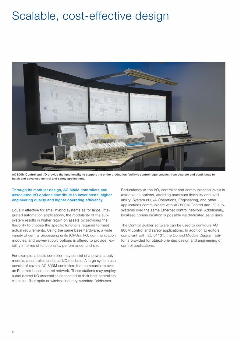
Through its modular design, AC 800M controllers and associated I/O options contribute to lower costs, higher engineering quality and higher operating efficiency.
Equally effective for small hybrid systems as for large, inte-grated automation applications, the modularity of the sub-system results in higher return on assets by providing the flexibility to choose the specific functions required to meet actual requirements. Using the same base hardware, a wide variety of central processing units (CPUs), I/O, communication modules, and power-supply options is offered to provide flex-ibility in terms of functionality, performance, and size.
For example, a basic controller may consist of a power supply module, a controller, and local I/O modules. A large system can consist of several AC 800M controllers that communicate over an Ethernet-based control network. These stations may employ subclustered I/O assemblies connected to their host controllers via cable, fiber-optic or wireless industry-standard fieldbuses.
Scalable, cost-effective design
Redundancy at the I/O, controller and communication levels is available as options, affording maximum flexibility and avail-ability. System 800xA Operations, Engineering, and other applications communicate with AC 800M Control and I/O sub-systems over the same Ethernet control network. Additionally, localized communication is possible via dedicated serial links.
The Control Builder software can be used to configure AC 800M control and safety applications. In addition to editors compliant with IEC 61131, the Control Module Diagram Edi-tor is provided for object-oriented design and engineering of control applications.
AC 800M Control and I/O provide the functionality to support the entire production facility’s control requirements, from discrete and continuous to batch and advanced control and safety applications.

7
The fault tolerance of AC 800M Control and I/O results in maximum control system availability with no single point of failure, thereby securing production and profits.
At the core, the base controller’s inherent reliability features contribute to high availability. Industrial-grade, conservatively loaded, on-board electronics result in a controller designed for installation in harsh environments. Low power consumption allows for installation in sealed enclosures without requiring fans, louvers, air filters or other forced cooling techniques. This simplicity eliminates many potential trouble-factors and thus contributes to the controller’s high reliability.
Maximum availability is achieved when the redundancy options are implemented. Redundancy is available in all critical areas of the AC 800M Control and I/O subsystem. These include control networks, field buses, internal buses, power supplies, CPUs and I/O. If a fault occurs in a primary circuit, bumpless transfer to the back-up ensures uninterrupted operation.
If one of the controller CPUs fails, fieldbus communication re-dundancy can be maintained unimpaired through the subsys-tem’s communication bus isolation and switchover scheme.
The AC 800M HI controller offers a TÜV certified control en-vironment for combining safety and business critical process control in one controller without sacrificing safety integrity.
Fault tolerance for maximum plant availability
The AC 800M, in combination with the Safety Module, per-forms advanced diagnostics and monitoring of application execution and I/O scanning.
Control modules, applications and hardware settings, may be changed on line, in real time and under power, resulting in maximum control availability.
The “Load Evaluate Go” function takes this handling ease a step further by supporting actions such as Modify, Download and Evaluate, making it possible to download a new version of the running application to the controller without it interfering with the running version.
The modified version is started in passive mode in parallel with the running version and an Evaluation Report and a Task Analy-sis tool shows the differences in real time.
The application(s) and data can optionally be stored in Flash memory to secure its contents e.g. after a power failure or during transport.
Finally, noise-immune fiber-optic communication is also available, safeguarding the operation of the AC 800M Control and I/O sub-system even under the most extreme electromagnetic conditions.
Optional redundancy in all areas of importance: power supply, CPUs, communication links and I/O circuits, is only one of many features of AC 800M Control and I/O that contributes to the highest possible plant availability.

8
AC 800M Control and I/O support industry-standard data interfaces, network protocols and field buses. Consequently the subsystem can interact with – and integrate – a wide range of devices and systems by both ABB and others.
Open architecture reduces lifecycle costsThe open architecture of AC 800M Control and I/O reduces lifecycle costs by simplifying the task of integrating plant systems and devices. Additionally, the subsystem’s useful life is extended since the open architecture allows for easy integration of new commercially-off-the-shelf (COTS) applica-tions and products. In System 800xA, seemingly disparate plant systems and devices are accessed via OPC, Ethernet, Ethernet IP, DeviceNet, Modbus TCP, PROFIBUS DP,
PROFINET I/O and FOUNDATION Fieldbus (H1 and HSE) and their resident information used in control strategies and higher-level applications to produce tighter and more reliable process control solutions.
The open design of AC 800M Control and I/O ensures peer-to-peer communication with existing, distributed control sys-tems by ABB. Wireless communication options exist at both the controller and I/O levels.
Open architecture reduces lifecycle costs

9
AC 800M controller
The AC 800M controller is a family of rail-mounted modules, consisting of CPUs, communication modules, power supply modules and various accessories. Several CPU modules are available that vary in terms of processing power, memory size, SIL-rating, and redundancy support.
Each CPU module is equipped with two Ethernet ports for communication with other controllers and for interaction with operators, engineers, managers, and higher level applica-tions. These ports can be configured for redundancy for those cases where availability is of paramount importance. It is also equipped with two RS-232C ports that can be used for point-to-point communication with programming/debugging tools and with third-party systems and devices. A Flash memory card can be inserted into a slot in the CPU module to store the application and data.
AC 800M control and I/O products
AC 800M controller ensures availability to meet all production require-ments, with redundancy options practical at all levels.
To this module, a number of communication and I/O modules can be added, for example: – Additional RS-232C ports, making it possible to connect
third-party systems and devices. – PROFIBUS DP, DP-V1 interfaces, providing integration of
S200, S800 and S900 I/O systems and access to the wide range of field devices, supporting these protocols.
– FOUNDATION Fieldbus HSE interface, provides a back- bone for access to FOUNDATION Fieldbus system solu- tions.
– PROFINET IO, PROFIBUS and DeviceNet interface provid-ing integration of a wide range of process equipments and I/O-systems.
– IEC 61850 interface, making it possible to protect and con-trol substation equipments by IEDs (Intelligent Electronic Devices) or protection relays.
– ABB INSUM interface, facilitating efficient supervision and control of electric switchgear over multidrop bus connections.
– MasterBus 300 and AF100 interface, providing compatibil-ity with Advant OCS and ABB Master systems.
– S100 I/O interface, making it possible to upgrade from ex-isting Advant Controller 410 or 450 – or even MasterPiece 200 - systems to AC 800M and retain existing I/O sections.
– TRIO I/O interface, making it possible to upgrade from ex-isting MOD300 Controllers to AC 800M and retain existing TRIO I/O sections.
– Satt I/O interface, making it possible to upgrade from existing Satt Controllers to AC 800M and retain existing Satt I/O sections.
– Modbus TCP interface, combining the MODBUS RTU with the Ethernet and TCP standards, thus providing communi-cation with 3rd-party equipment.
– I/O modules from the S800 I/O family as direct I/O.
These connectivity and expansion options make the AC 800M exceptionally open and scalable, that is, easy to connect to the surrounding world of supervisory systems and intelligent devices of all kinds - and adaptable to changing requirements as the process it controls changes, expands or contracts.
PM 851
PM 891

10
S800 I/O family
The S800 I/O system is closely related to AC 800M, not only in appearance but also in features.
– Comprehensive: The S800 family of I/O covers virtually all conceivable signal types and ranges. From basic ana-log and digital inputs and outputs to pulse counters and intrinsic-safety I/O.
– Flexible configuration: S800 I/O may be set up in a variety of ways, from directly connected to the host controller, to sub-clustered (using fiber-optic cables), to PROFIBUS-connect-ed. Redundancy solutions are available at all levels including; power supply, communication interfaces and I/O circuits.
Flexible installationThree mechanical designs are available: – Compact (plug-in modules with a basic I/O signal termi-
nation area). – Extended (plug in modules with ample space for I/O cable
termination, fuses, jumpering and field power distribution). – S800L (all-in-one modules and bases with detachable
screw terminal blocks for I/O signals) for installations not requiring hot-swap capability.
Easy to set upOnce station numbers have been allocated and set, all other settings can be made from a network-connected engineering tool. A pass-through feature makes it possible to configure and examine all HART®- compliant field devices in a similar way.
S800 I/O is available in three different designs: Compact, Extended, and S800L.
Reliable S800 I/O offer availability-improving features such as: – Input/Output Set as Predefined (ISP/OSP). Each input/out-
put can be set individually to default to a predefined value or freeze in case of communication loss.
– Hot swap of modules. A faulty I/O module can be replaced live, i.e. without powering the station down and without the rest of the station being affected. A hardware key ensures that only modules of the right type can be inserted.
– Hot configuration in run (HCIR). An S800 I/O station can be reconfigured while in full normal operation, i.e. without hav-ing to switch it over to configuration mode.
– Redundancy options in all areas: power supply, fieldbus media, fieldbus interfaces and I/O modules.
Accurate S800 I/O modules can time-stamp events, i.e. input signal transitions, at the source with millisecond accuracy. Thereby providing the basis for meaningful sequence-of-events record-ing by the host system. In tightly interlocked processes this is essential to finding the root causes of production disturbances.
For harsh environments, all control and I/O modules are compliant to G3 severity level of ISA-S71.04, Environmental Conditions for Process Measurement and Control Systems.
S800 I/O
AC 800M control and I/O products
S800L

11
AC 800M High Integrity controller
The AC 800M HI offers a certified TÜV control environment for combining safety and business critical process control in one controller without sacrificing safety integrity.
The AC 800M HI, in combination with a diverse co-processor, performs diagnostics and monitoring of application execution and I/O scanning.
To enable use of the same controller for both SIL and non-SIL applications, all functions/types in standard AC 800M HI Controller libraries are marked non-SIL or SIL to show their usability in the two application types. Embedded safety mea-sures prevent inadvertent degradation of safety applications.
The SIL 3-rated, IEC 61508-certified AC 800M HI Controller is ideally suited to running both process control and safety application concur-rently, in the same machine.
A comprehensive assortment of I/O modules are available for safety-criti-cal use. These include a range of SIL-3-rated S800 I/O modules for analog inputs, digital inputs, and digital outputs.
High Integrity I/O
Within the S800 family, there are SIL3 certified modules that can be used for safety critical applications.
These I/O modules include those for 4 - 20 mA analog inputs, 24 Vdc normally closed digital inputs, and 24 Vdc digital outputs. The digital output module provides both Normally Energized (ESD) and Normally De-energized (F&G) outputs.
Analog inputs support HART routing for easy calibration checking and diagnosis with configurable access, while the digital inputs support local time-tagging of signal changes for high-accuracy sequence-of-events logging.
AC 800M High Integrity Controller High Integrity I/O

S900 I/O family
The S900 remote I/O system communicates with 800xA or other controllers over PROFIBUS.
Suitable for applications in the chemical, pharmaceutical, oil and gas industries, S900 I/O can be installed in hazardous areas, thereby reducing marshalling and wiring costs. Further maintenance savings can be achieved through S900’s extend-ed diagnostics and the use of HART®-compliant field devices.
Three versions of S900 I/O – S-series for applications in Zone 1 hazardous areas – B-series for applications in Zone 2 hazardous areas – N-series for applications in non hazardous areas
Additional solutions for specific applications – Field housing – for wall mounting and field mounting in
Zone 1 installations with system approval fully certified in accordance with ATEX. The high-grade steel housing is prepared for wall-mounting with facility for insulated screen rails or terminals.
Series Assembly Field devices /
signals
Hazardous area
approval
S series In Zone 1 In Zones 2, 1 and
0 (intrinsically safe
signals)
ATEX Zone 1
B series In Zone 2 In Zones 2, 1 and
0 (intrinsically safe
signals)
ATEX Zone 2
N series In safe areas In safe areas No
– CB220 compact box – S900 in compact form (with up to 4 I/O modules). This variant is suitable for use in applications such as temperature multiplexers and solenoid valve circuits.
The S900 components are based on a passive backplane suitable for mounting on a DIN rail or directly in a sub-distri-bution board. The passive backplane includes internal bus communication, terminals for field circuits, communication, and power supply. The function modules are plugged into the backplane in their appropriate slots. The redundant backplane has two slots for power supply units, two slots for commu-nication interfaces, and 16 slots for function modules. Digital function modules have up to 8 channels, analog modules up to four. Therefore, when using a redundant backplane, 128 digital or 64 analog channels can be connected per station. In the case of the S and B series, up to ten S900 stations can be connected on a single fieldbus line.
Key S900 benefits – Intrinsically safe – can be installed in Zone 1 and Zone 2 areas. – Good price/performance ratio because external barriers
have been removed and costs are reduced in terms of cabling, installation, hardware, and maintenance.
– High reliability thanks to smooth automatic transfer of data and to auto-diagnostics.
– Easy configuration using either FDT/DTM or GSD files, allow-ing easy integration with 800xA process control systems.
– High availability of the plant thanks to redundancy and hot-swap capability of all components during operation.
The intrinsically safe S900 I/O system can be installed in Zone 1 and Zone 2 areas and offers features such as hot swap and optional redundancy.
12

Engineering software
13
System 800xA Engineering provides real-time information integration for better and faster access. 800xA Engineering, is designed to facilitate one-time data entry for all areas within the automation system, from field devices to asset optimization, while ensuring built-in data consistency.
Providing a single source of accurate and real-time plant infor-mation results in maximum engineering performance, quality, and reliability.
This integrated environment results in fewer startup delays, reduced maintenance costs, and more effective engineering practices.
800xA Engineering features – Graphic display configuration – Control application design – Safety application design – Control system configuration – Field device and instrumentation configuration – Control System and field device maintenance – Trend and history configuration – Integration with CAE tools as Intergraph SmartPlant®
Instrumentation

Control builder Software includes an extensive library of pre-defined and support of user-defined control elements, ranging from simple AND gates to powerful adaptive PID controllers and ready-to-use process objects and control functions e.g. for motors, valves and switchgear. These can be used to eas-ily design simple to complex control strategies to fit any appli-cation, including continous, sequential, batch and advanced control.
Control builder Software and its engineering tools support all five of the IEC61131-3 programming languages (function block diagram, structured text, ladder diagram, sequential function chart and instruction list) plus ABB’s own high- powered Control Module language.
For scenarios where the plant design is driven by highly re-petitive units, the Control Modules are available. With Control Modules, user defined types covering a unit like a reactor can be designed and efficiently parameterized and instantiated multiple times.
For most efficient engineering the Control Diagram Editor can be used. This Graphical Engineering tool is in addition to the 61131 languages and brings it all together allowing for function blocks, structured text and sequences etc to all be in one engineering environment making it easier to create and maintain application software.
14

System 800xA 6.0Product Catalog

System 800xA Extended Automation It’s all about control ___________________________ 4
System 800xA Software _______________________ 6License .................................................................................. 6
Lifecycle Management – System Expansion ______ 7Automation Sentinel Program .................................................. 7
Software Updates and upgrades ............................................. 7
Cyber and IT security reports and updates ............................... 7
System Benchmark Tool.......................................................... 7
Expert product technical support ............................................. 7
800xA 6.0 System Identifier ____________________ 8Control System Lifecycle Management Program ....................... 8
System Identifier ..................................................................... 8
800xA 6.0 System ____________________________ 9Remark .................................................................................. 9
Automation Sentinel Upgrade Orders ....................................... 9
800xA Base System ............................................................... 9
Tag Expansion ...................................................................... 10
Subscriber System Tags ........................................................ 11
800xA Applications ............................................................... 12
Connectivity ......................................................................... 12
System Extensions ............................................................... 14
Cyber Security ...................................................................... 15
Operator Workplaces ............................................................ 15
Extended Operator Workplaces ............................................. 16
Extended Operations ............................................................ 17
Public Addressing ................................................................. 18
Batch Management .............................................................. 19
Standard Engineering Tools ................................................... 20
Engineering Systems ............................................................ 20
Professional Engineering Tools .............................................. 21
2 Contents | System 800xA 6.0 Product Catalog
Contents
Decathlon based SW licenses for 800xA ................................ 21
800xA History ....................................................................... 22
IM Historian .......................................................................... 23
Safety .................................................................................. 25
Asset Optimization ................................................................ 25
Asset Monitors ..................................................................... 26
Device Management & Fieldbuses ......................................... 26
Libraries ............................................................................... 28
Options for Extended Operator Workplace ............................. 28
Localization .......................................................................... 30
AC 800M Processor Units ____________________ 31AC 800M Controllers and users guide .................................... 32
Hardware Upgrade orders ..................................................... 33
AC 800M Hardware .............................................................. 33
System Units ........................................................................ 35
Communication .................................................................... 36
AC 800M Power supply ........................................................ 42
AC 800M Mounting Rails....................................................... 42
S800 I/O Modules ___________________________ 43S800 I/O Modules ................................................................. 44
Extended warranty for S800 I/O Hardware ............................. 47
ISA-S71.04 level G3 Compliance ........................................... 47
Field Communication Interface .............................................. 47
Upgrade Kit and Tool Cables ................................................. 48
S800 I/O Modules ................................................................. 49
Pulse Counting Modules ....................................................... 53
Label sets for I/O Modules .................................................... 53
High Integrity I/O Modules ..................................................... 53
Module Termination Units ...................................................... 54
S800L I/O Modules ............................................................... 56
Label sets for S800L I/O Modules.......................................... 56
ModuleBus Communication Parts .......................................... 57

System 800xA 6.0 Product Catalog | Contents 3
Power Supply ....................................................................... 59
User Documentation ............................................................. 60
Process Industries Application Libraries ................................. 60
PIAL Media ........................................................................... 60
Process Control Device Library .............................................. 61
PCDL Application Engineering ............................................... 61
Process Control Equipment Library ........................................ 62
Process Control Equipment Library ........................................ 63
Additional Control Equipment Library Licenses ....................... 63
PCEL Application Engineering ............................................... 64
ProBase ............................................................................... 64
S900 Remote I/O System ____________________ 65Ex zone 1 system components .............................................. 66
Ex zone 2 system components .............................................. 68
Safe area system components .............................................. 70
Accessories .......................................................................... 72
Field Housing S900-FH660S ................................................. 73
Field Housing S900-FH680S ................................................. 74
Accessories .......................................................................... 75
FOUNDATION Fieldbus Network Components ........................ 75
PROFIBUS Network Components .......................................... 78
Media and Documentation ____________________ 79Industrial IT 800xA ................................................................ 80
Library ................................................................................. 80
Dongles ............................................................................... 80
800xA Base System User Documentation .............................. 81
Panel 800 Version 6 _________________________ 83Specifications Panel 800 Version 6 ........................................ 84
Software Management Program ............................................ 85
Panel Builder 800 ................................................................. 85
Operator Panels ................................................................... 86
Accessories .......................................................................... 87
Dongles ............................................................................... 88
Panel 800 Version 5 _________________________ 89Specifications Panel 800 Version 5 ........................................ 90
Control System Lifecycle Support Program ............................ 91
Panel Builder 800 ................................................................. 91
Operator Panels ................................................................... 92
Touch Panels ........................................................................ 93
Accessories .......................................................................... 94
IEC 61850 Engineering Tool for 800xA 6.0 ______ 95
Extended Warranty Time _____________________ 96Extended warranty time on hardware for
S800 I/O, S900 I/O, Fieldbus and AC800M ............................ 96
800xA Marketing Material_____________________ 97Brochures ............................................................................ 98
Data Sheets ......................................................................... 99
USB with configuration graphics ............................................ 99
Posters ...............................................................................100
Roll Ups ..............................................................................100
Accessories .........................................................................101
Giveaways ...........................................................................102
Safety – Brochures ..............................................................103
Safety – Data Sheets ...........................................................103
Safety – Posters ..................................................................104
Safety – Roll Ups .................................................................104
Safety – Giveaways ..............................................................104
Reference documentation ___________________ 105

4 Topology | System 800xA 6.0 Product Catalog
System 800xA Extended AutomationIt’s all about control
CollaborationTable
WirelessHARTGateway
Variable Speed Drive
System Networks
Inte
rnet
Field Networks
PowerAutomation
ProcessElectrification
ProcessInstrumentation
BusinessSystemsSafety PLC & DCS
MotorController
AC 800MController
S800 I/O
ABB and 3rd party PLC & DCS
Mod
uleb
us
M008CAytirgetnIhgiH
rellortnoC
MO
DB
US
System Workplaces
Base SystemServers
Protection &Control IED
Panel 800
IEC
618
50
PR
OFI
BU
S /
PR
OFI
NE
T /
Mod
uleb
us /
Dev
iceN
et
PR
OFI
BU
S /
Fou
ndat
ion
Fiel
dbus
/ M
odul
ebus
S900 I/OLV Switchgear
REG670
WirelessHART
CMMSERPDMSCADVideo
...
Shut-down
Fire & Gas
System 800xA v6It’s all about control
3BSE045753 en G
DMZ MI Servers
ExtendedOperatorWorkplace
Wireless MeshNetwork
800xA is not only a DCS (Distributed Control System) it’s also an Electrical Control System, a Safety System and a collaboration enabler with the capacity to improve engineering efficiency, operator performance and asset utilization.
Promoting collaboration Collaboration between people and systems is a necessity to increase engineering efficiency, asset utilization, energy savings, and operator effectiveness. System 800xA’s ‘xA’ stands for Extended Automation and utilizes the system architecture which was built for collaboration. System 800xA is the only automation platform that has the ability to engineer, commission, control, and operate automation strategies for process, power, electrical and safety in the same, redundant, reliable system. Also, facilitating collaboration is System 800xA’s pre-integrated applications such as a full featured historian, asset optimization and batch management.

System 800xA 6.0 Product Catalog | Topology 5
System 800xA ABB’s award winning System 800xA provides you with a better way to achieve measurable productivity and profitability improvements. 800xA extends the scope of traditional DCS systems to include all automation functions in a single opera-tions and engineering environment; enabling your plants to perform smarter and better at substantial cost savings. Embracing the principles of open, real-time networking, System 800xA provides a scalable solution that spans and in-tegrates loop, unit, area, plant, and inter plant controls. From providing a secure foundation with robust, but flexible, base level regulatory and sequence control to higher level man-agement and advanced control functions that include safety controls,batch management, maintenance management, information management, and network management solu-tions, 800xA meets the application needs of a wide variety of industries.
System 800xA provides you with a secure, reliable control environment with minimum effort through built-in security features such as access control, user authentication, and audit trail capability. ABB enhances secure system operations by actively participating on security standards committees, conducting threat-modeling studies, and incorporating “safe design” practices into product development.
Based upon the Aspect Object technology and a common set of hardware, 800xA seamlessly integrates traditionally isolated DCS and Safety systems. SIS realization is achieved by either utilizing individual controllers or through dedicated applica-tions within the same controller. With this embedded control and safety architecture, 800xA reduces costs significantly; achieving the objectives of both systems – maximum plant availability at minimum risk.
For more information about 800xA please visit our web: www.abb.com/800xA

6 Topology | System 800xA 6.0 Product Catalog
System 800xA Software
The system installation is supported by the Automated Instal-lation program. The Automated Installation program is a shell framework to ease the installation and configuration of your 800xA System.
Installation is never prevented due to lack of licensing, but licenses are required to unlock features for operating or engineering the system. Updates and security related soft-ware from non-ABB companies must be downloaded and installed separately, as guided from the Automated Installation program.
The Automated Installation program is supplied on the 800xA media box. The common part is to specify the system details of your system in the Automated Installation program System Planner and generate a unique setup package for each node (workstation) describing what should be installed from the 800xA media box, or a file server, onto each node, and how it should be configured.
The System 800xA Installer is installed on each node, and then the following steps are executed to install and configure your node:
− Windows configuration − System Verifier tool − System installation − System configuration
The setup-files may also reside on the file server. Windows c onfiguration configures the environment (IP address, host-name, Windows components, and Windows services) connect to the workgroup or domain. The System Verifier tool checks for the necessary 3rd party software and where installations are required.
License The central licensing system (CLS) is local to each system. Each system is ordered separately, and a separate license file is fetched for each system from the Software Factory. This also means that each system is managed individually updates and upgrades, as well as initial system installation
The software or hardware described in the document is furnished under a license and may be used, copied, or disclosed only in accordance with the terms of such license.

System 800xA 6.0 Product Catalog | Software 7
System 800xA Software 800xA 6.0 System Lifecycle Management – System Expansion
Automation Sentinel Program Automation Sentinel is the control system lifecycle support program and is aimed at providing services for the mainte-nance, continuous enhancement and evolution of the ABB installed base of control systems.
Each and every control system under Automation Sentinel can make use, depending on the active subscription mode, of the following main program deliverables listed below:
Software Updates and upgradesAutomation Sentinel users have the exclusive right to receive control system software updates and upgrades:
− Automation Sentinel users with a Maintain subscription have the possibility to receive technical corrections, roll-ups, service packs and software revisions for the current 800xA software version in use.
− Automation Sentinel users with a Maintain Plus subscrip-tion receive all what the Maintain users are receiving PLUS software upgrades to move from any 800xA version to the latest available 800xA software version.
− Automation Sentinel users with a Maintain&Evolve sub-scription receive all what the Maintain Plus users are receiving PLUS the possibility to take an ABB heritage control system (and selected 3rd party control systems) all the way to the latest available 800xA software version.
Cyber and IT security reports and updates Automation Sentinel users have the exclusive right to access IT security validation reports:
ABB reviews, tests and validates on a regular basis Microsoft security updates and 3rd party virus scanner software for compat-ibility with the 800xA control system. Automation Sentinel users will have access to all available cyber and IT security reports and updates for application as needed in order to ensure that the run-ning control systems are better protected against any security risks which are encountered more often now than ever before. Each and every control system must be under Automation Senti-nel before making use of the published IT security validation reports.
System Benchmark ToolAutomation Sentinel users will have the right to use, at no addi-tional cost, the following service tools:
− 800xA Control System Software and Performance Benchmark
− 800xA Control System Security Benchmark
The above listed service tools are employed to perform health and security checks on the 800xA control system and gener-ate ‘Traffic light’ reports of the findings.
Expert product technical supportAutomation Sentinel users have access to ABB expert and R&D support organizations. This support is being provided for troubleshooting of product defects and issues they encounter during the validity of the subscription.
Program Options
Maintain Basic
Maintain Maintain Plus
Maintain & Evolve
Basic
Deliverables
- IT Security verification and validation reports
- Web access via My Control System and SolutionsBank
- Access to expert product support (L3/L4 support)
Maintenance
Deliverables
- Software maintenance updates & corrections
- System status and performance Benchmark tool
- Scalable discount on selected service products
- Scalable discount on selected expansion HW & SW
Enhancement
Deliverables
- New sotfware versions & enhancements
Evolution
Deliverables
- Evolution from ABB Heritage OCS and
3rd party control systems to the latest
ABB control platform

8 Software | System 800xA 6.0 Product Catalog
Control System Lifecycle Management Program
Control System Lifecycle Management ProgramAutomation Sentinel is the ABB control system lifecycle management program. An introduc-tory trial period to the Automation Sentinel program will be included, at no additional cost, with each new ABB control system software delivery. Please contact your designated Automation Sentinel responsible for any questions or please refer to the Automation Sentinel 3.0 product guide for detailed information on the program and on how to calculate and order Automation Sentinel subscriptions.
800xA 6.0 System Identifier
System Identifier
800xA System IdentifierSystem identifier, used as identifier for each individual 800xA system. The ID must be used when ordering hardware and software to a system. After ordering this item a system license in design phase can be downloaded from SOFA.
Article no.
800xA System Identifier 3BSE081075R1

System 800xA 6.0 Product Catalog | Software 9
Automation Sentinel Upgrade Orders
Base System – 800xA Base System
Automation Sentinel Upgrade
Article no.
Automation Sentinel Upgrade 3BSE047992R1
800xA Base SystemIncludes one Operator Workplace, one Engineering Workplace, AC800M Connectivity, Redundant Aspect Server, Plant Explorer, Logging of Operator Actions,Topology Status Viewer, Softpoint Server, Scheduler, Primary History Logs (logging of signals for operator trends for up to 3 months), 10 Asset Monitors and Diagnostics Collection. Fast log-over of users.
Article no.
800xA Base System 3BSE078781R1
800xA 6.0 System
Remark
RemarkWhen System Software Expansion licenses are ordered, the Serial Number of the ABB Soft-ware License Cerificate for the previously ordered System Software licenses must be stated on the order to the ABB Supplier.
800xA Production LicenseOrdered to be able to download a production license to switch the system from Engineering Phase to Production Phase.
Article no.
800xA Production License 3BSE081642R1
The base system is used as the base for 800xA production system, mulitsystem integration subscriber system and as Read only system. Tags can be added to all these systems. Only one type of subscriber tags (ie. subscriber tags or read only subscriber tags) can be added to a subscriber system. A subscriber system can not be converted from read only to read and write and vice versa.

10 Software | System 800xA 6.0 Product Catalog
TagsAll process objects with faceplate for operator interactions counts as a tag. (Total max 120,000. Can not be mixed with redundant tags)
Article no.
100 tags, non-redundant 3BSE078782R1
1,000 tags, non-redundant 3BSE078782R2
10,000 tags, non-redundant 3BSE078782R3
A TSA is NEEDED for a system with more than 60,000 tags.
Redundant TagsAll process objects with an operator faceplate counts as a tag. (Total max 120,000. Can not be mixed with non-redundant tags) Enables tag access through redundant Connectivity Servers.
Article no.
100 tags, redundant 3BSE078783R1
1,000 tags, redundant 3BSE078783R2
10,000 tags, redundant 3BSE078783R3
A TSA is NEEDED for a system with more than 60,000 tags.
Base System – Tag Expansion
Non-Redundant to Redundant Tag ConversionAll process objects with faceplate for operator interaction counts as a tag. (Total max 120,000. Redundant and non-redundant tags can not be mixed) Enables tag access through redundant Connectivity Servers.
Article no.
100 Non-redundant to Redundant Tag Expansion 3BSE079637R1
1,000 Non-redundant to Redundant Tag Expansion 3BSE079637R2
10,000 Non-redundant to Redundant Tag Expansion 3BSE079637R3
A TSA is NEEDED for a system with more than 60,000 tags.

System 800xA 6.0 Product Catalog | Software 11
Non-Redundant to Redundant Multisystem Subscriber Tag ConversionTags in the subscriber system in a Multisystem Integration configuration.
Article no.
100 Multisystem Subscriber Non-Redundant to
Redundant Tags
3BSE079641R1
1,000 Multisystem Subscriber Non-Redundant to
Redundant Tags
3BSE079641R2
10,000 Multisystem Subscriber Non-Redundant to
Redundant Tags
3BSE079641R3
A TSA is NEEDED for a system with more than 60,000 tags.
Multisystem Subscriber TagsTags in the subscriber system in a Multisystem Integration configuration.
Article no.
100 Multisystem Subscriber Tags 3BSE079526R1
1,000 Multisystem Subscriber Tags 3BSE079526R2
10,000 Multisystem Subscriber Tags 3BSE079526R3
A TSA is NEEDED for a system with more than 60,000 tags.
Base System – Subscriber System Tags
Subscriber System TagsTags in the subscriber system in a Multisystem Integration configuration. These tags are Object with a faceplate that collects data from a provider system. Subscriber tags are only required in the subscriber system.
Note that non-redundant Multisystem Subscriber Tags can not be mixed with Multisystem Subscriber Redundant Tags.
Note that Multisystem Subscriber Tags can not be mixed with Multisystem Read Only Subscriber Tags.
Multisystem Subscriber Redundant TagsTags in the subscriber system in a Multisystem Integration configuration.
Article no.
100 Multisystem Subscriber Redundant Tags 3BSE079527R1
1,000 Multisystem Subscriber Redundant Tags 3BSE079527R2
10,000 Multisystem Subscriber Redundant Tags 3BSE079527R3
A TSA is NEEDED for a system with more than 60,000 tags.

12 Software | System 800xA 6.0 Product Catalog
Multisystem Read Only Subscriber TagsTags in a Read Only Subscriber system in a Multisystem Integration configuration. Read only sub-scriber systems provides aspect object enabled clients read only clients to office users. Subscriber tags are only required in the subscriber system. Subscriber tag is required for every provider tag that needs to be accessed from graphics, alarms, trends etc, in the subscriber system.
Note that Multisystem Read Only Subscriber Tags can not be mixed with Multisystem Subscriber Tags.
Article no.
100 Multisystem Read Only Subscriber Tags 3BSE079104R1
1,000 Multisystem Read Only Subscriber Tags 3BSE079104R2
10,000 Multisystem Read Only Subscriber Tags
NOTE: At pricebook release a TSA was NEEDED for a system
with more than 60,000 tags. Please, check current need of a
TSA in the TSA Database before ordering
3BSE079104R3
Office Workplace – Read Only Client
Includes one local or remote read-only operator workplace,
Excel based reporting aspects, MS Excel is NOT included, use
of up to 2 screens is included.
(One is included with Core system so this limit to Total-1)
(Only in systems with read-only MI tags)
3BSE078864R1
Base System – 800xA Applications
ConnectivityNote that there may be 800xA price list options that are not supported with a particular OCS controller. Please refer to the table “Available functions per Controller Connectivity” in the System Guide “Technical Data and Configuration Information”. To check what connectivity combinations that are valid, use the Project Wizard or refer to the System 800xA System Guide for information.
Article no.
PLC Connect
Faceplates, graphical elements and means to communicate with
the system. (one per system)
3BSE078822R1
PLC Connect Dial-Up
Scaled on number of dial up lines in a system.
3BSE078823R1
KNX Connect
Data access to KNX devices connected via ABB KNX IP router.
The 800xA server node communicates over TCP/IP with the
router.
3BSE078865R1
800xA for Advant Master
Faceplates, graphical elements and means to communicate with
the system (One per system.) RTA hardware needs to be
ordered separately. Please refer to pricebook 3BSE001706,
Advant OCS with Master Software, for RTA hardware.
3BSE078816R1
Base System – Connectivity

System 800xA 6.0 Product Catalog | Software 13
ConnectivityNote that there may be 800xA price list options that are not supported with a particular OCS controller. Please refer to the table “Available functions per Controller Connectivity” in the System Guide “Technical Data and Configuration Information”. To check what connectivity combinations that are valid, use the Project Wizard or refer to the System 800xA System Guide for information.
Article no.
Advant Master Central Backup
Backup and restore of applications for Advant Master
controllers(AC410, AC450, MP200/1, SG400) One license per
system. Requires 800xA for Advant Master.
3BSE078817R1
800xA for Harmony
Faceplates, graphical elements and means to communicate with
the system.
3BSE078819R1
800xA for AC 870P / Melody
Graphical elements and means to communicate with the system
(Faceplates not included) (One per system.)
3BSE078821R1
800xA for MOD 300
Faceplates, graphical elements and means to communicate with
the system. RTA hardware needs to be ordered separately.
Please refer to pricebook 3BSE001709, Advant OCS with MOD
300 SW, for RTA hardware.
3BSE078818R1
800xA for DCI
Faceplates, graphical elements and means to communicate with
the Harmony Distributed Control Unit (HDCU), includes: Batch
connectivity, VB6 and PG2 faceplates, HDCU maintenance
functions.
3BSE078820R1
800xA for Safeguard
Faceplates, graphical elements and means to communicate with
the system. Note: Requires also 800xA for Advant Master.
3BSE078824R1
800xA for AC 100
Faceplates, graphical elements and means to communicate with
the AC 100 Controller, OPC server included.
3BSE078825R1
Base System – Connectivity
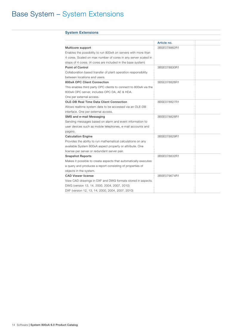
14 Software | System 800xA 6.0 Product Catalog
Base System – System Extensions
System Extensions
Article no.
Multicore support
Enables the possibility to run 800xA on servers with more than
4 cores. Scaled on max number of cores in any server scaled in
steps of 4 cores. (4 cores are included in the base system)
3BSE078862R1
Point of Control
Collaboration based transfer of plant operation responsibility
between locations and users.
3BSE078830R1
800xA OPC Client Connection
This enables third party OPC clients to connect to 800xA via the
800xA OPC server, includes OPC DA, AE & HDA.
One per external access.
3BSE078826R1
OLE-DB Real Time Data Client Connection
Allows realtime system data to be accessed via an OLE-DB
interface. One per external access.
3BSE078827R1
SMS and e-mail Messaging
Sending messages based on alarm and event information to
user devices such as mobile telephones, e-mail accounts and
pagers.
3BSE078828R1
Calculation Engine
Provides the ability to run mathematical calculations on any
available System 800xA aspect property or attribute. One
license per server or redundant server pair.
3BSE078829R1
Snapshot Reports
Makes it possible to create aspects that automatically executes
a query and produces a report consisting of properties of
objects in the system.
3BSE078832R1
CAD Viewer license
View CAD drawings in DXF and DWG formats stored in aspects.
DWG (version 13, 14, 2000, 2004, 2007, 2010)
DXF (version 12, 13, 14, 2000, 2004, 2007, 2010)
3BSE079674R1

System 800xA 6.0 Product Catalog | Software 15
Base System – Cyber Security
Cyber Security
Article no.
Digital Signature
Makes it possible to digitally sign aspects to ensure that data is
kept unchanged after approval.
3BSE078833R1
Advanced Access Control
Reauthentication, double reauthentication and inactivity logout.
3BSE078834R1
Audit Trail
Logging of all user initiated actions in a system. e.g. Graphics
editing, Control Logic editing, Batch recipe editing and start/
stop of servers etc.
3BSE078835R1
800xA for Industrial Defender
Industrial Defender monitoring is updated with 800xA security
events (one per system)
3BSE079528R1
Whitelisting SE46
Whitelisting SE46 provides advanced threat protection, through
checks of executing SW on clients and servers. The number of
licenses should match the number of clients in a system.
Protection of servers are included.
3BSE079529R1
Whitelisting Studio SE46
Configuration tool required when using Whitelisting SE46 option.
One tool needed per site using Whitelisting SE46.
3BSE079530R1
Operations – Operator Workplaces
Operator Workplaces
Article no.
Operator Workplace – Additional Client
Includes one local or remote operator workplace, Excel based
reporting aspects, MS Excel is NOT included, use of up to 2
screens is included.
(One is included with Core system so this limit to Total-1)
The total quantity of Operator Workplaces, Large Operator
Workplaces and Engineering Workplaces - must not exceed 80.
3BSE078749R1
Large Operator Workplace Client
Includes one local or remote Operator Workplace, with the
possibility to use up to 4 screens and Large Desktop.
The total quantity of Operator Workplaces, Large Operator
Workplaces and Engineering Workplaces - must not exceed 80.
3BSE078750R1
Convert Operator Workplace to large Operator Workplace 3BSE079107R1

16 Software | System 800xA 6.0 Product Catalog
Operations – Extended Operator Workplaces
Extended Operator WorkplacesAdditional options for the Extended Operator Workplaces must be selected in the sections 12.1 to 12.5 at the end of this price list.
Article no.
EOW-x2 workplace
Operator Cockpit with adjustable ergonomic desk, 1 close large
screen area and 2 sets of 2 wide screen motorized adjusted
monitors each. Network switches and 3x quiet client PCs with 1
multifunctional keyboard and mouse for control. Built in sound,
light and video camera for communication. Installation manuals,
Partly assembled for easy commissiong.
Ships with EOW-x Base License, which includes 1 camera
input, cad and video view on all three screen areas.
Options for desk color, keyboard layout and110/230V are
needed.
3BSE079114R1
EOW-x3 workplace
Operator Cockpit with adjustable ergonomic desk, 1 close large
screen area and 2 areas with 3 adjustable monitor each. Net-
work switches and 3x quiet client PCs with 1 multifunctional
keyboard and mouse for control. Built in sound, lighting and
video camera for communication. Installation manuals, Partly
assembled for easy commissiong. Ships with EOW-x Base
License, which includes 1 camera input, cad and video view
on all three screen areas. Operator Cockpit with adjustable
ergonomic desk, 1 close large screen area and 2 sets of 3 wide
screen motorized adjusted monitors. Network switches and
3x quiet client PCs with 1 multifunctional keyboard and mouse
for control. Built in sound, lighting and video camera for com-
munication. Installation manuals, Partly assembled for easy
commissiong.
Ships with EOW-x Base License, which includes 1 camera
input, cad and video view on all three screen areas.
Options for desk color, keyboard layout and110/230V are
needed.
3BSE079115R1
EOW-f2 workplace
Operator console including fixed ergonomic desk, 1 close large
screen area and 2x2 personal screen setup. 1 programmable
keyboard and moouse for control. Installation manuals.
Delivered disassembled. Ships with EOW-f base license.
Option needed for keyboard layout and 110/230 V.
3BSE079116R1
EOW-f3 workplace
Operator console including fixed ergonomic desk, 1 close large
screen area and 2x3 personal screen setup. 1 programmable
keyboard and moouse for control. Installation manuals.
Delivered disassembled. Ships with EOW-f base license.
Option needed for keyboard layout and 110/230 V.
3BSE079117R1

System 800xA 6.0 Product Catalog | Software 17
Operations – Extended Operations
Extended Operations
Article no.
Control Room Review Prestudy
Results in a customer unique future design of an existing or new
control room. Based on general information, Plans and Photos,
a questionnaire and phone interviews. Final result will be pre-
sented in a webmeeting.
3BSE079590R1
Control Room Design Prestudy
Results in a customer unique future design of an existing or new
control room. Based on general information, Plans and Photos,
a questionnaire and on site interviews with a work flow study.
Final result will be presented in a webmeeting. The onsite work
is included in the price.
3BSE079591R1
Complete Control Room Prestudy
Results in a customer unique future design of an existing or new
control room. Based on general information, Plans and Photos,
a questionnaire and on site interviews with a work flow study.
Final result will be presented in a webmeeting. The onsite work
is included in the price.
3BSE079592R1
Video Input Channel
Connection to attach a video stream from one video camera for
recording or live viewing in the system.
3BSE079118R1
Video Client
One concurrent client using video stream viewing from either
recorded or live video source. Each Client need a compatible
video codec to uncompress the video stream. The codec is not
included. The total quantity of Video clients must not exceed the
total number of clients in a system.
3BSE079119R1
Alarm awareness light control (per area)
Situation awareness with colored light showing the alarm prior-
ity. Led light combined with soundabsorbers, covered surface
approx 6 Sqm.
3BSE078868R1
Alarm Operations, < 2000 Tags
Alarm Grouping, Alarm Shelving and Basic Alarm Analysis.
Alarm Help aspects. (Alarm Hiding and Alarm Response are
parts of the base system)
NOTE: At pricebook release a TSA was NEEDED for the Alarm
Help item. Please, check current need of a TSA in the TSA
Database before ordering.
3BSE078751R1
Alarm Operations, < 5000 Tags
Alarm Grouping, Alarm Shelving and Basic Alarm Analysis.
Alarm Help aspects. (Alarm Hiding and Alarm Response are
parts of the base system)
NOTE: At pricebook release a TSA was NEEDED for the Alarm
Help item. Please, check current need of a TSA in the TSA
Database before ordering.
3BSE078751R2
Alarm Operations, >= 5000 Tags
Alarm Grouping, Alarm Shelving and Basic Alarm Analysis.
Alarm Help aspects. (Alarm Hiding and Alarm Response are
parts of the base system)
NOTE: At pricebook release a TSA was NEEDED for the Alarm
Help item. Please, check current need of a TSA in the TSA
Database before ordering.
3BSE078751R3

18 Software | System 800xA 6.0 Product Catalog
Operations – Extended Operations
Extended Operations
Article no.
Alarm History and Reports, < 2000 Tags
Long term Alarm storage and analyze, Alarm system KPI
reports, web and e-mail distribution of reports.
Note: At pricebook release this item required a TSA to be
ordered. Please, check current need of a TSA in the TSA Data-
base before ordering.
3BSE078869R1
Alarm History and Reports, < 5000 Tags
Long term Alarm storage and analyze, Alarm system KPI re-
ports, web and e-mail distribution of reports.
Note: At pricebook release this item required a TSA to be
ordered. Please, check current need of a TSA in the TSA Data-
base before ordering.
3BSE078869R2
Alarm History and Reports, >= 5000 Tags
Long term Alarm storage and analyze, Alarm system KPI
reports, web and e-mail distribution of reports.
Note: At pricebook release this item required a TSA to be
ordered. Please, check current need of a TSA in the TSA Data-
base before ordering.
3BSE078869R3
Symbol Factory for Process Graphics
Support for Symbol Factory graphics items in graphics displays.
3BSE080146R1
Operations – Public Addressing
Extended Operations
Article no.
Public Addressing output channel
One output channel with one language.The channel can convert
alarms in alarmlists and predefined text messages to sound.
The sound content can be configured differently for each output
channel.
A TSA is NEEDED to buy this item
3BSE078808R1
Public Addressing additional language
One additional language for all channels.
A TSA is NEEDED to buy this item
3BSE078809R1

System 800xA 6.0 Product Catalog | Software 19
800xA 6.0 System – Batch Management
Batch Management
Article no.
Batch Base System
Provides the basic server functionality for batch management.
The batch server includes 10 Batch Equipment and 2000 Batch
Procedures. 1 Batch client included.
3BSE078752R1
10 Additional Batch Equipment
The number of batch equipment instances includes each piece
of equipment configured in Batch Management including both
Units and Shared Equipment Modules.
3BSE078756R1
100 Additional Batch Equipment
The number of batch equipment instances includes each piece
of equipment configured in Batch Management including both
Units and Shared Equipment Modules.
3BSE078757R1
Batch Management Full Client
This Client feature provides access to Batch Management
functions. The Client feature is based upon concurrent users,
not physical workstation installation.
Including SL and SQL server licenses.
Requires Operator Workplace Client - item C010 or C030; or
Engineering Workplace Client - item D510. Maximum 40 Clients.
One Client is included with the Batch Base System.
3BSE078754R1
Redundant Batch Server Option
Provides redundancy for the basic server functionality for batch
management. Requires Batch Base System, item D010.
3BSE078753R1
Batch Advanced Phase Templates
This feature provides access to the Batch Advanced templates
control modules for phases, units and shared equipment mod-
ules. For use with AC 800M controllers. Batch Phase Control
library option, includes 2000 Advanced Phases.
3BSE078758R1
Batch Schedule Interface
This feature is used to interface Batch Management to external
applications such as schedulers and ERP systems. Webservice
interface to batch scheduling and equipment status.
3BSE078755R1
Simple Batch Parameter Management
Batch spreadsheet recipe scheduling tool for desktop PC
interface to Batch Management using Excel.
(Not required when Batch Schedule Interface is ordered)
Requires a minimum of System 800xA 5.1 Feature Pack 3.
3BSE079105R1

20 Software | System 800xA 6.0 Product Catalog
Engineering – Standard Engineering Tools
Standard Engineering Tools
Article no.
Engineering Workplace – Additional Client
Includes Control Configuration for AC 800M, Bulk Data Han-
dling, Graphic Configuration, Document Manager, Parameter
Manager, I/O allocation function and Script Manager Profes-
sional. (one client is included with the Base system)
The total quantity of Operator Workplaces-Additional and
Remote Clients, Large Operator Workplaces and Engineering
Workplaces – must not exceed 80.
3BSE078790R1
Engineering Workplace with Application Change
Management – Client
Includes one Engineering Workplace and in addition Application
Change Management.
The total quantity of Operator Workplaces-Additional and
Remote Clients, Large Operator Workplaces and Engineering
Workplaces - must not exceed 80.
3BSE078810R1
Engineering Workplace with Load Evaluate Go - Client
Includes one Engineering Workplace and in addition Load
Evaluate Go. The total quantity of Operator Workplaces-Ad-
ditional and Remote Clients, Large Operator Workplaces and
Engineering Workplaces - must not exceed 80.
A TSA is NEEDED for a system with more than 60,000 tags.
3BSE079103R1
Advanced Engineering Workplace – Client
Includes one Engineering Workplace and in addition Application
Change Management and Load Evaluate Go. The total quantity
of Operator Workplace-Additional and Remote Clients, Large
Operator Workplaces and Engineering Workplaces - must not
exceed 80.
A TSA is NEEDED for a system with more than 60,000 tags.
3BSE079106R1
SoftController
To be used with the programming tool Control Builder M. This
product is to be used as a test tool only. One license is required
per SoftController.
3BSE078794R1
Engineering Systems
Article no.
Engineering System small
Includes a copy of the licenses in a corresponding production
system but the license can only run in engineering mode.
Systems up to 2000 Tags.
3BSE080147R1
Engineering System large
Includes a copy of the licenses in a corresponding production
system but the license can only run in engineering mode.
Systems larger than 2000 Tags.
3BSE079593R1
Engineering – Engineering Systems

System 800xA 6.0 Product Catalog | Software 21
Engineering – Professional Engineering Tools
Professional Engineering ToolsAspect Studio and Aspect Express are not available in the price list. Please, contact your BU Area Sales Manager for quotation.
Article no.
Reuse Assistant
Wizard help for selection of reusable solutions.
3BSE078791R1
Process Engineering Tool Integration – Base for INtools
Supports synchronization of properties between INtools objects
and existing 800xA objects and property map definition chang-
es. New 800xA object creation is NOT supported.
3BSE078792R1
Process Engineering Tool Integration – New Object Creation
Support for INtools
Supports new 800xA object creation.
3BSE078793R1
Information Management – Decathlon based SW licenses for 800xA
Smart Client WorkplacesSmart Client Workplaces - Includes access to system information from the office network. Includes: View Process Graphics 2 displays, Trend displays, Build/view business graphics, historic data, alarm & events analyze (H & AE analyze requires IM or 800xA History)
Article no.
Smart Client Workplace - Client 1-10 3BSE079531R10
Smart Client Workplace - Client 11-50 3BSE079531R50
Smart Client Workplace - Client 51-100 3BSE079531R100

22 Software | System 800xA 6.0 Product Catalog
Information Management – 800xA History
800xA History Signals – LogsHistory signals capable of storing actual and historic values retrieved from 800xA, Heritage ABB DCS systems and OPC sources. The signals include logging, trending, calculations, Alarm and Events, and archiving. Max 75,000 per Server node, signal storage for upto 6 data sources per Server.
Article no.
800xA History Signals – Basic 100 signals 3BSE079539R1
800xA History Signals – Basic 1,000 signals 3BSE079539R10
800xA History Signals – Basic 15,000 signals 3BSE079539R150
800xA Dual History Signals – LogsHistory signals for parallel logging in two history servers. The number of dual history signals should match the number of history signals that should be logged in two servers. Including Decathlon history service.
Article no.
800xA Dual History Signals – 100 signals 3BSE079540R1
800xA Dual History Signals – 1,000 signals 3BSE079540R10
800xA Dual History Signals – 15,000 signals 3BSE079540R150
Data access to 800xA History SignalsOPC and ODBC access to data stored in history signals. Gives access to both the current and the historical values, and in addition Alarms and Events for the signals. (Same size as total number of 800xA History Signals)
Article no.
Data Access to 800xA History Signals – 100 signals 3BSE079541R1
Data Access to 800xA History Signals – 1,000 signals 3BSE079541R10
Data Access to 800xA History Signals – 15,000 signals 3BSE079541R150
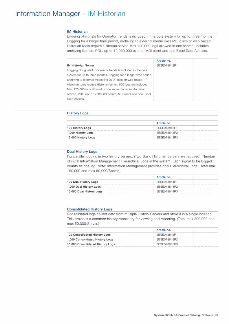
System 800xA 6.0 Product Catalog | Software 23
IM HistorianLogging of signals for Operator trends is included in the core system for up to three months. Logging for a longer time period, archiving to external media like DVD, discs or web based Historian tools require Historian server. Max 120,000 logs allowed in one server. (Includes archiving license, PDL, up to 12,000,000 events, MDI client and one Excel Data Access).
Article no.
IM Historian Server
Logging of signals for Operator trends is included in the core
system for up to three months. Logging for a longer time period,
archiving to external media like DVD, discs or web based
Historian tools require Historian server. 500 logs are included.
Max 120 000 logs allowed in one server (Includes Archiving
license, PDL, up to 12000000 events, MDI client and one Excel
Data Access).
3BSE078842R1
History Logs
Article no.
100 History Logs 3BSE078843R1
1,000 History Logs 3BSE078843R2
15,000 History Logs 3BSE078843R3
Dual History LogsFor parallel logging in two history servers. (Two Basic Historian Servers are required). Number of initial Information Management Hierarchical Logs in the system. Each signal to be logged counts as one log. Note: Information Management provides only Hierarchical Logs. (Total max 150,000 and max 50,000/Server.)
Article no.
100 Dual History Logs 3BSE078844R1
1,000 Dual History Logs 3BSE078844R2
15,000 Dual History Logs 3BSE078844R3
Consolidated History LogsConsolidated logs collect data from multiple History Servers and store it in a single location. This provides a common history repository for viewing and reporting. (Total max 300,000 and max 50,000/Server.)
Article no.
100 Consolidated History Logs 3BSE078845R1
1,000 Consolidated History Logs 3BSE078845R2
15,000 Consolidated History Logs 3BSE078845R3
Information Manager – IM Historian

24 Software | System 800xA 6.0 Product Catalog
Convert History Logs to Dual History Logs(Total max 150,000, and max 50,000/Server) Use this option when converting an existing systems single History Logs to Dual History Logs.
Article no.
100 Convert Single to Dual History Logs 3BSE079643R1
1,000 Convert Single to Dual History Logs 3BSE079643R2
15,000 Convert Single to Dual History Logs 3BSE079643R3
Historian Display and Reporting Options
Article no.
Display Builder for MDI – Additional Client
Provides the ability to create MDI information displays for
desktop applications.
3BSE078846R1
Multi-Display Interface (MDI) – Additional Client
Provides the ability to view MDI information displays on any PC
Desktop (Max 64 per Server)
3BSE078847R1
Desktop Trends – Additional Client
Provides trend viewing for desktop applications. Includes web
enabled trend display for long and short term history and stock
ticker like viewer. (Max 64 per Server)
3BSE078848R1
Historian Data Access OptionsTo access historical data through SQL from third party applications. Batch Reports with trending requires the ODBC Server (E510) and ODBC Client (E520) op-tion. This option provides the links necessary to connect the Oracle database (PDL) and the numeric log and process data. Applications which utilize commercial third party reporting tools should also include the ODBC Server (E510) and ODBC Client (E520) option. The number of client connection is based on whether the applications utilizes the connection directly or indirectly. If the connection is made indirectly (using Oracle), then the client connection requires is only one. If the client connections are direct, then the number of clients should equal the number of concurrent users.
Article no.
Excel Data Access
To access historical data through SQL from third party
applications. Used to access historical data in Excel from
non-800xA PC’’s. For 800xA Client PC’’s Excel Data Access is
included. (Max 64 per Server)
3BSE078849R1
ODBC Historical Data Server
ODBC, includes third party code. (One per server.)
3BSE078850R1
ODBC Client Connection
ODBC Clients are purchased separately from the ODBC server.
(Max 10 per ODBC Server.)
3BSE078851R1
Information Manager – IM Historian

System 800xA 6.0 Product Catalog | Software 25
800xA 6.0 System – Safety
Enabler for combined PA Control and Certified Safety software
Article no.
AC 800M High Integrity and Process Control
One fixed license feature per AC 800M controller running both
non-SIL and SIL applications in the same controller.
3BSE078759R1
800xA 6.0 System – Asset Optimization
Asset Optimization
Article no.
100 Asset Monitors
Asset monitoring and Basic Asset Monitor Library.
Each Aspect Object being monitored by one or more asset
monitors counts as one.
3BSE078871R1
1000 Asset Monitors
Asset monitoring and Basic Asset Monitor Library.
Each Aspect Object being monitored by one or more asset
monitors counts as one.
3BSE078871R2
800xA Maximo Integration
Enables integration into Maximo for work order management.
Application Engineering available through ConsultIT.
Note: at pricebook release this item required a TSA to be
ordered. Please, check current need of a TSA in the TSA Data-
base before ordering.
3BSE078873R1
800xA SAP / Plant Maintenance Integration
Enables integration into SAP for work order management.
Application Engingeering available through ConsultIT.
Note: at pricebook release this item required a TSA to be
ordered. Please, check current need of a TSA in the TSA Data-
base before ordering.
3BSE078874R1

26 Software | System 800xA 6.0 Product Catalog
Asset Optimization – Asset Monitors
Asset Monitors
Article no.
Generic Heat Exchanger Asset Monitor
It monitors the performance against standard operating param-
eters independent of type of heat exchanger.
3BSE078875R1
Shell and Tube Heat Exchanger Asset Monitor
It monitors the performance against standard operating param-
eters based on the size of shell and tube heat exchanger.
3BSE078876R1
Advanced Harmony Control System Monitoring
Enables Harmony Control Network monitors for diagnostic
monitoring, reporting, and analysis
3BSE078877R1
100 Control Loop Asset Monitors
Each Control Loop Asset Monitor monitors and assesses the
performance of a control loop in real-time and report significant
problems related to the control loop and final control element.
The total quantity of Control Loop Asset Monitors must not
exceed 500.
3BSE078878R100
300 Control Loop Asset Monitors
Each Control Loop Asset Monitor monitors and assesses the
performance of a control loop in real-time and report significant
problems related to the control loop and final control element.
The total quantity of Control Loop Asset Monitors must not
exceed 500.
3BSE078878R300
500 Control Loop Asset Monitors
Each Control Loop Asset Monitor monitors and assesses the
performance of a control loop in real-time and report significant
problems related to the control loop and final control element.
The total quantity of Control Loop Asset Monitors must not
exceed 500.
3BSE078878R500
PC, Network and Software Monitoring
Enables availability monitoring of IT assets.
3BSE078879R1
800xA 6.0 System – Device Management & Fieldbuses
Device Management HARTFor HART devices to be accessed using Device Type Manager (DTM’’s) within System 800xA.Includes HART Device Library with generic and specific HART Device Aspect Objects incl. DTM’’s, I/O DTM for S800 and S900, HART Instruments Asset Monitor Library and OPC Server. Each HART device aspect object accessed with DTM counts as one. (Max 2500 per Connecivity Server if OPC Communication is used. For details refer to System Guide)
Article no.
100 HART Device Aspect Objects 3BSE078880R1
1,000 HART Device Aspect Objects 3BSE078880R2
10,000 HART Device Aspect Objects 3BSE078880R3
HART Multiplexer Connect
Enables HART Device Integration to connect to HART devices
using HART Multiplexers.
3BSE078881R1

System 800xA 6.0 Product Catalog | Software 27
Device Management FOUNDATION FieldbusFor FOUNDATION Fieldbus (FF) devices to be accessed using Fieldbus Builder FF within Sys-tem 800xA. Includes FF Device Library with FF Device Aspect Objects, FF Instruments Asset Monitor Library and OPC Server. Each FF device aspect object counts as one. (Max 1000 per Connecivity Server. For details refer to System Guide.)
Article no.
100 FF Device Aspect Objects 3BSE078882R1
1,000 FF Device Aspect Objects 3BSE078882R2
10,000 FF Device Aspect Objects 3BSE078882R3
Device Management PROFIBUSFor PROFIBUS DP/PA devices to be accessed using Device Type Manager (DTM’’s) within System 800xA. Includes PROFIBUS Device Library with specific PROFIBUS Device Aspect Objects incl. DTM’’s, I/O DTM for S800 and S900, and PROFIBUS Instruments Asset Monitor Library. Each PROFIBUS device aspect object accessed with DTM counts as one. (Max 2500 per Connectivity Server if OPC communication is used. For details refer to System Guide.)
Article no.
100 PROFIBUS Device Aspect Objects 3BSE078883R1
1,000 PROFIBUS Device Aspect Objects 3BSE078883R2
10,000 PROFIBUS Device Aspect Objects 3BSE078883R3
IEC 61850-Ed1 ConnectFor order of IEC 61850 related products, local organizations must comply with the Demands on the Purchaser to secure successful sales of IEC 61850 with System 800xA. Ref doc, 3BSE058798.
Article no.
IEC 61850-Ed1 Connect
Allows operation clients to access data and alarm and event
values from Intelligent Electronic Devices (IEDs) according IEC
61850-Ed1 (Edition1).
Package includes IEC 61850 OPC server software with configu-
ration tool on Connectivity Servers. You have to order number of
used OPC server instances (max. 16 per System)
IEC 61850 Substation Operation Library with Faceplates to con-
trol substation equipment (Bay, Breaker, Switch,...) is included.
3BSE078884R1
Redundant IEC 61850-Ed1 Connect Option
Allows operation clients to access data, and alarm and event
values through redundant OPC-servers from Intelligent Elec-
tronic Devices (IEDs) through redundant Connectivity Servers
according IEC 61850-Ed1 (Edition1).
Package includes IEC 61850 OPC server software with con-
figuration tool on Connectivity Servers. You have to order the
number of used OPC server instances. (max. 16 per System)
Requires IEC 61850-Ed1 Connect.
IEC 61850 Substation Operation Library with Faceplates to con-
trol substation equipment (Bay, Breaker, Switch,...) is included.
3BSE078885R1
800xA 6.0 System – Device Management & Fieldbuses

28 Software | System 800xA 6.0 Product Catalog
800xA 6.0 System – Libraries
Libraries
Article no.
INFI90 Function Code Library for AC 800M
Requires separate media.
3BSE078890R1
MOD 300 CCF Library for AC 800M
Requires separate media.
3BSE078889R1
TCP Communication Library License
Control functions to create TCP based communication protocols
in the AC800M controller. One licence is needed for each con-
troller using the library.
3BSE079542R1
UDP Communication Library License
Control functions to create UDP based communication proto-
cols in the AC800M controller. One licence is needed for each
controller using the library.
3BSE079543R1
800xA 6.0 System – Options for Extended Operator Workplace
Options for Regional Power SupplyRegional power supply
Article no.
110V System 3BSE073373R1
220V System 3BSE073374R1
Options for Advanced Operator Keyboard LayoutAdvanced Operator Keyboard layout.
Article no.
US English Keyboard layout 3BSE073301R1
Belgian Keyboard layout 3BSE073302R1
Spanish Keyboard layout 3BSE073303R1
French Keyboard layout 3BSE073304R1
German Keyboard layout 3BSE073305R1
Italian Keyboard layout 3BSE073306R1
Swiss Keyboard layout 3BSE073307R1
British English Keyboard layout 3BSE073308R1
Danish Keyboard layout 3BSE073309R1
Swedish Keyboard layout 3BSE073310R1
Russian Keyboard layout 3BSE073311R1
Norwegian Keyboard layout 3BSE073312R1

System 800xA 6.0 Product Catalog | Software 29
800xA 6.0 System – Options for Extended Operator Workplace
Options for PackagingDelivery option for EOW.
Article no.
Disassembled system
Reduce packages dimension and decrease cost for air freight.
We recommend an additional service to assist with the assem-
bly on site when you chose this option.
3BSE073375R1
Options for Desk SurfaceDesk surface.
Article no.
Birch desk surface 3BSE073295R1
Grey desk surface 3BSE073294R1

30 Software | System 800xA 6.0 Product Catalog
800xA 6.0 System – Localization
National Language Support (NLS) is intended for the localization of the operator interface to the desired language. NLS contains a set of functions that are harmonized with the Windows regional settings to enable a multilingual environment for the System 800xA.
The System 800xA supports translations, mainly the operator interface and the operator manuals as shown in the Table 3 and Table 4. The translation, or System 800xA Language Package, is implemented as a system extension and is possible to install without stopping the system.
The NLS Localization Guide describes what and how localization can be performed by a project with or without an installed Language Package. The English version of the Windows operating system is required. The System 800xA Language Packages can be downloaded free of charge from ABB Library.
Language Packages
Functional Areas
Bas
e S
yste
m
Saf
ety
SM
S &
eM
ailin
g
*Ass
et
Op
timiz
atio
n
FO
UN
DAT
ION
F
IELD
BU
S
Bat
ch
Man
agem
ent
** In
form
atio
n M
anag
emen
t
English (default) Yes Yes Yes Yes Yes Yes Yes
Arabic Yes Yes
Chinese Yes Yes Yes Yes Yes Yes
French Yes Yes Yes Yes
German Yes Yes Yes Yes Yes Yes
Russian Yes Yes Yes
Spanish Yes Yes Yes Yes
Swedish Yes Yes Yes Yes Yes
Language Packages
Connectivity
800x
A f
or
A
C 8
00M
800x
A f
or
A
dva
nt M
aste
r
PLC
C
onn
ect
800x
A f
or
M
elo
dy
English (default) Yes Yes Yes Yes
Arabic Yes
Chinese Yes Yes Yes
French Yes Yes
German Yes Yes Yes
Russian Yes Yes
Spanish Yes
Swedish Yes Yes
Table 3. Supported Language Packages for Functional Areas
Table 4. Supported Language Packages for Connectivity
* Only system messages** Storage of messages in local language

System 800xA 6.0 Product Catalog | AC 800M Processor Units 31
AC 800M Processor Units
CPU ModulesSeveral CPU modules are available that vary in terms of processing power, memory size, and redundancy support. Each CPU module is equipped with built in Ethernet port(s) for communication with other controllers and for interaction with operators, engineers, managers, and higher level applica-tions. These ports can be configured for redundancy for those cases where availability is of paramount importance. It is also equipped with two RS-232C ports that can be used for point-to-point communication with programming/debugging tools and with third-party systems and devices.
The SIL3-rated and IEC61508-certified, AC 800HI controller supports running both process control and safety application, i n the same machine.
The AC 800M controller can be configured with 800xA control builder. When configured with the 800xA control builder AC 800M becomes a tightly integrated part of the System 800xA.
Communication & I/O ModulesTo each CPU module, a number of communication and I/O modules can be added, for example:
− Additional RS-232C ports − PROFIBUS DP, PROFINET IO − Foundation Fieldbus HSE/H1 − DeviceNet − IEC 61850 − Ethernet IP − MasterBus 300 − MODBUS TCP − S100 I/O − S800 I/O
AC 800M
PM891
AC 800M high integrity

32 AC 800M Processor Units | System 800xA 6.0 Product Catalog
AC 800M Controllers and users guide
CPUs / Features PM851A PM856A PM860A PM861A PM864A PM865 PM866 PM891
Processor Unit PM851K01 incl:1 PM851 CPUand required optional items
PM856K01 incl:1 PM856 CPUand requiredoptional items
PM860K01 incl:1 PM860 CPUand requiredoptional items
PM861AK01 incl:1 PM861A CPUand requiredoptional itemsPM861AK02 incl:2 PM861A CPUsand requiredoptional items
PM864AK01 incl:1 PM864A CPUand requiredoptional itemsPM864AK02 incl:2 PM864A CPUsand requiredoptional items
PM865AK01 incl: 1 PM865K01 CPU and requiredoptional itemsPM865AK02 incl: 2 PM865K02 CPUs and requiredoptional items
PM866K01 incl:1 PM866 CPU and requiredoptional itemsPM866K02 incl:2 PM866 CPUs and requiredoptional items
PM891K01 incl:1 PM891 CPU and requiredoptional itemsPM891K02 incl:2 PM891 CPUs and requiredoptional items
High Integrity Controller No No No No No Yes No No
Clock frequency 48 MHz 48 MHz 48 MHz 48 MHz 96 MHz 96 MHz 133 MHz 450 MHz
Memory (RAM) 12 MB * 16 MB * 16 MB * 16 MB 32 MB 32 MB 64 MB 256 MB
RAM available for application
6.372 MB 10.456 MB 10.457 MB 7.320 MB 23.663 MB 24.242 MB22.415 MB w SM81022.386 MB w SM811
51.402 MB 199.233 MB
CPU redundancy support No No No Yes Yes Yes Yes Yes
Communication interfaces
1 Ethernet port 2 RS-232C ports
2 Ethernet ports 2 RS-232C ports
2 Ethernet ports 2 RS-232C ports
2 Ethernet ports 2 RS-232C ports
2 Ethernet ports 2 RS-232C ports
2 Ethernet ports 2 RS-232C ports
2 Ethernet ports 2 RS-232C ports
Performance, 1000 boolean operations (a:=b and c)
0.46 ms 0.46 ms 0.23 ms 0.23 ms 0.15 ms 0.15 ms 0.09 ms 0.043 ms
Recommended Control Network backbone
100 Mbit/s - 1 Gbit/s Ethernet (IEEE 802.3)
Dimensions W 119 x H 186 x D 135 mm (4.7 x 7.3 x 5.3 in.)W 174 x H 186 x D 94 mm
Weight (including base) 1100 g (2.4 lb) 1100 g (2.4 lb) 1100 g (2.4 lb) 1200 g (2.6 lb) 1200 g (2.6 lb) 1200 g (2.6 lb) 1200 g (2.6 lb) 1600 g (3.5 lb)
Measurements
115 (25.4) 135 (5.3)
186
(7.3
)
174
186
94
CPU PM891
Environmental Data for AC 800M
Climatic Operating Conditions 0 to +55 C (Storage -40 to +70C), RH = 5 to 95 % no condensation, IEC/EN 61131-2
Protection class IP20 according to EN 60529, IEC 529
Corrosive protection G3 compliant according to ISA-71.04
Electromagnetic Compatibility and CE-mark Meets EMC directive 2004/108/EC according to EN 61000-6-2 and EN 61000-6-4
Electromagnetic Emission Tested according to EN 61000-6-4 EMC – Generic Emission Standard, Part 2 – Industrial Environment
Electromagnetic Immunity Tested according to EN 61000-6-2 EMC – Generic Immunity Standard, Part 2 – Industrial Environment
Electrical Safety UL508, IEC/EN 61131-2
Hazardous Classified Locations UL60079-15 (Class 1 Zone 2)
Hazardous Classified Locations ATEX S890 series of I/O modules: Category 3 (1) G, EEx nA [ia] IIC T4
Safety Integrity (IEC 61508) PM865, AI880A, DI880, DO880: IEC 61508 up to SIL3
* Available with 5.1 FP4 Firmware (or newer) else its 8 / 12 / 12 MB

System 800xA 6.0 Product Catalog | AC 800M Processor Units 33
AC 800M Hardware – System Units
System UnitsThe Tool Cable TK212A is most useful when working with AC 800M. Please order a cable (Item P215) together with your first order of PM851AK01, PM856AK01, PM860AK01, PM861AK01, PM861AK02, PM864AK01, PM864AK02, PM865K01, PM865K02, PM866K01, PM866K02, PM891K01 or PM891K02.
AC 800M Hardware – AC 800M Processor Units
800M Processor Units
Article no.
PM851AK01 Processor Unit
Package including:
-PM851A, CPU
-TP830, Baseplate, width=115 mm
-TB850, CEX-bus terminator
-TB807, ModuleBus terminator
-Battery for memory backup (4943013-6)
3BSE066485R1
PM856AK01 Processor Unit
Package including:
-PM856A, CPU
-TP830, Baseplate, width=115 mm
-TB850, CEX-bus terminator
-TB807, ModuleBus terminator
-Battery for memory backup (4943013-6)
3BSE066490R1
AC 800M Hardware – Hardware Upgrade orders
Hardware Upgrade ordersFor Hardware Upgrade orders please send your inquiry to Service Center mail box: [email protected]
ISA-S71.04 level G3 CompliamceModules are compliant to ISA-S71.04 level G3, unless explicitly stated differently.
Extended Warranty for AC 800M HardwareWe can offer an extended warranty for one, two, or three years in addition to normal warranty conditions for AC 800M Hardware. See price list Extended Warranty 3BSE049908.

34 AC 800M Processor Units | System 800xA 6.0 Product Catalog
AC 800M Hardware – AC 800M Processor Units
800M Processor Units
Article no.
PM860AK01 Processor Unit
Package including:
-PM860A, CPU
-TP830, Baseplate, width=115 mm
-TB850, CEX-bus terminator
-TB807, ModuleBus terminator
-Battery for memory backup (4943013-6)
3BSE066495R1
PM861AK01 Processor Unit
Package including:
-PM861A, CPU
-TP830, Baseplate, width =115mm
-TB850, CEX-bus terminator
-TB807, ModuleBus terminator
-TB852, RCU-Link terminator
-Battery for memory backup (4943013-6)
3BSE018157R1
PM861AK02 Redundant Processor Unit
Package including:
2 pcs PM861AK01, Processor unit.
1 pcs TK850, CEX-bus expansion cable.
1 pcs TK851, RCU-Link cable.
3BSE018160R1
PM864AK01 Processor Unit
Package including:
-PM864A, CPU
-TP830, Baseplate, width =115mm
-TB850, CEX-bus terminator
-TB807, ModuleBus terminator
-TB852, RCU-Link terminator
-Battery for memory backup (4943013-6)
3BSE018161R1
PM864AK02 Redundant Processor Unit
Package including:
2 pcs PM864AK01, Processor unit.
1 pcs TK850, CEX-bus expansion cable.
1 pcs TK851, RCU-Link cable.
3BSE018164R1
PM866K01 Processor Unit
Package including:
-PM866, CPU
-TP830, Baseplate, width =115mm
-TB850, CEX-bus terminator
-TB807, ModuleBus terminator
-TB852, RCU-Link terminator
-Battery for memory backup (4943013-6)
3BSE050198R1
PM866K02 Redundant Processor Units
Package including:
2 pcs PM866K01, Processor unit.
1 pcs TK850, CEX-bus expansion cable.
1 pcs TK851, RCU-Link cable.
3BSE050199R1

System 800xA 6.0 Product Catalog | AC 800M Processor Units 35
System Units – AC 800M Processor Units
800M Processor Units
Article no.
PM891K01 Processor Unit
Package including:
-PM891 CPU Module
-TB850, CEX-bus terminator
-TB853, RCU Control Link Terminator
3BSE053241R1
PM891K02 Redundant Processor Unit
Package including:
2 pcs PM891K01 Processor Unit
1 pcs TK850V007 CEX-bus Extension Cable
1 pcs TK855 RCU Data Link Cable
1 pcs TK856 RCU Control Link Cable
Please note: The BC810K02 is not included in the PM891K02
Redundant Processor Unit kit. In order to make hot replacement
of PM891 Processor Unit possible, the BC810K02 is required
and has to be ordered separately.
3BSE053242R1
SB822 Rechargeable battery unit
External DIN-rail mounted rechargeable battery unit including
lithium-ion battery, 24V DC connector and connection cable
TK821V020. Width=85 mm.
Equivalent amount of Lithium metal=0,8g (0,03oz)
3BSE018172R1
System Units – AC 800M High Integrity Units
AC 800M High Integrity UnitsThe PM865 CPU Unit is intended for use in High Integrity systems. Local organizations must comply with the Qualifications to secure successful sales of ABB safety systems, to order safety equipment. Ref doc, 3BSE047224
Article no.
PM865K01 Processor Unit
Package including:
-PM865, CPU
-TP830, Baseplate, width =115mm
-TB850, CEX-bus terminator
-TB807, ModuleBus terminator
-TB852, RCU-Link terminator
-Battery for memory backup (4943013-6)
3BSE031151R1
PM865K02 Redundant Processor Unit
Package including:
2 pcs PM865K01, Processor unit.
1 pcs TK850, CEX-bus expansion cable.
1 pcs TK851, RCU-Link cable.
3BSE031150R1
SM811K01 Safety CPU module kit
Collaborating safety CPU. Connects to CEX bus after BC810
CEX bus interconnection box. Including:
-SM811, Safety Module
-TP868, Baseplate, width=60mm
-TK852V10, Syncronization link cable
3BSE018173R1
SS823 Voting Device
Required in a High Integrity 800xA system.
One per power supply unit, also at redundant configurations
3BSE038226R1

36 AC 800M Processor Units | System 800xA 6.0 Product Catalog
System Units – Extra Batteries
Extra BatteriesFor extra Lithium batteries (4943013-6), please refer to ABB Parts Online; www.abb.com/partsonline.
Communication – Control Network
Control NetworkNo articles, such as cables, hubs, switches etc, for Control Network are included in this price list. Please refer to Product Guide AC 800M, for recommended articles. Recommended network components are available in 800xA Networks price list, 3BSE081392
Communication – Serial Interfaces on TP830
Serial Interfaces on TP830RS232-C interfaces for protocols COMLI, MODBUS, Siemens 3964R, the free-programmable serial protocol etc. Also for connection of engineering tool.
Article no.
TK212A Tool cable
RJ45 (male) to Dsub-9 (female), length 3 m. RJ45 8P8C plug
(with shell). Cable : UL2464 26 AWG x 8C.
3BSC630197R1
TC562 Short Distance Modem, G1 Compliant
Length < 10 km. Point-to-point up to 1 km at 19200 bps.
Power 24V d.c. Width=55 mm
3BSC630049R1
TK853V020 Modem Cable
Length 2 m. Cable for connection between modem TC562 and
TP830.
3BSC950201R1
Communication – Serial Communication Interface
Serial Communication InterfaceRS232-C interfaces for protocols COMLI, MODBUS, Siemens 3964R, the free-programmable serial protocol etc.
Article no.
CI853K01 Dual RS232-C interface
Package including:
-CI853, Communication Interface
-TP853, Baseplate, width = 60 mm
3BSE018103R1

System 800xA 6.0 Product Catalog | AC 800M Processor Units 37
Communication – MODBUS TCP
MODBUS TCP
Article no.
CI867K01 Modbus TCP Interface
Package including:
-CI867 , Communication Interface
-TP867 , Baseplate, width=60mm
3BSE043660R1
Communication – PROFIBUS DP
PROFIBUS DPThe required PROFIBUS network components (Linking Devices, etc) must be ordered from price list 3BDD 013 232, PROFIBUS Network Components.
Article no.
CI854BK01 Profibus Communication Interface
Package including:
- CI854B, Communication Interface
- TP854, Baseplate, width = 60 mm
3BSE069449R1
Communication – PROFINET IO
PROFINET IO
Article no.
CI871K01 PROFINET IO Communication Interface
Package including:
- CI854A, Communication Interface
- TP854, Baseplate, width = 60 mm
3BSE056767R1
Communication – FOUNDATION Fieldbus
FOUNDATION FieldbusThe required FOUNDATION Fieldbus network components (Linking devices, etc) must be ordered from price list 3BDD 013 231, FOUNDATION Fieldbus Network Components.
Article no.
CI871K01 PROFINET IO Communication Interface
Package including:
-CI860, Communication Interface
-TP860, Baseplate, width = 60 mm
3BSE032444R1

38 AC 800M Processor Units | System 800xA 6.0 Product Catalog
Communication – IEC 61850
IEC 61850For order of IEC 61850 related products, local organizations must comply with the Demands on the Purchaser to secure successful sales of IEC 61850 with System 800xA. Ref doc, 3BSE058798.
Article no.
CI868K01 IEC61850-Ed1 (Edition 1) Communication
Interface
Package including:
- CI868, Communication Interface
- TP867, Baseplate, width=60mm
3BSE048845R1
Communication – Ethernet/IP
Ethernet/IPFor order of IEC 61850 related products, local organizations must comply with the Demands on the Purchaser to secure successful sales of IEC 61850 with System 800xA. Ref doc, 3BSE058798.
Article no.
CI873K01 Ethernet/IP Communication Interface
Packaging including:
- CI873, Communication Interface
- TP867, Baseplate width=60mm
3BSE056899R1
LD 800DN EtherNet/IP to DeviceNet Linking Device,
G1 Compliant
Package including:
1 pcs LD 800DN
1 pcs Installation Guide
2 pcs Termination resistors for DeviceNet, 1/4 W, 121 Ohm
May only be used with CI873 Communication Interface.
3BSC690164R1
Communication – Advant Fieldbus 100
Advant Fieldbus 100
Article no.
CI869K01 AF 100 Communication Interface
Package including:
- CI869, Communication Interface
- TP869, Baseplate, width=60mm
3BSE049110R1

System 800xA 6.0 Product Catalog | AC 800M Processor Units 39
Communication – MasterBus 300
MasterBus 300
Article no.
CI855K01 MB 300 Dual Ethernet port interface
Package including:
- CI855, MB300 Interface Module
- TP853, Base plate
3BSE018106R1
Communication – S100 I/O Bus
S100 I/O Bus
Article no.
CI856K01 S100 I/O Interface
Installed on DIN rail. Communication bridge between AC800M
and S100 system. Package including:
- CI856, Communication Interface
- TP856, Baseplate, width = 60mm
3BSE026055R1
Communication – TRIO
TRIO
Article no.
CI862K01 TRIO Interface Kit, G1 Compliant
Package including:
- CI862, Communication Interface
- TP862, Baseplate, width = 60mm
3BUA000037R1
CI862K02 Redundant TRIO Interface Kit with Connection
Cable, G1 Compliant
Package including:
- 2xCI862, Communication Interface
- 2xTP862, Baseplate, width = 60mm
- TK862 Cable, 1m
3BUA000111R1

40 AC 800M Processor Units | System 800xA 6.0 Product Catalog
Communication – INSUM
INSUM
Article no.
CI857K01 INSUM Ethernet Interface
Package including:
- CI857, Communication Interface
- TP853, Baseplate, width = 60 mm
3BSE018144R1
Communication – DriveBus
DriveBus
Article no.
CI858K01 DriveBus Interface
Package including:
- CI858, Communication Interface
- TP858, Baseplate, width = 60 mm
3BSE018135R1
Communication – MOD5
MOD5
Article no.
CI872K01 MOD5 Communication interface
Installed on DIN rail. Communication interface between AC800M
and MOD5 system. Package including:
- CI872, Communication module
- TP858, Baseplate, width=60mm
3BSE051129R1
Communication – Satt I/O
S100 I/O BusFor SATT 19‘‘‘‘ rack I/O and S200 I/O via ControlNet. For additional Satt 19“ rack I/O compo-nents, see price list 3BSE014353 (Interface) in price book 3BSE014360. (SattLine/SattCon).
Article no.
CI865K01Communication Interface Module for Satt I/O
Package including:
- CI865, Communication Interface
- TP865, Baseplate, width = 60 mm
3BSE040795R1

System 800xA 6.0 Product Catalog | AC 800M Processor Units 41
Communication – Bus Accessories
Bus Accessories
Article no.
TK850V007 CEX-Bus Extension Cable
Length = 0.7 m
Use of TK850V007 needs TK851 as CEX-bus terminator.
3BSC950192R1
TB850 CEX-Bus Terminator
With 25-pin DB25P male connector. With screw fixing.
A TB850 CEX-Bus terminator must always be installed on the
last unit on the CEX bus.
3BSC950193R1
TB851 CEX-Bus Terminator
With 25-pin DB25S female connector. With screw fixing.
3BSC950194R1
BC810K02 CEX-bus Interconnection Unit
Including:
- BC810, Interconnection Unit, 2 units
- TP857, Baseplate, width = 60 mm, 2 units
- TK851, Interconnection Cable
- TB850, CEX-Bus Terminator, 2 units
3BSE031155R1
BC820K02 RCU-Link and CEX-Bus Interconnection Units
Including:
- BC820, RCU-Link and CEX-Bus Interconnection Unit, 2 units
- TP850, Baseplate, width = 60 mm, 2 units
- TK857 RCU-Link Cable for BC820, 2 units
- TB850, CEX-Bus Terminator, 2 units
PM866 PR: H or later is required.
3BSE071500R1
TK851V010 Connection Cable
Length = 1.0 m. Used as:
- RCU Link Cable
- BC810 Interconnection Cable
3BSC950262R1
TB852 RCU Link Terminator 3BSC950263R1
TB853 RCU Control Link Terminator 3BSE057022R1
TK855 RCU Data Link Cable
Length = 1.0 m. Used as:
- RCU Data Link Cable
3BSC950356R1
TK856 RCU Control Link Cable
Length = 1.0 m. Used as:
- RCU Control Link Cable
3BSE057021R1
TK857V003 RCU Link Cable 3BSC950375R1

42 AC 800M Processor Units | System 800xA 6.0 Product Catalog
AC 800M Processor Units – AC 800M Power supply
AC 800M Power supply
Article no.
SD822Z Power Supply Device
Input 115/230V a.c. switch selectable, output 24V d.c., 5A.
If redundant power application is required connect to SS822Z
Voting Unit.. Width=65 mm. DIN rail mounted.
3BSC610054R1
SD831 Power Supply Device, G2 Compliant
Input a.c. 100-240 V or d.c. 110-300 V. Output d.c. 24 V 3A. If
redundant power application is required connect to
SS8XX. Voting unit. Width=35mm. DIN rail mounted.
3BSC610064R1
SD832 Power Supply Device, G2 Compliant
Input a.c. 100-120/200-240 V. Output d.c. 24 V 5A, auto-select
input. If redundant power application is required connect to
SD8XX. Voting unit. Width=35mm. DIN rail mounted.
3BSC610065R1
SSD833 Power Supply Device, G2 Compliant
IInput a.c. 100-120/200-240 V, auto-select input. Output d.c.
24 V 10A. If redundant power application is required connect to
SD8XX. Voting unit. Width=60mm. DIN rail mounted.
3BSC610066R1
SD834 Power Supply Device, G2 Compliant
Input a.c. 100-240 V or d.c. 110-300 V. Output d.c. 24 V 20A. If
redundant power application is required connect to SS8XX. Vot-
ing unit. Width=85mm. DIN rail mounted.
3BSC610067R1
SS822Z Power Voting Unit
IWith dual 24V d.c 20A inputs, single 24V d.c. 20A output. Each
power input supervised. Used if redundant power supply is
required. For use with power supply SD822Z.
Width=50 mm. DIN rail mounted.
3BSC610055R1
SS832 Voting Device, G2 Compliant
Input d.c. 24 V. Dual 24 V to single 24 V, 2x10A.
Width=35mm. DIN rail mounted.
3BSC610068R1
Mains Breaker Kit for DIN Rail
I115/230V a.c. with input terminals, breaker and 3 fused (6.3A),
double output terminals. Width=102,5 mm.
3BSE022262R1
AC 800M Processor Units – AC 800M Mounting Rails
AC 800M Mounting Rails
Article no.
Al-profile with DIN rail and Cable Duct for RE820, mounting
719mm (28,3”)
DIN rail length 683mm (26,9”)
3BSE022257R1
Al-profile with DIN Rail and Cable Duct for RM550,
mounting 592mm (24”)
DIN rail length 556mm (21,9”)
3BSE022256R1
Al-profile with DIN Rail and Cable Duct,
mounting 465mm (19”)
DIN rail length 429mm (16,9”)
3BSE022255R1

System 800xA 6.0 Product Catalog | S800 I/O Modules 43
S800 I/O Modules
S800 I/O is a comprehensive and modular process I/O system that communicates with parent controllers either direct con-nected using the Modulebus or over industry-standard field buses. Thanks to its broad connectivity it fits a wide range of process controllers from ABB and others.
By permitting installation in the field, close to sensors and actuators, S800 I/O reduces the installation cost by reducing the cost of cabling. And thanks to features such as hot swap of modules, on-line reconfiguration and redundancy options, it contributes to keeping production – and thereby profits up.
S800 I/O features include: − Comprehensive coverage − Flexible configuration and installation − Ease of set up − Reliability and accuracy − HART pass-through − Redundancy also on I/O module level − High Integrity I/O modules certified to SIL3 − High accuracy time tagging − Defined outputs at communication errors − I/O modules with Intrinsic Safety interfaces
With its cost-effective design and just 59 mm depth instal-lation, S800L I/O modules are the perfect choice for PLC applications. Robust mechanics, one-piece handling, easy mounting and smart connections save your time in all phases of installation. The comprehensive S800 I/O system consists of more than 40 different module types to respond to every need. Classification of corrosive protection, electrical safety, hazardous location and marine certification brings the possi-bility to install S800 I/O in a wide variety of applications. S800 I/O is installed with more than 30 million channels worldwide.
S800S800 S800L

44 S800 I/O Modules | System 800xA 6.0 Product Catalog
Digital input modules
DI810 16 channels, 2 groups of 8 channels, 24 V d.c., current sink.
DI811 16 channels, 2 groups of 8 channels, 48 V d.c., current sink.
DI814 16 channels, 2 groups of 8 channels, 24 V d.c., current source.
DI818 32 Channels, 2 groups of 16 channels, 24 V d.c., current sink.
DI820 8 channels, separate returns, 110 V d.c., 120 V a.c.
DI821 8 channels, separate returns, 220 V d.c., 230 V a.c.
DI825 With time tagging, 8 channels, separate returns, 125 V d.c.
DI828 16 Channels, separate returns, 110 V d.c, 120 V a.c. / d.c
DI830 With time tagging. 16 channels, 2 groups of 8 channels, 24 V d.c., current sink. Resolution: < 0.5 ms.
DI831 With time tagging. 16 channels, 2 groups of 8 channels, 48 V d.c., current sink. Resolution: < 0.5 ms.
DI885 With time tagging & wire-fault detection. 8 channels, common return, 24-48 V d.c., current sink. Resolution: 1 ms.
Pulse input module
DP820 2 channels, separate returns, 0.25 Hz - 1.5 MHz, signal voltage: 5 / 12 V d.c.
DP840 8 channels, extended diagnostics, wire-fault detection, current limited sensor supply, 0.5-20 kHz, 12/24 V d.c or NAMUR, common return.
Digital output modules
DO810 16 channels, 2 groups of 8 channels, 24 V, max 0.5 A d.c., transistor, current source, short-circuit-proof.
DO814 16 channels, 2 groups of 8 channels, 24 V d.c., max 0.5 A, transistor, current sink, short-circuit-proof.
DO815 8 channels, 2 groups of 4 channels, 24 V d.c., max 2 A, transistor, current source, short-circuit-proof, wire-fault detection.
DO818 32 Channels, 2 groups of 16 channels, 24 V, max 0.5 A d.c., transistor, current source, short-circuit-proof.
DO820 8 channels, separate returns, 5-250 V, max 3 A a.c./d.c., relay (N.O.).
DO821 8 channels, separate returns, 5-250 V, max 3 A a.c./d.c., relay (N.C.).
DO828 16 Channels, separate returns, 5-250 V a.c / 5-125 V d.c, max 2 A a.c./d.c., relay (N.O.).
Analog input modules
AI810 8 channels, single-ended, 0(4)-20 mA, 0(2)-10 V, 12 bits.
AI815 8 channels with HART. 0(4)..20 mA, 0(1)..5 V, 12 bit, single ended, current limited transmitter supply.
AI820 Differential inputs, 4 channels, 0(1)-5 V, ±0(2)-10 V, ±0(4)-20 mA, 14 bits + sign.
AI825 Individually galvanically isolated channels, 4 channels, ±0(2)-10 V, ±0(4)- 20 mA, 14 bits + sign.
AI830A RTD inputs, 8 channels, Pt100, Ni100, Ni120, Cu10, resistor 0-400 ohms, 14 bits, 3-wire.
AI835A TC inputs, 8 channels, (7+ ref. junction), separate returns. TC types B, C, D, E, J, K, L, N, R, S, T, U, - 30…75 mV, 15 bits.
Analog output modules
AO810V2 8 channels, common return, 0(4)-20 mA, 14 bits, load: 850 ohms (short-circuit-proof).
AO815 8 channels with HART. 4..20 mA, 12 bit, load: 750 ohms, common return, short-circuit-proof.
AO820 4 channels, individually galvanically isolated, separate returns, measuring range: ±0(2)-10 V, ±0(4)-20 mA, resolution: 12 bits + sign, load: 500 ohms (current) / 5
kohms (voltage), short-circuit-proof.
Intrinsic-safety modules
DI890 8 channels, separate returns, proximity sensors (NAMUR) or voltage-free contact., current sink, wire-fault detection.
DO890 4 channels, separate returns, load 150-5000 ohms, 11 V @ 40 mA, current source, wire-fault detection, short circuit-proof.
AI890 8 channels, single-ended, 0(4)-20 mA, 12 bits, transmitter power supply.
AI893 8 channels, TC: 7 + ref. junction, sep. returns. TC types B, C, E, J, K, L, N, R, S, T, U, -10…80 mV. RTD: Pt50-1000, Ni100-500, Cu 10-100, resistor 0-4000 W,
3-wire. 15 bits + sign.
AI895 8 channels, single-ended, 4-20 mA, 12 bits, transmitter power supply, HART pass-through.
AO890 8 channels, common return, 0(4)-20 mA, 12 bits, load: 725 ohms short-circuit-proof.
AO895 8 channels, common return, 4-20 mA, 12 bits, load: 725 ohms short-circuit-proof, HART pass-through.
Redundant modules
DI840 16 channels, common return, 24 V d.c., current sink, extended diagnostics, time-tagging, current limited sensor supply.
DP840 8 channels, common return, 0.5-20 kHz, 12/24 V d.c or NAMUR, extended diagnostics, wire-fault detection.
DO840 16 channels, common return, 24 V d.c., max. 0,5 A, transistor, current source, short-circuit-proof, extended diagnostics.
AI843 TC input, 8 channels + ref. junction. TC types: B, C, E, J, K, L, N, R, S, T, U, -30…75 mV, 16 bits, extended diagnostics.
AI845 8 channels, 12 bits, 0(4)-20 mA 0(1)-5 V, extended diagnostics, HART pass-through, current limited transmitter supply, single ended.
AO845 8 channels, 12 bits, common return, 4-20 mA, extended diagnostics, HART pass-through, 750 ohms.
High Integrity modules
AI880A 4..20 mA, 8 channels, 12 bits, SIL3, current limited transmitter supply, also 0-20 mA, single ended, extended diagnostics, HART communication.
DI880 24 V d.c., 16 channels, 24 V d.c. inputs, SIL3, time-tagging, current limited sensor supply, common return, current sink, extended diagnostics.
DO880 24 V d.c., 16 channels, 0,5 A outputs, SIL3, wire-fault detection, 24 V, transistor, current source short-circuit-proof, common return, extended
diagnostics.
SS823 Required in a High Integrity 800xA system. One per power supply unit, also at redundant configurations.
S800 I/O Modules

System 800xA 6.0 Product Catalog | S800 I/O Modules 45
S800L I/O Modules
S800L modules
DI801 16 channels, 1 group, 24 V d.c., current sink.
DI802 8 channels, 110 V d.c., 150 V a.c.
DI803 8 channels, 220 V d.c., 230 V a.c.
DO801 16 channels, common return, 24 V, max 0.5 A d.c., transistor, current source, short-circuit-proof.
DO802 8 channels, 5-250 V, max 2 A a.c./d.c., relay (N.O.).
AI801 8 channels, single-ended, 0(4)-20 mA, 12 bits.
AO801 8 channels, common return, 0(4)-20 mA, 12 bits, load: less than 750 ohms.
Measurements
127.5 (5.0)84 (3.3)
162
(6.4
)
132 (5.2)120 (4.7)
110
(4.3
)
127.5 (5.0)58 (2.3)
162
(6.4
)
136
(5.4
)
86 (3.4) 58.5 (2.3)
132 (5.2)58 (2.3)
162
(6.4
)
127.5 (5.0)123 (4.8)
162
(6.4
)
132 (5.2)123 (4.8)
162
(6.4
)
132 (5.2)58 (2,3)
194
(7,6
)
Dimensions in mm (in.)
CI810 CI820, TB815 Compact I/O Redundant I/O
Intrinsic safety I/ORedundant Comm. ModulesCI801, S800L I/OExtended I/O
Environmental Data for AC 800M and S800 I/O
Climatic Operating Conditions 0 to +55 C (Storage -40 to +70C), RH=5 to 95 % no condensation, IEC/EN 61131-2
Protection class IP20 according to EN 60529, IEC 529
Corrosive protection G3 compliant according to ISA-71.04
Electromagnetic Compatibility and CE-mark Meets EMC directive 2004/108/EC according to EN 61000-6-2 and EN 61000-6-4
Electromagnetic Emission Tested according to EN 61000-6-4 EMC – Generic Emission Standard, Part 2 – Industrial Environment
Electromagnetic Immunity Tested according to EN 61000-6-2 EMC – Generic Immunity Standard, Part 2 – Industrial Environment
Electrical Safety UL508, IEC/EN 61131-2
Hazardous Classified Locations C1 Div 2 cULus, C1 Zone 2 cULus, ATEX Zone 2
Hazardous Classified Locations ATEX S890 series of I/O modules: Category 3 (1) G, EEx nA [ia] IIC T4
Safety Integrity (IEC 61508) PM865, AI880A, DI880, DO880: IEC 61508 up to SIL3

46 S800 I/O Modules | System 800xA 6.0 Product Catalog
S800 I/O modules – Users guide
NA
MU
R in
put
s
Bin
ary
24 V
Bin
ary
48 V
Bin
ary
110
V
Bin
ary
230
V
Bin
ary
Rel
ay
Ana
log
Uni
po
lar
Ana
log
Bip
ola
r
Tem
per
atur
e R
TD
Tem
per
atur
e T
/C
SO
E
HA
RT
Intr
insi
c sa
fety
Red
und
ant
Hig
h in
teg
rity
I/O Features S800
Digital input modules
DI810
DI811
DI814
DI818
DI820
DI821
DI825
DI828
DI830
DI831
DI840
DI880
DI885
DI890
Digital output modules
DO810
DO814
DO815
DO818
DO820
DO821
DO828
DO840
DO880
DO890
Pulse input modules
DP820
DP840
Analog input modules
AI810
AI815
AI820
AI825
AI830A
AI835A
AI843
AI845
AI880A
AI890
AI893
AI895
Analog output modules
AO810V2
AO815
AO820
AO845
AO890
AO895
S800L modules
DI801
DI802
DI803
DO801
DO802
AI801
AO801

System 800xA 6.0 Product Catalog | S800 I/O Modules 47
S800 I/O – Extended warranty for S800 I/O Hardware
Extended warranty for S800 I/O HardwareWe can offer an extended warranty for one, two, or three years in addition to normal warranty conditions for S800 I/O Hardware. See price list Extended Warranty Time 3BSE049908.
S800 I/O – ISA-S71.04 level G3 Compliance
ISA-S71.04 level G3 ComplianceModules are compliant to ISA-S71.04 level G3, unless explicitly stated differently.
Communication – Field Communication Interface
Field Communication Interface
Article no.
CI801 PROFIBUS DP-V1 Communication Interface
Including:
1 pce Power Supply Connector
1 pce TB807 Modulebus Terminator
3BSE022366R1
CI801 Engineering kit SW1.3
Including:
1 pce CD with GSD file, Memory Maps and Release Note.
1 pce Reference Manual Memory Maps for CI801.
3BSE038540R1300
CI840A Profibus DP-V1 Communication Interface.
For 1+1 redundant operation.
New article, replace CI840.
3BSE041882R1
CI840 Engineering kit SW 4.0
Including:
1 pce CD with GSD file, Memory Maps and Release Notes.
1 pce Reference Manual Memory Maps for CI840.
3BSE031694R4000
TU846 Module Termination Unit, MTU, for 1+1 CI840.
Support for redundant I/O.
Vertical mounting of modules.
Including:
1 pce Power Supply Connector
2 pcs TB807 Modulebus Terminator
3BSE022460R1
TU847 Module Termination Unit for 1+1 CI840. Support for
non-redundant I/O.
Vertical mounting of modules.
Including:
1 pce Power Supply Connector
1 pce TB807 Modulebus Terminator
3BSE022462R1

48 S800 I/O Modules | System 800xA 6.0 Product Catalog
Field Communication Interface
Article no.
Extra, Front label set FCI/AC 70/TB
Sheet with 12 labels
3BSC970089R1
Extra, Label set, item design. FCI/AC70/TB
Sheet with 40 labels
3BSC970091R1
Mounting kit
For vertical mounting of CI801, CI840, and TB840 on a vertical
DIN rail.
3BSE040749R1
Mounting profile 1800, 2 DIN rails and 1cable duct
DIN rail length: 1650 mm + 210mm (65”) + (8.3”)
3BSE049768R1
Al-profile with DIN Rail and Cable Duct,
mounting 465 mm (19”)
DIN rail length 429 mm (16,9”)
3BSE022255R1
Al-profile with DIN Rail and Cable Duct for RM550,
mounting 592 mm (24”)
DIN rail length 556 mm (21,9”)
3BSE022256R1
Communication – Field Communication Interface
Communication – Upgrade Kit and Tool Cables
Upgrade Kit and Tool CablesUpgrading of CI801, CI810, CI820, CI830, CI840 or CI840A to latest software version are available for download from ABB Library/Solutions Bank. Item R160 is cable connecting a PC to CI810, CI820 and CI830 for download of software. Item R165 is cable connecting a PC to CI840 or CI840A for download of software. CI801 requires items A160 and A165 for download of software.
Article no.
TK527V030 Interface cable, L = 3 m. DE9 pin to DE9 socket. 3BSC950004R1
TK212A Tool cable
RJ45 (male) to Dsub-9 (female), length 3 m. RJ45 8P8C plug
(with shell). Cable : UL2464 26 AWG x 8C.
3BSC630197R1
FS801K01 Service adapter kit
Including:
1 pcs Service adapter FS801
1 pcs cable TK802
3BSE038407R1

System 800xA 6.0 Product Catalog | S800 I/O Modules 49
S800 I/O – S800 I/O Modules
Analog Input Modules
Article no.
AI810 Analog input 1x8 ch.
0(4)..20mA, 0..10V, 12Bit, single ended, 0.1%, Rated isol. 50V
Use Module Termination Unit TU810, TU812, TU814, TU818,
TU830, TU833, TU835, TU838, TU850.
3BSE008516R1
AI815 Analog Input 1x8 ch with HART
0(4)..20mA, 0(1)..5V, 12bit, single ended, 0.1%, Rated isol. 50V.
Current limited transmitter power distribution.
Use Module Termination Unit TU810, TU812, TU814, TU818,
TU830, TU833, TU835, TU838.
3BSE052604R1
AI820 Analog input 4x1 ch.
+-20mA, 0(4)...20mA, +-10V, +-5V, 0(1)...5V, diff., 50V CMV,
14bit+sign. Rin(curr)250 Ohms, Rated isol. 50V. Use Module
Termination Unit TU810, TU812, TU814, TU830, TU833.
3BSE008544R1
AI825 Analog Input 4x1ch Galv. isol.
-20..20mA, 0(4)..20mA, -10..10V, 0(2)..10V, Galvanically isolated
channels 14Bit+sign, 0.1%, Rated isol. 250V
Use Module Termination Unit TU811, TU813, TU831.
3BSE036456R1
AI830A Analog input 1x8ch RTD
Pt100, Ni100/120, Cu10, R, Rated isol. 50V. Use Module Termi-
nation Unit TU810, TU812, TU814, TU830, TU833.
3BSE040662R1
AI835A Analog input 8 ch. Thermocouple/mV
Rated isol. 50V. Use Module Termination Unit TU810, TU812,
TU814, TU818, TU830, TU833.
3BSE051306R1
AI843 Analog Input , Redundant or Single 1x8ch
Termocouple/mV
Rated isol. 50V. Use Modules Termination Unit TU818, TU830,
TU833, TU842, TU843, TU852.
3BSE028925R1
AI845 Analog Input. Redundant or single 1x8ch. HART.
0(4)..20mA, 0(1)..5V, 12bit, single ended, 0.1%, Rated isol. 50V.
Current limited transmitter power distribution. Advanced on-
board diagnostics. Use Module Termination Unit TU810, TU812,
TU814, TU818, TU830, TU833, TU835, TU838, TU844, TU845,
TU854.
3BSE023675R1
AI890 Analog Input 1x8 ch with Intrinsic Safety Interface
0 (4)...20mA single ended 0,1%. Rated isol. 50V
Use Module Termination Unit TU890 or TU891.
3BSC690071R1
AI893 Analog Input 8 ch. Temp. measuring. Intrinsic
Safety Interf.
For TC and RTD sensors. Rated isol. 50V.
3BSC690141R1
AI895 Analog Input 1x8 ch with Intrinsic Safety and HART.
4...20mA single ended 0,1%. Rated isol. 50V.
Use Module Termination Unit TU890 or TU891
3BSC690086R1

50 S800 I/O Modules | System 800xA 6.0 Product Catalog
Analog Output Modules
Article no.
AO810V2 Analog Output 1*8 channels, 0(4)...20mA
0(4)..20mA, 14bit RLmax 500/850 Ohms, Rated isolation 50V.
Use module Termination Unit TU810, TU812, TU814, TU830 or
TU833.
3BSE038415R1
AO815 Analog Output 1x8 ch with HART
4..20mA, 12bit, 0.1%, RLmax 750 ohm, Rated isol. 50V.
Use Module Termination Unit TU810, TU812, TU814, TU830 or
TU833.
3BSE052605R1
AO820 Analog Output 4x1 ch,
+-20mA, 0(4)...20mA, +-10V, 12bit+sign. Indiv. isol. ch. RL max
500 Ohms, Rated isol. 50V. Use Module Termination Unit
TU810, TU812, TU814, TU830, TU833.
3BSE008546R1
AO845A Analog Output Redundant or single 1x8ch HART
4..20mA, 12bit, 0.1%, RLmax 750 ohm, Rated isol. 50V.
Advanced on-board diagnostics. Use Module Termination Unit
TU810, TU812, TU814, TU830, TU833, TU842, TU843, TU852.
3BSE045584R1
AO890 Analog Output 1x8 ch with Intrinsic Safety Interface
0 (4)...20mA 0,1%. RL max 750 ohm Rated isol. 50V
Use Module Termination Unit TU890 or TU891.
3BSC690072R1
AO895 Analog Output 1x8 ch with Intrinsic Safety
and HART.
4...20mA 0,1%. RL max 750 ohm Rated isol. 50V.
Use Module Termination Unit TU890 or TU891.
3BSC690087R1
S800 I/O – S800 I/O Modules

System 800xA 6.0 Product Catalog | S800 I/O Modules 51
Digital Input Modules
Article no.
DI810 Digital Input 24V d.c. 2x8 ch.
Rated isolation 50V. Use Module Termination Unit TU810,
TU812, TU814, TU818, TU830, TU833, TU838, TU850.
3BSE008508R1
DI811 2x8 ch 48V Digital input
48Vd.c. 2x8ch, Rated isol. 50V. Use Module Termination Unit
TU810, TU812, TU814, TU818, TU830, TU833, TU838, TU850.
3BSE008552R1
DI814 Digital Input 24V d.c. Current Source 2x8 ch,
Rated isol. 50V. Use Module Termination Unit TU810, TU812,
TU814, TU830, TU833, TU838.
3BUR001454R1
DI818 Digital Input 24V d.c. 32 ch
2x16 ch, Rated isol. 50V, Use Module Termination Unit TU818,
TU819, TU830.
3BSE069052R1
DI820 Digital Input 120V a.c./d.c.
8x1 ch,Rated isol. 250V. Use Module Termination Unit TU811,
TU813, TU831, TU839, TU851.
3BSE008512R1
DI821 Digital Input 230V a.c./d.c.
8x1 ch, Rated isol. 250V. Use Module Termination Unit TU811,
TU813, TU831, TU839, TU851.
3BSE008550R1
DI825 Digital Input 1x8ch , 125V d.c. SOE
Individually Isolated channels, Rated isol. 250V. Use Module
Termination Unit TU811, TU813, TU831, TU839, TU851.
3BSE036373R1
DI828 Digital Input, 120V a.c./d.c. 16 ch
16x1 ch, Rated isol. 250V, Use Module Termination Unit TU851.
3BSE069054R1
DI830 Digital Input 24V d.c. SOE
2x8 ch, Rated isol. 50V. Use Module Termination Unit TU810,
TU812, TU814, TU818, TU830, TU833, TU838, TU850.
3BSE013210R1
DI831 Digital Input 48V d.c., SOE
2x8 ch, Rated isol. 50V. Use Module Termination Unit TU810,
TU812, TU814, TU818, TU830, TU833, TU838, TU850.
3BSE013212R1
DI840 Digital Input. Redundant or single, 24V d.c., 1x16 ch.
Advanced On-Board diagnostics. Rated isol. 50V.
Use Module Termination Unit TU810, TU812, TU814, TU818,
TU830, TU833, TU838, TU842, TU843, TU852.
3BSE020836R1
DI885 Digital Input 24/48V d.c., SOE
1x8 ch, Rated isol. 50V
Use Module Termination Unit TU810, TU812, TU814, TU818,
TU830, TU833.
3BSE013088R1
DI890 Digital Input 8x1 ch with Intrinsic Safety Interface
Rated isol. 50V. Use Module Termination Unit TU890 or TU891.
3BSC690073R1
S800 I/O – S800 I/O Modules

52 S800 I/O Modules | System 800xA 6.0 Product Catalog
Digital Output Modules
Article no.
DO810 Digital Output 24 V d.c.
2x8 ch 0.5A, Short circuit proof, Rated isol. 50V. Use Module
Termination Unit TU810, TU812, TU814, TU830, TU833.
3BSE008510R1
DO814 Digital Output current sinking
2x8 ch 0,5A , shortcut circuit proof, Rated isol.50V
Use Module Termination Unit TU810, TU812, TU814, TU830,
TU833, TU838.
3BUR001455R1
DO815 Digital Output 24V d.c
2x4 ch, 2.0A short circuit proof. Rated isolation 50V. Use Mod-
ule Termination Unit TU810, TU812, TU814, TU830, TU833.
3BSE013258R1
DO818 Digital Output 24V d.c. 32 ch
2x16 ch, 0.5A, Short circuit proof, Rated isol. 50V,
Use Module Termination Unit TU818, TU819, TU830.
3BSE069053R1
DO820 Digital Output, Relay. Normal open
8x1 ch, 24-230V a.c../d.c. 3A, cos phi>0.4, d.c. 42W, Rated
isol. 250V. Use Module Termination Unit TU811, TU813, TU831,
TU836, TU837, TU851.
3BSE008514R1
DO821 Digital Output, Relay. Normal closed
8x1 ch, 24-230V a.c./d.c.. 3A, cos phi>0.4, d.c. 42W, Rated
isol.250V. Use Module Termination Unit TU811, TU813, TU831,
TU836, TU837, TU851.
3BSE013250R1
DO828 Digital Output, Relay Normally Open, 16 ch
16x1 ch, 5-250V a.c and 5-125V d.c, max 2A, Rated isol. 250V,
Use Module Termination Unit TU851.
3BSE069055R1
DO840 Digital Output. Redundant or single.
24V d.c., 0.5A. 2x8 ch. Advanced On-board diagnostics. Rated
isol. 50V. Use Module Termination Unit TU810, TU812, TU814,
TU830, TU833, TU842, TU843, TU852.
3BSE020838R1
DO890 Digital Output 4x1 ch with Intrinsic Safety Interface
Rated isol. 50V. Use Module Termination Unit TU890 or TU891.
3BSC690074R1
S800 I/O – S800 I/O Modules

System 800xA 6.0 Product Catalog | S800 I/O Modules 53
Pulse Counting Modules
Article no.
DP820 Pulse Counter RS-422, Current, 5V, (12V), 24V
2 ch bidirectional pulse counters and frequency measurement.
1,5MHz Rated isol 50V. Use Module Termination Unit TU810,
TU812, TU814, TU830, TU833.
3BSE013228R1
DP840 Pulse Counter or Frequency Measurement Module.
Redundant or single.
1x8ch, 20kHz. Rated isol. 50V. Use Module Termination Unit
TU810, TU812, TU814, TU818, TU830, TU833, TU842, TU843,
TU844, TU845, TU852, TU854.
3BSE028926R1
S800 I/O – Label sets for I/O ModulesLabel sets for I/O Modules
Article no.
Transparent film fronts
1Set of 12 transparent plastic film fronts.
To be used with ordinary paper quality.
3BSE072159R1
White colored plastic coated paper
One sheet of size A4. Original paper quality. No need to use
transparent films.
3BSE072160R1
Yellow colored plastic coated paper
One sheet of size A4. Original paper quality. No need to use
transparent films. To be used with DI880, DO880, AI880A.
3BSE072161R1
S800 I/O – High Integrity I/O Modules
High Integrity I/O ModulesThe modules can only be connected to AC800M controller PM865. Direct connection to the module-bus and via the optical modulebus via TB840 (not TB820).
Article no.
AI880A High Integrity Analog Input. Single or Redundant.
HART
4..20mA, 8 ch. Current input. HART communication. Certified
for SIL3. Requires configuration according to Safety Manual.
Use Module Termination Unit TU834, TU844, TU845, TU854.
3BSE039293R1
DI880 High Integrity Digital Input Single or Redundant
24V d.c., 16 ch. 24V d.c. inputs. Certified for SIL3. Requires
configuration according to Safety Manual.
Use Module Termination Unit TU810, TU812, TU814, TU818,
TU830, TU833, TU838, TU842, TU843, TU852.
3BSE028586R1
DO880 High Integrity Digital Output. Single or Redundant.
24V d.c., 16 ch. 0,5A Outputs. Certified for SIL3. Requires
configuration according to Safety Manual. Use Module Termi-
nation Unit TU810, TU812, TU814, TU830, TU833, TU842,
TU843, TU852.
3BSE028602R1
S800 I/O – Pulse Counting Modules

54 S800 I/O Modules | System 800xA 6.0 Product Catalog
S800 I/O – Module Termination Units
Module Termination Units
Article no.
TU805K01 Termination Units for two or three wire
connection of DI801 and DO801
Include 10 pcs of Termination Unit TU805.
3BSE035990R1
TU810V1 Compact Module Termination Unit, MTU, 50V.
2x8 signal terminals, rated isol. 50V.
3BSE013230R1
TU811V1 Compact Module Termination Unit, MTU, 250V.
1x8 signal terminals, rated isol. 250V.
3BSE013231R1
TU812V1 Compact Module Termination Unit, MTU, 50V.
With 25 pin D-sub connector, rated isol. 50V. D-sub (female)
connector is not enclosed.
3BSE013232R1
TU813 Compact Module Termination Unit, MTU, 250V
2x8 Signal terminals, Rated isol. 250V Detachable (pluggable)
connectors are enclosed.
3BSE036714R1
TU814V1 Compact Module Termination Unit, MTU, 50V.
2x8 Signal terminals, rated isol. 50V. Detachable (pluggable)
connectors are enclosed.
3BSE013233R1
TU818 Compact Module Termination Unit, MTU, 50V
1x32 (and 2x16) signal terminals, Rated isol. 50V
3BSE069209R1
TU819 Compact Module Termination Unit, MTU, 50V.
With 2x25 pin D-sub connector, Rated isol. 50V, D-sub (female)
connector is not enclosed.
3BSE068891R1
TU830V1 Extended Module Termination Unit, MTU, 50V.
2x16 signal terminals, rated isol. 50V.
3BSE013234R1
TU831V1 Extended Module Termination Unit, MTU, 250V.
2x8 signal terminals, rated isol. 250V.
3BSE013235R1
TU833 Extended Module Termination Unit, MTU, 50V.
2x16 signal terminals, Rated isol. 50V. Spring-cage terminals.
3BSE038726R1
TU834 Extended Module Termination Unit, MTU 50V
Used with AI880/AI880A. Rated isol. 50V. Shunt Stick not
included.
3BSE040364R1
TU835V1 Extended Module Termination Unit, MTU, 50V.
8 fused power outlets, 8 signal terminals, rated isol. 50V.
3BSE013236R1
TU836V1 Extended Module Termination Unit, MTU, 250V.
2x4 fused signals, 2x4 return terminals, 2x2 L 2x2N terminals,
rated isol. 250V.
3BSE013237R1
TU837V1 Extended Module Termination Unit, MTU, 250V.
8x1 fused isol. signals, 8x1 L terminals, 2x6 N terminals,
rated isol. 250V.
3BSE013238R1
TU838 Extended Module Termination Unit, MTU, 50V.
2x4 fused transducer power outlets, 16 signal terminals, 2x4
return terminals, 2x2 L+, 2x2 L- terminals, rated isol. 50V.
Module is mounted horizontally.
3BSE008572R1
TU839 Extended Module Termination Unit, 250V
2x8 signal terminals. 2x4 fused sensor power. Rated isol. 250V
3BSE046966R1
TU842 Module Termination Unit, MTU, for redundant
applications, 50V.
Used for AO845, DI840, DO840. Horizontal mounted DIN rail.
Rated isol. 50V.
3BSE020850R1
TU843 Module Termination Unit, MTU, for redundant
applications, 50V.
Used for AO845, DI840, DO840. Vertical mounted DIN rail.
Rated isol. 50V.
3BSE021443R1

System 800xA 6.0 Product Catalog | S800 I/O Modules 55
S800 I/O and S800L I/O – Module Termination Units
Module Termination Units
Article no.
TU844 Module Termination Unit, MTU, for redundant
applications, 50V.
Used with AI845, AI880 and DP840. Horizontal mounted DIN
rail. Rated isol. 50V. Shunt Stick not included.
3BSE021445R1
TU845 Module Termination Unit, MTU, for redundant
applications, 50V.
Used with AI845, AI880A and DP840. Vertical mounted DIN rail.
Rated isol. 50V. Shunt Stick not included.
3BSE021447R1
TU850 Extended Module Termination Unit, MTU, 50V
2x8 signal terminals and 2x8 disconnetable current limited
sensor/transmitter outlet power terminals. Rated isol. 50V.
3BSE050930R1
TU851 Extended Module Termination Unit, MTU, 250V
2x16 signal terminals, Rated isol. 250V
3BSE068782R1
TU852 Module Termination Unit, MTU, for redundant
applications, 50V
Horizontal mounted DIN rail, used with redundnat AO, DI, DO
and DP I/O modules, with 2x25 pin D-sub connector,
Rated isol. 50V
3BSE069964R1
TU854 Module Termination Unit, MTU, for redundant
applications, 50V
Horizontal mounted DIN rail, used with redundnat AI and DP I/O
modules, with 1x25 pin D-sub connector, Rated isol. 50V, Shunt
Stick not included.
3BSE069966R1
TU890 Module Termination Unit for Intrinsic Safety
applications
3x9 signal terminals Rated isol. 50V. Including wiring separator.
3BSC690075R1
TU891 Module Termination Unit for non Intrinsic Safety
applications
3x9 signal terminals Rated isol. 50V.
3BSC840157R1
TY801K01 8pcs Shunt Stick TY801
125 + 125 ohms shunt. Used for AI845 and AI880A on TU844,
TU845, TU854.
3BSE023607R1
TY804K01 8pcs Shunt Stick TY804
1000 ohms shunt. Used for DP840 on TU844, TU845, TU854
3BSE033670R1
TY820K01 10pcs Temperature Sensor TY820
TY820 is a temperature sensor with a PT 100 element. Can be
used with AI835/AI835A and AI843 to measure cold junction
Temperature.
3BSE056980R1
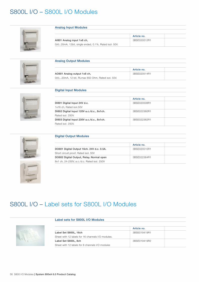
56 S800 I/O Modules | System 800xA 6.0 Product Catalog
Analog Input Modules
Article no.
AI801 Analog input 1x8 ch,
0(4)..20mA, 12bit, single ended, 0.1%, Rated isol. 50V.
3BSE020512R1
S800L I/O – S800L I/O Modules
Analog Output Modules
Article no.
AO801 Analog output 1x8 ch,
0(4)...20mA, 12 bit, RLmax 850 Ohm, Rated isol. 50V.
3BSE020514R1
Digital Input Modules
Article no.
DI801 Digital Input 24V d.c.
1x16 ch, Rated isol.50V
3BSE020508R1
DI802 Digital Input 120V a.c./d.c., 8x1ch.
Rated isol. 250V.
3BSE022360R1
DI803 Digital Input 230V a.c./d.c., 8x1ch.
Rated isol. 250V.
3BSE022362R1
Digital Output Modules
Article no.
DO801 Digital Output 16ch. 24V d.c. 0.5A.
Short circuit proof, Rated isol. 50V
3BSE020510R1
DO802 Digital Output, Relay. Normal open
8x1 ch, 24-230V, a.c./d.c. Rated isol. 250V
3BSE022364R1
Label sets for S800L I/O Modules
Article no.
Label Set S800L, 16ch
Sheet with 12 labels for 16 channels I/O modules.
3BSE019419R1
Label Set S800L, 8ch
Sheet with 12 labels for 8 channels I/O modules
3BSE019419R2
S800L I/O – Label sets for S800L I/O Modules

System 800xA 6.0 Product Catalog | S800 I/O Modules 57
S800 I/O and S800L I/O – ModuleBus Communication Parts
ModuleBus Communication Parts
Article no.
TB805 Bus Outlet
Modulebus extension cable adaptor D-sub 25, female.
One requried per extension cable TK801.
3BSE008534R1
TB845, Dual Modulebus outlet
Modulebus extension cable adaptor two D-sub, female.
Two TK801 cables for redundancy.
3BSE021437R1
TB806 Bus Inlet
Modulebus extension cable adaptor D-sub 25, male.
One requried per extension cable TK801.
3BSE008536R1
TB846, Dual Modulebus inlet
Modulebus extension cable adaptor two D-sub, male.
Two TK801 cables for redundancy.
3BSE021439R1
TK801V003 Cable.
Modulebus Extension Shielded Cable 0.3m D-sub 25, male-
female.
3BSC950089R1
TK801V006 Cable.
Modulebus Extension Shielded Cable 0.6m D-sub 25, male-
female.
3BSC950089R2
TK801V012 Cable.
Modulebus Extension Shielded Cable 1.2m D-sub 25, male-
female.
3BSC950089R3
TB807 Modulebus terminator. 3BSE008538R1
TB820V2 Modulebus Cluster Modem
Optical cluster modem for non redundant operation.
Including:
1 pce Power Supply Connector
1 pce TB807 Modulebus Terminator
3BSE013208R1
TB825 Optical Media Converter Multi Mode
Short to long distance optical fiber conversion.
For modulebus communication up to 1000m.
3BSE036634R1
TB826 Optical Media Converter Single Mode
Short to long distance optical fiber conversion. For modulebus
communication up to 5000m, for S800 I/O HI up to 20000m.
3BSE061637R1
TB840A Modulebus Cluster Modem
Optical cluster modem for 1+1 redundant operation.
3BSE037760R1
TB842 Modulebus Optical Port
Used together with CI801 and CI840, connected via TB806 or
TB846. 10 Mbits driver.
3BSE022464R1
TU807 Termination Unit for TB840/TB840A
Support for single modulebus I/O.
Including:
1 pcs TB807
3BSE039025R1
TU840 Termination Unit for 1+1 TB840. Support for
redundant I/O
Including:
1 pce Power Supply Connector
2 pcs TB807 Modulebus Terminator
3BSE020846R1
TU841 Termination unit for 1+1 TB840. Support for
non-redundant I/O.
Including:
1 pce Power Supply Connector
1 pce TB807 Modulebus Terminator
3BSE020848R1

58 S800 I/O Modules | System 800xA 6.0 Product Catalog
S800 I/O and S800L I/O – ModuleBus Communication Parts
ModuleBus Communication Parts
Article no.
TU848, MTU with individual power supply for red. TB840/
TB840A. Support for dual modulebus.
Including:
2 pcs TB807
3BSE042558R1
TU849, MTU with individual power supply for red. TB840/
TB840A. Support for single modulebus
Including:
1 pcs TB807
3BSE042560R1
TK811V015 POF Cable, 1.5m, Duplex
L=1.5m latching duplex connector Duplex plastic fibre
3BSC950107R1
TK811V050 POF Cable, 5m, Duplex
L=5m latching duplex connector Duplex plastic fibre.
3BSC950107R2
TK811V150 POF Cable, 15m, Duplex
L=15m latching duplex connector Duplex plastic fibre.
3BSC950107R3
TK812V015 POF Cable, 1.5m, Simplex
L=1.5m latching connector Simplex plastic fibre.
3BSC950118R1
TK812V050 POF Cable, 5m, Simplex
L=5.0m latching connector Simplex plastic fibre.
3BSC950089R1
TK812V150 POF Cable, 15m, Simplex
L=15m latching connector Simplex plastic fibre.
3BSC950118R3

System 800xA 6.0 Product Catalog | S800 I/O Modules 59
S800 I/O – Power Supply
Power Supply
Article no.
SD822Z Power Supply Device
Input 115/230V a.c. switch selectable, output 24V d.c., 5A.
If redundant power application is required connect to SS822Z
Voting Unit. Width=65 mm. DIN rail mounted.
3BSC610054R1
SS822Z Power Voting Unit
With dual 24V d.c 20A inputs, single 24V d.c. 20A output. Each
power input supervised. Used if redundant power supply is
required. For use with power supply SD822Z.
Width=50 mm. DIN rail mounted.
3BSC610055R1
SD831 Power Supply Device, G2 Compliant
Input a.c. 100-240 V or d.c. 110-300 V. Output d.c. 24 V 3A. If
redundant power application is required connect to
SS8XX. Voting unit. Width=35mm. DIN rail mounted.
3BSC610064R1
SD832 Power Supply Device, G2 Compliant
Input a.c. 100-120/200-240 V. Output d.c. 24 V 5A, auto-select
input. If redundant power application is required connect to
SD8XX. Voting unit. Width=35mm. DIN rail mounted.
3BSC610065R1
SD833 Power Supply Device, G2 Compliant
Input a.c. 100-120/200-240 V, auto-select input. Output d.c.
24 V 10A. If redundant power application is required connect to
SD8XX. Voting unit. Width=60mm. DIN rail mounted.
3BSC610066R1
SD834 Power Supply Device, G2 Compliant
Input a.c. 100-240 V or d.c. 110-300 V. Output d.c. 24 V 20A.
If redundant power application is required connect to SS8XX.
Voting unit. Width=85mm. DIN rail mounted.
3BSC610067R1
SS832 Voting Device, G2 Compliant
Input d.c. 24 V. Dual 24 V to single 24 V, 2x10A.
Width=35mm. DIN rail mounted.
3BSC610068R1

60 S800 I/O Modules | System 800xA 6.0 Product Catalog
800xA – Process Industries Application Libraries
Process Industries Application LibrariesThe Process Industries Application Libraries (PIAL) in this book include Process Control Device Library (PCDL), Process Control Equipment Library (PCEL) and ProBase Library. One valid license is required per 800xA system. User documentation is provided electronically with the product media. The licenses support use with System 800xA. These licenses entitle license holders to use the library in one system, meaning one Aspect Server. Please refer to System Guide Ordering and Licensing (3BSE041435) for more information.
800xA – PIAL Media
PIAL Media
Article no.
CD media with Process Industries Application Libraries for
System 800xA
3BSE057164R1
S800 I/O – User Documentation
User Documentation
Article no.
S800 I/O Getting Started 3BSE020923-600
S800 I/O Modules and Termination Units 3BSE020924-600
S800 I/O Fieldbus Communication Interface for PROFIBUS
DP/DPV1
3BSE020926-600
S800 I/O Modules and Termination Units with Intrinsic
Safety Interface
3BSE020927-600
System 800xA 6.0 Product Catalog | S800 I/O Modules 61
800xA – Process Control Device Library
Process Industries Application LibrariesThe 800xA PC Device Library provides device-level objects. The PCDeviceLib is a customized library for the process industry. It builds upon the 800xA - AC800M library to provide additional functionality and engineering efficiency. Benefits include minimizing the initial learning curve for the Industrial IT Extended Automation System 800xA and to minimize the engineering effort. The PCDevice Library contains an extensive list of objects, but it is licensed only by the num-ber of Control Elements used. Control Elements are the Valves, Motors and PID Loops in a system. The following PCDevice library control modules are categorized as Control Elements - Valve, ValveMan, MotorOnOff, MotorOnOffAdv, Motor2Speed, MotorVarSpeed, ControllerPIDLoop, ControlValvePneumatic, ControlValveElectric, ChokeValve, MotorOnOffCore, Motor2SpeedCore and MotorVarSpeedCore
Process Control Device Library Licenses
Article no.
Base Process Control Device Library (including 125 Control
Elements)
The PCDevice Library comes with all PCDevice library objects
but only the 13 objects listed above are counted as Control Ele-
ments. To arrive at the correct number of Control Elements to
purchase, count the number of Valve, Motor and ControllerPID-
Loop objects associated with the project.
3BSE081553R1
PCDL Application Engineering
Article no.
PCDL License for Application Engineering
This Engineering system License is intended to use for Applica-
tion Engineering purpose only. A maximum of 2500 Control
Elements will be issued as a part of the license. For production
system, appropriate quantity of Control Elements license must
be purchased separately. Media is ordered separately.
3BSE081555R1
800xA – PCDL Application Engineering
Additional Control Device Library Licenses
Article no.
Additional 125 Control Elements 3BSE081554R1
PCDL Application Engineering
Article no.
PCDL Additional License for Application Engineering
Each additional license comes with 2500 control elements
license.
3BSE081556R1

62 S800 I/O Modules | System 800xA 6.0 Product Catalog
Process Control Equipment Library Licenses
Article no.
Base Process Control Equipment Library With Production
Management
This license is for working with up to 125 PCDevice Lib Control
Elements. This license shall allow using any number of PCEL
Batch Unit type with Standard Phases. All other modules for
Equipment module implementation, quality monitoring, PCC
configuration, and operator visualization are included with this
license. This license also includes Pre-engineered Facility Au-
tomation Solutions like AHUs, Scheduler, ZoneMonitor, Facility,
Start-Stop sequence, Operator visualization etc.
With one base license, a maximum of 125 PCDeviceLib Control
Elements can be used. An incremental purchase of PCDevice
Lib Control Elements (License Expansion) requires an incremen-
tal purchase of PCEquipment Lib license (License Expansion).
Note: License for PCDevice Lib Control Elements to be pur-
chased separately.
3BSE081558R1
800xA – Process Control Equipment Library
Process Control Equipment LibraryProcess Control Equipment Library (PCEquipmentLib) is a comprehensive library of Equip-ment Module templates, and toolkit components for industrial IT Extended Automation System 800xA. PCEquipmentLib is designed to optimize the specification and building of ANSI/ISA-88.01-1995 style Equipment Modules and customized Process Units. Designed to “plug and produce” with standard PCDeviceLib control objects, PCEquipmentLib shares common terminology, engineer-ing principles, and naming conventions to make engineering consistent and easy. It is a require-ment to use a compatible version of PCDevice Library in conjunction with PCEquipment Library. Refer to PCEquipment Library release notes for appropriate version information. The PCEquipment Library contains an extensive list of Pre-engineered and Validated objects like Unit template and Standard Phases, Equipment Modules, Quality Monitor, pcc Supervi-sion, EqTimer, Prompts/PromptsAlarmOwner etc. The PCEquipment Library also contains Pre-engineered Facility Automation Solution objects.

System 800xA 6.0 Product Catalog | S800 I/O Modules 63
Process Control Equipment Library Licenses
Article no.
Base Process Control Equipment Library Without Produc-
tion Management
This license is for working with up to 125 PCDevice Lib Control
Elements. This license shall allow using any number of PCEL
Equipment Module (EM) types with Device Summary and Mod-
eControl. Other modules like Prompt, PromptAlarmOwner and
EqTimer are included in the license. This license also includes
Pre-engineered Facility Automation Solution objects like AHUs,
Scheduler, ZoneMonitor, Facility Start-Stop sequence, Operator
visualization etc.
With one base license, a maximum of 125 PCDL Control Ele-
ments can be used. An incremental purchase of PCDevice Lib
Control Elements (License Expansion) requires an incremental
purchase of PCEquipment Lib license (License Expansion).
Note: License for PCDevice Lib Control Elements to be pur-
chased separately.
3BSE081559R1
800xA – Process Control Equipment Library
800xA – Additional Control Equipment Library Licenses
Additional Control Equipment Library LicensesIt is a requirement to use a compatible version of PCDevice Library in conjunction with PCE-quipment Library. Refer to PCEquipment Library release notes for appropriate version informa-tion. Additional expansion licenses can be purchased. When ordering additional licenses, the original quantity and the license information must be included with the expansion order.
Additional Control Equipment Library Licenses
Article no.
Additional Process Control Equipment Library With
Production Management
Each Expansion license is for working with up to 125 PCDevice
Lib Control Elements.
3BSE081560R1
Additional Process Control Equipment Library Without
Production Management
Each Expansion license is for working with up to 125 PCDevice
Lib Control Elements.
3BSE081561R1

64 S800 I/O Modules | System 800xA 6.0 Product Catalog
800xA – ProBase
ProBaseProBase is a set of System 800xA libraries with industry specific functionality targeting liquid process handling or other applications where routing, storage of material, CIP, etc. are a major concern in the application. Example industries are food & beverage, chemical, pharmaceuti-cals, tank farms, etc.
ProBase LicensesProBase licensing is based on type and number of controllers executing ProBase and the number of ProBase operator workplaces.
Article no.
ProBase 6.0 Operator Workplace - First Client 3BSE081563R1
ProBase 6.0 Operator Workplace - Additional Client 3BSE081564R1
ProBase 6.0 PM861/PM861A Software License 3BSE081565R1
ProBase 6.0 PM864/PM864A Software License 3BSE081566R1
ProBase 6.0 PM865 Software License 3BSE081567R1
ProBase 6.0 PM866 Software License 3BSE081568R1
ProBase 6.0 PM891 Software License 3BSE081569R1
ProBase 6.0 Demo License and Application Engineering
License
This license is to be used with the 800xA Demo License and
Application Engineering License. The intended use is sales re-
lated activities such as fairs, training centers etc that requires a
full sized system. It is also intended for application engineering.
Media is ordered separately.
3BSE081570R1
800xA – PCEL Application Engineering
PCEL Application Engineering
Article no.
PCEL License for Application Engineering
This Engineering system License is intended to use for Applica-
tion Engineering purpose only. A maximum of 20 ‘PCEL With
Production Management’. License quantity will be issued as
a part of this license, which can be used with both Batch and
Non-Batch version of PCEquipmentLib. For production system,
appropriate quantity of PCEL With Production Management or
WithOut Production Management license quantities must be
purchased separately. Media is ordered separately.
3BSE081562R1
PCEL Application Engineering
Article no.
PCEL Additional License for Application Engineering
Each additional license comes with 20 PCEL WithBatch license.
3BSE081557R1

System 800xA 6.0 Product Catalog | S900 Remote I/O System 65
The S900 remote I/O system communicates with 800xA or other controllers over PROFIBUS. Suitable for applications in the chemical, pharmaceutical, oil and gas industries, S900 I/O can be installed in hazardous areas, thereby reducing mar-shalling and wiring costs. Further maintenance savings can be achieved through S900’s extended diagnostics and the use of HART®-compliant field devices.
Three series of S900 I/O are available: − S-series for applications in Zone 1 hazardous areas − B-series for applications in Zone 2 hazardous areas − N-series for applications in non hazardous areas
Additional solutions for specific applications are available: − Field housing - for wall mounting and field mounting in
Zone 1 installations with system approval fully certified in accordance with ATEX. The high-grade steel housing is prepared for wall-mounting with facility for insulated screen rails or terminals.
− CB220 compact box - S900 in compact form (with up to 4 I/O modules). This variant is suitable for use in applications such as temperature multiplexers and solenoid valve circuits.
S900 Remote I/O System
The S900 components are based on a passive backplane suitable for mounting on a DIN rail or directly in a sub-distri-bution board. The passive backplane includes internal bus communication, terminals for field circuits, communication, and power supply. The function modules are plugged into the backplane in their appropriate slots. The redundant backplane has two slots for power supply units, two slots for commu-nication interfaces, and 16 slots for function modules. Digital function modules have up to 8 channels, analog modules up to four. Therefore, when using a redundant backplane, 128 digital or 64 analog channels can be connected per station. In the case of the S and B series, up to ten S900 stations can be connected on a single fieldbus line.
Key S900 benefits include: − Intrinsically safe - can be installed in Zone 1 and Zone 2 areas. − Good price/performance ratio because external barriers have
been removed and costs are reduced in terms of cabling, installation, hardware, and maintenance.
− Easy configuration using either FDT/DTM or GSD files, allowing easy integration with 800xA process control systems.
− High availability of the plant thanks to redundancy and hot-swap capability of all components during operation.
Series Assembly Field devices /
signals
Hazardous area
approval
S series In Zone 1 In Zones 2, 1 and
0 (intrinsically safe
signals)
ATEX Zone 1
B series In Zone 2 In Zones 2, 1 and
0 (intrinsically safe
signals)
ATEX Zone 2
N series In safe areas In safe areas No
S900
NA
MU
R in
put
s
Bin
ary
24 V
Bin
ary
48 V
Bin
ary
110
V
Bin
ary
230
V
Bin
ary
Rel
ay
Ana
log
Uni
po
lar
Ana
log
Bip
ola
r
Tem
per
atur
e R
TD
Tem
per
atur
e T
/C
SO
E
HA
RT
Intr
insi
c sa
fety
Red
und
ant
Hig
h in
teg
rity
I/O Features S900Digital I/O modulesDX910S,B,N* S,B
Digital output modulesDO910S,B,N* S,B
DO930N Pulse input modulesDP910S,B,N* S,B
Analog input modulesAI910S,B,N* S,B
AI930S,B,N* S,B
AI931S,B,N* S,B
AI950S,B,N* S,B
Analog output modulesAO910S,B,N* S,B
AO920S,B,N* S,B
AO930S,B,N* S,B

66 S900 Remote I/O System | System 800xA 6.0 Product Catalog
S900 Remote I/O System – Ex zone 1 system components
Termination Unit
Article no.
TU921S Redundant Termination Unit (TU16R-Ex)
for 16 I/O-modules
redundant communication and power
(Delivery includes CD910)
3KDE175111L9210
Power Supply
Article no.
SA920S Power Supply
for 24 V DC
Do not mix SA910S with SA920S for redundancy (observe
Release Notes)
3BDH000602R1
Communication Interface
Article no.
CI920AS Communication Interface V 2.1 (CIPBA-Ex)
Use only CI920AS with the same firmware for redundancy for
PROFIBUS DP-V1 (observe Release Notes).
3BDH000690R1
Digital Input or Output
Article no.
DX910S Digital Input or Output (DIO8-Ex)
input for dry contact or NAMUR initiator
output for low power Intrinsic Safe valves
3KDE175311L9100
DO910S Digital Output (DO4-Ex)
output for Intrinsic Safe valves
3KDE175321L9100
DP910S Frequency Input (FI2-Ex)
input for dry contact or NAMUR initiator
3KDE175361L9100

System 800xA 6.0 Product Catalog | S900 Remote I/O System 67
Analog Input
Article no.
AI910S Analog input (AI4-Ex)
transmitter power supply, 4...20 mA
3KDE175511L9100
AI930S Analog Input, HART (AI4H-Ex)
transmitter power supply, 4...20 mA
3KDE175511L9300
AI931S Analog Input, HART (AI4H-Ex)
passive input, 0/4...20 mA
3KDE175511L9310
AI950S Temperature (TI4-Ex)
Pt100, Pt1000, Ni100 in 2-/3-/4-technology
thermocouples type B, E, J, K, L, N, R, S, T
isolated inputs channel by channel
3KDE175521L9500
S900 Remote I/O System – Ex zone 1 system components
Analog Output
Article no.
AO910S Analog output (AO4-Ex)
output 0/4...20 mA
3KDE175531L9100
AO920S Analog output, isolated (AO4I-Ex)
output 0/4...20 mA
isolated outputs channel by channel
3KDE175531L9200
AO930S Analog output HART (AO4H-Ex)
output 0/4...20 mA
3KDE175531L9300

68 S900 Remote I/O System | System 800xA 6.0 Product Catalog
S900 Remote I/O System – Ex zone 2 system components
Termination Unit
Article no.
TU921B Redundant Termination Unit (TU16R-B)
for 16 I/O-modules
redundant communication and power
(Delivery includes CD910)
3KDE175112L9210
Power Supply
Article no.
SA920B Power Supply
for 24 V DC
the power supply filter type BP901S is not required
SA920B is the functional replacement for SA910B do not mix
SA910B with SA920B for redundancy (observe Release Notes)
3BDH000601R1
Communication Interface
Article no.
CI920AB Communication Interface V 2.1 (CIPBA-B)
Use only CI920AB with the same firmware for redundancy for
PROFIBUS DP-V1 (observe Release Notes).
3BDH000691R1
Digital Input or Output
Article no.
DX910B Digital Input or Output (DIO8-B)
input for dry contact or NAMUR initiator
output for low power I.S. valves
3KDE175312L9100
DO910B Digital Output (DO4-B)
output for I.S. valves
3KDE175322L9100
DP910B Frequency Input (FI2-B)
input for dry contact or NAMUR initiator
3KDE175362L9100

System 800xA 6.0 Product Catalog | S900 Remote I/O System 69
Analog Input
Article no.
AI910B Analog input (AI4-B)
transmitter power supply, 4...20 mA
3KDE175512L9100
AI930B Analog Input, HART (AI4H-B)
transmitter power supply, 4...20 mA
3KDE175512L9300
AI931B Analog Input, HART (AI4H-B)
passive input, 0/4...20 mA
3KDE175512L9310
AI950B Temperature (TI4-B)
Pt100, Pt1000, Ni100 in 2-/3-/4-technology
thermocouples type B, E, J, K, L, N, R, S, T
isolated inputs channel by channel
3KDE175522L9500
S900 Remote I/O System – Ex zone 2 system components
Analog Output
Article no.
AO910B Analog output (AO4-B)
output 0/4...20 mA
3KDE175532L9100
AO920B Analog output, isolated (AO4I-B)
output 0/4...20 mA
isolated outputs channel by channel
3KDE175532L9200
AO930B Analog output HART (AO4H-B)
output 0/4...20 mA
3KDE175532L9300

70 S900 Remote I/O System | System 800xA 6.0 Product Catalog
S900 Remote I/O System – Safe area system components
Termination Unit
Article no.
TU921N Redundant Termination Unit (TU16R)
for 16 I/O-modules
redundant communication and power
(Delivery includes CD910)
3KDE175113L9210
Power Supply
Article no.
SA920N Power Supply
for 24 V DC
Do not mix SA910N with SA920N for redundancy (observe
Release Notes)
3BDH000600R1
Communication Interface
Article no.
CI920AN Communication Interface V 2.1 (CIPBA)
use only CI920AN with the same firmware for redundancy
for PROFIBUS DP-V1 (observe Release Notes)
3BDH000692R1
Digital Input or Output
Article no.
DX910N Digital Input or Output (DIO8)
input for dry contact or NAMUR initiator
output for low power valves
3KDE175313L9100
DO910N Digital Output (DO4)
output for valves
3KDE175323L9100
DO930N Relay Output (RO6)
with 4 normally-open contacts and 2 changeover contacts
3BDS014114
DP910N Frequency Input (FI2)
input for dry contact or NAMUR initiator
3KDE175363L9100

System 800xA 6.0 Product Catalog | S900 Remote I/O System 71
Analog Input
Article no.
AI910N Analog input (AI4)
transmitter power supply, 4...20 mA
3KDE175513L9100
AI930N Analog Input, HART (AI4H)
transmitter power supply, 4...20 mA
3KDE175513L9300
AI931N Analog Input, HART (AI4H)
passive input, 0/4...20 mA
3KDE175513L9310
AI950N Temperature (TI4)
Pt100, Pt1000, Ni100 in 2-/3-/4-technology
thermocouples type B, E, J, K, L, N, R, S, T
isolated inputs channel by channel
3KDE175523L9500
S900 Remote I/O System – Safe area system components
Analog Output
Article no.
AO910N Analog output (AO4)
output 0/4...20 mA
3KDE175533L9100
AO920N Analog output, isolated (AO4I)
output 0/4...20 mA
isolated outputs channel by channel
3KDE175533L9200
AO930N Analog output HART (AO4H)
output 0/4...20 mA
3KDE175533L9300
Compact-Box
Article no.
CB220N Compact-Box
for power supply SA911N, communication interface CI920AN
and four I/O modules S900 type N
(Delivery includes CD910)
3KDE175613L2210
SA911N Power supply for CB220N
for 24 V DC
3KDE175613L9110
72 S900 Remote I/O System | System 800xA 6.0 Product Catalog
S900 Remote I/O System – Accessories
Fieldbus isolating repeater
Article no.
BI914S Fieldbus isolating repeater
separates an intrinsically safe RS485 fieldbus from a non
intrinsically safe RS485 fieldbus with bus termination
mounted in DIN rail mounted housing with IP20 protection
one channel version
BARTEC - 07-7311-97WP/K1E0
3BDH000649R1
BI923S Ring-coupler RS485 / FO - intrinsically safe - Slave
separates an intrinsically safe fibre optic ring from a non
intrinsically safe RS485 fieldbus
BARTEC - 07-7311-97WP5400
mounted in DIN rail mounted housing with IP20 protection
(Slave) Optical Plug FSMA
3KDE175831L9230
BI924S Ring-coupler RS485 / FO intrinsically safe - Master
separates an intrinsically safe fibre optic ring from a non
intrinsically safe RS485 fieldbus
BARTEC - 07-7311-97WP5400
mounted in DIN rail mounted housing with IP20 protection
(Master) Optical Plug FSMA
3KDE175831L9240
BI934S Ring-coupler RS485 / FO intrinsically safe – Slave
Separates an intrinsically safe fibre optic ring from one intrinsi-
cally safe RS485 fieldbus segment
Mounted in separate field housing
BARTEC - 07-3103-2512/9003
Optical Plug FSMA
3BDH000674R0001
Accessories
Article no.
BP914S Intrinsically safe PROFIBUS-DP connector for
CI920AS and CI920AB
D-SUB Connector (color blue) for operating the intrinsically safe
PROFIBUS-DP with CI920AS and CI920AB.
Siemens 6ES7972-0DA60-0XA0
Connector can only be used with CI920AS and CI920AB. Do
not use in combination with CI920S or CI920B. This would
violate the explosion protection and could cause destruction of
CI920S or CI920B. For CI920S and CI920B connector BP910S
has to be ordered as spare part via BOL or Parts OnLine.
3BSE067082R1
IP920 Module housing
IP20 protection for empty slots on the termination unit
for use in S900 S, B, and N systems
3KDE175831L9200
IL910 Insert labels
380 pcs.
3KDE175839L9101
Software
Article no.
CD910, S900 I/O Media CD-ROM
CD-ROM incl S900 Documentation, Certificates, GSD (file)
CD-ROM will be delivered with all TU921 and CB220 deliveries
3KDE175839L9100

System 800xA 6.0 Product Catalog | S900 Remote I/O System 73
S900 Remote I/O System – Field Housing S900-FH660S
General InformationThe Ex e field housings FH660S from stainless steel (1.4301) serves for the reception of one redundant termination unit (backplane) TU16R-Ex (Order-No. TU921S) as well as further components with ATEX-certification for the hazardous area in zone 1.
Dimensions 600x600x300 mm / for max 100 field cables
The field housings are pre-mounted with stopping plugs instead of cable glands. The cable glands have to be ordered separately at manufacturer Hummel or manufacturer Bimed.
To fulfill the ATEX-certification the following cable glands are recommended:
Manufacturer Hummel:- Type HSK-M-EMV-Ex M16 (article no. 1646160050)- Type HSK-M-EMV-Ex M20 (article no. 1646200051)- Type HSK-M-EMV-Ex M32 (article no. 1646320050)
Manufacturer Bimed:- Type EBS M16 (article no. EBS01M)- Type EBS M20 (article no. EBS1M)- Type EBS M25 (article no. EBS2M)
All S900 modules and power supply components have to be ordered separately!Additional costs of air transport and courier transport ask under e-mail:Orderbox-CtrlPr DEAPR/DEAPR/ABB or [email protected]
Internal InstallationWith system certificate.
Article no.
FH660S-2000 Field housing
including the following components:
- Termination Unit (backplane) TU921S
- 4 Terminals (UK10N)
Field housings are delivered without cable glands. Cable glands
have to be ordered separately (see General information and
Product Update 2PAA112874)
3KDE175804V2000
FH660S-2020 Field housing
including the following components:
- Termination Unit (backplane) TU921S
- 4 Terminals (UK10N)
- 2 Switches
Field housings are delivered without cable glands. Cable glands
have to be ordered separately (see General information and
Product Update 2PAA112874)
3KDE175804V2020
74 S900 Remote I/O System | System 800xA 6.0 Product Catalog
S900 Remote I/O System – Field Housing S900-FH680S
General InformationThe Ex e field housings FH680S from stainless steel (1.4301) serves for the reception of one redundant termination unit (backplane) TU16R-Ex (Order-No. TU921S) as well as further components with ATEX-certification for the hazardous area in zone 1.
Dimensions 600x800x300 mm / for max 100 field cables
The field housings are pre-mounted with stopping plugs instead of cable glands. The cable glands have to be ordered separately at manufacturer Hummel or manufacturer Bimed.To fulfill the ATEX-certification the following cable glands are recommended:
Manufacturer Hummel:- Type HSK-M-EMV-Ex M16 (article no. 1646160050)- Type HSK-M-EMV-Ex M20 (article no. 1646200051)- Type HSK-M-EMV-Ex M32 (article no. 1646320050)
Manufacturer Bimed:- Type EBS M16 (article no. EBS01M)- Type EBS M20 (article no. EBS1M)- Type EBS M25 (article no. EBS2M)
All S900 modules and power supply components have to be ordered separately!Additional costs of air transport and courier transport ask under e-mail:Orderbox-CtrlPr DEAPR/DEAPR/ABB or [email protected]
Internal InstallationWith system certificate.
Article no.
FH680S-2020 Field housing
including the following components:
- Termination Unit (backplane) TU921S
- 4 Terminals (UK10N)
- 2 Switches
Field housings are delivered without cable glands. Cable glands
have to be ordered separately (see General information and
Product Update 2PAA112874)
3KDE175811V2020

System 800xA 6.0 Product Catalog | S900 Remote I/O System 75
Accessories
Article no.
Field Housing roof
weather protection fits to all field housing
3KDE175831L1000
S900 Remote I/O System – Accessories
Fieldbus Network – FOUNDATION Fieldbus Network Components
FOUNDATION Fieldbus HSE/H1 Linking DeviceLD 800HSE links the FOUNDATION Fieldbus HSE protocol to the FOUNDATION Fieldbus H1 protocol and vice versa. Up to 4 external powered H1 lines can be connected to one LD 800HSE. Two LD 800HSE can be combined to a redundant set of devices. In this case the Redundancy Link cable is required.
Linking Devices
Article no.
Linking Device LD 800HSE
LD 800 HSE module for DIN rail mounting with 4 H1 links and
one HSE connector. The module itself needs external 24 VDC
power supply. H1 links must be powered separately.
Restrictions:
Both Linking Device versions, 3BDH000320R02 and
3BSE073314R1 are not suitable for replacing a device with
article no 3BDH000320R0101 in a redundant set of devices.
So this restriction is valid for both LDs, the EX and the non-EX
version.
For this purpose a limited number of spare devices
3BDH000320R0101 are available via:
ABB AB/Service Center
B357, Tvarleden 2
SE-721 59 Vasteras
Sweden
E-Mail: [email protected]
3BDH000320R02

76 S900 Remote I/O System | System 800xA 6.0 Product Catalog
Fieldbus Network – FOUNDATION Fieldbus Network Components
Linking Devices
Article no.
Linking Device LD 800HSE EX
LD 800HSE EX module for DIN rail mounting with 4 H1 links and
one HSE connector. Certified for hazardous area Zone 2 acc. to
ATEX and IECEx. (Observe Release Notes).
The module itself needs external 24 VDC power supply.
H1 links must be powered separately
Restrictions:
Both Linking Device versions, 3BDH000320R02 and
3BSE073314R1 are not suitable for replacing a device with
article no 3BDH000320R0101 in a redundant set of devices.
So this restriction is valid for both LDs, the EX and the non-EX
version.
For this purpose a limited number of spare devices
3BDH000320R0101 are available via:
ABB AB/Service Center
B357, Tvarleden 2
SE-721 59 Vasteras
Sweden
E-Mail: [email protected]
3BSE073314R1
Accessories Linking Device LD 800HSE
Article no.
Redundancy Link Cable, 0,5m
Redundancy Link Cable links two LD 800HSE to a redundant
set of devices.
3BDH000281R1

System 800xA 6.0 Product Catalog | S900 Remote I/O System 77
Media and Documentation
Article no.
Media CD-ROM LD 800HSE, Version 3.5.0, English
Documentation in pdf-format, tools, capabilities file, and
bitmaps for LD 800HSE.
3BDD011678R0701
Media CD-ROM LD 800HSE/LD 800HSE Ex, Version 3.6.0,
English
Documentation in pdf-format, tools, capabilities file, and
bitmaps for LD 800HSE/LD 800HSE EX.
3BDD011678R0801
Device Management FOUNDATION Fieldbus Linking Device,
LD 800HSE 3.5.0/0
Describes in detail the FOUNDATION Fieldbus Linking Device
LD 800HSE features, hardware installation, configuration, and
diagnostics.
3BDD011677-510
Device Management FOUNDATION Fieldbus Linking Device,
LD 800HSE 3.6.0
Describes in detail the FOUNDATION Fieldbus Linking Device
LD 800HSE/LD 800HSE EX features, hardware installation,
configuration, and diagnostics.
3BDD011677-600
Fieldbus Network – FOUNDATION Fieldbus Network Components

78 S900 Remote I/O System | System 800xA 6.0 Product Catalog
PROFIBUS Redundancy Link Module RLM01The RLM01 is delivered with a printed manual.
Article no.
RLM01, PROFIBUS Redundancy Link Module for PROFIBUS
line redundancy
Converts a non-redundant PROFIBUS line to two redundant
RS485 lines or vice versa. Germanischer Lloyd (GL) certi-
fied (cat. A,B,C,D) in connection with power supply filter
(3BDZ000397R1).
3BDZ000398R1
Power Supply Filter (surge) 24 V DC
Mandatory to fulfill the requirements of Germanischer Lloyd
(GL). WAGO article no. 750-626
3BDZ000397R1
Network Components – PROFIBUS Network Components
PROFIBUS DP Accessories
Article no.
PCO 010, PROFIBUS DP connector, standard
max. 12 Mbit/s, 35° cable outlet, IP40, without bus termination
Phoenix Contact article no. 2744597
3BDZ000370R1
PCO 011, PROFIBUS DP connector with bus termination
max. 12 Mbit/s, 35° cable outlet, IP40, switchable bus termina-
tion Phoenix Contact article no. 2708232.
3BDZ000371R1
PCO 012, PROFIBUS DP connector with bus termination
and adapter
max. 12 Mbit/s, 35° cable outlet, IP40, switchable bus
termination, programming connection SUB-D
Phoenix Contact article no. 2708245
3BDZ000372R1

System 800xA 6.0 Product Catalog | Media and Documentation 79
800xA 6.0 System – Media and Documentation
Related Documentation A complete list of all documents applicable to the 800xA System is provided in Released User Documents (3BUA000263-600). This document lists applicable Release Notes and User Instructions. It is provided in PDF format and is included on the Release Notes/Documentation media provided with your system. Released User Documents are updated with each release and a new file is provided that contains all user documents applicable for that release with their applicable document number. Whenever a reference to a specific instruction is made, the instruction number is included in the reference.

80 Media and Documentation | System 800xA 6.0 Product Catalog
Media and Documentation – Dongles
Dongles
Article no.
Dongle for USB Port
To be used with 800xA 5.1 Rev A.
For USB Dongle to 800xA 5.1 (not Rev A), 800xA 5.0, 800xA
4.1 and 800xA 3.1, please, purchase the Dongle from price
book 3BSE41710, System 800xA Expansion.
3BSE064644R1
Media and Documentation – Industrial IT 800xA
Industrial IT 800xA – MediaThe articles in section 1 may only be selected when ordering a new 800xA system, or if the end user has a valid Automation Sentinel agreement.
Article no.
System 800xA 6.0, Media Box (Solid State Drive)
Including: System 800xA 6.0, and User Documentation on a
Solid State Drive device.
3BSE079233R600
System 800xA 6.0, Media Box (CD/DVD)
Including: System 800xA 6.0, and User Documentation on DVD
and CD.
3BSE078932R600
Media and Documentation – Library
Library – Media
Article no.
INFI90 Function Code Library for AC 800M
CD/DVD Media – INFI90FCLib Latest Revision
3BSE079546R200
MOD 300 CCF Library for AC 800M
CD/DVD Media MODCCFLib 2.1-x latest revision – Supports
System version 5.1.
3BSE079547R21
CD media with Process Industries Application Libraries for
System 800xA
3BSE057164R1

System 800xA 6.0 Product Catalog | Media and Documentation 81
800xA Base System User Documentation
800xA Base System User DocumentationNote! User Manuals are printed on demand and delivery time expects to 15 working days.For S900 I/O documentation, please, refer to the S900 I/O and Fieldbus Network Components price book, 2PAA102823.
Article no.
800xA Base System Documentation
Documents included: Manual Installation, Automated Installa-
tion, Upgrade, Network Configuration, IEC 61850 Engineer-
ing Workflow, IEC 61850 Configuration, IEC 61850 Operation
Library Substation Equipment, PC Network and Software
Monitoring Operation, PC Network and Software Monitoring
Configuration, Administration and Security, Post Installation,
Configuration, Operations, System Planning, Site Planning,
Server Node Virtualization, Tools, Multisystem Integration,
Maintenance, VideONet Connect.
3BSE079003-600
800xA for Advant Master – Connectivity Documentation
Documents included: Advant Master Configuration, Advant
Master Operation, Advant Master Graphic Library, Advant
Master Extended Graphic Library
3BSE079004-600
800xA for Harmony – Connectivity Documentation
Documents included: Harmony Configuration, Harmony
Operation
3BSE079005-600
800xA for DCI – Connectivity Documentation
Documents included: DCI Configuration, DCI Operation
3BSE079006-600
800xA for AC 870P/Melody – Connectivity Documentation
Documents included: AC 870P/Melody Configuration, AC 870P/
Melody Asset Managament for HART devices Configuration.
3BSE079007-600
800xA for MOD 300 – Connectivity Documentation
Documents included: MOD 300 Configuration, MOD 300
Operation
3BSE079008-600
PLC Connect – Connectivity Documentation
Documents included: PLC Connect Operation, PLC Connect
Configuration
3BSE079009-600
800xA for Safeguard – Connectivity Documentation
Documents included: Safeguard Configuration, Safeguard
Operation, Safeguard Graphic Library
3BSE079010-600
800xA for AC 100 – Connectivity Documentation
Documents included: AC 100 Aspect Object Types, AC 100/AC
100 OPC Server Installation, AC 100 OPC Server Configuration
and Operation, AC 100 Configuration and Operation
3BSE079011-600
Operations Documentation
Documents included: Operations Operator Workplace
Configuration, Mobile Devices Support
3BSE079012-600
Batch Management Documentation
Documents included: Batch Management Operation, Batch
Management Configuration
3BSE079013-600
Information Management Documentation
Documents included: Information Management Getting Started,
Information Management Configuration, Information Manage-
ment Display Services, Information Management Data Access
and Reports.
3BSE079014-600

82 Media and Documentation | System 800xA 6.0 Product Catalog
800xA Base System User Documentation
800xA Base System User Documentation
Article no.
Engineering Documentation
Documents included: Engineering Studio, Engineering Studio
Function Designer, Engineering Studio Topology Designer,
Engineering Process Graphics, Engineering Process Graphics
Migration Tool, Engineering Process Graphics based on Visual
Basic, Engineering Process Engineering Tool Integration, Engi-
neering Studio Function Designer Getting Started, Engineering
and Production Environments, Engineering Programmers Guide,
Engineering Application Change Management.
3BSE079015-600
AC 800M Documentation
Documents included: AC 800M Getting Started, AC 800M
Configuration, AC 800M Planning, AC 800M Binary and Analog
Handling, AC 800M Library Object Style Guide, AC 800M OPC
Server, AC 800M Communication Protocols, AC 800M FOUN-
DATION Fieldbus HSE, AC 800M PROFIBUS DP Configuration,
AC 800M PROFIBUS DP Installation, AC 800M ProfiNet IO
Configuration, AC 800M AC 800M DriveBus, AC 800M
Ethernet/IP DeviceNet Configuration, AC 800M Ethernet/IP
DeviceNet Installation, AC 800M IEC 61850 Configuration,
AC 800M Controller Hardware, AC 800M Interfacing SATT I/O.
Advant Fieldbus 100 User Manual, TRIO/Genius Getting Started,
TRIO/Genius
3BSE079016-600
S800 I/O Documentation
Documents included: S800 I/O Getting Started, S800 I/O
Modules and Termination Units, S800 I/O Fieldbus Communica-
tion Interface for PROFIBUS DP/DP-V1, S800 I/O Modules and
Termination Units with Intrinsic Safety, S800 I/O DTM 5.3
3BSE079017-600
S200 I/O Documentation
Documents included: S200 I/O Hardware
3BSE079018-600
AC 800M High Integrity Documentation
Documents included: Safety Manual AC 800M High Integrity,
Safety Manual AC 800M High Integrity Reliability and
Availability Data
3BSE079019-600
Asset Optimization Documentation
Documents included: Asset Optimization Configuration, Asset
Optimization Operation
3BSE079020-600
Device Management and Fieldbus Documentation
Documents included: Device Management Device Library Wizard
3BSE079021-600
Device Management FOUNDATION Fieldbus Documentation
Documents included: Device Management FOUNDATION
Fieldbus Configuration
3BSE079022-600
Device Management PROFIBUS and HART Documentation
Documents included: Device Management PROFIBUS and
HART Configuration, Device Management Basic PROFIBUS
DTM 5.3, Device Management Basic HART DTM 5.2, Device
Management PROFIBUS DTM Builder 5.3, Device Management
HART DTM Builder 5.2.
3BSE079023-600

System 800xA 6.0 Product Catalog | Panel 800 Version 6 83
Panel 800 Version 6
Panel 800 is a user-friendly, intuitive and ergonomic operator panel that combines slim, space saving dimensions with a comprehensive range of advanced functions.
All panels are equipped with advanced functionality for process and equipment control, maneuvered either by function keys located next to the screen or by touching the LCD display. Combined with market leading performance and stunning graphical ability, the Panel 800 erodes the line between ordinary Operator Panels and PC based HMIs. Panel 800 is the successor after the Process Panels.
Panel 800 is designed specifically for ABB Control Network and AC 800M controllers, but thanks to the extensive driver library, the Panel 800 is compatible with most makes of PLC and ABB legacy control systems. When using it together with AC 800M, certain unique features become available, such as integrated alarm handling with the controller.
Panel 800 consists of a modern powerful hardware platform, which enables a very limited mounting depth. The frame is made of powder-coated aluminum, giving the panels a very robust look-and-feel. The front enclosure is designed to withstand demanding industrious usage according to the IP66 standard. The panels have also been certified by DNV and UL.
In December 2012, ABB launched the Panel 800 version 6 series. All Panel 800 Version 6 are developed to satisfy the demands of human-machine communication. Built-in functions such as displaying and controlling text, dynamic indication, time channels, alarm and recipe handling are included.
The Panel 800 Version 6 works primarily in an object-oriented way, making it easy to understand and use. Confi guration is carried out on a PC using the Panel Builder confi guration tool. The project can then be transferred and stored in the operator panel itself.
Various types of automation equipment such PLCs, servos or drives can be connected to the Panel 800 Version 6.
Touch panels

84 Panel 800 Version 5 | System 800xA 6.0 Product Catalog
Specifications Panel 800 Version 6
Specifications Panel 800Display backlight CCFL/LED backlight with dimming functionCPU 316 or 416 MHz RISC CPU (Intel Xscale)
Memory, flash 32 MB (Intel StrataFlash)Memory, RAM 64 MBFlash memory for application 12 MBReal time clock YESPower supply +24 C14 20-30 VAmbient temperature 0 ° to +50 °CRelative humidity 5 - 85 % non-condensingHousing material Powder-coated aluminiumFront side material Autotex F250 / F157 (keyboard), (PP865S in Stainless Steel 316 / 1.4401)PeripheralsSerial Ports RS422/RS485, female, 25-pin D-Sub, RS232C, male, 9-pin D-SubEthernet Shielded RJ45 10/100 Mbit/secUSB Host type A (power consumption max. 500 mA), Device type BPROFIBUS Expansion slot for PROFIBUS DPEnvironmental Data for Panel 800Climatic Operating Conditions Vertical installation: 0 ° to +50 °C
Horizontal installation: 0 ° to +40 °C Storage temperature -20 °C to +70 °C Relative humidity 5 - 85 % non-condensed
Protection class Front panel seal IP 66 Rear panel seal IP 20
Electromagnetic Compatibility and CE-mark Meets EMC directive 2004/108/ECElectromagnetic Emission Tested according to EN61000-6-4 (2007)Electromagnetic Immunity Tested according to EN61000-6-2 (2005)Electrical Safety UL508Hazardous Classified Locations UL 1604 Class I, Div 2 Groups A, B, C, D, T4Marine Certificates ABS, DNV, GL, RINA
Specifications PP871 PP874 PP877
Display size 4,3" 7" 10,4"Resolution 480 x 272 pixels (16:9) 800 x 480 pixels (16:9) 640 x 480 pixels (4:3)Interaction type Resistive Touch Resistive Touch Resistive TouchLED - - -Power consumption (normal/max) 3,6 W 6,0 W 9,6 WDimensions
Front panel, W x H x D 145 x 103 x 49 mm 204 x 143 x 49 mm 280 x 228 x 51 mmCut-out dimensions 128 x 87 x 43 mm 187 x 126 x 43 mm 262 x 209 x 46 mmMounting Panel mount and VESA 50 x 50 Panel mount and VESA 75 x 75 Panel mount and VESA 75 x 75 Net weight ca. 0.5 kg ca. 0.8 kg ca. 1.5 kg
Specifications PP882 PP885 PP893 PP896
Display size 12.1" 15.4" 15.4" 21.5"Resolution 1280 x 800 pixels (16:10) 1280 x 800 pixels (16:10) 1280 x 800 pixels (16:10) 1920 × 1080 pixels (16:9)Interaction type Resistive Touch Resistive Touch Resistive touch, 1 million finger
touch operationsResistive touch, 1 million finger touch operations
LED - - - -Power consumption (normal/max) 22 W 24 W 114 W 125 WDimensions
Front panel, W x H x D 340 × 242 × 79 mm 410 × 286 × 83 mm 410 × 286 × 83 mm 556 × 347 × 87 mmCut-out dimensions 324 × 226 mm 394 × 270 mm 394 × 270 mm 539 × 331 mmMounting Panel mount and VESA 75 × 75 Panel mount and VESA 75 x 75 Panel mount and VESA 100 x 100 Panel mount and VESA 100 x 100 Net weight ca. 2.6 kg ca. 3.85 kg ca. 5.4 kg ca. 8.1 kg

System 800xA 6.0 Product Catalog | Panel 800 Version 6 85
Panel 800 Version 6 – Software Management Program
Software Management ProgramAutomation Sentinel is the ABB control system lifecycle support program. An introductory trial period to the Automation Sentinel program will be included, at no additional cost, with each new ABB control system software delivery. Please contact your designated Automation Sentinel responsible for any questions or please refer to the Automation Sentinel 3.0 productguide for detailed information on the program and on how to calculate and order Automation Sentinel subscriptions.
Upgrade Orders
Article no.
Panel Builder 800 Version 6, for upgrades only
Media folder with Panel Builder 800 Version 6 containing the
latest version of:
- Panel Builder 800 Version 6
- Firmware for panels
- Manuals as pdf-files
- Release Notes
- Renewed license
- Mouse Pad
This item can be ordered by users with a valid Automation
Sentinel agreement for Panel Builder 800 Version 6.
3BSE069301R1
Panel 800 Version 6 – Panel Builder 800
Panel Builder 800
Article no.
Panel Builder 800 Version 6
Media folder with Panel Builder 800 Version 6 containing the
latest version of:
- Panel Builder 800 Version 6
- Firmware for panels
- Manuals as pdf-files
- Release Notes
- License for one Panel Builder 800 Version 6
- Mouse Pad
3BSE069300R1

86 Panel 800 Version 6 | System 800xA 6.0 Product Catalog
Touch Panels
Article no.
PP871 Touch panel 4.3”
TFT 480x272 (16:9)
Requires Panel Builder 800 Version 6 for configuration.
3BSE069270R1
PP874 Touch panel 7”
TFT 800x480 (16:9)
Requires Panel Builder 800 Version 6 for configuration.
3BSE069271R1
PP877 Touch panel 10.4”
TFT 640x480 (4:3)
Requires Panel Builder 800 Version 6 for configuration.
3BSE069272R1
Panel 800 Version 6 – Operator Panels
High Performance Touch Panels
Article no.
PP882 High performance touch panel 12”
TFT 1280x800 (16:9)
Requires Panel Builder 800 Version 6 for configuration.
3BSE069275R1
PP885 High performance touch panel 15”
TFT 1280x800 (16:9)
Requires Panel Builder 800 Version 6 for configuration.
3BSE069276R1
Top Performance Touch Panels
Article no.
PP893 Top performance touch panel 10.4”
TFT 640x480 (4:3)
Requires Panel Builder 800 Version 6 for configuration.
3BSE069277R1
PP896 Top performance touch panel 10.4”
TFT 640x480 (4:3)
Requires Panel Builder 800 Version 6 for configuration.
3BSE069278R1

System 800xA 6.0 Product Catalog | Panel 800 Version 6 87
Communication Interface for Panel 800
Article no.
CB810 USB to Ethernet adapter for programming
USB to Ethernet adapter with software
Cross over Ethernet patch cable included
3BSE042255R1
Panel 800 Version 6 – Accessories
Connection Cables for Panel 800
Article no.
TK858V002 Adapter cable (CAB 107, TK855V002)
Adapter cable RS232 - RS485 0.2 m 9 pin D-Sub to 25 pin D-
Sub. For using 5.1 RS422/485 cables on Version 6 panels.
3BSE069474R1
TK859V000 Gender changer (TK856V000)
Gender changer 9 pin D-Sub male/male.
3BSE069475R1
TK860V001 Splitter cable (CAB 109, TK857V001)
Splitter cable Version 6 panel. Y-split cable to utilize more than
two COM ports on Version 6 panels.
3BSE069476R1
Miscellaneous
Article no.
RX871 Touch cover for PP871 3BSE069286R1
RX874 Touch cover for PP874 3BSE069287R1
RX877 Touch cover for PP877 3BSE069288R1
RX882 Touch cover for PP882 3BSE069291R1
RX885/893 Touch cover for PP885/893 3BSE069292R1
RX896 Touch cover for PP896 3BSE069294R1
MB802V2 SD card 2GB
Secure Digital memory card 2GB Industrial grade for Version 6
panels.
3BSE069477R1

88 Panel 800 Version 6 | System 800xA 6.0 Product Catalog
Dongles
Article no.
Panel 800 Version 6 dongle 250 tags
Dongle 250 tags.
3BSE069282R1
Panel 800 Version 6 dongle 2000 tags
Dongle 2000 tags.
3BSE069283R1
Panel 800 Version 6 dongle 4000 tags
Dongle 4000 tags.
3BSE069284R1
Panel 800 Version 6 – Dongles

System 800xA 6.0 Product Catalog | Panel 800 Version 5 89
Panel 800 Version 5
Panel 800 is a user-friendly, intuitive and ergonomic op-erator panel that combines slim, space saving dimensions with a comprehensive range of advanced functions.
All panels are equipped with advanced functionality for process and equipment control, maneuvered either by function keys located next to the screen or by touching the LCD display. Combined with market leading performance and stunning graphical ability, the Panel 800 erodes the line between ordinary Operator Panels and PC based HMIs. Panel 800 is the successor after the Process Panels.
Panel 800 is designed specifically for ABB Control Network and AC 800M controllers, but thanks to the extensive driver library, the Panel 800 is compatible with most makes of PLC and ABB legacy control systems. When using it together with AC 800M, certain unique features become available, such as integrated alarm handling with the controller.
Panel 800 consists of a modern powerful hardware platform, which enables a very limited mounting depth. The frame is made of powder-coated aluminum, giving the panels a very robust look-and-feel. The front enclosure is designed to withstand demanding industrious usage according to the IP66 standard. The panels have also been certified by DNV and UL.
Key panel
Touch panel

90 Panel 800 Version 5 | System 800xA 6.0 Product Catalog
Specifications Panel 800 Version 5
Specifications Panel 800Display backlight CCFL/LED backlight with dimming functionCPU 316 or 416 MHz RISC CPU (Intel Xscale)
Memory, flash 32 MB (Intel StrataFlash)Memory, RAM 64 MBFlash memory for application 12 MBReal time clock YESPower supply +24 C14 20-30 VAmbient temperature 0 ° to +50 °CRelative humidity 5 - 85 % non-condensingHousing material Powder-coated aluminiumFront side material Autotex F250 / F157 (keyboard), (PP865S in Stainless Steel 316 / 1.4401)PeripheralsSerial Ports RS422/RS485, female, 25-pin D-Sub, RS232C, male, 9-pin D-SubEthernet Shielded RJ45 10/100 Mbit/secUSB Host type A (power consumption max. 500 mA), Device type BPROFIBUS Expansion slot for PROFIBUS DPEnvironmental Data for Panel 800Climatic Operating Conditions Vertical installation: 0 ° to +50 °C
Horizontal installation: 0 ° to +40 °C Storage temperature -20 °C to +70 °C Relative humidity 5 - 85 % non-condensed
Protection class Front panel seal IP 66 Rear panel seal IP 20
Electromagnetic Compatibility and CE-mark Meets EMC directive 2004/108/ECElectromagnetic Emission Tested according to EN61000-6-4 (2007)Electromagnetic Immunity Tested according to EN61000-6-2 (2005)Electrical Safety UL508Hazardous Classified Locations UL 1604 Class I, Div 2 Groups A, B, C, D, T4Marine Certificates ABS, DNV, GL, RINA
Specifications PP820A PP826A PP836A PP846A
Display size - 5,7" 6,5" 10,4"Active area of display, W x H 127,0 x 33,8 mmResolution 240 x 64 pixels 320 x 240 pixels 640 x 480 pixels 800 x 600 pixelsInteraction type Function key Function key Function key Function keyLED 16 (2 color) 16 (2 color) 16 (2 color) 20 (2 color)Power consumption (normal/max) 0,15 A 0,3 A 0,4 A / 0,9 A 0,5 A / 1 ADimensions
Front panel, W x H x D 202 x 187 x 57 mm 275 x 168 x 57 mm 285 x 177 x 60 mm 382 x 252 x 60 mmCut-out dimensions 166 x 149 mm 240 x 130 mm 246 x 139 mm 343 x 208 mmMounting depth 57 mm 58 mm 55 mm 58 mmWeight 0,875 kg 1,11 kg 1,3 kg 2,3 kg
Specifications PP815A PP825A PP835A PP845A PP865A
Display size 3,8" 5,7" 6,5" 10,4" 15"Resolution 320 x 240 pixels 320 x 240 pixels 640 x 480 pixels 800 x 600 pixels 1024 x 768 pixelsInteraction type Resistive Touch Resistive Touch Resistive Touch Resistive Touch Resistive TouchLED - - - - -Power consumption (normal/max) 0,15 A 0,25 A 0,4 A / 0,9 A 0,5 A / 1 A 1,2 A / 1,7 ADimensions
Front panel, W x H x D 156 x 119 x 59 mm 201 x 152 x 57 mm 219 x 154 x 60 mm 302 x 228 x 60 mm 398 x 304 x 60 mmCut-out dimensions 139 x 105 mm 180 x 130 mm 189 x 138 mm 265 x 206 mm 356 x 279 mmMounting depth 57 mm 57 mm 55 mm 58 mm 60 mmWeight 0,56 kg 0,87 kg 1,1 kg 2 kg 3,7 kg
Specifications PP871 PP874 PP877
Display size 4,3" 7" 10,4"Resolution 480 x 272 pixels (16:9) 800 x 480 pixels (16:9) 640 x 480 pixels (4:3)Interaction type Resistive Touch Resistive Touch Resistive TouchLED - - -Power consumption (normal/max) 3,6 W 6,0 W 9,6 WDimensions
Front panel, W x H x D 145 x 103 x 49 mm 204 x 143 x 49 mm 280 x 228 x 51 mmCut-out dimensions 128 x 87 x 43 mm 187 x 126 x 43 mm 262 x 209 x 46 mmMounting Panel mount and VESA 50 x 50 Panel mount and VESA 75 x 75 Panel mount and VESA 75 x 75 Net weight (kg) ca. 0,5 kg ca. 0,8 kg ca. 1,5 kg

System 800xA 6.0 Product Catalog | Panel 800 Version 5 91
Panel 800 Version 5 – Control System Lifecycle Support Program
Control System Lifecycle Support ProgramAutomation Sentinel is the ABB control system lifecycle support program. An introductory trial period to the Automation Sentinel program will be included, at no additional cost, with each new ABB control system software delivery. Please contact your designated Automation Sentinel responsible for any questions or please refer to the Automation Sentinel 3.0 productguide for detailed information on the program and on how to calculate and order Automation Sentinel subscriptions.
Upgrade Orders
Article no.
Panel Builder 800 Version 5
Media folder with Panel Builder 800 Version 5 containing the
latest version of:
- Panel Builder 800 Version 5 and Panel Tools
- Firmware for panels
- Manuals as pdf-files
- Release Notes
- Renewed license
This item can be ordered by users with a valid Automation
Sentinel agreement for Panel Builder 800 Version 5.
3BSE052516R1
Panel 800 Version 5 – Panel Builder 800
Panel Builder 800
Article no.
Panel Builder 800 Version 5
Media folder with Panel Builder 800 Version 5 containing the
latest version of:
- Panel Builder 800 Version 5 and Panel Tools
- Firmware for panels
- Manuals as pdf-files
- Release Notes
- License for one Panel Builder 800 Version 5
3BSE042250R1

92 Panel 800 Version 5 | System 800xA 6.0 Product Catalog
Functional Key Panels
Article no.
PP820A
240*64 pixels, graphics & text, black/white.
New CPU and power boards – no UL 1604 certification.
Requires Panel Builder 800 version 5 for configuring. To protect
the front, it’s recommended to use the RX820 Key Cover.
3BSE042243R2
PP826A
5,7” TFT, 320x240 pixels, graphics & text, color.
New display, CPU and power boards – no UL 1604 certification.
Requires Panel Builder 800 version 5 for configuring. To protect
the front, it’’s recommended to use the RX826 Key Cover.
3BSE042244R3
PP836A
6,5” TFT, 640x480 pixels, graphics & text, color.
New display, CPU and power boards – no UL 1604 certification.
Requires Panel Builder 800 version 5 for configuring. To protect
the front, it’’s recommended to use the RX836 Key Cover.
3BSE042237R2
PP846A
10,4” TFT, 800x640 pixels, graphics & text, color.
New CPU and power boards – no UL 1604 certification.
Requires Panel Builder 800 version 5 for configuring. To protect
the front, it’’s recommended to use the RX846 Key Cover.
3BSE042238R2
Panel 800 Version 5 – Operator Panels

System 800xA 6.0 Product Catalog | Panel 800 Version 5 93
Touch Panels
Article no.
PP815A
3,5” TFT, 320x240 pixels, graphics & text, touch, color.
New display, CPU and power boards – no UL 1604 certification.
Requires Panel Builder 800 version 5 for configuring.
To protect the touch screen, it’s recommended to use the
RX815 Touch Cover.
3BSE042239R2
PP825A
5,7” TFT, 320*240 pixels, graphics & text, touch, color.
New display, CPU and power boards – no UL 1604 certification.
Requires Panel Builder 800 version 5 for configuring.
To protect the touch screen, it’’s recommended to use the
RX825 Touch Cover.
3BSE042240R3
PP835A
6,5” TFT, 640x480 pixels, graphics & text, touch, color.
New display, CPU and power boards – no UL 1604 certification.
Requires Panel Builder 800 version 5 for configuring.
To protect the touch screen, it’’s recommended to use the
RX835 Touch Cover.
3BSE042234R2
PP845A
10,4” TFT, 800x640 pixels, graphics & text, touch, color.
New CPU and power boards – no UL 1604 certification.
Requires Panel Builder 800 version 5 for configuring.
To protect the touch screen, it’’s recommended to use the
RX845 Touch Cover.
3BSE042235R2
PP865A
15” TFT, 1024x768 pixels, graphics & text, touch, color.
New CPU and power boards – no UL 1604 certification.
Requires Panel Builder 800 version 5 for configuring.
To protect the touch screen, it’’s recommended to use the
RX865 Touch Cover.
3BSE042236R2
Panel 800 Version 5 – Touch Panels

94 Panel 800 Version 5 | System 800xA 6.0 Product Catalog
Connection Cables for Panel 800
Article no.
TK854V030 Programming Cable
RS232 programming cable Panel 800 Version 5 <--> PC
Length 3 m.
3BSE042251R1
TK212A Tool cable
RJ45 (male) to Dsub-9 (female), length 3 m. RJ45 8P8C plug
(with shell). Cable : UL2464 26 AWG x 8C. For serial communi-
cation between Panel 800 Version 5 panels and AC 800M.
3BSC630197R1
Panel 800 Version 5 – Accessories
Communication Interface for Panel 800
Article no.
CB801 PROFIBUS DP Communication Interface
PROFIBUS DP slave expansion module for Panel 800 Version 5
panels.
3BSE042245R1
CB810 USB to Ethernet adapter for programming
USB to Ethernet adapter with software. Cross over Ethernet
patch cable included.
3BSE042255R1
Miscellaneous
Article no.
RX815 Touch cover for PP815/PP815A, 1 pcs 3BSE049366R1
RX820 Key cover for PP820/PP820A, 1 pcs 3BSE049367R1
RX825 Touch cover for PP825/PP825A, 1 pcs 3BSE042246R1
RX826 Key cover for PP826/PP826A, 1 pcs 3BSE049368R1
RX835 Touch cover for PP835/PP835A, 1 pcs 3BSE042247R1
RX836 Key cover for PP836/PP836A, 1 pcs 3BSE049369R1
RX845 Touch cover for PP845/PP845A, 1 pcs 3BSE042248R1
RX846 Key cover for PP846/PP846A, 1 pcs 3BSE049370R1
RX865 Touch cover for PP865/PP865A, 1 pcs 3BSE042249R1
MB801V512 Compact Flash card
Expansion Compact Flash memory for Panel 800 Version 5
panels, 512 MB
3BSE042257R1

System 800xA 6.0 Product Catalog | IEC 61850 Engineering Tool 95
IEC 61850 Engineering Tool for 800xA 6.0
With the built-in electrical control system, ABB’s 800xA provides ways to be in control of the complete electri-cal system, from high-voltage switchgear to low-voltage motor control. Whether together with 800xA DCS or not, 800xA is the ideal solution as your Engineering Tool for Electrical Control Systems.
Reduce hardwired cabling on switchgear by connecting to in-telligent devices, no matter which standard protocol you have.
The high reliability on digital communication improves the information flow from the devices and additional electrical measurement equipment can be removed. Simpler installa-tions and reduced automation system are easier to engineer and maintain.
In addition, 800xA electrical control system allows the asset management strategies to be extended to electrical equip-ment. The result is reduced plant downtime and an optimal level of production.
IEC 61850 Engineering ToolThe engineering tool is licensed on a per seat basis, separate from System 800xA licenses. The detailed license process is described in Ref. Doc 2PAA113852.This ABB IEC 61850 Engineering Tool version can be used for 800xA 5.1 FP4 and 800xA 6.0
IEC 61850 Engineering Tool for 800xA 6.0 – Project Engineering and End Customer useThis ABB IEC 61850 Engineering Tool version IET 600 5.x is used ABB wide and can be ordered from one central place ABB Power Products.Product type IET 600 5.x – Integrated Engineering Tool with USB-dongle. This tool version is released for Microsoft Windows 7/8.1 and Microsoft Server 2008/2012.This license is a one-time fee (no renewal is necessary) and can be ordered via the ABB Power Product division Website: CCP – Common Configurator Platform

96 Extended Warranty Time | System 800xA 6.0 Product Catalog
Extended Warranty Time – S800 I/O, S900 I/O, Fieldbus and AC 800M
Extended warranty time on hardware for S800 I/O, S900 I/O, Fieldbus and AC 800MTerms and conditions for the supply of products from Local Division Process Automation, LBU Control Technologies within ABB AB in Sweden is valid.
Note that the price for the Extended Warranty Time order will be calculated as a percentage of the affected S800 I/O, S900 I/O, Fieldbus and AC 800M articles in the accompanying order.
– Item A100 => 3% of the affected HW articles within the whole order– Item A110 => 6% of the affected HW articles within the whole order– Item A120 => 9% of the affected HW articles within the whole order
Article no.
12 additional months warranty time – S800 I/O, S900 I/O,
Fieldbus and AC 800M
3BSE049878R1
24 additional months warranty time – S800 I/O, S900 I/O,
Fieldbus and AC 800M
3BSE049878R2
36 additional months warranty time – S800 I/O, S900 I/O,
Fieldbus and AC 800M
3BSE049878R3
S800 AC 800M
S900

System 800xA 6.0 Product Catalog | 800xA Marketing Material 97
System 800xA Marketing Material
Marketing material available for 800xAThis is a new service for order and delivery of our 800xA marke-ting material from Operation Center in Västerås, Sweden, via BOL (Business Online)
If you have further questions on order and shipping for marketing material, please contact [email protected], alternatively by phone +46 21 325700 (order department)

98 800xA Marketing Material | System 800xA 6.0 Product Catalog
Marketing Materials
Marketing MaterialsOrders greater than max quantity on request.
Brochures
BrochuresPrint on Demand. Delivery time up to 10 days.
Article no.
ABB Value Provider Program –
A Partnership for growth and profit
Revised 2014. 8 pages brochure. Rev F
3BSE048129-EN
BrochuresPrint on Demand.
Article no.
800xA System Introduction 3BSE077506-EN
800xA Solutions Handbook 3BSE069330-EN
800xA 6.0 System Guide Summary 3BSE078159-EN
800xA 6.0 Product Catalog 3BSE078160-EN
Panel 800 Version 6 Overview 3BSE070214-EN
800xA Engineering Overview 3BDD013082-EN
800xA Asset Management Overview 3BUS095292-EN
800xA Batch Management Overview 3BUS095068-EN
800xA AC 800M Control and I/O Owerview 3BSE047351-EN
800xA S800 I/O System – Overview 3BSE009891-EN
800xA Electrical Control System Overview 3BSE062087-EN
800xA Device Management Overview 3BDD013081-EN
800xA Simulator – Improve safety and productivity
through simulation
3BSE059989-EN
800xA Enables Effective Operations 3BSE059723-EN
800xA Server Node Virtualization 3BSE065912-EN
800xA Alarm Management Overview 3BSE067466-EN
System 800xA Evolve your plant into the future 3BSE063622-EN
Evolution of TDC3000 Connect to System 800xA 3BSE051328-EN
800xA 5.1 and feature releases Executive Summary 3BSE069638-EN
800xA Control rooms of the future are here now 3BSE068791-EN
Brochures – System 800xA
ABB Value Provider ProgramPartnership for growth and profit
Control Technologies
System 800xA 6.0System Guide Summary
System 800xA 6.0Product Catalog
System 800xA Operator EffectivenessControl rooms of the future are here now
Imagine a process event suddenly requiring an operator’s undivided attention. It’s vital to stay alert. The operator needs immediate access to important information about what’s happening. This can be overwhelming in a room full of systems with multiple monitors each with different user interfaces. It requires careful attention to design so the correct information appears on monitors exactly where an operator needs it most, accessed through a single multi-system keyboard and mouse.
This is the concept of “the operator as part of the process”. It goes further – imagine in the same critical situation the opera-tor desk automatically rising, requiring him to stand and quite literally be ‘up and doing’.
Next, reflective ceiling lights change color from green to red to warn others that now is not the best time to chat about
the weekend’s football matches. At the same time, micro-ventilation blows cooler air around the work station to match increased level of alert. You can imagine an operator as part of the process, ready to handle the increasingly complicated operating challenges in these 24 hour, 365 day environments.
The intelligent control roomModern control rooms can be designed to be part of the direct production interface. By integrating intelligence into the environment, the rooms can blend process events into how the workstations respond to assist the operator in manag-ing events. Better work environments have an important side effect – they add to employee satisfaction increasing retention rates of highly trained employees. “The need for an opera-tor to work efficiently is not confined to crisis situations; it is a priority in day-to-day work as well,” Pierre Schäring points out. “A lot can be done to improve the operator’s working situation.”
Pierre Schäring, MD at CGM, and Per Lundmark, responsible for the EOW-x workstation at ABB.

System 800xA 6.0 Product Catalog | 800xA Marketing Material 99
Brochures
Article no.
Food & Beverage Manufacturing Solutions Overview 3BSE065421-EN
ProBase – System 800xA libraries for food and
beverage operations
3BSE042371-EN
Control Technologies Service Center – Life Cycle Parts
Services
3BSE065503-EN
Brochures – System 800xA related material
Data SheetsPrint on Demand. Delivery time up to 10 days.
Article no.
800xA System Capabilities Data Sheet 3BSE039129-EN
AC 800M Controller Data Sheet 3BSE063691-EN
S800 IO System – Outline of all modules 3BSE025986-EN
S800 I/O Communication interfaces 3BSE039116-EN
800xA Power supplies and voters 3BSE054914-EN
System 800xA – Life Cycle Parts Services 3BSE042708-EN
Control Technologies – Preventive Maintenance Kits
for System 800xA
3BSE065040D0011
Data Sheets
USB with configuration graphicsCustomer material on USB media.
Article no.
BUCT Clipart USB 2014
Configuration graphics and ppt artwork for System 800xA
(with High Integrity, Electrical Control System and Cyber
Security), Freelance, Compact Products Suite, Advant Master
and CT related clipart and Visio objects.
3BSE054491-EN
USB with configuration graphics
System 800xA – The Power of Integration System 800xA from ABB is a system that enables plant wide collaboration between people, systems and equipment. 800xA utilizes the system architecture which was built for integration in a fully redundant, reliable environment. Removing the barriers in traditional distributed control systems, System 800xA provides the integrated environment that is required to increase productivity while reducing risk and total cost of ownership. Now including Feature Pack 4.
System 800xA 5.1System capabilities
Data sheet
System Capabilities
Tags 120 000
Aspect Objects 400 000
Total number of Clients, nodes with one or several workplaces 80
Rich Clients 80
Remote Clients (clients connected via a terminal server) 30
Operator screens per system 160
Operator screens per Operator Workplace 4
Operator Workplaces 80
Remote Operator Workplaces 30
Engineering Workplaces 20
Remote Engineering Workplaces 5
Information Management Workplaces 80
Desktop Displays for trends and events 150
Batch Workplaces 80
Nodes in one control network segment (excl. domain server and controllers) 100
Aspect Servers 1 (single, redundant 1oo2 or 2oo3)
Connectivity servers 12 (24 if redundant)
AC 800M Connectivity servers 8 (16 if redundant)
AC 800M controllers per connectivity server 48 (Application Dependent)
AC 800M controllers per system 80 (Larger number application dependent)
I/O channels From a few hundred to over 1,000 per controller depending on CPU type and application.
Food & Beverage manufacturing solutionsAutomation products and systems that satisfy your hunger for success

100 800xA Marketing Material | System 800xA 6.0 Product Catalog
PostersPrint on Demand. Delivery time up to 10 days.
Article no.
800xA Its all about control Configuration
Poster 700 x 500 mm. Delivers in a paper tube.
3BSE045753-EN
800xA Electrical Control System Configuration Poster
Poster 700 x 500 mm. Delivered in a paper tube.
3BSE063646-EN
800xA Cyber Security Configuration Poster
Poster 700 x 500 mm. Delivered in a paper tube.
3BSE076592-EN
Posters
Roll UpsPortable, foldable exhibition display.Delivery time up to 10 days.
Article no.
800xA v6 Industry, Level 1
850 x 2000 mm. Expolinc Compact. Delivered in a canvas bag.
3BSE079170-EN
800xA v6 Industry, Level 2
850 x 2000 mm. Expolinc Compact. Delivered in a canvas bag.
3BSE079171-EN
800xA v6 Offshore, Level 1
850 x 2000 mm. Expolinc Compact. Delivered in a canvas bag.
3BSE079200-EN
800xA v6 Offshore, Level 2
850 x 2000 mm. Expolinc Compact. Delivered in a canvas bag.
3BSE079201-EN
800xA v6 Mining, Level 1
850 x 2000 mm. Expolinc Compact. Delivered in a canvas bag.
3BSE079537-EN
800xA v6 Mining, Level 2
850 x 2000 mm. Expolinc Compact. Delivered in a canvas bag.
3BSE079533-EN
800xA Extended Automation EOW Picture, Level 2
850 x 2000 mm. Expolinc Compact. Delivered in a canvas bag.
Revised 2014.
3BSE062963-EN
800xA v6 Operator Effectiveness, Level 1
850 x 2000 mm. Expolinc Compact. Delivered in a canvas bag.
3BSE079174-EN
800xA v6 Operator Effectiveness, Level 2
850 x 2000 mm. Expolinc Compact. Delivered in a canvas bag.
3BSE079175-EN
800xA Cyber Security, Level 1
850 x 2000 mm. Expolinc Compact. Delivered in a canvas bag.
Revised 2014.
3BSE076250-EN
800xA Cyber Security, Level 2
850 x 2000 mm. Expolinc Compact. Delivered in a canvas bag.
Revised 2014.
3BSE076251-EN
800xA Wireless, Level 1
850 x 2000 mm. Expolinc Compact. Delivered in a canvas bag.
3BSE079538-EN
800xA Wireless, Level 2
850 x 2000 mm. Expolinc Compact. Delivered in a canvas bag.
3BSE079518-EN
Roll Ups

System 800xA 6.0 Product Catalog | 800xA Marketing Material 101
Roll UpsPortable, foldable exhibition display. Delivery time up to 10 days.
Article no.
800xA 35 years in safety. Level 1
850 x 2000 mm. Expolinc Compact. Delivered in a canvas bag.
Revised 2014.
3BSE057722-EN
800xA High Integrity SIL3., Level 1
850 x 2000 mm. Expolinc Compact. Delivered in a canvas bag.
Revised 2014.
3BSE057723-EN
800xA Enterprise Asset Management, Level 1
850 x 2000 mm. Expolinc Compact. Delivered in a canvas bag.
Revised 2014.
3BSE070955-EN
800xA Electrical Control System, Level 1
850 x 2000 mm. Expolinc Compact. Delivered in a canvas bag.
3BSE079176-EN
800xA Electrical Control System, Level 2
850 x 2000 mm. Expolinc Compact. Delivered in a canvas bag.
3BSE079177-EN
800xA Collaboration Table, Level 2
850 x 2000 mm. Expolinc Compact. Delivered in a canvas bag.
3BSE079520-EN
800xA Evolve your DCS investment to 800xA. Level 2
850 x 2000 mm. Expolinc Compact. Delivered in a canvas bag.
Revised 2014.
3BSE067179-EN
800xA Networks, Level 1
850 x 2000 mm. Expolinc Compact. Delivered in a canvas bag.
3BSE081072-EN
800xA Networks, Level 2
850 x 2000 mm. Expolinc Compact. Delivered in a canvas bag.
3BSE081073-EN
Roll Ups
Accessories
Article no.
System 800xA sticker kit
With self-adhesive backside. 2 large, 2 medium and 13 small.
3BSE054488-EN
System 800xA – Aluminium sign
120 x 20 mm. With self-adhesive backside.
3BSE053648-EN
Black doc folder – Accessories
Black cardboard box with ABB logo in right lower corner.
Height 10 mm; for printed matters in A4 format, CD/DVD,
small size giveaways etc. With business card holder.
3BSE051893-EN
Accessories
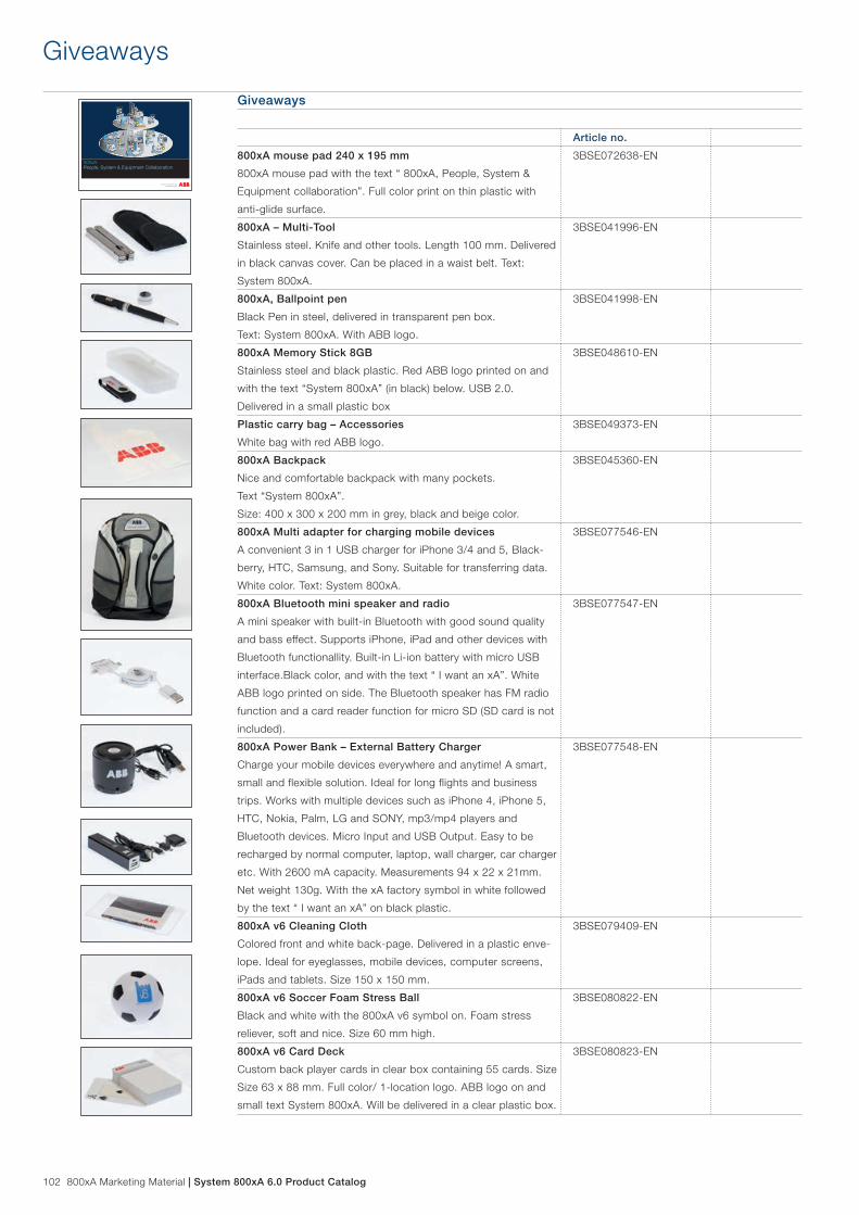
102 800xA Marketing Material | System 800xA 6.0 Product Catalog
Giveaways
Article no.
800xA mouse pad 240 x 195 mm
800xA mouse pad with the text “ 800xA, People, System &
Equipment collaboration”. Full color print on thin plastic with
anti-glide surface.
3BSE072638-EN
800xA – Multi-Tool
Stainless steel. Knife and other tools. Length 100 mm. Delivered
in black canvas cover. Can be placed in a waist belt. Text:
System 800xA.
3BSE041996-EN
800xA, Ballpoint pen
Black Pen in steel, delivered in transparent pen box.
Text: System 800xA. With ABB logo.
3BSE041998-EN
800xA Memory Stick 8GB
Stainless steel and black plastic. Red ABB logo printed on and
with the text “System 800xA” (in black) below. USB 2.0.
Delivered in a small plastic box
3BSE048610-EN
Plastic carry bag – Accessories
White bag with red ABB logo.
3BSE049373-EN
800xA Backpack
Nice and comfortable backpack with many pockets.
Text “System 800xA”.
Size: 400 x 300 x 200 mm in grey, black and beige color.
3BSE045360-EN
800xA Multi adapter for charging mobile devices
A convenient 3 in 1 USB charger for iPhone 3/4 and 5, Black-
berry, HTC, Samsung, and Sony. Suitable for transferring data.
White color. Text: System 800xA.
3BSE077546-EN
800xA Bluetooth mini speaker and radio
A mini speaker with built-in Bluetooth with good sound quality
and bass effect. Supports iPhone, iPad and other devices with
Bluetooth functionallity. Built-in Li-ion battery with micro USB
interface.Black color, and with the text “ I want an xA”. White
ABB logo printed on side. The Bluetooth speaker has FM radio
function and a card reader function for micro SD (SD card is not
included).
3BSE077547-EN
800xA Power Bank – External Battery Charger
Charge your mobile devices everywhere and anytime! A smart,
small and flexible solution. Ideal for long flights and business
trips. Works with multiple devices such as iPhone 4, iPhone 5,
HTC, Nokia, Palm, LG and SONY, mp3/mp4 players and
Bluetooth devices. Micro Input and USB Output. Easy to be
recharged by normal computer, laptop, wall charger, car charger
etc. With 2600 mA capacity. Measurements 94 x 22 x 21mm.
Net weight 130g. With the xA factory symbol in white followed
by the text “ I want an xA” on black plastic.
3BSE077548-EN
800xA v6 Cleaning Cloth
Colored front and white back-page. Delivered in a plastic enve-
lope. Ideal for eyeglasses, mobile devices, computer screens,
iPads and tablets. Size 150 x 150 mm.
3BSE079409-EN
800xA v6 Soccer Foam Stress Ball
Black and white with the 800xA v6 symbol on. Foam stress
reliever, soft and nice. Size 60 mm high.
3BSE080822-EN
800xA v6 Card Deck
Custom back player cards in clear box containing 55 cards. Size
Size 63 x 88 mm. Full color/ 1-location logo. ABB logo on and
small text System 800xA. Will be delivered in a clear plastic box.
3BSE080823-EN
Giveaways
Process automation made easy800xAPeople, System & Equipment Collaboration

System 800xA 6.0 Product Catalog | 800xA Marketing Material 103
Safety – Marketing Materials
Marketing MaterialsOrders greater than max quantity on request
Safety – Brochures
BrochuresPrint on Demand. Delivery time up to 10 days.
Article no.
Safety, 35 years in safety.
Revised 2014 6 pages brochure
3BSE055300-EN
System 800xA Safety Overview
Revised 2014. Rev E
3BSE038820-EN
ABB - your partner in functional safety 3BUS094322-EN
System 800xA - Safety Lifecycle Services 3BUS092094-EN
Evergreen Safety Solutions 3AJE000124-139
Independent High Integrity Safety System 3BUS095645
Safety – Data Sheets
Data SheetsPrinted matters.
Article no.
800xA High Integrity - Burner Management System Solution
Revised 2014 8 page brochure.
3BSE055219-EN
800xA High Integrity - Emergency Shutdown Solution
Reviced 2014. 8 page brochure.
3BSE055220-EN
800xA High Integrity - Fire & Gas Solution
Revised 2014 8 page brochure.
3BSE055221-EN
AC 800M Controller Data Sheet 3BSE063691-EN
35 years in safetyAn ocean of experience
System 800xASafety Overview
800xA High IntegrityBurner Management System Solution
AC 800M is a family of rail-mounted modules, consisting of CPU:s, communication modules, power supply modules and various accessories. There are 8 CPU modules to choose from, ranging from medium processor power and low cost to high processor power and support for full redundancy.
The AC 800M family does also include an IEC 61508-SIL3 certified controller (PM865), which supports controller configurations for: – Safety application – Combined Process Automation and Safety application
Features / CPUs PM851A PM856A PM860A PM861A PM864A PM865 PM866 PM891
Processor Unit PM851K01 incl:1 PM851 CPU and required optional items
PM856K01 incl:1 PM856 CPU and requiredoptional items
PM860K01 incl:1 PM860 CPU and requiredoptional items
PM861AK01 incl:1 PM861A CPU and requiredoptional itemsPM861AK02 incl:2 PM861AK01
PM864AK01 incl:1 PM864A CPU and requiredoptional itemsPM864AK02 incl:2 PM864AK01
PM865K01 incl: 1 PM865K01 CPU and requiredoptional itemsPM865K02 incl: 2 PM865K01
PM866K01 incl:1 PM866 CPU and requiredoptional itemsPM866K02 incl:2 PM866K01
PM891K01incl:1 PM891CPU andrequiredoptional itemsPM891K02incl:2 PM891K01
Optional items(partly included in Processor Units, see Price List)
TP830 Baseplate, TP850 CEX-bus term., TK850 CEX-bus cable, TB807, Modulebus term, Battery RAM backup, TB852/TB853 RCU-link term, TB851/TB855/TB856 RCU-link cable, SB822 External Battery Unit, TK212A Tool cable, TC562 Short Distance Modem, TK853V020 Modem cable, BC810K02 CEX-bus Interconnection unit; TK851V010 Con-nection cable, SD831/SD832/SD833 Power Supply, SS832 Voting Unit, Mains Breaker Kit, SM811 Supervisory Module.
High Integrity Controller
No No No No No Yes No No
Clock frequency 24 MHz 24 MHz 48 MHz 48 MHz 96 MHz 96 MHz 133 MHz 450 MHz
Memory (RAM)
From 5.1 FP4
8 MB 8 MB 8 MB 16 MB 32 MB 32 MB 64 MB 256 MB
12 MB 16 MB 16 MB
RAM available for application
From 5.1 FP4
2.282 MB 2.282 MB 2.282 MB 7.320 MB 23.663 MB 24.242 MB22.415 MB SM81022.386 MB SM811
51.402 MB 199.233 MB
6.372 MB 10.456 MB 10.457 MB
Processor type MPC860 MPC860 MPC860 MPC860 MPC862 MPC862P MPC866 MPC8270
Flash memory for storage of application and data
Yes Yes Yes Yes Yes No Yes Yes
CPU redundancy support No No No Yes Yes Yes Yes Yes
Switch over time in red. conf.
– – – max 10 ms max 10 ms max 10 ms max 10 ms max 10 ms
Performance, 1000 boolean operations (a:=b and c)
0.46 ms 0.46 ms 0.23 ms 0.23 ms 0.15 ms 0.15 ms 0.09 ms 0.043 ms
System 800xA 5.1AC 800M controller
Data sheet

104 800xA Marketing Material | System 800xA 6.0 Product Catalog
Safety – Posters
PostersPrinted matters.
Article no.
System 800xA - High Integrity Configuration -
Poster 500x700 mm
Revised 2014. Delivers in a paper tube. Rev D
3BSE052805-EN
Safety – Roll Ups
Roll UpsPortable, foldable exhibition display. Delivery time up to 10 days.
Article no.
800xA - 35 years in safety , Level 1 Size 850 x 2000 mm
Expolinc Compact. Delivered in a canvas bag.
Revised 2014.
3BSE057722-EN
8800xA - High Integrity SIL 3 , Level 1 Size 850 x 2000 mm
Expolinc Compact. Delivered in a canvas bag.
Revised 2014.
3BSE057723-EN
Your trusted partner in safety , Level 1 Size 850 x 2000 mm
Expolinc Compact. Delivered in a canvas bag.
3BSE081151-EN
ABB Safety Systems, Level 2 Size 850 x 2000 mm
Expolinc Compact. Delivered in a canvas bag.
3BSE081152-EN
Independent High Integrity Safety, Level 2
Size 850 x 2000 mm
Expolinc Compact. Delivered in a canvas bag.
3BSE081154-EN
Safety – Giveaways
Giveaways
Article no.
ABB Safety Stress Ball
-2009
3BSE058211-EN

System 800xA 6.0 Product Catalog | Reference documentation 105
Reference documentation
Release NotesThis table lists the Release Notes and applicable document numbers that are released for use with 800xA System 6.0
Functional Area Document number.
System 800xA System 800xA 6.0 Release
Notes New Functions and
Known Problems
2PAA111899-600
System 800xA 6.0 Release
Notes Resolved Issues
2PAA112277-600
This document includes listings of the Release Notes and User Instructions applicable for 800xA 6.0 version. The listings include the title of the document and the corresponding document number. The documents are grouped by functional areas within the system and by Release Notes and User Instructions.
For more information about System 800xA please visit our web: www.abb.com/800xA
User ManualsThis table lists the User Manuals and associated document numbers that are released for use with 800xA System 6.0
Functional Area Document title Document number.
System 800xA System 800xA 6.0 Installation
and Upgrade Getting Started
2PAA111708-600
System 800xA 6.0 Tools 2PAA101888-600
System 800xA 6.0 Configura-
tion
3BDS011222-600
System 800xA 6.0 Network
Configuration
3BSE034463-600
System 800xA 6.0 Manual
Installation
2PAA112455-600
System 800xA 5.1 to 6.0
Upgrade
2PAA111694-600
System GuidesThis table lists the System Guides and applicable document numbers that are released for use with 800xA System 6.0
Functional Area Document number.
System 800xA System 800xA 6.0 System
Guide Technical Data
and Configuration
3BSE041434-600
System 800xA Pre-installed
Product Guide
3BSE042730-600
800xA 6.0 System Guide
Summary
3BSE078159

106 Reference documentation | System 800xA 6.0 Product Catalog
Reference documentation
Functional Area Document title Document number.
System 800xA System 800xA 5.0 SP2 to 6.0
Upgrade
2PAA111695-600
System 800xA 6.0 Multisystem
Integration
3BSE037076-600
System 800xA 6.0
Administration and Security
3BSE037410-600
System 800xA 6.0 System
Planning
3BSE041389-600
System 800xA 6.0
Maintenance
3BSE046784-600
System 800xA 6.0 Post Instal-
lation
2PAA111693-600
System 800xA 6.0
Virtualization
3BSE056141-600
System 800xA 6.0 Licensing
Information
2PAA111691-600
System 800xA PC, Network
and Software Monitoring
System 800xA 6.0 PC, Net-
work, and Software Monitoring
Operation
3BUA000446-600
System 800xA 6.0 PC, Net-
work, and Software Monitoring
Configuration
3BUA000447-600
System 800xA PLC Connect System 800xA 6.0 PLC
Connect Operation
3BSE035040-600
System 800xA 6.0 PLC
Connect Configuration
3BSE035041-600
Asset Optimization System 800xA Asset Optimi-
zation 6.0 Operation
3BUA000150-600
System 800xA Asset Optimi-
zation 6.0 Configuration
3BUA000118-600
AC 800M 6.0 AC 800M DriveBus 2PAA113566-600
AC 800M 6.0 FOUNDATION
Fieldbus HSE
3BDD012903-600
AC 800M 6.0 PROFIBUS DP
Installation
3BDS009029-600
AC 800M 6.0 PROFIBUS DP
Configuration
3BDS009030-600
AC 800M 6.0 Communication
Protocols
3BSE035982-600
AC 800M 6.0 OPC Server 3BSE035983-600
AC 800M 6.0 Controller
Hardware
3BSE036351-600
AC 800M 6.0 Interfacing SATT
IO
3BSE042821-600
AC800M 6.0 Library Object
Style Guide
3BSE042835-600
System 800xA 6.0 Product Catalog | Reference documentation 107
Reference documentation
Functional Area Document title Document number.
AC 800M
(Continued)
AC 800M 6.0 IEC 61850
Configuration for CI868
9ARD171385-600
AC 800M 6.0 PROFINET IO
Configuration
3BDS021515-600
AC 800M 6.0 EthernetIP
DeviceNet Configuration
9ARD000014-600
AC 800M 6.0 Ethernet/IP
DeviceNet Installation
9ARD000015-600
AC 800M 5.1 Ethernet/IP
DeviceNet Linking Device LD
800DN
3BSE059754R0001
AC 800M 6.0 Controller
Hardware Product Guide
3BSE036352-600
Control System 800xA Control 6.0 AC
800M Configuration
3BSE035980-600
System 800xA Control 6.0
AC 800M Binary and Analog
Handling
3BSE035981-600
System 800xA Control 6.0 AC
800M Getting Started
3BSE041880-600
System 800xA Control 6.0 AC
800M Planning
3BSE043732-600
Advant Fieldbus 100 User
Manual
3BSE000506-600
Compact Control Builder AC
800M 6.0 Getting Started
3BSE041584-600
Compact Control Builder AC
800M 6.0 Configuration
3BSE040935-600
Compact Control Builder AC
800M 6.0 Planning
3BSE044222-600
Compact Control Builder AC
800M 6.0 Binary and Analog
Handling
3BSE041488-600
Compact Control Builder AC
800M 6.0 Product Guide
3BSE041586-600

108 Reference documentation | System 800xA 6.0 Product Catalog
Reference documentation
Functional Area Document title Document number.
Device Management System 800xA 6.0 Device
Management Device Library
Wizard
2PAA102573-600
System 800xA Device
Management 6.0
FOUNDATION Fieldbus
Configuration
3BDD012902-600
System 800xA 6.0 Device
Management PROFIBUS and
HART Configuration
3BDD011934-600
Device Management Basic
PROFIBUS DTM
3BDD011938-600
Device Management Basic
HART DTM
3BDD011939-600
Device Management
PROFIBUS DTM Installation
3BDD011941-600
Device Management HART
DTM Installation
3BDD011942-600
Field IT Linking Device Integra-
tion Pepperl Fuchs Power Hub
2PAA102122R0201
Device Management
PROFIBUS DP FMS
Redundancy Link Module
RLM01
3BDD011600R0601
Device Management FOUNDA-
TION Fieldbus Linking Device
LD 800HSE 3.6.0
3BDD011677-600
Device Management PROFI-
BUS DTM Builder
3BDD011945-600
Device Management HART
DTM Builder
3BDD011946-600
System 800xA Engineering System 800xA Engineering 6.0
Engineering Studio
3BDS011223-600
System 800xA Engineering 6.0
Engineering Studio Function
Designer
3BDS011224-600
System 800xA Engineering 6.0
Engineering Studio Function
Designer Getting Started
3BDS100968-600
System 800xA Engineering 6.0
Application Change
Management
2PAA108438-600
System 800xA Engineering 6.0
Engineering and Production
Environments
3BSE045030-600
System 800xA Engineering 6.0
Engineering Studio Topology
Designer
3BDS011225-600
System 800xA Engineering
6.0 Process Engineering Tool
Integration
3BUA000184-600
System 800xA Engineering 6.0
Process Graphics
3BSE049230-600
System 800xA 6.0 .NET
Aspects Programmers Guide
2PAA107043-600

System 800xA 6.0 Product Catalog | Reference documentation 109
Reference documentation
Functional Area Document title Document number.
IEC 61850 System 800xA 6.0 IEC 61850
Engineering Workflow
9ARD171384-600
System 800xA 6.0 IEC 61850
Connect Configuration
9ARD171387-600
System 800xA 6.0 IEC 61850
Operation Library Substation
Equipment
2PAA108626-600
System 800xA Information
Management
System 800xA Information
Management 6.0 Getting
Started
3BUF001091-600
System 800xA Information
Management 6.0 Configuration
3BUF001092-600
System 800xA Information
Management 6.0 Display
Services
3BUF001093-600
System 800xA Information
Management 6.0 Data Access
and Reports
3BUF001094-600
System 800xA Information
Management 6.0 Profile
Historian Operation
3BUF001121-600
System 800xA Information
Management 6.0 Enterprise
Historian Migration
3BUF001150-600
System 800xA Information
Management 6.0 Technical
Support Reference
3BUF001147-600
I/O S900 I/O Manual DTM 6.x 3BDD010407-600
S900 I/O S- and N-System
with SA920 Installation
3BDD010421R0401
S900 I/O Digital I/O Modules
DO910 and DX910
3BDD010423R0601
S900 I/O Frequency Input/
Pulse Counter DP910
3BDD010424R0601
S900 I/O Temperature Input
Module AI950
3BDD010426R0601
S900 I/O B-System with
SA920 Installation
3BDD010432R0401
S900 I/O Manual Communica-
tion Interface for PROFIBUS
DP CI920A V2.1
2PAA107375
S900 I/O Manual Installation-
Guide S-N-System SA920
CI920A
3BDD010421R0601
S900 I/O PROFIBUS DP
Communication Interface,
CI920 1.5
3BDD015031R0101
S900 I/O Digital I/O Relay
Module DO930N
3BDD010435R0601
S900 I/O Analog I/O Modules
(HART) AI930, AI931, AO930
3BDD010425R0601

110 Reference documentation | System 800xA 6.0 Product Catalog
Reference documentation
Functional Area Document title Document number.
I/O
(Continued)
S900 I/O Manual Installation-
Guide B-System SA920
CI920A
3BDD010432R0601
S800 I/O Getting Started 3BSE020923-600
S800 I/O Modules and
Termination Units
3BSE020924-600
S800 I/O Fieldbus
Communication Interface for
PROFIBUS DP/DPV1
3BSE020926-600
S800 I/O DTM 6.0 3BSE027630-600
S200 I/O Hardware 3BSE021356-600
S200L I/O Hardware 3BSE021357-600
S800 I/O Product Guide 3BSE015969-600
S800 I/O CI801 Memory Maps 3BSE036959-600
S800 I/O CI840 Memory Maps 3BSE025251-600
S800 I/O Modules and
Termination Units with Intrinsic
Safety Interface
3BSE020927-600
System 800xA Operations System 800xA Operations
6.0 Operator Workplace
Configuration
3BSE030322-600
System 800xA Operations 6.0 3BSE036904-600
System 800xA 6.0 Snapshot
Reports User Guide
3BSE060242-600
VideoNet Connect for 800xA
User Manual
2PAA109407-600
System 800xA Operations
Operator Workplace Support
for Mobile Devices
2PAA110154-600
System 800xA 6.0
ABB System Extension
Configuration and Packager
Tool
2PAA111022-600
System 800xA Batch
Management
System 800xA Batch
Management 6.0 Operation
3BUA000145-600
System 800xA Batch
Management 6.0 Configuration
3BUA000146-600
800xA for AC 100 AC 100 OPC Server 6.0
Installation
3BSE077523-600
System 800xA for AC 100 6.0
Aspect Object Types
3BDS013986-600
800xA for AC 100 6.0
Configuration and Operation
3BDS013989-600
AC 100 OPC Server 6.0
Configuration and Operation
3BDS013988-600
AC 100 OPC Server 6.0
Product Guide
3BSE078405-600

System 800xA 6.0 Product Catalog | Reference documentation 111
Reference documentation
Functional Area Document title Document number.
800xA for Advant Master 800xA for Advant Master 6.0
Extended Graphic Library
3BSE026427-600
800xA for Advant Master 6.0
Configuration
3BSE030340-600
800xA for Advant Master 6.0
Operation
3BSE030352-600
800xA for Advant Master 6.0
Graphic Library
3BSE030430-600
800xA for DCI 800xA for DCI 6.0 Operation 3BUA000129-600
800xA for DCI 6.0
Configuration
3BUA000135-600
800xA for Harmony 800xA for Harmony 6.0
Configuration
3BUA000157-600
800xA for Harmony 6.0
Operation
3BUA000158-600
800xA for AC 870P/Melody System 800xA for AC870P/
Melody 6.0 Configuration
3BDD011741-600
System 800xA for AC870P/
Melody 6.0 Asset Management
for HART Devices
Configuration
2VAA000938-600
800xA for MOD 300 800xA for MOD 300 6.0
Configuration
3BUR002417-600
800xA for MOD 300 6.0
Operation
3BUR002418-600
800xA for Safeguard 800xA for Safeguard 6.0
Configuration
3BNP004848-600
800xA for Safeguard 6.0
Operation
3BNP004849-600
800xA for Safeguard 6.0
Graphic Library
3BSE044423-600
800xA for TRIO/Genius 800xA for TRIO/Genius 6.0
Getting Started
3BUR002459-600
800xA for TRIO/Genius 6.0 3BUR002460-600
800xA History 800xA History 6.0 Installation 2PAA107280-600
800xA History 6.0
Administration and
Configuration
2PAA107563-600
Freelance Connect 800xA for Freelance 6.0
Installation
3BDD011810-600
800xA for Freelance 6.0
Operation
3BDD011811-600
800xA for Freelance 6.0
Configuration
3BDD011812-600
800xA for Freelance 6.0
Product Guide
3BDD011861-600
800xA for Freelance 6.0
Release Notes
2PAA111455-600

S800 I/O SystemOverview

2
S800 I/O meet all automation and safety needs
S800 I/O is a open comprehensive, distributed, process I/O system that communicates with controllers by direct connection or over industry-standard field buses. Thanks to its open connectivity it fits a wide range of process controllers from ABB and others. And it bears the name ABB, the world leader in process automation.
By permitting installation in the field, close to sensors and actuators, S800 I/O reduces the installation cost by reducing the cost of cabling. And thanks to benefits such as:
–– flexibility,–permitting–a–virtually–infinite–number–of–installation–arrangements,–small–or–large,–indoors–or–outdoors,–wall–mounting–or–floor–standing,
–– modularity,–permitting–step-by-step–expansion–without–bottlenecks–ever–developing,
–– cost-effectiveness,–making–for–savings–on–hardware,–cabling,–installation–and–maintenance,
–– reliability–thanks–to–features–such–as–autodiagnostics–and–redundancy–with–bumpless,–automatic,–change-over,
it helps industrial operators get a tighter grip on production and thereby improve profitability.
Features and Benefits
–– Comprehensive:–S800–I/O–offers–costeffective–solutions–to–practically–all–needs–for–field-device–interfacing,–including–basic–analog–and–digital–I/O,–as–well–as–intrinsic-safety–and–high-integrity–solutions.
–– Structurally–flexible:–S800–I/O–is–highly–modular–and–offers–a–number–of–ways–in–which–the–modules–can–be–intercon-nected.–Consequently,–S800–I/O–networks–can–be–built–in–a–near-infinite–number–of–ways,–from–highly–centralized–to–highly–distributed.
–– Supports–industry-standard–field–bus–PROFIBUS–DP–which–makes–S800–I/O–compatible–also–with–non-ABB–controllers.
–– S800–I/O–supports–also–ABB’s–Advant–Fieldbus–100.–– Easy–to–configure:–S800–I/O–devices–are–configured–trans-
parently–as–part–of–their–parent–controllers,–like–local–I/O.–No–additional–knowledge–or–skills–are–required.
–– Reliable:–Comprehensive–diagnostics,–hot–swapping–of–modules–and–redundancy–solutions–are–available,–ensuring–that–both–the–I/O–system–and–the–production–plant–will–stay–up.

3
Comprehensive and flexible
–– Comprehensive:–The–S800–family–of–I/O–covers–virtually–all–conceivable–signal–types–and–ranges.–From–basic–ana-log–and–digital–inputs–and–outputs–to–pulse–counters–and–intrinsic-safety–I/O.
–– Flexible configuration:–S800–I/O–may–be–set–up–in–a–vari-ety–of–ways,–from–directly–connected–to–the–host–controller,–to–subclustered–(using–fiber-optic–cables),–to–PROFIBUS-connected.–Redundancy–solutions–are–available–at–all–levels–including;–power–supply,–communication–interfaces–and–I/O–circuits.
Flexible installationThree mechanical designs are available:–– Compact–(plug-in–modules–with–a–basic–I/O–signal–termina-
tion–area).–– Extended–(plug–in–modules–with–ample–space–for–I/O–cable–
termination,–fuses,–jumpering–and–field–power–distribution).–– S800L–(all-in-one–modules–and–bases–with–detachable–
screw–terminal–blocks–for–I/O–signals)–for–installations–not–requiring–hot-swap–capability.–
Easy to set upOnce station numbers have been allocated and set, all other settings can be made from a network-connected engineering tool. A pass-through feature makes it possible to confi gure and examine all HART®- compliant fi eld devices in a similar way.
Reliable S800 I/O offer availability-improving features such as: –– Input/Output–Set–as–Predefined–(ISP/OSP).–Each–input/out-
put–can–be–set–individually–to–default–to–a–predefined–value–or–freeze–in–case–of–communication–loss.–
–– Hot–swap–of–modules.–A–faulty–I/O–module–can–be–replaced–live,–i.e.–without–powering–the–station–down–and–without–the–rest–of–the–station–being–affected.–A–hardware–key–ensures–that–only–modules–of–the–right–type–can–be–inserted.–
–– Hot–configuration–in–run–(HCIR).–An–S800–I/O–station–can–be–reconfigured–while–in–full–normal–operation,–i.e.–without–having–to–switch–it–over–to–configuration–mode.–
–– Redundancy–options–in–all–areas:–power–supply,–fieldbus–media,–fieldbus–interfaces–and–I/O–modules.
–– To–withstand–harsh–environments,–all–S800–modules–are–compliant–to–G3–severity–level–of–ISA-S71.04,–Environ-mental–Conditions–for–Process–Measurement–and–Control–Systems.
Accurate S800 I/O modules can time-stamp events, i.e. input signal transitions, at the source with millisecond accuracy. Thereby providing the basis for meaningful sequence-of-events re-cording by the host system. In tightly interlocked processes this is essential to finding the root causes of production disturbances.
Analog inputs/outputs support HART routing for easy cali-bration checking and diagnosis with configurable access.
High Integrity I/OWithin the S800 family, there are SIL3 certified modules that can be used for safety critical applications.
These I/O modules include those for 4 - 20 mA analog inputs, 24 Vdc normally closed digital inputs, and 24 Vdc digital outputs. The digital output module provides both Normally Energized (ESD) and Normally De-energized (F&G) outputs.
A comprehensive assortment of I/O modules are available for safety-criti-cal use. These include a range of SIL-3-rated S800 I/O modules for analog inputs, digital inputs, and digital outputs.
High Integrity I/O
A comprehensive assortment of I/O modules are available for safety-criti-S800 I/O is available in three different designs: Compact, Extended, and S800L.
S800 I/O

4
Build your I/O system freely
PROFIBUS DP or Advant Fieldbus 100S800 I/O support both PROFIBUS DP and Advant Fieldbus 100 and make thereby the I/O system compatible with a wide range of process control systems from ABB and oth-ers, including System 800xA with AC 800M, Advant Master, Advant MOD, Freelance, Melody / AC 870P, Harmony, and DCI System Six.
Single or redundant solutionsS800 I/O offer redundancy options for I/O channels, power supply and all host-connection modes: direct, fiberoptic, and field bus. And it follows through with redundancy options for all downstream links: internal bus and I/O channels. Meaning that all weak links can be eliminated and availability maxi-mized.
Analog or digital I/ODigital process interfacing modules typically provide 16 chan-nels while analog modules offer 8. Since an S800 I/O station can accommodate 12 I/O modules, this means up to 192 digitals or 96 analogs per station or any mix between the two extremes.
With optional Modulebus expansion, up to 24 I/O modules can be accommodated, thus doubling the above-mentioned I/O capacity.
The I/O modules of a station can all be mounted on a single rail or be distributed across several, in the latter case using plug-in interconnecting cables.
These alternatives make S800 I/O fit a wide range of standard wall-mounting and floor-standing enclosures. A fiber-optic Modulebus even makes it possible to break up S800 I/O sta-tions into clusters installed hundreds of meters apart. A cost-effective and noise-immune way of implementing distributed control.
There are inputs and outputs for industry-standard d.c. and a.c. signal levels and devices, including resistance-temper-ature sensors and thermocouples. There are even pulse and frequency counters as well as intrinsic safety- and HART®-supporting modules. So just about all the process devices we can think of can be wired up to S800 I/O stations with a minimum of field cabling and intermediate signal conditioning.

5
1 2
3 4
1 S800 I/O supports both PROFIBUS DP and Advant Fieldbus 100, making the I/O system compatible with a wide range of industrial controllers. 2 From left to right, redundant pairs of fieldbus interfaces, process inputs and process outputs.3 Subordinated I/O clusters can be connected as far as 200 m away by fiber-optic extension cable (Modulebus). Ideal for electrically noisy environments and sprawling equipment sets.4 The S800 I/O family supports cost-effective solutions from minimal I/O-stations with few signals to demanding I/O-stations including mix of redundancy and I/O types.
PROFIBUS DP or Advant Fieldbus 100
Economical S800 I/O when tasks are
simple...
...or demanding
Full redundant S800 I/O-station
Fie
ldb
us
Fie
ldb
us
Op
tica
l ext
ensi
on
cab
le
A minimal S800 I/O station with two S800L modules.

6
Efficient engineering and maintenance
Transparent configurationS800 I/O stations are configured as part of the parent control-ler like local I/O, which means that no additional knowledge or skills are required. Configurations defined in this way are downloaded automatically on start-up. Similarly, the I/O system supports the FDT/ DTM standard and offers HART® pass-through. That is, a consistent, easy-to use interface toward fieldbusconnected devices. Thanks to it all, such devices can be managed in the same easy way, regardless of type or make.
Ample means for keeping production upPlenty of features are built into S800 I/O to make it reliable, fault tolerant and autodiagnosing, e.g.:
–– Diagnostic–LEDs–on–all–modules,–– High–data–communication–security–for–zero–errors,–– Optional–dual–redundancy–in–everything–from–power–supply,–
through–fieldbus–communication,–to–I/O–channels,–– Each–input–and–output–can–be–set–individually–to–take–on–a–
predefined–value–or–freeze–in–case–of–communication–failure,–– S800–I/O–modules–can–be–withdrawn–and–reinserted–live–
without–disturbing–the–rest–of–the–station.–Hardware–and–software–keys–ensure–that–only–modules–of–the–right–type–can–be–inserted–––and–adopted–––by–the–system.
–– Hot–Configuration–In–Run.–Each–I/O–circuit–can–be–recon-figured–from–the–host–system–while–in–full–uninterrupted–service.
These and other features, improve reliability, boost availability and shorten downtimes.

7
Reliability and ruggedness confirmedS800 I/O has passed tough type tests by leading maritime inspection and classification societies, confirming that the equipment is able to operate reliably and durably even under the most extreme conditions. G3 compliant to ISA-S71.04 standard, adds even more environmental immunity to the system.
Safe or hazardous areasS800 I/O includes intrinsic safety I/O modules, facilitating installation of I/O stations in safe or potentially hazardous areas and connection to field devices in hazardous areas by means of modules with built-in barriers. Consequently, S800 I/O can be used throughout the plant, standardization that all involved will benefit from.
Investment protectionThanks to S800 I/O’s wide-ranging compatibility with different kinds of control systems, it is the perfect choice for safe-guarding the investments made in field cabling when upgrad-ing to newer control systems.
Environment-friendlyThe S800 I/O family is designed and manufactured according to the environmental protection standard ISO 14001, thereby offering a clear conscience as a bonus.
Industrialized hardware

81.6 %
7.23 MW
Auto
249.1 m3/h250.0 m3/h
Auto
50.7 m3/h50.0 m3/h
Auto
91.3 m3/h92.0 m3/h
7.2 %
Auto
99.7 m3/h100.0 m3/h
Auto
40.0 m3/h
Auto
44.6 %45.0 %
No FilterNo Filter
Freelance Product CatalogVersion 2013


3BDD015188 Rev C Product Catalog Freelance Version 2013 | Table of Contents 3
Table of Contents
Chapter 1 Freelance – distributed control system for process applications � � � � � � � � � � � � � � � � 7
Chapter 2 System architecture � � � � � � � � � � � � � � � � � � � � � � � � � � � � � � � � � � � � � � � � � � � � � � � � � � � � 92.3 The operator level . . . . . . . . . . . . . . . . . . . . . . . . . . . . . . . . . . . . . . . . . . . . . . . . . . . . . . . . . . . 92.3 Engineering tool . . . . . . . . . . . . . . . . . . . . . . . . . . . . . . . . . . . . . . . . . . . . . . . . . . . . . . . . . . . . . 92.3 The process level . . . . . . . . . . . . . . . . . . . . . . . . . . . . . . . . . . . . . . . . . . . . . . . . . . . . . . . . . . . . 92.3 System communication . . . . . . . . . . . . . . . . . . . . . . . . . . . . . . . . . . . . . . . . . . . . . . . . . . . . . . 10
2.3.1 Control network . . . . . . . . . . . . . . . . . . . . . . . . . . . . . . . . . . . . . . . . . . . . . . . . . . . . . . . 112.3.2 OPC . . . . . . . . . . . . . . . . . . . . . . . . . . . . . . . . . . . . . . . . . . . . . . . . . . . . . . . . . . . . . . . . 112.3.3 Advanced application programming DMS-API . . . . . . . . . . . . . . . . . . . . . . . . . . . . . . . . 112.3.4 Technical details of the control network . . . . . . . . . . . . . . . . . . . . . . . . . . . . . . . . . . . . . 11
Chapter 3 The controllers � � � � � � � � � � � � � � � � � � � � � � � � � � � � � � � � � � � � � � � � � � � � � � � � � � � � � � � 133.3 Functions . . . . . . . . . . . . . . . . . . . . . . . . . . . . . . . . . . . . . . . . . . . . . . . . . . . . . . . . . . . . . . . . . 143.3 The controller AC 900F . . . . . . . . . . . . . . . . . . . . . . . . . . . . . . . . . . . . . . . . . . . . . . . . . . . . . . 16
3.3.1 Hardware and certificates . . . . . . . . . . . . . . . . . . . . . . . . . . . . . . . . . . . . . . . . . . . . . . . . 163.3.2 Redundancy concept . . . . . . . . . . . . . . . . . . . . . . . . . . . . . . . . . . . . . . . . . . . . . . . . . . . 193.3.3 Central processing unit PM 902F . . . . . . . . . . . . . . . . . . . . . . . . . . . . . . . . . . . . . . . . . . 203.3.4 PROFIBUS Modules CI 930F and CM 772F . . . . . . . . . . . . . . . . . . . . . . . . . . . . . . . . . 223.3.5 Accessories . . . . . . . . . . . . . . . . . . . . . . . . . . . . . . . . . . . . . . . . . . . . . . . . . . . . . . . . . . 24
3.3 The controller AC 800F . . . . . . . . . . . . . . . . . . . . . . . . . . . . . . . . . . . . . . . . . . . . . . . . . . . . . . 263.3.6 Hardware and certificates . . . . . . . . . . . . . . . . . . . . . . . . . . . . . . . . . . . . . . . . . . . . . . . . 263.3.7 Redundancy concept . . . . . . . . . . . . . . . . . . . . . . . . . . . . . . . . . . . . . . . . . . . . . . . . . . . 303.3.8 AC 800F, pre-assembled stations . . . . . . . . . . . . . . . . . . . . . . . . . . . . . . . . . . . . . . . . . . . . . . . . . . . . . . . . . . . . . . . . . . . . . . . . 343.3.9 AC 800F, base units PM 803F . . . . . . . . . . . . . . . . . . . . . . . . . . . . . . . . . . . . . . . . . . . . 343.3.10 Power supply . . . . . . . . . . . . . . . . . . . . . . . . . . . . . . . . . . . . . . . . . . . . . . . . . . . . . . . 363.3.11 Ethernet interface . . . . . . . . . . . . . . . . . . . . . . . . . . . . . . . . . . . . . . . . . . . . . . . . . . . . . 403.3.12 Fieldbus interface modules . . . . . . . . . . . . . . . . . . . . . . . . . . . . . . . . . . . . . . . . . . . . . . 423.3.13 Coated and G3 compliant hardware . . . . . . . . . . . . . . . . . . . . . . . . . . . . . . . . . . . . . . . . . . . . 483.3.14 Accessories . . . . . . . . . . . . . . . . . . . . . . . . . . . . . . . . . . . . . . . . . . . . . . . . . . . . . . . . . 50
3.0.14.1 Battery modules and holder . . . . . . . . . . . . . . . . . . . . . . . . . . . . . . . . . . . . . .503.0.14.2 Front panel . . . . . . . . . . . . . . . . . . . . . . . . . . . . . . . . . . . . . . . . . . . . . . . . . . .523.0.14.3 Auxiliary power supply . . . . . . . . . . . . . . . . . . . . . . . . . . . . . . . . . . . . . . . . . . .523.0.14.4 Cables . . . . . . . . . . . . . . . . . . . . . . . . . . . . . . . . . . . . . . . . . . . . . . . . . . . . . . .533.0.14.5 Miscellaneous . . . . . . . . . . . . . . . . . . . . . . . . . . . . . . . . . . . . . . . . . . . . . . . . .53
3.3 The controller AC 700F . . . . . . . . . . . . . . . . . . . . . . . . . . . . . . . . . . . . . . . . . . . . . . . . . . . . . . 543.3.15 Hardware and certificates . . . . . . . . . . . . . . . . . . . . . . . . . . . . . . . . . . . . . . . . . . . . . . . 543.3.16 Central processing unit PM 783F . . . . . . . . . . . . . . . . . . . . . . . . . . . . . . . . . . . . . . . . . 573.3.17 PROFIBUS module CM 772F . . . . . . . . . . . . . . . . . . . . . . . . . . . . . . . . . . . . . . . . . . . . 583.3.18 CPU terminal base TB 711F . . . . . . . . . . . . . . . . . . . . . . . . . . . . . . . . . . . . . . . . . . . . . 60
3.0.18.1 Dimensional drawings . . . . . . . . . . . . . . . . . . . . . . . . . . . . . . . . . . . . . . . . . . .613.3.19 Accessories for CPU module . . . . . . . . . . . . . . . . . . . . . . . . . . . . . . . . . . . . . . . . . . . . 62

4 Table of Contents | Product Catalog Freelance Version 2013 3BDD015188 Rev C
Chapter 4 Power supplies for AC 900F, AC 700F and S700 I/O � � � � � � � � � � � � � � � � � � � � � � � � � 634.3 Power supply modules . . . . . . . . . . . . . . . . . . . . . . . . . . . . . . . . . . . . . . . . . . . . . . . . . . . . . . . 634.3 Accessories . . . . . . . . . . . . . . . . . . . . . . . . . . . . . . . . . . . . . . . . . . . . . . . . . . . . . . . . . . . . . . . 65
Chapter 5 Remote I/Os � � � � � � � � � � � � � � � � � � � � � � � � � � � � � � � � � � � � � � � � � � � � � � � � � � � � � � � � � 675.3 S700 I/O . . . . . . . . . . . . . . . . . . . . . . . . . . . . . . . . . . . . . . . . . . . . . . . . . . . . . . . . . . . . . . . . . 68
5.3.1 S700 I/O modules . . . . . . . . . . . . . . . . . . . . . . . . . . . . . . . . . . . . . . . . . . . . . . . . . . . . . 695.3.2 Fieldbus interface module DC 705F . . . . . . . . . . . . . . . . . . . . . . . . . . . . . . . . . . . . . . . . 705.3.3 Digital I/O Modules . . . . . . . . . . . . . . . . . . . . . . . . . . . . . . . . . . . . . . . . . . . . . . . . . . . . . 74
5.1.3.1 Frequency input module CD 722F . . . . . . . . . . . . . . . . . . . . . . . . . . . . . . . . . . .745.1.3.2 Digital input/output module DC 722F. . . . . . . . . . . . . . . . . . . . . . . . . . . . . . . . .805.1.3.3 Digital input/output module DC 723F. . . . . . . . . . . . . . . . . . . . . . . . . . . . . . . . .845.1.3.4 Digital input / output module DC 732F. . . . . . . . . . . . . . . . . . . . . . . . . . . . . . . .885.1.3.5 Digital input module DI 724F . . . . . . . . . . . . . . . . . . . . . . . . . . . . . . . . . . . . . . .925.1.3.6 Digital input / output module DX 722F . . . . . . . . . . . . . . . . . . . . . . . . . . . . . . . .945.1.3.7 Digital input / output module DX 731F . . . . . . . . . . . . . . . . . . . . . . . . . . . . . . . .97
5.3.4 Analog I/O Modules . . . . . . . . . . . . . . . . . . . . . . . . . . . . . . . . . . . . . . . . . . . . . . . . . . . 1005.1.4.1 Analog input/output module AC 722F . . . . . . . . . . . . . . . . . . . . . . . . . . . . . . .1005.1.4.2 Analog input module AI 723F . . . . . . . . . . . . . . . . . . . . . . . . . . . . . . . . . . . . .1045.1.4.3 Analog input module AI 731F (Thermocouple) . . . . . . . . . . . . . . . . . . . . . . . . .1085.1.4.4 Analog output module AO 723F . . . . . . . . . . . . . . . . . . . . . . . . . . . . . . . . . . .1105.1.4.5 Analog input/output module AX 721F . . . . . . . . . . . . . . . . . . . . . . . . . . . . . . .1145.1.4.6 Analog input / output module AX 722F . . . . . . . . . . . . . . . . . . . . . . . . . . . . . .118
5.3.5 Digital/Analog I/O module . . . . . . . . . . . . . . . . . . . . . . . . . . . . . . . . . . . . . . . . . . . . . . 1225.1.5.1 Digital / analog module DA 701F . . . . . . . . . . . . . . . . . . . . . . . . . . . . . . . . . . .122
5.3.6 I/O terminal units . . . . . . . . . . . . . . . . . . . . . . . . . . . . . . . . . . . . . . . . . . . . . . . . . . . . . 1285.1.6.1 Dimensional drawings I/O terminal units . . . . . . . . . . . . . . . . . . . . . . . . . . . . .1285.1.6.2 TU 705F / TU 706F . . . . . . . . . . . . . . . . . . . . . . . . . . . . . . . . . . . . . . . . . . . . .1295.1.6.3 TU 715F / TU 716F . . . . . . . . . . . . . . . . . . . . . . . . . . . . . . . . . . . . . . . . . . . . .1305.1.6.4 TU 731F / TU 732F . . . . . . . . . . . . . . . . . . . . . . . . . . . . . . . . . . . . . . . . . . . . .131
5.3.7 S 700 I/O Accessories . . . . . . . . . . . . . . . . . . . . . . . . . . . . . . . . . . . . . . . . . . . . . . . . 1325.1.7.1 FieldBusPlug . . . . . . . . . . . . . . . . . . . . . . . . . . . . . . . . . . . . . . . . . . . . . . . . . .1325.1.7.2 Markers for I/O modules . . . . . . . . . . . . . . . . . . . . . . . . . . . . . . . . . . . . . . . . .1335.1.7.3 Connectors . . . . . . . . . . . . . . . . . . . . . . . . . . . . . . . . . . . . . . . . . . . . . . . . . . .1335.1.7.4 Cables . . . . . . . . . . . . . . . . . . . . . . . . . . . . . . . . . . . . . . . . . . . . . . . . . . . . . . .133
5.3 S800 Remote I/O . . . . . . . . . . . . . . . . . . . . . . . . . . . . . . . . . . . . . . . . . . . . . . . . . . . . . . . . . . 1345.3.8 Communication . . . . . . . . . . . . . . . . . . . . . . . . . . . . . . . . . . . . . . . . . . . . . . . . . . . . . . 134
5.0.8.1 Field communication interfaces . . . . . . . . . . . . . . . . . . . . . . . . . . . . . . . . . . . .1345.0.8.2 Upgrade kit and tool cables . . . . . . . . . . . . . . . . . . . . . . . . . . . . . . . . . . . . . . .135
5.3.9 S800 I/O modules . . . . . . . . . . . . . . . . . . . . . . . . . . . . . . . . . . . . . . . . . . . . . . . . . . . . 1365.0.9.1 Analog input modules . . . . . . . . . . . . . . . . . . . . . . . . . . . . . . . . . . . . . . . . . . .1365.0.9.2 Analog output modules . . . . . . . . . . . . . . . . . . . . . . . . . . . . . . . . . . . . . . . . . .1375.0.9.3 Digital input modules . . . . . . . . . . . . . . . . . . . . . . . . . . . . . . . . . . . . . . . . . . . . . . . . 138
5.0.9.4 Digital output modules . . . . . . . . . . . . . . . . . . . . . . . . . . . . . . . . . . . . . . . . . . .139

3BDD015188 Rev C Product Catalog Freelance Version 2013 | Table of Contents 5
5.0.9.5 Pulse counting modules . . . . . . . . . . . . . . . . . . . . . . . . . . . . . . . . . . . . . . . . .1405.0.9.6 Label sets for I/O modules. . . . . . . . . . . . . . . . . . . . . . . . . . . . . . . . . . . . . . . .1405.0.9.7 Module termination units . . . . . . . . . . . . . . . . . . . . . . . . . . . . . . . . . . . . . . . . .141
5.3.10 S800L modules . . . . . . . . . . . . . . . . . . . . . . . . . . . . . . . . . . . . . . . . . . . . . . . . . . . . . 1425.0.10.1 Analog input modules . . . . . . . . . . . . . . . . . . . . . . . . . . . . . . . . . . . . . . . . . .1425.0.10.2 Analog output modules . . . . . . . . . . . . . . . . . . . . . . . . . . . . . . . . . . . . . . . . .1425.0.10.3 Digital input modules . . . . . . . . . . . . . . . . . . . . . . . . . . . . . . . . . . . . . . . . . . .1425.0.10.4 Digital output modules . . . . . . . . . . . . . . . . . . . . . . . . . . . . . . . . . . . . . . . . . .1425.0.10.5 Label sets for S800L I/O modules . . . . . . . . . . . . . . . . . . . . . . . . . . . . . . . . .1435.0.10.6 ModuleBus communication parts . . . . . . . . . . . . . . . . . . . . . . . . . . . . . . . . .143
5.3.11 Power supplies . . . . . . . . . . . . . . . . . . . . . . . . . . . . . . . . . . . . . . . . . . . . . . . . . . . . . 1455.3.12 User documentation . . . . . . . . . . . . . . . . . . . . . . . . . . . . . . . . . . . . . . . . . . . . . . . . . . 146
5.3 S900 Remote I/O . . . . . . . . . . . . . . . . . . . . . . . . . . . . . . . . . . . . . . . . . . . . . . . . . . . . . . . . . . 1475.3.13 System description of S900 Remote I/O system . . . . . . . . . . . . . . . . . . . . . . . . . . . . 1475.3.14 Technical data of S900 Remote I/O system . . . . . . . . . . . . . . . . . . . . . . . . . . . . . . . . 1515.3.15 Redundant termination unit TU921S/B/N . . . . . . . . . . . . . . . . . . . . . . . . . . . . . . . . . . 1525.3.16 Power supply SA920S/B/N . . . . . . . . . . . . . . . . . . . . . . . . . . . . . . . . . . . . . . . . . . . . 1545.3.17 Communication interface CI920AS/AB/AN . . . . . . . . . . . . . . . . . . . . . . . . . . . . . . . . . 1565.3.18 Digital I/O modules . . . . . . . . . . . . . . . . . . . . . . . . . . . . . . . . . . . . . . . . . . . . . . . . . . . 1575.3.19 Analog I/O modules . . . . . . . . . . . . . . . . . . . . . . . . . . . . . . . . . . . . . . . . . . . . . . . . . . 1615.3.20 Field housing . . . . . . . . . . . . . . . . . . . . . . . . . . . . . . . . . . . . . . . . . . . . . . . . . . . . . . . 1685.3.21 Accessories . . . . . . . . . . . . . . . . . . . . . . . . . . . . . . . . . . . . . . . . . . . . . . . . . . . . . . . . 1725.3.22 Software . . . . . . . . . . . . . . . . . . . . . . . . . . . . . . . . . . . . . . . . . . . . . . . . . . . . . . . . . . 173
Chapter 6 Fieldbus network components and Profibus configuration for S700 � � � � � � � � � � � 1756.3 Profibus DP configuration for S700 . . . . . . . . . . . . . . . . . . . . . . . . . . . . . . . . . . . . . . . . . . . . 1756.3 PROFIBUS network components . . . . . . . . . . . . . . . . . . . . . . . . . . . . . . . . . . . . . . . . . . . . . . 1776.3 FOUNDATION Fieldbus network components . . . . . . . . . . . . . . . . . . . . . . . . . . . . . . . . . . . . 178
Chapter 7 Freelance Operations (DigiVis) � � � � � � � � � � � � � � � � � � � � � � � � � � � � � � � � � � � � � � � � � 1797.3 Messages & operator hints . . . . . . . . . . . . . . . . . . . . . . . . . . . . . . . . . . . . . . . . . . . . . . . . . . . 1837.3 Software subscription . . . . . . . . . . . . . . . . . . . . . . . . . . . . . . . . . . . . . . . . . . . . . . . . . . . . . . 1857.3 DigiVis languages . . . . . . . . . . . . . . . . . . . . . . . . . . . . . . . . . . . . . . . . . . . . . . . . . . . . . . . . . . 1857.3 DigiVis license V10.1 . . . . . . . . . . . . . . . . . . . . . . . . . . . . . . . . . . . . . . . . . . . . . . . . . . . . . . . 1857.3 DigiVis options . . . . . . . . . . . . . . . . . . . . . . . . . . . . . . . . . . . . . . . . . . . . . . . . . . . . . . . . . . . . 1867.3 DigiVis hardkeys . . . . . . . . . . . . . . . . . . . . . . . . . . . . . . . . . . . . . . . . . . . . . . . . . . . . . . . . . . . 187

6 Table of Contents | Product Catalog Freelance Version 2013 3BDD015188 Rev C
Chapter 8 Freelance Engineering (Control Builder F) � � � � � � � � � � � � � � � � � � � � � � � � � � � � � � � � 1898.3 Configuration of functions . . . . . . . . . . . . . . . . . . . . . . . . . . . . . . . . . . . . . . . . . . . . . . . . . . . 1918.3 Hardware structure . . . . . . . . . . . . . . . . . . . . . . . . . . . . . . . . . . . . . . . . . . . . . . . . . . . . . . . . 1948.3 Commissioning . . . . . . . . . . . . . . . . . . . . . . . . . . . . . . . . . . . . . . . . . . . . . . . . . . . . . . . . . . . 1958.3 Control Builder F languages . . . . . . . . . . . . . . . . . . . . . . . . . . . . . . . . . . . . . . . . . . . . . . . . . . 1978.3 Control Builder F license . . . . . . . . . . . . . . . . . . . . . . . . . . . . . . . . . . . . . . . . . . . . . . . . . . . . 1978.3 Control Builder F options . . . . . . . . . . . . . . . . . . . . . . . . . . . . . . . . . . . . . . . . . . . . . . . . . . . . 1988.3 Control Builder F hardkeys . . . . . . . . . . . . . . . . . . . . . . . . . . . . . . . . . . . . . . . . . . . . . . . . . . . 1988.3 Control - Software license . . . . . . . . . . . . . . . . . . . . . . . . . . . . . . . . . . . . . . . . . . . . . . . . . . . 199
8.3.1 Base License . . . . . . . . . . . . . . . . . . . . . . . . . . . . . . . . . . . . . . . . . . . . . . . . . . . . . . . . 1998.3.2 Additional basic I/Os . . . . . . . . . . . . . . . . . . . . . . . . . . . . . . . . . . . . . . . . . . . . . . . . . . 1998.3.3 Control software options . . . . . . . . . . . . . . . . . . . . . . . . . . . . . . . . . . . . . . . . . . . . . . . 2008.3.4 Batch . . . . . . . . . . . . . . . . . . . . . . . . . . . . . . . . . . . . . . . . . . . . . . . . . . . . . . . . . . . . . . 200
Chapter 9 Media and documentation � � � � � � � � � � � � � � � � � � � � � � � � � � � � � � � � � � � � � � � � � � � � � 201
Chapter 10 Add-ons, extensions, and service � � � � � � � � � � � � � � � � � � � � � � � � � � � � � � � � � � � � � � 203
Chapter 11 Automation Sentinel Program � � � � � � � � � � � � � � � � � � � � � � � � � � � � � � � � � � � � � � � � � 205
Chapter 12 Repairs � � � � � � � � � � � � � � � � � � � � � � � � � � � � � � � � � � � � � � � � � � � � � � � � � � � � � � � � � � � 209
Notes � � � � � � � � � � � � � � � � � � � � � � � � � � � � � � � � � � � � � � � � � � � � � � � � � � � � � � � � � � � � � � � � � � � � � � 210
Index � � � � � � � � � � � � � � � � � � � � � � � � � � � � � � � � � � � � � � � � � � � � � � � � � � � � � � � � � � � � � � � � � � � � � � 212

3BDD015188 Rev C Product Catalog Freelance Version 2013 | Introduction 7
Freelance is a full-fledged distributed control system that combines the advantages of both worlds – DCS and PLC. It offers the small footprint of a PLC, together with the full functionality of a DCS. The integrated environment simplifies engineering, commissioning, maintenance and fieldbus man-agement. The intuitive operator interface enables easy opera-tion and diagnosis of the entire system.
The objective of process industry companies today is clearly defined: increased automation at lower cost. Today, people are impressed by the global success story of Freelance, with more than 18,000 applications covering all industry sectors. With Freelance, ABB has taken a further step forward, provid-ing powerful automation that is not only cost-effective in terms of hardware and software, but is also very easy to use.
Freelance is ABB’s process control system solution covering the full range from very small to medium size applications. The advanced design of Freelance makes the process control sys-tem ideal for numerous applications in power, process or envi-ronmental technology plants.
For PLCs, processing speed, scalable performance, small footprint and low component prices are competitive require-ments. In contrast to this, high engineering efficiency, collabo-ration of the entire plant crew and full lifecycle support are highly demanded in DCS markets. Freelance, the control sys-tem, offers the best of two worlds: The full scalability with PLC type controllers and the comfort of a full-blown DCS.
When PLCs are used instead of control systems in process industries, application engineers have to deal with various tools and programs from different providers. This implies a lot of disadvantages with respect to seamless configuration pro-cedures, reliable visualization and operation and uncertainty about long term availability of individual tools.
The advantages of using Freelance for different application types are evident. For example, consider a small automation task: only a few measured analog values, a few actuators and push buttons for control operation. Even these very small applications benefit – when implemented with the AC 700F controller – a lot from the comfort of the process control system:
Chapter 1 Freelance – distributed control system for process applications
81.6 %
7.23 MW
Auto
249.1 m3/h250.0 m3/h
Auto
50.7 m3/h50.0 m3/h
Auto
91.3 m3/h92.0 m3/h
7.2 %
Auto
99.7 m3/h100.0 m3/h
Auto
40.0 m3/h
Auto
44.6 %45.0 %
No FilterNo Filter

8 Introduction | Product Catalog Freelance Version 2013 3BDD015188 Rev C
− Easy setup of configuration including process control and visualization
− High reliability through use of well-tested and ready-made function blocks for any kind of applications
− Reduced testing efforts − Being well prepared for any kind of future modifications and
improvements
The latter argument really points to the unquestioned realm of Freelance, the control system.
Consider even a small application where you like to perform just a minor modification. How many different, non-integrated tools are affected when running in a PLC type scenario? How much effort do you have to spend just to assure that every-thing is well tested as before?
What a difference with Freelance. Project reports show that it makes sense to replace older PLCs with AC 700F controllers to gain efficiency and productivity.
The advantages described above apply in the same manner to bigger projects or applications with several AC 700F and AC 800F or AC 900F controllers and different fieldbus lines.
As almost all applications are designed to run 10 to 20 years or even longer, life cycle considerations always play a major role. This is where ABB as a strong partner stays committed over the entire life cycle.
With Freelance all engineering work is performed with one single tool, Control Builder F, which works hand in hand with the visualization and operation tool DigiVis. Ease of use is the important design factor for Freelance: Configuration of all plant objects ranging from process graphics to field devices and operation of the entire plant is easy and intuitive to per-form. Some of the advantages of Freelance are listed here:
− Three controller types (AC 700F, AC 800F and AC 900F) for any kind of applications
− Use of just one engineering tool (Control Builder F) to configure the entire system, consisting of automation functions, graphics, the operator interface, fieldbus lines (Profibus®, FOUNDATION™ Fieldbus, HART®, etc.) and field devices
− Automatic generation of the entire communication between controllers and operator stations
− System-wide single source data treatment for controllers, operator stations, and field devices, leading to data consis-tency within the entire system
− Fully compatible to former versions
− Uniform, system-wide plausibility check of user programs covering all process and operator stations up to intelligent field devices. The plausibility check includes the formal check for completeness and consistency of the user pro-grams
− Graphical configuration with high-performance editors in programming languages according to IEC 61131-3
− Function block diagram (FBD) − Ladder diagram (LD) − Instruction list (IL) − Sequential function chart (SFC) − Structured text (ST)
− Extensive function block library, to which user defined function blocks can be added; macro libraries and graphic symbols to create graphics and faceplates for user defined function blocks
− Integration of any PROFIBUS-DP and PA slave using the concept of the generic slave (via a GSD-file) with the pos-sibility of configuring these components in user-defined dialogs
− Integration of PROFIBUS devices using FDT technology
The same user-friendly configuration and support features also apply to the operation level. The operator is supported by a mechanism providing not only information from the plant but also operating hints, which can serve as simplified SOP (Stan-dard Operating Procedures). For this purpose, for example, an intuitive operator interface, logs and sophisticated alarm and message management function are available.
The quality of Freelance is also reflected in the robust hard-ware, which is immune to electromagnetic interference and bears the CE, UL and GL Mark as a quality symbol for all its components.
In cases where demands on availability are particularly high, it is possible to configure the controller including the modules redundantly. Fieldbus lines and the operator stations can also be configured redundantly. The availability of the control net-work can be increased by using ring topologies. Redundant configuration is done without any additional engineering effort.
The Freelance control system provides powerful automation that is cost-effective and easy to use. Freelance is ideally suited to applications requiring simple handling and attrac-tively-priced hardware and software in power, process or environmental industry.
It is a sound investment in the future, with a straightforward and clearly designed system based on the motto:
Minimum engineering – maximum automation
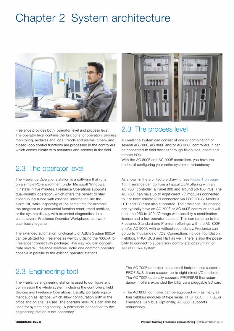
3BDD015188 Rev C Product Catalog Freelance Version 2013 | System Architecture 9
Freelance provides both, operator level and process level. The operator level contains the functions for operation, process monitoring, archives and logs, trends and alarms. Open- and closed-loop control functions are processed in the controllers which communicate with actuators and sensors in the field.
2.3 The operator levelThe Freelance Operations station is a software that runson a simple PC-environment under Microsoft Windows.It installs in five minutes. Freelance Operations supportsdual-monitor operation, which offers the benefit to staycontinuously tuned with essential information like thealarm list, while inspecting at the same time for examplethe progress of a sequential function chart, trend archives,or the system display with extended diagnostics. In aplant, several Freelance Operator Workplaces can workseamlessly together.
The extended automation functionality of ABB’s System 800xA can be utilized for Freelance as well by utilizing the “800xA for Freelance” connectivity package. This way you can concen-trate several Freelance systems under one common operator console in parallel to the existing operator stations.
2.3 Engineering toolThe Freelance engineering station is used to configure andcommission the whole system including the controllers, fielddevices and Freelance Operations. Usually, portable equip-ment such as laptops, which allow configuration both in the office and on site, is used. The operator level PCs can also be used for system engineering. A permanent connection to theengineering station is not necessary.
Chapter 2 System architecture
2.3 The process levelA Freelance system can consist of one or combination ofseveral AC 700F, AC 800F and/or AC 900F controllers. It canbe connected to field devices through fieldbuses, direct and remote I/Os.With the AC 800F and AC 900F controllers, you have the option of configuring your entire system in redundancy.
As shown in the architecture drawing (see Figure 1 on page 10), Freelance can go from a typical OEM offering with an AC 700F controller, a Panel 800 and around 50-100 I/Os. The AC 700F can have up to eight direct I/O modules connected to it or have remote I/Os connected via PROFIBUS. Modbus RTU and TCP are also supported. The Freelance Lite offering can typically have an AC 700F or AC 900F controller and will be in the 250 to 400 I/O range with possibly a combination license and a few operator stations. This can ramp up to the Freelance Standard and Premium offerings with the AC 800F and/or AC 900F, with or without redundancy. Freelance can go up to thousands of I/Os. Connections include Foundation Fieldbus, PROFIBUS and Hart as well. There is also the possi-bility to connect to supervisory control stations running on ABB’s 800xA system.
− The AC 700F controller has a small footprint that supports PROFIBUS. It can support up to eight direct I/O modules. The AC 700F optionally supports PROFIBUS line redun-dancy. It offers expanded flexibility via a pluggable SD card.
− The AC 800F controller can be equipped with as many as four fieldbus modules of type serial, PROFIBUS, FF HSE or Freelance CAN bus. Optionally, AC 800F supports redundancy.

10 System Architecture | Product Catalog Freelance Version 2013 3BDD015188 Rev C
Freelance Operations,Batch,
Information,Asset Management
System 800xASupervisory OperationsFreelance Engineering
Operator level
Process level
ERPMES
Industrial ethernet (optionally redundant)
ABB and 3rd party PLC & DCS
SafetyController
SafetyTransmitter
Safetyvalve
Safety I/O
SIL3High Integrity
FieldDevices
AC 700F orAC 900FControllerwith direct I/O
Panel 800Family
S700 I/O
ControlMasterControllers
ScreenMasterRecorders
PR
OFI
BU
S
MO
DB
US
FieldDevices
FieldDevices
Drives and Motors
Foun
dat
ion
Fiel
db
usFreelance Rack I/O
PR
OFI
BU
S
MODBUS
AC 800FController,optionallyredundant
S800 I/O
Intelligent SwitchgearMNS iS
FieldDevices
DrivesandMotors
Panel 800 Family
Panel PC
Package Unit
Valve
MODBUS
AC 700F Controllerwith direct I/O
Drives and Motors
S800 I/O
S900 I/O
AC 900FController,optionally redundant
PR
OFI
BU
S
FieldDevices
MO
DB
US
via
OP
C
3rd party PLC
UniversalMotorController
Intelligent SwitchgearMNS iS
− The new AC 900F controller also supports PROFIBUS and truly extends the hardware portfolio of the Freelance distributed control system. The AC 900F modular con-troller offers expanded flexibility via a pluggable SD card, more Ethernet ports, redundancy options for high avail-ability and power enough for around 1,500 I/Os per con-troller. AC 900F can be equipped with either up to 10 direct I/Os or remote I/Os via PROFIBUS. Optionally, AC 900F supports redundancy.
Integration of 3rd party PLCs like Safety PLCs or package units can easily be achieved by using the new OPC based “PLC Integration” functionality of Freelance. This not only provides the ability read or write data, but also to create faceplates based on existing Freelance ones to interact with those units and to integrate the alarms into the Freelance alarm management.
2.3 System communicationThe operator and the process level communicate via the control network, which is based on Standard Ethernet. You can choose between various transmission media such as twisted pair or fiber optic cable. The system components use a specific pro-tocol called DMS, which is an enhanced MMS (Machine Mes-sage Specification) protocol. This protocol can be utilized by 3rd party network subscribers using the application interface DMS-API. This is a „C“ programming interface for MS Windows to enable programmers to create tailored solutions. A more standardized and generic approach to connect to the system is provided by the Freelance OPC server to access real-time process values (DA) and alarms/ events (AE) from the Freelance System.
A Freelance system in theory can have up to 100 controllers and 100 operator stations. However - the majority of the sys-tems are in the range of 1 to 5 controllers/ operator stations.
Each controller can communicate to a total of 10 Freelance operator stations, OPC- or trend servers. If the number of those exceeds 10, the system allows to segment the data communication accordingly per simply setting some check marks.
Figure 1: Freelance System Architecture
Freelance OEM Freelance Lite Freelance Standard

3BDD015188 Rev C Product Catalog Freelance Version 2013 | System Architecture 11
Note: a DigiVis operator station or the Freelance OPC-server can talk to more than 10 controllers. So, if the number of con-trollers exceed 10, there is no further action required.
2.3.1 Control networkThe control network connects the controllers, operator stations and engineering station in the Freelance system.
The control network complies with the Ethernet Standard according to DIN/ISO 8802, Part 3 (IEEE 802.3) and can be used with twisted pair or coaxial cable. It is also possible to use a combination of these standards or to implement 1-GBit/s components within a network as high-speed backbone. Freelance uses confirmed and unconfirmed ser-vices. The unconfirmed UDP service is used for screen updat-ing and lateral communication between controllers. The con-firmed TCP/IP service is used for alarming and trend archiving.
The control network has the following features: − The ability to cover long distances − A high data throughput − A flexible network layout
2.3.2 OPCFreelance provides an OPC gateway (server), which allows OPC clients to access data and alarms from the Freelance controllers. The OPC server also allows access to the DPV1 parameters and user parameters of PROFIBUS and HART devices. In the case of HART devices, this is only possible if they are connected to an S900 remote I/O unit. For Freelance version 8.2 and higher, the parameters of FOUNDATION Field-bus devices can also be accessed. It is possible to limit access to this data at the OPC gateway such that an OPC client cannot see certain tags and variables at all, can only read other tags and variables, or has both read and write access to certain tags and variables.
The DigiVis operator station has a built-in OPC client, which permits you to access data from external OPC servers. Using this, for example, data from third-party controllers with OPC support can be integrated into a custom graphic in DigiVis. With Version 9.2, when using DigiVis PLC Integration, also Faceplate creation and Alarm & Events are supported.
As several OPC gateways can be used in the Freelance sys-tem, server redundancy can be established using OPC clients that support this function. The Control Builder F engineering software supports this with the redundant OPC gateway configuration.
The trend server option provides a special OPC gateway that is used by the DigiVis operator stations for user-defined trend displays. Access to the trend server is fixed to “read only”, and all trend variables are automatically available. There is one trend server per Freelance system.
2.3.3 Advanced application pro-gramming DMS-APIThe DMS Application Programming Interface provides C pro-grammers with a Windows interface through which they can access internal Freelance communications services. This enables them to create their own Windows applications that can read online data from the Freelance system and create values
2.3.4 Technical details of the control network
Details of the control network
Bus type: Twisted Pair (TP) Fiber optic (FL)
Max. length: 5 x 100 m 5 x 400 m for shielded TP
4500 m
Application: Control network connection of Freelance operator stations (for operation and observation), engineering station and controllers
Standard: DIN/ISO 8802 Part 3 (IEEE 802.3) 10BASE-FL
DIN/ISO 8802 Part 3 10BASE-FL (IEEE 802.3)
Transmission rate: 10/100 MBit/s 10/100 MBit/s

3BDD015188 Rev C Product Catalog Freelance Version 2013 | Controllers 13
Chapter 3 The controllers
Freelance comes with three different types of controllers, AC 700F, AC 800F and its latest Freelance controller – the AC 900F. This controller truly extends the hardware portfolio of Freelance distributed control system.
AC 900F – SD card support – Typically around 1,500 I/Os supported – G3 compliant as standard – Redundancy option for high availability – Four (4) built-in Ethernet ports supporting Modbus TCP/IP
or 60870-5-104 telecontrol protocol – Two (2) serial ports supporting Modbus RTU/ASCII or IEC
60870-5-101 telecontrol protocol – Optional PROFIBUS master modules (up to two) providing
integrated line redundancy – Direct connection of I/O modules (as many as 10), including
modules combining inputs and outputs in just one module can reduce footprint and costs.
– I/O modules can also be connected remotely via PROFIBUS
AC 800F – The outstanding feature is it can be equipped with a set of
fieldbus modules, covering all major fieldbuses used in process automation.
– Option to run controllers either redundantly (CPU redun-dancy, fieldbus module redundancy) or non-redundantly.
– Fieldbus-compliant components such as remote I/O, field devices, and network components can be used.
– Optional G3-compliant – A single controller can typically support around 1,000 I/Os
AC 700F – Typically supports around 300 I/O signals per AC 700F
controller. – This PLC-like controller comes with a very small footprint.
As many as eight (8) S700 direct I/O modules can be plugged to the right of the controller module.
– The connection to the Freelance control network is via Ethernet as for all other controllers. As an alternative to remote I/Os, AC 700F can be placed directly in the field, offering a very flexible and cost-effective solution for an “intelligent” I/O station.
– I/O modules can also be connected remotely via PROFIBUS. This allows for high flexibility in installation.
– SD card support
All three controller types can be used side by side within a proj-ect and can easily communicate with each other via the Ethernet based control network. The engineering is performed with one engineering tool, Freelance. All function blocks and pre-engineered functions are available for all controllers in the same way.
AC 900F
AC 800F
AC 700F

14 Controllers | Product Catalog Freelance Version 2013 3BDD015188 Rev C
3.3 FunctionsThe scope of functions provided by the Freelance system corresponds to the basic supply defined in IEC 61131-3, in addition to numerous other high performance, industry-proven func-tions and function blocks. Furthermore user-specific function blocks can be added for dedicated tasks. During configuration, the processing capacity and speed of the controllers can be easily adapted to the demands of the automation task. Program execution in the controller is based on real-time multitasking operating system, leading to flexible strategies for processing programs.
The operating system of the controllers has two different types of tasks, system tasks and user tasks. System tasks supervise the system for example at cold start or in case of an error. User tasks execute the application programs.
Different modes are available for user task execution: − Up to eight tasks with individual cycle times between 5 ms and 24 hours − Processing as fast as possible (PLC mode); one task only
System tasks are automatically available. These tasks are executed once in case of the following events:
− RUN − STOP − COLD START − WARM START (voltage restored) − REDUNDANCY TOGGLE − ERROR

3BDD015188 Rev C Product Catalog Freelance Version 2013 | Controllers 15
It is possible to add your own applications to these tasks.
Functions and function blocks
Analog value processing Input and output conversion Linearization Delay and dead-time filter Average / extreme value determination in time Setpoint adjustment Counter with analog input Time scheduler
Binary value processing Binary output, monostable Input and output delay Pulse / Time Counter, pushbutton
Closed-loop control Continuous controllers (PID) Step controllers On / Off controller, three-position controller Ratio controller Basic functions Auto-tuning
Open-loop control Individual drive functions Sequence control, dosing circuits
Logic functions Logic processing Average / Extreme value determination Comparator, binary switch Multiplexer Converter (data type & code) Flip-flop, edge detection String blocks Radio controlled adjustment of daylight-saving time
Monitoring Analog and binary monitoring Event monitoring Audible alarm control Connection monitoring
Acquisition functions Disturbance course acquisition, trend acquisition
Arithmetic functions Basic arithmetic functions, numerical functions Logarithmic functions Trigonometric functions Analog value and time limitation
Modbus functions Master and slave functions
PROFIBUS DPV1 master functions
Telecontrol functions Master and slave functions
Phase logic processing Interface module for batch applications

16 Controllers | Product Catalog Freelance Version 2013 3BDD015188 Rev C
3.3 The controller AC 900F
3.3.1 Hardware and certificatesThe AC 900F controller truly extends the hardware portfolio of Freelance distributed control system. Apart from its highly sophisticated automation functions, the AC 900F modular con-troller offers expanded flexibility via a pluggable SD card, more Ethernet ports, redundancy options for high availability and powers for around 1,500 I/Os.
A key feature of the AC 900F is the support of SD cards. Especially the new optional display for AC 900F allows to load applications or firmware into the controller without the need of a terminal program on a computer.
Benefits at a glance:
− More power than any previous generation Freelance controller − More connectivity with 2 serial ports and 4 Ethernet ports − Built-in SD card support − New Ethernet based protocols – Modbus TCP & IEC 60870-5-104 − G3 compliant as standard − Built-in power supply − Optional LCD − Small footprint − Optional redundancy
Mechanical design
Thanks to its four holes in the rear, the CPU module PM 902F allows easy wall-mounting.
DIN rail mounting is even faster and easier by just placing the component on top of the DIN rail and pushing it down to lock it in place.
Technical data
The AC 900F controller consists of a CPU module which is the main component. According to the application and requirements, further modules can be added to the controller. These mod-ules are fieldbus interface modules and I/O modules.
The AC 900F consists of: − CPU module PM 902F with
− four Ethernet interfaces − one diagnostic interface − two serial interfaces − display unit (optional)
− As many as ten S700 I/O modules directly attached on terminal units − A maximum of two fieldbus interface modules
The AC 900F controller can be arranged in a single or redundant manner. The controller sup-ports remote I/Os, transmitters, actuators, drives and other devices, for example through PROFIBUS and other fieldbus protocols. At present, the following field busses are available for the AC 900F controller:
− PROFIBUS DP V0/V1 − Modbus and Modbus TCP − Telecontrol and Telecontrol TCP

3BDD015188 Rev C Product Catalog Freelance Version 2013 | Controllers 17
Input/output modules are used as direct I/O and remote I/O in accordance with the type and quantity of process signals. The hardware configuration of AC 900F is based on a hardware function block concept similar to the configuration like AC 700F and AC 800F.AC 900F can be equipped with a maximum of two PROFIBUS modules. You have the option to run these controllers in redundancy.Modular plug-in I/O modules are used in accordance with the type and quantity of process signals.With AC 900F controllers, fieldbus compliant components such as remote I/O, field devices, and network components can be used. ABB offers equipment for applications covering stan-dard and hazardous areas.
Certificates
The AC 900F controller has the following certificates: − CE (2004/108/EC), c(UL)us, ISA-S71.04 G3.
Environmental conditions
The temperature range of AC 900F ranges from 0 - 60°C, no forced cooling required.
Controller temperature Operating:Storage:Storage (TD 951F inserted):
0 … 60°C (32°F ... 140°F)- 40 °C ... +85°C (-40°F ... 185°F)
- 25 °C ... +70 °C (13°F ... 158°F)
Module temperature Operating: Storage:
0 °C ... +60 °C (32°F ... 140°F)- 40 °C ... +70 °C (-40°F ... 58°F
Display temperature Operating: Storage:
0 °C ... +60 °C (32°F ... 140°F)- 25 °C ... +70 °C (13°F ... 158°F)
Battery temperature Operating: Storage:
- 40 °C ... +85 °C (-40°F ... 185°F)- 40 °C ... +85 °C (-40°F ... 185°F)
Humidity Maximum 93%, without condensation
Air pressure Operating:Storage:
< 2000 m (2187 yd.)< 3500 m (3827 yd.)
Climatic category 3K3 according to EN 60721-3-3
Degree of protection IP 20
G3 severity level ISA-S71.04 G3
Electromagnetic compatibility
2004/108/EC Complies with the European directive
NAMUR NE21 Electromagnetic Compatibility of Industrial Pro-cess and Laboratory Control Equipment
IEC/EN 61000-4-3 Electromagnetic compatibility (EMC) – Testing and measurement techniques, Radiated, radio-frequency, electromagnetic field immunity test
IEC/EN 61000-6-4 Electromagnetic compatibility (EMC) – Generic standards, Emission standard for industrial environments
Mechanical stress / Mounting

18 Controllers | Product Catalog Freelance Version 2013 3BDD015188 Rev C
Mounting Horizontal
Mounting of the modules Wall mounting or DIN rail according to DIN EN 50022, 35 mm, depth 7,5 mm or 15 mm, mounting with screws of type M4, fastening torque 1.2 Nm
Flammability According to UL 94 V0
Vibration resistance according to IEC/EN 60068-2-6
2 g, 2 Hz … 150 Hz
Shock test according to IEC/EN 60068-2-27 15 g, 11 ms, half-sinusoidal
Electric data / Electrical protection
Voltages according to EN 61131-2
Process- and Supply-voltage 24 VDC
Absolute limits +19.2 V ... +32.5 V incl. ripple (see below)
Ripple < 5 %
Protection against reverse polarity Yes
Permissible interruptions of power supply as per EN 61131-2
DC supply Interruptions < 7.5 ms, time between 2 interruptions > 1 s, PS2
Creepage distances and clearances
The creepage distances and clearances meet the overvoltage category II, pollution degree 2.
Power supply units
Power supply units meeting the PELV specification should be used for powering the modules.
Power dissipation for the calculation of cooling systems
The following table lists the anticipated power dissipation (heat dissipation) of individual AC 900F modules.The data for the modules contain the combined power consumption from internal and external supply sources. For detailed information see the Mounting and Installation Instructions, AC 900F manual.
Module Max. power dissipation
Central processing unit PM 902F 18 W
Communication interface CI 930F 1.8 W
Communication module CM 772F 1.2 W
Display unit TD 951F 0.35 W
Power supply CP-C 24/5.0 and CP-C 24/10.0 < 15 W / < 29 W

3BDD015188 Rev C Product Catalog Freelance Version 2013 | Controllers 19
3.3.2 Redundancy concept
Controller redundancy
Profibus
S800
Freelance Engineering
Freelance Operations
S900
Panel
Field device
Field device
Redundancy cable (Ethernet)
Control Network
AC 900F AC 900F
Controller redundancy can be achieved by installing two AC 900F. To ensure quick and smooth takeover by the secondary AC 900F in case the primary AC 900F fails, a dedicated redundancy communications link through the second Ethernet module makes sure that both AC 900F are always synchronized. All inputs and outputs are designed to support redundant operation.
Profibus line redundancy
Freelance Engineering
Freelance Operations
Control Network
Profibus, redundant
S900 S800
Slave withoutredundant interface
Non-redundant slaves
AC 900F with CI 930F
The CI 930F communication interface supports Profibus line redundany. An alternative solution to the Profibus line redundancy is to use a Fiber Optic Ring.Controller redundancy together with Profibus line redundancy

20 Controllers | Product Catalog Freelance Version 2013 3BDD015188 Rev C
Controller redundancy together with Profibus line redundancy
Profibus, redundant
Freelance Engineering
Freelance Operations
Redundancy cable (Ethernet)
Control Network
Slave withoutredundant interface
S900 S800 Non-redundant slaves
AC 900F with CI 930F
AC 900F with CI 930F
You can achieve the highest availability when doing both, controller redundancy and Profibus line redundancy by using two AC 900F with a CI 930F communication interface each. This topology combines the advantages of controller redundancy with the one of line redundancy as described in the preceding paragraphs.
3.3.3 Central processing unit PM 902FName Short Description Article No.
PM 902F Central Processing UnitWithout operating system. The operating system has to be loaded during software installation.Needs external 24 VDC power supplyRequires software version 2013 or higher.A two-slot terminal base for CI/CM modules is integral part of this CPU module. Without battery.
3BDH001000R0001
The PM 902F CPU module is the central part of the AC 900F controller. It provides a high per-formance processor for multitasking and executing fast loop cycle times.It comes with four on-board 100 Mbit/s Ethernet network connections and two serial inter-faces. A third serial interface is reserved for diagnosis purpose and radio clock connection.Coupler bus slots and an I/O bus interface enables for adding further modules left and right to the CPU modules.

3BDD015188 Rev C Product Catalog Freelance Version 2013 | Controllers 21
The front panel display shows status and diagnostic information directly at at the module. Operating modes can be modified by switches on the front panel.
Ethernet interfaces
Slots forinterfacemodules
Diagnostic interface
Serial interfaces
Power supply
Operating elements
LEDs
SD card slot
Figure 2: CPU module PM 902F
Technical data
Technical data PM 902F
CPU Power PC (II Pro family)
RAM 8 MB SRAM battery backed 16 MB DDR-RAM
SD card support For controller backup and firmware update
Display 128 x 64 Dot Matrix LCD (optional)
Processing time for 1000 instructions 0.120 ms for binary instructions
0.130 ms for word instructions
0.640 ms for floating point instructions
Number of direct I/O modules As many as 10
Power consumption 24 W (full station assembly)
Power supply Terminal for 24 VDC power supplyDC-IN +24 VDC
Max. power dissipation within the module 18 W
Current consumption from 24 VDC 1 A
Inrush current at 24 VDC 1,5 A
Data backup source Lithium battery for SRAM contents and real time clock
Buffering time at +40 °C > 2 yearsAfter battery low warning: 14 days
Optional display

22 Controllers | Product Catalog Freelance Version 2013 3BDD015188 Rev C
Technical data PM 902F
Battery low indication Warning indication issued about 2 weeks before the battery charge becomes critical
Real-time clock, with battery backup Yes
Multitasking program executionCyclic (equidistant) Cyclic (as fast as possible)Event driven
Configurable cycle times from 5 msPLC modePredefined events
Serial interfaces (SER1 and SER2)Physical link:
Connection:
Usage:
Configurable for RS-232 or RS-485 (from 600 bps to 38400 bps), Pluggable terminal block with spring connectionModbus - ASCII (Master / Slave)- RTU (Master / Slave)Telecontrol IEC 60870-5-101
Onboard network interface 4 Ethernet interfaces (RJ45)Ethernet 1: for Control Net (optional Modbus TCP and Telecontrol IEC 60870-5-104)Ethernet 2: for redundancy linkEthernet 3 & 4:for Modbus TCP and Telecontrol IEC 60870-5-104
Weight 1.07 kg (2.36 lbs)
Dimensions Width 227 mm (8.94 inch)Height 152 mm (5.98 inch)Depth 95 mm (3.74 inch)
3.3.4 PROFIBUS Modules CI 930F and CM 772F Two types of PROFIBUS Interface Modules can be used with AC 900F: CI 930F and CM 772F.
For AC 900F can be located on the left side of the CPU module PM 902F. PROFIBUS Interface modules make communication over the PROFIBUS DP field bus possible. The internal coupler bus makes the connection to CPU..
PROFIBUS modules will be configured in the Control Builder F hardware structure. Information on configuring the PROFIBUS module in hardware structure, see Engineering Manual System Configuration, Hardware Structure.
The parameter data directly influence the functionality of the module. Further information on configuration and parameterization of the module, refer to the Engineering Manual AC 900F.

3BDD015188 Rev C Product Catalog Freelance Version 2013 | Controllers 23
Communication Interface CI 930F
CI 930F is a more powerful module than CM 772F. It is also a PROFIBUS DP master, but with additional features and enhanced performance.
Each PROFIBUS module allows the connection of a PROFIBUS line of maximum of 126 slaves. Each of these slaves can be modular.
Technical data CI 930F
Protocol PROFIBUS DP master, DP-V0/V1 protocol
Transmission rate 9.6 kBit/s to 12 MBit/s
Fieldbus connectorD-SUB, 9-pole, femaleNum-ber of slaves
126
Useable CPU PM 902F, PM 783F
Data interchange 16 kByte (AC 700F) / 64 kByte (AC 900F)
PROFIBUS line redundancyyes, TU 951F required
Support controller redundancy With AC 900F only
Hotplug, hot configuration in run With AC 900F only
Current consumption 80 mA, via 24 V terminal of CPU module
Power dissipation 1,8 W
Status display PWR, STA, RUN, Line A, Line B
Weight 102 g (0.22 lbs)
Dimension Width: 28 mm (1.1 inch)Height: 135 mm (5.3 inch)Depth: 75 mm (2.95 inch)
LED Status DisplaysThe PROFIBUS module CI 930F runs a self test during the power ON process. During the ini-tialization procedure if the module is newly configured or if the operating mode is changed then all the LEDs may light up for a short period of time before reaching a definite condition.

24 Controllers | Product Catalog Freelance Version 2013 3BDD015188 Rev C
PROFIBUS DP Master Module CM 772F
The number of possible slaves depends on their total number of input and output bytes. As a rule, many PA devices (few I/O bytes) or a restricted number remote I/O (many I/O bytes) can be connected to the bus.
Technical data CI 930F
Protocol PROFIBUS master, DP-V0/V1 protocol
Baud rate 9.6 kBit/s to 12 MBit/s
Connector D-SUB, 9-pole, female
Number of slaves 126, depending on I/O data
Useable CPU PM 902F, PM 783F
Data interchange 8 kByte
PROFIBUS line redundancy no
Support controller redundancy no
Current consumption 50 mA, via 24 V terminal of CPU module
Power dissipation 1.2 W
Status display PWR, RDY, RUN, STA, ERR
Weight 96 g (0.21 lbs)
Dimension Width: 28 mm (1.1 inch)Height: 135 mm (5.3 inch)Depth: 75 mm (2.95 inch)
LED Status DisplaysThe PROFIBUS module CM 772F runs a self test during the power ON process. If the test is successful, the yellow RDY LED goes ON. Otherwise the LED starts flashing and aborts further initialization. If the RDY LED remains OFF then the module is defective. During the initialization procedure if the module is newly configured or if the operating mode is changed then all the LEDs may light up for a short period of time before reaching a definite condition.
3.3.5 Accessories
TD 951F Display Unit
This is an optional accessory. It provides a dot matrix LCD with 128 x 64 pixel resolution, key-pad with six predefined and four function keys. The display unit allows the following functions:
− Network settings − Backup/Restore application − Status display − Display of process variables − Module exchange − Firmware update

3BDD015188 Rev C Product Catalog Freelance Version 2013 | Controllers 25
TA 951F Battery for RAM buffering
TA 951F contains a 2/3A Lithium battery with cable connection. The battery is sealed within a plastic pack. It is possible to exchange this battery without stopping the CPU module. In the event of power failure, the TA 951F Lithium battery supplies power to store the SRAM contents (e.g. process and configuration data) and to back-up the real time clock. The CPU module is supplied without a Lithium battery. New battery TA 951F is inserted before starting the CPU module.Although the CPU module can work without a battery, its use is still recommended in order to avoid losing process data. The CPU module monitors the discharge status of the battery. An pre-warning indication is displayed before (at least two weeks in advance) the battery status becomes critical. The battery should be replaced in fixed intervals or as soon as possible after this error indication is displayed. The TA 951F Lithium battery is the only battery that can be used with CPU module PM 902F. It is a primary cell and cannot be recharged.
Technical data: − Lithium cylindrical cell − 3 V, 1200 mAh − Primary cell, non rechargeable − Protection against reverse polarity is by mechanical coding of the plug
TU 951F PROFIBUS Terminal for Line B
This accessory provides a second PROFIBUS terminal (B). The communication interface CI 930F together with TU 951F enable for PROFIBUS line redundancy. An associated cable makes the link between the RJ45 plug on TU 951F and CI 930F. The connection of PROFIBUS line A to CI 930F and line B to TU 951F is carried out as usual with SUB-D plugs (male). Man-aging the PROFIBUS telegrams on both lines takes place in CI 930F.
A new module with two D plugs is planned for beginning of 2014.
Dummy coupler Module
Name Short Description Article No.
TA 724F Dummy Coupler Module 3BDH000367R0001
Empty module, to protect an unused coupler slot from dust and touch.
White Plastic MarkersName Short Description Article No.
TA525 White Plastic Markers, 10 pcs. 1SAP180700R0001
For labelling CPU and I/O modules in AC 700F.

26 Controllers | Product Catalog Freelance Version 2013 3BDD015188 Rev C
3.3 The controller AC 800FThe AC 800F controller has a modular structure. The CPU is designed as a backplane to which various modules – power supply units, Ethernet and fieldbus modules – can be attached in line with the application. On the fieldbus side, modules for PROFIBUS-DPV1, FOUNDATION Fieldbus HSE, MODBUS (master / slave, RTU or ASCII), IEC 60870-5-101, IEC 60870-5-104 and CAN for Freelance Rack I/O are available.
The fieldbus line and the connected field devices are entirely configured and parameterized using the engineering tool Freelance. No further external tools are needed for configuration. Fieldbus and device configuration can be performed offline without connection to the field devices. In case of Profibus, field devices or slaves can be integrated into the system using device specific GSD1 files or DTMs2. If for a certain device no DTM is available, generic GSD files of Profibus slaves can be used instead. Together with S900 remote I/O, HART variables are cyclically available as process data.
In the case of FOUNDATION Fieldbus, configuration takes place using specific CFF3 or DD4 files. Field devices are connected to H1 links, which in turn are connected via LD 800HSE link-ing de vices to the high-speed HSE subnet.
Even a single AC 800F controller can be connected to both buses, Profibus and FOUNDATION Fieldbus at the same time. This makes it very convenient to run loops of an FF application using „control in the field“ technology, while at the same time gathering fast binary data via high-speed Profibus using remote I/Os.
3.3.6 Hardware and certificates
Mechanical design
The front panel connection technique of the AC 800F controller makes it exceptionally easy to assemble and to service. Mounting on the wall can be achieved very easily. All AC 800F modules are inserted into slots from the front and secured in position with screws. The modules are activated using a lock switch, which conceals the upper screw opening. The lock switch must be opened to reach the upper screw opening.
By moving the screw-cover, the wish to remove the module from the CPU is signalized, and the fieldbus is automatically shut down. As a result, the remote I/Os and field device outputs have time enough to go to configured safety values, avoiding undefined states when the module is removed.
All modules are surrounded by metal housing when installed, which gives them optimum mechanical and electrical protection. All housing materials used are simply screwed together, allowing them to be separated for future recycling. Last but not least, Freelance has taken environmental protection into account by using a minimal amount of paint.
1 GSD = Device Master Data, abbreviation for the German term „Gerätestammdaten“. A GSD is the device
database file (also called device data sheet)
2 DTM = Device Driver based on FDT technology
3 CFF= Capabilities File
4 DD= Device Description

3BDD015188 Rev C Product Catalog Freelance Version 2013 | Controllers 27
Technical data
The AC 800F opens up the flexibility of fieldbus technology to the user. The AC 800F collects and processes diagnostic and process data from four fieldbus lines, which may be of different types.
The AC 800F is available with 16 MB for typically up to 1000 I/Os.
Up to 4 fieldbus modules can be plugged into the AC 800F. The communication with other controllers runs via Ethernet.
AC 800F optionally provides several levels of redundancy: − Controller redundancy with two identically equipped AC 800F controllers, which means full
redundancy versus just a CPU-board redundancy. Possibility to mount the redundant unit far away from each other, e.g. in a fire proof room
− Cable redundancy for Profibus DP, by using external equipment (RLM01)
The availability of the control network can be increased by using ring topologies.
The data protection is made via battery backup.
Features: − Controller with built-in fieldbus capability − 4 high-speed fieldbus lines − Supports different fieldbus types, even simultaneously:
− PROFIBUS-DP, up to 12 MBd − FOUNDATION Fieldbus H1 (with LD 800HSE) − HART − Modbus − Telecontrol − CAN (for Freelance Rack I/O)
− Easy engineering: fully integrated in Freelance − One system-wide database for field devices shared by the control level and the Human
System Interface − Module recognition with factory and operational parameters − Comprehensive diagnostics for predictive maintenance − Compact, rugged design − Front panel connectors − DIN Rail (C-rail) or wall mounting for easy installation − Ambient temperature 0-60 °C / 32-140 °F with temperature monitoring − EMC certification according to EN50082
Certificates
The AC 800F controller has the following certificates: − CE, NAMUR, UL, EN61000-6-2, G3 ISA71.04, ISO 9001

28 Controllers | Product Catalog Freelance Version 2013 3BDD015188 Rev C
System Communication
Details of system communication
Bus type: Twisted Pair (TP)
Fiber optic (FL)
Thin-Ethernet (Cheapernet)
Control network Full-Ethernet (Yellow Cable)
Station bus (CAN-Bus)
Max. length: 5 x 100 m 5 x 400 m for shielded TP
4500 m 5 x 185 m 5 x 500 m for Coax, 50 m for AUI
80 m, 400 m
Application: Control network connection of Freelance operator stations (for operation and observation), engineering station and controllers
Station bus and as connection to I/O units
Standard: DIN/ISO 8802 Part 3 (IEEE 802.3) 10BASE-FL
DIN/ISO 8802 Part 3 10BASE-FL (IEEE 802.3)
DIN/ISO 8802 Part 3 (IEEE 802.3) 10BASE2
DIN/ISO 8802 Part 3 (IEEE 802.3) 10BASE5
ISO/DIN 11898
Transmission rate:
10 MBit/s 10 MBit/s 10 MBit/s 10 MBit/s 500 KBit/s for 80 m 100 KBit/s for 400 m
Fieldbus modules
The AC 800F uses the fieldbus modules to collect and process real-time and diagnostic data. Up to four fieldbus modules can be mounted into one AC 800F.
The fieldbus modules have the following tasks and characteristics: − Electrical isolation between the process and the Controller − Status LEDs for each module − Independent fault detection and fault signaling − Connection of the fieldbus segments and subnets
Details of the fieldbus modules
Type Channels Function Max. number of modules per controller
CAN module 3 Connection of up to 5 Freelance I/O racks
1
Serial module 2 RS232 / RS422 / RS485 configurable for MODBUS, IEC 60870-5-101 telecontrol protocol
4
PROFIBUS module 1 Full-value PROFIBUS DPV1 Master 4
FF-HSE module 1 For the connection of up to 10 LD 800HSE Linking Devices with 10/100 MBaud auto-sense twisted pair connection
4

3BDD015188 Rev C Product Catalog Freelance Version 2013 | Controllers 29
Ethernet modules
Controllers, operator stations, and engineering stations communicate with each other via the Ethernet based control network.
Ethernet modules for the control network
Type Channels Function
Ethernet module EI 813F 1 Twisted pair connection 10 base T for connection to hubs or switches
Linking devices
As the AC 800F is equipped with high-speed connections to both PROFIBUS (PROFIBUS DP) and FOUNDATION Fieldbus (FF-HSE), the slower buses of the two fieldbus technologies (PROFI-BUS PA and FF-H1) can be connected using intelligent linking devices. These devices allow to connect several slow buses to one fast bus, with the advantage that a lot more field devices can be connected to an AC 800F station than when the slow fieldbuses are connected directly.
PROFIBUS DP / PA linking device
The PROFIBUS Power Hub is an interface between the PROFIBUS DP and the PROFIBUS PA. Combining a PROFIBUS Power Hub with a field barriers and segment protectors makes it pos-sible to connect field devices to a control system, which are located in intrinsic safe areas. The field barriers and segment protectors can be connected to the non-intrinsically safe outputs (trunks) of PROFIBUS Power Hub. PROFIBUS Power Hub is a device from Pepperl+Fuchs.
FOUNDATION Fieldbus linking device LD 800HSE
FOUNDATION Fieldbus (FF) is a fieldbus protocol based on international standards and designed for applications in the manufacturing industry, process automation and buildings automation. FF defines two communication profiles, H1 and HSE. The H1 profile, with a transmission rate of 31.25 kbit/s, is preferably used for direct communication between field devices in one link (H1 link).
The HSE profile, which is based on standard Ethernet and typically features a transmission rate of 100 Mbit/s, serves a backbone for the connection between H1 links. The LD 800HSE connects the HSE Ethernet with the field devices on the H1 link side. They serve as a gateway between the field devices on the H1 link and the HSE subnet. LD 800HSE is also designed for redundancy.
Fieldbus infrastructure
To protect fieldbus segments and links, appropriate fieldbus barriers can be used. For H1 links, power conditioners have to provide sufficient current.
Furthermore proper network switches should be used to connect AC 800F FF modules and several LD 800HSE.

30 Controllers | Product Catalog Freelance Version 2013 3BDD015188 Rev C
3.3.7 Redundancy concept
Controller redundancy
Freelance Engineering
Freelance Operations
Profibus
S900 S800 PanelField device
Redundancy cable (Ethernet)
AC 800F
FI 830F FI 830F
AC 800F
Control Network
Controller redundancy can be achieved by installing two AC 800F. To ensure quick and smooth takeover by the secondary AC 800F in case the primary AC 800F fails, a dedicated redundancy communications link through the second Ethernet module makes sure that both AC 800F are always synchronized. All inputs and outputs are designed to support redundant operation.
Profibus line redundancy
Freelance Engineering
Freelance Operations
Control Network
Profibus, redundant
S900 S800
Slave withoutredundant interface
Non-redundant slaves
AC 800F
FI 830FRLM 01
(Redundancy Link Module)
Using the Redundancy Link Module RLM 01 will do the conversion of one simple, non-redundant Profibus line into two reciprocally redundant lines. You can position the Redundancy Link Mod-ule RLM 01 directly after a Profibus module (master), before a bus segment with several slaves or before an individual slave. PROFIBUS stations with redundant couplers can be directly con-nected to the PROFIBUS set redundant by RLM 01. Stations with only one interface can be optionally assigned to the one or other line. An alternative solution to the Profibus line redun-dancy is to use a Fiber Optic Ring.

3BDD015188 Rev C Product Catalog Freelance Version 2013 | Controllers 31
Controller redundancy together with Profibus line redundancy
Profibus, redundant
Freelance Engineering
Freelance Operations
Redundancy cable (Ethernet)
AC 800F
FI 830F FI 830F
AC 800F
Control Network
Slave withoutredundant interface
S900 S800 Non-redundant slaves
You can achieve the highest availability when doing both, controller redundancy and Profibus line redundancy by using two AC 800F with one RLM01 each. This topology combines the advantages of controller redundancy with the one of line redundancy as described in the above paragraphs.
Controller redundancy together with FOUNDATION Fieldbus redundancy
Switch
H1
FI 840F
Freelance Engineering
Freelance Operations
Redundancy cable (Ethernet)
Redundancy cable (COM)
AC 800F
FI 840F
HSE Subnet
Field devicesRedundantLD 800HSE
AC 800F
Control Network
FOUNDATION Fieldbus redundancy can be achieved by installing two LD 800HSE. To ensure quick and smooth takeover by the secondary LD 800HSE in case the primary LD 800HSE fails, both devices are linked via a redundancy cable (COM).

32 Controllers | Product Catalog Freelance Version 2013 3BDD015188 Rev C
Environmental conditions
Permissible ambient temperature 0 °C - 60 °C / 32 °F - 140 °F
Permissible module internal temperature 0 °C - 70 °C / 32 °F - 158 °F(temperature monitoring on basic unit)
Temperature gradient In operation: 1 °C (33.8 °F) / min, according to DIN IEC 68, Part 14 / EN 60068-2-14(11.99)
Transport and storage temperature -25 °C - +85 °C / -13 °F / 185 °F
Permissible relative humidity Non-condensing, ≤ 80 % annual average ≤ 95 % for 30 days per year maximum
Degree of humidity RH-1, according to EN 61131-2: 1994 (IEC 1131-2)
Climatic category KWF according to DIN 40040 (replaced by EN 60721-3-3 and EN 61709) 3K3 according to DIN IEC 721 / EN 60721-3-3
Degree of protection For basic unit with module complement: IP20
G3 severity level ISA71.04 G3 compliant (-Z variant)
Electromagnetic compatibility (EMC)
2004/108/EC Complies with the European directive
EN 61000-6-2 Electromagnetic compatibility (EMC) – Generic standards, Immunity for industrial environments
EN 61000-6-4 Electromagnetic compatibility (EMC) – Generic standards, Emission standard for industrial environments
2006/95/EC Low Voltage Directive
NAMUR NE21 Electromagnetic Compatibility of industrial process and laboratory control equipment
Electrical protection
Safety class II
Overvoltage category II for all connectors, pollution degree 2
Designed according to IEC 1010-1 (1990 - 09); EN 61010-1 / 3.94 or DIN/EN 61010-Part 1 / 3.94 (VDE 0411-Part 1), CSAC 22.2, No. 1010-1 and No. 213 (Class I, Div 2), SIQ (CB Scheme 97NK2421), CSA / NTRL.
Module supply power Extra low voltage with protective separation from other circuits which may be grounded according to DIN VDE 0100, Part 410-1.97/IEC 60364-4-41/10.92
Power supply SA 811F Safety isolating transformer according to DIN VDE 0551, Part 1 (9.95); EN 60742 Optocoupler for protective separation against electrical shock (German standard VDE 0884 / 8.87)
Power supply SD 812F No electrical separation!

3BDD015188 Rev C Product Catalog Freelance Version 2013 | Controllers 33
Shock and vibration data
Tested according to DIN IEC 68, Part 2-6, 2-27 / EN 60068-2-6, 2-27 (11.99)
Transport
Shock 30 g / 11 ms / 3 times to each axis Max. values for the individual modules. The values are valid for correct mounted modules.
In operation
Vibration, 3x5 cycles 2 g / 0.15 mm / 5 - 150 Hz
Power dissipation for the calculation of cooling system
The following table lists the anticipated power dissipation (heat dissipation) of individual AC 800F modules.
The data for the modules contain the combined power consumption from internal and external supply sources. For detailed information see the Mounting and Installation Instructions, AC 800F manual.
Module Max. power dissipation
Basic unit PM 803F
power supply SA 811F 26.8 W
power supply SD 812F 13.8 W
Ethernet module EI 813F 1.2 W
CAN-module FI 810F 2.6 W
Serial module FI 820F 2.6 W
Profibus module FI 830F 2.8 W
FF / HSE module FI 840F 2.1 W
Battery module AM 811F 0.28 W

34 Controllers | Product Catalog Freelance Version 2013 3BDD015188 Rev C
3.3.8 AC 800F, pre-assembled stations
Name Short Description Article No.
AC 800F – 16 MB, 115 / 230 VAC
With Ethernet 10BaseT, PROFIBUS module and Base Unit PM 803F
3BDH000103R1
Incl. standard system test, battery SB 808F, mains cable TK 807F (open end). Slot assignment: P = SA 811F, E1 = EI 813F, F3 = FI 830F, E2, F1, F2, F4 = Front panel. Compliant to UL by using mains cable TK 809F (3BDM000212R1). Freelance V7.1SP2a or higher is mandatory.
AC 800F – 16 MB, prepared for Redundancy, 24 VDC
With Ethernet 10BaseT, PROFIBUS module and Base Unit PM 803F
3BDH000133R1
Incl. standard system test, 2 batteries SB 808F, 2 mains cable TK 802F (open end). Slot assignment: P = SD 812F, E1, E2 = EI 813F, F3 = FI 830F, F1, F2, F4 = Front panel. Freelance V7.1SP2a or higher is mandatory.
P E1 E2 F1 F2 F3 F4
Figure 3: AC 800F Housing with slot assignment
3.3.9 AC 800F, base units PM 803F
Name Short Description Article No.
PM 803F Base Unit 16 MB, battery-buffered RAM 3BDH000530R1
Without operating system. The operating system has to be loaded during software installation. With special Contact Ledge RW 855F. Freelance V7.1PS2a or higher is mandatory.
The basic unit PM 803F, cyclically scans signals from the fieldbus lines via the corresponding fieldbus modules, processes these signals according the application programs installed by the user and sends appropriate signals to the fieldbus actuators via the fieldbus modules.
239
F4F3F2F1E2E1P Slot
202
152164
3BDD015188 Rev C Product Catalog Freelance Version 2013 | Controllers 35
Controller redundancy can be achieved by using two AC 800F. To ensure quick and smooth takeover in milliseconds by the secondary AC 800F in case the primary AC 800F fails, a dedi-cated redundancy communications link through the second Ethernet module makes sure that both AC 800F are always synchronized. All inputs and outputs are designed to support redun-dant operation.
Data communication between AC 800F, the engineering and operator stations runs via the control network. Engineering station communications can involve new or updated configuration files being downloaded to the controller, or information about the connected modules being reported back. When fieldbus modules are installed or exchanged, the required configuration information is automatically updated.
Configuration and real-time process data is stored in the controllers. To safeguard this data in case of power loss, the RAM power is backed up with batteries located either on the Ethernet modules or on battery modules.
Features: − Super Scalar RISC microprocessor (up to 150 MIPS) − 16 K internal CPU cache RAM − RAM memory with error detection and correction
− 16 MB synchronous dynamic − Flash-EPROM
− 8 MB, 32-bit words − EEPROM, serial, 16 kbit − Monitoring of the temperature inside the device − Watchdog − 4 slots for fieldbus modules − 2 slots for Ethernet communications modules, 32-bit data bus, 10 Mbits/s − Battery backup incl. battery watchdog − G3 compliant Z variant available
Technical data
Technical data PM 803F
CPU CPU Intel® 32-bit RISC Super Scalar processor up to 150 MIPS
RAM 16 MB synchronous dynamic read / write memory, battery back up
I/O scan cycle time Selectable by configuration. Depends on the capabilities of the fieldbus module
Processing time for 1000 instructions 0.78 ms for binary instructions0.78 ms for word instructions1.09 ms for floating point instructions
Power consumption: Basic unit only: max. 7.8 W depending on CPU usage and cycle time
Power supply 115 - 230 VAC SA 811F 24 VDC SD 812F
Max. power output See power supply modules
Weight 1.6 kg / 3.3 lbs max. 5 kg / 11 lbs (fully assembled)
Dimensions Width 239 mm, 9.4” Height 202 mm, 8“ Depth 164 mm, 6.5“

36 Controllers | Product Catalog Freelance Version 2013 3BDD015188 Rev C
3.3.10 Power supply
SA 811FName Short Description Article No.
SA 811F Power Supply 115 / 230 VAC 3BDH000013R1
To use together with PM 803F. Freelance V7.1SP2a or higher is mandatory.
The AC 800F modules are supplied with 5 VDC / 5.5 A and 3.3 VDC / 6.5 A by SA 811F. The power supply has open-circuit, overload and sustained short-circuit protection. The electronically controlled output voltage provides high stability and low residual ripple.
In case of power loss ≥ 5 ms, the power supply module generates a power-fail signal. This signal is used by the CPU module to shut down operations and enter to a safe state of connected out puts of Remote I/Os. This is required for a controlled restart of the system and the user application when power is restored. The output voltage remains within its tolerance limits for at least another 15 ms. Altogether a mains voltage drop of 20 ms will be managed.
Features: − Input voltage 115 - 230 VAC (self adjusting), output is electrically isolated − Power supply outputs provide: 5 VDC / 5.5 A and 3.3 VDC / 6.5 A − Enhanced power-fail prediction and shutdown procedures − LED indication for power supply status and operating status of the AC 800F − Short circuit proof, current limited − 20 ms backup energy for use in the event of primary power failure, according to NAMUR − G3 compliant Z variant available.
Technical data
Technical data SA 811F
Input voltage Alternating current 115 - 230 VAC Permissible range 90 - 260 VAC Frequency: 50 - 60 Hz (47 - 63 Hz)
Input current at nominal load 230 VAC: 275 mA 115 VAC: 541 mA
Rated input power 63 VA
Backup energy for the event of power failure > 20 ms
Fuse Subminiature fuse 2.5 AT, soldered
Output voltage 3.3 VDC (± 3%) typical 5 VDC (± 3%) typical
Output current 0.5 - 6.5 A to 3.3 V 0.5 - 5.5 A to 5.0 V
Current limit Approx. 7.5 A Automatic return to normal operation after short circuit
Total output power Max. 35 W
Weight 0.460 kg, 1.014 lbs

3BDD015188 Rev C Product Catalog Freelance Version 2013 | Controllers 37
LED displays Status Description
Power Green Internal supply voltage is available
Failure Off Normal status
Orange Self test
Flashing orange Overtemperature occurred during operation
Red Hardware failure of the basic unit
Flashing red Software failure of the system
Run/Stop Green Processing active
Flashing green Process was stopped and is now started again
Red Processing inactive
Flashing red Process was active and is stopped now
Orange Self test
Off Software initialization
Prim/Sec In case of redundancy please see the LEDs description in the manual “Mounting and Installation Instruction”.
For non-redundancy the states are:
Orange Self test
Off Normal status
Operator controls Description
Run/Stop switch Connected to LED
Toggle Prim/Sec For redundancy. Toggles between primary and secondary AC 800F (operational on primary AC 800F only, and only if a secondary AC 800F is available)
Reset Reset button press and hold > 4 s for coldstart
Front panel connections Description
Power supply One connector for 115 - 230 VAC input
Diag For diagnostics and optional radio-controlled clock 9-pin male connector
GND 5 n.c. 4 TxD output 3 RxD input 2 Output 1
+5 V/100 mA
9 Not used!8 CTS input7 RTS output6 n.c.

38 Controllers | Product Catalog Freelance Version 2013 3BDD015188 Rev C
SD 812FName Short Description Article No.
SD 812F Power Supply 24 VDC 3BDH000014R1
To use together with PM 803F. Freelance V7.1SP2a or higher is mandatory.
The AC 800F modules are supplied with 5 VDC / 5.5 A and 3.3 VDC / 6.5 A by SD 812F. The power supply has open-circuit, overload and sustained short-circuit protection. The electronically controlled output voltage provides high stability and low residual ripple.
In case of power loss ≥ 5 ms, the power supply module generates a power-fail signal. This signal is used by the CPU module to shut down operations and enter to a safe state. This is required for a controlled restart of the system and the user application when power is restored. The output voltage remains within its tolerance limits for at least another 15 ms. Altogether an input voltage drop of 20 ms will be managed..
Features: − Redundant input voltage 24 VDC, provides operation in accordance with NAMUR − Power supply outputs provide: 5 VDC / 5.5 A and 3.3 VDC / 6.5 A − Enhanced power-fail prediction and shutdown procedures − LED indication for power supply status and operating status of the AC 800F − Short circuit proof, current limited − 20 ms backup energy for use in the event of primary power failure, according to NAMUR − G3 compliant Z variant available
Technical data
Technical data SD 812F
Input voltage 24 VDC, 2 redundant inputs permissible range 19.2 - 32.5 VDC
Input current at nominal load 1.7 A at 24 VDC
Rated input power 41 W
Backup energy for the event of power failure > 20 ms
Fuse For each supply: subminiature fuse 3.15 AT, soldered
Output voltage 3.3 VDC (± 3%) typical 5 VDC (± 3%) typical
Output current 0.5 - 6.5 A to 3.3 V 0.5 - 5.5 A to 5.0 V
Current limit Approx. 7.5 A Automatic return to normal operation after short circuit
Total output power Max. 35 W
Weight 0.460 kg, 1.014 lbs

3BDD015188 Rev C Product Catalog Freelance Version 2013 | Controllers 39
LED displays Status Description
Power Green Internal supply voltage is available
Failure Off Normal status
Orange Self test
Flashing orange Overtemperature occurred during operation
Red Hardware failure of the basic unit
Flashing red Software failure of the system
Run/Stop Green Processing active
Flashing green Process was stopped and is now started again
Red Processing inactive
Flashing red Process was active and is stopped now
Orange Self test
Off Software initialization
Prim/Sec In case of redundancy please see the LEDs description in the manual “Mounting and Installation Instruction”.
For non-redundancy the states are:
Orange Self test
Off Normal status
Operator controls Description
Run/Stop switch Connected to LED
Toggle Prim/Sec For redundancy. Toggles between primary and secondary AC 800F (operational on primary AC 800F only, and only if a secondary AC 800F is available)
Reset Reset button press and hold > 4 s for coldstart
Front panel connections Description
Power supply Two connectors for 24 VDC, automatic input selection when used with single power supply
Diag For diagnostics and optional radio- controlled clock 9-pin male connector
GND 5 n.c. 4 TxD output 3 RxD input 2 Output 1
+5 V/100 mA
9 Not used!8 CTS input7 RTS output6 n.c.

40 Controllers | Product Catalog Freelance Version 2013 3BDD015188 Rev C
3.3.11 Ethernet interface
EI 813F, 10BaseT
Name Short Description Article No.
EI 813F Ethernet Module 10BaseT (Twisted pair) 3BDH000022R1
To use together with PM 803F. Battery not included. Freelance V7.1SP2a or higher is mandatory.
These communication modules provide Ethernet communications to the control network compliant with IEEE802.3 standard.
Communications module, compliant with 10BaseT shielded Twisted Pair (STP, cable category 3, 4 or 5 advanced)
Features: − IEEE802.3 Ethernet standard − Provides 10BaseT compliant communication (10Mbit) − 32-bit data bus − Transmission rate 10 Mbit/s − Direct memory access to main memory, < 4% CPU overhead for operation − Optional battery for redundant battery backup of main memory − G3 compliant Z variant available
Technical data
Technical data EI 813F
Rated voltage 3.3 V / 5 V, ±3%, from CPU board
Power consumption Max. 1.2 W
STP 10BaseT cable category 3, 4 or 5 advanced
RAM and real-time-clock buffering time New battery inserted After “Low” warning
PM 803F: ≥ 10 days ≥ 5 hours
Battery 3.6 V lithium battery, 950 mAh (has to be ordered separately
Weight Approx. 0.150 kg, 0.33 lbs (without battery)

3BDD015188 Rev C Product Catalog Freelance Version 2013 | Controllers 41
LED displays Status Description
Status Off No supply voltage, module is isolated
Green Power supply on, module identified and ready to operate as configured
Orange Power supply on, module identified and either:
Normal transitory state after module startup
Configuration mode of Boot Loader
Orange flashing Power supply on, module iden-tified; module not connected to proper bus structure
Red Power supply on and either:
Module not yet identified (normal for short time during module startup)
Error occurred during module test
Battery (PM 803F) Off AC 800F is active, EI 812F not active => buffering from power supply module
AC 800F is off (no watchdog of the batteries voltage) => buffering from battery
Orange During battery recovery or start-up phase
Red Warning: battery low, no battery inserted, insufficient electrical contact etc
Green Battery inserted and data protection provided
Front panel connections
RJ-45 female connector (shielded) There are two integrated LED’s indicating the current communication status. The LEDs are not labeled but can be identified by their color. The upper yellow LED indicates the link state; the lower green LED indicates active communication.
LED 10BaseT link Off No active link. No communica-tion possible.
Static yellow Active link. communication possible.
LED 10BaseT active Off No communication.
Flashing green Communication.
1 TD+2 TD–3 RD+456 RD–78
1 2 3 4 5 6 7 8

42 Controllers | Product Catalog Freelance Version 2013 3BDD015188 Rev C
3.3.12 Fieldbus interface modules
CAN-3 module FI 810Name Short Description Article No.
FI 810F Fieldbus Module, CAN (triple channel) for rack I/O 3BDH000030R1
To use together with PM 803F.
The FI 810F module provides connectivity to the Freelance rack I/O - up to 5 racks can be connected. It provides functionality according CAN 2.0 specification and supports baud rates up 1 MBd. All interfaces are electrically isolated and support redundant operation in conjunction with a second AC 800F.
Only one FI 810F module may be plugged per AC 800F. The slot of the FI 810F module has to be F1.
Features: − 3-channel CAN modules − Transmission rate: up to 1 MBd − Module can be removed or inserted during operation − Redundant operation, with redundant AC 800F − G3 compliant Z variant available
Technical data
Technical data FI 810F
Rated voltage 5 V, ± 3% from basic unit
Power consumption 1.6 W - 2.6 W, appending from communication
Channel supply: Raged voltage Power consump. per channel
5 V, ± 10%0.15 W, when idling0.30 W, during communication
Weight Approx. 0.145 kg, 0.32 lbs

3BDD015188 Rev C Product Catalog Freelance Version 2013 | Controllers 43
LED displays Status Description
Status Off No supply power, module is isolated
Green Module is active and working properly
Orange Module has been identified by AC 800F, but has not yet been activated
Red Module powered up, but not yet identified, or an error has occurred
RxD0 Green Receive data on channel 0
TxD0 Green Transmit data on channel 0
RxD1 Green Receive data on channel 1
TxD1 Green Transmit data on channel 1
RxD2 Green Receive data on channel 2
TxD2 Green Transmit data on channel 2
Front panel connections
CAN 3 9-pin female connector
Serial module FI 820F
Name Short Description Article No.
FI 820F Fieldbus Module, Serial (dual channel) 3BDH000031R1
To use together with PM 803F.
The FI 820F module provides connectivity to a variety of serial fieldbuses and serial protocols. Standard protocol is MODBUS
By using different connection cables the physical interface can easily be selected: RS485 (half duplex), RS422 (full duplex) or RS232. All interfaces are electrically isolated and support redundant operation in conjunction with a second AC 800F.
Features: − Provides 2 serial interfaces − Transmission rates up to 38.4 kBd configurable − Physical interfaces RS485, RS422, RS232 selectable − Electrical isolation − Module can be removed or inserted during operation − Redundant operation, with redundant AC 800F − G3 compliant Z variant available
n.c. 1 CAN 0 H 2 CAN 0 L 3 CAN 2 L 4 n.c. 5
6 CAN 1 H7 CAN 1 L8 CAN 2 H9 n.c.
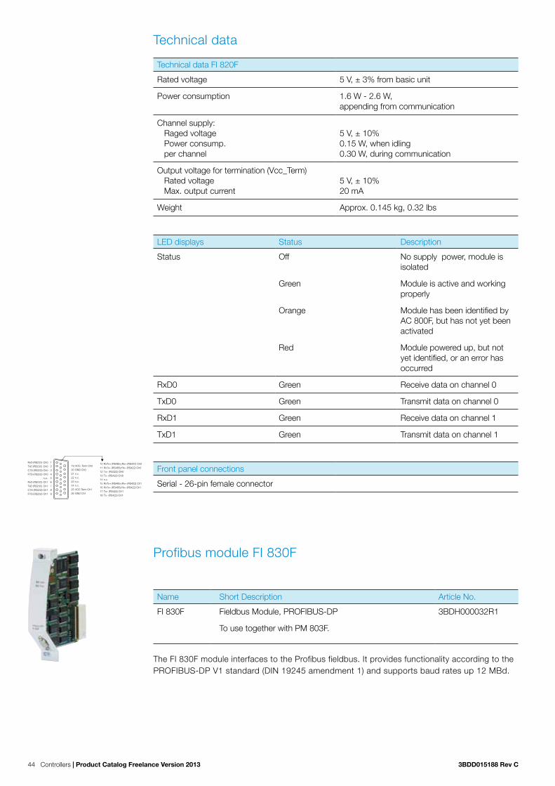
44 Controllers | Product Catalog Freelance Version 2013 3BDD015188 Rev C
Technical data
Technical data FI 820F
Rated voltage 5 V, ± 3% from basic unit
Power consumption 1.6 W - 2.6 W, appending from communication
Channel supply: Raged voltage Power consump. per channel
5 V, ± 10%0.15 W, when idling0.30 W, during communication
Output voltage for termination (Vcc_Term) Rated voltage Max. output current
5 V, ± 10%20 mA
Weight Approx. 0.145 kg, 0.32 lbs
LED displays Status Description
Status Off No supply power, module is isolated
Green Module is active and working properly
Orange Module has been identified by AC 800F, but has not yet been activated
Red Module powered up, but not yet identified, or an error has occurred
RxD0 Green Receive data on channel 0
TxD0 Green Transmit data on channel 0
RxD1 Green Receive data on channel 1
TxD1 Green Transmit data on channel 1
Front panel connections
Serial - 26-pin female connector
Profibus module FI 830F
Name Short Description Article No.
FI 830F Fieldbus Module, PROFIBUS-DP 3BDH000032R1
To use together with PM 803F.
The FI 830F module interfaces to the Profibus fieldbus. It provides functionality according to the PROFIBUS-DP V1 standard (DIN 19245 amendment 1) and supports baud rates up 12 MBd.
RxD (RS232) Ch0 1
TxD (RS232) Ch0 2
CTS (RS232) Ch0 3
RTS (RS232) Ch0 4
n.o. 5
RxD (RS232) Ch1 6
TxD (RS232) Ch1 7
CTS (RS232) Ch1 8
RTS (RS232) Ch1 9
19 VCC_Term Ch0
20 GND Ch0
21 n.c.
22 n.c.
23 n.c.
24 n.c.
25 VCC Term Ch1
26 GND Ch1
10 RxTx+ (RS485γ Rx+ (RS422) Ch0
11 RxTx– (RS485γ Rx– (RS422) Ch0
12 Tx+ (RS422) CH0
13 Tx– (RS422) CH0
14 n.c.
15 RxTx+ (RS485γ Rx+ (RS422) Ch1
16 RxTx– (RS485γ Rx– (RS422) Ch1
17 Tx+ (RS422) CH1
18 Tx– (RS422) CH1

3BDD015188 Rev C Product Catalog Freelance Version 2013 | Controllers 45
The module is the master on the Profibus line and allows connecting up to 126 Profibus slaves. Configuration and parameterization is carried out completely with Freelance — no additional external configuration tools are required.
Line redundancy can be achieved using an external device (RLM 01) which drives two Profibus lines in parallel. In conjunction with a second AC 800F the module can also operate in a redun-dant-master mode without limiting any other feature.
Features: − PROFIBUS-DP Module (DIN 19245) − Transmission rate up 12 MBd − Supports up to 126 slaves − Physical interface: RS485 − Electrical isolation − Shared memory (256 KB) onboard, to minimize the use of basic unit memory − Module can be removed or inserted during operation − Redundant operation, with redundant AC 800F − G3 compliant Z variant available
Technical data
Technical data FI 830F
Power consumption In the active state, depends on the communi cation cycle time: 2.8 W
Max. output current 20 mA for bus termination / repeater supply
Output voltage 5 V, ± 5%
Overvoltage protection +7.5 V / -5 V either transmission line to GND
Weight Approx. 0.150 kg, 0.33 lbs
LED displays Status Description
Status Off No supply power, module is isolated
Green Module is active and working properly
Orange Module has been identified by AC 800F, but has not yet been activated
Red Module powered up, but not yet identified, or an error has occurred
Busy Off Module is in passive state on the Profibus
Green Module has token and, thus, is acting as the master
Front panel connections
Profibus 9-pin female connector (DIN 41652)
Shield 1 n.c. 2 RxD+/TxD+ 3 RTS 4 GND 5
6 VP (5 V/20 mA)7 n.c.8 RxD-/TxD-9 n.c.

46 Controllers | Product Catalog Freelance Version 2013 3BDD015188 Rev C
FF / HSE module FI 840F
Name Short Description Article No.
FI 840F Fieldbus Module, FF HSE 3BDH000033R1
To use together with PM 803F. UL certified. Freelance V7.1SP2a or higher is mandatory.
The FI 840F is a high speed ethernet fieldbus module designed for fast data exchange in pro-duction engineering with decentralized peripherals.
The FF / HSE module FI 840F is a Fieldbus Foundation-(FF)-Master. Using the Freelance it is possible to configure diverse Fieldbus Foundation devices.
The FF / HSE module FI 840F is designed to connect the AC 800F to a FF / HSE network. It can be mounted on slots F1...F4. It is used if high transmission rates are required or shall be made available for future use. FF / HSE wiring is always a point-to-point connection. Therefore a networks with more than two nodes always requires network switches or hubs.
Features: − ARM-CPU with integrated Ethernet controller, 32-bit data bus, 32-bit address bus − Flash EPROM for module CPU and protocol software − Software / firmware update without EPROM exchange − Separate memory for module CPU − Shared memory for data exchange between main processor and module CPU. Data protection
by parity check − Automatic detection if 10BaseT or 100BaseTX is connected − Electrical isolation for TP interface − ESD protector on RJ45 socket − Serial interface / Manchester encoder for generating a serial bit stream − EEPROM for configuration data and diagnostic data memory independent from battery buffering − Isolator for electrical isolation of the bus signals − RJ45 connector with two link LEDs − G3 compliant Z variant available
Technical data
Technical data FI 840F
Rated voltage 5 V ± 3 % 3.3 V ± 3 % and 2.5 V ± 5 %
Power consumption In the active state, 1.4 W - 2.1 W depending on communications load
Module memory 8 MBytes synchronous dynamic RAM
Shared memory 1 MByte synchronous static RAM used for data exchange between CPU board and module
Firmware memory 2 MByte Flash EPROM, 32-bit word length, capable of programming in the system and direct programming from AC 800F CPU board
EEPROM Serial 16 kbit EEPROM, write cycles ≥ 107 buffering time ≥ 10 years
Weight Approx. 0.150 kg, 0.33 lbs

3BDD015188 Rev C Product Catalog Freelance Version 2013 | Controllers 47
Static characteristics
Power consumption Max. 2.1 W
Medium 100BaseTx cable, category 5
Max. segment length 100 m
Max. number of nodes per segment 2
Dynamic characteristics
Transmission rate 10 Mbit/s or 100 Mbit/s
LED displays Status Description
State Off No voltage applied, module is separated
Green Power on, module is identified and ready for operation accord-ing to the configuration
Orange Power on,
Module has been identified by AC 800F,
Intermediate state during start-up
Configuration mode of the boot loader
Flashing orange Power on, module has been identified by AC 800F. Module is not connected to corrected bus physics
Red Power on
Module not yet identified (on a short-term basis during startup)
An error has occurred during module test
Front panel connections
RJ-45 female connector (shielded)There are two integrated LEDs indicating the current communication status. The LEDs are not labeled but can be identified by their color. The upper yellow LED indicates the transmission rate, the lower green LED indicates the communication state.
LED FF / HSE Speed Off Module has detected 10 Mbit/s data connection.
Static yellow Module has detected 100 Mbit/s data connection
LED FF / HSE Link Off No active link, neither 10Mbit nor 100 Mbit. No communi-cation possible.
Static green Active link. Communication possible. No data transfer.
Flashing green Active link. Communication possible.
1 TD+2 TD–3 RD+456 RD–78
1 2 3 4 5 6 7 8

48 Controllers | Product Catalog Freelance Version 2013 3BDD015188 Rev C
3.3.13 Coated and G3 compliant hardwareG3 compliant components are protected with a special coating against corrosive gases. The following Freelance ISA71.04 G3 compliant components can be ordered under the same conditions as any ordinary Freelance component. G3 compliance for AC 800F requires exclu-sively use of –Z components. AM 810F-Z serves for closing unused slots and the behind system plug.
G3 compliant components are identified by “Z“ added to the module name, for example AC 800F-Z-4 MB.
Base unitsName Short Description Article No.
PM 803F-Z Base Unit 16 MB, battery-buffered RAM 3BDH000530Z1
Coated and G3 compliant version. Without operating system. The operating system has to be loaded during software installation. With special Contact Ledge RW 855F. Freelance V7.1SP2a or higher is mandatory.
Power suppliesName Short Description Article No.
SA 811F-Z Power Supply 115 / 230 VAC 3BDH000013Z1
Coated and G3 compliant version. To use together with PM 803F-Z. Software V7.1SP2a or higher is mandatory.
SD 812F-Z Power Supply 24 VDC 3BDH000014Z1
Coated and G3 compliant version. To use together with PM 803F-Z. Software V7.1SP2a or higher is mandatory.
Ethernet interface modulesName Short Description Article No.
EI 813F-Z Ethernet Module 10BaseT (Twisted pair) 3BDH000022Z1
Coated and G3 compliant version. To use together with PM 803F-Z. Battery not included. Software V7.1SP2a or higher is mandatory.

3BDD015188 Rev C Product Catalog Freelance Version 2013 | Controllers 49
Fieldbus interface modulesName Short Description Article No.
FI 810F-Z Fieldbus Module, CAN (triple channel) for Rack I/O 3BDH000030Z1
Coated and G3 compliant version. To use together with PM 803F-Z.
FI 820F-Z Fieldbus Module, Serial (dual channel) 3BDH000031Z1
Coated and G3 compliant version. To use together with PM 803F-Z.
FI 830F-Z Fieldbus Module, PROFIBUS-DP 3BDH000032Z1
Coated and G3 compliant version. To use together with PM 803F-Z.
FI 840F-Z Fieldbus Module, FF HSE 3BDH000033Z1
Coated and G3 compliant version. To use together with PM 803F-Z. Software V7.1SP2a or higher is mandatory.
Auxiliary modules
Name Short Description Article No.
AM 810F-Z Cover Module 3BDH000622Z1
G3 compliant station assembly requires AM 810F-Z for closing unused slots and the behind system plug.
AM 811F-Z Battery Module 3BDH000050Z1
Coated and G3 compliant version. To use together with PM 803F-Z. Without battery SB 808. Software V7.1SP2a or higher is mandatory.

50 Controllers | Product Catalog Freelance Version 2013 3BDD015188 Rev C
3.3.14 Accessories
3.0.14.1 Battery modules and holderName Short Description Article No.
SY 809F Battery Holder 3BDH000042R1
Without battery SB 808F.
SB 808F Battery for RAM buffering, 2 pcs. 3BDM000199R1
AC 800F battery moduleName Short Description Article No.
AM 811F Battery Module 3BDH000050R1
To use together with PM 803F Battery not included SB 808. Freelance V7.1SP2a or higher is mandatory.
The battery module can be used in non-redundant controllers with only one Ethernet module to increases the buffering time.
Features: − Provides battery backup − Enables redundant battery energy backup on the AC 800F − G3 compliant Z variant available
Technical data
Technical data AM 811F
Rated voltage 3.3 V / 5 V ±3%, from CPU board
Power consumption Approx. 0.28 W
Battery 3.6 V lithium battery, 950 mAh (included in delivery)
Low battery signaling ≤ 3.2 V
RAM and real-time-clock buffering time New battery inserted After “Low“ warning
PM 803F: ≥ 10 days ≥ 5 hours
Weight Approx. 0.150 kg, 0.33 lbs without buffer battery Approx. 0.170 kg, 0.375 lbs with buffer battery

3BDD015188 Rev C Product Catalog Freelance Version 2013 | Controllers 51
LED displays Status Description
Status Off No supply voltage, module is isolated
Green Power supply on, module identified and ready to operate as configured
Orange Power supply on, module identified and either:
Normal transitory state after module startup
Configuration mode of Boot Loader
Red Module power supply on and either:
Module not yet identified (normal for short time during module startup)
Error occurred during module test
Battery (PM 803F) Off AC 800F is active, AM 811F not active => buffering from power supply module
AC 800F is off (no watchdog of the batteries voltage): => buffering from Battery.
Orange During battery recovery or start-up phase
Red Warning: battery low, no battery inserted, insufficient electrical contact etc.
Green Battery inserted and data protection provided..

52 Controllers | Product Catalog Freelance Version 2013 3BDD015188 Rev C
3.0.14.2 Front panelName Short Description Article No.
AM 895F Front Panel, 4 pcs 3BDH000044R1
Covering unused slots of AC 800F.
3.0.14.3 Auxiliary power supplyName Short Description Article No.
TK 807F Supply Cable 115 / 230 VAC, ferrules, 2 m 3BDM000210R1
For SA 811F.
TK 808F Supply Cable 115 / 230 VAC, Euro plug, 2 m 3BDM000211R1
For SA 811F.
TK 809F Supply Cable 115 / 230 VAC, US plug, 2 m 3BDM000212R1
For SA 811F.
TK 802F Supply Cable 24 VDC, ferrules, 2 m 3BDM000213R1
For SD 812F.
DPW 02 Power Supply, 24 VDC - 24 VDC, 5 A 8018277M
74 x 30 x 120 (W, H, D)
DPW 03 Power Supply, 115 / 230 VAC - 24 VDC, 5 A 8018544M
65 x 125 x 103 (W, H, D)
DSU 45 Mains Cable for 230 VAC, Euro plug, 1.5 m 0339140M
DSU 45 Mains Cable for 230 VAC, Euro plug, 5 m 0339141M

3BDD015188 Rev C Product Catalog Freelance Version 2013 | Controllers 53
3.0.14.4 CablesName Short Description Article No.
TK 831F CAN Cable (3 channel), integral connectors, 0.5 m 3BDM000100R1
3 x 2 x 0.25 mm², Identical with DFA 031. Connection FI 810F to Terminal Block TB 870F.
TK 811F CAN Cable, open end, ferrules, 3 m 3BDM000103R1
3 x 2 x 0.25 mm², Identical with DFA 011. Connection FI 8x0F to Terminal Block TB 870F.
TK 817F CAN Cable, open end, ferrules, 100 m 3BDM000356R1
3 x 2 x 0.5 mm², Identical with DFA 007.
TK 821F Serial Cable (2 channel), integral connectors, 0.5 m 3BDM000150R1
Identical with DFA 021. Connection FI 820F to Terminal Block TB 870F.
TK 891F Diagnostics Cable, 5 m 3BDM000201R1
Identical with DSU 141.
TK 890F Diagnostics Cable, 10 m 3BDM000202R1
Identical with DSU 141.
3.0.14.5 MiscellaneousName Short Description Article No.
TB 870F Terminal Block, for serial interface 3BDM000160R1
RW 856F Mounting Accessory, for enforced wall mounting 3BDM000190R1
Clips and clams
RY 885F Grounding Strap, 2 pcs. 3BDM000169R1
TV 821F Clip for shielding, 6 mm, 5 pcs. 3BDM000171R1
TV 822F Clip for shielding, 16 mm, 5 pcs. 3BDM000172R1
TV 823F Clip for shielding, 16..25 mm, 5 pcs. 3BDM000173R1
TV 824F Clip for shielding, 23..35 mm, 5 pcs. 3BDM000174R1
TV 825F Clip for shielding, 25..40 mm, 5 pcs. 3BDM000175R1
TV 831F Clamp-type terminal, 3..10 mm, 5 pcs. 3BDM000180R1
TV 832F Clamp-type Terminal, 16…20 mm, 5 pcs. 3BDM000181R1

54 Controllers | Product Catalog Freelance Version 2013 3BDD015188 Rev C
3.3 The controller AC 700FThe AC 700F controller comes in a really small footprint and high signal density of S700 I/O. The S700 I/O modules are directly plugged to the CPU module or can be used as remote I/O via Profibus. A maximum of eight modules can be connected to one controller. 3rd party I/O‘s can be connected via a MODBUS ASCII / RTU serial bus or via Profibus. AC 700F now also offers expanded flexibility via a pluggable SD card for controller backup and firmware update.
AC 700F is based on hardware that is successfully used as PLC in practice for years in factory automation. The AC 700F controller, as a member of Freelance, has numerous advantages over a PLC based solution: The compact process control system simplifies engineering, com-missioning, and maintenance of the automation system. Visualization is directly incorporated into the engineering, making configuration particularly straightforward. Small or distributed plant components can be implemented cost effectively by using AC 700F. The competitive advantage is clear: the same engineering, operation and maintenance method for all plant components hand in hand with the well-known ease of use of Freelance.
3.3.15 Hardware and certificatesAC 700F comes with a modular design. The base elements are different types of terminal units, for the CPU module, for the FBP interface module, and for S700 I/O modules. Both, screw type and spring type terminal units are available. The modules can be easily plugged to the terminal units and then the terminal units can be plugged one to the other. The entire controller is then mounted on a DIN rail.
Certificates
The AC 700F controller has the following certificates:
− CE, GL, UL, ISO 9001.
Technical data
The CPU and the local S700 I/O modules communicate very fast. I/O scan times of 2 ms are possible. Short circuit and line break detection is realized for each channel.
The AC 700F controller is designed according to the EN 61131-2 / IEC 61131-2 standards. Data that differ from the IEC 61131 standards are caused due to the high requirements of Maritime Services.

3BDD015188 Rev C Product Catalog Freelance Version 2013 | Controllers 55
Environmental conditions
The temperature range of AC 700F and S700 I/O extends from 0 °C to 60 °C / 32-140 °F.
Module temperature Operating:
Storage:Transport:
Temperature range: 0 °C (32 °F) ..+60 °C (140 °F) With FieldbusPlug: 0 °C (32 °F) ..+55 °C (131 °F) Highly recommended mounting: horizontally Vertical mounting: Vertical mounting is possible, how-ever, derating considerations should be made to avoid problems with poor air circulation and the potential for excessive temperatures. Temperature range: 0 °C (32 °F) ..+40 °C / 104 °F 50% output load derating -25 °C (-13 °F)...+75 °C (167 °F) -25 °C (-13 °F)...+75 °C (167 °F)
Battery temperature Operating: Storage: Transport:
0 °C (32 °F)...+60 °C (140 °F) -20 °C (-4 °F)...+60 °C (140 °F) -20 °C (-4 °F)...+60 °C (140 °F)
Humidity Maximum 95%, without condensation
Air pressure Operating: Storage:
> 800 hPa / < 2000 m > 660 hPa / < 3500 m
Mechanical stress
Mounting Horizontal
Degree of protection IP 20
Housing According to UL 94
Vibration resistance according to EN 61131-2 All three axes 2 Hz...15 Hz, continuous 3.5 mm (0.1379 inch) 15 Hz...150 Hz, continuous 1 g (0.04 oz) (4 g (0.14 oz) in preparation)
Shock test All three axes 15 g (0.53 oz), 11 ms, half-sinusoidal
Mounting of the modules DIN-rail according to DIN EN 50022, 35 mm (1.38 inch), depth 7.5 mm (0.2955 inch) or 15 mm (0.591 inch), mounting with screws of type M4, fastening torque 1.2 Nm
Electromagnetic compatibility
2004/108/EC Complies with the European directive
EN 61000-6-2 Electromagnetic compatibility (EMC) – Generic standards, Immunity for industrial environments
EN 61000-6-4 Electromagnetic compatibility (EMC) – Generic standards, Emission standard for industrial environments
2006/95/EC Low Voltage Directive

56 Controllers | Product Catalog Freelance Version 2013 3BDD015188 Rev C
Electric data
Voltages according to EN 61131-2
Process- and Supply-voltage 24 VDC (-15 %, +20 % without ripple)
Absolute limits 19.2 V...30 V incl. Ripple (see below)
Ripple < 5 %
Protection against reverse polarity 10 s
Permissible interruptions of power supply as per EN 61131-2
DC supply Interruption < 10 ms, time between 2 interruptions > 1 s, PS2
Creepage distances and clearances
The creepage distances and clearances meet the overvoltage category II, pollution degree 2.
Power supply units
Power supply units meeting the PELV specification should be used for powering the modules.
Insulation test voltages, routine test, as per EN 61131-2
230 V circuits against other circuitry 2500 V Surge 1.2 / 50 µs
120 V circuits against other circuitry 1500 V Surge 1.2 / 50 µs
120-240 V circuits against other circuitry 2500 V Surge 1.2 / 50 µs
24 V circuits (supply, 24 V inputs / outputs), if they are electrically isolated against other circuitry.
500 V Surge 1.2 / 50 µs
COM interfaces, electrically isolated 500 V Surge 1.2 / 50 µs
Ethernet 500 V Surge 1.2 / 50 µs
24 V circuits (supply, 24 inputs / outputs), if they are electrically isolated against other circuitry
350 V AC 2 s
COM interfaces, electrically isolated 350 V AC 2 s
Ethernet 350 V AC 2 s

3BDD015188 Rev C Product Catalog Freelance Version 2013 | Controllers 57
3.3.16 Central processing unit PM 783F
Name Short Description Article No.
PM 783F Central Processing Unit (2 MB) 3BDH000364R0001
Needs external 24 VDC power supply. Without terminal base. The operating system has to be loaded by Freelance. For AC 700F, Freelance of Version 9.1 or later is manda-tory.
The Central Processing Unit (CPU) module is equipped with a high-performance processor for fast loop cycle times. It comes with on-board 100 Mbit/s Ethernet network connection used for communication between controllers, operator stations, and engineering tool. Two serial line interfaces complement the connectivity. One interface can be used for Modbus communication, while the other is used for diagnostics. For demanding applications, eight cyclic and priority driven tasks with adjustable cycle time can be configured, as well as a cyclic PLC type task, which runs as fast as possible. This multi-tasking scenario enables engineers to design appli-cations that reflect all demands of process control, while at the same time balancing the CPU load. This keeps the resources needed in a project at the minimum.
The small front panel display shows status and diagnostic information directly at the module.
Technical data
Technical data PM 783F
CPU Freescale PowerPCTM
RAM Program memory (battery backed up) 2 MB SRAM Internal memory 8 MB SDRAM, 4 MB FLASH ROM
Processing time for 1000 instructions 0.71 ms for binary instructions 0.84 ms for word instructions 1.36 ms for floating point instructions
Max. number of I/O modules 8
Power supply CP-C 24 / 5.0, power supply, 5 A / 24 VDC output CP-C 24 / 10.0, power supply, 10 A / 24 VDC output
Max. power dissipation within the module 10 W
Current consumption from 24 VDC 80 mA (max)
Inrush current at 24 VDC 1 A²s
Data backup source Lithium battery
Data buffering time at 25 °C / 77 °F Approximately 1.5 years
Battery low indication Warning indication issued about 2 weeks before the battery charge becomes critical
Real-time clock, with battery backup Yes
Multitasking program executionCyclic (equidistant)Cyclic (as fast as possible)Event driven
8 tasks1 PLC type taskUpon any of these events: “Run, Stop, Warm start, Cold start, Error“
Serial interface “SER“ (COM1) (see Figure 4 of the Terminal Base TB 711F)

58 Controllers | Product Catalog Freelance Version 2013 3BDD015188 Rev C
Technical data PM 783F
Physical link:
Connection:Usage:
Configurable for RS-232 or RS-485 (from 1200 bps to 38400 bps)Pluggable terminal block, spring connectionModbus - ASCII (Master / Slave) - RTU (Master / Slave)- IEC 60870-5-101 telecontrol protocol
Serial interface “DIAG“ (COM2) (see Figure 4 of the Terminal Base TB 711F)
Physical link:Connection:Usage:
RS-232SUB-D female connectorFor diagnostics
Onboard network interfaceUsage:
1 x Ethernet (RJ45) 100 Mbit/s Modbus TCP Telecontrol (IEC 60870-5-104)
LEDs, LCD display, 8 function keys For RUN / STOP switch-over, status displays and diagnostics
Weight (CPU without the Terminal Base) 150 g / 5.29 oz.
Dimensions (CPU without the Terminal Base) Width 67.5 mm, 2.66 inches Height 76 mm, 2.99 inches Depth 54 mm, 2.13 inches
3.3.17 PROFIBUS module CM 772F
Name Short Description Article No.
CM 772F PROFIBUS DP Master Modul 3BDH000368R0001
DP-V0/V1, 12 MBit/sD-Sub, 9-poleRequires one slot on CPU terminal base TB
The Profibus module CM 772F makes communication over the PROFIBUS DP field bus possible. The module is mounted on the left side of the CPU on the same terminal Base. The communi-cation between the CPU and the coupler takes place through the coupler bus (coupler interface), which is integrated in the Terminal Base. The data interchange is realized by a dual-port RAM.
Technical data
Functionality CM 772F
Protocol PROFIBUS DP Master V0/V1
Fieldbus connector D-SUB, 9-pole, female
Internal power supply Through the coupler interface of the Terminal Base
LEDs Five for status display

3BDD015188 Rev C Product Catalog Freelance Version 2013 | Controllers 59
Technical data CM 772F
Fieldbus PROFIBUS DP
Transmission rate 9.6 kBit/s to 12 MBit/s
Protocol PROFIBUS DP Master V0/V1
Field bus connector D-SUB, 9-pole, female
Processor EC1
Clock frequency 48 MHz
Usable CPU PM 783F
Coupler interface Dual-port memory, 8 kByte
Current consumption from 24 V DC power sup-ply at the Terminal Base of the CPU
typ. 60 mA
Internal RAM memory (EC1) 256 kByte
External RAM memory -
External Flash memory 512 kByte (firmware)
Status display PWR, RDY, RUN, STA, ERR
Weight Approx. 150 g (5.29 oz)

60 Controllers | Product Catalog Freelance Version 2013 3BDD015188 Rev C
3.3.18 CPU terminal base TB 711F
Name Short Description Article No.
TB 711F CPU Terminal Base 3BDH000365R0001
24 VDC, 1x Coupler slots, Ethernet RJ45.
Technical data
Technical data TB 711F
Connection of the 24 VDC process voltage With a 5-pole removable terminal block
Slots 1 CPU, 1 Communication module (not used currently)
Interfaces Field I/O: 1 for I/O-Bus Serial ports: 2 (“SER“ (COM1), “DIAG“ (COM2)) Networking: 1 Ethernet (RJ45)Profibus Master port
Weight 175 g / 6.17 oz.
Dimensions (with CPU inserted) Width 95.5 mm, 3.75 inches Height 135 mm, 5.31 inches Depth 75 mm, 2.95 inches
1 I/O-Bus connection2 Plug for the CPU module3 Holes for wall mounting4 Ethernet interface5 Serial Interface DIAG (COM2)6 Serial interface SER (COM1)7 Power supply terminal 24 VDC8 Feldbus connector (for future use)9 Connector for Profibus Master (protected using the dummy coupler module when not in use)
DC
-IN
10W
ET
HE
RN
ET
FBP
SE
RD
IAG
1
2
3
4
5
7
6
8
9
L+
L-
M
M
FE
1
2
3
4
5
67
8
9
Figure 4: Terminal assignment for supply voltage (24 VDC) and the serial interface SER (COM1)

3BDD015188 Rev C Product Catalog Freelance Version 2013 | Controllers 61
3.0.18.1 Dimensional drawings
Figure 5: Front view terminal base
Figure 6: Side view terminal base
28
21 (0.83)54 (2.13)
75 (2.95)
59 (
2.32
)
70.5
(2.
78)
135
(5.3
1)
76 (
2.99
)
View on the left side View on the right side
77 (3.03)
84.5 (3.33)
DIN rail 15 mmDIN rail 7.5 mm
135 mm(5.31) inches
Dimensions:
(1.10)

62 Controllers | Product Catalog Freelance Version 2013 3BDD015188 Rev C
3.3.19 Accessories for CPU module
Name Short Description Article No.
TK 701F Diagnostic Serial Cable, Sub-D / Sub-D, 5 m / 16.4 ft. 3BDH000366R0001
SUB-D,9-pole, female,RS-232,PC side,COM interface
16
59SUB-D,9-pole, male,RS-232, AC 700FCPU side,COM2 interface
23
234
56
56
SGNDDSR
SGND
Shield
4DTR
PC, COM..,9-pole,maleSUB-D
RTS RxDCTS
9RI
DCD Data Carrier DetectDSR Data Set ReadyDTR Data Terminal ReadySGND Signal GroundRI Ring Indicator
1DCD
Cable,9-pole,female,SUB-D
Cable,9-pole,male,SUB-D
AC 700F CPU,COM2, 9-pole,female,SUB-D
FE Functional EarthTxD Transmit DataRxD Receive DataRTS Request To SendCTS Clear To Send
RxDTxD
FEHousing1
9 CTS
Programming cable TK 701F
59
16
TxD
RTS
FEHousingFE
TK 701FPC
TK 701FAC 700F
78
78
Name Short Description Article No.
TA521 Battery for RAM buffering 1SAP180300R0001
Name Short Description Article No.
TA 724F Dummy Coupler Module 3BDH000367R0001
Empty module, to protect an unused coupler slot from dust and touch when AC 700F is used without a Profibus Master module CM 772F. Is mounted on the CPU Terminal Base TB 711F.
Name Short Description Article No.
TA526 Accessories for back-plate mounting, 10 pcs. 1SAP180800R0001
With wall mounting of Terminal Bases and Terminal Units.
3Front view
1
Rear view 2Rear view
Holes for wall mounting

3BDD015188 Rev C Product Catalog Freelance Version 2013 | Power supplies 63
4.3 Power supply modules
Power supplies Name Short Description Article No.
CP-C 24 / 5.0
Power Supply, 5 A / 24 VDC Output 3BDH001040R0001
110-240 VAC / 100-350 VDC Input. For extended protection against accidental contact, mounting in a cabinet is recommended.
CP-C 24 / 10.0
Power Supply, 10 A / 24 VDC Output 3BDH001041R0001
110-240 VAC / 100-350 VDC Input. For extended protection against accidental contact, mounting in a cabinet is recommended.
Technical data
Technical data CP-C 24 / 5.0 / 10.0
Power dissipation CP-C 24 / 5.0: typically < 15 W CP-C 24 / 10.0: typically < 29 W
Efficiency Typically 89 %
MTBF 500.000 h
Dimensions W x H x D CP-C 24 / 5.0: 56.5 x 130 x 137 mm / 2.22 x 5.12 x 5.39 inch CP-C 24 / 10.0: 90 x 130 x 137 mm / 3.54 x 5.12 x 5.39 inch
Weight CP-C 24 / 5.0: approx. 0.96 kg / 2.11 lb CP-C 24 / 10.0: approx. 1.34 kg / 2.95 lb
Mounting DIN-rail (DIN EN 50022) snap mechanism
Mounting position Horizontal
Minimum distance between devices Horizontal 10 mm (0.39 inch) Vertical 80 mm (3.15 inches)
Degree of Protection IP 20 Protection class ( EN 61140)
Environmental data
Ambient temperature range Operation Full load Storage
-25 °C (-13 °F)...+70 °C (158 °F) 0 °C (32 °F)...+60 °C (140 °F) (without derating) -40 °C (-40 °F)...+85 °C (185 °F)
Damp heat (IEC/EN 60068-2-3)Pollution category (EN 50178)Climatic category (IEC/EN 60721)
93 % at +40 °C (104 °F), no condensation24 VDC3K3
Isolation data
CP-C 24/5.0
CP-C 24/10.0
Chapter 4 Power supplies for AC 900F, AC 700F and S700 I/O
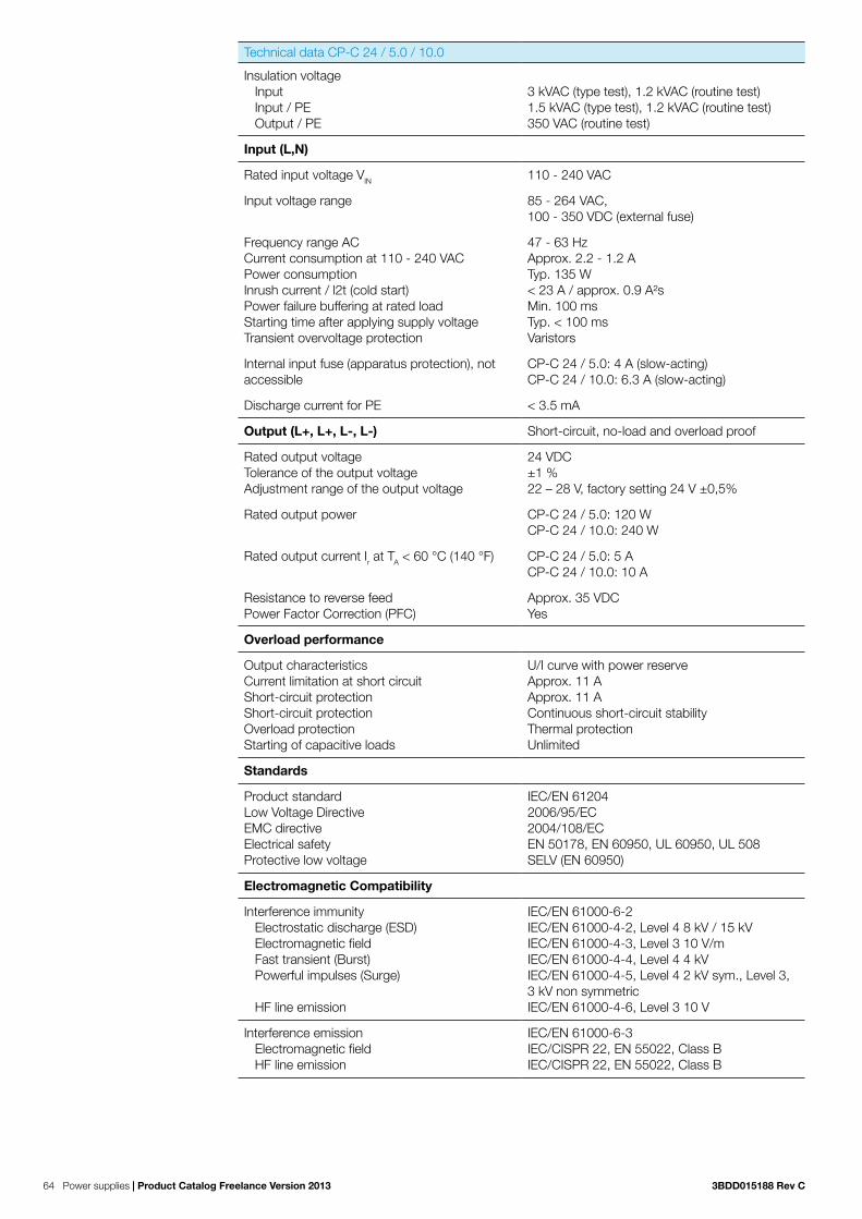
64 Power supplies | Product Catalog Freelance Version 2013 3BDD015188 Rev C
Technical data CP-C 24 / 5.0 / 10.0
Insulation voltage Input Input / PE Output / PE
3 kVAC (type test), 1.2 kVAC (routine test) 1.5 kVAC (type test), 1.2 kVAC (routine test) 350 VAC (routine test)
Input (L,N)
Rated input voltage VIN 110 - 240 VAC
Input voltage range 85 - 264 VAC, 100 - 350 VDC (external fuse)
Frequency range ACCurrent consumption at 110 - 240 VACPower consumptionInrush current / l2t (cold start)Power failure buffering at rated loadStarting time after applying supply voltageTransient overvoltage protection
47 - 63 HzApprox. 2.2 - 1.2 ATyp. 135 W< 23 A / approx. 0.9 A²sMin. 100 msTyp. < 100 msVaristors
Internal input fuse (apparatus protection), not accessible
CP-C 24 / 5.0: 4 A (slow-acting) CP-C 24 / 10.0: 6.3 A (slow-acting)
Discharge current for PE < 3.5 mA
Output (L+, L+, L-, L-) Short-circuit, no-load and overload proof
Rated output voltageTolerance of the output voltageAdjustment range of the output voltage
24 VDC±1 %22 – 28 V, factory setting 24 V ±0,5%
Rated output power CP-C 24 / 5.0: 120 W CP-C 24 / 10.0: 240 W
Rated output current Ir at TA < 60 °C (140 °F) CP-C 24 / 5.0: 5 A CP-C 24 / 10.0: 10 A
Resistance to reverse feedPower Factor Correction (PFC)
Approx. 35 VDCYes
Overload performance
Output characteristicsCurrent limitation at short circuitShort-circuit protectionShort-circuit protectionOverload protectionStarting of capacitive loads
U/I curve with power reserveApprox. 11 AApprox. 11 AContinuous short-circuit stabilityThermal protectionUnlimited
Standards
Product standardLow Voltage DirectiveEMC directiveElectrical safetyProtective low voltage
IEC/EN 612042006/95/EC2004/108/ECEN 50178, EN 60950, UL 60950, UL 508SELV (EN 60950)
Electromagnetic Compatibility
Interference immunity Electrostatic discharge (ESD) Electromagnetic field Fast transient (Burst) Powerful impulses (Surge) HF line emission
IEC/EN 61000-6-2 IEC/EN 61000-4-2, Level 4 8 kV / 15 kV IEC/EN 61000-4-3, Level 3 10 V/m IEC/EN 61000-4-4, Level 4 4 kV IEC/EN 61000-4-5, Level 4 2 kV sym., Level 3, 3 kV non symmetric IEC/EN 61000-4-6, Level 3 10 V
Interference emission Electromagnetic field HF line emission
IEC/EN 61000-6-3 IEC/CISPR 22, EN 55022, Class B IEC/CISPR 22, EN 55022, Class B

3BDD015188 Rev C Product Catalog Freelance Version 2013 | Power supplies 65
4.3 Accessories
Accessories for power suppliesName Short Description Article No.
CP-C MM Messaging Module for CP-C, relay outputs 3BDH001043R0001
The message module CP-C MM indicates the correct function of the power supply unit via LEDs and energized output relays. The module will be plugged at the front side of the power supply.
Name Short Description Article No.
CP-A RU Redundancy Unit 3BDH001044R0001
If a fault occurs in the first power supply circuit, the total current requirement of all consumers can be completely covered by a second power supply unit,and the output circuits are decoupled by means of the redundancy unit CP-A RU.
Name Short Description Article No.
CP-C MM Messaging Module for CP-C, relay outputs 3BDH001043R0001
The message module CP-C MM indicates the correct function of the power supply unit via LEDs and energized output relays. The module will be plugged at the front side of the power supply.

66 Power supplies | Product Catalog Freelance Version 2013 3BDD015188 Rev C

3BDD015188 Rev C Product Catalog Freelance Version 2013 | I/Os 67
The following chapter will give you a brief overview about the Remote I/O systems S700, S800 and S900. For more detailed information please see the data sheets.
The picture above shows a possible Profibus topology.
The controllers are assembled in the control room. Remote I/O systems S700, S800 and S900 can be assembled in the control room or directly in the field. Furthermore S900 can be placed locally in the field in hazardous area, depending on the customer’s wishes. Field devices are connected to the remote I/O systems. With AC 700F and AC 900F a subset of S700 I/O can be plugged as direct I/O to the right side of the controller.
Remote I/O systems can also be mounted locally in the field, near field devices. This type of installation reduces the costs for cabling from the field device to the system.
On-site assembly of the remote I/O systems is easy, as only a single cable is required for Profibus communication and just one suitable field housing is needed for mounting. This field housing usually has the IP66 degree of protection. Other devices such as fiber optic couplers, pneumatic valves, termi-nals, terminal blocs or additional electronical devices can also be mounted in such a field housing. This reduces both design, engineering and cabling costs.
Chapter 5 Remote I/Os
In order for devices to be installed in hazardous areas, extra regulations and functional rules need to be considered in addition to the usual engineering rules.
All devices which are used in hazardous area have to be certi-fied. The devices shall have a certificate for either Zone 1 or Zone 2.
The S900 remote I/O system (S and B series) is suitable for installation in hazardous areas.
Series Assembly Field devices / signals
Hazardous area approval
S series in Zone 1 in Zones 2, 1, and 0 (intrinsically safe signals)
ATEX Zone 1
B series in Zone 2 in Zones 2, 1, and 0 (intrinsically safe signals)
ATEX Zone 2
N series in safe areas in safe areas no
S900Remote I/O
S800Remote I/O
S800 CB220N
Control Room Area
Field Area
Ex Area
S900
S700Remote I/O
AC 800FController
AC 900FController
AC 700FController
S900Field Housing
S700

68 I/Os | Product Catalog Freelance Version 2013 3BDD015188 Rev C
5.3 S700 I/OS700 I/O modules can be used as direct I/O together with the AC 700F and AC 900F controller as well as remote I/O at any Profibus DP segment. A typical setup as remote I/O is shown in Figure 7.
Fieldbus Plug
DC 705F
Figure 7: S700 Remote I/O

3BDD015188 Rev C Product Catalog Freelance Version 2013 | I/Os 69
5.3.1 S700 I/O modulesThe following table lists the entire set of S700 I/O modules. All modules can be used as remote I/O at Profibus DP. The indicated subset can be used as direct I/O together with the AC 700F and AC 900F controller.
Module Name
Type (Channel Groups)
Input Range Output Range
AC
700
F D
irect
I/O
S70
0 R
emot
e I/O
DC 732F 16 DI, 16 DI/DO configu-rable
24V DC, 1-wire, standard binary signals, all signals share common ground
24 V DC, 0.5 A
AI 723F 16 AI , 12-Bit+Sign
0...10 V, -10...+10 V, 0/4...20 mA, Pt100/1000, Ni1000, DI
-
AX 722F 8 AI + 8 AO (2x4), 12 Bit+Sign
0...10 V, -10...+10 V, 0/4...20 mA, Pt100/1000, Ni1000, DI
0...10 V, -10...+10 V, 0/4...20 mA, Pt100/1000, Ni1000, DI, Ch 0-3: -10...+10 V, 0/4...20 mA; Ch 4-7: -10...+10 V
AO 723F 16 AO (2x8), 12 Bit+Sign
- Ch 0-3: & 8-11: -10...+10 V, 0/4...20 mA, Ch 4-7 & 12-15: -10...+10 V
DX 722F 8 DI, 8 DO Relay 24 V DC 24 V DC, 110 V/ 230 V AC
DX 731F 8 DI, 4 DO Relay 110 V/ 230 V AC 24 V DC, 110 V/ 230 V AC
AI 731F 8 AI , 15 Bit+Sign
-50 mV…+50 mV, -500 mV…+500 mV, -1 V…+1 V, 0…10 V, -10 V…+10 V, 0 V…+5 V, -5 V…+5 V, 0...20 mA, 4...20 mA, -20…+20 mA, Pt100/1000, Ni1000, Cu50 (1.426), Cu50 (1.428), 0...50 kOhm, Thermocouple J K T N S Type, DI
-
DI 724F 32 DI 24 V DC, 1-wire, standard binary signals, all signals share common ground
-
AX 721F 4 AI + 4 AO, 12 Bit+Sign
0...10 V, -10...+10 V, 0/4...20 mA, Pt100/1000, Ni1000, DI
0...10 V, -10...+10 V, 0/4...20 mA
DA 701F 16 DI, 8 DC, 4 AI, 2 AO
24 V DC (for DI), 0...10 V, -10...+10 V, 0/4...20 mA, Pt100/1000, Ni1000, DI
24 V DC, 0.5 A (for DO), -10...+10 V, 0/4...20 mA
DC 705F FBP Interface + 8 DI, 8 DC
24 V DC, 1-wire, this is the commu-nication module for Profibus
24V DC, 0.5 A
AC 722F 8 AC, 12 Bit+Sign
24 V DC, 2-wire...10 V, -10...+10 V, 0/4...20 mA, Pt100/1000, Ni1000, DI
24 V DC, 2-wireCh 0-3: -10...+10 V, 0/4...20 mA, Ch 4-7: -10...+10 V
DC 722F 16 DC, 24 V DC
24 V DC (2/3-wire DI possible) 24 V DC, 0.5 A
DC 723F 24 DC, 24 V DC
24 V DC (2/3-wire DI possible) 24 V DC, 0.5 A
CD 722F 2 counter in-puts, 2PWM, 2DI, 8DC
RS-422, 5-V-TTL, 24-V-totem-pole, 1-Vpp, SSI interface
PWM, 24V DC, 0.5 A, frequency (pulse) module

70 I/Os | Product Catalog Freelance Version 2013 3BDD015188 Rev C
Environmental Conditions
Please refer to chapter „Hardware and certificates“ auf Seite 16.
5.3.2 Fieldbus interface module DC 705FName Short Description Article No.
DC 705F Fieldbus interface module 3BDH000388R0001
Interface for Fieldbus Plug FBP 8 DI: 24 VDC8 DI/DO: 24 VDC/0.5 A1-wire, 24 VDC 100 WTU 705F /TU 706F (terminal unit not included)
The FBP Interface Module DC 705F is used as a decentralized I/O module for Profibus. The bus connection is performed by a neutral FieldBusPlug interface, to which the FieldBusPlug PDP22 is plugged in. In addition FBP Interface Module DC 705F provideds 16 I/O channels with the following features:
− 8 digital inputs 24 V DC in one groups (1.0...1.7) − 8 digital inputs/outputs in one group (2.0...2.7), of which each can be used as an input,
− as a transistor output with short-circuit and overload protection with 0.5 A rated current or
− as a re-readable output (combined input/output) and can be addressed accordingly.The technical data correspond to the input and output values. The inputs and outputs are electrically isolated from the other electronic circuitry of the module. There is no potential separation between the channels.
This I/O module cannot be used directly with the CPU module PM 783F or PM 902F and should be used with S700 remote I/O.
Environmental Conditions
Please refer to chapter „Hardware and certificates“ auf Seite 16.
Technical data
Functionality DC 705F
Interface Neutral FieldBusPlug interface
Supply of the module’s electronic circuitry From the FieldBusPlug
Supply of the electronic circuitry of the I/O expansion modules attached
Through the expansion bus interface (I/O-Bus)
Address switches For setting the field bus address (0 to 99)
Digital Inputs 8 (24 V DC)
Digital Inputs/Outputs 8 (24 V DC)
LED displays For system displays, signal status, errors and power supply
External supply voltage Via the terminals ZP and UP (process voltage 24 V DC)

3BDD015188 Rev C Product Catalog Freelance Version 2013 | I/Os 71
Technical Data DC 705F
Rated supply voltage of the module 24 V DC (through the FieldBusPlug)
Current consumption of the module 15 mA (through the FieldBusPlug)
Process voltage UP
rated value 24 V DC (for inputs and outputs)
max. current loadability for the supply terminals
10 A
Protection against reversed voltage yes
Rated protection fuse at UP 10 A fast
Electrical isolation FBP system bus interface from the rest of the module
Inrush current from UP (at power-up) 0.008 A²s
Current consumption from UP at normal operation / with outputs
0.005 A + max. 0.5 A per output
Connections Terminals 1.8 - 2.8 for +24 V (UP) and 1.9 - 2.9 for 0 V (ZP)
Max. power dissipation within themodule
6 W (outputs unloaded)
Number of digital inputs 8
Number of configurable digitalinputs/outputs
8
Reference potential for all digitalinputs and outputs
Minus pole of the supply voltage, signal name ZP
Address setting with 2 rotary switches on the front panel
Operating and error displays 23 LEDs altogether
Weight (without Terminal Unit) ca. 125 g
Mounting position horizontal or vertical with derating (output load reduced to 50 % at 40°C per group)
Cooling The natural convection cooling must not be hindered by cable ducts or other parts in the switch-gear cabinet.
Technical Data of the digital inputs
Number of channels per module 8
Distribution of the channels into groups 1 group of 8 channels
Terminals of the channels I0 to I7 1.0 to 1.7
Terminals of the channels C8 to C16 2.0 to 2.7
Reference potential for all inputs terminals 1.9...4.9 (Minus pole of the process supply voltage, signal name ZP)
Electrical isolation from the FBP system bus
Indication of the input signals one yellow LED per channel, the LED is ON when the input signal is high (signal 1)
Input type acc. to EN 61131-2 Type 1
Input delay (0->1 or 1-> 0) typ. 8 ms, configurable from 0.1 to 32 ms
Input signal voltage 24 V DC

72 I/Os | Product Catalog Freelance Version 2013 3BDD015188 Rev C
Technical Data of the digital inputs
Signal 0 -3 V...+5 V
undefined signal > +5 V...< +15 V
Signal 1 +15 V...+30 V
Ripple with signal 0 within -3 V...+5 V
Ripple with signal 1 within +15 V...+30 V
Input current per channel
input voltage +24 V typ. 5 mA
input voltage +5 V > 1 mA
input voltage +15 V > 2 mA
input voltage +30 V < 8 mA
Max. cable length
shielded 1000 m
unshielded 600 m
Technical Data of of the configurable digital inputs/outputs
Number of channels per module 8 inputs/outputs (with transistors)
Distributen of the channels into groups 1 group of 8 channels
if the channels are used as inputs
channels I8...I15 terminals 2.0...2.7
if the channels are used as outputs
channels Q8...Q15 terminals 2.0...2.7
Indication of the input/output signals one yellow LED per channel, the LED is ON when the input/output signal is high (signal 1)
Electrical isolation from the FBP system bus
Technical Data of the digital inputs/outputs if used as outputs
Number of channels per module max. 8 transistor outputs
Reference potential for all outputs terminals 1.9...2.9 (minus pole of the process supply voltage, signal name ZP)
Common power supply voltage for all outputs: terminals 1.8...2.8 (plus pole of the process supply voltage, signal name UP)
Output voltage for signal 1 UP (-0.8 V)
Output current
rated value, per channel 500 mA at UP = 24 V
maximum value (all channels together) 10 A
Leakage current with signal 0 < 0.5 mA
Rated protection fuse 10 A fast
De-magnitization when inductive loadsare switched off
with varistors integrated in the module
Switching frequency

3BDD015188 Rev C Product Catalog Freelance Version 2013 | I/Os 73
Technical Data of the digital inputs/outputs if used as outputs
with inductive loads max. 0.5 Hz
with lamp loads max. 11 Hz with max. 5 W
Short-circuit proof / overload proof yes
Overload message (I > 0.7 A) yes, after ca. 100 ms
Output current limitation yes, automatic reactivation after short-circuit/overload
Resistance to feedback against 24V signals yes
Max. cable length
shielded 1000 m
unshielded 600 m
Technical Data of the digital inputs/outputs if used as inputs
Number of channels per module max. 8 digital inputs
Reference potential for all inputs terminals 1.9...2.9 (minus pole of the process supply voltage, signal name ZP)
Input current, per channel see ”Digital inputs”
Input type acc. to EN 61131-2 Type 1
Input delay (0->1 or 1->0) typ. 8 ms, configurable from 0.1 to 32 ms
Input signal voltage 24 V DC
Signal 0 -3 V...+5 V *
undefined signal > +5 V...< +15 V
Signal 1 +15 V...+30 V
Ripple with signal 0 within -3 V...+5 V *
Ripple with signal 1 within +15 V...+30 V
Max. cable length
shielded 1000 m
unshielded 600 m
* Due to the direct connection to the output, the demagnetizing varistor is also effective at the input (see figure) above. This is why the difference between UPx and the input signal may not exceed the clamp voltage of the varistor. The varistor limits the voltage to approx. 36 V. Following this, the input voltage must range from - 12 V to + 30 V when UPx = 24 V and from - 6 V to + 30 V when UPx = 30 V.

74 I/Os | Product Catalog Freelance Version 2013 3BDD015188 Rev C
5.3.3 Digital I/O Modules
5.1.3.1 Frequency input module CD 722F
Name Short Description Article No.
CD 722F Frequency input module 3BDH000393R0001
2 Counter Inputs: 5/24 VDC, 1 Vpp sinus, fmax 300 kHz2 DO: 24 VDC/0,1 A, pulse width PWM2 DI: 24 VDC8 DI/DO: 24 VDC/0,5 A1/2-wire, 24 VDC 100 WTU 715F /TU 716F (terminal unit not included)
The frequency input module CD 722F is installed as a remote expansion module at the FBP interface module DC 705F. It has the following features:
− 2 independent counting functions with up to 12 configurable modes (including incremental position encoder and frequency input up to 300 kHz)
− 2 independent PWM (pulse-width modulator) or pulse outputs with push- pull driver. − Dedicated inputs/outputs for specific counting functions (e.g. touch, set, reset) − All unused inputs/outputs can be used with the specifications of standard inputs/outputs range
This I/O module cannot be used directly with the CPU module PM 783F or PM 902F and should be used with S700 remote I/O.
The technical data correspond to the input and output values. The inputs and outputs are electrically isolated from the other electronic circuitry of the module. There is no potential separation between the channels.
Technical data
The technical data correspond to the input and output values. The inputs and outputs are electrically isolated from the other electronic circuitry of the module. There is no potential separation between the channels.

3BDD015188 Rev C Product Catalog Freelance Version 2013 | I/Os 75
Functionality CD 722F
Digital inputs/outputs 24 V DC, dedicated inputs/outputs can be used for specific counting functions:
Catch/touch operation, counter value stored in separate variable on external event (rising or falling edge)
Set input to preset counter register with predefined value
Set input to reset counter register
End value output; the output is set when pre-defined value is reached
Reference point initialization (RPI) input for incre-mental encoder initialization
All unused inputs/outputs can be used with the specification of standard input/output range.
High-speed counter/encoder integrated, 2 counters (hardware interface with +24 V DC, +5 V DC, differential and 1 Vpp sinus input) with up to 12 configurable operation modes:
32 bits one counter mode
16 bits two counter mode
Incremental position encoder
Absolute SSI encoder
Time frequency meter
Frequency input up to 300 kHz
PWM/pulse outputs 2 pulse-width-modulators or pulse outputs
Output specification
Push-pull output: 24 V DC, 100 mA max.
Current limitation (thermal and over current)
PWM specification
Frequency from 1 Hz to 100 kHz
Value from 0 to 100 %
Pulse specification
Frequency from 1 Hz to 15 kHz
Pulse emission from 1 to 65535 pulses
Number of pulses emitted indicator (0 to 100 %)
Frequency specification
Frequency output = 100 kHz when duty cycle set to 50 %
Power supply for encoders Two 5 V power supplies, max. 100mA
LEDs For system displays, indicating signal statuses, errors and power supply
Internal power supply Via I/O Bus
External power supply Via the terminals UP(process voltage 24 V DC) and ZP (0 V DC)

76 I/Os | Product Catalog Freelance Version 2013 3BDD015188 Rev C
Technical Data
Process voltage
Connection Terminals 1.8,2.8,3.8 and 4.8 for UP (+24 V DC) and 1.9, 2.9, 3.9 and 4.9 for ZP (0V)
Protection against reversed voltage Yes
Rated protection fuse on UP 10 A fast
Rated value 24 V DC
max. ripple 5 %
Current consumption
From UP 0.07 A + max. 0.008 A per input + max. 0.5 A per output + 0.01 A for A, B and Z inputs
Via I/O Bus Approx. 5 mA
Inrush current from UP (at power up) 0.04 A²s
Electrical isolation Yes, per module
Max. power dissipation within the module 6 W (outputs not loaded)
Dimensions (without the Terminal Unit) 67.5 x 76 x 54 mm / 2.66 x 2.99 x 2.13 incheswidth x height x depth
Weight 125 g/ 4.41 oz.
Mounting position Horizontal or vertical with limitations (output load per group 50 % at 40°C (104°F))
Cooling The natural convection cooling must not be hindered by cable ducts or other parts in the mounting cabinet.
Technical data for the digital inputs/outputs if used as standard inputs
Number of channels per module 2 + 8 configurable digital inputs/outputs
Reference potential for all inputs Terminals 1.9…4.9 (Minus pole of the supply voltage, signal name ZP)
Electrical isolation From the rest of the module
Indication of the input signals 1 yellow LED per channel, the LED is ON when the input signal is high (signal1)
Input type acc. to EN 61131-2 Type 1
Input delay (0->1 or 1->0) typically 8 ms, configurable from 0.1…32 ms
Input signal voltage 24 V DC
signal 0 -3 V...+5 V
undefined signal > +5 V...< +15 V
signal 1 +15 V...+30 V
Ripple with signal 0 within -3 V...+5 V*
Ripple with signal 1 within +15 V...+30 V
Input current per channel
input voltage +24 V typically 5 mA
input voltage +5 V > 1 mA
input voltage +15 V > 5 mA

3BDD015188 Rev C Product Catalog Freelance Version 2013 | I/Os 77
Technical data for the digital inputs/outputs if used as standard inputs
input voltage +30 V < 8 mA
Max. cable length
shielded 1000 m (3280.83 ft)
unshielded 600 m (1968.50 ft)
* Due to the direct connection to the output, the demagnetizing varistor is also effective at the input. This is why the difference between UPx and the input signal may not exceed the clamp voltage of the varistor. The varistor limits the voltage to approx. 36 V. Following this, the input voltage must range from -12 V to +30 V when UPx = 24 V and from -6 V to +30 V when UPx = 30 V.
Technical data for the digital inputs/outputs if used as standard outputs
Number of channels per module 8 configurable digital inputs/outputs
Reference potential for all inputs Terminals 1.9…4.9 (Minus pole of the supply voltage, signal name ZP)
Common power supply voltage For all outputs: terminals 1.8…4.8 (plus pole of the process supply voltage, signal name UP)
Output voltage for signal 1 UP (-0.8 V)
Input delay (0->1 or 1->0) typically 10 µs
Output current
Rated value, per channel 500 mA at UP = 24 V
Maximum value (all channels together, PWM included)
8 A
Leakage current with signal 0 < 0.5 mA
Rated protection fuse on UP 10 A fast
Demagnetization when inductive loads are switched off
With varistors integrated in the module
Switching frequency
With inductive loads Max. 0.5 Hz
With lamp loads Max. 11 Hz with max. 5 W
Short circuit proof/overload proof yes
Overload message (I > 0.7 A) Yes, after approx. 100 ms
Output current limitation Yes, automatic reactivation after short-circuit/overload
Resistance to feedback against 24 V signals Yes
Max. cable length
shielded 1000 m (3280.83 ft)
unshielded 600 m (1968.50 ft)

78 I/Os | Product Catalog Freelance Version 2013 3BDD015188 Rev C
Technical data for the high-speed inputs (A0, B0, Z0; A1, B1, Z1)
Number of channels per module
6
Reference potential for all inputs
Terminals 1.9, 2.9, 3.9 and 4.9 (Minus pole of the process voltage, signal name ZP)
Input Type 24 V DC 5 V DC / Differential / Sinus 1 Vpp
Input current per channel
Input voltage +24 V Typically 14 mA
Input voltage +5 V > 4.8 mA
Input voltage +15 V > 12 mA
Input voltage +30 V < 15 mA
Input type according to EN 61131-2
Type 1
Input frequency (max.) 300 kHz 300 kHz
Input signal voltage 24 V DC 5 V DC
Signal 0 -3 V…+ 5 V -3 V…+ 0.5 V
Undefined signal > +5 V…< +15 V --
Signal 1 + 15 V…+30 V + 0.5 V…+30 V
Ripple with signal 0 Within -3 V…+5 V Within -3 V…+0.5 V
Ripple with signal 1 Within +15 V…+30 V Within +0.5 V…+30 V
Max. cable length
shielded 1000 m (3280.83 ft)
unshielded 600 m (1968.50 ft)
Technical data of the fast outputs
Number of channels per module 2
Reference potential for all inputs Terminals 1.9…4.9 (Minus pole of the process voltage, signal name ZP)
Common power supply voltage For all outputs: terminals 1.8…4.8 (plus pole of the process supply voltage, signal name UP)
Indication of the output signals Brightness of the LED depends on the number of pulses emitted (0% to 100%) – pulse output mode only
Output voltage for signal 1
Output voltage for signal 0
Output delay (0->1 or 1->0) Typically 1 µs
Output current
Rated value, per channel 100 mA at UP = 24 V
Maximum value (all channels together, configu-rable outputs included)
8 A
Leakage current with signal 0 < 0.5 mA
Rated protection fuse on UP 10 A fast

3BDD015188 Rev C Product Catalog Freelance Version 2013 | I/Os 79
Technical data of the fast outputs
De-magnetization when inductive loads are switched off
With varistors integrated in the module
Switching frequency PWM: upto 100 kHz (min. step for PWM value: 2 µs)Pulse: upto 15 k Hz
Short circuit proof/overload proof yes
Overload message (I > 0.7A) Yes, after approx. 100 ms
Output current limitation Yes, automatic reactivation after short-circuit/overload
Resistance to feedback against 24 V signals Yes, with positive polarity only
Max. cable length
shielded 1000 m (3280.83 ft)
unshielded 600 m (1968.50 ft)
Technical data of the 5-V-sensor supply
Number of supplies 2, independent configuration
Voltage supply (outputs unloaded) 5 V DC +/- 5%
Resistance to feedback against reverse polarity No
Output current 100 mA max. (independently)200 mA max. (parallel use)
Output diagnosis Yes, with diagnosis LED and error message
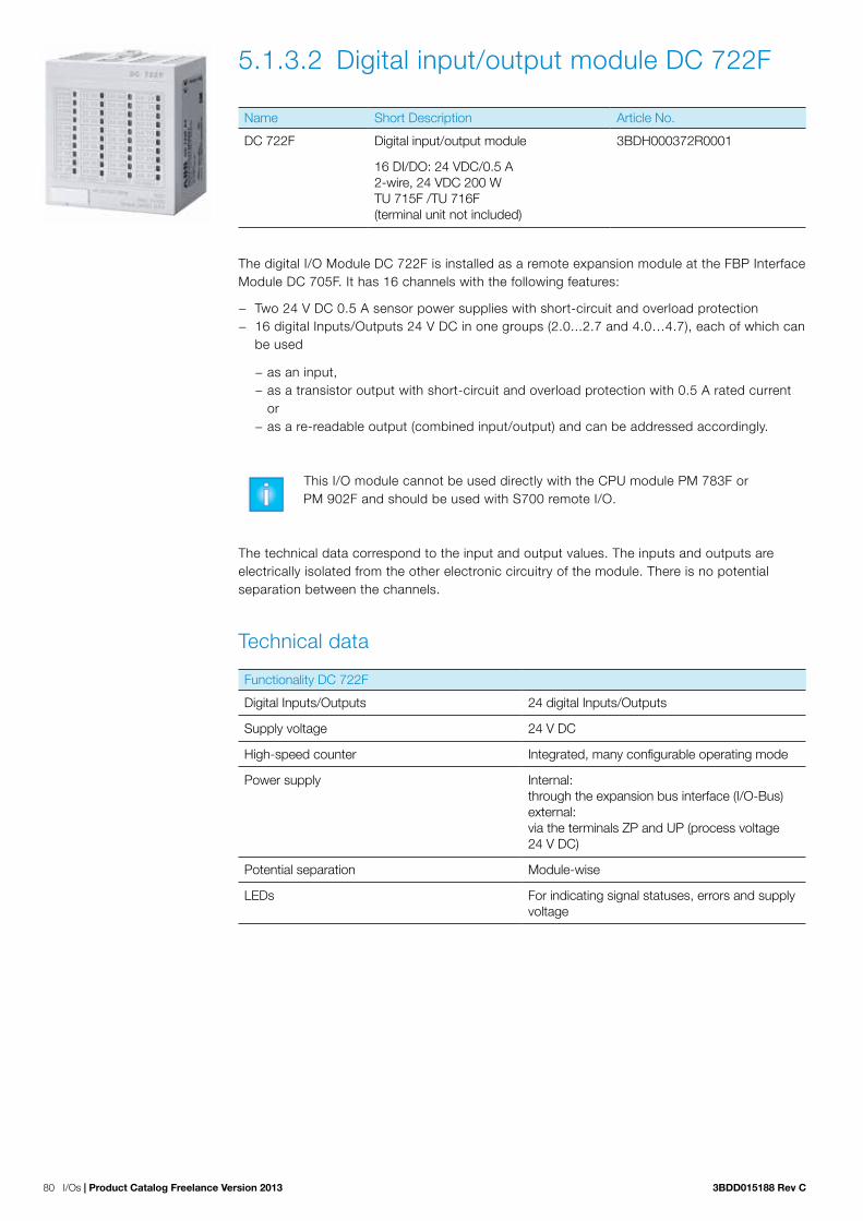
80 I/Os | Product Catalog Freelance Version 2013 3BDD015188 Rev C
5.1.3.2 Digital input/output module DC 722F
Name Short Description Article No.
DC 722F Digital input/output module 3BDH000372R0001
16 DI/DO: 24 VDC/0.5 A2-wire, 24 VDC 200 WTU 715F /TU 716F (terminal unit not included)
The digital I/O Module DC 722F is installed as a remote expansion module at the FBP Interface Module DC 705F. It has 16 channels with the following features:
− Two 24 V DC 0.5 A sensor power supplies with short-circuit and overload protection − 16 digital Inputs/Outputs 24 V DC in one groups (2.0...2.7 and 4.0…4.7), each of which can
be used
− as an input, − as a transistor output with short-circuit and overload protection with 0.5 A rated current or
− as a re-readable output (combined input/output) and can be addressed accordingly.
This I/O module cannot be used directly with the CPU module PM 783F or PM 902F and should be used with S700 remote I/O.
The technical data correspond to the input and output values. The inputs and outputs are electrically isolated from the other electronic circuitry of the module. There is no potential separation between the channels.
Technical data
Functionality DC 722F
Digital Inputs/Outputs 24 digital Inputs/Outputs
Supply voltage 24 V DC
High-speed counter Integrated, many configurable operating mode
Power supply Internal: through the expansion bus interface (I/O-Bus) external: via the terminals ZP and UP (process voltage 24 V DC)
Potential separation Module-wise
LEDs For indicating signal statuses, errors and supply voltage

3BDD015188 Rev C Product Catalog Freelance Version 2013 | I/Os 81
Technical data DC 722F
Process supply voltage UP
Connections Terminals 1.8 – 4.8 for +24 V (UP) and 1.9 – 4.9 for 0 V (ZP)
Rated value 24 V DC
max. ripple 5 %
Protection against reversed voltage Yes
Rated protection fuse on UP 10 A fast
Electrical isolation Yes, per module
Current consumption
From 24 V DC power supply at the terminals UP/L+ and ZP/M of the CPU/Bus Module
Approx. 1 mA
Current consumption via UP in case of normal operation
50 mA + max. 8 mA per input + max. 0.5 A per output
Inrush current from UP (at power-up) 0.008 A²s
Max. power dissipation within the module 6 W (outputs not loaded)
Sensor power supply
Connections Terminals 1.0…1.3 = +24 V, 1.4…1.7 = 0V Terminals 3.0…3.3 = +24 V, 3.4…3.7 = 0V
Voltage 24 V DC with short-circuit and overload protec-tion
Loadability Terminals 1.0…1.3, in total max. 0.5 A Terminals 3.0…3.3, in total max. 0.5 A
Dimensions 67.5 x 76 x 54 mm / 2.66 x 2.99 x 2.13 inch width x height x depth
Weight (without terminal unit) Approx. 125 g / 4.41 oz.
Mounting position Horizontal or vertical with limitations (Output load per group is 50 % at 40°C (104°F))
Cooling The natural convection cooling must not be hindered by cable ducts or other parts in the mounting cabinet.
Technical data digital inputs/outputs
Number of channels per module 16
Distribution of the channels into groups 1 group of 16 channels
If the channels are used as inputs
Connections to the channels C0 to C7 Terminals 2.0 to 2.7
Connections to the channels C8 to C15 Terminals 4.0 to 4.7
If the channels are used as outputs
Connections to the channels C0 to C7 Terminals 2.0 to 2.7
Connections to the channels C8 to C15 Terminals 4.0 to 4.7
Indication of the input/output signals One yellow LED per channel, the LED is ON when the input/output signal is high (signal 1)
Electrical isolation From the rest of the module

82 I/Os | Product Catalog Freelance Version 2013 3BDD015188 Rev C
Technical data digital inputs/outputs if used as inputs
Each of the configurable I/O channels is defined as input or output by the user program. This is done through scanning or allocation of the corresponding channel.
Number of channels per module 16 inputs digital
Reference potential for all inputs Terminals 1.9…4.9 ( minus pole of the process supply voltage, signal name ZP)
Electrical isolation From the rest of the module
Indication of the input signals One yellow LED per channel, the LED is ON when the input/output signal is high (signal 1)
Input type according to EN 61131-2 Type 1
Input delay (0->1 or 1->0) Typically 8 ms, configurable from 0.1 to 32 ms
Input signal voltage 24 V DC
Signal 0 -3 V...+5 VP*
Undefined signal > +5 V...< +15 V
Signal 1 +15 V...+30 V
Ripple with signal 0 Within -3 V...+5 V *
Ripple with signal 1 Within +15 V...+30 V
Input current per channel
Input voltage +24 V typically 5 mA
Input voltage +5 V > 1 mA
Input voltage +15 V > 5 mA
Input voltage +30 V < 8 mA
Max. cable length
Shielded 1000 m (3280.83 ft)
Unshielded 600 m (1968.50 ft)
* Due to the direct connection to the output, the demagnetizing varistor is also effective at the input. This is why the difference between UPx and the input signal may not exceed the clamp voltage of the varistor. The varistor limits the voltage to approx. 36 V. Following this, the input voltage must range from -12 V to +30 V when UPx = 24 V and from -6 V to +30 V when UPx = 30 V.

3BDD015188 Rev C Product Catalog Freelance Version 2013 | I/Os 83
Technical data digital inputs/outputs if used as outputs
Number of channels per module Max. 16 digital outputs
Reference potential for all outputs Terminals 1.9...4.9 (minus pole of the process supply voltage, signal name ZP)
Common power supply voltage For all outputs: terminals 1.8...4.8 (plus pole of the process supply voltage, signal name UP)
Output voltage for signal 1 UP (-0.8 V)
Output current
rated value, per channel 500 mA at UP = 24 V
maximum value (all channels) 8 A
Leakage current with signal 0 < 0.5 mA
Rated protection fuse on UP 10 A fast
Demagnetization when inductive loads are switched off
Via varistors integrated in the module
Switching frequency
With inductive loads Max. 0.5 Hz
With lamp loads Max. 11 Hz with max. 5 W
Short-circuit proofed /overload proofed Yes
Overload message (I > 0,7 A) Yes, after approx. 100 ms
Output current limitation Yes, automatic reactivation after short-circuit /overload
Resistance to feedback against 24 V signals Yes
Max. cable length
Shielded 1000 m (3280.83 ft)
Unshielded 600 m (1968.50 ft)
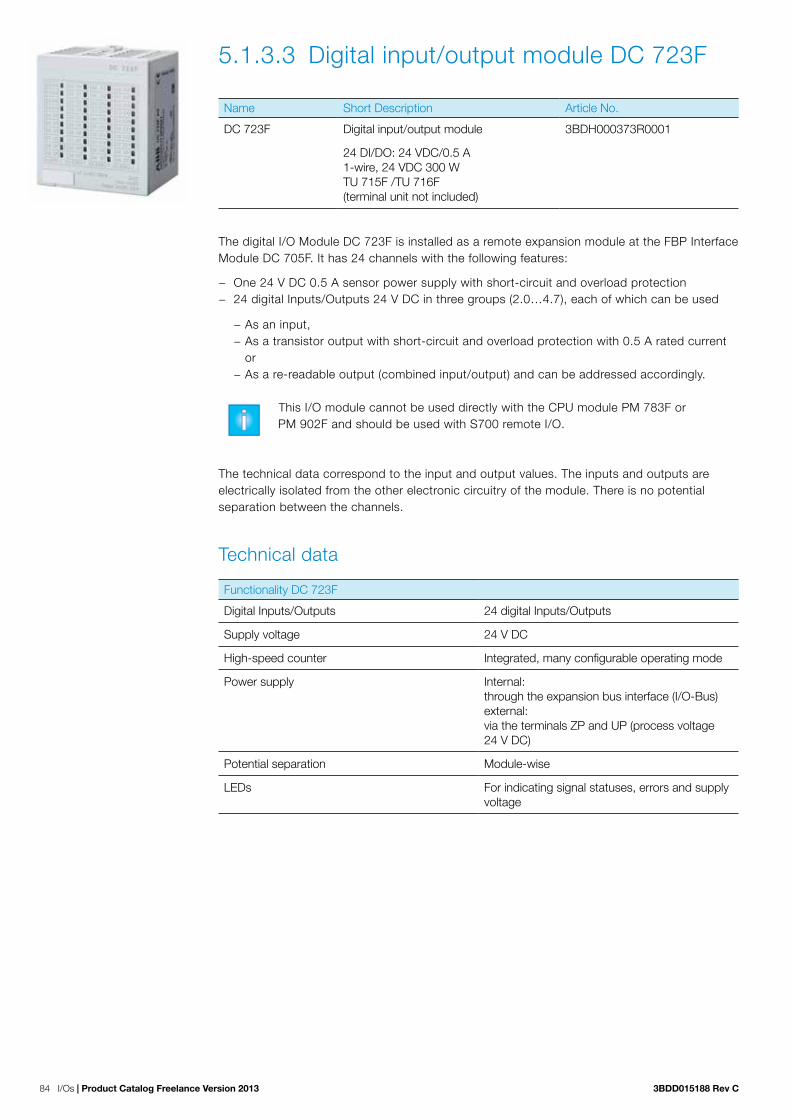
84 I/Os | Product Catalog Freelance Version 2013 3BDD015188 Rev C
5.1.3.3 Digital input/output module DC 723F
Name Short Description Article No.
DC 723F Digital input/output module 3BDH000373R0001
24 DI/DO: 24 VDC/0.5 A1-wire, 24 VDC 300 WTU 715F /TU 716F (terminal unit not included)
The digital I/O Module DC 723F is installed as a remote expansion module at the FBP Interface Module DC 705F. It has 24 channels with the following features:
− One 24 V DC 0.5 A sensor power supply with short-circuit and overload protection − 24 digital Inputs/Outputs 24 V DC in three groups (2.0…4.7), each of which can be used
− As an input, − As a transistor output with short-circuit and overload protection with 0.5 A rated current or
− As a re-readable output (combined input/output) and can be addressed accordingly.
This I/O module cannot be used directly with the CPU module PM 783F or PM 902F and should be used with S700 remote I/O.
The technical data correspond to the input and output values. The inputs and outputs are electrically isolated from the other electronic circuitry of the module. There is no potential separation between the channels.
Technical data
Functionality DC 723F
Digital Inputs/Outputs 24 digital Inputs/Outputs
Supply voltage 24 V DC
High-speed counter Integrated, many configurable operating mode
Power supply Internal: through the expansion bus interface (I/O-Bus)external: via the terminals ZP and UP (process voltage 24 V DC)
Potential separation Module-wise
LEDs For indicating signal statuses, errors and supply voltage

3BDD015188 Rev C Product Catalog Freelance Version 2013 | I/Os 85
Technical data DC 723F
Process supply voltage UP
Connections Terminals 1.8 – 4.8 for +24 V (UP) and 1.9 – 4.9 for 0 V (ZP)
Rated value 24 V DC
Max. ripple 5 %
Protection against reversed voltage Yes
Rated protection fuse on UP 10 A fast
Electrical isolation Yes, per module
Current consumption
From 24 V DC power supply at the terminals UP/L+ and ZP/M of the CPU/Bus Module
Approx. 1 mA
Current consumption via UP in case of normal operation
50 mA + max. 8 mA per input + max. 0.5 A per output
Inrush current from UP (at power-up) 0.008 A²s
Max. power dissipation within the module 6 W (outputs not loaded)
Sensor power supply
Connections Terminals 1.0…1.3 = +24 V, 1.4…1.7 = 0V
Voltage 24 V DC with short-circuit and overload protec-tion
Loadability Terminals 1.0…1.3, in total max. 0.5 A
Dimensions 67.5 x 76 x 54 mm / 2.66 x 2.99 x 2.13 inch width x height x depth
Weight (without terminal unit) Approx. 125 g / 4.41 oz.
Mounting position Horizontal or vertical with limitations (Output load per group is 50 % at 40°C (104°F))
Cooling The natural convection cooling must not be hindered by cable ducts or other parts in the mounting cabinet.
Technical data digital inputs/outputs
Number of channels per module 24
Distribution of the channels into groups if the channels are used as inputs
1 group of 24 channels
Connections to the channels C0 to C7 Terminals 2.0 to 2.7
Connections to the channels C8 to C15 Terminals 3.0 to 3.7
Connections to the channels C16 to C23 Terminals 4.0 to 4.7
If the channels are used as outputs
Connections to the channels C0 to C7 Terminals 2.0 to 2.7
Connections to the channels C8 to C15 Terminals 3.0 to 3.7
Connections to the channels C16 to C23 Terminals 4.0 to 4.7
Indication of the input/output signals One yellow LED per channel, the LED is ON when the input/output signal is high (signal 1)
Electrical isolation From the rest of the module

86 I/Os | Product Catalog Freelance Version 2013 3BDD015188 Rev C
Technical data digital inputs/outputs if used as inputs
Each of the configurable I/O channels is defined as input or output by the user program. This is done through scanning or allocation of the corresponding channel.
Number of channels per module 24 inputs digital
Reference potential for all inputs Terminals 1.9…4.9 ( minus pole of the process supply voltage, signal name ZP)
Electrical isolation From the rest of the module
Indication of the input signals One yellow LED per channel, the LED is ON when the input/output signal is high (signal 1)
Input type according to EN 61131-2 Type 1
Input delay (0->1 or 1->0) Typically 8 ms, configurable from 0.1 to 32 ms
Input signal voltage 24 V DC
Signal 0 -3 V...+5 VP*
Undefined signal +5 V...+15 V
Signal 1 +15 V...+30 V
Ripple with signal 0 Within -3 V...+5 V*
Ripple with signal 1 Within +15 V...+30 V
Input current per channel
Input voltage +24 V typically 5 mA
Input voltage +5 V > 1 mA
Input voltage +15 V > 5 mA
Input voltage +30 V < 8 mA
Max. cable length
Shielded 1000 m (3280.83 ft)
Unshielded 600 m (1968.50 ft)
* Due to the direct connection to the output, the demagnetizing varistor is also effective at the input. This is why the difference between UPx and the input signal may not exceed the clamp voltage of the varistor. The varistor limits the voltage to approx. 36 V. Following this, the input voltage must range from -12 V to +30 V when UPx = 24 V and from -6 V to +30 V when UPx = 30 V.

3BDD015188 Rev C Product Catalog Freelance Version 2013 | I/Os 87
Technical data digital inputs/outputs if used as outputs
Number of channels per module Max. 24 digital outputs
Reference potential for all outputs Terminals 1.9...4.9 (minus pole of the process supply voltage, signal name ZP)
Common power supply voltage for all outputs: terminals 1.8...4.8 (plus pole of the process supply voltage, signal name UP)
Output voltage for signal 1 UP (-0.8 V)
Output current
Rated value, per channel 500 mA at UP = 24 V
Maximum value (all channels) 8 A
Leakage current with signal 0 < 0.5 mA
Rated protection fuse on UP 10 A fast
Demagnetization when inductive loads are switched off
Via varistors integrated in the module
Switching frequency
With inductive loads Max. 0.5 Hz
With lamp loads Max. 11 Hz with max. 5 W
Short-circuit proofed /overload proofed Yes
Overload message (I > 0,7 A) Yes, after approx. 100 ms
Output current limitation Yes, automatic reactivation after short-circuit /overload
Resistance to feedback against 24 V signals Yes
Max. cable length
Shielded 1000 m (3280.83 ft)
Unshielded 600 m (1968.50 ft)

88 I/Os | Product Catalog Freelance Version 2013 3BDD015188 Rev C
5.1.3.4 Digital input / output module DC 732FName Short Description Article No.
DC 732F Digital Input / Output Module 3BDH000375R0001
16 DI, 16 DI/DO, 24 VDC / 0.5 A, 1-Wire, 24 VDC 200 W. Without terminal unit.
The DC 732F module offers 32 channels. 16 channels are assigned as digital inputs, while the remaining 16 channels can be configured as input or as output.
Technical data
Functionality DC 732F
Digital inputs 16 (24 VDC)
Digital inputs / outputs (configurable) 16 (24 VDC)
LED displays For signal statuses, errors and supply voltage
External power supply Via the terminals ZP and UP (process voltage 24 VDC) of the modules terminal unit TU 715F
Technical data DC 732F
Process supply voltage UP
Connections Terminals 1.8 - 4.8 for +24 V (UP) and 1.9 - 4.9 for 0 V (ZP)
Rated value 24 VDC
Max. ripple 5%
Protection against reversed voltage Yes
Rated protection fuse on UP 10 A fast
Electrical isolation Yes, per module
Current consumption
Internal (via I/O-Bus) ca. 5 mA at 3.3 VDC
Current consumption from UP at normal operation / with outputs
50 mA + max. 8 mA per input + max. 0.5 A per output
Inrush current from UP (at power up) 0.007 A²s
Max. power dissipation within the module 6 W (outputs unloaded)
Width x height x depth (without the Terminal Unit)
67.5 x 76 x 54 mm / 2.66 x 2.99 x 2.13 inch
Weight (without Terminal Unit) Approx. 125 g / 4.41 Oz.
Cooling The natural convection cooling must not be hindered by cable ducts or other parts in the mounting cabinet.

3BDD015188 Rev C Product Catalog Freelance Version 2013 | I/Os 89
Technical data of the digital inputs DC 732F
Number of channels per module 16
Distribution of the channels into groups 1 group of 16 channels
Terminals of the channels I0 to I7 1.0 to 1.7
Terminals of the channels I8 to I15 2.0 to 2.7
Reference potential for all inputs Terminals 1.9...4.9 (minus pole of the process supply voltage, signal name ZP)
Electrical isolation From the rest of the module (I/O-Bus)
Indication of the input signals One yellow LED per channel, the LED is ON when the input signal is high (signal 1)
Input type acc. to EN 61131-2 Type 1
Input delay (0->1 or 1->0) Typ. 8 ms, configurable from 0.1 to 32 ms
Input signal voltage 24 VDC
Signal 0Undefined signalSignal 1
-3 V...+5 V> +5 V...< +15 V+15 V...+30 V
Ripple with signal 0 Within -3 V...+5 V
Ripple with signal 1 Within +15 V...+30 V
Input current per channel
Input voltage +24 VInput voltage +5 VInput voltage +15 VInput voltage +30 V
Typ. 5 mA> 1 mA> 5 mA< 8 mA
Max. cable length
ShieldedUnshielded
1000 m / 3280 ft.600 m / 1968 ft.
Technical data of the configurable digital inputs / outputs DC 732F
Each of the configurable I/O channels can be wired as input or output by the user.
Number of channels per module 16 inputs / outputs (with transistors)
Distribution of the channels into groups 1 group of 16 channels
If the channels are used as inputs
Channels I16...I23Channels I24...I31
Terminals 3.0...3.7Terminals 4.0...4.7
If the channels are used as outputs
Channels O16...O23Channels O24...O31
Terminals 3.0...3.7Terminals 4.0...4.7
Indication of the input / output signals One yellow LED per channel, the LED is ON when the input / output signal is high (signal 1)
Electrical isolation From the rest of the module

90 I/Os | Product Catalog Freelance Version 2013 3BDD015188 Rev C
Technical data of the digital inputs / outputs if used as outputs DC 732F
Number of channels per module Max. 16 transistor outputs
Reference potential for all outputs Terminals 1.9...4.9 (minus pole of the process supply voltage, signal name ZP)
Common power supply voltage For all outputs: terminals 1.8...4.8 (plus pole of the process supply voltage, signal name UP)
Output voltage for signal 1 UP -0.8 V
Output current
Rated value, per channelMaximum value (all channels together)
500 mA at UP = 24 V8 A
Leakage current with signal 0 < 0.5 mA
Rated protection fuse on UP 10 A fast
De-magnitization when inductive loads are switched off
With varistors integrated in the module
Short-circuit proof / overload proof Yes
Overload message (I > 0.7 A) Yes, after ca. 100 ms
Output current limitation Yes, automatic reactivation after short-circuit / overload
Resistance to feedback against 24 V signals Yes
Max. cable length
ShieldedUnshielded
1000 m / 3280 ft.600 m / 1968 ft.
Technical data of the digital inputs / outputs if used as inputs DC 732F
Number of channels per module Max. 16 digital inputs
Reference potential for all inputs Terminals 1.9...4.9 (minus pole of the process supply voltage, signal name ZP)
Input type acc. to EN 61131-2 Type 1
Input delay (0->1 or 1->0) Typ. 8 ms, configurable from 0.1 to 32 ms
Input signal voltage 24 VDC
Signal 0 -3 V...+5 V *
Undefined signal > +5 V...< +15 V
Signal 1 +15 V...+30 V
Ripple with signal 0 within -3 V...+5 V *
Ripple with signal 1 within +15 V...+30 V
Max. cable length
ShieldedUnshielded
1000 m / 3280 ft.600 m / 1968 ft.
* Due to the direct connection to the output, the demagnetizing varistor is also effective at the input. This is why the difference between
UPx and the input signal may not exceed the clamp voltage of the varistor. The varistor limits the voltage to approx. 36 V. Following this,
the input voltage must range from - 12 V to + 30 V when UPx = 24 V and from - 6 V to + 30 V when UPx = 30 V.

3BDD015188 Rev C Product Catalog Freelance Version 2013 | I/Os 91
The configurable channels are defined by the wiring. As you can see from Figure 8, some of the first 16 input channels show the corresponding wiring. For the next 16 configurable channels you see some examples for inputs (channel 16, 23, 24, and 31) and some examples for outputs (channel 19 and 27). Note that the power has to be supplied depending on the planned power consumption as indicated. The I/O bus supplies the power for the modules electronics only.
1.0
1.1
1.2
1.3
1.4
1.5
1.6
1.7
1.8
1.9
3.0
3.1
3.2
3.3
3.4
3.5
3.6
3.7
3.8
3.9
2.0
2.1
2.2
2.3
2.4
2.5
2.6
2.7
2.8
2.9
4.0
4.1
4.2
4.3
4.4
4.5
4.6
4.7
4.8
4.9
DC 732F
UP 24VDC 200W 16DI 16DCInput 24 VDC
Output 24 VDC 0.5A
CH-ERR1 CH-ERR2 CH-ERR3 CH-ERR4
1.0 I0
1.1 I1
1.2 I2
1.3 I3
1.4 I4
1.5 I5
1.6 I6
1.7 I7
1.8 UP
1.9 ZP
2.0 I8
2.1 I9
2.2 I10
2.3 I11
2.4 I12
2.5 I12
2.6 I14
2.7 I15
2.8 UP
2.9 ZP
3.0 C16
3.1 C17
3.2 C18
3.3 C19
3.4 C20
3.5 C21
3.6 C22
3.7 C23
3.8 UP
3.9 ZP
4.0 C24
4.1 C25
4.2 C26
4.3 C27
4.4 C28
4.5 C29
4.6 C30
4.7 C31
4.8 UP
4.9 ZP
I0 1.0
I7 1.7
C24 4.0
Sw
itch
gear
cab
int e
arth
Attention:
I/O-Bus in I/O-Bus out
Power supply
+24 V 0 V
I8 2.0
I15 2.7
C27 4.3
C31 4.7
C16 3.0
C19 3.3
C23 3.7
24 V DC
The process voltage must beincluded in the earthing conceptof the control system(e.g. earthing the minus pole).
Note: The terminals 1.8 to 4.8 (UP)and 1.9 to 4.9 (ZP) are connected toeach other within the I/O Terminal Unit.
Inputs orloads for 24 V DC
Load
Load
Figure 8: Wiring of DC 732F

92 I/Os | Product Catalog Freelance Version 2013 3BDD015188 Rev C
5.1.3.5 Digital input module DI 724F
Name Short Description Article No.
DI 724F Digital input module 3BDH000374R0001
32 DI: 24 VDC1-wire, 24 VDC 1 WTU 715F /TU 716F (terminal unit not included)
The digital I/O module DI 724F can be installed either as direct I/O to an AC 700F or AC 900F CPU or as remote I/O module for any Profibus remote I/O system. It has 32 channels with the following features:
− 32 digital inputs 24V DC in four groups (1.0…4.7)
The technical data correspond to the input values. The inputs are electrically isolated from the other electronic circuitry of the module. There is no potential separation between the channels.
Technical data
Functionality DI 724F
Digital Inputs 32 digital inputs
Supply voltage 24 V DC
High-speed counter Integrated, many configurable operating mode
Power supply Internal:through the expansion bus interface (I/O-Bus)external:via the terminals ZP and UP (process voltage 24 V DC)
Potential separation Module-wise
LEDs For indicating signal statuses, errors and supply voltage
Technical data DI 724F
Process supply voltage UP
Connections Terminals 1.8 – 4.8 for +24 V (UP) and 1.9 – 4.9 for 0 V (ZP)
Rated value 24 V DC
max. ripple 5 %
Protection against reversed voltage Yes
Rated protection fuse on UP 10 A fast
Electrical isolation Yes, per module
Current consumption
From 24 V DC power supply at the terminals UP/L+ and ZP/M of the CPU/Bus Module
approx. 1 mA
Current consumption via UP in case of normal operation
50 mA + max. 8 mA per input
Inrush current from UP (at power-up) 0.008 A²s

3BDD015188 Rev C Product Catalog Freelance Version 2013 | I/Os 93
Technical data DI 724F
Dimensions 67.5 x 76 x 54 mm / 2.66 x 2.99 x 2.13 inchWidth x height x depth
Weight (without Terminal Unit) Approx. 105 g / 3.7 oz.
Mounting position Horizontal or vertical with limitations (output load per group is 50 % at 40°C (104°F))
Cooling The natural convection cooling must not be hindered by cable ducts or other parts in the mounting cabinet.
Technical data digital inputs
Number of channels per module 32
Distribution of the channels into groups 1 group of 32 channels
Connections to the channels I0 to I7
Terminals 1.0 to 1.7
Connections to the channels I8 to I15
Terminals 2.0 to 2.7
Connections to the channels I16 to I23
Terminals 3.0 to 3.7
Connections to the channels I24 to I31
Terminals 4.0 to 4.7
Reference potential for all inputs Terminal 1.9...4.9 (minus pole of the process supply voltage, signal name ZP)
Electrical isolation From the rest of the module
Indication of the input signals One yellow LED per channel, the LED is ON when the input signal is high (signal 1)
Input type acc. to EN 61131-2 Type 1
Input delay (0->1 or 1->0) Typically 8 ms, configurable from 0.1 to 32 ms
Input signal voltage 24 V DC
Signal 0 -3 V...+5 V
Undefined signal > +5 V...< +15 V
Signal 1 +15 V...+30 V
Ripple with signal 0 Within -3 V...+5 V
Ripple with signal 1 Within +15 V...+30 V
Input current per channel
Input voltage +24 V typically 5 mA
Input voltage +5 V > 1 mA
Input voltage +15 V > 5 mA
Input voltage +30 V < 8 mA
Max. cable length
Shielded 1000 m (3280.83 ft)
Unshielded 600 m (1968.50 ft)

94 I/Os | Product Catalog Freelance Version 2013 3BDD015188 Rev C
5.1.3.6 Digital input / output module DX 722F
Name Short description Article No.
DX 722F Digital input / output module 3BDH000383R0001
8 DI: 24 VDC8 DO: relay contacts, 24 VDC, 230 VAC1/3-wire, 24 VDC 2 WTU 731F /TU 732F (terminal unit not included)
The digital I/O module DX 722F can be installed either as direct I/O to an AC 700F or AC 900F CPU or as remote I/O module for any Profibus remote I/O system. It has 16 channels with the following features:
− 8 digital inputs 24 V DC in one group (1.0...1.7) − as well as 8 relay outputs (2.0…2.7), with one switch-over contact each
The technical data correspond to the input and output values. The inputs and outputs are electrically isolated from the other electronic circuitry of the module. There is no potential separation between the input channels.
Technical data
Functionality DX 722F
Inputs/outputs 8 digital inputs8 relay outputs with one switch-over contact each
Relay contact supply voltage 24 V DC
Power supply internal:through the expansion bus interface (I/O Bus)external:via the terminals ZP and UP (process voltage 24 V DC
Potential separation module-wise
LEDs for indicating signal statuses, errors and supply voltage
Technical data DX 722F
Process supply voltage UP
Connections Terminals 1.8 – 4.8 for +24 V (UP) and 1.9 – 4.9 for 0 V (ZP)
Rated value 24 V DC
Max. ripple 5 %
Protection against reversed voltage Yes
Rated protection fuse on UP 10 A fast
Electrical isolation Yes, per module
Current consumption
internal (via I/O-Bus) approx. 1 mA at 24 V DCs
current consumption via UP in case of normal operation
0.05 A + output loads)
inrush current from UP (at power-up) 0.010 A²s

3BDD015188 Rev C Product Catalog Freelance Version 2013 | I/Os 95
Technical data DX 722F
Max. power dissipation within the module 6 W (outputs not loaded)
Dimensions 67.5 x 76 x 54 mm / 2.66 x 2.99 x 2.13 inch width x height x depth
Weight (without terminal unit) approx. 300 g/10.58 oz.
Mounting position Horizontal or vertical with limitations (output load per group 50 % at 40°C (104°F))
Cooling The natural convection cooling must not be hindered by cable ducts or other parts in the mounting cabinet.
Technical data digital inputs DX 722F
Number of channels per module 8
Distribution of the channels into groups 1 group of 8 channels
Connections to the channels I0 to I7 Terminals 1.0 to 1.7
Reference potential for all inputs Terminal 1.9...4.9 (minus pole of the process supply voltage, signal name ZP)
Electrical isolation From the rest of the module
Indication of the input signals One yellow LED per channel, the LED is ON when the input signal is high (signal 1)
Input type according to EN 61131-2 Type 1
Input delay (0->1 or 1->0) Typically 8 ms
Input signal voltage 24 V DC
Signal 0 -3 V...+5 V
Undefined signal +5 V... +15 V
Signal 1 +15 V...+30 V
Ripple with signal 0 Within -3 V...+5 V
Ripple with signal 1 Within +15 V...+30 V
Input current per channel
Input voltage +24 V Typically 5 mA
Input voltage +5 V > 1 mA
Input voltage +15 V > 5 mA
Input voltage +30 V < 8 mA
Maximal cable length
Shielded 1000 m (3280.83 ft)
Unshielded 600 m (1968.50 ft)

96 I/Os | Product Catalog Freelance Version 2013 3BDD015188 Rev C
Technical data relay outputs DX 722F
Number of channels per module 8 relay outputs
Distribution of the channels into groups 8 groups of 1 channel each
Connection of the channel R0 Terminal 2.0 (common), 3.0 (NO) and 4.0 (NC)
Connection of the channel R1 Terminal 2.1 (common), 3.1 (NO) and 4.1 (NC)
Connection of the channel R6 Terminal 2.6 (common), 3.6 (NO) and 4.6 (NC)
Connection of the channel R7 Terminal 2.7 (common), 3.7 (NO) and 4.7 (NC)
Electrical isolation Between the channels and from the rest of the module
Indication of the output signals One yellow LED per channel, the LED is ON when the relay coil is energized
Relay power supply By UP process voltage
Relay outputs
Output short-circuit protection Should be provided externally with a fuse or circuit breaker
Rated protection fuse 6A gL/gG per channel
Output switching capacity
Resistive load max. 3 A; 3A (120/230V AC), 2A (24 V DC)
Inductive load max. 1.5 A; 1.5A (120/230V AC), 1.5 A (24 V DC)
Lamp load 60 W (230V AC), 10 W (24 V DC)
Life times (cycles) Mechanical: 300 000;under load: 300 000 (24 V DC at 2 A), 200 000 (120 V AC at 2 A), 100 000 (230 V AC at 3 A)
Spark suppression with inductive AC load Must be performed externally according to driven load specifications
Demagnetization with inductive DC load A free-wheeling diode must be circuited in paral-lel to the inductive load
Switching frequency
With resistive load Max. 10 Hz
With inductive load Max. 2 Hz
Maximal cable length
Shielded 1000 m (3280.83 ft)
Unshielded 600 m (1968.50 ft)

3BDD015188 Rev C Product Catalog Freelance Version 2013 | I/Os 97
5.1.3.7 Digital input / output module DX 731F
Name Short description Article No.
DX 731F Digital input / output module 3BDH000387R0001
8 DI: 120/230 VAC4 DO: relay contacts, 24 VDC, 120/230 VAC2-wire, 24 VDC 2 WTU 731F /TU 732F (terminal unit not included)
The digital I/O module DX 731F can be installed either as direct I/O to an AC 700F or AC 900F CPU or as remote I/O module for any Profibus remote I/O system. It has 12 channels with the following features:
− 8 digital inputs 230 V DC in two groups (2.0...3.3) − as well as 4 relay outputs (2.4...2.7), with one switch-over contact each
The technical data correspond to the input and output values. The inputs and outputs are electrically isolated from the other electronic circuitry of the module.
Technical data
Functionality DX 731F
Inputs/outputs 8 digital inputs4 relay outputs with one switch-over contact each
Supply voltage 230 V AC
Power supply internal:through the expansion bus interface (I/O Bus)external:via the terminals ZP and UP (process voltage 24 V DC
Potential separation module-wise
LEDs for indicating signal statuses, errors and supply voltage
Technical data DX 731F
Process supply voltage UP
Connections Terminals 1.8 – 4.8 for +24 V (UP) and 1.9 – 4.9 for 0 V (ZP)
Rated value 24 V DC
Max. ripple 5 %
Protection against reversed voltage Yes
Rated protection fuse on UP 10 A fast
Electrical isolation Yes, per module
Current consumption
internal (via I/O-Bus) approx. 1 mA
current consumption via UP in case of normal operation
0.05 A + output loads)
inrush current from UP (at power-up) 0.004 A²s

98 I/Os | Product Catalog Freelance Version 2013 3BDD015188 Rev C
Technical data DX 731F
Max. power dissipation within the module 6 W (outputs not loaded)
Dimensions 67.5 x 76 x 54 mm / 2.66 x 2.99 x 2.13 inch width x height x depth
Weight (without terminal unit) approx. 300 g/10.58 oz.
Mounting position Horizontal or vertical with limitations (output load per group 50 % at 40°C (104°F))
Cooling The natural convection cooling must not be hindered by cable ducts or other parts in the mounting cabinet.
Technical data digital inputs DX 731F
Number of channels per module 8
Distribution of the channels into groups 4 group of 2 channels
Terminals of the channels I0 to I7 Terminals 2.0 to 2.3, 3.0 to 3.3, 4.0 to 4.3
Electrical isolation From the rest of the module
Indication of the input signals One yellow LED per channel, the LED is ON when the input signal is high (signal 1)
Input type acc. to EN 61131-2 Type 2
Input delay (0->1 or 1->0) Typically 20 ms
Input signal voltage 230 V AC or 120V AC
Signal 0 0 V...40 V AC
Undefined signal > 40 V AC...< 74 V AC
Signal 1 74 V...265 V AC
Input current per channel
Input voltage 159 V AC > 7 mA
Input voltage 40 V AC < 5 mA
Max. cable length
Shielded 1000 m (3280.83 ft)
Unshielded 600 m (1968.50 ft)
Technical data relay outputs DX 731F
Number of channels per module 4 relay outputs
Distribution of the channels into groups 4 groups of 1 channel each
Connection of the channel R0 Terminal 2.4 (common), 3.4 (NO) and 4.4 (NC)
Connection of the channel R1 Terminal 2.5 (common), 3.5 (NO) and 4.5 (NC)
Connection of the channel R2 Terminal 2.6 (common), 3.6 (NO) and 4.6 (NC)
Connection of the channel R3 Terminal 2.7 (common), 3.7 (NO) and 4.7 (NC)
Electrical isolation Between the channels and from the rest of the module

3BDD015188 Rev C Product Catalog Freelance Version 2013 | I/Os 99
Technical data relay outputs DX 731F
Indication of the output signals one yellow LED per channel, the LED is ON when the relay coil is energized
Relay power supply By UP process voltage
Relay outputs
output short-circuit protection Should be provided externally with a fuse or circuit breaker
rated protection fuse 6A gL/gG per channel
Output switching capacity
resistive load max. 3 A; 3A (230V AC), 2A (24 V DC)
inductive load max. 1.5 A; 1.5A (230V AC), 1.5 A (24 V DC)
lamp load 60 W (230V AC), 10 W (24 V DC)
Life times (cycles) mechanical: 300 000;
under load: 300 000 (24 V DC at 2 A), 200 000 (120 V AC at 2 A), 100 000 (230 V AC at 3 A)
Spark suppression with inductive AC load must be performed externally according to driven load specifications
Demagnetization with inductive DC load a free-wheeling diode must be circuited in parallel to the inductive load
Switching frequency
with resistive load max. 10 Hz
with inductive load max. 2 Hz
Max. cable length
shielded 1000 m (3280.83 ft)
unshielded 600 m (1968.50 ft)

100 I/Os | Product Catalog Freelance Version 2013 3BDD015188 Rev C
5.3.4 Analog I/O Modules
5.1.4.1 Analog input/output module AC 722F
Name Short Description Article No.
AC 722F Analog input/output module 3BDH000369R0001
8 AI/AO: +-10 V, 0/4-20 mA, RTD12 Bit + sign, 2-wire, 24 VDC 5 WTU 715F /TU 716F (terminal unit not included)
The analog input/output AC 722F is installed as a remote expansion module at the FBP Inter-face Module DC 705F. It has 8 channels with the following features:
− 8 analog inputs/outputs in one group (2.0…2.7 and 3.0…3.7), of which each can be used
− as an input or − as an output
This I/O module cannot be used directly with the CPU module PM 783F and PM 902F and should be used with S700 remote I/O.
The technical data correspond to the input and output values. The inputs and outputs are electrically isolated from the other electronic circuitry of the module. There is no potential separation between the channels.

3BDD015188 Rev C Product Catalog Freelance Version 2013 | I/Os 101
Technical data
Functionality AC 722F
8 channels, when used as individually configurable analog inputs
unused (default setting)
0...10 V
-10 V...+10 V
0...20 mA
4...20 mA
Pt100, -50 °C (-58 °F)...+400 °C (+752 °F) (2-wire)
Pt100, -50 °C (-58 °F)...+400 °C (+752 °F) (3-wire), requires 2 channels
Pt100, -50 °C (-58 °F)...+70 °C (+158°F) (2-wire)
Pt100, -50 °C (-58 °F)...+70 °C (+158°F) (3-wire), requires 2 channels
Pt1000, -50 °C (-58 °F)...+400 °C (+752 °F) (2-wire)
Pt1000, -50 °C (-58 °F)...+400 °C (+752 °F) (3-wire), requires 2 channels
Ni1000, -50 °C (-58 °F)...+150 °C (+302 °F) (2-wire)
Ni1000, -50 °C (-58 °F)...+150 °C (+302 °F) (3-wire), requires 2 channels
0...10 V with differential inputs, requires 2 channels
-10 V...+10 V with differential inputs, requires 2 channels digital signals (digital input)
4 channels, when used as individually configurable analog outputs
unused (default setting)
-10 V...+10 V
0…20 mA
4…20 mA
4 channels, when used as individually configurable analog outputs
Unused (default setting)
-10 V...+10 V
Resolution of the analog channels Voltage -10 V... +10 V: 12 bits plus sign Voltage 0...10 V: 12 bitsCurrent 0...20 mA, 4...20 mA: 12 bitsTemperature: 0.1 °C/0.18 °F
Power supply Internal:through the expansion bus interface (I/O Bus)external:via the terminals (process voltage 24 V DC)
Potential separation Module-wise
LEDs 10 LEDs for signals and error messages

102 I/Os | Product Catalog Freelance Version 2013 3BDD015188 Rev C
Technical data AC 722F
Process voltage
Rated value 24 V DC
Max. ripple 5 %
Protection against reversed voltage Yes
Rated protection fuse on UP 10 A fast
Electrical isolation Yes, per module
Current consumption from UP at normal opera-tion
0.10 A + output load
Inrush current from UP (at power up) 0.040 A²s
Connections Terminals 1.8 – 4.8 for +24 V (UP) and 1.9 - 4.9 for 0 V (ZP)
Max. length of analog cables, conductor cross section > 0.14 mm² (~26 AWG)
100 m (328.08 ft)
Conversion error of the analog values caused by non-linearity, adjustment error at factory and resolution within the normal range
Typically 0.5 %, max. 1 %
Dimensions (without the Terminal Unit)
67.5 x 76 x 54 mm / 2.66 x 2.99 x 2.13 inch width x height x depth
Weight 300 g/10.58 oz.
Mounting position Horizontal or vertical with limitations (output load per group 50 % at 40°C (104°F))
Cooling The natural convection cooling must not be hindered by cable ducts or other parts in the mounting cabinet
Technical data analog inputs AC 722F
Number of channels per module 8
Distribution of channels into groups 1 group of 8 channels
Connections to channels C0- to C7- Terminals 2.0 to 2.7
Connections to channels C0+ to C7+ Terminals 3.0 to 3.7
Type of Inputs Bipolar (not in the case of current or Pt100/Pt1000/Ni1000)
Electrical isolation Against internal supply and other modules
Configurability 0...10 V, -10...+10 V, 0/4...20 mA, Pt100/1000, Ni1000 (each input can be configured individually)
Channel input resistance Voltage: > 100 kΩ, current: approx. 330 Ω
Time constant of the input filter Voltage: 100 µs, current: 100 µs
Indication of the input signals One LED per channel
Conversion cycle 2 ms (for 8 inputs + 8 outputs), with Pt/Ni...1 s
Resolution Range 0...10 V: 12 bits
Range -10...+10 V: 12 bits + sign
Range 0...20 mA: 12 bits
Range 4...20 mA: 12 bits
Unused voltage inputs Are configurable as “unused”
Surge protection Yes

3BDD015188 Rev C Product Catalog Freelance Version 2013 | I/Os 103
Technical data analog inputs AC 722F if they are used as digital inputs
Number of channels per module max. 8
Distribution of channels into groups 1 group of 8 channels
Connections to channels C0+ to C7+ Terminals 3.0 to 3.7
Reference potential for the inputs Terminals 1.8 to 4.8 (ZP)
Input signal delay Typically 8 ms, configurable from 0.1 to 32 ms
Indication of the input signals One LED per channel
Input signal voltage 24 V DC
Signal 0 -30 V...+5 V
Undefined signal +5 V...+13 V
Signal 1 +13 V...+30 V
Input current per channel
Input voltage +24 V Typically 7 mA
Input voltage +5 V Typically 1.4 mA
Input voltage +15 V Typically 4.3 mA
Input voltage +30 V < 9 mA
Input resistance Approx. 3.5 kΩ
Technical data for analog outputs AC 722F
Number of channels per module 8, all channels for voltage, the first 4 are also for current
Distribution of channels into groups 1 group of 8 channels
Channels C0-...C7- Terminals 2.0...2.7
Channels C0+...C7+ Terminals 3.0...3.7
Output type Bipolar with voltage, unipolar with current
Electrical isolation Against internal supply and other modules
Configurability -10...+10 V, 0...20 mA, 4...20 mA (each output can be configured individually), current output in channels 0...3 only
Output resistance (load), as current output 0...500 Ω
Output load capacity,as voltage output
Max. ±10 mA
Indication of the output signals One LED per channel
Resolution 12 bits (+ sign)
Unused outputs Can be left open circuited

104 I/Os | Product Catalog Freelance Version 2013 3BDD015188 Rev C
5.1.4.2 Analog input module AI 723FName Short Description Article No.
AI 723F Analog input module 3BDH000376R0001
16 AI: +-10 V, 0/4-20 mA 24 VDC, Pt100 12 bit + Sign, 2-wire, 24 VDC 5 W. Without terminal unit.
The AI 723F module comes with 16 input channels. Each of these channels can be individually configured depending on its intended usage.
Possible applications are: − Sensing a voltage (0…10 V or -10…+10 V) − Sensing a current (0…20 mA or 4…20 mA) − Temperature measurement (platinum or nickel resistance thermometers Pt100, Pt1000,
Ni1000) − For 3-wired connections two channels are required
Technical data
Functionality AI 723F
Inputs 16 analog inputs, individually configurable forUnused (default setting)
0...10 V
-10 V...+10 V
0...20 mA
4...20 mA
Pt100, -50 °C (-58 °F)...+400 °C (+752 °F) 2-wire or3-wire, requires 2 channels
Pt100, -50 °C (-58 °F)...+70 °C (+158 °F) 2-wire or3-wire, requires 2 channels
Pt1000, -50 °C (-58 °F)...+400 °C (+752 °F) 2-wire or3-wire, requires 2 channels
Ni1000, -50 °C (-58 °F)...+150 °C (+302 °F) 2-wire or3-wire, requires 2 channels
0...10 V with differential inputs, requires 2 channels
-10 V...+10 V with differential inputs, requires 2 channels
Digital signals (digital input)

3BDD015188 Rev C Product Catalog Freelance Version 2013 | I/Os 105
Technical data AI 723F
LED displays 19 LEDs for signals and error indication
Internal power supply Through the expansion bus interface (I/O-Bus)
External power supply Via the terminals ZP and UP (process voltage 24 VDC) of TU 715F
Process voltage
Rated value 24 VDC
Max. ripple 5%
Protection against reversed voltage Yes
Rated protection fuse on UP 10 A fast
Electrical isolation Per module
Current consumption from UP at normal operation
0.15 A
Inrush current from UP (at power up) 0.050 A²s
Connections Terminals 1.8 - 4.8 for +24 V (UP) and 1.9 - 4.9 for 0 V (ZP)
Max. length of analog cables, conductor cross section > 0.14 mm² (~26 AWG)
100 m / 328 ft.
Conversion error of the analog values caused by nonlinearity, adjustment error at factory and resolution within the normal range
Typ. 0.5 %, max. 1 %
Width x height x depth (without the Terminal Unit)
67.5 x 76 x 54 mm / 2.66 x 2.99 x 2.13 inch
Weight 300 g / 10.52 oz
Cooling The natural convection cooling must not be hindered by cable ducts or other parts in the mounting cabinet.
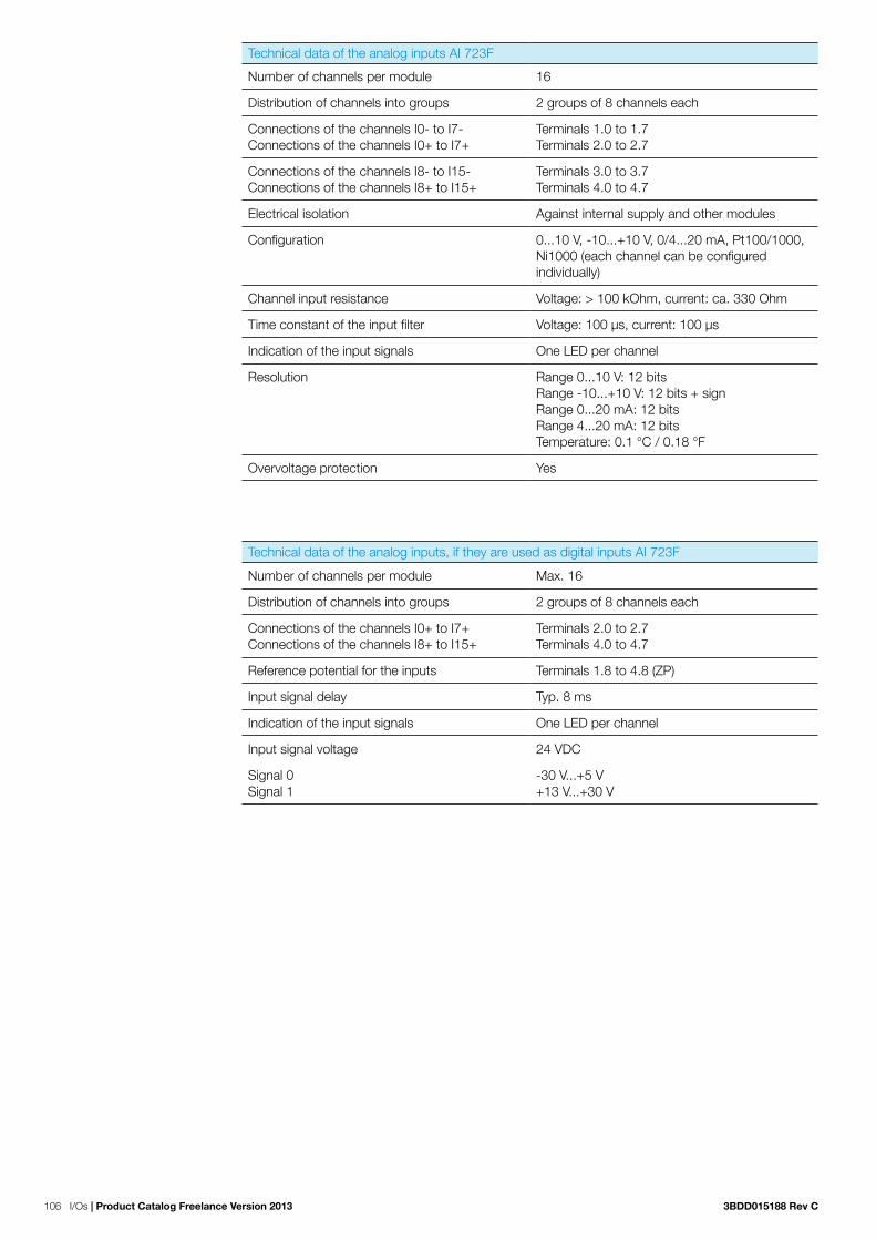
106 I/Os | Product Catalog Freelance Version 2013 3BDD015188 Rev C
Technical data of the analog inputs AI 723F
Number of channels per module 16
Distribution of channels into groups 2 groups of 8 channels each
Connections of the channels I0- to I7- Connections of the channels I0+ to I7+
Terminals 1.0 to 1.7 Terminals 2.0 to 2.7
Connections of the channels I8- to I15- Connections of the channels I8+ to I15+
Terminals 3.0 to 3.7 Terminals 4.0 to 4.7
Electrical isolation Against internal supply and other modules
Configuration 0...10 V, -10...+10 V, 0/4...20 mA, Pt100/1000, Ni1000 (each channel can be configured individually)
Channel input resistance Voltage: > 100 kOhm, current: ca. 330 Ohm
Time constant of the input filter Voltage: 100 μs, current: 100 μs
Indication of the input signals One LED per channel
Resolution Range 0...10 V: 12 bitsRange -10...+10 V: 12 bits + signRange 0...20 mA: 12 bitsRange 4...20 mA: 12 bitsTemperature: 0.1 °C / 0.18 °F
Overvoltage protection Yes
Technical data of the analog inputs, if they are used as digital inputs AI 723F
Number of channels per module Max. 16
Distribution of channels into groups 2 groups of 8 channels each
Connections of the channels I0+ to I7+ Connections of the channels I8+ to I15+
Terminals 2.0 to 2.7 Terminals 4.0 to 4.7
Reference potential for the inputs Terminals 1.8 to 4.8 (ZP)
Input signal delay Typ. 8 ms
Indication of the input signals One LED per channel
Input signal voltage 24 VDC
Signal 0Signal 1
-30 V...+5 V+13 V...+30 V

3BDD015188 Rev C Product Catalog Freelance Version 2013 | I/Os 107
UP 24VDC 5W
1.0
1.1
1.2
1.3
1.4
1.5
1.6
1.7
I0-
I1-
I2-
I3-
I4-
I5-
I6-
I7-
1.8 UP
1.9 ZP
2.0 I0+
2.1 I1+
2.2
2.3
2.4
2.5
2.6
2.7
I2+
I3+
I4+
I5+
I6+
I7+
2.8 UP
2.9 ZP
3.0 I8-
3.1 I9-
3.2 I10-
3.3 I11-
3.4 I12-
3.5 I13-
3.6 I14-
3.7 I15-
3.8 UP
3.9 ZP
4.0 I8+
4.1 I9+
4.2 I10+
4.3 I11+
4.4 I12+
4.5 I13+
4.6 I14+
4.7 I15+
4.8 UP
4.9 ZP
AI 723F
16AIAnalog Input
CH-ERR4CH-ERR2
Figure 9: AI 723F
Two example of wiring are shown with the following figures. Figure 10 shows wiring for a current input for 4...20 mA while Figure 11 shows a voltage sensor with differential inputs. Note that the latter one needs two adjacent channels, starting with an even channel number.
Figure 10: Connection of passive-type analog sensors (current)
Figure 11: Connection of active-type analog sensors (voltage) to differential inputs
Figure 12: 3 wire RTC

108 I/Os | Product Catalog Freelance Version 2013 3BDD015188 Rev C
5.1.4.3 Analog input module AI 731F (Thermocouple)
Name Short Description Article No.
AI 731F Analog input module 3BDH000385R0001
8 AI: TC, RTD, mV/V, mA, kOhm and 24 VDC 15 Bit + sign, 2-, 3- and 4-wire, 24 VDC 5 WTU 715F /TU 716F (terminal unit not included)
The analog input module AI 731F can be installed as a local expansion module on a AC 700F or AC 900F CPU. This module can also be used as a remote expansion module at the Inter-face Module DC 705F. It has 8 channels with the following features:
− 8 configurable analog inputs in two groups (1.0...2.7 and 2.0…2.7 as well as 3.0...3.7 and 4.0…4.7)
Technical data
Functionality AI 731F
Input 8 analog inputs, individually configurable for: unused (default setting)
0…5V, 0...10 V
-50…+50 mV, -500…+500 mV
-1…+1 V, -5…+5 V, -10 V...+10 V
0...20 mA
4...20 mA
-20…+20 mA
Pt100, -50 °C (-58 °F)...+70 °C (+158°F) (2-wire)
Pt100, -50 °C (-58 °F)...+70 °C (+158°F) (3-wire)
Pt100, -50 °C (-58 °F)...+70 °C (+158°F) (4-wire)
Pt100, -50 °C (-58 °F)...+70 °C (+158°F) (2-wire), resolution 0.01 K
Pt100, -50 °C (-58 °F)...+70 °C (+158°F) (3-wire),resolution 0.01 K
Pt100, -50 °C (-58 °F)...+70 °C (+158°F) (4-wire),resolution 0.01 K
Pt100, -50 °C (-58 °F)...+400 °C (+752 °F) (2-wire)
Pt100, -50 °C (-58 °F)...+400 °C (+752 °F) (3-wire)
Pt100, -50 °C (-58 °F)...+400 °C (+752 °F) (4-wire)
Pt100, -200 °C (-328°F)...+850 °C (+1562°F) (2-wire)
Pt100, -200 °C (-328°F)... +850 °C (+1562°F) (3-wire)
Pt100, -200 °C (-328°F)... +850 °C (+1562°F) (4-wire)
Pt1000, -50 °C (-58 °F)...+400 °C (+752 °F) (2-wire)
Pt1000, -50 °C (-58 °F)...+400 °C (+752 °F) (3-wire)
Pt1000, -50 °C (-58 °F)...+400 °C (+752 °F) (4-wire)
Ni1000, -50 °C (-58 °F)...+150 °C (+302 °F) (2-wire)
Ni1000, -50 °C (-58 °F)...+150 °C (+302 °F) (3-wire)
Ni1000, -50 °C (-58 °F)...+150 °C (+302 °F) (4-wire)
Cu50 1.426, -50 °C (-58 °F)...+200 °C (+392°F) (2-wire)
Cu50 1.426, -50 °C (-58 °F)...+200 °C (+392°F) (3-wire)

3BDD015188 Rev C Product Catalog Freelance Version 2013 | I/Os 109
Functionality AI 731F
Cu50 1.426, -50 °C (-58 °F)...+200 °C (+392°F) (4-wire)
Cu50 1.428, -200 °C (-328°F)...+200 °C (+392°F) (2-wire)
Cu50 1.428, -200 °C (-328°F)...+200 °C (+392°F) (3-wire)
Cu50 1.428, -200 °C (-328°F)...+200 °C (+392°F) (4-wire)
0…50 kOhm
Thermocouples of types J, K, T, N, S
digital signals (digital input)
Resolution of the analog channels
Voltage -1…+1V, -5…+5V,-10 V... +10 V: 15 bits plus signVoltage 0…5 V, 0...10 V: 15 bitsCurrent 0...20 mA, 4...20 mA,-20…+20 mA: 15 bitsTemperature: 0.1 °C (0.18 °F), 0.01°C at Pt100 -50°C…+70°C
Power supply internal:through the expansion bus interface (I/O Bus)external:via the terminals (process voltage 24 V DC)
Potential separation module-wise
LEDs 11 LEDs for signals and error messages
Technical data AI 731F
Process voltage
Rated value 24 V DC
Max. ripple 5 %
Protection against reversed voltage Yes
Rated protection fuse on UP 10 A fast
Electrical isolation Yes, per module
Power consumption through UP during normal operation
130 mA (depending on output loads)
Connections Terminals 1.8, 2.8, 3.8, and 4.8 for +24 V (UP) as well as 1.9, 2.9, 3.9 and 4.9 for 0 V (ZP))
Max. length of analog cables, conductor cross section > 0.14 mm² (~26 AWG)
100 m (328.08 ft)
Conversion error of the analog values caused by non-linearity, adjustment error at factory and resolution within the normal range
Typically 0.5 %, max. 1 %
Dimensions 67.5 x 76 x 54 mm / 2.66 x 2.99 x 2.13 inchwidth x height x depth
Weight Approx. 130 g / 4.6 oz
Mounting position Horizontal or vertical with limitations (output load per group 50 % at 40°C (104°F))
Cooling The natural convection cooling must not be hindered by cable ducts or other parts in the mounting cabinet.
Technical data analog inputs AI 731F
Number of channels per module 8
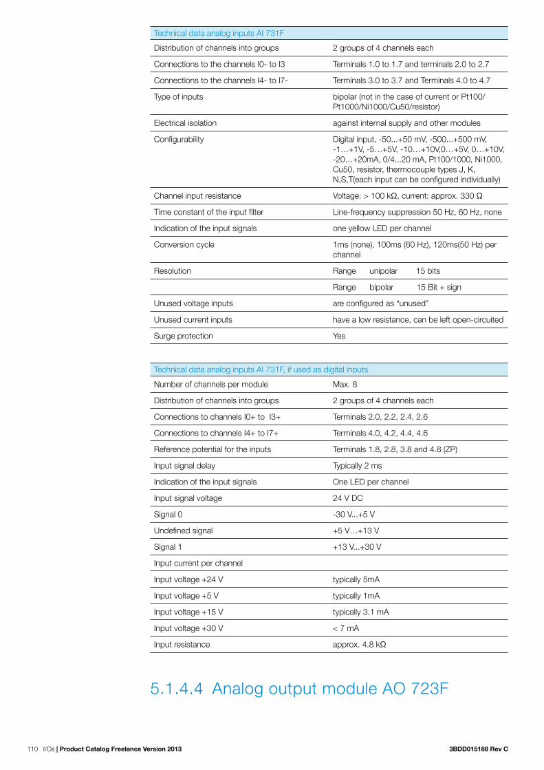
110 I/Os | Product Catalog Freelance Version 2013 3BDD015188 Rev C
Technical data analog inputs AI 731F
Distribution of channels into groups 2 groups of 4 channels each
Connections to the channels I0- to I3 Terminals 1.0 to 1.7 and terminals 2.0 to 2.7
Connections to the channels I4- to I7- Terminals 3.0 to 3.7 and Terminals 4.0 to 4.7
Type of inputs bipolar (not in the case of current or Pt100/Pt1000/Ni1000/Cu50/resistor)
Electrical isolation against internal supply and other modules
Configurability Digital input, -50...+50 mV, -500...+500 mV, -1…+1V, -5…+5V, -10…+10V,0…+5V, 0…+10V, -20…+20mA, 0/4...20 mA, Pt100/1000, Ni1000, Cu50, resistor, thermocouple types J, K, N,S,T(each input can be configured individually)
Channel input resistance Voltage: > 100 kΩ, current: approx. 330 Ω
Time constant of the input filter Line-frequency suppression 50 Hz, 60 Hz, none
Indication of the input signals one yellow LED per channel
Conversion cycle 1ms (none), 100ms (60 Hz), 120ms(50 Hz) per channel
Resolution Range unipolar 15 bits
Range bipolar 15 Bit + sign
Unused voltage inputs are configured as “unused”
Unused current inputs have a low resistance, can be left open-circuited
Surge protection Yes
Technical data analog inputs AI 731F, if used as digital inputs
Number of channels per module Max. 8
Distribution of channels into groups 2 groups of 4 channels each
Connections to channels I0+ to I3+ Terminals 2.0, 2.2, 2.4, 2.6
Connections to channels I4+ to I7+ Terminals 4.0, 4.2, 4.4, 4.6
Reference potential for the inputs Terminals 1.8, 2.8, 3.8 and 4.8 (ZP)
Input signal delay Typically 2 ms
Indication of the input signals One LED per channel
Input signal voltage 24 V DC
Signal 0 -30 V...+5 V
Undefined signal +5 V…+13 V
Signal 1 +13 V...+30 V
Input current per channel
Input voltage +24 V typically 5mA
Input voltage +5 V typically 1mA
Input voltage +15 V typically 3.1 mA
Input voltage +30 V < 7 mA
Input resistance approx. 4.8 kΩ
5.1.4.4 Analog output module AO 723F

3BDD015188 Rev C Product Catalog Freelance Version 2013 | I/Os 111
Name Short Description Article No.
AO 723F Analog output module 3BDH000384R0001
16 AO: +-10 V, 0/4-20 mAmax. 8 AO usable as current outputs12 Bit + sign, 2-wire, 24 VDC 8 WTU 715F /TU 716F (terminal unit not included
The analog output module AO 723F is installed either as direct I/O beside an AC 700F or AC 900F CPU or as remote I/O module for any Profibus remote I/O system. It has 16 channels with the following features:
− 16 configurable analog outputs in two groups (1.0...2.7 and 3.0…4.7)
Figure 13: AO 723F output configuration using predefined template; configurable channels
Figure 14: Output group 2 with voltage only channels
Technical data

112 I/Os | Product Catalog Freelance Version 2013 3BDD015188 Rev C
Functionality AO 723F
Outputs 16 analog outputs, individually configurable for:unused (default setting)-10 V...+10 V0...20 mA4...20 mA
Resolution of the analog channels Voltage 10 V... +10 V: 12 bits plus signCurrent 0...20 mA, 4...20 mA: 12 bitsTemperature: 0.1 °C (0.18 °F)
Power supply internal:through the expansion bus interface (I/O Bus)external:via the terminals ZP and UP (process voltage 24 V DC)
Potential separation module-wise
LEDs 19 LEDs for signals and error messages
Technical data AO 723F
Process voltage
Rated value 24 V DC
Max. ripple 5 %
Protection against reversed voltage Yes
Rated protection fuse on UP 10 A fast
Electrical isolation Yes, per module
Current consumption from UP at normal opera-tion
0.15 A + output load
Inrush current from UP (at power up) 0.020 A²s
Connections Terminals 1.8 – 4.8 for +24 V (UP) and 1.9 - 4.9 for 0 V (ZP)
Max. length of analog cables, conductor cross section > 0.14 mm² (~26 AWG)
100 m (328.08 ft)
Conversion error of the analog values caused by non-linearity, adjustment error at factory and resolution within the normal range
typically 0.5 %, max. 1 %
Dimensions 67.5 x 76 x 54 mm / 2.66 x 2.99 x 2.13 inch width x height x depth
Weight (without the terminal unit) approx. 300 g/10.58 oz.
Mounting position horizontal or vertical with limitations (output load per group 50 % at 40°C (104°F))
Cooling the natural convection cooling must not be hindered by cable ducts or other parts in the mounting cabinet.

3BDD015188 Rev C Product Catalog Freelance Version 2013 | I/Os 113
Technical data of analog outputs AO 723F
Number of channels per module 16, O0…O3 and O8…O11 for voltage and current, and channels O4…7 and O12…15 only for voltage
Distribution of channels into groups 2 group of 8 channels
Channels O0-...O7- Terminals 1.0...1.7
Channels O0+...O7+ Terminals 2.0...2.7
Channels O8-...O15- Terminals 3.0...3.7
Channels O8+...O15+ Terminals 4.0...4.7
Output type bipolar with voltage, unipolar with current
Electrical isolation against internal supply and other modules
Configurability -10...+10 V, 0...20 mA, 4...20 mA (each output can be configured individually), current output in channels 0...3 only
Output resistance (load), as current output 0...500 Ω
Output load capacity, as voltage output max. ±10 mA
Indication of the output signals one LED per channel
Resolution 12 bits (+ sign)
Unused outputs can be left open circuited
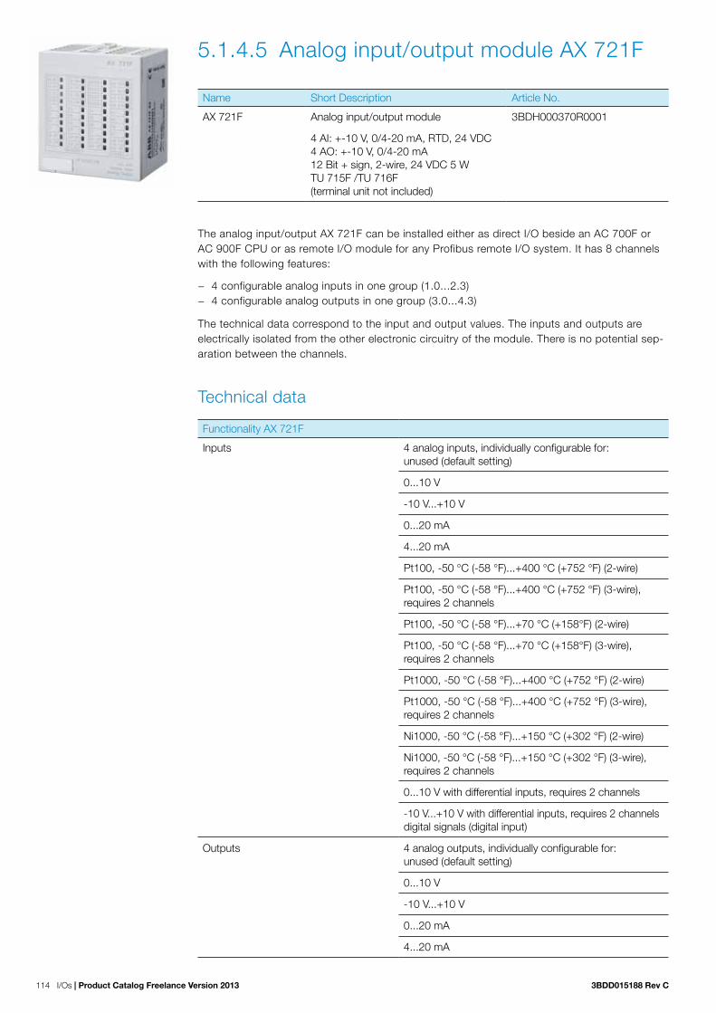
114 I/Os | Product Catalog Freelance Version 2013 3BDD015188 Rev C
5.1.4.5 Analog input/output module AX 721F
Name Short Description Article No.
AX 721F Analog input/output module 3BDH000370R0001
4 AI: +-10 V, 0/4-20 mA, RTD, 24 VDC4 AO: +-10 V, 0/4-20 mA12 Bit + sign, 2-wire, 24 VDC 5 WTU 715F /TU 716F (terminal unit not included)
The analog input/output AX 721F can be installed either as direct I/O beside an AC 700F or AC 900F CPU or as remote I/O module for any Profibus remote I/O system. It has 8 channels with the following features:
− 4 configurable analog inputs in one group (1.0...2.3) − 4 configurable analog outputs in one group (3.0...4.3)
The technical data correspond to the input and output values. The inputs and outputs are electrically isolated from the other electronic circuitry of the module. There is no potential sep-aration between the channels.
Technical data
Functionality AX 721F
Inputs 4 analog inputs, individually configurable for:unused (default setting)
0...10 V
-10 V...+10 V
0...20 mA
4...20 mA
Pt100, -50 °C (-58 °F)...+400 °C (+752 °F) (2-wire)
Pt100, -50 °C (-58 °F)...+400 °C (+752 °F) (3-wire), requires 2 channels
Pt100, -50 °C (-58 °F)...+70 °C (+158°F) (2-wire)
Pt100, -50 °C (-58 °F)...+70 °C (+158°F) (3-wire), requires 2 channels
Pt1000, -50 °C (-58 °F)...+400 °C (+752 °F) (2-wire)
Pt1000, -50 °C (-58 °F)...+400 °C (+752 °F) (3-wire), requires 2 channels
Ni1000, -50 °C (-58 °F)...+150 °C (+302 °F) (2-wire)
Ni1000, -50 °C (-58 °F)...+150 °C (+302 °F) (3-wire), requires 2 channels
0...10 V with differential inputs, requires 2 channels
-10 V...+10 V with differential inputs, requires 2 channels digital signals (digital input)
Outputs 4 analog outputs, individually configurable for:unused (default setting)
0...10 V
-10 V...+10 V
0...20 mA
4...20 mA

3BDD015188 Rev C Product Catalog Freelance Version 2013 | I/Os 115
Functionality AX 721F
Resolution of the analog channels Voltage -10 V... +10 V: 12 bits plus sign Voltage 0...10 V: 12 bitsCurrent 0...20 mA, 4...20 mA: 12 bits
Power supply Temperature: 0.1 °C/0.18 °Finternal:through the expansion bus interface (I/O Bus)external:via the terminals (process voltage 24 V DC)
Potential separation Module-wise
LEDs 11 LEDs for signals and error messages
Technical data AX 721F
Process voltage
Rated value 24 V DC
Max. ripple 5 %
Protection against reversed voltage Yes
Rated protection fuse on UP 10 A fast
Electrical isolation Yes, per module
Current consumption from UP at normal opera-tion
0.10 A + output load
Inrush current from UP (at power up) 0.020 A²s
Connections Terminals 1.8, 2.8, 3.8 and 4.8 for +24 V (UP) and 1.9, 2.9, 3.9 and 4.9 for 0 V (ZP)
Max. length of analog cables, conductor cross section > 0.14 mm² (~26 AWG)
100 m (328.08 ft)
Conversion error of the analog values caused by non-linearity, adjustment error at factory and resolution within the normal range
Typically 0.5 %, max. 1 %
Dimensions(without the Terminal Unit)
67.5 x 76 x 54 mm / 2.66 x 2.99 x 2.13 inch width x height x depth
Weight 300 g/10.58 oz.
Mounting position Horizontal or vertical with limitations (output load per group 50 % at 40°C (104°F))
Cooling The natural convection cooling must not be hindered by cable ducts or other parts in the mounting cabinet

116 I/Os | Product Catalog Freelance Version 2013 3BDD015188 Rev C
Technical data analog inputs AX 721F
Number of channels per module 4
Distribution of channels into groups 1 group of 4 channels
Connections to channels I0- to I3- Terminals 1.0 to 1.3
Connections to channels I0+ to I3+ Terminals 2.0 to 2.3
Type of Inputs Bipolar (not in the case of current or Pt100/Pt1000/Ni1000)
Electrical isolation Against internal supply and other modules
Configurability 0...10 V, -10...+10 V, 0/4...20 mA, Pt100/1000, Ni1000 (each input can be configured individually)
Channel input resistance Voltage: > 100 kΩ, current: approx. 330 Ω
Time constant of the input filter Voltage: 100 µs, current: 100 µs
Indication of the input signals one LED per channel
Conversion cycle 2 ms (for 8 inputs + 8 outputs), with Pt/Ni...1 s
Resolution Range 0...10 V: 12 bits
Range -10...+10 V: 12 bits + sign
Range 0...20 mA: 12 bits
Range 4...20 mA: 12 bits
Unused voltage inputs Are configurable as “unused”
Unused current inputs Have a low resistance, can be left open circuited
Surge protection Yes
Technical data analog inputs if they are used as digital inputs AX 721F
Number of channels per module Max. 4
Distribution of channels into groups 1 group of 4 channels
Connections to channels I0+ to I3+ Terminals 2.0 to 2.3
Reference potential for the inputs Terminals 1.8, 2.8, 3.8 and 4.8 (ZP)
Input signal delay Typically 8 ms, configurable from 0.1 to 32 ms
Indication of the input signals One LED per channel
Input signal voltage 24 V DC
Signal 0 -30 V...+5 V
Undefined signal +5 V…+13 V
Signal 1 +13 V...+30 V
Input current per cannel
Input voltage +24 V Typically 7 mA
Input voltage +5 V Typically 1.4 mA
Input voltage +15 V Typically 4.3 mA
Input voltage +30 V < 9 mA
Input resistance Approx. 3.5 kΩ

3BDD015188 Rev C Product Catalog Freelance Version 2013 | I/Os 117
Technical data analog outputs AX 721F
Number of channels per module 4, all channels for voltage, the first 4 are also for current
Distribution of channels into groups 1 group of 4 channels
Channels O0-...O3- Terminals 3.0...3.3
Channels O0+...O3+ Terminals 4.0...4.3
Output type bipolar with voltage, unipolar with current
Electrical isolation against internal supply and other modules
Configurability -10...+10 V, 0...20 mA, 4...20 mA (each output can be configured individually), current output in channels 0...3 only
Output resistance (load),as current output
0...500 Ω
Output load capacity,as voltage output
max. ±10 mA
Indication of the output signals one LED per channel
Resolution 12 bits (+ sign)
Unused outputs can be left open circuited

118 I/Os | Product Catalog Freelance Version 2013 3BDD015188 Rev C
5.1.4.6 Analog input / output module AX 722FName Short Description Article No.
AX 722F Analog input / output module 3BDH000377R0001
8 AI: +-10 V 0/4-20 mA 24 VDC, Pt100. 8 AO: +-10 V 0/4-20 mA 24 VDC. 12 bit + Sign, 2-wire, 24 VDC 5 W. Without terminal unit.
The AX 722F module offers even more flexibility, as it combines analog input and output channels in one module with 16 channels.
Eight of these channels can be individually configured as inputs, which can again sense voltage, current, or temperatures.
Furthermore four channels can be configured as analog voltage outputs (-10 V to +10 V) or analog current outputs (0 … 20 mA or 4 … 20 mA) and the remaining four channels can provide voltage signals in the range from -10 V to +10 V.
Figure 15: AX 722F options

3BDD015188 Rev C Product Catalog Freelance Version 2013 | I/Os 119
Technical data
Functionality AX 722F
8 analog inputs, (channels I0 - I7) individually configurable for
Unused (default setting)
0...10 V
-10 V...+10 V
0...20 mA
4...20 mA
Pt100, -50 °C (-58 °F)...+400 °C (+752 °F) 2-wire or3-wire, requires 2 channels
Pt100, -50 °C (-58 °F)...+70 °C (+158 °F) 2-wire or3-wire, requires 2 channels
Pt1000, -50 °C (-58 °F)...+400 °C (+752 °F) 2-wire or3-wire, requires 2 channels
Ni1000, -50 °C (-58 °F)...+150 °C (+302 °F) 2-wire or3-wire, requires 2 channels
0...10 V with differential inputs, requires 2 channels
-10 V...+10 V with differential inputs, requires 2 channels
Digital signals (digital input)
4 analog outputs, (channels O0 - O3) individually configurable for
Unused (default setting)-10 V...+10 V0...20 mA4...20 mA
4 analog outputs, (channels O4 - O7) individually configurable for
unused (default setting)-10 V...+10 V
Technical data AX 722F
LED displays 19 LEDs for signals and error indication, where the brightness depends on the current (or signal level)
Internal power supply Through the expansion bus interface (I/O-Bus)
External power supply Via the terminals ZP and UP (process voltage 24 VDC) of TU 715F
Process voltage
Rated value 24 VDC
Max. ripple 5%
Protection against reversed voltage Yes
Rated protection fuse on UP 10 A fast
Electrical isolation Yes, per module
Current consumption from UP at normal operation
0.10 A output loads
Inrush current from UP (at power up) 0.020 A²s
Connections Terminals 1.8 - 4.8 for +24 V (UP) and 1.9 - 4.9 for 0 V (ZP)

120 I/Os | Product Catalog Freelance Version 2013 3BDD015188 Rev C
Technical data AX 722F
Max. length of analog cables, conductor cross section > 0.14 mm² (~26 AWG)
100 m / 328 ft.
Conversion error of the analog values caused by non-linearity, adjustment error at factory and resolution within the normal range
Typ. 0.5 %, max. 1 %
Width x height x depth 67.5 x 76 x 54 mm / 2.66 x 2.99 x 2.13 inches
Weight (without the Terminal Unit) approx. 300 g / 10.58 oz.
Cooling The natural convection cooling must not be hindered by cable ducts or other parts in the mounting cabinet.
Technical data of the analog inputs AX 722F
Number of channels per module 8
Distribution of the channels into groups 1 group of 8 channels
Connections of the channels I0- to I7- Terminals 1.0 to 1.7
Connections of the channels I0+ to I7+ Terminals 2.0 to 2.7
Electrical isolation Against internal supply and other modules
Configuration 0...10 V, -10...+10 V, 0/4...20 mA, Pt100/1000, Ni1000 (each channel can be configured individually)
Channel input resistance Voltage: > 100 kOhm, current: ca. 330 Ohm
Time constant of the input filter Voltage: 100 μs, current: 100 μs
Indication of the input signals One LED per channel
Conversion cycle 2 ms (for 8 inputs + 8 outputs), with Pt / Ni...1 s
Resolution Range 0...10 V: 12 bitsRange -10...+10 V: 12 bits + signRange 0...20 mA: 12 bitsRange 4...20 mA: 12 bitsTemperature : 0.1 °C / 0.18 °F
Unused voltage inputs Are configured as „unused“
Unused current inputs Have a low resistance, can be left open-circuited
Overvoltage protection Yes
Technical data of the analog inputs, if they are used as digital inputs AX 722F
Number of channels per module Max. 8
Distribution of channels into groups 1 group of 8 channels
Connections of the channels I0+ to I7+ Terminals 2.0 to 2.7
Reference potential for the inputs Terminals 1.8 to 4.8 (ZP)
Input signal delay Typ. 8 ms
Indication of the input signals One LED per channel
Input signal voltage 24 VDC
Signal 0Signal 1
-30 V...+5 V+13 V...+30 V

3BDD015188 Rev C Product Catalog Freelance Version 2013 | I/Os 121
Technical data of the analog outputs AX 722F
Number of channels per module 8, all channels for voltage, the first 4 channels also for current
Distribution of channels into groups 1 group of 8 channels
Channels O0-...O7-Channels O0+...O7+
Terminals 3.0...3.7Terminals 4.0...4.7
Output type Bipolar with voltage, unipolar with current
Electrical isolation Against internal supply and other modules
Configurability -10...+10 V, 0...20 mA, 4...20 mA (each output can be configured individually), current outputs only channels 0...3
Output resistance (load), as current output 0...500 Ohm
Output loadability, as voltage output max. ±10 mA
Indication of the output signals One LED per channel, where the brightness depends on the current (or signal level)
Resolution 12 bits (+ sign)
Unused outputs Can be left open-circuited

122 I/Os | Product Catalog Freelance Version 2013 3BDD015188 Rev C
5.3.5 Digital/Analog I/O module
5.1.5.1 Digital / analog module DA 701F
Name Short Description Article No.
DA 701F Digital / analog module 3BDH000371R0001
16 DI: 24 VDC8 DI/DO: 24 VDC/0.5 A4 AI: +-10 V 0/4-20 mA, RTD , 24 VDC2 AO: +-10 V, 0/4-20 mA12 Bit + sign, 1-wire, 24 VDC 200 WTU 715F /TU 716F (terminal unit not included)
The digital / analog I/O module DA 701F can be installed either as direct I/O beside an AC 700F or AC 900F CPU or as remote I/O module for any Profibus remote I/O system.It has 30 channels with the following features:
− 16 digital inputs, 24 V DC − 8 configurable digital inputs/outputs 24 V DC, 0.5 A max. − 4 analog inputs, voltage, current and RTD, resolution 12 bits plus sign − 2 analog outputs, voltage and current, resolution 12 bits plus sign
The technical data correspond to the input and output values. The inputs and outputs are electrically isolated from the other electronic circuitry of the module. There is no potential separation between the channels.
Technical data
Functionality DA 701F
Digital Inputs 16 (24 V DC; delay time configurable via soft-ware)
Configurable digital inputs/outputs 8 (24 V DC, 0.5 A max)
Analog inputs 4 (configurable via software), resolution 12 bits plus sign, voltage, current and RTD input
Analog outputs 2 (configurable via software), resolution 12 bits plus sign, voltage, current and RTD output
Power supply Internal:through the expansion bus interface (I/O-Bus)external:via the terminals ZP and UP (process voltage 24 V DC)
Potential separation Module-wise
LEDs For system displays, indicating signal statuses, errors and power supply

3BDD015188 Rev C Product Catalog Freelance Version 2013 | I/Os 123
Technical data DA 701F
Process supply voltage UP
Connections Terminals 1.8, 2.8, 3.8 and 4.8 for +24 V (UP) and 1.9, 2.9, 3.9 and 4.9 for 0 V (ZP)
Rated value 24 V DC
max. ripple 5 %
Protection against reversed voltage Yes
Rated protection fuse on UP 10 A fast
Electrical isolation Yes, per module
Current consumption 0.07 A + max. 0.5 A per output
From UP Approx. 1 mA at 24 V DC
From 24 V DC power supply at the terminals UP/L+ and ZP/M of the CPU/Bus Module
Approx. 5 mA
Inrush current from UP (at power-up) 0.04 A²s
Max. power dissipation within the module 6 W (outputs not loaded)
Dimensions 67.5 x 76 x 54 mm / 2.66 x 2.99 x 2.13 inchwidth x height x depth
Weight (without Terminal Unit) Approx. 125g / 4.41 oz.
Mounting position Horizontal or vertical with limitations (Output load per group is 50 % at 40°C (104°F))
Cooling The natural convection cooling must not be hindered by cable ducts or other parts in the mounting cabinet.
Technical data digital inputs DA 701F
Number of channels per module 16
Distribution of the channels into groups 2 group of 8 channels
Connections to the channels DI0 to DI7 Terminals 1.0 to 1.7
Connections to the channels DI8 to DI15 Terminals 2.0 to 2.7
Reference potential for all inputs Terminal 1.9...3.9 (minus pole of the process supply voltage, signal name ZP)
Electrical isolation From the rest of the module
Indication of the input signals One yellow LED per channel, the LED is ON when the input signal is high (signal 1)
Input type acc. to EN 61131-2 Type 1
Input delay (0->1 or 1->0) Typically 0.1 ms, configurable from 0.1…32 ms
Input signal voltage 24 V DC
Signal 0 -3 V...+5 V
Undefined signal > +5 V...< +15 V
Signal 1 +15 V...+30 V
Ripple with signal 0 Within -3 V...+5 V
Ripple with signal 1 Within +15 V...+30 V
Input current per channel
Input voltage +24 V typically 5 mA
Input voltage +5 V > 1 mA
Input voltage +15 V > 2 mA

124 I/Os | Product Catalog Freelance Version 2013 3BDD015188 Rev C
Technical data digital inputs DA 701F
Input voltage +30 V < 8 mA
Max. cable length
Shielded 1000 m (3280.83 ft)
Unshielded 600 m (1968.50 ft)
Technical data digital inputs / outputs DA 701F
Number of channels per module 8 inputs/outputs (with transistors)
Distribution of the channels into groups 1 groups of 8 channel
If channels are used as inputs:
Channels DC16…DC23 Terminals 4.0…4.7
If channels are used as outputs:
Channels DC16…DC23 Terminals 4.0…4.7
Indications of the input/output signals 1 yellow LED per channel, the LED is ON when the input/output signal is high (signal 1)
Electrical isolation Yes, per module
Technical data digital inputs / outputs DA 701F if used as inputs
Number of channels per module 8
Distribution of the channels into groups 1 groups of 8 channel
Channels DC16…DC23 Terminals 4.0…4.7
Reference potential for all inputs Terminals 1.9…4.9 (Minus pole of the supply voltage, signal name ZP)
Indication of the input signals 1 yellow LED per channel, the LED is ON when the input signal is high (signal1)
Input type acc. to EN 61131-2 Type 1
Input delay (0->1 or 1->0) Typically 0.1 ms, configurable from 0.1…32 ms
Input signal voltage 24 V DC
Signal 0 -3 V...+5 V
Undefined signal > +5 V...< +15 V
Signal 1 +15 V...+30 V
Ripple with signal 0 Within -3 V...+5 V
Ripple with signal 1 Within +15 V...+30 V
Input current per channel
Input voltage +24 V Typically 5 mA
Input voltage +5 V > 1 mA
Input voltage +15 V > 2 mA
Input voltage +30 V < 8 mA
Max. cable length
Shielded 1000 m (3280.83 ft)
Unshielded 600 m (1968.50 ft)
* Due to the direct connection to the output, the demagnetizing varistor is also effective at the input. This is why the difference between UPx and the input signal may not exceed the clamp voltage of the varistor. The varistor limits the voltage to approx. 36 V. Following this, the input voltage must range from -12 V to +30 V when UPx = 24 V and from -6 V to +30 V when UPx = 30 V.

3BDD015188 Rev C Product Catalog Freelance Version 2013 | I/Os 125
Technical data digital inputs / outputs DA 701F if used as outputs
Number of channels per module 8
Distribution of the channels into groups 1 groups of 8 channel
Channels DC16…DC23 Terminals 4.0…4.7
Reference potential for all outputs Terminals 1.9…4.9 (Minus pole of the supply voltage, signal name ZP)
Common power supply voltage For all output terminals 1.8, 2.8, 3.8 and 4.8 (plus pole of the supply voltage, signal name UP)
Output voltage for signal 1 UP (-0.8 V)
Output current
Rated value per channel 500 mA @ UP = 24 V
Max. value (all channels together) 4 A
Leakage current with signal 0 <0.5 mA
Fuse for UP 10 A fast
Demagnetization with inductive DC load Via internal varistors
Output switching frequency
With inductive loads Max. 0.5 Hz
With lamp loads 11Hz max. @ 5W max.
Overload message (I >0.7 A) Yes
Output current limitation Yes, after approx. 100 ms
Resistance to feedback against 24 V signals Yes (Software controlled supervision)
Max. cable length
Shielded 1000 m (3280.83 ft)
Unshielded 600 m (1968.50 ft)

126 I/Os | Product Catalog Freelance Version 2013 3BDD015188 Rev C
Technical data analog inputs DA 701F
Number of channels per module 4
Distribution of the channels into groups 1 groups of 4 channel
Channels AI0+…AI3+ Terminals 3.0…3.3
Reference potential for AI0+…AI3+ Terminals 3.4 (AI-) for voltage and RTD measurement
Terminal 1.9, 2.9, 3.9 and 4.9 for current measurement
Input type
Unipolar Voltage 0…10 V, current or Pt100/Pt1000/Ni1000
Bipolar Voltaqe -10…+10V
Configurability 0…10 V, -10…+10 V, 0/4…20 mA, Pt1000/1000, Ni1000 (each input can be con-figured individually)
Channel input resistance Voltage: >100 kΩ, current: approx. 330 Ω
Time constant of the input filter Voltage: 100 µs, current: 100 µs
Indication of the input signals 1 LED per channel (brightness depends on the value of the analog signal)
Conversion cycle 1 ms (for 4 inputs + 2 outputs); with RTDs Pt/Ni… 1s
Resolution Range 0…10 V: 12 Bits
Range -10…+10 V: 12 Bits +sign
Range 0…20 mA: 12 Bits
Range 4…20 mA: 12 Bits
Range RTD (Pt100, Pt1000, Ni1000): 0.1°C (°F)
Unused inputs Configured as ‘unused’
Overvoltage protection Yes

3BDD015188 Rev C Product Catalog Freelance Version 2013 | I/Os 127
Technical data analog inputs DA 701F if used as digital inputs
Number of channels per module Max. 4
Distribution of the channels into groups 1 groups of 4 channel
Channels AI0+…AI3+ Terminals 3.0…3.3
Reference potential for all inputs Terminals 1.9, 2.9, 3.9 and 4.9 (ZP)
Indication of the input signals 1 LED per channel
Input signal voltage 24 V DC
Signal 0 -30 V...+5 V
Undefined signal +5 V...+13 V
Signal 1 +13 V...+30 V
Input current per channel
Input voltage +24 V typically 7 mA
Input voltage +5 V typically 1.4 mA
Input voltage +15 V typically 3.7 mA
Input voltage +30 V < 9 mA
Input resistance Approx. 3.5 kΩ
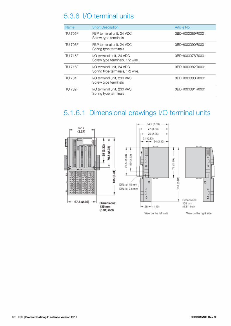
128 I/Os | Product Catalog Freelance Version 2013 3BDD015188 Rev C
5.3.6 I/O terminal unitsName Short Description Article No.
TU 705F FBP terminal unit, 24 VDCScrew type terminals
3BDH000389R0001
TU 706F FBP terminal unit, 24 VDCSpring type terminals
3BDH000390R0001
TU 715F I/O terminal unit, 24 VDCScrew type terminals, 1/2 wire.
3BDH000378R0001
TU 716F I/O terminal unit, 24 VDCSpring type terminals, 1/2 wire.
3BDH000382R0001
TU 731F I/O terminal unit, 230 VACScrew type terminals
3BDH000380R0001
TU 732F I/O terminal unit, 230 VACSpring type terminals
3BDH000381R0001
5.1.6.1 Dimensional drawings I/O terminal units

3BDD015188 Rev C Product Catalog Freelance Version 2013 | I/Os 129
5.1.6.2 TU 705F / TU 706F
Name Short Description Article No.
TU 705F FBP terminal unit, 24 VDCScrew type terminals
3BDH000389R0001
TU 706F FBP terminal unit, 24 VDCSpring type terminals
3BDH000390R0001
The FBP Terminal Units TU 705F (screw type terminal) and TU 706F (spring type terminal) are used as a socket for the FBP Interface Module, The FBP Interface Modules is placed on the FBP Terminal Unit and locked into place using two mechanical locks. To loosen this connection a screw driver should be inserted in the recess provided and the Terminal units are carefully pulled away. All electrical connections are made through the Terminal Unit, which allows removal and replacement of the FBP Interface Module without disturbing the wiring at the FBP terminal unit.
The terminals 1.8 to 2.8 and 1.9 to 2.9 are electrically interconnected within the FBP Terminal Unit and always have the same assignment irrespective of which module is inserted:
− Terminals 1.8 to 2.8: Process voltage UP = +24 V DC − Terminals 1.9 to 2.9: Process voltage ZP = 0 V
The assignment of other terminals is dependent on the FBP Interface Module inserted.
The supply voltage of +24 V DC device-voltage for the electronic circuitry of the device comes from the FieldBusPlug
Technical data
Technical data TU 705 F / TU 706 F
Number of terminals 16
Distribution of the channels into groups 2 groups of 8 channels each (1.0...1.7, 2.0...2.7), the allocation of the channels is as per the FBP Interface Module inserted
Rated voltage 24 V DC
Max. permitted total current 10 A (between the terminal 1.8...2.8 and 1.9...2.9)
Earthing direct connection to the earthed DIN rail or via the screws in the case of wall mounting
Type Front terminal, conductor connection vertically with respect to the printed circuit board
Conductor cross sectionsolidflexiblewith wire-end ferrule
0.08 - 2.5 mm² (~26 - 14 AWG)0.08 - 2.5 mm² (~26 - 14 AWG)0.25 - 1.5 mm² (~24 - 16 AWG)
Length of the stripped conductor / TU 705F 8 mm (0.32 inch)
Length of the stripped conductor / TU 706F 7 mm (inch), min. 5 mm (inch)
Width of the screwdriver 3.5 mm (0.14 inch)
Fastening torque 0.6 Nm
Degree of protection IP 20
Dimensions 67.5 x 135 x 30 mm / 2.66 x 5.31 x 1.18 inchwidth x height x depth
Weight 200 g / 7.05 oz.
Mounting position horizontal or vertical
TU 705F
TU 706F

130 I/Os | Product Catalog Freelance Version 2013 3BDD015188 Rev C
5.1.6.3 TU 715F / TU 716F
Name Short Description Articel No.
TU 715F I/O terminal unit, 24 VDCScrew type terminals, 1/2 wire.
3BDH000378R0001
TU 716F I/O terminal unit, 24 VDCSpring type terminals, 1/2 wire.
3BDH000382R0001
The I/O Terminal Units TU 715F (screw type terminal) and TU 716F (spring type terminal) are used as a socket for the I/O module, which exclusively incorporates inputs and outputs for 24V DC digital or analog signals. The I/O Modules (I/O expansion modules) are placed on the I/O Terminal Unit and locked into place using two mechanical locks. To loosen this connection a screw driver should be inserted in the recess provided and the Terminal units are carefully pulled away. All electrical connections are made through the Terminal Unit, which allows removal and replacement of the I/O units without disturbing the wiring at the terminal unit.
The terminals 1.8 to 4.8 and 1.9 to 4.9 are electrically interconnected within the I/O Terminal Unit and always have the same assignment irrespective of which I/O expansion module is inserted:
− Terminals 1.8 to 4.8: Process voltage UP = +24 V DC − Terminals 1.9 to 4.9: Process voltage ZP = 0 V
The assignment of other terminals is dependent on the I/O expansion module that is inserted.
The supply voltage of +24 V DC device-voltage for the electronic circuitry of the device comes from the I/O expansion bus (I/O Bus) and from the CPU respectively.
Technical data
Technical data TU 715F / TU 716 F
Number of terminals 32
Distribution of the channels into groups 4 groups of 8 terminals each (1.0...1.7, 2.0...2.7, 3.0...3.7, 4.0...4.7), the allocation of the channels is given by the inserted I/O expansion module
Rated voltage 24 VDC
Max. permitted total current 10 A (between the terminals 1.8...4.8 and 1.9...4.9)
Earthing Direct connection to the earthed DIN rail or via the screws with wall mounting
Type Front terminal, conductor connection vertically with respect to the printed circuit board
Conductor cross sectionSolidFlexibleWith wire-end ferrule
0.08 mm² to 2.5 mm² (28 AWG to 13 AWG)0.08 mm² to 2.5 mm² (28 AWG to 13 AWG)0.25 mm² to 1.5 mm² (23 AWG to 15 AWG)
Length of the stripped conductor / TU 715F 8 mm (0.31 inch)
Length of the stripped conductor / TU 716F 7 mm, min. 5 mm
Width of the screwdriver 3.5 mm (0.14 inch)
Fastening torque (screw type terminals) 0.6 Nm (5.3 Pound Inch)
Degree of protection IP 20
Dimensions 67.5 x 135 x 30 mm / 2.66 x 5.31 x 1.18 inchwidth x height x depth
Weight 200 g / 7.05 oz.
Mounting position horizontal or vertical
TU 715F
TU 716F

3BDD015188 Rev C Product Catalog Freelance Version 2013 | I/Os 131
5.1.6.4 TU 731F / TU 732F
Name Short Description Article No.
TU 731F I/O terminal unit, 230 VACScrew type terminals
3BDH000380R0001
TU 732F I/O terminal unit, 230 VACSpring type terminals
3BDH000381R0001
The I/O Terminal Units TU 731F (with screw-type terminals) and TU 732F (with spring type terminals) are specifically designed for use with AC 700F/AC 900F/S700 I/O modules that incorporate 115-230 V AC inputs and/or 115-230 V AC relay outputs.
The input/output modules (I/O expansion modules) plug into the I/O terminal Unit. When properly seated, they are secured with two mechanical locks. All the electrical connections are made through the Terminal Unit, which allows removal and replacement of the I/O modules without disturbing the wiring at the Terminal Unit.
The terminals 1.8 to 4.8 and 1.9 to 4.9 are electrically interconnected within the I/O Terminal Unit and have always the same assignment, irrespective of which I/O expansion module is inserted:
− Terminals 1.8 to 4.8: Process voltage UP = +24 V DC − Terminals 1.9 to 4.9: Process voltage ZP = 0 V
The assignment of the other terminals is dependent on the inserted expansion module (see thedescription of the used expansion module).The supply voltage 24 V DC for the module‘s electronic circuitry comes from the I/O expansionbus (I/O-Bus) or from the FieldBusPlug or from the AC 700F or AC 900F CPU.
Technical data TU 731F / TU 732 F
Number of terminals 32
Distribution of the channels into groups 4 groups of 8 channels each (1.0...1.7, 2.0...2.7, 3.0...3.7, 4.0...4.7), the allocation of the channels is given by the inserted I/O expansion module
Rated voltage 230 V AC
Max. permitted total current 10 A (between the terminals 1.8...4.8 and 1.9...4.9)
Earthing Direct connection to the earthed DIN rail or via the screws with wall mounting
Type Front terminal, conductor connection vertically with respect to the printed circuit board
Conductor cross sectionSolidFlexibleWith wire-end ferrule
0.08 mm² to 2.5 mm² (28 AWG to 13 AWG)0.08 mm² to 2.5 mm² (28 AWG to 13 AWG)0.25 mm² to 1.5 mm² (23 AWG to 15 AWG)
Length of the stripped conductor / TU 731F 8 mm (0.31 inch)
Length of the stripped conductor / TU 732F 7 mm, min. 5 mm
Width of the screwdriver 3.5 mm (0.14 inch)
Fastening torque (screw type terminals) 0.6 Nm (5.3 Pound Inch)
Degree of protection IP 20
Dimensions 67.5 x 135 x 30 mm / 2.66 x 5.31 x 1.18 inchwidth x height x depth
Weight 200 g / 7.05 oz.
Mounting position horizontal or vertical
TU 732F
TU731F

132 I/Os | Product Catalog Freelance Version 2013 3BDD015188 Rev C
5.3.7 S 700 I/O Accessories
5.1.7.1 FieldBusPlug
Name Short Description Article No.
PDP22-FBP.025 FieldBusPlug, DP-V0/1, 0.25 m 1SAJ240100R1003
PDP22-FBP.050 FieldBusPlug, DP-V0/1, 0.5 m 1SAJ240100R1005
PDP22-FBP.100 FieldBusPlug, DP-V0/1, 1 m 1SAJ240100R1010
PDP22-FBP.200 FieldBusPlug, DP-V0/1, 2 m 1SAJ240100R1020
PDP22-FBP.500 FieldBusPlug, DP-V0/1, 5 m 1SAJ240100R1050
5 4 1 2
3
5 4 3
2 1
5 4 3
2 1 Fieldbus-neutral interface, to the terminal device
femal e
femal e
male
Pin assignment for parallel mode:
+24 V (standard 1 power supply unit) Digital input (DI 1) 2 0 V (standard 3 power supply unit) Digital input (DI 0) 4 Digital output (DO 0) 5
Pin assignment for serial mode:
+24 V (standard 1 power supply unit) Diagnosis pin) 2 0 V (standard 3 power supply unit) Serial data 4 Serial data 5
M12 plug at the cable end, to previous FieldBusPlug or to bus master
PROFIBUS DP-V0 (PDP21) or PROFIBUS DP-V1 (PDP22) slave circuitry
PROFIBUS interface. Here, the M12 plug of the next FieldBusPlug is plugged in.
At the end of the bus line, the termination unit PDR 11 must be installed for correct bus termination.
Pin assignment: +24 V 1 Bus-N = A 2 0 V DC 3 Bus-P = B 4 Shield 5
(brown) (green) (blue) (red) (bare)
M12 plug / cable of the next FieldBusPlug
PDP22 represents a tee unit, which means that if the built in bus node in on of them fails then all remaining FieldBusPlugs are still connected with the bus master.
− A power unit, preferable situated near the bus master, is necessary to supply power to the FieldBusPlugs.
− A maximum baud rate of 12 Mbit/s is possible provided the termination on both ends is done correctly and the maximum bus length is not exceeded.
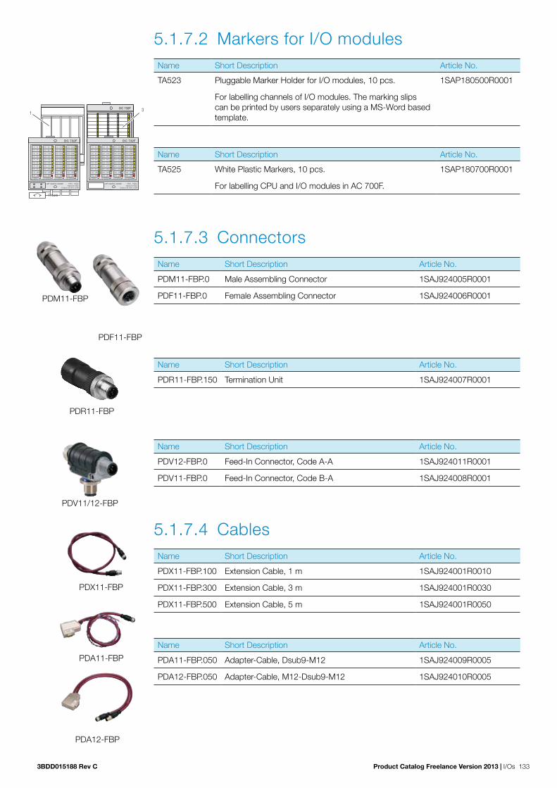
3BDD015188 Rev C Product Catalog Freelance Version 2013 | I/Os 133
5.1.7.2 Markers for I/O modulesName Short Description Article No.
TA523 Pluggable Marker Holder for I/O modules, 10 pcs. 1SAP180500R0001
For labelling channels of I/O modules. The marking slips can be printed by users separately using a MS-Word based template.
Name Short Description Article No.
TA525 White Plastic Markers, 10 pcs. 1SAP180700R0001
For labelling CPU and I/O modules in AC 700F.
5.1.7.3 Connectors
Name Short Description Article No.
PDM11-FBP.0 Male Assembling Connector 1SAJ924005R0001
PDF11-FBP.0 Female Assembling Connector 1SAJ924006R0001
Name Short Description Article No.
PDR11-FBP.150 Termination Unit 1SAJ924007R0001
Name Short Description Article No.
PDV12-FBP.0 Feed-In Connector, Code A-A 1SAJ924011R0001
PDV11-FBP.0 Feed-In Connector, Code B-A 1SAJ924008R0001
5.1.7.4 Cables
Name Short Description Article No.
PDX11-FBP.100 Extension Cable, 1 m 1SAJ924001R0010
PDX11-FBP.300 Extension Cable, 3 m 1SAJ924001R0030
PDX11-FBP.500 Extension Cable, 5 m 1SAJ924001R0050
Name Short Description Article No.
PDA11-FBP.050 Adapter-Cable, Dsub9-M12 1SAJ924009R0005
PDA12-FBP.050 Adapter-Cable, M12-Dsub9-M12 1SAJ924010R0005
DC 732F
UP 24VDC 200W 16DI 16DCInput 24 VDC
Output 24 VDC 0.5A
CH-ERR1 CH-ERR2 CH-ERR3 CH-ERR4
1.0 I0
1.1 I1
1.2 I2
1.3 I3
1.4 I4
1.5 I5
1.6 I6
1.7 I7
1.8 UP
1.9 ZP
2.0 I8
2.1 I9
2.2 I10
2.3 I11
2.4 I12
2.5 I12
2.6 I14
2.7 I15
2.8 UP
2.9 ZP
3.0 C16
3.1 C17
3.2 C18
3.3 C19
3.4 C20
3.5 C21
3.6 C22
3.7 C23
3.8 UP
3.9 ZP
4.0 C24
4.1 C25
4.2 C26
4.3 C27
4.4 C28
4.5 C29
4.6 C30
4.7 C31
4.8 UP
4.9 ZP
1.0 I0
1.1 I1
1.2 I2
1.3 I3
1.4 I4
1.5 I5
1.6 I6
1.7 I7
1.8 UP
1.9 ZP
2.0 I8
2.1 I9
2.2 I10
2.3 I11
2.4 I12
2.5 I13
2.6 I14
2.7 I15
2.8 UP
2.9 ZP
3.0 C1 6
3.1 C1 7
3.2 C1 8
3.3 C1 9
3.4 C2 0
3.5 C2 1
3.6 C2 2
3.7 C2 3
3.8 UP
3.9 ZP
4.0 C2 4
4.1 C2 5
4.2 C2 6
4.3 C2 7
4.4 C2 8
4.5 C2 9
4.6 C3 0
4.7 C3 1
4.8 UP
4.9 ZP
CH-ERR3 CH-ERR4CH-ERR2CH-ERR1
1
2
3
TA525
DC 732F
UP 24VDC 200W 16DI 16DCInput 24 VDC
Output 24 VDC 0.5A
CH-ERR1 CH-ERR2 CH-ERR3 CH-ERR4
1.0 I0
1.1 I1
1.2 I2
1.3 I3
1.4 I4
1.5 I5
1.6 I6
1.7 I7
1.8 UP
1.9 ZP
2.0 I8
2.1 I9
2.2 I10
2.3 I11
2.4 I12
2.5 I12
2.6 I14
2.7 I15
2.8 UP
2.9 ZP
3.0 C16
3.1 C17
3.2 C18
3.3 C19
3.4 C20
3.5 C21
3.6 C22
3.7 C23
3.8 UP
3.9 ZP
4.0 C24
4.1 C25
4.2 C26
4.3 C27
4.4 C28
4.5 C29
4.6 C30
4.7 C31
4.8 UP
4.9 ZP
PDF11-FBP
PDM11-FBP
PDR11-FBP
PDV11/12-FBP
PDX11-FBP
PDA11-FBP
PDA12-FBP

134 I/Os | Product Catalog Freelance Version 2013 3BDD015188 Rev C
5.3 S800 Remote I/OS800 I/O is a comprehensive, distributed and modular process I/O system that communicates with parent controllers via PROFIBUS. Thanks to its broad connectivity, the system is able to communicate with a wide range of process control systems from both ABB and other suppliers. By permitting installation in the field, close to sensors and actuators, S800 I/O greatly reduces the installation cost by reducing the cost of cabling. It is possible to exchange modules and reconfigure the system during operation. Redundancy options allow a high degree of availability.
With its cost-effective design and just 59 mm depth installation, S800L I/O modules are the perfect choice for PLC applications. Robust mechanics, one-piece handling, easy mounting and smart connections save your time in all phases of installation.
Furthermore S800L I/O is a subset of the comprehensive S800 I/O system. Consequently S800L I/O has the same full-featured signal interfacing and high availability as the S800 I/O system.
To withstand harsh environments, all S800 modules are compliant to G3 severity level ISA-S71.04 , Environmental Conditions for Process Measurement and Control Systems.
Note: The S800 modules that can be used with Freelance are listed here.
5.3.8 Communication
5.0.8.1 Field communication interfacesName Short Description Article No.
CI801 -PROFIBUS DP-V1 Communication Interface 3BSE022366R1
Including: 1x Power Supply Connector 1x TB807 ModuleBus Terminator The basic system software loaded in CI801 does not support the following I/O modules: DI830, DI831, DI885, AI880A, DI880 and DO880.
CI801 Engineering kit
SW 1.2 3BSE038540R1200
Including: 1x CD with GSD file, Memory Maps and Release Note. 1x Reference Manual Memory Maps for CI801.
CI840A Profibus DP-V1 Communication Interface. For 1+1 redundant operation.
3BSE041882R1
Two CI840A and one TU847 or one TU846 must be or-dered. The basic system software loaded in CI840 does not support the following I/O modules: DI830, DI831, DI885, AI880A, DI880, DO880 and ABB Drives.
CI840 Engineering kit
SW 4.0 3BSE031694R4000
Including: 1x CD with GSD file, Memory Maps and Release Notes. 1x Reference Manual Memory Maps for CI840.

3BDD015188 Rev C Product Catalog Freelance Version 2013 | I/Os 135
Name Short Description Article No.
TU846 Module Termination Unit, MTU, for 1+1 CI840. Support for redundant I/O
3BSE022460R1
Vertical mounting of modules. Including: 1x Power Supply Connector 2x TB807 ModuleBus Terminator.
TU847 Module Termination Unit for 1+1 CI840. Support for non-redundant I/O
3BSE022462R1
Vertical mounting of modules. Including: 1x Power Supply Connector 1x TB807 ModuleBus Terminator.
Front label set
FCI / AC 70 / TB 3BSC970089R1
Sheet with 12 labels. For CI810, CI820, CI830, and TB820.
Label set, item design
FCI / AC 70 / TB 3BSC970091R1
Sheet with 40 labels. For CI810, CI820, CI830, and TB820.
Mounting kit For vertical mounting of CI801, CI840 and TB840 on a verti-cal DIN rail
3BSE040749R1
Mounting profile 1800
2 DIN rails and 1 cable duct 3BSE049768R1
DIN rail length : 1650mm + 210mm (65”) + (8.3”)
Al-profile Al-profile with DIN Rail and Cable Duct, mounting 465 mm (19”)
3BSE022255R1
DIN rail length 429mm (16,9”)
Al-profile Al-profile with DIN Rail and Cable Duct for RM550, mounting 592 mm (24”)
3BSE022256R1
DIN rail length 556mm (21,9”)
5.0.8.2 Upgrade kit and tool cablesUpgrading of CI801, CI810, CI820, CI830, CI840 or CI840A to latest software version are available for download from ABB Library/Solutions Bank.
Item A190 is cable connecting a PC to CI810, CI820 and CI830 for download of software. Item A195 is cable connecting a PC to CI840 or CI840A for download of software. CI801 requires items A195 and A197 for download of software
Name Short Description Article No.
TK527V030 Interface cable L = 3 m. DE9 pin to DE9 socket. 3BSC950004R1
For connection of CI810, CI820 and CI830 to PC.
TK212A Tool cable 3BSC630197R1
RJ45 (male) to Dsub-9 (female), length 3 m. RJ45 8P8C plug (with shell). Cable : UL2464 26 AWG x 8C.
FS801K01 Service adapter kit 3BSE038407R1
Including: 1x Service adapter FS801 1x cable TK802 For connection of CI801 to PC. A cable TK812 is also needed.

136 I/Os | Product Catalog Freelance Version 2013 3BDD015188 Rev C
5.3.9 S800 I/O modules
5.0.9.1 Analog input modulesName Short Description Article No.
AI810 Analog Input, 1x8 channels 3BSE008516R1
0(4)…20 mA, 0…10 V, 12 bit, single ended, 0.1%, Rated isolation 50 V. Use Module Termination Unit TU810, TU812, TU814, TU830, TU833, TU835, TU838.
AI815 Analog Input, 1x8 channels, HART 3BSE052604R1
0(4)..20mA, 0(1)..5V, 12bit, single ended, 0.1%, Rated isola-tion 50V. Current limited transmitter power distribution. Use Module Termination Unit TU810, TU812, TU814, TU830, TU833, TU835 or TU838.
AI820 Analog Input, 4x1 channel 3BSE008544R1
+-20 mA, 0(4)..20 mA, +-10 V, +-5 V, 0(1)..5 V, diff., 5 0V CMV, 14 bit +sign. Rin(curr)250 Ohm, Rated isolation 50 V. Use Module Termination Unit TU810, TU812, TU814, TU830, TU833.
AI825 Analog Input, 4x1 channel, galvanically isolated 3BSE036456R1
-20..20 mA, 0(4)..20 mA, -10…10 V, 0(2)…10 V, Galvanically isolated channels. 14 bit+sign, 0.1%, Rated isolation 250 V. Use Module Termination Unit TU811, TU813, TU831.
AI830A Analog Input, 1x8 channels RTD 3BSE040662R1
Pt100, Ni100/120, Cu10, R, Rated isolation 50 V. Use Module Termination Unit TU810, TU812, TU814, TU830, TU833.
AI835A Analog Input, 8 channels, Thermocouple / mV 3BSE051306R1
Rated isolation 50 V. Use Module Termination Unit TU810, TU812, TU814, TU830, TU833.
AI843 Analog Input, Redundant or Single 1x8 channels Thermocouple / mV
3BSE028925R1
Rated isolation 50 V. Use Modules Termination Unit TU830, TU833, TU842, TU843.
AI845 Analog Input, redundant or single, 1x8 channels HART 3BSE023675R1
0(4)…20 mA, 0(1)…5 V, 12 bit, single ended, 0.1%, Rated isolation 50 V. Current limited transmitter power distribution. Advanced on-board diagnostics. Use Module Termination Unit TU810, TU812, TU814, TU830, TU833, TU835, TU838, TU844, TU845.
AI890 Analog Input, 1x8 channels with Intrinsic Safety Interface 3BSC690071R1
(4)..20 mA single ended 0.1%. Rated isolation 50 V. Use Module Termination Unit TU890 or TU891

3BDD015188 Rev C Product Catalog Freelance Version 2013 | I/Os 137
Name Short Description Article No.
AI893 Analog Input 8 channels, temperature measuring. Intrinsic Safety Interface, G3 compliant
3BSC690141R1
For TC and RTD sensors. Rated isolation 50 V. Protection class G3. Use Module Termination Unit TU890 or TU891.
AI895 Analog Input, 1x8 channels with Intrinsic Safety and HART, G3 compliant.
3BSC690086R1
4..20 mA single ended 0,1%. Rated isolation 50 V. Protection class G3. Use Module Termination Unit TU890 or TU891.
5.0.9.2 Analog output modulesName Short Description Article No.
AO810V2 Analog Output, 1x8 channels, 0(4)..20 mA 3BSE038415R1
0(4)…20 mA, 14 bit RLmax 500/850 Ohm, Rated isolation 50 V. Use module Termination Unit TU810, TU812, TU814, TU830 or TU833.
AO815 Analog Output, 1x8 channels, HART 3BSE052605R1
4..20mA, 12bit, 0.1%, RLmax 750 ohm, Rated isol. 50V. Use Module Termination Unit TU810, TU812, TU814, TU830 or TU833.
AO820 Analog Output, 4x1 channel 3BSE008546R1
+-20 mA, 0(4)..20 mA, +-10 V, 12 bit+sign. Indiv. isolation channels. RL max 500 Ohm, Rated isolation 50 V. Use Module Termination Unit TU810, TU812, TU814, TU830, TU833.
AO845A Analog Output, redundant or single, 1x8 channels, HART 3BSE045584R1
4…20 mA, 12 bit, 0.1%, RLmax 750 ohm, Rated isolation 50 V. Advanced on-board diagnostics. Use Module Termination Unit TU810, TU812, TU814, TU830, TU833, TU842, TU843.
AO890 Analog Output, 1x8 channels with Intrinsic Safety Interface 3BSC690072R1
0 (4)..20 mA 0,1%. RL max 750 Ohm Rated isolation 50 V. Use Module Termination Unit TU890 or TU891.
AO895 Analog Output 1x8 channels with Intrinsic Safety and HART. G3 compliant
3BSC690087R1
4..20 mA 0,1%. RL max 750 Ohm Rated isolation 50 V. Protection class G3. Use Module Termination Unit TU890 or TU891.

138 I/Os | Product Catalog Freelance Version 2013 3BDD015188 Rev C
5.0.9.3 Digital input modules
Name Short Description Article No.
DI810 Digital Input, 24 VDC, 2x8 channels 3BSE008508R1
Rated isolation 50 V. Use Module Termination Unit TU810, TU812, TU814, TU830, TU833, TU838.
DI811 Digital Input, 48 VDC, 2x8 channels 3BSE008552R1
Rated isolation 50 V. Use Module Termination Unit TU810, TU812, TU814, TU830, TU833, TU838.
DI814 Digital Input, 24 VDC, 2x8 channels 3BUR001454R1
Rated isolation 50 V. Use Module Termination Unit TU810, TU812, TU814, TU830, TU833, TU838.
DI818 Digital Input, 24 VDC, 2x16 channels 3BSE069052R1
Rated isolation 50 V. Use Module Termination Unit TU818, TU819, TU830.
DI820 Digital Input, 120 VAC, 8x1 channel 3BSE008512R1
Rated isolation 250 V. Use Module Termination Unit TU811, TU813, TU831.
DI821 Digital Input, 230 VAC, 8x1 channel 3BSE008550R1
Rated isolation 250 V. Use Module Termination Unit TU811, TU813, TU831.
DI828 Digital Input, 120 V AC/DC, 16x1 channel 3BSE069054R1
Rated isolation 250 V. Use Module Termination Unit TU851.
DI840 Digital Input, redundant or single, 24 VDC, 1x16 channels 3BSE020836R1
Advanced On-Board diagnostics. Rated isolation 50 V. Use Module Termination Unit TU810, TU812, TU814, TU830, TU833, TU838, TU842, TU843.
DI890 Digital Input, 8x1 channel with Intrinsic Safety Interface 3BSC690073R1
Rated isolation 50 V. Use Module Termination Unit TU890 or TU891.

3BDD015188 Rev C Product Catalog Freelance Version 2013 | I/Os 139
5.0.9.4 Digital output modulesName Short Description Article No.
DO810 Digital Output, 24 VDC, 2x8 channels 3BSE008510R1
0.5 A, Short circuit proof, Rated isolation 50 V. Use Module Termination Unit TU810, TU812, TU814, TU830, TU833.
DO814 Digital Output, current sinking, 2x8 channels 3BUR001455R1
0,5 A, shortcut circuit proof, Rated isolation 50 V. Use Module Termination Unit TU810, TU812, TU814, TU830, TU833, TU838.
DO815 Digital Output, 24 VDC, 2x4 channels 3BSE013258R1
2.0 A short circuit proof. Rated isolation 50 V. Use Module Termination Unit TU810, TU812, TU814, TU830, TU833.
DO818 Digital Output, 24 VDC, 2x16 channels 3BSE069053R1
0.5A, Short circuit proof, Rated isolation 50VUse Module Termination Unit TU818, TU819, TU830.
DO820 Digital Output, Relay, normal open, 8x1 channel 3BSE008514R1
24-230 VAC 3 A, cos phi>0.4, d.c. 42 W, Rated isolation 250 V. Use Module Termination Unit TU811, TU813, TU831, TU836, TU837.
DO821 Digital Output, Relay, normal closed, 8x1 channel 3BSE013250R1
24-230 VAC 3 A, cos phi>0.4, d.c. 42 W, Rated isolation 250 V. Use Module Termination Unit TU811, TU813, TU831, TU836, TU837.
DO828 DO828 Digital Output, Relay Normally Open, 16x1 channel 3BSE069055R1
5-250VAC and 5-125VDC, max 2A, Rated isolation 250V. Use Module Termination Unit TU851.
DO840 Digital Output, redundant or single, 2x8 channels 3BSE020838R1
24 VDC, 0.5 A. Advanced On-board diagnostics. Rated isolation 50 V. Use Module Termination Unit TU810, TU812, TU814, TU830, TU833, TU842, TU843.
DO890 Digital Output, 4x1 channel with Intrinsic Safety Interface 3BSC690074R1
Rated isolation 50 V. Use Module Termination Unit TU890 or TU891.

140 I/Os | Product Catalog Freelance Version 2013 3BDD015188 Rev C
5.0.9.5 Pulse counting modulesName Short Description Article No.
DP820 Pulse Counter RS-422, Current, 5 V, (12 V), 24 V 3BSE013228R1
2 channels bidirectional pulse counters and frequency mea-surement. 1,5 MHz Rated isolation 50 V. Use Module Termination Unit TU810, TU812, TU814, TU830, TU833.
DP840 Pulse Counter or Frequency Measurement Module, redundant or single, 1x8 channels
3BSE028926R1
20 kHz. Rated isolation 50 V. Use Module Termination Unit TU810, TU812, TU814, TU830, TU833, TU842, TU843, TU844, TU845.
5.0.9.6 Label sets for I/O modulesName Short Description Article No.
Extra, Front label set
I/O-box 16 channels 3BSC970087R1
Sheet with 12 labels for 16 channels I/O modules.
Extra, Front label set
I/O-box 8 channels 3BSC970088R1
Sheet with 12 labels for 8 channels I/O modules.
Label set I/O-box 4 channels 3BSC970306R1
Sheet with 12 labels for 4 channel I/O modules.

3BDD015188 Rev C Product Catalog Freelance Version 2013 | I/Os 141
5.0.9.7 Module termination unitsName Short Description Article No.
TU805K01 Termination Units 3BSE035990R1
Termination Units for two or three wire connection of DI801 and DO801. Include 10 pcs of Termination Unit TU805.
TU810V1 Compact Module Termination Unit 50 V 3BSE013230R1
2x8 signal terminals, rated isolation 50 V.
TU811V1 Compact Module Termination Unit 250 V 3BSE013231R1
1x8 signal terminals rated isolation 250 V.
TU812V1 Compact Module Termination Unit 50 V 3BSE013232R1
With 25 pin D-sub connector, rated isolation 50 V. D-sub (female) connector is not enclosed.
TU813 Compact Module Termination Unit 250 V 3BSE036714R1
2x8 Signal terminals, Rated isolation 250 V. Detachable (pluggable) connectors are enclosed.
TU814V1 Compact Module Termination Unit 50 V 3BSE013233R1
2x8 Signal terminals, rated isolation 50 V. Detachable (plug-gable) connectors are enclosed.
TU830V1 Extended Module Termination Unit 50 V 3BSE013234R1
2x16 signal terminals rated isolation 50 V.
TU831V1 Extended Module Termination Unit 250 V 3BSE013235R1
2x8 signal terminals rated isolation 250 V.
TU833 Extended Module Termination Unit 50 V 3BSE038726R1
2x16 signal terminals, Rated isolation 50 V. Spring-cage terminals.
TU834 Extended Module Termination Unit 50 V 3BSE040364R1
Used with AI880 / AI880A. Rated isolation 50 V. Shunt Stick not included.
TU835V1 Extended Module Termination Unit 50 V 3BSE013236R1
8 fused power outlets, 8 signal terminals, rated isolation 50 V
TU836V1 Extended Module Termination Unit 250 V 3BSE013237R1
2x4 fused signals, 2x4 return terminals, 2x2 L terminals, 2x2 N terminals. Rated isolation 250 V.
TU837V1 Extended Module Termination Unit 250 V 3BSE013238R1
8x1 fused isolated signals, 8x1 L terminals, 2x6 N terminals. Rated isolation 250 V.

142 I/Os | Product Catalog Freelance Version 2013 3BDD015188 Rev C
5.3.10 S800L modules
5.0.10.1 Analog input modulesName Short Description Article No.
AI801 Analog Input, 1x8 channels 3BSE020512R1
0(4)..20 mA, 12 bit, single ended, 0.1%, Rated isolation 50 V.
5.0.10.2 Analog output modulesName Short Description Article No.
AO801 Analog Output, 1x8 channels 3BSE020514R1
0(4)..20 mA, 12 bit, RLmax 850 Ohm, Rated isolation 50 V.
5.0.10.3 Digital input modulesName Short Description Article No.
DI801 Digital Input, 24 VDC, 1x16 channels 3BSE020508R1
Rated isolation 50 V.
DI802 Digital Input, 120 VAC / DC, 8x1 channel 3BSE022360R1
Rated isolation 250 V.
DI803 Digital Input, 230 VAC / DC, 8x1 channel 3BSE022362R1
Rated isolation 250 V.
5.0.10.4 Digital output modulesName Short Description Article No.
DO801 Digital Output, 24 VDC, 16 channels 3BSE020510R1
0.5 A. Short circuit proof, Rated isolation 50 V.
DO802 Digital Output, Relay, normal open, 8x1 channel 3BSE022364R1
24-230 V, AC Rated isolation 250 V.

3BDD015188 Rev C Product Catalog Freelance Version 2013 | I/Os 143
5.0.10.5 Label sets for S800L I/O modulesName Short Description Article No.
Label Set S800L
16 channels 3BSE019419R1
Sheet with 12 labels for 16 channels I/O modules.
Label Set S800L
8 channels 3BSE019419R2
Sheet with 12 labels for 8 channels I/O modules.
5.0.10.6 ModuleBus communication partsName Short Description Article No.
TB805 Bus Outlet 3BSE008534R1
ModuleBus extension cable adaptor D-sub 25, female. One requried per extension cable TK801.
TB845 Dual ModuleBus outlet 3BSE021437R1
ModuleBus extension cable adaptor two D-sub, female. Two TK801 cables for redundancy.
TB806 Bus Inlet 3BSE008536R1
ModuleBus extension cable adaptor D-sub 25, male. One requried per extension cable TK801.
TB846 Dual ModuleBus inlet 3BSE021439R1
ModuleBus extension cable adaptor two D-sub, male. Two TK801 cables for redundancy.
TK801V003 TK801V003 Cable 3BSC950089R1
ModuleBus Extension Shielded Cable 0.3m D-sub 25, male-female. G3 compliant.
TK801V006 TK801V006 Cable 3BSC950089R2
ModuleBus Extension Shielded Cable 0.6m D-sub 25, male-female. G3 compliant.
TK801V012 TK801V012 Cable 3BSC950089R3
ModuleBus Extension Shielded Cable 1.2m D-sub 25, male-female. G3 compliant.
TB807 ModuleBus terminator 3BSE008538R1
G3 compliant.
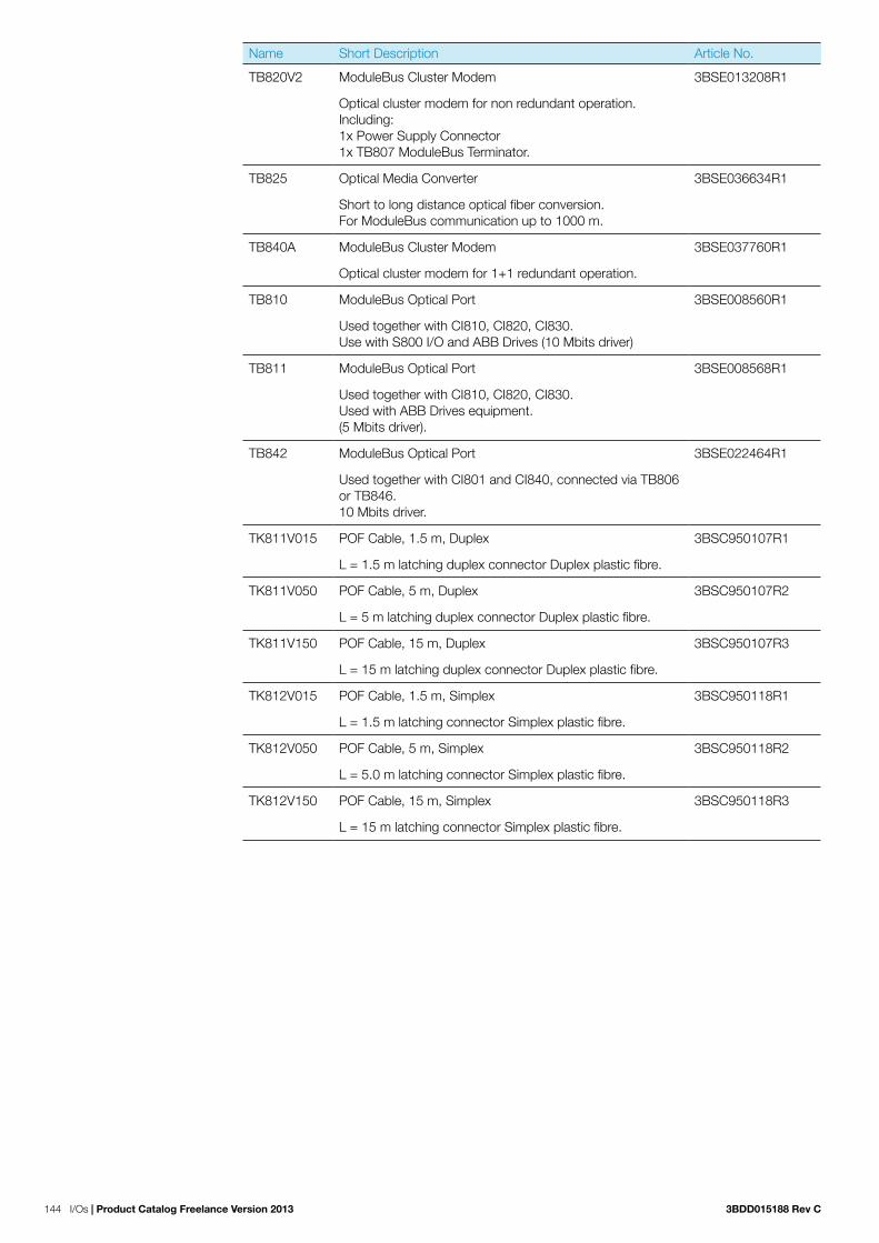
144 I/Os | Product Catalog Freelance Version 2013 3BDD015188 Rev C
Name Short Description Article No.
TB820V2 ModuleBus Cluster Modem 3BSE013208R1
Optical cluster modem for non redundant operation. Including: 1x Power Supply Connector 1x TB807 ModuleBus Terminator.
TB825 Optical Media Converter 3BSE036634R1
Short to long distance optical fiber conversion. For ModuleBus communication up to 1000 m.
TB840A ModuleBus Cluster Modem 3BSE037760R1
Optical cluster modem for 1+1 redundant operation.
TB810 ModuleBus Optical Port 3BSE008560R1
Used together with CI810, CI820, CI830. Use with S800 I/O and ABB Drives (10 Mbits driver)
TB811 ModuleBus Optical Port 3BSE008568R1
Used together with CI810, CI820, CI830. Used with ABB Drives equipment. (5 Mbits driver).
TB842 ModuleBus Optical Port 3BSE022464R1
Used together with CI801 and CI840, connected via TB806 or TB846. 10 Mbits driver.
TK811V015 POF Cable, 1.5 m, Duplex 3BSC950107R1
L = 1.5 m latching duplex connector Duplex plastic fibre.
TK811V050 POF Cable, 5 m, Duplex 3BSC950107R2
L = 5 m latching duplex connector Duplex plastic fibre.
TK811V150 POF Cable, 15 m, Duplex 3BSC950107R3
L = 15 m latching duplex connector Duplex plastic fibre.
TK812V015 POF Cable, 1.5 m, Simplex 3BSC950118R1
L = 1.5 m latching connector Simplex plastic fibre.
TK812V050 POF Cable, 5 m, Simplex 3BSC950118R2
L = 5.0 m latching connector Simplex plastic fibre.
TK812V150 POF Cable, 15 m, Simplex 3BSC950118R3
L = 15 m latching connector Simplex plastic fibre.

3BDD015188 Rev C Product Catalog Freelance Version 2013 | I/Os 145
5.3.11 Power suppliesName Short Description Article No.
SD821 Power Supply Device 3BSC610037R1
Input 115 / 230 VAC, switch selectable, output 24 VDC, 2.5 A. If redundant power application is required connect to SS82x Voting Unit. Width = 50 mm. DIN rail mounted.
SD822 Power Supply Device 3BSC610038R1
Input 115 / 230 VAC, switch selectable, output 24 VDC, 5 A. If redundant power application is required connect to SS82x Voting Unit. Width = 65 mm. DIN rail mounted.
SD823 Power Supply Device 3BSC610039R1
Input 115 / 230 VAC, switch selectable, output 24 VDC, 10 A. If redundant power application is required connect to SS82x Voting Unit. Width = 120 mm. DIN rail mounted.
SS822 Power Voting Unit 3BSC610042R1
With dual 24 VDC 20 A inputs, single 24 VDC, 20 A output. Each power input supervised. Used if redundant power supply is required. For use with SD821 / 822 / 823. Width=50 mm. DIN rail mounted.
SD831 Power Supply Device 3BSC610064R1
Input 100-240 VAC or 110-300 VDC. Output 24 VDC, 3 A. If redundant power application is required connect to SS8XX Voting unit. Width = 35 mm. DIN rail mounted.
SD832 Power Supply Device 3BSC610065R1
Input 100-120 / 200-240 VAC. Output 24 VDC, 5 A, auto-select input. If redundant power application is required connect to SD8XX Voting unit. Width = 35 mm. DIN rail mounted.
SD833 Power Supply Device 3BSC610066R1
Input 100-120 / 200-240 VAC, auto-select input. Output 24 VDC, 10 A. If redundant power application is required con-nect to SD8XX Voting unit. Width = 60 mm. DIN rail mounted.
SD834 Power Supply Device 3BSC610067R1
Input 100-240 VAC or 110-300 VDC. Output 24 VDC, 20 A. If redundant power application is required connect to SS8XX Voting unit. Width = 85 mm. DIN rail mounted.
SS832 Voting Device 3BSC610068R1
Input 24 VDC. Dual 24 V to single 24 V, 2x 10 A. Width = 35 mm. DIN rail mounted.

146 I/Os | Product Catalog Freelance Version 2013 3BDD015188 Rev C
5.3.12 User documentationName Short Description Article No.
S800 I/O General Information and Installation 3BSE020923R5001
User’s Guide.
S800 I/O Modules and Termination Units 3BSE020924R5011
User’s Guide.
S800 I/O Fieldbus Communication Interface for PROFIBUS DP / DP-V1
3BSE020926R5001
User’s Guide.
S800 I/O Modules and Termination Units with Intrinsic Safety Interface 3BSE020927R4001
User’s Guide.
S800 I/O PROFIBUS FCI - Memory maps for CI830 3BSE019081R501
Reference Manual.
S800 I/O PROFIBUS FCI - Memory maps for CI840 3BSE025251R5001
Reference Manual.
S800 I/O PROFIBUS FCI - Memory maps for CI801 3BSE036959R5001
Reference Manual.

3BDD015188 Rev C Product Catalog Freelance Version 2013 | I/Os 147
5.3 S900 Remote I/O
5.3.13 System description of S900 Remote I/O systemS900 provides the input and output modules needed for intrinsically safe field signal connection. The field signals are digitized in every S900 functional module, electrically isolated, and then output via an internal serial bus. The communication interface converts the signals to adapt them to the standard-ized PROFIBUS-DP V1 fieldbus protocol.
Supervisory process control systems, DCS or SCADA systems use an intrinsically safe fieldbus to communicate with the com-munication interface. A Profibus connect allows the configu-ration of the individual S900 stations with cyclic data exchange, acyclic services and communication with HART-compatible field instruments. All functional modules can be replaced eas-ily and quickly, which is an advantage especially in the instal-lation or maintenance phase in hazardous area. The functional modules and the – optionally redundant – communication interface modules placed in Zone 1 can be removed and plugged in while operation is running.
Integrated encapsulated switch-off mechanisms allow for hot swapping of the power supplies. Due to its little space require-ments and robust design and its environmentally ruggedized case, the S900 Remote I/O System is a cost-saving solution for use on site, in hazardous Zone 1 or Zone 2 areas (ATEX).
Various installation solutions for different tasksThe S900 components are arranged in a passive termination unit for direct mounting in a junction box. The termination unit contains the internal redundant communication interface and all connectors for the field circuitry, communication and primary power. The functional modules are plugged in the appropriate slot of the termination unit.
Two termination unit versions are available: a redundant one with slots for two power supplies and two communication interfaces and 16 slots for the different functional modules (type TU921), and a non-redundant one (integrated in a field housing type CB220N) with a maximum of 4 slots. Digital functional modules are designed for up to 8 channels, and analog functional modules for up to 4 channels. Thus, up to 128 digital or up to 64 analog channels are possible for each fieldbus node when using a redundant termination unit. It is also possible to combine different functional modules. Up to 125 fieldbus nodes can be connected to a single fieldbus net-work. This means that up to 10,000 inputs or outputs can be handled by single S900 network. Extensions beyond this scope depend upon the fieldbus type used.
No external signal adaptation or routing requiredS900 provides various input and output modules: Analog input modules with or without integral transmitter supply, or with direct temperature measuring input for 2-, 3- or 4-wire resis-tance thermometers or thermocouples with internal cold junc-tion compensation. Analog output modules for direct positioner or actuator control. Solenoid driver units or NAMUR inputs for intrinsically safe and short-circuit-proof power supply of digital field instruments.
Additionally, options are available for critical applications, allowing for channel-wise electrical isolation of the inputs and outputs. S900 permits direct connection of the entire field level through only 2 lines. As no separate routing, power supply or fusing is needed, the installation cost is reduced considerably.

148 I/Os | Product Catalog Freelance Version 2013 3BDD015188 Rev C
Consistent configurationJust like local I/O modules, the individual S900 Remote I/O stations can be configured directly, using the engineering tool integrated in the Distributed Control System (DCS). The Device Type Manager (DTM) exactly “knows” the functionality and parameters of the individual functional modules and their interface to the bus. Besides the module configuration, the DTM also provides for forcing (simulation) of the inputs and outputs and for display of the diagnosis messages.
Due to the standardized FDT / DTM interface the DTM can be easily integrated in the configuration tool of the DCS. Since the DTM belongs to the instrument and not to the DCS, the user has to get familiar with the operating procedure only once. The complete configuration and all parameters are automati-cally loaded into the S900 stations when the bus network is starting up or upon replacement of a hardware component. So, this is a real “plug & play” system.
In consequence, there is no local service interface for the communication interface, since it is no longer needed. The configuration and parameter data is exclusively visualized and updated by the DTM. The data is stored in the central data-base of the engineering tool. Thus, system-wide data consis-tency is ensured. The efforts needed for commissioning and trouble-shooting are reduced to the minimum. Of course, it is alternatively possible to use the GSD file for commissioning/putting into operation.
System features of S900 Remote I/O system
S900 is a remote I/O system for use in hazardous areas. It provides bus-compatible local inputs and outputs (protection class IP20) for connection of digital and analog field instruments. Due to its degree of explosion protection it can be mounted in both hazardous areas (zone 1 and zone 2 / ATEX) and safe areas.
The system consists of a termination unit accommodating the power supply units, the communication interfaces, and the I/O modules. The passive termination unit ensures power distribution and data transfer, and also provides the connection platform. The power supply units reliably power the entire system. One power supply unit is sufficient for normal operation. A second (redundant) power supply unit can be added, to improve the system availability (for termination unit TU921). The communication interface controls all data traffic between the I/O modules and the distributed control system (DCS) or the programmable logical controller (PLC). The communi-cation interfaces can also be used in redundancy mode (line redundancy and station redundancy with termination unit TU921).
The termination unit is accommodated in a suitable field hous-ing (junction box) to protect it from environmental exposure. When mounting the unit in a hazardous area you have to use a field housing with increased safety Ex-e. Appropriate ready-made S900 field housings are available.
The S900 Remote I/O System is powered / connected via sufficiently protected terminals on the termination unit, with increased safety. The power supply units, the communication interfaces, and the I/O modules are plugged into the termina-tion unit and locked automatically. The power supply modules have a built-in shut-off mechanism with automatic locking and can be plugged / removed under power (even in zone 1 / ATEX), although the power supply in the primary circuit is still active in this case. As a result, the S900 Remote I/O system does not require a flame-proof enclosure or pres-surized housing and, therefore, is easy to handle.
The termination unit and the power supply unit(s) ensure intrinsically safe power supply of the communication inter-faces and up to 16 I/O modules. The mounting termination unit provides all internal connections. Thus, only the peripheral units need to be connected by the user. Also, hot swapping of the communication interfaces and I/O modules is possible, i.e. these units can be connected or removed during operation. This ensures easy replaceability of all active components, and a high degree of flexibility and user-friendliness.
Field instruments complying with protection class Ex ia IIC / IIID can be connected to the Ex I/O modules. Up to 16 I/O mod-ules can be run on the same termination unit. Each I/O mod-ule is designed for connecting 2, 4, 6 or 8 field instruments, depending on the respective model. The I/O modules and the underlying field instrument level are powered via the termination unit. All intrinsically safe modules are self-feeding and short-circuit proof. No separate routing level with additional power supply and individual fusing is required.
HART communication in the field with all analog S900 I/O modules is possible via a PC or a hand-held terminal. In addi-tion, the special HART variants allow for a consistent HART communication up to the distributed control system (DCS). Cyclic transmission of all secondary HART variables, HART diagnosis, and (acyclic) configuration of all HART devices are possible.
The S900 I/O modules are slot-addressed and, therefore, do not require any settings on the modules themselves. The PROFIBUS address is set via three coding switches on TU921 and two coding switches on CB220N. The S900 communica-tion interface, the I/O modules, and the connected HART devices are configured and parameterized via a fieldbus net-work. No additional configuration and parameterization net-work is required. The communication interface and the I/O modules have built-in LEDs allowing for “on site“ diagnostics. All diagnostic and status indicator LEDs comply with DIN EN 60073 and NAMUR NE44. In addition, PROFIBUS diagnosis down to channel-specific error messages is possible via the communication bus.

3BDD015188 Rev C Product Catalog Freelance Version 2013 | I/Os 149
Required S900 componentsThe S900 Remote I/O System for hazardous area Ex zone 1 in its minimum hardware configuration (based on termination unit TU921S) consists of the following components:
Type TU921S Extended Termination Unit / TU16R-Ex
Type SA920S Power Supply 24 V DC
Type CI920AS Communication Interface / CIPBA-Ex
Type BP914S Sub D connector Ex i for intrinsically safe Profibus DP (RS485-IS)
Type DX910S Digital I/O Module / DIO8-Ex
Type BI9xxS Fieldbus isolating repeater / (see ordering information for accessories)
If required, a 230 VAC / 24 VDC power supply unit must be provided by the customer to ensure 24 VDC supply of the S900 Remote I/O System.
For more installation details refer to the installation guide on the CD910 (Catalog No. 3KDE175839L9100). The CD910 will be delivered with every ordered TU921 or CB220N.
Requirements on PLC/DCS master systemsS900 Remote I/O can be connected to systems with a PROFIBUS DP master.
The PROFIBUS-DP V0 services provide the following S900 Remote I/O functions:
− Configuring / setting parameters of the S900 Remote I/O station by restarting all slaves.
− S900 diagnosis messages − Reading HART secondary variables from the connected
field instruments − Reading HART diagnosis from the connected field instru-ments through PROFIBUS diagnosis messages.
To be able to use the full range of functions provided by the S900 Remote I/O System, the master has to support addi-tional functions. Modern, state of the art master systems sup-port PROFIBUS-DP V1 services, and are capable to (re)load user-defined and configuration parameters while the system is running, without affecting other slaves or requiring to restart the network.
PROFIBUS-DP V1 services allow you to − simulate (force) the S900 inputs and outputs − configure HART field instruments connected to the system
You can select special user-defined and configuration parame-ters and (re)load them while the system is running to
− change the parameters of the communication interfaces or of individual I/O modules
− add more S900 Remote I/O groups − add, remove or replace S900 I/O modules.
All I/O modules not involved in these parameter or configura-tion changes continue cyclic communication. The S900 outputs hold their values / states while the master is downloading the parameters.
Modern master systems meeting the requirements stated above are, for example
− System 800xA − Melody / AC 870P − Freelance − other systems
Number of PROFIBUS nodesWith PROFIBUS-DP, a maximum of 32 nodes (including the master and the class 2 configuration tool, if applicable) can be connected to a segment. A maximum of 16 nodes per seg-ment can be connected to the intrinsically safe PROFIBUS-DP. When using repeaters, you can connect up to 126 nodes to a DP master.The specified transmission rate and the max. permissible cable length of the segments (see installation guide) must be observed. For example, a cable length of 400 m (1314 ft) is permissible for a network with a transmission rate of 500 Kbauds. Longer cables are possible when using fiber optic cables.
I/O module power supplyThe S900 power supplies are designed for two communication interfaces and up to 16 I/O modules of any type. No system limitations result from the selection of typical combinations of the module types DX910, AI930, AI950 and DO910. The power supply dimension on the secondary side can cause a reduction of the possible number of I/O modules, if:
− the type DO910 is used to power valves which support less than 1,500 Ohm input impedance
− types AO920 (or AI920 / AI921) are to be used exclusively.
In these cases, the user must ensure that the total power loss of all Ex modules and communication interfaces is less than 55 Watt. (For non-Ex modules / type N a total power loss of less than 60 Watt must be observed).
When using redundant termination units (e.g. TU921), a redundant slot can be left free for the power supply unit if required. The power supply units are designed to power the entire S900 station.

150 I/Os | Product Catalog Freelance Version 2013 3BDD015188 Rev C
Number of I/O modulesIn accordance with the PROFIBUS standard up to 240 user parameters are available for parameterizing the S900 System. The S900 System uses one byte per module in Mode 1, and six bytes per module in Mode 2 for the module parameteriza-tion. The 16 slots can be assigned as required.
The total quantity of I/O data must not exceed 216 bytes. If no HART variables are to be transmitted, no system limitations result from this, since the max. possible I/O data quantity is 128 bytes, with up to 8 bytes per module and a maximum of 16 modules. Thus, an S900 Remote I/O Station can be equipped with up to 16 I/O modules.
However, the max. number of transferable HART secondary variables is limited, since the maximum quantity of I/O data is 240 bytes. The max. number of HART variables can be derived from the table below. If the system is configured using a con-figuration tool based on the FDT/DTM technology, the DTM will monitor the system limits (see the DTM manual).
Modules I/O Modules HART Devices
Out Bytes In/Status Bytes
In Bytes
CI920 ¹ 0 0 0
AI930 ¹ 0 8 0/4/16/32 ²
AO930 ¹ 8 0 0/4/16/32 ²
AI950 ¹ 0 8 0
DX910 ¹ 1 1 0
DI910 with Status ¹
1 2 0
DO910 ¹ 1 0 0
DP910 ¹ 2 8 0
I/O data of various I/O modules
1) stands for S900 S/B/N modules2) 0...8 (0/4/16/32) HART variables per channel can be selected here
Calculation of the total I/O data example
Modules: 1 x CI920, 6 x AI930, 4 x AO930, 6 x DX910 with status
Total of out bytes = 6 x 0 + 4 x 8 + 6 x 1 = 38Total of in/status bytes = 6 x 8 + 4 x 0 + 6 x 2 = 60
Total of I/O bytes = 38 + 60 = 98Number of still available bytes = 216 – 98 = 118Number of possible HART variables = 118 / 4 = 29
Cycle timeThe PROFIBUS master defines the transmission rate used in the system. The internal CAN-Bus cycle time is 5 ms for pro-cessing 128 digital signals and 20 ms for processing 64 analog signals. The response time of the entire system, consisting of controller and remote I/O, depends on the total I/O data quan-tity of all PROFIBUS nodes and the processing speed of the supervisory system.
The S900 output data are synchronized with the PROFIBUS. Therefore, the internal cycle time only needs to be considered once.
The following approximation formula is valid TR = Ti + 2 x TB + TS
TR = response timeTi = internal cycle timeTB = cycle time of the higher-level busTS = cycle time of the DCS
With a bus cycle time of 5 ms and a DCS cycle time of 5 ms, a response time of TR = 5 + 2 x 5 + 5 = 20 ms results from this for the 128 digital signals for typical application.
Figure 16: PROFIBUS DP cycle time
Range of applicationsThe S900 Remote I/O System is tailored to applications in the field of process engineering. It provides a variety of functions which make the system robust, fault-tolerant and easy to diagnose. The main features of the system are its compact design, the redundant bus architecture, and the direct access to the configuration data of the connected HART-compatible instruments via the fieldbus network.
The S900 Remote I/O System is the economic extension of your sensors and actors which can be directly contacted via the standardized fieldbus protocol. Due to the FDT technology both simple digital field instruments or temperature sensors and the well-proven basis of the intelligent HART instruments can be integrated easily into the fieldbus system.
As a result, the S900 Remote I/O System provides a consid-erable cost-saving potential for all applications in the field of process engineering.
1.00
10.00
100.00
1000.00
10000.00
TB [ms]
9600 Baud
45.45 KBaud
93.75 KBaud
500 KBaud
1.5 MBaud
1 3 5 7 9 11 13 15 17 19 21 23 25 27 29 31
Slaves

3BDD015188 Rev C Product Catalog Freelance Version 2013 | I/Os 151
5.3.14 Technical data of S900 Remote I/O system
Device variants for:Safe area mounting Type NZone 2 mounting Type BZone 1 mounting Type S
Attention: Do not mix Type N, B, S components!
General data of S900 Remote I/O system
Power supply
MaterialColorExternal dimensions (W x H x D)Weight
Aluminum, powder coatedRAL 9002 + black47 x 129 x 117 mmApprox. 1.5 kg
I/O modules and communication interface
MaterialFire protection classColor (light grey)External dimensions (W x H x D)WeightTest voltage (fieldbus, PS, I/O)Test voltage (fieldbus -> I/O)Test voltage (I/O -> I/O)
PCV2, UL 94 (DIN IEC 707)RAL 900220 x 104 x 104 mmApprox. 0.15 kg1500 V500 V (intrinsically safe Profibus)500 V (with el. isolation)
Termination unit
Material
ColorExternal dimensions (W x H x D)Weight
Aluminium corrosion protected, electrically conductiveAluminium + RAL 9002498 x 274 x 147 mmApprox. 3 kg
Mounting Zone1 / Zone 2 (modules B / S only)
Operating temperature horizontal mounting vertical mountingStorage temperatureAltitude above sea level
-20 °C...60 °C not allowed-40 °C...85 °Cmax. 2000 m
Standards
Transport / shockFunction / VibrationEMCHumidityRelative humidityCondensation
Corrosive gases
15 g (IEC 60068-2-27)2 g (IEC 60068-2-6)EN 61326IEC 60068-2-30max. 93 % +/- 3 % at 40°C+/- 2 K for 24 hoursANSI/ISA S71.04 G3 Harsh Group A DIN EN 60068-2-60 Method 4

152 I/Os | Product Catalog Freelance Version 2013 3BDD015188 Rev C
System architecture of S900 Remote I/O system
I/O modules per stationNo. of channels
16 (on Termination Unit)2, 4 and 8 channel
S900 stations for Zone 1 (IS fieldbus via IS isolating repeater)
Mounting options Stations / isolating repeater
Safe area, Zone 2, Zone 1Max. 15 stations type S + 1 isolating repeater
S900 stations for Zone 2 (IS fieldbus via IS isolating repeater)
Mounting options Stations / isolating repeater
Safe area, Zone 2Max. 15 stations type B + 1 isolating repeater
S900 stations for safe area (standard fieldbus)
Mounting options S900 stations per bus line
Bus length (copper)
Bus length (fibre optic)
Safe areaPROFIBUS non-Ex standard
200 m (1.5 MBaud) 400 m (0.5 MBaud)(see instruction manual)
5.3.15 Redundant termination unit TU921S/B/N − Termination unit for up to 16 I/O modules − Prepared for redundant system power and communication − Up to 4 terminals per channel − Preselection of fieldbus address − Prepared for certified field housing − Mounting in Zone 1 or Zone 2 possible
Name Short Description Article No.
TU921S Redundant Termination Unit (TU16R-Ex) 3KDE175111L9210
For 16 I/O-modules. Redundant communication and power. (Delivery includes CD910).
TU921B Redundant Termination Unit (TU16R-B) 3KDE175112L9210
For 16 I/O-modules. Redundant communication and power. (Delivery includes CD910).
TU921N Redundant Termination Unit (TU16R) 3KDE175113L9210
For 16 I/O-modules. Redundant communication and power. (Delivery includes CD910).

3BDD015188 Rev C Product Catalog Freelance Version 2013 | I/Os 153
Technical data
Technical data TU921S/B/N
Field Terminals
Rated supply voltage (PS) Depending on power supply
System power terminals Screw terminals
Wire CSA 0.5...2.5 mm²
Fieldbus plug connector SUB D, 9 pins
Preselection of bus address 0...126 (rotary switch)
I/O Terminals (type TU921N) Black
I/O Terminals (type TU921B) Ex i (blue)
I/O Terminals (type TU921S) Ex i (blue)
Wire CSA 0.8...2.5 mm²
Connection Spring loaded
Explosion protection (type ...S) PTB 00 ATEX 2156 U II 2(1) G Ex e ib [ia Ga] IIC Gb and II (1) D [Ex ia IIIC Da]
Explosion protection (type ...B) PTB 03 ATEX 2028 II (2) G [Ex ib] IIB/IIC PTB 03 ATEX 2029 II 3 G Ex nAC IIC T4
254 mm
274 mm
147 mm 10 mm
M8
498 mm465 mm
Ø 8,5 mm
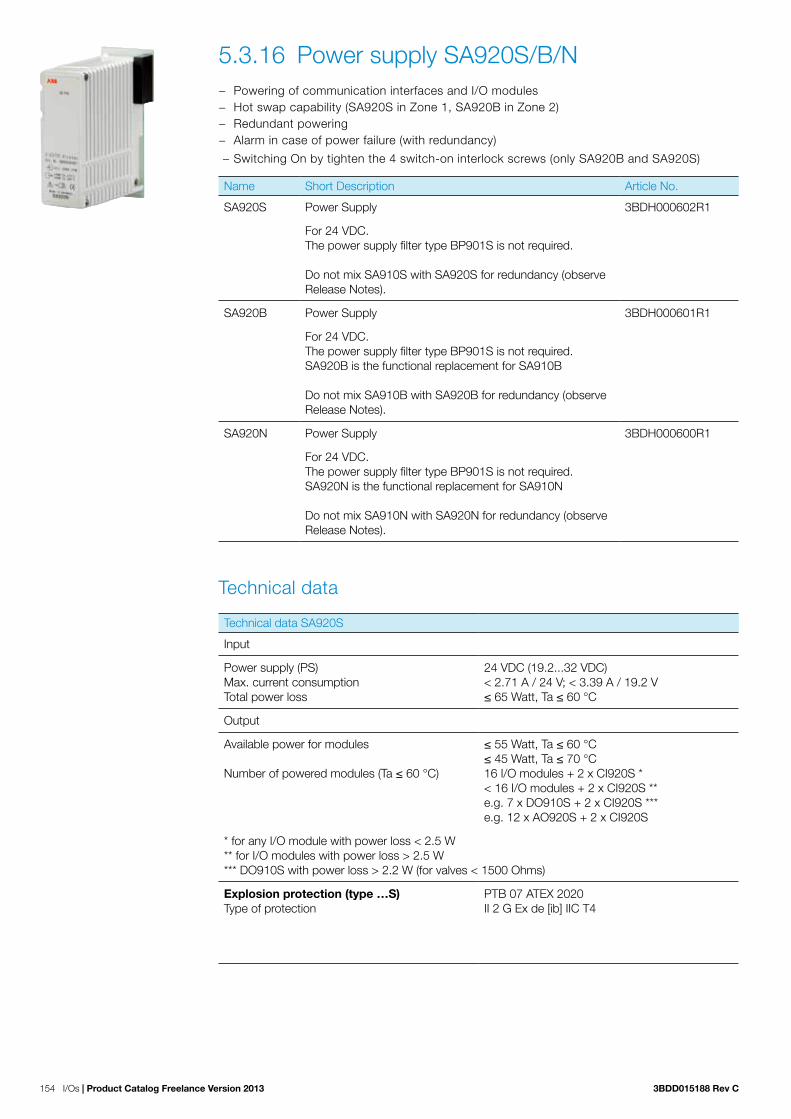
154 I/Os | Product Catalog Freelance Version 2013 3BDD015188 Rev C
5.3.16 Power supply SA920S/B/N − Powering of communication interfaces and I/O modules − Hot swap capability (SA920S in Zone 1, SA920B in Zone 2) − Redundant powering − Alarm in case of power failure (with redundancy)
− Switching On by tighten the 4 switch-on interlock screws (only SA920B and SA920S)
Name Short Description Article No.
SA920S Power Supply 3BDH000602R1
For 24 VDC. The power supply filter type BP901S is not required.
Do not mix SA910S with SA920S for redundancy (observe Release Notes).
SA920B Power Supply 3BDH000601R1
For 24 VDC. The power supply filter type BP901S is not required. SA920B is the functional replacement for SA910B Do not mix SA910B with SA920B for redundancy (observe Release Notes).
SA920N Power Supply 3BDH000600R1
For 24 VDC. The power supply filter type BP901S is not required. SA920N is the functional replacement for SA910N Do not mix SA910N with SA920N for redundancy (observe Release Notes).
Technical data
Technical data SA920S
Input
Power supply (PS) Max. current consumption Total power loss
24 VDC (19.2...32 VDC) < 2.71 A / 24 V; < 3.39 A / 19.2 V ≤ 65 Watt, Ta ≤ 60 °C
Output
Available power for modules Number of powered modules (Ta ≤ 60 °C)
≤ 55 Watt, Ta ≤ 60 °C ≤ 45 Watt, Ta ≤ 70 °C 16 I/O modules + 2 x CI920S * < 16 I/O modules + 2 x CI920S ** e.g. 7 x DO910S + 2 x CI920S *** e.g. 12 x AO920S + 2 x CI920S
* for any I/O module with power loss < 2.5 W ** for I/O modules with power loss > 2.5 W *** DO910S with power loss > 2.2 W (for valves < 1500 Ohms)
Explosion protection (type …S) Type of protection
PTB 07 ATEX 2020 II 2 G Ex de [ib] IIC T4

3BDD015188 Rev C Product Catalog Freelance Version 2013 | I/Os 155
Technical data SA920B
Input
Power supply (PS) Max. current consumption Total power loss
24 VDC (19.2...32 VDC) < 2.71 A / 24 V; < 3.39 A / 19.2 V ≤ 65 Watt, Ta ≤ 60 °C
Output
Available power for modules Number of powered modules (Ta ≤ 60 °C)
≤ 55 Watt, Ta ≤ 60 °C ≤ 45 Watt, Ta ≤ 70 °C 16 I/O modules + 2 x CI920B * < 16 I/O modules + 2 x CI920B ** e.g. 7 x DO910B + 2 x CI920B *** e.g. 12 x AO920B + 2 x CI920B
* for any I/O module with power loss < 2.5 W ** for I/O modules with power loss > 2.5 W *** DO910S with power loss > 2.2 W (for valves < 1500 Ohm)
Explosion protection (type …B) Type of protection
PTB 03 ATEX 2028 II (2) G [Ex ib] IIB/IIC PTB 03 ATEX 2029 II 3 G Ex nAC IIC T4
Technical data SA920N
Input
Power supply (PS) Max. current consumption Total power loss
24 VDC (19.2...32 VDC) < 2.95 A / 24 V; < 3.65 A / 19.2 V ≤ 70 Watt, Ta ≤ 60 °C
Output
Available power for modules Number of powered modules (Ta ≤ 60 °C)
≤ 60 Watt, Ta ≤ 60 °C ≤ 45 Watt, Ta ≤ 70 °C 16 I/O modules + 2 x CI920N * < 16 I/O modules + 2 x CI920N ** e.g. 9 x DO910N + 2 x CI920N ***
* for any I/O module with power loss < 3.4 W ** for I/O modules with power loss > 3.4 W *** DO910N with power loss > 2.2 W (for valves < 1500 Ohm)

156 I/Os | Product Catalog Freelance Version 2013 3BDD015188 Rev C
5.3.17 Communication interface CI920AS/AB/AN − Fieldbus protocol PROFIBUS-DP V1 (IEC 61158) − Coupling of the internal CAN bus to external PROFIBUS − HART protocol on PROFIBUS-DP V1 − Line or media redundancy via two coupling modules − Electrical isolation between field bus, power
− Diagnosis, configuration and parameterization via PROFIBUS
Name Short Description Article No.
CI920AS Communication Interface V 2.1 (CIPBA-Ex) 3BDH000690R1
Use only CI920AS with the same firmware for redundancy for PROFIBUS DP-V1 (observe Release Notes)
CI920AB Communication Interface V 2.1 (CIPBA-B) 3BDH000691R1
Use only CI920AB with the same firmware for redundancy for PROFIBUS DP-V1 (observe Release Notes).
CI920AN Communication Interface V 2.1 (CIPBA) 3BDH000692R1
Use only CI920AN with the same firmware for redundancy for PROFIBUS DP-V1 (observe Release Notes).
Technical data
Technical data CI920AS/AB/AN
Fieldbus
PROFIBUS-DP V1, C1+C2 (IEC 61158), RS485-IS intrinsically safe for CI920AS/ABRS485 for CI920AN
DP baud rate Max. 1.5 Mbaud Hot Configuration in Run (HCIR)
Explosion protection (type …S) PTB 11 ATEX 2001II 2 G Ex ib IIC T4
Explosion protection (type …B) PTB 03 ATEX 2028 II (2) G [Ex ib] IIB/IIC PTB 03 ATEX 2029 II 3 G Ex nAC IIC T4
Via fieldbusStation diagnosisRedundancy diagnosisI/O module diagnosisChannel diagnosis

3BDD015188 Rev C Product Catalog Freelance Version 2013 | I/Os 157
5.3.18 Digital I/O modules
Digital I/O modules DX910S/B/N − Input for dry contacts or proximity switches (NAMUR) − Output for low power intrinsically safe valves − Short and break detection − Electrical isolation between input / bus and input / power − Common return for all inputs / outputs − Configurable as a mixture of inputs and outputs − 8 I/O channel
Name Short Description Article No.
DX910S Digital Input or Output (DIO8-Ex) 3KDE175311L9100
Input for dry contact or NAMUR initiator. Output for low power intrinsic safe valves.
DX910B Digital Input or Output (DIO8-B) 3KDE175312L9100
Input for dry contact or NAMUR initiator. Output for low power intrinsic safe valves.
DX910N Digital Input or Output (DIO8) 3KDE175313L9100
Input for dry contact or NAMUR initiator. Output for low power valves.
Technical data
Technical data DX910S/B/N
Input
No-load voltageShort-circuit currentSwitching point in rangeSwitching hysteresisSwitching frequencyShort-circuit detectionLine-break detection
8 VDC4 mA...5 mA1.4...1.8 mA0.2 mA< 100 Hz0...367 Ohms0...0.2 mA
Explosion protection (type …S) PTB 00 ATEX 2180 II 2 (1) G Ex ib [ia Ga] IIC T4 Gb andII (1) D [Ex ia IIIC Da]
Explosion protection (type …B) PTB 03 ATEX 2078 II (1) G [Ex ia IIC Ga] andII (1) D [Ex ia IIIC Da]PTB 03 ATEX 2079 II 3 G Ex nA IIC T4 Gc
Input or output
Max. short-circuit currentMax. voltageMax. powerExternal inductanceExternal capacitance
IO = 44 mAUO = 9.6 VPO = 106 mWLO = 1 mHCO = 1100 nF

158 I/Os | Product Catalog Freelance Version 2013 3BDD015188 Rev C
Solenoid driver DO910S/B/N − Output for intrinsically safe valves or alarms − Integrated driving power − Short and break detection − Electrical isolation between output / bus and output / power − Electrical isolation channel to channel − 4 channels
Name Short Description Article No.
DO910S Digital Output (DO4-Ex) 3KDE175321L9100
Output for intrinsic safe valves.
DO910B Digital Output (DO4-B) 3KDE175322L9100
Output for intrinsic safe valves.
DO910N Digital Output (DO4) 3KDE175323L9100
Output for valves.
Technical data
Technical data DO910S/B/N
Output Curve A: high-voltageCurve B: low-voltage
Supply voltage and current
No-load voltage
Switching frequency
Curve A: 21 V / 8 mA Curve A: 18 V / 20 mA Curve B: 15 V / 30 mA Curve B: 12 V / 40 mACurve A: approx. 24 V DCCurve B: approx. 18 V DC< 100 Hz
Explosion protection (type …S) PTB 01 ATEX 2008 II 2 (1) G Ex ib [ia Ga] IIC T4 Gb andII (1) D [Ex ia IIIC Da]
Explosion protection (type …B) PTB 03 ATEX 2078 II (1) G [Ex ia IIC Ga] andII (1) D [Ex ia IIIC Da]PTB 03 ATEX 2079 II 3 G Ex nA IIC T4 Gc
Max. short-circuit current
Max. voltage
Max. power
External inductance
External capacitance
Curve A: IO ≤ 80 mACurve B: IO ≤ 100 mACurve A: UO = 25 V Curve B: UO = 19 V Curve A: PO ≤ 750 mW Curve B: PO ≤ 710 mW Curve A: LO = 0.1 mHCurve B: LO = 0.5 mHCurve A: CO = 110 nFCurve B: CO = 140 nF
Further information about power ratings see ATEX documents

3BDD015188 Rev C Product Catalog Freelance Version 2013 | I/Os 159
Relay output DO930N − Relay output for higher switching power − Output configurable as NO or NC contact − Electrical isolation between output / bus and output / power − Electrical isolation channel to channel − Configurable as 4 x changeover contact − Configurable as 6 x NO contact
Name Short Description Article No.
DO930N Relay Output (RO6) 3BDS014114
With 4 normally-open contacts and 2 changeover contacts (only to use with CI920AN Article No. 3BDH000692R1).
Technical data
Technical data DO930N
Output
Switching voltage
Switching current
Switching delay
Contact type
Mechanical life time
max. 60 VDC / 60 VAC min. 12 VDC / 12 VACmax. 1 A (60 VAC, 30 VDC) max. 0.7 A (60 VDC) min. 10 mA (DC) / 10 mA (AC)
> 4 ms...< 12 ms
2 x changeover (channel 1 and 2) 4 x NO contacts (channel 3 to 6) The channels 3+4 and 5+6 resp.are switchable via software as changeover contacts.
For this an external bridge is required at the terminals.
30 x 106 switching cycles
Electrical isolation
Contact circuit to int. bus /module supply
between contact circuits
1500 V
500 V
11 NO
1 2 3
CHANNEL
µC
CH4
CH3
CH2
CH1gn/rd
INTERNAL BUSINTERNAL POWER SUPPLY
4 5 6
CH5
CH6
PW
12 COM13 COM14 NC
21 NO22 COM23 COM24 NC
31 NO32 COM
33 NO34 COM
41 NO42 COM
43 NO44 COM

160 I/Os | Product Catalog Freelance Version 2013 3BDD015188 Rev C
Frequency input DP910S/B/N − Frequency input for dry contacts or proximity switches − Short and break detection − Electrical isolation between input / bus and input / power − Frequency measurement or counting applications − 2 Function blocks − Reset via fieldbus or control input − Status outputs / Direction recognition
Name Short Description Article No.
DP910S Frequency Input (FI2-Ex) 3KDE175361L9100
Input for dry contact or NAMUR initiator.
DP910B Frequency Input (FI2-B) 3KDE175362L9100
Input for dry contact or NAMUR initiator.
DP910N Frequency Input (FI2) 3KDE175363L9100
Input for dry contact or NAMUR initiator.
Technical data
Technical data DP910S/B/N
Input
No-load voltageShort-circuit currentSwitching point in rangeSwitching hysteresisShort-circuit detectionLine-break detectionInput frequencyCounter
8 VDC4...5 mA1.4…1.8 mA0.2 mA300...350 Ohm0.1...0.2 mAMax. 4 kHz, 1.25 kHz w. direction recognition30 bit (29 bit and digit sign)
Explosion protection (type …S) PTB 00 ATEX 2180 II 2 (1) G EEx ib [ia] IIC T4(only up to 2. supplement) 1
Explosion protection (type …B) PTB 03 ATEX 2078 II (1) G [EEx ia] IIB/IIC(only up to 1. supplement) PTB 03 ATEX 2079 II 3 G EEx nA II T4(only up to 1. supplement)
Max. short-circuit currentMax. voltageMax. powerExternal inductanceExternal capacitance
IO = 44 mAUO = 9.6 VPO = 106 mWLO = 1 mHCO = 1100 nF
1 New version is in preparation and will be released acc. to new ATEX standards (3. supplement). Release is planned for Q3/2014.

3BDD015188 Rev C Product Catalog Freelance Version 2013 | I/Os 161
5.3.19 Analog I/O modules
Analog input AI910S/B/N − Power supply for 4...20 mA loop powered 2-wire transmitters − Short and break detection − Electrical isolation between input / bus and input / power − Common return for all inputs − 4 channels
Name Short Description Article No.
AI910S Analog Input (AI4-Ex) 3KDE175511L9100
Transmitter power supply, 4..20 mA.
AI910B Analog Input (AI4-B) 3KDE175512L9100
Transmitter power supply, 4..20 mA.
AI910N Analog Input (AI4) 3KDE175513L9100
Transmitter power supply, 4..20 mA.
Technical data
Technical data AI910S/B/N
Input
Input currentTransmitter supplyInternal current limitationInput impedanceResidual rippleShort-circuit detectionLine-break detection
4...20 mA> 15 V (@ 20 mA)24...26 mA240 Ohm< 100 mV< 5 V< 2 mA
Explosion protection (type …S) PTB 00 ATEX 2058 X II 2 (1) G Ex ib [ia Ga] IIC T4 Gb and II (1) D [Ex ia IIIC Da]
Explosion protection (type …B) PTB 03 ATEX 2078 II (1) G [Ex ia IIC Ga] andII (1) D [Ex ia IIIC Da] PTB 03 ATEX 2079 II 3 G Ex nA IIC T4 Gc
Max. short-circuit currentMax. voltageMax. powerExternal inductanceExternal capacitance
IO = 93 mAUO = 22.1 VPO = 640 mWLO = 0.5 mHCO = 65 nF

162 I/Os | Product Catalog Freelance Version 2013 3BDD015188 Rev C
Analog input, HART, AI930S/B/N − Power supply for 4...20 mA loop powered 2-wire transmitters − Short and break detection − Electrical isolation between input / bus and input / power − Common return for all inputs − 4 channels − Transmission of HART frames via the fieldbus − Cyclic HART variables
Name Short Description Article No.
AI930S Analog Input, HART (AI4H-Ex) 3KDE175511L9300
Transmitter power supply, 4..20 mA.
AI930B Analog Input, HART (AI4H-B) 3KDE175512L9300
Transmitter power supply, 4..20 mA.
AI930N Analog Input, HART (AI4H) 3KDE175513L9300
Transmitter power supply, 4..20 mA.
Technical data
Technical data AI930S/B/N
Input
Input currentTransmitter supplyInternal current limitationInput impedanceResidual rippleShort-circuit detectionLine-break detection
4...20 mA> 15 V (20 mA)24...26 mA240 Ohms< 100 mV< 5 V< 2 mA
Explosion protection (type …S) PTB 00 ATEX 2058 X II 2 (1) G Ex ib [ia Ga] IIC T4 Gb andII (1) D [Ex ia IIIC Da]
Explosion protection (type …B) PTB 03 ATEX 2078 II (1) G [Ex ia IIC Ga] andII (1) D [Ex ia IIIC Da] PTB 03 ATEX 2079 II 3 G Ex nA IIC T4 Gc
Max. short-circuit currentMax. voltageMax. powerExternal inductanceExternal capacitance
IO = 93 mAUO = 22.1 VPO = 640 mWLO = 0.5 mHCO = 100 nF

3BDD015188 Rev C Product Catalog Freelance Version 2013 | I/Os 163
Analog input, HART, passive, AI931S/B/N − Passive inputs for 0/4...20 mA − Short and break detection − Electrical isolation between input / bus and input / power − Common return for all inputs − 4 channels − Transmission of HART frames via the fieldbus − Cyclic HART variables
Name Short Description Article No.
AI931S Analog Input, HART (AI4H-Ex) 3KDE175511L9310
Passive input, 0/4..20 mA.
AI931B Analog Input, HART (AI4H-B) 3KDE175512L9310
Passive input, 0/4..20 mA.
AI931N Analog Input, HART (AI4H) 3KDE175513L9310
Passive input, 0/4..20 mA.
Technical data
Technical data AI931S/B/N
Input
Input currentInput impedanceLine-break / short circuit det.
0/4...20 mA240 Ohm< 2 mA (4...20 mA)
Explosion protection (type …S) PTB 00 ATEX 2058 X II 2 (1) G Ex ib [ia Ga] IIC T4 Gb andII (1) D [Ex ia IIIC Da]
Explosion protection (type …B) PTB 03 ATEX 2078 II (1) G [Ex ia IIC Ga] andII (1) D [Ex ia IIIC Da] PTB 03 ATEX 2079 II 3 G Ex nA IIC T4 Gc
Max. short-circuit currentMax. voltageMax. power
IO = 16 mAUO = 7.2 VPO = 29 mW

164 I/Os | Product Catalog Freelance Version 2013 3BDD015188 Rev C
Temperature input AI950S/B/N − Pt 100, Pt 1000, Ni 100, 0...3 kOhm in 2-/3-/4-wire technique − Thermocouple Type B, E, J, K, L, N, R, S, T, U, mV − Internal or external cold junction compensation − Short and break detection − Electrical isolation between input / bus and input / power − Electrical isolation channel to channel − 4 channels
Name Short Description Article No.
AI950S Temperature (TI4-Ex) 3KDE175521L9500
Pt100, Pt1000, Ni100 in 2-/3-/4-wire technique thermo-couples type B, E, J, K, L, N, R, S, T isolated inputs channel by channel.
AI950B Temperature (TI4-B) 3KDE175522L9500
Pt100, Pt1000, Ni100 in 2-/3-/4-wire technique thermo-couples type B, E, J, K, L, N, R, S, T isolated inputs channel by channel.
AI950N Temperature (TI4) 3KDE175523L9500
Pt100, Pt1000, Ni100 in 2-/3-/4-wire technique thermo-couples type B, E, J, K, L, N, R, S, T isolated inputs channel by channel.
Technical data
Technical data AI950S/B/N
Input
Input (Pt 100, Pt 1000)Wire resistance (4 wire)Wire resistance (3 wire)Wire resistance (2 wire)Short-circuit detectionSensor, line-break detection
< 50 Ohms for each wire0...10 Ohms symmetric< 10 Ohms< 5 Ohms> 10 kOhms
Input (Thermocouple)Line-break detection < 100 nA , > 150 mV
Explosion protection (type …S) PTB 00 ATEX 2182 II 2 (1) G Ex ib [ia Ga] IIC T4 Gb andII (1) D [Ex ia IIIC Da]
Explosion protection (type …B) PTB 00 ATEX 2078 II (1) G [Ex ia IIC Ga] andII (1) D [Ex ia IIIC Da] PTB 00 ATEX 2079 II 3 G Ex nA IIC T4 Gc
Max. short-circuit currentMax. voltageMax. powerExternal inductanceExternal capacitance
IO = 25 mAUO = 5.5 VPO = 35 mWLO = 2 mHCO = 1600 nF

3BDD015188 Rev C Product Catalog Freelance Version 2013 | I/Os 165
Analog output AO910S/B/N − Output signal 0/4...20 mA for actuators − Short and break detection − Electrical isolation between output / bus and output / power − Output with common ground − 4 channels
Name Short Description Article No.
AO910S Analog Output (AO4-Ex) 3KDE175531L9100
Output 0/4..20 mA.
AO910B Analog Output (AO4-B) 3KDE175532L9100
Output 0/4..20 mA.
AO910N Analog Output (AO4) 3KDE175533L9100
Output 0/4..20 mA.
Technical data
Technical data AO910S/B/N
Output
Output currentRangeLoadShort-circuit detectionLine-break detection
0/4...20 mA0...24 mA700 Ohms (20 mA)< 30 Ohms (Ia > 2 mA)15...18 V
Explosion protection (type …S) PTB 02 ATEX 2029 II 2 (1) G Ex ib [ia Ga] IIC T4 Gb andII (1) D [Ex ia IIIC Da]
Explosion protection (type …B) PTB 03 ATEX 2078 II (1) G [Ex ia IIC Ga] and II (1) D [Ex ia IIIC Da] PTB 03 ATEX 2079 II 3 G Ex nA IIC T4 Gc
Max. short-circuit currentMax. voltageMax. powerExternal inductanceExternal capacitance
IO = 93 mAUO = 22.1 VPO = 640 mWLO = 0.5 mHCO = 65 nF

166 I/Os | Product Catalog Freelance Version 2013 3BDD015188 Rev C
Analog output, isolated AO920S/B/N − Output signal 0/4...20 mA for actuators − Short and break detection − Electrical isolation between output / bus and output / power − Electrical isolation channel to channel − 4 channels
Name Short Description Article No.
AO920S Analog Output, isolated (AO4I-Ex) 3KDE175531L9200
Output 0/4..20 mA. Isolated outputs channel by channel.
AO920B Analog Output, isolated (AO4I-B) 3KDE175532L9200
Output 0/4..20 mA. Isolated outputs channel by channel.
AO920N Analog Output, isolated (AO4I) 3KDE175533L9200
Output 0/4..20 mA. Isolated outputs channel by channel.
Technical data
Technical data AO920S/B/N
Output
Output currentRangeLoadShort-circuit detectionLine-break detection
0/4...20 mA0...22 mA700 Ohms (20 mA)< 50 Ohms< 2 mA
Explosion protection (type …S) PTB 00 ATEX 2200 II 2 (1) G Ex ib [ia Ga] IIC T4 Gb andII (1) D [Ex ia IIIC Da]
Explosion protection (type …B) PTB 03 ATEX 2078 II (1) G [Ex ia IIC Ga] andII (1) D [Ex ia IIIC Da] PTB 03 ATEX 2079 II 3 G Ex nA IIC T4 Gc
Max. short-circuit currentMax. voltageMax. powerExternal inductanceExternal capacitance
IO = 80 mAUO =18.9 VPO = 510 mWLO = 2 mHCO = 100 nF

3BDD015188 Rev C Product Catalog Freelance Version 2013 | I/Os 167
Analog output, HART, AO930S/B/N − Output signal 0/4...20 mA for actuators − Short and break detection − Electrical isolation between output / bus and output / power − Output with common ground − 4 channels − Transmission of HART frames via the fieldbus − Cyclic HART variables
Name Short Description Article No.
AO930S Analog Output, HART (AO4H-Ex) 3KDE175531L9300
Output 0/4..20 mA.
AO930B Analog Output, HART (AO4H-B) 3KDE175532L9300
Output 0/4..20 mA.
AO930N Analog Output, HART (AO4H) 3KDE175533L9300
Output 0/4..20 mA.
Technical data
Technical data AO930S/B/N
Output
Output currentRangeLoadShort-circuit detectionLine-break detection
0/4...20 mA0...24 mA700 Ohm (20 mA)< 30 Ohm (Ia > 2 mA)15...18 V
Explosion protection (type …S) PTB 02 ATEX 2029 II 2 (1) G Ex ib [ia Ga] IIC T4 Gb andII (1) D [Ex ia IIIC Da]
Explosion protection (type …B) PTB 03 ATEX 2078 II (1) G [Ex ia IIC Ga] andII (1) D [Ex ia IIIC Da] PTB 03 ATEX 2079 III 3 G Ex nA IIC T4 Gc
Max. short-circuit currentMax. voltageMax. powerExternal inductanceExternal capacitance
IO = 93 mAUO = 22.1 VPO = 640 mWLO = 0.5 mHCO = 65 nF

168 I/Os | Product Catalog Freelance Version 2013 3BDD015188 Rev C
5.3.20 Field housing
Field housing FH660S, FH680S − Stainless steel field housing for extended termination unit − Prepared for wall mounting − Mounting in Zone 1 or Zone 2
Name Short Description Article No.
FH660S - 2000
Field housing 3KDE175804V2000
Including the following components: Termination Unit TU921S and 4 TerminalsUK10N
FH660S - 2020
Field housing 3KDE175804V2020
Including the following components: Termination Unit TU921S, 4 Terminals UK10Nand 2 Switches
FH680S - 2020
Field housing 3KDE175811V2020
Including the following components: Termination Unit TU921S, 4 Terminals UK10Nand 2 Switches
600
Side view FH660S
600
300275
Bottom view FH660S

3BDD015188 Rev C Product Catalog Freelance Version 2013 | I/Os 169
Technical data
Technical data FH660S/FH680S
Explosion protection (type …S)Type of protection
PTB 02 ATEX 1133II 2(1) G Ex d e ia/ib [ia Ga] mb IIC T4 GbII 2(1) D Ex tb [Ex ia IIIC Da] IIIC T135°C Db
General Data FH660S
External dimensions (W x H x D)Protection degreeDrain plug/breatherDoor hingesMaterialCable gland for central power cable diameter for field signals and fieldbus cable diameterExternal earthWeight without S900 Process I/O fully equipped
600 x 600 x 300 mmIP 66 (EN 60529)M25, IP 56Left hand sideM6, stainless steel 1.4301Brass (chromium-plated)6 x M20 / 2 x M32 8.5...13 mm / 17.5…25 mm100 x M16 6…11 mmM6, stainless steel 1.4301 Approx. 24 kg Approx. 33 kg
General Data FH680S
External dimensions (W x H x D)Protection degreeDrain plug/breatherDoor hingesMaterialCable gland for central power cable diameter for field signals and fieldbus cable diameterExternal earthWeight without S900 Process I/O fully equipped
600 x 800 x 300 mmIP 66 (EN 60529)M25, IP 56Left hand sideM6, stainless steel 1.4301Brass (chromium-plated)6 x M20 / 2 x M32 8.5...13 mm / 17.5…25 mm100 x M16 6…11 mmM6, stainless steel 1.4301 Approx. 31 kg Approx. 40 kg
Field Housing roofName Short Description Article No.
S900 - BI100 Field Housing roof 3KDE175831L1000
Weather protection. Fits to all field housing.

170 I/Os | Product Catalog Freelance Version 2013 3BDD015188 Rev C
Compact box CB220N − Field housing for power supply and communication interface − Mounting of max. 4 I/O modules − Preselection of fieldbus address (0 ... 99) − Separation of function level and wiring level − Mounting in safe area
Name Short Description Article No.
CB220N Compact-Box 3KDE175613L2210
For power supply SA911N, communication interface CI920AN and four I/O modules S900 type N (Delivery includes CD910).
Technical data
Technical data CB220N
I/O modules and communication interface
MaterialFire protection classColor (light grey)External dimensions (W x H x D)WeightTest voltage (fieldbus, PS, I/O)Test voltage (fieldbus -> I/O)Test voltage (I/O -> I/O)
PCV2, UL 94 (IEC/DIN EN 60695-11)RAL 900220 x 104 x 104 mmApprox. 0.15 kg1500 V500 V500 V (with el. isolation)
Mounting Non-hazardous area
Operating temperature Horizontal mounting Vertical mountingStorage temperature
-20 °C...60 °C, Observe equipping !Not allowed-40 °C...85 °C
Fieldbus connection PROFIBUS DP
Preselection of bus addressBus termination
0 ... 99 (rotary switch)(see manual)
Standards: Transport / shockFunction / VibrationEMCHumidityRelative humidity
Corrosive gases
15 g (IEC 60068-2-27)2 g (IEC 60068-2-6)EN 61326IEC 60068-2-30max. 93 % +/- 3 % at 40°C+/- 2 K for 24 hoursANSI/ISA S71.04 G3 Harsh Group A DIN EN 60068-2-60 Method 4

3BDD015188 Rev C Product Catalog Freelance Version 2013 | I/Os 171
System architecture
System architecture CB220N
I/O modules per stationNo. of channelsBus length (copper)
Max. 42, 4, 6 and 8 channel200 / 400 m (1.5 / 0.5 MBaud)
CB220 in safe area (type N)Mounting possibilitiesStations per bus line
Safe areaPROFIBUS non-Ex standard
General Data: Protection classDoor hingesMaterialColor (light grey)External dimensions (W x H x D)
IP66 (EN60529)Left hand sideAluminium, powder coated RAL 9002208 x 278 x 153 mm
Weight Only CB220 Fully equipped
Approx. 3.8 kgApprox. 5.8 kg
Cable gland For central power Cable diameter For field signals and fieldbus Cable diameter
Brass (chromium-plated)1 x M208...12 mm12 x M166...9 mm
External earthFastening drillings
M6, stainless steel 1.43014 x 6.8 mm diameter
TerminalsSystem power terminals Wire CSA ConnectionI/O and fieldbus terminals (type N) Wire CSA Connection
EEx e (black)0.5 ... 2.5 mm²Screw terminalsBlack0.08 ... 2.5 mm²Spring loaded
Power Supply voltageMax. current consumptionTotal power loss
24 VDC (19.2...32 V)See power supplySee power supply

172 I/Os | Product Catalog Freelance Version 2013 3BDD015188 Rev C
Power supply SA911N for CB220N − Powering of communication interfaces and I/O modules − Hot swap capability
Name Short Description Article No.
SA911N Power supply for CB220N 3KDE175613L9110
For 24 VDC.
Technical data
Technical data SA911N
InputPower supply (PS)Max. current consumptionTotal power loss
24 VDC (19.2...32 V)< 1.25 A / 24 V; < 1.56 A / 19.2 V< 30 Watt
Output:Available power for modules < 27 Watt
Diagnosis:System / Module power on LED green / green
General data:External dimensions (W x H x D)Weight SA911N
45 x 135 x 105 mm
Approx. 0.8 kg
5.3.21 Accessories
Fieldbus isolating repeaterName Short Description Article No.
BI914S Fieldbus isolating repeater 3BDH000649R1
separates one intrinsically safe RS485 fieldbus segment from a non intrinsically safe RS485 fieldbuswith bus terminationBARTEC - 07-7311-97WP/K1E0DIN rail housing with IP20 protection
illustration similar

3BDD015188 Rev C Product Catalog Freelance Version 2013 | I/Os 173
Ring-couplerName Short Description Article No.
BI923S Ring-coupler RS485 / FO - intrinsically safe - Slave 3KDE175831L9230
Separates an intrinsically safe fibre optic ring from a non intrinsically safe RS485 interfaceBARTEC - 07-7311-97WP5400integrated in DIN rail mounted housing with IP20 protectionOptical Plug FSMA(Slave)
BI924S Ring-coupler RS485 / FO intrinsically safe - Master 3KDE175831L9240
Separates an intrinsically safe fibre optic ring from a non intrinsically safe RS485 interfaceBARTEC - 07-7311-97WP5400integrated in DIN rail mounted housing with IP20 protectionOptical Plug FSMA(Master)
BI934S Ring-coupler RS485 / FO intrinsically safe (slave) 3BDH000674R0001
separates an intrinsically safe fibre optic ring from oneintrinsically RS485 fieldbus segmentintegrated in separate field housingBARTEC - 07-3103-2512/9003Optical Plug FSMA
Additional accessoriesName Short Description Article No.
IP920 Module housing 3KDE175831L9200
IP20 protection for empty slots on the termination unit. For use in S900 S, B, and N systems.
IL910 Insert labels 3KDE175839L9101
380 pcs.
BP914S Intrinsically safe PROFIBUS-DP connectorfor CI920AS and CI920AB
D-SUB Connector (color blue) for operating the intrinsically safePROFIBUS-DP with CI920AS and CI920AB(Siemens 6ES7972-0DA60-0XA0)
3BSE067082R1
5.3.22 SoftwareName Short Description Article No.
CD910 Additional Software 3KDE175839L9100
CD ROM incl. S900 Documentation, Certificates, GSD (file)ABB DTM S900 DP and Software ToolsCD ROM will be delivered with all TU921 and CB220 deliveries

174 I/Os | Product Catalog Freelance Version 2013 3BDD015188 Rev C

3BDD015188 Rev C Product Catalog Freelance Version 2013 | Fieldbuses 175
Chapter 6 Fieldbus network components and Profibus configuration for S700
6.3 Profibus DP configuration for S700When the Freelance controllers are equipped with the appropriate Profibus Master module they can communicate over a single Profibus DP segment with several remote I/O stations. Some configurations are shown in the following figures. They describe different ways how to feed the PDP22-FBP fieldbus plug, which is an active element, with power.
Figure 17 shows the first variant, where the power is fed in with the PDA11 adapter cable. The twisted-pair cable has to be connected to an 24 V DC power supply. The M12 connector of the cable is directly connected close to the controller using the fieldbus plug. The adapter cable has four wires, two more than a standard Profibus cable. The additional wires are used to feed the external power to both fieldbus plugs shown in Figure 17.
The Profibus DP segment has to be terminated with a PDR11-FBP terminator.
24 VDC
PDA11adapter cablewith power feed
PDP22-FBPFieldbus Plugwith ProfibusSlave PDR11-FBP
Terminator
S700 Remote I/OS700 Remote I/O
Controller with Profibus Interface
AC 900F with CI 930ForAC 800F with FI 830ForAC 700F with CM772 F
PDX11 Extension Cable
DC 705FFBP InterfaceModule
Figure 17: Profibus configuration with AC 900F, AC 800F or AC 700F, S700 remote I/O and PDA11 adapter cable

176 Fieldbuses | Product Catalog Freelance Version 2013 3BDD015188 Rev C
Another variant to feed the fieldbus plug with power is shown in Figure 18. In this case a stan-dard Profibus cable (D-Sub9 - M12) is used instead of PDA11. To supply the power, a feed-in connector of type PDV11 or PDV 12 is used. The cable of the fieldbus plug is connected close to the remote I/O feed-in connector.
PDV11/12
PDP22-FBPFieldbus Plugwith ProfibusSlave PDR11-FBP
Terminator
S700 Remote I/OS700 Remote I/O
Controller with Profibus Interface
AC 900F with CI 930ForAC 800F with FI 830ForAC 700F with CM772 F
PDX11 Extension Cable
DC 705FFBP InterfaceModule
24 VDC
Figure 18: Profibus configuration with AC 900F, AC 800F or AC 700F, S700 remote I/O and power feed-in
connector
Figure 19 shows a Profibus configuration where two different types of remote I/O stations are connected to a Freelance controller. Standard cables are used to connect the S900 station. The power for the fieldbus plug will be again fed by a PDV11 or PDV12 feed-in connector.
PDV11/12
PDR11-FBPTerminator
S700 Remote I/OS900 Remote I/O
Controller with Profibus Interface
AC 900F with CI 930ForAC 800F with FI 830ForAC 700F with CM772 F
PDX11 Extension Cable
DC 705FFBP InterfaceModule
24 VDC
M12 Connector
Figure 19: Profibus configuration with S900 and S700 remote I/O; and power feed-in connector

3BDD015188 Rev C Product Catalog Freelance Version 2013 | Fieldbuses 177
6.3 PROFIBUS network components
Name Short Description Article No.
RLM01 PROFIBUS Redundancy Link Module for PROFIBUS line redundancy
3BDZ000398R1
Converts a non-redundant PROFIBUS line to two redundant RS485 lines or vice versa. Germanischer Lloyd (GL) certified (cat. A,B,C,D) in connection with power supply filter (3BDZ000397R1).
Power Sup-ply Filter
Power Supply Filter (surge) 24 VDC 3BDZ000397R1
Mandatory to fulfill the requirements of Germanischer Lloyd (GL).
PCO 010 PROFIBUS DP connector, standard 3BDZ000370R1
Max. 12 Mbit/s, 35° cable outlet, IP40, without bus termination.
PCO 011 PROFIBUS DP connector with bus termination 3BDZ000371R1
Max. 12 Mbit/s, 35° cable outlet, IP40, switchable bus termination.
PCO 012 PROFIBUS DP connector with bus termination and adapter
3BDZ000372R1
Max. 12 Mbit/s, 35° cable outlet, IP40, switchable bus termination, programming connection SUB-D.

178 Fieldbuses | Product Catalog Freelance Version 2013 3BDD015188 Rev C
6.3 FOUNDATION Fieldbus network components
Name Short Description Article No.
LD 800HSE Linking Device LD 800HSE 3BDH000320R02
LD 800 HSE module for DIN rail mounting with 4 H1 links and one HSE connector. The module itself needs external 24 VDC power supply. H1 links must be powered separately.
LD 800HSE EX Linking Device LD 800HSE EX 3BSE073314R1
LD 800 HSE module for DIN rail mounting with 4 H1 links and one HSE connector. Certified for hazardous area Zone 2 acc. to ATEX and IECEx (observe Release Notes). The module itself needs external 24 VDC power supply. H1 links must be powered separately.
Redundancy Link Cable
Redundancy Link Cable, 0.5 m 3BDH000281R1
Redundancy Link Cable links two LD 800HSE to a redundant set of devices.
Media CD LD 800HSE
Version 3.5.0, English 3BDD011678R0701
Documentation in pdf-format, tools, capabilities file, and bitmaps for LD 800HSE.
Media CD LD 800HSE and LD 800HSE EX
Version 3.6.0, English 3BDD011678R0801
Documentation in pdf-format, tools, capabilities file, and bitmaps for LD 800HSE. and LD 800HSE EX
Printed User Instructions LD 800HSE
Version 3.5.0, English 3BDD011677R0701
Describes in detail the FOUNDATION Fieldbus Linking Device LD 800HSE features, hardware installation, configuration, and diagnostics.
Printed User Instructions LD 800HSE and LD 800HSE EX
Version 3.6.0, English 3BDD011677-600
Describes in detail the FOUNDATION Fieldbus Linking Device LD 800HSE/LD 800HSE EX features, hardware installation, configuration, and diagnostics.

3BDD015188 Rev C Product Catalog Freelance Version 2013 | Operations 179
Chapter 7 Freelance Operations (DigiVis)
Freelance Operations or DigiVis, based on Microsoft Windows as a graphical user interface, enhances the ease of use and the performance of process operation. In addition, you can also use any PC peripherals such as monitors, printers, mouses and keyboards that are available on the market for Windows compliant PCs.
The operation (DigiVis) and engineering (Control Builder F) functions can also be performed together on one PC. For operation, DigiVis offers the following features:
− Transparent and rapid operation due to a clearly structured information hierarchy
− User-specific function key assignment for fast display selection
− A large number of pre-engineered displays − Rapid and secure action in case of process alarms − Trend displays with archiving − Logging of all operator actions, including name and time-
stamp − System diagnostics, even down to the field device, allowing
extended field device diagnostics
− Uniform process alarm and message concept and clearly arranged display of messages and operator hints
− Up to 16 user groups / access profiles, with up to 1000 users, specific password for each user (with optional Security Lock software)
− Various language versions: English, Chinese, German, Spanish, Brazilian Portuguese, Swedish, Russian, Polish, French, and Japanese
− A control aspect, providing access to automatically gener-ated dynamic interlocking displays for the selected tag (in connection with OPC or trend server)
− External aspects, providing access to additional information such as PDF documentation, live videos from the plant, standard operational procedures (SOPs), etc.
− Configurable voice output on the PC for process alarms
− Dual-monitor operation on a single PC, with one mouse and one keyboard
The process visualization is supported by plant-specific custom graphic displays, faceplates for tags and up to 15 plant areas with plain text labeling.
FreelanceOperations
Trend display and archiving1)
Time scheduler display1)
Operator hint list1)
Access control
Formulation and batch
Report
Group display of faceplates1)
Alarm and message list1)
InformationOverview display1)
SFC display1)
1) Pre-engineered and ready-to-use displays
System and device diagnostics1)

180 Operations | Product Catalog Freelance Version 2013 3BDD015188 Rev C
Plant-specific displays
Figure 20: Graphic display with faceplates
Plant-specific displays geared to the specific demands of the plant operator can be configured to depict process activities. Static sections of the graphic displays can be created using the graphics editor. In addition, you also have the option of inserting such static sections in the form of bitmaps, created by any other graphic editor, scanner, or digital photograph. Current process data or process states can be animated at every suitable position using features such as bar graphs, level indicators and trend windows.
Depending on process states, graphic symbols can, flash, change color and position or be replaced in the graphic dis-play. Tags can be viewed either via faceplates in the graphic displays or via the standard group displays. Display selector fields or buttons can be used to setup a spe-cific selection hierarchy within custom graphics for operation. The number of custom graphics available in Freelance Opera-tions is limited only by the hard disk capacity.
Pre-engineered, ready-to-use displays
Pre-engineered displays are adapted to the needs of process control engineering with regard to structure and information content.
The following displays are available: − Overview display − Group display − Faceplate − Sequential Function Cart (SFC) display − Time scheduler display − Trend display − Web display − Message list and operator hint list − Logs − System display for hardware diagnostics
Therefore, most functions already have fully prepared displays for operation and observation, and can be used without addi-tional work.
Overview display
Figure 21: Overview display
The process information for the entire plant is presented in a condensed manner in a single overview display. It offers facilities for selecting the group, graphic, SFC, Web, time scheduler and trend displays. Logs can also be called up directly from the overview display. Up to 96 displays can be shown in the overview display. The group display symbols within the over-view display also feature dynamic updating of tags, allowing disturbance states to be detected rapidly through appropriate symbols and colors. If required, you can also set a graphic display of your choice as overview display. It then replaces the standardized display.
Faceplates
Figure 22: Faceplates
Faceplates allow both overview and detailed information to be obtained simultaneously. Since faceplates are predefined, they are available immediately in the system following the definition of a tag, without any additional programming. This is also the case for user-defined faceplates. Therefore, faceplates can be displayed together with standardized and freely designed displays.

3BDD015188 Rev C Product Catalog Freelance Version 2013 | Operations 181
Group display
Figure 23: Group display
The group display is a combination of several faceplates and contains detailed information about associated tags. All func-tions, including controllers, PID-loops, time and monitoring functions as well as open-loop control functions, can be displayed and operated.
To provide a quick source of information, analog values are displayed as colored bars. To allow more precise reading, they are also shown as alphanumeric values. Pending disturbance states in the respective variables can be detected immediately through a change in color and flashing, and can be acknowl-edged directly in the faceplate or message list. Configured limits can be additionally displayed as symbols. You can cre-ate your own faceplates for user-defined function blocks.
SFC display
Figure 24: SFC display
The sequential function chart (SFC) based on the IEC 61131-3 standard is viewed in a standardized SFC display showing the current program state of the sequential function chart.
In the SFC display, you see the actual processing status, where already finished and coming steps are marked with different colors. Disturbance states, such as non-fulfilled pro-cess criteria or time outs can be easily detected by a color change within a criteria window for steps and transitions. Furthermore, a display selection can be configured for each step and transition. The variables shown in the criteria window can be operated.
An SFC overview display allows direct access to a step or transition, and the desired information can be selected imme-diately. This is particularly beneficial in the case of complex open-loop control structures, when rapid intervention by the operator is essential. The Control Aspect allows the animated display of the transition program, similar to the commissioning display in Control Builder F.
The display is generated automatically and is an alternative to the criteria window, which allows you to configure a standard-ized, reduced display of the criterias.
Time scheduler display
Figure 25: Time scheduler display
The time scheduler module makes it possible to define analog variables during a pre-defined time by default, e.g. as a set point value for a connected controller. The current set point is deter-mined from a series of up to 32 configured values describing a set point curve. The time scheduler display is easy to operate. Apart from enabling the switching of operation modes, it also permits the modification of the current set point. Manual alter-ations to the set point are displayed in a separate curve.
A manual set point can be defined by offsetting the configured set point. A return (time-delayed) to the original value is possible at any time. A program can be executed cyclically or by stating a certain number of runs.
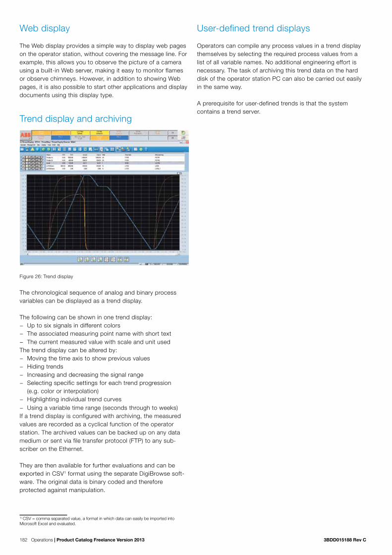
182 Operations | Product Catalog Freelance Version 2013 3BDD015188 Rev C
Web display
The Web display provides a simple way to display web pages on the operator station, without covering the message line. For example, this allows you to observe the picture of a camera using a built-in Web server, making it easy to monitor flames or observe chimneys. However, in addition to showing Web pages, it is also possible to start other applications and display documents using this display type.
Trend display and archiving
Figure 26: Trend display
The chronological sequence of analog and binary process variables can be displayed as a trend display.
The following can be shown in one trend display: − Up to six signals in different colors − The associated measuring point name with short text − The current measured value with scale and unit used
The trend display can be altered by: − Moving the time axis to show previous values − Hiding trends − Increasing and decreasing the signal range − Selecting specific settings for each trend progression
(e.g. color or interpolation) − Highlighting individual trend curves − Using a variable time range (seconds through to weeks)
If a trend display is configured with archiving, the measured values are recorded as a cyclical function of the operator station. The archived values can be backed up on any data medium or sent via file transfer protocol (FTP) to any sub-scriber on the Ethernet.
They are then available for further evaluations and can be exported in CSV1 format using the separate DigiBrowse soft-ware. The original data is binary coded and therefore protected against manipulation.
1) CSV = comma separated value, a format in which data can easily be imported into Microsoft Excel and evaluated.
User-defined trend displays
Operators can compile any process values in a trend display themselves by selecting the required process values from a list of all variable names. No additional engineering effort is necessary. The task of archiving this trend data on the hard disk of the operator station PC can also be carried out easily in the same way.
A prerequisite for user-defined trends is that the system contains a trend server.

3BDD015188 Rev C Product Catalog Freelance Version 2013 | Operations 183
7.3 Messages & operator hintsProcess disturbances are detected by the controllers and for-warded to the operator stations with a timestamp.
The Freelance system allows the following message types: system alarm (S1-S3), process alarm (P1-P4) fault message and operator hint message (P5). Process alarms are divided into fault messages (P1-P3) and switching messages (P4). When parameterizing the function blocks, it is possible to assign up to 4 messages to its limit monitoring units integrated into the block. Whereas the internal controller time is generally used for the timestamp for messages, you also have the option of using a special function block to assign external timestamps to alarms. In this way, for example, you can generate an alarm from a device connected to the Modbus in the correct chron-ological order with the device’s timestamp. Different methods of acknowledgement can be selected for each priority level. Incoming messages are displayed in different colors, along with the name and disturbed status of the tag in accordance with their priority.
Message line
The upper area of the display is always reserved as a message line for the higher-level display of all message types from the entire process.
The message line optionally displays either the newest or oldest messages, as well as buttons for acknowledging messages and viewing operator hints. There is also a field for indicating overflow, a field for acknowledging alarms and a field showing the number of unacknowledged messages in the message list. For quick operation, the faceplate of the disturbed tag can be accessed directly from the message line.
Operators can choose between three different message line views:
− Standard view
− Area view
− List view
Message list
Figure 27: Message list
The message list offers an overview of all pending messages. It features a chronological list of fault, switch and system alarm messages. The latest message is placed at the begin-ning or end of the list, as configured. This message sequence can be altered by configuration.
Just as in the message line, different priorities are color-coded. Messages can be acknowledged both by block and by page. To provide a better overview, the user can filter certain priorities or plant areas on the screen display.
Other displays belonging to the tag, such as faceplates, graphic or trend displays, can be selected via tag specific aspect navigation from the message list simply by a right-click.

184 Operations | Product Catalog Freelance Version 2013 3BDD015188 Rev C
Operator hint list
Figure 28: Operator hint list
A hint for the operator can be configured for each process alarm or event. Hints are intended to inform the operator about the cause of the message or about the procedure to be adopted for eliminating a process alarm. If necessary, hints can also provide further user help.
All configured hints are displayed in the hint list. Faceplates or other displays can also be called up directly from the hint list to operate a tag or analyze critical process situations.
Logging
Logs are used to document events, states and sequences from the process. Log files can be displayed on the screen, printed, and saved on a CD, DVD, or memory stick for further evaluation.
In addition, the archived files can be automatically sent to any subscriber on the Ethernet via the file transfer protocol. The DigiBrowse software makes it possible to view the data and to convert it into ASCII (CSV file) for further evaluation, for instance using Excel.
The Freelance system features the following log types:
Signal sequence log
The signal sequence log is used for logging events such as process and system messages, switching messages and hints. Even operator intervention can be logged in detail together with the user name and timestamp. The user can determine which message priorities are to be logged. Process messages and alarms are logged with time stamps of 1 ms resolution. “Signal sequence log 1” allows the operation of a line printer in order to immediately print every alarm when it is received.
Operation log
At certain intervals or in certain situations, the plant log records the current values or states of process variables. It can run cyclically, or can be started and stopped manually or by an event. The output format is freely configurable as table or fill-in-the-blanks text.
Disturbance course log
The disturbance course log is used to examine the course of disturbances. The process values before and after a distur-bance are recorded with a high time resolution and archived in an operator station. Four logs of each type can be configured in one operator station.
System diagnostics
Figure 29: Easy system diagnostics with the system display
The current state of the hardware and software of a Freelance system is shown in the automatically generated system display. Here, information can be obtained in various degrees of detail about the status of an individual controller to a specific field device.
The simple system display is available to all operators of a DigiVis operator station. Additional information is also avail-able for field devices on Profibus or FOUNDATION Fieldbus.

3BDD015188 Rev C Product Catalog Freelance Version 2013 | Operations 185
7.3 Software subscriptionName Short Description Article No.
Automa-tion Sentinel Upgrade
Provides software licenses for upgrades/updates free of charge based on an existing and valid ’Automation Sentinel’ agreement.
2PAA103267R01
For Freelance systems < 6.2 indicate the DigiTool/DigiVis. hardkey number and for a system replacement enter the text ”New Hardkey”. Enter the ”System ID” into the ”Quotation ID” input field of the Wizard.
7.3 DigiVis languagesName Short Description Article No.
Changing the current language
Changing the current language 3BDS008503R07
Indicate the DigiVis hardkey number and the new language. Setup CD and the documentation manuals in the cho-sen language are to be ordered additional. The language change becomes part of the existing Software Management Program.
English lan-guage
English language 3BDS008502R0701
German language
German language 3BDS008502R0703
other languages
DigiVis is available in many other languages.Please refer to the price list.
see price list
7.3 DigiVis license V10.1Name Short Description Article No.
DigiVis DigiVis, Software License 3BDS008790R07
DigiBrowse DigiBrowse 3BDS008792R067
DigiBrowse doesn’t need a hardkey.
Combined Workplace
Expands an engineering workplace to a combined workplace (Control Builder + DigiVis).Only in combination with Control Builder F licenses. A Combi Hardkey will be required for each workplace
3BDS008794R07

186 Operations | Product Catalog Freelance Version 2013 3BDD015188 Rev C
7.3 DigiVis optionsName Short Description Article No.
DigiVis Combi- Version
DigiVis Combi-Version 3BDS008794R07
Allows for engineering and operation on the sameworkplace (PC).Only in combination with Control Builder F.
WEB Display run time
WEB Display run time 3BDS008785R07
Enables a DigiVis Station to execute a configured Web Display. Enables a Combi Station to execute a configured Web Display.
Dual Monitor Support
Dual Monitor Support 3BDS008784R07
For a single operator station. A graphic interface with dual monitor support is required. See release note.
Control Aspect
Control Aspect 3BDS009973R07
Display (read only) of Control Builder F function block dia-grams in DigiVis.
Extended Diagnostic
Extended Diagnostic 2PAA102040R07
A Control Builder F Professional license supporting the Security Lock function is recommended. Intended only for use with one DigiVis station per system.

3BDD015188 Rev C Product Catalog Freelance Version 2013 | Operations 187
7.3 DigiVis hardkeysName Short Description Article No.
Combi Hardkey
Combi Hardkey for Parallel Port 3BDH000196R1
Hardkey for DigiVis and Control Builder F.
Combi Hardkey
Combi Hardkey for USB 3BDH000196R2
Hardkey for DigiVis and Control Builder F. DigiBrowse doesn’t need a hardkey.
DigiVis Hardkey
DigiVis Hardkey for Parallel Port 3BDH000197R1
DigiVis Hardkey
DigiVis Hardkey for USB Port 3BDH000197R2
Replacement Hardkey
Replacement Hardkey 3BDH000199R1
This will render the old hardkey obsolete. Licenses noted for the old hardkey will be moved to the replacement hardkey. Indicate the hardkey number of the key you want to replace.
Change Hardkey
Change Hardkey type to USB Port 3BDH000199R2
For PC replacement without parallel interface. This will render the old hardkey obsolete. Licenses noted for the old hardkey will be moved to the replacement hardkey. Indicate the hardkey number of the key you want to replace.

188 Operations | Product Catalog Freelance Version 2013 3BDD015188 Rev C

3BDD015188 Rev C Product Catalog Freelance Version 2013 | Engineering 189
Chapter 8 Freelance Engineering (Control Builder F) With Freelance, all engineering work is performed with one single tool, Freelance Engineering, which works hand in hand with the visualization and operation tool Freelance Operations. Configuration of all plant objects – ranging from process graphics to field devices and operation of the entire plant – is easy and intuitive to perform.
The entire Freelance system can be configured either online, while the engineering tool is connected to a controller, or offline. For offline configuration, no controller is necessary. The application program, that was created during offline con-figuration, can later on be downloaded to a controller.
In particular, this is also true for FOUNDATION Fieldbus con-figuration, whereby Control Builder F can be used to generate the control-in-the-field application even without any devices being available.
Freelance Engineering offers the following features for configu-ration, parameterization and commissioning:
− A single software tool for configuration of the automation functions, the operator interface with displays and logs, and fieldbus parameters.
− Graphical configuration with powerful editors according to IEC 61131-3: Function block diagram (FBD); Instruction List (IL); Ladder diagram (LD); Sequential function chart (SFC) and Structured text (ST).
− A function block library with more than 220 tried and tested functions, greatly exceeding the basic ones outlined in IEC 61131-3.
− An extensive macro library containing more than 200 graphic symbols, which can be extended by the user.
− A project tree for flexible program generation and transpar-ent program structuring.
− Verification of automation functions, with the chance to find and remove errors quickly and easily.
− Cross-reference function allowing variables and tags to be found easily in any editor right up to the graphic display.
− Importing and exporting of programs, displays, variables, − tags and parts of the project tree. − Password protection to prevent unauthorized project modi-
fication. − Password protection for user-defined function blocks. − Uniform and auto-generated system-wide graphical docu-
mentation of the entire user program, system communica-tion and all field device parameters.
− Project file (application) backup on any data medium (hard disk, CD, memory stick, etc.). The project file includes the complete project with all programs, graphics, controllers, and field device parameters.
− Testing and simulation of user programs (e.g. interlocks) even without connected hardware using the controller emu-lator.
− Bulk data manager allows to import signal lists from plan-ning tools via Excel and fast duplicating of typical solutions.
FreelanceEngineering
Project tree
Project database
Function Block Diagram Sequential Function Chart Structured Text Instruction List Ladder Diagram
Hardware structure
Configuration of fieldbus
Display process states
Freely configurable graphic displays
Cross referencing

190 Engineering | Product Catalog Freelance Version 2013 3BDD015188 Rev C
Project tree
Figure 30: Project tree with Function Block Diagram
The project tree is the central instrument for managing the entire user program and commissioning. All project configu-ration data is displayed as a tree structure.
Within the project tree: − The configuration data in a project is structured − Task levels and cycle times are defined − Programs are assigned to the task levels − Programs, displays and logs can be opened for editing,
copied and moved − Programs are checked for plausibility and their processing
status displayed − Project configuration data is exported and imported − User programs are loaded into the process and operator
stations
Project data base
Figure 31: Tag list with cross references
All configured signals, variables and tags are managed in the Freelance system as lists in a common project database:
− List of variables (inputs, outputs, internal variables) − Tag list (function blocks) − Graphics − Programs
Because the database is system-wide, data only needs to be entered once, avoiding further potential errors during configu-ration. The single project database file makes archiving or backup ease of use.
The list of variables and tags is created automatically when a user program is generated.
Other list functions include: − Project-wide modification of name, comments, data or
module type − Search and display based on specified search criteria − Cross-reference function permitting rapid, system-wide
location of all programs and displays in which a selected variable or tag is used. This makes debugging very easy to do.

3BDD015188 Rev C Product Catalog Freelance Version 2013 | Engineering 191
8.3 Configuration of functions
Function block diagrams
Figure 32: Program with parameterization screen and plausibility check
The function block diagram (FBD) is a graphical programming language.
It keeps one or several function blocks. The inputs and out-puts of the function blocks can be connected to create the signal flow. Control Builder F checks if the terminals of two function blocks can be connected.
Inputs are always displayed on the left and outputs always on the right of a function block. With variables, values can be referenced from one diagram to another one. Two different access types to variables are available: read and write access. While write variables are written by a single function block, read variables can be used by several blocks.
The layout of the terminals and the color of signal flow lines provide information about the data type.
All parameters of the function blocks are defined in the function block diagram. Clearly structured and easy to understand parameter dialogs, in which all block-specific entries can be made, are available. Once completed, the function block dia-gram can be verified using a plausibility check for errors or syntactic accuracy. Any errors or warnings are displayed in a list, and it is possible to navigate directly to the source of the error by simply clicking on the relevant line in that list.
The cross references in a program can be displayed for the whole system. The corresponding displays or programs can be called up directly in order to gain easy access to the variables or tags referred to.
A function block diagram (FBD program) , is configured as follows:
− Define name for FBD program − Open editor for FBD program − Select function blocks - position in the graphic area − Connect functions with the signal flow lines
− Enter input and output variables − Define parameters for the functions − Check FBD program for plausibility − Correct any syntax errors
Sequential function charts
Figure 33: SFC program
The Sequential Function Chart (SFC) readily allows transpar-ent, graphical creation of sequential control programs. To cre-ate an SFC program, steps are configured with assigned actions (commands) and transitions with step-enabling condi-tions. Programs (function block diagram, ladder diagram, structured text, or instruction list) can be assigned to the steps and transitions. A further feature of the sequential func-tion chart is the facility for creating alternative and parallel branches as well as the synchronization of these sequential structures. At the same time as the sequential function chart is configured, the SFC display for operation and observation on the operator station is generated automatically.

192 Engineering | Product Catalog Freelance Version 2013 3BDD015188 Rev C
Structured text
Figure 34: Structured text
Structured text (ST) is one of the text-oriented programming languages of IEC 61131-3, in which program processing is determined by instructions. All functions and function blocks can also be used in ST programs. The scope of the functions is partly covered by the ST operands. Function blocks can be used in the ST program following declaration.
Parameter definition of the function blocks also takes place in the same way as in the ladder diagram or function block dia-gram. In contrast to that of the function block diagram (FBD), the scope of functions of the structured text also includes conditional commands and loop commands, which are called using appropriate key words. The processing sequence is determined from the order of the commands in the ST editor. The only way to specifically change the order is to insert loop commands.
Instruction lists
Figure 35: IL program
All Freelance processing functions can be defined by the instruction list (IL). The scope of the instruction list exceeds that of the function block diagram and sequential flow chart, as jump commands and program loops can also be pro-grammed. The operands can be displayed and entered with a selection list according to IEC 61131-3. Parameter definition of the function blocks also uses the same parameter definition screens as those used in the function block diagram.
Ladder diagrams
Along with the function block diagram (FBD) and sequential function chart (SFC), the ladder diagram (LD) is also one of the graphical languages of the IEC 61131-3.
The ladder diagram language originates from the area of elec-tromagnetic relay systems and describes the flow of current through individual rungs. The boundaries of a rung are defined on the right and left side by devices known as power rails, which have the logical state 1 (current is flowing). A rung is created with the elements of the ladder diagram (links, contacts and coils).
Functions and function blocks in the ladder diagram can be called up and used in the same way as in the function block diagram. Parameters are also defined for function blocks using the same parameter screens.

3BDD015188 Rev C Product Catalog Freelance Version 2013 | Engineering 193
Operation and observation functions
The following functions can be configured for operation and display:
− Custom graphic displays − Web displays − Standard display types: overview display, group display,
trend display, time scheduler display − SFC display − Signal sequence, disturbance course and plant log − Message list and message line − Operator hint list.
Since the common system database is automatically accessed while configuring these functions, there is no need to re-enter the data.
Standardized displays (pre-engineered)
Standard displays can be configured very easily using Control Builder F. To configure a group display, for example, it is only necessary to select the tags via the selection list. The entry is made automatically.
In this manner, up to 10 large analog faceplate tags can be entered per group display. The configuration procedure for the overview display is equally simple, as the containing displays are entered from a selection list.
Freely configurable graphic displays
Figure 36: Graphics editor
Plant-specific graphic displays can be constructed for dis-playing the process. The graphic displays contain static and dynamic display elements. The static part of the plant display – the background display – is composed of separate graphic elements which can be modified in color, line type and filling pattern and can, for example, display the schematic plant layout.
The following constructional aids in the system make it easier to create displays:
− Static elements such as lines, polylines, rectangles, polygons, ellipses, arcs and texts are created, for example, by speci-fying the start and end points
− Display sections already created can be duplicated, moved, rotated in 90° steps, transposed or superimposed
− The combination of several graphic elements can be saved as a macro and stored in libraries to be used when desired
− The zoom function facilitates precise construction of the individual graphic display elements
− Import of bitmap files facilitates the generation of static background displays
The process variables are displayed in the dynamic section of the display – the foreground display. Specific process variables can be visualized simply by making the display elements dynamic.
The following types of dynamic elements can be used:Bar graphs and dynamic filling set to operate in different directions
− Superimposed numerical values and text variables − Trend window − Color change or symbol change to depict states − Continuous or discrete position modifications of the
graphic symbol − Keys (buttons) for the direct execution of actions (e.g. write
value or similar) − Animated objects, e.g. mixers that turn realistically − Tool tips
Selection fields can be defined at any position so that the operator can access any other displays using the mouse or keyboard.

194 Engineering | Product Catalog Freelance Version 2013 3BDD015188 Rev C
8.3 Hardware structure
Figure 37: Definition of the hardware structure
The required hardware structure can be configured in a graphical system overview and the system communication can also be defined there. It is possible to assign particular DigiVis opera-tor stations to specific controllers. Furthermore, detailed infor-mation can be obtained on the operator and process stations, together with their modules and the controllers with their con-nected fieldbus lines. In the station overview display, the oper-ator and process stations can be equipped using selection lists. Specifications for processing, display and I/O channel assignment can be made for the individual modules of the controllers. And all this with just a few clicks.
Fieldbus and field device configuration
The respective bus parameters, for instance the baud rate, number of subscribers and time constants, can be set for each fieldbus module. Control Builder F also suggests a set-ting for the bus parameters in line with how the fieldbus is equipped. This makes work easier for those new to the subject.
PROFIBUS
Figure 38: Configuration of the fieldbus line (PROFIBUS)
In the configuration view of the fieldbus line, new PROFIBUS slaves can be integrated into the fieldbus line using a GSD-file or FDT technology.
Using the template concept, it is also possible to integrate completely pre-configurable PROFIBUS slaves by means of drag and drop. The intelligent DP / PA Linking Device is trans-parent with regard to configuration, allowing PA devices to be viewed as if they were connected to the PROFIBUS DP. Parameter definition screens are then available in the device display for defining parameters for both remote I/O and PA field devices.
HART
HART devices connected to the S800 or S900 Remote I/O can be configured with the aid of HART DTMs. For S900, also HART templates can be used. They consist of preconfigured DPV1 services which tunnel a HART command via the PROFI-BUS to the HART device on the analog channel of a particular S900 I/O module. Users can also create HART templates themselves.

3BDD015188 Rev C Product Catalog Freelance Version 2013 | Engineering 195
FOUNDATION Fieldbus
Figure 39: Configuration of the fieldbus line (FF)
The devices are configured in the feedforward part by linking the Device Description (DD) files. This makes it possible to configure the FF without the field devices being physically connected to the controllers.
The devices are configured on the H1 links of the LD 800HSE Linking Devices. As Control Builder F supports control in the field for FF devices, it is possible to configure function charts that interconnect the function blocks in the individual FF devices. Control Builder F then automatically generates a pro-cess that is passed on to the Link Active Scheduler (LAS). Redundant Link Active Schedulers are also supported. How-ever, it is also possible to use the FF devices “only” as I/O suppliers and use the function blocks in the controllers.
Graphical documentation
The fully graphical forward documentation allows configured programs and displays to be printed. The documentation is always up-to-date, as the current configuration data is accessed. Various sorting criteria, such as drawing numbers, assure an orderly and transparent output of the data to be documented.
The scope of documentation can be specified as desired by the user, such as:
− Program and display contents, cross references, parameter definition data and comments
− System overview and hardware configurationThe documentation specification can be stored for future use. The FBD, IL, LD, SFC and ST programs, displays, etc. are documented in the form in which they appear on the screen. Using Freelance documentation management, complete or partial project documentation can be produced without effort. It is also possible to include bitmaps (such as customer logos) in the drawing footer.
8.3 CommissioningDuring commissioning, the user programs are loaded into the operator and process stations. It is also possible to:
− Load modifications − Start and stop process stations − Start, stop or reset tasks − Define and activate parameters for function blocks − Define and activate parameters for field devices − Display, set and track process values − Combine any process values at any time in a trend window − Perform version and status checks − Perform system diagnoses right up to the field device
Displaying process states
Figure 40: Trend and value window during commissioning
The editors for displaying the configured programs can also be accessed during commissioning. As opposed to during configuration, the process states of the I/O variables are also displayed in the program. The status of the binary process signals is displayed in the FBD display by a change in the graphical representation of the signal flow lines.
Value and trend windows are available for displaying process values. They offer an optimal overview of the current process values for commissioning and test purposes.
Here, the user is not restricted to the display of I/O variables for the program currently shown on the screen. Variables from other programs and / or controllers can also be displayed, as well as values from connections between various function blocks of the current program.

196 Engineering | Product Catalog Freelance Version 2013 3BDD015188 Rev C
Modifying parameters
Parameters can also be modified during the commissioning phase, allowing optimal program settings for the process. These parameters can be altered from either the engineering station or the operator station. Whether the changes made are retained permanently or only temporarily is decided by the commissioner.
Through a parameter upload, it is possible to view all parameter modifications made in a particular period of time and to select those which are to be saved in order to be used at the next cold start.
Other features allow you to force inputs and outputs and to specify new values for simulation purposes.
Commissioning the fieldbus lines
Figure 41: Online diagnosis of fieldbus components
PROFIBUS
The fieldbus line overview shows whether the configured PROFIBUS I/O and PA devices are available. In addition, the bus can be scanned using Control Builder F in order to detect new or incorrectly configured devices. Such devices can then be given the correct address from Control Builder F via the PROFIBUS.
During commissioning, Freelance allows you to compare con-figured parameters with the parameters that exist in the device. This makes it possible to detect device parameters that have been changed locally and transfer them to the configuration by means of uploading. When the PROFIBUS device transmits diagnoses, they can be displayed by Control Builder F. When FDT / DTM technology is used, specific diagnostic options can be used, provided that the device manufacturer has incorporated such options in the DTM.
Individual PROFIBUS devices can be removed from cyclical data traffic in order to perform maintenance without it being necessary to stop the fieldbus.
FOUNDATION Fieldbus
Live lists displaying which devices exist are available for HSE and H1.
During commissioning, Freelance allows you to compare con-figured parameters for the device modules with the parameters that exist in the device. This makes it possible to detect device parameters that have been changed locally and transfer them to the configuration by means of uploading.
The Link Active Scheduler (LAS) can be stopped in order to interrupt processing of the control loops in a H1 link.

3BDD015188 Rev C Product Catalog Freelance Version 2013 | Engineering 197
8.3 Control Builder F languagesName Short Description Article No.
Changing the current language
Changing the current language 3BDS008503R07
Indicate the Control Builder F hardkey number and the new language. Setup CD and the user documentation in the chosen language are to order additional. The language change be-comes part of the existing Software Management Program.
Available languages
Control Builder F is available in various languages, such as English, Chinese, French, German, Brazilian Portuguese. For article numbers see the price list.
see price list
8.3 Control Builder F licenseFor an executable system is necessary:
− One setup CD − One Control Builder F license − One hard key (part of Control Builder F license) − One Control Software license for every used controller (station)
Name Short Description Article No.
Control Builder F Standard
Software License 3BDS008510R07
Control Builder F Standard supports: - 16 Character Tag Names - User Defined Function Blocks (Runtime license) - OPC Function Block Classes (runtime license)..
Control Builder F Professional
Software License 3BDS008520R07
Control Builder F Professional supports: - all features of Control Builder F Standard - Security Lock - Creation of User Defined Function Blocks (developer license) - Creation of OPC Function Block Classes (developer license) - FDT Technology- DTM Device Driver
Please check the list of DTMs which are approved by ABB for use with Control Builder F in version 2013.Order one Control Builder F hardkey for each engineeringworkplace.

198 Engineering | Product Catalog Freelance Version 2013 3BDD015188 Rev C
8.3 Control Builder F optionsName Short Description Article No.
WEB Display Configuration
WEB Display Configuration 3BDS008786R07
Enables Control Builder F Standard and Professional to configure Web Displays.
8.3 Control Builder F hardkeysName Short Description Article No.
Control Builder F Hardkey
Control Builder F Hardkey for Parallel Port 3BDH000198R1
Control Builder F Hardkey
Control Builder F Hardkey for USB 3BDH000198R2
Replacement Hardkey
Replacement Hardkey 3BDH000199R1
This will render the old hardkey obsolete. Licenses noted for the old hardkey will be moved to the replace-ment hardkey. Indicate the hardkey number of the key you want to replace.
Change Hardkey Change Hardkey type to USB Port 3BDH000199R2
For PC replacement without parallel interface. This will render the old hardkey obsolete. Licenses noted for the old hardkey will be moved to the replacement hardkey. Indicate the hardkey number of the key you want to replace.

3BDD015188 Rev C Product Catalog Freelance Version 2013 | Engineering 199
8.3 Control - Software licenseThis Price List contains software licenses for the following controllers:
− AC 900F − AC 800F − AC 700F − DCP 02/10, DFC 01/02
This license releases the specified number of controllers (process stations) in the Freelance project tree. For every used controller (process station) one license is needed:
− One redundancy couple = 1 controller = 1 control software license; − Gateway (e.g. OPC) = no controller = no control software license.
8.3.1 Base LicenseControl Software license supports:
− IEC 61131-3, binary and analogue − Closed loop control − DigiVis − 800xA Operation and Process Portal B. Requires item B050.
Included in a controller license
− 50 I/Os − Tune (Self tune PID) − Sequence of Events SOE − CSO Gateway − Phase Logic Interface PLI − Programming Interface API − Modbus Serial − Modbus TCP (AC 700F/ AC 900F, AC 800F will supported later with a Service Pack from
Mid 2014) Not supported with AC 700F/AC 900F
− - Foundation Fieldbus − - Coupling Sartorius − - Protronic Remote Control.
Name Short Description Article No.
Control Soft-ware license
Number of supported controllers incl. 50 I/Os each 2PAA110432R08
8.3.2 Additional basic I/OsThe maximum number of I/O license depends on CPU type and application. Please use DigiSize for load calculation. The number of I/Os relevant for licensing is determined by count-ing only those I/Os that are in use in the field.
Name Short Description Article No.
Set of 50 I/Os
Set of additional 50 I/Os 2PAA110433R08

200 Engineering | Product Catalog Freelance Version 2013 3BDD015188 Rev C
8.3.3 Control software optionsAdditional option to Control Software Basic. This option must be ordered for every controller, where you want to use it.
Name Short Description Article No.
TeleControl Support for IEC 60870-5-101 and -104 3BDS008758R08
ICheck whether the implemented subset of functionality meets your requirements. IEC 60870-5-104 is currently not released with DCP 02/10 and DFC 01/02..
8.3.4 Batch
Name Short Description Article No.
Freelance Formulation
Essential Recipe Manager 2PAA110436R08
This license includes a license for the Freelance Formulation batch application.
Freelance Batch
Interface to Workflow Manager (BCM module) 2PAA110437R08
Please refer to Decathlon Suite WFM price list for the batch application (license)..
Batch for Extended Automation
Interface to 800xA Batch 2PAA110438R08
Please refer to Extended Automation 800xA price list for the batch application (license).

3BDD015188 Rev C Product Catalog Freelance Version 2013 | Media and Documentation 201
Chapter 9 Media and documentation
Product boxName Short Description Article No.
Product Box Freelance, Product Box 3BDS008536R0703
Including Software CD, Documentation CD, Manual ”Get-ting Started”.
Software CDName Short Description Article No.
Freelance Software V2013
available in various languages 3BDS008531Rxxxx (see price list)
Documentation CDName Short Description Article No.
Freelance Documenta-tion V2013
German and English CD 3BDD012530R0703

202 Media and Documentation | Product Catalog Freelance Version 2013 3BDD015188 Rev C

3BDD015188 Rev C Product Catalog Freelance Version 2013 | Add-ons, Extensions and Service 203
Chapter 10 Add-ons, extensions, and service
ABB is one of the world‘s largest suppliers of equipment, sys-tems and services for measurement and process automation.
A crucial factor in maintaining this market position is the quality of our products, from manufacture right through to services. The DQS Certificate based on DIN ISO 9001 awarded to ABB Automation as far back as 1990 bears testimony to this fact. The same applies for the EQNet Certificate based on ISO 9000/EN 29000.
Comprehensive customer serviceService means a profitable investment in continually maximiz-ing and optimizing the availability, performance, quality and security of a plant. ABB’s support covers the following areas:
− Customer Support Services − Training − Spare Parts & Logistics, Repair Shops − Process, Application & Consulting Services − Service agreements − Extensions, upgrades and retrofits
Through the resulting specialization of our employees, we ensure maximum competence for each task we perform. Whether it’s more traditional service support such as commis-sioning and maintenance or individual consulting services – the result is measurable customer benefits.
Our comprehensive Life Cycle Services enable us to increase the value of your plant over its entire lifetime. The conven-tional, reactive service can reduce production downtimes, while the use of new technologies offers an increased number of capabilities for preventive service measures to identify and
avoid cost-intensive faults at an early stage. Proactive ser-vices such as asset management or ongoing modernization increase the value of our customers’ plants and give them a distinct competitive edge.
Life cycle managementAutomation Sentinel is ABB’s control system life cycle man-agement and support program. With this program, you can keep your control system up-to-date and maintain a flexible path to new technology. Automation Sentinel helps manage automation software assets with timely delivery of the latest Freelance releases, thus providing you with better productivity, lower support cost and simpler software management. Migra-tion from traditional control systems to Freelance enables ease-of-use and lower maintenance cost.
One valuable service of the Automation Sentinel program is the secure, web-based platform My Control System. It pro-vides detailed information about your installed software, as well as operational data such as alerts and reports (including health status, performance, safety, and security reports) and all that in a single location. More information about Automation Sentinel can be found in “Chapter 11 Automation Sentinel Program” on page 205.
My Control System presents, in dashboard format, important information about the control system’s subscriptions and soft-ware licenses in terms of content, expiry dates, tools and license key downloads. All this data is available with just a few clicks. For convenience, the ABB local service contact infor-mation is listed on the starting page.

204 Add-ons, Extensions and Service | Product Catalog Freelance Version 2013 3BDD015188 Rev C
Using My Control System to access pre-filtered information dedicated to your installed control system can help you lower-ing your total support cost and reduce after-hours support or service calls.
Asset ManagementIf you want to keep your production plant up and running in the long term, you need information about the availability and degree of wear and tear of your equipment. All of the informa-tion necessary for this is available; integrated and included in the basic software package of the Freelance control system. As a result, several customers have been able to avoid mak-ing investments that appeared essential but were in fact unnecessary. Freelance allows the use of modern asset man-agement methods for more efficient maintenance and optimi-zation – helping for instance to make optimum use of plant capacity.
System IntegrationOur instrumentation and control specialists, or our certified partners in system integration, will be happy to assist you in planning and implementing your automation project. ABB Automation‘s staff can also work with you to plan and implement the installation of a Freelance system in your plant.
Under this arrangement, the ABB Automation Engineering Department will compile the specific project documentation for you. This can include functional diagrams, circuit diagrams, configuration documentation, and operating documentation including system descriptions and instructions for operation, modes of operation and plant maintenance.
At many sites, ABB Automation has its own commissioning engineers who work together with planning engineers, process instructors and operators to commission your plant, optimize it, perform a test run and hand over the system to the operator.
TrainingTo make sure your operators are fully knowledgeable in the operation of the Freelance distributed control system, we offer a range of technical training courses.
In addition, we offer a computer-based training program for Freelance on a multimedia DVD. This will provide you with the basic knowledge you need for configuration, therefore allow-ing you to start using the system very quickly and efficiently.

3BDD015188 Rev C Product Catalog Freelance Version 2013 | Automation Sentinel 205
Automation Sentinel is ABB’s control system lifecycle man-agement and support program that assists system owners to actively manage their control system lifecycle, support and maintenance. With this program, system owners can keep their control software up-to-date and maintain a flexible path forward to new system software technology. This program provides the fundamental software support deliverables required to maintain operation and maximize the availability of the installed Freelance control system.
Features and Benefits
Deliver Freelance software services to match operations needs
− Functionality to address increased performance demands − Respond faster to production changes − Higher production availability (24/7 operations)
Supports lifecycle management of control system software assets
− Make informed decisions − Predictable costs for accurate budgets – remove
uncertainty − Eliminate unplanned upsets and trips due to system
interruption Lowers system software lifecycle costs and risks
− Extending the life of automation system − Protects intellectual property investment − Provides software upgrades to newer software versions
Extends lifecycle support periods for Freelance System soft-ware versions
− Provides software support for up to five years
Provides comprehensive software support and maintenance − On-line access to software downloads − On-line access to software product documentation − Technical phone support to troubleshoot product and
configuration issues
ABB offers two levels of services with options which are designed to be flexible to meet the varying needs of system owners: Maintain and Maintain Plus. Please see the table on the following page for a listing of the services provided in each of these options.
Furthermore, if you like to extend a Freelance system with 800xA Operations, a third level called Maintain and Evolve is available as well. See the System 800xA Pricelist.
Benefits: − Extends the support of the system investment − Provides flexibility in deciding when the timing is right to
perform a system upgrade − Ensures system owners can continue to use their software
in their system with predictable support results − Production environment − Locate manuals for control systems on-line quickly and
easily.
Chapter 11 Automation Sentinel Program

206 Automation Sentinel | Product Catalog Freelance Version 2013 3BDD015188 Rev C
Overview maintain services:
System Lifecycle Needs Description Maintain Plus Maintain
Enhancement New software license versions / enhancements
•
Maintenance Software maintenance updates • •
Extended version maintenance • •
Device Library management updates • •
Early access to software patch • •
Product technical phone support • •
Software security management • •
On-line access to SolutionsBank • •
Subscribers are entitled to the following services, based on selected program options:
New software license versions / enhancementsSubscribers are eligible to upgrade their software licenses to new versions and/or receive enhancements of their existing products at no additional cost.
Benefits: − Lowers the cost of lifecycle maintenance through a predict-
able annual fee − Add new functions and features (improving performance) − Maintains operation on current and available third-party
technology (PC’s, Microsoft Operating Systems, etc.)
Software Maintenance UpdatesAutomation Sentinel subscribers are entitled to software main-tenance for the current version of installed software products, including service packs, patches and updates.
Benefits: − Minimizes unplanned plant upsets and trips − Reduce maintenance costs with improved overall reliability
(improving quality) − Incorporates third-party product updates to ensure compati-
bility and on-going lifecycle support
Extended Version Maintenance Automation Sentinel delivers extended lifecycle support for Freelance System software versions for up to five years. This is achieved by providing corrections of business critical issues and support for security management strategies throughout the software version’s lifecycle.
Benefits: − Extends the support of the system investment − Provides flexibility in deciding when the timing is right to
Benefits: − Extends the support of the system investment − Provides flexibility in deciding when the timing is right to
perform a system upgrade − Ensures system owners can continue to use their software
in their system with predictable support results
Device Management Library UpdatesSubscribers are entitled to updates for ABB’s Device Manage-ment Library which provides support for new and updated devices including PROFIBUS, FOUNDATION Fieldbus and HART device types.
Benefits: − Access to new device types for easy integration into your
system − Provides support for the replacement of failed devices with
the latest available device types
Early access to software patchesAutomation Sentinel subscribers may request1 a patch to a critical issue within ABB’s software products in advance of the normally planned schedule for release.
Benefits: − Access to business critical issue corrections that have a
significant impact on your business / production
− Minimizes impacts to production availability
1 Eligibility requires installing the latest available software release and
is limited based on technical & economic feasibility

3BDD015188 Rev C Product Catalog Freelance Version 2013 | Automation Sentinel 207
DownloadsBrowse information by control system type and download the latest service packs, release notes and updates.
AutoNotificationAutomatic e-mail notifications regarding technical updates and product release information, filtered according to your pre-defined installed ABB control system profile.
TroubleshootingKnowledgeBankSM includes a variety of hardware and software solutions generated from actual support cases, dynamically incorporated as they are validated. A natural language-query search engine easily locates solutions.
Video LibraryAVIBank1 (ABB Video Instruction Bank) provides video instruction files, which demonstrate step-by-step procedures for ABB software products and tools.
ForumsForums provide an interactive environment for discussion groups by creating communication channels. Information, ideas and questions can be presented and exchanged with other users.
My Solutions BankCustomize your views of content based on individual prefer-ences. Product-specific views present publications and down-loads for specific products or product lines.
Benefits: − Lower support cost through access to ABB’s online self-
help database − Download service packs and updates for immediate
installation − Reduction of documentation and software delivery times − Meet demands for self-support tools and reference
resources − Reduce cost of after-hours phone support or service calls
by accessing self-help on-line − Provides just-in-time answers to frequently asked questions
1 Not available for all technologies
Product Technical Phone SupportAutomation Sentinel provides technical phone support, trouble-shooting and assistance with product, application and con-figuration issues and questions.
Benefits: − Access to product experts for assistance in troubleshooting
system or product issues − Escalation to product design engineers for expert trouble-
shooting assistance
Software Security ManagementABB reviews, tests and validates monthly Microsoft security updates and third-party virus scanner software for compatibility with our control system software. A monthly qualification report is provided to subscribers.
Benefits: − Minimizes users efforts in evaluation and testing of security
patches − Reduces risk of introducing an unvalidated patch into the
production environment
On-line Support ToolsYour Automation Sentinel subscription includes access to ABB’s 24-hour access premium control systems content delivered through SolutionsBank. Each system subscription is entitled to two user accounts with access to the following features:
PublicationsTechnical product information for ABB control products and systems.
− Technical Bulletins/Application Guides: Keep up to date with technical supplements describing system maintenance and configuration procedures.
− Product Manuals: Locate manuals for control systems on-line quickly and easily.
− Change Notices: Access engineering documents, which detail modifications and control systems enhancements, including new soft-ware releases and hardware design changes.

208 Automation Sentinel | Product Catalog Freelance Version 2013 3BDD015188 Rev C

3BDD015188 Rev C Product Catalog Freelance Version 2013 | Repairs 209
Chapter 12 Repairs
Handling of cases under warranty
The Ratingen Repair Service carries out repairs and handling of warranty cases.
Rudolf Cypek, Email: [email protected]: +49 2102 12-251450, Fax: +49 2102 12-1588
Support under warranty where some sort of emergency actions and site visits are required, are not covered. This isbeyond the responsibility of the Ratingen feeder factory (no delivery of complete configurations).Warranty covers parts only.
ABB Automation GmbHService ControlOberhausener Str. 3340472 Ratingen, GermanyPhone: + 49 2102 12-1450Fax: + 49 2102 [email protected] Service Center: +49 [email protected]