Kollmorgen Automation and Motion Control
202
Kollmorgen Automation and Motion Control AKMH ™ Servo Motors AKM ® Servo Motors Frameless Direct Drive Motors AKD ® Servo Drives Kollmorgen Automation Suite (KAS) AKD ® PDMM Programmable Automation Controller and Servo Drive AKD-N ™ Decentralized Servo Drive AKI Touch Panels AKT I/O Block Stepper Motors P-Series Stepper Drives Micron TRUE ™ Gearboxes AquaTRUE ™ Gearbox Rodless Actuators Electric Cylinder Actuators Direct Drive Linear Motors Cartridge DDR ™ Motors Housed DDR ™ Motors Multi-Axis Precision Tables CLASSIC DRIVE SERVO MOTORS SERVO DRIVES DIRECT DRIVE HYGIENIC PROGRAMMABLE CONTROL GEARING & ACTUATION STEPPER SYSTEMS PROGRAMMABLE AUTOMATION SOLUTIONS Synchronous Motors SS Gearbox Synchronous MX Explosion-Proof Stepper Motors
-
Upload
khangminh22 -
Category
Documents
-
view
0 -
download
0
Transcript of Kollmorgen Automation and Motion Control

Kollmorgen Automation and Motion Control
AKMH™ Servo Motors
AKM® Servo Motors
Frameless Direct Drive Motors
AKD® Servo Drives Kollmorgen
Automation Suite (KAS)
AKD® PDMM Programmable Automation Controller
and Servo Drive
AKD-N™ Decentralized Servo Drive
AKI Touch Panels
AKT I/O Block
Stepper Motors
P-Series Stepper Drives
MicronTRUE™ Gearboxes
AquaTRUE™ Gearbox
Rodless Actuators
Electric Cylinder Actuators
Direct Drive Linear Motors
Cartridge DDR™ Motors
Housed DDR™ Motors
Multi-Axis Precision Tables
CLASSICDRIVE
SERVO MOTORS
SERVO DRIVES
DIRECT DRIVE
HYGIENIC
PROGRAMMABLE
CONTROL
GEARING & ACTUATION
STEPPERSYSTEMS
PROGRAMMABLE AUTOMATION SOLUTIONS
Synchronous MotorsSS Gearbox Synchronous
.125 [3.18]
.120 [3.2].001 [0.025] C
3.26[82.81]MAX
2X Ø 0.223 [5.66] THRU 180˚ APART ON A Ø3.88 [98.55]
.56 [14.22]
.57 [14.48]
Ø 3.39 [86.11]MAX.
1.10 [27.94] MINLENGTHØ (500)[12.7]1.79 ±0.03[45.47 ±0.77]
.500 [12.7]
.498 [12.64]- C -
.20[5.11]MIN
#405 WOODRUFFKEY SUPPLIED
.25 MAX[6.35]
"B"MAX
Ø 2.91[73.92]MAX
.41[10.49]
MX Explosion-Proof Stepper Motors
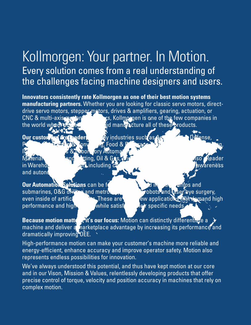
Kollmorgen: Your partner. In Motion.Every solution comes from a real understanding of the challenges facing machine designers and users.Innovators consistently rate Kollmorgen as one of their best motion systems manufacturing partners. Whether you are looking for classic servo motors, direct-drive servo motors, stepper motors, drives & amplifi ers, gearing, actuation, or CNC & multi-axis motion controllers, Kollmorgen is one of the few companies in the world whom actually design and manufacture all of these products.
Our customers are leaders in many industries such as Aerospace & Defense, Printing, Packaging & Converting, Food & Beverage Processing, Medical Imaging, Invitro Diagnostics & Laboratory Automation, Pharmaceutical Manufacturing, Material Forming and Cutting, Oil & Gas, and Robotics. Kollmorgen is also a leader in Warehouse Automation, including complete AGV systems, software, awareness and autonomy.
Our Automation Solutions can be found on Mars and in space, Ships and submarines, O&G drilling and metrology, Surgical robots and laser eye surgery, even inside of artifi cial hearts. These are just a few applications that demand high performance and high quality while satisfying their specifi c needs.
Because motion matters, it’s our focus: Motion can distinctly differentiate a machine and deliver a marketplace advantage by increasing its performance and dramatically improving OEE. High-performance motion can make your customer’s machine more reliable and energy-effi cient, enhance accuracy and improve operator safety. Motion also represents endless possibilities for innovation.We’ve always understood this potential, and thus have kept motion at our core and in our Vison, Mission & Values, relentlessly developing products that offer precise control of torque, velocity and position accuracy in machines that rely on complex motion.

Removing the Barriers of Design, Sourcing, and Time At Kollmorgen, we know that OEM engineers can achieve a lot more when obstacles aren’t in the way. So, we clear obstacles in three important ways:
Integrating Standard and Custom Products The optimal solution is often not clear-cut. Our application expertise allows us to modify standard products or develop totally custom solutions across our whole product portfolio so that designs can take flight.
Providing Motion Solutions, Not Just Components As companies reduce their supplier base and have less engineering manpower, they need a total system supplier with a wide range of integrated solutions. Kollmorgen offers complete solutions as well as motion subsystems that combine programming software, engineering services and best-in-class motion components.
Global Footprint With direct sales, engineering support, manufacturing facilities, and distributors spanning the Americas, Europe, Middle East, and Asia, we’re close to OEMs worldwide. Our proximity helps speed delivery and lend support where and when they’re needed.
Financial and Operational Stability Kollmorgen is part of Fortive. A key driver in the growth of all Fortive divisions is the Fortive Business System, which relies on the principle of “kaizen” – or continuous improvement. Using world-class tools, cross-disciplinary teams of exceptional people evaluate processes and develop plans that result in superior performance.
Kollmorgen: Your partner. In Motion.
K O L L M O R G E N A U T O M A T I O N A N D M O T I O N C O N T R O L
w w w. k o l l m o r g e n . c o m
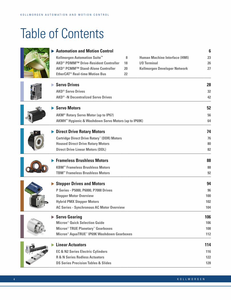
u Automation and Motion Control 6Kollmorgen Automation Suite™ 8 Human Machine Interface (HMI) 23AKD® PDMM™ Drive-Resident Controller 18 I/O Terminal 26AKD® PCMM™ Stand-Alone Controller 20 Kollmorgen Developer Network 27EtherCAT® Real-time Motion Bus 22
u Servo Drives 28AKD® Servo Drives 32
AKD® -N Decentralized Servo Drives 42
u Servo Motors 52
AKM® Rotary Servo Motor (up to IP67) 56
AKMH™ Hygienic & Washdown Servo Motors (up to IP69K) 64
u Direct Drive Rotary Motors 74Cartridge Direct Drive Rotary™ (DDR) Motors 76Housed Direct Drive Rotary Motors 80
Direct Drive Linear Motors (DDL) 82
u Frameless Brushless Motors 88KBM™ Frameless Brushless Motors 88TBM™ Frameless Brushless Motors 92
u Stepper Drives and Motors 94P Series - P5000, P6000, P7000 Drives 96Stepper Motor Overview 100
Hybrid PMX Stepper Motors 102
AC Series - Synchronous AC Motor Overview 104
u Servo Gearing 106Micron® Quick Selection Guide 106
Micron® TRUE Planetary™ Gearboxes 108Micron® AquaTRUE™ IP69K Washdown Gearboxes 112
u Linear Actuators 114EC & N2 Series Electric Cylinders 116R & N Series Rodless Actuators 122
DS Series Precision Tables & Slides 128
Table of Contents
K O L L M O R G E N A U T O M A T I O N A N D M O T I O N C O N T R O L
K O L L M O R G E N4
AKM AKMH CDDR HDDR DDL KBM
TBM PMX STEPPER EC R & N DS
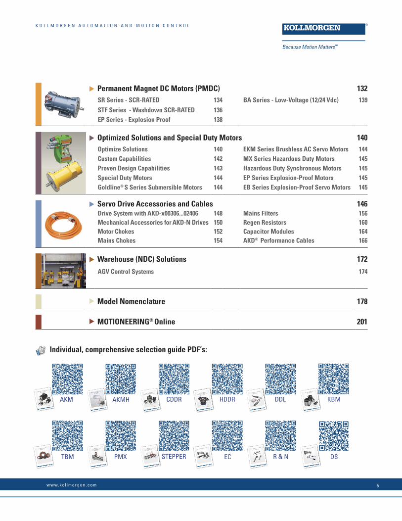
u Permanent Magnet DC Motors (PMDC) 132SR Series - SCR-RATED 134 BA Series - Low-Voltage (12/24 Vdc) 139
STF Series - Washdown SCR-RATED 136EP Series - Explosion Proof 138
u Optimized Solutions and Special Duty Motors 140Optimize Solutions 140 EKM Series Brushless AC Servo Motors 144Custom Capabilities 142 MX Series Hazardous Duty Motors 145Proven Design Capabilities 143 Hazardous Duty Synchronous Motors 145Special Duty Motors 144 EP Series Explosion-Proof Motors 145Goldline® S Series Submersible Motors 144 EB Series Explosion-Proof Servo Motors 145
u Servo Drive Accessories and Cables 146Drive System with AKD-x00306...02406 148 Mains Filters 156Mechanical Accessories for AKD-N Drives 150 Regen Resistors 160Motor Chokes 152 Capacitor Modules 164Mains Chokes 154 AKD® Performance Cables 166
u Warehouse (NDC) Solutions 172
AGV Control Systems 174
u Model Nomenclature 178
u MOTIONEERING® Online 201
K O L L M O R G E N A U T O M A T I O N A N D M O T I O N C O N T R O L
Removing the Barriers of Design, Sourcing, and TimeAt Kollmorgen, we know that OEM engineers can achieve a lot more when obstacles aren’t in the way. So, we clear obstacles in three important ways:
Integrating Standard and Custom ProductsThe optimal solution is often not clear-cut. Our application expertise allows us to modify standard products or develop totally custom solutions across our whole product portfolio so that designs can take fl ight.
Providing Motion Solutions, Not Just ComponentsAs companies reduce their supplier base and have less engineering manpower, they need a total system supplier with a wide range of integrated solutions. Kollmorgen offers complete solutions as well as motion subsystems that combine programming software, engineering services and best-in-class motion components.
Global FootprintWith direct sales, engineering support, manufacturing facilities, and distributors spanning the Americas, Europe, Middle East, and Asia, we’re close to OEMs worldwide. Our proximity helps speed delivery and lend support where and when they’re needed.
Financial and Operational StabilityKollmorgen is part of Fortive. A key driver in the growth of all Fortive divisions is the Fortive Business System, which relies on the principle of “kaizen” – or continuous improvement. Using world-class tools, cross-disciplinary teams of exceptional people evaluate processes and develop plans that result in superior performance.
Kollmorgen: Your partner. In Motion.
Individual, comprehensive selection guide PDF’s:
w w w. k o l l m o r g e n . c o m 5

AKD-N™ Decentralized Servo Drive
AKD-C Power Supply Module
KBM Frameless MotorAKM® Servo MotorCartridge DDR Motor AKMH™ Servo Motor
System programming with the Pipe-NetworkTM or PLCopen
AKI touch panelsoperate and display
Control of motors with AKD® PDMM programmable multi-axis master
Supported System Bus Protocols
Flexible single or multi-axis drive solutions in decentralized and central architectures with AKD-PDMM and the Kollmorgen Automation Suite
Automation and Motion Control
Kollmorgen’s comprehensive line of control software and hardware, drives and motors enables you to complete your solutions with one supplier:
Whether you want a stand-alone controller or drive-resident, Kollmorgen’s KAS can coordinate up to 128 axes, and synchronize the path of up to 32 axes per control engine. We offer standard languages according to IEC61131 -3, as well as C, C+, C++, C#, .NET, and our industry-leading graphical programming language, Pipe Network.
Our broad range of motor- and drive technologies and gearing and actuation products interface seamlessly with our KAS.
The AKD PDMM multi-axis motion controller is equipped with an AKD servo drive for direct connection to a motor. Additional axes each with their own AKD servo drive are controlled by the AKD PDMM via the system bus with the EtherCAT® protocol; extremely precise with cycle times of 250 µs. Optionally, an AKI control panel with one of the standard communication protocols can be connected for operating the machine. The AKD PDMM supports all leading bus systems and thus opens up limitless control system options. The PDMM motion controller functionality is also available in a stand-alone package, the PCMM, for machine designers that prefer traditional, independent controller hardware.
AU
TO
MA
TI
ON
A
ND
M
OT
IO
N
CO
NT
RO
L
Comprehensive Line of Products Offering Complete System Solutions
SERVO MOTORS
DECENTRALIZED SERVO DRIVES
PROGRAMMABLE
CONTROL
K O L L M O R G E N6

AKD™ Servo Drives
Stepper Motors
Direct Drive Linear Motor
P-Series Stepper Drives
AKM® Servo Motor
TBM Frameless MotorHoused DDR Motor
Micron TRUE™ GearboxesAquaTRUE™ Gearbox
AKMH™ Servo Motor
Rodless ActuatorsElectric Cylinder Actuators
MX Explosion-Proof Stepper Motors
Interface diversity: I/O bus terminalsAKT - Advanced Kollmorgen Terminals
System bus
Interface expansion with the ® system bus
Diverse and Scalable Drive Solutions
Need more axes? Different motor types? Linear direct drives here, direct drives with no housing there? No problem! With the EtherCat® system bus you can connect more AKD servo drives and add motors of all performance classes from the Kollmorgen product range.
Interfaces are frequently the bottleneck in system design. Not so with the Kollmorgen Automation Suite. With the AKT (Advanced Kollmorgen Terminals) IO bus terminals and the EtherCat® bus coupler, you possess a flexible interface system which meets all of your requirements.
Control and monitor the processes on the machine with the AKI series touch panels. With the KVB (Kollmorgen Visualization Builder), you can program ergonomic user interfaces which guarantee safe handling and which display machine data clearly.
AU
TO
MA
TI
ON
A
ND
M
OT
IO
N
CO
NT
RO
L
Multi-Axis Precision Tables
SERVO MOTORS
SERVO DRIVES
HYGIENIC
GEARING & ACTUATION
STEPPERSYSTEMS
Synchronous MotorsSS Gearbox Synchronous
.125 [3.18]
.120 [3.2].001 [0.025] C
3.26[82.81]MAX
2X Ø 0.223 [5.66] THRU 180˚ APART ON A Ø3.88 [98.55]
.56 [14.22]
.57 [14.48]
Ø 3.39 [86.11]MAX.
1.10 [27.94] MINLENGTHØ (500)[12.7]1.79 ±0.03[45.47 ±0.77]
.500 [12.7]
.498 [12.64]- C -
.20[5.11]MIN
#405 WOODRUFFKEY SUPPLIED
.25 MAX[6.35]
"B"MAX
Ø 2.91[73.92]MAX
.41[10.49]
w w w. k o l l m o r g e n . c o m 7
K O L L M O R G E N | A DA N A H E R M O T I O N C O M PA N Y
Kollmorgen Automation Suite™
Kollmorgen’s machine automation platform dramatically simplifi es how you approach the many complex automation challenges of today’s machines. We have created an integrated development environment (IDE) that greatly simplifi es programming and system confi guration and combines multiple tools into one intuitive platform, we have global support and experience engineering services to solve your biggest challenges, and our best-in-class automation and motion components deliver unparalleled motion performance; all of which combine to help you create a differentiated machine, get to market faster, and have the comfort and ease of collaborating with just one vendor.
Integrated Development Environment – Quickly and easily design, refi ne and troubleshoot all of amachine’s automated solutions in this highly intuitive application featuring a single programmingenvironment that provides great fl exibility and control.
Engineering Services – A Kollmorgen representative establishes a collaborative, consultativerelationship from the beginning by assessing needs and objectives. Field engineers and application engineers constantly support the design and build phase as well as the factory installation phase to ensure that your needs are met from concept to production. Additional services are availablethat include development, on-site deployment, and training.
Best-in-Class Automation and Motion Components – With Kollmorgen, there’s security in knowing the necessary components that form the building blocks of a machine are always available. No one offers a wider range of standard, modifi ed standard and custom products. Motion is at the core of our Automation suite, where others in the industry consider it an add-on.
Kollmorgen Co-engineering – More than a solutions provider, we co-engineer a better fi t with your company using both products and services. From a wide breadth of product modifi cations, over 500,000 standard options with 5-day delivery on our AKM® line, to aftermarket revenue protection and training programs, Kollmorgen co-engineering helps you differentiate your machine and business.
We accept your challenges as our own. That’s the Kollmorgen co-engineering difference.
KO
LL
MO
RG
EN
A
UT
OM
AT
IO
N
SU
IT
E
KO
LL
MO
RG
EN
A
UT
OM
AT
IO
N
SU
IT
EK
OL
LM
OR
GE
N
AU
TO
MA
TI
ON
S
UI
TE
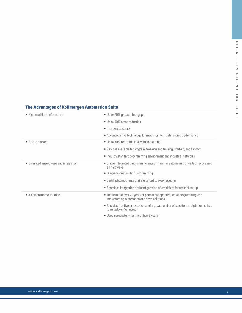
The Advantages of Kollmorgen Automation Suite• High machine performance • Up to 25% greater throughput
• Up to 50% scrap reduction
• Improved accuracy
• Advanced drive technology for machines with outstanding performance
• Fast to market • Up to 30% reduction in development time
• Services available for program development, training, start-up, and support
• Industry standard programming environment and industrial networks
• Enhanced ease-of-use and integration • Single integrated programming environment for automation, drive technology, and all hardware
• Drag-and-drop motion programming
• Certifi ed components that are tested to work together
• Seamless integration and confi guration of amplifi ers for optimal set-up
• A demonstrated solution • The result of over 20 years of permanent optimization of programming and implementing automation and drive solutions
• Provides the diverse experience of a great number of suppliers and platforms that form today's Kollmorgen
• Used successfully for more than 6 years
w w w. k o l l m o r g e n . c o m 9
KO
LL
MO
RG
EN
A
UT
OM
AT
IO
N
SU
IT
E
Basic Operation
R A N G E O F K O L L M O R G E N A U T O M AT I O N S U I T E C A PA B I L I T I E S
Single-Axis Programming
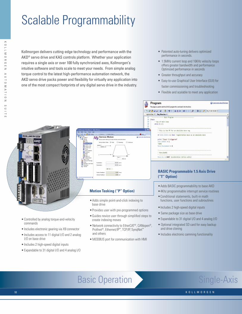
Kollmorgen delivers cutting-edge technology and performance with the AKD® servo drive and KAS controls platform. Whether your application requires a single axis or over 100 fully synchronized axes, Kollmorgen’s intuitive software and tools scale to meet your needs. From simple analog torque control to the latest high-performance automation network, the AKD servo drive packs power and fl exibility for virtually any application into one of the most compact footprints of any digital servo drive in the industry.
• Patented auto-tuning delivers optimized performance in seconds.
• 1.5MHz current loop and 16KHz velocity loops offers greater bandwidth and performance Optimized performance in seconds
• Greater throughput and accuracy
• Easy-to-use Graphical User Interface (GUI) for
faster commissioning and troubleshooting
• Flexible and scalable to meet any application
• Controlled by analog torque-and-velocitycommands
• Includes electronic gearing via X9 connector
• Includes access to 11 digital I/O and 2 analogI/O on base drive
• Includes 2 high-speed digital inputs
• Expandable to 31 digital I/O and 4 analog I/O
Motion Tasking (“P” Option)
• Adds simple point-and-click indexing tobase drive
• Provides user with pre-programmed options
• Guides novice user through simplifi ed steps to create indexing moves
• Network connectivity to EtherCAT®, CANopen®, Profi net®, Ethernet/IP™, TCP/IP, SynqNet™
and others
• MODBUS port for communication with HMI
BASIC Programmable 1.5 Axis Drive (“T” Option)
• Adds BASIC programmability to base AKD• 4Khz programmable interrupt service routines• Conditional statements, built-in math
functions, user functions and subroutines
• Includes 2 high-speed digital inputs
• Same package size as base drive
• Expandable to 31 digital I/O and 4 analog I/O
• Optional integrated SD card for easy backupand drive cloning
• Includes electronic camming functionality
Scalable Programmability
K O L L M O R G E N10
KO
LL
MO
RG
EN
A
UT
OM
AT
IO
N
SU
IT
E
R A N G E O F K O L L M O R G E N A U T O M AT I O N S U I T E C A PA B I L I T I E S
AKD Servo Drive AKD Servo Drive AKT I/O
Multi-Axis Programming
AKI HMI AKD PDMM AKT I/O
Single-Axis Programming
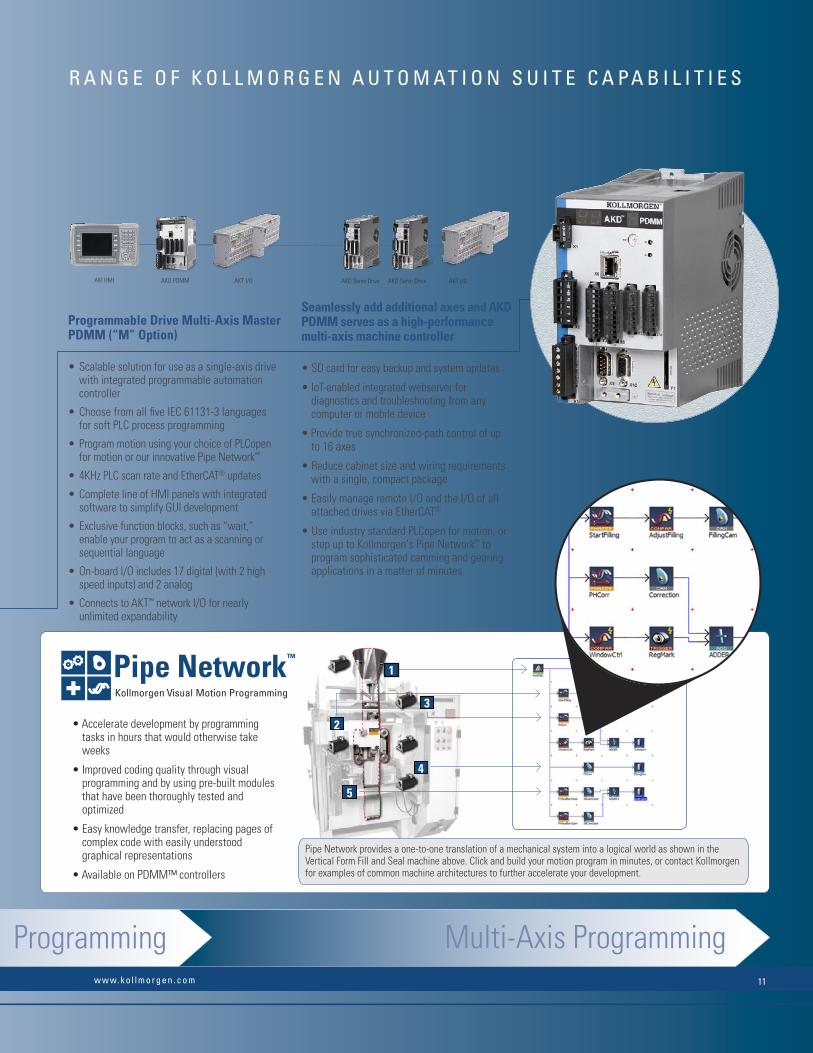
Pipe Network provides a one-to-one translation of a mechanical system into a logical world as shown in the Vertical Form Fill and Seal machine above. Click and build your motion program in minutes, or contact Kollmorgen for examples of common machine architectures to further accelerate your development.
2
4
5
3
Programmable Drive Multi-Axis Master PDMM (“M” Option)
• Scalable solution for use as a single-axis drivewith integrated programmable automation controller
• Choose from all fi ve IEC 61131-3 languagesfor soft PLC process programming
• Program motion using your choice of PLCopenfor motion or our innovative Pipe Network™
• 4KHz PLC scan rate and EtherCAT® updates
• Complete line of HMI panels with integratedsoftware to simplify GUI development
• Exclusive function blocks, such as “wait,”enable your program to act as a scanning orsequential language
• On-board I/O includes 17 digital (with 2 highspeed inputs) and 2 analog
• Connects to AKT™ network I/O for nearlyunlimited expandability
1
• Accelerate development by programmingtasks in hours that would otherwise takeweeks
• Improved coding quality through visualprogramming and by using pre-built modulesthat have been thoroughly tested andoptimized
• Easy knowledge transfer, replacing pages ofcomplex code with easily understoodgraphical representations
• Available on PDMM™ controllers
Seamlessly add additional axes and AKD PDMM serves as a high-performance multi-axis machine controller
• SD card for easy backup and system updates
• IoT-enabled integrated webserver for diagnostics and troubleshooting from any computer or mobile device
• Provide true synchronized-path control of up to 16 axes
• Reduce cabinet size and wiring requirementswith a single, compact package
• Easily manage remote I/O and the I/O of allattached drives via EtherCAT®
• Use industry standard PLCopen for motion, or step up to Kollmorgen’s Pipe Network™ toprogram sophisticated camming and gearingapplications in a matter of minutes
Visual Programming for Motion
Pipe NetworkKollmorgen Visual Programming for Motion
™
Pipe NetworkKollmorgen Visual Motion Programming
™
Pipe Network™
w w w. k o l l m o r g e n . c o m 11
KO
LL
MO
RG
EN
A
UT
OM
AT
IO
N
SU
IT
EK
OL
LM
OR
GE
N
AU
TO
MA
TI
ON
S
UI
TE
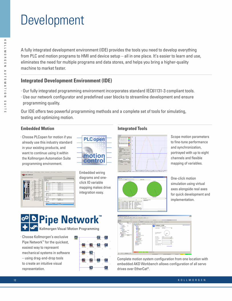
Development
Integrated Development Environment (IDE)
. Our fully integrated programming environment incorporates standard IEC61131-3 compliant tools.
. Use our network confi gurator and predefi ned user blocks to streamline development and ensure programming quality.
Our IDE offers two powerful programming methods and a complete set of tools for simulating, testing and optimizing motion.
A fully integrated development environment (IDE) provides the tools you need to develop everything from PLC and motion programs to HMI and device setup – all in one place. It’s easier to learn and use, eliminates the need for multiple programs and data stores, and helps you bring a higher-quality machine to market faster.
One-click motion simulation using virtual axes alongside real axes for quick development and implementation.
Scope motion parameters to fi ne-tune performance and synchronization, portrayed with up to eight channels and fl exible mapping of variables.
Complete motion system confi guration from one location with embedded AKD Workbench allows confi guration of all servo drives over EtherCat®.
Embedded wiring diagrams and one-click IO variable mapping makes drive integration easy.
Integrated ToolsEmbedded Motion
. Choose PLCopen for motion if you already use this industry standard in your existing products, and want to continue using it within the Kollmorgen Automation Suite programming environment.
. Choose Kollmorgen’s exclusive Pipe Network™ for the quickest, easiest way to represent mechanical systems in software – using drag-and-drop tools to create an intuitive visual representation.
Visual Programming for Motion
Pipe NetworkKollmorgen Visual Programming for Motion
™
Pipe NetworkKollmorgen Visual Motion Programming
™
Pipe Network™
KO
LL
MO
RG
EN
A
UT
OM
AT
IO
N
SU
IT
E
Lifecycle
Kollmorgen is committed to helping you maximize the productivity and profi tability of your machine across an extended lifecycle. Design and build today, with confi dence for a full return on investment for years to come.
Continual Development TestingKollmorgen develops, tests, and continually validates all new products to ensure compatibility and performance, in the Kollmorgen ecosystem.
Software and Hardware SecurityPassword protection for source code and hardware connectivity provides security for both OEMs and end-users.
Protect source code Protect network access
Maintenance Support ToolsOur tools give end-users the ability to remotely verify continuous operation and communicate issues effectively.
Built-in, mobile-ready webserver provides performance information with no software required
K O L L M O R G E N12

KO
LL
MO
RG
EN
A
UT
OM
AT
IO
N
SU
IT
E
KO
LL
MO
RG
EN
A
UT
OM
AT
IO
N
SU
IT
E
Development
Integrated Development Environment (IDE)
. Our fully integrated programming environment incorporates standard IEC61131-3 compliant tools.
. Use our network confi gurator and predefi ned user blocks to streamline development and ensure programming quality.
Our IDE offers two powerful programming methods and a complete set of tools for simulating, testing and optimizing motion.
A fully integrated development environment (IDE) provides the tools you need to develop everything from PLC and motion programs to HMI and device setup – all in one place. It’s easier to learn and use, eliminates the need for multiple programs and data stores, and helps you bring a higher-quality machine to market faster.
One-click motion simulation using virtual axes alongside real axes for quick development and implementation.
Scope motion parameters to fi ne-tune performance and synchronization, portrayed with up to eight channels and fl exible mapping of variables.
Complete motion system confi guration from one location with embedded AKD Workbench allows confi guration of all servo drives over EtherCat®.
Embedded wiring diagrams and one-click IO variable mapping makes drive integration easy.
Integrated ToolsEmbedded Motion
. Choose PLCopen for motion if you already use this industry standard in your existing products, and want to continue using it within the Kollmorgen Automation Suite programming environment.
. Choose Kollmorgen’s exclusive Pipe Network™ for the quickest, easiest way to represent mechanical systems in software – using drag-and-drop tools to create an intuitive visual representation.
Visual Programming for Motion
Pipe NetworkKollmorgen Visual Programming for Motion
™
Pipe NetworkKollmorgen Visual Motion Programming
™
Pipe Network™
KO
LL
MO
RG
EN
A
UT
OM
AT
IO
N
SU
IT
E
Lifecycle
Kollmorgen is committed to helping you maximize the productivity and profi tability of your machine across an extended lifecycle. Design and build today, with confi dence for a full return on investment for years to come.
Continual Development TestingKollmorgen develops, tests, and continually validates all new products to ensure compatibility and performance, in the Kollmorgen ecosystem.
Software and Hardware SecurityPassword protection for source code and hardware connectivity provides security for both OEMs and end-users.
Protect source code Protect network access
Maintenance Support ToolsOur tools give end-users the ability to remotely verify continuous operation and communicate issues effectively.
Built-in, mobile-ready webserver provides performance information with no software required
w w w. k o l l m o r g e n . c o m 13

KO
LL
MO
RG
EN
A
UT
OM
AT
IO
N
SU
IT
EK
OL
LM
OR
GE
N
AU
TO
MA
TI
ON
S
UI
TE
• Kollmorgen Automation Suite offers a set of tools that is familiar to automation programs, but has enhancements like predefi ned motion blocks and visual diagnostics tools.
• The environment for developing PLC programs has been created with an emphasis on speed. Recognize and confi gure motion control components to accelerate systems development. With auto-recognize and auto-confi gure features, testing efforts are reduced.
• Once an application or a function block has been created for a given application, the user can store this as a “user-defi ned function block” to promote reuse of tested software in subsequent projects to save time.
• Maintain your standards in corporate programming languages by using any of the IEC 61131-3 languages. In fact, enhance it further by mixing and matching languages to deliver the best solution for the application.
Software PLC
All fi ve IEC 61131-3 PLC languages are supported
Sequential Function Chart (SFC)
Function Block Diagram (FBD)
Ladder Diagram (LD)
Structured Text (ST)
Instruction List (IL)
• IEC-61131-3 engine
• Re-compile while running animated variables
• Industry and application Specifi c Function Blocks
• PID temperature control block
• Debugger Tools with Watch window
• 8-channel Real-Time Oscilliscope
IEC 61131-3 Toolkit Features
Easy-to-Use, Auto-Discover, Auto-Recognize, Auto-Confi gure, Scope, CAM, IEC 61131-3 PLC
KO
LL
MO
RG
EN
A
UT
OM
AT
IO
N
SU
IT
E
Simulator with PLC simulation and motion
Automatic I/O variable creation with scope defi nitions
Adding bus couplers with I/Os onto a motion network topology
Graphical environment for creating CAMs
• Sta ndard debugging features like “step into”, “step over”, etc. are available to troubleshoot programs. In addition, debug your code using the softoscilloscope and continuously plot up to 8 variables at network update rates – the display can also be confi gured to suit the scale that the developer desires.
• Our CAM editor lets you create complex CAM profi les using a graphical interface. When converting, it is also possible to import existing CAM profi le points into the CAM editor to allow you to seamlessly reuse your existing profi les.
• CAM-on-the-Fly lets you change CAM profi les based on network inputs or changes in machine conditions.
• Kollmorgen Automation Suite’s integrated development environment (IDE) allows the developer to create solutions without having to connect a single device by using the offl ine simulator. Start creating systems before the fi rst hardware component is delivered. Simply confi gure your system network in “offl ine development” mode and change the status of the devices one-by-one when you actually connect them.
K O L L M O R G E N14

KO
LL
MO
RG
EN
A
UT
OM
AT
IO
N
SU
IT
E
KO
LL
MO
RG
EN
A
UT
OM
AT
IO
N
SU
IT
E
• Kollmorgen Automation Suite offers a set of tools that is familiar to automation programs, but has enhancements like predefi ned motion blocks and visual diagnostics tools.
• The environment for developing PLC programs has been created with an emphasis on speed. Recognize and confi gure motion control components to accelerate systems development. With auto-recognize and auto-confi gure features, testing efforts are reduced.
• Once an application or a function block has been created for a given application, the user can store this as a “user-defi ned function block” to promote reuse of tested software in subsequent projects to save time.
• Maintain your standards in corporate programming languages by using any of the IEC 61131-3 languages. In fact, enhance it further by mixing and matching languages to deliver the best solution for the application.
Software PLC
All fi ve IEC 61131-3 PLC languages are supported
Sequential Function Chart (SFC)
Function Block Diagram (FBD)
Ladder Diagram (LD)
Structured Text (ST)
Instruction List (IL)
• IEC-61131-3 engine
• Re-compile while running animated variables
• Industry and application Specifi c Function Blocks
• PID temperature control block
• Debugger Tools with Watch window
• 8-channel Real-Time Oscilliscope
IEC 61131-3 Toolkit Features
Easy-to-Use, Auto-Discover, Auto-Recognize, Auto-Confi gure, Scope, CAM, IEC 61131-3 PLC
KO
LL
MO
RG
EN
A
UT
OM
AT
IO
N
SU
IT
E
Simulator with PLC simulation and motion
Automatic I/O variable creation with scope defi nitions
Adding bus couplers with I/Os onto a motion network topology
Graphical environment for creating CAMs
• Sta ndard debugging features like “step into”, “step over”, etc. are available to troubleshoot programs. In addition, debug your code using the softoscilloscope and continuously plot up to 8 variables at network update rates – the display can also be confi gured to suit the scale that the developer desires.
• Our CAM editor lets you create complex CAM profi les using a graphical interface. When converting, it is also possible to import existing CAM profi le points into the CAM editor to allow you to seamlessly reuse your existing profi les.
• CAM-on-the-Fly lets you change CAM profi les based on network inputs or changes in machine conditions.
• Kollmorgen Automation Suite’s integrated development environment (IDE) allows the developer to create solutions without having to connect a single device by using the offl ine simulator. Start creating systems before the fi rst hardware component is delivered. Simply confi gure your system network in “offl ine development” mode and change the status of the devices one-by-one when you actually connect them.
w w w. k o l l m o r g e n . c o m 15
KO
LL
MO
RG
EN
A
UT
OM
AT
IO
N
SU
IT
EK
OL
LM
OR
GE
N
AU
TO
MA
TI
ON
S
UI
TE
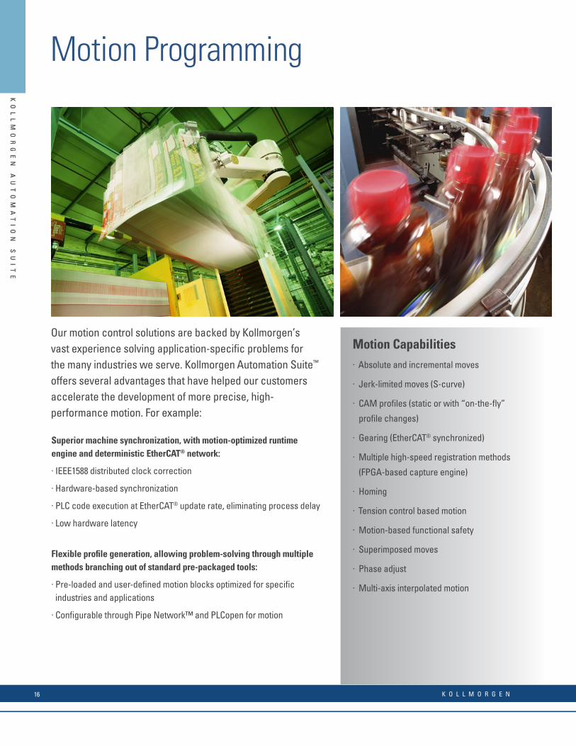
Motion Programming
Motion Capabilities. Absolute and incremental moves
. Jerk-limited moves (S-curve)
. CAM profi les (static or with “on-the-fl y”
profi le changes)
. Gearing (EtherCAT® synchronized)
. Multiple high-speed registration methods
(FPGA-based capture engine)
. Homing
. Tension control based motion
. Motion-based functional safety
. Superimposed moves
. Phase adjust
. Multi-axis interpolated motion
Our motion control solutions are backed by Kollmorgen’s vast experience solving application-specifi c problems for the many industries we serve. Kollmorgen Automation Suite™ offers several advantages that have helped our customers accelerate the development of more precise, high-performance motion. For example: Superior machine synchronization, with motion-optimized runtime engine and deterministic EtherCAT® network:
. IEEE1588 distributed clock correction
. Hardware-based synchronization
. PLC code execution at EtherCAT® update rate, eliminating process delay
. Low hardware latency
Flexible profi le generation, allowing problem-solving through multiple methods branching out of standard pre-packaged tools:
. Pre-loaded and user-defi ned motion blocks optimized for specifi c industries and applications
. Confi gurable through Pipe Network™ and PLCopen for motion
KO
LL
MO
RG
EN
A
UT
OM
AT
IO
N
SU
IT
E
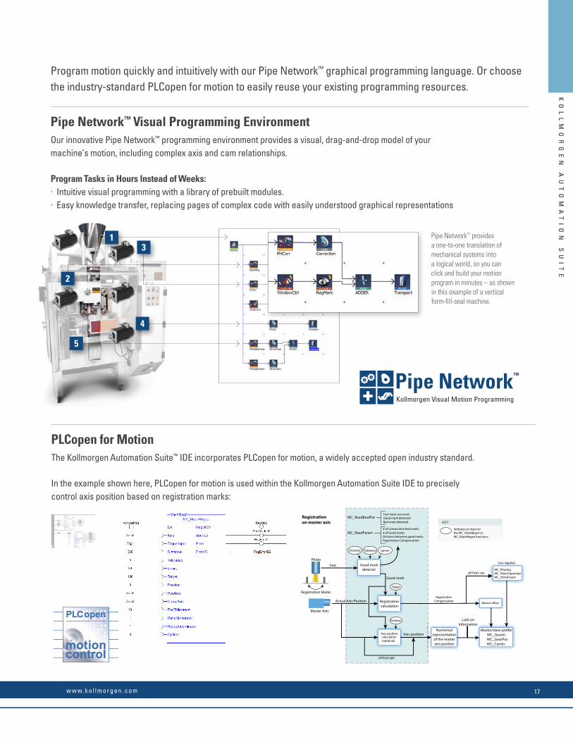
PLCopen for MotionThe Kollmorgen Automation Suite™ IDE incorporates PLCopen for motion, a widely accepted open industry standard.
In the example shown here, PLCopen for motion is used within the Kollmorgen Automation Suite IDE to precisely control axis position based on registration marks:
Pipe NetworkTM provides a one-to-one translation of mechanical systems into a logical world, so you can click and build your motion program in minutes – as shown in this example of a vertical form-fi ll-seal machine.
Program motion quickly and intuitively with our Pipe Network™ graphical programming language. Or choose the industry-standard PLCopen for motion to easily reuse your existing programming resources.
Pipe Network™ Visual Programming Environment Our innovative Pipe Network™ programming environment provides a visual, drag-and-drop model of your machine’s motion, including complex axis and cam relationships.
Program Tasks in Hours Instead of Weeks:. Intuitive visual programming with a library of prebuilt modules.. Easy knowledge transfer, replacing pages of complex code with easily understood graphical representations
Good markdetector
Registrationcalculation
Axis positioncalculation(optional)
Master oset
Numericalrepresentationof the masteraxis position
MC_GearInMC_GearPosMC_CamIn
Registration Marks
Master Axis
MC_ReadBoolParBad mark detected
MC_ReadParam
Axis position
Lock onInformation
Fast
Actual Axis Position
Photo
Good mark
Registrationon master axis
Distance Tolerance Ignore
Indicates an input to the MC_MarkRegist or MC_MachRegist functions
KEY
Target
Position
OPTION 08H
RegistrationCompensation
OPTION 10HMC_PhasingMC_MoveSuperimpMC_WriteParam
User Applied
# of consecutive bad marks# of Good marksDistance between good marksRegistration Compensation
Fast input occurredGood mark detected
13
4
5
2
Visual Programming for Motion
Pipe NetworkKollmorgen Visual Programming for Motion
™
Pipe NetworkKollmorgen Visual Motion Programming
™
Pipe Network™
K O L L M O R G E N16
KO
LL
MO
RG
EN
A
UT
OM
AT
IO
N
SU
IT
E
KO
LL
MO
RG
EN
A
UT
OM
AT
IO
N
SU
IT
E
Motion Programming
Motion Capabilities. Absolute and incremental moves
. Jerk-limited moves (S-curve)
. CAM profi les (static or with “on-the-fl y”
profi le changes)
. Gearing (EtherCAT® synchronized)
. Multiple high-speed registration methods
(FPGA-based capture engine)
. Homing
. Tension control based motion
. Motion-based functional safety
. Superimposed moves
. Phase adjust
. Multi-axis interpolated motion
Our motion control solutions are backed by Kollmorgen’s vast experience solving application-specifi c problems for the many industries we serve. Kollmorgen Automation Suite™ offers several advantages that have helped our customers accelerate the development of more precise, high-performance motion. For example: Superior machine synchronization, with motion-optimized runtime engine and deterministic EtherCAT® network:
. IEEE1588 distributed clock correction
. Hardware-based synchronization
. PLC code execution at EtherCAT® update rate, eliminating process delay
. Low hardware latency
Flexible profi le generation, allowing problem-solving through multiple methods branching out of standard pre-packaged tools:
. Pre-loaded and user-defi ned motion blocks optimized for specifi c industries and applications
. Confi gurable through Pipe Network™ and PLCopen for motion
KO
LL
MO
RG
EN
A
UT
OM
AT
IO
N
SU
IT
E
PLCopen for MotionThe Kollmorgen Automation Suite™ IDE incorporates PLCopen for motion, a widely accepted open industry standard.
In the example shown here, PLCopen for motion is used within the Kollmorgen Automation Suite IDE to precisely control axis position based on registration marks:
Pipe NetworkTM provides a one-to-one translation of mechanical systems into a logical world, so you can click and build your motion program in minutes – as shown in this example of a vertical form-fi ll-seal machine.
Program motion quickly and intuitively with our Pipe Network™ graphical programming language. Or choose the industry-standard PLCopen for motion to easily reuse your existing programming resources.
Pipe Network™ Visual Programming Environment Our innovative Pipe Network™ programming environment provides a visual, drag-and-drop model of your machine’s motion, including complex axis and cam relationships.
Program Tasks in Hours Instead of Weeks:. Intuitive visual programming with a library of prebuilt modules.. Easy knowledge transfer, replacing pages of complex code with easily understood graphical representations
Good markdetector
Registrationcalculation
Axis positioncalculation(optional)
Master oset
Numericalrepresentationof the masteraxis position
MC_GearInMC_GearPosMC_CamIn
Registration Marks
Master Axis
MC_ReadBoolParBad mark detected
MC_ReadParam
Axis position
Lock onInformation
Fast
Actual Axis Position
Photo
Good mark
Registrationon master axis
Distance Tolerance Ignore
Indicates an input to the MC_MarkRegist or MC_MachRegist functions
KEY
Target
Position
OPTION 08H
RegistrationCompensation
OPTION 10HMC_PhasingMC_MoveSuperimpMC_WriteParam
User Applied
# of consecutive bad marks# of Good marksDistance between good marksRegistration Compensation
Fast input occurredGood mark detected
13
4
5
2
Visual Programming for Motion
Pipe NetworkKollmorgen Visual Programming for Motion
™
Pipe NetworkKollmorgen Visual Motion Programming
™
Pipe Network™
w w w. k o l l m o r g e n . c o m 17
KO
LL
MO
RG
EN
A
UT
OM
AT
IO
N
SU
IT
E
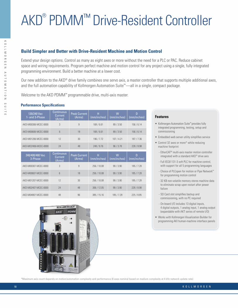
Features
• Kollmorgen Automation Suite™ provides fully integrated programming, testing, setup and commissioning
• Embedded web server utility simplifi es service
• Control 32 axes or more* while reducing machine footprint
- EtherCAT® multi-axis master motion controller integrated with a standard AKD™ drive axis
- Full IEC61131-3 soft PLC for machine control, with support for all 5 programming languages
- Choice of PLCopen for motion or Pipe Network™ for programming motion control
- 32 KB non-volatile memory stores machine data to eliminate scrap upon restart after power failure
- SD Card slot simplifi es backup and commissioning, with no PC required
- On-board I/O includes 13 digital inputs, 4 digital outputs, 1 analog input, 1 analog output (expandable with AKT series of remote I/O)
• Works with Kollmorgen Visualization Builder for programming AKI human-machine interface panels
Build Simpler and Better with Drive-Resident Machine and Motion Control
Extend your design options. Control as many as eight axes or more without the need for a PLC or PAC. Reduce cabinet space and wiring requirements. Program perfect machine and motion control for any project using a single, fully integrated programming environment. Build a better machine at a lower cost.
Our new addition to the AKD® drive family combines one servo axis, a master controller that supports multiple additional axes, and the full automation capability of Kollmorgen Automation Suite™ —all in a single, compact package.
Welcome to the AKD PDMM™ programmable drive, multi-axis master.
*Maximum axis count depends on motion/automation complexity and performance (8 axes nominal based on medium complexity at 4 kHz network update rate)
Performance Specifi cations
120/240 Vac1- and 3-Phase
Continuous Current (Arms)
Peak Current (Arms)
H(mm/inches)
W(mm/inches)
D(mm/inches)
AKD-M00306-MCEC-0000 3 9 168 / 6.61 89 / 3.50 156 / 6.14
AKD-M00606-MCEC-0000 6 18 168 / 6.61 89 / 3.50 156 / 6.14
AKD-M01206-MCEC-0000 12 30 196 / 7.72 107 / 4.21 187 / 7.36
AKD-MO2406-MCEC-0000 24 48 248 / 9.76 96 / 3.78 228 / 8.98
240/400/480 Vac3-Phase
Continuous Current (Arms)
Peak Current (Arms)
H(mm/inches)
W(mm/inches)
D(mm/inches)
AKD-M00307-MCEC-0000 3 9 256 / 10.08 99 / 3.90 185 / 7.28
AKD-M00607-MCEC-0000 6 18 256 / 10.08 99 / 3.90 185 / 7.28
AKD-M01207-MCEC-0000 12 30 256 / 10.08 99 / 3.90 185 / 7.28
AKD-M02407-MCEC-0000 24 48 306 / 12.05 99 / 3.90 228 / 8.98
AKD-M04807-MCEC-0000 48 96 385 / 15.16 185 / 7.28 225 / 8.85
AK
D®
P
DM
M™
D
RI
VE
-R
ES
ID
EN
T
CO
NT
RO
LL
ER
AKD® PDMM™ Drive-Resident Controller
K O L L M O R G E N18

KO
LL
MO
RG
EN
A
UT
OM
AT
IO
N
SU
IT
E
A Single, Scalable Development Suite
Kollmorgen Automation Suite™ simplifi es and accelerates development through a unifi ed system of software, hardware, and collaborative co-engineering. This scalable solution provides a fully integrated development environment for any application, whether you’re programming a single axis of motion, a multi-axis AKD PDMM™ system, or a PCMM-based system up to 64 axes or more. Kollmorgen Automation Suite has been proven to:
• Improve product throughput by up to 25% with industry-leading motion bandwidth
• Reduce scrap by up to 50% with world-class servo accuracy, seamless power-failure recovery and highly dynamic changeovers
• Increase precision for better quality, reduced waste and less downtime using EtherCAT®—the fi eld bus with motion bus performance
• Enable more adaptable, sustainable and innovative machines that measurably improve marketability and profi tability
A Single Family of Servo Drives
Kollmorgen AKD™ servo drives deliver cutting-edge performance in a compact footprint. From basic torque-and-velocity applications, to indexing, to multi-axis programmable motion, these feature-rich drives offer:
• Plug-and-play compatibility with your servo motor
• All the advantages of Kollmorgen´s breadth of motor platforms including AKM™, CDDR™, and other direct-drive technologies
• The fastest velocity and position loop updates
• Full-frequency auto-tuning for perfect motion across the performance spectrum
• Real-time feedback from a wide variety of devices
Our Best Drive and Automation Solution in a Single Package
The new AKD PDMM programmable drive, multi-axis master combines our AKD drive platform with the full feature set of Kollmorgen Automation Suite in a single package—providing complete machine and motion control for up to eight axes or more.
You need only one development suite and one drive family for all your projects. And you can rely on one source for all the motion components and co-engineering expertise you need to build a better machine.
With AKD PDMM, the best in machine engineering has never been easier, faster or more cost-effective.
Features
• Kollmorgen Automation Suite™ provides fully integrated programming, testing, setup and commissioning
• Embedded web server utility simplifi es service
• Control 32 axes or more* while reducing machine footprint
- EtherCAT® multi-axis master motion controller integrated with a standard AKD™ drive axis
- Full IEC61131-3 soft PLC for machine control, with support for all 5 programming languages
- Choice of PLCopen for motion or Pipe Network™ for programming motion control
- 32 KB non-volatile memory stores machine data to eliminate scrap upon restart after power failure
- SD Card slot simplifi es backup and commissioning, with no PC required
- On-board I/O includes 13 digital inputs, 4 digital outputs, 1 analog input, 1 analog output (expandable with AKT series of remote I/O)
• Works with Kollmorgen Visualization Builder for programming AKI human-machine interface panels
Build Simpler and Better with Drive-Resident Machine and Motion Control
Extend your design options. Control as many as eight axes or more without the need for a PLC or PAC. Reduce cabinet space and wiring requirements. Program perfect machine and motion control for any project using a single, fully integrated programming environment. Build a better machine at a lower cost.
Our new addition to the AKD® drive family combines one servo axis, a master controller that supports multiple additional axes, and the full automation capability of Kollmorgen Automation Suite™ —all in a single, compact package.
Welcome to the AKD PDMM™ programmable drive, multi-axis master.
*Maximum axis count depends on motion/automation complexity and performance (8 axes nominal based on medium complexity at 4 kHz network update rate)
Performance Specifi cations
120/240 Vac1- and 3-Phase
Continuous Current (Arms)
Peak Current (Arms)
H(mm/inches)
W(mm/inches)
D(mm/inches)
AKD-M00306-MCEC-0000 3 9 168 / 6.61 89 / 3.50 156 / 6.14
AKD-M00606-MCEC-0000 6 18 168 / 6.61 89 / 3.50 156 / 6.14
AKD-M01206-MCEC-0000 12 30 196 / 7.72 107 / 4.21 187 / 7.36
AKD-MO2406-MCEC-0000 24 48 248 / 9.76 96 / 3.78 228 / 8.98
240/400/480 Vac3-Phase
Continuous Current (Arms)
Peak Current (Arms)
H(mm/inches)
W(mm/inches)
D(mm/inches)
AKD-M00307-MCEC-0000 3 9 256 / 10.08 99 / 3.90 185 / 7.28
AKD-M00607-MCEC-0000 6 18 256 / 10.08 99 / 3.90 185 / 7.28
AKD-M01207-MCEC-0000 12 30 256 / 10.08 99 / 3.90 185 / 7.28
AKD-M02407-MCEC-0000 24 48 306 / 12.05 99 / 3.90 228 / 8.98
AKD-M04807-MCEC-0000 48 96 385 / 15.16 185 / 7.28 225 / 8.85
AK
D®
P
DM
M™
D
RI
VE
-R
ES
ID
EN
T
CO
NT
RO
LL
ER
AKD® PDMM™ Drive-Resident Controller
w w w. k o l l m o r g e n . c o m 19
KO
LL
MO
RG
EN
A
UT
OM
AT
IO
N
SU
IT
EK
OL
LM
OR
GE
N
AU
TO
MA
TI
ON
S
UI
TE
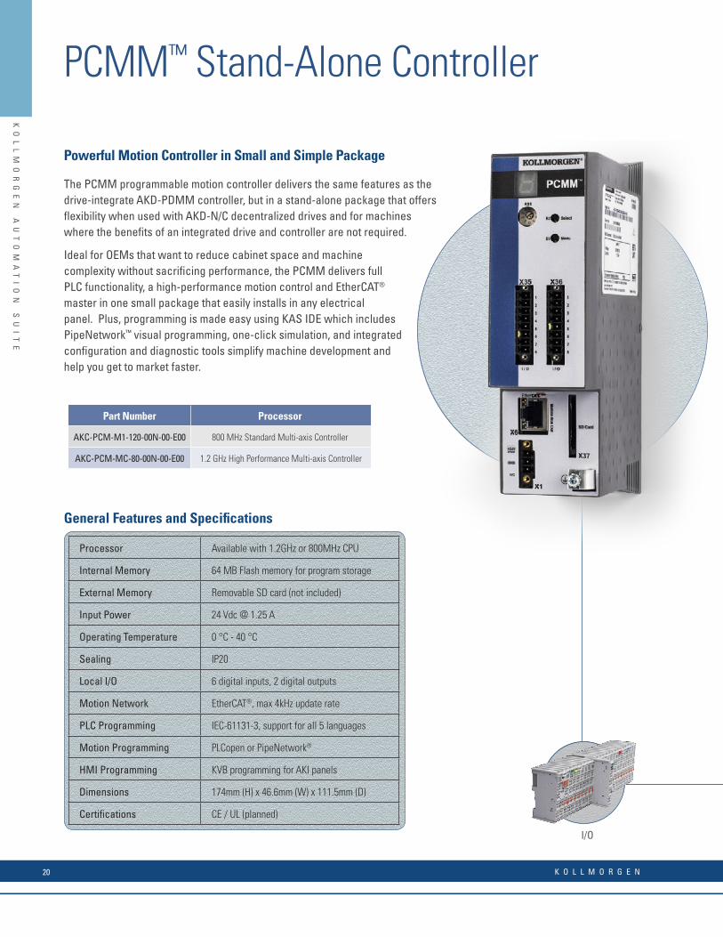
The PCMM programmable motion controller delivers the same features as the drive-integrate AKD-PDMM controller, but in a stand-alone package that offers fl exibility when used with AKD-N/C decentralized drives and for machines where the benefi ts of an integrated drive and controller are not required.
Ideal for OEMs that want to reduce cabinet space and machine complexity without sacrifi cing performance, the PCMM delivers full PLC functionality, a high-performance motion control and EtherCAT® master in one small package that easily installs in any electrical panel. Plus, programming is made easy using KAS IDE which includes PipeNetwork™ visual programming, one-click simulation, and integrated confi guration and diagnostic tools simplify machine development and help you get to market faster.
Powerful Motion Controller in Small and Simple Package
I/O
General Features and Specifi cations
Processor Available with 1.2GHz or 800MHz CPU
Internal Memory 64 MB Flash memory for program storage
External Memory Removable SD card (not included)
Input Power 24 Vdc @ 1.25 A
Operating Temperature 0 °C - 40 °C
Sealing IP20
Local I/O 6 digital inputs, 2 digital outputs
Motion Network EtherCAT®, max 4kHz update rate
PLC Programming IEC-61131-3, support for all 5 languages
Motion Programming PLCopen or PipeNetwork®
HMI Programming KVB programming for AKI panels
Dimensions 174mm (H) x 46.6mm (W) x 111.5mm (D)
Certifi cations CE / UL (planned)
Part Number Processor
AKC-PCM-M1-120-00N-00-E00 800 MHz Standard Multi-axis Controller
AKC-PCM-MC-80-00N-00-E00 1.2 GHz High Performance Multi-axis Controller
PCMM™ Stand-Alone Controller
K O L L M O R G E N20

KO
LL
MO
RG
EN
A
UT
OM
AT
IO
N
SU
IT
E
KO
LL
MO
RG
EN
A
UT
OM
AT
IO
N
SU
IT
E
The PCMM programmable motion controller delivers the same features as the drive-integrate AKD-PDMM controller, but in a stand-alone package that offers fl exibility when used with AKD-N/C decentralized drives and for machines where the benefi ts of an integrated drive and controller are not required.
Ideal for OEMs that want to reduce cabinet space and machine complexity without sacrifi cing performance, the PCMM delivers full PLC functionality, a high-performance motion control and EtherCAT® master in one small package that easily installs in any electrical panel. Plus, programming is made easy using KAS IDE which includes PipeNetwork™ visual programming, one-click simulation, and integrated confi guration and diagnostic tools simplify machine development and help you get to market faster.
Powerful Motion Controller in Small and Simple Package
I/O
General Features and Specifi cations
Processor Available with 1.2GHz or 800MHz CPU
Internal Memory 64 MB Flash memory for program storage
External Memory Removable SD card (not included)
Input Power 24 Vdc @ 1.25 A
Operating Temperature 0 °C - 40 °C
Sealing IP20
Local I/O 6 digital inputs, 2 digital outputs
Motion Network EtherCAT®, max 4kHz update rate
PLC Programming IEC-61131-3, support for all 5 languages
Motion Programming PLCopen or PipeNetwork®
HMI Programming KVB programming for AKI panels
Dimensions 174mm (H) x 46.6mm (W) x 111.5mm (D)
Certifi cations CE / UL (planned)
Part Number Processor
AKC-PCM-M1-120-00N-00-E00 800 MHz Standard Multi-axis Controller
AKC-PCM-MC-80-00N-00-E00 1.2 GHz High Performance Multi-axis Controller
PCMM™ Stand-Alone ControllerK
OL
LM
OR
GE
N
AU
TO
MA
TI
ON
S
UI
TE
PCMM™ Hardware Features• Up to 1.2GHz CPU meets the performance requirements for a broad
range of machines• Control 1 to 30 or more axes with a single controller• 100BaseT connection supporting TCP/IP, MODBUS, EthernetIP®,
Profi net® to host PLC, computer, or network to easily interface with most manufacturing systems
• Cycle times as low as 250 μs• Alphanumeric display for fast diagnostics and system
troubleshooting • Removable SD memory card for simple backup/restore and fi le
storage• On-board digital I/O with support for expansion I/O via EtherCAT®
• Compact size reduces cabinet space and cost
PCMM™ Software Features• IEC 61131-3 programmable automation and motion controller• EtherCAT® master for high-performance motion and device
synchronization• PipeNetwork™ motion engine for visual programming• Embedded RTOS for guaranteed performance and stability• Integrated webserver for remote diagnostics and status checking • Ideal design for modular machines and fl exible manufacturing
systems
PCMM™ System Integration• Seamless integration with Kollmorgen’s AKD® servo drives, AKM®
rotary servo motors , AKI® HMIs, and AKT® fi eldbus I/O modules for complete automation solution
• Network communication via OPC, MODBUS, TCP/IP, UDP, and common fi eldbus for fast integration into your machine or factory
• Intuitive EtherCAT® confi guration tools built into KAS IDE simplifi es network confi guration
• Integrated Kollmorgen Workbench® for rapid servo tuning and machine optimization
HMIAKM® Servo Motor AKD®-N Servo Drive AKD® Servo Drive
X37SD Card
X124 Vdc Supply
X6EtherCAT® Master
X35/X36Digital I/O
X32TCP/IP Ethernet
PROFINET®
Ethernet/IP®
Modbus/TCP®
w w w. k o l l m o r g e n . c o m 21

KO
LL
MO
RG
EN
A
UT
OM
AT
IO
N
SU
IT
EK
OL
LM
OR
GE
N
AU
TO
MA
TI
ON
S
UI
TE
EtherCAT® Real-time Bus for Motion and I/O Connectivity
• Auto-recognition of Kollmorgen Automation Suite-compatible components
• Guaranteed real-time update cycle down to 250 microseconds.
• Supported by 2000+ member companies
• Standard Ethernet cabling = lower implementation cost
• Interoperability with other buses
• Wide availability of devices
Real-time Motion Bus
Transparent for all Ethernet protocols
Versatile network architecture
EtherCAT® Performance Overview
Kollmorgen EtherCAT® Bus Coupler
Process Data Update Time
256 distributed digital I/O 11 μs = 0.01 ms
1000 distributed digital I/O 30μs
200 analog I/O (16 bit) 50 μs – 20 kHz
100 Servo Axis, with 8 Bytes input and output data each 100 μs
1 Fieldbus Master-Gateway (1486 Bytes Input and 1486 Bytes Output Data) 150 μs
switch
virtual MAC AddressIP Address
virtual Ethernet SwitchFunctionality
EtherCAT Signal Input
Power LEDs
Standard-Bus
Bus Coupler Supply
Input for Power Contacts
Power Contacts
EtherCAT Signal Output
Confi guration Interface
Link/Act In
Link/Act Out
See page 26 for models and confi gurations
K O L L M O R G E N22

KO
LL
MO
RG
EN
A
UT
OM
AT
IO
N
SU
IT
EK
OL
LM
OR
GE
N
AU
TO
MA
TI
ON
S
UI
TE
Kollmorgen HMI Panels
With Kollmorgen HMI’s visualization projects can be scaled for different size screens and performance demands without having to re-write code or learn different tools.
• Full range of sizes 4” to 21” models• 3 processor levels from ARM to multi-core options• Wide screen layout gives 30% larger viewing area• Rugged Aluminum Housing• Smooth ridgeless IP65 protection class screen for easy cleaning
Human Machine Interface (HMI)
4”, 7”, 10” Touchscreen HMI
Space, price or reliability issues should not limit your application - with Kollmorgen performance panels, any small to medium sized HMI application can have an intuitive graphic interface that’ll make operation easier for your customers. These units have no fan or rotating hard drive, which means no moving parts.
12”, 15”, 21” Touchscreen HMI
Ideal for medium to large scale HMI applications that require more power or add-on functionality such as video.Kollmorgen high-performance terminals give you a full, open and expandable HMI, with KVB runtime software, in a robust industrial PC hardware with high connectivity.
7”, 12”, 15” Touchscreen HMI
For demanding HMI applications or large projects within traditional industrial or process industry, where complex operating screens filled with objects are required, this operator panel steps up and delivers with mid-range performance hardware that is finely tuned for KVB HMI solutions.
HMI Software Tools
Kollmorgen Automation Suite Visualization Builder™ HMI Software
AKI-CDA Series AKI-CDB Series AKI-CDC Series
HMI developer environment
Kollmorgen Automation Suite Visualization Builder operates from within the Kollmorgen Automation Suite integrated development environment making it quick and easy to create your HMI program and transfer it to the panel.
Features include
• Automatic mapping transfers PLC variables to HMI tags avoiding
mistakes and saving time.
• Multi-screen navigation
• Trending/Data Logging
• Recipes
• Alarm management
• Drag and Drop programming
• Password Protection
KO
LL
MO
RG
EN
A
UT
OM
AT
IO
N
SU
IT
E
EtherCAT® Real-time Bus for Motion and I/O Connectivity
• Auto-recognition of Kollmorgen Automation Suite-compatible components
• Guaranteed real-time update cycle down to 250 microseconds.
• Supported by 2000+ member companies
• Standard Ethernet cabling = lower implementation cost
• Interoperability with other buses
• Wide availability of devices
Real-time Motion Bus
Transparent for all Ethernet protocols
Versatile network architecture
EtherCAT® Performance Overview
Kollmorgen EtherCAT® Bus Coupler
Process Data Update Time
256 distributed digital I/O 11 μs = 0.01 ms
1000 distributed digital I/O 30μs
200 analog I/O (16 bit) 50 μs – 20 kHz
100 Servo Axis, with 8 Bytes input and output data each 100 μs
1 Fieldbus Master-Gateway (1486 Bytes Input and 1486 Bytes Output Data) 150 μs
switch
virtual MAC AddressIP Address
virtual Ethernet SwitchFunctionality
EtherCAT Signal Input
Power LEDs
Standard-Bus
Bus Coupler Supply
Input for Power Contacts
Power Contacts
EtherCAT Signal Output
Confi guration Interface
Link/Act In
Link/Act Out
See page 26 for models and confi gurations
w w w. k o l l m o r g e n . c o m 23
KO
LL
MO
RG
EN
A
UT
OM
AT
IO
N
SU
IT
E
KO
LL
MO
RG
EN
A
UT
OM
AT
IO
N
SU
IT
E
Human Machine Interface (HMI)
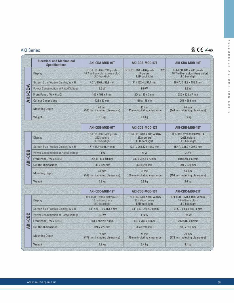
Electrical and Mechanical Specifi cations AKI-CDA-MOD-04T AKI-CDA-MOD-07T AKI-CDA-MOD-10T
AK
I-C
DA
DisplayTFT-LCD. 480 x 272 pixels
16.7 million colors (true color)LED backlight
TFT-LCD. 800 x 480 pixels 262 K colors
LED backlight
TFT-LCD. 640 x 480 pixels 16.7 million colors (true color)
LED backlight
Screen Size / Active Display, W x H 4.3” / 95.0 x 53.9 mm 7” / 152.4 x 91.4 mm 10.4” / 211.2 x 158.4 mm
Power Consumption at Rated Voltage 3.6 W 6.0 W 9.6 W
Front Panel, (W x H x D) 145 x 103 x 7 mm 204 x 143 x 7 mm 280 x 228 x 7 mm
Cut out Dimensions 128 x 87 mm 189 x 128 mm 262 x 209 mm
Mounting Depth 43 mm (100 mm including clearance)
43 mm (143 mm including clearance)
44 mm(144 mm including clearance)
Weight 0.5 kg 0.8 kg 1.5 kg
AKI-CDB-MOD-07T AKI-CDB-MOD-12T AKI-CDB-MOD-15T
AKI
-CD
B
DisplayTFT-LCD. 800 x 480 pixels
262k colorsLED backlight
TFT-LCD. 1280 X 800 WXGA262k colors
LED backlight
TFT-LCD. 1280 X 800 WXGA262k colors
LED backlight
Screen Size / Active Display, W x H 7” / 152.4 x 91.44 mm 12.1” / 261.12 x 163.2 mm 15.4” / 331.2 x 207.0 mm
Power Consumption at Rated Voltage 14 W 22 W 24 W
Front Panel, (W x H x D) 204 x 143 x 50 mm 340 x 242,2 x 57mm 410 x 286 x 61mm
Cut Out Dimensions 189 x 128 mm 324 x 226 mm 394 x 270 mm
Mounting Depth43 mm
(143 mm including clearance)50 mm
(150 mm including clearance)54 mm
(154 mm including clearance)
Weight 0.9 kg 2.5 kg 3.6 kg
AKI-CDC-MOD-12T AKI-CDC-MOD-15T AKI-CDC-MOD-21T
AKI
-CD
C
DisplayTFT-LCD. 1280 X 800 WXGA
16 million colorsLED backlight
TFT-LCD. 1280 X 800 WXGA16 million colors
LED backlight
TFT-LCD. 1920 X 1080 WXGA16 million colors
LED backlight
Screen Size / Active Display, W x H 12.1” / 261.12 x 163.2 mm 15.4” / 331.2 x 207.0 mm 21.5” / 6.64 x 268.11 mm
Power Consumption at Rated Voltage 107 W 114 W 125 W
Front Panel, (W x H x D) 340 x 242,2 x 79mm 410 x 286 x 83mm 556 x 347 x 87mm
Cut Out Dimensions 324 x 226 mm 394 x 270 mm 539 x 331 mm
Mounting Depth 72 mm (172 mm including clearance)
76 mm (176 mm including clearance)
79 mm(179 mm including clearance)
Weight 4.2 kg 5.4 kg 8.1 kg
AKI Series
KO
LL
MO
RG
EN
A
UT
OM
AT
IO
N
SU
IT
E
Human Machine Interface (HMI)
AKI Series
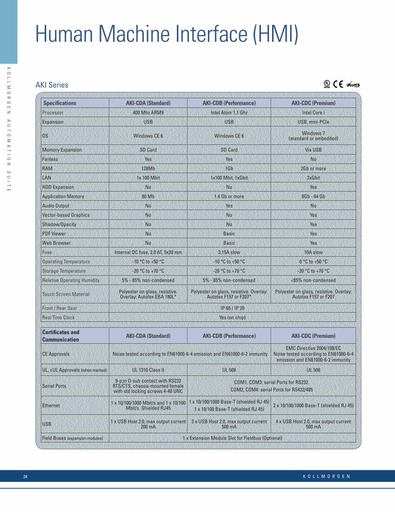
Specifi cations AKI-CDA (Standard) AKI-CDB (Performance) AKI-CDC (Premium)
Processor 400 Mhz ARM9 Intel Atom 1.1 Ghz Intel Core i
Expansion USB USB USB, mini-PCIe
OS Windows CE 6 Windows CE 6 Windows 7 (standard or embedded)
Memory Expansion SD Card SD Card Via USB
Fanless Yes Yes No
RAM 128Mb 1Gb 2Gb or more
LAN 1x 100 Mbit 1x100 Mbit, 1xGbit 2xGbit
HDD Expansion No No Yes
Application Memory 80 Mb 1.4 Gb or more 8Gb - 64 Gb
Audio Output No Yes No
Vector-based Graphics No No Yes
Shadow/Opacity No No Yes
PDF Viewer No Basic Yes
Web Browser No Basic Yes
Fuse Internal DC fuse, 2.0 AT, 5x20 mm 3.15A slow 10A slow
Operating Temperature -10 °C to +50 °C -10 °C to +50 °C 0 °C to +50 °C
Storage Temperature -20 °C to +70 °C -20 °C to +70 °C -20 °C to +70 °C
Relative Operating Humidity 5% - 85% non-condensed 5% - 85% non-condensed <85% non-condensed
Touch Screen Material Polyester on glass, resistive. Overlay: Autofex EBA 180L*
Polyester on glass, resistive. Overlay: Autotex F157 or F207*
Polyester on glass, resistive. Overlay: Autotex F157 or F207
Front / Rear Seal IP 65 / IP 20
Real Time Clock Yes (on chip)
Certifi cates and Communication
AKI-CDA (Standard) AKI-CDB (Performance) AKI-CDC (Premium)
CE Approvals Noise tested according to EN61000-6-4 emission and EN61000-6-2 immunityEMC Directive 2004/108/EC
Noise tested according to EN61000-6-4 emission and EN61000-6-2 immunity
UL, cUL Approvals (when marked) UL 1310 Class II UL 508 UL 508
Serial Ports9-p;in D-sub contact with RS232
RTS/CTS, chassis-mounted female with std locking screws 4-40 UNC
COM1, COM3: serial Ports for RS232. COM2, COM4: serial Ports for RS422/485
Ethernet 1 x 10/100/1000 Mbit/s and 1 x 10/100 Mbit/s. Shielded RJ45
1 x 10/100/1000 Base-T (shielded RJ 45) 1 x 10/100 Base-T (shielded RJ 45)
2 x 10/100/1000 Base-T (shielded RJ 45)
USB 1 x USB Host 2.0, max output current 200 mA
3 x USB Host 2.0, max output current 500 mA
4 x USB Host 2.0, max output current 500 mA
Field Buses (expansion modules) 1 x Extension Module Slot for Fieldbus (Optional)
K O L L M O R G E N24
KO
LL
MO
RG
EN
A
UT
OM
AT
IO
N
SU
IT
EK
OL
LM
OR
GE
N
AU
TO
MA
TI
ON
S
UI
TE
Human Machine Interface (HMI)
Electrical and Mechanical Specifi cations AKI-CDA-MOD-04T AKI-CDA-MOD-07T AKI-CDA-MOD-10T
AK
I-C
DA
DisplayTFT-LCD. 480 x 272 pixels
16.7 million colors (true color)LED backlight
TFT-LCD. 800 x 480 pixels 262 K colors
LED backlight
TFT-LCD. 640 x 480 pixels 16.7 million colors (true color)
LED backlight
Screen Size / Active Display, W x H 4.3” / 95.0 x 53.9 mm 7” / 152.4 x 91.4 mm 10.4” / 211.2 x 158.4 mm
Power Consumption at Rated Voltage 3.6 W 6.0 W 9.6 W
Front Panel, (W x H x D) 145 x 103 x 7 mm 204 x 143 x 7 mm 280 x 228 x 7 mm
Cut out Dimensions 128 x 87 mm 189 x 128 mm 262 x 209 mm
Mounting Depth 43 mm (100 mm including clearance)
43 mm (143 mm including clearance)
44 mm(144 mm including clearance)
Weight 0.5 kg 0.8 kg 1.5 kg
AKI-CDB-MOD-07T AKI-CDB-MOD-12T AKI-CDB-MOD-15T
AKI
-CD
B
DisplayTFT-LCD. 800 x 480 pixels
262k colorsLED backlight
TFT-LCD. 1280 X 800 WXGA262k colors
LED backlight
TFT-LCD. 1280 X 800 WXGA262k colors
LED backlight
Screen Size / Active Display, W x H 7” / 152.4 x 91.44 mm 12.1” / 261.12 x 163.2 mm 15.4” / 331.2 x 207.0 mm
Power Consumption at Rated Voltage 14 W 22 W 24 W
Front Panel, (W x H x D) 204 x 143 x 50 mm 340 x 242,2 x 57mm 410 x 286 x 61mm
Cut Out Dimensions 189 x 128 mm 324 x 226 mm 394 x 270 mm
Mounting Depth43 mm
(143 mm including clearance)50 mm
(150 mm including clearance)54 mm
(154 mm including clearance)
Weight 0.9 kg 2.5 kg 3.6 kg
AKI-CDC-MOD-12T AKI-CDC-MOD-15T AKI-CDC-MOD-21T
AKI
-CD
C
DisplayTFT-LCD. 1280 X 800 WXGA
16 million colorsLED backlight
TFT-LCD. 1280 X 800 WXGA16 million colors
LED backlight
TFT-LCD. 1920 X 1080 WXGA16 million colors
LED backlight
Screen Size / Active Display, W x H 12.1” / 261.12 x 163.2 mm 15.4” / 331.2 x 207.0 mm 21.5” / 6.64 x 268.11 mm
Power Consumption at Rated Voltage 107 W 114 W 125 W
Front Panel, (W x H x D) 340 x 242,2 x 79mm 410 x 286 x 83mm 556 x 347 x 87mm
Cut Out Dimensions 324 x 226 mm 394 x 270 mm 539 x 331 mm
Mounting Depth 72 mm (172 mm including clearance)
76 mm (176 mm including clearance)
79 mm(179 mm including clearance)
Weight 4.2 kg 5.4 kg 8.1 kg
AKI Series
w w w. k o l l m o r g e n . c o m 25

KO
LL
MO
RG
EN
A
UT
OM
AT
IO
N
SU
IT
EK
OL
LM
OR
GE
N
AU
TO
MA
TI
ON
S
UI
TE
Available Motion Bus Coupler Model
AKT-ECT-000-000 EtherCAT® Bus Coupler
Available Analog Input Terminal Models
AKT-AN-410-000 4 channel analog input module, 0-10 Vdc
AKT-AN-420-000 4 channel analog input module, 0-20 ma
AKT-AN-810-000 8 channel analog input module, 0-10 Vdc
AKT-AN-820-000 8 channel analog input module, 0-20 ma
AKT-AN-200-000 2 channel thermocouple input module
AKT-AN-400-000 4 channel thermocouple input module
Available Analog Output Terminal Models
AKT-AT-220-000 2 channel analog output module, 0-20 ma
AKT-AT-410-000 4 channel analog output module, 0-10 Vdc
AKT-AT-420-000 4 channel analog output module, 0-20 ma
AKT-AT-810-000 8 channel analog output module, 0-10 Vdc
AKT-AT-820-000 8 channel analog output module, 0-20 ma
Available Digital Output Terminal Models
AKT-DT-004-000 4 channel digital output module, 0.5A
AKT-DT-008-000 8 channel digital output module, 0.5A
AKT-DT-2RT-000 2 channel relay output module, 2.0A, N/O
I/O Terminals
Advanced Kollmorgen Terminal (AKT)
The Kollmorgen Automation Suite includes an array of I/O options for applications that need more I/O than can be provided by the onboard I/O of the drives or for applications that need specialized functionality such as thermocouple management through I/O. The DIN rail mount IP20 terminals simply slide together and connect to the system’s EtherCAT® bus where they are auto-recognized for easy confi guration.
I/O
Typical Bus Coupler
EtherCAT® bus coupler Front wiring view Side label view
Typical I/O Terminal
Available Digital Input Terminal Models
AKT-DN-004-000 4 channel digital input module, 3ms
AKT-DNH-004-000 4 channel digital input module, .2ms
AKT-DN-008-000 8 channel digital input module, 3ms
AKT-DNH-008-000 8 channel digital input module, .2ms
Available Specialty Terminal Models
AKT-EM-000-000 End module
AKT-IM-000-000 Isolation module
AKT-PS-024-000 Bus feed terminal, 24 Vdc
AKT-PSF-024-000 Bus feed terminal, 24 Vdc, fused
Available Field Bus Coupler Models
AKT-PRB-000-000 Profi bus Bus Coupler
AKT-ENP-000-000 Ethernet/IP Bus Coupler
Stepper Driver
AKT-SM-L15-000 Stepper Module, 24 Vdc, 1.5 A
AKT-SM-L50-000 Stepper Module, 50 Vdc, 5 A
KO
LL
MO
RG
EN
A
UT
OM
AT
IO
N
SU
IT
E
Kollmorgen Developer Network
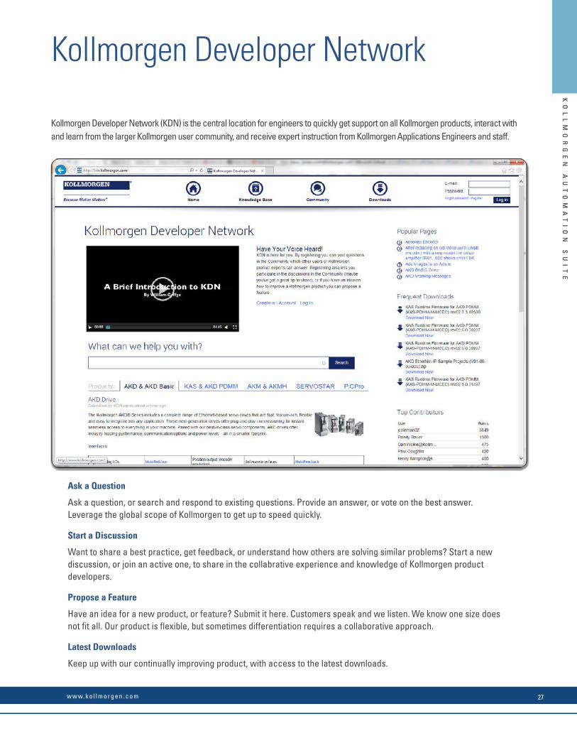
Ask a Question
Ask a question, or search and respond to existing questions. Provide an answer, or vote on the best answer. Leverage the global scope of Kollmorgen to get up to speed quickly.
Start a Discussion
Want to share a best practice, get feedback, or understand how others are solving similar problems? Start a new discussion, or join an active one, to share in the collabrative experience and knowledge of Kollmorgen product developers.
Propose a Feature
Have an idea for a new product, or feature? Submit it here. Customers speak and we listen. We know one size does not fi t all. Our product is fl exible, but sometimes differentiation requires a collaborative approach.
Latest Downloads
Keep up with our continually improving product, with access to the latest downloads.
Kollmorgen Developer Network (KDN) is the central location for engineers to quickly get support on all Kollmorgen products, interact with and learn from the larger Kollmorgen user community, and receive expert instruction from Kollmorgen Applications Engineers and staff.
K O L L M O R G E N26
KO
LL
MO
RG
EN
A
UT
OM
AT
IO
N
SU
IT
E
KO
LL
MO
RG
EN
A
UT
OM
AT
IO
N
SU
IT
E
Available Motion Bus Coupler Model
AKT-ECT-000-000 EtherCAT® Bus Coupler
Available Analog Input Terminal Models
AKT-AN-410-000 4 channel analog input module, 0-10 Vdc
AKT-AN-420-000 4 channel analog input module, 0-20 ma
AKT-AN-810-000 8 channel analog input module, 0-10 Vdc
AKT-AN-820-000 8 channel analog input module, 0-20 ma
AKT-AN-200-000 2 channel thermocouple input module
AKT-AN-400-000 4 channel thermocouple input module
Available Analog Output Terminal Models
AKT-AT-220-000 2 channel analog output module, 0-20 ma
AKT-AT-410-000 4 channel analog output module, 0-10 Vdc
AKT-AT-420-000 4 channel analog output module, 0-20 ma
AKT-AT-810-000 8 channel analog output module, 0-10 Vdc
AKT-AT-820-000 8 channel analog output module, 0-20 ma
Available Digital Output Terminal Models
AKT-DT-004-000 4 channel digital output module, 0.5A
AKT-DT-008-000 8 channel digital output module, 0.5A
AKT-DT-2RT-000 2 channel relay output module, 2.0A, N/O
I/O Terminals
Advanced Kollmorgen Terminal (AKT)
The Kollmorgen Automation Suite includes an array of I/O options for applications that need more I/O than can be provided by the onboard I/O of the drives or for applications that need specialized functionality such as thermocouple management through I/O. The DIN rail mount IP20 terminals simply slide together and connect to the system’s EtherCAT® bus where they are auto-recognized for easy confi guration.
I/O
Typical Bus Coupler
EtherCAT® bus coupler Front wiring view Side label view
Typical I/O Terminal
Available Digital Input Terminal Models
AKT-DN-004-000 4 channel digital input module, 3ms
AKT-DNH-004-000 4 channel digital input module, .2ms
AKT-DN-008-000 8 channel digital input module, 3ms
AKT-DNH-008-000 8 channel digital input module, .2ms
Available Specialty Terminal Models
AKT-EM-000-000 End module
AKT-IM-000-000 Isolation module
AKT-PS-024-000 Bus feed terminal, 24 Vdc
AKT-PSF-024-000 Bus feed terminal, 24 Vdc, fused
Available Field Bus Coupler Models
AKT-PRB-000-000 Profi bus Bus Coupler
AKT-ENP-000-000 Ethernet/IP Bus Coupler
Stepper Driver
AKT-SM-L15-000 Stepper Module, 24 Vdc, 1.5 A
AKT-SM-L50-000 Stepper Module, 50 Vdc, 5 A
KO
LL
MO
RG
EN
A
UT
OM
AT
IO
N
SU
IT
E
Kollmorgen Developer Network
Ask a Question
Ask a question, or search and respond to existing questions. Provide an answer, or vote on the best answer. Leverage the global scope of Kollmorgen to get up to speed quickly.
Start a Discussion
Want to share a best practice, get feedback, or understand how others are solving similar problems? Start a new discussion, or join an active one, to share in the collabrative experience and knowledge of Kollmorgen product developers.
Propose a Feature
Have an idea for a new product, or feature? Submit it here. Customers speak and we listen. We know one size does not fi t all. Our product is fl exible, but sometimes differentiation requires a collaborative approach.
Latest Downloads
Keep up with our continually improving product, with access to the latest downloads.
Kollmorgen Developer Network (KDN) is the central location for engineers to quickly get support on all Kollmorgen products, interact with and learn from the larger Kollmorgen user community, and receive expert instruction from Kollmorgen Applications Engineers and staff.
w w w. k o l l m o r g e n . c o m 27
The Benefi ts of AKD Servo Drive• Optimized Performance in Seconds • Auto-tuning is one of the best and fastest in the industry
• Automatically adjusts all gains, including observers
• Immediate and adaptive response to dynamic loads
• Precise control of all motor types
• Compensation for stiff and compliant transmission and couplings
• Greater Throughput and Accuracy • Up to 27-bit-resolution feedback yields unmatched precision and excellent repeatability
• Very fast settling times result from a powerful dual processor system that executes industry-leading and patent pending servo algorithms with high resolution
• Advanced servo techniques such as high-order observer and bi-quad fi lters yield industry-leading machine performance
• Highest bandwidth torque-and-velocity loops. Fastest digital current loop in the market
• Easy-to-use Graphical User Interface (GUI) for Faster Commissioning and Troubleshooting
• Six-channel real-time software oscilloscope commissions and diagnoses quickly
• Multi-function Bode Plot allows users to quickly evaluate performance
• Auto-complete of programmable commands saves looking up parameter names
• One-click capture and sharing of program plots and parameter settings allow you to send machine performance data instantly
• Widest range of programming options in the industry
• Flexible and Scalable to Meet any Application • 3 to 48 Arms continuous current; 9 to 96 Arms peak
• Very high power density enables an extremely small package
• True plug-and-play with all standard Kollmorgen servo motors and actuators
• Supports a variety of single and multi-turn feedback devices— Smart Feedback Device (SFD), EnDat2.2, 01, BiSS, analog Sine/ Cos encoder, incremental encoder, HIPERFACE®, and resolver
• Tightly integrated Ethernet motion buses without the need to add large hardware: EtherCAT®, SynqNet®, Modbus/TCP, EtherNet/IP, PROFINET, SERCOS III, and CANopen®
• Scalable programmability from base torque-and-velocity through multi-axis master
K O L L M O R G E N | A DA N A H E R M O T I O N C O M PA N YK O L L M O R G E N
AKD® Servo DriveOur AKD series is a complete range of Ethernet-based servo drives that are fast, feature-rich, fl exible and integrate quickly and easily into any application. AKD ensures plug-and-play commissioning for instant, seamless access to everything in your machine. And, no matter what your application demands, AKD offers industry-leading servo performance, communication options, and power levels, all in a smaller footprint.
This robust, technologically advanced family of drives delivers optimized performance when paired with our best-in-class components, producing higher quality results at greater speeds and more uptime. With Kollmorgen servo components, we can help you increase your machine’s OEE by 50%.
AK
D®
S
ER
VO
D
RI
VE

AK
D®
S
ER
VO
D
RI
VE
The Benefi ts of AKD Servo Drive• Optimized Performance in Seconds • Auto-tuning is one of the best and fastest in the industry
• Automatically adjusts all gains, including observers
• Immediate and adaptive response to dynamic loads
• Precise control of all motor types
• Compensation for stiff and compliant transmission and couplings
• Greater Throughput and Accuracy • Up to 27-bit-resolution feedback yields unmatched precision and excellent repeatability
• Very fast settling times result from a powerful dual processor system that executes industry-leading and patent pending servo algorithms with high resolution
• Advanced servo techniques such as high-order observer and bi-quad fi lters yield industry-leading machine performance
• Highest bandwidth torque-and-velocity loops. Fastest digital current loop in the market
• Easy-to-use Graphical User Interface (GUI) for Faster Commissioning and Troubleshooting
• Six-channel real-time software oscilloscope commissions and diagnoses quickly
• Multi-function Bode Plot allows users to quickly evaluate performance
• Auto-complete of programmable commands saves looking up parameter names
• One-click capture and sharing of program plots and parameter settings allow you to send machine performance data instantly
• Widest range of programming options in the industry
• Flexible and Scalable to Meet any Application • 3 to 48 Arms continuous current; 9 to 96 Arms peak
• Very high power density enables an extremely small package
• True plug-and-play with all standard Kollmorgen servo motors and actuators
• Supports a variety of single and multi-turn feedback devices— Smart Feedback Device (SFD), EnDat2.2, 01, BiSS, analog Sine/ Cos encoder, incremental encoder, HIPERFACE®, and resolver
• Tightly integrated Ethernet motion buses without the need to add large hardware: EtherCAT®, SynqNet®, Modbus/TCP, EtherNet/IP, PROFINET, SERCOS III, and CANopen®
• Scalable programmability from base torque-and-velocity through multi-axis master
w w w. k o l l m o r g e n . c o m 29
K O L L M O R G E N | A DA N A H E R M O T I O N C O M PA N YK O L L M O R G E N
AKD® Servo DriveOur AKD series is a complete range of Ethernet-based servo drives that are fast, feature-rich, fl exible and integrate quickly and easily into any application. AKD ensures plug-and-play commissioning for instant, seamless access to everything in your machine. And, no matter what your application demands, AKD offers industry-leading servo performance, communication options, and power levels, all in a smaller footprint.
This robust, technologically advanced family of drives delivers optimized performance when paired with our best-in-class components, producing higher quality results at greater speeds and more uptime. With Kollmorgen servo components, we can help you increase your machine’s OEE by 50%.
AK
D®
S
ER
VO
D
RI
VE

Basic Operation
R A N G E O F K O L L M O R G E N A U T O M AT I O N S U I T E C A PA B I L I T I E S
Single-Axis Programming
Kollmorgen delivers cutting-edge technology and performance with the AKD® servo drive and KAS controls platform. Whether your application requires a single axis or over 100 fully synchronized axes, Kollmorgen’s intuitive software and tools scale to meet your needs. From simple analog torque control to the latest high-performance automation network, the AKD servo drive packs power and fl exibility for virtually any application into one of the most compact footprints of any digital servo drive in the industry.
• Patented auto-tuning delivers optimized performance in seconds.
• 1.5MHz current loop and 16KHz velocity loops offers greater bandwidth and performance Optimized performance in seconds
• Greater throughput and accuracy
• Easy-to-use Graphical User Interface (GUI) for
faster commissioning and troubleshooting
• Flexible and scalable to meet any application
• Controlled by analog torque-and-velocitycommands
• Includes electronic gearing via X9 connector
• Includes access to 11 digital I/O and 2 analogI/O on base drive
• Includes 2 high-speed digital inputs
• Expandable to 31 digital I/O and 4 analog I/O
Motion Tasking (“P” Option)
• Adds simple point-and-click indexing tobase drive
• Provides user with pre-programmed options
• Guides novice user through simplifi ed steps to create indexing moves
• Network connectivity to EtherCAT®, CANopen®, Profi net®, Ethernet/IP™, TCP/IP, SynqNet™
and others
• MODBUS port for communication with HMI
BASIC Programmable 1.5 Axis Drive (“T” Option)
• Adds BASIC programmability to base AKD• 4Khz programmable interrupt service routines• Conditional statements, built-in math
functions, user functions and subroutines
• Includes 2 high-speed digital inputs
• Same package size as base drive
• Expandable to 31 digital I/O and 4 analog I/O
• Optional integrated SD card for easy backupand drive cloning
• Includes electronic camming functionality
Scalable Programmability
SC
AL
AB
LE
P
RO
GR
AM
MA
BI
LI
TY
K O L L M O R G E N30

Note: For complete AKD page 89.
R A N G E O F K O L L M O R G E N A U T O M AT I O N S U I T E C A PA B I L I T I E S
AKD Servo Drive AKD Servo Drive AKT I/O
Multi-Axis Programming
AKI HMI AKD PDMM AKT I/O
Single-Axis Programming
Pipe Network provides a one-to-one translation of a mechanical system into a logical world as shown in the Vertical Form Fill and Seal machine above. Click and build your motion program in minutes, or contact Kollmorgen for examples of common machine architectures to further accelerate your development.
2
4
5
3
Programmable Drive Multi-Axis Master PDMM (“M” Option)
• Scalable solution for use as a single-axis drivewith integrated programmable automation controller
• Choose from all fi ve IEC 61131-3 languagesfor soft PLC process programming
• Program motion using your choice of PLCopenfor motion or our innovative Pipe Network™
• 4KHz PLC scan rate and EtherCAT® updates
• Complete line of HMI panels with integratedsoftware to simplify GUI development
• Exclusive function blocks, such as “wait,”enable your program to act as a scanning orsequential language
• On-board I/O includes 17 digital (with 2 highspeed inputs) and 2 analog
• Connects to AKT™ network I/O for nearlyunlimited expandability
1
• Accelerate development by programmingtasks in hours that would otherwise takeweeks
• Improved coding quality through visualprogramming and by using pre-built modulesthat have been thoroughly tested andoptimized
• Easy knowledge transfer, replacing pages ofcomplex code with easily understoodgraphical representations
• Available on PDMM™ controllers
Seamlessly add additional axes and AKD PDMM serves as a high-performance multi-axis machine controller
• SD card for easy backup and system updates
• IoT-enabled integrated webserver for diagnostics and troubleshooting from any computer or mobile device
• Provide true synchronized-path control of up to 16 axes
• Reduce cabinet size and wiring requirementswith a single, compact package
• Easily manage remote I/O and the I/O of allattached drives via EtherCAT®
• Use industry standard PLCopen for motion, or step up to Kollmorgen’s Pipe Network™ toprogram sophisticated camming and gearingapplications in a matter of minutes
Visual Programming for Motion
Pipe NetworkKollmorgen Visual Programming for Motion
™
Pipe NetworkKollmorgen Visual Motion Programming
™
Pipe Network™
SC
AL
AB
LE
P
RO
GR
AM
MA
BI
LI
TY
w w w. k o l l m o r g e n . c o m 31
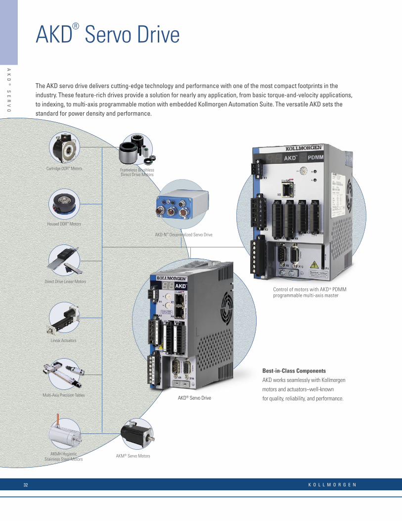
AK
D®
S
ER
VO
D
RI
VE
AKD® Servo Drive
The AKD servo drive delivers cutting-edge technology and performance with one of the most compact footprints in the industry. These feature-rich drives provide a solution for nearly any application, from basic torque-and-velocity applications, to indexing, to multi-axis programmable motion with embedded Kollmorgen Automation Suite. The versatile AKD sets the standard for power density and performance.
Best-in-Class Components
AKD works seamlessly with Kollmorgen
motors and actuators–well-known
for quality, reliability, and performance.AKD® Servo Drive
AKMH HygienicStainless Steel Motors
Control of motors with AKD® PDMM programmable multi-axis master
AKD-N™ Decentralized Servo Drive
AKM® Servo Motors
Frameless BrushlessDirect Drive Motors
Linear Actuators
Direct Drive Linear Motors
Cartridge DDR™ Motors
Housed DDR™ Motors
Multi-Axis Precision Tables
120 / 240 Vac1 & 3 Phase(85 -265 V)
ContinuousCurrent(Arms)
PeakCurrent(Arms)
Drive Continuous Output Power
Capacity(Watts)
Internal Regen(Watts) (Ohms)
Heightmm(in)
Widthmm(in)
Depthmm(in)
Depth with CableBend Radius
mm(in)
AKD-n00306 3 9 1100 0 0 168(6.61)
57(2.24)
153(6.02)
184(7.24)
AKD-n00606 6 18 2000 0 0 168(6.61)
57(2.24)
153(6.02)
184(7.24)
AKD-n01206 12 30 4000 100 15 195(7.68)
76(2.99)
186(7.32)
215(8.46)
AKD-n02406 24 48 8000 200 8 250(9.84)
100(3.94)
230(9.06)
265(10.43)
240/480 Vac3 Phase
(187-528 V)
ContinuousCurrent(Arms)
PeakCurrent(Arms)
Drive Continuous Output Power
Capacity(Watts)
Internal Regen(Watts) (Ohms)
Heightmm(in)
Widthmm(in)
Depthmm(in)
Depth with CableBend Radius
mm(in)
AKD-n00307 3 9 2000 100 33 256(10.08)
70(2.76)
186(7.32)
221(8.70)
AKD-n00607 6 18 4000 100 33 256(10.08)
70(2.76)
186(7.32)
221(8.70)
AKD-n01207 12 30 8000 100 33 256(10.08)
70(2.76)
186(7.32)
221(8.70)
AKD-n02407 24 48 16,000 200 23 310(12.20)
105(4.13)
229(9.02)
264(10.39)
AKD-n04807 48 96 35,000 – – 385(15.16)
185(7.28)
224(8.82)
260(10.23)
Industry-leading power density
General Specifi cations
/TCP
H
W
D
K O L L M O R G E N32

AK
D®
S
ER
VO
D
RI
VE
The AKD servo drive delivers cutting-edge technology and performance with one of the most compact footprints in the industry. These feature-rich drives provide a solution for nearly any application, from basic torque-and-velocity applications, to indexing, to multi-axis programmable motion with embedded Kollmorgen Automation Suite. The versatile AKD sets the standard for power density and performance.
Best-in-Class Components
AKD works seamlessly with Kollmorgen
motors and actuators–well-known
for quality, reliability, and performance.AKD® Servo Drive
AKMH HygienicStainless Steel Motors
Control of motors with AKD® PDMM programmable multi-axis master
AKD-N™ Decentralized Servo Drive
AKM® Servo Motors
Frameless BrushlessDirect Drive Motors
Linear Actuators
Direct Drive Linear Motors
Cartridge DDR™ Motors
Housed DDR™ Motors
Multi-Axis Precision Tables
120 / 240 Vac1 & 3 Phase(85 -265 V)
ContinuousCurrent(Arms)
PeakCurrent(Arms)
Drive Continuous Output Power
Capacity(Watts)
Internal Regen(Watts) (Ohms)
Heightmm(in)
Widthmm(in)
Depthmm(in)
Depth with CableBend Radius
mm(in)
AKD-n00306 3 9 1100 0 0 168(6.61)
57(2.24)
153(6.02)
184(7.24)
AKD-n00606 6 18 2000 0 0 168(6.61)
57(2.24)
153(6.02)
184(7.24)
AKD-n01206 12 30 4000 100 15 195(7.68)
76(2.99)
186(7.32)
215(8.46)
AKD-n02406 24 48 8000 200 8 250(9.84)
100(3.94)
230(9.06)
265(10.43)
240/480 Vac3 Phase
(187-528 V)
ContinuousCurrent(Arms)
PeakCurrent(Arms)
Drive Continuous Output Power
Capacity(Watts)
Internal Regen(Watts) (Ohms)
Heightmm(in)
Widthmm(in)
Depthmm(in)
Depth with CableBend Radius
mm(in)
AKD-n00307 3 9 2000 100 33 256(10.08)
70(2.76)
186(7.32)
221(8.70)
AKD-n00607 6 18 4000 100 33 256(10.08)
70(2.76)
186(7.32)
221(8.70)
AKD-n01207 12 30 8000 100 33 256(10.08)
70(2.76)
186(7.32)
221(8.70)
AKD-n02407 24 48 16,000 200 23 310(12.20)
105(4.13)
229(9.02)
264(10.39)
AKD-n04807 48 96 35,000 – – 385(15.16)
185(7.28)
224(8.82)
260(10.23)
Industry-leading power density
General Specifi cations
/TCP
H
W
D
For complete AKD servo drive nomenclature, please see page 176.
w w w. k o l l m o r g e n . c o m 33

When you pair the AKD servo drive with any of our Kollmorgen motors or linear actuators, you’ll achieve optimized performance. From 3 to 48 Arms continuous current and 9 to 96 Arms peak current, the feature-rich AKD provides a solution for nearly any application.
Continuous Torque at Stall - Nm [lb-in] ** AKM Compatible Micron Gearboxes available up to 5,000 Nm
Kollm
orge
n Ro
tary
Mot
ors
0 10 100 1,000 10,000
AKM
AKMH
DDR
CDDR
KBM
TBM
Continuous
Peak
Kollm
orge
n Li
near
Act
uato
rs
Precision Tables
Rodless Actuators
Electric Cylinders
1 10 100
Continuous Thrust at Speed - N [lbs]
1,000 10,000 100,000
Continuous
Peak
AKD
Ser
vo D
rive
1 100 10,000 100,000
Drive Output Power (watts)
1,00010
240 Vac
480 Vac
Continuous
Peak
Range of Coverage
55,000
16,000
25,000 [5,620]
3,115 [700]
1,958 [400]
10 [121]36 [427]
1,200 [10,621]
1,070 [9,890]
1,340 [11,900]
92 [814]
324 [2,860]
538 [4,762]
510 [4,510]
339 [3,000]
22 [195]
180 [1,590]
AK
D®
S
ER
VO
D
RI
VE
AKD® Servo Drive
AKD’s Kollmorgen Rotary Motor Coverage (pp 52-93)
AKD’s Kollmorgen Linear Actuators Coverage (pp 114-131)
AKD Power Range (pp 28-49)
K O L L M O R G E N34

AKD® servo drive is specifi cally designed with the versatility, communications, and power you need to expand machine performance and increase integration speeds. Motor set-up is plug-and-play and multiple Ethernet connectivity options provide both open and closed protocols. Online troubleshooting and data verifi cation enable faster, bug-proof programming. And a broad power range in a smaller, compact design allows you to use these robust drives with a single interface while experiencing industry-leading, high-performance servo loops.
AKD Specifi cations
Base drive With I/O expansionEncoder Output orAUX Encoder Input 2.5 MHz Maximum line frequency
Feedback Smart Feedback Device (SFD), EnDat2.2, 01, BiSS, analog Sine/Cos encoder, incremental encoder, HIPERFACE®, and resolver
Logic supply 24 Vdc
Digital input (24 Vdc) 8(1 dedicated to enable)
20(1 dedicated to enable)
Digital output (24 Vdc) 3(1 dedicated to fault relay)
13(1 dedicated to fault relay)
Analog input (+/- 10 Vdc, 16-bit) 1 2
Analog output (+/- 10 Vdc, 16-bit) 1 2
Programmable inputs 7 19
Programmable outputs 2 12
Sink/Source inputs/outputs Yes Yes
Feedback & I/O AK
D®
S
ER
VO
D
RI
VE
w w w. k o l l m o r g e n . c o m 35

AKD BASIC Language Programmable Drive
In addition to the wide selection and key features of our proven AKD, the standard version of our AKD BASIC drive offers:
• Programmable machine control built into the drive, so you can engineer perfect axis-level performance without touching the machine controller. In fact, AKD BASIC can eliminate the need for a PLC in single and 1.5 axis applications – reducing wiring requirements, panel space, design complexity and cost.
• High performance motion control built into the drive, enabling increased speed for more complex moves in a simpler design with reduced wiring.
• BASIC Language programming, providing simple program fl ow control in a solution that’s easy to learn, quick to master and universally accepted.
• An integrated development environment, allowing single-point programming, de-bugging, commissioning, tuning and management of your AKD BASIC drive from within AKD WorkBench. Our BASIC editor provides innovative features that speed development time and reduce coding errors.
• Source code lockout with password protection, freeing you to differentiate your product with drive-level control while safeguarding your intellectual property.
Expanded I/O AKD BASIC Programmable Drive
Building on the features of the AKD BASIC drive, we also offer an expanded I/O version that adds:
• A total of 20 digital inputs, 13 digital outputs, 2 analog inputs and 2 analog outputs, reducing or eliminating the need for remote I/O and its associated installation and wiring costs.
• An SD memory card slot for loading, and restoring programs and parameters, without the need for a PC.
High Performance Capabilities in an Integrated Drive/Control Solution
Add co-engineering to your toolbox. Save money, simplify your machine and customize performance to meet the specifi c needs of each customer or application – as needed, today or tomorrow.
Our new Kollmorgen AKD® BASIC drives add BASIC-programmable machine and motion control to the superior performance of our AKD drive platform. So engineers can quickly customize performance at the drive level without touching the PLC. In fact, for many applications you can avoid the expense, wiring and cabinet space of a PLC altogether.
Whether you rely on your own engineering expertise or Kollmorgen’s, the base and Expanded I/O versions of our AKD BASIC drive give you the unprecedented machine and motion control fl exibility in a compact, fully integrated drive package. It’s one more example of our co-engineering mission to help you deliver exactly what your customers want – when they want it – in solutions that are more cost-effective to build, simpler in design and faster to market.
I/0 Capabilities Base Version Expanded I/O Version
Digital Inputs 8 20
Digital Outputs 3 13
Analog Inputs 1 2
Analog Outputs 1 2
AK
D®
B
AS
IC
D
RI
VE
S
AKD® BASIC Drives
K O L L M O R G E N36
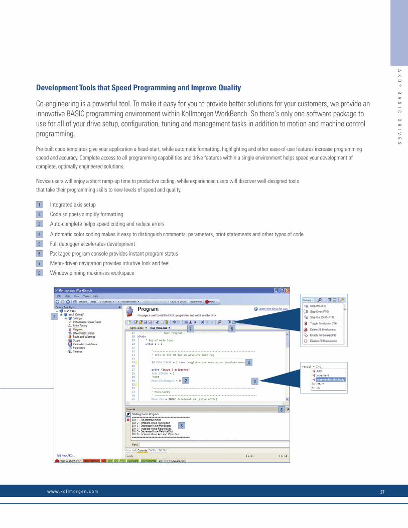
1
2 3
4
57
8
6
1 Integrated axis setup
2 Code snippets simplify formatting
3 Auto-complete helps speed coding and reduce errors
4 Automatic color coding makes it easy to distinguish comments, parameters, print statements and other types of code
5 Full debugger accelerates development
6 Packaged program console provides instant program status
7 Menu-driven navigation provides intuitive look and feel
8 Window pinning maximizes workspace
Development Tools that Speed Programming and Improve Quality
Co-engineering is a powerful tool. To make it easy for you to provide better solutions for your customers, we provide an innovative BASIC programming environment within Kollmorgen WorkBench. So there’s only one software package to use for all of your drive setup, confi guration, tuning and management tasks in addition to motion and machine control programming.
Pre-built code templates give your application a head-start, while automatic formatting, highlighting and other ease-of-use features increase programming speed and accuracy. Complete access to all programming capabilities and drive features within a single environment helps speed your development of complete, optimally engineered solutions.
Novice users will enjoy a short ramp-up time to productive coding, while experienced users will discover well-designed tools that take their programming skills to new levels of speed and quality.
AK
D®
B
AS
IC
D
RI
VE
S
w w w. k o l l m o r g e n . c o m 37

Features
• Kollmorgen Automation Suite™ provides fully integrated programming, testing, setup and commissioning
• Embedded web server utility simplifi es service
• Control 32 axes or more* while reducing machine footprint
- EtherCAT® multi-axis master motion controller integrated with a standard AKD™ drive axis
- Full IEC61131-3 soft PLC for machine control, with support for all 5 programming languages
- Choice of PLCopen for motion or Pipe Network™ for programming motion control
- 32 KB non-volatile memory stores machine data to eliminate scrap upon restart after power failure
- SD Card slot simplifi es backup and commissioning, with no PC required
- On-board I/O includes 13 digital inputs, 4 digital outputs, 1 analog input, 1 analog output (expandable with AKT series of remote I/O)
• Works with Kollmorgen Visualization Builder for programming AKI human-machine interface panels
Build Simpler and Better with Drive-Resident Machine and Motion Control
Extend your design options. Control as many as eight axes or more without the need for a PLC or PAC. Reduce cabinet space and wiring requirements. Program perfect machine and motion control for any project using a single, fully integrated programming environment. Build a better machine at a lower cost.
Our new addition to the AKD® drive family combines one servo axis, a master controller that supports multiple additional axes, and the full automation capability of Kollmorgen Automation Suite™ —all in a single, compact package.
Welcome to the AKD PDMM™ programmable drive, multi-axis master.
*Maximum axis count depends on motion/automation complexity and performance (8 axes nominal based on medium complexity at 4 kHz network update rate)
Performance Specifi cations
120/240 Vac1- and 3-Phase
Continuous Current (Arms)
Peak Current (Arms)
H(mm/inches)
W(mm/inches)
D(mm/inches)
AKD-M00306-MCEC-0000 3 9 168 / 6.61 89 / 3.50 156 / 6.14
AKD-M00606-MCEC-0000 6 18 168 / 6.61 89 / 3.50 156 / 6.14
AKD-M01206-MCEC-0000 12 30 196 / 7.72 107 / 4.21 187 / 7.36
AKD-MO2406-MCEC-0000 24 48 248 / 9.76 96 / 3.78 228 / 8.98
240/400/480 Vac3-Phase
Continuous Current (Arms)
Peak Current (Arms)
H(mm/inches)
W(mm/inches)
D(mm/inches)
AKD-M00307-MCEC-0000 3 9 256 / 10.08 99 / 3.90 185 / 7.28
AKD-M00607-MCEC-0000 6 18 256 / 10.08 99 / 3.90 185 / 7.28
AKD-M01207-MCEC-0000 12 30 256 / 10.08 99 / 3.90 185 / 7.28
AKD-M02407-MCEC-0000 24 48 306 / 12.05 99 / 3.90 228 / 8.98
AKD-M04807-MCEC-0000 48 96 385 / 15.16 185 / 7.28 225 / 8.85
AK
D®
P
DM
M™
D
RI
VE
-R
ES
ID
EN
T
CO
NT
RO
LL
ER
AKD® PDMM™ Drive-Resident Controller
K O L L M O R G E N38
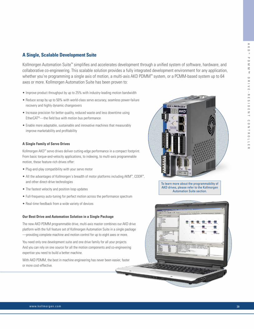
A Single, Scalable Development Suite
Kollmorgen Automation Suite™ simplifi es and accelerates development through a unifi ed system of software, hardware, and collaborative co-engineering. This scalable solution provides a fully integrated development environment for any application, whether you’re programming a single axis of motion, a multi-axis AKD PDMM™ system, or a PCMM-based system up to 64 axes or more. Kollmorgen Automation Suite has been proven to:
• Improve product throughput by up to 25% with industry-leading motion bandwidth
• Reduce scrap by up to 50% with world-class servo accuracy, seamless power-failure recovery and highly dynamic changeovers
• Increase precision for better quality, reduced waste and less downtime using EtherCAT®—the fi eld bus with motion bus performance
• Enable more adaptable, sustainable and innovative machines that measurably improve marketability and profi tability
A Single Family of Servo Drives
Kollmorgen AKD™ servo drives deliver cutting-edge performance in a compact footprint. From basic torque-and-velocity applications, to indexing, to multi-axis programmable motion, these feature-rich drives offer:
• Plug-and-play compatibility with your servo motor
• All the advantages of Kollmorgen´s breadth of motor platforms including AKM™, CDDR™, and other direct-drive technologies
• The fastest velocity and position loop updates
• Full-frequency auto-tuning for perfect motion across the performance spectrum
• Real-time feedback from a wide variety of devices
Our Best Drive and Automation Solution in a Single Package
The new AKD PDMM programmable drive, multi-axis master combines our AKD drive platform with the full feature set of Kollmorgen Automation Suite in a single package—providing complete machine and motion control for up to eight axes or more.
You need only one development suite and one drive family for all your projects. And you can rely on one source for all the motion components and co-engineering expertise you need to build a better machine.
With AKD PDMM, the best in machine engineering has never been easier, faster or more cost-effective.
AK
D®
P
DM
M™
D
RI
VE
-R
ES
ID
EN
T
CO
NT
RO
LL
ER
To learn more about the programmability of AKD drives, please refer to the Kollmorgen
Automation Suite section.
w w w. k o l l m o r g e n . c o m 39

AK
D®
S
ER
VO
D
RI
VE
AKD® Servo Drive
Ethernet Connectivity• Ethernet-based AKD servo drive provides the user with multiple bus choices
• EtherCAT® (DSP402 protocol), Modbus/TCP, SynqNet®, EtherNet/IP, PROFINET, SERCOS III, and CANopen®
• No option cards are required
Industrial Design• Rugged circuit design and compact enclosure for space-saving, modern appearance – minimizes electrical noise emission and susceptibility
• Full fault protection
• UL, cUL listed, and CE
• No external line fi lters needed (480 Vac units) for CE & UL compliance
• Removable screw terminal connectors for easy connections
• DC Bus sharing
Safe-Torque-Off (STO)(IEC 61800 SIL2)
• Switches off the power stage to ensure personnel safety and prevents an unintended restart of the drive, even in fault condition
• Allows logic and communication to remain on during power stage shut down
Internal Regenerative Braking Resistor(All powers except 120/240 Vac 3 Arms and 6 Arms)
• Simplifi es system components
• Saves overhead of managing external regeneration when internal regeneration is suffi cient
Performance Servo Tuner (PST)• Exclusive patent pending auto-tuner reaches optimized set-up in seconds
• Handles inertia mismatches up to 1000:1
• Industry leading bandwidth under compliant and stiff load conditions, no matter the mechanical bandwidth of the machine
Plug-and-Play with Kollmorgen Motors and Actuators• Electronic motor nameplates allow parameters to automatically load for fast commissioning
• Motion in seconds
• Custom motor parameters easily entered
I/O (Base Drive) • 8 digital inputs (1 dedicated to enable)
• 2 high-speed digital inputs (maximum time delay of 1.0 μs)
• 3 digital outputs (1 dedicated to fault relay)
• 1 analog input - 16 bit
• 1 analog output - 16 bit
/TCP
X124 Vdc Supply
STO EnableIEC 61508 SIL2
X9Encoder
Emulation
X10Feedback
X7 / X8I/O
X3 (4 Pin)DC Bus
Brake Resistor(DC Bus Sharing Mating
Connector Option Shown)
X5/ X6Motion BusEtherCAT®
SynqNet®
MotorHolding Brake
(Cable Clamp Option Shown)
X124 Vdc Supply
STO EnableIEC 61508 SIL2
X9Encoder
EmulationX10
Feedback
X7 / X8I/O
X3 (7 Pin)Power Supply
DC BusBrake Resistor
X5/ X6Motion BusEtherCAT®
SynqNet®
X2Motor
Holding Brake
X11Service Channel
Modbus/TCPEtherNet/IPPROFINET
X12 / X13CANopen®
(CiA certifi ed)
AKD 120/240 Vac Connector Layout
AKD 240/480 Vac Connector Layout
X12 / X13CANopen®
(CiA certifi ed)
X11Service Channel
Modbus/TCP EtherNet/IPPROFINET
X4Power Supply
Physical Earth (PE)Ground Stud
Physical Earth (PE)Ground Stud
SE
RV
O
DR
IV
E
AC
CE
SS
OR
IE
S
K O L L M O R G E N40
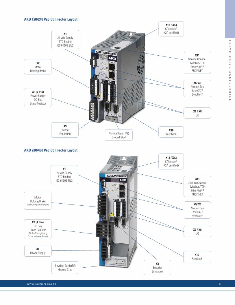
Ethernet Connectivity• Ethernet-based AKD servo drive provides the user with multiple bus choices
• EtherCAT® (DSP402 protocol), Modbus/TCP, SynqNet®, EtherNet/IP, PROFINET, SERCOS III, and CANopen®
• No option cards are required
Industrial Design• Rugged circuit design and compact enclosure for space-saving, modern appearance – minimizes electrical noise emission and susceptibility
• Full fault protection
• UL, cUL listed, and CE
• No external line fi lters needed (480 Vac units) for CE & UL compliance
• Removable screw terminal connectors for easy connections
• DC Bus sharing
Safe-Torque-Off (STO)(IEC 61800 SIL2)
• Switches off the power stage to ensure personnel safety and prevents an unintended restart of the drive, even in fault condition
• Allows logic and communication to remain on during power stage shut down
Internal Regenerative Braking Resistor(All powers except 120/240 Vac 3 Arms and 6 Arms)
• Simplifi es system components
• Saves overhead of managing external regeneration when internal regeneration is suffi cient
Performance Servo Tuner (PST)• Exclusive patent pending auto-tuner reaches optimized set-up in seconds
• Handles inertia mismatches up to 1000:1
• Industry leading bandwidth under compliant and stiff load conditions, no matter the mechanical bandwidth of the machine
Plug-and-Play with Kollmorgen Motors and Actuators• Electronic motor nameplates allow parameters to automatically load for fast commissioning
• Motion in seconds
• Custom motor parameters easily entered
I/O (Base Drive) • 8 digital inputs (1 dedicated to enable)
• 2 high-speed digital inputs (maximum time delay of 1.0 μs)
• 3 digital outputs (1 dedicated to fault relay)
• 1 analog input - 16 bit
• 1 analog output - 16 bit
/TCP
X124 Vdc Supply
STO EnableIEC 61508 SIL2
X9Encoder
Emulation
X10Feedback
X7 / X8I/O
X3 (4 Pin)DC Bus
Brake Resistor(DC Bus Sharing Mating
Connector Option Shown)
X5/ X6Motion BusEtherCAT®
SynqNet®
MotorHolding Brake
(Cable Clamp Option Shown)
X124 Vdc Supply
STO EnableIEC 61508 SIL2
X9Encoder
EmulationX10
Feedback
X7 / X8I/O
X3 (7 Pin)Power Supply
DC BusBrake Resistor
X5/ X6Motion BusEtherCAT®
SynqNet®
X2Motor
Holding Brake
X11Service Channel
Modbus/TCPEtherNet/IPPROFINET
X12 / X13CANopen®
(CiA certifi ed)
AKD 120/240 Vac Connector Layout
AKD 240/480 Vac Connector Layout
X12 / X13CANopen®
(CiA certifi ed)
X11Service Channel
Modbus/TCP EtherNet/IPPROFINET
X4Power Supply
Physical Earth (PE)Ground Stud
Physical Earth (PE)Ground Stud
SE
RV
O
DR
IV
E
AC
CE
SS
OR
IE
S
w w w. k o l l m o r g e n . c o m 41

K O L L M O R G E N42
The new decentralized AKD-N servo drives from Kollmorgen can be placed in the immediate vicinity of the motor thanks to its robust, compact construction and protection class IP67, plug-in connections, excellent motor compatibility and high degree of integrated functionality. With the decentralized AKD-N servo drives, you can develop drive and automation architectures that are easily comprehensible, and integrate with the central AKD servo drives. Using EtherCAT® as a system bus, we reduce complexity further since the AKD-N can collect I/O signals on the axis and pass them on in bundled form.
Improved Overall Equipment Effectiveness (OEE)
With AKD-N you increase the effectiveness beyond the entire life cycle of your machine (OEE, Overall Equipment Effectiveness). The design confi guration and simple connection technology decrease the time for assembly, installation, and start-up. During the operating phase, the AKD-N plays a valuable part in energy savings due to the integrated DC connection. Further advantages in production are faster cleaning cycles, thanks to a higher protection class, as well as fewer cables in combination with a space-saving switch cabinet superstructure. Moreover, the assembly and connection technology increases the availability – and thereby productivity – because maintenance and service tasks are completed faster.
AKD-N™ Decentralized Servo Drive
AK
D-
N
DE
CE
NT
RA
LI
ZE
D
SE
RV
O
DR
IV
ES
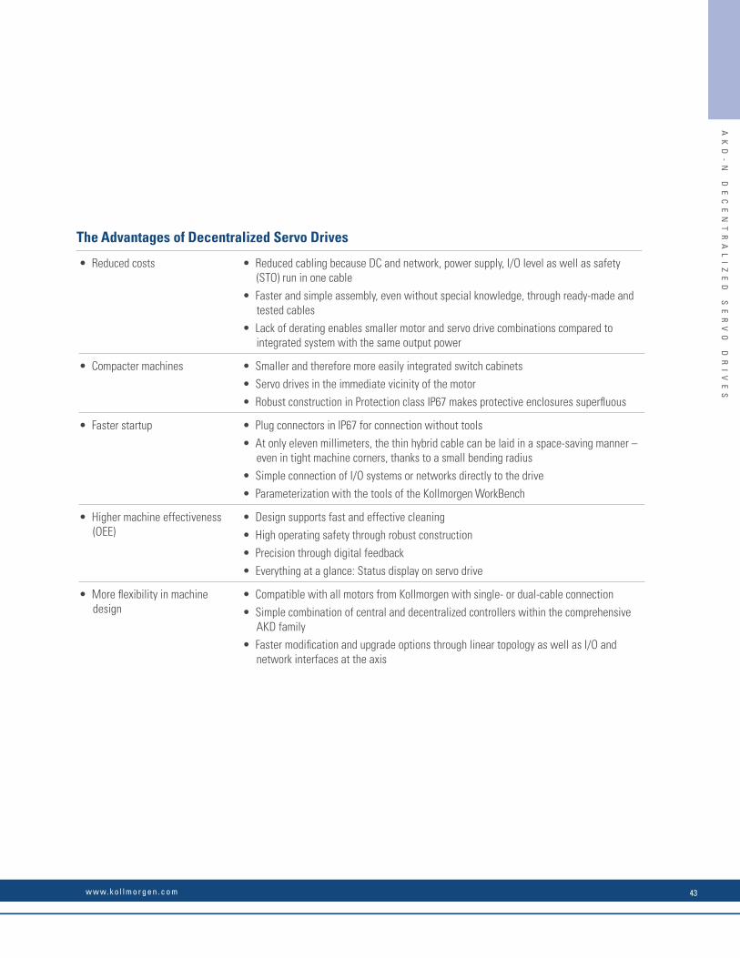
• Reduced costs • Reduced cabling because DC and network, power supply, I/O level as well as safety (STO) run in one cable
• Faster and simple assembly, even without special knowledge, through ready-made and tested cables
• Lack of derating enables smaller motor and servo drive combinations compared to integrated system with the same output power
• Compacter machines • Smaller and therefore more easily integrated switch cabinets
• Servo drives in the immediate vicinity of the motor
• Robust construction in Protection class IP67 makes protective enclosures superfl uous
• Faster startup • Plug connectors in IP67 for connection without tools
• At only eleven millimeters, the thin hybrid cable can be laid in a space-saving manner – even in tight machine corners, thanks to a small bending radius
• Simple connection of I/O systems or networks directly to the drive
• Parameterization with the tools of the Kollmorgen WorkBench
• Higher machine effectiveness (OEE)
• Design supports fast and effective cleaning
• High operating safety through robust construction
• Precision through digital feedback
• Everything at a glance: Status display on servo drive
• More fl exibility in machine design
• Compatible with all motors from Kollmorgen with single- or dual-cable connection
• Simple combination of central and decentralized controllers within the comprehensive AKD family
• Faster modifi cation and upgrade options through linear topology as well as I/O and network interfaces at the axis
The Advantages of Decentralized Servo Drives
AK
D-
N
DE
CE
NT
RA
LI
ZE
D
SE
RV
O
DR
IV
ES
w w w. k o l l m o r g e n . c o m 43
The new decentralized AKD-N servo drives from Kollmorgen can be placed in the immediate vicinity of the motor thanks to its robust, compact construction and protection class IP67, plug-in connections, excellent motor compatibility and high degree of integrated functionality. With the decentralized AKD-N servo drives, you can develop drive and automation architectures that are easily comprehensible, and integrate with the central AKD servo drives. Using EtherCAT® as a system bus, we reduce complexity further since the AKD-N can collect I/O signals on the axis and pass them on in bundled form.
Improved Overall Equipment Effectiveness (OEE)
With AKD-N you increase the effectiveness beyond the entire life cycle of your machine (OEE, Overall Equipment Effectiveness). The design confi guration and simple connection technology decrease the time for assembly, installation, and start-up. During the operating phase, the AKD-N plays a valuable part in energy savings due to the integrated DC connection. Further advantages in production are faster cleaning cycles, thanks to a higher protection class, as well as fewer cables in combination with a space-saving switch cabinet superstructure. Moreover, the assembly and connection technology increases the availability – and thereby productivity – because maintenance and service tasks are completed faster.
AKD-N™ Decentralized Servo Drive
AK
D-
N
DE
CE
NT
RA
LI
ZE
D
SE
RV
O
DR
IV
ES
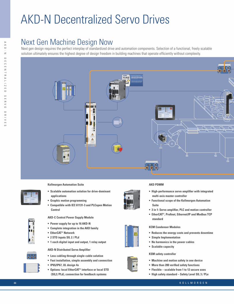
Kollmorgen Automation Suite
• Scalable automation solution for drive-dominant
applications
• Graphic motion programming
• Compatible with IEC 61131-3 and PLCopen Motion
Control
AKD-C Central Power Supply Module
• Power supply for up to 16 AKD-N
• Complete integration in the AKD family
• EtherCAT® Network
• 2 STO inputs SIL 2 / PLd
• 1 each digital input and output, 1 relay output
AKD-N Distributed Servo Amplifi er
• Less cabling through single-cable solution
• Fast installation, simple assembly and connection
• IP65/IP67, UL design 4x
• Options: local EtherCAT® interface or local STO
(SIL2 / PLd), connection for feedback systems
AKD PDMM
• High-performance servo amplifi er with integrated
multi-axis master controller
• Functional scope of the Kollmorgen Automation
Suite
• 3 in 1: Servo amplifi er, PLC and motion controller
• EtherCAT®, Profi net, Ethernet/IP and Modbus TCP
standard
KCM Condenser Modules
• Reduces the energy costs and prevents downtime
• Simple Implementation
• No harmonics in the power cables
• Scalable capacity
KSM safety controller
• Machine and motion safety in one device
• More than 200 verifi ed safety functions
• Flexible – scalable from 1 to 12 secure axes
• High safety standard – Safety Level SIL 3 / PLe
Next gen design requires the perfect interplay of standardized drive and automation components. Selection of a functional, freely scalable solution ultimately ensures the highest degree of design freedom in building machines that operate effi ciently without complexity.
Next Gen Machine Design NowAK
D-
N
DE
CE
NT
RA
LI
ZE
D
SE
RV
O
DR
IV
ES
AKD-N Decentralized Servo Drives
K O L L M O R G E N44

AKM Servo Motors
• High torque density
• High precision and dynamics
• Produced in Europe, US and Asia regions
AKM Washdown Servo Motors
• Applications with regular cleaning
• Housing coating is Ecolab®-certifi ed
AKM Washdown Food Servo Motors
• For use in the food and beverage industry
• Protection class IP67, FDA compliant
AKMH Stainless Steel Motors
• For the highest hygienic requirements
• Protection class IP69K
• Fulfi lls EHEDG directive
AKM Food-Grade Gearmotor
• The highest hygienic requirements
• High effi ciency
• Single-cable connection
Cartridge DDR Rotary Direct Drives
• Direct load coupling without gears or belts
• High precision, low noise generation
KBM Direct Drives with No Housing
• Low weight, exceptionally compact
• Modular system
DDL Linear Motor
• High power density
• Large dynamics (>10g)
• Patented anti-cogging design
AK
D-
N
DE
CE
NT
RA
LI
ZE
D
SE
RV
O
DR
IV
ES
w w w. k o l l m o r g e n . c o m 45

A single cable with 11 mm diameter for DC bus, electrical supply, EtherCAT® network and STO reduces cabling outlay, increases the reliability and enables fl exible machine design
Simple connection of local I/O
Startup with the Kollmorgen WorkBench
IP67 / UL type 4x housing reduces cleaning times and makes special protective enclosures redundant.
Hybrid motor cable for simplifi ed cabling, faster installation and higher reliability
Simple and fast attachment
Status LED forsimple diagnosis
Options like tertiary network and local STO offer maximal fl exibility
Decentralized solution reduces effort and costs for switch cabinet
Complete integration in the AKD family
Advantage: Lower machine complexityAdvantage: Greater freedom of designAdvantage: Higher OEE (Overall Equipment Effectiveness)
Connection of external additional components
A single AKD-C supplies up to 16 AKD-N
MotionBus (EtherCAT®) for connection to automation systems
Our Way of Making Machines Simpler and More Effi cient
Compatible with all motors from Kollmorgen
AK
D-
N
DE
CE
NT
RA
LI
ZE
D
SE
RV
O
DR
IV
ES
AKD-N Decentralized Servo Drives
K O L L M O R G E N46
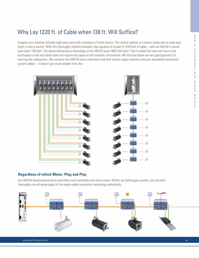
Imagine your machine includes eight axes each with a distance of three meters. The switch cabinet is 5 meters away and on each axis there is also a switch. With this thoroughly realistic example, that equates to a total of 1220 feet of cable – with our AKD-N it would have been 138 feet. The decentralized servo technology of the AKD-N saves 1082 feet here! That is cable that does not have to be purchased or laid and which does not require any space in the machine construction. We fi nd that these are very good grounds for starting the comparison. We combine the AKD-N servo controllers and their power supply modules with pre-assembled and tested system cables – it doesn't get much simpler than this.
Regardless of which Motor: Plug and PlayOur AKD-N decentralized servo controllers work optimally with every motor. Within our Kollmorgen system, you can also thoroughly use all advantages of the single-cable connection technology individually.
Why Lay 1220 ft. of Cable when 138 ft. Will Suffi ce? AK
D-
N
DE
CE
NT
RA
LI
ZE
D
SE
RV
O
DR
IV
ES
w w w. k o l l m o r g e n . c o m 47

Hybrid cable AKD-C to AKD-N:CCNCN1
Hybrid motor cables for single-cable operation:CCJNA2
Hybrid cable AKD-N to AKD-N:CCNNN1
Feedback cables for dual-cable operation:CFSNA1 SFDCFCNA1 ComcoderCFENA1 EndDat / BiSSCFHNA1 Hiperface
M
M
AKD-C
max
. 100
m, m
ax. 8
AKD
-N p
er s
trand
max
. 40
mm
ax. 2
5 m
AKD-N
AKD-NAKD-N
AKD-N AKD-N
AKD-N
EtherCAT®, max. 100 m
[1]
[2]
[3]
[5]
[4]
AKD-C
AKD-N AKD-N
AKD-NAKD-N
AKD-N AKD-N
[1]
[2]
[3]
[5]
[4]Motor cables for dual-cable operation:CMØNA1 without brakesCM1NA1 with brakes
AKD-N Decentralized Servo Drives
Continuous current 3 A, 6 A
Peak current 9 A, 18 A
Continuous input power 1.5 kVA, 3 kVA
Protection class IP67
Digital inputs/outputs 3 digital inputs/ 1 digital output
Safety function STO SIL 2 (only AKD-N-DS)
Feedback systemsDual-cable (not with -DB)
SFD (digital resolver), BISS-C, Comcorder, hall sensor, Endat 2.1 and 2.2, Hiperface, Hiperface DSL
Feedback systemsSingle-cable SFD3 (digital resolver) and Hiperface DSL
Communication EtherCAT®
Dimensions (W x H x D) Housing: 130 x 75 x 201 (mm)With plugs 130 x 75 x 247 (mm)
AKD-C Power Supply Module
Line voltage 400 / 480 V
Overall performance 10 kW
Intermediate circuit voltage 560 / 680 V DC
Output current 17 A (peak 34 A)
Protection class IP20
Output strands 2, for up to 8 AKD-N apiece
Safety function one STO Enable and STO Status apiece for each strand, SIL 2
Digital inputs/outputs 1 input, 1 output, 1 relay output
Communication EtherCAT®, TCP/IP service interface
Dimensions (W x H x D) Housing (Front) 80 x 260 x 198 (mm)Installation dimension with plugs 80 x 329 x 231 (mm)
Technical Data and TopologyAK
D-
N
DE
CE
NT
RA
LI
ZE
D
SE
RV
O
DR
IV
ES
AKD-N Decentralized Servo Drives
For complete AKD-N and AKD-C nomenclature, please see page 178.
K O L L M O R G E N48
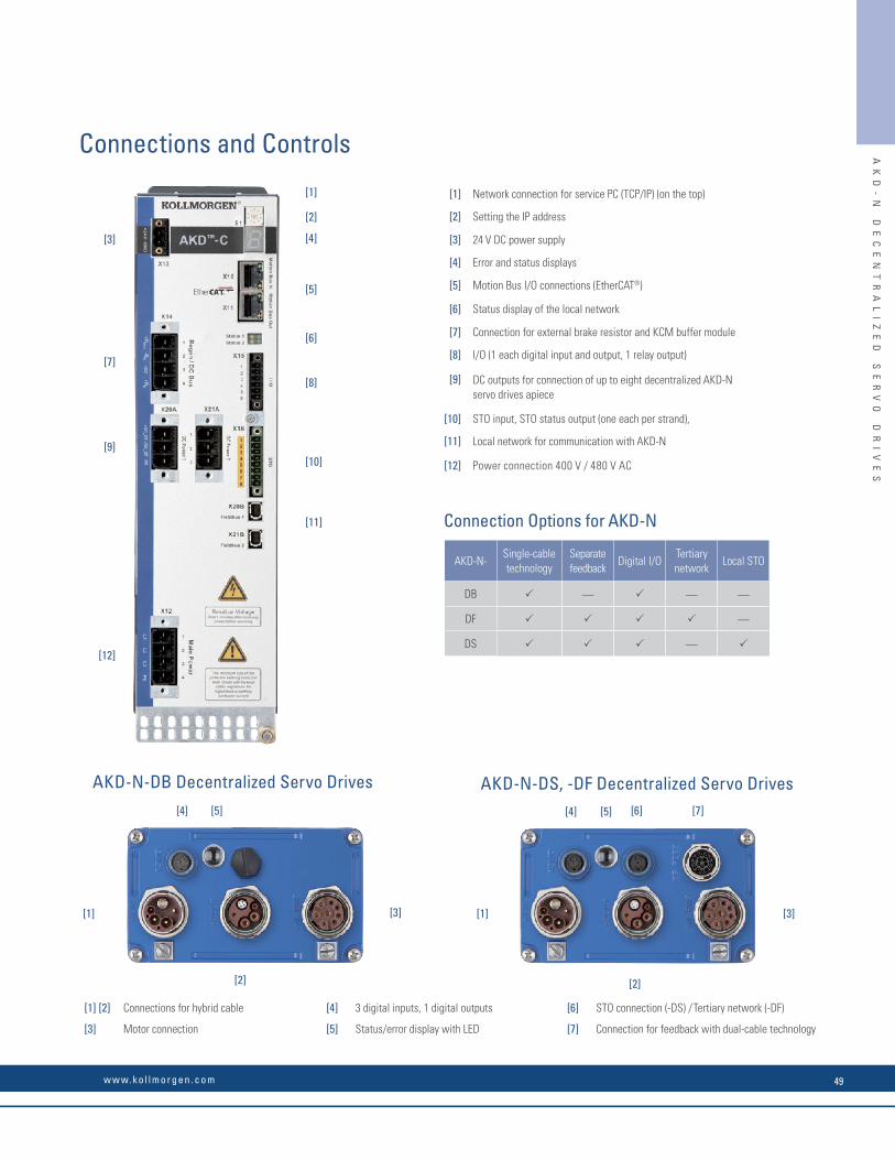
[1] [3]
[2]
[4] [5]
[1] [3]
[2]
[7][4] [5] [6]
[1]
[4]
[2]
[5]
[6]
[8]
[10]
[11]
[3]
[7]
[9]
[12]
[1] Network connection for service PC (TCP/IP) (on the top)
[2] Setting the IP address
[3] 24 V DC power supply
[4] Error and status displays
[5] Motion Bus I/O connections (EtherCAT®)
[6] Status display of the local network
[7] Connection for external brake resistor and KCM buffer module
[8] I/O (1 each digital input and output, 1 relay output)
[9] DC outputs for connection of up to eight decentralized AKD-N servo drives apiece
[10] STO input, STO status output (one each per strand),
[11] Local network for communication with AKD-N
[12] Power connection 400 V / 480 V AC
[1] [2] Connections for hybrid cable [4] 3 digital inputs, 1 digital outputs [6] STO connection (-DS) / Tertiary network (-DF)
[3] Motor connection [5] Status/error display with LED [7] Connection for feedback with dual-cable technology
AKD-N-DB Decentralized Servo Drives AKD-N-DS, -DF Decentralized Servo Drives
Connection Options for AKD-N
AKD-N-Single-cable technology
Separate feedback
Digital I/OTertiary network
Local STO
DB — — —
DF —
DS —
Connections and Controls AK
D-
N
DE
CE
NT
RA
LI
ZE
D
SE
RV
O
DR
IV
ES
w w w. k o l l m o r g e n . c o m 49

Our simple Graphical User Interface (GUI), Kollmorgen WorkBench, is designed to expedite and streamline the user’s experience with the AKD® servo drive. From easy application selection and reduced math, to a sleek six-channel scope; the user interface is extremely easy to use. Kollmorgen WorkBench supports intuitive access to the exclusive Performance Servo Tuner (PST) available inside AKD. The patent pending PST makes auto-tuning the AKD high-performance servo drive with world-class Kollmorgen motors very simple.
User-Friendly Environment
Logical fl ow, colorful icons and easy access simplify interactions with the AKD servo drive. The folder structure allows for instant identifi cation and easy navigation.
Sleek Six-Channel “Real-Time” Software Oscilloscope
The easy-to-use AKD servo drive interface has a sleek digital oscilloscope that provides a comfortable environment for users to monitor performance.There are multiple options to share data in the format you prefer at the click of a button.
• Save as an image
• Load to an e-mail
KO
LL
MO
RG
EN
W
OR
KB
EN
CH
Kollmorgen Workbench
Nip Roller Application Selection
Application Selection
Simplifi es set-up by allowing use of machine or application-based units. Nip roller and rack and pinion set-ups shown.
Data-Sharing
The ease-of-sharing continues in the parameters window. Kollmorgen WorkBench provides the user the easy options of printing or emailing the parameter values at the click of a button.
Rack and Pinion Application Selection
KO
LL
MO
RG
EN
W
OR
KB
EN
CH
K O L L M O R G E N50
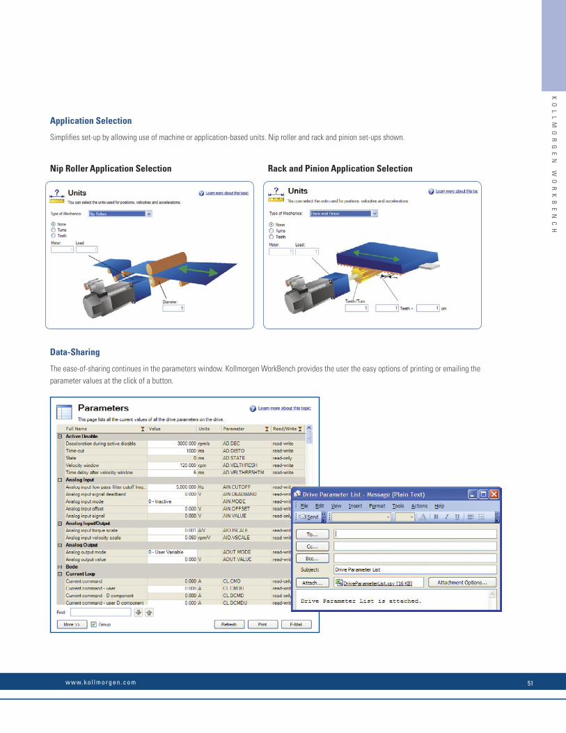
Our simple Graphical User Interface (GUI), Kollmorgen WorkBench, is designed to expedite and streamline the user’s experience with the AKD® servo drive. From easy application selection and reduced math, to a sleek six-channel scope; the user interface is extremely easy to use. Kollmorgen WorkBench supports intuitive access to the exclusive Performance Servo Tuner (PST) available inside AKD. The patent pending PST makes auto-tuning the AKD high-performance servo drive with world-class Kollmorgen motors very simple.
User-Friendly Environment
Logical fl ow, colorful icons and easy access simplify interactions with the AKD servo drive. The folder structure allows for instant identifi cation and easy navigation.
Sleek Six-Channel “Real-Time” Software Oscilloscope
The easy-to-use AKD servo drive interface has a sleek digital oscilloscope that provides a comfortable environment for users to monitor performance.There are multiple options to share data in the format you prefer at the click of a button.
• Save as an image
• Load to an e-mail
KO
LL
MO
RG
EN
W
OR
KB
EN
CH
Kollmorgen Workbench
Nip Roller Application Selection
Application Selection
Simplifi es set-up by allowing use of machine or application-based units. Nip roller and rack and pinion set-ups shown.
Data-Sharing
The ease-of-sharing continues in the parameters window. Kollmorgen WorkBench provides the user the easy options of printing or emailing the parameter values at the click of a button.
Rack and Pinion Application Selection
KO
LL
MO
RG
EN
W
OR
KB
EN
CH
w w w. k o l l m o r g e n . c o m 51
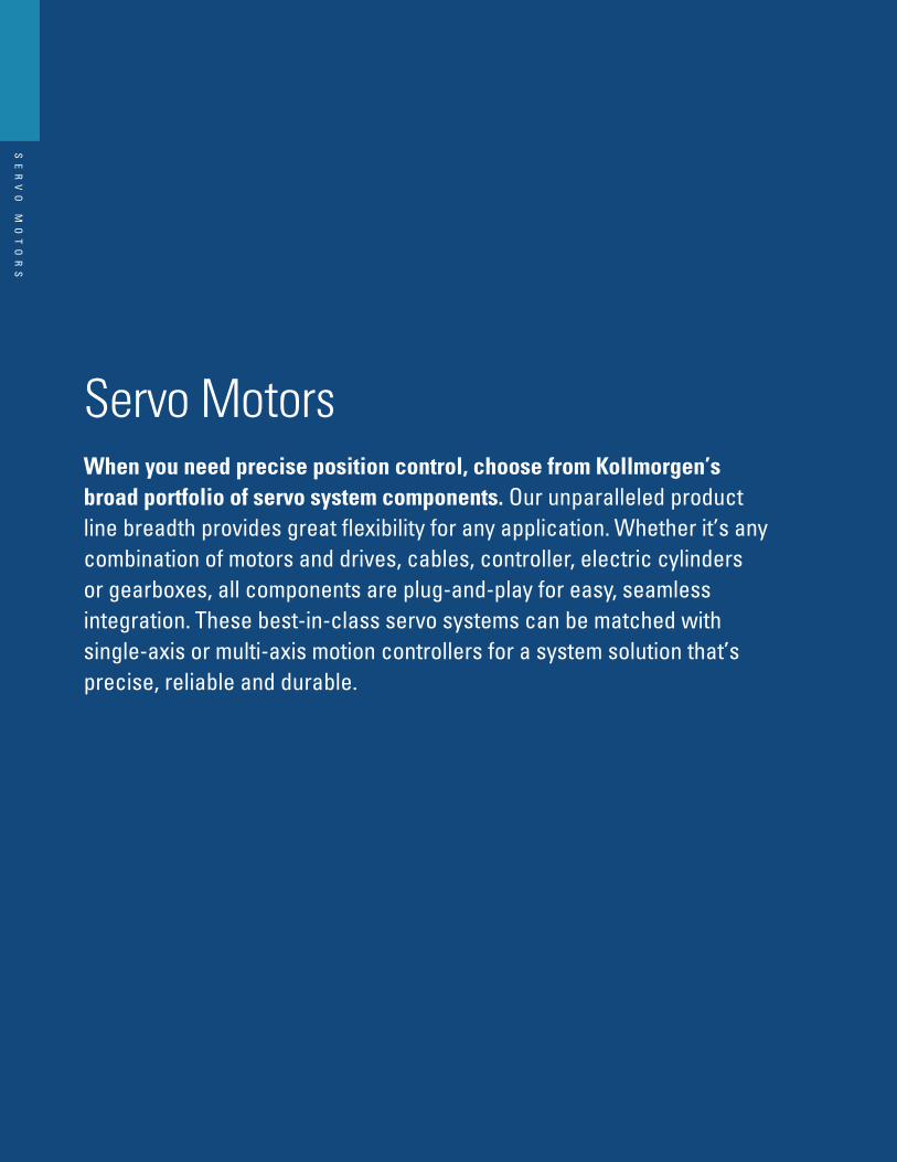
K O L L M O R G E N
Servo MotorsWhen you need precise position control, choose from Kollmorgen’s broad portfolio of servo system components. Our unparalleled product line breadth provides great flexibility for any application. Whether it’s any combination of motors and drives, cables, controller, electric cylinders or gearboxes, all components are plug-and-play for easy, seamless integration. These best-in-class servo systems can be matched with single-axis or multi-axis motion controllers for a system solution that’s precise, reliable and durable.
SE
RV
O
MO
TO
RS

SE
RV
O
MO
TO
RS
The Advantages of AKM® Servo Motors• With the same size, the AKM offers up to 47% more power on the
motor shaft than before
• Amplifier and motor dimensions reduced
• Lower system costs
• Optimized AKM and direct drive motor windings for the AKD servo drive
• Quicker start-up of all servo systems
• Immediate and adaptive reaction to dynamic loads optimizes performance within seconds
• Precise regulation of all motor types
• Compensation for stiff and compatible gearboxes and clutches
• Start-up of amplifiers with plug-and-play detection for AKM and Cartridge DDR series motors
• More precise machines due to higher resolution and improved accuracy
• With multi-turn absolute encoders: reduced cycle times and lower costs for sensors and cabling through the omission of conventional reference run methods
• New, cost-efficient multi-turn feedback option
• Machine design independent of motor size
• Installation of motors in the tightest space
• Motors with the highest power densities in the whole industry
• Over 500,000 standard motor versions available in various mounting, connection, and feedback variants, as well as further options
• Our flexible products deliver a perfectly suited solution to your application
• Simplifies mechanical modifications and design adjustments or renders them totally superfluous
• AKM offers 28 housing and design length combinations, as well as 120 different standard windings for a single motor series
• AKM Washdown and AKM Washdown Food also offer maximum reliability and a long service life for the most demanding industrial applications
• New IP67 option for AKM
w w w. k o l l m o r g e n . c o m 53

SE
RV
O
MO
TO
RS
KO
LL
MO
RG
EN
S
ER
VO
M
OT
OR
O
VE
RV
IE
W
Kollmorgen Servo Motor Overview
Model Product Family Applications
AKM Servo Motors AKM
Designed with industry leading torque density and confi gurability. The AKM line includes more than 500,000 standard models to fi t applications from general automation to applications that require IP67 sealing.
AKMH IP69K Washdown Motors
AKMH
The AKMH meets the food industry’s strictest hygienic design criteria while being rugged enough to withstand the toughest of daily washdown regimens. Perfect for Food Processing, Primary Food Packaging, Pharmaceutical and Medical applications.
Cartridge Direct Drive
Servo MotorsCDDR
The CDDR is designed to provide the benefi t of embedded frameless motor technology in an easy-to-integrate package. Perfect for applications in Printing, Packaging and Converting.
Housed Direct Drive
Servo MotorsHDDR
Housed DDR motors are designed for precise positioning of larger loads without the use of a mechanical transmission. Increasing OEE through the removal of belts and gearboxes that fail unexpectedly or require frequent maintenance.
KBM Frameless Direct
Drive MotorsKBM
With a wide variety of sizes and an extensive range of torque and speed options the KBM frameless direct drive motors are engineered to provide the high-performance, long life and simple installation that today’s design engineers demand.
TBM Frameless Direct
Drive MotorsTBM
The Kollmorgen TBM frameless direct direct drive motors are designed for applications that require high power in a small, compact form factor with minimized weight and inertia. These motors provide the highest performance in applications such as robotic joints, medical robotics, sensor gimbals, guidance systems and other motion-critical applications.
Direct Drive Linear
Servo Motors
IC
IL
Ideal for applications requiring very low bearing friction, high acceleration of lighter loads, and for maximizing constant velocity, even at ultra low speeds.
Kollmorgen offers a comprehensive range of servo motors including electric cylinders, rodless actuators, and precision tables to meet a wide range of application requirements. For actuator products not included in this catalog go to www.kollmorgen.com for information about other Kollmorgen linear positioning products.
KO
LL
MO
RG
EN
S
ER
VO
M
OT
OR
O
VE
RV
IE
W
Model Product Family Features
AKM Servo Motors AKMDesigned to deliver precise motion and more power for your money. More than 500,000 standard confi gurations that include various feedback, connector, paint and sealing options.
AKMH IP69K Washdown Motor
AKMH
The AKMH is designed to withstand the toughest of daily washdown regimens without the need for covers. The AKMH’s hygienic design makes it easy to clean, keeping your machine running and protecting your brand. Designed with a single cable that combines power, feedback and an innovative venting feature that extends the life of the motor.
Cartridge Direct Drive
Servo MotorsCDDR
The CDDR is a patented design that allows for this torque dense frameless motor to be installed on your machine in 5 minutes. The CDDR lowers your machines maintenance, increases your machines uptime and increase your machines peformance.
Housed Direct Drive
Servo MotorsHDDR
Housed DDR motors are maintenance free and run more quietly and with better dynamics than systems that use gears, belts, cams or other mechanical transmission components.
KBM Frameless Direct
Drive MotorsKBM
KBM motors cover a range of frameless motor solutions across a variety of applications. KBM is engineered to provide the high-performance, long life and simple installation that today’s design engineers demand.
TBM Frameless Direct
Drive MotorsTBM
Typical applications include robotic joints, weapon stations, sensor gimbals, sight systems, UAV propulsion and guidance, as well as many others.
Direct Drive Linear
Servo Motors
IC
ILKollmorgen linear motors provide precise placement of product by directly coupling to your load and eliminating the backlash associated with high maintenance linear transmission components.
K O L L M O R G E N54

SE
RV
O
MO
TO
RS
KO
LL
MO
RG
EN
S
ER
VO
M
OT
OR
O
VE
RV
IE
W
Kollmorgen Servo Motor Overview
Model Product Family Applications
AKM Servo Motors AKM
Designed with industry leading torque density and confi gurability. The AKM line includes more than 500,000 standard models to fi t applications from general automation to applications that require IP67 sealing.
AKMH IP69K Washdown Motors
AKMH
The AKMH meets the food industry’s strictest hygienic design criteria while being rugged enough to withstand the toughest of daily washdown regimens. Perfect for Food Processing, Primary Food Packaging, Pharmaceutical and Medical applications.
Cartridge Direct Drive
Servo MotorsCDDR
The CDDR is designed to provide the benefi t of embedded frameless motor technology in an easy-to-integrate package. Perfect for applications in Printing, Packaging and Converting.
Housed Direct Drive
Servo MotorsHDDR
Housed DDR motors are designed for precise positioning of larger loads without the use of a mechanical transmission. Increasing OEE through the removal of belts and gearboxes that fail unexpectedly or require frequent maintenance.
KBM Frameless Direct
Drive MotorsKBM
With a wide variety of sizes and an extensive range of torque and speed options the KBM frameless direct drive motors are engineered to provide the high-performance, long life and simple installation that today’s design engineers demand.
TBM Frameless Direct
Drive MotorsTBM
The Kollmorgen TBM frameless direct direct drive motors are designed for applications that require high power in a small, compact form factor with minimized weight and inertia. These motors provide the highest performance in applications such as robotic joints, medical robotics, sensor gimbals, guidance systems and other motion-critical applications.
Direct Drive Linear
Servo Motors
IC
IL
Ideal for applications requiring very low bearing friction, high acceleration of lighter loads, and for maximizing constant velocity, even at ultra low speeds.
Kollmorgen offers a comprehensive range of servo motors including electric cylinders, rodless actuators, and precision tables to meet a wide range of application requirements. For actuator products not included in this catalog go to www.kollmorgen.com for information about other Kollmorgen linear positioning products.
KO
LL
MO
RG
EN
S
ER
VO
M
OT
OR
O
VE
RV
IE
W
Model Product Family Features
AKM Servo Motors AKMDesigned to deliver precise motion and more power for your money. More than 500,000 standard confi gurations that include various feedback, connector, paint and sealing options.
AKMH IP69K Washdown Motor
AKMH
The AKMH is designed to withstand the toughest of daily washdown regimens without the need for covers. The AKMH’s hygienic design makes it easy to clean, keeping your machine running and protecting your brand. Designed with a single cable that combines power, feedback and an innovative venting feature that extends the life of the motor.
Cartridge Direct Drive
Servo MotorsCDDR
The CDDR is a patented design that allows for this torque dense frameless motor to be installed on your machine in 5 minutes. The CDDR lowers your machines maintenance, increases your machines uptime and increase your machines peformance.
Housed Direct Drive
Servo MotorsHDDR
Housed DDR motors are maintenance free and run more quietly and with better dynamics than systems that use gears, belts, cams or other mechanical transmission components.
KBM Frameless Direct
Drive MotorsKBM
KBM motors cover a range of frameless motor solutions across a variety of applications. KBM is engineered to provide the high-performance, long life and simple installation that today’s design engineers demand.
TBM Frameless Direct
Drive MotorsTBM
Typical applications include robotic joints, weapon stations, sensor gimbals, sight systems, UAV propulsion and guidance, as well as many others.
Direct Drive Linear
Servo Motors
IC
ILKollmorgen linear motors provide precise placement of product by directly coupling to your load and eliminating the backlash associated with high maintenance linear transmission components.
w w w. k o l l m o r g e n . c o m 55

SE
RV
O
MO
TO
RS
AKM® Brushless Servo Motor
Over 500,000 standard configurations
Smaller and lighter motors due to high torque densities
Robust: Housing and front flange produced from one casting
Motor design that cuts to the chase – with customer-specific windings or modifications.
Numerous feedback options such as the SFD3 digital resolver, single-turn and multi-turn absolute encoders
Small but impressive:
AKM1 is one of the smallest servo motors on the market
High degree of accuracy thanks to digital feedback systems (optional)
Heavy-duty shaft, optionally with reinforced bearings (only AKM8)
Worldwide availability and user support through the international Kollmorgen sales and support network
Numerous connection options
• 8 frame sizes from 40 to 260 mm• 28 housing and design length combinations• 117 standard windings for 120/240/400/480 V• Winding options for low DC voltage
• Numerous flange and shaft options• Minimal cogging and high degree of efficiency• Extensive customization options with special
windings and shafts
The AKM® brushless servo motor stands alone in the marketplace in terms of flexibility and performance advantages. Kollmorgen’s culture of continuous improvement has paid dividends again. The AKM servo motor’s innovative design has been polished and optimized. With the new AKD amplifier, the distinguished AKM servo motor sets a new standard of refined servo performance, designed to deliver precise motion and more power for your money. Nowhere else will you find a more versatile and complete servo family to meet your needs and exceed your expectations.
AK
M
BR
US
HL
ES
S
SE
RV
O
MO
TO
R
K O L L M O R G E N56
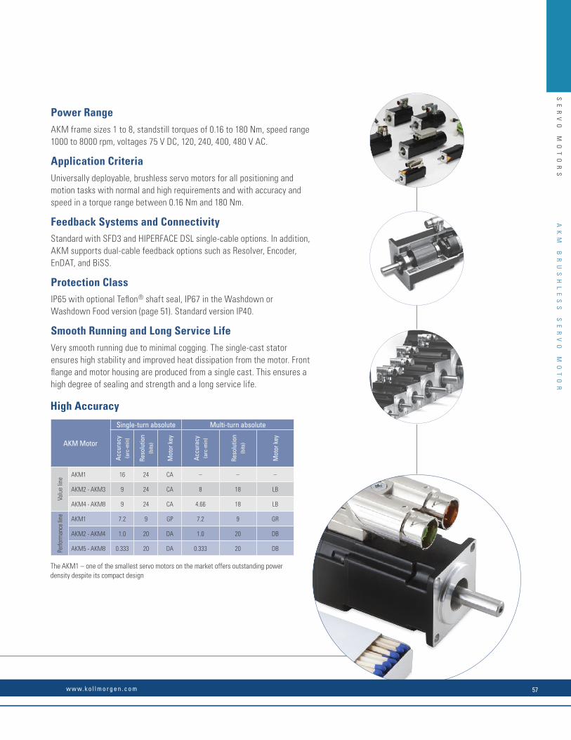
SE
RV
O
MO
TO
RS
High Accuracy
AKM Motor
Single-turn absolute Multi-turn absolute
Accu
racy
(a
rc-m
in)
Reso
lutio
n (b
its)
Mot
or k
ey
Accu
racy
(a
rc-m
in)
Reso
lutio
n (b
its)
Mot
or k
ey
Valu
e lin
e AKM1 16 24 CA – – –
AKM2 - AKM3 9 24 CA 8 18 LB
AKM4 - AKM8 9 24 CA 4.66 18 LB
Perfo
rman
ce li
ne AKM1 7.2 9 GP 7.2 9 GR
AKM2 - AKM4 1.0 20 DA 1.0 20 DB
AKM5 - AKM8 0.333 20 DA 0.333 20 DB
The AKM1 – one of the smallest servo motors on the market offers outstanding power density despite its compact design
Power RangeAKM frame sizes 1 to 8, standstill torques of 0.16 to 180 Nm, speed range 1000 to 8000 rpm, voltages 75 V DC, 120, 240, 400, 480 V AC.
Application CriteriaUniversally deployable, brushless servo motors for all positioning and motion tasks with normal and high requirements and with accuracy and speed in a torque range between 0.16 Nm and 180 Nm.
Feedback Systems and ConnectivityStandard with SFD3 and HIPERFACE DSL single-cable options. In addition, AKM supports dual-cable feedback options such as Resolver, Encoder, EnDAT, and BiSS.
Protection ClassIP65 with optional Teflon® shaft seal, IP67 in the Washdown or Washdown Food version (page 51). Standard version IP40.
Smooth Running and Long Service LifeVery smooth running due to minimal cogging. The single-cast stator ensures high stability and improved heat dissipation from the motor. Front flange and motor housing are produced from a single cast. This ensures a high degree of sealing and strength and a long service life.
AK
M
BR
US
HL
ES
S
SE
RV
O
MO
TO
R
w w w. k o l l m o r g e n . c o m 57
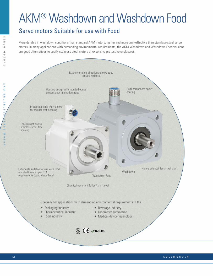
SE
RV
O
MO
TO
RS
AKM® Washdown and Washdown FoodServo motors Suitable for use with Food
WashdownWashdown Food
Housing design with rounded edges prevents contamination traps
Extensive range of options allows up to 150000 variants!
Dual-component epoxy coating
High grade stainless steel shaft
Chemical-resistant Teflon® shaft seal
Lubricants suitable for use with food and shaft seal as per FDA requirements (Washdown Food)
Protection class IP67 allows for regular wet cleaning
Less weight due to stainless-steel-free housing
More durable in washdown conditions than standard AKM motors, lighter and more cost-effective than stainless-steel servo motors: In many applications with demanding environmental requirements, the AKM Washdown and Washdown Food versions are good alternatives to costly stainless steel motors or expensive protective enclosures.
Specially for applications with demanding environmental requirements in the
• Packaging industry• Pharmaceutical industry• Food industry
• Beverage industry• Laboratory automation• Medical device technology
AK
M
BR
US
HL
ES
S
SE
RV
O
MO
TO
R
K O L L M O R G E N58

SE
RV
O
MO
TO
RS
Also proven in harsh environments: The AKM Washdown Food is resistant to most acids and bases, as well as aggressive substances.
Power RangeAKM frame sizes 2 to 6 with standstill torques of 1 to 25 Nm, supply voltages of 75 to 480 V, large selection of different construction lengths, winding variants, as well as feedback systems and connection technologies.
Application CriteriaDesigned for environments with acids, bases, or aggressive substances such as frequent cleaning with cleaning agents with pH values of between 2 and 12.
Housing CoatingThe coating material of the AKM Washdown motors is resistant to acids and bases and aggressive substances and meets the global migration requirement of the FDA. The rounded and smooth surfaces prevent hazardous contamination traps and germ formation.
Seals and BearingsBoth Washdown versions meet the IP67 protection rating. The proven AKM PTFE shaft seal is used. For the AKM Washdown Food version, the shaft seal meets FDA requirements and only food-safe lubricants are used.
Connectors and CablesEach in size 1 with special stainless steel design and smooth surface. Cables with special mating connectors are used from stainless steel or a material appropriate for maintaining food quality. The cables are clamped using a special clamping method.
International StandardsUL, CE, FDA*, RoHS
* Global migration requirement
AK
M
BR
US
HL
ES
S
SE
RV
O
MO
TO
R
w w w. k o l l m o r g e n . c o m 59

SE
RV
O
MO
TO
RS
AKM® Servo MotorsAKM, AKM Washdown, and AKM Washdown FoodPerformance Data
AKM
Ser
vo M
otor
Flan
ge s
ize [m
m]
Cont
. Tor
que
at S
tall
Tcs
[Nm
]
Cont
inuo
us C
urre
nt I 0 [A
]
Peak
Torq
ue a
t sta
ll Tp
s [N
m] 75 V DC 115 V 230 V 400 V 480 V
Iner
tia (J
m) [
kgc
m2 ]
Wei
ght [
kg]
Rate
d Sp
eed
Nrtd
[RPM
]
Rate
d To
rque
Trtd
[Nm
]
Rate
d Po
wer
Prtd
[kW
]
Rate
d Sp
eed
Nrtd
[RPM
]
Rate
d To
rque
Trtd
[Nm
]
Rate
d Po
wer
Prtd
[kW
]
Rate
d Sp
eed
Nrtd
[RPM
]
Rate
d To
rque
Trtd
[Nm
]
Rate
d Po
wer
Prtd
[kW
]
Rate
d Sp
eed
Nrtd
[RPM
]
Rate
d To
rque
Trtd
[Nm
]
Rate
d Po
wer
Prtd
[kW
]
Rate
d Sp
eed
Nrtd
[RPM
]
Rate
d To
rque
Trtd
[Nm
]
Rate
d Po
wer
Prtd
[kW
]
11B 40 0.18 1.16 0.61 – – – 4000 0.18 0.08 8000 0.17 0.14 – – – – – – 0.017 0.35
11C 40 0.18 1.45 0.61 – – – 6000 0.18 0.11 – – – – – – – – – 0.017 0.35
11E 40 0.18 2.91 0.61 6000 0.18 0.11 – – – – – – – – – – – – 0.017 0.35
12C 40 0.31 1.51 1.08 – – – 4000 0.30 0.13 8000 0.28 0.23 – – – – – – 0.031 0.49
12E 40 0.31 2.72 1.08 3000 0.31 0.10 8000 0.28 0.23 – – – – – – – – – 0.031 0.49
13C 40 0.41 1.48 1.46 – – – 3000 0.41 0.13 8000 0.36 0.30 – – – – – – 0.045 0.63
13D 40 0.40 2.40 1.44 2000 0.40 0.08 7000 0.36 0.27 – – – – – – – – – 0.045 0.63
21C 60 0.48 1.58 1.47 – – – 2500 0.46 0.12 8000 0.39 0.32 – – – – – – 0.11 0.82
21E 60 0.50 3.11 1.49 2000 0.48 0.10 7000 0.41 0.30 – – – – – – – – – 0.11 0.82
21G 60 0.50 4.87 1.51 4000 0.46 0.19 – – – – – – – – – – – – 0.11 0.82
22C 60 0.84 1.39 2.73 – – – 1000 0.83 0.09 3500 0.78 0.29 8000 0.68 0.57 8000 0.68 0.57 0.16 1.10
22E 60 0.87 2.73 2.76 1000 0.85 0.09 3500 0.81 0.30 8000 0.70 0.59 – – – – – – 0.16 1.10
22G 60 0.88 4.82 2.79 2500 0.83 0.22 7000 0.74 0.54 – – – – – – – – – 0.16 1.10
23C 60 1.13 1.41 3.77 – – – 1000 1.11 0.12 2500 1.08 0.28 5500 0.99 0.57 7000 0.95 0.70 0.22 1.38
23D 60 1.16 2.19 3.84 – – – 1500 1.12 0.18 5000 1.03 0.54 8000 0.92 0.77 8000 0.92 0.77 0.22 1.38
23F 60 1.18 4.31 3.88 1500 1.15 0.18 4500 1.07 0.50 8000 0.94 0.79 – – – – – – 0.22 1.38
24C 60 1.38 1.42 4.67 – – – – – – 2000 1.32 0.28 4500 1.25 0.59 5500 1.22 0.70 0.27 1.66
24D 60 1.41 2.21 4.76 – – – 1500 1.36 0.21 4000 1.29 0.54 8000 1.11 0.93 8000 1.11 0.93 0.27 1.66
24F 60 1.42 3.89 4.82 1000 1.39 0.15 3000 1.33 0.42 8000 1.12 0.94 – – – – – – 0.27 1.66
31C 80 1.15 1.37 3.88 – – – – – – 2500 1.12 0.29 5000 1.00 0.52 6000 0.91 0.57 0.33 1.55
31E 80 1.20 2.99 4.00 750 1.19 0.09 2500 1.17 0.31 6000 0.95 0.60 – – – – – – 0.33 1.55
31H 80 1.23 5.85 4.06 2000 1.20 0.25 6000 0.97 0.61 – – – – – – – – – 0.33 1.55
32C 80 2.00 1.44 6.92 – – – – – – 1500 1.95 0.31 3000 1.86 0.58 3500 1.83 0.67 0.59 2.23
32D 80 2.04 2.23 7.10 – – – 1000 2.00 0.21 2500 1.93 0.51 5500 1.65 0.95 6000 1.58 0.99 0.59 2.23
32E 80 2.04 2.82 7.11 – – – – – – 3500 1.87 0.69 7000 1.41 1.03 7000 1.22 1.02 0.59 2.23
32H 80 2.10 5.50 7.26 1200 2.06 0.26 3000 1.96 0.62 7000 1.45 1.06 – – – – – – 0.59 2.23
33C 80 2.71 1.47 9.76 – – – – – – 1000 2.64 0.28 2000 2.54 0.53 2500 2.50 0.65 0.85 2.9
33E 80 2.79 2.58 9.96 – – – – – – 2000 2.62 0.55 4500 2.34 1.10 5000 2.27 1.19 0.85 2.9
33H 80 2.88 5.62 10.22 800 2.82 0.24 2500 2.66 0.70 5500 2.27 1.31 – – – – – – 0.85 2.9
41C 90 1.95 1.46 6.12 – – – – – – 1200 1.88 0.24 3000 1.77 0.56 3500 1.74 0.64 0.81 2.44
41E 90 2.02 2.85 6.28 – – – 1200 1.94 0.24 3000 1.82 0.57 6000 1.58 0.99 6000 1.58 0.99 0.81 2.44
41H 90 2.06 5.6 6.36 1000 1.99 0.21 3000 1.86 0.58 6000 1.62 1.02 – – – – – – 0.81 2.44
42C 90 3.35 1.40 11.3 – – – – – – – – – 1500 3.10 0.49 2000 3.02 0.63 1.5 3.39
42E 90 3.42 2.74 11.3 – – – – – – 1800 3.12 0.59 3500 2.81 2.35 4000 2.72 1.14 1.5 3.39
42G 90 3.53 4.80 11.5 – – – – – – 3500 2.90 1.06 6000 2.35 1.48 6000 2.35 1.48 1.5 3.39
42J 90 3.56 8.4 11.6 – – – 3000 3.03 0.95 6000 2.36 1.50 – – – – – – 1.5 3.39
43E 90 4.70 2.76 15.9 – – – – – – 1500 4.24 0.67 2500 3.92 1.03 3000 3.76 1.18 2.1 4.35
43G 90 4.80 4.87 16.1 – – – – – – 2500 4.00 1.05 5000 3.01 1.58 6000 2.57 1.61 2.1 4.35
43K 90 4.90 9.60 16.4 – – – 2500 4.08 1.07 6000 2.62 1.65 – – – – – – 2.1 4.35
44E 90 5.76 2.90 19.9 – – – – – – 1200 5.22 0.66 2000 4.80 1.01 2500 4.56 1.19 2.7 5.3
44G 90 5.88 5.00 20.3 – – – – – – 2000 4.90 1.03 4000 3.76 1.57 5000 3.19 1.67 2.7 5.3
44J 90 6.00 8.80 20.4 – – – – – – 4000 3.84 1.61 6000 2.75 1.73 6000 2.75 1.73 2.7 5.3
51E 115 4.70 2.75 11.6 – – – – – – 1200 4.41 0.55 2500 3.98 1.04 3000 3.80 1.19 3.4 4.2
51G 115 4.75 4.84 11.7 – – – – – – 2500 4.02 1.05 5000 2.62 1.37 6000 1.94 1.22 3.4 4.2
51H 115 4.79 6.00 11.7 – – – – – – 3000 3.87 1.22 6000 1.95 1.23 6000 1.95 1.23 3.4 4.2
51K 115 4.90 9.40 11.9 – – – 2500 4.15 1.09 5500 2.35 1.35 – – – – – – 3.4 4.2
AK
M
BR
US
HL
ES
S
SE
RV
O
MO
TO
R
K O L L M O R G E N60
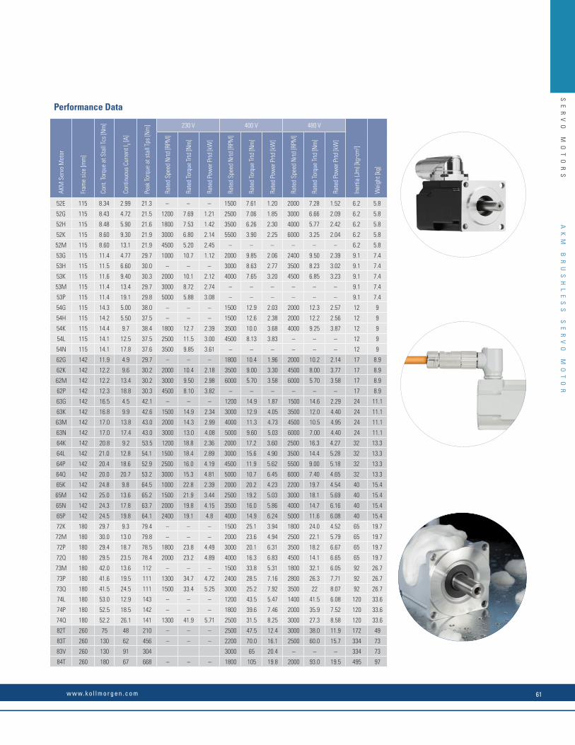
SE
RV
O
MO
TO
RS
Performance Data
AKM
Ser
vo M
otor
Fram
e si
ze [m
m]
Cont
. Tor
que
at S
tall
Tcs
[Nm
]
Cont
inuo
us C
urre
nt I 0 [A
]
Peak
Torq
ue a
t sta
ll Tp
s [N
m] 230 V 400 V 480 V
Iner
tia (J
m) [
kgc
m2 ]
Wei
ght [
kg]
Rate
d Sp
eed
Nrtd
[RPM
]
Rate
d To
rque
Trtd
[Nm
]
Rate
d Po
wer
Prtd
[kW
]
Rate
d Sp
eed
Nrtd
[RPM
]
Rate
d To
rque
Trtd
[Nm
]
Rate
d Po
wer
Prtd
[kW
]
Rate
d Sp
eed
Nrtd
[RPM
]
Rate
d To
rque
Trtd
[Nm
]
Rate
d Po
wer
Prtd
[kW
]
52E 115 8.34 2.99 21.3 – – – 1500 7.61 1.20 2000 7.28 1.52 6.2 5.8
52G 115 8.43 4.72 21.5 1200 7.69 1.21 2500 7.06 1.85 3000 6.66 2.09 6.2 5.8
52H 115 8.48 5.90 21.6 1800 7.53 1.42 3500 6.26 2.30 4000 5.77 2.42 6.2 5.8
52K 115 8.60 9.30 21.9 3000 6.80 2.14 5500 3.90 2.25 6000 3.25 2.04 6.2 5.8
52M 115 8.60 13.1 21.9 4500 5.20 2.45 – – – – – – 6.2 5.8
53G 115 11.4 4.77 29.7 1000 10.7 1.12 2000 9.85 2.06 2400 9.50 2.39 9.1 7.4
53H 115 11.5 6.60 30.0 – – – 3000 8.63 2.77 3500 8.23 3.02 9.1 7.4
53K 115 11.6 9.40 30.3 2000 10.1 2.12 4000 7.65 3.20 4500 6.85 3.23 9.1 7.4
53M 115 11.4 13.4 29.7 3000 8.72 2.74 – – – – – – 9.1 7.4
53P 115 11.4 19.1 29.8 5000 5.88 3.08 – – – – – – 9.1 7.4
54G 115 14.3 5.00 38.0 – – – 1500 12.9 2.03 2000 12.3 2.57 12 9
54H 115 14.2 5.50 37.5 – – – 1500 12.6 2.38 2000 12.2 2.56 12 9
54K 115 14.4 9.7 38.4 1800 12.7 2.39 3500 10.0 3.68 4000 9.25 3.87 12 9
54L 115 14.1 12.5 37.5 2500 11.5 3.00 4500 8.13 3.83 – – – 12 9
54N 115 14.1 17.8 37.6 3500 9.85 3.61 – – – – – – 12 9
62G 142 11.9 4.9 29.7 – – – 1800 10.4 1.96 2000 10.2 2.14 17 8.9
62K 142 12.2 9.6 30.2 2000 10.4 2.18 3500 9.00 3.30 4500 8.00 3.77 17 8.9
62M 142 12.2 13.4 30.2 3000 9.50 2.98 6000 5.70 3.58 6000 5.70 3.58 17 8.9
62P 142 12.3 18.8 30.3 4500 8.10 3.82 – – – – – – 17 8.9
63G 142 16.5 4.5 42.1 – – – 1200 14.9 1.87 1500 14.6 2.29 24 11.1
63K 142 16.8 9.9 42.6 1500 14.9 2.34 3000 12.9 4.05 3500 12.0 4.40 24 11.1
63M 142 17.0 13.8 43.0 2000 14.3 2.99 4000 11.3 4.73 4500 10.5 4.95 24 11.1
63N 142 17.0 17.4 43.0 3000 13.0 4.08 5000 9.60 5.03 6000 7.00 4.40 24 11.1
64K 142 20.8 9.2 53.5 1200 18.8 2.36 2000 17.2 3.60 2500 16.3 4.27 32 13.3
64L 142 21.0 12.8 54.1 1500 18.4 2.89 3000 15.6 4.90 3500 14.4 5.28 32 13.3
64P 142 20.4 18.6 52.9 2500 16.0 4.19 4500 11.9 5.62 5500 9.00 5.18 32 13.3
64Q 142 20.0 20.7 53.2 3000 15.3 4.81 5000 10.7 6.45 6000 7.40 4.65 32 13.3
65K 142 24.8 9.8 64.5 1000 22.8 2.39 2000 20.2 4.23 2200 19.7 4.54 40 15.4
65M 142 25.0 13.6 65.2 1500 21.9 3.44 2500 19.2 5.03 3000 18.1 5.69 40 15.4
65N 142 24.3 17.8 63.7 2000 19.8 4.15 3500 16.0 5.86 4000 14.7 6.16 40 15.4
65P 142 24.5 19.8 64.1 2400 19.1 4.8 4000 14.9 6.24 5000 11.6 6.08 40 15.4
72K 180 29.7 9.3 79.4 – – – 1500 25.1 3.94 1800 24.0 4.52 65 19.7
72M 180 30.0 13.0 79.8 – – – 2000 23.6 4.94 2500 22.1 5.79 65 19.7
72P 180 29.4 18.7 78.5 1800 23.8 4.49 3000 20.1 6.31 3500 18.2 6.67 65 19.7
72Q 180 29.5 23.5 78.4 2000 23.2 4.89 4000 16.3 6.83 4500 14.1 6.65 65 19.7
73M 180 42.0 13.6 112 – – – 1500 33.8 5.31 1800 32.1 6.05 92 26.7
73P 180 41.6 19.5 111 1300 34.7 4.72 2400 28.5 7.16 2800 26.3 7.71 92 26.7
73Q 180 41.5 24.5 111 1500 33.4 5.25 3000 25.2 7.92 3500 22 8.07 92 26.7
74L 180 53.0 12.9 143 – – – 1200 43.5 5.47 1400 41.5 6.08 120 33.6
74P 180 52.5 18.5 142 – – – 1800 39.6 7.46 2000 35.9 7.52 120 33.6
74Q 180 52.2 26.1 141 1300 41.9 5.71 2500 31.5 8.25 3000 27.3 8.58 120 33.6
82T 260 75 48 210 – – – 2500 47.5 12.4 3000 38.0 11.9 172 49
83T 260 130 62 456 – – – 2200 70.0 16.1 2500 60.0 15.7 334 73
83V 260 130 91 304 3000 65 20.4 – – – 334 73
84T 260 180 67 668 – – – 1800 105 19.8 2000 93.0 19.5 495 97
AK
M
BR
US
HL
ES
S
SE
RV
O
MO
TO
R
w w w. k o l l m o r g e n . c o m 61
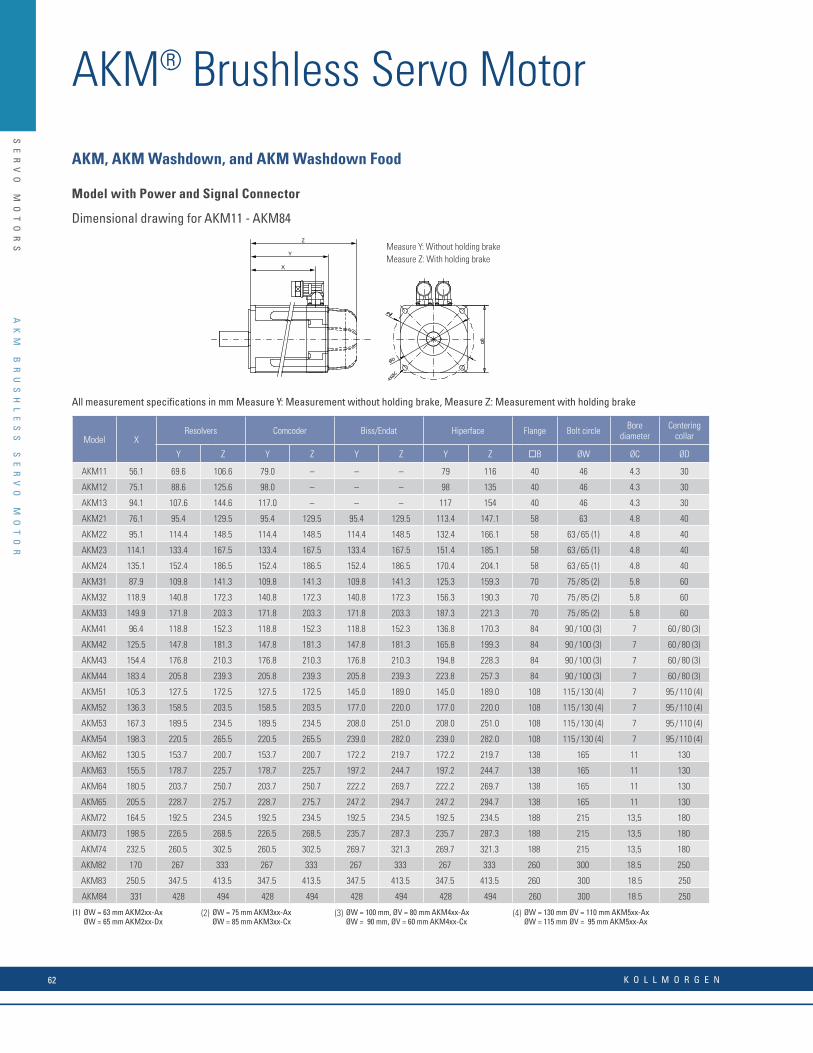
SE
RV
O
MO
TO
RS
AKM® Brushless Servo Motor
B
ØD
4XØC
Y
Z
X
Measure Y: Without holding brakeMeasure Z: With holding brake
AKM, AKM Washdown, and AKM Washdown Food
Model with Power and Signal Connector
Dimensional drawing for AKM11 - AKM84
Model X Resolvers Comcoder Biss/Endat Hiperface Flange Bolt circle Bore
diameterCentering
collar
Y Z Y Z Y Z Y Z B ØW ØC ØD
AKM11 56.1 69.6 106.6 79.0 – – – 79 116 40 46 4.3 30
AKM12 75.1 88.6 125.6 98.0 – – – 98 135 40 46 4.3 30
AKM13 94.1 107.6 144.6 117.0 – – – 117 154 40 46 4.3 30
AKM21 76.1 95.4 129.5 95.4 129.5 95.4 129.5 113.4 147.1 58 63 4.8 40
AKM22 95.1 114.4 148.5 114.4 148.5 114.4 148.5 132.4 166.1 58 63 / 65 (1) 4.8 40
AKM23 114.1 133.4 167.5 133.4 167.5 133.4 167.5 151.4 185.1 58 63 / 65 (1) 4.8 40
AKM24 135.1 152.4 186.5 152.4 186.5 152.4 186.5 170.4 204.1 58 63 / 65 (1) 4.8 40
AKM31 87.9 109.8 141.3 109.8 141.3 109.8 141.3 125.3 159.3 70 75 / 85 (2) 5.8 60
AKM32 118.9 140.8 172.3 140.8 172.3 140.8 172.3 156.3 190.3 70 75 / 85 (2) 5.8 60
AKM33 149.9 171.8 203.3 171.8 203.3 171.8 203.3 187.3 221.3 70 75 / 85 (2) 5.8 60
AKM41 96.4 118.8 152.3 118.8 152.3 118.8 152.3 136.8 170.3 84 90 / 100 (3) 7 60 / 80 (3)
AKM42 125.5 147.8 181.3 147.8 181.3 147.8 181.3 165.8 199.3 84 90 / 100 (3) 7 60 / 80 (3)
AKM43 154.4 176.8 210.3 176.8 210.3 176.8 210.3 194.8 228.3 84 90 / 100 (3) 7 60 / 80 (3)
AKM44 183.4 205.8 239.3 205.8 239.3 205.8 239.3 223.8 257.3 84 90 / 100 (3) 7 60 / 80 (3)
AKM51 105.3 127.5 172.5 127.5 172.5 145.0 189.0 145.0 189.0 108 115 / 130 (4) 7 95 / 110 (4)
AKM52 136.3 158.5 203.5 158.5 203.5 177.0 220.0 177.0 220.0 108 115 / 130 (4) 7 95 / 110 (4)
AKM53 167.3 189.5 234.5 189.5 234.5 208.0 251.0 208.0 251.0 108 115 / 130 (4) 7 95 / 110 (4)
AKM54 198.3 220.5 265.5 220.5 265.5 239.0 282.0 239.0 282.0 108 115 / 130 (4) 7 95 / 110 (4)
AKM62 130.5 153.7 200.7 153.7 200.7 172.2 219.7 172.2 219.7 138 165 11 130
AKM63 155.5 178.7 225.7 178.7 225.7 197.2 244.7 197.2 244.7 138 165 11 130
AKM64 180.5 203.7 250.7 203.7 250.7 222.2 269.7 222.2 269.7 138 165 11 130
AKM65 205.5 228.7 275.7 228.7 275.7 247.2 294.7 247.2 294.7 138 165 11 130
AKM72 164.5 192.5 234.5 192.5 234.5 192.5 234.5 192.5 234.5 188 215 13,5 180
AKM73 198.5 226.5 268.5 226.5 268.5 235.7 287.3 235.7 287.3 188 215 13,5 180
AKM74 232.5 260.5 302.5 260.5 302.5 269.7 321.3 269.7 321.3 188 215 13,5 180
AKM82 170 267 333 267 333 267 333 267 333 260 300 18.5 250
AKM83 250.5 347.5 413.5 347.5 413.5 347.5 413.5 347.5 413.5 260 300 18.5 250
AKM84 331 428 494 428 494 428 494 428 494 260 300 18.5 250
(1) ØW = 63 mm AKM2xx-AxØW = 65 mm AKM2xx-Dx
(2) ØW = 75 mm AKM3xx-AxØW = 85 mm AKM3xx-Cx
(3) ØW = 100 mm, ØV = 80 mm AKM4xx-AxØW = 90 mm, ØV = 60 mm AKM4xx-Cx
(4) ØW = 130 mm ØV = 110 mm AKM5xx-AxØW = 115 mm ØV = 95 mm AKM5xx-Ax
All measurement specifications in mm Measure Y: Measurement without holding brake, Measure Z: Measurement with holding brake
AK
M
BR
US
HL
ES
S
SE
RV
O
MO
TO
R
K O L L M O R G E N62

SE
RV
O
MO
TO
RS
The Design Features of AKM in the 3D Model
The modular brake prevents contamination of the friction surface and faulty air-gap configuration during brake assembly.
Multiple feedback systems for a wide variety of requirements.
The robust powder coating and O-ring seals offer reliable protection for the motor in harsh environments.
The housing design allows for installation in the tightest of spaces.
Optimized electromagnetic design for high torque density and minimum cogging.
The gearing in the shaft prevents the loosening of the brake hub.
The encapsulated front bearing prevents axial backlash.
The integrated front bearing shield increases stability and ensures improved sealing.
AK
M
BR
US
HL
ES
S
SE
RV
O
MO
TO
R
w w w. k o l l m o r g e n . c o m 63

SE
RV
O
MO
TO
RS
K O L L M O R G E N64
AKMHTM Washdown Motors
AK
MH
H
YG
IE
NI
C
ST
AI
NL
ES
S
ST
EE
L
SE
RV
O
MO
TO
RS
For more than 70 years, Kollmorgen has been developing special motors for use in difficult environments. For example, the remotely controlled submarine vehicle called the Jason Jr. discovered the wreck of the Titanic with the help of Kollmorgen motors developed especially for this purpose.
Reduced recall risk. In the food production industry extremely strict hygiene regulations apply so that public health is not compromised. The stainless-steel AKMH servo motors meet the most demanding requirements in relation to hygiene standards and reduce the risk of product contamination and costly recalls.
Faster cleaning and reduced maintenance times. The stainless steel AKMH servo motors are designed to protection class IP69K and satisfy the requirements of the EHEDG and 3A hygiene regulations. Only materials are used that are FDA-approved and suitable for use with food. These characteristics of the AKMH series enable quick, hygienic cleaning, reduce maintenance times, and therefore increase the overall equipment effectiveness of your production line.
The bottom line. The stainless steel AKMH series of motors has been designed for hygienic machine applications. The large product range with 19 standard motor frame sizes, multiple standard windings, and numerous connection, brake, and cable options makes it easier to choose a motor that satisfies the requirements of the highest standards in the food, beverage, and pharmaceutical industries.
AKMHTM Hygienic Stainless Steel Servo Motors
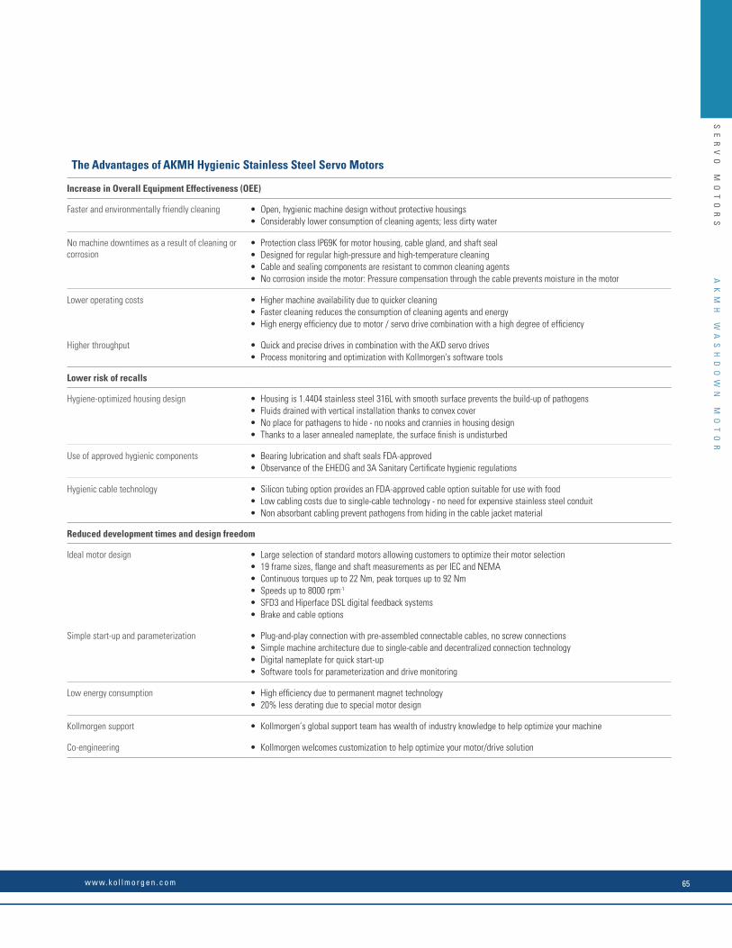
SE
RV
O
MO
TO
RS
AK
MH
W
AS
HD
OW
N
MO
TO
R
The Advantages of AKMH Hygienic Stainless Steel Servo Motors
Increase in Overall Equipment Effectiveness (OEE)
Faster and environmentally friendly cleaning • Open, hygienic machine design without protective housings• Considerably lower consumption of cleaning agents; less dirty water
No machine downtimes as a result of cleaning or corrosion
• Protection class IP69K for motor housing, cable gland, and shaft seal• Designed for regular high-pressure and high-temperature cleaning• Cable and sealing components are resistant to common cleaning agents• No corrosion inside the motor: Pressure compensation through the cable prevents moisture in the motor
Lower operating costs • Higher machine availability due to quicker cleaning• Faster cleaning reduces the consumption of cleaning agents and energy• High energy efficiency due to motor / servo drive combination with a high degree of efficiency
Higher throughput • Quick and precise drives in combination with the AKD servo drives• Process monitoring and optimization with Kollmorgen's software tools
Lower risk of recalls
Hygiene-optimized housing design • Housing is 1.4404 stainless steel 316L with smooth surface prevents the build-up of pathogens• Fluids drained with vertical installation thanks to convex cover• No place for pathagens to hide - no nooks and crannies in housing design• Thanks to a laser annealed nameplate, the surface finish is undisturbed
Use of approved hygienic components • Bearing lubrication and shaft seals FDA-approved• Observance of the EHEDG and 3A Sanitary Certificate hygienic regulations
Hygienic cable technology • Silicon tubing option provides an FDA-approved cable option suitable for use with food • Low cabling costs due to single-cable technology - no need for expensive stainless steel conduit• Non absorbant cabling prevent pathogens from hiding in the cable jacket material
Reduced development times and design freedom
Ideal motor design • Large selection of standard motors allowing customers to optimize their motor selection• 19 frame sizes, flange and shaft measurements as per IEC and NEMA• Continuous torques up to 22 Nm, peak torques up to 92 Nm• Speeds up to 8000 rpm-1
• SFD3 and Hiperface DSL digital feedback systems• Brake and cable options
Simple start-up and parameterization • Plug-and-play connection with pre-assembled connectable cables, no screw connections• Simple machine architecture due to single-cable and decentralized connection technology• Digital nameplate for quick start-up• Software tools for parameterization and drive monitoring
Low energy consumption • High efficiency due to permanent magnet technology• 20% less derating due to special motor design
Kollmorgen support • Kollmorgen’s global support team has wealth of industry knowledge to help optimize your machine
Co-engineering • Kollmorgen welcomes customization to help optimize your motor/drive solution
w w w. k o l l m o r g e n . c o m 65

SE
RV
O
MO
TO
RS
The new stainless steel AKMH motors have been designed for hygienic machine applications in wet areas with food contact in accordance with the EHEDG regulations and they comply with 3A, USDA* and NFS hygiene standards. Shorter cleaning times and high reliability ensure noticeably greater overall equipment effectiveness.
AKMH Hygienic Stainless Steel Servo Motors
Washdown
Ideal in harsh washdown environments where frequent cleaning with caustic chemicals and high pressure water are required.
Extremely durable, even with frequent, intensive cleaning processes
Specially suited to applications where contact with food is possible
Specially for applications in the food, beverage, and packaging industry, as well as in medical devices
* In preparation
* A
KM
H
WA
SH
DO
WN
M
OT
OR
K O L L M O R G E N66
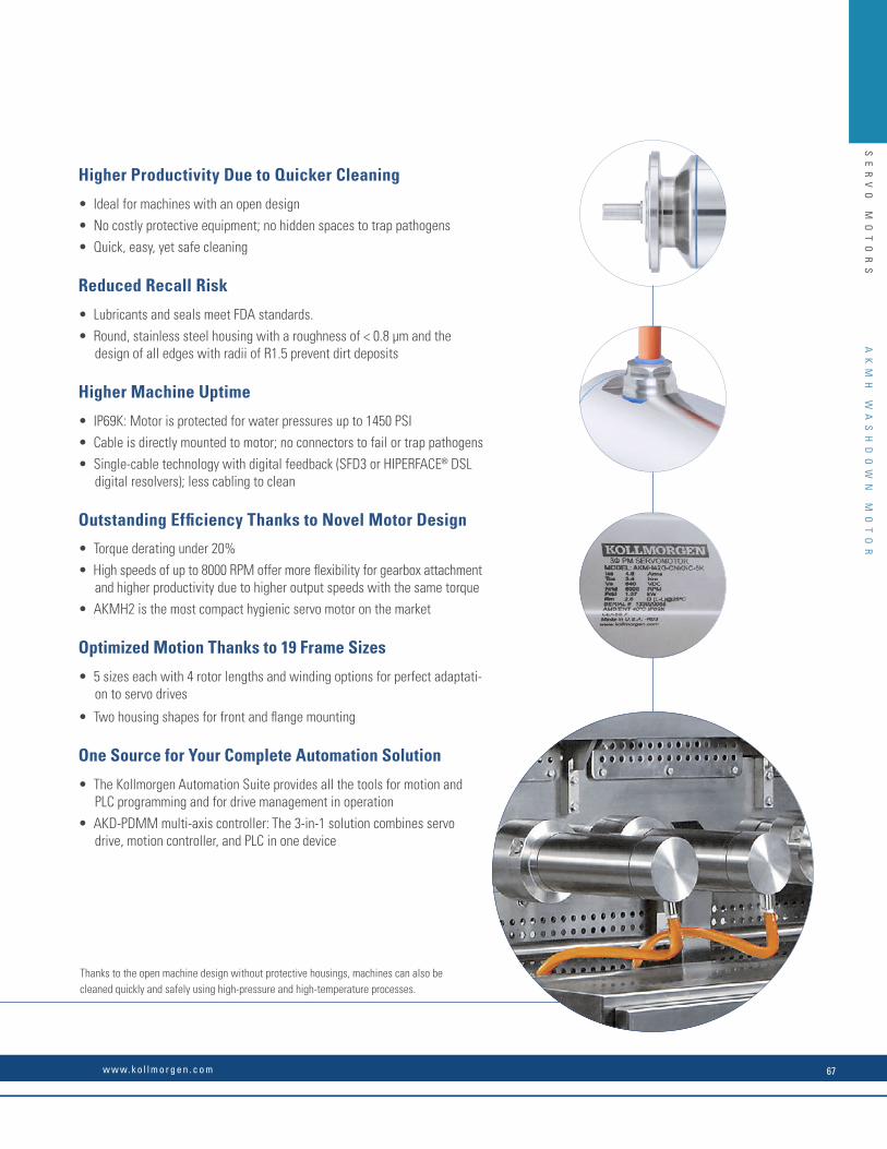
SE
RV
O
MO
TO
RS
Thanks to the open machine design without protective housings, machines can also be cleaned quickly and safely using high-pressure and high-temperature processes.
Higher Productivity Due to Quicker Cleaning
• Ideal for machines with an open design
• No costly protective equipment; no hidden spaces to trap pathogens
• Quick, easy, yet safe cleaning
Reduced Recall Risk
• Lubricants and seals meet FDA standards.
• Round, stainless steel housing with a roughness of < 0.8 µm and the design of all edges with radii of R1.5 prevent dirt deposits
Higher Machine Uptime
• IP69K: Motor is protected for water pressures up to 1450 PSI
• Cable is directly mounted to motor; no connectors to fail or trap pathogens
• Single-cable technology with digital feedback (SFD3 or HIPERFACE® DSL digital resolvers); less cabling to clean
Outstanding Efficiency Thanks to Novel Motor Design
• Torque derating under 20%
• High speeds of up to 8000 RPM offer more flexibility for gearbox attachment and higher productivity due to higher output speeds with the same torque
• AKMH2 is the most compact hygienic servo motor on the market
Optimized Motion Thanks to 19 Frame Sizes
• 5 sizes each with 4 rotor lengths and winding options for perfect adaptati-on to servo drives
• Two housing shapes for front and flange mounting
One Source for Your Complete Automation Solution
• The Kollmorgen Automation Suite provides all the tools for motion and PLC programming and for drive management in operation
• AKD-PDMM multi-axis controller: The 3-in-1 solution combines servo drive, motion controller, and PLC in one device
AK
MH
W
AS
HD
OW
N
MO
TO
R
w w w. k o l l m o r g e n . c o m 67

AKMH Design Features
Reduces risk of food recallIncreases reliability in wash-down applicationReduces cleaning time: higher OEE
The key benefi ts of AKMH clean design features:
n n
Smooth surface meeting EHEDG & 3A criteria, promotes rapid cleaning and
no harboring of pathogens
n n n
All exposed surfaces are 316 stainless, superior to 304/303 for hygiene &
corrosion resistance
n n
No protective covers required for washdown... no secondary cleaning
disassembly required
n n
Conical end cover to eliminate water puddling, even in vertical mounting
n n
Chemical resistant cable for pH of 2-12, meeting IEC60364-5-52,
UL, CSA, CE, RoHS
n n
FDA food-grade approved tubing over cable for food
zone applications
n n n
External O-ring and gasket sealing with blue FDA approved
materials
n n n
No external hardware (no bolts, washers, or screws) to trap soil
& pathogens or fall into food
SE
RV
O
MO
TO
RS
AK
MH
W
AS
HD
OW
N
MO
TO
R
K O L L M O R G E N68
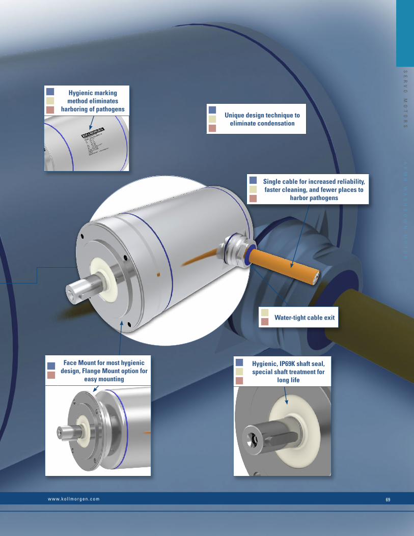
n n n
Single cable for increased reliability, faster cleaning, and fewer places to
harbor pathogens
n n
Water-tight cable exit
n n n
Hygienic, IP69K shaft seal, special shaft treatment for
long life
n n n
Unique design technique to eliminate condensation
n n n
Hygienic marking method eliminates
harboring of pathogens
n n
Face Mount for most hygienic design, Flange Mount option for
easy mounting
SE
RV
O
MO
TO
RS
AK
MH
W
AS
HD
OW
N
MO
TO
R
w w w. k o l l m o r g e n . c o m 69

Performance Data
AKM
H Se
rvo
Mot
or
Cont
. Tor
que
at S
tall
Tcs
[Nm
] ➀
Cont
inuo
us C
urre
nt I 0 [A
] ➀
Peak
Torq
ue a
t sta
ll Tp
s [N
m]
➀
75 V DC 160 V DC 320 V DC V 560 V DC 640 V DC
Iner
tia (J
m) [
kgc
m2 ]
Wei
ght [
kg]
Rate
d Sp
eed
Nrtd
[RPM
]
Rate
d To
rque
Trtd
[Nm
] ➀
Rate
d Po
wer
Prtd
[kW
] ➀
Rate
d Sp
eed
Nrtd
[RPM
]
Rate
d To
rque
Trtd
[Nm
] ➀
Rate
d Po
wer
Prtd
[kW
] ➀
Rate
d Sp
eed
Nrtd
[RPM
]
Rate
d To
rque
Trtd
[Nm
] ➃
Rate
d po
wer
Pn [k
W] ➀
Rate
d Sp
eed
Nrtd
[RPM
]
Rate
d To
rque
Trtd
[Nm
] ➀
Rate
d Po
wer
Prtd
[kW
] ➀
Rate
d Sp
eed
Nrtd
[RPM
]
Rate
d To
rque
Trtd
[Nm
] ➀
Rate
d Po
wer
Prtd
[kW
] ➀
21C 0.317 1.31 1.57 – – – 2500 0.311 0.08 8000 0.255 0.21 8000 0.255 0.21 8000 0.255 0.21 0.107 3.6
21E 0.329 2.56 1.59 2000 0.324 0.068 7000 0.28 0.21 – – – – – – – – – 0.107 3.6
21G 0.335 4.04 1.60 4000 0.318 0.13 – – – – – – – – – – – – 0.107 3.6
22C 0.633 1.18 3.03 – – – 1000 0.627 0.07 3500 0.583 0.21 8000 0.40 0.34 8000 0.40 0.34 0.161 4.1
22E 0.654 2.33 3.07 1000 0.647 0.07 3500 0.601 0.22 8000 0.41 0.35 – – – – – – 0.161 4.1
22G 0.661 4.09 3.09 2500 0.632 0.17 7000 0.473 0.35 – – – – – – – – – 0.161 4.1
23D 0.897 1.88 4.35 – – – 1500 0.881 0.14 5000 0.765 0.40 8000 0.58 0.49 8000 0.58 0.49 0.216 4.6
23E 0.904 2.36 4.37 – – – 2500 0.865 0.23 6500 0.688 0.47 – – – – – – 0.216 4.6
23F 0.917 3.67 4.41 1500 0.900 0.14 4500 0.806 0.38 8000 0.593 0.50 – – – – – – 0.216 4.6
24D 1.12 1.90 5.50 – – – 1500 1.11 0.17 4000 1.04 0.44 8000 0.83 0.70 8000 0.83 0.70 0.27 5.1
24E 1.12 2.39 5.51 – – – 2000 1.10 0.23 5500 0.98 0.57 – – – – – – 0.27 5.1
24F 1.13 3.34 5.53 1000 1.12 0.12 3000 1.09 0.34 8000 0.839 0.70 – – – – – – 0.27 5.1
31C 1.00 1.29 4.41 – – – – – – 2500 0.95 0.25 5000 0.86 0.45 6000 0.82 0.51 0.33 4.1
31E 1.04 2.76 4.52 750 1.03 0.08 2500 0.96 0.25 6000 0.86 0.54 8000 0.74 0.62 – – – 0.33 4.1
31H 1.08 5.51 4.59 2000 1.04 0.22 6000 0.88 0.55 – – – – – – – – – 0.33 4.1
32C 1.72 1.30 8.10 – – – – – – 1500 1.66 0.26 3000 1.57 0.49 3500 1.52 0.56 0.59 5.0
32E 1.77 2.56 8.24 – – – – – – 3500 1.57 0.57 7000 1.10 0.81 8000 0.92 0.77 0.59 5.0
32H 1.82 4.98 8.39 1200 1.78 0.22 3000 1.66 0.52 7000 1.13 0.83 – – – – – – 0.59 5.0
33C 2.25 1.27 11.5 – – – – – – 1000 2.22 0.23 2000 2.14 0.45 2500 2.09 0.55 0.85 5.9
33E 2.32 2.20 11.7 – – – – – – 2000 2.20 0.46 4500 1.82 0.86 5000 1.72 0.90 0.85 5.9
33H 2.38 4.80 11.9 800 2.35 0.20 2500 2.20 0.58 5500 1.64 0.94 8000 0.88 0.74 – – – 0.85 5.9
41C 1.85 1.54 6.82 – – – – – – 1200 1.78 0.22 3000 1.68 0.53 3500 1.65 0.60 0.81 6.1
41E 1.90 2.89 6.95 – – – 1200 1.85 0.23 3000 1.74 0.55 6000 1.44 0.90 6000 1.44 0.90 0.81 6.1
41H 1.94 5.82 7.00 1000 1.89 0.20 3000 1.77 0.56 6000 1.47 0.92 – – – – – – 0.81 6.1
42C 3.19 1.42 12.6 – – – – – – – – – 1500 2.98 0.47 2000 2.91 0.61 1.45 7.4
42E 3.27 2.77 12.8 – – – – – – 1800 2.99 0.56 3500 2.72 1.00 4000 2.62 1.10 1.45 7.4
42H 3.40 6.10 13.1 – – – 2000 3.09 0.65 4500 2.63 1.24 6000 2.21 1.39 6000 2.21 1.39 1.45 7.4
42J 3.43 8.56 13.1 – – – 3000 2.94 0.92 6000 2.23 1.40 – – – – – – 1.45 7.4
43E 4.56 2.79 18.3 – – – – – – 1500 4.15 0.65 2500 3.83 1.00 3000 3.68 1.16 2.09 8.8
43H 4.68 5.52 18.7 – – – – – – 3000 3.77 1.18 6000 2.44 1.53 6000 2.44 1.53 2.09 8.8
43L 4.59 11.4 18.4 – – – 3000 3.69 1.16 6000 2.39 1.50 – – – – – – 2.09 8.8
44E 5.64 2.89 23.5 – – – – – – 1200 5.13 0.64 2000 4.76 1.00 2500 4.52 1.18 2.73 10.2
44H 5.77 5.68 23.5 – – – – – – 2500 4.59 1.20 5000 3.13 1.64 6000 2.58 1.62 2.73 10.2
44K 5.76 10.2 23.5 – – – 2000 4.83 1.01 5000 3.10 1.62 6000 2.55 1.60 – – – 2.73 10.2
51E 3.3 2.28 15.0 – – – – – – 1200 3.11 0.39 2500 2.83 0.74 3000 2.68 0.84 3.42 8.9
51H 3.39 5.02 15.0 – – – – – – 3000 2.75 0.86 5500 1.41 0.81 5500 1.41 0.81 3.42 8.9
51L 3.47 10.0 15.2 – – – 3000 2.82 0.89 5500 1.45 0.84 – – – – – – 3.42 8.9
➀ Motor winding excess temperature, ∆T = 100 K with ambient temperature = 40°C
All specifications refer to sinusoidal supply
Rated data with reference flange (aluminum, dims (mm): AKMH2, AKMH3, AKMH4: 254 x 254 x 6.35 AKMH5: 305 x 305 x 12.7 AKMH6: 457 x 457 x 12.7)
AKMH Hygienic Stainless Steel Servo Motors
SE
RV
O
MO
TO
RS
AK
MH
W
AS
HD
OW
N
MO
TO
R
K O L L M O R G E N70
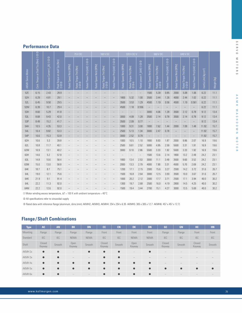
Performance Data
AKM
H Se
rvo
Mot
or
Cont
. Tor
que
at S
tall
Tcs
[Nm
] ➀
Cont
inuo
us C
urre
nt I 0 [A
] ➀
Peak
Torq
ue a
t sta
ll Tp
s [N
m]
➀
75 V DC 160 V DC 320 V DC V 560 V DC 640 V DC
Iner
tia (J
m) [
kgc
m2 ]
Wei
ght [
kg]
Rate
d Sp
eed
Nrtd
[RPM
]
Rate
d To
rque
Trtd
[Nm
] ➀
Rate
d Po
wer
Prtd
[kW
] ➀
Rate
d Sp
eed
Nrtd
[RPM
]
Rate
d To
rque
Trtd
[Nm
] ➀
Rate
d Po
wer
Prtd
[kW
] ➀
Rate
d Sp
eed
Nrtd
[RPM
]
Rate
d To
rque
Trtd
[Nm
] ➃
Rate
d po
wer
Pn [k
W] ➀
Rate
d Sp
eed
Nrtd
[RPM
]
Rate
d To
rque
Trtd
[Nm
] ➀
Rate
d Po
wer
Prtd
[kW
] ➀
Rate
d Sp
eed
Nrtd
[RPM
]
Rate
d To
rque
Trtd
[Nm
] ➀
Rate
d Po
wer
Prtd
[kW
] ➀
52E 6.15 2.43 28.9 – – – – – – – – – 1500 5.39 0.85 2000 5.08 1.06 6.22 11.1
52H 6.29 4.81 29.1 – – – – – – 1800 5.32 1.00 3500 3.44 1.26 4000 2.44 1.02 6.22 11.1
52L 6.45 9.50 29.5 – – – – – – 3500 3.53 1.29 4500 1.19 0.56 4500 1.19 0.561 6.22 11.1
52M 6.39 10.7 29.4 – – – – – – 4500 1.18 0.556 – – – – – – 6.22 11.1
53H 8.60 5.29 41.8 – – – – – – – – – 3000 4.06 1.28 3500 2.12 0.78 9.12 13.4
53L 8.68 9.43 42.0 – – – – – – 3000 4.09 1.28 3500 2.14 0.78 3500 2.14 0.78 9.12 13.4
53P 8.49 15.2 41.7 – – – – – – 3500 2.09 0.77 – – – – – – 9.12 13.4
54H 10.5 4.35 53.3 – – – – – – 1000 9.31 3.00 1800 7.62 1.44 2000 7.09 1.48 11.92 15.7
54L 10.4 9.82 53.3 – – – – – – 2500 5.13 1.34 3000 2.47 0.78 – – – 11.92 15.7
54P 10.6 15.3 53.9 – – – – – – 3000 2.52 0.79 – – – – – – 11.92 15.7
62H 10.6 5.3 39.8 – – – – – – 1000 10.5 1.10 1800 9.93 1.87 2000 9.86 2.07 16.9 19.6
62L 10.8 11.7 40.1 – – – – – – 2500 9.61 2.52 5000 4.95 2.59 5500 3.31 1.91 16.9 19.6
62M 10.9 13.1 40.2 – – – – – – 3000 9.10 2.86 5500 3.33 1.92 5500 3.33 1.92 16.9 19.6
63H 14.6 5.2 57.9 – – – – – – – – – 1500 13.6 2.14 1800 13.2 2.49 24.2 23.1
63L 14.8 10.6 58.4 – – – – – – 1800 13.4 2.53 3000 11.1 3.49 3500 9.60 3.52 24.2 23.1
63M 15.0 13.0 58.8 – – – – – – 2000 13.3 2.79 4000 7.90 3.31 4500 5.70 2.69 24.2 23.1
64K 18.7 8.7 75.1 – – – – – – 1200 17.1 2.15 2000 15.6 3.27 2500 14.2 3.72 31.6 26.7
64L 19.0 12.1 75.6 – – – – – – 1500 16.8 2.64 3000 12.5 3.93 3500 10.0 3.67 31.6 26.7
64K 21.9 9.1 91.4 – – – – – – 1000 20.2 2.12 2000 17.7 3.71 2500 17.1 3.94 40.0 30.2
64L 22.2 11.3 92.0 – – – – – – 1300 19.7 2.68 2500 16.0 4.19 2800 14.5 4.25 40.0 30.2
64M 22.2 12.6 92.0 – – – – – – 1500 19.4 3.44 2700 15.1 4.27 3000 13.5 5.69 40.0 30.2
➀ Motor winding excess temperature, ∆T = 100 K with ambient temperature = 40°C
All specifications refer to sinusoidal supply
Rated data with reference flange (aluminum, dims (mm): AKMH2, AKMH3, AKMH4: 254 x 254 x 6.35 AKMH5: 305 x 305 x 12.7 AKMH6: 457 x 457 x 12.7)
Type AC AN BK BN CC CN DK DN GC GN HC HN
Mounting Flange Flange Flange Flange Front Front Front Front Flange Flange Front Front
Standard IEC IEC NEMA NEMA IEC IEC NEMA NEMA IEC IEC IEC IEC
Shaft Closed Keyway Smooth Open
Keyway Smooth Closed Keyway Smooth Open
Keyway Smooth Closed Keyway Smooth Closed
Keyway Smooth
AKMH 2x – – – – – –
AKMH 3x – – – – – – – –
AKMH 4x – – – –
AKMH 5x
AKMH 6x – – – – – –
Flange / Shaft Combinations
SE
RV
O
MO
TO
RS
AK
MH
W
AS
HD
OW
N
MO
TO
R
w w w. k o l l m o r g e n . c o m 71
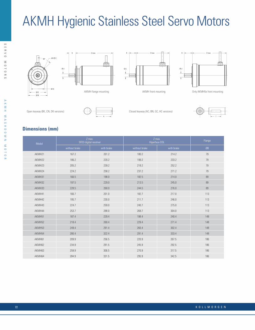
4X Ø C 45°
EØ
BØ
Ø D
Z maxK
ØJ
Z maxK
ØJ
K Z max
ØJ
Model
Z max.SFD3 digital resolver
Z max.Hiperface DSL Flange
without brake with brake without brake with brake ØB
AKMH21 167.2 201.2 180.2 214.2 79
AKMH22 186.2 220.2 199.2 233.2 79
AKMH23 205.2 239.2 218.2 252.2 79
AKMH24 224.2 258.2 237.2 271.2 79
AKMH31 166.5 198.0 182.5 214.0 89
AKMH32 197.5 229.0 213.5 245.0 89
AKMH33 228.5 260.0 244.5 276.0 89
AKMH41 166.7 201.0 182.7 217.0 113
AKMH42 195.7 230.0 211.7 246.0 113
AKMH43 224.7 259.0 240.7 275.0 113
AKMH44 253.7 288.0 269.7 304.0 113
AKMH51 187.4 229.4 198.4 240.4 148
AKMH52 218.4 260.4 229.4 271.4 148
AKMH53 249.4 291.4 260.4 302.4 148
AKMH54 280.4 322.4 291.4 333.4 148
AKMH61 209.9 256.5 220.9 267.5 186
AKMH62 234.9 281.5 245.9 292.5 186
AKMH63 259.9 306.5 270.9 317.5 186
AKMH64 284.9 331.5 295.9 342.5 186
AKMH Hygienic Stainless Steel Servo Motors
Dimensions (mm)
N
Open keyway (BK, CN, DK versions)
T
Closed keyway (AC, BN, GC, HC versions)
AKMH flange mounting AKMH front mounting Only AKMH5x front mounting
SE
RV
O
MO
TO
RS
AK
MH
W
AS
HD
OW
N
MO
TO
R
K O L L M O R G E N72

AKMH XX- AC AN BK BN CC CN DK DN GC GN HC HN
Mounting Flange Flange Front Front Front Front Flange Flange Front Front
Standard IEC NEMA IEC IEC NEMA NEMA IEC IEC IEC IEC
Shaft Closed Keyway Smooth Open
Keyway Smooth Closed Keyway Smooth Open
Keyway Smooth Closed Keyway Smooth Closed
Keyway Smooth
AKMH 2x
Ø C 4.80 – 5.10 M4 x 0.7 x 8.0 – UNF10-32 – –
Ø D 40 – 38.10 40 – 38.1 – –
Ø E 63 – 66.68 63 – 66.68 – –
Ø J 11 – 9.524 11 – 9.524 – –
K 30 – 31.8 30.0 – 31.8 – –
N/T T = 16 NA – NA T = 16 NA – NA – –
AKMH 3x
Ø C 5.80 – M5 x 0.8 x 10.0 – – –
Ø D 60 – 60 – – –
Ø E 75 – 75 – – –
Ø J 14 – 14 – – –
K 30 – 30.0 – – –
N/T T = 16 NA – T = 16 NA – – –
AKMH 4x
Ø C 7.0 6.91 M6 x 1 x 12 UNC 1/4 - 20 x 12.3 – –
Ø D 80 73.025 80 73.025 73 – –
Ø E 100 98.43 100 98.43 – –
Ø J 19 15.875 19 15.875 – –
K 40.0 52.40 40.0 52.40 – –
N/T T = 25 NA N = 34.93 NA T = 25 NA N = 34.93 NA – –
AKMH 5x
Ø C 9 8.33 M8 x 1.25 x 16.0 UNC 3/8 - 16 x 19.05 9 M8 x 1.25 x 16.0
Ø D 110 55.560 110 55.563 95 95
Ø E 130 125.73 130 125.73 115 115
Ø J 24 19.05 24 19.05 24 24
K 50.0 57.15 50.0 57.15 50.0 50.0
D T = 36 NA N = 38.1 NA T = 36 NA N = 38.1 NA T = 36 NA T = 36 N = 38.1
AKMH 6x
Ø C 11.00 – M10 x 1.5 x 20.0 UNC 3/8 - 16 x 19.05 – –
Ø D 130 – 130 114.3 – –
Ø E 165.0 – 165.0 149.23 – –
Ø J 32 – 32 28.580 – –
K 58 – 58 69.9 – –
D 40 NA – T = 40 NA N = 38.10 NA – –
Dimensions (mm)
SE
RV
O
MO
TO
RS
AK
MH
W
AS
HD
OW
N
MO
TO
R
w w w. k o l l m o r g e n . c o m 73

SE
RV
O
MO
TO
RS
Direct Drive Rotary Motors
Conventional servo systems commonly have a mechanical transmission which can consist of gears, gearboxes, belts/pulleys or cams connected between the motor and the load.
With Direct Drive Rotary Motors, the mechanical transmission is eliminated and the motor is coupled directly to the load.
Why Use Direct Drive Rotary Motors?
Increased Accuracy and Repeatability
A “precision” planetary gearbox could have a backlash of 1 arc-minute. This can result in the load moving by 1 arc-minute with an absolutely stationary drive motor. Kollmorgen’s standard direct drive rotary (DDR) servo motors have repeatability better than 1 arc-second. Therefore, a direct drive motor can hold a position 60 times better than a conventional motor/gearbox.
The increased accuracy of direct drive rotary motors results in a higher quality product out of the machine:
• Print registration is more accurate• Cut or feed lengths can be held more precisely • Coordination with other machine axes is more accurate• Indexing location is more exact• Tuning issues due to backlash are eliminated
Higher Bandwidth
Mechanical transmission components impose a limit on how fast a machine can start and stop and also extend the required settling time. These factors limit the possible throughput of a machine.
Direct drive rotary motors remove these limitations and allows for much fasterstart/stop cycles and also provide greatly reduced settling time. This will allow a greater throughput from the machine. Users of direct drive systems have reported up to a 2X increase in throughput.
Improved Reliability and Zero Maintenance
Gears, belts, and other mechanical transmission parts break. By eliminating these parts and using DDR motors, the reliability of the machine is improved. Gearboxes require periodic lubrication and/or replacement in aggressive start/stop applications. Belts require periodic tightening. There are no time-wear components in a direct drive motorand consequently they require zero maintenance.
Servo Motor and Gearbox
Direct Drive Motor
Improved Repeatability
Increased Throughput
Gearbox
Motor
GearboxBacklash
DDRRepeatability60 Times Better
Arc
Minutes
1
0
-1
Conventional RotaryServo with MechanicalTransmission
DDR motors provide higherthroughput because start/stoplimitations of mechanicaltransmissions are eliminated
DI
RE
CT
D
RI
VE
R
OT
AR
Y
MO
TO
RS
K O L L M O R G E N74

SE
RV
O
MO
TO
RS
Fewer Parts
With direct drive motors, all you need is the motor and the mounting bolts. This often replaces many parts including brackets, guards, belts, pulleys, tensioners, couplings, and bolts, resulting in:
• Fewer parts on the BOM. Less parts to purchase, schedule, inventory and control, and less parts to assemble.• Assembly time of the servo drops from several hours with the mechanical transmission to several minutes with the DDR.• Reduced cost. Although a direct drive motor may carry a small price-premium compared to a motor/gearbox with the same torque, consider that there is an overall cost reduction when eliminating the parts and labor of all the extra components required in a servo system with mechanical transmission.
No Inertia Matching
Servo systems with mechanical transmissions require inertia matching that limits the refl ected load inertia at 5 to 10 times the motor inertia. If this limitation is not met, the system becomes diffi cult to control due to instability issues. Inertia matching limitations of mechanical transmission systems often force machine designers to use a larger motor than would otherwise be required just to satisfy the inertia matching requirement.
Such sizing conventions are not required with direct drive rotary motors. Since the motor is directly connected to the load, the inertia of the motor and the load become a common inertia. Therefore, no inertia matching is required when using DDR. DDR applications have run with inertia ratios greater than 11,000:1.
Reduced Audible Noise
Machines with DDR motors have audible noise levels as low as 20 dB less than the same machine with a mechanical transmission.
Three DDR Product Categories to Choose From
Kollmorgen’s 50 years of electromagnetic and electromechanical design experience combined with our quality and service, allowed us to refi ne and expand DDR motors into three product categories for easy installation, use, and short lead times: Frameless DDR, Housed DDR, and the Cartridge DDR. This allows you to select the right DDR solution for your application.
Frameless DDR
Frameless motors include a rotor and stator as separate components which are integrated into, ride on the bearings of, and become a part of the driven load. Frameless motors offer the most compact and lightweight DDR solution available. The KBM and TBM series are Kollmorgen’s latest Frameless DDR products. The KBM provides excellent torque/volume with the use of a proprietary neodymium-iron magnet rotor structure and skewed armature assembly. The KBM series is the fi rst UL recognized parts set available on the market. This provides OEMs with the benefi ts of UL component ratings for easier agency approval on their machines. The TBM frameless motor is a new series of direct drive torque motors designed for applications that require high power in a small, compact form factor with minimized weight and inertia.
Housed DDR
The Housed DDR is a housed motor assembly featuring a factory aligned high-resolution feedback device and precision bearings, allowing it to function as the core of rotary indexing and rate table applications. The system can also be used as a fl exible indexer, providing programmable, rapid indexing far exceeding the throughput and accuracy of conventional mechanical or variable reluctance indexers.
Cartridge DDR
This motor is the fi rst in the industry to combine the space-saving and performance advantages of Frameless DDR motors with the ease of installation of a full-frame motor. Consisting of a rotor, stator, and factory-aligned high-resolution feedback device, the motor uses the machine’s bearings to support the rotor. An innovative compression coupling engages the rotor to the load and the frame of the motor mounts to the machine with a bolt circle and pilot diameter just like a conventional servo motor, saving space and design time and simplifying the overall system.
Format Where Used
Frameless DDR Application where size and weightmust be absolutely minimized
Housed DDR Applications where the load rides on the motor’s bearings such as indexing or rate tables
Cartridge DDR Any application with existing bearings
Format Where Used
Ironless (IL) Series Applications requiring zero cogging or high acceleration of low mass loads
Ironcore (IC or ICD) Series Applications requiring highest thrust forces for their size
Water-cooled (IC) Series Applications requiring the highest possible force
DDR Applications
Direct Drive Linear (DDL) Motor
Directly coupling a linear motor to the driven load offers many advantages, including eliminating all mechanical transmissions, such as ball/lead screws, rack & pinions, belts/pulleys, and eliminating gearboxes. This in turn also eliminates backlash and compliance, and other problems associated with these mechanical transmissions.
DDL Applications
DI
RE
CT
D
RI
VE
R
OT
AR
Y
MO
TO
RS
w w w. k o l l m o r g e n . c o m 75
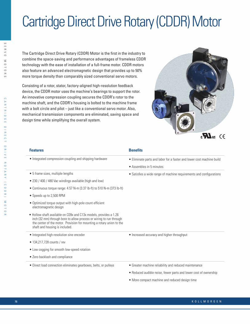
SE
RV
O
MO
TO
RS
w w w. k o l l m o r g e n . c o m 13
CA
RT
RI
DG
E
DD
R
MO
TO
R
T
EC
HN
IC
AL
P
ER
FO
RM
AN
CE
D
AT
A
Features Benefits
• Integrated compression coupling and shipping hardware • Eliminate parts and labor for a faster and lower cost machine build
• Assembles in 5 minutes
• 5 frame sizes, multiple lengths • Satisfi es a wide range of machine requirements and confi gurations
• 230 / 400 / 480 Vac windings available (high and low)
• Continuous torque range: 4.57 N-m (3.37 lb-ft) to 510 N-m (373 lb-ft)
• Speeds up to 2,500 RPM
• Optimized torque output with high-pole count effi cient electromagnetic design
• Hollow shaft available on C09x and C13x models, provides a 1.26 inch (32 mm) through bore to allow process or wiring to run through
the center of the motor. Provision for mounting a rotary union to the shaft and housing is included.
• Integrated high-resolution sine encoder • Increased accuracy and higher throughput
• 134,217,728 counts / rev
• Low cogging for smooth low-speed rotation
• Zero backlash and compliance
• Direct load connection eliminates gearboxes, belts, or pulleys • Greater machine reliability and reduced maintenance
• Reduced audible noise, fewer parts and lower cost of ownership
• More compact machine and reduced design time
Cartridge Direct Drive Rotary (CDDR) Motor
The Cartridge Direct Drive Rotary (CDDR) Motor is the first in the industry to combine the space-saving and performance advantages of frameless CDDR technology with the ease of installation of a full-frame motor. CDDR motors also feature an advanced electromagnetic design that provides up to 50% more torque density than comparably sized conventional servo motors.
Consisting of a rotor, stator, factory-aligned high-resolution feedback device, the CDDR motor uses the machine’s bearings to support the rotor.An innovative compression coupling secures the CDDR’s rotor to the machine shaft, and the CDDR’s housing is bolted to the machine frame with a bolt circle and pilot – just like a conventional servo motor. Also, mechanical transmission components are eliminated, saving space and design time while simplifying the overall system.
The Cartridge DDR Advantage – Press Feed Machine
Consider how Cartridge DDR technology improves a PressFeed machine:
Reduced Assembly Time
The assembly time for the original mechanical transmission system was 4 hours. In contrast, the Cartridge DDR motor is installed in less than 5 minutes, resulting in a signifi cant cost savings in labor.
Reduced Parts Count
The original mechanical transmission system comprises 2 bracket pieces, 12 bolts, 2 pulleys, 2 set screws, 2 keys, a timing belt, a housing to protect operators from the timing belt, a tension system for the timing belt, and motor/gearbox. With the Cartridge DDR system, this is all replaced by the motor and 4 mounting bolts, resulting in fewer parts to maintain and cost savings.
Improved Accuracy
The best planetary gearboxes have a backlash between 1 and 2 arc-minutes. Over the life of the gearbox, the backlash will increase. The Cartridge DDR system has an absolute accuracy of 26 arc-seconds and a repeatability of 0.7 arc-seconds. The Press Feed machine with the Cartridge DDR has a feed accuracy of +/- 0.0005 inch where the Press Feed machine with the mechanical transmission has a feed accuracy of 0.002 inch. Therefore, there was an overall four times improvement in machine accuracy with the Cartridge DDR system.
Increased Throughput
The cycle rate of the Cartridge DDR system is two times better than the mechanical transmission. This results in an increase in throughput of 100 percent.
Improved Reliability and Simplifi ed Maintenance
The Cartridge DDR system eliminates parts that wear, change over time, or fail. Gearboxes are prone to wear, and backlash increases over time. Belts and pulleys stretch and require maintenance to maintain proper belt tension. By eliminating these components, the Cartridge DDR system delivers greater system reliability.
Press Feed Example
Gearboxes have a fi nite life span, especially in a demanding cyclic application such as a Press Feed. On this machine, the gearbox must be replaced every 10,000 hours and the belt must be tensioned every 2,000 hours. By contrast, the Cartridge DDR motor has no wear components and requires no maintenance thus simplifying the maintenance schedule for the machine, including operating costs.
Reduced Audible Noise
The Cartridge DDR system has as much as a 20 dB reduction in noise compared to a mechanical transmission servo system. This can dramatically reduce the overall noise level of the machine. A quieter machine gives the perception of quality. This is rightfully so as the noise emitted by gears and belts is caused by the wearing of the parts.
Total Reduced Cost
A Cartridge DDR motor typically costs 20 percent more than a comparable motor/gearbox combination. However, the elimination of parts and assembly time typically results in a lower total cost for the Cartridge DDR solution.
Same machine with a Cartridge DDR motor installed. Here, the shaft of the driven roll is extended into the Cartridge DDR motor and the motor applies torque directly to the driven roll.
Press feed machine built with a conventional servo motor, gearbox, belt and pulleys.
CA
RT
RI
DG
E
DI
RE
CT
D
RI
VE
R
OT
AR
Y
(C
DD
R)
M
OT
OR
K O L L M O R G E N76
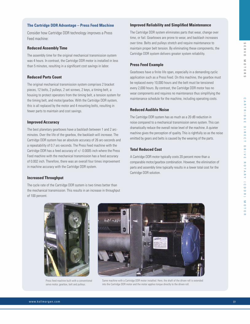
SE
RV
O
MO
TO
RS
The Cartridge DDR Advantage – Press Feed Machine
Consider how Cartridge DDR technology improves a PressFeed machine:
Reduced Assembly Time
The assembly time for the original mechanical transmission system was 4 hours. In contrast, the Cartridge DDR motor is installed in less than 5 minutes, resulting in a signifi cant cost savings in labor.
Reduced Parts Count
The original mechanical transmission system comprises 2 bracket pieces, 12 bolts, 2 pulleys, 2 set screws, 2 keys, a timing belt, a housing to protect operators from the timing belt, a tension system for the timing belt, and motor/gearbox. With the Cartridge DDR system, this is all replaced by the motor and 4 mounting bolts, resulting in fewer parts to maintain and cost savings.
Improved Accuracy
The best planetary gearboxes have a backlash between 1 and 2 arc-minutes. Over the life of the gearbox, the backlash will increase. The Cartridge DDR system has an absolute accuracy of 26 arc-seconds and a repeatability of 0.7 arc-seconds. The Press Feed machine with the Cartridge DDR has a feed accuracy of +/- 0.0005 inch where the Press Feed machine with the mechanical transmission has a feed accuracy of 0.002 inch. Therefore, there was an overall four times improvement in machine accuracy with the Cartridge DDR system.
Increased Throughput
The cycle rate of the Cartridge DDR system is two times better than the mechanical transmission. This results in an increase in throughput of 100 percent.
Improved Reliability and Simplifi ed Maintenance
The Cartridge DDR system eliminates parts that wear, change over time, or fail. Gearboxes are prone to wear, and backlash increases over time. Belts and pulleys stretch and require maintenance to maintain proper belt tension. By eliminating these components, the Cartridge DDR system delivers greater system reliability.
Press Feed Example
Gearboxes have a fi nite life span, especially in a demanding cyclic application such as a Press Feed. On this machine, the gearbox must be replaced every 10,000 hours and the belt must be tensioned every 2,000 hours. By contrast, the Cartridge DDR motor has no wear components and requires no maintenance thus simplifying the maintenance schedule for the machine, including operating costs.
Reduced Audible Noise
The Cartridge DDR system has as much as a 20 dB reduction in noise compared to a mechanical transmission servo system. This can dramatically reduce the overall noise level of the machine. A quieter machine gives the perception of quality. This is rightfully so as the noise emitted by gears and belts is caused by the wearing of the parts.
Total Reduced Cost
A Cartridge DDR motor typically costs 20 percent more than a comparable motor/gearbox combination. However, the elimination of parts and assembly time typically results in a lower total cost for the Cartridge DDR solution.
Same machine with a Cartridge DDR motor installed. Here, the shaft of the driven roll is extended into the Cartridge DDR motor and the motor applies torque directly to the driven roll.
Press feed machine built with a conventional servo motor, gearbox, belt and pulleys.
CA
RT
RI
DG
E
DI
RE
CT
D
RI
VE
R
OT
AR
Y
(C
DD
R)
M
OT
OR
w w w. k o l l m o r g e n . c o m 77
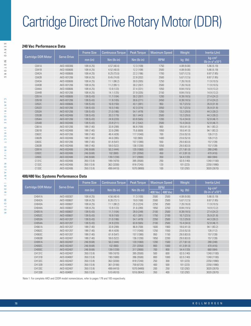
SE
RV
O
MO
TO
RS
Cartridge Direct Drive Rotary Motor (DDR)240 Vac Performance Data
Cartridge DDR Motor Servo DriveFrame Size Continuous Torque Peak Torque Maximum Speed Weight Inertia (Jm)
mm (in) Nm (lb-in) Nm (lb-in) RPM kg (lb) kg-cm2
(lb-in-s2 x10-3)C041A AKD-X00306 108 (4.25) 4.57 (40.4) 12.3 (109) 1750 4.08 (9.00) 5.86 (5.19)C041B AKD-X00606 108 (4.25) 4.52 (40.0) 12.2 (108) 2500 4.08 (9.00) 5.86 (5.19)C042A AKD-X00606 108 (4.25) 8.25 (73.0) 22.2 (196) 1700 5.67 (12.5) 8.87 (7.85)C042B AKD-X01206 108 (4.25) 8.45 (74.8) 22.8 (202) 2500 5.67 (12.5) 8.87 (7.85)C043A AKD-X00606 108 (4.25) 11.1 (98.2) 30.0 (265) 1250 7.26 (16.0) 11.9 (10.5)C043B AKD-X01206 108 (4.25) 11.2 (99.1) 30.2 (267) 2500 7.26 (16.0) 11.9 (10.5)C044A AKD-X00606 108 (4.25) 13.9 (123) 37.4 (331) 1050 8.84 (19.5) 14.9 (13.2)C044B AKD-X01206 108 (4.25) 14.1 (125) 37.9 (335) 2150 8.84 (19.5) 14.9 (13.2)C051A AKD-X00606 138 (5.43) 11.7 (104) 30.2 (267) 1200 8.39 (18.5) 27.4 (24.2)C051B AKD-X01206 138 (5.43) 11.9 (105) 30.6 (271) 2450 8.39 (18.5) 27.4 (24.2)C052C AKD-X00606 138 (5.43) 16.9 (150) 43.1 (381) 950 10.7 (23.5) 35.9 (31.8)C052D AKD-X01206 138 (5.43) 16.5 (146) 42.3 (374) 2050 10.7 (23.5) 35.9 (31.8)C053A AKD-X01206 138 (5.43) 21.0 (186) 54.1 (479) 1350 13.2 (29.0) 44.3 (39.2)C053B AKD-X02406 138 (5.43) 20.2 (179) 50.1 (443) 2500 13.2 (29.0) 44.3 (39.2)C054A AKD-X01206 138 (5.43) 24.9 (220) 63.8 (565) 1200 15.4 (34.0) 52.8 (46.7)C054B AKD-X02406 138 (5.43) 23.8 (211) 61.2 (542) 2500 15.4 (34.0) 52.8 (46.7)C061A AKD-X01206 188 (7.40) 33.8 (299) 86.8 (768) 900 18.6 (41.0) 94.1 (83.2)C061B AKD-X02406 188 (7.40) 32.6 (288) 75.6 (669) 1950 18.6 (41.0) 94.1 (83.2)C062C AKD-X01206 188 (7.40) 48.4 (428) 117 (1040) 700 23.6 (52.0) 126 (112)C062B AKD-X02406 188 (7.40) 44.6 (395) 102 (900) 1400 23.6 (52.0) 126 (112)C063C AKD-X01206 188 (7.40) 61.8 (547) 157 (1380) 550 29.0 (63.0) 157 (139)C063B AKD-X02406 188 (7.40) 59.0 (522) 136 (1200) 1050 29.0 (63.0) 157 (139)C091A AKD-X02406 246 (9.68) 50.2 (444) 120 (1060) 600 27.7 (61.0) 280 (248)C092C AKD-X02406 246 (9.68) 102 (900) 231 (2050) 450 41.3 (91.0) 470 (416)C093C AKD-X02406 246 (9.68) 139 (1230) 317 (2800) 350 54.4 (120) 660 (584)C131C AKD-X02406 350 (13.8) 189 (1670) 395 (3500) 250 63.5 (140) 1240 (1100)C132C AKD-X02406 350 (13.8) 362 (3200) 818 (7240) 120 101 (223) 2250 (1990)C133C AKD-X02406 350 (13.8) 499 (4410) 1070 (9890) 100 132 (292) 3020 (2670)
400/480 Vac Systems Performance Data
Cartridge DDR Motor Servo DriveFrame Size Continuous Torque Peak Torque Maximum Speed Weight Inertia (Jm)
mm (in) Nm (lb-in) Nm (lb-in)RPM
kg (lb) kg-cm2
(lb-in-s2 x10-3)400 Vac 480 VacCH041A AKD-X00307 108 (4.25) 4.56 (40.4) 11.3 (100) 2500 2500 4.08 (9.00) 5.86 (5.19)CH042A AKD-X00607 108 (4.25) 8.26 (73.1) 19.0 (168) 2500 2500 5.67 (12.5) 8.87 (7.85)CH043A AKD-X00607 108 (4.25) 11.1 (98.2) 25.3 (224) 2250 2500 7.26 (16.0) 11.9 (10.5)CH044A AKD-X00607 108 (4.25) 13.9 (123) 31.6 (280) 1850 2250 8.84 (19.5) 14.9 (13.2)CH051A AKD-X00607 138 (5.43) 11.7 (104) 28.0 (248) 2100 2500 8.39 (18.5) 27.4 (24.2)CH052C AKD-X00607 138 (5.43) 16.9 (150) 43.1 (381) 1750 2100 10.7 (23.5) 35.9 (31.8)CH053A AKD-X01207 138 (5.43) 21.0 (186) 54.1 (479) 2350 2500 13.2 (29.0) 44.3 (39.2)CH054A AKD-X01207 138 (5.43) 24.9 (220) 63.8 (565) 2100 2500 15.4 (34.0) 52.8 (46.7)CH061A AKD-X01207 188 (7.40) 33.8 (299) 86.8 (768) 1600 1900 18.6 (41.0) 94.1 (83.2)CH062C AKD-X01207 188 (7.40) 48.4 (428) 117 (1040) 1250 1550 23.6 (52.0) 126 (112)CH063C AKD-X01207 188 (7.40) 61.8 (547) 157 (1380) 950 1150 29.0 (63.0) 157 (139)CH063B AKD-X02407 188 (7.40) 59.0 (522) 136 (1200) 1850 2200 29.0 (63.0) 157 (139)CH091A AKD-X02407 246 (9.68) 50.2 (444) 120 (1060) 1200 1500 27.7 (61.0) 280 (248)CH092C AKD-X02407 246 (9.68) 102 (900) 231 (2050) 800 1000 41.3 (91.0) 470 (416)CH093C AKD-X02407 246 (9.68) 139 (1230) 317 (2800) 700 800 54.4 (120) 660 (584)CH131C AKD-X02407 350 (13.8) 189 (1670) 395 (3500) 500 600 63.5 (140) 1240 (1100)CH131B AKD-X04807 350 (13.8) 190 (1680) 396 (3500) 800 1000 63.5 (140) 1240 (1100)CH132C AKD-X02407 350 (13.8) 362 (3200) 818 (7240) 250 300 101 (223) 2250 (1990)CH132B AKD-X04807 350 (13.8) 361 (3190) 759 (6720) 400 500 101 (223) 2250 (1990)CH133C AKD-X02407 350 (13.8) 499 (4410) 1070 (9480) 200 250 132 (292) 3020 (2670)CH133B AKD-X04807 350 (13.8) 510 (4510) 1016 (9042) 350 400 132 (292) 3020 (2670)
Cartridge DDR Motor Amm (in)
Bmm (in)
Cmm (in)
Dmm (in)
C(H)091 204 (8.03) 246 (9.68) 149 (5.88) 182 (7.18)
C(H)092 253 (9.96) 246 (9.68) 149 (5.88) 182 (7.18)
C(H)093 302 (11.9) 246 (9.68) 149 (5.88) 182 (7.18)
C(H)131 231 (9.09) 350 (13.8) 200 (7.87) 256 (10.1)
C(H)132 301 (11.9) 350 (13.8) 200 (7.87) 256 (10.1)
C(H)133 370 (14.6) 350 (13.8) 200 (7.87) 256 (10.1)
A
B
B
D
C
A
Cartridge DDR C04, C05 and C06 Dimensions
Cartridge DDR Motor Amm (in)
Bmm (in)
Cmm (in)
Dmm (in)
C(H)041 171 (6.73) 108 (4.25) 59 (2.31) 93 (3.67)
C(H)042 202 (7.95) 108 (4.25) 59 (2.31) 93 (3.67)
C(H)043 233 (9.17) 108 (4.25) 59 (2.31) 93 (3.67)
C(H)044 264 (10.4) 108 (4.25) 59 (2.31) 93 (3.67)
C(H)051 195 (7.68) 138 (5.43) 76 (3.00) 108 (4.25)
C(H)052 220 (8.66) 138 (5.43) 76 (3.00) 108 (4.25)
C(H)053 245 (9.65) 138 (5.43) 76 (3.00) 108 (4.25)
C(H)054 270 (10.6) 138 (5.43) 76 (3.00) 108 (4.25)
C(H)061 226 (8.90) 188 (7.40) 99 (3.88) 133 (5.25)
C(H)062 260 (10.2) 188 (7.40) 99 (3.88) 133 (5.25)
C(H)063 294 (11.6) 188 (7.40) 99 (3.88) 133 (5.25)
D
C
B
B
Optional through bore
O-ring provided
Cartridge DDR C09 and C13 Dimensions
CA
RT
RI
DG
E
DI
RE
CT
D
RI
VE
R
OT
AR
Y
(D
DR
)
MO
TO
R
Note 1: For complete AKD and CDDR model nomenclature, refer to pages 178 and 183 respectively.
K O L L M O R G E N78

SE
RV
O
MO
TO
RS
240 Vac Performance Data
Cartridge DDR Motor Servo DriveFrame Size Continuous Torque Peak Torque Maximum Speed Weight Inertia (Jm)
mm (in) Nm (lb-in) Nm (lb-in) RPM kg (lb) kg-cm2
(lb-in-s2 x10-3)C041A AKD-X00306 108 (4.25) 4.57 (40.4) 12.3 (109) 1750 4.08 (9.00) 5.86 (5.19)C041B AKD-X00606 108 (4.25) 4.52 (40.0) 12.2 (108) 2500 4.08 (9.00) 5.86 (5.19)C042A AKD-X00606 108 (4.25) 8.25 (73.0) 22.2 (196) 1700 5.67 (12.5) 8.87 (7.85)C042B AKD-X01206 108 (4.25) 8.45 (74.8) 22.8 (202) 2500 5.67 (12.5) 8.87 (7.85)C043A AKD-X00606 108 (4.25) 11.1 (98.2) 30.0 (265) 1250 7.26 (16.0) 11.9 (10.5)C043B AKD-X01206 108 (4.25) 11.2 (99.1) 30.2 (267) 2500 7.26 (16.0) 11.9 (10.5)C044A AKD-X00606 108 (4.25) 13.9 (123) 37.4 (331) 1050 8.84 (19.5) 14.9 (13.2)C044B AKD-X01206 108 (4.25) 14.1 (125) 37.9 (335) 2150 8.84 (19.5) 14.9 (13.2)C051A AKD-X00606 138 (5.43) 11.7 (104) 30.2 (267) 1200 8.39 (18.5) 27.4 (24.2)C051B AKD-X01206 138 (5.43) 11.9 (105) 30.6 (271) 2450 8.39 (18.5) 27.4 (24.2)C052C AKD-X00606 138 (5.43) 16.9 (150) 43.1 (381) 950 10.7 (23.5) 35.9 (31.8)C052D AKD-X01206 138 (5.43) 16.5 (146) 42.3 (374) 2050 10.7 (23.5) 35.9 (31.8)C053A AKD-X01206 138 (5.43) 21.0 (186) 54.1 (479) 1350 13.2 (29.0) 44.3 (39.2)C053B AKD-X02406 138 (5.43) 20.2 (179) 50.1 (443) 2500 13.2 (29.0) 44.3 (39.2)C054A AKD-X01206 138 (5.43) 24.9 (220) 63.8 (565) 1200 15.4 (34.0) 52.8 (46.7)C054B AKD-X02406 138 (5.43) 23.8 (211) 61.2 (542) 2500 15.4 (34.0) 52.8 (46.7)C061A AKD-X01206 188 (7.40) 33.8 (299) 86.8 (768) 900 18.6 (41.0) 94.1 (83.2)C061B AKD-X02406 188 (7.40) 32.6 (288) 75.6 (669) 1950 18.6 (41.0) 94.1 (83.2)C062C AKD-X01206 188 (7.40) 48.4 (428) 117 (1040) 700 23.6 (52.0) 126 (112)C062B AKD-X02406 188 (7.40) 44.6 (395) 102 (900) 1400 23.6 (52.0) 126 (112)C063C AKD-X01206 188 (7.40) 61.8 (547) 157 (1380) 550 29.0 (63.0) 157 (139)C063B AKD-X02406 188 (7.40) 59.0 (522) 136 (1200) 1050 29.0 (63.0) 157 (139)C091A AKD-X02406 246 (9.68) 50.2 (444) 120 (1060) 600 27.7 (61.0) 280 (248)C092C AKD-X02406 246 (9.68) 102 (900) 231 (2050) 450 41.3 (91.0) 470 (416)C093C AKD-X02406 246 (9.68) 139 (1230) 317 (2800) 350 54.4 (120) 660 (584)C131C AKD-X02406 350 (13.8) 189 (1670) 395 (3500) 250 63.5 (140) 1240 (1100)C132C AKD-X02406 350 (13.8) 362 (3200) 818 (7240) 120 101 (223) 2250 (1990)C133C AKD-X02406 350 (13.8) 499 (4410) 1070 (9890) 100 132 (292) 3020 (2670)
400/480 Vac Systems Performance Data
Cartridge DDR Motor Servo DriveFrame Size Continuous Torque Peak Torque Maximum Speed Weight Inertia (Jm)
mm (in) Nm (lb-in) Nm (lb-in)RPM
kg (lb) kg-cm2
(lb-in-s2 x10-3)400 Vac 480 VacCH041A AKD-X00307 108 (4.25) 4.56 (40.4) 11.3 (100) 2500 2500 4.08 (9.00) 5.86 (5.19)CH042A AKD-X00607 108 (4.25) 8.26 (73.1) 19.0 (168) 2500 2500 5.67 (12.5) 8.87 (7.85)CH043A AKD-X00607 108 (4.25) 11.1 (98.2) 25.3 (224) 2250 2500 7.26 (16.0) 11.9 (10.5)CH044A AKD-X00607 108 (4.25) 13.9 (123) 31.6 (280) 1850 2250 8.84 (19.5) 14.9 (13.2)CH051A AKD-X00607 138 (5.43) 11.7 (104) 28.0 (248) 2100 2500 8.39 (18.5) 27.4 (24.2)CH052C AKD-X00607 138 (5.43) 16.9 (150) 43.1 (381) 1750 2100 10.7 (23.5) 35.9 (31.8)CH053A AKD-X01207 138 (5.43) 21.0 (186) 54.1 (479) 2350 2500 13.2 (29.0) 44.3 (39.2)CH054A AKD-X01207 138 (5.43) 24.9 (220) 63.8 (565) 2100 2500 15.4 (34.0) 52.8 (46.7)CH061A AKD-X01207 188 (7.40) 33.8 (299) 86.8 (768) 1600 1900 18.6 (41.0) 94.1 (83.2)CH062C AKD-X01207 188 (7.40) 48.4 (428) 117 (1040) 1250 1550 23.6 (52.0) 126 (112)CH063C AKD-X01207 188 (7.40) 61.8 (547) 157 (1380) 950 1150 29.0 (63.0) 157 (139)CH063B AKD-X02407 188 (7.40) 59.0 (522) 136 (1200) 1850 2200 29.0 (63.0) 157 (139)CH091A AKD-X02407 246 (9.68) 50.2 (444) 120 (1060) 1200 1500 27.7 (61.0) 280 (248)CH092C AKD-X02407 246 (9.68) 102 (900) 231 (2050) 800 1000 41.3 (91.0) 470 (416)CH093C AKD-X02407 246 (9.68) 139 (1230) 317 (2800) 700 800 54.4 (120) 660 (584)CH131C AKD-X02407 350 (13.8) 189 (1670) 395 (3500) 500 600 63.5 (140) 1240 (1100)CH131B AKD-X04807 350 (13.8) 190 (1680) 396 (3500) 800 1000 63.5 (140) 1240 (1100)CH132C AKD-X02407 350 (13.8) 362 (3200) 818 (7240) 250 300 101 (223) 2250 (1990)CH132B AKD-X04807 350 (13.8) 361 (3190) 759 (6720) 400 500 101 (223) 2250 (1990)CH133C AKD-X02407 350 (13.8) 499 (4410) 1070 (9480) 200 250 132 (292) 3020 (2670)CH133B AKD-X04807 350 (13.8) 510 (4510) 1016 (9042) 350 400 132 (292) 3020 (2670)
Cartridge DDR Motor Amm (in)
Bmm (in)
Cmm (in)
Dmm (in)
C(H)091 204 (8.03) 246 (9.68) 149 (5.88) 182 (7.18)
C(H)092 253 (9.96) 246 (9.68) 149 (5.88) 182 (7.18)
C(H)093 302 (11.9) 246 (9.68) 149 (5.88) 182 (7.18)
C(H)131 231 (9.09) 350 (13.8) 200 (7.87) 256 (10.1)
C(H)132 301 (11.9) 350 (13.8) 200 (7.87) 256 (10.1)
C(H)133 370 (14.6) 350 (13.8) 200 (7.87) 256 (10.1)
A
B
B
D
C
A
Cartridge DDR C04, C05 and C06 Dimensions
Cartridge DDR Motor Amm (in)
Bmm (in)
Cmm (in)
Dmm (in)
C(H)041 171 (6.73) 108 (4.25) 59 (2.31) 93 (3.67)
C(H)042 202 (7.95) 108 (4.25) 59 (2.31) 93 (3.67)
C(H)043 233 (9.17) 108 (4.25) 59 (2.31) 93 (3.67)
C(H)044 264 (10.4) 108 (4.25) 59 (2.31) 93 (3.67)
C(H)051 195 (7.68) 138 (5.43) 76 (3.00) 108 (4.25)
C(H)052 220 (8.66) 138 (5.43) 76 (3.00) 108 (4.25)
C(H)053 245 (9.65) 138 (5.43) 76 (3.00) 108 (4.25)
C(H)054 270 (10.6) 138 (5.43) 76 (3.00) 108 (4.25)
C(H)061 226 (8.90) 188 (7.40) 99 (3.88) 133 (5.25)
C(H)062 260 (10.2) 188 (7.40) 99 (3.88) 133 (5.25)
C(H)063 294 (11.6) 188 (7.40) 99 (3.88) 133 (5.25)
D
C
B
B
Optional through bore
O-ring provided
Cartridge DDR C09 and C13 Dimensions
CA
RT
RI
DG
E
DI
RE
CT
D
RI
VE
R
OT
AR
Y
(D
DR
)
MO
TO
R
w w w. k o l l m o r g e n . c o m 79
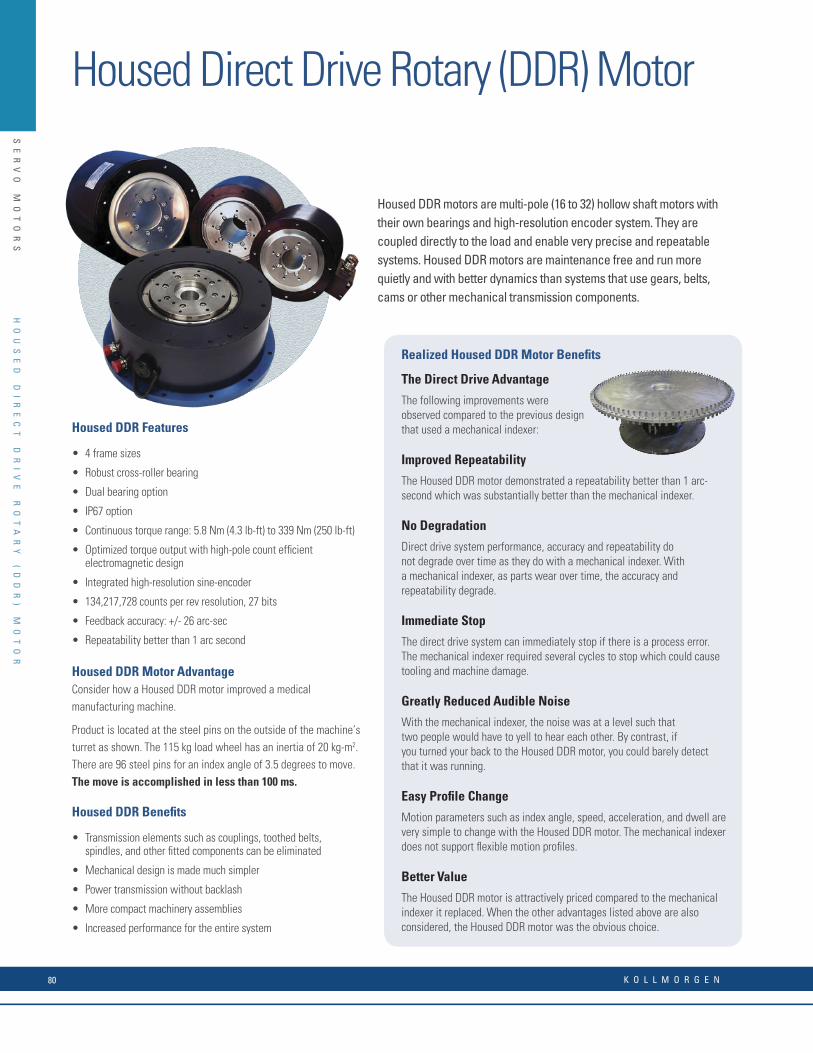
SE
RV
O
MO
TO
RS
Housed DDR motors are multi-pole (16 to 32) hollow shaft motors with their own bearings and high-resolution encoder system. They are coupled directly to the load and enable very precise and repeatable systems. Housed DDR motors are maintenance free and run more quietly and with better dynamics than systems that use gears, belts, cams or other mechanical transmission components.
Realized Housed DDR Motor Benefi ts
The Direct Drive Advantage
The following improvements were observed compared to the previous design that used a mechanical indexer:
Improved Repeatability
The Housed DDR motor demonstrated a repeatability better than 1 arc-second which was substantially better than the mechanical indexer.
No Degradation
Direct drive system performance, accuracy and repeatability do not degrade over time as they do with a mechanical indexer. With a mechanical indexer, as parts wear over time, the accuracy and repeatability degrade.
Immediate Stop
The direct drive system can immediately stop if there is a process error. The mechanical indexer required several cycles to stop which could cause tooling and machine damage.
Greatly Reduced Audible Noise
With the mechanical indexer, the noise was at a level such that two people would have to yell to hear each other. By contrast, if you turned your back to the Housed DDR motor, you could barely detect that it was running.
Easy Profi le Change
Motion parameters such as index angle, speed, acceleration, and dwell are very simple to change with the Housed DDR motor. The mechanical indexer does not support fl exible motion profi les.
Better Value
The Housed DDR motor is attractively priced compared to the mechanical indexer it replaced. When the other advantages listed above are also considered, the Housed DDR motor was the obvious choice.
Housed DDR Features
• 4 frame sizes
• Robust cross-roller bearing
• Dual bearing option
• IP67 option
• Continuous torque range: 5.8 Nm (4.3 lb-ft) to 339 Nm (250 lb-ft)
• Optimized torque output with high-pole count effi cient electromagnetic design
• Integrated high-resolution sine-encoder
• 134,217,728 counts per rev resolution, 27 bits
• Feedback accuracy: +/- 26 arc-sec
• Repeatability better than 1 arc second
Housed DDR Motor AdvantageConsider how a Housed DDR motor improved a medical manufacturing machine.
Product is located at the steel pins on the outside of the machine’s turret as shown. The 115 kg load wheel has an inertia of 20 kg-m2. There are 96 steel pins for an index angle of 3.5 degrees to move.The move is accomplished in less than 100 ms.
Housed DDR Benefi ts
• Transmission elements such as couplings, toothed belts, spindles, and other fi tted components can be eliminated
• Mechanical design is made much simpler
• Power transmission without backlash
• More compact machinery assemblies
• Increased performance for the entire system
Housed DDR Performance Data and Dimensions
240 Vac Performance Data
Housed DDR Motor
AKD Servo DriveFrame Size
mm (in)Continuous Torque
Nm (lb-in)Peak TorqueNm (lb-in)
Maximum Speed(RPM)
Weightkg (lb)
Inertia (Jm)cm2
(lb-in-s2 x10-3)
D061 AKD-X00606 175 (6.90) 5.3 (46.9) 16.9 (150) 500 9.4 (20.7) 61 (54.0)
D062 AKD-X00606 175 (6.90) 9.8 (86.7) 33.5 (296) 500 11.3 (24.9) 71 (62.8)
D063 AKD-X00606 175 (6.90) 17.7 (157) 64.4 (570) 500 13.8 (30.4) 86 (76.1)
D081 AKD-X00606 217 (8.55) 15.9 (141) 45.0 (398) 500 17.9 (39.4) 144 (127)
D082 AKD-X00606 217 (8.55) 25.9 (229) 92.2 (816) 300 21.5 (47.3) 194 (172)
D083 AKD-X00606 217 (8.55) 50.4 (446) 160 (1420) 250 28.8 (63.4) 301 (266)
D101 AKD-X00606 280 (11.0) 34.6 (306) 129 (1140) 300 31.5 (69.3) 693 (613)
D102 AKD-X00606 280 (11.0) 63.4 (561) 227 (2010) 200 43.8 (96.4) 992 (878)
D103 AKD-X01206 280 (11.0) 115 (1020) 501 (4430) 120 60.8 (134) 1750 (1550)
D141 AKD-X01206 362 (14.2) 108 (956) 367 (3250) 200 59.4 (131) 1630 (1440)
D142 AKD-X01206 362 (14.2) 183 (1620) 519 (4590) 120 86.6 (191) 2740 (2430)
D143 AKD-X02406 362 (14.2) 339 (3000) 1340 (11,900) 60 146 (321) 5420 (4800)
400/480 Vac Performance Data
Housed DDR Motor
AKD Servo DriveFrame Size
mm (in)Continuous Torque
Nm (lb-in)Peak TorqueNm (lb-in)
Maximum SpeedRPM
Weightkg (lb)
Inertia (Jm)cm2
(lb-in-s2 x10-3)
DH061 AKD-X00607 175 (6.90) 5.3 (46.9) 16.9 (150) 800 9.4 (20.7) 61 (54.0)
DH062 AKD-X00607 175 (6.90) 9.8 (86.7) 33.5 (296) 800 11.3 (24.9) 71 (62.8)
DH063 AKD-X00607 175 (6.90) 17.7 (157) 64.4 (570) 800 13.8 (30.4) 86 (76.1)
DH081 AKD-X00607 217 (8.55) 15.9 (141) 45.0 (398) 500 17.9 (39.4) 144 (127)
DH082 AKD-X00607 217 (8.55) 25.9 (229) 92.2 (816) 500 21.5 (47.3) 194 (172)
DH083 AKD-X00607 217 (8.55) 50.4 (446) 160 (1420) 500 28.8 (63.4) 301 (266)
DH101 AKD-X00607 280 (11.0) 34.6 (306) 129 (1140) 300 31.5 (69.3) 693 (613)
DH102 AKD-X00607 280 (11.0) 63.4 (561) 227 (2010) 300 43.8 (96.4) 992 (878)
DH103 AKD-X01207 280 (11.0) 115 (1020) 501 (4430) 250 60.8 (134) 1750 (1550)
DH141 AKD-X01207 362 (14.2) 108 (956) 367 (3250) 300 59.4 (131) 1630 (1440)
DH142 AKD-X01207 362 (14.2) 183 (1620) 519 (4590) 300 86.6 (191) 2740 (2430)
DH143 AKD-X02407 362 (14.2) 339 (3000) 1340 (11,900) 120 146.0 (321) 5420 (4800)
Dimensions
DDR Amm (in)
Bmm (in)
Cmm (in)
Dmm (in)
D(H)061 130 (5.12) 175 (6.90) 220 (8.66) 126 (4.95)
D(H)062 140 (5.55) 175 (6.90) 220 (8.66) 126 (4.95)
D(H)063 164 (6.46) 175 (6.90) 220 (8.66) 126 (4.95)
D(H)081 145 (5.71) 217 (8.55) 260 (10.2) 147 (5.80)
D(H)082 165 (6.50) 217 (8.55) 260 (10.2) 147 (5.80)
D(H)083 206 (8.11) 217 (8.55) 260 (10.2) 147 (5.80)
D(H)101 153 (6.02) 280 (11.0) 330 (13.0) 181 (7.11)
D(H)102 185 (7.28) 280 (11.0) 330 (13.0) 181 (7.11)
D(H)103 248 (9.76) 280 (11.0) 330 (13.0) 181 (7.11)
D(H)141 153 (6.02) 362 (14.2) 406 (16.0) 218 (8.59)
D(H)142 217 (8.52) 362 (14.2) 406 (16.0) 218 (8.59)
D(H)143 344 (13.50) 362 (14.2) 406 (16.0) 218 (8.59)
Ø 42.9 (1.69) Thru Bore(Sine Encoder)
Flange Mount Face Mount
D
B
A
C
Note 1: Refer to page 166 for matching cables.Note 2: For complete AKD and Housed DDR motor model nomenclature, refer to pages 178 and 184 respectively.
Housed Direct Drive Rotary (DDR) Motor
HO
US
ED
D
IR
EC
T
DR
IV
E
RO
TA
RY
(
DD
R)
M
OT
OR
K O L L M O R G E N80
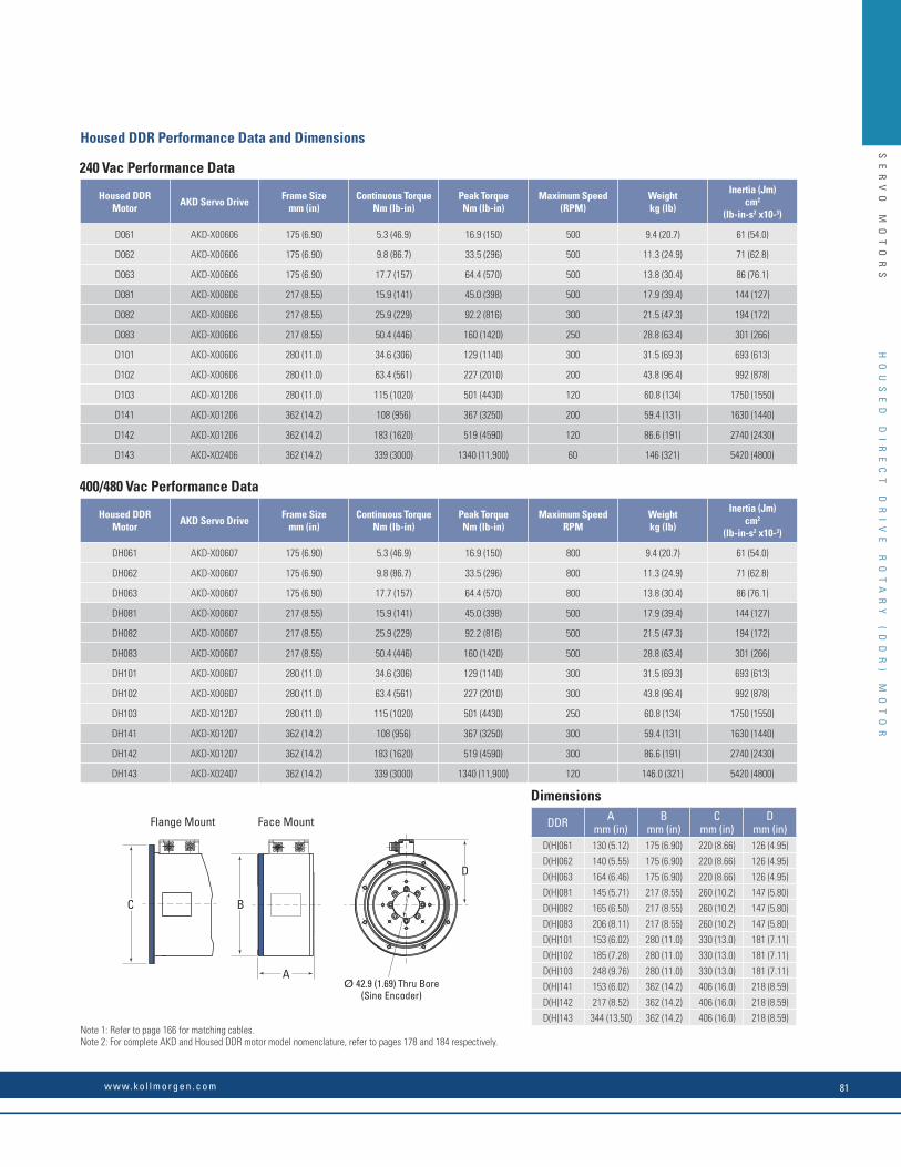
SE
RV
O
MO
TO
RS
Housed DDR motors are multi-pole (16 to 32) hollow shaft motors with their own bearings and high-resolution encoder system. They are coupled directly to the load and enable very precise and repeatable systems. Housed DDR motors are maintenance free and run more quietly and with better dynamics than systems that use gears, belts, cams or other mechanical transmission components.
Realized Housed DDR Motor Benefi ts
The Direct Drive Advantage
The following improvements were observed compared to the previous design that used a mechanical indexer:
Improved Repeatability
The Housed DDR motor demonstrated a repeatability better than 1 arc-second which was substantially better than the mechanical indexer.
No Degradation
Direct drive system performance, accuracy and repeatability do not degrade over time as they do with a mechanical indexer. With a mechanical indexer, as parts wear over time, the accuracy and repeatability degrade.
Immediate Stop
The direct drive system can immediately stop if there is a process error. The mechanical indexer required several cycles to stop which could cause tooling and machine damage.
Greatly Reduced Audible Noise
With the mechanical indexer, the noise was at a level such that two people would have to yell to hear each other. By contrast, if you turned your back to the Housed DDR motor, you could barely detect that it was running.
Easy Profi le Change
Motion parameters such as index angle, speed, acceleration, and dwell are very simple to change with the Housed DDR motor. The mechanical indexer does not support fl exible motion profi les.
Better Value
The Housed DDR motor is attractively priced compared to the mechanical indexer it replaced. When the other advantages listed above are also considered, the Housed DDR motor was the obvious choice.
Housed DDR Features
• 4 frame sizes
• Robust cross-roller bearing
• Dual bearing option
• IP67 option
• Continuous torque range: 5.8 Nm (4.3 lb-ft) to 339 Nm (250 lb-ft)
• Optimized torque output with high-pole count effi cient electromagnetic design
• Integrated high-resolution sine-encoder
• 134,217,728 counts per rev resolution, 27 bits
• Feedback accuracy: +/- 26 arc-sec
• Repeatability better than 1 arc second
Housed DDR Motor AdvantageConsider how a Housed DDR motor improved a medical manufacturing machine.
Product is located at the steel pins on the outside of the machine’s turret as shown. The 115 kg load wheel has an inertia of 20 kg-m2. There are 96 steel pins for an index angle of 3.5 degrees to move.The move is accomplished in less than 100 ms.
Housed DDR Benefi ts
• Transmission elements such as couplings, toothed belts, spindles, and other fi tted components can be eliminated
• Mechanical design is made much simpler
• Power transmission without backlash
• More compact machinery assemblies
• Increased performance for the entire system
Housed DDR Performance Data and Dimensions
240 Vac Performance Data
Housed DDR Motor
AKD Servo DriveFrame Size
mm (in)Continuous Torque
Nm (lb-in)Peak TorqueNm (lb-in)
Maximum Speed(RPM)
Weightkg (lb)
Inertia (Jm)cm2
(lb-in-s2 x10-3)
D061 AKD-X00606 175 (6.90) 5.3 (46.9) 16.9 (150) 500 9.4 (20.7) 61 (54.0)
D062 AKD-X00606 175 (6.90) 9.8 (86.7) 33.5 (296) 500 11.3 (24.9) 71 (62.8)
D063 AKD-X00606 175 (6.90) 17.7 (157) 64.4 (570) 500 13.8 (30.4) 86 (76.1)
D081 AKD-X00606 217 (8.55) 15.9 (141) 45.0 (398) 500 17.9 (39.4) 144 (127)
D082 AKD-X00606 217 (8.55) 25.9 (229) 92.2 (816) 300 21.5 (47.3) 194 (172)
D083 AKD-X00606 217 (8.55) 50.4 (446) 160 (1420) 250 28.8 (63.4) 301 (266)
D101 AKD-X00606 280 (11.0) 34.6 (306) 129 (1140) 300 31.5 (69.3) 693 (613)
D102 AKD-X00606 280 (11.0) 63.4 (561) 227 (2010) 200 43.8 (96.4) 992 (878)
D103 AKD-X01206 280 (11.0) 115 (1020) 501 (4430) 120 60.8 (134) 1750 (1550)
D141 AKD-X01206 362 (14.2) 108 (956) 367 (3250) 200 59.4 (131) 1630 (1440)
D142 AKD-X01206 362 (14.2) 183 (1620) 519 (4590) 120 86.6 (191) 2740 (2430)
D143 AKD-X02406 362 (14.2) 339 (3000) 1340 (11,900) 60 146 (321) 5420 (4800)
400/480 Vac Performance Data
Housed DDR Motor
AKD Servo DriveFrame Size
mm (in)Continuous Torque
Nm (lb-in)Peak TorqueNm (lb-in)
Maximum SpeedRPM
Weightkg (lb)
Inertia (Jm)cm2
(lb-in-s2 x10-3)
DH061 AKD-X00607 175 (6.90) 5.3 (46.9) 16.9 (150) 800 9.4 (20.7) 61 (54.0)
DH062 AKD-X00607 175 (6.90) 9.8 (86.7) 33.5 (296) 800 11.3 (24.9) 71 (62.8)
DH063 AKD-X00607 175 (6.90) 17.7 (157) 64.4 (570) 800 13.8 (30.4) 86 (76.1)
DH081 AKD-X00607 217 (8.55) 15.9 (141) 45.0 (398) 500 17.9 (39.4) 144 (127)
DH082 AKD-X00607 217 (8.55) 25.9 (229) 92.2 (816) 500 21.5 (47.3) 194 (172)
DH083 AKD-X00607 217 (8.55) 50.4 (446) 160 (1420) 500 28.8 (63.4) 301 (266)
DH101 AKD-X00607 280 (11.0) 34.6 (306) 129 (1140) 300 31.5 (69.3) 693 (613)
DH102 AKD-X00607 280 (11.0) 63.4 (561) 227 (2010) 300 43.8 (96.4) 992 (878)
DH103 AKD-X01207 280 (11.0) 115 (1020) 501 (4430) 250 60.8 (134) 1750 (1550)
DH141 AKD-X01207 362 (14.2) 108 (956) 367 (3250) 300 59.4 (131) 1630 (1440)
DH142 AKD-X01207 362 (14.2) 183 (1620) 519 (4590) 300 86.6 (191) 2740 (2430)
DH143 AKD-X02407 362 (14.2) 339 (3000) 1340 (11,900) 120 146.0 (321) 5420 (4800)
Dimensions
DDR Amm (in)
Bmm (in)
Cmm (in)
Dmm (in)
D(H)061 130 (5.12) 175 (6.90) 220 (8.66) 126 (4.95)
D(H)062 140 (5.55) 175 (6.90) 220 (8.66) 126 (4.95)
D(H)063 164 (6.46) 175 (6.90) 220 (8.66) 126 (4.95)
D(H)081 145 (5.71) 217 (8.55) 260 (10.2) 147 (5.80)
D(H)082 165 (6.50) 217 (8.55) 260 (10.2) 147 (5.80)
D(H)083 206 (8.11) 217 (8.55) 260 (10.2) 147 (5.80)
D(H)101 153 (6.02) 280 (11.0) 330 (13.0) 181 (7.11)
D(H)102 185 (7.28) 280 (11.0) 330 (13.0) 181 (7.11)
D(H)103 248 (9.76) 280 (11.0) 330 (13.0) 181 (7.11)
D(H)141 153 (6.02) 362 (14.2) 406 (16.0) 218 (8.59)
D(H)142 217 (8.52) 362 (14.2) 406 (16.0) 218 (8.59)
D(H)143 344 (13.50) 362 (14.2) 406 (16.0) 218 (8.59)
Ø 42.9 (1.69) Thru Bore(Sine Encoder)
Flange Mount Face Mount
D
B
A
C
Note 1: Refer to page 166 for matching cables.Note 2: For complete AKD and Housed DDR motor model nomenclature, refer to pages 178 and 184 respectively.
HO
US
ED
D
IR
EC
T
DR
IV
E
RO
TA
RY
(
DD
R)
M
OT
OR
w w w. k o l l m o r g e n . c o m 81

SE
RV
O
MO
TO
RS
Feedback Types
All brushless motors require feedback for commutation. The conventional rotary motor typically utilizes a resolver mounted on the rear of the motor or Hall effect devices mounted integrally in the coil windings. For a linear motor, commutation feedback can also be accomplished with a variety of methods. Digital or linear Hall effect devices are available from Kollmorgen for the DDL motor series which allow the drive electronics to commutate the linear motors in a manner identical to rotary motors.
For exceptionally smooth motion requirements, sinusoidal drive electronics such as the Kollmorgen's AKD series, using digital Hall effects, provide sinusoidal drive currents to the motor for the best constant force and velocity performance. As an alternative, it is typical for linear motor applications to have a linear encoder present in the system for position feedback. It is increasingly common today for drive amplifiers, such as the AKD digital amplifier, to derive the necessary commutation information directly from this linear encoder, either with or without supplemental digital Hall effect devices on startup. Other types of feedback used on linear motor applications include linear Inductosyns, laser interferometers, and LVDT.
Direct Drive Linear Motor Options
Two types of linear motors are available, Ironcore and Ironless. Each one provides characteristics and features that are optimal depending upon the application. Ironcore motors have coils wound on silicon steel laminations, to maximize the generated force, with a single sided magnet way.
Using a patented electromagnetic design, DDL linear motors have the highest rated force per size, a high Km motor constant (equals low thermal losses), and low cogging forces without the need for skewing of the magnets. The high thrust forces possible with these motors make them ideal for accelerating and moving high masses, and maintaining stiffness during machining or process forces. Ironless motors have no iron, or slots for the coils to be wound on.
Therefore, these motors have zero cogging, a very light mass, and absolutely no attractive forces between the coil assembly and the magnet way. These characteristics are ideal for applications requiring very low bearing friction, high acceleration of lighter loads, and for maximizing constant velocity, even at ultra low speeds. The modular magnet ways consists of a double row of magnets to maximize the generated thrust force and to provide a flux return path for the magnetic circuit.
Ironcore Motor
Ironless Motor
DI
RE
CT
D
RI
VE
L
IN
EA
R
(D
DL
)
MO
TO
R
Direct Drive Linear (DDL) Motor
K O L L M O R G E N82

SE
RV
O
MO
TO
RS
Advantages
Wide Speed RangeSince the frameless parts of the linear motor are non-contact, and no limitations of a mechanical transmission are present, both very high speeds and very low speeds are easily obtainable. Speeds are truly not limited by the motor. Instead, by eliminating the mechanical transmission, speed becomes limited by other elements in the system such as the linear bearings, and the achievable bandwidth from any feedback devices. Application speeds of greater than 5 meters per second (200 in./sec.) or less than 1 micron per second (.00004 in./sec.) are typically achievable. In comparison, mechanical transmissions such as ball screws are commonly limited to linear speeds of 0.5 to 0.7 meters per second (20-30 in./sec.) because of resonances and wear. In addition to a wide speed range, linear motors, both ironcore and ironless, have excellent constant velocity characteristics, typically better than ± 0.01% speed variation.
High System DynamicsIn addition to high speed capability, direct drive linear motors are capable of very high accelerations. Limited only by the system bearings, accelerations of 3 to 5 G are quite typical for the larger motors and accelerations exceeding 10 G are easily achievable for smaller motors.
Smooth Operation and Positional AccuracyBoth ironless and ironcore motors exhibit very smooth motion profiles due to the inherent motor design of Kollmorgen's DDL series. Cogging, which is a component of force, is greatly reduced in the ironcore designs and is zero in the ironless designs. As a result, these direct drive linear motors provide very low force and velocity ripple for ultra smooth motion. Positioning accuracies are limited only by the feedback resolution,and sub-micron resolutions are commonly achievable.
Unlimited TravelWith the DDL motor series, magnet ways are made in 5 modular sections: 64 mm, 128 mm, 256 mm, 512 mm and 1024 mm long. Each module can be added in unlimited numbers to any other module to allow for unlimited travel. Whether the travel required is 1mm (0.04 inches) or 100 meters (330 feet), the DDL series can accommodate the need.
No Wear or MaintenanceLinear motors have few components, therefore the need for ball screw components such as nuts, bearing blocks, couplings, motor mounts and the need to maintain these components have been eliminated. Very long life and clean operation, with no lubrication or maintenance of these parts are the result.
Integration of Components is Much SimplerFrameless linear motors require much fewer components than rotary motors with mechanical transmissions. A 0.8 mm airgap (0.031 inches) for the ironcore design and 0.5 mm airgap (0.020 inches) for the ironless design is the only alignment of the frameless linear motor components that is necessary. No critical alignments are required as with ball screws. Straightness of travel as provided by the system linear bearings is more than sufficient for the Kollmorgen linear motors.
Typical Applications for Linear Motors Include:
Machine Tool Measurement/inspectionDrilling Coordinate measurement machinesMilling Electronic assemblyGrinding Pick-and-place machinesLaser cutting Component insertionCam grinding Screen printersSemiconductor Adhesive dispensersWafer handling process PC board inspection, drillingWafer-inspection Wafer slicing Other applications include: Tab bonding Flight SimulatorsWire bonding Acceleration sledsIon implantation CatapultLithography G-Force measurement Textile Carpet tufting
Easy Selection process:1. Determine peak and continuous force required for your applications (see Motioneering Online, page 201, for information about sizing)2. Use the motor selection guide on pages 84-86 to choose your motor3. Refer to the appropriate pages in the data publication for technical details4. Build model number for ordering using pages 78-80 of the Direct Drive Linear Motor Selection Guide
DI
RE
CT
D
RI
VE
L
IN
EA
R
(D
DL
)
MO
TO
R
w w w. k o l l m o r g e n . c o m 83
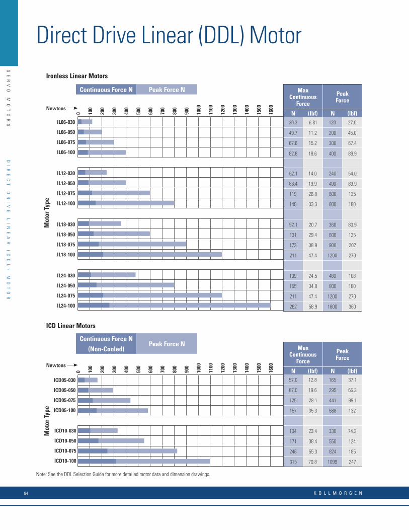
SE
RV
O
MO
TO
RS
0 100
200
300
400
500
600
700
800
900
1000
1100
1200
1300
1400
1500
1600
Ironless Linear Motors
MaxContinuous
Force
PeakForce
SeePageNo.
N (lbf) N (lbf)30.3 6.81 120 27.0 18
49.7 11.2 200 45.0 18
67.6 15.2 300 67.4 18
82.8 18.6 400 89.9 18
62.1 14.0 240 54.0 20
88.4 19.9 400 89.9 20
119 26.8 600 135 20
148 33.3 800 180 20
92.1 20.7 360 80.9 22
131 29.4 600 135 22
173 38.9 900 202 23
211 47.4 1200 270 23
109 24.5 480 108 26
155 34.8 800 180 26
211 47.4 1200 270 26
262 58.9 1600 360 26
IL06-030
IL06-050
IL06-075
IL06-100
IL12-030
IL12-050
IL12-075
IL12-100
IL18-030
IL18-050
IL18-075
IL18-100
IL24-030
IL24-050
IL24-075
IL24-100
Mot
or T
ype
0 100
200
300
400
500
600
700
800
900
1000
1100
1200
1300
1400
1500
1600
ICD05-030
ICD05-050
ICD05-075
ICD05-100
ICD10-030
ICD10-050
ICD10-075
ICD10-100
MaxContinuous
Force
PeakForce
SeePageNo.
N (lbf) N (lbf)57.0 12.8 165 37.1 32
87.0 19.6 295 66.3 32
125 28.1 441 99.1 32
157 35.3 588 132 32
104 23.4 330 74.2 34
171 38.4 550 124 34
246 55.3 824 185 34
315 70.8 1099 247 34
ICD Linear Motors
Mot
or T
ype
Continuous Force N Peak Force N
Continuous Force NPeak Force N
(Non-Cooled)
Newtons
Newtons
Note: Performance data summarized here represents motor data only. For system performance data with Kollmorgen drives use the Motion-eering Application Engine sizing software. See page 81 for more information about Motioneering.
Note: See the DDL Selection Guide for more detailed motor data and dimension drawings.
DI
RE
CT
D
RI
VE
L
IN
EA
R
(D
DL
)
MO
TO
R
Direct Drive Linear (DDL) Motor
K O L L M O R G E N84
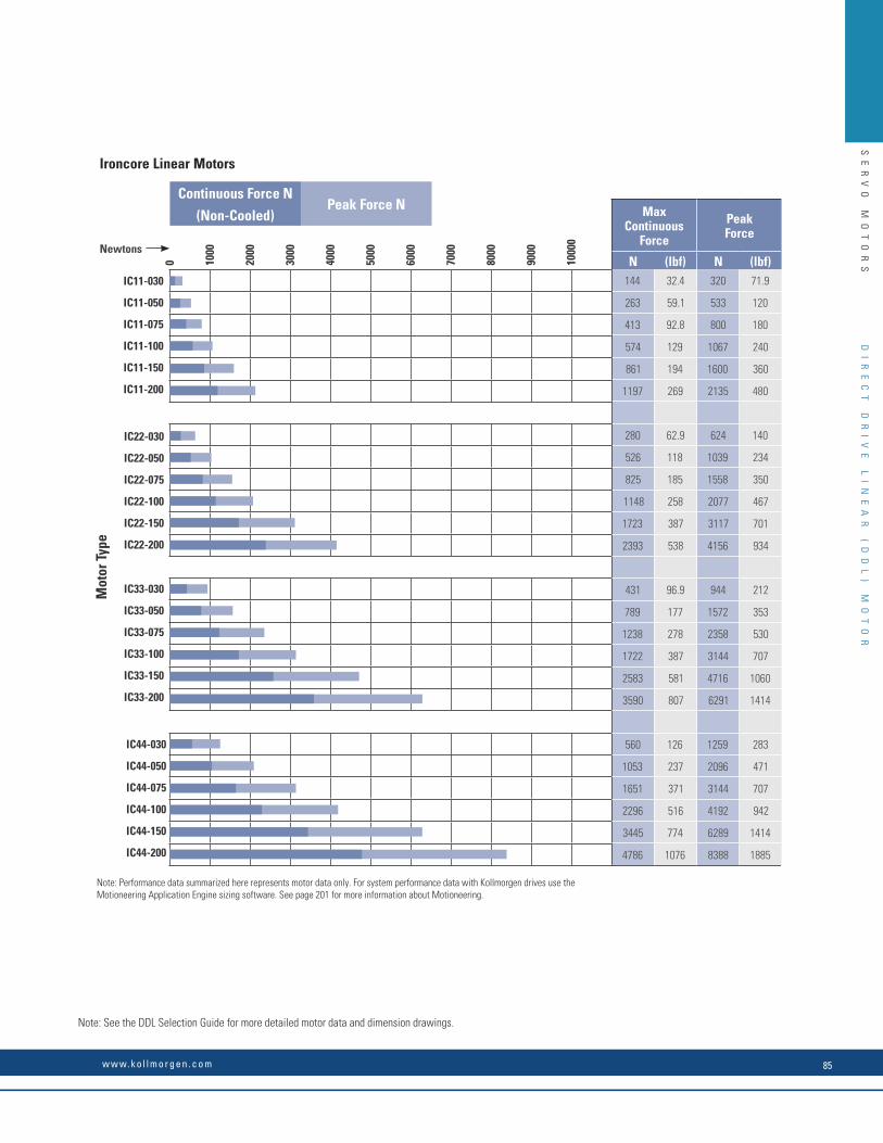
SE
RV
O
MO
TO
RS0 10
00
2000
3000
4000
5000
6000
7000
8000
9000
1000
0
IC11-030
IC11-050
IC11-075
IC11-100
IC11-150
IC11-200
IC22-030
IC22-050
IC22-075
IC22-100
IC22-150
IC22-200
Ironcore Linear Motors
Mot
or T
ype
Newtons
IC33-030
IC33-050
IC33-075
IC33-100
IC33-150
IC33-200
IC44-030
IC44-050
IC44-075
IC44-100
IC44-150
IC44-200
Continuous Force NPeak Force N
(Non-Cooled)
MaxContinuous
Force
PeakForce
SeePageNo.
N (lbf) N (lbf)144 32.4 320 71.9 40
263 59.1 533 120 40
413 92.8 800 180 40
574 129 1067 240 40
861 194 1600 360 40
1197 269 2135 480 40
280 62.9 624 140 42
526 118 1039 234 42
825 185 1558 350 42
1148 258 2077 467 43
1723 387 3117 701 43
2393 538 4156 934 43
431 96.9 944 212 46
789 177 1572 353 46
1238 278 2358 530 46
1722 387 3144 707 47
2583 581 4716 1060 47
3590 807 6291 1414 47
560 126 1259 283 50
1053 237 2096 471 50
1651 371 3144 707 50
2296 516 4192 942 51
3445 774 6289 1414 51
4786 1076 8388 1885 51
Note: Performance data summarized here represents motor data only. For system performance data with Kollmorgen drives use the Motion-eering Application Engine sizing software. See page 81 for more information about Motioneering.
Note: See the DDL Selection Guide for more detailed motor data and dimension drawings.
DI
RE
CT
D
RI
VE
L
IN
EA
R
(D
DL
)
MO
TO
R
Note: Performance data summarized here represents motor data only. For system performance data with Kollmorgen drives use the Motioneering Application Engine sizing software. See page 201 for more information about Motioneering.
w w w. k o l l m o r g e n . c o m 85
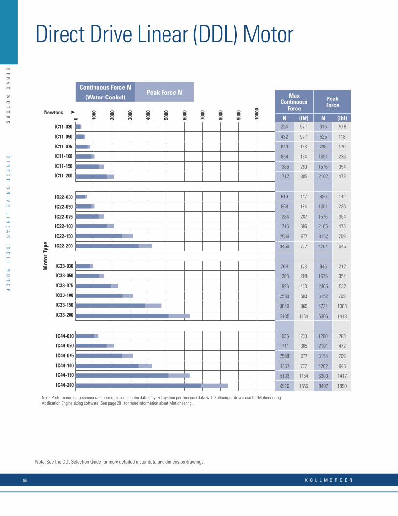
SE
RV
O
MO
TO
RS
w w w. k o l l m o r g e n . c o m 17
0 1000
2000
3000
4000
5000
6000
7000
8000
9000
1000
0
IC11-030
IC11-050
IC11-075
IC11-100
IC11-150
IC11-200
Mot
or T
ype
IC33-030
IC33-050
IC33-075
IC33-100
IC33-150
IC33-200
Continuous Force NPeak Force N
(Water-Cooled)
IC22-030
IC22-050
IC22-075
IC22-100
IC22-150
IC22-200
Newtons
IC44-030
IC44-050
IC44-075
IC44-100
IC44-150
IC44-200
MaxContinuous
Force
PeakForce
SeePageNo.
N (lbf) N (lbf)254 57.1 315 70.8 54
432 97.1 525 118 54
649 146 798 179 54
864 194 1051 236 54
1285 289 1576 354 54
1712 385 2102 473 54
519 117 630 142 56
864 194 1051 236 56
1284 287 1576 354 56
1715 386 2106 473 57
2566 577 3152 709 57
3458 777 4204 945 57
769 173 945 212 60
1283 288 1575 354 60
1926 433 2365 532 60
2593 583 3152 709 61
3849 865 4724 1063 61
5135 1154 6306 1418 61
1036 233 1260 283 64
1711 385 2101 472 64
2568 577 3154 709 64
3457 777 4202 945 65
5133 1154 6303 1417 65
6916 1555 8407 1890 65
Note: Performance data summarized here represents motor data only. For system performance data with Kollmorgen drives use the Motion-eering Application Engine sizing software. See page 81 for more information about Motioneering.
DI
RE
CT
D
RI
VE
L
IN
EA
R
MO
TO
R
SU
MM
AR
Y
Note: See the DDL Selection Guide for more detailed motor data and dimension drawings.
DI
RE
CT
D
RI
VE
L
IN
EA
R
(D
DL
)
MO
TO
R
Direct Drive Linear (DDL) Motor
Note: Performance data summarized here represents motor data only. For system performance data with Kollmorgen drives use the Motioneering Application Engine sizing software. See page 201 for more information about Motioneering.
K O L L M O R G E N86

SE
RV
O
MO
TO
RS
NotesD
IR
EC
T
DR
IV
E
LI
NE
AR
(
DD
L)
M
OT
OR
w w w. k o l l m o r g e n . c o m 87

SE
RV
O
MO
TO
RS
Custom Application Solutions
For customized features, contact Kollmorgen to help us understand exactly what you need and how we can further optimize any KBM or engineer a new custom motor solution for the unique requirements of your application. We are experts in providing optimized solutions such as special winding configurations, tailored mounting features, diameter and stack length dimensional adjustments, or material variations.
KBM Series Frameless Brushless Motor
KB
M
SE
RI
ES
F
RA
ME
LE
SS
B
RU
SH
LE
SS
M
OT
OR
The KBM frameless motor series is our newest direct drive technology.
KBM frameless brushless motor models are engineered to provide the high-performance, long life and simple installation that today’s design engineers demand. Optional latching digital Hall effect sensors are pre-aligned and factory installed with added axial rotor length to achieve proper triggering. Choice of insulation allows operation over a wide range of line input voltage. Our detailed selection guide provides a variety of pre-engineered options and configurations that are currently available.
K O L L M O R G E N88

SE
RV
O
MO
TO
RS
w w w. k o l l m o r g e n . c o m 5
The Benefi ts of KBM Frameless Motors
• Industry-Leading Frameless Motor Performance • Advanced electromagnetic designs deliver maximum torque• density which minimizes required motor space envelope
• Extremely smooth rotation with minimal cogging and low total• harmonic distortion (THD)
• Broad operating speed range and rapid acceleration
• Quality Construction Ensures Reliability and Safe Operation • Redundant magnet attachment to rotor on high-speed models – • adhesive bonding and high-strength banding
• 155°C motor winding temperature rating with integral thermistor • allows continuous safe operation for demanding applications
• Designed with UL-recommended insulation systems to simplify• system regulatory approval
• RoHS compliant material selection
• Compliant with Harmonized Type C Standards EN60034-1:2004 -• Rotating Electrical Machines and where appropriate in• accordance to the Low Voltage Directive 2006-95-EC
• Highly Confi gurable Design Minimizes Time to Solution • 14 frame sizes with multiple stack lengths
• Standard sensor feedback using Hall effect sensors
• Standard high and low voltage insulation
• Multiple standard windings with custom windings available upon • request
• Mechanical interface changes easily accommodated
KB
M
FR
AM
EL
ES
S
MO
TO
R
KB
M
SE
RI
ES
F
RA
ME
LE
SS
B
RU
SH
LE
SS
M
OT
OR
w w w. k o l l m o r g e n . c o m 89

SE
RV
O
MO
TO
RS
K O L L M O R G E N6
KB
M
FR
AM
EL
ES
S
MO
TO
R
Kollmorgen, the global leader in direct drive motor technology, is pleased to offer KBM series frameless brushless motors. With a wide variety of sizes and torque ranges available, KBM models are engineered to provide the high-performance, long life and simple installation that today’s design engineers demand.
KBM Series Overview
Quality Construction
• Fully encapsulated stator windings
• 155°C internal winding temperature continuous capability
• PTC thermistor (avalanche-type) overload protection
• High performance magnets
• Fail-safe bands over rotor magnets*
• RoHS compliant
Available Options (No engineering fees apply)
Sensor Feedback (KBMS models)Latching digital hall effect sensors are pre-aligned and factory installed
on the lead end of the stator. Wiring instructions and electrical timing
diagrams are included in this selection guide. KBMS models include
added axial rotor length to achieve proper sensor triggering.
Choice of Insulation SystemS (standard) – acceptable for applications up to 240 Vac drive
amplifi er supply.
H (high voltage) – required for applications >240 Vac and up to
480 Vac drive amplifi er supply.
Allowed Modifi cations (Engineering fees apply.
Consult Kollmorgen Customer Support for guidance or to obtain a
quotation. Unit price increase may apply, depending upon extent of
modifi cation.)
Special WindingsMotor windings may be optimized to provide desired speed and torque
performance according to the unique voltage and current requirements
of a customer’s application. Kollmorgen engineers must confi rm
electrical feasibility and manufacturability of each special winding
arrangement prior to quotation.
Special Rotor Hub DimensionsRotor hubs may be provided with special customer-designated hole
patterns, mounting features or smaller inner bore diameters. Standard
KBM(S) models shown within this selection guide include the largest
available inner rotor bore diameter.
Rotor Hub MaterialStandard confi guration KBM(S) rotor hubs are constructed from non-
plated cold rolled steel. If special plating, coating, cleaning or alternate
material is desired, Kollmorgen engineers must confi rm feasibility and
pricing adjustment prior to quotation.
Stator Sleeve MaterialStandard confi guration KBM(S)-10, 14, 17, 25, 35, 45, 163 and 260 size
stators are designed with uncoated aluminum sleeves around the stator
lamination stack. If special coating or plating is desired for the aluminum
stator sleeve, Kollmorgen engineers must confi rm feasibility and pricing
adjustment prior to quotation. Stator sleeves are only utilized for the
sizes listed above.
Agency UL InformationKBM(S) motors are designed to facilitate UL certifi cation in the
customer’s higher-level assembly. Stator insulation systems are
constructed entirely from agency-approved materials and are designed
in full compliance with agency creepage and clearance dimensional
guidelines. Dielectric strength between winding circuit and grounded
metal stator surface is tested at agency-specifi ed voltage level. Because
a frameless motor’s compliance with agency requirements is dependent
upon correct installation and proper design of the surrounding enclosure
by the user, KBM(S) series products are not formally labeled or agency-
approved at the frameless motor level.
* Does not apply to KBM 163 and KBM 260.
w w w. k o l l m o r g e n . c o m 7
KB
M(
S)
C
ON
TI
NU
OU
S
TO
RQ
UE
O
VE
RV
IE
W
Tc in Nm
10
0.10 10.00
1000 10000100
100.001.00
KBM(S)-10XXX-X
KBM(S)-14XXX-X
KBM(S)-17XXX-X
KBM(S)-25XXX-X
KBM(S)-35XXX-X
KBM(S)-43XXX-X
KBM(S)-45XXX-X
KBM(S)-57XXX-X
KBM(S)-60XXX-X
KBM(S)-79XXX-X
KBM(S)-88XXX-X
KBM(S)-118XXX-X
KBM(S)-163XXX-X
KBM(S)-260XXX-X
01 stack
00 stack
02 stack
01 stack
03 stack
02 stack
04 stack
04 stack
05 stack
03 stack
05 stack
KBM(S) Continuous Torque OverviewSelect from our wide variety of sizes and torque ranges to suit your application needs.
KBM
Ser
ies
Fram
eles
s M
otor
sFor more detailed information please visit: http://www.kollmorgen.com/en-us/products/motors/direct-drive/kbm-series-frameless/
KB
M
SE
RI
ES
F
RA
ME
LE
SS
B
RU
SH
LE
SS
M
OT
OR
K O L L M O R G E N90
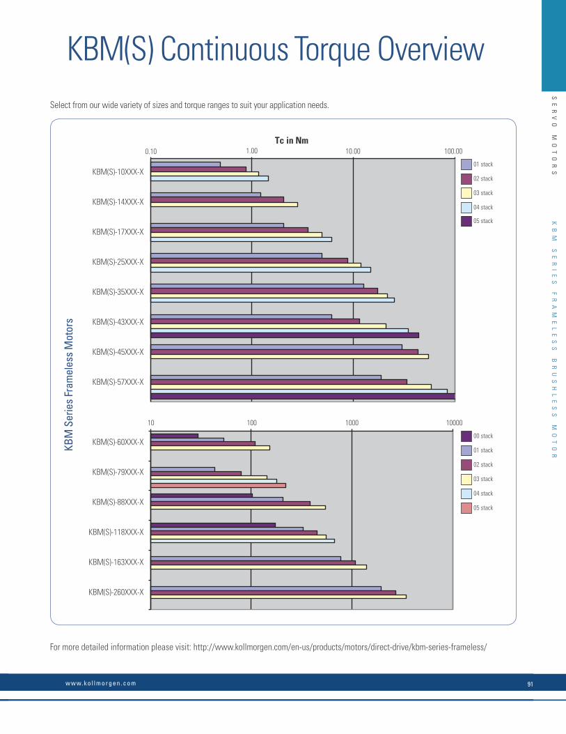
SE
RV
O
MO
TO
RS
K O L L M O R G E N6
KB
M
FR
AM
EL
ES
S
MO
TO
R
Kollmorgen, the global leader in direct drive motor technology, is pleased to offer KBM series frameless brushless motors. With a wide variety of sizes and torque ranges available, KBM models are engineered to provide the high-performance, long life and simple installation that today’s design engineers demand.
KBM Series Overview
Quality Construction
• Fully encapsulated stator windings
• 155°C internal winding temperature continuous capability
• PTC thermistor (avalanche-type) overload protection
• High performance magnets
• Fail-safe bands over rotor magnets*
• RoHS compliant
Available Options (No engineering fees apply)
Sensor Feedback (KBMS models)Latching digital hall effect sensors are pre-aligned and factory installed
on the lead end of the stator. Wiring instructions and electrical timing
diagrams are included in this selection guide. KBMS models include
added axial rotor length to achieve proper sensor triggering.
Choice of Insulation SystemS (standard) – acceptable for applications up to 240 Vac drive
amplifi er supply.
H (high voltage) – required for applications >240 Vac and up to
480 Vac drive amplifi er supply.
Allowed Modifi cations (Engineering fees apply.
Consult Kollmorgen Customer Support for guidance or to obtain a
quotation. Unit price increase may apply, depending upon extent of
modifi cation.)
Special WindingsMotor windings may be optimized to provide desired speed and torque
performance according to the unique voltage and current requirements
of a customer’s application. Kollmorgen engineers must confi rm
electrical feasibility and manufacturability of each special winding
arrangement prior to quotation.
Special Rotor Hub DimensionsRotor hubs may be provided with special customer-designated hole
patterns, mounting features or smaller inner bore diameters. Standard
KBM(S) models shown within this selection guide include the largest
available inner rotor bore diameter.
Rotor Hub MaterialStandard confi guration KBM(S) rotor hubs are constructed from non-
plated cold rolled steel. If special plating, coating, cleaning or alternate
material is desired, Kollmorgen engineers must confi rm feasibility and
pricing adjustment prior to quotation.
Stator Sleeve MaterialStandard confi guration KBM(S)-10, 14, 17, 25, 35, 45, 163 and 260 size
stators are designed with uncoated aluminum sleeves around the stator
lamination stack. If special coating or plating is desired for the aluminum
stator sleeve, Kollmorgen engineers must confi rm feasibility and pricing
adjustment prior to quotation. Stator sleeves are only utilized for the
sizes listed above.
Agency UL InformationKBM(S) motors are designed to facilitate UL certifi cation in the
customer’s higher-level assembly. Stator insulation systems are
constructed entirely from agency-approved materials and are designed
in full compliance with agency creepage and clearance dimensional
guidelines. Dielectric strength between winding circuit and grounded
metal stator surface is tested at agency-specifi ed voltage level. Because
a frameless motor’s compliance with agency requirements is dependent
upon correct installation and proper design of the surrounding enclosure
by the user, KBM(S) series products are not formally labeled or agency-
approved at the frameless motor level.
* Does not apply to KBM 163 and KBM 260.
w w w. k o l l m o r g e n . c o m 7
KB
M(
S)
C
ON
TI
NU
OU
S
TO
RQ
UE
O
VE
RV
IE
W
Tc in Nm
10
0.10 10.00
1000 10000100
100.001.00
KBM(S)-10XXX-X
KBM(S)-14XXX-X
KBM(S)-17XXX-X
KBM(S)-25XXX-X
KBM(S)-35XXX-X
KBM(S)-43XXX-X
KBM(S)-45XXX-X
KBM(S)-57XXX-X
KBM(S)-60XXX-X
KBM(S)-79XXX-X
KBM(S)-88XXX-X
KBM(S)-118XXX-X
KBM(S)-163XXX-X
KBM(S)-260XXX-X
01 stack
00 stack
02 stack
01 stack
03 stack
02 stack
04 stack
04 stack
05 stack
03 stack
05 stack
KBM(S) Continuous Torque OverviewSelect from our wide variety of sizes and torque ranges to suit your application needs.
KBM
Ser
ies
Fram
eles
s M
otor
s
For more detailed information please visit: http://www.kollmorgen.com/en-us/products/motors/direct-drive/kbm-series-frameless/
KB
M
SE
RI
ES
F
RA
ME
LE
SS
B
RU
SH
LE
SS
M
OT
OR
w w w. k o l l m o r g e n . c o m 91

SE
RV
O
MO
TO
RS
The TBM frameless motor is a new series of direct drive torque motors designed for applications that require high power in a small, compact form factor with minimized weight and inertia.
Typical applications include robotic joints, weapon stations, sensor gimbals, sight systems, UAV propulsion and guidance, as well as many others.
TBM(S) Product Features
• 3 frame sizes ranging from 60mm (2.36 inches) up to 129mm (5.08 inches)
• 3 stacks lengths per frame
• 2 standard winding options per frame
• Latching Hall Effects (pre-aligned / factory installed)
• Low Cogging designs
• Stainless Steel Yokes for maximum corrosion protection
• RoHS Compliant
• Banded Rotors
• Laser Marked Armatures
For non-standard requests Kollmorgen provides a variety of standard options and configurations.
If higher levels of customization are required, contact Kollmorgen to help us understand exactly what you need.
TBM Series Frameless Motors
TB
M
SE
RI
ES
F
RA
ME
LE
SS
B
RU
SH
LE
SS
M
OT
OR
K O L L M O R G E N92
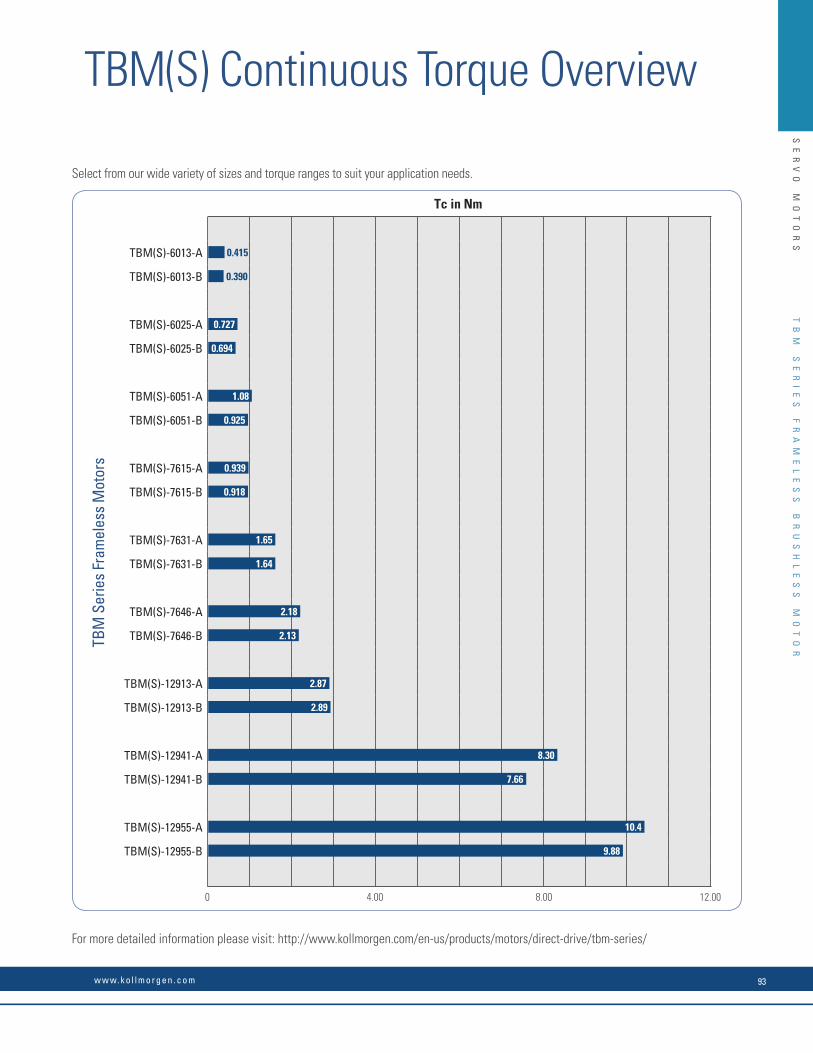
SE
RV
O
MO
TO
RS
TBM(S) Continuous Torque OverviewT
BM
S
ER
IE
S
FR
AM
EL
ES
S
BR
US
HL
ES
S
MO
TO
R
Tc in Nm
TBM(S)-6013-A
TBM(S)-6013-B
TBM(S)-6025-A
TBM(S)-6025-B
TBM(S)-6051-A
TBM(S)-6051-B
TBM(S)-7615-A
TBM(S)-7615-B
TBM(S)-7631-A
TBM(S)-7631-B
TBM(S)-7646-A
TBM(S)-7646-B
TBM(S)-12913-A
TBM(S)-12913-B
TBM(S)-12941-A
TBM(S)-12941-B
TBM(S)-12955-A
TBM(S)-12955-B
0.415
0.727
1.08
0.939
1.65
2.18
2.87
8.30
10.4
0.390
0.694
0.925
0.918
1.64
2.13
2.89
7.66
9.88
Select from our wide variety of sizes and torque ranges to suit your application needs.
For more detailed information please visit: http://www.kollmorgen.com/en-us/products/motors/direct-drive/tbm-series/
TBM
Ser
ies
Fram
eles
s M
otor
s
4.000 8.00 12.00
w w w. k o l l m o r g e n . c o m 93
K O L L M O R G E N
ST
EP
PE
R
PR
OD
UC
TS
Stepper Drives and MotorsOur stepper motors, drives and controllers, which accommodate a wide range of power requirements, provide a high-performance, yet very cost-effective solution when you need precise motion control.
Our hybrid stepper motors are some of the highest torque-density motors in the industry. Available in several NEMA frame sizes, these 2 phase stepper motors inherently move in small, precise 0.9 or 1.8 degree increments (400 or 200 steps/revolution). This stepping action is simple to control and does not require complicated, expensive feedback devices. Our stepper motors are excellent alternatives to pneumatic, hydraulic and servo motor systems.
Kollmorgen’s stepper drives are designed with versatility, ease-of-use, and cost-effectiveness in mind. Choose from a broad range of advanced drives and controls including full, half, and microstepping models in both modular and packaged designs.
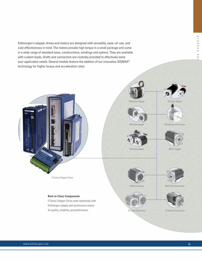
ST
EP
PE
R
PR
OD
UC
TS
PMX Series Stepper EH Series Stepper
MP Series Stepper
KS06 Synchronous
MX Explosion-Proof Series
X(CE) Series Synchronous
KN Series Stepper
SS Series Synchronous
MH172 Stepper
SS Gearbox Synchronous
P-Series Stepper Drives
.125 [3.18]
.120 [3.2].001 [0.025] C
3.26[82.81]MAX
2X Ø 0.223 [5.66] THRU 180˚ APART ON A Ø3.88 [98.55]
.56 [14.22]
.57 [14.48]
Ø 3.39 [86.11]MAX.
1.10 [27.94] MINLENGTHØ (500)[12.7]1.79 ±0.03[45.47 ±0.77]
.500 [12.7]
.498 [12.64]- C -
.20[5.11]MIN
#405 WOODRUFFKEY SUPPLIED
.25 MAX[6.35]
"B"MAX
Ø 2.91[73.92]MAX
.41[10.49]
Kollmorgen’s stepper drives and motors are designed with versatility, ease–of–use, and cost-effectiveness in mind. The motors provide high torque in a small package and come in a wide range of standard sizes, constructions, windings and options. They are available with custom leads, shafts and connectors are routinely provided to effectively solve your application needs. Several models feature the addition of our innovative SIGMAX® technology for higher torque and acceleration rates.
Best-in-Class Components
P-Series Stepper Drives work seamlessly with
Kollmorgen stepper and synchronous motors
for quality, reliability, and performance.
w w w. k o l l m o r g e n . c o m 95

ST
EP
PE
R
PR
OD
UC
TS
P-
SE
RI
ES
D
RI
VE
-C
ON
TR
OL
LE
RS
Value DC Input Stepper Drive
• Wave matching for Kollmorgen motors to provide optimal performance
• All inputs and outputs are optically isolated
• Step and direction inputs or internal velocity controlled oscillator (VCO) dip switch selectable
• DIP switch selectable micro-stepping resolution settings
• Idle current reduction, DIP switch selectable
• Compensation for mid-range instability• RoHS & CE certifi ed• UL pending
Full Featured AC Input Stepper Drive
• No programming required• Covers full power range of Kollmorgen
steppers• Switch selectable current from 0.2-5.7
Arms, 8.0 A peak• Switch selectable for many Kollmorgen
motor parings• All inputs and outputs are optically
isolated• Single-ended and differential step and
direction• Enable input• Switch selectable micro-stepping
resolution• Anti-resonance based on load inertia• RoHS & CE certifi ed
Full Featured AC or DC Input Stepper Drives with Intelligent Indexing Option (-PN)
• AC and DC input versions• Covers full power range of Kollmorgen
steppers• Drives can be confi gured by either dip
switches or P7000 software• Intelligent indexing option (-PN) provides
ability to link motion tasks.• All inputs and outputs are optically
isolated• Single-ended and differential step and
direction• Enable input• Switch selectable micro-stepping
resolution• Anti-resonance based on load inertia• RoHS, CE and UL certifi ed
P-
SE
RI
ES
D
RI
VE
F
EA
TU
RE
S
AN
D
BE
NE
FI
TS
Budget/Value Full–Featured
P5000 P6000 P7000
P-Series Drive Features and Benefi ts
Stepper Drive Model Modes of Operation* Input voltage (Vdc) Input Voltage (Vac) Output current (Adc) Continuous (Peak)
P5000 S, V 20 - 75 n/a 0.7 - 2.0 (3.5)
P6000 S n/a 110-240 +/-10% 0.3 - 5.7 (8.0)
P70530 S, M 20 - 75 n/a 0 - 5.0 (7.1)
P70360 S, M n/a 120/240 0 - 2.5 (3.5)
Modes of Operation: S - Step and Direction; V - Velocity Controlled Oscillator (VCO); M - Motion Node Indexing
STEPPER DRIVE PRODUCT OVERVIEW
K O L L M O R G E N96

ST
EP
PE
R
PR
OD
UC
TS
P-
SE
RI
ES
D
RI
VE
-C
ON
TR
OL
LE
RS
P5
00
0
ST
EP
PE
R
DR
IV
E-
CO
NT
RO
LL
ER
P5000 Stepper Drive-Controller
Introducing the New Kollmorgen P5000 Stepper Drive.
The P5000 is a compact micro-stepping stepper drive optimized for high system performance with Kollmorgen’s industry leading POWERMAX II stepper motors. It is an impressive yet simple addition to the Kollmorgen stepper drive family.
Optimized. Smooth. Compact.
Pairing a stepper system doesn’t get any easier! The P5000 and Kollmorgen stepper motors are meant to be together. With Kollmorgen motor windings optimized for the P5000, all you have to do is set the dip switches for the motor you are paired with and you have a smooth operating system that fully utilizes the potential of your Kollmorgen motor and drive combination!
Features• Current output from 0.7-3.5 Arms peak; DIP switch selectable in 0.2 Amp increments
• Bus Voltage 20-75 Vdc
• Wave matching for Kollmorgen motors to provide optimal performance for the Kollmorgen Stepper Motor Families.
• All Inputs and Outputs are Optically Isolated
• Command Source from External Step and Direction Inputs or Internal Velocity Controlled Oscillator (VCO); DIP switch selectable
• External Single-Ended Step and Direction Command
• Disable or Fault Reset Input
• Fault or Enable Output
• VCO Mode
• CW Limit Input
• CCW Limit Input
• Run/Stop Input
• Run/Stop Output
• CW Speed trimpot
• CCW Speed trimpot
• Accel/Decel trimpot
• DIP switch selectable micro-stepping-resolution settings
• Pulse Multiplier smooths micro-stepping*
• Idle Current Reduction; DIP switch selectable
• Compensation for mid-range instability*
• RoHS & CE certifi ed
• UL pending
*Patents Pending
P5000 Stepper Drive
(Shown Actual Size)
Big Performance,Micro Package.
Note: For complete P-Series model nomenclature, refer to page 186.
w w w. k o l l m o r g e n . c o m 97
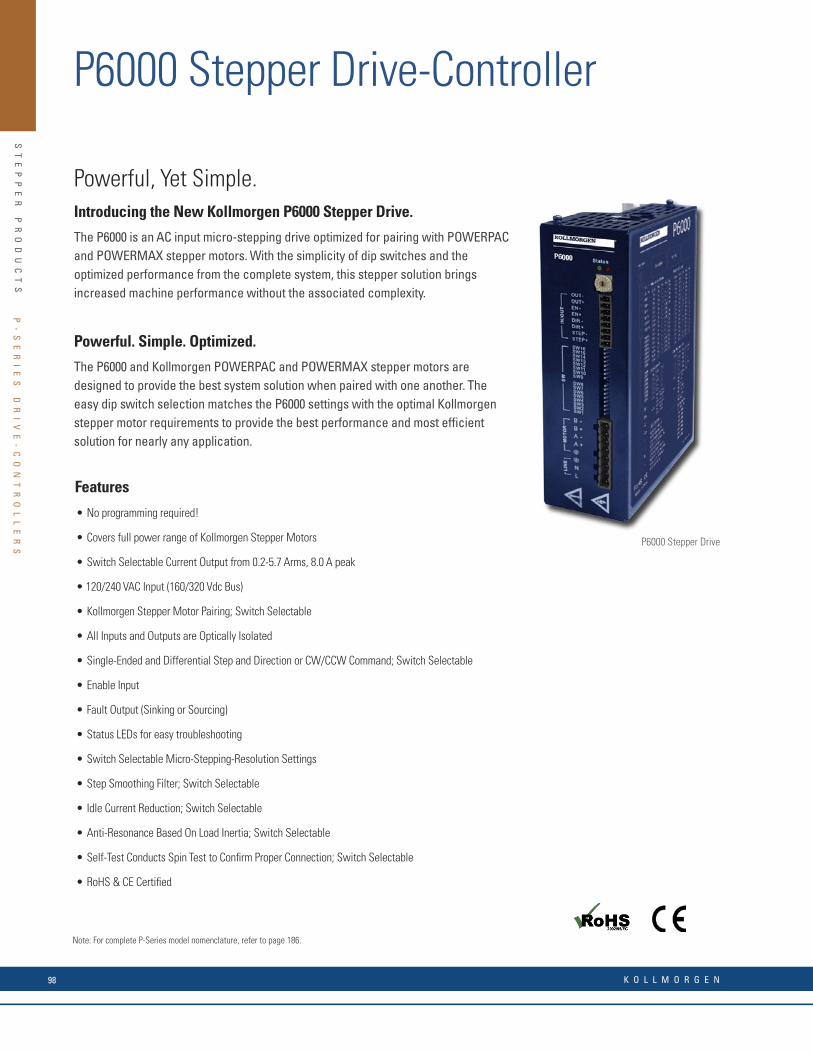
ST
EP
PE
R
PR
OD
UC
TS
Note: For complete P-Series model nomenclature, refer to page 186.
P-
SE
RI
ES
D
RI
VE
-C
ON
TR
OL
LE
RS
P6
00
0
ST
EP
PE
R
DR
IV
E-
CO
NT
RO
LL
ER
P6000 Stepper Drive-Controller
Powerful, Yet Simple.Introducing the New Kollmorgen P6000 Stepper Drive.
The P6000 is an AC input micro-stepping drive optimized for pairing with POWERPAC and POWERMAX stepper motors. With the simplicity of dip switches and the optimized performance from the complete system, this stepper solution brings increased machine performance without the associated complexity.
Powerful. Simple. Optimized.
The P6000 and Kollmorgen POWERPAC and POWERMAX stepper motors are designed to provide the best system solution when paired with one another. The easy dip switch selection matches the P6000 settings with the optimal Kollmorgen stepper motor requirements to provide the best performance and most effi cient solution for nearly any application.
P6000 Stepper Drive
Features
• No programming required!
• Covers full power range of Kollmorgen Stepper Motors
• Switch Selectable Current Output from 0.2-5.7 Arms, 8.0 A peak
• 120/240 VAC Input (160/320 Vdc Bus)
• Kollmorgen Stepper Motor Pairing; Switch Selectable
• All Inputs and Outputs are Optically Isolated
• Single-Ended and Differential Step and Direction or CW/CCW Command; Switch Selectable
• Enable Input
• Fault Output (Sinking or Sourcing)
• Status LEDs for easy troubleshooting
• Switch Selectable Micro-Stepping-Resolution Settings
• Step Smoothing Filter; Switch Selectable
• Idle Current Reduction; Switch Selectable
• Anti-Resonance Based On Load Inertia; Switch Selectable
• Self-Test Conducts Spin Test to Confi rm Proper Connection; Switch Selectable
• RoHS & CE Certifi ed
K O L L M O R G E N98

ST
EP
PE
R
PR
OD
UC
TS
P-
SE
RI
ES
D
RI
VE
-C
ON
TR
OL
LE
RS
P7
00
0
ST
EP
PE
R
DR
IV
E-
CO
NT
RO
LL
ER
P7000 Stepper Drive-Controller
Multistepping™
Also known as auto-smoothing. The P7000 drive accepts full step pulse commands from the indexer and inserts fi ne micro-steps to smooth coarse low speed motion. This allows you to signifi cantly upgrade machine performance without having to redesign machine control architecture.
Auto-Tuning
Advanced current auto-tuning techniques provide outstanding low-speed smoothness. The P7000 senses the motor’s characteristics and automatically fi ne tunes itself to meet your high-performance needs. This reduces installation and set-up time.
Mid-Band Anti-Resonance Control
Reduces negative effects of mechanical resonance, allowing you to get more out of a smaller motor and virtually eliminating nuisance stalls and machine downtime.
Idle Current Reduction
If you do not require the motor’s full torque to hold a load at rest, you can select the right amount of current (torque) to reduce motor heating and power consumption. This increases the life of the system.
Dynamic Smoothing
Quasi-S-curve algorithm reduces jerk, especially upon acceleration. Increases mechanical life of the machine and reduces energy consumption.
Intelligent Indexing Option (-PN)
Wizard-like P7000 helps you to develop and link motion tasks such as homing and conditional and unconditional indexing. You can be up-and-running quickly.
Modbus RTU Compatible
The intelligent indexing option (-PN) supports Modbus RTU to control motion with an external interface device. External interfaces make controlling motion simple for machine operators.
P7000 Tools
The position node option allows you to confi gure up to 63 absolute or relative moves. You can specify the moves’ distance, acceleration, velocity, and deceleration rates, or simply specify the distance and total time for the move – P7000 will perform the calculations automatically.
Specifi cations Units P70530 P70360
Input voltage range Volts 20 - 75 Vdc 120 or 240 Vac
Continuous current Amps rms 5 2.5
Microstep peak current Amps peak 7.1 3.5
P7000 stepper drives offer a unique level of system functionality, smoothness, high-speed performance and innovation unmatched in the industry.
The compact P7000 is designed to power Kollmorgen step motors ranging from NEMA size 17 up to NEMA size 42. Two power confi gurations are available for operation directly from AC power, or from a DC power supply.
There are two levels of control offered. The basic drive accepts step and direction inputs. P7000 drives are also available with an integrated position controller (-PN option). The drives are confi gured by either on-board dip switches, or with the P7000 tools software.
Advanced P7000 Features Make it the Best Choice to Meet Your Application Requirements
Note: For complete P-Series model nomenclature, refer to page 186.
P6
00
0
ST
EP
PE
R
DR
IV
E-
CO
NT
RO
LL
ER
P6000 Stepper Drive-Controller
Powerful, Yet Simple.Introducing the New Kollmorgen P6000 Stepper Drive.
The P6000 is an AC input micro-stepping drive optimized for pairing with POWERPAC and POWERMAX stepper motors. With the simplicity of dip switches and the optimized performance from the complete system, this stepper solution brings increased machine performance without the associated complexity.
Powerful. Simple. Optimized.
The P6000 and Kollmorgen POWERPAC and POWERMAX stepper motors are designed to provide the best system solution when paired with one another. The easy dip switch selection matches the P6000 settings with the optimal Kollmorgen stepper motor requirements to provide the best performance and most effi cient solution for nearly any application.
P6000 Stepper Drive
Features
• No programming required!
• Covers full power range of Kollmorgen Stepper Motors
• Switch Selectable Current Output from 0.2-5.7 Arms, 8.0 A peak
• 120/240 VAC Input (160/320 Vdc Bus)
• Kollmorgen Stepper Motor Pairing; Switch Selectable
• All Inputs and Outputs are Optically Isolated
• Single-Ended and Differential Step and Direction or CW/CCW Command; Switch Selectable
• Enable Input
• Fault Output (Sinking or Sourcing)
• Status LEDs for easy troubleshooting
• Switch Selectable Micro-Stepping-Resolution Settings
• Step Smoothing Filter; Switch Selectable
• Idle Current Reduction; Switch Selectable
• Anti-Resonance Based On Load Inertia; Switch Selectable
• Self-Test Conducts Spin Test to Confi rm Proper Connection; Switch Selectable
• RoHS & CE Certifi ed
w w w. k o l l m o r g e n . c o m 99
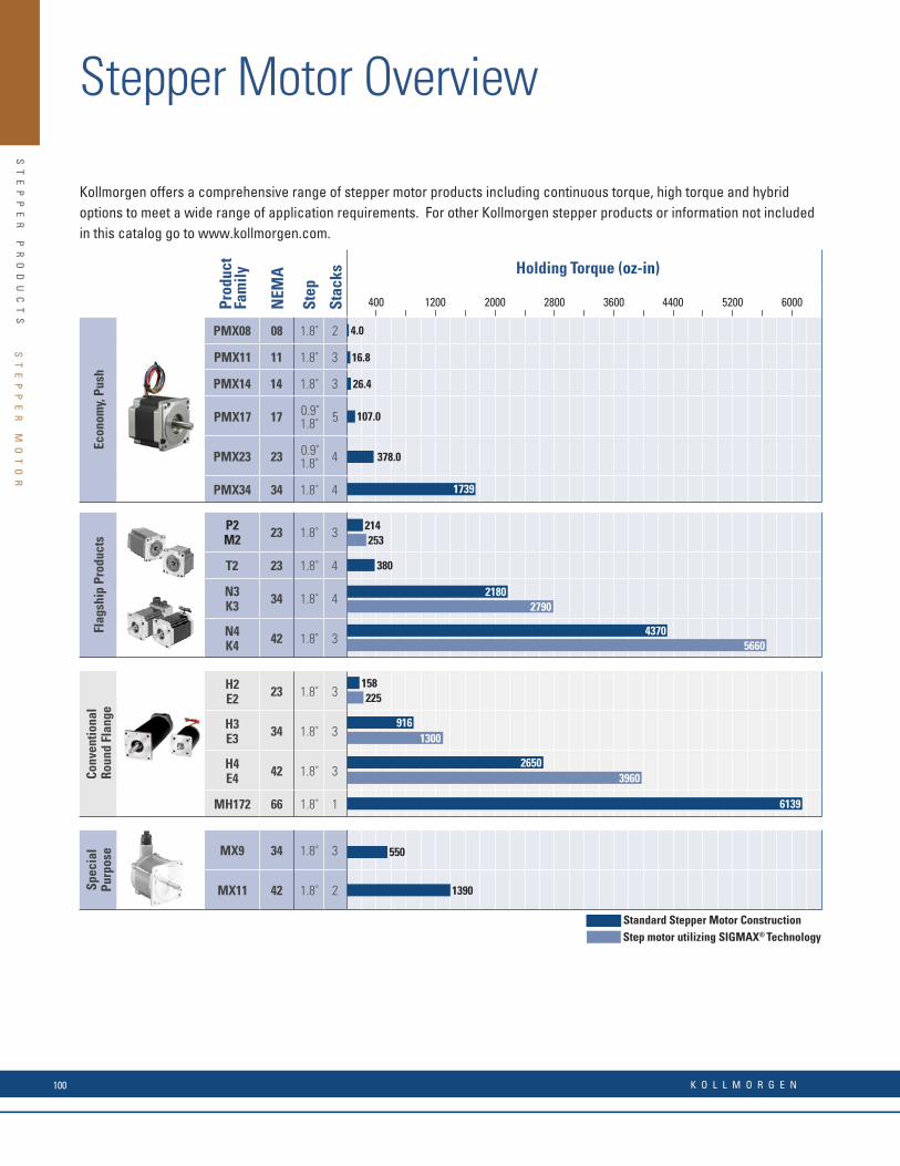
ST
EP
PE
R
PR
OD
UC
TS
Kollmorgen Stepper Motor Overview
Kollmorgen offers a comprehensive range of stepper motor products including continuous torque, high torque and hybrid options to meet a wide range of application requirements. For other Kollmorgen stepper products or information not included in this catalog go to www.kollmorgen.com.
Standard Stepper Motor ConstructionStep motor utilizing SIGMAX® Technology
Prod
uct
Fam
ily
NEM
A
Step
Stac
ks Holding Torque (oz-in)
400 1200 2000 2800 3600 4400 5200 6000
Econ
omy,
Push
PMX08 08 1.8˚ 2
PMX11 11 1.8˚ 3
PMX14 14 1.8˚ 3
PMX17 17 0.9˚ 1.8˚ 5
PMX23 23 0.9˚ 1.8˚ 4
PMX34 34 1.8˚ 4
Econ
omy
CTP1 17 1.8˚ 3
CTP2CTM2 23 1.8˚ 3
CTP3CTM3 34 1.8˚ 3
Flag
ship
Pro
duct
s
P2M2 23 1.8˚ 3
T2 23 1.8˚ 4
N3K3 34 1.8˚ 4
N4K4 42 1.8˚ 3
Conv
entio
nal
Rou
nd F
lang
e
H2E2 23 1.8˚ 3
H3E3 34 1.8˚ 3
H4E4 42 1.8˚ 3
MH172 66 1.8˚ 1
Spec
ial
Purp
ose MX9 34 1.8˚ 3
MX11 42 1.8˚ 2
80
214
4.0
253
16.8
380
26.4
107.0
378.0
550
158225
1390
360
5660
39602650
470
4370
6139
1300916
1500
2790
1930
1739
2180
ST
EP
PE
R
MO
TO
R
Stepper Motor Overview
K O L L M O R G E N100

ST
EP
PE
R
PR
OD
UC
TS
Notes: 1. Requires shaft seal and connection option other than leaded (Meets IP40 otherwise) 2. Requires shaft seal option (Meets IP40 otherwise)
Prod
uct
Fam
ily
Features Standard Options
Family FeaturesNEM
A
UL
Reco
gniz
ed
CE M
ark
RoH
S
SIG
MA
X®
Tech
nolo
gyIn
tegr
al C
onne
ctoi
n
Lead
wir
e4-
Lead
Bip
olar
6-Le
ad U
nipo
lar
8-Le
adTe
rmin
al B
oxM
S Co
nnec
tor
IP S
ealin
g
Enco
ders
Front Shaft
Rear
Sha
ftLo
w In
ertia
Nor
mal
Flat
Keyw
ay
PMX08 08 • • • • 30 • •
• NEMA Sizes 8, 11, 14, 17, 23, 34• CE, RoHS, and REACH Compliant• Unipolar or Bipolar windings• Options: shaft fl ats, rear shaft with encoder mounting
holes, IP Sealing • Special Options readily available: spur and planetary
gearboxes, encoders, special shafts
PMX11 11 • • • • 30 • •
PMX14 14 • • • • 30 • •
PMX17 17 • • • • • 30 • •
PMX23 23 • • • • • 30 • •
PMX34 34 • • • • 30 • •
CTP1 17 • • • • • • 40 • •• High torque standard CTP models • Enhanced CTM SIGMAX models produce up to 25% more torque in same package• Large bearings provide high thrust and radial loads
CTP2CTM2 23 •
•••
•• •
••
••
•• 40 • •
•
CTP3CTM3 34 •
•••
•• •
••
••
•• 40 • •
•
P2M2 23 •
••• •
••
••
••
4040
••
••
••
••
• High torque standard hybrid stepper motor• Enhanced M and K SIGMAX models provide up to 25% more torque in same package• Low detent torque for smoother microstepping• Bipolar and unipolar winding• Large array of options
T2 23 • • • • • • • 40 • • •
K3N3 34 •
••• •
••
••
••
••
••
••
651
651••
••
••
K4N4 42 •
••• •
••
••
••
••
••
••
651
651••
••
••
H2E2 23 •
••• •
••
••
••
••
••
4040
••
••
••
•• • High effi ciency, low loss hybrid designs in a conventional
round frame• Enhanced E SIGMAX models provide up to 25% more torque in the same package• Torque produced over a wide speed range• Large array of options• E2, H2 offer high axial loading
H3E3 34 •
••• •
••
••
••
••
••
651
651••
••
••
H4E4 42 •
••• •
••
••
••
••
••
652
652••
••
••
MH172 66 • 40 • • •
MX9 34 • 40 • •• Standard hybrid stepper motor • Meets Explosion proof UL Class 1, Division 1 Group D
requirements• Up to 150% rated torque reserve capacity (MX9)
and 200% for MX11MX11 42 • 40 • •
• available option
ST
EP
PE
R
MO
TO
R
w w w. k o l l m o r g e n . c o m 101

ST
EP
PE
R
PR
OD
UC
TS
Kollmorgen’s new PMXTM
stepper motor line delivers breadth and design fl exibility at competitive lead times.
PMX Stepper Motors
• Increased Design Flexibility – six frame sizes (08, 11, 14, 17, 23, 34) each with several stack length and winding options available
• Minimal Drive Adjustments – options for 1.8 and 0.9 degree step angles
• Lower Unit Cost – PMX motors are priced competitively in today’s current stepper market and are the lowest of all Kollmorgen stepper products
• Quality construction translates to reliability in the fi eld and a long service life
• Localized Support gives you the delivery terms and immediate technical support you need, meaning quicker time to market and less downtime
• Flexible Manufacturing enables Kollmorgen to immediately evaluate modifi cations and co-engineered solutions for rapid prototyping
• Easy to Apply Worldwide – CE, RoHS, REACH
Many Applications
PMX motors allow Kollmorgen customers to fulfi ll their automation needs at an affordable cost, enabling higher throughput in a wide variety of equipment. In addition, leveraging Kollmorgen’s technical expertise and fl exible engineering, the PMX is ready for seamless special and co-engineering options, allowing for swifter and easier integration into both new and existing applications.
Kollmorgen is excited to continue its winning heritage in hybrid stepper motors by introducing the PMX family. Leveraging the best practices from customer preferred products in the POWERMAX and POWERPAC families, the PMX lines will deliver breadth and design fl exibility at a very competitive lead time. Look no further for that hybrid stepper motor family with local support that gives you the fl exibility you need to succeed.
PMX Series motors include smaller Nema 08, 11, and 14 frame sizes in addition to the traditional Nema 17, 23, and 34 frame sizes. Each frame size is built with high quality construction in an affordable, market competitive solution. Numerous co-engineering options are also available including: customizing shafts, encoders, and mounted spur and planetary gearboxes.
Hybrid PMX Step Motor
HY
BR
ID
P
MX
S
TE
P
MO
TO
RH
YB
RI
D
PM
X
ST
EP
M
OT
OR
K O L L M O R G E N102

ST
EP
PE
R
PR
OD
UC
TS
Note: For complete PMX series model nomenclature, refer to page 147.
PMX Stepper Motor General Specifi cations
Series Stacks
Holding Torque(Motor Mounted) Length
FeaturesBipolarin mm
oz-in Nm
Size 08 PMX Series
2 Phase, 1.8° Step Motors. Frame size: 0.8 inch, 20 mm
PMX081 1 2.50 0.018 1.18 30.0 • Front shaft fl at option • Rear shaft optionPMX082 2 4.00 0.028 1.65 42.0
Size 11 PMX Series
2 Phase, 1.8° Step Motors. Frame size: 1.1 inch, 28 mm
PMX111 1 10.1 0.071 1.26 32.0• Front shaft fl at option• Rear shaft option• Integral connector option
PMX112 2 16.1 0.114 1.77 45.0
PMX113 3 16.8 0.119 2.01 51.0
Size 14 PMX Series
2 Phase, 1.8° Step Motors. Frame size: 1.4 inch, 35 mm
PMX141 1 14.7 0.104 1.02 26.0• Front shaft fl at option• Rear shaft option• Rear encoder mounting holes
PMX142 2 20.1 0.142 1.10 28.0
PMX143 3 26.4 0.186 1.42 36.0
Size 17 PMX Series
2 Phase, 0.9° or 1.8° Step Motors. Frame size: 1.7 inch, 42 mm
PMX171 (1.8) 1 28.4 0.201 1.02 26.0
• Front shaft fl at option• Rear shaft option• Integral connector option• Bipolar or Unipolar winding available• Rear encoder mounting holes
PMX172 (1.8) 2 40 0.281 1.32 33.5
PMX173 (1.8) 3 61 0.427 1.56 39.5
PMX174 (1.8) 4 78 0.551 1.87 47.5
PMX171 (1.8) 5 107 0.756 2.36 60.0
Size 23 PMX Series
2 Phase, 0.9° or 1.8° Step Motors. Frame size: 2.2 inch, 57 mm
PMX231 (1.8) 1 102 0.722 1.61 41.0• Front shaft fl at option• Bipolar or Unipolar winding available• Rear shaft option• Integral connector option• Rear encoder mounting holes
PMX232 (1.8) 2 208 1.47 2.20 56.0
PMX233 (1.8) 3 337 2.38 2.99 76.0
PMX234 (1.8) 4 378 2.67 3.35 85.0
Size 34 PMX Series
2 Phase, 1.8° Step Motors. Frame size: 3.4 inch, 86 mm
PMX341 1 490 3.46 2.56 65.0
• Front shaft fl at option• Rear shaft option
PMX342 2 704 4.97 3.15 80.0
PMX343 3 1285 9.07 4.65 118.0
PM344 4 1739 12.28 6.14 156.0
HY
BR
ID
P
MX
S
TE
P
MO
TO
RH
YB
RI
D
PM
X
ST
EP
M
OT
OR
Kollmorgen’s new PMXTM
stepper motor line delivers breadth and design fl exibility at competitive lead times.
PMX Stepper Motors
• Increased Design Flexibility – six frame sizes (08, 11, 14, 17, 23, 34) each with several stack length and winding options available
• Minimal Drive Adjustments – options for 1.8 and 0.9 degree step angles
• Lower Unit Cost – PMX motors are priced competitively in today’s current stepper market and are the lowest of all Kollmorgen stepper products
• Quality construction translates to reliability in the fi eld and a long service life
• Localized Support gives you the delivery terms and immediate technical support you need, meaning quicker time to market and less downtime
• Flexible Manufacturing enables Kollmorgen to immediately evaluate modifi cations and co-engineered solutions for rapid prototyping
• Easy to Apply Worldwide – CE, RoHS, REACH
Many Applications
PMX motors allow Kollmorgen customers to fulfi ll their automation needs at an affordable cost, enabling higher throughput in a wide variety of equipment. In addition, leveraging Kollmorgen’s technical expertise and fl exible engineering, the PMX is ready for seamless special and co-engineering options, allowing for swifter and easier integration into both new and existing applications.
Kollmorgen is excited to continue its winning heritage in hybrid stepper motors by introducing the PMX family. Leveraging the best practices from customer preferred products in the POWERMAX and POWERPAC families, the PMX lines will deliver breadth and design fl exibility at a very competitive lead time. Look no further for that hybrid stepper motor family with local support that gives you the fl exibility you need to succeed.
PMX Series motors include smaller Nema 08, 11, and 14 frame sizes in addition to the traditional Nema 17, 23, and 34 frame sizes. Each frame size is built with high quality construction in an affordable, market competitive solution. Numerous co-engineering options are also available including: customizing shafts, encoders, and mounted spur and planetary gearboxes.
Hybrid PMX Step Motor
HY
BR
ID
P
MX
S
TE
P
MO
TO
R
Note: For complete PMX series model nomenclature, refer to page 187.
w w w. k o l l m o r g e n . c o m 103

ST
EP
PE
R
PR
OD
UC
TS
AC Synchronous Motor Overview
AC
S
YN
CH
RO
NO
US
M
OT
OR
O
VE
RV
IE
W
Product Family Pa
ge N
o.
NEM
A Torque (oz-in)
200 400 600 800 1000 1200 1400 1600
High Torque, Feature Rich
KS06 110 23
SS240, 450 112 34
SS150, 250, 400, 700 112 42
SS1800 112 66
Special Purpose
X(CE)250, 700 118 42
X(CE)1100, 1500 118 66
Kollmorgen offers a comprehensive range of AC synchronous motor products including continous torque, high torque and hybrid options to meet a wide range of application requirements. For products not included in this catalog go to www.kollmorgen.com for information about other Kollmorgen synchronous motor products.
80 – 185
150
250
1100
700
700
1500
240 450
1000 2000 3000 4000 5000
Gearm
otor
SS24x, 45x
Gearmotor122 34
.125 [3.18]
.120 [3.2].001 [0.025] C
3.26[82.81]MAX
2X Ø 0.223 [5.66] THRU 180˚ APART ON A Ø3.88 [98.55]
.56 [14.22]
.57 [14.48]
Ø 3.39 [86.11]MAX.
1.10 [27.94] MINLENGTHØ (500)[12.7]1.79 ±0.03[45.47 ±0.77]
.500 [12.7]
.498 [12.64]- C -
.20[5.11]MIN
#405 WOODRUFFKEY SUPPLIED
.25 MAX[6.35]
"B"MAX
Ø 2.91[73.92]MAX
.41[10.49]
630
700 1800
5000
Flagship Products
AC
S
YN
CH
RO
NO
US
M
OT
OR
AC Synchronous Motor Overview
AC
S
YN
CH
RO
NO
US
M
OT
OR
O
VE
RV
IE
W
Product Family Pa
ge N
o.
NEM
A Torque (oz-in)
200 400 600 800 1000 1200 1400 1600
High Torque, Feature Rich
KS06 110 23
SS240, 450 112 34
SS150, 250, 400, 700 112 42
SS1800 112 66
Special Purpose
X(CE)250, 700 118 42
X(CE)1100, 1500 118 66
Kollmorgen offers a comprehensive range of AC synchronous motor products including continous torque, high torque and hybrid options to meet a wide range of application requirements. For products not included in this catalog go to www.kollmorgen.com for information about other Kollmorgen synchronous motor products.
80 – 185
150
250
1100
700
700
1500
240 450
1000 2000 3000 4000 5000G
earmotor
SS24x, 45x
Gearmotor122 34
.125 [3.18]
.120 [3.2].001 [0.025] C
3.26[82.81]MAX
2X Ø 0.223 [5.66] THRU 180˚ APART ON A Ø3.88 [98.55]
.56 [14.22]
.57 [14.48]
Ø 3.39 [86.11]MAX.
1.10 [27.94] MINLENGTHØ (500)[12.7]1.79 ±0.03[45.47 ±0.77]
.500 [12.7]
.498 [12.64]- C -
.20[5.11]MIN
#405 WOODRUFFKEY SUPPLIED
.25 MAX[6.35]
"B"MAX
Ø 2.91[73.92]MAX
.41[10.49]
630
700 1800
5000
Flagship Products
AC Synchronous Motor Overview
AC
S
YN
CH
RO
NO
US
M
OT
OR
O
VE
RV
IE
W
Product Family Pa
ge N
o.
NEM
A Torque (oz-in)
200 400 600 800 1000 1200 1400 1600
High Torque, Feature Rich
KS06 110 23
SS240, 450 112 34
SS150, 250, 400, 700 112 42
SS1800 112 66
Special Purpose
X(CE)250, 700 118 42
X(CE)1100, 1500 118 66
Kollmorgen offers a comprehensive range of AC synchronous motor products including continous torque, high torque and hybrid options to meet a wide range of application requirements. For products not included in this catalog go to www.kollmorgen.com for information about other Kollmorgen synchronous motor products.
80 – 185
150
250
1100
700
700
1500
240 450
1000 2000 3000 4000 5000
Gearm
otor
SS24x, 45x
Gearmotor122 34
.125 [3.18]
.120 [3.2].001 [0.025] C
3.26[82.81]MAX
2X Ø 0.223 [5.66] THRU 180˚ APART ON A Ø3.88 [98.55]
.56 [14.22]
.57 [14.48]
Ø 3.39 [86.11]MAX.
1.10 [27.94] MINLENGTHØ (500)[12.7]1.79 ±0.03[45.47 ±0.77]
.500 [12.7]
.498 [12.64]- C -
.20[5.11]MIN
#405 WOODRUFFKEY SUPPLIED
.25 MAX[6.35]
"B"MAX
Ø 2.91[73.92]MAX
.41[10.49]
630
700 1800
5000
Flagship Products
K O L L M O R G E N104

ST
EP
PE
R
PR
OD
UC
TS
AC
S
YN
CH
RO
NO
US
M
OT
OR
O
VE
RV
IE
W
ProductFamily Pa
ge N
o.
NEM
A
Phas
esOptions
Family FeaturesLead
ed
Teer
min
alB
ox
Rear
Sha
ft
KS06 110 23 1Ø • • • • 1Ø and 3Ø (SS240, 450 models only)
• 72 rpm motor speed (with 60 Hz voltage)
• 60 rpm motor speed (with 50 Hz voltage)
• 120 volt or 240 volt AC models
• Torques: 80 – 1800 oz-in (0.56 – 12.7 Nm)
• Fast starting, stopping, or reversing
• Can be stalled indefi nitely without overheating
SS240, 450 112 34 3Ø • • •
SS150, 250,400, 700 112 42 1Ø • • •
SS1800 112 66 1Ø • • •
X(CE)250, 700 118 42 1Ø • •
• 1Ø models• X models meet UL Class 1, Group D requirements• XCE models meet ATEX CE 0081 II2 G Exd IIC T5 Gb rqmt. • 60 and 50 Hz models (72 and 60 rpm respectively)• 120 volt or 240 volt AC models• Torques: 250 – 1500 oz-in (1.77 – 10.6 Nm)• Fast starting, stopping, or reversing• Can be stalled indefi nitely without overheating
X(CE)1100, 1500 118 66 1Ø • •
SS240, 450
Gearmotor122 34 3Ø • • •
• All the features of the SS240, 450 series
• Gear reducers with ratios up to 125:1
• Torques: 634 - 5000 oz-in (4.48 – 35.3 Nm)
AC
S
YN
CH
RO
NO
US
M
OT
OR
AC
S
YN
CH
RO
NO
US
M
OT
OR
O
VE
RV
IE
W
ProductFamily Pa
ge N
o.
NEM
A
Phas
es
Options
Family FeaturesLead
ed
Teer
min
alB
ox
Rear
Sha
ft
KS06 110 23 1Ø • • • • 1Ø and 3Ø (SS240, 450 models only)
• 72 rpm motor speed (with 60 Hz voltage)
• 60 rpm motor speed (with 50 Hz voltage)
• 120 volt or 240 volt AC models
• Torques: 80 – 1800 oz-in (0.56 – 12.7 Nm)
• Fast starting, stopping, or reversing
• Can be stalled indefi nitely without overheating
SS240, 450 112 34 3Ø • • •
SS150, 250,400, 700 112 42 1Ø • • •
SS1800 112 66 1Ø • • •
X(CE)250, 700 118 42 1Ø • •
• 1Ø models• X models meet UL Class 1, Group D requirements• XCE models meet ATEX CE 0081 II2 G Exd IIC T5 Gb rqmt. • 60 and 50 Hz models (72 and 60 rpm respectively)• 120 volt or 240 volt AC models• Torques: 250 – 1500 oz-in (1.77 – 10.6 Nm)• Fast starting, stopping, or reversing• Can be stalled indefi nitely without overheating
X(CE)1100, 1500 118 66 1Ø • •
SS240, 450
Gearmotor122 34 3Ø • • •
• All the features of the SS240, 450 series
• Gear reducers with ratios up to 125:1
• Torques: 634 - 5000 oz-in (4.48 – 35.3 Nm)
w w w. k o l l m o r g e n . c o m 105
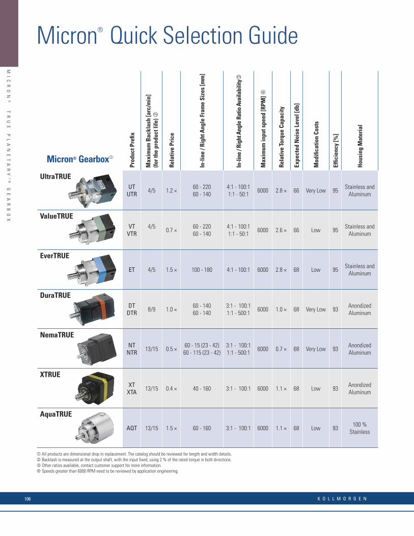
MI
CR
ON
®
T
RU
E
PL
AN
ET
AR
YT
M
GE
AR
BO
X
Micron® TRUE PlanetaryTM Gearbox
Micron® Gearbox
Prod
uct P
refi x
Max
imum
Bac
klas
h [a
rc/m
in]
(for t
he p
rodu
ct li
fe)
Rela
tive
Pric
e
In-l
ine
/ Rig
ht A
ngle
Fra
me
Size
s [m
m]
In-li
ne /
Righ
t Ang
le R
atio
Ava
ilabi
lity
Max
imum
inpu
t spe
ed [R
PM]
Rela
tive
Torq
ue C
apac
ity
Expe
cted
Noi
se L
evel
[db]
Mod
ifi ca
tion
Cost
s
Effi c
ienc
y [%
]
Hou
sing
Mat
eria
l
UltraTRUEUT
UTR 4/5 1.2 ×60 - 220 60 - 140
4:1 - 100:11:1 - 50:1
6000 2.8 × 66 Very Low 95Stainless and
Aluminum
ValueTRUEVT
VTR4/5
0.7 ×60 - 22060 - 140
4:1 - 100:11:1 - 50:1
6000 2.6 × 66 Low 95Stainless and
Aluminum
EverTRUE
ET 4/5 1.5 × 100 - 180 4:1 - 100:1 6000 2.8 × 68 Low 95Stainless and
Aluminum
DuraTRUEDT
DTR 8/9 1.0 × 60 - 14060 - 140
3:1 - 100:11:1 - 500:1
6000 1.0 × 68 Very Low 93Anondized Aluminum
NemaTRUENT
NTR 13/15 0.5 × 60 - 15 (23 - 42)60 - 115 (23 - 42)
3:1 - 100:11:1 - 500:1
6000 0.7 × 68 Very Low 93Anondized Aluminum
XTRUEXT
XTA 13/15 0.4 × 40 - 160 3:1 - 100:1 6000 1.1 × 68 Low 93Anondized Aluminum
AquaTRUE
AQT 13/15 1.5 × 60 - 160 3:1 - 100:1 6000 1.1 × 68 Low 93100 %
Stainless
All products are dimensional drop in replacement. The catalog should be reviewed for length and width details. Backlash is measured at the output shaft, with the input fixed, using 2 % of the rated torque in both directions. Other ratios available, contact customer support for more information. Speeds greater than 6000 RPM need to be reviewed by application engineering.
Micron® Quick Selection Guide
Prod
uct P
refi x
Low
er B
ackl
ash
Opt
ion
Dou
ble
Stag
e Av
aila
ble
True
Pla
neta
ry G
eari
ng
Hel
ical
Cro
wne
d G
eari
ng
Lubr
icat
ed fo
r Life
Dua
l and
Hol
low
Sha
fts A
vaila
ble
3D C
AD
Mod
els
on M
icro
n M
otio
neer
ing
One
Pie
ce O
utpu
t Sha
ft/Ca
rrie
r
Inte
rnal
Gea
r Mac
hine
d in
to H
ousi
ng
ROH
S Co
mpl
iant
Case
Har
dene
d G
ears
(HRC
60)
Gea
rbox
Exp
ress
Low
Tem
pera
ture
Gre
ase
Avai
labl
e
Food
Gra
de G
reas
e Av
aila
ble
NSF
Cer
tifi e
d
Redi
Mou
nt C
ompl
iant
Ultr
aTRU
E
UTUTR • • • • • • • • • • • • •
Valu
eTRU
E
VTVTR • • • • • • • • • • • • •
Ever
TRU
E
ET • • • • • • • • • • • •
Dur
aTRU
E
DTDTR • • • • • • • • • • • •
Nem
aTRU
E
NTNTR • • • • • • • • • • • •
XTRU
E
XTXTA • • • • • • • • • • •
Aqu
aTRU
E
AQT • • • • • • • • • • •
Lower backlash, high precision available (8/9 arc-min). Double stage AquaTRUE now available. ROHS on right angle product is still being confirmed. Geahead express not available in frame sizes larger than 140 mm or dual and hollow shafts. The AquaTRUE is certified to NSF/ANSO STD 169.
RediMount™ – Fast and Error Free Motor MountingThe unique RediMount system will mount any Micron gearhead to any motor in just three simple steps in less than five minutes!
Superior TechnologyAll Micron gears are case hardened to HRC60 for longer life. Our UltraTRUE and ValueTRUE models have a higher helix angle (15 °) than our competitors’ helical gearheads resulting in less backlash, smoother
and quieter operation and longer life.
Lubricated For LifeMicron gearheads require no maintenance and are grease filled. Unlike oil filled units, they can be mounted in any orientation and will never leak.
Unmatched Product BreadthMicron has the largest selection of planetary gearheads in the world with over 3000 size and ratio combinations.
Unmatched QualityAll Micron gearheads are tested through our state of the art end of line tester, making our outgoing quality best in the market.
Made in the USAAll Micron Gearheads are manufactured in the USA making us able to respond to emergencies quickly reducing down time for our customers.
3
4
5
6
2
1
6 Reasons to Choose Micron® Gearboxes
K O L L M O R G E N106

MI
CR
ON
®
T
RU
E
PL
AN
ET
AR
YT
M
GE
AR
BO
X
Micron® Gearbox
Prod
uct P
refi x
Max
imum
Bac
klas
h [a
rc/m
in]
(for t
he p
rodu
ct li
fe)
Rela
tive
Pric
e
In-l
ine
/ Rig
ht A
ngle
Fra
me
Size
s [m
m]
In-li
ne /
Righ
t Ang
le R
atio
Ava
ilabi
lity
Max
imum
inpu
t spe
ed [R
PM]
Rela
tive
Torq
ue C
apac
ity
Expe
cted
Noi
se L
evel
[db]
Mod
ifi ca
tion
Cost
s
Effi c
ienc
y [%
]
Hou
sing
Mat
eria
l
UltraTRUEUT
UTR 4/5 1.2 ×60 - 220 60 - 140
4:1 - 100:11:1 - 50:1
6000 2.8 × 66 Very Low 95Stainless and
Aluminum
ValueTRUEVT
VTR4/5
0.7 ×60 - 22060 - 140
4:1 - 100:11:1 - 50:1
6000 2.6 × 66 Low 95Stainless and
Aluminum
EverTRUE
ET 4/5 1.5 × 100 - 180 4:1 - 100:1 6000 2.8 × 68 Low 95Stainless and
Aluminum
DuraTRUEDT
DTR 8/9 1.0 × 60 - 14060 - 140
3:1 - 100:11:1 - 500:1
6000 1.0 × 68 Very Low 93Anondized Aluminum
NemaTRUENT
NTR 13/15 0.5 × 60 - 15 (23 - 42)60 - 115 (23 - 42)
3:1 - 100:11:1 - 500:1
6000 0.7 × 68 Very Low 93Anondized Aluminum
XTRUEXT
XTA 13/15 0.4 × 40 - 160 3:1 - 100:1 6000 1.1 × 68 Low 93Anondized Aluminum
AquaTRUE
AQT 13/15 1.5 × 60 - 160 3:1 - 100:1 6000 1.1 × 68 Low 93100 %
Stainless
All products are dimensional drop in replacement. The catalog should be reviewed for length and width details. Backlash is measured at the output shaft, with the input fixed, using 2 % of the rated torque in both directions. Other ratios available, contact customer support for more information. Speeds greater than 6000 RPM need to be reviewed by application engineering.
Micron® Quick Selection GuidePr
oduc
t Pre
fi x
Low
er B
ackl
ash
Opt
ion
Dou
ble
Stag
e Av
aila
ble
True
Pla
neta
ry G
eari
ng
Hel
ical
Cro
wne
d G
eari
ng
Lubr
icat
ed fo
r Life
Dua
l and
Hol
low
Sha
fts A
vaila
ble
3D C
AD
Mod
els
on M
icro
n M
otio
neer
ing
One
Pie
ce O
utpu
t Sha
ft/Ca
rrie
r
Inte
rnal
Gea
r Mac
hine
d in
to H
ousi
ng
ROH
S Co
mpl
iant
Case
Har
dene
d G
ears
(HRC
60)
Gea
rbox
Exp
ress
Low
Tem
pera
ture
Gre
ase
Avai
labl
e
Food
Gra
de G
reas
e Av
aila
ble
NSF
Cer
tifi e
d
Redi
Mou
nt C
ompl
iant
Ultr
aTRU
E
UTUTR • • • • • • • • • • • • •
Valu
eTRU
E
VTVTR • • • • • • • • • • • • •
Ever
TRU
E
ET • • • • • • • • • • • •
Dur
aTRU
E
DTDTR • • • • • • • • • • • •
Nem
aTRU
E
NTNTR • • • • • • • • • • • •
XTRU
E
XTXTA • • • • • • • • • • •
Aqu
aTRU
E
AQT • • • • • • • • • • •
Lower backlash, high precision available (8/9 arc-min). Double stage AquaTRUE now available. ROHS on right angle product is still being confirmed. Geahead express not available in frame sizes larger than 140 mm or dual and hollow shafts. The AquaTRUE is certified to NSF/ANSO STD 169.
RediMount™ – Fast and Error Free Motor MountingThe unique RediMount system will mount any Micron gearhead to any motor in just three simple steps in less than five minutes!
Superior TechnologyAll Micron gears are case hardened to HRC60 for longer life. Our UltraTRUE and ValueTRUE models have a higher helix angle (15 °) than our competitors’ helical gearheads resulting in less backlash, smoother
and quieter operation and longer life.
Lubricated For LifeMicron gearheads require no maintenance and are grease filled. Unlike oil filled units, they can be mounted in any orientation and will never leak.
Unmatched Product BreadthMicron has the largest selection of planetary gearheads in the world with over 3000 size and ratio combinations.
Unmatched QualityAll Micron gearheads are tested through our state of the art end of line tester, making our outgoing quality best in the market.
Made in the USAAll Micron Gearheads are manufactured in the USA making us able to respond to emergencies quickly reducing down time for our customers.
3
4
5
6
2
1
6 Reasons to Choose Micron® Gearboxes
w w w. k o l l m o r g e n . c o m 107
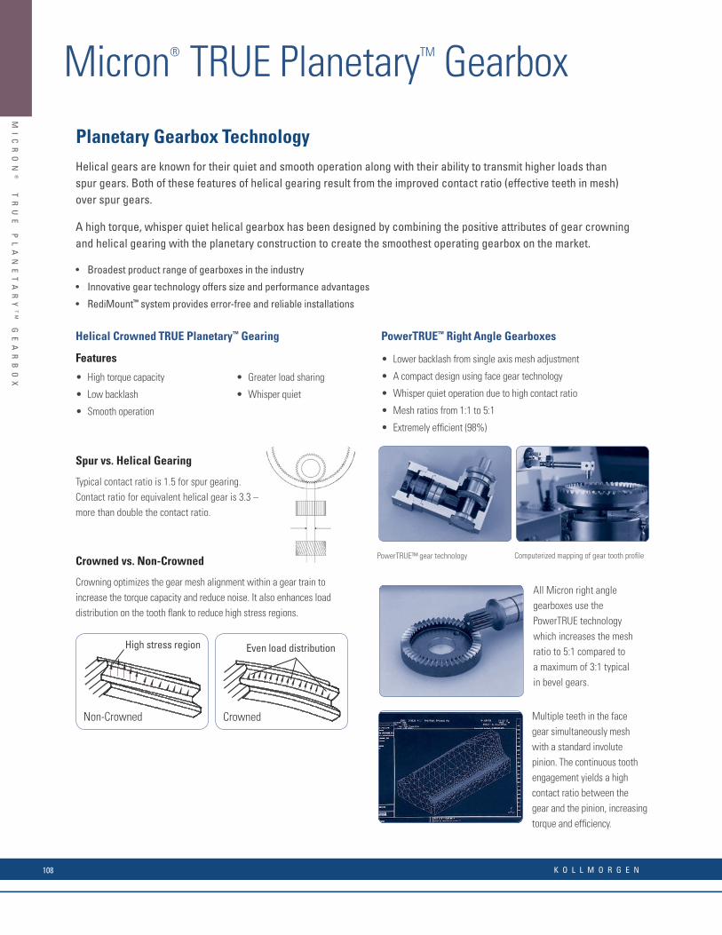
MI
CR
ON
®
T
RU
E
PL
AN
ET
AR
YT
M
GE
AR
BO
X
Micron® TRUE PlanetaryTM Gearbox
Helical Crowned TRUE Planetary™ Gearing
Features
Spur vs. Helical Gearing
Typical contact ratio is 1.5 for spur gearing.Contact ratio for equivalent helical gear is 3.3 –more than double the contact ratio.
Crowned vs. Non-Crowned
Crowning optimizes the gear mesh alignment within a gear train to increase the torque capacity and reduce noise. It also enhances load distribution on the tooth fl ank to reduce high stress regions.
PowerTRUE™ Right Angle Gearboxes
• Lower backlash from single axis mesh adjustment
• A compact design using face gear technology
• Whisper quiet operation due to high contact ratio
• Mesh ratios from 1:1 to 5:1
• Extremely effi cient (98%)
• High torque capacity
• Low backlash
• Smooth operation
• Greater load sharing
• Whisper quiet
High stress region
Non-Crowned
Even load distribution
Crowned
Helical gears are known for their quiet and smooth operation along with their ability to transmit higher loads than spur gears. Both of these features of helical gearing result from the improved contact ratio (effective teeth in mesh) over spur gears.
A high torque, whisper quiet helical gearbox has been designed by combining the positive attributes of gear crowning and helical gearing with the planetary construction to create the smoothest operating gearbox on the market.
• Broadest product range of gearboxes in the industry
• Innovative gear technology offers size and performance advantages
• RediMount™ system provides error-free and reliable installations
Computerized mapping of gear tooth profi lePowerTRUE™ gear technology
All Micron right angle gearboxes use the PowerTRUE technology which increases the mesh ratio to 5:1 compared to a maximum of 3:1 typical in bevel gears.
Multiple teeth in the face gear simultaneously mesh with a standard involute pinion. The continuous tooth engagement yields a high contact ratio between the gear and the pinion, increasing torque and effi ciency.
Planetary Gearbox Technology
K O L L M O R G E N108

MI
CR
ON
®
T
RU
E
PL
AN
ET
AR
YT
M
GE
AR
BO
X
Helical Crowned TRUE Planetary™ Gearing
Features
Spur vs. Helical Gearing
Typical contact ratio is 1.5 for spur gearing.Contact ratio for equivalent helical gear is 3.3 –more than double the contact ratio.
Crowned vs. Non-Crowned
Crowning optimizes the gear mesh alignment within a gear train to increase the torque capacity and reduce noise. It also enhances load distribution on the tooth fl ank to reduce high stress regions.
PowerTRUE™ Right Angle Gearboxes
• Lower backlash from single axis mesh adjustment
• A compact design using face gear technology
• Whisper quiet operation due to high contact ratio
• Mesh ratios from 1:1 to 5:1
• Extremely effi cient (98%)
• High torque capacity
• Low backlash
• Smooth operation
• Greater load sharing
• Whisper quiet
High stress region
Non-Crowned
Even load distribution
Crowned
Helical gears are known for their quiet and smooth operation along with their ability to transmit higher loads than spur gears. Both of these features of helical gearing result from the improved contact ratio (effective teeth in mesh) over spur gears.
A high torque, whisper quiet helical gearbox has been designed by combining the positive attributes of gear crowning and helical gearing with the planetary construction to create the smoothest operating gearbox on the market.
• Broadest product range of gearboxes in the industry
• Innovative gear technology offers size and performance advantages
• RediMount™ system provides error-free and reliable installations
Computerized mapping of gear tooth profi lePowerTRUE™ gear technology
All Micron right angle gearboxes use the PowerTRUE technology which increases the mesh ratio to 5:1 compared to a maximum of 3:1 typical in bevel gears.
Multiple teeth in the face gear simultaneously mesh with a standard involute pinion. The continuous tooth engagement yields a high contact ratio between the gear and the pinion, increasing torque and effi ciency.
Planetary Gearbox Technology
AK
D
SE
RV
O
SY
ST
EM
S
TR
UE
P
LA
NE
TA
RY
G
EA
RB
OX
Micron™ TRUE Planetary™ Gearbox NEMA TRUE™ True planetary gearbox, fl ange mount design with anodized aluminum housing employing RediMount™ system.
InlineFrame Size Max T Peak (lb-in)
All Sizes Gear Ratios Available Effi ciency Backlash (arc-min)English Metric 1 Stage 2 Stage
Size 17 NEMA 17 42 mm 170 1701 Stage 3, 4, 5, 7, 10 93% 13 (8)*
Size 23 / 60 NEMA 23 60 mm 250 275
Size 34 / 90 NEMA 34 90 mm 700 8502 Stage 15, 20, 25, 30, 40, 50, 70, 100 88% 15 (9)*
Size 42 / 115 NEMA 42 115 mm 1000 1600
NEMA TRUE™ True planetary gearbox, fl ange mount design with anodized aluminum housing employing RediMount™ system.
Right Angle
Frame Size Max T Peak (lb-in)All Sizes Gear Ratios Available Effi ciency Backlash
(arc-min)English Metric 1 Stage 2 Stage 3 Stage
Size 23 / 60 NEMA 23 60 mm 360 366 366 1 Stage 1, 2, 3, 4, 5P 98% 13
Size 34 / 90 NEMA 34 90 mm 1110 1110 1110 2 Stage 5T, 6, 9, 10, 12, 15, 20, 25, 30, 40, 50 93% 15
Size 42 / 115 NEMA 42 115 mm 2250 2250 2250 3 Stage 60, 75, 90, 100, 120, 125, 150, 200, 250, 300, 400, 500 88% 15
XTRUE™ The XTRUE Series is a new precision gearbox employing RediMount™ system that compliments our TRUE planetary gearbox line – already the largest selection of planetary gearboxes in the world.
Inline Frame SizeMetric
Max T Peak (lb-in)All Sizes Gear Ratios Available Effi ciency Backlash
(arc-min)1 Stage 2 Stage
XT040 40 mm 162 299
1 Stage 3, 4, 5, 7, 8, 10 93% 13
XT060 60 mm 483 483
XT080 80 mm 1460 1550
XT120 120 mm 2640 2640
XT160 160 mm 7750 7750
2 Stage 15, 20, 25, 30, 40, 50, 70, 80, 100 88% 15
XTA050 50 mm 162 299
XTA070 70 mm 483 483
XTA090 90 mm 1460 1552
XTA120 120 mm 2639 2639
EverTRUE™ EverTRUE, employing RediMount™ system, is specifi cally designed for 24/7 continuous running applications providing 3 times (30,000 hours) service life.
Inline Frame SizeMetric
Max T Peak (lb-in)All Sizes Gear Ratios Available Effi ciency Backlash
(arc-min)1 Stage 2 Stage
ET010 101 mm 4093 47941 Stage 4, 5, 7, 10 95% 4
ET014 141 mm 9430 11,250
2 Stage 16, 20, 25, 28, 35, 40, 50, 70, 100 90% 5ET018 182 mm 21,600 26,280
ntinuous duty operation. Superior thermal management. Tapered roller bearings.
* High Precision, low backlash versions available, low backlash value in parenthesis (Not available in size 17).Note 1: Torque capacity is maximum of frame size stage design, not all ratios have the same rated torque capacity. Note 2: Torque capacity is the maximum allowable momentary torque for emergency stopping or heavy shock loading.Note 3: Ratio 5P is designed using the compact PowerTrue face gearing technology.Note 4: Ratio 5T is designed using a True planetary gear stage for increased torque capacity.Note 5: For complete gearbox model nomenclature, refer to page 95.
Note 1: Torque capacity is maximum of frame size stage design, not all ratios have the same rated torque capacity. Note 2: Torque capacity is the maximum allowable momentary torque for emergency stopping or heavy shock loading.Note 3: Ratio 5P is designed using the compact PowerTrue face gearing technology.Note 4: Ratio 5T is designed using a True planetary gear stage for increased torque capacity. Note 5: For complete gearbox model nomenclature, refer to page 196.
w w w. k o l l m o r g e n . c o m 109
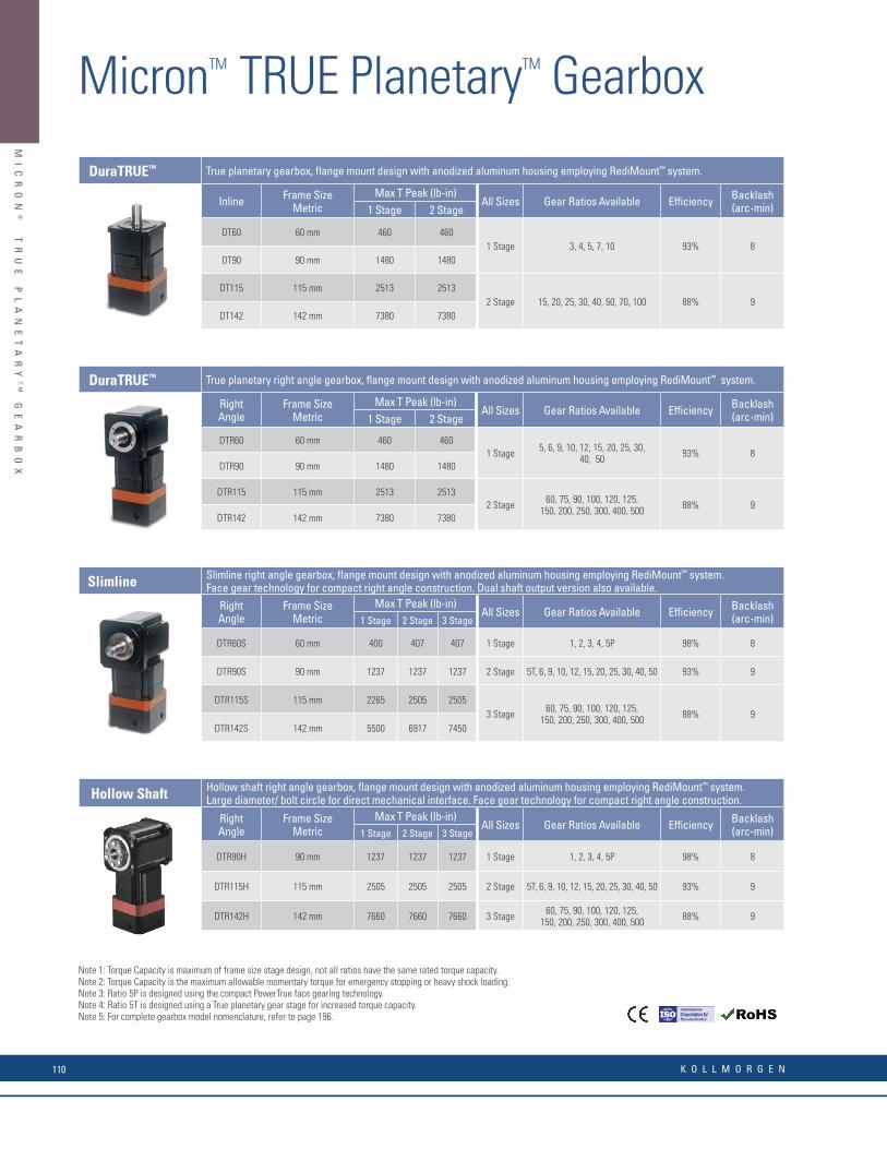
MI
CR
ON
®
T
RU
E
PL
AN
ET
AR
YT
M
GE
AR
BO
X
Micron® TRUE PlanetaryTM Gearbox
DuraTRUE™ True planetary gearbox, fl ange mount design with anodized aluminum housing employing RediMount™ system.
Inline Frame SizeMetric
Max T Peak (lb-in)All Sizes Gear Ratios Available Effi ciency Backlash
(arc-min)1 Stage 2 Stage
DT60 60 mm 460 4601 Stage 3, 4, 5, 7, 10 93% 8
DT90 90 mm 1480 1480
DT115 115 mm 2513 25132 Stage 15, 20, 25, 30, 40, 50, 70, 100 88% 9
DT142 142 mm 7380 7380
DuraTRUE™ True planetary right angle gearbox, fl ange mount design with anodized aluminum housing employing RediMount™ system.
Right Angle
Frame SizeMetric
Max T Peak (lb-in)All Sizes Gear Ratios Available Effi ciency Backlash
(arc-min)1 Stage 2 Stage
DTR60 60 mm 460 4601 Stage 5, 6, 9, 10, 12, 15, 20, 25, 30,
40, 50 93% 8DTR90 90 mm 1480 1480
DTR115 115 mm 2513 25132 Stage 60, 75, 90, 100, 120, 125,
150, 200, 250, 300, 400, 500 88% 9DTR142 142 mm 7380 7380
Slimline Slimline right angle gearbox, fl ange mount design with anodized aluminum housing employing RediMount™ system. Face gear technology for compact right angle construction. Dual shaft output version also available.
Right Angle
Frame SizeMetric
Max T Peak (lb-in)All Sizes Gear Ratios Available Effi ciency Backlash
(arc-min)1 Stage 2 Stage 3 Stage
DTR60S 60 mm 400 407 407 1 Stage 1, 2, 3, 4, 5P 98% 8
DTR90S 90 mm 1237 1237 1237 2 Stage 5T, 6, 9, 10, 12, 15, 20, 25, 30, 40, 50 93% 9
DTR115S 115 mm 2265 2505 25053 Stage 60, 75, 90, 100, 120, 125,
150, 200, 250, 300, 400, 500 88% 9DTR142S 142 mm 5500 6917 7450
Hollow Shaft Hollow shaft right angle gearbox, fl ange mount design with anodized aluminum housing employing RediMount™ system. Large diameter/ bolt circle for direct mechanical interface. Face gear technology for compact right angle construction.
Right Angle
Frame SizeMetric
Max T Peak (lb-in)All Sizes Gear Ratios Available Effi ciency Backlash
(arc-min)1 Stage 2 Stage 3 Stage
DTR90H 90 mm 1237 1237 1237 1 Stage 1, 2, 3, 4, 5P 98% 8
DTR115H 115 mm 2505 2505 2505 2 Stage 5T, 6, 9, 10, 12, 15, 20, 25, 30, 40, 50 93% 9
DTR142H 142 mm 7660 7660 7660 3 Stage 60, 75, 90, 100, 120, 125,150, 200, 250, 300, 400, 500 88% 9
ntinuous duty operation. Superior thermal management. Tapered roller bearings.Note 1: Torque Capacity is maximum of frame size stage design, not all ratios have the same rated torque capacity. Note 2: Torque Capacity is the maximum allowable momentary torque for emergency stopping or heavy shock loading.Note 3: Ratio 5P is designed using the compact PowerTrue face gearing technology.Note 4: Ratio 5T is designed using a True planetary gear stage for increased torque capacity.Note 5: For complete gearbox model nomenclature, refer to page 95.
MicronTM TRUE PlanetaryTM Gearbox
Note 1: Torque Capacity is maximum of frame size stage design, not all ratios have the same rated torque capacity. Note 2: Torque Capacity is the maximum allowable momentary torque for emergency stopping or heavy shock loading.Note 3: Ratio 5P is designed using the compact PowerTrue face gearing technology.Note 4: Ratio 5T is designed using a True planetary gear stage for increased torque capacity. Note 5: For complete gearbox model nomenclature, refer to page 196.
K O L L M O R G E N110

MI
CR
ON
®
T
RU
E
PL
AN
ET
AR
YT
M
GE
AR
BO
X
ValueTRUE™ Helical True planetary gearbox, fl ange mount design with stainless steel housing employing RediMount™ system.
Inline Frame SizeMetric
Max T Peak (lb-in)All Sizes Gear Ratios Available Effi ciency Backlash
(arc-min)1 Stage 2 Stage
VT006 61 mm 800 910
1 Stage 4, 5, 7, 10 95% 4VT075 75 mm 1423 1632
VT090 90 mm 1423 1632
VT010 101 mm 4093 4794
VT115 115 mm 4093 4794
2 Stage 16, 20, 25, 28, 35, 40, 50, 70, 100 90% 5VT014 141 mm 9430 11,250
VT018 182 mm 21,609 26,287
VT022 220 mm 36,986 44,000
ValueTRUE™ Helical True planetary gearbox, fl ange mount design with stainless steel housing employing RediMount™ system.
Right Angle
Frame SizeMetric
Max T Peak (lb-in)All Sizes* Gear Ratios Available Effi ciency Backlash
(arc-min)1 StageVTR006 61 mm 876
1 Stage 4, 5, 8, 10, 12, 14, 15, 16, 20, 25, 28, 30, 35, 40, 50 93% 5
VTR075 75 mm 1570
VTR090 90 mm 1570
VTR010 101 mm 4580
VTR115 115 mm 4580
VTR014 141 mm 10,673
VTR018 182 mm 24,780
UltraTRUE™ Helical True planetary inline gearbox, fl ange mount design with anodized aluminum housing employing RediMount™ system. Stainless steel housing, gear-path hobbed into stainless steel housing.
Inline Frame SizeMetric
Max T Peak (lb-in)All Sizes Gear Ratios Available Effi ciency Backlash
(arc-min)1 Stage 2 StageUT006 61 mm 890 1010
1 Stage 4, 5, 7, 10 95% 4UT075 75 mm 1580 1813
UT090 90 mm 1580 1813
UT010 101 mm 4548 5327
UT115 115 mm 4548 5327
2 Stage 16, 20, 25, 28, 35, 40, 50, 70, 100 90% 5UT014 141 mm 10,480 12,500
UT018 182 mm 24,010 29,200
UT022 220 mm 41,096 48,890
UltraTRUE™ Helical True planetary right angle gearbox, fl ange mount design with anodized aluminum housing employing RediMount™ system. Stainless steel housing, gear-path hobbed into stainless steel housing.
Right Angle
Frame SizeMetric
Max T Peak (lb-in)All Sizes Gear Ratios Available Effi ciency Backlash
(arc-min)1 Stage 2 StageUTR006 61 mm 456 975
1 Stage 1, 2, 3, 4, 5 98% 4UTR075 75 mm 1410 1740
UTR090 90 mm 1410 1740
UTR010 101 mm 2856 5085
2 Stage 8, 10, 12, 14, 15, 16,20, 25, 28, 30, 35, 40, 50 93% 5
UTR115 115 mm 2856 5085
UTR014 141 mm 6270 11,860
UTR018 182 mm 16,914 27,530
ntinuous duty operation. Superior thermal management. Tapered roller bearings.
* 4 and 5:1 ratios not available with VTR006-VTR090.
Note 1: Torque capacity is maximum of frame size stage design, not all ratios have the same rated torque capacity. Note 2: Torque capacity is the maximum allowable momentary torque for emergency stopping or heavy shock loading.Note 3: Ratio 5P is designed using the compact PowerTrue face gearing technology.Note 4: Ratio 5T is designed using a True planetary gear stage for increased torque capacity.Note 5: For complete gearbox model nomenclature, refer to page 95.
Note 1: Torque capacity is maximum of frame size stage design, not all ratios have the same rated torque capacity. Note 2: Torque capacity is the maximum allowable momentary torque for emergency stopping or heavy shock loading.Note 3: Ratio 5P is designed using the compact PowerTrue face gearing technology.Note 4: Ratio 5T is designed using a True planetary gear stage for increased torque capacity. Note 5: For complete gearbox model nomenclature, refer to page 196.
w w w. k o l l m o r g e n . c o m 111

AQ
UA
TR
UE
™
HY
GI
EN
IC
I
P6
9K
G
EA
RB
OX
AquaTRUE™ Hygienic IP69K Gearbox
Tested for IP66, IP67 and IP69K Protection Throughout
300 Series Stainless Steel Housing
Non-Contact Labyrinth Seal for Minimal wear and
Maximum Protection
Stainless SteelOutput Shaft
Silicone Gasket to seal motor-gearbox interface
Round and SquareMotor Mounts
1 pc. Housing - No External Seams
Permanent Product Label(Laser Etched)
AquaTrue Hygienic IP69K Gearbox
Micron’s new AquaTRUE gearbox combines the high performance and torque capacity of Micron’s True Planetarygearboxes with features specifi cally designed to meet the strict requirements of applications such as food and beveragehandling, packaging and dispensing. The AquaTRUE’s IP66/IP67 and IP69K protection is able to handle caustic cleaningchemicals as well as high pressure washdown. Until now, manufacturers have been unable to use gearboxes in manyapplications involving harsh environments because there was not a product available that met those needs. TheAquaTRUE is engineered to be placed anywhere in the application’s design, regardless of environmental factors. Thiseliminates the cost of additional components such as enclosers, shielding or mechanical transmissions.The gearbox’s 304 stainless steel housing eliminates the concern for rust or any type of corrosion. The AquaTRUEhas a laser etched permanent product label and a smooth, round external housing that is designed without anyexternal seams or corners for bacteria to collect. This makes the AquaTRUE very easy to clean and a perfect fi t in anywashdown environment.
• Frame Sizes: 60 mm, 80 mm, 120 mm, 160 mm• Precision: 13 arc-min max• Torque Capacity: up to 876 Nm• Ratio Availability: 3:1 to 100:1 (1 and 2 stage)
Features and Benefi ts• Round Housing• No External Seams• 300 Series Stainless Steel• IP66/IP67 and IP69K Protection on both the input and output• NSF/ANSI 169 Certifi cation
• No corners or areas for bacteria to collect• No areas of ingress• Corrosion Resistance• Can handle high pressure washdown
The perfect gearbox to mate to the AKMH Series...
AQ
UA
TR
UE
G
EA
RB
OX
I
P6
6/
IP
67
A
ND
I
P6
9
AquaTrue Hygienic IP69K Gearbox
AQ
UA
TR
UE
G
EA
RB
OX
I
P6
6/
IP
67
A
ND
I
P6
9
The AKMH can be ordered with the AquaTRUE gearbox mounted at our factory for a perfectly integrated hygienic gearmotor solution. If you need more power than the AKMH can provide, the addition of an AquaTRUE gearbox will add the power you need while maintaining a hygienic solution. The AKMH/AquaTRUE combination also maintains the IP69K rating. The hygienic stainless steel and food-grade materials make it a perfect fi t for all your food and beverage applications.
Example P/N: “AKMH42E-CNKNC-1K + AQT080-003-0-MMR-726”
AquaTRUE™ True planetary gearbox, fl ange mount design with anodized aluminum housing employing RediMount™ system.
Inline Frame Size MetricMax T Peak (lb-in)
All Sizes Gear Ratios Available Effi ciency Backlash (arc-min)1 Stage 2 Stage
AQT060 60 mm 483 4831 Stage 3, 4, 5, 7, 8, 10 93% 13
AQT080 80 mm 1460 1552AQT120 110.5 mm 2639 2639
2 Stage 15, 20, 25, 30, 40, 50, 70, 80, 100 88% 13AQT160 140 mm 7750 7750
K O L L M O R G E N112

AQ
UA
TR
UE
™
HY
GI
EN
IC
I
P6
9K
G
EA
RB
OX
Tested for IP66, IP67 and IP69K Protection Throughout
300 Series Stainless Steel Housing
Non-Contact Labyrinth Seal for Minimal wear and
Maximum Protection
Stainless SteelOutput Shaft
Silicone Gasket to seal motor-gearbox interface
Round and SquareMotor Mounts
1 pc. Housing - No External Seams
Permanent Product Label(Laser Etched)
AquaTrue Hygienic IP69K Gearbox
Micron’s new AquaTRUE gearbox combines the high performance and torque capacity of Micron’s True Planetarygearboxes with features specifi cally designed to meet the strict requirements of applications such as food and beveragehandling, packaging and dispensing. The AquaTRUE’s IP66/IP67 and IP69K protection is able to handle caustic cleaningchemicals as well as high pressure washdown. Until now, manufacturers have been unable to use gearboxes in manyapplications involving harsh environments because there was not a product available that met those needs. TheAquaTRUE is engineered to be placed anywhere in the application’s design, regardless of environmental factors. Thiseliminates the cost of additional components such as enclosers, shielding or mechanical transmissions.The gearbox’s 304 stainless steel housing eliminates the concern for rust or any type of corrosion. The AquaTRUEhas a laser etched permanent product label and a smooth, round external housing that is designed without anyexternal seams or corners for bacteria to collect. This makes the AquaTRUE very easy to clean and a perfect fi t in anywashdown environment.
• Frame Sizes: 60 mm, 80 mm, 120 mm, 160 mm• Precision: 13 arc-min max• Torque Capacity: up to 876 Nm• Ratio Availability: 3:1 to 100:1 (1 and 2 stage)
Features and Benefi ts• Round Housing• No External Seams• 300 Series Stainless Steel• IP66/IP67 and IP69K Protection on both the input and output• NSF/ANSI 169 Certifi cation
• No corners or areas for bacteria to collect• No areas of ingress• Corrosion Resistance• Can handle high pressure washdown
The perfect gearbox to mate to the AKMH Series...
AQ
UA
TR
UE
G
EA
RB
OX
I
P6
6/
IP
67
A
ND
I
P6
9
AquaTrue Hygienic IP69K GearboxA
QU
AT
RU
E
GE
AR
BO
X
IP
66
/I
P6
7
AN
D
IP
69
The AKMH can be ordered with the AquaTRUE gearbox mounted at our factory for a perfectly integrated hygienic gearmotor solution. If you need more power than the AKMH can provide, the addition of an AquaTRUE gearbox will add the power you need while maintaining a hygienic solution. The AKMH/AquaTRUE combination also maintains the IP69K rating. The hygienic stainless steel and food-grade materials make it a perfect fi t for all your food and beverage applications.
Example P/N: “AKMH42E-CNKNC-1K + AQT080-003-0-MMR-726”
AquaTRUE™ True planetary gearbox, fl ange mount design with anodized aluminum housing employing RediMount™ system.
Inline Frame Size MetricMax T Peak (lb-in)
All Sizes Gear Ratios Available Effi ciency Backlash (arc-min)1 Stage 2 Stage
AQT060 60 mm 483 4831 Stage 3, 4, 5, 7, 8, 10 93% 13
AQT080 80 mm 1460 1552AQT120 110.5 mm 2639 2639
2 Stage 15, 20, 25, 30, 40, 50, 70, 80, 100 88% 13AQT160 140 mm 7750 7750
w w w. k o l l m o r g e n . c o m 113

LI
NE
AR
A
CT
UA
TO
RS
Model Product Family General Information
Electric Cylinders1
EC1
EC2
EC3
EC4
EC5
N2
• Highest Force (Thrust)
• Clean, Hydraulic Replacement
• Compact Cross Section
• Extends into Work Area
Rodless Actuators
(screw drive)
R2A
R3
R4
• High Force (Thrust)
• High Repeatability
• Long Travel
• Load Carrying Capability
Rodless Actuators
(belt drive)
R2A
R3
R4
• Very High Speed
• Quiet Operation
• Long Travel
• Load Carrying Capability
Precision TablesDS4
DS6
• High Accuracy & Repeatability
• Low Maintenance, Long Life
• High Moment Loads
Kollmorgen offers a comprehensive range of linear actuator products including electric cylinders, rodless actuators, and precision tables to meet a wide range of application requirements. For actuator products not included in this catalog go to www.kollmorgen.com for information about other Kollmorgen linear positioning products.
Electric Cylinders (EC)
Primarily designed to apply a force through an extendable rod, electric cylinders are a clean and effi cient replacement for hydraulic actuators and pneumatic cylinders, and an alternative to many types of linear transmissions. A wide variety of mounting and coupling alternatives signifi cantly increases their problem solving potential.
Rodless Actuators
Long travel, quiet operation, and high moment loading differentiates rodless actuators from other mechanical transmissions.
Precision Tables
Positioning tables are used when accurate and repeatable motion is critical (1 part per 10,000 or better). These tables offer a wide variety of single and multi-axis confi gurations, open and closed frame tables, ball or lead screw driven, and overhung and constant support for Kollmorgen geometry confi gurations.
Model Max Speed 3
In/s (mm/s)Max Thrust 2, 3
Lb (N)Repeatability 4, 5
In (mm)Max Payload
Lb (kg)Max Travel
In (mm)
Electric Cylinders152.5
(1330)
5620
(25,000)
to 0.0005
(0.013)Note 1
59.1
(1500)
Rodless Actuators
(screw drive)
39
(1000)
700
(3110)
to 0.0005
(0.013)
300
(136)
108
(2743)
Rodless Actuators
(belt drive)
118
(3000)
300
(1330)
to 0.004
(0.10)
300
(136)
108
(2743)
Precision Tables32.5
(825)
440
(1960)
3 microns (commer-
cial grade) /
1.3 microns (precision
grade)
794
(360)
79
(2000)
Notes:1. Electric cylinders are designed primarily for thrust application where loads are supported externally.2. Thrust ratings are based on mechanical limits rather than motor limits unless indicated otherwise.3. Max speed and max thrust ratings are not necessarily available simultaneously4. Repeatability is dependent on feedback resolution, load, friction, and drive gain settings.5. Repeatability is unidirectional unless otherwise specified
Linear Actuation & Positioning Systems
K O L L M O R G E N114
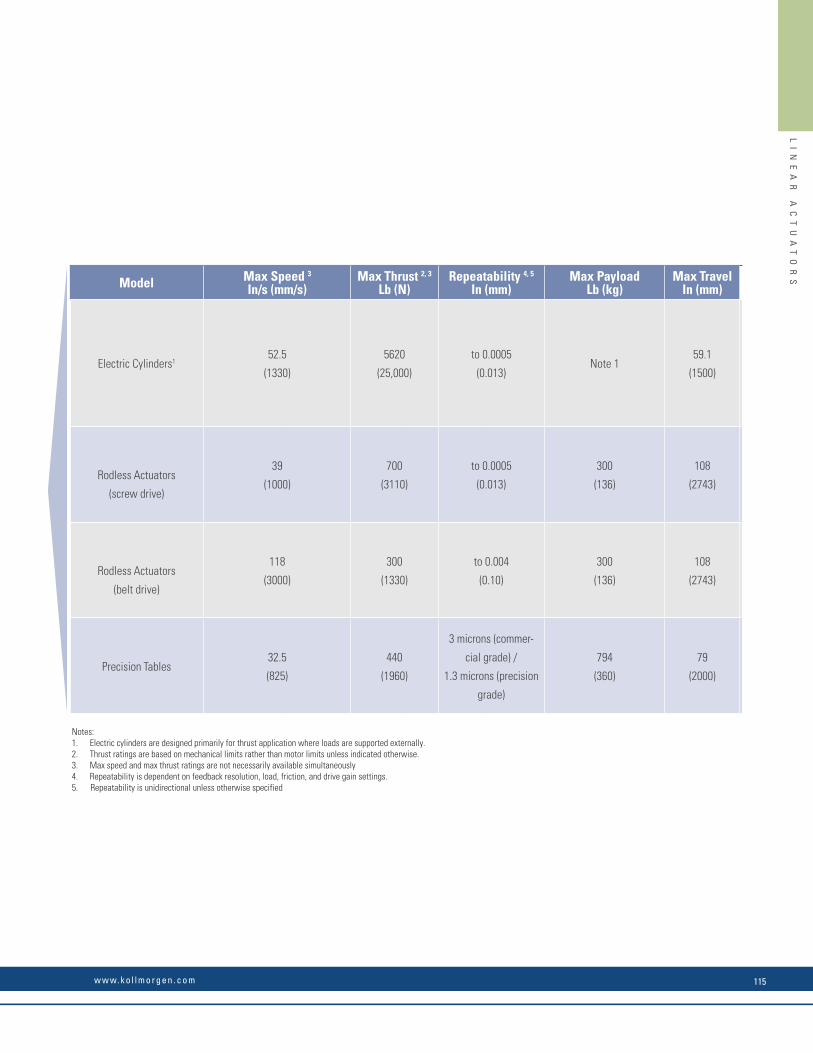
LI
NE
AR
A
CT
UA
TO
RS
Model Product Family General Information
Electric Cylinders1
EC1
EC2
EC3
EC4
EC5
N2
• Highest Force (Thrust)
• Clean, Hydraulic Replacement
• Compact Cross Section
• Extends into Work Area
Rodless Actuators
(screw drive)
R2A
R3
R4
• High Force (Thrust)
• High Repeatability
• Long Travel
• Load Carrying Capability
Rodless Actuators
(belt drive)
R2A
R3
R4
• Very High Speed
• Quiet Operation
• Long Travel
• Load Carrying Capability
Precision TablesDS4
DS6
• High Accuracy & Repeatability
• Low Maintenance, Long Life
• High Moment Loads
Kollmorgen offers a comprehensive range of linear actuator products including electric cylinders, rodless actuators, and precision tables to meet a wide range of application requirements. For actuator products not included in this catalog go to www.kollmorgen.com for information about other Kollmorgen linear positioning products.
Electric Cylinders (EC)
Primarily designed to apply a force through an extendable rod, electric cylinders are a clean and effi cient replacement for hydraulic actuators and pneumatic cylinders, and an alternative to many types of linear transmissions. A wide variety of mounting and coupling alternatives signifi cantly increases their problem solving potential.
Rodless Actuators
Long travel, quiet operation, and high moment loading differentiates rodless actuators from other mechanical transmissions.
Precision Tables
Positioning tables are used when accurate and repeatable motion is critical (1 part per 10,000 or better). These tables offer a wide variety of single and multi-axis confi gurations, open and closed frame tables, ball or lead screw driven, and overhung and constant support for Kollmorgen geometry confi gurations.
Model Max Speed 3
In/s (mm/s)Max Thrust 2, 3
Lb (N)Repeatability 4, 5
In (mm)Max Payload
Lb (kg)Max Travel
In (mm)
Electric Cylinders152.5
(1330)
5620
(25,000)
to 0.0005
(0.013)Note 1
59.1
(1500)
Rodless Actuators
(screw drive)
39
(1000)
700
(3110)
to 0.0005
(0.013)
300
(136)
108
(2743)
Rodless Actuators
(belt drive)
118
(3000)
300
(1330)
to 0.004
(0.10)
300
(136)
108
(2743)
Precision Tables32.5
(825)
440
(1960)
3 microns (commer-
cial grade) /
1.3 microns (precision
grade)
794
(360)
79
(2000)
Notes:1. Electric cylinders are designed primarily for thrust application where loads are supported externally.2. Thrust ratings are based on mechanical limits rather than motor limits unless indicated otherwise.3. Max speed and max thrust ratings are not necessarily available simultaneously4. Repeatability is dependent on feedback resolution, load, friction, and drive gain settings.5. Repeatability is unidirectional unless otherwise specified
w w w. k o l l m o r g e n . c o m 115

LI
NE
AR
A
CT
UA
TO
RS
Electric Cylinders N2 / EC SeriesElectric cylinders are thrust-producing devices that are best suited for applications requiring high axial force with the moment and side loads already properly supported.
Kollmorgen has combined the broad product offering of the N2 and EC Series electric cylinders with the industry-leading AKM servo motors and AKD servo drives. The N2 and EC Series of electric cylinders offer a wide range of available thrusts in standard units from 600 lb (N2) to 5620 lb (EC5) across 5 electric cylinder frame sizes.
• Speeds up to 52 in/sec are available and integrated geared options provide the ability to increase thrust capacity for lower speed applications, leveraging the speed capacity of servo systems.
• Multiple servo motor options are available for the product line ranging from NEMA 23 size to NEMA 42 size servos. The combination with the AKM servo motor enables the use of various feedback devices including sine-encoder and the low-cost but high-performance Smart Feedback Device (SFD) when used with the AKD servo drive.
• Windings and voltage operation are not differentiated in MOTIONEERING®. All systems are offered at all voltages (240, 400, 480).
• The AKM servo motor comes mounted on the electric cylinder as specified by the electric cylinder part number. This eliminates time to match the motor to the electric cylinder and eliminates potential mechanical incompatibility.
EL
EC
TR
IC
C
YL
IN
DE
RS
EC Servo Linear Actuators• Designed for performance• Highest quality precision rolled ballscrews and lead screws –
for quiet, long-life operation• Brushless Servo motor and Stepper motor options available• Sealed for IP54 protection. IP65 option available.• Thrust up to 25000 N [5620 lb]• Speed up to 1.3 m/s [52.5 in/s]• Metric design (ISO 6431)• Available in 5 power ranges – EC1, 2, 3, 4 & 5Kollmorgen offers electric cylinder drive mechanisms designed around either
lead screws or ballscrews. Ballscrews, being the more effi cient of the two, utilize ballnuts riding on recirculating ball bearings resulting in higher speeds, loads and cycle rates. However, the more effi cient design of ballscrew technology lends it to being backdriven when power is removed if precautions are not taken (e.g., electric brakes or counter loading).
Lead screws are capable of holding the load in position when power is removed, but are less effi cient in operation.
Kollmorgen’s guide system prevents rotation of the ball / lead nut, thus eliminating any torque loading to machine linkage
N2 Servo Linear Actuators • Smallest Package Size• Time-Proven Design• Improved Durability Over Previous Designs• Thrust up to 2670 N [600 lb]• Speed up to 0.76 m/s [30 in/sec]• English dimensions (to NFPA standards)• Brushless Servo with encoder, resolver or SFD feedback• Stepper motors also available
Typical Construction (EC2 cut-away shown)
Brushless servo motors (not shown) with quick disconnect cabling and a
variety of feedback options.
Wiper seal on polished stainless steel output tube keeps contaminants out and
lubricants in. Metric (ISO 6431) and English rod ends available
Ground stainless steel thrust tube for long wear and
corrosion resistance.
Front sleeve bearing supports side loads and minimizes runout.
Housing is hard-coat anodized and Tefl on® coated for long life, permanent lubrication, resistant to corrosion, and protection of all
internal components.
Recirculating ballscrews and lead screws provide smooth, high thrust drive. Lead
screws hold load without power.
Angular contact bearings ensure long life with minimal
backlash.
Timing belt and geared drives provide long life with a wide
variety of drive ratios.
Electric Cylinders Are Preferred When:• Positioning an externally guided and supported load.• Moving a load that pivots.• There is a high concentration of airborne contaminants (rodless actuators
are inherently less well protected).• Replacing a hydraulic or pneumatic cylinder with an electro-mechanical
solution.
w w w. k o l l m o r g e n . c o m 5
EL
EC
TR
IC
C
YL
IN
DE
RS
N
2/
EC
S
ER
IE
S
K O L L M O R G E N116
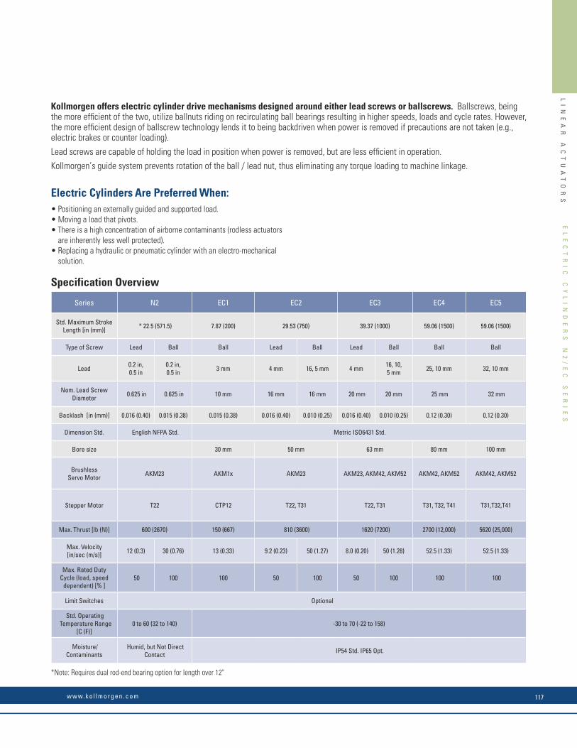
LI
NE
AR
A
CT
UA
TO
RS
EL
EC
TR
IC
C
YL
IN
DE
RS
Series N2 EC1 EC2 EC3 EC4 EC5
Std. Maximum Stroke Length [in (mm)] * 22.5 (571.5) 7.87 (200) 29.53 (750) 39.37 (1000) 59.06 (1500) 59.06 (1500)
Type of Screw Lead Ball Ball Lead Ball Lead Ball Ball Ball
Lead 0.2 in, 0.5 in
0.2 in, 0.5 in 3 mm 4 mm 16, 5 mm 4 mm 16, 10,
5 mm 25, 10 mm 32, 10 mm
Nom. Lead Screw Diameter 0.625 in 0.625 in 10 mm 16 mm 16 mm 20 mm 20 mm 25 mm 32 mm
Backlash [in (mm)] 0.016 (0.40) 0.015 (0.38) 0.015 (0.38) 0.016 (0.40) 0.010 (0.25) 0.016 (0.40) 0.010 (0.25) 0.12 (0.30) 0.12 (0.30)
Dimension Std. English NFPA Std. Metric ISO6431 Std.
Bore size 30 mm 50 mm 63 mm 80 mm 100 mm
Brushless Servo Motor AKM23 AKM1x AKM23 AKM23, AKM42, AKM52 AKM42, AKM52 AKM42, AKM52
Stepper Motor T22 CTP12 T22, T31 T22, T31 T31, T32, T41 T31,T32,T41
Max. Thrust [lb (N)] 600 (2670) 150 (667) 810 (3600) 1620 (7200) 2700 (12,000) 5620 (25,000)
Max. Velocity[in/sec (m/s)] 12 (0.3) 30 (0.76) 13 (0.33) 9.2 (0.23) 50 (1.27) 8.0 (0.20) 50 (1.28) 52.5 (1.33) 52.5 (1.33)
Max. Rated Duty Cycle (load, speed
dependent) [% ] 50 100 100 50 100 50 100 100 100
Limit Switches Optional
Std. Operating Temperature Range
[C (F)]0 to 60 (32 to 140) -30 to 70 (-22 to 158)
Moisture/Contaminants
Humid, but Not Direct Contact IP54 Std. IP65 Opt.
*Note: Requires dual rod-end bearing option for length over 12"
EC3
Specification Overview
w w w. k o l l m o r g e n . c o m 7
Kollmorgen offers electric cylinder drive mechanisms designed around either lead screws or ballscrews. Ballscrews, being the more efficient of the two, utilize ballnuts riding on recirculating ball bearings resulting in higher speeds, loads and cycle rates. However, the more efficient design of ballscrew technology lends it to being backdriven when power is removed if precautions are not taken (e.g., electric brakes or counter loading).
Lead screws are capable of holding the load in position when power is removed, but are less efficient in operation.
Kollmorgen’s guide system prevents rotation of the ball / lead nut, thus eliminating any torque loading to machine linkage.
Electric Cylinders Are Preferred When:• Positioning an externally guided and supported load.• Moving a load that pivots.• There is a high concentration of airborne contaminants (rodless actuators
are inherently less well protected).• Replacing a hydraulic or pneumatic cylinder with an electro-mechanical
solution.
EL
EC
TR
IC
C
YL
IN
DE
RS
N
2/
EC
S
ER
IE
S
w w w. k o l l m o r g e n . c o m 117

LI
NE
AR
A
CT
UA
TO
RS
MF1 Front FlangeParallel
MF2 Rear FlangeParallel
SBottom
KN
J
O
G
H
I
E
Stroke
M
QR
Right L
D
A
B
F
R
T
L
P
C
SBottom
KN
J
O
G
H
I
E
Stroke
M
QR
RightL
D
A
B
F
R
T
L
P
C
A
mm (in) B
mm (in) C
mm (in) D
mm (in) E
mm (in) F
mm (in)G
mm (in)H
mm (in)I
mm (in)J
mm (in)K
mm (in)EC1 60.0 (2.36) 74.0 (2.91) 28.0 (1.10) 40.0 (1.57) 6.60 (0.26) 48.0 (1.89) 82.6 (3.25) 19.0 (0.75) 41.8 (1.65) 31.3 (1.23) -EC2 90.0 (3.54) 114.3 (4.50) 45.0 (1.77) 63.5 (2.50) 9.0 (0.35) 79.8 (3.14) 144.0 (5.7) 28.4 (1.12) 74.7 (2.94) 41.7 (1.64) 88.6 (3.49)EC3 100.0 (3.94) 127.0 (5.00) 50.0 (1.97) 69.1 (2.72) 9.0 (0.35) 95.5 (3.76) 169.7 (6.7) 34.8 (1.37) *87.6/89.7 (*3.45/3.53) 49.3 (1.94) 94.2 (3.71)
EC4 (-MF1E) 127.0 (5.00) 152.4 (6.00) 69.9 (2.75) 96.3 (3.79) 13.5 (0.53) 127.0 (5.00) 221.0 (8.7) 46.1 (1.81) 111.1 (4.37) 71.9 (2.83) 150.9 (5.94)EC5 150.0 (5.91) 186.9 (7.36) 75.0 (2.95) 114.3 (4.50) 14.2 (0.56) 127.0 (5.00) 221.0 (8.7) 46.1 (1.81) 111.1 (4.37) 71.9 (2.83) 150.9 (5.94)
Lmm (in)
Mmm (in)
N Cyl Lengthmm (in)
O Retract lengthmm (in)
P Breather port Hex Qmm (in)
Rmm (in)
Smm (in)type mm (in)
EC1 10.2 (0.40) 38.1 (1.50) 113.8 + S (4.48 + S) 124.0 + S (4.88 + S) - - - 10.0 (0.39) 22.2 (0.88)EC2 25.0 (0.98) 56.9 (2.24) 218.5 + S (8.6 + S) 243.4 + S (9.58 + S) 1/8 NPT 11.1 (0.44) 34.8 (1.37) 9.5 (0.37) 28.0 (1.10)EC3 25.0 (0.98) 69.6 (2.74) 246.3 + S (9.7 + S) 271.1 + S (10.67 + S) 1/8 NPT 11.1 (0.44) 41.1 (1.62) 12.7 (0.50) 35.0 (1.38)
EC4 (-MF1E) 41.4 (1.63) 92.2 (3.63) 365.8 + S (14.4 + S) 406.9 + S (16.02 + S) 1/4 NPT 14.0 (0.55) 52.8 (2.08) 12.7 (0.50) 50.0 (1.97)EC5 35.0 (1.38) 92.2 (3.63) 365.8 + S (14.4 + S) 406.9 + S (16.02 + S) 1/4 NPT 14.0 (0.55) 52.8 (2.08) 19.1 (0.75) 50.0 (1.97)
Flange dimensions in accordance with ISO 6431 for:
Type Bore SizeEC2 50 mmEC3 63 mmEC4 80 mmEC5 100 mm
A
mm (in) B C
mm (in) D
mm (in) E
mm (in) F
mm (in)G
mm (in)H
mm (in)I
mm (in)J
mm (in)K
mm (in)mm (in) EC2 90.0 (3.54) 114.3 (4.50) 45.0 (1.77) 63.5 (2.50) 9.0 (0.35) 79.8 (3.14) 147.3 (5.80) 28.45 (1.12) 74.7 (2.94) 41.7 (1.64) 98.3 (3.87) EC3 100.0 (3.94) 127.0 (5.00) 50.0 (1.97) 69.1 (2.72) 9.0 (0.35) 95.5 (3.76) 169.7 (6.68) 34.8 (1.37) *87.6/89.7 (*3.45/3.53) 49.3 (1.94) 106.9 (4.21)
EC4 (-MF1E) 127.0 (5.00) 152.4 (6.00) 69.9 (2.75) 96.3 (3.79) 13.5 (0.53) 127.0 (5.00) 221.0 (8.70) 46.1 (1.81) 111.1 (4.37) 71.9 (2.83) 163.5 (6.44) EC5 150.0 (5.91) 186.9 (7.36) 75.0 (2.95) 114.3 (4.50) 14.2 (0.56) 127.0 (5.00) 221.0 (8.70) 46.1 (1.81) 111.1 (4.37) 71.9 (2.83) 169.9 (6.69)
Lmm (in)
Mmm (in)
N Cyl Lengthmm (in)
O Retract lengthmm (in)
P Breather port Hex Qmm (in)
Rmm (in)
Smm (in)type mm (in)
EC2 34.5 (1.36) 56.9 (2.24) 218.5 + S (8.6 + S) 253.0 + S (9.96 + S) 1/8 NPT 11.1 (0.44) 34.8 (1.37) 9.5 (0.37) 28.0 (1.10) EC3 37.7 (1.48) 69.6 (2.74) 246.3 + S (9.7 + S) 284.3 + S (11.19 + S) 1/8 NPT 11.1 (0.44) 41.1 (1.62) 12.7 (0.50) 35.0 (1.38)
EC4 (-MF1E) 54.1 (2.13) 92.2 (3.63) 365.8 + S (14.4 + S) 419.6 + S (16.52 + S) 1/4 NPT 14.0 (0.55) 52.8 (2.08) 12.7 (0.50) 50.0 (1.97) EC5 54.1 (2.13) 92.2 (3.63) 365.8 + S (14.4 + S) 419.6 + S (16.52 + S) 1/4 NPT 14.0 (0.55) 52.8 (2.08) 19.1 (0.75) 50.0 (1.97)
Flange dimensions in accordance with ISO 6431 for:
Type Bore SizeEC1 30 mmEC2 50 mmEC3 63 mmEC4 80 mmEC5 100 mm
* AKM23 / AKM42 dimension
Electric Cylinder EC Series General Outline Drawing
240 Vac Performance Data
Sys # Electric Cylinder - AKM Servo motor
AKD Servo Drive
Cont. Thrust @ Speed(lb @ in/sec)
Peak Thrust @ Speed(lb @ in/sec)
Max Thrust (lb)
Max System Speed (in/sec)
**Max Strokefor Max Speed (mm)
EC1
1 EC1-AKM11B- - -10-O3B * AKD-X00306 50 13.0 75 13.0 75 13.0 200
2 EC1-AKM11B- - -20-O3B AKD-X00306 100 6.0 125 6.0 125 6.0 200
3 EC1-AKM11B- - -40-O3B AKD-X00306 150 3.0 150 3.0 150 3.0 200
4 EC1-AKM13C- - -10-03B* AKD-X00306 75 11.5 75 13.0 75 13.0 200
5 EC1-AKM13C- - -20-03B AKD-X00306 125 5.9 125 6.0 126 6.0 200
Note 1: Refer to the Kollmorgen Electric Cylinder Catalog catalog, or contact customer support for matching cables. Note 2: For complete AKD, EC, and N2 Series model nomenclature, refer to pages 178, 197 and 198, respectively. * In-line type with 1-to-1 gear ratio (-10L) provide 10% additional thrust (not to exceed the max thrust). ** Based on critical speed of screw specification.
Electric Cylinders N2 / EC Series
EL
EC
TR
IC
C
YL
IN
DE
RS
N
2/
EC
S
ER
IE
S
K O L L M O R G E N118
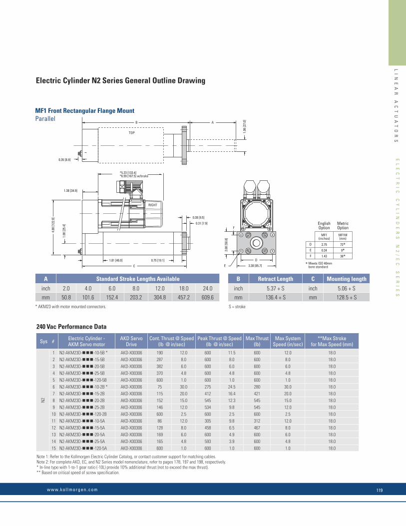
LI
NE
AR
A
CT
UA
TO
RS
TOP
RIGHT
0.75 [19.1]1.81 [46.0]
1.06
[27.
0]B
0.31 [7.9]
0.35 [8.9]
0.38 [9.5]
C
1.00
[25.
4]
4.80
[122
.0]
1.38 [34.9]
A
*5.23 [133.4]*6.59 [167.5] w/brake
E 3.38 [85.7]
D
2.00
[50.
8]F
FEEDBACKCONNECTOR
POWERCONNECTOR
( )39-----------[1.535]
( )28-----------[1.102]
(o )58-----------[2.283]
B
1.06
[27.
0]
0.75 [19.1]1.81 [46.0]
1.38 [34.9]
0.38 [9.5]
A
1.00
[25.
4]
4.80
[122
.0]
C
0.69 [17.5]
TOP
RIGHT
*5.23 [133.4]*6.59 [167.5] w/brake
E
3.38 [85.7]
D
2.00 [50.8]
2.00
[50.
8]
F
D
E
F
*
72*9*36*
2.75
0.34
1.43
Meets ISO 40mmbore standard
MF2(inches)
MF2M(mm)
EnglishOption
MetricOption
D
E
F
*
72*9*36*
2.75
0.34
1.43
Meets ISO 40mmbore standard
MF1(inches)
MF1M(mm)
EnglishOption
MetricOption
MF2 Rear Rectangular Flange MountParallel
A Standard Stroke Lengths Available
inch 2.0 4.0 6.0 8.0 12.0 18.0 24.0
mm 50.8 101.6 152.4 203.2 304.8 457.2 609.6
B Retract Length C Mounting length
inch 5.37 + S inch 5.06 + S
mm 136.4 + S mm 128.5 + S
S = stroke
A Standard Stroke Lengths Available
inch 2.0 4.0 6.0 8.0 12.0 18.0 24.0
mm 50.8 101.6 152.4 203.2 304.8 457.2 609.6
B Retract Length C Mounting length
inch 5.75 + S inch 5.06 + S
mm 146.1 + S mm 128.5 + S
S = stroke
MF1 Front Rectangular Flange MountParallel
* AKM23 with motor mounted connectors.
* AKM23 with motor mounted connectors.
Electric Cylinder N2 Series General Outline Drawing
Sys # Electric Cylinder - AKM Servo motor
AKD Servo Drive
Cont. Thrust @ Speed(lb @ in/sec)
Peak Thrust @ Speed(lb @ in/sec)
Max Thrust (lb)
Max System Speed (in/sec)
**Max Strokefor Max Speed (mm)
N2
1 N2-AKM23D- - -10-5B * AKD-X00306 190 12.0 600 11.5 600 12.0 18.02 N2-AKM23D- - -15-5B AKD-X00306 287 8.0 600 8.0 600 8.0 18.03 N2-AKM23D- - -20-5B AKD-X00306 382 6.0 600 6.0 600 6.0 18.04 N2-AKM23D- - -25-5B AKD-X00306 370 4.8 600 4.8 600 4.8 18.05 N2-AKM23D- - -120-5B AKD-X00306 600 1.0 600 1.0 600 1.0 18.06 N2-AKM23D- - -10-2B * AKD-X00306 75 30.0 275 24.5 280 30.0 18.07 N2-AKM23D- - -15-2B AKD-X00306 115 20.0 412 16.4 421 20.0 18.08 N2-AKM23D- - -20-2B AKD-X00306 152 15.0 545 12.3 545 15.0 18.09 N2-AKM23D- - -25-2B AKD-X00306 146 12.0 534 9.8 545 12.0 18.010 N2-AKM23D- - -120-2B AKD-X00306 600 2.5 600 2.5 600 2.5 18.011 N2-AKM23D- - -10-5A AKD-X00306 86 12.0 305 9.8 312 12.0 18.012 N2-AKM23D- - -15-5A AKD-X00306 128 8.0 458 6.5 467 8.0 18.013 N2-AKM23D- - -20-5A AKD-X00306 169 6.0 600 4.9 600 6.0 18.014 N2-AKM23D- - -25-5A AKD-X00306 165 4.8 593 3.9 600 4.8 18.015 N2-AKM23D- - -120-5A AKD-X00306 600 1.0 600 1.0 600 1.0 18.0
240 Vac Performance Data
Note 1: Refer to the Kollmorgen Electric Cylinder Catalog, or contact customer support for matching cables. Note 2: For complete AKD, EC, and N2 Series model nomenclature, refer to pages 178, 197 and 198, respectively. * In-line type with 1-to-1 gear ratio (-10L) provide 10% additional thrust (not to exceed the max thrust). ** Based on critical speed of screw specification.
EL
EC
TR
IC
C
YL
IN
DE
RS
N
2/
EC
S
ER
IE
S
w w w. k o l l m o r g e n . c o m 119
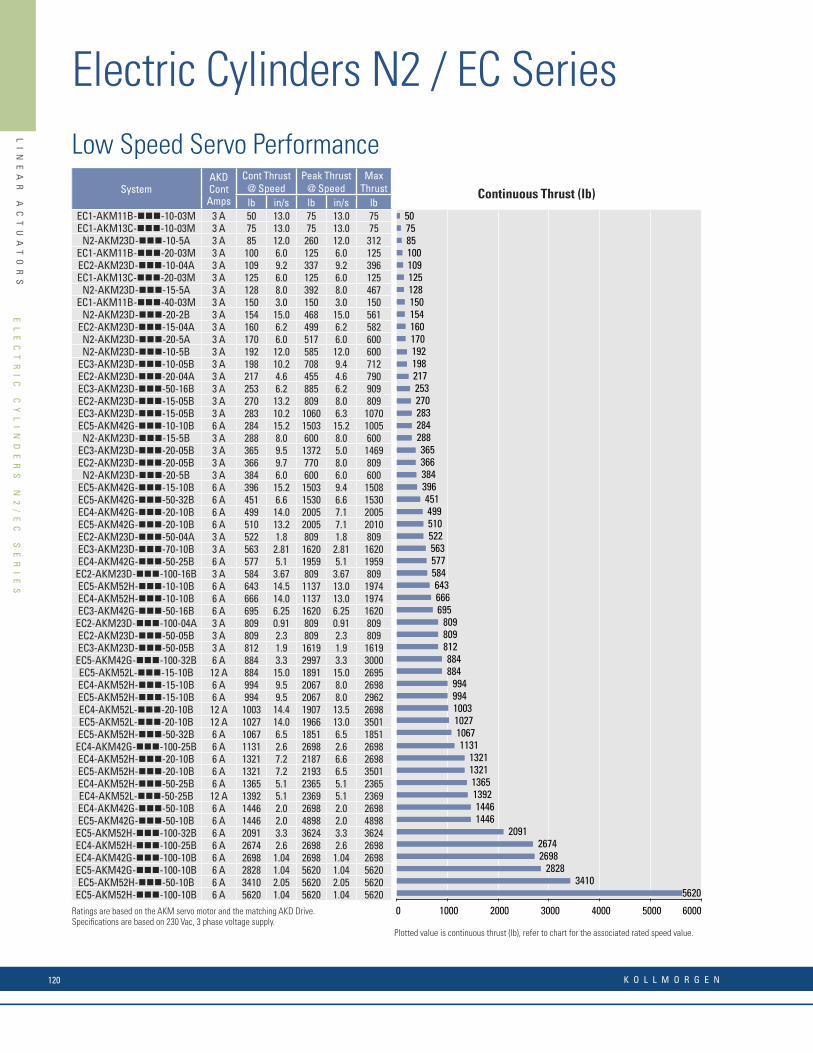
LI
NE
AR
A
CT
UA
TO
RS
Pg SystemAKD Cont Amps
Cont Thrust @ Speed
Peak Thrust @ Speed
Max Thrust
lb in/s lb in/s lb52 EC1-AKM11B-nnn-10-03M 3 A 50 13.0 75 13.0 7552 EC1-AKM13C-nnn-10-03M 3 A 75 13.0 75 13.0 7546 N2-AKM23D-nnn-10-5A 3 A 85 12.0 260 12.0 31252 EC1-AKM11B-nnn-20-03M 3 A 100 6.0 125 6.0 12554 EC2-AKM23D-nnn-10-04A 3 A 109 9.2 337 9.2 39652 EC1-AKM13C-nnn-20-03M 3 A 125 6.0 125 6.0 12546 N2-AKM23D-nnn-15-5A 3 A 128 8.0 392 8.0 46752 EC1-AKM11B-nnn-40-03M 3 A 150 3.0 150 3.0 15047 N2-AKM23D-nnn-20-2B 3 A 154 15.0 468 15.0 56155 EC2-AKM23D-nnn-15-04A 3 A 160 6.2 499 6.2 58247 N2-AKM23D-nnn-20-5A 3 A 170 6.0 517 6.0 60047 N2-AKM23D-nnn-10-5B 3 A 192 12.0 585 12.0 60063 EC3-AKM23D-nnn-10-05B 3 A 198 10.2 708 9.4 71255 EC2-AKM23D-nnn-20-04A 3 A 217 4.6 455 4.6 79063 EC3-AKM23D-nnn-50-16B 3 A 253 6.2 885 6.2 90955 EC2-AKM23D-nnn-15-05B 3 A 270 13.2 809 8.0 80964 EC3-AKM23D-nnn-15-05B 3 A 283 10.2 1060 6.3 107083 EC5-AKM42G-nnn-10-10B 6 A 284 15.2 1503 15.2 100547 N2-AKM23D-nnn-15-5B 3 A 288 8.0 600 8.0 60064 EC3-AKM23D-nnn-20-05B 3 A 365 9.5 1372 5.0 146956 EC2-AKM23D-nnn-20-05B 3 A 366 9.7 770 8.0 80946 N2-AKM23D-nnn-20-5B 3 A 384 6.0 600 6.0 60084 EC5-AKM42G-nnn-15-10B 6 A 396 15.2 1503 9.4 150884 EC5-AKM42G-nnn-50-32B 6 A 451 6.6 1530 6.6 153073 EC4-AKM42G-nnn-20-10B 6 A 499 14.0 2005 7.1 200584 EC5-AKM42G-nnn-20-10B 6 A 510 13.2 2005 7.1 201056 EC2-AKM23D-nnn-50-04A 3 A 522 1.8 809 1.8 80965 EC3-AKM23D-nnn-70-10B 3 A 563 2.81 1620 2.81 162072 EC4-AKM42G-nnn-50-25B 6 A 577 5.1 1959 5.1 195956 EC2-AKM23D-nnn-100-16B 3 A 584 3.67 809 3.67 80985 EC5-AKM52H-nnn-10-10B 6 A 643 14.5 1137 13.0 197473 EC4-AKM52H-nnn-10-10B 6 A 666 14.0 1137 13.0 197465 EC3-AKM42G-nnn-50-16B 6 A 695 6.25 1620 6.25 162056 EC2-AKM23D-nnn-100-04A 3 A 809 0.91 809 0.91 80957 EC2-AKM23D-nnn-50-05B 3 A 809 2.3 809 2.3 80965 EC3-AKM23D-nnn-50-05B 3 A 812 1.9 1619 1.9 161985 EC5-AKM42G-nnn-100-32B 6 A 884 3.3 2997 3.3 300085 EC5-AKM52L-nnn-15-10B 12 A 884 15.0 1891 15.0 269573 EC4-AKM52H-nnn-15-10B 6 A 994 9.5 2067 8.0 269885 EC5-AKM52H-nnn-15-10B 6 A 994 9.5 2067 8.0 296275 EC4-AKM52L-nnn-20-10B 12 A 1003 14.4 1907 13.5 269886 EC5-AKM52L-nnn-20-10B 12 A 1027 14.0 1966 13.0 350186 EC5-AKM52H-nnn-50-32B 6 A 1067 6.5 1851 6.5 185174 EC4-AKM42G-nnn-100-25B 6 A 1131 2.6 2698 2.6 269874 EC4-AKM52H-nnn-20-10B 6 A 1321 7.2 2187 6.6 269886 EC5-AKM52H-nnn-20-10B 6 A 1321 7.2 2193 6.5 350174 EC4-AKM52H-nnn-50-25B 6 A 1365 5.1 2365 5.1 236575 EC4-AKM52L-nnn-50-25B 12 A 1392 5.1 2369 5.1 236975 EC4-AKM42G-nnn-50-10B 6 A 1446 2.0 2698 2.0 269886 EC5-AKM42G-nnn-50-10B 6 A 1446 2.0 4898 2.0 489887 EC5-AKM52H-nnn-100-32B 6 A 2091 3.3 3624 3.3 362476 EC4-AKM52H-nnn-100-25B 6 A 2674 2.6 2698 2.6 269875 EC4-AKM42G-nnn-100-10B 6 A 2698 1.04 2698 1.04 269887 EC5-AKM42G-nnn-100-10B 6 A 2828 1.04 5620 1.04 562087 EC5-AKM52H-nnn-50-10B 6 A 3410 2.05 5620 2.05 562087 EC5-AKM52H-nnn-100-10B 6 A 5620 1.04 5620 1.04 5620
Low Speed Servo Performance
Continuous Thrust (lb)
Plotted value is continuous thrust (lb), refer to chart for the associated rated speed value.
5620 3410
2828 2698 2674
2091 1446 1446
1392 1365 1321 1321
1131 1067 1027 1003 994 994
884 884
812 809 809
695 666 643
584 577 563 522 510 499
451 396 384 366 365
288 284 283 270 253 217 198 192 170 160 154 150 128 125 109 100 85 75 50
0 1000 2000 3000 4000 5000 6000
Continuous Force (lb)
Ratings are based on the AKM servo motor and the matching AKD Drive. Specifications are based on 230 Vac, 3 phase voltage supply.
Electric Cylinders N2 / EC Series
EL
EC
TR
IC
C
YL
IN
DE
RS
N
2/
EC
S
ER
IE
S
K O L L M O R G E N120

LI
NE
AR
A
CT
UA
TO
RS
Pg SystemAKD Cont Amps
Cont Thrust @ Speed
Peak Thrust @ Speed
Max Thrust
lb in/s lb in/s lb54 EC2-AKM23D-nnn-10-16B 3 A 59 50.0 221 30.0 22262 EC3-AKM23D-nnn-10-16B 3 A 59 50.0 221 30.0 22246 N2-AKM23D-nnn-10-2B 3 A 77 30.0 233 30.0 28054 EC2-AKM23D-nnn-15-16B 3 A 84 42.0 293 23.0 32762 EC3-AKM23D-nnn-15-16B 3 A 86 41.0 332 20.0 33482 EC5-AKM42G-nnn-10-32B 6 A 87 52.5 313 45.0 31370 EC4-AKM42G-nnn-10-25B 6 A 108 52.0 400 35.0 40254 EC2-AKM23D-nnn-20-16B 3 A 115 31.0 223 26.0 44546 N2-AKM23D-nnn-15-2B 3 A 115 20.0 350 20.0 42062 EC3-AKM23D-nnn-20-16B 3 A 118 30.0 457 12.5 45982 EC5-AKM42G-nnn-15-32B 6 A 122 52.5 470 30.0 47062 EC3-AKM23D-nnn-15-10B 3 A 141 21.0 520 13.0 53470 EC4-AKM42G-nnn-15-25B 6 A 149 47.0 595 24.0 60363 EC3-AKM42G-nnn-10-16B 6 A 154 45.2 598 24.0 62882 EC5-AKM42G-nnn-20-32B 6 A 156 45.0 626 22.5 62855 EC2-AKM23D-nnn-10-05B 3 A 188 16.0 385 16.0 71263 EC3-AKM23D-nnn-20-10B 3 A 190 18.0 686 10.0 73570 EC4-AKM42G-nnn-20-25B 6 A 200 35.0 802 17.5 80482 EC5-AKM52H-nnn-10-32B 6 A 207 46.0 351 42.0 61764 EC3-AKM42G-nnn-15-16B 6 A 234 30.0 495 25.0 88870 EC4-AKM52L-nnn-10-25B 12 A 244 52.5 422 52.5 71971 EC4-AKM52H-nnn-10-25B 6 A 264 36.0 441 33.0 79083 EC5-AKM52L-nnn-15-32B 12 A 265 52.0 584 52.0 84271 EC4-AKM52L-nnn-15-25B 12 A 267 48.5 699 43.0 107864 EC3-AKM42G-nnn-10-10B 6 A 269 20.9 958 15.0 101071 EC4-AKM42G-nnn-10-10B 6 A 269 21.0 1002 14.2 100583 EC5-AKM52H-nnn-15-32B 6 A 312 30.0 626 26.0 92584 EC5-AKM52L-nnn-20-32B 12 A 314 46.0 614 42.0 109465 EC3-AKM42G-nnn-15-10B 6 A 358 18.9 820 15.0 142072 EC4-AKM42G-nnn-15-10B 6 A 383 17.5 1501 9.5 150871 EC4-AKM52H-nnn-15-25B 6 A 396 24.0 827 20.0 118572 EC4-AKM52L-nnn-20-25B 12 A 406 35.5 785 33.0 140083 EC5-AKM52H-nnn-20-32B 6 A 413 23.0 684 21.0 109472 EC4-AKM52H-nnn-20-25B 6 A 529 18.0 879 16.0 140073 EC4-AKM52L-nnn-10-10B 12 A 610 21.0 1055 21.0 179774 EC4-AKM52L-nnn-15-10B 12 A 772 18.6 1825 17.0 2695
High Speed Servo Performance
Plotted value is continuous thrust (lb), refer to chart for the associated rated speed value.
Continuous Thrust (lb)
772610
529413
406396
383358
314312
269269267265264
244234
207200
190188
156154149
141122118115115
108878684
775959
0 100 200 300 400 500 600 700 800 900
Continuous Force (lb)
w w w. k o l l m o r g e n . c o m 27
Pg SystemAKD Cont Amps
Cont Thrust @ Speed
Peak Thrust @ Speed
Max Thrust
lb in/s lb in/s lb54 EC2-AKM23D-nnn-10-16B 3 A 59 50.0 221 30.0 22262 EC3-AKM23D-nnn-10-16B 3 A 59 50.0 221 30.0 22246 N2-AKM23D-nnn-10-2B 3 A 77 30.0 233 30.0 28054 EC2-AKM23D-nnn-15-16B 3 A 84 42.0 293 23.0 32762 EC3-AKM23D-nnn-15-16B 3 A 86 41.0 332 20.0 33482 EC5-AKM42G-nnn-10-32B 6 A 87 52.5 313 45.0 31370 EC4-AKM42G-nnn-10-25B 6 A 108 52.0 400 35.0 40254 EC2-AKM23D-nnn-20-16B 3 A 115 31.0 223 26.0 44546 N2-AKM23D-nnn-15-2B 3 A 115 20.0 350 20.0 42062 EC3-AKM23D-nnn-20-16B 3 A 118 30.0 457 12.5 45982 EC5-AKM42G-nnn-15-32B 6 A 122 52.5 470 30.0 47062 EC3-AKM23D-nnn-15-10B 3 A 141 21.0 520 13.0 53470 EC4-AKM42G-nnn-15-25B 6 A 149 47.0 595 24.0 60363 EC3-AKM42G-nnn-10-16B 6 A 154 45.2 598 24.0 62882 EC5-AKM42G-nnn-20-32B 6 A 156 45.0 626 22.5 62855 EC2-AKM23D-nnn-10-05B 3 A 188 16.0 385 16.0 71263 EC3-AKM23D-nnn-20-10B 3 A 190 18.0 686 10.0 73570 EC4-AKM42G-nnn-20-25B 6 A 200 35.0 802 17.5 80482 EC5-AKM52H-nnn-10-32B 6 A 207 46.0 351 42.0 61764 EC3-AKM42G-nnn-15-16B 6 A 234 30.0 495 25.0 88870 EC4-AKM52L-nnn-10-25B 12 A 244 52.5 422 52.5 71971 EC4-AKM52H-nnn-10-25B 6 A 264 36.0 441 33.0 79083 EC5-AKM52L-nnn-15-32B 12 A 265 52.0 584 52.0 84271 EC4-AKM52L-nnn-15-25B 12 A 267 48.5 699 43.0 107864 EC3-AKM42G-nnn-10-10B 6 A 269 20.9 958 15.0 101071 EC4-AKM42G-nnn-10-10B 6 A 269 21.0 1002 14.2 100583 EC5-AKM52H-nnn-15-32B 6 A 312 30.0 626 26.0 92584 EC5-AKM52L-nnn-20-32B 12 A 314 46.0 614 42.0 109465 EC3-AKM42G-nnn-15-10B 6 A 358 18.9 820 15.0 142072 EC4-AKM42G-nnn-15-10B 6 A 383 17.5 1501 9.5 150871 EC4-AKM52H-nnn-15-25B 6 A 396 24.0 827 20.0 118572 EC4-AKM52L-nnn-20-25B 12 A 406 35.5 785 33.0 140083 EC5-AKM52H-nnn-20-32B 6 A 413 23.0 684 21.0 109472 EC4-AKM52H-nnn-20-25B 6 A 529 18.0 879 16.0 140073 EC4-AKM52L-nnn-10-10B 12 A 610 21.0 1055 21.0 179774 EC4-AKM52L-nnn-15-10B 12 A 772 18.6 1825 17.0 2695
High Speed Servo Performance
Plotted value is continuous thrust (lb), refer to chart for the associated rated speed value.
Continuous Thrust (lb)
772610
529413
406396
383358
314312
269269267265264
244234
207200
190188
156154149
141122118115115
108878684
775959
0 100 200 300 400 500 600 700 800 900
Continuous Force (lb)
Ratings are based on the AKM servo motor and the matching AKD Drive. Specifications are based on 230 Vac, 3 phase voltage supply.
EL
EC
TR
IC
C
YL
IN
DE
RS
N
2/
EC
S
ER
IE
S
w w w. k o l l m o r g e n . c o m 121

LI
NE
AR
A
CT
UA
TO
RS
The name rodless actuator comes from this technology’s close relationship to electric cylinders, sharing many of the same components. Rather than having a rod, rodless actuators incorporate a carriage supported by linear bearings. Where electric cylinders are designed to extend in and out of the work area delivering force or thrust, rodless actuators are designed to be load carrying mechanisms (up to 300 lb) incorporating ballscrews, leadscrews, or belt drive transmissions with optional integrated gearboxes.
Rodless actuators also share many of the fundamental design characteristics of precision positioning tables. Precision tables are designed to carry larger payloads and deliver superior repeatability and accuracy. Rodless actuators offer longer travels and higher speeds at a lower price. Screw driven rodless actuators are also thrust-producing devices that are best for axial force applications where the space is limited and a payload must also be supported or carried. As individual components, rodless actuators are not well suited for moment loading; however, they can be effectively combined into complete Cartesian systems for some multi-axis applications. For higher speed, lower thrust applications, rodless actuators can be repeatability-driven with a timing belt instead of a screw.
Kollmorgen has combined the broad product offering of the R-Series rodless actuators with the industry-leading AKM servo motors and AKD servo drives. The R-Series of rodless actuators offer a wide range of available thrusts in standard units with three basic frame sizes (R2A, R3, R4).
Rodless actuators offer longer travels (up to 108") and higher speeds (belt drives up to a maximum speed of 120 in/sec). Integrated geared options provide the ability to increase thrust capacity for lower speed applications leveraging the speed capacity of servo systems.
Multiple servo motor options are available for the product line, ranging from NEMA 23 size to NEMA 42 size servos. The combination with the AKM servo motor enables the use of various feedback devices including sine-encoder and the low-cost but high-performance Smart Feedback Device (SFD) when used with the AKD servo drive.
The AKM servo motor comes mounted on the rodless actuators as specifi ed by the rodless actuator part number. This eliminates time to match the motor to the electric cylinder and eliminates potential mechanical incompatibility.
RO
DL
ES
S
AC
TU
AT
OR
S
R-
SE
RI
ES
Rodless Actuators R-Series
K O L L M O R G E N122

LI
NE
AR
A
CT
UA
TO
RS
T-slots accommodate several mounting options
Belt tensioning enclosure, to compensate for belt stretch over time
Belt drive – for high speeds to 120 inches per second
R4 carriage – up to 300 lbs. normal load. Travel distance to 108 inches
Exceptionally rigid carriage, supported by two bearing blocks
Three motor mounting choices for belt-driven models, under (shown), behind and over
Wide range of geared and fi rming belt reduction ratios to optimize speed/thrust performance and to match motor/load inertia with drives
The operation of rodless actuators is similar to the electric cylinders described earlier. However, instead of an extending rod, a rodless unit features a moving carriage supported by linear bearings within an extruded aluminum chassis. This gives the rodless actuator the ability to guide and support a load, as well as position it.
Kollmorgen rodless actuators are designed for outstanding overall performance, value, fl exibility and reliability in industrial applications.
Rodless Actuators Are Preferred When:• A low cost system is needed to both position and guide a load
• It is desired to eliminate external guides and ways
• The shortest overall work envelope (extended length
equals retracted length) is required
• Multiple units will be combined into Cartesian systems
• There is a need for a compact cross-sectional linear positioning system
Typical Construction
(R4 belt-driven cutaway shown)
RO
DL
ES
S
AC
TU
AT
OR
S
R-
SE
RI
ES
w w w. k o l l m o r g e n . c o m 123

LI
NE
AR
A
CT
UA
TO
RS
H
DE
BI C
Top view
J
K
LA
G F
Side view
B D
N
C
K
H
J
M DE
P
Top view
A
G F
Side view
O
R3 Screw DriveR3 screw drive with AKM42, parallel belowmotor orientation and fl ange mounting shown.
R3 Belt DriveR3 belt drive with AKM42, behind left motor orientation and angle bracket feet shown.
H
DE
BI C
Top view
J
K
LA
G F
Side view
B D
N
C
K
H
J
M DE
P
Top view
A
G F
Side view
O
RO
DL
ES
S
AC
TU
AT
OR
S
R-
SE
RI
ES
Rodless Actuators R-Series
K O L L M O R G E N124

LI
NE
AR
A
CT
UA
TO
RS
I J K L
mm (in) mm (in) mm (in) mm (in)
RA2 72.1 (2.84) 123.2 (4.85) 43.0 (1.69) 90.7 (3.57)
R3 91.4 (3.60) 168.9 (6.65) 45.5 (1.79) 88.1 (3.47)
R4 127.0 (5.00) 220.7 (8.69) 71.9 (2.83) 147.8 (5.82)
Metric Version(mm)
English Version(inch)
RA2 8 x M5 x 0.8 x 8.0 deep 8 x 10-32 UNF x 0.31 deep
R3 8 x M5 x 0.8 x 9.6 deep 8 x 10-32 UNF x 0.38 deep
R4 4 x M6 x 1 x 12 deep 4 x 1/4-20 x 0.50 deep
A B C D E
mm (in) mm (in) mm (in) mm (in) mm (in)
RA2 210 (8.25) 50.8 (2.00) 31.8 (1.25) 50.8 (2.00) 101.6 (4.00)
R3 197 (7.76) 63.5 (2.50) 47.6 (1.88) 50.8 (2.00) 101.6 (4.00)
R4 197 (7.76) 92.2 (3.63) 63.5 (2.50) NA 127.0 (5.00)
Carriage Mounting Features
Dimension Data
M N O P
mm (in) mm (in) mm (in) mm (in)
RA2 50.1 (1.97) NA 88.8 (3.50) 8.7 (0.34) thru
R3 45.5 (1.79) 47.6 (1.88) 101.6 (4.00) 5.5 (0.22) thru
R4 71.9 (2.83) 63.5 (2.50) 127.0 (5.00) 7.0 (0.28) thru
F G H (Screw) H (Belt)
mm (in) mm (in) mm (in) mm (in)
RA2 71.9 (2.83) 50.8 (2.00) "S" + 345.3 (13.59) "S" + 378.3 (14.89)
R3 88.8 (3.50) 71.5 (2.82) "S" + 326.4 (12.85) "S" + 522.0 (20.55)
R4 71.9 (2.83) 108.0 (4.25) "S" + 411.8 (16.21) "S" + 578.6 (22.78)
S = stroke
RO
DL
ES
S
AC
TU
AT
OR
S
R-
SE
RI
ES
w w w. k o l l m o r g e n . c o m 125
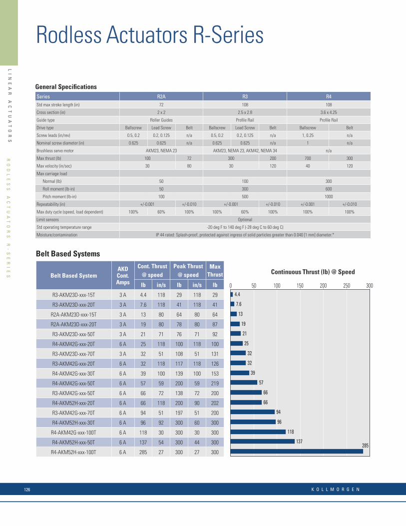
LI
NE
AR
A
CT
UA
TO
RS
SE
RV
OM
OT
OR
S
YS
TE
M
PE
RF
OR
MA
NC
E
SU
MM
AR
Y
Continuous Thrust (lb) @ Speed
Belt Based Systems
Belt Based SystemAKD Cont. Amps
Cont. Thrust @ speed
Peak Thrust@ speed
Max Thrust
lb in/s lb in/s lb
R3-AKM23D-xxx-15T 3 A 4.4 118 29 118 29
R3-AKM23D-xxx-20T 3 A 7.6 118 41 118 41
R2A-AKM23D-xxx-15T 3 A 13 80 64 80 64
R2A-AKM23D-xxx-20T 3 A 19 80 78 80 87
R3-AKM23D-xxx-50T 3 A 21 71 76 71 92
R4-AKM42G-xxx-20T 6 A 25 118 100 118 100
R3-AKM23D-xxx-70T 3 A 32 51 108 51 131
R3-AKM42G-xxx-20T 6 A 32 118 117 118 126
R4-AKM42G-xxx-30T 6 A 39 100 139 100 153
R4-AKM42G-xxx-50T 6 A 57 59 200 59 219
R3-AKM42G-xxx-50T 6 A 66 72 138 72 200
R4-AKM52H-xxx-20T 6 A 66 118 200 90 202
R3-AKM42G-xxx-70T 6 A 94 51 197 51 200
R4-AKM52H-xxx-30T 6 A 96 92 300 60 300
R4-AKM42G-xxx-100T 6 A 118 30 300 30 300
R4-AKM52H-xxx-50T 6 A 137 54 300 44 300
R4-AKM52H-xxx-100T 6 A 285 27 300 27 300285
137
118
96
94
66
66
57
39
32
32
25
21
19
13
7.6
4.4
0 50 100 150 200 250 300Continuous Thrust (lb)
Servomotor System Performance Summary
General Specifi cationsSeries R2A R3 R4Std max stroke length (in) 72 108 108
Cross section (in) 2 x 2 2.5 x 2.8 3.6 x 4.25
Guide type Roller Guides Profi le Rail Profi le Rail
Drive type Ballscrew Lead Screw Belt Ballscrew Lead Screw Belt Ballscrew Belt
Screw leads (in/rev) 0.5, 0.2 0.2, 0.125 n/a 0.5, 0.2 0.2, 0.125 n/a 1, 0.25 n/a
Nominal screw diameter (in) 0.625 0.625 n/a 0.625 0.625 n/a 1 n/a
Brushless servo motor AKM23, NEMA 23 AKM23, NEMA 23, AKM42, NEMA 34 n/a
Max thrust (lb) 100 72 300 200 700 300
Max velocity (in/sec) 30 80 30 120 40 120
Max carriage load
Normal (lb) 50 100 300
Roll moment (lb-in) 50 300 600
Pitch moment (lb-in) 100 500 1000
Repeatability (in) +/-0.001 +/-0.010 +/-0.001 +/-0.010 +/-0.001 +/-0.010
Max duty cycle (speed, load dependent) 100% 60% 100% 100% 60% 100% 100% 100%
Limit sensors Optional
Std operating temperature range -20 deg F to 140 deg F (-28 deg C to 60 deg C)
Moisture/contamination IP 44 rated: Splash-proof, protected against ingress of solid particles greater than 0.040 [1 mm] diameter.*
240 Vac Performance Data
Sys # Rodless Actuator-Servo Motor
AKD ServoDrive
Cont. Thrust @ Speed(lb @ in/sec)
Peak Thrust @ Speed(lb @ in/sec)
Max Thrust(lb)
Max System Speed (in/sec)
Max Stroke for Max Speed (in)
R2A
1 R2A-AKM23D-n n n- -10-2B* AKD-X00306 70 30 100 30 100 30 18
2 R2A-AKM23D-n n n- -15-2B AKD-X00306 100 20 100 20 100 20 24
3 R2A-AKM23D-n n n- -20-2B AKD-X00306 100 15 100 15 100 15 30
4 R2A-AKM23D-n n n- -10-5B AKD-X00306 100 12 100 12 100 12 18
5 R2A-AKM23D-n n n- -15-5B AKD-X00306 100 8.0 100 8.0 100 8.0 24
6 R2A-AKM23D-n n n- -20-5B AKD-X00306 100 6.0 100 6.0 100 6.0 30
7 R2A-AKM23D-n n n- -10-5A* AKD-X00306 79 12 100 12 100 12 12
8 R2A-AKM23D-n n n- -15-5A AKD-X00306 100 8.0 100 8.0 100 8.0 18
9 R2A-AKM23D-n n n- -20-5A AKD-X00306 100 6.0 100 6.0 100 6.0 24
10 R2A-AKM23D-n n n- -10-T* AKD-X00306 7.0 80 40 80 40 80 72
11 R2A-AKM23D-n n n- -15-T AKD-X00306 13 80 64 80 64 80 72
12 R2A-AKM23D-n n n- -20-T AKD-X00306 19 80 78 80 87 80 72
R3
13 R3-AKM23D-n n n- -10-2B* AKD-X00306 71 30 269 25 275 30 18
14 R3-AKM23D-n n n- -15-2B AKD-X00306 110 20 300 20 300 20 24
15 R3-AKM23D-n n n- -20-2B AKD-X00306 148 15 300 15 300 15 30
16 R3-AKM23D-n n n- -50-2B AKD-X00306 300 6.0 300 6.0 300 6.0 48
17 R3-AKM23D-n n n- -10-5B* AKD-X00306 186 12 300 12 300 12.0 18
18 R3-AKM23D-n n n- -15-5B AKD-X00306 283 8.0 300 8.0 300 8.0 24
19 R3-AKM23D-n n n- -20-5B AKD-X00306 300 6.0 300 6.0 300 6.0 30
20 R3-AKM23D-n n n- -50-5B AKD-X00306 300 2.4 300 2.4 300 2.4 48
21 R3-AKM23D-n n n- -10-5A* AKD-X00306 80 12 250 12 300 12 12
22 R3-AKM23D-n n n- -15-5A AKD-X00306 122 8.0 300 8.0 300 8.0 18
23 R3-AKM23D-n n n- -20-5A AKD-X00306 165 6.0 300 6.0 300 6.0 24
24 R3-AKM23D-n n n- -50-5A AKD-X00306 300 2.4 300 2.4 300 2.4 42
25 R3-AKM23D-n n n- -10-8A* AKD-X00306 131 7.5 300 7.5 300 7.5 18
26 R3-AKM23D-n n n- -15-8A AKD-X00306 199 5.0 300 5.0 300 5.0 30
27 R3-AKM23D-n n n- -20-8A* AKD-X00306 267 3.8 300 3.8 300 3.7 30
28 R3-AKM23D-n n n- -50-8A AKD-X00306 300 1.5 300 1.5 300 1.5 48
29 R3-AKM23D-n n n- -10-T* AKD-X00306 1.2 110 18 110 18 110 108
Note 1: Refer to page 66 for matching cables. Note 2: For complete AKD and R-Series model nomenclature, refer to pages 67 and 75 respectively.* Inline type with 1-to-1 gear ratio (-10L) provide 10% additional thrust (not to exceed the max thrust).
RO
DL
ES
S
AC
TU
AT
OR
S
R-
SE
RI
ES
Rodless Actuators R-Series
K O L L M O R G E N126

LI
NE
AR
A
CT
UA
TO
RS
SE
RV
OM
OT
OR
S
YS
TE
M
PE
RF
OR
MA
NC
E
SU
MM
AR
Y
Continuous Thrust (lb) @ Speed
Screw Based Systems
Screw Based SystemAKD Cont. Amps
Cont. Thrust @ speed
Peak Thrust @ speed
Max
Thrust
lb in/s lb in/s lb
R2A-AKM23D-xxx-102B-yy-P 3 A 70 30 100 30 100
R3-AKM23D-xxx-102B-yy-P 3 A 71 30 269 25 275
R2A-AKM23D-xxx-105A-yy-P 3 A 79 12 100 12 100
R3-AKM23D-xxx-105A-yy-P 3 A 80 12 255 12 300
R2A-AKM23D-xxx-152B-yy-P 3 A 100 20 100 20 100
R2A-AKM23D-xxx-155A-yy-P 3 A 100 8.0 100 8 100
R4-AKM42G-xxx-101B-yy-P 6 A 105 40 356 40 390
R3-AKM23D-xxx-152B-yy-P 3 A 110 20 300 20 300
R3-AKM23D-xxx-155A-yy-P 3 A 122 8.0 300 8.0 300
R3-AKM23D-xxx-108A-yy-P 3 A 131 7.5 300 7.5 300
R3-AKM23D-xxx-202B-yy-P 3 A 148 15 300 15 300
R4-AKM42G-xxx-151B-yy-P 6 A 161 27 540 27 588
R3-AKM23D-xxx-205A-yy-P 3 A 165 6.0 300 6.0 300
R3-AKM23D-xxx-105B-yy-P 3 A 186 12 300 12 300
R3-AKM23D-xxx-158A-yy-P 3 A 199 5.0 300 5.0 300
R3-AKM42G-xxx-102B-yy-P 6 A 201 30 300 30 300
R4-AKM42G-xxx-201B-yy-P 6 A 217 20 700 20 700
R3-AKM42G-xxx-105A-yy-P 6 A 249 12 300 12 300
R4-AKM52H-xxx-101B-yy-P 6 A 263 37 263 37 700
R3-AKM23D-xxx-208A-yy-P 3 A 267 3.8 300 3.8 300
R3-AKM23D-xxx-155B-yy-P 3 A 283 8.0 300 8.0 300
R3-AKM23D-xxx-505A-yy-P 3 A 300 2.4 300 2.4 300
R3-AKM42G-xxx-152B-yy-P 6 A 300 20 300 20 300
R3-AKM42G-xxx-155A-yy-P 6 A 300 8.0 300 8.0 300
R4-AKM52H-xxx-151B-yy-P 6 A 307 25 307 25 700
R4-AKM42G-xxx-104B-yy-P 6 A 440 10 700 10 700
R4-AKM42G-xxx-501B-yy-P 6 A 468 7.8 700 7.8 700
R4-AKM52H-xxx-201B-yy-P 6 A 517 18 600 18 700
R4-AKM42G-xxx-154B-yy-P 6 A 660 6.7 700 6.7 700
R4-AKM52H-xxx-104B-yy-P 6 A 700 9.4 700 9.4 700 700
660
517
468
440
307
300
300
300
283
267
263
249
217
201
199
186
165
161
148
131
122
110
105
100
100
80
79
71
70
0 200 400 600 800Continuous Thrust (lb)
Servomotor System Performance Summary
RO
DL
ES
S
AC
TU
AT
OR
S
R-
SE
RI
ES
w w w. k o l l m o r g e n . c o m 127

LI
NE
AR
A
CT
UA
TO
RS
Precision positioning tables are best suited for applications where the accuracy and repeatability requirements are more important than axial thrust of the drive train. Precision positioning tables can also be used in less precise applications where adequate moment load support is necessary, and are ideal building blocks for complete multi-axis positioning systems.
The DS4 and DS6 are Kollmorgen’s most versatile and modularline of positioning tables.
Combined with the AKD® Servo Drive andAKM® Servo Motors, DS4 and DS6 Systems Offer• An optimized electromechanical solution suitable
for demanding high precision positioning
• Performance and versatility in a compact package
• Outstanding industrial durability
• Tremendous confi guration fl exibility
• Industry-leading price vs. performance value
DS Series Design Features
Following are several features that make the DS Series the positioning table of choice for the most demanding applications:
• Travel lengths from 50 mm to 2 m cover a wide range of applications.
• Precision ballscrew drive, with 5 mm, 10 mm and 25 mm leads, offers high speed and effi ciency, excellent repeatability and accuracy, and mechanical advantage.
• Proven magnetic stainless steel seal strip technology effectively seals the internal components of the DS Series, protecting the ballscrew and ways from contaminants. This feature also contains ballscrew and way lubrication within the DS Series.
• Easily confi gurable modular design and option set, including a variety of motor mounting orientations, motor sizes and type, ballscrew leads, coupling types and sizes, encoder feedback options, limit/home sensor types, and shaft brakes allow the DS Series to be customized to meet your specifi c requirements.
High effi ciency ballscrew minimizes torque needed to drive the load
Low profi le shuttle carriage accepts direct mounting of a second DS4 for XY confi gurations
Base unit designed to accept a variety of confi gurable inline and parallel motor mounting options
Stainless steel square rails for long life in various environments
Precision-machined extruded high-strength aluminum base minimizes angular positioning errors
Long bearing modules provide rigidity, stable accuracy and smooth, precise motion
Single piece carriage design offers maximum stiffness
T-slots for mounting the DS4 and attaching options for application fl exibility
Unique IDEAL-SEAL cover strip locking device properly tensions the seal strip and provides easy access to internal features
Magnetic seal strips effectively seal the internal components
Metric dimensionsand mounting features
PR
EC
IS
IO
N
TA
BL
ES
D
S4
/D
S6
S
ER
IE
S
Precision Tables DS4 / DS6 SeriesDS Series precision tables can be ordered in a variety of multi-axis confi gurations including XY, XZ, and XYZ or cartesian arrangements. Consult Kollmorgen applications engineering for standard and custom confi gurations.
A second option is to order standard multi-axis brackets and assemble the axes yourself.
Unique IDEAL-SEAL Magnetic Cover Strip Locking Device• Entire length of lead screw and linear bearing system are protected, providing both operator safety and protection from contaminants.
• Seal strips are always properly tensioned, drastically decreasing wear that requires regular fi eld repair.
• Allows easy access to interior of DS4 for mounting and maintenance.
• No small hardware or springs to lose, and no exposure to the sharpends of the strips, which are problems for similar seal end-cap designs.
Toe Clamp
All DS4 and DS6 tables will bolt directly together in a standard XY without modifi cation.
DS Series
Servo motor options AKM23D, AKM42G
Grades Precision* (up to 600 mm), commercial
Motor orientations In-line, parallel right/left/under
Couplings options** (inline confi gurations) Bellows
Transmission ratio (parallel confi gurations) 1:1
Limit sensors PNP (sinking) inductive proximity sensors, 5-30 Vdc
Home sensor PNP (sinking) inductive proximity sensors, 5-30 Vdc
Shaft brake Electromagnetic power of holding brake, 24 Vdc
Linear encoder options 1.0, 0.5 and 0.1 motion resolution, modular incremental type
* Additional lead time applies to precision grade. Contact customer support for details.** Additional couplings available. Contact customer support for details.
DS Series
Toe clamps Provide convenient external mounting to a base plate or to riser blocks
Narrow riser blocks Raise unit for clearance of larger motor options, utilizing internal base mounting features on the side
Wide riser blocks Allow rising of the unit, independent of base mounting features
Brackets and mounting plates Facilitate multi-axis confi gurations
Cable sets For connection to AKD and other drives
Linear Encoder
Limit Sensor
Confi gurable Options
Accessories
PR
EC
IS
IO
N
TA
BL
ES
D
S4
/D
S6
S
ER
IE
S
K O L L M O R G E N128

LI
NE
AR
A
CT
UA
TO
RS
DS Series precision tables can be ordered in a variety of multi-axis confi gurations including XY, XZ, and XYZ or cartesian arrangements. Consult Kollmorgen applications engineering for standard and custom confi gurations.
A second option is to order standard multi-axis brackets and assemble the axes yourself.
Unique IDEAL-SEAL Magnetic Cover Strip Locking Device• Entire length of lead screw and linear bearing system are protected, providing both operator safety and protection from contaminants.
• Seal strips are always properly tensioned, drastically decreasing wear that requires regular fi eld repair.
• Allows easy access to interior of DS4 for mounting and maintenance.
• No small hardware or springs to lose, and no exposure to the sharpends of the strips, which are problems for similar seal end-cap designs.
Toe Clamp
All DS4 and DS6 tables will bolt directly together in a standard XY without modifi cation.
DS Series
Servo motor options AKM23D, AKM42G
Grades Precision* (up to 600 mm), commercial
Motor orientations In-line, parallel right/left/under
Couplings options** (inline confi gurations) Bellows
Transmission ratio (parallel confi gurations) 1:1
Limit sensors PNP (sinking) inductive proximity sensors, 5-30 Vdc
Home sensor PNP (sinking) inductive proximity sensors, 5-30 Vdc
Shaft brake Electromagnetic power of holding brake, 24 Vdc
Linear encoder options 1.0, 0.5 and 0.1 motion resolution, modular incremental type
* Additional lead time applies to precision grade. Contact customer support for details.** Additional couplings available. Contact customer support for details.
DS Series
Toe clamps Provide convenient external mounting to a base plate or to riser blocks
Narrow riser blocks Raise unit for clearance of larger motor options, utilizing internal base mounting features on the side
Wide riser blocks Allow rising of the unit, independent of base mounting features
Brackets and mounting plates Facilitate multi-axis confi gurations
Cable sets For connection to AKD and other drives
Linear Encoder
Limit Sensor
Confi gurable Options
Accessories
PR
EC
IS
IO
N
TA
BL
ES
D
S4
/D
S6
S
ER
IE
S
w w w. k o l l m o r g e n . c o m 129

LI
NE
AR
A
CT
UA
TO
RS
DS4 General Specifi cationsTravel (mm) 50 100 150 200 250 300 350 400 450 500 550 600
Overall height, less motor (mm) 47
Width (mm) 95
System length, Inline less motor (mm) 317 367 417 467 517 567 617 667 717 767 817 867
System length, parallel motor mounts (mm) 300 350 400 450 500 550 600 650 700 750 800 850
Positional accuracy (microns)
Commercial grade 12 12 14 20 22 24 26 26 28 34 36 40
Precision grade 8 8 10 12 12 14 14 16 19 21 23 25
Straightness & fl atness (microns) 6 6 9 12 12 14 18 21 23 23 25 25
Bi-directional repeatability, open loopCommercial grade (microns) +/- 3
Precision grade (microns) +/- 1.3
Load capacity, normal (kg) (max) 170
Axial load capacity (kg) 90
Acceleration (max) (m/sec2) 20
Moving mass (kg) 0.75
Total mass (kg) 2.7 3 3.3 3.6 3.9 4.1 4.4 4.7 5 5.3 5.6 5.9
Ballscrew diameter (mm) 16
Duty cycle (%) 100
Ballscrew effi ciency 90
Max. breakaway torque (oz-in) 18
Max. running torque (oz-in) 16
Ballscrew lead available (mm) 5, 10
Input inertia (10-5 kg-m2) 1.17 1.24 1.67 1.93 2.18 2.43 2.68 2.93 3.19 3.44 3.69 3.94
Max. ballscrew speed (rev/sec) 80 60 55 50
DS6 General Specifi cationsTravel (mm) 100 200 300 400 500 600 700 800 900 1000 1250 1500 1750 2000
Overall height (mm) 70
Width (mm) 150
System length, inline less motor (mm) 465 565 665 765 865 965 1065 1165 1265 1365 1615 1865 2115 2365
System length, parallel motor mounts (mm) 470 570 670 770 870 970 1070 1170 1270 1370 1620 1870 2120 2370
Positional accuracy (microns)
Commercial grade 14 22 28 39 45 48 92 94 103 105 118 134 154 159
Precision grade 12 14 15 20 25 50 - - - - - - - -
Straightness & fl atness (microns) 10 14 17 23 30 33 40 46 50 55 76 95 115 135
Bi-directional repeatability, open loopCommercial grade (microns) +/- 3 +/-5
Precision grade (microns) +/- 1.3 N/A
Load capacity, normal (kg) (max) 630
Axial load capacity (kg)Commercial grade 90 200
Precision grade 90 N/A
Acceleration (max) (m/sec2) 20
Moving mass (kg) 2.8
Total mass (kg) 8.9 10.2 11.5 12.8 14.0 15.4 19.4 20.9 22.4 23.9 27.8 31.6 35.4 40.1
Ballscrew diameter (mm) 16 25
Duty cycle (%) 100
Ballscrew effi ciency 90 80
Max. breakaway torque (oz-in) 18 55
Max. running torque (oz-in) 16 48
Ballscrew lead available (mm) 5, 10 5, 10, 25
Input inertia (10-5 kg-m2) 3.8 4.4 5 5.5 6.1 6.7 37 40.4 43.9 47.3 56 64.5 73.2 81.9
Max. ballscrew speed (rev/sec) 80 60 50 60 50 40 35 24 16 13 11
*All performance specifications are based upon proper mounting procedures, with the DS table fully supported on a flat surface (flat within 0.008 mm/300 mm). Positional accuracy and repeatability specifications are for inline motor mount models only. Contact customer support for specifications of parallel mount configurations. Above specifications are measured 37.5 mm directly above the center of the carriage. Specifications are based upon operation at 20° C.
PR
EC
IS
IO
N
TA
BL
ES
D
S4
/D
S6
S
ER
IE
S
Precision Tables DS4 / DS6 Series
PR
EC
IS
IO
N
TA
BL
ES
D
S4
/D
S6
S
ER
IE
S
K O L L M O R G E N130

LI
NE
AR
A
CT
UA
TO
RS
Sys #
Precision Table - AKM Servo Motor
AKD ServoDrive
Stroke LengthType
Cont. Thrust @ Speed
(lb @ in/sec)
Peak Thrust @ Speed
(lb @ in/sec)
MaxThrust
(lb)
Max System Speed(in/sec)
Max Strokefor Max Speed
(mm)
DS4 1 DS4-XXX-10G-AKM23D-n n n AKD-X00306 ≤ 600 mm 104 17.6 210 10.8 210 17.6 600
2 DS4-XXX- 5G-AKM23D-n n n AKD-X00306 ≤ 600 mm 195 8.8 210 8.4 210 8.8 600
DS6
3 DS6-XXX-25G-AKM23D-n n n AKD-X00306 ≤ 600 mm 37 44.0 138 8.2 138 44.0 600
4 DS6-XXX-10G-AKM23D-n n n AKD-X00306 ≤ 600 mm 104 17.6 210 12.4 210 17.6 600
5 DS6-XXX- 5G-AKM23D-n n n AKD-X00306 ≤ 600 mm 195 8.8 210 8.6 210 8.8 600
DS6
6 DS6-XXX-25G-AKM23D-n n n AKD-X00306 ≥ 700 mm 41 44.0 138 8.2 154 44.0 800
7 DS6-XXX-10G-AKM23D-n n n AKD-X00306 ≥ 700 mm 91 17.6 331 3.1 376 17.6 800
8 DS6-XXX- 5G-AKM23D-n n n AKD-X00306 ≥ 700 mm 143 8.8 440 5.0 440 8.8 800
Sys #
Precision Table - AKM Servo Motor
AKD ServoDrive
Stroke LengthType
Cont. Thrust @ Speed
(lb @ in/sec)
Peak Thrust @ Speed
(lb @ in/sec)
MaxThrust
(lb)
Max System Speed(in/sec)
Max Strokefor Max Speed
(mm)
DS4 1 DS4-XXX-10G-AKM23D-n n n AKD-X00306 ≤ 600 mm 98 31.5 210 31.5 210 31.5 300
2 DS4-XXX- 5G-AKM23D-n n n AKD-X00306 ≤ 600 mm 184 15.7 210 15.7 210 15.7 300
DS6
3 DS6-XXX-10G-AKM23D-n n n AKD-X00306 ≤ 600 mm 98 31.5 210 31.5 210 31.5 300
4 DS6-XXX- 5G-AKM23D-n n n AKD-X00306 ≤ 600 mm 184 15.7 210 15.7 210 15.7 300
5 DS6-XXX-25G-AKM23D-n n n AKD-X00306 ≥ 700 mm 40 59 154 47 154 59 700
6 DS6-XXX-10G-AKM23D-n n n AKD-X00306 ≥ 700 mm 88 23.6 374 18 374 23.6 700
7 DS6-XXX- 5G-AKM23D-n n n AKD-X00306 ≥ 700 mm 138 11.8 440 11.8 440 11.8 700
8 DS6-XXX-10G-AKM42G-n n n AKD-X00306 ≤ 600 mm 210 28.4 210 28.4 210 28.4 300
9 DS6-XXX- 5G-AKM42G-n n n AKD-X00306 ≤ 600 mm 210 14.5 210 14.5 210 14.5 300
10 DS6-XXX-25G-AKM42G-n n n AKD-X00306 ≥ 700 mm 114 59 438 35.8 438 59 700
11 DS6-XXX-10G-AKM42G-n n n AKD-X00306 ≥ 700 mm 272 23.6 440 23.6 440 23.6 700
12 DS6-XXX- 5G-AKM42G-n n n AKD-X00306 ≥ 700 mm 440 11.8 440 11.8 440 11.8 700
120 Vac Performance Data
240 Vac Performance Data
Note 1: Performance based on in-line motor configuration. Note 2: Contact customer support for matching cables. Note 3: For complete AKD and DS4 / DS6 Series model nomenclature, refer to pages 178 and 200 respectively.
PR
EC
IS
IO
N
TA
BL
ES
D
S4
/D
S6
S
ER
IE
S
w w w. k o l l m o r g e n . c o m 131

K O L L M O R G E N132
PMDC Permanent Magnet DC MotorsWhy have design engineers depended on Kollmorgen permanent magnet DC motors for nearly 50 years? Value and Performance. Rugged, quality construction, backed by a 2 year warranty.
Plus, when you need something special, you know we’ve built thousands of custom-designed motors. Many more than we could ever show with these pages.
And if we don’t have just what you need, we’ll design you a new one, even for a modest volume requirement.
PM
DC
P
ER
MA
NE
NT
M
AG
NE
T
DC
M
OT
OR
S
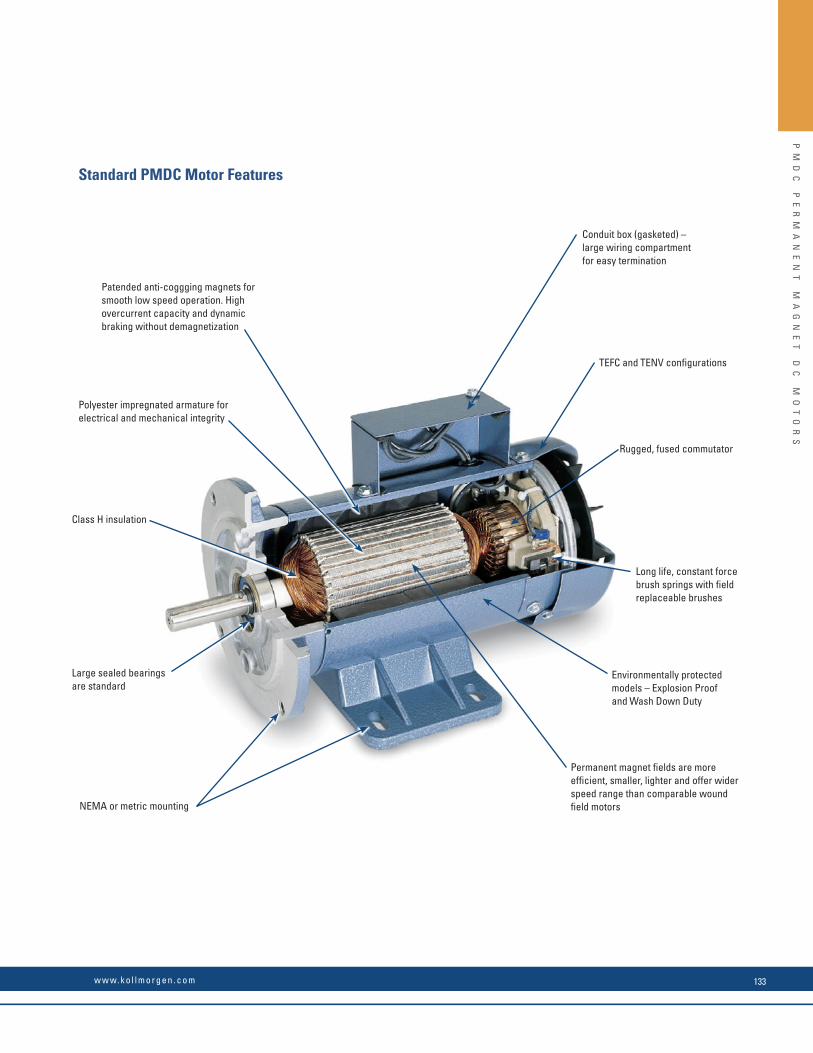
Patended anti-coggging magnets for smooth low speed operation. High overcurrent capacity and dynamic braking without demagnetization
Polyester impregnated armature for electrical and mechanical integrity
Class H insulation
Large sealed bearings are standard
NEMA or metric mounting
Conduit box (gasketed) – large wiring compartment for easy termination
TEFC and TENV confi gurations
Rugged, fused commutator
Long life, constant force brush springs with fi eld replaceable brushes
Environmentally protected models – Explosion Proof and Wash Down Duty
Permanent magnet fi elds are more effi cient, smaller, lighter and offer wider speed range than comparable wound fi eld motors
Standard PMDC Motor Features
PM
DC
P
ER
MA
NE
NT
M
AG
NE
T
DC
M
OT
OR
S
w w w. k o l l m o r g e n . c o m 133
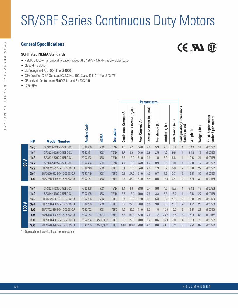
SR/SRF Series Continuous Duty Motors
HP Model Number Prod
uct C
ode
NEM
A
Encl
osur
e
Parameters
Confi
gur
atio
n/D
imen
sion
s(fa
cing
pag
e)
Leng
th (i
n)
Wei
ght (
lbs)
Bru
sh R
epla
cem
ent
(ord
er 2
per
mot
or)
Cont
inuo
us C
urre
nt (A
)
Cont
inuo
us To
rque
(lb f-in
)
Peak
Cur
rent
(A)
Torq
ue C
onst
ant (
lbf-i
n/A
)
Resi
stan
ce (Ω
)
Iner
tia (l
b f-in)
Indu
ctan
ce (m
H)
90 V
1/8 SR3616-8290-7-56BC-CU FGS2430 56C TENV 1.5 4.5 34.0 4.0 5.3 2.9 19.4 1 8.13 14 YP00565
1/4 SR3624-8291-7-56BC-CU FGS2431 56C TENV 2.7 9.0 54.0 3.9 2.5 4.0 9.6 1 9.13 18 YP00565
1/3 SR3632-8292-7-56BC-CU FGS2432 56C TENV 3.5 12.0 71.0 3.9 1.8 5.0 6.6 1 10.13 21 YP00565
1/2 SR3642-4822-7-56BC-CU FGS2434 56C TENV 4.7 18.0 74.0 4.2 0.9 6.5 3.8 1 12.10 17 YP00565
1/2 SRF3632-5227-84-5-56BC-CU FGS2748 56C TEFC 5.1 18.0 54.0 4.0 1.3 5.2 5.8 2 10.10 22 YP00565
3/4 SRF3650-4823-84-5-56BC-CU FGS2749 56C TEFC 6.9 27.0 81.0 4.2 0.7 7.8 3.7 2 13.25 30 YP00565
1.0 SRF3765-4996-84-5-56BC-CU FGS2751 56C TEFC 9.5 36.0 81.0 4.4 0.5 12.8 3.4 2 13.25 30 YP00565
180
V
1/4 SR3624-1032-7-56BC-CU FGS2658 56C TENV 1.4 9.0 28.0 7.4 9.6 4.0 42.8 1 9.13 18 YP00566
1/2 SR3642-4982-7-56BC-CU FGS2438 56C TENV 2.6 18.0 40.0 7.6 3.3 6.3 16.2 1 12.13 27 YP00566
1/2 SRF3632-5265-84-5-56BC-CU FGS2735 56C TEFC 2.4 18.0 27.0 8.1 5.3 5.2 29.5 2 10.10 21 YP00566
3/4 SRF3736-4983-84-5-56BC-CU FGS2750 56C TEFC 3.2 27.0 26.0 8.8 3.6 8.9 28.8 2 11.25 23 YP00566
1.0 SRF3752-4984-84-5-56BC-CU FGS2752 56C TEFC 4.6 36.0 41.0 8.2 1.8 12.0 15.6 2 13.25 29 YP00566
1.5 SRF5348-4485-84-5-45BC-CU FGS2753 145TC* TEFC 7.8 54.0 62.0 7.9 1.2 26.2 13.5 3 16.00 64 YP00574
2.0 SRF5360-4985-84-5-82BC-CU FGS2754 145TC/182 TEFC 9.5 72.0 78.0 8.2 0.6 35.9 7.0 4 16.50 75 YP00559
3.0 SRF5570-4986-84-5-82BC-CU FGS2755 145TC/182 TEFC 14.0 108.0 78.0 9.3 0.6 40.1 7.2 5 19.75 87 YP00585
SCR Rated NEMA Standards
General Specifi cations
• NEMA C face with removable base – except the 180 V / 1.5 HP has a welded base • Class H insulation• UL Recognized (UL 1004, File E61960• CSA Certifi ed (CSA Standard C22.2 No. 100, Class 421101, File LR43477)• CE marked. Conforms to EN60034-1 and EN60034-5• 1750 RPM
* Stamped steel, welded base, not removable P
MD
C
PE
RM
AN
EN
T
MA
GN
ET
D
C
MO
TO
RS
1.
2.
3.
4.
5.
3.88
3.500.38
3.500.38
Ø 6.50
Ø 5.23
Ø 6.50 Ø 4.63
Ø 4.500
Ø 0.6250
4X 3/8-16 UNC-2B THRU EQUALLY SPACED ON A Ø 5.875 B.C.
KNOCKOUT HOLESØ 0.62 AND Ø 0.88
4X Ø0.875 CONDUIT OPENING
4X Ø0.875 CONDUIT OPENING
4X Ø0.875 CONDUIT OPENING
4X 3/8-16 UNC-2B THRU EQUALLY SPACED ON A Ø 5.875 B.C.
+.000-.003
Ø 4.500+.000-.003
Ø 4.500+.000-.003
Ø 4.500+.000-.003
Ø 4.500+.000-.003
+.0000-.0005
Ø 0.6250 +.0000-.0005
Ø 0.8750 +.0000-.0005
Ø 0.8750 +.0000-.0005
Ø 0.8750 +.0000-.0005
4X 0.88
4X 0.88
4X 0.88
4X 0.41
4.886.50
4.886.50
4.886.50
2.75
2.75
2.061.88
0.188 X 1.38 KEY
2.061.88
0.188 X 1.38 KEY
0.188 X 1.38 KEY
0.16 MAX.
Ø 4.63
Ø 6.63
Ø 6.63
Ø 6.63
Ø 6.50
Ø 6.63
Ø 8.5
0.16 MAX.
0.16 MAX.
LENGTH
LENGTH
LENGTH
1.31
TERMINAL COVER2X BRUSH ACCESS COVER
2X BRUSH ACCESS COVER
2X BRUSH ACCESS COVER
2X BRUSH ACCESS COVER
2X BRUSH ACCESS COVER
4X 0.34
4X 0.34
3.004.19
2.75 3.004.19
2.312.0
4.00
4X 3/8-16 UNC-2B 0.63 MAX. EQUALLY SPACED ON A Ø 5.875 B.C.
4X 3/8-16 UNC-2B 0.63 MAX. EQUALLY SPACED ON A Ø 5.875 B.C.
4X 3/8-16 UNC-2B 0.63 MIN. EQUALLY SPACED ON A Ø 5.875 B.C.
4.88
4.88
2.75
2.75
3.50
0.62
4X Ø 0.41
0.62
2.94
2.122.06
0.188 X 1.38 KEY0.16 MAX.
2.12
0.188 X 1.38 KEY0.16 MAX.
2.12
2.06
4X 0.34
4X Ø 0.41
4X Ø 0.41
6.97
2.504.53 4.00
5.006.50
4.50
7.508.75
4.505.75
2.94
6.97
2.504.53 4.00
LENGTH
LENGTHHOOK (REMOVABLE)
5.2 4.53.25
CONDUIT BOX
4.505.75
5.00
6.2
4.50
7.508.75
Confi gurations and Dimensions (inches)
1.
2.
3.
4.
5.
3.88
3.500.38
3.500.38
Ø 6.50
Ø 5.23
Ø 6.50 Ø 4.63
Ø 4.500
Ø 0.6250
4X 3/8-16 UNC-2B THRU EQUALLY SPACED ON A Ø 5.875 B.C.
KNOCKOUT HOLESØ 0.62 AND Ø 0.88
4X Ø0.875 CONDUIT OPENING
4X Ø0.875 CONDUIT OPENING
4X Ø0.875 CONDUIT OPENING
4X 3/8-16 UNC-2B THRU EQUALLY SPACED ON A Ø 5.875 B.C.
+.000-.003
Ø 4.500+.000-.003
Ø 4.500+.000-.003
Ø 4.500+.000-.003
Ø 4.500+.000-.003
+.0000-.0005
Ø 0.6250 +.0000-.0005
Ø 0.8750 +.0000-.0005
Ø 0.8750 +.0000-.0005
Ø 0.8750 +.0000-.0005
4X 0.88
4X 0.88
4X 0.88
4X 0.41
4.886.50
4.886.50
4.886.50
2.75
2.75
2.061.88
0.188 X 1.38 KEY
2.061.88
0.188 X 1.38 KEY
0.188 X 1.38 KEY
0.16 MAX.
Ø 4.63
Ø 6.63
Ø 6.63
Ø 6.63
Ø 6.50
Ø 6.63
Ø 8.5
0.16 MAX.
0.16 MAX.
LENGTH
LENGTH
LENGTH
1.31
TERMINAL COVER2X BRUSH ACCESS COVER
2X BRUSH ACCESS COVER
2X BRUSH ACCESS COVER
2X BRUSH ACCESS COVER
2X BRUSH ACCESS COVER
4X 0.34
4X 0.34
3.004.19
2.75 3.004.19
2.312.0
4.00
4X 3/8-16 UNC-2B 0.63 MAX. EQUALLY SPACED ON A Ø 5.875 B.C.
4X 3/8-16 UNC-2B 0.63 MAX. EQUALLY SPACED ON A Ø 5.875 B.C.
4X 3/8-16 UNC-2B 0.63 MIN. EQUALLY SPACED ON A Ø 5.875 B.C.
4.88
4.88
2.75
2.75
3.50
0.62
4X Ø 0.41
0.62
2.94
2.122.06
0.188 X 1.38 KEY0.16 MAX.
2.12
0.188 X 1.38 KEY0.16 MAX.
2.12
2.06
4X 0.34
4X Ø 0.41
4X Ø 0.41
6.97
2.504.53 4.00
5.006.50
4.50
7.508.75
4.505.75
2.94
6.97
2.504.53 4.00
LENGTH
LENGTHHOOK (REMOVABLE)
5.2 4.53.25
CONDUIT BOX
4.505.75
5.00
6.2
4.50
7.508.75
1 – TENV
2 – TEFC
3 – TEFC
4 – TEFC
5 – TEFC
PM
DC
P
ER
MA
NE
NT
M
AG
NE
T
DC
M
OT
OR
S
K O L L M O R G E N134
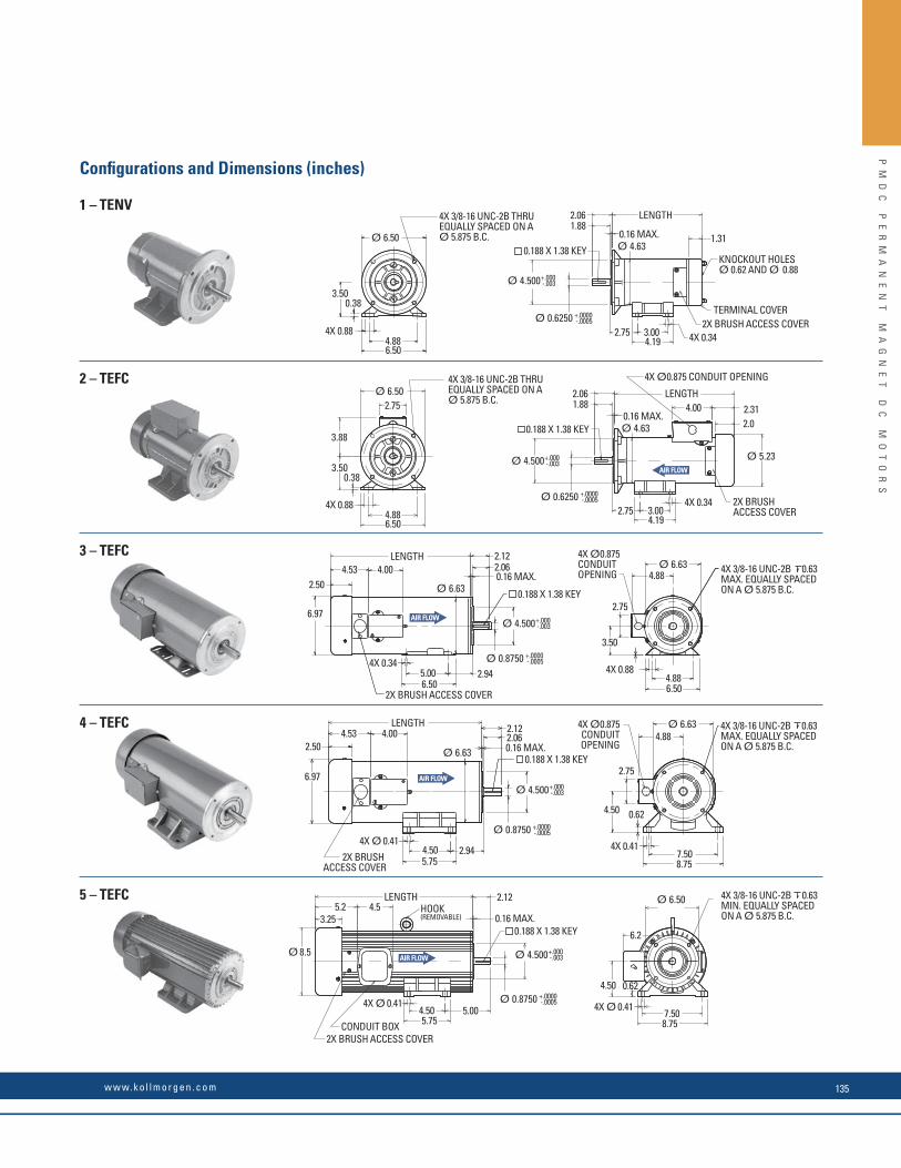
1.
2.
3.
4.
5.
3.88
3.500.38
3.500.38
Ø 6.50
Ø 5.23
Ø 6.50 Ø 4.63
Ø 4.500
Ø 0.6250
4X 3/8-16 UNC-2B THRU EQUALLY SPACED ON A Ø 5.875 B.C.
KNOCKOUT HOLESØ 0.62 AND Ø 0.88
4X Ø0.875 CONDUIT OPENING
4X Ø0.875 CONDUIT OPENING
4X Ø0.875 CONDUIT OPENING
4X 3/8-16 UNC-2B THRU EQUALLY SPACED ON A Ø 5.875 B.C.
+.000-.003
Ø 4.500+.000-.003
Ø 4.500+.000-.003
Ø 4.500+.000-.003
Ø 4.500+.000-.003
+.0000-.0005
Ø 0.6250 +.0000-.0005
Ø 0.8750 +.0000-.0005
Ø 0.8750 +.0000-.0005
Ø 0.8750 +.0000-.0005
4X 0.88
4X 0.88
4X 0.88
4X 0.41
4.886.50
4.886.50
4.886.50
2.75
2.75
2.061.88
0.188 X 1.38 KEY
2.061.88
0.188 X 1.38 KEY
0.188 X 1.38 KEY
0.16 MAX.
Ø 4.63
Ø 6.63
Ø 6.63
Ø 6.63
Ø 6.50
Ø 6.63
Ø 8.5
0.16 MAX.
0.16 MAX.
LENGTH
LENGTH
LENGTH
1.31
TERMINAL COVER2X BRUSH ACCESS COVER
2X BRUSH ACCESS COVER
2X BRUSH ACCESS COVER
2X BRUSH ACCESS COVER
2X BRUSH ACCESS COVER
4X 0.34
4X 0.34
3.004.19
2.75 3.004.19
2.312.0
4.00
4X 3/8-16 UNC-2B 0.63 MAX. EQUALLY SPACED ON A Ø 5.875 B.C.
4X 3/8-16 UNC-2B 0.63 MAX. EQUALLY SPACED ON A Ø 5.875 B.C.
4X 3/8-16 UNC-2B 0.63 MIN. EQUALLY SPACED ON A Ø 5.875 B.C.
4.88
4.88
2.75
2.75
3.50
0.62
4X Ø 0.41
0.62
2.94
2.122.06
0.188 X 1.38 KEY0.16 MAX.
2.12
0.188 X 1.38 KEY0.16 MAX.
2.12
2.06
4X 0.34
4X Ø 0.41
4X Ø 0.41
6.97
2.504.53 4.00
5.006.50
4.50
7.508.75
4.505.75
2.94
6.97
2.504.53 4.00
LENGTH
LENGTHHOOK (REMOVABLE)
5.2 4.53.25
CONDUIT BOX
4.505.75
5.00
6.2
4.50
7.508.75
Confi gurations and Dimensions (inches)
1.
2.
3.
4.
5.
3.88
3.500.38
3.500.38
Ø 6.50
Ø 5.23
Ø 6.50 Ø 4.63
Ø 4.500
Ø 0.6250
4X 3/8-16 UNC-2B THRU EQUALLY SPACED ON A Ø 5.875 B.C.
KNOCKOUT HOLESØ 0.62 AND Ø 0.88
4X Ø0.875 CONDUIT OPENING
4X Ø0.875 CONDUIT OPENING
4X Ø0.875 CONDUIT OPENING
4X 3/8-16 UNC-2B THRU EQUALLY SPACED ON A Ø 5.875 B.C.
+.000-.003
Ø 4.500+.000-.003
Ø 4.500+.000-.003
Ø 4.500+.000-.003
Ø 4.500+.000-.003
+.0000-.0005
Ø 0.6250 +.0000-.0005
Ø 0.8750 +.0000-.0005
Ø 0.8750 +.0000-.0005
Ø 0.8750 +.0000-.0005
4X 0.88
4X 0.88
4X 0.88
4X 0.41
4.886.50
4.886.50
4.886.50
2.75
2.75
2.061.88
0.188 X 1.38 KEY
2.061.88
0.188 X 1.38 KEY
0.188 X 1.38 KEY
0.16 MAX.
Ø 4.63
Ø 6.63
Ø 6.63
Ø 6.63
Ø 6.50
Ø 6.63
Ø 8.5
0.16 MAX.
0.16 MAX.
LENGTH
LENGTH
LENGTH
1.31
TERMINAL COVER2X BRUSH ACCESS COVER
2X BRUSH ACCESS COVER
2X BRUSH ACCESS COVER
2X BRUSH ACCESS COVER
2X BRUSH ACCESS COVER
4X 0.34
4X 0.34
3.004.19
2.75 3.004.19
2.312.0
4.00
4X 3/8-16 UNC-2B 0.63 MAX. EQUALLY SPACED ON A Ø 5.875 B.C.
4X 3/8-16 UNC-2B 0.63 MAX. EQUALLY SPACED ON A Ø 5.875 B.C.
4X 3/8-16 UNC-2B 0.63 MIN. EQUALLY SPACED ON A Ø 5.875 B.C.
4.88
4.88
2.75
2.75
3.50
0.62
4X Ø 0.41
0.62
2.94
2.122.06
0.188 X 1.38 KEY0.16 MAX.
2.12
0.188 X 1.38 KEY0.16 MAX.
2.12
2.06
4X 0.34
4X Ø 0.41
4X Ø 0.41
6.97
2.504.53 4.00
5.006.50
4.50
7.508.75
4.505.75
2.94
6.97
2.504.53 4.00
LENGTH
LENGTHHOOK (REMOVABLE)
5.2 4.53.25
CONDUIT BOX
4.505.75
5.00
6.2
4.50
7.508.75
1 – TENV
2 – TEFC
3 – TEFC
4 – TEFC
5 – TEFC
PM
DC
P
ER
MA
NE
NT
M
AG
NE
T
DC
M
OT
OR
S
w w w. k o l l m o r g e n . c o m 135

STF Series Washdown Motors
SC
R
RA
TE
D
NE
MA
S
TA
ND
AR
DS
W
AS
H
DO
WN
D
UT
Y HP Model Number Prod
uct C
ode
NEM
A
Encl
osur
e
Parameters
Confi
gur
atio
n/D
imen
sion
s(fa
cing
pag
e)
Leng
th (i
n)
Wei
ght (
lbs)
Bru
sh R
epla
cem
ent
(ord
er 2
per
mot
or)
Cont
inuo
us C
urre
nt (A
)
Cont
inuo
us To
rque
(lb f-in
)
Peak
Cur
rent
(A)
Torq
ue C
onst
ant (
lbf-i
n/A
)
Resi
stan
ce (Ω
)
Iner
tia (l
b f-in)
Indu
ctan
ce (m
H)
90 V
1/4 STF3624-4976-61-56BC FGS2419 56C TENV 2.9 9.0 54.0 3.89 2.51 4.0 9.61 1 11.20 22 YP00572
1/2 STF3640-4977-61-56BC FGS2420 56C TENV 5.1 18.0 67.0 4.05 0.95 6.3 4.38 1 12.20 26 YP00572
3/4 STF3758-5150-61-56BC FGS2757 56C TENV 7.3 27.0 126.0 4.05 0.72 8.7 3.50 2 15.20 41 YP00572
180
V
1/2 STF3648-5268-61-56BC FGS2738 56C TENV 2.4 18.0 37.0 8.30 3.59 6.4 19.60 1 11.80 27 YP00571
1.0 STF5332-3748-61-56BC-CU FGS2389 56C* TENV 4.6 36.0 36.0 8.00 2.40 22.4 32.00 3 13.30 41 YP00574
1.5 STF5356-3749-61-45BC-CU FGS2390 145TC* TENV 7.1 54.0 70.0 7.90 1.11 29.8 11.20 4 16.30 65 YP00574
2.0 STF5372-3750-61-82BC-CU FGS2342 145TC/182 TENV 9.3 72.0 93.0 7.90 0.77 39.3 6.80 5 18.30 84 YP00574
SCR Rated NEMA Standards – Wash Down Duty
General Specifi cations
• NEMA C face with removable base – except the 1 and 1.5 HP motors have welded bases • Class H insulation• UL Recognized (UL 1004, File E61960• Complies with NEMA MG1-1.26.5 Waterproof designation and IP65• Bakery Industry Sanitation Standards Committee (BISSC) certifi ed per BISSC Standard 29 (Authorization No. 301)• 1750 RPM
* Stamped steel, welded base, not removable
PM
DC
P
ER
MA
NE
NT
M
AG
NE
T
DC
M
OT
OR
S
K O L L M O R G E N136

Confi gurations and Dimensions (inches)
1 – TENV
2 – TENV
3 – TENV
4 – TENV
5 – TENV
2.
1.
3.
4.
5.
3.50
3.59
3.53
0.38
0.38
Ø 6.50
Ø 6.50
Ø 6.68
Ø 6.68
Ø 6.68
Ø 4.63
Ø 4.81
Ø 6.68
Ø 6.68
4X 3/8-16 UNC-2B .5 MIN. EQUALLY SPACED ON AØ 5.875 B.C.
4X 3/8-16 UNC-2B .5 MIN. EQUALLY SPACED ON AØ 5.875 B.C.
Ø 4.500+.000-.003
Ø 4.500+.000-.003
Ø 4.500+.000-.003
Ø 4.500+.000-.003
Ø 4.500+.000-.003
Ø 0.6250 +.0000-.0005
Ø 0.6250 +.0000-.0005
Ø 0.6250 +.0000-.0005
Ø 0.8750 +.0000-.0005
Ø 0.8750 +.0000-.0005
4X 0.88
4X 0.88
4.886.50
4.886.50
4.886.50
4.886.50
2.75
2.75
2.75
3.08
3.08
2.061.88
0.188 X 1.38 KEY
0.188 X 1.38 KEY
0.188 X 1.38 KEY
0.188 X 1.38 KEY
0.188 X 1.38 KEY
0.16 MAX.
2.061.880.16 MAX.
2.061.880.16 MAX.
0.16 MAX.
LENGTH
LENGTH
LENGTH
LENGTH
LENGTH
1.31
2X BRUSH ACCESS
2X BRUSH ACCESS
2X BRUSH ACCESS
2X BRUSH ACCESS
2X BRUSH ACCESS
4X 0.34
4X 0.34
4X 0.34
3.004.19
3.00
3.004.19
4X 3/8-16 UNC-2B .5 MIN. EQUALLY SPACED ON AØ 5.875 B.C.
4X 3/8-16 UNC-2B .5 MIN. EQUALLY SPACED ON AØ 5.875 B.C.
4X 3/8-16 UNC-2B .56 MIN. EQUALLY SPACED ON AØ 5.875 B.C.
POWER TERMINALS INSIDE THIS COVER
POWER TERMINALS INSIDE THIS COVER
5.5
5.5
2X 2.9
2X 2.9
Ø 0.88 HOLE FOR POWER LEADWIRES.CUSTOMER TO SEAL TO PREVENTENTRANCE OF LIQUID
Ø 0.88 HOLE FOR POWER LEADWIRES.CUSTOMER TO SEAL TO PREVENTENTRANCE OF LIQUID
0.25WIRING COVER
1.31
0.25
WIRINGCOVER
WIRINGCOVER
0.09
3.530.09
4X 0.88
4X 0.88
4X 0.41
6.50
1/2-1/4 NPT
0.50
1/2-1/4 NPT
0.50
1/2-1/4 NPT
0.50
0.190.73
0.190.73
Ø 6.68
0.190.73
7.19
7.19
WIRINGCOVER
7.19
2X 3.0
2X 3.0
2X 3.0
5.006.50
2.121.92
0.16 MAX.
2.121.92
4.53 0.62
7.508.75
4X Ø 0.414.505.75
PM
DC
P
ER
MA
NE
NT
M
AG
NE
T
DC
M
OT
OR
S
w w w. k o l l m o r g e n . c o m 137

EP Series Explosion Proof Motors
HP Model Number Prod
uct C
ode
NEM
A
Encl
osur
e
Parameters
Confi
gur
atio
n/D
imen
sion
s(fa
cing
pag
e)
Leng
th (i
n)
Wei
ght (
lbs)
Bru
sh R
epla
cem
ent
(ord
er 2
per
mot
or)
Cont
inuo
us C
urre
nt (A
)
Cont
inuo
us To
rque
(lb f-in
)
Peak
Cur
rent
(A)
Torq
ue C
onst
ant (
lbf-i
n/A
)
Resi
stan
ce (Ω
)
Iner
tia (l
b f-in)
Indu
ctan
ce (m
H)
90 V
1/4 EP3624-1434-7-56BC-CU FGE0212 56C TENV 2.6 9.0 52.0 4.07 2.63 4.0 10.5 1 10.38 23 YP00565
1/3 EP3632-1435-7-56BC-CU FGE0242 56C TENV 3.5 12.0 71.0 3.94 1.76 5.0 6.6 1 11.38 27 YP00565
1/2 EP3640-1436-7-56BC-CU FGE0213 56C TENV 4.7 18.0 87.0 4.24 1.03 6.4 5.1 1 12.38 30 YP00565
3/4 EP3758-5151-7-56BC-CU FGE0248 56C TENV 7.0 27.0 113.0 4.15 0.74 8.0 3.8 1 14.0 36 YP00565
180
V 1/4 EP3624-5269-7-56BC-CU FGE0261 56C TENV 1.3 9.0 26.0 8.10 10.50 4.0 51.80 1 10.38 23 YP00566
1/2 EP36445214-7-56BC-CU FGE0262 56C TENV 2.3 18.0 34.0 8.10 4.00 6.7 24.20 1 12.38 30 YP00566
3/4 EP3752-5215-7-56BC-CU FGE0263 56C TENV 3.3 27.0 38.0 8.10 3.10 11.4 17.40 1 14.38 34 YP00566
12 V 1/3 EP3620-1954-7-56BC-CU FGE0243 56C TENV 28.0 12.0 n/a 0.52 0.04 3.5 0.18 1 10.38 19 YP00583
24 V 1/3 EP3624-2757-7-56BC-CU FGE0245 56C TENV 13.4 12.0 n/a 1.02 0.16 4.0 0.66 1 10.38 24 YP00593
3/4 EP3648-4952-7-56BC-CU FGE0244 56C TENV 28.2 27.0 n/a 1.02 0.06 7.1 0.22 1 13.38 33 YP00593
General Specifi cations
SCR Rated NEMA Standards – Explosion Proof
Confi guration and Dimensions (inches)
• NEMA C face with removable base• Class H insulation• UL Recognized (UL 674, File E56538), meets Division 1 & 2, Class 1 (Groups C & D), Class II (Groups F & G) and Class III• CSA Listed Components per CSA Standard C22.2 No. 145, Class 428801 (fi le 213464).• 1750 RPM
1 – TENV
3.50.38
Ø 6.42
4X 3/8-16 UNC-2B .62 MIN. EQUALLY SPACED ON AØ 5.875 B.C.
Ø 4.500+.000-.003
Ø 0.6250 +.0000-.0005 4X 0.88
4.886.50
0.188 X 1.38 KEY 0.16 MAX.
LENGTH
3.004.19
45°
2.06
4.63
2X BRUSH ACCESS PLUG
0.75 HEXSOCKET
4X 0.34
3/4-14 NPT
POWER LEAD BLACKPOWER LEAD WHITE
GROUND LEAD GREEN THERMOSTATLEADS RED
6.0
6.0 MIN.
PM
DC
P
ER
MA
NE
NT
M
AG
NE
T
DC
M
OT
OR
S
K O L L M O R G E N138

BA/BAF Series Low Voltage Motors
HP Model Number Prod
uct C
ode
NEM
A
Encl
osur
e
Parameters
Confi
gur
atio
n/D
imen
sion
s(fa
cing
pag
e)
Leng
th (i
n)
Wei
ght (
lbs)
Bru
sh R
epla
cem
ent
(ord
er 2
per
mot
or)
Cont
inuo
us C
urre
nt (A
)
Cont
inuo
us To
rque
(lb f-in
)
Peak
Cur
rent
(A)
Torq
ue C
onst
ant (
lbf-i
n/A
)
Resi
stan
ce (Ω
)
Iner
tia (l
b f-in)
Indu
ctan
ce (m
H)
12 V
1/4 BA3614-4648-9-56BC FGB2010 56C TENV 21.1 9.0 n/a 0.51 0.07 2.9 0.27 1 8.13 15 YP00593
1/3 BA3624-7005-9-56BC FGB2002 56C TENV 27.0 12.0 n/a 0.51 0.04 4.0 0.14 1 9.13 19 YP00582
1/2 BA3638-4588-9-56BC FGB2005 56C TENV 39.8 18.0 n/a 0.49 0.02 5.5 0.07 1 11.13 25 YP00592
24 V
1/4 BA3618-7009-9-56BC FGB1592 56C TENV 10.3 9.0 n/a 1.04 0.14 3.2 0.57 1 9.13 18 YP00593
1/3 BA3624-7024-9-56BC FGB2285 56C TENV 13.4 12.0 n/a 1.02 0.16 4.0 0.66 1 9.13 19 YP00593
1/2 BA3628-7012-9-56BC FGB1441 56C TENV 19.5 18.0 n/a 1.01 0.10 4.4 0.38 1 10.13 21 YP00593
3/4 BA3648-4650-9-56BC FGB2006 56C TENV 28.2 27.0 n/a 1.02 0.06 7.1 0.22 1 12.10 29 YP00592
1.0 BAF3644-5081-56BC FGB2335 56C TEFC 38.4 36.0 n/a 1.00 0.05 6.6 0.21 2 12.25 28 YP00583
General Specifi cations
Low Voltage Rated NEMA Standards
Confi guration and Dimensions (inches)
• NEMA C face with removable base• Class H insulation• UL Recognized (UL1004, File E61960)• Designed for use with low voltage supplies (batteries).• Highly effi cient• For constant speed, motors are operated directly from
a battery with no motor control interface.• For adjustable speeds, low voltage motor controls are
readily available• 1750 RPM
1 – TENV
2 – TEFC
3.500.38
3.500.38
Ø 6.50
Ø 6.50
Ø 4.63
4X 3/8-16 UNC-2B THRU EQUALLY SPACED ON AØ 5.875 B.C.
4X 3/8-16 UNC-2B THRU EQUALLY SPACED ON AØ 5.875 B.C.
Ø 4.500+.000-.003
Ø 4.500+.000-.003
Ø 0.6250 +.0000-.0005
Ø 0.6250 +.0000-.0005
4X 0.88
4X 0.88
4.886.50
4.886.50
0.188 X 1.38 KEY
0.188 X 1.38 KEY
0.16 MAX.
Ø 4.63
Ø 5.23
0.16 MAX.
LENGTH
LENGTH
3.004.19
3.004.19
2.06
4X 0.34
4X 0.34
1.88
2.061.88
1.31
KNOCKOUT HOLESØ 0.62 AND Ø 0.88
TERMINAL COVER
2.75
2.75
0.81 2.0
2X BRUSHACCESS COVER
3.500.38
3.500.38
Ø 6.50
Ø 6.50
Ø 4.63
4X 3/8-16 UNC-2B THRU EQUALLY SPACED ON AØ 5.875 B.C.
4X 3/8-16 UNC-2B THRU EQUALLY SPACED ON AØ 5.875 B.C.
Ø 4.500+.000-.003
Ø 4.500+.000-.003
Ø 0.6250 +.0000-.0005
Ø 0.6250 +.0000-.0005
4X 0.88
4X 0.88
4.886.50
4.886.50
0.188 X 1.38 KEY
0.188 X 1.38 KEY
0.16 MAX.
Ø 4.63
Ø 5.23
0.16 MAX.
LENGTH
LENGTH
3.004.19
3.004.19
2.06
4X 0.34
4X 0.34
1.88
2.061.88
1.31
KNOCKOUT HOLESØ 0.62 AND Ø 0.88
TERMINAL COVER
2.75
2.75
0.81 2.0
2X BRUSHACCESS COVER
PM
DC
P
ER
MA
NE
NT
M
AG
NE
T
DC
M
OT
OR
S
w w w. k o l l m o r g e n . c o m 139
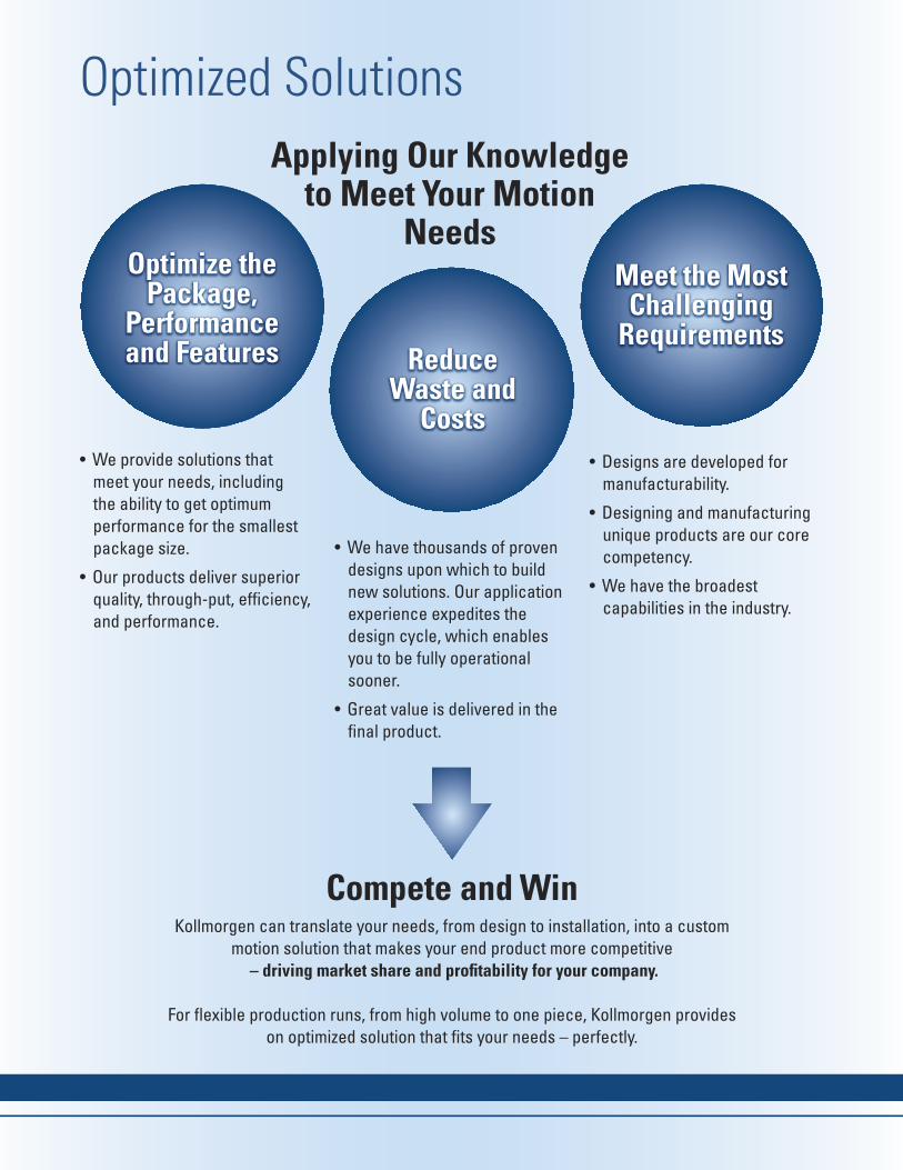
OP
TI
MI
ZE
D
SO
LU
TI
ON
S
Optimize the Package,
Performance and Features Reduce
Waste and Costs
Meet the Most Challenging
Requirements
Applying Our Knowledge to Meet Your Motion
Needs
Compete and Win
• We provide solutions that meet your needs, including the ability to get optimum performance for the smallest package size.
• Our products deliver superior quality, through-put, effi ciency, and performance.
• We have thousands of proven designs upon which to build new solutions. Our application experience expedites the design cycle, which enables you to be fully operational sooner.
• Great value is delivered in the fi nal product.
Kollmorgen can translate your needs, from design to installation, into a custom motion solution that makes your end product more competitive
– driving market share and profi tability for your company.
For fl exible production runs, from high volume to one piece, Kollmorgen provides on optimized solution that fi ts your needs – perfectly.
• Designs are developed for manufacturability.
• Designing and manufacturing unique products are our core competency.
• We have the broadest capabilities in the industry.
Optimized Solutions
OP
TI
MI
ZE
D
SO
LU
TI
ON
S
Optimized Solutions
Whether it’s modifying a product from our standard catalog or a white sheet design for a custom solution, you can rely on decades of Kollmorgen expertise to solve your motion challenges and help your machine stand out from the crowd.
Why You Should Partner with Kollmorgen• Experienced application engineers help defi ne a customer’s needs and identify the optimal Kollmorgen products and technologies • Products optimized or developed by cross-functional teams to meet customer needs • Rapid prototyping• Smooth transition from prototype designs to sustainable and cost effective manufacturing• Industry-proven quality, performance, and delivery• Proven technology building blocks mitigate risks of customization
Modifi ed Standard
Because our application expertise runs deep and our product portfolio is so broad, we can take any standard product and modify it a lot or a little to suit many needs – in a very rapid time frame. This approach ensures quality, performance and reliability by leveraging our proven track record.
Kollmorgen application engineers have a great deal of experience helping OEM engineers achieve their objectives: Typical motor modifi cations include shaft, housing, winding and through-bore alterations; feedback type; mounting and connectors; ruggedization (high-shock-and-vibration), vacuum-duty, radiation-hardened, explosion-proof. Typical drive modifi cations include housing, mounting and heat-sinking; connector type; I/O type- and count; fi eld buses and motion buses; special cabling; ruggedization (high-shock-and-vibration).
Custom ProductsWith motion as our core capability, we bring a signifi cant history of innovation to today’s engineering challenges. We leverage our design and engineering excellence and technical knowledge to deliver creative new solutions for virtually any need. Our vast experience also helps us deliver a custom product in a surprisingly short time. If you can conceive it, we can make it happen.
Project Management
We follow a structured development process from initial concept to volume production. This enables us to provide a complete solution from design to implementation.
Our skilled engineering team is assigned to each project and ensures a high quality product designed and delivered on time, successfully taking the prototype to full production.
• Dedicated Resources & Equipment• Real Time Customer Collaboration• Validation of Performance, Cost & Manufacturability
Before Volume Production
Customer Visibility Throughout the Entire Process
A communicative and proactive approach keeps you updated and aware of what is required throughout, what it will cost, and what to expect for design testing
This not only puts you in charge of approving any modifi cations before installation, but ensures the product is up and running quickly, with minimal development time and maximum value.
Engineering Excellence
What really sets us apart is our engineering expertise. With over 50 years of successfully designing custom motors, we are able to quickly assess, design and implement a solution that meets your needs.
Our engineers have an average tenure of 20 years, which means they have designed solutions for almost every unique and challenging situation. Their insightfulness and expertise will guide you through the development and implementation of an optimized motor solution.
We rely on the most advanced simulation tools to deliver the best products, designed to withstand the most unique and challenging environments:
• 3-D Modeling –ProE• Finite Element Analysis
–Electromagnetics–Structural (stress, vibration, fatigue)–Thermal
• Speed• Infolytica• Ansys• Magneto
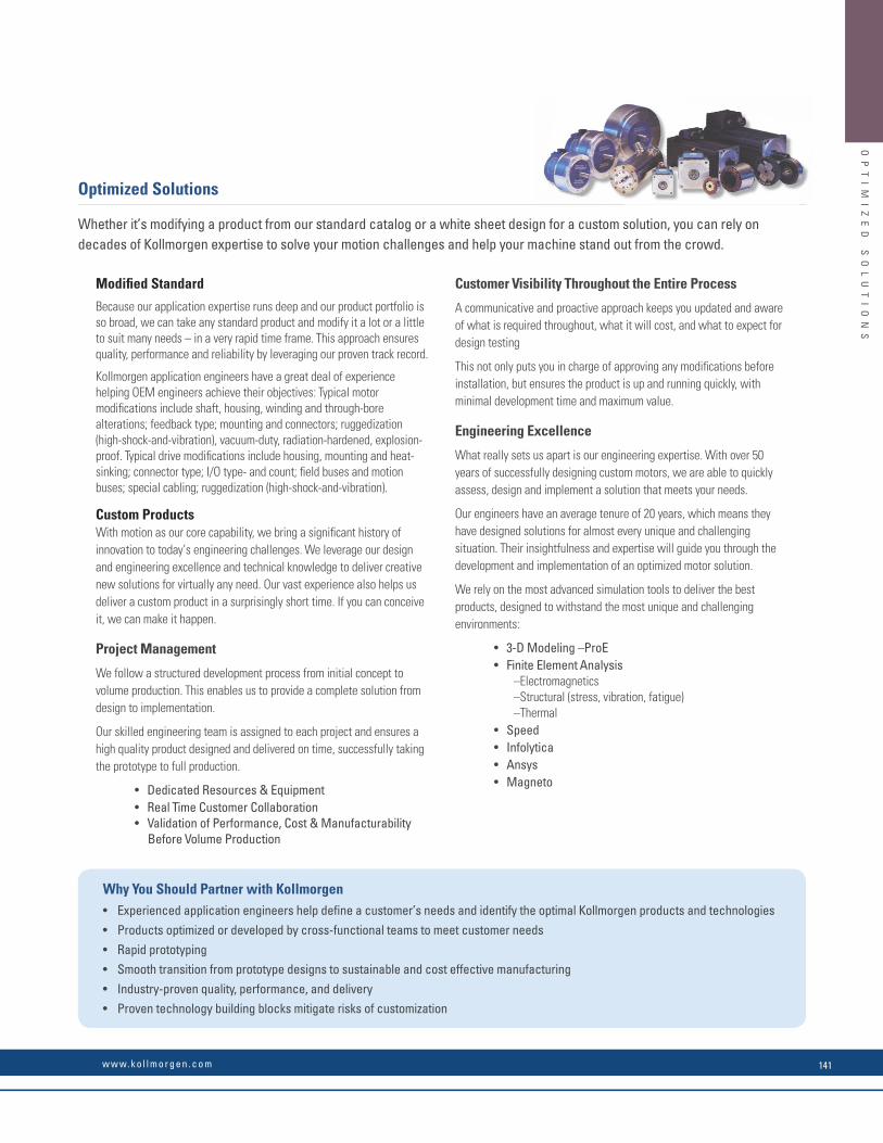
OP
TI
MI
ZE
D
SO
LU
TI
ON
S
Optimize the Package,
Performance and Features Reduce
Waste and Costs
Meet the Most Challenging
Requirements
Applying Our Knowledge to Meet Your Motion
Needs
Compete and Win
• We provide solutions that meet your needs, including the ability to get optimum performance for the smallest package size.
• Our products deliver superior quality, through-put, effi ciency, and performance.
• We have thousands of proven designs upon which to build new solutions. Our application experience expedites the design cycle, which enables you to be fully operational sooner.
• Great value is delivered in the fi nal product.
Kollmorgen can translate your needs, from design to installation, into a custom motion solution that makes your end product more competitive
– driving market share and profi tability for your company.
For fl exible production runs, from high volume to one piece, Kollmorgen provides on optimized solution that fi ts your needs – perfectly.
• Designs are developed for manufacturability.
• Designing and manufacturing unique products are our core competency.
• We have the broadest capabilities in the industry.
Optimized SolutionsO
PT
IM
IZ
ED
S
OL
UT
IO
NS
Optimized Solutions
Whether it’s modifying a product from our standard catalog or a white sheet design for a custom solution, you can rely on decades of Kollmorgen expertise to solve your motion challenges and help your machine stand out from the crowd.
Why You Should Partner with Kollmorgen• Experienced application engineers help defi ne a customer’s needs and identify the optimal Kollmorgen products and technologies • Products optimized or developed by cross-functional teams to meet customer needs • Rapid prototyping• Smooth transition from prototype designs to sustainable and cost effective manufacturing• Industry-proven quality, performance, and delivery• Proven technology building blocks mitigate risks of customization
Modifi ed Standard
Because our application expertise runs deep and our product portfolio is so broad, we can take any standard product and modify it a lot or a little to suit many needs – in a very rapid time frame. This approach ensures quality, performance and reliability by leveraging our proven track record.
Kollmorgen application engineers have a great deal of experience helping OEM engineers achieve their objectives: Typical motor modifi cations include shaft, housing, winding and through-bore alterations; feedback type; mounting and connectors; ruggedization (high-shock-and-vibration), vacuum-duty, radiation-hardened, explosion-proof. Typical drive modifi cations include housing, mounting and heat-sinking; connector type; I/O type- and count; fi eld buses and motion buses; special cabling; ruggedization (high-shock-and-vibration).
Custom ProductsWith motion as our core capability, we bring a signifi cant history of innovation to today’s engineering challenges. We leverage our design and engineering excellence and technical knowledge to deliver creative new solutions for virtually any need. Our vast experience also helps us deliver a custom product in a surprisingly short time. If you can conceive it, we can make it happen.
Project Management
We follow a structured development process from initial concept to volume production. This enables us to provide a complete solution from design to implementation.
Our skilled engineering team is assigned to each project and ensures a high quality product designed and delivered on time, successfully taking the prototype to full production.
• Dedicated Resources & Equipment• Real Time Customer Collaboration• Validation of Performance, Cost & Manufacturability
Before Volume Production
Customer Visibility Throughout the Entire Process
A communicative and proactive approach keeps you updated and aware of what is required throughout, what it will cost, and what to expect for design testing
This not only puts you in charge of approving any modifi cations before installation, but ensures the product is up and running quickly, with minimal development time and maximum value.
Engineering Excellence
What really sets us apart is our engineering expertise. With over 50 years of successfully designing custom motors, we are able to quickly assess, design and implement a solution that meets your needs.
Our engineers have an average tenure of 20 years, which means they have designed solutions for almost every unique and challenging situation. Their insightfulness and expertise will guide you through the development and implementation of an optimized motor solution.
We rely on the most advanced simulation tools to deliver the best products, designed to withstand the most unique and challenging environments:
• 3-D Modeling –ProE• Finite Element Analysis
–Electromagnetics–Structural (stress, vibration, fatigue)–Thermal
• Speed• Infolytica• Ansys• Magneto
w w w. k o l l m o r g e n . c o m 141

OP
TI
MI
ZE
D
SO
LU
TI
ON
S
Product Planning Delivery
Project Proposal
Preparation Design Implementation Validation Pre-Production & Launch Readiness
ProjectConclusion
Post-Launch Tracking
Production
> Project directive> Market and fi nancial analysis> Project cost estimate
> Project defi nition> Requirement specifi cations> Preliminary engineering> Design specifi cations
> Project specifi cations> Preliminary product test specifi cations> Verifi cations planning> Operations plan
> Verifi cation records> CAR> Design readiness checklist> Implementation description
> Verifi cation records> Operation readiness checklist> Pre-production plan> Component approval matrix
> Acceptance from customer> Readiness checklist
> Final report> Post launch tracking plan> Supplier tracking plan
Kollmorgen offers 5-day lead-time on nearly 1,000,000 COTS products, all with best-in-class performance and quality.
When COTS is not quite the best way to realize a totally optimized system, Kollmorgen can offer co-engineered solutions to meet your most diffi cult challenges and advance your competitive position. Drawing on a wealth of knowledge and expertise, our engineering support team will work alongside you to build a solution that differentiates your machine and improves your bottom line.
Here are just few examples of how Kollmorgen delivers real value to companies likes yours:
What You Need Why Motion Matters Kollmorgen Co-Engineering Results
30% Increase in Throughput • Low inertia servo motors
• High bandwidth servo loops
• Simple, accurate, graphical programming tools
Using the Kollmorgen Automation SuiteTM
graphical camming design tool, Pipe NetworkTM and low-inertia AKM servo motors, a major supplier of diabetic test labs increased throughput by more than 30% while improving accuracy and reducing scrap.
50% Increase in Accuracy and Quality • Low cogging frameless servo motor
• Advanced observers and bi-quad fi lters
• Fast control loop update rates (.67μs)
Using our AKD servo drive, a next-generation CT scanning manufacturer achieved more than 50% improvement in velocity ripple to produce the most accurate and detailed medical images possible while overcoming an extremely high moment of inertia.
25% Increase in Reliability
(Overall Equipment Effectiveness)
• Innovative Cartridge Direct Drive RotaryTM DDR motor
• Eliminating parts on the machine
• No additional wearing components
Using Kollmorgen’s award-winning Cartridge DDR servo motor technology, we eliminated more than 60 parts in a die-cutting machine and increased the OEE by 25% and throughput by 20%.
50% Reduction in Waste • Superior motor/drive system bandwidth
• DDR technology: – eliminates gearbox – 20X more accurate than geared solution
We helped a manufacturer of pharmaceutical packaging machines incorporate Housed DDR motors to increase the throughput by 35% and reduce scrap by more than 50% through more accurate alignment of the capsules.
Optimized Solutions Process
Comprehensive design, manufacture and test capabilities ensure the end product meets the customer performance specifi cations and quality requirements. Our skilled engineering team works directly with each customer throughout the process, quickly taking the prototype to full production.
Capabilities to Meet Your Needs
OP
TI
MI
ZE
D
SO
LU
TI
ON
S
Motor Solutions
• Brushed, brushless and stepper motor building blocks used in frameless or housed confi gurations
• Designed for agency compliance (UL, CE, RoHS)
• Voltage ratings from 48 Vdc – 600 Vdc, with capabilities in 800 Vdc and up
• Continuous torques from 0.5 Nm – 29,000 Nm
• Proven performance and reliability in a customizable package
Drive Solutions
• Board-level or packaged solutions supporting single to multi-axis confi gurations
• Brushed or brushless servo drives, stepper, AC induction control
• Integrated controller and communications options
• Designed for agency approvals (UL 508C, EN 50178, EN 61000-6-6, EN 61800-3, CISPR 14-1, and others available)
• Proprietary technology and software can be embedded into the drive
Motors and Electronics
Optimized for Application
Reliability, weight Implantable heart pumps, military, remote equipment
Precision Pick and place, satellite tracking, fi lm processing
Package size Medical imaging, ground based telescopes, aircraft instrumentation, collaborative robotics
Smooth operation Medical respirators, high precision robotics, printing and textile machines
Harsh environments Deep sea, outer space, high shock and vibration, extreme temperatures
Medical diagnostics drive optimized for form-factor, I/O and EMC Frameless direct drive rotary motorwith water cooling features
Custom submersible motor
2-axis drive for high-power robotics, optimized for form-factor and communications interface
200 kW electric starter/generator 4-axis stepper drive using SynqNet
Proven Design Capabilities
K O L L M O R G E N142
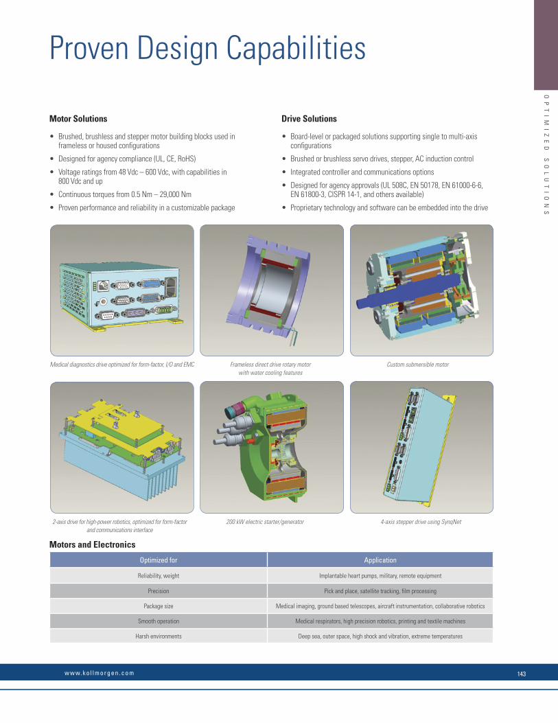
OP
TI
MI
ZE
D
SO
LU
TI
ON
S
Product Planning Delivery
Project Proposal
Preparation Design Implementation Validation Pre-Production & Launch Readiness
ProjectConclusion
Post-Launch Tracking
Production
> Project directive> Market and fi nancial analysis> Project cost estimate
> Project defi nition> Requirement specifi cations> Preliminary engineering> Design specifi cations
> Project specifi cations> Preliminary product test specifi cations> Verifi cations planning> Operations plan
> Verifi cation records> CAR> Design readiness checklist> Implementation description
> Verifi cation records> Operation readiness checklist> Pre-production plan> Component approval matrix
> Acceptance from customer> Readiness checklist
> Final report> Post launch tracking plan> Supplier tracking plan
Kollmorgen offers 5-day lead-time on nearly 1,000,000 COTS products, all with best-in-class performance and quality.
When COTS is not quite the best way to realize a totally optimized system, Kollmorgen can offer co-engineered solutions to meet your most diffi cult challenges and advance your competitive position. Drawing on a wealth of knowledge and expertise, our engineering support team will work alongside you to build a solution that differentiates your machine and improves your bottom line.
Here are just few examples of how Kollmorgen delivers real value to companies likes yours:
What You Need Why Motion Matters Kollmorgen Co-Engineering Results
30% Increase in Throughput • Low inertia servo motors
• High bandwidth servo loops
• Simple, accurate, graphical programming tools
Using the Kollmorgen Automation SuiteTM
graphical camming design tool, Pipe NetworkTM and low-inertia AKM servo motors, a major supplier of diabetic test labs increased throughput by more than 30% while improving accuracy and reducing scrap.
50% Increase in Accuracy and Quality • Low cogging frameless servo motor
• Advanced observers and bi-quad fi lters
• Fast control loop update rates (.67μs)
Using our AKD servo drive, a next-generation CT scanning manufacturer achieved more than 50% improvement in velocity ripple to produce the most accurate and detailed medical images possible while overcoming an extremely high moment of inertia.
25% Increase in Reliability
(Overall Equipment Effectiveness)
• Innovative Cartridge Direct Drive RotaryTM DDR motor
• Eliminating parts on the machine
• No additional wearing components
Using Kollmorgen’s award-winning Cartridge DDR servo motor technology, we eliminated more than 60 parts in a die-cutting machine and increased the OEE by 25% and throughput by 20%.
50% Reduction in Waste • Superior motor/drive system bandwidth
• DDR technology: – eliminates gearbox – 20X more accurate than geared solution
We helped a manufacturer of pharmaceutical packaging machines incorporate Housed DDR motors to increase the throughput by 35% and reduce scrap by more than 50% through more accurate alignment of the capsules.
Optimized Solutions Process
Comprehensive design, manufacture and test capabilities ensure the end product meets the customer performance specifi cations and quality requirements. Our skilled engineering team works directly with each customer throughout the process, quickly taking the prototype to full production.
Capabilities to Meet Your NeedsO
PT
IM
IZ
ED
S
OL
UT
IO
NS
Motor Solutions
• Brushed, brushless and stepper motor building blocks used in frameless or housed confi gurations
• Designed for agency compliance (UL, CE, RoHS)
• Voltage ratings from 48 Vdc – 600 Vdc, with capabilities in 800 Vdc and up
• Continuous torques from 0.5 Nm – 29,000 Nm
• Proven performance and reliability in a customizable package
Drive Solutions
• Board-level or packaged solutions supporting single to multi-axis confi gurations
• Brushed or brushless servo drives, stepper, AC induction control
• Integrated controller and communications options
• Designed for agency approvals (UL 508C, EN 50178, EN 61000-6-6, EN 61800-3, CISPR 14-1, and others available)
• Proprietary technology and software can be embedded into the drive
Motors and Electronics
Optimized for Application
Reliability, weight Implantable heart pumps, military, remote equipment
Precision Pick and place, satellite tracking, fi lm processing
Package size Medical imaging, ground based telescopes, aircraft instrumentation, collaborative robotics
Smooth operation Medical respirators, high precision robotics, printing and textile machines
Harsh environments Deep sea, outer space, high shock and vibration, extreme temperatures
Medical diagnostics drive optimized for form-factor, I/O and EMC Frameless direct drive rotary motorwith water cooling features
Custom submersible motor
2-axis drive for high-power robotics, optimized for form-factor and communications interface
200 kW electric starter/generator 4-axis stepper drive using SynqNet
Proven Design Capabilities
w w w. k o l l m o r g e n . c o m 143

OP
TI
MI
ZE
D
SO
LU
TI
ON
S
The explosion-proof MX Series provides hazardous-duty stepper motors suitable for use in Class 1, Division 1, Group D locations. They are available in NEMA 34 and 42 frame sizes (90 and 110 mm), and provide minimum holding torques from 1.27 to 9.82 N-m (180 to 1390 oz-in).
• MX09 models: NEMA 34 (90 mm) motors available in three stack lengths with minimum torque ratings from 1.27 to 3.88 N-m (180 to 550 oz-in
• MX11 models: NEMA 42 (110 mm) motors available in 2 stack lengths with minimum torque ratings from 6.0 to 9.82 N-m (850 to 1390 oz-in)
• Speeds up to 3,000 rpm provide for velocity demands of most high torque applications
These synchronous motors are available in UL Listed versions suitable for use in Class I, Division 1, Group D hazardous locations. They provide torque up to 1,500 oz-in (1059 N-cm) and are available in NEMA 42 and 66 frame sizes (110 mm and 170 mm).
These permanent magnet DC (PMDC) motors are SCR rated and adhere to NEMA standards. They are available in a variety of DC voltages, from 1/4 to 3/4 HP.
Based on our 230 VAC B and M Series, the Kollmorgen EB Series provides a high-performance explosion-proof servo motor suitable for applications where fl ammable vapors or gases create a potentially hazardous environment. These motors have been tested and proven capable of withstanding an internal explosion without bursting or allowing ignition to reach outside the motor frame.
• Motor torque up to 1,500 oz-in (1059 N-cm)
• 72 rpm at 60 Hz, 60 rpm at 50 Hz
• 120 and 240 volt AC versions
• UL Listed and CE Certifi ed versions
• UL Listed versions meet Class I, Division 1, Group D requirements
• Patented anti-cog magnets for smooth low speed operation
• Polyester-impregnated armature for electrical and mechanical integrity
• High overcurrent capacity and dynamic braking
• Rugged, fused commutator
• TEFC and TENV confi gurations
• 230 VAC explosion-proof (Class I, Division 1, Groups C and D)
• Tested and proven capable of withstanding an internal explosion without bursting or allowing ignition to reach outside the motor frame
MX Series Hazardous Duty Motors
Hazardous Duty Synchronous Motors
EP Series Explosion-Proof Motors
EB Series High-Performance Explosion-Proof Servo Motors
• UL Listed versions have a conduit connection
• CE Certifi ed versions: CE 0081 Ex II 2G Ex d IIC T5
• CE Certifi ed versions have an integral 10 ft (3 M) cable
• Long life, constant force brush springs with fi eld-replaceable brushes
• Gasketed conduit box with large wiring compartment
• Large sealed bearings, standard
• Class H insulation
OP
TI
MI
ZE
D
SO
LU
TI
ON
S Every day Kollmorgen pushes the boundaries of motion to deliver optimized solutions that satisfy even the most demanding application requirements in the harshest of environments.
We’ve been working with the biggest names in harsh and hazardous environments in Industry, Automation, Aerospace & Defense, Exploration, Nuclear, Medical and Robotics for nearly 60 years.
We are on Mars and the Moon and at the bottom of the oceans: In fact, Kollmorgen motors powered the legendary ROV Jason Jr. at a depth of 3,784 meters (12,415 feet) to explore the interior of Titanic for the fi rst time since it sank in 1912.
Kollmorgen continues to collaborate with leading innovators with the same enthusiasm and acumen: Kollmorgen knows that motion matters and represents endless possibilities for innovation. Our engineering expertise and engineering capabilities enable us to deliver superior performing solutions for these demanding environments.
These enhanced, high-performance motors are Mil-Spec 810E rated and IP67 sealed, and comes standard with a stainless steel and chemical-agent-resistant paint, for duty in harsh environmental conditions.
• 0.43 to 53 Nm continuous stall torque (3.8 to 467 lb-in)
• Speeds up to 8000 RPM meet high speed requirements
• Custom windings, shaft variations, and fail-safe brakes available
• 480 Vac High Voltage Insulation
• Rugged resolver feedback for extreme environments
• Operating temperature range of -51˚ C to 54˚ C
• Shock and Vibration tested per MIL-STD-810E, Methods 516.4 & 514.4, Procedure 1
• International Standard Mount available
EKM Series Brushless AC Servo Motors
These brushless servo motors incorporate pressure compensation technology to allow underwater opera-tion up to 20,000 ft while withstanding extreme environments. They feature stainless steel and aluminum nickel bronze housings or an anodized aluminum housing for lighter overall weight. All shafts are stainless steel and sealed with an externally serviceable O-ring seal. The S Series is fully tooled for cost-effective volume production.
• Choice of stainless steel and aluminum nickel bronze housings or an anodized aluminum housing for lighter overall weight
• Stainless steel shaft with externally serviceable seal
• SEACON connectors
• Pressure compensated: 10,000 psi
• Designed to withstand severe shock and extreme environments
Goldline® S Series Submersible Servo Motors
Kollmorgen COTS Motors for Special Duty
KO
LL
MO
RG
EN
C
OT
S
MO
TO
RS
F
OR
S
PE
CI
AL
D
UT
Y
K O L L M O R G E N144

OP
TI
MI
ZE
D
SO
LU
TI
ON
S
The explosion-proof MX Series provides hazardous-duty stepper motors suitable for use in Class 1, Division 1, Group D locations. They are available in NEMA 34 and 42 frame sizes (90 and 110 mm), and provide minimum holding torques from 1.27 to 9.82 N-m (180 to 1390 oz-in).
• MX09 models: NEMA 34 (90 mm) motors available in three stack lengths with minimum torque ratings from 1.27 to 3.88 N-m (180 to 550 oz-in
• MX11 models: NEMA 42 (110 mm) motors available in 2 stack lengths with minimum torque ratings from 6.0 to 9.82 N-m (850 to 1390 oz-in)
• Speeds up to 3,000 rpm provide for velocity demands of most high torque applications
These synchronous motors are available in UL Listed versions suitable for use in Class I, Division 1, Group D hazardous locations. They provide torque up to 1,500 oz-in (1059 N-cm) and are available in NEMA 42 and 66 frame sizes (110 mm and 170 mm).
These permanent magnet DC (PMDC) motors are SCR rated and adhere to NEMA standards. They are available in a variety of DC voltages, from 1/4 to 3/4 HP.
Based on our 230 VAC B and M Series, the Kollmorgen EB Series provides a high-performance explosion-proof servo motor suitable for applications where fl ammable vapors or gases create a potentially hazardous environment. These motors have been tested and proven capable of withstanding an internal explosion without bursting or allowing ignition to reach outside the motor frame.
• Motor torque up to 1,500 oz-in (1059 N-cm)
• 72 rpm at 60 Hz, 60 rpm at 50 Hz
• 120 and 240 volt AC versions
• UL Listed and CE Certifi ed versions
• UL Listed versions meet Class I, Division 1, Group D requirements
• Patented anti-cog magnets for smooth low speed operation
• Polyester-impregnated armature for electrical and mechanical integrity
• High overcurrent capacity and dynamic braking
• Rugged, fused commutator
• TEFC and TENV confi gurations
• 230 VAC explosion-proof (Class I, Division 1, Groups C and D)
• Tested and proven capable of withstanding an internal explosion without bursting or allowing ignition to reach outside the motor frame
MX Series Hazardous Duty Motors
Hazardous Duty Synchronous Motors
EP Series Explosion-Proof Motors
EB Series High-Performance Explosion-Proof Servo Motors
• UL Listed versions have a conduit connection
• CE Certifi ed versions: CE 0081 Ex II 2G Ex d IIC T5
• CE Certifi ed versions have an integral 10 ft (3 M) cable
• Long life, constant force brush springs with fi eld-replaceable brushes
• Gasketed conduit box with large wiring compartment
• Large sealed bearings, standard
• Class H insulation
OP
TI
MI
ZE
D
SO
LU
TI
ON
S Every day Kollmorgen pushes the boundaries of motion to deliver optimized solutions that satisfy even the most demanding application requirements in the harshest of environments.
We’ve been working with the biggest names in harsh and hazardous environments in Industry, Automation, Aerospace & Defense, Exploration, Nuclear, Medical and Robotics for nearly 60 years.
We are on Mars and the Moon and at the bottom of the oceans: In fact, Kollmorgen motors powered the legendary ROV Jason Jr. at a depth of 3,784 meters (12,415 feet) to explore the interior of Titanic for the fi rst time since it sank in 1912.
Kollmorgen continues to collaborate with leading innovators with the same enthusiasm and acumen: Kollmorgen knows that motion matters and represents endless possibilities for innovation. Our engineering expertise and engineering capabilities enable us to deliver superior performing solutions for these demanding environments.
These enhanced, high-performance motors are Mil-Spec 810E rated and IP67 sealed, and comes standard with a stainless steel and chemical-agent-resistant paint, for duty in harsh environmental conditions.
• 0.43 to 53 Nm continuous stall torque (3.8 to 467 lb-in)
• Speeds up to 8000 RPM meet high speed requirements
• Custom windings, shaft variations, and fail-safe brakes available
• 480 Vac High Voltage Insulation
• Rugged resolver feedback for extreme environments
• Operating temperature range of -51˚ C to 54˚ C
• Shock and Vibration tested per MIL-STD-810E, Methods 516.4 & 514.4, Procedure 1
• International Standard Mount available
EKM Series Brushless AC Servo Motors
These brushless servo motors incorporate pressure compensation technology to allow underwater opera-tion up to 20,000 ft while withstanding extreme environments. They feature stainless steel and aluminum nickel bronze housings or an anodized aluminum housing for lighter overall weight. All shafts are stainless steel and sealed with an externally serviceable O-ring seal. The S Series is fully tooled for cost-effective volume production.
• Choice of stainless steel and aluminum nickel bronze housings or an anodized aluminum housing for lighter overall weight
• Stainless steel shaft with externally serviceable seal
• SEACON connectors
• Pressure compensated: 10,000 psi
• Designed to withstand severe shock and extreme environments
Goldline® S Series Submersible Servo Motors
Kollmorgen COTS Motors for Special DutyK
OL
LM
OR
GE
N
CO
TS
M
OT
OR
S
FO
R
SP
EC
IA
L
DU
TY
w w w. k o l l m o r g e n . c o m 145
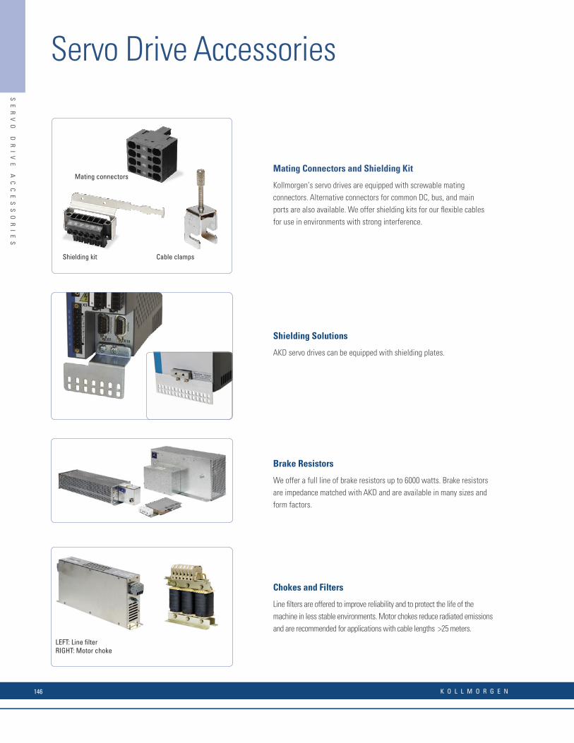
Shielding Solutions
AKD servo drives can be equipped with shielding plates.
Brake Resistors
We offer a full line of brake resistors up to 6000 watts. Brake resistors are impedance matched with AKD and are available in many sizes and form factors.
Chokes and Filters
Line fi lters are offered to improve reliability and to protect the life of the machine in less stable environments. Motor chokes reduce radiated emissions and are recommended for applications with cable lengths >25 meters.
LEFT: Line filterRIGHT: Motor choke
Mating Connectors and Shielding Kit
Kollmorgen’s servo drives are equipped with screwable mating connectors. Alternative connectors for common DC, bus, and main ports are also available. We offer shielding kits for our fl exible cables for use in environments with strong interference.
Mating connectors
Cable clampsShielding kit
SE
RV
O
DR
IV
E
AC
CE
SS
OR
IE
S
Servo Drive Accessories
Motion Bus and Service Port Cables
We offer industrial shielded PUR cables with RJ45 connections for demanding industrial environments. These cables outperform offi ce cables in EMC resilience, durability, and life.
Static Energy Storage
Our Static Energy Storage supplies the drive with power in the event of power outages until the machine reaches a defi ned state. It generates a power outage signal for evaluation by the machine control system. Simple connection to the DC intermediate circuit with two cables; im-mediately ready for use; no adjustment; no controls. Cascade for nearly unlimited power range
CANopen Accessories
We offer cables, terminators and adapters for simple integration with CANopen machine networks.
I/O Control Box and Breakout Adapter
Our I/O Control Box is pre-populated with I/O switches and a power connection for quicker prototyping.
Screw lock adapterfor auxiliary connection
Braking Energy Storage
Our Braking Energy Storage saves Energy through Intelligent Energy Feedback. Substantial saving, especially in applications with short cycle times. Simple connection to DC intermediate circuit. Simple start-up – immediately ready for use; no adjustment; no controls. Nearly unlimited power range with expansion modules
SE
RV
O
DR
IV
E
AC
CE
SS
OR
IE
S
K O L L M O R G E N146
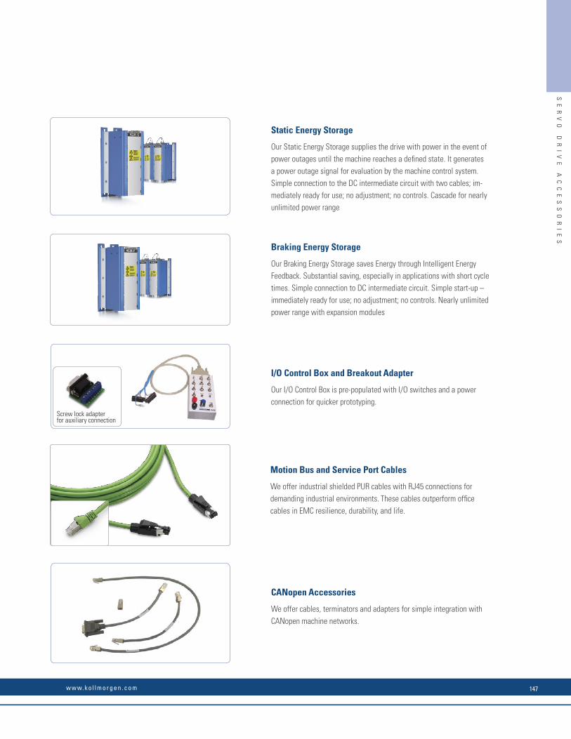
Shielding Solutions
AKD servo drives can be equipped with shielding plates.
Brake Resistors
We offer a full line of brake resistors up to 6000 watts. Brake resistors are impedance matched with AKD and are available in many sizes and form factors.
Chokes and Filters
Line fi lters are offered to improve reliability and to protect the life of the machine in less stable environments. Motor chokes reduce radiated emissions and are recommended for applications with cable lengths >25 meters.
LEFT: Line filterRIGHT: Motor choke
Mating Connectors and Shielding Kit
Kollmorgen’s servo drives are equipped with screwable mating connectors. Alternative connectors for common DC, bus, and main ports are also available. We offer shielding kits for our fl exible cables for use in environments with strong interference.
Mating connectors
Cable clampsShielding kit
SE
RV
O
DR
IV
E
AC
CE
SS
OR
IE
S
Servo Drive Accessories
Motion Bus and Service Port Cables
We offer industrial shielded PUR cables with RJ45 connections for demanding industrial environments. These cables outperform offi ce cables in EMC resilience, durability, and life.
Static Energy Storage
Our Static Energy Storage supplies the drive with power in the event of power outages until the machine reaches a defi ned state. It generates a power outage signal for evaluation by the machine control system. Simple connection to the DC intermediate circuit with two cables; im-mediately ready for use; no adjustment; no controls. Cascade for nearly unlimited power range
CANopen Accessories
We offer cables, terminators and adapters for simple integration with CANopen machine networks.
I/O Control Box and Breakout Adapter
Our I/O Control Box is pre-populated with I/O switches and a power connection for quicker prototyping.
Screw lock adapterfor auxiliary connection
Braking Energy Storage
Our Braking Energy Storage saves Energy through Intelligent Energy Feedback. Substantial saving, especially in applications with short cycle times. Simple connection to DC intermediate circuit. Simple start-up – immediately ready for use; no adjustment; no controls. Nearly unlimited power range with expansion modules
SE
RV
O
DR
IV
E
AC
CE
SS
OR
IE
S
w w w. k o l l m o r g e n . c o m 147
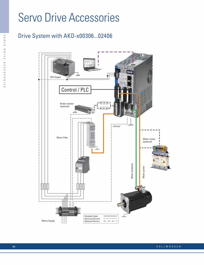
Mot
or fe
edba
ck
Mot
or p
ower
Brake resistor(optional)
Control / PLC
Motor choke(optional)
Mains Filter
Electrical GroundOptional Devices
Shielded Cable
Mains Supply
24V Supply
>10 mm2
Drive System with AKD-x00306...02406SE
RV
O
DR
IV
E
AC
CE
SS
OR
IE
S
Servo Drive AccessoriesSystem Featuring AKD-N
AKD-C
AKD-N-DB
AKD-N-DF
AKD-N-DS AKD-N
BAR/BAS/BAFP
KCMCCNCN1
CCNNN1
CM0NXX
CFCNXX
CFDNA1
CM1NA1
ENCP
ENCP
x
ENCP
PCMM
SAC-8P-M12MS
SAC-4P-M12MS
IP54
IP65/67
3~ 400/480 Vac50/60Hz
x
x
SAC-4P-M12MSD
CM0NDL
CFCNDLCCJNA1
Brake resistoroptional
Mains SupplyPC withWorkBench
PC Connection
24V Supply
EtherCAT® cable
Capacitor Moduleoptional
Heat Sinkoptional
Hybrid Cable
Hybrid Cable
I/O Cable
STO Cable
Motor Feedback Cable
Motor Power Cable
IP67 Grommet
Slip Rings
Fieldbus Cable
SE
RV
O
DR
IV
E
AC
CE
SS
OR
IE
S
K O L L M O R G E N148

Mot
or fe
edba
ck
Mot
or p
ower
Brake resistor(optional)
Control / PLC
Motor choke(optional)
Mains Filter
Electrical GroundOptional Devices
Shielded Cable
Mains Supply
24V Supply
>10 mm2
Drive System with AKD-x00306...02406SE
RV
O
DR
IV
E
AC
CE
SS
OR
IE
S
Servo Drive AccessoriesSystem Featuring AKD-N
AKD-C
AKD-N-DB
AKD-N-DF
AKD-N-DS AKD-N
BAR/BAS/BAFP
KCMCCNCN1
CCNNN1
CM0NXX
CFCNXX
CFDNA1
CM1NA1
ENCP
ENCP
x
ENCP
PCMM
SAC-8P-M12MS
SAC-4P-M12MS
IP54
IP65/67
3~ 400/480 Vac50/60Hz
x
x
SAC-4P-M12MSD
CM0NDL
CFCNDLCCJNA1
Brake resistoroptional
Mains SupplyPC withWorkBench
PC Connection
24V Supply
EtherCAT® cable
Capacitor Moduleoptional
Heat Sinkoptional
Hybrid Cable
Hybrid Cable
I/O Cable
STO Cable
Motor Feedback Cable
Motor Power Cable
IP67 Grommet
Slip Rings
Fieldbus Cable
SE
RV
O
DR
IV
E
AC
CE
SS
OR
IE
S
w w w. k o l l m o r g e n . c o m 149

Mechanical Accessories for Decentralized Drives (AKD-N, AKD-C)Heat Sink for AKD-N
When mounting AKD-N to the machinery, temperature management is important to ensure maximum performance of the drive system. If needed, a heat sink may be mounted to the AKD-N.
Mounting clamps for AKD-N
The AKD-N drive is mounted to a machine with special mounting clamps. The delivery package contains 4 clamps.
Part Number Description
AKD-N 3,6 HEATSINK KIT 40MM Heat sink kit 40 mm with heat conducting fi lm and 4 screws M4x16
AKD-N 3,6 HEATSINK KIT 50MM Heat sink kit 50 mm with heat conducting fi lm and 4 screws M4x16
849-373001-04 Heat conducting fi lm
Part Number Description
AKD-N-M/C-Set AKD-N Mounting Clamps Set, 4 clamps
200
40/50
80
184.4
60
4xØ4.5
14
1120
6S
ER
VO
D
RI
VE
A
CC
ES
SO
RI
ES
Servo Drive Accessories
Sealing plugs for AKD-N connectors
The sealing plugs are attached to unused AKD-N connectors to ensure the IP class for the machine environment.
Shield Clamps
AKD drives feature slots on the front panel for the connection of additionalshield clamps.
Jump-X5 connector for AKD-N-DS/DF with single line connection
For suffi cient voltage supply of the digital feedback systems Hiperface DSL or SFD3 connected to AKD-N-DS/DF connector X4, a dongle must be plugged into X5.
Connector Kit for AKD-C
Mating connectors X12, X13, X14, X15, and X16 are part of delivery.
Part Number Description
AKD-N-S/P-Set AKD-N Sealing Plug Set, 4xM12, 2xM23, 2xM17
Part Number Description
AKD-N-JUMP-X5 AKD-N X5 sealed mating connector with jumper 4-5
Part Number Description
AKD-C-CONKIT AKD-N connector kit, included mating connectors X12, X13, 14, X15, and X16
Part Number Description Tension Range
DE-108248 SK14 6–13mm
SE
RV
O
DR
IV
E
AC
CE
SS
OR
IE
S
K O L L M O R G E N150
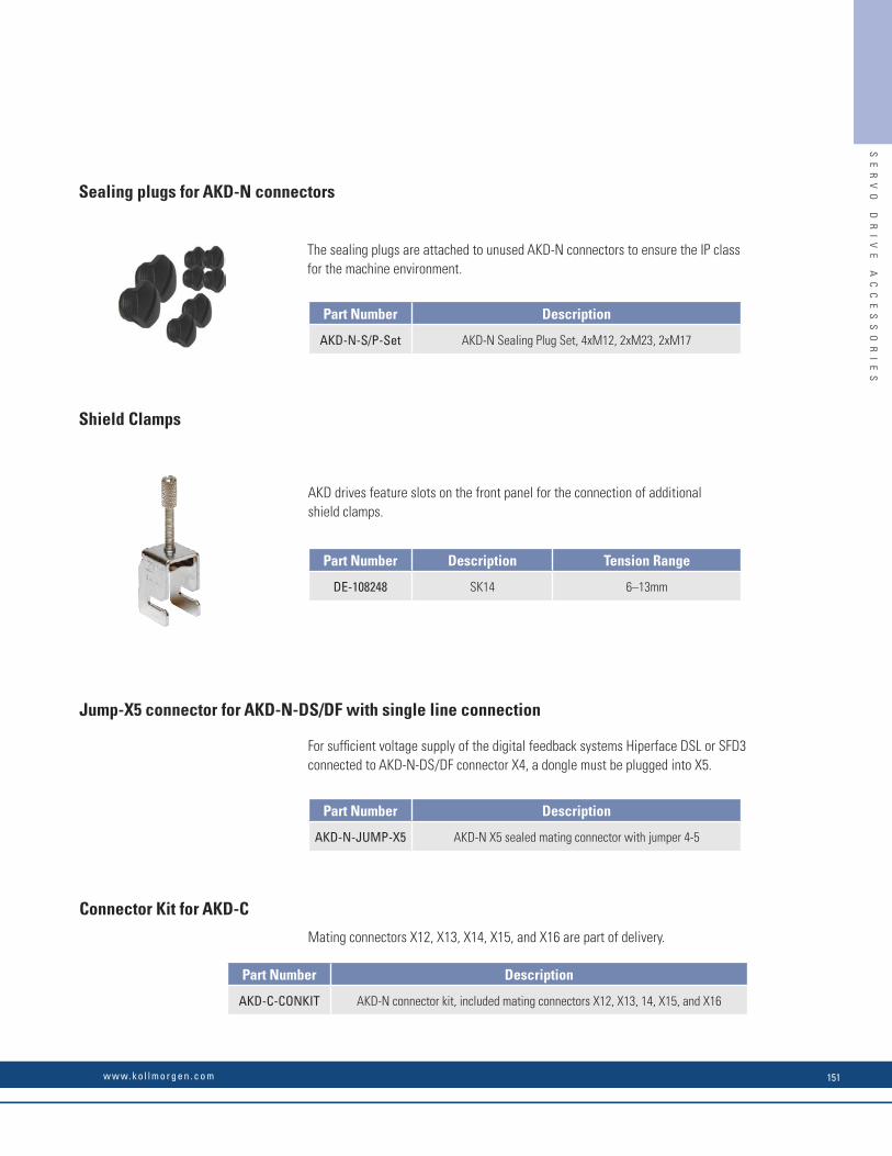
Mechanical Accessories for Decentralized Drives (AKD-N, AKD-C)Heat Sink for AKD-N
When mounting AKD-N to the machinery, temperature management is important to ensure maximum performance of the drive system. If needed, a heat sink may be mounted to the AKD-N.
Mounting clamps for AKD-N
The AKD-N drive is mounted to a machine with special mounting clamps. The delivery package contains 4 clamps.
Part Number Description
AKD-N 3,6 HEATSINK KIT 40MM Heat sink kit 40 mm with heat conducting fi lm and 4 screws M4x16
AKD-N 3,6 HEATSINK KIT 50MM Heat sink kit 50 mm with heat conducting fi lm and 4 screws M4x16
849-373001-04 Heat conducting fi lm
Part Number Description
AKD-N-M/C-Set AKD-N Mounting Clamps Set, 4 clamps
200
40/50
80
184.4
60
4xØ4.5
14
1120
6
SE
RV
O
DR
IV
E
AC
CE
SS
OR
IE
S
Servo Drive Accessories
Sealing plugs for AKD-N connectors
The sealing plugs are attached to unused AKD-N connectors to ensure the IP class for the machine environment.
Shield Clamps
AKD drives feature slots on the front panel for the connection of additionalshield clamps.
Jump-X5 connector for AKD-N-DS/DF with single line connection
For suffi cient voltage supply of the digital feedback systems Hiperface DSL or SFD3 connected to AKD-N-DS/DF connector X4, a dongle must be plugged into X5.
Connector Kit for AKD-C
Mating connectors X12, X13, X14, X15, and X16 are part of delivery.
Part Number Description
AKD-N-S/P-Set AKD-N Sealing Plug Set, 4xM12, 2xM23, 2xM17
Part Number Description
AKD-N-JUMP-X5 AKD-N X5 sealed mating connector with jumper 4-5
Part Number Description
AKD-C-CONKIT AKD-N connector kit, included mating connectors X12, X13, 14, X15, and X16
Part Number Description Tension Range
DE-108248 SK14 6–13mm
SE
RV
O
DR
IV
E
AC
CE
SS
OR
IE
S
w w w. k o l l m o r g e n . c o m 151

Motor ChokesGeneral
Shielded motor cables
For reasons of electromagnetic compatibility, the motor must be supplied with power via a shielded cable. The structure of a cable with 100% shielding and the capacity equivalent circuit diagram (to earth) are shown below.
U
V
W
PE
3~M
and Phase-to-PE of the motor cableCapacity Phase-to-Shield
Motor chokeD
rive
Core Isolation
CoreIsolation
Fill material
Shield
SHIELD
Drive* Motor choke Description
AKD-x003 to AKD-x006 3YLN-06 Motor cable ≥ 25m
AKD-x012 3YLN-14 Motor cable ≥ 25m
AKD-x024 3YLN‐24 Motor cable ≥ 25m
*= x means variants -B, -P, -T or -
Part Number Nominal Current Approvals Description
DE-107929 6 A CE, UL Motor choke 3YLN-06
DE-107931 14 A CE, UL Motor choke 3YLN-14
DE-201447 24 A CE, UL Motor choke 3YLN-24
Why use motor chokes?
• To compensate high capacitive charge/discharge currents typical of shielded motor cables approximately 25 m and longer.• To reduce current alternation noise in the motor.• To reduce current ripple in the motor.
The digital drives high switching frequencies and steep switching edges give rise to the transfer of capacitive currents to the shield by the three phases (U, V, W). These currents fl ow from the shield to earth. Depending on the cable length and cable capacity (determined by design), this can lead to the generation of shield currents with peak values of up to 20 A.
These shield currents place a load on the drives and motor. On large systems, this can lead to shifts in potential which can damage other components.
This effect is evident on systems with multiple drives operating in parallel on the same mains fi lter.
The motor chokes slow down the rate of rise of the motor current (reduce edge steepness), thereby reducing thecurrent transferred to the shield.
Why is the cross-section of the motor cable important?
Motor cables longer than 50 m with a small cross-section (e.g. 4 x 1.0 mm2) and therefore a higher equivalent resistanceare able to reduce the oscillation tendency of the LCR oscillating circuit (drive/choke/cable/motor). This cross-section canalso be advantageous for cable lengths shorter than 50 m if the cable capacity and motor inductance are very high. However,the current loading of the cable must always be within the limits specifi ed by industry standards.
SE
RV
O
DR
IV
E
AC
CE
SS
OR
IE
S
Servo Drive Accessories
DA
E
B
F
C
Rated Data Sym DIM 3YLN-06 3YLN-14 3YLN-24
Rated current I0rms A 6 14 24
Rated voltage Unom V 480
Rated frequency fnom Hz 0 to 150
Max. frequency fmax kHz 8
Inductivity L μH 900 900 450
Power loss P W 12 19.4 23.2
Protection class - - IP00
Temperature class - - F
Operation class - - S1
Weight G kg 4.5 10 10
Cable diameter (Shield clamp) - mm 4 to 13.5
Wiring cross section max. (Terminals) - mm2 10 16 16
Width A mm 155 190 190
Depth B mm 90 125 125
Height C mm 195 230 230
Mounting hole distance D mm 130 170 170
Mounting hole distance E mm 56.5 78 78
Mounting screws F - 4xM6 4xM6 4xM6
SE
RV
O
DR
IV
E
AC
CE
SS
OR
IE
S
K O L L M O R G E N152

Motor ChokesGeneral
Shielded motor cables
For reasons of electromagnetic compatibility, the motor must be supplied with power via a shielded cable. The structure of a cable with 100% shielding and the capacity equivalent circuit diagram (to earth) are shown below.
U
V
W
PE
3~M
and Phase-to-PE of the motor cableCapacity Phase-to-Shield
Motor choke
Driv
e
Core Isolation
CoreIsolation
Fill material
Shield
SHIELD
Drive* Motor choke Description
AKD-x003 to AKD-x006 3YLN-06 Motor cable ≥ 25m
AKD-x012 3YLN-14 Motor cable ≥ 25m
AKD-x024 3YLN‐24 Motor cable ≥ 25m
*= x means variants -B, -P, -T or -
Part Number Nominal Current Approvals Description
DE-107929 6 A CE, UL Motor choke 3YLN-06
DE-107931 14 A CE, UL Motor choke 3YLN-14
DE-201447 24 A CE, UL Motor choke 3YLN-24
Why use motor chokes?
• To compensate high capacitive charge/discharge currents typical of shielded motor cables approximately 25 m and longer.• To reduce current alternation noise in the motor.• To reduce current ripple in the motor.
The digital drives high switching frequencies and steep switching edges give rise to the transfer of capacitive currents to the shield by the three phases (U, V, W). These currents fl ow from the shield to earth. Depending on the cable length and cable capacity (determined by design), this can lead to the generation of shield currents with peak values of up to 20 A.
These shield currents place a load on the drives and motor. On large systems, this can lead to shifts in potential which can damage other components.
This effect is evident on systems with multiple drives operating in parallel on the same mains fi lter.
The motor chokes slow down the rate of rise of the motor current (reduce edge steepness), thereby reducing thecurrent transferred to the shield.
Why is the cross-section of the motor cable important?
Motor cables longer than 50 m with a small cross-section (e.g. 4 x 1.0 mm2) and therefore a higher equivalent resistanceare able to reduce the oscillation tendency of the LCR oscillating circuit (drive/choke/cable/motor). This cross-section canalso be advantageous for cable lengths shorter than 50 m if the cable capacity and motor inductance are very high. However,the current loading of the cable must always be within the limits specifi ed by industry standards.
SE
RV
O
DR
IV
E
AC
CE
SS
OR
IE
S
Servo Drive Accessories
DA
E
B
F
C
Rated Data Sym DIM 3YLN-06 3YLN-14 3YLN-24
Rated current I0rms A 6 14 24
Rated voltage Unom V 480
Rated frequency fnom Hz 0 to 150
Max. frequency fmax kHz 8
Inductivity L μH 900 900 450
Power loss P W 12 19.4 23.2
Protection class - - IP00
Temperature class - - F
Operation class - - S1
Weight G kg 4.5 10 10
Cable diameter (Shield clamp) - mm 4 to 13.5
Wiring cross section max. (Terminals) - mm2 10 16 16
Width A mm 155 190 190
Depth B mm 90 125 125
Height C mm 195 230 230
Mounting hole distance D mm 130 170 170
Mounting hole distance E mm 56.5 78 78
Mounting screws F - 4xM6 4xM6 4xM6
SE
RV
O
DR
IV
E
AC
CE
SS
OR
IE
S
w w w. k o l l m o r g e n . c o m 153

Mains ChokesGeneral
In special cases, if mains voltage is more than 3% asymmetrical, then the AKD-48A must be used with a mains choke.
Purpose of mains choke:
• Prevents impermissible loading of semiconductors in the event of rapid current rise during commutation.• Prevents voltage dips in the mains voltage caused by commutation.• Reduces current ripple in the DC link, thereby increasing the service life of the DC link capacitors.
Drive Mains Choke
AKD-x04807 (with asymmetrical mains >3% only) 2% uk
AKD other types not required
Part Number Description
DE-201476 Mains choke 3L0,24-50-2 (0.24mH, 50A)
DE-201477 Mains choke 3L0,2-75-2 (0.20mH, 75A)
SE
RV
O
DR
IV
E
AC
CE
SS
OR
IE
S
Servo Drive Accessories
U1 U2 V1 V2 W1W2
BA
CD
F
E
Mains choke 3LA number of drives can be connected to the same mains choke; the rated current of the mains choke must be greater than or at least equal to the total current of the connected drives.
TypeInductivity
[mH]Nominal
Current [A]uk
A[mm]
B[mm]
C[mm]
D[mm]
E[mm]
F[mm]
Terminals [mm2]
Weight [kg]
3L 0,24-50-2 0.24 50 2% 152.5 114.3 88.9 114.3 163 6.5 10 5.9
3L 0,2-75-2 0.2 75 2% 185 170 77 122 220 8x12 35 9.9
SE
RV
O
DR
IV
E
AC
CE
SS
OR
IE
S
K O L L M O R G E N154
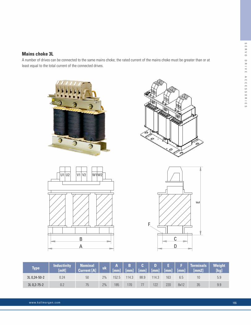
Mains ChokesGeneral
In special cases, if mains voltage is more than 3% asymmetrical, then the AKD-48A must be used with a mains choke.
Purpose of mains choke:
• Prevents impermissible loading of semiconductors in the event of rapid current rise during commutation.• Prevents voltage dips in the mains voltage caused by commutation.• Reduces current ripple in the DC link, thereby increasing the service life of the DC link capacitors.
Drive Mains Choke
AKD-x04807 (with asymmetrical mains >3% only) 2% uk
AKD other types not required
Part Number Description
DE-201476 Mains choke 3L0,24-50-2 (0.24mH, 50A)
DE-201477 Mains choke 3L0,2-75-2 (0.20mH, 75A)
SE
RV
O
DR
IV
E
AC
CE
SS
OR
IE
S
Servo Drive Accessories
U1 U2 V1 V2 W1W2
BA
CD
F
E
Mains choke 3LA number of drives can be connected to the same mains choke; the rated current of the mains choke must be greater than or at least equal to the total current of the connected drives.
TypeInductivity
[mH]Nominal
Current [A]uk
A[mm]
B[mm]
C[mm]
D[mm]
E[mm]
F[mm]
Terminals [mm2]
Weight [kg]
3L 0,24-50-2 0.24 50 2% 152.5 114.3 88.9 114.3 163 6.5 10 5.9
3L 0,2-75-2 0.2 75 2% 185 170 77 122 220 8x12 35 9.9
SE
RV
O
DR
IV
E
AC
CE
SS
OR
IE
S
w w w. k o l l m o r g e n . c o m 155

Mains fi ltersGeneralAKD-x00306 to AKD-x02406 drives require an external mains fi lter.
Drive Mains Filter
AKD-x00307...04807 (240 to 480V) not required
AKD-B/P/T/M 00306...02406 (120 to 240V) 1NF, 3NF
Part Number Description
DE-201565 Mains fi lter 1NF-10 (230 VAC, 10A)
DE-201566 Mains fi lter 1NF-12 (230 VAC, 12A)
DE-201865 Mains fi lter 1NF-20B (125V/230 VAC, 20A)
DE-201568 Mains fi lter 1NF-25 (230 VAC, 25A)
DE-201569 Mains fi lter 3NF-07 (480 VAC, 07A)
DE-201570 Mains fi lter 3NF-16 (480 VAC, 16A)
DE-201571 Mains fi lter 3NF-30 (480 VAC, 30A)
SE
RV
O
DR
IV
E
AC
CE
SS
OR
IE
S
Servo Drive Accessories
Mains fi lters 1NF-10...12
Type
Nominal Current Voltage
[A]*
Nominal Voltage [V]
A[mm]
B[mm]
C[mm]
D[mm]
F[mm]
M[mm]
N[mm]
P[mm]
Weight [kg]
Connection
1NF-10 10 230 85 49 40.3 54 75 5.3 6.3 87 0.29 Fast-on
1NF-12 12 230 156 57.5 45.4 130.5 143 5.3 6 156 0.73 Fast-on
* at 40°C environment temperature
N
1NF-10
1NF-12
M
D AF P
C
B
SE
RV
O
DR
IV
E
AC
CE
SS
OR
IE
S
K O L L M O R G E N156

Mains fi ltersGeneralAKD-x00306 to AKD-x02406 drives require an external mains fi lter.
Drive Mains Filter
AKD-x00307...04807 (240 to 480V) not required
AKD-B/P/T/M 00306...02406 (120 to 240V) 1NF, 3NF
Part Number Description
DE-201565 Mains fi lter 1NF-10 (230 VAC, 10A)
DE-201566 Mains fi lter 1NF-12 (230 VAC, 12A)
DE-201865 Mains fi lter 1NF-20B (125V/230 VAC, 20A)
DE-201568 Mains fi lter 1NF-25 (230 VAC, 25A)
DE-201569 Mains fi lter 3NF-07 (480 VAC, 07A)
DE-201570 Mains fi lter 3NF-16 (480 VAC, 16A)
DE-201571 Mains fi lter 3NF-30 (480 VAC, 30A)
SE
RV
O
DR
IV
E
AC
CE
SS
OR
IE
S
Servo Drive Accessories
Mains fi lters 1NF-10...12
Type
Nominal Current Voltage
[A]*
Nominal Voltage [V]
A[mm]
B[mm]
C[mm]
D[mm]
F[mm]
M[mm]
N[mm]
P[mm]
Weight [kg]
Connection
1NF-10 10 230 85 49 40.3 54 75 5.3 6.3 87 0.29 Fast-on
1NF-12 12 230 156 57.5 45.4 130.5 143 5.3 6 156 0.73 Fast-on
* at 40°C environment temperature
N
1NF-10
1NF-12
M
D AF P
C
B
SE
RV
O
DR
IV
E
AC
CE
SS
OR
IE
S
w w w. k o l l m o r g e n . c o m 157
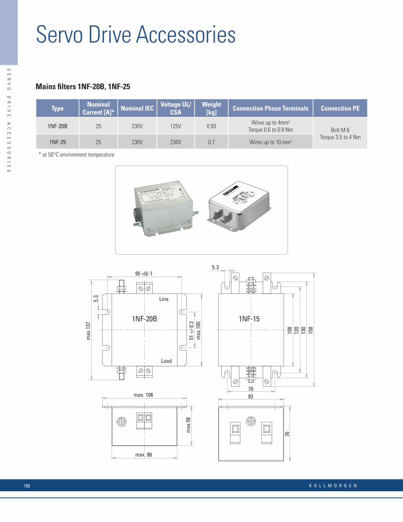
Mains fi lters 1NF-20B, 1NF-25
TypeNominal
Current [A]*Nominal IEC
Voltage UL/CSA
Weight [kg]
Connection Phase Terminals Connection PE
1NF-20B 20 230V 125V 0.93Wires up to 4mm2
Torque 0.6 to 0.8 Nm Bolt M 6Torque 3.5 to 4 Nm
1NF-25 25 230V 230V 0.7 Wires up to 10 mm2
* at 50°C environment temperature
93
76
70
1NF-20B 1NF-15
5.395 +0/-1
5.3
51 +
/-0.
3m
ax.1
00
Line
Load
108
120
130
158
max. 86
max. 106
max
.58
max
.137
SE
RV
O
DR
IV
E
AC
CE
SS
OR
IE
S
Servo Drive Accessories
Mains fi lter 3NF-07...30
TypeNominal Current
[A]*
A[mm]
B[mm]
C[mm]
D[mm]
F[mm]
G[mm]
M[mm]
P[mm]
Weight [kg]
TerminalsPE
Bolt
3NF-07 7 A 190 40 70 160 180 20 4.5 180 0.5 4 mm2, 0.7-0.8 Nm
M5, 2.2 Nm3NF-16 16 A 250 45 70 220 235 25 5.4 240 0.8
3NF-30 30 A 270 50 85 240 255 30 5.4 260 1.210 mm2,
1.9-2.2 Nm
DA
CGB
F P
M
3NF-xx
* at 50°C environment temperature
SE
RV
O
DR
IV
E
AC
CE
SS
OR
IE
S
K O L L M O R G E N158
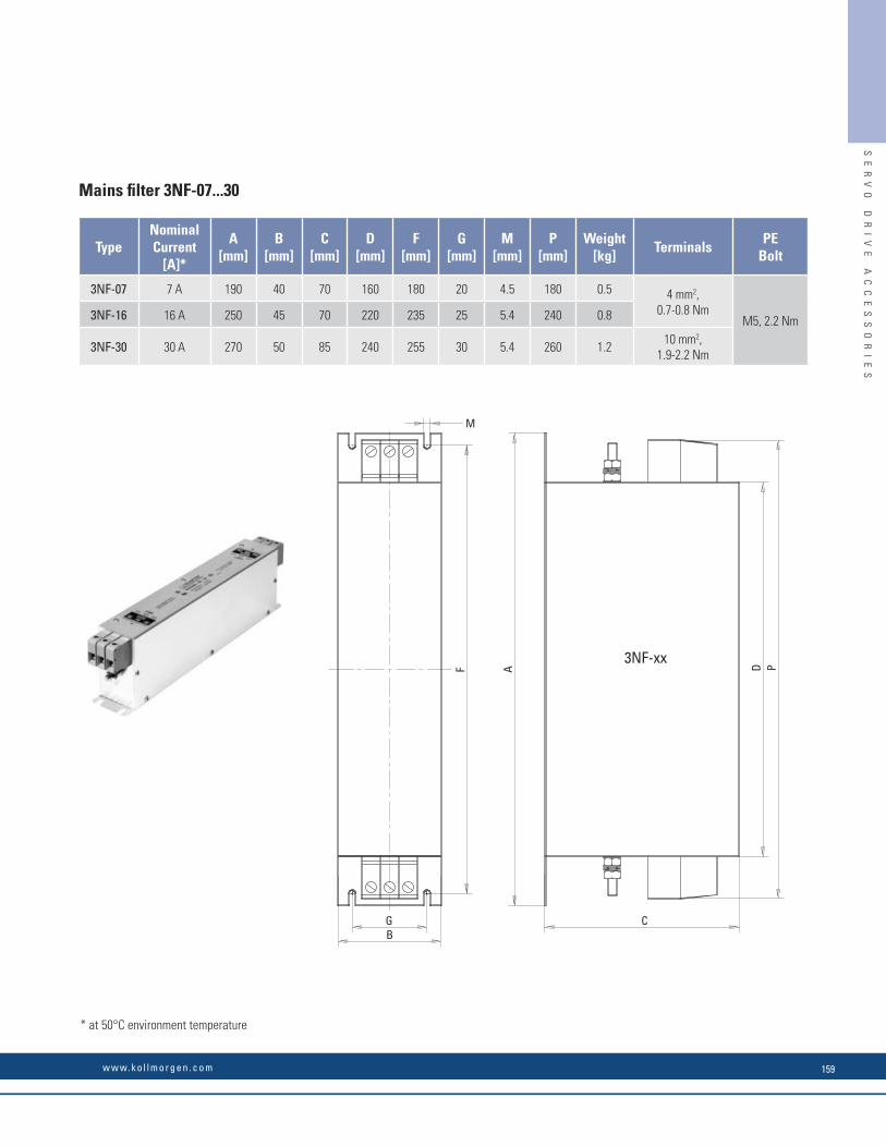
Mains fi lters 1NF-20B, 1NF-25
TypeNominal
Current [A]*Nominal IEC
Voltage UL/CSA
Weight [kg]
Connection Phase Terminals Connection PE
1NF-20B 20 230V 125V 0.93Wires up to 4mm2
Torque 0.6 to 0.8 Nm Bolt M 6Torque 3.5 to 4 Nm
1NF-25 25 230V 230V 0.7 Wires up to 10 mm2
* at 50°C environment temperature
93
76
70
1NF-20B 1NF-15
5.395 +0/-1
5.3
51 +
/-0.
3m
ax.1
00
Line
Load
108
120
130
158
max. 86
max. 106
max
.58
max
.137
SE
RV
O
DR
IV
E
AC
CE
SS
OR
IE
S
Servo Drive Accessories
Mains fi lter 3NF-07...30
TypeNominal Current
[A]*
A[mm]
B[mm]
C[mm]
D[mm]
F[mm]
G[mm]
M[mm]
P[mm]
Weight [kg]
TerminalsPE
Bolt
3NF-07 7 A 190 40 70 160 180 20 4.5 180 0.5 4 mm2, 0.7-0.8 Nm
M5, 2.2 Nm3NF-16 16 A 250 45 70 220 235 25 5.4 240 0.8
3NF-30 30 A 270 50 85 240 255 30 5.4 260 1.210 mm2,
1.9-2.2 Nm
DA
CGB
F P
M
3NF-xx
* at 50°C environment temperature
SE
RV
O
DR
IV
E
AC
CE
SS
OR
IE
S
w w w. k o l l m o r g e n . c o m 159
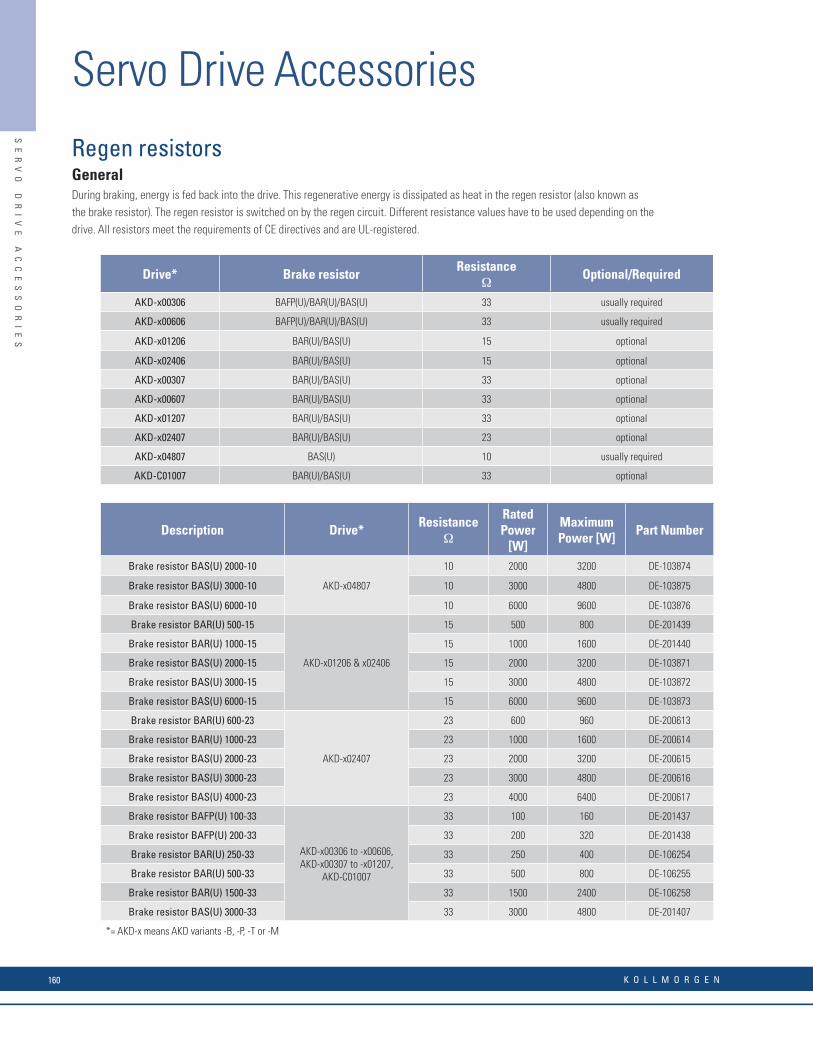
Regen resistorsGeneralDuring braking, energy is fed back into the drive. This regenerative energy is dissipated as heat in the regen resistor (also known as the brake resistor). The regen resistor is switched on by the regen circuit. Different resistance values have to be used depending on the drive. All resistors meet the requirements of CE directives and are UL-registered.
Drive* Brake resistorResistance
ΩOptional/Required
AKD-x00306 BAFP(U)/BAR(U)/BAS(U) 33 usually required
AKD-x00606 BAFP(U)/BAR(U)/BAS(U) 33 usually required
AKD-x01206 BAR(U)/BAS(U) 15 optional
AKD-x02406 BAR(U)/BAS(U) 15 optional
AKD-x00307 BAR(U)/BAS(U) 33 optional
AKD-x00607 BAR(U)/BAS(U) 33 optional
AKD-x01207 BAR(U)/BAS(U) 33 optional
AKD-x02407 BAR(U)/BAS(U) 23 optional
AKD-x04807 BAS(U) 10 usually required
AKD-C01007 BAR(U)/BAS(U) 33 optional
Description Drive*Resistance
Ω
Rated Power
[W]
Maximum Power [W]
Part Number
Brake resistor BAS(U) 2000-10
AKD-x04807
10 2000 3200 DE-103874
Brake resistor BAS(U) 3000-10 10 3000 4800 DE-103875
Brake resistor BAS(U) 6000-10 10 6000 9600 DE-103876
Brake resistor BAR(U) 500-15
AKD-x01206 & x02406
15 500 800 DE-201439
Brake resistor BAR(U) 1000-15 15 1000 1600 DE-201440
Brake resistor BAS(U) 2000-15 15 2000 3200 DE-103871
Brake resistor BAS(U) 3000-15 15 3000 4800 DE-103872
Brake resistor BAS(U) 6000-15 15 6000 9600 DE-103873
Brake resistor BAR(U) 600-23
AKD-x02407
23 600 960 DE-200613
Brake resistor BAR(U) 1000-23 23 1000 1600 DE-200614
Brake resistor BAS(U) 2000-23 23 2000 3200 DE-200615
Brake resistor BAS(U) 3000-23 23 3000 4800 DE-200616
Brake resistor BAS(U) 4000-23 23 4000 6400 DE-200617
Brake resistor BAFP(U) 100-33
AKD-x00306 to -x00606, AKD-x00307 to -x01207,
AKD-C01007
33 100 160 DE-201437
Brake resistor BAFP(U) 200-33 33 200 320 DE-201438
Brake resistor BAR(U) 250-33 33 250 400 DE-106254
Brake resistor BAR(U) 500-33 33 500 800 DE-106255
Brake resistor BAR(U) 1500-33 33 1500 2400 DE-106258
Brake resistor BAS(U) 3000-33 33 3000 4800 DE-201407
*= AKD-x means AKD variants -B, -P, -T or -M
SE
RV
O
DR
IV
E
AC
CE
SS
OR
IE
S
Servo Drive Accessories
76.6
170
/ 276
98 /
204
32
300
200 200
76.6
26
170 / 276
32
98 / 204
106
106
26
170
/ 276
98 /
204
170276
33BAFP(U) 100-33BAFP(U) 200-33 33
TypeRΩ mm
0.3100200 0.55
W Kg
98104
98110
170
/ 276
29Top
Top
max. Ø12mm
Keep space
Length
free
Admissible floor mounting Admissible ceiling mounting
Clamps downAdmissible wall mounting
Other types of mounting are not admitted!
Power Weight
External Regen Resistor BAFP(U)
TypeR Length Power WeightΩ mm W Kg
BAFP(U) 100-33 33 170 100 0.3BAFP(U) 200-33 33 276 200 0.55
SE
RV
O
DR
IV
E
AC
CE
SS
OR
IE
S
K O L L M O R G E N160

Regen resistorsGeneralDuring braking, energy is fed back into the drive. This regenerative energy is dissipated as heat in the regen resistor (also known as the brake resistor). The regen resistor is switched on by the regen circuit. Different resistance values have to be used depending on the drive. All resistors meet the requirements of CE directives and are UL-registered.
Drive* Brake resistorResistance
ΩOptional/Required
AKD-x00306 BAFP(U)/BAR(U)/BAS(U) 33 usually required
AKD-x00606 BAFP(U)/BAR(U)/BAS(U) 33 usually required
AKD-x01206 BAR(U)/BAS(U) 15 optional
AKD-x02406 BAR(U)/BAS(U) 15 optional
AKD-x00307 BAR(U)/BAS(U) 33 optional
AKD-x00607 BAR(U)/BAS(U) 33 optional
AKD-x01207 BAR(U)/BAS(U) 33 optional
AKD-x02407 BAR(U)/BAS(U) 23 optional
AKD-x04807 BAS(U) 10 usually required
AKD-C01007 BAR(U)/BAS(U) 33 optional
Description Drive*Resistance
Ω
Rated Power
[W]
Maximum Power [W]
Part Number
Brake resistor BAS(U) 2000-10
AKD-x04807
10 2000 3200 DE-103874
Brake resistor BAS(U) 3000-10 10 3000 4800 DE-103875
Brake resistor BAS(U) 6000-10 10 6000 9600 DE-103876
Brake resistor BAR(U) 500-15
AKD-x01206 & x02406
15 500 800 DE-201439
Brake resistor BAR(U) 1000-15 15 1000 1600 DE-201440
Brake resistor BAS(U) 2000-15 15 2000 3200 DE-103871
Brake resistor BAS(U) 3000-15 15 3000 4800 DE-103872
Brake resistor BAS(U) 6000-15 15 6000 9600 DE-103873
Brake resistor BAR(U) 600-23
AKD-x02407
23 600 960 DE-200613
Brake resistor BAR(U) 1000-23 23 1000 1600 DE-200614
Brake resistor BAS(U) 2000-23 23 2000 3200 DE-200615
Brake resistor BAS(U) 3000-23 23 3000 4800 DE-200616
Brake resistor BAS(U) 4000-23 23 4000 6400 DE-200617
Brake resistor BAFP(U) 100-33
AKD-x00306 to -x00606, AKD-x00307 to -x01207,
AKD-C01007
33 100 160 DE-201437
Brake resistor BAFP(U) 200-33 33 200 320 DE-201438
Brake resistor BAR(U) 250-33 33 250 400 DE-106254
Brake resistor BAR(U) 500-33 33 500 800 DE-106255
Brake resistor BAR(U) 1500-33 33 1500 2400 DE-106258
Brake resistor BAS(U) 3000-33 33 3000 4800 DE-201407
*= AKD-x means AKD variants -B, -P, -T or -M
SE
RV
O
DR
IV
E
AC
CE
SS
OR
IE
S
Servo Drive Accessories
76.6
170
/ 276
98 /
204
32
300
200 200
76.6
26
170 / 276
32
98 / 204
106
106
26
170
/ 276
98 /
204
170276
33BAFP(U) 100-33BAFP(U) 200-33 33
TypeRΩ mm
0.3100200 0.55
W Kg
98104
98110
170
/ 276
29Top
Top
max. Ø12mm
Keep space
Length
free
Admissible floor mounting Admissible ceiling mounting
Clamps downAdmissible wall mounting
Other types of mounting are not admitted!
Power Weight
External Regen Resistor BAFP(U)
TypeR Length Power WeightΩ mm W Kg
BAFP(U) 100-33 33 170 100 0.3BAFP(U) 200-33 33 276 200 0.55
SE
RV
O
DR
IV
E
AC
CE
SS
OR
IE
S
w w w. k o l l m o r g e n . c o m 161

External Regen Resistor BAR(U)
BAR(U) 600BAR(U) 1000BAR(U) 250BAR(U) 500BAR(U) 1500
BAR(U) 1000BAR(U) 600BAR(U) 300
BAR(U) 300BAR(U) 600BAR(U) 1000
-RBext
+RBextPE
Kg
120
120120
120120
120120
120120
1000
1000
66
919191
600300
15003333
6666
232333
600300
500250
6001000
749349
749549
626226
626426
9292
9292
349
649549
549349
530430
426226
230
185
9292
9292
3.4
3.42.31.5
1.52.3
5.832
mmΩR
WB
mm mmDA
mmC
mmE
mmF
120120
549749
430630
9292
34
A
B
C
D
EF
12
9292BAR(U) 500
BAR(U) 1000500100015
15 430630120
120749549 8064
43
64 8064 8064 80
6464
8080
- 150
64 8064 80
64 80
64 8064 8064 80
200 200200
200
200200
300
200
200
300
weight
Other types of mounting are not admitted!
Admissible floor mounting Clamps downAdmissible wall mounting
Cold approx. +8%, 320°C approx. -7%±10%, temperature drift approx. 1%
TypePower
Ø 6.5
Ø 6.5
TypeR Power A B C D E F Weight
Ω W mm mm mm mm mm mm KgBAR(U) 500 15 500 549 120 92 430 64 80 3
BAR(U) 1000 15 1000 749 120 92 630 64 80 4BAR(U) 600 23 600 549 120 92 430 64 80 3
BAR(U) 1000 23 1000 749 120 92 630 64 80 4BAR(U) 250 33 250 349 120 92 230 64 80 2BAR(U) 500 33 500 549 120 92 430 64 80 3
BAR(U) 1500 33 1500 649 120 185 530 - 150 5.8BAR(U) 300 66 300 349 120 92 226 64 80 1.5BAR(U) 600 66 600 549 120 92 426 64 80 2.3
BAR(U) 1000 66 1000 749 120 92 626 64 80 3.4BAR(U) 300 91 300 349 120 92 226 64 80 1.5BAR(U) 600 91 600 549 120 92 426 64 80 2.3
BAR(U) 1000 91 1000 749 120 92 626 64 80 3.4
±10%, temperature drift approx. 1%Cold approx. +6%, 320° C approx. -7%
SE
RV
O
DR
IV
E
AC
CE
SS
OR
IE
S
Servo Drive Accessories
External Regen Resistor BAS(U)
-RB
ext
+RB
ext
PE
A
GE
B
D C
300300300
300
300
300
1000
1000
300
300
F
255355455BAS(U)6000-10
BAS(U)3000-10BAS(U)2000-10 2000
60003000
101010 490
490490
380380
380WΩ
RmmA
mmB
mmC
260
260260270
370250350
170 150
Ø10.5Ø10.5Ø10.5
1187
Gmmmm
DEmm mm
FKg
2602602606000
20003000
BAS(U)2000-15BAS(U)3000-15BAS(U)6000-15 15
1515
455355255
490490490
380380380
270170
370 350250150
Ø10.5Ø10.5Ø10.5
1187
2602602604000
30002000BAS(U)2000-23
BAS(U)3000-23BAS(U)4000-23 23
2323
355355255
490490490
380380380 170
270270
250250150 Ø10.5
Ø10.5Ø10.5
987
2603000BAS(U)3000-33 33 355490 380 270 250 Ø10.5 8
Admissible floor mounting Admissible wall mountingClamps down
Other types of mounting are not admitted!
Rated power weight
Cold approx. +8%, 320°C approx. -7%±10%, temperature drift approx. 1%
Type
TypeR
Rated Power
A B C D E Ø F G Weight
Ω W mm mm mm mm mm mm mm KgBAS(U)2000-10 10 2000 490 380 255 170 150 10.5 260 7BAS(U)3000-10 10 3000 490 380 355 270 250 10.5 260 8BAS(U)6000-10 10 6000 490 380 455 370 350 10.5 260 11BAS(U)2000-15 15 2000 490 380 255 170 150 10.5 260 7BAS(U)3000-15 15 3000 490 380 355 270 250 10.5 260 8BAS(U)6000-15 15 6000 490 380 455 370 350 10.5 260 11BAS(U)2000-23 23 2000 490 380 255 170 150 10.5 260 7BAS(U)3000-23 23 3000 490 380 355 270 250 10.5 260 8BAS(U)4000-23 23 4000 490 380 355 270 250 10.5 260 9BAS(U)3000-33 33 3000 490 380 355 270 250 10.5 260 8
SE
RV
O
DR
IV
E
AC
CE
SS
OR
IE
S
K O L L M O R G E N162
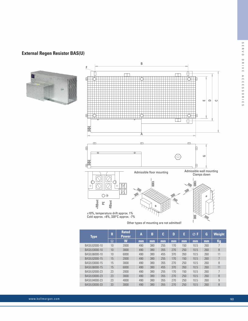
External Regen Resistor BAR(U)
BAR(U) 600BAR(U) 1000BAR(U) 250BAR(U) 500BAR(U) 1500
BAR(U) 1000BAR(U) 600BAR(U) 300
BAR(U) 300BAR(U) 600BAR(U) 1000
-RBext
+RBextPE
Kg
120
120120
120120
120120
120120
1000
1000
66
919191
600300
15003333
6666
232333
600300
500250
6001000
749349
749549
626226
626426
9292
9292
349
649549
549349
530430
426226
230
185
9292
9292
3.4
3.42.31.5
1.52.3
5.832
mmΩR
WB
mm mmDA
mmC
mmE
mmF
120120
549749
430630
9292
34
A
B
C
D
EF
12
9292BAR(U) 500
BAR(U) 1000500100015
15 430630120
120749549 8064
43
64 8064 8064 80
6464
8080
- 150
64 8064 80
64 80
64 8064 8064 80
200 200200
200
200200
300
200
200
300
weight
Other types of mounting are not admitted!
Admissible floor mounting Clamps downAdmissible wall mounting
Cold approx. +8%, 320°C approx. -7%±10%, temperature drift approx. 1%
TypePower
Ø 6.5
Ø 6.5
TypeR Power A B C D E F Weight
Ω W mm mm mm mm mm mm KgBAR(U) 500 15 500 549 120 92 430 64 80 3
BAR(U) 1000 15 1000 749 120 92 630 64 80 4BAR(U) 600 23 600 549 120 92 430 64 80 3
BAR(U) 1000 23 1000 749 120 92 630 64 80 4BAR(U) 250 33 250 349 120 92 230 64 80 2BAR(U) 500 33 500 549 120 92 430 64 80 3
BAR(U) 1500 33 1500 649 120 185 530 - 150 5.8BAR(U) 300 66 300 349 120 92 226 64 80 1.5BAR(U) 600 66 600 549 120 92 426 64 80 2.3
BAR(U) 1000 66 1000 749 120 92 626 64 80 3.4BAR(U) 300 91 300 349 120 92 226 64 80 1.5BAR(U) 600 91 600 549 120 92 426 64 80 2.3
BAR(U) 1000 91 1000 749 120 92 626 64 80 3.4
±10%, temperature drift approx. 1%Cold approx. +6%, 320° C approx. -7%
SE
RV
O
DR
IV
E
AC
CE
SS
OR
IE
S
Servo Drive Accessories
External Regen Resistor BAS(U)
-RB
ext
+RB
ext
PE
A
GE
B
D C
300300300
300
300
300
1000
1000
300
300
F
255355455BAS(U)6000-10
BAS(U)3000-10BAS(U)2000-10 2000
60003000
101010 490
490490
380380
380WΩ
RmmA
mmB
mmC
260
260260270
370250350
170 150
Ø10.5Ø10.5Ø10.5
1187
Gmmmm
DEmm mm
FKg
2602602606000
20003000
BAS(U)2000-15BAS(U)3000-15BAS(U)6000-15 15
1515
455355255
490490490
380380380
270170
370 350250150
Ø10.5Ø10.5Ø10.5
1187
2602602604000
30002000BAS(U)2000-23
BAS(U)3000-23BAS(U)4000-23 23
2323
355355255
490490490
380380380 170
270270
250250150 Ø10.5
Ø10.5Ø10.5
987
2603000BAS(U)3000-33 33 355490 380 270 250 Ø10.5 8
Admissible floor mounting Admissible wall mountingClamps down
Other types of mounting are not admitted!
Rated power weight
Cold approx. +8%, 320°C approx. -7%±10%, temperature drift approx. 1%
Type
TypeR
Rated Power
A B C D E Ø F G Weight
Ω W mm mm mm mm mm mm mm KgBAS(U)2000-10 10 2000 490 380 255 170 150 10.5 260 7BAS(U)3000-10 10 3000 490 380 355 270 250 10.5 260 8BAS(U)6000-10 10 6000 490 380 455 370 350 10.5 260 11BAS(U)2000-15 15 2000 490 380 255 170 150 10.5 260 7BAS(U)3000-15 15 3000 490 380 355 270 250 10.5 260 8BAS(U)6000-15 15 6000 490 380 455 370 350 10.5 260 11BAS(U)2000-23 23 2000 490 380 255 170 150 10.5 260 7BAS(U)3000-23 23 3000 490 380 355 270 250 10.5 260 8BAS(U)4000-23 23 4000 490 380 355 270 250 10.5 260 9BAS(U)3000-33 33 3000 490 380 355 270 250 10.5 260 8
SE
RV
O
DR
IV
E
AC
CE
SS
OR
IE
S
w w w. k o l l m o r g e n . c o m 163

General
KCM modules (KOLLMORGEN Capacitor Modules) absorb energy generated by the motor when it is operating in generator mode. Normally, this energy is dissipated as waste via regen resistors. KCM modules, however, feed the energy they have stored back into the DC Bus link as and when it is required.
KCM-S Saves energy: The energy stored in the capacitor module during generative braking is available the next time acceleration happens. The module’s inception voltage is calculated automatically during the fi rst load cycles.
KCM-P Power in spite of power failure: If the power supply fails, the module provides the drive with the stored energy that is required to bring the drive to a standstill in a controlled manner (this only applies to the power supply voltage; battery-back the 24 V supply separately).
KCM-E Expansion module for both applications. Expansion modules are available in two capacitance classes.
The KCM modules may only be connected to drives with 400/480 V rated voltage.
Drive* KCM Module Voltage
AKD-x00306...02406 not allowed 240 V
AKD-x00307...02407 all modules 480 V
AKD-x04807 contact customer support 480 V
AKD-C01007 all modules 480 V
*= x means variants -B, -P, -T or -M
Part Number Description
KCM-S200-0000 Energy Saving Module, 1.6 kWs
KCM-P200-0000 Power Module, 2 kWs
KCM-E200-0000 Expansion Module 2 kWs
KCM-E400-0000 Expansion Module 4 kWs
Capacitor ModulesSE
RV
O
DR
IV
E
AC
CE
SS
OR
IE
S
Servo Drive Accessories
KCM Module
TypeStorage
Capacity [Ws]
Rated supply
[V=]
Peak supply
[V=]
Power [kW]
Protection ClassInception Voltage
[V=]Weight [kg]
KCM- S200 1600
max 850VDC
max950VDC(30s in6min)
18 IP20
calculated 6.9
KCM- P200 2000 470 VDC 6.9
KCM- E200 2000 - 4.1
KCM- E400 4000 - 6.2
201136.5
1012
280
300
10058
258
1012
Keep space free!
SE
RV
O
DR
IV
E
AC
CE
SS
OR
IE
S
K O L L M O R G E N164
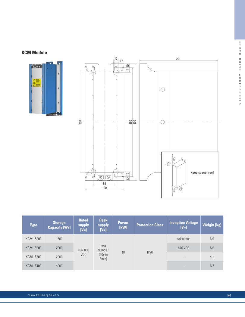
General
KCM modules (KOLLMORGEN Capacitor Modules) absorb energy generated by the motor when it is operating in generator mode. Normally, this energy is dissipated as waste via regen resistors. KCM modules, however, feed the energy they have stored back into the DC Bus link as and when it is required.
KCM-S Saves energy: The energy stored in the capacitor module during generative braking is available the next time acceleration happens. The module’s inception voltage is calculated automatically during the fi rst load cycles.
KCM-P Power in spite of power failure: If the power supply fails, the module provides the drive with the stored energy that is required to bring the drive to a standstill in a controlled manner (this only applies to the power supply voltage; battery-back the 24 V supply separately).
KCM-E Expansion module for both applications. Expansion modules are available in two capacitance classes.
The KCM modules may only be connected to drives with 400/480 V rated voltage.
Drive* KCM Module Voltage
AKD-x00306...02406 not allowed 240 V
AKD-x00307...02407 all modules 480 V
AKD-x04807 contact customer support 480 V
AKD-C01007 all modules 480 V
*= x means variants -B, -P, -T or -M
Part Number Description
KCM-S200-0000 Energy Saving Module, 1.6 kWs
KCM-P200-0000 Power Module, 2 kWs
KCM-E200-0000 Expansion Module 2 kWs
KCM-E400-0000 Expansion Module 4 kWs
Capacitor ModulesSE
RV
O
DR
IV
E
AC
CE
SS
OR
IE
S
Servo Drive Accessories
KCM Module
TypeStorage
Capacity [Ws]
Rated supply
[V=]
Peak supply
[V=]
Power [kW]
Protection ClassInception Voltage
[V=]Weight [kg]
KCM- S200 1600
max 850VDC
max950VDC(30s in6min)
18 IP20
calculated 6.9
KCM- P200 2000 470 VDC 6.9
KCM- E200 2000 - 4.1
KCM- E400 4000 - 6.2
201136.5
1012
280
300
10058
258
1012
Keep space free!
SE
RV
O
DR
IV
E
AC
CE
SS
OR
IE
S
w w w. k o l l m o r g e n . c o m 165
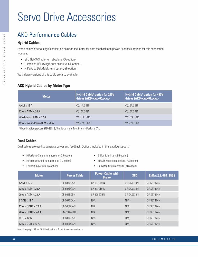
AKD Performance CablesHybrid Cables
Hybrid cables offer a single connection point on the motor for both feedback and power. Feedback options for this connection type are:
• SFD GEN3 (Single-turn absolute, CA option)• HiPerFace DSL (Single-turn absolute, GE option)• HiPerFace DSL (Multi-turn option, GF option)
Washdown versions of this cable are also available.
AKD Hybrid Cables by Motor Type
MotorHybrid Cable1 option for 240V drives (AKD-xxxx06xxxx)
Hybrid Cable1 option for 480V drives (AKD-xxxx07xxxx)
AKM < 12 A CCJ1A2-015 CCJ2A2-015
12 A ≤ AKM < 20 A CCJ2A2-025 CCJ2A2-025
Washdown AKM < 12 A WCJ1A1-015 WCJ2A1-015
12 A ≤ Washdown AKM < 20 A WCJ2A1-025 WCJ2A1-025
1 Hybrid cables support SFD GEN 3, Single-turn and Multi-turn HiPerFace DSL
Dual CablesDual cables are used to separate power and feedback. Options included in this catalog support:
Motor Power CablePower Cable with
BrakeSFD EnDat 2.2, 01& BiSS
AKM < 12 A CP-507CCAN CP-507CDAN CF-DA0374N CF-SB7374N
12 A ≤ AKM < 20 A CP-507DCAN CP-507DDAN CF-DA0374N CF-SB7374N
20 A ≤ AKM < 24 A CP-508EDBN CP-508EDBN CF-DA0374N CF-SB7374N
CDDR < 12 A CP-507CCAN N/A N/A CF-SB7374N
12 A ≤ CDDR < 20 A CP-508DCAN N/A N/A CF-SB7374N
20 A ≤ CDDR < 48 A CM-13A4-010 N/A N/A CF-SB7374N
DDR < 12 A CP-507CCAN N/A N/A CF-SB7374N
12 A ≤ DDR < 20 A CP-508DCAN N/A N/A CF-SB7374N
• HiPerFace (Single-turn absolute, GJ option)
• HiPerFace (Multi-turn absolute, GK option)
• EnDat (Single-turn, LA option)
• EnDat (Multi-turn, LB option)
• BiSS (Single-turn absolute, AA option)
• BiSS (Multi-turn absolute, AB option)
SE
RV
O
DR
IV
E
AC
CE
SS
OR
IE
S
Servo Drive Accessories
AKD Value Line Cables
Value Line Cables are alternative cable options suitable for most applications. These cables separate power and feedback. Options included in this catalog support Single-turn (GJ) and Multi-turn (GK) for AKD.
Motor Power Cable Power Cable with Brake SFD EnDat 2.2, 01& BiSS
AKM < 6 A VP-507BEAN VP-508CFAN VF-DA0474N VF-SB7374N
6 A ≤ AKM < 12 A VP-508CEAN VP-508CFAN VF-DA0474N VF-SB7374N
12 A ≤ AKM < 20 A VP-508DEAN VP-508DFAN VF-DA0474N VF-SB7374N
CDDR < 12 A VP-507BEAN N/A N/A VF-SB7374N
12 A ≤ CDDR < 20 A VP-508CEAN N/A N/A VF-SB7374N
20 A ≤ CDDR < 48 A VP-508DEAN N/A N/A VF-SB7374N
DDR < 12 A VP-507BEAN N/A N/A VF-SB7374N
12 A ≤ DDR < 20 A VP-508CEAN N/A N/A VF-SB7374N
12 A ≤ DDR < 20 A VP-508DEAN N/A N/A VF-SB7374N
SE
RV
O
DR
IV
E
AC
CE
SS
OR
IE
S
Note: See page 179 for AKD Feedback and Power Cable nomenclature.
K O L L M O R G E N166
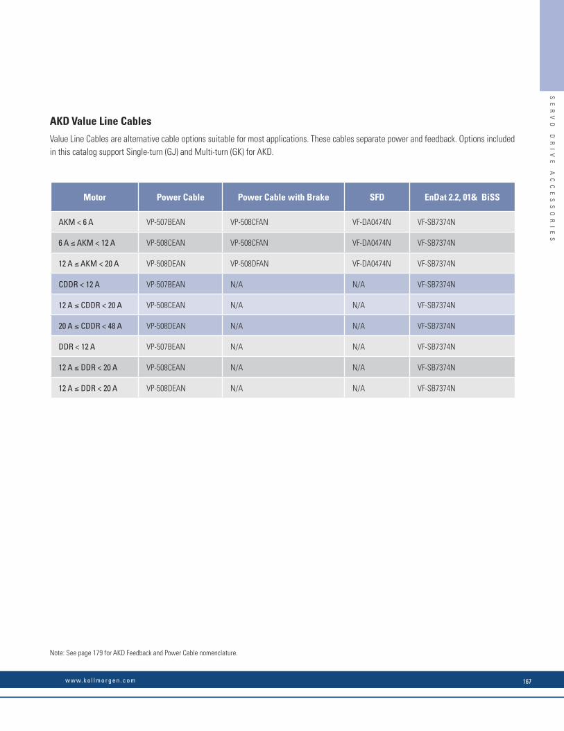
AKD Performance CablesHybrid Cables
Hybrid cables offer a single connection point on the motor for both feedback and power. Feedback options for this connection type are:
• SFD GEN3 (Single-turn absolute, CA option)• HiPerFace DSL (Single-turn absolute, GE option)• HiPerFace DSL (Multi-turn option, GF option)
Washdown versions of this cable are also available.
AKD Hybrid Cables by Motor Type
MotorHybrid Cable1 option for 240V drives (AKD-xxxx06xxxx)
Hybrid Cable1 option for 480V drives (AKD-xxxx07xxxx)
AKM < 12 A CCJ1A2-015 CCJ2A2-015
12 A ≤ AKM < 20 A CCJ2A2-025 CCJ2A2-025
Washdown AKM < 12 A WCJ1A1-015 WCJ2A1-015
12 A ≤ Washdown AKM < 20 A WCJ2A1-025 WCJ2A1-025
1 Hybrid cables support SFD GEN 3, Single-turn and Multi-turn HiPerFace DSL
Dual CablesDual cables are used to separate power and feedback. Options included in this catalog support:
Motor Power CablePower Cable with
BrakeSFD EnDat 2.2, 01& BiSS
AKM < 12 A CP-507CCAN CP-507CDAN CF-DA0374N CF-SB7374N
12 A ≤ AKM < 20 A CP-507DCAN CP-507DDAN CF-DA0374N CF-SB7374N
20 A ≤ AKM < 24 A CP-508EDBN CP-508EDBN CF-DA0374N CF-SB7374N
CDDR < 12 A CP-507CCAN N/A N/A CF-SB7374N
12 A ≤ CDDR < 20 A CP-508DCAN N/A N/A CF-SB7374N
20 A ≤ CDDR < 48 A CM-13A4-010 N/A N/A CF-SB7374N
DDR < 12 A CP-507CCAN N/A N/A CF-SB7374N
12 A ≤ DDR < 20 A CP-508DCAN N/A N/A CF-SB7374N
• HiPerFace (Single-turn absolute, GJ option)
• HiPerFace (Multi-turn absolute, GK option)
• EnDat (Single-turn, LA option)
• EnDat (Multi-turn, LB option)
• BiSS (Single-turn absolute, AA option)
• BiSS (Multi-turn absolute, AB option)
SE
RV
O
DR
IV
E
AC
CE
SS
OR
IE
S
Servo Drive Accessories
AKD Value Line Cables
Value Line Cables are alternative cable options suitable for most applications. These cables separate power and feedback. Options included in this catalog support Single-turn (GJ) and Multi-turn (GK) for AKD.
Motor Power Cable Power Cable with Brake SFD EnDat 2.2, 01& BiSS
AKM < 6 A VP-507BEAN VP-508CFAN VF-DA0474N VF-SB7374N
6 A ≤ AKM < 12 A VP-508CEAN VP-508CFAN VF-DA0474N VF-SB7374N
12 A ≤ AKM < 20 A VP-508DEAN VP-508DFAN VF-DA0474N VF-SB7374N
CDDR < 12 A VP-507BEAN N/A N/A VF-SB7374N
12 A ≤ CDDR < 20 A VP-508CEAN N/A N/A VF-SB7374N
20 A ≤ CDDR < 48 A VP-508DEAN N/A N/A VF-SB7374N
DDR < 12 A VP-507BEAN N/A N/A VF-SB7374N
12 A ≤ DDR < 20 A VP-508CEAN N/A N/A VF-SB7374N
12 A ≤ DDR < 20 A VP-508DEAN N/A N/A VF-SB7374N
SE
RV
O
DR
IV
E
AC
CE
SS
OR
IE
S
Note: See page 179 for AKD Feedback and Power Cable nomenclature.
w w w. k o l l m o r g e n . c o m 167
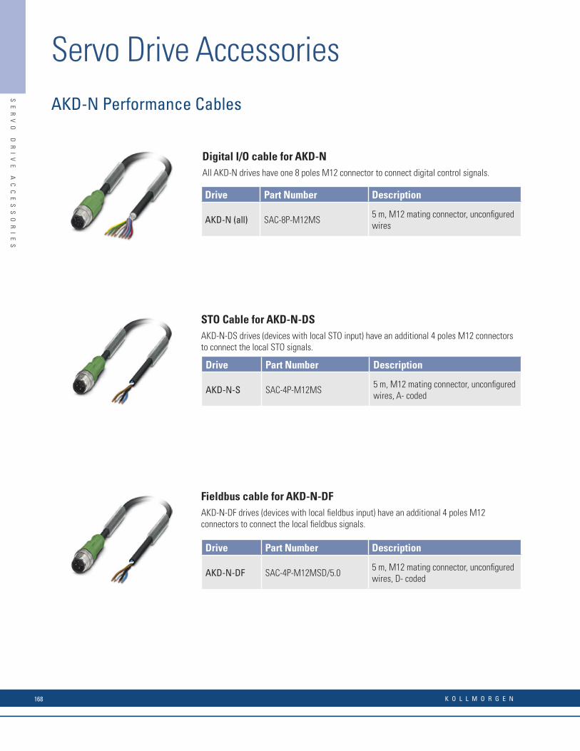
Digital I/O cable for AKD-N All AKD-N drives have one 8 poles M12 connector to connect digital control signals.
STO Cable for AKD-N-DS AKD-N-DS drives (devices with local STO input) have an additional 4 poles M12 connectors to connect the local STO signals.
Fieldbus cable for AKD-N-DF AKD-N-DF drives (devices with local fi eldbus input) have an additional 4 poles M12 connectors to connect the local fi eldbus signals.
Drive Part Number Description
AKD-N (all) SAC-8P-M12MS5 m, M12 mating connector, unconfi gured wires
Drive Part Number Description
AKD-N-S SAC-4P-M12MS5 m, M12 mating connector, unconfi gured wires, A- coded
Drive Part Number Description
AKD-N-DF SAC-4P-M12MSD/5.05 m, M12 mating connector, unconfi gured wires, D- coded
AKD-N Performance Cables
SE
RV
O
DR
IV
E
AC
CE
SS
OR
IE
S
Servo Drive AccessoriesAKD‐N Performance Cables
Hybrid Cable Connecting AKD-C Power Supply to AKD-N Axis Module
Hybrid Cable Connecting AKD-N Axis Module to AKD-N Axis Module
Hybrid Cable Connecting AKD-N Axis Module to AKM Motor
Part Number Description
CCNCN1-025-xxmyy-00 Hybrid cable connecting AKD-C to AKD-N
Length defi nition: xx=meters, yy=centimeters
Part Number Description
CCNNN1-025-xxmyy-00 Hybrid cable connecting AKD-N to AKD-N
Length defi nition: xx=meters, yy=centimeters
Part Number Description
CCJNA3-015-xxmyy-00 Hybrid cable connecting AKD-N to AKM (SFD GEN3, Single-turn/Multi-turn HiPerFace DSL)
Length defi nition: xx=meters, yy=centimeters
SE
RV
O
DR
IV
E
AC
CE
SS
OR
IE
S
K O L L M O R G E N168

Digital I/O cable for AKD-N All AKD-N drives have one 8 poles M12 connector to connect digital control signals.
STO Cable for AKD-N-DS AKD-N-DS drives (devices with local STO input) have an additional 4 poles M12 connectors to connect the local STO signals.
Fieldbus cable for AKD-N-DF AKD-N-DF drives (devices with local fi eldbus input) have an additional 4 poles M12 connectors to connect the local fi eldbus signals.
Drive Part Number Description
AKD-N (all) SAC-8P-M12MS5 m, M12 mating connector, unconfi gured wires
Drive Part Number Description
AKD-N-S SAC-4P-M12MS5 m, M12 mating connector, unconfi gured wires, A- coded
Drive Part Number Description
AKD-N-DF SAC-4P-M12MSD/5.05 m, M12 mating connector, unconfi gured wires, D- coded
AKD-N Performance Cables
SE
RV
O
DR
IV
E
AC
CE
SS
OR
IE
S
Servo Drive AccessoriesAKD‐N Performance Cables
Hybrid Cable Connecting AKD-C Power Supply to AKD-N Axis Module
Hybrid Cable Connecting AKD-N Axis Module to AKD-N Axis Module
Hybrid Cable Connecting AKD-N Axis Module to AKM Motor
Part Number Description
CCNCN1-025-xxmyy-00 Hybrid cable connecting AKD-C to AKD-N
Length defi nition: xx=meters, yy=centimeters
Part Number Description
CCNNN1-025-xxmyy-00 Hybrid cable connecting AKD-N to AKD-N
Length defi nition: xx=meters, yy=centimeters
Part Number Description
CCJNA3-015-xxmyy-00 Hybrid cable connecting AKD-N to AKM (SFD GEN3, Single-turn/Multi-turn HiPerFace DSL)
Length defi nition: xx=meters, yy=centimeters
SE
RV
O
DR
IV
E
AC
CE
SS
OR
IE
S
w w w. k o l l m o r g e n . c o m 169
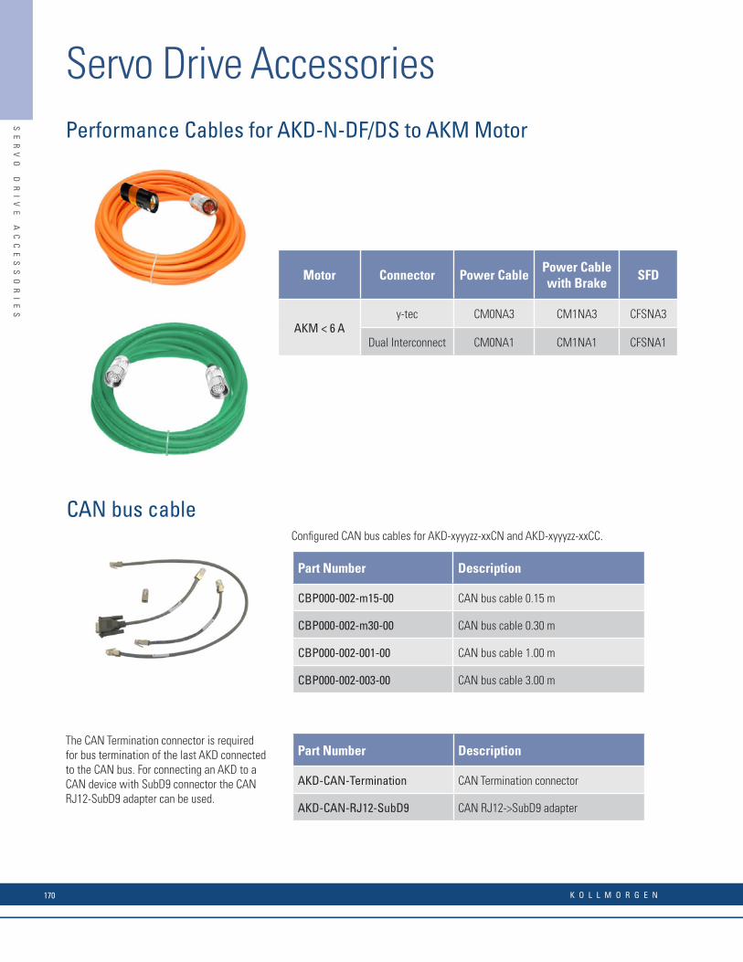
Performance Cables for AKD-N-DF/DS to AKM Motor
Motor Connector Power CablePower Cable with Brake
SFD
AKM < 6 Ay-tec CM0NA3 CM1NA3 CFSNA3
Dual Interconnect CM0NA1 CM1NA1 CFSNA1
CAN bus cableConfi gured CAN bus cables for AKD-xyyyzz-xxCN and AKD-xyyyzz-xxCC.
The CAN Termination connector is required for bus termination of the last AKD connected to the CAN bus. For connecting an AKD to a CAN device with SubD9 connector the CAN RJ12-SubD9 adapter can be used.
Part Number Description
CBP000-002-m15-00 CAN bus cable 0.15 m
CBP000-002-m30-00 CAN bus cable 0.30 m
CBP000-002-001-00 CAN bus cable 1.00 m
CBP000-002-003-00 CAN bus cable 3.00 m
Part Number Description
AKD-CAN-Termination CAN Termination connector
AKD-CAN-RJ12-SubD9 CAN RJ12->SubD9 adapter
SE
RV
O
DR
IV
E
AC
CE
SS
OR
IE
S
Servo Drive Accessories
K O L L M O R G E N170

SE
RV
O
DR
IV
E
AC
CE
SS
OR
IE
S
Performance Cables for AKD-N-DF/DS to AKM Motor
Motor Connector Power CablePower Cable with Brake
SFD
AKM < 6 Ay-tec CM0NA3 CM1NA3 CFSNA3
Dual Interconnect CM0NA1 CM1NA1 CFSNA1
CAN bus cableConfi gured CAN bus cables for AKD-xyyyzz-xxCN and AKD-xyyyzz-xxCC.
The CAN Termination connector is required for bus termination of the last AKD connected to the CAN bus. For connecting an AKD to a CAN device with SubD9 connector the CAN RJ12-SubD9 adapter can be used.
Part Number Description
CBP000-002-m15-00 CAN bus cable 0.15 m
CBP000-002-m30-00 CAN bus cable 0.30 m
CBP000-002-001-00 CAN bus cable 1.00 m
CBP000-002-003-00 CAN bus cable 3.00 m
Part Number Description
AKD-CAN-Termination CAN Termination connector
AKD-CAN-RJ12-SubD9 CAN RJ12->SubD9 adapter
SE
RV
O
DR
IV
E
AC
CE
SS
OR
IE
S
Servo Drive Accessories Notes
w w w. k o l l m o r g e n . c o m 171

Kollmorgen is a world-leading provider of vehicle automation kits. We combine a complete range of hardware, software and navigation technologies with vast knowledge and experience. We have a long and successful history in this fi eld and can provide you with everything you need for excellent vehicle control independent of application. The result is lower total costs – for you and your customers.
Turn to us when you want to create vehicle solutions that give you a competitive advantage in the marketplace.
Warehouse (NDC) Solutions
AG
V
CO
NT
RO
L
SY
ST
EM
S

w w w. k o l l m o r g e n . c o m 2
Benefi ts Features
• Lowest total cost for partners • No need to develop your own controls
• More time to focus on end-user application
• Proven and fl exible concept
• Works for all applications in all segments
• Support in the sales process
• Access to value-adding services
• Lowest total cost for end-users • Customized application
• Easy to integrate with other systems
• Easy to operate, maintain and update
• High availability – 24/7 opration
AG
V
CO
NT
RO
L
SY
ST
EM
S
w w w. k o l l m o r g e n . c o m 173
Kollmorgen is a world-leading provider of vehicle automation kits. We combine a complete range of hardware, software and navigation technologies with vast knowledge and experience. We have a long and successful history in this fi eld and can provide you with everything you need for excellent vehicle control independent of application. The result is lower total costs – for you and your customers.
Turn to us when you want to create vehicle solutions that give you a competitive advantage in the marketplace.
Warehouse (NDC) Solutions
AG
V
CO
NT
RO
L
SY
ST
EM
S

K O L L M O R G E N3
AGV Control SystemsPowerful Software Solutions for Effi cient Design and Service
NDC Solutions gives you access to a set of effi cient design and service tools. The design tools help you outline all kinds of lay-outs as well as system and vehicle applications. Service tools include vehicle maintenance (e.g. fault-tracing, statistics and soft-ware downloads) and automatic surveying of the environment.
Design toolsLayoutApplications
Vehicle system controller
Transport flow controlTraffic managementFleet management
Vehicles
NavigationSteer/drive controlLoad handling
(ERP/MES/WMS)
Host
Vehicle maintenanceVehicle diagnostics
Service tools
Operator interfacesA
GV
C
ON
TR
OL
S
YS
TE
MS
K O L L M O R G E N174

w w w. k o l l m o r g e n . c o m 4
Robust and Reliable Vehicle Hardware
Displays
EncodersDrives
Safety sensors Vehicle I/ONavigation sensors
Manual control device
Vehicle controllers
The different platforms in NDC Solutions use the same vehicle hardware. The hardware consists of powerful and reliable components in a number of areas. All components are designed for tough environments where vibrations, dust, moisture and temperature variations are all part of daily life.
AG
V
CO
NT
RO
L
SY
ST
EM
S
w w w. k o l l m o r g e n . c o m 175
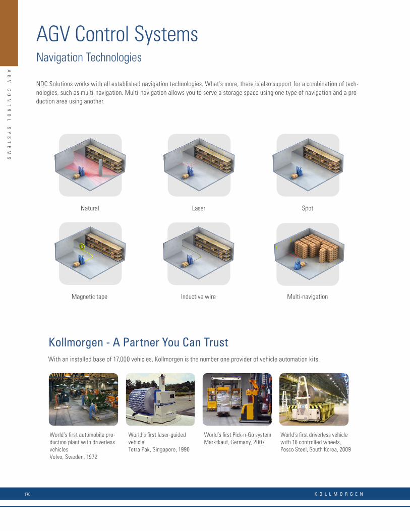
K O L L M O R G E N5
AGV Control SystemsNavigation Technologies
NDC Solutions works with all established navigation technologies. What’s more, there is also support for a combination of tech-nologies, such as multi-navigation. Multi-navigation allows you to serve a storage space using one type of navigation and a pro-duction area using another.
Magnetic tape
Laser
Multi-navigation
Natural Spot
Inductive wire
Kollmorgen - A Partner You Can Trust
World’s fi rst automobile pro-duction plant with driverless vehiclesVolvo, Sweden, 1972
World’s fi rst Pick-n-Go systemMarktkauf, Germany, 2007
World’s fi rst laser-guided vehicleTetra Pak, Singapore, 1990
World’s fi rst driverless vehicle with 16 controlled wheels,Posco Steel, South Korea, 2009
With an installed base of 17,000 vehicles, Kollmorgen is the number one provider of vehicle automation kits.
AG
V
CO
NT
RO
L
SY
ST
EM
S
K O L L M O R G E N176

w w w. k o l l m o r g e n . c o m 6
Services that Last a Lifetime
The end-users require high uptime, effi cient daily operations and applications that are easy to change. We help you meet these demands with both technology and services.
Our services portfolio consists of:
• Training services that quickly make you an NDC Solutions expert. We offerbasic, advanced and tailor-made courses, either at our training facilities orat your site. Internet-based training is also available.
• Support services where we give answers and solutions to your requests.
• Consulting services where our senior consultants help you in the sales and design process.
The illustration shows how we support you throughout the lifecycle of your system.
Your system lifecycle
Design supportSenior consultants help with:
• Layout design
• Application programming
• Knowledge transfer
Commissioning supportApplication engineers help with:
• System start-up
• Vehicle tuning
• Facility surveying
Operation and maintenance support• Helpdesk 24/7
• On-site assistance
• Preventive maintenance
• Spare parts and repair
available at least 10 years
after fi nal sale
Sales supportSenior consultants:
• Give advice
• Help at customer visits
• Prepare simulations
• Write system specifi cations
Upgrade supportSenior consultants help with:
• Sales argumentation
• Technical solutions
• System specifi cations
AG
V
CO
NT
RO
L
SY
ST
EM
S
w w w. k o l l m o r g e n . c o m 177
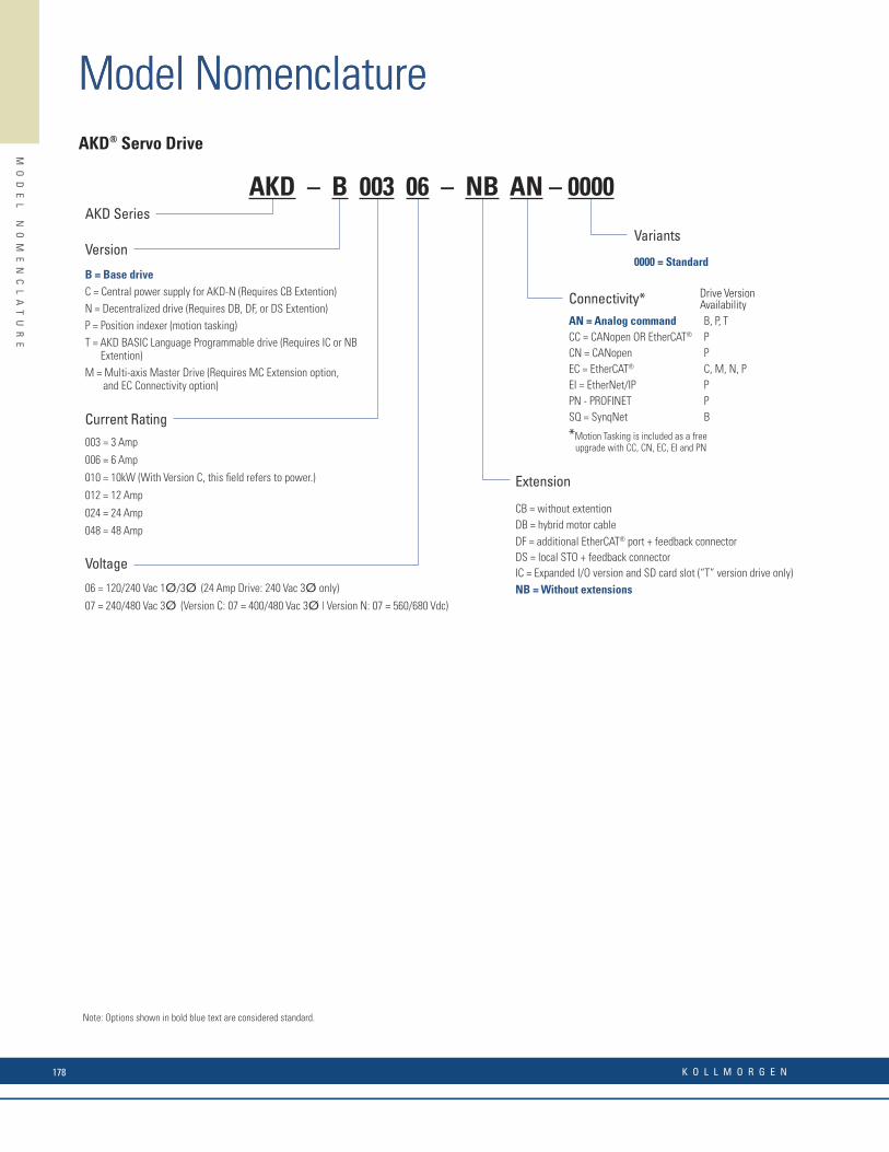
AKD® Servo Drive Cables
“AA” - Cable Type
CF = Performance LineVF = Value Line Feedback
“C” - Feedback Device TypeA = Size 1.0, 12-pin (SFD or Resolver)
B = Size 1.0, 17-pin (Encoder)
“DD” - Feedback Device Type
03 = 4 conductor (SFD) (Performance Line)04 = 4 conductor (SFD) (Value Line)
“B” - Feedback Device TypeD = SFD
H = HiPerFace
S = Sine Encoder
– 74N –
“HHJ” - Cable Length
Length in meters
Feedback Cables
“AA” - Cable Type
CP = Performance LineVP = Value Line Feedback
“CC” - Power Cable Material Type
BE = 16 AWG, 4 conductor, Value Line DE = 12 AWG, 4 conductor, Value Line
CD = 14/18 AWG, 6 conductor, brake, Performance DD = 12/18 AWG, 6 conductor, brake, Performance
CE = 14 AWG, 4 conductor, Value Line DF = 12/18 AWG, 6 conductor, brake, Value Line
CF = 14/18 AWG, 6 conductor, brake, Value Line ED = 10/18 AWG, 6 conductor, brake, Value Line
“E” - Motor Power Connector Type
A = Size 1.0, 8 pinB = Size 1.5, 8 pin
“BB” - Drive Power Connector Type
07 = AKD, 1-12A (230V)
08 = AKD, 24A (230V) & 1-24A (480V)
– 5 N – AA B B C C E FFG
“FFG” - Cable Length
Length in meters
Power Cables
AA B C D D HHJ
w w w. k o l l m o r g e n . c o m 21
Model Nomenclature
MO
DE
L
NO
ME
NC
LA
TU
RE
Version
B = Base driveC = Central power supply for AKD-N (Requires CB Extention)N = Decentralized drive (Requires DB, DF, or DS Extention) P = Position indexer (motion tasking)T = AKD BASIC Language Programmable drive (Requires IC or NB Extention)M = Multi-axis Master Drive (Requires MC Extension option, and EC Connectivity option)
AKD Series
Connectivity*AN = Analog commandCC = CANopen OR EtherCAT®
CN = CANopenEC = EtherCAT®
EI = EtherNet/IPPN - PROFINETSQ = SynqNet
B, P, TPPC, M, N, PPPB
Voltage
06 = 120/240 Vac 1Ø/3Ø (24 Amp Drive: 240 Vac 3Ø only)
07 = 240/480 Vac 3Ø (Version C: 07 = 400/480 Vac 3Ø | Version N: 07 = 560/680 Vdc)
Extension
CB = without extentionDB = hybrid motor cableDF = additional EtherCAT® port + feedback connectorDS = local STO + feedback connectorIC = Expanded I/O version and SD card slot (“T” version drive only)NB = Without extensions
Current Rating003 = 3 Amp
006 = 6 Amp
010 = 10kW (With Version C, this fi eld refers to power.)
012 = 12 Amp
024 = 24 Amp
048 = 48 Amp
AKD – B 003 06 – NB AN – 0000
Note: Options shown in bold blue text are considered standard.
Variants
0000 = Standard
AKD® Servo Drive
*Motion Tasking is included as a free upgrade with CC, CN, EC, EI and PN
Drive VersionAvailability
Model Nomenclature
K O L L M O R G E N178
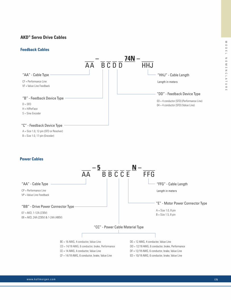
AKD® Servo Drive Cables
“AA” - Cable Type
CF = Performance LineVF = Value Line Feedback
“C” - Feedback Device TypeA = Size 1.0, 12-pin (SFD or Resolver)
B = Size 1.0, 17-pin (Encoder)
“DD” - Feedback Device Type
03 = 4 conductor (SFD) (Performance Line)04 = 4 conductor (SFD) (Value Line)
“B” - Feedback Device TypeD = SFD
H = HiPerFace
S = Sine Encoder
– 74N –
“HHJ” - Cable Length
Length in meters
Feedback Cables
“AA” - Cable Type
CP = Performance LineVP = Value Line Feedback
“CC” - Power Cable Material Type
BE = 16 AWG, 4 conductor, Value Line DE = 12 AWG, 4 conductor, Value Line
CD = 14/18 AWG, 6 conductor, brake, Performance DD = 12/18 AWG, 6 conductor, brake, Performance
CE = 14 AWG, 4 conductor, Value Line DF = 12/18 AWG, 6 conductor, brake, Value Line
CF = 14/18 AWG, 6 conductor, brake, Value Line ED = 10/18 AWG, 6 conductor, brake, Value Line
“E” - Motor Power Connector Type
A = Size 1.0, 8 pinB = Size 1.5, 8 pin
“BB” - Drive Power Connector Type
07 = AKD, 1-12A (230V)
08 = AKD, 24A (230V) & 1-24A (480V)
– 5 N – AA B B C C E FFG
“FFG” - Cable Length
Length in meters
Power Cables
AA B C D D HHJ
w w w. k o l l m o r g e n . c o m 21
MO
DE
L
NO
ME
NC
LA
TU
RE
w w w. k o l l m o r g e n . c o m 179
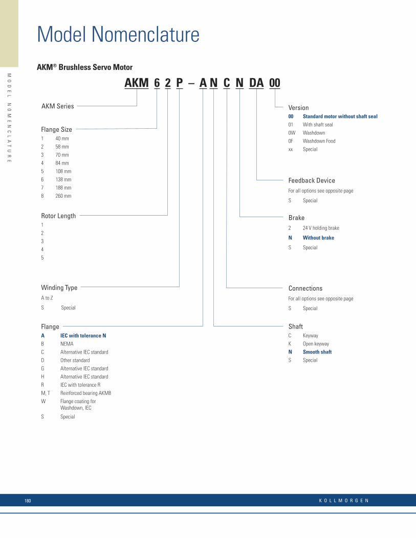
AKM® Brushless Servo Motor
Winding TypeA to Z
S Special
Flange Size1 40 mm
2 58 mm
3 70 mm
4 84 mm
5 108 mm
6 138 mm
7 188 mm
8 260 mm
AKM Series Version00 Standard motor without shaft seal
01 With shaft seal
0W Washdown
0F Washdown Food
xx Special
Brake2 24 V holding brake
N Without brake
S Special
ConnectionsFor all options see opposite page
S Special
Feedback DeviceFor all options see opposite page
S Special
Rotor Length1
2
3
4
5
FlangeA IEC with tolerance N
B NEMA
C Alternative IEC standard
D Other standard
G Alternative IEC standard
H Alternative IEC standard
R IEC with tolerance R
M, T Reinforced bearing AKM8
W Flange coating for Washdown, IEC
S Special
ShaftC Keyway
K Open keyway
N Smooth shaft
S Special
AKM 6 2 P – A N C N DA 00 Code Designation Model Can be used with Connection Option Comment
1- Comcorder AKM1 - AKM8 1, 2, 7, B, C, G, H, T 1024 incr./rev2- Comcorder AKM1 -AKM8 1, 2, 7, B, C, G, H, T 2048 incr./revAA BiSS B encoder AD36 AKM2 - AKM4 1, 7, B, C, M Single-turn, opticalAA BiSS B encoder AD58 AKM5 - AKM8 1, 2, C, G, H, M, T Single-turn, opticalAB BiSS B encoder AD36 AKM2 - AKM4 1,7,B, C, M Multi-turn, opticalAB BiSS B encoder AD58 AKM5 - AKM8 1, 2, C, G, H, M, T Multi-turn, opticalC- Smart Feedback Device SFD Size 10 AKM1 1, D, Y, M, P Single-turn 4-wireC- Smart Feedback Device SFD Size 15 AKM2 - AKM4 1, D, Y, M, P Single-turn 4-wireC- Smart Feedback Device SFD Size 21 AKM5- AKM8 1, D, Y, M, P Single-turn 4-wireCA Smart Feedback Device SFD3 AKM1 - AKM6 D Single-turn 2-wireDA EnDAT 2.1 encoder ECN 1113 AKM2 - AKM4 1, 7, B, C, M Single-turn. opticalDA EnDAT 2.1 encoder ECN 1313 AKM5 - AKM8 1, 2, C, G, H, M, T Single-turn, opticalDB EnDAT 2.1 encoder EQN 1125 AKM2 - AKM4 1, 7, B, C, M Multi-turn, opticalDB EnDAT 2.1 encoder EQN 1325 AKM5 - AKM8 1, 2, C, G, H, M, T Multi-turn, opticalLA EnDAT 2.1 encoder ECI 1118 AKM2 - AKM3 1, 7, B , C, M Single-turn, inductiveLA EnDAT 2.1 encoder ECI 1319 AKM4 - AKM8 1, 2, C, G, H, M, T Single-turn, inductiveLB EnDAT 2.1 encoder ECI 1130 AKM2 - AKM3 1,7, B, C, M Multi-turn, inductiveLB EnDAT 2.1 encoder ECI 1331 AKM4 - AKM8 1, 2, C, G, H, M, T Multi-turn, inductiveGJ HIPERFACE encoder SKS36 AKM2 - AKM8 1,2,7, B, C, G, H, M, T Single-turn, opticalGK HIPERFACE encoder SKM36 AKM2 - AKM8 1,2,7, B, C, G, H, M, T Multi-turn, opticalGP HIPERFACE encoder SEK34 AKM1 1, Y, M Single-turn, capacitiveGR HIPERFACE encoder SEL34 AKM1 1, Y, M Multi-turn, capacitiveGE HIPERFACE DSL encoder EKS36 AKM2 - AKM8 D Single-turn, opticalGF HIPERFACE DSL encoder EKM36 AKM2 - AKM8 D Multi-turn, opticalGM Safety HIPERFACE SKS36S AKM2 - AKM8 1, 2, 7, B, C, G, H, M, T Single-turn, opticalGN Safety HIPERFACE SKM36S AKM2 - AKM8 1, 2, 7, B, C, G, H, M, T Multi-turn, opticalMA Drive Cliq ECN1324S AKM4 - AKM8 Single-turn, opticalMB Drive Cliq EQN1336S AKM4 - AKM8 tba Multi-turn, opticalR- Resolvers Size 10 AKM1 1,2,7, B, C, G, H, M, T, Y 2-pin, hollow shaftR- Resolvers Size 15 AKM2 - AKM4 1,2,7, B, C, G, H, M, T, Y 2-pin, hollow shaftR- Resolvers Size 21 AKM5 - AKM8 1,2,7, B, C, G, H, M, T, Y 2-pin, hollow shaft
* not available for AKM2 with connection option C (cable with IP65 connector)
Feedback Unit Options
Code
Can be used withProtection
classConnection type DescriptionWith
PTC
With KTY
84-130B 1 AKM2 IP65 2 threaded connectors, size 1.0 Angled, rotatable, mounted on motorC 7 AKM1 - AKM2 IP65 2 threaded connectors, size 1.0 On 0.5 m cableC 1 AKM3 IP65 2 threaded connectors, size 1.0 Angled, rotatable, mounted on motorC 1 AKM4 - AKM7 IP65 2 Speed Tec Ready connectors, size 1.0 Angled, rotatable, mounted on motor– D AKM1 IP65 1 hybrid i-tec connector Mounted on motor– D AKM2 - AKM6 IP65 1 hybrid threaded connector, size 1.0 Angled, rotatable, mounted on motorG – AKM2 - AKM3 IP65 2 threaded connectors, size 1.0 Straight, mounted on motorG – AKM4 - AKM6 IP65 2 Speed Tec Ready connectors, size 1.0 Straight, mounted on motor
H 1 AKM74Q and AKM82T IP651 feedback threaded connector, size 1.0
1 power threaded connector, size 1.5Angled, rotatable, mounted on motor
M – AKM1 - AKM4 IP20 2 Molex connectors, I0 < 6 A On 0.5 m cableP – AKM1 - AKM4 IP20 1 Molex connector, I0 < 6 A On 0.5 m cable
R – AKM4 - AKM7 IP651 feedback threaded connector M12
1 power connector SpeedTec-Ready M23Straight, mounted on motorAngled, mounted on motor
T 2 AKM8 IP651 terminal box IP65 for power
1 Feedback threaded connector, size 1.0Mounted on motor
Y 1 AKM1 IP65 1 y-tec® connector Mounted on motor
Connector Options
Model Nomenclature
MO
DE
L
NO
ME
NC
LA
TU
RE
K O L L M O R G E N180

AKM® Brushless Servo Motor
Winding TypeA to Z
S Special
Flange Size1 40 mm
2 58 mm
3 70 mm
4 84 mm
5 108 mm
6 138 mm
7 188 mm
8 260 mm
AKM Series Version00 Standard motor without shaft seal
01 With shaft seal
0W Washdown
0F Washdown Food
xx Special
Brake2 24 V holding brake
N Without brake
S Special
ConnectionsFor all options see opposite page
S Special
Feedback DeviceFor all options see opposite page
S Special
Rotor Length1
2
3
4
5
FlangeA IEC with tolerance N
B NEMA
C Alternative IEC standard
D Other standard
G Alternative IEC standard
H Alternative IEC standard
R IEC with tolerance R
M, T Reinforced bearing AKM8
W Flange coating for Washdown, IEC
S Special
ShaftC Keyway
K Open keyway
N Smooth shaft
S Special
AKM 6 2 P – A N C N DA 00 Code Designation Model Can be used with Connection Option Comment
1- Comcorder AKM1 - AKM8 1, 2, 7, B, C, G, H, T 1024 incr./rev2- Comcorder AKM1 -AKM8 1, 2, 7, B, C, G, H, T 2048 incr./revAA BiSS B encoder AD36 AKM2 - AKM4 1, 7, B, C, M Single-turn, opticalAA BiSS B encoder AD58 AKM5 - AKM8 1, 2, C, G, H, M, T Single-turn, opticalAB BiSS B encoder AD36 AKM2 - AKM4 1,7,B, C, M Multi-turn, opticalAB BiSS B encoder AD58 AKM5 - AKM8 1, 2, C, G, H, M, T Multi-turn, opticalC- Smart Feedback Device SFD Size 10 AKM1 1, D, Y, M, P Single-turn 4-wireC- Smart Feedback Device SFD Size 15 AKM2 - AKM4 1, D, Y, M, P Single-turn 4-wireC- Smart Feedback Device SFD Size 21 AKM5- AKM8 1, D, Y, M, P Single-turn 4-wireCA Smart Feedback Device SFD3 AKM1 - AKM6 D Single-turn 2-wireDA EnDAT 2.1 encoder ECN 1113 AKM2 - AKM4 1, 7, B, C, M Single-turn. opticalDA EnDAT 2.1 encoder ECN 1313 AKM5 - AKM8 1, 2, C, G, H, M, T Single-turn, opticalDB EnDAT 2.1 encoder EQN 1125 AKM2 - AKM4 1, 7, B, C, M Multi-turn, opticalDB EnDAT 2.1 encoder EQN 1325 AKM5 - AKM8 1, 2, C, G, H, M, T Multi-turn, opticalLA EnDAT 2.1 encoder ECI 1118 AKM2 - AKM3 1, 7, B , C, M Single-turn, inductiveLA EnDAT 2.1 encoder ECI 1319 AKM4 - AKM8 1, 2, C, G, H, M, T Single-turn, inductiveLB EnDAT 2.1 encoder ECI 1130 AKM2 - AKM3 1,7, B, C, M Multi-turn, inductiveLB EnDAT 2.1 encoder ECI 1331 AKM4 - AKM8 1, 2, C, G, H, M, T Multi-turn, inductiveGJ HIPERFACE encoder SKS36 AKM2 - AKM8 1,2,7, B, C, G, H, M, T Single-turn, opticalGK HIPERFACE encoder SKM36 AKM2 - AKM8 1,2,7, B, C, G, H, M, T Multi-turn, opticalGP HIPERFACE encoder SEK34 AKM1 1, Y, M Single-turn, capacitiveGR HIPERFACE encoder SEL34 AKM1 1, Y, M Multi-turn, capacitiveGE HIPERFACE DSL encoder EKS36 AKM2 - AKM8 D Single-turn, opticalGF HIPERFACE DSL encoder EKM36 AKM2 - AKM8 D Multi-turn, opticalGM Safety HIPERFACE SKS36S AKM2 - AKM8 1, 2, 7, B, C, G, H, M, T Single-turn, opticalGN Safety HIPERFACE SKM36S AKM2 - AKM8 1, 2, 7, B, C, G, H, M, T Multi-turn, opticalMA Drive Cliq ECN1324S AKM4 - AKM8 Single-turn, opticalMB Drive Cliq EQN1336S AKM4 - AKM8 tba Multi-turn, opticalR- Resolvers Size 10 AKM1 1,2,7, B, C, G, H, M, T, Y 2-pin, hollow shaftR- Resolvers Size 15 AKM2 - AKM4 1,2,7, B, C, G, H, M, T, Y 2-pin, hollow shaftR- Resolvers Size 21 AKM5 - AKM8 1,2,7, B, C, G, H, M, T, Y 2-pin, hollow shaft
* not available for AKM2 with connection option C (cable with IP65 connector)
Feedback Unit Options
Code
Can be used withProtection
classConnection type DescriptionWith
PTC
With KTY
84-130B 1 AKM2 IP65 2 threaded connectors, size 1.0 Angled, rotatable, mounted on motorC 7 AKM1 - AKM2 IP65 2 threaded connectors, size 1.0 On 0.5 m cableC 1 AKM3 IP65 2 threaded connectors, size 1.0 Angled, rotatable, mounted on motorC 1 AKM4 - AKM7 IP65 2 Speed Tec Ready connectors, size 1.0 Angled, rotatable, mounted on motor– D AKM1 IP65 1 hybrid i-tec connector Mounted on motor– D AKM2 - AKM6 IP65 1 hybrid threaded connector, size 1.0 Angled, rotatable, mounted on motorG – AKM2 - AKM3 IP65 2 threaded connectors, size 1.0 Straight, mounted on motorG – AKM4 - AKM6 IP65 2 Speed Tec Ready connectors, size 1.0 Straight, mounted on motor
H 1 AKM74Q and AKM82T IP651 feedback threaded connector, size 1.0
1 power threaded connector, size 1.5Angled, rotatable, mounted on motor
M – AKM1 - AKM4 IP20 2 Molex connectors, I0 < 6 A On 0.5 m cableP – AKM1 - AKM4 IP20 1 Molex connector, I0 < 6 A On 0.5 m cable
R – AKM4 - AKM7 IP651 feedback threaded connector M12
1 power connector SpeedTec-Ready M23Straight, mounted on motorAngled, mounted on motor
T 2 AKM8 IP651 terminal box IP65 for power
1 Feedback threaded connector, size 1.0Mounted on motor
Y 1 AKM1 IP65 1 y-tec® connector Mounted on motor
Connector Options
MO
DE
L
NO
ME
NC
LA
TU
RE
w w w. k o l l m o r g e n . c o m 181
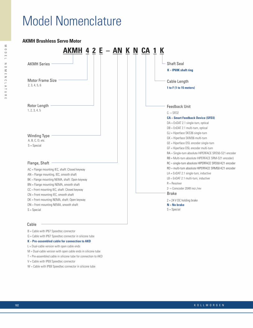
AKMH Brushless Servo Motor
Motor Frame Size
AKMH Series
1, 2, 3, 4, 5
2, 3, 4, 5, 6
Brake
2 = 24 V DC holding brakeN = No brakeS = Special
A, B, C, D, etc.
S = Special
Winding Type
Flange, ShaftAC = Flange mounting IEC, shaft: Closed keyway
AN = Flange mounting, IEC, smooth shaft
BK = Flange mounting NEMA, shaft: Open keyway
BN = Flange mounting NEMA, smooth shaft
CC = Front mounting IEC, shaft: Closed keyway
CN = Front mounting IEC, smooth shaft
DK = Front mounting NEMA, shaft: Open keyway
DN = Front mounting NEMA, smooth shaft
S = Special
Cable
B = Cable with IP67 Speedtec connector
G = Cable with IP67 Speedtec connector in silicone tube
K = Pre-assembled cable for connection to AKD
L = Dual-cable version with open cable ends
M = Dual-cable version with open cable ends in silicone tube
T = Pre-assembled cable in silicone tube for connection to AKD
V = Cable with IP69 Speedtec connector
W = Cable with IP69 Speedtec connector in silicone tube
Shaft SealK = IP69K shaft ring
Rotor Length Feedback UnitC- = SFD2
CA = Smart Feedback Device (SFD3)
DA = EnDAT 2.1 single-turn, optical
DB = EnDAT 2.1 multi-turn, optical
GJ = Hiperface SKS36 single-turn
GK = Hiperface SKM36 multi-turn
GE = Hiperface DSL encoder single-turn
GF = Hiperface DSL encoder multi-turn
RA = Single-turn absolute HIPERFACE SRS50-S21 encoder
RB = Multi-turn absolute HIPERFACE SRM-S21 encoder)
RC = single-turn absolute HIPERFACE SRS50-K21 encoder
RD = multi-turn absolute HIPERFACE SRM50-K21 encoder
LA = EnDAT 2.1 single-turn, inductive
LB = EnDAT 2.1 multi-turn, inductive
R = Resolver
2- = Comcoder 2048 incr./rev
Cable Length1 to F (1 to 15 meters)
AKMH 4 2 E – AN K N CA 1 K
Model Nomenclature
MO
DE
L
NO
ME
NC
LA
TU
RE
Cartridge DDR Motor
Product Family C = 230 Volt CH = 400/480 Volt
Frame Size Field 04 = 4.25” Sq. Housing 05 = 5.43” Sq. Housing 06 = 7.40” Sq. Housing 09 = 9.68” Sq. Housing 13 = 13.78” Sq. Housing
Stack Length Field 1 = Short Stack 2 = Mid Stack 3 = Long Stack 4 = Extra Long Stack (04 and 05 frame sizes only)
Winding Letter Field A = Standard Winding B = High-Speed Winding (C04x, C05x, C06x, C13x) C = Standard Winding (C052, C062, C063, C092, C093, C13x) D = High-Speed Winding (C052 only)
Mounting Option Field 1 = Std. Flange Mount
Connector Option Field 1 = Side Connector Option (09 and 13 frame sizes only) 2 = Rear Connector Option (09 and 13 frame sizes only) 3 = 90° Rotatable Connectors (04, 05 and 06 frame sizes only)
Sequential number for specials (Unique description within a frame size)
Agency Certification Option Field Blank = UL/CE Certification S = Non-UL
Unit Seal Option Field 5 = Sealed (Shaft Option “1” - IP64 Rating when customer seals interface side) (Shaft Option “2” or “3” - IP65 Rating when customer seals interface side)
Bearing Option Field 0 = No Bearing Design (Standard - Integral Shipping Clamp Provided)
Feedback Option Field 1 = EnDat single turn absolute sine encoder (2048 line) 3 = BiSS single turn absolute since encoder (2048 line) 4 = BiSS multi-turn absolute since encoder (2048 line) 5 = EnDat Multi-turn absolute since encoder (2048 line)
Shaft Field 1 = Hollow with Compression Coupling and Key (09 and 13 frame sizes only) 2 = Solid with Compression Coupling and Key (09 and 13 frame sizes only) 3 = Solid with Split Ring Coupling and no Key (04, 05, and 06 frame sizes only)
Note: Options shown in bold blue text are considered standard.
C 09 1 A - 1 1 - 1 1 0 5 S - xxx
MO
DE
L
NO
ME
NC
LA
TU
RE
K O L L M O R G E N182
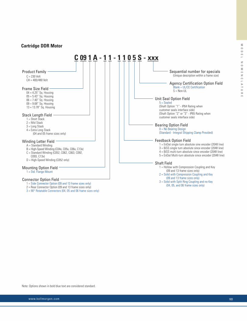
AKMH Brushless Servo Motor
Motor Frame Size
AKMH Series
1, 2, 3, 4, 5
2, 3, 4, 5, 6
Brake
2 = 24 V DC holding brakeN = No brakeS = Special
A, B, C, D, etc.
S = Special
Winding Type
Flange, ShaftAC = Flange mounting IEC, shaft: Closed keyway
AN = Flange mounting, IEC, smooth shaft
BK = Flange mounting NEMA, shaft: Open keyway
BN = Flange mounting NEMA, smooth shaft
CC = Front mounting IEC, shaft: Closed keyway
CN = Front mounting IEC, smooth shaft
DK = Front mounting NEMA, shaft: Open keyway
DN = Front mounting NEMA, smooth shaft
S = Special
Cable
B = Cable with IP67 Speedtec connector
G = Cable with IP67 Speedtec connector in silicone tube
K = Pre-assembled cable for connection to AKD
L = Dual-cable version with open cable ends
M = Dual-cable version with open cable ends in silicone tube
T = Pre-assembled cable in silicone tube for connection to AKD
V = Cable with IP69 Speedtec connector
W = Cable with IP69 Speedtec connector in silicone tube
Shaft SealK = IP69K shaft ring
Rotor Length Feedback UnitC- = SFD2
CA = Smart Feedback Device (SFD3)
DA = EnDAT 2.1 single-turn, optical
DB = EnDAT 2.1 multi-turn, optical
GJ = Hiperface SKS36 single-turn
GK = Hiperface SKM36 multi-turn
GE = Hiperface DSL encoder single-turn
GF = Hiperface DSL encoder multi-turn
RA = Single-turn absolute HIPERFACE SRS50-S21 encoder
RB = Multi-turn absolute HIPERFACE SRM-S21 encoder)
RC = single-turn absolute HIPERFACE SRS50-K21 encoder
RD = multi-turn absolute HIPERFACE SRM50-K21 encoder
LA = EnDAT 2.1 single-turn, inductive
LB = EnDAT 2.1 multi-turn, inductive
R = Resolver
2- = Comcoder 2048 incr./rev
Cable Length1 to F (1 to 15 meters)
AKMH 4 2 E – AN K N CA 1 K
MO
DE
L
NO
ME
NC
LA
TU
RE
Cartridge DDR Motor
Product Family C = 230 Volt CH = 400/480 Volt
Frame Size Field 04 = 4.25” Sq. Housing 05 = 5.43” Sq. Housing 06 = 7.40” Sq. Housing 09 = 9.68” Sq. Housing 13 = 13.78” Sq. Housing
Stack Length Field 1 = Short Stack 2 = Mid Stack 3 = Long Stack 4 = Extra Long Stack (04 and 05 frame sizes only)
Winding Letter Field A = Standard Winding B = High-Speed Winding (C04x, C05x, C06x, C13x) C = Standard Winding (C052, C062, C063, C092, C093, C13x) D = High-Speed Winding (C052 only)
Mounting Option Field 1 = Std. Flange Mount
Connector Option Field 1 = Side Connector Option (09 and 13 frame sizes only) 2 = Rear Connector Option (09 and 13 frame sizes only) 3 = 90° Rotatable Connectors (04, 05 and 06 frame sizes only)
Sequential number for specials (Unique description within a frame size)
Agency Certification Option Field Blank = UL/CE Certification S = Non-UL
Unit Seal Option Field 5 = Sealed (Shaft Option “1” - IP64 Rating when customer seals interface side) (Shaft Option “2” or “3” - IP65 Rating when customer seals interface side)
Bearing Option Field 0 = No Bearing Design (Standard - Integral Shipping Clamp Provided)
Feedback Option Field 1 = EnDat single turn absolute sine encoder (2048 line) 3 = BiSS single turn absolute since encoder (2048 line) 4 = BiSS multi-turn absolute since encoder (2048 line) 5 = EnDat Multi-turn absolute since encoder (2048 line)
Shaft Field 1 = Hollow with Compression Coupling and Key (09 and 13 frame sizes only) 2 = Solid with Compression Coupling and Key (09 and 13 frame sizes only) 3 = Solid with Split Ring Coupling and no Key (04, 05, and 06 frame sizes only)
Note: Options shown in bold blue text are considered standard.
C 09 1 A - 1 1 - 1 1 0 5 S - xxx
MO
DE
L
NO
ME
NC
LA
TU
RE
w w w. k o l l m o r g e n . c o m 183

Sequential Number for Available Modifi cations
KBM(S) - 25 H 01 - A XXProduct Family
Stack Length Specifi er00 = 0
01 = 1
02 = 2
03 = 3
04 = 4
05 = 5
(A, B, C, etc...)
Winding Options
Motor Frame Size (Armature I.D.)10 57
14 60
17 79
25 88
35 118
43 163
45 260
Insulation Ratings
KBM = Frameless motor
KBMS = Frameless motor with sensors
H = High voltage insulation (>240 Vac), S = Low-Voltage insulation (≤240 Vac)Note: H insulation is standard option for frame sizes 10, 14, 17, 25, 35 and 45.
KBM Frameless Motor
Model Nomenclature
MO
DE
L
NO
ME
NC
LA
TU
RE
Direct Drive Series D = 115/230 VAC winding DH = 400/480 VAC winding
Motor Frame Size 06 = 6.93” O.D. 08 = 8.60” O.D. 10 = 11.19” O.D. 14 = 14.25” O.D.
Rotor Stack Length 1 = Short stack 2 = Mid stack 3 = Long stack
Winding Type A = Std. w/ resolver1
M = Std. w/ sine encoder
Mounting Option 1 = Face mount 2 = Flange mount
Designated for Specials
Unit Seal 0 = Non-sealed unit 5 = IP652 - length increase 7 = IP672 - length increase
Bearing Option 1 = Single bearing design 2 = Dual bearing design3
Feedback Device 2 = Resolver (“A” Winding Type)1
3 = Sine Encoder (“M” Winding Type)
Shaft Option 1= Straight thru bore w/ face coupling
Connector Type 2 = Straight 3 = 90o, rotatable
Notes:1. Not available on D14x & DH14x.2. Encoder sealed motors have increased length. See outline drawing. 3. Standard on D143 & DH143 models.4. Options shown in bold blue text are considered standard.
Housed DDR Motor
DH 08 1 M - 1 2 - 1 3 1 0 - xxx
K O L L M O R G E N184

Sequential Number for Available Modifi cations
KBM(S) - 25 H 01 - A XXProduct Family
Stack Length Specifi er00 = 0
01 = 1
02 = 2
03 = 3
04 = 4
05 = 5
(A, B, C, etc...)
Winding Options
Motor Frame Size (Armature I.D.)10 57
14 60
17 79
25 88
35 118
43 163
45 260
Insulation Ratings
KBM = Frameless motor
KBMS = Frameless motor with sensors
H = High voltage insulation (>240 Vac), S = Low-Voltage insulation (≤240 Vac)Note: H insulation is standard option for frame sizes 10, 14, 17, 25, 35 and 45.
KBM Frameless Motor
Sequential Number for Available Modifi cations
TBM(S) - 60 13 - A 00Product Family
Stack Length Specifi er
A, B
Winding Options
Motor Frame Size (Armature Outer Diameter)60
76
129
TBM = Frameless motor
TBMS = Frameless motor with Hall sensors
TBM Frameless MotorMO
DE
L
NO
ME
NC
LA
TU
RE
TBM Frameless Motor Nomenclature
K O L L M O R G E N1
MO
DE
L
NO
ME
NC
LA
TU
RE
Direct Drive Series D = 115/230 VAC winding DH = 400/480 VAC winding
Motor Frame Size 06 = 6.93” O.D. 08 = 8.60” O.D. 10 = 11.19” O.D. 14 = 14.25” O.D.
Rotor Stack Length 1 = Short stack 2 = Mid stack 3 = Long stack
Winding Type A = Std. w/ resolver1
M = Std. w/ sine encoder
Mounting Option 1 = Face mount 2 = Flange mount
Designated for Specials
Unit Seal 0 = Non-sealed unit 5 = IP652 - length increase 7 = IP672 - length increase
Bearing Option 1 = Single bearing design 2 = Dual bearing design3
Feedback Device 2 = Resolver (“A” Winding Type)1
3 = Sine Encoder (“M” Winding Type)
Shaft Option 1= Straight thru bore w/ face coupling
Connector Type 2 = Straight 3 = 90o, rotatable
Notes:1. Not available on D14x & DH14x.2. Encoder sealed motors have increased length. See outline drawing. 3. Standard on D143 & DH143 models.4. Options shown in bold blue text are considered standard.
Housed DDR Motor
DH 08 1 M - 1 2 - 1 3 1 0 - xxx
w w w. k o l l m o r g e n . c o m 185
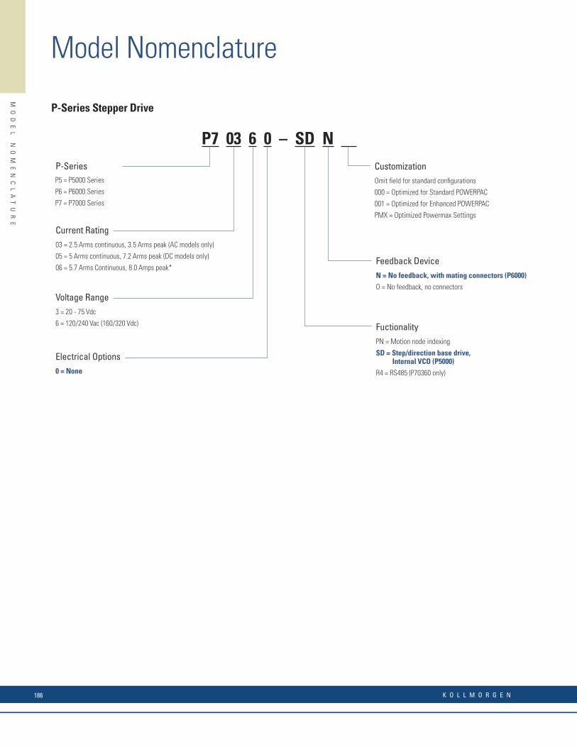
Model Nomenclature
MO
DE
L
NO
ME
NC
LA
TU
RE
Current Rating03 = 2.5 Arms continuous, 3.5 Arms peak (AC models only)
05 = 5 Arms continuous, 7.2 Arms peak (DC models only)
06 = 5.7 Arms Continuous, 8.0 Amps peak*
P7 03 6 0 – SD N
P-Series Stepper Drive
P-Series
Voltage Range3 = 20 - 75 Vdc
6 = 120/240 Vac (160/320 Vdc)
Electrical Options0 = None
CustomizationOmit fi eld for standard confi gurations
000 = Optimized for Standard POWERPAC
001 = Optimized for Enhanced POWERPAC
PMX = Optimized Powermax Settings
Feedback DeviceN = No feedback, with mating connectors (P6000)
O = No feedback, no connectors
FuctionalityPN = Motion node indexing
SD = Step/direction base drive, Internal VCO (P5000)
R4 = RS485 (P70360 only)
P5 = P5000 Series
P6 = P6000 Series
P7 = P7000 Series
K O L L M O R G E N186
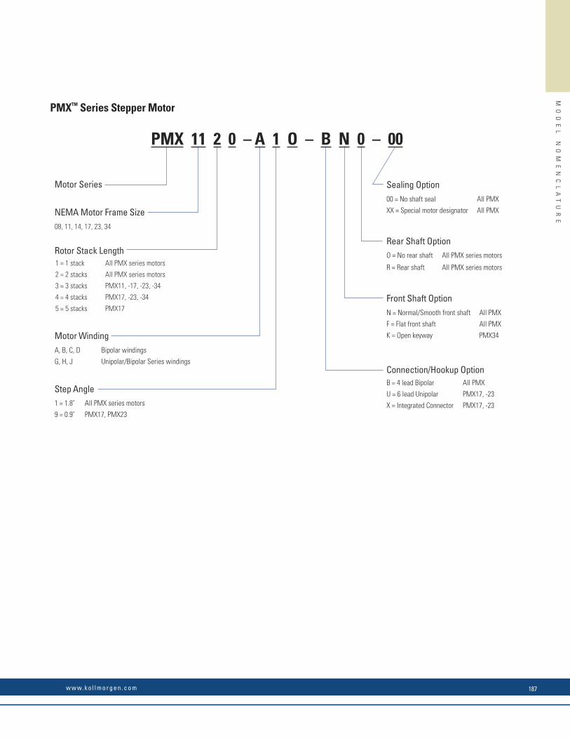
MO
DE
L
NO
ME
NC
LA
TU
RE
Sealing Option00 = No shaft seal All PMX
XX = Special motor designator All PMXNEMA Motor Frame Size08, 11, 14, 17, 23, 34
Rotor Stack Length
Motor WindingA, B, C, D Bipolar windings
G, H, J Unipolar/Bipolar Series windings
Motor Series
PMXTM Series Stepper Motor
Step Angle1 = 1.8˚ All PMX series motors
9 = 0.9˚ PMX17, PMX23
Rear Shaft OptionO = No rear shaft All PMX series motors
R = Rear shaft All PMX series motors
Front Shaft Option
Connection/Hookup Option
N = Normal/Smooth front shaft All PMX
F = Flat front shaft All PMX
K = Open keyway PMX34
B = 4 lead Bipolar All PMX
U = 6 lead Unipolar PMX17, -23
X = Integrated Connector PMX17, -23
1 = 1 stack All PMX series motors
2 = 2 stacks All PMX series motors
3 = 3 stacks PMX11, -17, -23, -34
4 = 4 stacks PMX17, -23, -34
5 = 5 stacks PMX17
PMX 11 2 0 – A 1 O – B N 0 – 00
w w w. k o l l m o r g e n . c o m 187

Model Nomenclature
MO
DE
L
NO
ME
NC
LA
TU
RE
Encoder OptionNS = No feedback
All options below require construction R or C
M1 = Encoder mounting provision (size 2 only). Requires shaft confi guration E
HD = 500 LPR encoder (size 2 only)
HJ = 512 LPR encoder (size 2 only)
M2 = HP encoder mounting provision (size 3,4 only). Requires shaft confi guration E
M3 = BEI encoder mounting provision (size 3,4 only). Requires shaft confi guration D
SS = Special, contact customer support
Size
2 = NEMA 23
frame size (2.25” dia,)
3 = NEMA 34
frame size (3.38”dia.)
4 = NEMA 42
frame size (4.28” dia.)
MountingN = NEMA (n/a 4 stacks)
H = Heavy duty NEMA
(opt. on 3 stacks, std. on 4 stacks)
S = Special, contact customer support
E & H Series Stepper Motor
Basic series
Number of Rotor StacksH = Half stack (H series only)
1 = 1 stack
2 = 2 stacks
3 = 3 stacks (size 3,4 only)
4 = 4 stacks (size 3 only)
Construction/Connection StyleR = Regular/leadwire
C = System MS connector
L = Splashproof/to terminal board via conduit connector: 1/2” NPS pipe thread (size 3,4 only)
M = Splashproof/to terminal board via conduit connect: metric PG11 pipe thread (size 3,4 only)
S = Special, contact customer support
Number of ConnectionsF = 8 lead
L = 4 lead series
H = 4 lead parallel
E = 6 lead
Shaft Confi guration(Diameter & Length)N = Single
D = Double (R or C construction only)
E = Double ended for encoder (R or C construction only, size 3,4 only)
S = Special, contact customer support
Rotor TypeL = Laminated
J = Low inertia (size 2 only, n/a with half stack motors)
Winding TypeT = Max, torque at low speed
P = Max. torque torque at high speed
A, B and C = Additional standards
S = Special, contact customer support
Special Sequence00 = Standard motor without shaft seal
01 = Standard motor with shaft seal (size 3 and 4 only)
Other numbers will be assigned for special motors
Shaft Modifi cations
N = Smooth (size 2,3 only)
(mounting confi g. N only)
F = Flat (size 2,3 only)
(mounting confi g. N only)
K = Straight key (size 3,4 only)
(mounting confi g. H only)
W = #303 Woodruff key (size 3 only)
(mounting confi g. N only)
S = Special
Note: Options shown in bold blue text are considered standard.
H = Standard construction
E = SIGMAX construction (n/a half stack)
E 3 3 H C H P – L E K – M2 – 01
Encoder OptionNS = No feedback
M2 = Encoder mounting provision (must use construction C or R and shaft confi guration E)
PD = 500 LPR encoder
PF = 1000 LPR encoder
SS = Special, contact customer support
Size3 = NEMA 34 frame size;
3.38” width/height, square frame
MountingH = Heavy duty NEMA
S = Special, contact customer support
NEMA 34 K & N Series Stepper Motor
K and N series
Length1 = 1 stack
2 = 2 stacks
3 = 3 stacks
4 = 4 stacks
Construction/Connection StyleR = Regular/leadwire
C = System MS connector
L = splashproof/to terminal board via conduit connector: 1/2” NPSC pipe thread
M = Splashproof/to terminal board via conduit connect: metric PG11 pipe thread
S = Special, contact customer support
Number of ConnectionsF = 8 lead (n/a C construction)
L = 4 lead series
H = 4 lead parallel
E = 6 lead (n/a C construction)
Shaft Confi guration(Diameter & Length)N = Single
D = Double (R or C construction only)
E = Double ended for encoder (R or C construction only)
Rotor TypeL = Laminated
Winding TypeH = Standard, 1 stack only
D, E, G, J, K, L = Standard
M = Standard, N/A on 1 stack
S = Special, contact customer support
Special Sequence00 = Standard motor without shaft seal
01 = Standard motor with shaft seal
Other numbers will be assigned for special motors
Shaft Modifi cationsK = Straight key
S = Special, contact customer support
N = Standard construction
K = Sigmax construction
Note: Options shown in bold blue text are considered standard.
N 3 3 H C H J – L E K – M2 – 01
K O L L M O R G E N188

MO
DE
L
NO
ME
NC
LA
TU
RE
Encoder OptionNS = No feedback
All options below require construction R or C
M1 = Encoder mounting provision (size 2 only). Requires shaft confi guration E
HD = 500 LPR encoder (size 2 only)
HJ = 512 LPR encoder (size 2 only)
M2 = HP encoder mounting provision (size 3,4 only). Requires shaft confi guration E
M3 = BEI encoder mounting provision (size 3,4 only). Requires shaft confi guration D
SS = Special, contact customer support
Size
2 = NEMA 23
frame size (2.25” dia,)
3 = NEMA 34
frame size (3.38”dia.)
4 = NEMA 42
frame size (4.28” dia.)
MountingN = NEMA (n/a 4 stacks)
H = Heavy duty NEMA
(opt. on 3 stacks, std. on 4 stacks)
S = Special, contact customer support
E & H Series Stepper Motor
Basic series
Number of Rotor StacksH = Half stack (H series only)
1 = 1 stack
2 = 2 stacks
3 = 3 stacks (size 3,4 only)
4 = 4 stacks (size 3 only)
Construction/Connection StyleR = Regular/leadwire
C = System MS connector
L = Splashproof/to terminal board via conduit connector: 1/2” NPS pipe thread (size 3,4 only)
M = Splashproof/to terminal board via conduit connect: metric PG11 pipe thread (size 3,4 only)
S = Special, contact customer support
Number of ConnectionsF = 8 lead
L = 4 lead series
H = 4 lead parallel
E = 6 lead
Shaft Confi guration(Diameter & Length)N = Single
D = Double (R or C construction only)
E = Double ended for encoder (R or C construction only, size 3,4 only)
S = Special, contact customer support
Rotor TypeL = Laminated
J = Low inertia (size 2 only, n/a with half stack motors)
Winding TypeT = Max, torque at low speed
P = Max. torque torque at high speed
A, B and C = Additional standards
S = Special, contact customer support
Special Sequence00 = Standard motor without shaft seal
01 = Standard motor with shaft seal (size 3 and 4 only)
Other numbers will be assigned for special motors
Shaft Modifi cations
N = Smooth (size 2,3 only)
(mounting confi g. N only)
F = Flat (size 2,3 only)
(mounting confi g. N only)
K = Straight key (size 3,4 only)
(mounting confi g. H only)
W = #303 Woodruff key (size 3 only)
(mounting confi g. N only)
S = Special
Note: Options shown in bold blue text are considered standard.
H = Standard construction
E = SIGMAX construction (n/a half stack)
E 3 3 H C H P – L E K – M2 – 01
Encoder OptionNS = No feedback
M2 = Encoder mounting provision (must use construction C or R and shaft confi guration E)
PD = 500 LPR encoder
PF = 1000 LPR encoder
SS = Special, contact customer support
Size3 = NEMA 34 frame size;
3.38” width/height, square frame
MountingH = Heavy duty NEMA
S = Special, contact customer support
NEMA 34 K & N Series Stepper Motor
K and N series
Length1 = 1 stack
2 = 2 stacks
3 = 3 stacks
4 = 4 stacks
Construction/Connection StyleR = Regular/leadwire
C = System MS connector
L = splashproof/to terminal board via conduit connector: 1/2” NPSC pipe thread
M = Splashproof/to terminal board via conduit connect: metric PG11 pipe thread
S = Special, contact customer support
Number of ConnectionsF = 8 lead (n/a C construction)
L = 4 lead series
H = 4 lead parallel
E = 6 lead (n/a C construction)
Shaft Confi guration(Diameter & Length)N = Single
D = Double (R or C construction only)
E = Double ended for encoder (R or C construction only)
Rotor TypeL = Laminated
Winding TypeH = Standard, 1 stack only
D, E, G, J, K, L = Standard
M = Standard, N/A on 1 stack
S = Special, contact customer support
Special Sequence00 = Standard motor without shaft seal
01 = Standard motor with shaft seal
Other numbers will be assigned for special motors
Shaft Modifi cationsK = Straight key
S = Special, contact customer support
N = Standard construction
K = Sigmax construction
Note: Options shown in bold blue text are considered standard.
N 3 3 H C H J – L E K – M2 – 01
w w w. k o l l m o r g e n . c o m 189
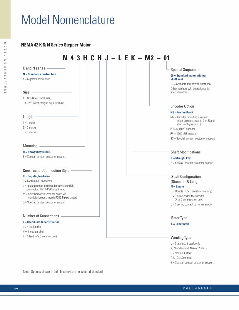
Model Nomenclature
MO
DE
L
NO
ME
NC
LA
TU
RE
Encoder OptionNS = No feedback
M2 = Encoder mounting provision (must use construction C or R and shaft confi guration E)
PD = 500 LPR encoder
PF = 1000 LPR encoder
SS = Special, contact customer support
Size4 = NEMA 42 frame size;
4.325” width/height, square frame
MountingH = Heavy duty NEMA
S = Special, contact customer support
NEMA 42 K & N Series Stepper Motor
K and N seriesN = Standard construction
K = Sigmax construction
Length1 = 1 stack
2 = 2 stacks
3 = 3 stacks
Construction/Connection StyleR = Regular/leadwire
C = System MS connector
L = splashproof/to terminal board via conduit connector: 1/2” NPSC pipe thread
M = Splashproof/to terminal board via conduit connect: metric PG13.5 pipe thread
S = Special, contact customer support
Number of ConnectionsF = 8 lead (n/a C construction)
L = 4 lead series
H = 4 lead parallel
E = 6 lead (n/a C construction)
Shaft Confi guration(Diameter & Length)N = Single
D = Double (R or C construction only)
E = Double ended for encoder (R or C construction only)
S = Special, contact customer support
Rotor TypeL = Laminated
Winding TypeJ = Standard, 1 stack only
K, N = Standard, N/A on 1 stack
L = N/A on 1 stack
F, M, G = Standard
S = Special, contact customer support
Special Sequence00 = Standard motor without shaft seal
01 = Standard motor with shaft seal
Other numbers will be assigned for special motors
Shaft Modifi cationsK = Straight key
S = Special, contact customer support
Note: Options shown in bold blue text are considered standard.
N 4 3 H C H J – L E K – M2 – 01
Shaft Confi guration(Diameter & Length)N = Single
D = Double
S = Special, contact customer support
Sequence NumberInsert 00 if all parts are standard.Other numbers will be assigned for special motors.
Encoder OptionNS = No Feedback
Use encoders below. You must specify shaft confi guration D (double ended)
Caution: An encoder with line driver output may be required for use with some stepper motor controls.
M1 = Encoder mounting provisions
HD = Encoder 500 LPR
HJ = Encoder 512 LPR
SS = Special, contact customer support
MountingN = NEMA
S = Special, contact customer support
ConstructionR = Regular
S = Special, contact customer support
TerminationX = Receptacle
F = 8 fl ying leads
S = Special, contact customer support
For X (receptacle) designation,Mating leaded connectors maybe ordered seperately.Optional GRN/YEL ground wireavailable.
M & P Series Stepper Motor
SeriesP = Standard
M = Enhanced (n/a half stack)
Size2 = NEMA 23
(2.25” across fl at)
Number of StacksH = Half stack
1 = 1 stack
2 = 2 stacks
Winding TypeA, B, C, D
S = Special, contact customer support
Shaft Modifi cationsN = Smooth
F = Flat
S = Special, contact customer support
Rotor TypeL = Standard
J = Low inertia (n/a half stack)
Note: Options shown in bold blue text are considered standard.
P 2 1 N R X A – L N N – N S – 00
K O L L M O R G E N190
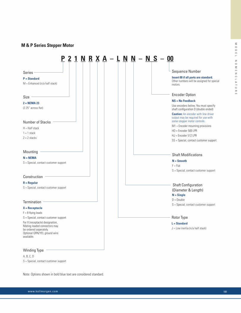
MO
DE
L
NO
ME
NC
LA
TU
RE
Encoder OptionNS = No feedback
M2 = Encoder mounting provision (must use construction C or R and shaft confi guration E)
PD = 500 LPR encoder
PF = 1000 LPR encoder
SS = Special, contact customer support
Size4 = NEMA 42 frame size;
4.325” width/height, square frame
MountingH = Heavy duty NEMA
S = Special, contact customer support
NEMA 42 K & N Series Stepper Motor
K and N seriesN = Standard construction
K = Sigmax construction
Length1 = 1 stack
2 = 2 stacks
3 = 3 stacks
Construction/Connection StyleR = Regular/leadwire
C = System MS connector
L = splashproof/to terminal board via conduit connector: 1/2” NPSC pipe thread
M = Splashproof/to terminal board via conduit connect: metric PG13.5 pipe thread
S = Special, contact customer support
Number of ConnectionsF = 8 lead (n/a C construction)
L = 4 lead series
H = 4 lead parallel
E = 6 lead (n/a C construction)
Shaft Confi guration(Diameter & Length)N = Single
D = Double (R or C construction only)
E = Double ended for encoder (R or C construction only)
S = Special, contact customer support
Rotor TypeL = Laminated
Winding TypeJ = Standard, 1 stack only
K, N = Standard, N/A on 1 stack
L = N/A on 1 stack
F, M, G = Standard
S = Special, contact customer support
Special Sequence00 = Standard motor without shaft seal
01 = Standard motor with shaft seal
Other numbers will be assigned for special motors
Shaft Modifi cationsK = Straight key
S = Special, contact customer support
Note: Options shown in bold blue text are considered standard.
N 4 3 H C H J – L E K – M2 – 01
Shaft Confi guration(Diameter & Length)N = Single
D = Double
S = Special, contact customer support
Sequence NumberInsert 00 if all parts are standard.Other numbers will be assigned for special motors.
Encoder OptionNS = No Feedback
Use encoders below. You must specify shaft confi guration D (double ended)
Caution: An encoder with line driver output may be required for use with some stepper motor controls.
M1 = Encoder mounting provisions
HD = Encoder 500 LPR
HJ = Encoder 512 LPR
SS = Special, contact customer support
MountingN = NEMA
S = Special, contact customer support
ConstructionR = Regular
S = Special, contact customer support
TerminationX = Receptacle
F = 8 fl ying leads
S = Special, contact customer support
For X (receptacle) designation,Mating leaded connectors maybe ordered seperately.Optional GRN/YEL ground wireavailable.
M & P Series Stepper Motor
SeriesP = Standard
M = Enhanced (n/a half stack)
Size2 = NEMA 23
(2.25” across fl at)
Number of StacksH = Half stack
1 = 1 stack
2 = 2 stacks
Winding TypeA, B, C, D
S = Special, contact customer support
Shaft Modifi cationsN = Smooth
F = Flat
S = Special, contact customer support
Rotor TypeL = Standard
J = Low inertia (n/a half stack)
Note: Options shown in bold blue text are considered standard.
P 2 1 N R X A – L N N – N S – 00
w w w. k o l l m o r g e n . c o m 191

Model Nomenclature
MO
DE
L
NO
ME
NC
LA
TU
RE
Lead Confi guration/MountFD = 8 connections, round fl ange
Frame Size17 = 170 mm
Stack length2 = double stack
MH 17 2 FD 8030 -
MH Series
MH172 Stepper Motor
Identifi cation Suffi x
Options
Omit for no options
E = Rear shaft extension
C2 = 200 line six output encoder
C2 = 200 line six output encoder
C4 = 400 line six output encoder
C5 = 500 line six output encoder
Note: Options shown in bold blue text are considered standard.
Rear OptionsU = No shaft extension
EU = Shaft extension
Frame Size9 = 90 mm
11 = 110mm
Number of Stacks1 = 1 Stack
2 = 2 Stacks
3 = 3 Stacks
MX 9 1 – F F – 206 U
MX Series Hazardous Duty Stepper Motor
Connection/MountFD
FF
FJ
Identifi cation Suffi x
MX SeriesMeets UL Class1, Division1,
Group D requirements
Note: Options shown in bold blue text are considered standard.
See outline drawing for details
Shaft Modifi cationsF = Flat
N = Smooth
S = Special, contact factory
Special SequenceInsert 00 if all parts are standard.Any other numbers are factoryassigned
Ecoder Option
C2 = Encoder 200 LPR w/line driver3
C4 = Encoder 400 LPR w/line driver3
C5 = Encoder 500 LPR w/line driver3
M4 = Encoder mtg. provisions3
NS = No Feedback
SS = Special, contact factory
Motor Frame Size2 = NEMA 23 (2.25” square)
Rotor Stack Length
Mounting Confi gurationN = NEMA 23
S = Special, contact factory
T Series
T2 Series Stepper Motor
Construction / HookupC = MS connector
L = Terminal box via 1/2” NPT pipe thread
M = Terminal box via metric PG11 pipe thread
R = Regular - leadwire
S = Special, contact factory
Windings / Leads
E = 6 leads (Unipolar)1
H = 4 leads (Parallel connected)
L = 4 leads (Series connected)
S = Special, contact factory
Winding TypeD, E, F, G, H, J, K
S = Special, contact factory
Shaft Confi guration
D = Rear shaf extension2
N = No rear shaft extension
S = Special, contact factory
Rotor TypeL = Laminated
Notes:
1. N/A with “C” Construction / Hookup option
2. “R” Construction / Hookup only, required for motors with encoders
3. Requires “R” Construction / Hookup option and “D” Shaft Confi guration option
H = Half stack
1 = 1 stack
2 = 2 stacks
3 = 3 stacks
T 2 3 N R H J – L N N – N – 00
K O L L M O R G E N192

MO
DE
L
NO
ME
NC
LA
TU
RE
Lead Confi guration/MountFD = 8 connections, round fl ange
Frame Size17 = 170 mm
Stack length2 = double stack
MH 17 2 FD 8030 -
MH Series
MH172 Stepper Motor
Identifi cation Suffi x
Options
Omit for no options
E = Rear shaft extension
C2 = 200 line six output encoder
C2 = 200 line six output encoder
C4 = 400 line six output encoder
C5 = 500 line six output encoder
Note: Options shown in bold blue text are considered standard.
Rear OptionsU = No shaft extension
EU = Shaft extension
Frame Size9 = 90 mm
11 = 110mm
Number of Stacks1 = 1 Stack
2 = 2 Stacks
3 = 3 Stacks
MX 9 1 – F F – 206 U
MX Series Hazardous Duty Stepper Motor
Connection/MountFD
FF
FJ
Identifi cation Suffi x
MX SeriesMeets UL Class1, Division1,
Group D requirements
Note: Options shown in bold blue text are considered standard.
See outline drawing for details
Shaft Modifi cationsF = Flat
N = Smooth
S = Special, contact factory
Special SequenceInsert 00 if all parts are standard.Any other numbers are factoryassigned
Ecoder Option
C2 = Encoder 200 LPR w/line driver3
C4 = Encoder 400 LPR w/line driver3
C5 = Encoder 500 LPR w/line driver3
M4 = Encoder mtg. provisions3
NS = No Feedback
SS = Special, contact factory
Motor Frame Size2 = NEMA 23 (2.25” square)
Rotor Stack Length
Mounting Confi gurationN = NEMA 23
S = Special, contact factory
T Series
T2 Series Stepper Motor
Construction / HookupC = MS connector
L = Terminal box via 1/2” NPT pipe thread
M = Terminal box via metric PG11 pipe thread
R = Regular - leadwire
S = Special, contact factory
Windings / Leads
E = 6 leads (Unipolar)1
H = 4 leads (Parallel connected)
L = 4 leads (Series connected)
S = Special, contact factory
Winding TypeD, E, F, G, H, J, K
S = Special, contact factory
Shaft Confi guration
D = Rear shaf extension2
N = No rear shaft extension
S = Special, contact factory
Rotor TypeL = Laminated
Notes:
1. N/A with “C” Construction / Hookup option
2. “R” Construction / Hookup only, required for motors with encoders
3. Requires “R” Construction / Hookup option and “D” Shaft Confi guration option
H = Half stack
1 = 1 stack
2 = 2 stacks
3 = 3 stacks
T 2 3 N R H J – L N N – N – 00
w w w. k o l l m o r g e n . c o m 193

Model Nomenclature
MO
DE
L
NO
ME
NC
LA
TU
RE
TerminationL = leaded
T = Terminal box
KS Series OptionsE = Rear shaft
(omit for no options)
Number of Stacks1 = 1 stack
2 = 2 stacks
3 = 3 stacks
KS Series AC Synchronous Motor
Frame Size06 = NEMA size 23
FrequencyW = 60 Hz
X = 50 Hz
Y = 50/60 Hz
VoltageT1 = 120 Vac
T2 = 240 Vac
Note: Options shown in bold blue text are considered standard.
KS L 06 2 T1 Y
X Series OptionsContact customer support for option availability
Omit for no options
X 25 2
X(CE) Series AC Synchronous Motor
X = Meets UL Class 1, Group D requirements
XCE = Meets CE0081 II2 G Exd IIC T5 Gb requirements
Minimum Running Torque (oz-in)24x = 240 oz-in
25x = 250 oz-in
45x = 450 oz-in
70x = 700 oz-in
110x = 1100 oz-in
150x = 1500 oz-in
180x = 1800 oz-in
Voltage0 or 1 = 120 Vac (model dependent)
2 = 240 Vac
Note: Options shown in bold blue text are considered standard.
SS Series
NEMA Size 23
SS Series AC Synchronous Motor
Minimum Running Torque (oz-in)
NEMA Size 24
5x = 50 oz-in
8x = 80 oz-in
24x = 240 oz-in
45x = 450 oz-in
NEMA Size 42
15xB = 150 oz-in
25xB = 250 oz-in
40xB = 400 oz-in
70xB = 700 oz-in
NEMA Size 66
180x = 1800 oz-in
Gearbox
Note: Options shown in bold blue text are considered standard.
25 = 25 oz-in
9x = 90 oz-in
13x = 130 oz-in
SS 24 1 L G60
GXX where XX = reducer ratioGXX where XX = reducer ratio
Voltage0 or 1 = 120 Vac (model dependent)
Omit for 25 oz-in models (25 oz-in models are 120 Vac)
2 = 240 Vac
OptionsL = Leads
T = Terminal box
(blank) = connector on leads
C = Covered capacitor
CT = Capacitor in terminal box
E = Rear shaft extension
MO
DE
L
NO
ME
NC
LA
TU
RE
K O L L M O R G E N194
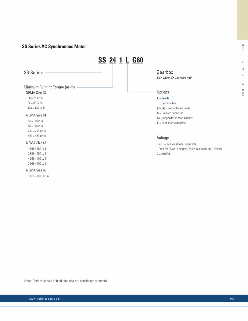
Kollmorgen offers 5-day lead-time on nearly 1,000,000 COTS products, all with best-in-class performance and quality.
When COTS is not quite the best way to realize a totally optimized system, Kollmorgen can offer co-engineered solutions to meet your most diffi cult challenges and advance your competitive position. Drawing on a wealth of knowledge and expertise, our engineering support team will work alongside with you to build a solution that differentiates your machine and improves your bottom line.
Here are just few examples of how Kollmorgen delivers real value to companies likes yours:
What You Need Why Motion Matters Kollmorgen Co-Engineering Results
30% Increase in Throughput • Low inertia servomotors
• High bandwidth servo loops
• Simple, accurate, graphical programming tools
Using the Kollmorgen Automation SuiteTM
graphical camming design tool, Pipe NetworkTM and low-inertia AKM servomotors, a major supplier of diabetic test labs increased throughput by more than 30% while improving accuracy and reducing scrap.
50% Increase in Accuracy and Quality • Low cogging frameless servomotor
• Advaced observers and bi-quad fi lters
• Fast control loop update rates (.67μs)
Using our AKD servo drive, a next-generation CT scanning manufacturer achieved more than 50% improvement in velocity ripple to produce the most accurate and detailed medical images possible while overcoming an extremely high moment of inertia.
25% Increase in Reliability
(Overall Equipment Effectiveness)
• Innovative Cartridge Direct Drive RotaryTM DDR motor
• Eliminating parts on the machine
• No additional wearing components
Using Kollmorgen’s award-winning Cartridge DDR sevomotor technology, we eliminated more than 60 parts in a die-cutting machine and increased the OEE by 25% and throughput by 20%.
50% Reduction in Waste • Superior motor/drive system bandwidth
• DDR technology: – eliminates gearbox – 20X more accurate than geared solution
We helped a manufacturer of pharmaceutical packaging machines incorporate Housed DDR motors to increase the throughput by 35% and reduce scrap by more than 50% through more accurate alignment of the capsules.
Co-Engineering CapabilitiesM
OD
EL
N
OM
EN
CL
AT
UR
E
TerminationL = leaded
T = Terminal box
KS Series OptionsE = Rear shaft
(omit for no options)
Number of Stacks1 = 1 stack
2 = 2 stacks
3 = 3 stacks
KS Series AC Synchronous Motor
Frame Size06 = NEMA size 23
FrequencyW = 60 Hz
X = 50 Hz
Y = 50/60 Hz
VoltageT1 = 120 Vac
T2 = 240 Vac
Note: Options shown in bold blue text are considered standard.
KS L 06 2 T1 Y
X Series OptionsContact customer support for option availability
Omit for no options
X 25 2
X(CE) Series AC Synchronous Motor
X = Meets UL Class 1, Group D requirements
XCE = Meets CE0081 II2 G Exd IIC T5 Gb requirements
Minimum Running Torque (oz-in)24x = 240 oz-in
25x = 250 oz-in
45x = 450 oz-in
70x = 700 oz-in
110x = 1100 oz-in
150x = 1500 oz-in
180x = 1800 oz-in
Voltage0 or 1 = 120 Vac (model dependent)
2 = 240 Vac
Note: Options shown in bold blue text are considered standard.
SS Series
NEMA Size 23
SS Series AC Synchronous Motor
Minimum Running Torque (oz-in)
NEMA Size 24
5x = 50 oz-in
8x = 80 oz-in
24x = 240 oz-in
45x = 450 oz-in
NEMA Size 42
15xB = 150 oz-in
25xB = 250 oz-in
40xB = 400 oz-in
70xB = 700 oz-in
NEMA Size 66
180x = 1800 oz-in
Gearbox
Note: Options shown in bold blue text are considered standard.
25 = 25 oz-in
9x = 90 oz-in
13x = 130 oz-in
SS 24 1 L G60
GXX where XX = reducer ratioGXX where XX = reducer ratio
Voltage0 or 1 = 120 Vac (model dependent)
Omit for 25 oz-in models (25 oz-in models are 120 Vac)
2 = 240 Vac
OptionsL = Leads
T = Terminal box
(blank) = connector on leads
C = Covered capacitor
CT = Capacitor in terminal box
E = Rear shaft extension
MO
DE
L
NO
ME
NC
LA
TU
RE
w w w. k o l l m o r g e n . c o m 195

Model Nomenclature
MO
DE
L
NO
ME
NC
LA
TU
RE
Micron™ TRUE Planetary™ Gearbox
Gearbox Series
AT = AquaTRUE™
NT = NemaTRUE™
NTP = NemaTRUE PLUS™
NTR = NemaTRUE 90™
XT = XTRUE™
ET = EverTRUE™
DT = DuraTRUE™
DTR = DuraTRUE 90™
DTRS = DuraTRUE™ slimline
DTRH = DuraTRUE™ hollow shaft
DTRD = DuraTRUE™ dual shaft
VT = ValueTRUE™
VTR = ValueTRUE 90™
UT = UltraTRUE™
UTR = UltraTRUE 90™
Motor Model Number
RediMount number (if available) or motor manufacturer and model number
Customer Options
0 = None
S = Special
H = High precision (for NemaTRUE™ product line only)
Gearbox Ratio
AquaTRUE™
060 = Size 60080 = Size 80120 = Size 120160 = Size 160
NemaTRUE™
NemaTRUE PLUS™
NemaTRUE 90™
17 = Size 1723 = Size 2334 = Size 3442 = Size 4260 = Size 6090 = Size 90115 = Size 115
XTRUE™
040 = Size 40060 = Size 60080 = Size 80120 = Size 120160 = Size 160
EverTRUE™
10 = Size 1014 = Size 1418 = Size 18
DuraTRUE™
DuraTRUE 90™
DuraTRUE™ SlimlineDuraTRUE™ Hollow ShaftDuraTRUE™ Dual Shaft60 = Size 6090 = Size 90115 = Size 115142 = Size 142
ValueTRUE™
ValueTRUE 90™
006 = Size 60075 = Size 75090 = Size 90010 = Size 10115 = Size 115014 = Size 14018 = Size 18022 = Size 22
UltraTRUE™
UltraTRUE 90™
006 = Size 60075 = Size 75090 = Size 90010 = Size 10115 = Size 115014 = Size 14018 = Size 18022 = Size 22 (UltraTRUE™ only)
Gearbox Size
DTR 115 – 005 – 0 – ( )
See ratio availability in corresponding gearbox section (pp 109-113)
EC Series Electric Cylinder with AKM Servo Motors
EC2 – AKM23D – BNC – 10 – 05B – 300 – MP2 – FT1M – ( ) – CO
CableCO = No cable supplies, motor includes connectors. Default for all AKM Servo Motors; select cable as an accessory.*Contact customer service for EC1
Options (add multiple in the following sequence, omit if no options)BA24 = 24 Vdc brake on actuator (EC1 only, not available with 10L ratio or MS1 mounting options)BS24 = 24 Vdc brake on ballscrew (not available with EC1 or 10L ratio, or with MF2(x), MF3(x), MS1, MP2(x), MP3(x) mounting options)BS115 = 115 Vac brake on ballscrew (not available with EC1 or 10L ratio, or with MF2(x), MF3(x), MS1, MP2(x), MP3(x) mounting options)PB = Protective boot*L = Linear potentiometer (only valid through 600 mm stroke, standard lengths)*17X = NEMA 17 mountless motor (EC1 only)
Stroke Length50 = 50 mm total stroke100 = 100 mm total stroke150 = 150 mm total stroke200 = 200 mm total stroke250 = 250 mm total stroke300 = 300 mm total stroke450 = 450 mm total stroke600 = 600 mm total stroke750 = 700 mm total stroke1000 = 1,000 mm total stroke1250 = 1,250 mm total stroke1500 = 1,500 mm total strokennn = Custom stroke lengths available in 10 mm increments
AllAllAllAllEC2, EC3, EC4, EC5EC2, EC3, EC4, EC5EC2, EC3, EC4, EC5EC2, EC3, EC4, EC5EC2, EC3, EC4, EC5EC3, EC4, EC5EC4, EC5EC4, EC5
Rod EndsFC2 = Clevis (includes MT1M)FS2 = Spherical joint (includes FT1M)FT1M = Female thread (metric)FT1E = Female thread (English)MT1M = Male thread (metric)MT1E = Male thread (English)
AvailableAllAllAllEC2, EC3, EC4, EC5AllEC2, EC3, EC4, EC5
Screw Lead03M = 3 mm/rev ballscrew05B = 5 mm/rev ballscrew10B = 10 mm/rev ballscrew16B = 16 mm/rev ballscrew25B = 25 mm/rev ballscrew32B = 32 mm/rev ballscrew04A = 4 mm/rev lead screw
AvailableEC1EC2, EC3EC3, EC4, EC5EC2, EC3EC4EC5EC2, EC3
AvailableAKM2AKM1, AKM2AKM4, AKM5AKM1, AKM2, AKM4, AKM5AKM2, AKM4, AKM5AKM1, AKM2, AKM4, AKM5AKM1, AKM2, AKM4, AKM5AKM1, AKM2, AKM4, AKM5
Motor OptionsB n n = Rotatable IP65 connectors C n n = 0.5 m shielded cables w/ IP65 connectorsC n n = Rotatable IP65 connectorsn N n = No braken 2 n = 24 Vdc power-off holding brakenn R = Resolvernn 2 = 2048 LPR incremental comm. encodernn C = Smart Feedback Device (SFD)
EC SeriesEC1EC2EC3EC4EC5
Note: Options shown in bold blue text are considered standard.
EC Series
Motor Options
Drive Ratio
Screw Lead
Stroke Length
Cylinder Mounting
Cable OptionRod Ends OptionsMotor Type
Cylinder MountingMF1 = Front rectangular fl angeMF1E = Front rectangular fl ange (English)MF1M = Front rectangular fl ange (metric)MF2 = Rear rectangular fl angeMF2E = Rear rectangular fl ange (English)MF2M = Rear rectangular fl ange (metric)MF3 = Front & rear rectangular fl angeMF3E = Front & rear rectangular fl angeMF3M = Front & rear rectangular fl angeMP2 = Rear double clevis without pivot baseMP3 = Rear double clevis with pivot baseMS1 = Side end angleMS2 = Side lugsMS6M = Side tapped holes (metric)MS6E = Side tapped holes (English)MT4 = Trunnion
AvailableEC1, EC2, EC3, EC5EC4 onlyEC4 onlyEC2, EC3, EC5 EC4 onlyEC4 onlyEC2, EC3, EC5EC4 onlyEC4 onlyAllAllEC2, EC3AllAllEC2, EC3, EC4, EC5EC2, EC3, EC4, EC5
AvailableAllAll
EC2, EC3, EC4, EC5Not valid for EC3-AKM42EC1 onlyEC2, EC3, EC4, EC5EC3 onlyEC2, EC4, EC5
Drive Ratio10 = 1.0:1 drive belt/pulley (EC1 – helical)10L = 1.0:1 inline coupling (direct 1:1 coupling is the only ratio available for inline models)15 = 1.5:1 drive belt/pulley20 = 2.0:1 drive belt/pulley (EC1 – helical)40 = 4.0:1 helical gears50 = 5.0:1 helical gears70 = 7.1:1 helical gears100 = 10.0:1 helical gears
Available
Motor TypeAKM11B = AKM11B-ANCNx-00 brushless servoAKM13C = AKM13C-ANCNx-00 brushless servoAKM23D = AKM23D-EFxxx-00 brushless servoAKM23C = AKM23C-EFxxx-00 brushless servoAKM42G = AKM42G-EKxxx-00 brushless servoAKM42E = AKM42E-EKxxx-00 brushless servoAKM52G = AKM52G-EKxxx-00 brushless servoAKM52H = AKM52H-EKxxx-00 brushless servoAKM52L = AKM52L-EKxxx-00 brushless servoX = Customer-supplied motor (motor described in Options element of part number)
AvailableEC1EC1EC2, EC3EC2, EC3EC3, EC4, EC5EC3, EC4, EC5EC4, EC5EC4, EC5EC4, EC5All
K O L L M O R G E N196

MO
DE
L
NO
ME
NC
LA
TU
RE
Micron™ TRUE Planetary™ Gearbox
Gearbox Series
AT = AquaTRUE™
NT = NemaTRUE™
NTP = NemaTRUE PLUS™
NTR = NemaTRUE 90™
XT = XTRUE™
ET = EverTRUE™
DT = DuraTRUE™
DTR = DuraTRUE 90™
DTRS = DuraTRUE™ slimline
DTRH = DuraTRUE™ hollow shaft
DTRD = DuraTRUE™ dual shaft
VT = ValueTRUE™
VTR = ValueTRUE 90™
UT = UltraTRUE™
UTR = UltraTRUE 90™
Motor Model Number
RediMount number (if available) or motor manufacturer and model number
Customer Options
0 = None
S = Special
H = High precision (for NemaTRUE™ product line only)
Gearbox Ratio
AquaTRUE™
060 = Size 60080 = Size 80120 = Size 120160 = Size 160
NemaTRUE™
NemaTRUE PLUS™
NemaTRUE 90™
17 = Size 1723 = Size 2334 = Size 3442 = Size 4260 = Size 6090 = Size 90115 = Size 115
XTRUE™
040 = Size 40060 = Size 60080 = Size 80120 = Size 120160 = Size 160
EverTRUE™
10 = Size 1014 = Size 1418 = Size 18
DuraTRUE™
DuraTRUE 90™
DuraTRUE™ SlimlineDuraTRUE™ Hollow ShaftDuraTRUE™ Dual Shaft60 = Size 6090 = Size 90115 = Size 115142 = Size 142
ValueTRUE™
ValueTRUE 90™
006 = Size 60075 = Size 75090 = Size 90010 = Size 10115 = Size 115014 = Size 14018 = Size 18022 = Size 22
UltraTRUE™
UltraTRUE 90™
006 = Size 60075 = Size 75090 = Size 90010 = Size 10115 = Size 115014 = Size 14018 = Size 18022 = Size 22 (UltraTRUE™ only)
Gearbox Size
DTR 115 – 005 – 0 – ( )
See ratio availability in corresponding gearbox section (pp 109-113)
EC Series Electric Cylinder with AKM Servo Motors
EC2 – AKM23D – BNC – 10 – 05B – 300 – MP2 – FT1M – ( ) – CO
CableCO = No cable supplies, motor includes connectors. Default for all AKM Servo Motors; select cable as an accessory.*Contact customer service for EC1
Options (add multiple in the following sequence, omit if no options)BA24 = 24 Vdc brake on actuator (EC1 only, not available with 10L ratio or MS1 mounting options)BS24 = 24 Vdc brake on ballscrew (not available with EC1 or 10L ratio, or with MF2(x), MF3(x), MS1, MP2(x), MP3(x) mounting options)BS115 = 115 Vac brake on ballscrew (not available with EC1 or 10L ratio, or with MF2(x), MF3(x), MS1, MP2(x), MP3(x) mounting options)PB = Protective boot*L = Linear potentiometer (only valid through 600 mm stroke, standard lengths)*17X = NEMA 17 mountless motor (EC1 only)
Stroke Length50 = 50 mm total stroke100 = 100 mm total stroke150 = 150 mm total stroke200 = 200 mm total stroke250 = 250 mm total stroke300 = 300 mm total stroke450 = 450 mm total stroke600 = 600 mm total stroke750 = 700 mm total stroke1000 = 1,000 mm total stroke1250 = 1,250 mm total stroke1500 = 1,500 mm total strokennn = Custom stroke lengths available in 10 mm increments
AllAllAllAllEC2, EC3, EC4, EC5EC2, EC3, EC4, EC5EC2, EC3, EC4, EC5EC2, EC3, EC4, EC5EC2, EC3, EC4, EC5EC3, EC4, EC5EC4, EC5EC4, EC5
Rod EndsFC2 = Clevis (includes MT1M)FS2 = Spherical joint (includes FT1M)FT1M = Female thread (metric)FT1E = Female thread (English)MT1M = Male thread (metric)MT1E = Male thread (English)
AvailableAllAllAllEC2, EC3, EC4, EC5AllEC2, EC3, EC4, EC5
Screw Lead03M = 3 mm/rev ballscrew05B = 5 mm/rev ballscrew10B = 10 mm/rev ballscrew16B = 16 mm/rev ballscrew25B = 25 mm/rev ballscrew32B = 32 mm/rev ballscrew04A = 4 mm/rev lead screw
AvailableEC1EC2, EC3EC3, EC4, EC5EC2, EC3EC4EC5EC2, EC3
AvailableAKM2AKM1, AKM2AKM4, AKM5AKM1, AKM2, AKM4, AKM5AKM2, AKM4, AKM5AKM1, AKM2, AKM4, AKM5AKM1, AKM2, AKM4, AKM5AKM1, AKM2, AKM4, AKM5
Motor OptionsB n n = Rotatable IP65 connectors C n n = 0.5 m shielded cables w/ IP65 connectorsC n n = Rotatable IP65 connectorsn N n = No braken 2 n = 24 Vdc power-off holding brakenn R = Resolvernn 2 = 2048 LPR incremental comm. encodernn C = Smart Feedback Device (SFD)
EC SeriesEC1EC2EC3EC4EC5
Note: Options shown in bold blue text are considered standard.
EC Series
Motor Options
Drive Ratio
Screw Lead
Stroke Length
Cylinder Mounting
Cable OptionRod Ends OptionsMotor Type
Cylinder MountingMF1 = Front rectangular fl angeMF1E = Front rectangular fl ange (English)MF1M = Front rectangular fl ange (metric)MF2 = Rear rectangular fl angeMF2E = Rear rectangular fl ange (English)MF2M = Rear rectangular fl ange (metric)MF3 = Front & rear rectangular fl angeMF3E = Front & rear rectangular fl angeMF3M = Front & rear rectangular fl angeMP2 = Rear double clevis without pivot baseMP3 = Rear double clevis with pivot baseMS1 = Side end angleMS2 = Side lugsMS6M = Side tapped holes (metric)MS6E = Side tapped holes (English)MT4 = Trunnion
AvailableEC1, EC2, EC3, EC5EC4 onlyEC4 onlyEC2, EC3, EC5 EC4 onlyEC4 onlyEC2, EC3, EC5EC4 onlyEC4 onlyAllAllEC2, EC3AllAllEC2, EC3, EC4, EC5EC2, EC3, EC4, EC5
AvailableAllAll
EC2, EC3, EC4, EC5Not valid for EC3-AKM42EC1 onlyEC2, EC3, EC4, EC5EC3 onlyEC2, EC4, EC5
Drive Ratio10 = 1.0:1 drive belt/pulley (EC1 – helical)10L = 1.0:1 inline coupling (direct 1:1 coupling is the only ratio available for inline models)15 = 1.5:1 drive belt/pulley20 = 2.0:1 drive belt/pulley (EC1 – helical)40 = 4.0:1 helical gears50 = 5.0:1 helical gears70 = 7.1:1 helical gears100 = 10.0:1 helical gears
Available
Motor TypeAKM11B = AKM11B-ANCNx-00 brushless servoAKM13C = AKM13C-ANCNx-00 brushless servoAKM23D = AKM23D-EFxxx-00 brushless servoAKM23C = AKM23C-EFxxx-00 brushless servoAKM42G = AKM42G-EKxxx-00 brushless servoAKM42E = AKM42E-EKxxx-00 brushless servoAKM52G = AKM52G-EKxxx-00 brushless servoAKM52H = AKM52H-EKxxx-00 brushless servoAKM52L = AKM52L-EKxxx-00 brushless servoX = Customer-supplied motor (motor described in Options element of part number)
AvailableEC1EC1EC2, EC3EC2, EC3EC3, EC4, EC5EC3, EC4, EC5EC4, EC5EC4, EC5EC4, EC5All
w w w. k o l l m o r g e n . c o m 197
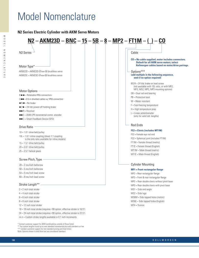
Model Nomenclature
MO
DE
L
NO
ME
NC
LA
TU
RE
N2 Series
B n n = Rotatable IP65 connectors
C nn = 0.5 m shielded cables w/ IP65 connectors
n N n = No brake
n 2 n = 24 Vdc power-off holding brake
nn R = Resolver
nn 2 = 2048 LPR incremental comm. encoder
nn C = Smart Feedback Device (SFD)
Stroke Length**2 = 2 inch total stroke
4 = 4 inch total stroke
6 = 6 inch total stroke
8 = 8 inch total stroke
12 = 12 inch total stroke
18 = 18 inch total stroke (requires -DB option, effective stroke is 16.5")
24 = 24 inch total stroke (requires -DB option, effective stroke is 22.5")
nn.n = Custom stroke lengths available in 0.1 inch increments
Cylinder MountingMF1 = Front rectangular fl ange
MF2 = Rear rectangular fl ange
MF3 = Front & rear rectangular fl ange
MP2 = Rear double clevis without pivot base
MP3 = Rear double clevis with pivot base
MS1 = Side end angle
MS2 = Side lugs
MS6M = Side tapped holes (metric)
MS6E = Side tapped holes (English)
MT4 = Trunion
Rod Ends
FC2 = Clevis (includes MT1M)
FE2 = Female eye rod end
FS2 = Spherical joint (includes FT1M)
FT1M = Female thread (metric)
FT1E = Female thread (English)
MT1M = Male thread (metric)
MT1E = Male thread (English)
Cable
CO = No cable supplied, motor includes connectors. Default for all AKM servo motors; select Kollmorgen cables based on motor/drive pairings.
Screw Pitch, Type
2B = 2 rev/inch ballscrew
5B = 5 rev/inch ballscrew
5A = 5 rev/inch lead screw
8A = 8 rev/inch lead screw
Drive Ratio
10 = 1.0:1 drive belt/pulley
10L = 1.0:1 inline coupling (direct 1:1 coupling is the only ratio available for inline models)
15 = 1.5:1 drive belt/pulley
20 = 2.0:1 drive belt/pulley
25 = 2.5:1 helical gears
Motor Type*AKM23D = AKM23D-EFxxx-00 brushless servo
AKM23C = AKM23C-EFxxx-00 brushless servo
* Contact customer support for AKM combinations outside of those listed.** For custom lengths round up to next standard incremental plus add standard cut fee.*** Contact customer support for non-standard pricing and lead times.Note: Options shown in bold blue text are considered standard.
BS24 = 24 Vdc brake on lead screw (not available with 10L ratio, or with MF2, MF3, MS2, MP2, MP3 mounting options)
DB = Dual rod end bearing
PB = Protective boot
W = Water resistant
F = Sub-freezing temperature
H = High temperature prep
L = Linear potentiometer (only for valid std. lengths)
Options*** (add multiple in the following sequence, omit if no option required)
N2 – AKM23D – BNC – 15 – 5B – 8 – MP2 – FT1M – ( ) – CO
N2 Series Electric Cylinder with AKM Servo Motors
Motor Options
R SeriesR2A, R3, R4
* Contact customer support for AKM combinations outside of those listed.** For custom lengths round up to next standard incremental plus add standard cut fee.*** Contact customer support if C0 is not selected. Note: Options shown in bold blue text are considered standard.
R2A, R3, R4R2A, R3, R4R2A, R3, R4R2A, R3, R4R2A, R3, R4R2A, R3, R4
R2A, R3, R4R2A, R3, R4R2A, R3, R4R2A, R3, R4
AvailableMotor OrientationBelt optionsAR = Motor housing rotated above/rightBR = Motor housing rotated behind/rightCR = Motor housing rotated under/rightAL = Motor housing rotated above/leftBL = Motor housing rotated behind/leftCL = Motor housing rotated under/left
Screw optionsI = Motor mounted inlineP = Motor mounted parallelPR = Motor mounted parallel/rightPL = Motor mounted parallel/left
R2AR2AR2AR2AR3, R4R3, R4R3, R4
AvailableMounting StyleMF3 = Front & rear rectangular fl angesMS1 = Side end anglesMS5 = Adjustable feetMS6 = Side tapped mounting holesA = Side angle bracketsB = Adjustable T-nutsC = Front & rear rectangular fl anges
R2A, R3, R4
R2A, R3, R4
R2A, R3, R4
R2AR2AR3, R4R3, R4R2A
R2A
R4R4R2A, R3, R4R2A
Available
R3, R4R3, R4
Available
S = Single carriageDxx = Dual carriage (xx = center distance between dual carriages in inches – contact customer support for lengths)
Carriage(omit this fi eld for R2A models)
R2A, R3, R4R2A, R3, R4
Available
E = English carriage & mounting dimensionsM = Metric carriage & mounting dimensions
English/Metric (carriage/mounting)
Motor Type*AKM23C = AKM23C-EFxxx-00 brushless servoAKM23D = AKM23D-EFxxx-00 brushless servoAKM42E = AKM42E-EKxxx-00 brushless servoAKM42G = AKM42G-EKxxx-00 brushless servoAKM52G = AKM52G-EKxxx-00 brushless servoAKM52H = AKM52H-EKxxx-00 brushless servo
AvailableR2A, R3R2A, R3R3, R4R3, R4R4R4
Options***BS24 = 24 Vdc brake on lead screw (Screw option only, n/a with inline models, MF3 or “C” options)BS115 = 115 Vdc brake on lead screw (Screw option only, n/a with inline models, MF3 or “C” options)BS230 = 230 Vdc brake on lead screw (Screw option only, n/a with inline models, MF3 or “C” options)WR = Water resistant seal option rightWL = Water resistant seal option leftGR = Lube port, right sideGL = Lube port, left sideDC1 = Idler carriage between driven carriage and non-motor endDC2 = Idler carriage between driven carriage and motor endVR = Breather vent, fi tting, tubing, right sideVL = Breather vent, fi tting, tubing, left sideC0 = No motor cableS = Stub shaft
AvailableR2A, R3R2A, R3R4R2A, R3R4R2A, R3R2A, R3, R4
Linear Drive Type5A = 5 pitch (0.2" lead) lead screw8A = 8 pitch (0.125" lead) lead screw1B = 1 pitch (1" lead) ball screw2B = 2 pitch (0.5" lead) ball screw4B = 4 pitch (0.25" lead) ball screw5B = 5 pitch (0.2" lead) ball screwT = Tangential drive belt
AvailableR2A, R3, R4R2A, R3, R4R2A, R3, R4R2A, R3, R4R2A, R3, R4R2A, R3, R4R2A, R3, R4R2A, R3, R4R2A, R3, R4R2A, R3, R4R2A, R3, R4R2A, R3, R4R3, R4R3, R4R3, R4
6 = 6" of total stroke12 = 12" of total stroke18 = 18" of total stroke24 = 24" of total stroke30 = 30" of total stroke36 = 36" of total stroke42 = 42" of total stroke48 = 48" of total stroke54 = 54" of total stroke60 = 60" of total stroke66 = 66" of total stroke72 = 72" of total stroke84 = 84" of total stroke96 = 96" of total stroke108 = 108" of total strokeCustom lengths available in the increment of 1"
Stroke Length**
R SeriesDriveRatio
Linear DriveType
Stroke Length
MotorOrientation
Cable OptionCarriage
English/MetricMotor Type*
Motor Options
MountingStyle
Motor OptionsB n n = Rotatable IP65 connectors C n n = 0.5 m shielded cables w/ IP65 connectorsC n n = Rotatable IP65 connectorsn N n = No braken 2 n = 24 Vdc power-off holding brakenn R = Resolvernn 2 = 2048 LPR incremental comm. encodernn C = Smart Feedback Device (SFD)
AKM2AKM2AKM4, AKM5AKM2, AKM4, AKM5AKM2, AKM4, AKM5AKM2, AKM4, AKM5AKM2, AKM4, AKM5AKM2, AKM4, AKM5
AvailableR2A, R3, R4R2A, R3, R4R2A, R3, R4R4R3, R4R3R3
Drive Ratio10 = 1.0:1 drive belt/pulley15 = 1.5:1 drive belt/pulley20 = 2.0:1 drive belt/pulley30 = 3.0:1 drive belt/pulley50 = 5:1 helical gear70 = 7:1 helical gear100 = 10:1 helical gear
Rodless Actuators R-Series with AKM Servo Motors
Available
R3 – AKM42G CNC – 10 5B – 12 – P – A S E – CO
K O L L M O R G E N198
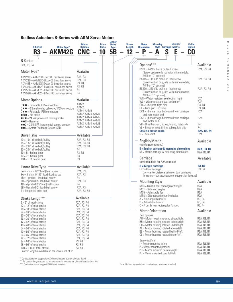
MO
DE
L
NO
ME
NC
LA
TU
RE
N2 Series
B n n = Rotatable IP65 connectors
C nn = 0.5 m shielded cables w/ IP65 connectors
n N n = No brake
n 2 n = 24 Vdc power-off holding brake
nn R = Resolver
nn 2 = 2048 LPR incremental comm. encoder
nn C = Smart Feedback Device (SFD)
Stroke Length**2 = 2 inch total stroke
4 = 4 inch total stroke
6 = 6 inch total stroke
8 = 8 inch total stroke
12 = 12 inch total stroke
18 = 18 inch total stroke (requires -DB option, effective stroke is 16.5")
24 = 24 inch total stroke (requires -DB option, effective stroke is 22.5")
nn.n = Custom stroke lengths available in 0.1 inch increments
Cylinder MountingMF1 = Front rectangular fl ange
MF2 = Rear rectangular fl ange
MF3 = Front & rear rectangular fl ange
MP2 = Rear double clevis without pivot base
MP3 = Rear double clevis with pivot base
MS1 = Side end angle
MS2 = Side lugs
MS6M = Side tapped holes (metric)
MS6E = Side tapped holes (English)
MT4 = Trunion
Rod Ends
FC2 = Clevis (includes MT1M)
FE2 = Female eye rod end
FS2 = Spherical joint (includes FT1M)
FT1M = Female thread (metric)
FT1E = Female thread (English)
MT1M = Male thread (metric)
MT1E = Male thread (English)
Cable
CO = No cable supplied, motor includes connectors. Default for all AKM servo motors; select Kollmorgen cables based on motor/drive pairings.
Screw Pitch, Type
2B = 2 rev/inch ballscrew
5B = 5 rev/inch ballscrew
5A = 5 rev/inch lead screw
8A = 8 rev/inch lead screw
Drive Ratio
10 = 1.0:1 drive belt/pulley
10L = 1.0:1 inline coupling (direct 1:1 coupling is the only ratio available for inline models)
15 = 1.5:1 drive belt/pulley
20 = 2.0:1 drive belt/pulley
25 = 2.5:1 helical gears
Motor Type*AKM23D = AKM23D-EFxxx-00 brushless servo
AKM23C = AKM23C-EFxxx-00 brushless servo
* Contact customer support for AKM combinations outside of those listed.** For custom lengths round up to next standard incremental plus add standard cut fee.*** Contact customer support for non-standard pricing and lead times.Note: Options shown in bold blue text are considered standard.
BS24 = 24 Vdc brake on lead screw (not available with 10L ratio, or with MF2, MF3, MS2, MP2, MP3 mounting options)
DB = Dual rod end bearing
PB = Protective boot
W = Water resistant
F = Sub-freezing temperature
H = High temperature prep
L = Linear potentiometer (only for valid std. lengths)
Options*** (add multiple in the following sequence, omit if no option required)
N2 – AKM23D – BNC – 15 – 5B – 8 – MP2 – FT1M – ( ) – CO
N2 Series Electric Cylinder with AKM Servo Motors
Motor Options
R SeriesR2A, R3, R4
* Contact customer support for AKM combinations outside of those listed.** For custom lengths round up to next standard incremental plus add standard cut fee.*** Contact customer support if C0 is not selected. Note: Options shown in bold blue text are considered standard.
R2A, R3, R4R2A, R3, R4R2A, R3, R4R2A, R3, R4R2A, R3, R4R2A, R3, R4
R2A, R3, R4R2A, R3, R4R2A, R3, R4R2A, R3, R4
AvailableMotor OrientationBelt optionsAR = Motor housing rotated above/rightBR = Motor housing rotated behind/rightCR = Motor housing rotated under/rightAL = Motor housing rotated above/leftBL = Motor housing rotated behind/leftCL = Motor housing rotated under/left
Screw optionsI = Motor mounted inlineP = Motor mounted parallelPR = Motor mounted parallel/rightPL = Motor mounted parallel/left
R2AR2AR2AR2AR3, R4R3, R4R3, R4
AvailableMounting StyleMF3 = Front & rear rectangular fl angesMS1 = Side end anglesMS5 = Adjustable feetMS6 = Side tapped mounting holesA = Side angle bracketsB = Adjustable T-nutsC = Front & rear rectangular fl anges
R2A, R3, R4
R2A, R3, R4
R2A, R3, R4
R2AR2AR3, R4R3, R4R2A
R2A
R4R4R2A, R3, R4R2A
Available
R3, R4R3, R4
Available
S = Single carriageDxx = Dual carriage (xx = center distance between dual carriages in inches – contact customer support for lengths)
Carriage(omit this fi eld for R2A models)
R2A, R3, R4R2A, R3, R4
Available
E = English carriage & mounting dimensionsM = Metric carriage & mounting dimensions
English/Metric (carriage/mounting)
Motor Type*AKM23C = AKM23C-EFxxx-00 brushless servoAKM23D = AKM23D-EFxxx-00 brushless servoAKM42E = AKM42E-EKxxx-00 brushless servoAKM42G = AKM42G-EKxxx-00 brushless servoAKM52G = AKM52G-EKxxx-00 brushless servoAKM52H = AKM52H-EKxxx-00 brushless servo
AvailableR2A, R3R2A, R3R3, R4R3, R4R4R4
Options***BS24 = 24 Vdc brake on lead screw (Screw option only, n/a with inline models, MF3 or “C” options)BS115 = 115 Vdc brake on lead screw (Screw option only, n/a with inline models, MF3 or “C” options)BS230 = 230 Vdc brake on lead screw (Screw option only, n/a with inline models, MF3 or “C” options)WR = Water resistant seal option rightWL = Water resistant seal option leftGR = Lube port, right sideGL = Lube port, left sideDC1 = Idler carriage between driven carriage and non-motor endDC2 = Idler carriage between driven carriage and motor endVR = Breather vent, fi tting, tubing, right sideVL = Breather vent, fi tting, tubing, left sideC0 = No motor cableS = Stub shaft
AvailableR2A, R3R2A, R3R4R2A, R3R4R2A, R3R2A, R3, R4
Linear Drive Type5A = 5 pitch (0.2" lead) lead screw8A = 8 pitch (0.125" lead) lead screw1B = 1 pitch (1" lead) ball screw2B = 2 pitch (0.5" lead) ball screw4B = 4 pitch (0.25" lead) ball screw5B = 5 pitch (0.2" lead) ball screwT = Tangential drive belt
AvailableR2A, R3, R4R2A, R3, R4R2A, R3, R4R2A, R3, R4R2A, R3, R4R2A, R3, R4R2A, R3, R4R2A, R3, R4R2A, R3, R4R2A, R3, R4R2A, R3, R4R2A, R3, R4R3, R4R3, R4R3, R4
6 = 6" of total stroke12 = 12" of total stroke18 = 18" of total stroke24 = 24" of total stroke30 = 30" of total stroke36 = 36" of total stroke42 = 42" of total stroke48 = 48" of total stroke54 = 54" of total stroke60 = 60" of total stroke66 = 66" of total stroke72 = 72" of total stroke84 = 84" of total stroke96 = 96" of total stroke108 = 108" of total strokeCustom lengths available in the increment of 1"
Stroke Length**
R SeriesDriveRatio
Linear DriveType
Stroke Length
MotorOrientation
Cable OptionCarriage
English/MetricMotor Type*
Motor Options
MountingStyle
Motor OptionsB n n = Rotatable IP65 connectors C n n = 0.5 m shielded cables w/ IP65 connectorsC n n = Rotatable IP65 connectorsn N n = No braken 2 n = 24 Vdc power-off holding brakenn R = Resolvernn 2 = 2048 LPR incremental comm. encodernn C = Smart Feedback Device (SFD)
AKM2AKM2AKM4, AKM5AKM2, AKM4, AKM5AKM2, AKM4, AKM5AKM2, AKM4, AKM5AKM2, AKM4, AKM5AKM2, AKM4, AKM5
AvailableR2A, R3, R4R2A, R3, R4R2A, R3, R4R4R3, R4R3R3
Drive Ratio10 = 1.0:1 drive belt/pulley15 = 1.5:1 drive belt/pulley20 = 2.0:1 drive belt/pulley30 = 3.0:1 drive belt/pulley50 = 5:1 helical gear70 = 7:1 helical gear100 = 10:1 helical gear
Rodless Actuators R-Series with AKM Servo Motors
Available
R3 – AKM42G CNC – 10 5B – 12 – P – A S E – CO
w w w. k o l l m o r g e n . c o m 199
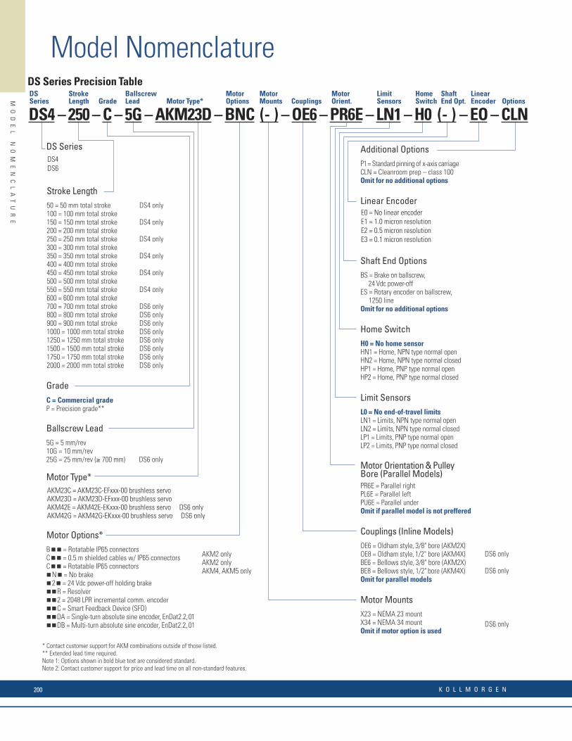
Model Nomenclature
MO
DE
L
NO
ME
NC
LA
TU
RE
* Contact customer support for AKM combinations outside of those listed.** Extended lead time required.Note 1: Options shown in bold blue text are considered standard.Note 2: Contact customer support for price and lead time on all non-standard features.
DS SeriesDS4DS6
GradeC = Commercial gradeP = Precision grade**
DS Series Precision Table
Stroke Length50 = 50 mm total stroke100 = 100 mm total stroke150 = 150 mm total stroke200 = 200 mm total stroke250 = 250 mm total stroke300 = 300 mm total stroke350 = 350 mm total stroke400 = 400 mm total stroke450 = 450 mm total stroke500 = 500 mm total stroke550 = 550 mm total stroke600 = 600 mm total stroke700 = 700 mm total stroke800 = 800 mm total stroke900 = 900 mm total stroke1000 = 1000 mm total stroke1250 = 1250 mm total stroke1500 = 1500 mm total stroke1750 = 1750 mm total stroke2000 = 2000 mm total stroke
DS4 only
DS4 only
DS4 only
DS4 only
DS4 only
DS4 only
DS6 onlyDS6 onlyDS6 onlyDS6 onlyDS6 onlyDS6 onlyDS6 onlyDS6 only
Ballscrew Lead5G = 5 mm/rev10G = 10 mm/rev25G = 25 mm/rev (≥ 700 mm) DS6 only
DS6 only
Couplings (Inline Models)OE6 = Oldham style, 3/8" bore (AKM2X)OE8 = Oldham style, 1/2" bore (AKM4X)BE6 = Bellows style, 3/8" bore (AKM2X)BE8 = Bellows style, 1/2" bore (AKM4X)Omit for parallel models
DS6 only
DS6 only
Limit SensorsL0 = No end-of-travel limitsLN1 = Limits, NPN type normal openLN2 = Limits, NPN type normal closedLP1 = Limits, PNP type normal openLP2 = Limits, PNP type normal closed
Linear EncoderE0 = No linear encoderE1 = 1.0 micron resolutionE2 = 0.5 micron resolutionE3 = 0.1 micron resolution
Additional OptionsP1 = Standard pinning of x-axis carriageCLN = Cleanroom prep – class 100Omit for no additional options
Shaft End OptionsBS = Brake on ballscrew, 24 Vdc power-offES = Rotary encoder on ballscrew, 1250 lineOmit for no additional options
Motor Orientation & Pulley Bore (Parallel Models)PR6E = Parallel rightPL6E = Parallel leftPU6E = Parallel underOmit if parallel model is not preffered
Motor Options*B n n = Rotatable IP65 connectors C n n = 0.5 m shielded cables w/ IP65 connectorsC n n = Rotatable IP65 connectorsn N n = No braken 2 n = 24 Vdc power-off holding brakenn R = Resolvernn 2 = 2048 LPR incremental comm. encodernn C = Smart Feedback Device (SFD)nn DA = Single-turn absolute sine encoder, EnDat2.2, 01nn DB = Multi-turn absolute sine encoder, EnDat2.2, 01
AKM2 onlyAKM2 onlyAKM4, AKM5 only
Motor Type*
DS4 – 250 – C – 5G – AKM23D – BNC (- ) – OE6 – PR6E – LN1 – H0 (- ) – EO – CLN
Motor MountsX23 = NEMA 23 mountX34 = NEMA 34 mountOmit if motor option is used
Home SwitchH0 = No home sensorHN1 = Home, NPN type normal openHN2 = Home, NPN type normal closedHP1 = Home, PNP type normal openHP2 = Home, PNP type normal closed
DS Series Motor Type*
Motor Options Couplings
Stroke Length
Motor Orient.
ShaftEnd Opt.
LimitSensors
Home SwitchGrade
Ballscrew Lead Options
Linear Encoder
Motor Mounts
AKM23C = AKM23C-EFxxx-00 brushless servoAKM23D = AKM23D-EFxxx-00 brushless servoAKM42E = AKM42E-EKxxx-00 brushless servo DS6 onlyAKM42G = AKM42G-EKxxx-00 brushless servo DS6 only
K O L L M O R G E N200

MOTIONEERING® Online NEW and Improved Features:• Inertia Calculator - lets you build up inertia based on odd shapes by additive or subtractive methods• Custom Motion Profi le - easy to add entire segments or copy segments to repeat• Environmental Factor - takes into account your ambient temperature• Project by Project Units - You can tailor your units on a project by project basis, or use the global units settings
MOTIONEERING Online Supported Browsers• IE, Chrome, Firefox, Safari
MOTIONEERING® Online
Announcing MOTIONEERING® Online – Kollmorgen has revamped, modernized and put online one of the most respected applications sizing programs of the last 20 years. You now can access this application sizing and selection tool wherever you have access to the internet. This initial launch of MOTIONEERING Online is just a start of a series of releases that will empower you to optimize solutions for your toughest applications. Sizing frameless motors and drive systems has never been easier. Using a mechanism project concept for collecting and saving multiple axes of load information, MOTIONEERING® Online can automatically calculate application results and compare against a catalog of systems - recommending the most optimized set of Kollmorgen system solutions available.
Versatile units-of-measure selection options for mechanism and motion profi le data-entry, with the ability to convert data into other available units, makes this a convenient international tool. A user-friendly Help fi le teaches program functions and algorithms used to provide results.
www.kollmorgen.com/motioneering
Mechanism Projects• Direct drive entry, lead screw, conveyor• Rack and pinion, nip rolls• Direct Drive Rotary• Electric Cylinder• Direct data entry
Solution Set Search Screen• Color-coded indication of system’s ability to meet application requirements• Review system components specifi cations• Save, print, or create a pdf application report• Evaluate system performance curve with application points
MO
TI
ON
EE
RI
NG
A
PP
LI
CA
TI
ON
E
NG
IN
E
* Contact customer support for AKM combinations outside of those listed.** Extended lead time required.Note 1: Options shown in bold blue text are considered standard.Note 2: Contact customer support for price and lead time on all non-standard features.
DS SeriesDS4DS6
GradeC = Commercial gradeP = Precision grade**
DS Series Precision Table
Stroke Length50 = 50 mm total stroke100 = 100 mm total stroke150 = 150 mm total stroke200 = 200 mm total stroke250 = 250 mm total stroke300 = 300 mm total stroke350 = 350 mm total stroke400 = 400 mm total stroke450 = 450 mm total stroke500 = 500 mm total stroke550 = 550 mm total stroke600 = 600 mm total stroke700 = 700 mm total stroke800 = 800 mm total stroke900 = 900 mm total stroke1000 = 1000 mm total stroke1250 = 1250 mm total stroke1500 = 1500 mm total stroke1750 = 1750 mm total stroke2000 = 2000 mm total stroke
DS4 only
DS4 only
DS4 only
DS4 only
DS4 only
DS4 only
DS6 onlyDS6 onlyDS6 onlyDS6 onlyDS6 onlyDS6 onlyDS6 onlyDS6 only
Ballscrew Lead5G = 5 mm/rev10G = 10 mm/rev25G = 25 mm/rev (≥ 700 mm) DS6 only
DS6 only
Couplings (Inline Models)OE6 = Oldham style, 3/8" bore (AKM2X)OE8 = Oldham style, 1/2" bore (AKM4X)BE6 = Bellows style, 3/8" bore (AKM2X)BE8 = Bellows style, 1/2" bore (AKM4X)Omit for parallel models
DS6 only
DS6 only
Limit SensorsL0 = No end-of-travel limitsLN1 = Limits, NPN type normal openLN2 = Limits, NPN type normal closedLP1 = Limits, PNP type normal openLP2 = Limits, PNP type normal closed
Linear EncoderE0 = No linear encoderE1 = 1.0 micron resolutionE2 = 0.5 micron resolutionE3 = 0.1 micron resolution
Additional OptionsP1 = Standard pinning of x-axis carriageCLN = Cleanroom prep – class 100Omit for no additional options
Shaft End OptionsBS = Brake on ballscrew, 24 Vdc power-offES = Rotary encoder on ballscrew, 1250 lineOmit for no additional options
Motor Orientation & Pulley Bore (Parallel Models)PR6E = Parallel rightPL6E = Parallel leftPU6E = Parallel underOmit if parallel model is not preffered
Motor Options*B n n = Rotatable IP65 connectors C n n = 0.5 m shielded cables w/ IP65 connectorsC n n = Rotatable IP65 connectorsn N n = No braken 2 n = 24 Vdc power-off holding brakenn R = Resolvernn 2 = 2048 LPR incremental comm. encodernn C = Smart Feedback Device (SFD)nn DA = Single-turn absolute sine encoder, EnDat2.2, 01nn DB = Multi-turn absolute sine encoder, EnDat2.2, 01
AKM2 onlyAKM2 onlyAKM4, AKM5 only
Motor Type*
DS4 – 250 – C – 5G – AKM23D – BNC (- ) – OE6 – PR6E – LN1 – H0 (- ) – EO – CLN
Motor MountsX23 = NEMA 23 mountX34 = NEMA 34 mountOmit if motor option is used
Home SwitchH0 = No home sensorHN1 = Home, NPN type normal openHN2 = Home, NPN type normal closedHP1 = Home, PNP type normal openHP2 = Home, PNP type normal closed
DS Series Motor Type*
Motor Options Couplings
Stroke Length
Motor Orient.
ShaftEnd Opt.
LimitSensors
Home SwitchGrade
Ballscrew Lead Options
Linear Encoder
Motor Mounts
AKM23C = AKM23C-EFxxx-00 brushless servoAKM23D = AKM23D-EFxxx-00 brushless servoAKM42E = AKM42E-EKxxx-00 brushless servo DS6 onlyAKM42G = AKM42G-EKxxx-00 brushless servo DS6 only
w w w. k o l l m o r g e n . c o m 201

Santa BarbaraTijuana
RadfordBostonMarengo
Ratingen
Gothenburg
BrnoMilan
Hong KongShenzhen
Mumbai
Shanghai
BeijingTianjin
NagoyaTokyo
São Paulo
IstanbulSeoul
Kollmorgen203A West Rock RoadRadford, VA 24141 USAPhone: 1-540-633-3545Fax: 1-540-639-4162
Kollmorgen Europe GmbHPempelfurtstraße 140880 RatingenGermanyPhone: +49 (0) 2102 9394 0Fax: +49 (0) 2102 9394 3155
Kollmorgen AsiaRm 202, Building 3, Lane 168Lin Hong RoadChangning District, Shanghai 200335, China Phone: +86 400 661 2802
Kollmorgen Aerospace and Defense501 West Main StreetRadford, VA 24141 USAPhone: 1-540-731-5668Fax: 1-540-731-5679
About Kollmorgen
Kollmorgen is a leading provider of motion systems and components for machine builders. Through world-class knowledge in motion, industry-leading quality and deep expertise in linking and integrating standard and custom products, Kollmorgen delivers breakthrough solutions that are unmatched in performance, reliability and ease-of-use, giving machine builders an irrefutable marketplace advantage.
For assistance with your application needs in North America, contact us at: 540-633-3545, [email protected] or visit www.kollmorgen.com for a global contact list.
Application Centers
Global Design & Manufacturing
Global Manufacturing
©2016 Kollmorgen Corporation. All rights reserved. KM_CA_000246_RevC_EN Specifications are subject to change without notice. It is the responsibility of the product user to determine the suitability of this product for a specific application. All trademarks are the property of their respective owners.