Automation for on-line remote-control in-situ electron microscopy
11
229 Scanning Microscopy Vol. 11, 1997 (Pages 229-239) 0891-7035/97$5.00+.25 Scanning Microscopy International, Chicago (AMF O’Hare), IL 60666 USA AUTOMATION FOR ON-LINE REMOTE-CONTROL IN SITU ELECTRON MICROSCOPY Abstract We are developing and testing a multimedia system for remote operation of transmission electron microscopes and using it to control the Kratos 1500 keV microscope in Berkeley during in situ experiments. Tests, including heating and cooling of specimens on-line under control of the remote operator, have been conducted from Washington (D.C.) and Kansas City. Such in situ experiments subject the specimen under observation to external stimuli (such as heating, cool- ing, and straining). Full operational control requires adjust- ments of external stimuli, adjustment of specimen position and orientation, and manipulation of microscope controls such as illumination, magnification, and focus. In con- ventional (non-remote) operation, a local operator makes adjustments in response to the image from the microscope; in remote mode, current wide area networks cannot offer the real-time delivery guarantees required for the adjustments necessary for dynamic in situ studies. We have designed a system that minimizes the real-time delivery requirement by incorporating local automation of stage control and microscope focus. The system corrects for specimen drift (often severe during rapid heating and cooling) by controlling stage movement with optical flow fields; it provides automatic focus using wavelet coefficients with Daubechies kernels. Wavelet transforms are also used for image compression. During remote operation, we obtained 640x480-pixel images at a rate of 0.6 fps, providing effective operator control of the microscope and the experiment. Key Words: Telemicroscopy, teleoperation, telepresence, on-line, remote control, collaboratory, in situ, high voltage electron microscopy, Internet. *Address for correspondence: Michael A. O’Keefe National Center for Electron Microscopy Lawrence Berkeley National Laboratory, B72 1 Cyclotron Road University of California, Berkeley, CA 94720. Telephone Number: 510-486-4610 FAX Number: 510-486-5888 E-mail: [email protected] M.A. O’Keefe 1 *, B. Parvin 2 , D. Owen 1 , J. Taylor 2 , K.H. Westmacott1 1 , W. Johnston 2 and U. Dahmen 1 1 National Center for Electron Microscopy and 2 Information and Computing Sciences Division, Lawrence Berkeley National Laboratory, University of California, Berkeley, CA 94720 Introduction National scientific user facilities are established with the aim of providing users with advanced instrumentation for scientific projects. One such user facility is the National Center for Electron Microscopy (NCEM) located at the Lawrence Berkeley National Laboratory (LBNL). This facility’s instrumentation includes two unique transmission electron microscopes, the JEOL (Tokyo, Japan) atomic- resolution microscope (ARM) with a resolution of 1.5 Å and the Kratos (Manchester, UK) EM-1500 high-voltage electron microscope (HVEM) with an electron energy of 1.5 MeV. Over the past thirteen years, instrumentation at the NCEM has provided hundreds of scientists with structural information from their sample materials, including metals, semiconductors and ceramics: information about the struc- tures of new phases, defects, interfaces, and nanocrystalline precipitates. At the atomic level, information is provided from thin specimens examined in the ARM. Information at lower resolutions, often under in situ conditions, comes from specimens examined in the Kratos EM-1500 HVEM. For the Kratos EM-1500 electron microscope, “in situ” means that samples may be thicker (more representative of bulk material) and may be subjected to various experimental conditions while under dynamic observation at 5 Å resolution. These experimental conditions can include heating, oxidation and reduction in appropriate gaseous environments, embrittlement with hydrogen, compression, and straining with a piezo-electric strain stage. Typical in situ HVEM sessions are likely to be much more experimental than with other more-standard microscopes, and users are typically more likely to travel to Berkeley to operate the microscope (or observe and direct while it is operated for them). To minimize travel, to better utilize NCEM facilities, and to speed the progress of typical user projects, we have established a program to provide our external users with remote on-line access to many of the NCEM electron microscopes. Initially, we have designed, and commenced to implement, a remote user interface to control both the Kratos EM-1500 and its in situ capabilities. Experience with this interface has shown that any viable interface for remote operation requires automation of several microscope functions.
Transcript of Automation for on-line remote-control in-situ electron microscopy
Teleoperation for in situ electron microscopy
229
Scanning Microscopy Vol. 11, 1997 (Pages 229-239) 0891-7035/97$5.00+.25Scanning Microscopy International, Chicago (AMF O’Hare), IL 60666 USA
AUTOMATION FOR ON-LINE REMOTE-CONTROL IN SITUELECTRON MICROSCOPY
Abstract
We are developing and testing a multimedia systemfor remote operation of transmission electron microscopesand using it to control the Kratos 1500 keV microscope inBerkeley during in situ experiments. Tests, including heatingand cooling of specimens on-line under control of the remoteoperator, have been conducted from Washington (D.C.) andKansas City. Such in situ experiments subject the specimenunder observation to external stimuli (such as heating, cool-ing, and straining). Full operational control requires adjust-ments of external stimuli, adjustment of specimen positionand orientation, and manipulation of microscope controlssuch as illumination, magnification, and focus. In con-ventional (non-remote) operation, a local operator makesadjustments in response to the image from the microscope;in remote mode, current wide area networks cannot offerthe real-time delivery guarantees required for theadjustments necessary for dynamic in situ studies. Wehave designed a system that minimizes the real-time deliveryrequirement by incorporating local automation of stagecontrol and microscope focus. The system corrects forspecimen drift (often severe during rapid heating andcooling) by controlling stage movement with optical flowfields; it provides automatic focus using wavelet coefficientswith Daubechies kernels. Wavelet transforms are also usedfor image compression. During remote operation, weobtained 640x480-pixel images at a rate of 0.6 fps, providingeffective operator control of the microscope and theexperiment.
Key Words: Telemicroscopy, teleoperation, telepresence,on-line, remote control, collaboratory, in situ, high voltageelectron microscopy, Internet.
*Address for correspondence:Michael A. O’KeefeNational Center for Electron MicroscopyLawrence Berkeley National Laboratory, B721 Cyclotron RoadUniversity of California, Berkeley, CA 94720.
Telephone Number: 510-486-4610FAX Number: 510-486-5888
E-mail: [email protected]
M.A. O’Keefe1*, B. Parvin2, D. Owen1, J. Taylor2, K.H. Westmacott11, W. Johnston2 and U. Dahmen1
1National Center for Electron Microscopy and 2Information and Computing Sciences Division,Lawrence Berkeley National Laboratory, University of California, Berkeley, CA 94720
Introduction
National scientific user facilities are established withthe aim of providing users with advanced instrumentationfor scientific projects. One such user facility is the NationalCenter for Electron Microscopy (NCEM) located at theLawrence Berkeley National Laboratory (LBNL). Thisfacility’s instrumentation includes two unique transmissionelectron microscopes, the JEOL (Tokyo, Japan) atomic-resolution microscope (ARM) with a resolution of 1.5 Åand the Kratos (Manchester, UK) EM-1500 high-voltageelectron microscope (HVEM) with an electron energy of 1.5MeV. Over the past thirteen years, instrumentation at theNCEM has provided hundreds of scientists with structuralinformation from their sample materials, including metals,semiconductors and ceramics: information about the struc-tures of new phases, defects, interfaces, and nanocrystallineprecipitates. At the atomic level, information is providedfrom thin specimens examined in the ARM. Information atlower resolutions, often under in situ conditions, comesfrom specimens examined in the Kratos EM-1500 HVEM.
For the Kratos EM-1500 electron microscope, “insitu” means that samples may be thicker (more representativeof bulk material) and may be subjected to variousexperimental conditions while under dynamic observationat 5 Å resolution. These experimental conditions can includeheating, oxidation and reduction in appropriate gaseousenvironments, embrittlement with hydrogen, compression,and straining with a piezo-electric strain stage. Typical insitu HVEM sessions are likely to be much more experimentalthan with other more-standard microscopes, and users aretypically more likely to travel to Berkeley to operate themicroscope (or observe and direct while it is operated forthem). To minimize travel, to better utilize NCEM facilities,and to speed the progress of typical user projects, we haveestablished a program to provide our external users withremote on-line access to many of the NCEM electronmicroscopes. Initially, we have designed, and commencedto implement, a remote user interface to control both theKratos EM-1500 and its in situ capabilities. Experience withthis interface has shown that any viable interface for remoteoperation requires automation of several microscopefunctions.

230
M.A. O’Keefe et al.
Remote Operation
Remote on-line control of scientific instrumentationis rapidly becoming more practicable as improvements inthe software and hardware of interfaces and networkscontinue [7, 8, 11, 18, 20]. At the NCEM, our program for fullremote operation of electron microscopes [17] evolved in aproject originally designed to establish use of on-line imageprocessing as an aid to electron microscope operation [12].We are developing and implementing a set of tools,protocols, and interfaces to provide for on-line control byremote users.
Because our present project has focused on the 1.5MeV Kratos EM-1500 transmission electron microscope,we have designed the control interface to include full on-line remote control of the currently-active in situ experi-ment in addition to implementing on-line remote control ofthe microscope itself.
The computational platform that implements controlin the local environment (including automatic control ofselected functions) must be able to acquire images, processthem at the required bandwidth, and manipulate a largenumber of HVEM operating functions. We have used asystem based on three computers, and partitioned thecontrol architecture over these computers in order toseparate microscope control into two areas. The lowfrequency servo loop functions that require direct humaninteraction are performed over the wide area network,whereas those functions that require low latency controlare performed locally using automated techniques. Thisapproach hides the latencies in the wide area network andpermits effective remote operation. The result is ateleoperation that provides the illusion of close geo-graphical proximity for remote users of the Kratos.
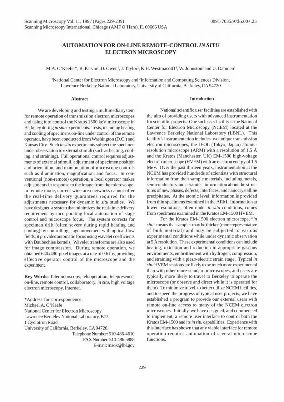
Figure 1 shows the computer hardware and datapaths. The video stream from the HVEM is digitized androuted to the remote user by a Sun SparcStation (SunMicrosystems, Palo Alto, CA) via a local network to thewide-area network. Teleoperation of the microscope by theremote user is achieved by routing commands to a personalcomputer (PC) that controls the appropriate microscopefunctions via three incorporated digital-to-analog converterboards and one stepper-motor board. Any image processingor analysis necessary for microscope control is performedby the DEC AlphaStation (Digital Equipment Corporation,now Compaq, Maynard, MA), and the results passed to theSun via a fast (100Mb/s) local Fiber Distributed-DataInterface (FDDI) link.
Not all of the locally-available HVEM controls arenecessary or appropriate for remote operation. We haveplaced only those functions that allow safe remote operationof the instrument under computer control. Control of some
other more-sensitive functions is not available to the remoteuser in order to safeguard the microscope. For example,control of the filament current is not offered because a
Figure 1. The operator area of the 1.5 MeV Kratos HVEMwith system architecture for video and servo loops. Videofrom the HVEM is digitized in the Sun and transmitted tothe remote user and to the DEC for processing for autocontrol. Commands from the DEC or the user are routed tothe PC to control microscope functions.

Teleoperation for in situ electron microscopy
231
novice operator (or intruder) could accidentally damage thefilament despite the microscope’s safety features. Allremotely operated functions have limit switches to preventremote users from going beyond safe bounds.
Remote functions currently implemented on theKratos include specimen translation in two orthogonal (xand y) directions, specimen tilt around two axes, objectivelens focus control, beam control (position and size), andcontrol of the specimen temperature. Magnification control,diffraction control, full aperture control (selection andpositioning), and control of the standard microscope platecamera will be added in the near future.
Remote operation of the Kratos EM-1500 HVEM,with concomitant remote control of an in situ heatingexperiment, was successfully demonstrated from KansasCity in 1995 over existing wide area networks [17]. Thisfacility is currently accessible from any single remote
location, and will soon become available to dispersed teams;in the case of collaborative teams, the software will bemodified to allow transfer of control from one operator toanother in order to provide simultaneous on-line microscopyto several collaborators at different geographical locations.
Graphical User Interface
Our remote control interface for the Kratos ispresented to the remote operator in the form of a point-and-click graphical user interface (GUI). As implementations ofon-line transmission electron microscopy become morewidespread, it is desirable that suitable standards foroperating interfaces be developed and adhered to. As astep in this direction, we have proposed [13] a basicstandardized transmission electron microscope (TEM) userinterface based on experience gained with on-line remote-
Figure 2. Standard remote operator interface configured for the Kratos EM-1500 HVEM. The main interface window (a)contains the live 640x480 NTSC (National Television Standards Committee) image and controls for magnification, apertureselection, focus and specimen tilt. Other pop-up windows control aperture positions (b), plate camera (c), beam position (d)and beam-stop position (e).

232
M.A. O’Keefe et al.
control using this GUI with the 1.5 MeV Kratos EM-1500HVEM.
Our standardized user interface (Fig. 2) is designedto present the remote operator with the most frequently-used controls, those for image magnification, apertureplacement, objective lens focus, and specimen tilt andtranslation. Since many TEMs already use a television (TV)camera to display the working image to the operator, themain interface window (Fig. 2a) also contains a smaller640x480 window with a standard NTSC video image of thespecimen, to provide the remote operator with the feedbacknecessary to position and tilt the specimen and select therequisite focus, aperture and magnification for recordingthe desired image. Subsidiary windows can be used foradjustments of apertures (Fig. 2b), for use of the plate camera(Fig. 2c), and for positioning the beam and beam-stop (Figs.2d,e). In situ functions are accessed by pulling down theIN-SITU header in the main menu bar.
Using the main window controls (Fig. 2a), the remoteoperator can step magnification through the full set availableon the electron microscope (29 steps for the Kratos) byusing the up and down arrows in the MAGNIFICATION box.By selecting the DIFFRACTION button, the operator is able tostep through the various diffraction camera lengths (6 forthe Kratos).
Objective lens focus control is continuous with fourup-down arrows and decade counters mapping the HVEM’scontrols for coarse, medium, fine, and vernier focus (as formost microscopes).
An auto-focus setting is provided to enable theremote operator to automatically establish or retain focusby using an autofocus routine running on the localcomputers. This routine is able to compensate for focuschanges caused by specimen tilt or by any temperature-induced buckling of the foil specimen.
The specimen is tilted by using the appropriate arrowbuttons in the TILTS box, adjusting the rate of change of tiltwith the SPEED slide bar.
There are no arrow controls for specimen movement.Instead, the specimen stage is moved by simply clicking onany part of the image with the mouse and dragging it to thedesired position within the 640x480 pixel image window.Correct scaling between the mouse movement and stagemovement is maintained with auto-scaling of the stage-motion system.
The main window control allows three sets ofapertures (OBJECTIVE, DIFFRACTION, and CONDENSER) to bewithdrawn and inserted. Clicking on the small buttonadjacent to each label in the APERTURE section of the mainmenu (Fig. 2a) inserts the corresponding aperture (aperturesize is indicated by the displayed number), or withdraws it(0 is then displayed). The size of the aperture to be insertedand withdrawn is selected initially by clicking on the
appropriate button (OBJECTIVE, DIFFRACTION, or CONDENSER)to open the corresponding pop-up window (Fig. 2b) whereinthe aperture size can be selected with the SIZE buttons andthe aperture centered with the arrow buttons. The step sizeof the centering buttons is controlled by the Speed slidebar.
Usually the apertures are selected and centered atthe beginning of a session; the selection/adjustmentwindows are then closed and the main window aperturecontrols used to insert and withdraw the apertures withoutthe need for additional positioning; however, the pop-upwindows can be opened at any time in order to change theaperture size or position if desired.
Because the remote interface is based around astandard NTSC TV signal, the resolution of the interactiveimage is limited to 640x480 pixels. Although digitized framesfrom this TV image can be stored at the remote location, orindeed the whole session recorded on video tape at themicroscope location, higher-quality images can be obtainedby using the microscope plate camera remotely, as for aconventional (local) session on the microscope.
By opening the MICROGRAPH window (Fig. 2c), theremote operator is able to view the plate number (bothoverall, and the number used so far in this session), readthe estimated exposure time (READ ET), adjust the exposuretime with the up-down arrows, and then initiate themicroscope camera exposure sequence (EXPOSE). Duringthe exposure, the control program makes an entry in thesession logbook (kept on both the local and remotecomputers), recording the associated parameters such asthe operator and specimen names, date and time of day,magnification or camera length (depending on whether theexposure is for an image or a diffraction pattern), plate numberand exposure time, and specimen temperature, tilt andposition.
The illumination condition, or beam position (Fig.2d), is controlled from a pop-up window (BEAM CONTROL)with arrow controls for positioning the beam in x and y, anda focus control for spreading it by adjusting the condenserlens (C2) current. Values of the x and y position are displayedin the pop-up window, and may be stored (together with theC2 focus value), by using the SAVE CONFIGURATION button.Saving the current values of the illumination condition writesthem into the microscope magnification look-up table. Aswell as containing values for all the lens currents at eachmagnification setting, this table also maintains entries forthe beam illumination conditions (x,y positions and C2current) at each magnification. When magnification ischanged, illumination also changes automatically to the lastcondition stored at that magnification.
Controls for additional options (e.g., objectivestigmators, or a high-definition charge-coupled device(CCD) camera) can be added to this GUI (as suitable pull-

Teleoperation for in situ electron microscopy
233
down options in the menu bar of the main window) to createappropriate subsidiary pop-up windows as re- quired.
Automation
Conventional (non-remote) in situ experiments in anelectron microscope require the local operator to makeroutine continuous adjustment of such microscope para-meters as specimen orientation (tilt) and position,illumination condition, microscope focus, and occasionallymagnification - all based upon the video signal coming fromthe imaging system. Because the specimen underobservation is often subjected to external stimuli such asheating (with or without an imposed gaseous environment),cooling, or straining, in situ experiments often require quitedynamic adjustment of microscope controls.
In the context of remote in-situ microscopy, thesystem must provide the remote operator with the look andfeel that is normally available to the local operator, and hidethe latency inherent in the wide area network. Usually, thelocal operator has no difficulty in making control adjustmentsin response to the microscope image; however, in remotemode, current wide area networks cannot offer the real-timeresponse required. Raw requirements for in situ studiescannot be met over existing wide area networks due to band-width limitations - for example, heating a specimen producesspecimen drift at a rate that exceeds the remote operator’snetwork response time - in fact, an image would have movedout of the field of view before the remote operator’scorrection signal could reach the microscope specimenstage, the stage be moved, and a new frame dispatched to(and received by) the remote operator.
This bandwidth limitation can be circumvented byusing local automated corrections, based on advancedcomputer vision algorithms, that eliminate the requirementfor real-time delivery over the wide area network. Given thatwe have computer control over microscope operations suchas incident-beam illumination, objective lens focus and stagemovement, it is possible, by partitioning the operating tasksinto operator-remote and automatic-local, to ensure that onlythose operating functions that require man-machineinteraction are performed over the (slow) wide area network.A list of operating tasks (Table 1) shows how some remoterequests generate a local response that requires automationto ensure that microscope control is seen as adequate fromthe remote location. Functions that can be automated areperformed using a local computer, in our case a DECAlphaStation (Fig. 1), acting over a fast local area network.
For successful remote control, we require computerroutines that will provide image compression, auto-scaling(to link image and stage movements), auto-recall ofillumination condition (on magnification change), auto-focus (to compensate for changes in specimen height due
to tilt, translation, or temperature), auto-eucentricity(compensation for tilt-induced translation of the image),stage drift compensation, and object tracking.Image compression
Image compression is required to ensure that theremote image window is updated at a rate sufficient for viablecontrol of microscope functions. Our image compressionroutine is based on the wavelet transform, and usesDaubechies kernels that are simple, orthogonal, andseparable for two dimensional processing [6]. During imagecompression, low order and low magnitude wavelet co-efficients are ignored and the remaining ones are encodedin blocks of 16-by-16 pixels. The remote user has full controlover the percentage of the wavelet coefficients that is usedfor compression. Typically, transmission speeds of 0.6 fpsto 1.0 fps are achieved over high-speed lines at compressionratios of 50% or more.Autofocus
Our autofocus routine also uses the wavelet trans-form with Daubechies kernels. In this case the sum of thewavelet coefficients is used as a measure of the goodnessof focus.
In the absence of automation, the focusing procedurefor the Kratos microscope is performed manually in twostages. Initially a coarse focus is found by removing theobjective aperture and focusing to an imprecise Gaussianposition using large steps of focus. Once an approximatefocus is found (and any necessary astigmatism correction
Table 1. Local responses to remote requests.
————————————————————————
RemoteRequest LocalResponse AutoAction
TV frame Send TV frame compression
Change focus Change obj current ———
Translate image Translate specimen auto-scale
Change magnif. Change currents illumination
Tilt specimen Contrast Change ———
Focus Change auto-focus
Image Translation auto-translate
Heat specimen Thermal Drift auto-translate
/cool specimen Buckling (tilt) ———
Buckling (focus) auto-focus
Shape Change auto-tracking
————————————————————————

234
M.A. O’Keefe et al.
made), an objective aperture is positioned around the centraldiffracted beam and small focus steps are used to find anexact focus condition. As the experiment proceeds, theoperator maintains focus by making intermittent smalladjustments. The autofocus routine follows a similar two-step procedure. During initialization, with the aperture with-drawn, the objective lens current is stepped, in relativelycoarse intervals, over a large current range in order to find avalue that minimizes the sum of the wavelet coefficients,corresponding to a search for a global contrast minimum.Once this approximate focus is identified, the microscopeoperator is required to switch to diffraction mode, insertand center an objective aperture, then switch back to imagemode. With the aperture inserted, the autofocus routineuses small increments in lens current, over a restricted focusrange, to search for a value that maximizes the sum of thewavelet coefficients, corresponding to a local maximum incontrast.
During normal remote operation, with the apertureinserted, the autofocus routine is able to maintain focus bymaking small adjustments in objective lens current tocompensate for small changes in specimen height (normallyproduced by changes in specimen tilt, translation, ortemperature).Drift control
Two methods are available to track motion in theimage and to provide drift control in the microscope. Oneway is to track a specific image feature, but a more-generalmethod uses optical flow fields. In our case, both drift
control and stage/image auto-scaling are implemented withan optical flow field estimation of image motion. With thismethod, two successive video frames are stored locally andthe motion between them is estimated.
The first step in drift control, as well as in user controlof specimen translation, is to calibrate the image pixel sizeto an equivalent number of steps in the xy-stepper motorcontroller of the specimen stage. Since the calibration willvary (in both x and y) for any change in specimen tilt orheight, as well as for any changes in magnification and itsassociated image rotation, the calibration method isautomated as much as possible. For stage/image-movementauto-scaling, the calibration is carried out by having thestage controller make a designated movement (dependingon magnification) in x and y, and using two successive videoframes (before and after the step), to measure the amount ofinduced image movement from the computed flow field.Once the scale between image and stage movement is stored,the remote operator’s request for image movement (clickingon any part of the displayed image and dragging it to anylocation within the image window) will cause acorresponding movement in the specimen stage, and henceprovide an updated remote image translated by therequested amount.
Drift in the HVEM is usually constant over the shortterm, so drift compensation can be implemented as a seriesof occasional adjustments to a pseudo-constant velocity.Adjustments are computed and supplied by the local motion-server software to the PC digital-to analog coverter (DAC)-server to drive the specimen stage and compensate for thestage drift motion. In the optical flow field approach, driftvelocity is measured from two successive video frames byusing the constraint that image motion be affine, andconstructing a least-squares solution to the resulting opticalflow field equations.
We define the optical flow in the video image as theinstantaneous velocity of each pixel in the image [2, 3]. Thenthe image at time t+∆t can be written as:
dttf+dy
yf+dx
xf+t)y,(x, f=t)+ty,+yx,+(x f
∂∂
∂∂
∂∂∆∆∆
Assuming constant brightness, we can express the imagevelocity in terms of the velocity components along twoaxes multiplied by the spatial image gradients in the x and ydirections:
Vf+Uf=tf
yx∂∂
where U and V are velocity components and fx and fy are thespatial image gradients in the x and y directions.
Applying the affine constraint to the image motion,we can express the velocity components in the form:
Figure 3. Estimation of drift by optical flow field. The rawdifference between two successive frames (a and b) showsthe image motion (c) that is compensated (d) by applyingthe optical flow field solution.
(2)
(1)

Teleoperation for in situ electron microscopy
235
U(x,y) = a1 + a2x + a3y
V(x,y) = a4 + a5x + a6y
and use the method of gradient descent to solve the resultingsystem of equations. Our implementation of the optical flowfield method uses a pyramid representation of the data forcoarse-to-fine motion estimation. The main advantages ofthis representation include fast estimation of large shifts inthe image plane, coupled with higher computationalthroughput. Our current algorithm is able to run at 4 Hz onour DEC multiprocessor AlphaStation, and is able to controldrift to maintain sufficient image stability for effective remote
control of the Kratos. Figure 3 shows an example of motionestimation and compensation using optical flow fields.Image feature tracking
Stage movement control not only enables us to setup a routine to control drift using optical flow fields, butalso a shape-tracking routine that can control drift bytracking well-defined image features.
One class of experiments carried out in situ on theKratos microscope involves observations of the shapechanges of precipitates as the temperature is cyclicallyincreased and decreased. Parvin et al. have developedtechniques for detecting [15] and tracking shape changesin these precipitates [16, 17]. The results of precipitate shapetracking can also be used to correct the microscope stagefor thermal drift.
Our tracking routine relies on the user to select andmark an image feature such as a precipitate. It thenautomatically marks (and tracks changes in) the shape ofthe particle with a contour line, controls the drift of themicroscope stage by applying an appropriate correction,and thus hides the network latencies from the remote user.In this case, drift control is based on tracking (and thencompensating any movement of) the centroid of the areadefined by the contour line placed around the precipitateby the detection routine.
Precipitates have convex geometrical shapes thatcan be identified in the video image (Fig. 4). The techniquefor detecting convex objects from the image is based onperceptual grouping principles [10, 14, 15]. The imple-mentation relies on grouping line segments, which areobtained using Canny’s edge detector [5], to form convexsets through a global convexity test on groups of linesegments in conjunction with a dynamic programming searchstrategy [16].
The precipitate detection routine provides a firstapproximation to the shape of the precipitate as a set ofbounding polygons. This approximation is refined andtracked in subsequent video frames [15]. The contourrefinement algorithm is optimized through dynamic pro-gramming to encode the desirable properties of the refinedcontour in terms of local edge magnitude and direction.Restraints, derived from the bounding polygon, constrainthe contour refinement by placing limits on precipitategeometry and the scope of the search for the currentprecipitate shape. Before we impose these limits, we smooththe initial polygon with a Gaussian kernel and bound therefined contour to lie in a small neighborhood as defined bythe normal lines to the smooth curve. Without Gaussiansmoothing the bounded polygon may not be smooth andthe normal lines may not intersect the actual boundary ofthe precipitate. However, given a smoothly-boundedpolygon, the normal lines are forced to scan the precipitatealong its real boundary.
(3)
Figure 4. Precipitate tracking and stage drift compensationduring one heating/cooling cycle of the specimen. A contourline traces the shape of the precipitate, and a vector fromthe centroid of the contour shows the correction for drift.

236
M.A. O’Keefe et al.
We use a multigrid implementation of the abovealgorithm for maximum speed and high tolerance for largemotion. The algorithm is able to perform well in the presenceof microscope artefacts such as image shading, image noise,low contrast, and non-uniform illumination.
Using the tracking routine, rather than the opticalflow field method, to control stage drift is an advantagewhen rapid heating and cooling of the specimen is desirable,especially when shape-tracking of precipitates is alreadycalled for by the experiment. However, it obviously lacksthe generality of the optical flow field method, wherein theimage field need not contain a convex shape that can bereadily identified and tracked.
To ensure that the stage motion is smooth, we use aKalman filter model to predict motion parameters from noisymeasurements; Kalman filtering has been used extensivelyfor smoothing and prediction [4, 19]. In general, our controlmodel predicts the trajectory of the motion and providessmooth compensation for drift with good tolerance for highspeed. Instead of making corrections to the microscopestage position, we run the stepper controller at a constantvelocity in the direction opposite to the measured thermaldrift (as with the optical flow field method). We then refinethe correction velocity (in both x and y) at the samplinginterval of the tracker.
Figure 4 shows a tracking example taken from theremote GUI screen. While being heated from room
temperature, the precipitate has a faceted crystallographicshape (top screen). At high temperature the precipitate ismore rounded, and it retains this shape while being cooled(lower screen). The centroid of the particle contour drawnby the shape-tracking routine is marked. The drift-trackingroutine aims to hold this centroid motionless, and indicatesthe direction and magnitude of each restoring correction bya vector (shown extending from the centroid to well outsidethe contour).
Because the drift-tracking routine runs at 5Hz to 8Hzon the DEC AlphaStation, whereas the remote image isupdated at slightly less than 1Hz, the perceived motion atthe remote station (in the absence of drift correction) wouldbe almost an order of magnitude greater than the vectorlength shown (since the drift is corrected more than five toeight times as often as a frame is received at the remotesite). Uncorrected heating/ cooling tests show that, withoutdrift correction, the precipitate disappears from the imagewindow in one (remote) frame time. In Fig. 4, the correctionvector also shows that the thermal drift reverses its directionas the sense of the temperature change is reversed, goingfrom an eight o’clock direction on heating to a directionlying between one and two o’clock on cooling.Distribution of control
Signals to operate the microscope controls areallowed to come from either the remote user or from theautomation routines running on local computers. The stage-server running on the DEC AlphaStation (Fig. 5) acts as aswitch to arbitrate between the local and remote requests.An additional advantage of limiting the remote clientinteraction to only one computer, is that the useridentification and authentication procedure need reside onthat platform only.
The software architecture is constructed to follow adistributed client-server model for scalability, performance,and modularity. The four servers are distributed over thethree computers as shown in Fig. 5. Briefly, the actions ofthe servers are:• Video-server on the Sun: digitizes video frames from theKratos as images with 640x480 pixels and transfers them viaFDDI to the motion-server on the DEC for image analysis(for automatic control), or for compression and transfer tothe remote user via the local and wide-area networks.• DAC-server on the PC: communicates directly with themicroscope to control its various functions, and readmicroscope parameters, as directed by the stage-server.• Stage-server on the DEC: handles all manual interactionsbetween the remote user and the electron microscope, suchas changing magnification and focus, tilting and translatingthe specimen stage, and moving the electron beam andapertures.• Motion-server on the DEC: runs all image analysis andservoing routines for automatic control of microscope
Figure 5. Distribution of the four software servers.

Teleoperation for in situ electron microscopy
237
functions. The motion-server consists of several modulesthat are executed asynchronously; they use a threadsprogramming paradigm, and communicate with data streamsthrough sockets for minimum delay.
Communication amongst the servers is also by datastreams through sockets, except that the DAC-server utilizesremote procedure calls.
A good example of the communication required isfor the self-calibration of the scaling between specimenstage movement and remote image movement.
When the remote client makes a request for selfcalibration, the request is transferred to the motion-server(running on the DEC); the motion-server requests a videoframe from the video-server (on the Sun), and the video-server sends an image to the motion-server (DEC); themotion-server makes a request for a translation from thestage-server (DEC) and a request for another frame from thevideo-server (Sun). After receiving the second frame, themotion-server computes the optical flow and solves theresulting linear system of equations to provide a mappingbetween the pixel size and the corresponding number ofstage steps. This value is retained for subsequent driftcorrections.
The motion-server has four threads that run asyn-chronously and can exchange data as required. The focusthread uses wavelet coefficients to keep the image in focus,the compression-thread uses them for image compression.The stage-thread handles all interactions with the stage-server, and the tracking thread provides drift correction forthe microscope stage.
Conclusions
Remote operation of the Kratos has revealed somelimitations in recording and storing final images. The 640x480video stream makes an ideal working image for adjustingthe microscope and positioning the specimen, but individualimages are of too low a quality to use as final data sets.Plate camera images are much better quality, but are notimmediately available to the remote user. A charge-coupleddevice camera would present the user with a high-qualitydownloadable image. In fact, a video/CCD cameracombination would be ideal for remote operation. The videocamera could simply be replaced with a 1024x1024 pixel CCDcamera and smaller binned images used as the video stream[18].
The work described here is only a first step towardsa new kind of availability for unique scientific instrumentslocated at central facilities. It will result in increasedutilization of these sophisticated instruments by providingmuch greater accessibility to them. It will reduce costsassociated with conducting individual experiments and willimprove user collaborations, allowing multiple collaborators
at scattered remote locations to monitor their on-lineexperiment, discuss results while it is in progress, andtransfer control of the microscope from one to another asnecessary - a true collaboratory.
The present project has provided us with toolsessential for real-time collaborative activities, includinggeneric techniques for manipulation of real-time video, andservo techniques for dynamic handling of video sequences.One serendipitous side-effect of our work is that our newautomated methods of controlling the Kratos electronmicroscope have already so improved the standard man-machine interface that they have resulted in a significanteasing of the users’ tasks - even operating in local mode -freeing the users to concentrate on the science of the projectrather than on the mechanics of running the microscope.
Our next step is to extend these techniques, and thelessons learned from the Kratos, to help us build standardsystems that can interface to more of the transmissionelectron microscopes at the NCEM. Such an extension ofthe present work will require the addition of morefunctionality to the user interface (e.g., high-resolutionelectron microscopy will require the system to be able topresent on-line diffractograms, and to acquire and storethrough-focal series of images) and including many moreautomation routines (e.g., high-resolution electronmicroscopy will require auto-alignment and auto-stigmationcapabilities — and possibly an auto-focus-to-Scherzer-defocus routine, with auto-through-focal-series acquisition,and automatic on-line comparison with simulated images).
A major challenge will be to produce a user interfacethat will present a standard “look and feel” to the user, andyet accommodate the individual differences in the variousmodels of microscope available from different manufacturers.At the other end of the command chain, a related challengeis to produce suitable software and hardware computerinterfaces that will operate with the microscope softwareinterface (including the manufacturers’ proprietaryprotocols) and with the various hardware interfaces (bothelectronic and mechanical) provided by the manufacturersand by suppliers of microscope accessories for energy-lossspectroscopy, x-ray analysis, and high-resolution imagecapture.
At this time, on-line access to scientific instru-mentation is generating wide-spread interest within thescientific community [1, 9]. It will soon become a requiredoption for all central facilities that supply scientists withinstrumentation for their research.
Acknowledgments
The authors wish to thank Dr. Mark Ellisman formany constructive comments on the manuscript. Work issupported by the Director, Office of Energy Research, Office
238
M.A. O’Keefe et al.
of Basic Energy Sciences, Material Sciences Division of theU.S. Department of Energy, under contract DE-AC03-76SF00098.
References
1. Anonymous (1996) In brief. Physics Today Feb1996: 55.
2. Barron J, Fleet D, Beauchemin S, Burkitt T (1992)Performance of optical flow techniques. Proc Conf ComputVision & Patt Recog. IEEE Computer Soc Press, Piscataway,NJ. pp 236-242.
3. Bergen J, Anandan K, Hanna K, Hingorani R (1992)Hierarchical model-based motion estimation. Eur Conf onComput Vision. Sandin G (ed). Springer, Berlin. pp 236-252.
4. Broida TJ, Chellappa R (1986) Estimation of objectmotion parameters from noisy images. IEEE Trans Patt Anal& Mach Intel 8: 90-99.
5. Canny JF (1986) A computational approach to edgedetection. IEEE Trans Patt Anal & Mach Intel 8: 679-698.
6. Daubechies I (1992) Ten Lectures on Wavelet.SIAM, Philadelphia, PA.
7. Ellisman MH (1995) Design of an intermediate highvoltage EM for 3-D studies of biological material and itsintegration with a system for remote access. Proc 53rd AnnMeeting MSA. Bailey GW, Ellisman MH, Hennigar RA,Zaluzec NJ (eds). Jones and Begell, New York. pp 66-67.
8. Fan G, Mercurio P, Young S, Ellisman MH (1993)Telemicroscopy. Ultramicroscopy 52: 499-503.
9. Holden D (ed) (1995) Random samples: real timeand remote. Science 270: 1125.
10. Huttenlocher D, Wayner P (1992) Finding con-vex groupings in an image. Internat J Comput Vision 8: 7-29.
11. Mercurio PJ, Elvins TT, Young SJ, Cohen PS, FallKR, Ellisman, MH (1992) The distributed laboratory: aninteractive visualization environment for electronmicroscopy and three-dimensional imaging. Comm AssocComp Mach 35: 54-63.
12. O’Keefe MA, Kilaas R (1989) Current and futuredirections of on-line transmission electron microscope imageprocessing and analysis. Proc 47th Ann Meeting EMSA.Bailey GW (ed). San Francisco Press, San Francisco. pp 48-49.
13. O’Keefe MA, Taylor J, Owen D, Crowley B,Westmacott KH, Johnston W, Dahmen U (1996) Remoteon-line control of a high-voltage in situ transmissionelectron microscope with a rational user interface. Proc 54thAnn Proc MSA. Bailey GW, Corbett JM, Dimlich RVW,Michael JR, Zaluzec NJ (eds). San Francisco Press, SanFrancisco. pp 384-385.
14. Parvin B, Medioni G (1991) A dynamic systemfor object description and correspondence. Proc Conf CompVision & Patt Recog. IEEE Computer Soc Press, Piscataway,
NJ. pp 393-399.15. Parvin B, Peng C, Johnston W, Maestre M (1995)
Tracking of tubular molecules for scientific applications.,IEEE Trans Pattern Anal & Mach Intel 17: 800-805.
16. Parvin B, Viswanatha S, Dahmen U (1995)Tracking of convex objects. Proc Int Symp Comput Vision.IEEE Computer Soc Press, Piscataway, NJ. pp 295-298.
17. Parvin B, Agarwal D, Owen D, O’Keefe MA,Westmacott KH, Dahmen U, Gronsky R (1995) A project foron-line remote control of a high-voltage TEM. Proc 53rdAnn Meeting MSA. Bailey GW, Ellisman MH, HennigarRA, Zaluzec NJ (eds). Jones and Begell, New York. pp 82-83.
18. Völkl E, Allard LF, Dodson TA, Nolen TA (1995)Computer control of transmission electron microscopes:possibilities, concepts and present limitations. Proc 53rdAnn Meeting MSA. Bailey GW, Ellisman MH, HennigarRA, Zaluzec NJ (eds). Jones and Begell, New York. pp 22-23.
19. Young GS, Chellappa R (1990) 3-d motionestimation using a sequence of noisy stereo images: Models,estimation, and uniqueness results. IEEE Trans Pattern Anal& Mach Intel 12: 735-759.
20. Zaluzec NJ (1995) “Tele-presence microscopy:an interactive multi-user environment for collaborative re-search using high-speed networks and the internet. Proc53rd Ann Meeting MSA. Bailey GW, Ellisman MH, HennigarRA, Zaluzec NJ (eds). Jones and Begell, New York. pp 14-15.
Discussion with Reviewers
M.H. Ellisman: Of the many functions described, it is notclear which are currently implemented and which are merelyplanned. Your section on Remote Operation indicates thatmagnification control has not yet been implemented.Authors: For completeness, we have included descriptionsof all the controls required for a remote user to carry out anin situ experiment during a microscope session. So far, thecontrols that have been implemented and utilized duringremote sessions are specimen translation and tilt, beamposition and focus, and objective lens focus. We startedwith these basic controls and are adding others to ourgraphical user interface in such a way as to permit it to beextended logically, hopefully leading to a model for astandardized interface for on-line TEMs. Magnification isthe next function we plan to implement.
M.H. Ellisman: It seems premature to propose a standardizedinterface, since your system is only in the beginning stagesand focuses on a specific class of microscope use requiredfor certain types of specimens, data acquisition, and in situexperiments.

Teleoperation for in situ electron microscopy
239
Authors: We are hoping to establish a basic interface thatcan form the basis of a standardized interface. Thestandardized interface should be modular and allow for user-selectable control panels to be present depending on thetype of microscope being controlled, its ancillary equipment,and the experiment underway. We feel that the basicinterface should display the working image and offercontrols for specimen translation and tilt, beam controls,focus, and a means of recording a final image. In our case,the working image is a 640x480 video stream, and the finalimage must be recorded using a plate camera. Ideally, whenthe interface is used with a microscope that is equippedwith a CCD camera, the plate camera controls on the remotegraphical user interface (GUI) should automatically bereplaced by CCD camera controls to allow the final image tobe “recorded” by downloading it to the user’s computer. Ifa CCD-equipped microscope happened to have no videocamera, the 640x480 window for the working image shouldautomatically be replaced by a window to display workingimages constructed by binning the output of the CCDcamera down to 512x512, 512x256, or 256x256, depending onavailable bandwidth. Völkl et al. [18] routinely use a 256x256working image binned from a 1024x1024 CCD camera tocontrol a Hitachi HF2000 electron microscope remotely.Incidentally, we plan to replace the video camera on theKratos with a CCD to facilitate the use of diffraction mode.At the moment, it is too easy for the user to damage thevideo camera by switching to diffraction mode under strongillumination. When the remote GUI is opened, it willinterrogate the Kratos control computer, receive the replythat the Kratos now uses a CCD instead of a video camera,and will open the correct working image window.
M.H. Ellisman: It appears that the video interface is employedby the remote user primarily for specimen positioning andcentering of apertures. It is not clear what other functionsit is intended to provide the remote user.Authors: The graphical user interface is designed to providethe remote user with a working image and the means tomodify basic microscope conditions according to theinformation coming from this image. The user can “roam”the specimen, adjust its tilt, change the focus andillumination, and generally set up conditions to record agood final image containing the desired information aboutthe specimen.
M.H. Ellisman: It is unclear why the autoscaling function isneeded. Why does the stage require repeated recalibration?How accurate and repeatable is stage positioning? It wouldbe surprising if mechanical stage motion is sufficientlyaccurate on your microscope, especially at highmagnification.
Authors: The autoscaling function maps the stage to thecurrent image orientation. Generally, there will be a rotationalmisorientation between the image and the specimen, suchthat a change in x (or y) in the image position will requirechanges in both x and y for the specimen stage. Thecoefficients in the matrix that maps the stage to the imagewill change with any change in magnification, specimen tiltand change in height (sometimes caused by buckling underheating). Stage positioning accuracy is now adequate.Initially, we fitted the microscope translation controls withgeared-down stepper motors. Experience with this systemhas led us to increase the gear ratio by another factor of ten,in order to reduce the step size. We also re-machined allmechanical links to minimize backlash.