JA-63 „PROFI“
17
JA-63 „PROFI“ Alarm system - installation manual
-
Upload
khangminh22 -
Category
Documents
-
view
6 -
download
0
Transcript of JA-63 „PROFI“

JA-63 „PROFI“ Alarm system - installation manual


JA-63 „PROFI“ Alarm System - 3 - MGK55401
Contents:
1 Architecture of the control panel ................................................................................................................................4 2 Control panel installation............................................................................................................................................4
2.1 Mains supply connection .......................................................................................................................................5 3 Antenna for the radio module ....................................................................................................................................5
3.1 Rubber rod antenna used in the control panel ......................................................................................................5 3.2 External antenna use.............................................................................................................................................5
4 Terminals and connectors on the main board ..........................................................................................................5 5 The JA-60 keypad(s)..................................................................................................................................................7 6 Installation of wireless items ......................................................................................................................................7 7 Back up battery installation........................................................................................................................................7 8 First powering of the control panel.............................................................................................................................7 9 Control panel programming .......................................................................................................................................7
9.1 Enrollment (teaching) of wireless items.................................................................................................................9 9.2 Hard-wired zone input setting................................................................................................................................9 9.3 Exit delay .............................................................................................................................................................10 9.4 Entrance delay.....................................................................................................................................................10 9.5 Alarm duration .....................................................................................................................................................10 9.6 PgX and PgY output functions ............................................................................................................................10 9.7 Recorded message and phone number editing in the user mode sequence: 2 5 x...........................................10 9.8 Radio signal jamming testing...............................................................................................................................10 9.9 Regular communication checking .......................................................................................................................10 9.10 Reset enabled .................................................................................................................................................11 9.11 Arming control of a subsystem........................................................................................................................11 9.12 Enrollment of the control panel to a UC-2xx or to a master control panel sequence: 2 9 9 .........................11 9.13 No code requested for , , , (F1, F2, F3), F4, F8 & F9 .............................................................11 9.14 Partial (Home) arming with - non split.....................................................................................................11 9.15 Hard wired siren alarm enabled ......................................................................................................................11 9.16 Exit delay audible indication............................................................................................................................12 9.17 Partial arming exit delay audible indication.....................................................................................................12 9.18 Entrance delay audible indication ...................................................................................................................12 9.19 Arming and disarming chirps with wired siren....................................................................................................12 9.20 Siren alarm in Disarm & Partial arming...........................................................................................................12 9.21 Wireless siren alarm........................................................................................................................................12 9.22 Indication of system problems when arming...................................................................................................12 9.23 Control panel splitting......................................................................................................................................12 9.24 Only first source of alarm is recorded .............................................................................................................13 9.25 Alarm triggered by opened zone when arming ..................................................................................................13 9.26 Audible panic alarm .........................................................................................................................................13 9.27 Next delay wireless detectors ...........................................................................................................................13 9.28 Communication loss alarm................................................................................................................................13 9.29 Entering the programming mode by SC+MC/UC ............................................................................................13 9.30 Addressing of wireless detectors to sections ..................................................................................................13 9.31 Addressing of the user codes to sections .......................................................................................................13 9.32 Addressing of wireless controllers to sections....................................................................................................13 9.33 Automatic arming / disarming setting..............................................................................................................14 9.34 New service code setting ................................................................................................................................14 9.35 User Mode entering.........................................................................................................................................14 9.36 Real time and date setting ..............................................................................................................................14
10 System testing .........................................................................................................................................................14 11 Control panel factory default reset...........................................................................................................................14 12 PC used with JA-63 .................................................................................................................................................15 13 Recommended professional in-staller basic rules ...................................................................................................16 14 Trouble shooting table .............................................................................................................................................16 15 Possibilities to extend the system............................................................................................................................16
15.1 Extension of the system with a subsystem .....................................................................................................16 15.2 Extension of the system with a communicator................................................................................................16 15.3 Brief overview of parts suitable for the JA-63 system.....................................................................................16
16 Control panel specifications:....................................................................................................................................17
This manual is valid for control panel model JA-63 version GK61008 (control panel board). The use of Comlink Windows v. 61 software or higher is required for this control panel and can be obtained from our home page at www.jablotron.com

JA-63 „PROFI“ Alarm System - 4 - MGK55401
This product should be installed by professional installers. The manufacturer assumes no liability for damages caused by incorrect installation or improper use of this system.
1 Architecture of the control panel The JA-63 "Profi" is a fully programmable control panel with
building block architecture. By programming, it can be split into two separately operated sections (with a shared section). It has a built in power supply and there is ample space for a back up battery (12V, 1.3Ah or 2.6Ah) in the control panel case.
The JA-63K main board has 4 hard-wired inputs with programmable triggering (NC, balanced or double balanced) and programmable reactions.
Model JA-63KR (equipped with the “R” radio communicating module) has 16 wireless zones. Up to two JA-60 detectors can be enrolled into each zone (totally 32 as a maximum). In total model 63KR has 20 zones (4 wired and 16 wireless). Up to 8 wireless controllers (remote controls or wireless keypads), a JA-60A wireless siren and unlimited number of UC family wireless output modules can be enrolled as well. If more zones are required,
another JA-6x control panel can be enrolled as a subsystem (Master & Slave architecture). The master control panel receives information from the sub control panel and it can also arm and disarm the subsystem panel.
Telephone module “X” can communicate with a Monitoring Station, send two voice messages, send five SMS messages via SMS server (or dial a numeric Pager). It can also communicate with a remote PC (using ComLink SW and a JA-60U modem).
GSM dialer JA-60GSM sends SMS messages, calls to predefined telephone numbers and plays audible warning, communicates with 2 CMS, allows remote access from a phone’s keypad and can be set via web page.
Operation and programming is possible via the JA-60E keypad. The control panel equipped with a radio module can also be programmed and operated by a JA-60F wireless keypad and can also be operated by RC-40, RC-22 or RC-60 remote controls or by a JA-60D wireless keypad. Operation and programming is also possible via a PC using PC-60A interface and ComLink software.
the internal layout
Available models of the JA-63 system
control panel R module
X module
GSM module description
JA-63K no no no four zone hard wired control panel JA-63KR yes no no 16 zones wireless (up to 32 detectors) & 4 hard wired zones
JA-63KRX yes yes no 16 zones wireless (up to 32 detectors) & 4 hard wired zones & digital telephone communicator.
JA-63KRG yes no yes 16 zones wireless (up to 32 detectors) & 4 hard wired zones & GSM dialer. Note: Radio module R can not be ”aftermarket” installed into 63K and 63KX models. Telephone communicator X module and GSM dialer JA-60GSM can be installed
additionally to a 63K or 63KR control panels.
2 Control panel installation
• The control panel should be easily accessible but not visible. There should be a power socket available and also a telephone line (if the system has an optional built in dialer).
• Attach the control panel’s rear housing to the wall (see drilling diagram on the last page of this manual).
• Route all the cables to the control panel (power, input loops, telephone line etc.) before you tighten the case to the desired location.
Note: Only a qualified technician can provide the installation, telephone line connection and servicing. User is not allowed to open the cover and/or make any modification.

JA-63 „PROFI“ Alarm System - 5 - MGK55401
2.1 Mains supply connection It is specified to connect the control panel by a permanent two-
wire cable. The power supply has a double isolation. The ground wire is unattached. • An inlet is realized by a permanent two-wire cable with a
double isolation – wire diameter 0.75 – 1.5 mm2. The inlet must be connected to the independent circuit breaker (10 A max) in the object, which has function of the switch.
• Thread the Inlet through the power supply case bushing; connect the wires to the terminals (equipped by a fuse T200mA / 250 V).
• Cable must be firmly fixed to the power supply board by a sliding strap (firstly check again that the wires are firmly secured in terminals)
3 Antenna for the radio module If the “R” radio module is used, install its antenna (rubber rod
or an external model AN-01). The antenna must not be shielded by any metal object in its proximity. The working range of the wireless accessories is about 100 meters under optimal conditions. However, building materials can absorb or obstruct radio signals and communication can also be effected by interference from other radio signals. For these reasons, you should anticipate a shorter working range for indoor installations.
3.1 Rubber rod antenna used in the control panel There is a hole on the top of the control panel case for the
rubber antenna. The rubber antenna is supplied with the control panel. Attach the antenna to the board using the provided screw as shown in the diagram. The antenna must not be obstructed by any metal object.
3.2 External antenna use An optional external antenna, model AN-01, has a connector
which fits the connector on the radio module board. If you use the external antenna, the rubber antenna should not be installed. The AN-01 antenna has a small plastic ring on its end, used to hang it from the wall. Its active part (from the plastic ring to the coil) should be installed vertically and should not be obstructed by any large metal object. The antenna can be located behind furniture, etc.
4 Terminals and connectors on the main board
There is a Digital data jack for the JA-60E keypad(s) and/or for a PC interface cable. The same connecter is also available on the bottom right corner of the control panel housing. The digital bus signals are also available on terminals 1234.
RADIOMODULEJA-63R
1,2,3,4 digital data terminals provide an option to use standard cable for the wiring of JA-60E keypads. Up to four JA-60E keypads can be wired to the control panel (connected in parallel). The total length of the keypad cables should not exceed 100m. If using the jack connectors, the data cable length should not exceed 10 meters. Use ordinary twisted pair cable connected to the 1234 terminals for longer distance. AC20V – output of the power transformer (20VAC) is connected to this pair of terminals. L1,L2, L3, L4 – hard wired zone inputs – detector outputs can
be wired here: see examples of wiring on page 7. For each input it is possible to program its method of triggering: Normally Closed loop, balanced loop (2k2) or double balanced loop (2x 1k1) and the type of reaction of the system (see section 9.2).
Factory default setting: all inputs are triggered as balanced loops, reactions: L1= delay, L2= next delay, L3= instant and L4= tamper
COM common terminal to close (balance) the input NO is a normally open contact of the alarm output relay. NC is a normally closed contact of the alarm output relay. C is a common contact of the alarm output relay, max. load
60V / 1A. The relay is turned on during any alarm. SIR is an external siren output. In the normal mode it has a +U
terminal voltage. In the alarm mode it has a GND terminal potential. Connect an ordinary external siren to +U and SIR terminals (max. load 0,7 A). A two wires back up siren should be connected to the GND and the SIR terminals

JA-63 „PROFI“ Alarm System - 6 - MGK55401
(during an alarm, the charging will temporarily halt). The siren can also be used for arming and disarming chirps and as an audible indicator while in the testing mode (see section 10).
PGX, PGY are outputs (switching to GND when activated, max. 12V, 100mA). The function of these outputs are determined by the setting in the programming mode (see 9.6). The control panel also wirelessly transmits the PGX and PGY signals and UC receiving units can be used as remote outputs for these signals.
+U is a back up power output for external items (detectors etc.). The max. permanent current is 0.4A (1A for max. 15 min - not more then one cycle per hour). This output is fused (FU1 1A) and supervised by the control panel. If it is overloaded, a control panel failure will be indicated (fault C).
GND is a common ground terminal for power output (-).
Fig. 1 – Wiring examples
JA-63 „PROFI“ Alarm System - 7 - MGK55401
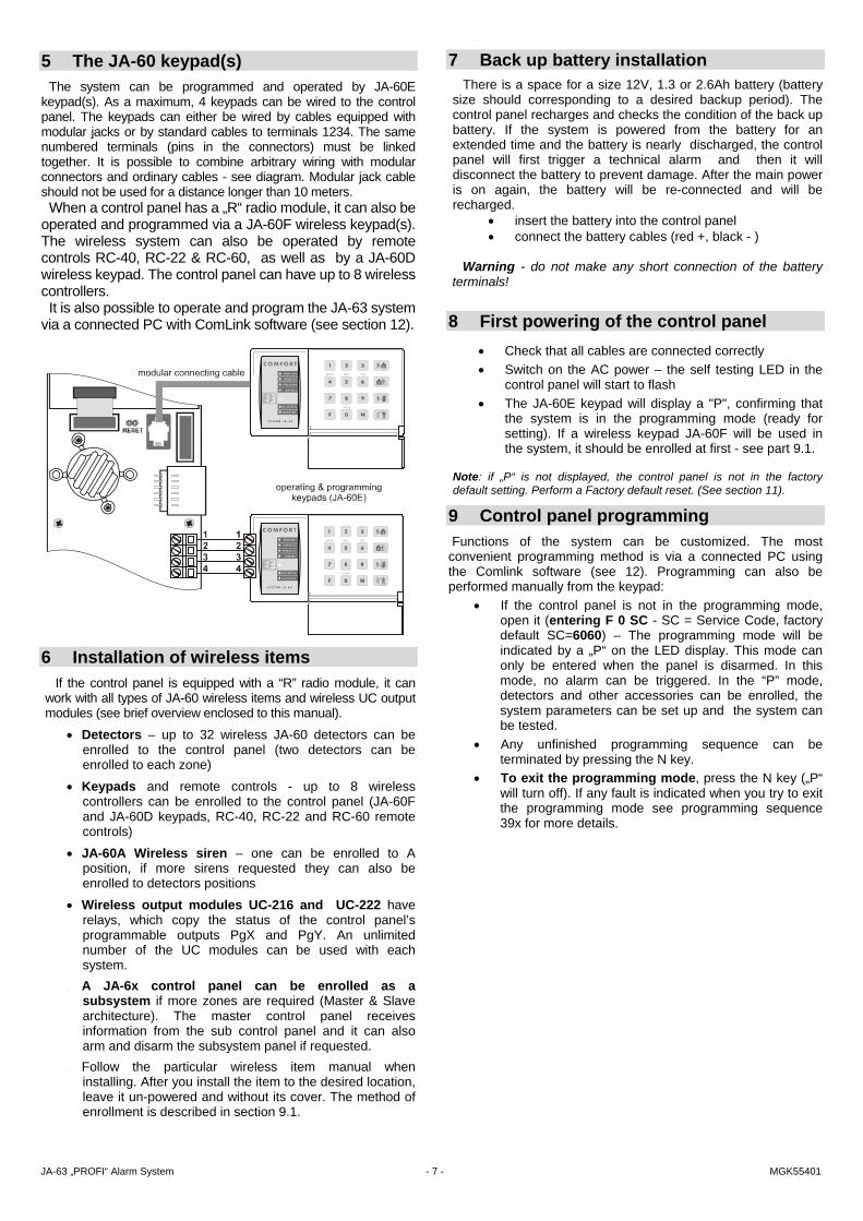
5 The JA-60 keypad(s)
The system can be programmed and operated by JA-60E keypad(s). As a maximum, 4 keypads can be wired to the control panel. The keypads can either be wired by cables equipped with modular jacks or by standard cables to terminals 1234. The same numbered terminals (pins in the connectors) must be linked together. It is possible to combine arbitrary wiring with modular connectors and ordinary cables - see diagram. Modular jack cable should not be used for a distance longer than 10 meters. When a control panel has a „R“ radio module, it can also be
operated and programmed via a JA-60F wireless keypad(s). The wireless system can also be operated by remote controls RC-40, RC-22 & RC-60, as well as by a JA-60D wireless keypad. The control panel can have up to 8 wireless controllers. It is also possible to operate and program the JA-63 system
via a connected PC with ComLink software (see section 12).
6 Installation of wireless items
If the control panel is equipped with a “R” radio module, it can work with all types of JA-60 wireless items and wireless UC output modules (see brief overview enclosed to this manual).
• Detectors – up to 32 wireless JA-60 detectors can be enrolled to the control panel (two detectors can be enrolled to each zone)
• Keypads and remote controls - up to 8 wireless controllers can be enrolled to the control panel (JA-60F and JA-60D keypads, RC-40, RC-22 and RC-60 remote controls)
• JA-60A Wireless siren – one can be enrolled to A position, if more sirens requested they can also be enrolled to detectors positions
• Wireless output modules UC-216 and UC-222 have relays, which copy the status of the control panel’s programmable outputs PgX and PgY. An unlimited number of the UC modules can be used with each system.
• A JA-6x control panel can be enrolled as a subsystem if more zones are required (Master & Slave architecture). The master control panel receives information from the sub control panel and it can also arm and disarm the subsystem panel if requested.
• Follow the particular wireless item manual when installing. After you install the item to the desired location, leave it un-powered and without its cover. The method of enrollment is described in section 9.1.
•
•
7 Back up battery installation There is a space for a size 12V, 1.3 or 2.6Ah battery (battery
size should corresponding to a desired backup period). The control panel recharges and checks the condition of the back up battery. If the system is powered from the battery for an extended time and the battery is nearly discharged, the control panel will first trigger a technical alarm and then it will disconnect the battery to prevent damage. After the main power is on again, the battery will be re-connected and will be recharged.
• insert the battery into the control panel • connect the battery cables (red +, black - )
Warning - do not make any short connection of the battery
terminals!
8 First powering of the control panel
• Check that all cables are connected correctly • Switch on the AC power – the self testing LED in the
control panel will start to flash • The JA-60E keypad will display a "P", confirming that
the system is in the programming mode (ready for setting). If a wireless keypad JA-60F will be used in the system, it should be enrolled at first - see part 9.1.
Note: if „P“ is not displayed, the control panel is not in the factory default setting. Perform a Factory default reset. (See section 11).
9 Control panel programming
Functions of the system can be customized. The most convenient programming method is via a connected PC using the Comlink software (see 12). Programming can also be performed manually from the keypad:
• If the control panel is not in the programming mode, open it (entering F 0 SC - SC = Service Code, factory default SC=6060) – The programming mode will be indicated by a „P“ on the LED display. This mode can only be entered when the panel is disarmed. In this mode, no alarm can be triggered. In the “P” mode, detectors and other accessories can be enrolled, the system parameters can be set up and the system can be tested.
• Any unfinished programming sequence can be terminated by pressing the N key.
• To exit the programming mode, press the N key („P“ will turn off). If any fault is indicated when you try to exit the programming mode see programming sequence 39x for more details.

JA-63 „PROFI“ Alarm System - 8 - MGK55401
List of control panel programmable parameters Function sequence options factory note
Enrolling of detectors and controllers 1 1& 7 scroll, 2 erases item - R module
Hard-wired zone input setting 60 nn xys nn - zone, x - triggering, y - reaction, s - section
L1=delay L2=next d. L3=instant L4=tamper
Exit delay 20x x = 1 to 9 (x 10sec.) 30sec.
Entrance delay 21x x = 1 to 9 (x 10sec.) 30sec.
Alarm duration 22x x = 1 to 8 (min.), 0=10s, 9=15min
4min.
Function of PgX output 23x x = 0 to 8 (0-Chime, 1-Fire, 2-Arm, 3-Panik, 4-Alarm,
5-Door, 6-Home, 7-No AC, 8-By phone)
Chime different when split
Function of PgY output 24x x = 0 to 8 (0-Chime, 1-Fire, 2-Arm, 3-Panik, 4-Alarm,
5-Door, 6-Home, 7-No AC, 8-By phone)
Arm different when split
Voice m. & tel. Numbers editable in the user mode 25x 251 = YES 250 = NO NO X module
Radio signal jamming regular testing 26x 261 = YES 260 = NO NO R module
Regular communication check enabled 27x 271 = YES 270 = NO NO R module
RESET enabled 28x 281 = YES 280 = NO YES Subsystem arming enrollment 290 will enroll to sub-control panel as wireless
controller R module
Control panel teaching to a UC-2xx, master-system,... 299 will enroll as control panel R module
No code requested for , , , F4 & F9 30x 301 = YES 300 = NO YES
Partial (Home) arming enabled 31x 311 = YES 310 = NO YES
Siren alarm enabled 32x 321 = YES 320 = NO YES
Exit delay audible indication enabled 33x 331 = YES 330 = NO YES
Partial arming exit delay audible indication 34x 341 = YES 340 = NO NO
Entrance delay audible indication enabled 35x 351 = YES 350 = NO YES
Arming & disarming chirp sounds enabled 36x 361 = YES 360 = NO NO
Siren in Disarm & Partial arming enabled 37x 371 = YES 370 = NO YES
Wireless siren alarm enabled 38x 381 = YES 380 = NO YES R module
Indication of system problems when arming 39x 391 = YES 390 = NO NO
Split control panel (A, B & C sections) 690x 6901 = YES 6900 = N0 NO
Only first source of alarm is recorded 691x 6911 = YES 6910 = NO NO
Alarm triggered by opened zone when arming 692x 6921 = YES 6920 = NO NO only if 391
Audible panic alarm 693x 6931 = YES 6930 = NO NO
Next delay wireless detectors 694x 6941 = YES 6940 = NO NO
Communication loss alarm 696x 6961 = YES 6960 = NO YES
Entering the programming mode by SC+MC/UC 697x 6971 = YES 6970 = NO NO
Addressing of wireless detectors to sections 61 nns nn - zone n., s - section 1-10A 11-16B R module
Addressing of user codes to sections 62 nns nn - code n., s - section all A when split
Addressing of wireless controllers to sections 63 nns nn - controller n., s - section all A R module
Automatic arming / disarming 64nahhmm N - 0-9, a - action, hh - hours, mm - min.
all off
Service Code changing 5 nSC nSC nSC = new Service Code 6060 code 2x User Mode entering 6999 Goes to the User mode -
Real time and date setting 4 hh mm DD MM RR 00 00 01 01 00

JA-63 „PROFI“ Alarm System - 9 - MGK55401
9.1 Enrollment (teaching) of wireless items enter: 1
The control panel equipped with a radio module can enroll up to 32 wireless detectors (2 in each zone), up to 8 controllers (remote controls & keypads), wireless sirens and an additional JA-6x control panel as subsystem:
• Press key 1 (while „P“ is displayed) to enter the enrolling mode. The control panel will display the next free position to enroll a detector. o If no JA-60E keypad is used in the installation and
you need to enroll a wireless JA-60F keypad: connect (short ) the RESET pins on the control
panel board it will open the learning mode (tamper in the control panel must remain opened)
install batteries to the JA-60F keypad and wait until the keypad enrolls. Enrollment will be confirmed on the keypad.
disconnect the RESET pins and then use the keypad to enroll all the other items in following way
• Use key 1 and 7 to scroll (up and down) all control panel wireless positions – 1 to 16 (detectors) – c1 to c8 (controllers & keypads) – A (wireless siren) – J (sub control panel JA-6x). The display shows the position number while the Battery LED indicates if the position is occupied. The system will not allow enrollment of an item into a non-corresponding position (a detector can not be enrolled into a controller position etc.).
• Detectors and keypads are enrolled after their power is switched on (batteries are installed). A remote control is enrolled after both of its buttons are simultaneously pressed and held for 3 seconds. A subsystem control panel will enroll after sequence 299 is entered while it is in its programming mode.
• Control panel confirms enrollment with a „beep“ (press F to get confirmation by a wired siren). The display will show the number of the enrolled item for 2 seconds and then it will display the next free position.
• Second detector enrolment to a zone – select the zone into which you want enroll the second detector. Press shortly key 5 (selects second position) and then install battery to the detector. Enrollment of the second detector will be indicated by the Fault LED. If there are two detectors in a zone, all indicators in this zone (alarm, tampering, low battery etc.) will be common for both enrolled detectors (for example, if any of the two detectors is tampered with, the zone will indicate tampering.).
• To change the position of an enrolled item - simply enroll it to the new selected position (the item will „move“). If you enroll an item to an occupied position, the former item will be deleted and only the new enrollment is valid. Normally only one item (detector, controller etc.) can be stored to each position.
• Erase an enrolled item by selecting the corresponding position and then press and hold key 2 for two seconds. The item will be erased (confirmed with a long beep). If you press and hold key 3, all enrolled controllers (remote controls and keypads) will be erased. Pressing and holding key 4 will erase all enrolled items (detectors, controllers, siren and the sub system). If two detectors were enrolled in a zone, both of them will be erased if you erase the zone’s position.
• The JA-60A wireless siren will enroll (to position A) when its power is switched on. If you need to enroll a siren which is already powered and it is not possible to easily switch off its power, you can enroll it the following way: enter the enrolling mode and then enter the 6 digit siren production code (printed in the siren’s manual). The control panel will “request” the siren to enroll. The siren will do that only if it
has no current communication with any other control panel (This protects you from enrolling your neighbor’s siren).
• Multiple outdoor sirens or multiple subsystems enrolment – enter 000000 while in enrolling mode. After this outdoor sirens and JA-6x subsystems can be enrolled to positions 1 to 16 (position A and/or J must be used first).
• By pressing the button 8 in the enrolment mode the communication quality of the items can be checked (LED indicator “battery” will start flashing). After receiving signal from the item the level of the signal is shown on the display from 0 to 10 (corresponding to 0-100% in the ComLink software). In this mode it is also possible to adjust level of audible indications by pressing the button F and scroll positions of the enrolled items by pressing buttons 1 and 7. Button N exits checking mode.
• To exit the enrolling mode press the N key
Note: if an item was not enrolled after its batteries were installed, it is because the control panel recognized its radio signal as a weak one. Items are only enrolled if their radio signal has a level which guarantees reliable communication. Check the detector’s batteries and try to enroll the problematic sensor once more. If it is not accepted by the control panel, you should change the location of the item. All items should be located 1 meter as minimum from the control panel.
9.2 Hard-wired zone input setting sequence: 60 nn xys
If the hard wired L1 to L4 zones are used, their features can be programmed by entering: 60 nn xys where: nn zone number: 01 to 16 x input triggering: 0 = off, 1 = Normally Closed, 2 = balanced
loop (EOL resistor 2k2), 3 = double balanced loop (EOL resistors 2x 2k2)
y reaction: 0 = Instant, 1 = Delay, 2 = Fire, 3 = Panic, 4 = Tamper, 5 = Next delay, 6 = Arming control
s address to section, 1 = A, 2 = B, 3 = C (shared common section, which is armed only if both A and B sections are armed). If the control panel is not split, select s=1; if you select s=2 then this zone will be automatically bypassed within partial arming. For details about splitting see section 9.23.
Notes: • If you will not use a particular input, you can switch it off
completely with parameter x = 0 • Next delay input (y=5) provides entrance delay only if at the
moment of its triggering the entrance delay has been in progress (activated before by any delayed input). If no delayed input is triggered before next delayed, the triggering will cause an instant alarm.
• Addressing of inputs to section C when the control panel is not split has the same effect as addressing to section B (i.e. automatic bypass while partial arming is used).
• If y=6 is programmed, then each triggering of this input changes arming status (arm – disarm – arm…) of the entire system or just the corresponding section if the system is split.
Example: to set zone 2 input as a balanced loop with an instant reaction, addressed to section A, enter: 60 02 201
Factory default setting: L1 = delay, L2 = next delay, L3 = instant, L4 = tamper

JA-63 „PROFI“ Alarm System - 10 - MGK55401
9.3 Exit delay sequence: 2 0 x
To change the duration of the exit delay enter: 20x (where x represents time in seconds x10). The delay can be selected from 10 to 90 seconds. Example: to select an Exit delay duration of 20 seconds, enter 202
Factory default setting: 30 seconds
9.4 Entrance delay sequence: 2 1 x
To change duration of the entrance delay enter: 21x (where x represents time in seconds x10). The delay can be selected from 10 to 90 seconds.
Example: To select entrance delay duration of 40 seconds, enter 214
Factory default setting: 30 seconds
9.5 Alarm duration sequence: 2 2 x
The alarm duration can be selected from 1 to 8 or 15 minutes entering: 22x (where x=time in minutes for1 to 8, x=9 means 15 minutes and x=0 means 10 seconds) Example: to select an alarm duration of 15 minutes, enter 229
Factory default setting: 4 minutes
9.6 PgX and PgY output functions sequences: 2 3 x & 2 4 x
The control panel outputs PgX and PgY can have different functions, depending on parameter x in the corresponding sequence:
23x - determines trigge-ring of PgX 24x - determines trigge-ring of PgY where: x represents the following functions (non split system):
0 Chime – triggered during the entrance delay (pre-alarm output)
1 Fire – triggered by a fire alarm (by a smoke or a gas detector)
2 Arm – activated when the control panel is armed (complete & partial arming)
3 Panic – activated when a silent panic alarm is triggered 4 Alarm – triggered by any audible alarm (except panic
alarm)
5 Door – activated for 5sec. after (F3) entering (electric door lock opening)
6 Home – activated when the control panel is partially armed (Home arming)
7 No AC – triggered by an AC power failure 8 Phone/F8 – output can be operated remotely by phone
or by SMS (if this feature is supported by installed communicator) or locally from the keypad by F81 (ON) and F80 (OFF). If a code is requested to operate the system (see 9.13) then the F8x instruction should be followed by a valid user code.
Note: the control panel also wirelessly transmits the PgX and PgY signals. Wireless output modules UC-216 and UC-222 can be used to receive the signals (see 9.12). The function of the UC module output relays is determined by the 23x and 24x setting.
Example: the PgX will work as a Panic output when 233 is entered, PgY as Door output when 245 is entered.
Factory default setting: PgX=Chime, PgY=Arm
9.7 Recorded message and phone number editing in the user mode sequence: 2 5 x
The User mode, which is accessible with F 0 “Master Code”, is for bypass setting, system testing and battery replacement. This setting enables the user to change the voice message and telephone numbers of the built in dialer. If the changes are enabled, then programming sequences for number programming, voice message recording and dialer testing are accessible in the User mode. These settings have effect only when the control panel has a telephone communicator module.
options: 2 5 1 changes enabled
2 5 0 changes disabled (no dialer programming in the User mode)
Factory default setting: changes disabled
9.8 Radio signal jamming testing sequence: 2 6 x
When this function is enabled, the control panel will indicate trouble if the working band is jammed for more than 30 seconds. Jamming will trigger an alarm when the control panel is armed. Do not enable this testing if the control panel does not have a radio module.
options: 2 6 1 testing enabled
2 6 0 testing disabled
Note: in large cities and some other locations the system can be randomly jammed from time to time (near TV or radio station, GSM cell station etc.). In these cases the control panel can work without any problems because all important data is repeated, but the jamming test should not be enabled. The level of the signals and interference can be observed using the Comlink software (see 12)
Factory default setting: disabled
9.9 Regular communication checking sequence: 2 7 x
The control panel will check communication regularly with all enrolled items (detectors, keypads, siren etc.) when this function is enabled. If communication is lost with any item, the control panel will indicate the fault of this item (when armed reaction of the system depends on setting 696x, see 9.28). Do not enable this checking if the control panel does not have a radio module.
options: 2 7 1 checking enabled
2 7 0 checking disabled
Note: in large cities and some other locations with a strong radio interference the communication can be jammed randomly. The control panel can detect such a strong interference as a temporary loss of communication with an item. Even in this case, the system is usually able to work without any problems because all important data is repeated, but the communication check should not be used.
Factory default setting: checking disabled
If the system is split: x
23x (PgX)
24x (PgY)
0 Alarm A Alarm A 1 Alarm B Alarm B 2 Chime A Chime A 3 Chime B Chime B 4 Arm A Arm B 5 Door A Door B 6 Panic A Panic B 7 FIRE No AC 8 Phone/F8 Phone/F8

JA-63 „PROFI“ Alarm System - 11 - MGK55401
9.10 Reset enabled sequence: 2 8 x
The factory default reset (see 11) can be disabled. This way no unauthorized future programming of the control panel will be possible.
options: 2 8 1 reset enabled
2 8 0 reset disabled Warning: if the Master or Service code is forgotten when the reset is disabled. The reset of the control panel will be possible only by the manufacturer.
Factory default setting: reset enabled
9.11 Arming control of a subsystem sequence: 2 9 0
A wireless master control panel receives event signals (alarms, tampering, faults, low battery) from a JA-6x subsystem if enrolled – see 9.1 and 9.12. This will cause the same kind of event on the master control panel and J will be indicated as the source of the event on the keypad.
The master and slave control panels can be either armed and disarmed as two independent systems or the slave system can follow the arming and disarming of the master. If the master should rule arming of the slave subsystem, make the following settings:
a. enroll a subsystem to the master‘s J position (see 9.1 and 9.12),
b. place the master panel into the programming mode (P is indicated),
c. enter the enrolling mode in the sub-control panel (pressing key 1 while in the programming mode)
d. enter 290 on the master control panel – this way the master will enroll to the slave sub-control panel as a wireless controller (to the first free position of c1 to c8)
e. turn both systems to standby mode and check that the subsystem will arm after the master control panel is armed (in 2 seconds). Check the same for disarming
Notes: • Master control panel generates wireless commands Arm
and Disarm the same way as a remote control RC-40. The control panel transmits these commands only if it has a subsystem enrolled in its position J.
• The Arm command is generated when the master control panel is completely armed and also at the end of an alarm while the system remains completely armed (automatic alarm timeout). The Disarm command is generated when the master control panel is disarmed, when it is partly armed (home arming or one section arming if it is split) and also in the end of an alarm while the system is disarmed (manual termination of the alarm).
• The subsystem can also be operated by its other controllers (remote controls, keypads) if there are any. For better understanding you can simply imagine, that the master control panel is just another remote control.
• Arming control of the subsystem by the master control panel can be disabled by erasing the corresponding cN position in the sub-control panel. For example if the master control panel was enrolled to position c3, scroll to this position in the enrolling mode and holding key 2 will erase the master control panel as a controller.
9.12 Enrollment of the control panel to a UC-2xx or to a master control panel sequence: 2 9 9
The wireless control panel can send data to output modules UC–216, UC–222 and UC-260. It can also work as a subsystem of another JA-6x.
Enter the enrolling mode of the UC receiving device and then enter 299 on the control panel. Note that the control panel must be in the programming mode. This enables the control panel to generate the enrollment signal.
If you want to enroll a subsystem to your control panel, enter the enrolling mode on the MASTER control panel (see 9.1) and then enter sequence 299 in the programming mode of the sub control panel.
If the system is split, the sub control panel enrolls to the common shared section.
9.13 No code requested for , , , (F1, F2, F3), F4, F8 & F9 sequence: 3 0 x
If this parameter is enabled, no code is requested for the functions listed above. When this parameter is disabled, these functions (keys) can be used only when followed by a code (Master or User) – see the following table:
„code“ = Master or User Factory default setting: no code requested
Note: this feature is also selectable on the JA-60D wireless keypad and it is independent from the control panel setting.
9.14 Partial (Home) arming with - non split control panel sequence: 3 1 x
In partial arming, the control panel reacts only to detectors addressed to section A (see 9.2 and 9.30) and it ignores the triggering of detectors in section B or C (except smoke and gas detectors). Partial arming can be disabled with this sequence.
options: 3 1 1 partial arming enabled
3 1 0 partial arming disabled
Factory default setting: partial arming enabled
9.15 Hard wired siren alarm enabled sequence: 3 2 x
The SIR siren output is activated when any alarm is triggered (except silent Panic alarm). This siren indication can be disabled with this parameter.
options: 3 2 1 siren enabled
3 2 0 siren disabled
Factory default setting: siren enabled
function / setting 301 300
arming
„code“
partial arming „code“
door opening „code“
memory reading F 4 F 4 „code“
appliance control F80, F81 F8 “code” 0 F8 “code” 1
message listening F 9 F 9 „code“

JA-63 „PROFI“ Alarm System - 12 - MGK55401
9.16 Exit delay audible indication sequence: 3 3 x
The exit delay can be indicated by the “beeping“ of the keypad (for the last five seconds, the beeping is faster). The audible indication can be disabled with this setting.
options: 3 3 1 indication enabled
3 3 0 indication disabled
Note: wireless indoor siren UC-260 also provides this indication
Factory default setting: indication enabled
9.17 Partial arming exit delay audible indication sequence: 3 4 x
Partial arming with provides an exit delay for delayed reaction detectors. The exit delay for partial arming can be indicated by the “beeping“ of the keypad (for the last five seconds the beeping is faster).
options: 3 4 1 indication enabled
3 4 0 indication disabled Factory default setting: indication disabled
Note: when this indication is disabled, the confirmation of partial arming and disarming will automatically be silent, regardless of the 36x setting.
9.18 Entrance delay audible indication sequence: 3 5 x
The entrance delay can be indicated by a rapid “beeping“ of the keypad. This indication can be disabled with this setting.
options: 3 5 1 indication enabled
3 5 0 indication disabled Note: wireless indoor siren UC-260 also provides this indication. Setting is also valid for partial arming if system is split.
Factory default setting: indication enabled
9.19 Arming and disarming chirps with wired siren sequence: 3 6 x
The control panel can confirm on the SIR output arming (1 chirp), disarming (2 chirps), disarming with information in the memory (3 chirps), and bypass or not ready component when arming (4 chirps). This parameter sets chirps on.
options: 3 6 1 siren chirps enabled
3 6 0 siren chirps disabled
Factory default setting: siren chirps disabled
Note: setting of chirp sounds is valid even if the siren is disabled for alarms with parameter 320. Partial arming is always silent, if sequence 340 is selected. Chirp sounds can also be generated with the JA-60A and UC-260 wireless siren (self-contained setting in the wireless siren).
9.20 Siren alarm in Disarm & Partial arming sequence: 3 7 x
The SIR output can be disabled for alarms during the Disarm & Partial arming of the control panel (while somebody is indoors). If the siren output is completely disabled for alarms with parameter 320, this setting has no effect.
options: 3 7 1 alarm in disarm & partial arming enabled
3 7 0 alarm in disarm & partial arming disabled
Factory default setting: enabled
9.21 Wireless siren alarm sequence: 3 8 x
The wireless siren alarm function can be disabled with this parameter. This setting will have no influence on the outdoor wireless siren chirp sound function if enabled in the siren. This setting has effect only when the control panel is equipped with a radio module:
options: 3 8 1 siren enabled
3 8 0 siren disabled
Factory default setting: siren enabled
9.22 Indication of system problems when arming sequence: 3 9 x
The system regularly checks the conditions of all items (detectors, keypads etc.). This setting ensures that the user will be warned with 4 rapid beeps after arming, if any component of the system is not ready for arming. Cause of the problem (for example permanently triggered detector, lost communication etc.) will remain displayed on the keypad. If the user ignores this warning, the system will arm after the exit delay, then the problematic item will be bypassed for this arming period. After disarming in such a mode, three beeps will be generated as well.
When the indication is not selected, the problematic item will be bypassed when arming with neither warning nor alarm.
If a permanently activated detector is deactivated during arming (for example your main door is not closed), the bypass of this detector will be canceled automatically and the detector will be ready to trigger an alarm after it is activated (if you close the door after the system is armed).
options: 3 9 1 warning enabled
3 9 0 warning disabled
Note: if this indication is enabled, the problems will also be indicated if there are any when leaving the programming or user mode.
Factory default setting: warning disabled
9.23 Control panel splitting sequence: 690 x
The control panel can be split into 2 independent sections A and B, with a shared common area C. This way the system can be operated by two independent user groups. In fact the system in this mode works like two independent systems. If the system is split into sections with this setting, it is possible to address detectors (both wireless and wired), user codes and remote controls to the individual sections. Use the following sequences.
options: 6 9 0 0 no splitting (partial arming available in this
mode)
6 9 0 1 splitting to sections A, B and common C (C is armed automatically when both A and B are armed)
Factory default setting: no splitting

JA-63 „PROFI“ Alarm System - 13 - MGK55401
9.24 Only first source of alarm is recorded sequence: 691 x
When any item triggers the alarm 4 times in a row the system will bypass it until any other events occurs. But it is possible to set the limit at the incoming events so only the very first event during the entire alarm will be recorded. This function is useful especially if the system contains a GSM communicator in order to decrease quantity of the SMS messages. This setting is valid for all kinds of the alarm.
Options: 6 9 1 0 All sources of alarm are recorded
6 9 1 1 Only first source of alarm is recorded
Factory default setting: All sources of alarm are recorded
9.25 Alarm triggered by opened zone when arming sequence: 692 x
If the “indication of system problems when arming” (see 9.21) is enabled, it is also possible to test the status of the detectors after expiring the exit delay. If any item is activated then in case of instant zone the alarm will be triggered immediately, in case of delay zone the entry delay will start.
Options: 6 9 2 0 test disable
6 9 2 1 test enable Factory default setting: test disabled
9.26 Audible panic alarm sequence: 693 x
For special cases it is possible to set the audible panic alarm.
Options: 6 9 3 0 audible panic alarm disabled
6 9 3 1 audible panic alarm enabled
Factory default setting: disabled
9.27 Next delay wireless detectors sequence 694x
All wireless detectors set to instant zone mode (see relevant
detector manuals) can be programmed as next delay detectors which will not trigger the alarm during the exit and entry delays. Options:
6 9 4 0 Next delay disabled
6 9 4 1 Next delay enabled Factory default setting: Next delay disabled
Notes: • This programming sequence concerns only wireless
detectors. Hard-wired detectors can be set by setting as in section 9.2.
• Next delay wireless detectors provide an exit/entrance delay only if at the moment of their triggering any one delayed detector has already been activated. If no delayed detector was triggered before the next delayed one, the triggering will cause an instant alarm.
9.28 Communication loss alarm sequence: 696x
If the regular communication check function is enabled (see
9.9) it is possible to determine if either an alarm will be triggered or a fault indication will be generated when communication with the detectors is lost and the control panel is armed.
Options: 6 9 6 1 Communication loss causes an alarm
6 9 6 0 Communication loss causes fault indication Factory default setting: Communication loss causes an alarm
Note: if the control panel is disarmed then in the case of lost communication the fault will be indicated regardless of this setting
9.29 Entering the programming mode by SC+MC/UC sequence: 697 x
If it is enabled then Master code or User code must follow the Service code in order to enter programming mode.
Options: 6 9 7 0 MC/UC must follow SC to open
programming mode disabled
6 9 7 1 MC/UC must follow SC to open programming mode enabled
Example: If it is enabled then to enter the programming mode (SC 6060/ MC 1234) must be set: F0 6060 1234 Factory default setting: disabled
Note: it has no influence on the user mode entering (F0 MC)
9.30 Addressing of wireless detectors to sections sequence: 61 nns
If the control panel is split (see 9.23) and is equipped with a radio module, the wireless detectors can be addressed to sections by entering: 61 nns where:
nn = wireless detector zone number: from 01 to 16 s = section: 1 = A, 2 = B, 3 = C (common section - it is
armed automatically when both A and B are armed). If the control panel is not split, and s=2 is selected, this detector will be bypassed while partial arming.
Example: to address wireless detector zone number 3 to section A enter: 61 031
Factory default setting: detectors 1 - 10 are addressed to A, detectors 11 - 16 are addressed to B 9.31 Addressing of the user codes to sections
sequence: 62 nns
If the control panel is split (see 9.23), the user codes can be addressed to sections A or B by entering: 62 nns where:
nn = user code number: from 01 to 14 s = section: 1 = A, 2 = B
Notes: • If the control panel is not split, this setting has no effect. • Master code (MC) can not be addressed. If the system is
split, the use of MC will arm all sections if no section is armed or it will disarm all sections if any are armed. If you want to operate only section A with master code, enter F1 MC and F2 MC for section B.
Example: to address user code number 4 to section A enter: 62 041
9.32 Addressing of wireless controllers to sections sequence: 63 nns
If the control panel is split (see 9.23) and is equipped with a radio module, the wireless controllers (RC-40, RC-22, RC-60 and JA-60D) can be addressed to A or B section by entering: 63 nns

JA-63 „PROFI“ Alarm System - 14 - MGK55401
actions' table a no splitting split system 0 no action no action 1 arm all arm all 2 disarm disarm all 3 partial arming arm A 4 partial arming arm B 5 disarm disarm A 6 disarm disarm B
where: nn = number of the enrolled controller from 01 to 08 (c1 to
c8) s = section: 1 = A, 2 = B
Notes: • If the control panel is not split, this setting has no effect • For the JA-60F keypad this setting has no effect (its user
codes are determined by 62 nns setting) • The JA-60D keypad is effected the same way as RC-40
remote controls (is addressed to a selected section)
Example: to address controller number 5 to section A enter: 63 051
Factory default setting: all wireless controllers are addressed to section A
9.33 Automatic arming / disarming setting sequence: 64 nahhmm
The control panel can automatically arm and disarm for a requested period of a day. Up to ten instructions (time & action) can be programmed in the period of one day by entering: 64 nahhmm where:
n = instruction number from 0 to 9 a = action (see the actions' table) hh = hours (from 00 to 23) mm = minutes (from 00 to 59)
Notes: • If any automatic action is selected, it will be preformed
everyday at the programmed time, following the internal control panel clock.
• The automatic arming and disarming can be overridden manually anytime (by a user code or a remote control)
• If the control panel is in the requested arming mode before the action time, performance of the programmed action will not change the arming
Example: to program an automatic complete arming of the system at 21:15 everyday enter: 64 0 1 21 15
Factory default setting: all instructions are set for no action
9.34 New service code setting sequence: 5 nSC nSC
The Service Code can be used to enter the programming mode. A new Service Code must be entered twice in a row to avoid an error. To change the code enter: 5 nSCnSC where:
nSC = your new Service Code (four digits) Example: to change service code to 1276 enter: 5 1276 1276
Factory default setting: service code is 6060
9.35 User Mode entering Sequence: 6 9 9 9
This sequence is used to switch from the Programming Mode to the User Mode, where you can set zones´ bypass (see User’s manual). You can exit the User Mode by pressing the “N” button. The bypassed zones will remain active after the leaving the User Mode.
9.36 Real time and date setting sequence: 4 hh mm dd MM YY
The control panel has a built in real time clock. All events are stored to the event memory including the time of the event. The clock should be set after the installation is completed. Time Setting: 4 hh mm dd MM YY
where: hh = hours (24 hr. cycle) mm = minutes dd = day MM = month YY = year
Example: on Jun. 30 2007 at 17:15 enter: 4 17 15 30 06 07
After the control panel is powered, its internal clock’s default setting is: 00 00 01 01 00
Note: detail control panel event history can be viewed with a connected PC using Comlink software.
10 System testing For testing by installer, the control panel should be in the
programming mode - "P" indicated on the keypad’s LED (F0 Service Code). Testing can also be done by a user in the user mode (confirmed by “U”). The user mode is accessible with the Master code. To open the user mode enter F 0 Master Code when the control panel is disarmed.
No alarm can be triggered in programming or user modes and any triggering of a detector (wireless or wired) will result in a “beep” (press F to select a loud “beep” generated by a wired siren) and the display will briefly show which zone was triggered. Enrolled wireless controllers, sirens and other items’ signals will be similarly indicated.
• Some detectors (JA-60P, JA-60N, JA-60B etc.) have an extra testing mode, which is activated for 5 minutes after the detector’s cover is attached (see manuals of the particular detectors). If the detector is in testing mode, it will indicate triggering locally with its LED, and it will also indicate the triggering on the control panel keypad’s LED. Note that the JA-60P motion detector in normal mode (after 5 minutes testing mode) can not send next triggering information until 5 minutes after the previous triggering was sent (this period can be shortened to 1 minute - see setting of the JA-60P detector).
• Triggering of a detector wired to one of the L1 to L4 inputs is indicated on the control panel keypad’s LED for about 2 seconds after the triggering. So, if a detector is permanently triggered for a longer period, it will not be indicated. If a double balanced input loop (2x 1k1) is used, then the control panel distinguishes triggering of the detector from tampering.
• The best way of testing is via a connected PC using the Comlink software (see section 12). In the service events window you will see a chronological record of all performed tests, including zone setting, quality of communication etc.
11 Control panel factory default reset If you forget the control panel codes or you have a control
panel which is currently not under factory default settings, perform the following:
• disconnect the AC power and back up battery in the control panel and wait for 10 seconds.
• connect (short) the RESET pins on the main board • leave the control panel cover open • reconnect back up battery and the AC power • within 1 minute disconnect the RESET jumper • reset is confirmed with a "P" (panel is in programming
mode)

JA-63 „PROFI“ Alarm System - 15 - MGK55401
Note: this procedure resets the factory default settings (see part 9). The Master code will be 1234, Service code 6060 and all user codes, wireless detectors & controllers will be forgotten. If there is built-in JA-65X communicator all telephone numbers for voice message and Pager dialing will be erased. The reset will not erase event memory and information about the reset will be recorded there. The RESET pins can also be used to enroll a JA-60F wireless keypad (see 9.1). Warning: if the Master code is forgotten when reset is disabled (with sequence 280), the control panel reset will be possible only by the manufacturer. 12 PC used with JA-63
The JA-63 system can be connected to a Personal Computer
(PC), using the PC-60A interface cable. Comlink software is designed for the Windows system.
User can check and operate the JA-63 system easily via their PC, can read complete events memory with all details, can view the map of the installation (seeing topical triggering of the detectors) etc. However, the user can not change settings of the system.
Installer who has access rights can program the system, can check the communication quality of the items, can view the level of interference in the location etc. There is also a convenient tool to make a map of the installation, which includes a library of components.
Depending on your access rights, the Comlink software will allow you to open the corresponding screens (see following examples). There is a comprehensive help file in the Comlink program.
"virtual" control panel access & complete events list item testing window & RF signal oscilloscope
programming dialogs map of the system (shows current conditions in the house)

JA-63 „PROFI“ Alarm System - 16 - MGK55401
13 Recommended professional in-staller basic rules
If you install the system for a customer, you should follow these rules:
• make a drawing of intended location of the items, keeping in mind proper protection for the intended area.
• if the customer requests reduction of the system (price reasons etc.), ask for a written confirmation that he does not want the particular items you recommended (to avoid blame and liability if poorly covered area is robed in the future)
• make a professional installation and do not forget to clean and be tidy.
• it is very important to explain to the customer all functions of the system, to teach to him or her how to program access codes, how to test the system and how to replace batteries in the items
• offer your regular assistance for testing and battery replacement (we recommend annually)
• make a written report signed by the customer, that the installation was finished properly and that she or he received your training on how to operate and test the system
14 Trouble shooting table
Problem possible cause solution alarm after first powering the control panel is not in factory default setting perform a factory default reset connected JA-60E keypad has no function
connecting cable does not connect the corresponding positions in the keypad and in the control panel (1-1, 2-2, 3-3, 4-4)
Check the colors of the cores in the cable and positions on each side
impossible to enroll a wireless item
location of the item is not suitable and the radio signal level is too low (too far away or an obstacle is in the way of communication)
change location of the item, (fix it in the new place temporary at first and then try it)
a fault is indicated on the keypad and it is beeping
check display for the reason of the trouble. Press key N to disable beeping. The trouble information is stored in the event memory and it can be reviewed entering F4 anytime in the future
check the reason of the trouble in user manual and fix it, or call the installer
If JA-65X is used, telephone line failure is indicated and the phone works as normal
when you make a phone call longer than 15 minutes, it is interpreted by the system that the tel. line is not ready.
if this problem repeats, disable tel. line checking in programming mode
PIR movement detector repeatedly triggers alarms with no visible reason
check if there are: animals in the protected area (mice...), sudden changes of temperature or intense air circulation, movement of objects with temperature of about 37°C etc.
increase detector’s immunity (internal setting), change location of the detector or use an optional sensor’s lens
fault or alarm C is indicated blown fuse in the control panel or radio communication jamming PC with Comlink SW gives details when activated, the tel. dialer calls a number multiple times
the telephone network does not use standard recognition signals and the dialer is not sure if the connection was successful or not
store F0 after the last digit of the problematic number
system does not communicate with connected PC
the PC-60A cable is not connected to the correct COM connector on the PC
check the connection or select the port number in SW manually
problem is not in this list call installer or the distributor for advice local hot line number:
15 Possibilities to extend the system
15.1 Extension of the system with a subsystem
An additional JA-6x control panel can be enrolled as a subsystem to the control panel (see 9.11.). Each system then can be operated either as an independent system, or the main control panel can arm and disarm the sub-control panel. Any event in the subsystem (alarm, tampering, failure or low battery) will trigger the same kind of event on the main control panel (the main control panel will display "J" as the event source). The main control panel will not indicate the number of the item which triggered the event, but this information is available on the subsystem’s control panel.
Using this method, multiple level subsystems can be chained.
Warning: never enroll the top level control panel as a subsystem of the lower level control panel. This would create endless circle for the data and such an alarm system chain would not work properly.
15.2 Extension of the system with a communicator GSM communicator JA-60GSM By using GSM communicator JA-60GSM you will get supervision over the system wherever you are. Communicator sends SMS messages, calls to predefined telephone numbers and plays audible warning, communicates with 2 CMS, allows remote access from a phone’s keypad and can be set and operate via web page www.GSMlink.cz. Digital communicator JA-65X Communicator JA-65X can communicate with a Monitoring Station, send two voice messages, send five SMS messages via SMS server (if it is supported in your country or dial a numeric Pager). It can also communicate with a remote PC (using ComLink SW and a JA-60U modem). By remotely connected PC it is possible to set and/or operate the control panel.
15.3 Brief overview of parts suitable for the JA-63 system
The brief overview you got along with this manual includes the basic assortment of accessories. Jablotron is systematically introducing new and improved items to the market. You can get the most current information from your distributor or you can visit Jablotron’s Internet home page at: www.jablotron.com

JA-63 „PROFI“ Alarm System - 17 - MGK55401
16 Control panel specifications:
Electrical Power 230 VAC, max 0.1 A, supervised, class II Backup battery 12 V, 1.3 or 2.6 Ah, normal life time 5 years Backup power output 13VDC, the max. permanent current is 0.4 or 1A for max. 15 min (1 cycle per hour), self
consumption of the control panel is 30mA
Hard-wired inputs 4 input zones, selectable triggering: NC, EOL resistor or Double EOL resistor Zone reactions selectable: instant, delayed, panic, fire, 24 hour, next delayed, arming control
Wireless zones* 16 zones (2 detectors can be enrolled to each = up to 32 detectors totally) Working frequency* 433.92 MHz; digital hopping code; supervised communication
Keypads max. 4 wired JA-60E keypads, max. 8 wireless controllers* JA-60F, JA-60D, RC-22, RC-40 or RC-60
Access codes master code and 14 user codes. When system is split, codes, detectors and remote controls can be addressed to particular sectors
Wired outputs Alarm relay dry contacts 1A/60V; programmable outputs PgX & PgY (Chime, Fire, Arm, Panic, Alarm, Door, Home, AC failure), siren output (12 V, 0.7 A)
Wireless outputs** control panel transmits signals for siren and PgX, PgY data for UC-2xx receivers Events memory 127 most recent events including date, time and detailed specification
* wireless control panel (JA-63KR, JA-63KRX)
comply with EN 50131-1, EN 50131-6 security grade 2 (low to medium risk) environmental class II indoor – general (-10 to 40oC) safety EN 60950, class II EMC ETS 300683 ** radio characteristics ETSI EN 300220 ** can be operated according to ERC REC 70-03
Hereby, Jablotron Ltd., declares that this JA-63 is in compliance with the essential requirements and other relevant provisions of Directive 1999/5/EC.
Original of the conformity assessment can be found at the web page www.jablotron.com, section Technical support. Note: Dispose of batteries safely depending on the type of the batteries and local regulation. Although this product does not contain any harmful materials we suggest you to return the product to the dealer or directly to the producer after usage.
dimensions (mm)