ITER PHYSICS - International Nuclear Information System (INIS)
Upload
khangminh22Category
view
0download
0
XA9745168
ITER EDA DOCUMENTATION SERIES No. 11
International Thermonuclear Experimental Reactor(ITER)
Engineering Design Activities(EDA)
ITERCOUNCIL PROCEEDINGS: 1996

ITER EDA DOCUMENTATION SERIES No. 11
International Thermonuclear Experimental Reactor(ITER)
Engineering Design Activities(EDA)
ITERCOUNCIL PROCEEDINGS: 1996
INTERNATIONAL ATOMIC ENERGY AGENCY, VIENNA, 1997

ITER COUNCIL PROCEEDINGS: 1996IAEA, VIENNA, 1997
IAEA/ITEREDA/DS/11
Printed by the IAEA in ViennaJuly 1997


FOREWORD
Development of nuclear fusion as a practical energy source couldprovide great benefits. This fact has been widely recognized and fusion researchhas enjoyed a high level of international co-operation. Since early in its history,the International Atomic Energy Agency has actively promoted the internationalexchange of fusion information.
In this context, the IAEA responded in 1986 to calls at summitlevel for expansion of international co-operation in fusion energy development.At the invitation of the Director General there was a series of meetings in Viennaduring 1987, at which representatives of the world's four major fusion programmesdeveloped a detailed proposal for co-operation on the InternationalThermonuclear Experimental Reactor (ITER) Conceptual Design Activities(CDA). The Director General then invited each interested Party to co-operatein the CDA in accordance with the Terms of Reference that had been workedout. All four Parties accepted this invitation.
The ITER CDA, under the auspices of the IAEA, began in April1988 and were successfully completed in December 1990. The informationproduced within the CDA has been made available for the ITER Parties andIAEA Member States to use either in their own programmes or as part of aninternational collaboration.
After completing the CDA, the ITER Parties entered into aseries of consultations on how ITER should proceed further, resulting in thesigning of the ITER EDA (Engineering Design Activities) Agreement andProtocol 1 on July 21, 1992 in Washington by representatives of the four Parties.The Agreement entered into force upon signature of the Parties and shall remainin force for six years, with the EDA being conducted under the auspices of theIAEA. Protocol 1 expired on March 21, 1994. On this very day representativesof the ITER Parties signed in Vienna Protocol 2, which entered into force uponsignature. This Protocol covers the remaining part of the EDA.
As part of its support of ITER, the IAEA is pleased to publishthe documents summarizing the results of the Engineering Design Activities.

CONTENTS
INTRODUCTION 9
DOCUMENTS OF THE 10TH ITER COUNCIL MEETING (IC-10)Record of Decisions 13List of Attendees 17Agenda 19ITER EDA Status Report 21Response to Technical Comments of the Parties on the IDR Package . . 37ITER Joint Fund Accounts for 1995 411996 ITER Joint Fund Budget Proposed New Allocations 48ITER Joint Fund - Budget for 1997 53MAC Report and Advice 57TAC-10 Report 61Report on Task #1 by ITER EDA Protocol 2 Special Working Group . 75Director's Comments on SWG Matters 97CPs' Understanding on Facilitation of the Start of Explorations 99Letter of IC Chair to IAEA DG 101MAC Further Tasks 103Press Guideline 105
DOCUMENTS OF THE 11TH ITER COUNCIL MEETING (IC-11)Record of Decisions 109List of Attendees 113Agenda 115ITER EDA Status Report 117ITER Detailed Design Report, Cost Review and Safety Analysis 129TAC-11 Report 157ITER EDA Work Programme 175MAC Report and Advice 195ITER Joint Fund Supplementary Budget for 1997 199CPs' Report 201MAC Further Tasks 203Press Guideline 205

INTRODUCTION
Continuing the ITER EDA, two further ITER Council Meetings were held sincethe publication of ITER Documentation Series no. 8, namely, the tenth ITERCouncil Meeting, IC-10, on 24-25 July 1996, in St. Petersburg, and the eleventhITER Council Meeting, IC-11, on 17-18 December 1996, in Tokyo.
This volume presents records of these two Council Meetings. Together with theten previous volumes in the ITER EDA Documentation Series, on:
ITER EDA Agreement and Protocol 1 (DS/1)Relevant Documents Initiating the EDA (DS/2)ITER Council Proceedings: 1992 (DS/3)ITER Council Proceedings: 1993 (DS/4)ITER EDA Agreement and Protocol 2 (DS/5)ITER Council Proceedings: 1994 (DS/6)Technical Basis for the ITER Interim Design Report,Cost Review and Safety Analysis (DS/7)ITER Council Proceedings: 1995 (DS/8)ITER Interim Design Report Package and Relevant Documents (DS/9)ITER Interim Design Report Package Documents (DS/10)
it represents essential information on the evolution of the ITER EDA.

<• / .
60
UU
OH
a*
u

i - 7 ' . >.•
DOCUMENTSOF THE TENTH ITER COUNCIL MEETING (IC-10)
22-25 JULY 1996, ST. PETERSBURG
NEXT PAGE(S)left BLANK

IC-10 RECORD OF DECISIONS24-25 July 1996, St. Petersburg
The Council accepted participation as attached (IC-10 ROD Attachment 1) noting theintroduction of Prof. J. Routti as a new Council member from EU. The Council adoptedthe IC-10 Agenda (IC-10 ROD Attachment 2).
In their opening remarks, each Party announced its readiness to enter Explorations andidentified its Explorers:
EU - J. Routti, Ch. Maisonnier, E. CanobbioJA - N. Old, M. Yoshikawa*, S. Tanaka*, A. Kitsunezaki*RF - E. Velikhov, N. Cheverev, Y. Sokolov, L. GolubchikovUS - J. Decker, N.A. Davies, M. Roberts
* participants in first Explorers' Meeting
1.1 The Council took note of the Director's Status Report (IC-10 RODAttachment 3).
12 The Council noted with appreciation the Director's successful effort during thepast year to work with the US Party to find ways of accommodating their budgetconstraints with minimum impact on the overall activities.
13 The Council noted the Director's statement that, after achieving a high'degree ofintegration through joint planning in the face of decreased contributions of someParties in 1996, and, given the short time remaining in the EDA, there remainsno margin to modify the programmes as now committed and any further decreasein contributions would be outside of his capacity to respond. In such an event,the Council requested the Director to consult urgently with IC members atProgramme Director level in order to consider an appropriate response.
1.4 Further to IC-8 ROD 2.9., the Council encouraged interested Parties to initiateinteractions between their own regulatory experts and the Director. The Councilnoted from the Director's Status Report that much can be learned fromdiscussions with regulatory experts.
1.5 The Council noted the MAC Chair's confirmation that the information concerningTask Agreements was in accordance with proposals supported by MAC underwritten procedure after MAC-10.
1.6 The Council took note of the Director's report on responses to the Parties'technical comments on the IDR Package (IC-10 ROD Attachment 4).
1.7 Following the Director's Joint Fund proposals and on the advice of MAC, theCouncil:
i) approved the consolidated Joint Fund Accounts for 1995 and took note of theDirector's report on the operation of the Joint Fund in 1995 (IC-10 RODAttachment 5);
13

ii) approved new allocations of the 1996 Joint Fund budget (IC-10 RODAttachment 6);
iii) approved the Joint Fund budget for 1997 of $2.4M in total, with contributionsof $0.6M per Party (IC-10 ROD Attachment 7).
1.8 The Council noted the successful initiation of the RF Design Support Contracts.While noting the Director's statement that the funds available for this work werelimited, the Council endorsed the idea of amplifying this support where possible,and invited the Director to consider proposing to the next meeting of the IC asupplementary Joint Fund budget for this purpose. The IC requests the Partiesto consider by IC-11 increasing their contributions to the Joint Fund.
1.9 In response to a question by the RF, the Director said that he, assisted by theJCT and Home Teams, is responsible for the development of a Breeding Blanketfor ITER's extended performance phase of operation. Further, the Councilencouraged the Parties to ensure that adequate priority was accorded, in time toprepare for the next TBWG meeting, to the development of policies andconceptual designs (including interface requirements) for DEMO-relevant blanketmodules and of programmes for their testing in ITER with JTER breedingmodules.
2.1 The Council accepted and took note of the MAC-10 Report and Advice (IC-10ROD Attachment 8).
2.2 The Council approved MAC recommendations concerning:
a) Work plan and schedule of the Seven Large R&D tasks;b) Interface Sub-Group (ISG) regarding certain interface issues.
The Council emphasized the need to place highest priority and resources on theSeven Large R&D Tasks.
3.1 The Council accepted and took note of the draft TAC-10 Report (IC-10 RODAttachment 9) and invited the Director to take account of the TAC advice andguidance in preparing the DDR including the possibility, as resources permit, ofsupporting design work to retain CS options.
4.1 The Council accepted the SWG Report on Task #1 (IC-10 ROD Attachment 10)and decided to transmit it to the Parties to serve as a basis for the start ofExplorations among the Parties toward ITER implementation. The Councilexpressed its appreciation to the SWG members and especially to the Co-Chairs,Drs. Canobbio and Tomabechi, and to the Director for bis considerable assistanceto the SWG. With this action, the SWG Task #1 was completed.
4.2 The Council asked the Director for his views on the SWG Report and he madecomments on the points of his emphasis from the perspective of projectmanagement (IC-10 ROD Attachment 11).
5.1 The Council accepted the CPs' Report (IC-10 ROD Attachment 12) on facilitationof Explorations.
14

5.2 The Council noted with appreciation that the Parties had made their decisions tobegin the Explorations in a timely manner in accordance with the TentativeSequence of Events approved at IC-9. The Council further noted that the actionstaken by the CPs had been effective in enabling these decisions.
5.3 The Council expressed satisfaction that the Newsletter would soon be availableto a wider audience on the WWW and agreed to express its appreciation to theIAEA for its assistance and to support continuation of the present funding fromthe IAEA for future years' publications via a letter to Director General Blix fromthe Council Chair (IC- 10 ROD Attachment 13).
5.4 The Council noted the CPs were beginning to work with the Director and theParties' Designated Physics Persons in considering how and which ITER physicswork could appropriately be made widely available on the WWW.
5.5 The Council, noting that smooth progress of technical work was, at times, affectedby difficulties arising over visas, recommended to all Parties to cooperate in bestefforts to facilitate the movement of ITER personnel between the Parties'territories, in the interests of ensuring the collaboration between the HomeTeams and the JCT. The Council asked the CPFPs to work with the visaapplicants to provide the affected Parties with information to enable them to easethe current problems.
7.0.1 The Council, hearing the statement from the EU delegation on the need forinformation on fusion safety and socio-economic benefits to be available to thepublic in a form appropriate for a general audience, requested the Director tocontribute to such information in particular in the field of safety in the context ofthe DDR and asked TAC to review for technical accuracy.
7.02 The Council asked the Director to assist the Explorers as needed.
7.1 The Council assigned MAC further tasks (IC-10 ROD Attachment 14).
7.2 The Council reaffirmed its request that the TAC conduct a thorough technicalreview of the technical documentation for the DDR to be issued by the Directorin November 1996. In preparation for this review, the TAC should participatewith the Director and the JCT in informal assessments of the safety of ITER, withthe assistance of safety experts from the Parties, and of the physics basis forITER, in conjunction with the Physics Committee. The TAC is requested toreport on this charge at the eleventh meeting of the ITER Council (IC-11).
7.3 The Council directed the CPs to continue to work toward fulfillment of theArticle 2(e) objective for the benefit of the Parties and the project
8.1 The Council agreed to hold IC-11 in Tokyo on December 17 and 18, 1996, withthe understanding that the Council session would require one day leaving one dayfor Explorations.
82 The Council further agreed to plan for IC-12 in US in late July, 1997.
9.1 The Council noted that the 16th IAEA Fusion Energy Conference in Montrealwould hold ITER sessions on October 10 and 11, 1996.
15

92 The Council noted that the JA delegation would communicate to the otherdelegations about further arrangements for the Parliamentarians' meetingfollowing consultations with JA Diet members.
93 The Council noted information on the Industries' meeting held in the US in lateJanuary 1996. It was understood that JA industries would host the next meetingin JA next year.
9.4 The Council accepted a Press Guideline (IC-10 ROD Attachment 15).
10. The Council approved this IC-10 ROD and the IC-10 Minutes. •)
*) Not included in this publication
16

IC-10 RODAttachment 1
TENTH ITER COUNCIL MEETING24 - 25 July 1996
St. Petersburg, Russian Federation
LIST OF ATTENDEES
EU
Prof. J. RouttiDr. Ch. Maisonnier
Prof. K. PinkauProf. R. ToschiDr. E. Canobbio
JA
Mr. N. OkiDr. M. Yoshikawa
Mr. S. TanakaMr. K. SugiyamaDr. S. MoriDr. K. TomabechiDr. S. MatsudaDr. A. KitsunezakiMr. K. KaiedaMr. K. Yoshida
RF
Acad. E.P. VelikhovDr. N.S. Cheverev
Dr. O.G. FilatovDr. L.G. GolubchikovAcad. V.A. GlukhihkDr. B.A. KouvshinnikovDr. Yu.A. SokolovMr. T.F. Timerbaev
IC MemberIC Member
Permanent ExpertExpert, HTL EUExpert, SWG Co-Chair, CP EU
IC MemberIC Co-Chair, MAC Chair
ExpertExpertExpertExpert, SWG Co-ChairExpert, HTL JAExpert, CP JAExpertExpert
IC ChairIC Member
Expert, HTL RFExpert, CP RFExpertExpertExpertExpert
17

usDr. J.F. DeckerDr. N.A. Davies
Dr. M. RobertsMr. W. MartonMr. B. Weakley
ITER
Dr. R. AymarMr. M. Drew
Dr. P. RutherfordDr. V. Vlasenkov
IAEA
Dr. T. Dolan
IC MemberIC Member
Expert, CP ChairExpertExpert
ITER DirectorPC w/D
TAC ChairIC Secretary
IAEA ReDresenta
18

IC-10 RODAttachment 2
AGENDA OF THEIC-10 MEETING
St. Petersburg, 24-25 July 1996
24 July
09:00 Meeting OpeningMeeting Arrangements, Papers and AttendanceRemarks by Heads of Parties' Delegations, including statements
on readiness for the Start of ExplorationsAdoption of Agenda
1. Director's Report and Proposals1.1 Status Report12 Report on the Parties' Comments on the IDR Package13 Director's Proposals on the Joint Fund
2. MAC Report (presented in conjunction w/#l, as appropriate)3. TAC Report
12:30 Lunch (IC Members' Consultations)
14:00 4. SWG Report5. CPs' Report
25 July
09:00 6. SWG Follow-up, if any7. Further Tasks, as appropriate
7.1 MAC7.2 TAC13 CPs
8. IC-11, IC-12 Meetings - dates, places9. Other business
9.1 ITER at the 16th IAEA Fusion Energy Conference9.2 Parliamentarians' Meeting93 Industries' Meeting9.4 Press Guideline
10. Approval of IC-10 ROD, approval of IC-10 Minutes
13:00 Lunch
NEXT PAGE(S)left BLANK

IC-10 RODAttachment 3
ITER EDA STATUS REPORT
report by the Director
1. This note summarises progress made in the ITER Engineering DesignActivities in the period between IC-9 and June 1996. As requested at IC-7, thesection on ITER Physics has been prepared in consultation with the Parties'Physics designated persons.
Overview2. The overall focus of the Project is towards the next major milestone - thepresentation of the Detailed Design Report to IC-11 at the end of 1996.
3. At the same time, the JCT and Home Teams have worked intensively onseven major R&D Projects as presented to MAC-8 and IC-8. The objectives,management organisations and work plans were developed in detail by January1996 and issued as an initial document among the Project Managements andresponsible persons. Details of the Work Plan and schedule of the Projects werepresented to MAC-10.
4. The work on ITER Physics carried out in the Parries' voluntary Physicsprogrammes continues to progress well within the effective structure of theExpert Groups. The immediate target is to prepare for the review of the overallPhysics Performance of ITER in autumn of 1996 in the context of the DetailedDesign Report. For the coming IAEA conference, the ITER Director has proposedsix oral talks and twelve posters as direct contributions on the design and ninejoint JCT/Home Team posters as introduction to the large R&D projects.
5. The Director, with assistance from the JCT has been actively involved inthe Special Working Group's first task. Copies of the Director's input documentsto SWG have been circulated to IC Members for information.
Design Work6. Following extensive work arising from the IDR and related documents, aJCT Design Review Meeting was held over two weeks at the endof January with the objective of establishing a "point design" to serve as the basisof the ITER detailed design work. The meeting led to decisions on designchanges from the IDR, and to directions for design revisions to be developedand eventually approved when reviewed for insertion in the DDR. A summaryof the report from the design review was circulated to Home Team Leaders inFebruary. As requested at IC-9, TAC-10 is informally reviewing the designchanges from the IDR.
21

7. The General Design Requirements Document (GDRD) has been updatedto reflect the results of the Review and there is a full set of CAD models anddrawings with "working" status which describe the point design .
8. Plans for preparation of the DDR have been circulated in the JCT andshared with Home Teams. The schedule allows for two informal partial reviewsin October - of the safety assessment and of the basis for Physics performance -before the formal review of the DDR as a whole by TAC-11. The informalreviews will take place around the time of the IAEA conference.
Joint Central Team and Support9. The status of the JCT is summarised by Joint Work Site and by Party inTables I and 13 below; the build up over time is shown in Figure 1. In the periodfrom IC-9 to 30 April 1996, 3 (1 JA, 2 US) members left the team, and 13 newmembers joined (3 EC, 6 JA, 1RF and 3 US). Under the Canadian associationthrough the EU, two more Canadian staff have been selected and are expected tobe on site shortly.
I. JCT - Status by Joint Work Site at 30 April 1996
Selected2
On Sice
Seconded
Garching50
49'
46
Naka58
56'
53
San Diego59
55'
51
Total167
1601
150
II. J C T - S t a t u s
Selected
On Site
Seconded
by Party at 30
EC50
48"
45
April 1995
JA48
44
41
KF29
28
28
US40
40
36
Total1672
160
150
2 figures exclude team members who haveleft, or selected staff who have declined posts or otherwisewithdrawn
10. The estimated cumulative PPY effort on site to 30 April 1996 is shown inTable HI below by JWS and by Party.
ITJ. JCT - Cumulative PPY's on-site to 1 May 1996
Garching
Naka
San Diego
Total
EC
37.2
37.2
28.8
103.2
JA
30.3
31.8
35.7
97.8
RP
12.7
14.4
25.1
52.3
US
26.2
32.9
42.8
101.9
Total
106.4
116.4
132.3
355.1
22

11. The Work Programme assumed a significant buildup of JCT membersthroughout 1995 as part of a rising trend to meet the approved target of 798 PPYfor the EDA. The Parties were advised of the priority vacancies most urgentlyrequiring to be filled. (It should also be recalled that the resources necessary toundertake for Site/Party-specific safety and regulatory work would beadditional to target figures for JCT effort in the Work Programme).
12. Whilst the recent net increase in Team members on site is welcome, thetarget of filling at least all of the priority posts by the end of 1995 was notachieved, a significant number of the posts are still vacant, and two of the totalstaff on site were replacements overlapping with staff due imminently to leavethe Team. Thus it is becoming inceasingly evident that, even if the increasecontinues at present rates, the total JCT effort over the EDA period is likely to fallshort of the approved target in the Work Programme. This will affect the amountof work that can be completed by the end of EDA and increase the amount ofpre-construction engineering to be undertaken after July 1998. In order topursue the Work Programme effectively, it is essential to continue the build up ofsuitable professional staff on the JCT as far and as fast as is practicable. Inaddition, as JCT members are recalled at the end of their secondment periods,their replacements need to be nominated and assigned on a timely basis (asexperienced now with some JA assignees), allowing a reasonable overlap periodto avoid disrupting the work. The recalling Party could be expected, in general,to make best efforts in finding suitable possible replacements.
13. The increases foreseen in the Work Programme in the CAD support staffand equipment at Garching and Naka have been implemented. It will beessential to maintain the levels now achieved for the remaining duration of theEDA.
14. The US Party's current budget limitations have made it impossible toenhance Host Support at San Diego as foreseen.
Visiting Home Team Personnel (VHTP) Scheme15. IC-3 adopted proposals to set up a VHTP scheme with the overallobjective of enhancing the collaboration between each Home Team and the JointCentral Team, and of offering Parties some flexibility in the modalities of theirinteractions with the JCT. Under the scheme. Home Team personnel from theParties can make extended visits to Joint Work Sites (normally of duration froma few months up to two years) to execute tasks agreed between the Director andthe Home Team leader concerned.
16. The scheme has been used to the mutual advantage of the Parties and theJCT since its approval by the ITER Council. In particular its inherent flexibilityhas proved valuable since it offers an approved formal basis for bringing to theJWS a variety of Party personnel for whom secondment as JCT members wouldhave not have been appropriate, for instance:
• many of the Home team personnel who provided urgent assistance atthe end of 1993 were on site as VHTP;
23

• physicists from the Parties have made valuable contributions todeveloping the Physics basis of ITER in the course of extended visits tothe Joint Work Sites under the VHTP scheme. (Where the peopleconcerned have been outside the Home Team, they have been assignedunder specific visiting scientist assignment arrangements based, mutatismutandis, on the VHTP assignment.);
• VHTP visits within the frame of Task Agreements have brought specificexpertise to bear on particular problems and issues at the Joint WorkSites and have helped the Home Teams to focus their effort in assignedtasks.
17. Because the scheme has been used flexibly according to circumstances, theformal treatment within the ITER framework has varied. For instance, not allvisitors have accrued ppy o-edit and, in some task agreements, VHTP time spenton sites represents only a fraction of the total task credit. Likewise, the US taskon planning and costing support, although based at the San Diego site, has notbeen treated formally as VHTP activity. The information available indicates thatabout 52 people have paid extended visits to the JWS's under the VHTP andrelated schemes, for a total of about 18 ppy's. 24 of the 52 were US Home Teampersonnel who were assigned for short periods {<2 months) to provide urgentassistance to the JCT (at the end of 1993). Excluding this group, the averageduration of visit was 6-7 months. Table IV below shows a summary of the effortprovided by each Party in the period to 1 May 1996. Because of the variationsmentioned above, these data must be viewed with some care and qualification.
IV. JCT - Cumulative VHTP effort (ppy) to 1 May 1996
Total
Effort
VHTP
at zerc
ppy credit to19964
Notes:I234
effort
) credit
1 May
EC
12.00
3.50
8.50
JA
2.41'
0.64
1.77
RF
0.5
0
0.5
US
3.i r-
1.0
2.11
Toial
18.023
5.14
12.89
includes one visiting scientistexcludes US Home Team task to assist on planning and costing from Jan 94includes Home Team Staff assigned lo provide urgent assistance at end 1993Credit has been pro-rated for those VHTPs whose assignments extend through 1 May 1996.
RF Design Support Contracts19. One possible means of supplementing limited JCT effort is being pursuedthrough actions taken to follow up IC-8 decisions to use the Joint Fund for RFdesign support directly to the JCT. First steps in that direction were reported toand noted with satisfaction at IC-9 who also accepted MAC recommendation thatthe activities should be reported in future status reports.
24

20. The work to be done under the contracts is additional to and independentfrom the ITER Tasks assigned to the Russian Home Team. It is normally to beperformed by people who are not members of the RF Home Team.
21. Each contract is staged, with stages typically of 3 months duration. Anewstage is released only after review and acceptance of a previous stage report by aresponsible contract officer nominated by the JCT. Payment authorisations toMinatom also depend on satisfactory acceptance of the specific stage reports.Each contract and each major stage leads to final written reports submitted to theJCT. Under the Joint Fund rules, the data from these contracts will be treatedlike information generated by the JCT and thus available to all Parties in linewith the IPR provisions of the EDA Agreement.
22. Up to May 1996, contracts had been placed with four RF Institutions -Kurchatov Institute, Efremov Institute, ENTEK, and VNIPEET. These contractshave built up to an intensity of the order of 30 full-time professionals. Inaddition, the RF Agent has procured enabling CAD hardware and software tothe value of $355K which it makes available to the design institutes. All contractteams have demonstrated a satisfactory performance and the stages completed todate have been accepted without any problems. Depending on the continuedprogress and efficiency in delivery, the work is expected to continue at a similarlevel up to the end of the year and in future years, within a financial limit ofabout S400K/year. Data about the contracts which have been authorised to dateare given in the Annex to this report.
Task Assignments23. The status of existing Task Assignments was set out in a separate Paper toMAC 10. There are no proposals for further major technology R&D tasks. Eightnew Design Task Agreements have been concluded since the last status report.Two of them involve voluntary Physics work with zero credit. Another two arehomework arising from SRG follow-up also with zero credit. The others aredesign tasks each with credit less than 2.5 ppy each.
24. The total value of technology R&D credits granted, or proposed, nowstands at 585.4KIUA compared with the previously reported value of 621.5KIUA.Because of current budget limitations in some Parties, some resources approvedat previous meetings have been reallocated. Since details of the task sharingnegotiations for the Seven Large Projects are still in progress, some furtherrevisions may be expected. The total design credit now stands at 705.07 PPY(including 17.25 PPY of VHTP effort). A general summary and comparison withdata presented to IC-9 are attached. Total values of task allocations to date,including the VHTP tasks, are as shown below:
TypeTA Work Completed1
L7 TasksOther tasksCommitted / ongoing
Totals
_ ^ IUA PPY128359 218.80329,800127,214 486.27
585,373 705.07
1 Tasks for which the HTL concerned has submitted the final report
25

The pattern of assignment to Parties is summarised below; totals of approvedtasks as reported to IC-9 are shown in italics:
PartyEC
JA
RF
US
Totals
1 Further reductions2 Further reductions
IUA188,386179,773171,427167,03493,2371303,577
1323232
165,149
585,373621,533
of -7 1UA against approvedof -6 IUA against approved
PPY196.05191.03167.43166.73157.20] 60.05184.39183.39
705.07701.60
levels are under negotiationlevels are under negotiation
25. It has been just possible, by joint planning, to accommodate significantbudget reductions in 1996 and beyond. In consequence, the Parties' programmesare now closely interwoven and critically dependent on maintaining budgets atleast at the levels pertaining in 1996. Any further budget reductions in theParties affected would jeopardise the interests of all the Parties and would makeit impossible to complete the agreed scope of the ITER EDA.
The ITER Joint Fund26. All the funds from the 1995 Joint Fund budget have been distributed to theAgents in line with the Budget allocations as finally approved at IC-9. For the1996 Budget, three Parties have paid their full contributions; the RF has, to date,made initial payments of just over half the amount due for the year. At theDirector's request the IAEA has distributed to the Joint Fund Agents $1,780,000.Further releases will be limited by the availability of funds at IAEA. The delay inreceiving all contributions has disrupted the release of spending authorisationsto the Agents and is blocking some planned expenditure.
HER Public Information27. In response to the request from IC-9 (IC-9 ROD 9.3) an ITER Brochure hasbeen prepared in consultation with the Home Teams and Party contacts. Thefirst print run of 12,000 copies is being distributed to Joint Work Sites, HomeTeam Offices and other interested parties. Publication of Japanese and Russianlanguage versions is under discussion with the Home Team Leaders concerned.
ITER Physics2S. Physics continues to be of key importance to the ITER EDA, both in termsof specific topics that bear directly on design as well as larger issues such asuncertainties in projected performance and scenarios for steady-state operation.
29. During December 1995, the ITER Physics Committee completed its firstannual cycle of reporting and assessment by the Physics Expert Groups ofcontributions from the Four Parties' Voluntary Physics research programs. Based
26

on these presentations, "urgent1" and "high-priority" needs were identified for1996 via discussions involving the Director, the Physics Designated Persons,other members of the ITER Physics Committee and Expert Group Chairs andCoChairs. Every effort was made to reduce the number of "urgent" needs to aminimum. The 2996 ITER Research Needs highlighted selected code developmentand database assembly activities where increased efforts were considerednecessary to meet ITER requirements. The 1996 HER Research Needs will providevaluable guidance to voluntary physics research throughout the year. It isplanned to update this document at the October meeting of the ITER PhysicsCommittee in Montreal.
30. A major physics issue in 1995-96 has been the magnitude and toroidalasymmetry of halo currents associated with vertical displacement events (VDEs).A halo-cunrent database, with contributions from JET, ASDEX-U, JT-60U, DUI-D,TFTR, and, most notably, Alcator C-Mod has found a common physics amongthese devices upon which to base estimates of the electro-magnetic loads onvessel and in-vessel components. Still under development is a 3D resistive MHDmodelling of the physical process. The timely response of the Four Parties'voluntary physics research programmes on this issue is highly appreciated.
31. Limiting values for density and pressure in tokamaks remain issues forwhich understanding is limited. The empirical density limit (Greenwald) hasbeen exceeded in a small number of experiments. For present experiments theusual working parameters do not need to exceed this limit, but normaloperations in ITER are envisaged at 1.5 times this limit. On present experiments,the trends may be that the maximum values of pressure decrease from highervalues to marginally satisfactory ones for ITER operations when going fromshort pulses towards steady state.
32 Five Expert Groups meetings took place in the period February-April1996.
1. The Confinement Database and Modeling Expert Group is workingtowards improving the H-mode thermal confinement and power thresholddatabases. With regards to tokamak modeling, a profile database is in itsinitial stages of assembly and at least eight models are under development inthe Four Parties. Agreement of the models with the profile database is unevenand no model is clearly superior at present.
2. The Diagnostics Expert Group found that, on the whole, the integration ofdiagnostics into the design was advancing well. But the Expert Groupexpressed concern regarding adequacy of the port access and allocation,especially top ports, as well as the definition of a design for the diagnosticneutral beam.
1 Here "urgent" means chat the information is needed for inclusion in the Detailed Design Report and thatexperimental and/or theoretical capabilities exist to meet this schedule. "High-priority" means thatinformation is needed for the Final Design Report.
27

3. Reports from present experiments to the Divertor Physics and DivertorDatabase and Modeling Expert Groups have established that plasmatemperatures are very low near detached divertor plates and thatcomputational modeling, still in an early phase of attempts to introduce allrelevant phemona, shows qualitative agreement. Overall, observed divertorphenomenology supports the project's approach to the ITER divertor.
4. The Disruption, MHD, and Plasma Control Expert Group focussed onissues of plasma control, VDE's and their mitigation by killer pellet injection.Within the past year, killer pellet mitigation experiments have been carriedout on many tokamaks (ASDEX-U, TFTR, Alcator C-Mod, JET, DIEI-D, JT-60U,and T10). Successful demonstrations of VDE mitigation must be temperedwith the prospects that runaway electrons will play a relatively moreimportant role in TTER and may transfer most of the inductive current to arunaway current.
RECOMMENDATION
The ITER Council is invited:
to take note of the current status of the Project as set out in this report.
28

JCT Staffing Progress 21-Apr-1996
100 T
160 --
-I-I-I-M-H-ICMcn-in
i
CM
O
o
COatc(0->
CO
pr-
<^
COcn3t
COo>1
O
CD1
c
CM CM eg c\j
O) eni
"5
OJ
Month
>
oO
CM
• OQ)
i
n)
ino»
CO
mO)
CM
men
OI
i—
CVJ
Oiic
nJ
CM
CD
cn
Cvl
IVJ
-a Onslle Target

TABLE1
Task Status Report Summary Table10-Jul-96
PARTY
European Union
Japan
Russian Federation
United States
Summary
MAC STATUS
Tasks completedTasks issued or being issued(of which tasks related to the L7 Projects)New tasks (since MAC-9)Modified/cancelled tasks (presented to MAC)
SubtotalSub total reported at MAC-9/1C-9
Tasks completedTasks issued or being issued .(of which tasks related to the L7 Projects)New tasks (since MAC-9)Modified/cancelled tasks (presented to MAC)
SubtotalSub total reported at MAC-9/IC-9
Tasks completedTasks issued or being issued(of which tasks related to the L7 Projects)New tasks (since MAC-9)Modified/cancelled tasks (presented to MAC)
SubtotalSub total reported at MAC-9/1C-9
Tasks completedTasks issued or being issued(of which tasks related to the L7 Projects)New tasks (since MAC-9)Modified/cancelled tasks (presented to MAC)
SubtotalSub total reported at MAC-9/1C-9
Tasks completedTasks issued or being issued(of which tasks related to the L7 Projects)New tasks (since MAC-9)Modified /cancelled tasks (presented to MAC)
TotalTotal reported at MAC-9/1C-9
U2A PPY
26,404153,193
(121,800)0
8,789188,386
179.773
34,004132,978
(106,300)0
4,445171,427
167.034
24,14378,549
(37,600)0
-9,45593,237
•209,577
43,808115,350(64,100)
0-26,835132,323
•165.149
128,359480,070
(329,800)0
-23,056585,373
'621J33
53.01138.02
-2.422.60
196.05191.03
4858118.15
0.000.70
167.43166.73
34.40125.65
-0.00
-2.85157.20
160.05
82.8110058
0.001.00
184.39283.39
218.80482.40
-2.421.45
705.07701.60
"Previously approved credits —7KIUA for the RF and -6K3UA for US - are still under negotiation andmay not be realised
20

Design Contracts in Russia
Efremov InstituteSt. Petersburg
TitleDates
Volume
Design ofSuperconducting Magnets
and Thermal shields
5PMY72k$
Stage 1 to 31/12/95
Stage 2 to 30/3/96
Further stages envisaged
Objective
Parametric analysis of the impact of TF, PF and CS and mechanical structures manufacturingand assembly tolerances on error fields.Determine size, location and manifolding for cooling passages in a TF cases, W and gravitysupports for TF, PF coils and for CS.Design TF, PF and CS joint layout and support systems.Design transition of coil terminal to the SC current bus for Nb3St and NbTi(TF, PF coils and CS).Evaluate alternative TF case and PF manufacturing procedures.Design feedthroughs, electrical breaker transitions and thermal expansions for current andcryolinesDesign steel plate covers, protective plates between modules and corresponding insulation forPF coilsDevelop manufacturing and assembly procedure for the crowns

Design Contracts in RussiaENTEKMoscow
TitleDates
VolumeDesign support in"Neutronics " area
Stage 1 to31/03/960.83PMY
12k$Design Support in area of
"Hydraulic Stability"Stage 1 to 29/02/29
1.25 PMY18 k$
Design Support in area ofLimiter
Stage 1 to 29/02/961PMY14k$
Objective
Calculate the radiation field in and around the equatorial ports as function of "generic" shieldingand penetrations that are likely to be present in the ports. ( 2D and 3 D)Calculate detailed fluxes, nuclear heating, radiation damage, activation, decay heat and doserate distributions in individual blanket modules near the equatorial ports . ( 2D and 3D)
Create thermohydraulic models of Limiter and Baffle FW panels.Create analytic methods for hydraulic stability analyzing.Perform static analysis and determine the coolant parameter area for static instabilityPerform dynamic analysis and determine the allowable coolant parameters
Develop detailed design of a limiter module.Optimize coolant channel layoutCalculate temperature and thermal stresses distribution.Produce design analysis nnd drawings to describe an optimized design.

Design Contracts in RussiaVNIPIET
St. Petersburg
TitleDates
VolumeSteady State Electrical
Power Network DesignTotal contract to
12/01/963.5 MMY
50k$
Stage 1 of four completed
Objective
Design steady state power supply for ITER:Switchyard,Power Distribution System,Emergency Power Supply Building,Utility Tunnels.
Develop detail design for electrical services in:PFCoil fabrication Building,Magnet Coil Test Building,Cryoplant Compressor Building (one train)Component Cooling Water System (one train)Chilled water system ( one train)Compressed air system ( one train)Potable and Fire water SystemMagnet Coil Power supply system (temporary location )

Design Contracts in Russia
RRC Kurchntov InstituteMoscow
TitleDates
VolumeDesign Support for Neutral
BeamsTotal Contract to
12/31/963 PMY
48k$Stages 1 and 2 executedPhysics Design SupportStage 1 and Stage 2 to
29/02/96executed
3PMY36k$
Stage 3 to 31/5/96in progress1.25PMY
15K$
Further stages foreseen
Objective
Develop engineering design of the following components :gas neutralize^ residual ion damp; component support and alignement structure; flexibleconnection between NBI valve and the port; active magnetic shielding coils.
Perform detail calculations of water cooling conditions of the NBI components
Calculate loss fractions of the high energy particles (alphas, NBI and ICRH minorities) for thelow current high p advanced scenario.Calculate radiation efficiency of the ITER divertor. as function of density , impurity fraction ,impurity species and other assumptions.Analyze dependence of neutral density in the divertor on pumping and particle throughputAnalyze the charge exchange recombination rate in the ITER divertor (including calculationof cross-sections)Develop specifications for plasma disturbances in ITER .Perform numerical analysis and optimization of the ITER ICRF system .Develop optimization of the ITER advanced steady state scenario taking in account constraintsof the ITER auxiliary current drive system.

Design Support for 1TERDiagnosticStage 1 to31/12/95executed
1.65 PMY20k$
Design Support for ITERDiagnosticto 31/12/96
5PMY60 k$
first stage executed for 20K$
Calculate ( 2D and 3 D) neutron and gamma flux levels and required shielding for:vertical neutron camera;radial neutral camera
Design multiple automatic connectors for probes and pressure gauges.Evaluate the design of HF magnetic coils
Optimize shielding geometry for: vertical neutron camera, radial neutron camera, LIDARSystem, eqv. plane density interferometer and for a mid-plane port with several otherdiagnosticsDesign multiple automatic connectors for a blanket module and for a divertor cassette.Design HF magnetic coils
B ffl09

IC-10 RODAttachment 4
RESPONSE TO TECHNICAL COMMENTS OF THE PARTIES
ON THE I D R PACKAGE
FROM THE ITER DIRECTOR
Introduction
At IC- 9 the ITER Council, after considering the Parties' technical commentsto the IDR package and related documentation (IC-9 ROD Attachments 6&7),asked that the comments be taken into account for future work to be includedin the Detailed Design Report. This note reports on actions taken in thisregard.
General Considerations
The Parties' assessments on the IDR package provide valuable orientation tothe JCT and Home Teams on areas of additional work either to provide moreinformation on missing points or to focus more analysis on design.
Many comments are common to all Parties or are related to the same topicThus, it would be quite repetitive to answer separately to each point But allcomments have been listed from all Parties, and responded to wheneverpossible, or work planned to provide a response in the future. All commentshave been considered.
Most of the specific comments call for more analysis and designimprovements, and thus have to be integrated in the global design or plan.Full responses, taking care of proposals and refinements in the detail design,will be described in the frame of the DDR. For a very limited number ofissues answers will be deferred to the FDR.
There are some issues of a general nature, covered below, which ask for ageneral policy or strategy for the project direction. These are:
Physics issues for HJbKSafety and environmental acceptabilityITER main parameters, design concepts and flexibilityRemote maintenance of ITERAlternative options for site design assumptions, according to the SRGreport in the IDR package.
37

V Physics issues for ITER
The Parties' comments involve requests for more analysis and for continuousintroduction in the ITER design of the results of R&D realised inside thepresent facilities under voluntary contributions on ITER Physics. In particularcomments have arisen concerning:
• energy confinement performance-with-limits in (3, n, impurities, includingHe, and obtaining Elmy H-mode;
• power handling and particle pumping for a radiative divertor and itscompatibility with the necessary global confinement performance;
• possible avoidance of large disruptions and their consequences;• scenarios and auxiliary power for long pulse and steady state;
All of these issues have already been identified, and the ITER PhysicsCommittee, assisted by Expert Groups, has proposed plans and priorities tofocus present experiments in the Four Parties to provide as quantitative aspossible answers on these issues. This process has been very effective, andsignificant progress has been made, thanks to voluntary contributions fromParties' experimental teams.
For example, improved understanding of processes occuring in a radiativedivertor has relieved some of the concerns related to the too high level ofpower flux on the divertor target to be expected otherwise. It appears that thepower flowing along field lines can be spread over a larger area by impurityradiation. Further efforts should continue on this question and plans exist tothis end.
The Director has also asked the Laboratory Directors for their assistance inestablishing a database on "Vertical Displacement Events", which drive largecurrents and forces in the vessel and in vessel components. In a short time, avery effective collaboration has been established; this rapid response is greatlyappreciated.
2/ Safety and environmental acceptability
Completely in line with the many comments received from all Parties, a largeemphasis was put on safety analysis starting last year and expanding thisyear.
It is normal that even-if substantial progress has been recognised in the IDR inresponse to earlier comments of Parties Experts, more detailed informationand more analysis quantitatively associated with the design were requested.A series of actions have been launched by the Safety Division of the JCT,with the help of the Home Teams, and in complete cooperation with the JCTdesigners, culminating in the preparation of a stand alone document, calledthe Non Site Specific Safety Report I (NSSR-I), which will be an integrated,plant level, comprehensive safety assessment of the ITER design. It shouldprovide sufficient information to potential Host Countries such that they canlaunch regulatory submissions for site selection (but not yet for a contruction
38

application). This report will simultaneously put in evidence and takebenefit of the specific safety features of fusion.
The table of contents of the NSSR-I is :I Safety Approach and FunctionsII Safety Design JustificationIII Radiological and Energy Source TermsIV Effluents and EmissionsV Waste Management and DecommissioningVI Occupational SafetyVII Accident Analysis of Reference EventsVIII Ultimate Safety MarginsIX External Hazards Assessment
Analyses are in progress, performed with the cooperation of the Home Teamsand in accordance with detailed design data, with plans to have the NSSR-Iready to be distributed along with the DDR for the ITER Council Meeting inDecember 1996. In order that the intended analysis be performed with highquality along with design progress, documents have been developed asinterfaces between designers and analysts. They include:
• Activation Analysis Specification• Activation Data for the NSSR-I• Safety Analysis Rules• Safety Analysis Specification
Two specific issues related to application of potential regulations have beenpointed out in the Parties' comments:• ITER design, besides using qualified codes and standards when
applicable, will rely on two specific Handbooks on Material Properties andStructural Design Criteria. The writing of these two important documents,in a draft form, is not receiving the expected and committed support fromsome Home Teams and is thus suffering delays.
• The investigation of safety regulations in all Countries has been initiatedwith Experts from all four Parties and has led to the expected contents ofthe NSSR-I. But ensuring a realistic schedule for approval by theregulatory bodies of the Host Country will not be possible without thedirect advice to the Director of regulatory experts nominated by potentialHost Country(ies) as suggested at the last ITER Council meeting andduring the present SWG meetings.
3/ ITER main parameters, design concepts and flexibility
The above safety analysis would not have been possible if the mainparameters and design concepts were not frozen. Following their presentationat the internal JCT design review, held at the end of January 1996, results fromappropriate studies have allowed ITER parameters and all essential designconcepts to be confirmed and frozen with confidence. Design changes havebeen decided when appropriate, and instructions for new development
39

directions issued. The subsequent detailed design of components should onlysearch for improvements without involving new changes which can affectother systems. These improvements should provide the flexibility inoperation, which is appropriate for an experimental device like ITER. Thesame design concepts should accommodate requirements from differentoperational scenarios, such as long pulses or steady state, and anticipateuncertainties which realistically may arise in R&D results to come.
4/ Remote maintenance of ITER
This is a very important issue, and comments received from almost all Partiesconfirm the decisions made last year to focus R&D efforts on the essentialmethods to be used for inspection, maintenance and repair of all activatedcomponents, specifically in-vessel components, and to dedicate moreresources to this goal.
Besides the development of methods and systems for in-vessel installation.ind removal of blanket modules and divertor cassettes, the remotization ofwell-proven cutting and welding methods, and non destructive testing hasstarted. Moreover, methods have been tested for in situ repair of plasmafacing materials, such as Beryllium plasma spray.
In addition to these developments underway in Home Teams, a policy hasbeen defined on how to transfer activated components like blanket modules,divertor cassettes, antennae, or diagnostics from torus ports to hot cells, cleanthem, and work on them before putting them back into the machine. All thesesteps are now under detailed study, to design the ports, transfer casks andfacilities, but also to determine as precisely as possible the realistic scheduleassociated with these actions which might determine the global availability ofITER.
5/ Alternative options for site design assumptions, defined by the SRG inthe IDR package
All these options are under detailed analysis, with Home Teams support, inorder to define their feasibility and measure their cost implications. Onequestion refers to the description of decommissioning methods and their costestimates. Most of the necessary tooling for dismantling the machine eitherwill belong to the tools developed for maintenance (blanket modules,cassettes, etc..) or assembly or will be conceptually defined for veryimprobable actions to replace permanent components of the machine (toroidalfield coil, vacuum vessel sector). This conceptual definition will not becompleted until the FDR.
40

IC-10 RODAttachment 5
ITER Joint Fund - Accounts for 1995Report by the Director
1 Introduction
In accordance with Section 8 of the ITER Joint Fund Financial Rules, this paperprovides the consolidated accounts for 1995 of the ITER Joint Fund in 1995 andthe Director's report on the operation of the Joint Fund. The report waspresented to MAC with additional supporting data for review before submissionto ITER Council.
2 Operation of the Joint Fund
1995 was the second year of operation of the ITER Joint Fund which wasestablished under Rules first agreed at IC-5 in January 1994 (IC-5 ROD 3.2). TheJoint Fund is established as a Trust Fund of the IAEA who collect the Parties'contributions and distribute monies, at the instruction of the Director or hisdesignees, to four Agents each of whom has legal personality in the territory ofone of the Parties and has undertaken to administer the expenditure of the fundat the request of the Director and his designees.
The Agents that operated the Joint Fund in 1995 were:
Territory
EC Party
JA Party
RF Party
US Party
Agent
IPP Garching
Nippon Advanced Technologies
Minatom
SAIC
In accordance with Article 5.11 of the Financial Rules, the Director delegated hisauthority and functions:
• to the Administrative Officer (for interactions with IAEA and for settingdetailed budgets for each agent); and
• to Deputy Directors (for authorising items of expenditure at their Sites and forapproving consequent payments).
41

3 Approval of the 1995 Budget and Budget transfers in 1995
On advice of MAC, IC-7 approved the Director's proposals for a 1995 Joint FundBudget and allocation by main budget articles to the Agents for a total of $2.4million (IC-7 ROD 3.1). In accordance with Rule 5.7.3, on proposals from theDirector and on MAC advice, IC-8 approved modifications to the allocation toAgent of appropriations for "Other Expenses" carried forward from the 1994budget; and IC-9 approved a transfer between Agents of 1995 Budgetappropriations for "Travel and Subsistence" (IC-8 ROD 4.1; IC-9 ROD 2.2 b).
4 Submission of Accounts
The IAEA and the Agents submitted timely accounts after the end of the yearand cooperated in analysis and consolidation. They also confirmed that theirJoint Fund activities fell within the scope of their normal external auditarrangements and undertook to advise the Director of any audit observationsrelating to their actions in respect of the Joint Fund. No such observations havebeen reported at the time of writing concerning either 1994 or 1995 Joint FundActivities.
5 Implementation of the Budget in 1995
Contributions to IAEA and Distribution to Agents
All Parties contributed their one quarter share of the 1995 Budget of $2.4M. TheProject was regularly informed by IAEA of the receipt of contributions.
At the request of the Project, the IAEA transferred to Agents a total of $3,236,375during 1995. Of this total, $1,061,200 was transferred in respect of funds carriedforward from 1994 and $2,175,175 was funds from the 1995 Budget. The balanceof funds remaining at IAEA at the year end was $224,825.
Table 1 shows the statement of contributions to and transfers by the IAEA.
Agents' Expenditure against Budget
The Council-approved budget allocations for each Agent (includingappropriations carried forward from 1994 and budget transfers) and expenditureagainst Budget are shown in Table 2.
All of the unspent 1994 balances were spent during 1995 for a total of $1,251,434.Total expenditure of 1995 Budget provisions by the Agents (includingcommitments) was $1,831,556 against a total budget for the year of $2,400K.
Travel and SubsistenceTotal Joint Fund expenditure on Travel and Subsistence, including use of thecarry-forward and commitments charged in 1995, amounted to $741K. This totalequals about 92.5% of the 1995 Budget provision for that Article. A part of theexpenditure ($131K) was funded from the provisions carried forward from 1994.
42

Most of the Joint Fund Travel and Subsistence expenditure (77%; S573K) wasaccounted for by the top levels of JCT management to whom the ITER Councilagreed that Joint Fund travel arrangements should apply - the Director, Deputy-Directors and Administrative Officer, and Division and Unit Heads - fifteenpeople in total.
The ITER Council has accepted that, under the Director's authority, the JointFund could support the priority travel needs of other members of the JCT havingno Joint Work Site on their territory. Total expenditure in this area amounted toS141K distributed between 26 JCT members.
The Joint Fund has also been used to support the travel and susbistence costs ofbringing the Secretary of the ITER Office at IAEA to assist at ITER Councilmeetings IAEA (IC-6 ROD Attachment 11). $9K was incurred for this purpose in1995. Finally, Travel and Subsistence costs incurred by RF staff travelling to theJoint Work Sites as part of the RF Design Support work are also charged to thisBudget Article. $19K was incurred for this purpose in 1995.
Analysis of the travel patterns for the three Joint Work Sites shows a reasonabledegree of uniformity and stability between the Sites. The data can be used tosupport future budget estimates with some confidence.
Other ExpensesTotal expenditure on Other Items amounted to $2,342K of which, $1,121Krepresented expenditure of the 1994 provisions carried forward and $1,221K wasexpenditure of the 1995 Budget for this article of $l,600K.
The total represents a significant increase over the level of budget utilisation in1994, when Joint Fund operations were just beginning (IC-8 ROD Attachment 9).The distribution of expenditure between Agents was also more balanced than in1994. In particular, following IC-8 support of proposals from the RF Party (IC-8ROD 4.3), the JCT and the RF agent established new modes of operation whichresulted in a significant and growing rate of expenditure in the RF in directsupport of JCT design activities.
The note to Table 3 shows the charges for Agents' costs of administration. As in1994 these costs vary as a result of the different modes of operation of the Agentsin the context of their normal operations.
Unspent appropriations from the 1995 budget have been carried forward to 1996in accordance with Article 5.8 of the Joint Fund Rules,
Agents' Flows of FundsTable 3 shows for each of the Agents the flow of funds, ie receipts of funds fromthe IAEA, disbursement of funds in accordance with Budgets and expenditureinstructions, and opening and closing balances. The final balances of funds heldby the Agents at the year end amounted to $341,904.
The Flow of Funds Statements show any exchange variations resulting from thefact that the fund and its accounts are denominated in US Dollars but arenormally spent in the domestic currency of each Agent.
43

Director's Observations on the operation of the Joint Fund in 1995
1 While 1994 was formally the first year of operation of the Joint Fund, 1995was the first year in which it was operating at significant levels and over its fullscope through all four Agents.
2 The 1995 Joint Fund activity in the area of Travel and Subsistence provedto be a relatively direct extrapolation of the patterns established in 1994. Theincrease over 1994 expenditure reflects:
• the application of the joint fund travel and subsistence arrangements for a fullyear rather than for about eight months in 1994; and
• the increase in numbers of staff on the JCT who have no JWS on their hometerritory.
3 Joint Fund plans for "Other Expenses" were formulated on the generalbasis that, under Article 14 of the Agreement, the Host Parties will be responsiblefor providing the resources of Host Support staff and related equipment acceptedin the Work Programme as agreed by ITER Council. In this context, the JointFund has been used:
• to complement the core support provided by the Hosts under Councildecisions - eg in providing tools to ensure effectiveness of cross-site activitiesand special requirements to enhance the efficiency of specific JCT activities;
• to support implementation of JCT management decisions, concerning work atall three sites eg management systems, communcations, or common upgradesto management systems;
Much of the expenditure for 1995 was thus contingent on IC-8 decisionsconcerning Host Support resources, and on the specifics of Host Partyimplementation of these decisions. The spending therefore took place mainlyduring the second half of the year and some planned procurements were notcompleted before the end of the year.
4 As anticipated in the report on the 1994 Joint Fund Accounts andfollowing IC-8 support of the RF Party's request to have a greater proportion ofthe Joint Fund spent in the RF on design support for the JCT, new anTangementswere set up and brought into operation to allow the project to use this approach.Under these arrangements the RF Agent, at JCT request, concluded contractswith appropriate institutes and organisations in the RF for eight design contractswith a total value of about $250K of which about $120K was spent in 1995. At thesame time, the RF Agent was instructed to procure and place in the organisationsconcerned suitable enabling computer equipment and CAD software to the valueof about $265K Some investments have also been made at the Joint Work Sitesto interact with and to integrate the output from these activities into the ITERdesign process.
5 The Joint Fund Agents at the three Joint Work Sites have continued torespond constructively to the needs and requests of the Project under the JointFund Rules and within the general framework of their normal financial
44

procedures. New procedures have been adopted and are being implemented formanaging the Joint Fund operations undertaken by the RF Agent in line with theJoint Fund Rules and with normal principles of sound financial management.
6 The pattern of Joint Fund expenditure is now showing a greater balancebetween the Agents. Nonetheless there is likely still to be some tendency for agreater proportion to be spent by the US Agent. This is largely a consequence ofthe agreed structure of the Project which places a higher proportion of seniormanagement in San Diego and so directly affects the travel and subsistencedemands. Moreover, since the Joint Fund is established by the Agreement toserve "common expenses" and since San Diego is by agreement the Site forProject Integration, there is a natural tendency for San Diego to be a focus forarticulating and addressing common project requirements. Howeveropportunities are being sought, where possible, to distribute funding andmanagement responsibilites for project-wide activities between the JWS.
RECOMMENDATION:The ITER Council is invited:-
1 to approve the consolidated Annual Accounts of the ITER Joint Fund for1995;
2 to note the Director's report on the operation of the Joint Fund in 1995.
45

ITER JOINT FUND
1995 ACCOUNTS
TABLE 1: Statement of Joint Fund Contributions to and Transfers by IAEA
US Dollars
1) Opening Balance of Fundscarried forward from 1994 1,061,200Budget
2) Transfers made to Joint FundAgents in respect of 1994 (1,061,200)Budget
3) Closing Balance of Funds from1994 Budget
4) Contributions to 1995 Budgetreceived from ITFJR Parties 2,400,000
5) Transfers made to Joint FundAgents in respect of 1995 (2,175,175)Budget
6) Closing Balance of Funds for 224,8251995 Budget
Note:The Joint Fund Agents in the territories of the four Parties were: IPP, Garching (EC); NipponAdvanced Technology QA); Minatom (RF); and SAIC (US). During 1995, funds weretransferred to the Agents in the four territories as follows:
US Dollars1994 Budget1995 Budget
EC274,200495,800
JA192,000490,000
RF175,000300,000
US420,000889,375
Total1,061,2002,175,175
46

Talile 2: Statements ol flurigrl and Einendilure (U.S. Dollars)
Travel and Snlwbtlrnrr
1994 Otidget carry forwardExpenditure i>( 1994 Uudgel c/fUnspent 1994 Budget appropriations
Initial Allocation ol 1995 DudgelAmendment of 1993 CudgelFinal 1995 Dudgel AlterationExpenditures of 1995 Dudgel:
Payment!Commilmcnlj charged lo 1995 accounts
1994 Budget carry forwardExpenditure of 1994 Dudget c/fUnspenl 1994 Budget appropriations
Inlllal Allocation of 1993 BudgetAmendment of I99S BudgetFinal 199S Dudget AllocationExpenditures of I99S Dudgel:PaymentsCommitments charged lo 1995 accounts
Tnlal i
1994 Budget carry forwardExpenditure of 1994 Budget c/fUnspent 1994 Budget appropriations
Initial Allocation of 1993 DudgetAmendment of 1995 Dud gelRevised Budget AllocationExpenditures of 1995 Dudgel:
PaymentsCommitments charged lo 1995 accounts
ITER JOINT FUNOI*»S ACCOUNTS
NAT Mlnalom SA1C
ID
(1)
(1)
(1)
13)
(1)
f »
29.11429.114
0
170.0000
170.000
127.276
229.979229,979
0
340.0000
340.000
133.729140,000
259,093259.093
0
510.0000
510.000
261.005140.000
69.93969,939
0
300.000(40,000)260.000
147,840
288.787288.787
0
340.0000
340,000
280.1)02
358.726358.726
0
640.000(40.000)600.000
428,642
14.83814.838
0
30.0000
30.000
11.530
197.000197.000
0
370.6230
370.625
221.244
211.838211.838
0
400.6250
400.623
232.774
16.68316.683
0
300.00040.000
340X00
294.90828.987
405.094405,094
0
549.3750
549,375
181.756263.484
421.777421.777
0
849J7S40.000
889J75
476,664292,471
130374130,574
800.0000
800.000
58135428.987
1.120,8601.120.860
0
1.600,0000
1.600.000
817.531403.484
1.251.4341.251,434
00
2,400.0000
2.4O0.0O0
1J99.O85432.471
Notes:" ' The 1994 carry forward li dtrtotd (ram tit* apprwtdl994 accounts (IC • ROD Allarhmtnl *) and InctvKki the fevbed altaatleni lo At/nll madt al K M (ICJ ROD Attachment I t )
" ' \<m ftud|tt altotaliMtt. f»chKMn| aimndiiwnM. are M approved at IC- 9 (IC-9 ROO AlUthmml S).
I " Olrwr >>pt«dHur« Inckadt chai t« lor AgenU' « t U of Admlnlilrallon ai lotlom:
USOolbri IEC MAI minium JAJ£ IslllDud|tl PiovMona- 75.000 IMJS nfiOO I4S.U4 4O:jO9
Ar)ualOurtn(paMandcommHted) 30.000 75.000 15. JOT I30JU U\,0K
' Kcordlof lo lh« Iwmula aitopttd al IC-7

oo ITI-R J O I N T FUND1995 A C C O U N T S
Table 3: Flow of Funds Sta tements
1) Opening Balance (Ol-Jan-1995)
2a) Transfers received from IAEA1994 Budget
1995 Budget
2b) Other credits (interest)
2) Total credits (l+2n+2b)
3a) 1995 Payments
3b) Commitments charged to 1995 accounts
3) Total Expendi ture (3a+3b)
4) Currency Variation (5-2+3)
5) Ending Balance (31-Dcc-1995) (3)
(1)
IPP
(15,107)
274,200495,800
754,893
520,098
140,000
660,098
94,795
(2)
NAT
166,726
192,000490,000
306
849,032
787,368
0
787,368
2,021
59,643
Minatom
36,838
175,000300,000
511,838
444,612
0
444,612
67,226
SAIC
1,777
420,000889,375
1,311,152
898,441
292,471
1,190,912
120,240
Total
190,234
1,061,2002,175,175
306
3,426,915
2,650,519
432,471
3,082,990
341,904
Notes:(') Expenditure of currencies other than US. dollars is bascil on a Iransaclional-based exchange rale for 1995 as provided by the Agent. Any final balances of other currencies are
evaluated at year-end exchange rales
" ' Expenditure of currencies other than U.S. dollars is evaluated at an average exchange rale for 1995 provided by the Agent. Any final balances of other currencies are
evaluated at year end exchange rates.
(3) In addition to funds held by Agents, the ending balance of funds held by IAEA was $224,825.

IC-10 RODAttachment 6
1996ITER JOINT FUND BUDGETPROPOSED NEW ALLOCATIONS
Proposal by the Director
IntroductionIn accordance with article 5.7.3 of the ITER Joint Fund Financial Rules, theDirector proposes to modify the allocation to Agent and main budget Articles ofthe 1996ITER Joint Fund provisions in order to match the pattern of needs that isarising from Council approved actions concerning design support in the RussianFederation. No change is proposed in the total Joint Fund Budget for the year.
BackgroundThe 1996 Joint Fund Budget proposals were presented through MAC-8 andapproved by IC-8 in July 1995, based on limited experience of the first year ofJoint Fund Operations.
At that time, some provision was made in the Budget proposals for designsupport work to be undertaken in the RF. IC-8 supported the RF Party's requestto have a greater proportion of the Joint Fund spent in this way (IC-8 ROD 4.3).Progress in this direction was noted with satisfaction at IC-9 (IC-9 ROD 1.1).
A full report on the status of design support activities is being presented toMAC-10. In summary, by mid-April 1996:
• the RF agent has invested in CAD capacity -13 AutoCAD and 2 ANSYSinstallations and related hardware and software presently distributedbetween four design organisations in Moscow and St Petersburg;
• initial design support contracts totalling about 25 ppy of design effort andstarting from October 1995 have been committed by the RF Agent with thefour organisations under direction of the JCT.
Depending on the progress and efficiency of the work, current plans envisagereaching a settled level at about 30 ppy/y for the remainder of the EDA.
Budget considerationsAll the expenditures in this activity are charged to the Budget Article - "OtherExpenses".
The 1996 Joint Fund budget allocations to the RF Agent for Other Expenses, asapproved in July 1995 - $170,000 - did not anticipate the extent of positivedevelopment of this new area.
49

The commitments to date have been funded largely from budget appropriationsfor previous years. However the limit of the the 1996 budget allocation has beenreached and it is now urgent to increase the allocations to avoid disrupting thestagewise management of the work and to be able to commit up to the targetedlevel (as well as to support other necessary expenditures in that Article such as.Agent's costs of administration.)
To reach the planned level of about 30 PPY effort over 1996, and with no furtherinvestment in hardware/software procurement, a further $260K needs to beallocated to the RF Agent.
After review of the 1995 Budget outturn and overall spend plans for 1996, it isapparent that the necessary increase can be achieved by redistribution within thetotal of the agreed Joint Fund Budget for 1996 (under article 5.7 4) of the JointFund Financial Rules. With two years of experience, Joint Fund travel patternsare relatively well established and it is possible to make some transfer from theprovisions made for Travel and Subsistence. A transfer in total of $165K fromthis Article to the "Other Expenses" Article for the RF Agent is proposed, thetransfer coming mainly from those Agents (including the RF) that had relativelyhigh unspent balances for T&S carried forward from 1995.
In addition, it is proposed to reduce the provisions for Other Expenses for theother three Agents of between $5K and $45K each and to transfer theseallocations to the RF Agent. For the three joint Work Sites, the reductions in 1996budget provisions can be offset by use of unspent funds carried forward from1995.
The full proposals are set out in the Attached Table, which also shows theprovisional figures for unspent balances available for use in 1996.
The overall financial effect of the proposed transfers will be to leave the totalunchanged but to provide a more balanced overall distribution of the use of JointFund between the four Parties.
RECOMMENDATION:
The ITER Council is invited:
to approve new 1996 Joint Fund Budget Allocations as set out inthis paper and its Attachment.
50

PROPOSED NEW ALLOCATIONS IN THE 1996 ITER JOINT FUND BUDGET (k$)
OJ
i
Agent
Budget Article
Travel and subsistenceInitial Allocation (IC-8)Proposed TransferNew Allocation
1995 unspent balance(provisional)Other ExpensesInitial Allocation (IC-8)Proposed TransferNew Allocation2995 unspent balance(provisional)
Total ExpensesInitial Allocation (IC-8)Proposed TransferNew Allocation
IPP
210-50160
43
490-45445
66
700-95605
NAT
230-100130
112
470-5
46559
700-105595
Minatom
30-1515
18
170260430150
200245445
SAIC
3150
315
16
485-45440104
800-45755
Total
785-165620
189
1615165
1780379
24000
2400
Note: the unspent balances carried forward from the 1995 Joint Fund Budget can be appliedto offset the proposed reductions for each Agent and budget Article.

IC-10 RODAttachment 7
THE ITER JOINT FUND1997 BUDGET
Proposal by the Director
In accordance with Article 3 of the ITER Joint Fund Financial Rules, this papersets out for ITER Council approval the Director's proposals for the 1997 Budgetof the Joint Fund. The proposals are set out in Table 1 which shows the budgetallocation to Agent and broken down by Main Article of Expenditure as requiredby Article 3. Additional supporting information was presented to MAC-10 for itsreview before the proposals were submitted to the ITER Council
The total budget for the year is set at $2.4M - the same level as in previous years.
The provisions for Travel and Subsistence are based on what are now quite well-established patterns of experience, and assume essentially no changes in thenumbers and types of people whose travel costs are covered by the Joint Fund.
The budget proposals for "Other Expenses" are formulated on the basis that theJoint Fund expenditure complements the support provided by the Host Partiesunder Article 14 of the EDA Agreement to support the CATIA design capacityand other support at the Joint Work Sites - both staff and equipment - as set outin the Work Programme approved at IC-8. The budget for "Other Expenses" isthen used as a complement to these basic resources as appropriate, eg providingfor special upgrades, process management software and other supplementarysoftware, communications enhancements etc, and to meet urgent or unexpecteddemands outside of the planned scope of Host support.
The expenditure plans for the RF Agent reflect the recent progress made inestablishing arrangements for design support work to be undertaken in the RFunder the direction of the JCT and for tile associated liaison expenses. This workis separate from the design tasks allocated to the RF Home Team.
Table l: rToposed lilaK JointBudgetArticle
Travel andSubsistence
OtherExpenses
Total
EC
190
426
616
Fund Budget -JA
230
370
600
1997RF
30
445
475
US
345
364
709
Total
795
1605
2400
53

EXPENDITURE BUDGET BY ARTICLE
1. Travel and Subsistence
The total provision for travel in 1997 is $795,000, just under one third of the totaLThis sum covers the estimated travel of the Director and the established group ofsenior JCT staff whose travel needs are supported by the Joint Fund. In addition,in accordance with IC-8 ROD 4.2, a provision of $180K is made to supportpriority travel needs of other JCT members for whom there is no Joint Work Siteon their home territory. The total is based on experience to date and takesaccount of the varying numbers of qualifying staff at the three JWSs.
The Travel and Subsistence provision for the RF Agent includes the costs ofsending the secretary of the IAEA ITER Office to assist at ITER Council meetings,as agreed by IC-6, and makes a small allowance for the costs of travel betweenthe RF and Joint Work Sites for RF liaison staff involved in design support work.
2. Other Expenses
Management SystemsGiven the central assumption that the principal CATIA capacity at the JWSs isprovided and maintained by the Host Parties, the Joint Fund spent on OtherExpenses focusses on complementary items such as:
• the procurement and maintenance of complementary AUTOCAD capacity atthe JWSs, including the facility to integrate input from the RF Design Supportactivities;supplementary scientific /analysis work stations and upgrades;special upgrades to existing capacity to cover the growing throughput ofdetailed drawings;data safety and storage;communications and network improvements;maintenance and enhancement of process management systems, includingpossible implementation within Home Teams;
• specific enhancements to desk-top equipment and software.
Provision is also made for the maintenance and repair requirements for allequipment and software previously purchased through the Joint Fund.
Special Common ServicesThe budget for design support in RF under JCT direction is charged to this line.A provision of $400K is made for this purpose. Other services covered includevideoconferencing and provisions for urgent design-related needs at the JointWork Sites or for specific additional support needs which fall outside therecognised Host responsibilties.
54

Publications and Public InformationThe provision of $55K made for mis item reflects the view expressed at IC-9 thatthe project should provide more material for pulic information with the costsbeing supported from Joint Fund and Home Team resources as appropriate.
RepresentationA provision of $42,000 is made to cover the JCTs overall representational needs.The allocation to Agents takes account of the needs at the three Joint Work Sites(reflecting the balance of senior staff).
Costs of AdministrationThe various agents have taken different approaches, as appropriate, to theoperation of their Joint Fund responsibilities. These differences are reflected inthe provisons made for costs of administration as shown below:
Table 2: JTER Joint Fund - Budgets for Agents' costs of administrationAgent
Agent'sAdmin
costs ($K)
EC
251
JA
752
RF
171
US
793
Total
192
Notes: I Assumes continuation of current administration approach2 Based on full costs of staff dedicated to Joint Fund Adminstration3 Charged at 115% of direct costs
INCOME BUDGET BY PARTY
On the basis of equal contributions, the necessary contibution from each Partyamounts to $600,000.
RECOMMENDATION:
The ITER Council is invited:
to approve the Budget for the ITER Joint Fund for 1997 as set out inthis paper.
NEXT PAGEIS)BLANK 55

IC-10 RODAttachment 8
MAC Report and Advice
MAC-10 Meeting5 and 6 June 1996
JAERI Headquarters in Tokyo
MAC Membership and Meeting Participation:
MAC recognized the replacement for Mr. Takaaki Nagamatsuya, JA MAC Memberand the change of JA and RF MAC Contact Persons, respectively:
JA; . Dr. Hiroshi Kishimoto
Dr. Shinzaburo Matsuda JA MAC-CP
RF; Dr. Lev G. Golubchikov RF MAC-CP
Participation is accepted as attached ( MAC10 R&A Attachment 2).
Agenda:
The Agenda was adopted as attached (MAC10 R&A Attachment 1).
ITER EDA Status:
MAC10 R&A-1:
a) Having heard the comments of the delegations on ITER-related developmentsin each of the Parties, MAC took note of the Director's statement that, whilst ithad been just possible, through joint planning, to accommodate budgetreductions in 1996, any further reductions in the Parties affected would requirehim to report formally to the Council that the interests of other Parties would bejeopardised and that it would not be possible to complete the agreed scope ofthe EDA.
b) MAC notes the Status Report presented by the Director set out in the MAC10R&A Attachment 3 to be amended prior to the Council meeting.
Work Program:
Task Status Summary:
a) MAC takes notes of the ITER Task status summary as set out in MAC10 R&AAttachment 4.
b) MAC notes that the Director will circulate by 1 July proposals for revisionsrequiring MAC review. These proposals should be treated by written procedureaccording to MAC rules.
57

Work Program and Schedule of the Seven Large R&D tasks:
MAC10.R&A-2;
a) MAC reviewed and supported the work plan and schedule of the Seven LargeR&D Projects as parts of the ITER EDA R&D Program.
b) MAC stresses the importance for each of the Parties to maintain priority supportfor the large R&D projects so as to maintain its own scope of work in order toavoid jeopardising the use of other Parties' resources and to keep the projects onschedule.
Review the consolidated Annual Accounts of the '95 Joint Fund:
MAC10 R&A-3:
a) MAC reviewed the consolidated accounts for the ITER Joint Fund Budget of1995 as presented by the Director (MAC10 R&A Attachment 6 asamended) with supporting detailed information.
b) On the basis of the information provided, MAC recommends to the ITERCouncil to approve the consolidated annual accounts of the ITER Joint Fund for1995.
c) MAC notes that each Party has exercised appropriate oversight of the fundsprovided to the Joint Fund Agent in its territory.
Review proposed new allocations of 1996 Joint Fund Budget:
MAC10 R&A-4:
MAC recommends to the Council to approve the new allocations of 1996 JointFund Budget as set out in MACK) R&A Attachment 7.
Review the Director's proposals for the 1997 Joint Fund Budget:
MACK) R&A-5:
a) MAC reviewed the Director's proposals for the 1997 Joint Fund Budget and itsallocations to Local Agents and main Budget Articles.
b) MAC recommends to the ITER Council to approve the Joint Fund Budget andallocations for 1997 as proposed by the Director (MACK) R&A Attachment8).
58

Review a report by Interlace Sub-Group (ISG) regarding CertainInterface issues:
MAC10 R&A-6:
a) MAC expressed high appreciation of the work performed by ISG and acceptedthe report of the ISG to MAC on some interface issues regarding final disposal,ownership and liabilities, MAC10 R&A Attachment 9.
b) MAC will report to the ITER Council its approval of the report by ISG andrequests that the Director, with assistance from the Home Team Leaders,prepare information for allocation of ownership interests.
ITER Workshops and Technical meetings:
MAC10 R&A-7:
a) MAC reviewed and supported the schedule of Technical Meetings andWorkshops as set out in the MAC9 R&A Attachment 10 as amended.
b) In accordance with the IC-3 ROD 5.2, this review constitutes IC endorsement ofITER meetings.
c) MAC agreed that the Director and the Home Team Leaders review the workplan regarding diagnostic design.
Other Business:
Future Meetings:
MAC tentatively decided that the MAC-11 meeting will be held in Tokyo on21 and 22 November 1996.
MAC10 Report and Advice:
MAC approved the present MAC10 Report and Advice to the Council.
NEXT PAGE(S) Ileft BLANK I 59

IC-10 RODAttachment 9
ITER TECHNICAL ADVISORY COMMITTEETenth Meeting -TAC-IO
8-10 July 1996Vienna International Center, Vienna, Austria
REPORT OF TAC-10 MEETING
1. INTRODUCTION AND BACKGROUND
At the ninth meeting of the ITER Council (IC-9), the following new charge wasgiven to the ITER Technical Advisor/ Committee (TAC):
"The Council requests the TAC to carry out an informal assessment of thoseaspects of the ITER design where there have been important improvementsintroduced by the Director following the Interim Design Review. The TAC isrequested to report on this charge at the tenth meeting of the ITER Council(IC-10). This assessment should be preparatory to the review of the DetailedDesign to be held toward the end of 1996."
The tenth meeting of the committee (TAC-10) was called to address this charge.
The scop© of the TAC-10 assessment of the major improvements to the ITERdesign was developed in consultations between the Director and the TAC Chair. Inpreparation for the meeting, the Joint Central Team (JCT) distributed descriptivematerial covering the major design improvement topics to be assessed. Copies of therelevant Design Description Documents (DDDs) were made available to the participantsat the meeting. Presentations at the TAC-10 meeting were given primarily by JCT staff,with one presentation by a member of a Home Team (HT). Participating HT expertsgave additional presentations during two parallel sessions.
The major design improvement topics assessed at this meeting were thefollowing:
• Seismic Design Policy;• Tokamak Building and Pit Layout;• Tokamak Assembly;• Remote Handling; ..• Fueling, Pumping, Tritium Processing;• Safety;• Vertical Displacement Events (VDEs) and Halo-Current Induced Loads;• Central Solenoid (Segmented Option).
The overall TAC response to tho charge from the ITER Council is given inSection 2, and the TAC's assessments of the eight topics listed above is given inSections 3 through 10.
2. OVERALL TAC RESPONSE TO THE CHARGE FROM THE ITER COUNCIL
The TAC notes that severaJ important improvements have been introduced intothe FTER design following the Interim Design Review. Some of the improvementsresponded to concerns previously raised by the TAC. Many of the improvements are
61

already intended to be incorporated into the Detailed Design Report (DDR) to bereviewed by TAC in December 1996; others could be introduced after the DDR.Improved definition of safety requirements and responses will be reviewed in greaterdetail at the special safety review in October 1996. The TAC commends the JCT andthe four HTs for the continued improvement and increased engineering detail evident inthe design.
3. SEISMIC DESIGN POLICY
The tokamak building design is driven by the need to withstand the 0.2 greference seismic acceleration. In addition, the tokamak building and pit design allowthe installation, if necessary, of a seismic isolation system which would also allow thetokamak to withstand a 0.4 g ground acceleration by limiting the load to 0.2 g for thecritical components inside an isolated pit. This subject is also treated in Section 4.
Three issues were discussed from the viewpoint of ensuring structural integrity ofthe major components against seismic loading under all ITER operating conditions, andthese are discussed below.
3.1. Rigidity of Trans-Gap Couplings
The device connections, pipes, ducts, etc., crossing the gap between the pit andthe surrounding galleries have to be designed to accommodate the differentialdisplacement originated by the effect of seismic events.
3.2. Supports for the TF-Magnets
The use of spring-plate-type supports for the toroidal field (TF) magnets isappropriate, leading to a stable reference for magnet assembly and providing vertical
stiffness while allowing for thermal expansion-
Optimization of spring-plate supports of TF-coils to obtain adequate flexibility andstrength is necessary to accommodate bending stresses and displacements caused bythe seismic loading.3.3. Linkage Structure between Vacuum Vessel and TF-Coils
Toroidal links between the vacuum vessel (VV) and the TF-coils are used toresist lateral forces acting on the W as a consequence of VDEs and localized peakingof halo currents. In addition, forces produced by seismic events should be considered inconjunction with resulting VDEs (see also Section 9.).
The toroidal links should have sufficient flexibility at the interface with the TF-coilsand the VV ports in order to avoid excessive bending stresses due to relativedisplacement of these two major components resulting from different operatingtemperatures and loadings.
Structural integrity of ports of W and cryostat are being verified againstelectromagnetic and seismic loading.
ADVICE AND GUIDANCE
A manufacturing design of toroidal links between the W and the TF-coils shouldbe developed, with consideration of the structural integrity of flexible joints under the

electromagnetic and seismic loading. The existing database on VDEs should beassembled and used, in combination with seismic data, to quantify the combined forceson the structure, as an input to the design (see also Section 9.).
4. TOKAMAK BUILDING AND PIT LAYOUT
4.1. Space Allocations and Ingress/Egre?s.
The TAC notes that the number of heat transport system (HTS) loops has beenincreased from 8 to 18, in order to reduce coolant inventory in a single loop to anacceptable level in case of a loss-of-coolant accident outside of the tokamak. Also, thelayout of ducts and piping in the tokamak building is already partially specified.However, many of the rooms of the building, shown in the present drawings, appearrather congested by various piping, ducts, equipment and components. The TAC wasinformed that the JCT may add several special shafts to be attached to the building, inorder to allow better ways of ingress and egress at various levels of the building.
4.2. Structural Integrity around Ports
The need for an analysis of the structural integrity of the bio-shield and outer pitwalls, which have to carry the vertical load, has been identified. These walls, ofnecessity, have numerous penetrations: dlvertor removal ports, diagnostic ports, etc.Because of these openings, there is a question of the integrity to 0.2 g seismic events.In the non-isolated structure, the pit is strengthened by the gallery walls and floor slabs,but they would be decoupled in the isolated pit design option.
Designers have strengthened these slabs by the addition of eight radial(shielding) webs at locations around the structure. Also, added strength is provided bytwenty Primary Heat Transport System (PHTS) vault ducts symmetrically locatedaround the structure. Finally, the penetrations of structural elements are reinforced tohandle containers carrying the plasma-facing components from the vacuum vessel tothe hot cell using a radial connecting system.
ADVICE AND GUIDANCE
The TAC suggests that the JCT should make further effort to optimize thetokamak building design, taking into account the necessary space and procedures forassembly, maintenance, and replacement of various equipment and componentshoused in the building.
In regard to structural integrity around ports, for the current preliminary design itis believed that the engineered solutions are adequate, but some detailed analysis (e.g.,finite element) should be performed on a representative section to assure adequacy ofthe final design.
5. TOKAMAK ASSEMBLY
The TAC endorses the basic assembly scheme, which incorporates paralleloperations and pre-assembly of components. In particular, welding groups of fourbackplate sectors outside the machine will help control welding deformations andreduce assembly time.
63

5.1. Assembly Schedule
The JCT is presently investigating the assembly schedule for the entire tokamak.\\ is planned that the entire schedule will be evaluated in detail during the next threemonths.
5.2. Tolerances during Assembly and Tolerances/Distortions from Welds
The dimensional tolerances for components are very demanding, with somecomponents to be positioned relative to the magnetic field surfaces within ±3 mm.
Due to the massive amount of welding in the vacuum vessel and backplate,significant distortions may occur.
The assembly scheme attempts to mitigate the buildup of tolerances anddistortion as much as possible by optimizing welds made from both sides, and bysurveying and adjusting components as the assembly progresses. Even with theseprecautions, it may still be necessary to make final dimensional corrections by in-situmachining of the backplate inner surfaces.
To date, estimates of the welding shrinkage have been made, but angulardistortions and residua! stresses and deformations due to fixtures have not beenassessed.
5.3. Inspection during Assembly and Operation
A generic procedure for inspection of welds during assembly has not beendecided, but dye penetrant, x-ray and ultrasonic examination coupled with leak checkingis being considered.
The dye penetrant or x-ray methods may be possible during initial assemblytesting, but may not be compatible with remote maintenance operations due to radiationlevels or vacuum leak.
ADVICE AND GUIDANCE
More detailed evaluations of stresses and deflections during assembly should beundertaken. Particular attention should be paid to prevention of deformation fromwelding. The present R&D activities should provide deformation data and should resultin establishing proven welding procedures.
Procedures and methods for inspection and qualification of welds should beevaluated and confirmed as part of the mock-up fabrication research and development(R&D).
6. REMOTE HANDLING
The JCT is in the process of developing the general philosophy of remotemaintenance. This would imply minimizing fully remote operations by an accuratemapping of radiation levels in the tokamak building and pit to allow hands-on operationas far as possible. Unforeseen deviations from predicted neutron streaming patternsmight constitute a problem.

6.1. Leak Detection and Repair
This is one of the most critical maintenance operations. The JCT is investigatingthe problem, although a final strategy has not been developed yet.
6.2. Removal of the Central Solenoid
This operation appears to have been already studied and does not seem topresent insurmountable problems. Disengagement of the central solenoid (CS) is madeeasier by the reasonable radiation level foreseen in the top and bottom regions aroundthe CS (approximately 0.1 mSv/h) which would allow direct human intervention forlimited time-spans. The CS and the bucking cylinder (together about 1200 t) would belifted by using the two available cranes combined together. No opening of the vacuumvessel is considered to be needed.
6.3. Removal of a TF-Coil
This is a Class-3 operation, in principle not to occur during the machine lifetime.Only preliminary consideration has been given to this event. Removal of a TF-coil wouldentail removal of one vacuum vessel sector. Therefore, additional temporary shieldingagainst skyshine would be required. Details of the operation, including, for example,removal of the equatorial keys behind poloidal-field-coil number 4 (PF4), have still to beproperly investigated.
6.4. Radiation Maps for Various Operating Conditions
This is related to the general maintenance philosophy. A full analysis remains tobe performed, although some critical points have already been identified. One of them isthe neutral beam injection (NBI) system, where radiation-level reduction will certainly beneeded.
6.5. Rescue of Failed Remote Handling Equipment
•The principle which is being implemented is to design the two major remotehandling (RH) systems, namely the in-vessel vehicle and the divertor system, so thatthey can be self-sufficient to cope with faults during operation.
An important element in this respect is the need for effective viewing systems,capable of providing good viewing inside the plasma chamber especially in the divertorregion.
Two different solutions are being investigated, and they are likely to provide anacceptable solution to the problem.
6.6. ngrymtamination of RH Equipment
This is a delicate problem where R&D is necessary and is underway.
ADVICE AND GUIDANCE
The TAC agrees with the chosen general RH philosophy, i.e., a combination ofhands-on and fully-remote operations which tends to ease the problems to be solved.The problem of leak testing and repair remains one of the most critical ones anddeserves a strong effort by the JCT to develop a convincing strategy.
65

7. FUELING, PUMPING, TRITIUM PROCESSING
7.1. Modeling
The TAC commends the JCT and HTs for their effective response to its requestfor comprehensive modeling of the fueling cycle. Good progress has been made inmodeling the fueling, pumping, and tritium processing systems for representativeplasma operating scenarios, including dynamic modeling and calculations of tritiumretention in the plasma wall and divertor.
7.2. Gas Throughput Operating Range
Analysis of the operation of various tokamaks has been used in setting theoperating range for gas throughput. The lower level of about 50 Pa^nVVs is set by theneed to remove the helium produced at 1.5 GW power, while keeping the heliumcontent in the plasma at <10% and allowing for a factor 5 dilution of the helium in thedivertor. There are indications that the upper level of 200 Pa»m3/s improves impurityremoval, and it is the maximum level which can be handled in steady-state, at theexpected minimum divertor operating pressure, within the limits of gas conductance inthe divertor ports, pumping speeds, maximum pump inventory and tritium processingcapabilities.
A pulsed input of up to 500 Pa«m3/s for up to 50 seconds is provided during thedensity rampup, for assisting the limiter-to-divertor transition, and for control of heatpulses in the divertor, without overloading the pumping and processing systems.
7.3. Hsotopic Tailoring
The capacity of the Isotope Separation System (ISS) allows the use of an"isotopic tailoring" fueling scheme, using a combination of pellet fueling (90% tritium)and gas puffing (deuterium). Depending on pellet penetration beyond the ELMing layer,modeling studies indicate that this scheme might be capable of reducing the fraction oftritium in the edge plasma to about 25%, while maintaining an approximately 50/50 D/Tmix in the core plasma. The scheme is intended to minimize the inventory of tritium Inthe torus and pumps.
7.4. Tritium Inventory in Fuel Cycle
The design of the fuel cycle incorporates a high degree of tritium inventorysegregation. The inventory of the ISS, at -160 g for 1000 second pulsed operation andup to 280 g (subdivided into two portions) for 10,000 second pulses, is the highestunsegregated inventory, and the only one outside the vacuum vessel which exceeds100 g. The ISS could be subdivided further so as to limit the tritium in any one portionto 100 g, the same limit that is imposed on all other elements of the fuel cycle system.
7.5. Closure Time of Valves fcrvopurnp inleti
It was clarified that the consequence of failure of these valves to respond quicklyenough to variations in divertor pressure is a relatively minor operating inconvenience,and does not threaten safety or cause damage to equipment.
ADVICE AND GUIDANCE
In the area of modeling of the fuel cycle, continuation of benchmarking of themodels against experiments is encouraged in order to remove uncertainties in the basicassumptions of the model, e.g., recombination coefficients, etc.
a

The TAC encourages the efforts to minimize the tritium inventory in the torus andpumps by "isotopic tailoring". It is particularly important to test the approachexperimentally under ITER-like conditions of pellet-fueling depth (penetration beyondthe ELMing-layer) and in high-density H-modes, in order to validate the use of moderatevelocity (1.5 km/s) pellets for efficient tritium fueling and to extend the data base on"fueling efficiency" versus pellet penetration.
Other approaches to deeper fueling, such as compact toroid fueling and highervelocity pellets, should be considered, to provide better assurance of torus tritiuminventory minimization and the accessibility of favorable, high central density, plasmaregimes. While pellet fueling requirements can be identified in existing experiments,compact toroid fueling will need to be done in large tokamak experiments to identify therequired characteristics. The TAC encourages such tests of compact toroid fueling on alarge tokamak as a part of the voluntary physics program.
In regard to tritium inventory segregation, an analysis of the maximum potentialrelease of tritium from the ISS should be made and. if necessary, design changes madeto reduce or further subdivide this inventory
8. SAFETY
The TAC notes that a special safety assessment will be held in October 1996.involving TAC members and safety experts from all four Parties. This assessment willbe held at the conclusion of a detailed review by safety experts of the Non-Site-SpecificSafety Report (NSSR). The brief safety review at TAC-10 served to identify a number ofissues to be addressed in depth at the special safety assessment in October, asdiscussed below.
8.1. Annual Dose Rate for Normal Conditions
Exposures incurred during normal operations, including planned maintenance,must not exceed allowable limits (ICRP).
8.2. Necessity to Consider All Possible Accidents
The potential consequences of all possible accidents, including those whichmight be classified as "beyond design basis," must be evaluated to determine whethermitigating responses such as evacuation might be necessary. Evacuation is to beavoided wherever possible.
8.3. Verification of Safety Codes
It appears that codes established for fission reactors cover most, but not all,eventualities for ITER.
8.4. Possible "Release of Energy" Events
Various categories of such events exist, e.g., from magnet systems, hydrogeninventories, and heat transport system failures.
8.5. Need for Fusjpn S, afetv Shutdown System
The need for a Fusion Safety Shutdown System (FSSS) originates from apostulated accident event initiated by toss-of-coolant from one of the ex-vessel coolantloops. If the plasma burn were sustained despite this loss of coolant, the temperature of
67

a first-wall component, for example, could rise to the point at which an in-vessel loss-of-coolant, followed by a beryllium-steam reaction and a consequent release of hydrogen,could occur. The purpose of the Fusion Safety Shutdown System is to terminate theplasma burn well before this temperature is reached, thereby protecting the machinefrom this postulated accident event.
8.6. Safety Aspects of Vertical Displacement Events (VDEs)
It appears that VDEs may occur as a consequence of, or in conjunction with,seismic events (see Section 9.). The maximum stresses to adopt in design, resultingfrom combinations of VDEs and seismic loading, have to be properly determined andthe design of pressure boundaries made to preclude failure.
8-7. Instrumentation and Control System
It was determined that no safety credit for actions of the instrumentation andcontrol (I&C) system is taken, and that any safety systems are to be separate and inaddition to the I&C system.
8.8. Configuration of Heat Transport Systems
It is noted that the intermediate circuit in the shield-blanket heat transport system(HTS) has been eliminated. The TAC understands that this change has been based onJCT and HTs analysis that tritium permeation rates and the build-up of activatedcorrosion products under normal machine life-cycle operating conditions are such thatpotential release of radioactive products to the environment are kept within acceptablelimits according to as-low-as-reasonably achievable (ALARA) principles.
ADVICE AND GUIDANCE
The following information should be prepared by the JCT for review at theOctober 1996 safety assessment:
• a quantitative assessment of maintenance times for "hands-on" operations, andmore accurate mapping of radiation fields in the zones concerned, in order todetermine exposures during planned maintenance;
• identification and clarification of all accident scenarios which might require anevacuation response;
• identification of specific events which are not covered by existing fission reactorcodes, and proposals for appropriate extensions to these codes and, ifnecessary, development of new codes;
• identification and characterization of all possible "release of energy" events as abasis for the development of appropriate design responses;
• thorough discussion of the requirements to preclude failure of pressureboundaries in the event of combinations of VDEs and seismic loads;
• analysis of tritium permeation rates and build-up of activated corrosion productsunder machine life-cycle operating conditions;
• information on waste management.

In regard to the need for a FSSS, It is noted that, even if spontaneous shutdownof the plasma might occur under the accident conditions postulated in Section 8.5,nevertheless this could not be relied on for regulatory purposes, so an FSSS with theappropriate time-constant appears to be necessary.
In regard to the I&C system, the JCTs approach is endorsed, as this will facilitateJCT's greater potential for optimizing the design of the I&C system lor its principalfunction.
9. VERTICAL DISPLACEMENT EVENTS (VDEs) AND HALO-CURRENTINDUCED LOADS
Disruptions resulting from the loss of vertical stability (Vertical DisplacementEvents, VDEs) lead to the production of large halo currents, which are observed to betoroidaliy asymmetric. Experimentally, the asymmetric halo current can produce asubstantial horizontal load on the structures, which needs to be restrained. Modeling ofthe magnitude of this load needs to be further refined and validated against theexperiments. If the halo current asymmetry rotates, as is observed in someexperiments, then there should be a substantial reduction in the horizontal load.
9.1. Mannet/Vacuum-Vessel Mechanical Link
A strong horizontal link between the vacuum vessel and magnets in the outerequatorial plane, using tangential supports, can prevent excessive motions (such asystem is already installed and the concept will be tested on the Joint European Torus,JET, in the near future), although care is needed not to produce undue stresses on thevacuum vessel.
9.2. Combination with Seismic Loads
Seismic loads in the horizontal direction will be limited by design of the tokamakbuilding to a level comparable to the presently estimated halo current horizontal load.Using a probabilistic approach to consider the likelihood of a combination of seismicevents and VDEs, it is concluded that for seismic events of 0.1 g, the horizontal loadswould be additive but may remain within acceptable limits. For a seismic event of 0.2 g,which has much smaller probability, the seismic load combined with a VDE (which couldinvolve a small excursion into plastic deformation) could be acceptable as a singleevent. However, this depends sensitively on the probability distribution of the severitiesof VDE horizontal loads, which needs to be determined experimentally on existingtokamaks.
9.3. Pre-emptive Techniques
Pre-emptive intervention techniques, which might need to be deployed duringseismic events, using for example a fast-shutdown system which might include a "killerpellet to produce a thermal- and current-quench before vertical stability is lost, couldreduce the forces. Although these techniques now have some experimental verification,with reductions in the halo current by a factor of approximately 2 for the "killer pellet",further demonstration of their reliability In reducing the forces and not producing otheradverse consequences such as electron runaways, in the case of the "killer pellet," isrequired in ITER-configuration devices. Given the significant level of the forces and theirpossible consequences for the design, it is important that further R&D be conducted onexisting single-null experiments to validate the modeling and extend the data base,particularly on the asymmetries, current densities, whether they rotate or not, at thefTER-relevant safety factor of q95 ~3 for the initial full-aperture plasmas. Should the
69

horizontal force prove to be somewhat larger, then further reinforcement of the vacuum-vessel vulnerable regions could be introduced to withstand the loads.
ADVICE AND GUIDANCE
The uncertainty over stresses arising from asymmetric halo currents associatedwith VDEs should be reduced, by the JCT and HTs encouraging the focusing of theongoing R&D effort on the data base for the magnitude and asymmetry of halo andinduced current densities and loads on ITER-relevant discharges, including sizescalings, together with model validation and mitigation techniques.
10. CENTRAL SOLENOID (Segmented Option)
As a result of the Interim Design Review (TAC-8) held in July 1995, the TACrecommended to the ITER Council that the JCT carry out a study of a segmentedalternative to the reference monolithic layer-wound CS. The JCT, working with the helpof the HTs, is to be commended for having now completed this study to the point atwhich its principal conclusions can be assessed. Specifically, the JCT has considered asegmented solenoid composed of five modules of pancake-wound coils. Both referenceand segmented solenoids fit within the same machine inner envelope; the layer-woundreference solenoid and all five modules of the segmented solenoid use niobium-tin(Nb3Sn) conductor at a peak field of 13 T.
From an engineering viewpoint, the main differences between the twoapproaches lie in (i) methods of manufacture and the associated risks, (ii) requirementsfor current interrupters in the power supplies, and (iii) location of the joints. For thereference solenoid, the joints are in the low-field region above the solenoid, whereas, forthe segmented option, the joints are in the high-field region inside the solenoid.
From a physics viewpoint, the main differences lie in plasma shaping capabilityand flexibility of plasma control, which are superior for the segmented option.
The segmented option also imposes less demanding requirements on theremainder of the PF system. In particular, the currents in the main top/bottom PF coils,namely PF2 and PF7, are reduced to the point at which niobium-titanium (NbTi), ratherthan Nt^Sn, conductor may be used.
The simpler manufacturing of pancake-wound coils and the substitution of NbTifor NbaSn in the two highest-current PF coils is expected to lead to reduced overallCS/PF system costs for the segmented option.
10a1. Assessment of Segmented versus Reference Solenoid
Since the reference monolithic layer-wound solenoid has been shown to becapable of meeting (TER requirements, the segmented pancake-wound alternative musthave compelling advantages if it is to be considered for the ITER design. The majoradvantages and disadvantages of the segmented solenoid versus the referencesolenoid are summarized and assessed as follows:
Advantages of Segmented versus Reference Solenoid
Plasma shape control and maintenance of q9s >3.0: By providing higher(upper) plasma triangularity, the segmented solenoid allows the plasma q95-value to bekept at or above 3.0 throughout the reference 21-MA plasma scenario, as is specified in
70

the general design requirements document (GDRD). For the reference solenoid, theq95-value drops to about 2.8 at the start-of-flattop. (However, It should be noted that analternative way of raising qgs to 3.0 at start-of-fiattop may be available for the referencesolenoid, if plasma heating can be applied before the end of the current-ramp phase.)
Improved separatrix-divertor interface control: Control of the separatrixposition in the divertor region is improved by the segmented solenoid.
Flexibility for steady-state, lower-current plasma operation: Extended-pulse(to 10,000 sec) operation is possible in ITER with currents in the 16-MA range, andfully-steady-state operation with primarily-bootstrap-driven current and reversedmagnetic shear (low Ij) is possible with currents in the 12-MA range. In the InterimDesign Report (IDR), a 12-MA steady-state plasma scenario is described using thereference solenoid. The increased shaping flexibility of the segmented solenoid allowsthe operating range for these steady-state plasmas to be widened substantially,especially in regard to the range of Rvalues. The average (upper and lower) triangularitycan be maintained at about 0.5 with the segmented solenoid, versus a range 0.35-0.45for the reference solenoid. Moreover, with the segmented solenoid, a 12-MA plasmamay be moved downward and inward away from the high-ripple region, which will beimportant for alpha-particle confinement at these low currents unless the ripple in ITERis reduced by other means.
Reduced CS manufacturing risk: Although industrial studies have shown it tobe feasible, the manufacturing of the 12-m high layer-wound reference monolithicsolenoid is challenging. By contrast, the pancake-wound approach in the segmentedsolenoid allows greater modularity of construction and could accommodate somefailures of individual elements during manufacture, thereby lowering the overallmanufacturing risk.
Reduced requirements for current Interrupters: The reference solenoidrequires the interruption of a total current of about 170 kA. In the present design, this isprovided, with some redundancy, by means of four breakers in parallel each interruptinga current of about 60 kA. A limited R&D program is underway to validate this approach.The larger number of series-connected coils in the pancake-wound segmented solenoidgreatly reduces the current interruption requirement.
Reduced requirements on PF2 and PF7: Because of the increased shapingcapability of the segmented solenoid, the currents needed in the main top/bottom PFcolts, namely PF2 and PF7, are reduced by 30-50%, allowing corresponding reductionsin coil cross sections. The peak fields at these coils now drop to about 5.0 T, at whichvalue the conductor could be changed from Nb3Sn (in the reference design) to NbTi.This would allow on-site winding of these PF coils and could result in a significant costsavings. (It should be noted, however, that a possibility may exist in the referencedesign for splitting each of PF2 and PF7 into two separate coils, both of which couldprobably be NbTi. A concept for replacing a failed PF7 coil with two NbTi coils waspresented by the JAHT.)
Possibility of reduced overall cost: Because of simpler CS manufacturing anduse of NbTi in PF2 and PF7, the JCT estimates that there is the possibility of an overallcost savings in the combined CS/PF system of order $50M. However, in view of themajor issues of plasma performance and engineering feasibility affected by the choiceof solenoid design, the TAC's assessment is that a cost savings even of this magnitudeshould not outweigh major technical factors in deciding whether to adopt the alternativedesign.
71

Disadvantages of Segmented versus Reference Solenoid
Need for high-field joints: The most serious disadvantage, by far, of the JCTsegmented solenoid is the requirement for a large number of joints between pancakeslocated within the solenoid where the field is 13 T and the field rise rate is 1 T/s. Themechanical layout of these joints and their interface with the bucking cylinder iscomplex. Although engineering concepts for such joints have been developed, thesewould require electrical and mechanical testing in an R&D program that is not presentlypart of the ITER program. Given resource limitations, it is the TAC's assessment thatthe program would be very unlikely to produce definitive favorable results by the end ofthe EDA.
Loss of inductive volt seconds: The segmented solenoid has approximately 5Wb less inductive flux than the reference solenoid. Considering that the total inductiveflux available for the burn is approximately 80 Wb, it is the TAC's assessment that thesmall (-8%) possible reduction in burn pulse-length for the segmented solenoid shouldnot be considered a significant issue.
10.2. "Hybrid" Solenoid Concept?
Two "hybrid" solenoid concepts (RFHT, USHT) seek to realize the physicsadvantages of the segmented solenoid, while avoiding the major engineeringdisadvantage, namely the high-field joints.
The concept described by the USHT, which has already been the subject of aconceptual engineering study, retains a layer-wound main CS module, but this moduleis reduced in height relative to the reference solenoid (from 12 m to 9.5 m). Additionalcoils above and below the main CS module are also Nb3Sn, but are pancake-wound.The CS system is completed by two further coils, which lie between the upper and lowersolenoid coils and PF2 and PF7, respectively. These coils are NbTi (pancake-wound),as also are PF2 and PF7 in this option. The "buffer zones" between the main CSmodule and the upper and lower CS coils are approximately 1.5 m tall, which isconsidered sufficient to accommodate the curved parts of the connections and whichallows joints of the "praying hands" type to be used.
The concept described by the RFHT, which was introduced for the first time atthe TAC-10 meeting, also retains a layer-wound main CS module of approximately 9.5m height, but adds only two additional CS coils, one immediately above and the otherimmediately below the main CS module. These coils are layer-wound NbaSn. The"buffer zones" are shorter (-0.5 m) than in the USHT concept, allowing joints only of the"overlap" type.
Both of these "hybrid" options offer the same physics advantages as thesegmented solenoid, namely (as discussed in Section 10.1.):
• Plasma shape control and maintenance of qgs > 3.0;• Improved separatrix-divertor interface control;• Flexibility for steady-state, lower-current plasma operation.
In addition, like the segmented solenoid, they both reduce the requirements on PF2 andPF7, so that NbTi can be used for these coils. Both of the hybrid options offer theengineering advantage of the reference solenoid in avoiding joints in a 13 T field.
Since a monolithic layer-wound main CS module is retained, the hybrid optionsdo not provide the engineering advantages of the segmented solenoid in regard toreducing manufacturing risk, although 9.5 m versus 12 m would represent a modest
11

improvement. Also, three-in-hand winding could possibly be used for the shortersolenoid, versus four-in-hand tor the reference case. Similarly, the hybrid options onlymodestly reduce the requirements for current interruption relative to the referenceoption (from 170 kA total current to be interrupted to about 130 kA).
Although neither of the hybrid options has yet been the subject of a detailedengineering study, they are seen as introducing some new engineering difficulties,including:
• mechanical connection of new PF coils through the thick regions of the crowns(US HT concept):
• limitation on possible joint design options in a short buffer zone (RFHTconcept);
• joints in the buffer zone where the field is of order 6-7 T (USHT and RFHTconcepts), requiring an extension of the present ITER R&D program (for 5.5 Tfields) on joints under pulsed-field conditions;
• mechanical design of the buffer zone.
Although the costs of the hybrid options cannot yet be given with any confidence,it seems likely that the total CS/PF system cost will not differ much from that of thereference option. In the case of the USHT concept, the cost savings from using NbTi forPF2 and PF7 may be largely compensated by the additional costs of tooling for bothlayer-wound and pancake-wound CS modules. In any event, as stated above, it is theTAC's view that cost, within the narrow range anticipated, should not outweigh majortechnical factors in deciding whether to adopt an alternative solenoid design.
ADVICE AND GUIDANCE
The TAC offers the following advice and guidance as a result of its assessmentof the options for CS design:
• The present reference solenoid should be retained for the DDR, as the JCTintends.
• Maintaining qg5 > 3.0 throughout the reference plasma scenario should be arequirement in all cases; provision of improved separatrix-divertor interfacecontrol and as wide as possible operating space for steady-state lower-currentplasma scenarios is also highly desirable.
• Because of the level of technical difficulty, and the shortage of resources, anR&D program on joints in a 13 T field would be difficult to complete within thetime-span of the EDA; without such a program, the adoption of the segmentedsolenoid as the primary ITER design option would be precluded.
• There seems, however, some potential that the reference solenoid design couldevolve toward a "hybrid" design, examples of which have been provided by theRFHT and USHT, in which the physics advantages of the segmented solenoidare realized, without the need for 13 T joints; if this evolution is supported byfurther engineering assessment of hybrid options, utilizing additional HTresources, it could occur after the DDR.
• Since the hybrid options are likely to require joints at field levels (~6-7 T)somewhat higher than in the reference design (5.5 T), high priority should beplaced on completing the present R&D program on joints and on extending thisprogram toward the 7 T range under pulsed-field conditions.
73

APPENDIX
UST OF THE TAC MEMBERS PRESENTAND IN AGREEMENT WITH THIS REPORT
Prof. R. Andreani Prof. N. InoueDr. J. Jacquinot Prof. K. MiyaDr. D. Robinson Dr. KL TomabechiProf. F. Troyon
Prof. E.O. Adamov Dr. H.K. ForsenAcad. V A Glukhikh Dr. P.H. RutherfordAcad. B. Kadomtsev Dr. J. SheffieldDr. M. Solonin
74

IC-10 RODAttachment 10
REPORT ON TASK # 1
BY THE
ITER EDA PROTOCOL 2 SPECIAL WORKING GROUP(SWG)
TO THE ITER COUNCIL
Vienna, 3 July 1996
INTRODUCTION
Halfway through the ITER EDA (at the 8th meeting of the ITER Council (IC-8) - 26-27July 1995), the ITER Council reaffirmed that "a next step such as ITER is a necessarystep in the development of fusion as an energy source, that the objectives of ITER(Attachment 1) are valid and timely, that the cooperation among four equal Parties hasshown to be an efficient frame to achieve the ITER objectives and that the right timefor such a step is now". Pursuant to Protocol 2 to the ITER EDA Agreement,proposals on approaches to joint implementation for decisions by the Pa/ties on futureconstruction, operation, exploitation and decommissioning of ITER, as specified inArticle 2(e) of the ITER EDA Agreement, are to be developed, with the assistance ofthe Director, by a Special Working Group (SWG).
At IC-9 (12-13 December 1995), the ITER Council established the SWG and adoptedits charter (Attachment 2). The charter specifies that the SWG should undertake tasksas directed by the ITER Council in accordance with the Tentative Sequence of Events(ITER Interim Design Report (IDR) Package, Part 5.).
At IC-9, the ITER Council also defined Task #1 for the SWG (Attachment 3) and, forthe duration of Task # 1 , the Parties designated their SWG members and the ITERCouncil appointed two SWG Co-Chairs (Attachment 4). The ITER Council directed thatthe Report on Task #1 be submitted by the SWG to IC-10, with an Interim Report bythe middle of March 1996, for consideration by the ITER Council.
The SWG met four times (San Diego, 13-15 February 1996; Paris, 12-14 March 1996;Naka, 14-16 May 1996; Vienna, 1-3 July 1996) and duly submitted its Interim Reporton Task # 1 .
As requested, this Report on Task #1 - a basis for the start of Explorations among theParties - presents possible scenarios toward siting, licensing and host support,including a brief analysis of these scenarios based on Parties' constraints and project'sneeds as well as the specific issues that should be resolved by the Explorers. For thepurpose of this Report, Explorations are defined as the non-committal, pre-negotiationexploratory discussions among the Parties interested in identifying issues for possible
75

Negotiations toward ITER Construction, Operation, Exploitation and DecommissioningActivities (COEDA). In order to minimize the probability of any unnecessary hiatusfollowing the completion of the ITER EDA, the Explorations should, as noted in theTentative Sequence of Events, begin in Summer 1996 and focus early on issues whichare critical to the timely implementation of ITER construction.
A. BENEFITS AND COSTS
Benefits
Programmatic Benefit
The primary benefit of involvement in ITER COEDA will be the realization of the fTERoverall programmatic objective, which is to demonstrate the scientific and technologicalfeasibility of fusion energy for peaceful purposes. The Parties will benefit from thescientific output and the detailed experience gained during ITER operation, exploitationand decommissioning and also from the expertise gained from designing and buildingITER systems and components specific to the reactor and integrating them into thetotal facility.
Other Benefits
There is a range of other benefits such as stimulation of industries including spin-offs,economic benefits derived from hosting ITER, and other economic benefits plusscientific and technological prestige gained by the participants in such a majorinternational collaboration.
In a world where the great challenges with their increasingly global dimension will haveto be faced through similarly global approaches, ITER represents an outstandingexample, and therefore a symbol, of what science and technology could achieve ifmajor industrial countries pool their efforts.
Costs
The cost estimates of the ITER COEDA as approved by the Parties in the frameworkof the ITER IDR Package are summarized in Attachment 5.
Sharing of Benefits and Costs
During ITER COEDA.with a Host and Non-Host Parties, a goal should be to have asmuch equal sharing of benefits and costs as possible within the Parties' constraints.Benefits related to the scientific and technological information and experiencegenerated in pursuing the overall programmatic objective of FTER should be sharedon an equal basis among the Parties.
Regarding construction, the Parties, therefore, should seek to contribute on an equalbasis to the supply of advanced fusion specific technologies (collectively referred to
76

as the construction core). The value of this core might range from about 40 to 70%of the construction costs. Equal sharing of the construction core costs would requireeach Party to provide for that purpose about 10% to 17.5% of the construction costs.
In the case where a Party cannot expect participation at these levels, a scenario forExplorers' consideration is acceptance of Parties' participation on a basis other thanthat of overall equality.
The sharing among the Parties of the Construction Activities costs and of theOperation, Exploitation and Decommissioning Activities costs, which could be different,should be determined in Negotiations before signature of the COEDA Agreement.
B. SITING AND HOSTING (INCLUDING UCENSING ANDDECOMMISSIONING)
Site Selection Approach
The preparation for the site selection should be carried out during the Explorations.The Parties (see also D below) that wish to host ITER should be prepared to make aformal offer before the end of the Explorations (tentatively mid-1997), by a specific dateto be determined in the Explorations. The Parties' offers should indicate the intentionto offer one or several candidate site(s) and the readiness to satisfy the ITER technicalsite requirements, to meet the Host responsibilities in providing services andinfrastructure and to bear the agreed share of project costs. The construction sitewould be identified during Negotiations, preferably before the end of the EDA, so asto incorporate into the ITER design specific requirements arising from the identifiedsite.
Requirements for the Host and Non-Hosts
Requirements for the Host
The ITER Site Requirements are listed in the IDR; further requirements include:
to provide the ITER Legal Entity (ILE) (see C. below) with the range ofnecessary support for the smooth implementation of the project;to second or send as agreed to the ILE personnel necessary for the projectimplementation;to have reliable technical basis to support the ILE, particularly on site;to have or be prepared to have the necessary legal framework for theimplementation of the ITER COEDA;to prepare an appropriate socio-cultural infrastructure (which includessatisfactory education, health care, relocation assistance and professionalsupport for family matters, choice of adequate accommodation, employmentopportunities for family members, and cultural and recreational environment) forITER personnel and their families;to assist the ILE in procurement of goods and services, and take necessarymeasures based on the requests by the ILE within the agreed upon framework.
77

Requirements for the Non-Host
The Requirements for the Non-Host include:
to provide the ITER Legal Entity (ILE) with the range of necessary support forthe smooth implementation of the project;to second or send as agreed to the ILE personnel necessary for the projectimplementation;to have reliable technical basis to support the ILE;to assist in preparing a socio-cultural infrastructure based on their Party'sparticular needs;to assist the ILE in procurement of goods and services and take necessarymeasures based on the requests by the ILE within the agreed upon framework.
Facilitations by the Host and Non-Hosts
It is important that the ILE enjoys in the territory of each of its Parties such legalcapacity and receives for itself and its personnel such facilitations as are necessary forthe exercise of its functions and for the fulfilment of its objectives.
International megascience collaborations which require the transfer of goods andservices among the Parties, and employment or secondment of an international stafffor comparatively long periods of time typically receive certain benefits and facilitationsfrom the Host Party and the Non-Host Parties in order to assure the effective operationof the project in question. The specific facilitations to be provided and the process ofgranting of these benefits could depend upon whether such a project is establishedunder international law or under the domestic law of the Host.
The following examples which are provided for informational purposes, comprise anon-exhaustive list of facilitations which have been accorded in various combinationsby the Host Party and the Non-Host Parties in other international megasciencecollaborations.
Tax free treatment accorded to real and personal property of the projectExemption from import duties, export fees, and use taxesTax free transfer of money into the Host Party or between PartiesTax exempt status for project personnel, including income taxes, social securityand employment taxesHousehold goods and personal property of project personnel free from taxationand dutiesAvailability of long-term multiple entry visas for all participants, regardless ofParty, to facilitate movement of persons between the PartiesSpousal work permitsFacilitation of drivers licenses
Further investigations are necessary considering the characteristics of the ITERCOEDA and situations of the Parties.
78

Licensing
The laws and regulations in the Host Party, which apply to all necessary licensing forthe ITER COEDA, provide the basis of safety assurance and environmental protectionthat is indispensable for implementing the project and obtaining public acceptance ofITER in the Host Party.
The regulatory framework of the Host for licensing must be clearly specified; it mustbe a consolidated system offering sound prospects of stability in order to ensure thatthe licensing process will not be unreasonably delayed on legal and regulatorygrounds. This requires that there should be a generally sympathetic perception ofITER throughout the various sectors in the Host Party (executive and legislativebranches of the central/regional/local governments; industrial, scientific and localcommunities) and sustained support at the highest level.
To assess the level of assurance of the regulatory framework that could be achieved,each potential Host should provide, at an early stage during the Explorations,information such as the domestic sequence of key interactions with the executive andlegislative branches of government and plausible scenarios for initiating the formallicensing process.
The ILE should be responsible for obtaining the licensing. To avoid delay, anappropriate organization in the Host Party may start licensing procedures in advance,to be superseded by the ILE as soon as practicable.
Decommissioning
Decommissioning includes deactivation, dismantling and disposal. It is understood atpresent that only the deactivation is within the responsibilities of the ILE.
Several issues are to be discussed, such as:how the costs for decommissioning should be shared;how the responsibilities for dismantling and disposal should be assigned;whether extra costs due to one Party's activities should be borne by that Party.
C. ORGANIZATIONAL STRUCTURE AND LEGAL ARRANGEMENTS
Overall Approach
Recognizing its scale, complexity and duration, it is essential to establish for ITERCOEDA an overall approach which defines clear responsibilities and accountabilitiesand provides for the exercise of effective project management both in making and inimplementing decisions.
The implementation of ITER COEDA should be the responsibility of an ITER LegalEntity (ILE) to be jointly established and subsequently supported by the Parties. TheILE would have a legal personality possessing, e.g., the ability to enter into contracts,to hold property, to secure licenses and other regulatory instruments, to have standingin courts, to be financially accountable, and to enter into agreements with Parties, non-Party States and other organizations in accordance with the charter of the ILE.
79

The ILE organization should consist of a Council and a Director, assisted by a staff(Project Team). The Council, where the Parties or their designees are represented,should have responsibility for the overall management of the COEDA. The Directorshould be the Chief/Executive and Legal Representative of the ILE. The respectiveroles of the Council and Director and their relationship would be defined in the charterof the ILE.
The Council should be supported by advisory bodies as appropriate.
The Project Team should possess requisite expertise and be under the solemanagement authority of the Director.
Procurement
Procurement Packages
Engineering design work for ITER results in a set of procurement packages for thegoods and services needed in the ITER COEDA. The packages comprise technicaldocuments and other information needed as the basis for procuring the necessarygoods and services together with estimates of their value (in lUA) and necessary timeschedules for procurement.
Parties' contributions
From the Parties' perspectives, both "in-kind" and "funded" contributions may be usedto provide what is needed during the ITER COEDA.
"In-kind" means the Party undertakes to supply to the ILE specific goods or servicesat its expense for a pre-determined credit value.
"Funded" means the ILE procures goods and services using funds placed at itsdisposal by the Parties. The funds could be provided by the Parties to a commonpool (cf the Joint Fund in the EDA) or by a specific Party for use restricted toexpenditures in the Party's territory. Another restriction could be that the purposes ofthe funding are also pre-determined to some level.
A Party providing an in-kind contribution bears the risk of having to provide additionalresources if they are required because of unforeseen conditions encountered by thatParty. The need for any additional resources arising from new requirements from theILE should, however, be considered as changes requiring renegotiation of thepre-determined credit value and other factors.
With funded activities such risks should lie with the ILE in the first instance but this riskshould be shared with the Party(ies) according to the conditions attached to thefunding.
However, problems arising from such risks need to be addressed and resolved at aproject-wide level.
In all cases, the ILE acting through the Director should have effective responsibility andauthority for the technical aspects of the procurement.
80

In order to develop the procurement packages and to establish the cost and theschedule estimates as a whole, it is necessary to make some broad assumptionsduring the Explorations about the overall pattern of procurements for construction, inparticular, to assess which systems would have multiple suppliers.
Before a construction decision is taken, there should be a high degree of mutualunderstanding about the expected distribution of procurements both in terms of thevarious approaches and among the Parties. To achieve a satisfactory level ofunderstanding in time to underlie a construction decision following the end of the EDA,early consideration should be given to these matters by the Parties.
Procurement Arrangements
To ensure effective procurement the ILE should have a presence both on site and ineach of the Parties. The ILE may also have the capability in any of the Parties toenable it to fulfil the role of principal in funded procurement contracts. Alternatively,the formal responsibility could be discharged by a Domestic Agency which has thenecessary administrative/financial expertise and legal capacity to act as procurementagent on behalf of the ILE. If the ILE were to be the procurement body in the territoryof a Party it would need to develop the necessary administrative infrastructure and toacquire appropriate specialists.
The ILE would also need procurement rules appropriate to the various fundingarrangements (e.g., to ensure international tender for Joint Fund procurements). Forprocurements with territorial or other restrictions, the ILE could adopt Party-specificrules.
For in-kind contributions, the principal to the contract would necessarily be a DomesticAgency; the Domestic Agency could remain owner of the item until its acceptance onsite, at which point ownership would be transferred to the ILE. The procurement rulesapplied to in-kind contributions would have to be based on those normally applyingin the Party concerned and would have to enable the Domestic Agency to operatewithin the Party's public expenditure framework. (Note:this should not necessarilyimply the imposition of all respective public expenditure rules.)
If the Domestic Agency were the procurement body, its role and functions in relationto the ILE should be clearly specified and there should be good communicationsacross organisational boundaries. The nature of the Domestic Agencies could varyfrom Party to Party. The Domestic Agency could be an organisation newly establishedspecifically for the purpose of ITER COEDA, or an existing public or privateorganisation given a specific charge/contract to act for ITER.
It is crucial that the ILE has:
an approval power for procurement contracts with regard to technical fitnessof a particular offer;direct involvement, on technical matters, with the performing organization withinthe standard operating procedures of the Domestic Agency (or ILE, asappropriate);power to approve, on technical grounds, payments according to progress.
81

Staffing the ILE
The terms of service in the Project Team must balance the need for stability andpersonal commitment for significant proportions of a professional career against theproblems associated with establishing a stand-alone organization with its own careerstructure and policy. The composition of the Project Team will vary during the differentphases of the project. Technical and administrative support to the Project Teamshould primarily be provided from host nationals under local terms and conditions.
There is a variety of means by which personnel may be provided to the ILE.
Secondment
Secondment to the ILE is one practical option for provision of individuals withparticular technical skills. These persons could be provided by the Parties onSecondment Agreements with limited terms, e.g. 5 years, with one renewalpossible. Individual extensions for additional terms could be considered on acase-by-case basis; these extensions should be anticipated for personnel inthose functions judged to be critical to the long-term stability of the activities.The Parties should ensure that administrative policies be implementeddomestically which are supportive of secondments including careerdevelopment related to individual performance as assessed by the ILE Director.
Consideration should also be given to the possibility of seconding pre-existinggroups of staff as a whole, where appropriate in order to bring the ProjectTeam into effective working operation as quickly as possible.
Employment
Possible options for direct employment by the ILE could include the possibilityof key staff being employed directly by the ILE in order to achieve stablemanagement of the long-term project and to fulfil the safety requirements.
Contracts
Contracts could be placed with qualified companies for the provision of specificskills.
Other staffing approaches
In addition to these main approaches to staffing for the ITER COEDA there canbe additional personnel resources for the exploitation period. During thisperiod, visiting technical teams and domestic teams acting at remote accessfacilities can participate in the experimental work minimizing the need foradditional personnel on-site.
A critical point is that individuals acting as members of the Project Team report in amanagerial sense solely through the Project Team hierarchy to the Director of the ILEand that the terms of participation of secondees and contractors support a workingenvironment of clear responsibilities.
82
Establishment of the ILE
The ITER COEDA will be carried out through an international agreement, pursuant towhich the ILE may be established under international law or under domestic law.
ILE Established Under International Law
The Parties may establish the ILE under international law through theinternational COEDA agreement. An ILE established under international lawwould strengthen the project's international character. In addition, theorganizational structure of the ILE and related financial issues would bedetermined at the outset and set forth in the agreement. By including theorganizational structure of the ILE in the international agreement, the legal entityis very stable and its basic structure can only be changed by amending theagreement itself. As an organization established under international law, the ILEcan receive necessary facilitations typically granted to internationalorganizations through a Host Agreement with the Host Party, and from theother Parties.
Once established under international law, the ILE could adopt internalprocedures concerning subjects such as procurement, finance, travel andstaffing, and would conclude the Host Agreement with the Host Party in orderto define in detail the benefits and facilitations to be provided to the ILE, basedon the COEDA agreement, and the obligations of the ILE relating to subjectssuch as safety regulations.
ILE Established Under Domestic Law
If the ILE is to be established under the domestic law of the Host Party, theParties would conclude an international agreement which would contain theircommitment to ITER COEDA and make provisions for the ILE to be establishedsubsequently under the domestic law of the Host (by directing the Parties'appropriate domestic organizations to establish the ILE under the domestic lawof the Host.) Since the ILE would be established according to domestic lawrather than directly through an international agreement, its organizationalstructure could more easily be changed by revision to the establishingdocuments.
With an ILE established thus under the domestic law of the Host Party, thedomestic organizations of the Parties should determine, as directed by theParties, the structure, powers, and function of the ILE.
As an organization established under domestic law, the ILE would be subjectto the law of the Host Party and should receive any facilitations considerednecessary to the successful operation of the project, through the adoption ofa domestic facilitation law.
Whether the ILE is established under international or domestic law, an immediate taskfor the ILE supervisory structure should be to establish sets of implementing measuressubordinate to the basic COEDA agreement, such as financial regulations andsupplementary staffing rules, which provide a clear framework for efficient ILEoperations whilst fairly reflecting the Parties' interests.
83

This issue of the nature of the ILE should continue to be explored in conjunction withthe clarification of the substantive parts of the ITER COEDA Agreement.
Other Legal Issues
Legal issues such as Intellectual Property Rights (IPR), liability and cross-waiver shouldbe discussed in the course of the Explorations/Negotiations.
D. PARTICIPATION AND ACCESSION
The ITER EDA Parties have already undertaken, pursuant to Article 2(e) of the ITEREDA Agreement, "to develop proposals on approaches to joint implementation fordecisions by the Parties on future construction, operation, exploitation anddecommissioning of ITER." Accordingly, the four ITER EDA Parties, taking intoaccount their integrated investments in fusion and in the ITER CDA and EDA and theirfusion energy programme focus on ITER, should be the initial parties in theExplorations.
There are several ways in which countries other than the Parties to the ITER EDAcould participate in the ITER COEDA: as participants in the Explorations/Negotiationswith a view of becoming a Party to the ITER COEDA Agreement, as new Partiessubsequently acceding to the ITER COEDA Agreement and as participants throughone of the Parties. Participation of individual researchers and institutions not involvingthird country governments needs to be addressed separately.
The Parties should consider the possible involvement of other countries on a case bycase basis and should determine whether, how, when, and on what terms to invitethem into the Explorations/Negotiations or to permit accession after entry into forceof the fTER COEDA Agreement, keeping in mind both the need to progress smoothlyand the importance of broadening technical and societal support of ITER. Requestsfrom other countries that wish to offer a substantial contribution should be handledon a basis of priority.
The ITER EDA procedures governing participation of third countries through one of theParties could be applied, mutatis mutandis, during the ITER COEDA.
Conditions of Participation
Approval procedures by the Parties may differ depending upon degree ofparticipation soughtContribution (either funded or in-kind) required.All countries that intend to participate must be signatories to any of the variousnuclear non-proliferation treaties.
The possibility of continuing a relationship with the IAEA should be considered.
84

RECOMMENDATIONS
The SWG recommends that the ITER Council consider forwarding to the Parties thepresent SWG Report on Task #1 to serve as a basis for the start of Explorationsamong the Parties toward ITER implementation.
SUMMARY
In accordance with an ITER Council charter adopted in December 1995, the SWG hasidentified and examined scenarios toward siting, licensing and host support of ITERduring the phases of construction, operation, exploitation and decommissioning,following the current EDA. This report contains the results of the SWG work andprovides a basis for the start of Explorations which are defined as non-committal, pre-negotiation discussions among the ITER Parties and which should begin in summer1996 and are tentatively planned to end about mid-1997.
Regarding the issues associated with siting, licensing and host support, the SWGreport discusses:
• benefits to be derived from participating in the ITER program• sharing of benefits and cost• site selection approach for those Parties interested in being the ITER Host,• guidance on the licensing process and associated procedures, and• requirements for Host and non-Host support of ITER as well as a list of facilitations
considered in international megascience projects.
The SWG report also discusses the following related issues:
• procurement packages• ITER project organizational considerations including staffing• legal basis of the ITER entity, either domestic or international• participation by parties other than the four ITER EDA Parties• decommissioning topics including responsibilities and cost sharing
The SWG report also discusses issues for Negotiation:
• determination of benefits and cost sharing• identification of site
The SWG report contains information that is ready for further consideration andrefinement during Explorations.
NEXT PAGEtS)left BLANK

ATTACHMENT 1
ITER PROGRAMMATIC AND DETAILED TECHNICAL OBJECTIVES
Programmatic Objective
The overall programmatic objective of ITER (...) is to demonstrate the scientific and technologicalfeasibility of fusion energy for peaceful purposes. ITER would accomplish this objective bydemonstrating controlled ignition and extended bum of deuterium-tritium plasmas, with steady-stateas an ultimate goal, by demonstrating technologies essential to a reactor in an integrated system,and by performing integrated testing of the high-heat-flux and nuclear components required to utilizefusion energy for practical purposes.(Article 1(2) of the TTER EDA Agreement)
Detailed Technical Objectives
The detailed technical objectives of ITER have been approved by the ITER Council and adopted bythe Parties.(Attachment 1 to the 1994 Negotiator*' Shared Views)
NEXT PAG£(3)left BLANK 87

ATTACHMENT 2
CHARTER FOR THE SPECIAL WORKING GROUP (SWG)
1. Objective and Reporting (from Section 2 of Protocol 2)
The SWG, assisted by the Director, shall submit proposals to the ITER Council onapproaches to joint implementation for decisions by the Parties on futureconstruction, operation, exploitation and decommissioning of ITER, as specified inArticle 2(e) of the Agreement.
The SWG shall report to the ITER Council.
2. Tasks
In fulfillment of its objective, the SWG shall undertake tasks as directed by theITER Council during the EDA in accordance with the Tentative Sequence ofEvents adopted by the ITER Council at IC-9.
2. Membership and Co-Chairs
The SWG is composed of delegations from the four Parties, each speaking with onevoice. For the performance of each task
1) each delegation shall be composed of members and possibly ad hoc expertschosen so as to ensure that all areas of relevant expertise required forperformance of the task are properly represented on the SWG,
2) the number of members on each delegation should be up to about four, and3) the ITER Council shall appoint Co-Chairs from among the members.
4. Assistance by the Director
The Director shall assist the SWG as needed and shall contribute, either in personor through his designees, to the progress of the work.
MEXT PAGE{S)left BLANK

ATTACHMENT 3
SWG - TASK # 1BASIS FOR THE START OF EXPLORATIONS
Part 1 Elaboration of a set of possible global framework "scenarios" toward siting,licensing and host support specifying the following:
a) benefits and costsb) siting and hosting including licensing and decommissioningc) organizational structure and legal arrangementsd) participation and accession
Part 2 Analysis of these "scenarios", considering Parties' constraints and project'sneeds, to prepare possible approaches to joint implementation.
Part 3 From the analysis, identification of those specific issues that should be resolvedby the Explorers as a priority to ensure their timely success as they seekconvergence to an acceptable approach for possible decisions on the futureactivities.
PAGE(S)left BLANK 91

ATTACHMENT 4
SWG TASK #1 Attendees
ECErnesto CANOBBIO (CC)Jiirgen GRUNWALD (M)Romano TOSCHI (M)David JACKSON (E)
JAToshiyuki KIMURA (M)Akio KITSUNEZAKI (M)Satoshi TANAKA (M)Ken TOMABECHI (CC)Koji SUGIYAMA (E)
RFLev GOLUBCHIKOV (M)Alexander KHOKHLOV (M)Nikolai KORNEV (M)Alexander KORSHUNOV (E)
USUse C. HOWE (M)Warren MARTON (M)Michael ROBERTS (M)
JCT: Robert AYMAR, Director; Martin DREW
Vladimir VLASENKOV, IC Secretary
CC = SWG Co-Chair; M = SWG Member; E = Delegation Expert
NEXT PAGE(S)left BLANK
93

ATTACHMENT 5
REFERENCE SCHEDULE AND COSTS OF ITER C.O.E.D.A.
A Reference Schedule for Construction and Operation/Exploitation of ITER. as presented in the IDRPackage, presumes a start of construction directly after the end of the EDA, and a timely licensingprocess <regulatory approval about two years after the end of EDA) leading through constructionand commissioning to first plasma about 10 years after the start of construction. In line with thedetailed technical objectives, the two periods of operation Basic Performance Phase and ExtendedPerformance Phase are each expected to last about one decade.
Construction Costs
The total 'evaluated" construction costs are as shown in the table below.
Estimated Construction Costs
Evaluated Estimate
Cost uncertainty Range
klUA
5.850
+ 77O/-8OO
Nou thol the estimates exclude items:. to be provided by the Host Forty (t.g. Und, cost of licensing);. to be provided by the Ponies themselves (e.g. Breeding Bionket whole cans is sho*m in o/xrmiinf colt txumeits}
Management. Engineering and R&D costs during Construction Phase
in addition to the construction costs estimates., it is assumed thai there will be a constructionmanagement team and engineering suppon and R&O during construction and commissioning. Totalcosts over an assumed 10 year period are estimated to be about 1.100-1.200 kfUA.
Operating Costs
The costs of operating ITER have been reviewed, taking account of operational scenarios, phasesand duration of the project. At this interim stage, and assuming an operational programme in linewith the detailed technical objectives, operating costs are expected to be. on average, of the orderof 350-400 klUA/year.
The operating costs will include:project personnel and overheads (assuming a team size of 300 professionals and about600 support staff):energy costs of operation;tritium fuel costs ( - 2 - 3 kg/year during operation at a cost of 10 klUA/kg assumed in theabsence of a market price for tritium);capital improvements, spare pans and materials;waste management during operation.
The figures bread down broadly as 25% for personnel and overhead. 25% for energy and fuel and50% for materials and other items. These costs could vary greatly depending on ihe hosi sue forITER. Any estimate in the absence of a specific site must therefore be very teniam-e The figuresare averaged over significant variations in profile arising from the operating scenarios -*nd front theproject's progress through different phase of activity, notably the transition from B.isic 10 ExtendedPerformance Phase.
95

Decommissioning Costs
Decommissioning costs have also been estimated in genera! terms ai this interim siaae based onexperience with fission power plants. Because the actual costs could vary considerably with thechoice of site, decommissioning scenarios and assumed regulatory environmem fordecommissioning, a range of potential costs between 5% and 15% of capital (construction) costhas been assessed, giving an estimate in ihe range 300-900 klUA.
96

IC-10 RODAttachment 11
DIRECTOR'S COMMENTS ON SWG MATTERS
The key points in the SWG report, from the perspective of project managementare:
a) to establish an ILE to undertake the project
b) the inclusion in the ILE of a Council entrusted with top levelresponsibility for ensuring the objectives are achieved; anda Director assisted by a staff with responsibility and the means toexecute the Project;
c) to maintain the international character of the project and to buildon the experience gained and lessons learnt both in the ITER phasesto date and in international megascience precedents;
d) to focus on getting the procurement approach and consequentorganisation right, recognising the range of feasible fundingapproaches envisaged.
NEXT PAG£(S) Ileft BLANK I 97

IC-10 RODAttachment 12
MARCH 14, 1996
CPs' UNDERSTANDING on FACILITATION of the START of EXPLORATIONS
I. PURPOSE OF THIS PAPER
The current ITER EDA Agreement includes provisions for conducting preparations (such as thework of the SWG) for decisions by the four ITER EDA Panies on whether and how to proceedto construction and operation of the ITER facility. Beyond preparation, however, the Agreementdoes not deal with the actual process of any future decision-making. It is with this backgroundthat the ITER EDA Parties' CPs are providing this Understanding as part of their Report to IC-10and their continuing facilitation of the Start of Explorations.
II. EXPLORATIONS GENERALLY
Definition: Explorations are the non-committal, pre-negotiation (exploratory) discussions amongthose parties interested in preparing for possible Negotiations.
Initiation: Explorations can begin when two or more interested parties determine and expressto each other their intention to explore whether there could be some common ground on whichto envisage, on a non-committal basis, the start, in due course, of formal Negotiations. Theparties could charge their "technical'/'programmatic" representatives, supported by their"diplomatic" representatives, to enter into Explorations. The timing of the initiation of theExplorations in the ideal case would be as soon as all interested parties are formally ready toexplore together, tn case, however, one or two panies foresee a delay in their formal readiness,those parties ready and those not yet ready should choose to determine whether to begin or towait and how to involve panies which are not yet ready in order to help them in overcomingdifficulties associated with delays.
Outcome: Explorations end when sufficient common understanding is reached to allow theinterested panies to issue negotiating mandates based on a sufficient degree of common groundto expect that Negotiations could converge in a reasonable time.
III. PROPOSED APPROACH FOR ITER EXPLORATIONS
Panicioants: In the case of ITER, the ITER EDA Panies have already undertaken, pursuant toAnicle 2(e) of the ITER EDA Agreement, "to develop proposals on approaches to jointimplementation for decisions by the Panies on future construction, operation, exploitation anddecommissioning of ITER". Accordingly, the four ITER EDA Panies have already been identifiedtaking into account their integrated investments in fusion and in the ITER CDA and EDA and theirfusion energy program focus on ITER, as the initial panies in the Explorations. These Partiesshould seek to overcome any potential problems that might be encountered in entering andconducting the Explorations. The exploring Panies should respond to possible requests fromother governments to join the Explorations on a case-by-case basis and should determinewhether, when, how, and on which terms to invite others into the Explorations, keeping in mindboth the need to progress smoothly and the possible imponance of a broad technical andsocietal suppon worldwide. Requests from other governments that wish to offer a substantialcontribution should be handled on a basis of priority.
Timing of Events: In order to minimize the probability of any unnecessary hiatus following thecompletion of the EDA, the Explorations should possibly begin, as noted in the Council'sTentative Sequence of Events, in July 1996, according to the attachedTentative Sequence of Events.
Role of Director: The Director should be asked to stand ready to assist in any possibleExplorations, as requested.
99

1994
1995
1946
19)7
I99S
IENTATIVE SEQUENCE OF EVENTS1 IN RELATION TO IC MEETINGS AND ITER EDA MILESTONESHijor Events and Issues December 13, 1995
PREPARATIONSCO
PREPARATIONS(P)
2,3EXPLORATIONS
If)
2.«NEGOTIATIONS
(P)CONSTRUCTION Inc. SSO(ITER is a legal entity)
2REGULATORY PROCESS(ITER • P)
1C-6
1C-7
I
IC-12-
IIC-13--FDR-
IC-I4.-CR—
•P2 S1GNEO
CONSIDERATION OF1DR PACKAGE
IC-8 --IOR
J !IC-1O
IC-ll.-OOR -
I I CONSIDERATIONI OF DOR PACKAGE
I CONSIDERATIONOF FOR PACKAGE
-iNO OF EDA-
EXPANOEOON SHEET ?
SIGNING OF CONSTRUCTION* AGREEEHENT
IC • ITER Council9 - PartiesSSO - Site Specific Design0 • DirectorC • CPs, R - SRG. W - SWGCR - Comprehensive ReportCONSTRUCTION* • ConstructionOperation, Exploitation 1Oeconalsslontng Activity(COCOA)
1 Target framework subject to fulfilleentof domestic constraints
2 On basts of prtor consultations3 Includes possible contingency planning
for any post-EDA, pre Construction* hiatus4 Implies completion of any required domestic
environmental analysis of site candidate
| - Ongoing acMvltes
f, - Tlalng uncertainty
I - Constdtrallon
100

IC-10 ROD
TTJ7T? J7HA Attachment 1311JOJ1\ E J U / 1 RRC "Kurchatov Institute"
123182 Kurduuov Square,!Moscow, RF
CsOUftCll Telephone: 7-095-196-9214Facsimile: 7-095-943-0023E-mail: [email protected]
July 25, 1996Dear Dr. Blix,
The ITER Council has just completed its tenth meeting, which was held in St.Petersburg, Russia. As we reach the point at which results of the EDA areincreasingly becoming available for dissemination, I want to share with you theprogress we have made and ask for your assistance in a publications matter.
Since my letter to you at the beginning of the EDA, the ITER EDA has become awell developed international scientific collaboration. We have an approved designbasis, have been making the technical results available broadly to IAEA membersthrough Agency publications and are now embarked on the preparations for futuredecisions on possible construction after the EDA. On behalf of the ITER Council, Itake pleasure in thanking you personally and your staff for supporting our activities,especially through the publications, Joint Fund activities, meeting assistance and theatomic and molecular data activities.
1996 is a year of particular significance for the JTER EDA. Shortly before the yearstarted, the ITER Council approved the ITER Interim Design Report (IDR) Package,the first comprehensive EDA document comprising the results of design and otheractivities achieved by that time. This voluminous document (over 700 pages) waspublished very speedily by the IAEA and in remarkable quality in 700 copies. Inaddition, two other booklets containing ITER policy documents are being publishedby the IAEA. Furthermore, every month people around the world involved orotherwise interested in ITER get copies of the ITER EDA Newsletter also publishedby the IAEA, and soon to be on the WWW through the IAEA's services. The regularand prompt publication in each year of ITER Council proceedings has been animportant contribution to general appreciation of ITER EDA developments.However, in this particular year, publication of "ITER Council Proceedings: 1995"(already approved by the IAEA's Publications Committee) is still pending because offinancial reasons.
Dr. Hans BlixDirector General of the
International Atomic Energy AgencyWagramerstrasse 5A-1400 Vienna/Austria
International Thermonuclear Experimental Reactor Engineering Design Activities conducted bythe European Atomic Energy Community, Japan, the Russian Federation and the United States
under the auspices of the International Atomic Energy Agency
101

Being fully aware of the financial difficulties the Agency is facing, in common with otherInternational Organizations, the ITER Council, nevertheless, decided to ask you kindly tolook into the publications support. In particular, it would be greatly appreciated if theAgency were able to continue its in-house assistance to FTER in this area in order toprovide for the publication in 1996 of the Council Proceedings for 1995 and to ensureadequate provisions for publication of the extensive design reports and documentationduring the remaining years of the EDA.
Looking forward to hearing from you, I remain,
Yours sincerely,
E.P. VelikhovChair, ITER Council
102

IC-10 RODAttachment 14
MAC FURTHER TASKS
1. Review Work Program:
Updated Work Program including resource allocation, schedules, and the level ofachievements on technical milestones;
Proposals by the Director for task assignment for tasks costing more man 500IUA, if any;
List of assigned design and R&D tasks which are grouped under categories forunder 500 IUA, over 500 IUA.
2. Review proposals by the Director for ITER meetings.
NEXTPAGE(S)left

IC-10 RODAttachment IS
PRESS GUIDELINEfor the Tenth Meeting of tbe Council of die
International Thermonuclear Experimental Reactor (TIER)Engineering Design Activities (EDA)
For Use by the HER Parties, the HER Director and the IAEA
1. The tenth Meeting of die Council of die International Thermonuclear Experimental Reactor (TIER)Engineering Design Activities (EDA) was held on July 24 and 25, 1996 in St. Petersburg, Russia.Work for ITER is an integral part of die fusion programs of die four ITER Parties (EU, Japan, Russiaand die US), who aim at fusion as a virtually limidess, environmentally attractive and economicallycompetitive source of energy. ITER EDA is an unprecedented international venture in die field ofscience and technology. JTER's goal is to establish die scientific and technological feasibility of fusionenergy by demonstrating controlled ignition and extended burn of deuterium-tritium plasmas as wellas technologies essential to a power plant.
2. The four delegations diat attended die meeting were headed, for die EU, by Prof. Jorma Routti,Director-General for Science, Research and Development of die European Commission, for Japan, byMr. Naotaka Old, Deputy Director-General of die Atomic Energy Bureau of die Science andTechnology Agency, for die Russian Federation, by Academician Evgenij Velikhov, President of dieRRC "Kurchatov Institute", and, for die United States, by Dr. James Decker, Deputy Director ofEnergy Research of die Derailment of Energy.
3. The Council confirmed die steady progress of die technical work and die preparations for die DetailedDesign Report (DDR) package by me end of 19% and accepted a report by me Special Working Grouppreparing die basis for exploratory discussions on arrangements for possible future ITER constructionand subsequent exploitation. The Council had previously accepted die Interim Design Report whichis die basis for die continued technical work leading to die DDR and to die Final Design Report in1998. The Council heard die Parties' statements on dieir willingness to continue to fulfil meirobligations in contributing to die ITER EDA.
4. The Council reaffirmed diat a next step such as ITER is a necessary step in die progress toward fusionenergy, diat its objectives and design are valid, diat die cooperation among four equal Parties has beenshown to be an efficient framework to achieve me ITER objectives and diat die right time for such astep is now.
5. On die occasion of dns meeting, each of die Parties made a significant move forward by announcingtheir readiness to enter non-committal, pre-Negotiation, exploratory discussions, called Explorations,aimed at identifying issues for subsequent Negotiations toward possible ITER construction, operation,exploitation and decommissioning. These Explorations were dien started focusing on die issues whichare critical to a timely implementation of ITER construction, such as siting, licensing and hostsupport. Subsequent Negotiations would hopefully allow a start of construction widiout delay afterdie present EDA, which are planned to be conducted in July, 1998.
105
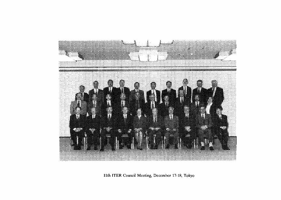
^•Xw WW>X 1 „
11th ITER Council Meeting, December 17-18, Tokyo

DOCUMENTSOF THE ELEVENTH ITER COUNCIL MEETING (IC-11)
17-18 DECEMBER 1996, TOKYO
NEXT PAQE(S)left *"i.**•'?*

IC-11 RECORD OF DECISIONS17-18 December 1996, Tokyo
The Council accepted participation as attached (IC-11 ROD Attachment 1) noting theintroduction of Dr. Y. Sokolov as a new Council Member from the RF and thanking Dr.N. Cheverev for his many years of dedicated service to ITER as a Council Member. TheCouncil adopted the IC-11 Agenda (IC-11 ROD Attachment 2).
1.1 The Council took note of the Director's Status Report (IC-11 ROD Attachment 3).
12 The Council commended the JCT and the Home Teams for the quality of theITER presentations to the 1996 IAEA Fusion Energy Conference and noted thatthe new experimental results have, in general terms, confirmed and strengthenedthe physics basis for the ITER design.
13 The Council noted that the Non-Site-Specific Safety Report (NSSR-1) would beavailable in final form in January 1997.
1.4 The Council noted the Director's concern over the possible effects on the JCTshould there be no positive indications regarding ITER's post EDA future andasked the Parties to take this concern into account in planning their decision-making process.
1.5 The Council encouraged the Parties to make their contributions to the 1997 JointFund Budget on a timely basis.
1.6 The Council endorsed the Director's request that due priority be given in theParties' major fusion experiments to strengthening the physics databases for ITERlisted in the Status Report and asked the Director to interact on this matter withIC members at Programme Director level to assure the timely transfer of these datato the ITER Project.
2.1 The Council accepted for consideration by the Parties, the Detailed Design Report,Cost Review and Safety Analysis (DDR). (IC-11 ROD Attachment 4).
22 The Council accepted the TAC Review of the Technical Basis for the DetailedDesign Report (ROD Attachment 5), noting that the review was based on theextensive technical documentation presented by the Director to TAC-11.
2.3 The Council, noting the TAC recommendation that the Detailed Design Reportoffers a sound basis for proceeding to the Final Design, agreed that the technicalwork of the EDA should continue on the basis of the DDR, taxing account of thedetailed technical findings and recommendations in the TAC Report
109

2.4 The Council noted with appreciation that essentially no change has occurred in theoverall cost estimate presented in the Interim Design and Cost Review in 1995.
2.5 The Council invited the Parties to present to IC-12 their views on the DDR and anyrelated technical comments arising from their domestic reviews.
2.6 The Council encouraged the Parties to notify the Director informally at the earliestopportunity of technical points arising from their domestic reviews that might affectthe preparation of the Final Design Report
3.1 The Council, approving the updated EDA Work Programme proposed by theDirector (IC-11 ROD Attachment 6), asked the Director and the four Home TeamLeaders to further elaborate the precise content and schedule of the R&D activitiesbeing undertaken in support of ITER design.
32 The Council agreed that, whatever the nature of the Arrangements coveringactivities after 20 July 1998, these Arrangement should include provisionsguaranteeing that the full results of the R&D initiated under the EDA, and whichmight not be completed at the end of the EDA, are made available to the fourParties.
3.3 The Council asked the Parties to make their best efforts to ensure that resourcesare maintained at current levels until July 1998, so as to implement the EDA work.
3.4 The Council supported the Director's view of the need for continuity from the EDAto construction activities and invited the Director, in consultation with Home TeamLeaders, to elaborate further and to report to IC-12 on the technical activities andestimated resources that would provide the required continuity.
3.5 The Council invited the Parties to consider taking actions needed to permit smoothtransition into construction activities.
4. The Council, on advice of MAC (IC-11 ROD Attachment 7), approved aSupplement of $100,000 to the ITER Joint Fund Budget for 1997 to permitincreases in Design Support contracts as proposed by the Director (IC-11 RODAttachment 8).
5. The Council took note of the CPs' Report on ongoing and future activities (IC-11ROD Attachment 9).
6.1 The Council requested TAC to review, from a technical viewpoint, the status andplans of the ITER R&D Programme. The TAC is also requested to reviewprogress on ITER diagnostics and the associated control system.
6.2 The Council approved further tasks for MAC (IC-11 ROD Attachment 10).
110

7. On the invitation of the EU delegation the IC-12 Meeting will be held in theEuropean Union on 23-24 July 1997. The IC-13 Meeting is tentatively scheduledfor January 1998 in San Diego.
8.1 The Council invited the Director to consider the options for Remote Participationin ITER operations and exploitations and to report on this matter to IC-13, in orderto allow the Council to take a position on the proposal from IEA for interactionwith an EEA Working Group on this subject
82 The Council noted from the JA Party an intention of the Japanese AtomicIndustrial Forum to host the Second Industries' Meeting in April 1997.
83 The Council developed a Press Guideline (IC-11 ROD Attachment 11).
8.4 The Council noted a statement from the JA Party that they will have an JTERmeeting with a group of Diet members where the Director is asked to make apresentation. The result of the meeting will be reported to the Council at IC-12.
8.5 The Council approved this IC-11 ROD.
8.6 The Council approved the IC-11 Minutes.*)
•) Not included in this publication
NEXT PAGE(S)left BLANK
111
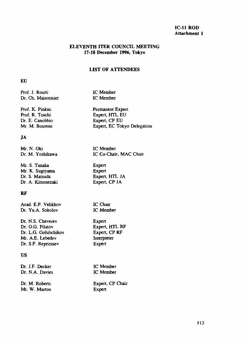
IC-11 RODAttachment 1
ELEVENTH ITER COUNCIL MEETING17-18 December 1996, Tokyo
LIST OF ATTENDEES
EU
Prof. J. RouttiDr. Ch. Maisonnier
Prof. K. PinkauProf. R. ToschiDr. E. CanobbioMr. M. Bourene
JA
Mr. N. OkiDr. M. Yoshikawa
Mr. S. TanakaMr. K. SugiyamaDr. S. MatsudaDr. A. Kitsunezaki
RF
Acad. E.P. VelikhovDr. Yu.A. Sokolov
Dr. N.S. CheverevDr. O.G. FilatovDr. L.G. GolubchikovMr. A.E. LebedevDr. S.F. Reprintsev
US
Dr. J.F. DeckerDr. N.A. Davies
Dr. M. RobertsMr. W. Marton
IC MemberIC Member
Permanent ExpertExpert, HTL EUExpert, CP EUExpert, EC Tokyo Delegation
IC MemberIC Co-Chair, MAC Chair
ExpertExpertExpert, HTL JAExpert, CP JA
IC ChairIC Member
ExpertExpert, HTL RFExpert, CP RFInterpreterExpert
IC MemberIC Member
Expert, CP ChairExpert
113

ITER
Dr. R. AymarDr. M. HuguetMr. M. Drew
Dr. P. RutherfordDr. V. Vlasenkov
IAEA
Dr. T. Dolan
ITER DirectorDeputy DirectorPCw/D
TAC ChairIC Secretary
IAEA ReDresenl
114

IC-11 RODAttachment 2
AGENDA OF THEIC-11 MEETING
Tokyo, 17-18 December 1996
17 December, Tuesday
14:00 Meeting openingMeeting arrangements, papers and attendanceRemarks by Heads of Parties' DelegationsChair's note about ExplorationsEx2 Chair's remarkAdoption of Agenda
1. ITER Status Report
2. Detailed Design Report2.1 Director's Presentation2.2 TAC Review
3. ITER Work Programme3.1 Director's Presentation
3.2 MAC Report and Advice
4. ITER Joint Fund
17:00 Adjournment
18 December, Wednesday
09:00 5. CPs' Report
6. Further Tasks6.1 TAC6.2 MAC63 CPs
7. IC-12, IC-13 Meetings - dates, places
8. Other Business8.1 Remote Participation8.2 Industries' Meeting83 Press Guideline
9. Approval of IC-11 ROD, approval of IC-11 Minutes
12:00 Adjournment
NEXTPAGE(S)| 115left BLANK

IC-11 RODAttachment 3
ITER EDA STATUS
report by the Director
1. This note summarises progress made in the ITER Engineering DesignActivities in the period between IC-10 and November 1996.
Overview2. The overall focus of the Project has been the preparation of the DetailDesign Report, Cost Review and Safety Analysis for presentation to IC-11.Following very intensive work, a 700 page document entitled Technical Basis forthe Detailed Design Report, Cost Review and Safety Analysis was completed andcirculated to Home Team Leaders and made available electronically to TACmembers and Experts. Supporting Design Description Documents for individualITER components were also made available electronically.
3 A major component of the DDR preparations was the completion, withvaluable contributions from the four Home Teams, of a comprehensiveassessment of ITER Safety and Environmental characteristics. The first draft ofthe Non-Site-Specific Safety Report (NSSR-1) was presented to safety expertsfrom the Parties at the end of September. Information from NSSR-1 provides thebasis of the safety section of the DDR which was discussed and at an informalTAC-JCT assessment meeting in early October. On current plans, a secondversion (NSSR-2) will be prepared by the end of 1997. This document is expectedto provide all the technical basis required by potential host parties to performenvironmental impact assessments and to start the licensing process. It is hopedthat the Parties will soon nominate their points of contact on regulatory mattersto help ensure the relevance and focus of further work on NSSR .
4. The DDR contains extensive coverage of the Physics basis for ITER whichreflects the large volume of high quality work undertaken in the establishedframework for ITER Physics. A draft of the ITER Physics Basis Chapter was thesubject of an informal TAC/JCT/Physics Committee assessment heldimmediately after the IAEA conference.
5 The progress of ITER, especially as concerns Physics, was presented at thesixteenth IAEA Fusion Energy Conference held,in Montreal, Canada, 7-11October. ITER was the subject of 34 papers or posters with over 400 JCT/HomeTeam authors drawn from almost 60 different organisations. Many of the otherpresentations from the major fusion experiments also bore witness to the keyrole that ITER occupies in fusion science and development.
117

6 ITER personnel took part in a meeting on remote participation in scientificexperiments held in the margins of the IAEA conference. The capability forremote participation in ITER operations may be important to a possible futureTIER collaboration.
7 The sensitivity studies of variations from the Site Design Assumptionsapproved as part of the IDR package are being prepared for circulation to theParties for review. Information on the design impact of the variations will bepresented to the coming TAC meeting. Other subjects recommended for furtherstudy by the SRG have been incorporated in the DDR documents.
8 The project continues to be affected by budget difficulties in some Parties.As indicated to IC-10, measures have been taken by the JCT and Home Teams tomitigate the adverse effects as far as possible. The update of the WorkProgramme presented to MAC 11 is based on revised assumptions aboutresource availability during the rest of the EDA.
9 Dr Iotti, the Administrative Officer, left the project with effect from 1November 1996. Through his energy and expertise, Dr Iotti has made a majorand lasting contribution to the successful conduct of the EDA which is widelyrecognised and warmly appreciated. There are no plans at present to replacehim; his continuing responsibilities are being distributed within the JCT.
Design Work10 The DDR represents the third major milestone of the ITER EDA. The nextmilestone — the Final Design Report — is currently scheduled for January 1998.Plans are now in hand for the work leading to the preparation of that report.Recognising the relatively short time time available to complete design work andto draft the report, it will be important to receive any comments on the DDRfrom the Parties as soon as possible. There will be a JCT internal design reviewmeeting in January to take account of the DDR and any TAC/Council commentsand to set the timetable for the year. The plans will be shared with the HomeTeams and TAC as appropriate.
Joint Central Team and Support11 The status of the JCT is summarised by Joint Work Site and by Party inTables I and II below; the build up over time is shown in Figure 1. Since the laststatus report, 5 (2 JA, 3 US) members left the team, and 8 new members joined (2Canadian/EC, 5 JA, and 1RF).
I. JCT - Status by Joint Work Site at end October 1996
Selected2
On Site
Seconded
Garching Naka San Diego53 62 56
511 571 551
50 56 50
Total17P16313
156
118

II. JCT - Status
Selected2
On Site
Seconded
by Party at end October 1996
EC54
50i
45
JA49
47
47
RF293
293
293
US39
37
35
Total171
163
1561 includes live Canadians provided through the Canadian association with the fct_ f arty.2 figures exclude team members who have left, or selected staff who have declined posts or otherwisewithdrawn3 in addition, 8 RF professionals have been requested, four of whom have arrived, under special VHTParrangements,
12 The estimated cumulative PPY effort on site to end October 1996 is shownin Table III below by JWS and by Party.
III. JCT - Cumulative PPYs on-site to end October 19%
Garching
Naka
San Diego
Total
EC
453
45.8
35.6
126.7
JA
37.6
38.9
43.7
120.2
RF
16.3
19.6
30.4
66.3*•The RF figures incudc 0 3 designer years of recent VHTP arrivals
US
31.4
39.4
48.7
119.5
Total
130.6
143.7
158.4
432.7
13 The updated Work Programme now assumes that JCT staffing will peak atthe level of about 167 from Jan 1997 to the end of the EDA. It will be essential tomaintain this figure. As JCT members are recalled at the end of their secondmentperiods, their replacements need to be nominated and assigned on a timely basis(as experienced now with some JA assignees), allowing a reasonable overlapperiod to avoid disrupting the work. The recalling Party could be expected, ingeneral, to make best efforts in finding suitable possible replacements.
14 It should also be recognized that with the end of the EDA approaching,staff will naturally be seeking to assure their longer term career prospects.Without positive indications for ITER's future they may seek such assuranceelsewhere and replacements will be harder to find. This could reduce further theavailable JCT resources at a time when they are needed the most.
15 The update of the Work Programme also emphasises the need to maintainfor the duration of the EDA Home Team design resources andthe CAD, technicaland secretarial support at the levels now reached.
Visiting Home Team Personnel (VHTP) Scheme16 Operation of the Visiting Home Team Personnel scheme was outlined inthe status report to IC 10. The scheme continues to function well as a means toenhance JCT/Home Team interaction and to offer some flexibility. In particular,
119

following the offer made by the RF Party, four new RF VHTPs are on site forassignments of three to four months each; four more are expected to arrive inJanuary. As noted at IC-10, these VHTPs are being assigned by the RF in lieu offurther JCT secondments. They are therefore accorded zero PPY credit but arenoted in the RF contribution to JCT resources.
IV. JCT - Cumulative VHTP effort (PPY) to end Oct,1996
Garching
Naka
San Diego
TotalNotes:
123
EC
4.42
2.75
6.96
14.13
JA
0.21
0.69
1.51"
2.41
RF
0.17
0.33
0.29
0.79
US
0.83
1.71
0.582
3.11
Total
5.63
5.48
9.34
20.443
includes one visiting scientistexcludes US Home Team task to assist on planning and costing from Jan 94includes Home Team Staff assiened to provide urzent assistance at end 1993
18 As noted above, not all the visitors have attracted ITER credit. The totalPPY credits accruing to end Oct 1996 are as follows:
EC10.47
JA1.77
RF0.5
US2.11
Total14.85
Note: Credit has been pro-rated for those VHTPs whoseassignments extend through I Nov 1996.
RF Design Support Contracts17 The arrangments for RF design support contracts presented to IC-10 havedeveloped as expected. A small number of further contract were authorisedshortly after IC-10 as planned. The updated status is summarised in the Annex.
18 Work plans are being drawn up at technical level for contracts to beundertaken in the remainder of the EDA. Following the advice of IC-10, it isproposed to increase the volume of work. A proposal for a supplementary JointFund Budget for this purpose is submitted for Council approval. Actualauthorisation of contracts wUl depend strictly on the availability of funds.
Task Assignments19 The status of existing Task Assignments is set out in a separate Paper tothe current Meeting. Major new tasks on Heating and Current Drive weresupported at MAC 11 following discussions at the Home Team Leaders' meeting.There are ten new Task Agreements for Design and one R&D Task to reportsince IC-10, two of which are Voluntary Physics work with zero credit. Six tasksare VHTP task agreements. Another task is homework to a Home Team withzero credit to fulfill the SRG requests on the consequences of changes in siteassumptions on design and cost. There is one technology R&D with 400IUA inthe safety area and one design task (2PPY) in the Divertor area.
120

20 The updated task status is summarised in the tables below. After theMAC-10 meeting in June 1996, significant task modifications were finalized andunanimously supported by MAC through written procedure. The supportedfigures were reported to IC-10.
21 The latest figure of about 596 klUA for the technology R&D taskscommitted or to be committed to the Parties represents an increase of about 11klU A over the figures by MAC and reported to IC-10. The number is about 25klUA less than the credits for identified tasks included in the Work Programmeendorsed by MAC-8 and approved by IC-8 in July 1995. The design credit valuenow stands at 70757 PPY (including 1725 PPY of VHTP effort).
22 About 315 tasks, including both design and technology R&D have beencompleted and the final reports have been submitted by the Home Teams. Totalvalues of task allocations to date, including the VHTP tasks, are as shown below:
TypeTAWorkCompletediU TasksOther tasksCommitted /ongoing
Totals
IUA PPY125,255 23130329,800J41,378 , 47627
596,433 707.57
1 Tasks for which the HTL concerned has submitted an acceptable final report for>6 weeks
The pattern of assignment to Parties is summarised below; totals of approvedtasks as reported to IC-10 are shown in italics:
PartyEC
JA
RF
US
Totals
IUA193,166188J86174JB27171.42795,41793237
133,023132323
596,433555,373
PPY196.05296.05169.93167.431572015720184.3918439707.57705.07
The ITER Joint Fund23 At the Director's request the IAEA has distributed during 1996 to the JointFund Agents S2.1M. A delay in receiving all contributions has caused some delayin planned expenditure during 1996. But all Parties have now paid their 1996contributions in full and further releases will be made.
24 Following IC-10 approval of the 1997 budget at the level S2.4M, theDirector so notified IAEA and the budget is now adopted in accordance withArticle 3.5 of the Joint Fund Financial Rules. The Director has sent to the Partiesthe call for 1997 contributions.
121

25. As noted above, there is a proposal to supplement the 1997 budget by$0.1 M to provide for an increase in the RF Design Contracts.
ITER Public Information25 The ITER Brochure has been well received and a second print run of5,000 copies was made. A Japanese language version of the brochure has nowbeen produced with the assistance and support of the Japanese Home Team.Work is in hand on the development of the project's presence on the World WideWeb.
Test Blanket Working Group26 Following the discussion at IC-10' (IC-10 ROD 1.9), the Test BlanketWorking Group has made considerable progress in its work. At TBWG-3 atentative agreement was reached on port-sharing for test purposes consistentwith operational and physical constraints of the ITER plant and ancillarysystems. Separate Design Description Documents have been produced for theproposed test modules and these DDD's (with an agreed executive summary) areavailable for review with the rest of the documents that support the DDR.TBWG members will participate informally in a review of the ITER BreedingBlanket design due to take place at the next blanket design tasks meeting.TBWG-4 has been scheduled for April 1994, to take place around the time of theISNFT conference.
ITER Physics27 The significant progress made on ITER Physics is reflected in the Physicssection of the DDR
28 Following the ITER Physics Committee meeting in October, the Directorwrote to the heads of major fusion laboratories seeking assistance in developingand strengthening the physics databases deemed "Urgent" by the PhysicsCommittee, ie:
H <=> L Power ThresholdH-mode Thermal ConfinementCritical shots for profile databaseDivertor Scalar DatabaseELM Properties DatabaseHalo Current Database.
The helpful response from the laboratories to previous request for assistancewith Halo current data was recognised at the IAEA conference. It is hoped thatthere will be a similar timely and generous response on the broader front.
RECOMMENDATION
The ITER Council is invited:
to take note of the current status of the Project as set out in this report.
122

Design Contracts in Russia
Efremov InstituteSt. Petersburg
TitleDates
Volume
Design ofSuperconducting Magnets
and Thermal-shields
8 Designer Years(DY)108k$
*
Stage 1-5 to 31/12/96
Further stages envisaged
Objective
Parametric analysis of the impact of TF, PF and CS and mechanical structures manufacturingand assembly tolerances on error fields.Determine size, location and manifolding for cooling passages in a TF cases, VV and gravitysupports for TF, PF coils and for CS.Design TF, PF and CS joint layout and support systems.Design transition of coil terminal to the SC current bus for NbaSt and NbTi(TF, PF coils and CS).Evaluate alternative TF case and PF manufacturing procedures.Design feedthroughs, electrical breaker transitions and thermal expansions for current andcryolinesDesign steel plate covers, protective plates between modules and corresponding insulation forPF coilsDevelop manufacturing and assembly procedure for the crowns

Design Contracts in RussiaENTEKMoscow
TitleDates
VolumeDesign support in"Neutronics " area
Stage 1 to31/03/960.83DY
12k$'Design Support in area of
"Hydraulic Stability"Stage 1 to 29/.02/96
1.25 DY18 k$ •
Design Support in area ofLimitef
Stage 1 to 29/02/961DY14k$
Objective
Calculate the radiation field in and around the equatorial ports as function of "generic" shieldingand penetrations that are likely to be present in the ports. (2D and 3 D)Calculate detailed fluxes, nuclear heating, radiation damage, activation, decay heat and doserate distributions in individual blanket modules near the equatorial ports . ( 2D and 3D)
Create thermohydraulic models of Limiter and Baffle FW panels.Create analytic methods for hydraulic stability analyzing.Perform static analysis and determine the coolant parameter area for static instabilityPerform dynamic analysis and determine the allowable coolant parameters
Develop detailed design of a limiter module.Optimize coolant channel layoutCalculate temperature and thermal stresses distribution.Produce design analysis and drawings to describe an optimized design.

Design Contracts in RussiaVNIPIET
St. Petersburg
TitleDates
VolumeSteady State Electrical
Power Network DesignTotal contract to
1/12/963.5 DY50k$
Stage 3 of four completed
Objective
Design steady state power supply for ITER:Switchyard,Power Distribution System,Emergency Power Supply Building,Utility Tunnels.
Develop detail design for electrical services in:PFCoil fabrication Building,Magnet Coil Test Building,Cryoplant Compressor Building (one train)Component Cooling Water System (one train)Chilled water system (one train)Compressed air system (one train)Potable and Fire water SystemMagnet Coil Power supply system (temporary location )

KJ
Design Contracts in Russia
RRC Kurchatov InstituteMoscow
TitleDates
Volume
Objective
Design Support for NeutralBeams
Total Contract to31/12/96
3DY
Develop engineering design of the following components :gas neutralizer; residual ion damp; component support and aligncment structure; flexibleconnection between NBI valve and the port; active magnetic shielding coils.
Perform detail calculations of water cooling conditions of the NBI components
stages 1-4 of 5 executedCalculate loss fractions of the high energy particles (alphas, NBI and ICRH minorities) for ihelow current high (5 advanced scenario.Calculate radiation efficiency of the ITER divertor. as function of density , impurity fraction ,impurity species and other assumptions.Analyze dependence of neutral density in the divertor on pumping and particle throughputAnalyze the charge exchange recombination rate in the ITER divertor (including calculationof cross-sections)Develop specifications for plasma disturbances in ITER.Perform numerical analysis and optimization of the ITER ICRF system .Develop optimization of the ITER advanced steady state scenario taking in account constraintsof the ITER auxiliary current drive system.
Physics Design Supportto 31/12/96
Stage 1-4 of 5 executed7.3 DY86k$
Further stages foreseen

Design Support for ITERDiagnosticsStage 1 to31/12/95executed1.65 DY
20k$Design Support for ITER
Diagnosticsto 31/12/96
5DY60 k$
2 of three stages completed
Calculate (2D and 3 D) neutron and gamma flux levels and required shielding for:vertical neutron camera;radial neutral camera
Design multiple automatic connectors for probes and pressure gauges.Evaluate the design of HF magnetic coils
Optimize shielding geometry for: vertical neutron camera, radial neutron camera, LIDARSystem, eqv. plane density interferometer and for a mid-plane port with several otherdiagnosticsDesign multiple automatic connectors for a blanket module and for a divertor cassette.Design HF magnetic coils
toJ

Teun Membeis
o
21-Jul-92 -»s
21-H-96 —
21-Oct-96 —
to
8
! =3
03 .

IC-11 RODAttachment 4
ITERDETAILED DESIGN REPORT,
COST REVIEW AND SAFETY ANALYSIS
CONTENTS
1. Introduction
2. ITER Objectives
3. Main Parameters and Key Features of the ITER Design
4. ITER Operating Scenarios and Performance
5. Design Development
6. Technology Development
7. Safety and Environmental Analysis
8. ITER Cost and Schedule
9. Conclusions
129

ITER
DETAILED DESIGN REPORT,
COST REVIEW AND SAFETY ANALYSIS
1. INTRODUCTION
1.1 The ITER Detailed Design Report, Cost Review and Safey Analysis Reportis the third major milestone report presenting the progress made in the ITEREngineering Design Activities.
12 An Outline Design Report was presented in January 1994 to ITER Counciland provided a basis on which the Parties concluded Protocol 2 of the ITER EDAAgreement. Further development and enhancements of the design werepresented in the Interim Design Report, Cost Review and Safety Analysis("IDR") which, with companion documents, was presented to ITER Council inJuly 1995. Following domestic reviews by the ITER Parties, the "Interim DesignReport Package" was approved by ITER Council at its meeting in December 1995.Against this background, the ITER Parties have entered explorations aimed atidentifying issues for subsequent Negotiations towards a possible Agreement onITER construction, operation, exploitation and decommissioning.
13 On the basis of the approved IDR package and taking account of commentsarising from the Parties' reviews of the IDR package, it has been possible tofreeze the core concepts and systems approaches for the ITER Tokamak. Indesign work, attention has been given to system-wide considerations, includingthe overall layout, access arrangements and procedures for construction andmaintenance, and the configuration of Tokamak peripherals. The programmeof validating R&D has been focussed on key issues arising from the developingdesign. The stable design also provides a firm basis for Physics assessments, foroverall safety and environmental analyses, and for updating cost and scheduleestimates.
1.4 This report outlines the progress being made in the above activities.Detailed supporting technical documentation has been made available forreview within the ITER EDA framework.
13 The next milestone of the EDA — the Final Design Report — will drawtogether, for all components and subsystems, the results of detailed design work(including related R&D) undertaken within well-defined system interfaces, inorder to provide the technical data including cost and schedule estimates onwhich to base a possible construction decision.
2. ITER OBJECTIVES
2.1 The overall programmatic objective of ITER, as defined in the ITER EDAAgreement, is to demonstrate the scientific and technological feasibility offusion energy for peaceful purposes. ITER would accomplish this objective bydemonstrating controlled ignition and extended burn of deuterium-tritium
130

plasmas, with steady state as an ultimate goal, by demonstrating technologiesessential to a reactor in an integrated system, and by performing integratedtesting of the high-heat-flux and nuclear components required to utilize fusionenergy for practical purposes.
2.2 Detailed technical objectives along with the technical approaches todetermine the best practicable way to achieve the programmatic objective ofITER have been established and were adopted by the ITER Council inDecember 1992 and acknowledged in Protocol 2 of the ITER EDA Agreement.
2 3 The detailed technical objectives involve two phases of operation, theBasic Performance Phase and an Enhanced Performance Phase. The ITERDesign provides the design for Basic Performance and allows for a futureincorporation of features, including a tritium breeding blanket, which would beneeded to achieve the objectives of the Enhanced Performance Phase.
3 . MAIN PARAMETERS AND KEY FEATURES OF THE ITER DESIGN
3.1 The main characteristics and parameters of the ITER Design follow fromthe agreed programmatic and detailed technical objectives for ITER, inparticular to meet the objective of demonstrating controlled ignition andextended bum, in inductive pulses with a flat-top duration of approximately1000 s and an average neutron wall loading of about 1 MW/m2. An importantassumption underlying the detailed technical objectives, is that there will be anadequate supply of tritium from external sources of up to about 3 kg/yearduring the Basic Performance Phase and 1.5 kg/year during the EnhancedPerformance Phase.
32 The main parameters and overall dimensions of ITER remain thoseestablished in the IDR, summarised in Table 1 below.
Table 1 Main Parameters and dimensions of ITER
Total Fusion PowerNeutron Wall loadingPlasma inductive burn timePlasma major radius4
Plasma minor radius
k95(eUipticity O95% flux surface)
q 9 5 (safety factor O95% flux surface)
Bo @ 8.1 m radiusBmax @ TF coilTF RippleAuxiliary Heating power
15 GW1 MW/m2
1000 s8.1m2.8 m21 MA1.635.7 T125 T2% at the separatrix100 MW
* Plasma major radius is measured from the centre of the last closed flux surface.
131

Overall the parameters reflect a careful balance of physics requirements forconfinement, plasma control and stability, and engineering constraints (e.g.,heat loads and electromagnetic characteristics, need for access) to ensure safeand reliable operation within reasonable cost.
3.3 The essential features of the Tokamak Design include:• an integrated structural arrangement in which superconducting magnet
coils (20 cased toroidal field coils, 7 poloidal field coils and a monolithiccentral solenoid) and vacuum vessel are linked to provide an overallassembly which simplifies the equilibrium of electromagnetic loads in allconditions, relying largely on the robustness of strong TF coil cases;
• modular in-vessel components (blanket modules on back-plate and divertorcassettes) designed to be readily and safely maintainable by a practicalcombination of remote handling and hands-on techniques.
• containment of the machine core in a cryostat vessel, and installation in anunderground pit, inside a building of minimum height.
3.4 The features of the Tokamak and peripheral systems are summarised inTable 2. Figure l(a) shows a 3-dimensional cutaway view of ITER including thecryostat; Figure l(b) shows the Tokamak in cross section.
35 A very small number of high-level design options remain open atconceptual level, principally:• possible improvements to the Central Solenoid reference design by splitting
the coil into separated modules;• blanket module attachment to the back plate;• possible reduction of TF ripple through ferritic inserts in the vacuum vessel.These options are the focus of intensive work in design and related R&D withthe view of finalizing choices for inclusion in the Final Design Report.
132
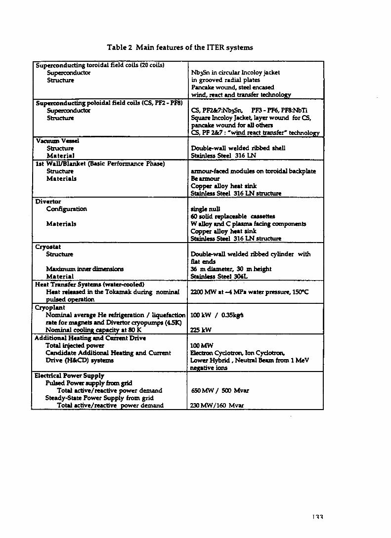
Table 2 Main features of the ITER systems
Superconducting toroidal field coils (20 coils)SuperconductorStructure
Superconducting poloidal field coils (CS, PF2 • PF8)SuperconductorStructure
Vacuum VesselStructureMaterial
1st Wall/Blanket (Basic Performance Phase)StructureMaterials
DivertorConfiguration
Materials
Cry os tatStructure
Maximum inner dimensionsMaterial
Heat Transfer Systems (water-cooled)Heat released in the Tokamak during nominalpulsed operation
CryoplantNominal average He refrigeration / liquefactionrate for magnets and Divertor cryopumps (4-5K)Nominal cooling capacity at 80 K
Additional Heating and Current DriveTotal injected powerCandidate Additional Heating and CurrentDrive (H&CD) systems
Electrical Power SupplyPulsed Power supply from grid
Total active/reactive power demandSteady-State Power Supply from grid
Total active/reactive power demand
NbjSn in circular Incoloy jacketin grooved radial platesPancake wound, steel encasedwind, react and transfer technology
CS, PF2&7:Nb3Sn, PF3 - PF6, PF&NbTiSquare Incoloy Jacket, layer wound forCS,pancake wound for all othersCS, PF 2&7: "wind react transfer" technology
Double-wall welded ribbed shellStainless Steel 316 LN
armour-faced modules on toroidal backplateBe armourCopper alloy heat sinkStainless Steel 316 LN structure
single null60 solid replaceable cassettesW alloy and C plasma facing componentsCopper alloy heat sinkStainless Steel 316 LN structure
Double-wall welded ribbed cylinder withflat ends36 m diameter, 30 m heightStainless Steel 304L
2200 MW at -4 MPa water pressure, 150°C
100 kW / 0.35kg*
225 kW
100 MWElectron Cyclotron, Ion Cyclotron,Lower Hybrid, Neutral Beam from 1 MeVnegative ions
650MW/ 500 Mvar
230MW/160 Mvar

Figure l(a)Cm- Awav View of the HTR lokamak Core

CENTRAL SOLENOID fUPPER CRQWN
AAA
POLOIDAL FIELD COIL
UPPER PORTTFCOIL
BLANKET MODULES
VACUUM VESSEL
INTERCOILSTRUCTURE
EQUATORIAL>ORT
DIVERTORPORT
0 Jm 2m
rnwra ntnwN
PRFT DAD STRT r m i R E
VACUUM VESSEL SUPPORT
BACKPLATESUPPORT
Figure l(b)ITER Tokamak Cross-Section
135

4. ITER OPERATING SCENARIOS AND PERFORMANCE
4.1 Operating scenarios
Plasma Operation Scenario.
4.1.1 The plasma discharge scenario for ITER will follow the familiarsequence vised in present Tokamaks. The pulse will start with breakdown andcurrent initiation (assisted with ECH power) followed by a 150 s inductivecurrent ramp up. The divertor configuration will be formed at Ip = -16 MA.Auxiliary power (up to 20 MW in the limiter phase, 50-100 MW in the divertedphase) can be applied if desired during current ramp up for control of plasmacurrent profile and toroidal rotation. Plasma density at the start of currentflattop will be 0.2-0.5 1020 nr3; Ohmic temperature will be 2-4 keV. Fullauxiliary heating of up to 100 MW will be applied at the start of the flattop toobtain H-mode, and plasma density will be subsequently increased by fuelinguntil the ignition and nominal value of the fusion power is achieved. Burn(fusion power) control, divertor power control and subsequent normal fusionshutdown over a 300 s shutdown period will be achieved with a coordinatedcombination of control of DT fueling, impurity fueling, auxiliary power input,and poloidal field control.
Plasma Operation Mode for Ignition/High-Q Driven Burn.
4.1.2 Operation with a sawtoothing, ELMy H-mode is used as the basis forprojections of ITER performance in the ignited or high-Q driven-burn regime(Sawteeth and Edge-Localized Modes occur naturally in the described operation;they play a useful role in avoiding impurities accumulation inside the plasmacore). This operational mode is well studied in the present experiments and alarge database is available for projection of the energy confinement and otheressential parameters to ITER. The mode provides adequate confinement andallows sustained stationary (time-independant) plasma operation with lowimpurity concentration, controlled density, sufficiently high plasma P (the ratioof plasma pressure to the magnetic energy density), and adequate heliumtransport to the plasma boundary. Long pulses ELMy discharges with ITER-likeplasma geometries and parameters (in relevant dimensionless values) havebeen demonstrated in all major divertor Tokamaks. H-mode can be achievedwhen sufficient heating power is applied to the plasma. Key physics issues areprojections of energy confinement and H-mode power threshold to ITERparameters.
In driven burn operation, auxiliary heating power of 100 MW allows extensionof pulse lengths and maintenance of high neutron wall load, providing highfluence for testing. From the reference pulse at 21 MA, 1.5 GW and 1000 s, thepulse length can be extended to 8000 s at about 1 GW with a plasma current ofabout 16 MA.
True steady-state operation can be obtained at 12-15 MA with the availableauxiliary heating/current drive capability to supplement a large bootstrapcurrent fraction (>70%). In this scenario, the radial distribution of currentdensity provides a configuration with "reversed shear" (the radial q profile has
136

a minimum off the axis), which has been demonstrated successfully in recentTokamak experiments with very good performance in confinement.
Divertor Operation and Power and Particle Exhaust.
4.13 Particle and Power control in HER will be accomplished with a tightlybaffled, single null poloidal divertor that is actively pumped with ex-vesselcryo-pumps. Plasma fueling will be provided with gas puffing and pelletinjection. The total heating power of 300-to-400 MW (o + auxiliary) will beexhausted via the first wall and divertor by a combination of bremsstrahlungand synchrotron radiation from the plasma core, impurity radiation from theplasma mantle, scrape-off layer and divertor channel and conduction to thedivertor targets. The radiation losses to the walls reduce the peak heat loads onthe divertor target plates to acceptable values. The radiation losses areenhanced by the injection of small quantities of impurities (Ne, Ar).
The ITER divertor plasma will be operated in the "detached" or "partiallydetached" regime achieved on modern divertor Tokamaks. This regime haslow heat loads on the divertor targets and provides adequate helium exhaust.
4.2 Plasma performance
An overall assessment of ITER Physics performance for the stable designhas been conducted. Evaluations were carried out through the ITER PhysicsExpert Groups to ensure that the EDA benefits to the fullest extent from theresults of current fusion experiments and from the most up to date views onthe relevant physics phenomena.
4.2J2 The assessment focusses on two categories of issues, namely, those thataffect the achievable power and burn duration of the ITER plasma and thosethat affect plasma operational reliability and/or in-vessel component lifetime,and therefore are dealt with in the engineering design.
The first category includes :
• energy confinement at ITER plasma parameters (e.g. low collisionality andsmall ion gyroradius) and operational limits on plasma density and p;
• divertpr operation, in "partially detached" regime, with low heat flux anderosion of the divertor targets, good exhaust efficacy for helium ashes andcontrolled impurity influx inside the plasma core.
The principal issues in the second category include :
• reliable control of the plasma magnetic configuration, fusion power level anddivertor target heatflux, achieving thus reliable plasma initiation and currentflattop with low disruptivity (disruption/ pulse);
• accommodation and mitigation of the thermal and electromagneticconsequences of plasma instabilities (disruptions and large verticaldisplacements events /VDEs).
137

4.2.3 The projections for plasma core energy confinement basically depend on aglobal scaling of ELMy H-mode, observed in present experiments, the resultsfrom which have been included in a large, critically analysed Database. Thisapproach relies conceptually on the assumption that the Tokamak confinementphysics is governed by a number of non dimensional parameters and that asimple power law relation suffices to represent the energy confinement time forthose non dimensional parameters that require extrapolation for ITER. Thefocus is therefore on "ITER Demonstration Discharges", in which experimentsare done in present machines with nondimensional quantities, except thenormalised gyroradius, having values envisaged for ITER. TheseDemonstration Discharges should provide the most reliable approach to scalingconfinement The output from this ongoing experimental campaign is expectedto generate high confidence in ITER projections. First results from JET andDIII-D Demonstration Discharges support an extrapolation of confinement inITER somewhat better than the reference value.
42.4 For detailed description and analysis of the sustained burn in ITER,including divertor operation and helium exhaust, the predictions of core energyconfinement time mentioned above must be complemented with temperatureand density profile information and other quantities, derived from lV2-Dpredictive transport codes, so as to compute, in a self-consistent way, theproduced fusion power. These code models provide local heat transportcoefficients either derived empirically or developed from first principles.Because the choice for the local coefficients is not unique and still somewhatarbitrary, they are normalized to give the prescribed global energy confinementtime. Moreover the predicted temperature profiles produced in this way havebeen checked to ensure that they agree well with temperature profiles observed(after proper normalization) in present ITER Demonstration Discharges fromJET and DIII-D. If used without normalisation, the nine available modelsconsidered to date by the Expert Group have not yet met the level of successwhen compared against data from the ITER Profile Database that would enablethe Group to recommend any of the models to be relied upon for the predictionof the core energy confinement time.
42J5 The ITER divertor targets cannot be expected to withstand the total alphapower concentrated onto the target "wetted" area (- 300 MW on - 1 0 m2). Thedevelopment of an acceptable engineering design requires a reduction of thepeak heat flux to 5-10 MW/m2. The strategy of using atomic processes to spreadout the deposition of the power over the first wall and the divertor chamber wall(1200 m2 and 400 m2 respectively in ITER) has been effectively and successfullyaddressed in present experiments by a combination of impurity seeding (Ne, Ar)
and gas puffing. Modelling of the complex physics occuring has made enoughprogress, to date, to check present experiments and to make the projection thatsimilar regimes can be achieved with impurity seeding in ITER.
4.2.6 Because of the limits of current experiments, inevitable uncertaintiesremain in the extrapolations to FTER and in the integration of different aspects ofITER plasma performance. Important areas of uncertainty include the H-modepower threshold, the density limit in H-mode and the effect of the plasma edgeon confinement, the formation of runaway electrons during plasma disruptionand the halo current asymmetry and magnitude. These issues have been and arecontinuing to be addressed in the FTER-related Physics R&D programme.
138

4.2.7 Present results of very good confinement performance in "reversed shear"discharges in various Tokamak experiments (the so called "advancedconfinement modes") are such that this operational scenario is presentlyenvisaged as necessary to obtain full power (> 1 GW of fusion power) steady stateoperation in ITER. The achievement of p and confinement values about 50%higher than the reference ones, with a much reduced current, will be necessary.But the present understanding and experimental knowledge of power andconfinement scaling and of operational limits in this scenario are less developedthan for the reference pulsed scenario; further work is required in present andfuture experiments.
4.2.8 Pending resolution of these issues, the "reversed shear" regime is beingused as a candidate for studying the steady-state operational flexibility andcapabilities of ITER.
4 3 Overall Assessment
Thanks to contributions from the world fusion community expressedcomprehensively through the HER Physics Expert Groups, significant progresshas been made in the integration of the different aspects of ITER performanceand operational scenarios. The Physics assessments for FTER are now broadlybased on the collated results of the current generation of fusion experiments andbenefit from continuous interaction with members of their teams. The newexperimental results presented at the recent IAEA Fusion Energy Conference(Montreal, October 1996) have, in general terms, confirmed and strengthened thephysics basis for the ITER design. Even with such a foundation, extrapolationfrom present plasmas to the ITER size and parameters cannot be predicted withcomplete certainty. Nevertheless, the wide-ranging reviews have not so farfound any limitations in principle which could preclude achieving the requiredITER performance and objectives.
According to the present most validated way of projecting ITER plasmaperformance, ignition in 1TER is probable with the reference plasma parameterand confinement values. With up to 100 MW of auxiliary heating, a sustainedburn at 1-1.5 GW of fusion power will be achieved, while simultaneouslysatisfying divertor heat load and H-mode power threshold, within a wide rangeof plausible conditions and reduction in confinement by ~ 30% from thereference value.
The flexibility of the ITER design permits realization of a range of operationalscenarios, from minimal 1000 s inductive pulse, to true steady state currentdriven "reversed shear" operations.
5. DESIGN DEVELOPMENT
5.1 The stability of the overall design allows detailed design for the variousTokamak systems and components to be conducted in the JCT and the HomeTeams with the assistance of their industries, within a framework of well-defined and stable design requirement documents which provide a morespecific statement at the system or component level of the performance, safety
139

and configuration requirements to be met. With the detailed design work inprogress it has also been possible to start developing in depth thecommissioning and operation plans.
ITER Plant Layout and Assembly
52 The main evolutions of the design after the IDR are at the level of theoverall ITER plant. Developments in this area include:
1. The design of the Tokamak building and the Tokamak pit and the layoutof the peripheral equipment have been reconfigured to give moreefficient use of the space around and below the Tokamak. A seismicdesign option which uses seismic isolators for the Tokamak pit has beenestablished which could accommodate a possible earthquake with aground acceleration significantly greater than the site design assumptionof 0.2g. Safety is also improved by providing dedicated galleries forspecific functions which are separated by radiological barriers, and byminimizing the number of penetrations across the possible boundary ofseismic isolation.
2. The shape of the cryostat vessel which confines the Tokamak vacuumvessel and magnet systems in a vacuum has been altered to improve useof space.
3. Remote assembly and handling procedures and design of relatedequipment have been developed and optimized further by consideringmaximum possible use of hands-on maintenance consistent with theALARA principle, and access to remote handling ports through shieldedcells, allowing parallel activities in the neighbouring cells.
4. Several changes of design have been made in primary heat transfersystems of the Tokamak in terms of number of loops, or routing of pipes,and reconfigurations to improve safety.
Figure 2(a) shows the Tokamak and its peripherals in the Tokamak pit with thesurrounding galleries. Figure 2(b) shows the seismic isolation option.
53 A procedure for assembly of the Tokamak core has been developedwithin the imperatives of accurate location of components, necessary testingand QA procedures and parallel activities to maintain a reasonable time scale.The procedure provides modules comprising one TF coil and two VacuumVessel half-sectors to be preassembled and tested before installation into theTokamak pit. In parallel, large sectors of the backplate are welded together andintroduced by rotation into the vacuumvessel. Pre-tested blanket modules arethen attached to the Back Plate.
Blanket design
5.4 Recognising ITER's mission to test design concepts of tritium breedingblankets relevant to a reactor, the Parties are developing their own plans fordesign and construction of scalable models for that purpose to install in ITERports and test during its operation. In addition, it is expected that ITER willitself require a breeding blanket to ensure an adequate supply of tritium fuelduring the later (Enhanced Performance) Phase of operations. For this purpose
140

ft-*
0 10 10 30 40 50 m
I , , , , ! . , , , ! , , , , ! , , , , ! , , , , ! , , , , ! . , , , ! , , , , ! , , , , ! , , , , !
Figure 2 (a)ITER Tokamak and Peripheral Equipment

Figure 2 (b)Cross-Section of Tokamak Building with
Seismic Isolation Option
142

O O Q p O Oooaboo
Key to Tokamak Building1. Tokamak Hall fc Pit2. Assembly Hall3. LaydownHall4. Hot CeU Building5. Tritium Building6. Tokamak Services Building7. Electrical Termination Building8. Radwaste Building9. Personnel BuildinglO.Cryoplant Compressor Building _ll.Cryoplant Cold Box/Dewar Building ^ p^i storage Tanks12.Magnet Power Supply Switching 29. Pulsed Power Switchyard
Network Building 30. steady Slate Switchyard13.Magnct Power Conversion Building 3, Outdoor Storage Areas14. RFheattng Power Supply Building 32 - Sewage Holdup Tank
IS. NBI power supply yards17. Cas storage yard18. Cooling Tower Hot Basin19. Steam Plant Fuel Tank20. Cooling Towers (not shown)21. Emergency Power Supply Building22. Laboratory Office Building23. Control Building24. Site Services Building25. RF CoU Fabrication Building27. Outdoor Water Storage Tanks
Figure 3The ITER Site General Layout

lithium ceramic with beryllium multiplier has been selected as the primarycandidate materials and detailed design is proceeding of breeding blanketmodules which would occupy the same space and use the same cooling circuitas the shielding blanket modules used for the Basic Performance Phase.Preliminary breeding calculations show that a tritium breeding ratio about 0.8should be achievable. This will allow the primary ITER fluence objective of1 M W a / m 2 to be attained over the 10 year Enhanced Performance Phaseprovided an external supply of 1.5 kg/y can be maintained during that period.
Site Layout
5.5 The ITER Site Requirements and Site Design Assumptions, approved aspart of the IDR package, provide the framework for design of the ITER sitelayout, pending identification of a specific construction site. The overall ITERlayout has been developed to minimize the connection* distances and thecomplexity of system interfaces. A general policy has been to avoid differentservice types such as electrical power, cooling water, and waste handling,crossing each other. The main buildings and outdoor structures for ITER andtheir area and space requirements are summarised in Table 3. The general sitelayout is illustrated in Figure 3.
TABLE 3: ITER Buildings and Structures
Buildings/ Structures
Tokamak Hall
Other Nuclear Buildings
Operations Buildings and Offices
Industrial Buildings
Total Buildings
Electrical Switchyards and otheroutdoor structures
Total buildings and outdoor structures
Footprint
5,600
26,100
19,800
50,700
102,200
158,800
261,000
Floor Aream2
29,900
56,900
29,800
83,400
200,000
Volumem3
536,000
624,000
460,000
1,043,000
2,663,000
5.6 In line with the policy described above, the Tokamak is positioned in thecenter of the site, and the main groups of service — electrical services , coolingand fueling services, information-related interfaces, and waste handlinginterfaces — each enter from one of the four quadrants. Outside the Tokamakbuilding, systems that require a protected environment are located in dedicatedstructures.
5.7 Design developments for the site layout include the following :
• The tritium, electrical termination building, and Tokamak servicesbuildings have all been reduced in size following more detailed design ofthe systems involved.
144

• The layout of the heating and current drive systems and their powersupplies has been simplified. Power supplies for the neutral beam injectorsare now designed as outdoor equipment with only a small building tohouse converters and inverters. Thus, the large NB H&CD power supplybuilding has been eliminated.
• Cold testing of Tokamak magnets will be carried out at factories, atsuccessive manufacturing steps, rather than at the ITER site, resulting in theelimination of the magnet test facility and allowing some reconfiguration ofthe cryoplant.
• Routes have been selected for electrical power distribution and circulatingwater. Some buildings have been relocated to simplify these routes and toavoid interferences.
5.8 In total, given the footprint for ITER structures and allowing forroadways, parking and separation space, the area enclosed in a fence to controlpublic access is 70 ha, as stated in the ITER Site Requirements. The generic sitecontinues to assume availability outside the fence of approximately 60 ha ofadjacent additional space for construction-related facilities, temporarybuildings, vendor work spaces, cooling towers, and disposition of excavationspoils, although it is possible that space requirements of this type could besatisfied by distant facilities or areas.
5.9 ITER will be a regulated facility requiring the on-site use of controlledmaterials such as tritium. In anticipation of regulatory requirements, access tothe ITER buildings and facilities will be controlled. The site will be enclosedwithin a boundary at its perimeter and there will be a second inner boundaryenclosing all radiologically controlled buildings. The area enclosed by the innerboundary is approximately 38 ha and will itself contain different areas withprogressive levels of control for radiological protection.
6. TECHNOLOGY DEVELOPMENT
6.1 Technology R&D for ITER is now focused on seven critical areas, eachthe subject of a large project aimed at validating key aspects of the ITER Design.Such activities include development and qualification of the applicabletechnologies by testing at different scales, development and verification ofindustrial techniques to be used for component prototypes manufacturing,definition and verification of the comprehensive quality control and qualityassurance programmes. On a longer timescale, testing programmes of theseprototypes will follow to determine their operating margins in performance, tooptimise their flexibility in operation, and sometimes to train their futureoperators.
6.2 The so-called "Seven Large Projects" share certain common features.They are typically multi-stage activities involving multiple Party contributionsand cross-dependencies, and high industrial content. Each has a unifiedmanagement structure and organization in which Project responsibility isshared between the JCT and the Home Teams, with one (or, in one case, two)Home Team(s) designated to take a lead role in overall coordination of theproject.
145

Super-conducting Magnet Coils
6.3 Two of the Projects are directed towards developing superconductingmagnet technology to a level that will allow the various HER magnets to bebuilt with confidence. The Central Solenoid Model Coil Project and theToroidal Field Model Coil Project are intended to drive the development of theITER full-scale conductor including strand, cable, conduit and terminations,and to integrate the supporting R&D programmes on insulators; joints;conductor ac losses and stability; Nb3Sn conductor wind, react and transferprocesses; and quality assurance. In each case the Home Teams concerned arecollaborating to produce relevant scale model coils and associated mechanicalstructures. To date, out of a total planned production of 29 tonnes, about25 tonnes of strand from seven different suppliers has been produced andqualified. For the CS model coil, the cabling and jacketing technology andwinding techniques have been established and these activities are nowproceeding. For the TF model coil, forging of the radial plates is complete, andcabling and jacketing work is in progress. The model coils will be installed andtested in dedicated facilities — the CS Model Coil in Japan and the TF ModelCoil in the EU — in order to gain broad experience in their operationalflexibility and to understand their performance margins.
In-vessel components
6.4 Three Projects focus on key in-vessel components, includingdevelopment and demonstration of necessary fabrication technologies andinitial testing for performance and assembly /integration into the Tokamaksystem.
6.5 In the Vacuum Vessel Sector Project, the main objective is to produce afull scale sector of the ITER vacuum vessel, and to undertake initial testing ofmechanical and hydraulic performance. The key technologies have beenestablished and, in relation to manufacturing techniques, large parts of thesector have been completed within acceptable ranges of geometrical accuracy.
6.6 The Blanket Module Project is aimed at producing and testing full scalemodules of primary wall-, limiter-, and baffle-type, and full scale, partialprototypes of coolant manifolds and backplate, and at demonstrating prototypeintegration in a model sector. The technology development has successfullydeveloped, tested and qualified a range of material interfaces such as Be/Cu andCu/Stainless Steel, bonded using advanced techniques (Hot Isostatic Pressing).Work is in progress to demonstrate the feasiblity of Be plasma spray as apossible means for in vessel repair of first wall armor, and to establish and testthe best techniques for fixing modules to the backplate with satisfactoryelectrical, hydraulic and mechanical attachment.
6.7 The Divertor Cassette Project aims to demonstrate that a divertor can bebuilt within tolerances and to withstand the thermal and mechanical loadsimposed on it during normal operation and during transients such as ELM'sand disruptions. To this end, a full-scale prototype of a half-cassette is beingbuilt and tested. The key technologies of the high heat flux components of thedivertor have been successfully demonstrated, using W-alloy and CFC as
146

plasma facing materials bonded to copper cooled by high velocity water.Because of the consequences of erosion of the plasma facing materials, theproject also includes tasks to understand erosion mechanisms, to developmethods of dust removal and of outgasing tritium codeposited with Be or C.
Remote Handling
6.8 The last two of the Large Projects focus on ensuring the availability ofappropriate remote handling technologies which allow intervention incontaminated and activated conditions on reasonable timescales. Thesetechnologies should provide the flexibility needed for ITER to pursue itsscientific and technical goals whilst satisfying stringent safety andenvironmental requirements. In this area, full scale tools and facilities shouldbe developed, and their testing extended on a long period of time in order notonly to check the right procedures, but also to optimise their use in detail andminimise the intervention time. This goal will require training of operators.
6.9 The Blanket Module Remote Handling Project is aimed atdemonstrating that the ITER Blanket modules can be replaced remotely. Thisinvolves proof of principle and related tests of remote handling transportscenarios including opening and closing of the vacuum vessel and of the use ofa transport vehicle on monorail inside the vacuum vessel for the installationand removal of blanket modules. The procedures have been successfullydemonstrated at about one fourth scale; work is now in progress on full scaledemonstration. Figure 4 illustrates the in-vessel transporter system for BlanketModules.
6.10 In the Divertor Remote Handling Development, the main objective isto demonstrate that the ITER divertor cassettes can be removed remotely fromthe vacuum vessel and remotely refurbished in a Hot Cell. This involves thedesign and manufacture of full scale prototype remote handling equipmentand tools and their testing in a Divertor Test Platform (to simulate a portion ofthe divertor area of the Tokamak) and a Divertor Refurbishment Platform tosimulate the refurbishment facility. Construction of the necessary equipmentand facilities is in progress.
6.11 The requirements for remote handling equipment take account of theirrole in ensuring safe handling of activated equipment and operational wastearisings. The remote procedures, equipment and tools now in detailed designfor use during ITER assembly and operation are directly applicable to thefunctions foreseen for the deactivation and dismantling of ITER after it ceasesoperation.
6.12 The technical output from the Seven Large R&D Projects has directimportance in validating the technologies and related manufacturingtechniques and QA incorporated in the ITER Design and in supporting themanufacturing cost estimates for some key cost drivers. The activities areforeseen as continuing beyond the EDA to further the prototypes componenttesting and/or to optimise their operational use.
6.13 The Projects also have a more general importance as exemplars of cross-Party complex ventures and hence as precursors to possible joint construction
147

oo
0/^80 Cell BioshieldCryos tot
90/270 Cell
90/270 Cell
Upper port
Vacuum vessel
0/180 Cell
Figure 4In-Vessel Transporter System

activities. Already they have provided valuable organizational experienceespecially in achieving clear project management arrangements in terms ofresponsibilities, authority and liaison across the JCT, Home Teams andindustries involved. Successful performance of the Large Projects within suchan organizational framework will provide lessons for, and increase confidencein, proposals for construction.
7. SAFETY AND ENVIRONMENTAL ANALYSIS
7.1 ITER should be designed to operate safely and to demonstrate the safetyand environmental potential of fusion power. To this end the ITER EDAinclude vigorous design and assessment activities to ensure the safety andenvironmental acceptability of ITER and to ensure that ITER can be sited in anyof the sponsoring Parties with a minimum of redesign to comply with specificdetailed regulations. In this work, detailed safety-related design requirementshave been established based on internationally recognized safety criteria andradiological limits, and in particular on the ALARA principle. Ongoingassessments are made to evaluate the success in meeting the requirements inthe facility, system, and component designs.
7.2 A first comprehensive non-site-specific safety and environmentalassessment of ITER design and operation has recently been completed with theinvolvement of the Home Team safety experts. This assessment includes:
• evaluation of public safety and operating personnel safety during normaloperation and in case of accidents;
• review of environmental impacts of ITER operations includingoperational waste management and decommissioning.
7.3 The assessment has shown that the IlJbR design has successfully met allof the ITER safety-related design requirements. The assessment furtherdemonstrates that the safety issues involved in construction and operation ofITER are adequately known and characterized, and that design solutions arebeing implemented to deal with these issues. Recognising the broadinternational acceptance of the ITER safety-related design requirements thathave been established and met in the design, it is concluded that the designcould meet the specific safety-related requirements of any of the potential hostcountries with only minor modifications required to satisfy specific localregulations. Moreover the facility could be constructed and operated with ahigh level of protection of the health and safety of the occupational work forceand the general public, and with minimal environmental impacts.
7.4 Many of the safety design issues addressed by ITER will remain relevantto a future fusion reactor. Safe operation of ITER itself will help demonstratefusion's general safety and environmental potential in areas such as personnelexposure, effluent control, and machine control. Data gathered though theprogressive stages of operation will provide validation of safety data andanalyses. In addition, operational data and experience from ITER will provideinformation on which to base the safety design of future fusion facilities.
7.5 Although the size of ITER is comparable to what might be expected forinitial commercial fusion reactors, ITER is a research facility. The experimental
149

nature of ITER requires a design and safety approach that permits flexibleoperation, facilitates experimentation, and can accommodate changes, forexample, the testing of alternative divertor designs, different plasma facingmaterials, tritium breeding blankets, etc. These needs have driven the safetydesign to provide a robust safety envelope which does not attribute any safetyrole to experimental components and equipment.
7.6 The ITER design meets the safety-related requirements by exploiting theinherent safety chacteristics of fusion as compared with other power sourcesand by following a design policy of defence in depth.
7.7 The stringent conditions for maintaining plasma burn, and the smallquantity of fuel in the plasma at any time are such that off-normal eventsgenerally provide a passive termination of the reaction. Moderate energydensity and low radioactivity decay heat density can eliminate the need for anemergency cooling system and allow time to intervene even in thehypothetical case that all cooling would be lost. In addition, mobilizableinventories of radioactive materials in ITER, tritium and activated metallicdust from plasma-wall interaction or from corrosion by water coolant, are suchthat effluents and emissions during normal operation and envisaged accidentsequences are within the conservative limits which follow frominternationally accepted recommendations.
7.8 The full realisation of fusion's potential safety advantages would requirethe use of low-activation structural materials to limit the activation induced bythe neutron flux. However, the development of such materials is notadvanced enough for use in the ITER design. In particular, near-plasmacomponents will typically have to use stainless steel and copper alloys. Thisleads to production of activation products with higher decay power and longerhalf-lives than would be desirable for use in a commercial fusion power plant.Even so, decay heat removal is solved by design in ITER through the use ofnormal facility cooling systems and capability for passive cooling without therequirement for emergency cooling systems, even for extremely unlikelyevents. The radiotoxicity of the activated materials falls rapidly to very lowlevels after about 100 years.
7.9 Defence in depth is achieved by taking maximum safety benefit fromequipment already needed for operation, by using conservative design toprevent incidents and by designing for tolerance to failure of mitigatingsystems. These concepts have been assessed through a comprehensive analysisof different Reference Accident scenarios. The results show that radioactivereleases associated with reference accidents are well below conservative limitsestablished for public exposure. In addition ultimate safety margins of thefacility have been examined by analyis of hypothetical events. Even for theultimate case of a hypothetical "worst event" accident, the ground-levelemission from "at risk" radioactive inventories will result in an early doselower than the agreed limit to meet the objective of no off-site evacuation.
7.10 The overall safety and environmental analyses will be updated, extendedand refined as the detailed design work progresses further and safety-relatedresults flow from component and system R&D projects. The information alsowill feed back continually into the design process. The updated analyses andevaluations will be incorporated in the Final Design Report and will provide
150

the safety and environmental information needed for a Host Party's regulatoryprocess.
8. ITER COST AND SCHEDULE
Costs
8.1 The ITER cost estimates presented in the IDR have been updated to takeaccount of the design changes that have occurred and of new costinginformation that has become available, using the same methods and basiccosting elements such as unit cost data and thus ending with a JCT-evaluatedcost estimate expressed in IUA. The cost update is thus a limited exercise andrepresents a tentative adjustment of the IDR figures, pending further revision asthe design changes are subjected to review and refinement under the "design tocost" approach. No new estimates have been made for engineering, operationand decommissioning costs. In contrast, a complete re-estimation of the costswill be presented in the Final Design Report, relying on new Industry inputsaccording to detailed design and to already experienced manufacturing processes.
8.2 Over half of the Work Breakdown Structure elements have been affected tosome degree by the design evolution since the IDR, with consequent possibleeffects on costs. The cost estimates have been adjusted only for those parts ofeach system that have changed; in most cases this represents a relatively smallproportion of system costs. Moreover the design changes that have led to costadjustments have yet to be subject to review under the design to cost approach.
8.3 The updating has in fact led to adjustments up and down in the costestimates resulting from the design developments as they now stand. Inaddition, some previously indeterminate items are now explicitly costed; theallowance for indeterminates has decreased accordingly. Overall, no change ofsignificance to the overall estimate presented in the IDR is apparent. This resultprovides confidence in the resilience of the overall costs estimate.
Schedule
8.4 The overall planning schedule for ITER construction is based on theanalysis presented in the IDR, slightly updated to take account of changes for themanufacturing process foreseen and in the splitting of some criticalprocurements. The net result is to provide a little more slack in the overallconstruction programme in terms of necessary dates for early orders, whilstmeeting the same target date for first plasma. This result is however subject tothe condition that the initial procurement of superconducting strand can andwill be made immediately after the end of the EDA period.
Other key initial assumptions underlying the schedule are:• the siting decision is known by the end of the EDA period and regulatory
review proceeds smoothly; the site specific constraints can then be adopted inthe design and the first "nuclear" construction start to be built by the end of2000.
151

toSummary Sctodute 1098 SK« S«4«e«on Rav. 6 KV21/IM
Activity Namt
ITER EDA
SITING
ITER SAFETY ANALYSIS
REPORTS
HOST PARTY ANALYSIS 4REGULATORY APPROVAL
PROCUREMENT
CONSTRUCTION
STARTUP 4 COMMISSIONING
IMS 1M4 1097
INTERIM DESIGN
^ ™ DETAIL DESIGNa^a^a^a^a^ta FINAL DE
ESECS
1995
NSSRI
1996
N88R-2
19M 19O9 2000
xahantVt Dolgn Report
SITE SPECIFIC DESIGN
SELECTS!
! •
ITEESECNSSR
3SR SSSR
SAFETY ANALYSIS 4 REGULATORY
1997
PFKX
PF
Cl
1996
2UREMENT OF MAGNET
2001
S EARLY S.-NON-SPI-SITESPE
CP(RE
9
2002 2003
AFETYt ENVIRONMEN:CIFIC SAFETY REPORTCIFIC SAFETY REPORT
QUIRED IN SOME COUN
LOWERPF
2004 M0S
rAL CHARACTERIZATIO
TRIES)
CSLASTTF tX
TFffV atari tookip CS looting 1STTF-2Tramt
OCUREMENT OF W SECTORS 4 BL
EAR SITE EXCAVATE
rBUILD CRITICA
CRITICAL NON
A
1999 2000
NUCLEAR C
AttmbfyToo
•
2001
ANKET MODULES 4 CHVERTOR
1ST V ^ T S T BLSECTORS MOO
. NUCLEAR BUILDING
UlLOtNQS
"9 TO)
Start BP 4 TT/V
2002 2003
KT DIVERTOf
NON-CRITICAL BUI
AMAK ASSEMBLY
'Aa-mbV £
2004 2009
20oe
N STUDY
2007 2008 20O«
W - Vacuum V«w»l
PF - PotoWal Colt
cs-ci cp.cML
s
J3INGS
»TF S«It Bar
• •
^onaliuctkm ParmM
FINALPUMPDiCOOLDi
CiyMlatral LkJ
1STARTUP 4COMMISSIONING
•a^a**s^k*»*
2006
INTEGRATED TESTCOMPLETE COMMI
1STPL(
i2007 2006
OWNS
3WN
NG4SSION
5MA
>
2009
Figure 5Summary Schedule for ITER Construction

• there is a smooth continuation of preparations for procurement and ofcomponent test programmes started in the EDA.
• the organisation for procurement and construction and the constructionteam build up occur without any hiatus, so that it will be technicallyresponsible for launching the first procurement order (besides for theconductor).
These assumptions can be seen as elements of an integrated scenario, in whichthe agreement on ITER construction between the potential Partners isprogressively extended from the siting decision at the end of the EDA period tothe final conclusion of a complete agreement about two years later.
8.5 During the ITER Construction Period, important technical features of thecritical path include successively :• timely procurement of materials for the superconducting coils and their
manufacture;• construction of the major buildings such as the Tokamak building and PF
coil fabrication building;• the core assembly process;• testing and commissioning of integrated systems.
8.6 The updated overall schedule is summarised in Figure 5. If there is asmooth transition from EDA into construction, and the initial assumptionsabove are realised, the critical path will lead to a first plasma around the end of2008, as foreseen in the IDR.
9. CONCLUSIONS
9.1 Following approval of the Interim Design Report Package and a subsequentinternal design review, the main elements of the ITER Tokamak have beenfrozen. The resulting stable "point design" provides the basis for detaileddesign activities, shared among the Joint Central Team, the Home Teams withthe assistance of their industries, aimed toward providing the necessarytechnical information to satisfy the purpose of the EDA Agreement. Attentionhas been given to optimising the overall ITER system around the Tokamak core.The Parties' technical comments to the IDR Package have been taken intoaccount in the ongoing work, in particular as regards the Physics assessment,Safety and Environmental acceptability, the provision of flexibility in theoperating scenarios, and capacity for remote maintenance. Alternative optionsfor the site design assumptions presented in the IDR package are being evaluatedfor their technical feasibility and cost implications.
9.2 Only a very small number of high-level design options have remainedopen at conceptual level, principally:• possible improvements to the Central Solenoid reference design by splitting
the coil into separated modules;• blanket module attachment to the back plate• possible reduction of TF ripple through ferritic inserts.These options are the focus of intensive work in design and related R&D withthe view of finalizing choices for inclusion in the Final Design Report.
153

9.3 Assessments of plasma performance and operating scenarios, based on thecollated results of the current generation of fusion experiments and relatedtheoretical work, have not indicated limitations in principle which couldpreclude ITER from achieving the required performance and objectives.Ignition in ITER is highly probable with optimal plasma parameter values.Whilst there remain inevitable uncertainties in the extrapolation ofperformance from current experience to the ITER size and parameters, theprovision of up to 100 MW of auxiliary heating gives assurance, within aplausible range of uncertainties, of achieving about lMW/m2 of 14 MeVneutrons in order to meet the required levels of neutron flux and fluence. Intheir voluntary physics programmes for ITER, the Parties are conducting well-focussed physics investigations aimed at providing key physics data and atnarrowing further the ranges of uncertainty
9.4 Considerable progress has been made, through integrated design andplanning, to optimise the layout of the Tokamak and its peripheral systems andin establishing the Tokamak assembly procedures to satisfy the constraints ofaccurate location of components, necessary testing and control procedures andparallel operations in order to maintain a reasonable time span for assembly.Similar progress has also been made on Remote Handling assembly andmaintenance capabilities so as to maximize operational availability.
9.5 The technological R&D for ITER is now focussed on seven large projectswhich are expected to validate the key aspects of the ITER design, includingdevelopment and qualification of the applicable technologies and developmentand verification of industrial techniques in manufacturing componentsprototypes, with related QA. Testing programmes of these prototypes willextend on a longer timescale to determine their performance margins andoptimise their operational flexibility. The projects are typically multi-stageactivities involving contributions from several Parties and with large industrialcontent. The technical results flowing from these projects are providing directvalidation of the ITER design and are helping to substantiate the cost estimates.At the same time the projects have more general importance as exemplars ofcross-Party, large-scale complex ventures and hence as possible precursors for acollaborative construction activity.
9.6 A first comprehensive non-site specific safety and environmentalassessment has recently been completed for the ITER Design. This provides anintegrated, plant-level comprehensive safety assessment which can be used byprospective host parties to assess site qualification on safety and environmentalgrounds. Against the general objective that ITER could be sited in the territoryof any of the Parties, the analysis shows that the design provides a robust safetyenvelope by using well-established concepts of defence in depth and multiplelines of defence against postulated accidents. It is concluded that the designmeets successfully all the safety-related requirements that have been established.Even for the ultimate case of a hypothetical "worst event" accident, thecondition of no off-site evacuation is met. The assessments will be extended andrefined as the detailed design work and related R&D progress further. Theupdated analysis to be incorporated in the Final Design Report will provide thesafety and environmental information needed for a Host Party's regulatoryprocess.
154

9.7 The cost and schedule estimates for ITER have been updated using theanalyses for the IDR as a basis. The cost update focusses on design changes fromthe IDR and on those components or systems for which new information hasbecome available since the IDR. No change in total costs is apparent. Moreoverthe evolutions in design have yet to be reviewed under the "design to cost"approach which will exert downward pressure on any sources of possible costincrease. A full reassessment of the cost estimates will be undertaken for theFDR using the results of detailed cost studies by the Parties' industries. This willlead to a final ITER cost estimate, assessed according to working hypotheses onthe constuction and procurement arrangements. The construction schedule hasbeen updated from the IDR to reflect improved understanding of the criticalactivities. The schedule still foresees a first plasma around the end of 2008 andthe pace of the regulatory process remains a critical feature of the schedule.Maintaining the overall schedule depends heavily on a rapid build up of theconstruction team and on avoiding any hiatus after the end of the EDA period.It will also be most important to reach rapidly a high volume ofsuperconducting magnet strand production. Detailed study is required to giveassurance of adequate capacity.
9.8 Work undertaken since the Interim Design Report in developing thedesign and in related physics and technology R&D has confirmed the validityof the concepts and design approaches taken for the main components of ITER.Recent design work has focussed on the optimising at the overall system levelaround the stable core. The detailed design work and associated R&D for ITERare now in full progress in the JCT and Home Teams, proceeding according towell-defined collaborative work plans, towards the next major milestone —the Final Design Report. With the continued support and commitment of theParties, there is good reason to be confident that the ITER EDA, over itsremaining duration, will provide the potential participants in constructionwith a firm base of the technical information necessary to reach a constructiondecision with full assurance in the engineering design and parameters and thecost estimate. Consideration of the appropriate early actions necessary to realisean efficient construction activity is now timely.
HEX1 PAGSfS)!eft BLANK

IC-11 RODAttachment 5
ITER TECHNICAL ADVISORY COMMITTEEEleventh Meeting - TAC-11
3-7 December, 1996Naka Joint Work Site, Japan
REPORT OF TAC-11 MEETING
1. INTRODUCTION AND BACKGROUND
The ITER Council requested the TAC to conduct a thorough review of thetechnical documentation for the ITER Detailed Design Report (DDR). The TAC reviewwas based on the draft, Technical Basis for the ITER Detailed Design Report, CostReview and Safety Analysis," which was issued by the Director on 12 November 1996.
The TAC followed a plan in which the review of the draft DDR technicaldocumentation was preceded by two informal assessments, one of safety and the otherof physics.
The TAC informal assessment of (TER safety was conducted on 4-5 October1996, at the San Diego Joint Work Site, and followed a more detailed safetyassessment involving JCT and Home Team members and outside safety experts fromthe Parties, which had taken place over the preceding two weeks. This more detailedsafety assessment had addressed all of the material in the nine-volume draft Non-Site-Specific Safety Report (NSSR-1). The TAC informal assessment was based on anExecutive Summary of the draft NSSR-1.
The informal assessment of ITER physics was conducted at a joint meeting ofTAC and the ITER Physics Committee (IPC) on 14-15 October in Montreal, and took theform of a review of a first draft of the physics chapter for the DDR technicaldocumentation titled, "ITER Physics Basis and Plasma Performance Assessment." TheTAC/IPC assessment followed immediately after meetings of the seven Physics ExpertGroups and after the IAEA Fusion Energy Conference.
In addition to the technical documentation for the DDR, which was distributed inadvance to all participants in the TAC-11 meeting, four sets of Design DescriptionDocuments (DDDs) were made available at the meeting. The Executive Summary of thedraft NSSR-1 was also available.
2. OVERALL RESPONSE TO THE ITER COUNCIL CHARGE
The TAC commends the Director, the JCT, and the Home Teams on the goodprogress made in the ITER design since the Interim Design and Cost Review (IDR) in1995.
The TAC has conducted as thorough a review of the document, Technical Basisfor the ITER Detailed Design Report, Cost Review and Safety Analysis," as has beenpossible considering the length of the document (-1,500 pages) and the limited timeavailable for consultation with experts before the TAC-11 meeting. Accordingly,
157

although the TAC has been able to assess the general direction in which the designs ofmost of the systems and subsystems have evolved and has formulated findings andrecommendations appropriate to this level of assessment, it must be emphasized that amore thorough technical review of the DDR documentation will be needed before all ofthe design details can be endorsed. In this context, the TAC notes that more thoroughreviews of the DDR documentation are to be carried out separately by the four ITERParties over the next three months, and the TAC urges that the detailed conclusions ofthese domestic reviews be given careful consideration by the JCT as soon as they areavailable.
The TAC notes that essentially no change has occurred in the overall costestimate presented in the Interim Design and Cost Review in 1995. Minor variations inthe cost of individual systems have arisen only from modifications in the designs,keeping unit costs fixed, and have not involved obtaining updated cost estimates fromindustry. Accordingly, the TAC has not, as part of the present review, carried out anyfurther assessment of the cost estimates.
In regard to the physics basis for ITER, the TAC notes that there is aninternational worldwide physics effort in support of ITER, encompassing seven PhysicsExpert Groups and involving many ITER-specific studies in the experimental andtheoretical programs of the Parties. This effort was reflected in a large number ofITER-relevant papers presented at the recent IAEA Fusion Energy Conference. Thenew experimental results presented at the IAEA conference have, in general terms,confirmed and strengthened the physics basis for the ITER design. Remaining openissues are being resolved by focussed experimental effort in the tokamak programs ofthe Parties. The TAC also takes note of the encouraging worldwide progress in thedevelopment of physics-based transport models for tokamaks and endorses theongoing effort by the JCT and the Physics Expert Groups to include such models inprojections of plasma performance in ITER. The TAC's overall assessment of thephysics basis for ITER is that the present design parameters have been well-chosen formeeting ITER's technical objectives.
In regard to engineering systems, the TAC notes that approval of the IDR by theITER Council in late-1995 has allowed the main features of the ITER design to befrozen and the detailed design of individual components and the associated issues ofdesign integration to be addressed. It is evident from the technical documentation forthe DDR that, for most components, the ITER design has now progressed to the level ofdetailed subsystem design and design integration, including incorporation of integratedsafety and remote handling requirements. Since the IDR, considerable attention hasbeen given to the tokamak building, so as to assure that safety and remote handlingrequirements will be met, that service lines will be incorporated in an efficient andfunctionally acceptable manner to result in a well-designed site layout, and that a rangeof seismic requirements can be satisfied. The TAC commends the JCT on the level ofdesign integration that has been achieved in the DDR. The design is being evolved instrict observance of a design policy of maintaining the total cost within the cost estimaterange developed at the IDR.
Three possible design modifications beyond the DDR were presented to the TACfor comment, namely the option of partially segmenting the central solenoid (CS), a newconcept of mechanical attachment of the shield/blanket modules to the backplate, andthe option of introducing ferritic inserts into the vacuum vessel to reduce the toroidalfield ripple. The TAC is in agreement with the factors being taken into consideration bythe JCT in deciding whether to incorporate these modifications, which are discussed inmore detail in the present report. If decisions on these open issues can be madesubsequent to this review, the detailed design and design integration process can be
158

extended to essentially all components and systems, including integrated safety andremote handling requirements.
The Interim Design defined an R&D program to be carried out during the balanceof the EDA. In many cases, the results of this R&D program are already confirming thetechnical validity of particular design choices. In the TAC's view, it is essential to provideresources so that the R&D program, at a level at least sufficient to confirm optimum andcost-effective manufacturing techniques, can be completed within the EDA.
As a result of its reviews of the draft NSSR-1 and the safety chapter in the DDRdocumentation, the TAC concludes that major progress has been made in defining theradiological and other hazards of ITER, both during normal operations and as a result ofa broad range of reference off-normal events, and in providing appropriate safetyfeatures in the ITER design. The TAC commends the JCT and the four Home Teams onthe safety analysis that is contained in the draft NSSR-1 and in the DDR documentation.A sound basis now exists for completing the comprehensive safety analysis of the ITERdesign that is an essential element of the EDA.
Recommendation:
The TAC recommends to the ITER Council that the Detailed Design Report beaccepted as a sound basis for proceeding to the Final Design.
The TAC calls attention to the several other recommendations contained in thesubsequent sections of this report.
3. PHYSICS
3.1. Findings
3.1.1. General
The DDR physics documentation, together with the contributions from the HomeTeams, the expert groups and the international community and combined with newresults at the recent IAEA meeting, provide a comprehensive description of the physicsbasis for the ITER design. The new experimental results, in general terms, confirm andstrengthen the physics basis for the ITER design. The flexibility of the design permitsrealization of a range of operating modes, including advanced confinement modes withsteady-state potential; divertor experiments support ITER's choice of divertorconfigurations.
The development of new databases and dimensionally correct characterizations,implemented with care, provides at the present time the most validated way ofprojecting ITER performance. The Home Teams, Physics Expert Groups and the fusioncommunity are to be congratulated for their combined efforts on ITER performancepredictions. Significant progress has also been made in the development of turbulenttransport models, taking into account flow shear and flux surface geometry. However,further evaluation and validation of these models against experiment is needed beforethey can be relied upon for quantitative ITER projections.
3.1.2. Plasma Performance , Operational Limits & Scenarios
Good progress has been achieved in many areas in reducing the uncertainties inpredicting the performance of ITER.
159

New data have mainly reinforced the present confinement scaling, but have alsosuggested a somewhat more optimistic scaling with a weaker pressure dependence. Arange of experiments has demonstrated that helium dilution is not a key issue. Thelower helium concentration permits operation of ITER at lower densities, relative to thesemi-empirical Greenwald limit, rather than 50% higher than this limit as in the IDR. Inaddition, the empirical density limit can be exceeded in existing devices with and withoutpellet fueling, showing that the limit is not fundamental. Dimensionless scalingexperimental studies have further reinforced the confinement picture and confirm thefavorable scaling as the normalized Larmor radius decreases. However, more workneeds to be done in ITER-like conditions, where central particle fueling and momentuminput are reduced, but with core radiation included.
A range of theoretical models, including ones based on gyro-fluid turbulencesimulations, some taking account of flow shear and flux surface geometry in 1.5-D, hasbeen used to explore the ITER performance capability. Progress has been made withelectrostatic turbulence models driven, for example, by ion-temperature-gradient modes.However, these models are not able to fit the ion and electron energy content of theplasma across the full range of experimental data to better than ±30%, and most areunable to successfully model the plasma all the way to its boundary. Depending onpedestal beta values, these models can give optimistic or pessimistic projections, andmore work is necessary to extend the validation and physics basis of these models tothe range of relevant current experiments.
Obtaining good confinement in plasma regimes close to several operational limitsis a key issue facing ITER. These limits include (i) high density with a radiative divertorwith refueling and possible fuel dilution due to core impurities, (ii) H-mode threshold,and (iii) beta-limits at low collisionality in an ELMy H-mode. Not all of these can beaddressed simultaneously on present experiments, but some combinations have beenstudied with encouraging results. A focussed R&D program integrating these limits willgive increased understanding of the operating margins. A range of scenarios has beendefined, demonstrating the operational flexibility and performance capability beyondthose at the time of the IDR. Fusion power in the region of 1.0 GW can be maintainedfor reductions in confinement by ~30% from the reference ELMy H-mode value. Also,ITER is capable of operation at 24 MA, so that a possible mode of operation is amoderately enhanced L-mode, producing about 1 GW of fusion power.
A high priority should be given to the R&D program on the H-mode threshold -particularly the underlying physics and the apparently favorable mass dependence orisotope effect.
Reduced pressure limits on a number of experiments have been observed due toneoclassical tearing modes at low collisionality growing from seed islands produced, forexample, by sawtooth activity: although the beta values are within acceptable values forITER, the potential for controlling these modes should be explored, for example, byusing electron cyclotron waves.
The mean of the range of plasma performance predictions for the present ITERdesign, derived from empirical scaling and from demonstration discharges with manydimensionless parameters held constant at ITER-like values while the Larmor radius isvaried, and supplemented by 1.5-D transport modelling, indicates that sustained burn atthe 1.5 GW level should be obtained, enabling ITER to meet its programmatic missionand technical objectives.
160

3.1.3. Plasma Disruptions
Considerable progress has been made in making HER resilient to disruptions inthe divertor region by deploying CFCs, which are capable of taking high power loadingsand will last for several thousand full-performance pulses (with 10% disruptions) beforecomponent replacement may be necessary due to erosion. To withstand the loads fromvertical displacement events at an amplitude of halo current and asymmetry consistentwith the mean from the experimental database, the lower parts of the vacuum vesseland port regions have been reinforced, as well as the thickness of the backplate.Mitigation techniques have now been successfully demonstrated, but their reliability andpossible tendency to produce runaways remains uncertain. The excursions beyond themean in the database need to be quantified in terms of forces and eddy currents, withthe assistance of 3-D modelling to add to our understanding, which can then be appliedto the ITER configuration.
3.1.4. Power Supplies and Control
If the heating power from any pair of the heating methods is applied at the start offlat-top, the total power requirement, including that for shape control, is within theassumed maximum active power of 650 MW available from the grid. Full heating on thecurrent rise phase after X-point formation is possible with some reduction in currentramp rate or control capability. Full heating power on the current rise phase is desirablefor current profile control, sawtooth removal and access to advanced scenarios.
A local energy storage system based on AC-excited motor generators could beused to control plasma perturbations and maintain the position and shape of the plasmawithin acceptable limits. This would permit ITER to be powered from a grid with a morelimited capability, -400 MW.
The control system should respond to potentially harmful transients, but a controlstrategy needs to be developed which avoids the system responding to small amplitude,high frequency disturbances to avoid possible excessive AC losses. The powerrequirements for establishing advanced scenarios, together with the heating and controlrequirements, need to be considered.
3.1.5. Error Fields
Helical error fields at resonant surfaces, especially at the q-2 surface, areestimated to be in the range of 10*4 of the toroidal field, even with considerable careover the alignment of the coils. These error fields may produce locked modes, and willrequire both correction coils capable of providing a mixture of poloidal harmonics and adegree of rotation to suppress the growth of error field instabilities. Good diagnostics arerequired to determine the error fields arising from misalignment of the coils and howthey change in time, both during a pulse and throughout the life of the machine. Afocused R&D effort is needed on existing facilities with appropriate correction coils toresolve the necessary combination of poloidal harmonics needed for ITER for relevantoperating modes.
3.1.6. Power and Particle Control
Experimental observations and theoretical modelling support the divertor designin ITER, with vertical targets and pumping from the private flux region and with a highdegree of closure for neutrals. The high-heat-flux components are able to withstandmany disruptions, according to simulations and also as indicated by laboratory tests.
161

ELMs remain a concern, but there is some evidence that for ITER-like conditions theymay be smaller. The partially detached operating mode seems compatible with heliumexhaust, with the helium concentration now lower than in the IDR. Divertor operation athigh density (where the H-mode can degrade) is a concern, but pellet refuelling beyondthe ELMing region, closure, and higher triangularity may assist, and such operationshould be investigated on current divertor tokamaks, together with modelling. The R&Dshould focus on extending the ELM and pedestal databases for scaling to ITER,together with pellet fueling beyond the ELMing radius. It is encouraging to note thatpellet fueling efficiency improves with inboard launch and that fueling using compacttoroids has been demonstrated; these should be considered further for ITER.
3.1.7. Heating and Current Drive
No one method can satisfy all the physics needs for ITER heating and currentdrive systems - start-up assist, heating to ignition, burn control, MHD control, currentdrive on- and off-axis, and driven rotation. Four heating and current drive candidateshave been developed to a substantial level with good progress in many areas, e.g.,coupling, source and window development, and current drive capability. All fourcandidate methods need further strong R&D to meet the ITER specifications. Integrationinto ITER, together with reliability, remote maintenance and safety issues, will play a keyrole in the ultimate choice of the heating and current drive systems. The TAC endorsesthe JCT position that a choice is neither necessary nor desirable at this time.
3.1.8. Design Evolution beyond the DDR: Physics
The operational flexibility of the machine should be extended by furtherinvestigation of the hybrid central solenoid design, which can increase the uppertriangularity significantly at the start of flat-top, and which offers improved stability andconfinement, divertor strike-point control, and access to high-density H-modes, basedon present experimental results and theoretical modelling. However, studies using thehybrid central solenoid indicate a loss of 13 Wb out of 80 Wb of poloidal flux for the flat-top, which would still permit a 1,000 second pulse at 21 MA. It would be valuable toquantify the gains in performance with increased triangularity from existing tokamaks.The engineering of the hybrid central solenoid design, in particular the indicatedincreased toroidal field stresses, will lead to reduced life and remote maintenanceissues, and these need to be considered further.
Although the TF ripple is not large (< 2%), it appears that it can lead to excessivealpha particle losses in operational modes at the lower plasma currents (-12 MA) thatcould provide steady-state capability, and to large losses of the 1-MeV NB ions at thereference current. These large losses of NB ions for ITER profiles need to besubstantiated by further calculations.
Reducing the TF ripple by a factor of two, which should be possible with theferromagnetic inserts, should lead to a reduction in alpha particle losses at 12 MA by afactor of three, and of the NB ions by a factor of five at the reference current. It istherefore highly desirable that a more detailed design study of the ferromagnetic insertsshould be carried out.
3.1.9. Diagnostics
Good diagnostics are essential for plasma control and machine protection, aswell as for performance optimization. The TAC would like to review the progress ondiagnostics, particularly those devoted to control and protection, and the potential forimproved access which might arise, for example, from ten top ports becoming availablefrom modifying the cooling arrangements.
162

3.2. Recommendations
The present physics performance predictions and scenarios embodied in theDDR are a sufficient basis to proceed with the present engineering design to the FinalDesign Report, taking account of the points of increased flexibility indicated below.
3.2.1. Configuration Flexibility
The TAC recommends that the studies of the physics benefits and engineeringissues of the hybrid central solenoid design should be completed, with a view toincorporating this central solenoid in the reference design by early 1997 if, on balance,the results from the studies should prove favorable.
The TAC recommends that ferromagnetic inserts in the vacuum vessel should beconsidered for the Final Design, with due consideration of error fields and engineeringissues.
The TAC recommends that consideration should be given to the installation oferror field correction coils, which can provide control of the poloidal harmonics, e.g., atthe bottom of the machine, and for experimental studies of this issue on ITER. The TACalso recommends that the combination of poloidal harmonic correcting fields to removelocked modes in relevant operating regimes should be further elucidated on existingtokamaks with correction coils.
3.2.2. Physics R&D
The TAC endorses the recommendations of the ITER Physics Committee andPhysics Expert Groups that a number of physics R&D tasks on existing tokamaks areurgent to reduce the remaining uncertainties in time for the Final Design Report, bothwith respect to performance and reliability. The TAC emphasizes the need to continueto make a systematic comparison of experimental data with empirical and theoreticalmodels focused on clarifying particular uncertainties. The TAC considers that thesespecific R&D tasks are the following:
• H-mode threshold and confinement scalings, including the isotope effect,particularly in discharges with low central particle fueling and low momentuminput, together with support from modelling.
• Beta-limits due to neoclassical islands and potential for their control.
• The effect of divertor detachment and impurity seeding on confinement atdensities close to, or above, the empirical density limit with pellet refueling,together with ELM and edge/pedestal databases.
• Extending the halo-current database, focusing on forces and on eddy-currenteffects, as well as on mitigation techniques and runaway production, togetherwith 3-D modelling to assist in making extrapolations to ITER conditions.
163

4. IN-VESSEL SYSTEMS
4.1. Findings
4.1.1. Vacuum Vessel
The detailed design has progressed well. Stress calculations include recentknowledge on asymmetric and seismic loads. Reinforcement of the lower part of thevessel has been implemented. New attachments to the TF structure have beendesigned to resist horizontal loads. With present physics specifications, theseimprovements achieve acceptable margin relative to allowable stresses.
The manufacture of the full-scale sector model is proceeding without significantdifficulties and is essentially on schedule.
A new cooling circuit has enhanced the cooling performance by naturalconvection, which is an important safety feature if active cooling is accidentally lost.
Ferritic inserts are being considered to reduce ripple losses.
4.1.2. Blanket and Backplate Systems
For the purpose of discussing the blanket modules, the TAC has assumed thatthe design has evolved to the point that the mechanical attachment is confirmed as thereference choice. This is based on presentations to the TAC augmenting the materialcontained in the DDR documentation.
The TAC notes that substantial modifications are being considered for theblanket and backplate systems. Strengthening of the backplate appears to be requiredwith respect to VDE loads. Revised mechanical attachment and hydraulic connectionsare under development to simplify and expedite assembly and replacement. Thesegmentation is being changed to toroidally elongated modules.
The TAC recognizes the potential benefits of the new design attachmentapproach, which increases margin against thermal deformation and is intended toreduce maintenance and assembly times.
The new attachment concept represents an appropriate evolution with respect tothe one presented in the IDR, but still needs further study and optimization for the finaldesign. Meanwhile, the welded attachment remains a back-up.
The TAC was presented with a breeding blanket concept fitting within thegeometrical and coolant constraints of the shielding blanket.
Good progress has been made in R&D on mock-ups. Successful tests on joiningdifferent materials, solid and powder hipping on large assemblies, and plasma spray ofberyllium are reported.
4.1.3. Divertor/Baffles
The divertor design has progressed well. Lifetime analysis has driven the choicefor plasma-facing components to the use of CFC for targets and dump plates and theuse of tungsten elsewhere. The design accommodates off-normal loads of up to 20MW/m2 albeit with reduced lifetime. Concern remains with regards to tritium inventoryand dust formation.
164

Stresses from VDEs in cassettes and high-heat-flux components are withinallowables, but the analysis requires more accurate modeling, which is in progress.
The baffles form a seal against neutral backflow from the divertor and are shapedso as to be tangential to a specified open flux surface.
Considerable progress in the R&D program was reported for the joining ofplasma-facing materials to copper alloy heat sinks, the high-heat-flux testing of armoredmock-ups, and thermal-hydraulic critical heat-flux studies.
4.1.4. In-Vessel Maintenance
The detailed design has confirmed remote handling (RH) classification andmaintenance scenarios (except for the blanket evolution).
The TAC notes impressive progress in RH equipment and tool design, and instandardization concerning RH equipment and cassette transportation.
Improvements from the IDR have been made mainly on:
- shielded RH cell for concurrent maintenance operations;- hands-on assisted operation improved by port lay-out (plugs and pipe tools).
The TAC is satisfied that full-scale RH equipment/tools fabrication in the L-6 andL-7 projects follows the original plan.
The following issues are being addressed, with satisfactory progress reported:
- the determination of the gamma radiation map in accordance withmaintenance procedures;
- the transfer scenario to the hot cell;- the interface structures, tolerances and requirements relating to attachment
accuracy of divertor cassettes and blanket modules.
4.1.5. RF Heating and Current Drive
The ICRH, ECRH, and LHCD systems use standardized in-port concepts. TheLHCD system is being designed by the EU Home Team on a voluntary basis. Systemparameters have been adequately chosen to fulfill ITER requirements for localizedheating and central current drive (ECRH, ICRH), ion heating (ICRH), off-axis currentdrive (ECRH, LHCD), start-up (ECRH), and discharge cleaning (ECRH, ICRH). Thedesigns are based on operating experience with comparable systems in present-daytokamaks.
A combination of heating and current drive systems will be required to meet allrequirements and to optimize plasma operation modes.
4.2. Recommendations
4.2.1. Vacuum Vessel
The TAC endorses the present design which incorporates the requirements of arobust safety boundary.
165

The TAC recognizes that uncertainties remain in the characterization ofasymmetric VDEs, which argues in favor of keeping good safety margins.
The TAC recommends that the ferritic insert design be completed, which wouldprovide a valuable broadening in the range of operating scenarios.
4.2.2. Blanket and Backplate Systems
The TAC recommends that the new mechanical attachment method be fullydeveloped with priority.
The TAC recommends that the JCT analyze thermohydraulic andthermomechanical aspects of the blanket module toroidal segmentation structure.
Further analysis is required to confirm that the same attachment approach wouldbe compatible with a breeding blanket with adequate breeding ratio.
4.2.3. Divertor/Baffles
The TAC considers that the choice of reference materials and the design of high-heat-flux components are supported by R&D results in physics and technology.
The distribution of power expelled by ELMs needs to be included in the designand in shaping the baffle with respect to the last closed surface.
The removal of tritium inventory from co-deposited layers and dust (notably withregards to CFC) requires intensified R&D and systematic analysis.
The proposed improvement of divertor cassette and target integration bysimplifying the cooling flow path should be confirmed by further studies.
4.Z4. In-Vessel Maintenance
Noting that conceptual work has been made on leak-testing and repair and in-service inspection, the TAC recommends that the details of this important issue bepursued.
4.2.5. RF Heating and Current Drive
The TAC notes the progress in the design of heating and current drive systemsand emphasizes the importance of detailed analysis of stresses and interfaces of all in-vessel components.
The TAC endorses the approach that ITER be designed with the flexibility toaccommodate up to 50 MW of any two of the heating and current drive options, with atotal input power of up to 100 MW.
166

5. EX-VESSEL SYSTEMS
5.1. Findings
5.1.1. Magnets
The design of the TF coils has very nearly reached a final form. There have beenonly minor changes since the IDR, namely (i) an improved gravity support system, (ii) animproved vessel-to-magnet link system, and (iii) a simplified intercoil structure. Theweight of the case, the intercoil structure and the PF supports is now estimated to beabout 10% higher than previously estimated.
On the basis of additional R&D, conditions necessary to protect the Incoloy fromSAGBO effects have been quantified and coil processing procedures established. As aresult, Incoloy has been accepted as the conductor jacket material of choice.
It is becoming clear that the model coils will not be tested before the end of theEDA. Progress during the EDA will demonstrate the production and performance ofconductor and establish the coil manufacturing procedures. However, without cold testsof the model coils, the performance margins available in the design will not bedemonstrated. The TAC believes that the delayed performance tests need not be atechnical factor in a decision to start with the procurement of the conductor strand andjacket materials immediately following the EDA. However, the TAC believes that it wouldbe inappropriate to begin the manufacture of the ITER coils before adequateperformance margin tests have been carried out.
Cold tests of sample pancakes and winding packs are assumed to take place atthe factory rather than on-site, the main rationale being the ability to carry out in-processcold tests on a partially completed coil in order to effect any necessary repairs at anappropriate stage in the fabrication process. The TAC notes that elimination of the on-site tests reduces the cost of the on-site facilities, but notes that the cost of the factorytests must be property reflected in the overall project cost. The cold test philosophy ispresented briefly in the DDR: the goals, as well as the advantages and disadvantages ofthe two cold test options should be further analyzed and documented in the future.
The TAC notes that the reference design of the TF includes pancake-to-pancakejoints on the inside of the TF. This simplifies the manufacture of the pancakes, butplaces joints in a more challenging and inaccessible environment. The TACunderstands that the JCT intends to retain, as an option, the design which eliminatesthe inner joints.
The TAC takes note of the conceptual design for the error correction coils. TheTAC supports the need for these coils, but cautions that the introduction of a largenumber of additional coils inside the cryostat adds a degree of risk.
The TAC endorses the philosophy presented for the magnet/cryoplant/powersystem interfaces. The focus on shortening the length of superconducting busses andswitch connections by including the terminal boxes and switches into the roomsimmediately adjacent to the pit is attractive.
The TAC endorses the design philosophy presented for the cryoplant, namely theuse of 25-kW modular units. This allows an initial complement of three modules to beused in the startup phase, with additional units added for operation with the referencepulse (1,000 sec burn) and a repetition time of 2,200 sec. An ultimate complement offive modules is anticipated, four for the magnet system, and one for the toruscryopumps.
167

The TAC notes that work remains to be done in quantifying and limiting thenuclear heat reaching the coils.
5.1.2. Heat Transfer Systems
The TAC notes that the JCT has adopted standard components, such as pumps,valves and pipings, for the heat transfer systems (HTS). The number of the HTS loopsare now 10 loops for the shield/blanket, 4 loops for the limiters and baffles, and 4 loopsfor the divertor. These design modifications help limit the coolant inventories, andtherefore the tritium inventory in each loop, so that these inventories in any single loopcan be confined within the confinement boundary for any postulated accident.
The TAC notes that the secondary loops of the HTS, except those for thedivertor, have been eliminated, because the other primary loops should not containsignificant radioactivity and the current plant design uses cooling towers as the ultimateheat transfer facility. The TAC endorses this design approach, The TAC understandsthat in the case where sea water is used as the ultimate heat transfer medium, thepresent cooling tower circuit can be converted to act as a secondary loop.
The JCT presented the results of preliminary analysis of the thermal transientbehavior of various components during normal pulsed operation of the plant.
5.1.3. Remote Handling (ex-vessel)
The TAC is encouraged by the very good progress that has been made indeveloping the remote handling for ITER. Good concepts have been developed forhandling the scheduled maintenance and for fixing the most likely component failures.
The extent of remote handling is being minimized by maximizing hands-onoperation at the cryostat level. There is continued progress in lowering the radiationexposure during hands-on preparation and recovery operations (for remote handling) byoptimizing designs and procedures. Encouraging progress has been made in thedevelopment and testing of remote handling techniques.
The building and cryostat layout has been improved to make it easier to repair orreplace the trapped poloidal coils.
There have been advances in developing the metrology and alignmentprocedures.
5.1.4. Tritium Processing and Fuel Cycle
The JCT described a comprehensive analysis of the tritium processing system,which covers the whole fuel cycle of ITER. The TAC endorses the results of theanalysis.
The TAC notes that the tritium inventory in the isotope separation system hasbeen increased to 320 g to accommodate the increased demands on the fuelingsystem. The TAC is encouraged that the JCT believes this inventory can be reduced.
5.1.5. Neutral Beams
The TAC is encouraged by the substantial advances that have been made in thepast two years in the performance of negative-ion-based neutral beams. The operationof the new negative-ion-based neutral beam system on JT-60U at the multi-MW level is
168

a very encouraging milestone in the application of this technology. (The specification is500 keV, 22 A, 10 MW. One ion source is operating at 400 keV, 13.5 A, and 2.5 MW of350 keV D° have been injected into JT-60U from 2 sources.).
Developments are progressing well in meeting the needs of a 1-MeV system forITER, and it is expected that 1-MeV beams will be produced by both the JA Home Team(< 0.8 A, H*), and the European Home Team (0.1 A, D") during 1997.
The principal development tasks remaining are (i) to demonstrate,simultaneously, for ITER pulse lengths the required energy, current density, andelectron suppression, (ii) to develop the technology for the production of the very large(3 m diameter) alumina ceramic insulators, which are needed to handle the highvoltages in the presence of the expected radiation field, (iii) to ensure remote handlingcompatibility, and (iv) to refine the interfaces to the tokamak and other systems, whileensuring adequate radiation shielding.
The TAC understands that these development tasks are progressing smoothly.
5.1.6. Segmented and Hybrid CS Design Options
The engineering advantages and disadvantages of the segmented solenoid havebeen quantified. The most important advantage is the reduced peak field at thePF2/PF7 coils, allowing NbTi to be substituted for the Nb3Sn used in the baseline. Thishas important implications in case of a need to replace a damaged PF7 coil which istrapped under the machine. Important disadvantages include a loss of 13 Wb of flux outof an available 80 Wb for the duration of the flat-top, a reduction in allowed full powershots by about 40% due to a re-distribution of out-of-plane forces resulting in higherstresses, and inaccessibility of the inter-layer joints.
5.2. Recommendations
5.2.1. Magnets
The TAC recommends that manufacture of the ITER coils should not beginbefore adequate performance margin tests have been carried out in the model coilprogram. However, sufficient test results will already be available at the end of the EDAto allow advanced procurement of strand and jacket material, should such a decision bemade.
The goals and costs of the in-factory versus the on-site cold test options shouldbe more fully documented in the future.
5.2.2. Heat Transfer Systems
The TAC suggests that further work be done to analyze the transient behavior ofall the relevant components of the ITER plant, so as to minimize the complexity of thecontrol system needed for the HTS.
5.2.3. Remote Handling (ex-vessel)
There remains the need to continually demonstrate the feasibility, efficacy, andreliability of remote handling operations.
The TAC encourages the efforts to maximize hands-on operation at the cryostatlevel.
169

The TAC continues to encourage the refinement of the radiation maps to permitbetter radiation dose estimates as designs mature.
To date, the efforts have concentrated on developing the component and RHequipment concepts and procedures for each anticipated operation. The TAC believesthat it is important now to consider the integrated operation of ITER. In particular, toconfirm the adequacy of a single lift for major component transfer to the hot cells, and tocheck the potential interference of parallel operations that could lead to longer-than-anticipated maintenance and repair times. The TAC encourages efforts to analyze andmodel the total operation, in regard to operational procedures, maintenance, reliabilityand repair.
5.2.4. Tritium Processing and Fuel Cycle
The TAC suggests further work be done, based on the results of thecomprehensive analysis of the tritium processing system, to develop theinstrumentation/control schemes for the fuel cycle system to cope with the postulatedaccidents.
6. BUILDINGS AND SITE LAYOUT
6.1. Findings
6.1.1. Buildings and Site Layout
The TAC takes note of the major changes in tokamak building design and sitelayout since the IDR in response to seismic and safety requirements. The creation ofclosed HTS vaults, magnet interface areas to contain the coil terminal boxes, space forthe vacuum vessel pressure suppression system and drain tanks, and service galleriesaround the pit have improved communication links, facilitated remote handling,increased safety and improved the potential for seismic isolation of the tokamak. TheTAC notes that HVAC ducts, small piping, power and instrumentation cabling, andpersonnel stairways and lifts have not yet been included in detail in the design.
The TAC supports the continued optimization and reduction of the land arearequired for buildings with the objective of further reducing costs.
6.2. Recommendations
6.2.1. Buildings and Site Layout
The TAC urges further design evolution to accommodate the building and sitelayout requirements in the most cost effective manner, subject to applicable safetyaccess, maintenance and other design requirements.
7. SAFETY
7.1. Findings
7.1.1. Radiological Safety
In general, the TAC finds that major progress has been made in definingradiological and other hazards, both during normal operations and as a result of a broadrange of reference off-normal events. The TAC notes the robust secondary confinement
170

barrier including the HTS vaults, the natural circulation capability of the vacuum vesselHTS, and the fusion power shutdown system as important design improvements thatcontribute to ITER safety. Furthermore, in order to demonstrate ITER's ultimate safetymargins and the absence of any need for public evacuation, many analysis cases ofextremely low probability have been considered, including maximum physically possibleradiological release as well as compound accident sequences involving failure ordegradation of mitigating safety functions. For the accident sequences considered, thisanalysis shows that ITER meets the no-evacuation criterion of a maximum of 50 mSvearly dose with ground level release and average weather conditions. The overallradiological safety analysis is generally well done and comprehensive.
7.1.2. Magnet Safety
The JCT has documented a comprehensive list of accident initiators andidentified a credible set of accident sequences that could occur in the magnet systems.Based on Appendix G of the DDD and the material presented, the TAC agrees with theoverall conclusions drawn, namely:
• No single initial fault can lead to a safety-related event that can damage theconfinement barriers;
• Two 'hypothetical' event sequences may lead to confinement barrier damage:
(i) Insulation failure (TF.PF, bus), requiring a simultaneous double fault in theTF insulation, and simultaneous triple faults in the PF systems;
(ii) Quench detection failure (TF), requiring a failure of the proposed threeindependent detection systems on three adjacent conductors.
In regard to insulation failure, the TAC believes that design features have beenincorporated (i.e., double insulation with intermediate metal screens to monitorinsulation quality, metallic grounded screens on all surfaces exposed to cryostatvacuum, etc.), to make insulation failure a low probability event.
In regard to quench detection failure, the TAC believes that provided thereliability of the detection systems is sufficiently high, quench detection failure can alsobe a low probability event.
The TAC cautions that it may be unattractive to include so much instrumentationand signal processing within the safety system, with the concomitant requirements thatthey be safety rated. In addition, the TAC cautions that the instrumentation itself cansometimes increase the risk - for example by introducing additional paths for voltagebreakdown.
7.2. Recommendations
7.2.1. Radiological Safety
The TAC recommends continued work for the second Non-Site-Specific SafetyReport (NSSR-2) in the following areas:
• Better define the instrumentation and measurement equipment to be used toimplement the safety functions (e.g., block diagram analysis);
171

• Refine the rationale and justification for selection of the key reference accidentsequences;
• Continue to investigate whether possible differences in temperature and/orreaction kinetics could result in increased amounts of hydrogen produced bythe beryllium-steam reaction;
• Provide sufficient information on the safety impacts of the breeding blanket inthe EPP and the different test blanket modules to be evaluated in the BPP;
• Provide more in-depth safety analysis of the tritium plant to address thehydrogen explosion potential, especially for extremely low probability events;
• Provide additional technical justification concerning the combination of loadsfrom an SL-2 earthquake and the induced VDE used in the design;
• Provide more complete analysis of occupational exposure to workers andreview the potential impact of these results on the maintenance strategy(hands-on versus remote) in light of the ALARA principle;
• Continue the R&D on activated corrosion products and tritium permeation toclarify the impact of these source terms on the design;
• Determine the influence of using worst-case weather conditions on the ability ofITER to meet the 50 mSv early-dose IAEA no-evacuation criteria;
• Provide a full picture of radioactive waste quantification and characterization(e.g., Phase III decommissioning wastes such as those from tritium systems,tritium building).
7.2.2. Magnet Safety
The TAC urges that the quench instrumentation required for safety (as opposedto capital investment protection) be identified, optimized and simplified to meet theappropriate safety requirements. For example, longer response but simpler andpotentially more reliable indicators, like persistent reverse flow or excess pressure in thecryogenic system, could be chosen to satisfy the safety requirements. The TAC alsourges the JCT to continue their work to determine the degree of confinement barrierdamage that might occur as the result of quench detection failure, so that radiologicalconsequence calculations can be performed.
172

APPENDIX
UST OF THE TAC MEMBERS PRESENTAND IN AGREEMENT WITH THIS REPORT
Prof. R. AndreaniDr. J. JacquinotDr. D. Robinson
Prof. E.O. AdamovDr. M. Solonin
Prof. N. InoueProf. S. ItohProf. K. MiyaDr. K. Tomabechi
Dr. H.K. ForsenDr. P.H. RutherfordDr. J. Sheffield
173

IC-11 RODAttachment 6
ITER EDA
Work Programme
Proposal by the Director
1. Introduction
The ITER Work Programme was most recently approved by IC-8 in July 1995 (IC-8 RODAttachment 8). This paper takes account of developments since IC-8 to present updatedbest estimates of the resources and schedule needed to satisfy the objectives set out inthe Agreement, taking account of current circumstances relating to application ofArticles 12 and 17 of the ITER EDA Agreement. The technical content of the workforeseen is essentially unchanged from that approved at IC-8. This paper represents anupdated work programme that builds from the details of the previous one, andexamines the changes that have occurred.
The main points of change result from variations from what was expected in the typeand levels of resources, i.e. JCT and Home Team PPY's, and IUA budgets forTechnology R&D, and the actions that management has taken to minimize the impact ofthe shortfall. The Work Programme, now utilizes the resources that have beencommitted, rather than presenting what are the required resources. This means that theschedule has been adapted to the resources that are currently available and assumed toremain in place until the end of the EDA, on the basis that no further resources are to beexpected during this period. The plans now also take account of a supplementaryresource that has been developed in the form of design support from institutes in theRP, working under direction from the JCT under the terms of Joint Fund contracts.
Section 2 below summarizes how the Work Program addresses the Purpose and Scopeof the ITER EDA and discusses the overall schedule for ITER. Section 3 summarizes anintegrated, resource-loaded schedule for the whole of the project, from EDA throughconstruction and commissioning to first plasma. Section 4 discusses the present statusof the allocation of tasks and their distribution among the JCT and the Home Teams ofthe Parties. Section 5 provides an analysis of the overall resource commitments duringthe EDA, that will achieve that schedule, and in particular it discusses differences fromthe previously approved Work Programme. Section 6 briefly discusses the extent of theresources needed during a pre-construction phase. Section 7 gives consideration, asrequired in Section 5 of Protocol 2, to the approaching end of the EDA, in particular toactions needed to allow a smooth transition towards construction.
2. Objectives and Deliverables
2.1 Purpose and Scope of the ITER EDA
The Purpose and Scope of the ITER Engineering Design Activities are defined inArticles 1 and 2 of the ITER EDA Agreement. Under the terms of Protocol 2(Section 1), the Parties agree to "complete jointly the activities identified inArticle 2 of the Agreement". These formal requirements set the objectives for the
175

programme of work to be performed during the ITER EDA. As noted above, theEDA Work Programme must set out the plans, in particular, for performing thetasks defined in Article 2 (a) - (d) of the Agreement.
2.2 Objectives of the EDA Work Programme
To provide a framework for reviewing the resources and deliverables of theWork Programme, it is assumed that the following key information will berequired in order to allow the Parties to take future decisions on the constructionof ITER and thus to satisfy the purpose of the Agreement
Technical completenessThe design of ITER should be detailed and complete in the sense that all thecomponents of ITER are incorporated in the design and the components togethercomprise a coherent whole, which will meet the overall programmatic objectivesset in Article 1(2) and the detailed technical objectives for ITER agreed by theITER Council. It should also be detailed and complete in the sense that all safetyissues required to satisfy the regulatory bodies of the potential Host Party areaddressed on a non-site specific basis, and can quickly be re-addressed once thesite is selected
Validation of key featuresThe critical components and technologies incorporated in the design should beadequately validated through analysis and R&D to provide full assurance oftheir expected manufacture techniques and assembly, operational performance,reliability and maintenance. Specific examples of the key features include theMagnet systems, the Divertor and the Remote Handling and maintenancesystems. Several of these key features are also those with the longest lead-timesfor procurement and construction.
Cost EstimateThe cost estimate should be complete in coverage, at an appropriate level ofdetail. The main cost drivers should be identified and the designs for thosesystems should have reached a high enough level of maturity to have permittedthorough cost estimates undertaken by industry and validated throughindependent critical scrutiny by the Home Teams. Since cost is inextricably tiedto schedule, the project schedule should also be complete, at an appropriate levelof detail, and supported by either past experience or industrial schedule studiesconducted simultaneously with the cost studies. The costs will be estimatedunder assumed conditions of project management and procurement processduring construction and assumed limits of vendor responsibility according todifferent types of procurement (Build-to Print, Detailed Specification, FunctionalSpecification) used in implementing the Work Programme.
RegulatorySafety and environmental features of the design and the related assessmentsshould have reached a stage at which the authorities can be satisfied that thereare no significant factors that might prevent or significantly delay regulatoryapproval for construction and operation.
176

2.3 Methodology to Develop the EDA Work Programme
The Work Programme here presented has been developed on the presumptionthat the ITER EDA is taking place with a view to construction starting as soon aspracticably possible after the end of EDA. The integrated schedule for the EDArequired under Annex B of the Agreement has therefore been derived as a subsetof a more extensive technical schedule for the Project which sets out a timetable,resources and related logic for all the design, engineering and R&D activitiesnecessary to carry ITER through procurement, construction and commissioningand to reach first plasma.
It is necessary to have such an overall schedule to be able to provide the frame ofreference for the EDA plans, to identify the critical actions and choices to makewithin the EDA, and, as required in Section 5 of Protocol 2, to consider whatactions might be necessary or otherwise appropriate as the end of the EDAperiod approaches.
The summary schedule shown in Figure 2.1 represents a reference scenario of atechnically realistic schedule of procurement, construction, assembly andcommissioning of ITER. It represents an "intermediate" analysis, with moredetail than was presented in the previous Work Programme. It will be detailedfurther in the schedule that will accompany the Final Design Report. Theschedule is accurate until the point at which procurement of each individualsystem/component etc. starts. Thereafter it will be strongly dependent on theactual organization and arrangements that will be put in place for theprocurement/construction/cornmissioning. The schedule shown is based on theassumptions:
• that procurement will proceed at the fastest practical rate within reasonablecosts. With exception of the conductor, procurement has been delayed to theextent permissible-without impacting the overall schedule, to permit theeventual ITER procurement organization to conduct all of the procurement;
• that the necessary regulatory processes are pursued on a timetable whichplaces a predictable constraint on the construction schedule. Namely, earlyinteraction with the HT's regulatory authorities via the Non-Site SpecificSafety Report provides assurance that it can be adjusted to the specific siteselected, and that the necessary permits/licenses can be obtained within atwo year period following the end of the EDA;
• that the transition from EDA to construction and other "post-EDA" activitiesis such as to introduce no disruption;
• for the purposes of the EDA Work Programme, the requirement is tocomplete by July 1998 the work necessary to support the possibleconstruction schedule as reflected in Figure 2.1.
In this scenario, construction would be essentially finished early in 2007 (i.e.closure of the cryostat), and first plasma could be achieved by end 2008. Criticalelements of the schedule include the delivery of the magnets and vacuum vesselsegments and the expected site-specific regulatory process, subsequent civilwork on the construction of nuclear buildings, and Tokamak assembly. Except
177

Sumnuiy Sdwkil* I t H Sit. SitacHcn R«v 8 1O2I/M
OO
• Comprahantfc* OeUgn RaponFINAL D E S K U T
SITE SPECIFIC DESIGN
ESECS - EARLY SAFETY I ENVIRONMENTAL CHARACTERIZATION STUDYNSSR - NON-SPECIFIC SAFETY REPORTSSSR -SITE SPECIFIC SAFETY REPORTITER SAFETY ANALYSIS
REPORTS BP - BackplM {Blankits )W • Vacuum V«M«ITF • T w o M * CollsPF - PotoWtl CotttCS - Canlral SolanoMCP - Conilrudion Psrmit
HOST PARTY ANALYSIS »REGULATORY APPROVAL
SAFETY ANALYSIS & REGULATORYCP (REQUIRED IN SOME COUNTRIES)
PROCUREMENT OF MAQNETS
TF/PF«Uittool-up CSlooIng 1STTF-2Tri lnt
I I IPROCUREMENT OF W SECTORS I BLANKET MOOULES « DtVERTOR
1STW tSTBLKTSECTORS MOO
CLEAR SITE EXCAVATE
BUILD CRITICAL NUCLEAR BUILDING
CRITICAL NON-NUCLEAR BUILDINGS
NON-CRITICAL BUILDINGSFINALPUMPOOWN SCOOLDOWN
Procuitnwnl ofAuwnbly Tootng
•TOKAMAK ASSEMBLY
SalCiyotUIBunl LMSUvtBPlTT/WAtUfliMy
STARTUP 1 COMMISSIONINGSTARTUP ICOMMISSIONING
INTEGRATED TESTING &COUPLETS COMMISSION
Figure 2.1Summary Schedule for ITER Construction

for magnets procurement, the major milestones of this schedule are virtuallyunchanged from those of the schedule presented in the previously approvedWork Programme. Because it has been possible to maintain it after havingdeveloped more detailed information, based on a more mature design, there isgood confidence on this schedule. Moreover a number of changes in design andprocurement strategy have been implemented to good effect to: retain theschedule while experiencing a chronic shortfall of design resources, and tominimize risk of organizational changes disrupting procurement in progress.This gives additional confidence that the schedule could be resilient though tothe end of EDA to the current shortfall in EDA resources and can bemaintained/retrieved provided that, as construction nears, the properorganization is in place and the resources are brought up to the level requiredwithout delay.
The summary schedule is derived from these detailed schedules of each majoractivity related to systems, and components, including procurement, delivery,testing before assembly if necessary, fabrication on-site, construction, assembly,and pre-operational testing. For the purposes of this document the characteristicsof the ITER device will be those described in the Detail Design Report, CostReview and Safety Analysis presented to TAC 11 for review before submission toIC 11. This design satisfies the detailed technical objectives for ITER set by theTTER Council.
Details of this schedule are presented in the section of the Detailed Design Reportwhich covers the HfcR Construction Plan, and are summarized for each majorwork element (third level Work Breakdown Structure) in Work Plans. Theresources needed to support such activities (i.e. craft, supervisory personnel etc.)are estimated by the Home Teams or JCT, as appropriate and are an input to theITER cost estimate.
Figure 2.1 highlights several important features which have impact on the EDA WorkProgramme:
• the lead-times for the different components of ITER vary widely. Thereforethe approach adopted in the EDA plans is consistent with supporting aprocurement policy which will have systems/components delivered just intime (but with adequate time reserve) for assembly, andinstallation/construction according to the construction schedule. It is alsobased on delaying procurement as far as possible without damaging theoverall schedule, to maximize the time available to set up the eventual ITERprocurement organization, so that procurement can be carried outuninterrupted by organizational changes.
• accordingly, the detailed engineering for ITER should continue after the endof EDA. Definitions of the continuing tasks and estimates of the necessaryresources axe summarized in section 6, and are included in the detailedactivity planning schedules noted above. These form the derailed Work Plansfor each major WBS activity, and from which the EDA Work Programme isderived. The continuation of project engineering in the period between theend of the EDA and the start of on site construction work is referred to as a"pre-construction engineering". During this period, R&D test programmes
179

continue in order to broaden understanding of the operating margins ofspecific key components. Also during this period documentation needed bythe eventual ITER procurement organization to purchase the various itemswill be brought to the appropriate state of readiness. The work foreseen andrelated resources are covered in the sections of the DDR that deal with theConstruction Plan and Cost Report update and are summarized in Section 6of this Work Programme.
• the provision of adequate resources during the remainder of the EDA and forthe "pre-construction engineering" and the requirements and pace of theregulatory process will have far-reaching effects on the technical scheduleand possibly on the costs of the project. A statement of the resources requiredduring the EDA was presented in the previous Work Programme approved atIC-8. The resource levels were not achieved. This update of the WorkProgramme rests on the basis that the EDA resources will remain fixed attheir current levels, and the programme has been adjusted accordingly.Failure to live up to the present commitment will have an adverse effect onthe EDA deliverables, and, if continued in the future, on the overall scheduleand cost.
2.4 Deliverables for the EDA
The Work Breakdown Structure for the design and related R&D activities in theITER EDA provides a multi-level analysis of the ITER Device into its maincomponents and sub-components. For planning purposes activities havegenerally been defined at a fourth or a fifth level of work breakdown.
The "deliverables" to be produced by the end of EDA, comprise a "design",expressed as a combination of design describing documents [the DesignDescription Document (DDDs) and their accompanying Interface Documents(IDs)]; specifications for the procurement with accompanying drawings andprocedures; and reports which are suitable to present the design to regulatoryauthorities (safety and environmental reports) or to support the budgetingprocess (cost estimates). The degree to which each deliverable is developedduring the EDA depends on the criticality of the component/system/building inthe overall FTER schedule, that is the degree of completion of the design for eachelement (and thus of the documents describing it) depends on the urgency ofprocurement to support construction of that element on a just-in -time basis. Themost urgent the procurement, the most complete will be the design, and themore design resources will be expended during EDA for that WBS element. Forsome components/systems, regulatory approval requirements are the drivers toreach a certain level of completeness.
In this Work Programme there are three basic types of procurement, which aredefine the level of detail of the design and the nature of the documents preparedfor the component or system procurement. The convention for identifying thedesign level of detail is as follows:
180

Level
A
B
C
Type of Procurement
Build-to-Print
Detailed Design
Functional
Specification/Responsibilities
The design is fully specified and the performanceresponsibility lies with ITER. Suppliers use thedesign exactly as it is provided to developfabrication/shop drawings. Suppliers can requestchanges to the design, if necessary duringfabrication, but those changes have to be analyzed,and approved by ITER.
ITER specifies a design that a supplier must follow.ITER is responsible for the analyses leading to themain design. From this design, the supplierdevelops a detailed design to be approved by ITERprior to manufacture. Shop drawings are thengenerated from that detailed design. Analysis toverify adequacy of the detailed design areperformed by the supplier. The supplier isresponsible for those analyses, and therefore sharesperformance responsibility with ITER.
ITER provides a functional specification andaccompanying explanatory drawings. The designand performance responsibility lie with thesupplier.
Detailed deliverables list are irjcluded in the Work Plans that have beendeveloped for each element at the third level of the Work Breakdown Structure.The deliverables list includes the deliverable title, the type of deliverable, its levelof detail, and its anticipated level of completion at the conclusion of the EDAperiod.
Table 2.4-1 shows those WBS elements which will have their design complete tosupport starting procurement e.g. industrial consultations in mid-1998, in 1999,and in the first half of 2000. These elements ask for "early procurement" andrequire most of the resources during the EDA. It provides an approximate valueof each procurement as a percentage of the total construction cost; and whenprocurement is over a period of time it provides an indication of the percentageof the initial procurement.
Also shown in Table 2.4-1 is the approximate status of the design for theseelements at the end of EDA. The status of the design refers to an average status.Each individual deliverable can be at different stages.
In Table 2.4-1, the status shown for overall system portions which are relevant tosafety review will be 100%. This means that for years 1999 onward,components'/systems' design completion at the end of EDA will be sufficient tosupport the preparation of required Safety Reports, and to enable completion ofthe procurement documents in time for scheduled procurement.
Thereafter, the time, in months, from the end of EDA (or the issuance of theinitial conductor procurement whichever comes first), corresponds to theinitiation of industrial consultations leading to contract. Purchase orders
181

TABLE 2.4-1Expected Status of procurement documentation at end of EDA
Systems/Components/Buildings
Coils Conductor (Nb3Sn)
Toroidal Field CoilsMagnet Structures
Cry os tatVacuum Vessel PressureSuppression
DivertorSite Infrastrucrure/Init. Buildings
Vacuum VesselPoloidal Field Coils
CryoplantBackplate/Blanket Shield
Heat Rejection SystemCoil Power Supplies and Distribution
BuildingsMagnet Feeder SystemHeat Transport Systems
Steady State Power SupplyLiquid and Gas Distribution
Waste Treatment (Construction)Central Soienoid
NBI Power Supplies*ICRF/ECRF Power Supplies*
NBI Modules/Ion Sources/Accel*Thermal Shields
Tritium Plant (8)Fueling/Wall Conditioning Sys.
Correction CoilsICRF7ECRF*
Assembly ToolingRemote Handling EquipmentBreeding Blanket Test ModuleVacuum/Pumping Systems
CODAC .Diagnostic Systems
% of TotalConstructionCost for full
procurement( % in InitialProcurement)
143(15)
13.11.71.40.23.0
12.0 (1.2)3.03 34.17.00.2
5.8(2.9)12.0 (10)
0.3ZS0.7130.22.7
2.1 (0.7)1.0
Z4 (0.8)03(0.1)
1.2 (0.6)0.60.64.1
3.0 (1.2)4.2
Mot Estimated1.0132 3
Type ofProcurement
A
AA
B/CCAC
A/BBCAC
ccB
B/CCcc
A/BC
cA/BB/C
B/CA/B/C
BA/CB/CB/CA
B/CC
B/C
Procurementdocumentation(percentage)
100
9080706060757580254060254575504545258020202520
4010302020201015525
Start ofIndustrial
Consultations.Months fromEnd of EDA
(PO 9-12 moslater)Initial
procurementimmediately
6-9
9-12
12-18
18-21
21-24
Later
' If the technology is selected
typically occur nine to twelve months later. This means that the first purchaseorder for the TF Coils will occur in the first quarter of the year 2000, providingtime to set up the ITER Procurement organization, so that it can purchase thisand all subsequent items. Experience has shown that changes in procurementorganization during ongoing procurements are quite disruptive and costly.Therefore inability to establish such organization in time for this and allsubsequent procurements is likely to cause disruption, with adverseconsequences on the overall schedule.
182
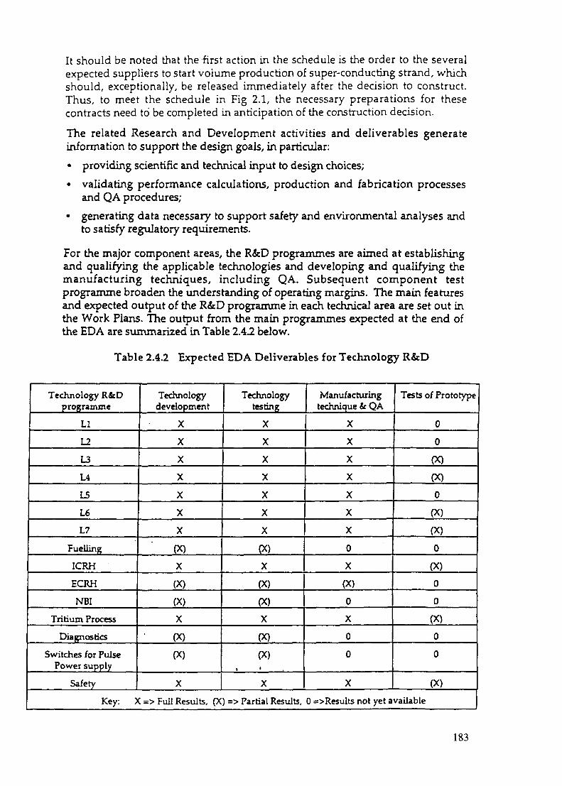
It should be noted that the first action in the schedule is the order to the severalexpected suppliers to start volume production of super-conducting strand, whichshould, exceptionally, be released immediately after the decision to construct.Thus, to meet the schedule in Fig 2.1, the necessary preparations for thesecontracts need to be completed in anticipation of the construction decision.
The related Research and Development activities and deliverables generateinformation to support the design goals, in particular:
• providing scientific and technical input to design choices;
• validating performance calculations, production and fabrication processesand QA procedures;
• generating data necessary to support safety and environmental analyses andto satisfy regulatory requirements.
For the major component areas, the R&D programmes are aimed at establishingand qualifying the applicable technologies and developing and qualifying themanufacturing techniques, including QA. Subsequent component testprogramme broaden the understanding of operating margins. The main featuresand expected output of the R&D programme in each technical area are set out inthe Work Plans. The output from the main programmes expected at the end ofthe EDA are summarized in Table 2.4.2 below.
Table 2.4.2 Expected EDA Deliverables for Technology R&D
Technology R&Dprogramme
LI
L2
L3
L4
L5
L6
L7
Fuelling
ICRH
ECRH
NBI
Tritium Process
Diagnostics
Switches for PulsePower supply
Safety
Technologydevelopment
X
X
X
X
X
X
X
(X)
X
(X)
PC)
X
(X)
(X)
X
Technologytesting
X
X
X
X
X
X
X
(X)
X
(X)
(X)
X
(X)
(X)t •
X
Manufacturingtechnique & QA
X
X
X
X
X
X
X
0
X
(X)
0
X
0
0
X
Tests of Prototype
0
0
(X)
(X)
0
(X)
(X)
0
PC)
0
0
(X)
0
0
(X)
Key: X => Full Results, (X) => Partial Results, 0 =>Results not yet available
183

The expected EDA deliverables as summarised in Tables 2.4.1 and 2.4.2 are consideredto provide the technical information necessary for a future.decision on the constructionof HER.
3. Overall Schedule for the EDA
3.1 Integrated Resource Loaded Schedule fTRLS)
A set of schedules has been developed for each element at Level 3 of the WBS.Each element shows basic engineering, procurement, R&D (where appropriate)and installation/construction information (time, resources, and constraints),through start-up and commissioning. The total set constitutes the IntegratedResource Loaded Schedule (IRLS). The IRLS is presently comprised of over11,000 activities.
3.2 Project Milestones
The major project milestones remain those determined at IC-7, i.e. thepreparation and clearance through the ITER Council of the Detail DesignReport (Dec 1996), Final Design Report (Jan 1998), and Comprehensive DesignReport. These major reports will encapsulate the continued progress on allaspects of the EDA design work including safety and cost analyses and providefor the ITER Council a means of assessing, with the help of TAC, the technicalstatus of evolving design work.
Within the design activities, one significant step, the choice of hearing methods,was scheduled to be made by the end of 1996. However the present design holdsopen the option to choose any of the methods. This will permit more work inphysics and technology to be completed in support of a future choice. Otherdesign related milestones, and comments on the current status are as follows:
- Initial Construction Schedule and Plan (Jan. 1997) - provided in the IDR; reviseddetailed schedule available in mid-November; on schedule
- Non-site specific Safety Report (First Draft) (Jan. 1997) - draftcompleted, Nov1996
- Specification for Site Layout and Buildings (Dec. 1997) - provided for generic siteto SRG(1995). Specific site layout and buildings require site identification.
- Operation Program and Schedule Oan.1998) - commissioning/operation scheduledraft being prepared
- Non-site specific Safety Report (Final) (June, 1998)
- Specifications for long lead procurements as shown in the IRLS - in progress.
Within the R&D programmes as now established, it has been possible to set specificgoals and intermediate steps. In particular, detailed schedules with milestonesexist for seven Large R&D projects undertaken in the ITER EDA. These schedulesnow form part of the Work Programme, with intermediate milestones which canbe used to monitor progress.
184

The work programme schedules for the large R&D projects are statused andreviewed for any necessary adjustments every two months. Changes of theschedules require agreement of the Director and the HT Leaders, and onceagreement is reached the intermediate milestones in the schedules offer a basisfor meeting the ITER Council's request that MAC should review progress on theschedules and intermediate technical milestones.
4. Allocation of Tasks to JCT and Parties
4.1 Design Tasks
In all of the main component areas, the Work Programme foresees a high level ofHome Team involvement in design activities with industry taking on anincreasing proportion of the work both on cost studies and on large-scale designpackages. It is assumed that all Home Team design work is undertaken withappropriate CAD support and complies with the needs of ITER designintegration.
The continuing JCT role in design work focuses on ensuring that the designs aredeveloped and specified to a satisfactory state for transmission to the HomeTeams, maintaining the coherence and configuration control of the differentelements of design work, and on integrating the Home Teams' contributions. Tofulfill its role - in particular to be able to provide the necessary and quality inputto the Home Team design Tasks and to accept their output efficiently - the JCTneed to retain adequate CAD support including qualified personnel equippedwith appropriate hardware, software and communications capacity.
The allocation of design Tasks to Parties is summarised in Table 4.1-1. Thisshows, by WBS and by Party, tasks already completed and ongoing. Agreementhas been reached with the HTs on the resources to be allocated to future tasks inselected activities. The precise nature of the tasks will be defined in Work Orders.The total future tasks for the remainder of the EDA are shown in Table 4.1-1.
42 R&D Tasks
The R&D Tasks required to validate the design work and to provide the technicalinformation necessary to support a construction decision are developed in theActivity Planning Packages and can be summarised by WBS number. Theallocation of R&D tasks to Parties is summarised at level 3 WBS in Table 4.2-1compiled on the same basis as above. The R&D resources shown in the Tablehave been approved by MAC, but some Task Agreements remain to be executed.
4.3 ITER Physics R&D
Physics R&D is needed to minimize uncertainties and to validate ITER designassumptions. The Parties' contributions in this area are on a voluntary basis,outside of the normal Home Team Task arrangements and with no formalITER credit. The Parties have nominated Physics coordinators and expertswho are to interact, in particular through the ITER Physics Committee andExpert Groups, with the Director and the JCT to offer a means of coordinatingthe overall ITER-related Physics programmes.
185

Party
WBS NO. & DESCRIPTION |
i1.1:17 Coils i1.2: PF Coils |15! Central Solenoid & BC |1.4! Magnet Structures j15 i Vacuum Vessel1.6! Blanket System1.7!Divertor1.81 Fuelling i1.9 i Plasma2.2; Machine Assembly j2.31 Remote Handling j2.4!Cryostat \2.6 i Primary Heat TS i2.7'Thennal Shields3.1'. Vacuum Pumping32:Tritium Plant |3.4'Cryoplant & Cryodist.3.5 i Heat Rejection4.1 i Coil Power Supply4.2! Additional Heating PS4.5 i COD AC4.7iPoloidal Field Control5.1IICH&CD5.2!ECH & CD5.3i Neutral Beam5.4! Other Heating & CD5.5 j Diagnostics6.1-Site6.2! Buildings6.3! Waste Treatment6.41 Radiological Protection7.2! Systems Engineering7.3 (Engineering Analysis7.4|Design Standards8.l!Safety8.8jQuality Assurance9. lj Project Mgmt.9.2|Cost & Schedule Control
| GRAND TOTALIIC-8 TOTAL1 DIFFERENCE
Table 4.1-1DESIGN TASKS (PPY)
Distribution by WBS (TaskAs of
EU i!
2330 ,
o.oo;o.oo t0.60 i5.75 ;
27.70 i12.75!0.00 ;0.00|2.17 j
1450;0.80 ;2.90 :
o.oo;3.90 |3.401.250.00 j8.850.500.00
11.526.15
1
I
:
130 !ZOO 10.008.400.253.000.000.000.001.50725 j
37.85 |130 |133 |5.83
196.05195.73
20-Oct-96
JA
20.400.00 j0.00 '0.00;
14.45 •14.40;5.10 ;0.000.61 i5.65:
26.00 !
3.00 :
2.40 ;1.00 .250 ;230 ;450 :0.75 j2.00 I5.00 !0.00 j8.10 i1.40;0.65 i6.12 i0.00!4.60 j0.25 •
1450 i250 |0.20 j0.00 j030 |5.00 !
10.85 j ,0.00 12.40 |3.00 j
169.93 |178.48 j
!
Status 1-4)
RF
3235050 :
0.000.009.65
16.706.10 .1.000502500.001.805.450.001500300.000.00 ;
13200.00 .0.00 .
15.000500.603.00 •0.00 :
15.80 .
o.oo;0.00 ;0.75 j0.10 •
0.00 10.00 I350 :
21.40 :0.00 •
0.00 i5.00 ;
15720 !18750 i
i
US
26.200.000.000.00
10.0517.6821.713.005.004.936.430.000.000.000502.750.000.001.080.000.30
18.656594.000.001.008.200317.750.000.00:228 =0.00655
17.40 j0.00 i2.72 i930
184.3919052
. TOTAL
102.250500.000.60
! 39.9076.4845.664.006.11
; 15.25: 46.93: 5.60
10.751.008.40
; 8.755.75
I 0.75; 25.13! 5 5 0
030532714.64655
11.121.00
37.000.81
25.253250302281.80
22.308750
1306.45
23.13707.57752.23(44.66)
186

TABLE 4.2-1
WBS NO. it DESCRIPTION •
l.VTr CoilsL2.PF CousIJlCcntnl Solenoid ic BCl.4>Magnet Srvcruiesl-5iV»cuum VesselL6. Blanket Svstem17' DivenorIJifucllint1.9<PUsma27:Machine Ajsesiblv23'Htmoa Handling14;C.-vo«ac2,6-Prisiarv Heat TS2.7'ThemaJ Shicids3-1 • Vacuum Punoin;37:T.-itium Plant3.4,'CrwioUnt 4: C.-voctist.3^KeaiR*iecaon4.1 Coil Power Susolv43CO0AC4.7'Potaidal Field Coneol5.i:lCH4CD5-2:ECH 4 CD5-3;Neucil Beam5.4;Other Heitine. ic CDI S Diagnostics6.1:Sitt67.! Buildings6-3; W»itt Treatment6.41 Radiological Prowcaon77:Svatemj Engineehnr,7JIEngineerin*. Analvsis7.41 Design Standards8.1:Safctv8J! Qullirv Assunnct9.1! Project Mymi.97:Cost U Schedule Concol
• GRAND TOTAL• IC-3 Totals
• Difference
1
jComplend 'ITasks '^
i1i
4i4
11j
iii
i:1!iit
1j
41
J3
1J\J
4
11j
\1i
14931
010101
1532!
7211:
6652!
13610101
1625;
01
o;01
4381
27731
01
Ol
01
o;01
307'.
7501
250!
15012501
0101
314i
011554 i
017501
0101
10001011
27.290;179338;
111
188.616 1
COMMIT
EU
OngoingTasks
59419'
531 :1.000 •
5.135.3 0 4 5 0 :
3ZJ22 !
o;001
4 7 5 0 -
0-700:
0:4.650
4.600:
00
2.130 ;
0:0
3.1002 4 5 0 .
3769
0:2 7 0 0 :
Ol010!0101
014.400
32C0I
010:01
1
1<347< i
1111!
TED TECHNOLOGYParry Distribution b)
JA
Tula17C0
0:i
0:Zili3.430'7J0S9 |
0 i
0:0 :
5.1510 '0 .00 '
U1000:0 :0 :'00 i
17-50:650:
Oi1J35
0:
o;0 '0 :
1.695 :0 '
1.100 >100
0 i1JX0
0 'I
MJXH ;
166^34:
1!
174427 •
Aioi«K)cl-96
JA
OngoingTuks
21.1580
34400S3S
13J001075014.130
000
19400000
5002700
00000
6003.5509400
01450
0-Ol
01
0 ,0>0 '
3450 ;3400
0 :00:
140423.
;111
R&D TASKS (IUA)WBS
HI
•laid i17-13
0!: 01: 0:: 679'
7J40 :i 8435'
; no
o-• 0.
0!0,o •
260 '
745!00
100000
1.100
250 .
1.686:
0:0 !010!0!Oi
750.
400 '0'
1X00.
0:i
24.143 :
109527i
11
95.417 1
RF
OngoingTasSci
13.426 :
0;100 •
2JK8 '5 4 3 5 ;
16450JJOO
o-0:0'0 '0:
300IJ2S0
1.400
1730'
0 '
05.000
00 .0
47D0 '
1.485-
0 ,2750 '
o:0 i
0i0 i
o;0!
4.030!3550
0 :0-
o:
71774 ,
i1
111
US
CompletedTasks
6419
000
1745
1177010488
66000
200000
1001580
00000
942950
00
1.4S7 :0 '00 :0:
170 -
3901.640
0 :1.000
0 '
I
S9SIS-165.199 :
1
i!
133.023;
US
• Ongoing jTasks
21.9650 .
: 13.560860
Z915 •: 127-50
19.6954300
: 0 •: 0
1.400: 0 .
000
470000000
2^002730
00 :
!7o0 •000 •0 .0 -0 '0
5700000 :
I
937051
!
TOTAL
127.653
49 X)l\4763
32435105751103731
5.40600
324260
1.0001.0507793
19.04300
773000
7.4491743015.179
15013498
00
3140
376c0
1577017;&5O
04.000
0
596.433
621.443
(25.015)
A structure of seven Expert Groups has been created to assure dose contactbetween the JCT and physics research in the Four Parties' base programs. TheseGroups meet approximately twice annually with the JCT to report and evaluatephysics research progress from the ITER perspective and to plan experiments,often coordinated among two or more devices, which will elucidate the majorphysics issues facing reactor scale tokamaks. On an annual basis, the ExpertGroup Chairs meet with the ITER Physics Committee to develop researchpriorities for the upcoming year.
Table 4.3 summarises the current priorities on which the Parties have beenrequested to focus their voluntary Physics programmes. The topics in the Tableare characterised as requiring "Urgent" attention, implying that the informationis needed for the preparation of the Final Design Report (ie available by 1September 1997). J
187

Table 4.3 Priority Areas for ITER Physics
I Databases• H<-> L Power Threshold Database• H-Mode Thermal Confinement Database• Critical shots in the Profile Database• Divertor Scalar Database• ELM.Properties Database• Halo Current Database
II Code Development• 2-Dimensional Fluid-Monte Carlo Divertor Code• 3-D Resistive, Nonlinear Code for Halo Currents• Formation and Evolution of Runaway Electron Currents
III Areas for Physics researchPlasma Termination and Halo CurrentsDivertor Detachment and Radiation Loss PhysicsFinite-P effectsDensity Limit PhysicsH-mode power thresholdH-mode core confinement
Important Physics issues will still remain to be explored after the end of EDA. Inparticular, tokamak research will be necessary throughout the ITER constructionperiod to complete details of the design, eg to better define auxiliary power andto support choices regarding divertor target plate configuration, and, in general,to better define ITER operations and/or lead to improvements in the confidenceof ITER projections.
4.4 RF Design Tasks Supported from Toint FundA design resource additional to the JCT and Parties' Home Teams has beenestablished for the EDA. Design work in support of and under the direction ofthe JCT is being undertaken at designated institutes in the Russian Federation.The work is financed from the ITER Joint Fund through Minatom acting in itscapacity as the Joint Fund Agent in Russia. In the Work Programme approved atIC-8, some supplementary work of this kind was anticipated at a level of about40 designer-years. However, the arrangements for this support have developedvery successfully to the point at which the total resource now foreseen for thiswork amounts to the equivalent of 30 designers engaged full time through 1996,rising possibly to around 36 for the remaining duration of the EDA (~57designer-yrs). The use currently foreseen for the design support resource isincluded in the Activity Planning Packages of the Work Plans of each WBS, and itis summarized in Table 4.4, which also presents the totals to date.
It is to be noted that an RF designer/year under this scheme is not directlyequivalent to a one-for-one increase in the Home Team or JCT PPY, since a JCTor Home Team Design PPY represents a professional fully supported by CADand technicians etc. Also there is an overhead in the liaison and managementactivities over the distance between the RF institutes and the ITER JWSs. Thusthe expected additional resource of about 55 RF designer years compared to theprevious Work Programme, is estimated to be the equivalent to about 20 PPYs.
188

TABLE 4.4
i
1 Table 4.4 ,IJOWT FUNO SUPPORTED RF DESIGN TASKS
1COMMIT I ED/COMPLETED
JT1 j TYPE OF SERVICEREQ. 1 PROVIDED
ii
95-01 | Diagnostics Tasks, Kurchatov95-02! Physics tasks at Kurchatov
| Magnets it Thermal Shield95-04lstagc 1 fc 295-/1 Hydraulic stability, Enttk95-81 Neutronics, Entek95-9ILimiter, Entek
95-lt)i SSPSVnjpiet95-ll:Neutral Beams
iTotal for <95i
j96-01 IStage 2 Physics
96-O4|stage 2 Diagnostics96-05iSt»ge 3 Physics96-ll!Stage 4 Physics96»12IM&T5stage396-HIM4TS stagt^96-16iStagc 5 Physics96-19IM&TSstagt5
i1-i
Totai for *96 1
11
AMOUNT
i S2O.0OO.OO
! S36.000.00
S60.000.00S1S.000.00
S1X000.00S14.000.00550.000.00S4S.000.00
S25S.000.00
S15.O0O.0O
S60.000.00'515,000.00
515.000.00 >S36.000.00
536.000.00'S20.000.00:
S36.000.00;
j1i
S233.000.00!!
• i
• FUTURE/PLANNED
! jI Designer 1: Yean i RF DESIGN SUPPORT PROPOSALS1
!
1.73.0
5.0U0.81.03.53.0
1SJ
U
5.01.3U3.03.01.73.0
19.4
I Physio Design! Diagnostics Design|V.V. Thermal Shield!Piping for Current Leads & He
i Neutral Beam| Power Supplies (electrical schematics)! Magnetsi Diagnostics Cassettei Monte Carlo Analysis of Ports (part in 1996)j Vacuum Pumping Leak DetectionIKilkr PelletIW Closure Plates Design/ Analysis| W Shield Plates Design/ Analysis• W Natural Convection Cooling Assessment
(Fatigue Analysis (part in 1996)1 Breeding Blanket Design (part in 1996)(Not yet definedI TOTAL11i 111 i! i11! 1
i
Designeryean over 19
monthsi 9.5
5D: s.41 i.o
3J)0.312.03.04.5l j
1.50.70.60.8
1.50.86.057.1
The increase in these planned activities mitigates, but does not make good theshortfall in the PPY's as compared to the previous Work Programme.
4.5 Tasks not Included
A complete list of all tasks by WBS and their allocation to Home Teams isprovided in Work Plans which also include summary information about futuretasks that have been defined for the remainder of the EDA. The lists of Tasksdescribed above do not cover additional resources that Parties with candidatesites will need to allocate in order to perform site-specific safety related work forthe regulatory review process and to adjust the design of the balance of plant tothe specific characteristics of the site. As noted above, the timely completion ofthe work on regulatory aspects has a critical influence on the overall schedule forconstruction. The exact duration and cost of this work will depend on theparticular process to be followed for each candidate party. However, to meet theoverall schedule shown in Figure 2.1 it will be necessary for Parties offeringcandidate sites to be ready to start the formal process immediately after a sitedecision This may involve starting such work well before the end of the EDA.
189

5. Analysis of Overall Resource RequirementsThe Work Programme approved at IC-8 was based on detailed development of projectplans through resource-loaded Activity Planning Packages (APP's). For this update ofthe Work Programme, the APP's have been updated to reflect the progress of work andto take account of actual resources used and reassessed expectations of future resourceavailability. In particular the plans now reflect a recognition of the need to adjust theprecise distribution of planned resources to specific circumstances and budgetaryconstraints; i.e. for the present work programme, to adjust the work plans to resourcesfixed at the levels now in place or committed.
The aggregate resource estimates and the balance of different resources now proposedfor the EDA Work Programme are compared to the planning figures from IC-8 asfollows:
JCTPPYCAD support to JCTHome Team Design Effort(PPY inc. support)Technology R&DJF Supported RF Design
IC-8 Approved
798 PPY34/yr (mid 1995)**
752.2 PPY
656WUA+40 Designer-year
IC-11 WorkProgramme Assumption
720 PPY34/yr
720 PPY+
615 kIUA++95 Designer-year*
* This represent the equivalent of 35-40 PPYs•* Plus 40 CAD designer-years off-site (now treated as RF Design Support-as shown)+ This includes 1Z5 PPY in reserve (of which 7-10 will be for new H&CD design tasks).+ This includes 19 klUA in reserve for 1997 and 1998
Table 5.1 shows the breakdown to Joint Work Sites of the different resources expectedfor the remainder of the EDA.
In the period to the end of 1996 - the base date for current planning - the total JCTresources provided amounted to 460 PPY. The present programme relies on a totalcommitted JCT staff of about 167 professionals.
Meeting the JCT figure of 798 PPY for the Work Programme approved at IC-8 requireda continued build up of JCT staff through 1995 and 1996, with a figure of about 165 staffon site being achieved by mid 1995. In the event the moderate growth profile was notachieved. The number of staff on site is now expected to reach about 168 by the end of1996 and no further growth is expected thereafter. The effect of the failure to reach theplanned JCT numbers, coupled with the decrease in HT Design and R&D resourcesbeing made available, is reflected in the adjustments that had to be made to thedeliverables to be produced by the end of the EDA.
Whilst the present Work Programme does not expect any further JCT growth, it isexpected that any staff departing are promptly replaced, with a reasonable hand-overperiod. Recognising the time taken for a new Team member to adjust to the task ofworking in a multi-national joint team, any delay in replacement is likely to reduce thepotential overall cost-effectiveness of JCT resources.
190

It must also be recognized that unless some assurance is given soon of continuance afterthe end of EDA, only 19 months away, staff will be seeking to assure their longer termcareer prospects and replacements will be harder to find. This could reduce further theavailable JCT resources at a time when they are needed the most.
The CAD support at the Joint Work Sites has reached the level foreseen in the previousWork Programme. The planning now assumes that the level of 34 qualified CADdesigners will be maintained through to the end of the EDA.
TABLE 5-1 EDA Resources1997 - End of EDA Resource Commitments by JWS
Naka JCTCADHT DesignR&DRF Design
Garching JCTCADHT DesignR&DRF Design
San Diego JCTCADHT DesignR&DRF Design
Unallocated Design/R&DTotal JCTTotal CADTotal HT DesignTotal JF Supported RF DesignTotal R&D
jcn(PPY)
93*
81*
86**
260
CAD(Des-yr)
19
19
16
54
H T "Design(PPY)
64.2
36.2
77.1
12.5
190•
JFRF***Design(Dyr)
20.7
14.9
215
57.1*"
•
Uncom.R&D
OcIUA)1
19
19
UnsigruR&D
(klUA)2
503
29.0
3.8
83.1
23
Committed resources from Jan 1997 in addition to 460 PPY expended through Dec 1996The 190 PPYs, already included in the 720 PPYs committed to the end of EDA, represent tasks to bedefined in 'V7-'9S.In addition to the 38 Dys already committed though Dec 31, 1996. A Dy corresponds toapproximately 0.35 PPY.The 125 PPY of unallocated Design effort includes about 7-10 PPY expected to be used for newH&CD tasksThe 19 klUA are in addition to the 596.4 klUA of committed R&D to the end of EDA.The 83.1 klUA represent those tasks out of the total 596.4 klUA of committed R&D to the end of EDAwhich have not been signed by the Home Team Leaders.
There is a direct and firm link in the planning between the deliverables and theresources provided. If the commitments in the various EDA resources types are notmaintained, the Parties may not have the information sufficient to take a positiveconstruction decision by the end of the EDA period.
191

At this stage, the Joint Fund is expected to continue at about its current level (~$2.5Mper year). About 20% of the resource is now foreseen as devoted to the RF DesignSupport activities. Other requirements foreseen include the maintenance of equipmentand systems already purchased through the Joint Fund, a strictly limited number offurther procurements considered necessary to maximise the efficiency of managementsystems, supplementing of JCT and support effort in areas where flexible response tospecific urgent problems might be needed, and to meet ongoing common Projectrequirements.
6. Pre-Construction Engineering
The so-called pre-construction engineering does not have a precisely defined duration.It covers the activities that take place in the period following the end of EDA duringwhich the appropriate documentation for early procurements continue to be developed.This period extend between the end of the EDA and sometimes between the mid-2000and the end of 2000, at which time all the design necessary to support "early"procurement as defined in Table 2.4-1 is complete. During the same period, R&D will bepursued, mostly by the testing of prototypes in order to broaden understanding ofoperational performance and flexibility. In preparing the individual work plans, and theActivity Planning Packages that accompany them, the resources needed during thisperiod to accomplish the necessary design and R&D activities have been estimated.Table 6-1 provides a summary of these resources. It should be understood that ifresources are not provided during the rest of the EDA according to Table 5-1, theshortfall should be added to the requirements set out in Table 6.1.
TABLE 6.1 Resource Requirements for Pre-Construction Period
Joint Central Team CAD Home Team Design R&D
396PPYs 78 Designer-yrs 370 PPYs 94 klUA
7. Termination of the EDA
Under Article 2(e) of the Agreement the Parties, assisted by the Director and HomeTeams, agree to develop proposals on approaches to joint implementation for decisionsby the Parties on furtre construction, operation, exploitation and decommissioning ofITER. Section 5 of Protocol 2 to the EDA Agreement requires the ITER Council, inapproving the Work Programme, to "provide for a timely and coordinated terminationof the work to be carried out under the Agreement ; if actions by the Parties areneeded or otherwise appropriate, then the Council, assisted by the Director, shall makesuitable proposals."
As noted in Section 5 above, completion of the EDA Work Programme as here describeddepends critically upon maintaining all resources at the levels presently committed. Toprovide the Parties with the product of the EDA in satisfactory form there will have tobe intensive efforts through the end of the EDA period to complete the specific EDAtasks, to draw conclusions, and to prepare the final reports and supporting material foruse by the Parties. To meet these demands, the ITER EDA structure (in particular JCTand support and Home Teams) should be maintained at full operational capability tothe end of the EDA.
192

Recognising the dependence of the overall project construction schedule on certain earlyprocurement actions, it will be necessary to encourage and facilitate serious responsefrom competent industries in anticipation of a construction decision so as to permittimely procurement action if and when construction is agreed. Specifically the Parties,by mid-1997 should develop a thorough assessment of the capability of their industriesto support fabrication of the conductors.
It will also be critical to be in a position to place initial contracts for the most time-critical components, i.e. the start of supply (10% or - lOOklUA) of super-conductingstrand, at the earliest possible time. The schedule of EDA deliverables in this WorkProgramme provides for the technical specifications of the strand to be available fordistribution to potential suppliers before the end of EDA so that preparation forprocurement could proceed without delay.
In order to permit an efficient start of construction in line with the overall schedule, itwill be essential to avoid any hiatus during the establishment and buildup of aconstruction management team and to maintain continuity of effort and resources:
• in design, to maintain the impetus of preparations for procurement of ITERcomponents; and
• in R&D, to continue system testing in order to broaden knowledge of theoperating margins of components before major financial commitments will have tobe made.
Conclusions
Thus, from the perspective of the EDA Work Programme, necessary or appropriateactions to be recommended to the Parties are:
1) the maintenance of resources at the levels foreseen as necessary to complete theEDA Work Programme satisfactorily within its time frame; and
2) the encouragement and facilitation of serious response from competentindustries in anticipation of a construction decision so as to permit timelyprocurement action if and when construction is agreed. Specifically the Parties,by mid-1997, should develop a thorough assessment of the capability of theirindustries to support fabrication of the conductors and should be in a positionto place initial contracts (10% - lOOklUA) for start of supply of superconductingstrand at the earliest possible time.
3) the initiation of actions which are required to realise the conditions needed atthe start of the construction schedule, in particular:
to maintain project staffing (- current levels) so as to avoid any hiatus inactivities while the construction management team is building up;
to permit smooth continuation into pre-construction activities foreseenafter the end of EDA, in particular
• to maintain the impetus of preparations for procurement of ITERcomponents; and
• to continue system testing in order to broaden knowledge of theoperating margins of components before major financialcommitments will have to be made.
193

to expedite timely progress on Host regulatory procedures inanticipation of a site decision, by preparatory interactions betweenregulatory experts and the JCT.
RECOMMENDATION:The ITER Council is invited:
1) to approve the EDA Work Programme as set out in this paper, including theproposed allocation and sharing of Tasks (Section 4) and the statement ofEDA resources (Section 5);
2) to note the expected deliverables of the EDA arising from the proposedEDA Work Programme which,given maintenance of the current levels ofresources, is considered to satisfy the purpose of the ITER EDA Agreement;
3) to ensure that resources are maintained at current levels so as to permitimplementation of the Work Programme;
4) to propose to the Parties at this time to take appropriate actions, inter alia, topermit smooth continuation of activities foreseen for the phase leading toconstruction (Section 7).
194

IC-11 RODAttachment 7
MAC Report and Advice
MAC-11 Meeting21 and 22 November 1996
JAERI Headquarters in Tokyo
MAC Membership and Meeting Participation:
MAC recognized the replacement for Dr. Nikolai P. Komev, RF MAC Member andthe change of RF MAC Contact Person to Dr Sergey Reprintsev.
Participation is accepted as attached ( MAC11 R&A Attachment 2).
Agenda:
The Agenda was adopted as attached (MAC11 R&A Attachment 1).
ITER EDA Status
MAC11 R&A-1:
a) MAC took note of Director's Status Report (MAC11 R&A Attachment 3)andinvited the Director to provide additional information on VHTP's in the Statusreport to ITER Council.
b) MAC supports the Director's request that any JCT staff departing should bepromptly replaced, with a reasonable hand-over period.
c) MAC noted that Dr. lotti's former responsibilities have been distributed toappropriate staff through out the JCT who will report to the Director.
d) MAC shares the Director's concern that, without positive indications within thecoming 6-12 months about ITER activities after July 1998, some JCT and otherITER personnel may seek to assure their career development elsewhere.
e) MAC notes that as requested at the MAC-10, the Director and the Home TeamLeaders reviewed and discussed about the work plan for ITER diagnosticdesign.
Task Status Summary:
MAC takes note of the ITER Task status summary and new task agreements ofwhich credits are less than 500 IUA or equivalent as set out in MAC11 R&AAttachment 4.
195

MAC11 R&A -2:
MAC reviewed and supported the Director's proposals for Task Agreements ofHeating and Current Drive Systems for the remainder of EDA (MAC-11 R&AAttachment 5); the total resources for the ICRF, ECRF and NBI systems R&D in1997 and 1998 are 4,100, 3,700 and 3,550 ILIA, respectively.
This review and support constitutes Council approval according to the IC-5 ROD4(c)c.9.
Review the Director's proposal for a supplementary 1996 Joint FundBudget
MAC11 R&A-3:
MAC recommends the ITER Council to approve a supplement of $100,000,shared equally by the Parties, to the ITER Joint Fund Budget for 1997 to permitincreases in Design Support contracts as proposed in the MAC11 R&AAttachment 6.
ITER Workshops and Technical meetings;
a) MAC reviewed and supported the schedule of Technical Meetings andWorkshops as set out in the MAC11 R&A Attachment 7 as amended. Inaccordance with the IC-3 ROD 5.2, this review constitutes IC endorsement ofITER meetings.
b) MAC reconfirms that ITER meetings be appropriately supported by the hostParty in accordance with Article 14 of the ITER EDA Agreement.
Updated Work Program
MAC notes that the EDA Work Programme has been updated to reflect the overallITER schedule shown in the DDR and to be consistent with the current level ofEDA resources. Against this background, the Director considers that thedeliverables expected from the Work Programme will provide, at the end of theEDA, the technical information necessary for a construction decision, thussatisfying the purposes of the EDA Agreement. MAC supports this conclusion.
MAC11 R&A-4:
a) MAC therefore recommends the ITER Council:1) to approve the EDA Work Programme, including the proposedallocation and sharing of Tasks (Section 4) and the statement of EDAresources (Section 5);
196

2) to ensure that resources are maintained at current levels so as topermit implementation of the EDA Work Programme.3) to note the expected deliverables of the EDA arising from the EDAWork Programme which, given maintenance of the current levels ofresources, is considered to satisfy the purpose of the ITER EDA Agreement;
b) Concerning the possible actions to be proposed under Section 5 of Protocol 2and in relation to Article 2(e) of the EDA Agreement, MAC supports theDirector's view of the need for continuity in the transition from the EDA to theconstruction activities.
c) MAC recommends to the ITER Council: _.to propose to the Parties, at this time, appropriate actions along the lines set outin the conclusion to Section 7 of the EDA Work Programme.
d) MAC recommends to the ITER Council:to invite the Director, in consultation with the Home Team Leaders, to elaboratefurther the technical activities and estimated resources that would provide therequired continuity.
Other Business
Future Meetings:
MAC tentatively decided that the MAC-12 meeting will be held on 26 and 27 June1997 in San Diego or Garching depending on the place for the ITER Councilmeeting.
MAC11 Report and Advice:
MAC approved the present MAC11 Report and Advice to the Council.
197

IC-11 RODAttachment 8
THE ITER JOINT FUNDSUPPLEMENTARY BUDGET for 1997
Proposal by the Director
At IC-10 the ITER Council approved a Joint Fund Budget for 1997 of $2.4M (IC-10ROD 1.7 iii). This budget has been adopted in accordance with article 3.5 of theJoint Fund Rules.
The budget as adopted includes a provision of $400,000 in the allocation of"Other Expenditures" by the RF Joint Fund Agent for design support contracts.The status of expenditures on RF Design Support contracts is regularly reportedto MAC and ITER Council in the Status Report.
The Council, noting the successful initiation of this activity, endorsed the idea ofamplifying this support and invited the Director to consider proposing asupplementary budget for this purpose.
Following detailed discussions at working level between the JCT and theInstitutes concerned on possible contracts to be undertaken in 1997, it isconsidered that an increase in total expenditure of $100,000 would beappropriate, taking into account the availability of suitable resources and theneed to maintain effective liaison and direction from the JCT.
A supplement of $100,000 to the 1997 Budget of the Joint Fund is thereforeproposed, in accordance with article 3.6 of the ITER Joint Fund Financial Rules.The supplement will be allocated entirely to the RF Joint Fund Agent under theMain Budget Article of "Other Expenses."
INCOME BUDGET
On the basis of equality, the contribution of each Party to the supplementarybudget is $25,000. This sum is additional to the contributions of $600,000 duefrom each Party for the 1997 Budget as initially adopted.
RECOMMENDATION:
The Council is invited:
to approve a Supplement of $100,000 to the ITER Joint Fund Budgetfor 1997 to permit increases in Design Support contracts as proposed inthis paper.
199

IC-11 RODAttachment 9
CPs'Report to IC-111. Ongoing Activities
Publications• Blue and Red Books
- Thanks to IAEA for added support
• Newsletter on the WWW- http://www.iaca.or.al/worldatom/inforcsource/iter/index.html
Physics on the WWW-working w/ Director
Formal status of DDR (no 'package')• One thin document inc. Safety Assessment
• Separate thick document with supporting details
• Separate TAC Report
Suggested SWG Position• SWG was established; completed, presented work
• No need to re-energize through end of EDA
Agendas
Archiving statements by Parties' officialsRemote Participation- interaction with IEA-FPCC resulted in IC-11
agenda item
2. Article 2(e) Activities
Tentative Sequence of Events- working document for CPs' and Parties' use
- further updating following IC-11/Ex2
Supportive of PSG- ready to carry out assigned tasks
NEXT PAGE{S)le f t BLANK 1 201

IC-11 RODAttachment 10
MAC FURTHER TASKS
1. Review Work Program:
Proposals by the Director for task agreement for tasks costing more than 500 IUA,if any;
List of assigned design and R&D tasks which are grouped under categories forunder 500 IUA, over 500 IUA, and by year.
2. Review the consolidated Annual Accounts of the '96 Joint Fund.
3. Review the Director's proposal for the 1998 Joint Fund Budget.
4. Review proposals by the Director for FTER meetings.
1 ^EXTPAGE(S)
L ief t BLANK 203

IC-11 RODAttachment 11
PRESS GUIDELINEfor the Eleventh Meeting of the Council of the
International Thermonuclear Experimental Reactor ( l lbR)Engineering Design Activities (EDA)
For Use by the ITER Parties, the HER Director and the IAEA
1. The eleventh Meeting of the Council of the International Thermonuclear Experimental Reactor ( l lbR)Engineering Design Activities (EDA) was held on December 17 and 18, 1996 in Tokyo, Japan. Work forITER is an integral part of the fusion programs of the four ITER Parties (EU, Japan, Russia and the US),who aim at fusion as a virtually limitless, environmentally attractive and economically competitive sourceof energy. ITER EDA is an unprecedented international venture in the field of science and technology.ITER's goal is to establish the scientific and technological feasibility of fusion energy by demonstratingcontrolled ignition and extended bum of deuterium-tritium plasmas as well as technologies essential to apower plant.
2. The four delegations that attended the meeting were headed, for the EU, by Prof. Jorma Routti, Director-General for Science, Research and Development of the European Commission, for Japan, by Mr. NaotakaOki, Deputy Director-General of the Atomic Energy Bureau of the Science and Technology Agency, forthe Russian Federation, by Academician Evgenij Velikhov, President of the RRC "Kurchatov Institute", and,for the United States, by Dr. James Decker, Deputy Director of Energy Research of the Department ofEnergy.
3. The Council received the Detailed Design Report (DDR) presented by the Director and transmitted it to theParties for their consideration. The DDR will be the basis for the continued technical work leading to theFinal Design Report in 1998. The Council noted with appreciation that the overall cost estimates wereessentially unchanged from those previously presented. The Council heard the Parties' statements on theirwillingness to continue to fulfil their obligations in contributing to the ITER EDA.
4. The Council was informed that two meetings of non-committal, pre-Negotiation, exploratory discussions,called Explorations, were held at the end of last July and in December just before the IC-11 Meeting.Subsequent Negotiations would hopefully allow a start of construction without delay after the present EDA,which are planned to be concluded in July, 1998.
5. Each Party is making a significant move towards the realization of ITER. In the EU, the Fusion ProgrammeEvaluation Board issued its Report which is strongly in favour of ITER construction. In Japan, a newForum on the l lbR Project is planned to be established very soon under the Japanese Atomic EnergyCommission, where the ITER Project will be discussed from a wide range of view point The RFGovernment approved the Federal Special Scientific and Technical Program "International ThermonuclearReactor JTER and R&D Works to its support" for 1996-1998 and entrusted the Ministry of the RussianFederation for Atomic Energy and the Ministry of Foreign Affairs of the Russian Federation together toprepare for the negotiations. The US informed the Council of its plans to hold an in-depth review of theDDR and its technical basis by its Fusion Energy Sciences Advisory Committee.
205
Copyright © 2022 FDOKUMEN