
IT5 T Recommendation Q.1400 - ITU
55
INTERNATIONAL TELECOMMUNICATION UNION )454 1 TELECOMMUNICATION (03/93) STANDARDIZATION SECTOR OF ITU ).4%,,)’%.4.%47/2+ !2#()4%#452%&2!-%7/2+&/2 4(%$%6%,/0-%.4/&3)’.!,,).’ !.$/!-02/4/#/,353).’ /3)#/.#%043 )4542ECOMMENDATION1 (Previously “CCITT Recommendation”)
-
Upload
khangminh22 -
Category
Documents
-
view
0 -
download
0
Transcript of IT5 T Recommendation Q.1400 - ITU
INTERNATIONAL TELECOMMUNICATION UNION
)45 4 1�����TELECOMMUNICATION (03/93)STANDARDIZATION SECTOROF ITU
).4%,,)'%.4��.%47/2+
!2#()4%#452%��&2!-%7/2+��&/24(%��$%6%,/0-%.4��/&��3)'.!,,).'!.$��/!�-�02/4/#/,3��53).'/3)��#/.#%043
)45 4��2ECOMMENDATION��1�����
(Previously “CCITT Recommendation”)

FOREWORD
The ITU Telecommunication Standardization Sector (ITU-T) is a permanent organ of the International Telecom-munication Union. The ITU-T is responsible for studying technical, operating and tariff questions and issuingRecommendations on them with a view to standardizing telecommunications on a worldwide basis.
The World Telecommunication Standardization Conference (WTSC), which meets every four years, established thetopics for study by the ITU-T Study Groups which, in their turn, produce Recommendations on these topics.
ITU-T Recommendation Q.1400 was prepared by the ITU-T Study Group XI (1988-1993) and was approved by theWTSC (Helsinki, March 1-12, 1993).
___________________
NOTES
1 As a consequence of a reform process within the International Telecommunication Union (ITU), the CCITTceased to exist as of 28 February 1993. In its place, the ITU Telecommunication Standardization Sector (ITU-T) wascreated as of 1 March 1993. Similarly, in this reform process, the CCIR and the IFRB have been replaced by theRadiocommunication Sector.
In order not to delay publication of this Recommendation, no change has been made in the text to references containingthe acronyms “CCITT, CCIR or IFRB” or their associated entities such as Plenary Assembly, Secretariat, etc. Futureeditions of this Recommendation will contain the proper terminology related to the new ITU structure.
2 In this Recommendation, the expression “Administration” is used for conciseness to indicate both atelecommunication administration and a recognized operating agency.
ITU 1994
All rights reserved. No part of this publication may be reproduced or utilized in any form or by any means, electronic ormechanical, including photocopying and microfilm, without permission in writing from the ITU.
Recommendation Q.1400 (03/93) i
CONTENTSRecommendation Q.1400 (03/93)
Page
1 General ........................................................................................................................................................... 1
1.1 Purpose ............................................................................................................................................. 1
1.2 Scope ................................................................................................................................................ 1
1.3 Background....................................................................................................................................... 1
1.4 OSI applicability ............................................................................................................................... 2
1.5 Relationship to the Three Stage Process........................................................................................... 2
2 The OSI Reference Model.............................................................................................................................. 3
2.1 General Description of the OSI Reference Model ............................................................................ 3
2.2 OSI Layering and SS No. 7 .............................................................................................................. 4
3 Control and User Plane Modelling Aspects ................................................................................................... 6
4 OSI Application Layer Structure.................................................................................................................... 6
4.1 AEs, APs, AEIs and APIs................................................................................................................. 7
4.2 AE-type and Application Context..................................................................................................... 8
4.3 ASEs, SACFs and MACFs ............................................................................................................... 8
4.4 SAOs................................................................................................................................................. 9
5 Addressing ..................................................................................................................................................... 9
5.1 Introduction ...................................................................................................................................... 9
5.2 Basic Definitions of SS No. 7 Addressing Information.................................................................... 10
5.3 Addressing Information in DSS 1..................................................................................................... 10
5.4 A Brief Review of OSI Addressing Concepts .................................................................................. 10
5.5 Lower Layer Addressing Relationships in International SS No. 7 ................................................... 11
5.6 Summary of Addressing Equivalents Noted for International SS No. 7 .......................................... 13
5.7 Further Study Item for Evolution of SS No. 7 Addressing ............................................................... 13
5.8 Addressing Equivalents for DSS 1 ................................................................................................... 13
6 Application of OSI Application Layer Concepts ........................................................................................... 15
6.1 Application of OSI Application Layer Concepts to SS No. 7 .......................................................... 15
6.2 Association Control Requirements for Signalling ............................................................................ 18
6.3 ROSE ................................................................................................................................................ 23
7 Management Functionality............................................................................................................................. 23
8 Layer 4, 5, 6 Guidelines ................................................................................................................................. 23
8.1 General.............................................................................................................................................. 23
8.2 Layer 6 – Presentation ...................................................................................................................... 23
8.3 Layer 5 – Session.............................................................................................................................. 28
8.4 Layer 4 – Transport .......................................................................................................................... 28
9 Layer 1, 2, 3 Guidelines ................................................................................................................................. 29
10 Convergence Functions .................................................................................................................................. 29
11 Applying Protocol Architecture Guidelines: Intelligent Network Application Part (INAP) ......................... 29
11.1 How IN Concepts are Realized in Protocol ...................................................................................... 29
11.2 Structure in the Application Layer.................................................................................................... 34
11.3 Proposed Structure of the INAP ....................................................................................................... 36
11.4 Protocol Assumptions....................................................................................................................... 36
11.5 IN Application Part Structure ........................................................................................................... 36
11.6 Hypothetical Example....................................................................................................................... 38

ii Recommendation Q.1400 (03/93)
Page
12 Compatibility Mechanisms and Rules in SS No. 7 and DSS 1 ...................................................................... 3912.1 Background....................................................................................................................................... 3912.2 Evolutionary Requirements .............................................................................................................. 4012.3 Forward and Backward Compatibility.............................................................................................. 4012.4 Compatibility Rules for SS No. 7 and DSS 1 ................................................................................... 4012.5 Application Protocol Enhancement Mechanism (ROSE-based protocols)....................................... 43
13 References ...................................................................................................................................................... 44
14 List of Acronyms............................................................................................................................................ 46

Recommendation Q.1400 (03/93) iii
SUMMARY
This Recommendation provides information on key concepts of the Open Systems Interconnection (OSI) ReferenceModel and how these concepts are applied in various portions of Signalling System No. 7 (SS No.7) and DigitalSubscriber Signalling System No. 1 (DSS 1). These concepts form the basis for the development of new applicationprotocols within the SS No. 7 and DSS 1 environments. They apply equally to Operations, Administration andManagement protocols.
The discussion covers the Application Layer Structure (ALS), the nature of the services provided by the AssociationControl Service Element in the Application Layer and how it may be adapted to the signalling environment, and theservices provided by the OSI Presentation Layer.
The application of the concepts is illustrated by means of a detailed discussion of their use in the development of theIntelligent Network Application Part (INAP) for Capability Set 1, Recommendation Q.1218.
In addition, this Recommendation contains guidelines for use when an existing protocol is extended. These are presentedas two sets. One is for existing, non-OSI structured protocols, and the other is for Remote Operations Service Element(ROSE)-based protocols. ROSE-based protocols are presently the most widely used OSI protocols within telephonysignalling systems.

Recommendation Q.1400 (03/93) 1
Recommendation Q.1400Recommendation Q.1400 (03/93)
ARCHITECTURE FRAMEWORK FOR THE DEVELOPMENTOF SIGNALLING AND OA&M PROTOCOLS
USING OSI CONCEPTS
(Helsinki, 1993)
1 General
1.1 Purpose
This Recommendation provides a framework for the common development and evolution of protocol specificationsusing OSI concepts, and to provide guidance on techniques that should be applied to the detailed specification ofsignalling and OA&M protocols.
1.2 Scope
The framework and guidance contained in this Recommendation apply to all signalling protocols, including those usedto access network resources as well as those used within a network to provide services to users of the network.
This Recommendation is applicable to emerging signalling protocols, providing the framework and guidance for theirspecification. Examples include the Intelligent Network Application Part (INAP), the B-ISDN application signallingprotocol and the Telecommunications Management Network (TMN) protocols.
This Recommendation is also applicable to the evolution of existing message-based signalling protocols, such as DigitalSubscriber Signalling System No. 1 (DSS 1), Transaction Capabilities (TC), Operations Administration and Mainte-nance and Administration Part (OMAP), Integrated Services User Part (ISUP), Telephony User Part (TUP), SignallingConnection Control Part (SCCP), and Message Transfer Part (MTP).
This Recommendation is not intended to take precedence over other specifications which describe the details of specifictopics discussed herein. Where discrepancies or inconsistencies occur, the referenced specification should be taken asdefinitive. It is intended that where such discrepancies are uncovered, they will be addressed jointly with experts in thearea affected with the intent to reach consensus such that the discrepancy or inconsistency is removed in future versionsof this Recommendation.
1.3 Background
As of the 1988 set of Recommendations, the work on signalling protocols had not proceeded within a commonframework and set of guidelines. This has resulted in the development of individual protocol architectures which are notwell aligned. In addition, different environments for the application of a protocol have led to decisions specific to theenvironment which have, from time to time, led to interworking difficulties when transitioning from one environment toanother. While, in general, these difficulties have been overcome, they have highlighted the need for a common protocolarchitecture framework together with guidelines for its application.
In the early stages of the work that led to the existing (1988 set of Recommendations) message-based signallingprotocols, work on OSI concepts, most particularly the seven layer communications model, was incomplete. Thisresulted in some parallel protocol modelling work which has not been well integrated.
Since the work on message-based signalling protocols got under way (SS No. 6; 1980 Recommendations as firstspecification of SS No. 7), physical technology advances have contributed major enhancement in:
– processing power (instructions executed per unit time);
– memory capacity;

2 Recommendation Q.1400 (03/93)
– physical media capacity (bit rate); and
– performance of physical media (bit error rate, down-time).
Software technology advances have also occurred:
– maturity of OSI model;
– specification of layer services and protocols;
– structured programming techniques;
– higher level languages; and
– distributed processing techniques.
The specification of many of the existing message-based signalling protocols is considered flawed because they do notclearly distinguish the application process specification from the protocol specification. That is, the existingspecifications are a combination of application procedures and supporting protocols without a clear distinction betweenthe two. This situation leads to significant difficulties in extending or evolving the protocols when new applicationprocedures are required. Note that this area advanced substantially from SS No. 6 to SS No. 7 through the distinctionachieved between the SS No. 7 MTP and users of the MTP. The recognition of the appropriateness of distinguishing theapplication process specification from the application protocol specification is also reflected in the present work on theIntegrated Services Control Part (ISCP).
As realization of the problems with the existing (1988 set of Recommendations) message-based signalling protocols hasemerged, there has also been a realization that the parallel work on OSI has matured and that it forms a basis forcommunications protocols in general.
1.4 OSI applicability
Despite their inception at approximately the same time, OSI and ISDN have not significantly influenced each other’smodels. Two different principles drove the development of OSI and ISDN protocols, mainly because of the perceiveddifferences between the data communications and the telecommunications environments. In particular, the mainrequirements of the telecommunications signalling environment has been efficiency, while the data processingenvironment’s main emphasis has been “openness”. “Openness” is the ability for any user with the communicationscapabilities provided by the OSI-standardized protocols to access the widest variety of applications subject toadministrative restrictions.
OSI provides a reference model, which is a framework or discipline for providing a communications infrastructure thatmay be used by any application in a distributed environment. It also provides a set of common protocol standards whichprovide uniform communications capabilities independent of the precise nature of the application.
There is a significant advantage to be obtained by studying the OSI models and protocols. The evolution of telephonenetworks requires ever more exchange of information among software controlled devices (computers). Thetelecommunication industry is solving similar problems and should take advantage of the knowledge and largeinvestment represented by OSI.
1.5 Relationship to the Three Stage Process
This subclause includes an outline of the three stage process defined in Recommendations I.130 and Q.65. The threestage process was designed for the complete definition and specification of individual ISDN (and non-ISDN) services. Itprovides, as described below, a stage for the specification of service specific protocol. It is anticipated that furtherevolution of telecommunications networks will include significant adoption of Intelligent Network (IN) techniques andcapabilities. IN represents a generalization of the service specific work being done on a number of supplementaryservices with the aim of achieving standards. The generalization of service work will also require generalization of theprotocol. A major objective of the protocol architecture guidance is to ensure a well-ordered, open-ended structure andframework for these general protocols. This will enable the protocols built on this framework to evolve and be extendedin a straightforward manner with minimal version and interworking problems.

Recommendation Q.1400 (03/93) 3
The three stage process may be summarized as:
– Stage 1 is an overall service description from the user’s standpoint.
– Stage 2 is an overall description of the organization of the network functions to map service requirementsinto network capabilities.
– Stage 3 is the definition of switching and signalling capabilities needed to support services defined inStage 1.
Each stage consists of several steps.
Stage 1
Stage 1 is an overall service description from the user’s point of view, but does not deal with the details of the humaninterface itself. The Stage 1 service description is independent of the amount of functionality in the user’s terminal, otherthan that required to provide the human interface. For example the conference calling service description is designed tobe independent of whether the conference bridge is in the terminal, in the serving exchange or elsewhere.
The steps in Stage 1 are:
– Step 1.1 – Service prose definition and description.
– Step 1.2 – Static description of the service using attributes.
– Step 1.3 – Dynamic description of the service using graphic means.
Stage 2
Stage 2 identifies the functional capabilities and the information flows needed to support the service as described inStage 1. The Stage 2 description will also include user operations not directly associated with a call (e.g. user change ofcall forwarding parameters via his service interface) as described in Stage 1. Furthermore, it identifies various possiblephysical locations for the functional capabilities. The output of Stage 2 which is signalling system independent is used asan input to the design of signalling system and exchange switching Recommendations.
The steps in Stage 2 are:
– Step 2.1 – Derivation of a functional model.
– Step 2.2 – Information flow diagrams.
– Step 2.3 – SDL diagrams for functional entities.
– Step 2.4 – Functional entity actions.
– Step 2.5 – Allocation of functional entities to physical locations.
Stage 3
In Stage 3 the information flow and SDL diagrams from the Stage 2 output form the basis for producing the signallingsystem protocol Recommendations and the switching Recommendations.
Stage 3 will need to be repeated for each service where, because of different allocations of functional entities to physicallocations, different protocols and procedures are needed.
The protocol architecture guidelines included in this Recommendation have been prepared based on known andpredicted relationship requirements.
It is expected that these protocol architecture guidelines will evolve to include further structure and capability asrelationships are identified and specified that require more complex capabilities than initially provided.
2 The OSI Reference Model
2.1 General Description of the OSI Reference Model
This subclause provides some general remarks on the OSI model. Later subclauses address the Application Layer of thatmodel, together with related aspects, in some detail.

4 Recommendation Q.1400 (03/93)
The purpose of the Reference Model of Open Systems for CCITT Applications (Recommendation X.200) is to provide awell-defined structure for modelling the interconnection and exchange of information between users in a communicationsystem. The approach allows standardized procedures to be defined not only to provide an open system interconnectionbetween users over a single network, but also to permit interworking between networks to allow communicationbetween users over several networks in tandem.
The approach taken in the OSI Reference Model is to partition the model used to describe the interconnection andexchange of information between users in a communication system into seven layers. From the point of view of aparticular layer, the lower layers provide a “transfer” service with specific features. The way in which the lower layersare realized is immaterial to the next higher layers. Correspondingly, the lower layers are not concerned with themeaning of information coming from higher layers or the reasons for its transfer.
The characteristics of each layer are described below:
a) Physical Layer (Layer 1)1) – Provides transparent transmission of a bit stream over a circuit built in somephysical communication medium. It furnishes the interface to the physical media and is responsible forrelaying bits (i.e. interconnects data circuits). A 64 kbit/s link as used for SS No. 7 is an example.
b) Data Link Layer (Layer 2) – Overcomes the limitations inherent in the physical circuits and allows errorsin transmission to be detected and recovered, thereby masking deficiencies in transmission quality.
c) Network Layer (Layer 3) – Transfers data transparently by performing routing and relaying of databetween end users. One or more of the subnetworks may interwork at the Network Layer to provide anend user to end user network service. A connectionless network provides for the transfer of data betweenend users, making no attempt to guarantee a relationship between two or more messages from the sameuser.
d) Transport Layer (Layer 4) – Provides an end user to end user transfer optimizing the use of resources(i.e. network service) according to the type and character of the communication, and relieves the user ofany concern for the details of the transfer. The Transport Layer always operates end-to-end, enhancing theNetwork Layer when necessary to meet the Quality of Service objectives of the users.
e) Session Layer (Layer 5) – Co-ordinates the interaction within each association between communicatingapplication processes. Full and half duplex dialogues are examples of possible Session Layer modes.
f) Presentation Layer (Layer 6) – Transforms the syntax of the data which is to be transferred into a formrecognizable by the communicating application processes.
g) Application Layer (Layer 7) – Specifies the nature of the communication required to satisfy the users’needs. This is the highest layer in the Model and so does not have a boundary with a higher layer. TheApplication Layer provides the sole means for application processes to access the OSI environment.
2.2 OSI Layering and SS No. 7
Evolution of SS No. 7 architecture has been based on the Open Systems Interconnection (OSI) Reference Model(see 2.1). OSI considers primarily connection-oriented protocols, that is, protocols which establish a logical connectionbefore transferring data. The Network Service Part (NSP) of SS No. 7 provides both connectionless and connection-oriented protocol. The NSP of SS No. 7 evolved from a four-level model, with the lower three levels corresponding tothe lower three layers of the OSI Reference Model, and level 4 corresponding to users of the lower three levels butwithout further generalized internal structure.
Layers 1-3 comprise functions for the transportation of information from one location to another, possibly via a numberof communication links in tandem. These functions provide the basis on which a communication network can be built.
_______________1) While OSI does not refer to its layers by numbers, it has become common usage to number the layers. This Recommendation uses
the name of the layer or its number interchangeably.

Recommendation Q.1400 (03/93) 5
The SCCP provides, with the MTP, OSI Layers 1-3.
Layers 4-7 define functions relating to end-to-end communication. These layers are so defined that they are independentof the internal structure of the communication network.
Transaction Capabilities directly uses the Network Service provided by the connectionless SCCP. The ISCP allows forthe possibility of functions in Layers 4-6, particularly at Layer 6. Other SS No. 7 application protocols, e.g. ISUP andTUP, do not provide for such an explicit structure.
Figure 1 illustrates the architecture of SS No. 7.
654
3
1
2
7
T1145650-92/d01
OSI Layer
OMAP(Note 2)
AE
ASE
(Note 3)
ASEs
Transactionservices
Other AE
(Note 3)
TCAP(Note 4)
TCAP(Note 4)
Call control application services
ISDN-UP TUP
(Notes 1, 3) (Notes 1, 3)
SCCP Level 4
(Note 3) (Note 3)
Level 4 Level 4
MTP(Levels 1-3)
Other S.S. No. 7 nodes
OMAPAEASETCAPISDN-UPTUPSCCPMTP
Operations, Maintenance and Administration PartApplication EntityApplication Service ElementTransaction Capabilities Application PartISDN User PartTelephony User PartSignalling Connection Control PartMessage Transfer Part
NOTES
1 The only standardized user of this interface is TCAP using the services of the connectionless SCCP.
2 OMAP is SS No. 7 management.
3 SS No. 7 primitive interface.
4 TCAP may be considered as an ASE.
FIGURE 1/Q.1400
Relationship Between SS No. 7 Functional Levels and OSI Layering
FIGURE 1/Q.1400 [D01] = 18 CM

6 Recommendation Q.1400 (03/93)
3 Control and User Plane Modelling Aspects
This clause supplements the material contained in Recommendation I.324.
As discussed in Recommendation I.324, the interaction between a terminal and an exchange may be modelled using OSIconcepts. The terminal and exchange in general interact with each other on a peer-to-peer basis. The interaction is in thecontrol plane and concerns the provision of a resource in the user plane (e.g. the Physical Layer channel in the case of avoice circuit). For example, in circuit mode, this resource is at Layer 1 (once established by the network) and the user ateach end must provide Layers 2 through 7 (described in clause 2) according to his needs. The Layer 1 bearer channelprovided by the network needs to be understood as entirely distinct (in the logical sense) from the Layer 1 being used totransport control plane messages. Further, the term “network” as generally used in telephony does not have the sameconnotation as the term in OSI. The telephone network is a physical network made up of exchanges and interconnectingbearer channels, and is the equivalent of the OSI term “subnetwork”. The OSI term “Network” refers to the Layer 3entity which has responsibilities including routing and relaying of messages on behalf of users of the network towardsindicated destinations.
The DSS 1 term “Layer 3” should not be confused with the OSI Network Layer (sometimes referred to as Layer 3). DSS1 Layer 3 has aspects of OSI Layers 3 to 7 in the control plane. It is therefore incorrect to place the terminal at theNetwork Layer as is sometimes done. Rather it should be viewed in two ways. For control plane purposes, it is a fullApplication Process with an Application Entity for its communication needs (further details on these concepts may befound in clause 4). In the user plane, the terminal provides the Application Entity but not the remainder of theApplication Process. The remainder of the Application Process is provided by the human user of the terminal andinterfaces to it via the man-machine interface (MMI). Alternatively, the user may be a computer interacting with theterminal via a machine-to-machine interface. After physical path establishment, the computer may itself provide Layer 2through 7 functions.
The discussion in this Recommendation refers to structure and addressing aspects of signalling protocols in the controlplane. The user plane has its own addressing mechanisms (e.g. Recommendation E.164 address or sub-address).
Further discussion and modelling in this area may be found in Recommendation I.324.
4 OSI Application Layer Structure2)
The following is a review of key concepts of the OSI Application Layer Structure described in ISO/IEC 9545.
The structure of the OSI Application Layer, Layer 7, is different from that of any other layer in the OSI ReferenceModel. Whereas each of the other six layers contains a set of well defined functions within a monolithic layer structure,the OSI Application Layer is structured modularly to allow flexibility in function and form, to meet the communicationneeds of every possible distributed application. This difference arises from the role of the Application Layer as thebridge between the work of Application Processes (of which it is a part) and the work of the OSI lower layers.
The Application Layer must be able to perform the functions necessary to communicate any information the ApplicationProcess needs conveyed to a remote peer. Thus, unlike the other layers in the OSI model, the Application Layer mustprovide functions that are application specific. The form and content of the functions in the Application Layer aredependent on the needs of the Application Process using these functions. In contrast, lower layers in the OSI stackprovide a fixed set of functions, which may be manipulated as needed, but not changed or expanded upon. In order toprovide flexibility and ease of expansion, the Application Layer has to be defined in an open-ended way, with room forApplication specific functions, yet still enforce standard methods of communication.
To accomplish all this, the structure shown in Figure 2 was conceived for the OSI Application Layer. The abbreviationsin the figure are expanded in subsequent subclauses.
_______________2) The ongoing work on Extended Application Layer Structure needs to be considered in the discussion of OSI applied to signalling
systems.

Recommendation Q.1400 (03/93) 7
T1123470-90/d02
APPLICATIONPROCESS
INVOCATION
AEI
MACF
SACF
ASE
ACSE
ROSEa)
ASE
ROSEa)
ACSE
ASE
SAO SAO
ApplicationAssociationwith peer A
ApplicationAssociationwith peer B
AEIMACFSAOSACFASEROSEACSE
Application Entity InvocationMultiple Association Control FunctionSingle Association ObjectSingle Association Control FunctionApplication Service ElementRemote Operations Service ElementAssociation Control Service Element
FIGURE 2/Q.1400
The OSI Application Layer Structure
a) Example of an ASE commonly used.
SACF
FIGURE 2/Q.1400 [D02] = 16 CM
This is a very modular approach, with each function in the OSI layer neatly labelled and boxed. Thus, it is easy toinclude the appropriate functions, such as a highly application specific function (such as an account managementfunction), while keeping within a structured framework.
4.1 AEs, APs, AEIs and APIs
An Application Entity or AE is the function that an Application Process (AP) uses to communicate with its peers. An APcan use several AEs, each of which provides a specific set of communication functions for the AP. An AE is composedof definitions of each of the functions and the rules that govern the use of these functions.
The AE and AP are abstract entities whose functions may be thought of as being realized through software programs.Thus, when instances of each are created and performing functions, the word “invocation” is added to the title. An actualinstance of an AE is an AE-Invocation or AEI and the instance of an AP is an AP-Invocation or API.
An API may have many AEIs performing communication functions for it, but the coordination of such AEIs is up to theAPI itself.
8 Recommendation Q.1400 (03/93)
4.2 AE-type and Application Context
The AE/AEI relationship may be viewed as a type/instance relationship. A type is a definition of a class of objects.Examples of types are “integer”, “elm tree” or “automobile”. Instances of types are particular objects within the class,such as “42”, “the elm tree in town square”, or “my car”. Thus, one can view an AE as a definition of a type, with aninstance of that type being the AEI.
An AEI is the abstraction of an actual “run-time” program that performs all or a subset of the communication functionsdefined by the AE-type specifications. The actual procedures that will be performed or need to be performed for aninstance of communication are determined by the Application Context. While an AE-type defines a set of functions usedfor communication, an actual instance of communication may require that only a subset of these functions be performed.The Application Context is used just to state which functions are needed, and based on this information, the AEI that fitsthese criteria is instantiated. Different Application Contexts may be handled by instances of the same AE-type, as longas the AE-type encompasses all the functions needed by all the requested Application Contexts.
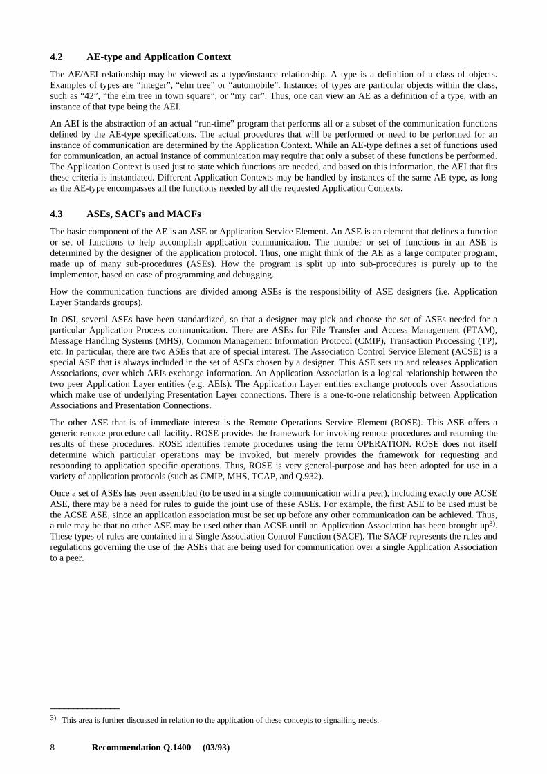
4.3 ASEs, SACFs and MACFs
The basic component of the AE is an ASE or Application Service Element. An ASE is an element that defines a functionor set of functions to help accomplish application communication. The number or set of functions in an ASE isdetermined by the designer of the application protocol. Thus, one might think of the AE as a large computer program,made up of many sub-procedures (ASEs). How the program is split up into sub-procedures is purely up to theimplementor, based on ease of programming and debugging.
How the communication functions are divided among ASEs is the responsibility of ASE designers (i.e. ApplicationLayer Standards groups).
In OSI, several ASEs have been standardized, so that a designer may pick and choose the set of ASEs needed for aparticular Application Process communication. There are ASEs for File Transfer and Access Management (FTAM),Message Handling Systems (MHS), Common Management Information Protocol (CMIP), Transaction Processing (TP),etc. In particular, there are two ASEs that are of special interest. The Association Control Service Element (ACSE) is aspecial ASE that is always included in the set of ASEs chosen by a designer. This ASE sets up and releases ApplicationAssociations, over which AEIs exchange information. An Application Association is a logical relationship between thetwo peer Application Layer entities (e.g. AEIs). The Application Layer entities exchange protocols over Associationswhich make use of underlying Presentation Layer connections. There is a one-to-one relationship between ApplicationAssociations and Presentation Connections.
The other ASE that is of immediate interest is the Remote Operations Service Element (ROSE). This ASE offers ageneric remote procedure call facility. ROSE provides the framework for invoking remote procedures and returning theresults of these procedures. ROSE identifies remote procedures using the term OPERATION. ROSE does not itselfdetermine which particular operations may be invoked, but merely provides the framework for requesting andresponding to application specific operations. Thus, ROSE is very general-purpose and has been adopted for use in avariety of application protocols (such as CMIP, MHS, TCAP, and Q.932).
Once a set of ASEs has been assembled (to be used in a single communication with a peer), including exactly one ACSEASE, there may be a need for rules to guide the joint use of these ASEs. For example, the first ASE to be used must bethe ACSE ASE, since an application association must be set up before any other communication can be achieved. Thus,a rule may be that no other ASE may be used other than ACSE until an Application Association has been brought up3).These types of rules are contained in a Single Association Control Function (SACF). The SACF represents the rules andregulations governing the use of the ASEs that are being used for communication over a single Application Associationto a peer.
_______________3) This area is further discussed in relation to the application of these concepts to signalling needs.

Recommendation Q.1400 (03/93) 9
There may also be rules that govern multiple communications with many peers. Thus, an Application Process Invocationmay have a need to communicate with more than one peer over more than one Application Association. For example,suppose that an Application Process Invocation is communicating with one peer in order to debit a bank account $50,while communicating with another peer to credit another bank account for that same $50. The API would not wish todebit the first account until it was sure that the amount was credited to the other account. Thus a rule for coordinating thetwo communications would be that if either one of the tasks were to fail, the other task would also be forced to fail. Theentire transaction would then fail. (This is an example taken from TP – Transaction Processing.) The MultipleAssociation Control Function or MACF represents the rules and regulations governing the coordination of the set ofpeer-to-peer communications within an AEI.
The combination of the ASEs, the SACF rules and the MACF rules form the total definition of the AE-type. AnApplication Context is then used to establish which functions are to be used for a particular instance of communication.These functions are performed by an AEI over a single Application Association. This is further described in clause 6.
4.4 SAOs
The collection of the particular set of ASEs and SACF rules to be used over one association is called a SingleAssociation Object (SAO). An SAO is the representation of the functions that are needed to communicate over a singleApplication Association to a peer. An AEI may contain many SAOs, all based on the same AE-type, but each possiblyperforming different sets of functions based on different Application Contexts. At a minimum, an AEI may contain noSAOs or one SAO and may or may not contain a MACF. At the other extreme, an AEI might contain a very largenumber of SAOs, offering different subsets of the functions defined in the AE-type, with an MACF governing theinteractions among the SAOs.
ASEs and Application Contexts are standardized so that Application Processes may make use of them.
5 Addressing
5.1 Introduction
The Transaction Capabilities (TC) portion of the SS No. 7 Application Layer evolved towards an architecture whichused concepts such as Application Entity (AE) and Application Service Element (ASE) that are defined in the OSIApplication Layer Structure (ALS) standard, ISO/IEC 9545. A similar formalization has occurred in the ISCP for theprotocol stack associated with call/bearer-related signalling.
However, a complete alignment with the OSI ALS is currently not possible because the SS No. 7 protocol architecturedoes not support a key OSI requirement which is the concept of an explicit association between peer AE-Invocationssupported by an underlying Presentation Layer connection. This is due to the absence from SS No. 7 of the IntermediateService Part (ISP) which is the collection of services provided by the OSI Transport, Session and Presentation Layers.Another issue, also arising because of the absence of the ISP, which requires considerable clarification, is the question ofhow SS No. 7 applications are addressed. An OSI Application Process would be accessed through an AE which isaddressed by a Presentation Service Access Point (PSAP). The absence of an explicit Presentation Layer in SS No. 7suggests that whatever addressing information is currently available in SS No. 7 indirectly provides a PresentationAddress.
This subclause clarifies aspects of the SS No. 7 protocol architecture. Its aim is to examine addressing concepts andfunctions in SS No. 7 and OSI. This will allow a common basis for comparison particularly when discussing questionsof alignment of the two protocol architectures. Such considerations are particularly applicable to the work on the “ISDNSignalling Control Part”.
The next two subclauses explore the relationships between existing SS No. 7 addressing information and those definedin the OSI Naming and Addressing specifications, Recommendation X.650 as well as Recommendation X.213 onNetwork Layer addressing.
Addressing equivalents for DSS 1 are also examined.
10 Recommendation Q.1400 (03/93)
5.2 Basic Definitions of SS No. 7 Addressing Information
The various addressing information elements present in an SS No. 7 message, using the definitions given inRecommendation Q.700 are:
a) Point Code (PC) – This uniquely identifies a node in an SS No. 7 network. It is used for inter-nodal,intra-network addressing in conjunction with the 2-bit Network Indicator field of the Service InformationOctet defined below.
b) Service Information Octet (SIO) – This consists of a 4-bit Service Indicator (SI) and 2-bit NetworkIndicator. The SI is being used by a signalling point’s distribution function to determine the “user” of theincoming message. The Service Indicator addresses “users” of the Message Transfer Part. Examples of“users” are the Signalling Connection Control Point (SCCP), ISDN User Part (ISDN-UP) and theTelephone User Part (TUP).
c) Global Title (GT) – This is addressing used by the SCCP, comprising dialled digits or another form ofaddress that will not be recognized by the SS No. 7 Network Layer. Therefore, translation of thisinformation to an SS No. 7 Network Address is necessary.
d) Sub-System Number (SSN) – This identifies a sub-system accessed via the SCCP within a node and maybe a User Part (e.g. ISDN-UP, SCCP Management) or an Application Entity containing the TCAP ASE.
5.3 Addressing Information in DSS 1
DSS 1 is a protocol for use between an exchange and an ISDN terminal or between PABXs. It therefore is not“networked” in the OSI sense. In fact, it may be modelled either as lacking a Network Layer altogether, or alternativelyas representing a very small closed network.
DSS 1 supports identification of a terminal on an ISDN interface through a TEI or Terminal Endpoint Identifier. Itfurther provides for distinguishing among classes of procedures through the use of SAPIs or Service Access PointIdentifiers. SAPIs indicate, for example, B-channel bearer control signalling or D-channel packet data.
5.4 A Brief Review of OSI Addressing Concepts
The relevant definitions from Recommendation X.650 which will help determine the necessary mapping of concepts andterminology are provided next.
In general, an (N)-Address is defined as a set of (N)-Service Access Points [(N)-SAPs] where (N) refers to any OSIlayer and an SAP is the conceptual Interface point through which a Layer (N+1) entity issues/receives service primitivesto/from a Layer (N) entity during an instance of communication. An (N)-SAP Address is used in the case when the(N)-Address identifies only one SAP. Therefore, (N)-Addresses are used to identify sets of (N)-SAPs in order to locate(N+1)-entities.
Each (N)-SAP in the set identified by an (N)-Address is bound to (N+1)-entities of the same type, i.e. each of these(N+1)-entities provides the same functions. Within an (N)-Layer an (N)-selector is used to identify a (set of) (N)-SAP(s),i.e. to address an (N+1)-entity once the end open system has been unambiguously identified. A locally chosen(N)-selector value would be known to communicating open systems either through directory look-up or advertisementand exchanged as part of the (N)-Protocol Addressing Information [(N)-PAI] during connection establishment.
When an actual connection is established between two peer (N+1)-entity Invocations, each assigns a local(N)-connection-endpoint-identifier [(N)-CEI] to that particular instance of communication. Thereafter, the (N)-CEI issufficient addressing information during the data transfer phase.

Recommendation Q.1400 (03/93) 11
Specifically, at the Network Layer, a Network Address is in general a set of NSAPs (where each NSAP is structured as apart that identifies the Network Entity unambiguously in the open system environment) plus a locally-specified“selector” which chooses a particular Network Service Access Point (NSAP). Transport entities of the same type arebound to each NSAP within this Network Address and, in general, different Transport entities are bound to differentNetwork Addresses. The most common sort of Network Address is an NSAP Address which is a Network Addressconsisting of only one NSAP. At connection establishment time, individual network connections between instances ofpeer transport entities are assigned local connection endpoint identifiers, which are then used as addressing informationduring the subsequent data transfer phase.
Recommendation X.213 has defined the structure and abstract syntax of an NSAP address leaving the actual encodingsto specific Network Layer protocols standards. This structure is shown in Figure 3.
T1132360-91/d03
Initial DomainPart IDP
Domain Specific PartDSP
Authority & FormatIdentifier AFI
Initial Domain IdentifierIDI
FIGURE 3/Q.1400
OSI NSAP Address Structure
FIGURE 3/Q.1400 [D03] = 6 CM
The conceptual format of the NSAP address is hierarchical in that the initial part of the address, the IDP, unambiguouslyidentifies an addressing domain, while the rest, the DSP, is allocated by the authority identified by that addressingdomain. The IDP is further structured into two parts: the first part, the AFI, names the addressing authority (e.g. ISO orCCITT) responsible for allocating values of the second part, the IDI, as well as the abstract syntax (e.g. binary octets,decimal digits, characters) of the DSP. The IDI identifies the network addressing domain and the network authority inthat addressing domain responsible for allocating and ensuring unique value of the DSP.
5.5 Lower Layer Addressing Relationships in International SS No. 7
The combination of SS No. 7 Point Code (PC), Service Information Octet (SIO) and SCCP Sub-System Number (SSN)meets the criteria for providing the semantics of an OSI Network (NSAP) address. It follows the hierarchical addressingstructure defined for the OSI NSAP Address because CCITT defines the network addressing authorities who in turndefine the addresses within their sub-domain. A part of the SS No. 7 PC, the 11-bit Signalling Area Network Code(SA/NC) field, together with the Network Indicator field in the SIO serves the purpose of the OSI NSAP ISP becausethey identify the sub-domain addressing authorities. Together with the remainder of the PC, which is domain-specific, anSS No. 7 node can be addressed in a “globally” unambiguous manner.
Within the Network at a node there are a number of NSAP Addresses with different types of upper-layer entries boundto these NSAPs. Once a node has been unambiguously identified, local selectors administered within that node identifythe possible NSAPs. In certain cases, the SI field contains sufficient information to locate these NSAPs. CCITT has

12 Recommendation Q.1400 (03/93)
standardized some of these SI fields. For instance, values have been assigned to those that directly access the ISDN-UPand TUP application entities of the call-processing application process. Also, another standardized SI locates anotherentity within the Network Layer which provides the functions of the SCCP. In this case, a further piece of addressinginformation, the SCCP SSN, is the local “selector” to distinguish between the possible NSAPs at the Network/ISPLayers’ interface. CCITT has also standardized the values for a few SSNs to locate certain upper-layer entities, e.g. thosefor the OMAP (Operations, Maintenance and Administration Part) and the MAP (Mobile Application Part) AEs, but itneed not do so in general. Communications between application processes at different nodes are ensured by the propermaintenance and administration of network directory functions like routing tables and global title translation tables.
These addressing relationships are illustrated in Figure 4.
T1123500-90/d04
TransportLayer
NetworkLayer
NSAPs for applications
NSAP forcircuit-related
applications usingISDN-UP
Network layerentity
SCCPentity
MTPLevel
3
SSN=“1” SSN=“2” SSN=“N”...
SCCP
SI=“SCCP” SI=“ISDN-UP”
Point Code + Network Indicator
NSAPSSNSCCPSIISDN-UPMTP
Network Service Access PointSubsystem NumberSignalling Connection Control PartService IndicatorISDN User PartMessage Transfer Part
FIGURE 4/Q.1400
Relationship of Point Code, Service Indicator andSub-System Number to OSI NSAP
FIGURE 4/Q.1400 [D04] = 13 CM
The NSAPs which are of particular interest are those that provide the interface to the SCCP-User for non-circuit relatedsignalling applications. When Network Layer connections (NC) are set up between peer entities addressed through theseNSAPs, they are identified by SCCP Local Reference Numbers which are, in Recommendation X.650 terminology,network-connection-endpoint-identifiers.
Connectionless data transfer using the N-UNITDATA primitive also occurs through these NSAPs though no connection-endpoint-identifiers are necessary in this instance.
The NSAPs for ISDN-UP and TUP directly locate, because of the absence of intervening layers, distinct ApplicationEntity types belonging to the Call Processing Application Process(es).

Recommendation Q.1400 (03/93) 13
5.6 Summary of Addressing Equivalents Noted for International SS No. 7
Table 1 shows the relationships between SS No. 7 and OSI Naming and Addressing terminology and functions that havebeen explored and noted in the previous subclause.
TABLE 1/Q.1400
Summary of Addressing Equivalencies for SS No. 7
5.7 Further Study Item for Evolution of SS No. 7 Addressing
At present the SCCP Calling and Called Party Address, which consist of a Global Title and SSN, are provided to theupper layer in the N-CONNECT and N-UNITDATA indication primitives. The SCCP Global Title Translation functionconverts a title into a Network Address. In contrast, an OSI application directory function converts an Application EntityTitle into a more detailed address of the form (PSAP, SSAP, TSAP, Network Address). The SCCP Global Titletranslation function in which a global title is converted into an NSAP Address of a node is simply the conversion of thegeneric name for a Network Address into an actual Network Address. In other words, the SS No. 7 GT currently is notproviding an application Entity Title even though the Global Title is sent up to the upper layers in the N-UNITDATAand N-CONNECT indication primitives. Therefore, the SCCP Global Title and SSN do not provide the full OSI PSAPAddress, but assume a one-to-one mapping with the more detailed address. Thus, if any greater distinction than iscurrently possible is to be made between upper-layer entities, it has to be performed by enhancing the current routing“directory” to provide the required upper-layer addressing information and enhancing the SS No. 7 protocol(s) to carrythat information.
This last point requires consideration particularly in the case where it is desirable to locate further sub-structure in theApplication Layer such as the Stage 2 Functional Entities within an Application Process at a physical node.
5.8 Addressing Equivalents for DSS 1
Elements of DSS 1 addressing information were discussed in 5.3. Figure 5 (DSS 1) parallels Figure 4 (SS No. 7).
DSS 1 provides in LAPD, Recommendations Q.920 and Q.921, procedures for broadcasting to and selecting fromterminals connected to the interface. All messages from the user side on the interface are seen by the network side andby all other user entities on the interface. Similarly, all messages sent by the network side are seen by all the entities onthe user side. Using the TEI and SAPI, the specific user entity and the specific capability of those it supports isidentified, or the message is labelled as a “broadcast” message to all the user entities. User side Layer 2 entities ignorenon-broadcast messages which do not match the assigned TEI and the SAPI. A specific instance of interaction isidentified by the DSS 1 Call Reference above the Connection Endpoint Suffix and SAPI.
OSI Term/Function SS No. 7 Equivalent
Network Address (PC, SIO, SSN)
NSAP IDP (NI, SA/NC portion of PC)
NSAP DSP (remainder PC, SI, SSN)
Network connection endpoint identifier SCCP Local Reference Number

14 Recommendation Q.1400 (03/93)
This means that all the users and the network element share a single Physical Service Access Point (PhSAP), with eachentity (terminal or network element) being identified by a physical connection end-point identifier, called the TerminalEnd-point Identifier (TEI), at the PhSAP. Having accessed the Data Link entity via the PhSAP, the Service Access PointIdentifier (SAPI) allows the choice between various Data link Service Access Points (DSAPs). A standardized value of 0identifies the DSAP corresponding to the D-channel of the ISDN access, while the SAPI = “X.25” identifies the DSAPwhich offers the Recommendation X.25 Network Entity. Above the DSAP reached by SAPI = 0, there are nointermediate layer entities below the Application Layer. Each instance of the Application Layer entity which generatesprotocol for bearer related (see Recommendation Q.931) or bearer-unrelated (see Recommendation Q.932) signalling isidentified by means of a Call Reference Number (CRN). The SAPI = “X.25” leads to a full OSI stack with its usualaddressing.
There is no further addressing in DSS 1, therefore no further substructuring can be delineated.
T1145660-92/d05
Bearer-control orBearer-unrelatedsignalling entity
PSAP CRN
OSILayers 4-7
OSI Network Service
X.25 NetworkLayer entity
DSAP
NULL(missing layers)
SAPI = 0 SAPI = X.25
PhSAP
Data link layer(LAPD)
TEI Physical layer
PSAPSAPITEIPhSAPDSAPCRN
Presentation Service Access pointService Access Point IdentifierTerminal Endpoint IdentifierPhysical Service Access PointData Link Service Access PointCall Reference Number
FIGURE 5/Q.1400
Application of OSI Addressing Concepts in DSS 1
FIGURE 5/Q.1400 [D05] = 15 CM

Recommendation Q.1400 (03/93) 15
6 Application of OSI Application Layer Concepts
6.1 Application of OSI Application Layer Concepts to SS No. 7
Given an Application Process (AP) static description, at some point in time an Application Process Invocation (API) willbe created as a result of some stimulus outside the scope of this discussion.
When the API wishes to communicate, it will create an Application Entity Invocation (AEI) which is a collection of allthe supportable ASEs that may be used in the communication.
Four aspects which are essential to every instance of communication must be understood. These are, in order:
– locating the application one wants to “talk” to (Addressing) (see 6.1.1);
– the “language” to be used to communicate (Presentation context) (see 6.1.2);
– the general “topic” of the “conversation” (Application context) (see 6.1.3); and
– the specific questions and responses related to that “topic” (operations, results and errors based on theROSE framework) (see 6.1.4).
6.1.1 Locating the Remote Application
Addressing is the first essential aspect of communication which allows one AE to establish an association with anotherAE by first accessing the node where the peer AE is located (using the Network Address) and then following “aninternal route” through the upper layer entities at that node (using the Transport, Session and Presentation selectors).
In OSI the initiating Application Entity consults a directory to locate the address of its peer. The initiator provides thedirectory with the Application Entity Title or the Application Process Title. The directory returns the appropriatePresentation Service Access Point (PSAP) which is a tuple = (P_selector, S_selector, T_selector, Network Address). Thedirectory can provide this information to its users only if all applications register their address with the directoryprovided. Each part of a PSAP is inserted into protocol addressing information at the corresponding layers for routing tothe peer AE (e.g. the Transport Layer protocol carries the Transport selector, etc.)
SS No. 7 applications use a similar directory technique. The application provides a Global Title to the “directory” –which is the SS No. 7 Global Title Translation function – which then provides the tuple = {SSN, PC}. The Point Code(PC) and SCCP Sub-System Number (SSN) are the addressing information that, because of the absence of interveninglayers, effectively locates an AE-type at an SS No. 7 node. The SSN really selects an NSAP, but as there are noTransport, Session and Presentation Layer protocols in SS No. 7, the chosen NSAP is therefore “nailed-up” to aPresentation Service Access Point (PSAP). In OSI addressing, the PSAP locates an AE-type.
AE-types for standardized applications, e.g. OMAP, are accessed at every SS No. 7 node by distinct CCITT-standardized SSNs. Other SSNs, chosen locally at a node, are used to access AE-types which contain the application-specific communications protocols for other applications. These are managed by an SS No. 7 network operator to ensurean accurate and up-to-date routing “directory” which constitutes the Global Title Translation tables.
6.1.2 Determination and Uses of Abstract Syntax
In OSI, the syntax of the Application Layer language to be used during an instance of communication is signalled duringthe setting up of the underlying Presentation Layer connection. This language is referred to as the Abstract Syntax. It isabstract because it is defined in terms of the structure and essential content of the information exchanged withoutpreference or choice on how the information is actually encoded as “bits on the wire” for transfer to the peer entity via acommunications medium. The actual encoding that is used is negotiated (or sometimes pre-determined) by the two peerpresentation entities and is called the Transfer Syntax.
For example, Recommendation X.208 specifies ASN.1, a notation for specifying Abstract Syntaxes. Recommenda-tion X.209, Basic Encoding Rules (BER), provides one possible set of encoding rules and thus represents a TransferSyntax for Application Layer protocols that have been defined using ASN.1.
16 Recommendation Q.1400 (03/93)
A presentation context is a mapping (for a period of time) between an abstract syntax and a transfer syntax. Apresentation context is given an identifier to uniquely distinguish it from other presentation contexts in use on anassociation.
The initiating Application Entity invocation must include, in its request for an application association, the mandatoryApplication Context Name. This contains, among other things, the identification of the Abstract Syntaxes (AS) of thedata structures to be used. Each of these ASs is given an identifier – a Presentation Context ID – by the ApplicationLayer to which the Presentation Layer attaches a choice of Transfer Syntaxes. This information is carried in thePresentation protocol to the peer during the Presentation connection set up. The peer Presentation entity chooses oneTransfer Syntax (from the offered choice) for each Abstract Syntax. The Presentation Context ID is used, during thesubsequent data transfer phase, to transform the received PDUs into the appropriate Abstract Syntax before delivery tothe appropriate protocol machine at the Application Layer where the AS can be meaningfully deciphered. Note thatcommunicating AEIs must use identical abstract syntaxes.
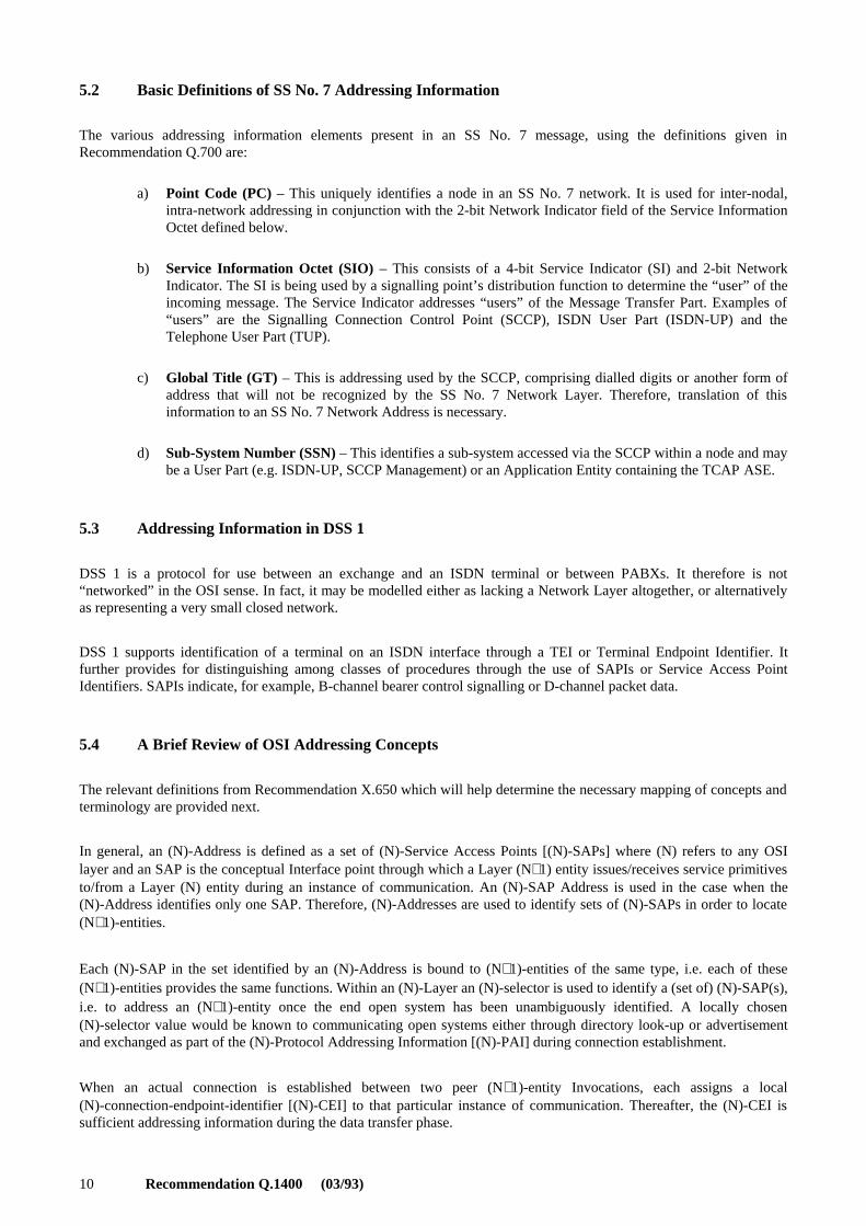
Presently in SS No. 7 TC, there is only one abstract syntax which therefore requires unique operation codes at an AEaddressed through a Network Address (PC + SSN) plus implicit P/S/T_selectors. This is illustrated by Figure 6, looselybased on the 1988 Recommendation Q.1051. Note that this requires that every node know the entire ASE even if it willnot use all of it, and is a direct result of the way the 1988 MAP Recommendation Q.1051 is specified.
VLR
MSCAS HLR
T1132380-91/d06
ASHLRVLRMSC
Abstract SyntaxHome Location RegisterVisited Location RegisterMobile Switching Centre
FIGURE 6/Q.1400
Recommendation Q.1051, MAP (1988) Abstract Syntax as Illustrative Example
FIGURE 6/Q.1400 [D06] = 8 CM
An alternative approach (purely to illustrate the use of Abstract Syntaxes) is illustrated in Figure 7. Here there are threecontexts representing the interactions, e.g. between the MSC and the VLR. A unique Abstract Syntax may be specifiedfor each of these. The operation codes may overlap across the contexts but must remain unique within the syntaxes.Other approaches are also possible.
SS No. 7 presently does not have any means to differentiate among multiple Abstract Syntaxes. As noted above, “large”ASEs (e.g. MAP) have been created as opposed to several smaller ASEs. We presently have an a priori Abstract Syntaxand Transfer Syntax as the only alternative and which must be understood by both ends. There is no opportunity fornegotiation and hence no need for a protocol to do negotiation. This situation is not expected to persist as discussion ofthe need for multiple Abstract Syntaxes and Transfer Syntaxes for ISCP and the Intelligent Network Application Part(INAP) are taking place.

Recommendation Q.1400 (03/93) 17
VLR
HLR MSC
AS1
AS2 AS3
T1123510-90/d07
ASNHLRVLRMSC
Abstract Syntax N, N = 1, 2, 3Home Location RegisterVisited Location RegisterMobile Switching Centre
FIGURE 7/Q.1400
Alternate MAP Abstract Syntaxes as Illustrative Example
FIGURE 7/Q.1400 [D07] = 8 CM
6.1.3 The Context for the Communications
Once the appropriate AE-type has been accessed, the “topic” of “discussion” between the peer application entityinvocations is determined by the AC. The AC provides all the information necessary to create the appropriate SingleAssociation Object (SAO) within an Application Entity Invocation (AEI). The SAO is a concise modelling descriptionof all the communications functions of the AE-type that is required for this one instance of communication over anapplication association.
This is analogous to human interactions where one person broaches a “topic” of conversation which outlines the scopeof the conversation but does not, as yet, determine the exact dialogue. That is dynamically generated by the speakersonly if the subject is agreeable to both. Unlike humans, though, the OSI application association requires that thediscussion does not stray from the topic.
An AE-type at a node can potentially support a very large number of communications capabilities for the ApplicationProcess. The AC serves the purpose of choosing from the available functions the specific functions needed for a singleinstance of communications. This leads to one further aspect of the explicit application association set up in OSI: the ACname is negotiated by the two peers, and the association fails if a mutually acceptable context cannot be agreed upon.
When an AE at an ISDN node supports a large number of capabilities, it is useful to signal up front just which of thesecapabilities are likely to be required during the instance of communications. In the case of SS No. 7 TCAP, logicallyrelated groups of TC-User defined remote operations are called TC-User ASEs. Each ASE is a collection of relatedoperations that together provide some overall capability. In SS No. 7, the context for an instance of communicationswould consist of a list of such ASEs that might be used together with some rules on how they would be used inconjunction with each other (such as the sequencing of operations, which side can invoke which operation, etc.).
6.1.4 Specific Questions and Topics Within an Application Context
In OSI, first an association is established during which the Application Context is used to pull together the specific ASEsand the coordination rules governing their use. Only after this, service requests from the Application process give rise toappropriate Application Layer protocol exchange.
As there is an underlying Presentation connection supporting the association, the subsequent data exchange need onlyuse the Presentation connection end-point identifier to reach the appropriate SAO while the Presentation ContextIdentifier serves to transform the incoming message encoding (Transfer Syntax) into the appropriate data structures(Abstract Syntax).

18 Recommendation Q.1400 (03/93)
The remainder of this subclause describes the application-specific data exchange progressing through the use of thequery/response paradigm. This is modelled as the invocation of Remote Operations and uses the ROSE protocol which isa key element in both DSS 1 and SS No. 7.
In SS No. 7, particularly in the case of 1988 TCAP Recommendations, the Transaction ID serves to identify the implicitassociation. As there is no protocol to support multiple Abstract Syntaxes, specific interactions necessary during atransaction are determined by a variety of means:
– unique operation codes;
– the same operation code but with different (optional) parameters;
– the same operation but with different parameter values.
These are options available to “route” the ROSE PDU to the appropriate User-ASE. These options may be thought of asa means of providing a “sub-context”, i.e. refining the initial Application Context, which still governs the overall “topicof conversation”.
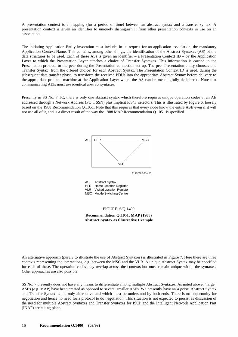
Thus, in TC, the effect at the start of a communication is as illustrated in Figure 8.
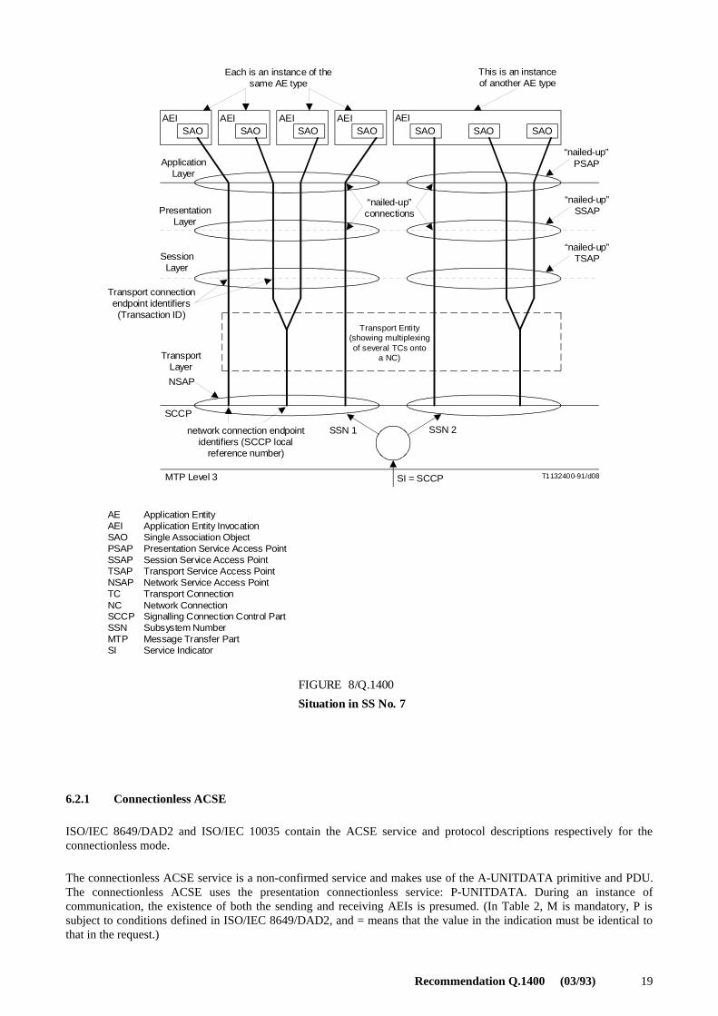
Considering the ISO ALS specification, and a Single Association Object in it, and relating this to TC, Figure 9 may bedrawn. Observe that the TR-BEGIN request may be considered equivalent in some ways to a P/S/T-CONNECT requestwith the User Data field containing the (presently implicit since there are no alternatives to be indicated) associationprotocol plus other ASE protocols.
Unlike OSI, ISDN applications do not have an explicit association establishment procedure that must be completedbefore data may be exchanged. For signalling efficiency, data is transferred at the time of the set-up, i.e. with the firstmessage exchanged.
Thus, in SS No. 7 TCAP applications where remote operations are embedded within the “association/transaction set-up”request, it is assumed that the two AE invocations know the AC beforehand. One way to mimic the OSI associationestablishment procedure, though at the cost of having additional messages, is to use an “empty” BEGIN messagecontaining the proposed AC to which the response is an empty CONTINUE containing the acceptable AC, after whichthe exchange of remote operations proceeds. Without an explicit “association” establishment procedure, the AC, asdefined in OSI, has no clear meaning.
6.2 Association Control Requirements for Signalling
The requirement of establishing an association before the transfer of any Application Layer PDUs does not suitapplications requiring stringent real time performance. Therefore, there is the need for an “efficient” association controlprotocol.
OSI has defined an ACSE but this is considered unsuitable for signalling needs for efficiency reasons. The following listof desirable characteristics is identified for signalling association control:
– support of unconfirmed and pre-arranged termination;
– simplicity at establishment; and
– allow ROSE (and possibly other) PDUs to be carried within the establishment PDU.
The next two subclauses review the essential elements of the Association Control Service Element (ACSE) and areintended to convey an understanding of the essential elements of this protocol. More detailed information should beobtained through consulting the indicated references.
Recommendation Q.1400 (03/93) 19
T1132400-91/d08
Each is an instance of thesame AE type
This is an instanceof another AE type
AEISAO SAO
AEI AEISAO SAO
AEI AEISAO SAO SAO
ApplicationLayer
PresentationLayer
SessionLayer
“nailed-up”connections
“nailed-up”PSAP
“nailed-up”SSAP
“nailed-up”TSAP
Transport connectionendpoint identifiers(Transaction ID)
Transport Entity(showing multiplexing of several TCs onto
a NC)Transport Layer
NSAP
SCCP
network connection endpointidentifiers (SCCP local
reference number)
SSN 1 SSN 2
SI = SCCPMTP Level 3
FIGURE 8/Q.1400
Situation in SS No. 7
AEAEISAOPSAPSSAPTSAPNSAPTCNCSCCPSSNMTPSI
Application EntityApplication Entity InvocationSingle Association ObjectPresentation Service Access PointSession Service Access PointTransport Service Access PointNetwork Service Access PointTransport ConnectionNetwork ConnectionSignalling Connection Control PartSubsystem NumberMessage Transfer PartService Indicator
FIGURE 8/Q.1400 [D08] = 19 CM
6.2.1 Connectionless ACSE
ISO/IEC 8649/DAD2 and ISO/IEC 10035 contain the ACSE service and protocol descriptions respectively for theconnectionless mode.
The connectionless ACSE service is a non-confirmed service and makes use of the A-UNITDATA primitive and PDU.The connectionless ACSE uses the presentation connectionless service: P-UNITDATA. During an instance ofcommunication, the existence of both the sending and receiving AEIs is presumed. (In Table 2, M is mandatory, P issubject to conditions defined in ISO/IEC 8649/DAD2, and = means that the value in the indication must be identical tothat in the request.)
20 Recommendation Q.1400 (03/93)
T1123520-90/d09
SAO
SACF
ASE
ROSE
ACSE
P/S/T-Connect request = TR-BEGIN request
SAOSACFASEROSEACSE
Single Association ObjectSingle Association Control FunctionApplication Service ElementRemote Operations Service ElementAssociation Control Service Element
FIGURE 9/Q.1400
Relating ISO ALS and SS No. 7 TC
FIGURE 9/Q.1400 [D09] = 9 CM
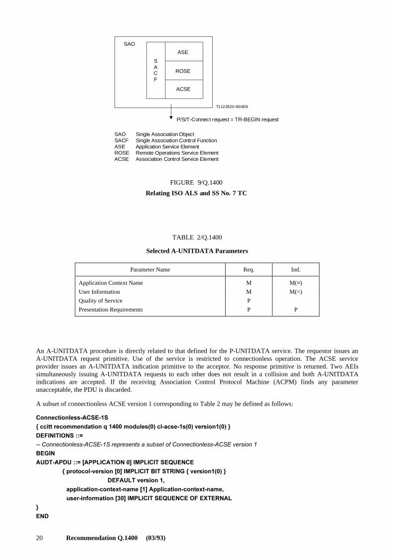
TABLE 2/Q.1400
Selected A-UNITDATA Parameters
An A-UNITDATA procedure is directly related to that defined for the P-UNITDATA service. The requestor issues anA-UNITDATA request primitive. Use of the service is restricted to connectionless operation. The ACSE serviceprovider issues an A-UNITDATA indication primitive to the acceptor. No response primitive is returned. Two AEIssimultaneously issuing A-UNITDATA requests to each other does not result in a collision and both A-UNITDATAindications are accepted. If the receiving Association Control Protocol Machine (ACPM) finds any parameterunacceptable, the PDU is discarded.
A subset of connectionless ACSE version 1 corresponding to Table 2 may be defined as follows:
#ONNECTIONLESS !#3% �3
[�CCITT�RECOMMENDATION�Q������MODULES���CL ACSE �S���VERSION����]
$%&).)4)/.3����
�#ONNECTIONLESS !#3% �3�REPRESENTS�A�SUBSET�OF�#ONNECTIONLESS !#3%�VERSION��
"%').
!5$4 !0$5�����;!00,)#!4)/.��=�)-0,)#)4�3%15%.#%
[�PROTOCOL VERSION�;�=�)-0,)#)4�")4�342).'�[�VERSION����]
$%&!5,4�VERSION���
[�APPLICATION CONTEXT NAME�;�=�!PPLICATION CONTEXT NAME�
[�USER INFORMATION�;��=�)-0,)#)4�3%15%.#%�/&�%84%2.!,
]
%.$
Parameter Name Req. Ind.
Application Context Name M M(=)
User Information M M(=)
Quality of Service P
Presentation Requirements P P
Recommendation Q.1400 (03/93) 21
The User Data field of the Application Association Request (AARQ) and the Application Association Response (AARE)APDUs of the connection-oriented ACSE were not intended to carry other Application Layer protocols such as theROSE PDU. Clearly, such an approach is not appropriate for the connectionless ACSE PDU.
The requirement of establishing an association before the transfer of any Application Layer PDUs does not suitapplications requiring stringent real time performance. Therefore, there is a need for an “efficient” association controlprotocol.
It should be noted that the current TC-UNI service is the SS No. 7 equivalent service to the A-UNITDATA service.Neither the A-UNITDATA nor TC-UNI services are suitable to control the exchange of several related signallingmessages. However, they can be used to control the transfer of signalling information such as alarm reporting.
If enhancements to the TC-UNI are required, they should be in line with the A-UNITDATA service.
6.2.2 Connection Oriented ACSE
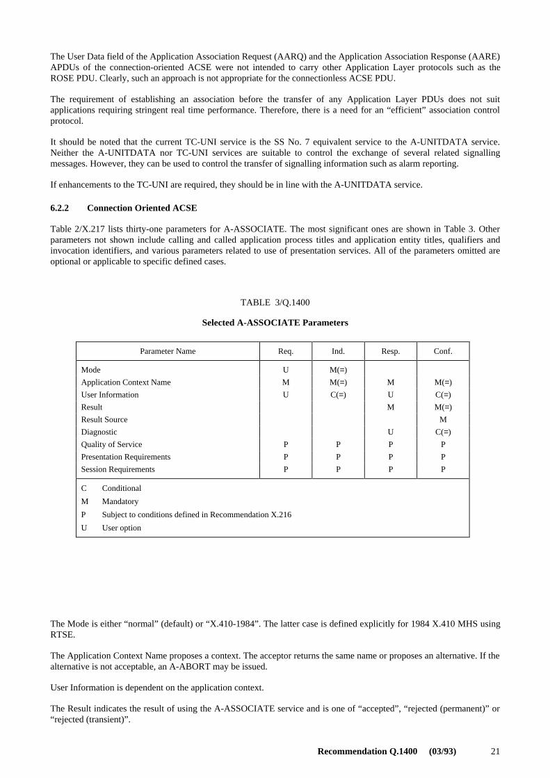
Table 2/X.217 lists thirty-one parameters for A-ASSOCIATE. The most significant ones are shown in Table 3. Otherparameters not shown include calling and called application process titles and application entity titles, qualifiers andinvocation identifiers, and various parameters related to use of presentation services. All of the parameters omitted areoptional or applicable to specific defined cases.
TABLE 3/Q.1400
Selected A-ASSOCIATE Parameters
The Mode is either “normal” (default) or “X.410-1984”. The latter case is defined explicitly for 1984 X.410 MHS usingRTSE.
The Application Context Name proposes a context. The acceptor returns the same name or proposes an alternative. If thealternative is not acceptable, an A-ABORT may be issued.
User Information is dependent on the application context.
The Result indicates the result of using the A-ASSOCIATE service and is one of “accepted”, “rejected (permanent)” or“rejected (transient)”.
Parameter Name Req. Ind. Resp. Conf.
Mode U M(=)
Application Context Name M M(=) M M(=)
User Information U C(=) U C(=)
Result M M(=)
Result Source M
Diagnostic U C(=)
Quality of Service P P P P
Presentation Requirements P P P P
Session Requirements P P P P
C Conditional
M Mandatory
P Subject to conditions defined in Recommendation X.216
U User option

22 Recommendation Q.1400 (03/93)
The Result-Source indicates the source of the Result and Diagnostic parameters. It is one of “ACSE service-user”,“ACSE service provider”, or “presentation service provider”.
The Diagnostic is used if the Result is “rejected” (permanent or transient).
Quality of Service, Presentation and Session Requirements are defined in Recommendation X.216.
Table 3/X.217 lists three parameters for A-RELEASE as shown in Table 4.
TABLE 4/Q.1400
A-RELEASE Parameters
Reason is “normal”, “urgent”, or user-defined. Result is “affirmative” or “negative”.
The structured dialogue handling capabilities of TCAP are modelled on the CO-ACSE (connection-oriented ACSE)services.
An A-ABORT is a user abort. A-ABORT parameters are shown in Table 5.
TABLE 5/Q.1400
A-ABORT Parameters
Abort source is used to indicate the initiating source of the abort: ACSE service user or ACSE service provider.
A-P-ABORT indicates an abort by the presentation service. A-P-ABORT parameters are shown in Table 6.
The Provider Reason is the indication of why the Provider is aborting.
TABLE 6/Q.1400
A-P-ABORT Parameters
Parameter Name Req. Ind. Resp. Conf.
Reason U C(=) U C(=)
User Information U C(=) U C(=)
Result M M(=)
Parameter Name Req. Ind.
Abort Source M
User Information U C(=)
Parameter Name Ind.
Provider Reason P
Recommendation Q.1400 (03/93) 23
6.3 ROSE
Recommendation Q.775 contains guidance on the usage of TCAP. The information contained in Recommenda-tion Q.775 is useful in understanding ROSE and since ROSE will be widely used in the network and access protocols(e.g. TCAP, Facility IE, etc.).
The reader’s attention is drawn to the OPERATION and ERROR macros in Recommendation X.229 and also discussedin Recommendation Q.775.
7 Management Functionality
Recommendation X.700, OSI Management Framework, provides general principles for the management framework.This clause describes briefly how this applies to SS No. 7. Recommendation Q.940 describes the application to DSS 1.For a more detailed discussion, refer to TMN.
Figure 10 shows that each entity in the protocol architecture has a Level Management Entity (LME) associated with it.The LME may be more or less explicitly defined within the level. For example, in the SCCP, there are a number ofmanagement functions (e.g. SSN management) which constitute the LME for the SCCP.
All the entities in the architecture communicate with a Management Information Base (MIB) through a LevelManagement Interface (LMI). The MIB is used by the System Management Application Process [SMAP, of which theOperations and Administration Application process (OMAP) is a part] in performing OA&M functions. The ApplicationManagement Interface (AMI) represents the interaction between SMAP and the other application processes at the nodethat SMAP supports.
8 Layer 4, 5, 6 Guidelines
8.1 General
This subclause provides general guidelines relating to Layers 4, 5 and 6 (Transport, Session and Presentation) of the OSImodel from a signalling perspective.
8.2 Layer 6 – Presentation
This subclause provides information on the Presentation Layer services and protocol based on Recommendations X.216and X.226. This subclause rationalizes the use of the Presentation Layer in the telephony network and providesguidelines on its usage.
At present, SS No. 7 TCAP employs a Presentation Layer function which is the representation transformation ofX.209-encoded PDUs into a single Abstract Syntax.
8.2.1 Use of the Presentation Context in OSI
The information content and structure of Application Layer PDUs are specified in OSI in Abstract Syntax using theASN.1 notation defined in Recommendation X.208. For two Application Entity Invocations (AEIs) to communicatesuccessfully over an application association, they must have an agreement on the set of Abstract Syntaxes that will beused, i.e. on the sets of APDUs that will be exchanged over the given association. Application Layer information definedin some, possibly several, abstract syntaxes is handed over to the Presentation Layer as a series of Presentation DataValues (PDVs). Each PDV must belong to a single named Abstract Syntax.

24 Recommendation Q.1400 (03/93)
x
y
T1157020-93/d10
SS No. 7 Management Process+ OMASE-User
AMI AMI
E.g.MAP
Call controlapplicationservices
MIB
LMI
LMI LME
OMASE
TCASE
SMSI OM-prim
SMAE
LMI
LMI
Other AE
ASEs
TCASE
LME
ISDN-UP TUP
LM E
LM E
(Note 6) (Note 6)
ST
MT
LME
LME
SCCP (Level 4)
MTP (Levels 1-3)
For communication betweenS.S. No. 7 nodes
LMI
LMI
AMIOMASESMSILMIMIBLMESTMTOM
Application Management InterfaceOperations, Maintenance and Administration Service ElementSystems Management Service InterfaceLevel Management InterfaceManagement Information BaseLevel Management EntitySCCP TesterMTP TesterOperation and Maintenance
NOTES
1 Dotted lines (but not boxes) denote direct management interfaces. Only the SMSI (see Note 5) is realized with primitives.
2 The LMI (Level Management Interface) is not a subject for standardization.
3 The AMI (Application Management Interface) is not a subject for standardization.
4 The items managed by OMAP can be regarded as conceptually resident in the MIB.
5 The SMSI is the systems management service Interface; the OM primitives are defined for use over it for managed objectfunctions defined in Recommendation Q.753.
6 OSI Layers 4, 5 and 6 are null in SS No. 7. TC forms the bottom of OSI Layer 7, SCCP the top of OSI Laser 3 (but is in SS No. 7 level 4).
7 Interface x uses subsystem numbers to test the SCCP using the SCCP Test (ST), interface y uses SIO to test the MTP using the MTP Tester (MT).
8 The LME (Level Management Entity) is defined for management of and within each level of SS No. 7. This is conceptuallywhere each managed item resides as far as the level is concerned.
FIGURE 10/Q.1400
SS No. 7 Management and Internal Configuration of an SP
FIGURE 10/Q.1400 [D10] = PAGE PLEINE CM

Recommendation Q.1400 (03/93) 25
It is the function of the Presentation Layer to transfer unchanged these PDUs using some mutually acceptable concreteencoding scheme, or possibly schemes. It is the responsibility of the initiating AEI, during the establishment ofcommunications, to inform the Presentation Layer of the ASs that will be used during the subsequent communicationsover the application association. Knowing the ASs to be used, it is the function of the Presentation Layer to negotiate,during the presentation connection establishment phase, a suitable Transfer Syntax (TS) for each AS. The pairing of anAS with a mutually acceptable TS is defined as a Presentation Context and is identified by a unique integer value – thePresentation Context Identifier – during the lifetime of the application association and its underlying presentationconnection. During the application data transfer phase, incoming messages are converted using the Presentation ContextID from their TS into the appropriate AS for delivery to the appropriate ASE. Figures 11, 12 and 13 provide a pictorialdescription of these Presentation Layer functions.
In Figure 11, the initiating AEI provides an identifier (the Presentation Context ID) for each of the three ASs that itanticipates using during communications. The initiating Presentation Service provider proposes, for each AS named byits user, a list (in general) of TSs that it is capable of supporting for that Presentation Context. The applicationestablishment PDU is transferred within the presentation-connection-establishment PDU which carries the list ofproposed Presentation Contexts. On receiving the presentation-connection-request PDU containing this information, thepeer presentation entity informs its user of those (if any) ASs whose representation transformation it cannot support withthe proposed TSs. (It is assumed, for simplicity, that such is not the case in this example.)
T1132430-91/d11
Initiating AEI
Chooses TSs
Responding AEIA-ASSOC-request PDU (AC1)
PRES-CONN-req PDU
PC1: AS1PC2: AS2PC3: AS3
P-CONNECTind
PC1: AS1, TS1PC2: AS2, TS1, TS2PC3: AS3, TS3
ApplicationLayer
P-CONNECT req
PC1: AS1PC2: AS2PC3: AS3
PresentationLayer
FIGURE 11/Q.1400
Presentation Connection Request
FIGURE 11/Q.1400 [D11] = 7 CM
Figure 12 shows the case where the responding AEI accepts the application association with the proposed ASs. Theresponding Presentation entity chooses, for each AS in the Presentation Context list, one TS from those proposed by theinitiator for that Presentation Context. The set of all such pairings of each AS with a TS is called the Defined ContextSet (DCS). The DCS remains in effect for the lifetime of the presentation connection. (For simplicity, and because theneed does not appear to exist for signalling applications at the moment, the optional possibility available in the OSIPresentation Service of altering the Presentation Contexts during the lifetime of the presentation connection is omittedfrom this discussion.)
In Figure 13, the user requests the transfer of some APDUs which it provides to the Presentation entity as a series ofPDUs. Each Presentation Data Value (PDV) is marked with its Presentation Context ID which permits the sendingPresentation entity to transform the AS into the correct TS and the receiving Presentation entity to transform the TS intothe correct AS.
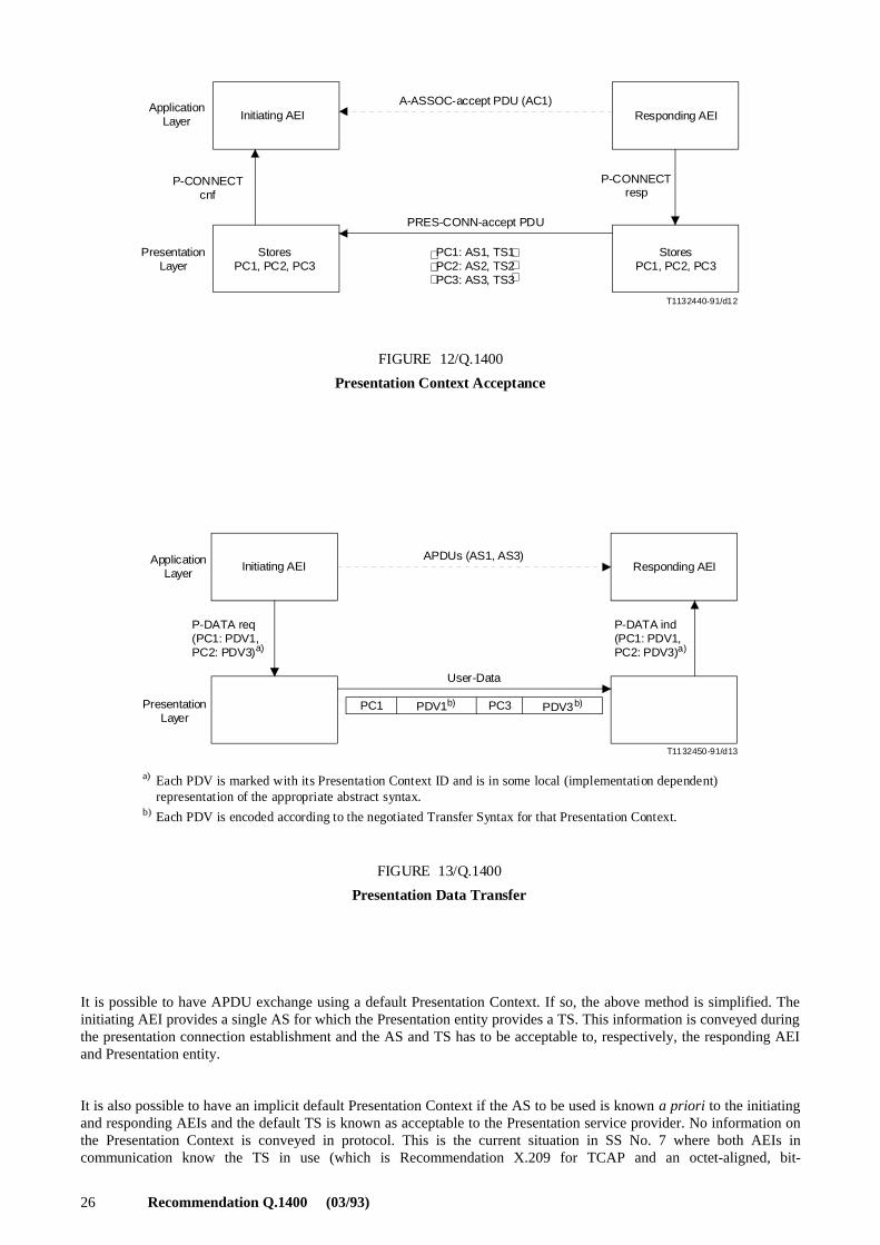
26 Recommendation Q.1400 (03/93)
T1132440-91/d12
Initiating AEIA-ASSOC-accept PDU (AC1)
PRES-CONN-accept PDU
StoresPC1, PC2, PC3
Responding AEIApplication
Layer
P-CONNECTcnf
PresentationLayer
Stores PC1, PC2, PC3
P-CONNECTresp
PC1: AS1, TS1PC2: AS2, TS2PC3: AS3, TS3
FIGURE 12/Q.1400
Presentation Context Acceptance
FIGURE 12/Q.1400 [D12] = 7 CM
T1132450-91/d13
Initiating AEIApplicationLayer
P-DATA req(PC1: PDV1,PC2: PDV3) a)
Presentation Layer
APDUs (AS1, AS3)
User-Data
Responding AEI
P-DATA ind(PC1: PDV1,PC2: PDV3) a)
PC1 PC3 PDV3b)
a)
b)
Each PDV is marked with its Presentation Context ID and is in some local (implementation dependent)representation of the appropriate abstract syntax.
Each PDV is encoded according to the negotiated Transfer Syntax for that Presentation Context.
FIGURE 13/Q.1400
Presentation Data Transfer
PDV1b)
FIGURE 13/Q.1400 [D13] = 9 CM
It is possible to have APDU exchange using a default Presentation Context. If so, the above method is simplified. Theinitiating AEI provides a single AS for which the Presentation entity provides a TS. This information is conveyed duringthe presentation connection establishment and the AS and TS has to be acceptable to, respectively, the responding AEIand Presentation entity.
It is also possible to have an implicit default Presentation Context if the AS to be used is known a priori to the initiatingand responding AEIs and the default TS is known as acceptable to the Presentation service provider. No information onthe Presentation Context is conveyed in protocol. This is the current situation in SS No. 7 where both AEIs incommunication know the TS in use (which is Recommendation X.209 for TCAP and an octet-aligned, bit-
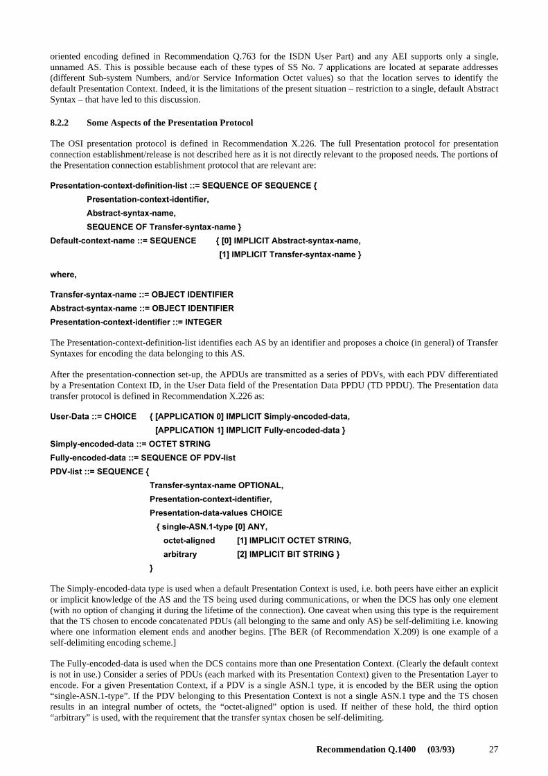
Recommendation Q.1400 (03/93) 27
oriented encoding defined in Recommendation Q.763 for the ISDN User Part) and any AEI supports only a single,unnamed AS. This is possible because each of these types of SS No. 7 applications are located at separate addresses(different Sub-system Numbers, and/or Service Information Octet values) so that the location serves to identify thedefault Presentation Context. Indeed, it is the limitations of the present situation – restriction to a single, default AbstractSyntax – that have led to this discussion.
8.2.2 Some Aspects of the Presentation Protocol
The OSI presentation protocol is defined in Recommendation X.226. The full Presentation protocol for presentationconnection establishment/release is not described here as it is not directly relevant to the proposed needs. The portions ofthe Presentation connection establishment protocol that are relevant are:
0RESENTATION CONTEXT DEFINITION LIST�����3%15%.#%�/&�3%15%.#%�[
0RESENTATION CONTEXT IDENTIFIER�
!BSTRACT SYNTAX NAME�
3%15%.#%�/&�4RANSFER SYNTAX NAME�]
$EFAULT CONTEXT NAME�����3%15%.#% [�;�=�)-0,)#)4�!BSTRACT SYNTAX NAME�
[;�=�)-0,)#)4�4RANSFER SYNTAX NAME�]
WHERE�
4RANSFER SYNTAX NAME�����/"*%#4�)$%.4)&)%2
!BSTRACT SYNTAX NAME�����/"*%#4�)$%.4)&)%2
0RESENTATION CONTEXT IDENTIFIER�����).4%'%2
The Presentation-context-definition-list identifies each AS by an identifier and proposes a choice (in general) of TransferSyntaxes for encoding the data belonging to this AS.
After the presentation-connection set-up, the APDUs are transmitted as a series of PDVs, with each PDV differentiatedby a Presentation Context ID, in the User Data field of the Presentation Data PPDU (TD PPDU). The Presentation datatransfer protocol is defined in Recommendation X.226 as:
5SER $ATA�����#(/)#% [�;!00,)#!4)/.��=�)-0,)#)4�3IMPLY ENCODED DATA�
[�;!00,)#!4)/.��=�)-0,)#)4�&ULLY ENCODED DATA�]
3IMPLY ENCODED DATA�����/#4%4�342).'
&ULLY ENCODED DATA�����3%15%.#%�/&�0$6 LIST
0$6 LIST�����3%15%.#%�[
4RANSFER SYNTAX NAME�/04)/.!,�
0RESENTATION CONTEXT IDENTIFIER�
0RESENTATION DATA VALUES�#(/)#%
���[�SINGLE !3.�� TYPE�;�=�!.9�
���[�OCTET ALIGNED ;�=�)-0,)#)4�/#4%4�342).'�
���[�ARBITRARY ;�=�)-0,)#)4�")4�342).'�]
]
The Simply-encoded-data type is used when a default Presentation Context is used, i.e. both peers have either an explicitor implicit knowledge of the AS and the TS being used during communications, or when the DCS has only one element(with no option of changing it during the lifetime of the connection). One caveat when using this type is the requirementthat the TS chosen to encode concatenated PDUs (all belonging to the same and only AS) be self-delimiting i.e. knowingwhere one information element ends and another begins. [The BER (of Recommendation X.209) is one example of aself-delimiting encoding scheme.]
The Fully-encoded-data is used when the DCS contains more than one Presentation Context. (Clearly the default contextis not in use.) Consider a series of PDUs (each marked with its Presentation Context) given to the Presentation Layer toencode. For a given Presentation Context, if a PDV is a single ASN.1 type, it is encoded by the BER using the option“single-ASN.1-type”. If the PDV belonging to this Presentation Context is not a single ASN.1 type and the TS chosenresults in an integral number of octets, the “octet-aligned” option is used. If neither of these hold, the third option“arbitrary” is used, with the requirement that the transfer syntax chosen be self-delimiting.

28 Recommendation Q.1400 (03/93)
8.2.3 Further Study Items for Application of Presentation Layer Concepts
In SS No. 7, each Presentation Context is implied by the encoding of the incoming message. This presently applies toTCAP applications where there is a well defined AS (given in Recommendation Q.773) as well as encoding. For any AEcontaining the TCAP ASE together with any TC-User ASEs, there is only one Abstract Syntax. [This is the motivebehind ensuring the uniqueness of operation and error codes as outlined in Recommendation Q.775. If there was morethan one AS, operation and error codes would need to be unique only within the scope of a particular Abstract Syntax(see Recommendation X.219); but it would be necessary to find a way to identify each AS.]
The use of more than one AS would alleviate a “language” problem concerning whether to import/export operation andcodes between ASN.1 modules by type or value. A common problem that arises when ROSE/TCAP-User ASEs aredefined independently is to find a way to ensure that, should the occasion arise, several ASEs can coexist in oneAE-Invocation. If the ASEs have been defined such that the constituent operation and error codes have already beenassigned “local” (i.e. integer) values, then the assignment of a separate AS to each ASE would alleviate the “language”problem that could arise if operation and error codes in different ASEs had the same value. Each ASE is identified by aseparate Presentation Context Id.
It is also noted that global operation and error code values (i.e. object identifiers) can solve the above-mentioned issue.The use of the OBJECT IDENTIFIER requires several octets to encode (vs. at least one for integer operation and errorcodes).
The most constraining way of ensuring uniqueness of local operation/error codes is to assign a range of integer values toeach ASE that is identified. Of course, not all values in that range need to be used. This requires coordination of rangeboundaries and may not be practicable if ASEs are borrowed from other non-signalling standards.
8.3 Layer 5 – Session
This subclause is a placeholder for material which will describe the Session Layer service and protocol based onRecommendations X.215 and X.225 and will identify the functional units suitable for a telephony network whenrequirements are identified.
8.4 Layer 4 – Transport
This subclause is a placeholder for material which will describe the Transport Layer service and protocol based onRecommendations X.214 and X.224 and will identify the classes of service suitable for telephony network whenrequirements are identified.
The exchange of several related signalling messages over a connectionless network service requires the existence of anexplicit end-to-end relation. Except if a specific mechanism is defined within the application (e.g. circuit identification inTUP), this relation has to be established by the exchange of explicit local references.
This is one of the basic transport functions in the OSI environment: in SS No. 7, this function is currently provided bythe TCAP TSL. However, it should be noted that the TCAP TSL does not provide any other transport specific servicessuch as multiplexing or segmenting.
It is for further study whether the Transport Protocol may provide the basis for any further proposals for enhancementsto the TCAP Transaction Sub-Layer. ISO has specified the use of Transport Protocol Class 4 over a connectionless modeNetwork Service. This protocol is “heavyweight” as connectionless data networks have minimal Quality of Servicerequirements. It will be useful to investigate the possibility of using a simpler transport protocol over CL-SCCP as thelatter has extremely robust characteristics.

Recommendation Q.1400 (03/93) 29
9 Layer 1, 2, 3 Guidelines
Recommendation Q.700 contains material relevant to the Layer 1, 2 and 3 services available from SS No. 7.Recommendations in the X.200-Series provide related information on services provided by these layers.Recommendations Q.701 through Q.704 specify the MTP levels 1 to 3. Recommendations Q.711 through Q.714 specifythe SCCP. Recommendations I.430 and I.431 specify the DSS 1 Physical Layer, while Recommendation Q.921 specifiesthe LAPD.
10 Convergence Functions
A Convergence Function is one that is intended to replace functions of missing OSI layers or sublayers, or interface tonon-OSI layers such that the user of the Convergence Function can behave as if the Convergence Function wereproviding the services of the applicable layer of the OSI Reference Model. The principal effect of adding a ConvergenceFunction is that it transfers protocol control information to perform a function not performed by the underlying layer(s),to provide the expected OSI layer service to its user. In general, missing functions should be provided by incorporatingappropriate subsets (e.g. protocol classes, FUs) of the relevant OSI layer protocol instead of re-specifying the functionsas part of a Convergence Function. For example, the function which would map Network Layer service primitives to aspecific sub-network (e.g. SS No. 7 SCCP) service primitives is called a Convergence Function.
SS No. 7 applications using TCAP (i.e. the TCAP-User plus TCAP represent an Application Layer protocol), and theISCP (whose structure is based on ISO’s ALS), are based on use of the SS No. 7 SCCP. The SCCP provides an OSI-likeNetwork Layer service. Both the ISCP and TCAP applications utilize the connectionless services of the SCCP. Tomaximize the portability of these applications to any other sub-network, they need to be specified so as to make use ofan OSI-like Network Layer service.
11 Applying Protocol Architecture Guidelines: Intelligent Network Application Part(INAP)
This clause describes how the protocol architecture guidelines are applied to the Intelligent Network Application Part.The details of the INAP specification may be found in Recommendation Q.1218.
11.1 How IN Concepts are Realized in Protocol
In order to aid the definition of IN capabilities, the CCITT has adopted a method of specification – called the INConceptual Model – where one proceeds from the highest level of abstraction (e.g. what a service provides to the end-user) to the lowest level of abstraction, viz. the details of the protocol between network elements that realize the service.An aid to this is the concept of “planes”, of which three are relevant to this discussion, which allows the IN to be viewedaccording to:
– the overall capabilities that have to be provided by a network to design a service for the end-customer (theGlobal Functional Plane);
– the effects of distribution of various capabilities within a network in achieving the overall effects (theDistributed Functional Plane); and
– the physical realization of these capabilities through standardized protocol between network nodes (thePhysical Plane).
This “top-down” approach for building service-independent IN capabilities, which can be accessed through standardizedinterfaces, is discussed in the subclauses below. Only those features of each “Plane” that are directly relevant to anunderstanding of the INAP are discussed below.

30 Recommendation Q.1400 (03/93)
11.1.1 View from the Global Functional Plane
The Global Function Plane (GFP) provides a global, abstract view of the capabilities provided by the network asperceived by its service designers.
To this end, the IN standards have defined a basic unit of modularity called the Service Independent Building-block(SIB). SIBs are defined to be abstractions of service-independent network resources/functions that are visible andaccessible through standardized interfaces. Each SIB represents a particular network capability realized through a(related) collection of procedures. For example, the ability of a network element to interact with an end-user can bemodelled as a SIB. The procedures that make up such a SIB are, for instance, “play an announcement”, “collect user-entered digits”, etc. The SIBs are manipulated via their standardized interfaces by Service Logic Programs (SLPs) toprovide service-specific functionality. As the Global Functional Plane (GFP) “hides” the effects of the distribution ofcapabilities, the SIBs are seen as “monolithic” entities by “users” of the SIBs.
Examples of SIBs are:
SIB: TRANSLATION
Procedures: Translate [a set of digits], …
SIB: USER INTERACTION
Procedures: GivePrompt, CollectDigits, …
In the above examples, the capabilities of a SIB such as “Translation” can be used in many different situations: forexample, such a SIB can be invoked by a Freephone service program to translate the Freephone number to a network-routable number; for another service, the same SIB can be invoked to translate a calling number into the caller’s name.
11.1.2 View from the Distributed Functional Plane
An IN is not in reality a monolithic entity as perceived from the viewpoint of the GFP, but rather a distributedconfiguration of physical entities as viewed in the Physical Plane of the IN Conceptual Model. The SIBs which areperceived as single monolithic entities in the GFP – for purposes of service design – may actually be realized from adistributed configuration of capabilities implemented in different Physical Entities within a network. Thus protocol willbe needed to correlate the actions of the distributed configuration of capabilities. To facilitate the definition of thephysical entity capabilities and protocol needed to realize each SIB, a reference model has been defined in theDistributed Functional Plane (DFP) (similar to the “3-Stage Method, Step 2.1 Functional Model”). This model defines anumber of Functional Entity types (FEs), e.g. Service Switching Function (SSF), Service Control Function (SCF),Service Resource Function (SRF) and Service Data Function (SDF) which are described in the paragraph below. AFunctional Entity is a grouping of various service-providing capabilities. It is intended to be substantially generic so thatit can be used as a template for modelling the distribution of all IN-based service features and the SIBs. Each FErepresents a grouping of capabilities which must be realized within a single physical entity.
The SSF contains the functions beyond those needed for basic call control (i.e. classical call processing at a telephoneexchange) that access new supplementary services as provided by the SCF. The SCF contains IN service logic forhandling service-related call processing activities. When certain decision points are reached during the processing of acall, the SCF provides the service-dependent information which allows call processing at the SSF to progress. The SDFcontains functions that handle access to and management of network- or service-related data. The SRF provides anumber of resources (e.g. speech recognition devices, DTMF tone receivers and generators, synthesized speechprocessing devices, etc.) which can be accessed by other network elements.
A (monolithic) SIB mapped onto the DFP is decomposed into an interacting set of capabilities which can be modelled asa client-server pair, with each partner located in the different Functional Entity types. This is illustrated in Figure 14.
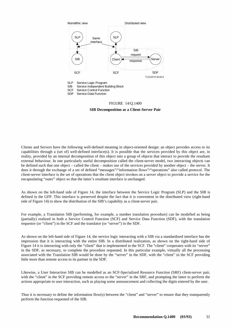
Recommendation Q.1400 (03/93) 31
T1132470-91/d14
Monolithic view
SLP
SIB
Sameinterface
SLP
Client Server
SIBrequest
response
SCF SCF SDF
Distributed view
SLPSIBSCFSDF
Service Logic ProgramService Independent Building BlockService Control FunctionService Data Function
FIGURE 14/Q.1400
SIB Decomposition as a Client-Server Pair
FIGURE 14/Q.1400 [D14] = 8 CM
Clients and Servers have the following well-defined meaning in object-oriented design: an object provides access to itscapabilities through a (set of) well-defined interface(s). It is possible that the services provided by this object are, inreality, provided by an internal decomposition of this object into a group of objects that interact to provide the resultantexternal behaviour. In one particularly useful decomposition called the client-server model, two interacting objects canbe defined such that one object – called the client – makes use of the services provided by another object – the server. Itdoes it through the exchange of a set of defined “messages”/“information flows”/“operations” also called protocol. Theclient-server interface is the set of operations that the client object invokes on a server object to provide a service for theencapsulating “outer” object so that the latter’s resultant interface is unchanged.
As shown on the left-hand side of Figure 14, the interface between the Service Logic Program (SLP) and the SIB isdefined in the GFP. This interface is preserved despite the fact that it is convenient in the distributed view (right-handside of Figure 14) to show the distribution of the SIB’s capability as a client-server pair.
For example, a Translation SIB (performing, for example, a number translation procedure) can be modelled as being(partially) realized in both a Service Control Function (SCF) and Service Data Function (SDF), with the translationrequestor (or “client”) in the SCF and the translator (or “server”) in the SDF.
As shown on the left-hand side of Figure 14, the service logic interacting with a SIB via a standardized interface has theimpression that it is interacting with the entire SIB. In a distributed realization, as shown on the right-hand side ofFigure 14 it is interacting with only the “client” that is implemented in the SCF. The “client” cooperates with its “server”in the SDF, as necessary, to complete the procedure requested. In this particular example, virtually all the processingassociated with the Translation SIB would be done by the “server” in the SDF, with the “client” in the SCF providinglittle more than remote access to its partner in the SDF.
Likewise, a User Interaction SIB can be modelled as an SCF-Specialized Resource Function (SRF) client-server pair,with the “client” in the SCF providing remote access to the “server” in the SRF, and prompting the latter to perform theactions appropriate to user interaction, such as playing some announcement and collecting the digits entered by the user.
Thus it is necessary to define the information flow(s) between the “client” and “server” to ensure that they transparentlyperform the function requested of the SIB.
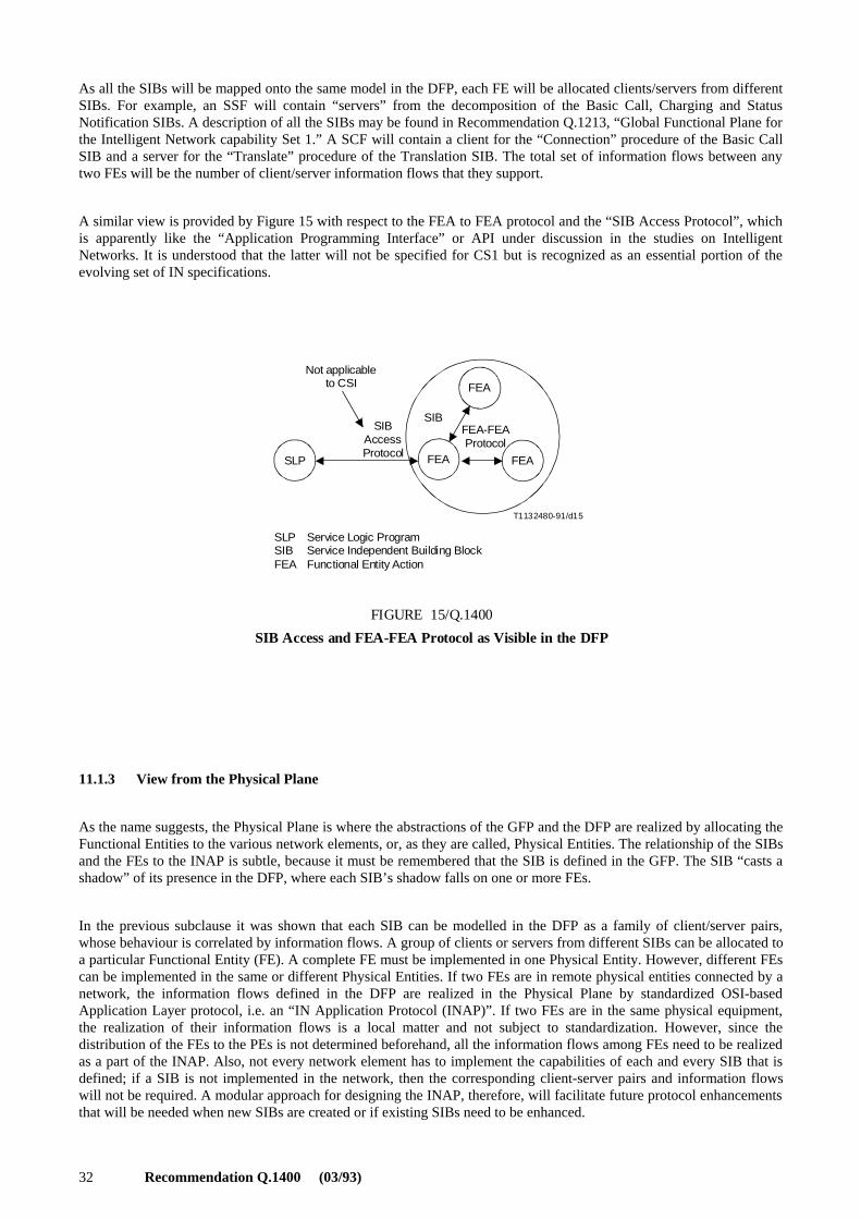
32 Recommendation Q.1400 (03/93)
As all the SIBs will be mapped onto the same model in the DFP, each FE will be allocated clients/servers from differentSIBs. For example, an SSF will contain “servers” from the decomposition of the Basic Call, Charging and StatusNotification SIBs. A description of all the SIBs may be found in Recommendation Q.1213, “Global Functional Plane forthe Intelligent Network capability Set 1.” A SCF will contain a client for the “Connection” procedure of the Basic CallSIB and a server for the “Translate” procedure of the Translation SIB. The total set of information flows between anytwo FEs will be the number of client/server information flows that they support.
A similar view is provided by Figure 15 with respect to the FEA to FEA protocol and the “SIB Access Protocol”, whichis apparently like the “Application Programming Interface” or API under discussion in the studies on IntelligentNetworks. It is understood that the latter will not be specified for CS1 but is recognized as an essential portion of theevolving set of IN specifications.
T1132480-91/d15
Not applicableto CSI
SLP
FEA
FEAFEA
SIBAccessProtocol
FEA-FEAProtocol
SIB
SLPSIBFEA
Service Logic ProgramService Independent Building BlockFunctional Entity Action
FIGURE 15/Q.1400
SIB Access and FEA-FEA Protocol as Visible in the DFP
FIGURE 15/Q.1400 [D15] = 7 CM
11.1.3 View from the Physical Plane
As the name suggests, the Physical Plane is where the abstractions of the GFP and the DFP are realized by allocating theFunctional Entities to the various network elements, or, as they are called, Physical Entities. The relationship of the SIBsand the FEs to the INAP is subtle, because it must be remembered that the SIB is defined in the GFP. The SIB “casts ashadow” of its presence in the DFP, where each SIB’s shadow falls on one or more FEs.
In the previous subclause it was shown that each SIB can be modelled in the DFP as a family of client/server pairs,whose behaviour is correlated by information flows. A group of clients or servers from different SIBs can be allocated toa particular Functional Entity (FE). A complete FE must be implemented in one Physical Entity. However, different FEscan be implemented in the same or different Physical Entities. If two FEs are in remote physical entities connected by anetwork, the information flows defined in the DFP are realized in the Physical Plane by standardized OSI-basedApplication Layer protocol, i.e. an “IN Application Protocol (INAP)”. If two FEs are in the same physical equipment,the realization of their information flows is a local matter and not subject to standardization. However, since thedistribution of the FEs to the PEs is not determined beforehand, all the information flows among FEs need to be realizedas a part of the INAP. Also, not every network element has to implement the capabilities of each and every SIB that isdefined; if a SIB is not implemented in the network, then the corresponding client-server pairs and information flowswill not be required. A modular approach for designing the INAP, therefore, will facilitate future protocol enhancementsthat will be needed when new SIBs are created or if existing SIBs need to be enhanced.
Recommendation Q.1400 (03/93) 33
The relationship of the SIBs to the INAP now needs to be addressed. A modular “building block” approach is proposedfor implementing the INAP, because:
– each SIB is modelled as a separate family of client/server pairs and information flows relating to them;
– not every network has to implement every SIB: if a SIB is not implemented in the network, then thecorresponding client/server pairs and information flows will not be required;
– a modular approach would facilitate future enhancements (new SIBs or enhancements to existing SIBs).
Such a modular “building block” approach is readily available for the design of the IN Application Protocol – namely,the concept of the Application Service Element (ASE). This is defined in ISO 9545 as “a set of applications-functionsthat provides a capability for the interworking of application-entity-invocations for a specific purpose”. In this case, the“specific purpose” is SIB-related communication. Thus, the elements of the protocol needed for each SIB could bedefined by a set of one or more ASEs.
The paradigm that best seems to model the information flows between a client and a server is that of a request/replyinteraction. The client requests some action to be performed by the server, which responds with the results when it hascompleted the task or informs the client that it cannot complete the task. Each client-server information flow will, ofcourse, have its own specific requests and replies. If one were to define a protocol for every application that decided tomodel its communications using the request/reply paradigm, then there would be an unwieldy – potentially infinite –number of protocols to define and manage. Recognizing this, CCITT has standardized a mechanism – called the RemoteOperations Service Element (ROSE) – where a separation is made between:
a) the common generic “vehicle” for the conveyance of a request (called, in technical jargon, the invocationof an operation) and the return of the response; and
b) the application-specific syntax and semantics of the requests and responses.
Item a) is the ROSE protocol specified in Recommendation X.229. Item b) is called the ROSE-User ASE and theguidelines for specifying these ASEs is, among other things, provided in Recommendation X.219. The next subclausewill provide greater detail on the use of ROSE by INAP.
The previous subclause discussed how a Translation SIB might be modelled as (in general, a family) of client-serverpair(s) – one located in the SCF and one in the SDF – correlated by information flow(s). Assuming that the SCF andSDF (and hence, the client and server) are implemented in different Physical Entities [e.g. in a Service Control Point(SCP) and a specialized data base respectively], then the appropriate client/server information flows need to beimplemented as protocol. The protocol to realize these information flows could be defined by one (or more) ASE(s).
11.1.4 INAP Protocol Platform
In the near term, such a protocol should make use of existing protocol standards and platforms (e.g. TCAP, Q.932,X.217/219) wherever possible. However, to ensure a smooth evolution towards a common longer-term OSI-alignedplatform, it should ideally be independent of any specific underlying communications protocols.
The “existing standards” (including TCAP and Q.932) are all based upon ISO 9545 “Application Layer Structure” andRecommendations X.219/229 Remote Operations (ROSE). The information flows between the client/server pairs arerealized in INAP through the use of remote operations. The client requests the server to perform a procedure byencapsulating the specifics of the request in an INVOKE PDU. The results (if any) are returned in a RETURN RESULTor RETURN ERROR PDU, depending, respectively, on whether the specific request (i.e. operation invoked) could orcould not be completed. Syntax errors in the INAP or ROSE protocol are signalled through the REJECT PDU.
The specific semantics of particular client/server procedures are defined through the use of the OPERATION andERROR macros which are a notation for showing the relationship between the “user data” of various ROSE PDUsrequired to complete a remote procedure. The OPERATION MACRO describes for a given operation (referenced by anINTEGER or OBJECT IDENTIFIER value) the arguments (i.e. parameters) that accompany the operation invocation,the arguments (parameters) that are returned upon successful completion and the error causes that signal the inability to
34 Recommendation Q.1400 (03/93)
complete an operation. Should an operation require a “linked operation” to complete, that is also denoted here. Thearguments that further qualify the report of an error are specified through an ERROR MACRO. Details on OPERATIONand ERROR macros and how to use them are provided in Recommendation Q.775 (the TCAP User’s Guide) as well asin Recommendations X.219 and X.229.
Thus the client/server information flow(s) are specified in protocol by ASN.1 modules that specify, using theOPERATION and ERROR MACRO notations, a set of operations and errors that comprise the SIB capability.
11.2 Structure in the Application Layer
The communications needs for the IN applications are provided by an Application Entity (AE). This AE consists ofseveral building blocks, one of which is TCAP whose purpose is to provide a mechanism to convey remote operationsand their results. [In other environments, such as the use of the full OSI stack, there will be a need to have theAssociation Control Service Element (ACSE).] Each AE will also contain one (or more) TCAP-User ASEs which aremodules of specifications which contain the definitions of the remote operations that make up the abstract syntax of thedata exchanged.
Given these building blocks, there are several ways in which the AE can be structured. These are outlined below and theusefulness or deficiencies of each are pointed out.
11.2.1 The Monolithic Approach
In this arrangement, the entire applications protocol which realizes the information flows between all possible FEAs isdefined as one large TCAP-User ASE. The requirement is that all operation and error codes have to be assigned uniquelocal INTEGER values or globally unambiguous OBJECT IDENTIFIER values.
While this has the apparent advantage of simplicity, the disadvantage is that the interface between two FEs is not clearlydistinguished and every node is required to support the entire protocol even if it will not use all of it. The reason is thatthere is no way using the current protocol to signal which subset of the total protocol each node supports without anexplicit handshake at the start of a transaction preceding the exchange of data. Such explicit handshakes have beenconsidered detrimental to signalling efficiency. Thus, even though the SCF and SDF may participate in only a limitednumber of inter-SIB client/server relationships, the network entities realizing these FEs has to support the entire set ofinformation flows (which maps to the one application protocol defined by the single AE type).
Another disadvantage is the inability to easily borrow some useful TCAP-User protocol from other specification. Let ussay that a remote operations-based authentication protocol has been defined somewhere which is found to be particularlyuseful. Should the INAP wish to borrow this protocol, rather than define its own version, it must ensure that importingthe new set of operations/errors into INAP does not cause code value clashes.
Of course, INAP could define globally unique values (of the type OBJECT IDENTIFIER) for operation and error codes.This requires several extra octets to encode.
11.2.2 A Modular Approach
In designing any complex application protocol, the designer may choose to structure the protocol such that the AE iscomprised of several TCAP-User ASEs. For example, the communications aspects of charging can be grouped togetherand separated from the aspects that have to do with a number translation. Such a structure allows the charging functionto be used in combination with some other capability (e.g. collect digits) should that combination be found useful insome service scenario.
In such a “top-down” modular approach, the safest way to ensure that constituent TCAP-User ASEs can coexist in thesame AE is to ensure that the operations and error are defined by TYPE in some module (specification). Values(integers) are assigned when these definitions are imported into the module defining the combination of ASEs that forma particular AE. A more constraining way to ensure uniqueness of local operation/error codes is to assign a range of codevalues (integers) to each ASE that is defined. (Of course, not all values in that range need be used.) Again, there isalways the possibility of providing globally unique values by assigning operation/error codes to the type OBJECTIDENTIFIER.

Recommendation Q.1400 (03/93) 35
The main advantage of using the definition of operations/errors by TYPE and assigning local values only within themodules into which they are imported is that there is only one definition of the syntax and information content of aparticular operation. If the operation needs to be changed, it is done only once; in the other approach every replicateddefinition needs to be changed. If the old definition cannot be easily modified (say by the addition of some newparameter) then a new operation is created – and only once – and its definition is available to anyone wishing to use it.This eases administration and leads to a more structured method of specification.
11.2.3 Use of Application Context
This subclause outlines a further OSI-based structuring capability that has been defined by CCITT SG XI and whichshall be adopted by various signalling protocols that use Transaction Capabilities. This structuring capability – called theApplication Context – will be used in conjunction with the modular structure of the Application Layer described inclause 4.
In CCITT TCAP, a new information element corresponding to the Application Context has been defined whose purposeis to identify the TC-User ASEs that will be used during a given transaction. As described in clauses 4 and 6, this isnecessary when the capabilities of the Application Layer have been divided into TCAP plus many TCAP-User ASEs,each of the latter being concerned with the communications for some specific capability. The Application Context willbe included in the TCAP Begin and Continue messages, and also the End message for short (two message) transactions.Without this extra piece of information in a Begin message, there is no other way to signal “up-front” which particularTCAP-User ASEs will be required on a given transaction. The only way to know how to “route” an operation to thecorrect process or capability is to use a unique operation code value as an index to the type of capability/procedure thatis being requested. Or, if there are “generic” operations, it is necessary to “look deeper” into an operation for a specialparameter; or, if parameters are also made “generic”, it is necessary to look for a special parameter value to determinethe requested capability.
In the network, an instance of communication between any pair of Physical Entities will potentially concern many SIBs,depending upon the Physical Entities involved and the service feature(s) being executed. It may also be necessary toinclude communication capabilities (ASEs) defined elsewhere, e.g. from mobility services or supplementary services.The Application Context selected must include the ASEs for all the client/server interactions anticipated, plus, if sorequested, those for mobility and supplementary services. In situations where a particular node supports only a certainspecific set of capabilities, i.e. in situations where each FE is implemented in a separate physical entity, a differentprotocol (i.e. application context) is needed across the interfaces (information flows) between each FE pair. (However, iftwo FEs are at the same node, then their communications do not require a standardized communications protocol.) TheAC signals, at the beginning of the transaction, which set of ASEs are potentially going to be used for protocol exchangebetween the two AEs. If there were “versions” of these ASEs defined, these could also be signalled at such a time.
With a monolithic protocol, all the capabilities are potentially required at every AE. There would be no flexibility inproviding for just those functions (ASEs) that are found necessary at a given node.
Thus, the structuring principle being adopted by at least one SG XI application protocol is as follows:
– Operations and errors are defined by type in modules.
– Related operations and errors are imported by type into modules called ASEs.
– Sets of ASEs make up an AC. In the module where the AC is defined, non-overlapping values areassigned to the operation/error codes.
– The corresponding application protocol is defined as a set of possible Application Contexts.
– The AE at a physical node supports one, some or all of these ACs depending on the FEs allocated to it.
– Two AEs agree at the start of the transaction on the AC that will be used for that instance ofcommunications.

36 Recommendation Q.1400 (03/93)
11.3 Proposed Structure of the INAP
The IN Application Protocol should be structured in the modular way described above so that for any instance ofcommunication (i.e. transaction) between two Physical Entities, an Application Context can be selected which containsthose ASEs which are needed to complete the network capability requested of the SIBs. For example, between the SSFand SCF FEs the possible Application Context(s) would bind together, for a given transaction, the ASEs for charging,monitoring, basic call control, etc. Thus, the AC is a subset of the total IN protocol and specifies that portion needed forcommunicating between these two types of functional entities. In a similar way, one can specify the subset of the INprotocol needed between the SCF and the SRF FE types, and so forth.
The easiest modular structure is to group the procedures that constitute a client/server relationship for providing thecapabilities of a SIB into one TC-User ASE. One can think of the “generic” description of the SIB (e.g. CONNECTIONor USER INTERACTION, to use the example in subclause 2.1) as providing a “family” of operations with theindividual procedures being the “specifiers”.
Specifications are simplified if a single ASN.1 module contains the type descriptions of all the operation and errorsusing the MACRO notation. When specific ASEs are constructed for the AE at a physical entity, the operations anderrors are given locally unique values. Combinations of ASEs are defined by an Application Context and the name ofthis context conveyed in protocol at the start of a transaction.
11.4 Protocol Assumptions
INAP will be a set of User ASEs of an X.219/229 Remote Operations (ROSE)-aligned Application Layer protocol. TheROSE functionality is provided in SS No. 7 by the Component Sub-Layer (CSL) of TCAP and in DSS 1 by the FacilityIE of Recommendation Q.932. The Application Layer should be independent of the underlying transport mechanism(e.g. it is possible that TCAP over Recommendation X.25 could be used). The four TCAP Component Sub-Layer (CSL)Application Protocol Data Units (APDUs) which are fully aligned with ROSE will be used, namely:
– Invoke
– Return Result
– Return Error
– Reject
with each INVOKE operation being one of four possible classes of operations:
– Class 1: Success (Return Result) and failure (Return Error) of the Invoke operation is reported
– Class 2: Only success is reported
– Class 3: Only failure is reported
– Class 4: Neither success nor failure is reported.
It will be assumed that the TCAP Transaction Sub-Layer (TSL) will provide services to initiate (Begin), continue(Continue) and terminate (End for graceful completion, Abort for abnormal completion) transactions for a particular calland to package multiple ROSE PDUs together in a single message.
The TCAP-based Application Layer structure to be used for IN is depicted in Figure 16.
11.5 IN Application Part Structure
As discussed earlier, the INAP can be structured either as one monolithic ASE or as a set of several ASEs grouped byfunctionality. The discussion pointed out the inherent advantages of the latter approach. In short, dividing the operationsinto self-contained groupings of functions is useful if there is possibility of reuse of the groupings for a variety ofdifferent contexts depending on current, planned and potential long-term distribution of network capabilities.
This subclause discusses the criteria for determining the functional grouping of operations into ASEs.
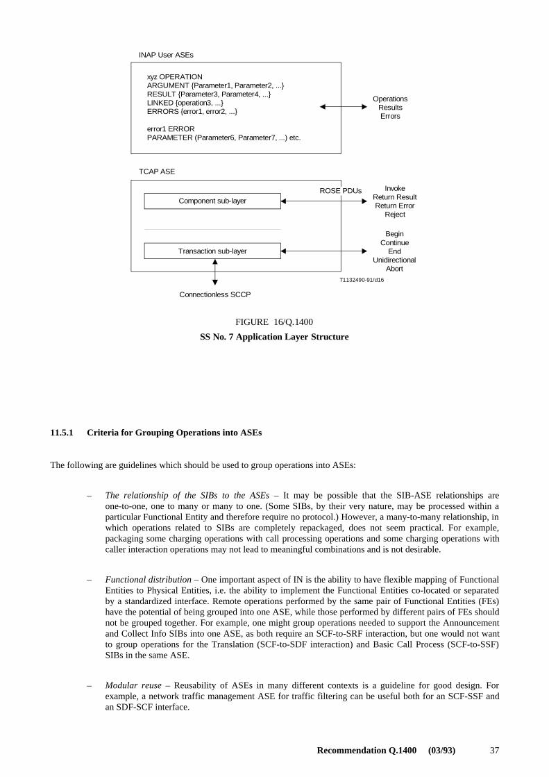
Recommendation Q.1400 (03/93) 37
T1132490-91/d16
INAP User ASEs
xyz OPERATIONARGUMENT {Parameter1, Parameter2, ...}RESULT {Parameter3, Parameter4, ...}LINKED {operation3, ...}ERRORS {error1, error2, ...}
error1 ERRORPARAMETER (Parameter6, Parameter7, ...) etc.
TCAP ASE
OperationsResultsErrors
InvokeReturn ResultReturn Error
Reject
BeginContinue
EndUnidirectional
Abort
ROSE PDUsComponent sub-layer
Transaction sub-layer
Connectionless SCCP
FIGURE 16/Q.1400
SS No. 7 Application Layer Structure
FIGURE 16/Q.1400 [D16] = 11 CM
11.5.1 Criteria for Grouping Operations into ASEs
The following are guidelines which should be used to group operations into ASEs:
– The relationship of the SIBs to the ASEs – It may be possible that the SIB-ASE relationships areone-to-one, one to many or many to one. (Some SIBs, by their very nature, may be processed within aparticular Functional Entity and therefore require no protocol.) However, a many-to-many relationship, inwhich operations related to SIBs are completely repackaged, does not seem practical. For example,packaging some charging operations with call processing operations and some charging operations withcaller interaction operations may not lead to meaningful combinations and is not desirable.
– Functional distribution – One important aspect of IN is the ability to have flexible mapping of FunctionalEntities to Physical Entities, i.e. the ability to implement the Functional Entities co-located or separatedby a standardized interface. Remote operations performed by the same pair of Functional Entities (FEs)have the potential of being grouped into one ASE, while those performed by different pairs of FEs shouldnot be grouped together. For example, one might group operations needed to support the Announcementand Collect Info SIBs into one ASE, as both require an SCF-to-SRF interaction, but one would not wantto group operations for the Translation (SCF-to-SDF interaction) and Basic Call Process (SCF-to-SSF)SIBs in the same ASE.
– Modular reuse – Reusability of ASEs in many different contexts is a guideline for good design. Forexample, a network traffic management ASE for traffic filtering can be useful both for an SCF-SSF andan SDF-SCF interface.
38 Recommendation Q.1400 (03/93)
– Objects – Several other standards areas, most notably Network Management, have used object-orientedmodelling techniques as a tool for deriving logically complete groupings of operations and for predictingpotential future distribution of network functionality. Applying object-oriented analysis techniques, itappears useful to group operations acting on an end-to-end connection object in one ASE and to groupoperations acting on a path object of a connection in another ASE.
– Future evolution – Obviously, future capability sets will build upon the foundation which CS1 willprovide. It must be possible to add new capabilities without having to alter the ASE definitions used forthe previous Capability Sets. Changes to one ASE (e.g. adding new parameters to operations of the ASEor adding a new operation to the ASE) in a new version of the ASE should not impact the definitions ofother ASEs. It will also be necessary for CS1 ASE development to take into account possible futuredistribution of network functionality. For example, it may seem expedient to combine call processing andcaller interaction operations in the same ASE; however, such an ASE would preclude support ofsignalling connection between a Physical Entity (PE) containing a Service Control Function (SCF) and astand-alone PE containing Specialized Resource Function (SRF) capabilities.
11.5.2 Criteria for Identification of Operations
The formation of INAP operations, or the remote operations questions to be asked across IN interfaces, also meritcareful thought. Decisions must take into account current and potential physical configurations, protocol flexibility andreal-time performance issues. For example, when determining whether call processing and call charging parametersshould be combined within one operation, the following must be taken into account:
– Does charging need to be supported by a multiplicity of call processing and non-call processing(e.g. caller interaction) operations in other ASEs?
– What if future systems designers decide to physically separate charging functionality from call processingfunctionality?
– What if another TCAP-User or ROSE-User would like to “borrow” INAP’s charging capabilities? Howeasy will modular reuse turn out to be?
– How will real-time performance be impacted?
It is a good practice for the operations to ask as specific a question as possible. Since the TCAP TSL allows multiplecomponents to be packaged within one message, required modularity can be supported with no impact on the number oftransactions required and with minimal overhead. Of course, this is assuming that such modularity can be shown toprovide a future benefit and does not make the protocol unnecessarily complex.
The following points must also be considered in determining the set of INAP operations:
– If an operation is so generic that a multiplicity of potential types of results are envisioned, then it is likelythat more than one operation is required. On the other hand, if multiple operations are proposed which askthe same question and expect the same results, then only one operation should be required.
– In theory, operations should be specific enough so that the class of the operation is identifiable from theoperation code. The operation code is used as an index into the MACRO notation definition of theoperation. The presence/absence of the keywords RESULTS and ERRORS determines the class of theoperation. Note that the class of the operation is not decided dynamically, but rather is accepted by bothpeers as part of the ASE definition.
11.6 Hypothetical Example
A hypothetical example to illustrate the use of several ASEs for INAP is shown in Figure 17. (None of the ASEs shownin Figure 17 should be treated as a specific recommendation for INAP.) Note that the protocol for management (callgapping) may be applicable in several relationships, and should therefore be specified as an ASE.

Recommendation Q.1400 (03/93) 39
T1132460-91/d17
SCF
MACF
SAO SAO SAO
User Interaction
MACF
SAO SAO SAO
SDF
Data RetrievalManagement (Call Gapping)a)
BCSM InteractionChargingManagement (Call Gapping)a)
Connection Control
SCFSRFSDFSSFMACFSAOASEBCSM
Service Control FunctionSpecialized Resource FunctionService Data FunctionService Switching FunctionMultiple Association Control FunctionSingle Association ObjectApplication Service ElementBasic Call State Model
a) Reused ASE.
SSF
SAO SAO
MACF
SRF
FIGURE 17/Q.1400
Hypothetical Example to Illustrate Usage of ASEs
12 Compatibility Mechanisms and Rules in SS No. 7 and DSS 1
Subclauses 12.1 through 12.4 relate to non-OSI-based signalling and OA&M protocols. Subclause 12.5 addresses OSI(ROSE-based) protocols.
12.1 Background
The wide scope of the signalling system requires that the total system include a large diversity of functions and thatfurther functions can be added to cater for extended future applications. As a consequence, only a subset of the totalsystem may need to be used in individual application.
40 Recommendation Q.1400 (03/93)
A major characteristic of the signalling system is that it is specified with a functional structure to ensure flexibility andmodularity for diverse applications within one system concept. This allows the system to be realized as a number offunctional modules which could ease adaptation of the functional content of operating SS No. 7 and/or DSS 1 to therequirements of particular applications.
The CCITT specifications of the signalling system specify functions and their use for international operation of thesystem. Many of those functions are also required in typical national applications. Furthermore, the system to someextent includes features that are particular to national applications. The CCITT specifications thus form aninternationally standardized base for a wide range of national applications of common channel signalling.
SS No. 7 is one common channel signalling system and DSS 1 is one digital access signalling system. However, as aconsequence of their modularity and their intended use as bases for national applications, the systems may be applied inmany forms. In general, to define the use of a system in a given national application, a selection of the CCITT specifiedfunctions must be specified depending on the nature of the application.
SS No. 7 and DSS 1 are evolutionary signalling systems which have undergone a number of enhancements. To allowease of evolution it has been necessary to incorporate a number of compatibility mechanisms in various functionalelements, and to apply a number of compatibility rules to protocol enhancement. Detailed specifications of thecompatibility mechanisms in each functional element are given in the appropriate Q.700-Series and Q.900-SeriesRecommendations. An overview is given in this Recommendation.
Compatibility rules which apply to all functional elements of SS No. 7 and DSS 1 are detailed in the following text.
12.2 Evolutionary Requirements
In application protocols (e.g. ISDN-UP, ASEs), the main evolutionary requirement is the ability to add new subscriberservices, new administration and network services to the protocol.
In the SCCP and MTP, the evolutionary requirements are different in that initial versions provide basic transportfunctions which are generally stable. The main enhancements have been in the management aspects of the protocols.
Although the evolutionary requirements are different across the elements of SS No. 7, it is possible to incorporate certaincommon mechanisms in the various functional elements.
12.3 Forward and Backward Compatibility
Compatibility mechanisms can be considered as being either:
– Forward compatibility mechanisms; or
– Backward compatibility rules.
Forward compatibility mechanisms are defined as a scheme to enable a version of a protocol to communicate effectivelywith and interwork with future versions of the protocol. That is, a version of a protocol should not restrict futureprotocols from providing extra capabilities.
Backward compatibility rules are defined as a scheme to ensure that future versions of the protocol will be able to sendprotocol messages to the previous version which will be understood and fully processed by the node supporting theprevious version. That is, future versions of a protocol must allow earlier versions to operate with it and not reduce theearlier version’s service level.
12.4 Compatibility Rules for SS No. 7 and DSS 1
The following compatibility rules are applied to each element of SS No. 7 (e.g. ISDN-UP) and DSS 1 when protocolsare enhanced, or when a subsequent version of a protocol is prepared.

Recommendation Q.1400 (03/93) 41
12.4.1 Rules for Forward Compatibility
All future versions of CCITT Recommendations for non-OSI-based SS No. 7 protocol elements (e.g. SCCP, ISDN-UP,etc.) and DSS 1, from 1992 onwards, shall include a mechanism for forward compatibility. The following list containsthe basic requirements of the mechanism:
i) include the ability to send a message indicating that the received information was not understood inresponse to an unrecognized message or parameter;
ii) send this message to the node responsible for the confusing information if the necessary routinginformation is available;
iii) for existing protocols, state the action to be taken on receipt of spare or reserved values of definedparameters, e.g. treat as appropriate default values, transmit them unchanged at intermediate nodes, orignore them at end nodes;
iv) when defining new messages, parameters or parameter values to support a new function, include in thespecification the action to be taken when a confusion message is received in response to the new message,parameter or value indicating that the information was not understood;
v) only send messages requiring an acknowledgement a limited number of times (e.g. three). If no responseis received, the sending signalling point should assume that the facility is not available and inform localmanagement;
vi) state that all new messages shall have the ability to add new optional fields; and
vii) unallocated codes of defined fields should be examined and handled as spare codes.
Note that the 1992 ISUP Recommendations (see the Q.76x–Series Recommendations) contain a special compatibilityprocedure. It uses an instruction indicator, which includes information about the handling of a parameter or message thatis not recognized (e.g. discard, pass-on, send Confusion). It is sent with every new message or parameter. For parameterscontaining new values, it is assumed that the instruction indicator for the whole parameter can be used for all valueswithin the parameter. For existing messages, parameters and parameter values, the required action if unrecognizedinformation is received is given in tabular form.
12.4.2 Rules for Backward Compatibility
All future versions of CCITT Recommendations for non-OSI-based SS No. 7 elements (e.g. SCCP, ISDN-UP, etc.) andDSS 1, from 1992 onwards, shall include a mechanism for backward compatibility. The following list contains the basicrequirements of the mechanism.
12.4.2.1 Existing Messages
i) The ability to receive all existing messages shall be possible, since the removal of a message implies theremoval of a function.
ii) The effect of receiving any existing message, parameter or function, in a new version, must be the sameas that in previous versions. The effects of new parameters or parameter values will thus be purelyadditive.
12.4.2.2 Existing Message Parameters
Message parameters consist of three basic types and occur in the pre-defined order: mandatory fixed length, mandatoryvariable length and optional fixed or variable length.
The following rules shall apply:
i) no fixed length parameter of the mandatory type shall be changed to variable length;
ii) no variable length parameter of the mandatory type shall be changed to fixed type;
iii) optional parameters shall not become mandatory;

42 Recommendation Q.1400 (03/93)
iv) mandatory parameters shall not become optional;
v) additional mandatory parameters shall not be added to a message;
vi) in existing messages whose format allows optional parameters, additional optional parameters areallowed;
vii) existing mandatory parameters shall not be removed from existing messages;
viii) the range of any parameter for an existing message shall not be reduced;
ix) the meaning of any defined parameter value shall not be changed on an existing message; and
x) there are no restrictions on the parameters for new messages.
12.4.2.3 New Messages
i) New messages may be added after a Recommendation has been published, however, nodes that do notrecognize these new messages will respond with a message indicating that the information was notrecognized.
ii) The “information not recognized” message shall never be sent in response to a received “information notrecognized” message, nor in response to other recognized messages received in the wrong call state.
Appropriate default action shall be defined to handle these situations.
12.4.2.4 New Parameters
New optional parameters can be added to existing messages after a Recommendation has been published, however,nodes that do not recognize these new parameters will respond with a message indicating that the information was notrecognized.
12.4.2.5 New Parameter Fields
New fields may be added to, or spare fields used in existing parameters after a Recommendation has been published,however, nodes that do not recognize these new fields will respond with a message indicating that the information wasnot recognized.
12.4.2.6 New Parameter Values
Previously spare, reserved or unallocated parameter values can be used after a Recommendation has been published;these will be treated as defined in 12.4.1 iii).
12.4.3 Handling of Unrecognized Information
When a new protocol, message or information element is created, a rule is required on a per message and informationelement basis to define the action on receipt of unrecognized information. This rule needs to be applied to unrecognizedmessages, unrecognized information elements within messages, and unrecognized values within recognized informationelements.
The actions defined for receipt of an unrecognized message/information element could be:
– discard message/information element;
– discard/ignore information element within a recognized message;
– default to a known general value (e.g. on receipt of an ISDN-UP IAM with an unrecognized calling partycategory, the value could be defaulted to “Unknown”);
– send a “Confusion” message;
– terminate the call/transaction; or
– inform management.

Recommendation Q.1400 (03/93) 43
12.4.4 Increase in the Length of Optional Parameters
If a parameter is used as an optional parameter in all messages that it appears, the length of the parameter can beincreased. The older version of the protocol would be able to function as it does today, assuming it ignores the extra bitsor a suitable extension method has been defined. The newer version would have to check the length of the parameter todetermine if the added information was present.
Protocols which use coding rules which are based on ASN.1 (e.g. TC) are not subject to this rule.
12.4.5 Processing of SS No. 7 Messages with Unrecognized SIO Information
To enable signalling points implemented to the 1988 Recommendations to interwork with signalling points implementedto earlier Recommendations when a message containing an unrecognized service information octet (see 14.2/Q.704) isreceived, the message is discarded.
12.4.6 Unacknowledged Messages
Where a function requires an acknowledgement to a message in order to continue, if no response is received the functionsends the message for only a limited number of times. The sending signalling point should assume that the function isnot available, and inform local management.
12.4.7 Processing of Spare Fields
For those functions which define fields or sub-fields in signalling messages as spare or reserved, the following rules forprocessing of these fields apply.
At a node generating a signalling message, all spare and reserved fields are set to zero. At transit nodes, spare orreserved fields may be passed on transparently. At the destination node, the spare and reserved fields are not examined.
12.5 Application Protocol Enhancement Mechanism (ROSE-based protocols)
It is envisaged that minor extensions to an application protocol may be needed from time to time. An abstract syntax isextended if its associated type is extended (i.e. if a choice type, it can be extended by adding a new component orextending an existing one). One way of extending a PDU (or any structure type) is to extend the type of any of itscomponents. In supporting such extensions, care needs to be taken to ensure that the extensions are indeed minor.Therefore, the following types of extensions to the Abstract Syntax might be considered minor:
– addition of an information element which may enhance an activity but is not essential to performing thebasic activity (e.g. list of additional routing options); or
– addition of an information element to add a capability which is not essential to the base capability(e.g. addition of “Name” in addition to “Number” for terminal display purposes).
In the above cases, a new Application Context name need not be defined, however forward compatibility procedures fordealing with the unknown information must exist at the receiving application process.
The following types of extensions might be considered major:
– addition of a new procedure; or
– fundamental alteration of a procedure (e.g. “do this procedure twice”).
In these cases, a new Application Context name should be defined.
When the changes are judged by the application designer not to warrant a new Application Context name, then anExtension Field containing a “criticality factor” may be used to extend the syntax of an existing PDU. This requiresforward compatibility procedures to be available at the receiving end.
The use of a “criticality factor” enables the receiving entity to determine appropriate reaction to the extension receivedshould it not be understood.

44 Recommendation Q.1400 (03/93)
An example of a generic extension mechanism is described by the following ASN.1 specification:
%XTENSION -ECHANISM %XAMPLE �
[�CCITT�RECOMMENDATION�Q������MODULES���EXTENSION EXAMPLE��
[�VERSION����]
$%&).)4)/.3�)-0,)#)4�4!'3����
"%').
%XTENSION&IELD�����3%15%.#%�[�TYPE�%84%.3)/.�
VALUE�;�=�!.9�$%&).%$�"9�TYPE�]
%84%.3)/.�-!#2/ ���
490%�./4!4)/. ����%XTENSION4YPE�#RITICALITY
6!,5%�./4!4)/. ����VALUE��6!,5%�#(/)#%�[
����VALUE��PRIVATE EXTENSION�).4%'%2�
����VALUE��STANDARD EXTENSION�/"*%#4�)$%.4)&)%2�]
%XTENSION4YPE ���� %84%.3)/. 39.4!8 �TYPE�\�EMPTY
#RITICALITY�� ���� #2)4)#!,)49 �VALUE��#RITICALITY4YPE
#RITICALITY4YPE ����%.5-%2!4%$�[�IGNORE���
����%.5-%2!4%$�[�ABORT���]
%.$
Any application protocol wishing to use this extension should IMPORT the ExtensionField from the above describedmodule into the module where such extensions are needed.
The following example illustrates the use of this mechanism for ROSE operations. The ASN.1 has been substantiallysimplified in order to help focus on the extension mechanism. The same approach applies to errors.
Original operation which cannot be extended:
NAME/F/PERATION�/0%2!4)/.
!2'5-%.4�3%15%.#%�[�X���X���X��]
2%35,4�3%15%.#%�[�Y���Y��]
%22/23�ETC�
Revised operation which can be extended:
NAME/F/PERATION�/0%2!4)/.
!2'5-%.4�3%15%.#%�[�8���8���8���3%4�/&�[�%XTENSION&IELD�]�/04)/.!,�]
2%35,4�S%15%.#%�[�9���9���3%4�/&�[�%XTENSION&IELD�]�/04)/.!,�]
%22/23�ETC�
It should be recognized that there is ongoing work in this area in ISO, and that other alternatives may emerge. However,the above mechanism is considered suitable for use in signalling and OA&M application protocols using ROSE.
13 References
– Recommendation X.200 Reference Model of Open Systems Interconnection for CCITT Applications.
ISO/IEC 7498-1 Information Processing Systems – Open Systems Interconnection – Basic ReferenceModel.
– Recommendation X.217 | ISO/IEC 8649 Information Technology – Open Systems Interconnection –Service Definition for the Association Control Service Element.
– Recommendation X.227 | ISO/IEC 8650 Information Technology – Open Systems Interconnection –Protocol Specification for the Association Control Service Element.
ISO/IEC 10035 Information Technology – Open Systems Interconnection – Connectionless ACSEProtocol Specification (A-UNITDATA protocol).
– Recommendation X.219. Remote Operations: Model, Notation and Service Definition.
ISO/IEC 9072-1 Information Processing Systems – Text Communication – Remote Operations – Part 1:Model, Notation and Service Definition.
Recommendation Q.1400 (03/93) 45
– Recommendation X.229 Remote Operations: Protocol Specification.
ISO/IEC 9072-2 Information Processing Systems – Text Communication – Remote Operations – Part 2:Protocol Specification.
ISO/IEC 9545 Information Processing Systems – Open Systems Interconnection – Application LayerStructure.
– Recommendation X.216 Presentation Service Definition for Open Systems Interconnection for CCITTApplications.
ISO/IEC 8822 Information Processing Systems – Open Systems Interconnection – Connection-OrientedPresentation Service Definition Amendment 1: Connectionless Mode Presentation Service.
– Recommendation X.226 Presentation Protocol Specification for Open Systems Interconnection forCCITT Applications.
ISO/IEC 8823 Information Processing Systems – Open Systems Interconnection – Connection-OrientedPresentation Protocol Specification.
ISO/IEC 9576 Information Technology – Open Systems Interconnection – Presentation ConnectionlessProtocol to Provide the Connectionless Presentation Service.
– Recommendation X.690 (to be published), Information Technology – Open Systems Interconnection –Specification of ASN.1 Encoding Rules: Basic Encoding Rules.
ISO/IEC 8824 Open Systems Interconnection – Specification of Abstract Syntax Notation One (ASN.1).
– Recommendation X.209 Specification of Basic Encoding Rules for Abstract Syntax Notation One(ASN.1).
ISO/IEC 8825 Information Technology – Open Systems Interconnection – Specification of BasicEncoding Rules for Abstract Syntax Notation One (ASN.1).
– Recommendation X.650 Open Systems Interconnection (OSI) – Reference Model for Naming andAddressing.
ISO/IEC 7498-3 Information Processing Systems: Open Systems Interconnection – Basic ReferenceModel – Part 3: Naming and Addressing.
– Recommendation X.700 OSI Management Framework.
– Recommendation Q.700 Introduction to CCITT Signalling System No. 7.
– Recommendations Q.701-Q.706 CCITT Recommendations for the Message Transfer Part (MTP) ofSignalling System No. 7.
– Recommendation Q.711-Q.716 CCITT Recommendations for the Signalling Connection Control Part(SCCP) of Signalling System No. 7.
– Recommendation Q.750-Series, Operations, Maintenance and Administration Part (OMAP) of SignallingSystem No. 7.
– Recommendations Q.761-Q.764, Q.766 CCITT Recommendations for the ISDN User Part (ISDN-UP) ofSignalling System No. 7.
– Recommendations Q.771-Q.775 CCITT Recommendations for the Transaction Capabilities ApplicationPart (TCAP) of Signalling System No. 7.
– Recommendation Q.931 ISDN User-Network Interface Layer 3 Specification for Basic Call Control.
– Recommendation Q.932 Generic Procedures for the Control of ISDN Supplementary Services.
– Recommendations Q.81x and Q.82x CCITT Recommendations, Network Management Service.
ISO DIS 10026 Information Technology OSI – Distributed Transaction Processing –Part 1: OSI TP Model.
Information Technology OSI – Distributed Transaction Processing – Part 2: OSI TP Service.
Information Technology OSI – Distributed Transaction Processing – Part 3: Protocol Specification.

46 Recommendation Q.1400 (03/93)
14 List of Acronyms
For the purpose of this Recommendation, the following abbreviations are used:
AARE Application Association Response
AARQ Application Association Request
AC Application Context
ACPM Association Control Protocol Machine
ACSE Association Control Service Element
AE Application Entity
AEI Application Entity Invocation
AFI Authority and Format Identifier
ALS Application Layer Structure
AMI Application Management Interface
AP Application Process
APDU Application Protocol Data Unit
API Application Process Invocation
AS Abstract Syntax
ASE Application Service Element
ASN.1 Abstract Syntax Notation One
AUDT Application Unitdata
BCSM Basic Call State Model
BER Basic Encoding Rules
CEI Connection Endpoint Identifier
CL Connectionless
CL-NS Connectionless Network Service
CL-SCCP Connectionless SCCP
CMIP Common Management Information Protocol
CO Connection-Oriented
CO-NS Connection-Oriented Network Service
CO-SCCP Connection-Oriented SCCP
CRN Call Reference Number
CSL Component Sub-Layer
DCS Defined Context Set
DFP Distributed Functional Plane
DSAP Data Link Service Access Point
DSP Domain Specific Part
DSS 1 Digital Subscriber Signalling 1
DTMF Dual-Tone Multi-Frequency

Recommendation Q.1400 (03/93) 47
FE Functional Entity
FEA Functional Entity Action
FTAM File Transfer and Access Management
GFP Global Functional Plane
GT Global Title
HLR Home Location Register
IAM Initial Address Message
IDI Initial Domain Identifier
IDP Initial Domain Part
IE Information Element
IN Intelligent Network
INAP Intelligent Network Application Part
ISDN Integrated Services Digital Network
ISDN-UP ISDN User Part
ISP Intermediate Service Part
ISUP Integrated Services User Part
LAPD Link Access Protocol – D channel
LME Level Management Entity
LMI Level Management Interface
MACF Multiple Association Control Function
MAP Mobile Application Part
MHS Message Handling System
MIB Management Information Base
MMI Man-Machine Interface
MSC Mobile Switching Centre
MT MTP Tester
MTP Message Transfer Part
NC Network Connection
NS Network Service
NSAP Network Service Access Point
NSP Network Service Part
OM Operation and Maintenance
OMAP Operations, Maintenance and Administration Part
OMASE Operations, Maintenance and Administration Service Element
OSI Open Systems Interconnection

48 Recommendation Q.1400 (03/93)
PABX Private Automatic Branch Exchange
PAI Protocol Addressing Information
PC Point Code
PC Presentation Context
PDU Protocol Data Unit
PDV Presentation Data Value
PhSAP Physical Service Access Point
PPDU Presentation Protocol Data Unit
PSAP Presentation Service Access Point
QOS Quality of Service
ROSE Remote Operations Service Element
RTSE Reliable Transfer Service Element
SA/NC Signalling Area Network Code
SACF Single Association Control Function
SAO Single Association Object
SAP Service Access Point
SAPI Service Access Point Identifier
SCCP Signalling Connection Control Part
SCF Service Control Function
SCP Service Control Point
SDF Service Data Function
SDL Specification and Description Language
SI Service Indicator
SIB Service Independent Building-block
SIO Service Information Octet
SLP Service Logic Program
SMAE Systems Management Application Entity
SMAP Systems Management Application Process
SMSI Systems Management Service Interface
SRF Specialized Resource Function
SS Signalling System
SSAP Session Service Access Point
SSF Service Switching Function
SSN Sub-System Number
ST SCCP Tester
Recommendation Q.1400 (03/93) 49
TC Transaction Capabilities
TC Transport Connection
TCAP Transaction Capabilities Application Part
TD-PPDU Transfer Data – Presentation Protocol Data Unit
TEI Terminal Endpoint Identifier
TMN Telecommunications Management Network
TP Transaction Processing
TP Transport Protocol
TS Transfer Syntax
TSAP Transport Service Access Point
TSL Transaction Sub-Layer
TUP Telephone User Part
VLR Visited Location Register