
ITU-T Recommendation T.30
176
INTERNATIONAL TELECOMMUNICATION UNION ITU-T T.30 TELECOMMUNICATION STANDARDIZATION SECTOR OF ITU (07/96) SERIES T: TERMINAL EQUIPMENTS AND PROTOCOLS FOR TELEMATIC SERVICES Procedures for document facsimile transmission in the general switched telephone network ITU-T Recommendation T.30 (Previously “CCITT Recommendation”)
-
Upload
khangminh22 -
Category
Documents
-
view
3 -
download
0
Transcript of ITU-T Recommendation T.30

INTERNATIONAL TELECOMMUNICATION UNION
ITU-T T.30TELECOMMUNICATION STANDARDIZATION SECTOR OF ITU
(07/96)
SERIES T: TERMINAL EQUIPMENTS AND PROTOCOLS FOR TELEMATIC SERVICES
Procedures for document facsimile transmission in the general switched telephone network
ITU-T Recommendation T.30 (Previously “CCITT Recommendation”)

ITU-T T-SERIES RECOMMENDATIONS
TERMINAL EQUIPMENTS AND PROTOCOLS FOR TELEMATIC SERVICES
For further details, please refer to ITU-T List of Recommendations.

Recommendation T.30 (07/96) i
FOREWORD
The ITU Telecommunication Standardization Sector (ITU-T) is a permanent organ of the International Telecommunication Union. The ITU-T is responsible for studying technical, operating and tariff questions and issuing Recommendations on them with a view to standardizing telecommunications on a worldwide basis.
The World Telecommunication Standardization Conference (WTSC), which meets every four years, established the topics for study by the ITU-T Study Groups which, in their turn, produce Recommendations on these topics.
ITU-T Recommendation T.30 was revised by the ITU-T Study Group VIII (1988-1993) and was approved by the WTSC (Helsinki, March 1-12, 1993). During 1993-1996, several amendments were approved. The publication of ITU-T Recommendation T.30 (1996) is based on the following materials: T.30 (1993), T.30/Amd.1 (1994), T.30/Amd.2 (1995) and T.30/Amd.3 (1996).
___________________
NOTE
In this Recommendation, the expression “Administration” is used for conciseness to indicate both a telecommunication administration and a recognized operating agency.
ITU 1997
All rights reserved. No part of this publication may be reproduced or utilized in any form or by any means, electronic or mechanical, including photocopying and microfilm, without permission in writing from the ITU.

ii Recommendation T.30 (07/96)
CONTENTS
Page 1 Scope.............................................................................................................................................................. 1
1.1 General.............................................................................................................................................. 1 1.2 Classification of operating methods ................................................................................................. 1 1.3 Terminal identification ..................................................................................................................... 2 1.4 General provisions ............................................................................................................................ 2 1.5 Optional provisions........................................................................................................................... 2
2 Explanation of terms used .............................................................................................................................. 3 2.2 Time sequence of a facsimile call ..................................................................................................... 3 2.3 Description of phases........................................................................................................................ 3
3 Description of a facsimile call........................................................................................................................ 4 3.1 Phase A – Call establishment............................................................................................................ 4 3.2 Phases B, C and D – Facsimile procedure ........................................................................................ 5 3.3 Phase E – Call release....................................................................................................................... 5
4 Tonal signal functions and formats ................................................................................................................ 13 4.1 Automatic answer sequence.............................................................................................................. 13 4.2 Calling tone (CNG)........................................................................................................................... 13
5 Binary coded signalling procedure................................................................................................................. 13 5.1 Description........................................................................................................................................ 14 5.2 Flow diagrams – Figures 5-2a to 5-2v (see also Appendix IV)........................................................ 15 5.3 Binary coded signal functions and formats....................................................................................... 39 5.4 Binary coded signalling implementation requirements..................................................................... 53
6 Use of the modulation system defined in Recommendation V.34 ................................................................. 55 6.1 Procedures ........................................................................................................................................ 55
Annex A – Procedure for Group 3 document facsimile transmission in the general switched telephone network incorporating error correction ........................................................................................................................ 56 A.1 Introduction ...................................................................................................................................... 56 A.2 Definitions ........................................................................................................................................ 57 A.3 Block size and frame size ................................................................................................................. 57 A.4 Information field (see also 5.3.6)...................................................................................................... 58 A.5 Flow control procedure..................................................................................................................... 62 A.6 Procedure interrupt ........................................................................................................................... 63 A.7 Flow diagrams .................................................................................................................................. 63 A.8 Signal sequence examples in case of error correction procedure ..................................................... 63
Annex B – BFT diagnostic message....................................................................................................................... 75
Annex C – Procedure for Group 3 document facsimile transmission on the Integrated Services Digital Network or on the GSTN using duplex modulation systems........................................................................................ 75 C.1 Introduction ...................................................................................................................................... 75 C.2 Definitions ........................................................................................................................................ 76 C.3 Facsimile procedure.......................................................................................................................... 77 C.4 Flow control procedure..................................................................................................................... 80 C.5 Flow diagrams .................................................................................................................................. 80 C.6 Signal sequence examples ................................................................................................................ 102 C.7 Procedures for using Annex C within analog transmission environments ....................................... 126
Annex D – Optional automatic terminal selection procedures ............................................................................... 127

Recommendation T.30 (07/96) iii
Page Annex E – Procedure for the Group 3 document facsimile transmission of continuous-tone colour images ......... 130
E.1 Introduction ...................................................................................................................................... 130 E.2 Definitions ........................................................................................................................................ 130 E.3 Normative references........................................................................................................................ 131 E.4 Negotiation procedure ...................................................................................................................... 131
Annex F – Procedures for Group 3 facsimile transmission using the half-duplex modulation system defined in Recommendation V.34................................................................................................................................... 131 F.1 Introduction ...................................................................................................................................... 131 F.2 References ........................................................................................................................................ 132 F.3 Procedures ........................................................................................................................................ 132 F.4 Refinement of the description of Recommendations V.34 and V.8 ................................................. 133 F.5 Examples of sequences ..................................................................................................................... 139
Appendix I – Index of abbreviations used in this Recommendation...................................................................... 153
Appendix II – List of commands and appropriate responses ................................................................................. 155
Appendix III – Alternative procedures used by some terminals which conform to the pre-1996 versions of this Recommendation............................................................................................................................................ 156 III.1 Alternative automatic answering sequence....................................................................................... 156 III.2 Optional binary coded preamble....................................................................................................... 157
Appendix IV – Signal sequence examples ............................................................................................................. 158
Appendix V – Procedure for binary file transmission with protocol examples...................................................... 166 V.1 Introduction ...................................................................................................................................... 166 V.2 Definitions ........................................................................................................................................ 166 V.3 BFT file transfer-protocol overview................................................................................................. 166 V.4 ECM-BFT data format...................................................................................................................... 167

iv Recommendation T.30 (07/96)
SUMMARY
This Recommendation defines the procedures used by Group 3 facsimile terminals as defined in Recommendation T.4. These procedures enable documents to be transmitted on the general switched telephone network, international leased circuits and the Integrated Services Digital Network (ISDN). Further, these procedures allow communication to be manual or automatic and for document transmission to be requested alternatively with telephone conversation.
INTRODUCTION
i) This Recommendation is intended to apply to document facsimile terminals covered by Recommendation T.4. It describes the procedures and signals to be used where facsimile terminals are operated over the general switched telephone network. When an existing terminal is operating in a non-ITU-T manner, it shall not interfere with a terminal operating in accordance with the T-Series Recommendations.
ii) Arrangements for automatic calling/answering on the general switched telephone network have been aligned as closely as possible with those described in the V-Series Recommendations for data terminal equipment.
The answering procedures for multifunction terminal configurations are contained in Annex D.
iii) While there are eight possible operating methods (see Table 1) each may be described by five separate and consecutive phases:
Phase A: Call set-up.
Phase B: Pre-message procedure for identifying and selecting the required facilities.
Phase C: Message transmission (includes phasing and synchronization where appropriate).
Phase D: Post-message procedure including end-of-message and confirmation and multi-document procedures.
Phase E: Call release.
iv) For digital document facsimile terminals conforming to Recommendation T.4, the binary coded system defined in this Recommendation shall be the standard signalling arrangement.
v) The binary coded signalling system is based on a High Level Data Link Control (HDLC) format developed for data transmission procedures. The basic HDLC structure consists of a number of frames, each of which is subdivided into a number of fields. It provides for frame labelling, error checking and confirmation of correctly received information and the frames can be easily extended if this should be required in the future.
vi) The transmission of the facsimile message itself (phase C) will be according to the modulation system described in the appropriate Recommendation for the facsimile terminal.

Recommendation T.30 (07/96) 1
Recommendation T.30 Recommendation T.30 (07/96)
PROCEDURES FOR DOCUMENT FACSIMILE TRANSMISSION IN THE GENERAL SWITCHED TELEPHONE NETWORK1)
(Former Recommendation T.4, Mar del Plata, 1968; amended and renumbered at Geneva, 1976 and 1980, Malaga-Torremolinos, 1984, Melbourne, 1988 and Helsinki, 1993;
revised in 1996)
The ITU-T,
considering
(a) that facilities exist for facsimile transmission over the general switched telephone network;
(b) that such facsimile transmission may be requested either alternatively with telephone conversation or when either or both terminals are not attended;
(c) that for this reason the operations involved in establishing and/or releasing a facsimile call should be capable of automatic operation,
unanimously declares the view
that the facsimile terminal should be designed and operated according to the following standards.
1 Scope
1.1 General
1.1.1 This Recommendation is concerned with the procedures which are necessary for document transmission between two facsimile terminals in the general switched telephone network.
These procedures essentially comprise the following: – call establishment and call release; – compatibility checking, status and control command; – checking and supervision of line conditions; – control functions and facsimile operator recall.
1.1.2 Only the procedures with their corresponding signals are specified in this Recommendation.
1.2 Classification of operating methods
1.2.1 This Recommendation regulates the operational sequence of manually operated facsimile terminals as well as of automatic terminals.
The automatic facsimile terminal is understood to be a terminal which is capable of performing all procedures (listed in 1.1) automatically. In this case, an operator is not necessary.
If, however, an operator is required for any of these procedures, the terminal must be regarded as a manually operated terminal.
1.2.2 Based upon all combinations which may result from the fact that there are manually operated terminals and automatic facsimile terminals, the operating methods shown in Table 1 are possible.
_______________ 1) Facsimile terminals referred to as Group 3 in this Recommendation are those conforming to Recommendation T.4.

2 Recommendation T.30 (07/96)
TABLE 1/T.30
1.3 Terminal identification
1.3.1 For the purpose of classifying an automatic facsimile terminal as a non-speech terminal, a tone must be transmitted to line. As both automatic calling and called facsimile terminals transmit tones to line during call establishment, a normal telephone user who becomes inadvertently connected to one will receive tone signals for a period of sufficient duration to indicate clearly to him that he is incorrectly connected.
1.3.2 Additionally an automatic verbal announcement may be used which can provide terminal identification.
1.4 General provisions
1.4.1 The control signals specified in this Recommendation have been chosen in such a way that the telephone service is not affected.
1.4.2 If any malfunction of the facsimile procedures described in this Recommendation is detected, the call should be released.
1.4.3 Where the called destination is an automatic facsimile terminal which is not ready or not able to operate, the call should not be answered automatically.
1.4.4 This Recommendation includes procedures for switching from facsimile to speech. However, speech facilities may be omitted if this is permitted by the regulations of the Administrations.
1.5 Optional provisions
1.5.1 The operator at each terminal may have the possibility of calling the other terminal at any time during the progress of the facsimile procedure (see 2.2).
1.5.2 The procedures in this Recommendation allow a facsimile terminal to transmit and/or receive several documents successively without the aid of an operator.
Method No. Description of operating method Direction of facsimile transmission Overall designation
1 Manual operation at calling terminal and Calling terminal transmits to called terminal 1-T
Manual operation at called terminal Calling terminal receives from called terminal 1-R
2 Manual operation at calling terminal and Calling terminal transmits to called terminal 2-T
Automatic operation at called terminal Calling terminal receives from called terminal 2-R
3 Automatic operation at calling terminal and Calling terminal transmits to called terminal 3-T
Manual operation at called terminal Calling terminal receives from called terminal 3-R
4 Automatic operation at calling terminal and Calling terminal transmits to called terminal 4-T
Automatic operation at called terminal Calling terminal receives from called terminal 4-R
4 bis
Automatic operation using the procedures defined in Recommendation V.8 at calling terminal and
Calling terminal transmits to called terminal using the procedures defined in Recommendation V.8
4-T
Automatic operation using the procedures defined in Recommendation V.8 at called terminal
Calling terminal receives from called terminal using the procedures defined in Recommendation V.8
4-R
NOTE – There may also be operating methods which will allow messages to be received by more than one terminal (multipoint connection).

Recommendation T.30 (07/96) 3
1.5.3 This Recommendation includes procedures for incorporating a unique terminal identification command if required to prevent unauthorized terminals from demanding a message.
If enhanced security is required, this may be provided by the use of the non-standard facilities frame.
2 Explanation of terms used
For the purposes of this Recommendation, the following definitions apply.
2.1 facsimile terminal main functions: One or more terminals at the end of the line providing three main functions.
2.1.1 call establishment and call release: The establishment and release of a connection according to the normal rules of using the general switched telephone network.
2.1.2 procedure: To identify, to supervise and to control the facsimile transmission according to a protocol.
2.1.3 message transmission: To transmit and/or receive the facsimile message.
2.2 Time sequence of a facsimile call
See Figure 1.
T0813020-93/d001
Phase A Phase BPhase C1
Phase C2Phase D Phase E
Messagetransmission
Facsimile procedure
Facsimile call
Activity progress
FIGURE 1/T.30
In-messageprocedure
FIGURE 1/T.30...[D001] = 3 CM
2.3 Description of phases
2.3.1 Phase A – Call establishment
Call establishment can be realized manually and/or automatically.
2.3.2 Phase B – Pre-message procedure
The pre-message procedure consists of the identification of capabilities and the commanding of the chosen conditions as well as the confirmation of acceptable conditions.
When connection is established between a terminal operating in accordance with this Recommendation and a terminal operating in a non-ITU-T manner, the terminals should disconnect before the in-message procedure unless both terminals include optional, compatible procedures.

4 Recommendation T.30 (07/96)
2.3.2.1 Identification section – capabilities identification; – confirmation for reception; – terminal identification (option); – non-standard facilities identification (option).
2.3.2.2 Command section – capabilities command; – training; – synchronization;
as well as the following optional commands: – non-standard facilities command; – terminal identification command; – polling (send) command; – echo suppressor disabling.
2.3.3 Phase C1 – In-message procedure
The in-message procedure takes place at the same time as message transmission and controls the complete signalling for in-message procedure, e.g. in-message synchronization, error detection and correction and line supervision.
2.3.4 Phase C2 – Message transmission
The message transmission procedure is covered by Recommendation T.4.
2.3.5 Phase D – Post-message procedure
The post-message procedure includes information regarding: – end-of-message signalling; – confirmation signalling; – multipage signalling; – end-of-facsimile procedure signalling.
2.3.6 Phase E – Call release
Call release shall be realized manually and/or automatically.
3 Description of a facsimile call
3.1 Phase A – Call establishment2)
The establishment of a facsimile call may be realized either manually, if an operator is in attendance, or automatically. To accomplish this, four operating methods have been defined.
3.1.1 Operating method 1
Manual operation at both the calling and called terminal. Figure 2 indicates the operators’ actions required to establish a call.
3.1.2 Operating method 2
Manual operation at the calling terminal and automatic operation at the called terminal. Figure 3 indicates the operator’s and terminal actions required to establish a call.
_______________ 2) See Appendix I for abbreviations used in this Recommendation.

Recommendation T.30 (07/96) 5
3.1.3 Operating method 3
Automatic operation at the calling terminal and manual operation at the called terminal. Figure 4 indicates the operator’s and terminal actions required to establish a call.
3.1.4 Operating method 4
Automatic operation at both the calling and called terminals. Figure 5 indicates the actions required by the terminal to establish a call.
3.1.5 Operating method 4 bis
3.1.5.1 Operating method 4 bis a
Automatic operation at both the calling and called terminals when either or both the calling and called terminal are capable of V.8 and V.34 operation. Figure 6a indicates the actions required by the terminal to establish a call.
3.1.5.2 Operating method 4 bis b
Manual operation at the calling and automatic operation at the called terminal when either or both the calling and called terminals are capable of V.8 and V.34 operation. Figure 6b indicates the actions required by the terminal to establish a call.
3.2 Phases B, C and D – Facsimile procedure
When entering phase B, the following rules should be adhered to:
All manual receiving terminals and all auto-answering terminals must enter phase B by identifying their capabilities (i.e. Node R of the flow diagram in 5.2). All manual transmitting terminals and all auto-calling terminals must enter phase B prepared to detect the capabilities and issue the appropriate mode setting command (i.e. Node T of the flow diagram in 5.2). To allow for operating method 2-R, the delay between the transmission of the digital identification signals shall be 4.5 seconds ± 15% when sent from a manual receiving terminal.
The detailed information pertaining to the binary coded facsimile procedures is contained in clause 5.
3.2.1 Signal sequences
The recommended system utilizes the interchange of signals between the two terminals to verify compatibility and assure operation. To do this, the called terminal identifies its capabilities. The calling terminal responds to this accordingly with a command. Now the transmitter continues phase B.
Following the transmission of the message, the transmitter sends an end-of-message signal and the receiver confirms reception. Multiple documents can then be transmitted by the repetition of this procedure.
The flow of signals is shown in Figure 7 for the configuration where the calling terminal is transmitting.
The condition where the calling terminal is to receive documents is shown in Figure 8.
3.3 Phase E – Call release
Call release occurs after the last post-message signal of the procedure or under certain conditions, e.g.
3.3.1 Time out
When a signal as specified by the facsimile procedure is not received within the specified time-out period, the terminal may signal to the operator (if one is in attendance) or disconnect the telephone connection. The appropriate time-out periods are specified in clause 5.
3.3.2 Procedural interrupt
The facsimile procedure may be interrupted by sending a procedural interrupt signal, by notifying the attending operator or by disconnecting the connection. The signal is defined in clause 5.

6 Recommendation T.30 (07/96)
3.3.3 Command
The call may be immediately terminated by the appropriate commands, as specified in clause 5.
T0817140-94/d002
Ring heard?
Yes
No
Dial number
Ringing toneheard?
Yes
No
No
Time elapsed?
No
Yes
Answer call
Yes
Disconnect Verbal exchangeVerbal exchange
Switch facsimilemachine to line
Switch facsimilemachine to line
Optionallytransmit CEDTransmit CNG
Calling terminal
Dial toneheard?
Called terminal
Enter Phase B Enter Phase B
FIGURE 2/T.30Call establishment, operating method 1
FIGURE 2/T.30...[D002] = 3 CM
Call event No. Calling terminal Called terminal
1 Operator hears dial tone and dials desired number
2 Operator hears ringing tone Call rings and operator answers the call
3 Verbal identification Verbal identification
4 Facsimile terminal is switched to line and transmits CNG
Facsimile terminal is switched to line
5 Begin facsimile procedure (see clauses 4 and/or 5) Begin facsimile procedure (see clauses 4 and/or 5)

Recommendation T.30 (07/96) 7
T0817150-94/d003
Answer call
Yes
Called terminal
NoDial toneheard?
Yes
Dial number
Ringingtone heard?
No
No
Time elapsed?
No
No
Ring detected?
Ready tooperate?
Yes
Yes
Disconnect
Yes
CED heard?
Switch facsimilemachine to line Disconnect
Time elapsed?Optionallyrecorded
announcement
Transmit CED
Enter Phase B
Enter Phase BNode R
No
No
Yes Yes
Calling terminal
Transmit CNG
FIGURE 3/T.30Call establishment, operating method 2
FIGURE 3/T.30...[D003] = 3 CM
Call event No. Calling terminal Called terminal
1 Operator hears dial tone and dials desired number
2 Operator hears ringing tone Terminal detects ring and answers the call
3 Optionally, a recorded verbal announcement may be transmitted
4 Operator hears CED or an optional recorded announcement and facsimile terminal is switched to line and transmits CNG
Transmit CED
5 Begin facsimile procedure (see clauses 4 and/or 5) Begin facsimile procedure (see clauses 4 and/or 5)

8 Recommendation T.30 (07/96)
T0813050-93/d004
Calling terminal Called terminal
No
Yes
Dial tonedetected?
Dial number
Ring heard? No
Yes
Answer call
Transmit CNG No
No
Yes
CNGdetected?
No
No
Yes
Yes
Signaldetected? Time elapsed?
Disconnect
Switch facsimilemachine to line
Optionallytransmit CED
Time elapsed?
Disconnect
Yes
Enter Phase BNode T
Enter Phase B
FIGURE 4/T.30Call establishment, operating method 3
FIGURE 4/T.30...[D004] = 3 CM
Call event No. Calling terminal Called terminal
1 Terminal detects dial tone and dials desired number (Note). To clearly indicate to a called operator that he is connected to a facsimile terminal or to a normal telephone user that he is inadvertently connected, CNG will be transmitted to line during the time that signals are attempted to be detected
2 Call rings and operator answers the call
3 Operator detects CNG and switches facsimile terminal to line (optionally CED may be generated)
4 Begin facsimile procedure (see clauses 4 and/or 5) Begin facsimile procedure (see clauses 4 and/or 5)
NOTE – An alternative procedure may be specified by Administrations.

Recommendation T.30 (07/96) 9
T0813060-93/d005
Calling terminal Called terminal
NoDial tonedetected?
Transmit CNG
Dial number
Yes
NoRing detected?
Answer call
Yes
Optionallyrecorded
announcement
Transmit CED
No
No
Yes
Signaldetected?
Timeelapsed?
Disconnect
Enter Phase BNode T
Enter Phase BNode R
Yes
FIGURE 5/T.30Call establishment, operating method 4
FIGURE 5/T.30...[D005] = 3 CM
Call event No. Calling terminal Called terminal
1 Terminal detects dial tone and dials desired number (Note). To clearly indicate to a normal telephone user that he is inadvertently connected, CNG will be transmitted to line during the time that signals are attempted to be detected
2 Terminal detects ring and answers the call
3 Optionally, a recorded verbal announcement may be transmitted
4 Transmit CED
5 Begin facsimile procedure (see clauses 4 and/or 5) Begin facsimile procedure (see clauses 4 and/or 5)
NOTE – An alternative procedure may be specified by Administrations.

10 Recommendation T.30 (07/96)
T0826780-97/d006
Calling terminal Called terminal
NoDial tonedetected?
Transmit CNG
Dial number
Yes
NoRing detected?
Answer call
Yes
Optionallyrecorded
announcement
Send ANSam No
No
Yes
DIS or V.21detected?
Timeelapsed?
Disconnect
Enter Phase BNode T
Enter T.30 Annex F orAnnex C procedures
FIGURE 6a/T.30Call establishment, operating method 4 bis a
Yes
NoANSamdetected?
Transmit CM
Yes
No
Yes
JM duplexindication?
Enter T.30Annex C
procedures
CM detected? CM detected?No
No
Yes
Yes
Enter Phase BNode R
Enter T.30annex Fhalf-duplexprocedures
FIGURE 6a/T.30...[D006] = 3 CM
Call event No. Calling terminal Called terminal
1 Terminal detects dial tone and dials desired number. To clearly indicate to a normal telephone user that he is inadvertently connected, CNG will be transmitted during the time that signals are attempted to be detected
2 Terminal detects ring and answers the call
3 Optionally, a recorded verbal announcement may be transmitted
4 Transmit ANSam
5 Transmit CM
6 Begin T.30 Annex F if half-duplex or Annex C if duplex procedures
Begin T.30 Annex F if half-duplex or Annex C if duplex procedures

Recommendation T.30 (07/96) 11
T0826790-97/d007
Calling terminal
Called terminal
NoDial tonedetected?
Yes
Dial number
CED heard,switch to line
Transmit CNG
Transmit CI
NoYes
V.8capability in
DIS?
Initiate Phase BNode T
No Yes
Yes No
ANSamdetected?
DIS or V.21detected?
Transmit CM Operatordisconnects
JM duplexindication?
No
Yes
Enter T.30Annex F half-duplex procedures
Enter T.30Annex C
procedures
No
Yes
Ringdetected?
Answer call
Optionallyrecorded
announcement
Send ANSam
Yes
Yes
CMdetected?
CIdetected?
Continue Phase BNode T
Enter T.30Annex F
or Annex Cprocedures
Enter Phase BNode R
FIGURE 6b/T.30Call establishment, operating method 4 bis b
No
No
Call event No. Calling terminal Called terminal 1 Operator detects dial tone and dials desired number. To
clearly indicate to a normal telephone user that he is inadvertently connected, CNG will be transmitted during the time that signals are attempted to be detected
2 Terminal detects ring and answers the call 3 Optionally, a recorded verbal announcement may be
transmitted 4 Transmit ANSam 5 Operator switches the terminal to line 6 Transmit CED, DIS 7 Terminal detects V.8 capability and transmits CM 8 Begin T.30 Annex F if half-duplex or Annex C if duplex
procedures Begin T.30 Annex F if half-duplex or Annex C if duplex procedures

12 Recommendation T.30 (07/96)
T0813080-93/d008
Calling transmitter Called receiver
Phase A
Phase B
Phase C
Phase D
Command information
Training
Message
End of message
Capabilities identification
Confirmation to receive
Message confirmation
Called terminal identification
FIGURE 7/T.30Calling terminal is transmitting
FIGURE 7/T.30...[D008] = 3 CM
T0813090-93/d009
Calling receiver Called transceiver
Phase A
Phase B
Phase C
Phase D
Called terminal identification
Capabilities identification (DIS)
Receive command (DCS)
Training
Transmit command (DTC)
Confirmation to receive (CFR)
Message
End of message (EOM)
Message confirmation (MCF)
FIGURE 8/T.30Calling terminal is receiving
FIGURE 8/T.30...[D009] = 3 CM

Recommendation T.30 (07/96) 13
4 Tonal signal functions and formats
4.1 Automatic answer sequence
Group 3 facsimile terminals may automatically answer calls in accordance with either 4.1.1 or 4.1.2.
4.1.1 For a period of at least 0.2 seconds after it is connected to line, it shall transmit no signal. After this period, it shall transmit the Called terminal identification (CED) answer tone, a continuous 2100 Hz ± 15 Hz tone for a duration of not less than 2.6 seconds and not more than 4.0 seconds and then follow the procedures defined in clause 5. The terminal delays for a period of 75 ± 20 milliseconds after transmitting the CED tone before transmitting further signals.
4.1.2 If the terminal incorporates the optional procedures defined in Recommendation V.8, it transmits the answer tone ANSam defined in Recommendation V.8 and then follows the procedures defined in clause 6.
NOTE – Some terminals which conform to the pre-1996 versions of this Recommendation may transmit a different automatic answer sequence to that described above. This alternative sequence is shown in Figure III.1.
4.2 Calling tone (CNG)
Format
See Figure 9.
T0813160-93/d0103 s
1100 Hz
1100 Hz, ON for 0.5 second, OFF for 3 seconds.
0.5 s
NOTE – Tolerances: timing ± 15%: frequency 1100 Hz ± 38 Hz.
FIGURE 9/T.30
FIGURE 9/T.30...[D010] = 3 CM
Function
1) To indicate a calling non-speech terminal. This signal is mandatory for automatic calling terminals and for manual terminals. However, manual calling terminals conforming to the 1993 and previous versions of this Recommendation may not transmit this signal.
2) To indicate that the terminal is in the transmit mode and is ready to transmit on receipt of the Digital Identification Signal (DIS).
3) Where a terminal is capable of sending more than one document without the necessity of operator assistance, this signal may be transmitted between documents whilst the transmitter is waiting for the Digital Identification Signal (DIS). It would indicate to an operator that the transmitter was still connected to line.
5 Binary coded signalling procedure
300 bits per second is the standard data signalling rate for the transmission of binary coded procedural data.
Except as otherwise noted, the binary coded control procedures should be transmitted in a synchronous mode on the general switched telephone network at 300 bits per second ± 0.01% utilizing the characteristics of V.21 channel No. 2 modulation system. For the tolerances, see clause 3/V.21. Signal generators should have a distortion not exceeding 1% and the control signal receivers should accept signals with a distortion not exceeding 40%.
An error correction capability is utilized as a recognized option. This procedure is defined in Annex A.

14 Recommendation T.30 (07/96)
A capability to operate over public digital networks or on the GSTN using duplex modulation systems is provided as a standardized option. This procedure is defined in Annex C.
NOTES
1 The transmission of training, TCF, and all in-message signals, shall be at the data rate of the high-speed message channel.
2 It is acknowledged that existing terminals may not conform in all aspects to this Recommendation. Other methods may be possible as long as they do not interfere with the recommended operation.
3 Transmission of signals utilizing the modulation system of V.21 channel No. 2 should be followed by a delay of 75 ±€20 milliseconds before the signalling, utilizing a different modulation system, commences (e.g. the delay between DCS and the V.27 ter or V.29 training sequence).
4 The transmission of signalling utilizing the modulation systems of Recommendations V.27 ter, V.29, or V.17 should be followed by a delay of 75 ± 20 milliseconds before the signalling, utilizing a different modulation system, commences (e.g. the delay between RTC and MPS).
5 Terminals using the modulation system defined in Recommendation V.17 (as specified by bits 11, 12, 13 and 14 of Table 2/V.17) shall use the short resynchronization sequence defined in Table 3/V.17 for all trellis mode training except during a TCF message and the first high-speed message after a CTC/CTR ECM message sequence. The long synchronization sequence shall be used in the TCF and the first high-speed message after the CTC/CTR sequence.
5.1 Description
Phases B, C and D
Case 1: Calling terminal wishes to transmit (see Figure 7).
Calling terminal Called terminal
1. Transmit DIS 2. DIS detected 3. Transmit DCS 4. DCS detected 5. Select mode 6. Transmit training 7. Training 8. Transmit CFR 9. Detect CFR 10. Transmit message 11. Receive message 12. At the end of message send either: a) EOM, or b) EOP, or c) MPS, or d) PRI-Q, or e) PPS-NULL, or f) PPS-MPS, or g) PPS-EOM, or h) PPS-EOP, or i) PPS-PRI-Q 13. Detect EOM, EOP, MPS, PRI-Q,
PPS-NULL, PPS-MPS, PPS-EOM, PPS-EOP or PPS-PRI-Q
14. Transmit one of the confirmation signals of post-message responses (see 5.3.6.1.7)
NOTE – Binary coded signals must be preceded by a preamble (see 5.3.1).

Recommendation T.30 (07/96) 15
Case 2: Calling terminal wishes to receive (see Figure 8).
5.2 Flow diagrams – Figures 5-2a to 5-2v (see also Appendix IV)
For the Notes and an explanation of terms to the flow diagrams, see 5.2.1.
Calling terminal Called terminal
1. Transmit DIS 2. DIS detected 3. Transmit DTC 4. DTC detected 5. Transmit DCS 6. DCS detected 7. Select mode 8. Transmit training 9. Training 10. Transmit CFR 11. Detect CFR 12. Transmit message 13. Receive message 14. At the end of message send either: a) EOM, or b) EOP, or c) MPS, or d) PRI-Q, or e) PPS-NULL, or f) PPS-MPS, or g) PPS-EOM, or h) PPS-EOP, or i) PPS-PRI-Q 15. Detect EOM, EOP, MPS, PRI-Q,
PPS-NULL, PPS-MPS, PPS-EOM, PPS-EOP or PPS-PRI-Q
16. Transmit one of the confirmation signals of post-message responses (see 5.3.6.1.7)

16 Recommendation T.30 (07/96)
1
T
C R
C
D
D
A
A
B
C
I
B
IV
II V
T0824710-95/d011
No
NoNoNo
Yes YesYes
Yes
Transmitting terminal
TransmitCNG
T1elapsed?
NSPREQ?
Go to non-specified
procedures(Note 1)
DIS orDTC?
COMMANDREC?
No
Yes
Yes
COMPTREMOTE
REC?
DOC TOXMIT?
No
No
No
No Yes
SETMODE
Transmit(TSI) (NSS) or
(TSI)DCS
COMPTREMOTEXMTR?
TransmitTraining
TCFError
Correction?(Note 2)
RESPONSEREC?
3RDTRY?
No
YesYes
YesYes
No
3RDTRY?
TransmitTraining
TransmitTraining
DIS orDTC?
Yes
RETRAIN? FTT?
CFR?
No
No
No
No
YesYes
Yes
Transmitfacsimilemessage
Transmitfacsimilemessage
TransmitRTC
TransmitRCP
FIGURE 5-2a/T.30 FIGURE 5-2a/T.30...[D011] = 3 CM

Recommendation T.30 (07/96) 17
1
R
CF F
F
B
R
F
F
VII III
F
D
A
T0824720-95/d012
NOTE – The last command, except RR, was one of EOM, PPS-EOM or EOR-EOM?
TCF OK?
Yes No Receivefacsimilemessage
EOM/RTC?
No
Errorcorrection?
(Note 2)
RespondCFR
RespondFTT
MSGCARRIER
REC?
DCS?
Yes
No
Receive trainingTCF
Receivetraining
YesYes Yes
Yes
No
No
No
DTC?
DIS?
YesYes
Yes
No
No
LOCALINT?
MSGCARRIER
REC?
EOM? 3 Tries?No NoYes Yes
No
COMMANDREC?
T2elapsed?
Errorcorrection?
(Note 2)
Receiving terminal
Transmit(NSF)(CSI)DIS
(NSC)(CIG)DTC
No
No
Yes
3 Tries?
Yes
RESPONSEREC?
T1elapsed?
Go to non-specifiedprocedures
(Note 1)
NoNo
Yes
No
Yes
Yes
No
Yes
Yes No
FIGURE 5-2b/T.30
FIGURE 5-2b/T.30...[D012] = 3 CM

18 Recommendation T.30 (07/96)
T0813190-93/d013
B
A C
T
CC
D
E C
D
III
EC
E E
C C
TransmitDCN
Disconnectthe line
Transmitting terminal
No
No
TransmitMPS
(PRI-MPS)(Note 3)
RESPONSEREC?
3RDTRY?
YesYes
No
PINor
PIP?
Yes
No
MCF?
RTP?
No
RTN?Yes
No
No
Yes
LASTDOC?
Interrupt(Note 4)
CHANGEMODE?
NoTransmit
EOP(PRI-EOP)(Note 3)
TransmitEOM
(PRI-EOM)(Note 3)
NoYes
Yes
No RESPONSEREC?
3RDTRY?
RESPONSEREC?
3RDTRY?
Yes
No
No
Yes
Yes
PINor
PIP?
PINor
PIP?Yes Yes
No No
YesMCF? MCF?
No No
RTP? RTP?
No No
RTN? RTN?
Yes Yes
CAPABLERE-
XMIT?
CAPABLERE-
XMIT?
No No
YesYes
Go tobeginning of
phase B
Alertoperator
No
No T3elapsed?
LINEREQ?
YesYes
TransmitPRI-Q?
Phone to line
No
Yes
OKto continue?
Go tobeginning of
phase B
TimersT1 = 35 ± 5 sT2 = 6 ± 1 sT3 = 10 ± 5 s
Yes
Yes
YesYes
No No
FIGURE 5-2c/T.30
FIGURE 5-2c/T.30...[D013] = 3 CM

Recommendation T.30 (07/96) 19
III
F
B
BF
F B
T0813200-93/d014
Yes
No
PRI-Q?
Alert Operator
Yes LINEREQ?
No
Yes
No
3RDPRI-Q?
Yes
Yes
MPS?
EOP?
No
No
EOM?
LOCALINT?
No
Yes
Yes
COPYQUALITY
OK?
Yes
No
RETRAIN?
No
Respond MCF Respond RTP Respond RTN
Disconnectthe line
Yes
No COPYQUALITY
OK?
Transmit PIN Transmit PIP
Yes
TransmitPIN or PIP
Phone to line
OK tocontinue?
Go tobeginning of
phase B
No
Yes
Phase DPost-message
procedures
Phase Ecall
release
Receivingterminal
No
FIGURE 5-2d/T.30
FIGURE 5-2d/T.30...[D014] = 3 CM

20 Recommendation T.30 (07/96)
T0813360-93/d015
V
Va Vb Vc Vd
END OFPAGE?
LAST DOC?
CHANGEMODE?
Interrupt
Transmitting terminal
No
No
Yes
Yes
No
FIGURE 5-2e/T.30
Yes
FIGURE 5-2e/T.30...[D015] = 3 CM

Recommendation T.30 (07/96) 21
Va
C
C IV C
VI
C
T0813370-93/d016
Transmitting terminal
TransmitPPS-NULL
3RD TRY? RESPONSEREC?
PPR?
RNR?
MCF?RR
RESPONSEREC?
4TH PPR?
CONTINUETO CORRECT?
CTCRESPONSE
REC?
Transmittraining
Transmiterror
frames
TransmitRCP
Yes
No
No
Yes
Yes
No
Yes
No
No
YesYes
No
No
Yes
No
Yes
Yes
No
FIGURE 5-2f/T.30
FIGURE 5-2f/T.30...[D016] = 3 CM

22 Recommendation T.30 (07/96)
Vb
C
C
IV
C
VI
C
T0813380-93/d017
E
Transmitting terminal
TransmitPPS-MPS
(PPS-PRI-MPS)
3RD TRY? RESPONSEREC?
PPR?
RNR?
4TH PPR?
CONTINUETO CORRECT?
CTCRESPONSE
REC?
MCF?
PIPor PIN?
RRRESPONSE
REC?
Transmittraining
Transmiterror
frames
TransmitRCP
Yes
No
No
Yes
Yes
No
No
Yes
No
Yes
No
Yes
Yes
No
No
NoYes
Yes
No
Yes
FIGURE 5-2g/T.30
FIGURE 5-2g/T.30...[D017] = 3 CM

Recommendation T.30 (07/96) 23
Vc
C
C
C
C
VI
C
T0813390-93/d018
E
Transmitting terminal
TransmitPPS-EOP
(PPS-PRI-EOP)
3RD TRY? RESPONSEREC?
PPR?
RNR?
4TH PPR?
CONTINUETO CORRECT?
CTCRESPONSE
REC?
MCF?
PIPor PIN?
RRRESPONSE
REC?
Transmittraining
Transmiterror
frames
TransmitRCP
Yes
No
No
Yes
Yes
No
No
Yes
No
Yes
No
Yes
Yes
No
No
No
Yes
Yes
No
Yes
FIGURE 5-2h/T.30
FIGURE 5-2h/T.30...[D018] = 3 CM

24 Recommendation T.30 (07/96)
Vd
C
C C
VI
C
T0813400-93/d019
E
Transmitting terminal
TransmitPPS-EOM
(PPS-PRI-EOM)
3RD TRY? RESPONSEREC?
PPR?
RNR?
4TH PPR?
CONTINUETO CORRECT?
CTCRESPONSE
REC?
MCF?
PIPor PIN?
RRRESPONSE
REC?
Transmittraining
Transmiterror
frames
TransmitRCP
Yes
No
No
Yes
Yes
No
No
Yes
No
Yes
No
Yes
Yes
No
No
No
Yes
Yes
No
Yes
FIGURE 5-2i/T.30
Go tobeginningof phase B
FIGURE 5-2I/T.30...[D019] = 3 CM

Recommendation T.30 (07/96) 25
T0813410-93/d020
VI
VIa VIb VIc VId
Transmitting terminal
END OFPAGE?
LAST DOC?
CHANGEMODE?
No
No
No
Yes
Yes
Yes
FIGURE 5-2j/T.30
FIGURE 5-2J/T.30...[D020] = 3 CM

26 Recommendation T.30 (07/96)
T0813420-93/d021
VIa
C
C C C IV
Transmitting terminal
TransmitEOR-NULL
3RD TRY? RESPONSEREC?
RNR?
CONT WITHNEXT MSG?
ERR?RR
RESPONSEREC?
Yes
No
No
Yes
No
Yes
No No
Yes
Yes
FIGURE 5-2k/T.30
Yes
No
FIGURE 5-2K/T.30...[D021] = 3 CM

Recommendation T.30 (07/96) 27
T0813430-93/d022
VIb
C
C E C C IV
Transmitting terminal
TransmitEOR-MPS
(EOR-PRI-MPS)
3RD TRY? RESPONSEREC?
RNR?
CONT WITHNEXT MSG?
ERR?RR
RESPONSEREC?
Yes
No
No
Yes
No
Yes
No
No
Yes
No
FIGURE 5-2l/T.30
Yes
Yes
PIN?Yes
No
FIGURE 5-2L/T.30...[D022] = 3 CM

28 Recommendation T.30 (07/96)
T0813440-93/d023
VIc
C
C E C C
Transmitting terminal
TransmitEOR-EOP
(EOR-PRI-EOP)
3RD TRY? RESPONSEREC?
RNR?
ERR?RR
RESPONSEREC?
Yes
No
No
Yes
No
Yes
No
Yes
No
FIGURE 5-2m/T.30
PIN?Yes
No
Yes
FIGURE 5-2M/T.30...[D023] = 3 CM

Recommendation T.30 (07/96) 29
T0813450-93/d024
VId
C
C E C C
Transmitting terminal
TransmitEOR-EOM
(EOR-PRI-EOM)
3RD TRY? RESPONSEREC?
RNR?
CONT WITHNEXT MSG?
ERR?RR
RESPONSEREC?
Yes
No
No
Yes
No
Yes
No
No
Yes
No
FIGURE 5-2n/T.30
Yes
Yes
PIN?Yes
No
Go tobeginningof phase B
FIGURE 5-2N/T.30...[D024] = 3 CM

30 Recommendation T.30 (07/96)
VII
VIII F
VIIa VIIb B
B
T0813460-93/d025
VII
PRI-Q?
CTC?
Respond CTR
ALERTOPERATOR
LINE REQ?
T3 elapsed?
Yes
Yes
No
No Yes
No
No
Yes
No
Yes
TransmitPIP
TransmitPIN
TransmitPIN or PIP
Phoneto line
OKto continue?
Go tobeginningof phase B
FIGURE 5-2o/T.30
Receiving terminal
FIGURE 5-2O/T.30...[D025] = 3 CM

Recommendation T.30 (07/96) 31
T0813470-93/d026
VIIaFBF
F B
F
VIIIaIX
VIII
FIGURE 5-2p/T.30
PPS-PRI-Q?
PPS-Q?
COPYQUALITY
OK?
COPYQUALITY
OK?
RespondPPR
RECEIVEREADY?
END OFPAGE?
RespondRNR
LOCAL INT?
TransmitPIP
COMMANDREC?
T2elapsed?
ALERTOPERATOR
RespondMCF
RRor PPS-Q?
LINE REQ?
3RDPPS-PRI-Q?
Receiving terminal
Yes
No
Yes
No
Yes
No
No
Yes
Yes
No
Yes
No
No
Yes
Yes
Yes
No
No
Yes
No
Yes
No
Yes
No
FIGURE 5-2P/T.30...[D026] = 3 CM

32 Recommendation T.30 (07/96)
T0813480-93/d027
VIIbFBF
F B
IXaX
IX
FIGURE 5-2q/T.30
EOR-PRI-Q?
EOR-Q?
RECEIVEREADY?
END OFPAGE?
RespondRNR
LOCAL INT?
TransmitPIN
COMMANDREC?
T2elapsed?
ALERTOPERATOR
RespondERR
RRor EOR-Q?
LINE REQ?
3RDEOR-PRI-Q?
Receiving terminal
Yes
No
Yes
No
Yes
No
Yes
No
No
Yes
Yes
Yes
No
No
Yes
No
Yes
No
Yes
No
FIGURE 5-2Q/T.30...[D027] = 3 CM

Recommendation T.30 (07/96) 33
X
B VIIIa IXa
T0813490-93/d028
RR?
Last postmessage command was
PPS-Q?
Yes
No
Yes
No
Receiving terminal
FIGURE 5-2r/T.30
FIGURE 5-2R/T.30...[D028] = 3 CM

34 Recommendation T.30 (07/96)
T0813210-93/d0292
3
1
3
2
1
2
Response received?
Enter
No
No
Yes Yes
T4delayed? Flag?
Receiveda frame?
No
Yes
YesFCS error?
No
No
No
Yes
Yes
Yes
Signal gone?
3 s delayed?
200 ms delay?
Yes
No
No
YesYes
Yes
No
3 s delayed? Signal gone?
Transmit DCN
Disconnectthe line
200 ms delay?
Return “No” Return “Yes”
No
No
Yes
Yes
No
No
Processoptional
response
Optionalresponse?
DCN?
CRP?
T4 = 4.5 s ± 15% for manual unitsT4 = 3.0 s ± 15% for automatic units
FIGURE 5-2s/T.30
FIGURE 5-2S/T.30...[D029] = 3 CM

Recommendation T.30 (07/96) 35
T0813500-93/d030
4
4
COMMANDREC?
Enter
Flag?
Reset 6 stimer T2
No
Yes
Receivea frame?
Yes
No
Signalgone?
3 s delay?
200 msdelay?
FCS error?
Signalgone? 3 s delay?
200 msdelay?
CRPoption?
Disconnectline
DCN?
Optionalcommand?
Return “No”
Return “Yes”
Processoptional
commandResponse CRP
No
Yes
No
No
Yes
Yes
NoYes
YesYes
No
No
Yes
No
No
FIGURE 5-2t/T.30
Yes
No
No
Yes
Yes
FIGURE 5-2T/T.30...[D030] = 3 CM

36 Recommendation T.30 (07/96)
T0813520-93/d031
1
1
RRRESPONSE
REC?
Enter
T5elapsed?
TransmitRR
RESPONSEREC?
3RD TRY?
Return (No) Return (Yes)
Yes
No
Yes
No
Yes
No
FIGURE 5-2u/T.30
T5 = 60 s ± 5 s
FIGURE 5-2U/T.30...[D031] = 3 CM

Recommendation T.30 (07/96) 37
T0813530-93/d032
CTCRESPONSE
REC?
Enter
SET MODE
TransmitCTC
RESPONSEREC?
3RD TRY?
Return (No) Return (Yes)
Yes
No
Yes
No
FIGURE 5-2v/T.30
No CTR?
Yes
FIGURE 5-2V/T.30...[D032] = 3 CM
5.2.1 Flow diagram key
COMMAND REC The “command received” subroutine searches for an error-free standard command. The decision diamonds in the flow diagram refer to the most recent standard command received (e.g. EOM, MPS, etc.).
COMPT REMOTE REC
The FIF associated with the DIS has indicated a REC “compatible remote receiver”.
DOC TO XMIT The terminal has “at least one document to be transmitted”.
COMPT REMOTE XMTR
The FIF associated with the DIS has indicated a “compatible remote transmitter” which has documents to send.
RESPONSE REC The “response received” subroutine which searches for an error-free standard response.
LAST DOC The “last document”, for the given operating mode, has been transmitted.

38 Recommendation T.30 (07/96)
SET MODE The system controller will “set the appropriate mode” of operation.
3RD TRY The command has been repeated three times without an appropriate response.
CAPABLE RE-XMIT The transmitting terminal is “capable of retransmitting” a document which was not received with acceptable quality.
MSG CARRIER REC The “message channel carrier has been received”. This carrier is 1800 Hz for the basic Group 3 modulation scheme. For details of the optional modulation schemes, refer to the relevant V-Series Recommendations.
TRAIN OK The training TCF signal has been analyzed and the results of “training were OK”.
CHANGE MODE The transmitting terminal desires to exit from the transmitting mode of operation and re-establish the capabilities.
NSP REQ A “non-specified procedure” has been “recognized” by a terminal compatible with the terminal initiating that procedure.
COPY QUALITY OK By some algorithm, the “copy quality was deemed OK”.
RETRAIN By some algorithm, it is deemed desirable to transmit a new training signal.
FLAG There has been the detection of a “flag”.
RECEIVE A FRAME The terminal has “received one complete HDLC frame”.
FCS ERROR The HDLC frame received contained an “FCS error”.
OPTIONAL RESPNS The HDLC frame received contained one of the listed “optional responses”.
OPTIONAL COMMAND
The HDLC frame received contained one of the listed “optional commands”.
CRP OPTION The facsimile terminal has the “CRP option” and can, therefore, request an immediate retransmission of the most recent command.
LOCAL INT Either the “local” terminal or the “local” operator wishes to generate an interrupt of the standard facsimile procedures. An operator would use this as a means to request the establishment of voice contact.
LINE REQ This means that the local operator has “requested” that the telephone line be connected to the handset for voice contact with the remote end.
PRI-Q A general term referring to either PRI-EOM, a PRI-MPS, or a PRI-EOP post-message command, i.e. the fifth bit of the standard post-message command is set to 1.
END OF PAGE? The transmitting terminal may have further data to transmit to complete the page.
4th PPR? PPR has been received 4 times.
TRANSMIT ERROR FRAMES
The frames defined in the information field associated with PPR are transmitted using the V.27 ter/V.29/V.17 modulation system.
CONTINUE TO CORRECT?
The transmitting terminal by some algorithm decides to continue correcting the previous message.
CONTINUE WITH NEXT MESSAGE?
The transmitting terminal by some algorithm decides to continue and transmit the next message. The previous message was not satisfactorily transmitted.
PPS-PRI-Q? The terminal has “received either PPS-PRI-EOM, PPS-PRI-MPS or PPS, PRI-EOP post-message command”.

Recommendation T.30 (07/96) 39
PPS-Q? The terminal has “received either PPS-EOM, PPS-MPS, PPS-EOP or PPS-NULL post-message command”.
EOR-PRI-Q? The terminal has “received either EOR-PRI-EOM, EOR, PRI-MPS or EOR, PRI-EOP post-message command”.
EOR-Q? The terminal has “received either EOR-EOM, EOR-MPS, EOR-EOP or EOR-NULL post-message command”.
RECEIVE READY? The receiving terminal is ready to receive the next message.
RR RESPONSE REC? The “RR response received” subroutine searches for an error-free response for the RR command.
CTC RESPONSE REC?
The “CTC response received” subroutine searches for an error free response for the CTC command.
NOTES
1 The non-specified procedure, NSP, refers to a procedure which takes 6 seconds or less to complete. It may not necessarily be a definable signal sequence.
2 The error correction mode is defined in Annex A.
3 The PRI-EOM, PRI-EOP, PRI-MPS post-message commands are sent when a local interrupt request is pending.
4 At any time during the operation an interrupt may be generated which would result in a procedural interrupt. It is understood that if this interrupt happens during the transmission of the document, the RTC/RCP signal will be transmitted prior to invoking the procedural interrupt.
5 Where the symbols { } are used, the signals within these symbols are a response to DIS from the calling terminal wishing to receive.
6 Where the symbols ( ) are used, the signals within these symbols are optional.
5.3 Binary coded signal functions and formats
An HDLC frame structure is utilized for all binary coded facsimile control procedures. The basic HDLC structure consists of a number of frames, each of which is subdivided into a number of fields. It provides for frame labelling, error checking and confirmation of correctly received information.
More specifically, the example in Figure 10 of a format is used for binary coded signalling. This example shows an initial identification sequence (see 5.3.6.1.1).
In the following descriptions of the fields, the order in which the bits are transmitted is from the most to the least significant bit, i.e. from left to right as printed. The exception to this is the CSI format (see 5.3.6.2.4).
The equivalent between binary notation symbols and the significant conditions of the signalling code should be in accordance with Recommendation V.1.
NOTES
1 Any initial (capabilities identification) non-standard frame which is transmitted shall be accompanied by a mandatory frame. The mandatory frame shall always be the last one transmitted (see Figure 10).
2 A terminal which receives optional frame(s) which it does not recognize shall discard the frame(s) and use the mandatory frames in continuing the procedure.

40 Recommendation T.30 (07/96)
5.3.1 Preamble Recommendation T.30 (07/96)
The preamble shall precede all binary coded signalling whenever a new transmission of information begins in any direction (i.e. for each line turnaround). This preamble assures that all elements of the communication channel (e.g. echo suppressors) are properly conditioned so that the subsequent data may be passed unimpaired. This preamble shall be a series of flag sequences for 1 s ± 15%.
NOTE – Some terminals which conform to the pre-1996 versions of this Recommendation may transmit an optional binary coded preamble at 2400 bit/s – see Appendix III.
5.3.2 Message/signalling delineation
T0826800-97/d033
Preamble Binary coded information
Non-standardfacilities frame
Called subscriberidentification frame
Digitalidentification frame
HDLC information field
Flag Flag Address ControlFacsimile
control(DIS)
Facsimileinformation
Framecheckingsequence
Flag
Basic G3capability
Additional G3capabilities+
FIGURE 10/T.30
5.3.2 1 When the V.27 ter, V.29 or V.17 modulation scheme is employed, the delineation is obtained by the transmission of the RTC signal (see 4.1.4/T.4) and an RCP frame (see Annex A/T.4). This signals the T.4 modulation system to drop off the line and be replaced by the binary coded modulation system. When the V.34 modulation scheme is employed, the delineation is obtained as defined in Annex F
NOTE – If the receiver detects at least one RCP frame correctly, it may initiate post-message command reception.
When operating in the duplex mode, the RCP frame is not used and delineation is obtained by use of the facsimile control field.
5.3.2.2 The transmission of the delineation signal, either the RTC signal or the RCP frame, shall be followed by a delay of 75 ± 20 ms before the binary coded modulation system commences to transmit.
5.3.2.3 After receipt of a signal using the binary coded modulation system, the transmitting terminal must wait at least 75 ms before sending any signals using V.27 ter/V.29/V.17 modulation system.
5.3.3 Flag sequence
The eight bit HDLC flag sequence is used to denote the beginning and end of the frame. For the facsimile procedure, the flag sequence is used to establish bit and frame synchronisation. The trailing flag of one frame may be the leading flag of the following frame.

Recommendation T.30 (07/96) 41
Continued transmission of the flag sequence may be used to signal to the distant terminal that the terminal remains on line but is not presently prepared to proceed with the facsimile procedure.
Format: 0111 1110
5.3.4 Address field
The eight bit HDLC address field is intended to provide identification of specific terminal(s) in a multi-point arrangement. In the case of transmission on the general switched telephone network, this field is limited to a single format.
Format: 1111 1111
5.3.5 Control field
The eight bit HDLC control field provides the capability of encoding the commands and responses unique to the facsimile control procedures.
Format: 1100 X000
X = 0 for non-final frames within the procedure, X = 1 for final frames within the procedure. A final frame is defined as the last frame transmitted prior to an expected response from the distant terminal.
5.3.6 Information field
The HDLC information field is of variable length and contains specific information for the control and message interchange between two facsimile terminals. In this Recommendation it is divided into two parts, the Facsimile Control Field (FCF) and the Facsimile Information Field (FIF).
5.3.6.1 Facsimile Control Field (FCF)
The facsimile control field is defined to be the first 8 or 16 bits of the HDLC information field. An FCF of 16 bits should be applied only for the optional T.4 error correction mode. This field contains the complete information regarding the type of information being exchanged and the position in the overall sequence. The bit assignments within the FCF are as follows:
Where X appears as the first bit of FCF, X will be defined as follows:
– X is set to 1 by the terminal which receives a valid DIS signal;
– X is set to 0 by the terminal which receives a valid and appropriate response to a DIS signal;
– X will remain unchanged until the terminal again enters the beginning of phase B.
5.3.6.1.1 Initial identification
From the called to the calling terminal.
Format: 0000 XXXX
1) Digital Identification Signal (DIS) – Characterizes the standard ITU-T capabilities of the called terminal.
Format: 0000 0001
2) Called Subscriber Identification (CSI) – This optional signal may be used to provide the specific identity of the called subscriber by its international telephone number (see 5.3.6.2.4, CSI coding format).
Format: 0000 0010
3) Non-Standard Facilities (NSF) – This optional signal may be used to identify specific user requirements which are not covered by the T-Series Recommendations.
Format: 0000 0100
5.3.6.1.2 Command to send
From a calling terminal wishing to be a receiver to a called terminal which is capable of transmitting.
Format: 1000 XXXX
1) Digital Transmit Command (DTC) – The digital command response to the standard capabilities identified by the DIS signal.
Format: 1000 0001

42 Recommendation T.30 (07/96)
2) Calling Subscriber Identification (CIG) – This optional signal indicates that the following FIF information is an identification of that calling terminal. It may be used to provide additional security to the facsimile procedure (see 5.3.6.2.5, CIG coding format).
Format: 1000 0010
3) Non-Standard facilities Command (NSC) – This optional signal is the digital command response to the information contained in the NSF signal.
Format: 1000 0100
4) Password (PWD) – This optional signal indicates that the following FIF information is a password for the polling mode. It may be used to provide additional security to the facsimile procedure (see 5.3.6.2.8 PWD coding format). PWD is only sent if bit 50 in DIS is set.
Format: 1000 0011
5) Selective Polling (SEP) – This optional signal indicates that the following FIF information is a subaddress for the polling mode. It may be used to indicate that a specific document shall be polled at the called terminal (see 5.3.6.2.9 SEP coding format). SEP is only sent if bit 47 in DIS is set.
Format: 1000 0101
5.3.6.1.3 Command to receive
From the transmitter to the receiver.
Format: X100 XXXX
1) Digital Command Signal (DCS) – The digital set-up command responding to the standard capabilities identified by the DIS signal.
Format: X100 0001
2) Transmitting Subscriber Identification (TSI) – This optional signal indicates that the following FIF information is the identification of the transmitting terminal. It may be used to provide additional security to the facsimile procedures. (See 5.3.6.2.6 TSI coding format.)
Format: X100 0010
3) Non-Standard facilities Set-up (NSS) – This optional signal is the digital command response to the information contained in the NSC or NSF signal.
Format: X100 0100
4) Subaddress (SUB) – This optional signal indicates that the following FIF information is a subaddress in the called subscriber’s domain. It may be used to provide additional routing information in the facsimile procedure (see 5.3.6.2.10 SUB coding format). SUB is only sent if bit 49 in DIS/DTC is set.
Format: X100 0011
5) Password (PWD) – This optional signal indicates that the following FIF information is a password for transmission (see 5.3.6.2.8 PWD coding format). PWD is only sent if bit 50 in DIS is set.
Format: X100 0101
6) Training Check (TCF) – This digital command is sent through the T.4 modulation system to verify training and to give a first indication of the acceptability of the channel for this data rate.
Format: A series of 0s for 1.5 s ± 10%.
NOTE – No HDLC frame is required for this command.
7) Continue To Correct (CTC) – This digital command is only used in the optional T.4 error correction mode. See item 1) of A.4.1.

Recommendation T.30 (07/96) 43
5.3.6.1.4 Pre-message response signals
From the receiver to the transmitter.
Format: X010 XXXX
1) Confirmation To Receive (CFR) – A digital response confirming that the entire pre-message procedure has been completed and the message transmissions may commence.
Format: X010 0001
2) Failure To Train (FTT) – A digital response rejecting the training signal and requesting a retrain.
Format: X010 0010
3) Response for Continue to Correct (CTR) – This digital response is only used in the optional T.4 error correction mode. In detail, make reference to item 1) of A.4.2.
5.3.6.1.5 In-message procedure
From the transmitter to the receiver. The in-message procedure formats and specific signals shall be consistent with Recommendation T.4.
5.3.6.1.6 Post-message commands
From the transmitter to the receiver.
Format: X111 XXXX
1) End Of Message (EOM) – To indicate the end of a complete page of facsimile information and to return to the beginning of phase B.
Format: X111 0001
2) MultiPage Signal (MPS) – To indicate the end of a complete page of facsimile information and to return to the beginning of phase C upon receipt of a confirmation.
Format: X111 0010
3) End Of Procedures (EOP) – To indicate the end of a complete page of facsimile information and to further indicate that no further documents are forthcoming and to proceed to phase E, upon receipt of a confirmation.
Format: X111 0100
4) Procedure Interrupt – End Of Message (PRI-EOM) – To indicate the same as an EOM command with the additional optional capability of requesting operator intervention. If operator intervention is accomplished, further facsimile procedures shall commence at the beginning of phase B.
Format: X111 1001
5) Procedure Interrupt – MultiPage Signal (PRI-MPS) – To indicate the same as an MPS command with the additional optional capability of requesting operator intervention. If operator intervention is accomplished, further facsimile procedures shall commence at the beginning of phase B.
Format: X111 1010
6) Procedure Interrupt – End Of Procedure (PRI-EOP) – To indicate the same as an EOP command with the additional optional capability of requesting operator intervention. If operator intervention is accomplished, further facsimile procedures shall commence at the beginning of phase B.
Format: X111 1100
NOTES
1 Commands EOM, MPS, EOP, PRI-Q should not be used in the optional T.4 error correction mode.
2 In the duration between partial-pages, procedure interrupt signals should not be transmitted in the optional T.4 error correction mode.

44 Recommendation T.30 (07/96)
7) Partial Page Signal (PPS) – This digital command is only used in the optional T.4 error correction mode. See item 1) of A.4.3.
8) End Of Retransmission (EOR) – This digital command is only used in the optional T.4 error correction mode. See item 2) of A.4.3.
9) Receive Ready (RR) – This digital command is only used in the optional T.4 error correction mode. See item 3) of A.4.3.
5.3.6.1.7 Post-message responses
From the receiver to the transmitter.
Format: X011 XXXX
1) Message Confirmation (MCF) – To indicate that a complete message has been satisfactorily received and that additional messages may follow. (This is a positive response to MPS, EOM, EOP, RR and PPS.)
Format: X011 0001
2) Retrain Positive (RTP) – To indicate that a complete message has been received and that additional messages may follow after retransmission of training and CFR.
Format: X011 0011
NOTE 1 – RTP is not applicable to the optional T.4 error correction mode.
3) Retrain Negative (RTN) – To indicate that the previous message has not been satisfactorily received. However, further receptions may be possible, provided training is retransmitted.
Format: X011 0010
NOTE 2 – RTN is not applicable to the optional T.4 error correction mode.
4) Procedure Interrupt Positive (PIP) – To indicate that a message has been received but that further transmissions are not possible without operator intervention. Failing operator intervention and if further documents are to follow, the facsimile procedure shall begin at the beginning of phase B. This is a positive response only to MPS, EOM, EOP, PRI-Q, PPS-MPS, PPS-EOM, PPS-EOP, PPS-PRI-Q.
Format: X011 0101
5) Procedure Interrupt Negative (PIN) – To indicate that the previous (or in-process) message has not been satisfactorily received and that further transmissions are not possible without operator intervention. Failing operator intervention and if further documents are to follow, the facsimile procedure shall begin at the beginning of phase B. This is a negative response only to MPS, EOM, EOP, PRI-Q, PPS-MPS, PPS-EOM, PPS-EOP, PPS-PRI-Q, EOR-MPS, EOR-EOM, EOR-EOP and EOR-PRI-Q.
Format: X011 0100
NOTE 3 – All terminals shall be able to recognize the PIN and PIP signals. The ability to transmit these signals is optional.
NOTE 4 – In the duration between partial-pages, RTP, RTN, PIP and PIN signals should not be transmitted in the optional T.4 error correction mode.
6) Partial Page Request (PPR) – This digital response is only used in the optional T.4 error correction mode. See item 1) of A.4.4.
7) Receive Not Ready (RNR) – This digital response is only used in the optional T.4 error correction mode. See item 2) of A.4.4.
8) Response for end of retransmission (ERR) – This digital response is only used in the optional T.4 error correction mode. See item 3) of A.4.4.

Recommendation T.30 (07/96) 45
9) File Diagnostics Message (FDM) – This digital response may be used in place of MCF. See Appendix V for more information.
Format: X011 1111
NOTE 5 – Applicable only to the optional BFT mode.
5.3.6.1.8 Other line control signals
For the purpose of handling errors and controlling the state of the line.
Format: X101 XXXX
1) Disconnect (DCN) – This command indicates the initiation of phase E (call release). This command requires no response.
Format: X101 1111
2) Command Repeat (CRP) – This optional response indicates that the previous command was received in error and should be repeated in its entirety (i.e. optional frames included).
Format: X101 1000
5.3.6.2 Facsimile Information Field (FIF)
In many cases the FIF will be followed by the transmission of additional 8-bit octets to further clarify the facsimile procedure. This information for the basic binary coded system would consist of the definition of the information in the DIS, DCS, DTC, CSI, CIG, TSI, NSC, NSF, NSS, PWD, SEP, SUB, FDM, CTC, PPS and PPR signals.
5.3.6.2.1 DIS standard capabilities
Additional information fields will be transmitted immediately following the DIS facsimile control field. The bit assignment for this information is given in Table 2 where a 1 indicates the condition is valid, except where specifically noted otherwise (e.g. bits 11, 12, 13, 14 and 21, 22, 23).
5.3.6.2.2 DCS standard commands
When issuing the command, bits 1, 4 and 9 shall be set to 0. The DCS standard commands are formatted as shown in Table 2.
5.3.6.2.3 DTC standard commands
The DTC standard capabilities are formatted as shown in Table 2.
5.3.6.2.4 CSI coding format
The facsimile information field of the CSI signal shall be the international telephone number including the “+” character, the telephone country code, area code and subscriber number. This field shall consist of 20 numeric digits coded as shown in Table 3 but excluding the “*” and “#” characters. The least significant bit of the least significant digit shall be the first bit transmitted.
5.3.6.2.5 CIG coding format
The facsimile information field of the CIG signal shall be the international telephone number including the “+” character, telephone country code, area code and subscriber number. This field shall consist of 20 numeric digits coded as shown in Table 3 but excluding the “*” and “#” characters. The least significant bit of the least significant digit shall be the first bit transmitted.
5.3.6.2.6 TSI coding format
The facsimile information field of the TSI signal shall be the international telephone number including the “+” character, telephone country code, area code and subscriber number. This field shall consist of 20 numeric digits coded as shown in Table 3 but excluding the “*” and “#” characters. The least significant bit of the least significant digit shall be the first bit transmitted.

46 Recommendation T.30 (07/96)
TABLE 2/T.30
Bit No. DIS/DTC Note DCS Note
1 Reserved 1 Reserved 1
2 Reserved 1 Reserved 1
3 Reserved 1 Reserved 1
4 Reserved 1 Reserved 1
5 Reserved 1 Reserved 1
6 V.8 capabilities 23 Invalid 24
7 “0” = 256 octets preferred “1” = 64 octets preferred
23 42
Invalid 24
8 Reserved 1 Reserved 1
9 Ready to transmit a facsimile document (polling)
18 Set to “0”
10 Receiver fax operation 19 Receiver fax operation 20
11, 12, 13, 14 Data signalling rate Data signalling rate 33 0, 0, 0, 0 Rec. V.27 ter fall-back mode 2400 bit/s, Rec. V.27 ter 0, 1, 0, 0 Rec. V.27 ter 3 4800 bit/s, Rec. V.27 ter 1, 0, 0, 0 Rec. V.29 9600 bit/s, Rec. V.29 1, 1, 0, 0 Recs. V.27 ter and V.29 7200 bit/s, Rec. V.29 0, 0, 1, 0 Not used Invalid 31 0, 1, 1, 0 Reserved Invalid 31 1, 0, 1, 0 Not used Reserved 1, 1, 1, 0 Invalid 32 Reserved 0, 0, 0, 1 Not used 14 400 bit/s, Rec. V.17 0, 1, 0, 1 Reserved 12 000 bit/s, Rec. V.17 1, 0, 0, 1 Not used 9600 bit/s, Rec. V.17 1, 1, 0, 1 Recs. V.27 ter, V.29, and V.17 7200 bit/s, Rec. V.17 0, 0, 1, 1 Not used Reserved 0, 1, 1, 1 Reserved Reserved 1, 0, 1, 1 Not used Reserved 1, 1, 1, 1 Reserved Reserved
15 R8 × 7.7 lines/mm and/or 200 × 200 pels/25.4 mm
10, 11
R8 × 7.7 lines/mm or 200 × 200 pels/25.4 mm
10
16 Two dimensional coding capability Two dimensional coding
17, 18 Recording width capabilities 27 Recording width 27 (0,0) Scan line length 215 mm ± 1% Scan line length 215 mm ± 1% (0,1) Scan line length 215 mm ± 1% and
scan line length 255 mm ± 1% and scan line length 303 mm ± 1%
Scan line length 303 mm ± 1%
(1,0) Scan line length 215 mm ± 1% and scan line length 255 mm ± 1%
Scan line length 255 mm ± 1%
(1,1) Invalid 6 Invalid

Recommendation T.30 (07/96) 47
TABLE 2/T.30 (continued)
Bit No. DIS/DTC Note DCS Note
19, 20 Maximum recording length capability Maximum recording length (0,0) A4 (297 mm) 2 A4 (297 mm) (0,1) Unlimited Unlimited (1,0) A4 (297 mm) and B4 (364 mm) B4 (364 mm) (1,1) Invalid Invalid
21, 22, 23 Minimum scan line time capability at the receiver
4, 8 23
Minimum scan line time 24
(0,0,0) 20 ms at 3.85 l/mm: T7.7 = T3.85 20 ms (0,0,1) 40 ms at 3.85 l/mm: T7.7 = T3.85 40 ms (0,1,0) 10 ms at 3.85 l/mm: T7.7 = T3.85 10 ms (1,0,0) 05 ms at 3.85 l/mm: T7.7 = T3.85 05 ms (0,1,1) 10 ms at 3.85 l/mm: T7.7 = 1/2 T3.85 (1,1,0) 20 ms at 3.85 l/mm: T7.7 = 1/2 T3.85 (1,0,1) 40 ms at 3.85 l/mm: T7.7 = 1/2 T3.85 (1,1,1) 00 ms at 3.85 l/mm: T7.7 = T3.85 00 ms
24 Extend field 5 Extend field 5
25 Reserved 1, 41 Reserved 1, 41
26 Uncompressed mode Uncompressed mode
27 Error correction mode 17 Error correction mode 17
28 Set to “0” Frame size 0 = 256 octets Frame size 1 = 064 octets
7 24
29 Reserved 1 Reserved 1
30 Reserved 1 Reserved 1
31 T.6 coding capability 9, 17 T.6 coding enabled 9
32 Extend field 5 Extend field 5
33 Reserved 1 Reserved 1
34 Reserved 1 Reserved 1
35 Reserved 1 Reserved 1
36 Reserved 1 Reserved 1
37 Reserved 1 Reserved 1
38 Reserved 1 Reserved 1
39 Reserved 1 Reserved 1
40 Extend field 5 Extend field 5
41 R8 × 15.4 lines/mm 10 R8 × 15.4 lines/mm 10
42 300 × 300 pels/25.4 mm 300 × 300 pels/25.4 mm
43 R16 × 15.4 lines/mm and/or 400 × 400 pels/25.4 mm
10, 12
R16 × 15.4 lines/mm and/or 400 × 400 pels/25.4 mm
10, 12
44 Inch based resolution preferred
13, 14
Resolution type selection “0”: metric based resolution “1”: inch based resolution
13, 14

48 Recommendation T.30 (07/96)
TABLE 2/T.30 (continued)
Bit No. DIS/DTC Note DCS Note
45 Metric based resolution preferred 14, 13
Don’t care
46 Minimum scan line time capability for higher resolutions “0”: T15.4 = T7.7 “1”: T15.4 = 1/2 T7.7
15 Don’t care
47 Selective polling 26 Set to “0”
48 Extend field 5 Extend field 5
49 Subaddressing capability Subaddressing transmission
50 Password 26 Password transmission
51 Ready to transmit a data file (polling) 21 Set to “0”
52 Reserved 1 Reserved 1
53 Binary File Transfer (BFT) 16, 17
Binary File Transfer (BFT) 16, 17
54 Document Transfer Mode (DTM) 17 Document Transfer Mode (DTM) 17
55 Electronic Data Interchange (EDI) 17 Electronic Data Interchange (EDI) 17
56 Extend field 5 Extend field 5
57 Basic Transfer Mode (BTM) 17 Basic Transfer Mode (BTM) 17
58 Reserved 1 Reserved 1
59 Ready to transmit a character or mixed mode document (polling)
17, 22
Set to “0”
60 Character mode 17 Character mode 17
61 Reserved 1 Reserved 1
62 Mixed mode (Annex E/T.4) 17 Mixed mode (Annex E/T.4) 17
63 Reserved 1 Reserved 1
64 Extend field 5 Extend field 5
65 Processable mode 26 (Rec. T.505) Processable mode 26 (Rec. T.505)
66 Digital network capability 43 Digital network capability 43
67 (0) (1)
Duplex and half duplex capabilities Half duplex operation only Duplex and half duplex operation
Duplex and half duplex capabilities Half duplex operation only Duplex operation
68 JPEG coding 25, 34 JPEG coding 25, 34

Recommendation T.30 (07/96) 49
TABLE 2/T.30 (continued)
Bit No. DIS/DTC Note DCS Note
69 Full colour mode 35 Full colour mode 35
70 Set to “0” Preferred Huffman tables 36
71 12 bits/pel component 37 12 bits/pel component 37
72 Extend field 5 Extend field 5
73 No subsampling (1:1:1) 38 No subsampling (1:1:1) 38
74 Custom illuminant 39 Custom illuminant 39
75 Custom gamut range 40 Custom gamut range 40
76 North American Letter (215.9 × 279.4 mm) capability
28 North American Letter (215.9 × 279.4 mm)
28
77 North American Legal (215.9 × 355.6 mm) capability
28 North American Legal (215.9 × 355.6 mm)
28
78 Single-progression sequential coding (Rec. T.85) basic capability
29, 30 Single-progression sequential coding (Rec. T.85) basic
29
79 Single-progression sequential coding (Rec. T.85) optional L0 capability
29, 30 Single-progression sequential coding (Rec. T.85) optional L0
29
80 Extend field 5 Extend field 5
NOTES 1 Bits that are indicated as “Reserved” shall be set to “0”. 2 Standard facsimile terminals conforming to Recommendation T.4 must have the following capability: Paper length = 297 mm. 3 Where the DIS or DTC frame defines V.27 ter capabilities, the terminal may be assumed to be operable at either 4800 or 2400 bit/s. Where the DIS or DTC frame defines V.29 capabilities, the terminal may be assumed to be operable at either 9600 or 7200 bit/s per Recommendation V.29; where it defines Recommendation V.17, the terminal may be assumed to be operable at 14 400 bit/s, 12 000 bit/s, 9600 bit/s or 7200 bit/s per Recommendation V.17. 4 T7.7 and T3.85 refer to the scan line times to be utilized when the vertical resolution is 7.7 lines/mm (or 200 lines/25.4 mm or 300 lines/25.4 mm) or 3.85 lines/mm, respectively (see bit 15 above). T7.7 =1/2 T3.85 indicates that when the vertical resolution is 7.7 lines/mm or 200 lines/25.4 mm or 300 lines/25.4 mm, the scan line time can be decreased by half. 5 The standard FIF field for the DIS, DTC and DCS signals is 24 bits long. If the “extend field” bit(s) is a “1”, the FIF field shall be extended by an additional eight bits. 6 Existing terminals may send the invalid (1,1) condition for bits 17 and 18 of their DIS signal. If such signal is received, it should be interpreted as (0,1). 7 The values of bit No. 28 in the DCS command is valid only when the indication of the T.4 error correction mode is invoked by bit 27. 8 The optional T.4 error correction mode of operation requires 0 ms of the minimum scan line time capability. Bits 21-23 in DIS/DTC signals indicate the minimum scan line time of a receiver regardless of the availability of the error correction mode. In case of error correction mode, the sender sends DCS signal with bits 21-23 set to 1, 1, 1 indicating 0 ms capability. In case of normal transmission, the sender sends DCS signal with bits 21-23 set to the appropriateness according to the capabilities of the two terminals.

50 Recommendation T.30 (07/96)
TABLE 2/T.30 (continued)
9 T.6 coding scheme capability specified by bit 31 is valid only when bit 27 (error correction mode) is set as a “1”. 10 Resolutions of R8 and R16 are defined as follows: R8 = 1728 pels/(215 mm ± 1%) for ISO A4, North American Letter and Legal R8 = 2048 pels/(255 mm ± 1%) for ISO B4 R8 = 2432 pels/(303 mm ± 1%) for ISO A3 R16 = 3456 pels/(215 mm ± 1%) for ISO A4, North American Letter and Legal R16 = 4096 pels/(255 mm ± 1%) for ISO B4
R16 = 4864 pels/(303 mm ± 1%) for ISO A3
11 Bit 15, when set to “1”, is interpreted according to bit 44 and 45 as follows: bit 44 bit 45 Interpretation 0 0 (invalid) 1 0 200 × 200 pels/25.4 mm 0 1 R8 × 7.7 lines/mm 1 1 R8 × 7.7 lines/mm and 200 × 200 pels/25.4 mm “1” in bit 15 without bits 41, 42, 43, 44, 45 and 46 indicates R8 × 7.7 lines/mm. 12 Bit 43, when set to “1”, is interpreted according to bit 44 and 45 as follows: bit 44 bit 45 Interpretation 0 0 (invalid) 1 0 400 × 400 pels/25.4 mm 0 1 R16 × 15.4 lines/mm 1 1 R16 × 15.4 lines/mm and 400 × 400 pels/25.4 mm 13 Bits 44 and 45 are used only in conjunction with bits 15 and 43. Bit 44 in DCS, when used, shall correctly indicate the resolution of the transmitted document, which means that bit 44 in DCS may not always match the indication of bits 44 and 45 in DIS/DTC. Cross selection will cause the distortion and reduction of reproducible area. If a receiver indicates in DIS that it prefers to receive metric based information but the transmitter has only the equivalent inch based information (or vice versa), then communication shall still take place. 14 Bits 44 and 45 do not require the provision of any additional features on the terminal to indicate to the sending or receiving user whether the information was transmitted or received on a metric-metric, inch-inch, metric-inch, inch-metric basis. 15 T15.4 refers to the scan line times to be utilized when the vertical resolution is 15.4 lines/mm or 400 lines/mm. T15.4 = 1/2 T7.7 indicates that when T7.7 is 10, 20 or 40 ms, the scan line time can be decreased by half in higher resolution mode. When T7.7 is 5 ms [i.e. (bit 21, bit 22, bit 23) = (1, 0, 0), (0, 1, 1)] or 0 ms [i.e. (1, 1, 1)], bit 46 in DIS/DTC should be set to “0” (T15.4 = T7.7). 16 The binary file transfer protocol is described in Recommendation T.434. 17 When either bit of 31, 51, 53, 54, 55, 57, 59, 60, 62, 78 and 79 is set to “1”, bit 27 shall also be set to “1”. 18 Bit 9 indicates that there is a facsimile document ready to be polled from the answering terminal. It is not an indication of a capability.
19 Bit 10 indicates that the answering terminal has receiving capabilities. 20 Bit 10 in DCS is a command to the receiving terminal to set itself in the receive mode.
21 Bit 51 indicates that there is a data file ready to be polled from the answering terminal. It is not an indication of a capability. This bit is used in conjunction with bits 53, 54 and 57.

Recommendation T.30 (07/96) 51
TABLE 2/T.30 (continued)
22 Bit 59 indicates that there is a character coded or mixed mode document ready to be polled from the answering terminal. It is not an indication of a capability. This bit is used in conjunction with bits 60, 62 and 65. 23 When the optional procedure defined in Annex C is used, in DIS/DTC bits 6 and 7 shall be set to “0” and bits 21 to 23 and 27 shall be set to “1”. 24 When the optional procedure defined in Annex C is used, in DCS bits 6, 7 and 28 shall be set to “0” and bits 21 to 23 and 27 shall be set to “1”. 25 The optional continuous-tone colour mode and gray-scale mode protocols are described in Annex E. If bit 68 in the DIS/DTC frame is set to “1”, indicating JPEG mode capability, then bit 15 and bit 27 in the DIS/DTC frame are also set to “1”. Bit 15 indicates 200 x 200 pels/25.4 mm resolution capability, which is basic for colour facsimile. Bit 27 indicates error correction mode capability, which is mandatory for colour facsimile. Bits 69 to 75 are relevant only if bit 68 is set to “1” (JPEG mode). 26 To provide an error recovery mechanism, when PWD/SEP/SUB frames are sent with DCS or DTC, bits 49 and 50 in DCS or bits 47 and 50 in DTC shall be set to “1”. Terminals conforming to the 1993 version of this Recommendation may set the above bits to “0” even though PWD/SEP/SUB frames are transmitted. 27 The corresponding scan line lengths for inch based resolutions can be found in 2.2/T.4.
28 While using bits 76 and 77 in DIS/DTC, the terminal is required to be able to receive ISO A4 documents in every combination of bits 76 and 77. A4, B4 and A3 transmitters may ignore the settings of bits 76 and 77. 29 The coding scheme indicated by bits 78 and 79 is defined in Recommendation T.85. 30 When bit 79 in DIS is set to “1”, bit 78 shall also be set to “1”. 31 Some terminals which conform to the 1994 and earlier versions of this Recommendation may have used this bit sequence to indicate use of the V.33 modulation system. 32 Some terminals which conform to the 1994 and earlier versions of this Recommendation may have used this bit sequence to indicate V.27 ter, V.29 and V.33 capabilities. In order to maintain compatibility with such terminals, a terminal which has the capability to receive using the modulation system defined in Recommendation V.17 must also be capable of receiving using the modulation system defined in Recommendation V.33. Further, a terminal which has the capability to receive using the modulation system defined in Recommendation V.33 must also be capable of receiving using the modulation system defined in Recommendation V.29. 33 When the modulation system defined in Recommendation V.34 is used, bits 11-14 in DCS are invalid and should be set to “0”. 34 In a DIS/DTC frame, setting bit 68 to 1 indicates that the called terminal’s JPEG mode is available and can decode continuous-tone image data (8 bits/component or more). Setting bit 68 to 0 indicates that the called terminal’s JPEG mode is not available and it cannot decode JPEG encoded data. In a DCS frame, setting bit 68 to 1 indicates that the calling terminal’s JPEG mode is used and JPEG encoded image data are sent. Setting bit 68 to 0 indicates that the JPEG mode is not used and image is not encoded using JPEG. 35 In a DIS/DTC frame, setting bit 69 to 1 indicates that the called terminal has full colour capability. It can accept full colour image data in CIELAB space. Setting bit 69 to 0 indicates that the called terminal has gray-scale mode only, that is, it accepts only the lightness component (the L* component) in the CIELAB representation. In a DCS frame, setting bit 69 to 1 indicates that the calling terminal sends image in full colour representation in the CIELAB space. Setting bit 69 to 0 indicates that the calling terminal sends only the lightness component (the L* component) in the CIELAB representation. Note that if bit 68 = 1 and bit 69 = 0, the continuous-tone image data have no colour component. The image data are called gray-scale or black and white gray-scale images. Continuous-tone full colour image capability is enabled only when bits 68 and 69 are both set to one. 36 Bit 70 is called “Indication of default Huffman tables”. A means is provided to indicate to the called terminal that the Huffman tables are the default tables. Default tables are specified only for the default image intensity resolution (8 bits/pel/component). The default Huffman tables are to be determined (for example, Tables K.3 to K.6/T.81). In a DIS/DTC frame, bit 70 is not used and is set to zero. In a DCS frame, setting bit 70 to 0 indicates that the calling terminal does not identify the Huffman tables that it uses to encode the image data as the default tables. Setting bit 70 to 1 indicates that the calling terminal identifies the Huffman tables that it uses to encode the image data as the default tables. 37 In a DIS/DTC frame, setting bit 71 to 0 indicates that the called terminal can only accept image data that are digitised to 8 bits/pel/component. Setting bit 71 to 1 indicates that the called terminal can also accept image data that are digitised to 12 bits/pel/component. In a DCS frame, setting bit 71 to 0 indicates that the calling terminal’s image data are digitised to 8 bits/pel/component. Setting bit 71 to 1 indicates that the calling terminal’s image data are digitised to 12 bits/pel/component.

52 Recommendation T.30 (07/96)
TABLE 2/T.30 (concluded)
5.3.6.2.7 Non-standard capabilities (NSF, NSC, NSS)
When a non-standard capabilities FCF is utilized, it must be immediately followed by an FIF. This information field will consist of at least two octets. The first octet will contain an ITU-T country code (see Note below). Additional information could then be transmitted within the FIF field. This information is not specified and can be used to describe non-standard features, etc.
NOTE – The procedure for obtaining a registered ITU-T code is given in Recommendation T.35.
5.3.6.2.8 PWD coding format
The facsimile information field of the PWD signal shall consist of 20 numeric digits coded as shown in Table 3 but excluding the “+” character. The least significant bit of the least significant digit shall be the first bit transmitted. The unused octets in the information field shall be filled with the “space” character and the information should be right justified.
5.3.6.2.9 SEP coding format
The facsimile information field of the SEP signal shall consist of 20 numeric digits coded as shown in Table 3 but excluding the “+” character. The least significant bit of the least significant digit shall be the first bit transmitted. The unused octets in the information field shall be filled with the “space” character and the information should be right justified.
5.3.6.2.10 SUB coding format
The facsimile information field of the SUB signal shall consist of 20 numeric digits coded as shown in Table 3 but excluding the “+” character. The least significant bit of the least significant digit shall be the first bit transmitted. The unused octets in the information field shall be filled with the “space” character and the information should be right justified.
38 In a DIS/DTC frame, setting bit 73 to 0 indicates that the called terminal expects a 4:1:1 subsampling ratio of the chrominance components in the image data; the a* and b* components in the CIELAB colour space representation are subsampled four times to one against the L* (Lightness) component. The details are described in Annex E/T.4. Setting bit 73 to 1 indicates that the called terminal, as an option, accepts no subsampling in the chrominance components in the image data. In a DCS frame, setting bit 73 to 0 indicates that the called terminal uses a 4:1:1 subsampling ratio of the a* and b* components in the image data. Setting bit 73 to 1 indicates that the called terminal does no subsampling. 39 In a DIS/DTC frame, setting bit 74 to 0 indicates that the called terminal expects that the CIE Standard Illuminant D50 is used in the colour image data as specified in Recommendation T.42. Setting bit 74 to 1 indicates that the called terminal can also accept other illuminant types besides the D50 illuminant. The specification of illuminant is embedded into the JPEG syntax as described in Annex E/T.4. In a DCS frame, setting bit 74 to 0 indicates that the calling terminal uses D50 illuminant in the colour image data representation as specified in Recommendation T.42. Setting bit 74 to 1 indicates that another type of illuminant is used, the specification of which is embedded into the JPEG syntax as described in Annex E/T.4. 40 In a DIS/DTC frame, setting bit 75 to 0 indicates that the called terminal expects that the colour image data are represented using the default gamut range as specified in Recommendation T.42. Setting bit 75 to 1 indicates that the called terminal can also accept other gamut ranges, the specification of which is embedded into the JPEG syntax as described in Annex E/T.4. In a DCS frame, setting bit 75 to 0 indicates that the calling terminal uses the default gamut range as specified in Recommendation T.42. Setting bit 75 to 1 indicates that the calling terminal uses a different gamut range, the specification of which is embedded into the JPEG syntax as described in Annex E/T.4. 41 Some terminals which conform to the pre-1996 versions of this Recommendation may set this bit to “1”. Such terminals will give an answering sequence as shown in Figure III.2. 42 It is understood that for backwards compatibility, a transmitting terminal may ignore the request for the 64 octet frame and therefore the receiving terminal must be prepared to handle 256 octet frames by some means. 43 See C.7.2.

Recommendation T.30 (07/96) 53
TABLE 3/T.30
5.3.7 Frame Checking Sequences (FCSs)
The FCS shall be a 16-bit sequence. It shall be the 1s complement of the sum (modulo 2) of:
1) remainder of xk (x15 + x14 + x13 + . . . + x2 + x + 1) divided (modulo 2) by the generator polynomial x16 + x12 + x5 + 1, where k is the number of bits in the frame existing between, but not including, the final bit of the opening flag and the first bit of the FCS, excluding bits inserted for transparency; and
2) the remainder after multiplication by x16 and then division (modulo 2) by the generator polynomial x16 + x12 + x5 + 1, of the content of the frame, existing between, but not including, the final bit of the opening flag and the first bit of the FCS, excluding bits inserted for transparency.
As a typical implementation, at the transmitter, the initial remainder of the division is preset to all 1s and is then modified by division by the generator polynomial (as described above) on the address, control and information fields; the 1s complement of the resulting remainder is transmitted as the 16-bit FCS sequence.
At the receiver, the initial remainder is preset to all 1s and the serial incoming protected bits and the FCS when divided by the generator polynomial will result in a remainder of 0001110100001111 (x15 through x0, respectively) in the absence of transmission errors.
The FCS shall be transmitted to the line commencing with the coefficient of the highest term.
5.4 Binary coded signalling implementation requirements
5.4.1 Commands and responses
Whereas 5.2 defines a flow diagram to give an accurate example of the typical use of the binary coded procedures, these procedures are defined specifically in terms of the actions that occur on receipt of commands by the receiving terminal (see 5.3).
Digit MSB (FB) Bits LSB
+ 0 010101 1
0 0 011000 0
1 0 011000 1
2 0 011001 0
3 0 011001 1
4 0 011010 0
5 0 011010 1
6 0 011011 0
7 0 011011 1
8 0 011100 0
9 0 011100 1
Space 0 010000 0
* 0 010101 0
# 0 010001 1
MSB Most Significant Bit LSB Least Significant Bit FB Fill Bit NOTES
1 The “+” character shall not be used in the PWD/SEP/SUB signals.
2 The “*” and “#” characters shall not be used in the CSI/CIG/TSI signals.

54 Recommendation T.30 (07/96)
A response must be sent, and only sent, upon detecting a valid command. Upon receiving a valid response, a new command must be issued within 3 seconds.
5.4.1.1 Optional command and response frames
If optional frames (e.g. NSF or NSF, CSI) are sent, they must directly precede any mandatory command/response frame which is sent. In this case, bit 5 of the control field is 0 for the optional frames and is 1 only for the final frame (refer to 5.3.5).
5.4.1.2 Options within standard frames
Certain optional portions of standard signals (e.g. the fifth bit of the PRI-Q signal) need not be utilized at either the transmitting terminal or the receiving terminal. However, the use of these optional portions of standard signals shall not cause erroneous operation.
5.4.2 Line control procedures and error recovery
Once the transmitting and receiving terminals have been identified, all commands are initiated by the transmitting terminal and solicit an appropriate response from the receiving terminal (see Appendix II). Furthermore, the transmission of a response is permitted only when solicited by a valid command. If the transmitting terminal does not receive an appropriate valid response within 3 s ± 15%, it will repeat the command. After three unsuccessful attempts, the transmitting terminal will send the disconnect (DCN) command and terminate the call. A command or a response is not valid and should be discarded if:
i) any of the frames, optional or mandatory, have an FCS error;
ii) any single frame exceeds 3 s ± 15% (see Note 1);
iii) the final frame does not have the control bit 5 set to a binary 1;
iv) the final frame is not a recognized standard command/response frame (see Appendix II).
The delay of 3 seconds before retransmission of the command can be shortened by the use of the optional command repeat (CRP) response. If the transmitting terminal receives a CRP response, it may immediately retransmit the most recent command.
During the initial pre-message procedure, neither terminal has a defined role (i.e. transmitter or receiver). Therefore, the terminal transmitting the DIS command will continue to retransmit it until, according to the procedures, each terminal has identified itself and the normal line control procedures may be followed.
NOTES
1 The implications of a maximum frame length of 3 s ± 15% are:
a) no transmitted frame should exceed 2.55 s (i.e. 3 s – 15%);
b) any frame which is received and is detected as greater than 3.45 s shall be discarded (i.e. 3 s + 15%);
c) a frame received which is between 2.55 and 3.45 s duration may be discarded.
2 A terminal may discard a received DIS signal with the identical bit allocation as that terminal has issued.
5.4.3 Timing considerations
5.4.3.1 Time-outs
Time-outs T1 defines the amount of time two terminals will continue to attempt to identify each other. T1 is 35 ± 5 seconds, begins upon entering phase B, and is reset upon detecting a valid signal or when T1 times out.
Time-out T2 makes use of the tight control between commands and responses to detect the loss of command/response synchronization. T2 is 6 ± 1 seconds and begins when initiating a command search (e.g. the first entrance into the “command received” subroutine, reference flow diagram in 5.2). T2 is reset when an HDLC flag is received or when T2 times out.
Time-out T3 defines the amount of time a terminal will attempt to alert the local operator in response to a procedural interrupt. Failing to achieve operator intervention, the terminal will discontinue this attempt and shall issue other commands or responses. T3 is 10 ± 5 seconds, begins on the first detection of a procedural interrupt command/response signal (i.e. PIN/PIP or PRI-Q) and is reset when T3 times out or when the operator initiates a line request.

Recommendation T.30 (07/96) 55
Time-out T5 is defined for the optional T.4 error correction mode. Time-out T5 defines the amount of time waiting for clearance of the busy condition of the receiving terminal. T5 is 60 ± 5 seconds and begins on the first detection of the RNR response. T5 is reset when T5 times out or the MCF or PIP response is received or when the ERR or PIN response is received in the flow control process after transmitting the EOR command. If the timer T5 has expired, the DCN command is transmitted for call release.
The time-outs for the optional mode of operation over public digital networks are given in Annex C.
6 Use of the modulation system defined in Recommendation V.34
6.1 Procedures
The use of Error Correction Mode (ECM) is mandatory for all facsimile messages using the V.34 half-duplex and duplex modulation system. The procedures in Annex A shall be followed except as indicated in Annex F and Annex C. A Group 3 facsimile terminal which supports the duplex mode is required also to support the half-duplex mode. The start up procedures defined in Recommendation V.8 are common to both half-duplex and duplex modes of Recom-mendation V.34, the terminal shall follow the procedures defined in Recommendation V.8 except as noted here.
6.1.1 An answering V.34 capable facsimile terminal shall transmit ANSam until a valid CM response is received or until an ANSam time-out (2.6 to 4.0 seconds) has expired.
6.1.2 A calling V.34 capable terminal shall respond to the detection of ANSam by transmitting a call menu (CM). The direction of facsimile transmission shall be determined by the call terminal selecting one of the V.8 call function codes shown in Table 4.
TABLE 4/T.30
The call function category
6.1.3 After receiving a valid CM, the terminal shall follow the procedures described in Recommendation V.8. However, if the ANSam time-out expires, the answer terminal shall proceed with the binary coded signalling procedures described in clause 5 using the basic 300 bit/s modulation. Bit 6 of the DIS frame shall be set to 1.
6.1.4 If a call terminal, while in the 300 bit/s mode receives a DIS frame with bit 6 set to 1, it may re-initiate the V.8 procedures by transmitting a CI signal. When an answer terminal expecting a response to a DIS frame, detects a CI signal, it shall enter the V.8 mode by resending the answer tone ANSam.
These operations correspond to manual transmission at the calling terminal and manual receipt at the called terminal.
NOTE – Further study is necessary for manual receipt at the calling terminal and manual transmission at the called terminal in conjunction with the procedures defined in Recommendation V.8.
6.1.5 If the CM/JM exchange indicates that the modulation system defined in Recommendation V.34 is available in both the calling and called terminals, then the procedures defined in Annex C shall be followed in the case of duplex operation and Annex F in the case of half-duplex operation.
6.1.6 If the CM/JM exchange indicates that the modulation system defined in Recommendation V.34 is not available in both the calling and called terminals, then the procedures defined in clause 5 shall be followed.
Start b0 b1 b2 b3 b4 b5 b6 b7 Stop Octet – 'callfo'
0 1 0 0 0 0 0 0 1 1 Transmit facsimile from call terminal
0 1 0 0 0 0 1 0 1 1 Receive facsimile at call terminal
NOTE – The same codepoints are used for duplex and half-duplex modes.

56 Recommendation T.30 (07/96)
6.2 The procedure for selecting the relevant mode is shown in Figure 11. The procedures for duplex and half-duplex operation are contained in Annexes C and F respectively.
T0826810-97/d034
No
Yes
No
No
Yes
Yes
Duplex?
No
Yes
Support V.8procedures?
Go to clause 4procedures
Initiate V.8procedures
V.34 Modulationmode?
Go to clause 5procedures
Go to Annex Fprocedures
Go to Annex Cprocedures
Channelestablished?
Initiate Annex Cprocedures
FIGURE 11/T.30
Annex A
Procedure for G3 document facsimile transmission in the general switched telephone network incorporating error correction
A.1 Introduction
A.1.1 This annex is intended to apply to document facsimile terminals covered by Annex A/T.4. It describes the procedures and signals to be used where terminal incorporates error correction capabilities. When existing terminals are operating in a non ITU-T manner, they shall not interfere with terminals operating in accordance with the T-Series Recommendations.

Recommendation T.30 (07/96) 57
A.1.2 Use of this annex is optional.
A.1.3 Outline of the error correction method
The error correction method described in this annex is based on half-duplex page selective repeat ARQ (Automatic Repeat Request) technique.
An HDLC frame structure is utilized for all binary coded facsimile message procedures.
The transmitting terminal can decide to use either 256 or 64 octets for the frame size by using DCS command. The receiving terminal must be able to receive 256 and 64 octets of frame size. The receiving terminal can express a preference for the frame size by using the DIS/DTC command.
The transmitting terminal divides the coded data specified in clause 4/T.4 into a number of frames and transmits them with each frame number.
When the previous message has not been satisfactorily received, the receiving terminal transmits PPR response to indicate that the frames specified in the associated facsimile information field are required to be retransmitted.
When PPR is received, the transmitting terminal retransmits the requested frames specified in PPR information field.
When PPR is received four times for the same block, either the EOR command is transmitted for end of retransmission or CTC (continue to correct) command is sent for continuous retransmission.
In the case of continuous retransmission, the modem speed may fall back or continue at the same speed in accordance with the decision of the transmitting terminal.
A.2 Definitions
A.2.1 The signals and definitions used in the error correction procedure are as defined in the main body of this Recommendation unless specified otherwise.
A.2.2 Frame formats of RCP frame and FCD frame for the in-message procedure are defined in Annex A/T.4.
A.2.3 Relations between a page, blocks, partial pages and frames
One page of coded data specified in clause 4/T.4 is divided into a number of blocks. The block contains a number of frames. A partial page is defined as one transmitted block or a number of retransmitted frames.
A.2.4 Block size
The block size is defined as the maximum number of frames that can be sent by the transmitter before receiving the response.
A.3 Block size and frame size
A.3.1 For T.4 error correction mode, a transmitting terminal indicates frame size by using DCS signal.
A.3.2 The following values of frame size are applicable: 256 or 64 octets. These values of frame size do not include either FCF or frame number octet. Therefore, the total length of the HDLC information field including both the FCF and the frame number octet is as follows: 258 or 66 octets.
A.3.3 The receiving terminal must have the following condition:
– frame size: 256 or 64 octets;
– block size: 256 frames.
A.3.4 The transmitting terminal may send the block whose size is less than 256 frames at the end of each page. This block is called a short block.
A.3.5 The frame size should not be changed during a transmission of one page. In order to change the frame size, indication of mode change should be made using PPS-EOM or EOR-EOM command at the page boundary.

58 Recommendation T.30 (07/96)
A.4 Information field (see also 5.3.6)
The HDLC information fields are of variable length and contain the specific information for the control and message interchange between two facsimile terminals. In this Recommendation it is divided into two parts, the Facsimile Control Field (FCF) and the Facsimile Information Field (FIF).
1) Facsimile Control Field (FCF) – The facsimile control field is defined to be the first 8 bits or 16 bits of the HDLC information field. FCF of 16 bits should be applied only for the optional T.4 error correction mode. This field contains the complete information regarding the type of information being exchanged and the position in the overall sequence. The bit assignments within the FCF are as follows:
Where X appears as the first bit of FCF, X will be defined as follows:
– X is set to 1 by the terminal which receives a valid DIS signal;
– X is set to 0 by the terminal which receives a valid and appropriate response to a DIS signal;
– X will remain unchanged until the terminal again enters the beginning of phase B.
2) Facsimile Information Field (FIF) – In many cases the FCF will be followed by the transmission of additional 8-bit octets to further clarify the facsimile procedure. This information for the basic binary coded system would consist of the definition of the information in DIS, DCS, DTC, CSI, CIG, TSI, NSC, NSF, NSS, CTC, PPS and PPR signals.
A.4.1 Command to receive (see also 5.3.6.1.3)
From the transmitter to the receiver.
Format: X100 XXXX
1) Continue To Correct (CTC) – This command indicates that the transmitting terminal shall continue to correct the previous message. This is a response to the 4th PPR received, and indicates that the transmitting terminal shall immediately send the requested frames specified in PPR information field.
When the transmitter receives PPR four times, the modem speed may fall back or continue the previous transmission speed using CTC command.
This command should have the FIF of 2 octets, which corresponds to bits 1-16 of DCS standard command (see Table 2). The receiving terminal uses only bits 11-14 to determine the data signalling rate.
Format: X100 1000
A.4.2 Pre-message response signals (see also 5.3.6.1.4)
From the receiver to the transmitter.
Format: X010 XXXX
1) Response for Continue To Correct (CTR) – This signal is the digital response to CTC signal, so that the receiving terminal can accept the contents included in the CTC signal.
Format: X010 0011
A.4.3 Post-message commands (see also 5.3.6.1.6)
From the transmitter to the receiver.
Format: X111 XXXX
1) Partial Page Signal (PPS) – This command indicates the end of a partial page or a complete page of facsimile information and also indicates to return to the beginning of phase B or C upon receipt of MCF.
Format: X111 1101

Recommendation T.30 (07/96) 59
The frame construction of PPS command and transmission order of bits included in I1-I3 are shown in Figure A.1.
. . . . 1 0 0 0 0 0 0 0 0 1 0 0 0 0 0 0 0 1 0 1 0 0 0 0b0 b7 b0 b7 b0 b7
. . . .T0813260-93/d035
2 I1: Page counter shows the page sequence modulo number in each call establishment for one direction of message transfer. Page counter is started from “0” and up to “255”. The page counter is reset at the start of each call establishment.3 I2: Block counter shows the block sequence modulo number in each page. Block counter is started from “0” and up to “255”. The block counter is reset at the start of each page.4 I3: Frame counter shows the total transmitted frame number minus 1 in each partial page. (Maximum 255).5 The least significant bit in I1-I3 should be transmitted first.
NOTES1 FCF2 indicates the post message commands in case of the T.4 error correction mode and the format of FCF2 is shown hereafter.
HDLC information field
F A CFCF1(PPS) FCF2
I1(PC)
I2(BC)
I3(FC) FCS F
PC = 1 BC = 2 FC = 10Transmit left to right
FCF20000 00001111 00011111 00101111 01001111 10011111 10101111 1100
MeaningNULL code which indicates the partial page boundaryEOM in optional T.4 error correction modeMPS in optional T.4 error correction modeEOP in optional T.4 error correction modePRI-EOM in optional T.4 error correction modePRI-MPS in optional T.4 error correction modePRI-EOP in optional T.4 error correction mode
The other bit combinations are not used.
Facsimile control field 1: Extension signal for error correction (PPS)Facsimile control field 2: Post message command (NULL, MPS, EOM, EOP and PRI-Q)Information field 1: Page counter (8 bits: modulo 256)Information field 2: Block counter (8 bits: modulo 256)Information field 3: (Number of frames) – 1 in each partial page (8 bits: maximum 255)
FCF1FCF2I1(PC)I2(BC)I3(FC)
FIGURE A.1/T.30
2) End Of Retransmission (EOR) – This command indicates that the transmitter decides to terminate the retransmission of error frames in the previous partial page and to transmit the next block upon receipt of ERR response.
Format: X111 0011
The frame construction of EOR command is shown in Figure A.2.

60 Recommendation T.30 (07/96)
T0813270-93/d036
HDLCinformation
field
F A CFCF1(EOR) FCF2 FCS F
FCF20000 00001111 00011111 00101111 01001111 10011111 10101111 1100
MeaningNULL code which indicates the partial page boundaryEOM in optional T.4 error correction modeMPS in optional T.4 error correction modeEOP in optional T.4 error correction modePRI-EOM in optional T.4 error correction modePRI-MPS in optional T.4 error correction modePRI-EOP in optional T.4 error correction mode
The other bit combinations are not used.
FIGURE A.2/T.30
Facsimile control field 1: Extension signal for error correction (EOR)Facsimile control field 2: Post message command (NULL, MPS, EOM, EOP and PRI-Q)
FCF1FCF2
The signal EOR is excluded from use during file transfer, character mode and mixed mode.
NOTE – FCF2 indicates the post message commands in case of the T.4 error correction modeand the format of FCF2 is shown hereafter.
3) Receive Ready (RR) – This command is used to ask for the status of the receiver.
Format: X111 0110 NOTES
1 This signal is defined for flow control.
2 For flow control, refer to A.5.
A.4.4 Post-message responses (see also 5.3.6.1.7)
From the receiver to the transmitter.
Format: X011 XXXX
1) Partial Page Request (PPR) – This signal indicates that the previous message has not been satisfactorily received and that the frames specified in the associated facsimile information field are required to be retransmitted.
Format: X011 1101
The facsimile information field of the PPR signal is a fixed length of 256 bits, each bit corresponds to an FCD frame, i.e. the first bit to the first frame, etc. For FCD frames which are received correctly, the corresponding bit in the PPR information field will be set to “0”; those that are received incorrectly or not received will have their bit set to “1”.
If more than one PPR signal is transmitted, the bit corresponding to an FCD frame which has been received correctly must always be set to “0”.
The frame construction of PPR response is shown in Figure A.3.
The process of an error correction is shown in Figure A.4. NOTES
1 The number of frames in a partial page is less than or equal to 256 frames. Therefore in some circumstances there may be extra bits that do not correspond to any frames. These bits are set to “1” (see Figure A.5.)
2 The first bit in the FIF corresponds to the first frame (frame No. 0).

Recommendation T.30 (07/96) 61
2) Receive Not Ready (RNR) – This signal is used to indicate that the receiver is not ready to receive more data.
Format: X011 0111
NOTES
3 This signal is defined for flow control.
4 For flow control, refer to A.5.
3) Response for End of Retransmission (ERR) – This signal is the digital response to EOR signal.
Format: X011 1000
. . . .0 0 1 0 0 00 2
. . . .T0813280-93/d037
1 3 255 bits
HDLCinformation field
Flag Address ControlFCF
(PPR) FIF FCS
FIGURE A.3/T.30
Flag
FIF:
. . . .0 0 1 00 2
. . . .1 3 2551
. . . .0 0 00 2
. . . .
T0813290-93/d038
1 3 2551 0
. . .
.
Frame 0Frame 1Frame 2Frame 3
Frame 255
PPS-EOP
PPR
Frame 1Frame 3
PPS-EOP
PPR
Frame 1
PPS-EOP
MCF
FIF (PPR)
Send Receive
Error frame
Error frame
Corrected by retransmission
FIGURE A.4/T.30
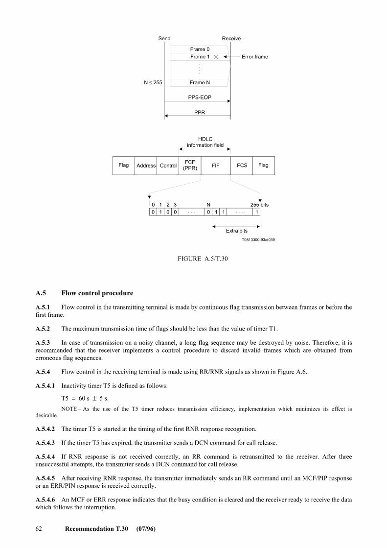
62 Recommendation T.30 (07/96)
. . .
.
. . . .0 01 00 2
. . . .
T0813300-93/d039
1 3 255 bits0 1 1 1N
Frame 0Frame 1 Error frame
Frame N
PPS-EOP
PPR
Send Receive
N ≤ 255
HDLCinformation field
Flag Address ControlFCF
(PPR) FIF FCS
FIGURE A.5/T.30
Flag
Extra bits
A.5 Flow control procedure
A.5.1 Flow control in the transmitting terminal is made by continuous flag transmission between frames or before the first frame.
A.5.2 The maximum transmission time of flags should be less than the value of timer T1.
A.5.3 In case of transmission on a noisy channel, a long flag sequence may be destroyed by noise. Therefore, it is recommended that the receiver implements a control procedure to discard invalid frames which are obtained from erroneous flag sequences.
A.5.4 Flow control in the receiving terminal is made using RR/RNR signals as shown in Figure A.6.
A.5.4.1 Inactivity timer T5 is defined as follows:
T5 = 60 s ± 5 s. NOTE – As the use of the T5 timer reduces transmission efficiency, implementation which minimizes its effect is
desirable.
A.5.4.2 The timer T5 is started at the timing of the first RNR response recognition.
A.5.4.3 If the timer T5 has expired, the transmitter sends a DCN command for call release.
A.5.4.4 If RNR response is not received correctly, an RR command is retransmitted to the receiver. After three unsuccessful attempts, the transmitter sends a DCN command for call release.
A.5.4.5 After receiving RNR response, the transmitter immediately sends an RR command until an MCF/PIP response or an ERR/PIN response is received correctly.
A.5.4.6 An MCF or ERR response indicates that the busy condition is cleared and the receiver ready to receive the data which follows the interruption.

Recommendation T.30 (07/96) 63
A.6 Procedure interrupt
A.6.1 Procedure interrupt signals are not allowed at the partial page boundaries.
T0813310-93/d040
T4
T4
T4
T5
Send Receive
Fax message
PPS-MPS
PPRTraining
Retransmission frame
PPS-MPS
RNR
RR
RNR
RR
MCF
Training
Fax message
Resetthe
T5 timer
Receive not ready
Receive ready
FIGURE A.6/T.30
A.6.2 Procedure interrupt after detection or transmission of PIP and PIN signals is accomplished by using the procedure defined in the main body of this Recommendation. This procedure is outside the scope of the error correction mode specified in this annex.
A.7 Flow diagrams
The flow diagrams in 5.2 show the phase B, pre-message procedures, phase C, message procedure, phase D, post-message procedures and phase E, call release for both the transmitting and receiving terminals.
A.8 Signal sequence examples in case of error correction procedure
The examples in Figure A.7 are based on the flow diagrams and for illustrative and instructional purposes only. They should not be interpreted as establishing or limiting the protocol. The exchange of the various commands and responses is limited only by the rules specified in this Recommendation.
In the following diagrams, the dashed lines indicate transmission at the message data rate (Recommendations V.27 ter, V.29, V.17, V.34) and (X,Y) means (page modulo number, block modulo number).

64 Recommendation T.30 (07/96)
T0813540-93/d041
CNG
CED(NSF) (CSI) DIS
(TSI) DCS
Training, TCFCFR
Training, FAX MSG
PPS-NULL (0,0)
MCF
Training, FAX MSG
PPS-MPS (0,1)
MCFTraining, FAX MSG
PPS-NULL (1,0)
MCF
Training, FAX MSG
PPS-EOP (1,1)
MCF
DCN
Calling terminal Called terminal
Example 1 An auto calling terminal wishing to transmit to an auto answer terminal: example of T.4 error correction.
FIGURE A.7/T.30 (sheet 1 of 13)
T0813550-93/d042
CNG
CED
(CSI) DIS
(TSI) DCS
Training, TCF
CFRTraining, FAX MSG
PPS-NULL (0,0)
PPR
Training, FAX MSG (retransmit)
MCF
Training, FAX MSG
MCF
DCN
Calling terminal Called terminal
Example 2 An auto calling terminal wishing to transmit to an auto answerterminal: example of PPR sequence with errors.
FIGURE A.7/T.30 (sheet 2 of 13)
PPS-NULL (0,0)
PPS-EOP (0,1)
(error)

Recommendation T.30 (07/96) 65
T0813560-93/d043
CNG
CED
(NSF) (CSI) DIS
(TSI) DCS
Training, TCF
CFR
Training, FAX MSG
PPS-MPS (0,0)
PPRTraining, FAX MSG (retransmit)
PPR
MCF
DCN
Calling terminal Called terminal
Example 3 An auto calling terminal wishing to transmit to an auto answer terminal: example of post-message commands with errors.
FIGURE A.7/T.30 (sheet 3 of 13)
(error)
(error)PPS-MPS (0,0)
PPS-MPS (0,0)
MCF
Training, FAX MSG
PPS-EOP (1,0)
PPR
Training, FAX MSG (retransmit)
PPS-EOP (1,0)
Training, FAX MSG (retransmit)
(error)

66 Recommendation T.30 (07/96)
T0813570-93/d044
T4
CNG
CED(NSF) (CSI) DIS
(TSI) DCS
Training, TCF
CFRTraining, FAX MSG
PPS-NULL (0,0)
PPR
MCF
DCN
Calling terminal Called terminal
Example 4 An auto calling terminal wishing to transmit to an auto answer terminal: example of first command failure with message errors.
FIGURE A.7/T.30 (sheet 4 of 13)
(error)
PPS-NULL (0,0)
MCFTraining, FAX MSG
PPS-EOP (0,1)
Training, FAX MSG (retransmit)
PPS-NULL (0,0)

Recommendation T.30 (07/96) 67
T0813580-93/d045
T4
CNG
CED(NSF) (CSI) DIS
(TSI) DCS
Training, TCF
CFRTraining, FAX MSG
PPS-NULL (0,0)
PPR
MCF
DCN
Calling terminal Called terminal
Example 5 An auto calling terminal wishing to transmit to an auto answer terminal: example of response failure with message errors.
FIGURE A.7/T.30 (sheet 5 of 13)
(error)
PPS-NULL (0,0)
MCFTraining, FAX MSG
PPS-EOP (0,1)
Training, FAX MSG (retransmit)
PPS-NULL (0,0)
PPR

68 Recommendation T.30 (07/96)
T0813590-93/d046
CNG
CED(NSF) (CSI) DIS
(TSI) DCS
Training, TCF
CFR
Training, FAX MSG
PPS-NULL (0,0)
PPR
Calling terminal Called terminal
Example 6 An auto calling terminal wishing to transmit to an auto answer terminal: example of fallback (CTC).
FIGURE A.7/T.30 (sheet 6 of 13)
(error)
CTC
Training, FAX MSG (retransmit)
PPS-NULL (0,0)
PPR
Training, FAX MSG (retransmit)PPS-NULL (0,0)
PPR
CTRTraining, FAX MSG (retransmit)
PPS-NULL (0,0)
Training, FAX MSG (retransmit)
PPS-NULL (0,0)
PPR
MCF
(error)
(error)
(error)

Recommendation T.30 (07/96) 69
T0813600-93/d047
T5
CNG
CED(NSF) (CSI) DIS
(TSI) DCS
Training, TCF
CFRTraining, FAX MSG
PPS-NULL (0,0)
RNR
Calling terminal Called terminal
Example 7 An auto calling terminal wishing to transmit to an auto answer terminal: example of flow control.
(error)
PPR
Training, FAX MSG (retransmit)
PPS-NULL (0,0)
MCF
RR
RNR
RR
MCF
Training, FAX MSG
PPS-NULL (0,1)
MEMORY BUSY occurred
ResetT5 timer
FIGURE A.7/T.30 (sheet 7 of 13)

70 Recommendation T.30 (07/96)
T0813610-93/d048
T4T5
CNG
CED(NSF) (CSI) DIS
(TSI) DCS
Training, TCF
CFRTraining, FAX MSG
PPS-NULL (0,0)
RNR
Calling terminal Called terminal
Example 8 An auto calling terminal wishing to transmit to an auto answer terminal: example of T5 time out during flow control.
FIGURE A.7/T.30 (sheet 8 of 13)
PPS-MPS (0,1)
RR
RNR
RR
MEMORY BUSY occurred
MCF
Training, FAX MSG
RNR
RR
RR
RNR
DCN

Recommendation T.30 (07/96) 71
T0813620-93/d049
CNG
CED(NSF) (CSI) DIS
(TSI) DCS
Training, TCF
CFRTraining, FAX MSG
PPS-PRI-EOP (0,0)
Calling terminal Called terminal
Example 9 An auto calling terminal wishing to transmit to an auto answer terminal: example of procedural interrupt.
FIGURE A.7/T.30 (sheet 9 of 13)
PPR
Training, FAX MSG (retransmit)
PPS-PRI-EOP (0,0)
PIP
PRI-EOP Operator on lineOperatoron line
(error)
Alert operator
Alert operator
(Request foroperatorintervention)
T0813630-93/d050
CNG
CED(NSF) (CSI) DIS
(TSI) DCS
Training, TCF
CFRTraining, FAX MSG
PPS-MPS (0,0)
Calling terminal Called terminal
Example 10 An auto calling terminal wishing to transmit to an auto answer terminal: example of post-message response.
FIGURE A.7/T.30 (sheet 10 of 13)
PPRTraining, FAX MSG (retransmit)
PIP
PRI-Q
Operator on line
Operator on line(Operator will hearPIP response)
Alert operator
Alert operator
PPS-MPS (0,0)
PIP
(error) (Request foroperator intervention)

72 Recommendation T.30 (07/96)
T0813640-93/d051
CNG
CED(NSF) (CSI) DIS
(TSI) DCS
Training, TCF
CFRTraining, FAX MSG
PPS-NULL (0,0)
PPR
Calling terminal Called terminal
Example 11 An auto calling terminal wishing to transmit to an auto answer terminal: example of EOR (first block message was not satisfactorily received).
FIGURE A.7/T.30 (sheet 11 of 13)
(error)
EOR-NULL
Training, FAX MSG (retransmit)
PPS-NULL (0,0)
PPR
Training, FAX MSG (retransmit)
PPS-NULL (0,0)
PPR
ERR
Training, FAX MSG
PPS-NULL (0,1)
Training, FAX MSG (retransmit)
PPS-NULL (0,0)
PPR
MCF
(error)
(error)
(error)

Recommendation T.30 (07/96) 73
T0813650-93/d052
CNG
CED(NSF) (CSI) DIS
(TSI) DCS
Training, TCF
CFRTraining, FAX MSG
PPS-NULL (0,0)
PPR
Calling terminal Called terminal
Example 12 An auto calling terminal wishing to transmit to an auto answer terminal: example of EOR (first page was not satisfactorily received).
FIGURE A.7/T.30 (sheet 12 of 13)
(error)
EOR-MPS
Training, FAX MSG (retransmit)
PPS-NULL (0,0)
PPR
Training, FAX MSG (retransmit)
PPS-NULL (0,0)
PPR
ERR
Training, FAX MSG
PPS-NULL (1,0)
Training, FAX MSG (retransmit)
PPS-NULL (0,0)
PPR
MCF
(error)
(error)
(error)

74 Recommendation T.30 (07/96)
T0813660-93/d053
CNG
CED(NSF) (CSI) DIS
(TSI) DCS
Training, TCF
CFR
Training, FAX MSG
PPS-NULL (0,0)
PPR
Calling terminal Called terminal
Example 13 An auto calling terminal wishing to transmit to an auto answer terminal: example of all frames and flag sequences in FAX MSG failure to receive.
FIGURE A.7/T.30 (sheet 13 of 13)
Training, FAX MSG (retransmit)
MCF
PPS-MPS (0,1)
MCF
Training, FAX MSG
PPS-MPS (0,1)
MCF
Training, FAX MSG
PPS-MPS (1,0)
MCF
Training, FAX MSG
PPS-EOP (2,0)
PPR
Training, FAX MSG (retransmit)
PPS-EOP (2,0)
When either all the frames or flag sequences in FAX MSG are destroyed, the receiver can detect the FAX MSG which was lost by checking block counter
When either all the frames or flag sequences in FAX MSG are destroyed, the receiver can detect the FAX MSG which was lost by checking page counter

Recommendation T.30 (07/96) 75
Annex B
BFT diagnostic message
The File Diagnostic Message (FDM) frame is an optional post-message response which may be sent by the receiver. It provides the transmitter with diagnostic information concerning the current transfer taking place. The semantics and the syntax of the FDM are described in Recommendation T.434.
The diagnostic information may be composed of one or more messages. Each message is informative, transient or permanent. An informative message does not require recovery and does not affect the current state of the BFT. A transient message may not re-occur if the sequence of events is repeated but does imply the failure of the present BFT being performed. A permanent message is sent every time the sequence of events is repeated, and implies the failure of at least the present BFT being performed.
A diagnostic message may be sent in place of an MCF frame. The message may be sent using one or more HDLC frames. If more than one HDLC frame is used, only the last one will have the control field set for a final frame. The encapsulation of the diagnostic information within a frame is completely independent of attribute boundaries. However, each frame must meet the transmission requirements of this Recommendation.
If the transmitter receives a transient or permanent message, it should review the set-up for the current binary file being transmitted. Control will continue as though four PPRs were received (emission of CTC command).
Annex C
Procedure for Group 3 document facsimile transmission on the Integrated Services Digital Network or on
the GSTN using duplex modulation systems
C.1 Introduction
C.1.1 This annex describes the protocol used by Group 3 document facsimile terminals when operating over the Integrated Services Digital Network. Optionally, the protocols described in this annex may be used on digital networks other than the ISDN. The protocols described in this annex may also be used on the GSTN using modulation schemes. The procedures and signals used are based upon those defined in the main body as well as Annex A. The protocol operates in either half duplex only or duplex and half duplex mode. In both cases, error correction is an integral part of the protocol. The Group 3 facsimile option described in this annex may be referred to as Group 3 Option C or Group 3C.
C.1.2 Outline of the error correction method
The error correction method described in this Recommendation is based on page selective repeat ARQ (Automatic Repeat Request) technique. An HDLC frame structure is utilized for all facsimile message procedures.
The transmitting terminal divides the message into a number of concatenated frames as described in Annex A/T.4 and transmits it as a number of pages and/or partial pages.
The transmitting terminal uses a frame size of 256 octets as indicated in the DCS command and the receiving terminal must be able to receive a frame of that size. Optionally, when operating over analogue networks, a frame size of 64 octets may be indicated by the transmitting terminal.
In the duplex mode of operation, the transmitting terminal transmits subsequent partial pages without waiting for a response to the preceding partial page. If corrections are required, they are sent at the end of the next partial page transmission. If there are any unacknowledged commands from previous pages or partial pages, these are retransmitted prior to any corrections. In the half duplex case, all corrections are sent and acknowledged before a subsequent partial page is sent.

76 Recommendation T.30 (07/96)
When the previous message has not been satisfactorily received, the receiving terminal transmits a PPR response to indicate that the frames specified in the associated facsimile information field are required to be retransmitted. The PPR signal contains the page and block numbers as well as the required frame numbers.
When a PPR signal is received, the transmitting terminal retransmits the requested frames specified in the PPR informa-tion field.
There is no predefined number of attempts to correct a page, the decision is left up to the transmitter. If it is considered that too many attempts have been made, then the transmitter will send the DCN signal.
If the receiver is unable to continue to receive new information, it sends RNR continuously until it is ready to receive new information. During this time the transmitter will send any outstanding correction frames and any unacknowledged commands. If there are no outstanding corrections, then it will continuously transmit any unacknowledged commands until it receives a response other than RNR.
The transmitter will send no new information until all previously transmitted pages are acknowledged as having been received correctly.
The format of the initial identification is a repeated sequence of XID + DIS or XID + NSF + DIS or XID + NSF + CSI + DIS sent three times concatenated together followed by 256 flags. This sequence is transmitted until a valid response is received from the calling terminal subject to a maximum time of 5 seconds.
The flow diagrams in C.5 do not address the issue of resilience against the remainder of the sequence but rather consider that this is implicitly ensured. Recommendation T.30 (07/96)
C.2 Definitions
C.2.1 When operating in the Group 3C mode, only the signals listed below are used. When used over the ISDN, the procedures and signals specified in this annex are carried on the B-channel. Unless stated otherwise, the signal functions and formats are as defined in the main body and/or Annex A.
CIG Calling subscriber identification (see Note)
CRP Command repeat
CSI Called subscriber identification (see Note)
DCN Disconnect
DCS Digital command signal
DIS Digital identification signal
DTC Digital transmit command
FCD Facsimile coded data
FCF Facsimile control field
FIF Facsimile information field
MCF Message confirmation (see C.3)
NSC Non-standard facilities Command (see Note)
NSF Non-standard facilities (see Note)
NSS Non-standard set-up (see Note)
PID Procedure interrupt disconnect (see C.3)
PPR Partial page request
PPS-EOM Partial page signal – End of message
PPS-EOP Partial page signal – End of procedure
PPS-MPS Partial page signal – Multipage signal
PPS-NULL Partial page signal – null
RCP Return to control for partial page

Recommendation T.30 (07/96) 77
RNR Receiver not ready
TSI Transmitting subscriber identification (see Note)
XID Exchange identification procedure (see C.3) NOTE – This signal is optional.
C.3 Facsimile procedure
C.3.1 Call establishment procedures
The call establishment procedures for this option are defined in Annex F/T.90.
C.3.2 Initial identification
Exchange identification procedure (XID) – This signal indicates that the called terminal has Group 3C capabilities and also can be used to facilitate identification of the characteristics of the remote terminal when interworking with other facsimile groups. This signal is defined in Recommendation T.90.
The format of the XID frame is defined in Annex F/T.90.
C.3.3 In-message procedure
From the transmitter to the receiver. The in-message procedure formats and specific signals shall be as defined in Annex A/T.4.
C.3.4 Post-message responses
From the receiver to the transmitter.
Format: X011 XXXX
1) Message Confirmation (MCF) – This digital response indicates that a complete message has been satisfactorily received and that additional messages may follow. This is a positive response to PPS-MPS, PPS-EOM, PPS-EOP and PPS-NULL.
Format: X011 0001
The frame construction of MCF command and transmission order of bits included in octets 5-7 are shown in Figure C.1.
2) Procedure Interrupt Disconnect (PID) – This digital response indicates that a message has been received but that further transmissions are not possible and that after correction of all outstanding pages or partial pages, the transmitter shall enter Phase E. If a transmitter receives PID whilst it is transmitting a partial page, it shall stop sending that partial page immediately and send only the outstanding corrections (if any) to previous partial pages. The interrupted page shall be assumed as having been discarded at the receiver.
In the half-duplex case, PID is sent at the end of a partial page and precedes any post-message response, i.e. MCF or PPR. The transmitter will continue to transmit the post-message command until it receives a valid response.
Format: X011 0110
3) Partial Page Request (PPR) – This digital response indicates that the previous message has not been satisfactorily received and that the frames specified in the associated facsimile information field are required to be retransmitted.
Format: X011 1101
The facsimile information field of the PPR signal is a fixed length of 272 bits. The first 8 bits define the page number and the second 8 bits define the block number. Each of the remaining 256 bits corresponds to an FCD frame within the relevant page and block i.e.: the first bit to the first frame, etc. For FCD frames which are received correctly, the corresponding bit in the PPR information field will be set to “0”; those that are received incorrectly or not received will have their bit set to “1”.
If more than one PPR signal is transmitted, the bit corresponding to an FCD frame which has been received correctly must always be set to “0”.
The frame construction of PPR response is shown in Figure C.2.

78 Recommendation T.30 (07/96)
4) Receive Not Ready (RNR) – This digital response is used to indicate that the receiver is not ready to receive more data. If a transmitter receives RNR, it shall stop sending new information at the end of the current partial page and transmit any requested corrections and/or any unacknowledged commands. Any unacknowledged commands shall be continuously transmitted until a response other than RNR is received. It shall not send any new information until all previously transmitted pages or partial pages have been acknowledged as being correctly received. If a transmitter receives RNR continuously for a period of 10 ± 1 second, it may transmit DCN and enter Phase E.
Format: X011 0111
T0807020-91/d054
0 0 0 0 0 0 0 0 0 0 0 0 0 0 0 01 0 1 0 01 0 1
b0 b7b0 b7 b0 b7
PC-1 FC-10
F A C FCFMCF
Octet5
(PC)
Octet6
(BC)
Octet7
(FC)FCS F
HDLC information field
Octet 5(PC)Octet 6(BC)Octet 7(FC)
Information field 1:Information field 2:Information field 3:
Page counter (8 bits: modulo 256)Block counter (8 bits: modulo 256)(Number of frames) –1 in each partial page (8 bits: maximum 255)
NOTES1 Octet 5: The page counter shows the page sequence modulo number for each callestablishment in one direction of message transfer. The page counter is started from “0” and goes up to “255”; it is reset at the start of each call establishment.2 Octet 6: The block counter shows the block sequence modulo number for each page. The block counter is started from “0” and goes up to “255”; it is reset at the start of each page.3 Octet 7: The frame counter shows the total number of transmitted frames minus 1 in each partial page (maximum 255).4 The least significant bit in octets 5-7 is transmitted first.
FIGURE C.1/T.30
BC-2
FIGURE C.1/T.30...[D54]
C.3.5 Other line control signals
For the purpose of handling errors and controlling the state of the line.
Format: X101 XXXX
1) Command Repeat (CRP) – This response indicates that the previous pre-message command(s) was/were received in error and should be repeated (including any optional frames). Upon receiving CRP, a transmitter shall repeat all commands which have not yet been acknowledged. The CRP signal is sent continuously until an error free command(s) is/are received.
Format: X101 1000

Recommendation T.30 (07/96) 79
0 0 0 0
T0807030-91/d055
1
0
2 3
1
F A C FCS FFCFPPR
256 bits
HDLC information field
FrameNo.
Octet 5(PC) Page counter (8 bits: modulo 256)Octet 6(BC) Block counter (8 bits: modulo 256)
NOTES1 Octet 5: The page counter shows the page sequence modulo number for each call establishment in one direction of message transfer. The page counter is started from “0” and goes up to “255”; it is reset at the start of each call establishment.2 Octet 6: The block counter shows the block sequence modulo number for each page. The block counter is started from “0” and goes up to “255”; it is reset at the start of each page.3 The frame counter shows the total number of transmitted frames minus 1 in each partial page (maximum 255).
FIGURE C.2/T.30
Octet5
(PC)
Octet6
(BC)
FIGURE C.2/T.30...[D55]
C.3.6 Facsimile information field (FIF)
C.3.6.1 DIS standard capabilities
The bit assignment for this information is given in Table 2 where a “1” indicates the condition is valid.
C.3.6.2 DCS standard commands
The DCS standard commands are formatted as shown in Table 2.
C.3.6.3 DTC standard command
The DTC standard capabilities are formatted as shown in Table 2.
C.3.7 Implementation requirements
C.3.7.1 Commands and responses
Whereas C.5 defines a flow diagram to give an accurate example of the typical use of the binary coded procedures, these procedures are defined specifically in terms of the actions that occur on receipt of commands by the receiving terminal.
A response must be sent, and only sent, upon detecting a valid command. Upon receiving a valid response, a new command must be issued within 3 seconds.

80 Recommendation T.30 (07/96)
C.3.7.2 Timing considerations
C.3.7.2.1 Time-Outs
Time-out T6 defines the amount of time two terminals will continue to attempt to identify each other. T6 is 5 ± 0.5 seconds. The time-out begins upon entering Phase B and is reset upon detecting a valid signal or when T6 times out.
Time-out T7 is used to detect loss of command/response synchronization. T7 is 6 ± 1 seconds. The time-out begins when initiating a command search (e.g. the first entrance into the “command received” subroutine – see flow diagram in C.5) and is reset upon detecting a valid signal or when T7 times out.
Time-out T8 defines the amount of time waiting for clearance of the busy condition of the receiving terminal. T8 is 10 ± 1 seconds, begins on the first detection of the combination of no outstanding corrections and the RNR response. T8 is reset when T8 times out or MCF response is received. If the timer T8 has expired, DCN command is transmitted for call release.
C.4 Flow control procedure
C.4.1 Flow control in the transmitting terminal is made by continuous flag transmission between frames or before the first frame.
C.4.2 The maximum transmission time of flags should be less than the value of timer T6.
C.4.3 In the case of transmission on noisy channel, a long flag sequence may be destroyed by noise. Therefore, it is recommended that the receiver implements a control procedure to discard invalid frames which are obtained from erroneous flag sequences.
C.4.4 Flow control in the receiving terminal is made using the RNR signal. An example is shown in Figure C.3.
C.5 Flow diagrams
The flow diagrams of Figures C.4 to C.23 show the phase B pre-message procedures, phase C message procedure, phase D post-message procedures and phase E call release for both the transmitting and receiving terminals.
For the notes and an explanation of terms to the flow diagrams, see 5.2.1 and C.5.1.
C.5.1 Explanation of flow chart terms
Unless defined otherwise below, the definition of the flow chart terms is given in the main body and/or Annex A.
COPY QUALITY OK All message frames have been received correctly or have been corrected.
OUTSTANDING COMMANDS There are still some commands to which a response has not yet been received.
OUTSTANDING CORR? There are still some pages or partial pages to which a positive acknowledgment has not yet been received.
RE-ISSUE COMMANDS The “outstanding commands” are transmitted in their chronological order prior to transmission of the next page or partial page.
NOTES
1 – At any time during the operation an interrupt may be generated which would result in a procedural interrupt. It is understood that if this interrupt happens during the transmission of the document, all the outstanding partial pages will be corrected if necessary prior to invoking the procedural interrupt.
2 – CRP is used only in the case of a pre-message command being received in error.

Recommendation T.30 (07/96) 81
T0807040-91/d056
PPR
RNR
RNR
MCF
PPS-EOP
PPS-EOP
PPS-EOP
PPS-EOP
DCN
PPS-EOP
PPS-EOP
RNR
RNR
RNR
PPS-EOP
PPS-EOP
PPS-EOP
RNR
Send Receive
Facsimile message
Retransmission frames
Receivenot ready
Receiveready
Flags
FIGURE C.3/T.30
Flags
FIGURE C.3/T.30...[D56]

82 Recommendation T.30 (07/96)
T0817200-94/d057
C
C
A
C
V
K
C
D
R
T
No
Yes
No
Yes
Yes
No
T6elapsed
DISor DTC?
COMPTREMOTE
REC?
No
Yes
Docto XMIT?
COMPTREMOTE
XMTR
No
Yes Yes
No
SETMODE
Transmit(TSI) (NSS)
or(TSI) DCS
Transmitfacsimilemessage
TransmitDCN
Disconnectthe line
Transmitting terminal
Timers
T6 = 5 ± 0.5 sT7 = 6 ± 1 sT8 = 10 ± 1 sT9 = duration of 256 flags
COMMANDREC?
Full duplex operation
Constitutes also the entry fromFigure F.5/T.90 calling side
PutT6 = 0
FIGURE C.4/T.30
FIGURE C.4/T.30 [D57]

Recommendation T.30 (07/96) 83
T0807060-91/d058
V
Va VdVb Vc
No
END OFPAGE
Interrupt(Note 1)
No
Yes
Yes
No
Yes
LASTDOC?
CHANGEMODE?
Transmitting terminal
FIGURE C.5/T.30
FIGURE C.5/T.30...[D58]

84 Recommendation T.30 (07/96)
Z
K
HC
H
H
C
T0807070-91/d059K
Va
OUTSTANDINGCOMMANDS?
RE-ISSUECOMMANDS
Yes
No
No
NoRESPONSEREC?
MCF?
PPR?Yes
No
OUTSTANDINGCORR?
Yes
Yes
TRANSMITERROR
FRAMES
No
RNR?Yes
No
No
Yes
PID?RE-ISSUE
COMMANDS
Yes
No
Yes
No
OUTSTANDINGCORR.?
Yes
OUTSTANDINGCOMMANDS?
T8elapsed
No
No
Yes
Yes
Yes
No
TransmitPPS-NULL
RE-ISSUECOMMANDS OUTSTANDING
COMMANDS?
OUTSTANDINGCORR?
Transmitting terminal
FIGURE C.6/T.30
FIGURE C.6/T.30...[D59]

Recommendation T.30 (07/96) 85
Z
K
HC
H
H
C
K
Vb
T0807080-91/d060
RE-ISSUECOMMANDS
Yes
No
No
NoRESPONSEREC?
MCF?
PPR?Yes
No
Yes
Yes
TRANSMITERRORFRAMES
No
RNR?Yes
No
No
Yes
PID?RE-ISSUE
COMMANDS
Yes
No
Yes
No
Yes
No OUTSTANDINGCOMMANDS?
T8elapsed
No
No
Yes
Yes
TransmitPPS-MPS
Yes
OUTSTANDINGCOMMANDS?
OUTSTANDINGCORR?
OUTSTANDINGCORR?
RE-ISSUECOMMANDS
OUTSTANDINGCOMMANDS?
OUTSTANDINGCORR?
Transmitting terminal
FIGURE C.7/T.30
FIGURE C.7/T.30...[D60]

86 Recommendation T.30 (07/96)
Z
K
HC
H
H
C
H
Z
Vc
C
T0807090-91/d061
TransmitPPS-EOP
OUTSTANDINGCOMMANDS?
RE-ISSUECOMMANDS
Yes
No
No
NoRESPONSEREC?
MCF?
PPR?Yes
No
Yes OUTSTANDINGCORR?
Yes
Yes
TRANSMITERRORFRAMES
No
RNR?Yes
No
No
Yes
PID?RE-ISSUECOMMANDS
Yes
No
Yes
No
Yes
No
OUTSTANDINGCOMMANDS?
No
No
YesRE-ISSUECOMMANDS
YesT8elapsed?
No
No
Yes
Yes
OUTSTANDINGCORR?
OUTSTANDINGCORR?
OUTSTANDINGCOMMANDS?
RE-ISSUECOMMANDS
OUTSTANDINGCOMMANDS?
OUTSTANDINGCORR?
Transmitting terminal
FIGURE C.8/T.30
FIGURE C.8/T.30...[D61]

Recommendation T.30 (07/96) 87
T0807100-91/d062
Z
K
HC
H
H
C
H
Z
Vd
OUTSTANDINGCOMMANDS?
RE-ISSUECOMMANDS
OUTSTANDINGCOMMANDS?
RESPONSEREC?
TransmitPPS-EOM
OUTSTANDINGCORR?
T8 elapsed?
OUTSTANDINGCORR?
OUTSTANDINGCORR?
MCF?
RE-ISSUECOMMANDS
PPR?
TRANSMITERROR FRAMES
Go to beginningPhase B
OUTSTANDINGCOMMANDS? RNR?
RE-ISSUECOMMANDS
RE-ISSUECOMMANDS
PID?
OUTSTANDINGCOMMANDS?
OUTSTANDINGCORR?
Transmitting terminal
Yes
No
No
No
Yes
No
Yes
Yes
No
No No
No
No
Yes
Yes
No
No
Yes
No
No
Yes
Yes
YesYes
YesYes
No
Yes
FIGURE C.9/T.30
FIGURE C.9/T.30...[D62]

88 Recommendation T.30 (07/96)
P
T0817210-94/d063
C
G
Receiving terminal
SetT6 = 0
Entry from FigureF.5/T.90 called side
SetCount = 0
Yes Count = 3
No
TransmitXID 84 (NSF)
(CSI) DIS
SetT9 = 0
RESPONSEREC?
No
Yes
XID 84 P = 1TPI = G3C?
No
Yes
DCSor DTC?
Yes
No
DMF = 1to ISO/IEC 7776
T6elapsed?
Yes
No
T9elapsed?
No
Yes
Count + 1
FIGURE C.10/T.30
FIGURE C.10/T.30...[D63]

Recommendation T.30 (07/96) 89
F
D
A
VIII
C
R
R
S
F
C
G
T0817220-94/d064
RESPONSE REC? T6 elapsed?
Transmit(NSF)(CSI)DIS
{(NSC)(CIG)DTC}
COMMAND REC? T7 elapsed? PPS-EOM?
DIS?
DCS?
DTC?
ReceiveFacsimile Message
Yes
Yes
Yes
No
No
No Yes No
No
Yes
No
YesYes
No
No
Yes
FIGURE C.11/T.30
Receiving terminal
FIGURE C.11/T.30...[D64]

90 Recommendation T.30 (07/96)
T0807120-91/d065
VIII
C
C
S
PPS-Q?
LOCAL INT? Transmit PID
COPY QUALITYOK?
RECEIVE READY?
Respond RNR
DCN received?
Respond MCF
OUTSTANDINGCORR?
Transmit PPR(s)
Respond PPR
OUTSTANDINGCORR?
Transmit PPR(s)
Yes
No
Yes
No
Yes
Yes
No
Yes
No
Yes
No
Yes
Receiving terminal
FIGURE C.12/T.30
No No
FIGURE C.12/T.30...[D65]

Recommendation T.30 (07/96) 91
T0817230-94/d066
C
D
C
V
K
C
T
R
A
C
Yes
No
Yes
Yes
No
T6elapsed
DISor DTC?
COMPTREMOTE
REC?
No
Yes
Docto XMIT?
COMPTREMOTE
XMTRNo
Yes Yes
No
SETMODE
Transmit(TSI) (NSS)
or(TSI) DCS
TransmitFacsimileMessage
TransmitDCN
Disconnectthe line
Transmitting terminal
Timers
T6 = 5 ± 0.5 sT7 = 6 ± 1 sT8 = 10 ± 1 sT9 = duration of 256 flags
COMMANDREC?
Half-duplex operation
Constitutes also the entry fromFigure F.5/T.90 calling side
SetT6 = 0
FIGURE C.13/T.30
NoC
FIGURE C.13/T.30...[D66]

92 Recommendation T.30 (07/96)
V
Va VdVb Vc
T0807140-91/d067
END OF PAGE?
Interrupt(Note 1)
LAST DOC?
CHANGE MODE?
Yes
Yes
No
Yes
No
No
Transmitting termimal
FIGURE C.14/T.30
FIGURE C.14/T.30...[D67]

Recommendation T.30 (07/96) 93
Va
C
C K
C
T0807150-91/d068
Transmitting terminal
Transmit PPS-NULL
RESPONSE REC?
PPR?
RNR?
MCF?
T8 elapsed?
TRANSMITERROR FRAMES
T6 elapsed?
Yes
No
No
No
Yes
No
Yes
No
No
Yes
Yes
Yes
FIGURE C.15/T.30
FIGURE C.15/T.30...[D68]

94 Recommendation T.30 (07/96)
C
C K
C
Vb
T0807160-91/d069
Transmitting terminal
Transmit PPS-MPS
T6 elapsed? RESPONSE REC?
PPR?
RNR?
MCF?
PID?
T8 elapsed?
TRANSMITERROR FRAMES
Yes
No
No
No
No
Yes
No
No
Yes
Yes
Yes
Yes
No
Yes
FIGURE C.16/T.30
FIGURE C.16/T.30...[D69]

Recommendation T.30 (07/96) 95
C
C
C
T0807170-91/d070
Vc
Transmitting terminal
Transmit PPS-EOP
T6 elapsed? RESPONSE REC?
PPR?
RNR?
MCF?
PID?
TRANSMITERROR FRAMES
T8 elapsed?
Yes
No
No
No
No
Yes
No
No
Yes
Yes
No
Yes
Yes
Yes
FIGURE C.17/T.30
FIGURE C.17/T.30...[D70]

96 Recommendation T.30 (07/96)
C
C
C
T0807180-91/d071
Vd
Transmitting terminal
Transmit PPS-EOM
T6 elapsed? RESPONSE REC?
PPR? TRANSMITERROR FRAMES
RNR?T8 elapsed?
MCF?
PID?
Go to beginningof Phase B
No
Yes
No
Yes
Yes
No
No
No
No
Yes
Yes
Yes
Yes
No
FIGURE C.18/T.30
FIGURE C.18/T.30...[D71]

Recommendation T.30 (07/96) 97
P
T0817240-94/d072
C
G
Receiving terminal
SetT6 = 0
Entry fromFigure F.5/T.90called side
SetCount = 0
Count = 3Yes
No
SetT9 = 0
TransmitXID 84 (NSF)
(CSI) DIS
Count + 1RESPONSE REC?
No
Yes
XID 84 P = 1TPI = G3C?
No T6elapsed?
Yes
T9elapsed?
No
Yes
Yes
No
DCSor DTC?
DMF = 1to ISO/IEC 7776
FIGURE C.19/T.30
NoYes
FIGURE C.19/T.30...[D72]

98 Recommendation T.30 (07/96)
CF
D
A
VIII
C
R
R
S
F
T0817250-94/d073
G
Receiving terminal
RESPONSE REC? T6 elapsed?
COMMAND REC? T7 elapsed? PPS-EOM?
DTC?
DIS?
DCS?
ReceiveFacsimile Message
Transmit(NSF)(CSI)DIS
{(NSC)(CIG)DTC}
No
Yes
No
YesYes
No
No
Yes
Yes No
No Yes No
Yes
Yes
No
FIGURE C.20/T.30
FIGURE C.20/T.30......[D73]

Recommendation T.30 (07/96) 99
VIII
C
F
C
S
T0807200-91/d074
PPS-Q?
LOCAL INT?
Transmit PID
COPY QUALITYOK?
RECEIVE READY?
Respond RNR
DCN received?
Respond MCF Respond PPR
Receiving terminal
Yes
Yes
No
Yes
Yes
No
No
No
Yes
No
FIGURE C.21/T.30
FIGURE C.21/T.30...[D74]

100 Recommendation T.30 (07/96)
C
T0807210-91/d075
COMMAND REC?
Enter
FLAG?
RECEIVEA FRAME?
FCS error? Transmit CRP(Note 2)
DCN?
OPTIONALCOMMAND?
Return “no” Return “yes”Process
optional command
Yes
Yes
No
No
Yes
No
No
Yes
Yes
No
FIGURE C.22/T.30
FIGURE C.22/T.30...[D75]

Recommendation T.30 (07/96) 101
C
T0807220-91/d076
RESPONSE REC?
Enter
Return “no” FLAG?
RECEIVEA FRAME?
FCS error?
CRP?(Note 2)
DCN?
OPTIONALRESPONSE?
Return “yes”Process
optional command
Yes
Yes
No
No
Yes
Yes
No
No
Yes
Yes
Yes
No
FIGURE C.23/T.30
FIGURE C.23/T.30...[D76]

102 Recommendation T.30 (07/96)
C.6 Signal sequence examples
C.6.1 Duplex operation
The examples below (Figures C.24 to C.37) are based on the flow diagrams and are for illustrative and instructional purpose only. They should not be interpreted as establishing or limiting the protocol. The exchange of the various commands and responses is limited only by the rules specified in this Recommendation.
C.6.2 Half duplex operation
The examples below (Figures C.38 to C.51) are based on the flow diagrams and are for illustrative and instructional purpose only. They should not be interpreted as establishing or limiting the protocol. The exchange of the various commands and responses is limited only by the rules specified in this Recommendation.
T0813670-93/d077
Calling Called
Flags
Flags
Flags
3 X (TSI) DCS
FCD frames
FCD frames
3 X PPS-EOP (1,1,x)
3 X PPS-EOP (1,1,x)
3 X DCN
Flags
Flags
3 X XID (NSF) (CSI) DIS
3 X XID (NSF) (CSI) DIS3 X XID (NSF) (CSI) DISFlags
Flags
Flags
Flags
Flags
3 X MCF (1,1)
3 X MCF (1,1)
A calling terminal wishing to transmit to an answering terminal.
The document being transmitted consists of a single partial page with no errors on the received document.
FIGURE C.24/T.30
Example 1
FIGURE C.24/T.30...[D77]

Recommendation T.30 (07/96) 103
T0813680-93/d078
Calling
Flags
3 X XID (NSF) (CSI) DIS
3 X XID (NSF) (CSI) DIS
3 X XID (NSF) (CSI) DIS
3 X MCF (1,1)
3 X MCF (1,2)
3 X MCF (1,2)
3 X MCF (1,2)
3 X (TSI) DCS
FCD frames
3 X PPS-NULL (1,1,x)
3 X PPS-EOP (1,2,x)
3 X PPS-EOP (1,2,x)
3 X PPS-EOP (1,2,x)
3 X DCN
Flags
Flags
Flags
FCD frames
Flags
Flags
Flags
Flags
Flags
Flags
Flags
Flags
Flags
Flags
Flags
A calling terminal wishing to transmit to an answering terminal. The document being transmitted consists of several partial pages with no errors onthe received document.
FIGURE C.25/T.30
Called
Example 2
FIGURE C.25/T.30...[D78]

104 Recommendation T.30 (07/96)
T0813690-93/d079
Calling Called
3 X (TSI) DCS
FCD frames
3 X PPS-NULL (1,1,x)
FCD frames
3 X PPS-EOP (1,2,y)
FCD error frames
3 X PPS-NULL (1,1,z)
3 X PPS-NULL (1,1,z)
3 X DCN
3 X XID (NSF) (CSI) DIS
3 X XID (NSF) (CSI) DIS
3 X PPR (1,1,z)
3 X MCF (1,2)
3 X MCF (1,1)
3 X MCF (1,1)
Flags
Flags
Flags
Flags
Flags
Flags
Flags
Flags
Flags
Flags
Flags
Flags
Flags
Flags
A calling terminal wishing to transmit to an answering terminal.
The document being transmitted consists of several partial pages with errors on thereceived document.
FIGURE C.26/T.30
Flags
3 X XID (NSF) (CSI) DIS
Flags
Flags
Flags
error
Example 3
FIGURE C.26/T.30...[D79]

Recommendation T.30 (07/96) 105
T0813700-93/d080
Calling Called
Flags
3 X (TSI) DCS
FCD frames
3 X PPS-NULL (1,1,x)
3 X XID (NSF) (CSI) DIS
3 X XID (NSF) (CSI) DIS
3 X XID (NSF) (CSI) DIS
3 X PPR (1,1,z)
3 X MCF (1,2)
3 X PPR (1,1,a)
3 X MCF (1,1)
3 X MCF (1,1)
3 X PPS-NULL (1,1,z)
3 X PPS-NULL (1,1,z)
3 X PPS-EOP (1,2,y)
FCD error frames
FCD error frames
3 X PPS-NULL (1,1,a)
3 X PPS-NULL (1,1,a)
3 X DCN
Flags
Flags
Flags
Flags
Flags
Flags
Flags
Flags
Flags
Flags
Flags
Flags
FCD frames
Flags
Flags
Flags
Flags
Flags
Flags
Flags
Flags
A calling terminal wishing to transmit to an answering terminal. The document being transmitted consists of several partial pages with errors on thereceived document and errors on the corrections.
error
error
FIGURE C.27/T.30
Example 4
FIGURE C.27/T.30...[D80]

106 Recommendation T.30 (07/96)
T0813710-93/d081
Calling CalledFlags
3 X (TSI) DCS
FCD frames
3 X PPS-NULL (1,1,x)
FCD frames
3 X XID (NSF) (CSI) DIS
3 X XID (NSF) (CSI) DIS
3 X XID (NSF) (CSI) DIS
3 X PPR (1,2,y)
3 X PPR (1,1,x)
3 X PPS-MPS (1,2,y)
3 X PPS-NULL (1,1,x)
FCD frames
3 X MCF (2,1)
3 X PPS-EOP (2,1,z)
FCD error frames
3 X PPS-MPS (1,2,y)
3 X PPS-NULL (1,1,x)
3 X PPS-NULL (1,1,x)
3 X PPS-NULL (1,1,x)3 X DCN
3 X MCF (1,2)
3 X MCF (1,1)
3 X MCF (1,1)
3 X MCF (1,1)
A calling terminal wishing to transmit to an answering terminal.
The document being transmitted consists of several partial pages with errors on a post-message command.
Flags
Flags
Flags
Flags
Flags
Flags
Flags
Flags
FlagsFlags
Flags
Flags
FlagsFlags
Flags
Flags
Flags
FlagsFlags
FCD error frames
Flags
Flags
Flags
Flags
Flags
Flags
Flags
Flags
error
FIGURE C.28/T.30
Example 5
FIGURE C.28/T.30...[D81]

Recommendation T.30 (07/96) 107
T0813720-93/d082
Flags
3 X (TSI) DCS
FCD frames
3 X XID (NSF) (CSI) DIS
3 X XID (NSF) (CSI) DIS
3 X XID (NSF) (CSI) DIS
3 X MCF (1,1)
3 X PPS-NULL (1,1,x)
FCD frames
3 X PPS-MPS (1,2,y)
FCD frames
Calling Called
3 X MCF (1,2)
3 X MCF (2,1)
3 X MCF (2,1)
3 X MCF (2,1)
3 X PPS-EOP (2,1,z)
3 X PPS-EOP (2,1,z)
3 X PPS-EOP (2,1,z)
3 X PPS-EOP (2,1,z)
3 X PPS-EOP (2,1,z)
3 X DCN
A calling terminal wishing to transmit to an answering terminal. The document being transmitted consists of several partial pages with errors on the lastpost-message command.
Flags
Flags
Flags
Flags
Flags
Flags
Flags
Flags
Flags
Flags
Flags
Flags
Flags
Flags
Flags
Flags
Flags
Flags
error
error
FIGURE C.29/T.30
Flags
Flags
Example 6
FIGURE C.29/T.30...[D82]

108 Recommendation T.30 (07/96)
T0813730-93/d083
Flags
3 X XID (NSF) (CSI) DIS
3 X XID (NSF) (CSI) DIS3 X XID (NSF) (CSI) DIS
3 X CRP
3 X CRP
3 X CRP
3 X MCF (1,1)
3 X MCF (1,2)
3 X MCF (1,2)
3 X (TSI) DCS
FCD frames
3 X (TSI) DCS
FCD frames
3 X PPS-NULL (1,1,x)
FCD frames
3 X PPS-EOP (1,2,x)3 X PPS-EOP (1,2,x)
3 X DCN
Calling Called
Example 7 A calling terminal wishing to transmit to an answering terminal.
The document being transmitted consists of several partial pages with an error on the pre-message command.
Flags
Flags
Flags
Flags
Flags
Flags
Flags
Flags
Flags
Flags
Flags
Flags
Flags
Flags
FIGURE C.30/T.30
FIGURE C.30/T.30...[D83]

Recommendation T.30 (07/96) 109
T0813740-93/d084
3 X (TSI) DCS
FCD frames
3 X PPS-NULL (1,1,x)FCD frames
3 X XID (NSF) (CSI) DIS3 X XID (NSF) (CSI) DIS
3 X XID (NSF) (CSI) DIS
3 X MCF (1,1)
3 X MCF (1,2)3 X PPS-MPS (1,2,y)
FCD frames
3 X PPS-EOP (2,1,z)
3 X PPS-EOP (2,1,z)
3 X PPS-EOP (2,1,z)
3 X DCN
Repeat for up to5 seconds i.e. T6 expires
error
error
error
errorerror
error
error
CalledCalling
Example 8 A calling terminal wishing to transmit to an answering terminal.
The document being transmitted consists of several partial pages with no response to the last post-message command.
Flags
Flags
FlagsFlags
Flags
Flags
Flags
Flags
Flags
Flags
Flags
Flags
Flags
Flags
Flags
Flags
Flags
Flags
Flags
Flags
FlagsFlags
Flags
Flags
Flags
Flags
FIGURE C.31/T.30
FIGURE C.31/T.30...[D84]

110 Recommendation T.30 (07/96)
T0813750-93/d085
Flags
3 X XID (NSF) (CSI) DIS3 X XID (NSF) (CSI) DIS
3 X XID (NSF) (CSI) DIS3 X (TSI) DCSFCD frames
3 X PPS-NULL (1,1,x)FCD frames
3 X PPS–MPS (1,2,y)FCD frames
3 X MCF (1,1)
3 X PPR (1,2,a)
RNRRNRRNRRNR
RNR3 X MCF (1,2)RNRRNRRNR
3 X PPS-NULL (2,1,z)FCD error frames
3 X PPS-MPS (1,2,a)FCD frames
3 X PPS-MPS (2,2,p)3 X PPS-MPS (1,2,a)
3 X PPS-NULL (2,1,z)3 X PPS-MPS (2,2,p)
3 X PPS-NULL (2,1,z)3 X PPS-MPS (2,2,p)
3 X PPS-NULL (2,1,z)
3 X PPS-MPS (2,2,p)3 X PPS-MPS (2,2,p)
FCD frames
3 X PPS-EOP (3,1,q)3 X PPS-EOP (3,1,q)
3 X DCN
3 X MCF (2,1)3 X MCF (2,2)
3 X MCF (3,1)3 X MCF (3,1)
Example 9 A calling terminal wishing to transmit to an answering terminal.
The document being transmitted consists of several partial pages with errors on the received document and receiver indicating it is not ready to receive new information.
CalledCalling
error
Flags
FlagsFlags
Flags
FlagsFlagsFlagsFlags
Flags
FlagsFlagsFlagsFlags
FlagsFlags
FlagsFlagsFlagsFlagsFlagsFlagsFlags
Flags
Flags
Flags
Flags
FIGURE C.32/T.30
FIGURE C.32/T.30...[D85]
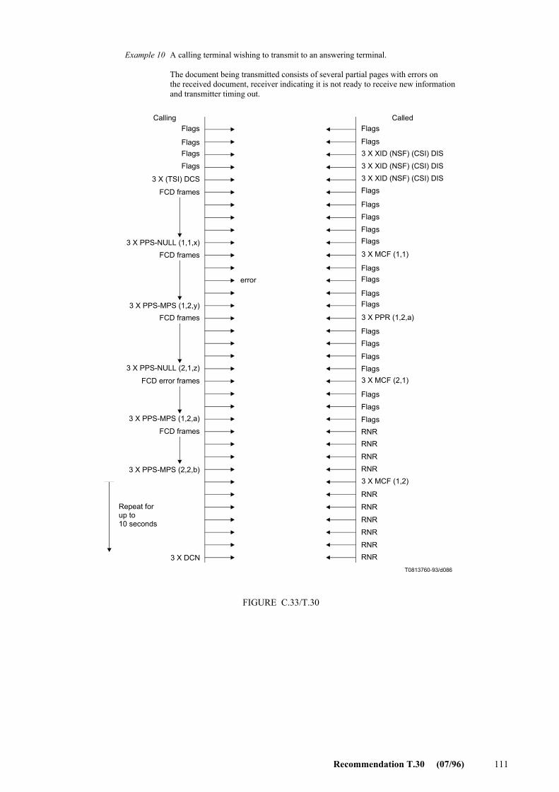
Recommendation T.30 (07/96) 111
T0813760-93/d086
3 X (TSI) DCS
FCD frames
Calling Called
3 X XID (NSF) (CSI) DIS
3 X XID (NSF) (CSI) DIS3 X XID (NSF) (CSI) DIS
3 X MCF (1,1)3 X PPS-NULL (1,1,x)
FCD frames
3 X PPR (1,2,a)3 X PPS-MPS (1,2,y)
FCD frames
3 X MCF (2,1)
RNRRNR
RNRRNR3 X MCF (1,2)
RNR
RNR
RNR
RNR
RNRRNR3 X DCN
3 X PPS-NULL (2,1,z)
FCD error frames
3 X PPS-MPS (1,2,a)
FCD frames
3 X PPS-MPS (2,2,b)
Repeat forup to10 seconds
A calling terminal wishing to transmit to an answering terminal.
The document being transmitted consists of several partial pages with errors onthe received document, receiver indicating it is not ready to receive new informationand transmitter timing out.
errorFlagsFlags
FlagsFlags
FlagsFlags
FlagsFlags
Flags
Flags
Flags
FIGURE C.33/T.30
Flags
Flags
Flags
FlagsFlags
Flags
Flags
FlagsFlags
FlagsFlags
Example 10
FIGURE C.33/T.30...[D86]

112 Recommendation T.30 (07/96)
T0813770-93/d087
CalledCalling
Flags
3 X (TSI) DCS
FCD frames
3 X XID (NSF) (CSI) DIS
3 X XID (NSF) (CSI) DIS
3 X XID (NSF) (CSI) DIS
3 X PPR (1,1,a)
PID
3 X MCF (1,1)
3 X MCF (1,1)
3 X PPS-NULL (1,1,x)
FCD frames
3 X PPS-EOP (1,2,y)
FCD error frames
3 X PPS-NULL (1,1,a)
3 X PPS-NULL (1,1,a)
3 X PPS-NULL (1,1,a)
3 X DCN
A calling terminal wishing to transmit to an answering terminal.
The document being transmitted consists of several partial pages with errors on thereceived document, receiver indicating it cannot receive any new information.
Flags
Flags
Flags
Flags
Flags
Flags
Flags
Flags
Flags
Flags
Flags
Flags
Flags
Flags
Flags
Flags
Flags
error
FIGURE C.34/T.30
Example 11
FIGURE C.34/T.30 [D87]

Recommendation T.30 (07/96) 113
T0813780-93/d088
Flags
error
error
error
error
error
error
error
3 X XID (NSF) (CSI) DIS
3 X XID (NSF) (CSI) DIS
3 X XID (NSF) (CSI) DIS
3 X XID (NSF) (CSI) DIS
3 X XID (NSF) (CSI) DIS 3 X XID (NSF) (CSI) DIS
3 X XID (NSF) (CSI) DIS
Calling Called
Timer T6expires
A calling terminal wishing to transmit to an answering terminal.
The calling terminal receives no recognizable signals from the called terminal and times out.
Flags
Flags
Flags
Flags
FlagsFlags
3 X DCN
Flags
Flags
FIGURE C.35/T.30
Example 12
FIGURE C.35/T.30...[D88]
T0813790-93/d089
Flags
3 X XID (NSF) (CSI) DIS
Repeat untiltimer T6expires
3 X DCN
Calling Called
A calling terminal wishing to receive from an answering terminal.
The called terminal receives no recognizable signals from the callingterminal and times out.
Flags
Flags
Flags
Flags
Flags
FlagsFlags
Flags
Flags
FIGURE C.36/T.30
Example 13
FIGURE C.36/T.30...[D89]

114 Recommendation T.30 (07/96)
T0813800-93/d090
Flags
3 X (CIG) DTC
3 X (CIG) DTC
3 X MCF (1,1)3 X MCF (1,1)
3 X XID (NSF) (CSI) DIS3 X XID (NSF) (CSI) DIS
3 X XID (NSF) (CSI) DIS
3 X (TSI) DCS
FCD frames
3 X PPS-EOP (1,1,x)
3 X PPS-EOP (1,1,x)3 X DCN
A calling terminal wishing to receive from an answering terminal. The document being transmitted consists of a single partial page with no errors on the received document.
Calling Called
Flags
Flags
Flags
Flags
Flags
Flags
Flags
Flags
Flags
FIGURE C.37/T.30
Example 14
FIGURE C.37/T.30...[D90]
T0813810-93/d091
Flags
3 X (TSI) DCS
FCD frames
3 X PPS-EOP (1,1,x)
3 X PPS-EOP (1,1,x)
3 X DCN
3 X XID (NSF) (CSI) DIS
3 X XID (NSF) (CSI) DIS
3 X XID (NSF) (CSI) DIS
3 X MCF (1,1)
3 X MCF (1,1)
Calling Called
A calling terminal wishing to transmit to an answering terminal.
The document being transmitted consists of a single partial page with no errorson the received document.
FlagsFlags
Flags
FCD frames
Flags
Flags
Flags
Flags
Flags
Flags
Flags
FIGURE C.38/T.30
Example 1
FIGURE C.38/T.30...[D91]

Recommendation T.30 (07/96) 115
T0813820-93/d092
Flags
Flags
3 X (TSI) DCS
FCD frames
3 X PPS-NULL (1,1,x)
3 X PPS-NULL (1,1,x)
FCD frames
3 X PPS-EOP (1,2,y)
3 X PPS-EOP (1,2,x)
3 X DCN
3 X XID (NSF) (CSI) DIS
3 X XID (NSF) (CSI) DIS
3 X XID (NSF) (CSI) DIS
3 X MCF (1,1)
3 X MCF (1,1)
3 X MCF (1,2)
3 X MCF (1,2)
Calling Called
A calling terminal wishing to transmit to an answering terminal.
The document being transmitted consists of several partial pages with no errorson the received document.
Flags
Flags
Flags
Flags
Flags
Flags
Flags
Flags
Flags
Flags
Flags
Flags
FIGURE C.39/T.30
Example 2
FIGURE C.39/T.30...[D92]

116 Recommendation T.30 (07/96)
T0813830-93/d093
Flags
3 X XID (NSF) (CSI) DIS
3 X XID (NSF) (CSI) DIS
3 X XID (NSF) (CSI) DIS
3 X PPR (1,1,z)
3 X PPR (1,1,z)
3 X (TSI) DCS
FCD frames
3 X PPS-NULL (1,1,x)
3 X PPS-NULL (1,1,x)
FCD error frames
3 X PPS-NULL (1,1,z)
3 X PPS-NULL (1,1,z)
FCD frames
3 X PPS-EOP (1,2,p)
3 X PPS-EOP (1,2,p)
3 X DCN
3 X MCF (1,1)
3 X MCF (1,1)
3 X MCF (1,2)
3 X MCF (1,2)
Calling Called
A calling terminal wishing to transmit to an answering terminal.
The document being transmitted consists of several partial pages with errors on thereceived document.
FlagsFlags
Flags
Flags
Flags
Flags
Flags
FlagsFlagsFlags
Flags
Flags
Flags
Flags
Flags
Flags
Flags
error
FIGURE C.40/T.30
Exemple 3
FIGURE C.40/T.30...[D93]

Recommendation T.30 (07/96) 117
T0813840-93/d094
Flags
3 X (TSI) DCS
FCD frames
3 X XID (NSF) (CSI) DIS
3 X XID (NSF) (CSI) DIS
3 X XID (NSF) (CSI) DIS
3 X PPR (1,1,z)
3 X PPR (1,1,z)3 X PPS-NULL (1,1,x)
3 X PPS-NULL (1,1,x)
FCD error frames
3 X PPS-NULL (1,1,z)
3 X PPS-NULL (1,1,z)
FCD error frames
3 X PPS-NULL (1,1,a)
3 X PPS-NULL (1,1,a)
FCD frames
3 X PPS-EOP (1,2,p)
3 X PPS-EOP (1,2,p)3 X DCN
3 X PPR (1,1,a)
3 X PPR (1,1,a)
3 X MCF (1,1)
3 X MCF (1,1)
3 X MCF (1,2)
3 X MCF (1,2)
A calling terminal wishing to transmit to an answering terminal.
The document being transmitted consists of several partial pages with errors on thereceived document and errors on the corrections.
Flags
Flags
Flags
Flags
Flags
Flags
Flags
Flags
Flags
Flags
Flags
Flags
Flags
Flags
Flags
Flags
Flags
Flags
CalledCalling
error
error
FIGURE C.41/T.30
Flags
Example 4
FIGURE C.41/T.30...[D94]

118 Recommendation T.30 (07/96)
T0813850-93/d095
Flags
3 X (TSI) DCS
FCD frames
3 X XID (NSF) (CSI) DIS
3 X XID (NSF) (CSI) DIS
3 X XID (NSF) (CSI) DIS
3 X PPS-NULL (1,1,x)
3 X PPS-NULL (1,1,x)
3 X PPS-NULL (1,1,x)
FCD frames
Calling Called
3 X MCF (1,1)
3 X MCF (1,1)
3 X MCF (1,2)
3 X MCF (1,2)
3 X PPS-MPS (1,2,y)
3 X PPS-MPS (1,2,y)
FCD frames
3 X MCF (2,1)
3 X MCF (2,1)
3 X MCF (2,1)
3 X PPS-EOP (2,1,z)3 X PPS-EOP (2,1,z)
3 X PPS-EOP (2,1,z)
3 X DCN
A calling terminal wishing to transmit to an answering terminal.
The document being transmitted consists of several partial pages with errors on apost-message command.
error
FlagsFlags
Flags
Flags
Flags
Flags
Flags
Flags
Flags
Flags
Flags
Flags
Flags
FlagsFlags
Flags
Flags
Flags
Flags
FIGURE C.42/T.30
Example 5
FIGURE C.42/T.30...[D95]

Recommendation T.30 (07/96) 119
T0813860-93/d096
Flags
3 X (TSI) DCS
FCD frames
3 X XID (NSF) (CSI) DIS
3 X XID (NSF) (CSI) DIS
3 X XID (NSF) (CSI) DIS
3 X MCF (1,1)
3 X MCF (1,1)
3 X MCF (1,2)
3 X MCF (1,2)
3 X PPS-NULL (1,1,x)
3 X PPS-NULL (1,1,x)
FCD frames
3 X PPS-MPS (1,2,y)3 X PPS-MPS (1,2,y)
FCD frames
3 X PPS-EOP (2,1,z)
3 X PPS-EOP (2,1,z)
3 X PPS-EOP (2,1,z)
3 X PPS-EOP (2,1,z)
3 X DCN
3 X MCF (2,1)
3 X MCF (2,1)
3 X MCF (2,1)
A calling terminal wishing to transmit to an answering terminal.
The document being transmitted consists of several partial pages with errors on the last post-message command.
error
error
Flags
Flags
Flags
Flags
Flags
Flags
Flags
Flags
Flags
Flags
Flags
Flags
Flags
Flags
Flags
Flags
Flags
Flags
Flags
Flags
Calling Called
FIGURE C.43/T.30
Example 6
FIGURE C.43/T.30...[D96]

120 Recommendation T.30 (07/96)
T0813870-93/d097
Calling CalledFlags
3 X XID (NSF) (CSI) DIS
3 X XID (NSF) (CSI) DIS
3 X XID (NSF) (CSI) DIS
3 X CRP
3 X (TSI) DCS
FCD frames
3 X (TSI) DCS
FCD frames
3 X PPS-NULL (1,1,x)
3 X PPS-NULL (1,1,x)
FCD frames
3 X PPS-EOP (1,2,y)
3 X PPS-EOP (1,2,y)
3 X DCN
3 X MCF (1,2)
3 X MCF (1,2)
3 X MCF (1,1)
3 X MCF (1,1)
A calling terminal wishing to transmit to an answering terminal.
The document being transmitted consists of several partial pages with an error onthe pre-message command.
Flags
Flags
Flags
Flags
Flags
FlagsFlags
FlagsFlags
Flags
Flags
Flags
Flags
Flags
FlagsFlags
error
FIGURE C.44/T.30
Example 7
FIGURE C.44/T.30...[D97]

Recommendation T.30 (07/96) 121
T0813880-93/d098
Flags
3 X (TSI) DCSFCD frames
3 X XID (NSF) (CSI) DIS
3 X XID (NSF) (CSI) DIS
3 X XID (NSF) (CSI) DIS
3 X MCF (1,1)
3 X MCF (1,1)
3 X PPS-NULL (1,1,x)3 X PPS-NULL (1,1,x)
FCD frames
3 X MCF (1,2)
3 X MCF (1,2)
3 X PPS-MPS (1,2,y)
3 X PPS-MPS (1,2,y)FCD frames
3 X PPS-EOP (2,1,z)
3 X PPS-EOP (2,1,z)3 X PPS-EOP (2,1,z)
Repeat for upto 5 secondsi.e. T6 expires
3 X DCN
Calling Called
A calling terminal wishing to transmit to an answering terminal.
The document being transmitted consists of several partial pages with no response tothe last post-message command.
error
errorerror
error
error
error
error
FlagsFlags
Flags
Flags
Flags
Flags
Flags
Flags
Flags
Flags
Flags
Flags
Flags
Flags
Flags
Flags
Flags
Flags
FlagsFlags
Flags
Flags
Flags
Flags
Flags
FIGURE C.45/T.30
Example 8
FIGURE C.45/T.30...[D98]

122 Recommendation T.30 (07/96)
T0813890-93/d099
FlagsFlags
3 X XID (NSF) (CSI) DIS
3 X XID (NSF) (CSI) DIS3 X XID (NSF) (CSI) DIS
3 X MCF (1,1)
3 X (TSI) DCSFCD frames
3 X PPS-NULL (1,1,x)FCD frames
3 X PPS-MPS (1,2,y)
FCD error frames3 X PPS-MPS (1,2,y)
3 X PPR (1,2,a)3 X PPR (1,2,a)
RNR
RNRRNRRNRRNRRNRRNR
3 X PPS-MPS (1,2,a)3 X PPS-MPS (1,2,a)3 X PPS-MPS (1,2,a)3 X PPS-MPS (1,2,a)3 X PPS-MPS (1,2,a)3 X PPS-MPS (1,2,a)3 X PPS-MPS (1,2,a)3 X PPS-MPS (1,2,a)3 X PPS-MPS (1,2,a)
FCD frames
3 X PPS-NULL (2,1,z)3 X PPS-NULL (2,1,z)
FCD frames
3 X PPS-EOP (2,2,q)3 X PPS-EOP (2,2,q)
3 X DCN
3 X MCF (1,2)3 X MCF (1,2)
3 X MCF (2,1)3 X MCF (2,1)
3 X MCF (2,2)3 X MCF (2,2)
A calling terminal wishing to transmit to an answering terminal.
The document being transmitted consists of several partial pages with errors onthe received document and receiver indicating it is not ready to receive new information.
Calling Called
FlagsFlags
FlagsFlags
FlagsFlagsFlagsFlagsFlags
FlagsFlagsFlagsFlags
FlagsFlagsFlagsFlags
FlagsFlagsFlagsFlags
FlagsFlagsFlags
error
FIGURE C.46/T.30
Example 9
FIGURE C.46/T.30...[D99]

Recommendation T.30 (07/96) 123
T0813900-93/d100
Calling CalledFlags
3 X (TSI) DCSFCD frames
3 X XID (NSF) (CSI) DIS3 X XID (NSF) (CSI) DIS
3 X XID (NSF) (CSI) DIS
3 X MCF (1,1)3 X PPS-NULL (1,1,x)
FCD frames
3 X PPS-MPS (1,2,y)
3 X PPS-MPS (1,2,y)FCD error frames
3 X PPS-MPS (1,2,a)
3 X PPS-MPS (1,2,a)FCD frames
3 X PPR (1,2,a)3 X PPR (1,2,a)
3 X MCF (1,2)
3 X MCF (1,2)
3 X MCF (1,2)
3 X MCF (1,2)
3 X PPS-NULL (1,2,a)3 X PPS-NULL (1,2,a)
FCD frames
3 X PPS-MPS (2,2,b)
Repeat forup to10 seconds
3 X DCN
RNRRNR
RNRRNR
RNR
RNRRNR
RNRRNR
RNR
A calling terminal wishing to transmit to an answering terminal.
The document being transmitted consists of several partial pages with errors on the received document, receiver indicating it is not ready to receive new information andtransmitter timing out.
FlagsFlagsFlags
Flags
Flags
Flags
FlagsFlags
FlagsFlags
Flags
Flags
FlagsFlags
FlagsFlagsFlags
FlagsFlags
Flags
Flags
error
FIGURE C.47/T.30
-
Example 10
FIGURE C.47/T.30...[D100]

124 Recommendation T.30 (07/96)
T0813910-93/d101
Calling Called
A calling terminal wishing to transmit to an answering terminal.
The document being transmitted consists of several partial pages with errors on thereceived document, receiver indicating it cannot receive any new information.
Flags
3 X (TSI) DCS
FCD frames
3 X PPS-NULL (1,1,x)
3 X PPS-NULL (1,1,x)
FCD error frames
3 X PPS-NULL (1,1,a)
3 X PPS-NULL (1,1,a)
FCD frames
3 X PPS-MPS (1,2,b)
3 X PPS-MPS (1,2,b)FCD error frames
3 X PPS-MPS (1,2,p)
3 X PPS-MPS (1,2,p)3 X DCN
Flags
Flags
Flags
3 X XID (NSF) (CSI) DIS
3 X XID (NSF) (CSI) DIS
3 X XID (NSF) (CSI) DIS
3 X PPR (1,1,a)
3 X PPR (1,1,a)
3 X MCF (1,1)
3 X MCF (1,1)
PID
3 X PPR (1,2,p)3 X PPR (1,2,p)
3 X MCF (1,2)
3 X MCF (1,2)
Flags
Flags
Flags
FlagsFlags
Flags
Flags
Flags
Flags
Flags
Flags
Flags
Flags
Flags
Flags
error
error
FIGURE C.48/T.30
Example 11
FIGURE C.48/T.30...[D101]

Recommendation T.30 (07/96) 125
T0813920-93/d102
CalledCalling
Flags
error
error
error
error
error
error
error
3 X XID (NSF) (CSI) DIS
3 X XID (NSF) (CSI) DIS
3 X XID (NSF) (CSI) DIS
3 X XID (NSF) (CSI) DIS
3 X XID (NSF) (CSI) DIS
3 X XID (NSF) (CSI) DIS
3 X XID (NSF) (CSI) DIS
Timer T6expires
3 X DCN
A calling terminal wishing to transmit to an answering terminal.
The calling terminal receives no recognizable signals from the called terminal and times out.
Flags
Flags
Flags
Flags
Flags
Flags
Flags
Flags
FIGURE C.49/T.30
Example 12
FIGURE C.49/T.30 [D102]
T0813930-93/d103
Flags
3 X XID (NSF) (CSI) DIS
Repeat untiltimer T6expires
Calling Called
A calling terminal wishing to transmit to an answering terminal.
The called terminal receives no recognizable signals from the calling terminaland times out.
3 X DCN
Flags
Flags
Flags
Flags
Flags
Flags
Flags
Flags
Flags
Flags
FIGURE C.50/T.30
Example 13
FIGURE C.50/T.30...[D103]

126 Recommendation T.30 (07/96)
T0813940-93/d104
Flags
3 X (CIG) DTC
3 X (CIG) DTC
3 X MCF (1,1)
3 X MCF (1,1)
Calling
3 X XID (NSF) (CSI) DIS
3 X XID (NSF) (CSI) DIS
3 X XID (NSF) (CSI) DIS
3 X (TSI) DCS
FCD frames
3 X PPS-EOP (1,1,x)
3 X PPS-EOP (1,1,x)
3 X DCN
A calling terminal wishing to receive from an answering terminal.
The document being transmitted consists of a single partial page with no errorson the received document.
Called
Flags
Flags
Flags
Flags
Flags
FlagsFlags
Flags
Flags
FIGURE C.51/T.30
Example 14
FIGURE C.51/T.30...[D104]
C.7 Procedures for using Annex C within analog transmission environments
This subclause describes the use of Annex C procedures when a prior data path has been established between two facsimile terminals by means other than those described in Phases A and B of this Recommendation.
C.7.1 Frame Size
The called terminal should be able to support 64 octet frames in addition to 256 octet frames. This capability will be indicated by setting DIS/DTC bit 7 to “1”. The calling terminal shall honour a called terminal’s request for 64 octet frames and respond by setting bit 28 of the DCS to “1”.
C.7.2 DIS/DTC/DCS indications
When the Annex C procedures are used in the analog transmission mode, bit 66 shall be set to “0”.
C.7.3 Use of XID
The User Data Subfield (UDS) of the XID information field may be employed to indicate the data rates to be used in transmission over the channel.
C.7.4 Timers
When Annex C procedures are used with analog transmission rates less than 32 kbit/s, the values for T6 and T8 (see C.3.7.2.1) should be increased according to Table C.1.

Recommendation T.30 (03/93) 127
TABLE C.1/T.30
Annex D
Optional automatic terminal selection procedures Recommendation T.30 (03/93)
This annex provides for optional automatic terminal selection procedures for two types of devices. Device 1 provides for selection between combined facsimile and telephone answering. Device 2 provides for selection between combined facsimile and telephone answering and recording device. Other terminal configurations are for further study.
Device 1: Combined facsimile and telephone answering
Full details of this procedure are defined in Figure D.1.
1) The called terminal shall attempt to detect CNG during the 1.8 to 2.5 sec of quiet immediately after the called terminal is connected to the line.
2) Outgoing message (OGM1) shall be issued by the called terminal to inform the caller that the call has been answered and is being processed. An example of OGM1 follows: “Please wait, to start Fax begin transmission now”.
At 1.8 to 2.5 sec after the called terminal is connected to the line, it shall send OGM1 for a duration of not more than TOGM1. The value of TOGM1 is for further study.
3) The called terminal may continue to detect CNG in parallel during OGM1.
4) A local operator at the called terminal may lift the handset off-hook at any point during this procedure, prior to detection of CNG.
5) CNG detection shall continue at the end of OGM1 if CNG was not detected earlier or local operator has not taken control of the call. The duration of this CNG detection is defined by Ta timer. Another OGM (OGM2) may be issued during this CNG detection period.
6) Fax signals shall be issued by the called terminal some time after Ta timer has elapsed if CNG was not detected or local operator has not taken control of the call.
Device 2: Combined facsimile and telephone answering and recording device
Full details of this procedure are defined in Figure D.2.
This procedure is similar to that described for device 1. The procedure differs in that it shall provide for speech detection during the CNG detection period to permit switching to the recording device.
Timer Value and tolerance Comment Note
T6 35 + 5 s Annex C, terminal ID timer 1
T8 60 + 5 s Annex C, busy (no corrections and RNR) timer 2
NOTES 1 In Annex C, timer T6 is functionally equivalent to timer T1 (see 5.4.3.1) and is given the same value. 2 In Annex C, timer T8 is functionally equivalent to timer T5 (see 5.4.3.1) and is given the same value.

128 Recommendation T.30 (03/93)
T0813950-93/d105
NoRingdetected?
Answer call
CNGdetected?
Yes
Yes
No
Begin recorded announcement (OGM1) (Note 1)Example: “Please wait for the connection.To send a fax, start transmission.”
NoYes YesHandset
off-hook?CNG
detected?
No Ann'mentcomplete?
Yes
No
Initialise timer Ta(Note 2)
Holding tone or recordedannouncement (OGM2)Example: “Now calling”
Handsetoff-hook?
No
No
CNGdetected?
Yes
Operatorvoice mode
Recorded announcement (OGM3)Example: “Sorry, no answer.To send a fax, start transmission.”
TaElapsed?(Note 2)
TransmitCED (NSF) (CSI) DIS
FIGURE D.1/T.30Terminal selection method for combined facsimile and telephone answering
No
Yes
NOTES1 At 1.8 to 2.5 seconds after the called station is connected to line, it sends a recorded announcement. CNG detection during this silent period.2 3.5 (CNG) × 1.15 (tolerance) × 2 ≤ Ta < T1 – (OGM1) – (OGM3). T1 = 35 ± 5 seconds.
Yes
FIGURE D.1/T.30...[D105] = 3 CM

Recommendation T.30 (03/93) 129
T0813960-93/d106
Ringdetected?
Answer call
CNGdetected?
Begin recorded announcement (OGM1) (Note 1)Example: “Please leave your message.To send a fax, start transmission.”
Handsetoff-hook?(Note 3)
Ann'mentcomplete?
Initialise timer Ta(Note 2)
CNGdetected?
Speeddetected?
Taelapsed?(Note 2)
Recorded announcement (OGM3)Example: “Sorry, no answer.To send a fax, start transmission.”
Operatorvoice mode(Note 3)
Handsetoff-hook?(Note 3)
Recordmessage
TransmitCED (NSF) (CSI) DIS
Yes
Yes
No
No
Yes
No
No
No
FIGURE D.2/T.30Terminal selection method for combined facsimile, telephone answering and recording device
NOTES1 At 1.8 to 2.5 seconds after the called station is connected to line, it sends announcement. CNG detection during this silent period.2 3.5 (CNG) × 1.15 (tolerance) × 2 ≤ Ta < T1 – (OGM1) – (OGM3). T1 = 35 ± 5 seconds.3 Procedure when operator is in attendance.
Yes
No
NoYes CNG
detected?Yes
No
No
Yes
Yes
Yes
FIGURE D.2/T.30...[D106] = 3 CM

130 Recommendation T.30 (03/93)
Annex E
Procedure for the Group 3 document facsimile transmission of continuous-tone colour images
E.1 Introduction
This annex describes the additions to Recommendation T.30 to enable the transmission of continuous-tone (multi-level) colour and gray-scale images for Group 3 facsimile mode of operation.
The objective is to enable the efficient transmission of high quality, full colour and gray-scale images over the general switched telephone network and other networks. The images are normally obtained by scanning the original sources with scanners of 200 pels/25.4 mm or higher, and bit depths of eight bits per picture element per colour component or higher. The original sources are typically colour or gray-scale photographs or hard copies from high quality printing systems.
The method specified here performs well on full-colour images, but for transmission of multi-colour images such as business graphics, other methods may be more efficient. Two such methods would be the transmission of images using Recommendations T.434, Binary File Transfer, and T.82, (JBIG encoding). This annex does not address the encoding of multi-colour images. This topic is left for further study.
The encoding methodology for continuous-tone (multi-level) images is based on the JPEG (CCITT Rec. T.81 | ISO/IEC 10918-1) image encoding standard. The JPEG image coding method includes both a lossy mode and a lossless mode of encoding. This annex adopts the lossy mode of encoding which is based on the Discrete Cosine Transform.
The representation of colour image data is based on Recommendation T.42. It adopts a device-independent colour space representation, the CIELAB space, that allows unambiguous exchange of colour information.
This annex explains the procedure for negotiation of the capabilities for transmission of continuous-tone colour and gray-scale images. It specifies the definitions and the specifications of new entries to the Facsimile Information Field of the DIS/DTC and DCS frames of Recommendation T.30.
Information is specified pertaining to image digitisation resolution (in bits/pel), sampling ratio of colour components, JPEG capability, colour capability, and image data scaling that is subject to negotiation in the pre-message phase of the T.30 protocol.
This annex does not address the semantics and syntax of the actual encoding of the continuous-tone colour and gray-scale images. That information is included in Annex E/T.4.
The use of Error Correction Mode (ECM) for error free transmission is mandatory in the procedure described by this annex. Under the error correction mode of transmission, the JPEG encoded image data are embedded in the Facsimile Coded Data (FCD) part of the HDLC (High Level Data Link Control) transmission frames specified by Annex A.
The technical features of encoding and decoding the continuous-tone colour and gray-scale image data are described in Annex E/T.4. It describes two modes of image encoding (lossy gray-scale and lossy colour) which are defined using Recommendation T.81.
E.2 Definitions
E.2.1 CIELAB: CIE 1976 (L* a* b*) space. A colour space defined by the CIE (Commission Internationale de l’Eclairage), having approximately equal visually perceptible difference between equally spaced points throughout the space. The three components are L*, or Lightness, and a* and b* in chrominance.
E.2.2 JPEG: Joint Photographic Experts Group, and also shorthand for the encoding method, described in Recommendation T.81, which was defined by this group.
E.2.3 baseline JPEG: A particular eight-bit sequential Discrete Cosine Transform (DCT) – based encoding and decoding process specified in Recommendation T.81.

Recommendation T.30 (03/93) 131
E.2.4 quantisation table: A set of 64 values used to quantise the DCT coefficients in baseline JPEG.
E.2.5 Huffman table: A set of variable length codes required in a Huffman encoder and a Huffman decoder.
E.3 Normative references
– CCITT Recommendation T.81 (1992), ISO/IEC 10918-1:1993, Information technology – Digital compression and coding of continuous-tone still images – Requirements and guidelines. (Commonly referred to as JPEG standard.)
– ITU-T Recommendation T.42 (1994), Continuous-tone colour representation method for facsimile.
– ITU-T Recommendation T.4 (1993), Standardization of Group 3 facsimile apparatus for document transmission.
E.4 Negotiation procedure
The negotiation to transmit and receive JPEG encoded continuous-tone colour and gray-scale images under the Group 3 facsimile protocol is invoked through the setting of the bits in the DIS/DTC and DCS frames during the pre-message procedure (Phase B) of the T.30 protocol.
The first capability to be established between the calling terminal and the called terminal is to indicate whether JPEG Mode is available. Then the second capability to be established is whether full colour mode is available.
Thirdly, a means is provided to indicate to the called terminal that the Huffman tables are the default tables. The transmission of Huffman tables is mandatory.
In addition to these three characteristics, the following four capabilities (see Table E.1) that pertain to mandatory or optional capabilities are exchanged.
TABLE E.1/T.30
Mandatory and optional capabilities
Annex F
Procedures for Group 3 facsimile transmission using the half-duplex modulation system defined in Recommendation V.34
F.1 Introduction
This annex describes the procedures to be used for the optional use of the half-duplex modulation system defined in Recommendation V.34 in Group 3 facsimile terminals covered by Annex A/T.4 and Annex A.
Mandatory Optional
8 bits/pel/component 12 bits/pel/component
4:1:1 Chrominance subsampling No subsampling (1:1:1)
CIE Standard Illuminant D50 Custom illuminant
Default gamut range Custom gamut range

132 Recommendation T.30 (03/93)
F.2 References
– ITU-T Recommendation V.8 (1994), Procedures for starting sessions of data transmission over the general switched telephone network.
– ITU-T Recommendation V.34 (1994), A modem operating at data signalling rates of up to 28 800 bit/s for use on the general switched telephone network and leased point-to-point 2-wire telephone-type circuits.
F.3 Procedures
The use of the Error Correction Mode (ECM) is mandatory for all facsimile messages using the V.34 modulation system. The procedure described in Annex A shall be followed except as indicated below.
F.3.1 General
F.3.1.1 The terminal shall follow the start-up procedures defined in Recommendation V.8 and clause 12/V.34 except as noted in clause 6 and in this annex.
F.3.1.2 After receiving the ANSam answer tone, in order to keep network echo suppressors disabled, the source terminal must transmit continuously except for the silent periods defined in Recommendations V.8 and V.34 during the start-up procedure and between control channel and primary channel transmissions. After control channel start-up, the recipient terminal shall be silent only when receiving primary channel training or data.
F.3.1.3 The binary coded procedural data shall be transmitted using the control channel also described in Recommen-dation V.34. The message data and RCP command shall be transmitted using the half-duplex primary channel described in Recommendation V.34.
F.3.1.4 After executing the control channel start-up procedure defined in 12.4/V.34, each terminal shall condition its receiver to receive HDLC frames and shall transmit HDLC flags using the control channel data rate determined between terminals during the control channel start-up procedure. At least two flags shall be sent prior to the first control channel frame after any start-up, resynchronization or retraining procedure.
The data signalling rate for the control channel shall be determined by the MPh sequence described in F.4.
NOTE – Use of the asymmetric data signalling rate as defined in bit 50 of MPh in Table 23/V.34 is left for further study.
F.3.1.5 If, during control channel operation, a terminal determines, by some means, that its modulation system receiver has lost control channel synchronization with the remote transmitter, then it shall initiate a control channel retrain as described in 12.8/V.34.
F.3.2 Pre-message procedures (Phase B)
F.3.2.1 The TCF signal is not used in V.34 facsimile operation. Therefore, after transmitting a DCS frame, the source terminal shall transmit control channel HDLC flags while waiting to receive a valid response. The recipient terminal shall respond to a DCS with a CFR indicating that the entire pre-message procedure has been completed and the message transmissions may commence. The FTT response shall not be used.
F.3.2.2 After sending a CFR frame, the recipient modulation system shall send flags until a string of at least 40 consecutive 1’s is detected and then shall transmit silence. While silent, the recipient terminal shall be prepared to receive the primary channel resynchronization signal followed by message data at the data rate determined by the MPh exchange.

Recommendation T.30 (03/93) 133
F.3.2.3 After receiving a CFR frame, the source terminal shall transmit consecutive 1’s until silence (or absence of flags) is detected from the recipient terminal and at least 40 1’s have been sent. The source terminal shall then transmit silence for 70 + 5 milliseconds followed by the primary channel resynchronization signal as defined in Recommen-dation V.34 followed by the synchronization signal defined in A.3.1/T.4 and then the message data at the data rate determined by the MPh exchange.
NOTES
1 Optionally, machines may restart the T1 timer when the V.8 procedure is completed in order to conform with operation of Annex D.
2 T2 timer shall be reset at the start of each new frame instead of the detection of flags.
F.3.3 In-message procedure and message transmission (Phase C)
Use of primary channel retrain as described in 12.7/V.34 is for further study.
F.3.4 Post-message procedure (Phase D)
F.3.4.1 After sending the message data and the return to control for partial page (RCP) sequence, the source terminal shall follow the primary channel turn-off procedure defined in Recommendation V.34 and then initiate either the control channel resynchronization procedure or, if a data rate change is desired, the control channel start-up procedure defined in Recommendation V.34. Its receiver shall be conditioned to detect either a control channel resynchronization response or a control channel start-up response in the case of the resynchronization procedure and a control channel start-up response in the case of the start-up procedure from the recipient terminal. The control channel start-up procedure allows the renegotiation of data rate through an MPh exchange
F.3.4.2 After receiving the message and the RCP sequence, the recipient modulation system shall condition its receiver to detect the control channel resynchronization signal. After detecting the signal, the recipient terminal shall respond with either the control channel resynchronization response or, if a data rate change is desired, the control channel start-up response in case of the resynchronization signal and with the control channel start-up response in case of the start-up signal. The control channel start-up procedure allows for the renegotiation of data rate through an MPh exchange.
F.3.4.3 After the control channel has been re-established, the source modulation system shall send the post-message command. After receiving the post-message command, the recipient terminal shall send the post-message response.
F.3.4.4 After sending the last post-message response between messages, the recipient modem modulation system shall send flags until a string of at least 40 consecutive 1’s is detected and then shall transmit silence. While silent, the recipient terminal shall be prepared to receive the primary channel resynchronization signal followed by message data at the rate determined by the MPh exchange.
F.3.4.5 After receiving the last post-message response between messages, the source terminal shall transmit consecutive 1’s until silence (or absence of flags) is detected from the recipient terminal and at least forty 1’s have been sent. The source terminal shall then transmit silence for 70 + 5 milliseconds followed by the primary channel resynchronization signal as defined in Recommendation V.34, followed by the synchronization signal defined in A.3.1/T.4 and then message data at the data rate determined by the MPh exchange.
NOTES
1 Data rate change is possible at every start of the control channel according to the procedures in F.3.4.1 and F.3.4.2. CTR/CTC frames shall not be used in V.34 ECM protocol and EOR/ERR or DCN signals are used to transit.
2 Optionally, terminals may disconnect the line immediately after sending DCN without sending consecutive 1’s.
3 Use of PIP/PIN and PRI-Q commands is left for further study.
F.4 Refinement of the description of Recommendations V.34 and V.8
The procedures described in this annex utilize Recommendations V.8 (1994) and V.34 (1994) with the amendments defined in this subclause. References in this annex to user data rates greater than 28 800 bit/s are in anticipation of an amended version of Recommendation V.34 expected in 1996. Amendments to Recommendations V.8 and V.34 are shown with additional text underlined and deleted text struckout.
The explanation of the abbreviations used in F.4 can be found in Recommendation V.34.

134 Recommendation T.30 (03/93)
F.4.1 In Table 23/V.34
F.4.2 In Table 24/V.34
MPh Bits LSB:MSB Definition
20:23 Maximum data signalling rate Data rate = N * 2400 where N is a four-bit integer between 1 and 12 14.
27 Control channel data signalling rate selected for remote transmitter. 0 = 1200 bit/s, 1 = 2400 bit/s. (See bit 50 below.)
35:49 Data signalling rate capability mask. Bit 35:2400; bit 36:4800; bit 37:7200; ... ; bit 46:28 800; bits 47:31 200; bit 48:33 600; bit 49: Reserved for ITU (This bit is These bits are set to 0 by the transmitting modem and is are not interpreted by the receiving modem.) Bits set to 1 indicate data signalling rates supported and enabled in both transmitter and receiver of modem.
50 Reserved for ITU: This bit is set to 0 by the transmitting modem and is not interpreted by the receiving modem.
Enables asymmetric control channel data rates:
0 = Asymmetric mode not allowed, 1 = Asymmetric mode allowed.
Asymmetric mode shall be used only when both modems set bit 50 to 1. If different data rates are selected in symmetric mode, both modems shall transmit at the lower rate.
NOTE 1 – Data rates greater than 12 in bits 20:23 shall only be indicated when the remote modem supports up to 1664 point signal constellations. NOTE 2 – Source modem does not use bits 29-32, and should set these bits to 0.
MPh Bits LSB:MSB Definition
20:23 Maximum data signalling rate Data rate = N * 2400 where N is a four-bit integer between 1 and 12 14.
27 Control channel data signalling rate selected for remote transmitter. 0 = 1200 bit/s, 1 = 2400 bit/s. (See bit 50 below.)
35:49 Data signalling rate capability mask. Bit 35:2400; bit 36:4800; bit 37:7200; ... ; bit 46:28 800; bits 47:31 200; bit 48:33 600; bit 49: Reserved for ITU (This bit is These bits are set to 0 by the transmitting modem and is are not interpreted by the receiving modem.) Bits set to 1 indicate data signalling rates supported and enabled in both transmitter and receiver of modem.
50 Reserved for ITU: This bit is set to 0 by the transmitting modem and is not interpreted by the receiving modem.
Enables asymmetric control channel data rates: 0 = Asymmetric mode not allowed, 1 = Asymmetric mode allowed. Asymmetric mode shall be used only when both modems set bit 50 to 1. If different data rates are selected in symmetric mode, both modems shall transmit at the lower rate.
NOTE 1 – Data rates greater than 12 in bits 20:23 shall only be indicated when the remote modem supports up to 1664 point signal constellations. NOTE 2 – Source modem does not use bits 29-32, and should set these bits to 0.

Recommendation T.30 (03/93) 135
F.4.3 The portion of Figure 23/V.34 shown should be amended to conform with the text
⇒
T0826820-97/d107
Current Correct
288T 288T128T 128T
≤ 2000 ms
16T 16T
S PP TRN S PP TRNS S
IGURE /T.30...[D107] = 3 CM
F.4.4 The portion of Figure 24/V.34 shown should be amended to conform with the text
⇒
T0826830-97/d108
Current Correct
S
16T 16T
S PP TRN S PP TRN
128T 288T 288T
≤ 2000 ms
128T
S
FIGURE /T.30...[D108] = 3 CM
F.4.5 The portion of Figure 26/V.34 shown should be changed to conform with the text
⇒
T0826840-97/d109
Sh ALT Sh ALT
PPh ALT PPh ALT
Sh Sh
Current Correct
Primarychannel
Primarychannel
FIGURE /T.30...[D109] = 3 CM

136 Recommendation T.30 (03/93)
F.4.6 The portion of Figure 27/V.34 shown should be changed to conform with the text
109 109
E E
E E
104 104
106 106
T0826850-97/d110
ALT
ALT
ALT
ALT
⇒Current Correct
Control channel data
Control channel data Control channel data
Control channel data
FIGURE /T.30...[D110] = 3 CM
F.4.7 In 10.2.4.4, third paragraph, second sentence, add phrase as shown
Type 0 contains maximum source modem data signalling rate, control channel data signalling rate, trellis encoder choice, non-linear encoding parameter, amount of shaping, data signalling rate capability mask, asymmetrical control channel data rate enable, and bits reserved for future use.
F.4.8 Change 12.2.2.3.3 as shown
If, in 12.2.2.1.6, the Tone A phase reversal is not detected within 2000 ms from transmission of the Tone B phase reversal in 12.2.2.1.5, the call modem sends INFOh, and then proceeds according to 12.3.2.
F.4.9 Replace text in 12.3.3 as shown
If, in 12.3.2.2, signal S is not detected within 2000 ms, the recipient modem conditions its receiver to detect Tone B. Upon detection of Tone B, the recipient modem shall transmit Tone A and proceed in accordance with 12.2.1.2.6, if it is the answer modem or 12.2.2.1.6, if it is the call modem.
If, in 12.3.2.2, signal S is not detected within 2000 ms or TRN is not satisfactorily received, if the recipient modem is the answer modem, it shall condition its receiver to detect Tone B and shall transmit Tone A and proceed in accordance with 12.2.1.2.6. If the recipient modem is the call modem, it shall condition its receiver to detect Tone A and shall transmit Tone B and proceed in accordance with 12.2.2.1.6.
F.4.10 Add 12.4.3 with four subclauses
12.4.3 Source Modem Recovery Procedures
12.4.3.1 If, in 12.4.1.1, the source modem is the call modem, upon detection of Tone A instead of signal PPh, it shall transmit Tone B. Upon reception of INFOh, it shall proceed according to 12.3.1. If the source modem is the answer modem, upon detection of Tone B instead of signal PPh, it shall transmit Tone A. Upon detection of INFOh, it shall proceed according to 12.3.1.
NOTE – This procedure is only applied to the control channel start-up sequence after primary channel equaliser training.
12.4.3.2 If, in 12.4.1.1, PPh from the remote modem is not detected within 3 seconds after sending PPh, the source modem shall initiate a control channel retrain as defined in 12.8.1.
12.4.3.3 If, in 12.4.1.3, MPh from the remote modem has not been received within 3 seconds after receiving PPh, the source modem shall initiate a control channel retrain as defined in 12.8.1.
12.4.3.4 If, in 12.4.1.4, the sequence E from the remote modem is not detected within 3 seconds after receiving MPh, the source modem shall initiate a control channel retrain as defined in 12.8.1.

Recommendation T.30 (03/93) 137
F.4.11 Add 12.4.4 with three subclauses
12.4.4 Recipient Modem Recovery Procedures
12.4.4.1 If, in 12.4.2.1, PPh from the remote modem is not detected within 3 seconds after receipt of the end of signal TRN or primary channel data, the recipient modem shall initiate a control channel retrain as defined in 12.8.1.
12.4.4.2 If, in 12.4.2.4, MPh from the remote modem has not been received within 3 seconds after sending PPh, the recipient modem shall initiate a control channel retrain as defined in 12.8.1.
12.4.4.3 If, in 12.4.2.5, the sequence E from the remote modem is not detected within 3 seconds after receiving MPh, the recipient modem shall initiate a control channel retrain as defined in 12.8.1.
F.4.12 Add 12.6.1.5 and 12.6.1.6
12.6.1.5 If, in 12.6.1.2, neither PPh nor Sh followed by Sh,____
from the remote modem is detected within 3 seconds after sending Sh followed by Sh,__
__, the source modem shall initiate a control channel retrain as defined in 12.8.1.
12.6.1.6 If, in 12.6.1.4, the sequence E from the remote modem is not detected within 3 seconds after sending Sh followed by Sh,__
__, the source modem shall initiate a control channel retrain as defined in 12.8.1.
F.4.13 Add subclause numbers that were originally unnumbered in 12.6.2.1
12.6.2.1 The modem shall condition its receiver to detect signal PPh or signal Sh followed by Sh__
. If signal PPh is detected, the modem shall send signal PPh, condition its receiver to receive sequence MPh, and proceed according to 12.4.2.2.
12.6.2.2 If signal Sh followed by Sh__
is detected and no change in modulation parameters is desired, the modem transmits sequence Sh for 24T, Sh
__ for 8T, and then sends ALT for a minimum of 16T but no more than 120T, followed
by sequence E. The modem shall then enable circuit 106 to respond to circuit 105 and transmit user control channel data using the control channel data signalling rate from the previous transmission. After receiving sequence E, the modem shall unclamp circuit 104, turn on circuit 109, and receive user control channel data.
12.6.2.3 If signal Sh followed by Sh__
is detected, and changes in modulation parameters are desired, the modem shall transmit signal PPh followed by sequence ALT, and condition its receiver to detect PPh. After PPh is detected, the modem shall proceed in accordance with 12.4.2.3.
F.4.14 Add 12.6.2.4 and 12.6.2.5
12.6.2.4 If, in 12.6.2.1, neither PPh nor Sh followed by Sh,____
from the remote modem is detected within 3 seconds after the receipt of the end of primary channel data, the recipient modem shall initiate a control channel retrain as defined in 12.8.1.
12.6.2.5 If, in 12.6.2.2, the sequence E from the remote modem is not detected within 3 seconds after sending Sh followed by Sh,__
__, the recipient modem shall initiate a control channel retrain as defined in 12.8.1.
F.4.15 In 12.7.1.1, first sentence, add phrase as shown
Initiating Retrain – To initiate a retrain, the call modem shall turn OFF circuit 106 if it is ON, clamp circuit 104 to binary one and transmit silence for 70 ± 5 ms.
F.4.16 In 12.7.1.2, first sentence, add phrase as shown
Responding to Retrain – After detecting Tone A for more than 50 ms, the call modem shall turn OFF circuit 106 if it is ON, clamp circuit 104 to binary one and transmit silence for 70 ± 5 ms.

138 Recommendation T.30 (03/93)
F.4.17 In 12.7.2.1, first sentence, add phrase as shown
Initiating Retrain – To initiate a retrain, the answer modem shall turn OFF circuit 106 if it is ON, clamp circuit 104 to binary one and transmit silence for 70 ± 5 ms.
F.4.18. In 12.7.2.2, first sentence, add phrase as shown
Responding to Retrain – After detecting Tone A for more than 50 ms, the answer modem shall turn OFF circuit 106 if it is ON, clamp circuit 104 to binary one and transmit silence for 70 ± 5 ms.
F.4.19 Change 12.8.1 as shown
To initiate a control channel retrain, the initiating modem shall turn OFF circuit 106, transmit signal AC, and condition its receiver to detect signal PPh. When signal PPh is detected, the modem shall clamp circuit 104 to binary one, condition its receiver to receive MPh and transmit signal PPh followed by sequence ALT for a minimum of 16T but no more than 120T. If the initiating modem is the recipient modem, it shall then proceed in accordance with 12.4.2.3. If the initiating modem is the source modem, it shall send the MPh sequence and then proceed in accordance with 12.4.1.3. If signal AC is detected from the remote modem while transmitting signal AC, then the modem shall become a responding modem and proceed according to 12.8.2. The modem shall then proceed in accordance with 12.4.1.2 (source modem) or 12.4.2.3 (recipient modem).
F.4.20 Change 12.8.2 as shown
After detecting signal AC for more than 100 ms, the responding modem shall then turn OFF circuit 106, clamp circuit 104 to binary one, and transmit PPh. and proceed in accordance with 12.4.1.1 (source modem) or 12.4.2.1 (recipient modem). After PPh has been transmitted, ALT should be transmitted for a minimum of 16T. Upon detection of the initiating modem’s PPh, the modem may train its control channel equaliser using signal PPh. If the responding modem is the source modem, it shall condition its receiver to receive MPh then proceed in accordance with 12.4.1.2. If the responding modem is the recipient modem, after receiving signal PPh, it shall send MPh within 120T (of ALT) and then proceed in accordance with 12.4.2.4.
F.4.21 Modifications to Table 3/V.8
TABLE 3/V.8
The call function category
start b0 b1 b2 b3 b4 b5 b6 b7 stop Octet – 'callfo'
0 1 0 0 0 Tag b0-b3 indicating the call function category
0 Indicates a tagged category octet
0 0 0 To be determined by the ITU-T
1 0 0 To be determined by the ITU-T
0 1 0 Textphone according to Recommendation V.18
1 1 0 To be determined by the ITU-T Videotex
0 0 1 To be determined by the ITU-T Transmit facsimile from call terminal
1 0 1 To be determined by the ITU-T Receive facsimile at call terminal
0 1 1 Transmit and Receive Data
1 1 1 Call function as indicated in an extension octet
1 Stop Bit

Recommendation T.30 (03/93) 139
F.5 Examples of sequences
This subclause contains examples of sequences used for the V.34 ECM protocol. See Figures F.5-1 to F.5-12.
T082
6860
-97/
d111
Cal
lTe
rmin
al
Ans
wer
Term
inal
Flag
sIm
age
Dat
a“1
”(N
ote)
Flag
s
Flags
Net
wor
k In
tera
ctio
nLi
ne P
robi
ng
Prim
ary
Cha
nnel
Equ
aliz
erTr
aini
ngM
odem
Par
amet
erE
xcha
nge
T.30
Fax
Han
dsha
king
Prim
ary
Cha
nnel
Res
ync.
NO
TE –
The
strin
g of
con
secu
tive
1s sh
all b
e fo
llow
ed b
y th
e 4T
of s
cram
bled
one
s def
ined
in 1
2.6.
3/V
.34.
FIG
UR
E F
.5-1
/T.3
0T
ypic
al V
.34
fax
star
t-up
sequ
ence
Flag
s
75 ±
5 m
s70
± 5
ms
70 ±
5 m
s
CN
GC
MC
J
INFO0c
BB
L1L2
BS
SP
PTR
NP
Ph
ALT
MP
hM
Ph
ETS
ID
CS
SS
PP
B1
AN
Sam
JM
INFO0a
AA
A
INFOh
PP
hA
LTM
Ph
MP
hE
NS
FC
SI
DIS
CFR
70 ±
5 m
s
75 ±
5 m
s
FIGURE F.5-1/T.30...[D111] = 3 CM

140 Recommendation T.30 (03/93)
T082
6870
-97/
d112
Imag
e D
ata
Flag
s“1
”Im
age
Dat
a
Flag
s
FIG
UR
E F
.5-2
/T.3
0B
etw
een
page
s
Flag
s
Sou
rce
Term
inal
Rec
ipie
nt T
erm
inal
ShS
hAL
TE
PPS-MPS
SS
PPB
1
ShSh
ALT
EM
CF
FIGURE F.5-2/T.30...[D112] = 3 CM

Recommendation T.30 (03/93) 141
T082
6880
-97/
d113
Sou
rce
Term
inal
Rec
ipie
nt T
erm
inal
Imag
e D
ata
Flag
s“1
”(N
ote)
Flag
sFl
ags
Line
Dis
conn
ect
Line
Dis
conn
ect
NO
TE –
Som
e te
rmin
als m
ay d
isco
nnec
t the
line
imm
edia
tely
afte
r sen
ding
DC
N w
ithou
t sen
ding
con
secu
tive
1s.
FIG
UR
E F
.5-3
/T.3
0C
omm
unic
atio
n en
d pr
oced
ure
Sh
ALT
E
PPS-EOP
DC
N
Sh
ALT
EM
CF
Sh
Sh
FIGURE F.5-3/T.30...[D113] = 3 CM

142 Recommendation T.30 (03/93)
T082
6890
-97/
d114
Imag
e D
ata
Sour
ce T
erm
inal
Rec
ipie
nt T
erm
inal
Flag
sFl
ags
“1”
Imag
e D
ata
Flag
sFl
ags
Flag
sFl
ags
T2 e
laps
ed
FIG
UR
E F
.5-4
/T.3
0M
ode
chan
ge (W
ithou
t dat
a ra
te c
hang
e)
Sh
ShA
LTE
PPS-EOM
TSI
DC
SS
SP
PB
1
Sh
Sh
ALT
EM
CF
NS
FC
SI
DIS
CFR
FIGURE F.5-4/T.30...[D114] = 3 CM

Recommendation T.30 (03/93) 143
T082
6900
-97/
d115
Imag
e D
ata
Flag
sFl
ags
“1”
Imag
e D
ata
Flag
sFl
ags
Flag
sFl
ags
T2 e
laps
ed
Sour
ce T
erm
inal
Rec
ipie
nt T
erm
inal
FIG
UR
E F
.5-5
/T.3
0M
ode
chan
ge (W
ith d
ata
rate
cha
nge
from
sour
ce te
rmin
al)
PP
hA
LTTS
IM
Ph
E
PPS-EOM
DC
SS
SP
PB
1
PPh
ALT
MP
h
MP
hM
Ph
EM
CF
NS
FC
SI
DIS
CFR
FIGURE F.5-5/T.30...[D115] = 3 CM

144 Recommendation T.30 (03/93)
T082
6910
-97/
d116
Sour
ce T
erm
inal
Imag
e D
ata
Rec
ipie
nt T
erm
inal
Flag
s“1
”
Flag
sFl
ags
FIG
UR
E F
.5-6
/T.3
0D
ata
rate
cha
nge
betw
een
part
ial p
ages
Imag
e D
ata
ShS
hA
LTP
PhA
LTM
Ph
EP
PS-
NU
LLS
PP
B1M
Ph
PPh
ALT
MP
hM
PhE
PPR
S
FIGURE F.5-6/T.30...[D116] = 3 CM

Recommendation T.30 (03/93) 145
T082
6920
-97/
d117
T4 e
laps
ed
Imag
e D
ata
Sour
ce T
erm
inal
Rec
ipie
nt T
erm
inal
Flag
sFl
ags
Imag
e D
ata
“1”
Flag
sFl
ags
Flag
s
FIG
UR
E F
.5-7
/T.3
0
Com
man
d re
tran
smis
sion
ShSh
ALT
EPP
S-M
PS
PPS-
MPS
SPP
B1
ShA
LTE
MC
FM
CF
S
Sh
FIGURE F.5-7/T.30...[D117] = 3 CM

146 Recommendation T.30 (03/93)
T082
6930
-97/
d118
CN
GC
IC
MC
J
ANSa
mD
ISD
ISAN
Sam
JM
75 ±
20
ms
Sta
rt
Cal
l Ter
min
al
Ans
wer
Ter
min
al
to L
ine
Pro
bing
Pha
se
to L
ine
Prob
ing
Pha
se(N
ote)
(Not
e)
FIG
UR
E F
.5-8
/T.3
0M
anua
l sen
ding
NO
TE –
Bit
6 is
set t
o 1.
FIGURE F.5-8/T.30...[D118] = 3 CM

Recommendation T.30 (03/93) 147
T082
6940
-97/
d119
Cal
l Ter
min
al
Ans
wer
Ter
min
al
Star
t
(Not
e)
to L
ine
Prob
ing
Pha
se
to L
ine
Prob
ing
Pha
se
NO
TE –
Bit
6 is
set t
o 1.
FIG
UR
E F
.5-9
/T.3
0M
anua
l rec
eivi
ng
C
NG
CI
A
NSa
m
C
M
JM
CJ
C
NG
C
NG
AN
Sam
D
IS
75 ±
20
ms
FIGURE F.5-9/T.30...[D119] = 3 CM

148 Recommendation T.30 (03/93)
T082
6950
-97/
d120
AN
Sam
JM(N
SF) (
CSI
) DIS
CFR
CM
CJ
(TS
I) D
CS
CN
G
75 ±
5 m
s
(Not
e)Tr
aini
ng a
ndTC
FIm
age
Dat
a(e
.g. R
ec. V
.17)
(Not
e)
Rec
. V.8
Nor
mal
T.3
0 Pr
oced
ure
(Not
e)
FIG
UR
E F
.5-1
0/T.
30N
orm
al T
.30
proc
edur
e fr
om R
ecom
men
datio
n V
.8
Cal
l Ter
min
al
Ans
wer
Ter
min
al
NO
TE –
V.2
1 m
odul
atio
n m
ode.
FIGURE F.5-10/T.30...[D120] = 3 CM
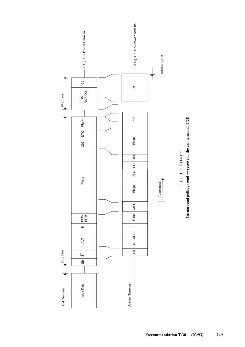
Recommendation T.30 (03/93) 149
T082
6960
-97/
d121
Imag
e D
ata
Flag
sFl
ags “1
”Fl
ags
T2 e
laps
ed
to F
ig. F
.5-1
1b C
all t
erm
inal
to F
ig. F
.5-1
1b A
nsw
er t
erm
inal
FIG
UR
E F
.5-1
1a/T
.30
Tur
naro
und
polli
ng (s
end
→ r
ecei
ve in
the
call
term
inal
[1/2
])
Cal
l Ter
min
al
Ans
wer
Ter
min
alFl
ags
Flag
s
CM
(RX
FA
X)
70 ±
5 m
s
Sh
Sh
ALT
EP
PS
-E
OM
CIG
DTC
70 ±
5 m
s
CJ
Sh
Sh
ALT
EM
CF
NS
FC
SID
ISJM
FIGURE F.5-11a/T.30...[D121] = 3 CM

150 Recommendation T.30 (03/93)
T082
6970
-97/
d122
Cal
l Ter
min
al
From
Fig
. F.5
-11a
Cal
l ter
min
al
Ans
wer
term
inal
From
Fig
. F.5
-11a
Ans
wer
term
inal
Flag
sFl
ags
Flag
sIm
age
Dat
a
75 ±
5 m
s
75 ±
5 m
s70
± 5
ms
70 ±
5 m
s70
± 5
ms
FIG
UR
E F
.5-1
1b/T
.30
Tur
naro
und
polli
ng (s
end
→ r
ecei
ve in
the
call
term
inal
[2/2
])
INFOh
INFO0a
“1”
INFO0cB
BB
PPh
ALT
MP
hM
Ph
EC
FR
AA
L1L2
AS
SP
PTR
NP
Ph
ALT
MPh
MP
hE
TSI
DC
SS
SPP
B1
FIGURE F.5-11b/T.30...[D122] = 3 CM

Recommendation T.30 (03/93) 151
70 ±
5 m
s
70 ±
5 m
s
T082
6980
-97/
d123
Cal
l Ter
min
al
Ans
wer
Ter
min
al
Imag
e D
ata
Flag
sFl
ags
Flag
s“1
”
Flag
sFl
ags
to F
ig. F
.5-1
2bC
all t
erm
inal
to F
ig. F
.5-1
2bAn
swer
ter
min
a l
FIG
UR
E F
.5-1
2a/T
.30
Tur
naro
und
polli
ng (r
ecei
ve →
send
in th
e ca
ll te
rmin
al [1
/2])
T2 e
laps
ed
CM
(TX
FAX)
ALT
MC
FN
SF
CS
ID
ISS
hS
hE
CJ
Sh
Sh
ALT
EC
IG D
TCP
PS-
EO
MJM
FIGURE F.5-12a/T.30...[D123] = 3 CM

152 Recommendation T.30 (03/93)
T082
6990
-97/
d124
75 ±
5 m
s
S
75 ±
5 m
s70
± 5
ms
70 ±
5 m
s70
± 5
ms
PP
hA
LTM
Ph
MP
hE
A
SB
1
CFR
INFO0c
SPP
AA
PP
hAL
TM
Ph
MP
hE
TSI
BL1
L2S
PP
TRN
DC
S
SB
B
INFO0a
INFOh
Cal
l Ter
min
al
Answ
er T
erm
inal
From
Fig
. F.5
-12a
Ans
wer
term
inal
FIG
UR
E F
.5-1
2b/T
.30
Tur
naro
und
polli
ng (r
ecei
ve →
send
in th
e ca
ll te
rmin
al [2
/2])
Flag
s“1
”Im
age
Dat
a
Flag
sFl
ags
From
Fig
. F.5
-12a
Cal
l ter
min
al
FIGURE F.5-12b/T.30...[D124] = 3 CM

Recommendation T.30 (03/93) 153
Appendix I
Index of abbreviations used in this Recommendation
Abbreviation Function Signal format Reference
ANSam Modulated answer tone See Recommendation V.8 4.1.2
CED Called terminal identification 2100 Hz 4.1.1
CFR Confirmation to receive X010 0001 5.3.6.1.4, 1)
CI Call indicator See Recommendation V.8 F.5
CIG Calling subscriber identification 1000 0010 5.3.6.1.2, 2)
CJ CM terminator See Recommendation V.8 F.5
CM Call menu See Recommendation V.8 F.5
CNG Calling tone 1100 Hz for 500 ms 4.2
CRP Command repeat X101 1000 5.3.6.1.8, 2)
CSI Called subscriber identification 0000 0010 5.3.6.1.1, 2)
CTC Continue to correct X100 1000 A.4.1
CTR Response for continue to correct X010 0011 A.4.2
DCN Disconnect X101 1111 5.3.6.1.8, 1)
DCS Digital command signal X100 0001 5.3.6.1.3, 1)
DIS Digital identification signal 0000 0001 5.3.6.1.1, 1)
DTC Digital transmit command 1000 0001 5.3.6.1.2, 1)
EOM End of message X111 0001 5.3.6.1.6, 1)
EOP End of procedure X111 0100 5.3.6.1.6, 3)
EOR End of retransmission X111 0011 A.4.3, 2)
ERR Response for end of retransmission X011 1000 A.4.4, 3)
FCD Facsimile coded data 0110 0000 A.2.2
FCF Facsimile control field – 5.3.6.1
FDM File diagnostics message X011 1111 5.3.6.1.7, 9)
FIF Facsimile information field – 5.3.6.2
FTT Failure to train X010 0010 5.3.6.1.4, 2)
HDLC High level data link control – 5.3
JM Joint menu See Recommendation V.8 F.5
MCF Message confirmation X011 0001 5.3.6.1.7, 1)
MPh Modulation parameter See Recommendation V.34 F.3.1.4
MPS Multipage signal X111 0010 5.3.6.1.6, 2)
NSC Non-standard facilities command 1000 0100 5.3.6.1.2, 3)

154 Recommendation T.30 (03/93)
Abbreviation Function Signal format Reference
NSF Non-standard facilities 0000 0100 5.3.6.1.1, 3)
NSS Non-standard set-up X100 0100 5.3.6.1.3, 3)
PID Procedure interrupt disconnect X011 0110 C.3.4, 2)
PIN Procedure interrupt negative X011 0100 5.3.6.1.7, 5)
PIP Procedure interrupt positive X011 0101 5.3.6.1.7, 4)
PPS Partial page signal X111 1101 A.4.3, 1)
PPR Partial page request X011 1101 A.4.4, 1)
PRI-EOM Procedure interrupt-EOM X111 1001 5.3.6.1.6, 4)
PRI-EOP Procedure interrupt-EOP X111 1100 5.3.6.1.6, 6)
PRI-MPS Procedure interrupt-MPS X111 1010 5.3.6.1.6, 5)
PWD Password (for polling) 1000 0011 5.3.6.1.2, 4)
PWD Password (for transmission) X100 0101 5.3.6.1.3, 5)
RCP Return to control for partial page 0110 0001 A.2.2
RNR Receive not ready X011 0111 A.4.4, 2)
RR Receive ready X111 0110 A.4.3, 3)
RTN Retrain negative X011 0010 5.3.6.1.7, 3)
RTP Retrain positive X011 0011 5.3.6.1.7, 2)
SEP Selective polling 1000 0101 5.3.6.1.2, 5)
SUB Subaddress X100 0011 5.3.6.1.3, 4)
TCF Training check Zeros for 1.5 s 5.3.6.1.3, 6)
TSI Transmitting subscriber identification X100 0010 5.3.6.1.3, 2)

Recommendation T.30 (03/93) 155
Appendix II
List of commands and appropriate responses
Commands Comments Appropriate responses
(NSF) (CSI) DIS Identifying capabilities: from a manual receiver or an auto answer terminal
(NSC) (CIG) DTC (TSI) DCS (NSF) (CSI) DIS (CRP) (TSI) (NSS) (PWD) (SEP) (CIG) DTC (PWD) (SUB) (TSI) DCS
(NSC) (CIG) DTC (PWD) (SEP) (CIG) DTC
Mode setting command: from calling terminal This is a poll operation
(TSI) DCS (NSF) (CSI) DIS (CRP) (TSI) (NSS)
(TSI) DCS (TSI) (NSS) (PWD) (SUB) (TSI) DCS
Mode setting command: from manual transmitter or automatic receiver This command is always followed by training
CFR FTT (NSC) (CIG) DTC (NSF) (CSI) DIS (CRP)
CTC Mode setting command: from the transmitter to the receiver (CTR) (CRP)
(EOR-NULL) Indicate the next block transmission from the transmitter to the receiver
(ERR) (RNR) (CRP)
(EOR-MPS) or (EOR-EOP) or (EOR-EOM) or (EOR-PRI-MPS) or (EOR-PRI-EOP) or (EOR-PRI-EOM)
Indicate the next message transmission from the transmitter to the receiver
(ERR) (RNR) PIN (CRP)
MPS or EOP or EOM or (PRI-MPS) or (PRI-EOP) or (PRI-EOM)
Post message commands MCF RTP RTN PIP PIN (CRP)
(PPS-NULL) Post-message command for a partial page: from the transmitter to the receiver
(PPR) MCF (RNR) (CRP)
(PPS-MPS) or (PPS-EOP) or (PPS-EOM) or (PPS-PRI-MPS) or (PPS-PRI-EOP) or (PPS-PRI-EOM)
Post-message commands for a complete page: from the transmitter to the receiver
(PPR) MCF (RNR) PIP PIN (CRP)
(RR) Ask for the status of the receiver: from the transmitter to the receiver
(RNR) (ERR) MCF PIP PIN (CRP)
DCN Phase E command None
NOTE – Where the symbols ( ) are used, the signals within these symbols are optional.

156 Recommendation T.30 (03/93)
Appendix III
Alternative procedures used by some terminals which conform to the pre-1996 versions of this Recommendation
III.1 Alternative automatic answering sequence
T0813070-93/d125
Transmit CED (4.1.1)
Transmit preamble (5.3.1)
Transmit binary coded information (5.3)
Listen for command information
Transmit preamble (5.3.1)
Transmit binary coded information (5.3)
3 s
± 1
5%3
s ±
15%
(Not
e 1)
(Not
e 1)
75 ±
20
ms
Silence (4.1.1)
Transmit tonal signal (Note 2)
Listen for command information
Repeat tonal signal, the preamble and the binary coded information until tonal or coded command is detectedor time-out occurs (30 to 40 s)
NOTES1 For manual receivers using the binary coded procedure, this delay should be 4.5 s ± 15%.2 The tonal signal will have one of the following formats: a) 1650 Hz (± 6 Hz) ON for 1.5 s and OFF for 3 s (timing tolerance ± 15%); or b) 1850 Hz (± 6 Hz) ON for 1.5 s and OFF for 3 s (timing tolerance ± 15%); or c) 1650 Hz (± 6 Hz) ON for 1.5 s immediately followed by 1850 Hz ON for 0.75 s followed by silence for 3 s (timing tolerance ± 15%).
FIGURE III.1/T.30Called terminal procedure
FIGURE III.1/T.30...[D125] = 3 CM

Recommendation T.30 (03/93) 157
III.2 Optional binary coded preamble
An example of a terminal having the standard binary coded, recognized optional binary coded and tonal capabilities is given in Figure III.2.
3 s
± 15
%75
± 2
0 m
s3
s ±
15%
75 ±
20
ms
3 s
± 15
%
T0813980-93/d126
Transmit CED
Transmit preamble
Transmit binary coded identification signal at 300 bit/s
(Not
e 1)
Listen to receive command information
Transmit tonal signals (Note 2)
Transmit preamble
Transmit binary coded identification signal at 300 bit/s
Listen to receive command information
Transmit long training modem sequence (Rec. V.27 ter, 2400 bit/s)
Transmit binary coded identification signal at 2400 bit/s
Transmit tonal signals (Note 2)
Listen to receive command information
Repeat the binary coded identification at 300 bit/s and the binary coded identification signal at 2400 bit/s (followed by the tonal) alternately until reception of a tonal command or binary coded command, or until the time T1 has elapsed (30 to 40 s)
FIGURE III.2/T.30Called terminal procedures
NOTES1 For manual receivers using the binary coded procedure, this delay should be 4.5 s ± 15%.2 The tonal signal will have one of the following formats: a) 1650 Hz (± 6 Hz) ON for 1.5 s and OFF for 3 s (timing tolerance ± 15%); or b) 1850 Hz (± 6 Hz) ON for 1.5 s and OFF for 3 s (timing tolerance ± 15%); or c) 1650 Hz (± 6 Hz) ON for 1.5 s immediately followed by 1850 Hz ON for 0.75 s followed by silence for 3 s (timing tolerance ± 15%)
(Not
e 1)
(Not
e 1)
FIGURE III.2/T.30...[D126] = 3 CM

158 Recommendation T.30 (03/93)
Appendix IV
Signal sequence examples
The examples below are based on the flow diagrams and are for illustrative and instructional purpose only. They should not be interpreted as establishing or limiting the protocol. The exchange of the various commands and responses is limited only by the rules specified in this Recommendation (see 5.3 and 5.4).
The notations used in these diagrams are as follows: – an arrowhead signifies the receiver of the signal; – a solid line indicates transmission of the signal at the data rate of 300 bit/s; – the dashed lines indicate transmission at the message data rate (Recommendations V.27 ter, V.29
and V.17); – a lightning bolt ( ) indicates an invalid frame; – a bold solid line indicates the transmission of tonal signals.
In Figures IV.1 to IV.11 the examples given assume the DIS will be repeated for T1 seconds unless responded by a valid signal.
T0813990-93/d127
Calling terminal Called terminal
Training, TCF
Training, FAX MSG
Training, FAX MSG
FIGURE IV.1/T.30
Example 1 An auto calling terminal wishing to transmit to an auto answer terminal: example of post-message commands.
CNG
CED
DIS
CFR
MPS
MCF
EOP
MCF
DCN
DCS
FIGURE IV.1/T.30...[D127] = 3 CM

Recommendation T.30 (03/93) 159
T0814000-93/d128
Transmittingterminal
Calledterminal
Training, TCF
Training, FAX MSG
Training, TCF
Training, FAX MSG
Training, TCF
Training, FAX MSG
T2 elapsed
T2 elapsed
T1 elapsed
Operatordisconnects
the line
FIGURE IV.2/T.30
Terminaldisconnects
T2 elapsed
Example 2 A single page transmitter wishing to transmit to an auto answer terminal: example of EOM.
CED
DIS
DCS
CFR
EOM
MCF
DIS
DCS
CFR
MCF
EOM
EOMMCF
DIS
DCS
CFR
EOM
MCF
DIS
DIS
DIS
FIGURE IV.2/T.30...[D128] = 3 CM

160 Recommendation T.30 (03/93)
T0814010-93/d129
Training, TCF
Training, FAX MSG
RTP or RTN
Training, TCF
Training, FAX MSG
Calling terminal Called terminal
(Request foroperatorretrain)
(Request foroperatorintervention)
Operatoron line
Operatoron line
(Operator will hearPIN/PIP response)
Alert operator
PRI-Q
PIN or PIP
FIGURE IV.3/T.30
Training, TCF
Training, FAX MSG
Operator intervention
PIN or PIP
Example 3 An auto calling terminal wishing to transmit to an auto answer terminal: example of post-message responses.
CNG
CED
DIS
DCS
CFR
MPS
DCS
CFR
MPS
CNG
CED
DIS
DCS
CFR
EOP
MCF
DCN
FIGURE IV.3/T.30...[D129] = 3 CM

Recommendation T.30 (03/93) 161
T0814020-93/d130
Transmitting terminal Called terminal
Training, TCF
Training, TCF
Training, FAX MSG
PIN or PIP
Training, TCF
Training, FAX MSG
PIN or PIP
Operatoron lineOperator
on lineOperator intervention
Both operators mutuallydecide to terminate the call
FIGURE IV.4/T.30
Operatoron line
Operatoron line(Operator will hearPRI-Q command)
(Request foroperator intervention) Alert operator
Operator intervention
Example 4 Manual transmitter wishing to transmit to an auto answer terminal: example of initial training failure and procedural interrupts.
CED
DISDCS
FTTDCS
CFR
PRI-Q
PRI-Q
CED
DIS
DCS
CFR
PRI-Q
PRI-Q
FIGURE IV.4/T.30...[D130] = 3 CM

162 Recommendation T.30 (03/93)
T0814030-93/d131
Called terminal
Training, TCF
Training, FAX MSG
Training, TCF
FIGURE IV.5/T.30
T2 elapsed
Training, FAX MSG
Calling terminal
Example 5 Auto calling terminal wishing to first receive from, then transmit to, an auto answer terminal.
CNG
CED
DIS
DTC
DCS
CFR
EOM
MCF
DIS
DTC
DCS
CFR
EOP
MCF
DCN
FIGURE IV.5/T.30...[D131] = 3 CM
T0814040-93/d132
Compatible non-standard facilities?
No Yes
Calling terminal Called terminal
Training, TCF
Training, FAX MSG
Proceed with non-standard operation
FIGURE IV.6/T.30
Example 6 Auto calling terminal wishing to receive from an auto answer terminal: example of polling and of optional as well as non-standard signals.
CNG
CED
(NSF) (CSI) DIS
(NSC) (CIG) DTC
(TSI) DCS
CFR
EOP
MCF
DCN
(NSS)
IGURE IV.6/T.30...[D132] = 3 CM

Recommendation T.30 (03/93) 163
T0814050-93/d133
Training, TCF
Training, TCF
Training, FAX MSG
Training, TCF
Training, FAX MSG
FIGURE IV.7/T.30
Calling terminal Called terminal
3 s elapsed
3 s elapsed
3 s elapsed
3 s elapsed
3 s elapsed
Example 7 An auto calling terminal wishing to transmit to an auto answer terminal: example of standard error recovery techniques.
(Line lost)
Training, TCF
CNG
CED
DIS
DIS
DCS
DIS
DCS
FTT
DCS
CFR
MPS
MPS
RTN
DCS
CFR
EOP
EOP
EOP
DCN
FIGURE IV.7/T.30...[D133] = 3 CM

164 Recommendation T.30 (03/93)
T0814060-93/d134
Training, TCF
Training, FAX MSG
FIGURE IV.8/T.30
4.5 s elapsed
Transmitting terminal Receiving terminal
Example 8 Manual transmitter wishing to transmit to a manual receiver: example of error recovery technique using the optional CRP response.
(CED)
DIS
CRP
DIS
DCS
CFR
EOM
CRP
EOM
MCF
DCN
FIGURE IV.8/T.30...[D134] = 3 CM
T0814110-93/d135
....
Calling terminal Called terminal
(Password OK?)Yes
No
FIGURE IV.9/T.30
Example 9 An auto calling terminal wishing to receive from an auto answer terminal using password/selective polling capabilities.
CED(NSF) (CSI) DIS
(PWD) (SEP) (CIG) DTC
(TSI) DCS
DCN
FIGURE IV.9/T.30...[D135] = 3 CM

Recommendation T.30 (03/93) 165
T0814120-93/d136
CED
(NSF) (CSI) DIS
(PWD) (SUB) (TSI) DCS....
Calling terminal Called terminal
FIGURE IV.10/T.30
Example 10 An auto calling terminal wishing to transmit to an auto answer terminal using password/subaddress capabilities.
FIGURE IV.10/T.30...[D136] = 3 CM
T0827000-97/d137
FIGURE IV.11/T.30
Example 11 Auto calling terminal wishing to first transmit to, then receive from an auto answer terminal.
T2 elapsed
Calling terminal Called terminal
Training, TCF
Training, FAX MSG
Training, TCF
Training, FAX MSG
CNG
CED
(NSF) (CSI) DIS
(PWD) (SUB) (TSI) DCS
MCF
(NSF) (CSI) DIS
(PWD) (SEP) (CIG) DTC
CFR
EOM
(PWD) (SUB) (TSI) DCS
MCF
CFR
EOP
DCN
FIGURE IV.11/T.30...[D137] = 3 CM

166 Recommendation T.30 (03/93)
Appendix V
Procedure for binary file transmission with protocol examples
V.1 Introduction
This appendix describes the operation of the Binary File Transfer (BFT) protocol in the Group 3 facsimile mode of operation. Use of this protocol allows Group 3 facsimile terminal to interchange binary data files. Refer to Recommendation T.434 for information regarding the semantics and syntax of a binary encoded data file.
Facsimile terminals that wish to support this facility must support optional error correction mode of this Recommendation.
V.2 Definitions
For the purposes of this Recommendation, the following definitions apply:
V.2.1 attribute: A piece of information stating a property of something, taking one of a set of defined values, each value having a defined meaning.
V.2.2 binary file (data): A sequence of octets, representing a binary file and optional attributes, formed, using the coding rules in Appendix I/T.434.
V.2.3 file attributes: The name and other identifiable properties of a file.
V.2.4 real filestore: An organized collection of files, including their attributes and names, which reside on a real system.
V.2.5 virtual filestore: An abstract model for describing files and filestores, and the possible actions performed on them.
V.3 BFT file transfer-protocol overview
Group 3 terminals supporting BFT are capable of sending and receiving facsimile messages and binary data files in the same call establishment. This is accomplished by using Error Correction Mode (ECM) and sending the binary data as the logical equivalent of an error-corrected facsimile message.
The BFT option is indicated by the setting of a capability bit in the DIS frame. Bit 53 specifies the additional capability required by BFT.
The high-speed binary file data is formed using the coding rules in Recommendation T.434. These rules specify how to code the set of attributes as a sequence of octets. This binary data is then transmitted on the high-speed data channel using ECM.
Transmitting a binary file is logically equivalent to transmitting an error-corrected facsimile message (with one or more pages). In fact, multiple binary files may be contained within the logical equivalent of an error-corrected facsimile message. At any point during the transmission, the transmitter may request a diagnostic message from the receiver by suspending the current transfer with a PPS post-message command. At this point the receiver may optionally respond with a diagnostic message. Transfer of the current binary file(s) will continue on the next page. The first octet of this new page will be the next unsent octet of the binary file data.
Other protocol considerations for BFT can be found in Annex C/T.4.

Recommendation T.30 (03/93) 167
V.4 ECM-BFT data format
The high-speed ECM-BFT binary data is a set of contiguous octets defined in Recommendation T.434. Using Group 3 facsimile terminal, this set of octets is transmitted as an ECM message. Within an ECM page, these octets are segmented into blocks and into the HDLC frames. This segmentation is completely independent of attribute boundaries. A sequence of octets is transmitted beginning with the least significant bit in the first octet.
The ECM-BFT binary data format allows the following combinations of binary data and ECM pages. Cases a) and d) where each binary file corresponds to a single ECM page are the preferred formats.
a) A single binary file in a single ECM page.
b) A single binary file in a multiple of ECM pages.
c) Multiple binary files in a single ECM page.
d) Multiple binary files in a multiple of ECM pages.


ITU-T RECOMMENDATIONS SERIES
Series A Organization of the work of the ITU-T
Series B Means of expression
Series C General telecommunication statistics
Series D General tariff principles
Series E Telephone network and ISDN
Series F Non-telephone telecommunication services
Series G Transmission systems and media
Series H Transmission of non-telephone signals
Series I Integrated services digital network
Series J Transmission of sound-programme and television signals
Series K Protection against interference
Series L Construction, installation and protection of cables and other elements of outside plant
Series M Maintenance: international transmission systems, telephone circuits, telegraphy, facsimile and leased circuits
Series N Maintenance: international sound-programme and television transmission circuits
Series O Specifications of measuring equipment
Series P Telephone transmission quality
Series Q Switching and signalling
Series R Telegraph transmission
Series S Telegraph services terminal equipment
Series T Terminal equipments and protocols for telematic services
Series U Telegraph switching
Series V Data communication over the telephone network
Series X Data networks and open system communication
Series Z Programming languages
*10121* Printed in Switzerland
Geneva, 1997