ITU-T Rec. J.94 (10/2016) Service information for digital ...
214
International Telecommunication Union ITU-T J.94 TELECOMMUNICATION STANDARDIZATION SECTOR OF ITU (10/2016) SERIES J: CABLE NETWORKS AND TRANSMISSION OF TELEVISION, SOUND PROGRAMME AND OTHER MULTIMEDIA SIGNALS Ancillary digital services for television transmission Service information for digital broadcasting in cable television systems Recommendation ITU-T J.94
-
Upload
khangminh22 -
Category
Documents
-
view
1 -
download
0
Transcript of ITU-T Rec. J.94 (10/2016) Service information for digital ...

I n t e r n a t i o n a l T e l e c o m m u n i c a t i o n U n i o n
ITU-T J.94 TELECOMMUNICATION STANDARDIZATION SECTOR OF ITU
(10/2016)
SERIES J: CABLE NETWORKS AND TRANSMISSION OF TELEVISION, SOUND PROGRAMME AND OTHER MULTIMEDIA SIGNALS
Ancillary digital services for television transmission
Service information for digital broadcasting in cable television systems
Recommendation ITU-T J.94


Rec. ITU-T J.94 (10/2016) i
Recommendation ITU-T J.94
Service information for digital broadcasting in cable television systems
Summary
Recommendation ITU-T J.94 specifies Service Information (SI) describing the services residing
within streams constructed in accordance with Recommendation ITU-T H.222.0 | ISO/IEC 13818-1
(MPEG-2 Systems). This Recommendation defines the standard protocol for transmission of the
relevant SI data tables carried in the MPEG-2 Transport Stream multiplex.
History
Edition Recommendation Approval Study Group Unique ID*
1.0 ITU-T J.94 1998-11-19 9 11.1002/1000/4346
1.1 ITU-T J.94 (1998) Amd. 1 2000-10-06 9 11.1002/1000/5167
1.2 ITU-T J.94 (1998) Amd. 2 2001-03-09 9 11.1002/1000/5377
1.3 ITU-T J.94 (1998) Amd. 3 2016-03-15 9 11.1002/1000/12763
2.0 ITU-T J.94 2016-10-14 9 11.1002/1000/13048
* To access the Recommendation, type the URL http://handle.itu.int/ in the address field of your web
browser, followed by the Recommendation's unique ID. For example, http://handle.itu.int/11.1002/1000/11
830-en.

ii Rec. ITU-T J.94 (10/2016)
FOREWORD
The International Telecommunication Union (ITU) is the United Nations specialized agency in the field of
telecommunications, information and communication technologies (ICTs). The ITU Telecommunication
Standardization Sector (ITU-T) is a permanent organ of ITU. ITU-T is responsible for studying technical,
operating and tariff questions and issuing Recommendations on them with a view to standardizing
telecommunications on a worldwide basis.
The World Telecommunication Standardization Assembly (WTSA), which meets every four years, establishes
the topics for study by the ITU-T study groups which, in turn, produce Recommendations on these topics.
The approval of ITU-T Recommendations is covered by the procedure laid down in WTSA Resolution 1.
In some areas of information technology which fall within ITU-T's purview, the necessary standards are
prepared on a collaborative basis with ISO and IEC.
NOTE
In this Recommendation, the expression "Administration" is used for conciseness to indicate both a
telecommunication administration and a recognized operating agency.
Compliance with this Recommendation is voluntary. However, the Recommendation may contain certain
mandatory provisions (to ensure, e.g., interoperability or applicability) and compliance with the
Recommendation is achieved when all of these mandatory provisions are met. The words "shall" or some other
obligatory language such as "must" and the negative equivalents are used to express requirements. The use of
such words does not suggest that compliance with the Recommendation is required of any party.
INTELLECTUAL PROPERTY RIGHTS
ITU draws attention to the possibility that the practice or implementation of this Recommendation may involve
the use of a claimed Intellectual Property Right. ITU takes no position concerning the evidence, validity or
applicability of claimed Intellectual Property Rights, whether asserted by ITU members or others outside of
the Recommendation development process.
As of the date of approval of this Recommendation, ITU had not received notice of intellectual property,
protected by patents, which may be required to implement this Recommendation. However, implementers are
cautioned that this may not represent the latest information and are therefore strongly urged to consult the TSB
patent database at http://www.itu.int/ITU-T/ipr/.
ITU 2017
All rights reserved. No part of this publication may be reproduced, by any means whatsoever, without the prior
written permission of ITU.

Rec. ITU-T J.94 (10/2016) iii
Table of Contents
Page
1 Scope ............................................................................................................................. 1
2 References ..................................................................................................................... 1
3 Terms and definitions ................................................................................................... 2
3.1 Terms defined elsewhere ................................................................................ 2
3.2 Terms defined in this Recommendation ......................................................... 2
4 Abbreviations and acronyms ........................................................................................ 5
5 Conventions .................................................................................................................. 7
6 Service information for systems A, B, and C ............................................................... 7
Annex A – Service information for digital multi-programme system A ................................. 8
A.1 Scope .............................................................................................................. 8
A.2 References ...................................................................................................... 8
A.3 Definitions, abbreviations and acronyms ....................................................... 8
A.4 Service information (SI) description .............................................................. 8
A.5 Service information (SI) tables ....................................................................... 9
A.6 Descriptors ...................................................................................................... 25
A.7 Storage media interoperability (SMI) measures ............................................. 65
Annex B – Service information for digital multi-programme System B ................................. 69
B.1 Purpose, scope and organization .................................................................... 69
B.2 References ...................................................................................................... 71
B.3 Definitions ...................................................................................................... 71
B.4 Acronyms and abbreviations .......................................................................... 73
B.5 Table structure ................................................................................................ 74
B.6 Table section formats ..................................................................................... 77
B.7 Descriptors ...................................................................................................... 107
B.8 Text string coding ........................................................................................... 116
Annex C – Service Information for digital multi-programme System C ................................. 124
C.1 SI tables .......................................................................................................... 124
C.2 Descriptor ....................................................................................................... 126
C.3 Character code tables ...................................................................................... 130
Annex D – Coding of text characters for System A ................................................................ 131
Annex E – CRC decoder model for system A ......................................................................... 138
Annex F – Operational profiles for cable service information delivery for system B ............. 139
F.1 Operational profiles ........................................................................................ 139
F.2 Profile Definition Tables ................................................................................ 139
F.3 Operational considerations for the use of profiles (Informative) ................... 141
Annex G – Packet rates for system B ...................................................................................... 142
G.1 Maximum cycle times .................................................................................... 142

iv Rec. ITU-T J.94 (10/2016)
Page
G.2 Maximum transmission rates .......................................................................... 142
G.3 Minimum transmission rates .......................................................................... 142
Annex H – Standard Huffman tables for text compression for system B ................................ 143
H.1 Character set definition ................................................................................... 143
Appendix I – Conversion between time and date conventions for System A .......................... 183
Appendix II – Implementation recommendations for System B ............................................. 185
II.1 Implications for retail digital cable-ready devices ......................................... 185
II.2 Channel number handling ............................................................................... 185
II.3 Processing of dynamic changes to service information ................................. 185
II.4 AEITs may include event information for inaccessible channels .................. 185
II.5 Splice flag processing ..................................................................................... 186
Appendix III – Service Information overview and guide for System B .................................. 187
III.1 Table hierarchy ............................................................................................... 187
III.2 SI_base PID .................................................................................................... 191
III.3 Representation of Time .................................................................................. 198
Appendix IV – Daylight Savings Time control for System B ................................................. 202
Bibliography............................................................................................................................. 203

Rec. ITU-T J.94 (10/2016) v
Introduction
The development of new digital technology has reached the point at which it is evident that they
enable digital systems to offer significant advantages, in comparison with conventional analogue
techniques, in terms of vision and sound quality, spectrum and power efficiency, service flexibility,
multimedia convergence and potentially lower equipment costs. Moreover, the use of cable
distribution for the delivery of video and audio signals to individual viewers and listeners is
continually growing, and has already become the dominant form of distribution in many parts of the
world. It is also evident that these potential benefits can best be achieved through the economies of
scale resulting from the widespread use of digital systems designed to be easily implementable on
existing infrastructure and which take advantage of the many possible synergies with related
audiovisual systems.
This Recommendation has three annexes, that provide the specifications for the service information
for the three digital television cable systems submitted to ITU-T.
This reflects the fact that standardization of digital cable television systems is being addressed for the
first time by ITU-T and that a number of systems had been developed and provisionally implemented
when this standardization effort was undertaken by ITU.
Administrations and private operators planning the introduction of digital cable television services
are encouraged to consider the use of one of the systems described in Annexes A, B and C, and to
seek opportunities for further convergence, rather than developing a different system based on the
same technologies.

Rec. ITU-T J.94 (10/2016) 1
Recommendation ITU-T J.94
Service information for digital broadcasting in cable television systems
1 Scope
The scope of this Recommendation defines the Service Information that conveys the relevant
description of the services contained in a multiplex of audio, video, and data that is distributed by
cable networks (e.g., CATV systems). [ITU-T J.83] defines the transmission characteristics for digital
multi-programme signals distributed through cable networks.
NOTE – The service information is specified to be contained within the MPEG-2 transport layer as Program
Specific Information (PSI). This mechanism provides some ancillary data capacity in the forward channel,
which can be used to accommodate the needs of other services such as program guides (a description of the
provision and characteristics of these services is outside the scope of this Recommendation).
Being highly flexible, the MPEG-2 transport layer can be configured to deliver any desired mix of
television, sound and data signals (with sound either related or unrelated to the video signal content,
and at various possible levels of quality).
This Recommendation is intended to ensure that the designers and operators of cable distribution
(e.g., CATV) networks carrying multi-programme signals will have the information they need to be
able to establish and maintain fully satisfactory networks. It also provides the information needed by
the designers and manufacturers of equipment (including receivers) for digital multi-programme
signals distributed by cable networks.
2 References
The following ITU-T Recommendations and other references contain provisions which, through
reference in this text, constitute provisions of this Recommendation. At the time of publication, the
editions indicated were valid. All Recommendations and other references are subject to revision;
users of this Recommendation are therefore encouraged to investigate the possibility of applying the
most recent edition of the Recommendations and other references listed below. A list of the currently
valid ITU-T Recommendations is regularly published. The reference to a document within this
Recommendation does not give it, as a stand-alone document, the status of a Recommendation.
[ITU-T H.222.0] Recommendation ITU-T H.222.0 (2014) | ISO/IEC 13818-1:2015,
Information technology – Generic coding of moving pictures and
associated audio information: Systems.
[ITU-T J.83] Recommendation ITU-T J.83 (2007), Digital multi-programme systems for
television, sound and data services for cable distribution.
[EBU SPB 492] EBU SPB 492 (1992), Teletext specification (625-line Television Systems).
[ETR 162] ETR 162, Digital Video Broadcasting (DVB); Allocation of Service
Information (SI) codes for DVB systems.
[ETR 154] ETR 154, Digital Video Broadcasting (DVB); Implementation guidelines
for the use of MPEG-2 Systems, Video and Audio in satellite, cable and
terrestrial broadcasting applications.
[ETR 211] ETR 211, Digital Video Broadcasting (DVB); Guidelines on
implementation and usage of Service Information (SI).
[IEC 61883] IEC Publication 61883 (1998), Consumer audio/video equipment – Digital
interface. (Parts 1 and 4.)
[IEEE 1394] IEEE 1394, High Performance Serial Bus.

2 Rec. ITU-T J.94 (10/2016)
[ISO 639] ISO 639:1988, Code for the representation of names of languages.
[ISO 3166] ISO 3166:1997, Codes for the representation of names of countries and
their subdivisions.
[ISO/IEC 6937] ISO/IEC 6937:1994, Information technology – Coded graphic character
set for text communication – Latin alphabet.
[ISO/IEC 8859] ISO/IEC 8859, Information technology – 8-bit single-byte coded graphic
character sets, Latin alphabets. (All parts).
[ISO/IEC 8859-1] ISO/IEC 8859-1 to 10, Information technology – 8-bit single-byte coded
graphic character sets.
[ISO/IEC 10646-1] ISO/IEC 10646-1:1993, Information technology – Universal
Multiple-Octet Coded Character Set (UCS) – Part 1: Architecture and
Basic Multilingual Plane.
[ISO/IEC 10646-1] ISO/IEC 10646-1:2000, Information technology – Universal
Multiple-Octet Coded Character Set (UCS) – Part 1: Architecture and
Basic Multilingual Plane.
[ISO/IEC 13818] ISO/IEC 13818, Information technology – Generic coding of moving
pictures and associated audio information. (All parts).
3 Terms and definitions
3.1 Terms defined elsewhere
This Recommendation uses the following terms defined elsewhere:
3.1.1 MPEG-2 [ISO/IEC 13818]: Refers to ISO/IEC standard 13818 (All parts). Systems coding
is defined in Part 1. Video coding is defined in Part 2. Audio coding is defined in Part 3.
3.1.2 transport stream (TS) [ITU-T H.222.0]: A TS is a data structure defined in
[ITU-T H.222.0].
3.2 Terms defined in this Recommendation
This Recommendation defines the following terms:
3.2.1 bouquet: A collection of services marketed as a single entity.
3.2.2 broadcaster (SERVICE Provider): An organization which assembles a sequence of events
or programmes to be delivered to the viewer based upon a schedule.
3.2.3 component (ELEMENTARY Stream): One or more entities which together make up an
event, e.g., video, audio, teletext.
3.2.4 conditional access (CA) system: A system to control subscriber access to services,
programmes and events e.g., Videoguard, Eurocrypt.
3.2.5 delivery system: The physical medium by which one or more multiplexes are transmitted
e.g., satellite system, wide-band coaxial cable, fibre optics, terrestrial channel of one emitting point.
3.2.6 descriptor: A data structure of the format: descriptor_tag, descriptor_length, and a variable
amount of data. The tag and length fields are each 8 bits. The length specifies the length of data that
begins immediately following the descriptor_length field itself. A descriptor whose descriptor_tag
identifies a type not recognized by a particular decoder shall be ignored by that decoder. Descriptors
can be included in certain specified places within PSIP tables, subject to certain restrictions.
Descriptors may be used to extend data represented as fixed fields within the tables. They make the
protocol very flexible since they can be included only as needed. New descriptor types can be

Rec. ITU-T J.94 (10/2016) 3
standardized and included without affecting receivers that have not been designed to recognize and
process the new types.
3.2.7 digital channel: A set of one or more digital elementary streams. See virtual channel.
3.2.8 entitlement management messages (EMM): Are private Conditional Access information
which specify the authorization levels or the services of specific decoders. They may be addressed to
individual decoder or groups of decoders.
3.2.9 event: A grouping of elementary broadcast data streams with a defined start and end time
belonging to a common service, e.g., first half of a football match, News Flash, first part of an
entertainment show.
3.2.10 forbidden: The term "forbidden" when used in the clauses defining the coded bitstream,
indicates that the value shall never be used.
3.2.11 instance: See table instance.
3.2.12 logical channel: See virtual channel.
3.2.13 message: The more general term message is used interchangeably with section, especially to
refer to non-table-oriented data structures such as, for example, the SYSTEM TIME message.
Likewise, the term message is used to refer to a data structure that may deliver portions of various
types of tables. The NETWORK INFORMATION message, for example, defines portions of several
types of network tables.
3.2.14 multiplex: A stream of all the digital data carrying one or more services within a single
physical channel.
3.2.15 network: A collection of MPEG-2 Transport Stream (TS) multiplexes transmitted on a single
delivery system, e.g., all digital channels on a specific cable system.
3.2.16 original_network_id: A unique identifier of a network.
3.2.17 physical channel: A generic term to refer to the each of the 6-8 MHz frequency bands where
television signals are embedded for transmission. Also known as the Physical Transmission Channel
(PTC). One analog virtual channel fits in one PTC but multiple digital virtual channels typically
coexist in one PTC.
3.2.18 physical transmission channel: See physical channel.
3.2.19 programme: A concatenation of one or more events under the control of a broadcaster e.g.,
news show, entertainment show.
3.2.20 program element: A generic term for one of the elementary streams or other data streams
that may be included in a program. For example: audio, video, data, etc.
3.2.21 reserved: The term "reserved" when used in the clause defining the coded bitstream,
indicates that the value may be used in the future for ISO defined extensions. Unless otherwise
specified within this Recommendation, all "reserved" bits shall be set to "1".
3.2.22 reserved_future_use: The term "reserved_future_use", when used in the clause defining the
coded bitstream, indicates that the value may be used in the future for ETSI defined extensions. Unless
otherwise specified within this Recommendation all "reserved_future_use" bits shall be set to "1".
3.2.23 section: A section is a syntactic structure that shall be used for mapping each
[ITU-T H.222.0] defined PSI table or private data table into transport stream packets. Private data
tables include service information (SI) except for PSI.
3.2.24 service: A sequence of programmes under the control of a broadcaster which can be
broadcast as part of a schedule.
3.2.25 service_id: A unique identifier of a service within a TS.

4 Rec. ITU-T J.94 (10/2016)
3.2.26 service information (SI): Digital data describing the delivery system, content and
scheduling/timing of broadcast data streams, etc. It includes MPEG-2 PSI together with
independently defined extensions.
3.2.27 stream: An ordered series of bytes. The usual context for the term stream is the series of
bytes extracted from Transport Stream packet payloads which have a common unique PID value
(e.g., video PES packets or Program Map Table sections).
3.2.28 sub_table: A sub_table is collection of sections with the same value of table_id and:
– for a NIT: the same table_id_extension (network_id) and version_number;
– for a BAT: the same table_id_extension (bouquet_id) and version_number;
– for a SDT: the same table_id_extension (transport_stream_id), the same original_network_id
and version_number;
– for a EIT: the same table_id_extension (service_id), the same transport_stream_id, the same
original_network_id and version_number.
The table_id_extension field is equivalent to the fourth and fifth byte of a section when the
section_syntax_indicator is set to a value of "1".
3.2.29 table: A table is comprised of a number of sub_tables with the same value of table_id.
3.2.30 table instance: Tables are identified by the table_id field. However, in cases such as the RRT
and EIT, several instances of a table are defined simultaneously. All instances have the same PID and
table_id but different table_id_extension.
3.2.31 transport_stream_id: A unique identifier of a TS within an original network.
3.2.32 virtual channel: A virtual channel is the designation, usually a number, that is recognized
by the user as the single entity that will provide access to an analog TV program or a set of one or
more digital elementary streams. It is called "virtual" because its identification (name and number)
may be defined independently from its physical location. Examples of virtual channels are: digital
radio (audio only), a typical analog TV channel, a typical digital TV channel (composed of one audio
and one video stream), multi-visual digital channels (composed of several video streams and one or
more audio tracks), or a data broadcast channel (composed of one or more data streams). In the case
of an analog TV channel, the virtual channel designation will link to a specific physical transmission
channel. In the case of a digital TV channel, the virtual channel designation will link both to the
physical transmission channel and to the particular video and audio streams within that physical
transmission channel.
The relationships of some of these definitions are illustrated in the service delivery model in Figure 1.

Rec. ITU-T J.94 (10/2016) 5
Figure 1 – Digital broadcasting, service delivery model
4 Abbreviations and acronyms
This Recommendation uses the following abbreviations and acronyms:
ATSC Advanced Television Systems Committee
BAT Bouquet Association Table
BCD Binary Coded Decimal
bslbf bit string, left bit first
CA Conditional Access
CAT Conditional Access Table
CDT Carrier Definition Table
CLUT Colour Look-Up Table
CRC Cyclic Redundancy Check
CVCT Cable Virtual Channel Table
DIT Discontinuity Information Table
DTV Digital Television
DVB Digital Video Broadcasting
EBU European Broadcasting Union
ECM Entitlement Control Message
EIT Event Information Table
EMM Entitlement Management Message
EPG Electronic Programme Guide
ETM Extended Text Message

6 Rec. ITU-T J.94 (10/2016)
ETS European Telecommunication Standard
ETT Extended Text Table
FEC Forward Error Correction
GA Grand Alliance
GMT Greenwich Mean Time
GPS Global Positioning System
IEC International Electrotechnical Commission
IRD Integrated Receiver-Decoder
ISO International Organization for Standardization
LSB Least Significant Bit
MCPT Multiple Carriers per Transponder
MGT Master Guide Table
MJD Modified Julian Date
MMT Modulation Mode Table
MPAA Motion Picture Association of America
MPEG Moving Pictures Expert Group
NIT Network Information Table
NVOD Near Video-on-Demand
PAT Program Association Table
PCR Program Clock Reference
PES Packetized Elementary Stream
PID Packet identifier
PMT Program Map Table
PSI Program Specific Information
PSIP Program and Service Information Protocol
PSTN Public Switched Telephone Network
PTC Physical Transmission Channel
PTS Presentation Time Stamp
QAM Quadrature Amplitude Modulation
QPSK Quaternary Phase Shift Keying
rpchof remainder polynomial coefficients, highest order first
RRT Rating Region Table
RS Reed-Solomon
RST Running Status Table
SCTE Society of Cable Telecommunications Engineers
SDT Service Description Table
SECAM Sequential colour with memory (Séquentiel Couleur avec Mémoire)
SI Service Information
SIT Satellite Information Table
SMI Storage Media Interoperability
ST Stuffing Table

Rec. ITU-T J.94 (10/2016) 7
STD System Target Decoder
STT System Time Table
TAI International Atomic Time1
TDT Time and Date Table
TNT Transponder Name Table
TOT Time Offset Table
TS Transport Stream
TVCT Terrestrial Virtual Channel Table
uimsbf unsigned integer most significant bit first
UTC Universal Time coordinated
VCN Virtual Channel Number
VCT Virtual Channel Table Used in reference to either TVCT or CVCT
5 Conventions
None.
6 Service information for systems A, B, and C
Service information for systems A, B, and C are defined in the relevant annexes in this
Recommendation, i.e., AnnexesA, B and C.
1 French acronym used.

8 Rec. ITU-T J.94 (10/2016)
Annex A
Service information for digital multi-programme system A
(This annex forms an integral part of this Recommendation.)
A.1 Scope
This annex is derived from work done in Europe and is based upon the European Telecommunication
Standard (ETS) 300 468. It specifies the service information (SI) data which forms a part of digital
video broadcasting (DBV) bitstreams, in order that the user can be provided with information to assist
in selection of services and/or events within the bitstream, and so that the integrated receiver decoder
(IRD) can automatically configure itself for the selected service. SI data for automatic configuration
is mostly specified within [ITU-T H.222.0] as program specific information (PSI). This annex
specifies additional data which complement the PSI by providing data to aid automatic tuning of
IRDs, and additional information intended for display to the user. The manner of presentation of the
information is not specified in this annex, and IRD manufacturers have the freedom to choose
appropriate presentation methods.
It is expected that electronic programme guides (EPGs) will be a feature of digital TV transmissions.
The definition of an EPG is outside the scope of the SI specification, but the data contained within
the SI specified here may be used as the basis for an EPG.
Rules of operation for the implementation of this annex are specified in [ETR 211].
A.2 References
For references, see clause 2.
A.3 Definitions, abbreviations and acronyms
The terms, definitions, abbreviations and acronyms used in this Recommendation can be found in
clauses 3 and 4.
A.4 Service information (SI) description
[ITU-T H.222.0] specifies SI which is referred to as PSI. The PSI data provides information to enable
automatic configuration of the receiver to demultiplex and decode the various streams of programs
within the multiplex.
The PSI data is structured as four types of table. The tables are transmitted in sections.
1) Program Association Table (PAT)
For each service in the multiplex, the PAT indicates the location [the Packet Identifier (PID)
values of the Transport Stream (TS) packets] of the corresponding Program Map Table
(PMT). It also gives the location of the Network Information Table (NIT).
2) Conditional Access Table (CAT)
The CAT provides information on the CA systems used in the multiplex; the information is
private (not defined within this annex) and dependent on the CA system, but includes the
location of the EMM stream, when applicable.
3) Program Map Table (PMT)
The PMT identifies and indicates the locations of the streams that make up each service, and
the location of the Program Clock Reference fields for a service.
4) Network Information Table (NIT)
The location of the NIT is defined in this annex in compliance with [ITU-T H.222.0] , but the
data format is outside the scope of [ITU-T H.222.0]. It is intended to provide information about
the physical network. The syntax and semantics of the NIT are defined in this annex.

Rec. ITU-T J.94 (10/2016) 9
In addition to the PSI, data are needed to provide identification of services and events for the user.
The coding of this data is defined in this annex. In contrast with the PAT, CAT, and PMT of the PSI,
which give information only for the multiplex in which they are contained (the actual multiplex), the
additional information defined within this annex can also provide information on services and events
carried by different multiplexes, and even on other networks. These data are structured as nine tables:
1) Bouquet Association Table (BAT)
The BAT provides information regarding bouquets. As well as giving the name of the
bouquet, it provides a list of services for each bouquet.
2) Service Description Table (SDT)
The SDT contains data describing the services in the system, e.g., names of services,
the service provider, etc.
3) Event Information Table (EIT)
The EIT contains data concerning events or programmes such as event name, start time,
duration, etc.
The use of different descriptors allows the transmission of different kinds of event
information, e.g., for different service types.
4) Running Status Table (RST)
The RST gives the status of an event (running/not running). The RST updates this
information and allows timely automatic switching to events.
5) Time and Date Table (TDT)
The TDT gives information relating to the present time and date. This information is given
in a separate table due to the frequent updating of this information.
6) Time Offset Table (TOT)
The TOT gives information relating to the present time and date and local time offset.
This information is given in a separate table due to the frequent updating of the time
information.
7) Stuffing Table (ST)
The ST is used to invalidate existing sections, for example at delivery system boundaries.
8) Selection Information Table (SIT)
The SIT is used only in "partial" (i.e., recorded) bitstreams. It carries a summary of the
SI information required to describe the streams in the partial bitstream.
9) Discontinuity Information Table (DIT)
The DIT is used only in "partial" (i.e., recorded) bitstreams. It is inserted where the
SI information in the partial bitstream may be discontinuous.
Where applicable, the use of descriptors allows a flexible approach to the organization of the tables
and allows for future compatible extensions. See Figure A.1.
A.5 Service information (SI) tables
A.5.1 SI table mechanism
The SI specified in this annex and MPEG-2 PSI tables shall be segmented into one or more sections
before being inserted into TS packets.
The tables listed in clause A.4 are conceptual in that they need never be regenerated in a specified
form within an IRD. The tables, when transmitted shall not be scrambled, with the exception of the
EIT, which may be scrambled if required (see clause A.5.1.5).
10 Rec. ITU-T J.94 (10/2016)
A section is a syntactic structure that shall be used for mapping all MPEG-2 tables and SI tables
specified in this annex, into TS packets.
These SI syntactic structures conform to the private section syntax defined in [ITU-T H.222.0].
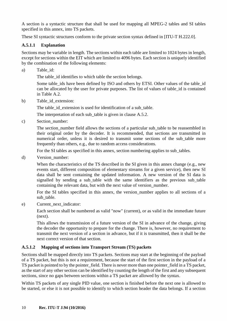
A.5.1.1 Explanation
Sections may be variable in length. The sections within each table are limited to 1024 bytes in length,
except for sections within the EIT which are limited to 4096 bytes. Each section is uniquely identified
by the combination of the following elements:
a) Table_id:
The table_id identifies to which table the section belongs.
Some table_ids have been defined by ISO and others by ETSI. Other values of the table_id
can be allocated by the user for private purposes. The list of values of table_id is contained
in Table A.2.
b) Table_id_extension:
The table_id_extension is used for identification of a sub_table.
The interpretation of each sub_table is given in clause A.5.2.
c) Section_number:
The section_number field allows the sections of a particular sub_table to be reassembled in
their original order by the decoder. It is recommended, that sections are transmitted in
numerical order, unless it is desired to transmit some sections of the sub_table more
frequently than others, e.g., due to random access considerations.
For the SI tables as specified in this annex, section numbering applies to sub_tables.
d) Version_number:
When the characteristics of the TS described in the SI given in this annex change (e.g., new
events start, different composition of elementary streams for a given service), then new SI
data shall be sent containing the updated information. A new version of the SI data is
signalled by sending a sub_table with the same identifiers as the previous sub_table
containing the relevant data, but with the next value of version_number.
For the SI tables specified in this annex, the version_number applies to all sections of a
sub_table.
e) Current_next_indicator:
Each section shall be numbered as valid "now" (current), or as valid in the immediate future
(next).
This allows the transmission of a future version of the SI in advance of the change, giving
the decoder the opportunity to prepare for the change. There is, however, no requirement to
transmit the next version of a section in advance, but if it is transmitted, then it shall be the
next correct version of that section.
A.5.1.2 Mapping of sections into Transport Stream (TS) packets
Sections shall be mapped directly into TS packets. Sections may start at the beginning of the payload
of a TS packet, but this is not a requirement, because the start of the first section in the payload of a
TS packet is pointed to by the pointer_field. There is never more than one pointer_field in a TS packet,
as the start of any other section can be identified by counting the length of the first and any subsequent
sections, since no gaps between sections within a TS packet are allowed by the syntax.
Within TS packets of any single PID value, one section is finished before the next one is allowed to
be started, or else it is not possible to identify to which section header the data belongs. If a section

Rec. ITU-T J.94 (10/2016) 11
finishes before the end of a TS packet, but it is not convenient to open another section, a stuffing
mechanism may be used to fill up the space.
Stuffing may be performed by filling each remaining byte of the TS packet with the value "0xFF".
Consequently the value "0xFF" shall not be used for the table_id. If the byte immediately following
the last byte of a section takes the value of "0xFF", then the rest of the TS packet shall be stuffed with
"0xFF" bytes. These bytes may be discarded by a decoder. Stuffing may also be performed using the
adaptation_field mechanism.
For a more detailed description of the mechanism and functionality, refer to clause 2.4.4 and Annex C
of [ITU-T H.222.0].
Figure A.1 – General organization of the service information (SI)

12 Rec. ITU-T J.94 (10/2016)
A.5.1.3 Coding of PID and table_id fields
Table A.1 lists the PID values which shall be used for the TS packets which carry SI sections.
Table A.1 – PID allocation for SI
Table PID value
PAT 0x0000
CAT 0x0001
TSDT 0x0002
Reserved 0x0003 to 0x000F
NIT, ST 0x0010
SDT, BAT, ST 0x0011
EIT, ST 0x0012
RST, ST 0x0013
TDT, TOT, ST 0x0014
Network synchronization 0x0015
Reserved for future use 0x0016 to 0x001D
DIT 0x001E
SIT 0x001F
Table A.2 lists the values which shall be used for table_id for the service information, defined in this
annex.
A.5.1.4 Repetition rates and random access
In systems where random access is a consideration, it is recommended to re-transmit SI sections
specified within this annex several times, even when changes do not occur in the configuration.
For SI specified within this annex, the minimum time interval between the arrival of the last byte of
a section to the first byte of the next transmitted section with the same PID, table_id and
table_id_extension and with the same or different section_number shall be 25 ms. This limit applies
for TSs with a total data rate of up to 100 Mbit/s.
A.5.1.5 Scrambling
With the exception of the EIT carrying schedule information, all tables specified in this annex shall
not be scrambled. One method for scrambling the EIT schedule table is given in Appendix A.II,
Bibliography. If a scrambling method operating over TS packets is used, it may be necessary to use
a stuffing mechanism to fill from the end of a section to the end of a packet so that any transitions
between scrambled and unscrambled data occur at packet boundaries.
In order to identify the CA streams which control the descrambling of the EIT data, a scrambled EIT
schedule table shall be identified in the PSI. Service_id value 0xFFFF is allocated to identifying a
scrambled EIT, and the program map section for this service shall describe the EIT as a private stream
and shall include one or more CA_descriptors (defined in [ITU-T H.222.0]) which give the PID
values and, optionally, other private data to identify the associated CA streams. Service_id
value 0xFFFF shall not be used for any other service.
A.5.2 Table definitions
The following clauses describe the syntax and semantics of the different types of table.
NOTE – The symbols and abbreviations, and the method of describing syntax used in this annex are the same
as those defined in clauses 2.2 and 2.3 of [ITU-T H.222.0].

Rec. ITU-T J.94 (10/2016) 13
Table A.2 – Allocation of table_id values
Value Description
0x00 program_association_section
0x01 conditional_access_section
0x02 program_map_section
0x03 transport_stream_description_section
0x04 to 0x3F Reserved
0x40 network_information_section – actual_network
0x41 network_information_section – other_network
0x42 service_description_section – actual_transport_stream
0x43 to 0x45 Reserved for future use
0x46 service_description_section – other_transport_stream
0x47 to 0x49 Reserved for future use
0x4A bouquet_association_section
0x4B to 0x4D Reserved for future use
0x4E event_information_section – actual_transport_stream, present/following
0x4F event_information_section – other_transport_stream, present/following
0x50 to 0x5F event_information_section – actual_transport_stream, schedule
0x60 to 0x6F event_information_section – other_transport_stream, schedule
0x70 time_date_section
0x71 running_status_section
0x72 stuffing_section
0x73 time_offset_section
0x74 to 0x7D Reserved for future use
0x7E discontinuity_information_section
0x7F selection_information_section
0x80 to 0xFE User-defined
0xFF Reserved
A.5.2.1 Network Information Table (NIT)
The NIT (see Table A.3) conveys information relating to the physical organization of the
multiplexes/TSs carried via a given network, and the characteristics of the network itself. The
combination of original_network_id and transport_stream_id allow each TS to be uniquely identified
throughout the ETS application area. Networks are assigned individual network_id values, which
serve as unique identification codes for networks. The allocation of these codes may be found in
[ETR 162]. In the case that the NIT is transmitted on the network on which the TS was originated,
the network_id and the original_network_id shall take the same value.
Guidelines for the processing of SI at transitions between delivery media boundaries, e.g., from
satellite to cable or SMATV systems, can be found in [ETR 211].
IRDs may be able to store the NIT information in non-volatile memory in order to minimize the
access time when switching between channels ("channel hopping"). It is also possible to transmit a
NIT for other networks in addition to the actual network. Differentiation between the NIT for the
actual network and the NIT for other networks is achieved using different table_id values
(see Table A.2).

14 Rec. ITU-T J.94 (10/2016)
The NIT shall be segmented into network_information_sections using the syntax of Table A.1. Any
sections forming part of an NIT shall be transmitted in TS packets with a PID value of 0x0010. Any
sections of the NIT which describe the actual network (that is, the network of which the TS containing
the NIT is a part) shall have the table_id value 0x40 with the network_id field taking the value
assigned to the actual network in [ETR 162]. Any sections of an NIT which refer to a network other
than the actual network shall take a table_id value of 0x41 and the network_id shall take the value
allocated to the other network in [ETR 162].
Table A.3 – Network information section
Syntax No. of bits Identifier
network_information_section(){
table_id 8 uimsbf
section_syntax_indicator 1 bslbf
reserved_future_use 1 bslbf
reserved 2 bslbf
section_length 12 uimsbf
network_id 16 uimsbf
reserved 2 bslbf
version_number 5 uimsbf
current_next_indicator 1 bslbf
section_number 8 uimsbf
last_section_number 8 uimsbf
reserved_future_use 4 bslbf
network_descriptors_length 12 uimsbf
for(i=0;i<N;i++){
descriptor()
}
reserved_future_use 4 bslbf
transport_stream_loop_length 12 uimsbf
for(i=0;i<N;i++){
transport_stream_id 16 uimsbf
original_network_id 16 uimsbf
reserved_future_use 4 bslbf
transport_descriptors_length 12 uimsbf
for(j=0;j<N;j++){
descriptor()
}
}
CRC_32 32 rpchof
}
Semantics for the network information section
table_id: See Table A.2.
section_syntax_indicator: The section_syntax_indicator is a 1-bit field which shall be set to "1".
section_length: This is a 12-bit field, the first two bits of which shall be "00". It specifies the number
of bytes of the section, starting immediately following the section_length field and including the
CRC. The section_length shall not exceed 1021 so that the entire section has a maximum length of
1024 bytes.

Rec. ITU-T J.94 (10/2016) 15
network_id: This is a 16-bit field which serves as a label to identify the delivery system, about which
the NIT informs, from any other delivery system. Allocations of the value of this field are found in
[ETR 162].
version_number: This 5-bit field is the version number of the sub_table. The version_number shall
be incremented by 1 when a change in the information carried within the sub_table occurs. When it
reaches value 31, it wraps around to 0. When the current_next_indicator is set to "1", then the
version_number shall be that of the currently applicable sub_table defined by the table_id and
network_id. When the current_next_indicator is set to "0", then the version_number shall be that of
the next applicable sub_table defined by the table_id and network_id.
current_next_indicator: This 1-bit indicator, when set to "1", indicates that the sub_table is the
currently applicable sub_table. When the bit is set to "0", it indicates that the sub_table sent is not yet
applicable and shall be the next sub_table to be valid.
section_number: This 8-bit field gives the number of the section. The section_number of the first
section in the sub_table shall be "0x00". The section_number shall be incremented by 1 with each
additional section with the same table_id and network_id.
last_section_number: This 8-bit field specifies the number of the last section (that is the section with
the highest section_number) of the sub_table of which this section is part.
network_descriptors_length: This 12-bit field gives the total length in bytes of the following
network descriptors.
transport_stream_loop_length: This is a 12-bit field specifying the total length in bytes of the TS
loops that follow, ending immediately before the first CRC-32 byte.
transport_stream_id: This is a 16-bit field which serves as a label for identification of this TS from
any other multiplex within the delivery system.
original_network_id: This 16-bit field gives the label identifying the network_id of the originating
delivery system.
transport_descriptors_length: This is a 12-bit field specifying the total length in bytes of TS
descriptors that follow.
CRC_32: This is a 32-bit field that contains the CRC value that gives a zero output of the registers
in the decoder defined in Annex E after processing the entire section.
A.5.2.2 Bouquet Association Table (BAT)
The BAT (see Table A.4) provides information regarding bouquets. A bouquet is a collection of
services, which may traverse the boundary of a network.
The BAT shall be segmented into bouquet_association_sections using the syntax of Table A.4. Any
sections forming part of a BAT shall be transmitted in TS packets with a PID value of 0x0011. The
sections of a BAT sub_table describing a particular bouquet shall have the bouquet_id field taking
the value assigned to the bouquet described in [ETR 162] . All BAT sections shall take a table_id
value of 0x4A.

16 Rec. ITU-T J.94 (10/2016)
Table A.4 – Bouquet association section
Syntax No. of bits Identifier
bouquet_association_section(){
table_id 8 uimsbf
section_syntax_indicator 1 bslbf
reserved_future_use 1 bslbf
reserved 2 bslbf
section_length 12 uimsbf
bouquet_id 16 uimsbf
reserved 2 bslbf
version_number 5 uimsbf
current_next_indicator 1 bslbf
section_number 8 uimsbf
last_section_number 8 uimsbf
reserved_future_use 4 bslbf
bouquet_descriptors_length 12 uimsbf
for(i=0;i<N;i++){
descriptor()
}
reserved_future_use 4 bslbf
transport_stream_loop_length 12 uimsbf
for(i=0;i<N;i++){
transport_stream_id 16 uimsbf
original_network_id 16 uimsbf
reserved_future_use 4 bslbf
transport_descriptors_length 12 uimsbf
for(j=0;j<N;j++){
descriptor()
}
}
CRC_32 32 rpchof
}
Semantics for the bouquet association section
table_id: See Table A.2.
section_syntax_indicator: The section_syntax_indicator is a 1-bit field which shall be set to "1".
section_length: This is a 12-bit field, the first two bits of which shall be "00". It specifies the number
of bytes of the section, starting immediately following the section_length field and including the
CRC. The section_length shall not exceed 1021 so that the entire section has a maximum length of
1024 bytes.
bouquet_id: This is a 16-bit field which serves as a label to identify the bouquet. Allocations of the
value of this field are found in [ETR 162] .
Rec. ITU-T J.94 (10/2016) 17
version_number: This 5-bit field is the version number of the sub_table. The version_number shall
be incremented by 1 when a change in the information carried within the sub_table occurs. When it
reaches value 31, it wraps around to 0. When the current_next_indicator is set to "1", then the
version_number shall be that of the currently applicable sub_table defined by the table_id and
bouquet_id. When the current_next_indicator is set to "0", then the version_number shall be that of
the next applicable sub_table defined by the table_id and bouquet_id.
current_next_indicator: This 1-bit indicator, when set to "1", indicates that the sub_table is the
currently applicable sub_table. When the bit is set to "0", it indicates that the sub_table sent is not yet
applicable and shall be the next sub_table to be valid.
section_number: This 8-bit field gives the number of the section. The section_number of the first
section in the sub_table shall be "0x00". The section_number shall be incremented by 1 with each
additional section with the same table_id and bouquet_id.
last_section_number: This 8-bit field specifies the number of the last section (that is the section with
the highest section_number) of the sub_table of which this section is part.
bouquet_descriptors_length: This 12-bit field gives the total length in bytes of the following
descriptors.
transport_stream_loop_length: This is a 12-bit field specifying the total length in bytes of the TS
loop that follows.
transport_stream_id: This is a 16-bit field which serves as a label for identification of this TS from
any other multiplex within the delivery system.
original_network_id: This 16-bit field gives the label identifying the network_id of the originating
delivery system.
transport_descriptors_length: This is a 12-bit field specifying the total length in bytes of TS
descriptors that follow.
CRC_32: This is a 32-bit field that contains the CRC value that gives a zero output of the registers
in the decoder defined in Annex E after processing the entire private section.
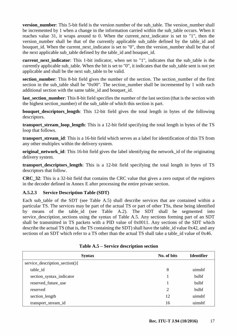
A.5.2.3 Service Description Table (SDT)
Each sub_table of the SDT (see Table A.5) shall describe services that are contained within a
particular TS. The services may be part of the actual TS or part of other TSs, these being identified
by means of the table_id (see Table A.2). The SDT shall be segmented into
service_description_sections using the syntax of Table A.5. Any sections forming part of an SDT
shall be transmitted in TS packets with a PID value of 0x0011. Any sections of the SDT which
describe the actual TS (that is, the TS containing the SDT) shall have the table_id value 0x42, and any
sections of an SDT which refer to a TS other than the actual TS shall take a table_id value of 0x46.
Table A.5 – Service description section
Syntax No. of bits Identifier
service_description_section(){
table_id 8 uimsbf
section_syntax_indicator 1 bslbf
reserved_future_use 1 bslbf
reserved 2 bslbf
section_length 12 uimsbf
transport_stream_id 16 uimsbf

18 Rec. ITU-T J.94 (10/2016)
Table A.5 – Service description section
Syntax No. of bits Identifier
reserved 2 bslbf
version_number 5 uimsbf
current_next_indicator 1 bslbf
section_number 8 uimsbf
last_section_number 8 uimsbf
original_network_id 16 uimsbf
reserved_future_use 8 bslbf
for (I=0;i<N;i++){
service_id 16 uimsbf
reserved_future_use 6 bslbf
EIT_schedule_flag 1 bslbf
EIT_present_following_flag 1 bslbf
running_status 3 uimsbf
free_CA_mode 1 bslbf
descriptors_loop_length 12 uimsbf
for (j=0;j<N;j++){
descriptor()
}
}
CRC_32 32 rpchof
}
Semantics for the service description section
table_id: See Table A.2.
section_syntax_indicator: The section_syntax_indicator is a 1-bit field which shall be set to "1".
section_length: This is a 12-bit field, the first two bits of which shall be "00". It specifies the number
of bytes of the section, starting immediately following the section_length field and including the
CRC. The section_length shall not exceed 1021 so that the entire section has a maximum length of
1024 bytes.
transport_stream_id: This is a 16-bit field which serves as a label for identification of the TS, about
which the SDT informs, from any other multiplex within the delivery system.
version_number: This 5-bit field is the version number of the sub_table. The version_number shall
be incremented by 1 when a change in the information carried within the sub_table occurs. When it
reaches value "31", it wraps around to "0". When the current_next_indicator is set to "1", then the
version_number shall be that of the currently applicable sub_table. When the current_next_indicator
is set to "0", then the version_number shall be that of the next applicable sub_table.
current_next_indicator: This 1-bit indicator, when set to "1", indicates that the sub_table is the
currently applicable sub_table. When the bit is set to "0", it indicates that the sub_table sent is not yet
applicable and shall be the next sub_table to be valid.

Rec. ITU-T J.94 (10/2016) 19
section_number: This 8-bit field gives the number of the section. The section_number of the first
section in the sub_table shall be "0x00". The section_number shall be incremented by 1 with each
additional section with the same table_id, transport_stream_id, and original_network_id.
last_section_number: This 8-bit field specifies the number of the last section (that is the section with
the highest section_number) of the sub_table of which this section is part.
original_network_id: This 16-bit field gives the label identifying the network_id of the originating
delivery system.
service_id: This is a 16-bit field which serves as a label to identify this service from any other service
within the TS. The service_id is the same as the program_number in the corresponding
program_map_section.
EIT_schedule_flag: This is a 1-bit field which when set to "1" indicates that EIT schedule
information for the service is present in the current TS, (see [ETR 211] for information on maximum
time interval between occurrences of an EIT schedule sub_table). If the flag is set to 0, then the EIT
schedule information for the service should not be present in the TS.
EIT_present_following_flag: This is a 1-bit field which when set to "1" indicates that
EIT_present_following information for the service is present in the current TS, (see [ETR 211] for
information on maximum time interval between occurrences of an EIT present/following sub_table).
If the flag is set to 0, then the EIT present/following information for the service should not be present
in the TS.
running_status: This is a 3-bit field indicating the status of the service as defined in Table A.6.
Table A.6 – running_status
Value Meaning
0 Undefined
1 Not running
2 Starts in a few seconds (e.g., for video recording)
3 Pausing
4 Running
5 to 7 Reserved for future use
For an NVOD reference service, the value of the running_status shall be set to "0".
free_CA_mode: This 1-bit field, when set to "0", indicates that all the component streams of the
service are not scrambled. When set to "1", it indicates that access to one or more streams may be
controlled by a CA system.
descriptors_loop_length: This 12-bit field gives the total length in bytes of the following descriptors.
CRC_32: This is a 32-bit field that contains the CRC value that gives a zero output of the registers
in the decoder defined in Annex E after processing the entire section.
A.5.2.4 Event Information Table (EIT)
The EIT (see Table A.7) provides information in chronological order regarding the events contained
within each service. Four classifications of EIT have been identified, distinguishable by the use of
different table_ids (see Table A.2):
1) actual TS, present/following event information = table_id = "0x4E";
2) other TS, present/following event information = table_id = "0x4F";
3) actual TS, event schedule information = table_id = "0x50" to "0x5F";
4) other TS, event schedule information = table_id = "0x60" to "0x6F".

20 Rec. ITU-T J.94 (10/2016)
The present/following table shall contain only information pertaining to the present event and the
chronologically following event carried by a given service on either the actual TS or another TS, except
in the case of a Near Video-on-Demand (NVOD) reference service where it may have more than two
event descriptions. The event schedule tables for either the actual TS or other TSs, contain a list of
events, in the form of a schedule, namely, including events taking place at some time beyond the next
event. The EIT schedule tables are optional. The event information shall be chronologically ordered.
The EIT shall be segmented into event_information_sections using the syntax of Table A.7. Any
sections forming part of an EIT shall be transmitted in TS packets with a PID value of 0x0012.
Table A.7 – Event information section
Syntax No. of bits Identifier
event_information_section(){
table_id 8 uimsbf
section_syntax_indicator 1 bslbf
reserved_future_use 1 bslbf
reserved 2 bslbf
section_length 12 uimsbf
service_id 16 uimsbf
reserved 2 bslbf
version_number 5 uimsbf
current_next_indicator 1 bslbf
section_number 8 uimsbf
last_section_number 8 uimsbf
transport_stream_id 16 uimsbf
original_network_id 16 uimsbf
segment_last_section_number 8 uimsbf
last_table_id 8 uimsbf
for(i=0;i<N;i++){
event_id 16 uimsbf
start_time 40 bslbf
duration 24 uimsbf
running_status 3 uimsbf
free_CA_mode 1 bslbf
descriptors_loop_length 12 uimsbf
for(i=0;i<N;i++){
descriptor()
}
}
CRC_32 32 rpchof
}
Semantics for the event information section
table_id: See Table A.2.
section_syntax_indicator: The section_syntax_indicator is a 1-bit field which shall be set to "1".
section_length: This is a 12-bit field. It specifies the number of bytes of the section, starting
immediately following the section_length field and including the CRC. The section_length shall not
exceed 4093 so that the entire section has a maximum length of 4096 bytes.
service_id: This is a 16-bit field which serves as a label to identify this service from any other service
within a TS.
Rec. ITU-T J.94 (10/2016) 21
The service_id is the same as the program_number in the corresponding program_map_section.
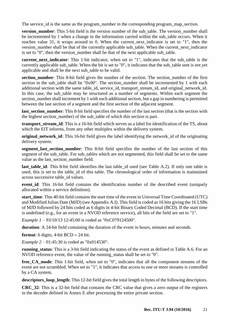
version_number: This 5-bit field is the version number of the sub_table. The version_number shall
be incremented by 1 when a change in the information carried within the sub_table occurs. When it
reaches value 31, it wraps around to 0. When the current_next_indicator is set to "1", then the
version_number shall be that of the currently applicable sub_table. When the current_next_indicator
is set to "0", then the version_number shall be that of the next applicable sub_table.
current_next_indicator: This 1-bit indicator, when set to "1", indicates that the sub_table is the
currently applicable sub_table. When the bit is set to "0", it indicates that the sub_table sent is not yet
applicable and shall be the next sub_table to be valid.
section_number: This 8-bit field gives the number of the section. The section_number of the first
section in the sub_table shall be "0x00". The section_number shall be incremented by 1 with each
additional section with the same table_id, service_id, transport_stream_id, and original_network_id.
In this case, the sub_table may be structured as a number of segments. Within each segment the
section_number shall increment by 1 with each additional section, but a gap in numbering is permitted
between the last section of a segment and the first section of the adjacent segment.
last_section_number: This 8-bit field specifies the number of the last section (that is the section with
the highest section_number) of the sub_table of which this section is part.
transport_stream_id: This is a 16-bit field which serves as a label for identification of the TS, about
which the EIT informs, from any other multiplex within the delivery system.
original_network_id: This 16-bit field gives the label identifying the network_id of the originating
delivery system.
segment_last_section_number: This 8-bit field specifies the number of the last section of this
segment of the sub_table. For sub_tables which are not segmented, this field shall be set to the same
value as the last_section_number field.
last_table_id: This 8-bit field identifies the last table_id used (see Table A.2). If only one table is
used, this is set to the table_id of this table. The chronological order of information is maintained
across successive table_id values.
event_id: This 16-bit field contains the identification number of the described event (uniquely
allocated within a service definition).
start_time: This 40-bit field contains the start time of the event in Universal Time Coordinated (UTC)
and Modified Julian Date (MJD) (see Appendix A.I). This field is coded as 16 bits giving the 16 LSBs
of MJD followed by 24 bits coded as 6 digits in 4-bit Binary Coded Decimal (BCD). If the start time
is undefined (e.g., for an event in a NVOD reference service), all bits of the field are set to "1".
Example 1 – 93/10/13 12:45:00 is coded as "0xC079124500".
duration: A 24-bit field containing the duration of the event in hours, minutes and seconds.
format: 6 digits, 4-bit BCD 24 bit.
Example 2 – 01:45:30 is coded as "0x014530".
running_status: This is a 3-bit field indicating the status of the event as defined in Table A.6. For an
NVOD reference event, the value of the running_status shall be set to "0".
free_CA_mode: This 1-bit field, when set to "0", indicates that all the component streams of the
event are not scrambled. When set to "1", it indicates that access to one or more streams is controlled
by a CA system.
descriptors_loop_length: This 12-bit field gives the total length in bytes of the following descriptors.
CRC_32: This is a 32-bit field that contains the CRC value that gives a zero output of the registers
in the decoder defined in Annex E after processing the entire private section.

22 Rec. ITU-T J.94 (10/2016)
A.5.2.5 Time and Date Table (TDT)
The TDT (see Table A.8) carries only the UTC-time and date information.
The TDT shall consist of a single section using the syntax of Table A.8. This TDT section shall be
transmitted in TS packets with a PID value of 0x0014, and the table_id shall take the value 0x70.
Table A.8 – Time and date section
Syntax No. of bits Identifier
time_date_section(){
table_id 8 uimsbf
section_syntax_indicator 1 bslbf
reserved_future_use 1 bslbf
reserved 2 bslbf
section_length 12 uimsbf
UTC_time 40 bslbf
}
Semantics for the time and date section
table_id: See Table A.2.
section_syntax_indicator: This is a one-bit indicator which shall be set to "0".
section_length: This is a 12-bit field, the first two bits of which shall be "00". It specifies the number
of bytes of the section, starting immediately following the section_length field and up to the end of
the section.
UTC_time: This 40-bit field contains the current time and date in UTC and MJD (see Appendix A.I).
This field is coded as 16 bits giving the 16 LSBs of MJD followed by 24 bits coded as 6 digits in
4-bit BCD.
Example – 93/10/13 12:45:00 is coded as "0xC079124500".
A.5.2.6 Time Offset Table (TOT)
The TOT (see Table A.9) carries the UTC-time and date information and local time offset. The TOT
shall consist of a single section using the syntax of Table A.9. This TOT section shall be transmitted
in TS packets with a PID value of 0x0014, and the table_id shall take the value 0x73.
Table A.9 – Time offset section
Syntax No. of bits Identifier
time_offset_section(){
table_id 8 uimsbf
section_syntax_indicator 1 bslbf
reserved_future_use 1 bslbf
reserved 2 bslbf
section_length 12 uimsbf
UTC_time 40 bslbf
reserved 4 bslbf
descriptors_loop_length 12 uimsbf

Rec. ITU-T J.94 (10/2016) 23
Table A.9 – Time offset section
Syntax No. of bits Identifier
for(i=0;i<N;i++){
descriptor()
}
CRC_32 32 rpchof
}
Semantics for the time offset section
table_id: See Table A.2.
section_syntax_indicator: This is a one-bit indicator which shall be set to "0".
section_length: This is a 12-bit field, the first two bits of which shall be "00". It specifies the number
of bytes of the section, starting immediately following the section_length field and up to the end of
the section.
UTC_time: This 40-bit field contains the current time and date in UTC and MJD (see Appendix A.I).
This field is coded as 16 bits giving the 16 LSBs of MJD followed by 24 bits coded as 6 digits in
4-bit BCD.
Example – 93/10/13 12:45:00 is coded as "0xC079124500".
descriptors_loop_length: This 12-bit field gives the total length in bytes of the following descriptors.
CRC_32: This is a 32-bit field that contains the CRC value that gives a zero output of the registers
in the decoder defined in Annex E after processing the entire private section.
A.5.2.7 Running Status Table (RST)
The RST (see Table A.10) allows accurate and rapid updating of the timing status of one or more
events. This may be necessary when an event starts early or late due to scheduling changes. The use
of a separate table enables fast updating mechanism to be achieved.
Table A.10 – Running status section
Syntax No. of bits Identifier
running_status_section(){
table_id 8 uimsbf
section_syntax_indicator 1 bslbf
reserved_future_use 1 bslbf
reserved 2 bslbf
section_length 12 uimsbf
for (i=0;i<N;i++){
transport_stream_id 16 uimsbf
original_network_id 16 uimsbf
service_id 16 uimsbf
event_id 16 uimsbf
reserved_future_use 5 bslbf
running_status 3 uimsbf
}
}

24 Rec. ITU-T J.94 (10/2016)
The RST shall be segmented into running_status_sections using the syntax of Table A.10. Any
sections forming part of an RST shall be transmitted in TS packets with a PID value of 0x0013, and
the table_id shall take the value 0x71.
Semantics for the running status section
table_id: See Table A.2.
section_syntax_indicator: This is a one-bit indicator which shall be set to "0".
section_length: This is a 12-bit field, the first two bits of which shall be "00". It specifies the number
of bytes of the section, starting immediately following the section_length field and up to the end of
the section. The section_length shall not exceed 1021 so that the entire section has a maximum length
of 1024 bytes.
transport_stream_id: This is a 16-bit field which serves as a label for identification of the TS, about
which the RST informs, from any other multiplex within the delivery system.
original_network_id: This 16-bit field gives the label identifying the network_id of the originating
delivery system.
service_id: This is a 16-bit field which serves as a label to identify this service from any other service
within the TS. The service_id is the same as the program_number in the corresponding
program_map_section.
event_id: This 16-bit field contains the identification number of the related event.
running_status: This is a 3-bit field indicating the status of the event, as defined in Table A.6.
A.5.2.8 Stuffing Table (ST)
The purpose of this section (see Table A.11) is to invalidate existing sections at a delivery system
boundary, e.g., at a cable head-end. When one section of a sub_table is overwritten, then all the
sections of that sub_table shall also be overwritten (stuffed) in order to retain the integrity of the
section_number field.
Table A.11 – Stuffing section
Syntax No. of bits Identifier
stuffing_section(){
table_id 8 uimsbf
section_syntax_indicator 1 bslbf
reserved_future_use 1 bslbf
reserved 2 bslbf
section_length 12 uimsbf
for (i=0;i<N;i++){
data_byte 8 uimsbf
}
}
Semantics for the stuffing section
table_id: See Table A.2.
section_syntax_indicator: This 1-bit field may take either the value "1" or "0".

Rec. ITU-T J.94 (10/2016) 25
section_length: This is a 12-bit field. It specifies the number of bytes of the section, starting
immediately following the section_length field and up to the end of the section. The section_length
shall not exceed 4093 so that the entire section has a maximum length of 4096 bytes.
data_byte: This 8-bit field may take any value and has no meaning.
A.5.2.9 Discontinuity Information Table (DIT)
See clause A.7.1.1
A.5.2.10 Selection Information Table (SIT)
See clause A.7.1.2
A.6 Descriptors
This subclause describes the different descriptors that can be used within the SI (for further
information, refer to [ETR 211] ).
A.6.1 Descriptor identification and location
Table A.12 lists the descriptors defined within this annex, giving the descriptors-tag values and the
intended placement within the SI tables. This does not imply that their use in other tables is restricted.
Table A.12 – Possible locations of descriptors
Descriptor Tag
value
NIT BAT SDT EIT TOT PMT SIT
(Note 1)
network_name_descriptor 0x40 * – – – – – –
service_list_descriptor 0x41 * * – – – – –
stuffing_descriptor 0x42 * * * * – – *
satellite_delivery_system_descriptor 0x43 * – – – – – –
cable_delivery_system_descriptor 0x44 * – – – – – –
Reserved for future use 0x45 – – – – – – –
Reserved for future use 0x46 – – – – – – –
bouquet_name_descriptor 0x47 – * * – – – *
service_descriptor 0x48 – – * – – – *
country_availability_descriptor 0x49 – * * – – – *
linkage_descriptor 0x4A * * * * – – *
NVOD_reference_descriptor 0x4B – – * – – – *
time_shifted_service_descriptor 0x4C – – * – – – *
short_event_descriptor 0x4D – – – * – – *
extended_event_descriptor 0x4E – – – * – – *
time_shifted_event_descriptor 0x4F – – – * – – *
component_descriptor 0x50 – – – * – – *
mosaic_descriptor 0x51 – – * – – * *
stream_identifier_descriptor 0x52 – – – – – * –
CA_identifier_descriptor 0x53 – * * * – – *
content_descriptor 0x54 – – – * – – *
parental_rating_descriptor 0x55 – – – * – – *
teletext_descriptor 0x56 – – – – – * –

26 Rec. ITU-T J.94 (10/2016)
Table A.12 – Possible locations of descriptors
Descriptor Tag
value
NIT BAT SDT EIT TOT PMT SIT
(Note 1)
telephone_descriptor 0x57 – – * * – – *
local_time_offset_descriptor 0x58 – – – – * – –
subtitling_descriptor 0x59 – – – – – * –
terrestrial_delivery_system_descriptor 0x5A * – – – – – –
multilingual_network_name_descriptor 0x5B * – – – – – –
multilingual_bouquet_name_descriptor 0x5C – * – – – – –
multilingual_service_name_descriptor 0x5D – – * – – – *
multilingual_component_descriptor 0x5E – – – * – – *
private_data_specifier_descriptor 0x5F * * * * – * *
service_move_descriptor 0x60 – – – – – * –
short_smoothing_buffer_descriptor 0x61 – – – * – – *
frequency_list_descriptor 0x62 * – – – – – –
partial_transport_stream_descriptor 0x63 – – – – – – *
data_broadcast_descriptor 0x64 – – * * – – *
CA_system_descriptor (Note 2) 0x65 – – – – – * –
data_broadcast_id_descriptor 0x66 – – – – – * –
Reserved for future use 0x67 to
0x7F
User-defined 0x80 to
0xFE
Forbidden 0xFF
* Possible location.
NOTE 1 – Only found in Partial Transport Streams.
NOTE 2 – Reserved for DAVIC/DVB use: DAVIC shall define its use.
A.6.2 Descriptor coding
When the construct "descriptor ()" appears in the subclauses of clause A.5.2, this indicates that zero
or more of the descriptors defined within this subclause shall occur.
The following semantics apply to all the descriptors defined in this clause.
descriptor_tag: The descriptor tag is an 8-bit field which identifies each descriptor. Those values
with MPEG-2 normative meaning are described in [ITU-T H.222.0]. The values of descriptor_tag are
defined in Table A.12.
descriptor_length: The descriptor length is an 8-bit field specifying the total number of bytes of the
data portion of the descriptor following the byte defining the value of this field.
A.6.2.1 Bouquet name descriptor
The bouquet name descriptor provides the bouquet name in text form, see Table A.13.

Rec. ITU-T J.94 (10/2016) 27
Table A.13 – Bouquet name descriptor
Syntax No. of bits Identifier
bouquet_name_descriptor(){
descriptor_tag 8 uimsbf
descriptor_length 8 uimsbf
for(i=0;i<N;i++){
char 8 uimsbf
}
}
Semantics for the bouquet name descriptor
char: This is an 8-bit field, a sequence of which conveys the name of the bouquet about which the
BAT sub_table informs. Text information is coded using the character sets and methods described in
Annex D.
A.6.2.2 CA identifier descriptor
The CA identifier descriptor (see Table A.14) indicates whether a particular bouquet, service or event
is associated with a conditional access system and identifies the CA system type by means of the
CA_system_id.
Table A.14 – CA identifier descriptor
Syntax No. of bits Identifier
CA_identifier_descriptor(){
descriptor_tag 8 uimsbf
descriptor_length 8 uimsbf
for (i=0;i<N;i++){
CA_system_id 16 uimsbf
}
}
Semantics for the CA identifier descriptor
CA_system_id: This 16-bit field identifies the CA system. Allocations of the value of this field are
found in [ETR 162] .
A.6.2.3 Component descriptor
The component descriptor identifies the type of component stream and may be used to provide a text
description of the elementary stream (see Table A.15).
Table A.15 – Component descriptor
Syntax No. of bits Identifier
component_descriptor(){
descriptor_tag 8 uimsbf
descriptor_length 8 uimsbf
reserved_future_use 4 bslbf
stream_content 4 uimsbf

28 Rec. ITU-T J.94 (10/2016)
Table A.15 – Component descriptor
Syntax No. of bits Identifier
component_type 8 uimsbf
component_tag 8 uimsbf
ISO_639_language_code 24 bslbf
for (i=0;i<N;i++){
text_char 8 uimsbf
}
}
Semantics for the component descriptor
stream_content: This 4-bit field specifies the type (video, audio, or EBU-data) of stream. The coding
of this field is specified in Table A.16.
component_type: This 8-bit field specifies the type of the video, audio or EBU-data component. The
coding of this field is specified in Table A.16.
component_tag: This 8-bit field has the same value as the component_tag field in the stream
identifier descriptor (if present in the PSI program map section) for the component stream.
ISO_639_language_code: This 24-bit field identifies the language of the component (in the case of
audio or EBU-data) and of the text description which may be contained in this descriptor.
The ISO_639_language_code contains a 3-character code as specified by [ISO 639] .
Both ISO 639-2/B and ISO 639-2/T may be used.
Each character is coded into 8 bits according to [ISO 8859] and inserted in order into the 24-bit field.
Example – French has 3-character code "fre", which is coded as:
'0110 0110 0111 0010 0110 0101'.
text_char: This is an 8-bit field. A string of "text_char" fields specify a text description of the
component stream.
Text information is coded using the character sets and methods described in Annex D.
Table A.16 – stream_content and component_type
stream_content component_type Description
0x00 0x00 to 0xFF Reserved for future use
0x01 0x00 Reserved for future use
0x01 0x01 Video, 4:3 aspect ratio
0x01 0x02 Video, 16:9 aspect ratio with pan vectors
0x01 0x03 Video, 16:9 aspect ratio without pan vectors
0x01 0x04 Video, 16:9 aspect ratio
0x01 0x05 to 0xFF Reserved for future use
0x02 0x00 Reserved for future use
0x02 0x01 Audio, single mono channel
0x02 0x02 Audio, dual mono channel
0x02 0x03 Audio, stereo (2 channel)
0x02 0x04 Audio, multilingual, multichannel

Rec. ITU-T J.94 (10/2016) 29
Table A.16 – stream_content and component_type
stream_content component_type Description
0x02 0x05 Audio, surround sound
0x02 0x06 to 0x3F Reserved for future use
0x02 0x40 Audio description for the visually impaired
0x02 0x41 Audio for the hard of hearing
0x02 0x42 to 0xAF Reserved for future use
0x02 0xB0 to 0xFE User-defined
0x02 0xFF Reserved for future use
0x03 0x00 Reserved for future use
0x03 0x01 EBU Teletext subtitles
0x03 0x02 Associated EBU Teletext
0x03 0x03 to 0x0F Reserved for future use
0x03 0x10 DVB subtitles (normal) with no monitor aspect ratio criticality
0x03 0x11 DVB subtitles (normal) for display on 4:3 aspect ratio monitor
0x03 0x12 DVB subtitles (normal) for display on 16:9 aspect ratio
monitor 0x03 0x13 DVB subtitles (normal) for display on 2.21:1 aspect ratio
monitor 0x03 0x14 to 0x1F Reserved for future use
0x03 0x20 DVB subtitles (for the hard of hearing) with no monitor aspect
ratio criticality 0x03 0x21 DVB subtitles (for the hard of hearing) for display on 4:3
aspect ratio monitor 0x03 0x22 DVB subtitles (for the hard of hearing) for display on 16:9
aspect ratio monitor 0x03 0x23 DVB subtitles (for the hard of hearing) for display on 2.21:1
aspect ratio monitor 0x03 0x24 to 0xFF Reserved for future use
0x04 to 0x0B 0x00 to 0xFF Reserved for future use
0x0C to 0x0F 0x00 to 0xFF User-defined
A.6.2.4 Content descriptor
The intention of the content descriptor (see Table A.17) is to provide classification information for
an event.
Table A.17 – Content descriptor
Syntax No. of bits Identifier
content_descriptor(){
descriptor_tag 8 uimsbf
descriptor_length 8 uimsbf
for (i=0;i<N;i++) {
content_nibble_level_1 4 uimsbf
content_nibble_level_2 4 uimsbf
user_nibble 4 uimsbf
user_nibble 4 uimsbf
}
}

30 Rec. ITU-T J.94 (10/2016)
Semantics of the content descriptor
content_nibble_level_1: This 4-bit field represents the first level of a content identifier. This field
shall be coded according to Table A.18.
content_nibble_level_2: This 4-bit field represents the second level of a content identifier. This field
shall be coded according to Table A.18.
user_nibble: This 4-bit field is defined by the broadcaster.
Table A.18 – content_nibble level 1 and 2 assignments
content_nibble_level_1 content_nibble_level_2 Description
0x0 0x0 to 0xF Undefined content
Movie/Drama
0x1 0x0 Movie/drama (general)
0x1 0x1 Detective/thriller
0x1 0x2 Adventure/western/war
0x1 0x3 Science fiction/fantasy/horror
0x1 0x4 Comedy
0x1 0x5 Soap/melodrama/folkloric
0x1 0x6 Romance
0x1 0x7 Serious/classical/religious/historical movie/drama
0x1 0x8 Adult movie/drama
0x1 0x9 to 0xE Reserved for future use
0x1 0xF User-defined
News/Current affairs
0x2 0x0 News/current affairs (general)
0x2 0x1 News/weather report
0x2 0x2 News magazine
0x2 0x3 Documentary
0x2 0x4 Discussion/interview/debate
0x2 0x5 to 0xE Reserved for future use
0x2 0xF User-defined
Show/Game show
0x3 0x0 Show/game show (general)
0x3 0x1 Game show/quiz/contest
0x3 0x2 Variety show
0x3 0x3 Talk show
0x3 0x4 to 0xE Reserved for future use
0x3 0xF User-defined

Rec. ITU-T J.94 (10/2016) 31
Table A.18 – content_nibble level 1 and 2 assignments
content_nibble_level_1 content_nibble_level_2 Description
Sports
0x4 0x0 Sports (general)
0x4 0x1 Special events (Olympic Games, World Cup etc.)
0x4 0x2 Sports magazines
0x4 0x3 Football/soccer
0x4 0x4 Tennis/squash
0x4 0x5 Team sports (excluding football)
0x4 0x6 Athletics
0x4 0x7 Motor sport
0x4 0x8 Water sport
0x4 0x9 Winter sports
0x4 0xA Equestrian
0x4 0xB Martial sports
0x4 0xC to 0xE Reserved for future use
0x4 0xF User-defined
Children’s/Youth programmes
0x5 0x0 Children’s/youth programmes (general)
0x5 0x1 Pre-school children’s programmes
0x5 0x2 Entertainment programmes for 6 to14
0x5 0x3 Entertainment programmes for 10 to 16
0x5 0x4 Informational/educational/school programmes
0x5 0x5 Cartoons/puppets
0x5 0x6 to 0xE Reserved for future use
0x5 0xF User-defined
Music/Ballet/Dance
0x6 0x0 Music/ballet/dance (general)
0x6 0x1 Rock/pop
0x6 0x2 Serious music/classical music
0x6 0x3 Folk/traditional music
0x6 0x4 Jazz
0x6 0x5 Musical/opera
0x6 0x6 Ballet
0x6 0x7 to 0xE Reserved for future use
0x6 0xF User-defined

32 Rec. ITU-T J.94 (10/2016)
Table A.18 – content_nibble level 1 and 2 assignments
content_nibble_level_1 content_nibble_level_2 Description
Arts/Culture (without music)
0x7 0x0 Arts/culture (without music, general)
0x7 0x1 Performing arts
0x7 0x2 Fine arts
0x7 0x3 Religion
0x7 0x4 Popular culture/traditional arts
0x7 0x5 Literature
0x7 0x6 Film/cinema
0x7 0x7 Experimental film/video
0x7 0x8 Broadcasting/press
0x7 0x9 New media
0x7 0xA Arts/culture magazines
0x7 0xB Fashion
0x7 0xC to 0xE Reserved for future use
0x7 0xF User-defined
Social/Political issues/Economics
0x8 0x0 Social/political issues/economics (general)
0x8 0x1 Magazines/reports/documentary
0x8 0x2 Economics/social advisory
0x8 0x3 Remarkable people
0x8 0x4 to 0xE Reserved for future use
0x8 0xF User-defined
Education/ Science/Factual topics
0x9 0x0 Education/science/factual topics (general)
0x9 0x1 Nature/animals/environment
0x9 0x2 Technology/natural sciences
0x9 0x3 Medicine/physiology/psychology
0x9 0x4 Foreign countries/expeditions
0x9 0x5 Social/spiritual sciences
0x9 0x6 Further education
0x9 0x7 Languages
0x9 0x8 to 0xE Reserved for future use
0x9 0xF User-defined
Leisure hobbies
0xA 0x0 Leisure hobbies (general)
0xA 0x1 Tourism/travel

Rec. ITU-T J.94 (10/2016) 33
Table A.18 – content_nibble level 1 and 2 assignments
content_nibble_level_1 content_nibble_level_2 Description
0xA 0x2 Handicraft
0xA 0x3 Motoring
0xA 0x4 Fitness & health
0xA 0x5 Cooking
0xA 0x6 Advertisement/shopping
0xA 0x7 Gardening
0xA 0x8 to 0xE Reserved for future use
0xA 0xF User-defined
Special Characteristics
0xB 0x0 Original language
0xB 0x1 Black & white
0xB 0x2 Unpublished
0xB 0x3 Live broadcast
0xB 0x4 to 0xE Reserved for future use
0xB 0xF User-defined
0xC to 0xE 0x0 to 0xF Reserved for future use
0xF 0x0 to 0xF User-defined
A.6.2.5 Country availability descriptor
In order to identify various combinations of countries efficiently, the descriptor may appear twice for
each service, once giving a list of countries and/or groups of countries where the service is intended
to be available, and the second giving a list of countries and/or groups where it is not. The latter list
overrides the former list. If only one descriptor is used, which lists countries where the service is
intended to be available, then it indicates that the service is not intended to be available in any other
country. If only one descriptor is used, which lists countries where the service is not intended to be
available, then it indicates that the service is intended to be available in every other country. If no
descriptor is used, then it is not defined for which countries the service is intended to be available
(see Table A.19).
Table A.19 – Country availability descriptor
Syntax No. of bits Identifier
country_availability_descriptor(){
descriptor_tag 8 uimsbf
descriptor_length 8 uimsbf
country_availability_flag 1 bslbf
reserved_future_use 7 bslbf
for (i=0;i<N;i++){
country_code 24 bslbf
}
}

34 Rec. ITU-T J.94 (10/2016)
Semantics for the country availability descriptor
country_availability_flag: This 1-bit field indicates whether the following country codes represent
the countries in which the reception of the service is intended or not. If country_availability_flag is
set to "1", the following country codes specify the countries in which the reception of the service is
intended. If set to "0", the following country codes specify the countries in which the reception of the
service is not intended.
country_code: This 24-bit field identifies a country using the 3-character code as specified in
[ISO 3166] .
Each character is coded into 8-bits according to [ISO 8859] and inserted in order into the 24-bit field.
In the case that the 3 characters represent a number in the range 900 to 999, then country_code
specifies an ETSI defined group of countries. These allocations are found in [ETR 162].
Example – United Kingdom has 3-character code "GBR", which is coded as:
'0100 0111 0100 0010 0101 0010'.
A.6.2.6 Data broadcast descriptor
The data broadcast descriptor identifies the type of the data component and may be used to provide a
text description of the data component (see Table A.20).
Table A.20 – Data broadcast descriptor
Syntax No. of bits Identifier
data_broadcast_descriptor(){
descriptor_tag 8 uimsbf
descriptor_length 8 uimsbf
data_broadcast_id 16 uimsbf
component_tag 8 uimsbf
selector_length 8 uimsbf
for (i=0; i<selector_length; i++){
selector_byte 8 uimsbf
}
ISO_639_language_code 24 bslbf
text_length 8 uimsbf
for (i=0; i<text_length; i++){
text_char 8 uimsbf
}
}
Semantics of the data broadcast descriptor
data_broadcast_id: This 16-bit field identifies the data broadcast specification that is used to
broadcast the data in the broadcast network. Allocations of the value of this field are found in
[ETR 162] .
component_tag: This optional 8-bit field has the same value as the component_tag field in the stream
identifier descriptor that may be present in the PSI program map section for the stream on which the
data are broadcasted.
If this field is not used, it shall be set to the value 0x00.

Rec. ITU-T J.94 (10/2016) 35
selector_length: This 8-bit field specifies the length in bytes of the following selector field.
selector_byte: This is an 8-bit field. The sequence of selector_byte fields specifies the selector field.
The syntax and semantics of the selector field shall be defined by the data broadcast specification that
is identified in the data_broadcast_id field. The selector field may contain service specific information
that is necessary to identify an entry-point of the broadcast data.
ISO_639_language_code: This 24-bit field contains the [ISO 639] three-character language code of
the following text fields. Both ISO 639-2/B and ISO 639-2/T may be used. Each character is coded
into 8 bits according to [ISO 8859] and inserted in order into the 24-bit field.
text_length: This 8-bit field specifies the length in bytes of the following text describing the data
component.
text_char: This is an 8-bit field. A string of "char" fields specify the text description of the data
component.
Text information is coded using the character sets and methods described in Annex D.
A.6.2.7 Data broadcast id descriptor
The data broadcast id descriptor identifies the type of the data component (see Table A.21). It is a
short form of the broadcast descriptor and it may be placed in the component loop of the PSI PMT
table.
Table A.21 – Data broadcast id descriptor
Syntax No. of bits Identifier
data_broadcast_id_descriptor(){
descriptor_tag 8 uimsbf
descriptor_length 8 uimsbf
data_broadcast_id 16 uimsbf
}
Semantics of the data broadcast id descriptor
data_broadcast_id: This 16-bit field identifies the data broadcast specification that is used to
broadcast the data in the broadcast network. Allocations of the value of this field are found in
[ETR 162] .
A.6.2.8 Delivery system descriptors
The delivery system descriptors all have the same overall length of 13 bytes. This facilitates the
interchange of these descriptors when a TS is transcoded from one delivery system to another, e.g.,
satellite to cable.
A.6.2.8.1 Cable delivery system descriptor
See Table A.22.

36 Rec. ITU-T J.94 (10/2016)
Table A.22 – Cable delivery system descriptor
Syntax No. of bits Identifier
cable_delivery_system_descriptor(){
descriptor_tag 8 uimsbf
descriptor_length 8 uimsbf
frequency 32 bslbf
reserved_future_use 12 bslbf
FEC_outer 4 bslbf
modulation 8 bslbf
symbol_rate 28 bslbf
FEC_inner 4 bslbf
}
Semantics for cable delivery system descriptor
frequency: The frequency is a 32-bit field giving the 4-bit BCD values specifying 8 characters of the
frequency value. For the cable_delivery_system_descriptor, the frequency is coded in MHz, where
the decimal occurs after the fourth character (e.g., 0312.0000 MHz).
FEC_outer: The FEC_outer is a 4-bit field specifying the outer Forward Error Correction (FEC)
scheme used according to Table A.23.
Table A.23 – Outer FEC scheme
FEC_outer bit 3210 Description
0000 Not defined
0001 No outer FEC coding
0010 RS(204/188)
0011 to 1111 Reserved for future use
modulation: This is an 8-bit field. It specifies the modulation scheme used on a cable delivery system
according to Table A.24.
Table A.24 – Modulation scheme for cable
Modulation
(hex)
Description
0x00 Not defined
0x01 16-QAM
0x02 32-QAM
0x03 64-QAM
0x04 128-QAM
0x05 256-QAM
0x06 to 0xFF Reserved for future use
symbol_rate: The symbol_rate is a 28-bit field giving the 4-bit BCD values specifying 7 characters
of the symbol_rate in Msymbol/s where the decimal point occurs after the third character
(e.g., 027.4500).

Rec. ITU-T J.94 (10/2016) 37
FEC_inner: The FEC_inner is a 4-bit field specifying the inner FEC scheme used according to
Table A.25.
Table A.25 – Inner FEC scheme
FEC_inner bit 3210 Description
0000 Not defined
0001 1/2 conv. code rate
0010 2/3 conv. code rate
0011 3/4 conv. code rate
0100 5/6 conv. code rate
0101 7/8 conv. code rate
1111 No conv. Coding
0110 to 1110 Reserved for future use
A.6.2.8.2 Satellite delivery system descriptor
See Table A.26.
Table A.26 – Satellite delivery system descriptor
Syntax No. of bits Identifier
satellite_delivery_system_descriptor(){
descriptor_tag 8 uimsbf
descriptor_length 8 uimsbf
frequency 32 bslbf
orbital_position 16 bslbf
west_east_flag 1 bslbf
polarization 2 bslbf
modulation 5 bslbf
symbol_rate 28 bslbf
FEC_inner 4 bslbf
}
Semantics for satellite delivery system descriptor
frequency: The frequency is a 32-bit field giving the 4-bit BCD values specifying 8 characters of the
frequency value. For the satellite_delivery_system_descriptor the frequency is coded in GHz, where
the decimal point occurs after the third character (e.g., 011.75725 GHz).
orbital_position: The orbital_position is a 16-bit field giving the 4-bit BCD values specifying
4 characters of the orbital position in degrees where the decimal point occurs after the third character
(e.g., 019.2 degrees).
west_east_flag: The west_east_flag is a 1-bit field indicating if the satellite position is in the western
or eastern part of the orbit. A value "0" indicates the western position and a value "1" indicates the
eastern position.
polarization: The polarization is a 2-bit field specifying the polarization of the transmitted signal.
The first bit defines whether the polarization is linear or circular (see Table A.27).

38 Rec. ITU-T J.94 (10/2016)
Table A.27 – Polarization
polarization Description
00 Linear – horizontal
01 Linear – vertical
10 Circular – left
11 Circular – right
modulation: This is a 5-bit field. It specifies the modulation scheme used on a satellite delivery
system according to Table A.28.
Table A.28 – Modulation scheme for satellite
Modulation bit 4 3210 Description
0 0000 Not defined
0 0001 QPSK
0 0010 to 1 1111 Reserved for future use
symbol_rate: The symbol_rate is a 28-bit field giving the 4-bit BCD values specifying 7 characters
of the symbol_rate in Msymbol/s where the decimal point occurs after the third character
(e.g., 027.4500).
FEC_inner: The FEC_inner is a 4-bit field specifying the inner FEC scheme used according to
Table A.25.
A.6.2.8.3 Terrestrial delivery system descriptor
See Table A.29.
Table A.29 – Terrestrial delivery system descriptor
Syntax No. of bits Identifier
terrestrial_delivery_system_descriptor(){
descriptor_tag 8 uimsbf
descriptor_length 8 uimsbf
centre_frequency 32 bslbf
bandwidth 3 bslbf
reserved_future_use 5 bslbf
constellation 2 bslbf
hierarchy_information 3 bslbf
code_rate-HP_stream 3 bslbf
code_rate-LP_stream 3 bslbf
guard_interval 2 bslbf
transmission_mode 2 bslbf
other_frequency_flag 1 bslbf
reserved_future_use 32 bslbf
}

Rec. ITU-T J.94 (10/2016) 39
Semantics for terrestrial delivery system descriptor
centre_frequency: The centre_frequency is a 32-bit uimsbf field giving the binary coded frequency
value in multiples of 10 Hz. The coding range is from minimum 10 Hz (0x00000001) up to a
maximum of 42 949 672 950 Hz (0xFFFFFFFF).
bandwidth: This is a 3-bit field specifying what is the bandwidth in use. See Table A.30.
Table A.30 – Signalling format for the bandwidth
bandwidth Bandwidth value
000 8 MHz
001 7 MHz
010 to 111 Reserved for future use
constellation: This is a 2-bit field. It specifies the constellation pattern used on a terrestrial delivery
system according to Table A.31.
Table A.31 – Signalling format for the possible constellation patterns
constellation Constellation characteristics
00 QPSK
01 16-QAM
10 64-QAM
11 Reserved for future use
hierarchy_information: The hierarchy_information specifies whether the transmission is
hierarchical and, if so, what the value is. See Table A.32.
Table A.32 – Signalling format for the values
hierarchy_information value
000 Non-hierarchical
001 1
010 2
011 4
100 to 111 Reserved for future use
code_rate: The code_rate is a 3-bit field specifying the inner FEC scheme used according
to Table A.33. Non-hierarchical channel coding and modulation requires signalling of one code rate.
In this case, 3 bits specifying code_rate according to Table A.34 are followed by another 3 bits of
value '000'. Two different code rates may be applied to two different levels of modulation with the
aim of achieving hierarchy. Transmission then starts with the code rate for the HP level of the
modulation and ends with the one for the LP level.

40 Rec. ITU-T J.94 (10/2016)
Table A.33 – Signalling format for each of the code rates
code_rate Description
000 1/2
001 2/3
010 3/4
011 5/6
100 7/8
101 to 111 Reserved for future use
guard_interval: The guard_interval is a 2-bit field specifying the guard interval values.
See Table A.34.
Table A.34 – Signalling format for each of the guard interval values
guard_interval Guard interval values
00 1/32
01 1/16
10 1/8
11 1/4
transmission_mode: This 2-bit field indicates the number of carriers in an OFDM frame.
See Table A.35.
Table A.35 – Signalling format for transmission mode
transmission_mode Description
00 2k mode
01 8k mode
10 to 11 Reserved for future use
other_frequency_flag: This 1-bit flag indicates whether other frequencies are in use:
– 0: no other frequency in use.
– 1: one or more other frequencies in use.
A.6.2.9 Extended event descriptor
The extended event descriptor provides a detailed text description of an event, which may be used in
addition to the short event descriptor. More than one extended event descriptor can be associated to
allow information about one event greater in length than 256 bytes to be conveyed. Text information
can be structured into two columns, one giving an item description field and the other the item text.
A typical application for this structure is to give a cast list, where for example the item description
field might be "Producer" and the item field would give the name of the producer. See Table A.36.

Rec. ITU-T J.94 (10/2016) 41
Table A.36 – Extended event descriptor
Syntax No. of bits Identifier
extended_event_descriptor(){
descriptor_tag 8 uimsbf
descriptor_length 8 uimsbf
descriptor_number 4 uimsbf
last_descriptor_number 4 uimsbf
ISO_639_language_code 24 bslbf
length_of_items 8 uimsbf
for ( i=0;i<N;i++){
item_description_length 8 uimsbf
for (j=0;j<N;j++){
item_description_char 8 uimsbf
}
item_length 8 uimsbf
for (j=0;j<N;j++){
item_char 8 uimsbf
}
}
text_length 8 uimsbf
for (i=0;i<N;i++){
text_char 8 uimsbf
}
}
Semantics for the extended event descriptor
descriptor_number: This 4-bit field gives the number of the descriptor. It is used to associate
information which cannot be fitted into a single descriptor. The descriptor_number of the first
extended_event_descriptor of an associated set of extended_event_descriptors shall be "0x00". The
descriptor_number shall be incremented by 1 with each additional extended_event_descriptor in this
section.
last_descriptor_number: This 4-bit field specifies the number of the last extended_event_descriptor
(that is, the descriptor with the highest value of descriptor_number) of the associated set of descriptors
of which this descriptor is part.
ISO_639_language_code: This 24-bit field identifies the language of the following text fields.
The ISO_639_language_code contains a 3-character code as specified by [ISO 639].
Both ISO 639-2/B and ISO 639-2/T may be used. Each character is coded into 8 bits according to
[ISO 8859] and inserted in order into the 24-bit field.
Example – French has 3-character code "fre", which is coded as:
'0110 0110 0111 0010 0110 0101'.
length_of_items: This is an 8-bit field specifying the length in bytes of the following items.
item_description_length: This 8-bit field specifies the length in bytes of the item description.
item_description_char: This is an 8-bit field. A string of "item_description_char" fields specify the
item description. Text information is coded using the character sets and methods described in
Annex D.

42 Rec. ITU-T J.94 (10/2016)
item_length: This 8-bit field specifies the length in bytes of the item text.
item_char: This is an 8-bit field. A string of "item_char" fields specify the item text. Text information
is coded using the character sets and methods described in Annex D.
text_length: This 8-bit field specifies the length in bytes of the non-itemized extended text.
text_char: This is an 8-bit field. A string of "text_char" fields specify the non-itemized extended text.
Text information is coded using the character sets and methods described in Annex D.
A.6.2.10 Frequency list descriptor
The frequency list descriptor may be used in the NIT. It gives the complete list of additional
frequencies for a certain multiplex which is transmitted on multiple frequencies. See Table A.37.
Table A.37 – Frequency list descriptor
Syntax No. of bits Identifier
frequency_list_descriptor(){
descriptor_tag 8 uimsbf
descriptor_length 8 uimsbf
reserved_future_use 6 bslbf
coding_type 2 bslbf
for (i=0;i<N;i++){
centre_frequency 32 uimsbf
}
}
Semantics for the frequency list descriptor
coding_type: This is a 2-bit field that indicates how the frequency is coded and relates to the delivery
system used. It has a value indicated in Table A.38.
Table A.38 – Coding type values
coding_type Delivery system
00 Not defined
01 Satellite
10 Cable
11 Terrestrial
centre_frequency: This is as defined in the delivery_system_descriptor for the delivery system given
by the coding_type.
A.6.2.11 Linkage descriptor
The linkage descriptor (see Table A.39) identifies a service that can be presented if the consumer
requests for additional information related to a specific entity described by the SI system. The location
of the linkage descriptor in the syntax indicates the entity for which additional information is
available. For example a linkage descriptor located within the NIT shall point to a service providing
additional information on the network, a linkage descriptor in the BAT shall provide a link to a service
informing about the bouquet, etc.
A CA replacement service can be identified using the linkage descriptor. This service may be selected
automatically by the IRD if the CA denies access to the specific entity described by the SI system.

Rec. ITU-T J.94 (10/2016) 43
A service replacement service can also be identified using the linkage_descriptor. This replacement
service may be selected automatically by the IRD when the running status of the current service is set
to "not_running".
Table A.39 – Linkage descriptor
Syntax No. of bits Identifier
linkage_descriptor(){
descriptor_tag 8 uimsbf
descriptor_length 8 uimsbf
transport_stream_id 16 uimsbf
original_network_id 16 uimsbf
service_id 16 uimsbf
linkage_type 8 uimsbf
for (i=0;i<N;i++){
private_data_byte 8 bslbf
}
}
Semantics for the linkage descriptor
transport_stream_id: This is a 16-bit field which identifies the TS containing the information
service indicated.
original_network_id: This 16-bit field gives the label identifying the network_id of the originating
delivery system of the information service indicated.
service_id: This is a 16-bit field which uniquely identifies an information service within a TS. The
service_id is the same as the program_number in the corresponding program_map_section. If the
linkage_type field has the value 0x04, then the service_id field is not relevant, and shall be set
to 0x0000.
linkage_type: This is an 8-bit field specifying the type of linkage e.g., to information (see Table A.40).
Table A.40 – Linkage type coding
linkage_type Description
0x00 Reserved for future use
0x01 Information service
0x02 EPG service
0x03 CA replacement service
0x04 TS containing complete Network/Bouquet SI
0x05 Service replacement service
0x06 Data broadcast service
0x07 to 0x7F Reserved for future use
0x80 to 0xFE User-defined
0xFF Reserved for future use
private_data_byte: This is an 8-bit field, the value of which is privately defined.

44 Rec. ITU-T J.94 (10/2016)
A.6.2.12 Local time offset descriptor
The local time offset descriptor (see Table A.41) may be used in the TOT to describe country specific
dynamic changes of the local time offset relative to UTC.
Table A.41 – Local time offset descriptor
Syntax No. of bits Identifier
local_time_offset_descriptor(){
descriptor_tag 8 uimsbf
descriptor_length 8 uimsbf
for(i=0;i<N;i++){
country_code 24 bslbf
country_region_id 6 bslbf
reserved 1 bslbf
local_time_offset_polarity 1 bslbf
local_time_offset 16 bslbf
time_of _change 40 bslbf
next_time_offset 16 bslbf
}
}
Semantics for the local time offset descriptor
country_code: This 24-bit field identifies a country using the 3-character code as specified in
[ISO 3166].
Each character is coded into 8 bits according to [ISO 8859] and inserted in order into the 24-bit field.
In the case where the 3 characters represent a number in the range of 900 to 999, then country_code
specifies an ETSI defined group of countries. These allocations are in [ETR 162]. Country codes for
groups of countries shall be limited to those within a single time zone.
Example – United Kingdom has 3-character code "GBR", which is coded as:
'0100 0111 0100 0010 0101 0010'.
country_region_id: This 6-bit field identifies a zone in the country which is indicated by
country_code.
This is set to "000000" when there are no different local time zones in the country. See Table A.42.
Table A.42 – Coding of country_region_id
country_region_id Description
00 0000 No time zone extension used
00 0001 Time zone 1 (most easterly region)
00 0010 Time zone 2
........ ....
11 1100 Time zone 60 (most westerly region)
11 1101 – 11 1111 Reserved

Rec. ITU-T J.94 (10/2016) 45
local_time_offset_polarity: This 1-bit information indicates the polarity of the following
local_offset_time.
If this bit is set to "0", the polarity is positive and the local time is advanced to UTC. (Usually east
direction from Greenwich.) If this bit is set to "1", the polarity is negative and the local time is
behind UTC.
local_time_offset: This 16-bit field contains the current offset time from UTC in the range
between −12 hours and +12 hours at the area which is indicated by the combination of country_code
and country_region_id in advance.
These 16 bits are coded as 4 digits in 4-bit BCD in the order hour tens, hour, minute tens and minutes.
time_of_change: This is a 40-bit field which specifies the date and time in MJD and UTC
(see Appendix A.I) when the time change takes place. This 40-bit field is coded as 16 bits giving
the 16 LSBs of MJD followed by 24 bits coded as 6 digits in the 4-bit BCD.
next_time_offset: This 16-bit field contains the next offset time after the change from UTC in the
range between −12hours and +12hours at the area which is indicated by the combination of
country_code and country_region_id in advance. These 16 bits are coded as 4 digits in 4-bit BCD in
the order hour tens, hour, minute tens and minutes.
A.6.2.13 Mosaic descriptor
A mosaic component is a collection of different video images to form a coded video component. The
information is organized so that each specific information when displayed appears on a small area of
a screen.
The mosaic descriptor gives a partitioning of a digital video component into elementary cells, the
allocation of elementary cells to logical cells, and gives a link between the content of the logical cell
and the corresponding information (e.g., bouquet, service, event, etc.), see Table A.43.
Table A.43 – Mosaic descriptor
Syntax No. of bits Identifier
mosaic_descriptor(){
descriptor_tag 8 uimsbf
descriptor_length 8 uimsbf
mosaic_entry_point 1 bslbf
number_of_horizontal_elementary_cells 3 uimsbf
reserved_future_use 1 bslbf
number_of_vertical_elementary_cells 3 uimsbf
for (i=0;i<N; i++) {
logical_cell_id 6 uimsbf
reserved_future_use 7 bslbf
logical_cell_presentation_info 3 uimsbf
elementary_cell_field_length 8 uimsbf
for (i=0;i<elementary_cell_field_length;i++) {
reserved_future_use 2 bslbf
elementary_cell_id 6 uimsbf
}
cell_linkage_info 8 uimsbf

46 Rec. ITU-T J.94 (10/2016)
Table A.43 – Mosaic descriptor
Syntax No. of bits Identifier
If (cell_linkage_info ==0x01){
bouquet_id 16 uimsbf
}
If (cell_linkage_info ==0x02){
original_network_id 16 uimsbf
transport_stream_id 16 uimsbf
service_id 16 uimsbf
}
If (cell_linkage_info ==0x03){
original_network_id 16 uimsbf
transport_stream_id 16 uimsbf
service_id 16 uimsbf
}
If (cell_linkage_info ==0x04){
original_network_id 16 uimsbf
transport_stream_id 16 uimsbf
service_id 16 uimsbf
event_id 16 uimsbf
}
}
}
Semantics for the mosaic descriptor
mosaic_entry_point: This is a 1-bit field which, when set to a value of "1", indicates that the mosaic
is the highest mosaic in a hierarchy. A complete mosaic system could be organized in a tree structure,
the flag being set to identify the entry point in the tree.
number_of_horizontal_elementary_cells: This 3-bit field indicates the number of cells of
horizontal screen display, see Table A.44 for coding.
Table A.44 – Coding of horizontal_elementary_cells
Value Meaning
0x00 One cell
0x01 Two cells
0x02 Three cells
0x03 Four cells
0x04 Five cells
0x05 Six cells
0x06 Seven cells
0x07 Eight cells

Rec. ITU-T J.94 (10/2016) 47
number_of_vertical_elementary_cells: This 3-bit field indicates the number of cells of vertical
screen display, see Table A.45 for coding.
Table A.45 – Coding of vertical_elementary_cells
Value Meaning
0x00 One cell
0x01 Two cells
0x02 Three cells
0x03 Four cells
0x04 Five cells
0x05 Six cells
0x06 Seven cells
0x07 Eight cells
logical_cell_id: This 6-bit field is coded in binary form.
Different adjacent (see Figure A.2) elementary cells may be grouped together to form a logical cell.
A logical_cell_number is associated to such a group of adjacent elementary_cell_ids. The total
number of logical cells shall not exceed the number of elementary cells (maximum = 64). Each
elementary cell shall be allocated to one logical cell.
More than one elementary cell may belong to one logical cell.
Cells B, D, H, F are adjacent to cell E; C is not adjacent to A or D; D is not adjacent to H.
A B C
D E F
G H I
Figure A.2 – Adjacent cells
logical_cell_presentation_info: This 3-bit field identifies the type of presentation for a logical cell.
The logical_cell_presentation information allows an identification of presentation styles, which are
defined in Table A.46.
Table A.46 – Coding of logical_cell_presentation_info
Value Meaning
0x00 Undefined
0x01 Video
0x02 Still picture (Note)
0x03 Graphics/text
0x04 to 0x07 Reserved for future use
NOTE – Still picture: A coded still picture consists of a video sequence containing exactly one coded
picture which is intra-coded.
elementary_cell_field_length: The elementary_cell_field_length is an 8-bit field specifying the
number of bytes following this field up to and including the last elementary_cell_id in this
logical_cell_id loop.

48 Rec. ITU-T J.94 (10/2016)
elementary_cell_id: This 6-bit field indicates in binary form the number of the cell. The value of this
field is in the range 0 to N.
NOTE – The elementary cells are implicitly numbered from 0 to N. The value 0 is allocated to the cell of the
first row (top left corner). This number is incremented from left to right and from top to bottom in such a way
that the number N is allocated to the cell of the last position of the last row (bottom right corner).
cell_linkage_info: This 8-bit field identifies the type of information carried in a logical cell,
see Table A.47 for coding.
Table A.47 – Coding of cell_linkage_info
Value Meaning
0x00 Undefined
0x01 Bouquet related
0x02 Service related
0x03 Other mosaic related
0x04 Event related
0x05 to 0xFF Reserved for future use
bouquet_id: This is a 16-bit field which serves as a label to identify the bouquet described by the cell.
original_network_id: This 16-bit field is a label (see clause A.5.2) which in conjunction with the
following fields uniquely identifies a service, event or mosaic.
transport_stream_id: This is a 16-bit field which serves as a label identifying the TS which contains
the service, event or mosaic described by the cell.
service_id: This is a 16-bit field which identifies a service within a TS. The service_id is the same as
the program_number in the corresponding program_map_section.
The interpretation of this field is context sensitive, dependent on the value of cell_linkage_info:
– when cell_linkage_info "0x02", this is the service_id of the service described by the cell;
– when cell_linkage_info = "0x03", this is the service_id of the mosaic service described by
the cell;
– when cell_linkage_info = "0x04", this is the service_id of the service to which the event
described by the cell belongs.
event_id: This is a 16-bit field containing the identification number of the described event.
A.6.2.14 Multilingual bouquet name descriptor
The multilingual bouquet name descriptor (see Table A.48) provides the bouquet name in text form
in one or more languages.
Table A.48 – Multilingual bouquet name descriptor
Syntax No. of bits Identifier
multilingual_bouquet_name_descriptor(){
descriptor_tag 8 uimsbf
descriptor_length 8 uimsbf
for (i=0;i<N;i++) {
ISO_639_language_code 24 bslbf
bouquet_name_length 8 uimsbf

Rec. ITU-T J.94 (10/2016) 49
Table A.48 – Multilingual bouquet name descriptor
Syntax No. of bits Identifier
for (j=0;j<N;j++){
char 8 uimsbf
}
}
}
Semantics for the multilingual bouquet name descriptor
ISO_639_language_code: This 24-bit field contains the [ISO 639] three-character language code of
the language of the following bouquet name. Both ISO 639-2/B and ISO 639-2/T may be used.
Each character is coded into 8 bits according to [ISO 8859] and inserted in order into the 24-bit field.
Example – French has 3-character code "fre", which is coded as:
'0110 0110 0111 0010 0110 0101'.
bouquet_name_length: This 8-bit field specifies the length in bytes of the following bouquet name.
char: This is an 8-bit field. A string of char fields specify the name of the bouquet about which the
BAT sub-table informs in the language specified. Text information is coded using the character sets
and methods described in Annex D.
A.6.2.15 Multilingual component descriptor
The multilingual component descriptor (see Table A.49) provides a text description of a component
in one or more languages. The component is identified by its component tag value.
Table A.49 – Multilingual component descriptor
Syntax No. of bits Identifier
multilingual_component_descriptor(){
descriptor_tag 8 uimsbf
descriptor_length 8 uimsbf
component_tag 8 uimsbf
for (i=0;i<N;i++) {
ISO_639_language_code 24 bslbf
text_description_length 8 uimsbf
for (j=0;j<N;j++){
text_char 8 uimsbf
}
}
}
Semantics for the multilingual component descriptor
component_tag: This 8-bit field has the same value as the component_tag field in the stream
identifier descriptor (if present in the PSI program map section) for the component stream.

50 Rec. ITU-T J.94 (10/2016)
ISO_639_language_code: This 24-bit field identifies the language of the following text description
of the component. The ISO_639_language_code contains a 3-character code as specified by
[ISO 639]. Both ISO 639-2/B and ISO 639-2/T may be used. Each character is coded into 8 bits
according to [ISO 8859] and inserted in order into the 24-bit field.
Example – French has 3-character code "fre", which is coded as:
'0110 0110 0111 0010 0110 0101'.
text_description_length: This 8-bit field specifies the length in bytes of the following text
description.
text_char: This is an 8-bit field. A string of "text_char" fields specify a text description of the
component stream. Text information is coded using the character sets and methods described
in Annex D.
A.6.2.16 Multilingual network name descriptor
The multilingual network name descriptor (see Table A.50) provides the network name in text form
in one or more languages.
Table A.50 – Multilingual network name descriptor
Syntax No. of bits Identifier
multilingual_network_name_descriptor(){
descriptor_tag 8 uimsbf
descriptor_length 8 uimsbf
for (i=0;i<N;i++) {
ISO_639_language_code 24 bslbf
network_name_length 8 uimsbf
for (j=0;j<N;j++){
char 8 uimsbf
}
}
}
Semantics for the multilingual network name descriptor
ISO_639_language_code: This 24-bit field contains the [ISO 639] three-character language code of
the language of the following network name. Both ISO 639-2/B and ISO 639-2/T may be used. Each
character is coded into 8 bits according to [ISO 8859] and inserted in order into the 24-bit field.
Example – French has 3-character code "fre", which is coded as:
'0110 0110 0111 0010 0110 0101'.
network_name_length: This 8-bit field specifies the length in bytes of the following network name.
char: This is an 8-bit field. A string of char fields specify the name of the network about which the
NIT informs in the language specified. Text information is coded using the character sets and methods
described in Annex D.
A.6.2.17 Multilingual service name descriptor
The multilingual service name descriptor (see Table A.51) provides the names of the service provider
and service in text form in one or more languages.

Rec. ITU-T J.94 (10/2016) 51
Table A.51 – Multilingual service name descriptor
Syntax No. of bits Identifier
multilingual_service_name_descriptor(){
descriptor_tag 8 uimsbf
descriptor_length 8 uimsbf
for (i=0;i<N;i++) {
ISO_639_language_code 24 bslbf
service_provider_name_length 8 uimsbf
for (j=0;j<N;j++){
char 8 uimsbf
}
service_name_length 8 uimsbf
for (j=0;j<N;j++){
char 8 uimsbf
}
}
}
Semantics for the multilingual service name descriptor
ISO_639_language_code: This 24-bit field contains the [ISO 639] three-character language code of
the language of the following text fields. Both ISO 639-2/B and ISO 639-2/T may be used.
Each character is coded into 8 bits according to [ISO 8859] and inserted in order into the 24-bit field.
Example – French has 3-character code "fre", which is coded as:
'0110 0110 0111 0010 0110 0101'.
service_provider_name_length: This 8-bit field specifies the length in bytes of the following service
provider name.
service_name_length: This 8-bit field specifies the length in bytes of the following service name.
char: This is an 8-bit field. A string of char fields specify the name of the service provider or service.
Text information is coded using the character sets and methods described in Annex D.
A.6.2.18 Near Video-on-Demand (NVOD) reference descriptor
This descriptor, in conjunction with the time shifted service and time shifted event descriptors,
provides a mechanism for efficiently describing a number of services which carry the same sequence
of events, but with the start times offset from one another. Such a group of time-shifted services is
referred to as Near Video-on-Demand, since a user can at any time access near to the start of an event
by selecting the appropriate service of the group.
The NVOD reference descriptor (see Table A.52) gives a list of the services which together form a
NVOD service.
Each service is also described in the appropriate SDT sub_table by a time-shifted service descriptor,
see clause A.6.2.29. The time shifted service descriptor associates a time-shifted service with a
reference_service_id.
The reference_service_id is the label under which a full description of the NVOD service is given,
but the reference_service_id does not itself correspond to any program_number in the
program_map_section.

52 Rec. ITU-T J.94 (10/2016)
The time-shifted event descriptor is used in the event information for each time-shifted service.
Instead of duplicating the full information for each event, the time-shifted event descriptor points to
a reference_event_id in the reference service. The full event information is provided in the event
information for the reference service.
The services which make up an NVOD service need not all be carried in the same TS.
However, a reference service shall be described in the SI in each TS which carries any services of the
NVOD service.
Table A.52 – NVOD reference descriptor
Syntax No. of bits Identifier
NVOD_reference_descriptor(){
descriptor_tag 8 uimsbf
descriptor_length 8 uimsbf
for (i=0;i<N;i++) {
transport_stream_id 16 uimsbf
original_network_id 16 uimsbf
service_id 16 uimsbf
}
}
Semantics for the NVOD reference descriptor
transport_stream_id: This is a 16-bit field which identifies the TS.
original_network_id: This 16-bit field gives the label identifying the network_id of the originating
delivery system.
service_id: This is a 16-bit field which uniquely identifies a service within a TS. The service_id is
the same as the program_number in the corresponding program_map_section.
A.6.2.19 Network name descriptor
The network name descriptor provides the network name in text form (see Table A.53).
Table A.53 – Network name descriptor
Syntax No. of bits Identifier
network_name_descriptor(){
descriptor_tag 8 uimsbf
descriptor_length 8 uimsbf
for (i=0;i<N;i++){
char 8 uimsbf
}
}
Semantics for the network name descriptor
char: This is an 8-bit field. A string of char fields specify the name of the delivery system about
which the NIT informs. Text information is coded using the character sets and methods described in
Annex D.

Rec. ITU-T J.94 (10/2016) 53
A.6.2.20 Parental rating descriptor
This descriptor (see Table A.54) gives a rating based on age and allows for extensions based on other
rating criteria.
Table A.54 – Parental rating descriptor
Syntax No. of bits Identifier
parental_rating_descriptor(){
descriptor_tag 8 uimsbf
descriptor_length 8 uimsbf
for (i=0;i<N;i++){
country_code 24 bslbf
rating 8 uimsbf
}
}
Semantics for the parental rating descriptor
country_code: This 24-bit field identifies a country using the 3-character code as specified in
[ISO 3166].
Each character is coded into 8 bits according to [ISO 8859] and inserted in order into the 24-bit field.
In the case where the 3 characters represent a number in the range of 900 to 999, then country_code
specifies an ETSI defined group of countries.
These allocations are found in [ETR 162].
Example – United Kingdom has 3-character code "GBR", which is coded as:
'0100 0111 0100 0010 0101 0010'.
rating: This 8-bit field is coded according to Table A.55, giving the recommended minimum age in
years of the end user.
Table A.55 – Parental rating descriptor, rating
Rating Description
0x00 Undefined
0x01 to 0x0F Minimum age rating 3 years
0x10 to 0xFF Defined by the broadcaster
Example – 0x04 implies that end users should be at least 7 years old.
A.6.2.21 Partial Transport Stream (TS) descriptor
See clause A.7.2.1
A.6.2.22 Private data specifier descriptor
This descriptor is used to identify the specifier of any private descriptors or private fields within
descriptors. See Table A.56.

54 Rec. ITU-T J.94 (10/2016)
Table A.56 – Private data specifier descriptor
Syntax No. of bits Identifier
private_data_specifier_descriptor(){
descriptor_tag 8 uimsbf
descriptor_length 8 uimsbf
private_data_specifier 32 uimsbf
}
Semantics for the private data specifier descriptor
private_data_specifier: The assignment of values for this field is given in [ETR 162].
A.6.2.23 Short smoothing buffer descriptor
A smoothing_buffer_descriptor is specified in [ITU-T H.222.0] which enables the bit-rate of a service
to be signalled in the PSI.
For use in DVB SI Tables, a more compact and efficient descriptor, the
short_smoothing_buffer_descriptor, is defined here.
This descriptor may be included in the EIT Present/Following and EIT Schedule Tables to signal the
bit-rate for each event.
The bit-rate is expressed in terms of a smoothing buffer size and output leak rate.
The presence of the descriptor in the EIT Present/Following and EIT Schedule Tables is optional.
The data flows into and from the smoothing buffer are defined as follows:
– bytes of TS packets belonging to the associated service are input to the smoothing buffer at
the time defined by equation 2-4 of [ITU-T H.222.0] (definition of the mathematical byte
delivery schedule).
The following packets belong to the service:
• all TS packets of all elementary streams of the service, i.e., all PIDs which are listed as
elementary_PIDs in the extended program information part of the PMT section for the
service during the time that the event is transmitted;
• all TS packets of the PID which is identified as the program_map_PID for the service in
the PAT at the time that the event is transmitted;
• all TS packets of the PID which is identified as the PCR_PID in the PMT section for the
service at the time that the event is transmitted.
– all bytes that enter the buffer also exit it.
See Table A.57.

Rec. ITU-T J.94 (10/2016) 55
Table A.57 – Short smoothing buffer descriptor
Syntax No. of bits Identifier
short_smoothing_buffer_descriptor(){
descriptor_tag 8 uimsbf
descriptor_length 8 uimsbf
sb_size 2 uimsbf
sb_leak_rate 6 uimsbf
for (i=0;i<N;i++){
DVB_reserved 8 bslbf
}
}
Semantics for the short smoothing buffer descriptor
sb_size: This 2-bit field indicates the size of the smoothing buffer, and is coded according to
Table A.58.
Table A.58 – Smoothing buffer size
Value Buffer size (bytes)
0 DVB_reserved
1 1536
2 DVB_reserved
3 DVB_reserved
NOTE – Due to implementation constraints, the specified buffer size value considers spare capacity that may
be required in a 2 kbyte RAM for packet jitter.
sb_leak_rate: This 6-bit field indicates the value of the leak rate from the buffer, and is coded
according to Table A.59.
Table A.59 – Smoothing buffer leak rate
Value Leak rate (Mbit/s)
0 DVB_reserved
1 0.0009
2 0.0018
3 0.0036
4 0.0072
5 0.0108
6 0.0144
7 0.0216
8 0.0288
9 0.075
10 0.5
11 0.5625
12 0.8437

56 Rec. ITU-T J.94 (10/2016)
Table A.59 – Smoothing buffer leak rate
Value Leak rate (Mbit/s)
13 1.0
14 1.1250
15 1.5
16 1.6875
17 2.0
18 2.2500
19 2.5
20 3.0
21 3.3750
22 3.5
23 4.0
24 4.5
25 5.0
26 5.5
27 6.0
28 6.5
29 6.7500
30-32 ((value) − 16) 0.5 (7.0, 7.5, 8.0 Mbit/s)
33-37 ((value) − 24) (9, 10, 11, 12, 13 Mbit/s)
38 13.5
39-43 ((value) − 25) (14, 15, 16, 17, 18 Mbit/s)
44-47 ((value) − 34) 2 (20, 22, 24, 26 Mbit/s)
48 27
49-55 ((value) − 35) 2 (28, 30, 32 ... 40 Mbit/s)
56 44
57 48
58 54
59 72
60 108
61-63 DVB_reserved
A.6.2.24 Service descriptor
The service descriptor (see Table A.60) provides the names of the service provider and the service in
text form together with the service_type.
Table A.60 – Service descriptor
Syntax No. of bits Identifier
service_descriptor(){
descriptor_tag 8 uimsbf
descriptor_length 8 uimsbf
service_type 8 uimsbf

Rec. ITU-T J.94 (10/2016) 57
Table A.60 – Service descriptor
Syntax No. of bits Identifier
service_provider_name_length 8 uimsbf
for (i=0;i<N;i++){
char 8 uimsbf
}
service_name_length 8 uimsbf
for (i=0;i<N;i++){
char 8 uimsbf
}
}
Semantics for the service descriptor
service_type: This is an 8-bit field specifying the type of the service. It shall be coded according to
Table A.61.
Table A.61 – Service type coding
service_type Description
0x00 Reserved for future use
0x01 Digital television service
0x02 Digital radio sound service
0x03 Teletext service
0x04 NVOD reference service
0x05 NVOD time-shifted service
0x06 Mosaic service
0x07 PAL coded signal
0x08 SECAM coded signal
0x09 D/D2-MAC
0x0A FM Radio
0x0B NTSC coded signal
0x0C Data broadcast service
0x0D to 0x7F Reserved for future use
0x80 to 0xFE User-defined
0xFF Reserved for future use
service_provider_name_length: This 8-bit field specifies the number of bytes that follow the
service_provider_name_length field for describing characters of the name of the service provider.
char: This is an 8-bit field. A string of char fields specify the name of the service provider or service.
Text information is coded using the character sets and methods described in Annex D.
service_name_length: This 8-bit field specifies the number of bytes that follow the
service_name_length field for describing characters of the name of the service.

58 Rec. ITU-T J.94 (10/2016)
A.6.2.25 Service list descriptor
The service list descriptor (see Table A.62) provides a means of listing the services by service_id and
service type.
Table A.62 – Service list descriptor
Syntax No. of bits Identifier
service_list_descriptor(){
descriptor_tag 8 uimsbf
descriptor_length 8 uimsbf
for (i=0;i<N;I++){
service_id 16 uimsbf
service_type 8 uimsbf
}
}
Semantics for the service list descriptor
service_id: This is a 16-bit field which uniquely identifies a service within a TS. The service_id is
the same as the program_number in the corresponding program_map_section, except that in the case
of service_type 0x04 (NVOD reference service) the service_id does not have a corresponding
program_number.
service_type: This is an 8-bit field specifying the type of the service. It shall be coded according to
Table A.61.
A.6.2.26 Service move descriptor
If it is required to move a service from one TS to another, a mechanism is provided which enables an
IRD to track the service between TSs by means of a service_move_descriptor. See Table A.63.
Table A.63 – Service move descriptor
Syntax No. of bits Identifier
service_move_descriptor(){
descriptor_tag 8 uimsbf
descriptor_length 8 uimsbf
new_original_network_id 16 uimsbf
new_transport_stream_id 16 uimsbf
new_service_id 16 uimsbf
}
Semantics for the service move descriptor
new_original_network_id: This field contains the original_network_id of the TS in which the
service is found after the move.
new_transport_stream_id: This field contains the transport_stream_id of the TS in which the
service is found after the move.
new_service_id: This field contains the service_id of the service after the move. If the service remains
within the same original network, then the new_service_id is the same as the previous service_id.
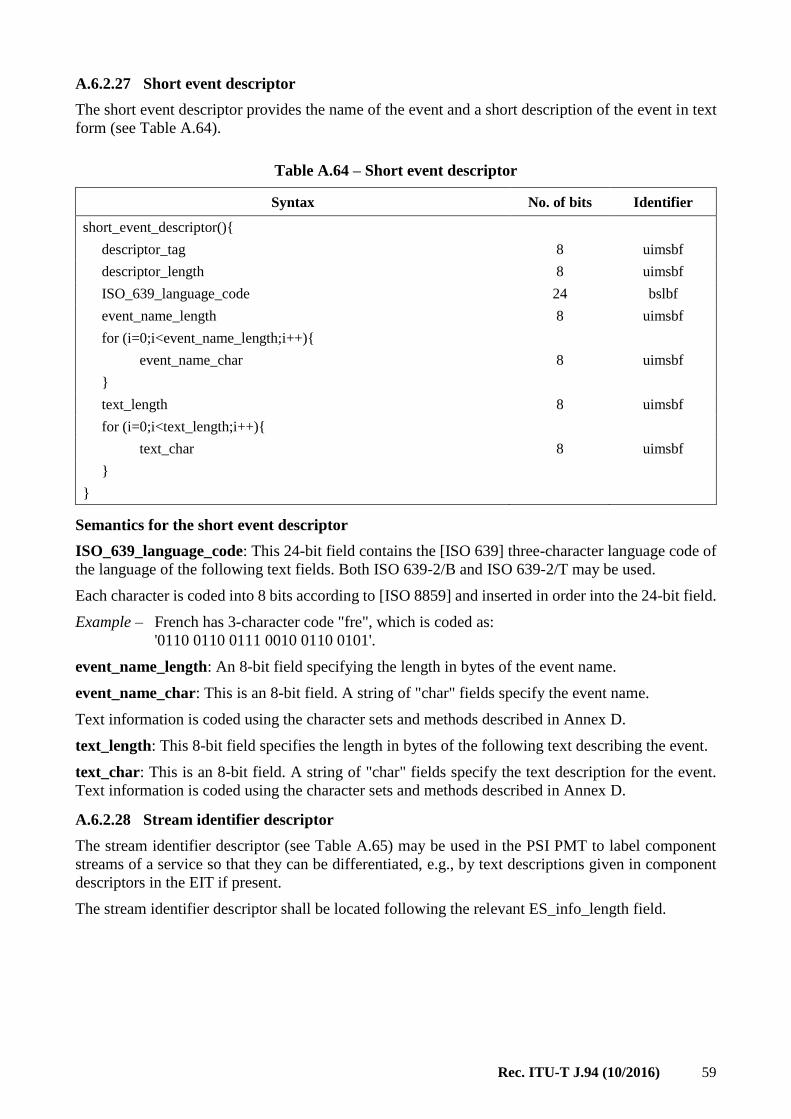
Rec. ITU-T J.94 (10/2016) 59
A.6.2.27 Short event descriptor
The short event descriptor provides the name of the event and a short description of the event in text
form (see Table A.64).
Table A.64 – Short event descriptor
Syntax No. of bits Identifier
short_event_descriptor(){
descriptor_tag 8 uimsbf
descriptor_length 8 uimsbf
ISO_639_language_code 24 bslbf
event_name_length 8 uimsbf
for (i=0;i<event_name_length;i++){
event_name_char 8 uimsbf
}
text_length 8 uimsbf
for (i=0;i<text_length;i++){
text_char 8 uimsbf
}
}
Semantics for the short event descriptor
ISO_639_language_code: This 24-bit field contains the [ISO 639] three-character language code of
the language of the following text fields. Both ISO 639-2/B and ISO 639-2/T may be used.
Each character is coded into 8 bits according to [ISO 8859] and inserted in order into the 24-bit field.
Example – French has 3-character code "fre", which is coded as:
'0110 0110 0111 0010 0110 0101'.
event_name_length: An 8-bit field specifying the length in bytes of the event name.
event_name_char: This is an 8-bit field. A string of "char" fields specify the event name.
Text information is coded using the character sets and methods described in Annex D.
text_length: This 8-bit field specifies the length in bytes of the following text describing the event.
text_char: This is an 8-bit field. A string of "char" fields specify the text description for the event.
Text information is coded using the character sets and methods described in Annex D.
A.6.2.28 Stream identifier descriptor
The stream identifier descriptor (see Table A.65) may be used in the PSI PMT to label component
streams of a service so that they can be differentiated, e.g., by text descriptions given in component
descriptors in the EIT if present.
The stream identifier descriptor shall be located following the relevant ES_info_length field.

60 Rec. ITU-T J.94 (10/2016)
Table A.65 – Stream identifier descriptor
Syntax No. of bits Identifier
stream_identifier_descriptor(){
descriptor_tag 8 uimsbf
descriptor_length 8 uimsbf
component_tag 8 uimsbf
}
Semantics for the stream identifier descriptor
component_tag: This 8-bit field identifies the component stream for associating it with a description
given in a component descriptor. Within a program map section, each stream identifier descriptor
shall have a different value for this field.
A.6.2.29 Stuffing descriptor
The stuffing descriptor provides a means of invalidating previously coded descriptors or inserting
dummy descriptors for table stuffing (see Table A.66).
Table A.66 – Stuffing descriptor
Syntax No. of bits Identifier
stuffing_descriptor(){
descriptor_tag 8 uimsbf
descriptor_length 8 uimsbf
for (i= 0;i<N;i++){
stuffing_byte 8 bslbf
}
}
Semantics for the stuffing descriptor
stuffing_byte: This is an 8-bit field. Each occurrence of the field may be set to any value. The IRDs
may discard the stuffing bytes.
A.6.2.30 Subtitling descriptor
In the [ITU-T H.222.0] Program Map Table (PMT), the value of stream_type for any PID carrying
DVB subtitle shall be '0x06' (this indicates a PES carrying private data). See Table A.67.
Table A.67 – Subtitling descriptor
Syntax No. of bits Identifier
subtitling_descriptor(){
descriptor_tag 8 uimsbf
descriptor_length 8 uimsbf
for (i= 0;i<N;i++){
ISO_639_language_code 24 bslbf
subtitling_type 8 bslbf
composition_page_id 16 bslbf
ancillary_page_id 16 bslbf
}
}

Rec. ITU-T J.94 (10/2016) 61
Semantics for the subtitling descriptor
ISO_639_language_code: This 24-bit field contains the [ISO 639] three-character language code of
the language of the subtitle. Both ISO 639-2/B and ISO 639-2/T may be used. Each character is coded
into 8 bits according to [ISO/IEC 8859] and inserted in order into the 24-bit field.
Example – French has 3-character code "fre", which is coded as:
'0110 0110 0111 0010 0110 0101'.
subtitling_type: This 8-bit field provides information on the content of the subtitle and the intended
display.
The coding of this field shall use the codes defined for component_type when stream_content is 0x03
in Table A.16, "stream_content and component_type".
composition_page_id: This 16-bit field identifies the composition page. DVB_subtitling_segments
signalling this page_id shall be decoded if the previous data in the subtitling descriptor matches the
user's selection criteria.
NOTE 1 – The composition_page_id is signalled in at least the DVB_subtitling_segments that define the data
structure of the subtitle screen; the page_composition_segment and region _composition_segments.
It may additionally be signalled in segments containing data on which the composition depends.
ancillary_page_id: This identifies the (optional) ancillary page. DVB_subtitling_segments
signalling this page_id shall also be decoded if the previous data in the subtitling descriptor matches
the user's selection criteria.
The values in the ancillary_page_id and the composition_page_id fields shall be the same if no
ancillary page is provided.
NOTE 2 – The ancillary_page_id is never signalled in a composition segment.
It may be signalled in Colour Look-Up Table (CLUT) definition segments, object segments and any other type
of segment.
NOTE 3 – (Terminology): A segment that signals a particular page number in its page_id field is said to be
"in" that page. The page is said to "contain" that segment.
A.6.2.31 Telephone descriptor
The telephone descriptor may be used to indicate a telephone number which may be used in
conjunction with a modem (PSTN or cable) to exploit narrow-band interactive channels. Further
information is given in "Implementation guidelines" for the use of telecommunications interfaces in
Digital Video Broadcasting systems (see Bibliography).
The telephone descriptor syntax is specified in Table A.68.
Table A.68 – Telephone descriptor
Syntax No. of bits Identifier
telephone_descriptor(){
descriptor_tag 8 uimsbf
descriptor_length 8 uimsbf
reserved_future_use 2 bslbf
foreign_availability 1 bslbf
connection_type 5 uimsbf
reserved_future_use 1 bslbf
country_prefix_length 2 uimsbf
international_area_code_length 3 uimsbf
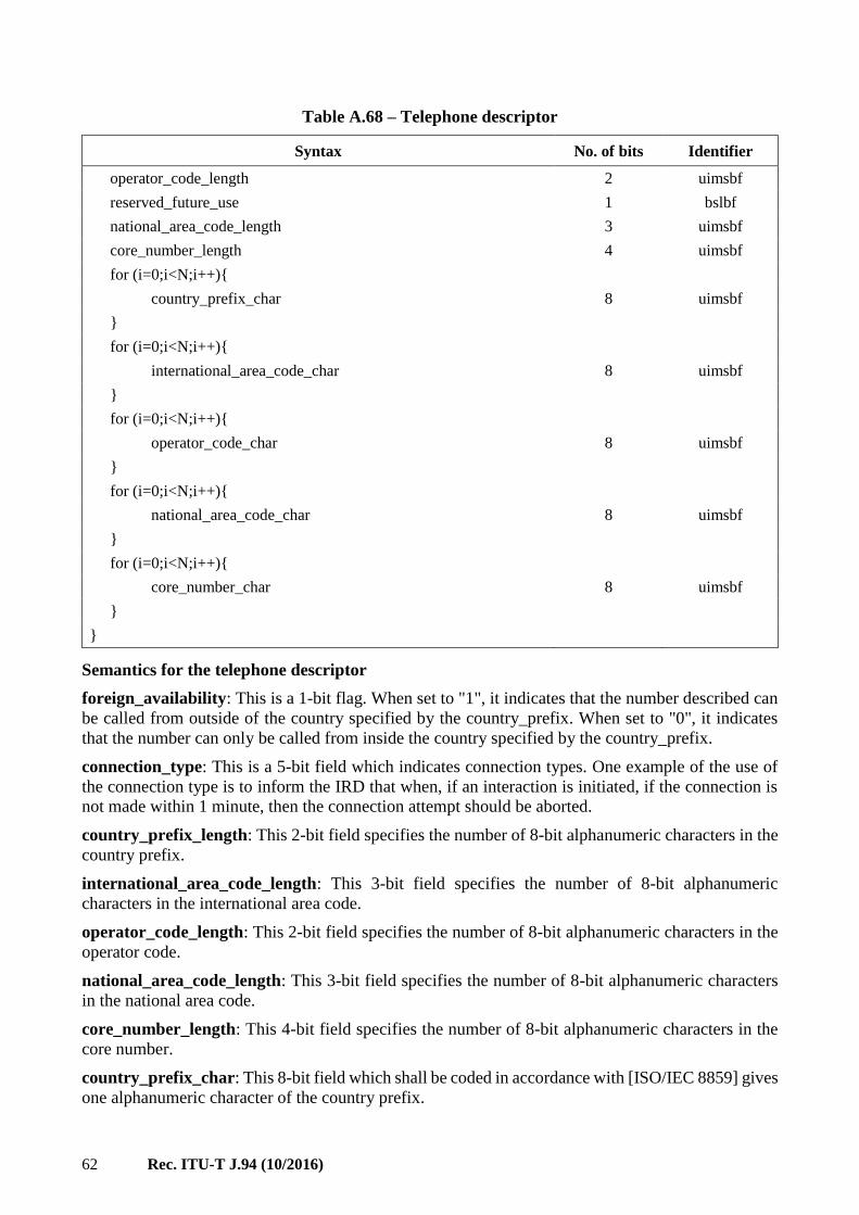
62 Rec. ITU-T J.94 (10/2016)
Table A.68 – Telephone descriptor
Syntax No. of bits Identifier
operator_code_length 2 uimsbf
reserved_future_use 1 bslbf
national_area_code_length 3 uimsbf
core_number_length 4 uimsbf
for (i=0;i<N;i++){
country_prefix_char 8 uimsbf
}
for (i=0;i<N;i++){
international_area_code_char 8 uimsbf
}
for (i=0;i<N;i++){
operator_code_char 8 uimsbf
}
for (i=0;i<N;i++){
national_area_code_char 8 uimsbf
}
for (i=0;i<N;i++){
core_number_char 8 uimsbf
}
}
Semantics for the telephone descriptor
foreign_availability: This is a 1-bit flag. When set to "1", it indicates that the number described can
be called from outside of the country specified by the country_prefix. When set to "0", it indicates
that the number can only be called from inside the country specified by the country_prefix.
connection_type: This is a 5-bit field which indicates connection types. One example of the use of
the connection type is to inform the IRD that when, if an interaction is initiated, if the connection is
not made within 1 minute, then the connection attempt should be aborted.
country_prefix_length: This 2-bit field specifies the number of 8-bit alphanumeric characters in the
country prefix.
international_area_code_length: This 3-bit field specifies the number of 8-bit alphanumeric
characters in the international area code.
operator_code_length: This 2-bit field specifies the number of 8-bit alphanumeric characters in the
operator code.
national_area_code_length: This 3-bit field specifies the number of 8-bit alphanumeric characters
in the national area code.
core_number_length: This 4-bit field specifies the number of 8-bit alphanumeric characters in the
core number.
country_prefix_char: This 8-bit field which shall be coded in accordance with [ISO/IEC 8859] gives
one alphanumeric character of the country prefix.

Rec. ITU-T J.94 (10/2016) 63
international_area_code_char: This 8-bit field which shall be coded in accordance with [ISO/IEC
8859] gives one alphanumeric character of the international area code.
operator_code_char: This 8-bit field which shall be coded in accordance with [ISO/IEC 8859] gives
one alphanumeric character of the operator code.
national_area_code_char: This 8-bit field which shall be coded in accordance with [ISO/IEC 8859]
gives one alphanumeric character of the national area code.
core_number_char: This 8-bit field which shall be coded in accordance with [ISO/IEC 8859] gives
one alphanumeric character of the core number.
A.6.2.32 Teletext descriptor
The Teletext descriptor (see Table A.69) shall be used in the PSI PMT to identify streams which carry
EBU Teletext data. The descriptor is to be located in a program map section following the relevant
ES_info_length field.
Table A.69 – Teletext descriptor
Syntax No. of bits Identifier
teletext_descriptor(){
descriptor_tag 8 uimsbf
descriptor_length 8 uimsbf
for (i=0;i<N;i++){
ISO_639_language_code 24 bslbf
teletext_type 5 uimsbf
teletext_magazine_number 3 uimsbf
teletext_page_number 8 uimsbf
}
}
Semantics for the Teletext descriptor
ISO_639_language_code: This 24-bit field contains the 3-character [ISO 639] language code of the
language of the teletext. Both ISO 639-2/B and ISO 639-2/T may be used. Each character is coded
into 8 bits according to [ISO/IEC 8859] and inserted in order into the 24-bit field.
Example – French has 3-character code "fre", which is coded as:
'0110 0110 0111 0010 0110 0101'.
teletext_type: This 5-bit field indicates the type of Teletext page indicated. This shall be coded
according to Table A.70.
Table A.70 – Teletext descriptor, teletext_type
teletext_type Description
0x00 Reserved for future use
0x01 Initial Teletext page
0x02 Teletext subtitle page
0x03 Additional information page
0x04 Programme schedule page
0x05 Teletext subtitle page for hearing impaired people
0x06 to 0x1F Reserved for future use

64 Rec. ITU-T J.94 (10/2016)
teletext_magazine_number: This is a 3-bit field which identifies the magazine number as defined
in [EBU SPB 492].
teletext_page_number: This is an 8-bit field giving two 4-bit hex digits identifying the page number
as defined in [EBU SPB 492].
A.6.2.33 Time-shifted event descriptor
The time-shifted event descriptor (see Table A.71) is used in place of the short_event_descriptor to
indicate an event which is a time-shifted copy of another event.
Table A.71 – Time-shifted event descriptor
Syntax No. of bits Identifier
Time_shifted_event_descriptor(){
descriptor_tag 8 uimsbf
descriptor_length 8 uimsbf
reference_service_id 16 uimsbf
reference_event_id 16 uimsbf
}
Semantics for the time-shifted event descriptor
reference_service_id: This 16-bit field identifies the reference service of a NVOD collection of
services.
The reference service can always be found in this TS. The service_id here does not have a
corresponding program_number in the program_map_section.
reference_event_id: This 16-bit field identifies the reference event of which the event described by
this descriptor is a time-shifted copy.
A.6.2.34 Time-shifted service descriptor
This descriptor is used in place of the service descriptor to indicate services which are time-shifted
copies of other services (see Table A.72).
Table A.72 – Time-shifted service descriptor
Syntax No. of bits Identifier
time_shifted_service_descriptor(){
descriptor_tag 8 uimsbf
descriptor_length 8 uimsbf
reference_service_id 16 uimsbf
}
Semantics for the time-shifted service descriptor
reference_service_id: This 16-bit field identifies the reference service of a NVOD collection of
services.
The reference service can always be found in this TS. The service_id here does not have a
corresponding program_number in the program_map_section.

Rec. ITU-T J.94 (10/2016) 65
A.7 Storage media interoperability (SMI) measures
[IEC Publication 61883] describes methods for delivering TS over the [IEEE 1394] "High
Performance Serial Bus" to receivers. One likely source for this data is a digital storage device.
In certain cases TSs can be "incomplete", thus not conforming to the normal broadcast specifications.
These "partial" TSs represent a subset of the data streams in the original TS. They may also be
"discontinuous" – that is there may be changes in the TS or the subset of the TS presented and there
may be temporal discontinuities. This subclause on Storage Media Interoperability (SMI) describes
the SI and PSI required in the delivered data in these cases.
A.7.1 SMI tables
The SMI tables are encoded using the private section syntax defined in [ITU-T H.222.0].
The SIT may be up to 4096 bytes long.
The bitstream presented at a digital interface shall either be a "complete" TS conforming to [ETR
154] and with SI conforming to this annex or it shall be "partial" TS.
In the latter case, the SI and PSI shall conform to the following subclauses.
A "partial" TS shall not carry any SI tables other than the Selection Information Table (SIT) and
Discontinuity Information Table (DIT) described below. The PSI shall be restricted to the PAT and
PMT instances required to correctly describe the streams within the "partial" TS.
The presence of the SIT in a bitstream identifies the bitstream as a "partial" TS coming from a digital
interface. In this case, the receiver should not expect the SI information required in a broadcast TS
and should instead rely on that carried by the SIT.
The SIT contains a summary of all relevant SI information contained in the broadcast stream. The DIT
shall be inserted at transition points where SI information is discontinuous. The use of the
SIT and DIT is restricted to partial TSs, they shall not be used in broadcasts.
A.7.1.1 Discontinuity Information Table (DIT)
The DIT (see Table A.73) is to be inserted at transition points at which SI information may be
discontinuous.
Table A.73 – Discontinuity information section
Syntax No. of bits Identifier
discontinuity_information_section(){
table_id 8 uimsbf
section_syntax_indicator 1 bslbf
reserved_future_use 1 bslbf
reserved 2 bslbf
section_length 12 uimsbf
transition_flag 1 uimsbf
reserved_future_use 7 bslbf
}
Semantics for the discontinuity information section
table_id: See Table A.2.
section_syntax_indicator: The section_syntax_indicator is a 1-bit field which shall be set to "0".
section_length: This is a 12-bit field, which is set to 0x001.

66 Rec. ITU-T J.94 (10/2016)
transition_flag: This 1-bit flag indicates the kind of transition in the TS. When the bit is set to "1",
it indicates that the transition is due to a change of the originating source. The change of the
originating source can be a change of originating TS and/or a change of the position in the TS (e.g., in
case of time-shift). When the bit is set to "0", it indicates that the transition is due to a change of the
selection only, i.e., while staying within the same originating TS at the same position.
A.7.1.2 Selection Information Table (SIT)
The SIT describes the service(s) and event(s) carried by the "partial" TS. See Table A.74.
Table A.74 – Selection information section
Syntax No. of bits Identifier
selection_information_section(){
table_id 8 uimsbf
section_syntax_indicator 1 bslbf
DVB_reserved_future_use 1 bslbf
ISO_reserved 2 bslbf
section_length 12 uimsbf
DVB_reserved_future_use 16 uimsbf
ISO_reserved 2 bslbf
version_number 5 uimsbf
current_next_indicator 1 bslbf
section_number 8 uimsbf
last_section_number 8 uimsbf
DVB_reserved_for_future_use 4 uimsbf
transmission_info_loop_length 12 bslbf
for(i =0;i<N;i++) {
descriptor()
}
for(i=0;i<N;i++){
service_id 16 uimsbf
DVB_reserved_future_use 1 uimsbf
running_status 3 bslbf
service_loop_length 12 bslbf
for(j=0;j<N;j++){
descriptor()
}
}
CRC_32 32 rpchof
}
Semantics for the selection information section
table_id: See Table A.2.
section_syntax_indicator: The section_syntax_indicator is a 1-bit field which shall be set to "1".

Rec. ITU-T J.94 (10/2016) 67
section_length: This is a 12-bit field, the first two bits of which shall be "00". It specifies the number
of bytes of the section, starting immediately following the section_length field and including the
CRC. The section_length shall not exceed 4093 so that the entire section has a maximum length of
4096 bytes.
version_number: This 5-bit field is the version number of the table. The version_number shall be
incremented by 1 when a change in the information carried within the table occurs. When it reaches
value 31, it wraps around to 0.
When the current_next_indicator is set to "1", then the version_number shall be that of the currently
applicable table. When the current_next_indicator is set to "0", then the version_number shall be that
of the next applicable table.
current_next_indicator: This 1-bit indicator, when set to "1", indicates that the table is the currently
applicable table. When the bit is set to "0", it indicates that the table sent is not yet applicable and
shall be the next table to be valid.
section_number: This 8-bit field gives the number of the section. The section_number shall be 0x00.
last_section_number: This 8-bit field specifies the number of the last section. The
last_section_number shall be 0x00.
transmission_info_loop_length: This 12-bit field gives the total length in bytes of the following
descriptor loop describing the transmission parameters of the partial TS.
service_id: This is a 16-bit field which serves as a label to identify this service from any other service
within a TS. The service_id is the same as the program_number in the corresponding
program_map_section.
running_status: This 3-bit field indicates the running status of the event in the original stream. This
is the running status of the original present event. If no present event exists in the original stream, the
status is considered as "not running". The meaning of the running_status value is as defined in
[ETR 211].
service_loop_length: This 12-bit field gives the total length in bytes of the following descriptor loop
containing SI related information on the service and event contained in the partial TS.
CRC_32: This is a 32-bit field that contains the CRC value that gives a zero output of the registers
in the decoder defined in Annex B of [ITU-T H.222.0] after processing the entire section.
A.7.2 SMI descriptors
This subclause contains syntax and semantics for descriptors exclusively found in partial TSs.
A.7.2.1 Partial Transport Stream (TS) descriptor
The transmission information descriptor loop of the SIT contains all the information required for
controlling and managing the play-out and copying of partial TSs. The following descriptor is
proposed to describe this information. See Table A.75.

68 Rec. ITU-T J.94 (10/2016)
Table A.75 – Partial Transport Stream (TS) descriptor
Syntax No. of bits Identifier
partial_transport_stream_descriptor() {
descriptor_tag 8 bslbf
descriptor_length 8 uimsbf
DVB_reserved_future_use 2 bslbf
peak_rate 22 uimsbf
DVB_reserved_future_use 2 bslbf
minimum_overall_smoothing_rate 22 uimsbf
DVB_reserved_future_use 2 bslbf
maximum_overall_smoothing_buffer 14 uimsbf
}
Semantics for the partial TS descriptor
peak_rate: The maximum momentary transport packet rate (i.e., 188 bytes divided by the time
interval between start times of two succeeding TS packets). At least an upper bound for this peak_rate
should be given.
This 22-bit field is coded as a positive integer in units of 400 bit/s.
minimum_overall_smoothing_rate: Minimum smoothing buffer leak rate for the overall TS
(all packets are covered). This 22-bit field is coded as a positive integer in units of 400 bit/s.
The value 0x3FFFFF is used to indicate that the minimum smoothing rate is undefined.
maximum_overall_smoothing_buffer: Maximum smoothing buffer size for the overall TS
(all packets are covered). This 14-bit field is coded as a positive integer in units of 1 byte.
The value 0x3FFFFF is used to indicate that the maximum smoothing buffer size is undefined.

Rec. ITU-T J.94 (10/2016) 69
Annex B
Service information for digital multi-programme System B
(This annex forms an integral part of this Recommendation.)
B.1 Purpose, scope and organization
B.1.1 Purpose
This annex defines a standard for service information (SI) delivered out of band on cable. This annex
is designed to support "navigation devices" on cable. The current specification defines the syntax and
semantics for a standard set of tables providing the data necessary for such a device to discover and
access digital and analogue services offered on cable.
B.1.2 Scope
This annex defines SI tables delivered via an out-of-band path to support service selection and
navigation by digital cable set-top boxes and other "digital cable-ready" devices. The SI tables defined
in this annex are formatted in accordance with the Program Specific Information (PSI) data structures
defined in MPEG-2 Systems ITU-T H.222.0 | ISO/IEC 13818-1.
The formal definition of "digital cable-ready" has a scope broader than that of the current standard.
The formal definition includes requirements related to navigation and service selection, demodulation
and decoding, video format decoding, Emergency Alert handling, and other aspects. The current
specification supports, primarily, the navigation and service selection function for services delivered
in the clear, as well as those subject to conditional access.
This annex does not address the electronic program guide application itself or any user interface
which might deal with the presentation and application of the Service Information.
A digital cable-ready device can take the form of a cable set-top box, a computer, a television, or a
convergence of these. Devices such as digital video recorders may also be cable-ready. A digital
cable-ready device capable of processing access controlled digital services supports an interface to a
conditional access module. As used here in this Recommendation, the term "Host" refers to the
capability to support an interface to a standard point of deployment (POD) security module.
SI data delivered out of band is transported in accordance with the Extended Channel interface
defined in SCTE DVS 131r7 (1998) and SCTE DVS 216r4 (2000). To have access to the Extended
Channel interface, the cable-ready device must act as a Host to a POD security module. The Extended
Channel interface presents the needed SI data to the Host. This data can be used by the Host for
channel navigation, construction of electronic program guides and other associated functions.
Figure B.1 is a high-level block diagram illustrating the POD module to Host interface via the
Extended Channel interface. The Host is responsible for providing a standard receiver/QPSK
demodulator function for the POD module. The choice of transport format of bits coming across from
the receiver/QPSK demodulator to the POD module is by mutual agreement between the POD and
the cable head-end equipment. The transport format of data travelling between the Host and POD
module on the Extended Channel interface conforms to standards defined in SCTE DVS 131r7 (1998)
and SCTE DVS 216r4 (2000).

70 Rec. ITU-T J.94 (10/2016)
Figure B.1 – A framework for the extended channel service information stream
The POD module may perform various transport, filtering, and error checking/correction functions
on the out-of-band data stream as depicted by the box labelled "Transport Processing, Filtering, and
Routing." As described in SCTE DVS 216r4 (2000), the Host may request from the POD module to
open one or several "flows" in which to receive PSI sections taken from the cable out-of-band data
stream. Each flow is associated with a PID value, in accordance with MPEG-2 Transport Stream
concepts.
Data flowing to the Host from the POD module that is associated with Service_type=MPEG_section is
required to be in the form of MPEG PSI data structures. However, data delivered into the POD from
cable out-of-band may or may not be organized in a Transport Stream compliant with ITU-T H.222.0
| ISO/IEC 13818-1. In other words, PID values associated with MPEG-2 tables on the Extended
Channel interface may or may not correspond to MPEG-2 Transport Stream packet header PID values
from the cable out of band.
Independent of the fact that out-of-band data may reach the POD module via a proprietary method,
the data structures delivered across the Extended Channel shall be formatted as MPEG-2 table
sections. Like table sections carried in an MPEG-2 Transport Stream, each is associated with a PID
value.
B.1.3 Organization
This annex is organized as follows:
– Clause B.1 – Provides a general introduction.
– Clause B.2 – Lists applicable references.
– Clause B.3 – Provides a list of definitions used in this annex.
– Clause B.4 – Provides a list of acronyms and abbreviations used in this annex.
– Clause B.5 – Describes the basic structure of sections.
Rec. ITU-T J.94 (10/2016) 71
– Clause B.6 – Describes formats of sections carried in the Base PID.1
– Clause B.7 – Explains descriptors applicable to the tables defined in this annex.
– Clause B.8 – Describes multilingual character string coding.
– Annex F – Defines profiles of choice for cable operator compliance with this annex.
– Annex G – Specifies packet rates for delivery of SI data.
– Annex H – Defines the standard Huffman tables used for text compression.
– Appendix I – Conversion between time and date conventions for System A.
– Appendix II – Discusses recommendations for receiver implementations.
– Appendix III – Provides an overview of tables defined in this Service Information Annex B.
– Appendix IV – Defines the daylight savings time control fields in the System Timetable.
B.2 References
For references, see clause 2.
B.3 Definitions
B.3.1 Compliance notation
As used in this annex, "shall" denotes a mandatory provision of the recommendation. "Should" denotes
a provision that is recommended but not mandatory. "May" denotes a feature whose presence does not
preclude compliance, that may or may not be present as optional for the implementers.
B.3.2 Definition of terms
The following terms are used throughout this annex:
B.3.2.1 conditional access: The control and security of subscriber access to cable or broadcast
services and events in the form of video, data and voice communications.
B.3.2.2 host: A device capable of supporting a POD module by implementing the interface protocol
defined in SCTE DVS 131r7 (1998) and SCTE DVS 216r4 (2000). These protocols define the
Extended Channel data path through which the SI tables defined in this annex are passed.
B.3.2.3 navigation: The process of selection and movement among analogue and digital services
offered on the cable network. The service information tables defined in this protocol assist in the
navigation process by providing physical service locations, channel names and numbers for user
reference. Those tables supporting electronic program guides also assist the navigation process.
B.3.2.4 program element: A generic term for one of the elementary streams or other data streams
that may be included in a program.
B.3.2.5 program: A collection of program elements. Program elements may be elementary streams.
Program elements need not have any defined time base. Those that do have a common time base are
intended for synchronized presentation. The term program is also used in the context of a "television
program" such as a scheduled daily news broadcast. The distinction between the two usages should
be understood by context.
B.3.2.6 region: As used in this annex, a region is a geographical area consisting of one or more
countries.
1 The Base PID is the PID associated with the "base" Service Information tables. In this protocol, the base_PID
is fixed at 0x1FFC. Refer to Table B.2.

72 Rec. ITU-T J.94 (10/2016)
B.3.2.7 section or table section: A data structure comprising a portion of an [ITU-T H.222.0 |
ISO/IEC 13818-1] –defined table, such as the Program Association Table (PAT), Conditional Access
Table (CAT), or Program Map Table (PMT). The term conforms to MPEG terminology. All sections
begin with the table_ID and end with the CRC_32 field. Sections are carried in Transport Stream packets
in which the starting point within a packet payload is indicated by the pointer_field mechanism defined
in theITU-T H.222.0 | ISO/IEC 13818-1 Systems document. The Network Information Table, for
example, defines portions of several types of tables.
B.3.2.8 service: ITU-T H.222.0 | ISO/IEC 13818-1 uses the term program to refer to a collection of
program elements with no regard to time. In this Service Information annex, the term service is used
in this same context to denote a collection of elementary components. Usage of the term service
clarifies certain discussions that also involve the notion of the term program in its traditional meaning
– for example, in the statement, "A video service carries a series of programs." In a broader sense,
service is also intended for multimedia services of video, voice and data, as these services become
prevalent.
B.3.2.9 stream: An ordered series of bytes. The usual context for the term stream involves
specification of a particular PID (such as the "Program Map PID stream"), in which case the term
indicates a series of bytes extracted from the packet multiplex from packets with the indicated
PID value.
B.3.3 Section and data structure syntax notation
This annex contains symbolic references to syntactic elements. These references are typographically
distinguished by the use of a different font (e.g., restricted), may contain the underscore character
(e.g., sequence_end_code) and may consist of character strings that are not English words (e.g., dynrng).
The formats of sections and data structures in this annex are described using a C-like notational
method employed in ITU-T H.222.0 | ISO/IEC 13818-1. Extensions to this method are described in
the following clauses.
B.3.3.1 Field sizes
Each data structure is described in a table format wherein the size in bits of each variable within that
section is listed in a column labelled "Bits." The column adjacent to the Bits column is labelled
"Bytes" and indicates the size of the item in bytes. For convenience, several bits within a particular
byte or multi-byte variable may be aggregated for the count. Table B.1 is an example:
Table B.1 – Field sizes example
Bits Bytes Format
foo_section(){ section_syntax_indicator 1 1
...
if (section_syntax_indicator) {
table_extension 16 (2) uimsbf
Reserved 2 (1) bslbf
version_number 5 uimsbf
current_next_indicator 1 bslbf {next, current}
...
}
...
In the byte count column, items that are conditional (because they are within a loop or conditional
statement) are in parentheses. Nested parentheses are used if the loops or conditions are nested.

Rec. ITU-T J.94 (10/2016) 73
B.4 Acronyms and abbreviations
The following acronyms and abbreviations are used within this annex:
AEIT Aggregate Event Information Table
AETT Aggregate Extended Text Table
ATSC Advanced Television Standards Committee
BMP Basic Multilingual Plane
bslbf bit serial, leftmost bit first
CAT Conditional Access Table
CC Closed Caption
CDS Carrier Definition Subtable
CRC Cyclic Redundancy Check
DCM Defined Channels Map
DTV Digital Television
ECM Entitlement Control Message
EMM Entitlement Management Message
ETSI European Telecommunications Standards Institute
GPS Global Positioning System
ICM Inverse Channel Map
ITU International Telecommunication Union
LSB Least Significant Bit
L-VCT Long-form Virtual Channel Table
MGT Master Guide Table
MMS Modulation Mode Subtable
MPAA Motion Picture Association of America
MPEG Moving Picture Experts Group
MSB Most Significant Bit
MSS Multiple String Structure
MTS Multi-lingual Text String
NTSC National Television System Committee
NVOD Near Video On Demand
OOB Out-of-band
PAT Program Association Table
PCR Program Clock Reference
PES Packetized Elementary Stream
PID Packet Identifier
PMT Program Map Table
POD Point of Deployment

74 Rec. ITU-T J.94 (10/2016)
PSIP Program and System Information Protocol
PTC Physical Transmission Channel
PTS Presentation Time Stamp
rpchof remainder polynomial coefficients, highest order first
RRT Rating Region Table
SCTE Society of Cable Telecommunications Engineers
SI Service Information
SNS Source Name Subtable
S-VCT Short-form Virtual Channel Table
TS Transport Stream
uimsbf unsigned integer, most significant bit first
UTC Coordinated Universal Time
VCM Virtual Channel Map
B.5 Table structure
This clause describes details of the structure of MPEG-2 tables defined in this annex.
Tables and table sections defined in this Service Information annex are structured in the same manner
used for carrying ITU-T H.222.0 | ISO/IEC 13818-1 -defined PSI tables. The MPEG-defined 32-bit
CRC is required.
B.5.1 Table ID ranges and values
Table B.2 defines table_ID ranges and values for tables defined in MPEG and in this annex.
Table B.2 – Table ID ranges and values for out-of-band transport
Table ID Value
(hex) Tables PID Reference
[ITU-T H.222.0] Sections
0x00 Program Association Table (PAT) 0 [ITU-T H.222.0]
0x01 Conditional Access Table (CAT) 1 [ITU-T H.222.0]
0x02 TS Program Map Table (PMT) Per PAT [ITU-T H.222.0 ]
0x03-0x3F [ISO Reserved]
User Private Sections
0x40-0x7F [User Private for other systems]
0x80-0xBF [SCTE User Private]
Other Standards
0xC0-0xC1 [Used in other standards]
Service Information Tables
0xC2 Network Information Table (NIT) 0x1FFC Clause B.6.1
0xC3 Network Text Table (NTT) 0x1FFC Clause B.6.2
0xC4 Short-form Virtual Channel Table (S-VCT) 0x1FFC Clause B.6.3
0xC5 System Timetable (STT) 0x1FFC Clause B.6.4
0xC6 [Used in other standards]
0xC7 Master Guide Table (MGT) 0x1FFC Clause B.6.5

Rec. ITU-T J.94 (10/2016) 75
Table B.2 – Table ID ranges and values for out-of-band transport
Table ID Value
(hex) Tables PID Reference
0xC8 Reserved
0xC9 Long-form Virtual Channel Table (L-VCT) 0x1FFC Clause B.6.6
0xCA Rating Region Table (RRT) 0x1FFC Clause B.6.7
0xCB-0xD5 [Used in ATSC]
0xD6 Aggregate Event Information Table (AEIT) Per MGT Clause B.6.8
0xD7 Aggregate Extended Text Table (AETT) Per MGT Clause B.6.9
0xD8 Cable Emergency Alert Message 0x1FFC SCTE DVS 208r6
(1999)
0xD9-0xFE [Reserved for future use] – –
Table sections defined in this Service Information annex, and any created as user extensions to it are
considered "private" with respect to ITU-T H.222.0 | ISO/IEC 13818-1. Table section types 0x80
through 0xBF are user-defined (outside the scope of this Service Information annex).
The maximum total length of any table section defined in this annex is 1024 bytes, except for the
MGT, L-VCT, AEIT and AETT, each of which has a maximum total length of 4096 bytes. This total
includes table_ID, CRC, and all fields contained within the specific table section.
B.5.2 Extensibility
This Service Information annex defines a number of tables and table sections. The Service
Information annex is designed to be extensible via the following mechanisms:
1) Reserved Fields: Fields in this Service Information annex marked reserved are reserved for
use either when revising this annex, or when another Recommendation is issued that builds
upon this one. See clause B.5.4.
2) Standard Table Types: As indicated in Table B.2, table_ID values in the range 0xCE through
0xFE are reserved for use either when revising this Service Information annex, or when
another Recommendation is issued that builds upon this one.2
3) User Private Table Types: As indicated in Table B.2, table_ID values in the range 0x80 through
0xBF are reserved for "user private" use. The format of user private tables carried in the
Network PID shall conform to the syntax described in Table B.3.
4) User Private Descriptors: Privately defined descriptors may be placed at designated locations
throughout the table sections described in this Service Information annex. Ownership of one
or more user private descriptors is indicated by the presence of an MPEG registration_descriptor()
preceding the descriptor(s).
2 NOTE Assignment of table_ID values in the 0xCE to 0xFE range requires coordination between ATSC
and SCTE.

76 Rec. ITU-T J.94 (10/2016)
Table B.3 Network private table section format
Bits Bytes Format
Network_private_table section(){ private_table_ID 8 1 uimsbf (0x80 <= table_ID <= 0xBF) section_syntax_indicator 1 2 bslbf Zero 1 bslbf Reserved 2 bslbf section_length 12 uimsbf if (section_syntax_indicator==1) { table_extension 16 (2) uimsbf Reserved 2 (1) bslbf version_number 5 uimsbf current_next_indicator 1 bslbf {next, current} section_number 8 (1) uimsbf last_section_number 8 (1) uimsbf } Zero 3 1 bslbf protocol_version 5 See clause B.5.4.1. format_identifier 32 4 uimsbf private_message_body() N*8 N CRC_32 32 4 rpchof }
B.5.3 Reserved fields
reserved: Fields in this Service Information annex marked reserved shall not be assigned by the user,
but shall be available for future use. Hosts are expected to disregard reserved fields for which no
definition exists that is known to that unit. Fields marked reserved shall be set to "1" until such time
as they are defined and supported.
zero: Indicates the bit or bit field shall be "0".
B.5.4 Private table section syntax
Table B.3 defines the syntax for user private table sections. The MPEG-defined CRC is required.
Refer to ITU-T H.222.0 | ISO/IEC 13818-1 for definition of MPEG-standard fields.
private_table_ID: The value of table_ID in private table sections shall be in the range 0x80 through 0xBF.
B.5.4.1 Protocol version
protocol_version: A 5-bit unsigned integer field whose function is to allow, in the future, any defined
table type to carry parameters that may be structured fundamentally differently from those defined in
the current protocol. At present, all defined table section types in this protocol are defined for
protocol_version zero only. Nonzero values of protocol_version may only be processed by Receivers
designed to accommodate the later versions as they become standardized.
B.5.4.2 Format identifier
format_identifier: A 32-bit unsigned integer value which unambiguously identifies the entity defining
this network_private_table_section() syntax. Values for format_identifiers shall be obtained from SCTE.
B.5.4.3 Private Message Body
private_message_body(): A data structure defined by the private entity identified by format_identifier.

Rec. ITU-T J.94 (10/2016) 77
B.5.4.4 CRC
CRC_32: The 32-bit CRC value defined in ITU-T H.222.0 | ISO/IEC 13818-1 for PSI sections. The
MPEG-2 CRC shall be checked in the POD, and only messages that pass the CRC check shall be
forwarded to the Host. The Host shall not check the CRC.
B.6 Table section formats
The following clauses define the formats of table sections as they are delivered across the Extended
Channel interface from POD module to Host.
B.6.1 Network Information Table
Sections of the Network Information Table shall be associated on the POD-Host interface with PID
value 0x1FFC, the SI_base PID. This table delivers sections of non-textual tables applicable
system-wide. The table types included are the Carrier Definition Subtable (CDS) and the Modulation
Mode Subtable (MMS).
Table B.4 shows the format of the Network Information Table section.
Table B.4 – Network Information Table section format
Bits Bytes Format
network_info_table_section(){ table_ID 8 1 uimsbf value 0xC2 Zero 2 2 bslbf Reserved 2 bslbf section_length 12 uimsbf Zero 3 1 bslbf protocol_version 5 See clause B.5.4.1. first_index 8 1 uimsbf range 1-255 number_of_records 8 1 uimsbf transmission_medium 4 1 uimsbf table_subtype 4 uimsbf (See Table B.5.) for (i=0; i<number_of_records; i++) { if (table_subtype==CDS) { CDS_record() ((5)) } if (table_subtype==MMS) { MMS_record() ((6)) } Descriptors_count 8 (1) uimsbf range 0-255 for (i=0; i<descriptors_count; i++) { descriptor() * ((*)) Optional } } for (i=0; i<N; i++) { descriptor() * (*) Optional } CRC_32 32 4 rpchof }
table_ID: The table_ID of the Network Information Table section shall be 0xC2.
first_index: An 8-bit unsigned integer number in the range 1 to 255 that indicates the index of the first
record to be defined in this table section. If more than one record is provided, the additional records
define successive table entries following first_index. The value zero is illegal and shall not be specified.

78 Rec. ITU-T J.94 (10/2016)
number_of_records: An 8-bit unsigned integer number that specifies the number of records being
defined in this table section. The maximum is limited by the maximum allowed length of the table
section.
transmission_medium: This 4-bit field shall be set to zero (0x0).
table_subtype: A 4-bit value that defines the type of table delivered in the table section. One instance
of a Network Information Table section can define entries within at most one type of table. The
table_subtype parameter is defined in Table B.5.
Table B.5 – Network Information Table Subtype
table_subtype Meaning
0 Invalid
1 CDS Carrier Definition Subtable
2 MMS Modulation Mode Subtable
3-15 Reserved
The receiver shall discard a Network Information Table section with table_subtype indicating an
unknown or unsupported table_subtype.
B.6.1.1 Carrier definition subtable (CDS)
Table B.6 defines the structure of the CDS_record(). Each CDS defines a set of carrier frequencies.
A full frequency plan table shall be constructed from one or more CDS_record() structures, each
defining a starting frequency, a number of carriers, and a frequency spacing for carriers in this group.
The specified carrier represents the nominal centre of the spectral band for all modulation methods,
including analogue. Carrier frequencies in the table thus represent the data carrier frequency for
digital transmissions modulated using QAM or PSK.3
Each CDS_record represents a definition of N carriers. The first_index parameter reflects the index in a
flat space between 1 and 255, representing the first carrier in the CDS_record. Starting from the first
CDS_record defining carriers C1, C2, C3, …, CN, where N = number_of_carriers, the carrier index for CI
is equal to first_index + I – 1. If the table section includes more than one CDS_record(), the carrier index
of the second CDS_record would be first_index plus the number of carriers defined in the first CDS_record(),
namely, first_index + number_of_carriers. References to the Carrier Definition Subtable, such as the
CDS_reference in the virtual_channel() of Table B.20, are to the carrier index (a carrier defined within a
CDS_record()), between 1 and N, where N is normally much smaller than 255. These references are not
to the index of a CDS_record() itself, which is sequenced from first_index and is not reset to 1 until it
exceeds 255.
Note that the carriers, as defined by one or more CDS_record()s, may or may not end up sorted in the
order of increasing carrier frequency. Certain frequency plans may be specified by overlapping two
or more CDS_record()s, each of which defines equally-spaced carriers.
3 Note that transmission systems using VSB modulation transmit spectra are not symmetrical about the carrier
or pilot tone. Acquisition of a VSB-modulated signal involves computation of the pilot tone (or in analogue
VSB, the picture carrier) location relative to the centre of the band. For example, for the ATSC Digital
Television Standard (ASTC A/53), where the channel bandwidth is 6 MHz, the pilot tone is located 310 kHz
above the lower edge of the channel, or 2.690 MHz below the specified centre of the band. Similarly, for
analogue NTSC, the picture carrier is 1.25 MHz above the lower edge of the channel, or 1.75 MHz below
the specified centre of the band.

Rec. ITU-T J.94 (10/2016) 79
Note also that carriers may be defined that are currently not in use. To facilitate the compressed
delivery format, defined carriers may not reflect reality. An example: carriers at 1, 2, 4, 5, 7, 8 MHz
could be defined as eight carriers at 1 MHz spacing (3 MHz and 6 MHz do not really exist, or are not
currently in use).
Table B.6 – CDS record format
Bits Bytes Format
CDS_record(){ number_of_carriers 8 1 uimsbf spacing_unit 1 2 bslbf (See Table B.7.) Zero 1 bslbf Frequency_spacing 14 uimsbf range 1-16 383
units of 10 or 125 kHz Frequency_unit 1 2 bslbf (See Table B.8.) first_carrier_frequency 15 uimsbf range 0-32 767
units of 10 or 125 kHz }
number_of_carriers: An unsigned integer in the range 1 to 255 that represents the number of carriers
whose frequency is being defined by this CDS_record().
spacing_unit: A 1-bit field identifying the units for the frequency_spacing field. Table B.7 defines the
coding for spacing_unit.
Table B.7 – Spacing unit
spacing_unit Meaning
0 10 kHz spacing
1 125 kHz spacing
frequency_spacing: A 14-bit unsigned integer number in the range 1 to 16 383 that defines the
frequency spacing in units of either 10 kHz or 125 kHz, depending upon the value of the spacing_unit
parameter. If spacing_unit is zero, indicating 10 kHz, then a value of 1 indicates 10 kHz spacing;
2 indicates 20 kHz, and so on. If the number_of_carriers field is one, the frequency_spacing field is ignored.
The maximum frequency spacing that can be represented is (214 − 1) * 125 kHz = 2047.875 MHz.
The minimum frequency spacing is 10 kHz.
frequency_unit: A 1-bit field identifying the units for the first_carrier_frequency field. Table B.8 defines
the coding for frequency_unit.
Table B.8 – Frequency unit
Frequency_unit Meaning
0 10 kHz units
1 125 kHz units

80 Rec. ITU-T J.94 (10/2016)
first_carrier_frequency: A 15-bit unsigned integer number in the range 0 to 32 767 that defines the
starting carrier frequency for the carriers defined in this group, in units of either 10 kHz or 125 kHz,
depending on the value of frequency_unit. If only one carrier is defined for the group, the
first_carrier_frequency represents its frequency. When the frequency_unit indicates 125 kHz, the
first_carrier_frequency can be interpreted as a fractional frequency (1/8 MHz) in the least-significant
3 bits, and an integer number of megahertz in the upper 12 bits. The range of frequencies that can be
represented is 0 to (215 − 1) * 125 kHz = 4095.875 MHz.
B.6.1.2 Modulation mode subtable (MMS)
Table B.9 defines the structure of the MMS_record().
Table B.9 – MMS record format
Bits Bytes Format
MMS_record(){ transmission_system 4 1 uimsbf (See Table B.10.) inner_coding_mode 4 uimsbf (See Table B.11.) split_bitstream_mode 1 1 bslbf {no, yes} Zero 2 bslbf modulation_format 5 uimsbf (See Table B.12.) Zero 4 4 bslbf symbol_rate 28 uimsbf units: symbols per second }
transmission_system: A 4-bit field that identifies the transmission standard employed for the waveform
defined by this MMS record. Table B.10 defines the coding for transmission_system.
Table B.10 – Transmission system
transmission_system Meaning
0 unknown The transmission system is not known.
1 Reserved (ETSI)
2 [ITU-T J.83] Annex B The transmission system conforms to the ITU North
American standard specified in Annex B of [ITU-T J.83].
3 Defined for use in other systems
4 ATSC The transmission system conforms to the ATSC Digital Television
Standard.
5-15 Reserved (satellite)
inner_coding_mode: A 4-bit field that indicates the coding mode for the inner code associated with the
waveform described in this MMS record. The following values are currently defined: 5/11, 1/2, 3/5,
2/3, 3/4, 4/5, 5/6, and 7/8. Coding of the inner_coding_mode field is shown in Table B.11.

Rec. ITU-T J.94 (10/2016) 81
Table B.11 – Inner coding mode
inner_coding_mode Meaning
0 Rate 5/11 coding
1 Rate 1/2 coding
2 Reserved
3 Rate 3/5 coding
4 Reserved
5 Rate 2/3 coding
6 Reserved
7 Rate 3/4 coding
8 Rate 4/5 coding
9 Rate 5/6 coding
10 Reserved
11 Rate 7/8 coding
12-14 Reserved
15 None – indicates that the waveform does not use concatenated coding
modulation_format: A 5-bit field that defines the basic modulation format for the carrier. Table B.12
defines the parameter.
Table B.12 – Modulation format
modulation_format Meaning
0 unknown The modulation format is unknown.
1 QPSK The modulation format is QPSK (Quadrature Phase Shift Keying).
2 BPSK The modulation format is BPSK (Binary Phase Shift Keying).
3 OQPSK The modulation format is offset QPSK.
4 VSB 8 The modulation format is 8-level VSB (Vestigial Sideband).
5 VSB 16 The modulation format is 16-level VSB.
6 QAM 16 Modulation format 16-level Quadrature Amplitude Modulation
(QAM).
7 QAM 32 32-level QAM
8 QAM 64 64-level QAM
9 QAM 80 80-level QAM
10 QAM 96 96-level QAM
11 QAM 112 112-level QAM
12 QAM 128 128-level QAM
13 QAM 160 160-level QAM
14 QAM 192 192-level QAM
15 QAM 224 224-level QAM
16 QAM 256 256-level QAM
17 QAM 320 320-level QAM

82 Rec. ITU-T J.94 (10/2016)
Table B.12 – Modulation format
modulation_format Meaning
18 QAM 384 384-level QAM
19 QAM 448 448-level QAM
20 QAM 512 512-level QAM
21 QAM 640 640-level QAM
22 QAM 768 768-level QAM
23 QAM 896 896-level QAM
24 QAM 1024 1024-level QAM
25-31 Reserved
symbol_rate: A 28-bit unsigned integer field that indicates the symbol rate in symbols per second
associated with the waveform described in this MMS record.
B.6.1.3 Descriptors count
descriptors_count: An 8-bit unsigned integer value in the range 0 to 255 representing the number of
descriptor blocks to follow.
descriptor(): The table section may include at its end one or more structures of the form tag, length,
data. The number of descriptors present is determined indirectly by processing the section_length field.
Descriptors are defined in clause B.7.
B.6.2 Network Text Table
The Network Text Table shall be associated on the POD-Host interface with PID value 0x1FFC, the
SI_base PID. This table delivers sections of textual tables applicable system-wide. Each instance of
Network Text Table is associated with a language, as such the textual information may be provided
multi-lingually. The Network Text Table delivers the Source Name Subtable (SNS).
Table B.13 shows the format of the Network Text Table.
Table B.13 – Network Text Table section format
Bits Bytes Format
network_text_table_section(){ table_ID 8 1 uimsbf value 0xC3 Zero 2 2 bslbf Reserved 2 bslbf section_length 12 uimsbf Zero 3 1 protocol_version 5 See clause B.5.4.1. ISO_639_language_code 24 3 Per ISO 639-2/B transmission_medium 4 1 uimsbf table_subtype 4 uimsbf (See Table B.14.) if (table_subtype==SNS) { source_name_subtable() * (*) } for (i=0; i<N; i++) { descriptor() * (*) Optional } CRC_32 32 4 rpchof }

Rec. ITU-T J.94 (10/2016) 83
The Network Text Table carries Multilingual Text Strings, formatted as defined in clause B.8.2. Text
Strings included in the Network Text Table shall not include format effectors (defined in
clause B.8.1.2). If format effectors are present in a text block, the Host is expected to disregard them.
table_ID: The table_ID of the Network Text Table section shall be 0xC3.
ISO_639_language_code: A 3-byte language code per ISO 639-2/B defining the language associated
with the text carried in this Network Text Table. The ISO_639_language_code field contains a
three-character code as specified by ISO 639-2/B. Each character is coded into 8 bits according to
ISO 8859-1 (ISO Latin-1) and inserted, in order, into the 24-bit field. The value 0xFFFFFF shall be
used in case the text is available in one language only. The value 0xFFFFFF shall represent a "wild
card" match when filtering by language.
transmission_medium: This 4-bit field shall be set to zero (0x0).
table_subtype: A 4-bit value that defines the type of table delivered in the table section. One instance
of a Network Text Table section can define entries within at most one type of table. The table_subtype
parameter is defined in Table B.14.
Table B.14 – Network Text Table Subtype
table_subtype Meaning
0 Invalid
1-5 Reserved
6 SNS Source Name Subtable
7-15 Reserved
A Host shall discard a Network Text Table section with table_subtype indicating an unknown or
unsupported value.
The SNS can provide a textual name associated with each service defined in the Short-form Virtual
Channel Table, by reference to its source_ID. The format of the source_name_subtable() is given in
Table B.15.
Table B.15 – Source Name Subtable format
Bits Bytes Format
source_name_subtable(){ number_of_SNS_records
8 1 uimsbf range 1-255
for (i=0; i<number_of_SNS_records; i++) { application_type 1 (1) bslbf {false, true} Zero 7 bslbf if (application_type) { Application_ID 16 ((2)) uimsbf } else { source_ID 16 ((2)) uimsbf } name_length 8 (1) Size of source_name() (L) source_name() L*8 (L) Multilingual text SNS_descriptors_count 8 (1) uimsbf range 0-255 for (i=0; i<SNS_descriptors_count; i++) { descriptor() * ((*)) } } }

84 Rec. ITU-T J.94 (10/2016)
number_of_SNS_records: An unsigned 8-bit integer number in the range 1 to 255 that specifies the
number of records being defined in this table section.
application_type: A Boolean flag, when set, indicates that the name string being defined is for an
application of the given application_ID. When the flag is clear, the name string being defined is for a
source of the given source_ID. Support for application-type virtual channels is optional. Hosts not
supporting application-type virtual channels may disregard name strings associated with these VC.
Support for application-type virtual channels is beyond the scope of this annex.
application_ID: A 16-bit unsigned integer value identifying the application associated with the name
string that follows. This field may be disregarded by Hosts not supporting application-type virtual
channels.
source_ID: A 16-bit unsigned integer value identifying the programming source associated with the
source name to follow.
name_length: An unsigned 8-bit integer number in the range 1 to 255 that defines the number of bytes
in the source_name() that follows.
source_name(): A Multilingual Text String defining the name of the source or application, formatted
according to the rules defined in clause B.8.1.
SNS_descriptors_count: An unsigned 8-bit integer number, in the range 0 to 255, that defines the
number of descriptors to follow.
descriptor(): The table section may include, at its end, one or more structures of the form tag, length,
data. The number of descriptors present is determined indirectly by processing the section_length field.
Descriptors are defined in clause B.7.
B.6.3 Short-form Virtual Channel Table Section
The Short-form Virtual Channel Table section delivers portions of the Virtual Channel Map (VCM),
the Defined Channels Map (DCM) and the Inverse Channel Map (ICM). Sections of the Short-form
Virtual Channel Table shall be associated on the POD-Host interface with PID value 0x1FFC,
the SI_base PID.
Table B.16 shows the syntax of the Short-form Virtual Channel Table section.
Table B.16 – Short-form Virtual Channel Table section format
Bits Bytes Format
shortform_virtual_channel_table_section(){ table_ID 8 1 uimsbf value 0xC4 Zero 2 2 bslbf Reserved 2 bslbf section_length 12 uimsbf Zero 3 1 bslbf protocol_version 5 See clause B.5.4.1. transmission_medium 4 1 uimsbf table_subtype 4 uimsbf (See Table B.17.) VCT_ID 16 2 uimsbf if (table_subtype==DCM) { DCM_structure() * (*) } if (table_subtype== VCM) { VCM_structure() * (*) } if (table_subtype== ICM) {

Rec. ITU-T J.94 (10/2016) 85
Table B.16 – Short-form Virtual Channel Table section format
Bits Bytes Format
ICM_structure() * (*) } for (i=0; i<N; i++) { descriptor() * (*) Optional } CRC_32 32 4 rpchof }
table_ID: The table_ID of the Short-form Virtual Channel Table shall be 0xC4.
transmission_medium: This 4-bit field shall be set to zero (0x0).
table_subtype: A 4-bit field that indicates the map type being delivered in this S-VCT section. Three
map types are currently defined: the Virtual Channel Map (VCM), the Defined Channels Map (DCM),
and the Inverse Channel Map (ICM). Table B.17 defines table_subtype.
Table B.17 – S-VCT Table Subtypes
table_subtype Meaning
0 VCM Virtual Channel Map
1 DCM Defined Channels Map
2 ICM Inverse Channel Map
3-15 Reserved
An S-VCT section received with table_subtype indicating an unknown or unsupported map type shall
be discarded.
VCT_ID: A 16-bit unsigned integer value, in the range 0x0000 to 0xFFFF, indicating the VCT to which
the channel definitions in this table section apply. This 16-bit field may be used by the POD module
for filtering purposes. The Host is expected to ignore VCT_ID. Only one version of the S-VCT,
corresponding to one value of VCT_ID, shall be delivered to the Host across the Extended Channel
interface at a given time.
B.6.3.1 Defined Channels Map
Table B.18 shows the format of the DCM_structure().
Table B.18 – DCM structure format
Bits Bytes Format
DCM_structure(){ Zero 4 2 bslbf first_virtual_channel 12 uimsbf range 0-4095 zero 1 1 bslbf DCM_data_length 7 uimsbf range 1-127 for (i=0; i<DCM_data_length; i++) { range_defined 1 (1) bslbf {no, yes} channels_count 7 uimsbf range 1-127 } }

86 Rec. ITU-T J.94 (10/2016)
first_virtual_channel: An unsigned 12-bit integer reflecting the first virtual channel whose existence is
being provided by this table section, for the map identified by the VCT_ID field. The range is 0 to 4095.
DCM_data_length: A 7-bit unsigned integer number, in the range 1 to 127, that defines the number of
DCM data fields to follow in the table section.
The DCM data bytes taken as a whole define which virtual channels, starting at the channel number
defined by first_virtual_channel, are defined and which are not. Each DCM_data_field defines two pieces of
data: a flag indicating whether this block of channels is defined or not, and the number of channels in
the block. The bytes are interpreted in an accumulative way, with a pointer into the Short-form Virtual
Channel Table which is initialized to first_virtual_channel. As each byte is processed, the pointer is
incremented by the number of channels indicated by the channels_count field.
For example, if channels 2-90, 200-210, 400-410, 600-610, 800-810, and 999 were defined, and
first_virtual_channel was zero, the DCM data sequence (in decimal) would be the following, where
underlined numbers have the range_defined bit set: 2, 89, 109, 11, 127, 62, 11, 127, 62, 11, 127, 62, 11,
127, 61, 1.
range_defined: A Boolean flag that indicates, when true, that the number of channels given by
channels_count is defined in the VCT, starting at the current pointer value. When the flag is clear, the
number of channels equal to channels_count are currently not defined starting at the current pointer
value.
channels_count: An unsigned 7-bit integer number, in the range 1 to 127, that indicates the number of
defined (or undefined) channels in a group.
B.6.3.2 Virtual Channel Map
Table B.19 shows the format of the VCM_structure().
Table B.19 – VCM structure format
Bits Bytes Format
VCM_structure(){ zero 2 1 bslbf descriptors_included 1 bslbf {no, yes} Zero 5 bslbf Splice 1 1 bslbf {no, yes} Zero 7 bslbf activation_time 32 4 uimsbf number_of_VC_records 8 1 for (i=0; i<number_of_VC_records; i++) { virtual_channel() * (*) } }
descriptors_included: A Boolean flag that indicates, when set, that one or more record-level descriptors
are present in the table section. Record-level descriptors are those defined in Table B.20 following
the "if (descriptors_included)" statement. When the flag is clear, the record-level descriptor block is
absent. The descriptors_included flag is not applicable to the section level descriptors shown at the
bottom of Table B.16.
The activation time indicates the time at which the data delivered in the table section will be valid.
splice: A Boolean flag that indicates, when set, that the Host should arm video processing hardware
to execute the application of the data delivered in the VCM_structure() at the next MPEG-2 video splice
point if the virtual channel changes described in the table section apply to a currently acquired
channel, and the activation_time is reached. If the activation is immediate or specified as a time that has

Rec. ITU-T J.94 (10/2016) 87
since passed, the data should be applied immediately. When the splice flag is clear, the virtual channel
change is made directly, without arming video hardware for a splice.
activation_time: A 32-bit unsigned integer field providing the absolute second the virtual channel data
carried in the table section will be valid, defined as the number of seconds since 0000 Hours UTC,
January 6th, 1980. If the GPS_UTC_offset delivered in the System Timetable is zero, activation_time
includes the correction for leap seconds. Otherwise, activation_time can be converted to UTC by
subtracting the GPS_UTC_offset. If the activation_time is in the past, the data in the table section shall be
considered valid immediately. An activation_time value of zero shall be used to indicate immediate
activation.
A Host may enter a virtual channel record whose activation times are in the future into a queue. Such
a queue may be called a pending virtual channel queue. Hosts are not required to implement a pending
virtual channel queue, and may choose to discard any data that is not currently applicable.
number_of_VC_records: An 8-bit unsigned integer number, in the range 1 to 255, that identifies the
number of virtual_channel() records to follow in the table section. The number of records included is
further limited by the allowed maximum table section length.
virtual_channel(): Table B.20 defines the virtual_channel() record structure.
Table B.20 – Virtual channel record format
Bits Bytes Format
virtual_channel(){ Zero 4 2 bslbf virtual_channel_number 12 uimsbf range 0-4095 application_virtual_channel 1 1 bslbf {no, yes} Zero 1 bslbf path_select 1 bslbf (See Table B.21.) transport_type 1 bslbf (See Table B.22.) channel_type 4 uimsbf (See Table B.23.) if (application_virtual_channel) { application_ID 16 (2) } else { source_ID 16 (2) } if (transport_type==MPEG_2) { CDS_reference 8 ((1)) uimsbf range 1-255 program_number 16 ((2)) MMS_reference 8 ((1)) uimsbf range 1-255 } else { /* non-MPEG-2 */ CDS_reference 8 ((1)) uimsbf range 0-255 Scrambled 1 ((1)) bslbf {no, yes} Zero 3 bslbf video_standard 4 uimsbf (See Table B.24.) Zero 16 ((2)) bslbf } if (descriptors_included) { descriptors_count 8 (1) uimsbf for (i=0; i<descriptors_count; i++) { descriptor() * ((*)) } } }

88 Rec. ITU-T J.94 (10/2016)
virtual_channel_number: An unsigned 12-bit integer, in the range 0 to 4095, reflecting the virtual
channel whose definition is being provided by this virtual channel record, for the map identified by
the VCT_ID field.
application_virtual_channel: A binary flag that, when set, indicates this virtual channel defines an access
point represented by the application_ID. When the flag is clear, the channel is not an application access
point, and this virtual channel defines an access point represented by the source_ID. Support for
application-type virtual channels is optional. Hosts not supporting application-type virtual channels
may disregard all data associated with them. Support for application-type virtual channels is beyond
the scope of this annex.
path_select: A 1-bit field that associates the virtual channel with a transmission path. For the cable
transmission medium, path_select identifies which physical cable carries the Transport Stream
associated with this virtual channel. Table B.21 defines path_select.
Table B.21 – Path Select
path_select meaning
0 path 1
1 path 2
transport_type: A 1-bit field identifying the type of transport carried on this carrier as either being an
MPEG-2 transport (value zero), or not (value one). Table B.22 defines the coding.
Table B.22 – Transport Type
transport_type Meaning
0 MPEG-2 transport
1 Non-MPEG-2 transport
channel_type: A 4-bit field defining the channel type. Table B.23 defines channel_type.
Table B.23 – Channel Type
channel_type Meaning
0 Normal Indicates that the record is a regular virtual channel record. For non-MPEG-2
channels, the waveform_type shall be defined as "normal."
1 Hidden Indicates that the record identifies a virtual channel that may not be accessed
by the user by direct entry of the channel number (hidden). Hidden channels are skipped
when the user is channel surfing, and appear as if undefined if accessed by direct channel
entry. Programs constructed for use by specific applications (such as NVOD theaters)
utilize hidden virtual channels. If a channel_properties_descriptor() is present and the
hide_guide bit is 0, the channel may be considered to be inactive. Inactive channels may
appear in EPG displays.
2-15 Reserved Hosts are expected to treat virtual channel records of unknown channel_type
the same as non-existent (undefined) channels.
application_ID: A 16-bit unsigned integer number, in the range 0x0001 to 0xFFFF, that identifies the
application associated with the virtual channel, on a system-wide basis. One particular program guide
application, for example, may look for a program carrying data in its native transmission format by
searching through the Short-form Virtual Channel Table for a match on its assigned application_ID. In
some cases, one application may be able to process streams associated with more than one application
ID. The application ID may be used to distinguish content as well as format, for the benefit of

Rec. ITU-T J.94 (10/2016) 89
processing within the application. The value zero for application_ID shall not be assigned; if specified
in a Virtual Channel record, the value zero indicates "unknown" or "inapplicable" for the
application_ID/source_ID field.
Support for application-type virtual channels is optional. Hosts not supporting application-type virtual
channels may disregard all data associated with them. Support for application-type virtual channels
is beyond the scope of this annex.
source_ID: A 16-bit unsigned integer number, in the range 0x0000 to 0xFFFF, that identifies the
programming source associated with the virtual channel, on a system-wide basis. In this context, a
source is one specific source of video, text, data, or audio programming. For the purposes of
referencing virtual channels to the program guide database, each such program source is associated
with a unique value of source_ID. The source_ID itself may appear in an EPG database, where it tags
entries to specific services. The value zero for source_ID, if used, shall indicate the channel is not
associated with a source ID.
program_number: A 16-bit unsigned integer number that associates the virtual channel number being
defined with services defined in the Program Association and TS Program Map Table sections.
Access to elementary streams defined in each virtual channel record involves first acquiring the
Transport Stream on the carrier associated with the virtual channel, then referencing the Program
Association section in PID 0 to find the PID associated with the TS Program Map Table section for
this program_number. PIDs for each elementary stream are then found by acquisition of the TS Program
Map Table section.
A program_number with value 0x0000 (invalid as a regular program number) is reserved to indicate that
the Host is expected to discard the corresponding virtual channel record from the queue of pending
virtual channel changes. Records are identified in the pending queue by their activation_time, VCT_ID,
and virtual_channel_number. If no pending virtual channel change is found in the Host's queue, no action
should be taken for this virtual channel (i.e., the record is expected to be discarded).
For inactive channels (those not currently present in the Transport Stream), program_number shall be
set to zero. This number shall not be interpreted as pointing to a Program Map Table entry.
descriptors_count: An 8-bit unsigned integer value, in the range 0 to 255, that defines the number of
descriptors to follow.
CDS_reference: An unsigned 8-bit integer number, in the range 0 to 255, that identifies the frequency
associated with this virtual channel. Values 1 to 255 of CDS_reference are used as indices into the
Carrier Definition Subtable to find a frequency to tune to acquire the virtual channel. The value zero
is reserved to indicate that the referenced service is carried on all digital multiplexes in this VCM.
The CDS_reference field shall be disregarded for inactive channels.
MMS_reference: An 8-bit unsigned integer value, in the range 0 to 255, that references an entry in the
Modulation Mode Subtable (MMS). The value zero is illegal and shall not be specified. For digital
waveforms, the MMS_reference associates the carrier with a digital modulation mode. For Host
implementations that support only one set of modulation parameters, in systems in which one
modulation method is used for all carriers, storage and processing of the MMS_reference is unnecessary.
The MMS_reference field shall be disregarded for inactive channels.
video_standard: A 4-bit field that indicates the video standard associated with this non-Standard virtual
channel. Table B.24 defines video_standard.

90 Rec. ITU-T J.94 (10/2016)
Table B.24 – Video Standard
video_standard Meaning
0 NTSC – The video standard is NTSC
1 PAL 625 – The video standard is 625-line PAL
2 PAL 525 – The video standard is 525-line PAL
3 SECAM – The video standard is SECAM
4 MAC – The video standard is MAC
5-15 Reserved
descriptor(): The table section may include, at its end, one or more structures of the form tag, length,
data. The number of descriptors present is determined indirectly by processing the section_length field.
Descriptors are defined in clause B.7.
B.6.3.3 Inverse Channel Map
The Inverse Channel Map, once reconstructed in the Host from a sequence of Virtual Channel records
that belong to the ICM, consists of a list of source_ID/virtual_channel_number pairs, ordered by source_ID.
The Host may use this table to quickly find the virtual channel carrying the program given by a
particular value of source_ID (by binary search), if such a virtual channel exists. One Inverse Channel
Map can be defined per Virtual Channel Map. The ICM may be constructed from the VCM, or linear
searches may be done to resolve source_ID references. Transmission of the ICM is therefore optional.
Virtual channels that provide access points for applications (i.e., with the application_virtual_channel flag
set to "yes") are not included in the ICM.
Table B.25 describes the format of the ICM_structure().
Table B.25 – ICM structure format
Bits Bytes Format
ICM_structure(){ Zero 4 2 bslbf first_map_index 12 uimsbf range 0-4095 zero 1 1 bslbf record_count 7 uimsbf range 1-127 for (i=0; i<record_count; i++) { source_ID 16 (2) uimsbf zero 4 (2) bslbf virtual_channel_number 12 uimsbf range 0-4095 } }
first_map_index: A 12-bit unsigned integer, in the range 0 to 4095, that represents the index into the
Inverse Channel Map where data carried in this ICM_structure() should be stored.
record_count: A 7-bit unsigned integer value, in the range 1 to 127, that represents the total number of
source_ID/virtual_channel pairs defined in this table section.
source_ID: A 16-bit unsigned integer number, in the range 0x0000 to 0xFFFF, that identifies the source
associated with the virtual channel, on a system-wide basis. In this context, a "source" is one specific
source of video, text, data, or audio programming. For the purposes of referencing virtual channels to
the program guide database, each such source is associated with a unique value of source_ID.
virtual_channel_number: A 12-bit unsigned integer value, in the range 0 to 4095, that represents the
virtual channel, in the Short-form Virtual Channel Table section (see Table B.16) given by VCT_ID,

Rec. ITU-T J.94 (10/2016) 91
associated with the given source_ID through the virtual_channel() record (see Table B.20).
A virtual_channel_number of zero indicates that the program given by source_ID is currently not carried in
this Short-form Virtual Channel Table. Such placeholders are useful in the case where the existence
of a certain program within a VCM may come and go.
B.6.4 System Timetable Section
The System Timetable is used to synchronize Hosts with accurate calendar time. The System
Timetable shall be associated on the POD-Host interface with PID value 0x1FFC, the SI_base PID.
Rate of transmission is typically once per minute, at second 00 of each minute.
The processing of the System Timetable in the Host is time-critical. Delays between reception and
processing of the table section increase the inaccuracy of timed events. Processing delays should be
kept below 200 milliseconds.
Table B.26 shows the format of the System Timetable section.
Table B.26 – System Timetable section format
Bits Bytes Format
system_time_table_section(){ table_ID 8 1 uimsbf value 0xC5 Zero 2 2 bslbf Reserved 2 bslbf section_length 12 uimsbf Zero 3 1 protocol_version 5 See clause B.5.4.1. Zero 8 1 bslbf system_time 32 4 uimsbf GPS_UTC_offset 8 1 uimsbf seconds for (i=0; i<N; i++) { descriptor() * (*) Optional } CRC_32 32 4 rpchof }
table_ID: The table_ID of the System Timetable shall be 0xC5.
system_time: A 32-bit unsigned integer quantity representing the current system time, as the number
of GPS seconds since 0000 Hours UTC, January 6th, 1980. The system_time value may or may not
include the correction factor for leap seconds, depending upon the value of GPS_UTC_offset, as
described below.
GPS_UTC_offset: An 8-bit value that serves dual roles. When set to zero, the field indicates that the
system_time field carries UTC time directly. When GPS_UTC_offset is not equal to zero, it is interpreted
as an 8-bit unsigned integer that defines the current offset in whole seconds between GPS and UTC
time standards. To convert GPS time to UTC, the GPS_UTC_offset is subtracted from GPS time.
Whenever the International Bureau of Weights and Measures decides that the current offset is too far
in error, an additional leap second may be added (or subtracted), and the GPS_UTC_offset will reflect
the change.
descriptor(): The table section may include at its end one or more structures of the form tag, length,
data. The number of descriptors present is determined indirectly by processing the section_length field.
Descriptors are defined in clause B.7.
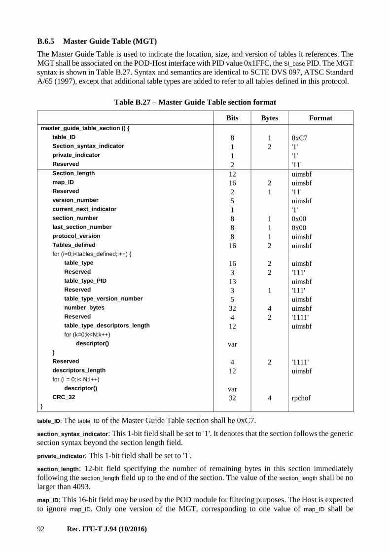
92 Rec. ITU-T J.94 (10/2016)
B.6.5 Master Guide Table (MGT)
The Master Guide Table is used to indicate the location, size, and version of tables it references. The
MGT shall be associated on the POD-Host interface with PID value 0x1FFC, the SI_base PID. The MGT
syntax is shown in Table B.27. Syntax and semantics are identical to SCTE DVS 097, ATSC Standard
A/65 (1997), except that additional table types are added to refer to all tables defined in this protocol.
Table B.27 – Master Guide Table section format
Bits Bytes Format
master_guide_table_section () { table_ID 8 1 0xC7 Section_syntax_indicator 1 2 '1' private_indicator 1 '1' Reserved 2 '11' Section_length 12 uimsbf map_ID 16 2 uimsbf Reserved 2 1 '11' version_number 5 uimsbf current_next_indicator 1 '1' section_number 8 1 0x00 last_section_number 8 1 0x00 protocol_version 8 1 uimsbf Tables_defined 16 2 uimsbf for (i=0;i<tables_defined;i++) { table_type 16 2 uimsbf Reserved 3 2 '111' table_type_PID 13 uimsbf Reserved 3 1 '111' table_type_version_number 5 uimsbf number_bytes 32 4 uimsbf Reserved 4 2 '1111' table_type_descriptors_length 12 uimsbf for (k=0;k<N;k++) descriptor() var } Reserved 4 2 '1111' descriptors_length 12 uimsbf for (I = 0;I< N;I++) descriptor() var CRC_32 32 4 rpchof }
table_ID: The table_ID of the Master Guide Table section shall be 0xC7.
section_syntax_indicator: This 1-bit field shall be set to '1'. It denotes that the section follows the generic
section syntax beyond the section length field.
private_indicator: This 1-bit field shall be set to '1'.
section_length: 12-bit field specifying the number of remaining bytes in this section immediately
following the section_length field up to the end of the section. The value of the section_length shall be no
larger than 4093.
map_ID: This 16-bit field may be used by the POD module for filtering purposes. The Host is expected
to ignore map_ID. Only one version of the MGT, corresponding to one value of map_ID shall be

Rec. ITU-T J.94 (10/2016) 93
delivered to the Host across the Extended Channel interface at a given time. Consequently, the Host
can disregard map_ID and may process the MGT version_number field as an indication that the MGT
version has changed.
NOTE – The map_ID may be considered to be an identifier for this instance of the Master Guide Table. In some
applications, the POD module may receive multiple Master Guide Table sections corresponding to distinct
channel maps. In this case, the POD module is responsible for accepting one MGT and discard the others. It
may use the map_ID to filter them, using information provided outside the scope of this annex.
In every case, the Host will receive just one MGT across the POD to Host interface, and the map_ID parameter
may be ignored.
version_number: This 5-bit field is the version number of MGT. The version number shall be
incremented by 1 modulo 32 when any field in the table_types defined in the loop below or the MGT
itself changes.
current_next_indicator: This 1-bit indicator is always set to '1' for the MGT section; the MGT sent is
always currently applicable.
section_number: The value of this 8-bit field shall always be 0x00 (this table is only one section long).
last_section_number: The value of this 8-bit field shall always be 0x00.
protocol_version: An 8-bit unsigned integer field whose function shall be to allow, in the future, this
table type to carry parameters that may be structured differently than those defined in the current
protocol. At present, the only valid value for protocol_version is zero. Non-zero values of protocol_version
may only be processed by Hosts designed to accommodate the later versions as they become
standardized.
tables_defined: This 16-bit unsigned integer in the range 0 to 65 535 represents the number of tables in
the following loop.
table_type: This 16-bit unsigned integer specifies the type of table, based on Table B.28.
Table B.28 – MGT Table Types
table_type Meaning
0x0000-0x0001 [Assigned by ATSC]
0x0002 Long-form Virtual Channel Table with current_next_indicator=1
0x0003 Long-form Virtual Channel Table with current_next_indicator=0
0x0004 [Assigned by ATSC]
0x0005-0x000F [Reserved]
0x0010 Short-form Virtual Channel Table-VCM Subtype
0x0011 Short-form Virtual Channel Table-DCM Subtype
0x0012 Short-form Virtual Channel Table-ICM Subtype
0x0013-0x01F [Reserved]
0x0020 Network Information Table-CDS Table Subtype
0x0021 Network Information Table-MMS Table Subtype
0x0021-0x02F [Reserved]
0x0030 Network Text Table-SNS Subtype
0x0031-0x00FF [Reserved]
0x0100-0x017F [Assigned by ATSC]
0x0180-0x01FF [Reserved]
0x0200-0x027F [Assigned by ATSC]
0x028F-0x0300 [Reserved]
0x0301-0x03FF Rating Region Table with rating_region 1-255

94 Rec. ITU-T J.94 (10/2016)
Table B.28 – MGT Table Types
table_type Meaning
0x0400-0x0FFF [User private]
0x1000-0x10FF Aggregate Event Information Table with MGT_tag 0 to 255
0x1100-0x11FF Aggregate Extended Text Table with MGT_tag 0 to 255
0x1200-0xFFFF [Reserved]
For table types formatted with the MPEG short-form syntax, the revision_detection_descriptor() shall be
used to indicate the section number and version. For example, table_type 0x0020 indicates the Network
Information Table, CDS table subtype. One MGT reference to CDS would cover all sections of the
delivered CDS.
MGT table types 0x1000 through 0x10FF reference AEIT instances with MGT_tag values 0x00 through
0xFF, respectively. Table types 0x1100 through 0x11FF reference AETT instances with MGT_tag
values 0x00 through 0xFF, respectively. A table_type value of 0x1023 in the MGT, for example, refers
to the instance of the AEIT with MGT_tag value 0x23.
Note that the choice of value of the MGT_tag is independent of the timeslot number. For example, the
MGT_tag value used to deliver AEIT-0 may be zero or any other value up to 255.
table_type_PID: This 13-bit field specifies the PID for the table_type described in the loop.
table_type_version_number: This 5-bit field reflects the version number of the table_type described in
the loop. The value of this field shall be the same as the version_number entered in the
corresponding fields of tables and table instances. The version number for the next L-VCT
(current_next_indicator = 0) shall be one unit more (modulo 32) than the version number for the current
L-VCT (current_next_indicator = 1).
number_bytes: This 32-bit unsigned integer field indicates the total number of bytes used for the
table_type described in the loop. There may be more than one instance of the indicated table_type.
table_type_descriptors_length: Total length of the descriptors for the table_type described in the loop
(in bytes).
descriptors_length: Total length of the MGT descriptor list that follows (in bytes).
descriptor(): The table section may include, at its end, one or more structures of the form tag, length,
data. Descriptors are defined in clause B.7.
CRC_32: This is a 32-bit field that contains the CRC value to ensure a zero output from the registers
in the decoder defined in Annex A of ITU-T H.222.0 | ISO/IEC 13818-1 "MPEG-2 Systems" after
processing the entire Master Guide Table section.
B.6.5.1 Restrictions on PID values
Certain restrictions apply to the PID values specified in the MGT. These restrictions are necessary to
ensure the Host can collect EPG data using a minimum number of concurrent flows on the Extended
Channel.
– All AEIT and AETT table sections with common MGT_tag values shall share a common PID.
– AEIT-0, AETT-0, AEIT-1 and AETT-1 instances shall share a common PID value.4
– AEIT-2, AETT-2, AEIT-3 and AETT-3 instances shall be associated with a second separate
PID value.
4 Please refer to clause B.6.8 for definition of the AEIT-n and AETT-n notation convention used in this annex.

Rec. ITU-T J.94 (10/2016) 95
– EPG data describing events farther into the future may be associated with one or more PID
values; the second PID value may be used for all or some of the AEIT/AETT-4 through
AEIT/AETT-N instances (N < 256).
B.6.5.2 Restrictions on order of occurrence of table references
For all table references except AEIT and AETT, the order of appearance in the MGT of various table
references is not specified or restricted. For AEIT and AETT references, the following restriction
applies:
– The order of appearance of AEIT/AETT references in the MGT shall correspond to
increasing time slot assignments.
NOTE This rule allows a Host to know, before processing the AEIT/AETT data, which table instances
correspond to near-term data and which correspond to data farther into the future. This information is useful if
the Host has insufficient RAM to hold all data transmitted.
B.6.6 Long-form Virtual Channel Table
The Long-form Virtual Channel Table is carried in MPEG-2 table sections with table ID 0xC9, and
conforms to the syntax and semantics of the MPEG-2 Private Section as described in clauses 2.4.4.10
and 2.4.4.11 of ITU-T H.222.0 | ISO/IEC 13818-1. The Long-form Virtual Channel Table shall be
associated on the POD-Host interface with PID value 0x1FFC, the SI_base PID.
The bit stream syntax for the Long-form Virtual Channel Table is shown in Table B.29.
Table B.29 – Long-form Virtual Channel Table section format
Syntax Bits Bytes Format
longform_virtual_channel_table_section () { table_id 8 1 0xC9 section_syntax_indicator 1 2 '1' private_indicator 1 '1' Reserved 2 '11' section_length 12 uimsbf map_ID 16 2 uimsbf Reserved 2 1 '11' version_number 5 uimsbf current_next_indicator 1 bslbf section_number 8 1 uimsbf last_section_number 8 1 uimsbf protocol_version 8 1 uimsbf num_channels_in_section 8 1 uimsbf For(i=0; i<num_channels_in_section;i++) { short_name 7*16 (14) unicode™BMP reserved 4 (3) '1111' major_channel_number 10 uimsbf minor_channel_number 10 uimsbf modulation mode 8 (1) uimsbf carrier_frequency 32 (4) uimsbf channel_TSID 16 (2) uimsbf program_number 16 (2) uimsbf reserved 2 (2) '11' access_controlled 1 bslbf hidden 1 bslbf path_select 1 bslbf out_of_band 1 bslbf hide_guide 1 bslbf reserved 3 '111' service_type 6 uimsbf source_id 16 (2) uimsbf reserved 6 (2) '111111'

96 Rec. ITU-T J.94 (10/2016)
Table B.29 – Long-form Virtual Channel Table section format
Syntax Bits Bytes Format
descriptors_length 10 uimsbf for (i=0;i<N;i++) { descriptors() } } reserved 6 2 '111111' additional_descriptors_length 10 uimsbf For(j=0; j<N;j++) { additional_descriptors() var } CRC_32 32 4 rpchof }
table_id: An 8-bit unsigned integer number that indicates the type of table section being defined here.
For the longform_virtual_channel_table_section, the table_ID shall be 0xC9.
section_syntax_indicator: The section_syntax_indicator is a one-bit field which shall be set to '1' for the
longform_virtual_channel_table_section().
private_indicator: This 1-bit field shall be set to '1'.
section_length: This is a twelve-bit field that specifies the number of bytes of the section, starting
immediately following the section_length field, and including the CRC. The value in this field shall not
exceed 4093.
map_ID: A 16-bit identifier for this Long-form Virtual Channel Table. In some applications, the POD
module may receive multiple Long-form Virtual Channel Table sections corresponding to distinct
channel maps. In this case, the POD may use the map_ID to distinguish them, using information
provided outside the scope of this annex. In every case, the Host will receive just one L-VCT across
the POD to Host interface, and the map_ID parameter may be ignored.
version_number: This 5-bit field is the version number of the Long-form Virtual Channel Table. For
the current L-VCT (current_next_indicator = 1), the version number shall be incremented by 1 whenever
the value of the current L-VCT changes. Upon reaching the value 31, it wraps around to 0. For the
next L-VCT (current_next_indicator = 0), the version number shall be one unit more than that of the
current L-VCT (also in modulo 32 arithmetic). In any case, the value of the version_number shall be
identical to that of the corresponding entries in the MGT.
current_next_indicator: A 1-bit indicator, which when set to '1' indicates that the Long-form Virtual
Channel Table sent is currently applicable. When the bit is set to '0', it indicates that the table sent is
not yet applicable and shall be the next table to become valid.
section_number: This 8-bit field gives the number of this section. The section_number of the first section
in the Long-form Virtual Channel Table shall be 0x00. It shall be incremented by one with each
additional section in the Long-form Virtual Channel Table.
last_section_number: This 8-bit field specifies the number of the last section (that is, the section with
the highest section_number) of the complete Long-form Virtual Channel Table.
protocol_version: An 8-bit unsigned integer field whose function is to allow, in the future, this table
type to carry parameters that may be structured differently than those defined in the current protocol.
At present, the only valid value for protocol_version is zero. Non-zero values of protocol_version may only
be processed by Hosts designed to accommodate the later versions as they become standardized.
num_channels_in_section: This 8-bit field specifies the number of virtual channels in the L-VCT
section. The number is limited by the section length.

Rec. ITU-T J.94 (10/2016) 97
short_name: The name of the virtual channel, represented as a sequence of one to seven 16-bit character
codes coded in accordance with the Basic Multilingual Plane (BMP) of Unicode, as specified in
ISO/IEC 10646-1. If the name of the virtual channel is shorter than seven Unicode characters, one or
more instances of the null character value 0x0000 shall be used to pad the string to its fixed 14-byte
length.
major_channel_number, minor_channel_number: These two 10-bit fields represent either a two-part or a
one-part virtual channel number associated with the virtual channel being defined in this iteration of
the "for" loop. One-part numbers range from 0 to 16 383. Two-part numbers consist of a major and a
minor number part; the range of each is 0 to 999. The one- or two-part number acts as the user's
reference number for the virtual channel. Some channels may be represented with a one-part number
while others in the VCT are represented with two-part numbers.
The six MSBs of the major_channel_number field, when all 1, indicate that a one-part number is being
specified. The value of the one-part number is given, in C syntax, by:
one_part_number = (major_channel_number & 0x00F) << 10 + minor_channel_number
When the six MSBs of the major_channel_number field are not all 1, and the 10-bit major_channel_number
field is less than 1000, two fields specify a two-part channel number. The value of the two-part
number is given by major_channel_number and minor_channel_number.
Table B.30 summarizes the coding of the major_channel_number and minor_channel_number fields.
Table B.30 – Major and minor channel number field coding
20-bit major/minor field
(10-bit major + 10-bit minor) User channel number
Two-part channel
numbers
(1000 major numbers,
each with 1000 minor
numbers)
Major Number
(10 bits)
Minor Number
(10 bits)
Two-part
user channel number
000d 000d 0-0
000d 001d 0-1
… … …
000d 999d 0-999
001d 000d 1-0
… … …
999d 999d 999-999
[Reserved] 000d to 999d 1000d-1023d N/A
1000-1007d All values N/A
One-part channel
numbers
(16 383 linear space
numbers)
6-bit flag
(set = 111111b)
One-Part Number
(14 bits)
One-part
user channel number
Set 0d 0
Set 1d 1
Set … …
Set 16383d 16383
modulation_mode: An 8-bit unsigned integer number that indicates the modulation mode for the
transmitted carrier associated with this virtual channel. Values of modulation_mode are defined by this
annex in Table B.31. For digital signals, the standard values for modulation mode (values below
0x80) indicate transport framing structure, channel coding, interleaving, channel modulation, forward
error correction, symbol rate, and other transmission-related parameters, by means of a reference to
an appropriate standard. Values of modulation_mode 0x80 and above are outside the scope of SCTE.
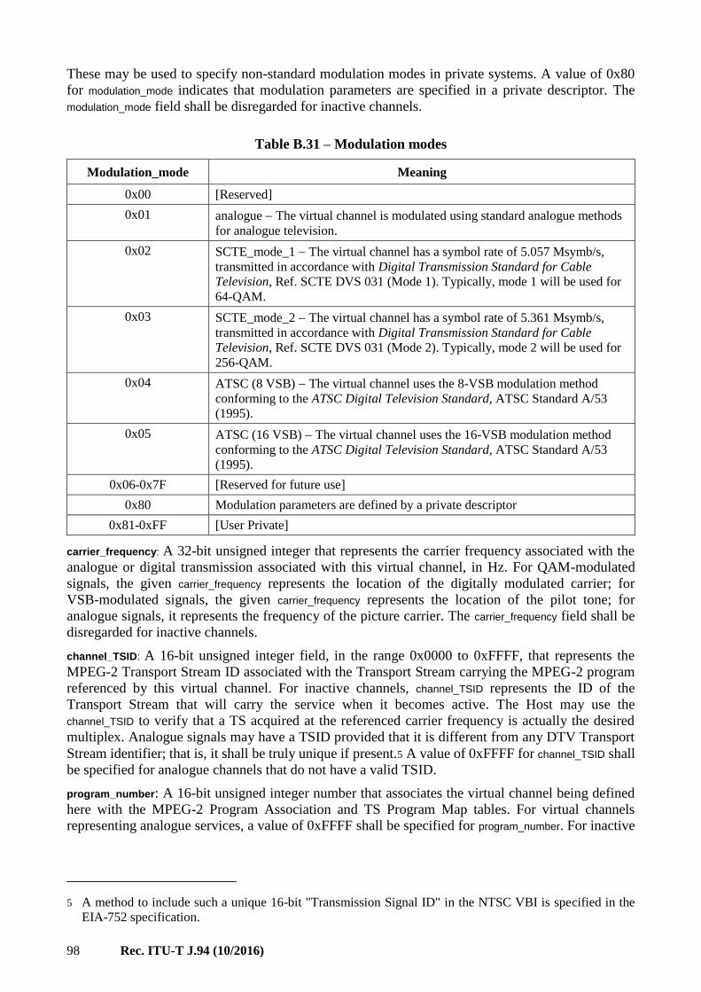
98 Rec. ITU-T J.94 (10/2016)
These may be used to specify non-standard modulation modes in private systems. A value of 0x80
for modulation_mode indicates that modulation parameters are specified in a private descriptor. The
modulation_mode field shall be disregarded for inactive channels.
Table B.31 – Modulation modes
Modulation_mode Meaning
0x00 [Reserved]
0x01 analogue The virtual channel is modulated using standard analogue methods
for analogue television.
0x02 SCTE_mode_1 The virtual channel has a symbol rate of 5.057 Msymb/s,
transmitted in accordance with Digital Transmission Standard for Cable
Television, Ref. SCTE DVS 031 (Mode 1). Typically, mode 1 will be used for
64-QAM.
0x03 SCTE_mode_2 The virtual channel has a symbol rate of 5.361 Msymb/s,
transmitted in accordance with Digital Transmission Standard for Cable
Television, Ref. SCTE DVS 031 (Mode 2). Typically, mode 2 will be used for
256-QAM.
0x04
ATSC (8 VSB) The virtual channel uses the 8-VSB modulation method
conforming to the ATSC Digital Television Standard, ATSC Standard A/53
(1995).
0x05
ATSC (16 VSB) The virtual channel uses the 16-VSB modulation method
conforming to the ATSC Digital Television Standard, ATSC Standard A/53
(1995).
0x06-0x7F [Reserved for future use]
0x80 Modulation parameters are defined by a private descriptor
0x81-0xFF [User Private]
carrier_frequency: A 32-bit unsigned integer that represents the carrier frequency associated with the
analogue or digital transmission associated with this virtual channel, in Hz. For QAM-modulated
signals, the given carrier_frequency represents the location of the digitally modulated carrier; for
VSB-modulated signals, the given carrier_frequency represents the location of the pilot tone; for
analogue signals, it represents the frequency of the picture carrier. The carrier_frequency field shall be
disregarded for inactive channels.
channel_TSID: A 16-bit unsigned integer field, in the range 0x0000 to 0xFFFF, that represents the
MPEG-2 Transport Stream ID associated with the Transport Stream carrying the MPEG-2 program
referenced by this virtual channel. For inactive channels, channel_TSID represents the ID of the
Transport Stream that will carry the service when it becomes active. The Host may use the
channel_TSID to verify that a TS acquired at the referenced carrier frequency is actually the desired
multiplex. Analogue signals may have a TSID provided that it is different from any DTV Transport
Stream identifier; that is, it shall be truly unique if present.5 A value of 0xFFFF for channel_TSID shall
be specified for analogue channels that do not have a valid TSID.
program_number: A 16-bit unsigned integer number that associates the virtual channel being defined
here with the MPEG-2 Program Association and TS Program Map tables. For virtual channels
representing analogue services, a value of 0xFFFF shall be specified for program_number. For inactive
5 A method to include such a unique 16-bit "Transmission Signal ID" in the NTSC VBI is specified in the
EIA-752 specification.

Rec. ITU-T J.94 (10/2016) 99
channels (those not currently present in the Transport Stream), program_number shall be set to zero.
This number shall not be interpreted as pointing to a Program Map Table entry.
access_controlled: A 1-bit Boolean flag, when set, indicates that events associated with this virtual
channel may be access controlled. When the flag is set to 0, event access is not restricted.
hidden: A 1-bit Boolean flag that indicates, when set, that the virtual channel is not accessed by the
user by direct entry of the virtual channel number. Hidden virtual channels are skipped when the user
is channel surfing, and appear as if undefined, if accessed by direct channel entry. Typical applications
for hidden channels are test signals and NVOD services. Whether a hidden channel and its event may
appear in EPG displays depends on the state of the hide_guide bit.
path_select: A 1-bit field that associates the virtual channel with a transmission path. Two paths are
available as defined in Table B.32. For the cable transmission medium, path_select identifies which of
two physical input cables carries the Transport Stream associated with this virtual channel.
Table B.32 – Path Select
path_select Meaning
0 path 1
1 path 2
out_of_band: A Boolean flag that indicates, when set, that the virtual channel defined in this iteration
of the "for" loop is carried on the cable on the Extended Channel interface carrying the tables defined
in this protocol. When clear, the virtual channel is carried within a standard tuned multiplex at that
frequency.
NOTE A virtual channel carried on the out-of-band channel may be acquired by opening a flow between
Host and POD to capture the PAT on PID 0. Processing the PAT will determine the PID associated with that
service's PMT. Then, a flow can be opened to capture and process the PMT to determine the PIDs associated
with elementary stream components of the service. Finally, a flow associated with the service's PID can be
opened to capture service-related data.
hide_guide: A Boolean flag that indicates, when set to 0 for a hidden channel, that the virtual channel
and its events may appear in EPG displays. This bit shall be ignored for channels which do not have
the hidden bit set, so that non-hidden channels and their events may always be included in EPG
displays regardless of the state of the hide_guide bit. Typical applications for hidden channels with the
hide_guide bit set to 1 are test signals and services accessible through application-level pointers.
An inactive channel is defined as a channel that has program guide data available, but the channel is
not currently on the air. Inactive channels are represented as hidden channels with the hide_guide bit
set to 0. The Transport Stream shall not carry a Program Map Table representing an inactive channel.
service_type: A 6-bit enumerated type field that identifies the type of service carried in this virtual
channel, based on Table B.33.

100 Rec. ITU-T J.94 (10/2016)
Table B.33 – Service Types
service_type Meaning
0x00 [Reserved]
0x01 analogue_television The virtual channel carries analogue television
programming
0x02 ATSC_digital_television The virtual channel carries television programming
(audio, video and data) conforming to the ATSC Digital Television Standard
0x03 ATSC_audio_only The virtual channel conforms to the ATSC Digital
Television Standard, and has one or more standard audio and data
components but no video.
0x04 ATSC_data_broadcast_service Conforming to the ATSC data broadcast
standard under development by T3/S13.
0x05-0x3F [Reserved for future ATSC use]
source_id: A 16-bit unsigned integer number that identifies the programming source associated with
the virtual channel. In this context, a source is one specific source of video, text, data, or audio
programming. Source ID value zero is reserved to indicate that the programming source is not
identified. Source ID values in the range 0x0001 to 0x0FFF shall be unique within the Transport
Stream that carries the VCT, while values 0x1000 to 0xFFFF shall be unique at the regional level.
Values for source_IDs 0x1000 and above shall be issued and administered by a Registration Authority
designated by the ATSC.
descriptors_length: Total length (in bytes) of the descriptors for this virtual channel that follows.
additional_descriptors_length: Total length (in bytes) of the VCT descriptor list that follows.
CRC_32: This is a 32-bit field that contains the CRC value that ensures a zero output from the registers
in the decoder defined in Annex A of ITU-T H.222.0 | ISO/IEC 13818-1 "MPEG-2 Systems" after
processing the entire Long-form Virtual Channel Table section.
For inactive channels, the short_name, major_channel_number, and minor_channel_number fields reflect the
name and channel number of the inactive channel, and may be used in construction of the program
guide. The source_ID for inactive channels is used, as it is for active channels, to link the virtual channel
to the program guide data. The service_type field and attribute flags reflect the characteristics of the
channel that will be valid when it is active.
B.6.7 Rating Region Table (RRT)
The Rating Region Table carries rating information for multiple geographical regions. The RRT shall
be associated on the POD-Host interface with PID value 0x1FFC, the SI_base PID.
Transmission of the RRT is required whenever any Transport Stream carries a service that includes a
content_advisory_descriptor() in one of its Program Map Tables, or if a content_advisory_descriptor() appears
in any transmitted AEIT. An instance of the RRT for each region referenced in any
content_advisory_descriptor() shall be transmitted.
Each RRT instance, identified by rating_region (the eight least significant bits of table_id_extension),
conveys the rating system information for one specific region. The size of each RRT instance shall
not be more than 1024 bytes (including section header and trailer), and it shall be carried by only one
MPEG-2 private section.
Table B.34 describes the Rating Region Table.

Rec. ITU-T J.94 (10/2016) 101
Table B.34 – Rating Region Table section format
Bits Bytes Format
rating_region_table_section () { table_ID 8 1 0xCA section_syntax_indicator 1 2 '1' private_indicator 1 '1' Reserved 2 '11' section_length 12 uimsbf table_ID_extension{ Reserved 8 1 0xFF rating_region 8 1 uimsbf } Reserved 2 1 '11' version_number 5 uimsbf current_next_indicator 1 '1' section_number 8 1 uimsbf last_section_number 8 1 uimsbf protocol_version 8 1 uimsbf rating_region_name_length 8 1 uimsbf rating_region_name_text() var dimensions_defined 8 1 uimsbf for(i=0; i<dimensions_defined;i++) { dimension_name_length 8 1 uimsbf dimension_name_text() var Reserved 3 1 '111' graduated_scale 1 bslbf values_defined 4 uimsbf for (j=0;j<values_defined;j ++) { abbrev_rating_value_length 8 1 uimsbf abbrev_rating_value_ text() var rating_value_length 8 1 uimsbf rating_value_ text() var } } Reserved 6 2 '111111' descriptors_length 10 uimsbf for (i=0;i<N;i++) { descriptors() var } CRC_32 32 4 rpchof }
table_ID: The table_ID of the Rating Region Table (RRT) shall be 0xCA.
section_syntax_indicator: This 1-bit field shall be set to '1'. It denotes that the section follows the generic
section syntax beyond the section length field.
private_indicator: This 1-bit field shall be set to '1'.
section_length: 12-bit field specifying the number of remaining bytes in this section immediately
following the section_length field up to the end of the section. The value of the section_length shall be no
larger than 1021.

102 Rec. ITU-T J.94 (10/2016)
rating_region: An 8-bit unsigned integer number that defines the rating region to be associated with the
text in this rating_region_table_section(). The value of this field is the identifier of this rating region, and
thus this field may be used by the other tables (e.g., MGT) for referring to a specific rating region
table. Values of rating_region are defined in Table B.35.
Table B.35 – Rating Regions
rating_region Rating Region Name
0x00 Forbidden
0x01 US (50 states + possessions)
0x02-0xFF [Reserved]
version_number: This 5-bit field is the version number of the Rating Region Table identified by
combination of the fields table_ID and table_ID_extension. The version number shall be incremented by
1 modulo 32 when any field in this instance of the Rating Region Table changes. The value of this
field shall be the same as that of the corresponding entry in MGT.
current_next_indicator: This 1-bit indicator is always set to '1'.
section_number: The value of this 8-bit field shall always be 0x00.
last_section_number: The value of this 8-bit field shall always be 0x00.
protocol_version: The value of this 8-bit field shall always be 0x00.
rating_region_name_length: An 8-bit unsigned integer number that defines the total length (in bytes) of
the rating_region_name_text() field to follow.
rating_region_name_text(): A data structure containing a Multiple String Structure which represents the
rating region name, e.g., "U.S. (50 states + possessions)", associated with the value given by rating_region.
The rating_region_name_text() shall be formatted according to the Multiple String Structure
(see clause B.8.2). The display string for the rating region name shall be limited to 32 characters or less.
dimensions_defined: This 8-bit field (1-255) specifies the number of dimensions defined in this
rating_region_table_section().
dimension_name_length: An 8-bit unsigned integer number that defines the total length in bytes of the
dimension_name_text() field to follow.
dimension_name_text(): A data structure containing a Multiple String Structure which represents the
dimension name being described in the loop. One dimension in the U.S. rating region, for example,
is used to describe the MPAA list. The dimension name for such a case may be defined as "MPAA".
The dimension_name_text() shall be formatted according to the Multiple String Structure
(see clause B.8.2). The dimension name display string shall be limited to 20 characters or less.
graduated_scale: This 1-bit flag indicates whether or not the rating values in this dimension represent
a graduated scale, i.e., higher rating values represent increasing levels of rated content within the
dimension. Value 1 means yes, while value 0 means no.
values_defined: This 4-bit field (1-15) specifies the number of values defined for this particular
dimension.
abbrev_rating_value_length: An 8-bit unsigned integer number that defines the total length (in bytes) of
the abbrev_rating_value_text() field to follow.
abbrev_rating_value_text(): A data structure containing a Multiple String Structure which represents the
abbreviated name for one particular rating value. The abbreviated name for rating value 0 shall be set
to a null string, i.e., "". The abbrev_rating_value_text() shall be formatted according to the Multiple String
Structure (see clause B.8.2). The abbreviated value display string shall be limited to 8 characters or less.

Rec. ITU-T J.94 (10/2016) 103
rating_value_length: An 8-bit unsigned integer number that defines the total length (in bytes) of the
rating_value_text() field to follow.
rating_value_text(): A data structure containing a Multiple String Structure which represents the full
name for one particular rating value. The full name for rating value 0 shall be set to a null string,
i.e., "". The rating_value_text() shall be formatted according to the Multiple String Structure (see clause
B.8.2). The rating value display string shall be limited to 150 characters or less.
descriptors_length: Length (in bytes) of all of the descriptors that follow this field.
CRC_32: This is a 32-bit field that contains the CRC value that ensures a zero output from the registers
in the decoder defined in Annex A of ITU-T H.222.0 | ISO/IEC 13818-1 "MPEG-2 Systems" after
processing the entire Rating Region Table section.
B.6.8 Aggregate Event Information Tables (AEIT)
The Aggregate Event Information Table delivers event title and schedule information that may be
used to support an Electronic Program Guide application. The transmission format allows instances
of table sections for different time periods to be associated with common PID values. For use on the
Extended Channel (out-of-band), reduction of the total number of PID values in use for SI data is
important, because the POD module can typically support only a small number of concurrent data
flows (each associated with one PID value).
Each AEIT instance describes event data for one three-hour time period. The start time for any AEIT
is constrained to be one of the following eight UTC times: 00:00 (midnight), 03:00, 06:00, 09:00,
12:00 (noon), 15:00, 18:00, and 21:00.
The notation AEIT-n refers to the AEIT corresponding to timeslot n. Value 0 for n indicates the
current timeslot, value 1 the next timeslot, etc. The same notational methods apply to AETT.
Except for AEIT-0, each AEIT instance shall include event data only for those events actually starting
within the covered time period.6 AEIT-0 shall also include event data for all events starting in a prior
timeslot but continuing into the current timeslot. In addition, if the VCT entry for a particular source
ID includes a time_shifted_service_descriptor(), AEIT-0 shall describe event data for active events on any
channels referenced through the time_shifted_service_descriptor().
ETMs for events described in AEIT-0 shall be provided in AETT-0 on the PID associated with
AEIT-0 until they are no longer referenced by AEIT-0.
Table B.36 defines the syntax of the Aggregate Event Information Table.
Table B.36 – Aggregate Event Information Table format
Syntax Bits Bytes Format
aggregate_event_information_table_section () { table_ID 8 1 0xD6 section_syntax_indicator 1 2 '1' private_indicator 1 '1' Reserved 2 '11' section_length 12 uimsbf AEIT_subtype 8 1 uimsbf MGT_tag 8 1 uimsbf Reserved 2 '11' version_number 5 uimsbf current_next_indicator 1 '1'
6 Although AEIT is similar in structure to the EIT in ATSC A/65, its properties differ from EIT in this regard.
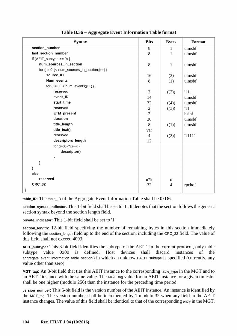
104 Rec. ITU-T J.94 (10/2016)
Table B.36 – Aggregate Event Information Table format
Syntax Bits Bytes Format
section_number 8 1 uimsbf last_section_number 8 1 uimsbf if (AEIT_subtype == 0) { num_sources_in_section 8 1 uimsbf for (j = 0; j< num_sources_in_section;j++) { source_ID 16 (2) uimsbf Num_events 8 (1) uimsbf for (j = 0; j< num_events;j++) { reserved 2 ((2)) '11' event_ID 14 uimsbf start_time 32 ((4)) uimsbf reserved 2 ((3)) '11' ETM_present 2 bslbf duration 20 uimsbf title_length 8 ((1)) uimsbf title_text() var reserved 4 ((2)) '1111' descriptors_length 12
for (i=0;i<N;i++) { descriptor() } } } else reserved n*8 n CRC_32 32 4 rpchof }
table_ID: The table_ID of the Aggregate Event Information Table shall be 0xD6.
section_syntax_indicator: This 1-bit field shall be set to '1'. It denotes that the section follows the generic
section syntax beyond the section length field.
private_indicator: This 1-bit field shall be set to '1'.
section_length: 12-bit field specifying the number of remaining bytes in this section immediately
following the section_length field up to the end of the section, including the CRC_32 field. The value of
this field shall not exceed 4093.
AEIT_subtype: This 8-bit field identifies the subtype of the AEIT. In the current protocol, only table
subtype value 0x00 is defined. Host devices shall discard instances of the
aggregate_event_information_table_section() in which an unknown AEIT_subtype is specified (currently, any
value other than zero).
MGT_tag: An 8-bit field that ties this AEIT instance to the corresponding table_type in the MGT and to
an AETT instance with the same value. The MGT_tag value for an AEIT instance for a given timeslot
shall be one higher (modulo 256) than the instance for the preceding time period.
version_number: This 5-bit field is the version number of the AEIT instance. An instance is identified by
the MGT_tag. The version number shall be incremented by 1 modulo 32 when any field in the AEIT
instance changes. The value of this field shall be identical to that of the corresponding entry in the MGT.

Rec. ITU-T J.94 (10/2016) 105
current_next_indicator: This 1-bit indicator is always set to '1' for AEIT sections; the AEIT sent is
always currently applicable.
section_number: This 8-bit field gives the number of this section.
last_section_number: This 8-bit field specifies the number of the last section.
num_sources_in_section: This 8-bit field gives the number of iterations of the "for" loop describing
program schedule data.
source_ID: This 16-bit field specifies the source_ID of the virtual channel carrying the events described
in this section.
num_events: Indicates the number of events to follow associated with the program source identified
by source_ID. Value 0 indicates no events are defined for this source for the time period covered by
the AEIT instance.
event_ID: This 14-bit field specifies the identification number of the event described. This number
serves as a part of the event ETM_ID (identifier for event Extended Text Message). An assigned event_ID
shall be unique at least within the scope of the instance of the AEIT in which it appears. Accordingly,
as an example, the event associated with event_ID 0x0123 in AEIT-m shall be considered to be an
event distinct from event_ID 0x0123 in AEIT-n, when m is not equal to n.
start_time: A 32-bit unsigned integer quantity representing the start time of this event as the number
of seconds since 0000 Hours UTC, January 6th, 1980. If the GPS_UTC_offset delivered in the System
Timetable is zero, start_time includes the correction for leap seconds. Otherwise, start_time can be
converted to UTC by subtracting the GPS_UTC_offset.
ETM_present: This 2-bit field indicates the existence of an Extended Text Message (ETM) based on
Table B.37.
Table B.37 – ETM_present
ETM_present Meaning
0x00 No ETM
0x01 ETM present on this out-of-band Extended Channel
0x02-0x03 [Reserved for future use]
duration: Duration of this event in seconds.
title_length: This field specifies the length (in bytes) of the title_text(). Value 0 means that no title exists
for this event.
title_text(): The event title in the format of a Multiple String Structure. title_text() shall be formatted
according to the Multiple String Structure (see clause B.8.2).
descriptors_length: Total length (in bytes) of the event descriptor list that follows.
CRC_32: This is a 32-bit field that contains the CRC value that ensures a zero output from the registers
in the decoder defined in Annex A of ITU-T H.222.0 | ISO/IEC 13818-1 "MPEG-2 Systems" after
processing the entire Aggregate Event Information Table section.
B.6.9 Aggregate Extended Text Tables (AETT)
The Aggregate Extended Text Table contains Extended Text Messages (ETM), which are used to
provide detailed descriptions of events. An ETM is a multiple string data structure. Thus, it may
represent a description in several different languages (each string corresponding to one language). If
necessary, the description may be truncated to fit the allocated display space.

106 Rec. ITU-T J.94 (10/2016)
The transmission format of the AETT and its affiliated AEIT allows instances of AEIT/AETT table
sections for different time slots to be associated with common PID values.
AETT-n shall be associated with the same PID value as AEIT-n for a given value of n.
The Aggregate Extended Text Table is carried in an MPEG-2 private section with table_ID 0xD7.
An instance of the AETT includes one or more ETMs. Each description is distinguished by its unique
32-bit ETM_ID.
Table B.38 defines the syntax of the Aggregate Extended Text Table.
Table B.38 – Aggregate Extended Text Table format
Syntax Bits Bytes Format
aggregate_extended_text_table_section () { table_ID 8 1 0xD7 section_syntax_indicator 1 2 '1' private_indicator 1 '1' Reserved 2 '11' section_length 12 uimsbf AETT_subtype 8 1 uimsbf MGT_tag 8 1 uimsbf Reserved 2 1 '11' version_number 5 uimsbf current_next_indicator 1 '1' section_number 8 1 uimsbf last_section_number 8 1 uimsbf if (AETT_subtype == 0) { num_blocks_in_section 8 1 uimsbf for (j = 0; j< num_blocks_in_section;j++) { ETM_ID 32 (4) uimsbf reserved 4 (2) '1111' extended_text_length 12 uimsbf extended_text_message() var } } Else reserved n*8 n CRC_32 32 4 rpchof }
table_ID: The table_ID of the Aggregate Extended Text Table shall be 0xD7.
section_syntax_indicator: This 1-bit field shall be set to '1'. It denotes that the section follows the generic
section syntax beyond the section length field.
private_indicator: This 1-bit field shall be set to '1'.
section_length: 12-bit field specifying the number of remaining bytes in the section immediately
following the section_length field up to the end of the section. The value of the section_length shall be no
larger than 4093.
AETT_subtype: This 8-bit field identifies the subtype of the AETT. In the current protocol, only table
subtype value 0x00 is defined. Host devices shall discard instances of the
aggregate_extended_text_table_section() in which an unknown AETT_subtype is specified (currently, any
value other than zero).

Rec. ITU-T J.94 (10/2016) 107
MGT_tag: An 8-bit field that ties this AETT instance to the corresponding table_type in the MGT and to
an AEIT instance with the same value. The MGT_tag value for an AETT instance for a given time
period shall be one higher (modulo 256) than the instance for the preceding time period.
version_number: This 5-bit field is the version number of the AETT instance. An instance is uniquely
identified by its MGT_tag. The version number shall be incremented by 1 modulo 32 when any field in
the AETT instance changes. The value of this field shall be identical to that of the corresponding entry
in the MGT.
current_next_indicator: This 1-bit indicator is always set to '1' for AETT sections; the AETT sent is
always currently applicable.
section_number: This 8-bit field gives the number of this section.
last_section_number: This 8-bit field specifies the number of the last section.
num_blocks_in_section: This 8-bit field gives the number of iterations of the "for" loop describing ETM
data.
ETM_ID: Unique 32-bit identifier of this Extended Text Message. This identifier is assigned by the rule
shown in Table B.39.
Table B.39 – ETM ID
MSB LSB
Bit 31 16 15 2 1 0
event ETM_ID source_ID event_ID 1 0
extended_text_length: A 12-bit unsigned integer number that represents the length, in bytes, of the
extended_text_message() field directly following.
extended_text_message(): The extended text message in the format of a Multiple String Structure
(see clause B.8.2).
CRC_32: This is a 32-bit field that contains the CRC value that ensures a zero output from the registers
in the decoder defined in Annex A of ITU-T H.222.0 | ISO/IEC 13818-1 "MPEG-2 Systems" after
processing the entire Transport Stream AETT section.
B.7 Descriptors
This clause defines descriptors applicable for use with various table sections defined in this annex.
B.7.1 Descriptor usage
Table B.40 lists all descriptors, their tag numbers and associated table sections applicable to out-of-band
SI transport. Asterisks mark the tables where the descriptors may appear. The range of descriptor tags
defined or reserved by MPEG-2 includes those with tag values 0x3F or below, plus 0xFF.

108 Rec. ITU-T J.94 (10/2016)
Table B.40 – Descriptor usage
Descriptor name Tag Table section
PMT NIT NTT S-VCT STT MGT L-VCT RRT AEIT
Stuffing descriptor 0x80 * * * * * * * * *
AC-3 audio descriptor 0x81 * *
Caption service
descriptor
0x86 * *
Content advisory
descriptor
0x87 * *
Revision detection
descriptor
0x93 * * *
Two part channel no.
descriptor
0x94 *
Channel properties
descriptor
0x95 *
Daylight savings time
descriptor
0x96 *
Extended channel name
descriptor
0xA0 *
Time shifted service
descriptor
0xA2 *
Component name
descriptor
0xA3 *
User private descriptors 0xC0-
0xFF
* * * * * * * *
B.7.2 Stuffing descriptor
For certain applications it is necessary to define a block of N bytes as a placeholder. The N bytes
themselves are not to be processed or interpreted. The stuffing_descriptor() is specified for this purpose.
The stuffing_descriptor() is simply a descriptor type for which the contents, as indicated by the
descriptor_length field, are to be disregarded. The tag type for the stuffing descriptor is 0x80. The
stuffing_descriptor() may appear where descriptors are allowed in any table defined in this annex.
B.7.3 AC-3 audio descriptor
The AC-3 audio descriptor, as defined in ATSC Standard A/52 (1995), and constrained in Annex B
of ATSC Standard A/53 (1995), may be used in the PMT and/or in AEITs.
B.7.4 Caption service descriptor
The caption service descriptor provides closed captioning information, such as closed captioning type
and language code for events with closed captioning service. This descriptor shall not appear on
events with no closed captioning service.
The bit stream syntax for the Caption Service Descriptor is shown in Table B.41.

Rec. ITU-T J.94 (10/2016) 109
Table B.41 – Caption Service Descriptor format
Syntax Bits Bytes Format
caption_service_descriptor() { descriptor_tag 8 1 0x86 descriptor_length 8 1 uimsbf Reserved 3 1 '111' number_of_services 5 uimsbf for (i=0;i<number_of_services;i++) { Language 8*3 (3) uimsbf cc_type 1 (1) bslbf Reserved 1 '1' if (cc_type==line21) { reserved 5 '11111' line21_field 1 bslbf } Else caption_service_number 6 uimsbf easy_reader 1 (2) bslbf wide_aspect_ratio 1 bslbf Reserved 14 '11111111111111' } }
descriptor_tag: An 8-bit field that identifies the type of descriptor. For the caption_service_descriptor() the
value is 0x86.
descriptor_length: An 8-bit count of the number of bytes following the descriptor_length itself.
number_of_services: An unsigned 5-bit integer in the range 1 to 16 that indicates the number of closed
caption services present in the associated video service. Note that if the video service does not carry
television closed captioning, the caption_service_descriptor() shall not be present either in the Program
Map Table or in the Aggregate Event Information Table.
Each iteration of the "for" loop defines one closed caption service present as a sub-stream within
the 9600 bit/s closed captioning stream. Each iteration provides the sub-stream's language, attributes,
and (for advanced captions) the associated Service Number reference. Refer to EIA-708 Specification
for Advanced Television Closed Captioning (ATVCC), for a description of the use of the Service
Number field within the syntax of the closed caption stream.
language: A 3-byte language code per ISO 639-2/B defining the language associated with one closed
caption service. The ISO_639_language_code field contains a three-character code as specified by
ISO 639-2/B. Each character is coded into 8 bits according to ISO 8859-1 (ISO Latin-1) and inserted
in order into the 24-bit field.
cc_type: A flag that indicates, when set, that an advanced television closed caption service is present
in accordance with EIA-708 Specification for Advanced Television Closed Captioning (ATVCC).
When the flag is clear, a line-21 closed caption service is present. For line 21 closed captions, the
line21_field indicates whether the service is carried in the even or odd field.
line21_field: A flag that indicates, when set, that the line 21 closed caption service is associated with
the field 2 of the NTSC waveform. When the flag is clear, the line-21 closed caption service is
associated with field 1 of the NTSC waveform. The line21_field flag is defined only if the cc_type flag
indicates line-21 closed caption service.
caption_service_number: A 6-bit unsigned integer value in the range zero to 63 that identifies the Service
Number within the closed captioning stream that is associated with the language and attributes defined
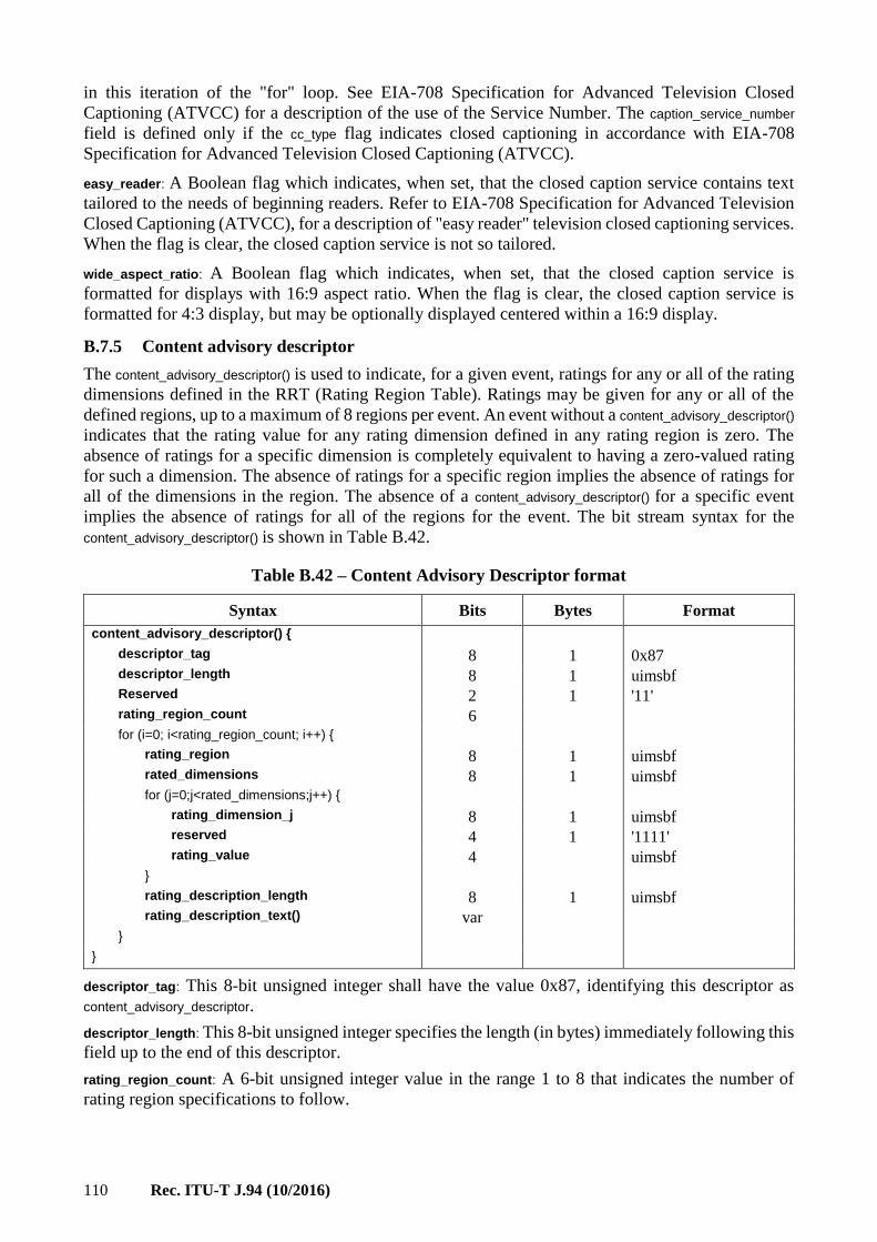
110 Rec. ITU-T J.94 (10/2016)
in this iteration of the "for" loop. See EIA-708 Specification for Advanced Television Closed
Captioning (ATVCC) for a description of the use of the Service Number. The caption_service_number
field is defined only if the cc_type flag indicates closed captioning in accordance with EIA-708
Specification for Advanced Television Closed Captioning (ATVCC).
easy_reader: A Boolean flag which indicates, when set, that the closed caption service contains text
tailored to the needs of beginning readers. Refer to EIA-708 Specification for Advanced Television
Closed Captioning (ATVCC), for a description of "easy reader" television closed captioning services.
When the flag is clear, the closed caption service is not so tailored.
wide_aspect_ratio: A Boolean flag which indicates, when set, that the closed caption service is
formatted for displays with 16:9 aspect ratio. When the flag is clear, the closed caption service is
formatted for 4:3 display, but may be optionally displayed centered within a 16:9 display.
B.7.5 Content advisory descriptor
The content_advisory_descriptor() is used to indicate, for a given event, ratings for any or all of the rating
dimensions defined in the RRT (Rating Region Table). Ratings may be given for any or all of the
defined regions, up to a maximum of 8 regions per event. An event without a content_advisory_descriptor()
indicates that the rating value for any rating dimension defined in any rating region is zero. The
absence of ratings for a specific dimension is completely equivalent to having a zero-valued rating
for such a dimension. The absence of ratings for a specific region implies the absence of ratings for
all of the dimensions in the region. The absence of a content_advisory_descriptor() for a specific event
implies the absence of ratings for all of the regions for the event. The bit stream syntax for the
content_advisory_descriptor() is shown in Table B.42.
Table B.42 – Content Advisory Descriptor format
Syntax Bits Bytes Format
content_advisory_descriptor() { descriptor_tag 8 1 0x87 descriptor_length 8 1 uimsbf Reserved 2 1 '11' rating_region_count 6 for (i=0; i<rating_region_count; i++) { rating_region 8 1 uimsbf rated_dimensions 8 1 uimsbf for (j=0;j<rated_dimensions;j++) { rating_dimension_j 8 1 uimsbf reserved 4 1 '1111' rating_value 4 uimsbf } rating_description_length 8 1 uimsbf rating_description_text() var } }
descriptor_tag: This 8-bit unsigned integer shall have the value 0x87, identifying this descriptor as
content_advisory_descriptor.
descriptor_length: This 8-bit unsigned integer specifies the length (in bytes) immediately following this
field up to the end of this descriptor.
rating_region_count: A 6-bit unsigned integer value in the range 1 to 8 that indicates the number of
rating region specifications to follow.

Rec. ITU-T J.94 (10/2016) 111
rating_region: An unsigned 8-bit integer that specifies the rating region for which the data in the bytes
to follow is defined. The rating_region associates ratings data given here with data defined in a Ratings
Region Table tagged with the corresponding rating region.
rated_dimensions: An 8-bit unsigned integer field that specifies the number of rating dimensions for
which content advisories are specified for this event. The value of this field shall not be greater than
the value specified by the field dimensions_defined in the corresponding RRT section.
rating_dimension_j: An 8-bit unsigned integer field specifies the dimension index into the RRT instance
for the region specified by the field rating_region. These dimension indices shall be listed in numerical
order, i.e., the value of rating_dimension_j+1 shall be greater than that of rating_dimension_j.
rating_value: A 4-bit field represents the rating value of the dimension specified by the field
rating_dimension_j for the region given by rating_region.
rating_description_length: An 8-bit unsigned integer value in the range 0 to 80 that represents the length
of the rating_description_text() field to follow.
rating_description_text(): The rating description in the format of a Multiple String Structure
(see clause B.8.2). The rating_description display string shall be limited to 16 characters or less. The
rating description text shall represent the program's rating in an abbreviated form suitable for
on-screen display. The rating description text collects multidimensional text information into a single
small text string. If "xxx" and "yyy" are abbreviated forms for rating values in two dimensions, then
"xxx-yyy" and "xxx (yyy)" are examples of possible strings represented in rating_description_text().
The program source provider shall be the responsible party for insertion of correct
content_advisory_descriptors in the Program Map Table (PMT). Also, the content_advisory_descriptors may
be included in Aggregate Event Information Tables. If content_ advisory_descriptors are available both in
AEIT and PMT, the PMT should be used first, then the AEITs.
B.7.6 Revision detection descriptor
The revision_detection_descriptor() is used to indicate whether new information is contained in the table
section in which it appears.
Table B.43 describes the revision_detection_descriptor. This descriptor should be the first descriptor in the
list to limit processing overhead.
Table B.43 – Revision Detection Descriptor format
Bits Bytes Format
revision_detection_descriptor(){ descriptor_tag 8 1 uimsbf value 0x93 descriptor_length 8 1 uimsbf reserved 3 1 bslbf table_version_number 5 uimsbf range 0-31 section_number 8 1 uimsbf range 0-255 last_section_number 8 1 uimsbf range 0-255 }
descriptor_tag: An 8-bit unsigned integer number that identifies the descriptor as a
revision_detection_descriptor(). The tag shall have the value 0x93.
descriptor_length: An 8-bit unsigned integer number that indicates the number of bytes to follow in the
descriptor. At present, just three bytes are defined, but the length field shall be processed to allow
new data to be added to the descriptor in the future.
table_version_number: This 5-bit unsigned integer in the range 0 to 31 identifies the version of the
current table. This integer applies only to the table (or the section of it) currently transmitted. Other

112 Rec. ITU-T J.94 (10/2016)
types of tables may have different version numbers. To indicate a change in a specific table, this
integer is incremented by 1 modulo 32.
section_number: An 8-bit unsigned integer in the range 0 to 255 that identifies the current table section.
Version numbers for all sections of a table must be the same. Note that section_number = 0 indicates
the first section of a table.
last_section_number: An 8-bit unsigned integer in the range 0 to 255 that identifies the number of
sections in a table. Note that if the last_section_number = 0, then there is only one section in this table.
B.7.7 Two-art channel number descriptor
Table B.44 describes the two_part_channel_number_descriptor(). This descriptor may appear in the
virtual_channel() record, contained in the VCM_structure; within the Short-form Virtual Channel Table
section. The descriptor may be used by compatible Hosts to associate a two-part user channel number
with any virtual channel. Some channels may have a two_part_channel_number_descriptor() while others
do not.
NOTE – For the L-VCT, the 10-bit major/minor number fields can be coded to represent a one-part channel
number. The one-part representation is not needed for the major/minor number fields in the
two_part_channel_number_descriptor() in the S-VCT, because there is already a 12-bit one-part number on each
channel in S-VCT. It would cause confusion to allow a second one-part number to be associated with a channel
defined in S-VCT.
Table B.44 – Two-part Channel Number Descriptor format
Bits Bytes Format
two_part_channel_number_descriptor(){ descriptor_tag 8 1 uimsbf value 0x94 descriptor_length 8 1 uimsbf Reserved 6 2 bslbf major_channel_number 10 uimsbf range 0-999 Reserved 6 2 bslbf minor_channel_number 10 uimsbf range 0-999 }
descriptor_tag: An 8-bit unsigned integer number that identifies the descriptor as a
two_part_channel_number_descriptor(). The tag shall have the value 0x94.
descriptor_length: An 8-bit unsigned integer number that indicates the number of bytes to follow in the
descriptor. At present, just four bytes are defined, but the length field shall be processed to allow new
data to be added to the descriptor in the future.
major_channel_number: A 10-bit unsigned integer in the range 0 to 999 that identifies the "major"
channel number to be associated with the virtual channel.
minor_channel_number: A 10-bit unsigned integer in the range 0 to 999 that identifies the "minor"
channel number to be associated with the virtual channel.
Hosts that support two-part channel numbering must support this descriptor. It is only mandatory for
this descriptor to be sent in the instance where system support of two-part channel numbering is
required. This means for virtual_channel() records where the Host does not receive the two-part channel
number descriptor, that the Host is expected to use the virtual_channel_number described in the
virtual_channel() record in clause B.6.3.2.
B.7.8 Channel properties descriptor
The channel_properties_descriptor() is defined to allow both forms of VCTs (S-VCT and L-VCT) carrying
the same properties. Table B.45 describes the syntax for this descriptor. The descriptor may appear
within a virtual_channel() record in the Short-form Virtual Channel Table.

Rec. ITU-T J.94 (10/2016) 113
Table B.45 – Channel Properties Descriptor format
Bits Bytes Format
channel_properties_descriptor(){ descriptor_tag 8 1 uimsbf value 0x95 descriptor_length 8 1 uimsbf channel_TSID 16 2 uimsbf reserved 6 1 '111111' out_of_band_channel 1 uimsbf access_controlled 1 uimbsf hide_guide 1 1 bslbf reserved 1 '1' service_type 6 uimsbf }
descriptor_tag: An 8-bit unsigned integer number that identifies the descriptor as a
channel_properties_descriptor(). The tag shall have the value 0x95.
descriptor_length: An 8-bit unsigned integer number that indicates the number of bytes to follow in the
descriptor. At present, just four bytes are defined, but the length field shall be processed to allow new
data to be added to the descriptor in the future.
channel_TSID: A 16-bit unsigned integer field in the range 0x0000 to 0xFFFF that represents the
MPEG-2 Transport Stream ID associated with the Transport Stream carrying the MPEG-2 program
referenced by this virtual channel. For inactive channels, channel_TSID represents the ID of the
Transport Stream that will carry the service when it becomes active. The Host may use the
channel_TSID to verify that a TS acquired at the referenced carrier frequency is actually the desired
multiplex. Analogue signals may have a TSID that is different from any MPEG-2 Transport Stream
identifier, that is, it shall be truly unique if present. A value of 0xFFFF for channel_TSID shall be
specified for situations where a valid TSID is not known (reserved as a wildcard capability).
out_of_band: A Boolean flag that indicates, when set, that the virtual channel associated with this
descriptor is carried on the cable on the Extended Channel interface carrying the tables defined in this
protocol. When clear, the virtual channel is carried within a standard tuned multiplex at that
frequency.
access_controlled: A Boolean flag that indicates, when set, that events associated with this virtual
channel may be access controlled. When the flag is zero, event access is not restricted.
hide_guide: A Boolean flag that indicates, when set to 0 for a channel of channel_type hidden, that the
virtual channel and its events may appear in EPG displays. This bit shall be ignored for channels
which are not the hidden type, so that non-hidden channels and their events may always be included
in EPG displays regardless of the state of the hide_guide bit. Typical applications for hidden channels
with the hide_guide bit set to 1 are test signals and services accessible through application-level
pointers.
service_type: A 6-bit enumerated type field that identifies the type of service carried in this virtual
channel. Service type is coded according to Table B.33.
Hosts may use this descriptor to become aware of aspects of the channel. In the case where this
descriptor is not received, the Host must tune the channel and self-discover these aspects of the
channel. For example, if this descriptor is not sent, and the channel is access controlled, the Host must
determine when it can obtain access permission (the same as if that bit in the descriptor were set).
Similar rules can be applied for service type and channel_TSID.

114 Rec. ITU-T J.94 (10/2016)
B.7.9 Extended channel name descriptor
The extended channel name descriptor provides the long channel name for the virtual channel
containing this descriptor.
The bit stream syntax for the extended channel name descriptor is shown in Table B.46.
Table B.46 – Extended Channel Name Descriptor format
Syntax Bits Bytes Format
extended_channel_name_descriptor() { descriptor_tag 8 1 0xA0 descriptor_length 8 1 uimsbf long_channel_name_text() Var }
descriptor_tag: This 8-bit unsigned integer shall have the value 0xA0, identifying this descriptor as
extended_channel_name_descriptor().
descriptor_length: This 8-bit unsigned integer specifies the length (in bytes) immediately following this
field up to the end of this descriptor.
long_channel_name_text(): The long channel name in the format of a Multiple String Structure
(see clause B.8.2).
B.7.10 Time-shifted service descriptor
This descriptor links one virtual channel with one or more virtual channels that carry the same
programming on a time-shifted basis. The typical application is for Near Video On Demand (NVOD)
services.
NOTE – For the L-VCT, the 10-bit major/minor number fields can be coded to represent a one-part channel
number. The one-part representation is not applicable for the major/minor number fields in the
time_shifted_services_descriptor() because this descriptor is not applicable to S-VCT (see Table F.2 ). The
major/minor number fields in the time_shifted_services_descriptor() are only used to match against fields in
the LVCT.
The bit stream syntax for the time_shifted_service_descriptor() is shown in Table B.47.
Table B.47 – Time-Shifted Service Descriptor format
Syntax Bits Bytes Format
time_shifted_service_descriptor() { descriptor_tag 8 1 0xA2 descriptor_length 8 1 uimsbf reserved 3 1 '111' number_of_services 5 uimsbf for (i=0;i<number_of_services;i++) { reserved 6 1 '111111' time_shift 10 1 uimsbf reserved 4 2 '1111' major_channel_number 10 uimsbf minor_channel_number 10 2 uimsbf } }
descriptor_tag: This 8-bit unsigned integer shall have the value 0xA2, identifying this descriptor as
time_shifted_service_descriptor().
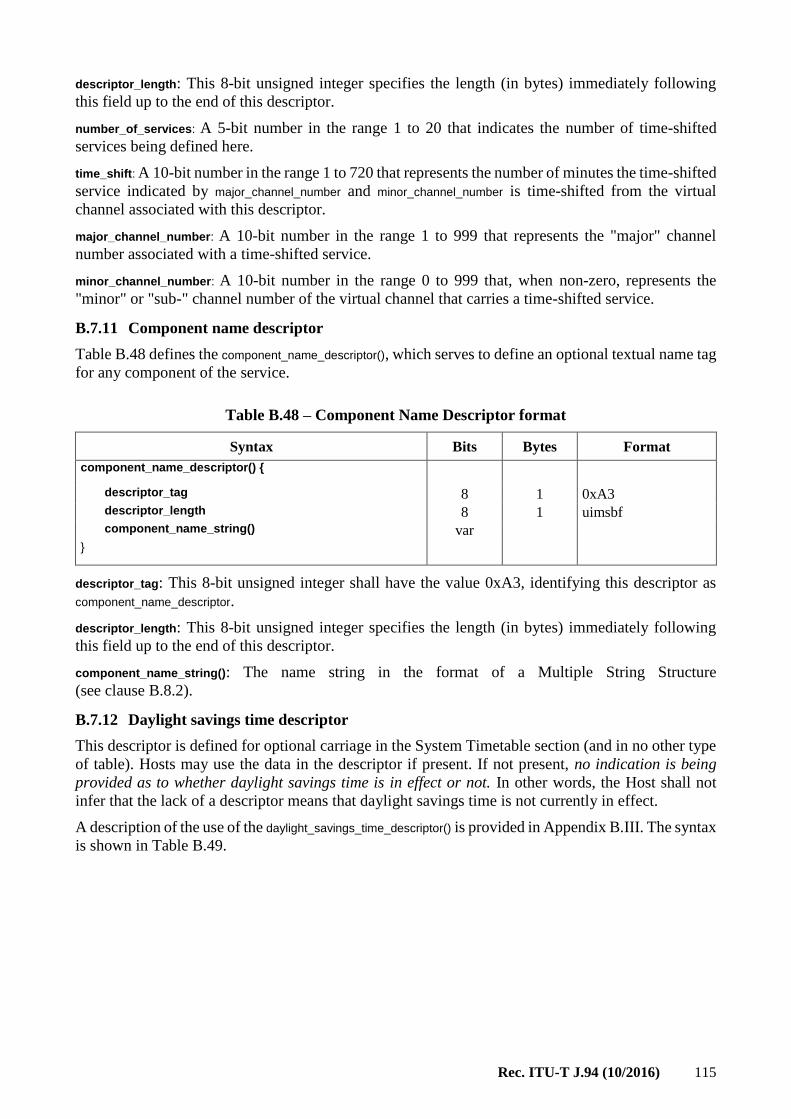
Rec. ITU-T J.94 (10/2016) 115
descriptor_length: This 8-bit unsigned integer specifies the length (in bytes) immediately following
this field up to the end of this descriptor.
number_of_services: A 5-bit number in the range 1 to 20 that indicates the number of time-shifted
services being defined here.
time_shift: A 10-bit number in the range 1 to 720 that represents the number of minutes the time-shifted
service indicated by major_channel_number and minor_channel_number is time-shifted from the virtual
channel associated with this descriptor.
major_channel_number: A 10-bit number in the range 1 to 999 that represents the "major" channel
number associated with a time-shifted service.
minor_channel_number: A 10-bit number in the range 0 to 999 that, when non-zero, represents the
"minor" or "sub-" channel number of the virtual channel that carries a time-shifted service.
B.7.11 Component name descriptor
Table B.48 defines the component_name_descriptor(), which serves to define an optional textual name tag
for any component of the service.
Table B.48 – Component Name Descriptor format
Syntax Bits Bytes Format
component_name_descriptor() {
descriptor_tag 8 1 0xA3 descriptor_length 8 1 uimsbf component_name_string() var }
descriptor_tag: This 8-bit unsigned integer shall have the value 0xA3, identifying this descriptor as
component_name_descriptor.
descriptor_length: This 8-bit unsigned integer specifies the length (in bytes) immediately following
this field up to the end of this descriptor.
component_name_string(): The name string in the format of a Multiple String Structure
(see clause B.8.2).
B.7.12 Daylight savings time descriptor
This descriptor is defined for optional carriage in the System Timetable section (and in no other type
of table). Hosts may use the data in the descriptor if present. If not present, no indication is being
provided as to whether daylight savings time is in effect or not. In other words, the Host shall not
infer that the lack of a descriptor means that daylight savings time is not currently in effect.
A description of the use of the daylight_savings_time_descriptor() is provided in Appendix B.III. The syntax
is shown in Table B.49.

116 Rec. ITU-T J.94 (10/2016)
Table B.49 – Daylight Savings Time Descriptor format
Syntax Bits Bytes Format
daylight_savings_time_descriptor() { descriptor_tag 8 1 uimsbf value 0x96 descriptor_length 8 1 uimsbf DS_status 1 1 bslbf reserved 2 '11' DS_day_of_month 5 uimsbf DS_hour 8 8 uimsbf }
descriptor_tag: This 8-bit unsigned integer shall have the value 0x96, identifying this descriptor as
daylight_savings_time_descriptor.
descriptor_length: This 8-bit unsigned integer specifies the length (in bytes) immediately following
this field up to the end of this descriptor.
DS_status: This bit indicates the status of daylight savings.
DS_status = '0': Not in daylight savings time.
DS_status = '1': In daylight savings time.
DS_day_of_month: This 5-bit unsigned integer field indicates the local day of the month on which the
transition into or out of daylight savings time is to occur (1-31).
DS_hour: This 8-bit unsigned integer field indicates the local hour at which the transition into or out
of daylight savings time is to occur (0-18). This usually occurs at 2 a.m. in the United States.
B.7.13 User private descriptors
Privately defined descriptors are those with descriptor_tag in the range 0xC0 through 0xFF. They may
be placed at any location where descriptors may be included within the table sections described in
this Service Information annex. Ownership of one or more user private descriptors is indicated by the
presence of an MPEG registration_descriptor() preceding the descriptor(s).
B.8 Text string coding
This clause describes the format of text strings in this Service Information annex. Two different
formats are used in this annex. Text strings in the Network Text Table uses a format called
Multilingual Text String (MTS), consisting of one or more mode-length-segment blocks. The MTS
format is described in clause B.8.1. All other tables and descriptors use a data structure called Multiple
String Structure, described in clause B.8.2. Tables B.50 and B.51 summarize these rules.
Table B.50 – Text String Coding Format in Tables
Table ID
Value (hex) Table Coding Reference
0xC3 Network Text Table (NTT) MTS Clause B.8.1
0xCA Rating Region Table (RRT) MSS Clause B.8.2
0xD6 Aggregate Event Information Table (AEIT) MSS Clause B.8.2
0xD7 Aggregate Extended Text Table (AETT) MSS Clause B.8.2

Rec. ITU-T J.94 (10/2016) 117
Table B.51 Text String Coding Format in Descriptors
Descriptor tag
value (hex) Descriptor Coding Reference
0x87 Content advisory descriptor MSS Clause B.8.2
0xA0 Extended channel name descriptor MSS Clause B.8.2
0xA3 Component name descriptor MSS Clause B.8.2
B.8.1 Multilingual Text String (MTS) Format
The format of Multilingual Text Strings adheres to the following structure. Items in square brackets
may be repeated one or more times:
<mode><length><segment> [ <mode><length><segment> ]
A string_length field always precedes one or more instances of mode, length, segment. This field is
described in each instance where multilingual text is used, and may be either 8- or 16-bits in length,
as appropriate. The value of string_length represents the sum total of all mode, length, segment blocks
comprising the multilingual text string to follow, and serves to indicate the end of the text string
structure.
The multilingual text data structure is designed to accommodate the need to represent a text string
composed of characters from a variety of alphabets, as well as ideographic characters. Whereas characters
could be represented using 16- or 32-bit character codes (as does Unicode ISO/IEC 10646-1), that form
is inefficient and wasteful of transmission bandwidth for strings composed primarily of alphabetic
rather than ideographic characters. To accommodate the need to handle Chinese, Japanese, and
Korean, modes are defined that allow 16-bit (double byte) character representations in standard
formats.
References below to ISO/IEC 10646-1 (Unicode) shall be to the Basic Multilingual Plane (BMP)
within that standard.
mode: An 8-bit value representing the text mode to be used to interpret characters in the segment to
follow. See Table B.52 for definition. Mode bytes in the range zero through 0x3E select Unicode
character code pages. Mode byte value 0x3F selects 16-bit Unicode character coding. Mode bytes in
the range 0x40 through 0xFF represent selection of a format effector function such as underline ON
or new line. If mode is in the range 0x40 to 0x9F, then the length/segment portion is omitted. Format
effector codes in the range 0x40 through 0x9F involve no associated parametric data; hence the
omission of the length/segment portion. Format effector codes in the range 0xA0 through 0xFF include
one or more parameters specific to the particular format effector function.
Table B.52 – Mode Byte Encoding
Mode Byte Meaning Language(s) or script
0x00 Select ISO/IEC 10646-1 Page 0x00 ASCII, ISO Latin-1 (Roman)
0x01 Select ISO/IEC 10646-1 Page 0x01 European Latin (many)a)
0x02 Select ISO/IEC 10646-1 Page 0x02 Standard Phonetic
0x03 Select ISO/IEC 10646-1 Page 0x03 Greek
0x04 Select ISO/IEC 10646-1 Page 0x04 Russian, Slavic
0x05 Select ISO/IEC 10646-1 Page 0x05 Armenian, Hebrew
0x06 Select ISO/IEC 10646-1 Page 0x06 Arabicb)
0x07-0x08 Reserved
0x09 Select ISO/IEC 10646-1 Page 0x09 Devanagaric), Bengali
0x0A Select ISO/IEC 10646-1 Page 0x0A Punjabi, Gujarti
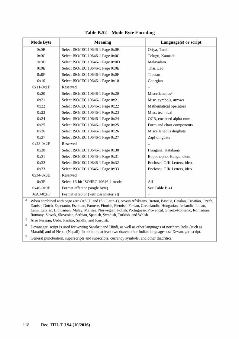
118 Rec. ITU-T J.94 (10/2016)
Table B.52 – Mode Byte Encoding
Mode Byte Meaning Language(s) or script
0x0B Select ISO/IEC 10646-1 Page 0x0B Oriya, Tamil
0x0C Select ISO/IEC 10646-1 Page 0x0C Telugu, Kannada
0x0D Select ISO/IEC 10646-1 Page 0x0D Malayalam
0x0E Select ISO/IEC 10646-1 Page 0x0E Thai, Lao
0x0F Select ISO/IEC 10646-1 Page 0x0F Tibetan
0x10 Select ISO/IEC 10646-1 Page 0x10 Georgian
0x11-0x1F Reserved
0x20 Select ISO/IEC 10646-1 Page 0x20 Miscellaneousd)
0x21 Select ISO/IEC 10646-1 Page 0x21 Misc. symbols, arrows
0x22 Select ISO/IEC 10646-1 Page 0x22 Mathematical operators
0x23 Select ISO/IEC 10646-1 Page 0x23 Misc. technical
0x24 Select ISO/IEC 10646-1 Page 0x24 OCR, enclosed alpha-num.
0x25 Select ISO/IEC 10646-1 Page 0x25 Form and chart components
0x26 Select ISO/IEC 10646-1 Page 0x26 Miscellaneous dingbats
0x27 Select ISO/IEC 10646-1 Page 0x27 Zapf dingbats
0x28-0x2F Reserved
0x30 Select ISO/IEC 10646-1 Page 0x30 Hiragana, Katakana
0x31 Select ISO/IEC 10646-1 Page 0x31 Bopomopho, Hangul elem.
0x32 Select ISO/IEC 10646-1 Page 0x32 Enclosed CJK Letters, ideo.
0x33 Select ISO/IEC 10646-1 Page 0x33 Enclosed CJK Letters, ideo.
0x34-0x3E Reserved
0x3F Select 16-bit ISO/IEC 10646-1 mode All
0x40-0x9F Format effector (single byte) See Table B.41.
0xA0-0xFF Format effector (with parameter[s])
a) When combined with page zero (ASCII and ISO Latin-1), covers Afrikaans, Breton, Basque, Catalan, Croatian, Czech,
Danish, Dutch, Esperanto, Estonian, Faroese, Finnish, Flemish, Firsian, Greenlandic, Hungarian, Icelandic, Italian,
Latin, Latvian, Lithuanian, Malay, Maltese, Norwegian, Polish, Portuguese, Provencal, Ghaeto-Romanic, Romanian,
Romany, Slovak, Slovenian, Serbian, Spanish, Swedish, Turkish, and Welsh. b) Also Persian, Urdu, Pashto, Sindhi, and Kurdish. c)
Devanagari script is used for writing Sanskrit and Hindi, as well as other languages of northern India (such as
Marathi) and of Nepal (Nepali). In addition, at least two dozen other Indian languages use Devanagari script. d)
General punctuation, superscripts and subscripts, currency symbols, and other diacritics.

Rec. ITU-T J.94 (10/2016) 119
Table B.53 describes the format of the multilingual_text_string().
Table B.53 – Multilingual text string format
Bits Bytes Format
multilingual_text_string(){ For (i=0; i<N; i++) { Mode 8 (1) uimsbf if (mode < 0x3F) { eightbit_string_length 8 ((1)) uimsbf for (i=0; i<eightbit_string_length; I++) { eightbit_char 8 (((1))) uimsbf } } else if (mode==0x3F) { sixteenbit_string_length 8 ((1)) uimsbf (even) for (i=0; i<(sixteenbit_string_length); i+=2) { sixteenbit_char 16 (((2))) uimsbf } } else if (mode >= 0xA0) { format_effector_param_length 8 ((1)) uimsbf for (i=0; i<(format_effector_param_length); i++) { format_effector_data 8 (((1))) } } } }
length: An 8-bit unsigned integer number representing the number of bytes in the segment to follow
in this block.
segment: An array of bytes representing a character string formatted according to the mode byte.
B.8.1.1 Mode byte definition
The mode byte is used either to select an ISO/IEC 10646-1 code page from the BMP (exact mapping,
or in the case of page zero, an extended mapping as defined herein), or to indicate that the text segment
is coded in one of a number of standard double-byte formats. Table B.52 shows the encoding of the
mode byte. Values in the zero to 0x33 range select ISO/IEC 10646-1 code pages.
Value 0x3F selects double-byte forms used with non-alphabetic script systems, where the segment
consists of a sequence of 16-bit character codes according to the ISO/IEC 10646-1 standard. Byte
ordering is high-order byte first (Motorola 680xx style), also known as big-endian.
B.8.1.2 Format effectors
Mode bytes in the 0x40 to 0xFF range are defined as format effectors. Table B.54 defines the
encoding for currently defined single-byte values. Format effectors in the range 0x40 through 0x9F
are self-contained, and do not have a length or data field following them. Format effectors in the range
0xA0 through 0xFF include a multi-byte parameter field. No multi-byte format effectors are currently
defined.

120 Rec. ITU-T J.94 (10/2016)
Table B.54 – Format Effector Function Codes
Mode byte Meaning
0x40-0x7F Reserved
0x80 new line, left justify
0x81 new line, right justify
0x82 new line, center
0x83 italics ON
0x84 italics OFF
0x85 underline ON
0x86 underline OFF
0x87 bold ON
0x88 bold OFF
0x89-0x9F Reserved
Line justification
Values 0x80, 0x81, and 0x82 signify the end of a line of displayed text. Value 0x80 indicates that the
text is displayed left justified within an enclosing rectangular region (defined outside the scope of the
text string). Value 0x81 indicates that the text is displayed right justified. Value 0x82 indicates that
the text is centered on the line. The dimensions and location on the screen of the box into which text
is placed is defined outside the scope of the text string itself.
Italics, underline, bold attributes
These format effectors toggle italics, underline, and bold display attributes. The italics, underline,
and bold format effectors indicate the start or end of the associated formatting within a text string.
Formatting extends through new lines. For example, to display three lines of bold text, only one
instance of the bold ON format effector is required.
Processing of unknown or unsupported format effectors
Hosts must discard format effectors that are unknown, or known not to be supported within a specific
Host model. If a parameter value carries an undefined value, that format effector is expected to be
discarded.
B.8.1.3 Default attributes
Upon entry to a multilingual text string, all mode toggles (bold, underline, italics) shall be assumed
"OFF".
B.8.1.4 Mode Zero
ISO/IEC 10646-1 page zero (U+0000 through U+00FF) includes ASCII in the lower half (U+0000
through U+007F), and Latin characters from ISO 8859-1, Latin-1, in U+0090 through U+00FF. This
set of characters covers Danish, Dutch, Faroese, Finnish, French, German, Icelandic, Irish, Italian,
Norwegian, Portuguese, Spanish and Swedish. Many other languages can be written with this set of
letters, including Hawaiian, Indonesian/Malay, and Swahili.
Table B.55 shows encodings of page zero characters in the range 0x80 through 0x9F (these are
undefined within ISO/IEC 10646-1).

Rec. ITU-T J.94 (10/2016) 121
Table B.55 – Encodings of columns 8 and 9 of mode zero latin character set
8 9
0 <RESERVED> <RESERVED>
1 <RESERVED> <RESERVED>
2 <RESERVED> <RESERVED>
3 <RESERVED> <RESERVED>
4 <RESERVED> <RESERVED>
5 <RESERVED> <RESERVED>
6 <RESERVED> <RESERVED>
7 <RESERVED> <RESERVED>
8 <RESERVED> U+2030 <PER MILLE>
9 <RESERVED> <RESERVED>
A <RESERVED> U+266A <MUSICAL NOTE>
B <RESERVED> <RESERVED>
C <RESERVED> U+2190 <LEFT ARROW>
D <RESERVED> U+2191 <UP ARROW>
E <RESERVED> U+2192 <RIGHT ARROW>
F <RESERVED> U+2193 <DOWN ARROW>
B.8.1.5 Supported characters
Support for specific characters and languages depends upon the specific model of
Standard-compatible Host. Not all Hosts support all defined character sets or character codes. Use of
multilingual text must be predicated on the knowledge of limitations in character rendering inherent
in different Host models for which text is available.
B.8.2 Multiple String Structure (MSS)
The Multiple String Structure is a general data structure used specifically for text strings. Text strings
appear as event titles, long channel names, the ETT messages, and RRT text items. The bit stream
syntax for the Multiple String Structure is shown in Table B.56.
Table B.56 – Multiple String Structure
Syntax Bits Format
multiple_string_structure () { number_strings 8 uimsbf for (i= 0;i< number_strings;i++) { ISO_639_language_code 8*3 uimsbf number_segments 8 uimsbf for (j=0;j<number_segments;j++) { compression_type 8 uimsbf Mode 8 uimsbf number_bytes 8 uimsbf for (k= 0;k<number_bytes;k++) compressed_string_byte [k] 8 bslbf } } }

122 Rec. ITU-T J.94 (10/2016)
number_strings: This 8-bit unsigned integer field identifies the number of strings in the following data.
ISO_639_language_code: This 3-byte (24 bits) field, in conformance with ISO 639-2/B, specifies the
language used for the ith string.
number_segments: This 8-bit unsigned integer field identifies the number of segments in the following
data. A specific mode is assigned for each segment.
compression_type: This 8-bit field identifies the compression type for the jth segment. Allowed values
for this field are shown in Table B.57.
Table B.57 – Compression types
compression_type Compression method
0x00 No compression
0x01 Huffman coding using standard encode/decode tables defined in Table C.4
and C.5 in Annex C of SCTE DVS 097, ATSC Standard A/65 (1997).
0x02 Huffman coding using standard encode/decode tables defined in Table C.6
and C.7 in Annex C of SCTE DVS 097, ATSC Standard A/65 (1997).
0x03 to 0xAF Reserved
0xB0 to 0xFF User private
mode: An 8-bit value representing the text mode to be used to interpret characters in the segment to
follow. See Table B.58 for definition. Mode values in the range zero through 0x3E select 8-bit
Unicode character code pages. Mode value 0x3F selects 16-bit Unicode character coding. Mode
values 0x40 through 0xDF are reserved for future use by ATSC. Mode values 0xE0 through 0xFE
are user private. Mode value 0xFF indicates the text mode is not applicable. Hosts shall ignore string
bytes associated with unknown or unsupported mode values.
Table B.58 – Modes
Mode Meaning Language(s) or script
0x00 Select ISO/IEC 10646-1 Page 0x00 ASCII, ISO Latin-1 (Roman)a)
0x01 Select ISO/IEC 10646-1 Page 0x01 European Latin (many)b)
0x02 Select ISO/IEC 10646-1 Page 0x02 Standard Phonetic
0x03 Select ISO/IEC 10646-1 Page 0x03
0x04 Select ISO/IEC 10646-1 Page 0x04 Russian, Slavic
0x05 Select ISO/IEC 10646-1 Page 0x05 Armenian, Hebrew
0x06 Select ISO/IEC 10646-1 Page 0x06 Arabicc)
0x07-0x08 Reserved –
0x09 Select ISO/IEC 10646-1 Page 0x09 Devanagarid), Bengali
0x0A Select ISO/IEC 10646-1 Page 0x0A Punjabi, Gujarati
0x0B Select ISO/IEC 10646-1 Page 0x0B Oriya, Tamil
0x0C Select ISO/IEC 10646-1 Page 0x0C Telugu, Kannada
0x0D Select ISO/IEC 10646-1 Page 0x0D Malayalam
0x0E Select ISO/IEC 10646-1 Page 0x0E Thai, Lao
0x0F Select ISO/IEC 10646-1 Page 0x0F Tibetan
0x10 Select ISO/IEC 10646-1 Page 0x10 Georgian
0x11-0x1F Reserved –
0x20 Select ISO/IEC 10646-1 Page 0x20 Miscellaneous
0x21 Select ISO/IEC 10646-1 Page 0x21 Misc. symbols, arrows

Rec. ITU-T J.94 (10/2016) 123
Table B.58 – Modes
Mode Meaning Language(s) or script
0x22 Select ISO/IEC 10646-1 Page 0x22 Mathematical operators
0x23 Select ISO/IEC 10646-1 Page 0x23 Misc. technical
0x24 Select ISO/IEC 10646-1 Page 0x24 OCR, enclosed alpha-num.
0x25 Select ISO/IEC 10646-1 Page 0x25 Form and chart components
0x26 Select ISO/IEC 10646-1 Page 0x26 Miscellaneous dingbats
0x27 Select ISO/IEC 10646-1 Page 0x27 Zapf dingbats
0x28-0x2F Reserved –
0x30 Select ISO/IEC 10646-1 Page 0x30 Hiragana, Katakana
0x31 Select ISO/IEC 10646-1 Page 0x31 Bopomopho, Hangul elem.
0x32 Select ISO/IEC 10646-1 Page 0x32 Enclosed CJK Letters, ideo.
0x33 Select ISO/IEC 10646-1 Page 0x33 Enclosed CJK Letters, ideo.
0x34-0x3E Reserved –
0x3F Select 16-bit ISO/IEC 10646-1 mode All
0x40-0xDF Reserved
0xE0-0xFE User private
0xFF Not applicable
a) The languages supported by ASCII plus the Latin-1 supplement include Danish, Dutch, English, Faroese, Finnish,
Flemish, German, Icelandic, Irish, Italian, Norwegian, Portuguese, Spanish and Swedish. Many other languages
can be written with this set of characters, including Hawaiian, Indonesian, and Swahili.
b) When combined with page zero (ASCII and ISO Latin-1), covers Afrikaans, Breton, Basque, Catalan, Croatian,
Czech, Esperanto, Estonian, French, Frisian, Greenlandic, Hungarian, Latin, Latvian, Lithuanian, Maltese, Polish,
Provencal, Rhaeto-Romanic, Romanian, Romany, Sami, Slovak, Slovenian, Sorbian, Turkish, Welsh, and many
others.
c) Also Persian, Urdu, Pashto, Sindhi, and Kurdish.
d) Devanagari script is used for writing Sanskrit and Hindi, as well as other languages of northern India (such as
Marathi) and of Nepal (Nepali). In addition, at least two dozen other Indian languages use Devanagari script.
number_bytes: This 8-bit unsigned integer field identifies the number of bytes that follows.
compressed_string_byte[k]: The kth byte of the jth segment.

124 Rec. ITU-T J.94 (10/2016)
Annex C
Service Information for digital multi-programme System C
(This annex forms an integral part of this Recommendation.)
Summary
This annex describes the service information for digital broadcasting by cable television of Annex C
of [ITU-T J.83] and basically constitutes a subset of Annex A to this Recommendation.
However, there are some specifications which are different from those of Annex A and also there are
some specifications which are yet to be established.
C.1 SI tables
The specifications for SI tables are fully aligned with those in Annex A both in table names and in
their function. See Table C.1.
Table C.1 – SI tables and their function
Table Function
Program Association Table
(PAT)
For each service in the multiplex, the PAT indicates the location (the PID
values of the Transport Stream packets) of the corresponding Program
Map Table (PMT). It also gives the location of the Network Information
Table (NIT).
Conditional Access Table
(CAT)
The CAT provides information on the Conditional Access (CA) systems
used in the multiplex; the information is private (not defined within
ITU-T H.222.0 | ISO/IEC 13818-1 and dependent on the CA system, but
includes the location of the EMM stream, when applicable.
Program Map Table
(PMT)
The PMT identifies and indicates the locations of the streams that make up
each service, and the location of the Program Clock Reference fields for a
service.
Network Information Table
(NIT) The location of the NIT is defined in ITU-T H.222.0 | ISO/IEC 13818-1,
but the data format is outside the scope of ITU-T H.222.0 | ISO/IEC
13818-1. It is intended to provide information about the physical network.
The syntax and semantics of the NIT are defined in this Recommendation.
Bouquet Association Table
(BAT)
The BAT provides information regarding bouquets. As well as giving the
name of the bouquet, it provides a list of services for each bouquet.
Service Description Table
(SDT)
The SDT contains data describing the services in the system, e.g., names
of services, the service provider, etc.
Network Information Table for
Type Length Value
(TLV-NIT)
It is intended to provide information about the physical network when the
signal is transmitted by TLV packets streams. The syntax and semantics of
the TLV-NIT are defined in this Recommendation.
Event Information Table
(EIT)
The EIT contains data concerning events or programs such as event name,
start time, duration, etc.; the use of different descriptors allows the
transmission of different kinds of event information, e.g., for different
service types.
Running Status Table
(RST)
The RST gives the status of an event (running/not running). The RST
updates this information and allows timely automatic switching to events.
Time and Date Table
(TDT)
The TDT gives information relating to present time and date. This
information is given in a separate table due to the frequent updating of the
time information.
Stuffing Table
(ST)
The ST is used to invalidate existing sections, for example at delivery
system boundaries.

Rec. ITU-T J.94 (10/2016) 125
The PID allocation for SI and the allocation of table_id values are as shown in Tables C.2 and C.3,
which are the same as those in Tables A.1 and A.2.
Table C.2 – PID allocation for SI
Table PID value
PAT 0x0000
CAT 0x0001
NIT, ST 0x0010
SDT, BAT, ST 0x0011
EIT, ST 0x0012
RST, ST 0x0013
TDT 0x0014
NULL 0x1FFF
Table C.3 – Allocation of table_id values
Value Table and description
0x00 PAT
0x01 CAT
0x02 PMT
0x40 NIT, network_information_section-actual_network
or TLV-NIT, network_information_actual_network
0x41 NIT, network_information_section-other_network
or TLV-NIT, network_information_other_network
0x42 SDT, service_description_section-actual_transport_stream
0x46 SDT, service_description_section-other_transport_stream
0x4A BAT
0x4E EIT, event_information_section-actual_transport_stream, present/following
0x4F EIT, event_information_section-other_transport_stream, present/following
0x50 to 0x5F EIT, event_information_section-actual_transport_stream, before 8th day
EIT, event_information_section-actual_transport_stream, on or after 8th day
0x60 to 0x6F EIT, event_information_section-other_transport_stream, before 8th day
EIT, event_information_section-other_transport_stream, on or after 8th day
0x70 TDT, time_date_section
0x71 RST, running_status_section
0x72 ST, stuffing_section
0x82 to 0x85 Reserved for conditional access system
0x90 to 0xBF Selectable as operator setting table_id

126 Rec. ITU-T J.94 (10/2016)
C.2 Descriptor
C.2.1 Location and tag value
The location and tag value of each descriptor are as shown in Table C.4. The description, data
structure, and syntax of each descriptor are the same as those in Table A.12. However, the coding of
the data field of each descriptor is not specified.
Table C.4 – Possible locations of descriptors
Descriptor Tag
value
NIT BAT SDT EIT PMT CAT TLV-
NIT
CA_descriptor 0x09 * *
network_name_descriptor 0x40 *
stuffing_descriptor 0x42 * * * *
cable_delivery_system_descriptor 0x44 *
bouquet_name_descriptor 0x47 * *
service_descriptor 0x48 *
linkage_descriptor 0x4A * * * *
NVOD_reference_descriptor 0x4B *
time_shifted_service_descriptor 0x4C *
short_event_descriptor 0x4D *
extended_event_descriptor 0x4E *
time_shifted_event_descriptor 0x4F *
component_descriptor 0x50 *
mosaic_descriptor 0x51 * *
stream_identifier_descriptor 0x52 *
content_descriptor 0x54 *
parental_rating_descriptor 0x55 *
User-defined 0x80 to
0xBF
channel_bonding_cable_delivery_system_descriptor 0xF3 * *
Forbidden 0xFF
area_specified_service_descriptor 0x96 * *
data_coding_method_descriptor 0xFD *
* Possible location
Descriptors which are used in Japan but not specified in Annex A are detailed in the following clauses.
C.2.2 CA descriptor
The CA descriptor which is described in CAT and PMT identifies the type of conditional access and
also identifies the PID in TS packet that carries the information related to conditional access.
Conditional access is only available when this descriptor is used. See Table C.5.

Rec. ITU-T J.94 (10/2016) 127
Table C.5 – CA descriptor
Syntax Bits Identifier Note
CA_descriptor(){
descriptor_tag 8 uimsbf
descriptor_length 8 uimsbf
CA_system_id 16 uimsbf
reserved 3 bslbf "111"
CA_PID 13 uimsbf
for (i = 0; i < N; i++) {
private_data } 8xN bslbf
}
C.2.3 Area specified service descriptor
This descriptor is used to render the services to the specified part within a given service area by
transmitting either the area list of the service reception area or the one beyond the service reception
area (see Table C.6). Area specified service is only available when this descriptor is used.
Table C.6 – Area specified service descriptor
Syntax Bits Identifier Note
area_specified_service _descriptor(){
descriptor_tag 8 uimsbf
descriptor_length 8 uimsbf
descriptor_flag 1 bslbf (1: available, 0: not available)
reserved 7 bslbf
for (i = 0; i < N; i++) { area_code 24 bslbf Alphanumeric 3 characters
}
}
C.2.4 Data coding method descriptor
The data coding method descriptor which is described in PMT identifies the data coding method for
data broadcasting services. See Table C.7.
Table C.7 – Data coding method descriptor
Syntax Bits Identifier Note
data_coding_method_descriptor(){
descriptor_tag 8 uimsbf
descriptor_length 8 uimsbf
data_component_id 16 uimsbf
for (i = 0; i < N; i++) {
additional_identification_information 8xN bslbf
}
}
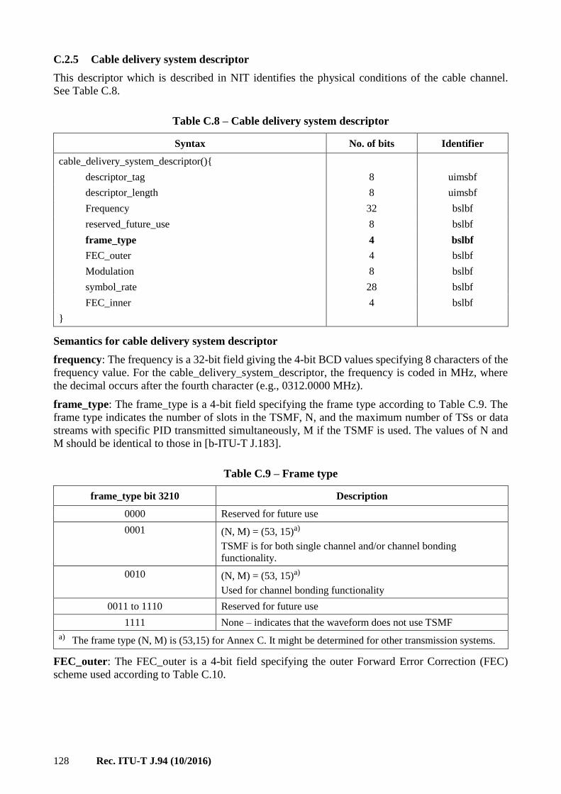
128 Rec. ITU-T J.94 (10/2016)
C.2.5 Cable delivery system descriptor
This descriptor which is described in NIT identifies the physical conditions of the cable channel.
See Table C.8.
Table C.8 – Cable delivery system descriptor
Syntax No. of bits Identifier
cable_delivery_system_descriptor(){
descriptor_tag 8 uimsbf
descriptor_length 8 uimsbf
Frequency 32 bslbf
reserved_future_use 8 bslbf
frame_type 4 bslbf
FEC_outer 4 bslbf
Modulation 8 bslbf
symbol_rate 28 bslbf
FEC_inner 4 bslbf
}
Semantics for cable delivery system descriptor
frequency: The frequency is a 32-bit field giving the 4-bit BCD values specifying 8 characters of the
frequency value. For the cable_delivery_system_descriptor, the frequency is coded in MHz, where
the decimal occurs after the fourth character (e.g., 0312.0000 MHz).
frame_type: The frame_type is a 4-bit field specifying the frame type according to Table C.9. The
frame type indicates the number of slots in the TSMF, N, and the maximum number of TSs or data
streams with specific PID transmitted simultaneously, M if the TSMF is used. The values of N and
M should be identical to those in [b-ITU-T J.183].
Table C.9 – Frame type
frame_type bit 3210 Description
0000 Reserved for future use
0001 (N, M) = (53, 15)a)
TSMF is for both single channel and/or channel bonding
functionality.
0010 (N, M) = (53, 15)a)
Used for channel bonding functionality
0011 to 1110 Reserved for future use
1111 None – indicates that the waveform does not use TSMF
a) The frame type (N, M) is (53,15) for Annex C. It might be determined for other transmission systems.
FEC_outer: The FEC_outer is a 4-bit field specifying the outer Forward Error Correction (FEC)
scheme used according to Table C.10.

Rec. ITU-T J.94 (10/2016) 129
Table C.10 – Outer FEC scheme
FEC_outer
bit 3210 Description
0000 Not defined
0001 No outer FEC coding
0010 RS(204/188)
0011 to 1111 Reserved for future use
modulation: This is an 8-bit field. It specifies the modulation scheme used on a cable delivery system
according to Table C.11.
Table C.11 – Modulation scheme for cable
Modulation
(hex) Description
0x00 Not defined
0x01 16-QAM
0x02 32-QAM
0x03 64-QAM
0x04 128-QAM
0x05 256-QAM
0x06 to 0xFF Reserved for future use
symbol_rate: The symbol_rate is a 28-bit field giving the 4-bit BCD values specifying 7 characters
of the symbol_rate in Msymbol/s where the decimal point occurs after the third character
(e.g., 027.4500).
FEC_inner: The FEC_inner is a 4-bit field specifying the inner FEC scheme used according to
Table C.12.
Table C.12 – Inner FEC scheme
FEC_inner
bit 3210 Description
0000 Not defined
0001 1/2 conv. code rate
0010 2/3 conv. code rate
0011 3/4 conv. code rate
0100 5/6 conv. code rate
0101 7/8 conv. code rate
1111 No conv. Coding
0110 to 1110 Reserved for future use

130 Rec. ITU-T J.94 (10/2016)
C.2.6 Channel bonding cable delivery system descriptor
This descriptor, which is described in NIT or TLV-NIT, is defined to identify the physical layer
specification of multiple channels for demodulation and combining to restore the original stream.
See Table C.13.
Table C.13 – Channel bonding cable delivery system descriptor
Syntax No. of bits Identifier
channel_bonding_cable_delivery_system_descriptor(){
descriptor_tag 8 uimsbf
descriptor_length 8 uimsbf
for(i=0;i<N;i++){
Frequency 32 bslbf
reserved_for_future_use 8
frame_type 4 uimsbf
FEC_outer 4 bslbf
Modulation 8 bslbf
symbol_rate 28 bslbf
FEC_inner 4 bslbf
group_id 8 bslbf
}
}
The value of descriptor tag,'0xF3', is used as described in Table C.4
N: number of carriers
group_id: This is an 8-bit field. It specifies a unique identifier of a group corresponding to bonding
channels.
Other semantics are the same as 'Cable delivery system descriptor' in clause C.2.5.
C.3 Character code tables
The tables corresponding to Annex A are currently under study.

Rec. ITU-T J.94 (10/2016) 131
Annex D
Coding of text characters for System A
(This annex forms an integral part of this Recommendation.)
Text items can optionally include information to select a wide range of character tables as indicated
below.
For the European languages a set of five character tables are available. If no character selection
information is given in a text item, then a default character set is assumed.
D.1 Control codes
The codes in the range 0x80 to 0x9F are assigned to control functions as shown in Table D.1.
Table D.1 – Single byte control codes
Control code Description
0x80 to 0x85 Reserved for future use
0x86 Character emphasis on
0x87 Character emphasis off
0x88 to 0x89 Reserved for future use
0x8A CR/LF
0x8B to 0x9F User-defined
For two-byte character tables, the codes in the range 0xE080 to 0xE09F are assigned to control
functions as shown in Table D.2.
Table D.2 – DVB codes within private use area of [ISO/IEC 10646-1]
Control code Description
0xE080 to 0xE085 Reserved for future use
0xE086 Character emphasis on
0xE087 Character emphasis off
0xE088 to 0xE089 Reserved for future use
0xE08A CR/LF
0xE08B to 0xE09F Reserved for future use
D.2 Selection of character table
Text fields can optionally start with non-spacing, non-displayed data which specify the alternative
character table to be used for the remainder of the text item. The selection of character table is
indicated as follows:
– if the first byte of the text field has a value in the range "0x20" to "0xFF", then this and
all subsequent bytes in the text item are coded using the default character coding table
(table 00 Latin alphabet) of Figure D.1;
– if the first byte of the text field has a value in the range "0x01" to "0x05", then the remaining
bytes in the text item are coded in accordance with character coding tables 01 to 05
respectively, which are given in Figures D.2 to D.6 respectively;

132 Rec. ITU-T J.94 (10/2016)
– if the first byte of the text field has a value "0x10", then the following two bytes carry a 16-bit
value (uimsbf) N to indicate that the remaining data of the text field is coded using the
character code table specified by [ISO/IEC 8859], Parts 1 to 9;
– if the first byte of the text field has a value "0x11", then the remaining bytes in the text item
are coded in pairs in accordance with the Basic Multilingual Plane of [ISO/IEC 10646-1].
Values for the first byte of "0x00", "0x06" to "0x0F", and "0x12" to "0x1F" are reserved for future use.
NOTE 1 – The SPACE character is located in position 20h of the code table.
NOTE 2 – NBSP = No-Break Space.
NOTE 3 – SHY = Soft Hyphen.
NOTE 4 – Table reproduced from ISO/IEC 6937 (1994).
NOTE 5 – All characters in column C are non-spacing characters (diacritical marks).
Figure D.1 – Character code table 00 – Latin alphabet
T0906080-98/d03
0 NBSP
TM
SHY
0 @ P p
q
r
! 1 A Q a
b R B 2 "
s c S c 3 #
$ 4 D T d t
u e U E %
F
G
5
& 6 V f v
7 W g w
x h X H 8 (
) 9 I Y i y
* : J Z j z
+ ; K [ k {
< L \ l |
– = M ] m }
~ n ^ N . >
o _ o ? /
à
First nibble Second nibble 0 1 2 3 4 5 6 7 8 9 A B C D E F
1
2
3
4
5
6
7
8
9
A
B
C
D
E
F
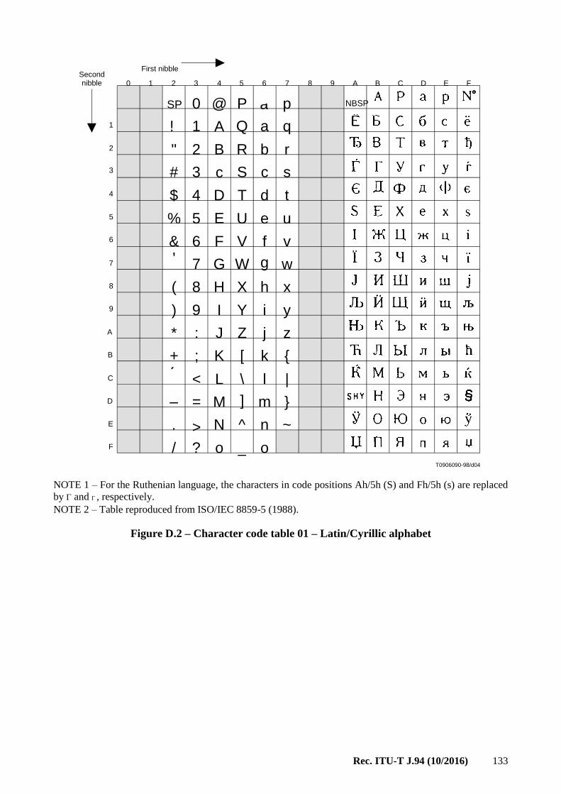
Rec. ITU-T J.94 (10/2016) 133
NOTE 1 – For the Ruthenian language, the characters in code positions Ah/5h (S) and Fh/5h (s) are replaced
by and , respectively.
NOTE 2 – Table reproduced from ISO/IEC 8859-5 (1988).
Figure D.2 – Character code table 01 – Latin/Cyrillic alphabet
IGURE A.A.2/J.94...[D04] = 3 CM
T0906090-98/d04
SP 0 @ P p
q
r
! 1 A Q a
b R B 2 "
s c S c 3 #
$ 4 D T d t
u e U E %
F
G
5
& 6 V f v
7 W g w
x h X H 8 (
) 9 I Y i y
* : J Z j z
+ ; K [ k {
< L \ l |
– = M ] m }
~ n ^ N . >
o _ o ? /
NBSP à
First nibble Second nibble 0 1 2 3 4 5 6 7 8 9 A B C D E F
1
2
3
4
5
6
7
8
9
A
B
C
D
E
F

134 Rec. ITU-T J.94 (10/2016)
NOTE – Table reproduced from ISO 8859-6 (1987).
Figure D.3 – Character code table 02 – Latin/Arabic alphabet
T0906100-98/d05
SP NBSP
SHY
0 @ P p
q
r
! 1 A Q a
b R B 2 "
s c S c 3 #
$ 4 D T d t
u e U E %
F
G
5
& 6 V f v
7 W g w
x h X H 8 (
) 9 I Y i y
* : J Z j z
+ ; K [ k {
< L \ l |
– = M ] m }
~ n ^ N . >
o _ o ? /
à
First nibble Second nibble 0 1 2 3 4 5 6 7 8 9 A B C D E F
1
2
3
4
5
6
7
8
9
A
B
C
D
E
F
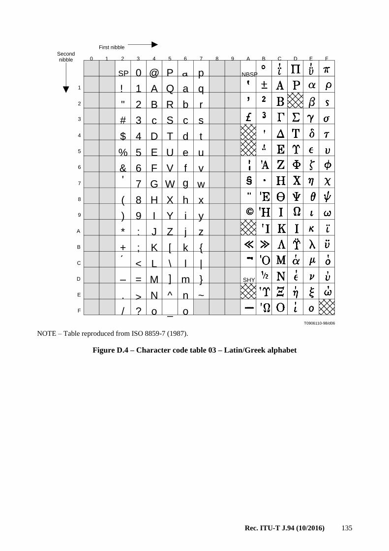
Rec. ITU-T J.94 (10/2016) 135
NOTE – Table reproduced from ISO 8859-7 (1987).
Figure D.4 – Character code table 03 – Latin/Greek alphabet
T0906110-98/d06
SP 0 @ P p
q
r
! 1 A Q a
b R B 2 "
s c S c 3 #
$ 4 D T d t
u e U E %
F
G
5
& 6 V f v
7 W g w
x h X H 8 (
) 9 I Y i y
* : J Z j z
+ ; K [ k {
< L \ l |
– = M ] m }
~ n ^ N . >
o _ o ? /
NBSP
SHY
à
First nibble Second nibble 0 1 2 3 4 5 6 7 8 9 A B C D E F
1
2
3
4
5
6
7
8
9
A
B
C
D
E
F

136 Rec. ITU-T J.94 (10/2016)
FIGURE A.A.5/J.94...[D07] = 3 CM
NOTE – Table reproduced from ISO 8859-8 (1988)
Figure D.5 – Character code table 04 – Latin/Hebrew alphabet
T0906120-98/d07
SP 0 @ P p
q
r
! 1 A Q a
b R B 2 "
s c S c 3 #
$ 4 D T d t
u e U E %
F
G
5
& 6 V f v
7 W g w
x h X H 8 (
) 9 I Y i y
* : J Z j z
+ ; K [ k {
< L \ l |
– = M ] m }
~ n ^ N . >
o _ o ? /
NBSP
SHY
à
First nibble Second nibble 0 1 2 3 4 5 6 7 8 9 A B C D E F
1
2
3
4
5
6
7
8
9
A
B
C
D
E
F

Rec. ITU-T J.94 (10/2016) 137
FIGURE A.A.6/J.94...[D08] = 3 CM
NOTE – Table reproduced from ISO/IEC 8859-9.
Figure D.6 – Character code table – Latin alphabet No 5
T0906130-98/d08
SP 0 @ P p
q
r
! 1 A Q a
b R B 2 "
s c S c 3 #
$ 4 D T d t
u e U E %
F
G
5
& 6 V f v
7 W g w
x h X H 8 (
) 9 I Y i y
* : J Z j z
+ ; K [ k {
< L \ l |
– = M ] m }
~ n ^ N . >
o _ o ? /
NBSP
SHY
à
First nibble Second nibble 0 1 2 3 4 5 6 7 8 9 A B C D E F
1
2
3
4
5
6
7
8
9
A
B
C
D
E
F

138 Rec. ITU-T J.94 (10/2016)
Annex E
CRC decoder model for system A
(This annex forms an integral part of this Recommendation.)
The 32-bit CRC decoder is specified in Figure E.1.
Figure E.1 – 32 bit CRC decoder model
The 32-bit CRC decoder operates at bit level and consists of 14 adders + and 32 delay elements z(i).
The input of the CRC decoder is added to the output of z(31), and the result is provided to the input
z(0) and to one of the inputs of each remaining adder.
The other input of each remaining adder is the output of z(i), while the output of each remaining adder
is connected to the input of z(I + 1), with i = 0, 1, 3, 4, 6, 7, 9, 10, 11, 15, 21, 22 and 25 (see Figure E.1).
This is the CRC calculated with the polynomial:
x32 x26 + x23 + x22 + x16 + x12 + x11 + x10 + x8 + x7 + x5 + x4 + x2 + x + 1
At the input of the CRC decoder bytes are received.
Each byte is shifted into the CRC decoder one bit at a time, with the most significant bit (msb) first,
i.e., from byte 0x01 (the last byte of the startcode prefix), first the seven "0"s enter the CRC decoder,
followed by the one "1".
Before the CRC processing of the data of a section the output of each delay element z(i) is set to its
initial value "1". After this initialization, each byte of the section is provided to the input of the CRC
decoder, including the four CRC_32 bytes.
After shifting the last bit of the last CRC_32 byte into the decoder, i.e., into z(0) after the addition
with the output of z(31), the output of all delay elements z(i) is read. In case of no errors, each of the
outputs of z(i) has to be zero.
At the CRC encoder the CRC_32 field is encoded with such value that this is ensured.

Rec. ITU-T J.94 (10/2016) 139
Annex F
Operational profiles for cable service information delivery for system B
(This annex forms an integral part of this Recommendation.)
F.1 Operational profiles
Annex F specifies Service Information tables that are required for delivery via an out-of-band channel
on cable. Six profiles are described with required and optional data specified for out-of-band transport
via cable. Adherence to these profile specifications is necessary for compliance with SCTE standard
transport streams.
F.1.1 Profile 1 – Baseline
This Baseline Profile reflects a practice in cable where the Short-Form Virtual Channel Table, the
Modulation Mode Subtable and the Carrier Definition Subtable are used for channel navigation.
F.1.2 Profile 2 – Revision detection
Profile 2 uses the same channel navigation mechanism as Profile 1 while adding a detection
mechanism that facilitates revision handling of tables. The revision detection mechanism is applicable
to the Network Information Table, Network Text Table, and S-VCT that are also used in Profile 1.
F.1.3 Profile 3 – Parental advisory
Profile 3 uses Profile 2 as the base and adds support for the Rating Region Table in order to be
compliant with the FCC-mandated V-chip content advisory scheme. Since for the U.S. and its
possessions, EIA-766 defines the contents of version 0 RRT, use of RRT is more applicable to outside
of North America. The channel navigation mechanism is the same as in Profile 1.
F.1.4 Profile 4 – Standard electronic program guide data
Profile 4 uses Profile 3 as the base and further defines a standard format for delivery of Electronic
Program Guide data by using the Aggregate Event Information Table and the Aggregate Extended
Text Table. The Master Guide Table shall be supported to manage the AEITs, AETTs and other
applicable tables from Profile 3. The same mechanism as in Profile 1 is used for channel navigation.
F.1.5 Profile 5 – Combination
Support for channel navigation based on L-VCT and MGT is added. Backward compatibility with
systems operating within profiles 1 to 4 is maintained. Using Profile 5, a cable operator could have a
mixture of devices requiring the S-VCT, NIT and NTT tables as well as ones requiring the long-form
tables: i.e., L-VCT, MGT.
When using Profile 5, both the S-VCT and the L-VCT shall be present, and each shall describe all
available services.
F.1.6 Profile 6 – PSIP Only
Profile 6 is based solely on long-form tables and is an extension of the terrestrial broadcasting
mechanism. Channel navigation is based on the Long-form Virtual Channel Table. The AEIT and the
optional AETT streams are used to provide EPG data.
F.2 Profile Definition Tables
In order to conform to this Service Information Annex F, a cable operator shall send a collection of
tables that corresponds to one or more of the defined operational profiles defined in Tables F.1 and F.2.

140 Rec. ITU-T J.94 (10/2016)
Table F.1 – Usage of Table Sections in Various Profiles
Profile
1
Profile
2
Profile
3
Profile
4
Profile
5
Profile
6
Table Section Table
ID Baseline
Revision
Detection
Parental
Advisory
Standard
EPG Data
Combi-
nation
PSIP
only
(Note 1)
Network Information
Table
0xC2
Carrier Definition
Subtable M M M M M –
Modulation Mode
Subtable M M M M M –
Network Text Table 0xC3
Source Name Subtable O O O M M –
Short-form Virtual
Channel Table
0xC4
Virtual Channel Map M M M M M –
Defined Channels Map M M M M M –
Inverse Channel Map O O O O O –
System Timetable 0xC5 M M M M M M
Master Guide Table 0xC7 – – (Note 2) M M M
Rating Region Table 0xCA – – (Note 3) (Note 3) (Note 3) (Note 3)
Long-form Virtual
Channel Table
0xC9 – – – – M M
Aggregate Event
Information Table
0xD6 – – – M M M
Aggregate Extended Text
Table
0xD7 – – – O O O
M Mandatory (shall be present)
O Optional (may or may not be present)
– Not applicable (shall not be present)
NOTE 1 – Exception: System Timetable (table ID 0xC5 is used here instead of table ID 0xCD defined in
PSIP) and other modifications.
NOTE 2 – Mandatory for outside of North America to describe any transmitted RRT. For region 0x01
(US and possessions), delivery of an RRT is optional, because this table is standardized in EIA-766.
NOTE 3 – Exception: delivery of the RRT corresponding to region 0x01 (US and possessions) is optional,
because this table is standardized in EIA-766.

Rec. ITU-T J.94 (10/2016) 141
Table F.2 – Usage of Descriptors in Various Profiles
Profile
1
Profile
2
Profile
3
Profile
4
Profile
5
Profile
6
Descriptor
(and associated table) Tag Baseline
Revision
Detection
Parental
Advisory
Standard
EPG Data
Combi-
nation
PSIP
only
(Note 1)
AC-3 audio
(PMT, AEIT)
0x81 O O O
Caption service
(PMT, AEIT)
0x86 O O O
Content advisory
(PMT, AEIT)
0x87 (Note 2) (Note 2) (Note 2) (Note 2)
Revision detection
(NIT,NTT,
S-VCT)
0x93 M M M M
Two-part channel
number
(S-VCT)
0x94 O O
Channel properties
(S-CT)
0x95 O O
Daylight savings time
(STT)
0x96 O M M M
Extended channel name
(L-VCT)
0xA0 O O
Time-shifted service
(L-CT)
0xA2 O O
Component name (PMT) 0xA3 O O O
M Mandatory (shall be present)
O Optional (may or may not be present)
Not applicable (shall not be present)
NOTE 1 – Exception: System Timetable (table ID 0xC5 is used here instead of table ID 0xCD defined in
PSIP) and other modifications.
NOTE 2 – The content_advisory_descriptor() shall be present in the AEIT and PMT for a given program when
Content Advisory data is available for that program. It is not required for programs for which Content
Advisory data is not available.
F.3 Operational considerations for the use of profiles (Informative)
1) If devices deployed in a particular cable system require the S-VCT in Profiles 1-5 for
navigation, cable operator's use of P6 will cause operational problems.
2) If devices in use require L-VCT for navigation, cable operator's use of Profiles 1-4 will cause
operational problems.
3) To provide EPG data, cable-ready devices operating on a cable system conforming to
Profiles 1, 2 or 3 must use alternative protocols and methods which are beyond the scope of
this Annex F.

142 Rec. ITU-T J.94 (10/2016)
Annex G
Packet rates for system B
(This annex forms an integral part of this Recommendation.)
G.1 Maximum cycle times
Table G.1 lists the maximum cycle time for Service Information table sections for out-of-band cable
operation, when the indicated table is present.
Table G.1 – Maximum cycle time for the STT, MGT, S-VCT, L-VCT and RRT
Table Section STT MGT S-VCT L-VCT RRT
Cycle time 1 min 500 msec 2 min 2 min 1 min
G.2 Maximum transmission rates
Table G.2 lists the maximum transmission rate for SI packet streams.
Table G.2 – Maximum rate for each packet stream
PID SI_base PID Any AEIT/AETT PID
Rate (bit/s) 150 000 150 000
G.3 Minimum transmission rates
Table G.3 lists the minimum transmission rate for SI packet streams. Minimum per-PID bit rates are
required to ensure efficiency of recovery of EPG data covering the current time period (3 hours
minimum) across the POD to Host interface, given the small number of PID values that can be used
concurrently.
Table G.3 – Minimum rate for each packet stream
PID AEIT-0,1/AETT-0,1 PID
Rate (bit/s) 10 000

Rec. ITU-T J.94 (10/2016) 143
Annex H
Standard Huffman tables for text compression for system B
(This annex forms an integral part of this Recommendation.)
Annex H describes the compression method adopted for the transmission of English-language text
strings in PSIP. The method distinguishes two types of text strings: titles and program descriptions.
For each of these types, Huffman tables are defined based on 1st-order conditional probabilities.
Clause H.2 defines standard Huffman encode and decode tables optimized for English-language text
such as that typically found in program titles. Clause H.3 defines Huffman encode and decode tables
optimized for English-language text such as that typically found in program descriptions. Hosts
supporting the English language are expected to support decoding of text using either of these two
standard Huffman compression tables.
The encode tables provide necessary and sufficient information to build the Huffman trees that need
to be implemented for decoding. The decode tables described in Tables H.5 and H.7 are a particular
mapping of those trees into a numerical array suitable for storage. This array can be easily
implemented and used with the decoding algorithm. However, the user is free to design its own
decoding tables as long as they follow the Huffman trees and rules defined in this annex.
H.1 Character set definition
This compression method supports the full ISO/IEC 8859-1 (Latin-1) character set, although only
characters in the ASCII range (character codes 1 to 127) can be compressed. The following characters
in Table H.1 have special definitions:
Table H.1 – Characters with special definitions
Character Value
(Decimal) Meaning
String Terminate
(ASCII Null)
0 The Terminate character is used to terminate strings. The Terminate
character is appended to the string in either compressed or
uncompressed form.
The first encoded character in a compressed string is
encoded/decoded from the Terminate sub-tree. In other words, when
encoding or decoding the first character in a compressed string,
assume that the previous character was a Terminate character.
Order-1 Escape
(ASCII ESC)
27 Used to escape from first-order context to uncompressed context. The
character which follows the Escape character is uncompressed.
H.1.1 First Order Escape
The order-1 Huffman trees are partial, that is, codes are not defined for every possible character
sequence. For example, the standard decode tables do not contain codes for the character sequence
qp. When uncompressed text contains a character sequence which is not defined in the decode table,
the order-1 escape character is used to escape back to the uncompressed context. Uncompressed
symbols are coded as 8-bit ASCII (Latin-1). For example, the character sequence qpa would be coded
with compressed q, compressed ESC, uncompressed p, compressed a.
First-order escape rules for compressed strings:
– Any character which follows a first-order escape character is an uncompressed (8-bit)
character. (Any character which follows an uncompressed escape character is compressed).
– Characters (128 … 255) cannot be compressed.
– Any character which follows a character from the set (128 … 255) is uncompressed.

144 Rec. ITU-T J.94 (10/2016)
H.1.2 Decode table data structures
Decode tables have two sections:
– Tree Root Offset List: Provides the table offsets, in bytes from the start of the decode table,
for the roots of the 128 first-order decode trees. The list is contained in bytes (0 … 255) of
the decode table, and is defined by the first "for" loop in Table H.1.
– Order-1 Decode Trees: Each and every character in the range (0 … 127) has a
corresponding first-order decode tree. For example, if the previous character was "s", then
the decoder would use the "s" first-order decode tree (decode tree #115) to decode the next
character (ASCII "s" equals 115 decimal). These 128 decode trees are delimited by the second
"for" loop in Table H.2.
Decode tables have the following format:
Table H.2 – Decode Table Format
Syntax Bits Format
decode_table() {
for (i==0; i<128; i++) {
byte_offset_of_char_i_tree_root 16 uimsbf
}
for (i==0; i<128; i++) {
character_i_order_1_tree() 8*M
}
}
Note that even though the ISO Latin-1 character set supports up to 256 characters, only the first
128 characters may be represented in compressed form.
H.1.2.1 Tree root byte offsets
byte_offset_of_character_i_tree_root: A 16-bit unsigned integer specifying the location, in bytes from the
beginning of the decode table, of the root for the ith character's order-1 tree.
H.1.2.2 Order-1 decode trees
Order-1 decode trees are binary trees. The roots of the decode trees are located at the table offsets
specified in the tree root offset list. The left and right children of a given node are specified as word
offsets from the root of the tree (a word is equivalent to two bytes).
Decode trees have the format as shown in Table H.3:
Table H.3 – Decode tree format
Syntax Bits Format
character_i_order_1_tree() { for (j==0; j<N; j++) { left_child_word_offset_or_char_leaf 8 uimsbf right_child_word_offset_or_char_leaf 8 uimsbf } }

Rec. ITU-T J.94 (10/2016) 145
left_child_word_offset_or_character_leaf: An 8-bit unsigned integer number with the following
interpretation: If the highest bit is cleared (i.e., bit 7 is zero), the number specifies the offset, in words,
of the left child from the root of the order-1 decode tree; if the highest bit is set (bit 7 is one), the
lower 7 bits give the code (e.g., in ASCII) for a leaf character.
right_child_word_offset_or_character_leaf: An 8-bit unsigned integer number with the following
interpretation: If the highest bit is cleared (i.e., bit 7 is zero), the number specifies the offset, in words,
of the right child from the root of the order-1 decode tree; if the highest bit is set (bit 7 is one), the
lower 7 bits give the code (e.g., in ASCII) for a leaf character.
Each node (corresponding to one iteration of the for-loop) has a byte for the left child or character,
and a byte for the right child or character.
Characters are leaves of the order-1 decode trees, and are differentiated from intermediate nodes by
the byte's most significant bit. When the most significant bit is set, the byte is a character leaf. When
the most significant bit is not set, the byte contains the tabular word offset of the child node.
H.2 Standard compression Type 1 Encode/Decode Tables
The following encode/decode tables (Tables H.4 and H.5) are optimized for English-language
program title text. These tables correspond to multiple_string_structure() with compression_type value 0x01,
and a mode equal to 0xFF.
Table H.4 – English-language Program Title Encode Table
Prior Symbol: 0 Symbol: 27 Code: 11001011
Prior Symbol: 0 Symbol: '$' Code: 1100101011
Prior Symbol: 0 Symbol: '2' Code: 011010010
Prior Symbol: 0 Symbol: '4' Code: 1100101010
Prior Symbol: 0 Symbol: '7' Code: 011010011
Prior Symbol: 0 Symbol: 'A' Code: 0111
Prior Symbol: 0 Symbol: 'B' Code: 1001
Prior Symbol: 0 Symbol: 'C' Code: 1011
Prior Symbol: 0 Symbol: 'D' Code: 11011
Prior Symbol: 0 Symbol: 'E' Code: 10001
Prior Symbol: 0 Symbol: 'F' Code: 11000
Prior Symbol: 0 Symbol: 'G' Code: 11100
Prior Symbol: 0 Symbol: 'H' Code: 11111
Prior Symbol: 0 Symbol: 'I' Code: 10000
Prior Symbol: 0 Symbol: 'J' Code: 01100
Prior Symbol: 0 Symbol: 'K' Code: 1100110
Prior Symbol: 0 Symbol: 'L' Code: 11101
Prior Symbol: 0 Symbol: 'M' Code: 1010
Prior Symbol: 0 Symbol: 'N' Code: 0011
Prior Symbol: 0 Symbol: 'O' Code: 011011
Prior Symbol: 0 Symbol: 'P' Code: 11110
Prior Symbol: 0 Symbol: 'Q' Code: 01101000
Prior Symbol: 0 Symbol: 'R' Code: 11010
Prior Symbol: 0 Symbol: 'S' Code: 000
Prior Symbol: 0 Symbol: 'T' Code: 010
Prior Symbol: 0 Symbol: 'U' Code: 0110101
Prior Symbol: 0 Symbol: 'V' Code: 1100111
Prior Symbol: 0 Symbol: 'W' Code: 0010
Prior Symbol: 0 Symbol: 'Y' Code: 1100100
Prior Symbol: 0 Symbol: 'Z' Code: 110010100
Prior Symbol: 1 Symbol: 27 Code: 1
Prior Symbol: 2 Symbol: 27 Code: 1
Prior Symbol: 3 Symbol: 27 Code: 1
Prior Symbol: 4 Symbol: 27 Code: 1
Prior Symbol: 5 Symbol: 27 Code: 1
Prior Symbol: 6 Symbol: 27 Code: 1
Prior Symbol: 7 Symbol: 27 Code: 1
Prior Symbol: 8 Symbol: 27 Code: 1
Prior Symbol: 9 Symbol: 27 Code: 1
Prior Symbol: 10 Symbol: 27 Code: 1
Prior Symbol: 11 Symbol: 27 Code: 1
Prior Symbol: 12 Symbol: 27 Code: 1
Prior Symbol: 13 Symbol: 27 Code: 1
Prior Symbol: 14 Symbol: 27 Code: 1
Prior Symbol: 15 Symbol: 27 Code: 1
Prior Symbol: 16 Symbol: 27 Code: 1
Prior Symbol: 17 Symbol: 27 Code: 1
Prior Symbol: 18 Symbol: 27 Code: 1
Prior Symbol: 19 Symbol: 27 Code: 1
Prior Symbol: 20 Symbol: 27 Code: 1

146 Rec. ITU-T J.94 (10/2016)
Prior Symbol: 21 Symbol: 27 Code: 1
Prior Symbol: 22 Symbol: 27 Code: 1
Prior Symbol: 23 Symbol: 27 Code: 1
Prior Symbol: 24 Symbol: 27 Code: 1
Prior Symbol: 25 Symbol: 27 Code: 1
Prior Symbol: 26 Symbol: 27 Code: 1
Prior Symbol: 27 Symbol: 27 Code: 1
Prior Symbol: 28 Symbol: 27 Code: 1
Prior Symbol: 29 Symbol: 27 Code: 1
Prior Symbol: 30 Symbol: 27 Code: 1
Prior Symbol: 31 Symbol: 27 Code: 1
Prior Symbol: ' ' Symbol: 27 Code: 10010100
Prior Symbol: ' ' Symbol: '&' Code: 010001
Prior Symbol: ' ' Symbol: ''' Code: 010000100
Prior Symbol: ' ' Symbol: '-' Code: 00000001
Prior Symbol: ' ' Symbol: '1' Code: 010000101
Prior Symbol: ' ' Symbol: '2' Code: 00000010
Prior Symbol: ' ' Symbol: '3' Code: 01000001
Prior Symbol: ' ' Symbol: '9' Code: 000000000
Prior Symbol: ' ' Symbol: 'A' Code: 10111
Prior Symbol: ' ' Symbol: 'B' Code: 0010
Prior Symbol: ' ' Symbol: 'C' Code: 1100
Prior Symbol: ' ' Symbol: 'D' Code: 11100
Prior Symbol: ' ' Symbol: 'E' Code: 011010
Prior Symbol: ' ' Symbol: 'F' Code: 10011
Prior Symbol: ' ' Symbol: 'G' Code: 00001
Prior Symbol: ' ' Symbol: 'H' Code: 10101
Prior Symbol: ' ' Symbol: 'I' Code: 111111
Prior Symbol: ' ' Symbol: 'J' Code: 111110
Prior Symbol: ' ' Symbol: 'K' Code: 010011
Prior Symbol: ' ' Symbol: 'L' Code: 11110
Prior Symbol: ' ' Symbol: 'M' Code: 0101
Prior Symbol: ' ' Symbol: 'N' Code: 10110
Prior Symbol: ' ' Symbol: 'O' Code: 011011
Prior Symbol: ' ' Symbol: 'P' Code: 11101
Prior Symbol: ' ' Symbol: 'Q' Code: 100100011
Prior Symbol: ' ' Symbol: 'R' Code: 10100
Prior Symbol: ' ' Symbol: 'S' Code: 1101
Prior Symbol: ' ' Symbol: 'T' Code: 1000
Prior Symbol: ' ' Symbol: 'U' Code: 1001001
Prior Symbol: ' ' Symbol: 'V' Code: 1001011
Prior Symbol: ' ' Symbol: 'W' Code: 0011
Prior Symbol: ' ' Symbol: 'X' Code: 0000000010
Prior Symbol: ' ' Symbol: 'Y' Code: 000001
Prior Symbol: ' ' Symbol: 'Z' Code: 00000011
Prior Symbol: ' ' Symbol: 'a' Code: 01100
Prior Symbol: ' ' Symbol: 'b' Code: 10010101
Prior Symbol: ' ' Symbol: 'c' Code: 01000000
Prior Symbol: ' ' Symbol: 'd' Code: 01000011
Prior Symbol: ' ' Symbol: 'e' Code: 0000000011
Prior Symbol: ' ' Symbol: 'f' Code: 10010000
Prior Symbol: ' ' Symbol: 'i' Code: 010010
Prior Symbol: ' ' Symbol: 'l' Code: 100100010
Prior Symbol: ' ' Symbol: 'o' Code: 0001
Prior Symbol: ' ' Symbol: 't' Code: 0111
Prior Symbol: '!' Symbol: 0 Code: 1
Prior Symbol: '!' Symbol: 27 Code: 01
Prior Symbol: '!' Symbol: ' ' Code: 00
Prior Symbol: '"' Symbol: 27 Code: 1
Prior Symbol: '#' Symbol: 27 Code: 1
Prior Symbol: '$' Symbol: 27 Code: 1
Prior Symbol: '$' Symbol: '1' Code: 0
Prior Symbol: '%' Symbol: 27 Code: 1
Prior Symbol: '&' Symbol: 27 Code: 0
Prior Symbol: '&' Symbol: ' ' Code: 1
Prior Symbol: ''' Symbol: 27 Code: 011
Prior Symbol: ''' Symbol: ' ' Code: 010
Prior Symbol: ''' Symbol: '9' Code: 0001
Prior Symbol: ''' Symbol: 'd' Code: 0000
Prior Symbol: ''' Symbol: 's' Code: 1
Prior Symbol: ''' Symbol: 't' Code: 001
Prior Symbol: '(' Symbol: 27 Code: 1
Prior Symbol: ')' Symbol: 27 Code: 1
Prior Symbol: '*' Symbol: 27 Code: 00
Prior Symbol: '*' Symbol: 'A' Code: 01
Prior Symbol: '*' Symbol: 'H' Code: 10
Prior Symbol: '*' Symbol: 'S' Code: 11
Prior Symbol: '+' Symbol: 27 Code: 1
Prior Symbol: ',' Symbol: 27 Code: 0
Prior Symbol: ',' Symbol: ' ' Code: 1
Prior Symbol: '-' Symbol: 27 Code: 01
Prior Symbol: '-' Symbol: ' ' Code: 111
Prior Symbol: '-' Symbol: '-' Code: 1101
Prior Symbol: '-' Symbol: '1' Code: 1000
Prior Symbol: '-' Symbol: 'A' Code: 001
Prior Symbol: '-' Symbol: 'M' Code: 000
Prior Symbol: '-' Symbol: 'R' Code: 1001
Prior Symbol: '-' Symbol: 'S' Code: 1010
Prior Symbol: '-' Symbol: 'T' Code: 1011
Prior Symbol: '-' Symbol: 'U' Code: 1100

Rec. ITU-T J.94 (10/2016) 147
Prior Symbol: '.' Symbol: 0 Code: 111
Prior Symbol: '.' Symbol: 27 Code: 101
Prior Symbol: '.' Symbol: ' ' Code: 0
Prior Symbol: '.' Symbol: '.' Code: 110
Prior Symbol: '.' Symbol: 'I' Code: 10010
Prior Symbol: '.' Symbol: 'S' Code: 1000
Prior Symbol: '.' Symbol: 'W' Code: 10011
Prior Symbol: '/' Symbol: 27 Code: 1
Prior Symbol: '0' Symbol: 0 Code: 01
Prior Symbol: '0' Symbol: 27 Code: 001
Prior Symbol: '0' Symbol: ' ' Code: 10
Prior Symbol: '0' Symbol: '-' Code: 000
Prior Symbol: '0' Symbol: '0' Code: 11
Prior Symbol: '1' Symbol: 0 Code: 010
Prior Symbol: '1' Symbol: 27 Code: 011
Prior Symbol: '1' Symbol: ' ' Code: 110
Prior Symbol: '1' Symbol: '0' Code: 111
Prior Symbol: '1' Symbol: '1' Code: 100
Prior Symbol: '1' Symbol: '2' Code: 101
Prior Symbol: '1' Symbol: '9' Code: 00
Prior Symbol: '2' Symbol: 0 Code: 11
Prior Symbol: '2' Symbol: 27 Code: 10
Prior Symbol: '2' Symbol: '0' Code: 01
Prior Symbol: '2' Symbol: '1' Code: 000
Prior Symbol: '2' Symbol: ':' Code: 001
Prior Symbol: '3' Symbol: 0 Code: 0
Prior Symbol: '3' Symbol: 27 Code: 11
Prior Symbol: '3' Symbol: '0' Code: 10
Prior Symbol: '4' Symbol: 27 Code: 0
Prior Symbol: '4' Symbol: '8' Code: 1
Prior Symbol: '5' Symbol: 27 Code: 1
Prior Symbol: '6' Symbol: 27 Code: 1
Prior Symbol: '7' Symbol: 27 Code: 0
Prior Symbol: '7' Symbol: '0' Code: 1
Prior Symbol: '8' Symbol: 27 Code: 0
Prior Symbol: '8' Symbol: ' ' Code: 1
Prior Symbol: '9' Symbol: 27 Code: 11
Prior Symbol: '9' Symbol: '0' Code: 01
Prior Symbol: '9' Symbol: '1' Code: 100
Prior Symbol: '9' Symbol: '3' Code: 101
Prior Symbol: '9' Symbol: '9' Code: 00
Prior Symbol: ':' Symbol: 27 Code: 0
Prior Symbol: ':' Symbol: ' ' Code: 1
Prior Symbol: ';' Symbol: 27 Code: 1
Prior Symbol: '<' Symbol: 27 Code: 1
Prior Symbol: '=' Symbol: 27 Code: 1
Prior Symbol: '>' Symbol: 27 Code: 1
Prior Symbol: '?' Symbol: 0 Code: 1
Prior Symbol: '?' Symbol: 27 Code: 0
Prior Symbol: '@' Symbol: 27 Code: 1
Prior Symbol: 'A' Symbol: 27 Code: 00010
Prior Symbol: 'A' Symbol: ' ' Code: 010
Prior Symbol: 'A' Symbol: '*' Code: 1101000
Prior Symbol: 'A' Symbol: '-' Code: 1101001
Prior Symbol: 'A' Symbol: '.' Code: 1101010
Prior Symbol: 'A' Symbol: 'B' Code: 110110
Prior Symbol: 'A' Symbol: 'b' Code: 110010
Prior Symbol: 'A' Symbol: 'c' Code: 01100
Prior Symbol: 'A' Symbol: 'd' Code: 001
Prior Symbol: 'A' Symbol: 'f' Code: 01101
Prior Symbol: 'A' Symbol: 'g' Code: 011110
Prior Symbol: 'A' Symbol: 'i' Code: 110011
Prior Symbol: 'A' Symbol: 'l' Code: 100
Prior Symbol: 'A' Symbol: 'm' Code: 111
Prior Symbol: 'A' Symbol: 'n' Code: 101
Prior Symbol: 'A' Symbol: 'p' Code: 110111
Prior Symbol: 'A' Symbol: 'r' Code: 0000
Prior Symbol: 'A' Symbol: 's' Code: 00011
Prior Symbol: 'A' Symbol: 't' Code: 011111
Prior Symbol: 'A' Symbol: 'u' Code: 11000
Prior Symbol: 'A' Symbol: 'v' Code: 1101011
Prior Symbol: 'A' Symbol: 'w' Code: 01110
Prior Symbol: 'B' Symbol: 27 Code: 00010
Prior Symbol: 'B' Symbol: 'A' Code: 000110
Prior Symbol: 'B' Symbol: 'C' Code: 0000
Prior Symbol: 'B' Symbol: 'S' Code: 000111
Prior Symbol: 'B' Symbol: 'a' Code: 111
Prior Symbol: 'B' Symbol: 'e' Code: 01
Prior Symbol: 'B' Symbol: 'i' Code: 1010
Prior Symbol: 'B' Symbol: 'l' Code: 1011
Prior Symbol: 'B' Symbol: 'o' Code: 110
Prior Symbol: 'B' Symbol: 'r' Code: 001
Prior Symbol: 'B' Symbol: 'u' Code: 100
Prior Symbol: 'C' Symbol: 27 Code: 00101
Prior Symbol: 'C' Symbol: ' ' Code: 10110
Prior Symbol: 'C' Symbol: 'A' Code: 0011100
Prior Symbol: 'C' Symbol: 'B' Code: 001111
Prior Symbol: 'C' Symbol: 'O' Code: 101110
Prior Symbol: 'C' Symbol: 'a' Code: 100
Prior Symbol: 'C' Symbol: 'e' Code: 101111

148 Rec. ITU-T J.94 (10/2016)
Prior Symbol: 'C' Symbol: 'h' Code: 01
Prior Symbol: 'C' Symbol: 'i' Code: 00110
Prior Symbol: 'C' Symbol: 'l' Code: 000
Prior Symbol: 'C' Symbol: 'o' Code: 11
Prior Symbol: 'C' Symbol: 'r' Code: 1010
Prior Symbol: 'C' Symbol: 'u' Code: 00100
Prior Symbol: 'C' Symbol: 'y' Code: 0011101
Prior Symbol: 'D' Symbol: 27 Code: 01001
Prior Symbol: 'D' Symbol: 'a' Code: 10
Prior Symbol: 'D' Symbol: 'e' Code: 111
Prior Symbol: 'D' Symbol: 'i' Code: 110
Prior Symbol: 'D' Symbol: 'o' Code: 00
Prior Symbol: 'D' Symbol: 'r' Code: 011
Prior Symbol: 'D' Symbol: 'u' Code: 0101
Prior Symbol: 'D' Symbol: 'y' Code: 01000
Prior Symbol: 'E' Symbol: 27 Code: 011
Prior Symbol: 'E' Symbol: 'C' Code: 1010
Prior Symbol: 'E' Symbol: 'a' Code: 111
Prior Symbol: 'E' Symbol: 'd' Code: 000
Prior Symbol: 'E' Symbol: 'l' Code: 1100
Prior Symbol: 'E' Symbol: 'm' Code: 0100
Prior Symbol: 'E' Symbol: 'n' Code: 1101
Prior Symbol: 'E' Symbol: 'q' Code: 101110
Prior Symbol: 'E' Symbol: 's' Code: 10110
Prior Symbol: 'E' Symbol: 'u' Code: 101111
Prior Symbol: 'E' Symbol: 'v' Code: 100
Prior Symbol: 'E' Symbol: 'x' Code: 001
Prior Symbol: 'E' Symbol: 'y' Code: 0101
Prior Symbol: 'F' Symbol: 27 Code: 011111
Prior Symbol: 'F' Symbol: ' ' Code: 011110
Prior Symbol: 'F' Symbol: 'L' Code: 01110
Prior Symbol: 'F' Symbol: 'a' Code: 10
Prior Symbol: 'F' Symbol: 'e' Code: 0110
Prior Symbol: 'F' Symbol: 'i' Code: 110
Prior Symbol: 'F' Symbol: 'l' Code: 000
Prior Symbol: 'F' Symbol: 'o' Code: 010
Prior Symbol: 'F' Symbol: 'r' Code: 111
Prior Symbol: 'F' Symbol: 'u' Code: 001
Prior Symbol: 'G' Symbol: 27 Code: 10110
Prior Symbol: 'G' Symbol: '.' Code: 101010
Prior Symbol: 'G' Symbol: 'A' Code: 101111
Prior Symbol: 'G' Symbol: 'a' Code: 1110
Prior Symbol: 'G' Symbol: 'e' Code: 110
Prior Symbol: 'G' Symbol: 'h' Code: 10100
Prior Symbol: 'G' Symbol: 'i' Code: 100
Prior Symbol: 'G' Symbol: 'l' Code: 101011
Prior Symbol: 'G' Symbol: 'o' Code: 01
Prior Symbol: 'G' Symbol: 'r' Code: 00
Prior Symbol: 'G' Symbol: 'u' Code: 1111
Prior Symbol: 'G' Symbol: 'y' Code: 101110
Prior Symbol: 'H' Symbol: 0 Code: 111010
Prior Symbol: 'H' Symbol: 27 Code: 111011
Prior Symbol: 'H' Symbol: 'a' Code: 110
Prior Symbol: 'H' Symbol: 'e' Code: 10
Prior Symbol: 'H' Symbol: 'i' Code: 1111
Prior Symbol: 'H' Symbol: 'o' Code: 0
Prior Symbol: 'H' Symbol: 'u' Code: 11100
Prior Symbol: 'I' Symbol: 0 Code: 1000
Prior Symbol: 'I' Symbol: 27 Code: 1001
Prior Symbol: 'I' Symbol: ' ' Code: 11110
Prior Symbol: 'I' Symbol: '.' Code: 111110
Prior Symbol: 'I' Symbol: ':' Code: 101110
Prior Symbol: 'I' Symbol: 'I' Code: 1100
Prior Symbol: 'I' Symbol: 'T' Code: 101111
Prior Symbol: 'I' Symbol: 'c' Code: 10110
Prior Symbol: 'I' Symbol: 'm' Code: 1010
Prior Symbol: 'I' Symbol: 'n' Code: 0
Prior Symbol: 'I' Symbol: 'r' Code: 111111
Prior Symbol: 'I' Symbol: 's' Code: 1101
Prior Symbol: 'I' Symbol: 't' Code: 1110
Prior Symbol: 'J' Symbol: 27 Code: 000
Prior Symbol: 'J' Symbol: 'a' Code: 01
Prior Symbol: 'J' Symbol: 'e' Code: 11
Prior Symbol: 'J' Symbol: 'o' Code: 10
Prior Symbol: 'J' Symbol: 'u' Code: 001
Prior Symbol: 'K' Symbol: 27 Code: 000
Prior Symbol: 'K' Symbol: 'a' Code: 0100
Prior Symbol: 'K' Symbol: 'e' Code: 001
Prior Symbol: 'K' Symbol: 'i' Code: 1
Prior Symbol: 'K' Symbol: 'n' Code: 0111
Prior Symbol: 'K' Symbol: 'o' Code: 0101
Prior Symbol: 'K' Symbol: 'u' Code: 0110
Prior Symbol: 'L' Symbol: 27 Code: 01001
Prior Symbol: 'L' Symbol: ' ' Code: 01000
Prior Symbol: 'L' Symbol: 'a' Code: 10
Prior Symbol: 'L' Symbol: 'e' Code: 011
Prior Symbol: 'L' Symbol: 'i' Code: 11
Prior Symbol: 'L' Symbol: 'o' Code: 00
Prior Symbol: 'L' Symbol: 'u' Code: 0101
Prior Symbol: 'M' Symbol: 27 Code: 1011111

Rec. ITU-T J.94 (10/2016) 149
Prior Symbol: 'M' Symbol: '*' Code: 10111100
Prior Symbol: 'M' Symbol: 'T' Code: 10111101
Prior Symbol: 'M' Symbol: 'a' Code: 11
Prior Symbol: 'M' Symbol: 'c' Code: 101110
Prior Symbol: 'M' Symbol: 'e' Code: 1010
Prior Symbol: 'M' Symbol: 'i' Code: 100
Prior Symbol: 'M' Symbol: 'o' Code: 00
Prior Symbol: 'M' Symbol: 'r' Code: 10110
Prior Symbol: 'M' Symbol: 'u' Code: 010
Prior Symbol: 'M' Symbol: 'y' Code: 011
Prior Symbol: 'N' Symbol: 27 Code: 1000
Prior Symbol: 'N' Symbol: ' ' Code: 110001
Prior Symbol: 'N' Symbol: 'B' Code: 1001
Prior Symbol: 'N' Symbol: 'F' Code: 110010
Prior Symbol: 'N' Symbol: 'N' Code: 110000
Prior Symbol: 'N' Symbol: 'a' Code: 1101
Prior Symbol: 'N' Symbol: 'e' Code: 0
Prior Symbol: 'N' Symbol: 'i' Code: 111
Prior Symbol: 'N' Symbol: 'o' Code: 101
Prior Symbol: 'N' Symbol: 'u' Code: 110011
Prior Symbol: 'O' Symbol: 27 Code: 010
Prior Symbol: 'O' Symbol: ' ' Code: 001
Prior Symbol: 'O' Symbol: 'd' Code: 01110
Prior Symbol: 'O' Symbol: 'f' Code: 11010
Prior Symbol: 'O' Symbol: 'l' Code: 1100
Prior Symbol: 'O' Symbol: 'n' Code: 10
Prior Symbol: 'O' Symbol: 'p' Code: 0001
Prior Symbol: 'O' Symbol: 'r' Code: 0110
Prior Symbol: 'O' Symbol: 's' Code: 01111
Prior Symbol: 'O' Symbol: 'u' Code: 111
Prior Symbol: 'O' Symbol: 'v' Code: 11011
Prior Symbol: 'O' Symbol: 'w' Code: 0000
Prior Symbol: 'P' Symbol: 27 Code: 111111
Prior Symbol: 'P' Symbol: ' ' Code: 1111100
Prior Symbol: 'P' Symbol: '.' Code: 011001
Prior Symbol: 'P' Symbol: 'G' Code: 111101
Prior Symbol: 'P' Symbol: 'R' Code: 111100
Prior Symbol: 'P' Symbol: 'a' Code: 00
Prior Symbol: 'P' Symbol: 'e' Code: 010
Prior Symbol: 'P' Symbol: 'i' Code: 0111
Prior Symbol: 'P' Symbol: 'l' Code: 1110
Prior Symbol: 'P' Symbol: 'o' Code: 110
Prior Symbol: 'P' Symbol: 'r' Code: 10
Prior Symbol: 'P' Symbol: 's' Code: 1111101
Prior Symbol: 'P' Symbol: 'u' Code: 01101
Prior Symbol: 'P' Symbol: 'y' Code: 011000
Prior Symbol: 'Q' Symbol: 27 Code: 00
Prior Symbol: 'Q' Symbol: 'V' Code: 01
Prior Symbol: 'Q' Symbol: 'u' Code: 1
Prior Symbol: 'R' Symbol: 27 Code: 10001
Prior Symbol: 'R' Symbol: 'a' Code: 101
Prior Symbol: 'R' Symbol: 'e' Code: 11
Prior Symbol: 'R' Symbol: 'h' Code: 10000
Prior Symbol: 'R' Symbol: 'i' Code: 00
Prior Symbol: 'R' Symbol: 'o' Code: 01
Prior Symbol: 'R' Symbol: 'u' Code: 1001
Prior Symbol: 'S' Symbol: 27 Code: 101110
Prior Symbol: 'S' Symbol: ' ' Code: 1110100
Prior Symbol: 'S' Symbol: '*' Code: 1011000
Prior Symbol: 'S' Symbol: '.' Code: 1011011
Prior Symbol: 'S' Symbol: 'a' Code: 1111
Prior Symbol: 'S' Symbol: 'c' Code: 11100
Prior Symbol: 'S' Symbol: 'e' Code: 000
Prior Symbol: 'S' Symbol: 'h' Code: 100
Prior Symbol: 'S' Symbol: 'i' Code: 1100
Prior Symbol: 'S' Symbol: 'k' Code: 101111
Prior Symbol: 'S' Symbol: 'l' Code: 1011001
Prior Symbol: 'S' Symbol: 'm' Code: 1110110
Prior Symbol: 'S' Symbol: 'n' Code: 1110111
Prior Symbol: 'S' Symbol: 'o' Code: 1010
Prior Symbol: 'S' Symbol: 'p' Code: 001
Prior Symbol: 'S' Symbol: 'q' Code: 1011010
Prior Symbol: 'S' Symbol: 't' Code: 01
Prior Symbol: 'S' Symbol: 'u' Code: 1101
Prior Symbol: 'S' Symbol: 'w' Code: 1110101
Prior Symbol: 'T' Symbol: 27 Code: 1111010
Prior Symbol: 'T' Symbol: '-' Code: 11110110
Prior Symbol: 'T' Symbol: 'N' Code: 11110111
Prior Symbol: 'T' Symbol: 'V' Code: 111100
Prior Symbol: 'T' Symbol: 'a' Code: 1010
Prior Symbol: 'T' Symbol: 'e' Code: 1011
Prior Symbol: 'T' Symbol: 'h' Code: 0
Prior Symbol: 'T' Symbol: 'i' Code: 1110
Prior Symbol: 'T' Symbol: 'o' Code: 110
Prior Symbol: 'T' Symbol: 'r' Code: 100
Prior Symbol: 'T' Symbol: 'u' Code: 111110
Prior Symbol: 'T' Symbol: 'w' Code: 111111
Prior Symbol: 'U' Symbol: 27 Code: 101
Prior Symbol: 'U' Symbol: '.' Code: 1001
Prior Symbol: 'U' Symbol: 'l' Code: 1000

150 Rec. ITU-T J.94 (10/2016)
Prior Symbol: 'U' Symbol: 'n' Code: 0
Prior Symbol: 'U' Symbol: 'p' Code: 11
Prior Symbol: 'V' Symbol: 0 Code: 000
Prior Symbol: 'V' Symbol: 27 Code: 0011
Prior Symbol: 'V' Symbol: ' ' Code: 01010
Prior Symbol: 'V' Symbol: 'C' Code: 01011
Prior Symbol: 'V' Symbol: 'a' Code: 011
Prior Symbol: 'V' Symbol: 'e' Code: 0100
Prior Symbol: 'V' Symbol: 'i' Code: 1
Prior Symbol: 'V' Symbol: 'o' Code: 0010
Prior Symbol: 'W' Symbol: 27 Code: 00011
Prior Symbol: 'W' Symbol: 'F' Code: 000100
Prior Symbol: 'W' Symbol: 'W' Code: 000101
Prior Symbol: 'W' Symbol: 'a' Code: 111
Prior Symbol: 'W' Symbol: 'e' Code: 110
Prior Symbol: 'W' Symbol: 'h' Code: 001
Prior Symbol: 'W' Symbol: 'i' Code: 01
Prior Symbol: 'W' Symbol: 'o' Code: 10
Prior Symbol: 'W' Symbol: 'r' Code: 0000
Prior Symbol: 'X' Symbol: 27 Code: 1
Prior Symbol: 'Y' Symbol: 27 Code: 001
Prior Symbol: 'Y' Symbol: 'a' Code: 000
Prior Symbol: 'Y' Symbol: 'e' Code: 01
Prior Symbol: 'Y' Symbol: 'o' Code: 1
Prior Symbol: 'Z' Symbol: 27 Code: 00
Prior Symbol: 'Z' Symbol: 'a' Code: 01
Prior Symbol: 'Z' Symbol: 'o' Code: 1
Prior Symbol: '[' Symbol: 27 Code: 1
Prior Symbol: '\' Symbol: 27 Code: 1
Prior Symbol: ']' Symbol: 27 Code: 1
Prior Symbol: '^' Symbol: 27 Code: 1
Prior Symbol: '_' Symbol: 27 Code: 1
Prior Symbol: '`' Symbol: 27 Code: 1
Prior Symbol: 'a' Symbol: 0 Code: 00010
Prior Symbol: 'a' Symbol: 27 Code: 1111010110
Prior Symbol: 'a' Symbol: ' ' Code: 10110
Prior Symbol: 'a' Symbol: ''' Code: 11110100
Prior Symbol: 'a' Symbol: ':' Code: 1111010111
Prior Symbol: 'a' Symbol: 'b' Code: 010010
Prior Symbol: 'a' Symbol: 'c' Code: 11111
Prior Symbol: 'a' Symbol: 'd' Code: 10100
Prior Symbol: 'a' Symbol: 'e' Code: 101011000
Prior Symbol: 'a' Symbol: 'f' Code: 10101101
Prior Symbol: 'a' Symbol: 'g' Code: 01000
Prior Symbol: 'a' Symbol: 'h' Code: 0100111
Prior Symbol: 'a' Symbol: 'i' Code: 10111
Prior Symbol: 'a' Symbol: 'j' Code: 101011001
Prior Symbol: 'a' Symbol: 'k' Code: 101010
Prior Symbol: 'a' Symbol: 'l' Code: 001
Prior Symbol: 'a' Symbol: 'm' Code: 0101
Prior Symbol: 'a' Symbol: 'n' Code: 110
Prior Symbol: 'a' Symbol: 'p' Code: 111100
Prior Symbol: 'a' Symbol: 'r' Code: 100
Prior Symbol: 'a' Symbol: 's' Code: 1110
Prior Symbol: 'a' Symbol: 't' Code: 011
Prior Symbol: 'a' Symbol: 'u' Code: 1111011
Prior Symbol: 'a' Symbol: 'v' Code: 00011
Prior Symbol: 'a' Symbol: 'w' Code: 1010111
Prior Symbol: 'a' Symbol: 'x' Code: 111101010
Prior Symbol: 'a' Symbol: 'y' Code: 0000
Prior Symbol: 'a' Symbol: 'z' Code: 0100110
Prior Symbol: 'b' Symbol: 0 Code: 11111
Prior Symbol: 'b' Symbol: 27 Code: 111101
Prior Symbol: 'b' Symbol: ' ' Code: 0110
Prior Symbol: 'b' Symbol: 'a' Code: 00
Prior Symbol: 'b' Symbol: 'b' Code: 01111
Prior Symbol: 'b' Symbol: 'e' Code: 1010
Prior Symbol: 'b' Symbol: 'i' Code: 1110
Prior Symbol: 'b' Symbol: 'l' Code: 010
Prior Symbol: 'b' Symbol: 'o' Code: 110
Prior Symbol: 'b' Symbol: 'r' Code: 1011
Prior Symbol: 'b' Symbol: 's' Code: 111100
Prior Symbol: 'b' Symbol: 'u' Code: 01110
Prior Symbol: 'b' Symbol: 'y' Code: 100
Prior Symbol: 'c' Symbol: 0 Code: 010110
Prior Symbol: 'c' Symbol: 27 Code: 1000011
Prior Symbol: 'c' Symbol: ' ' Code: 0100
Prior Symbol: 'c' Symbol: 'C' Code: 0010110
Prior Symbol: 'c' Symbol: 'G' Code: 1000010
Prior Symbol: 'c' Symbol: 'L' Code: 0010111
Prior Symbol: 'c' Symbol: 'a' Code: 011
Prior Symbol: 'c' Symbol: 'c' Code: 001010
Prior Symbol: 'c' Symbol: 'e' Code: 111
Prior Symbol: 'c' Symbol: 'h' Code: 101
Prior Symbol: 'c' Symbol: 'i' Code: 0011
Prior Symbol: 'c' Symbol: 'k' Code: 110
Prior Symbol: 'c' Symbol: 'l' Code: 010111
Prior Symbol: 'c' Symbol: 'o' Code: 1001
Prior Symbol: 'c' Symbol: 'r' Code: 10001
Prior Symbol: 'c' Symbol: 's' Code: 00100

Rec. ITU-T J.94 (10/2016) 151
Prior Symbol: 'c' Symbol: 't' Code: 000
Prior Symbol: 'c' Symbol: 'u' Code: 01010
Prior Symbol: 'c' Symbol: 'y' Code: 100000
Prior Symbol: 'd' Symbol: 0 Code: 011
Prior Symbol: 'd' Symbol: 27 Code: 101110
Prior Symbol: 'd' Symbol: ' ' Code: 11
Prior Symbol: 'd' Symbol: '.' Code: 101101110
Prior Symbol: 'd' Symbol: 'a' Code: 1010
Prior Symbol: 'd' Symbol: 'd' Code: 100000
Prior Symbol: 'd' Symbol: 'e' Code: 00
Prior Symbol: 'd' Symbol: 'g' Code: 100001
Prior Symbol: 'd' Symbol: 'i' Code: 1001
Prior Symbol: 'd' Symbol: 'l' Code: 1011010
Prior Symbol: 'd' Symbol: 'o' Code: 101111
Prior Symbol: 'd' Symbol: 'r' Code: 101100
Prior Symbol: 'd' Symbol: 's' Code: 0101
Prior Symbol: 'd' Symbol: 'u' Code: 101101111
Prior Symbol: 'd' Symbol: 'v' Code: 10001
Prior Symbol: 'd' Symbol: 'w' Code: 10110110
Prior Symbol: 'd' Symbol: 'y' Code: 0100
Prior Symbol: 'e' Symbol: 0 Code: 001
Prior Symbol: 'e' Symbol: 27 Code: 1010111100
Prior Symbol: 'e' Symbol: ' ' Code: 01
Prior Symbol: 'e' Symbol: '!' Code: 1010111101
Prior Symbol: 'e' Symbol: ''' Code: 10101100
Prior Symbol: 'e' Symbol: '-' Code: 1010111110
Prior Symbol: 'e' Symbol: ':' Code: 00010010
Prior Symbol: 'e' Symbol: 'a' Code: 1000
Prior Symbol: 'e' Symbol: 'b' Code: 10101101
Prior Symbol: 'e' Symbol: 'c' Code: 100111
Prior Symbol: 'e' Symbol: 'd' Code: 00011
Prior Symbol: 'e' Symbol: 'e' Code: 10100
Prior Symbol: 'e' Symbol: 'f' Code: 1001100
Prior Symbol: 'e' Symbol: 'g' Code: 1010100
Prior Symbol: 'e' Symbol: 'h' Code: 1010111111
Prior Symbol: 'e' Symbol: 'i' Code: 10101110
Prior Symbol: 'e' Symbol: 'j' Code: 000100000
Prior Symbol: 'e' Symbol: 'k' Code: 1010101
Prior Symbol: 'e' Symbol: 'l' Code: 10010
Prior Symbol: 'e' Symbol: 'm' Code: 1001101
Prior Symbol: 'e' Symbol: 'n' Code: 1110
Prior Symbol: 'e' Symbol: 'o' Code: 000101
Prior Symbol: 'e' Symbol: 'p' Code: 000001
Prior Symbol: 'e' Symbol: 'q' Code: 000100001
Prior Symbol: 'e' Symbol: 'r' Code: 110
Prior Symbol: 'e' Symbol: 's' Code: 1111
Prior Symbol: 'e' Symbol: 't' Code: 10110
Prior Symbol: 'e' Symbol: 'u' Code: 000100010
Prior Symbol: 'e' Symbol: 'v' Code: 000000
Prior Symbol: 'e' Symbol: 'w' Code: 10111
Prior Symbol: 'e' Symbol: 'x' Code: 00010011
Prior Symbol: 'e' Symbol: 'y' Code: 00001
Prior Symbol: 'e' Symbol: 'z' Code: 000100011
Prior Symbol: 'f' Symbol: 0 Code: 11100
Prior Symbol: 'f' Symbol: 27 Code: 1111001
Prior Symbol: 'f' Symbol: ' ' Code: 0
Prior Symbol: 'f' Symbol: 'a' Code: 11101
Prior Symbol: 'f' Symbol: 'e' Code: 110
Prior Symbol: 'f' Symbol: 'f' Code: 1011
Prior Symbol: 'f' Symbol: 'i' Code: 1001
Prior Symbol: 'f' Symbol: 'l' Code: 111101
Prior Symbol: 'f' Symbol: 'o' Code: 1010
Prior Symbol: 'f' Symbol: 'r' Code: 111111
Prior Symbol: 'f' Symbol: 's' Code: 111110
Prior Symbol: 'f' Symbol: 't' Code: 1000
Prior Symbol: 'f' Symbol: 'u' Code: 1111000
Prior Symbol: 'g' Symbol: 0 Code: 110
Prior Symbol: 'g' Symbol: 27 Code: 1110000
Prior Symbol: 'g' Symbol: ' ' Code: 01
Prior Symbol: 'g' Symbol: ''' Code: 1001100
Prior Symbol: 'g' Symbol: ':' Code: 11100010
Prior Symbol: 'g' Symbol: 'a' Code: 1000
Prior Symbol: 'g' Symbol: 'e' Code: 101
Prior Symbol: 'g' Symbol: 'g' Code: 1111010
Prior Symbol: 'g' Symbol: 'h' Code: 00
Prior Symbol: 'g' Symbol: 'i' Code: 11101
Prior Symbol: 'g' Symbol: 'l' Code: 1111011
Prior Symbol: 'g' Symbol: 'n' Code: 100111
Prior Symbol: 'g' Symbol: 'o' Code: 111001
Prior Symbol: 'g' Symbol: 'r' Code: 10010
Prior Symbol: 'g' Symbol: 's' Code: 11111
Prior Symbol: 'g' Symbol: 't' Code: 1001101
Prior Symbol: 'g' Symbol: 'u' Code: 111100
Prior Symbol: 'g' Symbol: 'y' Code: 11100011
Prior Symbol: 'h' Symbol: 0 Code: 11101
Prior Symbol: 'h' Symbol: 27 Code: 1110001
Prior Symbol: 'h' Symbol: ' ' Code: 1011
Prior Symbol: 'h' Symbol: 'a' Code: 1100
Prior Symbol: 'h' Symbol: 'b' Code: 11100110
Prior Symbol: 'h' Symbol: 'e' Code: 0
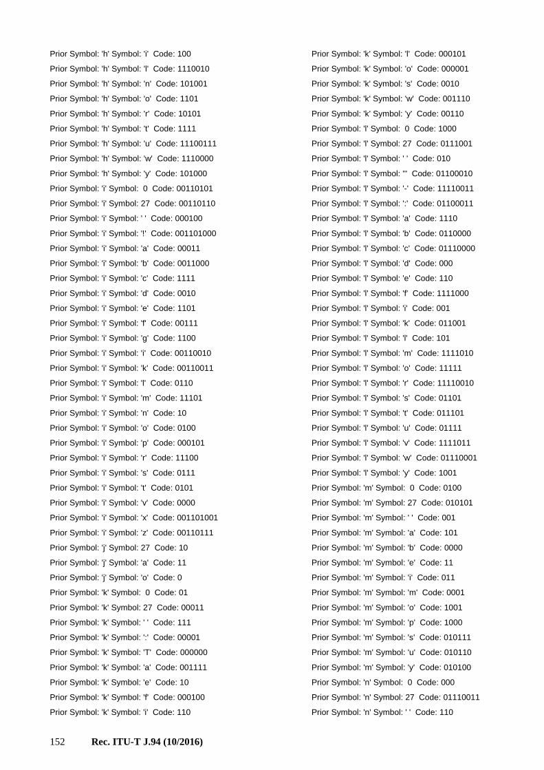
152 Rec. ITU-T J.94 (10/2016)
Prior Symbol: 'h' Symbol: 'i' Code: 100
Prior Symbol: 'h' Symbol: 'l' Code: 1110010
Prior Symbol: 'h' Symbol: 'n' Code: 101001
Prior Symbol: 'h' Symbol: 'o' Code: 1101
Prior Symbol: 'h' Symbol: 'r' Code: 10101
Prior Symbol: 'h' Symbol: 't' Code: 1111
Prior Symbol: 'h' Symbol: 'u' Code: 11100111
Prior Symbol: 'h' Symbol: 'w' Code: 1110000
Prior Symbol: 'h' Symbol: 'y' Code: 101000
Prior Symbol: 'i' Symbol: 0 Code: 00110101
Prior Symbol: 'i' Symbol: 27 Code: 00110110
Prior Symbol: 'i' Symbol: ' ' Code: 000100
Prior Symbol: 'i' Symbol: '!' Code: 001101000
Prior Symbol: 'i' Symbol: 'a' Code: 00011
Prior Symbol: 'i' Symbol: 'b' Code: 0011000
Prior Symbol: 'i' Symbol: 'c' Code: 1111
Prior Symbol: 'i' Symbol: 'd' Code: 0010
Prior Symbol: 'i' Symbol: 'e' Code: 1101
Prior Symbol: 'i' Symbol: 'f' Code: 00111
Prior Symbol: 'i' Symbol: 'g' Code: 1100
Prior Symbol: 'i' Symbol: 'i' Code: 00110010
Prior Symbol: 'i' Symbol: 'k' Code: 00110011
Prior Symbol: 'i' Symbol: 'l' Code: 0110
Prior Symbol: 'i' Symbol: 'm' Code: 11101
Prior Symbol: 'i' Symbol: 'n' Code: 10
Prior Symbol: 'i' Symbol: 'o' Code: 0100
Prior Symbol: 'i' Symbol: 'p' Code: 000101
Prior Symbol: 'i' Symbol: 'r' Code: 11100
Prior Symbol: 'i' Symbol: 's' Code: 0111
Prior Symbol: 'i' Symbol: 't' Code: 0101
Prior Symbol: 'i' Symbol: 'v' Code: 0000
Prior Symbol: 'i' Symbol: 'x' Code: 001101001
Prior Symbol: 'i' Symbol: 'z' Code: 00110111
Prior Symbol: 'j' Symbol: 27 Code: 10
Prior Symbol: 'j' Symbol: 'a' Code: 11
Prior Symbol: 'j' Symbol: 'o' Code: 0
Prior Symbol: 'k' Symbol: 0 Code: 01
Prior Symbol: 'k' Symbol: 27 Code: 00011
Prior Symbol: 'k' Symbol: ' ' Code: 111
Prior Symbol: 'k' Symbol: ':' Code: 00001
Prior Symbol: 'k' Symbol: 'T' Code: 000000
Prior Symbol: 'k' Symbol: 'a' Code: 001111
Prior Symbol: 'k' Symbol: 'e' Code: 10
Prior Symbol: 'k' Symbol: 'f' Code: 000100
Prior Symbol: 'k' Symbol: 'i' Code: 110
Prior Symbol: 'k' Symbol: 'l' Code: 000101
Prior Symbol: 'k' Symbol: 'o' Code: 000001
Prior Symbol: 'k' Symbol: 's' Code: 0010
Prior Symbol: 'k' Symbol: 'w' Code: 001110
Prior Symbol: 'k' Symbol: 'y' Code: 00110
Prior Symbol: 'l' Symbol: 0 Code: 1000
Prior Symbol: 'l' Symbol: 27 Code: 0111001
Prior Symbol: 'l' Symbol: ' ' Code: 010
Prior Symbol: 'l' Symbol: ''' Code: 01100010
Prior Symbol: 'l' Symbol: '-' Code: 11110011
Prior Symbol: 'l' Symbol: ':' Code: 01100011
Prior Symbol: 'l' Symbol: 'a' Code: 1110
Prior Symbol: 'l' Symbol: 'b' Code: 0110000
Prior Symbol: 'l' Symbol: 'c' Code: 01110000
Prior Symbol: 'l' Symbol: 'd' Code: 000
Prior Symbol: 'l' Symbol: 'e' Code: 110
Prior Symbol: 'l' Symbol: 'f' Code: 1111000
Prior Symbol: 'l' Symbol: 'i' Code: 001
Prior Symbol: 'l' Symbol: 'k' Code: 011001
Prior Symbol: 'l' Symbol: 'l' Code: 101
Prior Symbol: 'l' Symbol: 'm' Code: 1111010
Prior Symbol: 'l' Symbol: 'o' Code: 11111
Prior Symbol: 'l' Symbol: 'r' Code: 11110010
Prior Symbol: 'l' Symbol: 's' Code: 01101
Prior Symbol: 'l' Symbol: 't' Code: 011101
Prior Symbol: 'l' Symbol: 'u' Code: 01111
Prior Symbol: 'l' Symbol: 'v' Code: 1111011
Prior Symbol: 'l' Symbol: 'w' Code: 01110001
Prior Symbol: 'l' Symbol: 'y' Code: 1001
Prior Symbol: 'm' Symbol: 0 Code: 0100
Prior Symbol: 'm' Symbol: 27 Code: 010101
Prior Symbol: 'm' Symbol: ' ' Code: 001
Prior Symbol: 'm' Symbol: 'a' Code: 101
Prior Symbol: 'm' Symbol: 'b' Code: 0000
Prior Symbol: 'm' Symbol: 'e' Code: 11
Prior Symbol: 'm' Symbol: 'i' Code: 011
Prior Symbol: 'm' Symbol: 'm' Code: 0001
Prior Symbol: 'm' Symbol: 'o' Code: 1001
Prior Symbol: 'm' Symbol: 'p' Code: 1000
Prior Symbol: 'm' Symbol: 's' Code: 010111
Prior Symbol: 'm' Symbol: 'u' Code: 010110
Prior Symbol: 'm' Symbol: 'y' Code: 010100
Prior Symbol: 'n' Symbol: 0 Code: 000
Prior Symbol: 'n' Symbol: 27 Code: 01110011
Prior Symbol: 'n' Symbol: ' ' Code: 110

Rec. ITU-T J.94 (10/2016) 153
Prior Symbol: 'n' Symbol: ''' Code: 011101
Prior Symbol: 'n' Symbol: ':' Code: 1001010
Prior Symbol: 'n' Symbol: 'a' Code: 11100
Prior Symbol: 'n' Symbol: 'b' Code: 111010000
Prior Symbol: 'n' Symbol: 'c' Code: 01111
Prior Symbol: 'n' Symbol: 'd' Code: 001
Prior Symbol: 'n' Symbol: 'e' Code: 010
Prior Symbol: 'n' Symbol: 'f' Code: 1001011
Prior Symbol: 'n' Symbol: 'g' Code: 101
Prior Symbol: 'n' Symbol: 'h' Code: 111010101
Prior Symbol: 'n' Symbol: 'i' Code: 1000
Prior Symbol: 'n' Symbol: 'j' Code: 111010001
Prior Symbol: 'n' Symbol: 'k' Code: 1110110
Prior Symbol: 'n' Symbol: 'l' Code: 111010110
Prior Symbol: 'n' Symbol: 'm' Code: 111010111
Prior Symbol: 'n' Symbol: 'n' Code: 10011
Prior Symbol: 'n' Symbol: 'o' Code: 1110111
Prior Symbol: 'n' Symbol: 'r' Code: 111010100
Prior Symbol: 'n' Symbol: 's' Code: 0110
Prior Symbol: 'n' Symbol: 't' Code: 1111
Prior Symbol: 'n' Symbol: 'u' Code: 11101001
Prior Symbol: 'n' Symbol: 'v' Code: 0111000
Prior Symbol: 'n' Symbol: 'y' Code: 100100
Prior Symbol: 'n' Symbol: 'z' Code: 01110010
Prior Symbol: 'o' Symbol: 0 Code: 00101
Prior Symbol: 'o' Symbol: 27 Code: 01110001
Prior Symbol: 'o' Symbol: ' ' Code: 0101
Prior Symbol: 'o' Symbol: ''' Code: 01110000
Prior Symbol: 'o' Symbol: '.' Code: 0111011010
Prior Symbol: 'o' Symbol: '?' Code: 011101100
Prior Symbol: 'o' Symbol: 'a' Code: 1100010
Prior Symbol: 'o' Symbol: 'b' Code: 001001
Prior Symbol: 'o' Symbol: 'c' Code: 110000
Prior Symbol: 'o' Symbol: 'd' Code: 01111
Prior Symbol: 'o' Symbol: 'e' Code: 0111001
Prior Symbol: 'o' Symbol: 'f' Code: 1001
Prior Symbol: 'o' Symbol: 'g' Code: 00010
Prior Symbol: 'o' Symbol: 'h' Code: 0111010
Prior Symbol: 'o' Symbol: 'i' Code: 01110111
Prior Symbol: 'o' Symbol: 'k' Code: 1100011
Prior Symbol: 'o' Symbol: 'l' Code: 0100
Prior Symbol: 'o' Symbol: 'm' Code: 1000
Prior Symbol: 'o' Symbol: 'n' Code: 111
Prior Symbol: 'o' Symbol: 'o' Code: 0011
Prior Symbol: 'o' Symbol: 'p' Code: 01101
Prior Symbol: 'o' Symbol: 'r' Code: 101
Prior Symbol: 'o' Symbol: 's' Code: 11001
Prior Symbol: 'o' Symbol: 't' Code: 00011
Prior Symbol: 'o' Symbol: 'u' Code: 1101
Prior Symbol: 'o' Symbol: 'v' Code: 01100
Prior Symbol: 'o' Symbol: 'w' Code: 0000
Prior Symbol: 'o' Symbol: 'x' Code: 0010000
Prior Symbol: 'o' Symbol: 'y' Code: 0010001
Prior Symbol: 'o' Symbol: 'z' Code: 0111011011
Prior Symbol: 'p' Symbol: 0 Code: 1101
Prior Symbol: 'p' Symbol: 27 Code: 101110
Prior Symbol: 'p' Symbol: ' ' Code: 010
Prior Symbol: 'p' Symbol: ''' Code: 1100101
Prior Symbol: 'p' Symbol: 'a' Code: 1001
Prior Symbol: 'p' Symbol: 'd' Code: 101111
Prior Symbol: 'p' Symbol: 'e' Code: 111
Prior Symbol: 'p' Symbol: 'h' Code: 11000
Prior Symbol: 'p' Symbol: 'i' Code: 1010
Prior Symbol: 'p' Symbol: 'l' Code: 0110
Prior Symbol: 'p' Symbol: 'm' Code: 1100100
Prior Symbol: 'p' Symbol: 'o' Code: 00
Prior Symbol: 'p' Symbol: 'p' Code: 0111
Prior Symbol: 'p' Symbol: 'r' Code: 10001
Prior Symbol: 'p' Symbol: 's' Code: 10000
Prior Symbol: 'p' Symbol: 't' Code: 10110
Prior Symbol: 'p' Symbol: 'y' Code: 110011
Prior Symbol: 'q' Symbol: 27 Code: 0
Prior Symbol: 'q' Symbol: 'u' Code: 1
Prior Symbol: 'r' Symbol: 0 Code: 1001
Prior Symbol: 'r' Symbol: 27 Code: 01100101
Prior Symbol: 'r' Symbol: ' ' Code: 1111
Prior Symbol: 'r' Symbol: ''' Code: 0110011
Prior Symbol: 'r' Symbol: ',' Code: 110011101
Prior Symbol: 'r' Symbol: '.' Code: 0111100
Prior Symbol: 'r' Symbol: ':' Code: 110011100
Prior Symbol: 'r' Symbol: 'a' Code: 000
Prior Symbol: 'r' Symbol: 'b' Code: 01111101
Prior Symbol: 'r' Symbol: 'c' Code: 0111111
Prior Symbol: 'r' Symbol: 'd' Code: 11000
Prior Symbol: 'r' Symbol: 'e' Code: 101
Prior Symbol: 'r' Symbol: 'f' Code: 11001111
Prior Symbol: 'r' Symbol: 'g' Code: 0111101
Prior Symbol: 'r' Symbol: 'i' Code: 010
Prior Symbol: 'r' Symbol: 'k' Code: 110010
Prior Symbol: 'r' Symbol: 'l' Code: 0011

154 Rec. ITU-T J.94 (10/2016)
Prior Symbol: 'r' Symbol: 'm' Code: 011000
Prior Symbol: 'r' Symbol: 'n' Code: 01101
Prior Symbol: 'r' Symbol: 'o' Code: 1101
Prior Symbol: 'r' Symbol: 'p' Code: 01111100
Prior Symbol: 'r' Symbol: 'r' Code: 01110
Prior Symbol: 'r' Symbol: 's' Code: 1110
Prior Symbol: 'r' Symbol: 't' Code: 1000
Prior Symbol: 'r' Symbol: 'u' Code: 1100110
Prior Symbol: 'r' Symbol: 'v' Code: 01100100
Prior Symbol: 'r' Symbol: 'y' Code: 0010
Prior Symbol: 's' Symbol: 0 Code: 11
Prior Symbol: 's' Symbol: 27 Code: 0010011
Prior Symbol: 's' Symbol: ' ' Code: 01
Prior Symbol: 's' Symbol: ''' Code: 001011010
Prior Symbol: 's' Symbol: ',' Code: 001011011
Prior Symbol: 's' Symbol: '.' Code: 00100101
Prior Symbol: 's' Symbol: ':' Code: 0000001
Prior Symbol: 's' Symbol: '?' Code: 001011100
Prior Symbol: 's' Symbol: 'C' Code: 001011101
Prior Symbol: 's' Symbol: 'H' Code: 001011110
Prior Symbol: 's' Symbol: 'a' Code: 101010
Prior Symbol: 's' Symbol: 'c' Code: 101011
Prior Symbol: 's' Symbol: 'd' Code: 001011111
Prior Symbol: 's' Symbol: 'e' Code: 1011
Prior Symbol: 's' Symbol: 'f' Code: 00000000
Prior Symbol: 's' Symbol: 'h' Code: 00001
Prior Symbol: 's' Symbol: 'i' Code: 0011
Prior Symbol: 's' Symbol: 'k' Code: 000001
Prior Symbol: 's' Symbol: 'l' Code: 00101010
Prior Symbol: 's' Symbol: 'm' Code: 00000001
Prior Symbol: 's' Symbol: 'n' Code: 00101011
Prior Symbol: 's' Symbol: 'o' Code: 10100
Prior Symbol: 's' Symbol: 'p' Code: 001000
Prior Symbol: 's' Symbol: 'r' Code: 00100100
Prior Symbol: 's' Symbol: 's' Code: 0001
Prior Symbol: 's' Symbol: 't' Code: 100
Prior Symbol: 's' Symbol: 'u' Code: 0010100
Prior Symbol: 's' Symbol: 'y' Code: 00101100
Prior Symbol: 't' Symbol: 0 Code: 010
Prior Symbol: 't' Symbol: 27 Code: 11000010
Prior Symbol: 't' Symbol: ' ' Code: 101
Prior Symbol: 't' Symbol: ''' Code: 11000011
Prior Symbol: 't' Symbol: ':' Code: 110110000
Prior Symbol: 't' Symbol: '?' Code: 110110001
Prior Symbol: 't' Symbol: 'a' Code: 0000
Prior Symbol: 't' Symbol: 'b' Code: 100000
Prior Symbol: 't' Symbol: 'c' Code: 1101101
Prior Symbol: 't' Symbol: 'd' Code: 11000000
Prior Symbol: 't' Symbol: 'e' Code: 011
Prior Symbol: 't' Symbol: 'h' Code: 111
Prior Symbol: 't' Symbol: 'i' Code: 001
Prior Symbol: 't' Symbol: 'l' Code: 10001
Prior Symbol: 't' Symbol: 'm' Code: 100001
Prior Symbol: 't' Symbol: 'n' Code: 11011001
Prior Symbol: 't' Symbol: 'o' Code: 1001
Prior Symbol: 't' Symbol: 'r' Code: 11010
Prior Symbol: 't' Symbol: 's' Code: 0001
Prior Symbol: 't' Symbol: 't' Code: 110111
Prior Symbol: 't' Symbol: 'u' Code: 11001
Prior Symbol: 't' Symbol: 'w' Code: 11000001
Prior Symbol: 't' Symbol: 'y' Code: 110001
Prior Symbol: 'u' Symbol: 0 Code: 0011110
Prior Symbol: 'u' Symbol: 27 Code: 000100
Prior Symbol: 'u' Symbol: ' ' Code: 001110
Prior Symbol: 'u' Symbol: 'a' Code: 00110
Prior Symbol: 'u' Symbol: 'b' Code: 10011
Prior Symbol: 'u' Symbol: 'c' Code: 11100
Prior Symbol: 'u' Symbol: 'd' Code: 10000
Prior Symbol: 'u' Symbol: 'e' Code: 0010
Prior Symbol: 'u' Symbol: 'f' Code: 0011111
Prior Symbol: 'u' Symbol: 'g' Code: 11101
Prior Symbol: 'u' Symbol: 'i' Code: 00011
Prior Symbol: 'u' Symbol: 'k' Code: 0001010
Prior Symbol: 'u' Symbol: 'l' Code: 0000
Prior Symbol: 'u' Symbol: 'm' Code: 10010
Prior Symbol: 'u' Symbol: 'n' Code: 110
Prior Symbol: 'u' Symbol: 'p' Code: 10001
Prior Symbol: 'u' Symbol: 'r' Code: 01
Prior Symbol: 'u' Symbol: 's' Code: 101
Prior Symbol: 'u' Symbol: 't' Code: 1111
Prior Symbol: 'u' Symbol: 'z' Code: 0001011
Prior Symbol: 'v' Symbol: 27 Code: 0010
Prior Symbol: 'v' Symbol: 'a' Code: 000
Prior Symbol: 'v' Symbol: 'e' Code: 1
Prior Symbol: 'v' Symbol: 'i' Code: 01
Prior Symbol: 'v' Symbol: 'o' Code: 00111
Prior Symbol: 'v' Symbol: 's' Code: 00110
Prior Symbol: 'w' Symbol: 0 Code: 001
Prior Symbol: 'w' Symbol: 27 Code: 01010
Prior Symbol: 'w' Symbol: ' ' Code: 011

Rec. ITU-T J.94 (10/2016) 155
Prior Symbol: 'w' Symbol: ''' Code: 010010
Prior Symbol: 'w' Symbol: 'a' Code: 000
Prior Symbol: 'w' Symbol: 'b' Code: 010011
Prior Symbol: 'w' Symbol: 'c' Code: 010111
Prior Symbol: 'w' Symbol: 'e' Code: 1111
Prior Symbol: 'w' Symbol: 'i' Code: 1100
Prior Symbol: 'w' Symbol: 'l' Code: 010110
Prior Symbol: 'w' Symbol: 'n' Code: 1110
Prior Symbol: 'w' Symbol: 'o' Code: 1101
Prior Symbol: 'w' Symbol: 'r' Code: 01000
Prior Symbol: 'w' Symbol: 's' Code: 10
Prior Symbol: 'x' Symbol: 0 Code: 110
Prior Symbol: 'x' Symbol: 27 Code: 1010
Prior Symbol: 'x' Symbol: ' ' Code: 1011
Prior Symbol: 'x' Symbol: 'a' Code: 000
Prior Symbol: 'x' Symbol: 'e' Code: 001
Prior Symbol: 'x' Symbol: 'i' Code: 100
Prior Symbol: 'x' Symbol: 'p' Code: 111
Prior Symbol: 'x' Symbol: 't' Code: 01
Prior Symbol: 'y' Symbol: 0 Code: 10
Prior Symbol: 'y' Symbol: 27 Code: 111110
Prior Symbol: 'y' Symbol: ' ' Code: 0
Prior Symbol: 'y' Symbol: '!' Code: 1101101
Prior Symbol: 'y' Symbol: ''' Code: 110101
Prior Symbol: 'y' Symbol: '-' Code: 11110101
Prior Symbol: 'y' Symbol: 'a' Code: 1101110
Prior Symbol: 'y' Symbol: 'b' Code: 1111011
Prior Symbol: 'y' Symbol: 'c' Code: 11110100
Prior Symbol: 'y' Symbol: 'd' Code: 1100000
Prior Symbol: 'y' Symbol: 'e' Code: 11001
Prior Symbol: 'y' Symbol: 'i' Code: 1100001
Prior Symbol: 'y' Symbol: 'l' Code: 111111
Prior Symbol: 'y' Symbol: 'm' Code: 1101111
Prior Symbol: 'y' Symbol: 'n' Code: 1100010
Prior Symbol: 'y' Symbol: 'o' Code: 1100011
Prior Symbol: 'y' Symbol: 'p' Code: 1101000
Prior Symbol: 'y' Symbol: 's' Code: 1110
Prior Symbol: 'y' Symbol: 't' Code: 1101001
Prior Symbol: 'y' Symbol: 'v' Code: 1101100
Prior Symbol: 'y' Symbol: 'w' Code: 111100
Prior Symbol: 'z' Symbol: 0 Code: 110
Prior Symbol: 'z' Symbol: 27 Code: 100
Prior Symbol: 'z' Symbol: ' ' Code: 000
Prior Symbol: 'z' Symbol: 'a' Code: 01
Prior Symbol: 'z' Symbol: 'e' Code: 1010
Prior Symbol: 'z' Symbol: 'i' Code: 111
Prior Symbol: 'z' Symbol: 'y' Code: 001
Prior Symbol: 'z' Symbol: 'z' Code: 1011
Prior Symbol: '{' Symbol: 27 Code: 1
Prior Symbol: '|' Symbol: 27 Code: 1
Prior Symbol: '}' Symbol: 27 Code: 1
Prior Symbol: '~' Symbol: 27 Code: 1
Prior Symbol: 127 Symbol: 27 Code: 1

156 Rec. ITU-T J.94 (10/2016)
Table H.5 – English-language Program Title Decode Table
0 1
1 0
2 1
3 58
4 1
5 60
6 1
7 62
8 1
9 64
10 1
11 66
12 1
13 68
14 1
15 70
16 1
17 72
18 1
19 74
20 1
21 76
22 1
23 78
24 1
25 80
26 1
27 82
28 1
29 84
30 1
31 86
32 1
33 88
34 1
35 90
36 1
37 92
38 1
39 94
40 1
41 96
42 1
43 98
44 1
45 100
46 1
47 102
48 1
49 104
50 1
51 106
52 1
53 108
54 1
55 110
56 1
57 112
58 1
59 114
60 1
61 116
62 1
63 118
64 1
65 120
66 1
67 206
68 1
69 210
70 1
71 212
72 1
73 214
74 1
75 216
76 1
77 218
78 1
79 220
80 1
81 230
82 1
83 232
84 1
85 234
86 1
87 240
88 1
89 242
90 1
91 244
92 2
93 6
94 2
95 18
96 2
97 20
98 2
99 28
100 2
101 40
102 2
103 48
104 2
105 52
106 2
107 54
108 2
109 56
110 2
111 58
112 2
113 60
114 2
115 62
116 2
117 70
118 2
119 72
120 2
121 74
122 2
123 76
124 2
125 78
126 2
127 80
128 2
129 82
130 2
131 84
132 2
133 126
134 2
135 146
136 2
137 172
138 2
139 186
140 2
141 210
142 2
143 228
144 2
145 250
146 3
147 6
148 3
149 30
150 3
151 38
152 3
153 50
154 3
155 62
156 3
157 82
158 3
159 100
160 3
161 122
162 3
163 148
164 3
165 152
166 3
167 164
168 3
169 200
170 3
171 222
172 3
173 230
174 3
175 244
176 4
177 4
178 4
179 6
180 4
181 12
182 4
183 16
184 4
185 18
186 4
187 20
188 4
189 22
190 4
191 24
192 4
193 26
194 4
195 28
196 4
197 82
198 4
199 106
200 4
201 142
202 4
203 174
204 4
205 238
206 5
207 6
208 5
209 40
210 5
211 68
212 5

Rec. ITU-T J.94 (10/2016) 157
213 114
214 5
215 118
216 5
217 144
218 5
219 190
220 5
221 214
222 6
223 10
224 6
225 68
226 6
227 100
228 6
229 102
230 6
231 154
232 6
233 208
234 6
235 252
236 7
237 34
238 7
239 44
240 7
241 70
242 7
243 84
244 7
245 124
246 7
247 138
248 7
249 140
250 7
251 142
252 7
253 144
254 7
255 146
256 27
257 28
258 180
259 164
260 178
261 183
262 218
263 1
264 209
265 2
266 3
267 155
268 4
269 213
270 217
271 5
272 203
273 214
274 6
275 207
276 7
277 8
278 202
279 9
280 201
281 197
282 198
283 10
284 210
285 196
286 199
287 204
288 208
289 200
290 215
291 206
292 11
293 193
294 12
295 194
296 205
297 195
298 13
299 14
300 15
301 16
302 211
303 17
304 212
305 18
306 19
307 20
308 21
309 22
310 23
311 24
312 25
313 26
314 155
315 155
316 155
317 155
318 155
319 155
320 155
321 155
322 155
323 155
324 155
325 155
326 155
327 155
328 155
329 155
330 155
331 155
332 155
333 155
334 155
335 155
336 155
337 155
338 155
339 155
340 155
341 155
342 155
343 155
344 155
345 155
346 155
347 155
348 155
349 155
350 155
351 155
352 155
353 155
354 155
355 155
356 155
357 155
358 155
359 155
360 155
361 155
362 155
363 155
364 155
365 155
366 155
367 155
368 155
369 155
370 155
371 155
372 155
373 155
374 155
375 155
376 41
377 42
378 216
379 229
380 185
381 1
382 167
383 177
384 236
385 209
386 2
387 173
388 178
389 218
390 227
391 179
392 3
393 228
394 230
395 4
396 155
397 226
398 5
399 6
400 7
401 8
402 9
403 213
404 10
405 214
406 11
407 217
408 12
409 166
410 233
411 203
412 197
413 207
414 13
415 14
416 202
417 201
418 15
419 199
420 16
421 17
422 225
423 18
424 19
425 198
426 210
427 200
428 206
429 193
430 196
431 208
432 204
433 20
434 21
435 239
436 194
437 215
438 22
439 205
440 23
441 244
442 212
443 24
444 25
445 26
446 195
447 211

158 Rec. ITU-T J.94 (10/2016)
448 27
449 28
450 29
451 30
452 31
453 32
454 33
455 34
456 35
457 36
458 37
459 38
460 39
461 40
462 1
463 128
464 160
465 155
466 155
467 155
468 155
469 155
470 177
471 155
472 155
473 155
474 155
475 160
476 4
477 243
478 228
479 185
480 1
481 244
482 160
483 155
484 2
485 3
486 155
487 155
488 155
489 155
490 1
491 2
492 155
493 193
494 200
495 211
496 155
497 155
498 155
499 160
500 7
501 8
502 177
503 210
504 211
505 212
506 213
507 173
508 205
509 193
510 1
511 2
512 3
513 160
514 4
515 155
516 5
517 6
518 160
519 5
520 201
521 215
522 211
523 1
524 2
525 155
526 174
527 128
528 3
529 4
530 155
531 155
532 2
533 3
534 173
535 155
536 1
537 128
538 160
539 176
540 4
541 5
542 128
543 155
544 177
545 178
546 160
547 176
548 185
549 1
550 2
551 3
552 2
553 3
554 177
555 186
556 1
557 176
558 155
559 128
560 128
561 1
562 176
563 155
564 155
565 184
566 155
567 155
568 155
569 155
570 155
571 176
572 155
573 160
574 2
575 3
576 177
577 179
578 185
579 176
580 1
581 155
582 155
583 160
584 155
585 155
586 155
587 155
588 155
589 155
590 155
591 155
592 155
593 128
594 155
595 155
596 19
597 20
598 170
599 173
600 174
601 246
602 231
603 244
604 226
605 233
606 1
607 2
608 194
609 240
610 155
611 243
612 227
613 230
614 247
615 3
616 245
617 4
618 5
619 6
620 242
621 7
622 8
623 9
624 10
625 11
626 12
627 228
628 160
629 13
630 236
631 238
632 14
633 237
634 15
635 16
636 17
637 18
638 8
639 9
640 193
641 211
642 155
643 1
644 195
645 2
646 233
647 236
648 3
649 242
650 245
651 4
652 239
653 225
654 5
655 229
656 6
657 7
658 11
659 12
660 193
661 249
662 1
663 194
664 207
665 229
666 245
667 155
668 233
669 2
670 160
671 3
672 4
673 5
674 242
675 6
676 236
677 7
678 225
679 8
680 9
681 232
682 10

Rec. ITU-T J.94 (10/2016) 159
683 239
684 5
685 6
686 249
687 155
688 1
689 245
690 2
691 242
692 233
693 229
694 239
695 3
696 225
697 4
698 10
699 11
700 241
701 245
702 243
703 1
704 237
705 249
706 195
707 2
708 236
709 238
710 228
711 248
712 3
713 155
714 246
715 4
716 5
717 225
718 6
719 7
720 8
721 9
722 7
723 8
724 160
725 155
726 204
727 1
728 229
729 2
730 236
731 245
732 239
733 3
734 233
735 242
736 4
737 5
738 225
739 6
740 9
741 10
742 174
743 236
744 249
745 193
746 232
747 1
748 155
749 2
750 3
751 4
752 225
753 245
754 233
755 5
756 229
757 6
758 242
759 239
760 7
761 8
762 239
763 5
764 128
765 155
766 245
767 1
768 2
769 233
770 225
771 3
772 229
773 4
774 238
775 11
776 186
777 212
778 174
779 242
780 227
781 1
782 160
783 2
784 128
785 155
786 237
787 3
788 201
789 243
790 244
791 4
792 5
793 6
794 7
795 8
796 9
797 10
798 2
799 3
800 155
801 245
802 1
803 225
804 239
805 229
806 5
807 233
808 225
809 239
810 245
811 238
812 155
813 229
814 1
815 2
816 3
817 4
818 4
819 5
820 160
821 155
822 1
823 245
824 2
825 229
826 239
827 3
828 225
829 233
830 8
831 9
832 170
833 212
834 1
835 155
836 227
837 2
838 242
839 3
840 229
841 4
842 245
843 249
844 233
845 5
846 239
847 6
848 7
849 225
850 229
851 8
852 206
853 160
854 198
855 245
856 1
857 2
858 155
859 194
860 3
861 225
862 4
863 239
864 5
865 233
866 6
867 7
868 9
869 10
870 228
871 243
872 230
873 246
874 247
875 240
876 242
877 1
878 236
879 2
880 3
881 160
882 155
883 4
884 5
885 245
886 6
887 7
888 238
889 8
890 11
891 12
892 160
893 243
894 249
895 174
896 210
897 199
898 1
899 155
900 2
901 245
902 3
903 4
904 5
905 233
906 236
907 6
908 229
909 7
910 239
911 8
912 225
913 9
914 242
915 10
916 1
917 245

160 Rec. ITU-T J.94 (10/2016)
918 155
919 214
920 4
921 5
922 232
923 155
924 1
925 245
926 2
927 225
928 233
929 239
930 3
931 229
932 16
933 17
934 170
935 236
936 241
937 174
938 160
939 247
940 237
941 238
942 1
943 2
944 155
945 235
946 3
947 4
948 5
949 6
950 227
951 7
952 239
953 8
954 233
955 245
956 9
957 225
958 229
959 240
960 232
961 10
962 11
963 12
964 13
965 244
966 14
967 15
968 232
969 10
970 173
971 206
972 155
973 1
974 214
975 2
976 245
977 247
978 3
979 4
980 225
981 229
982 233
983 5
984 242
985 6
986 239
987 7
988 8
989 9
990 238
991 3
992 236
993 174
994 1
995 155
996 2
997 240
998 6
999 233
1000 160
1001 195
1002 239
1003 155
1004 229
1005 1
1006 128
1007 2
1008 3
1009 225
1010 4
1011 5
1012 6
1013 7
1014 198
1015 215
1016 1
1017 155
1018 242
1019 2
1020 3
1021 232
1022 229
1023 225
1024 4
1025 233
1026 239
1027 5
1028 155
1029 155
1030 2
1031 239
1032 225
1033 155
1034 1
1035 229
1036 1
1037 239
1038 155
1039 225
1040 155
1041 155
1042 155
1043 155
1044 155
1045 155
1046 155
1047 155
1048 155
1049 155
1050 155
1051 155
1052 25
1053 26
1054 155
1055 186
1056 229
1057 234
1058 248
1059 1
1060 2
1061 230
1062 167
1063 3
1064 250
1065 232
1066 4
1067 247
1068 5
1069 245
1070 226
1071 6
1072 235
1073 7
1074 240
1075 8
1076 128
1077 246
1078 231
1079 9
1080 228
1081 10
1082 160
1083 233
1084 11
1085 227
1086 249
1087 12
1088 13
1089 237
1090 14
1091 15
1092 243
1093 16
1094 17
1095 236
1096 18
1097 244
1098 242
1099 19
1100 238
1101 20
1102 21
1103 22
1104 23
1105 24
1106 10
1107 11
1108 243
1109 155
1110 245
1111 226
1112 1
1113 128
1114 160
1115 2
1116 229
1117 242
1118 233
1119 3
1120 236
1121 4
1122 249
1123 5
1124 239
1125 6
1126 225
1127 7
1128 8
1129 9
1130 16
1131 17
1132 195
1133 204
1134 199
1135 155
1136 227
1137 1
1138 128
1139 236
1140 249
1141 2
1142 243
1143 3
1144 245
1145 4
1146 5
1147 242
1148 6
1149 233
1150 160
1151 7
1152 8

Rec. ITU-T J.94 (10/2016) 161
1153 239
1154 244
1155 9
1156 10
1157 225
1158 11
1159 232
1160 235
1161 229
1162 12
1163 13
1164 14
1165 15
1166 14
1167 15
1168 174
1169 245
1170 247
1171 1
1172 236
1173 2
1174 228
1175 231
1176 242
1177 3
1178 155
1179 239
1180 4
1181 246
1182 5
1183 6
1184 249
1185 243
1186 7
1187 233
1188 225
1189 8
1190 9
1191 128
1192 10
1193 11
1194 229
1195 12
1196 13
1197 160
1198 30
1199 31
1200 155
1201 161
1202 173
1203 232
1204 234
1205 241
1206 245
1207 250
1208 1
1209 2
1210 3
1211 4
1212 186
1213 248
1214 167
1215 226
1216 233
1217 5
1218 6
1219 7
1220 230
1221 237
1222 231
1223 235
1224 8
1225 9
1226 246
1227 240
1228 10
1229 239
1230 11
1231 227
1232 12
1233 13
1234 14
1235 249
1236 15
1237 228
1238 236
1239 16
1240 229
1241 17
1242 244
1243 247
1244 18
1245 19
1246 225
1247 20
1248 21
1249 22
1250 238
1251 243
1252 23
1253 128
1254 24
1255 25
1256 242
1257 26
1258 27
1259 160
1260 28
1261 29
1262 160
1263 11
1264 245
1265 155
1266 1
1267 236
1268 243
1269 242
1270 128
1271 225
1272 2
1273 3
1274 244
1275 233
1276 239
1277 230
1278 4
1279 5
1280 6
1281 7
1282 229
1283 8
1284 9
1285 10
1286 15
1287 16
1288 186
1289 249
1290 167
1291 244
1292 155
1293 1
1294 231
1295 236
1296 2
1297 238
1298 3
1299 239
1300 245
1301 4
1302 242
1303 5
1304 6
1305 233
1306 7
1307 243
1308 225
1309 8
1310 9
1311 10
1312 11
1313 229
1314 128
1315 12
1316 232
1317 160
1318 13
1319 14
1320 229
1321 13
1322 226
1323 245
1324 247
1325 155
1326 236
1327 1
1328 249
1329 238
1330 2
1331 3
1332 4
1333 242
1334 5
1335 128
1336 6
1337 160
1338 225
1339 239
1340 7
1341 244
1342 233
1343 8
1344 9
1345 10
1346 11
1347 12
1348 21
1349 22
1350 161
1351 248
1352 233
1353 235
1354 1
1355 128
1356 155
1357 250
1358 226
1359 2
1360 3
1361 4
1362 160
1363 240
1364 5
1365 6
1366 7
1367 225
1368 8
1369 230
1370 242
1371 237
1372 246
1373 9
1374 228
1375 10
1376 239
1377 244
1378 236
1379 243
1380 231
1381 229
1382 11
1383 227
1384 12
1385 13
1386 14
1387 15

162 Rec. ITU-T J.94 (10/2016)
1388 16
1389 17
1390 18
1391 19
1392 238
1393 20
1394 239
1395 1
1396 155
1397 225
1398 11
1399 12
1400 212
1401 239
1402 230
1403 236
1404 247
1405 225
1406 1
1407 186
1408 2
1409 155
1410 249
1411 3
1412 4
1413 5
1414 243
1415 6
1416 7
1417 8
1418 233
1419 160
1420 9
1421 128
1422 229
1423 10
1424 21
1425 22
1426 167
1427 186
1428 227
1429 247
1430 242
1431 173
1432 226
1433 1
1434 2
1435 155
1436 230
1437 3
1438 237
1439 246
1440 4
1441 235
1442 5
1443 244
1444 6
1445 7
1446 8
1447 243
1448 9
1449 245
1450 10
1451 239
1452 11
1453 12
1454 128
1455 249
1456 225
1457 13
1458 228
1459 233
1460 160
1461 14
1462 15
1463 236
1464 229
1465 16
1466 17
1467 18
1468 19
1469 20
1470 10
1471 11
1472 249
1473 155
1474 245
1475 243
1476 1
1477 2
1478 226
1479 237
1480 128
1481 3
1482 240
1483 239
1484 4
1485 160
1486 5
1487 233
1488 6
1489 225
1490 7
1491 8
1492 9
1493 229
1494 24
1495 25
1496 226
1497 234
1498 242
1499 232
1500 236
1501 237
1502 250
1503 155
1504 1
1505 245
1506 2
1507 3
1508 246
1509 4
1510 186
1511 230
1512 5
1513 6
1514 235
1515 239
1516 7
1517 167
1518 249
1519 8
1520 9
1521 10
1522 11
1523 227
1524 12
1525 238
1526 225
1527 13
1528 243
1529 14
1530 233
1531 15
1532 16
1533 244
1534 128
1535 228
1536 229
1537 17
1538 18
1539 231
1540 160
1541 19
1542 20
1543 21
1544 22
1545 23
1546 27
1547 28
1548 174
1549 250
1550 191
1551 1
1552 167
1553 155
1554 2
1555 233
1556 248
1557 249
1558 3
1559 229
1560 232
1561 4
1562 225
1563 235
1564 5
1565 226
1566 6
1567 7
1568 227
1569 8
1570 231
1571 244
1572 9
1573 128
1574 246
1575 240
1576 10
1577 228
1578 11
1579 243
1580 247
1581 12
1582 13
1583 239
1584 236
1585 160
1586 14
1587 15
1588 237
1589 230
1590 16
1591 245
1592 17
1593 18
1594 19
1595 20
1596 21
1597 242
1598 22
1599 238
1600 23
1601 24
1602 25
1603 26
1604 14
1605 15
1606 237
1607 167
1608 155
1609 228
1610 1
1611 249
1612 243
1613 242
1614 244
1615 2
1616 232
1617 3
1618 236
1619 240
1620 4
1621 225
1622 233

Rec. ITU-T J.94 (10/2016) 163
1623 5
1624 6
1625 128
1626 160
1627 7
1628 8
1629 9
1630 10
1631 229
1632 239
1633 11
1634 12
1635 13
1636 155
1637 245
1638 24
1639 25
1640 186
1641 172
1642 246
1643 155
1644 240
1645 226
1646 1
1647 230
1648 2
1649 167
1650 174
1651 231
1652 3
1653 227
1654 245
1655 4
1656 237
1657 5
1658 6
1659 7
1660 235
1661 8
1662 9
1663 238
1664 242
1665 10
1666 228
1667 11
1668 249
1669 236
1670 12
1671 13
1672 244
1673 128
1674 14
1675 239
1676 243
1677 160
1678 225
1679 15
1680 233
1681 16
1682 17
1683 229
1684 18
1685 19
1686 20
1687 21
1688 22
1689 23
1690 25
1691 26
1692 167
1693 172
1694 191
1695 195
1696 200
1697 228
1698 230
1699 237
1700 242
1701 174
1702 236
1703 238
1704 249
1705 1
1706 2
1707 3
1708 4
1709 186
1710 5
1711 155
1712 245
1713 6
1714 7
1715 8
1716 9
1717 235
1718 240
1719 10
1720 11
1721 12
1722 225
1723 227
1724 13
1725 232
1726 14
1727 15
1728 239
1729 16
1730 17
1731 243
1732 18
1733 233
1734 19
1735 229
1736 20
1737 21
1738 244
1739 22
1740 23
1741 160
1742 24
1743 128
1744 20
1745 21
1746 186
1747 191
1748 228
1749 247
1750 155
1751 167
1752 1
1753 238
1754 2
1755 3
1756 4
1757 227
1758 226
1759 237
1760 5
1761 249
1762 6
1763 244
1764 7
1765 236
1766 8
1767 245
1768 242
1769 9
1770 225
1771 243
1772 10
1773 239
1774 11
1775 12
1776 13
1777 233
1778 128
1779 229
1780 14
1781 160
1782 15
1783 232
1784 16
1785 17
1786 18
1787 19
1788 17
1789 18
1790 235
1791 250
1792 128
1793 230
1794 155
1795 1
1796 160
1797 2
1798 3
1799 233
1800 225
1801 4
1802 228
1803 240
1804 237
1805 226
1806 227
1807 231
1808 236
1809 5
1810 229
1811 6
1812 7
1813 8
1814 9
1815 244
1816 10
1817 11
1818 12
1819 243
1820 238
1821 13
1822 14
1823 242
1824 15
1825 16
1826 4
1827 229
1828 243
1829 239
1830 155
1831 1
1832 225
1833 2
1834 3
1835 233
1836 11
1837 12
1838 167
1839 226
1840 236
1841 227
1842 242
1843 1
1844 155
1845 2
1846 3
1847 4
1848 233
1849 239
1850 238
1851 229
1852 225
1853 128
1854 5
1855 160
1856 6
1857 7

164 Rec. ITU-T J.94 (10/2016)
1858 8
1859 9
1860 243
1861 10
1862 5
1863 6
1864 155
1865 160
1866 225
1867 229
1868 233
1869 1
1870 128
1871 240
1872 2
1873 244
1874 3
1875 4
1876 160
1877 19
1878 227
1879 173
1880 228
1881 233
1882 238
1883 239
1884 240
1885 244
1886 246
1887 161
1888 225
1889 237
1890 1
1891 226
1892 2
1893 3
1894 4
1895 167
1896 5
1897 6
1898 247
1899 7
1900 155
1901 236
1902 8
1903 229
1904 9
1905 10
1906 11
1907 12
1908 13
1909 14
1910 243
1911 15
1912 16
1913 17
1914 128
1915 18
1916 5
1917 6
1918 229
1919 250
1920 160
1921 249
1922 155
1923 1
1924 128
1925 233
1926 2
1927 225
1928 3
1929 4
1930 155
1931 155
1932 155
1933 155
1934 155
1935 155
1936 155
1937 155
1938 155
1939 155

Rec. ITU-T J.94 (10/2016) 165
H.3 Standard compression Type 2 Huffman Encode/Decode tables
The following encode/decode tables (Tables H.6 and H.7) are optimized for English-language program
description text. These tables correspond to multiple_string_structure() with compression_type value 0x02,
and mode equal to 0xFF.
Table H.6 – English-language Program Description Encode Table
Prior Symbol: 0 Symbol: 27 Code: 1110000
Prior Symbol: 0 Symbol: '"' Code: 111001
Prior Symbol: 0 Symbol: 'A' Code: 010
Prior Symbol: 0 Symbol: 'B' Code: 0011
Prior Symbol: 0 Symbol: 'C' Code: 0111
Prior Symbol: 0 Symbol: 'D' Code: 11101
Prior Symbol: 0 Symbol: 'E' Code: 10010
Prior Symbol: 0 Symbol: 'F' Code: 10110
Prior Symbol: 0 Symbol: 'G' Code: 011011
Prior Symbol: 0 Symbol: 'H' Code: 10111
Prior Symbol: 0 Symbol: 'I' Code: 011000
Prior Symbol: 0 Symbol: 'J' Code: 1100
Prior Symbol: 0 Symbol: 'K' Code: 00101
Prior Symbol: 0 Symbol: 'L' Code: 10011
Prior Symbol: 0 Symbol: 'M' Code: 1111
Prior Symbol: 0 Symbol: 'N' Code: 00100
Prior Symbol: 0 Symbol: 'O' Code: 011001
Prior Symbol: 0 Symbol: 'P' Code: 000
Prior Symbol: 0 Symbol: 'R' Code: 1000
Prior Symbol: 0 Symbol: 'S' Code: 1010
Prior Symbol: 0 Symbol: 'T' Code: 1101
Prior Symbol: 0 Symbol: 'V' Code: 1110001
Prior Symbol: 0 Symbol: 'W' Code: 011010
Prior Symbol: 1 Symbol: 27 Code: 1
Prior Symbol: 2 Symbol: 27 Code: 1
Prior Symbol: 3 Symbol: 27 Code: 1
Prior Symbol: 4 Symbol: 27 Code: 1
Prior Symbol: 5 Symbol: 27 Code: 1
Prior Symbol: 6 Symbol: 27 Code: 1
Prior Symbol: 7 Symbol: 27 Code: 1
Prior Symbol: 8 Symbol: 27 Code: 1
Prior Symbol: 9 Symbol: 27 Code: 1
Prior Symbol: 10 Symbol: 27 Code: 1
Prior Symbol: 11 Symbol: 27 Code: 1
Prior Symbol: 12 Symbol: 27 Code: 1
Prior Symbol: 13 Symbol: 27 Code: 1
Prior Symbol: 14 Symbol: 27 Code: 1
Prior Symbol: 15 Symbol: 27 Code: 1
Prior Symbol: 16 Symbol: 27 Code: 1
Prior Symbol: 17 Symbol: 27 Code: 1
Prior Symbol: 18 Symbol: 27 Code: 1
Prior Symbol: 19 Symbol: 27 Code: 1
Prior Symbol: 20 Symbol: 27 Code: 1
Prior Symbol: 21 Symbol: 27 Code: 1
Prior Symbol: 22 Symbol: 27 Code: 1
Prior Symbol: 23 Symbol: 27 Code: 1
Prior Symbol: 24 Symbol: 27 Code: 1
Prior Symbol: 25 Symbol: 27 Code: 1
Prior Symbol: 26 Symbol: 27 Code: 1
Prior Symbol: 27 Symbol: 27 Code: 1
Prior Symbol: 28 Symbol: 27 Code: 1
Prior Symbol: 29 Symbol: 27 Code: 1
Prior Symbol: 30 Symbol: 27 Code: 1
Prior Symbol: 31 Symbol: 27 Code: 1
Prior Symbol: ' ' Symbol: 27 Code: 101000001
Prior Symbol: ' ' Symbol: '"' Code: 111111010
Prior Symbol: ' ' Symbol: '(' Code: 1111111100
Prior Symbol: ' ' Symbol: '-' Code: 11111111110
Prior Symbol: ' ' Symbol: '/' Code: 11111111111
Prior Symbol: ' ' Symbol: '1' Code: 0101011
Prior Symbol: ' ' Symbol: '2' Code: 0100010
Prior Symbol: ' ' Symbol: '3' Code: 1111111101
Prior Symbol: ' ' Symbol: '4' Code: 110010100
Prior Symbol: ' ' Symbol: '5' Code: 1111111110
Prior Symbol: ' ' Symbol: '7' Code: 1010000000
Prior Symbol: ' ' Symbol: 'A' Code: 10010
Prior Symbol: ' ' Symbol: 'B' Code: 010100
Prior Symbol: ' ' Symbol: 'C' Code: 111100
Prior Symbol: ' ' Symbol: 'D' Code: 1111010
Prior Symbol: ' ' Symbol: 'E' Code: 0100011
Prior Symbol: ' ' Symbol: 'F' Code: 0101010
Prior Symbol: ' ' Symbol: 'G' Code: 000010
Prior Symbol: ' ' Symbol: 'H' Code: 1111011
Prior Symbol: ' ' Symbol: 'I' Code: 11001011

166 Rec. ITU-T J.94 (10/2016)
Prior Symbol: ' ' Symbol: 'J' Code: 000011
Prior Symbol: ' ' Symbol: 'K' Code: 1100100
Prior Symbol: ' ' Symbol: 'L' Code: 010110
Prior Symbol: ' ' Symbol: 'M' Code: 101001
Prior Symbol: ' ' Symbol: 'N' Code: 001100
Prior Symbol: ' ' Symbol: 'O' Code: 10100001
Prior Symbol: ' ' Symbol: 'P' Code: 001101
Prior Symbol: ' ' Symbol: 'R' Code: 1111100
Prior Symbol: ' ' Symbol: 'S' Code: 01001
Prior Symbol: ' ' Symbol: 'T' Code: 1100110
Prior Symbol: ' ' Symbol: 'U' Code: 111111011
Prior Symbol: ' ' Symbol: 'V' Code: 111111100
Prior Symbol: ' ' Symbol: 'W' Code: 010000
Prior Symbol: ' ' Symbol: 'Y' Code: 111111101
Prior Symbol: ' ' Symbol: 'Z' Code: 1010000001
Prior Symbol: ' ' Symbol: 'a' Code: 011
Prior Symbol: ' ' Symbol: 'b' Code: 10111
Prior Symbol: ' ' Symbol: 'c' Code: 10011
Prior Symbol: ' ' Symbol: 'd' Code: 10000
Prior Symbol: ' ' Symbol: 'e' Code: 100010
Prior Symbol: ' ' Symbol: 'f' Code: 11101
Prior Symbol: ' ' Symbol: 'g' Code: 100011
Prior Symbol: ' ' Symbol: 'h' Code: 0001
Prior Symbol: ' ' Symbol: 'i' Code: 10101
Prior Symbol: ' ' Symbol: 'j' Code: 11001111
Prior Symbol: ' ' Symbol: 'k' Code: 11111010
Prior Symbol: ' ' Symbol: 'l' Code: 010111
Prior Symbol: ' ' Symbol: 'm' Code: 00000
Prior Symbol: ' ' Symbol: 'n' Code: 1010001
Prior Symbol: ' ' Symbol: 'o' Code: 0010
Prior Symbol: ' ' Symbol: 'p' Code: 10110
Prior Symbol: ' ' Symbol: 'q' Code: 110010101
Prior Symbol: ' ' Symbol: 'r' Code: 00111
Prior Symbol: ' ' Symbol: 's' Code: 11100
Prior Symbol: ' ' Symbol: 't' Code: 1101
Prior Symbol: ' ' Symbol: 'u' Code: 11111011
Prior Symbol: ' ' Symbol: 'v' Code: 11111100
Prior Symbol: ' ' Symbol: 'w' Code: 11000
Prior Symbol: ' ' Symbol: 'y' Code: 11001110
Prior Symbol: '!' Symbol: 27 Code: 1
Prior Symbol: '"' Symbol: 0 Code: 000
Prior Symbol: '"' Symbol: 27 Code: 10
Prior Symbol: '"' Symbol: ' ' Code: 11
Prior Symbol: '"' Symbol: '.' Code: 001
Prior Symbol: '"' Symbol: 'H' Code: 010
Prior Symbol: '"' Symbol: 'T' Code: 011
Prior Symbol: '#' Symbol: 27 Code: 1
Prior Symbol: '$' Symbol: 27 Code: 1
Prior Symbol: '%' Symbol: 27 Code: 1
Prior Symbol: '&' Symbol: 27 Code: 1
Prior Symbol: ''' Symbol: 27 Code: 00
Prior Symbol: ''' Symbol: ' ' Code: 010
Prior Symbol: ''' Symbol: 's' Code: 1
Prior Symbol: ''' Symbol: 't' Code: 011
Prior Symbol: '(' Symbol: 27 Code: 1
Prior Symbol: ')' Symbol: 27 Code: 1
Prior Symbol: ')' Symbol: ',' Code: 0
Prior Symbol: '*' Symbol: 27 Code: 1
Prior Symbol: '+' Symbol: 27 Code: 1
Prior Symbol: ',' Symbol: 27 Code: 00
Prior Symbol: ',' Symbol: ' ' Code: 1
Prior Symbol: ',' Symbol: '"' Code: 01
Prior Symbol: '-' Symbol: 27 Code: 10
Prior Symbol: '-' Symbol: ' ' Code: 1110
Prior Symbol: '-' Symbol: 'a' Code: 000
Prior Symbol: '-' Symbol: 'b' Code: 0010
Prior Symbol: '-' Symbol: 'c' Code: 110
Prior Symbol: '-' Symbol: 'd' Code: 0011
Prior Symbol: '-' Symbol: 'e' Code: 0100
Prior Symbol: '-' Symbol: 'f' Code: 0101
Prior Symbol: '-' Symbol: 'r' Code: 1111
Prior Symbol: '-' Symbol: 's' Code: 011
Prior Symbol: '.' Symbol: 0 Code: 1
Prior Symbol: '.' Symbol: 27 Code: 000
Prior Symbol: '.' Symbol: ' ' Code: 01
Prior Symbol: '.' Symbol: '"' Code: 0010
Prior Symbol: '.' Symbol: 'J' Code: 00110
Prior Symbol: '.' Symbol: 'S' Code: 00111
Prior Symbol: '/' Symbol: 27 Code: 0
Prior Symbol: '/' Symbol: ' ' Code: 1
Prior Symbol: '0' Symbol: 27 Code: 100
Prior Symbol: '0' Symbol: ' ' Code: 111
Prior Symbol: '0' Symbol: '0' Code: 00
Prior Symbol: '0' Symbol: '7' Code: 101
Prior Symbol: '0' Symbol: 's' Code: 01
Prior Symbol: '0' Symbol: 't' Code: 110
Prior Symbol: '1' Symbol: 27 Code: 111
Prior Symbol: '1' Symbol: ' ' Code: 10
Prior Symbol: '1' Symbol: '8' Code: 110
Prior Symbol: '1' Symbol: '9' Code: 0

Rec. ITU-T J.94 (10/2016) 167
Prior Symbol: '2' Symbol: 27 Code: 101
Prior Symbol: '2' Symbol: ' ' Code: 11
Prior Symbol: '2' Symbol: '.' Code: 0
Prior Symbol: '2' Symbol: '6' Code: 100
Prior Symbol: '3' Symbol: 27 Code: 10
Prior Symbol: '3' Symbol: ' ' Code: 0
Prior Symbol: '3' Symbol: '0' Code: 11
Prior Symbol: '4' Symbol: 27 Code: 10
Prior Symbol: '4' Symbol: ' ' Code: 11
Prior Symbol: '4' Symbol: '.' Code: 0
Prior Symbol: '5' Symbol: 27 Code: 11
Prior Symbol: '5' Symbol: ' ' Code: 10
Prior Symbol: '5' Symbol: '.' Code: 0
Prior Symbol: '6' Symbol: 27 Code: 1
Prior Symbol: '7' Symbol: 27 Code: 0
Prior Symbol: '7' Symbol: ',' Code: 10
Prior Symbol: '7' Symbol: '.' Code: 11
Prior Symbol: '8' Symbol: 27 Code: 1
Prior Symbol: '9' Symbol: 27 Code: 110
Prior Symbol: '9' Symbol: ' ' Code: 111
Prior Symbol: '9' Symbol: '5' Code: 00
Prior Symbol: '9' Symbol: '6' Code: 01
Prior Symbol: '9' Symbol: '8' Code: 10
Prior Symbol: ':' Symbol: 27 Code: 0
Prior Symbol: ':' Symbol: ' ' Code: 1
Prior Symbol: ';' Symbol: 27 Code: 0
Prior Symbol: ';' Symbol: ' ' Code: 1
Prior Symbol: '<' Symbol: 27 Code: 1
Prior Symbol: '=' Symbol: 27 Code: 1
Prior Symbol: '>' Symbol: 27 Code: 1
Prior Symbol: '?' Symbol: 27 Code: 0
Prior Symbol: '?' Symbol: ' ' Code: 1
Prior Symbol: '@' Symbol: 27 Code: 1
Prior Symbol: 'A' Symbol: 27 Code: 10010
Prior Symbol: 'A' Symbol: ' ' Code: 11
Prior Symbol: 'A' Symbol: 'd' Code: 10011
Prior Symbol: 'A' Symbol: 'f' Code: 101000
Prior Symbol: 'A' Symbol: 'l' Code: 00
Prior Symbol: 'A' Symbol: 'm' Code: 10101
Prior Symbol: 'A' Symbol: 'n' Code: 01
Prior Symbol: 'A' Symbol: 'r' Code: 1011
Prior Symbol: 'A' Symbol: 's' Code: 10000
Prior Symbol: 'A' Symbol: 't' Code: 10001
Prior Symbol: 'A' Symbol: 'u' Code: 101001
Prior Symbol: 'B' Symbol: 27 Code: 10010
Prior Symbol: 'B' Symbol: 'a' Code: 101
Prior Symbol: 'B' Symbol: 'e' Code: 111
Prior Symbol: 'B' Symbol: 'i' Code: 00
Prior Symbol: 'B' Symbol: 'l' Code: 10011
Prior Symbol: 'B' Symbol: 'o' Code: 110
Prior Symbol: 'B' Symbol: 'r' Code: 01
Prior Symbol: 'B' Symbol: 'u' Code: 1000
Prior Symbol: 'C' Symbol: 27 Code: 01110
Prior Symbol: 'C' Symbol: 'a' Code: 00
Prior Symbol: 'C' Symbol: 'h' Code: 10
Prior Symbol: 'C' Symbol: 'i' Code: 01111
Prior Symbol: 'C' Symbol: 'l' Code: 110
Prior Symbol: 'C' Symbol: 'o' Code: 111
Prior Symbol: 'C' Symbol: 'r' Code: 0101
Prior Symbol: 'C' Symbol: 'u' Code: 0110
Prior Symbol: 'C' Symbol: 'y' Code: 0100
Prior Symbol: 'D' Symbol: 27 Code: 1111
Prior Symbol: 'D' Symbol: 'a' Code: 01
Prior Symbol: 'D' Symbol: 'e' Code: 100
Prior Symbol: 'D' Symbol: 'i' Code: 00
Prior Symbol: 'D' Symbol: 'o' Code: 101
Prior Symbol: 'D' Symbol: 'r' Code: 1101
Prior Symbol: 'D' Symbol: 'u' Code: 1110
Prior Symbol: 'D' Symbol: 'y' Code: 1100
Prior Symbol: 'E' Symbol: 27 Code: 10
Prior Symbol: 'E' Symbol: 'a' Code: 0110
Prior Symbol: 'E' Symbol: 'd' Code: 000
Prior Symbol: 'E' Symbol: 'i' Code: 0111
Prior Symbol: 'E' Symbol: 'l' Code: 001
Prior Symbol: 'E' Symbol: 'n' Code: 1100
Prior Symbol: 'E' Symbol: 'r' Code: 111
Prior Symbol: 'E' Symbol: 's' Code: 010
Prior Symbol: 'E' Symbol: 'v' Code: 1101
Prior Symbol: 'F' Symbol: 27 Code: 00
Prior Symbol: 'F' Symbol: 'e' Code: 100
Prior Symbol: 'F' Symbol: 'l' Code: 101
Prior Symbol: 'F' Symbol: 'o' Code: 01
Prior Symbol: 'F' Symbol: 'r' Code: 11
Prior Symbol: 'G' Symbol: 27 Code: 000
Prior Symbol: 'G' Symbol: 'a' Code: 110
Prior Symbol: 'G' Symbol: 'e' Code: 01
Prior Symbol: 'G' Symbol: 'i' Code: 100
Prior Symbol: 'G' Symbol: 'l' Code: 001
Prior Symbol: 'G' Symbol: 'o' Code: 1011
Prior Symbol: 'G' Symbol: 'r' Code: 111

168 Rec. ITU-T J.94 (10/2016)
Prior Symbol: 'G' Symbol: 'u' Code: 1010
Prior Symbol: 'H' Symbol: 27 Code: 010
Prior Symbol: 'H' Symbol: 'a' Code: 00
Prior Symbol: 'H' Symbol: 'e' Code: 011
Prior Symbol: 'H' Symbol: 'i' Code: 110
Prior Symbol: 'H' Symbol: 'o' Code: 10
Prior Symbol: 'H' Symbol: 'u' Code: 111
Prior Symbol: 'I' Symbol: 27 Code: 011
Prior Symbol: 'I' Symbol: ' ' Code: 000
Prior Symbol: 'I' Symbol: '.' Code: 100
Prior Symbol: 'I' Symbol: 'I' Code: 001
Prior Symbol: 'I' Symbol: 'n' Code: 11
Prior Symbol: 'I' Symbol: 'r' Code: 101
Prior Symbol: 'I' Symbol: 's' Code: 010
Prior Symbol: 'J' Symbol: 27 Code: 1000
Prior Symbol: 'J' Symbol: '.' Code: 1001
Prior Symbol: 'J' Symbol: 'a' Code: 111
Prior Symbol: 'J' Symbol: 'e' Code: 1101
Prior Symbol: 'J' Symbol: 'i' Code: 1100
Prior Symbol: 'J' Symbol: 'o' Code: 0
Prior Symbol: 'J' Symbol: 'u' Code: 101
Prior Symbol: 'K' Symbol: 27 Code: 111
Prior Symbol: 'K' Symbol: 'a' Code: 100
Prior Symbol: 'K' Symbol: 'e' Code: 0
Prior Symbol: 'K' Symbol: 'i' Code: 101
Prior Symbol: 'K' Symbol: 'r' Code: 110
Prior Symbol: 'L' Symbol: 27 Code: 0110
Prior Symbol: 'L' Symbol: 'a' Code: 11
Prior Symbol: 'L' Symbol: 'e' Code: 00
Prior Symbol: 'L' Symbol: 'i' Code: 0111
Prior Symbol: 'L' Symbol: 'o' Code: 10
Prior Symbol: 'L' Symbol: 'u' Code: 010
Prior Symbol: 'M' Symbol: 27 Code: 11010
Prior Symbol: 'M' Symbol: 'a' Code: 0
Prior Symbol: 'M' Symbol: 'c' Code: 11011
Prior Symbol: 'M' Symbol: 'e' Code: 1111
Prior Symbol: 'M' Symbol: 'i' Code: 10
Prior Symbol: 'M' Symbol: 'o' Code: 1100
Prior Symbol: 'M' Symbol: 'u' Code: 1110
Prior Symbol: 'N' Symbol: 27 Code: 1100
Prior Symbol: 'N' Symbol: 'a' Code: 111
Prior Symbol: 'N' Symbol: 'e' Code: 0
Prior Symbol: 'N' Symbol: 'i' Code: 1101
Prior Symbol: 'N' Symbol: 'o' Code: 10
Prior Symbol: 'O' Symbol: 27 Code: 10
Prior Symbol: 'O' Symbol: ''' Code: 010
Prior Symbol: 'O' Symbol: 'l' Code: 110
Prior Symbol: 'O' Symbol: 'n' Code: 011
Prior Symbol: 'O' Symbol: 'r' Code: 111
Prior Symbol: 'O' Symbol: 's' Code: 00
Prior Symbol: 'P' Symbol: 27 Code: 10010
Prior Symbol: 'P' Symbol: 'a' Code: 0
Prior Symbol: 'P' Symbol: 'e' Code: 111
Prior Symbol: 'P' Symbol: 'h' Code: 10011
Prior Symbol: 'P' Symbol: 'i' Code: 1000
Prior Symbol: 'P' Symbol: 'l' Code: 1101
Prior Symbol: 'P' Symbol: 'o' Code: 101
Prior Symbol: 'P' Symbol: 'r' Code: 1100
Prior Symbol: 'Q' Symbol: 27 Code: 1
Prior Symbol: 'R' Symbol: 27 Code: 0000
Prior Symbol: 'R' Symbol: '.' Code: 0001
Prior Symbol: 'R' Symbol: 'a' Code: 01
Prior Symbol: 'R' Symbol: 'e' Code: 10
Prior Symbol: 'R' Symbol: 'i' Code: 001
Prior Symbol: 'R' Symbol: 'o' Code: 11
Prior Symbol: 'S' Symbol: 27 Code: 1011
Prior Symbol: 'S' Symbol: '.' Code: 0001
Prior Symbol: 'S' Symbol: 'a' Code: 100
Prior Symbol: 'S' Symbol: 'c' Code: 0010
Prior Symbol: 'S' Symbol: 'e' Code: 1110
Prior Symbol: 'S' Symbol: 'h' Code: 110
Prior Symbol: 'S' Symbol: 'i' Code: 0011
Prior Symbol: 'S' Symbol: 'o' Code: 1111
Prior Symbol: 'S' Symbol: 't' Code: 01
Prior Symbol: 'S' Symbol: 'u' Code: 1010
Prior Symbol: 'S' Symbol: 'v' Code: 00000
Prior Symbol: 'S' Symbol: 'y' Code: 00001
Prior Symbol: 'T' Symbol: 27 Code: 1010
Prior Symbol: 'T' Symbol: 'V' Code: 1000
Prior Symbol: 'T' Symbol: 'a' Code: 1001
Prior Symbol: 'T' Symbol: 'e' Code: 11010
Prior Symbol: 'T' Symbol: 'h' Code: 0
Prior Symbol: 'T' Symbol: 'i' Code: 1011
Prior Symbol: 'T' Symbol: 'o' Code: 111
Prior Symbol: 'T' Symbol: 'r' Code: 1100
Prior Symbol: 'T' Symbol: 'w' Code: 11011
Prior Symbol: 'U' Symbol: 27 Code: 10
Prior Symbol: 'U' Symbol: '.' Code: 0
Prior Symbol: 'U' Symbol: 'n' Code: 11
Prior Symbol: 'V' Symbol: 27 Code: 111

Rec. ITU-T J.94 (10/2016) 169
Prior Symbol: 'V' Symbol: ' ' Code: 10
Prior Symbol: 'V' Symbol: 'e' Code: 110
Prior Symbol: 'V' Symbol: 'i' Code: 0
Prior Symbol: 'W' Symbol: 27 Code: 010
Prior Symbol: 'W' Symbol: 'a' Code: 111
Prior Symbol: 'W' Symbol: 'e' Code: 110
Prior Symbol: 'W' Symbol: 'h' Code: 011
Prior Symbol: 'W' Symbol: 'i' Code: 10
Prior Symbol: 'W' Symbol: 'o' Code: 00
Prior Symbol: 'X' Symbol: 27 Code: 1
Prior Symbol: 'Y' Symbol: 27 Code: 0
Prior Symbol: 'Y' Symbol: 'o' Code: 1
Prior Symbol: 'Z' Symbol: 27 Code: 1
Prior Symbol: '[' Symbol: 27 Code: 1
Prior Symbol: '\' Symbol: 27 Code: 1
Prior Symbol: ']' Symbol: 27 Code: 1
Prior Symbol: '^' Symbol: 27 Code: 1
Prior Symbol: '_' Symbol: 27 Code: 1
Prior Symbol: '`' Symbol: 27 Code: 1
Prior Symbol: 'a' Symbol: 27 Code: 111001101
Prior Symbol: 'a' Symbol: ' ' Code: 101
Prior Symbol: 'a' Symbol: ''' Code: 111001110
Prior Symbol: 'a' Symbol: '.' Code: 1110010
Prior Symbol: 'a' Symbol: 'b' Code: 001011
Prior Symbol: 'a' Symbol: 'c' Code: 11001
Prior Symbol: 'a' Symbol: 'd' Code: 00111
Prior Symbol: 'a' Symbol: 'e' Code: 0011001
Prior Symbol: 'a' Symbol: 'f' Code: 001010
Prior Symbol: 'a' Symbol: 'g' Code: 00100
Prior Symbol: 'a' Symbol: 'h' Code: 001100010
Prior Symbol: 'a' Symbol: 'i' Code: 111000
Prior Symbol: 'a' Symbol: 'k' Code: 110000
Prior Symbol: 'a' Symbol: 'l' Code: 1101
Prior Symbol: 'a' Symbol: 'm' Code: 11101
Prior Symbol: 'a' Symbol: 'n' Code: 01
Prior Symbol: 'a' Symbol: 'o' Code: 001100011
Prior Symbol: 'a' Symbol: 'p' Code: 00000
Prior Symbol: 'a' Symbol: 'r' Code: 100
Prior Symbol: 'a' Symbol: 's' Code: 0001
Prior Symbol: 'a' Symbol: 't' Code: 1111
Prior Symbol: 'a' Symbol: 'u' Code: 110001
Prior Symbol: 'a' Symbol: 'v' Code: 001101
Prior Symbol: 'a' Symbol: 'w' Code: 111001111
Prior Symbol: 'a' Symbol: 'x' Code: 111001100
Prior Symbol: 'a' Symbol: 'y' Code: 00001
Prior Symbol: 'a' Symbol: 'z' Code: 00110000
Prior Symbol: 'b' Symbol: 27 Code: 101000
Prior Symbol: 'b' Symbol: ' ' Code: 0101
Prior Symbol: 'b' Symbol: '.' Code: 101001
Prior Symbol: 'b' Symbol: 'a' Code: 100
Prior Symbol: 'b' Symbol: 'b' Code: 101010
Prior Symbol: 'b' Symbol: 'd' Code: 1010110
Prior Symbol: 'b' Symbol: 'e' Code: 00
Prior Symbol: 'b' Symbol: 'i' Code: 1011
Prior Symbol: 'b' Symbol: 'l' Code: 0100
Prior Symbol: 'b' Symbol: 'o' Code: 110
Prior Symbol: 'b' Symbol: 'r' Code: 1110
Prior Symbol: 'b' Symbol: 's' Code: 1010111
Prior Symbol: 'b' Symbol: 'u' Code: 1111
Prior Symbol: 'b' Symbol: 'y' Code: 011
Prior Symbol: 'c' Symbol: 27 Code: 00010
Prior Symbol: 'c' Symbol: ' ' Code: 10000
Prior Symbol: 'c' Symbol: ',' Code: 010000
Prior Symbol: 'c' Symbol: '.' Code: 0100011
Prior Symbol: 'c' Symbol: 'D' Code: 0100110
Prior Symbol: 'c' Symbol: 'a' Code: 110
Prior Symbol: 'c' Symbol: 'c' Code: 010010
Prior Symbol: 'c' Symbol: 'e' Code: 011
Prior Symbol: 'c' Symbol: 'h' Code: 111
Prior Symbol: 'c' Symbol: 'i' Code: 0101
Prior Symbol: 'c' Symbol: 'k' Code: 1001
Prior Symbol: 'c' Symbol: 'l' Code: 10001
Prior Symbol: 'c' Symbol: 'o' Code: 101
Prior Symbol: 'c' Symbol: 'q' Code: 0100010
Prior Symbol: 'c' Symbol: 'r' Code: 00011
Prior Symbol: 'c' Symbol: 't' Code: 001
Prior Symbol: 'c' Symbol: 'u' Code: 0000
Prior Symbol: 'c' Symbol: 'y' Code: 0100111
Prior Symbol: 'd' Symbol: 27 Code: 1010001
Prior Symbol: 'd' Symbol: ' ' Code: 11
Prior Symbol: 'd' Symbol: ''' Code: 01111010
Prior Symbol: 'd' Symbol: ',' Code: 101011
Prior Symbol: 'd' Symbol: '.' Code: 0100
Prior Symbol: 'd' Symbol: ';' Code: 01111011
Prior Symbol: 'd' Symbol: 'a' Code: 1000
Prior Symbol: 'd' Symbol: 'd' Code: 01010
Prior Symbol: 'd' Symbol: 'e' Code: 00
Prior Symbol: 'd' Symbol: 'f' Code: 10100000
Prior Symbol: 'd' Symbol: 'g' Code: 10101011
Prior Symbol: 'd' Symbol: 'i' Code: 1011

170 Rec. ITU-T J.94 (10/2016)
Prior Symbol: 'd' Symbol: 'l' Code: 011111
Prior Symbol: 'd' Symbol: 'm' Code: 10100001
Prior Symbol: 'd' Symbol: 'n' Code: 1010100
Prior Symbol: 'd' Symbol: 'o' Code: 0110
Prior Symbol: 'd' Symbol: 'r' Code: 01110
Prior Symbol: 'd' Symbol: 's' Code: 1001
Prior Symbol: 'd' Symbol: 'u' Code: 101001
Prior Symbol: 'd' Symbol: 'v' Code: 0111100
Prior Symbol: 'd' Symbol: 'w' Code: 10101010
Prior Symbol: 'd' Symbol: 'y' Code: 01011
Prior Symbol: 'e' Symbol: 27 Code: 101110011
Prior Symbol: 'e' Symbol: ' ' Code: 111
Prior Symbol: 'e' Symbol: ''' Code: 10111010
Prior Symbol: 'e' Symbol: ')' Code: 100110000
Prior Symbol: 'e' Symbol: ',' Code: 000111
Prior Symbol: 'e' Symbol: '-' Code: 10011001
Prior Symbol: 'e' Symbol: '.' Code: 00110
Prior Symbol: 'e' Symbol: ';' Code: 10011010
Prior Symbol: 'e' Symbol: 'a' Code: 1000
Prior Symbol: 'e' Symbol: 'b' Code: 0001100
Prior Symbol: 'e' Symbol: 'c' Code: 10010
Prior Symbol: 'e' Symbol: 'd' Code: 0000
Prior Symbol: 'e' Symbol: 'e' Code: 10100
Prior Symbol: 'e' Symbol: 'f' Code: 10111011
Prior Symbol: 'e' Symbol: 'g' Code: 0001101
Prior Symbol: 'e' Symbol: 'h' Code: 100110001
Prior Symbol: 'e' Symbol: 'i' Code: 000100
Prior Symbol: 'e' Symbol: 'k' Code: 10011011
Prior Symbol: 'e' Symbol: 'l' Code: 0010
Prior Symbol: 'e' Symbol: 'm' Code: 100111
Prior Symbol: 'e' Symbol: 'n' Code: 010
Prior Symbol: 'e' Symbol: 'o' Code: 001110
Prior Symbol: 'e' Symbol: 'p' Code: 001111
Prior Symbol: 'e' Symbol: 'r' Code: 110
Prior Symbol: 'e' Symbol: 's' Code: 011
Prior Symbol: 'e' Symbol: 't' Code: 10101
Prior Symbol: 'e' Symbol: 'u' Code: 101110010
Prior Symbol: 'e' Symbol: 'v' Code: 101100
Prior Symbol: 'e' Symbol: 'w' Code: 101111
Prior Symbol: 'e' Symbol: 'x' Code: 000101
Prior Symbol: 'e' Symbol: 'y' Code: 101101
Prior Symbol: 'e' Symbol: 'z' Code: 10111000
Prior Symbol: 'f' Symbol: 27 Code: 1110111
Prior Symbol: 'f' Symbol: ' ' Code: 10
Prior Symbol: 'f' Symbol: '.' Code: 1110110
Prior Symbol: 'f' Symbol: 'a' Code: 1111
Prior Symbol: 'f' Symbol: 'e' Code: 000
Prior Symbol: 'f' Symbol: 'f' Code: 0101
Prior Symbol: 'f' Symbol: 'i' Code: 001
Prior Symbol: 'f' Symbol: 'l' Code: 111010
Prior Symbol: 'f' Symbol: 'o' Code: 110
Prior Symbol: 'f' Symbol: 'r' Code: 011
Prior Symbol: 'f' Symbol: 't' Code: 0100
Prior Symbol: 'f' Symbol: 'u' Code: 11100
Prior Symbol: 'g' Symbol: 27 Code: 1111010
Prior Symbol: 'g' Symbol: ' ' Code: 10
Prior Symbol: 'g' Symbol: ''' Code: 1111011
Prior Symbol: 'g' Symbol: ',' Code: 111110
Prior Symbol: 'g' Symbol: '-' Code: 0101010
Prior Symbol: 'g' Symbol: '.' Code: 01011
Prior Symbol: 'g' Symbol: 'a' Code: 1110
Prior Symbol: 'g' Symbol: 'e' Code: 00
Prior Symbol: 'g' Symbol: 'g' Code: 0101011
Prior Symbol: 'g' Symbol: 'h' Code: 011
Prior Symbol: 'g' Symbol: 'i' Code: 1101
Prior Symbol: 'g' Symbol: 'l' Code: 111100
Prior Symbol: 'g' Symbol: 'o' Code: 0100
Prior Symbol: 'g' Symbol: 'r' Code: 111111
Prior Symbol: 'g' Symbol: 's' Code: 11000
Prior Symbol: 'g' Symbol: 'u' Code: 11001
Prior Symbol: 'g' Symbol: 'y' Code: 010100
Prior Symbol: 'h' Symbol: 27 Code: 1011100
Prior Symbol: 'h' Symbol: ' ' Code: 100
Prior Symbol: 'h' Symbol: ''' Code: 10101000
Prior Symbol: 'h' Symbol: ',' Code: 10101001
Prior Symbol: 'h' Symbol: '-' Code: 10101011
Prior Symbol: 'h' Symbol: '.' Code: 101001
Prior Symbol: 'h' Symbol: 'a' Code: 011
Prior Symbol: 'h' Symbol: 'e' Code: 11
Prior Symbol: 'h' Symbol: 'i' Code: 00
Prior Symbol: 'h' Symbol: 'n' Code: 101011
Prior Symbol: 'h' Symbol: 'o' Code: 010
Prior Symbol: 'h' Symbol: 'r' Code: 101111
Prior Symbol: 'h' Symbol: 's' Code: 10101010
Prior Symbol: 'h' Symbol: 't' Code: 10110
Prior Symbol: 'h' Symbol: 'u' Code: 101000
Prior Symbol: 'h' Symbol: 'y' Code: 1011101
Prior Symbol: 'i' Symbol: 27 Code: 00011101
Prior Symbol: 'i' Symbol: ' ' Code: 0001111
Prior Symbol: 'i' Symbol: ',' Code: 100110100

Rec. ITU-T J.94 (10/2016) 171
Prior Symbol: 'i' Symbol: '.' Code: 10011000
Prior Symbol: 'i' Symbol: 'a' Code: 11010
Prior Symbol: 'i' Symbol: 'b' Code: 100110101
Prior Symbol: 'i' Symbol: 'c' Code: 1111
Prior Symbol: 'i' Symbol: 'd' Code: 10000
Prior Symbol: 'i' Symbol: 'e' Code: 1110
Prior Symbol: 'i' Symbol: 'f' Code: 100111
Prior Symbol: 'i' Symbol: 'g' Code: 10010
Prior Symbol: 'i' Symbol: 'k' Code: 10011011
Prior Symbol: 'i' Symbol: 'l' Code: 1100
Prior Symbol: 'i' Symbol: 'm' Code: 10001
Prior Symbol: 'i' Symbol: 'n' Code: 01
Prior Symbol: 'i' Symbol: 'o' Code: 11011
Prior Symbol: 'i' Symbol: 'p' Code: 000110
Prior Symbol: 'i' Symbol: 'r' Code: 0000
Prior Symbol: 'i' Symbol: 's' Code: 101
Prior Symbol: 'i' Symbol: 't' Code: 001
Prior Symbol: 'i' Symbol: 'v' Code: 00010
Prior Symbol: 'i' Symbol: 'x' Code: 00011100
Prior Symbol: 'i' Symbol: 'z' Code: 10011001
Prior Symbol: 'j' Symbol: 27 Code: 000
Prior Symbol: 'j' Symbol: 'a' Code: 001
Prior Symbol: 'j' Symbol: 'e' Code: 010
Prior Symbol: 'j' Symbol: 'o' Code: 1
Prior Symbol: 'j' Symbol: 'u' Code: 011
Prior Symbol: 'k' Symbol: 27 Code: 0000
Prior Symbol: 'k' Symbol: ' ' Code: 01
Prior Symbol: 'k' Symbol: ''' Code: 10000
Prior Symbol: 'k' Symbol: ',' Code: 10011
Prior Symbol: 'k' Symbol: '.' Code: 0001
Prior Symbol: 'k' Symbol: 'e' Code: 11
Prior Symbol: 'k' Symbol: 'i' Code: 101
Prior Symbol: 'k' Symbol: 'l' Code: 100100
Prior Symbol: 'k' Symbol: 'n' Code: 10001
Prior Symbol: 'k' Symbol: 's' Code: 001
Prior Symbol: 'k' Symbol: 'y' Code: 100101
Prior Symbol: 'l' Symbol: 27 Code: 0011100
Prior Symbol: 'l' Symbol: ' ' Code: 110
Prior Symbol: 'l' Symbol: ''' Code: 00111100
Prior Symbol: 'l' Symbol: ',' Code: 001101
Prior Symbol: 'l' Symbol: '-' Code: 00111101
Prior Symbol: 'l' Symbol: '.' Code: 00100
Prior Symbol: 'l' Symbol: 'a' Code: 000
Prior Symbol: 'l' Symbol: 'b' Code: 0011101
Prior Symbol: 'l' Symbol: 'c' Code: 00111111
Prior Symbol: 'l' Symbol: 'd' Code: 10111
Prior Symbol: 'l' Symbol: 'e' Code: 111
Prior Symbol: 'l' Symbol: 'f' Code: 010110
Prior Symbol: 'l' Symbol: 'i' Code: 011
Prior Symbol: 'l' Symbol: 'k' Code: 10110110
Prior Symbol: 'l' Symbol: 'l' Code: 100
Prior Symbol: 'l' Symbol: 'm' Code: 010111
Prior Symbol: 'l' Symbol: 'n' Code: 00111110
Prior Symbol: 'l' Symbol: 'o' Code: 1010
Prior Symbol: 'l' Symbol: 'p' Code: 00101
Prior Symbol: 'l' Symbol: 'r' Code: 10110111
Prior Symbol: 'l' Symbol: 's' Code: 01010
Prior Symbol: 'l' Symbol: 't' Code: 001100
Prior Symbol: 'l' Symbol: 'u' Code: 1011010
Prior Symbol: 'l' Symbol: 'v' Code: 101100
Prior Symbol: 'l' Symbol: 'y' Code: 0100
Prior Symbol: 'm' Symbol: 27 Code: 101010
Prior Symbol: 'm' Symbol: ' ' Code: 111
Prior Symbol: 'm' Symbol: ''' Code: 1010110
Prior Symbol: 'm' Symbol: '.' Code: 110101
Prior Symbol: 'm' Symbol: ';' Code: 1010111
Prior Symbol: 'm' Symbol: 'a' Code: 00
Prior Symbol: 'm' Symbol: 'b' Code: 10100
Prior Symbol: 'm' Symbol: 'e' Code: 01
Prior Symbol: 'm' Symbol: 'i' Code: 1100
Prior Symbol: 'm' Symbol: 'm' Code: 10110
Prior Symbol: 'm' Symbol: 'o' Code: 1000
Prior Symbol: 'm' Symbol: 'p' Code: 1001
Prior Symbol: 'm' Symbol: 's' Code: 10111
Prior Symbol: 'm' Symbol: 'u' Code: 11011
Prior Symbol: 'm' Symbol: 'y' Code: 110100
Prior Symbol: 'n' Symbol: 27 Code: 0100000
Prior Symbol: 'n' Symbol: ' ' Code: 10
Prior Symbol: 'n' Symbol: ''' Code: 0100011
Prior Symbol: 'n' Symbol: ',' Code: 111100
Prior Symbol: 'n' Symbol: '-' Code: 011011010
Prior Symbol: 'n' Symbol: '.' Code: 01100
Prior Symbol: 'n' Symbol: ';' Code: 011011011
Prior Symbol: 'n' Symbol: 'a' Code: 11111
Prior Symbol: 'n' Symbol: 'b' Code: 011011100
Prior Symbol: 'n' Symbol: 'c' Code: 01001
Prior Symbol: 'n' Symbol: 'd' Code: 110
Prior Symbol: 'n' Symbol: 'e' Code: 001
Prior Symbol: 'n' Symbol: 'f' Code: 01000101
Prior Symbol: 'n' Symbol: 'g' Code: 000

172 Rec. ITU-T J.94 (10/2016)
Prior Symbol: 'n' Symbol: 'i' Code: 01111
Prior Symbol: 'n' Symbol: 'j' Code: 011011101
Prior Symbol: 'n' Symbol: 'k' Code: 1111010
Prior Symbol: 'n' Symbol: 'l' Code: 01101100
Prior Symbol: 'n' Symbol: 'm' Code: 011011110
Prior Symbol: 'n' Symbol: 'n' Code: 01110
Prior Symbol: 'n' Symbol: 'o' Code: 1111011
Prior Symbol: 'n' Symbol: 'r' Code: 011011111
Prior Symbol: 'n' Symbol: 's' Code: 0101
Prior Symbol: 'n' Symbol: 't' Code: 1110
Prior Symbol: 'n' Symbol: 'u' Code: 0100001
Prior Symbol: 'n' Symbol: 'v' Code: 0110100
Prior Symbol: 'n' Symbol: 'y' Code: 0110101
Prior Symbol: 'n' Symbol: 'z' Code: 01000100
Prior Symbol: 'o' Symbol: 27 Code: 101010011
Prior Symbol: 'o' Symbol: ' ' Code: 001
Prior Symbol: 'o' Symbol: ',' Code: 01001111
Prior Symbol: 'o' Symbol: '-' Code: 01001110
Prior Symbol: 'o' Symbol: '.' Code: 0100110
Prior Symbol: 'o' Symbol: 'B' Code: 101010010
Prior Symbol: 'o' Symbol: 'a' Code: 100001
Prior Symbol: 'o' Symbol: 'b' Code: 110111
Prior Symbol: 'o' Symbol: 'c' Code: 100000
Prior Symbol: 'o' Symbol: 'd' Code: 110101
Prior Symbol: 'o' Symbol: 'e' Code: 1010101
Prior Symbol: 'o' Symbol: 'f' Code: 000
Prior Symbol: 'o' Symbol: 'g' Code: 1101000
Prior Symbol: 'o' Symbol: 'h' Code: 1101001
Prior Symbol: 'o' Symbol: 'i' Code: 1101101
Prior Symbol: 'o' Symbol: 'k' Code: 010010
Prior Symbol: 'o' Symbol: 'l' Code: 0101
Prior Symbol: 'o' Symbol: 'm' Code: 1100
Prior Symbol: 'o' Symbol: 'n' Code: 111
Prior Symbol: 'o' Symbol: 'o' Code: 10100
Prior Symbol: 'o' Symbol: 'p' Code: 01000
Prior Symbol: 'o' Symbol: 'r' Code: 011
Prior Symbol: 'o' Symbol: 's' Code: 10001
Prior Symbol: 'o' Symbol: 't' Code: 10010
Prior Symbol: 'o' Symbol: 'u' Code: 1011
Prior Symbol: 'o' Symbol: 'v' Code: 101011
Prior Symbol: 'o' Symbol: 'w' Code: 10011
Prior Symbol: 'o' Symbol: 'x' Code: 10101000
Prior Symbol: 'o' Symbol: 'y' Code: 1101100
Prior Symbol: 'p' Symbol: 27 Code: 011011
Prior Symbol: 'p' Symbol: ' ' Code: 000
Prior Symbol: 'p' Symbol: '-' Code: 1010010
Prior Symbol: 'p' Symbol: '.' Code: 101000
Prior Symbol: 'p' Symbol: 'a' Code: 001
Prior Symbol: 'p' Symbol: 'e' Code: 110
Prior Symbol: 'p' Symbol: 'h' Code: 1111
Prior Symbol: 'p' Symbol: 'i' Code: 1011
Prior Symbol: 'p' Symbol: 'l' Code: 010
Prior Symbol: 'p' Symbol: 'm' Code: 1010011
Prior Symbol: 'p' Symbol: 'o' Code: 0111
Prior Symbol: 'p' Symbol: 'p' Code: 11101
Prior Symbol: 'p' Symbol: 'r' Code: 100
Prior Symbol: 'p' Symbol: 's' Code: 01100
Prior Symbol: 'p' Symbol: 't' Code: 11100
Prior Symbol: 'p' Symbol: 'u' Code: 10101
Prior Symbol: 'p' Symbol: 'y' Code: 011010
Prior Symbol: 'q' Symbol: 27 Code: 0
Prior Symbol: 'q' Symbol: 'u' Code: 1
Prior Symbol: 'r' Symbol: 27 Code: 10011111
Prior Symbol: 'r' Symbol: ' ' Code: 111
Prior Symbol: 'r' Symbol: ''' Code: 1001110
Prior Symbol: 'r' Symbol: ')' Code: 100111100
Prior Symbol: 'r' Symbol: ',' Code: 100100
Prior Symbol: 'r' Symbol: '-' Code: 11001100
Prior Symbol: 'r' Symbol: '.' Code: 10001
Prior Symbol: 'r' Symbol: ';' Code: 100111101
Prior Symbol: 'r' Symbol: 'a' Code: 1101
Prior Symbol: 'r' Symbol: 'b' Code: 11001101
Prior Symbol: 'r' Symbol: 'c' Code: 100001
Prior Symbol: 'r' Symbol: 'd' Code: 11000
Prior Symbol: 'r' Symbol: 'e' Code: 101
Prior Symbol: 'r' Symbol: 'f' Code: 110011111
Prior Symbol: 'r' Symbol: 'g' Code: 100101
Prior Symbol: 'r' Symbol: 'i' Code: 010
Prior Symbol: 'r' Symbol: 'k' Code: 110010
Prior Symbol: 'r' Symbol: 'l' Code: 00100
Prior Symbol: 'r' Symbol: 'm' Code: 00101
Prior Symbol: 'r' Symbol: 'n' Code: 01100
Prior Symbol: 'r' Symbol: 'o' Code: 000
Prior Symbol: 'r' Symbol: 'p' Code: 11001110
Prior Symbol: 'r' Symbol: 'r' Code: 100110
Prior Symbol: 'r' Symbol: 's' Code: 0111
Prior Symbol: 'r' Symbol: 't' Code: 0011
Prior Symbol: 'r' Symbol: 'u' Code: 100000
Prior Symbol: 'r' Symbol: 'v' Code: 110011110
Prior Symbol: 'r' Symbol: 'y' Code: 01101

Rec. ITU-T J.94 (10/2016) 173
Prior Symbol: 's' Symbol: 27 Code: 10011100
Prior Symbol: 's' Symbol: ' ' Code: 0
Prior Symbol: 's' Symbol: '"' Code: 100111100
Prior Symbol: 's' Symbol: ''' Code: 100111101
Prior Symbol: 's' Symbol: ',' Code: 111011
Prior Symbol: 's' Symbol: '.' Code: 1000
Prior Symbol: 's' Symbol: ';' Code: 11101011
Prior Symbol: 's' Symbol: 'a' Code: 110011
Prior Symbol: 's' Symbol: 'b' Code: 100111110
Prior Symbol: 's' Symbol: 'c' Code: 10010
Prior Symbol: 's' Symbol: 'e' Code: 1101
Prior Symbol: 's' Symbol: 'h' Code: 11000
Prior Symbol: 's' Symbol: 'i' Code: 11100
Prior Symbol: 's' Symbol: 'k' Code: 100111111
Prior Symbol: 's' Symbol: 'l' Code: 1110100
Prior Symbol: 's' Symbol: 'm' Code: 111010100
Prior Symbol: 's' Symbol: 'n' Code: 111010101
Prior Symbol: 's' Symbol: 'o' Code: 11110
Prior Symbol: 's' Symbol: 'p' Code: 1001101
Prior Symbol: 's' Symbol: 's' Code: 11111
Prior Symbol: 's' Symbol: 't' Code: 101
Prior Symbol: 's' Symbol: 'u' Code: 110010
Prior Symbol: 's' Symbol: 'w' Code: 10011101
Prior Symbol: 's' Symbol: 'y' Code: 1001100
Prior Symbol: 't' Symbol: 27 Code: 11000011
Prior Symbol: 't' Symbol: ' ' Code: 111
Prior Symbol: 't' Symbol: ''' Code: 11000100
Prior Symbol: 't' Symbol: ',' Code: 0111100
Prior Symbol: 't' Symbol: '-' Code: 01111110
Prior Symbol: 't' Symbol: '.' Code: 01101
Prior Symbol: 't' Symbol: ';' Code: 110000100
Prior Symbol: 't' Symbol: 'a' Code: 0100
Prior Symbol: 't' Symbol: 'b' Code: 110000101
Prior Symbol: 't' Symbol: 'c' Code: 11000101
Prior Symbol: 't' Symbol: 'e' Code: 101
Prior Symbol: 't' Symbol: 'h' Code: 00
Prior Symbol: 't' Symbol: 'i' Code: 1101
Prior Symbol: 't' Symbol: 'l' Code: 0111101
Prior Symbol: 't' Symbol: 'm' Code: 01111111
Prior Symbol: 't' Symbol: 'n' Code: 0111110
Prior Symbol: 't' Symbol: 'o' Code: 100
Prior Symbol: 't' Symbol: 'r' Code: 11001
Prior Symbol: 't' Symbol: 's' Code: 0101
Prior Symbol: 't' Symbol: 't' Code: 01100
Prior Symbol: 't' Symbol: 'u' Code: 01110
Prior Symbol: 't' Symbol: 'w' Code: 1100000
Prior Symbol: 't' Symbol: 'y' Code: 1100011
Prior Symbol: 'u' Symbol: 27 Code: 1001100
Prior Symbol: 'u' Symbol: ' ' Code: 100000
Prior Symbol: 'u' Symbol: 'a' Code: 100111
Prior Symbol: 'u' Symbol: 'b' Code: 100001
Prior Symbol: 'u' Symbol: 'c' Code: 10001
Prior Symbol: 'u' Symbol: 'd' Code: 11100
Prior Symbol: 'u' Symbol: 'e' Code: 11101
Prior Symbol: 'u' Symbol: 'g' Code: 11110
Prior Symbol: 'u' Symbol: 'i' Code: 10010
Prior Symbol: 'u' Symbol: 'k' Code: 1001101
Prior Symbol: 'u' Symbol: 'l' Code: 0100
Prior Symbol: 'u' Symbol: 'm' Code: 111111
Prior Symbol: 'u' Symbol: 'n' Code: 110
Prior Symbol: 'u' Symbol: 'o' Code: 11111010
Prior Symbol: 'u' Symbol: 'p' Code: 0101
Prior Symbol: 'u' Symbol: 'r' Code: 00
Prior Symbol: 'u' Symbol: 's' Code: 011
Prior Symbol: 'u' Symbol: 't' Code: 101
Prior Symbol: 'u' Symbol: 'v' Code: 11111011
Prior Symbol: 'u' Symbol: 'y' Code: 1111100
Prior Symbol: 'v' Symbol: 27 Code: 00010
Prior Symbol: 'v' Symbol: 'a' Code: 001
Prior Symbol: 'v' Symbol: 'e' Code: 1
Prior Symbol: 'v' Symbol: 'i' Code: 01
Prior Symbol: 'v' Symbol: 'o' Code: 0000
Prior Symbol: 'v' Symbol: 's' Code: 000110
Prior Symbol: 'v' Symbol: 'y' Code: 000111
Prior Symbol: 'w' Symbol: 27 Code: 011101
Prior Symbol: 'w' Symbol: ' ' Code: 001
Prior Symbol: 'w' Symbol: '.' Code: 011100
Prior Symbol: 'w' Symbol: 'a' Code: 010
Prior Symbol: 'w' Symbol: 'e' Code: 1110
Prior Symbol: 'w' Symbol: 'h' Code: 000
Prior Symbol: 'w' Symbol: 'i' Code: 10
Prior Symbol: 'w' Symbol: 'l' Code: 011110
Prior Symbol: 'w' Symbol: 'm' Code: 011111
Prior Symbol: 'w' Symbol: 'n' Code: 11111
Prior Symbol: 'w' Symbol: 'o' Code: 110
Prior Symbol: 'w' Symbol: 'r' Code: 0110
Prior Symbol: 'w' Symbol: 's' Code: 11110
Prior Symbol: 'x' Symbol: 27 Code: 10
Prior Symbol: 'x' Symbol: ' ' Code: 0110
Prior Symbol: 'x' Symbol: ',' Code: 0111

174 Rec. ITU-T J.94 (10/2016)
Prior Symbol: 'x' Symbol: '-' Code: 1100
Prior Symbol: 'x' Symbol: 'a' Code: 111
Prior Symbol: 'x' Symbol: 'e' Code: 00
Prior Symbol: 'x' Symbol: 'i' Code: 010
Prior Symbol: 'x' Symbol: 't' Code: 1101
Prior Symbol: 'y' Symbol: 27 Code: 01010
Prior Symbol: 'y' Symbol: ' ' Code: 1
Prior Symbol: 'y' Symbol: ''' Code: 010010
Prior Symbol: 'y' Symbol: ',' Code: 0001
Prior Symbol: 'y' Symbol: '.' Code: 0111
Prior Symbol: 'y' Symbol: ';' Code: 011001
Prior Symbol: 'y' Symbol: '?' Code: 0100110
Prior Symbol: 'y' Symbol: 'a' Code: 0100111
Prior Symbol: 'y' Symbol: 'b' Code: 0110000
Prior Symbol: 'y' Symbol: 'd' Code: 000001
Prior Symbol: 'y' Symbol: 'e' Code: 0010
Prior Symbol: 'y' Symbol: 'f' Code: 0110001
Prior Symbol: 'y' Symbol: 'i' Code: 000010
Prior Symbol: 'y' Symbol: 'l' Code: 01000
Prior Symbol: 'y' Symbol: 'm' Code: 000000
Prior Symbol: 'y' Symbol: 'n' Code: 01011
Prior Symbol: 'y' Symbol: 'o' Code: 01101
Prior Symbol: 'y' Symbol: 's' Code: 0011
Prior Symbol: 'y' Symbol: 'w' Code: 000011
Prior Symbol: 'z' Symbol: 27 Code: 100
Prior Symbol: 'z' Symbol: ' ' Code: 1110
Prior Symbol: 'z' Symbol: '.' Code: 1111
Prior Symbol: 'z' Symbol: 'a' Code: 000
Prior Symbol: 'z' Symbol: 'e' Code: 001
Prior Symbol: 'z' Symbol: 'i' Code: 110
Prior Symbol: 'z' Symbol: 'l' Code: 010
Prior Symbol: 'z' Symbol: 'o' Code: 101
Prior Symbol: 'z' Symbol: 'z' Code: 011
Prior Symbol: '{' Symbol: 27 Code: 1
Prior Symbol: '|' Symbol: 27 Code: 1
Prior Symbol: '}' Symbol: 27 Code: 1
Prior Symbol: '~' Symbol: 27 Code: 1
Prior Symbol: 127 Symbol: 27 Code: 1

Rec. ITU-T J.94 (10/2016) 175
Table H.7 – English-language Program Description Decode Table
0 1
1 0
2 1
3 44
4 1
5 46
6 1
7 48
8 1
9 50
10 1
11 52
12 1
13 54
14 1
15 56
16 1
17 58
18 1
19 60
20 1
21 62
22 1
23 64
24 1
25 66
26 1
27 68
28 1
29 70
30 1
31 72
32 1
33 74
34 1
35 76
36 1
37 78
38 1
39 80
40 1
41 82
42 1
43 84
44 1
45 86
46 1
47 88
48 1
49 90
50 1
51 92
52 1
53 94
54 1
55 96
56 1
57 98
58 1
59 100
60 1
61 102
62 1
63 104
64 1
65 106
66 1
67 222
68 1
69 224
70 1
71 234
72 1
73 236
74 1
75 238
76 1
77 240
78 1
79 242
80 1
81 248
82 1
83 250
84 1
85 252
86 1
87 254
88 2
89 0
90 2
91 4
92 2
93 22
94 2
95 32
96 2
97 34
98 2
99 44
100 2
101 50
102 2
103 56
104 2
105 60
106 2
107 64
108 2
109 68
110 2
111 70
112 2
113 74
114 2
115 76
116 2
117 84
118 2
119 86
120 2
121 88
122 2
123 90
124 2
125 92
126 2
127 94
128 2
129 96
130 2
131 98
132 2
133 118
134 2
135 132
136 2
137 148
138 2
139 162
140 2
141 178
142 2
143 186
144 2
145 200
146 2
147 210
148 2
149 222
150 2
151 234
152 2
153 242
154 2
155 252
156 3
157 8
158 3
159 16
160 3
161 26
162 3
163 40
164 3
165 42
166 3
167 52
168 3
169 74
170 3
171 90
172 3
173 94
174 3
175 100
176 3
177 110
178 3
179 112
180 3
181 114
182 3
183 116
184 3
185 118
186 3
187 120
188 3
189 122
190 3
191 124
192 3
193 126
194 3
195 128
196 3
197 180
198 3
199 206
200 3
201 240
202 4
203 26
204 4
205 88
206 4
207 110
208 4
209 142

176 Rec. ITU-T J.94 (10/2016)
210 4
211 172
212 4
213 216
214 4
215 224
216 4
217 244
218 5
219 36
220 5
221 64
222 5
223 118
224 5
225 174
226 5
227 206
228 5
229 208
230 6
231 6
232 6
233 52
234 6
235 96
236 6
237 134
238 6
239 146
240 6
241 170
242 6
243 184
244 6
245 220
246 6
247 236 248 6
249 238
250 6
251 240
252 6
253 242
254 6
255 244
256 20
257 21
258 155
259 214
260 201
261 207
262 215
263 199
264 1
265 162
266 206
267 203
268 2
269 3
270 197
271 204
272 198
273 200
274 4
275 196
276 5
277 194
278 6
279 195
280 210
281 7
282 211
283 8
284 202
285 212
286 9
287 205
288 208
289 10
290 193
291 11
292 12
293 13
294 14
295 15
296 16
297 17
298 18
299 19
300 155
301 155
302 155
303 155
304 155
305 155
306 155
307 155
308 155
309 155
310 155
311 155
312 155
313 155
314 155
315 155
316 155
317 155
318 155
319 155
320 155
321 155
322 155
323 155
324 155
325 155
326 155
327 155
328 155
329 155
330 155
331 155
332 155
333 155
334 155
335 155
336 155
337 155
338 155
339 155
340 155
341 155
342 155
343 155
344 155
345 155
346 155
347 155
348 155
349 155
350 155
351 155
352 155
353 155
354 155
355 155
356 155
357 155
358 155
359 155
360 155
361 155
362 56
363 57
364 173
365 175
366 183
367 218
368 168
369 179
370 181
371 1
372 2
373 155
374 180
375 241
376 162
377 213
378 214
379 217
380 3
381 4
382 5
383 207
384 6
385 201
386 249
387 234
388 235
389 245
390 246
391 7
392 8
393 9
394 178
395 197
396 198
397 177
398 10
399 238
400 203
401 11
402 212
403 12
404 196
405 200
406 210
407 13
408 14
409 15
410 199
411 202
412 206
413 208
414 215
415 16
416 194
417 17
418 204
419 236
420 229
421 231
422 18
423 205
424 19
425 20
426 195
427 21
428 22
429 23
430 237
431 24
432 25
433 242
434 26
435 211
436 27
437 28
438 228
439 29
440 193

Rec. ITU-T J.94 (10/2016) 177
441 227
442 30
443 233
444 240
445 226
446 247
447 31
448 243
449 230
450 32
451 33
452 34
453 232
454 239
455 35
456 36
457 37
458 38
459 39
460 40
461 41
462 42
463 244
464 43
465 44
466 45
467 46
468 47
469 225
470 48
471 49
472 50
473 51
474 52
475 53
476 54
477 55
478 155
479 155
480 3
481 4
482 128
483 174
484 200
485 212
486 1
487 2
488 155
489 160
490 155
491 155
492 155
493 155
494 155
495 155
496 155
497 155
498 2
499 243
500 160
501 244
502 155
503 1
504 155
505 155
506 172
507 155
508 155
509 155
510 155
511 155
512 1
513 160
514 155
515 162
516 7
517 8
518 226
519 228
520 229
521 230
522 160
523 242
524 225
525 1
526 2
527 243
528 227
529 3
530 4
531 5
532 155
533 6
534 4
535 128
536 202
537 211
538 162
539 1
540 155
541 2
542 3
543 160
544 155
545 160
546 3
547 4
548 155
549 183
550 244
551 160
552 176
553 243
554 1
555 2
556 185
557 2
558 184
559 155
560 160
561 1
562 174
563 2
564 182
565 155
566 1
567 160
568 160
569 1
570 155
571 176
572 174
573 1
574 155
575 160
576 174
577 1
578 160
579 155
580 155
581 155
582 155
583 1
584 172
585 174
586 155
587 155
588 2
589 3
590 155
591 160
592 181
593 182
594 184
595 1
596 155
597 160
598 155
599 160
600 155
601 155
602 155
603 155
604 155
605 155
606 155
607 160
608 155
609 155
610 8
611 9
612 230
613 245
614 243
615 244
616 155
617 228
618 1
619 237
620 2
621 3
622 4
623 242
624 5
625 6
626 236
627 238
628 7
629 160
630 5
631 6
632 155
633 236
634 245
635 1
636 2
637 225
638 239
639 229
640 233
641 242
642 3
643 4
644 6
645 7
646 155
647 233
648 249
649 242
650 245
651 1
652 2
653 3
654 236
655 239
656 225
657 4
658 232
659 5
660 5
661 6
662 249
663 242
664 245
665 155
666 229
667 239
668 1
669 2
670 233

178 Rec. ITU-T J.94 (10/2016)
671 225
672 3
673 4
674 6
675 7
676 225
677 233
678 238
679 246
680 228
681 236
682 243
683 1
684 2
685 242
686 3
687 4
688 155
689 5
690 2
691 3
692 229
693 236
694 155
695 239
696 1
697 242
698 5
699 6
700 245
701 239
702 155
703 236
704 233
705 1
706 225
707 242
708 2
709 229
710 3
711 4
712 3
713 4
714 155
715 229
716 233
717 245
718 225
719 1
720 239
721 2
722 4
723 5
724 160
725 201
726 243
727 155
728 174
729 242
730 1
731 2
732 3
733 238
734 239
735 5
736 155
737 174
738 233
739 229
740 1
741 245
742 2
743 225
744 3
745 4
746 229
747 3
748 225
749 233
750 242
751 155
752 1
753 2
754 3
755 4
756 155
757 233
758 245
759 1
760 229
761 2
762 239
763 225
764 225
765 5
766 155
767 227
768 239
769 1
770 245
771 229
772 2
773 3
774 233
775 4
776 229
777 3
778 155
779 233
780 1
781 225
782 239
783 2
784 3
785 4
786 167
787 238
788 236
789 242
790 243
791 1
792 155
793 2
794 225
795 6
796 155
797 232
798 233
799 1
800 242
801 236
802 2
803 239
804 3
805 229
806 4
807 5
808 155
809 155
810 3
811 4
812 155
813 174
814 1
815 233
816 2
817 225
818 229
819 239
820 9
821 10
822 246
823 249
824 1
825 174
826 227
827 233
828 245
829 155
830 229
831 239
832 2
833 3
834 225
835 4
836 232
837 5
838 6
839 244
840 7
841 8
842 232
843 7
844 229
845 247
846 214
847 225
848 155
849 233
850 242
851 1
852 2
853 3
854 4
855 239
856 5
857 6
858 174
859 1
860 155
861 238
862 233
863 2
864 229
865 155
866 160
867 1
868 3
869 4
870 155
871 232
872 229
873 225
874 239
875 1
876 233
877 2
878 155
879 155
880 155
881 239
882 155
883 155
884 155
885 155
886 155
887 155
888 155
889 155
890 155
891 155
892 155
893 155
894 155
895 155
896 24
897 25
898 232
899 239
900 248

Rec. ITU-T J.94 (10/2016) 179
901 155
902 167
903 247
904 250
905 1
906 2
907 3
908 4
909 229
910 174
911 5
912 230
913 226
914 6
915 246
916 235
917 245
918 233
919 7
920 240
921 249
922 231
923 8
924 9
925 228
926 10
927 227
928 11
929 237
930 12
931 243
932 13
933 14
934 15
935 236
936 16
937 244
938 17
939 18
940 242
941 160
942 19
943 20
944 21
945 238
946 22
947 23
948 11
949 12
950 228
951 243
952 155
953 174
954 226
955 1
956 2
957 3
958 236
959 160
960 4
961 233
962 242
963 245
964 5
965 249
966 225
967 6
968 239
969 7
970 229
971 8
972 9
973 10
974 15
975 16
976 241
977 174
978 196
979 249
980 172
981 1
982 227
983 2
984 155
985 242
986 3
987 4
988 160
989 236
990 245
991 5
992 6
993 233
994 7
995 235
996 8
997 244
998 9
999 229
1000 10
1001 239
1002 225
1003 232
1004 11
1005 12
1006 13
1007 14
1008 19
1009 20
1010 167
1011 187
1012 230
1013 237
1014 247
1015 231
1016 246
1017 1
1018 2
1019 155
1020 238
1021 3
1022 4
1023 236
1024 5
1025 245
1026 6
1027 172
1028 228
1029 249
1030 242
1031 7
1032 8
1033 9
1034 174
1035 10
1036 239
1037 11
1038 225
1039 243
1040 12
1041 233
1042 13
1043 14
1044 15
1045 16
1046 229
1047 17
1048 18
1049 160
1050 29
1051 30
1052 169
1053 232
1054 245
1055 155
1056 1
1057 173
1058 187
1059 235
1060 250
1061 2
1062 167
1063 230
1064 226
1065 231
1066 3
1067 4
1068 5
1069 6
1070 233
1071 248
1072 7
1073 172
1074 239
1075 240
1076 8
1077 237
1078 246
1079 249
1080 9
1081 247
1082 10
1083 11
1084 174
1085 12
1086 227
1087 13
1088 229
1089 244
1090 14
1091 15
1092 228
1093 16
1094 236
1095 17
1096 225
1097 18
1098 19
1099 20
1100 21
1101 22
1102 238
1103 243
1104 23
1105 24
1106 242
1107 160
1108 25
1109 26
1110 27
1111 28
1112 9
1113 10
1114 174
1115 155
1116 236
1117 1
1118 245
1119 2
1120 244
1121 230
1122 3
1123 225
1124 229
1125 233
1126 4
1127 242
1128 239
1129 5
1130 6

180 Rec. ITU-T J.94 (10/2016)
1131 7
1132 160
1133 8
1134 14
1135 15
1136 173
1137 231
1138 155
1139 167
1140 249
1141 1
1142 236
1143 2
1144 172
1145 242
1146 3
1147 174
1148 243
1149 245
1150 4
1151 5
1152 239
1153 6
1154 7
1155 233
1156 225
1157 8
1158 9
1159 232
1160 10
1161 11
1162 229
1163 12
1164 160
1165 13
1166 13
1167 14
1168 167
1169 172
1170 243
1171 173
1172 1
1173 2
1174 155
1175 249
1176 245
1177 174
1178 3
1179 238
1180 4
1181 242
1182 5
1183 6
1184 244
1185 7
1186 8
1187 9
1188 239
1189 225
1190 160
1191 10
1192 233
1193 11
1194 12
1195 229
1196 20
1197 21
1198 172
1199 226
1200 248
1201 155
1202 174
1203 250
1204 1
1205 235
1206 2
1207 160
1208 3
1209 4
1210 240
1211 5
1212 6
1213 230
1214 246
1215 7
1216 228
1217 237
1218 231
1219 8
1220 225
1221 239
1222 242
1223 9
1224 10
1225 11
1226 236
1227 12
1228 229
1229 227
1230 13
1231 244
1232 14
1233 243
1234 15
1235 16
1236 17
1237 238
1238 18
1239 19
1240 3
1241 239
1242 155
1243 225
1244 229
1245 245
1246 1
1247 2
1248 8
1249 9
1250 236
1251 249
1252 167
1253 238
1254 1
1255 172
1256 155
1257 174
1258 2
1259 3
1260 4
1261 243
1262 5
1263 233
1264 6
1265 160
1266 7
1267 229
1268 22
1269 23
1270 167
1271 173
1272 238
1273 227
1274 235
1275 242
1276 155
1277 226
1278 1
1279 2
1280 245
1281 3
1282 244
1283 172
1284 4
1285 5
1286 230
1287 237
1288 246
1289 6
1290 174
1291 240
1292 7
1293 8
1294 243
1295 9
1296 10
1297 228
1298 11
1299 12
1300 249
1301 13
1302 239
1303 14
1304 225
1305 15
1306 16
1307 233
1308 236
1309 17
1310 160
1311 229
1312 18
1313 19
1314 20
1315 21
1316 12
1317 13
1318 167
1319 187
1320 155
1321 1
1322 249
1323 174
1324 226
1325 2
1326 237
1327 243
1328 3
1329 245
1330 239
1331 240
1332 4
1333 5
1334 233
1335 6
1336 7
1337 8
1338 9
1339 160
1340 225
1341 229
1342 10
1343 11
1344 25
1345 26
1346 173
1347 187
1348 226
1349 234
1350 237
1351 242
1352 250
1353 230
1354 236
1355 1
1356 2
1357 3
1358 155
1359 245
1360 4

Rec. ITU-T J.94 (10/2016) 181
1361 167
1362 246
1363 249
1364 5
1365 6
1366 235
1367 239
1368 7
1369 8
1370 9
1371 10
1372 172
1373 11
1374 12
1375 227
1376 174
1377 13
1378 238
1379 233
1380 14
1381 225
1382 15
1383 243
1384 16
1385 17
1386 244
1387 18
1388 231
1389 229
1390 19
1391 20
1392 228
1393 21
1394 22
1395 23
1396 160
1397 24
1398 26
1399 27
1400 194
1401 155
1402 173
1403 172
1404 248
1405 1
1406 174
1407 2
1408 3
1409 229
1410 231
1411 232
1412 249
1413 233
1414 235
1415 4
1416 227
1417 225
1418 5
1419 246
1420 6
1421 228
1422 7
1423 226
1424 240
1425 8
1426 9
1427 243
1428 244
1429 247
1430 239
1431 10
1432 11
1433 12
1434 13
1435 236
1436 14
1437 15
1438 16
1439 245
1440 237
1441 17
1442 230
1443 160
1444 18
1445 242
1446 19
1447 20
1448 21
1449 238
1450 22
1451 23
1452 24
1453 25
1454 14
1455 15
1456 173
1457 237
1458 249
1459 155
1460 174
1461 1
1462 243
1463 2
1464 3
1465 245
1466 244
1467 240
1468 4
1469 239
1470 5
1471 233
1472 6
1473 232
1474 160
1475 225
1476 236
1477 7
1478 242
1479 8
1480 229
1481 9
1482 10
1483 11
1484 12
1485 13
1486 155
1487 245
1488 25
1489 26
1490 169
1491 187
1492 246
1493 230
1494 1
1495 155
1496 173
1497 226
1498 240
1499 2
1500 167
1501 3
1502 4
1503 5
1504 245
1505 227
1506 172
1507 231
1508 242
1509 6
1510 235
1511 7
1512 236
1513 237
1514 238
1515 249
1516 8
1517 174
1518 9
1519 10
1520 228
1521 11
1522 12
1523 244
1524 13
1525 243
1526 14
1527 15
1528 16
1529 225
1530 239
1531 17
1532 233
1533 18
1534 19
1535 229
1536 20
1537 160
1538 21
1539 22
1540 23
1541 24
1542 160
1543 22
1544 162
1545 167
1546 226
1547 235
1548 237
1549 238
1550 155
1551 247
1552 1
1553 2
1554 3
1555 187
1556 249
1557 240
1558 4
1559 5
1560 236
1561 6
1562 7
1563 8
1564 245
1565 225
1566 9
1567 172
1568 227
1569 10
1570 232
1571 11
1572 233
1573 12
1574 239
1575 243
1576 174
1577 13
1578 14
1579 229
1580 15
1581 16
1582 17
1583 244
1584 18
1585 19
1586 20
1587 21
1588 20
1589 21
1590 187

182 Rec. ITU-T J.94 (10/2016)
1591 226
1592 173
1593 237
1594 1
1595 155
1596 167
1597 227
1598 172
1599 236
1600 238
1601 2
1602 247
1603 3
1604 4
1605 249
1606 5
1607 6
1608 7
1609 8
1610 244
1611 174
1612 245
1613 9
1614 10
1615 242
1616 225
1617 243
1618 11
1619 12
1620 13
1621 233
1622 14
1623 15
1624 239
1625 229
1626 16
1627 160
1628 232
1629 17
1630 18
1631 19
1632 17
1633 18
1634 239
1635 246
1636 155
1637 235
1638 249
1639 1
1640 160
1641 226
1642 2
1643 225
1644 3
1645 237
1646 4
1647 227
1648 233
1649 5
1650 228
1651 229
1652 231
1653 6
1654 236
1655 240
1656 7
1657 8
1658 9
1659 10
1660 11
1661 243
1662 12
1663 244
1664 238
1665 13
1666 242
1667 14
1668 15
1669 16
1670 5
1671 229
1672 243
1673 249
1674 155
1675 1
1676 239
1677 2
1678 3
1679 225
1680 4
1681 233
1682 10
1683 11
1684 174
1685 155
1686 236
1687 237
1688 1
1689 2
1690 243
1691 238
1692 242
1693 3
1694 229
1695 4
1696 232
1697 160
1698 225
1699 5
1700 239
1701 6
1702 7
1703 8
1704 233
1705 9
1706 5
1707 6
1708 160
1709 172
1710 173
1711 244
1712 233
1713 1
1714 2
1715 225
1716 229
1717 3
1718 155
1719 4
1720 17
1721 160
1722 191
1723 225
1724 226
1725 230
1726 237
1727 228
1728 233
1729 247
1730 167
1731 1
1732 2
1733 187
1734 3
1735 4
1736 236
1737 5
1738 155
1739 238
1740 6
1741 239
1742 7
1743 172
1744 229
1745 243
1746 8
1747 9
1748 10
1749 174
1750 11
1751 12
1752 13
1753 14
1754 15
1755 16
1756 6
1757 7
1758 160
1759 174
1760 225
1761 229
1762 236
1763 250
1764 155
1765 239
1766 233
1767 1
1768 2
1769 3
1770 4
1771 5
1772 155
1773 155
1774 155 1775 155
1776 155
1777 155
1778 155
1779 155
1780 155
1781 155
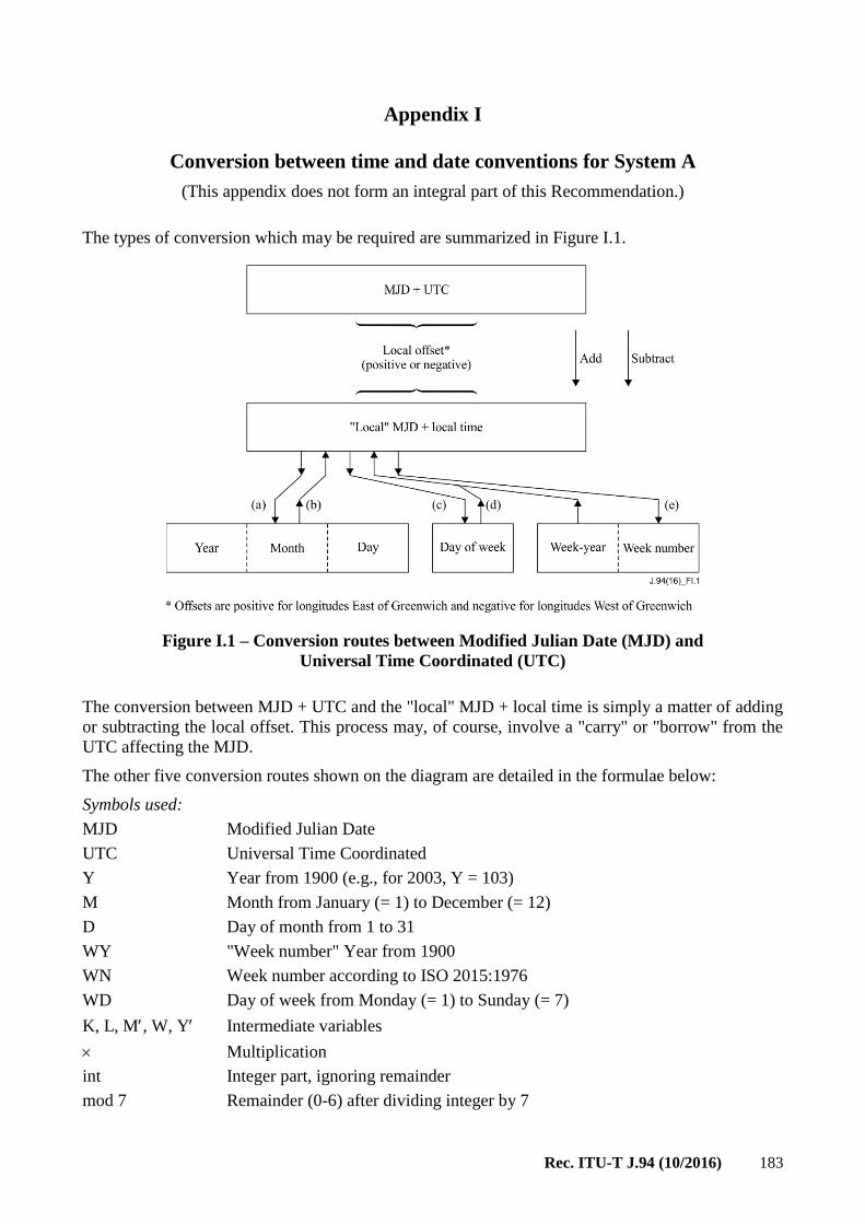
Rec. ITU-T J.94 (10/2016) 183
Appendix I
Conversion between time and date conventions for System A
(This appendix does not form an integral part of this Recommendation.)
The types of conversion which may be required are summarized in Figure I.1.
Figure I.1 – Conversion routes between Modified Julian Date (MJD) and
Universal Time Coordinated (UTC)
The conversion between MJD + UTC and the "local" MJD + local time is simply a matter of adding
or subtracting the local offset. This process may, of course, involve a "carry" or "borrow" from the
UTC affecting the MJD.
The other five conversion routes shown on the diagram are detailed in the formulae below:
Symbols used:
MJD Modified Julian Date
UTC Universal Time Coordinated
Y Year from 1900 (e.g., for 2003, Y = 103)
M Month from January (= 1) to December (= 12)
D Day of month from 1 to 31
WY "Week number" Year from 1900
WN Week number according to ISO 2015:1976
WD Day of week from Monday (= 1) to Sunday (= 7)
K, L, M, W, Y Intermediate variables
Multiplication
int Integer part, ignoring remainder
mod 7 Remainder (0-6) after dividing integer by 7

184 Rec. ITU-T J.94 (10/2016)
a) To find Y, M, D from MJD
Y = int [ (MJD – 15078.2) / 365.25 ]
M = int { [ MJD – 14956.1 – int (Y 365.25) ] / 30.6001 }
D = MJD – 14956 – int (Y 365.25) – int (M 30.6001)
If M = 14 or M = 15, then K = 1; else K = 0
Y = Y + K
M = M' – 1 – K 12
b) To find MJD from Y, M, D
If M = 1 or M = 2, then L = 1; else L = 0
MJD = 14956 + D + int [ (Y – L) 365.25 ] + int [ (M + 1 + L 12) 30.6001 ]
c) To find WD from MJD
WD = [ (MJD + 2) mod 7 ] + 1
d) To find MJD from WY, WN, WD
MJD = 15012 + WD + 7 { WN + int [ (WY 1461 / 28) + 0.41 ] }
e) To find WY, WN from MJD
W = int [ (MJD / 7) – 2144.64 ]
WY = int [ (W 28 / 1461) – 0.0079 ]
WN = W – int [ (WY 1461 / 28) + 0.41 ]
Example – MJD = 45218 W = 4315
Y = (19)82 WY = (19)82
M = 9 (September) WN = 36
D = 6 WD = 1 (Monday)
NOTE – These formulae are applicable between the inclusive dates 1 March 1900 to 28 February 2100.

Rec. ITU-T J.94 (10/2016) 185
Appendix II
Implementation recommendations for System B
(This appendix does not form an integral part of this Recommendation.)
II.1 Implications for retail digital cable-ready devices
Given that a cable operator could choose to deliver SI tables according to any of the profiles defined
in Annex D on any given hub, digital cable-ready devices offered for retail sale should be able to
accept a Short-form Virtual Channel Table for basic navigation if the Long-form Virtual Channel is
not provided. It should also accept the Long-form Virtual Channel Table if the Short-form table is
not provided.
II.2 Channel number handling
Host devices are expected to support navigation based on virtual channel records associated with
two-part channel numbers. If an S-VCT virtual channel record includes a
two_part_channel_number_descriptor(), the Host is expected to use it, and to disregard the 12-bit
virtual_channel_number field in the same virtual_channel() record.
If a two_part_channel_number_descriptor() is not present in the record-level descriptors loop of a particular
S-VCT virtual channel record, the Host is expected to use the virtual_channel_number field in the
virtual_channel() record, (see Table B.20) as the channel number reference.
Both numbering schemes may co-exist in a channel map, but each individual channel must be
considered labelled with either a one-part or a two-part number.
II.3 Processing of dynamic changes to service information
The Host is expected to monitor SI data on a continuous basis, and react to changes dynamically. For
example, an update to an S-VCT or L-VCT may indicate that the definition of the currently acquired
virtual channel has changed. The change could involve, for example, association of the channel with
a different MPEG-2 program_number within a Transport Stream on a different carrier frequency. In
response to such a change, the Host is expected to tune to and acquire the service as redefined.
For some types of changes, the Host is not expected to respond in a visible way. For example, the
name of the current event may change, but the new name would be visible as the response to a regular
user action to show the event name on-screen or in a program guide display.
II.4 AEITs may include event information for inaccessible channels
In the out-of-band system, depending on the data delivery methods employed by the cable headend
and POD module, there may be occasions where AEITs are broadcast for which some set-top boxes
do not have corresponding virtual channel assignments. In these cases, the Host is expected to discard
portions of the AEITs corresponding to source_ID values not present in the Virtual Channel Table
(short- or long-form).
For example, the AEIT may include data describing the program schedule for a service identified
with source_ID value 0x0123, and suppose the Virtual Channel Table does not include a channel
associated with source_ID 0x0123. When constructing a program guide display, the channel name,
number and physical location associated with events tied to source_ID 0x0123 will not be available.
Therefore, the events described in the AEIT data for this channel are inaccessible, and the AEIT
records for this source_ID should be discarded.

186 Rec. ITU-T J.94 (10/2016)
II.5 Splice flag processing
The S-VCT includes a flag called splice. Hosts supporting application of virtual channel changes tied
to video splice point timing are expected to execute the change after two seconds following the
activation_time, in the absence of a video splice point prior to that time.
Support of the splice timing function is optional in Hosts. A Host not supporting the splice timing
feature is expected to apply the data delivered in the VCM_structure() at the indicated activation time
(i.e., the splice flag may be simply disregarded).

Rec. ITU-T J.94 (10/2016) 187
Appendix III
Service Information overview and guide for System B
(This appendix does not form an integral part of this Recommendation.)
III.1 Table hierarchy
Figures III.1 through III.5 describe the relationships between SI tables for Profiles 1 through 6 in a
simplified form. A mandatory table is shown in a solid box. An optional table is shown in a dotted
box. An italicized name indicates a sub-table or a map carried within the table.
Figure III.1 – Hierarchy of Table Sections –
Profiles 1 and 2
Figure III.2 – Hierarchy of Table Sections –
Profile 3

188 Rec. ITU-T J.94 (10/2016)
Figure III.3 Hierarchy of Table Sections Profile 4

Rec. ITU-T J.94 (10/2016) 189
Figure III.4 – Hierarchy of Table Sections – Profile 5

190 Rec. ITU-T J.94 (10/2016)
Figure III.5 – Hierarchy of Table Sections – Profile 6
The Short-form Virtual Channel Table section (table_ID 0xC4) or the Long-form Virtual Channel
Table (table_ID 0xC9) provide navigation data on the out-of-band path. If MGT is provided, it
references all tables present in Service Information (except the System Timetable).
The Master Guide Table provides general information about all of the other tables including the
S-VCT, L-VCT, RRT, AEIT, and AETT. It defines table sizes necessary for memory allocation
during decoding; it defines version numbers to identify those tables that need to be updated; and it
gives the packet identifier (PID) values associated with instances of AEITs and AETTs.
In Profile 3 and higher, the Rating Region Table must be included, with one exception, to describe
rating regions in use. The exception is that delivery of version 0 of the RRT for region 0x01 (US and
possessions), need not be sent because this table is standardized in EIA-766. Furthermore, for Profile
3, the MGT need not be sent if no RRT is sent.
Aggregate Event Information Tables are included in the out-of-band data in Profiles 4-6. Each AEIT
instance describes the events or TV programs associated with a particular three-hour time slot. In the
AEIT table structure, program schedule and title data for all virtual channels is aggregated together.
Each AEIT instance is valid for a time interval of three hours. As shown in Figure III.3, at minimum,
AEIT-0 through AEIT-3 must be sent. Therefore, when Profiles 4-6 are used, current program
information and information covering nine to twelve hours of future programming will be available
to the Host.
Up to 256 AEITs may be transmitted; over 30 days of future programming may therefore be
described. For the fourth timeslot and beyond (AEIT-4 through AEIT-N), the tables may be
associated with the same or different PID values.
The start time for any AEIT is constrained to be one of the following UTC times: 00:00 (midnight),
03:00, 06:00, 09:00, 12:00 (noon), 15:00, 18:00, and 21:00. Imposing constraints on the start times
as well as the interval duration simplifies re-multiplexing. During re-multiplexing, AEIT tables

Rec. ITU-T J.94 (10/2016) 191
coming from several distinct Transport Streams may end up grouped together or vice versa. If no
constraints were imposed, re-multiplexing equipment would have to parse AEIT by content in real
time, which is a difficult task.
However, it is also possible to regenerate one or several AEIT at any time for correcting and/or
updating the content (e.g., in cases where "to be assigned" events become known). Regeneration of
an AEIT may be flagged by updating version fields in the MGT. A new AEIT may also be associated
with a PID value not in current use. The MGT may be updated to show this new PID value association.
In Profiles 4-6, there can be several Aggregate Extended Text Tables, each of them having its
associated PID defined in the MGT. As its name indicates, the purpose of an Aggregate Extended
Text Table is to carry textual data. For example, for an event such as a movie listed in the AEIT, the
typical data is a short paragraph that describes the movie itself. Each Aggregate Event Information
Table can have one associated AETT. Each AETT instance includes all the text associated with events
starting within a particular timeslot. Aggregate Extended Text Tables are optional in Profiles 4-6.
III.2 SI_base PID
Data associated with the SI_base PID defines information of system-wide applicability such as
frequency plans, channel maps, and channel names. The SI_base PID value is 0x1FFC. The types of
table sections that may be included in the Network Stream include:
Network Information Table, carrying the:
• Carrier Definition Subtable,
• Modulation Mode Subtable;
Network Text Table, carrying the Source Name Subtable;
Short-form Virtual Channel Table, carrying the:
• Virtual Channel Map,
• Defined Channels Map,
• Inverse Channels Map;
Long-form Virtual Channel Table;
Master Guide Table;
Rating Region Table;
System Timetable.
Carrier Definition Subtable
The Carrier Definition Subtable provides a foundation for the definition of frequency plans by
defining a set of carrier frequencies appropriate to a particular transmission medium. The CDS is
stored in the Host as an array of as many as 255 CDS records, each consisting of:
– Carrier frequency, 15 bits, in units of 10 or 125 kHz.
Modulation Mode Subtable
The Modulation Mode Subtable provides a foundation for quick acquisition of digitally modulated
waveforms. A separate MMS shall be transmitted in Network data for each transmission medium
supported by that network. An MMS is stored in the Host as an array of up to 255 MMS records, each
consisting of:
– Modulation format: analogue NTSC or QAM;
– Transmission system: ITU-T (North America) or ATSC;

192 Rec. ITU-T J.94 (10/2016)
– Symbol rate, in units of 1 Hz;
– Inner coding mode, expressed as either "none" or an integer ratio such as 1/2 or 3/4;
– For QAM modulation, the number of levels.
Each MMS contains entries for each modulation mode currently in use by any digital waveform, plus
entries for any modes anticipated to be used. As with the CDS, changes to the table are rare.
Parameters defined within the MMS are not specifically manipulated by Hosts compliant with the SI
protocol, but are referenced by the Host when attempting to acquire a digitally encoded and modulated
waveform.
Short-form Virtual Channel Table and Virtual Channel Record
The Short-form Virtual Channel Table is a hierarchical data structure that may carry within it the
Virtual Channel Map and Virtual Channel record, for support of up to 4096 channel definition
records. Each virtual channel is associated with a 16-bit reference ID number called the source_ID.
Each record in the VCM consists of:
– The MPEG program number, associating the virtual channel record with a program defined
in the Program Association Table and TS Program Map Table.
– For virtual channels associated with programs carried in a program guide, the source_ID, a
number that may be used to link the virtual channel to entries in the Electronic Program Guide
(EPG) database.
– For virtual channels used as access paths to application code or data (such as EPG), the
application ID7.
Source ID
Source ID is a 16-bit number associated with each program source, defined in such a way that every
programming source offered anywhere in the system described in this Service Information annex is
uniquely identified. For example, HBO/W has a different assigned source ID than HBO/E, and both
are different from HBO-2 or HBO-3. Uniqueness is necessary to maintain correct linkages between
an EPG database and virtual channel tables. See below for a discussion of the relationship between
source_ID, virtual channels, and an EPG database.
Source Names and Source Name Subtable
The Source Name is a variable length multilingual text string associating a source ID with a textual
name. The Source Name Subtable is delivered within the Network Text Table section.
Source name information is delivered in a table format separate from the table containing other
information comprising the virtual channel table. Name information is not strictly necessary for
channel acquisition, and (depending on the memory management scheme employed in the Host) may
not always be available from memory at acquisition time. Source name information may be refreshed
often, and can be available within several seconds of acquisition.
An EPG database may define textual reference names associated with given program sources
(referenced by source ID). Such a database may be used to derive virtual channel names in some
applications, though in an EPG database the name is generally abbreviated due to display
considerations.
7 Source ID and application ID need never be defined in the same virtual channel record, therefore they share
a common 16-bit field in the stored map. Channels are defined as for "application access" or not; if they are
application access, the field defines the application ID, if not, it defines the source ID.

Rec. ITU-T J.94 (10/2016) 193
Name data is, unlike the regular VCT data, language tagged, so that multilingual source names may
be defined. Transmission format for multilingual text is defined to include references to multiple
phonetic and ideographic character sets.
Defined Channels Map and Inverse Channels Map
For a given Standard-compliant channel, DCM data consist of a series of bytes that, taken as a whole,
specify which channels in the map are defined, and which are not.
Each Virtual Channel Table has associated with it a table listing source_IDs and their associated virtual
channel numbers. The source_ID values are sorted by value from the lowest to the highest in the table,
to facilitate (using a binary search) lookup of a virtual channel given a source ID.
Master Guide Table
Use of the MGT is optional in certain profiles. Table III.1 shows a typical Master Guide Table
indicating, in this case, the existence in the Transport Stream of a Long-form Virtual Channel Table,
the Rating Region Table, four Aggregate Event Information Tables, and two Aggregate Extended
Text Tables describing the first six hours' events.
Table III.1 – Example Master Guide Table content
table_type PID version_number table size (bytes)
LVCT 0x1FFC 4 5 922
RRT – region 6 0x1FFC 0 1 020
AEIT-0 – MGT_tag = 56 0x1DD2 6 29 250
AEIT-1 – MGT_tag = 57 0x1DD2 4 28 440
AEIT-2 – MGT_tag = 58 0x1DD3 10 25 704
AEIT-3 – MGT_tag = 59 0x1DD3 2 27 606
AETT-0 – MGT_tag = 56 0x1DD2 2 24 004
AETT-1 – MGT_tag = 57 0x1DD2 7 25 922
AETT-2 – MGT_tag = 58 0x1DD3 8 27 711
AETT-3 – MGT_tag = 59 0x1DD3 0 19 945
The first entry of the MGT describes the version number and size of the Long-form Virtual Channel
Table. The second entry corresponds to an instance of the Rating Region Table for region 6. If some
region's policy makers decided to use more than one instance of an RRT, the MGT would list each
PID, version number, and size.
The next entries in the MGT correspond to the four AEITs that must be supplied in the Transport
Stream for profiles 4-6. After the AEITs, the MGT references four Aggregate Extended Text Tables.
The PID values for AEIT-0 and AEIT-1 are both 0x1DD2. MGT_tag values 56 and 57 are used for
these. For AEIT-2 AEIT-3, PID 0x1DD3 is used. The last four references are to Aggregate ETTs.
Note that AETT-n shares a common PID value with AEIT-n for every value of n. AEIT-0 and
AETT-0 are associated with PID 0x1DD2, as are AEIT-1 and AETT-1. AEIT-2 and AETT-2 are
associated with PID 0x1DD3, etc.
Descriptors can be added for each entry as well as for the entire MGT. By using descriptors, future
improvements can be incorporated without modifying the basic structure of the MGT. The MGT is
like a flag table that continuously informs the Host about the status of all the other tables (except the
System Time which has an independent function). The MGT is continuously monitored at the Host
to prepare and anticipate changes in the channel/event structure. When tables are changed at the
broadcast side and the PID association is unchanged, their version numbers are incremented and the
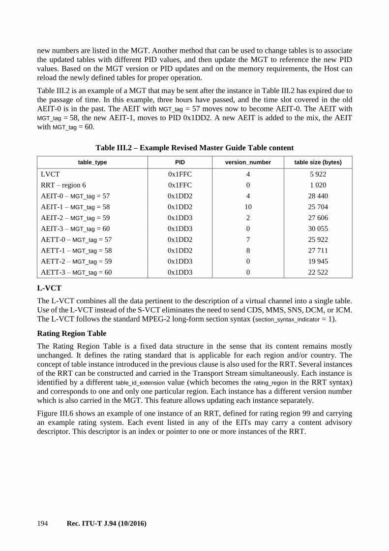
194 Rec. ITU-T J.94 (10/2016)
new numbers are listed in the MGT. Another method that can be used to change tables is to associate
the updated tables with different PID values, and then update the MGT to reference the new PID
values. Based on the MGT version or PID updates and on the memory requirements, the Host can
reload the newly defined tables for proper operation.
Table III.2 is an example of a MGT that may be sent after the instance in Table III.2 has expired due to
the passage of time. In this example, three hours have passed, and the time slot covered in the old
AEIT-0 is in the past. The AEIT with MGT_tag = 57 moves now to become AEIT-0. The AEIT with
MGT_tag = 58, the new AEIT-1, moves to PID 0x1DD2. A new AEIT is added to the mix, the AEIT
with MGT_tag = 60.
Table III.2 – Example Revised Master Guide Table content
table_type PID version_number table size (bytes)
LVCT 0x1FFC 4 5 922
RRT – region 6 0x1FFC 0 1 020
AEIT-0 – MGT_tag = 57 0x1DD2 4 28 440
AEIT-1 – MGT_tag = 58 0x1DD2 10 25 704
AEIT-2 – MGT_tag = 59 0x1DD3 2 27 606
AEIT-3 – MGT_tag = 60 0x1DD3 0 30 055
AETT-0 – MGT_tag = 57 0x1DD2 7 25 922
AETT-1 – MGT_tag = 58 0x1DD2 8 27 711
AETT-2 – MGT_tag = 59 0x1DD3 0 19 945
AETT-3 – MGT_tag = 60 0x1DD3 0 22 522
L-VCT
The L-VCT combines all the data pertinent to the description of a virtual channel into a single table.
Use of the L-VCT instead of the S-VCT eliminates the need to send CDS, MMS, SNS, DCM, or ICM.
The L-VCT follows the standard MPEG-2 long-form section syntax (section_syntax_indicator = 1).
Rating Region Table
The Rating Region Table is a fixed data structure in the sense that its content remains mostly
unchanged. It defines the rating standard that is applicable for each region and/or country. The
concept of table instance introduced in the previous clause is also used for the RRT. Several instances
of the RRT can be constructed and carried in the Transport Stream simultaneously. Each instance is
identified by a different table_id_extension value (which becomes the rating_region in the RRT syntax)
and corresponds to one and only one particular region. Each instance has a different version number
which is also carried in the MGT. This feature allows updating each instance separately.
Figure III.6 shows an example of one instance of an RRT, defined for rating region 99 and carrying
an example rating system. Each event listed in any of the EITs may carry a content advisory
descriptor. This descriptor is an index or pointer to one or more instances of the RRT.

Rec. ITU-T J.94 (10/2016) 195
Figure III.6 – An instance of a Rating Region Table
Aggregate Event Information Tables and Aggregate Extended Text Tables
The purpose of an AEIT is to list all events for those channels that appear in the VCT for a given time
window. As mentioned before, AEIT-0 describes the events for the first 3 hours and AEIT-1 for the
second 3 hours. AEIT-0 and AEIT-1 share a common associated PID value as defined in the MGT.
In MPEG, tables can have a multitude of instances. When different instances of a table share the same
table_id value and PID, they are distinguished by differences in the 16-bit table_id_extension field.
In this SI appendix for out-of-band use, each instance of AEIT-k contains a list of events for each
virtual channel. Linkage to each channel in the VCT is made via the source_ID. For the AEIT, the
table_id_extension field appears as MGT_tag.
Figure III.7 shows, for example, a program provider's instance for AEIT-0.

196 Rec. ITU-T J.94 (10/2016)
Figure III.7 – Example AEIT-0
AEIT-0 is unique in that it must list all events starting within the three-hour time period it covers, as
well as any events that started earlier but extend into the covered period. For all other AEITs, only
those events actually starting within the three hour time period are included. The Host is expected to
collect AEITs in order of their time coverage. If AEIT-4 is available to the Host but AEIT-3 is not,
for example, information for events that started in the time period covered by AEIT-3 but extending
into AEIT-4 will not be available for display.
Figure III.7 shows an example of a small AEIT-0, including event data for two sources, a channel
called "TSPN" (source_ID 22) and one called "MOOV" (source_ID 80). For the three-hour period
covered by AEIT-0, 9 a.m. to noon, three events are listed for TSPN and two for MOOV. The field
event_id is a number used to identify each event. The event_id is used to link events with associated text
delivered in the AETT. The assignment of an event_ID value must be unique within a source ID and a
3-hour interval defined by one AEIT instance. The event_id is followed by the start_time and then the
length_in_seconds. Notice that for AEIT-0 only, events can have start times before the activation time
of the table. ETMs are simply long textual descriptions. The collection of ETMs constitutes an
Aggregate Extended Text Table (ETT).
An example of an ETM for the Car Racing event may be:
"Live coverage from Indianapolis. This car race has become the largest single-day sporting event in
the world. Two hundred laps of full action and speed."
Several descriptors can be associated with each event. The most important is the content advisory
descriptor which assigns a rating value according to one or more systems. Recall that the actual rating
system definitions are tabulated within the RRT.

Rec. ITU-T J.94 (10/2016) 197
Figure III.8 diagrams the AEIT data structure. As shown, the AEIT includes event data for all sources
listed in the VCT. In the figure, the hatched box represents one or more "event data" blocks, each
comprised of the data items shown in the upper left.
Figure III.8 – AEIT data structure
Figure III.9 diagrams the AETT data structure. The AETT aggregates text for a given timeslot into
one sectioned MPEG table.

198 Rec. ITU-T J.94 (10/2016)
Figure III.9 – Structure of AETT
An AETT-n instance for a given value of n (timeslot) is associated with the same PID value as
AEIT-n. This means that they can be collected using a single Extended Channel data flow between
Host and POD.
Inactive Channels
Any channels in the L-VCT which are not currently active shall have the hidden attribute set to 1 and
the hide_guide attribute set to 0. Inactive channels in the S-VCT shall have the hidden attribute in
channel_type, and the hide_guide flag in the channel_properties_descriptor() set to 0.
Table III.3 shows expected DTV behavior for the various combinations of the hidden and hide_guide
attributes. In the table the "x" entry indicates "don't care." A check in the "surf" column indicates the
channel is available by channel surfing and via direct channel number entry. A check in the "guide"
column indicates that the channel may appear in the program guide listing.
Table III.3 – Receiver Behavior with hidden and hide_guide attributes
hidden Hide_guide Receiver Behavior
Surf Guide
0 x Normal channel
1 1 Special access only
1 0 Inactive channel
III.3 Representation of Time
The System Timetable provides time of day information to Hosts. In this Service Information
appendix, time of day is represented as the number of seconds that have elapsed since the beginning
of "GPS time," 0000 Hours UTC, January 6th, 1980. GPS time is referenced to the Master Clock at
the US Naval Observatory and steered to Coordinated Universal Time (UTC). UTC is the current
Rec. ITU-T J.94 (10/2016) 199
time of day at the time zone local to Greenwich, England, and is the time source we use to set our
clocks.
The cycle of the seasons, technically known as the tropical year, is approximately 365.2422 days.
Using the Gregorian calendar we adjust for the fractional day by occasionally adding an extra day to
the year. Every fourth year is a leap year, except that three leap years in every 400 are skipped
(the centennial years not divisible by 400). With this scheme there are 97 leap years in each 400 year
span, yielding an average year that is 365.2425 days long.
UTC is occasionally adjusted by one-second increments to ensure that the difference between a
uniform time scale defined by atomic clocks does not differ from the Earth's rotational time by more
than 0.9 seconds. The timing of occurrence of these "leap seconds" is determined by careful
observations of the Earth's rotation; each is announced months in advance. On the days it is scheduled
to occur, the leap second is inserted just following 12:59:59 p.m. UTC.
UTC can be directly computed from the count of GPS seconds since January 6th, 1980 by subtracting
from it the count of leap seconds that have occurred since the beginning of GPS time. In the months
just following January 1st, 1999, this offset was 13 seconds.
This protocol defines various time-related events and activities, including starting times for
programs, text display, changes to VCTs, and others. Two methods of time distribution are used in
headend systems. One method derives time in the form of GPS seconds from GPS Hosts. These
Hosts also provide current GPS/UTC offset data. The second method of time distribution relies on
the Internet Standard Network Time Protocol (NTP). NTP servers provide output in the form of
UTC time, and do not provide GPS/UTC offset data. The Standard-compliant Host is synchronized
to system time by the System Timetable, which provides time either in the form of GPS seconds
since week zero of GPS time, January 6th, 1980, or directly in UTC time. The interpretation
depends on the value of the GPS/UTC offset field. The special value of zero is used to indicate that
the system is being driven by a UTC time source directly, and that GPS/UTC offset data is not
available.
System Time
GPS satellites typically output GPS time in a format consisting of a week count (Tw) and a seconds
within the week count (Ts), where week zero is defined as starting January 6th, 1980. For purposes
of building the System Timetable, the following formula may be used:
T = (Tw * 604 800) + Ts
There are 604 800 seconds per week.
When converting between GPS seconds and current local time in hours/minutes/seconds, the
following factors must be taken into account:
– GPS to UTC offset Given a time represented as GPS seconds, the Host first subtracts the
GPS/UTC offset to convert to UTC.
– 1980 The first year of GPS time started on January 6th, yielding 361 days in the first year
(1980 was also a leap year).
– Leap years The number of leap years that occurred between the current GPS second and
1980 must be accounted for. A leap year is a year whose number is evenly divisible by four,
or, in the case of century years, by 400.
NOTE According to this rule, the year 2000 is a leap year even though it is a century year, because it is also
divisible by 400.
– Time zones Time zones are signed integer values in the range −12 to +13 hours, where
positive numbers represent zones east of the Greenwich meridian and negative numbers west
200 Rec. ITU-T J.94 (10/2016)
of it. Pacific Standard Time (PST) is 8 hours behind standard time, and Eastern Standard
Time (EST) is 5 hours behind. The system defined by this Service Information standard
accommodates time zones that are not an integral number of hours offset from Greenwich by
defining time zone as an 11-bit signed integer number in units of minutes. To convert to local
time, the time zone is added to Greenwich time using signed integer arithmetic.
– Daylight savings time If applicable, daylight savings time must be taken into account. On
a unit by unit basis, each Host may be given a definition for when daylight savings time is
entered into in Spring, and when it is exited in Fall. Entry/exit points are given as absolute
times (GPS seconds), and hence are given in one second resolution.
Transmission Format for Event Times
In this messaging protocol, the absolute time of action is specified for most events in terms of an
unsigned 32-bit integer number, the count of GPS seconds since January 6th, 1980. This count does
not wrap until after the year 21168.
Handling of Leap Second Events
In this Service Information protocol, times of future events (such as event start times in the EIT) are
specified the same as time of day, as the count of seconds since January 6th, 1980. Converting an event
start time to UTC and local time involves the same calculation as the conversion of system time to local
time. In both cases, the leap seconds count is subtracted from the count of GPS seconds to derive UTC.
GPS time is used to represent future times because it allows the Host to compute the time interval to
the future event without regard for the possible leap second that may occur in the meantime. Also, if
UTC were to be used instead, it would not be possible to specify an event time that occurred right at
the point in time where a leap second was added. UTC is discontinuous at those points.
Around the time a leap second event occurs, program start times represented in local time
(UTC adjusted by local time zone and [as needed] daylight savings time) may appear to be off by
plus or minus one second. Generating equipment may use one of two methods to handle leap seconds.
In method A, generating equipment does not anticipate the future occurrence of a leap second. In this
case, prior to the leap second, program start times will appear correct. An event starting at exactly
10 a.m. will be computed as starting at 10:00:00. But just following the leap second, that same event
time will be computed as 9:59:59. The generating equipment should re-compute the start times in all
the EITs and introduce the leap second correction. Once that happens, and Hosts have updated their
EIT data, the computed time will again show as 10:00:00. In this way the disruption can be limited
to a matter of seconds.
In method B, generating equipment does anticipate the occurrence of a leap second, and adjusts
program start times for events happening after the new leap second is added. If the leap second event
is to occur at midnight tonight, an event starting at 10 a.m. tomorrow will be computed by receiving
equipment as starting at 10:00:01.
For certain types of events, the precision of method B is necessary. By specifying events using a time
system that involves no discontinuities, difficulties involving leap seconds are avoided. Events such
as program start times do not require that level of precision. Therefore, method A works well.
8 Prior to that time, all initial Receivers will surely be out of service, and new ones can be designed to handle
the wrap condition.

Rec. ITU-T J.94 (10/2016) 201
Handling of Leap Second Events
Consider the following example. Times are given relative to UTC, and would be corrected to local
time zone and daylight savings time as necessary.
– Time of day (UTC): 1:00 p.m., December 30th, 1998
– Event start time (UTC): 2:00 p.m., January 2nd, 1999
– A leap second event will occur just after 12:59:59 p.m. on December 31st , 1998.
– Leap seconds count on December 30th is 12.
The data in the System Timetable is:
– GPS seconds = 599 058 012 = 0x23B4E65C
– GPS to UTC offset = 12
Using method A (upcoming leap second event is not accounted for):
– Event start time in EIT: 599 320 812 = 0x23B8E8EC
– Converted to UTC: 2:00:00 p.m., January 2nd, 1999
– Number of seconds to event: 262 800 = 73 hours, 0 minutes, 0 seconds
Using method B (upcoming leap second event is anticipated):
– Event start time in EIT: 599 320 813 = 0x23B8E8ED
– Converted to UTC: 2:00:01 p.m., January 2nd, 1999
– Number of seconds to event: 262 801 = 73 hours, 0 minutes, 1 second
Note that using method B, the number of seconds to event is correct, and does not need to be
recomputed when the leap seconds count moves from 12 to 13 at year-end.

202 Rec. ITU-T J.94 (10/2016)
Appendix IV
Daylight Savings Time control for System B
(This appendix does not form an integral part of this Recommendation.)
In order to convert GPS into local time, the Host needs to store a time offset (from GPS to local time)
in local memory and an indicator as to whether daylight savings is observed. These two quantities
can be obtained from the user interface (indicating time zone and daylight savings observance) or
from the conditional access system, if present, and stored in non-volatile Host memory.
Since there is a common time (GPS) transmitted in SI, a mechanism to indicate when the Host should
switch into (or out of) daylight savings time at the appropriate local time can be very useful. Once all
the Hosts have transitioned at their local times, the entire system can be shifted into daylight savings
time. This is accomplished by appropriate setting of the daylight_savings in the
daylight_savings_time_descriptor() the STT. The basic use of daylight savings fields through the year is
shown in Table IV.1.
Table IV.1 – Basic use of daylight savings fields through the year
Conditions DS
status
DS_day
of_month DS_hour
At the beginning of the year (January) daylight savings is off. This
is the status of the fields until:
0 0 0
When the transition into daylight savings time is within less than one
month, the DS_day_of_month field takes the value day_in, and
the DS_hour field takes the value hour_in. The DS_status bit is 0
indicating it is not yet daylight savings time. (The transition is to
occur on the day_in day of the month at hour=hour_in; for
example, if the transition were on April 15 at 2 a.m., then day_in=15
and hour_in=2.)
0 day_in hour_in
After all time zone daylight transitions (within the span of the
network) have occurred, the DS_status bit takes the value 1,
indicating that daylight savings time is on. The DS_day_of_month
field and the DS_hour field take the value 0. (In the U.S., this
transition has to occur no later than 7 p.m. Pacific Time on the day
day_in.) This is the status of the fields until:
1 0 0
When the transition out of daylight savings time is within less than
one month, the DS_day_of_month field takes the value day_out, and the DS_hour field takes the value hour_out. The DS_status
bit is 1 indicating it is still daylight savings time. (The transition is
to occur on the day_out day of the month at hour=hour_out; for
example, if the transition were on October 27 at 2 a.m., then
day_out=27 and hour_out=2.)
1 day_out hour_out
After all time zones (within the span of the network) have shifted
out of daylight savings time, the DS_status bit takes the value 0,
indicating that daylight savings time is off. The DS_day_of_month
field and the DS_hour field take the value 0. (In the U.S., this
transition has to occur no later than 7 p.m. Pacific Time on the day
day_out.) This finishes the cycle.
0 0 0

Rec. ITU-T J.94 (10/2016) 203
Bibliography
[b-ITU-T J.183] Recommendation ITU-T J.183 (2001), Time-division multiplexing of
multiple MPEG-2 transport streams over cable television systems.
[b-DVB Implementation guidelines] Implementation guidelines for use of telecommunications
interfaces in the Digital Broadcasting systems, DVB Project Office.
[b-EIA-708] EIA-708, Specification for Advanced Television Closed Captioning
(ATVCC), Electronic Industry Association.
[b-EIA-752] EIA-752, Transport of Transmission Signal Identifier (TSID) Using
Extended Data Service (XDS).
[b-EIA-766] EIA 766, U.S. Rating Region Table (RRT) and Content Advisory
Descriptor for Transport of Content Advisory Information Using ATSC
A/65 Program and System Information Protocol (PSIP).
[b-SCTE DVS 031] SCTE DVS 031, Digital Video Transmission Standard for Cable
Television, Rev.2, 29 May 1997.
[b-SCTE DVS 097] SCTE DVS 097 (1997), Program and System Information Protocol for
Terrestrial Broadcast and Cable.
[b-SCTE DVS 131r7] SCTE DVS 131r7 (1998), Point of Deployment (POD) Module
Interface.
[b-SCTE DVS 208r6] SCTE DVS 208r6 (1999), Cable Emergency Alert Message (EIA-814).
[b-SCTE DVS 216r4] SCTE DVS 216r4 (2000), POD Extended Channel Specification.
[b-ATSC Standard A/52] ATSC Standard A/52 (1995), Digital Audio Compression (AC-3).
[b-ATSC Standard A/53] ATSC Standard A/53 (1995), ATSC Digital Television Standard.


Printed in Switzerland Geneva, 2017
SERIES OF ITU-T RECOMMENDATIONS
Series A Organization of the work of ITU-T
Series D Tariff and accounting principles and international telecommunication/ICT economic and
policy issues
Series E Overall network operation, telephone service, service operation and human factors
Series F Non-telephone telecommunication services
Series G Transmission systems and media, digital systems and networks
Series H Audiovisual and multimedia systems
Series I Integrated services digital network
Series J Cable networks and transmission of television, sound programme and other
multimedia signals
Series K Protection against interference
Series L Environment and ICTs, climate change, e-waste, energy efficiency; construction, installation
and protection of cables and other elements of outside plant
Series M Telecommunication management, including TMN and network maintenance
Series N Maintenance: international sound programme and television transmission circuits
Series O Specifications of measuring equipment
Series P Telephone transmission quality, telephone installations, local line networks
Series Q Switching and signalling, and associated measurements and tests
Series R Telegraph transmission
Series S Telegraph services terminal equipment
Series T Terminals for telematic services
Series U Telegraph switching
Series V Data communication over the telephone network
Series X Data networks, open system communications and security
Series Y Global information infrastructure, Internet protocol aspects, next-generation networks,
Internet of Things and smart cities
Series Z Languages and general software aspects for telecommunication systems