
Investigation of the Aerodynamics Characteristics of the ...
6
concerns of high-speed electric motor which can be used to drive compressors are increasing. Windage losses and temperature issues have become caught more attention for high-speed electric motor design /5/. In order to solve the challenges of in-line high-speed electric motor-driven axial-flow compressor, a novel design that integrates an electric motor with an axial-flow compressor is proposed and is shown in Figure 1(c) /6/. The rotor of the electric motor is curved as airfoil; it can provide both electromagnetic torque and accelerating the flow of compression function. In Figure 1(c), the integrated motor-compressor is working as the first stage of the multistage axial-flow compressor, and it is connected to the later compressor stages through the same shaft. Hence, the integrated motor-compressor is part of the multistage compressor, and it can provide mechanical energy to drive the whole compressor system /7/. The proposed machine can increase the compactness of the compressor system and provide self-cooling benefit. However, few researches have been done on investigating the aerodynamic characteristics of the integrated machine [D2]. Hence the contribution of this paper is to investigate both the electromagnetic performance and aerodynamic performance of the proposed integrated motor-compressor. In Section II, the electromagnetic and aerodynamic design of the proposed integrated machine is presented by analytical method. The aerodynamic performance is provided in Section III by meanline method and computational fluid dynamics (CFD). Section IV provided the electromagnetic performance of the proposed machine by finite element analysis (FEA). Section V follows the conclusion. 2 Electromagnetic and Aerodynamic Design of the Integrated Motor-Compressor The design of the flux-switching integrated motor-compressor is electromagnetically and aerodynamically cross- coupled. The dimensions of the proposed machine have a very large impact on the performance of motoring and compression aspect. In this section, the electromagnetic and aerodynamic design of the integrated motor- compressor is provided. (a) (b) (c) Figure 1: Electric motor-driven axial-flow compressor, (a) STC-SX model of axial-flow compressor, (b) in- line electric motor driven STC-SX axial-flow compressor, (c) multistage integrated motor-compressor (a) (b) (c) (d) Figure 2: Candidate electric motor topologies, (a) Doubly Salient PM machine, (b) Flux Reversal PM (FRPM) machine, (c) Switched Reluctance Machine (SRM), (d) Flux-Switching PM (FSPM) machine Investigation of the Aerodynamics Characteristics of the Integrated Motor- Compressor Hao Ding, William Sixel, and Bulent Sarlioglu Wisconsin Electric Machines and Power Electronics Consortium (WEMPEC) University of Wisconsin-Madison Madison, WI 53706 USA [email protected] The objective of this work is to design and investigate the aerodynamic performance of a novel integrated motor- compressor. The integrated motor-compressor integrates the axial-flow compression into the electromagnetic function by designing the airfoil-shaped rotor of the electric machine to provide compression. Hence, the integrated motor-compressor is both an axial-flow compressor and an electric machine. It is capable of providing axial flow compression and electromagnetic torque at the same time. In this work, the aerodynamic design of the proposed machine is done and evaluated by both analytical method and computational fluid dynamics (CFD). The effect of attack angle to the blade lift and drag forces are investigated. The effect of solidity to the axial-flow compressor performance is also evaluated. The electromagnetic performance of the proposed machine is investigated by motor sizing equations and finite element analysis (FEA). Keywords: Aerodynamics, axial-flow compressor, electric motor, FEA, CFD Target audience: Pumps and Motors, Novel Production Technologies 1 Introduction Compressors are commonly defined as dynamic compressors and positive displacement compressors. The positive displacement compressors trap and transport the fluid in a confined space to achieve high pressure. The dynamic compressors dynamic transfer the energy in the continuously flowing fluid to achieve a pressure increase. Axial- flow compressors and centrifugal compressors are two basi c types of dynamic compressors. The radius of flow streamlines in a centrifugal compressor is increasing while the radius of an axial-flow compressor is almost constant through all the stages. The centrifugal compressor has larger stage pressure increase than the axial-flow compressor. While in an axial-flow compressor, it has multiple stages to achieve large pressure ratio, and it has a significantly larger mass flow rate than a centrifugal compressor /1/. Axial-flow compressors are widely used in gas turbines, aircraft engines, power plants and gas transportation stations. There are multiple stages in axial-flow compressor and a compressor stage consists a rotor stage and a stator stage. Flow in an axial-flow compressor is accelerated by the rotating compressor rotor stages and diffused by the compressor stator stages to achieve high-pressure rise. Axial-flow compressors have the advantages of very high mass flow rate, high efficiency, and high total pressure concerning /2/. Figure 1(a) shows STC-SX model of axial-flow compressor designed by Siemens which can be used for blasting furnace air and FCC (Fluid Catalytic Cracking) air; it is typically driven by the steam turbine, and electric motor depends on energy resources and application types. Figure 1(b) shows an example of in-line electric motor driven STC-SX axial-flow compressor for an FCC plant /3/. The in-line motor-driven compressor has the advantages of faster control speed, highly flexible, and higher efficiency compared with the conventional turbine-driven axial-flow compressors /4/. However, the in-line motor driven axial-flow compressor has challenges on motor cooling, system compactness, and motor locations as the axial-flow compressor need to rotate at a very high speed to accelerate the flow. The complicated structure results in the large size of the in-line motor-driven compressor system. In addition, the 283 GROUP E - 5
-
Upload
khangminh22 -
Category
Documents
-
view
0 -
download
0
Transcript of Investigation of the Aerodynamics Characteristics of the ...

The 11th International Fluid Power Conference, 11. IFK, March 19-21, 2018, Aachen, Germany
concerns of high-speed electric motor which can be used to drive compressors are increasing. Windage losses and temperature issues have become caught more attention for high-speed electric motor design /5/.
In order to solve the challenges of in-line high-speed electric motor-driven axial-flow compressor, a novel design that integrates an electric motor with an axial-flow compressor is proposed and is shown in Figure 1(c) /6/. The rotor of the electric motor is curved as airfoil; it can provide both electromagnetic torque and accelerating the flow of compression function. In Figure 1(c), the integrated motor-compressor is working as the first stage of the multistage axial-flow compressor, and it is connected to the later compressor stages through the same shaft. Hence, the integrated motor-compressor is part of the multistage compressor, and it can provide mechanical energy to drive the whole compressor system /7/. The proposed machine can increase the compactness of the compressor system and provide self-cooling benefit.
However, few researches have been done on investigating the aerodynamic characteristics of the integrated machine [D2]. Hence the contribution of this paper is to investigate both the electromagnetic performance and aerodynamic performance of the proposed integrated motor-compressor. In Section II, the electromagnetic and aerodynamic design of the proposed integrated machine is presented by analytical method. The aerodynamic performance is provided in Section III by meanline method and computational fluid dynamics (CFD). Section IV provided the electromagnetic performance of the proposed machine by finite element analysis (FEA). Section V follows the conclusion.
2 Electromagnetic and Aerodynamic Design of the Integrated Motor-Compressor
The design of the flux-switching integrated motor-compressor is electromagnetically and aerodynamically cross-coupled. The dimensions of the proposed machine have a very large impact on the performance of motoring and compression aspect. In this section, the electromagnetic and aerodynamic design of the integrated motor-compressor is provided.
(a) (b) (c)
Figure 1: Electric motor-driven axial-flow compressor, (a) STC-SX model of axial-flow compressor, (b) in-line electric motor driven STC-SX axial-flow compressor, (c) multistage integrated motor-compressor
(a) (b) (c) (d)
Figure 2: Candidate electric motor topologies, (a) Doubly Salient PM machine, (b) Flux Reversal PM (FRPM) machine, (c) Switched Reluctance Machine (SRM), (d) Flux-Switching PM (FSPM) machine
The 11th International Fluid Power Conference, 11. IFK, March 19-21, 2018, Aachen, Germany
Investigation of the Aerodynamics Characteristics of the Integrated Motor-Compressor
Hao Ding, William Sixel, and Bulent Sarlioglu
Wisconsin Electric Machines and Power Electronics Consortium (WEMPEC) University of Wisconsin-Madison
Madison, WI 53706 USA [email protected]
The objective of this work is to design and investigate the aerodynamic performance of a novel integrated motor-compressor. The integrated motor-compressor integrates the axial-flow compression into the electromagnetic function by designing the airfoil-shaped rotor of the electric machine to provide compression. Hence, the integrated motor-compressor is both an axial-flow compressor and an electric machine. It is capable of providing axial flow compression and electromagnetic torque at the same time. In this work, the aerodynamic design of the proposed machine is done and evaluated by both analytical method and computational fluid dynamics (CFD). The effect of attack angle to the blade lift and drag forces are investigated. The effect of solidity to the axial-flow compressor performance is also evaluated. The electromagnetic performance of the proposed machine is investigated by motor sizing equations and finite element analysis (FEA).
Keywords: Aerodynamics, axial-flow compressor, electric motor, FEA, CFD Target audience: Pumps and Motors, Novel Production Technologies
1 Introduction
Compressors are commonly defined as dynamic compressors and positive displacement compressors. The positive displacement compressors trap and transport the fluid in a confined space to achieve high pressure. The dynamic compressors dynamic transfer the energy in the continuously flowing fluid to achieve a pressure increase. Axial-flow compressors and centrifugal compressors are two basic types of dynamic compressors. The radius of flow streamlines in a centrifugal compressor is increasing while the radius of an axial-flow compressor is almost constant through all the stages. The centrifugal compressor has larger stage pressure increase than the axial-flow compressor. While in an axial-flow compressor, it has multiple stages to achieve large pressure ratio, and it has a significantly larger mass flow rate than a centrifugal compressor /1/.
Axial-flow compressors are widely used in gas turbines, aircraft engines, power plants and gas transportation stations. There are multiple stages in axial-flow compressor and a compressor stage consists a rotor stage and a stator stage. Flow in an axial-flow compressor is accelerated by the rotating compressor rotor stages and diffused by the compressor stator stages to achieve high-pressure rise. Axial-flow compressors have the advantages of very high mass flow rate, high efficiency, and high total pressure concerning /2/. Figure 1(a) shows STC-SX model of axial-flow compressor designed by Siemens which can be used for blasting furnace air and FCC (Fluid Catalytic Cracking) air; it is typically driven by the steam turbine, and electric motor depends on energy resources and application types. Figure 1(b) shows an example of in-line electric motor driven STC-SX axial-flow compressor for an FCC plant /3/. The in-line motor-driven compressor has the advantages of faster control speed, highly flexible, and higher efficiency compared with the conventional turbine-driven axial-flow compressors /4/. However, the in-line motor driven axial-flow compressor has challenges on motor cooling, system compactness, and motor locations as the axial-flow compressor need to rotate at a very high speed to accelerate the flow. The complicated structure results in the large size of the in-line motor-driven compressor system. In addition, the
283
GR
OU
P E
- 5

The 11th International Fluid Power Conference, 11. IFK, March 19-21, 2018, Aachen, Germany
saturation. Hence, tradeoff of the blade thickness is a key concern in this design. The NACA65(4)-421 blade is selected
for the rotor for its large thickness which satisfies the tradeoffs of the blade thickness concerns [11]. Figure 3 shows the compressor rotor blades nomenclature with flow directions. Figure 4 shows the corresponding velocity triangle calculating the flow properties where V is the flow velocity, U is the blade velocity, W is the flow relative velocity to the blades which need to be at least 0.3 Ma for measurable pressure increase /1/. The subscription 1 and 1.5 refers to entering and exiting the rotor stage. The flow angle β in Figure 3 equals the sum of flow attack angle α and blade stagger angle γ. The flow turn angle θ reflects the deflection angle of the relative velocity before and after the rotor stage. The axial-flow compressor solidity σ is defined as the ratio of blade chord length c over blade pitch s, and the solidity is commonly small to avoid large incidence losses /9/. The aspect ratio AR of the blade equals to the blade height over blade chord length.
2.2.1 Dimensions
The design of the dimensions of the integrated motor-compressor is mainly constrained by the trade-off between electromagnetic and aerodynamic requirements. The solidity and blade aspect ratio is the key parameter which can be used as a metric to design the integrated motor-compressor. NACA65(4)-421 blade has a blade thickness of 21% of blade chord length, and it is selected for the integrated machine. As in the FSPM machine, when the thickness of the rotor pole is 1.4 times of the thickness of the stator tooth, maximum back-EMF can be achieved. Therefore, in this work, the thickness of rotor pole should be larger than that of the stator tooth. The blade thickness can be calculated as a function of solidity shown in Equation (5) where ht is the hub-to-tip ratio defined as the ratio of the radius of rotor hub to rotor tip, and Dr is the rotor diameter. The blade thickness can also be derived as a function of aspect ratio shown in Equation (6). The relations between aspect ratio and solidity is derived in Equation (7). In axial-flow compressors, the hub-to-tip ratio is usually greater than 0.7 /2/, and in this design, the hub-to-tip ratio is set to be 0.7.
2 10.212t
r
htBN
�� �� (5)
(1 )0.212
rt
D htBAR�
� (6)
2
(1 )
2 2rN htAR
ht��
��
� (7)
The stator tooth thickness St is calculated by Equation (8), where γ is the blade stagger angle.
( 2) cos36
rt
DS ��
�� (8)
The dimension of the rotor can be calculated by adjusting the solidity and aspect ratio. In this design, the solidity is set to be 1.5, the aspect ratio is set to be 0.375, and the blade chord length is set to be 40 mm. Then the rotor diameter is designed to be 100 mm satisfying the blade thickness requirement and is about 1.2 times of the stator tooth thickness.
Figure 4: Velocity triangle of the flow
The 11th International Fluid Power Conference, 11. IFK, March 19-21, 2018, Aachen, Germany
2.1 Electromagnetic Design
The rotor pole of the electric motor needs to be robust as the airfoil-shaped rotor of an integrated motor-compressor needs to spin at a very high speed to provide compression function. In addition, permanent magnets should be on the stator instead of on the rotor for reliability concerns. Therefore, electric motor with salient pole rotor is a good candidate for the integrated motor-compressor. The candidate electric motor topologies for the integrated motor compressor includes flux-switching permanent magnet (FSPM) machine, doubly salient PM (DSPM) machine, flux reversal PM (FRPM) machine, and switched reluctance machine (SRM) can be used as the motor topology of the proposed machine which is shown in Figure 2. Among the candidates, 12-slot, 10-pole FSPM machine shown in Figure 2(d) is selected as the motor topology for the integrated motor-compressor for its large torque density, sinusoidal back-EMF, and robust structure which are suitable for high-speed operations /5/.
The electric motor can be designed by sizing equations, and the electromagnetic performance can be calculated by the modified sizing equations for the integrated motor-compressor. The fundamental frequency of the FSPM machine is calculated in Equation (1) where n is the rotating speed in rpm, Nr is the number of rotor poles.
60r
eN nf � (1)
The peak value of back-EMF is calculated in Equation (2) where Km is the magnetizing coefficient, Kt is the stator tooth width to pole pitch ratio, Kcurve accounts for the airfoil curvature effect of the rotor pole, Ns is the number of stator slots, Nt is the winding turns per phase, Le is the effective length of the machine, Dis is the stator inner diameter, and Bg,pk is defined as peak airgap flux density /8/.
2,2 ( )e
pk t g pk m t curve is es
fE N B K K K D L
N�� (2)
The torque and output power of the electric motor are calculated in Equation (3) and (4) where η is the motor efficiency, As,rms is the electric loading in Arms/m.
32
, ,2 ( )2
eout m t curve g pk s rms is e
s
fP K K K B A D L
N� �� (3)
22
, ,2 ( )4
rout m t curve g pk s rms is e
s
NT K K K B A D LN
� �� (4)
2.2 Aerodynamic Design
As the rotor of the integrated motor-compressor is the rotor of both an electric motor and axial-flow compressor, the shape of the rotor needs to be carefully designed that there is an inherent trade-off associated with the design of the compressor blade. Specifically, the width of the blade should not be too thick in order to reduce the blade profile loss, however from an electric motor standpoint the width of the rotor pole must be thick enough to avoid
Figure 3: Compressor blade nomenclature showing flow angles
285
GR
OU
P E
- 5

The 11th International Fluid Power Conference, 11. IFK, March 19-21, 2018, Aachen, Germany
of rotor hub to the blade tip, and it is usually greater than 0.7. The degree of reaction is defined as the ratio of the change of enthalpy across the rotor to the entire stage. Blade loading coefficient is defined as rotor work over blade kinetic energy. In heavy loaded stages, the blade loading coefficient is larger than 1 /2/.
As the proposed integrated motor-compressor locates at the first stage of the multistage axial-flow compressor, without inlet guide vanes, the flow can enter the rotor stage axially. The inlet flow absolute velocity is set to be 140 m/s. Then, the De Haller number equals to 0.84; flow coefficient equals to 0.89, blade loading coefficient equals to 0.6, degree of reaction equals to 0.84. It is noted that the stage with greater than 0.5 reaction has low exit loss for the small static pressure rise in the stationary blades. The blade loading coefficient and degree of reaction at different solidity are shown in Figure 7 /1/.
The compressor performance can be calculated using the velocity triangle and meanline method. The power
required by the rotor to turn the flow is calculated in Equation 13 where m. is mass flow rate, r is the rotor radius, ω is the rotational velocity in rad/s.
1.5 1( )shaft u uP mr V V�� � (13)
The stagnation temperature before and after the rotor and total pressure rise can be calculated by Equation (14), (15), and (16), respectively. To is the stagnation temperature in K, subscripts 1 and 1.5 refer to the inlet and outlet of the rotor stage, respectively. The work done by the rotor is defined as w12, cp is the constant-pressure specific heat of gas, and k is the heat capacity ratio. The total pressure ratio of the proposed machine at different solidity are shown in Figure 8. It can be seen that the total pressure increases with the increase of solidity.
(14)
121.5 2 01o o
p
wT T Tc
� � � (15)
/( 1)
1.5 1.5
1 1
k k
o o
o o
P TP T
�� �
� � �� �
(16)
The rotor stage efficiency considering stagnation pressure losses is calculated in Equation (17) where ζR is the stagnation pressure loss coefficient for the rotor, and it is defined as 0.014σ/cosβ2 [13].
2
21.5
0.01412cos cos ( )
R
def
� ���� � �
� ��
(17)
21
1 1 2op
VT Tc
� �
Figure 7: Blade loading coefficient and degree of reaction versus solidity
Figure 8: Stage total pressure ratio versus solidity
The 11th International Fluid Power Conference, 11. IFK, March 19-21, 2018, Aachen, Germany
2.2.2 Design of Attack Angle, Incidence Angle and Deviation Angle
The attack angle, incidence angle and deviation angle need to be designed to define a minimum-loss inlet and outlet angle for the blade /10/. The attack angle is designed based on achieving smooth blade surface pressure distributions and is formulated in Equation (9). For NACA65 series blade, Ksh = 1, Kt,i is the incidence correlations, a/c = 0.5 defines maximum camber occurs at half chord.
0.25* 0.65 0.002
,3.6 0.3532sh t iaK Kc
�� � � �� �� �� �� �� �� �� �� �
(9)
The designed incidence angle is formulated in Equation (10) based on equivalent circular arc camber lines, where (i0
*)21 zero camber incidence angle and n is correlation slop factor /11/.
* *, 0 21( )sh t ii K K i n�� � (10)
The designed deviation angle is formulated in Equation (11) corresponding to the designed incidence angle, where (δ0
*)21 zero camber deviation angle, and m is correlation slop factor /12/.
* *, 0 21( )sh tK K m�� � �� � (11)
The deflection angle of the blade then is derived in Equation (12) showing the turn angle of the flow by the blade.
* *d i d� �� � � (12)
The designed attack angle, incidence angle, deviation angle, and deflection angle are functions of solidity, and they are shown in Figure 5 and Figure 6. In this design, as the solidity is set to be 1.5, therefore the designed attack angle, incidence angle, deviation angle, and deflection angle are 10 degrees, 6.7 degrees, 6.1 degrees, and 10.6 degrees, respectively.
2.2.3 Velocity Triangle Calculation
As is shown in Figure 4, the flow entering the rotor stage is accelerated by the rotor, and the flow relative velocity is turned by the deflection angle. The rotor operating speed need to be very high to enable pressure rise as the rotor diameter is only 100 mm, therefore in this design, the rotating speed is set to be 35000 rpm. In the velocity triangle, the speed and angles are calculated using meanline method; then the blade meanline speed is 155.8 m/s.
In order to determine the flow inlet absolute velocity, there are several parameters need to be considered such as De Haller number, flow coefficient, hub-to-tip-ratio, degree of reaction, and blade loading coefficient. De Haller number determines diffusion rate of an axial-flow compressor, and it is calculated by outlet relative velocity over inlet relative velocity. De Haller number is commonly larger than 0.7 to avoid the separation of the boundary layer. Flow coefficient determines the ratio of inlet velocity to the blade velocity. Hub-to-tip ratio determines the ratio
Figure 5: Designed attack angle versus solidity Figure 6: Designed incidence angle, deviation angle, and deflection angle versus solidity
287
GR
OU
P E
- 5

The 11th International Fluid Power Conference, 11. IFK, March 19-21, 2018, Aachen, Germany
3.2 Effect of Attack Angle
In the previous section, the attack angle is designed to minimize the losses, and the designed attack angle is 10 degrees. In this section, 2-D CFD modeling steady-state blade will be used to investigate the effect of different attack angles. Figure 11 shows the velocity distributions of the flow at multiple attack angles.
Figure 9: Rotor stage efficiency versus solidity Figure 10: Compression power versus solidity
0 degree 2 degrees 4 degrees
6 degrees 8 degrees 10 degrees
11 degrees 12 degrees 14 degrees
16 degrees 18 degrees 20 degrees
Figure 11: Flow velocity distribution at multiple attack angles
The 11th International Fluid Power Conference, 11. IFK, March 19-21, 2018, Aachen, Germany
3 Aerodynamic Performance of the Proposed Integrated Motor-Compressor
The design parameters are shown in Table 1.
3.1 Power and Efficiency
The compression required power and rotor stage efficiency based on Equation (13) and (17), when solidity equals to 1.5, the compression required power is about 5kW, and the rotor stage efficiency is 98.28%. The total pressure ratio is 1.088.
Figure 9 shows the variation of rotor stage efficiency according to different solidity. The rotor stage efficiency decreases with the increase of solidity. Figure 10 shows the required compression power to accelerate the flow versus different solidity. The compression power increases with the increase of the solidity. Hence, there is a tradeoff determining the solidity. In this design, as there is a requirement on the blade thickness, solidity is set to be 1.5.
Parameters Value
Flow
pro
pert
ies
Rotor speed n [krpm] 35
Hub diameter Dhub [mm] 70.0
Stator stack length [mm] 20
Stator outer diameter Dos [mm] 150
Blade tip diameter Dtip [mm] 100.0
DeHaller number 0.84
Hub-to-tip ratio 0.7
Flow coefficient 0.89
Blade loading coefficient 0.6
Degree of reaction 0.84
Solidity 1.5
Aspect Ratio 0.375
Camber angle, θ [deg.] 10
Designed attack angle, α [deg] 10
Designed incidence angle [deg] 6.7
Designed deviation angle [deg] 6.1
Deflection angle [deg] 10.6
Axial flow velocity, V1 [m/s] 140
Mass rate of flow [kg/s] 0.664
Compression Power, P [kW] 5.07
Stage efficiency 98.3%
Ideal total pressure rise 8.8%
Table 1: Integrated motor-compressor design parameters
289
GR
OU
P E
- 5
The 11th International Fluid Power Conference, 11. IFK, March 19-21, 2018, Aachen, Germany
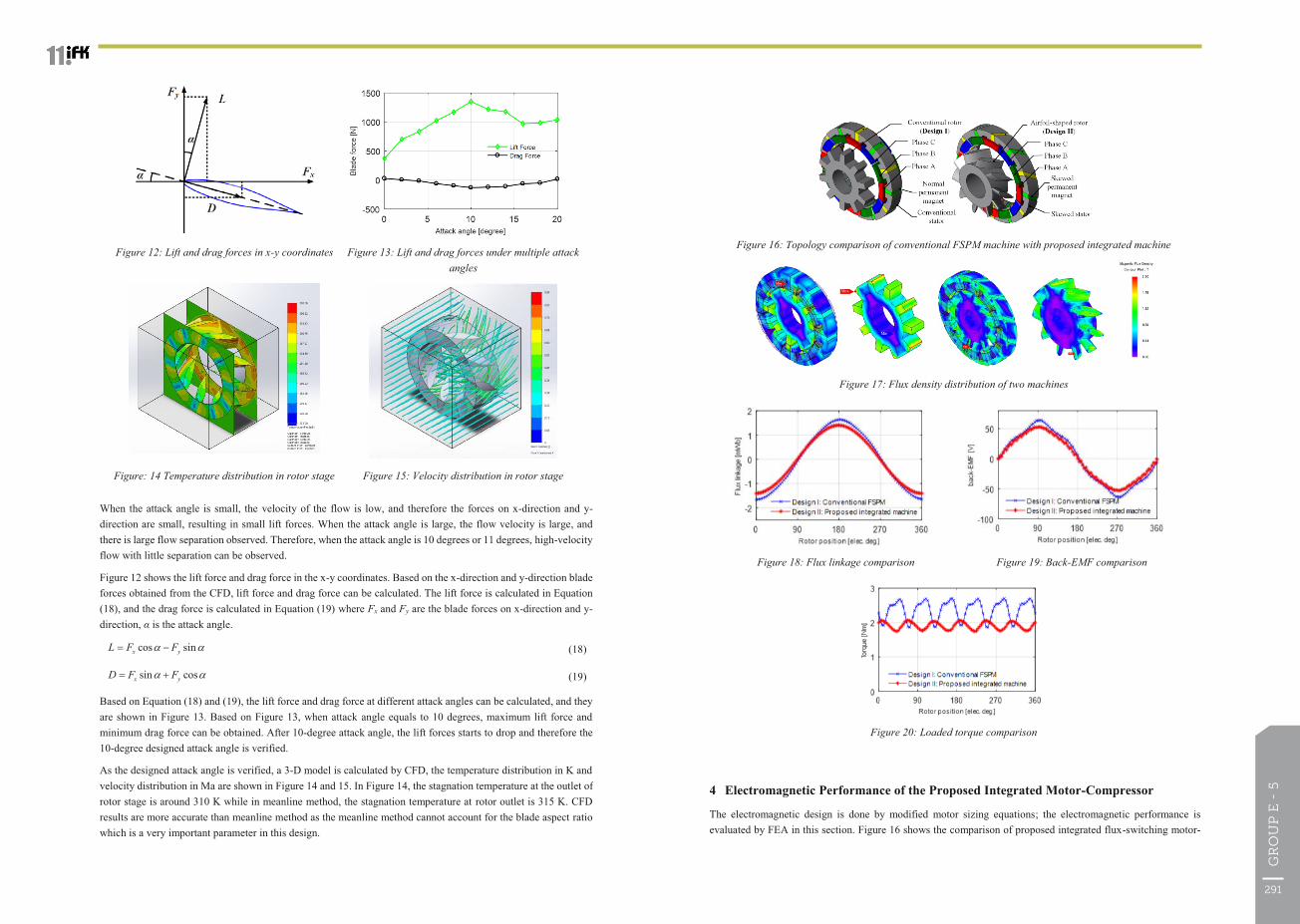
4 Electromagnetic Performance of the Proposed Integrated Motor-Compressor
The electromagnetic design is done by modified motor sizing equations; the electromagnetic performance is evaluated by FEA in this section. Figure 16 shows the comparison of proposed integrated flux-switching motor-
Figure 16: Topology comparison of conventional FSPM machine with proposed integrated machine
Figure 17: Flux density distribution of two machines
Figure 18: Flux linkage comparison Figure 19: Back-EMF comparison
Figure 20: Loaded torque comparison
The 11th International Fluid Power Conference, 11. IFK, March 19-21, 2018, Aachen, Germany
When the attack angle is small, the velocity of the flow is low, and therefore the forces on x-direction and y-direction are small, resulting in small lift forces. When the attack angle is large, the flow velocity is large, and there is large flow separation observed. Therefore, when the attack angle is 10 degrees or 11 degrees, high-velocity flow with little separation can be observed.
Figure 12 shows the lift force and drag force in the x-y coordinates. Based on the x-direction and y-direction blade forces obtained from the CFD, lift force and drag force can be calculated. The lift force is calculated in Equation (18), and the drag force is calculated in Equation (19) where Fx and Fy are the blade forces on x-direction and y-direction, α is the attack angle.
cos sinx yL F F� �� � (18)
sin cosx yD F F� �� � (19)
Based on Equation (18) and (19), the lift force and drag force at different attack angles can be calculated, and they are shown in Figure 13. Based on Figure 13, when attack angle equals to 10 degrees, maximum lift force and minimum drag force can be obtained. After 10-degree attack angle, the lift forces starts to drop and therefore the 10-degree designed attack angle is verified.
As the designed attack angle is verified, a 3-D model is calculated by CFD, the temperature distribution in K and velocity distribution in Ma are shown in Figure 14 and 15. In Figure 14, the stagnation temperature at the outlet of rotor stage is around 310 K while in meanline method, the stagnation temperature at rotor outlet is 315 K. CFD results are more accurate than meanline method as the meanline method cannot account for the blade aspect ratio which is a very important parameter in this design.
Figure 12: Lift and drag forces in x-y coordinates Figure 13: Lift and drag forces under multiple attack angles
Figure: 14 Temperature distribution in rotor stage Figure 15: Velocity distribution in rotor stage
291
GR
OU
P E
- 5

The 11th International Fluid Power Conference, 11. IFK, March 19-21, 2018, Aachen, Germany
/7/ H. Ding, Y. Li, M. Liu and B. Sarlioglu, “Novel design of multistage integrated motor-compressor,” IEEE Transportation Electrification Conference and Expo (ITEC)., Chicago, 2017.
/8/ Y. Li, D. Bobba, E. Schubert, H. Ding and B. Sarlioglu, “Concept of integration of axial-flow compression into electric machine design,” IEEE Transactions on Transportation Electrification., vol. 3, no. 1, 2017.
/9/ J. Sans, J.F. Brouckaert, and S. Hiernaux, “Experimental and numerical investigations of the solidity effect on a linear compressor cascade,” in Proceedings of ASME Turbo Expo 2015, Montreal, Canada, 2015.
/10/ L.J. Herrig, J.C. Emery, and J. R. Erwin, “Systematic two-dimensional cascade tests of NACA 65-series compressor blades at low speeds,” NACA TN3916. NACA, Washington DC, 1957.
/11/ S. Lieblein, “Incidence and deviation angle correlations for compressor cascades,” ASME Trans. Journal of Basic Engineering., vol. 82, pp. 575-587, 1960.
/12/ I. A. Johnsen, and R. O. Bullock, “Aerodynamic design of axial-flow compressors,” NASA SP-36, NASA, Washington, DC, 1965.
/13/ S. A. Korpela, Principles of Turbomachinery, John Wiley & Sons, 2011.
The 11th International Fluid Power Conference, 11. IFK, March 19-21, 2018, Aachen, Germany
compressor with conventional flux-switching PM machine. Figure 17 shows the flux density distribution of the two machines. The flux linkage, back-EMF, and rated torque comparison are shown in Figure 18, Figure 19, and Figure 20, respectively.
In Figure 18 and Figure 19, the flux linkage and back-EMF of the proposed integrated motor-compressor are very close to conventional FSPM machine. In Figure 20, the average rated torque of the proposed machine is around 85% of that of the conventional FSPM machine. However, the torque is still much larger than the compression torque, and the torque ripple is significantly reduced. The mechanical output power from FEA is 7.9 kW, which is larger than the compression required 5kW power. By increasing the electric loading of the proposed machine, it is capable of driving multiple compressor stages.
5 Summary and Conclusion
In this work, the aerodynamic and electromagnetic design of the integrated motor-compressor is investigated. The evaluations of the blade thickness as well as compressor blade solidity are provided. The aerodynamic performance is investigated by meanline method and CFD; it turns out that increasing the solidity will increase the total pressure ratio and compression power, but the rotor stage efficiency will decrease. The effect of attack angle is also evaluated, when the designed attack angle is 10 degrees, maximum lift force can be obtained. The 3-D CFD verified the meanline method calculation and is more accurate. The electromagnetic performance is verified by FEA, the mechanical output power is sufficient to provide compression function and it can be further increased by increasing the electric loading.
6 Acknowledgements
This research has been funded in part by the National Science Foundation (NSF) under CAREER award number 1552942.
I would like to express my special thanks of gratitude to Prof. Nellis who gives me a lot of insight advices in doing this project.
References
/1/ M. P. Boyce, Gas Turbine Engineering Handbook, Second Edition, Butterworth-Heinemann 2003.
/2/ W. W. Bathie, Fundamentals of Gas Turbines, Second Edition, John Wiley & Sons, 1996.
/3/ The Siemens Corporation, “STC-SX Siemens Turbocompressor – Single Shaft, Axial Design,” Siemens, Germany, 2008. Available: https://www.energy.siemens.com/br/pool/hq/compression/single-shaft compressors/downloads/STC_SX_EN.pdf
/4/ Anders T. Johnson, “In-line electric motor driven compressor.” U.S. Patent 6261070 B1, issued July 17, 2001.
/5/ S. Li, Y. Li, W. Choi, and B. Sarlioglu, “High-speed electric machines – challenges and design considerations,” IEEE Transactions on Transportation Electrification, vol. 2, pp. 2-13, 2016.
/6/ H. Ding, Y. Li, S. Min and B. Sarlioglu, “Electromagnetic and thermodynamic design of a novel integrated flux-switching motor-compressor with the airfoil-shaped rotor,” IEEE Energy Conversion Congress & Expo (ECCE)., Cincinnati, 2017.
293
GR
OU
P E
- 5