IntesisBox MAPS BACnet User Manual English - Futurasmus ...
56
IntesisBox MAPS Configuration & monitoring software of IntesisBox BACnet series User's manual Issue Date: 05/17 r1.0 eng
-
Upload
khangminh22 -
Category
Documents
-
view
1 -
download
0
Transcript of IntesisBox MAPS BACnet User Manual English - Futurasmus ...

IntesisBox MAPS
Configuration & monitoring software of IntesisBox BACnet series
User's manual Issue Date: 05/17
r1.0 eng

IntesisBox® MAPS – BACnet Server series User’s Manual r1.2 EN
© Intesis Software S.L.U. - All rights reserved This information is subject to change without notice
IntesisBox® is a registered trademark of Intesis Software SLU
URL Email tel
http://www.intesisbox.com [email protected] +34 938047134
2 / 56
© Intesis Software S.L.U. 2017 All Rights Reserved. Information in this document is subject to change without notice. The software described in this document is furnished under a license agreement or nondisclosure agreement. The software may be used only in accordance with the terms of those agreements. No part of this publication may be reproduced, stored in a retrieval system or transmitted in any form or any means electronic or mechanical, including photocopying and recording for any purpose other than the purchaser’s personal use without the written permission of Intesis Software S.L.U.
Intesis Software S.L.U. Milà i Fontanals, 1 bis - 1º 08700 Igualada Spain TRADEMARKS All trademarks and tradenames used in this document are acknowledged to be the copyright of their respective holders.

IntesisBox® MAPS – BACnet Server series User’s Manual r1.2 EN
© Intesis Software S.L.U. - All rights reserved This information is subject to change without notice
IntesisBox® is a registered trademark of Intesis Software SLU
URL Email tel
http://www.intesisbox.com [email protected] +34 938047134
3 / 56
Table of Contents 1. Introduction ............................................................................................................................ 5 2. Installation .............................................................................................................................. 5 3. Welcome page ....................................................................................................................... 6
3.1 News .................................................................................................................................. 6 3.2 Create New Project............................................................................................................. 6 3.3 Load Project ....................................................................................................................... 7 3.4 Get Project from Device ...................................................................................................... 8 3.5 Recent ................................................................................................................................ 8 3.6 Import Project from LinkBox ................................................................................................ 8
4. Navigation .............................................................................................................................. 9 4.1 Home .................................................................................................................................. 9 4.2 Project ................................................................................................................................ 9 4.3 Tools ................................................................................................................................ 10 4.4 Help .................................................................................................................................. 11 4.5 Footer ............................................................................................................................... 12
5. Connection ........................................................................................................................... 13 5.1 IP connection .................................................................................................................... 13 5.2 USB connection ................................................................................................................ 14
6. Configuration ........................................................................................................................ 16 6.1 General ............................................................................................................................. 16 6.2 BACnet Server .................................................................................................................. 18
6.2.1 Standard Configuration .............................................................................................. 18 6.2.2 Advanced Configuration ............................................................................................ 20
6.3 External protocol ............................................................................................................... 29 7. Signals ................................................................................................................................. 30
7.1 Extra functions .................................................................................................................. 30 7.1.1 Auto BACname ......................................................................................................... 30 7.1.2 Auto BACInst. ........................................................................................................... 30 7.1.3 Edit Columns ............................................................................................................ 31 7.1.4 Import ....................................................................................................................... 31 7.1.5 Export ....................................................................................................................... 32 7.1.6 Font size ................................................................................................................... 32 7.1.7 Move Up/Down ......................................................................................................... 32 7.1.8 Add Multiple Rows .................................................................................................... 32 7.1.9 Delete Rows ............................................................................................................. 32 7.1.10 Check Table ............................................................................................................. 32
7.2 Signals configuration ........................................................................................................ 33 7.3 Tips and tricks .................................................................................................................. 35
7.3.1 Text Edit .................................................................................................................... 35 7.3.2 Multiple Values selection ........................................................................................... 35 7.3.3 Auto numeration ........................................................................................................ 35
8. Send/Receive ....................................................................................................................... 37 8.1 Send ................................................................................................................................. 37 8.2 Receive ............................................................................................................................ 37
9. Diagnostic ............................................................................................................................ 38 9.3 Tools ................................................................................................................................ 38
9.3.1 Hardware Test ........................................................................................................... 39 9.3.2 Log ............................................................................................................................ 39 9.3.3 Commands ................................................................................................................ 39 9.3.4 View preferences ....................................................................................................... 39
9.4 Viewers ............................................................................................................................. 40 9.4.1 Console ..................................................................................................................... 40

IntesisBox® MAPS – BACnet Server series User’s Manual r1.2 EN
© Intesis Software S.L.U. - All rights reserved This information is subject to change without notice
IntesisBox® is a registered trademark of Intesis Software SLU
URL Email tel
http://www.intesisbox.com [email protected] +34 938047134
4 / 56
9.4.2 BACnet Server Viewer ............................................................................................... 40 9.4.3 External Protocol Viewer ........................................................................................... 41 9.4.4 Signals Viewer ........................................................................................................... 41
10. External protocols ................................................................................................................ 42 10.1 KNX .................................................................................................................................. 42
10.1.1 Standard configuration ............................................................................................... 42 10.1.2 Signals configuration ................................................................................................. 42
10.2 Modbus Master ................................................................................................................. 44 10.2.1 Standard Configuration .............................................................................................. 44 10.2.2 Signals configuration ................................................................................................. 49
10.3 M-Bus ............................................................................................................................... 50 10.3.1 Standard configuration ............................................................................................... 50 10.3.2 Advanced configuration ............................................................................................. 54 10.3.3 Signals configuration ................................................................................................. 55

IntesisBox® MAPS – BACnet Server series User’s Manual r1.2 EN
© Intesis Software S.L.U. - All rights reserved This information is subject to change without notice
IntesisBox® is a registered trademark of Intesis Software SLU
URL Email tel
http://www.intesisbox.com [email protected] +34 938047134
5 / 56
1. Introduction IntesisBox MAPS is a Windows compatible software tool developed specifically to monitor and configure the IntesisBox BACnet Server series (IntesisBox BACnet Server integrating an External Protocol). In this document, its use and how to configure the IntesisBox is explained. Following nomenclatures are used in this document:
• External Protocol: Protocol that the IntesisBox integrates besides BACnet. i.e: if using the IBOX-BAC-KNX, KNX would be the External Protocol.
• IntesisBox or gateway: the words "gateway" or “IntesisBox” are used instead of the full product name (IntesisBox BACnet/IP Server integrating an External Protocol). Any other use of the word "gateway" not meaning that will be specifically indicated.
• Configuration Tool: IntesisBox MAPS
2. Installation The tool is supplied in the shape of a self-extracting setup utility. Supported operating systems are Windows 7 and onwards versions of the Windows OS. The configuration tool can be downloaded from: http://intesisbox.com/intesis/software/intesisbox_maps_installer.exe The web browser will ask for saving the file. Select Save File and wait for the file to download.
Figure 2.1 Downloading IntesisBox MAPS
Once downloaded, double click on the intesisbox_maps_installer.exe file and follow instructions provided by the installation wizard.

IntesisBox® MAPS – BACnet Server series User’s Manual r1.2 EN
© Intesis Software S.L.U. - All rights reserved This information is subject to change without notice
IntesisBox® is a registered trademark of Intesis Software SLU
URL Email tel
http://www.intesisbox.com [email protected] +34 938047134
6 / 56
3. Welcome page After starting the IntesisBox MAPS, by clicking its program entry under Windows Start menu (or any other established link), the welcome page will prompt. This window is used to show general information, latest news and the project management and creation. All this sections are explained in the detail in the following sections.
Figure 3.1 Welcome page
3.1 News
This link provides access to the welcome page to check the latest news related to the IntesisBox gateways and MAPS configuration tool. Use this section to get the latest information related with our products.
3.2 Create New Project
Create a new project from an existing template. In order to start a specific integration project, simply select one of the available templates from the list. Note: The template is an example of an integration and may be used under this scope. Depending on the type of integration, some parameters may not be left as by default and shall be modified. Please check your IntesisBox gateway user manual for more information on some of the specific parameters configuration. Click on the BACnet logo to list all available project templates for the BACnet Server gateway series.

IntesisBox® MAPS – BACnet Server series User’s Manual r1.2 EN
© Intesis Software S.L.U. - All rights reserved This information is subject to change without notice
IntesisBox® is a registered trademark of Intesis Software SLU
URL Email tel
http://www.intesisbox.com [email protected] +34 938047134
7 / 56
Make sure that you select the right template according to the external protocol of the gateway.
Figure 3.2 Project template selection
3.3 Load Project
Load an already existing project to the configuration tool. In order to import an existing project already programmed, use the Load Project option and select the project from the PC or external storage device where the project is stored.
Figure 3.3 Project selection window After selection, the project will be loaded and configuration can be started as if using a brand-new project, but with all previous work in the project present.
IntesisBox® MAPS – BACnet Server series User’s Manual r1.2 EN
© Intesis Software S.L.U. - All rights reserved This information is subject to change without notice
IntesisBox® is a registered trademark of Intesis Software SLU
URL Email tel
http://www.intesisbox.com [email protected] +34 938047134
8 / 56
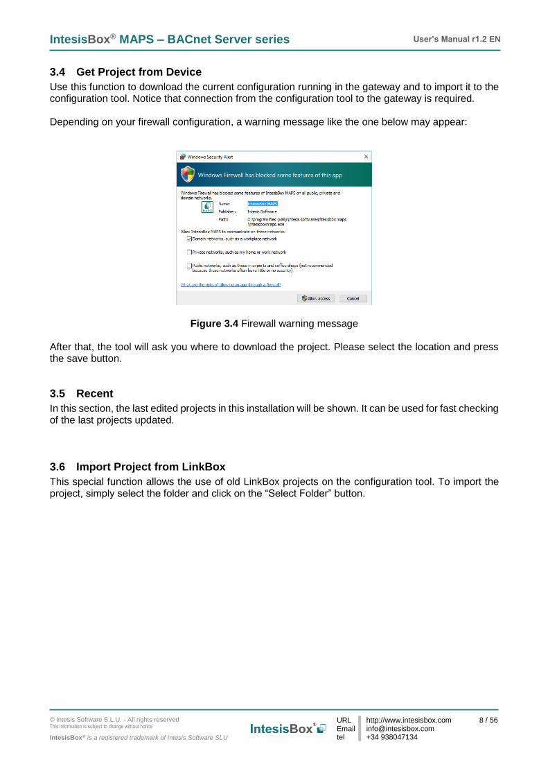
3.4 Get Project from Device
Use this function to download the current configuration running in the gateway and to import it to the configuration tool. Notice that connection from the configuration tool to the gateway is required. Depending on your firewall configuration, a warning message like the one below may appear:
Figure 3.4 Firewall warning message After that, the tool will ask you where to download the project. Please select the location and press the save button.
3.5 Recent
In this section, the last edited projects in this installation will be shown. It can be used for fast checking of the last projects updated.
3.6 Import Project from LinkBox
This special function allows the use of old LinkBox projects on the configuration tool. To import the project, simply select the folder and click on the “Select Folder” button.

IntesisBox® MAPS – BACnet Server series User’s Manual r1.2 EN
© Intesis Software S.L.U. - All rights reserved This information is subject to change without notice
IntesisBox® is a registered trademark of Intesis Software SLU
URL Email tel
http://www.intesisbox.com [email protected] +34 938047134
9 / 56
4. Navigation To work with the configuration tool, the menu and the tool bar (Figure 4.1) need to be used. In the following lines a brief explanation and links to the corresponding sections can be found.
Figure 4.1 Menu and Tool Bar
4.1 Home
This options brings you back to the Welcome page. Check section 3 for more information.
4.2 Project
This option let the user apply basic functions to the project, such as create new projects, load an already existing project, save the project and close the configuration tool.
Figure 4.2 Project options
• New project: Moves back to the Welcome page and let you select a new project.
• Load: Opens a selection window to pick up the project you wanted to load.
• Save: Saves the current project changes in the same file. If it is the first time, it will ask for the project location. Otherwise, it will automatically update the current project file.
• Save As: Saves the current project into a different location or with a different name from the current one.
• Close: Closes the configuration tool.

IntesisBox® MAPS – BACnet Server series User’s Manual r1.2 EN
© Intesis Software S.L.U. - All rights reserved This information is subject to change without notice
IntesisBox® is a registered trademark of Intesis Software SLU
URL Email tel
http://www.intesisbox.com [email protected] +34 938047134
10 / 56
4.3 Tools
This option provides access to language settings and Gateway firmware update.
Figure 4.3 Tools options
• Language: This option allows the user to select one of the available languages. Once the language is selected, you need to reboot the software for the new language configuration to be applied.
Figure 4.4 Language selection
• Firmware: By default, information shown is only the one coming from the current gateway status. In case the user is interested in checking for new firmware updates, the “Check for Update” button needs to be pressed. In case there is any update available, a summary for the new update information will be shown in the “Firmware Update Information” side of the window. If the user is interested, the “send” button should be pressed to update the box. IMPORTANT: Please notice that the firmware update process shall not be interrupted. Make sure that you go for the update process while in a safe location (no risk of power blackouts or similar). NOTE: If the Gateway is already working as expected, the update may not be advisable. Please, make sure that you update the gateway only when required.

IntesisBox® MAPS – BACnet Server series User’s Manual r1.2 EN
© Intesis Software S.L.U. - All rights reserved This information is subject to change without notice
IntesisBox® is a registered trademark of Intesis Software SLU
URL Email tel
http://www.intesisbox.com [email protected] +34 938047134
11 / 56
Figure 4.5 Firmware Manager view
4.4 Help
Extra information about the software is shown in this section.
Figure 4.6 Help menu
• About:
It prompts information about the current configuration tool version.
Figure 4.7 About information
IntesisBox® MAPS – BACnet Server series User’s Manual r1.2 EN
© Intesis Software S.L.U. - All rights reserved This information is subject to change without notice
IntesisBox® is a registered trademark of Intesis Software SLU
URL Email tel
http://www.intesisbox.com [email protected] +34 938047134
12 / 56
• Check for Updates Periodically, new free versions of Configuration Tool are released. Those new releases include improvements, fixes, support for new firmware versions of IntesisBox or support for newer IntesisBox products. This option automatically checks if there is any newer version and in case it exists, it offers the possibility to download and update the software. Notice that this requires Internet connection.
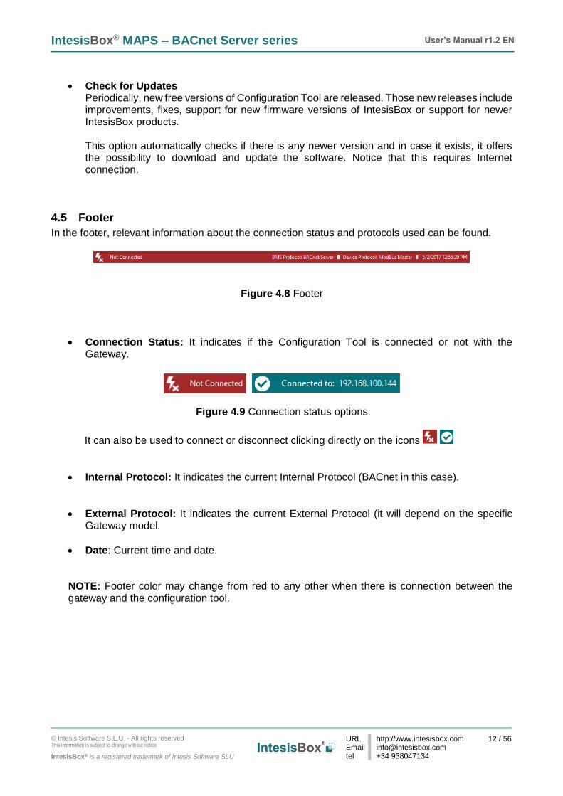
4.5 Footer
In the footer, relevant information about the connection status and protocols used can be found.
Figure 4.8 Footer
• Connection Status: It indicates if the Configuration Tool is connected or not with the Gateway.
Figure 4.9 Connection status options
It can also be used to connect or disconnect clicking directly on the icons
• Internal Protocol: It indicates the current Internal Protocol (BACnet in this case).
• External Protocol: It indicates the current External Protocol (it will depend on the specific Gateway model.
• Date: Current time and date.
NOTE: Footer color may change from red to any other when there is connection between the gateway and the configuration tool.

IntesisBox® MAPS – BACnet Server series User’s Manual r1.2 EN
© Intesis Software S.L.U. - All rights reserved This information is subject to change without notice
IntesisBox® is a registered trademark of Intesis Software SLU
URL Email tel
http://www.intesisbox.com [email protected] +34 938047134
13 / 56
5. Connection In this section, it is detailed how to set the communication and monitor the IntesisBox.
Figure 5.1 Connection section There are two different ways of communicating the Configuration Tool with the IntesisBox (check the Connection section in your IntesisBox User Manual): using the USB port or the Ethernet network. In the following lines the configuration of both is explained as well as the functionalities of the Configuration Tool when connected or not. When there is no connection with the IntesisBox, IntesisBox MAPS allows the creation and edition of configuration projects. That includes setting the linked signals, protocol parameters … When the Configuration Tool is connected to the IntesisBox, it can perform other functionalities such as monitoring the communication and sending the configuration files to the device (sections 9.4 and 8.1 respectively).
5.1 IP connection
If connection with the Gateway shall be done by Ethernet IP network, select IP as the connection mode. The software will automatically scan the current network where the PC is connected looking for IntesisBox gateways.
Figure 5.2 IP connection

IntesisBox® MAPS – BACnet Server series User’s Manual r1.2 EN
© Intesis Software S.L.U. - All rights reserved This information is subject to change without notice
IntesisBox® is a registered trademark of Intesis Software SLU
URL Email tel
http://www.intesisbox.com [email protected] +34 938047134
14 / 56
In the Discovered Devices list, all gateways found will be listed. In black, gateways that match the current project selected. In red, gateways that do not match the current project selected. If no gateways are shown, please check your network connection parameters and make sure that the gateway is powered and connected. Notice that relevant information can be checked by clicking on each gateway (Figure 5.3).
Once the device is selected, connection will be started by pressing the connect button , on the bottom left corner, or clicking on the Connect button.
Figure 5.3 IP connection If connection has been successful, the footer will turn from red to any other color prompting the current IP of the gateway where the configuration tool is connected to. To disconnect, simply click on the connect button again. IMPORTANT: Notice that if connecting through IP, a password is required. By default, the password is “admin”. Find more information on how to change the password on section 6. NOTE: By default, the gateway is offered with DHCP enabled. If you want to change this setting, please check section 6.
5.2 USB connection
If Ethernet IP connection is not possible or if USB is preferred, select USB port in the Connection Mode. A list of available COM ports on the PC will be listed. Select the COM port where the USB cable is connected.

IntesisBox® MAPS – BACnet Server series User’s Manual r1.2 EN
© Intesis Software S.L.U. - All rights reserved This information is subject to change without notice
IntesisBox® is a registered trademark of Intesis Software SLU
URL Email tel
http://www.intesisbox.com [email protected] +34 938047134
15 / 56
Figure 5.4 USB connection If the device does not appear or if the COM port list is empty, please check the USB connection on both sides (gateway and PC) and check the Windows Device Manager to check if there is any issue regarding COM ports. To disconnect simply click on the Connect button again.

IntesisBox® MAPS – BACnet Server series User’s Manual r1.2 EN
© Intesis Software S.L.U. - All rights reserved This information is subject to change without notice
IntesisBox® is a registered trademark of Intesis Software SLU
URL Email tel
http://www.intesisbox.com [email protected] +34 938047134
16 / 56
6. Configuration In this section, main configuration parameters for the gateway and both, internal and external protocols, can be modified to match the project requirements.
Figure 6.1 Configuration
6.1 General
In the general section, all options related to generic gateway parameters can be defined.
Figure 6.2 General configuration
1. Gateway name Name of device. It can be modified by the user to simplify its identification inside the project. This name is not related to neither the external or internal protocol.
2. Project description
Short description of the project. It can be modified by the user to simplify its identification inside the project. This name is not related to neither the external or internal protocol.

IntesisBox® MAPS – BACnet Server series User’s Manual r1.2 EN
© Intesis Software S.L.U. - All rights reserved This information is subject to change without notice
IntesisBox® is a registered trademark of Intesis Software SLU
URL Email tel
http://www.intesisbox.com [email protected] +34 938047134
17 / 56
3. IP 1 IP address associated to the gateway. It can be modified by the user to match the project requirements. This IP will be the same one to be used on the BACnet/IP side in case of using BACnet/IP communication.
4. Netmask 1
Network mask to be applied on the IP communication. It can be modified by the user to match the project requirements. This netmask will be the same one to be used on the BACnet/IP side in case of using BACnet/IP communication.
5. Gateway 1
Default gateway to be applied on the IP communication. It can be modified by the user to match the project requirements. This default gateway will be the same one to be used on the BACnet/IP side in case of using BACnet/IP communication.
6. Password This is the password to allow connection to the Gateway when using IP connection (see section 5.1). By default, the password is set as “admin”, but can be modified by the user at any time. In order to change the password, simply set the desired password in this field and download the configuration to the Gateway. You can find more information on how to download the configuration in section 8.1. IMPORTANT: Please, in case of changing the default password, please keep it posted or noted in a safe place to be used in the future.
7. Conversions In this section, different conversions can be defined on the MAPS so values from the Internal to the External protocol or vice versa can be modified to help the integrator matching the project requirements.
Figure 6.3 Conversions
1 This setting does not apply if the “Enable DHCP” option is selected. In that case, this parameter will be automatically set by the DHCP server.
IntesisBox® MAPS – BACnet Server series User’s Manual r1.2 EN
© Intesis Software S.L.U. - All rights reserved This information is subject to change without notice
IntesisBox® is a registered trademark of Intesis Software SLU
URL Email tel
http://www.intesisbox.com [email protected] +34 938047134
18 / 56
6.2 BACnet Server
In the BACnet Server section, all parameters related to the BACnet side can be configured.
6.2.1 Standard Configuration
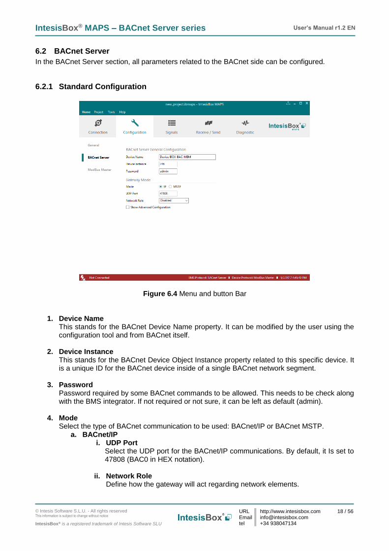
Figure 6.4 Menu and button Bar
1. Device Name This stands for the BACnet Device Name property. It can be modified by the user using the configuration tool and from BACnet itself.
2. Device Instance
This stands for the BACnet Device Object Instance property related to this specific device. It is a unique ID for the BACnet device inside of a single BACnet network segment.
3. Password
Password required by some BACnet commands to be allowed. This needs to be check along with the BMS integrator. If not required or not sure, it can be left as default (admin).
4. Mode
Select the type of BACnet communication to be used: BACnet/IP or BACnet MSTP. a. BACnet/IP
i. UDP Port Select the UDP port for the BACnet/IP communications. By default, it Is set to 47808 (BAC0 in HEX notation).
ii. Network Role
Define how the gateway will act regarding network elements.

IntesisBox® MAPS – BACnet Server series User’s Manual r1.2 EN
© Intesis Software S.L.U. - All rights reserved This information is subject to change without notice
IntesisBox® is a registered trademark of Intesis Software SLU
URL Email tel
http://www.intesisbox.com [email protected] +34 938047134
19 / 56
IMPORTANT: If not familiar with this options, please left the parameter as Disabled to avoid issues on the BACnet communication.
• Disabled: The gateway will not provide any special service regarding network communication or settings.
• Foreign Device: The gateway will act as a foreign device from the BACnet network point of view.
Figure 6.5 Foreign Device configuration
• BBMD: The gateway will act as a BBMD in the BACnet network.
Figure 6.6 BBMD configuration
b. BACnet MSTP
i. Max. Masters Define the maximum number of BACnet MSTP masters supported
ii. Max. Info Frames Define the maximum number of Info frames.
iii. Baud Rate Select the BACnet MSTP communication speed. Possible values are: Auto | 9600 |19200 | 38400 | 57600 | 76800 | 115200
iv. MAC address Define the gateway MAC address for BACnet MSTP communication.

IntesisBox® MAPS – BACnet Server series User’s Manual r1.2 EN
© Intesis Software S.L.U. - All rights reserved This information is subject to change without notice
IntesisBox® is a registered trademark of Intesis Software SLU
URL Email tel
http://www.intesisbox.com [email protected] +34 938047134
20 / 56
6.2.2 Advanced Configuration
Once the Advanced configuration is activated, the user will have access to BACnet advanced settings.
Figure 6.7 Advanced settings selection NOTE: If you are not familiar with these functions, please do not use them as it may cause problems in the BACnet communication/configuration.
6.2.2.1 Notification Class
In this section, Notification Classes can be created and configured. Up to 10 Notification Class objects can be created.

IntesisBox® MAPS – BACnet Server series User’s Manual r1.2 EN
© Intesis Software S.L.U. - All rights reserved This information is subject to change without notice
IntesisBox® is a registered trademark of Intesis Software SLU
URL Email tel
http://www.intesisbox.com [email protected] +34 938047134
21 / 56
Figure 6.8 Menu and button Bar
Per each Notification Class, the user will be able to configure:
1. NC Name Name for the Notification Class
2. NC Instance BACnet Object Instance for the Notification Class
3. Recipient List
Up to 8 different BACnet Destinations can be created. For each destination, the following parameters can be modified:
a) Destination name Descriptive name for the BACnet Destination
b) Transitions Select which transitions will force the notification class to be active:
• Off_normal: When status changes from Off to normal.
• Fault: When status changes to fault.
• Normal: When status changes from fault to normal.
c) Recipient Type Select the type of recipient from:
• Device: The recipient is a device. The Device Instance Number for this device needs to be selected in the Instance Number text box.
• Address: The recipient is set using the specific address on BACnet/IP.
• Address (MSTP): The recipient is set using the specific address on BACnet MSTP.
d) Advanced Options
• Active Days: Select the days when the Notification Class will be available for the specific recipient BACnet destination.
IntesisBox® MAPS – BACnet Server series User’s Manual r1.2 EN
© Intesis Software S.L.U. - All rights reserved This information is subject to change without notice
IntesisBox® is a registered trademark of Intesis Software SLU
URL Email tel
http://www.intesisbox.com [email protected] +34 938047134
22 / 56
• From: Defines the starting time for the Notifications Class to be available during the day.
• To: Defines the end time for the Notifications Class to be available during the day.
• Issue Confirmed Notifications
4. Advanced In this section, ACK for different transitions can be set as required and the priority of this transitions ACK too. Values for priority in this case may vary from 0 to 255.
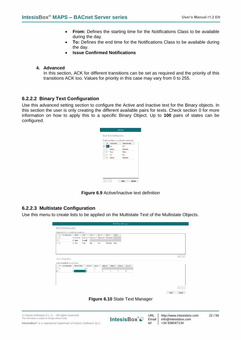
6.2.2.2 Binary Text Configuration
Use this advanced setting section to configure the Active and Inactive text for the Binary objects. In this section the user is only creating the different available pairs for texts. Check section 0 for more information on how to apply this to a specific Binary Object. Up to 100 pairs of states can be configured.
Figure 6.9 Active/Inactive text definition
6.2.2.3 Multistate Configuration
Use this menu to create lists to be applied on the Multistate Text of the Multistate Objects.
Figure 6.10 State Text Manager

IntesisBox® MAPS – BACnet Server series User’s Manual r1.2 EN
© Intesis Software S.L.U. - All rights reserved This information is subject to change without notice
IntesisBox® is a registered trademark of Intesis Software SLU
URL Email tel
http://www.intesisbox.com [email protected] +34 938047134
23 / 56
1. State Text Configuration
Use this section to create new state text lists or to modify the current ones available.
2. Tool Configuration Use this section to create a secondary mapping for the states to create custom conversions between the BACnet states received and the values that the gateway will transmit to the external protocol.
Check section 7.2 for more information on how to apply this to a specific Multistate Object. Up to 100 State Text Lists can be configured with a maximum of 100 elements (status) per State Text List.
6.2.2.4 Calendars
In this section, the user will be able to create calendars to be applied on the BACnet side. Up to 10 calendars can be created.
Figure 6.11 State Text Manager For each calendar, the following parameters can be configured:
1. Calendar Name Determines the name for the calendar.
2. Calendar Instance Sets the BACnet Object Instance for this specific calendar.
3. Calendar Entries Determines the number of calendar entries (patterns). Up to 32 different entries can be created per each calendar.
4. Rules For each entry, different rules can be applied. Configuration for these rules can be done using either Date, Date Range or Week N Day.
a. Date: The rule is related only to a specific date.

IntesisBox® MAPS – BACnet Server series User’s Manual r1.2 EN
© Intesis Software S.L.U. - All rights reserved This information is subject to change without notice
IntesisBox® is a registered trademark of Intesis Software SLU
URL Email tel
http://www.intesisbox.com [email protected] +34 938047134
24 / 56
Figure 6.12 Rule – Date Selection
b. Date Range: The rule is applied inside a date range.
Figure 6.13 Rule – Date Range Selection
c. Week N Day: The rule is applied on specific months, weeks and/or week days. If an * is selected, the rule will apply for all cases.
Figure 6.14 Rule – Week N Day Selection
IntesisBox® MAPS – BACnet Server series User’s Manual r1.2 EN
© Intesis Software S.L.U. - All rights reserved This information is subject to change without notice
IntesisBox® is a registered trademark of Intesis Software SLU
URL Email tel
http://www.intesisbox.com [email protected] +34 938047134
25 / 56
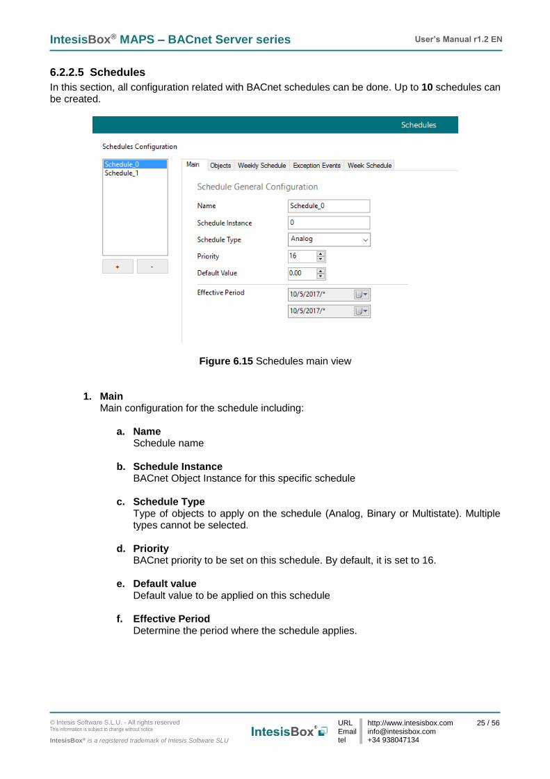
6.2.2.5 Schedules
In this section, all configuration related with BACnet schedules can be done. Up to 10 schedules can be created.
Figure 6.15 Schedules main view
1. Main Main configuration for the schedule including:
a. Name Schedule name
b. Schedule Instance BACnet Object Instance for this specific schedule
c. Schedule Type Type of objects to apply on the schedule (Analog, Binary or Multistate). Multiple types cannot be selected.
d. Priority BACnet priority to be set on this schedule. By default, it is set to 16.
e. Default value Default value to be applied on this schedule
f. Effective Period Determine the period where the schedule applies.

IntesisBox® MAPS – BACnet Server series User’s Manual r1.2 EN
© Intesis Software S.L.U. - All rights reserved This information is subject to change without notice
IntesisBox® is a registered trademark of Intesis Software SLU
URL Email tel
http://www.intesisbox.com [email protected] +34 938047134
26 / 56
2. Objects Selection of BACnet objects to be included in a specific schedule. Notice that object types are selected in the main menu, so only the BACnet object that match the schedule type selected in the main section will be allowed.
Figure 6.16 Schedules Object selection
3. Weekly Schedule Select one week day and the desired Time Values when the schedule needs to apply. Only 6 Time Values are allowed.
Figure 6.17 Weekly schedule configuration
4. Exception Events Create exceptions to the schedules. Up to 16 different expections can be created with up to 6 Time Values for each exception.

IntesisBox® MAPS – BACnet Server series User’s Manual r1.2 EN
© Intesis Software S.L.U. - All rights reserved This information is subject to change without notice
IntesisBox® is a registered trademark of Intesis Software SLU
URL Email tel
http://www.intesisbox.com [email protected] +34 938047134
27 / 56
Figure 6.18 Rule – Week N Day Selection
5. Week Schedule Create schedules directly on a friendlier user interface modifying or creating them directly on the calendar.
Figure 6.19 Rule – Week N Day Selection

IntesisBox® MAPS – BACnet Server series User’s Manual r1.2 EN
© Intesis Software S.L.U. - All rights reserved This information is subject to change without notice
IntesisBox® is a registered trademark of Intesis Software SLU
URL Email tel
http://www.intesisbox.com [email protected] +34 938047134
28 / 56
6.2.2.6 Trend Logs
In this section, all trend logs related configuration can be carried out. Up to 5 Trend Logs can be created.
Figure 6.20 Trend Logs
1. Name
Name for the Trend Log
2. Trend Log Instance BACnet Object Instance for the specific Trend Log
3. Trend Mode
Selection of the type of Trend mode to be used: a. Polled
The poll cadence for this needs to be set in the Interval parameter
b. COV The COV increment to be considered needs to be set in the COV Increment parameter
c. Triggered It will be triggered by the BACnet BMS system
4. Interval
It will only apply if Trend Mode Polled is selected.
5. COV Increment It will only apply if Trend Mode COV is selected.
6. Properties
Extra properties can be defined:
a. Enable It allows enabling or disabling the specific Trend Log even if the Trend Log is in the valid time range.

IntesisBox® MAPS – BACnet Server series User’s Manual r1.2 EN
© Intesis Software S.L.U. - All rights reserved This information is subject to change without notice
IntesisBox® is a registered trademark of Intesis Software SLU
URL Email tel
http://www.intesisbox.com [email protected] +34 938047134
29 / 56
b. Stop Buffer Full If enabled, it will stop the Trend Log when the buffer is full. If disabled, it will roll up the Trend Log information keeping the last 2880 valid values.
7. Date Configuration
Set the period when Trend Logs will be active. It can be set as always or in a time frame or range
8. Selected Objects Selection of objects to be included inside a Trend Log. Up to 10 different BACnet Objects can be selected.
6.3 External protocol
Please, check the Annex section and your Gateway User Manual for more information on the specific configuration of the external protocol parameters.

IntesisBox® MAPS – BACnet Server series User’s Manual r1.2 EN
© Intesis Software S.L.U. - All rights reserved This information is subject to change without notice
IntesisBox® is a registered trademark of Intesis Software SLU
URL Email tel
http://www.intesisbox.com [email protected] +34 938047134
30 / 56
7. Signals In this section, the main configuration for the signals on both external and internal protocols will be set.
Figure 7.1 Default view
7.1 Extra functions
Find below a list of extra functions or tools available in the Signals view.
7.1.1 Auto BACname
This option generates the BACnet Object Name for each signal automatically. It uses the following format to create this name automatically: BACnetObjectType_BACnetObjectInstance_Custom_Name Ex: BI_0_ONOFF BACnet Object Name => ONOFF BACnet Object Instance => 0
BACnet Object Type => Binary Input
7.1.2 Auto BACInst.
Generates automatically all BACnet Object Instances to grant a unique identifier.

IntesisBox® MAPS – BACnet Server series User’s Manual r1.2 EN
© Intesis Software S.L.U. - All rights reserved This information is subject to change without notice
IntesisBox® is a registered trademark of Intesis Software SLU
URL Email tel
http://www.intesisbox.com [email protected] +34 938047134
31 / 56
7.1.3 Edit Columns
It shows/hides columns on the Signal table to help the integration tasks.
Figure 7.2 Edit Columns view
7.1.4 Import
Import previous exported Excel files to the project. This can be useful in case you want to manage some special configuration on Excel to speed up the signals list creation. Notice that this will need to be used in very few scenarios as the Configuration Tool already offers lots of options and tips to create the signal’s table in a fast and easy way.
Notice that there are two Import options: Replace and Add Signals.
• Replace: This will replace (overwrite) current signals in the Signal table.
• Add Signals: This will add the imported signals to the Signal table without replacing the current ones.

IntesisBox® MAPS – BACnet Server series User’s Manual r1.2 EN
© Intesis Software S.L.U. - All rights reserved This information is subject to change without notice
IntesisBox® is a registered trademark of Intesis Software SLU
URL Email tel
http://www.intesisbox.com [email protected] +34 938047134
32 / 56
7.1.5 Export
This function will allow two different types of exportations: Excel and EDE.
• Excel: This will export the Signal table into Excel format to allow extra manipulation or consultation from Excel. This may be helpful to share integration information with other integrators that do not have the Configuration Tool.
• EDE: This will export BACnet information into an EDE file format. This is useful to share BACnet information with the BACnet BMS integrator to speed up the integration time.
7.1.6 Font size
It changes the font size to help on the visualization. It is a toggle function: on each click it will change from big to small and vice versa.
7.1.7 Move Up/Down
It moves one row Up or Down the selected signal inside the Signal table on each click.
7.1.8 Add Multiple Rows
It adds new signals to the Signal table. The number of new signals can be selected in the text box.
7.1.9 Delete Rows
It deletes the selected rows. If it is required to erase more than one signal (row), select them previously and then press the Delet Rows button to erase all selected rows.
7.1.10 Check Table
This options verifies that the current configuration in the Signal Table is OK from a theoretical point of view. That means that this check will not include integration issues related to bad addresses, mistakes or confusions of the integrators information. It will only check that the standard defined conditions and properties are fulfilled.

IntesisBox® MAPS – BACnet Server series User’s Manual r1.2 EN
© Intesis Software S.L.U. - All rights reserved This information is subject to change without notice
IntesisBox® is a registered trademark of Intesis Software SLU
URL Email tel
http://www.intesisbox.com [email protected] +34 938047134
33 / 56
7.2 Signals configuration
Next, there is the description for common and BACnet specific parameters to be configured on each signal.
1. Active If selected, the signal will be considered in the configuration and will be downloaded to the Gateway as active.
2. Name BACnet Object Name to be applied to the signal
3. Type
It can be selected depending on the different BACnet Object Types
• AI: Analog Input
• AO: Analog Output
• AV: Analog Value
• BI: Binary Input
• BO: Binary Output
• BV: Binary Value
• MI: Multistate Input
• MO: Multistate Output
• MV: Multistate Value
4. Instance
BACnet Object Instance. 5. Units
If required, units for this signal can be defined (ºC, Kg, kW…) 6. NC

IntesisBox® MAPS – BACnet Server series User’s Manual r1.2 EN
© Intesis Software S.L.U. - All rights reserved This information is subject to change without notice
IntesisBox® is a registered trademark of Intesis Software SLU
URL Email tel
http://www.intesisbox.com [email protected] +34 938047134
34 / 56
It is used to select which Notification Class from the ones defined in section 6.2.2.1 will be used.
7. State Text
For Multistate Objects, it is used to select which State Text List from the ones defined in section 6.2.2.3 will be used. For Binary Objects, it is used to select which State Text List from the ones defined in section 6.2.2.2 will be used.
8. #States
It sets the number of states for the Multistate Objects. It only applies if the State Text is not selected.
9. Rel. Def.
It is used to define the Relinquish Default value.
10. Cov. It is used to define the COV (Change Of Value) increment.
11. Conversion It is used to define the conversion that you want to apply. This conversion can be checked or selected as stated in section 6.1.
IntesisBox® MAPS – BACnet Server series User’s Manual r1.2 EN
© Intesis Software S.L.U. - All rights reserved This information is subject to change without notice
IntesisBox® is a registered trademark of Intesis Software SLU
URL Email tel
http://www.intesisbox.com [email protected] +34 938047134
35 / 56
7.3 Tips and tricks
7.3.1 Text Edit
On editable cells, click on the cell. The text is going to be highlighted and it can then be modified.
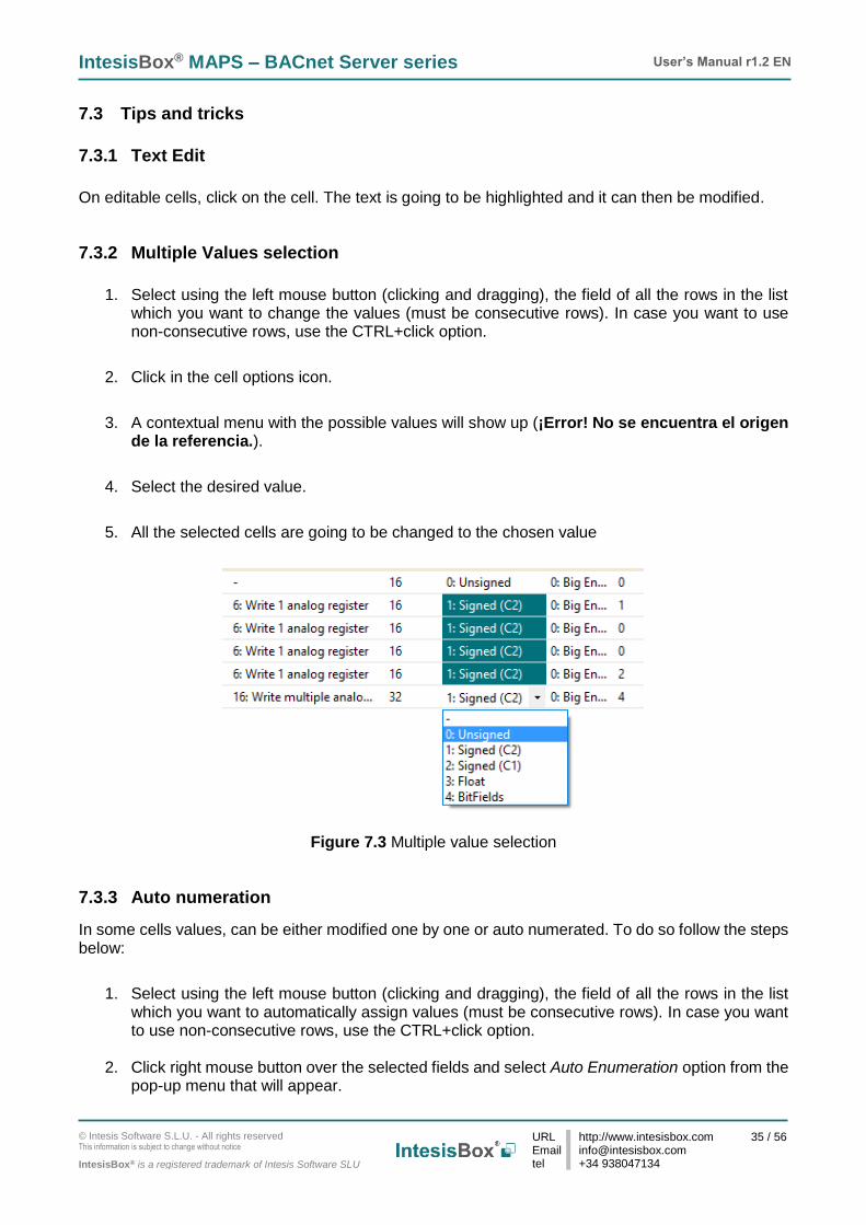
7.3.2 Multiple Values selection
1. Select using the left mouse button (clicking and dragging), the field of all the rows in the list
which you want to change the values (must be consecutive rows). In case you want to use non-consecutive rows, use the CTRL+click option.
2. Click in the cell options icon.
3. A contextual menu with the possible values will show up (¡Error! No se encuentra el origen de la referencia.).
4. Select the desired value.
5. All the selected cells are going to be changed to the chosen value
Figure 7.3 Multiple value selection
7.3.3 Auto numeration
In some cells values, can be either modified one by one or auto numerated. To do so follow the steps below:
1. Select using the left mouse button (clicking and dragging), the field of all the rows in the list
which you want to automatically assign values (must be consecutive rows). In case you want to use non-consecutive rows, use the CTRL+click option.
2. Click right mouse button over the selected fields and select Auto Enumeration option from the
pop-up menu that will appear.

IntesisBox® MAPS – BACnet Server series User’s Manual r1.2 EN
© Intesis Software S.L.U. - All rights reserved This information is subject to change without notice
IntesisBox® is a registered trademark of Intesis Software SLU
URL Email tel
http://www.intesisbox.com [email protected] +34 938047134
36 / 56
Figure 7.4 Auto numeration selection
3. Enter the Start Value.
4. Enter the increment between consecutive assignments.
For example selecting 100 for the first value and an increment of 1, the values generated will be 100, 101, 102, 103, 104.. and so on. To assign the same value to all the rows (useful to assign the same Device number in the column Dev for some consecutive rows) just select the desired value and an increment of 0.
5. The values are changed accordingly.
Figure 7.5 Values auto numerated
IntesisBox® MAPS – BACnet Server series User’s Manual r1.2 EN
© Intesis Software S.L.U. - All rights reserved This information is subject to change without notice
IntesisBox® is a registered trademark of Intesis Software SLU
URL Email tel
http://www.intesisbox.com [email protected] +34 938047134
37 / 56
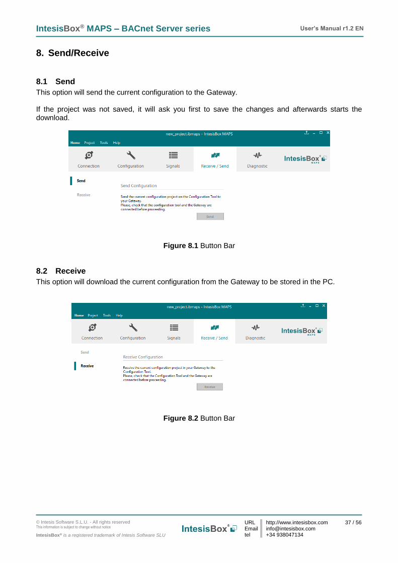
8. Send/Receive
8.1 Send
This option will send the current configuration to the Gateway. If the project was not saved, it will ask you first to save the changes and afterwards starts the download.
Figure 8.1 Button Bar
8.2 Receive
This option will download the current configuration from the Gateway to be stored in the PC.
Figure 8.2 Button Bar

IntesisBox® MAPS – BACnet Server series User’s Manual r1.2 EN
© Intesis Software S.L.U. - All rights reserved This information is subject to change without notice
IntesisBox® is a registered trademark of Intesis Software SLU
URL Email tel
http://www.intesisbox.com [email protected] +34 938047134
38 / 56
9. Diagnostic To help integrators in the commissioning tasks and troubleshooting, the Configuration Tool offers some specific tools and viewers. In order to start using the diagnostic tools, connection with the Gateway is required. The Diagnostic section is composed by two main parts: Tools and Viewer.
Figure 9.1 Diagnostic
9.3 Tools
The tool bar located in the left side of the window.
Figure 9.2 Tool bar

IntesisBox® MAPS – BACnet Server series User’s Manual r1.2 EN
© Intesis Software S.L.U. - All rights reserved This information is subject to change without notice
IntesisBox® is a registered trademark of Intesis Software SLU
URL Email tel
http://www.intesisbox.com [email protected] +34 938047134
39 / 56
It offers 4 main tools:
9.3.1 Hardware Test
It initiates a hardware test on the gateway to identify possible hardware issues. During the hardware test, standard communications with external and internal protocols will stop.
9.3.2 Log
It sets the Configuration Tool into logging mode. This will record all information present in all viewers and zip it in a compressed file. This file can be then sent to the support team to help in any issue you may have.
9.3.3 Commands
It is used to send specific commands to the Gateway, such as:
• INFO?: Requests general information from the Gateway
• RESET: Resets the Gateway
• Enable COMMS: Enable communications in all viewers
• Disable COMMS: Disables communications in all viewers
Figure 9.3 Available commands
9.3.4 View preferences
It offers several viewers layouts to help the integrator checking the required information on each moment.
Figure 9.4 View selection
Notice that apart from the predefined options, the user will be able to place the different viewers according to its own needs manually.

IntesisBox® MAPS – BACnet Server series User’s Manual r1.2 EN
© Intesis Software S.L.U. - All rights reserved This information is subject to change without notice
IntesisBox® is a registered trademark of Intesis Software SLU
URL Email tel
http://www.intesisbox.com [email protected] +34 938047134
40 / 56
9.4 Viewers
The Configuration Tool offers 3 different viewers to monitor communications: Console, Internal Protocol (BACnet Server) and External Protocol. On each viewer, there are some common options:
• Clear It clears all information in the viewer.
• Enable It enables/disables the information to be shown in the viewer. It may be helpful if information from a specific viewer is not required and communication payload is required to be reduced to improve other viewers’ performance.
• Autoscroll It enables/disables autoscroll on the specific viewer so when new information is received the viewer automatically will scroll down to allow last information to be visible.
9.4.1 Console
It is used to display general information of the gateway not related to specific Internal or External protocol communication. Remember that the Gateway
Figure 9.5 Console View
9.4.2 BACnet Server Viewer
To monitor the BACnet bus, the software needs to be connected to the Gateway. It shows frames related to the BACnet communication.

IntesisBox® MAPS – BACnet Server series User’s Manual r1.2 EN
© Intesis Software S.L.U. - All rights reserved This information is subject to change without notice
IntesisBox® is a registered trademark of Intesis Software SLU
URL Email tel
http://www.intesisbox.com [email protected] +34 938047134
41 / 56
Figure 9.6 Console View
9.4.3 External Protocol Viewer
To monitor the External protocol bus, the software needs to be connected to the Gateway. It shoes frames related to the External protocol communication.
9.4.4 Signals Viewer
To supervise the configured signals, either being connected to the Gateway or not, check the Signals Viewer window. This window shows all active signals within the gateway with its main configuration parameters and its real-time value (if connected to the Gateway).
Figure 9.7 Signal Viewer If you connect to the IntesisBox when it’s been running for a certain time, you should press the Refresh
button ( ) to get updated values. In order to force a specific value to a signal, double-click its Value field. This will display a dialog in which the desired value can be entered. This change will be transferred to the internal and External Protocol depending on their configurations (more information in the signals configuration of the User Manual of the Used IntesisBox.

IntesisBox® MAPS – BACnet Server series User’s Manual r1.2 EN
© Intesis Software S.L.U. - All rights reserved This information is subject to change without notice
IntesisBox® is a registered trademark of Intesis Software SLU
URL Email tel
http://www.intesisbox.com [email protected] +34 938047134
42 / 56
10. External protocols
10.1 KNX
10.1.1 Standard configuration
Figure 10.1 KNX configuration
1. Physical Address This parameter is used to set the KNX Physical Address (Individual Address) to set to the gateway. This is a unique identifier for the gateway inside a single KNX TP-1 segment. Max value is 15.15.255.
2. Extended Addresses
This parameter is used to enable the use of KNX Extended Addresses. By enabling this setting, the range of KNX group addresses available increases from the standard 15/7/255 to 31/7/255. IMPORTANT: Please, do not enable this feature unless required or under clear control of the integrator.
10.1.2 Signals configuration
Next, there is the description for common and KNX specific parameters to be configured on each signal.
Figure 10.2 KNX signals

IntesisBox® MAPS – BACnet Server series User’s Manual r1.2 EN
© Intesis Software S.L.U. - All rights reserved This information is subject to change without notice
IntesisBox® is a registered trademark of Intesis Software SLU
URL Email tel
http://www.intesisbox.com [email protected] +34 938047134
43 / 56
1. Data Type EIS data type corresponding to the selected DPT column. Not editable, just for information.
2. DPT
Select the KNX Data Point Type (DPT) to be used for each signal or KNX communication object.
3. Sending
KNX sending group address associated to the communication object. 2 (P/S) and 3 (P/I/S) level format is supported.
4. Listening
KNX listening group address associated to the communication object. 2 (P/S) and 3 (P/I/S) level format is supported. More than one group address can be used, comma separated.
5. U
If selected, the KNX Communication Object will be updated after a KNX bus failure.
6. T If selected, the KNX Communication Object will be updated when a transmit telegrams are sent from KNX.
7. Ri
If selected, the KNX Communication Object will be updated on initialization.
8. W If selected, the KNX Communication Object is ready to be written from KNX.
9. R If selected, the KNX Communication Object is ready to be read from KNX.
10. Priority Define the KNX priority for each KNX Communication Object. Values go from 0 to 3, being the ‘0’ the one with the highest priority and 3 the one with the lowest priority.

IntesisBox® MAPS – BACnet Server series User’s Manual r1.2 EN
© Intesis Software S.L.U. - All rights reserved This information is subject to change without notice
IntesisBox® is a registered trademark of Intesis Software SLU
URL Email tel
http://www.intesisbox.com [email protected] +34 938047134
44 / 56
10.2 Modbus Master
10.2.1 Standard Configuration
Figure 10.3 Modbus Master configuration
1. Modbus Type Select the type of Modbus communication required with the Modbus Slave devices:
1. Modbus RTU Modbus connection through EIA485.
2. Modbus TCP Modbus connection through Ethernet. More than one Modbus master device allowed.
3. Both Modbus RTU and Modbus TCP connections active and allowed simultaneously.
2. RTU devices configuration
Depending on selection made on Modbus type parameter, different options will be available.
1. Modbus RTU There are two main sections to configure: the node and the device itself. For the node, the user can configure the following parameters:
IntesisBox® MAPS – BACnet Server series User’s Manual r1.2 EN
© Intesis Software S.L.U. - All rights reserved This information is subject to change without notice
IntesisBox® is a registered trademark of Intesis Software SLU
URL Email tel
http://www.intesisbox.com [email protected] +34 938047134
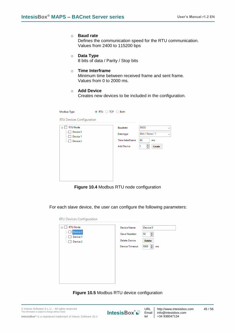
45 / 56
o Baud rate
Defines the communication speed for the RTU communication. Values from 2400 to 115200 bps
o Data Type 8 bits of data / Parity / Stop bits
o Time Interframe
Minimum time between received frame and sent frame. Values from 0 to 2000 ms.
o Add Device
Creates new devices to be included in the configuration.
Figure 10.4 Modbus RTU node configuration
For each slave device, the user can configure the following parameters:
Figure 10.5 Modbus RTU device configuration

IntesisBox® MAPS – BACnet Server series User’s Manual r1.2 EN
© Intesis Software S.L.U. - All rights reserved This information is subject to change without notice
IntesisBox® is a registered trademark of Intesis Software SLU
URL Email tel
http://www.intesisbox.com [email protected] +34 938047134
46 / 56
o Device Name Descriptive name for the Modbus RTU slave device
o Slave Number Modbus slave address
o Delete Device
This option deletes the current selected device
o Device Timeout Time to wait before sending a timeout message if there is no response from the slave device.
2. Modbus TCP For the Modbus TCP, the following standard parameters can be configured:
o Name Descriptive device name
o IP IP for the Modbus TCP server to connect
o Port Port for the Modbus TCP server to connect. By default, it is 502 (standard)
o Add Device Adds as many devices as the ones set in the combo box.
Figure 10.6 Modbus TCP node configuration

IntesisBox® MAPS – BACnet Server series User’s Manual r1.2 EN
© Intesis Software S.L.U. - All rights reserved This information is subject to change without notice
IntesisBox® is a registered trademark of Intesis Software SLU
URL Email tel
http://www.intesisbox.com [email protected] +34 938047134
47 / 56
Moreover, the following advanced settings can be configured too:
o Time Interframe Minimum time between received frame and sent frame. Values from 0 to 10000 ms.
o Retry Timeout Minimum time before launching a retry frame after no response on the TCP connection. Values from 0 to 30000 ms
o Conn. Timeout Minimum time before launching an error message after no TCP connection. Values from 0 to 30000 ms
o Rx. Timeout Minimum time before launching an error message after no TCP frames received, but TCP connection is OK. Values from 0 to 30000 ms
o Time Slave Chg Minimum time of silence when changing from one slave device to another. Values from 0 to 10000 ms
3. Both In this case, simply both options are active and enabled.
Figure 10.7 Modbus TCP node configuration

IntesisBox® MAPS – BACnet Server series User’s Manual r1.2 EN
© Intesis Software S.L.U. - All rights reserved This information is subject to change without notice
IntesisBox® is a registered trademark of Intesis Software SLU
URL Email tel
http://www.intesisbox.com [email protected] +34 938047134
48 / 56
3. Modbus Poll Records The gateway allows the use of Modbus Poll Records. Available options for poll records will be shown in the Poll Records window according to the current Modbus configuration.
Figure 10.8 Modbus Poll Records configuration
1. Allow using polling records with missing registers
If enabled, it allows nonconsecutive registers to be grouped in the same Poll Record.
2. Maximum registers in a Polling Record Max number of registers to be grouped in a single Poll Record.
3. Poll Records Preview Summary of the Poll Records to be used according to the current configuration present in the Signals table.

IntesisBox® MAPS – BACnet Server series User’s Manual r1.2 EN
© Intesis Software S.L.U. - All rights reserved This information is subject to change without notice
IntesisBox® is a registered trademark of Intesis Software SLU
URL Email tel
http://www.intesisbox.com [email protected] +34 938047134
49 / 56
10.2.2 Signals configuration
For the Modbus configuration as an external protocol, the following parameters need to be considered:
1. Device
Indicates the Modbus device.
2. Read Function Indicate the Modbus function used to read, if allowed or required. Modbus functions 1, 2, 3 and 4 supported.
3. Write Function
Indicate the Modbus function used to write, if allowed or required Modbus functions 5, 6, 15 and 16 supported.
4. #bit
Indicate the signal size expressed in bits.
5. Format Indicate the register information format. Unsigned, Signed C2, Signed C1 and
6. ByteOrder
Indicate the byte order
7. Address Indicate the register signal starting address
8. Bit
If using multiple bit (bit fields), indicate the bit you want to read
Figure 10.9 Modbus signals configuration

IntesisBox® MAPS – BACnet Server series User’s Manual r1.2 EN
© Intesis Software S.L.U. - All rights reserved This information is subject to change without notice
IntesisBox® is a registered trademark of Intesis Software SLU
URL Email tel
http://www.intesisbox.com [email protected] +34 938047134
50 / 56
10.3 M-Bus
10.3.1 Standard configuration
Figure 10.10 M-Bus configuration
1. Gateway configuration Select the type of Modbus communication required with the Modbus Slave devices:
A. Baudrate Determines the baudrate connection for the M-Bus gateway. Values may be set to:
o 300 bps o 600 bps o 1200 bps o 2400 bps o 4800 bps o 9600 bps
B. Inter-Polling Gap
Delay between two consecutive polling cycles.
C. Continous Polling Enables/Disables continuous polling from the gateway to the connected M-Bus meters and or devices.

IntesisBox® MAPS – BACnet Server series User’s Manual r1.2 EN
© Intesis Software S.L.U. - All rights reserved This information is subject to change without notice
IntesisBox® is a registered trademark of Intesis Software SLU
URL Email tel
http://www.intesisbox.com [email protected] +34 938047134
51 / 56
2. Devices configuration
A. Scan M-Bus Network This option forces the box to scan the M-Bus network, searching for devices.
Figure 10.11 M-Bus scan options
• Scan configuration:
o M-Bus Scan Mode: 1. Primary Address
If this option is selected, the scan will be done using primary address. Start Address and the End Address can be adjusted to minimize the scan period. Value ranges may vary from 0 to 254.
2. Secondary Address If this option is selected, the scan will be done using the secondary address.
3. Single Device If this option is selected, the scan will be done using a broadcast message sent to the M-Bus bus. If this option is used, only one single M-Bus device must be connected to the bus.

IntesisBox® MAPS – BACnet Server series User’s Manual r1.2 EN
© Intesis Software S.L.U. - All rights reserved This information is subject to change without notice
IntesisBox® is a registered trademark of Intesis Software SLU
URL Email tel
http://www.intesisbox.com [email protected] +34 938047134
52 / 56
o Primary Address Config: a) Start Address
Indicates the M-Bus meter starting address for the Scan process.
b) End Address Indicates the M-Bus meter ending address for the Scan process.
o Baudrates: It is used to select the different baudrates to be used during the scan process of the M-Bus bus. Multiple selection can be used.
o Advanced Configuration:
Figure 10.12 M-Bus advanced scan options Select a general Time Interframe and a specific timeout for each individual baudrate. If not sure about these parameters, please let them as by default.
• Scan status:
o Start scan: a) Start
It initiates the scan process for the M-Bus network.
b) Stop It stops the scan process in case it has not finished yet and the user needs to stop it.

IntesisBox® MAPS – BACnet Server series User’s Manual r1.2 EN
© Intesis Software S.L.U. - All rights reserved This information is subject to change without notice
IntesisBox® is a registered trademark of Intesis Software SLU
URL Email tel
http://www.intesisbox.com [email protected] +34 938047134
53 / 56
• Scan results: o Meters newly detected
List of the new meters found after the scan process is finished or stopped by the user.
o Address
It shows the current M-Bus address of the selected device.
o Version It shows the current M-Bus program version of the selected device.
o Identifier
It shows the current M-Bus identifier of the selected device.
o Medium It shows the current M-Bus medium used by the selected device.
o Manufacturer ID
It shows the current M-Bus Manufacturer ID of the selected device.
o Export to file This option exports the M-Bus information from the meter in a file with a pre-defined template format. This file can be imported to add new devices in the configuration easily.
o Available Registers
List of all the available registers for each M-Bus meter.
o Replace Meters/Signals If this option is active, the current meters and signals (registers) present in the configuration will erased and imports the meters and signals (registers) selected in the Scan Results section.
o Replace Meters If this option is active, the current meters present in the configuration will erased and imports the meters and signals (registers) selected in the Scan Results section. The current meters signals will be kept in the configuration.
o Add Meters
If this option is active, the current meters and signals (registers) present in the configuration will be kept and imports the meters and signals (registers) selected in the Scan Results section.
Figure 10.13 Scan Results information

IntesisBox® MAPS – BACnet Server series User’s Manual r1.2 EN
© Intesis Software S.L.U. - All rights reserved This information is subject to change without notice
IntesisBox® is a registered trademark of Intesis Software SLU
URL Email tel
http://www.intesisbox.com [email protected] +34 938047134
54 / 56
10.3.2 Advanced configuration
Figure 10.14 Scan Results information
• Manage Timeouts This section allows specific configurations for each baud rate during standard communication. If you are not familiar with these values, please left it as default.
Figure 10.15 Scan Results information
• Reset Values on read If active, before reading any M-Bus register, the gateway will force the meter to update the register value to its last valid known value. This ensures updated values on the BACnet side.
• Inter-Polling Gap This parameter is used to determine the time left between the two consecutive polling cycles.
IntesisBox® MAPS – BACnet Server series User’s Manual r1.2 EN
© Intesis Software S.L.U. - All rights reserved This information is subject to change without notice
IntesisBox® is a registered trademark of Intesis Software SLU
URL Email tel
http://www.intesisbox.com [email protected] +34 938047134
55 / 56
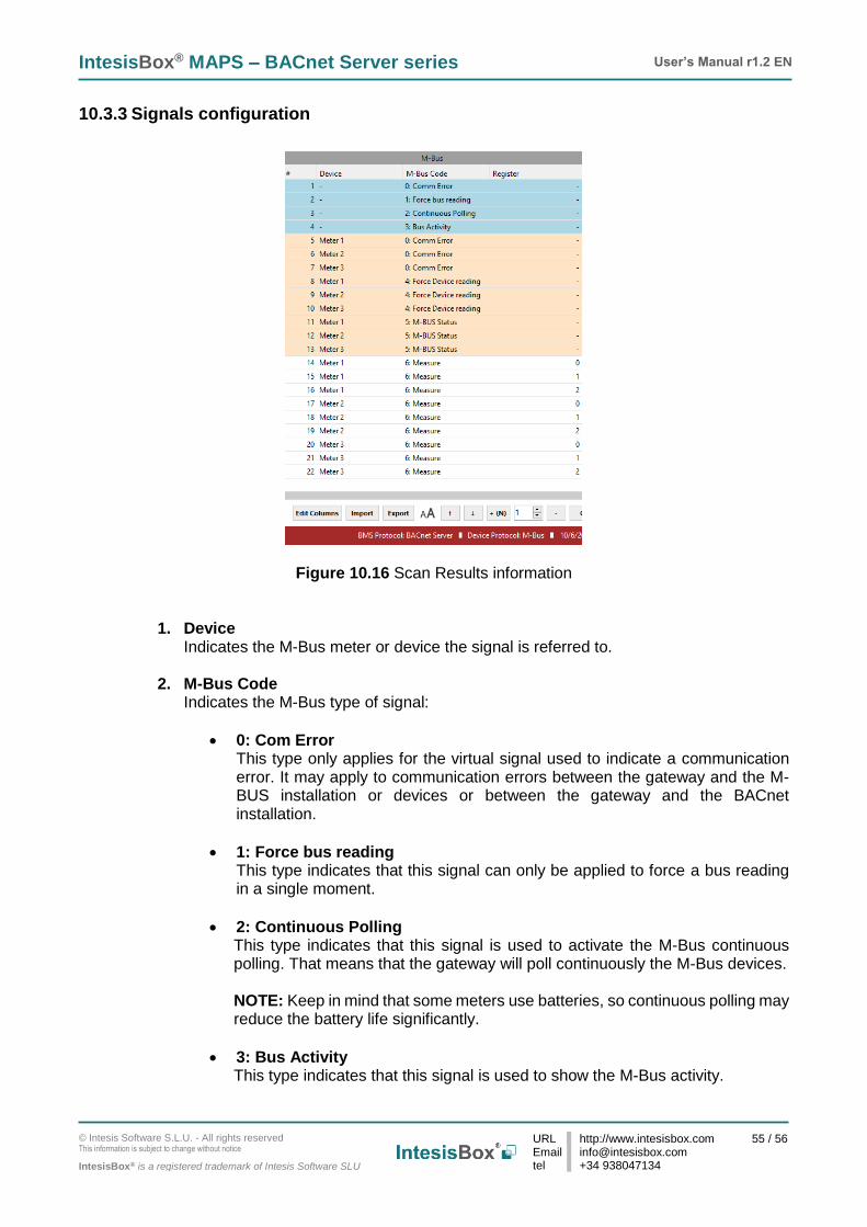
10.3.3 Signals configuration
Figure 10.16 Scan Results information
1. Device Indicates the M-Bus meter or device the signal is referred to.
2. M-Bus Code
Indicates the M-Bus type of signal:
• 0: Com Error This type only applies for the virtual signal used to indicate a communication error. It may apply to communication errors between the gateway and the M-BUS installation or devices or between the gateway and the BACnet installation.
• 1: Force bus reading This type indicates that this signal can only be applied to force a bus reading in a single moment.
• 2: Continuous Polling This type indicates that this signal is used to activate the M-Bus continuous polling. That means that the gateway will poll continuously the M-Bus devices. NOTE: Keep in mind that some meters use batteries, so continuous polling may reduce the battery life significantly.
• 3: Bus Activity This type indicates that this signal is used to show the M-Bus activity.

IntesisBox® MAPS – BACnet Server series User’s Manual r1.2 EN
© Intesis Software S.L.U. - All rights reserved This information is subject to change without notice
IntesisBox® is a registered trademark of Intesis Software SLU
URL Email tel
http://www.intesisbox.com [email protected] +34 938047134
56 / 56
• 4: Force Device reading This type indicates that this signal is used to force a device reading in a certain moment.
• 5: M-BUS Status This type indicates that this signal is used to show the current status of the M-Bus device.
• 6: Measure This type indicates that this signal is used to show measures provided by the M-Bus meter or device.
3. Register
Indicates the corresponding register address of the value that’s going to be red from the meter.