Video Surveillance using Distance Maps
12
Video Surveillance using Distance Maps Theo E. Schouten a , Harco C. Kuppens a , and Egon L. van den Broek b,c a Nijmegen Institute for Computing and Information Science, Radboud University Nijmegen P.O. Box 9010, 6500 KL Nijmegen, The Netherlands {T.Schouten,H.Kuppens}@cs.ru.nl http://www.cs.ru.nl/~{ths,harcok}/ b Faculty of Behavioral Sciences, University Twente P.O. box 217, 7500 AE Enschede, The Netherlands [email protected] http://users.gw.utwente.nl/BroekEL/ c Department of Artificial Intelligence, Faculty of Sciences, Vrije Universiteit Amsterdam De Boelelaan 1081a, 1081 HV Amsterdam, The Netherlands [email protected] http://www.few.vu.nl/~egon/ ABSTRACT Human vigilance is limited; hence, automatic motion and distance detection is one of the central issues in video surveillance. Hereby, many aspects are of importance, this paper specially addresses: efficiency, achieving real-time performance, accuracy, and robustness against various noise factors. To obtain fully controlled test environments, an artificial development center for robot navigation is introduced in which several parameters can be set (e.g., number of objects, trajectories and type and amount of noise). In the videos, for each following frame, movement of stationary objects is detected and pixels of moving objects are located from which moving objects are identified in a robust way. An Exact Euclidean Distance Map (E 2 DM) is utilized to determine accurately the distances between moving and stationary objects. Together with the determined distances between moving objects and the detected movement of stationary objects, this provides the input for detecting unwanted situations in the scene. Further, each intelligent object (e.g., a robot), is provided with its E 2 DM, allowing the object to plan its course of action. Timing results are specified for each program block of the processing chain for 20 different setups. So, the current paper presents extensive, experimentally controlled research on real-time, accurate, and robust motion detection for video surveillance, using E 2 DMs, which makes it a unique approach. 1. INTRODUCTION In video processing, it is often needed to detect motion; i.e., it is required to extract information about the relative positions of stationary and moving objects. The resulting distances between the objects can, for example, be used for surveillance purposes. Unwanted or possible dangerous distances can be automatically detected (e.g., too small or too large), in order to take appropriate actions. The automation of this process is of the utmost importance since the vigilance of humans is limited. The ability of humans to hold attention and to react to rarely occurring events, is extremely demanding and, consequently, prone to error due to lapses in human attention 1 . These actions might include intervention by a (human) supervisor watching the video or sending relevant distance information to objects (or persons) that have capabilities for changing the course of their actions 1–3 . Amer and Regazzoni 3 state that video-based surveillance is one of the fastest growing sectors in the security market due to the high amount of useful information that can be extracted from a video sequence. They present a generic block diagram of a video processing module for video surveillance and identify a list of nine funda- mental issues and challenges: interpretation, generality, automation, efficiency, robustness, trade off (accuracy versus efficiency), performance evaluation, multiple camera processing and data fusion, and feature selection and integration. This broad range of issues illustrates the complexity of extracting the useful information from the large amount of data present in a video sequence. In this paper, we concentrate on two issues as identified by Amer and Regazzoni 3 , namely: efficiency, which is the core focus, and robustness, considered as essential and, hence, tested as well. We choose for an operational environment where a single camera provides a top view of a scene with moving and stationary objects. The conversion of the gray and color images of the camera to binary (i.e., black-and- white) images, which are used for further processing, will not be discussed. However, we do take into account
Transcript of Video Surveillance using Distance Maps

Video Surveillance using Distance Maps
Theo E. Schoutena, Harco C. Kuppensa, and Egon L. van den Broekb,c
aNijmegen Institute for Computing and Information Science, Radboud University Nijmegen
P.O. Box 9010, 6500 KL Nijmegen, The Netherlands
{T.Schouten,H.Kuppens}@cs.ru.nl http://www.cs.ru.nl/~{ths,harcok}/bFaculty of Behavioral Sciences, University Twente
P.O. box 217, 7500 AE Enschede, The Netherlands
[email protected] http://users.gw.utwente.nl/BroekEL/c Department of Artificial Intelligence, Faculty of Sciences, Vrije Universiteit Amsterdam
De Boelelaan 1081a, 1081 HV Amsterdam, The Netherlands
[email protected] http://www.few.vu.nl/~egon/
ABSTRACT
Human vigilance is limited; hence, automatic motion and distance detection is one of the central issues invideo surveillance. Hereby, many aspects are of importance, this paper specially addresses: efficiency, achievingreal-time performance, accuracy, and robustness against various noise factors. To obtain fully controlled testenvironments, an artificial development center for robot navigation is introduced in which several parameterscan be set (e.g., number of objects, trajectories and type and amount of noise). In the videos, for each followingframe, movement of stationary objects is detected and pixels of moving objects are located from which movingobjects are identified in a robust way. An Exact Euclidean Distance Map (E2DM) is utilized to determineaccurately the distances between moving and stationary objects. Together with the determined distances betweenmoving objects and the detected movement of stationary objects, this provides the input for detecting unwantedsituations in the scene. Further, each intelligent object (e.g., a robot), is provided with its E2DM, allowing theobject to plan its course of action. Timing results are specified for each program block of the processing chainfor 20 different setups. So, the current paper presents extensive, experimentally controlled research on real-time,accurate, and robust motion detection for video surveillance, using E2DMs, which makes it a unique approach.
1. INTRODUCTION
In video processing, it is often needed to detect motion; i.e., it is required to extract information about the relativepositions of stationary and moving objects. The resulting distances between the objects can, for example, beused for surveillance purposes. Unwanted or possible dangerous distances can be automatically detected (e.g.,too small or too large), in order to take appropriate actions. The automation of this process is of the utmostimportance since the vigilance of humans is limited. The ability of humans to hold attention and to react to rarelyoccurring events, is extremely demanding and, consequently, prone to error due to lapses in human attention1.These actions might include intervention by a (human) supervisor watching the video or sending relevant distanceinformation to objects (or persons) that have capabilities for changing the course of their actions1–3.
Amer and Regazzoni3 state that video-based surveillance is one of the fastest growing sectors in the securitymarket due to the high amount of useful information that can be extracted from a video sequence. They presenta generic block diagram of a video processing module for video surveillance and identify a list of nine funda-mental issues and challenges: interpretation, generality, automation, efficiency, robustness, trade off (accuracyversus efficiency), performance evaluation, multiple camera processing and data fusion, and feature selection andintegration. This broad range of issues illustrates the complexity of extracting the useful information from thelarge amount of data present in a video sequence. In this paper, we concentrate on two issues as identified byAmer and Regazzoni3, namely: efficiency, which is the core focus, and robustness, considered as essential and,hence, tested as well.
We choose for an operational environment where a single camera provides a top view of a scene with movingand stationary objects. The conversion of the gray and color images of the camera to binary (i.e., black-and-white) images, which are used for further processing, will not be discussed. However, we do take into account

that this conversion process is not able to handle all the challenges posed by changing illumination conditions,shadows and video noise correctly. We model the conversion and its imperfections by an extension of our virtual,dynamic robot navigation environment4.
The calculation of distances is based on the Fast Exact Euclidean Distance (FEED) transformation developedby Schouten and Van den Broek5. This Euclidean Distance Transformation converts a binary image to anotherimage of the same size, such that each pixel has a value equal to the exact Euclidean distance to the nearestobject pixel, where most other algorithms approximate the true Euclidean distance6, 7. The new image is calledthe exact Euclidean Distance Map (E2DM) of the old image. With the calculation of the E2DM for stationaryobjects, the distance of a moving object to the stationary object can be calculated by taking the minimum ofthe distances in this E2DM at the locations of the border pixels of the moving object.
As shown by Schouten, Kuppens, and Van den Broek4, the E2DM of images containing stationary andmoving objects can be obtained very fast, using the FEED transformation. Here, very fast denotes that theE2DMs of a sequence of more than a few images can be obtained faster than city-block8 or 3,4 chamfer9 distancemaps. To achieve the latter, the E2DMs for the stationary objects (E2DMstationary) and for the moving object(E2DMmoving) are calculated separately and combined, using the minimum operator, to obtain the distancemap for the total image:
E2DMstationary+moving(p) = min{E2DMstationary(p) , E2DMmoving(p)} (1)
This E2DM is used to provide each object (e.g., a robot) with processing capabilities, with a map of objects andfree space in its environment. The robot can use information obtained from the E2DM to achieve its goal; e.g.,path planning10.
The processing chain developed in this paper consists of two phases:
1. The initialization phase: A number of sequential images are used to determine the stationary pixels. Atthe end of it, E2DMstationary is calculated.
2. The processing phase: For each next image it is verified whether or not the stationary pixels have changedsubstantially. If they have done so, the initialization is entered again. Otherwise, the moving pixels areidentified, from which the moving objects are determined in a robust way. Next, distances from eachmoving object to the fixed and the other moving objects are calculated and presented to the (human)supervisor. Finally, in case an object with processing capabilities is present (for the purposes of this paperwe simply assume that one of the objects has this capability), its E2DM to the stationary and the othermoving objects is calculated.
In the next section, the operational environment is described. Three compounds can be distinguished: 1)the creation of the robot navigation environments, 2) the method of modeling imperfections (noise), and 3) thespecification of hardware and software parameters. In Section 3, the principle of Fast Exact Euclidean Distance(FEED) maps is explained and some (further) improvements are specified. Section 4 describes the processingchain for real-time and exact motion detection. In this processing chain, two phases can be distinguished: theinitialization phase and the processing phase. Obtained execution times for the most demanding video sequenceare given and the design guidelines used for obtaining the fast execution times are explained. The next Sectiondescribes the programming blocks in details, including visualization of the (intermediate) results. The overalltiming results are provided for the various settings, determined by: two image sizes and five levels of noise ontwo platforms. We end the paper with a discussion (Section 6) that raps up the current research, describes followup research, and draws some final conclusions.
2. OPERATIONAL ENVIRONMENT
As stated in Section 1, we choose for an operational environment where a single camera provides a top view ofa scene with moving and stationary objects. In order to experiment with such environments, we have developeda virtual, dynamic robot navigation environment4. It generates a binary video stream by animation usingMacromedia r© Flash; see also4. This provides us the means to record video sequences in a fully controlledenvironment. Moreover, using this animation system has the following advantages:

• Moving objects can be separated from the background, using layers.
• The creation of moving objects is easy: Drawing a line in a layer. Given a number of frames, Flash willgenerate the different frames with the object shifted along the path. In addition, rotation of the objectcan be specified.
• Animations can be changed easily since Flash uses vector graphics.
• The color map and with that the object indexation is preserved with the export from animation to gifimages. Most animation programs interpolate color values at edges of objects, with the export of bitmapimages. This results in a loss of object indexation.
To model the imperfections of the conversion from real camera images to binary images, noise was added to theoutput of the robot navigation environment, using three transformations:
• Each border pixel of an object was with a probability of p1% changed into a background pixel. Here, aborder pixel is defined as an object pixel with at least one of its 4 connected neighbors in the background5.
• Randomly chosen background pixels that lay next to a border pixel were changed into an object pixel, witha probability of p2%.
• Each pixel was changed into its inverse, with a probability of p3%.
For the current research, two video sequences were generated:
1. A sequence of 60 frames of 320×240 pixels with two moving objects being present during the full sequence.One of the moving objects collides once with a fixed object and displaces it.
2. A sequence of 120 frames of 640×480 with one permanently moving object present and up to two additionalobjects that randomly appear and disappear from the scene. Once during the sequence, one of the stationaryobjects displaces itself and once, a moving object bounces off a stationary object, which is displaced andthen returns to its original position.
To each generated image sequence five different p1% − p2% − p3% noise patterns were applied, ranging from10%-10%-1% to 50%-50%-5%. Thus in total ten sequences with a total number of 900 frames were used for thispaper. To provide an impression, two of the images are shown in Figure 1. Note that the large image looks“darker” because it is printed at the same scale as the small image.
Two execution platforms were use for developing and testing the algorithms. The first, further referred to asAMD, was a desktop PC with an AMD Athlon XP r© 1666 MHz processor, having 64kB L1 cache, 256kB L2 cache,and 512 MB memory. The second, further referred to as INTEL, was a DELL Inspiron r© 510m laptop. It had anIntel Pentium r© M 725 processor with a clock of 1600 MHz, no L1 cache, 2MB L2 cache, and 512MB memory.On both platforms, the Microsoft r© Visual C++ 6.0 programming environment was used in the standard releasesetting. Please note that no effort was spend on reducing the execution time by varying compiler optimizationparameters, by using pointers instead of indices, or by exploiting the particular characteristics of one of themachines.
Timing measurement were performed by calling the Visual C++ clock() routine before and after a repeatednumber of executions of (parts) of programs on all images of a sequence. As the clock() routine returns elapsedtime with a granularity of ten milliseconds, the number of repetitions is set such that the total elapsed timeis more than one second. The error on a single elapsed time measurement is than less than 2%, provided thatthe computer was not busy with other tasks like processing interrupts. This was guarded against by switchingoff unneeded sources of interrupts (e.g., networks) and by repeating the measurements a number of times andtaking the minimum of these measurements.
All frames of a sequence were read in memory and consequently, were directly available to the developedprograms. The measured times reported in this paper include the times needed to generate the images used foroutput to the (human) supervisor or to intelligent objects. The time needed to actually display these images orto communicate them is not reported in this paper.
(a) (b)
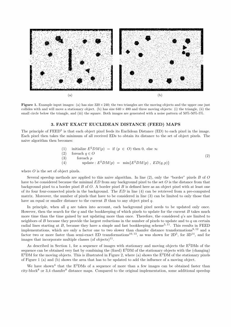
Figure 1. Example input images: (a) has size 320× 240; the two triangles are the moving objects and the upper one justcollides with and will move a stationary object. (b) has size 640× 480 and three moving objects: (i) the triangle, (ii) thesmall circle below the triangle, and (iii) the square. Both images are generated with a noise pattern of 50%-50%-5%.
3. FAST EXACT EUCLIDEAN DISTANCE (FEED) MAPS
The principle of FEED5 is that each object pixel feeds its Euclidean Distance (ED) to each pixel in the image.Each pixel then takes the minimum of all received EDs to obtain its distance to the set of object pixels. Thenaive algorithm then becomes:
(1) initialize E2DM(p) = if (p ∈ O) then 0, else ∞(2) foreach q ∈ O
(3) foreach p
(4) update : E2DM(p) = min{E2DM(p) , ED(q, p)}
(2)
where O is the set of object pixels.
Several speedup methods are applied to this naive algorithm. In line (2), only the “border” pixels B of O
have to be considered because the minimal ED from any background pixel to the set O is the distance from thatbackground pixel to a border pixel B of O. A border pixel B is defined here as an object pixel with at least oneof its four four-connected pixels in the background. The ED in line (4) can be retrieved from a pre-computedmatrix. Moreover, the number of pixels that have to be considered in line (3) can be limited to only those thathave an equal or smaller distance to the current B than to any object pixel q.
In principle, when all q are taken into account, each background pixel needs to be updated only once.However, then the search for the q and the bookkeeping of which pixels to update for the current B takes muchmore time than the time gained by not updating more than once. Therefore, the considered q’s are limited toneighbors of B because they provide the largest reductions in the number of pixels to update and to q on certainradial lines starting at B, because they have a simple and fast bookkeeping scheme5, 11. This results in FEEDimplementations, which are only a factor one to two slower than chamfer distance transformations9, 12 and afactor two or more faster than semi-exact ED transformations10, 13, as was shown for 2D5, for 3D14, and forimages that incorporate multiple classes (of objects)11.
As described in Section 1, for a sequence of images with stationary and moving objects the E2DMs of thesequence can be obtained very fast by combining the (fixed) E2DM of the stationary objects with the (changing)E2DM for the moving objects. This is illustrated in Figure 2, where (a) shows the E2DM of the stationary pixelsof Figure 1 (a) and (b) shows the area that has to be updated to add the influence of a moving object.
We have shown4 that the E2DMs of a sequence of more than a few images can be obtained faster thancity-block8 or 3,4 chamfer9 distance maps. Compared to the original implementation, some additional speedup

(a) (b)
Figure 2. Two Euclidean Distance Maps (E2DMs): (a) The E2DM of the stationary pixels of Figure 1 (a). A color rangefrom bright green to bright blue is used here for EDs ranging from 0 to the maximum ED in the images. Image (b) showsin white the area that was updated for adding the Euclidean Distances to the triangular moving object.
methods have been applied. The border pixels of the stationary objects are determined and stored in two lists,one for the x and one for the y direction. This speeds up the search for object pixels q in the horizontal andvertical directions for each border pixel. Further, the influence of the maximum distance dmax in the stationaryE2DM was better taken into account. It defines a maximum to the distance that a border pixel of a movingobject might have to feed its ED to. This circle was in the original implementation approximated by its outsidesquare. In the current implementation, it is approximated by its outside octagon. In total, these two additionsprovide an additional speedup of 10 to 20%, compared to the original implementation.
4. REAL-TIME AND EXACT MOTION DETECTION
The processing chain for the real-time and exact motion detection, shown in Figure 3, consists of two phases. Inthe initialization phase, a number of sequential images are used to determine the pixels of the stationary objects.This is followed by a number of pre-calculations to speedup the processing of the following frames. In addition,pre-calculations are done for the generation of images to display the results of the processing. How the resultsof the processing chain are used depends on the specific application the program is used for; for this paper, theresults were simply visualized.
In the processing phase, for each next frame the object pixels in it are classified as stationary or movingobject pixels, while removing most of the noise pixels. It is verified whether or not the stationary pixels havechanged substantially; if they have done so, the initialization phase is entered again. Otherwise, the movingpixels are grouped into objects in a robust way and the remaining noise pixels, which give small noise objects,are removed. Then, distances from each moving object to the stationary and to the other moving objects arecalculated. From that point on, they can be handled in an application-specific way. In case an object withprocessing capabilities is present (for the purposes of this paper we simply assume that one of the objects hasthis capability), its E2DM to the stationary and to the other moving objects is calculated. Next, this E2DM canbe communicated to the intelligent object, depending on the particular circumstances. Finally, the displays forthe visualization of the results are generated.
In Table 1, the execution time for each program block is given for the image sequence with the large framesand the most noise on both the execution platforms. The reported times show a clear difference between thetwo execution platforms. The AMD platform is faster in the generation of display images; for the other programparts, the INTEL platform is faster. Please note that the reported times do not include the time needed forgrabbing of frames for a particular application nor for processing the frames to obtain the binary frames needed

Figure 3. The processing chain for real-time and exact motion detection, as presented in this paper.
for our processing chain. However, the measured times are small compared to the inter frame times of typicalwebcam like cameras, which are in the order of 50 to 80 milliseconds.
The following design guidelines were used to obtain the fast execution times:
1. Pre-calculation of information: For frame-to-frame processing, information is used that only depends on theinformation obtained in the initialization phase. Pre-calculating this information and storing it in suitabledata structures allows faster processing in the processing phase. An example is the position information ofborders of the stationary objects stored in two lists, mentioned in Section 3.
2. Restriction of data movement: Often in the processing phase an image or matrix is initialized with pre-calculated information and then information derived from the current frame is added. By keeping trackof which parts(s) of the data structure has been changed, only those parts have to be reinitialized for thenext frame. An example is the situation shown in Figure 2, a bounding box of the changed, white area inimage (b) is determined and used in the next frame to restore the original situation as shown in image (a).
3. Combination of loops and test: Often program parts with logically distinct purposes use nearly the sameloops and test structures, they can be combined to avoid double execution of the common parts. Anexample is the detection of the moving objects combined with the detection of moved stationary objects.The opposite of this can also sometimes be exploited: the removal of noise is distributed over a number ofother program parts to get a free ride on tests performed for those parts.
5. DETAILS OF THE PROCESSING CHAIN
5.1. Determining stationary pixels
For a number of frames, currently set to five, the number of occurrences of an object pixel are counted foreach pixel location in a count matrix. Here, an object pixel is only counted if at least one of its four-connectedneighbors is also an object pixel. For being considered as a stationary object pixel, a location must have receivedfive counts or three or four counts, but then all its four-connected neighbors must have received five counts.Further, holes of one background pixel surrounded by 4 stationary pixels are filled. This procedure is fast andsufficient even for sequences with a large amount of noise.

Table 1. Execution times for the program blocks in the processing chain. They are given here for the sequence of frameswith size 640× 480 and the most noise (50%-50%-5% pattern), on both execution platforms.
Phase Program block Time AMD Time INTELInitialization Accumulate objects pixels for 5
frames9.7 ms 7.7 ms
(time per 5 frames) Determine stationary objects 2.5 ms 2.0 msPre-calculate for further processing 34.4 ms 18.5 msPre-calculate for generation of displayimages
10.3 ms 14.5 ms
Processing Determine stationary/ moving objectpixels
2.6 ms 2.0 ms
(time per frame) Determine moving objects 0.7 ms 0.3 msCalculate distances 0.4 ms 0.3 msCalculate E2DM(s) 1.2 ms 0.6 msGenerate display images 1.4 ms 2.0 ms
Please note that for the determination of stationary pixels, the moving objects have to move sufficiently fast:in the used number of frames, there should be at least two frames in which the pixels of the moving object donot overlap. If there is an overlap, some part of the moving object will be considered as stationary object pixels.When that part is large enough, the processing phase will detect for one of the following frames a substantiallychange of that part and then reenter the initialization phase. If this happens too often, our program keepsfunctioning but too few frames are used for deriving video surveillance values.
A simple strategy to detect whether or not moving object move too slow is to track the interval betweeninitializations. Then, a first counter measure would be to adapt the number of frames used for initialization tothe determined intervals. A next step would be to switch to a more elaborate statistical processing of the pixelsin the initialization frames, like giving weights to the counts, depending on neighboring pixels.
5.2. Pre-calculation
In Table 2, the most important pre-calculations are given with their execution times. Here, we will provide someadditional information. The input matrix for each next frame is initialized with the stationary object pixels towhich then the object pixels in the frame are added.
In the pixel classification matrix, each pixel location is classified as being: (a) inside a stationary object, whenthe location and its four-connected neighbors are occupied by stationary object pixels; (b) outside the stationaryobjects, when the location and its four-connected neighbors are occupied by background pixels; (c) otherwisethe location is in the border area. This matrix is used in the first processing block to speed up the processingphase of that block.
Table 2. A list of the operations performed as pre-calculation and the execution time for the sequence of frames withsize 640× 480, with the most noise (50%-50%-5% pattern), on the AMD system.
Pre-calculation operation TimeInitialization matrix for the input matrix for each next frame 0.5 msCalculation of E2DMstationary 24.8 msDetermination of the borders of the stationary objects 1.3 msInitialization of E2DMstationary+moving, maximum distance 4.1 msCalculation of the pixel classification matrix 2.8 msCalculation and initialization of display of moving objects 1.7 msCalculation and initialization of display of E2DMstationary+moving 8.6 ms

(a) (b) (c)
Figure 4. Detection of movement of stationary objects, where a red pixel indicates a position where a stationary objectpixel is replaced in the current frame with a background pixel. (a) shows part of the image in the sequence with 320×240frames after a stationary object is displaced by a moving object. (b) and (c) show part of the image in the sequence of640× 480 frames, where a stationary object moves spontaneously, respectively is displaced by a moving object.
The determination of the borders of the stationary objects and the filling of the pixel classification matrixare done in the FEED program, used to determine E2DMstationary. The filling of the initialization matrix forE2DMstationary+moving is combined with the calculation of the maximum distance in E2DMstationary.
5.3. Determine stationary / moving object pixels
The input matrix for each new frame is initialized with the stationary input pixels. As described in the previousSection, we keep track of which parts of it were changed for the previous frame and only those parts arereinitialized. Then a single scan over the frame is performed both to detect moved stationary objects and todetermine the moving object pixels.
Each background pixel is checked for being located inside a stationary object, using the pixel classificationmatrix described in the previous subsection. If that is the case and all its four-connected pixels are also back-ground pixels, the pixel is counted as a changed stationary object pixel. Figure 4 shows the detected changedstationary object pixels for the three occurrences in the video sequences of a moved stationary object for thesequences with the most noise.
A simple threshold on the number of changed stationary object pixels is sufficient to define a substantialmovement of a stationary object, in which case the program chain reenters the initialization phase. In theimages shown in Figure 4, the number of changed pixels is 22, 54, and 73, while in the other images of thesequences the maximal number of changed pixels is two. For the images with the least noise the number ofchanged pixels is 36, 99, and 92, while in the other images no changed pixels are detected. Thus, our movementdetector is very robust against noise and is able to detect small changes.
In the same single scan over the frame, each object pixel is checked for being located outside the stationaryobjects and for being four-connected to at least two other object pixels. If the latter is the case, the pixel isconsidered to be a moving object pixel, indicated by a value of 127 in the input matrix. Then, a check is madefor small holes in the moving object by determining whether the pixels at the same column in the previous twoscan lines form such a hole. By changing the pixels in the hole to moving object pixels, the hole is removed.This procedure removes all of the single pixel holes and about half (the vertical ones) of the double pixel holesin the moving objects. Further, during the scan, a list is generated containing the position of the first and lastmoving object pixel for each scan line. This is used to decrease the execution time of the next processing block.
Figure 5(b) shows the result of the above processing for part of a large frame, which is shown in Figure 5(a).Please note that the holes in the moving object are removed except for the horizontal hole of two pixels. Inaddition, most of the noise object pixels outside the moving objects are removed. The remaining ones are mostlylocated close to the borders of the fixed objects, caused by the large amount of noise present in the borders

(a) (b) (c)
Figure 5. Locating the moving objects: (a) shows part of a large input frame. (b) shows the detected moving objectpixels indicated in gray. (c) shows (in color) the borders of the detected objects; note that a hole in an object alsogenerates an object.
5.4. Determine moving objects
The determination of the moving objects is performed in three steps: 1) locating the border pixels of the objects,2) finding the objects, and 3) removing the noise objects.
For locating the border pixels of the moving objects, a single scan over the frame is made, restricting thenumber of pixels to be considered using the list described in the previous Section. Isolated moving objectspixels, defined as having no four-connected moving objects pixels, are detected and removed during this scan.The locations of the border pixels found are stored in a list in order to speed up further processing.
The moving objects are found by identifying their contours consisting of their eight-connected border pixels.These contours are constructed using a variant of a standard “blob coloring” algorithm. This variant operatesdirectly on the list of border pixels using a single forward scan over the list. It uses a direct backward scan toresolve each color (the contour number) equivalence. The assigned contour number of each border pixel is storedin a separate list. Each object has one outside contour and one inside contour for each hole in the object. Forthe purposes of this paper, an inside contour is considered to be the outside contour of a hole object.
For the removal of noise objects, hole objects have to be distinguished from the other objects. This is done in asimple and very fast way by counting the number of background and the number of moving object pixels betweenconsecutive pairs of its contour pixels on each scan line. If there are more background than moving object pixelscounted this way, the object is considered to be a hole. There might be rather pathological situations in whichthe above test fails. As this does not happen with our input sets, we have not implemented more complicatedtests (for which many possibilities exists), to cure this potential problem. As hole objects have at least fourcontour pixels, the above test is not performed for objects with less than four contour pixels, which constituteclose to 90% of the total number of noise objects.
The non-hole noise objects can only be distinguished from the real objects, based on their size, when consid-ering each frame separately. The maximum occurring number of pixels on the contour of noise objects is nine inall the ten video sequences. For comparison, the minimal occurring contour size of the real objects is 42 in thesmall frames and 67 in the large frames. Thus, smaller objects than used in our input sets can be distinguishedfrom noise objects, using a simple threshold on the contour size. Switching to a more complicated size measure,like the number of inside pixels, will decrease the size of real objects that can be distinguished from noise.
Figure 5(c) shows the result of the object detection for part of a large frame, which is shown in Figure 5(a).In the full frame there were 775 border pixels of moving pixels determined from which 182 objects were detected.This was reduced to the three real objects by the removal of the noise objects.
5.5. Distance calculation
The minimal distance from each moving object to the stationary objects is calculated by taking the minimumof the distances in the E2DMstationary at the locations of all the contour points of the moving object. This is

(a) (b)
Figure 6. Supervisor displays: (a) The pixels of the stationary objects and the contours of the moving objects are shown.The color of the latter encodes the determined distances; e.g., red indicates to close to another object. (b) The E2DM forthe triangular moving object of which the contour is shown.
a very fast operation, taking less than 0.02 milliseconds of the 0.4 milliseconds, reported for the total distancecalculation in Table 1. The minimal distance from each moving object to other moving objects is obtained bytaking the minimum of the distances between all pairs of points on the contours of the objects. This operationtakes most of the time for this processing block.
A frame-to-frame tracking of objects is implemented which uses as track measure the sum of the absolutevalue of the difference between the x position of the objects, the y position, and the number of contour pixels.Here, the positions are taken as the average positions of all contour points. This tracking is used to select thesame object for the calculation in the next processing block and for showing the supervisor a list of disappeared,new, and continued objects.
5.6. Calculate E2DM(s) and display generation
The first appearing object in a sequence is chosen and tracked, as described in the previous subsection. TheE2DM is calculated for the stationary objects and the other moving objects in the frame using the FEED4
method, as described in Section 3.
Figure 6 shows examples of the two generated displays. Figure 6 (a) shows the stationary pixels and thecontours of the detected moving objects for the frame given in Figure 1 (a). The contours are color coded;e.g., red indicates being to close to another objects, according to some chosen video surveillance parameters.Figure 6 (b) shows the maneuver space for the triangular object in Figure 1 (b) of which only the contour isdrawn. This consists of the combined E2DM for the other moving objects and for the stationary objects. Thecontours of all moving objects are also color coded.
5.7. Overall timing results
In Table 3, the execution times are provided for the different video sequences and execution platforms (seeSection 2). The times for the initialization phase are for the full processing of the frames used for initialization;those for the processing phase are given per frame. For both phases, the times are given separately for theprocessing to obtain the distances as the video surveillance results and for the processing needed to generate thedisplay images for a human supervisor. The latter is only presented in this paper as an example of what can bedone with the produced video surveillance results.
From inspection of the programming code, it can be derived that the execution times for generating thedisplay images should be rather independent from the noise applied to the video sequences. The times should

Sequence AMD platform INTEL platformInit phase Per frame Init phase Per frame
Size Noise process. display process. display process. display process. display320 × 240 10%-10%-1% 9.15 2.81 0.88 0.41 5.89 3.91 0.59 0.38
20%-20%-2% 9.59 2.88 0.91 0.40 6.42 3.90 0.61 0.3830%-30%-3% 10.15 2.77 0.94 0.41 7.02 3.85 0.65 0.3840%-40%-4% 10.42 2.80 1.02 0.42 7.39 3.85 0.70 0.4050%-50%-5% 10.62 2.83 1.13 0.42 7.66 3.91 0.73 0.40
640 × 480 10%-10%-1% 39.88 10.63 4.12 1.37 24.03 14.67 2.49 1.8720%-20%-2% 42.66 10.30 4.20 1.42 25.63 14.38 2.57 1.9130%-30%-3% 45.41 10.27 4.32 1.44 27.00 14.57 2.72 1.9540%-40%-4% 46.78 10.56 4.52 1.42 27.98 14.42 2.90 1.9350%-50%-5% 46.60 10.33 4.94 1.40 28.32 14.54 3.21 1.99
Table 3. Timing results in ms for all ten sequences on the two execution platforms. Times are given separately for thetwo phases of our processing chain. Further, times are given separately for the core processing (process.) that producesthe video surveillance results and for a visual display of them (display), which is just given as an example of what can bedone with the results.
be constant in the initialization phase (only dependent on the frame size), while in the processing phase theyshould show a small variation of a few percent. The measured root mean square deviation for the time seriesvaries from 0.8 to 1.6% in the initialization phase and from 1.9 to 2.6% in the processing phase. This confirmsthe stated accuracy of 2% for our time mesurement (see Section 2).
The reported times also show a difference between the two execution platforms. For the generation of displayimages the AMD platform is up to 40% faster (with exception of the small frames in the processing phase); forthe other program parts, the INTEL platform is up to 68% faster.
6. DISCUSSION
We have presented a real-time, accurate, and robust system for automatic distance and motion detection invideo sequences. Stationary and moving objects are detected in a robust way, from video sequences taken bya single camera providing a top view of a scene. To obtain fully controlled test environments, an artificialdevelopment center for robot navigation is introduced in which several parameters can be set; e.g., number ofobjects, trajectories and type and amount of noise. Ten different noisy video sequences were generated in orderto test both the robustness and the speed of our system. Distances between moving and stationary objects areobtained in a fast and accurate way, using the Fast Exact Euclidean Distance (FEED)4, 5, 11, 14 transform. Eachobject with processing capabilities (e.g., a robot) is provided with its Exact Euclidean Distance Map (E2DM)to the stationary and other moving objects and, for example, can be used to detect and prevent unwanted orpossible dangerous situations.
Several restrictions on the content of the video sequences have been identified in this paper and ways to removethem have been discussed. They include the minimum speed of moving objects during the determination of thepixels of the stationary objects (see Section 5.1), the minimal amount of detectable movement of stationaryobjects (see Section 5.3), and the minimal size of the moving objects in order to be able to separate themfrom noise objects (see Section 5.4). Further reduction of these minimal values will be one of the topics inour further research. More in general, the fundamental research toward the application of E2DMs in variouscontrolled environments will continue. In addition, parallel motion detection, in line with Schouten et al.4, willbe employed for various types of objects, each with their own characteristics, as was done for images in Van denBroek et al.11. For the latter purpose, the artificial development center for robot navigation will be extended.This will continue until environments can be created that almost touch reality.
In parallel with the controlled tasks, the application of motion detection in real life recordings will be con-ducted. Without any doubt, these recordings will give birth to a range of problems that were not encountered,so far. One of the most striking is occlusion. In contrast with video surveillance techniques, humans are able

to track moving objects with a striking ease, even when temporarily occluded. However, what principles laybehind this capability is far from clear. Only in the last five years, attempts have been made to extend occlusionresearch to the domain of video surveillance1. Hence, the problem of occlusion forms one of the big challengesfor the application of E2DMs on video surveillance.
With the increase of attention for safety issues in modern societies, the need for automated, preferably,autonomous, real-time video surveillance techniques is pressing. The current paper uses distance maps for real-time, exact tracking of moving objects, which is an unique approach. Moreover, the processing chain presentedis robust to noise. This line of research will be continued and, in parallel, will be extended to real life videosurveillance. Considering the promising results, the processing chain presented can be expected to become ofsignificant importance for video surveillance.
REFERENCES
1. A. Hampapur, L. M. Brown, J. Connell, M. Lu, H. Merkl, S. Pankanti, A. W. Senior, C.-F. Shu, and Y.-L.Tian, “Multi-scale tracking for smart video surveillance,” IEEE Transactions on Signal Processing 22(2),pp. 38–51, 2005.
2. A. R. Dick and M. J. Brooks, “Issues in automated visual surveillance,” in Proceedings of the InternationalConference on Digital Image Computing: Techniques and Applications (DICTA 2003), pp. 195–204, (Sydney,Australia), December 2003.
3. A. Amer and C. Regazzoni, “Introduction to the special issue on video object processing for surveillanceapplications,” Real-Time Imaging 11(3), pp. 167–171, 2005.
4. Th. E. Schouten, H. C. Kuppens, and E. L. van den Broek, “Timed Fast Exact Euclidean Distance (tFEED)maps,” Proceedings of SPIE (Real Time Imaging IX) 5671, pp. 52–63, 2005.
5. Th. E. Schouten and E. L. van den Broek, “Fast Exact Euclidean Distance (FEED) Transformation,” inProceedings of the 17th IEEE International Conference on Pattern Recognition (ICPR 2004), J. Kittler,M. Petrou, and M. Nixon, eds., 3, pp. 594–597, (Cambridge, United Kingdom), 2004.
6. A. Hajdu and L. Hajdu, “Approximating the Euclidean distance using non-periodic neighbourhood se-quences,” Discrete Mathematics 283(1–3), pp. 101–111, 2004.
7. C. Fouard and G. Malandain, “3-D chamfer distances and norms in anisotropic grids,” Image and VisionComputing 23(2), pp. 143–158, 2005.
8. A. Rosenfeld and J. L. Pfaltz, “Distance functions on digital pictures,” Pattern Recognition 1, pp. 33–61,1968.
9. G. Borgefors, “Distance transformations in digital images,” Computer Vision, Graphics, and Image Pro-cessing: An International Journal 34, pp. 344–371, 1986.
10. F. Y. Shih and Y.-T. Wu, “Three-dimensional Euclidean distance transformation and its application toshortest path planning,” Pattern Recognition 37(1), pp. 79–92, 2004.
11. E. L. van den Broek, Th. E. Schouten, P. M. F. Kisters, and H. C. Kuppens, “Weighted Distance Mapping(WDM),” in Proceedings of the IEE International Conference on Visual Information Engineering (VIE2005),N. Canagarajah, A. Chalmers, F. Deravi, S. Gibson, P. Hobson, M. Mirmehdi, and S. Marshall, eds., pp. 157–164, Wrightsons - Earls Barton, Northants, Great Britain, (Glasgow, United Kingdom), 2005.
12. S. Svensson and G. Sanniti di Baja, “Using distance transforms to decompose 3d discrete objects,” Imageand Vision Computing 20(8), pp. 529–540, 2002.
13. F. Y. Shih and Y.-T. Wu, “Fast euclidean distance transformation in two scans using a 3×3 neighborhood,”Computer Vision and Image Understanding 93(2), pp. 195–205, 2004.
14. Th. E. Schouten, H. C. Kuppens, and E. L. van den Broek, “Three dimensional fast exact euclidean distance(3D-FEED) maps,” Proceedings of SPIE (Vision Geometry XIV) 6066, p. [in press], 2006.