Untitled - Amherst Maps
152
-
Upload
khangminh22 -
Category
Documents
-
view
0 -
download
0
Transcript of Untitled - Amherst Maps


FORM 3A - CERTIFICATE OF COMPLIANCE
No. __ _ Fee. __ _
CO'M1t1.O'1>IW!Eu'T''lf O'F ~9tC'lf'US!E'I'tr'S Board of Health, Amherst, MA
CERTIFICATE OF COMPLIANCE
Description of Work: (X) Complete System ( ) Individual Components
The undersigned hereby certify that the Sewage Disposal System: Upgrade
by:
at:
Joe Burek Constructio n
563 Montague Road. Amherst
Homestead Inc. Project If: ~
has been installed in accordance with the provisions of 310 CMR 15.00 (Title 5) and the approved
design plans/as built plans relating to application No. __ _
Design Flow 355 (gpd).
Date of sub-grade inspection: 1113/12
Installer
Designer:
Inspector: Local Aporovi ng Authority Amherst Board of Health
dated 8(16(12 . Approved
Date:
Date: 11/7/12
Date:
This certification represents no warranty, expressed or Implied as to the functioning or longevity of the onsite subsurface disposal system. Rather, the plan and installation are in compliance with all applicable rules and regulations in effect at the time of plan submittal.
cc: Marga and Bob Coler. c/o Delap Real Estate. Northampton. MA 01060
DEP APPROVED FORM 5/96

I
I I I I I I I I I I I I I I I I I
,. I -;(
I I I I
Infiltration Chamber Leachfield: Design based on Infiltrator Brand chamber by Infiltrator Systems Inc. Use only the model number specified. Contact System Designer for held sizing if other brand is to be used for this project . Use Title 5 sand for all flll req .. !irements under units, between rows of units, to the level of the top of the units. and within 5 feet surrounding units .
Inspection
Install top 8R of parking araa and driveway with TAG media, compacted and smoothed.
Use quality topsoil fill over non-parking areas. Town water in
Partial House Oulline
Schedule 40 sewer pipe .
I I I I I I I
Variances Applied For: 3 foot separation to groundwater. 310 CMR 15.405 (h)
I I I I I I I I I I I
New Leachfield: Infiltrator High Capacity H-20 _ New 1,500 !la/ton ntle 5 Chambe
L",· 3 'ows, '!... ""ambo", PO' 'ow. \Ie"Ii'ated ----~_ septio tao' With outlet h'e,. I
10'
--- ~ 1 ~Ie Vent, see Delail. - -- _ _ ". ! TBM : nsn at base of 24" dla. oak. -- _ __ __ -.......... Schedule 80 ptpe. B evation: 100.00' \ -- -- __ __ _ ___ _ I
~ig .SUr1 _EIeV.: 95.9-_-- _ \
1 ---- ----.. I DrtYeway - ___ -::- ___
Note: Reid installed in native P -- --~~ II soil. 00 not over~excavate . ____
---'-..
¢ NORTH
------->
Closeout Notes:
\
\
I I
)
1, Septic tank is equipped with an outlet filter. This is a maintenance item. Filter must be cleaned whenever septic tank is pumped, or every 3 years, whichever is sooner. Failure to maintain filter may lead to system failure, 2. Recommend pumping septic tank on a 3 to 5 year schedule, depending on house occupancy. 3. A copy of this document attached in the basement/utility area will keep this information available in future years for maintenance.
As-Built Drawing Existing Septic Svs tern.
Scale: 1 : 20'
Except as Noted
Date: 8/16/2012
Revision Date: 11/7/2012
Owner: Marga and Bob Coler
563 Montague "~~Y-/ Amherst, MA 01002
HOMESTEAD INC. Thomas S. Leue R.S.
~ 1664CapeSt.
. ~ Williamsburg, MA 01096 I" [413]628-4533

.,
Important: When filling out forms on the computer, use only the tab key to move your cursor - do not use the return key.
~ ~
sepsysct • date
Commonwealth of Massachusetts CityfTown of
Septic System Installation Checklist
DEP has provided this form for use by local Boards of Health if they wish to do so.
A. Applicant Information ~c, ..... ~ ~o-13 C""-'ER- _________________ _ Name
GID U£~ ~Ik.. eS.T'¥~"£-Address
\) Di---ru..-~ I Kt\ 6 10<"'0 City C'SC-ta-:-te- - -----
__ IZ.-\~ _ 1A_ Disposal ~ystem Construction Permit # Map
Zip Code
I') Lot
~~c;,E(>~ rs"R.~'C-Insta=tI"eT-
_:rt<~ 6-£O\'Z-Designer
~?""J"':'"," \2--~ __ '"_~ ______ ___ __________ ____ _ Board of Health Representative
Inspection Dates:
Tank: ...1h-j e I ~ (h L--Oat Leach Area : t ,j t' t'L h"Z..-
Oat'!
Final : r1/tj~ f~OYl.--- Other: Date
B. Application Checklist
1. Pre-Construction Conference Approved N/A Problem
Sieve analysis supplied for sand D D D
Current approved plans (3 copies) g' D D
System staked prior to construction D D D
On-site check for tank water-tightness
~ .JI D D D
Abandonment of existing system (repairs) 0 0 D U \fo e..-Plan revision(s) D D D
Conditions/Approvals D ~ D
O/M Plan on file D D
DEP approval on file D ilY D
Form Name· Page 1 of 6


•
Commonwealth of Massachusetts CityfTown of
Septic System Installation Checklist
B. Application Checklist (cont.)
2. Construction Inspection
a) Building Sewer (310 CMR 15.222) APp1 N/A Problem
All waste pipes tied into building sewer Basement check 0 0
y " t:7J~ 'O.\) Schedule 40 PVC 4" or cast iron Verify by reading pipe ~.
0 0
Minimum slope of 0.01-0.02 Visual G/ 0 0
l:.iY~ Pipe laid in continuous straight line Visual GY 0 0
Pipe laid on compact, firm base cV 0 0
JN1~1 Visual
Cleanouts precede all changes in Verify by visual/tape 0 ~ 0 alignment/grade
Cleanout provided every 100 ft . Verify by visual/tape 0 ~ 0
Backfill material clean Visua l 0" 0 0
b) Septic Tank (310 CMR 15.223) Approved N/A Problem
Tank is set level with 6" stone under Check with level c:I 0 0 (15.228)
Tank is required size/loading per plan Verify with plan bY 0 0 Inlet and outlet are at proper location Verify with plan 0' 0 0 (15.227)
Tank is water tight (15.226) Test ~ 0 0
Outlet tees extend 6" above fiow line Verify by visual/tape g' 0 0
Approved filter device placed at outlet DEP list uV~D 0
Gas baffle installed at outlet tee Visual o ~ 0
Inlet and outlet tees on center line Visual ~ 0 0
Tank is backfilled with acceptable material Visual u:V' 0 0
Notes:
sepsyscl . date Form Name' Page 2 of 6

•

~ Commonwealth of Massachusetts Cityrfown of
Septic System Installation Checklist
B. Application Checklist (cont.)
c) Distribution Box (310 CMR 15.232) Approved N/A Problem
All outlet pipes at same elevation Check by adding water GY 0 0
Number of outlets ~ Number of laterals '2 per plan per plan
Inlet tee min. 1" over outlet Visual and w/tape ClY 0 0
D box set on level base Visual 0/ 0 0
Top of D box 36" max depth Visual and w/tape d 0 0
D box is water-tight Add water Q 0 0
D box has a minimum of 2" thick wall and Q/ 12" inside dimension
0 0
d) Pump Chamber (310 CMR 15231) Approved N/A Problem I
Tank is set level Visual and w/level 0 ~ 0
Proper volume is provided Check plan and tank 0 dJ 0 I
Float elevations set per plan Measure w/tape 0 0 0
Min. 2" delivery line to D box Visual 0 0 0
Number of pumps: 0 D 0 Specified pump provided or designers 0 0 0 approval for equal pump
Correct pump sequence 0 CJ 0
Covers set to grade 0 0 0 •
Electrical permit provided 0 0 ' 1 0 i
6" of stone beneath chamber Visual 0 0 , 0 I
Chamber is water-tight Test 0 0 0
Min. 9" cover provided Visual 0 0 0
Correct loading provided per plan Visual on tank 0 dJ 0
Notes:
sepsyscl • date Form Name· Page 3 of 6

,

,
Commonwealth of Massachusetts CityfTown of
Septic System Installation Checklist
B. Application Checklist (cont.)
e) Leaching Facility (310 CMR 15.240) Approved N/A Problem
No frozen material used including back fill Visual c¥ 0 0 No clay, tailings or stones larger than 6" for Q/ cover material
0 0 Soil at bottom/sides of excavation matches Q/' info on deep holes
0 0
All impervious layers removed Visual Q/' 0 0
No remaining NB horizons Visual d 0 0 Groundwater conditions match plan and Visual/check plan deep holes
Q/ 0 0 Vented if under impervious cover per plan (15.241)
D- O 0 Vent is protected from precipitation Q/ and animal entry
0 0
Cover of a minimum of 9" over leach area c¥ 0 0
Pipe slope equal to 0,005 Check w/transit Q/ 0 0
Leach area per design (15.241) [y' 0 0
Excavation is level and at required depth Visual/check plan W
~ 0
Removal of 5 It material and replacement Visual/check plan 0 0 (if in fill)
CJ!' Back fill material is acceptable Visual 0 0
Final contours correct per plan Check with plan
~ 0 0
Surface/subsurface drainage away from 0 0 leach area
Final grade and side slopes are stable cu/ 0 0 Distribution lines are capped, vented , or uV ~/ 0 connected together
Impermeable barrier (15.255[2)) 0 0
Retaining wall inspected by PE 0 QI 0
Retaining wall is water-proofed 0 Q' 0 Retaining wall/barrier is at correct 0 d 0 depth/height
sepsyscl • date Form Name' Page 4 of 6


Commonwealth of Massachusetts CityfTown of
Septic System Installation Checklist
B. Application Checklist (cont.)
f) Leaching trenches (310 CMR 15251) Approved N/A Problem
N umber of trenches: '2 G' 0 0
Depth of trenches: --- ~ 0 0
Width of trenches: 0/ 0 0
Trench spacing per plan 0/ 0 0
Stone is double-washed [3/4" to 1 \1,"] (15.247) 0 s" 0
g) Leaching fields (310 CMR 15.242)
Length of field : 0 cg/ 0
Width of field: -- 0 ~ 0
Min. of 2 distribution lines 0 0 0
Separation distance conforms to plan 0 CJ 0
Stone is double-washed [3/4" to 1 \1," ] (15247) 0 0 0
h) Leaching Pits (310 CMR 15.253)
Number of pits: 0 d 0
Depth of pits: 0 ~ 0
Stone is double-washed [3/4" to 1 It,''] (15247) 0 0
Each pit has min. 1 20" access cover 0 0 0 Piping network and configuration of 0 0 0 pits/chambers per plan
i) Tight Tank (310 CMR 15.260)
cI Tank is set level with 6" stone under Visual and with level 0 0
Tank is proper size per plan Visual with plan 0 0
Pumping contract has been provided 0 0
Covers to grade Visual 0 0
AN alarm set at 3/5 tank capacity Check floats by raising 0 0
AN alarm test on separate circuit Set off alarm 0 0
sepsyscl • date Form Name' Page 5 of 6

,

•
sepsyscl • date
Commonwealth of Massachusetts CityfTown of
Septic System Installation Checklist
B. Application Checklist (cont.)
j) Certificate of Compliance (310 CMR 15.021)
As Built Plan Submitted -;:-c-Date~nu Ll Q () &;2 Date ~~ 11/1l1.!L Signed by Installer
Signed by Designer Date
Certificate of Compliance Issued Date
Notes:
----- -- -- ----------
--------------------------
Form Name' Page 6 of 6


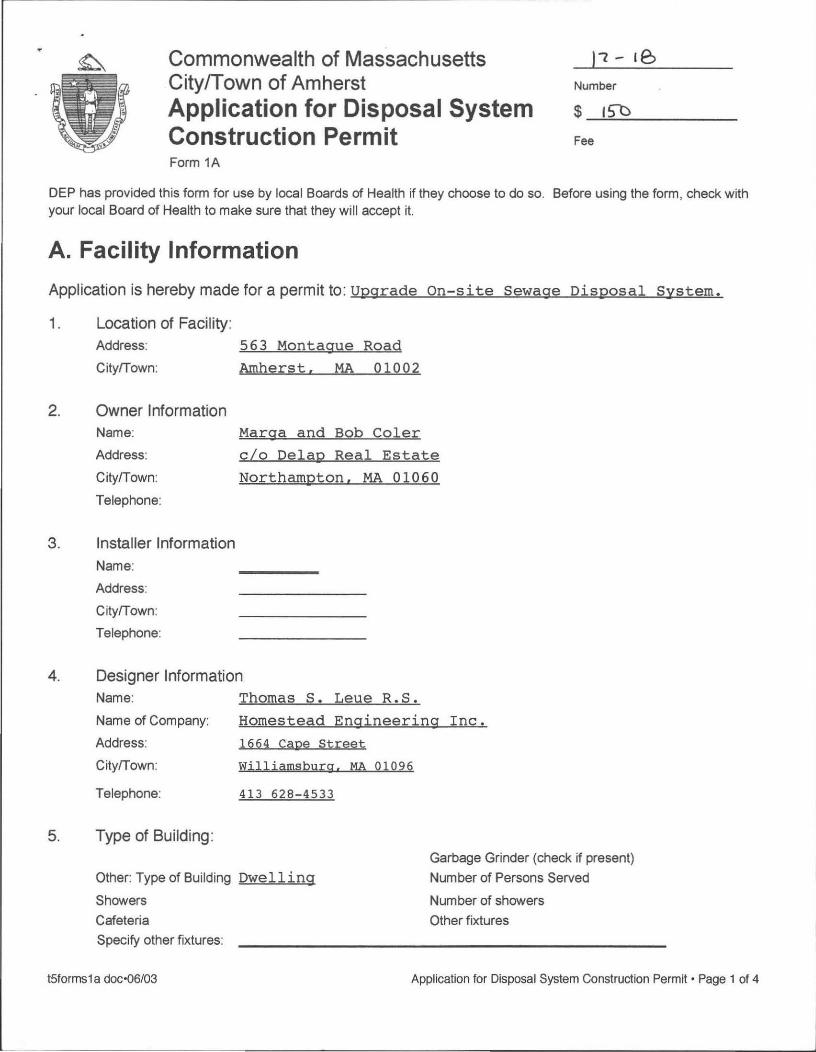
Commonwealth of Massachusetts City/Town of Amherst Application for Disposal System Construction Permit Form 1A
I' - Ie, Number
$ ISD
Fee
DEP has provided this form for use by local Boards of Health if they choose to do so, Before using the form, check with your local Board of Health to make sure that they will accept it.
A. Facility Information
Application is hereby made for a permit to: Upgrade On-site Sewag,
1, Location of Facility: Address:
Cityrrown:
2, Owner Information Name:
3,
Address:
Cityrrown:
Telephone:
Installer Information Name:
Address:
Cityrrown:
Telephone:
563 Montague Road
Amherst, MA 01002
Marga and Bob Coler
c / o Delap Real Estate
Northampton. MA 01060
4, Designer Information Name:
Name of Company:
Address:
Cityrrown:
Telephone:
5, Type of Building :
Thomas S. Leue R.S.
Homestead Engineering Inc.
1664 Cape Street
williamsburg, MA 01096
413 628-4533
.,... ~ff C")
N. 'h
N ~o
.,... ~i
~ 1l • '"
~ 1'1 ~
Other: Type of Building Dwelling
Showers
Garbage Grinder (check if present)
Number of Persons Served
Number of showers
Cafeteria Other fixtures
Specify other fixtures:
~;:
\ !Ul cG
~ '" ~ "'- " 'E tA ~
tSforms1 a doc'06/03 Appl ication for Disposal System Construction Permit· Page 1 of 4
.... r1"I n.J ....


CUST NAME 4 BOLTWOOD AVENUE 08/2 4 / 12 CITY, ST , ZIP
DE HEA017
15 0 . 00 J J POIRIE QUA CHECK
***TOWN OF A TOWN HAL AMHERST M REFERENCE DATE / TIME 10:28
o DEPT
CUST NAME
SEPTIC TAN 150.
RECPT TOTAL
AMOUNT 1231
130 PE


"
'p~ Sl,,'!' Kv,.)~C00e. ~; Desumed by ~CMp,<,. t':E~ ',,' cE:BcKLIST FOR SEPTIC PLANS· . ',
. , ,
r,·, ··. '
·'
, ..
~~~~2i~: . · ~~~~~~~fb~~, ,&!.&. ~~.', ... ~.' .::, r l!.b-' - - . . f ~-L:f-...J!::f'-~~..j...{C~~~~~~~~-,---.:,-...:....,:..c~-~--"'~~ . .. ,
;-bf~ ;'()USE '.pzrk. 6etAKJt~ T - ' , .•. - -.

Cell (413) 207-1737 ~ john~delaprealeslale.com ~Jap
REALESrATE delaprealestate,com
158 North King Street, Big Y Plaza Northampton, MA 0106(}.1120
John Poirier (413) 586-9111.104 ASsociate Broker Fax (413) 586-9112
Commonwealth of Massachusetts City/Town of Amherst Application for Disposal System Construction Permit Form 1A
)L - Ie, Number
$ 15D
Fee
DEP has provided this form for use by local Boards of Health if they choose to do so. Before using the form, check with your local Board of Health to make sure that they will accept it.
A. Facility Information
Application is hereby made for a permit to: Upgrade On-site Sewage Disposal System.
1. Location of Facility:
Address:
Cityrrown:
2. Owner Information
Name:
Address:
Cityrrown:
Telephone:
3. Installer Information
Name:
Address:
Cityrrown:
Telephone:
563 Montague Road
Amherst. MA 01002
Marga and Bob Coler
c/o Delap Real Estate
Northampton. MA 01060
4. Designer Information
Name:
Name of Company:
Address:
Cityrrown:
Telephone:
5. Type of Building:
Thomas S. Leue R.S.
Homestead Engineering Inc.
1664 Cape Street
williamsburg. MA 01096
413 628-4533
Other: Type of Building Dwelling
Showers
Garbage Grinder (check if present)
Number of Persons Served
Number of showers
Cafeteria Other fixtures Specify other fixtures:
t5forms1a doc·06/03 Application for Disposal System Construction Permit· Page 1 of 4


Form 1A
Commonwealth of Massachusetts City/Town of Amherst Application for Disposal System Construction Permit
A. Facility Information (continued)
6. Design Flow: 355 Galions per Day
Calculated Daily Flow: 330 Gallons
7. Plan: 80602 Date of Original
Number of Sheets -ll. Revision Date
Title of Plan: Plan to Uggrade Segtic System
8. Description of Soil:
fine sand
9. Nature of Repairs or Alterations (if applicable):
Number
$_-----
Fee
New segtic tank and infiltration chamber leachfield.
10. Date last inspected 4/6/12
B. Agreement The undersigned agrees to ensure the construction and maintenance of the aforedescribed onsite sewage disposal system in accordance with the provisions of Title 5 of the Environmental Code and not to place the system in operation until a Certificate of Compliance has been issued by this Board of Health .
. """~ J;T,' r;/ ~ Application Ap roved By:
Date I
Name Date
Application Disapproved for the following reasons:
t5forms1a doc'06/03 Application for Oisposal System Construction Permit· Page 2 of 4


Commonwealth of Massachusetts (2, I y;'
CitylTown of Amherst Number
No. t ,'l r
Application for Disposal System $
Construction Permit Fee
FORM 2A - DSCP
Fee
Co.M~o.MW!Eru:'1'1f OP 'M9f.SS91C1f'US!E'1''1'S Board of Health, Amherst, MA
DISPOSAL SYSTEM CONSTRUCTION PERMIT
Permission is hereby granted to : Upgrade an individual sewage disposal system at
/ <.7)
Y
563 Montague Road, Amherst as described in the application for Disposal System Construction Permit No._
dated 3'/1 (, Ii 2.-/ . rJ Provided: Construction shall be completed within three years of the date of this permit. All local conditions must be met.
Date ~h-o/~/z.. Board of Health I?z. dtlL~~
tSforms 1 a doc·06/03 Application for Disposal System Construction Permit· Page 3 of 4

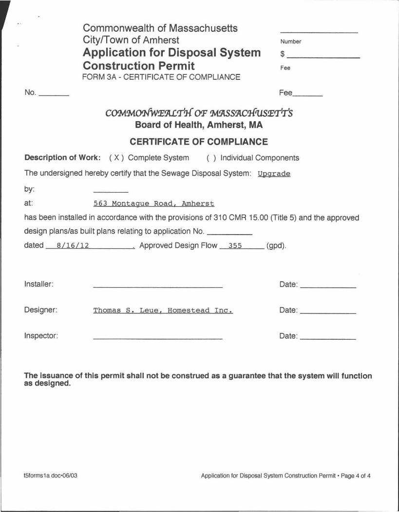
No. __ _
Commonwealth of Massachusetts City/Town of Amherst Application for Disposal System Construction Permit FORM 3A - CERTIFICATE OF COMPLIANCE
Number
$_-----
Fee
Fee __ _
C()tM!MWW!E9lLtT'l-f OP 'M9tSS!Ac'l-f'llS!EtTtTS Board of Health, Amherst, MA
CERTIFICATE OF COMPLIANCE
Description of Work: (X) Complete System ( ) Individual Components
The undersigned hereby certify that the Sewage Disposal System : Upgrade
by:
at: 563 Montague Road. Amherst
has been installed in accordance with the provisions of 310 CMR 15.00 (Title 5) and the approved
design plans/as built plans relating to application No. ____ _
dated 8/16/12 . Approved Design Flow 355 (gpd).
Installer: Date: _____ _
Designer: Thomas S. Leue. Homestead Inc. Date: _____ _
Inspector: Date: _____ _
The Issuance of this permit shall not be construed as a guarantee that the system will function as designed.
t5forms1 a doc'06/03 Application for Disposal System Construction Permit· Page 4 of 4


Commonwealth of Massachusetts City/Town of Amherst
Form 9A - Application for Local Upgrade Approval DEP has provided this form for use by local Boards of Health. Other forms may be used, but the information must be substantially the same as that provided here. Before using this form , check with your local Board of Health to determine the form they use.
Form 9A is to be submitted to the Local Board of Health for the upgrade of a failed or nonconforming septic system with a design flow of less than 10,000 gpd, where full compliance, as defined in 310 CMR 15.404(1), is not feasible.
System upgrades that cannot be performed in accordance with 310 CMR 15.404 and 15.405, or in full compliance with the requirements of 310 CMR 15.000, require a variance pursuant to 310 CMR 15.410 through 15.415.
NQIf;. Local upgrade approval shall not be granted for an upgrade proposal that includes the addition of a new design flow to a cesspool or privy, or the addition of a new design flow above the existing approved capacity of an onsite system constructed in accordance with either the 1978 Code or 310 CMR 15.000.
A. Facility Information
1. Facility Name and Address: Name: Marga and Bob Coler Street Address: 563 Montague Road, Amherst
2. Owner Name and Address (if different from above):
3.
4.
5.
6.
7.
Name: Marga and Bob Coler Address: c/o Delap Real Estate,
Northampton, MA 01060 Phone #
Type of Facility (check all that apply): X Residential
School Commercial Institutional
Other (specify) ______________ _
Describe Facility: single family dwelling
Type of Existing System: privy _ cesspool
-X. conventional system Other (specify) ______________ _
Type of soil absorption system (SAS) (trenches, chambers, pits, etc): leachfield
Design Flow based on 310 CMR 15.203:
Design for existing system:
Design flow of proposed upgraded system:
Design flow of facility:
unknown gpd(not verified)
355 gpd
330 gpd

Commonwealth of Massachusetts City/Town of Amherst
Form 9A - Application for Local Upgrade Approval DEP has provided this fOnTI for use by local Boards of Health. Other forms may be used, but the information must be substantially the same as that provided here. Before using this fOnTI, check with your local Board of Health to determ ine the form they use.
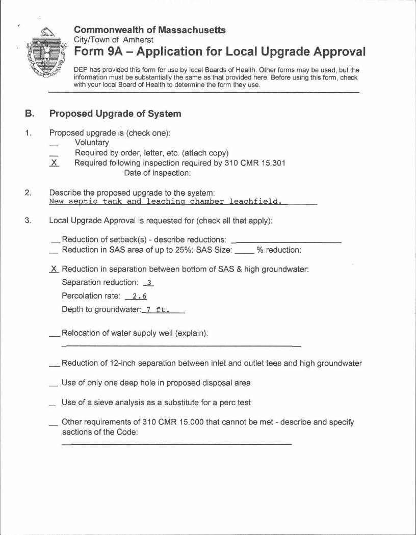
B. Proposed Upgrade of System
1. Proposed upgrade is (check one): Voluntary Required by order, letter, etc. (attach copy)
X Required following inspection required by 310 CMR 15.301 Date of inspection:
2. Describe the proposed upgrade to the system: New septic tank and leaching chamber leachfield.
3. Local Upgrade Approval is requested for (check all that apply):
_ Reduction of setback(s) - describe reductions: __________ _ _ Reduction in SAS area of up to 25%: SAS Size: __ % reduction:
X Reduction in separation between bottom of SAS & high groundwater:
Separation reduction: -l
Percolation rate: 2.6
Depth to groundwater: 7 ft.
_ Relocation of water supply well (explain):
_ Reduction of 12-inch separation between inlet and outlet tees and high groundwater
_ Use of only one deep hole in proposed disposal area
_ Use of a sieve analysis as a substitute for a perc test
_ Other requirements of 310 CMR 15.000 that cannot be met - describe and specify sections of the Code:


Commonwealth of Massachusetts City/Town of Amherst
Form 9A - Application for Local Upgrade Approval DEP has provided this form for use by local Boards of Health. Other forms may be used, but the information must be substantially the same as that provided here. Before using this form , check with your local Board of Health to determine the form they use.
B. Proposed Upgrade of System (continued)
If the proposed upgrade involves a reduction in the required separation between the bottom of the soil absorption system and the high groundwater elevation, an Approved Soil Evaluator must determine the high groundwater elevation pursuant to 310 CMR 15.404 (1 )(i)(1). The soil evaluator must be a member or agent of the local approving authority.
High groundwater evaluation determined by:
Evaluator's Name: Ed Smith
Evaluator's Signature: t&--(2 t..:;;;/;t~ Date of Evaluation: 7/31/12
C. Explanation
Explain why full compliance, as described in 310 CMR 15.404(1), is not feasible. (Each section must be completed)
1. An upgraded system in full compliance with 310 CMR 15.000 is not feasible: The purpose is to lower the repair costs in a economically
constrained situation.
2. An alternative system approved pursuant to 310 CMR 15.283 to 15.288 is not feasible: conventional system is sufficient.
3. A shared system is not feasible: Not necessary.
4. Connection to a sewer is not feasible: No public sewer in area.
5. The Application for Local Upgrade Approval must be accompanied by all of the following (check the appropriate boxes): X Application for Disposal System Construction Permit X Complete plans and specifications X Site evaluation forms
A list of abutters affected by reduced setbacks to private water supply wells or property lines. Provide proof that affected abutters have been notified pursuant to 310 CMR 15.405(2). _ Other (List):


Commonwealth of Massachusetts City/Town of Amherst
Form 9A - Application for Local Upgrade Approval DEP has provided this form for use by local Boards of Health. Other forms may be used, but the information must be substantially the same as that provided here. Before using this form , check with your local Board of Health to determine the form they use.
D. Certification
"I, the facility owner, certify under penalty of law that this document and all attachments, to the best of my knowledge and belief, are true, accurate, and complete. I am aware that there may be significant consequences for submitting false information, including, but not limited to, penalties or fine and/or imprisonment for knowing violations."
Marga and Bob Coler Print Name
Thomas S. Leue, Homestead Inc. 8116/12
1664 Cape Street, Williamsburg, MA 01096 (413) 628-4533 Address and Telephone Number of Preparer
_ l)pgmde !-umuJoc "rev . 7/06 l\PtJiicatinf) !or LOCal U l(jr;:::l.de Approva! • ~aQe 4 ul 4


Plan to Upgrade SEPTIC SYSTEM
for
Marga and Bob Coler Located at
563 Montague Road Amherst, MA 01002
Design Date: Updated:
Contents - Site Plan:
Perc Test Forms: Specification Requirements System Calculations: Plan Drawing:
Plan Number 594
8/16/12
1 pages 5 pages 3 pages 1 page 1 page
$eparate Application for Construction Permit: Local Upgrade Approval:
4 pages 3 pages
Septic System Designer: Thomas S. Leue R.S.
Homestead Inc. 1664 Cape St.
Williamsburg , MA 01096 (located in Ashfield)
413 628-4533 800 285-4533
fax: 413 628-3973
email: [email protected]

•• AT&T 4G 1:17 PM 89 '. ~~.
gis.amherstma.gov/publicN iewer.aspx
Andy Nuciforo fa •••
I \/: _ ,,' "-..r-.. ~.1.'" .... -/.~ MAS-5J.;CHUS .ETTS ..... ~ ......... :.,.
~~ Property M.p I:
El~E1 •• ~Ij)Elf)
I More Maps Here --::: a Go
·i
r"\ r<"". r '''' " \.--~Ii 'v'
Daily Digest 7130 ••• GIS Property Sea ••• X Property Vaewer
£1IU! . ~: :.,tUt:.L~!J IhlE.'¥~
~J4HeRST MAPS ...... " ,t Size
Help Scale 1- = ~ ft
6 gO.xv ~ = .. ' Parcel Address Land Use
j: 2A-I7 563 MONTAGUE RO Single Familv
! .! 1 selected To Mailing Labels To Spreadsheet
~ ~ -;.:.::v-;' ~".:, . ~ P';' ,;;;:~i' ::::=c=~
\ \
. __ .. s",av~.J as Imagt: a
, , , , I
!
2A-17 I 563 MONTAGUE RD
Parcel lA -I7
Owner COLER. ROB ERT A & MARGA UFE ESTATE
Assessment $233,000.00 (FY12)
$250,800.00 (FYll)
Landuse Single Familv (10lC )
Primary Zone RO (Dimensional Regulations)
Neighborhood NORTH AMHERST
Town Hall I 4 Bollw(aOd Avenue J Amhcr!>t MA 01002
41 3· 259' )247 41 ].256. 40Q6
\

Commonwealth of Massachusetts Cityrrown of Amherst Form 11 - Soil Suitability Assessment for On-Site Sewage Disposal
Site Address: 563 Montague Road. Amherst
DEP has provided this form for use by on-site professionals and local Boards of Health. Other forms may be used, but the information must be substantially the same as provided here. Before using this form, check with your local Board of Health to determine the form they use.
A. Facility Information 1. Facility Information
Marga and Bob Coler Owner Name
563 Montague Road Street Address Amherst MA 01002
B. Site Information
:') ' ''A 8,'1 MapILot \ v-Y ( ~ \ .1- - " 'r
1. (Check one) New Construction 0 Upgrade.
2. Published Soil Survey available? L Yes No If yes:
Repair 0 1967 15840 59 Year Published Publication Scale Soil Map Unit
CrC Charlton-Hollis fine sandy loam. rocky. 3-15% slopes Moderate limitations: ~ Soil Name
Comment: 3. Superficial Geological Report available? L Yes
glaciated Geologic Material
4. Flood Rate Insurance Map:
No If yes:
upland Landform
Above the 500 year flood boundary? -L Yes No
Within the 500 year flood boundary?
5. Wetland Area: National Wetland Inventory Map
Wetlands Conservancy Program Map
6. Current Water Resource Conditions (USGS)
7. Other references reviewed:
Yes -L No
Map Unit
Map Un~
MonthNear
Soil limitations
1980 1:190.080 _ __ 6 _ _ _ _
Year Published Publication Scale Map Unit
Within the 100 year flood boundary? Yes .1L No
Within a Velocity Zone? Yes .1L No
Nam-e--
Name
Range: Above Normal Normal_X_ Below Normal
DEP Fonn 11 Soil Suitability Assessment for On-Site Sewage Disposal' Page 1 of 5

Commonwealth of Massachusetts CitylTown of Amherst
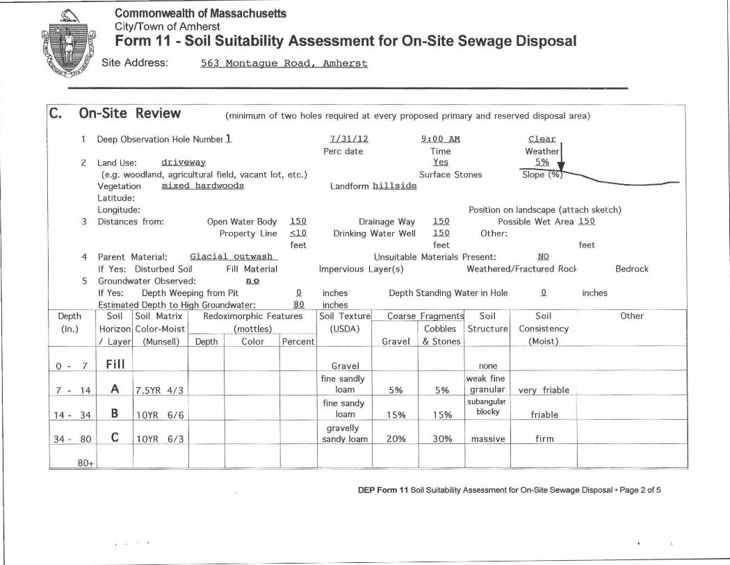
Form 11 - Soil Suitability Assessment for On-Site Sewage Disposal Site Address: 563 Montague Road. Amherst
-- -c. On-Site Review (minimum of two holes required at every proposed primary and reserved disposal area)
1 Deep Observation Hole Number 1 1U1Ll2 9:00 A!:I ~ Perc date Time Weather
2 Land Use: driveway fu ~ , (e.g. woodland, agricultural field, vacant lot, etc.) Surface Stones Slope \'7'.
Vegetation mixeg bS\rdwQods Landform hillside Latitude: Longitude: Position on landscape (attach sketch)
3 Distances from: Open Water Body 150 Drainage Way 150 Possible Wet Area .l..5.Q
Property Line <10 Drinking Water Well .l..5.Q Other: feet feet feet
4 Parent Material: ~lgQjgl Qutwash Unsuitable Materials Present: NO
If Yes: Disturbed Soil Fill Material Impervious Layer(s) Weathered/ Fractured Rod Bedrock 5 Groundwater Observed: !l.Q
If Yes: Depth Weeping from Pit Q inches Depth Standing Water in Hole Q inches Estimated Depth to Hiqh Groundwater: Jl.Q inches
Depth Soil Soil Matrix Redoximorphic Features Soil Texture Coarse Fraqments Soil Soil Other
(In.) Horizon Color-Moist (mottles) (USDA) Cobbles Structure Consistency
/ Layer (Munsell) ~pth Color Percent Gravel & Stones (Moist)
o - 7 Fill Gravel none
fine sandly weak fine 7 - 14 A 7.5YR 4/3 loam 5% 5% granular very friable
fine sandy 5ubangular
14 - 34 B 10YR 6/6 loam 15% 15% blocky friable , i
C gravelly
34 - 80 10YR 6/3 sandy loam 20% 30% massive firm
80+ --- -- - --- - - ---- -----
DEP Fonn 11 Soil Suitability Assessment for On-Site Sewage Disposal· Page 2 of 5

Conimonwealth of Massachusetts CityfTown of Amherst
Form 11 - Soil Suitability Assessment for On-Site Sewage Disposal Site Address: 563 Montague Road. Amherst
c. On-Site Review (minimum of two holes required at every proposed primary and reserved disposal area)
1 Deep Observation Hole Number 1 ZLJlL12 2;QO AM ~
Perc date Time Weather 2 Land Use: <1<:.', \J l?,(}.JoJj \f e<;, ~
(e.g. woodland, agricultural field, vacant lot, etc.) Surface Stones Slope (%) Vegetation l)I.iXtV ~\)IOOO~ Landform hillside Latitude: Longitude: Position on landscape (attach sketch)
3 Distances from: Open Water Body .uQ Drainage Way .l.2Q Possible Wet Area .uQ Property Line 70 Drinking Water Well 150 Other:
feet feet feet 4 Parent Material: GlaciSll till Unsuitable Materials Present: NQ
If Yes: Disturbed Soil Fill Material Impervious Layer(s) Weathered/Fractured Rod Bedrock 5 Groundwater Observed: .!l.Q
If Yes: Depth Weeping from Pit Q inches Depth Standing Water in Hole Q inches Estimated Depth to High Groundwater: 72 inches
Depth Soil Soil Matrix Redoximorphic Features Soil Texture Coarse Fraqment! Soil So il Other
(In.) Horizon Color-Moist (mottles) (USDA) Cobbles Structure Consistency
/ Laver (Munsell) Depth Color Percent Gravel & Stones (Moist) -
o - 7 Fill Gravel none fine sandly weak fine
7 - 14 A 7.SYR 4/3 loam 5% 5% granular very friable
fine sandy subangular
14 - 34 B 10YR 6/1 loam 15% 15% blocky friable
C gravelly
34 - 72 10YR 6/3 sandv loam 20% 30% massive firm
DEP Fonn 11 Soil Suilabilily Assessment for On-Site Sewage Disposal· Page 3 of 5

Commonwealth of Massachusetts CityfTown of Amherst
Form 11 - Soil Suitability Assessment for On-Site Sewage Disposal Site Address: 563 Montague Road, Amherst
D. Determination of High Groundwater Elevation
1. Method used: Depth observed standing water in observation hole A. inches B. inches
Depth weeping from side of observation hole A. inches B. inches
Depth to soil redoximorphic features (mottles) A inches B. indles
Groundwater adjustment (USGS methodology) A. inches B. inches
2. Index Well Number _______ _ Reading Date Index Well Level
Adjustment Factor Adjusted Groundwater Level ,----.,-__ ",---,----: _ _ No mottles seen : depth of refusal found at 80 inches in observation hole A, 72 inches at observation ho le B.
E. Depth of Pervious Material 1. Depth of Naturally Occurring Pervious Material
a. Does at least four feet of naturally occurring pervious material exist in all areas observed throughout the area proposed for the soil absorption system? ... Y.,.e",s,-_ _
b. If yes, at what depth was it observed? Upper boundary: 14 Min. inches Lower boundary: 80 Max. im,hes
F. Certification I certify that I am currently approved by the Department of Environmental Protection pursuant to 310 CMR 15.017 to conduct soil evaluations and that the above analysis has b~ performed by me consistent with the required training , expertise and experience described in 310 CMR 15.017. I further certify that the results of my soi~!9" , as indicated,-iR-the/attached Soil Evaluation Form, are accurate and in accordance with 310 CMR 15.100 through 15.107.
Signature of Soil Evaluator
Thomas S. Leue SE 1368 Typed or Printed Name of Soil Evaluator/license Numbe
Ed Smith Name of Board of Health wtness
7/31/12 Date
June 1995 Date of So~ Evaluator Exam
Town of Amherst Board of Health
Note: In accordance with 310 CMR 15.018(2) this form must be submitted to the approving authority within 60 days of the date of field testing , and to the designer and the
DEP Fonn 11 Soil Suitability Assessment for On-Site Sewage Disposal' Page 4 of 5

I. General
CONSTRUCTION SPECIFICATIONS 563 Montague Road, Amherst
Title 5 Septic System Plan Number 594
a. No work on this system construction shall take place until a permit for the approved system plan has been received from the local Board of Health. A copy ofthe Disposal Works Construction Pennit should be on site for inspection during the time of construction. Additional specifications may be included elsewhere in this design.
b. Loading requirements are specified for the septic tank on the system calculations page. Loading requirements for any other component are on the drawing. Normal loading systems are designated H-IO. If H-20 rating is specified on the drawing and/or on the page for system calculations, the tank or leaching facility shall be custom built to meet the increased loading requirements using additional rebar, greater wall thickness and/or other approved methods. Follow the manufacturer's rating system and installation procedures.
c. Alternatives to these specifications should be discussed with the System Designer in advance at 800 285-4533.
2. Septic Tank
a The septic tank selected by the contractor shall confonn with 310 CMR 15.223. The septic tank shall be a minimum effective liquid capacity of 1,500 gallons below the outlet invert, rectangular, and with a minimum length to width ration of 1.5: 1. Liquid depth to be 48". Compartmentalized tanks are not to be used.
b. Septic tank shall be installed on a minimum of 6" of crushed stone, leveled to grade and thoroughly compacted. Septic tanks shall have a minimum cover of 9". No structures shall be located directly upon or above the septic tank access locations which interfere with perfonnance, access, inspection, pumping, or repal[.
c. All tlrree access covers to the septic tank shall have risers at least 20" diameter, if round, tightly fitted to the tank to resist water infiltration, and tenninated with a tight fitting cover no more than 6" below ground surface. If, with the agreement of the Owner, one or more of the risers are tenninated flush with ground, these shall be secured against unauthorized entry with stainless steel hardware.
d. Inlet and outlet tees shall be of Schedule 40 PVC and shall extend a minimum of 6" above the flow line of the septic tank and be on the center line of the septic tank located directly under the clean-out manhole. All fittings to be glued and secured against any movement due to horizontal or vertical impacts. Cross-sectional flow baffles shall not be used as substitutes for inlet or outlet tees. The inlet pipe elevation shall be no less than 2" nor more than 3" above the invert elevation of the outlet pipe. Inlet tee minimum of 10" length below water surface. The outlet shall be provided with a tee extending below the flow line 14" and be equipped with a gas baffie. There shall be an air space of at least 3" between the tops of the tees and the inside of the tank cover. Inlet tees may be modified or a 6" riser on inlet cover may achieve this spacing. The tops of the tees shall be left open to provide ventilation or separate ventilation shall be provided. The effiuent tee shaH be fitted with a removable plastic outlet filter, as manufactured by Polylok Inc., model PL-120, Zebco, or approved equal. Provide manufacturer's maintenance data, as boxed with the filter, to the homeowner or the System Designer.
Homestead Inc. Page 1 8116112,

CONSTRUCTION SPECIFICATIONS 563 Montague Road. Amherst
e. Septic tank should be inspected by the Owner or his representative for solids accumulation annually. When the sum of the sludge and scum layer approach 114 the net working volume of the tank (net of 12" total thickness), as measured at the center of the tank, the tank is due for pumping. Septic tanks shall be inspected and maintained in accordance with 310 CMR 15.300 and applicable local requirements.
3. Distribution Box a The distribution box selected by the contractor shall conform with 310 CMR 15.232. Material of
construction shall be concrete or plastic lined concrete. A 6" sump is required in the d-box. b. The distribution box shall be placed on thoroughly tamped and compacted sand or peastone a minimum
of 6" thickness, and shall be leveled utilizing a water flow test. Speed levelers shall not be used on a new installation to obtain level and equal distribution flow, but should be installed after leveling is completed in case uneven settling occurs in the future.
c. For inlet pipe slopes of 5% or greater, or where there is a pumped flow, the distribution box shall have an internal cast baffle or solvent welded pipe tee to reduce the velocity of the influent flow. An internal pipe "Y" or an elbow are not acceptable.
d. The first 2 feet of pipe out ofthe distribution box to be set dead level. Use a fernco connector to join to pitched pipes beyond first two feet.
e. A riser to grade is required on distribution boxes buried more than 9 inches below grade.
4. Piping a. Piping to the septic tank (the building sewer) shall be 4" diameter, PVC Schedule 40 or better. Slope new
pipe installations at 114" per foot length. b. All piping from the septic tank to the end of the system shall be 4" diameter, SDR-35 or better, except
as noted on the drawings. Slope pipe installations 1/8" per foot length as a minimum value. c. Place magnetic detectable warning tape pre-printed "Sewer Pipe Below" or similar wording
approximately 12" above all new 4" diameter piping installed on this project.
5. Leaching Facilities a. General: All leaching facilities to be of the size and location shown on the drawings. b. Leach fields (Infiltration chambers): Arrange infiltration chambers on levelled ground. Parallel rows
should be placed a minimum of6" apart. Add end plates as per manufacturer's assembly directions. Fill spaces between rows with Title 5 sand to the level of the top of the chambers.
c. All fill materials used on this project within five feet of the leaching chambers to be certified Title 5 sand, including any fill materials under chambers, between chambers and to the level of the top of the chambers.
d. A reasonably current copy of the certification from the sand supplier is required to be submitted to the System Designer before the conclusion of this project.
e. Breakout barrier, where required, to be minimum 40 mil thick continuous sheet. Install barrier vertically from bottom of excavation to height of top of leaching system. Seams of membrane material to be overlapped a minimum of 12 inches and glued with sealant as recommended by manufacturer. Material to be hypolon, low density polyethylene, buna-N rubber, EPDM, or approved equal. Backfill in lifts of no more than 6" to assure minimal deformation of membrane. If material is wider than the vertical distance to be covered as shown on the drawing, fold excess material over at the bottom of the trench, or trim with upper
Homestead Inc. Page 2 8116112,

CONSTRUCTION SPECIFICATIONS 563 Montague Road. Amherst
edge level at appropriate elevation.
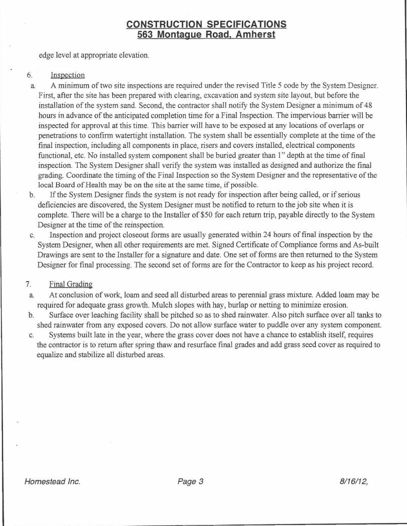
6. Inspection a. A minimum of two site inspections are required under the revised Title 5 code by the System Designer.
First, after the site has been prepared with clearing, excavation and system site layout, but before the installation of the system sand. Second, the contractor shall notifY the System Designer a minimum of 48 hours in advance of the anticipated completion time for a Final Inspection. The impervious barrier will be inspected for approval at this time. This barrier will have to be exposed at any locations of overlaps or penetrations to confirm watertight installation. The system shall be essentially complete at the time of the final inspection, including all components in place, risers and covers installed, electrical components functional, etc. No installed system component shall be buried greater than I" depth at the time of final inspection. The System Designer shall verifY the system was installed as designed and authorize the final grading. Coordinate the timing ofthe Final Inspection so the System Designer and the representative of the local Board ofHealtb may be on the site at the same time, if possible.
b. If the System Designer fmds the system is not ready for inspection after being called, or if serious deficiencies are discovered, the System Designer must be notified to return to the job site when it is complete. There will be a charge to the Installer of $50 for each return trip, payable directly to the System Designer at the time of the reinspection.
c. Inspection and project closeout forms are usually generated within 24 hours of final inspection by the System Designer, when all other requirements are met. Signed Certificate of Compliance forms and As-built Drawings are sent to the Installer for a signature and date. One set of forms are then returned to the System Designer for final processing. The second set of forms are for the Contractor to keep as his project record.
7. Final Grading a. At conclusion of work, loam and seed all disturbed areas to perennial grass mixture. Added loam may be
required for adequate grass growth. Mulch slopes with hay, burlap or netting to minimize erosion. b. Surface over leaching facility shall be pitched so as to shed rainwater. Also pitch surface over all tanks to
shed rainwater from any exposed covers. Do not allow surface water to puddle over any system component. c. Systems built late in the year, where the grass cover does not have a chance to establish itself, requires
the contractor is to return after spring thaw and resurface final grades and add grass seed cover as required to equalize and stabilize all disturbed areas.
Homestead Inc. Page 3 8/16/12,

Location Address or Lot No. Homestead Inc. # :
FORM 12 - PERCOLATION TEST
563 Montague Road Amherst 594
COMMONWEALTH OF MASSACHUSETTS Amherst, Massachusetts
Percolation Test*
Date: 7/3 1/ 12 Time: ' 9:46 AM
Observation Hole # 1 2 3 4 ~ - -
Depth of Perc: (in .) 28 Qn':h~s.L
Start Pre-soak: 9:46 AM ~ ~~~
End Pre-soak : 10:01 AM ._._ .. -
Time at 12": 10:01 AM .- -~
Time at 9" : 10:06 AM ~ -
Time at 6" : 10:1 3 AM I -----
Time (9" - 6") : 0:07:45 ~- .- -
Rate - Min.llnch: 0:02:35
• Minimum of 1 percolation test must be performed in both the primary area AND reserve area.
Site Passes / Site Fails: Passes
Performed By:
Witnessed By:
Comments:
Thomas S. Leue. Homestead Inc.
Ed Smith. Amherst
DEP APPROVED FORM - 12/07/95

563 Montague Road DESIGN CALCULATIONS
Amherst Plan Number 594
Leaching Chamber type Leach Bed System Structure: Single Family House
Flow Design Criteria :
Ca lc. Design Flow:
Garbage Grinder: Not Allowed Total Design Flow: Percolation Rate:
Percolation Rate:
Loading Rate:
Area required for infiltration:
Measured
Design Rate
Class I SOil
Field Size Reduction Variance Application:
Net Field Size:
Bed Configuration: Model Used:
Effective Leaching Area:
Length per chamber:
Width per chamber:
Invert height:
Overali height: Leaching area/chamber:
# Chambers required:
# Chambers provided: # field provided:
# rows wide: space between rows:
Total Field Width: # Chambers long:
Total Field length: Total Field Area:
Effective Leaching Area :
Net Calculated Capacity:
Loadin>!:
Homestead Inc.
Info Source 3 bedrooms Owner's information
110 galions per bedroom per day 310 CMR 15.203 330 gallons per day 1.0 factor
330 gallons per day 2.3 min. per inch
2 min. per inch
0.74 gallons/sq.ft./day
446 sq. ft.
Z.O%
437 sq. ft.
multiply above
310CMR 15.240 multiply above from perc test
310CMR15.105
310 CMR 15.242
divide flow by loading rate 310 CMR 15A04(Zdl
multiply above
I 'nfi'trator Systems Inc.
I High Capacity H-20 Manuf. Trade Name 7.79 sq ft/ ln ft PEP technology ratings
75 inches Manyfacturer's size 34 inches
11 inches
16 inches
48.7 sq ft 9.0
9 1
3 Z inches
8.83 feet
3 18.75 feet ea.
165.6 sq. ft.
438.2 sq. ft. 331 gals/day
H-ZO
Manyfacturer's size
Manufacturer's size
Manufacturer's size
length x leaching area
field size divided
by leachjng area iudgement judgement
average chambers ± spacing
judgement length of assembly
length X wjdth # chambers X rating
area X loading rate
judgement
8116112


, , INFILTRATION CHAMBERS INSTALLATION INSTRI.ICTIONS. 1. Excavate and level field area to depth of excavation . 2. Prepare fie ld area in accordance with 310 CMR 15.00. Add Title 5 sand to depth of Field Base specified . 3. Snap chamber end with integral splash plate into inlet end of first Infiltrator chamber wtth s~ash plate extending into chamber. Secure end plate with two or more stainless screws. 4 .• Place first unit in the inlet end of trench wtth interlocks downstream. 5. Run distribution pipe through inlet opening in end plate but not beyond splash plate. A single screw to be used to hold in place. Pipe does not normally run the length of system. 6. 'Connect Infinrator chambers together. fully engaging interlocks to form desired field length. Be sure to check all grades with a level or surveying equipment. Secure sections with three or more screws each. 7. Screw closed end plate in downstream end of last chamber. 8 . Space parallel rows 2" apart in field configuration. Space between rows. surrounding rows. and to the level of the top of the rows to be filled with Title 5 sand. 9 . "Walk" sand fill into place to give proper support of sides. THIS IS VERY IMPORTANT TO ACHIEVE FULL STRENGTH 10. Backfill to a minimum of 12" cover after compaction and settling for H-10 chambers and 16" for H-20 chambers. Avoid large rocks in the backfill material. CAUTION - Avoid vehicular traffic on system during construction since soil has not settled. This is particularly important in sand. since loose sand offers very little structural support.
~ Existing Leachfield, approximate location. remove all pipes, contaminated media plus one foot additional uncontaminated media in all directions, including belOW system.
I I I
Inspection
\ \.
\ ,,0. \ \
\ \
Install top 8" of parking area and driveway with TRG media. compacted and smoothed.
Use quality topsoil fill over non-parking areas.
99 _5 -- . ~==--~~.::- '- porch
.- .--- '----95 4 .........--
Town water in
CONSTRUCTION NOTES 1 . Board of Health approval required before licensed contractor installs system. Obtain Disposal Works Permit. 2. Notify engineer at least 24 hours in advance of completion of excavation and before addition of sand to certify site preparation. 3. Notify engineer at least 24 hours in advance of completion of system construction and prior to backfill for final inspection. 4 . All construction to be in accordance with Title 5 of the State Environmental Code. 5. At conclusion of work, loam and seed all disturbed areas to perennial grass mixture. Added loam may be required for adequate grass growth. 6. Contractor responsible for verifying all dimensions, elevations and conditions. Contact engineer immediately if discrepancies are found. 7. Property lines are apprOXimate, based on best available information. 8. Any required tree cutting is the responsibility of the Contractor. 9. See attached Specifications for additional requirements. 1 D. System not designed for a garbage grinder. Do not connect one to the system. 11. All drain pipes from greywater and blackwater sources are to be connected to the building sewer in the basement.
"- --'- Partial House Outline
12. All wells within 150' of system are, shown on the drawing.
I I
Existina Septic Tank : pump, remove as required.
i..-Schedule 40 sewer pipe.
I I I I
Variances Applied For:
New Leachfield: Infiltrator High Capacity H-2D ' '. 12- - lo~{q- -r-.J--'-~'~,1 New 1,500 gallon Title 5 Chambers. 3 rows,-3...?t:..ambersper row. Ventllated.~ . * h ( " ',,-- _-L--, septictankw~houtletfiler. I
\ 10' <'---
3 foot separation to groundwater.
310 CMR 15.405 (h)
¢ NORTH
- __ \. \ Ie _- - -- . - ....... ____ I -- _ \ .,.... ~ I
Remote Vent. see Detail. -- "'._ .- ._ ._ . _ __ '- I _ \ (' '- Schedule 80Pipe:- - Abandoned Cesspool: crush and backfill. I
100..00'
Note: Field installed in native soil. Do not over-excavate.
- - ,-- .... ---.. I ----\_ .......... ----- "'.. _ . I
~. I .r-,. ng.SurtElev · 95.9=:.-::-~.-= ~~ _.- . I , 98 ~1_ : i ---- - - - I
./ 87 86 . 9 1 o;;V"way- _ :::-- ---- _____ I --- ! I lIS ~PL - ,"-. .,~ - - - _ ..:::-- ____ I
/ " ! 84 ~-- ---~~ I ---------- -- \ 1 ... 1 --
PL
-:---. --------~ '=-- -
ground surface SYSTEM PROFILE
-_/
L native loam to cover
~ .:t-____ __ ____ 't:: _________ ~ot_~~~~al~ _______________ ~ _______ 'VC ________ , ___ 15' _____ , 1: 3
1
side slope -- ) - ----- -
\
1
1
1
I I
)
~ - + ~ Infiltration Chamber --- __ g 6" washed stone '.~ . '-"" ~ under tanks " .• ___
NVERT HEIGHTS & ELEVATIONS: D-box Excavat~1 Field Base >1 Inlet Inv. Final Height of SHWT Depth to Orig.
Infiltration Chamber Leachfield: Design based on Infiltrator Brand chamber by Infiltrator Systems
Inc. Use only the model number specified. Contact System Designer for field sizing if other brand
is to be used for this project. Use Title 5 sand for all fill requirements under units, between rows
of units, to the level of the top of the units, and within 5 feet surrounding units.
Bldg. out Septic in Septic out In: 93.2
96.1 95.8 9S.S Out: 93.0
·Sewer: House to Septic Tank: 12ft.
SePtic Tank to D-box: 42 ft.
Plan to Repair Septic System
Scale: 1 : 20'
Except as Noted
Date: 8/16/2012
Revision Date:
18" soil 92.0 93.0 Surface
Field size for Infiltrator High Capacity: 95.0
Chambers per Row: 3 Length:
Number of Rows: 3 Width:
Owner: Marga and Bob Coler
563 Montague Roa.o---j Amherst, MA 01002
Gndwater
89.0
183/4 '
87/8 '
Separation Gndwater Contour
3 ft. 72 in.
HOMESTEAD INC. Thomas S. Leue RS.
1664 Cape SI. Williamsburg, MA 01096
1413J 628-4533
95.0
LEGEND
$ Perc Test location & #
-eg Deep Hole location & #
_ .- ._-- Original contour
-------- Revised contour
Indicates perf. pipe
Indicates solid pipe
• Well location I PL = Property Line
Remote Vent Scale ' ": 10'
36" height above grade
n:=screened Outlet 4" Sched. 40 ABS p'pe
9" bury depth, minimum
1 cu.ft. concrete mix.
Length : Min. 5', Max: 20'
From Invert Height of Chambers.

· '

Plan to Upgrade SEPTIC SYSTEM
for
Marga and Bob Coler Located at
563 Montague Road Amherst, MA 01002
yontents Site Plan: Perc Test Forms:
Design Date: Updated :
Specification Requirements System Calculations: Plan Drawing:
Plan Number 594
8/16/12
1 pages 5 pages 3 pages 1 page 1 page
Separate Application for Construction Permit: Local Upgrade Approval :
4 pages 3 pages
Septic System Designer: Thomas S. Leue R.S.
Homestead Inc. 1664 Cape St.
Williamsburg, MA 01096 (located in Ashfield)
413 628-4533 800 285-4533
fax: 413 628-3973
email : [email protected]

.. AT&T.fG 1.17 PM ~9 "",'
Andy Nuciforo JO •••
\
\ \
63 -,
\ ~
~ '.. ".
\ ~ \ ~
'\
gis.amherstma.gov/publicNiewer.aspx
/'
\"
\ \
Daily DigesH 130 ••.
" ,;
\ \ \ ~x:
/" : .. "", \ /~ ..
Property Sea... . X Property Voewer
-, ..... . . 1,;
Pllreel Address u.nd Use
lA-17 563 MONTAGUE RO Single Fami ly
, I '-- 1 selected To Mailing Labels. T~ _~preadsheet ____ _
! If Property l' Salc~ Pt.''-nll',~:-~~~~hbo~tu,l~~
, , i i
I!
211.·17 I 563 MONTAGUE RD
Parcel 2A-I7
Owner COLER, ROBERT A & MARGA UFE ESTATE
Assessment $233,000.00 (FY12)
$250,800.00 (FYU)
Landuse Single Family (1010)
Primary Zone RO (Dimensional Regulations)
I Neighborhood NORTH AMHERST
L. _ _ _______________________ ~
TOW I1 H " II J 4 Bo ilwoOO Ave nue! ArIl twrst M A 01 0 02
511- 259-3247 ' _ 413-256-4006 :::: -',1 ,.
+

, Commonwealth of Massachusetts City/Town of Amherst
Form 11 - Soil Suitability Assessment for On-Site Sewage Disposal Site Address: 563 Montague Road, Amherst
DEP has provided this form for use by on-site professionals and local Boards of Health. Other forms may be used, but the information must be substantially the same as provided here. Before using this form, check with your local Board of Health to determine the form they use.
A. Facility Information 1. Facility Information
Marga and Bob Coler OWner Name 563 Montague Road Street Address Amherst MA 01002
R Site Information 1. (Check one) New Construction D upgrade.
2. Published Soil Survey available? l Yes No If yes:
Repair D 1967
;'1 ' " A 8,'''' Ma!>'lot r v"\", ,, \ .1- - I~ 'r
15840 59 Year Published Publication Scale Soil Map lJn~
CrC Charlton-Hollis fine sandy loam. rocky, 3-15% slopes Moderate limitations: Slo£~ Soil Name
Comment: 3. Superficial Geological Report available? l Yes
glaciated Geologic Material
4 . Flood Rate Insurance Map:
No If yes:
upland Landform
Above the 500 year flood boundary? -1L Yes No
Within the 500 year flood boundary?
5. Wetland Area: National Wetland Inventory Map
Wetlands Conservancy Program Map
6. Current Water Resource Conditions (USGS)
7. Other references reviewed:
Yes lNo
Map Unit
Map Un~
MonthNear
Soil limitations
1980 1:190,080 ___ 6. ___ _
Vear Published Publication Scale
Within the 100 year flood boundary?
Within a Velocity Zone?
Name
Name
Map Unit
Yes -1L No
Yes l No
Range: Above Normal _ Normal --2L.. Below Normal
DEP Fonn 11 Soil Suitability Assessment for On-Site Sewage Disposal' Page 1 of 5
Commonwealth of Massachusetts CityfTown of Amherst
Form 11 - Soil Suitability Assessment for On-Site Sewage Disposal Site Address: 563 Montague Road. Amherst
C. On-Site Review (minimum of two holes required at every proposed primary and reserved disposal area)
Deep Observation Hole Numbe. 1 UJI L12 2;QQ AM ~
Perc date Time Weather Z Land Use: driveway fu ~
(e.g. woodland, agricultural field , vacant lot, etc.) Surface Stones Slope \% Vegetation mixed. hardwoQQ.Q Landform hillside Latitude: Longitude: Position on landscape (attach sketch)
3 Distances from: Open Water Body .liQ. Drainage Way .liQ. Possible Wet Area liQ
Property Line 5lQ Drinking Water Well .liQ. Other: feet feet feet
4 Parent Material: Gla~ial outwash Unsuitable Materials Present: NQ If Yes: Disturbed Soil Fill Material Impervious Layer(s) Weathered/Fractured Rod Bedrock
5 Groundwater Observed: no
If Yes: Depth Weeping from Pit Q inches Depth Standing Water in Hole Q inches Estimated Depth to Hiqh Groundwater: 80 inches
Depth Soil Soil Matrix Redoximorphic Features SOil Texture Coarse Fraqment Soil Soil Other
(In.) Horizon Color-Moist (mottles) (USDA) Cobbles Structure Consistency
/ Laver (Munsell) Depth Color Percent Gravel & Stones (Moist)
o - 7 Fill Gravel none
fine sandly weak fine 7 - 14 A 7.5YR 4/ 3 loam 5% 5% granular very friable
fine sandy subangular ,
I
14 - 34 B 10YR 6/6 loam 15% 15% blocky friable , •
C gravelly
34 - 80 10YR 6/3 sandy loam 20% 30% massive firm
80+ - --- --- -- - -_._- --- . -
DEP Fonn 11 Soil Suitability Assessment for On-Site Sewage Disposal' Page 2 of 5
I
,

· Commonwealth of Massachusetts CitylTown of Amherst
Form 11 - Soil Suitability Assessment for On-Site Sewage Disposal
Site Address: 563 Montague Road, Amherst
C. On-Site Review (minimum of two holes required at every proposed primary and reserved disposal area)
Deep Observation Hole Number 1 101L12 2;QQ l\!1 ~ Perc date Time Weather
2 Land Use: (k\ \J e..O.JcU/ \j e.<, ~ (e.g. woodland, agricultural field, vacant lot, etc.) Surface Stones Slope (%)
Vegetation rr.iXtO ~\)IOOO.') Landform hillside Latitude: Longitude: Position on landscape (attach sketch)
3 Distances from: Open Water Body liQ. Drainage Way liQ. Possible Wet Area UQ
Property line 1Jl. Drinking Water Well UQ Other: feet feet feet
4 Parent Material: (llgQi!l.l till Unsuitable Materials Present: I':IQ If Yes: Disturbed Soil Fill Material Impervious Layer(s) Weathered/ Fractured Rod Bedrock
5 Groundwater Observed: no
If Yes: Depth Weeping from Pit Q inches Depth Standing Water in Hole Q inches Estimated Depth to HiQh Groundwater: II inches
Depth Soil Soil Matrix Redoximorphic Features Soil Texture Coarse Fragments Soil Soil Other
(In.) Horizon Color-Moist (mottles) (USDA) Cobbles Structure Consistency
/ Layer (Munsell) Depth Color Percent Gravel & Stones (Moist)
o - 7 Fill Gravel none
fine sandly weak fine
7 - 14 A 7 .SYR 4/3 loam 5% 5% granular verv friable
fine sandy subangular
14 - 34 B 10YR 6/1 loam 15% 15% blocky friable
C gravelly
34 - 72 10YR 6/ 3 san9y. 19~1Tl ... 20% 30% . .. massive firm
DEP Form 11 Soil Suitability Assessment for On-Site Sewage Disposal' Page 3 of 5
. -

Commonwealth of Massachusetts CityfTown of Amherst
Form 11 - Soil Suitability Assessment for On-Site Sewage Disposal Site Address: 563 Montague Road, Amherst
D. Determination of High Groundwater Elevation
1. Method used: Depth observed standing water in observation hole A. inches B. inches
Depth weeping from side of observation hole A. inches B. inches
Depth to soil redoximorphic features (mottles) A. inches B. inches
Groundwater adjustment (USGS methodology) A. inches B. inches
2. Index Well Number _______ _ Reading Date Index Well Level
Adjustment Factor Adjusted Groundwater Level ____ ,,-.....,.-__ _ No mot t les s een: d e pth of refusal found at 80 inches in observation hole A, 72 inches at observation hole B .
E. Depth of Pervious Material 1. Depth of Naturally Occurring Pervious Material
a. Does at least four feet of naturally occurring pervious material exist in all areas observed throughout the area proposed for the soil absorption system? lYl.!e",S,,-__
b. If yes, at what depth was it observed? Upper boundary: 14 Min. inches Lower boundary: 80 Max. inches
F. Certification I certify that I am currently approved by the Department of Environmental Protection pursuant to 310 CMR 15.017 to conduct soil evaluations and that the above analYSis has bee performed by me consistent with the required training, expertise and experience described in 310 CMR 15.017. I further certify that the results of my S~I ,as indicate the attached Soil Evaluation Form, are accurate and in accordance with 310 CMR 15.100 through 15.107.
Signature of Soil Evaluator
Thomas S. Leue SE 1368 Typed or Printed Name of Soil Evaluatorllicense Numbe
Ed Smith Name of Board of Health VVltness
7/31/12 Date
June 1995 Date of SoH Evaluator Exam
Town of Amherst Board of Health
Note: In accordance with 310 CMR 15.018(2) this form must be submitted to the approving authority within 60 days of the dale of field testlng, and to the designer and the
DEP Fonn 11 Soil Suitability Assessment for On-Site Sewage Disposal· Page 4 of 5

I . General
CONSTRUCTION SPECIFICATIONS 563 Montague Road. Amherst
Title 5 Septic System Plan Number 594
a. No work on this system construction shall take place until a permit for the approved system plan has been received from the local Board of Health. A copy of the Disposal Works Construction Permit should be on site for inspection during the time of construction. Additional specifications may be included elsewhere in this design.
b. Loading requirements are specified for the septic tank on the system calculations page. Loading requirements for any other component are on the drawing. Normal loading systems are designated H-IO. If H-20 rating is specified on the drawing and/or on the page for system calculations, the tank or leaching facility shall be custom built to meet the increased loading requirements using additional rebar, greater wall thickness and/or other approved methods. Follow the manufacturer' s rating system and installation procedures.
c. Altematives to these specifications should be di scussed with the System Designer in advance at 800 285-4533.
2. Septic Tank
a The septic tank selected by the contractor shall conform with 310 CMR 15.223. The septic tank shall be a minimum effective liquid capacity of 1,500 gallons below the outlet invert, rectangular, and with a minimum length to width ration of 1.5: 1. Liquid depth to be 48". Compartmentalized tanks are not to be used.
b. Septic tank shall be installed on a minimum of 6" of crushed stone, leveled to grade and thoroughly compacted. Septic tanks shall have a minimum cover of9". No structures shall be located directly upon or above the septic tank access locations which interfere with performance, access, inspection, pumping, or repalf.
c. All three access covers to the septic tank shall have risers at least 20" diameter, if round, tightly fitted to the tank to resist water inftltration, and terminated with a tight fitting cover no more than 6" below ground surface. If, with the agreement of the Owner, one or more of the risers are terminated flush with ground, these shall be secured against unauthorized entry with stainless steel hardware.
d. Inlet and outlet tees shall be of Schedule 40 PVC and shall extend a minimum of 6" above the flow line of the septic tank and be on the center line of the septic tank located directly under the clean-out manhole. All fittings to be glued and secured against any movement due to horizontal or vertical impacts. Cross-sectional flow baffles shall not be used as substitutes for inlet or outlet tees. The inlet pipe elevation shall be no less than 2" nor more than 3" above the invert elevation of the outlet pipe. Inlet tee minimum of 10" length below water surface. The outlet shall be provided with a tee extending below the flow line 14" and be equipped with a gas baffle. There shall be an air space of at least 3" between the tops of the tees and the inside of the tank cover. Inlet tees may be modified or a 6" riser on inlet cover may achieve this spacing. The tops of the tees shall be left open to provide ventilation or separate ventilation shall be provided. The effluent tee shall be fitted with a removable plastic outlet filter, as manufactured by Polylok Inc., model PL-120, Zebco, or approved equal. Provide manufacturer's maintenance data, as boxed with the filter, to the homeowner or the System Designer.
Homestead Inc. Page 1 8/16/12,

CONSTRUCTION SPECIFICATIONS 563 Montague Road, Amherst
e. Septic tank should be inspected by the Owner or his representative for solids accumulation annually. When the sum ofthe sludge and scum layer approach 1/4 the net working volume of the tank (net of 12" total thickness), as measured at the center of the tank, the tank is due for pumping. Septic tanks shall be inspected and maintained in accordance with 310 CMR 15.300 and applicable local requirements.
3. Distribution Box
a The distribution box selected by the contractor shall conform with 310 CMR 15.232. Material of construction shall be concrete or plastic lined concrete. A 6" sump is required in the d-box.
b. The distribution box shall be placed on thoroughly tamped and compacted sand or peastone a minimum of 6" thickness, and shall be leveled utilizing a water flow test. Speed levelers shall not be used on a new installation to obtain level and equal distribution flow, but should be installed after leveling is completed in case uneven settling occurs in the future.
c. F or inlet pipe slopes of 5% or greater, or where there is a pumped flow, the distribution box shall have an internal cast baflle or solvent welded pipe tee to reduce the velocity of the influent flow. An internal pipe "y" or an elbow are not acceptable.
d. The first 2 feet of pipe out of the distribution box to be set dead level. Use a fernco connector to join to pitched pipes beyond first two feet.
e. A riser to grade is required on distribution boxes buried more than 9 inches below grade.
4. Piping
a. Piping to the septic tank (the building sewer) shall be 4" diameter, PVC Schedule 40 or better. Slope new pipe installations at 1/4" per foot length.
b. All piping from the septic tank to the end of the system shall be 4" diameter, SDR-35 or better, except as noted on the drawings. Slope pipe installations 118" per foot length as a minimum value.
c. Place magnetic detectable warning tape pre-printed "Sewer Pipe Below" or similar wording approximately 12" above all new 4" diameter piping installed on this project.
5. Leaching Facilities
a General: All leaching facilities to be of the size and location shown on the drawings. b. Leach fields (Infiltration chambers): Arrange infiltration chambers on levelled ground. Parallel rows
should be placed a minimum of6" apart. Add end plates as per manufacturer' s assembly directions. Fill spaces between rows with Title 5 sand to the level of the top of the chambers.
c. All fill materials used on this project within five feet of the leaching chambers to be certified Title 5 sand, including any fill materials under chambers, between chambers and to the level of the top of the chambers.
d. A reasonably current copy of the certification from the sand supplier is required to be submitted to the System Designer before the conclusion of this project.
e. Breakout barrier, where required, to be minimum 40 mil thick continuous sheet. Install barrier vertically from bottom of excavation to height of top of leaching system. Seams of membrane material to be overlapped a minimum of 12 inches and glued with sealant as recommended by manufacturer. Material to be hypolon, low density polyethylene, buna-N rubber, EPDM, or approved equal. Backfill in lifts of no more than 6" to assure minimal deformation of membrane. If material is wider than the vertical distance to be covered as shown on the drawing, fold excess material over at the bottom of the trench, or trim with upper
Homestead Inc. Page 2 8/16/12,
CONSTRUCTION SPECIFICATIONS 563 Montague Road. Amherst
edge level at appropriate elevation.
6. Inspection a A minimum of two site inspections are required under the revised Title 5 code by the System Designer.
First, after the site has been prepared with clearing, excavation and system site layout, but before the installation of the system sand. Second, the contractor shall notifY the System Designer a minimum of 48 hours in advance of the anticipated completion time for a Final Inspection. The impervious barrier will be inspected for approval at this time. This barrier will have to be exposed at any locations of overlaps or penetrations to confirm watertight installation. The system shall be essentially complete at the time of the final inspection, including all components in place, risers and covers installed, electrical components functional, etc. No installed system component shall be buried greater than 1" depth at the time of final inspection. The System Designer shall verifY the system was installed as designed and authorize the final grading. Coordinate the timing of the Final Inspection so the System Designer and the representative of the local Board of Health may be on the site at the same time, if possible.
b. If the System Designer fmds the system is not ready for inspection after being called, or if serious deficiencies are discovered, the System Designer must be notified to return to the job site when it is complete. There will be a charge to the Installer of $50 for each return trip, payable directly to the System Designer at the time of the reinspection.
c. Inspection and project closeout forms are usually generated within 24 hours of final inspection by the System Designer, when all other requirements are met. Signed Certificate of Compliance forms and As-built Drawings are sent to the Installer for a signature and date. One set of forms are then returned to the System Designer for final processing. The second set of forms are for the Contractor to keep as his project record.
7. Final Grading a At conclusion of work, loam and seed all disturbed areas to perennial grass mixture. Added loam may be
required for adequate grass growth. Mulch slopes with hay, burlap or netting to minimize erosion. b. Surface over leaching facility shall be pitched so as to shed rainwater. Also pitch surface over all tanks to
shed rainwater from any exposed covers. Do not allow surface water to puddle over any system component. c. Systems built late in the year, where the grass cover does not have a chance to establish itself, requires
the contractor is to return after spring thaw and resurface final grades and add grass seed cover as required to equalize and stabilize all disturbed areas.
Homestead Inc. Page 3 8/16/12,

Location Address or Lot No. Homestead Inc. #:
FORM 12 - PERCOLATION TEST
563 Montague Road Amherst 594
COMMONWEALTH OF MASSACHUSETTS Amherst, Massachusetts
Percolation Test*
,
Date:; 7/ 31 / 12 Time:: 9:46 AM
Observation Hole # 1 2 3 4 - -- . --
Depth of Perc: (in.) 28 I (i!,cJ:lest _
Start Pre-soak: I 9:46 AM -,---
End Pre-soak: 10:01 AM .-
Time at 12": 10:01 AM --Time at 9": 10:06 AM ._---
Time at 6": 10:13AM
Time (9" - 6") : I 0:07:45 - -
Rate - Min.llnch: 0:02:35
I
• Minimum of 1 percolation test must be performed In both the primary area AND reserve area.
Site Passes I Site Fails: Passes
Performed By:
Witnessed By:
Comments:
Thomas S. Leue, Homestead Inc.
Ed Smith, Amherst
DEP APPROVED FORM - 12/07/95

563 Montague Road DESIGN CALCULA liONS
Amherst Plan Number 594
Leaching Chamber type Leach Bed System Structure: Single Family House
Flow Design Criteria:
Calc. Design Flow:
Garbage Grinder: Not Allowed Total DeSign Flow: Percolation Rate:
Percolation Rate:
Loading Rate:
Area required for infiltration:
Measured Design Rate
Class I Soil
Fjeld Sjze Reduction Varjance Application:
Net Field Size:
Bed Configuration: Model Used: I
Effective Leaching Area: Length per chamber:
Width per chamber:
Invert height:
Overall height: Leaching area/chamber:
# Chambers required:
# Chambers provided: # field provided:
# rows wide:
space between rows: I Total Field Width: '
# Chambers long:
Total Field Length:
Total Field Area: Effective Leaching Area: Net Calculated Capacity:
Loadin :
.'
Homestead Inc.
3 bedrooms
11 0 gallons per bedroom per day
330 gallons per day
Info Source Owner's information
310 CMR 15,203 multjply above
310 CMR 15.240
multiply above from perc test
310 CMR 15,105
310 CMR 15.242
1.0 factor
330 gallons per day 2.3 min. per inch
2 min. per inch
0.74 gallons/sq.ft./day
446 sq. ft .
2.0% 437 sq. ft.
Infiltrator 5 stems Inc.
djvjde flow by loading rate
310 CMR 15.40412dl multjply above
High Capacity H-20 Manuf. Trade Name 7.79 sq ft/ ln ft PEP technology ratings
75 inches Manyfacturer's sjze
34 inches Manufacturer's sjze
11 inches
16 inches 48.7 sq ft
9.0
9 1
3 2 inches
8.83 feet
3 18.7 5 feet ea.
165.6 sq. ft.
438.2 sq. ft. 331 gals/ day
H-20
Manufacturer's size
Manufacturer's size
length x leaching area field size divided
by leachjng area judgement
judgement
average chambers ± spacing
judgement
length of assembly
length X width # chambers X rating
area X loading rate judgement
8/16/12


I I INFILTRATION CHAMBERS INSTALLATION INSTRUCTIONS. 1. Excavate and level field area to depth of excavation. 2. Prepare field area in accordance with 310 CMR 15.00. Add lltle 5 sand to depth of Field Base specified. 3: Snap chamber end With integral splash plate into inlet end of first Infiltrator chamber wtth splash plate extending into chamber. Secure end plate With two or more stainless screws. 4. Place first unit in the inlet end of trench wtth interlocks downstream. 5.-Run distribution pipe through inlet opening in end plate but not beyond splash plate . A single sCrew to be used to hold in place. Pipe does not normally run the length of system. 6. Connect InMrator chambers together, fully engaging interlocks to form desired field length. Be sure to check all grades with a level or surveying equipment. Secure sections with three or more screws each. 7. Screw closed end plate in downstream end of last chamber. 8. Space parallel rows 2" apart in field configuration. Space between rows, surrounding rows,
Install top 8" of parking area and driveway with TRG media, compacted and smoothed.
Use quality topsoil fill over non-parking areas.
CONSTRUCTION NOTES 1 . 80ard of Health approval required before licensed contractor installs system. Obtain Disposal Works Permit . 2. Notify engineer at least 24 hours in advance of completion of excavation and before addition of sand to certify site preparation. 3. Notify engineer at least 24 hours in advance of completion of system construction and prior to backflll for tinal inspection. 4. All construction to be in accordance with Title 5 of the State Environmental Code. 5. At conclusion of work, loam and seed all disturbed areas to perennial grass mixture. Added loam may be required for adequate grass growth.
and to the level of the top of the rows to be filled with lltle 5 sand. 9. "Walk" sand fill into place to give proper support of sides, THIS IS VERY IMPORTANT TO ACHIEVE FULL STRENGTH
Town water in 6. Contractor responsible for verifying all dimensions, elevations and conditions. Contact engineer immediately if discrepancies are found.
10. Backfill to a minimum of 12" cover after compaction and settling for H-l0 chambers and 16" for H-20 chambers. Avoid large rocks in the backfill material. CAUTION - Avoid vehicular traffic on system during construction since soil has not settled. This is particularly important in sand, since loose sand offers very little structural support.
\ \.
99.~
- -- -- -- '--" porch ~==-~~~'- .
'_ --..... -- .. I 95.4 -........ -......... -.......:j!-_ ____ ..J " --....
7. Property lines are apprOXimate, based on best available information. S. Any required tree cutting is the responsibility of the Contractor. 9. See attached Specincations for additional requirements. 1 O. System not designed for a garbage grinder. Do not connect one to the system. 11. All drain pipes from greywater and blackwater sources are to be connected to the building sewer in the basement. 12. All wells within 150' of system are shown on the drawing. ~ \ .70. Partial House Outline I
\ Existing Leachfield, approximate location, remove all pipes, contaminated media plus one foot additional uncontaminated media in all di\rections
i including below system. .
: Inspection
\ \ \ Fxi"ting Septic Tank: pump,
and remove as required.
v Schedule 40 sewer pipe.
I I I \
New Leachfield: Infiltrator High Capacity H-20
C"~"",' '~'c'~"'~t .. '::w ":~:~:s:Ii B (-'C~>/L~-.f E ~ote Vent, see DetaiL - - 11111111111111 S,·-·---~.-.- .-
Schedule SO pipe.
/
--,./' "
.---
ew 1,500 gallon l1tle 5 septic tank w~h outlet filer.
I \
I ,..,.. Abandoned Cesspool: crush and backfilL I TBM:
E;evation : 100.00' \ _ .' \ ---- ----.--
~\ I ~lgt;unt:1ElV. 959- ~-=--:=.-:=:~~ · -· \ 1 ' . -- - \ 98 . . . , --- - --
/ ' 97 96 9 , OrWeway- _ _ ------ ______ I -- ! I as ~P - .~ ---_ ------ I
\ " 1---e ;
NORTH
10'
Variances Applied For: 3 foot separation to groundwater.
310 CMR 1S.40S (h)
I I I I I I Note: Field installed in native
soil. Do not over-excavate. /• I G~ ~ _ --:::--______ I
/ ... I -__ ----~ __ ' .. , 113 -_~ _~ )
-_/
ground surface SYSTEM PROFILE
L native loam to cover ~ %._. .___ 'i/ Not to Scale ~ ~ ___ .. _ •• _ _ , 1 : 3 side slope :s: -.-------.-----.------------------------ ------- I -, S ___ I I ~ - t ~ Intiltration Chambe ---. ___ ~ 6" washed stone .-___ •• - ---. ~ under tanks -'-
NVERT HEIGHTS & ELEVATIONS: D-box
Bldg. out Septic in Septic out In: 93.2
96. , 9S.8 95.5 Out: 93.0
Sewer: House to Septic Tank: '2 ft. SePtic Tank to D-box: 42 ft.
Plan to Repair Septic System
Scale: 1 : 20'
Except as Noted
Date:
8/16/2012
Revision Date:
Excavat~1 Field Base) I Inlet Inv. Final
, 8" soil 92_0 93,0 Surface
Field size for Intiltrator High Capacity: 9S.0
Chambers per Row: 3 Length:
Number of Rows: 3 Width:
Owner:
Marga and Bob Coler
563 Montague ROa9----/
Amherst, MA 01002
Height of
Gndwater
89.0
'83/4 '
87/8 '
SHWT Depth to Orig.
Separation Gndwater Contour
3 ft. 72 in.
HOMESTEAD INC. Thomas S. Leue R.S.
1664 cape 51. wlillamsburg, MA 01096
[413] 62S-4533
95.0
----
Inftltration Chamber Leachtield: Design based on Inftltrator Brand chamber by Intiltrator Systems Inc. Use only the model number specifted. Contact System Designer for fteld sizing if other brand
is to be used for this project. Use Title S sand for all till requirements under units, between rows
of units, to the level of the top of the units, and within S feet surrounding units.
LEGEND
$ Perc Test location & #
-E!3- Deep Hole location & #
- .-.- .- Original contour
----._-. Revised contour
Indicates perf. pipe
Indicates solid pipe
• Well location I PL = Property Line
Remote Vent Scale P: 10'
36" height above grade
ftcScreened Outlet 4" Sched. 40 ABS pipe
9" bury depth, minimum
1 cu. ft. concrete mix. ---..... - .. --------------
Length : Min. 5', Max: 20'
From Invert Height of Chambers.

.. . .

Smith, Edmund
From: Sent: To: Subject:
Hello Ed.
Thomas Leue [[email protected] Friday, August 24, 2012 11:45 AM Smith, Edmund Re: questions: 563 Montague Road
let me answer questions as best as I can.
On Fri, Aug 24, 2012 at 11 :09 AM, Smith, Edmund <smitheialamherstma.gov> wrote:
Hi Tom
Left you a phone message but I'm going home early today, so I'll send you my questions by email:
i -on your plans, you don' t indicate what you ' ll use (and the installer should use) for a benchmark (or tell me where I missed it)
The TBM is to the lower left. Sorry there was a line crossing the note, and a spelling error, making it somewhat obscure. It says "TBM: nail at base of 24" dia. oak. Elevation: 100.00'"
I-along with that, the distances from house to tank, etc., aren't given
In the little number block in the "System Profile" it says the sewer from the house to the septic tank is 12 ft. The Septic Tank to the D-box is 42 ft. I hope that is specific enough. let me know if you want more.
J -the profile of the tank doesn't show a gas baffle
The septic tank has an outlet filter. these are considered to be an effective substitute to a gas baffle.
J -I didn't see a statement about why you are choosing a field(bed) over trenches
I am not familiar with any such required statement. In this instance, there is not enough room for trenches. For repairs, usually fields are acceptable for the required flow.
j -washed stone is indicated, but not double washed
The stone is used only under the tanks for leveling purposes. There is no practical use for double washed stone in this instance.
1


Also, is the driveway going to increase in steepness (pitch) at the top where it meets the bed? I can't quite visualize what's happening there.
The initial and final elevation of the parking areas are not changes. there is no change to the pitch of the driveway.
If I've missed any of this info on the material you provided, just let me know where to look. I take it the installer is not chosen?
I do not know who the installer is yet. I am sure we can let you know soon.
Thanks-
Ed
Tom Leue, R.S.
Edmund R. Smith
Health Inspector; (413)259-3153
my regular hours: Tuesdays 8-4:30; Thursdays 12:30-4:30; Fridays 8-4:30
Amherst Health Department
main phone # : (413)259-3077; fax (413)259-2404
Bangs Community Center
70 Boltwood Walk
Amherst, MA 01002
2


Homestead Engineering Inc. d.b.a. Homestead Inc. 1664 Cape S t. located in Ashfield Williamsburg, MA 0 I 096 413-628-4533 Homesteadlnc.net YeilowBiodiesel.com
3


...
Plan to Upgrade SEPTIC SYSTEM
for
Marga and Bob Coler Located at
563 Montague Road Amherst, MA 01002
Plan Number 594 Septic System Designer:
Thomas S. Leue R.S. Homestead Inc. 1664 Cape St.
Williamsburg, MA 01096 (located in Ashfield)
413 628-4533 800 285-4533
fax: 413 628-3973
email: [email protected]
Contents Site Plan: Perc Test Forms:
Design Date: Updated:
Specification Requirements System Calculations: Plan Drawing:
Separate Application for Construction Permit: Local Upgrade Approval:
8/16/12
1 pages 5 pages 3 pages 1 page 1 page
4 pages 3 pages
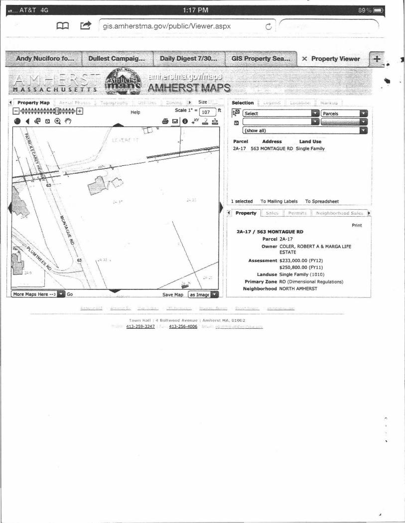
•• AT&T 4G 1:17 PM 89 " ~
.AlIcfy>Nl.ucilrOro fa ••• ,
~i:;;;-pertYM;; " t,.~ · " n~,'.
IB~fB ! .~~BI(flO
I
More Maps Here -- ;: a Go
-'
gis.amherstma.gov/publ icNiewer.aspx G \ r
/
",..
," r'
Daily Digest 713lJ ••• GIS Property Sea ••• X Property Viewer
"
::111 U l::btHl:.L ~!.J'I1JJ8l-'J
.~~~~MA1rS
•.. j
\ ;:: .. " \
" ,.
Save Maw as lmagt: a
, ; I
i
Parcel Address land Use
2A-17, 563 MONTAGUE RO Single FamUy
! L!_~~~~T~ Mailing La ~els ~!~read5heet !
~; 11 Pro.;;;:tYTI~'o.' "~",, t, N'''9hbO.h;;;;;S;;;;:;:-r ,
I
I I' , I ,
2A-17 I 563 MONTAGUE RD
Parcel 2A-17
Owner COLER, ROBERT A & MARGA UFE ESTATE
Assessment $233,000.00 (FY12)
$250,800.00 (FYll )
landuse Single Family (1010)
Primary Zone RO (Dim ensional Regulations)
~ ____ N_e_;._h_~ ___ h_OO_d __ N_O_R_T_H_A_M_H_E_R_ST ______________ ~
Town Hilll 4 Sortwood I'l.IICr'lUC I Arnherst MA, 01002
413·259·}Z47 41].256,4006 ~.'

·Commonwealth of Massachusetts City/Town of Amherst
Form 11 - Soil Suitability Assessment for On-Site Sewage Disposal
Site Address: 563 Montague Road. Amherst
" ..
DEP has provided this form for use by on-site professionals and local Boards of Health. Other forms may be used, but the information must be substantially the same as provided here. Before using this form, check with your local Board of Health to determine the form they use.
A. Facility Information 1. Facility Information
Marga and Bob Coler Owner Name
563 Montague Road Street Address Amherst MA 01002
B. Site Information 1. (Check one) New Construction 0 upgrade.
2. Published Soil Survey available? -1C Yes No If yes:
Repair 0 1967
:') ' '' A '11" MapILot \' V,Y ( <. \ ,,_ - I, 'r
15840 59 Year Published Publication Scale Soil Map Unit
CrC Charlton-Hollis fine sandy loam. rocky. 3-15% slopes Moderate limitations: Sl o~~
Soil Name Comment: 3. Superficial Geological Report available? .lL Yes
glaciated Geologic Material
4. Flood Rate Insurance Map:
No If yes:
upland Landform
Above the 500 year flood boundary? -1C Yes No
Within the 500 year flood boundary?
S. Wetland Area: National Wetland Inventory Map
Wetlands Conservancy Program Map
6. Current Water Resource Conditions (USGS)
7. Other references reviewed:
Yes .lL No
Map Unit
Map Un~
MonthIYear
1980 Year Published
Soil limitations
1:190.080 Publication Scale
_ __ 6
Map Unit
Within the 100 year flood boundary? Yes
Within a Velocity Zone? Yes
Name
Name Range: Above Normal Normal _X_
-1C No
.lL No
Below Normal
DEP Fonn 11 Soil Suitability Assessment for On-Site Sewage Disposal' Page 1 of 5

Commonwealth of Massachusetts CitylTown of Amherst
Form 11 - Soil Suitability Assessment for On-Site Sewage Disposal Site Address: 563 Montague Road. Amherst
c. On-Site Review (minimum of two holes required at every proposed primary and reserved disposal area)
1 Deep Observation Hole Number l lU1Ll2 9:00 AM Clear Perc date Time Weather
2 Land Use: driveway ill lli , (e.g . woodland, agricultural field, vacant lot, etc.) Surface Stones Slope ('Yo -Vegetation mixeg bgrgwoods Landform hillside -
Latitude: Longitude: Position on landscape (attach sketch)
3 Distances from: Open Water Body l.2Q Drainage Way 150 Possible Wet Area l.2Q Property Line <10 Drinking Water Well l.2Q Other:
feet feet feet 4 Parent Material: GlaCial Qutwash Unsuitable Materials Present: NO
If Yes: Disturbed Soil Fill Material Impervious Layer(s) Weathered/Fractured Rod Bedrock 5 Groundwater Observed: no
If Yes: Depth Weeping from Pit Q inches Depth Standing Water in Hole Q inches Estimated Depth to Hiqh Groundwater: 80 inches
Depth Soil Soil Matrix Redoximorphic Features Soil Texture Coarse Fraqment' Soil Soil Other (In.) Horizon Color-Moist (mottles) (USDA) Cobbles Structure Consistency
/ Laver (Munsell) Depth Color Percent Gravel & Stones (Moist)
o - 7 Fill Gravel none fine sandly weak fine
7 - 14 A 7.SYR 4/3 loam 5% 5% granular verv friable fine sandy 5ubangular
! 14 - 34 B 10YR 6/6 loam 15% 15% blocky friable ,
34 - 80 C 10YR 6/3 gravelly
sandy loam 20% 30% massive firm
80+
DEP Form 11 Soil Suitability Assessment for On-Site Sewage Disposal' Page 2 of 5
.. ~
.'
I

· Commonwealth of Massachusetts Cityrfown of Amherst
Form 11 - Soil Suitability Assessment for On-Site Sewage Disposal
Site Address: 563 Montague Road. Amherst
C. On-Site Review (minimum of two holes required at every proposed primary and reserved disposal area)
1 Deep Observation Hole Number 1 ZLJll12 2;QO AM tle.iu: Perc date Time Weather
2 Land Use: (\<:.\\ItlOJoJ./ \f e';. .5j1,
(e.g. woodland, agricultural field, vacant lot, etc.) Surface Stones Slope (%) Vegetation ~1)(t() ~\)JOOO:' Landform hills ide
Latitude: Longitude: Position on landscape (attach sketch)
3 Distances from: Open Water Body .l.5.Q Drainage Way liQ. Possible Wet Area 150 Property Line 1Q Drinking Water Well .l.5.Q Other:
feet feet feet 4 Parent Material: ~lSlcial till Unsuitable Materials Present: N.Q
If Yes: Disturbed Soil Fill Material Impervious Layer(s) Weathered/Fractured Rod Bedrock 5 Groundwater Observed: Ill!
If Yes: Depth Weeping from Pit Q inches Depth Standing Water in Hole Q inches Estimated Depth to HiQh Groundwater: 1.1. inches
Oepth Soil Soil Matrix Redoximorphic Features Soil Texture Coarse FraQments Soi l Soi l Other
(In .) Horizon Color-Moist (mottles) (USDA) Cobbles Structure Consistency
/ Layer (Munsell) Oepth Color Percent Gravel & Stones (Moist)
o . 7 Fill Gravel none fine sandly weak fine
7 - 14 A 7.5YR 4/3 loam 5% 5% granular very friable
fine sandy subangular
14 - 34 B 10YR 6/1 loam 15% 15% blockY friable -
C gravelly
34 - 72 10YR 6/3 sandy loam 20% 30% massive firm
-
DEP Fonn 11 Soil Suitability Assessment for On-Site Sewage Disposal. Page 3 of 5
Commonwealth of Massachusetts Cityrrown of Amherst
Form 11 - Soil Suitability Assessment for On-Site Sewage Disposal Site Address: 563 Montague Road. Amherst
D. Determination of High Groundwater Elevation
1 . Method used: Depth observed standing water in observation hole A. inches B. inches
Depth weeping from side of observation hole A. inches B. inches
Depth to soil redoximorphic features (mottles) A. inches B. inmes
Groundwater adjustment (USGS methodology) A. inches B. inches
2. Index Well Number _______ _ Reading Date Index Well Level
Adjustment Factor Adjusted Groundwater Level :--:--::-_=-=--: __ No mott l es seen : depth of r e fusal found at 80 inches in observation hole A, 72 inches at observation ho .le B.
E. Depth of Pervious Material 1. Depth of Naturally Occurring Pervious Material
a. Does at least four feet of naturally occurring pervious material exist in all areas observed throughout the area proposed for the soil absorption system? ... Y",e",sL... __
b. If yes, at what depth was it observed? Upper boundary: 14 Min. inches Lower boundary: 80 Max. inches
F. Certification I certify that I am currently approved by the Department of Environmenlal Protection pursuant to 310 CMR 15.017 to conduct soil evaluations and that the above analysis has b~ performed by me consistent with the required training , expertise and experience described in 310 CMR 15.017. I further certify that the results of my soi~i»f1. as indicated,-iA-the,attached Soil Evaluation Form, are accurate and in accordance with 310 CMR 15.100 through 15.107.
Signature of Soil Evaluator
Thomas S. Leue SE 1368 Typed or PrWlted Name of Soil Evaluator/Ucense Nuwbe
Ed Smith Name of Board of Health V\Atness
7/31112 Date
June 1995 Date of SOU Evaluator Exam
Town of Amherst Board of Health
Note: In accordance with 310 CMR 15.018(2) this form must be submitted to the approving authority within 60 days of the date of field testing, and to the designer and the
DEP Form 11 Soil Suitability Assessment for On·Site Sewage Disposal' Page 4 of 5

•
1. General
CONSTRUCTION SPECIFICATIONS 563 Montague Road. Amherst
Title 5 Septic System Plan Number 594
a. No work on this system construction shall take place until a permit for the approved system plan has been received from the local Board of Health. A copy of the Disposal Works Construction Permit should be on site for inspection during the time of construction. Additional specifications may be included elsewhere in this design.
b. Loading requirements are specified for the septic tank on the system calculations page. Loading requirements for any other component are on the drawing. Normal loading systems are designated H-10. If H-20 rating is specified on the drawing and/or on the page for system calculations, the tank or leaching facility shall be custom built to meet the increased loading requirements using additional rebar, greater wall thickness and/or other approved methods. Follow the manufacturer's rating system and installation procedures.
c. Alternatives to these specifications should he discussed with the System Designer in advance at 800 285-4533.
2. Septic Tank
a. The septic tank selected by the contractor shall conform with 310 CMR 15.223. The septic tank shall be a minimum effective liquid capacity of 1,500 gallons below the outlet invert, rectangular, and with a minimum length to width ration of 1.5: I. Liquid depth to be 48". Compartmentalized tanks are not to be used.
b. Septic tank shall be installed on a minimum of 6" of crushed stone, leveled to grade and thoroughly compacted. Septic tanks shall have a minimum cover of 9". No structures shall be located directly upon or above the septic tank access locations which interfere with performance, access, inspection, pumping, or repaiT.
c. All Wee access covers to the septic tank shall have risers at least 20" diameter, if round, tightly fitted to the tank to resist water infiltration, and terminated with a tight fitting cover no more than 6" below ground surface. If, with the agreement of the Owner, one or more of the risers are terminated flush with ground, these shall be secured against unauthorized entry with stainless steel hardware.
d. Inlet and outlet tees shall be of Schedule 40 PVC and shall extend a minimum of 6" above the flow line of the septic tank and be on the center line of the septic tank located directly under the clean-out manhole. All fittings to be glued and secured against any movement due to horizontal or vertical impacts. Cross-sectional flow baffles shall not be used as substitutes for inlet or outlet tees. The inlet pipe elevation shall be no less than 2" nor more than 3" above the invert elevation of the outlet pipe. Inlet tee minimum of 10" length below water surface. The outlet shall be provided with a tee extending below the flow line 14" and be equipped with a gas baffle. There shall be an air space of at least 3" between the tops of the tees and the inside of the tank cover. Inlet tees may be modified or a 6" riser on inlet cover may achieve this spacing. The tops of the tees shall be left open to provide ventilation or separate ventilation shall be provided. The effluent tee shall be fitted with a removable plastic outlet filter, as manufactured by Polylok Inc., model PL-120, Zebco, or approved equal. Provide manufacturer's maintenance data, as boxed with the filter, to the homeowner or the System Designer.
Homestead Inc. Page 1 8/16/12,

CONSTRUCTION SPECIFICATIONS 563 Montague Road, Amherst
e. Septic tank should be inspected by the Owner or his representative for solids accumulation annually. When the sum of the sludge and scum layer approach 1/4 the net working volume of the tank (net of 12" total thickness), as measured at the center of the tank, the tank is due for pumping. Septic tanks shall be inspected and maintained in accordance with 310 CMR 15.300 and applicable local requirements.
3. Distribution Box
a The distribution box selected by the contractor shall conform with 310 CMR 15.232. Material of construction shall be concrete or plastic lined concrete. A 6" sump is required in the d-box.
b. The distribution box shall be placed on thoroughly tamped and compacted sand or peastone a minimum of 6" thickness, and shall be leveled utilizing a water flow test. Speed levelers shall not be used on a new installation to obtain level and equal distribution flow, but should be installed after leveling is completed in case uneven settling occurs in the future.
c. For inlet pipe slopes of 5% or greater, or where there is a pumped flow, the distribution box shall have an internal cast baffie or solvent welded pipe tee to reduce the velocity of the influent flow. An internal pipe "y" or an elbow are not acceptable.
d. The first 2 feet of pipe out of the distribution box to be set dead level. Use a fernco connector to join to pitched pipes beyond first two feet.
e. A riser to grade is required on distribution boxes buried more than 9 inches below grade.
4. Piping
a Piping to the septic tank (the building sewer) shall be 4" diameter, PVC Schedule 40 or better. Slope new pipe installations at 114" per foot length.
b. All piping from the septic tank to the end of the system shall be 4" diameter, SDR-35 or better, except as noted on the drawings. Slope pipe installations 1/8" per foot length as a minimum value.
c. Place magnetic detectable warning tape pre-printed "Sewer Pipe Below" or similar wording approximately 12" above all new 4" diameter piping installed on this project.
5. Leaching Facilities a. General: All leaching facilities to be of the size and location shown on the drawings. b. Leach fields (Infiltration chambers): Arrange infiltration chambers on levelled ground. Parallel rows
should be placed a minimum of 6" apart. Add end plates as per manufacturer's assembly directions. Fill spaces between rows with Title 5 sand to the level of the top of the chambers.
c. All fill materials used on this project within five feet of the leaching chambers to be certified Title 5 sand, including any fill materials under chambers, between chambers and to the level of the top of the chambers.
d. A reasonably current copy of the certification from the sand supplier is required to be submitted to the System Designer before the conclusion of this project.
e. Breakout barrier, where required, to be minimum 40 mil thick continuous sheet. Install barrier vertically from bottom of excavation to height of top of leaching system. Seams of membrane material to be overlapped a minimum of 12 inches and glued with sealant as recommended by manufacturer. Material to be hypolon, low density polyethylene, buna-N rubber, EPDM, or approved equal. Backfill in lifts of no more than 6" to assure minimal deformation of membrane. If material is wider than the vertical distance to be covered as shown on the drawing, fold excess material over at the bottom of the trench, or trim with upper
Homestead Inc. Page 2 8/16/12,
•

CONSTRUCTION SPECIFICATIONS 563 Montague Road. Amherst
edge level at appropriate elevation.
6. Inspection
a. A minimum of two site inspections are required under the revised Title 5 code by the System Designer. First, after the site has been prepared with clearing, excavation and system site layout, but before the installation of the system sand. Second, the contractor shall notifY the System Designer a minimum of 48 hours in advance of the anticipated completion time for a Final Inspection. The impervious barrier will be inspected for approval at this time. This barrier will have to be exposed at any locations of overlaps or penetrations to confirm watertight installation. The system shall be essentially complete at the time of the final inspection, including all components in place, risers and covers installed, electrical components functional , etc. No installed system component shall be buried greater than I" depth at the time of final inspection. The System Designer shall verifY the system was installed as designed and authorize the final grading. Coordinate the timing of the Final Inspection so the System Designer and the representative of the local Board of Health may be on the site at the same time, if possible.
b. If the System Designer finds the system is not ready for inspection after being called, or if serious deficiencies are discovered, the System Designer must be notified to return to the job site when it is complete. There will be a charge to the Installer of $50 for each return trip, payable directly to the System Designer at the time of the reinspection.
c. Inspection and project closeout forms are usually generated within 24 hours of final inspection by the System Designer, when all other requirements are met. Signed Certificate of Compliance forms and As-built Drawings are sent to the Installer for a signature and date. One set of forms are then returned to the System Designer for final processing. The second set of forms are for the Contractor to keep as his project record.
7. Final Grading
a At conclusion of work, loam and seed all disturbed areas to perennial grass mixture. Added loam may be required for adequate grass growth. Mulch slopes with hay, burlap or netting to minimize erosion.
b. Surface over leaching facility shall be pitched so as to shed rainwater. Also pitch surface over all tanks to shed rainwater from any exposed covers. Do not allow surface water to puddle over any system component.
c. Systems built late in the year, where the grass cover does not have a chance to establish itself, requires the contractor is to return after spring thaw and resurface final grades and add grass seed cover as required to equalize and stabilize all disturbed areas.
Homestead Inc. Page 3 8/16/12,

Location Address or Lot No. Homestead Inc. #:
FORM 12 - PERCOLATION TEST
563 Montague Road Amherst 594
COMMONWEALTH OF MASSACHUSETTS Amherst, Massachusetts
Percolation Test*
Date:, 7/ 31 / 12 Time: · 9:46 AM
Observation Hole # 1 2 3 4 - -- - -
Depth of Perc: (in) 28 (inches) -
Start Pre-soak: 9:46 AM ._-----
End Pre-soak: 10:01 AM ----Time at 12": 10:01 AM ------
Time at 9" : 10:06 AM --
Time at 6": 10:13 AM ----
Time (9" - 6"): 0:07:45 -
Rate - Min.llnch : 0:02:35
• Minimum of 1 percolation test must be performed in both the primary area AND reserve area.
Site Passes / Site Fails : Passes
Performed By:
Witnessed By:
Comments:
Thomas S. Leue. Homestead Inc.
Ed Smith. Amherst
DEP APPROVED FORM - 12/07/95

563 Montague Road DESIGN CALCULATIONS
Amherst Plan Number 594
Leaching Chamber type Leach Bed System Structure: Single Family House
Flow Design Criteria: Calc. Design Flow:
Garbage Grinder: Not Allowed Total Design Flow:
Percolation Rate:
Percolation Rate:
Loading Rate:
Area required for infiltration:
Measured
Design Rate
Class I Soil
Field Size Reduction Variance Application:
Net Field Size:
Bed Configuration: Model Used:
Effective Leaching Area:
Length per chamber:
Width per chamber:
Invert height: Overall height:
Leaching area/ chamber:
# Chambers required: # Chambers provided:
# field provided:
# rows wide: space between rows:
Total Field Width: # Chambers long:
Total Field Length: Total Field Area:
Effective Leaching Area:
Net Calculated Capacity:
Loadina:
Homestead Inc.
3 bedrooms
110 gallons per bedroom per day 330 gallons per day
Info Source Owner's information
310 CMR 15.203
multiply above 310 CMR 15.240
multiply above
from perc test
310 CMR 15.105
310 CMR 15.242
1.0 factor
330 gallons per day
2.3 min. per inch
2 min. per inch
0.74 gallons/sq.ft./day
446 sq. ft. 2.0%
437 sq. ft.
Infiltrator SYstems Inc.
High Capacity H-20
7.79 sq ft/ ln ft
75 inches
34 inches 11 inches
16 inches
48.7 sq ft
9.0
9 1
3 Z inches
8.83 feet
3 18.75 feet ea.
165.6 sq. ft . 438.2 sq. ft.
331 gals/day
H-20
divide flow by loading rate
310 CMR 15.404(Zdl
multjply above
Manuf. Trade Name
PEP technology ratings
Manufacturer's size
Manufacturer's sjze
Manufacturer's size
Manufacturer's size
length x leaching area
field size divided by leachjng area
judgement
judgement
average
chambers + spacing
judgement length of assembly
length X wjdth # chambers X rating
area X loading rate
judgement
8116112


I I INFIL TRATION CHAMBERS INS71ILLA TION INSTRUCTIONS 1. Excavate and level field area to depth of excavation. 2 . Prepare field area in accordance with 310 CMR 15.00. Add Hie 5 sand to depth of Field Base specified. 3. Snap chamber end with integral splash plate into inlet end of first Infiltrator chamber wtth splash plate extending into chamber. Secure end plate with two or more stainless screws. 4. Place first unit in the inlet end of trench wtth interlocks downstream. 5. Run distribution pipe through inlet opening in end plate but not beyond splash plate . A single scre"" to be used to hold in place. Pipe does not normally run the length of system. 6. Cemnect Infi~rator chambers together, fully engaging interlocks to form desired field length. Be sur,,; lo check all grades with a level or surveying equipment. Secure sections with three or more scre~s each. 7. Screw closed end plate in downstream end of last chamber. S. Space parallel rows 2" apart in field configuration. Space between rows, surrounding rows, and to the level of the top of the rows to be filled with Title 5 sand. 9. "Walk" sand fill into place to give proper support of sides, THIS IS VERY IMPCRTANT TO ACHIEVE FULL STRENGTH 10. Backfill to a minimum of 12" cover after compaction and settling for H-10 chambers and 16" for H-20 chambers. Avoid large rocks in the backfill material. CAUTION - Avoid vehicular traffic on system during construction since soil has not settled. This is particularly important in sand , since loose sand offers very little structural support.
~ Existing Leachfield , approximate location, remove all pipes, contaminated media plus one foot additional uncontaminated media in all directions, including below system.
I I
. I Inspection
\ \
Install top 8" of parking area and driveway with TRG media, compacted and smoothed.
Use quality topsoil fill over non-parking areas.
99.5
'. . ,--,,: ':'-'j porch ---- '-- '-"" ,'--.
gSA ............ -.....-....
Town water in
Partial House Outline
CONSTRUCTION NOTES 1 . Board of Health approval required before licensed contractor installs system. Obtain Disposal Works Permit. 2. Notify engineer at least 24 hours in advance of completion of excavation and before addition of sand to certify site preparation. 3. Notify engineer at least 24 hours in advance of completion of system construction and prior to backfill for fmal inspection. 4. All construction to be in accordance with Title 5 of the State Environmental Code. 5. At conclusion of work, loam and seed all disturbed areas to perennial grass mixture. Added loam may be required for adequate grass growth. 6. Contractor responsible for verifying all dimensions, elevations and conditions. Contact engineer immediately if discrepancies are found. 7. Property lines are approximate, based on best available information. 8. Any required tree cutting is the responsibil ity of the Contractor. 9. See attached Specincations for additional requirements. 1 O. System not designed for a garbage grinder. Do not connect one to the system. 1 1. All drain pipes from greywater and blackwater sources <mr ~~ COl" lee ted to the- building sewer in the basement. 1 2. All wells within 1 50' of system are. shown on the drawing.
I I
Existina Septic Tank : pump, I I I I
Variances Applied For: remove as required.
40 sewer pipe. 3 foot separation to groundwater.
310 CMR 15.405 (h) New Leachfield: Infiltrator High Capacity H-20 '.' ir 1l- - 10 ~/q - - r.J-- .-~·_ / / New 1,500 gallon TItle 5 Chambers. 3 rows,-3~hambers ~e~:w. Ventilated.. 7<" h (_--·~.:.."-,-- - -L-.::-9 ..__ . septic tank wtth outlet filer. :
\ 10' ~
0-;
NORTH
--_ I Vent, see Detail. -- ~._._ ._._. _ ._ I
na~11 a 4" dia. oak. .- - -\ __ _ ~\ .~ '--... Schedule 80pipe:-' Abandoned Cesspool: crush and backfill. I . 10000' \ \ - ' I . " I - - --\_ ---"" I
Note: Field installed in native soil. Do not over-excavate.
..-- . I / /
. SurfElev . 95 9:::..--=-~=~~' - -.- I , . -- ---- I ,. ,-- - - -
. Driveway- - _ - __ I "F-=PL - " I' - - - _ -- I a~ --== :-i-- - _ ----... ~-- --~--=- I --=-. ,
.,..\
PL \
I I I j I
/ - __________ I
"-- -_/
ground surface SYSTEM PROFILE ...J ...J
~ I Not to Scale I native loam to cover
11->::----L. __ -__ 't::._ . ___ . _____ 12. n_. ___ n ___________ ~ .. _____ 1:-___ ------ -'1 5' I .
1 : 3 side slope
(!l z 15 ...J 5 m
I I Innltration Chambe 6" washed stone
L:"~ '.' • •• ;:::;;::b under tanks
INVERT HEIGHTS & ELEVATIONS: D-box Excavatel Field Base 1 Inlet Inv. Final i
Bldg. outl Septic in Septic out In: 93.2 18" soil] 92.01 93.0 Surface
........
: 96.11 95.8 95.5 Out: 93.0 Field size for Innltrator High Capacity: 95.0 v~.v ~ ".1
I S~wer: House to Septic Tank: 12 ft. Chambers per Row: 3 Length:
SePtic Tank to D-box: 42 ft. Number of Rows: 3 Width:
Plan to Repair Septic System
Scale: 1 : 20'
Except as Noted
Date:
8/16/2012
Revision Date:
Owner:
Marga and Bob Coler
563 Montague ROa9----j Amherst, MA 01002
HOMESTEAD INC Thomas S. Leue R.S.
1664 Cape st. iamsburg, MA 01096
1413J 628-4533
.......
-------- )
Infiltration Chamber Leachfleld: Design based on Infiltrator Brand chamber by Infiltrator Systems Inc. Use only the model number speCified. Contact System Designer for field sizing if other brand
is to be used for this project. Use Title 5 sand for all fill requirements under units, between rows
of units, to the level of the top of the units, and within 5 feet surrounding units.
LEGEND -$ Perc Test location & #
-e=t Deep Hole location & #
Original contour
Revised contour
Indicates perf. pipe
Indicates solid pipe
,. Well location 1 PL = Property Line
Remote Vent Scale 1": 10'
36" height above grade
9" bury depth, minimum
rilscreened Outlet 1...--4" Sched. 40 ABS pipe
1 cU.ft. concrete mix.
Length : Min. 5', Max: 20'
From Invert Height of Chambers.

~ . . ... . . .. : , . , ·

AMHERST PUBLIC HEALTH DEPARTMENT
Bangs Community Center 70 Boltwood Walk
Amherst, MA 0 I 002
TO
RE: Invoice for
Robert A. &: Marga Coler
5 Spruce Run
South Hadley, MA 01075
Perc & Soil Evaluation, 563 Montague Rd., Amherst MA 01002
Services provided by Edmund Smith
PAYMENT TERMS: t PAID
QUANTITY DESCRIPTION
1.00 Perc &: Soil Evaluation, 563 Montague Rd. , Amherst MA 01002
Rec·d today your check #3757 for $300.00
this invoice is paid in full/thank you
-9 .... .0 - /~t67
~4-f=7 - ~ ~7
April 2012 INVOICE
DATE: April 6, 2012
UNIT PRICE
$ 300.00
SUBTOTAL
SALES TAX
TOTAL
liNE TOTAL
S 300.00
$ 300.00
$ 300.00


CUST NAME 4 BOLTWOOD AVENUE 08 / 01 / 12 CITY, ST, ZIP
DE HEA011
300.00 MARGA COLE QUA CHECK
***TOWN OF A TOWN HAL AMHERST M REFERENCE DATE / TIME 10:06
o DEPT
CUST NAME
PERCOLATIO 300 .
RECPT TOTAL
AMOUNT 3757
130 PE

- . - . -- - ' -
/-fit. ha I -I /
b(, ~ M~>*t, Je
rD- A tM.J o,,-.JOI!,:J B J T ,Jr-,- e.e.; SLli£P r F I <-LiE y:) C~UI ./,iU
1=-"-" ?i I 1= .. T7 n,E.. r. .~ ."
i?) ~I<- 11 l,oJF-1 .., .:, / F<.-IE.. i2-wn . e (~ , Z
I
. <: ." -- , } ';¥';'D'> :> ~ .-k-I ,{ ~ ~ <E <.J o-u.. rt.£ r I~?
(J) HglA~ 11 J ,Jf)i£ft 'I>.7,,;T- .. . --t / T1!& 171- """' ·7"'" , '"
; A t- L1 Lf~ r; , ') I ( J
. -


AMHERST Massacfiusetts
AMHERST HEALTH DEPARTMENT, 70 BOLTWOOD WALK, AMHERST, MA 01002 (4 13) 259-3077 (413) 259-2404 - FAX [email protected]
Apri123,2012
Marga and Bob Coler 5 Spruce Run South Hadley, MA 0 I 075
RE: Title V Septic Inspection
Dear Mr. and Mrs. Coler
The Amherst Board of Health is in receipt of a report on the Subsurface Sewage Disposal System Inspection conducted by Thomas Leue, on April 6, 2012. That inspection report indicates that the subsurface sewage disposal system at that address fails to protect the public health and the environment as defined in Section 15.303 of CMR 15.000, State Environmental Code, Title 5.
Therefore, in accordance with the provisions of310 CMR 15.000 of the State Environmental Code, Title 5, and under authority of Massachusetts General Laws, Chapter 21A, Section 13, you (or the subsequent owners of the property) are hereby ordered to repair the subsurface sewage disposal system at 563 Montague Road, within two (2) years of the date of the inspection, (bv April 6, 2014). If further degradation of the sewage disposal system occurs (e .g, sewage fl owing to the surface of the ground),you may be required to complete the repairs sooner.
All work to repair/upgrade the subsurface sewage disposal system must be perfonned by a licensed sewage disposal system installer, in accordance with the requirements of 31 0 CMR 15.000, and with plans prepared by a Registered Sanitarian or Registered Professional Engineer and approved by the Northampton Board of Health.
Please be advised that you are entitled to a hearing on this order to upgrade your subsurface sewage di sposal system, provided that you file a written petition requesting such a hearing in the Board of health office within seven (7) days of the receipt of this notice.
Please feel free to contact the Board of Health office, at 253-3077, if you have any questions concerning this notice.
Thank you for your anticipated cooperation in this matter.
Sincerely,
~~~~ r:;,-~ CUf(
Assistant Sanitarian I at:, - (> twJtJE~


• BOARD OF HEALTH, AMHERST, MASSACHUSETTS !
, ,
/~~ rJ.PPLIC~TION FOR DISPOSA~ WORKS CONSTBUQ'ION PERMIT m n No. It(g' (f Date 6.. 7~b Fee I ~ Date Rec'd. f9' L -& b By -"~..".~=-_
Application is hereby made for a permit to Construct ( ) or Repair (>4 an Individual Sewage Disposal
System at: st~~ _ /J ~w::ron:A~re~ ~~ 'V 0~rmc,o C:: ;<.I.) Address .'Jj£,j ;;;~~{~ Contractor Ilk l_ • _ _ _ Address .y"", t/trJfJAv":! y f!A 7 Type of Building ~'DimenSions Size Lot
Dwelling-No. of Bedrooms 1!!f Expansion Attic ( Garbage Grinder ( ~ Other No. of persons _____ Showers ( ) Other fixtures.. Town Water? YeS Type of WY!-:._= ____ _________ _
Design Flow ~ gallons per person er day. Total daily flow 70 0 gallons = Septic Tank- Liquid capa.s;\ty lSaliolli, Dimensions: r. W D,____ frl.!-vV Disposal Trench-No. .~ Wid '" ~ Total Length lao" Total leaching area ;LyO ~q . ft. Disposal Bed-No. Diameter Depth below inlet Total leaching area sq. ft. Dry Well-No. Diameter Depth below inlet Dimensions: x ___ x __ _ Other: Distribution box ()O No. Dosing tank ( ) (Depth of Soil Line Bdo~v ~nished grade at foundation~ Percolation Tes; Results Performed by V~"'"
Test Pit No. 1 ,.j minutes per inch Test Pit No. 2 minutes per inch
t-$1-6& Depth of Test Pit ~''';:?=_~ __ _ Depth of Test Pit ____ _
Date
Description of Soil Depth to Ground Water ___________ _ Will disposal. area be filled? Cut down? (On reverse side or separate sheet, show plot plan with buiJding. Include dimensions. distances from all boundaries. Show location of wells, streams, ledge, large trees, etc.)
AGREEMENT: The undersigned agrees to construct the aforedescribed individual sewage disposal system in accord· ance with the provisions of Article XI of the Sanitary Code lations of the Amherst Boar 0 eaIth. The undersigned further agrees not to place the system in opel:«ifon un' a Ce.rtificate 0 Ii /' een issued by this board of health. /. ~
Application Approved by -7'U'-"==..c:...------- Owner or builder
Application Disapproved jor the following reasons:
BOARD OF HEALTH, AMHERST, MASSACHUSETTS CERTIFlCATE OF COMPLIANCE
~~X':tt date
THIS IS TO CERTIFY, That the individual Sewage Disposal System installed ) or repaired ( ) by ______ ____ at has been constructed in accordance with the provisions of
INSTALLER
Article XI of the State Sanitary Code as described in the application for Disposal Works Construction Permit No.
---- dated -:---c:-:---c~---;--::-The issuance of this certificate shall not be construed as a guarantee that the system will function satisfactorily.
DATE _______ _ Inspector _________ _
._-"- --_. ---- - - ----- - - - - . - --- - - - ---- ------------------------------"""'========,
BOARD OF HEALTH, AMHERST, MASSACHUSETTS
No. tf~~ hereby g~::OSAL v;;;: )(NS~:N P=uct ) or repair (~ an
Individual Sewage Disposal System at _ __ -'I"'I1l.<,f1'-'-"l(:LT-'ItCL..J.G,--"U'-'L-=·~_____________ '\' as shown on the application for Disposal Works Construction Permit No. ___ __ _
This permit is issued with the understanding that fu ture alterations or additions will be made if necessary. This permit shall not be construed as permission to create or maintain any sewage nuisance and in the issuance of this permit the Board of Health assumes no responsibility for the future operation or maintenance of the system.
£'_/_ // d;2.nh DATE & Q ~Q . • Board of Health

•
I ~_-I-__ --,I ..

Soil Web via Gmaps!
,;I"
<INDO !,
• ".
http://casoilresource.lawr.ucdavis.edu/soilweb_gmap/
, ,
.8iIIIII , ~ ',I
Page 1 of 1
Map Unit Legend
4/612012


.• Smith, Edmund
Subject: Location:
Start: End:
Recurrence:
Meeting Status:
Organizer: Required Attendees:
title v Tom leue 800-285-4533 563 montague road
Fri 4/6/20129:00 AM Fri 4/6/2012 10:00 AM
(none)
Accepted
Mir, Javeria Smith, Edmund
Any files regarding this property, please bring with you!!
Any changes please call him.
1

•.

- - ---- --~---.---------....".,
'.
nE V

- - . . . .
ZSI
.)G'f {
~~ _ ....
· -
AMHERST PUBLIC HEALTH DEPARTMENT
Bangs Community Center
70 Bollwood Wa lk
Amherst, MA 0 I 002
TO Robert A. & Marga Coter
5 Spruce Run
South Hadley, MA 01075
RE: Invoice for Septic Title V witness: 563 Montague Road, Amherst MA
Services provided by Edmund Smith
PAYMENT TERMS: I PAID
QUANTITY DESCRIPTION
1.00 Septic Title V witness: Complete ystem failed Title V inspection
Rec'd today your check #3734 for $200.00
this invoice is paid in full/thank you
April 2012 INVOICE
DATE: April 6, 2012
UNIT PRICE
$ 200.00
SUBTOTAL
SALES TAX
TOTAL
LINE TOTAL
$ 200.00
$ 200.00
$ 200.00

- .

OWner information is requ ired for every page.
Important: When filling out forms on the computer, use only the tab key to move your cursor - do not use the retum key.
~ ~
tSins • 11110
Commonwealth of Massachusetts
Title 5 Official Inspection Form Subsurface Sewage Disposal System Form - Not for Voluntary Assessments
563 Montague Road Property Address
Marga and Bob Coler Owner's Name
Amherst 4/6/2012 c~rrown
MA Slale
01002 Zip Code Date of Inspection
Inspection results must be submitted on this form. Inspection forms may not be altered in any way. Please see completeness checklist at the end of the form.
A. General Information
1. Inspector:
Thomas S. Leue Name of Inspector
Homestead Engineering Inc. Company Name
1664 Cape St. Company Address
Williamsburg CityfTown
413-628-4533 Telephone Number
B. Certification
MA Slale SI-130 license Number
01096 Zip Code
I certify that I have personally inspected the sewage disposal system at this address and that the information reported below is true, accurate and complete as of the time of the inspection. The inspection was performed based on my training and experience in the proper function and maintenance of on site sewage disposal systems. I am a DEP approved system inspector pursuant to Section 15.340 of Title 5 (310 CMR 15.000). The system:
o Passes o Conditionally Passes ~ Fails
o Needs Further Evaluation by the Local Approving Authority
April 6, 2012 lilSpectOi Date
The system inspector shall submit a copy of this inspection report to the Approving Authority (Board of Health or OEP) within 30 days of completing this inspection. If the system is a shared system or has a design flow of 10,000 gpd or greater, the inspector and the system owner shall submit the report to the appropriate regional office of the OEP. The original should be sent to the system owner and copies sent to the buyer, if applicable, and the approving authority .
· ···This report only describes conditions at the time of inspection and under the conditions of use at that time. This inspection does not address how the system will perform in the future under the same or different conditions of use.
TItle 5 Official Inspection Form: Subsurface Sewage Oisposal Syslem • Page 1 of 17


Owner information is requ ired for every page.
tSins • 11/10
Commonwealth of Massachusetts
Title 5 Official Inspection Form Subsurface Sewage Disposal System Form - Not for Voluntary Assessments
563 Montague Road Property Address
Marga and Bob Coler Owner's Name
Amherst CityfTown
B. Certification (cont.)
MA State
01002 Zip Code
4/6/2012 Date of Inspection
Inspection Summary: Check A,B,C,O or E I a/ways complete all of Section 0
A) System Passes:
o I have not found any information that indicates that any of the fa ilure criteria described in 310 CMR 15.303 or in 310 CMR 15.304 exist. Any failure criteria not evaluated are indicated below.
Comments:
B) System Conditionally Passes:
o One or more system components as described in the "Conditional Pass" section need to be replaced or repaired. The system, upon completion of the replacement or repair. as approved
by the Board of Health, will pass.
Check the box for "yes", "no" or "not determined" (y, N, NO) for the following statements. If "not determined," please explain.
The septic tank is metal and over 20 years old' or the septic tank (whether metal or not) is structurally unsound, exhibits substantial infiltration or exfiltration or tank failure is imminent. System will pass inspection if the existing tank is replaced with a complying septic tank as approved by the Board of Health.
, A metal septic tank will pass inspection if it is structurally sound, not leaking and if a Certificate of Compliance indicating that the tank is less than 20 years old is available.
OY ON o NO (Explain below):
Title S Official Inspection Form: Subsi.llfsce Sewage Disposal System ' Page 2 of 17


Owner information is required for every page.
tSins ·1 1110
Commonwealth of Massachusetts
Title 5 Official Inspection Form Subsurface Sewage Disposal System Form - Not for Voluntary Assessments
563 Montague Road Property Address
Marga and Bob Coler Owner's Name
Amherst CrtylTown
B. Certification (cont.)
B) System Conditionally Passes (cont.):
MA State
01002 Zip Code
4/6/2012 Date of Inspection
D Observation of sewage backup or break out or high static water level in the distribution box due to broken or obstructed pipets) or due to a broken, settled or uneven distribution box. System
will pass inspection if (with approval of Board of Health):
D broken pipets) are replaced 0 YON 0 NO (Explain below):
D obstruction is removed D y D N 0 NO (Explain below):
D distribution box is leveled or replaced D y D N 0 NO (Explain below):
o The system required pumping more than 4 times a year due to broken or obstructed pipe(s). The system will pass inspection if (with approval of the Board of Health):
o D
broken pipe(s) are replaced
obstruction is removed
o YON 0 NO (Explain below):
D y D N D NO (Explain below):
C) Further Evaluation is Required by the Board of Health:
D Conditions exist which require further evaluation by the Board of Health in order to determine if the system is failing to protect public health, safety or the environment.
1. System will pass unless Board of Health determines in accordance with 310 CMR 15.303(1)(b) that the system is not functioning in a manner which will protect public
health, safety and the environment:
D
D
Cesspool or privy is within 50 feet of a surface water
Cesspool or privy is within 50 feet of a bordering vegetated wetland or a salt marsh
Title 5 OfftCial lnspection Form: Subsooace Sewage Disposal System · Page 3 of 17


Commonwealth of Massachusetts
Title 5 Official Inspection Form Subsurface Sewage Disposal System Form - Not for Voluntary Assessments
563 Montague Road Property Address
Marga and Bob Coler Owner Owner's Name information is required for every page.
tS ins '1 1/10
Amherst MA State
01002 Zip Gode
4/6/2012 CityfTown Date of Inspection
B. Certification (cont.)
2. System will fail unless the Board of Health (and Public Water Supplier, if any) determines that the system is functioning in a manner that protects the public health, safety and environment:
D
D
D
The system has a septic tank and soil absorption syslem (SAS) and the SAS is within 100 feet of a surface water supply or tributary to a surface water supply. The system has a septic tank and SAS and the SAS is within a Zone 1 of a public water supply. The system has a septic tank and SAS and the SAS is within 50 feet of a private water supply well.
D The system has a septic tank and SAS and the SAS is less than 100 feet but 50 feet or more from a private water supply well** . Method used to determine distance: ___ __________________ _
** This system passes if the well water analysis, performed at a DEP certified laboratory, for fecal coliform bacteria indicates absent and the presence of ammonia nitrogen and nitrate nitrogen is equal to or less than 5 ppm, provided that no other failure criteria are triggered. A copy of the analysis must be attached to this form.
3. Olher:
D) System Failure Criteria Applicable to All Systems:
You must indicate "Yes" or "No" to each of the following for all inspections:
Yes No
[gJ D
D [gJ
D D
D [gJ
Backup of sewage into facility or system component due to overloaded or clogged SAS or cesspool Discharge or ponding of effluent to the surface of the ground or surface waters due to an overloaded or clogged SAS or cesspool Static liquid level in the distribution box above outlet invert due to an overloaded or clogged SAS or cesspool Liquid depth in cesspool is less than 6" below invert or available volume is less than y. day flow
TItle 5 Official Inspection Form: Subsurface Sewage Oisposal System ' Page 4 of 17


Commonwealth of Massachusetts
Title 5 Official Inspection Form Subsurface Sewage Disposal System Form - Not for Voluntary Assessments
563 Montague Road Property Address
Marga and Bob Coler Owner Owner's Name information is required for every page.
iSins·'1'10
Amherst C~ylTown
MA State
01002 Zip Code
4/6/2012 Date of Inspection
B. Certification (cont.)
Yes No
D
D
D
D
D
D
D
~
~
D
Required pumping more than 4 times in the last year NOT due to clogged or obstructed pipe(s) . Number of times pumped: __ . Any portion of the SAS, cesspool or privy is below high ground water elevation. Any portion of cesspool or privy is within 100 feet of a surface water supply or tributary to a surface water supply.
Any portion of a cesspool or privy is within a Zone 1 of a public well.
Any portion of a cesspool or privy is within 50 feet of a private water supply well.
Any portion of a SAS, cesspool or privy is less than 100 feet but greater than 50 feet from a private water supply well with no acceptable water quality analysis. [This system passes if the well water analysis, performed at a DEP certified laboratory, for fecal coliform bacteria indicates absent and the presence of ammonia nitrogen and nitrate nitrogen is equal to or less than 5 ppm, provided that no other failure criteria are triggered. A copy of the analysis and chain of custody must be attached to this form.]
The system is a cesspool serving a facility with a design flow of 2000 gpd-10,000 gpd. The system fails. I have determined that one or more of the above failure criteria exist as described in 310 CMR 15.303, therefore the system fails. The system owner should contact the Board of Health to determine what will be necessary to correct the failure.
E) Large Systems: To be considered a large system the system must serve a facility with a design flow of 10,000 gpd to 15,000 gpd.
For large systems, you must indicate either "yes" or "no" to each of the following, in addition to the questions in Section D.
Yes No
D
D
D
the system is within 400 feet of a surface drinking water supply
Ihe system is within 200 feet of a tributary to a surface drinking water supply
the system is located in a nitrogen sensitive area (Interim Wellhead Protection Area - IWPA) or a mapped Zone II of a public water supply well
If you have answered "yes" to any question in Section E the system is considered a significant threat, or answered "yes" in Section 0 above the large system has failed . The owner or operator of any large system considered a significant threat under Section E or failed under Section D shall upgrade the system in accordance with 310 CMR 15.304. The system owner should contact the appropriate regional office of the Department.
Trtle 5 Officiallnspeaion FOfI'Tl: Subsurface Sewage Disposal System· Page 5 of 17


Owner information is required for every page.
tSins • 11110
Commonwealth of Massachusetts
Title 5 Official Inspection Form Subsurface Sewage Disposal System Form - Not for Voluntary Assessments
563 Montague Road Property Address
Marga and Bob Coler Owner's Name
Amherst C~yfTown
C_ Checklist
MA State
01002 Zip Code
4/6/2012 Date of Inspection
Check if the following have been done. You must indicate "yes" or "no" as to each of the following:
Yes No
D
D
[8J
D
[8J
D
D
D
D
D
Pumping information was provided by the owner, occupant, or Board of Health
Were any of the system components pumped out in the previous two weeks?
Has the system received normal flows in the previous two-week period?
Have large volumes of water been introduced to the system recently or as part of this inspection? Were as built plans of the system obtained and examined? (If they were not available note as N/A) N/A
Was the facility or dwelling inspected for signs of sewage back up?
Was the site inspected for signs of break out?
Were all system components, excluding the SAS, located on site?
Were the septic tank manholes uncovered, opened, and the interior of the tank inspected for the condition of the baffles or tees, material of construction, dimensions, depth of liquid, depth of sludge and depth of scum?
Was the facility owner (and occupants if different from owner) provided with information on the proper maintenance of subsurface sewage disposal The size and location of the Soil Absorption System (SAS) on the site has been determined based on:
Existing information. For example, a plan at the Board of Health.
Determined in the field (if any of the failure criteria related to Part C is at issue approximation of distance is unacceptable) [310 CMR 15.302(5)]
D. System Information
Residential Flow Conditions:
Number of bedrooms (design): 3 Number of bedrooms
(actual): DESIGN flow based on 310 CMR 15.203 (for example: 110 gpd x # of bedrooms):
2
400 gpd
Title 5 Official Inspection Form: Subsurface Sewage Disposal System. Page 6 of 17


Owner information is required for every page.
15ins • 11110
Commonwealth of Massachusetts
Title 5 Official Inspection Form Subsurface Sewage Disposal System Form - Not for Voluntary Assessments
563 Montague Road Property Address
Marga and Bob Coler Owner's Name
Amherst CityfTown
D_ System Information
Description:
MA State
01002 Zip Code
4/6/2012 Date of Inspection
conventional se tic tank distribution box and two leachin trenches on
ermit a lication but leachfield shown on sketch.
Number of current residents: 1
Does residence have a garbage grinder? 0 Yes 181 No
Is laundry on a separate sewage system? [if yes separate inspection 0 Yes 181 No required]
Laundry system inspected? 0 Yes 181 No
Seasonal use? 0 Yes 181 No
Water meter readings, if available (last 2 years usage (gpd»:
Detail :
Sump pumpl DYes 181 No
Continuous Last date of occupancy: Date
Commercial/Industrial Flow Conditions:
Type of Establishment:
Design flow (based on 310 CMR 15203): Gallons per day (gpd)
Basis of design flow (seatslpersons/sq.ft. , etc.):
Grease trap present?
Industrial waste holding tank present?
Non-sanitary waste discharged to the Title 5 system?
DYes 0 No
DYes 0 No
DYes 0 No
Water meter readings, if available:
TrtIe 5 Offitiallnspedion FOfTTl: Subsufface Sewage Di!ijX)Sa1 System · Page 7 of 17


Owner information is required for every page.
tSins ·11110
Commonwealth of Massachusetts
Title 5 Official Inspection Form Subsurface Sewage Disposal System Form - Not for Voluntary Assessments
563 Montague Road Property Address
Marga and Bob Coler Owner's Name
Amherst C"yfTown
MA State
01002 Zip Code
D. System Information (cont.)
Last date of occupancy/use: Date
Other (describe below):
General Information
Pumping Records:
4/6/2012 Date of Inspection
Source of information: Pumped 3 or 4 years ago, says Owner.
Was system pumped as part of the inspection? DYes 00 No
If yes, volume pumped: gallons
How was quantity pumped determined?
Reason for pumping:
Type of System:
Septic tank, distribution box, soil absorption system
Single cesspool
Overflow cesspool
Privy
[8]
D
D
D
D
D
Shared system (yes or no) (if yes, attach previous inspection records, if any)
D
D
Innovative/Alternative technology . Attach a copy of the current operation and maintenance contract (to be obtained from system owner) and a copy of latest inspection of the IIA system by system operator under contract
Tight tank. Attach a copy of the DEP approvaL
Other (describe):
TItle 5 Official nspection Form: Subsurface Sewage Disposal System· Page 8 of 17


Owner infonnation is required for every page.
t5ins ' 11/10
Commonwealth of Massachusetts
Title 5 Official Inspection Form Subsurface Sewage Disposal System Form - Not for Voluntary Assessments
563 Montague Road Property Address
Marga and Bob Coler Owner's Name
Amherst CityfTown
D. System Information (cont.)
MA Slale
01002 Zip Code
4/6/2012 Date of Inspection
Approximate age of all components, date installed (if known) and source of information:
Septic plan permit dated 6-8-66.
Were sewage odors detected when arriving at the site? DYes ~ No
Building Sewer (locate on site plan):
Depth below grade: 1 average feel
Material of construction :
o cast iron 040 PVC ~ other (explain) : ABS Plastic
Distance from private water supply well or suction line: 10 ft. feet
Comments (on condition of joints, venting, evidence of leakage, etc.):
NO problems seen .
Septic Tank (locate on site plan):
Depth below grade: 0.75 feet
Material of construction :
~ concrete o metal o fiberglass o polyethylene 0 other (explain)
Standard septic tank of nominal 950 gallons capacity. Removable outlet
baffle deteriorated and non-functional.
If tank is metal, list age: years
Is age confirmed by a Certificate of Compliance? (attach a copy of certificate) 0 Yes 0 No
Dimensions (both tanks): 52" tall, 96" long, 52" wide
Sludge depth: 5"
TItle 5 OffICial nspection Form: Subsurface Sewage Disposal Sysiem • Page 9 of 17

Owner information is required for every page.
15ins • I 1/1 0
Commonwealth of Massachusetts
Title 5 Official Inspection Form Subsurface Sewage Disposal System Form - Not for Voluntary Assessments
563 Montague Road Property Address
Marga and Bob Coler Owner's Name
Amherst CityfTown
D. System Information (cont.)
Septic Tank (cant)
MA State
01002 Zip Code
Distance from top of sludge to bottom of outlet tee or baffle
Scum thickness
Distance from top of scum to top of outlet tee or baffle
Distance from bottom of scum to bottom of outlet tee or baffle
How were dimensions determined?
4/6/2012 Date of Inspection
No outlet baffle
0"
No outlet baffle
No outlet baffle
measured
Comments (on pumping recommendations, inlet and outlet tee or baffle condition , structural integrity, liquid levels as related to outlet invert, evidence of leakage, etc.):
Tank structurally OK. Tank of mid-1960's vintage, but structurally OK if
outlet tee replaced .
Grease Trap (locate on site plan):
Depth below grade:
Material of construction :
o concrete o metal o fiberglass
Dimensions:
Scum thickness
Distance from top of scum to top of outlet tee or baffle
Distance from bottom of scum to bottom of outlet tee or baffle
Date of last pumping:
feet
o polyethylene
Date
o other (explain):
Title 5 OffIciallnspeclion Form: Subsurface Sewage Olsposal System· Page 100f 17


Owner information is required for every page.
t5ins • 11110
Commonwealth of Massachusetts
Title 5 Official Inspection Form Subsurface Sewage Disposal System Form - Not for Voluntary Assessments
563 Montague Road Property Address
Marga and Bob Coler Owner's Name
Amherst MA State
01002 Zip Code
4/6/2012 Cityrrown Date of Inspedion
D_ System Information (cont.)
Comments (on pumping recommendations, inlet and outlet tee or baffle condition, structural integrity, liquid levels as related to outlet invert, evidence of leakage, etc.):
Tight or Holding Tank (tank must be pumped at time of inspection) (locate on site plan):
Depth below grade:
Material of construction :
o concrete o metal o fiberglass o polyethylene
Dimensions:
Capacity: gallons
Design Flow: gallons per day
Alarm present: DYes o No
Alarm level: Alarm in working order:
Date of last pumping: Date
Comments (condition of alarm and float switches, etc.):
• Attach copy of current pumping contract (required). Is copy attached?
o other (explain):
o Yes 0 No
o Yes 0 No
Title 5 Offtciallnspec:tion Fonn: Subsurface Sewage Disposal System ' Page 11 of 17


Owner information is required for every page.
tSins '1 1110
Commonwealth of Massachusetts
Title 5 Official Inspection Form Subsurface Sewage Disposal System Form - Not for Voluntary Assessments
563 Montague Road Property Address
Marga and Bob Coler Owner's Name
Amherst CitylTown
D. System Information (cent.)
MA State
01002 Zip Code
Distribution Box (if present must be opened) (locate on site plan):
Depth of liquid level above outlet invert unknown
4/6/2012 Date of Inspection
Comments (note if box is level and distribution to outlets equal, any evidence of solids carryover, any evidence of leakage into or out of box, etc.):
General location of d-box identified, but encountered standing sewage in
gravel media near box, a failure criterion. Digging up d-box has no
purpose when standing sewaqe encountered.
Pump Chamber (locate on site plan):
Pumps in working order: D Yes D No
Alarms in working order: D Yes D No
Comments (note condition of pump chamber, condition of pumps and appurtenances, etc.):
Soil Absorption System (SAS) (locate on site plan, excavation not required):
If SAS not located, explain why:
Title 5 Officiallnspec1ion Form: Subsurface Sewage Oisposal System' Page 12 of 17


Owner information is required for every page.
t5ins ' 11/10
Commonwealth of Massachusetts
Title 5 Official Inspection Form Subsurface Sewage Disposal System Form· Not for Voluntary Assessments
563 Montague Road Property Address
Marga and Bob Coler Owner's Name
Amherst CityfTown
D. System Information (cent.)
Type:
0 leaching pits
0 leaching chambers
0 leaching galleries
0 leaching trenches
ltJ leaching fields
0 overflow cesspool
MA State
0 innovative/alternative system
Type/name of technology:
01002 Zip Code
number:
number:
number:
4/6/2012 Date of Inspection
number, length: pr;{,J..t
number, dimensions:
number:
s::",,1,'
Comments (note condition of soil , signs of hydraulic failure, level of ponding, damp soil , condition of vegetation , etc.): No surface problems seen. Located about 28" below parking area, so
surfacing of sewage is unlikely due to compact fill over field. Gravel
media was blackened by anaerobic conditions, sewage odor present. Due to
site constraints, designed trenches are not likely to be present, but
sketch of leachfield, about 15' x 25' is likely to be present. This was
not confirmed.
Cesspools (cesspool must be pumped as part of inspection) (locate on site plan):
Number and configuration
Depth - top of liquid to inlet invert
Depth of solids layer
Depth of scu m layer
Dimensions of cesspool
Materials of construction
Indication of groundwater inflow DYes o No
T,Ue 5 Officiallnsped:ion Fotm: Subsurface Sewage Disposal System· Page 13 of 17


Owner infonnation is required for every page.
15ins ·11110
Commonwealth of Massachusetts
Title 5 Official Inspection Form Subsurface Sewage Disposal System Form - Not for Voluntary Assessments
563 Montague Road Property Address
Marga and Bob Coler Owner's Name
Amherst CitylTown
D. System Information (cont.)
MA State
01002 Zip Code
4/6/2012 Date of Inspection
Comments (note condition of soil , signs of hydraulic failure , level of ponding, condition of vegetation , etc.):
Privy (locate on site plan):
Materials of construction :
Dimensions
Depth of solids
Comments (note condition of soil, signs of hydraulic failure, level of ponding, condition of vegetation , etc.):
Title 5 Official Inspection FOffTl: Subsurface Sewage Disposal System ' Page 14 of 17


Owner information is required for every page.
tSins ·1 1/10
Commonwealth of Massachusetts
Title 5 Official Inspection Form Subsurface Sewage Disposal System Form - Not for Voluntary Assessments
563 Montague Road Property Address
Marga and Bob Coler Owner's Name
Amherst CityfTown
D. System Information (cant.)
MA State
01002 Zip Code
4/6/2012 Date of Insped ion
Sketch Of Sewage Disposal System: Provide a view of the sewage disposal system, including ties to at least two permanent reference landmarks or benchmarks. Locate all wells within 100 feet. Locate where public water supply enters the building. Check one of the boxes below:
o hand-sketch in the area below ~ drawing attached separately
Title S Official Inspection Foon: Subsurface Sewage Disposal System · Page 15 of 17


Commonwealth of Massachusetts
Title 5 Official Inspection Form Subsurface Sewage Disposal System Form - Not for Voluntary Assessments
563 Montague Road Property Address
Marga and Bob Coler Owner Owner's Name information is required for every page.
tSins'11110
Amherst CityfTown
D. System Information (cant.)
Site Exam:
I:8J Check Slope
I:8J Surface water
I:8J Check cellar
o Shallow wells
Estimated depth to high ground water:
MA State
01002 Zip Code
5+ feet
4/6/2012 Date of Inspection
Please indicate all methods used to determine the high ground water elevation:
o Obtained from system design plans on record
If checked, date of design plan reviewed: Date
I:8J Observed site (abutting property/observation hole within 150 feet of SAS)
o Checked with local Board of Health - explain:
See below
o Checked with local excavators, installers - (attach documentation)
o Accessed USGS database - explain:
You must describe how you established the high ground water elevation:
Estimated based on elevation of leachfield area above slopes on all
sides. Actual depth to groundwater to be determined during perc test for
repair.
Before filing this Inspection Report, please see Report Completeness Checklist on next page.
Title 5 OffICial Inspection Fcrm: SubslMface Sewage Disposal System' Page 16 of 17

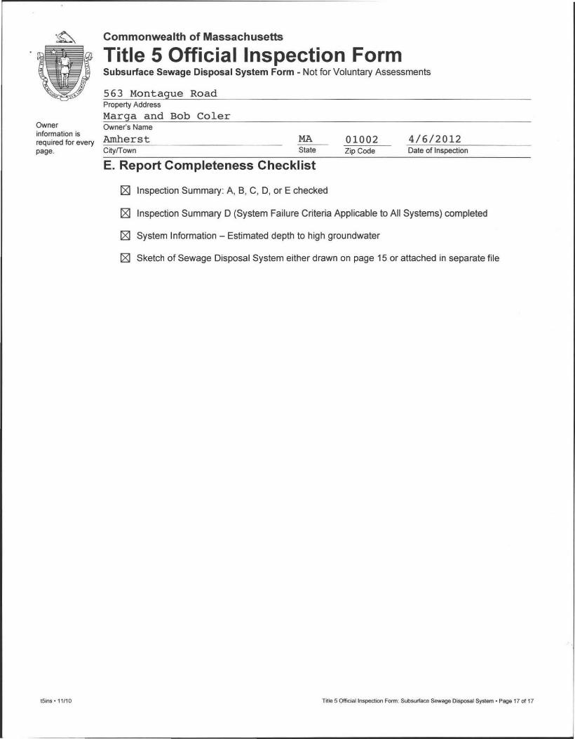
Owner information is required for every page.
tSins ' 11 /10
Commonwealth of Massachusetts
Title 5 Official Inspection Form Subsurface Sewage Disposal System Form - Not for Voluntary Assessments
563 Montague Road Property Address
Marga and Bob Coler Owner's Name
Amherst CitylTown
MA State
E. Report Completeness Checklist
[gJ Inspection Summary: A, S, C, D, or E checked
01002 Zip Code
4/6/2012 Date of Inspection
[gJ Inspection Summary D (System Failure Criteria Applicable to All Systems) completed
[gJ System Information - Estimated depth to high groundwater
[gJ Sketch of Sewage Disposal System either drawn on page 15 or attached in separate file
Title 5 Official Inspection Form: Slilsufface Sewage Disposal System· Page 17 of 17


Town water in
\ ,
porch porch
'0,~ Partial House Outline , NORTH ~
-I-,{} '\
<1-? '~7 )~ ~ ,.;
~
'"" Leachfield, estimated size Distribution Box,
approximate location Septic Tank
As-Built Drawing Existing Septic System
Scale: 1 : 20'
Except as Noted
Date: 4/612012
Revision Date:
Owner: Marga and Bob Coler
563 Montague Roa>",/
Amherst, MA 01002
Abandoned cesspool
HOMESTEAD INC. Thomas S. Leue RS.
1664 Ca pe St. Williamsburg, MA 01096
[413 J 628-1533


AMHERST PUBLIC HEALTH DEPARTMENT
Bangs Community Center 70 Boltwood Walk
Amherst. MA 0 I 002
TO
RE: Invoice for
Robert A. & Marga Coler
5 Spruce Run
South Hadley, MA 01075
Septic Title V witness: 563 Montague Road, Amherst MA
Services provided by Edmund Smith
PAYMENT TERMS: I PAID
QUANTITY DESCRIPTION
1,00 Septic Title V witness: Complete ystem failed Title V inspection
Rec'd today your check #3734 for 5200.00
this invoice is paid in full/ thank you
/7pp - /3/'>'0
g", hI> - 1'$ S 7
April 2012 INVOICE
DATE: Apri l 6, 2012
UNIT PRICE LINE TOTAL
5 200.00 5 200,00
SUBTOTAL 5 200.00
SALES TAX
TOTAL 5 200.00


CUST NAME 4 BOLTWOOD AVENUE 04 / 09 / 12 CITY, ST, ZIP
DE HEA058
200.00 MARGA COLE QUA CHECK
***TOWN OF A TOWN HAL AMHERST M REFERENCE DATE/ TIME 07:54
o DEPT
CUST NAME
TITLE V WI 200.
RECPT TOTAL
AMOUNT 3734
120 PE


Commonwealth of Massachusetts CityfTown of
Form 11 - Soil Suitability Assessment for On-Site Sewage Disposal
A. Facility Information
Owner Name
Street Address Map/Lot #
City State Zip Code
B. Site Information
1. (Check one) o New Construction o Upgrade o Repair
2. Published Soil Survey Available? DYes o No If yes: Year Published Publication Scale Soil Map Unit
Soil Name Soil Limitations
3. Surficial Geological Report Available? 0 Yes o No If yes: Year Published Publication Scale Map Unit
Geologic Material Landform
4. Flood Rate Insurance Map
Above the 500-year flood boundary? DYes o No Within the 1 ~O-year flood boundary? 0 Yes o No
Within the 500-year flood boundary? DYes o No Within a velocity zone? DYes o No
5. Wetland Area: National Wetland Inventory Map Map Unit Name
Wetlands Conservancy Program Map Map Unit Name
6. Current Water Resource Conditions (USGS): MonthfYear Range: 0 Above Normal 0 Nomnal 0 Below Normal
7. Other references reviewed:
tSform11.doc· rev. 1/10 Form 11 - Soil Suitability Assessment for On-Site Sewage Disposal • Page 1 of 8
~

~ Commonwealth of Massachusetts BE§DL CityfTown of
Form 11 - Soil Suitability Assessment for On-Site Sewage Disposal
c. On-Site Review (minimum of two holes required at every proposed primary and reserved disposal area)
Deep Observation Hole Number: Date Time Weather
1. Location
Ground Elevation al Surface 01 Hole: Location (identify on plan) :
2. Land Use (e.g" woodland, agricultural field. vacanl lot. etc.) Surface Stones Slope (%)
Vegetation Landform Position on Landscape (attach sheet)
3. Distances from: Open Water Body feet Drainage Way feel Possible Wet Area
feel
Property Line feet Drinki ng Water Well feet Other
feet
4. Parent Material : Unsuitable Materials Present: DYes D No
II Yes: D Disturbed Soil D Fill Material D Impervious Layerls) D Weathered/Fractured Rock D Bedrock
5. Groundwater Observed: DYes D No II yes: Depth Weeping from Pit Depth Standing Water in Hole
Estimated Depth to High Groundwater: inches elevation
t5form11 .doc· rev. 1/10 Form 11 - Soil Suitability Assessment for On-Site Sewage Disposal' Page 2 of 8

Commonwealth of Massachusetts CityfTown of
J.1.~
5"'5-..Ir- '-¥.,~ ~
r'\~J'~ ~~
if',e.-"r : h,J rm~( Form 11 - Soil Suitability Assessment for On-Site Sewage Disposal
C. On-Site Review (continued)
Deep Observation Hole Number:
Depth (In.) Soil Horizonl Soil Matrix: Color-
Layer Moist (Munsell)
()~I-J ~
7~1'i 4- 7.5'~~..j/?
t1.-/-}1 f? /Q 'liz.. ~A
8+'6'0 C In ~t (p/~
Additional Notes:
~ w ftt.{. (~~ ""5~.s S~ 3%
Redoxlmorphic Features Coarse Fragments
Depth
(mottles) Soil Texture °/0 by Volume
(USDA) Cobbles & Color Percent Gravel Stones
W<'O'l
,....,.,t:.L F'IL.L ';-..
~5L
p$L
l..S
? <Z~
q;Yi> S~f<" .~~
10'0 t £)0 re.o~'" • "' ' & • '"'7'" ~v.'" I J v
1i):H~ 9"'-I D:r~:'f5" j, ~I
q_&,vt ;: '}:lff /If,,, ~
Soil Soil Consistence Structure
(Moist)
F-'i>)"tJc::rtH. '" ~f;';
Other
.:xrzEy
tSform11.doc· rev. 1/10 Form 11 - Soil Suitability Assessment for On-Site Sewage Disposal • Page 3 of 8
I

Commonwealth of Massachusetts CityfTown of
Form 11 - Soil Suitability Assessment for On-Site Sewage Disposal
C. On-Site Review (continued)
Deep Observation Hole Number: Date Time Weather
1. Location
Ground Elevation at Surface of Hole: Location (identify on plan) :
2. Land Use (e.g ., woodland , agricultural field, vacant 101. etc. ) Surface Stones Slope (%)
Vegetation Landfonn Position on Landscape (attach sheet)
3. Distances from: Open Water Body feet
Drainage Way feet Possible Wet Area feet
Property Line feet Drinking Water Well feet
Other feet
4. Parent Material: Unsuitable Materials Present: DYes o No
If Yes: D Disturbed Soil D Fill Material D Impervious Layer(s) D Weathered/Fractured Rock D Bedrock
5. Groundwater Observed: DYes o No If yes: Depth Weeping from Pit Depth Standing Water In Hole
Estimated Depth to High Groundwater: indles elevation
t5form11.doc· rev. 1110 Form 11 - Soil Suitability Assessment for On-Site Sewage Disposal • Page 4 of 8

Commonwealth of Massachusetts CityfTown of
Form 11 - Soil Suitability Assessment for On-Site Sewage Disposal
C. On-Site Review (continued)
Deep Observation Hole Number:
Redoximorphic Features Coarse Fragments Soil Horlzonl Soil Matrix: Color- (mottles) 5011 Texture % by Volume Soil Soli
Depth lin.) Layer Moist (Munsell)
fOlor r arcent IUSDA) Structure
Consistence Other
pepth Fravel rObbles & (Moist) Stones
Additional Notes:
tSform11.doc· rev. 1110 Form 11 - Soil Suitability Assessment for On-Site Sewage Disposal • Page 5 of 8

• Commonwealth of Massachusetts CityfTown of
Form 11 - Soil Suitability Assessment for On-Site Sewage Disposal
D. Determination of High Groundwater Elevation
1. Method Used:
D Depth observed standing water in observation hole A. inches
B. inches
D Depth weeping from side of observation hole A. inches
B. inches
D Depth to soil redoximorphic features (mottles) A. inches
B. inches
o Groundwater adjustment (USGS methodology) A. inches
B. inches
2. Index Well Number Reading Date Index Well level
Adjustment Factor Adjusted Groundwater Level
E. Depth of Pervious Material
1 . Depth of Naturally Occurring Pervious Material
a. Does at least four feet of naturally occurring pervious material exist in all areas observed throughout the area proposed for the soil absorption system?
DYes 0 No
b. If yes, at what depth was it observed? Upper boundary: inches Lower boundary: inches
tSfonn11.doc· rev. 1110 Form 11 - Soil Suitability Assessment for On·Sile Sewage Disposal • Page 6 of 8

t Commonwealth of Massachusetts CityfTown of
Form 11 - Soil Suitability Assessment for On-Site Sewage Disposal
F. Certification
I certify that I am currently approved by the Department of Environmental Protection pursuant to 310 CMR 15.017 to conduct soil evaluations and that the above analysis has been performed by me consistent with the required training , expertise and experience described in 310 CMR 15.017. I further certify that the results of my soil evaluation, as indicated in the attached Soil Evaluation Form, are accurate and in accordance with 310 CMR 15.100 through 15.107.
Signature of Soil Evaluator Date
Typed or Printed Name of Soil Evaluator I License # Date of Soil Evaluator Exam
Name of Board of Health Witness Board of Health
Note: In accordance with 310 CMR 15.018(2) this form must be submitted to the approving authority within 60 days of the date of field testing , and to the designer and the property owner with Percolation Test Form 12.
t5form11 .doc • rev. 1110 Form 11 - Soil Suitability Assessment for On-Site Sewage Disposal • Page 7 of 8

~ Commonwealth of Massachusetts CityfTown of
Form 11 - Soil Suitability Assessment for On-Site Sewage Disposal
Field Diagrams
Use this sheet for field diagrams:
t5form11.doc· rev. 1/10 Fonn 11 - Soil Suitability Assessment for On-Site Sewage Disposal • Page 8 of 8