Interactive deformable geometry maps
13
Visual Comput (2007) 23: 119–131 DOI 10.1007/s00371-006-0033-3 ORIGINAL ARTICLE Qiang Liu Edmond C. Prakash Mandayam A. Srinivasan Interactive deformable geometry maps Efficient modeling for interactive deformation of non-rigid 3D objects Published online: 11 July 2006 © Springer-Verlag 2006 Q. Liu (✉) · E.C. Prakash School of Computer Engineering, Nanyang Technological University, Singapore 639798 {pg04825433, asprakash}@ntu.edu.sg M.A. Srinivasan MIT Touch Lab, Room 36-791, 77 Massachusetts Avenue, Cambridge MA 02139, USA [email protected] Abstract Haptics on 3D deformable models is a challenge because of the inevitable and expensive 3D deformation computation. In this paper, we propose a new technique that extends the conventional rigid geometry images approach proposed by Gu et al. [9]. Our approach not only flattens the geometry, but also helps to accomplish deformation in an effective and efficient manner. Our approach is suitable for hap- tics computing, as it performs the deformation on the geometry map itself thereby avoiding the expensive 3D deformation computation. We demonstrate construction of the deformable geometry map represen- tation and its application utilizing practical methods for interactive surgery simulation and interactive textile simulation. Keywords Deformable geom- etry · Surgery simulation · Haptics computing 1 Introduction Traditional model representations, such as complex trian- gle meshes or NURBS surfaces, pose a variety of prob- lems when it comes to interactive deformation. Some of the problems encountered are: determining the contact point, application of textures, difficulty in deformation, non-real-time response for interaction. – Mesh primitives: Traditionally the input data for mod- eling 3D deformable objects have been 3D meshes and primitives which are represented as a collection of triangles. This representation seriously limits the pick- ing of one or more triangles out of a large mesh. It is also extremely difficult to determine the neighbor- hood points or triangles associated with a given contact point. – Contact point: Determining the contact point in 3D space is tedious. This requires ray intersection with the object of interest to find the closest intersection point. – Deformation footprint: Even though the footprint ker- nel of shape deformation in picking or pinching is quite uniform for most objects, representing the orientation of the shape of the kernel in 3D is difficult. – Interactive deformation: In order to visualize the de- formation, we need to have immediate feedback to facilitate responsive user interaction with the 3D de- formable object. In addressing these problems, this paper makes two major contributions. First, it introduces the deformable geometry map (DGM), a multi-layer parameterized repre- sentation of 3D meshes (for example, the representation of human organs for the purpose of virtual surgery simu- lation). An unstructured 3D input mesh is parameterized and resampled into a regular 2D parameterized model. The
-
Upload
westminster -
Category
Documents
-
view
0 -
download
0
Transcript of Interactive deformable geometry maps
Visual Comput (2007) 23: 119–131DOI 10.1007/s00371-006-0033-3 O R I G I N A L A R T I C L E
Qiang LiuEdmond C. PrakashMandayam A. Srinivasan
Interactive deformable geometry maps
Efficient modeling for interactive deformationof non-rigid 3D objects
Published online: 11 July 2006© Springer-Verlag 2006
Q. Liu (�) · E.C. PrakashSchool of Computer Engineering,Nanyang Technological University,Singapore 639798{pg04825433, asprakash}@ntu.edu.sg
M.A. SrinivasanMIT Touch Lab,Room 36-791, 77 Massachusetts Avenue,CambridgeMA 02139, [email protected]
Abstract Haptics on 3D deformablemodels is a challenge because ofthe inevitable and expensive 3Ddeformation computation. In thispaper, we propose a new techniquethat extends the conventional rigidgeometry images approach proposedby Gu et al. [9]. Our approach notonly flattens the geometry, but alsohelps to accomplish deformation inan effective and efficient manner.Our approach is suitable for hap-tics computing, as it performs thedeformation on the geometry mapitself thereby avoiding the expensive3D deformation computation. Wedemonstrate construction of the
deformable geometry map represen-tation and its application utilizingpractical methods for interactivesurgery simulation and interactivetextile simulation.
Keywords Deformable geom-etry · Surgery simulation · Hapticscomputing
1 Introduction
Traditional model representations, such as complex trian-gle meshes or NURBS surfaces, pose a variety of prob-lems when it comes to interactive deformation. Some ofthe problems encountered are: determining the contactpoint, application of textures, difficulty in deformation,non-real-time response for interaction.
– Mesh primitives: Traditionally the input data for mod-eling 3D deformable objects have been 3D meshesand primitives which are represented as a collection oftriangles. This representation seriously limits the pick-ing of one or more triangles out of a large mesh. Itis also extremely difficult to determine the neighbor-hood points or triangles associated with a given contactpoint.
– Contact point: Determining the contact point in 3Dspace is tedious. This requires ray intersection with theobject of interest to find the closest intersection point.
– Deformation footprint: Even though the footprint ker-nel of shape deformation in picking or pinching is quiteuniform for most objects, representing the orientationof the shape of the kernel in 3D is difficult.
– Interactive deformation: In order to visualize the de-formation, we need to have immediate feedback tofacilitate responsive user interaction with the 3D de-formable object.
In addressing these problems, this paper makes twomajor contributions. First, it introduces the deformablegeometry map (DGM), a multi-layer parameterized repre-sentation of 3D meshes (for example, the representationof human organs for the purpose of virtual surgery simu-lation). An unstructured 3D input mesh is parameterizedand resampled into a regular 2D parameterized model. The
120 Q. Liu et al.
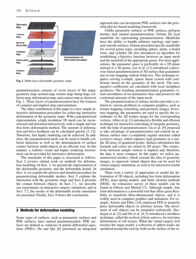
Fig. 1. Multi-layer deformable geometry maps
parameterization consists of seven layers of flat maps:geometry map, normal map, texture map, bump map, col-lision map, deformation map, and contact map as shown inFig. 1. These layers of parameterization have the featuresof compact and implicit data representation.
The other contribution of this paper is a new simple in-teractive deformation procedure for achieving interactivedeformation of the geometry maps. With a parameterizedrepresentation, a high resolution 3D mesh can be recon-structed and deformed interactively with a simple and fastfree-form deformation method. The amount of deforma-tion and force feedback can be calculated quickly [3, 15].Therefore, fast haptic rendering can be achieved. In add-ition, the parameterized mesh can be used to handle col-lision detection as well as the determination of surfacecontact between multi-objects in an efficient way. In thismanner, a realistic visual and haptic rendering environ-ment can be provided for interactive deformation.
The remainder of this paper is structured as follows.Sect. 2 reviews related work on methods for deforma-tion modeling. In Sect. 3, we present the representation ofthe deformable geometry and the deformable kernel. InSect. 4, we explain the process and detailed procedure forparameterizing deformable meshes. Sect. 5 explains theinteraction with the geometric maps and Sect. 6 presentsthe contact between objects. In Sect. 7.1, we describeour experiments on interactive surgery simulation, and inSect. 7.2, the results of the deformable textile simulationare presented. Finally, Sect. 8 draws the conclusions.
2 Methods for deformation modeling
Some types of surfaces, such as parametric surfaces andPDE surfaces, have natural parameterization. PDE sur-faces are defined as solutions of partial differential equa-tions (PDEs). Du and Qin [6] presented an integrated
approach that can incorporate PDE surfaces into the pow-erful physics-based modeling framework.
Unlike parametric surfaces or PDE surfaces, polygonmeshes lack natural parameterization. Grimm [8] usedmanifolds for representing parameterization. Manifoldshave the ability to handle arbitrary topology and repre-sent smooth surfaces. Grimm presented specific manifoldsfor several genus types, including sphere, plane, n-holedtorus, and cylinder. He also introduced an algorithm forestablishing a bijective function between an input meshand the manifold of the appropriate genus. For most appli-cations, the parameter space is preferably on a 2D planeinstead of a 3D genus. Lee et al. [11] introduced a piece-wise linear parameterization of 3D surface that guaranteesone-to-one mapping without foldovers. This technique re-quires solving a simple, sparse linear system with coef-ficients based on the geometry of the mesh. The non-negative coefficients are calculated with local straightestgeodesics. The resulting parameterization guarantees vi-sual smoothness of iso-parametric lines and preserves theconformal structure of the input mesh.
The parameterization of surface meshes provides a so-lution to various problems in computer graphics, such astexture mapping, remeshing, and geometry images. In tex-ture mapping, the parameters are used to specify the co-ordinates of the 2D texture image for the correspondingvertices. Alliez et al. [1] introduced a flexible and efficienttechnique for interactive remeshing of irregular geometry,with the help of parameterization. Gu et al. [9] proposedto take advantage of parameterization and remesh an ar-bitrary surface onto a completely regular structure calledgeometry image, which captures rigid geometry as a sim-ple 2D array of quantized points. Surface information likenormals and colors are stored in 2D arrays. The connec-tivity between sample vertices is implicit and, therefore,the data is more compact. In this paper, we utilize pa-rameterized meshes, which extends the idea of geometryimages, to represent virtual objects that can be used forvirtual surgery simulation, as well as for interactive textilesimulation.
There exist a variety of approaches to model the de-formation of 3D objects, including free form deformation(FFD), mass-spring models, and finite element methods(FEM). An exhaustive survey of these models can befound in Gibson and Mirtich [7]. Although simple, freeform deformation is a powerful tool that offers great flexi-bility to transform three-dimensional objects, and it iswidely used in computer graphics and animation. For ex-ample, Schein and Elber [14] employed FFD to properlyplace deformable objects in arbitrary terrain. The move-ment of soft objects can be simulated realistically. Bas-dogan et al. [2] and De et al. [4, 5] introduced a meshlesstechnique, called the method of finite spheres, for real-timedeformation of soft tissues. When the virtual surgery tooltouches the organ model, a collection of sphere nodes aresprinkled around the tool tip, both on the surface of the or-
Interactive deformable geometry maps 121
gan model as well as inside. Because the computationallyexpensive process of defining the relative location of thenodes and the tool tip, and the process of computing thestiffness matrix are done off-line, the runtime deformationcan be performed in real-time.
Hirota et al. [10] introduced a novel penalty method tosimulate mechanical contact between elastic objects basedon the concept of material depth. The penalty method isused for finite-element simulation. This method results ina reliable and smooth simulation. However, it is not prac-tical for interactive simulation due to the computationalcost. Onoue and Nishita [13] proposed a deformation al-gorithm for ground surfaces composed of granular mate-rial such as sand. In this algorithm, objects and granularmaterial on them are represented by a layered data struc-ture called the height spans (HS) map. This method cansimulate the contact between solid objects and the gran-ular material in a realistic way so that the volume of thegranular material is conserved. The idea of conservation ofvolume is also adopted in this paper for the simulation ofthe contact between deformable object and other objects.
3 Deformable geometry representation
3.1 Parametric geometry map representation
Surface parameterization is the process of mapping eachindividual surface patch to an isomorphic triangulation ona 2D plane. An arbitrary mesh is cut along a network ofedge paths, and the resulting single chart is parameter-ized onto a unit square, so that there is one-to-one cor-respondence between each vertex V on the original meshand each point on the parameter space P = (u, v), with0 ≤ u ≤ 1 and 0 ≤ v ≤ 1.
A parameterized mesh is a regular 2D array of quan-tized points in 3D space of the following form.
Vij = (xij, yij, zij), 0 ≤ i ≤ m, 0 ≤ j ≤ n, (1)
wherei and j are the surface parameters,m, n are the dimensions of the parameterized mesh,xij , yij , zij are the x, y, z coordinates of the points.
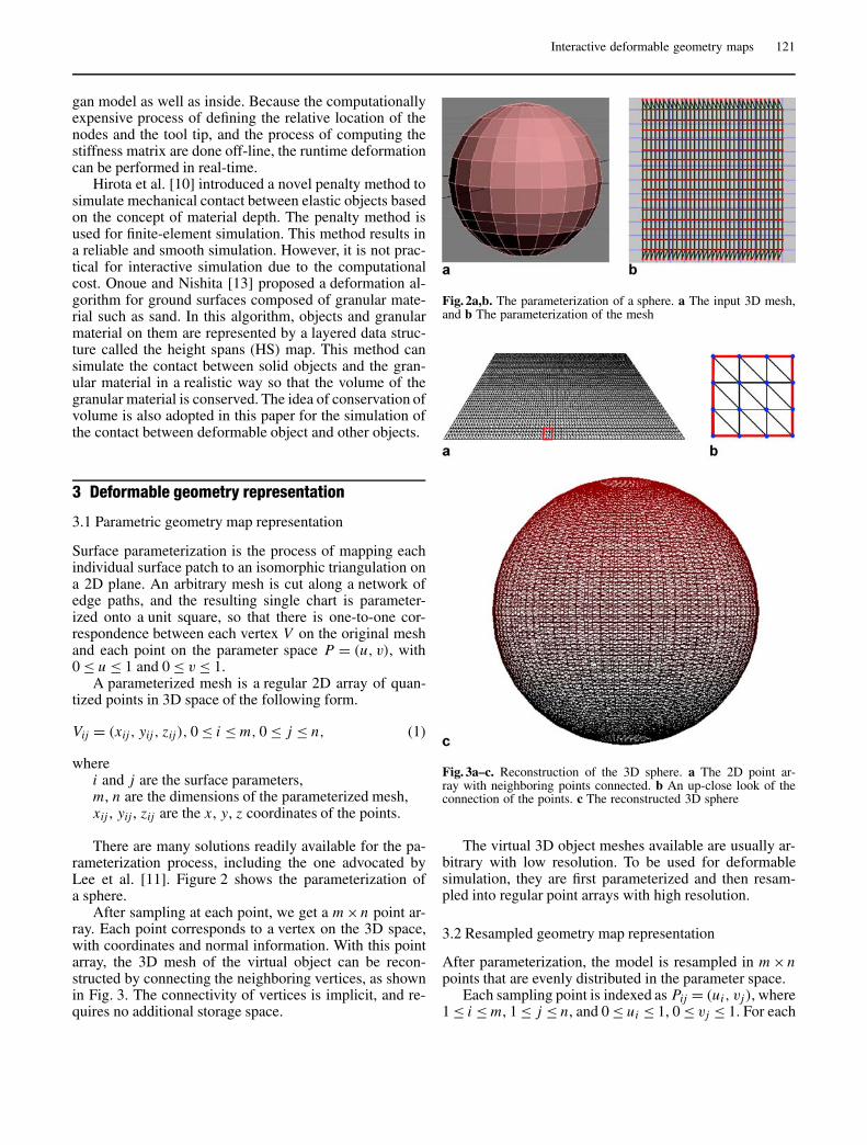
There are many solutions readily available for the pa-rameterization process, including the one advocated byLee et al. [11]. Figure 2 shows the parameterization ofa sphere.
After sampling at each point, we get a m ×n point ar-ray. Each point corresponds to a vertex on the 3D space,with coordinates and normal information. With this pointarray, the 3D mesh of the virtual object can be recon-structed by connecting the neighboring vertices, as shownin Fig. 3. The connectivity of vertices is implicit, and re-quires no additional storage space.
Fig. 2a,b. The parameterization of a sphere. a The input 3D mesh,and b The parameterization of the mesh
Fig. 3a–c. Reconstruction of the 3D sphere. a The 2D point ar-ray with neighboring points connected. b An up-close look of theconnection of the points. c The reconstructed 3D sphere
The virtual 3D object meshes available are usually ar-bitrary with low resolution. To be used for deformablesimulation, they are first parameterized and then resam-pled into regular point arrays with high resolution.
3.2 Resampled geometry map representation
After parameterization, the model is resampled in m ×npoints that are evenly distributed in the parameter space.
Each sampling point is indexed as Pij = (ui, vj), where1 ≤ i ≤ m, 1 ≤ j ≤ n, and 0 ≤ ui ≤ 1, 0 ≤ vj ≤ 1. For each
122 Q. Liu et al.
sampling point, we check for the triangle it resides. Ifa sampling point Pij lies within a triangle V ′
1V ′2V ′
3, whichcorrespond to triangle V1V2V3 on the 3D mesh, we calcu-late the barycentric coordinates (w1, w2, w3) of Pij as
w1 = ui(v2 −v3)+vj(u3 −u2)+u2v3 −u3v2
A, (2)
w2 = ui(v3 −v1)+vj(u1 −u3)+u3v1 −u1v3
A, (3)
w3 = ui(v1 −v2)+vj(u2 −u1)+u1v2 −u2v1
A, (4)
where A is the area of triangle V ′1V ′
2V ′3 and
A = u1v2 +u2v3 +u3v1 −u1v3 −u2v1 −u3v2. (5)
The barycentric coordinates are used to interpolate thecoordinates of a 3D point Vij , which corresponds to thevertex Pij on the 3D mesh,
Vij = w1V1 +w2V2 +w3V3. (6)
Similarly, the normal of Vij can be calculated via interpo-lation.
3.3 Representation of parametric deformation
We designed a fast and easy free form deformation methodthat is based on the parameterized representation of theorgan model. Although the scheme is simple, realistic de-formation can be achieved.
Deformation is calculated based on 2D parameterspace. When one vertex C is touched by the tool andmoved, the amount of displacement dc = [dxc dyc dzc]of this vertex is transferred to the corresponding pointPic jc on the 2D parameter space. A Gaussian distributionfunction is evaluated at each surrounding point, and thedisplacements of these points are calculated with this dis-tribution function as
d(Pij) = dce− (i−ic)2+( j− jc)2
σ (7)
In the equation above, σ is the standard deviation ofthe distribution, and is a parameter that reflects the ma-terial property of the deformable object. The amount ofdisplacement that vertex V undergoes, depends on thedistance between its corresponding vertex V ′ on the pa-rameter space and Pic jc . The further V ′ is from Pic jc ,the less displacement V undergoes. The displacementsof the vertices are evaluated locally, i.e., in Eq. 7, (ic −b) < i < (ic +b), ( jc −b) < j < ( jc +b), where b is a con-stant. Therefore, the resulting deformation is a local defor-mation.
The 3D coordinates of the corresponding vertex on themesh are updated based on the calculated displacementsof each point. The shape of the 3D deformable object is
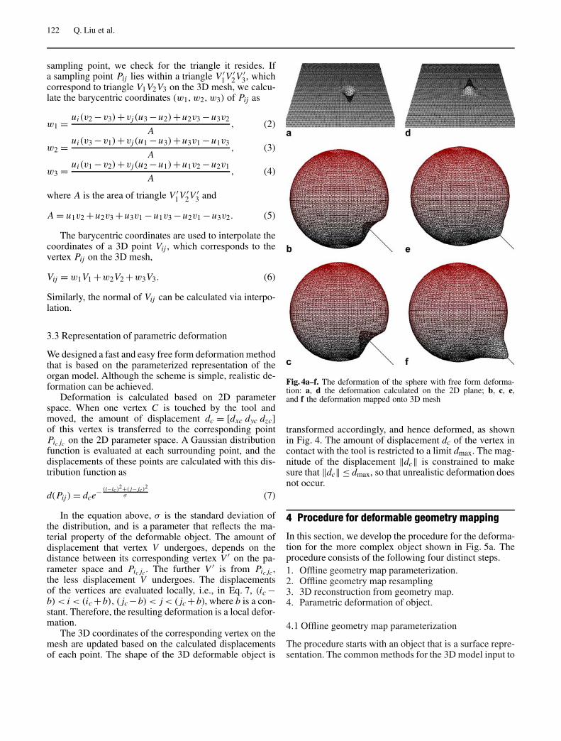
Fig. 4a–f. The deformation of the sphere with free form deforma-tion: a, d the deformation calculated on the 2D plane; b, c, e,and f the deformation mapped onto 3D mesh
transformed accordingly, and hence deformed, as shownin Fig. 4. The amount of displacement dc of the vertex incontact with the tool is restricted to a limit dmax. The mag-nitude of the displacement ‖dc‖ is constrained to makesure that ‖dc‖ ≤ dmax, so that unrealistic deformation doesnot occur.
4 Procedure for deformable geometry mapping
In this section, we develop the procedure for the deforma-tion for the more complex object shown in Fig. 5a. Theprocedure consists of the following four distinct steps.1. Offline geometry map parameterization.2. Offline geometry map resampling3. 3D reconstruction from geometry map.4. Parametric deformation of object.
4.1 Offline geometry map parameterization
The procedure starts with an object that is a surface repre-sentation. The common methods for the 3D model input to
Interactive deformable geometry maps 123
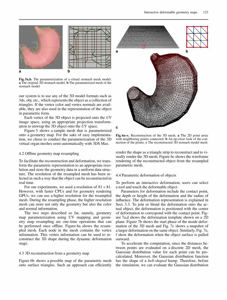
Fig. 5a,b. The parameterization of a virtual stomach mesh model.a The original 3D stomach model. b The parameterized mesh of thestomach model
our system is to use any of the 3D model formats such as3ds, obj, etc., which represents the object as a collection oftriangles. If the vertex color and vertex normals are avail-able, they are also used in the representation of the objectin parametric form.
Each vertex of the 3D object is projected onto the UVimage space, using an appropriate projection transform-ation to unwrap the 3D object onto the UV space.
Figure 5 shows a sample mesh that is parameterizedonto a geometry map. For the sake of easy implementa-tion, we chose to conduct the parameterization of the 3Dvirtual organ meshes semi-automatically with 3DS Max.
4.2 Offline geometry map resampling
To facilitate the reconstruction and deformation, we trans-form the parametric representation to an appropriate reso-lution and store the geometry data in a uniform data struc-ture. The resolution of the resampled mesh has been se-lected in such a way that the object can be reconstructed inreal-time.
For our experiments, we used a resolution of 81×81.However, with faster CPUs and for geometry renderingGPUs, we can use a higher resolution for the resampledmesh. During the resampling phase, the higher resolutionmesh can store not only the geometry but also the colorand normal information.
The two steps described so far, namely, geometrymap parameterization using UV mapping and geom-etry map resampling are one-time operations that canbe performed once offline. Figure 6a shows the resam-pled mesh. Each node in the mesh contains the vertexinformation. This vertex information can be used to re-construct the 3D shape during the dynamic deformationstage.
4.3 3D reconstruction from a geometry map
Figure 6b shows a possible map of the parametric meshonto surface triangles. Such an approach can efficiently
Fig. 6a–c. Reconstruction of the 3D mesh. a The 2D point arraywith neighboring points connected. b An up-close look of the con-nection of the points. c The reconstructed 3D stomach model mesh
render the shape as a triangle strip to reconstruct and to vi-sually render the 3D mesh. Figure 6c shows the wireframerendering of the reconstructed object from the resampledparametric mesh.
4.4 Parametric deformation of objects
To perform an interactive deformation, users can selecta tool and touch the deformable object.
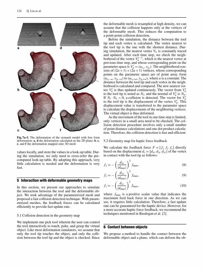
Parameters for deformation include the contact point,the depth or height of the deformation and the radius ofinfluence. The deformation representation is explained inSect. 3.3. To join or blend the deformation onto the ac-tual object, the deformation is positioned with the centerof deformation to correspond with the contact point. Fig-ure 7a,d shows the deformation template shown on a 2Dplane. Figure 7b shows the start phase of the inside defor-mation of the 3D mesh and Fig. 7c shows a snapshot ofa larger deformation on the same object. Similarly, Fig. 7e,f show the deformation when the object surface is pulledoutward.
To accelerate the computation, since the distances be-tween points are evaluated on a discrete 2D mesh, theGaussian distribution value for each point can be pre-calculated. Moreover, the Gaussian distribution functionhas the shape of a bell-shaped hump. Therefore, beforethe simulation, we can evaluate the Gaussian distribution
124 Q. Liu et al.
Fig. 7a–f. The deformation of the stomach model with free formdeformation: a, d the deformation calculated on the 2D plane; b, c,e, and f the deformation mapped onto 3D mesh
values locally, and store the values in a look-up table. Dur-ing the simulation, we only need to cross-refer the pre-computed look-up table. By adopting this approach, verylittle calculation is needed and the deformation is veryfast.
5 Interaction with deformable geometry maps
In this section, we present our approaches to simulatethe interaction between the tool and the deformable ob-ject. We took advantage of the parameterized mesh andproposed a fast collision detection technique. With param-eterized meshes, the feedback forces can be calculatedefficiently to provide fast update rate.
5.1 Collision detection in the geometry map
We implement one pick tool wherein the user can controlthe tool interactively to touch, poke, and grasp the virtualobject. Like most deformation simulators, we assume thatonly the tool tip touches the object, and only the colli-sion between the tool tip and the object is checked. Since
the deformable mesh is resampled at high density, we canassume that the collision happens only at the vertices ofthe deformable mesh. This reduces the computation toa point-point collision detection.
Before the simulation, the distance between the tooltip and each vertex is calculated. The vertex nearest tothe tool tip is the one with the shortest distance. Dur-ing simulation, the nearest vertex Vn is constantly tracedand updated. After each time step, we check the neigh-borhood of the vertex V t−1
n , which is the nearest vertex atprevious time step, and whose corresponding point on theparameter space is V ′
n = (uin , vjn). The neighborhood con-sists of (2a +1)× (2a +1) vertices, whose correspondingpoints on the parameter space are of point array form(uin−a, vjn−a) to (uin+a, vjn+a), where a is a constant. Thedistance between the tool tip and each vertex in the neigh-borhood is calculated and compared. The new nearest ver-tex V t
n is thus updated continuously. The vector from V tn
to the tool tip is noted as Nt , and the normal of V tn is Nn .
If Nt · Nn < 0, a collision is detected. The vector for V tn
to the tool tip is the displacement of the vertex V tn . This
displacement value is transferred to the parameter spaceto calculate the displacements of the neighboring vertices.The virtual object is thus deformed.
As the movement of the tool in one time step is limited,only vertices in a small area need to be checked. The col-lision detection procedure involves only a small numberof point distance calculations and one dot product calcula-tion. Therefore, the collision detection is fast and efficient.
5.2 Geometry map for haptic force feedback
We calculate the feedback force F = [ fx fy fz] directlybased on the displacement dc = [dxc dyc dzc] of the vertexin contact with the tool tip as follows:
fx = −(
dxc
|dmax|)3
fmax, (8)
fy = −(
dyc
|dmax|)3
fmax, (9)
fz = −(
dzc
|dmax|)3
fmax, (10)
where fmax is a positive scalar value that indicates themaximum feed back force in one direction. As we cansee, it requires little calculation. Therefore, a fast updaterate can be guaranteed for the haptic device. However, fora more accurate haptic force feedback, we recommend thetechniques mentioned in Basdogan et al. [2].
6 Contact between objects
We propose a method to handle the contact between thedeformable object and a plane, which can deform the ob-
Interactive deformable geometry maps 125
ject in a natural way and preserve the volume of the de-formable object approximately. This method can be ex-tended to handle the contact between the deformable ob-ject and another object of any shape. The other object caneither be rigid, such as some kind of surgery tool, or de-formable, such as an organ.
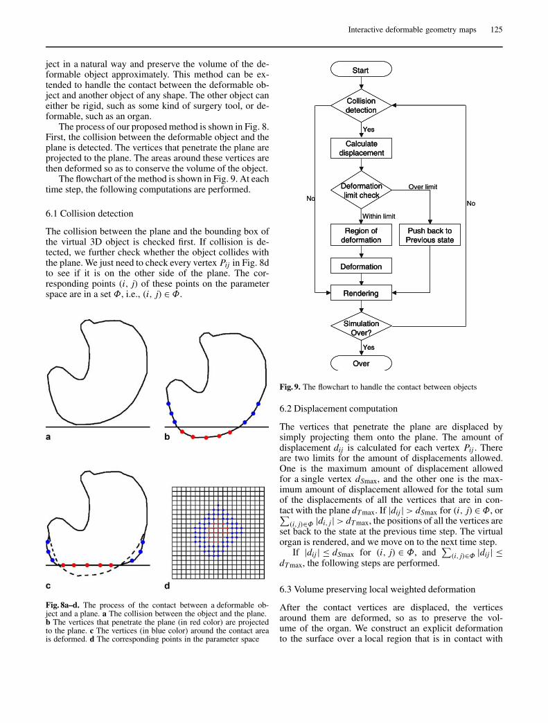
The process of our proposed method is shown in Fig. 8.First, the collision between the deformable object and theplane is detected. The vertices that penetrate the plane areprojected to the plane. The areas around these vertices arethen deformed so as to conserve the volume of the object.
The flowchart of the method is shown in Fig. 9. At eachtime step, the following computations are performed.
6.1 Collision detection
The collision between the plane and the bounding box ofthe virtual 3D object is checked first. If collision is de-tected, we further check whether the object collides withthe plane. We just need to check every vertex Pij in Fig. 8dto see if it is on the other side of the plane. The cor-responding points (i, j) of these points on the parameterspace are in a set Φ, i.e., (i, j) ∈ Φ.
Fig. 8a–d. The process of the contact between a deformable ob-ject and a plane. a The collision between the object and the plane.b The vertices that penetrate the plane (in red color) are projectedto the plane. c The vertices (in blue color) around the contact areais deformed. d The corresponding points in the parameter space
Fig. 9. The flowchart to handle the contact between objects
6.2 Displacement computation
The vertices that penetrate the plane are displaced bysimply projecting them onto the plane. The amount ofdisplacement dij is calculated for each vertex Pij . Thereare two limits for the amount of displacements allowed.One is the maximum amount of displacement allowedfor a single vertex dSmax, and the other one is the max-imum amount of displacement allowed for the total sumof the displacements of all the vertices that are in con-tact with the plane dTmax. If |dij | > dSmax for (i, j) ∈ Φ, or∑
(i, j)∈Φ |di, j | > dTmax, the positions of all the vertices areset back to the state at the previous time step. The virtualorgan is rendered, and we move on to the next time step.
If |dij | ≤ dSmax for (i, j) ∈ Φ, and∑
(i, j)∈Φ |dij | ≤dTmax, the following steps are performed.
6.3 Volume preserving local weighted deformation
After the contact vertices are displaced, the verticesaround them are deformed, so as to preserve the vol-ume of the organ. We construct an explicit deformationto the surface over a local region that is in contact with
126 Q. Liu et al.
the plane. The region of the deformation Ψ is decidedby the sum of the displacements of the contact verticesD = ∑
(i, j)∈Φ |dij |. The higher the value of D, the largerthe region.
In the parameter space, we check each point (i, j) andfind its nearest contact vertex and the distance sij . If thevalue of sij is lower than a threshold R, the vertex Pij cor-responding to (i, j) is in the region of deformation, i.e.,(i, j) ∈ Ψ . R is defined as a function of D. The higher thevalue of D, the higher the value of R. In practice, we canpredefine a set of discrete threshold values Rk and its cor-responding Dk, where k = 1, 2, . . . , p.
If the vertex Pij is in the region of deformation, the di-rection of its displacement dij is in its normal direction,so that the volume of the organ is increased to compen-sate the decrease of volume due to the contact area. Theamount of displacement is defined as
|dij |(i, j)∈Ψ = e− s2
ijσk
∑(i′, j ′)∈Φ
|di′ j ′ |, (11)
where σk is the standard deviation of Gaussian distributionthat corresponds to the threshold value Rk.
Similar to the case where the object is deformed bythe tool, the Gaussian distribution value for each discretevalue of sij can be pre-calculated and stored. During simu-lation, the distribution values are looked up in the pre-calculated data so as to increase the speed of simulation.
7 Experimental results
7.1 DGM for surgery simulation
Laparoscopic surgery is a popular surgery technique thathas benefits such as less pain, faster recovery, and shorterhospitalization time. The drawback of this technique isthat it is more difficult than traditional surgery procedures,and surgeons need to learn and adapt themselves to thisnew type of surgery. To master laparoscopic surgery, mas-sive training and practice is required. With virtual realitytechnology, surgery simulator can provide cheap and in-tensive training without the need of cadavers or animals.
One important issue of surgery simulation is to modelthe virtual human organs in a realistic way, not only visu-ally, but also haptically. Visually, the virtual organs shouldhave an adequate number of polygons so that the surfacescan be rendered smoothly. Textures are applied to addcolors and details. Some deformation methods should beapplied to allow interaction between the user and the vir-tual organ.
To add haptical realism, a haptic device, such as thePHANTOM device developed by SensAble Technologies,can be used to control the movement of the virtual surgerytool. The feedback forces should be calculated and up-dated at a high frequency (1 KHz at least for PHANTOM).
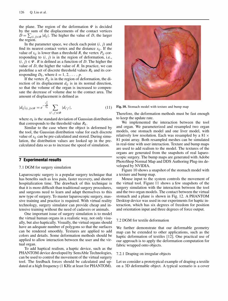
Fig. 10. Stomach model with texture and bump map
Therefore, the deformation methods must be fast enoughto keep the update rate.
We implemented the interaction between the tooland organ. We parameterized and resampled two organmodels, one stomach model and one liver model, withrelatively low resolution. Each was resampled by a 81 ×81 point array. Both resampled meshes can be simulatedin real-time with user interaction. Texture and bump mapsare used to add realism to the model. The textures of theorgans are generated from the snapshots of real laparo-scopic surgery. The bump maps are generated with AdobePhotoShop Normal Map and DDS Authoring Plug-ins de-veloped by NVIDIA.
Figure 10 shows a snapshot of the stomach model witha texture and bump map.
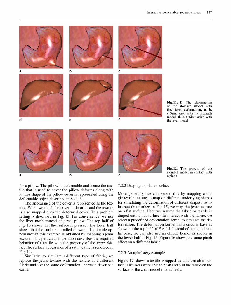
Mouse input to the system controls the movement ofthe virtual tool. Figure 11 shows a few snapshots of thesurgery simulation with the interaction between the tooland the two organ models. The contact between the virtualstomach and a plane is shown in Fig. 12. A PHANTOMDesktop device was used in our experiments for haptic in-teraction, which has six degrees of freedom for positionand orientation input and three degrees of force output.
7.2 DGM for textile deformation
We further demonstrate that our deformable geometrymap can be extended to other applications, such as thehaptic deformation of textiles [12]. One practical use ofour approach is to apply the deformation computation forfabric wrapped onto objects.
7.2.1 Draping on irregular objects
Let us consider a prototypical example of draping a textileon a 3D deformable object. A typical scenario is a cover
Interactive deformable geometry maps 127
Fig. 11a–f. The deformationof the stomach model withfree form deformation. a, b,c Simulation with the stomachmodel. d, e, f Simulation withthe liver model
Fig. 12. The process of thestomach model in contact witha plane
for a pillow. The pillow is deformable and hence the tex-tile that is used to cover the pillow deforms along withit. The shape of the pillow cover is represented using thedeformable object described in Sect. 3.
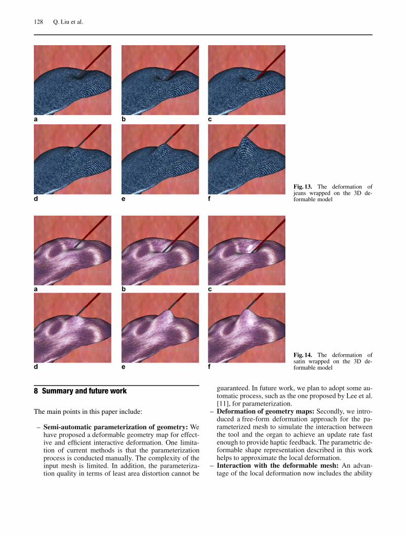
The appearance of the cover is represented as the tex-ture. When we touch the cover, it deforms and the textureis also mapped onto the deformed cover. This problemsetting is described in Fig. 13. For convenience, we usethe liver mesh instead of a real pillow. The top half ofFig. 13 shows that the surface is pressed. The lower halfshows that the surface is pulled outward. The textile ap-pearance in this example is obtained by mapping a jeanstexture. This particular illustration describes the requiredbehavior of a textile with the property of the jeans fab-ric. The surface appearance of a satin textile is rendered inFig. 14.
Similarly, to simulate a different type of fabric, wereplace the jeans texture with the texture of a differentfabric and use the same deformation approach describedearlier.
7.2.2 Draping on planar surfaces
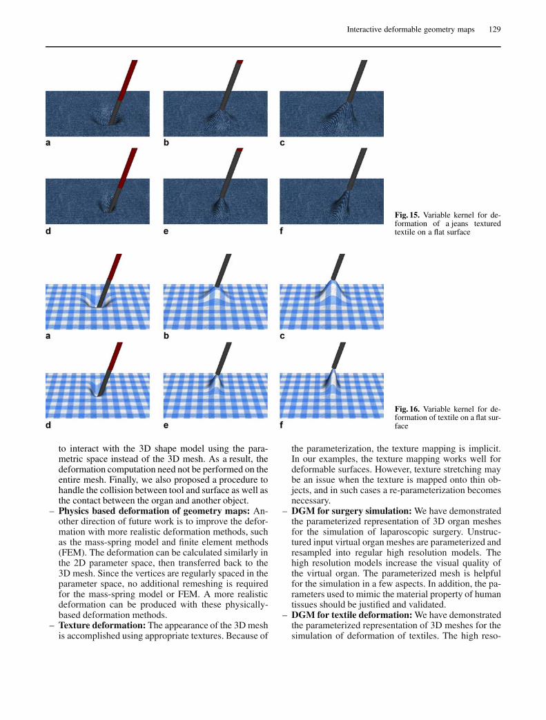
More generally, we can extend this by mapping a sin-gle textile texture to map on different underlying shapesfor simulating the deformation of different shapes. To il-lustrate this further, in Fig. 15, we map the jeans textureon a flat surface. Here we assume the fabric or textile isdraped onto a flat surface. To interact with the fabric, weselect a predefined deformation kernel to simulate the de-formation. The deformation kernel has a circular base asshown in the top half of Fig. 15. Instead of using a circu-lar base, we can also use an elliptic kernel as shown inthe lower half of Fig. 15. Figure 16 shows the same pincheffect on a different fabric.
7.2.3 An upholstery example
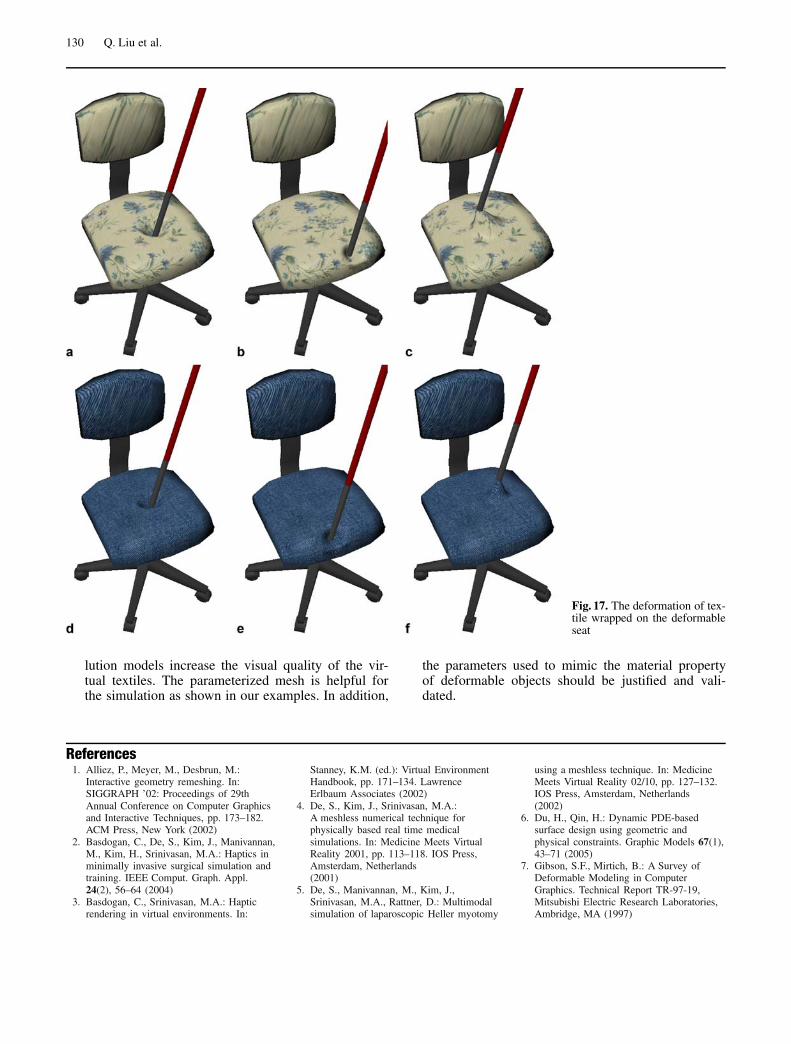
Figure 17 shows a textile wrapped as a deformable sur-face. The users were able to push and pull the fabric on thesurface of the chair model interactively.
128 Q. Liu et al.
Fig. 13. The deformation ofjeans wrapped on the 3D de-formable model
Fig. 14. The deformation ofsatin wrapped on the 3D de-formable model
8 Summary and future work
The main points in this paper include:
– Semi-automatic parameterization of geometry: Wehave proposed a deformable geometry map for effect-ive and efficient interactive deformation. One limita-tion of current methods is that the parameterizationprocess is conducted manually. The complexity of theinput mesh is limited. In addition, the parameteriza-tion quality in terms of least area distortion cannot be
guaranteed. In future work, we plan to adopt some au-tomatic process, such as the one proposed by Lee et al.[11], for parameterization.
– Deformation of geometry maps: Secondly, we intro-duced a free-form deformation approach for the pa-rameterized mesh to simulate the interaction betweenthe tool and the organ to achieve an update rate fastenough to provide haptic feedback. The parametric de-formable shape representation described in this workhelps to approximate the local deformation.
– Interaction with the deformable mesh: An advan-tage of the local deformation now includes the ability
Interactive deformable geometry maps 129
Fig. 15. Variable kernel for de-formation of a jeans texturedtextile on a flat surface
Fig. 16. Variable kernel for de-formation of textile on a flat sur-face
to interact with the 3D shape model using the para-metric space instead of the 3D mesh. As a result, thedeformation computation need not be performed on theentire mesh. Finally, we also proposed a procedure tohandle the collision between tool and surface as well asthe contact between the organ and another object.
– Physics based deformation of geometry maps: An-other direction of future work is to improve the defor-mation with more realistic deformation methods, suchas the mass-spring model and finite element methods(FEM). The deformation can be calculated similarly inthe 2D parameter space, then transferred back to the3D mesh. Since the vertices are regularly spaced in theparameter space, no additional remeshing is requiredfor the mass-spring model or FEM. A more realisticdeformation can be produced with these physically-based deformation methods.
– Texture deformation: The appearance of the 3D meshis accomplished using appropriate textures. Because of
the parameterization, the texture mapping is implicit.In our examples, the texture mapping works well fordeformable surfaces. However, texture stretching maybe an issue when the texture is mapped onto thin ob-jects, and in such cases a re-parameterization becomesnecessary.
– DGM for surgery simulation: We have demonstratedthe parameterized representation of 3D organ meshesfor the simulation of laparoscopic surgery. Unstruc-tured input virtual organ meshes are parameterized andresampled into regular high resolution models. Thehigh resolution models increase the visual quality ofthe virtual organ. The parameterized mesh is helpfulfor the simulation in a few aspects. In addition, the pa-rameters used to mimic the material property of humantissues should be justified and validated.
– DGM for textile deformation: We have demonstratedthe parameterized representation of 3D meshes for thesimulation of deformation of textiles. The high reso-
130 Q. Liu et al.
Fig. 17. The deformation of tex-tile wrapped on the deformableseat
lution models increase the visual quality of the vir-tual textiles. The parameterized mesh is helpful forthe simulation as shown in our examples. In addition,
the parameters used to mimic the material propertyof deformable objects should be justified and vali-dated.
References1. Alliez, P., Meyer, M., Desbrun, M.:
Interactive geometry remeshing. In:SIGGRAPH ’02: Proceedings of 29thAnnual Conference on Computer Graphicsand Interactive Techniques, pp. 173–182.ACM Press, New York (2002)
2. Basdogan, C., De, S., Kim, J., Manivannan,M., Kim, H., Srinivasan, M.A.: Haptics inminimally invasive surgical simulation andtraining. IEEE Comput. Graph. Appl.24(2), 56–64 (2004)
3. Basdogan, C., Srinivasan, M.A.: Hapticrendering in virtual environments. In:
Stanney, K.M. (ed.): Virtual EnvironmentHandbook, pp. 171–134. LawrenceErlbaum Associates (2002)
4. De, S., Kim, J., Srinivasan, M.A.:A meshless numerical technique forphysically based real time medicalsimulations. In: Medicine Meets VirtualReality 2001, pp. 113–118. IOS Press,Amsterdam, Netherlands(2001)
5. De, S., Manivannan, M., Kim, J.,Srinivasan, M.A., Rattner, D.: Multimodalsimulation of laparoscopic Heller myotomy
using a meshless technique. In: MedicineMeets Virtual Reality 02/10, pp. 127–132.IOS Press, Amsterdam, Netherlands(2002)
6. Du, H., Qin, H.: Dynamic PDE-basedsurface design using geometric andphysical constraints. Graphic Models 67(1),43–71 (2005)
7. Gibson, S.F., Mirtich, B.: A Survey ofDeformable Modeling in ComputerGraphics. Technical Report TR-97-19,Mitsubishi Electric Research Laboratories,Ambridge, MA (1997)
Interactive deformable geometry maps 131
8. Grimm, C.M.: Parameterization usingmanifolds. Int. J. Shape Model. 10(1),51–81 (2004)
9. Gu, X., Gortler, S.J., Hoppe, H.: Geometryimages. In: SIGGRAPH ’02: Proceedingsof 29th Annual Conference on ComputerGraphics and Interactive Techniques, pp.355–361. ACM Press, New York(2002)
10. Hirota, G., Fisher, S., State, A.: Animproved finite-element contact model foranatomical simulations. Visual Comput.19(5), 291–309 (2003)
11. Lee, H., Tong, Y., Desbrun, M.:Geodesics-based one-to-oneparameterization of 3D triangle meshes.IEEE Multimedia 12(1), 27–33 (2005)
12. Magnenat-Thalmann, N., Wolter, F.:Workshop on haptic and tactile perceptionof deformable objects. In: Proceedings ofHAPTEX ’05: VR workshop on haptic andtactile perception of deformable objects,pp. 1–86, Hannover, Germany (2005)
13. Onoue, K., Nishita, T.: An interactivedeformation system for granular material.
Comput. Graph. Forum 24(1), 51–60(2005)
14. Schein, S., Elber, G.: Placement ofdeformable objects. Comput. Graph. Forum23(4), 727–739 (2004)
15. Srinivasan, M.A., Basdogan, C.: Haptics invirtual environments: taxonomy, researchstatus, and challenges. Comput. Graph.21(4), 393–404 (1997)
QIANG LIU received his BEng in ComputerScience and Technology in 2002 from ZhejiangUniversity, China. He is currently a PhD stu-dent at the School of Computer Engineering,Nanyang Technological University, Singapore.He is also working as a research assistant atNational Institute of Education, an Instituteof Nanyang Technological University. Hisresearch interests include virtual reality, com-puter graphics, computer animation, and 3Dvisualization.
DR. EDMOND PRAKASH joined the Schoolof Computer Engineering as an AssistantProfessor in 1997. He received his PhD inComputer Science from the Indian Instituteof Science, Bangalore, India. After receivinghis PhD, he joined the State University ofNew York–Stony Brook, USA. He has alsobeen a visiting faculty member at (i) the Na-tional Center for Supercomputing Applications(NCSA) at the University of Illinois at UrbanaChampaign (UIUC), (ii) the Beckman Institute,UIUC and (iii) the Touch Lab at MIT. Cur-rently, Dr. Prakash is an Assistant Professorin Computer Science and concurrently theResearch Director for the GameLAB at theSchool of Computer Engineering at NanyangTechnological University, Singapore. Formore information on his research please visit:http://www.ntu.edu.sg/home/ASprakash/
DR. MANDAYAM A. SRINIVASAN is the direc-tor of MIT’s Touch Lab and a senior researchscientist at MIT’s Department of MechanicalEngineering and the Research Laboratory ofElectronics. His research interests include hapticcomputation, cognition, and communication inhumans and machines, particularly to enhancehuman–machine interactions in virtual environ-ment systems. Srinivasan has a PhD in AppliedMechanics from the Department of MechanicalEngineering at Yale University.