
InterReach Spectrum Remote Access Unit Installation Guide ...
30
ADCP-77-168 Issue 3 May 2012 D-620731-0-20 Rev C InterReach Spectrum ™ Remote Access Unit Installation Guide - Preliminary Update - Issue 3 Main Remote Access Unit Secondary Remote Access Unit
-
Upload
khangminh22 -
Category
Documents
-
view
0 -
download
0
Transcript of InterReach Spectrum Remote Access Unit Installation Guide ...
ADCP-77-168 Issue 3 May 2012
D-620731-0-20 Rev C
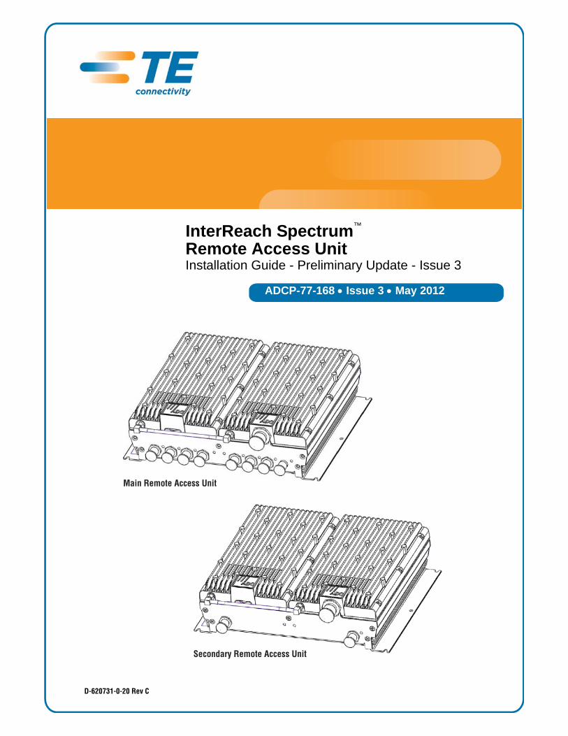
InterReach Spectrum™ Remote Access Unit Installation Guide - Preliminary Update - Issue 3
Main Remote Access Unit
Secondary Remote Access Unit
Copyright© 2012 TE Connectivity, Inc. All Rights Reserved.Information contained in this document is company private to TE Connectivity Ltd., and shall not be modified, used, copied, reproduced or disclosed in whole or in part without the written consent of TE.
Trademark InformationFlexWave, FlexWave Prism, InterReach Spectrum, Universal Radio Head, TE Connectivity, and TE connectivity (logo) are trademarks.All other logos, products and/or company names referred to herein might be trademarks of their respective owners.
Disclaimer of LiabilityContents herein are current as of the date of publication. TE reserves the right to change the contents without prior notice. Should the content of printed user documentation shipped with product differ from documentation provided on a product CD (inclusive of the associated Help modules), the printed user documentation supersedes the documentation on the product CD. In no event shall TE be liable for any damages resulting from loss of data, loss of use, or loss of profits, and TE further disclaims any and all liability for indirect, incidental, special, consequential or other similar damages. This disclaimer of liability applies to all products, publications and services during and after the warranty period.
Specific Disclaimer for High-Risk ActivitiesThis Product is not specifically designed, manufactured, tested or intended for use in high-risk activities including, without restricting the generality of the foregoing, on-line control of aircraft, air traffic, aircraft navigation or aircraft communications; or in the design, construction, operation or maintenance of any nuclear facility. TE (including its affiliates) and its suppliers specifically disclaim any express or implied warranty of fitness for such purposes or any other purposes.
Screenshots in User DocumentationDue to concurrent development of this documentation, artwork, and the InterReach Spectrum Element Management System (EMS), there may be some minor discrepancies between screenshots contained in this documentation and those actually displayed in the InterReach Spectrum EMS. These discrepancies will generally be few and minor and should not affect your understanding of InterReach Spectrum EMS.

TABLE OF CONTENTS
Preface.............................................................................................................................................................................2Revision History .......................................................................................................................................................2InterReach Spectrum User Documentation...............................................................................................................2Standards Certification .............................................................................................................................................3
Product Overview.............................................................................................................................................................4Main Remote Access Units .......................................................................................................................................5
MRAU Ports, Cable, and Connectors .................................................................................................................5MRAU LEDs.......................................................................................................................................................6
Secondary Remote Access Units ..............................................................................................................................7SRAU Ports, Cable, and Connectors..................................................................................................................7SRAU LEDs........................................................................................................................................................8
RAU N Connectors....................................................................................................................................................9Install the RAUs and Antennas.......................................................................................................................................10
Mount the RAUs and Antennas...............................................................................................................................10General Safety Precautions.....................................................................................................................................10Connect the IFEU to the MRAU...............................................................................................................................11Connect the MRAU to SRAUs .................................................................................................................................13Configure the MRAUs and SRAUs ..........................................................................................................................14
Appendix A: Specifications.............................................................................................................................................15Remote Access Unit Specifications.........................................................................................................................15Spectrum System Specifications ............................................................................................................................15Composite Power Out of RAU.................................................................................................................................17
Appendix B: 75-Ohm CATV Cable ..................................................................................................................................18CATV Cable Requirements ......................................................................................................................................18Belden 1695A Coax Specifications..........................................................................................................................19
Description ......................................................................................................................................................19Overall Physical Characteristics.......................................................................................................................19Overall Nominal Electrical Characteristics........................................................................................................20
Belden 7732A Coax Specifications..........................................................................................................................21Description ......................................................................................................................................................21Overall Physical Characteristics.......................................................................................................................21Overall Nominal Electrical Characteristics........................................................................................................21
Appendix C: Omni Antenna ............................................................................................................................................23Appendix D: Contacting TE Connectivity ........................................................................................................................24
InterReach Spectrum Remote Access Unit Installation Guide - Preliminary Update for Issue 3 Page 1ADCP-77-168 • Issue 3 • May 2012 ©2012 TE Connectivity Ltd.
Preface
PREFACE
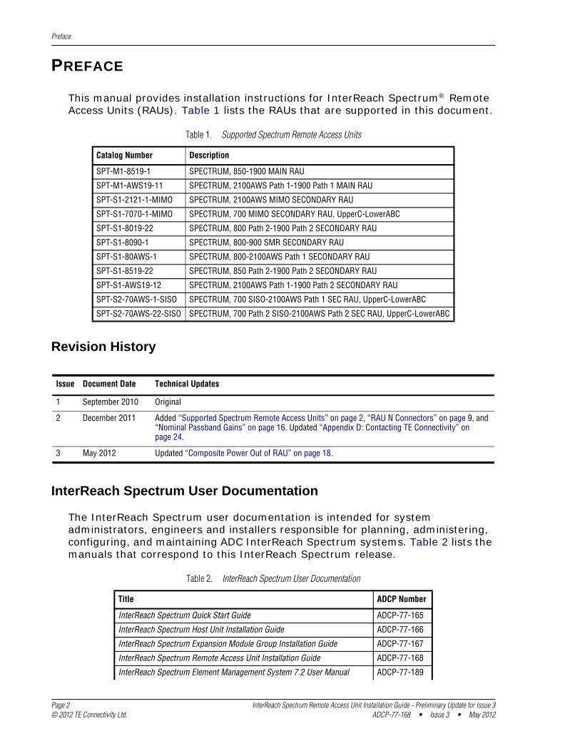
This manual provides installation instructions for InterReach Spectrum® Remote Access Units (RAUs). Table 1 lists the RAUs that are supported in this document.
Table 1. Supported Spectrum Remote Access Units
Catalog Number Description
SPT-M1-8519-1 SPECTRUM, 850-1900 MAIN RAU
SPT-M1-AWS19-11 SPECTRUM, 2100AWS Path 1-1900 Path 1 MAIN RAU
SPT-S1-2121-1-MIMO SPECTRUM, 2100AWS MIMO SECONDARY RAU
SPT-S1-7070-1-MIMO SPECTRUM, 700 MIMO SECONDARY RAU, UpperC-LowerABC
SPT-S1-8019-22 SPECTRUM, 800 Path 2-1900 Path 2 SECONDARY RAU
SPT-S1-8090-1 SPECTRUM, 800-900 SMR SECONDARY RAU
SPT-S1-80AWS-1 SPECTRUM, 800-2100AWS Path 1 SECONDARY RAU
SPT-S1-8519-22 SPECTRUM, 850 Path 2-1900 Path 2 SECONDARY RAU
SPT-S1-AWS19-12 SPECTRUM, 2100AWS Path 1-1900 Path 2 SECONDARY RAU
SPT-S2-70AWS-1-SISO SPECTRUM, 700 SISO-2100AWS Path 1 SEC RAU, UpperC-LowerABC
SPT-S2-70AWS-22-SISO SPECTRUM, 700 Path 2 SISO-2100AWS Path 2 SEC RAU, UpperC-LowerABC
Revision History
Issue Document Date Technical Updates
1 September 2010 Original
2 December 2011 Added “Supported Spectrum Remote Access Units” on page 2, “RAU N Connectors” on page 9, and “Nominal Passband Gains” on page 16. Updated “Appendix D: Contacting TE Connectivity” on page 24.
3 May 2012 Updated “Composite Power Out of RAU” on page 18.
InterReach Spectrum User Documentation
The InterReach Spectrum user documentation is intended for system administrators, engineers and installers responsible for planning, administering, configuring, and maintaining ADC InterReach Spectrum systems. Table 2 lists the manuals that correspond to this InterReach Spectrum release.
Table 2. InterReach Spectrum User Documentation
Title ADCP Number
InterReach Spectrum Quick Start Guide ADCP-77-165
InterReach Spectrum Host Unit Installation Guide ADCP-77-166
InterReach Spectrum Expansion Module Group Installation Guide ADCP-77-167
InterReach Spectrum Remote Access Unit Installation Guide ADCP-77-168
InterReach Spectrum Element Management System 7.2 User Manual ADCP-77-189
Page 2 InterReach Spectrum Remote Access Unit Installation Guide - Preliminary Update for Issue 3© 2012 TE Connectivity Ltd. ADCP-77-168 • Issue 3 • May 2012
Preface
Two types of messages, identified below, appear in the InterReach Spectrum user documentation:
CAUTION! Caution text indicates operations or steps that could cause personal injury, induce a safety problem in a managed device, destroy or corrupt information, or interrupt or stop services.
NOTE: Note text contains information about special circumstances.
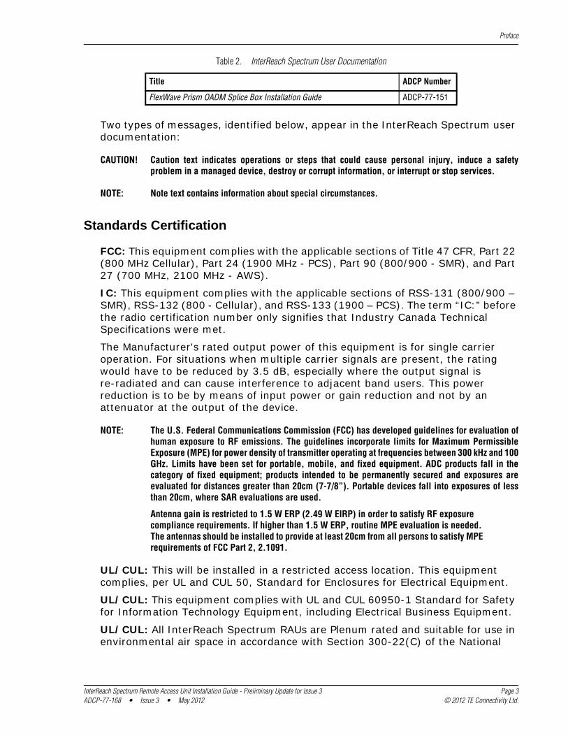
Standards Certification
FCC: This equipment complies with the applicable sections of Title 47 CFR, Part 22 (800 MHz Cellular), Part 24 (1900 MHz - PCS), Part 90 (800/900 - SMR), and Part 27 (700 MHz, 2100 MHz - AWS).
IC: This equipment complies with the applicable sections of RSS-131 (800/900 – SMR), RSS-132 (800 - Cellular), and RSS-133 (1900 – PCS). The term “IC:” before the radio certification number only signifies that Industry Canada Technical Specifications were met.
The Manufacturer's rated output power of this equipment is for single carrier operation. For situations when multiple carrier signals are present, the rating would have to be reduced by 3.5 dB, especially where the output signal is re-radiated and can cause interference to adjacent band users. This power reduction is to be by means of input power or gain reduction and not by an attenuator at the output of the device.
NOTE: The U.S. Federal Communications Commission (FCC) has developed guidelines for evaluation of human exposure to RF emissions. The guidelines incorporate limits for Maximum Permissible Exposure (MPE) for power density of transmitter operating at frequencies between 300 kHz and 100 GHz. Limits have been set for portable, mobile, and fixed equipment. ADC products fall in the category of fixed equipment; products intended to be permanently secured and exposures are evaluated for distances greater than 20cm (7-7/8”). Portable devices fall into exposures of less than 20cm, where SAR evaluations are used.
Antenna gain is restricted to 1.5 W ERP (2.49 W EIRP) in order to satisfy RF exposure compliance requirements. If higher than 1.5 W ERP, routine MPE evaluation is needed. The antennas should be installed to provide at least 20cm from all persons to satisfy MPE requirements of FCC Part 2, 2.1091.
UL/CUL: This will be installed in a restricted access location. This equipment complies, per UL and CUL 50, Standard for Enclosures for Electrical Equipment.
UL/CUL: This equipment complies with UL and CUL 60950-1 Standard for Safety for Information Technology Equipment, including Electrical Business Equipment.
UL/CUL: All InterReach Spectrum RAUs are Plenum rated and suitable for use in environmental air space in accordance with Section 300-22(C) of the National
FlexWave Prism OADM Splice Box Installation Guide ADCP-77-151
Table 2. InterReach Spectrum User Documentation
Title ADCP Number
InterReach Spectrum Remote Access Unit Installation Guide - Preliminary Update for Issue 3 Page 3ADCP-77-168 • Issue 3 • May 2012 © 2012 TE Connectivity Ltd.

Preface
Electrical Code, and Sections 2-128, 12-010(3) and 12-100 of the Canadian Electrical Code, Part 1, CSA C22.1.
UL: This equipment is UL Plenum rated under UL 2043.
CAUTION! Modifications not expressly approved by the party responsible for compliance could void the user's authority to operate the equipment.
Page 4 InterReach Spectrum Remote Access Unit Installation Guide - Preliminary Update for Issue 3© 2012 TE Connectivity Ltd. ADCP-77-168 • Issue 3 • May 2012
Product Overview
PRODUCT OVERVIEW
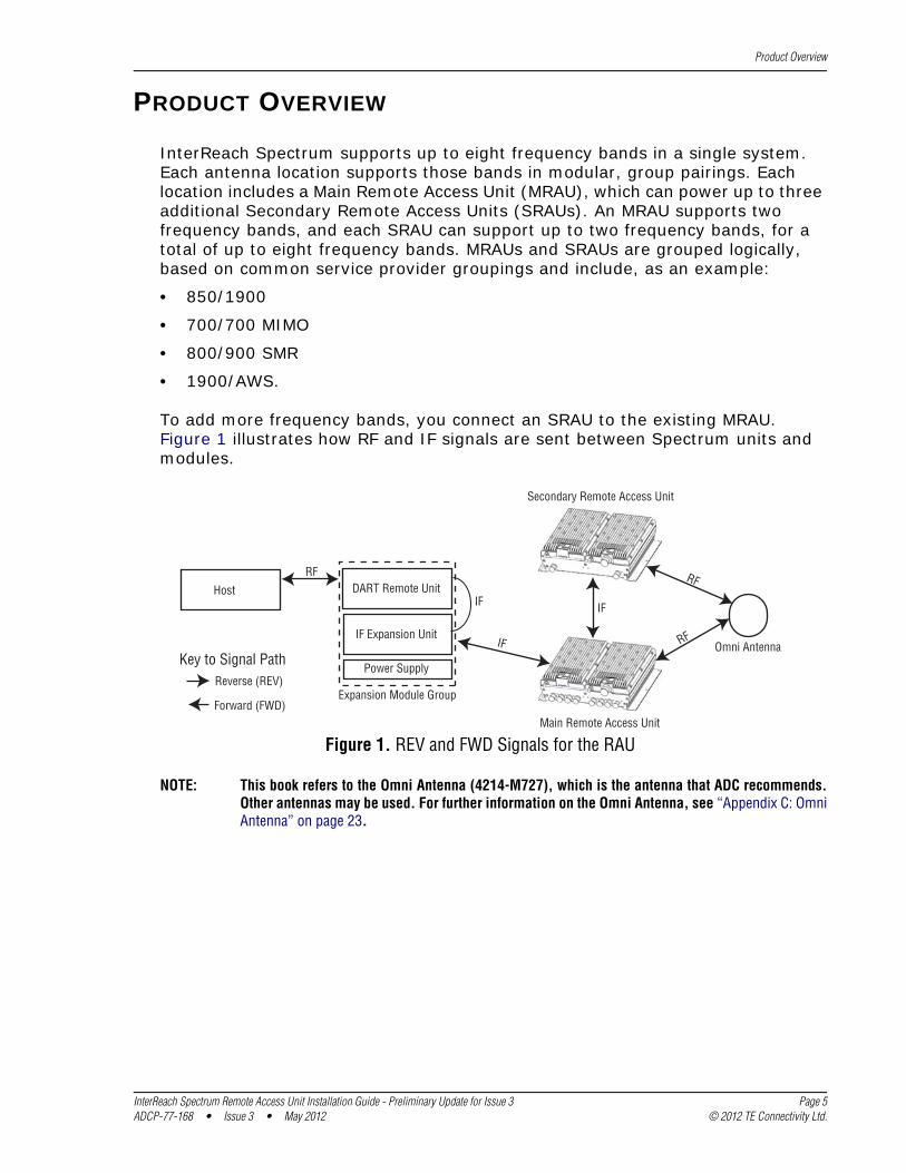
InterReach Spectrum supports up to eight frequency bands in a single system. Each antenna location supports those bands in modular, group pairings. Each location includes a Main Remote Access Unit (MRAU), which can power up to three additional Secondary Remote Access Units (SRAUs). An MRAU supports two frequency bands, and each SRAU can support up to two frequency bands, for a total of up to eight frequency bands. MRAUs and SRAUs are grouped logically, based on common service provider groupings and include, as an example:
• 850/1900
• 700/700 MIMO
• 800/900 SMR
• 1900/AWS.
To add more frequency bands, you connect an SRAU to the existing MRAU. Figure 1 illustrates how RF and IF signals are sent between Spectrum units and modules.
Omni Antenna
Host
Power Supply
IF Expansion Unit
DART Remote Unit
Expansion Module Group
Secondary Remote Access Unit
Main Remote Access Unit
IF
RFRF
IF
Reverse (REV)
Forward (FWD)
Key to Signal PathRFIF
Figure 1. REV and FWD Signals for the RAU
NOTE: This book refers to the Omni Antenna (4214-M727), which is the antenna that ADC recommends. Other antennas may be used. For further information on the Omni Antenna, see “Appendix C: Omni Antenna” on page 23.
InterReach Spectrum Remote Access Unit Installation Guide - Preliminary Update for Issue 3 Page 5ADCP-77-168 • Issue 3 • May 2012 © 2012 TE Connectivity Ltd.
Product Overview
Main Remote Access Units
The Main Remote Access Unit (MRAU) receives FWD IF signals from an IF Expansion Unit (IFEU), which is part of the Spectrum Expansion Module Group, using 75 CATV cable. The MRAU converts the IF signals to RF and sends them to a passive RF antenna using 50 coaxial cable. The MRAU also receives configuration information and power from and sends its status information to the IFEU.
The MRAU receives REV RF signals from a passive RF antenna using 50 coaxial cable. It converts the signals to IF and sends them to the IFEU using 75 CATV cable.
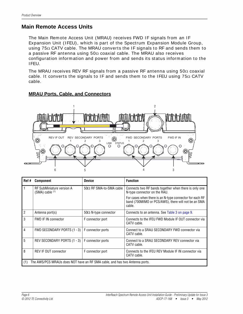
MRAU Ports, Cable, and Connectors
REV IF OUT REV SECONDARY PORTS 1 2 3
FWD SECONDARY PORTS 1 2 3
FWD IF IN
LINK STATUS
1 2
36 5 4
Ref # Component Device Function
1 RF SubMiniature version A (SMA) cable (1)
50 RF SMA-to-SMA cable Connects two RF bands together when there is only one N-type connector on the RAU.
For cases when there is an N-type connector for each RF band (700MIMO or PCS/AWS), there will not be an SMA cable.
2 Antenna port(s) 50 N-type connector Connects to an antenna. See Table 3 on page 9.
3 FWD IF IN connector F connector port Connects to the IFEU FWD Module IF OUT connector via CATV cable.
4 FWD SECONDARY PORTS (1 - 3) F connector ports Connect to a SRAU SECONDARY FWD connector via CATV cable.
5 REV SECONDARY PORTS (1 - 3) F connector ports Connect to a SRAU SECONDARY REV connector via CATV cable.
8 REV IF OUT connector F connector port Connects to the IFEU REV Module IF IN connector via CATV cable.
(1) The AWS/PCS MRAUs does NOT have an RF SMA cable, and has two Antenna ports.
Page 6 InterReach Spectrum Remote Access Unit Installation Guide - Preliminary Update for Issue 3© 2012 TE Connectivity Ltd. ADCP-77-168 • Issue 3 • May 2012
Product Overview
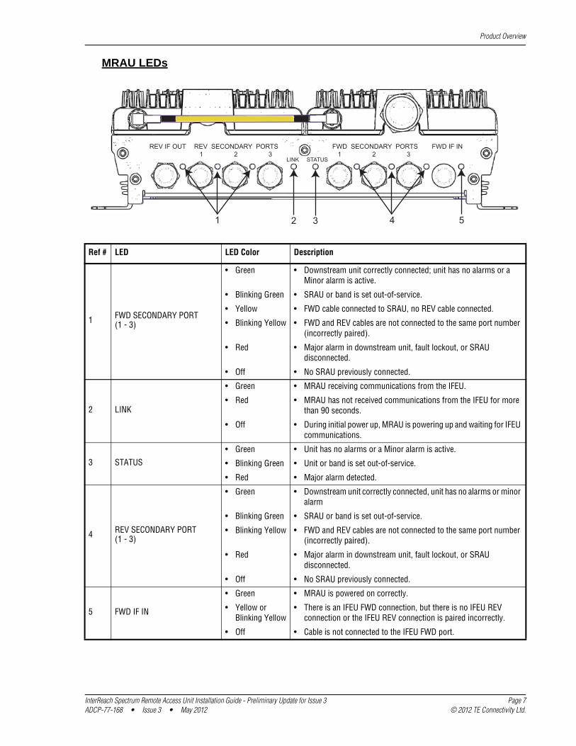
MRAU LEDs
REV IF OUT REV SECONDARY PORTS 1 2 3
FWD SECONDARY PORTS 1 2 3
FWD IF IN
LINK STATUS
41 52 3
Ref # LED LED Color Description
1 FWD SECONDARY PORT (1 - 3)
2 LINK
3 STATUS
4 REV SECONDARY PORT(1 - 3)
5 FWD IF IN
• Green • Downstream unit correctly connected; unit has no alarms or a Minor alarm is active.
• Blinking Green • SRAU or band is set out-of-service.
• Yellow • FWD cable connected to SRAU, no REV cable connected.
• Blinking Yellow • FWD and REV cables are not connected to the same port number (incorrectly paired).
• Red • Major alarm in downstream unit, fault lockout, or SRAU disconnected.
• Off • No SRAU previously connected.
• Green • MRAU receiving communications from the IFEU.
• Red • MRAU has not received communications from the IFEU for more than 90 seconds.
• Off • During initial power up, MRAU is powering up and waiting for IFEU communications.
• Green • Unit has no alarms or a Minor alarm is active.
• Blinking Green • Unit or band is set out-of-service.
• Red • Major alarm detected.
• Green • Downstream unit correctly connected, unit has no alarms or minor alarm
• Blinking Green • SRAU or band is set out-of-service.
• Blinking Yellow • FWD and REV cables are not connected to the same port number (incorrectly paired).
• Red • Major alarm in downstream unit, fault lockout, or SRAU disconnected.
• Off • No SRAU previously connected.
• Green • MRAU is powered on correctly.
• Yellow orBlinking Yellow
• There is an IFEU FWD connection, but there is no IFEU REV connection or the IFEU REV connection is paired incorrectly.
• Off • Cable is not connected to the IFEU FWD port.
InterReach Spectrum Remote Access Unit Installation Guide - Preliminary Update for Issue 3 Page 7ADCP-77-168 • Issue 3 • May 2012 © 2012 TE Connectivity Ltd.
Product Overview
Secondary Remote Access Units
A Secondary Remote Access Unit (SRAU) receives FWD IF signals from the MRAU, using 75 CATV cable. The SRAU converts the IF signals to RF and sends them to a passive RF antenna using 50 coaxial cable. The SRAU, through the MRAU, also receives configuration information and power from and sends its status information to the IFEU.
The SRAU receives REV RF signals from a passive RF antenna using 50 coaxial cable. It converts the signals to IF and sends them to the MRAU using 75 CATV cable.
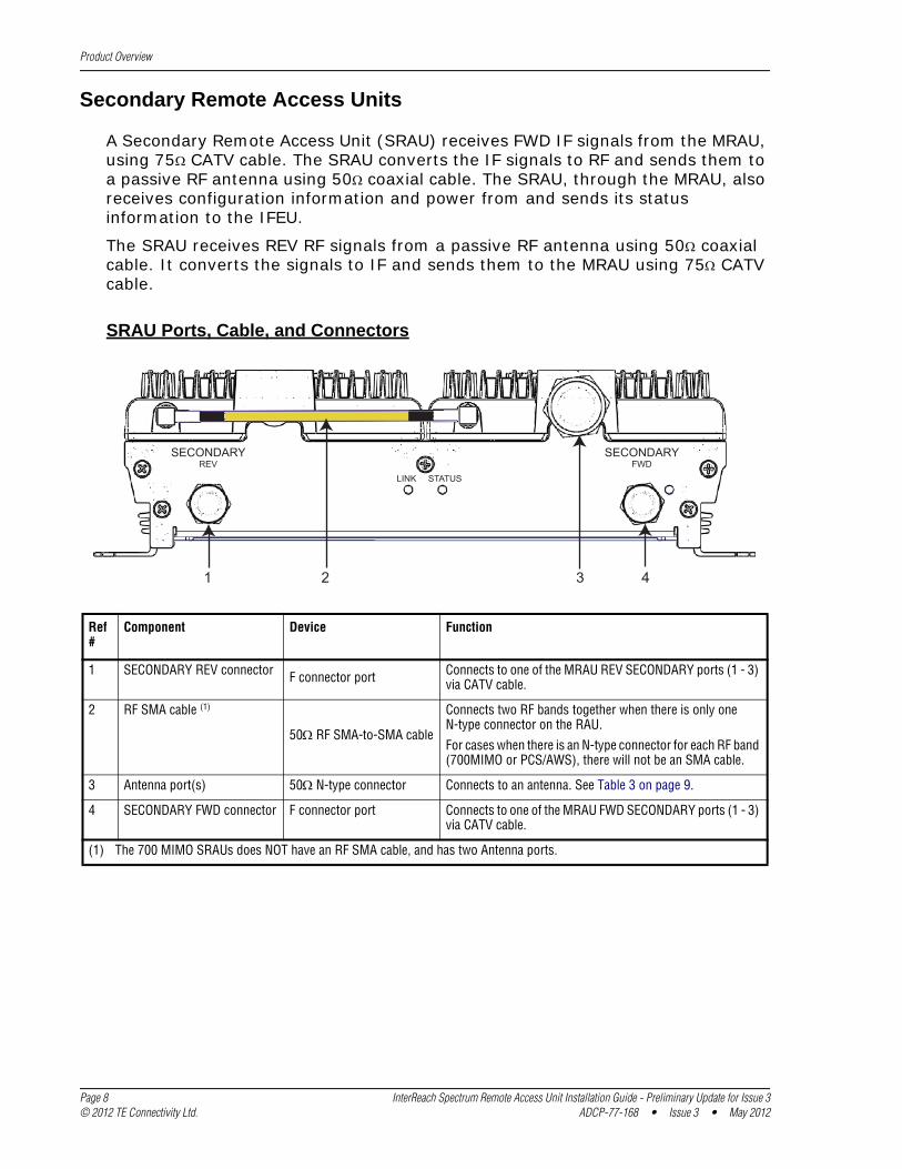
SRAU Ports, Cable, and Connectors
1 4
LINK STATUS
SECONDARYREV
SECONDARYFWD
2 3
Ref #
Component Device Function
1 SECONDARY REV connector F connector port Connects to one of the MRAU REV SECONDARY ports (1 - 3) via CATV cable.
2 RF SMA cable (1)
50 RF SMA-to-SMA cable
Connects two RF bands together when there is only one N-type connector on the RAU.
For cases when there is an N-type connector for each RF band (700MIMO or PCS/AWS), there will not be an SMA cable.
3 Antenna port(s) 50 N-type connector Connects to an antenna. See Table 3 on page 9.
4 SECONDARY FWD connector F connector port Connects to one of the MRAU FWD SECONDARY ports (1 - 3) via CATV cable.
(1) The 700 MIMO SRAUs does NOT have an RF SMA cable, and has two Antenna ports.
Page 8 InterReach Spectrum Remote Access Unit Installation Guide - Preliminary Update for Issue 3© 2012 TE Connectivity Ltd. ADCP-77-168 • Issue 3 • May 2012
Product Overview
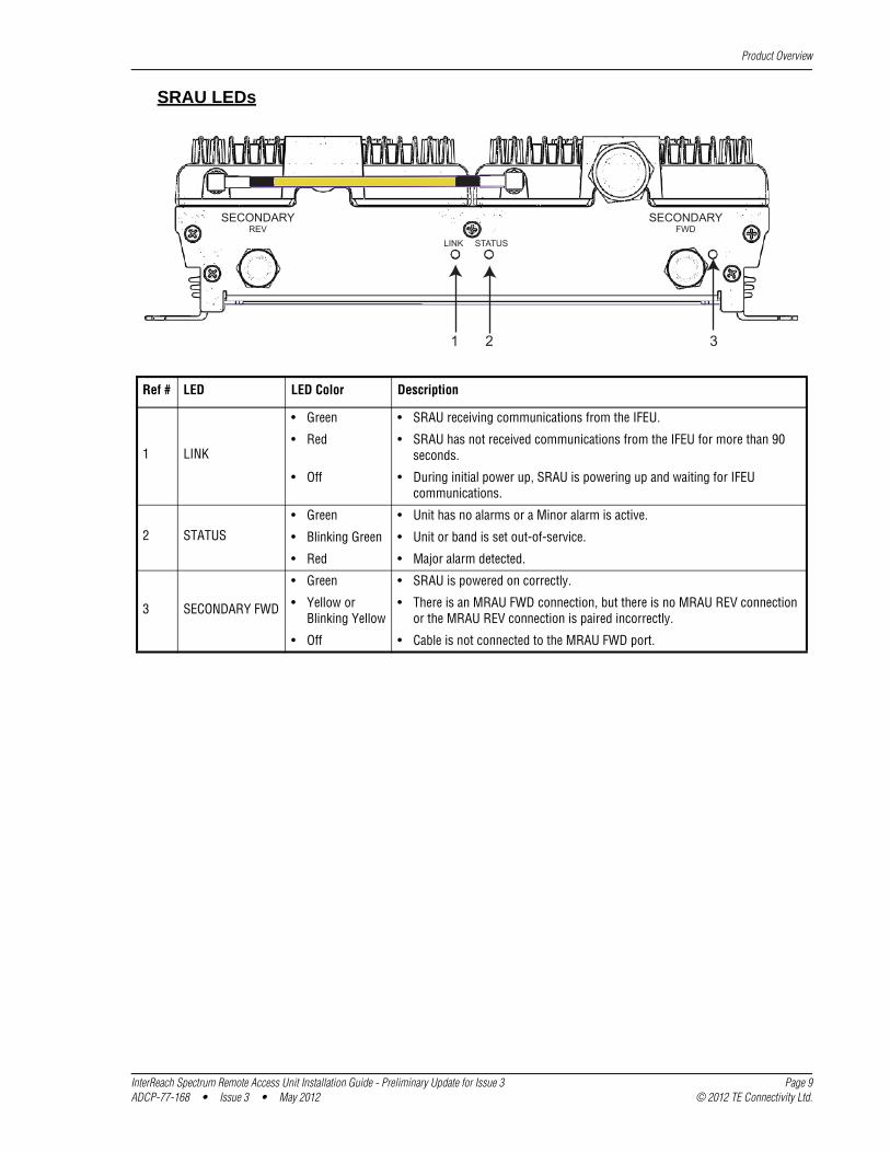
SRAU LEDs
LINK STATUS
SECONDARYREV
SECONDARYFWD
21 3
Ref # LED LED Color Description
1 LINK
2 STATUS
3 SECONDARY FWD
• Green • SRAU receiving communications from the IFEU.
• Red • SRAU has not received communications from the IFEU for more than 90 seconds.
• Off • During initial power up, SRAU is powering up and waiting for IFEU communications.
• Green • Unit has no alarms or a Minor alarm is active.
• Blinking Green • Unit or band is set out-of-service.
• Red • Major alarm detected.
• Green • SRAU is powered on correctly.
• Yellow orBlinking Yellow
• There is an MRAU FWD connection, but there is no MRAU REV connection or the MRAU REV connection is paired incorrectly.
• Off • Cable is not connected to the MRAU FWD port.
InterReach Spectrum Remote Access Unit Installation Guide - Preliminary Update for Issue 3 Page 9ADCP-77-168 • Issue 3 • May 2012 © 2012 TE Connectivity Ltd.
Product Overview
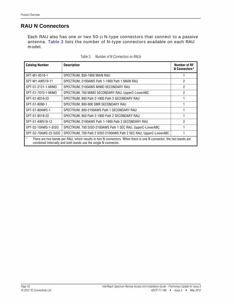
RAU N Connectors
Each RAU also has one or two 50- N-type connectors that connect to a passive antenna. Table 3 lists the number of N-type connectors available on each RAU model.
Table 3. Number of N Connectors on RAUs
Catalog Number Description Number of RFN Connectors*
SPT-M1-8519-1 SPECTRUM, 850-1900 MAIN RAU 1
SPT-M1-AWS19-11 SPECTRUM, 2100AWS Path 1-1900 Path 1 MAIN RAU 2
SPT-S1-2121-1-MIMO SPECTRUM, 2100AWS MIMO SECONDARY RAU 2
SPT-S1-7070-1-MIMO SPECTRUM, 700 MIMO SECONDARY RAU, UpperC-LowerABC 2
SPT-S1-8019-22 SPECTRUM, 800 Path 2-1900 Path 2 SECONDARY RAU 1
SPT-S1-8090-1 SPECTRUM, 800-900 SMR SECONDARY RAU 1
SPT-S1-80AWS-1 SPECTRUM, 800-2100AWS Path 1 SECONDARY RAU 1
SPT-S1-8519-22 SPECTRUM, 850 Path 2-1900 Path 2 SECONDARY RAU 1
SPT-S1-AWS19-12 SPECTRUM, 2100AWS Path 1-1900 Path 2 SECONDARY RAU 2
SPT-S2-70AWS-1-SISO SPECTRUM, 700 SISO-2100AWS Path 1 SEC RAU, UpperC-LowerABC 1
SPT-S2-70AWS-22-SISO SPECTRUM, 700 Path 2 SISO-2100AWS Path 2 SEC RAU, UpperC-LowerABC 1
* There are two bands per RAU, which results in two N connectors. When there is one N connector, the two bands are combined internally and both bands use the single N connector.
Page 10 InterReach Spectrum Remote Access Unit Installation Guide - Preliminary Update for Issue 3© 2012 TE Connectivity Ltd. ADCP-77-168 • Issue 3 • May 2012
Install the RAUs and Antennas
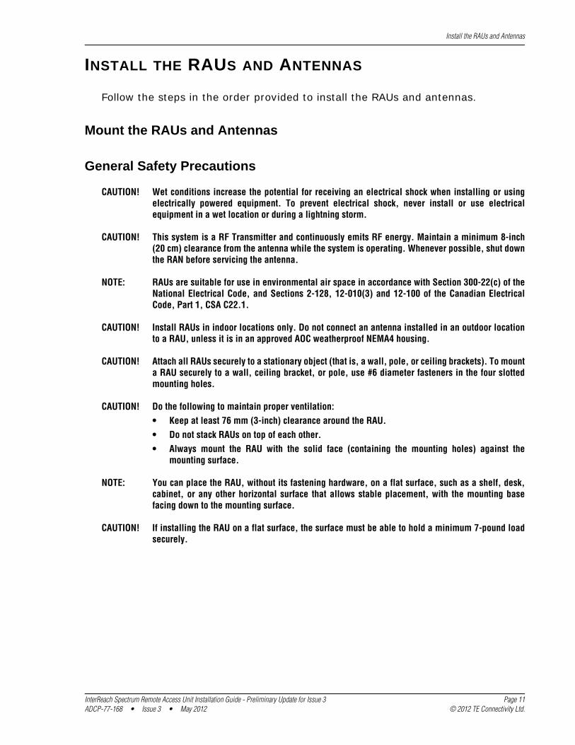
INSTALL THE RAUS AND ANTENNAS
Follow the steps in the order provided to install the RAUs and antennas.
Mount the RAUs and Antennas
General Safety Precautions
CAUTION! Wet conditions increase the potential for receiving an electrical shock when installing or using electrically powered equipment. To prevent electrical shock, never install or use electrical equipment in a wet location or during a lightning storm.
CAUTION! This system is a RF Transmitter and continuously emits RF energy. Maintain a minimum 8-inch (20 cm) clearance from the antenna while the system is operating. Whenever possible, shut down the RAN before servicing the antenna.
NOTE: RAUs are suitable for use in environmental air space in accordance with Section 300-22(c) of the National Electrical Code, and Sections 2-128, 12-010(3) and 12-100 of the Canadian Electrical Code, Part 1, CSA C22.1.
CAUTION! Install RAUs in indoor locations only. Do not connect an antenna installed in an outdoor location to a RAU, unless it is in an approved AOC weatherproof NEMA4 housing.
CAUTION! Attach all RAUs securely to a stationary object (that is, a wall, pole, or ceiling brackets). To mount a RAU securely to a wall, ceiling bracket, or pole, use #6 diameter fasteners in the four slotted mounting holes.
CAUTION! Do the following to maintain proper ventilation:• Keep at least 76 mm (3-inch) clearance around the RAU.• Do not stack RAUs on top of each other.• Always mount the RAU with the solid face (containing the mounting holes) against the
mounting surface.
NOTE: You can place the RAU, without its fastening hardware, on a flat surface, such as a shelf, desk, cabinet, or any other horizontal surface that allows stable placement, with the mounting base facing down to the mounting surface.
CAUTION! If installing the RAU on a flat surface, the surface must be able to hold a minimum 7-pound load securely.
InterReach Spectrum Remote Access Unit Installation Guide - Preliminary Update for Issue 3 Page 11ADCP-77-168 • Issue 3 • May 2012 © 2012 TE Connectivity Ltd.
Install the RAUs and Antennas
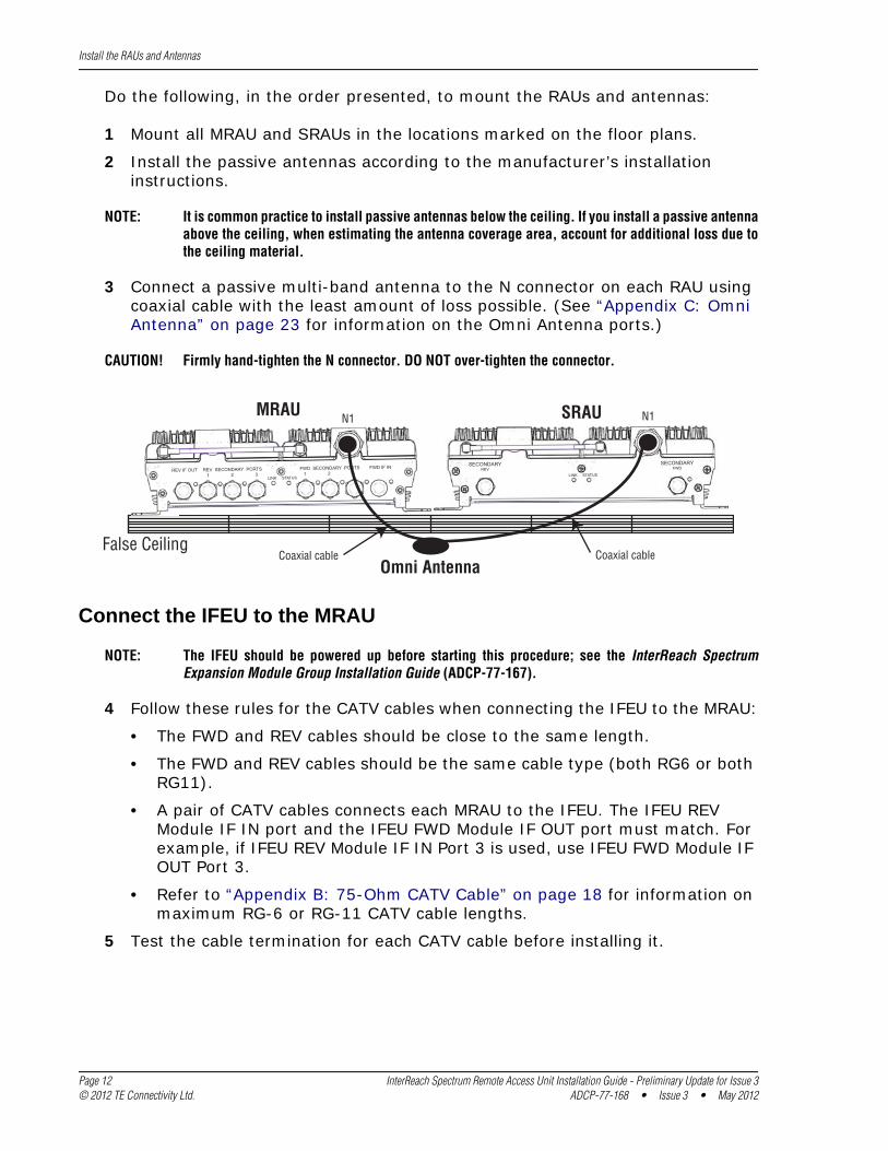
Do the following, in the order presented, to mount the RAUs and antennas:
1 Mount all MRAU and SRAUs in the locations marked on the floor plans.
2 Install the passive antennas according to the manufacturer’s installation instructions.
NOTE: It is common practice to install passive antennas below the ceiling. If you install a passive antenna above the ceiling, when estimating the antenna coverage area, account for additional loss due to the ceiling material.
3 Connect a passive multi-band antenna to the N connector on each RAU using coaxial cable with the least amount of loss possible. (See “Appendix C: Omni Antenna” on page 23 for information on the Omni Antenna ports.)
Omni AntennaFalse Ceiling
SRAU N1
REV IF OUT REV SECONDARY PORTS 1 2 3
FWD SECONDARY PORTS 1 2 3
FWD IF IN
LINK STATUS LINK STATUS
SECONDARYREV
SECONDARYFWD
MRAU N1
Coaxial cableCoaxial cable
CAUTION! Firmly hand-tighten the N connector. DO NOT over-tighten the connector.
Connect the IFEU to the MRAU
NOTE: The IFEU should be powered up before starting this procedure; see the InterReach Spectrum Expansion Module Group Installation Guide (ADCP-77-167).
4 Follow these rules for the CATV cables when connecting the IFEU to the MRAU:
• The FWD and REV cables should be close to the same length.
• The FWD and REV cables should be the same cable type (both RG6 or both RG11).
• A pair of CATV cables connects each MRAU to the IFEU. The IFEU REV Module IF IN port and the IFEU FWD Module IF OUT port must match. For example, if IFEU REV Module IF IN Port 3 is used, use IFEU FWD Module IF OUT Port 3.
• Refer to “Appendix B: 75-Ohm CATV Cable” on page 18 for information on maximum RG-6 or RG-11 CATV cable lengths.
5 Test the cable termination for each CATV cable before installing it.
Page 12 InterReach Spectrum Remote Access Unit Installation Guide - Preliminary Update for Issue 3© 2012 TE Connectivity Ltd. ADCP-77-168 • Issue 3 • May 2012
Install the RAUs and Antennas
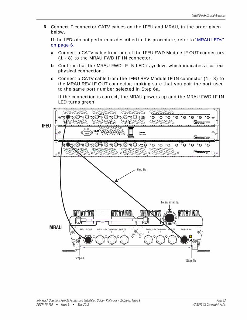
6 Connect F connector CATV cables on the IFEU and MRAU, in the order given below.
If the LEDs do not perform as described in this procedure, refer to “MRAU LEDs” on page 6.
a Connect a CATV cable from one of the IFEU FWD Module IF OUT connectors (1 - 8) to the MRAU FWD IF IN connector.
b Confirm that the MRAU FWD IF IN LED is yellow, which indicates a correct physical connection.
c Connect a CATV cable from the IFEU REV Module IF IN connector (1 - 8) to the MRAU REV IF OUT connector, making sure that you pair the port used to the same port number selected in Step 6a.
If the connection is correct, the MRAU powers up and the MRAU FWD IF IN LED turns green.
IFEU
Step 6a
REV IF OUT REV SECONDARY PORTS 1 2 3
FWD SECONDARY PORTS 1 2 3
FWD IF IN
LINK STATUS
To an antenna
MRAU
Step 6bStep 6c
InterReach Spectrum Remote Access Unit Installation Guide - Preliminary Update for Issue 3 Page 13ADCP-77-168 • Issue 3 • May 2012 © 2012 TE Connectivity Ltd.
Install the RAUs and Antennas
Connect the MRAU to SRAUs
CAUTION! To prevent interference, do not install an 850/1900 MRAU antenna near an 800/900 SRAU. The 850 MHz band must be 20 feet away from the 800/1900 SRAU’s passive antenna.
7 Use one of the following 6’ and 20’ CATV RG6 jumpers, available for purchase from ADC, to connect an MRAU to SRAUs.
ADC Part Number Description Note
300469-0 6’ RG-6 Cable; F Male to F Male CATV cable that connects the MRAU to SRAUs. Two cables required per SRAU.
300469-1 20’ RG-6 Cable; F Male to F Male CATV cable that connects the MRAU to SRAUs. Two cables required per SRAU.
8 Test the cable termination for each CATV cable before installing it.
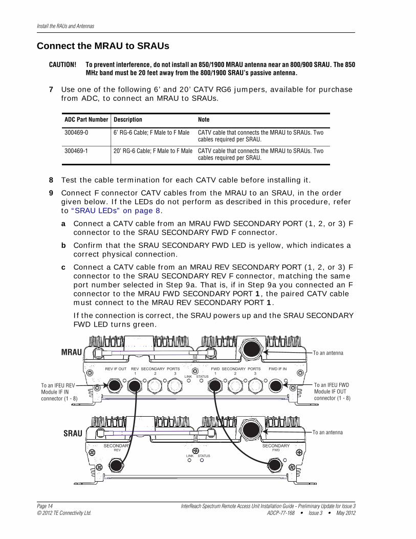
9 Connect F connector CATV cables from the MRAU to an SRAU, in the order given below. If the LEDs do not perform as described in this procedure, refer to “SRAU LEDs” on page 8.
a Connect a CATV cable from an MRAU FWD SECONDARY PORT (1, 2, or 3) F connector to the SRAU SECONDARY FWD F connector.
b Confirm that the SRAU SECONDARY FWD LED is yellow, which indicates a correct physical connection.
c Connect a CATV cable from an MRAU REV SECONDARY PORT (1, 2, or 3) F connector to the SRAU SECONDARY REV F connector, matching the same port number selected in Step 9a. That is, if in Step 9a you connected an F connector to the MRAU FWD SECONDARY PORT 1, the paired CATV cable must connect to the MRAU REV SECONDARY PORT 1.
If the connection is correct, the SRAU powers up and the SRAU SECONDARY FWD LED turns green.
REV IF OUT REV SECONDARY PORTS 1 2 3
FWD SECONDARY PORTS 1 2 3
FWD IF IN
LINK STATUS
LINK STATUS
SECONDARYREV
SECONDARYFWD
To an IFEU REVModule IF INconnector (1 - 8)
To an IFEU FWDModule IF OUTconnector (1 - 8)
MRAU
SRAU To an antenna
To an antenna
Page 14 InterReach Spectrum Remote Access Unit Installation Guide - Preliminary Update for Issue 3© 2012 TE Connectivity Ltd. ADCP-77-168 • Issue 3 • May 2012
Install the RAUs and Antennas
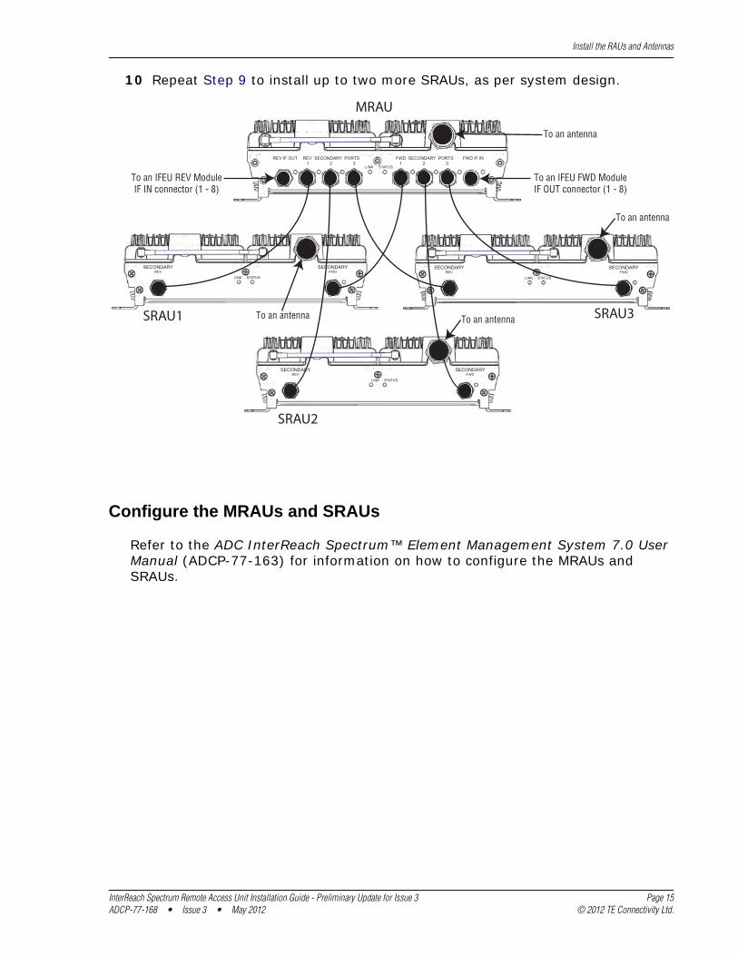
10 Repeat Step 9 to install up to two more SRAUs, as per system design.
REV IF OUT REV SECONDARY PORTS 1 2 3
FWD SECONDARY PORTS 1 2 3
FWD IF IN
LINK STATUS
LINK STATUS
SECONDARYREV
SECONDARYFWD
LINK STATUS
SECONDARYREV
SECONDARYFWD
LINK STATUS
SECONDARYREV
SECONDARYFWD
MRAU
SRAU1
SRAU2
SRAU3
To an IFEU FWD ModuleIF OUT connector (1 - 8)
To an IFEU REV ModuleIF IN connector (1 - 8)
To an antenna
To an antenna
To an antennaTo an antenna
Configure the MRAUs and SRAUs
Refer to the ADC InterReach Spectrum™ Element Management System 7.0 User Manual (ADCP-77-163) for information on how to configure the MRAUs and SRAUs.
InterReach Spectrum Remote Access Unit Installation Guide - Preliminary Update for Issue 3 Page 15ADCP-77-168 • Issue 3 • May 2012 © 2012 TE Connectivity Ltd.
Appendix A: Specifications
APPENDIX A: SPECIFICATIONS
Remote Access Unit Specifications
Operating Temp -25°C to +50°C
Storage Temperature -40°C to +70°C
Humidity 10% to 90% non-condensing
Dimensions 11.50" x 9.00" x 3.50"
Weight 7.49 Pounds
Power Source +54Vdc (from IFEU)
Spectrum System Specifications
RF SpecificationSupported Frequency Blocks 2 per Remote Antenna Unit; 1-8 per Host Unit
Bandwidth 1.5 to 75 MHz non-contiguous
Frequency Band Supported 850 Cellular; 800 iDEN; 900 iDEN; 1900 PCS; 2100 AWS; 700 Upper C Lower ABC
Propagation DelaySystem Delay <12 microseconds
Delay Management Digital (Manual or Automatic)
Noise FigureNoise Figure For 1 Host, 1 DRU, 8 RAUs: < 17 dB
For 1 Host, 4 DRUs, 32 RAUs: < 23 dB
Input IP3 >-10 dBm
Optical SpecificationsOptical Budget 10 dB (Standard); 26 dB (Optional)
Digital Transport Rate 3.072 Gbps
Page 16 InterReach Spectrum Remote Access Unit Installation Guide - Preliminary Update for Issue 3© 2012 TE Connectivity Ltd. ADCP-77-168 • Issue 3 • May 2012
Appendix A: Specifications
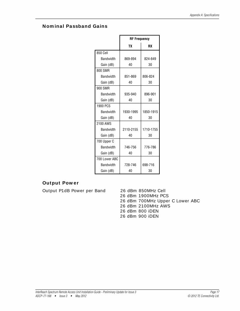
RF Frequency
TX RX
850 Cell
Bandwidth 869-894 824-849
Gain (dB) 40 30
800 SMR
Bandwidth 851-869 806-824
Gain (dB) 40 30
900 SMR
Bandwidth 935-940 896-901
Gain (dB) 40 30
1900 PCS
Bandwidth 1930-1995 1850-1915
Gain (dB) 40 30
2100 AWS
Bandwidth 2110-2155 1710-1755
Gain (dB) 40 30
700 Upper C
Bandwidth 746-756 776-786
Gain (dB) 40 30
700 Lower ABC
Bandwidth 728-746 698-716
Gain (dB) 40 30
Nominal Passband Gains
Output PowerOutput P1dB Power per Band 26 dBm 850MHz Cell
26 dBm 1900MHz PCS26 dBm 700MHz Upper C Lower ABC26 dBm 2100MHz AWS26 dBm 800 iDEN26 dBm 900 iDEN
InterReach Spectrum Remote Access Unit Installation Guide - Preliminary Update for Issue 3 Page 17ADCP-77-168 • Issue 3 • May 2012 © 2012 TE Connectivity Ltd.
Appendix A: Specifications
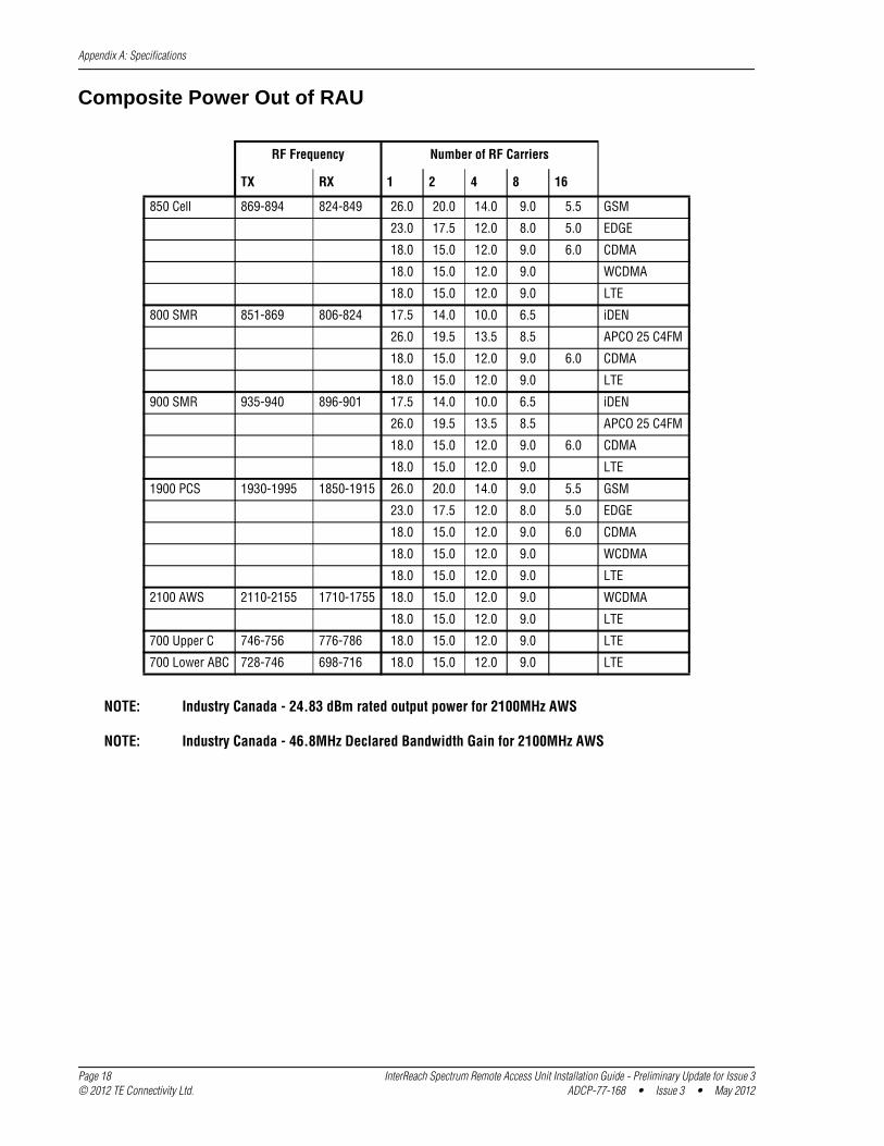
Composite Power Out of RAU
RF Frequency Number of RF Carriers
TX RX 1 2 4 8 16
850 Cell 869-894 824-849 26.0 20.0 14.0 9.0 5.5 GSM
23.0 17.5 12.0 8.0 5.0 EDGE
18.0 15.0 12.0 9.0 6.0 CDMA
18.0 15.0 12.0 9.0 WCDMA
18.0 15.0 12.0 9.0 LTE
800 SMR 851-869 806-824 17.5 14.0 10.0 6.5 iDEN
26.0 19.5 13.5 8.5 APCO 25 C4FM
18.0 15.0 12.0 9.0 6.0 CDMA
18.0 15.0 12.0 9.0 LTE
900 SMR 935-940 896-901 17.5 14.0 10.0 6.5 iDEN
26.0 19.5 13.5 8.5 APCO 25 C4FM
18.0 15.0 12.0 9.0 6.0 CDMA
18.0 15.0 12.0 9.0 LTE
1900 PCS 1930-1995 1850-1915 26.0 20.0 14.0 9.0 5.5 GSM
23.0 17.5 12.0 8.0 5.0 EDGE
18.0 15.0 12.0 9.0 6.0 CDMA
18.0 15.0 12.0 9.0 WCDMA
18.0 15.0 12.0 9.0 LTE
2100 AWS 2110-2155 1710-1755 18.0 15.0 12.0 9.0 WCDMA
18.0 15.0 12.0 9.0 LTE
700 Upper C 746-756 776-786 18.0 15.0 12.0 9.0 LTE
700 Lower ABC 728-746 698-716 18.0 15.0 12.0 9.0 LTE
NOTE: Industry Canada - 24.83 dBm rated output power for 2100MHz AWS
NOTE: Industry Canada - 46.8MHz Declared Bandwidth Gain for 2100MHz AWS
Page 18 InterReach Spectrum Remote Access Unit Installation Guide - Preliminary Update for Issue 3© 2012 TE Connectivity Ltd. ADCP-77-168 • Issue 3 • May 2012
Appendix B: 75-Ohm CATV Cable
APPENDIX B: 75-OHM CATV CABLE
The 75-Ohm CATV Cable:
• connects the IFEU to MRAU(s) and the MRAU(s) to the SRAU(s)
• transmits (FWD) multiband and receives (REV) IF signals
• delivers DC electrical power to the RAUs. The Spectrum IFEU DC voltage output is +54Vdc nominal. If the IFEU reaches its current limit, a current-limiting circuit protects it.
• carries configuration and status information
• uses 75 type-F connectors with captive center pins.
CATV Cable Requirements
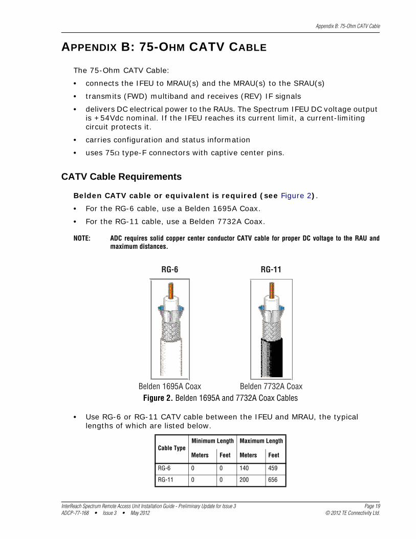
Belden CATV cable or equivalent is required (see Figure 2).
• For the RG-6 cable, use a Belden 1695A Coax.
• For the RG-11 cable, use a Belden 7732A Coax.
RG-11
Belden 1695A Coax
RG-6
Belden 7732A Coax
NOTE: ADC requires solid copper center conductor CATV cable for proper DC voltage to the RAU and maximum distances.
Figure 2. Belden 1695A and 7732A Coax Cables
• Use RG-6 or RG-11 CATV cable between the IFEU and MRAU, the typical lengths of which are listed below.
Cable TypeMinimum Length Maximum Length
Meters Feet Meters Feet
RG-6 0 0 140 459
RG-11 0 0 200 656
InterReach Spectrum Remote Access Unit Installation Guide - Preliminary Update for Issue 3 Page 19ADCP-77-168 • Issue 3 • May 2012 © 2012 TE Connectivity Ltd.
Appendix B: 75-Ohm CATV Cable
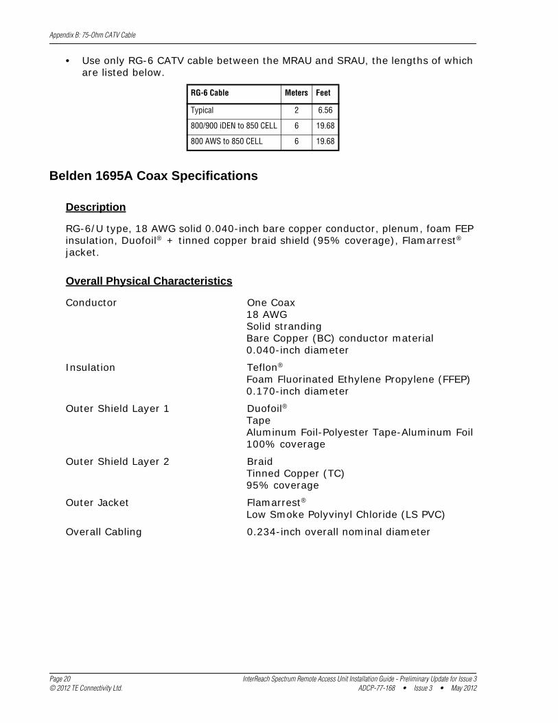
• Use only RG-6 CATV cable between the MRAU and SRAU, the lengths of which are listed below.
RG-6 Cable Meters Feet
Typical 2 6.56
800/900 iDEN to 850 CELL 6 19.68
800 AWS to 850 CELL 6 19.68
Belden 1695A Coax Specifications
Description
RG-6/U type, 18 AWG solid 0.040-inch bare copper conductor, plenum, foam FEP insulation, Duofoil® + tinned copper braid shield (95% coverage), Flamarrest® jacket.
Overall Physical Characteristics
Conductor One Coax18 AWGSolid strandingBare Copper (BC) conductor material0.040-inch diameter
Insulation Teflon®Foam Fluorinated Ethylene Propylene (FFEP)0.170-inch diameter
Outer Shield Layer 1 Duofoil®TapeAluminum Foil-Polyester Tape-Aluminum Foil100% coverage
Outer Shield Layer 2 BraidTinned Copper (TC)95% coverage
Outer Jacket Flamarrest®Low Smoke Polyvinyl Chloride (LS PVC)
Overall Cabling 0.234-inch overall nominal diameter
Page 20 InterReach Spectrum Remote Access Unit Installation Guide - Preliminary Update for Issue 3© 2012 TE Connectivity Ltd. ADCP-77-168 • Issue 3 • May 2012
Appendix B: 75-Ohm CATV Cable
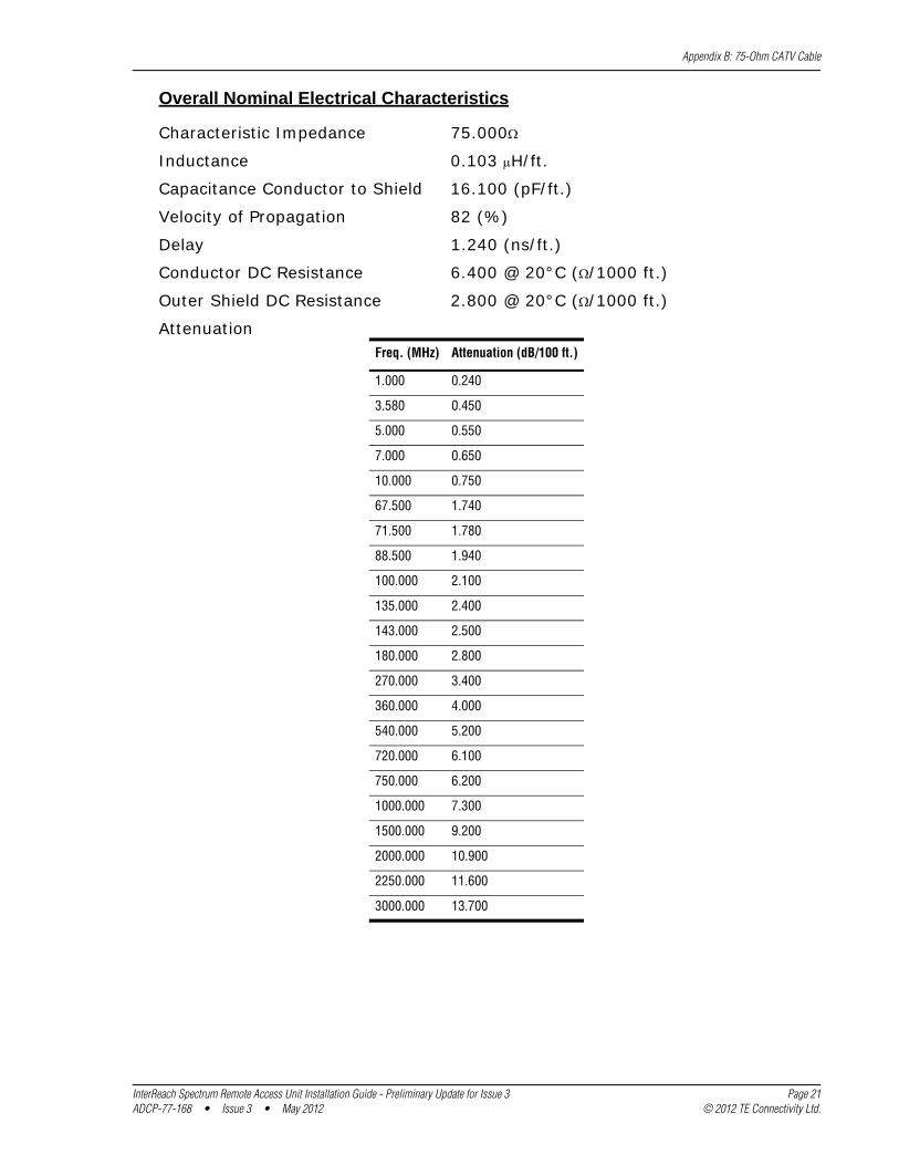
Overall Nominal Electrical Characteristics
Characteristic Impedance 75.000
Inductance 0.103 H/ft.
Capacitance Conductor to Shield 16.100 (pF/ft.)
Velocity of Propagation 82 (%)
Delay 1.240 (ns/ft.)
Conductor DC Resistance 6.400 @ 20°C (/1000 ft.)
Outer Shield DC Resistance 2.800 @ 20°C (/1000 ft.)
AttenuationFreq. (MHz) Attenuation (dB/100 ft.)
1.000 0.240
3.580 0.450
5.000 0.550
7.000 0.650
10.000 0.750
67.500 1.740
71.500 1.780
88.500 1.940
100.000 2.100
135.000 2.400
143.000 2.500
180.000 2.800
270.000 3.400
360.000 4.000
540.000 5.200
720.000 6.100
750.000 6.200
1000.000 7.300
1500.000 9.200
2000.000 10.900
2250.000 11.600
3000.000 13.700
InterReach Spectrum Remote Access Unit Installation Guide - Preliminary Update for Issue 3 Page 21ADCP-77-168 • Issue 3 • May 2012 © 2012 TE Connectivity Ltd.
Appendix B: 75-Ohm CATV Cable
Belden 7732A Coax Specifications
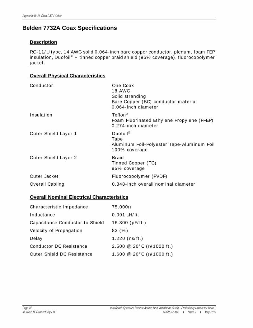
Description
RG-11/U type, 14 AWG solid 0.064-inch bare copper conductor, plenum, foam FEP insulation, Duofoil® + tinned copper braid shield (95% coverage), fluorocopolymer jacket.
Overall Physical Characteristics
Conductor One Coax18 AWGSolid strandingBare Copper (BC) conductor material0.064-inch diameter
Insulation Teflon®Foam Fluorinated Ethylene Propylene (FFEP)0.274-inch diameter
Outer Shield Layer 1 Duofoil®TapeAluminum Foil-Polyester Tape-Aluminum Foil100% coverage
Outer Shield Layer 2 BraidTinned Copper (TC)95% coverage
Outer Jacket Fluorocopolymer (PVDF)
Overall Cabling 0.348-inch overall nominal diameter
Overall Nominal Electrical Characteristics
Characteristic Impedance 75.000
Inductance 0.091 H/ft.
Capacitance Conductor to Shield 16.300 (pF/ft.)
Velocity of Propagation 83 (%)
Delay 1.220 (ns/ft.)
Conductor DC Resistance 2.500 @ 20°C (/1000 ft.)
Outer Shield DC Resistance 1.600 @ 20°C (/1000 ft.)
Page 22 InterReach Spectrum Remote Access Unit Installation Guide - Preliminary Update for Issue 3© 2012 TE Connectivity Ltd. ADCP-77-168 • Issue 3 • May 2012
Appendix B: 75-Ohm CATV Cable
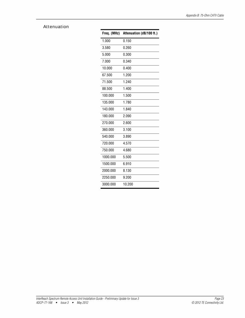
AttenuationFreq. (MHz) Attenuation (dB/100 ft.)
1.000 0.150
3.580 0.260
5.000 0.300
7.000 0.340
10.000 0.400
67.500 1.200
71.500 1.240
88.500 1.400
100.000 1.500
135.000 1.780
143.000 1.840
180.000 2.090
270.000 2.600
360.000 3.100
540.000 3.890
720.000 4.570
750.000 4.680
1000.000 5.500
1500.000 6.910
2000.000 8.130
2250.000 9.200
3000.000 10.200
InterReach Spectrum Remote Access Unit Installation Guide - Preliminary Update for Issue 3 Page 23ADCP-77-168 • Issue 3 • May 2012 © 2012 TE Connectivity Ltd.
Appendix C: Omni Antenna
APPENDIX C: OMNI ANTENNA
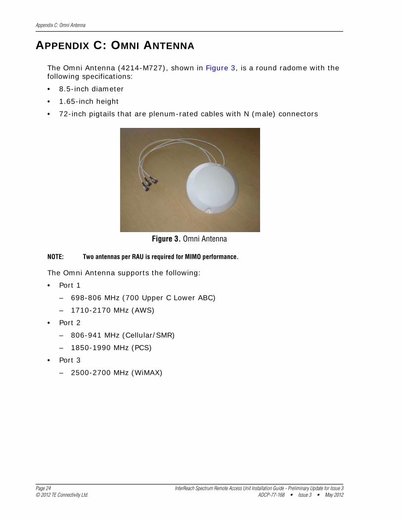
The Omni Antenna (4214-M727), shown in Figure 3, is a round radome with the following specifications:
• 8.5-inch diameter
• 1.65-inch height
• 72-inch pigtails that are plenum-rated cables with N (male) connectors
Figure 3. Omni Antenna
NOTE: Two antennas per RAU is required for MIMO performance.
The Omni Antenna supports the following:
• Port 1
– 698-806 MHz (700 Upper C Lower ABC)
– 1710-2170 MHz (AWS)
• Port 2
– 806-941 MHz (Cellular/SMR)
– 1850-1990 MHz (PCS)
• Port 3
– 2500-2700 MHz (WiMAX)
Page 24 InterReach Spectrum Remote Access Unit Installation Guide - Preliminary Update for Issue 3© 2012 TE Connectivity Ltd. ADCP-77-168 • Issue 3 • May 2012
Appendix D: Contacting TE Connectivity
APPENDIX D: CONTACTING TE CONNECTIVITY
PHONEU.S.A. or CANADASales: 1-800-366-3891 Extension 73000Technical Assistance: 1-800-530-9960 Connectivity Extension: 73475 Wireless Extension: 73476EUROPESales Administration: +32-2-712-65 00Technical Assistance: +32-2-712-65 42EUROPEAN TOLL FREE NUMBERSGermany: 0180 2232923UK: 0800 960236Spain: 900 983291France: 0800 914032Italy: 0800 782374ASIA/PACIFICSales Administration: +65-6294-9948Technical Assistance: +65-6393-0739ELSEWHERESales Administration: +1-952-917-3000Technical Assistance: +1-952-917-3475
ONLINE ACCESS
Connectivity ProductsUnited States: [email protected]: [email protected]/Pacific: [email protected] Wireless Products [email protected]
Customer Portalhttp://www.adc.com/Americas/en_US/1268116693520Online Customer Support Requesthttps://nssales.adc.com/ftr/ftrhome1.asp
NOTE: ADC is now TE Connectivity.
InterReach Spectrum Remote Access Unit Installation Guide - Preliminary Update for Issue 3 Page 25ADCP-77-168 • Issue 3 • May 2012 © 2012 TE Connectivity Ltd.

Appendix D: Contacting TE Connectivity
Page 26 InterReach Spectrum Remote Access Unit Installation Guide - Preliminary Update for Issue 3© 2012 TE Connectivity Ltd. ADCP-77-168 • Issue 3 • May 2012