
International Journal of Energy and Environment (IJEE)
10
INTERNATIONAL JOURNAL OF ENERGY AND ENVIRONMENT Volume 9, Issue 6, 2018 pp.581-590 Journal homepage: www.IJEE.IEEFoundation.org ISSN 2076-2895 (Print), ISSN 2076-2909 (Online) ©2018 International Energy & Environment Foundation. All rights reserved. Optimization thickness of head type for horizontal LPG pressure vessels according to ASME Marwan Abdulrazzaq Salman 1 , Mahmud Rasheed Ismail 2 , Yassr Y.Kahtan 2 1 Mechanical Engineerig Department, Al-Nahrain University, Baghdad, Iraq. 2 Prosthetics and orthotics Engineerig Department, Al-Nahrain University, Baghdad, Iraq. Received 17 Jun. 2018; Received in revised form 19 Oct. 2018; Accepted 20 Oct. 2018; Available online 1 Nov. 2018 Abstract Liquefied Petroleum Gas (LPG) are commonly used in many practical applications as a storage container for gasses under pressure such as oil refinery, production and fuel stations. Design of LPG vessels must meet strict requirements to insure safety and prevent environmental hazard ASME codes for pressure vessel are a general roles for design and testing for all the available vessels ranging from huge nuclear to small fuel tanks. For specified vessel the designer must has a spatial experience to involve the right criteria. In ASME codes there existed many types of end heads for pressure vessels such as; Torispherical, Elliptical 2:1 and Hemispherical. Selection of head type is left as an option for the designer. In this work an attempt is made to investigate the effect of using three types of end heads on the design of in- service horizontal. Moderate pressure vessel using ASME codes. The studied model represents a practical case in which a horizontal (18 bar) LPG vessel fabricated in Heavy Engineering Equipment State Company (HEESC) - Dura Refinery -Baghdad - Iraq. The design is based on ASME: SEC.VIII div.1 which is suitable for moderate pressure as classified by ASME The results are compared with two commercial design software namely; COMPRESS and PV Elite. It is found that using of hemispherical head can reduce design thickness up to 51.5% as compared with other heads which results economic and light weight vessel, so it is recommended in to be used at HEESC and using the commercial software lead to higher design thickness for all head types. Copyright © 2018 International Energy and Environment Foundation - All rights reserved. Keywords: LPG; Pressure Vessel; ASME code; COMPRESS; PV Elite. 1. Introduction LPG pressure vessels are storage container widely used for petroleum gasses under pressure. The design pressure of this type of vessels is ranged from (1-206) bar. For the safety purposes the design must insure strict requirement to avoid severe damage. Many design criteria are suggested [1]. However ASME codes is the most acceptable design criteria for practical applications due to the elaborated improvements via addenda and longtime experience. ASME codes are general roles for design of wide range of pressure vessels. To include the vast variety of pressure vessels and requirements ASME allocated many sections and divisions as below: I. Power Boilers II. Materials
-
Upload
khangminh22 -
Category
Documents
-
view
0 -
download
0
Transcript of International Journal of Energy and Environment (IJEE)
INTERNATIONAL JOURNAL OF
ENERGY AND ENVIRONMENT
Volume 9, Issue 6, 2018 pp.581-590
Journal homepage: www.IJEE.IEEFoundation.org
ISSN 2076-2895 (Print), ISSN 2076-2909 (Online) ©2018 International Energy & Environment Foundation. All rights reserved.
Optimization thickness of head type for horizontal LPG
pressure vessels according to ASME
Marwan Abdulrazzaq Salman1, Mahmud Rasheed Ismail2, Yassr Y.Kahtan2
1 Mechanical Engineerig Department, Al-Nahrain University, Baghdad, Iraq. 2 Prosthetics and orthotics Engineerig Department, Al-Nahrain University, Baghdad, Iraq.
Received 17 Jun. 2018; Received in revised form 19 Oct. 2018; Accepted 20 Oct. 2018; Available online 1 Nov. 2018
Abstract
Liquefied Petroleum Gas (LPG) are commonly used in many practical applications as a storage container
for gasses under pressure such as oil refinery, production and fuel stations. Design of LPG vessels must
meet strict requirements to insure safety and prevent environmental hazard ASME codes for pressure
vessel are a general roles for design and testing for all the available vessels ranging from huge nuclear to
small fuel tanks. For specified vessel the designer must has a spatial experience to involve the right criteria.
In ASME codes there existed many types of end heads for pressure vessels such as; Torispherical, Elliptical
2:1 and Hemispherical. Selection of head type is left as an option for the designer. In this work an attempt
is made to investigate the effect of using three types of end heads on the design of in- service horizontal.
Moderate pressure vessel using ASME codes. The studied model represents a practical case in which a
horizontal (18 bar) LPG vessel fabricated in Heavy Engineering Equipment State Company (HEESC) -
Dura Refinery -Baghdad - Iraq. The design is based on ASME: SEC.VIII div.1 which is suitable for
moderate pressure as classified by ASME The results are compared with two commercial design software
namely; COMPRESS and PV Elite. It is found that using of hemispherical head can reduce design
thickness up to 51.5% as compared with other heads which results economic and light weight vessel, so it
is recommended in to be used at HEESC and using the commercial software lead to higher design thickness
for all head types.
Copyright © 2018 International Energy and Environment Foundation - All rights reserved.
Keywords: LPG; Pressure Vessel; ASME code; COMPRESS; PV Elite.
1. Introduction
LPG pressure vessels are storage container widely used for petroleum gasses under pressure. The design
pressure of this type of vessels is ranged from (1-206) bar. For the safety purposes the design must insure
strict requirement to avoid severe damage. Many design criteria are suggested [1]. However ASME codes
is the most acceptable design criteria for practical applications due to the elaborated improvements via
addenda and longtime experience.
ASME codes are general roles for design of wide range of pressure vessels. To include the vast variety of
pressure vessels and requirements ASME allocated many sections and divisions as below:
I. Power Boilers
II. Materials
International Journal of Energy and Environment (IJEE), Volume 9, Issue 6, 2018, pp.581-590
ISSN 2076-2895 (Print), ISSN 2076-2909 (Online) ©2018 International Energy & Environment Foundation. All rights reserved.
582
III. Nuclear Facility Components
IV. Heating Boilers
V. Nondestructive Examination
VI. Care and Operation of Heating Boilers
VII. Care of Power Boilers
VIII. Pressure Vessels
VIII. DIV.1 Operating Pressure:1 to 206 bar
VIII. DIV.2 Operating Pressure:206 to 690 bar
VIII. DIV.3 Operating Pressure: above 690 bar
IX. Welding and Brazing Qualifications
X. Fiber-Reinforced Plastic Pressure Vessels
XI. Inspection of Nuclear Power Plant Components
XII. Transport Tanks
Many researchers investigated the design of pressure vessels capsule and its accessories. In this regard.
Thakkar B.S and Thakkar S.A [2] investigated the high pressure rise in the pressure vessel. They carried
out Hydrostatic tests to test the vessel at different pressures. ASME criteria was employed to design and
manufacture the pressure vessel capsule and accessories Dhanaraj, A. and Mallikarjuna M.V. [3] studied
the effect of stresses at the opening in the capsule of pressure vessel assuming round shape. Aluminum
alloy is used for construction the vessel wall under the effect of internal pressure. Finite element method
is used for analyzing stresses. A comparison between experiments and numerical analysis were made under
the effects of many parameters related to the operation conditions. Kumar, V., and Kumar, P. [4] studied
the effect of material properties such as safety factor for tensile and yield strength on the vessel design and
operation. ASME section VIII is employed in design and testing, PV ELITE software is used in the
theoretical analysis of horizontal pressure vessel containing opening and saddle supports The main factors
investigated in this research are ; effect of internal and external pressure, geometry and weight, nozzle and
saddle design. Dubal, S. V., et al [5] investigated the effect of high pressure in pressure vessel according
to ASME codes namely; division 1 and division 2, section VIII, They investigated the effect of stresses on
the design to maintain safe design and operation conditions Narale P., and Kachare P. S. [6] studies the
effect of the opening size in vessel capsule especially for large opening such as manhole for ASME Sec.
VIII Division 1 was followed in this study. Finite element analysis is used to evaluate the stresses
developed at the vessel wall and opening the stress analysis is performed by ANSYS software. In this work
a large exhaust opening located near to the filter sheet are considered. The effect of stresses in the large
opening is treated as per ASME to validate the design. Sankara et al [7] investigated the shape and
geometry of a manhole at the upper part of a cylindrical pressure vessel. Two opening types are investigated
namely; circular and elliptical opening. The manhole is locate at the vertical position with respect to the
cylindrical vessel. Many aspects related to the manhole walls are considered; such as major axes of the
elliptical hole in case of parallel or perpendicularly to the axis of the vessel cylinder. They presented the
results in many figures and tables for the design purposes. Lewiński, J. [8] studied the pressure vessels,
nozzles required for inlet and outlet attachments. They considered the geometrical parameters of nozzle
connections and the effect of a stress concentration around the opening at vessel capsule, they analyzed
the model using Numerical analysis for stress analysis around the nozzle. Siva et al. [9] considered a steel
LPG vessel containing fluid with partially liquid and vapor. The stresses due to pressure loading inside the
cylinder and heads are investigated. The results of stresses are compared with the available solution in
literature to check the theory and the mathematical model. PV Elite Pro is used to analyze the stresses in
the vessel wall. Kumar, V., et al. [10] analyzed a horizontal vessel with saddle support. A solid model of
the pressure vessel is employed by using ANSYS software. Then the stresses are obtained from the static
analysis. It is found that; the higher localized stress is located at the junction of the pressure vessel and at
the saddle support. A comparison between the numerical and theoretical of the allowable stress and safety
of design are made in this study. Mukhtar, F. M., and Al-Gahtani, H. J. [11] considered a cylindrical
pressure vessel with nozzle connection according to thin shell stress analysis. The analysis is perfumed
numerically by using FE method, In order to validate the analysis the obtained results are compared with
other models founded in the literature. It is concluded that; the results for the stresses in the vessels with
moderate to large diameter nozzles are larger as compared with that for vessels having small diameter
nozzles which is suggested in the research.
In dealing with the ASME codes for pressure vessels many head types are suggested for design, however
selecting the head type is left as an option for the designer. So it is interest to investigate the effect of

International Journal of Energy and Environment (IJEE), Volume 9, Issue 6, 2018, pp.581-590
ISSN 2076-2895 (Print), ISSN 2076-2909 (Online) ©2018 International Energy & Environment Foundation. All rights reserved.
583
changing of head type on the vessel design and applying the idea on a real practical pressure vessel case
to serve a recommendation for future improving.
2. Theory
Vessel capsule includes; vessel cylindrical shell which is formed from rolling of sheet metals plate, two
end heads and flanges made from pressing and flanging. The required thicknesses, Maximum Allowable
Working Pressure (MAWP) and Maximum Allowable Pressure (MAP) for the cylindrical shell as the
follows [1];
𝑡𝑠ℎ =𝑃𝑅𝑖
2𝑆𝐸+0.6𝑃 (1)
𝑀𝐴𝑊𝑃 =SEt
R+0.6t (2)
𝑀𝐴𝑃 =SEt
(R+0.6t)−Ps (3)
All shells of the pressure vessel must be closed by heads at the ends. Head are normally curved rather than
flat Curved shapes are stronger and allow the head to be lighter, thinner, and less expensive that the flat
heads. The following three types of heads are commonly used by ASME codes [1];
A. Hemisphere head
Thickness and pressure design equations based on internal diameter are as the follows [2];
t = 𝑃𝑅𝑖
2𝑆𝐸−0.2𝑃 (4)
P = 2𝑆𝐸𝑡
𝑅𝑖+0.2𝑡 (5)
B. Ellipsoidal head
Thickness and pressure are as the follows [2];
t = 𝑃𝐷𝑖𝐾
2𝑆𝐸−0.2𝑃 (6)
P = 2𝑆𝐸𝑡
𝐾𝐷𝑖+0.2𝑡 (7)
Where k is a shape factor for ellipse.
C. Torispherical head
Thickness and pressure are as the follows [2]:
t = 0.885𝑃𝐿𝑖
𝑆𝐸−0.1𝑃 (8)
P = 𝑆𝐸𝑡
0.885𝐿𝑖+0.1𝑡 (9)
3. Design as Per ASME Codes
Figure 1 shows block diagram for the design steps of pressure vessels. The pressure vessel must be met
the requirements of safe design fabrication and testing. Also meets the standard of ASME codes.
4. Design using compress and PV elite software
In order to compare the results of design of the various parts of the model which are made by hand as per
ASME codes, two commercial software were attempted which are COMPRESS and PV Elite which are
widely used in factories. Before using of these programs many trains are made to design simple cases such
as solid vessel and other built in examples which are supplied with these programs. The same studied

International Journal of Energy and Environment (IJEE), Volume 9, Issue 6, 2018, pp.581-590
ISSN 2076-2895 (Print), ISSN 2076-2909 (Online) ©2018 International Energy & Environment Foundation. All rights reserved.
584
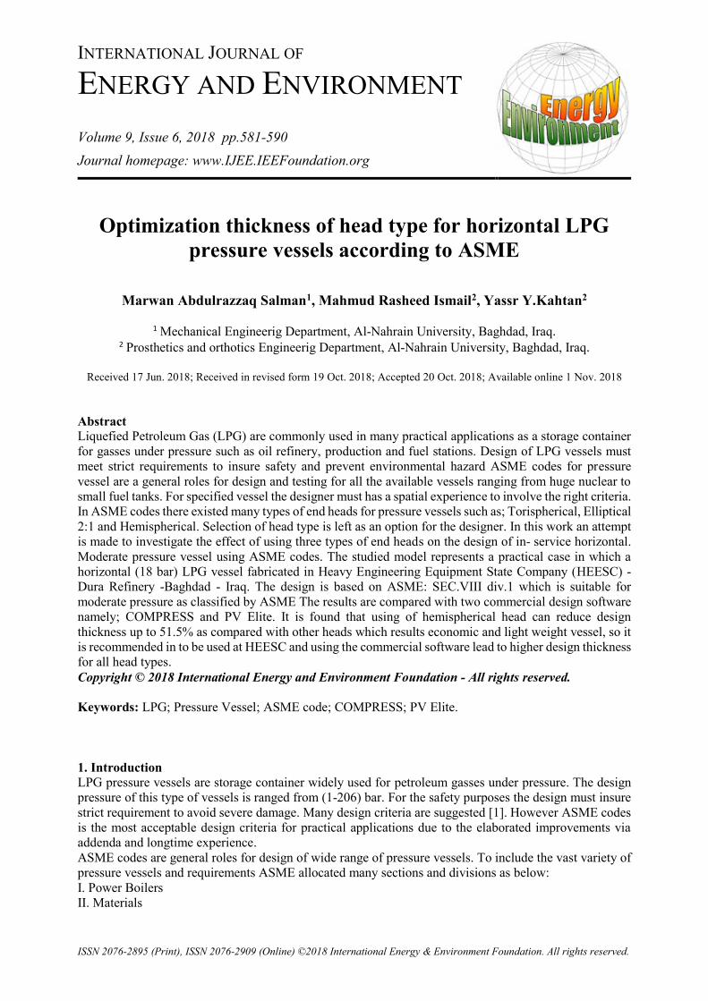
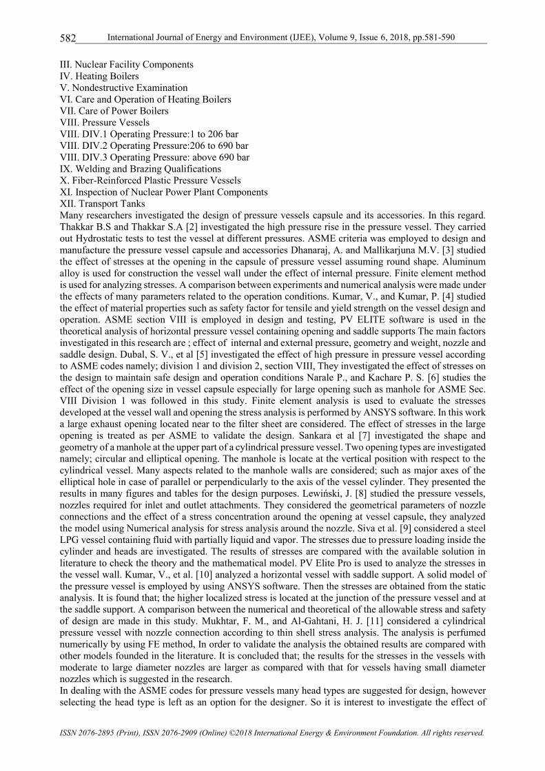
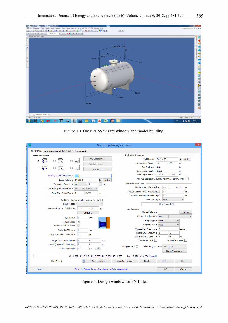
model is built in COMPRESS program as shown in Figures (2 and 3) and PV Elite programs as shown in
Figures (4 and 5) workspace and wizard windows respectively. The same materials properties and design
requirements are employed. Following the programs wizard complete design reports are gotten.
Figure 1. Design steps of pressure vessels.
Figure 2. Software wizard window for COMPRESS.
International Journal of Energy and Environment (IJEE), Volume 9, Issue 6, 2018, pp.581-590
ISSN 2076-2895 (Print), ISSN 2076-2909 (Online) ©2018 International Energy & Environment Foundation. All rights reserved.
585
Figure 3. COMPRESS wizard window and model building.
Figure 4. Design window for PV Elite.
International Journal of Energy and Environment (IJEE), Volume 9, Issue 6, 2018, pp.581-590
ISSN 2076-2895 (Print), ISSN 2076-2909 (Online) ©2018 International Energy & Environment Foundation. All rights reserved.
586
Figure 5. PV Elite wizard window and model building.
5. Results and discussions
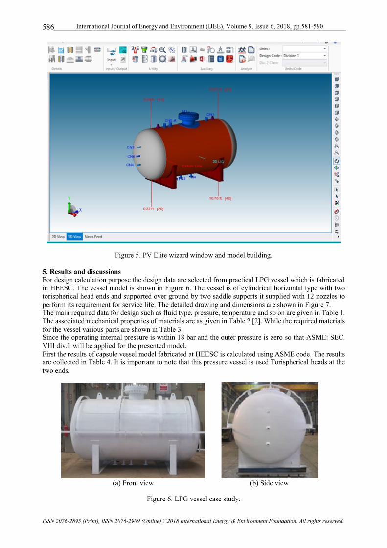
For design calculation purpose the design data are selected from practical LPG vessel which is fabricated
in HEESC. The vessel model is shown in Figure 6. The vessel is of cylindrical horizontal type with two
torispherical head ends and supported over ground by two saddle supports it supplied with 12 nozzles to
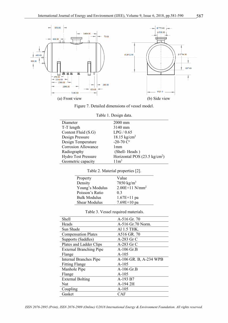
perform its requirement for service life. The detailed drawing and dimensions are shown in Figure 7.
The main required data for design such as fluid type, pressure, temperature and so on are given in Table 1.
The associated mechanical properties of materials are as given in Table 2 [2]. While the required materials
for the vessel various parts are shown in Table 3.
Since the operating internal pressure is within 18 bar and the outer pressure is zero so that ASME: SEC.
VIII div.1 will be applied for the presented model.
First the results of capsule vessel model fabricated at HEESC is calculated using ASME code. The results
are collected in Table 4. It is important to note that this pressure vessel is used Torispherical heads at the
two ends.
(a) Front view (b) Side view
Figure 6. LPG vessel case study.
International Journal of Energy and Environment (IJEE), Volume 9, Issue 6, 2018, pp.581-590
ISSN 2076-2895 (Print), ISSN 2076-2909 (Online) ©2018 International Energy & Environment Foundation. All rights reserved.
587
(a) Front view (b) Side view
Figure 7. Detailed dimensions of vessel model.
Table 1. Design data.
Diameter 2000 mm
T-T length 3041 mm
Content Fluid (S.G) LPG / 0.65
Design Pressure 18.15 kg/cm2
Design Temperature -20-70 Co
Corrosion Allowance 1mm
Radiography (Shell- Heads )
Hydro Test Pressure Horizontal POS (23.5 kg/cm2)
Geometric capacity 11m3
Table 2. Material properties [2].
Property Value
Density 7850 kg/m3
Young’s Modulus 2.00E+11 N/mm2
Poisson’s Ratio 0.3
Bulk Modulus 1.67E+11 pa
Shear Modulus 7.69E+10 pa
Table 3. Vessel required materials.
Shell A-516 Gr. 70
Heads A-516 Gr.70 Norm.
Sun Shade Al 1.5 THK.
Compensation Plates A516 GR. 70
Supports (Saddles) A-283 Gr C
Plates and Ladder Clips A-283 Gr C
External Branching Pipe
Flange
A-106 Gr.B
A-105
Internal Branches Pipe
Fitting Flange
A-106 GR. B, A-234 WPB
A-105
Manhole Pipe
Flange
A-106 Gr.B
A-105
External Bolting
Nut
A-193 B7
A-194 2H
Coupling A-105
Gasket CAF

International Journal of Energy and Environment (IJEE), Volume 9, Issue 6, 2018, pp.581-590
ISSN 2076-2895 (Print), ISSN 2076-2909 (Online) ©2018 International Energy & Environment Foundation. All rights reserved.
588
Table 4. Summary of capsule design for HEESC vessel model.
Component Mat. ID
mm
Len.
mm
Design t
mm
Nom t
mm
MAWP
bar
MAP
bar
Head 1 (Torispherical)
SA-516 70 2,000
516.36 15.23 16 18.98 20.4
Straight Flange on F&D Head 1 70 14.27 16 18.98 20.4
Cylinder 3,000 14.27 15 20.35 21.87
Straight Flange on F&D Head 2 70 14.27 16 18.98 20.4
Head 2 (Torispherical) 516.36 15.23 16 18.98 20.4
To compare the effect of using other two types of heads which are; Ellipsoidal (2:1) and Hemispherical.
The calculations are made using ASME (hand calculations), COMPRESS and PV Elite program. The
results of head thicknesses are summarized in Table 5.
In order to investigate the effect of head type on the design thickness Figure 8 is plotted. As it is shown
from this figure the minimum head thickness is obtained when using hemispherical type. The reduction in
thickness is 46.8% and 51.5% as compared with the Ellipsoidal (2:1) and Torispherical head.
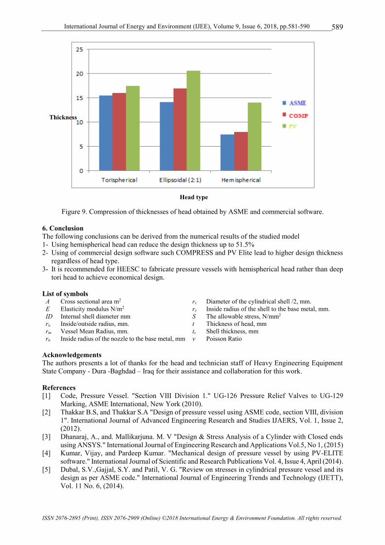
Figure 9 is plotted to compare the result of thicknesses calculated by ASME codes (hand calculations) and
by using, COMPRESS and PV Elite programs.
As it can be seen from Figure 9 that the minimum design thickness values are obtained from using ASME
codes for all head types while the higher values are obtained from using PV Elite program. This mean that
such programs are used higher safety factors which are leading to non-economical design.
Table 5. Compression of heads thicknesses (mm).
Torispherical Ellipsoidal (2:1) Hemispherical
r1=1000 r1=1000 r1 = 1000
r2=300 r2=340 r 2= 1000
t (by hand) =15.47 t (by hand) =14.1 t (by hand) =7.5
t (COMP.) = 16 t (COMP.) = 17 t (COMP. )= 8
t (PV Elite) = 17.5 t (PV Elite) = 20.63 t (PV Elite) = 14
Figure 8. Design thickness of the three head types.
0
2
4
6
8
10
12
14
16
18
Torispherical Ellipsoidal (2:1) Hemispherical
Thickness
International Journal of Energy and Environment (IJEE), Volume 9, Issue 6, 2018, pp.581-590
ISSN 2076-2895 (Print), ISSN 2076-2909 (Online) ©2018 International Energy & Environment Foundation. All rights reserved.
589
Figure 9. Compression of thicknesses of head obtained by ASME and commercial software.
6. Conclusion
The following conclusions can be derived from the numerical results of the studied model
1- Using hemispherical head can reduce the design thickness up to 51.5%
2- Using of commercial design software such COMPRESS and PV Elite lead to higher design thickness
regardless of head type.
3- It is recommended for HEESC to fabricate pressure vessels with hemispherical head rather than deep
tori head to achieve economical design.
List of symbols A Cross sectional area m2 rs Diameter of the cylindrical shell /2, mm.
E Elasticity modulus N/m2 rs Inside radius of the shell to the base metal, mm.
ID Internal shell diameter mm S The allowable stress, N/mm2
ri, Inside/outside radius, mm. t Thickness of head, mm
rm Vessel Mean Radius, mm. ts Shell thickness, mm
rn Inside radius of the nozzle to the base metal, mm ν Poisson Ratio
Acknowledgements
The authors presents a lot of thanks for the head and technician staff of Heavy Engineering Equipment
State Company - Dura -Baghdad – Iraq for their assistance and collaboration for this work.
References
[1] Code, Pressure Vessel. "Section VIII Division 1." UG-126 Pressure Relief Valves to UG-129
Marking, ASME International, New York (2010).
[2] Thakkar B.S, and Thakkar S.A "Design of pressure vessel using ASME code, section VIII, division
1". International Journal of Advanced Engineering Research and Studies IJAERS, Vol. 1, Issue 2,
(2012).
[3] Dhanaraj, A., and. Mallikarjuna. M. V "Design & Stress Analysis of a Cylinder with Closed ends
using ANSYS." International Journal of Engineering Research and Applications Vol.5, No 1, (2015)
[4] Kumar, Vijay, and Pardeep Kumar. "Mechanical design of pressure vessel by using PV-ELITE
software." International Journal of Scientific and Research Publications Vol. 4, Issue 4, April (2014).
[5] Dubal, S.V.,Gajjal, S.Y. and Patil, V. G. "Review on stresses in cylindrical pressure vessel and its
design as per ASME code." International Journal of Engineering Trends and Technology (IJETT),
Vol. 11 No. 6, (2014).
Head type
Thickness
International Journal of Energy and Environment (IJEE), Volume 9, Issue 6, 2018, pp.581-590
ISSN 2076-2895 (Print), ISSN 2076-2909 (Online) ©2018 International Energy & Environment Foundation. All rights reserved.
590
[6] Narale, Pravin, and. Kachare. P. S "Structural analysis of nozzle attachment on pressure vessel
design." International Journal of Engineering Research and Applications (IJERA) ISSN Vol. 2,
Issue4, (2012).
[7] Sankara Raju R,.Ashok D "Determination of Stress and Deformations Analysis on Lpg Steel.
Cylinder". International Journal of Engineering Research and Applications (IJERA), Vol.3, ISSN 1,
(2013).
[8] Lewiński Jerzy "The effect of manhole shape and wall thickness on stress state in a cylindrical
pressure vessel." Journal of Theoretical and Applied Mechanics, vol.2, (2015).
[9] Siva Sankara Raju R,.Ashok D and Thimothy Pandi, "Determination of Stress And Deformations
Analysis On Lpg Steel Cylinder". International Journal of Engineering Research and Applications
(IJERA) ISSN: 2248-9622 www.ijera.com Vol. 3, Issue 1, (2013).
[10] Kumar V, Kumar N, Angra S, and Sharma.P, "Design of Saddle Support for Horizontal Pressure
Vessel." International Journal of Mechanical, Aerospace, Industrial, Mechatronic and
Manufacturing Engineering Vol: 8 No: 12, (2014).
[11] Mukhtar, Faisal M., and Husain J. Al-Gahtani. "Design-Focused Stress Analysis of Cylindrical
Pressure Vessels Intersected by Small-Diameter Nozzles." Journal of Pressure Vessel Technology
Vol. 139, Issue 2 (2017).