International Journal of Advanced Scientific and Technical ...
11
International Journal of Advanced Scientific and Technical Research Issue 4 volume 6, Nov. – Dec. 2014 Available online on http://www.rspublication.com/ijst/index.html ISSN 2249-9954 R S. Publication, [email protected] Page 246 Structural and Fatigue Analysis of Pinned Joints Aditya Shankar 1 A.R. Nayak 2 T.Suresh Prakash 3 P.N.E.Naveen 4 1 SVEC BOBILLI, Ph no: +917207742978 . 2 SVEC BOBILLI. 3 SVEC BOBILLI. 4 GIET, RJY. ABSTRACT The application of physics and engineering in designing, manufacturing and maintenance of mechanical systems is an important part of mechanical engineering. In this discipline, there are plethora of ways and means in which two objects can be fastened together. A solid cylinder- shaped device known as pin joint is widely used to connect compatible objects at joint areas in the real world systems. Here the type of joint connection plays an important role in the successful connection of objects. Pint joint is typically used in most of the mechanical devices as it is flexible. Such joint can be subjected to welding or allow free movement between the connected objects. In this paper, we present a methodology for structural and fatigue analysis of pinned joints. E Glass and S2 Glass epoxy composite plate is considered. Two serial holes are used that have varying distance from the free edge of the plate. A composite plate is made and the fatigue analysis of pinned joints is made. Cosmos is used for structural and fatigue analysis. The empirical study revealed that the proposed approach is capable of analyzing fatigue of pinned joints. Key Words: Fatigue analysis, pinned joints, fastening of objects
-
Upload
khangminh22 -
Category
Documents
-
view
1 -
download
0
Transcript of International Journal of Advanced Scientific and Technical ...
International Journal of Advanced Scientific and Technical Research Issue 4 volume 6, Nov. – Dec. 2014
Available online on http://www.rspublication.com/ijst/index.html ISSN 2249-9954
R S. Publication, [email protected] Page 246
Structural and Fatigue Analysis of Pinned Joints
Aditya Shankar 1 A.R. Nayak
2 T.Suresh Prakash
3 P.N.E.Naveen
4
1 SVEC BOBILLI, Ph no: +917207742978 .
2 SVEC BOBILLI.
3 SVEC BOBILLI.
4 GIET, RJY.
ABSTRACT
The application of physics and engineering in designing, manufacturing and maintenance of
mechanical systems is an important part of mechanical engineering. In this discipline, there are
plethora of ways and means in which two objects can be fastened together. A solid cylinder-
shaped device known as pin joint is widely used to connect compatible objects at joint areas in
the real world systems. Here the type of joint connection plays an important role in the
successful connection of objects. Pint joint is typically used in most of the mechanical devices as
it is flexible. Such joint can be subjected to welding or allow free movement between the
connected objects. In this paper, we present a methodology for structural and fatigue analysis of
pinned joints. E Glass and S2 Glass epoxy composite plate is considered. Two serial holes are
used that have varying distance from the free edge of the plate. A composite plate is made and
the fatigue analysis of pinned joints is made. Cosmos is used for structural and fatigue analysis.
The empirical study revealed that the proposed approach is capable of analyzing fatigue of
pinned joints.
Key Words: Fatigue analysis, pinned joints, fastening of objects

International Journal of Advanced Scientific and Technical Research Issue 4 volume 6, Nov. – Dec. 2014
Available online on http://www.rspublication.com/ijst/index.html ISSN 2249-9954
R S. Publication, [email protected] Page 247
INTRODUCTION
A composite material is the material which is made up of two or more materials. The materials
used for composite material might have different characteristics. However, when two or more
materials are mixed as per the engineering principles of mechanical engineering, the resultant
material can have unique characteristics that are very useful. However, identification of materials
in composite material is possible as the materials do not dissolve or be converted to other ones.
There are many instances in nature where the combining of multiple materials to form new
materials as shown in Fig. 1. The materials when combined get different features which are
unique and may not existing in the constituent materials.
Figure 1 – Materials combination and dynamics of characteristics
Many researchers contributed towards the mechanical engineering in terms of fusion of two or
more materials to form new material. The investigation into the effects of staking objects was
made in [1]. Experiments were made on bolted woven composite objects and their strengths [2].
Pin-loaded holes and the layered composites, their strengths and the failures were analyzed in
[3]. More works related to this can be found in literature review section of this paper.
Our contributions in this paper include the design and implementation of a methodology that
helps in structural and fatigue analysis of pinned joints. We made an empirical study to analyze
the fatigue of pinned joints using Cosmos. The remainder of the paper is structured as follows.
Section II reviews literature on prior works. Section III presents proposed methodology. Section
IV presents experimental results while section V concludes the paper besides providing
directions for future work.
LITERATURE REVIEW
Khashaba [1] studied the stacking effect of a sequence of failure loads with respect to strength.
His research also involves the pinned – joints. The experiments also involve epoxy composite
laminates which are glass-fiber reinforced. The investigations were made on specimens like
[0/90]2S, [15/-75]2S, [30/-60]2S and [45/-45]2S and stacking sequences are studied both
numerically and experimentally. On unidirectional [8]0 glass-fiber which is reinforced composite
laminate are used for ASTM tests. The tests are conducted to know the characteristics of single
lamina which is very essential for finite element analysis. With the aid of ABAQUS software, a
3D progressive damage model was planned to implement through simulations. The empirical
International Journal of Advanced Scientific and Technical Research Issue 4 volume 6, Nov. – Dec. 2014
Available online on http://www.rspublication.com/ijst/index.html ISSN 2249-9954
R S. Publication, [email protected] Page 248
results revealed that the highest ultimate strength is associated with the laminate [0/90]2S. In the
same fashion, the ultimate strength and minimum bearing was associated with the laminate [30/-
60]2S. Shear-out failure mode for [0/90]2S, [15/-75]2S and [30/-60]2S was resulted when loading
the specimens to max value. This is done when sequences are stacked. The stacking sequences
with speciments [45/-45]2s leads to failure mode. The numerical and empercal results reveal that
there an is agreement of results with Euclidean error norm of 8.57%.
F. Pierron [2] made a numerical and empirical study on bolted woven composite joints with
respect to their streangth and stiffness. The purpose of this research was to find out the possible
prediciotn of characteristics of joints obtained from the materials used for experiements. Later
another model was developed which is a refined finite element model where nonlinearities are
obnserved. They are due to contact angle between hole and pin and materials used for the
purpose. Influence of the clearance was given specific attention while making experiments as it
is very important. The research concludes that there was good agreement between the numerical
results and empirical results. Ivana Ilic etc [3] used a com putation method meant for failure
analysis on layered composites that have pin-loaded holes. The research focused on the making a
reliable approach for computing and analyzing intial failure load for such holes in layered
composite structures. Stress distribution is around the fastener hole which is determined using
Finite Element Method (FEM). In order to determine the joint failure Tsai-Wu intial failure
condition and Chang-Scott-Springer property curve approaches are combined. Pin-load
distributions were given highest attention in order to determine the failure at load level and its
localization. The prior work to this was focused on the cosine distribution between the lug and
pin which was mechanically fastened joint. The failure analysis was carried out using that. The
observations reveal that the stacking of seuquences of layered composites that are having pin-
loaded holes was made. Failure load in composites and mode analysis with stacking sequence
[0/(±45)3/903]S is given important attention. The results are compared with experimental results
and good correlatins are found.
H.M. Harsha et al. [4] focused on investigating the dynamics of bearing or failure load of filler.
The composites were used with single or double pinned joints that are having different
characteristics and subjected to various methods of experimentation. The effect of the distance
between the first hole and diameter and the width of plate to W/D ratio and filler effect were
experimented on Zinc Sulphide (ZnS) and Titanium dioxide (TiO2) with respect to bearing load.
Laminated woven glass biber composite plate containing double and single serial pinned joints
were used for experiments.
Larry B. Lessard et al. [5] studied the modeling of damage in laminated composite materials.
Such material contains complexity and prone to failure process due to difficulties. Stress
concentrations are more in joint region and there is complicated stress in the observations. For
modeling progress damage right from the start to the end the approach used is finite elements
methods. They avoided usage of closed form stress analysis for obvious reasons. For finite
element technique, there are two approaches. They are non-linear models and simple two-
dimensional linear model. When non-linear material is used, its behavior is analyzed using
deformation theory and two enhancements are observed in the model. There should be logical
combination of appropriate material characteristic degradation rules and suitable failure
conditions.
International Journal of Advanced Scientific and Technical Research Issue 4 volume 6, Nov. – Dec. 2014
Available online on http://www.rspublication.com/ijst/index.html ISSN 2249-9954
R S. Publication, [email protected] Page 249
STRUCTURAL ANALYSIS OF PINNED JOINTS USING S2 GLASS FIBER
This section provides details of the experiments and the study in terms of model information,
loads and fixtures, mesh information and related details. These details can help in understand
ing the procedure followed for the empirical study and the results reveal that significance of the
study.
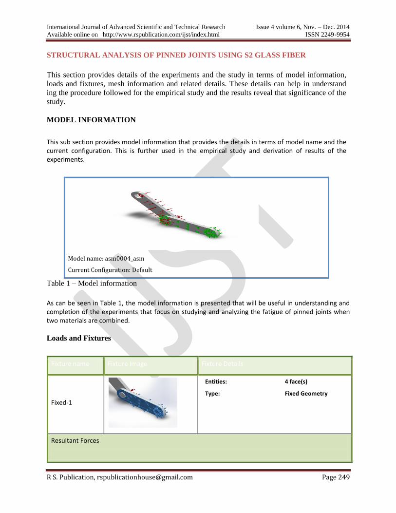
MODEL INFORMATION
This sub section provides model information that provides the details in terms of model name and the current configuration. This is further used in the empirical study and derivation of results of the experiments.
Model name: asm0004_asm
Current Configuration: Default
Table 1 – Model information
As can be seen in Table 1, the model information is presented that will be useful in understanding and completion of the experiments that focus on studying and analyzing the fatigue of pinned joints when two materials are combined.
Loads and Fixtures
Fixture name Fixture Image Fixture Details
Fixed-1
Entities: 4 face(s)
Type: Fixed Geometry
Resultant Forces

International Journal of Advanced Scientific and Technical Research Issue 4 volume 6, Nov. – Dec. 2014
Available online on http://www.rspublication.com/ijst/index.html ISSN 2249-9954
R S. Publication, [email protected] Page 250
Table 2 – Loads and Fixtures
As can be seen in Table 2, it is evident that the details are given in terms of fixture name, its visual appearance,
and fixture details in terms of type and entities. The resultant forces are also shown in terms of components,
reaction force and reaction moment.
Load name Load Image Load Details
Pressure-1
Entities: 4 face(s)
Type: Normal to selected
face
Value: 6.99
Units: N/mm^2 (MPa)
Centrifugal-1
Centrifugal, Ref: Face< 1 >
Angular Velocity: 4 rad/s
Angular Acceleration: 0 rad/s^2
Components X Y Z Resultant
Reaction force(N) 0.068675 -0.017952 -0.348679 0.35583
Reaction Moment(N·m) 0 0 0 0
Table 3 – Other loads
As can be seen in Table 2, it is evident that the details are given in terms of fixture name, its
visual appearance, and fixture details in terms of type and entities. Value and units are given to
pressure -1 while the centrifugal reference value, angular velocity and angular acceleration are
provided for centrifugal – 1.
International Journal of Advanced Scientific and Technical Research Issue 4 volume 6, Nov. – Dec. 2014
Available online on http://www.rspublication.com/ijst/index.html ISSN 2249-9954
R S. Publication, [email protected] Page 251
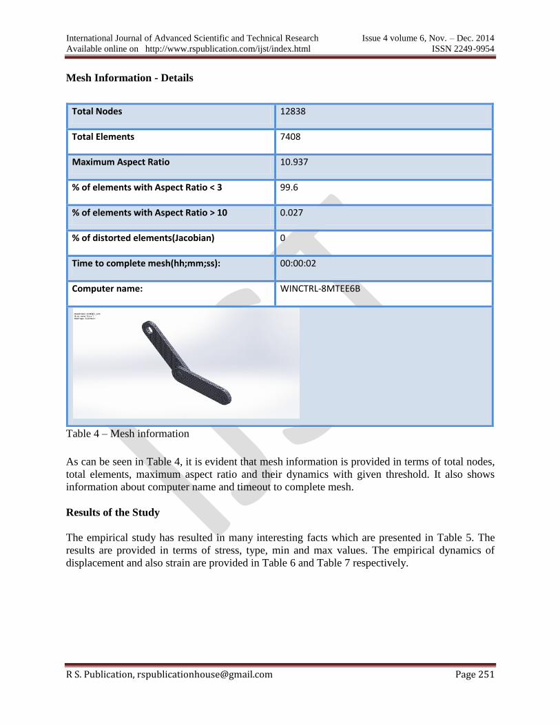
Mesh Information - Details
Total Nodes 12838
Total Elements 7408
Maximum Aspect Ratio 10.937
% of elements with Aspect Ratio < 3 99.6
% of elements with Aspect Ratio > 10 0.027
% of distorted elements(Jacobian) 0
Time to complete mesh(hh;mm;ss): 00:00:02
Computer name: WINCTRL-8MTEE6B
Table 4 – Mesh information
As can be seen in Table 4, it is evident that mesh information is provided in terms of total nodes,
total elements, maximum aspect ratio and their dynamics with given threshold. It also shows
information about computer name and timeout to complete mesh.
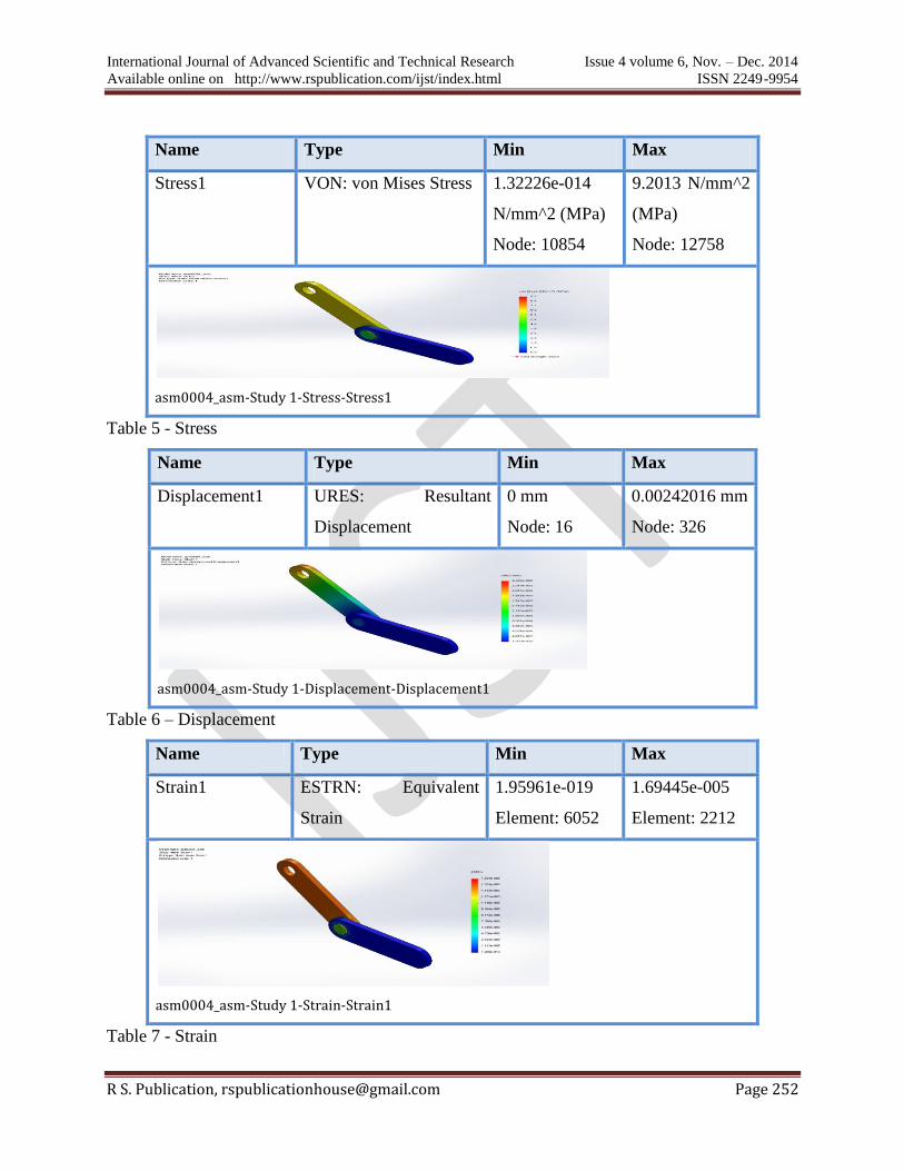
Results of the Study
The empirical study has resulted in many interesting facts which are presented in Table 5. The
results are provided in terms of stress, type, min and max values. The empirical dynamics of
displacement and also strain are provided in Table 6 and Table 7 respectively.
International Journal of Advanced Scientific and Technical Research Issue 4 volume 6, Nov. – Dec. 2014
Available online on http://www.rspublication.com/ijst/index.html ISSN 2249-9954
R S. Publication, [email protected] Page 252
Name Type Min Max
Stress1 VON: von Mises Stress 1.32226e-014
N/mm^2 (MPa)
Node: 10854
9.2013 N/mm^2
(MPa)
Node: 12758
asm0004_asm-Study 1-Stress-Stress1
Table 5 - Stress
Name Type Min Max
Displacement1 URES: Resultant
Displacement
0 mm
Node: 16
0.00242016 mm
Node: 326
asm0004_asm-Study 1-Displacement-Displacement1
Table 6 – Displacement
Name Type Min Max
Strain1 ESTRN: Equivalent
Strain
1.95961e-019
Element: 6052
1.69445e-005
Element: 2212
asm0004_asm-Study 1-Strain-Strain1
Table 7 - Strain
International Journal of Advanced Scientific and Technical Research Issue 4 volume 6, Nov. – Dec. 2014
Available online on http://www.rspublication.com/ijst/index.html ISSN 2249-9954
R S. Publication, [email protected] Page 253
The results presented in Table 5, 6, and 7 reinforce the facts and figures that are related to the
experiments. The results are provided in terms of stress, strain and displacement. Min and max
values besides the type are considered for result analysis.
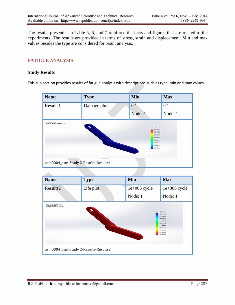
FATIGUE ANALYSIS
Study Results
This sub section provides results of fatigue analysis with descriptions such as type, min and max values.
Name Type Min Max
Results1 Damage plot 0.1
Node: 1
0.1
Node: 1
asm0004_asm-Study 2-Results-Results1
Name Type Min Max
Results2 Life plot 1e+006 cycle
Node: 1
1e+006 cycle
Node: 1
asm0004_asm-Study 2-Results-Results2

International Journal of Advanced Scientific and Technical Research Issue 4 volume 6, Nov. – Dec. 2014
Available online on http://www.rspublication.com/ijst/index.html ISSN 2249-9954
R S. Publication, [email protected] Page 254
Name Type Min Max
Results3 Load factor 309.934
Node: 12758
2.77137e+019
Node: 11218
asm0004_asm-Study 2-Results-Results3
RESULTS TABLE
ORIGINAL MODEL
Static Stress (N/mm2) Displacement (mm) Strain
S2 Glass 9.2 2.420e-003 1.694e-006
E Glass 8.5 1.147e-008 9.234e-011
Fatigue Damage Load factor Life
S2 Glass 1.001e-001 2.771e+019 1.001e+006
E Glass 1.001e-001 2.269e+024 1.001e+006
CHANGING HOLE DISTANCE
Static Stress (N/mm2) Displacement (mm) Strain
S2 Glass 8.5 1.813e-003 1.756e-006
E Glass 8.5 9.266e-003 8.973e-006
Fatigue Damage Load factor Life
S2 Glass 1.001e-001 1.049e+017 1.001e+006
E Glass 1.001e+001 2.055e+016 1.001e+006
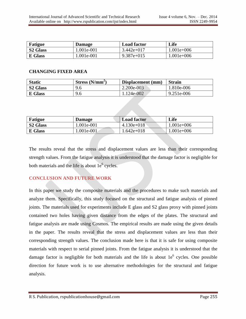
CHANGING LINK
Static Stress (N/mm2) Displacement (mm) Strain
S2 Glass 8.8 4.113e-004 1.619e-006
E Glass 8.7 8.962e-003 8.960e-006
International Journal of Advanced Scientific and Technical Research Issue 4 volume 6, Nov. – Dec. 2014
Available online on http://www.rspublication.com/ijst/index.html ISSN 2249-9954
R S. Publication, [email protected] Page 255
Fatigue Damage Load factor Life
S2 Glass 1.001e-001 3.442e+017 1.001e+006
E Glass 1.001e-001 9.387e+015 1.001e+006
CHANGING FIXED AREA
Static Stress (N/mm2) Displacement (mm) Strain
S2 Glass 9.6 2.200e-003 1.810e-006
E Glass 9.6 1.124e-002 9.251e-006
Fatigue Damage Load factor Life
S2 Glass 1.001e-001 4.130e+018 1.001e+006
E Glass 1.001e-001 1.642e+018 1.001e+006
The results reveal that the stress and displacement values are less than their corresponding
strength values. From the fatigue analysis it is understood that the damage factor is negligible for
both materials and the life is about 1e6 cycles.
CONCLUSION AND FUTURE WORK
In this paper we study the composite materials and the procedures to make such materials and
analyze them. Specifically, this study focused on the structural and fatigue analysis of pinned
joints. The materials used for experiments include E glass and S2 glass proxy with pinned joints
contained two holes having given distance from the edges of the plates. The structural and
fatigue analysis are made using Cosmos. The empirical results are made using the given details
in the paper. The results reveal that the stress and displacement values are less than their
corresponding strength values. The conclusion made here is that it is safe for using composite
materials with respect to serial pinned joints. From the fatigue analysis it is understood that the
damage factor is negligible for both materials and the life is about 1e6 cycles. One possible
direction for future work is to use alternative methodologies for the structural and fatigue
analysis.
International Journal of Advanced Scientific and Technical Research Issue 4 volume 6, Nov. – Dec. 2014
Available online on http://www.rspublication.com/ijst/index.html ISSN 2249-9954
R S. Publication, [email protected] Page 256
REFERENCE
[1] Experimental and numerical analysis of pinned-joints composite laminates: Effects of
stacking sequences by UA Khashaba, Mechanical Engineering Department, Faculty of
Engineering, King Abdulaziz University, Jeddah, Saudi Arabia
[2] A Numerical and Experimental Study of Woven Composite Pin-Joints by F. Pierron,
Department of Mechanical and Materials Engineering, France
[3] Computation Method in Failure Analysis of mechanically Fastened Joints at Layered
Composites by iIvana Ilić – Zlatko Petrovic – Mirko Maksimović – Slobodan Stupar – Dragi
Stamenković, Serbia
[4] Influence of Filler Materials on Pinned Joints of Woven Glass Fiber Reinforced Epoxy
Composites by H.M. Harsha, M.C. Murugesh and K.N. Bharath Department of Mechanical
Engineering, GM Institute of Technology, Davangere, Karnataka, India
[5] Two-Dimensional Modeling of Composite Pinned-Joint Failure by Larry B. Lessard,
Mahmood M. Shokrieh, Department of Mechanical Engineering, McGill University,
Montreal, Quebec.