
design aspects of - Scientific, technical publications in the ...
301
IAEA-TECDOC-677 Progress in development and design aspects of advanced water cooled reactors Proceedings of a Technical Committee Meeting held in Rome, 9-12 September 1991 INTERNATIONAL ATOMIC ENERGY AGENCY December 1992
-
Upload
khangminh22 -
Category
Documents
-
view
1 -
download
0
Transcript of design aspects of - Scientific, technical publications in the ...

IAEA-TECDOC-677
Progress in development anddesign aspects of
advanced water cooled reactorsProceedings of a Technical Committee Meeting
held in Rome, 9-12 September 1991
INTERNATIONAL ATOMIC ENERGY AGENCY
December 1992

The IAEA does not normally maintain stocks of reports in this series.However, microfiche copies of these reports can be obtained from
INIS ClearinghouseInternational Atomic Energy AgencyWagramerstrasse 5P.O. Box 100A-1400 Vienna, Austria
Orders should be accompanied by prepayment of Austrian Schillings 100,in the form of a cheque or in the form of IAEA microfiche service couponswhich may be ordered separately from the INIS Clearinghouse.

PROGRESS IN DEVELOPMENT AND DESIGN ASPECTS OFADVANCED WATER COOLED REACTORS
IAEA, VIENNA, 1992IAEA-TECDOC-677ISSN 1011-4289
Printed by the IAEA in AustriaDecember 1992

FOREWORD
The International Atomic Energy Agency has been providing aninternational forum for the exchange of information for many years. Thishas allowed Member States to prepare, taking into account their specificnational requirements, an international consensus on subjects of mutualinterest and thereby provide advisory standards and requirements in manyareas. This effort should be continued for future nuclear reactors andshould cover a wide range of topics including not only electricitygenerating plants but also plants for the supply of nuclear heat and forcogeneration, with sizes ranging from the smallest of the small and mediumsized power reactors to the largest electricity generating plants. MemberStates with sizeable nuclear power programmes have also developed thenecessary national infrastructures for design, development, safetyassessment as well as licensing processes and stable regulatory regimes.Following the conclusions of the IAEA Conference on the Safety of NuclearPower: Strategy for the Future, held in Vienna, 2-6 September 1991, thereis a need for guidance/advice to Member States on a number of issuesranging from suitable regulatory requirements, preferably of aninternationally acceptable nature, down to design objectives/targets andthe assessment methodologies needed to show how these may be met by thevarious advanced reactor designs which are likely to be available as"off-the-shelf" plants in the future. This publication addresses the stateof the art reached in the development of advanced reactor designs, theircontainments, safety systems and physics/thermohydraulic aspects.

EDITORIAL NOTE
In preparing this material for the press, staff of the International Atomic Energy Agency havemounted and paginated the original manuscripts as submitted by the authors and given some attentionto the presentation.
The views expressed in the papers, the statements made and the general style adopted are theresponsibility of the named authors. The views do not necessarily reflect those of the governments ofthe Member States or organizations under whose auspices the manuscripts were produced.
The use in this book of particular designations of countries or territories does not imply anyjudgement by the publisher, the IAEA, as to the legal status of such countries or territories, of theirauthorities and institutions or of the delimitation of their boundaries.
The mention of specific companies or of their products or brand names does not imply anyendorsement or recommendation on the part of the IAEA.
Authors are themselves responsible for obtaining the necessary permission to reproduce copyrightmaterial from other sources.
This text was compiled before the recent changes in the former Union of Soviet SocialistRepublics.

CONTENTS
Summary of the Technical Committee Meeting ............................................................ 9
DEVELOPMENT PROGRAMMES AND CONCEPTUAL DESIGN OF ALWRs(Session 1)
Progress on meeting utility requirements for ALWRs ................................................. 27J.C. DeVine, Jr., T.U. Marston
Requirements for next generation light water reactors for the 21st century in Japan ........... 32K. Matsui, K. Kuriyama
Conceptual design and development of simplified light water reactors in Japan ................. 37Y. Oka, G. Yagawa, K. Nishida, Y. Makihara, M. Murase
Swiss research and development activities in the domain of ALWRs .............................. 44K. Foskolos, P. Coddington, S. Güntay
ABWR — The first of the new generation of reactors for the 1990s ............................... 50S.A. Hucik, A.S. Rao
Evolutionary advancements to proven technology are the key to success .......................... 54R. S. Turk, R.A. Matzie
Development of projects of advanced water cooled reactor plants .................................. 62E.V. Budylin, G.I. Biryukov, V.G. Fedorov, V.A. Voznesenskij
The Westinghouse AP600: The leading technology for proven safety and simplicity ........... 67H.J. Bruschi, T.S. Andersen
SBWR — Simplifications in plant design for the 1990s ............................................... 70R.J. McCandless, A.S. Rao, C.D. Sawyer
Enhanced safety reactors for nuclear district heating and co-generation plants ................... 75V.S. Kuul', A.A. Falkov, O.B. Samojlov
Design status and perspectives of advanced water cooled reactor application for productionof electricity and heat in Czechoslovakia ............................................................. 82Z. Mlady
Current activities on advanced light water reactor design and technology atthe Japan Atomic Energy Research Institute .......................................................... 88T. Tone
SBWR technology and development ....................................................................... 95A.S. Rao, C.D. Sawyer, R.J. McCandless
Conceptual design of an inherently safe and simple tube reactor using water moderatorand coolant .................................................................................................. 100Soon Heung Chang, Won-Pil Baek
CONTAINMENT SYSTEMS (Session 2)
Trends in the required performances of containments for the next generation ofnuclear power plants ...................................................................................... 109L. Noviello, I. Tripputi

PIUS, aspects of containment: Philosophy and design ................................................. 113C. Sundqvist, L. Nilsson, T, Pedersen
New research trends for the structural assessment of concrete containment structuresunder extreme load conditions with emphasis on constitutive laws of concrete ............... 119P. Angeloni, L. Brusa, P. Contri, R. Pellegrini, M. Venturuzzo
Development and qualification of the FUMO code for the containment system simulationof advanced LWRs ........................................................................................ 132P. Barbucci, A. Manfredini, G. Mariotli, F. Oriolo, S. Pad
Studies on ALWR containment system penetrations ................................................... 139F. Mantega, E. Penno, P. Vanini
Design of the AP600 passive containment cooling system structures ............................... 145M. Olivieri, S. Orlandi, R. Orr
Enhancement of advanced PWR safety margins through relaxation of PCS andcontainment DBA assumptions .......................................................................... 152C. Addabbo
Foundation bearing capacity on soft soils ................................................................ 158C. Ricciardi, G. Liberati, R. Previti, G. Paoti
SAFETY SYSTEM AND ANALYSIS (Session 3)
Investigation of passive systems for the Nuclear Power International PWR ...................... 173U. Krugmann, R. Schilling
Innovative systems and components aimed at providing PWRs with completely passiveemergency shutdown and decay heat removal ........................................................ 177M. Cairo, M. Cumo, L. Gramiccia, A. Naviglio
Steam injectors as passive components for high pressure water supply ............................ 185L. Mazzocchi, P. Vanini
SBWR — Isolation condenser and passive containment cooling:An approach to passive safety ........................................................................... 191M. Brandani, F.L. Rizzo, E. Gesi, A.J. James
Design of back-up protection systems for new generation nuclear reactors ....................... 198A. Ghiri, M. Nobile, G. Torsello
Advanced reactor design philosophy and application — Ways and meansto prevent core melt ....................................................................................... 204L. Nilsson, T. Pedersen
Summary of theoretical analyses and experimental verification of the PIUS density lockdevelopment program ..................................................................................... 213C. Find, J. Fredell
Long term decay heat removal with passive features in ALWRs .................................... 219L. Mazzocchi, P. Vanini, R. Vanzan
Survey of activities for assessing thermalhydraulic aspects of new reactors ...................... 226C. Bilia, F. D'Auria, E. Gesi
Research activities in the field of severe accident analysis ........................................... 239F. Cecchini, F. Corsi, F. De Rosa, M. Pezzilli
PHYSICS AND THERMOHYDRAULICS (Session 4)
Use of slightly enriched uranium in a PHWR in Argentina .......................................... 245G. Anbinder, A.M. Lerner, C. Notari, R. Ferez, J. Sidelnik

Perspectives on innovative fuel and associated core physics ......................................... 249J. Porta
Low power reactivity initiated accidents in new generation light water reactors ................. 256G. Alloggio, E. Brega, E. Fiorino
Advanced boiling water reactors ........................................................................... 265V.G. Rodrigues, D. Stegemann
Some thermal hydraulic studies related to Indian AHWRs ........................................... 275D. Saha, V. Venkat Raj, A. Kakodkar, D.S. Pilkhwal, S.G. Markandeya
Capabilities of the RELAPS in simulating SBWR and AP600 thermal-hydraulic behaviour ... 282P. Andreuccetti, P. Barbucci, F. Donatini, F. D'Auria, G.M. Galassi, F. Oriolo
Assessment of the PIUS primary system using analytical and experimental models ............. 289P. Barbucci, C. Bertani, C. Carbone, G. Del Tin, F. Donatini, G. Sobrero
Simulation of operational and accident transients of the PIUS reactor by TRIP model ......... 297E. Brega, C. Lombardi, M. Ricotti, A. Rilli
List of Participants ............................................................................................ 307

SUMMARY OF THE TECHNICAL COMMITTEE MEETING
INTRODUCTION
The objective of the Technical Committee Meeting (TCM) on Progress inDevelopment and Design Aspects of Advanced Water Cooled Reactors held inRome, from 9 to 12 September 1991, was to provide an international forumfor technical specialists to review and discuss technology developments anddesign work for advanced water cooled reactors, safety approaches andfeatures of current water cooled reactors and to identify, understand anddescribe advanced features for safety and operational improvements. TheTCM was attended by 92 participants representing 18 countries and twointernational organizations and included 40 presentations by authors of 14countries and one international organization.
Mr. J. Kupitz, Head of the IAEA's Nuclear Power TechnologyDevelopment Section opened the TCM and presented an overview of the outcomeof the IAEA Conference on the Safety of Nuclear Power: Strategy for theFuture, held in Vienna, 2-6 September 1991 (the IAEA Safety Conference1991). Mr. F. Velonà, Director of R&D Division of the Ente Nazionale perl'Energia Elettrica (ENEL), Italy, welcomed the participants. The TCM waschaired by Mr. L. Noviello, Technical Director of the Nuclear Department inthe ENEL R&D Division. The meeting was divided into four sessions andWorking Groups.
It was generally agreed by the participants that the topics coveredat the meeting had met with great interest. The IAEA wishes to acknowledgethe excellent organizational arrangements and the high level of hospitalityprovided by ENEL and especially by Mr. Noviello.
The IAEA-TECDOC-626 on "Safety Related Terms for Advanced NuclearPlants" was presented by Mr. J. Kupitz. Mr. L. Kabanov, Head of the IAEA'sEngineering Safety Section, presented information on the IAEA activities inthe safety of advanced reactors.
The conclusions and recommendations agreed to at the TCM in Rome werereviewed at an IAEA Consultants Meeting in December 1991 in Vienna. Asummary of the sessions, conclusions and recommendations was drawn up toprovide a reduced survey of the main issues arising from the TCM.
As a result of the discussions and analysis of the papers, WorkingGroup reports and the meeting Chairman's report, the following conclusionsand recommendations, embodying the main issues raised, have been compiled.

SUMMARY OF PRESENTATIONS AND DISCUSSIONS
Summary by the Chairman of the TCM. Mr. L. NovielloThe meeting provided an international forum for the presentation and
discussion of the Member States' approach to the development and designaspects of advanced water cooled reactors.
The summary of the IAEA Safety Conference 1991 presented by Mr.Kupitz has put this meeting in the proper perspective from the beginning.Actually we have been able to verify throughout our technical sessions thefeasibility and the degree of maturity of the main improvements discussedat the Safety Conference in Vienna.
All the elements necessary to make a step forward in the technologyof future reactors are becoming available, including, of course, the needto consider severe accidents from the inception of containment design.Probably this evolution is one of the key elements needed to reach the fullmaturity of nuclear power and a further expansion of the worldwide use ofthis important source of energy.
The meeting was divided into four sessions:- Development programmes and conceptual design of ALWRs- Containment systems- Safety systems and analysis- Physics and thermohydraulics
covering both the general concepts and the particular aspects of design.It is possible to draw some general conclusions from all the valuable
contributions that have been made by almost 100 participants from about 20different countries and international organizations:1. We have clearly seen three levels of design evolutions, although the
timing of the expected commercial availability is somehowcontradictory.
2. Caution has been asked in the adoption of new technologies, and only,in any case, after exhaustive testing of both components and systems.
3. Improved containments are the most readily and possibly the best wayto meet the goal of a step forward in safety. In practice, thismeans explicit integration of severe accidents into the designcriteria. There was a clear indication that the elimination of thehigh pressure core melt sequences can be achieved effectively by theadoption of a depressurization system. There were less unanimousindications on the approach to be followed to cope with the lowpressure sequences; the containment can be designed for these eventsbut, according to some authors the uncertainties must be furtherreduced in order to avoid the need for too large margins.
4. The depressurization systems being adopted for the PWRs, but alsomany other passive systems proposed for different reactors, presentsimilar configurations and probably similar issues. It will beappropriate for the future IWGATWR activity at the right time, toprovide a forum to discuss in detail these issues with such a basicinterest.
10

5. Design tools enhancement has been widely discussed. Many of themreferred to the natural circulation of the water in the primarycircuit or of the air moisture and aerosols in the containmentatmosphere. It was a proper focus since natural circulation isrelated to the adoption of passive systems and then to thesimplification of the designs. Although present in the nuclearplants from the beginning, in many of the new designs naturalcirculation plays a much more important role.
6. The new designs have some other important goals beyond safety i.e.man-machine interface, construction techniques and schedule,licensing procedures, costs. These problems may be a good subjectfor the next meetings.
RecommendationsSome technical areas and specialists meetings which it is possible to
recommend for the IWGATWR have been discussed and recommended.One is the need to clearly separate the technical discussions arenafrom the licensing discussions arena. Industry needs a forum todiscuss openly, I would say with no licensing concerns, of itsdesires, trends, needs. This shall not prevent preliminarydiscussions with the licensing authorities only with mature, wellfounded industry positions in which, when appropriate, designimprovements and particulary safety improvement will have been put inan appropriate cost-benefit balance.The second one refers to the subject of tests. This issue emergedfrom this meeting as particulary important for next generation powerplants in the following fields:
severe accident phenomena- natural circulation thermohydraulics.Extensive testing is under way in both areas in several countries andit is appropriate to mention that an outstanding co-ordinationactivity is being performed by OECD. It is most important that theresults of the experiments are brought to the attention of alldesigners.
11

SUMMARY OF SESSIONS
SUMMARY OF SESSION 1
DEVELOPMENT PROGRAMMES AND CONCEPTUAL DESIGN OF ALWRsChairmen: Mr. J. DeVine, Mr. T. Pedersen
The Session provided an overview of the ALWR development programmesin Member States and reviewed a number of conceptual designs that are beingstudied.
Fourteen technical papers were presented describing the currentposition in Czechoslovakia, Japan, the Republic of Korea*, USA, Switzerland,and the USSR.
The order of the presentations was changed from that in the MeetingAgenda to permit first discussion of technical requirements for ALWRs,followed by description of advanced water reactor designs, design conceptsand their application for heat and electricity generation. Finally thefuture R&D needs for the next generation of power plants and some otherdesign concepts were presented.
An up-to-date review of the US DOE ALWR programme, focussing on theEPRI Utility Requirement Documents (URDs) which embody the plant-wide needsof US utilities for the new ALWRs, was presented. The role, scope andtop-tier requirements of the URDs were summarized and the overall safetyobjectives were given.
The requirements and conceptual design proposals for simplified smalland medium sized light water reactor for the next generation of powerplants were presented. In addition, a conceptual design for a pressuretube reactor, which avoids the need for emergency core cooling systems, wasdescribed.
Currently, advanced ALWRs have been sucessfully developed in Japan,and two advanced BWR units are now under construction. In addition,further developments in reactor protection are being advocated for PWRs,involving simplified active safety systems plus passive safety systems forsevere accidents. Issues on the future labour force, etc., were discussed.
The results of a study of Swiss (nuclear) specialists views on theweight to be attached to future reactor issues was presented. To keep thenuclear option open, a call for effort to be focussed on stringent safetyregulations was seen as necessary.
The US designs of ABWR and SBWR plants were described as examples ofadvanced light water reactors designed to address the needs for the nextgeneration of power plants. Key features of the plants were discussed.
Commercializing of large evolutionary AWRs was outlined and. adescription of the design of CE System 80+ which is currently going througha regulatory review, was given. The rationale for this design approachwhich includes the addition of specific passive safety features, waspresented.
* Note the paper from the Republic of Korea was presented in Session 3.
12

The main features of the Westinghouse AP-600, a revolutionary PWRdesign, were described. The feasibility of using passive safety systems tomitigate the consequences of both design basis accidents and severeaccidents was reviewed. The concept as proposed gives confidence that theplant could be expected in the mid-1990s.
The main development effort and the progress made in the USSR towarda future pressurized water cooled reactor design were described.Information included the use of horizontal steam generators and theoperational experience gained with the current series of WWER type reactors.
The design status and perspective for advanced water cooled reactorsin Czechoslovakia were described. The necessity for substantialimprovements in safety and economics for future nuclear power plants wasrecognized previously and a brief description plus the main characteristicsof a medium sized NPP (about 600 MWe) were presented.
CONCLUSIONSA diversity of viewpoints and opinions was offered on this topic
(both by presenters and the TCM participants). The numerous points madewere widely supported by the meeting suggesting some level of consensus.In this Session the following points were made:
There was widespread agreement on the need for clearly stated,technically sound design requirements for ALWRs and the paperspresented were consistent in their presentations of the requirementsneeded. Greatest interest was shown in items like design andconstruction simplification, reliance upon proven technology safetyaspects and the importance of the man-machine interface and humanfactors.There is a growing consensus on the safety objectives/targets for newplants (e.g., International Nuclear Safety Advisory Group (INSAG) andEPRI ALWR Utility Requirement Documents), but it is still an openissue as to how such targets can be met or how they are to bemeasured and regulated (i.e., deterministic and/or probabilisticdesign methodology)There was also agreement on the necessity of achieving publicacceptance, as a precondition for building new plants. It was alsonoted that a nuclear power plant that would not require relocation ofpeople under accident conditions would represent a significant anddesirable improvement from the "public acceptance" point of view.
Evolutionary plant designs were generally seen to represent the majoroption for near term development whereas the more innovative typeswill need more time before commercial availability.
Concepts making use of passive systems and/or components have merit,but (in the view of many participants) only to the degree that theyresult in demonstrable improvement.Most participants felt that simplified evolutionary or passive plantsemploying proven technology will lead to real improvements (e.g. insafety and cost). Simplification, while supported in concept, needsbetter definition. Simplicity from the standpoint of the operator isconsidered very beneficial to safety.
13

It was generally agreed that there may be merit in designs whichemploy active systems for common and high frequency events andpassive systems for low frequency event prevention and/or mitigation.It was agreed that testing of ALWR features will be extremelyimportant, particularly for innovative or passive safety systems.Requirements regarding the amount of testing of such systems, andassociated test methods (scaling, modelling, etc.) before plantconstruction are not well established and warrant specific (further)attention.
RECOMMENDATIONS
1. It is recommended for the IWGATWR that an activity be initiated withthe aim of defining a consistent and general set of criteria for theassessment of concepts with regard to degree of safety, as well assimplicity and concept maturity.
2. This TCM was considered by the participants to be a very effectiveforum for constructive, open dialogue. It is recommended thatfollow-up meetings be held, similar in structures that is relativelysmall group, international and diverse attendance, and stressingtechnical focus. Suggested scientific topics for future meetingsinclude on-going testing and experimental programs and the conceptassessment criteria of ALWRs.
14

SUMMARY OF SESSION 2
CONTAINMENT SYSTEMSChairmen: Mr. P.J. Meyer, Mr. Y. Dennielou
The papers presented in this Session dealt with the main issuesassociated with reactor containment.
The consequences of severe accidents to the population living in thevicinity of a nuclear power plant were outlined. Ideas on how theseconsequences may be minimized were given. This could be achieved bybuilding in bigger safety margins through for instance a conservativedesign of containment and/or improved containment systems using passivesafety features. The resulting longer grace periods possible would allowconsidered action to be taken if and when necessary.
Requirements and standards were discussed and proposals made forthese to be internationally harmonized to provide uniform design standardswith addtional guidance on how to meet them being important.
The philosophy of the defence in depth concept (barrier concept) wasoutlined and it would still remain valid for future systems, with accidentprevention and mitigation continuing to be considered for all futurecontainment designs.
In considering containment design it was noted that neither therelease nor the probability of a release, of radioactivity as a consequenceof a wide range of accidents should result in the need for evacuation ofthe public. However an evacuation plan may be established on request ofthe appropriate authorities.
Presentations were made on the wide range of tests which have been orare being planned for advanced passive containment systems; some of thesehave already been completed. Boundary as well as new design parametershave been specified for each different design proposal. Respectivecomputer programmes are being both developed and improved and will bequalified by test results. Sensitivity analyses presented gave details ofthe influence of physical properties on containment configurations.
Future theoretical development programs as well as new tests weredescribed which may lead to further optimization of containment andmaterial configurations, of specifications for and simplification of,containment systems, leading to a reduction in the number of penetrationsand higher reliability.
The need for developing new codes or for adapting existing codescalculating physical and thermohydraulic phemenoma was outlined along withthe need for such codes to be verified against test results. Codes havebeen developed for specific purposes in containment design i.e.multicompartment system, and their adaptation to current and innovativecontainment systems was considered to be possible.
It was noted that the leak-tightness of the containment, under bothnormal and accident conditions was one of great importance. The differentmodes of plant operation each rely upon a certain number of operatingsystems which penetrate the containment (electrical, mechanical, valves,hatches, etc.), all of which need to be qualified as to their
15

functionability and leak-tightness. Validation of the proposed solutionsshould be by either full-scale or reduced-scaled tests. For some advancedNPPs passive containments were described where the decay heat istransferred within and removed from the containment by internal naturalcirculation and by external natural convection respectively. New safetyfeatures will need to be qualified by test and/or calculation sufficient tomeet the necessary licensing requirements.
The role of containments for existing plants, which are designed towithstand design basis accidents, defined by pipebreaks in the primarysystems as well as specified steamline and feedwater line breaks, wasdiscussed against possible future objectives. To minimize the risk of lossof containment integrity the existing safety margins may be increased byeither increasing the containment volume or by the use of containmentventing. It was noted that the latter is not contemplated for advancedNPPs. Accident management planning within future reactor safety marginswould have to be analyzed very carefully and tests are necessary to justifysuch planning. In the construction of NPP the role of the site subsoilconditions in NPP construction was also reviewed. Calculations necessaryto evaluate the effect of different soil conditions were discussed.
CONCLUSIONSThe design basis for current reactors containment is a double-ended
break of primary piping based on already existing rules and regulations.This provides protection over a wide range of accident scenarios.
The next generation of reactor containment systems and structuresmust be designed to assure their design functions for the whole spectrum ofaccidents including severe accident consequences. For the containmentlayout and design respectively uncertainties and/or margins must becarefully investigated and included in the design.
Physical and thermo-mechanical behaviour and the source termassumptions, as used in designing the containment, should be considered forall accident conditions, including severe accidents. The input parametersfor such computerized analyses must be carefully investigated and therespective codes qualified. International consensus should be reached.
The design of the plant should provide the technical bases to makepublic evacuation unnecessary. However, a simplified Emergency Planningcould be adopted by decision of Administrative Authorities.
International consensus should be reached regarding design and layoutrequirements.
The containment should be designed as soon as possible with a passivesafety feature. Credit can be given in the safety analysis for accidentmanagement actions after a certain grace period.
For the selection of the passive containment systems extensivestudies are needed considering e.g. concrete containments with liner,prestressed concrete, freestanding cylinder or sphere, single, againstdouble containment. These analyses have to consider carefully influencesfrom inside as well as from outside.
The different components constituting the containment must bequalified under accidental conditions to ensure integrity and function
16

under short and long-term conditions (such as penetrations and air locks).Proper diversification at sensor and logic level should be taken intoaccount. Model tests of complete containment systems, as well as of singlecomponents, may be necessary to demonstrate their reliable functions (underaccidental inner as well as outside events such as earthquake, missileprotection).
For accident management procedures the possibility of monitoring thestate of components during accident evolution should be considered ashighly desirable.
In addition to the technical, safety-related and design requirementsthe economic viability needs to be evaluated, to establish thecompetitiveness of nuclear as opposed to conventional energy sources, avery important and crucial point for the future introduction of advancedreactors.
Licence criteria consensus for systems such as the containment bynational authorities is essential in the frame of wide acceptance of thenext generation of NPPs.
RECOMMENDATIONS
It is recommended for the IWGATWR:To consider setting down the requirements for new containment designs.To rationalize the containment design features and characteristicsfor future reactors.In a planned IWGATWR TCM meeting to consider design aspects for theadvanced reactor containments and to identify to generally acceptedtechnical solutions applicable to future reactors.TCM or CRP to consider code development needs for the differentcontainment designs and for varying accident conditions. The targetsshould be internationally agreed and accepted code packages.TCM on economic comparison of containment systems with the goal ofidentifying realistic cost reduction proposals and internationallyacceptable optimized containment concepts (design, assembling,modularization, testing, in-service inspections).
17

SUMMARY OF SESSION 3
SAFETY SYSTEM AND ANALYSISChairmen: Mr. Y. Oka, Mr. Z. Mlady
The Session provided a complete picture of the status of theresearch, development and design activities, referring to innovativesystems and components, currently underway in many Member States.
Nine papers were presented and discussed during the Session, fromFrance, Germany, Italy* and Sweden.
The results of a systematic investigation of the role of passivesystems in accident mitigation and severe accident mitigation for possibleimplementation in PWRs, as performed by Nuclear Power International (NPI),was presented. The merits of such features and their definition wereinvestigated to assess their suitability for large sized PWRs. The resultspointed to a positive safety gain from the use of a secondary side safetycondenser (SAGO), to replace the existing emergency feed water system.
A possible role for completely passive emergency shut-down and decayremoval systems for PWRs was presented. Features developed for the MARSreactor concept were explained in some detail.
Studies on the design requirements of a steam ejector used as apassive component to supply high pressure water as a function of both waterdischarge pressure and steam pressure were described. Studies relating toan Isolation Condenser and a Passive Containment Cooling System aimed atproviding a 72 hour grace period were also outlined, together with expectedbenefits.
The design of a proposed back-up protection system using laddershaped module technology was presented. This aimed to avoid a common modefailure of the main protection system leading to an un-tripped faults.
The design philosophy of the PIUS plant, together with some of theexperimental tests performed and test results obtained to support thedesign development were presented.
The need for a drastic design change "yielding a quantum jump" inperceived safety and reduced plant complexity was claimed as a prerequisitefor a real revival of the nuclear option. The PIUS plant design has beenproposed as an example meeting this claim.
The experimental activities presently under way in Italy to assessthe thermal-hydraulic behaviour of innovative reactors were presented.These included the gravity driven reflood experiments performed in thePIPER-ONE facility and the tests performed at the SPES facility. Codepredictions of the test results were reported.
CONCLUSIONS
The findings of Session 3 correlate closely with the results of theother sessions and only the most relevant findings are listed here.
* Some of these papers were presented in Sessions 2 and 4.
18

Regarding the introduction of passive systems to replace activesystems in nuclear power plants, further scientific investigations areneeded. Some aspects (pros and cons) are listed below.
benefits;1. allow for enhanced simplification2. introducing higher degree of diversity3. decreasing needs for safety-grade electrical power4. increasing grace period5. less dependence on human efforts in operation, and maintenanceconcerns;1. slow response2. poor flexibility3. functional uncertainty4. testability5. controllability6. licensability.
19

SUMMARY OF SESSION
PHYSICS AND THEEMOHYDRAULICSChairman: Mr. M. Cumo, Mr. J. Rixon
The Session discussed the way forward to more forgiving reactor coredesigns, through increasing the level of accident prevention rather thanprotection itself, and the behaviour of reactors with passive safetyfeatures for both reactor shutdown and decay heat removal.
Eight technical papers were presented covering the above topics, byorganizations from Argentina, Brazil, France, India and Italy. In thefollowing, a short synthesis of Session 4 presentations is given.
The ways available for the optimization of uranium consumption andeconomic benefits achievable by the use of different enrichments in anexisting Heavy Water Reactor (1179 MW(th)) were presented and discussed.
The increased safety level achievable through the use of "cold fuels"and burnable poisons in advanced reactors was reviewed, along withreactivity accidents at zero/low power for the SBWR and the AP600. Thepossibility of preventing severe fuel damage by using operating proceduresin the SBWR was proposed.
An analysis of the length of fuel cycles with changes in Plutoniumenrichment was presented in association with thermal hydraulics for theABWR.
The work carried out on the thermal-hydraulic analysis of core flowdistribution and the possibility of maintaining the coolant flow throughthe core by natural circulation, in a heavy water moderated reactor, waspresented and discussed.
Presentations were given on the application of the RELAP5/Mod2 codeto the analysis of thermal hydraulic transients in the SBWR, AP600 nuclearreactors and the PIUS system. The RELAPS capabilities and limits werediscussed and the problems encountered in its use for natural circulationconditions outlined. The need for seperate effects tests was presented.
CONCLUSIONSIn general the core-physics and thermohydraulics of advanced reactors
utilizing natural circulation and/or convection are at the stage where anunderstanding of a bigger range of parameters of the physical variables ofalready known phenomena is needed. New tests in this area are advisable.
Best estimate codes which coupled neutronics and thermohydraulics arenow a possibility to be considered due to improved computationalcapabilities. Their development and application to advanced reactors ishighly advisable and this should be an area for further considerations.
Some further consideration needs to be given toward a betterunderstanding of accidents beyond the design basis for ALWRs. Some work inthis area seems necessary.
20

RECOMMENDATIONS1. Further work is needed in relation to natural circulation/convection
to obtain a better understanding of a wider range of core physics andthermohydraulic parameters of already known phenomena.
2. Further considerations should be given to the development of bestestimate coupled neutronic-thermohydraulic codes.
21

GENERAL CONCLUSIONS AND RECOMMENDATIONS
CONCLUSIONS1. There is a need for clearly stated and technically sound
internationally agreed design objectives/targets for advancedreactors.
2. While there is a growing consensus on the need for internationallyagreed safety objectives/targets for new plants it is still an openissue as to how such targets can be met.
3. Advanced evolutionary reactor designs should utilize as far aspossible, passive safety features instead of active systems, but onlyto the extent that safety is either maintained at the level attainedin the best operating plants or it is improved.
4. For revolutionary designs of NPPs which mainly incorporate passivesafety systems consideration needs to be given to the safety statusand performance required of other supporting active systems which maycontribute to meeting the overall safety objectives/targets.
5. Attention needs to be paid to the need for testing innovative and/orpassive safety features.
6. In considering the design of future nuclear power plants, specialattention should be given to the design of containments which shouldcover the whole spectrum of accidents, including severe accidents.The available margins to unacceptable performance, available graceperiods and accident management measures should be included.
7. The design of the plant should provide the technical basis for makingpublic evacuation measures unnecessary. However, simplifiedemergency planning could be adopted by decision of the appropriateauthorities.
8. There is a need for international consensus on containment design andlayout which may be met by an IAEA NUSS Series No. 50-SG-D12.
9. Extensive studies are needed to aid in the selection of passivecontainment concepts, to ensure their integrity under both short- andlong-term conditions.
10. The economic viability of advanced reactors with the new designrequirements for containment for systems and for equipment needs tobe evaluated and demonstrated.
11. Discussion is needed to clarify and identify the main problem areasto allow useful discussions to be held at future IWGATWR TCMs.
12. In the area of core physics and thermohydraulics where naturalcirculation dominates there is a need for further R&D work to obtaina better understanding of a wider range of parameters as well asappropriate tests.
13. Development and application of best estimate codes in"coupled-neutronics and thermohydraulic" should continue to be aimedat improving computation for advanced reactors.
22

RECOMMENDATIONS
1. Special support should be given to the International activities underway aimed at harmonizing safety standards/goals and how they are tobe implemented.
2. Requirements for new containment designs for advanced reactors shouldbe documented.
3. There is a need for continued activities to review the on-goingactivities in the area of containment designs, safetyobjectives/targets and economics.
4. Further work should be persued toa) obtain a better understanding of a wide range of core physics
and thermohydraulic parameters associated with naturalcirculation phenomena,
b) develop the best estimating coupled neutronic thermohydrauliccodes for advanced reactors,
c) identify the testing needed to validate the claimedperformance of innovative passive safety features.
Next page(s) left blank 23

DEVELOPMENT PROGRAMMESAND CONCEPTUAL DESIGN OF ALWRs
(Session 1)
Chairmen
J.C DE VINEUnited States of America
T. PEDERSENSweden

PROGRESS ON MEETINGUTILITY REQUIREMENTS FOR ALWRs
J.C. DE VINE, Jr.GPU Nuclear Corporation,Parsippany, New JerseyT.U. MARSTONElectric Power Research Institute,Palo Alto, CaliforniaUnited States of America
Abstract
The advanced light water reactor (ALWR) has been under development since1981 in the United States. The paper briefly reviews the progress to date. Theindustry is working towards meeting the goal of the Nuclear Power OversightCommittee (NPOC) Strategic Plan for Building New Nuclear Power Plants whichis to provide the U.S. utilities with a viable ALWR option by 2000. A key aspect ofthe Plan is the degree of commitment to standardization throughout the design,construction and operation of the ALWRs. Emphasis is placed upon the UtilityRequirements Document (URD) and its role in this overall plan.
The URDs embody the plant-wide needs of the utilities for the new ALWRs. Therole, scope a^d top tier requirements of the URDs are summarized. The overallsafety objectives which exceed those required by regulation are presented.Containments for the new reactors have increased margin over current designs andnumerous engineering features are specified to address key challenges potentiallyimparted by severe accidents. The status of NRC review of the URDs and currentschedules are provided. Finally, future ALWR activities are discussed.
Table 1NPOC Plan
Building Block Summary
Prerequisites from Ongoing Programs(1)" Current Nuclear Plant Performance (Licensees)(11) High Level Radioactive Waste (EEI-ACORD)(12) Low-Level Radioactive Waste (EEI-ACORD)(13) Adequate, economic Fuel Supply (EEI)
Generic Safety/Environmental Regulation & Industry Standards(2) Predictable Licensing & Stable Regulation (NUMARC)(3) ALWR Utility Requirements (EPRI-USC)
Project-Specific Activities(4) NRC Design Certification (Plant Designers)(5) Siting (EPRI-USC/NUMARC)(6) First-of-a-Kind Engineering (EPRI-USC)(7) Enhanced Standardization Beyond Design (NUMARC)
Institutional Steps(8) Enhanced Public Acceptance (USCEA)(9) Clarification of Ownership and Financing (EEI)(10) State Economic Regulatory Issues (EEI)(14) Enhanced Governmental Support (ANEC)
* Building Block Number
Introduction
The commitment of the U.S. utilities to reopening the nuclear option issummarized by the Nuclear Power Oversight Committee in the Strategic Plan forBuilding New Nuclear Power Plants.1
"The extensive operating experience with today's light water reactors(LWRs), and the promise shown in the recent technical developments,leads the industry to the conclusion that the next nuclear plantsordered in the United States will be advanced light water reactors(ALWRs). Two types are under development: units of large output(1300 MWe) called "evolutionary" ALWRs and units of mid-sizeoutput (600 MWe) called "passive" ALWRs."
to 1 "Strategic Plan for Building New Nuclear Power Plants," prepared by the Nuclear Power OversightCommittee, November 1990.
The NPOC Plan identifies 14 enabling conditions (or building blocks) necessary toreopen the nuclear option in the U.S. Those are listed in Table 1.
The Plan:
• identifies all the significant enabling conditions (technical/industrial,regulatory, environmental, financial, legislative/legal, organizational, political,and public acceptance) which must be met to achieve the goal;
• assigns lead and supporting responsibilities to the appropriate organizations orstanding committees in the industry to develop and implement an action planfor achieving each condition;
• fosters joint and coordinated efforts between government and industry whichwould enhance implementation of the strategies and provide for sharedresources.

00Of particular technical interest to this paper are the building blocks 2, 3, 4, 6 and 7.The Plan was originally published in November 1990 and is to be updated inNovember 1991. The Plan includes a schedule which reflects the goal of having anALWR which could be built and ready for operation on or about the turn of thecentury. This would require that an ALWK order be placed in the 1995 timeframe.Key dates from the Plan that support the 1995 order date include:
• Safety Evaluation Report (SER) on evolutionary plant Utility RequirementsDocument (URD) - 3/91SER on passive plant URD - 2/92Design Certification (DC) of the ABWR - 6/92DC for ABB-CE System 80+ - 12/92DC for AP600 -12/94DC for SBWR - 2/95Complete first-of-a-kind (FOAK) engineering - 6/95 (depends upon design)
Some of the Plan dates have slipped and the situation with the review and approvalschedule for the URDs will be discussed later in this paper.
Standardization
One of the central themes of the NPOC Plan is that of standardization. Utilitiesbelieve that the viability of ALWRs will be greatly enhanced by standardization indesign and operation. In order to convey the importance of standardization, NPOCdeveloped 'The Position Paper on Standardization for Building New PowerPlants."2 The Chief Executive Officers (CEOs) of all US nuclear utilities approvedthis position paper before publishing.
The US Utility commitment to standardization is summarized in this paper asfollows:
"Nuclear power plant standardization is a life-cycle commitment to theuniformity in the design, construction and operation of a family ofnuclear power plants. Rigorous implementation of standardization isexpected to achieve the efficiency and economy typically associatedwith increases in scale or breakthroughs in technology."
The process of standardization includes four stages: the foundation levelestablished by the ALWR Utility Requirements Documents; additionalstandardization through the NRC Design Certification Process; commercialstandardization (engineering beyond DC); and enhanced standardization beyonddesign. The primary motivation for standardization is its economic benefit, andstandardization's contribution to safety is also well recognized.
2 'Position Paper on Standardization," prepared by the Nuclear Power Oversight Committee, April1991.
For each family of ALWR plants, the following principles are proposed:
Standardization will be maintained throughout the construction and operatinglife of the family of standardized plants. An owner/operator structure will beestablished with clear mechanisms for maintaining standardization including aformal process for the review of proposed modifications or other departures.
Standardization within systems, structures and components needed for safetywill be subject to regulatory acceptance. Standardization within systemsrequired for reliable power generation will be maintained by all theowner/operators of a family of standardized plants or by the organizationalentity established and charged with that responsibility by all theowner/opera tors of that family.
The plant design will be transferable, without alteration, to any site within thedesign envelope for the family of plants.
Layouts of major systems and components will be identical. Plant layoutshould preclude the use of any shared equipment between units.
System functional requirements will be identical, with siting consideration asthe only acceptable reason for differences.
Major structural, mechanical, electrical, or I&C components (includinginstalled spares) essential to nuclear safety or reliable power generation will beidentical.
Functional, physical, and interface requirements for bulk commodities and forother components will be identical. The spécifications should identify criticaldesign characteristics to allow selection of the component that best meets therequirements and allow qualified substitutions without modifying essentialidentical components.
Each plant within a family will be built to construction drawings andspecifications that are identical to the extent noted above. It is recognized thatsome differences will arise due to site-specific requirements and variationswithin acceptable construction tolerances.
Permanent modifications to systems, structures, or components essential tonuclear safety or reliable power generation will be made only after review andapproval of the organizational entity established and charged with thatresponsibility by all the owner/opera tors of a family of standardized plants.Such review and approval by the family of plants may be deferred in the case ofan emergency modification. However, modifications to replace failed orobsolete components should maintain standardization, or if necessary, beplanned so as to recover standardization as the same components are replacedin the other plants within the family.

• Standardization beyond hardware design will be implemented in such areas astraining, maintenance and operating procedures, quality assurance, licensing,spare parts management and outage management.
From a technical standpoint, the development of Utility Requirements (BuildingBlock 3 - NPOC Plan) is of key importance to the U.S. strategy.
UTILITY REQUIREMENTS
Since 1982, the U.S. utilities have been leading an industry-wide effort to establish atechnical foundation for the design of the next generation of light water reactors inthe United States. Since 1985, the utility initiative has been effected through a majortechnical program managed by the Electric Power Research Institute (EPRI); the USAdvanced Light Water Reactor (ALWR) Program. In addition to the US utilityleadership and sponsorship, the ALWR Program also has the participation andsponsorship of numerous international utility companies and close cooperationwith the U.S. Department of Energy (DOE). One of the main goals of the ALWRProgram has been to develop a comprehensive set of design requirements for theadvanced LWR. The Utility Requirements Document3 defines the technical basisfor improved and standardized future LWR designs.
Although established nearly eight years before the NPOC initiative in settingbuilding blocks for the revitalization of Nuclear Power, the ALWR Program, andparticularly the Requirements Document effort fits naturally and fully into thebroader NPOC program.
The Requirements Document covers the entire plant up to the grid interface. Ittherefore is the basis for an integrated plant design, i.e., nuclear steam supply systemand balance of plant, and it emphasizes those areas which are most important to theobjective of achieving an ALWR which is excellent with respect to safety,performance, constructibility, and economics, the document applies to bothPressurized Water Reactors (PWRs) and Boiling Water Reactors (BWRs).
There are numerous basic design policies underlying the ALWR URD, establishedby the Utility sponsors. Among these:
Simplification Simplification is fundamental to the ALWR success, is pursuedwith very high priority, and is assessed primarily from thestandpoint of the operator.
VO 3 ALWR Utility Requirements Document
Design Margin Like simplification, design margin is of fundamentalimportance and is pursued with very high priority. TheALWR is to be a rugged, forgiving design. Its designincorporates margins which go beyond regulatoryrequirements and these margins are not to be traded off oreroded for regulatory purposes.
Human Factors Human factors considerations will be incorporated into everystep of the ALWR design process but especially in the maincontrol room design.
Safety The ALWR design will achieve excellence in safety forprotection of the public, on-site personnel safety, andinvestment protection. (This is discussed in more detailbelow.)
Design Basis The ALWR design will include both safety design and safetyVersus margin requirements (discussed later.)Safety Margin
Regulatory ALWR licensability is to be assured by resolving open licensingStabilization issues, appropriately updating regulatory requirements,
establishing acceptable severe accident provisions, andachieving a design consistent with regulatory requirements.
Standardization The ALWR Requirements Document sets the technicalfoundation for standardized designs, consistent with the NPOCPolicy Paper. The ALWR design is intended to make extensiveuse of the extraordinary data base of information and lessonslearned from 30 years of experience in operation of over 100light water reactor power plants in the US and many moreoverseas.
Proven Proven technology will be employed (requiring no prototype)Technology throughout the design.
Maintainability The ALWR will be designed for ease of maintenance to reduceoperations and maintenance costs, reduce occupationalexposure, and to facilitate repair and replacement ofequipment.
Constructibility The ALWR construction schedule will be substantiallyimproved compared to previous U.S. experience, due to use ofmore constructible plant configuration, better constructionmethodology and completion of most of the engineering priorto construction.
Economics The ALWR is to be designed to be economically attractive incomparison to other central station alternatives on both a near-term (10 year) and life cycle (60 year) basis.

Good Neighbor The ALWR plant will be a good neighbor by minimizingradioactive and chemical releases to its surroundingenvironment and chemical releases.
Of particular interest are the Requirements Document treatments of safety andcontainment performance.
It is ALWR Program policy to require excellence in safety and environmentalperformance. In this regard ALWR safety goals have been established to limit thecore damage frequency to less than 10'5 per reactor year and to limit the siteboundary whole body dose to less than 25 rem for those severe accidents withcumulative frequency which exceeds 10** per reactor year. These safety goals will bedemonstrated by plant specific probabilistic risk assessment (PRA) as part of thedesign process.
In addition to the ALWR safety goals, containment performance requirements havebeen stipulated to provide high assurance of containment integrity even in theevent of a severe accident. Further, the combination of safety goals andcontainment requirements provide a technical basis for substantial simplification inemergency planning, at the same time providing very high protection of publicsafety.
The ALWR safety design goal is achieved through an integrated approach whichincludes three overlapping levels of safety protection: accident resistance, coredamage prevention, and accident mitigation. These levels of safety protectionreflect the defense-in-depth philosophy. Accident resistance refers to minimizingthe frequency of initiating events which could lead to a demand on engineeredsafety systems. This is accomplished through simplicity, increased design marginand other intrinsic characteristics to minimize frequency and severity of initiatingevents. Core damage prevention refers to engineered systems which preventinitiating events from progressing to core damage. Mitigation refers to systems andstructures to contain fission products released from a damaged core. Table 2 listsexamples of ALWR requirements established to address accident resistance and coredamage prevention. It is important to note that requirements in the first two areasmake any core damage event very low in probability for ALWRs.
ALWR safety requirements encompass Licensing Design Basis (LDB) and the SafetyMargin Basis (SMB). The LDB is the set of ALWR design requirements which satisfyNRC regulations, including LDB transient and accident events, in the Code ofFederal Regulations and associated regulatory guidance. Only safety-relatedequipment is assumed to be available for purposes of meeting regulatory limits(with the exception of a few multiple failure events such as ATWS and stationblackout where limited credit for non-safety-related equipment is allowed.)
The SMB is the set of ALWR requirements which addresses severe accidents byproviding margin beyond the LDB. The severe accident protection incorporates
Table 2Examples of ALWR Requirement? Addressing Accident Prevention
Accident Resistance (i.e., minimizing frequency and severity of initiatingevents)
No recirculation piping in BWRsNo loop seal and minimal welds in PWR primary system pipingGreatly improved control roomImproved accessibility and design for maintenanceImproved resistance to embrittlement in reactor vessel
Core Damage Prevention
High reliability decay heat removalHigh reliability ECCSIncreased RCS inventory delaying core recoveryIncreased time for operator action
NRC policy level guidance and provides increased assurance of containmentintegrity and low release of radioactivity during a severe accident. SMB analyses aretypically best-estimate evaluations which meet utility specified limits. Reasonablecredit is taken for non-safety-related equipment. While much has been learned inthe last decade about severe accidents through experimental and analytical work, theSMB calculation methods and assumptions necessarily involve more engineeringjudgment than the LDB.
The accident resistance and core damage prevention requirements result in ALWRdesigns that are very safe from the following perspectives. First, the designs willresult in fewer and less severe initiating transients. Second, given an initiatingevent, the ALWR design will have a much reduced likelihood of the transientleading to core melt. Furthermore, the very robust containment for ALWRs cantolerate "credible" severe accidents, those with probabilities of occurrence greaterthan 10*7/year.
Containment Requirements
The Requirements Document specifies that containment systems and structuresprovide sufficient design margin to accommodate severe accident loads such thatASME Service Level C (steel), Factored Load 1.0 (reinforced concrete) limits are notexceeded. Those load levels are specified to insure leak-tightness of thecontainment, therefore the margin against gross rupture is considerably greater thanthat typically required by design codes. In addition, containment failures prior to orcoincident with a severe accident, such as containment bypass, shall be precluded bydesign.
Related top tier requirements include for evolutionary plants:
• Electrical power supplies shall address all concerns about Station Blackoutincluding alternate AC on-site generation
• Enhanced Man-Machine Interface Systems and Information ManagementSystems shall significantly improve the control room environment to simplifycontrol and operations of the plant during transients, accidents and normaloperation
For passive plants
• The plant shall satisfy the above severe accident limit for an indefinite time(72 hours without operator action and thereafter only simple operator actions).
• Leak-tightness shall be sufficient to meet applicable offsite dose limitsContainment system components for which a change of state is necessaryto assure an intact containment (e.g., containment isolation valves) arenot vulnerable to common cause failure because they are redundant andsufficiently independent from the systems whose failure could lead todamage.
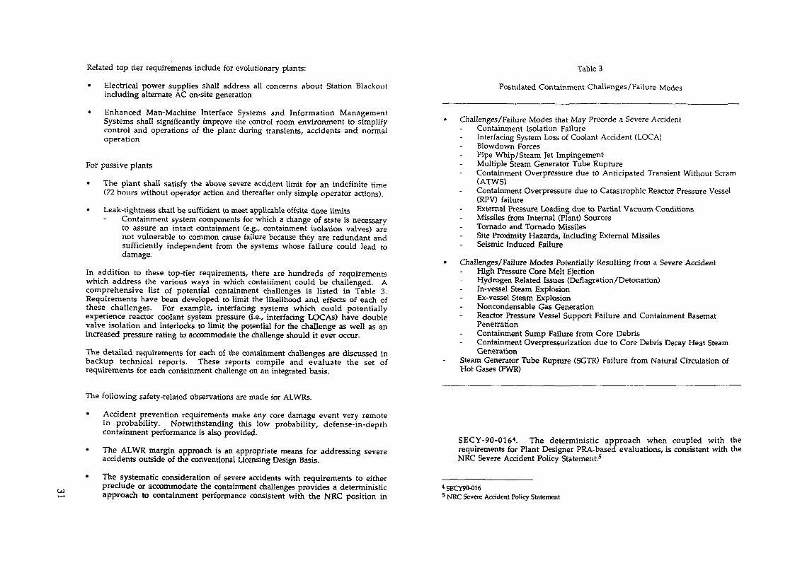
In addition to these top-tier requirements, there are hundreds of requirementswhich address the various ways in which containment could be challenged. Acomprehensive list of potential containment challenges is listed in Table 3.Requirements have been developed to limit the likelihood and effects of each ofthese challenges. For example, interfacing systems which could potentiallyexperience reactor coolant system pressure (i.e., interfacing LOCAs) have doublevalve isolation and interlocks to limit the potential for the challenge as well as anincreased pressure rating to accommodate the challenge should it ever occur.
The detailed requirements for each of the containment challenges are discussed inbackup technical reports. These reports compile and evaluate the set ofrequirements for each containment challenge on an integrated basis.
The following safety-related observations are made for ALWRs.
• Accident prevention requirements make any core damage event very remotein probability. Notwithstanding this low probability, defense-in-depthcontainment performance is also provided.
• The ALWR margin approach is an appropriate means for addressing severeaccidents outside of the conventional Licensing Design Basis.
• The systematic consideration of severe accidents with requirements to eitherpreclude or accommodate the containment challenges provides a deterministicapproach to containment performance consistent with the NRC position in
Table 3
Postulated Containment Challenges/Failure Modes
Challenges/Failure Modes that May Precede a Severe AccidentContainment Isolation FailureInterfacing System Loss of Coolant Accident (LOCA)Slowdown ForcesPipe Whip/Steam Jet ImpingementMultiple Steam Generator Tube RuptureContainment Overpressure due to Anticipated Transient Without Scram(ATWS)Containment Overpressure due to Catastrophic Reactor Pressure Vessel(RPV) failureExternal Pressure Loading due to Partial Vacuum ConditionsMissiles from Internal (Plant) SourcesTornado and Tornado MissilesSite Proximity Hazards, Including External MissilesSeismic Induced Failure
Challenges/Failure Modes Potentially Resulting from a Severe AccidentHigh Pressure Core Melt EjectionHydrogen Related Issues (Deflagration/Detonation)In-vessel Steam ExplosionEx-vessel Steam ExplosionNoncondensable Gas GenerationReactor Pressure Vessel Support Failure and Containment BasematPenetrationContainment Sump Failure from Core DebrisContainment Overpressurization due to Core Debris Decay Heat SteamGeneration
Steam Generator Tube Rupture (SGTR) Failure from Natural Circulation ofHot Gases (PWR)
SECY-90-0164. The deterministic approach when coupled with therequirements for Plant Designer PRA-based evaluations, is consistent with theNRC Severe Accident Policy Statement-5
* SECY9O-0165 NRC Severe Accident Policy Statement

The schedule established for Building Block 3 in the NPOC Plan is being revised toreflect actual progress to date. The following table compares the original keymilestone dates with the schedules recently published by the NRC in SECY 91-1616
Milestone Description NPOC NRCNRC final Safety Evaluation Report (SER) on evolutionary 3/91 8/92ALWR Utility Requirements Document
NRC final SER on passive ALWR Utility Requirements 2/92 9/93Document
The present status of the Evolutionary Plant SER is that all but two (of fourteen)submittals have draft SERs prepared. There are several key issues that needresolution before the final SER can be approved.
For the Passive Plant, all requests for additional information (RAIs) are addressedon a schedule well ahead of the SECY-91-161 average of 90 days. Progress to date byNRC in review and evaluation of the Requirements Document has beendisappointing. A major effort is being made to reach closure on key issues andrecover some of the lost schedule.
THE NEXT STEPS
In order to meet the U.S. utilities needs for baseload capacity additions in the timeperiod 2000-2010, the NPOC Plan schedule must be met. The following actions arenecessary.
1. Close out issues and expedite the SERs for the evolutionary plant URD and thepassive plant URD.
2. Expedite the DC process for the ABWR System 80+, AP600 and SBWR.3. Initiate the first-of-a-kind engineering work as soon as practicable.4. Complete the siting effort on its current schedule.5. Establish the infrastructure for the families of plants.6. Promote standardization to the extent possible through requirements,
certification commercialization and beyond design.
6 SECY91-161
REQUIREMENTS FOR NEXT GENERATIONLIGHT WATER REACTORS FOR THE21st CENTURY IN JAPAN
K. MATSUI, K. KURIYAMAInstitute of Applied Energy,Tokyo, Japan
Abstract
Although nuclear power generation with light water reactors has beensuccessfully employed and developed in Japan, further improvements ineconomics and safety are desirable in order to achieve further developmentand maturity of nuclear power. At the present time advanced light waterreactors have successfully been developed and construction of two units hasstarted in Japan, Large LWRs of highly developed function and performancehave been studied as a candidate for the next-generation power reactoradopting the newest technoligical concepts as for Advanced LWRs such asABWR and APWR. On the other hand, innovative design ideas which diffèrefrom conventional concepts are being advocated abroad and in Japan.
Issues on the energy situation, labor force, etc. likely to arise inthe 21st century in relation to the design of LWRs and of nuclear powerdevelopment and requirements for Japan are discussed.
The anticipated social changes toward the future have been consideredas the surrounding conditions for defining the required specifications ofthe new-concept reactors. The results of the discussion are summarizedbelow for the items most likely to be encountered from the aspects ofenergy demand, labor issues and technical development.
1. Energy Consumption Outlook
1.1 World Energy Demand
(1) PopulationThe current world population (1990) is 5.2 billion of which1.2 billion is in the developed countries and 4 billion inthe developing countries (77% of the total).According to a prediction by the United Nations, thepopulation in the developed countries will increase slightlyto 1.2 times the current level by 2025, but the populationin the developing countries wil l increase explosively to 1.7times the current level. Consequently, the world populationwill be 8.21 billions in 2025 with 84% in the developingnations. 2.8 billions of the 3 billion increase will be inthe developing countries. The population problem in the 21stcentury will be attributed to the population explosion inthe developing countries.

£ 4
1 9 8 7 % USA
developingcountries ave
FRG_/developedcountries ave
oraEi_01
c
o•P
JAPAN
R 0 K
P.R C
1 The per capita annual energy consumption
USA
FRG
JAPAN
R O K
P R C
Fig 2
1970 1980 1990 2000 2010 2020 2030
The changes in per capita annual energy consumption
(2) Energy Issues(a) Per Capita Annual Energy Consumption
Figure 1 shows the per capita annual energy consumption for1987 in various countries. The average consumption in thedeveloped countries is approximately 5 tons in terms of oiland 0.5 ton in the developing countries, only 10% of thatin the developed countriesThe average values differ largely even among the developedcountries (among the United States, West Germany andJapan). The consumption in Japan is less than half that ofthe United States and is approximately 60% of the averagefor the developed countries. Figure 2 shows the changesin per capita annual energy consumption in these countries.While the consumption is almost constant in U.S.A , inGermany and Japan, whose consumption levels are below theaverage for the developed countries, it grew steadily at16% and 19% , respectively, from 1970 to 1987 On theother hand, per capita consumption in a newlyindustrialized country (REPUBLIC OF KOREA) and in adeveloping country (PEOPLE'S REPUBLIC OF CHINA) hasremarkably increased by factor 2.5 during the same period.
(b) Electricity to Primary Energy RatioIt can be deduced that the importance of electric energywill be further increasing after 2000 because of itsconvenience as an energy form. The portion of the primaryenergy used to generated electric power in the totalconsumed primary energy is currently 15% to 20% in thedeveloped countries and 5% to 1% in the developingcountries. This value must be increased to improve theliving standards in the developing countries, by factor 1.5to 2 under the assumption the whole world should reach thelevel of the developed countries by 2050.
(3) Uranium Resources in View of World Energy SituationThe energy consumption should continue to increase asmentioned above and part of it will be supplied by nuclearpower generation. According to 1989 OECD report ('UraniumResource,Production and Demand"), the confirmed deposit ofuranium costing less than 130 $/kg (equivalent to 60 $/lb)is approximately 2,300,000 tons and estimated additionaldeposit will be approximately 1,300,000 tons.According to the report, on the other hand, the cumulativeuranium consumption by 2030 will be 2,400,000 to 3,090,000tons if used only for LWRs, which is close to the amount ofthe reserves It may be not appropriate to judge on thebasis of currently available data only since new mines havenot been developed in these years, however consideratationshould be made now for the possible problems arising whensupply and demand becomes tight.
The keys to more effective use of uranium resources are,forLWRs, the development of high-burnup fuel, plutonium use inthermal reactors and an advanced flexible reactor core, and,for FBRs, the studies and development towards realization ofthe actual plants.
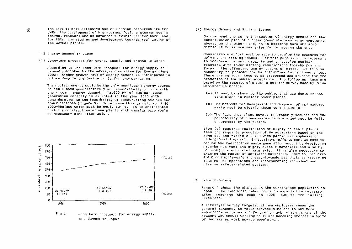
1.2 Energy Demand in Japan(1) Long-term prospect for energy supply and demand in Japan
According to the long-term prospect for energy supply anddemand published by the Advisory Committee for Energy (June1990), higher growth rate of energy demand is anticipated infuture despite the best efforts for energy-saving.The nuclear energy could be the only non-fossil energy sourcereliable both quantitatively and economically to cope withthe growing energy demand. 72,500 MW of nuclear powergeneration capacity is expected in the year 2010 withconsideration to the feasibility of constructing new nuclearpower stations (Figure 3). To achieve this target, about 401000-MWclass units must be newly built. It is anticipatedthat the construction of new plants with similar pace wouldbe necessary also after 2010 .
•M 900
S00-
400-
300'
i00-
28 900MW(9 0%)
50 500MW(13 2%)
72.500MW(16 7%)
— total
nuclear
1988 2IW0 2010
Fl9 3 Long-term prospect for energy supplyand demand in Japan
(2) Energy demand and Sitting IssuesOn one hand the current situation of energy demand and theconstruction plan of nuclear power stations is as mentionedabove, on the other hand, it is becoming more and moredifficult to secure new sites for achieving the end.Considerable effort must be made to develop the measures forsolving the sitting issues. For this purpose it is necessaryto increase the unit capacity and to develop nuclearreactors with fewer sitting restrictions thereby pushingforward the effective use of potential sites. It is alsonecessary to promote the PA activities to find new sites.There are various items to be discussed and studied for thepromotion of the public acceptance The following items arebased on the results of a public-opinion survey made by PrimeMinisteruLs Office.(a) It must be shown to the public that accidents cannot
take place in nuclear power plants.(b) The methods for management and disposal of radioactive
waste must be clearly shown to the public.(c) The fact that plant safety is properly secured and the
possibility of human errors is minimized must be fullyunderstood by the public.
Item (a) requires realization of highly-reliable plants.Item (b) requires promotion of PA activities based on theconcrete and flexible R & D with particular emphasis onunderground disposal, in addition, efforts must be made toreduce the radioactive waste generation amount by developinghigh-burnup fuel and highly-durable materials and also byreducing the activated materials. It is also necessary toexamine the resume of activated materials. Item (c) requiresR & D on highly-safe and easy-to-understand plants requiringless manual operations and incorporating redundant andpassive safety-related systems.
2 Labor ProblemsFigure 4 shows the changes in the working-age population inJapan. The awailable labor force is expected to decreaseafter reaching the peak in 1995, due to the fallingbirthrate.A lifestyle survey targeted at new employees shows thegeneral tendency to value private time and to put moreimportance on private life than on job, which is one of thereasons why annual working hours are becoming shorter in spiteof decreasing working-age population.

Q.oQJQ.
90 -8070-60-50403020100
1995working-age population
old-age population(over 65 years)
young-age population(lower 14 years)
Fig 41985 2000 2025 2085
Changes in the working-age population in Japan
(Annual working hours in Japan are about 2100 hours whilethose in Europe and the United States are about 1700 hours.The working hours in Japan are expected to fall to the levelin Europe and the United States in the near future.)As demonstrated by the recent data on the employment-seekingof university graduates (engineering departments), there isa tendency for them to select companies which are notmanufacturing industries. That results in difficulty formanufacturers to recruit appropriate human resourcesFurthermore, young employees are feeling less resistance tochanging their job and that makes it difficult for an employerretain them in a company.The rapid rise of the average age of the working populationwill create larger working opportunities for older people andwomen workers will become more important.Consequently, more and more older people and women areexpected to join the working population to cope with the laborshortage. Foreign workers can be another remedy for the laborshortage.Under such labor situation, the society may have to change sothat women and older people can participate more easily inwork. It is also necessary to make up for the labor shortage
by applying labor-saving measures and automation. The numberof nuclear power stations will increase in the 21st centuryunder serious labor shortage More nuclear power stationswill require larger number of nuclear power plantpersonnel (operators, maintenance personnel, designers, andconstruction workers). From the viewpoint of shortage ofskilled laborers, it will be necessary to design the systemsand components so that they can be operated by fewer people.For anticipated women and older workers, the facilities mustbe designed to be handled by people without significanttechnical knowledge. For this purpose, R & D must beconducted on personnel-savi ng plants incorporating automaticoperation, inspection/maintenance robots and systemsimplification.
3. Required Specifications for New Reactor Concepts3.1 Safety(1) The defence-in-depth philosophy based on the
current concept of safety functions (prevention ofoccurrence of abnormal events, prevention of theirexpansion, and prevention of abnormal radioactivityrelease) should be applied.
(2) Passive safety systems should be incorporated tomake operators action unnecessary for anappropriate time, to give the operators sufficient timebefore initiating the counteractions, and to reduce theoperator burden and consequently the possibility of humanfactors in accident cases.
(remark) Operators manual action should not berequired for more than 72 hours. (EPRIspecification)
3.2 Rellabi1ity(1) Component failure frequencies should be reduced to
assure plant reliability by applying passive andsimplified features.
(2) Plants should be designed with larger design margin in orderto be sufficiently trouble-torelant and to slow the troubleexpansion.
3.3 Operability and Maintainability(1) Higher operability and maintainability (easier operation
and maintenance) should be achieved by applying expanded

Öl automation, advanced man-machine interfaces, robotics anddiagnosis technologies, and consequently the burden onoperators and maintenance workers should be reduced.
(2) New technologies (materials and components) should beintroduced to improve maintainability
(3) Plants should meet the requirements with respect toload-following capability.
3.4 Site Adaptability(1) Plant design should be flexible enough to be adapted to
various siting methods (underground,mari ne siting, etc.) andvarious site locations (e.g.,city suburbs) to expand thepossible choice of new sites and to avoid over-concentrationof sites.
(2) Flexibility/adaptability to various site conditions shouldbe enhanced, e.g., by introducing seismic isolationtechnologies.
3.5 Constructibil ity(1) Shorter construction period, consequently reduced
construction man-power, should be pursued by expanding theapplication of prefabricated modules and large blocks as faras possible and by introducing large-scale constructionmachines.
(2) Learning effect should be taken into account more widelyby standardizing the component design, etc.
3.6 Design Lifetime(1) Plant lifetime should be extended to solve the siting
difficulties and to reduce the amount of radioactive waste.(2) Development should be made to establish the
1 ife-prediction/1ife-extension technologies for heavycomponents and systems and also to enable easier replacementof heavy components(remark)The design lifetime should be about 60
years(EPRI specification).
3.7 Quality Assurance/Quality Control(1) Extensive and thorough quality assurance should be
implemented for entire plant life throughout design,operation and periodical inspection of the plant
(establishment and documentation of necessary items such asdesign methods, verification and design modification).
(2) The experience of past accidents, troubles and plantoperation should be duly reflected on the plant design.
(3) Easier quality assurance and control should be realized byintroducing new technologies (improved welding techniques,advanced inspection methods, etc.), by reducing the safetysystem hardware as a result of application of passive andsimplified features, and by reducing the site work withextended prefabricated modules.
3.8 Public Acceptance(1) The plant should give an impression to the public that
accidents/troubles cannot occur easily and sagety cansecured easily if an accident does occur.
(2) The plant must coexist with the local community be inharmony with natural environment.
(3) The plant must not give a dangerous impression(4) The plant design should minimize the troubles due to human
factors.
3.9 Nuclear fuel(1) The fuel and core should be handled easily including
reprocessing with minimum necessity for reprocessing as theresult of appropriate core design.
(2) The core and fuel design should make the best use ofavailable uranium resources.
(3) The fuel should be high-performance fuel (PCI-free fuel) forrapid start/stop and load-following operation.
(4) The fuel design should incorporate passive safetytechnology.
3.10 Economics(1) The systems and equipment must be simplified as much as
possible and the physical number of systems, equipment andbuildings must also be reduced to optimize the plantoperating conditions (reduced capital expenditure).
(2) Equipment reliability and durability must be promoted andthe plant must have high availability and high reliabilityfactors as a result of extended continuous-operation periods

and reduced periodic inspection outages. The economics mustalso be enhanced by reducing the fuel cycle cost, number ofpersonnel and exposure dosage. (reduced operation andmaintenance costs).
(3) The economics must be enhanced by considering the plantservice life.
(4) The goal must be to generate power at less cost thancompetiting power-generation methods.
3 11 Others(1) No prototype reactor is required.(2) The plant capacity should be large because new sites are
hard to find.(3) Consideration should be given to the power transmission
systems because of the remote plant location and systeminstability resulting from the larger capacity.
(4) Promotion of thermal efficiency and effective use(multipurpose) of energy such as waste heat must bediscussed and studied.
(5) The applicability of standard designs and equipment mustbe examined so as to simplify licensing procedures.
(6) The technologies (such as those related to water chemistryand reduced exposure dosage) gained from past operatingexperience must be utilized effectively.
CONCEPTUAL DESIGN AND DEVELOPMENT OFSIMPLIFIED LIGHT WATER REACTORS IN JAPAN
Y. OKANuclear Engineering Research Laboratory,University of Tokyo,TokyoG. YAGAWADepartment of Nuclear Engineering,University of Tokyo,TokyoK. NISfflDAInstitute of Research and Innovation,University of Tokyo,TokyoY. MAKIHARAMitsubishi Atomic Power Industries, Inc.,TokyoM. MURASEEnergy Research Laboratory,Hitachi Limited,Ibaraki-kenJapan
AbstractJapanese plant vendors have developed concepts of small and
medium-sized light water reactors meeting international as well as domesticneeds based on their reliable nuclear technologies in Japan. They are theMitsubishi Simplified PWR (MSPWR) and the Hitachi Simplified BWR (HSBWR).The MSPWR is a new PWR concept. It has the innovative features of anoptimum combination of active and passive systems and horizontal steamgenerators which enhanced its natural circulation capability. Activesystems (charging/safety injection pumps and emergency diesel generators)are used to provide flexible operation and early termination of accidentsequences. Passive safety features (quench pool, automaticdepressurization systems and accumulators) are provided for long termcooling after a LOG A and make operator intervention unnecessary for 3days. The HSBWR is at the design concept stage, has been conceptuallydesigned. The major safety systems are an accummulated water injectionsystems as an ECCS and an outer pool which stands outside of the steelprimary containment vessel, as a long term cooling systems after LOCAs.The safety systems have redundancy in active and passive systems. Thegrace period is one day for core cooling and 3 days for the containmentvessel heat removal.
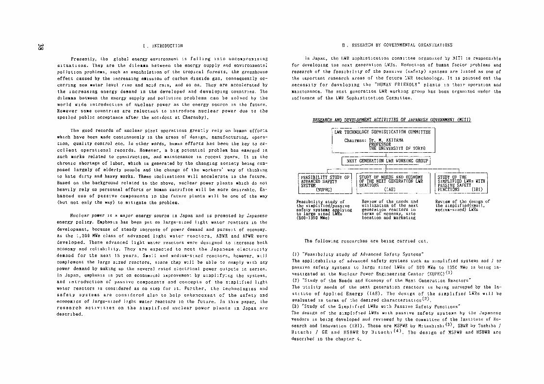
I . INTRODUCTION H . RESEARCH BY GOVERNMENTAL ORGANIZATIONS
Presently, the global energy environment is falling into uncompromisingsituations. They are the dilemma between the energy supply and environmentalpollution problems, such as annihilation of the tropical forests, the greenhouseeffect caused by the increasing emission of carbon dioxide gas, consequently oc-curring sea water level rise and acid rain, and so on. They are accelerated bythe increasing energy deaand in the developed and developing countries. Thedilemma between the energy supply and pollution problems can be solved by theworld wide introduction of nuclear power as the energy source in the future.However some countries are reluctant to introduce nuclear power due to thespoiled public acceptance after the accident at Chernobyl.
The good records of nuclear plant operations greatly rely on human effortswhich have been made continuously in the areas of design, manufacturing, opera-tion, quality control etc. In other »ords, huaan efforts has been the key to ex-cellent operational records. However, a big potential problem has emerged insuch works related to construction, and maintenance in recent years. It is thechronic shortage of labor, which is generated by the changing society being com-posed largely of elderly people and the change of the workers' way of thinkingto hate dirty and heavy works. These inclinations will accelerate in the future.Based on the background related to the above, nuclear power plants which do notheavily rely on personnel efforts or human sacrifice will be more desirable. En-hanced use of passive components in the future plants will be one of the way(but not only the way) to mitigate the problem.
Nuclear power is a major energy source in Japan and is promoted by Japaneseenergy policy. Emphasis has been put on large-sized light water reactors in thedevelopment, because of steady increase of power demand and pursuit of economy.As the 1,300 HWe class of advanced light water reactors, ABWR and APWR weredeveloped. These advanced light water reactors were designed to increase botheconomy and reliability. They are expected to meet the Japanese electricitydemand for the next 15 years. Small and medium-sized reactors, however, willcomplement the large sized reactors, since they will be able to comply with anypower demand by making up the several rated electrical power outputs in series.In Japan, emphasis is put on economical improvement by simplifying the systems,and introduction of passive components and concepts of the simplified lightwater reactors is considered as on step for it. Further, the technologies andsafety systems are considered also to help enhancement of the safety andeconomics of large-sized light water reactors in the future. In this paper, theresearch act i v i t i e s on the simplified nuclear power plants in Japan aredescribed.
In Japan, the LWR sophistication committee organized by HITI is responsiblefor developing tne next generation LWRs. Reduction of human factor problems andresearch of the feasibility of the passive (safety) systems are listed as one ofthe important research areas of the future LWR technology. It is pointed out thenecessity for developing the "HUMAN FRIENDLY" plants in their operation andmaintenance. The next generation LWR working group has been organized under theinfluence of the LWR Sophistication Committee.
RESEARCH AND DEVELOPMENT ACTIViTIES OF JAPANESE GOVERNMENT (HITI)
LWR TECHNOLOGY SOPHISTICATION COMMITTEEChairman: Dr. M. AKIYAMAPROFESSORTHE UNIVERSITY OF TOKYO
NEXT GENERATION LWR WORKING GROUP
:£ 1_FEASIBILITY STUDY OFADVANCED SAFETYSYSTEM (NUPEC)
STUDY OF NEEDS AND ECONOMYOF THE NEXT GENERATION LWRREACTORS (IAE)
STUDY OF THESIMPLIFIED LWRs WITHPASSIVE SAFETYFUNCTIONS (IRI)
Feasibility study ofthe simplified/passivesafety systems applyingto large sized LWRs(800-1350 MWe)
Review of the needs andut i l izat ion of the nextgeneration reactors interms of economy, sitelocation and marketing
Review of the design ofthe s impl i f ied(s«al l ,medium-sized) LWRs
The fo l l owing researches are being carried ou t .
(1) "Feasibi l i ty s tudy of Advanced Safe ty Systems"The a p p l i c a b i l i t y of advanced sa fe ty systems such as s i m p l i f i e d systems and / orpassive safety systems to large sized LWRs of 800 MWe to 1350 MWe is be ing in-vestigated at the Nuclear Power E n g i n e e r i n g Center ( N U P E C ) ' 1 '(2) "Study of the Needs and Economy of the Nex t Genera t ion Reactors"The u t i l i t y needs of the next generat ion reactors is being surveyed by the In-s t i t u t e o f A p p l i e d Energy ( I A E ) . The d e s i g n o f t he s i m p l i f i e d L W R s w i l l beevaluated in terms of the desired character is t ics") ,(3) "Study of the S i m p l i f i e d L W R s w i t h Passive Safe ty Func t ions"The design of the s i m p l i f i e d LWRs w i t h pass ive safe ty sy s t ems by the Japanesevendors is being developed and reviewed by the commi t t ee of the I n s t i t u t e of Re-search and Innova t i on ( I R I ) . Those are MSPWR by M i t s u b i s h i ^ 3 ) , SBWR by Toshiba /H i t a c h i / GE and H S B W R by H i t a c h i ^ 4 ) . The des ign o f M S P W R and H S B W R a redescribed in the chapter 4.

ffl RESEARCH BY JAPANESE ELhCTRIC POWER UTILITIES TABLE 1 PRINCIPAL PARAMETERS OF MS-300/600
Japanese electric ut i l i t i e s are interested in large sized LWRs, more than900 MWe. They are studying simplified LWRs as one of the approaches to improvethe economy and the safety of the next generation LWRs. The emphasis is placedon the study of each sinplification passive technologies rather than the wholeplant conceptual design. The studies are carried out by two groups. One is thegroup of PWR u t i l i t i e s , the other is the BWR s
The group of the PWR utilities are studying the simplified PWR (SPWR) bythe help of Westinghouse and Mitsubishi. It is based on the AP-600 design. Theincrease in the power rating is pursued The feasibility of the 960 MWe reactorwith three coolant loops is assessed, while the AP-600 is the two loop plants.The power density of the core is slightly higher than that of AP-600, but lowerthan the current ones. The pressure vessel is the same as that of the current 4loop PWRs, The safety systems are similar to that of AP-600, for example thecontainment air cooling by the outside spray is adopted. The volume of the con-tainment vessel w i l l be 1 2 times larger than the current 3 loop PWRs. Thecanned motor pumps are used and the cross-over legs and their support structuresare eliminated.
The group of BWR utilities are studying the technology of SBWR and HSBWR bythe help of Toshiba and Hitachi and GE. They are the isolation condensers andthe water pool cooling of the containment vessel. The experiments are beingcarried out at Toshiba and Hitachi The optimization study of the gravity drivenECCS system is also carried out using the TRAC code. The feasibility of thenatural circulation core cooling of large sized plants is also being studied.The application of the technologies to the 1000 MWe class BWRs will be assessed.
IV. STUDY FOR SIMPLIFIED LWRs BY JAPANESE PLANT VENDORS
Japanese plant vendors are developing the simplified (small and medium-sized) LWRs meeting international as well as domestic requirements They areMSPWR (MS-300 and MS-600) by Mi tsubishi and HSBWR by Hitachi^.
A 1 MS-300, MS-600, Mitsubishi's amplified PWR
Mitsubishi is developing a new PWR plant concept, Mitsubishi's simplifiedPWR, MS-300 and MS-600 It has the features of the hybrid safety systems (an op-timum combination of the passive and active safety systems). In this plant con-cept, active safety systems are used for events of higher probabilities and thepassive safety systems for the events of lower probabilities. These plants alsoadopt the unique horizontal steam generator systems. They are utilized for thecore cooling after an accident
PARAMETERS
Electrical Output(MWe)
NSSS Thermal Output
Reactor Type
Reactor Core
Fuel AssembliesType
Turbine
Containment Vessel Type
MS 300
854
MS 500
-630
1825
PWR
Density
14x14
TC2F40
15x15
TC4F40
Steel PrimaryContainment WithConcrete FilledSteel SecondaryContainment
PARAMETERS
Number of LoopsOperating Pressure (kg/cm2g)
TemperatureReactor Outlet (*C)Reactor Inlet (*C)
Steam GeneratorsNumberType
Steam Pressure (kg/cm^a)
Reactor Coolant PumpsNumberType
MS 300 MS 600
2157
3250302 5
32502906
2Horizontal U Tube Type
62 58
2High EfficiencyType with ImprovedSeals
The design objectives of the MS-PWR are to produce the plant that has im-proved safety, better economy, and higher reliability to satisfy the worldwiderequirements. These objectives have been achieved by using the design philosophyof "simple is best". Both MS-300 (300 MWe) and MS-600 (600 MWe) are the two loopplants, using the same design concept. The larger versions are easily designedby using 3 or 4 loop arrangements. The characteristics of the MS-300 / 600 aregiven in table 1. The design features of the MS-600 are described in the follow-ing.
4.1.1 Reactor system
(1) Reactor core design 24 month cycle operation is possible in the MS-PWRswithout the need for unusually high enrichments due to the use of low power den-sity cores. Neutron economy and fuel costs are also improved by using radialneutron reflectors around the core.(2) Top mounted incore instrumentation The incore instrumentation system hasbeen changed to a top mounted system. As a result, the concrete structure in thelower part of contaminent has been reduced in size and the plant has becoaesimpler and easier to maintain.(3) Control rod drive mechanism (CRDM) coils A new technology has been adoptedwhich uses high temperature windings for the CRDM coils and this el usinâtes theneed for forced cooling of the CRDMs and simplifies the vessel head design.

Ji.o (4) Steam generators The horizontal steam generators have been used and arepart of the passive safety design. These steam generators have a number of ad-vantages such as freedom from sludge b u i l d - u p on the tube plates and acapability for withstanding any possible seismic events.(5) Reactor coolant pumps The RCPs are of a high efficiency type. A monoblockceramic No. 1 seal has been used and high temperature secondary seals are beingdeveloped to improve both the seal performance and the service life, as well asto give greater endurance during the loss-of-seal-cooling which occurs when allAC power is lost.
4.1.2 Safety system
The MS-PWR safety systems are based on the experience of existing plantsbut have been simplified to increase their reliability and safety. An optimizedcombination of active and passive systems (known as a hybrid safety system) hasbeen adopted. It is shown in Fig. I. Conventional active safety systems act ef-fectively for nany transients and accidents and have been improved by reflectingoperating experience back into the design Since THI accident there has been in-creasing concern about human errors. The ultimate protection should be provided
by a simple and secure safety system We have selected a passive safety systemfor this purpose. Passive systems have »any advantages such as simplicity, areduced possibility of operator error, and to reject need for power Howevertheir weakness is that the post accident procedures are rigid and always involveflooding the containment vessel as a Beans of rejecting core decay heat to theultimate heat sink. Consequently, the fundamental philosophy of the MS-PWRs isthat the conventional active system w i l l be used as the basic system but that itwill be backed up by the secure passive safety system which needs no operatoraction and consequently is immune from operator's errors.
(1 )Ac t i ve systemsThe act ive safe ty systems consist of combined charging / safe ty i n j e c t i o n pumpsa n d s t eam- tu rb ine -d r iven a n d m o t o r - d r i v e n a u x i l i a r y f e e d w a t e r p u m p s t o g e t h e rw i t h small emergency diesel generators. They can handle very small break LOCAs,steam generator tube ruptures and non-LOCA t ransients . They f u n c t i o n in the sameway as they do on t rad i t iona l PWRs.
(2)Passive systemsThe MS-600 passive safety systems make m a x i m u m use of natural phenomena (na tura lc i r c u l a t i o n , g r a v i t y , gas pressure , e t c . ) . These s y s t e m s c o n s i s t s o f theautomat ic depressunzation system, the advanced accumulators , the g rav i ty injec-t ion tanks and the hor izonta l steam generators.
Secondary Dtpressurlzatlon Va[v«i
FIG. 1 MS-600 safety system
To Bake sure that the reactor coolant system (RCS) is rapidly depressunzedunder any LOCA condition (other than a very small one), an automatic depres-sunzation system has been provided For the MS-600, the steam generator coolingis used as part of the depressunzation process. This system therefore consistsof the primary and secondary depressurization valves and the horizontal steamgenerator. The primary valves blow down from the pressurizer steam volume intothe gravity injection tanks. The secondary valves discharge to atmospherethrough the relief valves on the main steam lines.
The advanced accumulators employ a fluidic flow control device When theaccumulator is full, the water flow through the main flow scandpipe and passesdirectly through the device to the outlet pipe When the level drops below thetop of the standpipe, water enters the device from the side connection which setup a vortex that restricts the flow Thus high i n i t i a l flow rate can be obtainedfollowed by a prolonged iniection at a much lower rate. This matches the flowrates required in a large LOCA. The gravity injection tanks are adopted, whichare used for core injection by gravity when RCS pressure is reduced to close tothe containment pressure. Water spilling from the break will completely submergethe RCS.
The horizontal steam generators are adopted for MS-600 in order to providenatural circulation cooling under accident conditions. The horizontal arrange-ment avoids the possibility of gas bubble forming in the U-tubes which couldobstruct natural circulation. The secondary side of the steam generators is sup-

plied by gravity from a condensais storage tank. No operator action is requiredfor 3 days. After 3 days, operators refill the condensais storage tank for con-tinuous decay heat removal and available active systems are put in service.
(3)Safety analysisMany kinds of safely analyses have been performed lo check the new features
of the MS-600 including,(a)Natural circulalion. The analyses to determine the natural circulation be-havior after the LOCA showed that natural circulation in the reactor system isestablished and is stable under the required conditions. If the break is in thehot leg at a point near the steam generator, the natural circulation flow in thedanaged loop is initially small. However as the temperature of the water in thepool rises, the flow increases and in the later stages the heat rénovai rate be-coaes almost as high as that of the undamaged loop.(b)Blowdown and coolant injection by gravity for small break LOCAs: A saallbreak in the pressurizer is the most severe case for depressurization of thereactor coolant system. Initially, RCS pressure drops rapidly due to the break,and when the primary side automatic depressurization systea is actuated at 90 kg/ c»% continues to decrease. Then the secondary side automatic depressurizationsysteit starts and both primary and secondary pressures fall rapidly. The ac-cuiulators start to discharge at 50 kg / cm^ and the gravity injection tanksstart to inject water to the reactor coolanl system after about 900 seconds. Theresult is shown in Fig. 2.
120
100- RCS pressure Advanced accumulator
Injection fromaccumulator
Injection fromgravity infection tank
140
120
60 I
0 100 200 300 100 500 600 700Tune (sec)
900 1000 1100
(c)Containraent vessel pressure transient In a large break LOCA, the peak occursas a result of the blowdown and quenching of the core, just as for a conven-tional PWR. When the break is covered by water, steam release sops and pressurethen falls as heat is absorbed into the building structure.
4.1.3 Containment vesselThe MS-600 uses a double containment consisting of a steel primary contain-
ment and a concrete filled steel secondary containment (Fig. 3). The primarycontainment is a 51 m steel sphere which gives a large operating floor space.The spent fuel pit and its cooling system are located inside containmenttogether with the gravity injection tanks which are also used as refuellingwater storage tanks.
Secondary contain-ne-il(concrete fillet* steel)
Primary containment
nnnQOn
Primary containmentSecondary containment
FIG. 2. Injection performance (small break LOCA). FIG. 3 MS-600, general arrangement

Accumulator SLC RPV Steel PCV
FIG 4 HSBWR system configuration
TABLE 2 HSBWR MAIN SPECIFICATIONS
Item
Electric power
Thermal power
Operation pressure
Core flow rateVolumetric powerdensity
Value600 MH(540 HW)1800 MW(1593 MW)
7 0 HPa(7.0 HPa)
17.8X10' kg/h(22.8X10' kg/h)
34.2 kH/£(50.3 kW/fl)
ItemCore height
Core diameter
RPV height
RPV diameter
Value3 1 m(3 7 m)4 7 m(3.3 m)25.0 m(20.0 m)6 3 m(4.7 m)
) value in the current BHR
4 2 HSBWR, simplified BWfi
The design target of HSBWR was to improve economy. As a basic principle,the maximum utilization of current BWR technologies has been considered Otherdesign bases were to satisfy the current safety criteria and to inprove safetymargins, in consideration of simple and highly reliable safety systems, earlytermination of accident conditions, and an adequate grace period to mitigatesevere accidents (safer staying)
4.2.1 Concept and features
The rated capacity of the HSBWR is 600 MW electricity. The nain system con-figuration is shown is Fig. 4. And the main specifications are listed in Table2. The features of the HSBWR are(1) short fuel rod bundles of 3.7 m with 3 1 m active heated length to avoidseismic resonance between the core and the reactor building constructed on softto firs ground, which make it possible to construct the standardized plant un-derground »ith a high ability against terrorisa, if necessary,(2) low volumetric power density of 34 2 KW/1, and a long continuous operationperiod of 23 months,(3) natural circulation in the core and no steam separators, resulting in simpleinternals,(4) no core uncovery in any loss of coolant accidents (LOCAs) during the givengrace period without any recovery actions,(5) decay heat absorption in the suppression pool for one day after accidentsand natural heat removal from the primary containment vessel (PCV) by heat con-duction through the steel fabricated PCV to the outer pool for three days,(6) depressunzation by the automatic depressurization system (ADS) and borated«ater injection by the accuaulator to decrease reactivity and to shut down thereactor in an anticipated transient without scram (ATWS),(7) standardized compact PCV, reactor building and turbine building and the sameplant layout at any reactor site, and(8) a short construction period of 32~36 months depending on the site condi-tions, including pre-operation and start-up tests.
4.2.2 Safety systems
The HSBWR has high safety configurations for postulate LOCAs, because thereare no large diameter pipes below the top of the core The safety systems haveredundancy in active and passive systems. The safety systems »ere designed tosatisfy the current safety criteria, simplify the systems, terminate accidentconditions early (quick quench), and provide an adequate grace period for safetyaction mitigating severe accidents.

(1) Core coolingTo simplify the engineered safety systems and keep them at a high standard,
the steam driven reactor core isolation cooling (RCIC) system and low pressureaccumulators are provided for short term core cooling (Fig. 4) instead of emer-gency diesel generators and pumped injection system in the current BWR designs.Elimination of these syste»s and equipments simplifies the emergency core cool-ing system (ECCS) and provides higher system reliability as there are fewer mov-able elements. The capacity of the accumulators is enough to supply emergencycoolant for at least 24 hours after reactor scrams, which is the most severecase of an accumulator line break. The grace period is typically longer at otherpipe breaks.
Core cooling after normal reactor shutdown and long-term core cooling afterreactor scram are performed by the residual heat removal system (RHR) with in-jection pumps and heat exchangers (Fig. 4). The RHR has ability to cool down thereactor to 52X; within 20 hours, and it is also enough for heat removal duringaccidents. The accumulators and the suppression pool can remove and sink decayheat for one day after reactor sera« by themselves, giving the RHR one day tospare for start-up. Even if the RHR is not available because of pump failure,coolant can be fed into the RPV by manually refilling the accumulators with at-tachable pumps such as fire engines.
(2) Decay heat removal froa PCVHeat removal fro« the PCV can be achieved by natural circulation in the
suppression pool and heat conduction through the steel PCV wall to the outerpool between the PCV and reactor building walls (Fig. 4). This heat removal fromthe PCV to the outer pool needs no movable components.
The decay heat is carried out to the drywell as steam through the break,and the steam is fed into the suppression pool through vent tubes. The fed steamcondenses in the water near the vent tube outlet, and natural circulation is in-duced, resulting in the pool temperature rise. Heat, is transferred to the outerpool through the steel PCV wall and long-term decay heat removal is achieved.
V. SUMMARY
(1) Nuclear power is essential to the solution of energy demand and pollutionproblems
(2) "Human friendliness" is the key word of the next generation LWRs(3) Simplification / passive technologies are being studied as one of the way
(but not only the way) to the "human friendly" plants.
The following studies and developments are being carried out.(1) Applicability of simplification / passive technologies to large sued LWRs(2) SPWR (960 MWe version of AP-600)(3) Experiments of isolation condensers and containment cooling by water pool(4) MSPWR Mitsubishi's simplified PWR with hybrid safety systems
•flexible operation and early termination by active systems•long term cooling and 3 days grace period by passive systems
(5) HSBWR, Hitachi simplified BWR with natural circulation core cooling•containment cooling by water pool and accumulators for ECCS.•short construction period 32-36 months, simplified structures and buildings
REFERENCES
1. M.Aritorai et al., "Study on applicability of advanced safety systems and concepts to large size light water reactors" to be presented at ICONE-I, Thefist JSME-ASME Joint International Conference on Nuclear Engineering, Nov. 4-7, 1991, Tokyo.
2. K.Matsui and K.Kunyama, presented at this »eeting.3. T.Matsuoka et al., "A simplified Japanese PWR", Nucl. International, p.47-51,
June 1991.4. Y.Kataoka et al., Nucl, Technol, 82. p. 147-156 (1988) and SU, p. 16-27 (1990).
The temperature in the outer pool reaches saturation at 30 hours after ac-cident initiation, and evaporation begins. At about 50 hours, the transferredheat to the outer pool exceeds the decay heat and the temperature in the sup-pression pool begins to decrease. The maximum temperature is 122°C,allowableconsidering the PCV toughness. After evaporation begins in the outer pool, itswater level begins to decrease, resulting in decrease of effective heat transferarea in the outer pool. Further temperature increase in the suppression pool is,however, avoided by a water supply of about 12 m3 / h into the outer pool, from72 hours after accident initiation.
-fxu>

SWISS RESEARCH AND DEVELOPMENTACTIVITIES IN THE DOMAIN OF ALWRs
K. FOSKOLOS, P. CODDINGTON, S. GÜNTAYNuclear Energy Department,Paul Scherrer Institute,Würenlingen,Switzerland
Abstract
Following the 10 year moratorium on new nuclear installations inSwitzerland, reactor development activities have been drastically reduced.However, in order to keep the nuclear option open, to satisfy the needs ofcurrent nuclear facilities and to build-up the knowledge necessary for aneventual deployment of advanced reactors in Switzerland, basic researchfocused mainly on reactor safety and waste disposal is further carried outwith undiminished efforts.
In a study carried out jointly by the Paul Scherrer Institute (PSI)and the Swiss Federal Institute of Technology in Lausanne (EPFL) under thesponsorship of the Swiss Federal Office for Energy, general criteria forfutur nuclear plants to be built in Switzerland have been established. Thetime horizon considered addresses the second decade of the next century.The results indicate that primary weight is given to the safety of futurenuclear installations; this comprises more stringent safety regulations aswell as the wish to completely avoid the necessity for evacuation measures.
A large experimental programme for the investigation of passive decayheat removal and fission product retention in Advanced LWRs (ALWRs) hasbeen started at PSI in close cooperation with the EPRI ALWR researchprogramme and with the financial support of the Swiss utilities. Firstinvestigations will concern isolation condensers of GE's SBWE and mixingphenomena in ABB's PIUS.
Table 1: Characteristics of Swiss nuclear power plants
1. Actual situation of nuclear energy in SwitzerlandFive NPPs ranging from 320 to 990 Mwe are actually connected to the grid in Switzerland (inchronological order of their start of commercial operation): Beznau-I and Beznau-II (KKB), Müh-leberg (KKM), Gösgen-Däniken (KKG) and Leibstadt (KKL). The following table summarizes themain characteristics of these plants:
Reactor typeCommercial operationNet nominal capacity (MWe)Number of turbinesSystem pressure (bar)Cooling systemFuel rods/assemblyNumber of fuel assembliesGross load factor 1990 (%)
KKB
PWR1969/712x3502 x 2155.0river
14x14-172x 121
83.9/86.2
KKM
BWR19723202
71.7river
8x8-124087.1
KKG
PWR1979920
1157.0tower
15 x 15-2017789.0
KKL
BWR1984990
170.0tower
8x8-161687.6
The total installed capacity of 2.93 GWe covered in 1990 41% of the domestic electricity produc-tion. The rest of electricity demand in Switzerland has been covered by domestic hydroelectricity(57%) and oil-fired plants (2%). During winter a significant part of electricity is imported whilepeak power is exported during summer. The demand for electric energy is continuously increasing.The growth rate of 2.4% in 1990, although below the average of the last decade (3%), is still im-portant; it is not expected to decrease unless drastic legal measures are taken to encourage electri-city economies.
The opposition against nuclear energy in Switzerland resulted into a series of federal votes1 on itsfuture use: two "popular initiatives" aiming at a restriction of nuclear energy in Switzerland havebeen rejected by 51.2% and 55.0% in February 1979 and September 1984 respectively. More re-cently, two new "initiatives" have been submitted to votes in September 1990. The first of thempostulating a phase-out of nuclear energy has been rejected by 52.9% of the votes. The second onepostulating a so-called "Moratorium" of 10 years has been accepted by 54.6% of the votes. Accord-ing to this law "... for a period of ten years (...) no frame-, construction-, commissioning- or opera-tion licences according to the Federal Law on new installations for generation of atomic energy(atomic power plants or atomic heating reactors) will be granted."
At the same votes a new "Energy Article" has been adopted by a clear majority of 71.0%. It postu-lates that central and local authorities in Switzerland should care for a sufficient, diversified, safe,competitive and environmentally acceptable energy supply and for a efficient and rational energyuse. Short after passing of this article, the Federal Office of Energy presented under the name"Energy 2000" a list of measures aiming at a stabilization of the energy consumption in Switzerlandaround the rum of the century by means of information and public awareness campaigns along withcoercive legal measures (e.g. energy or CO2 taxes). On the other hand this list of measures postu-lates a power increase of 10% in the existing NPPs and a continuation of the R&D efforts on advan-ced reactor concepts in order to maintain know-how and to provide a capability for concept assess-ment if a new plant would have to be built in Switzerland after the end of the moratorium period.
1 Federal votes on "popular initiatives" for new legislations or on referenda against laws proposed by the governmentare the most commonly used instrument of "direct democracy" in Switzerland; they are guaranteed by the constitu-tion, take place 3-4 times yearly on different subjects and thus belong to the usual Swiss political environment

It is against this background that the future of nuclear energy in Switzerland has to be considered. Itbecomes clear, that given the time constraints, if new NPPs would be built in this country, theywould base on a future generation of reactor concepts. As the nuclear capacity in Switzerland is ex-clusively based on LWR technology, it can reasonably be expected that these future reactor con-cepts will most probably belong to the ALWR family.
It thus becomes clear, why, in this period of reduced R&D activities, the main efforts are focussedon two objectives
- a timely definition of the required characteristics of future NPPs;- the familiarization with the new technologies and especially their novel features, in particular
passive safety systems and inherent safety mechanisms. This last goal can be most efficientlyachieved by specific contributions to selected international research activities and by keepingalive international contacts and the information flow.
The first questionnaire included 24 questions with multiple choice answers and space for more de-tailed comments; it was structured around following topics: general design requirements, safety,performance, and economic criteria. Whenever this was relevant, a discrimination was made be-tween the answers regarding reactors for power generation or co-generation, and those specificallydesigned for district-heating applications. In the following however only the results concerningNPPs will be discussed. This questionnaire was answered by 49 persons
After the results of the first inquiry round were evaluated and items of consensus as well as unclearpoints have been identified, a second questionnaire was constructed and sent to the same persons.Its purpose was to confirm strong statements and to clarify weak points, and also to assess theeffects of the outcome of the federal votes of September 1990; it was accompanied by a survey ofthe results obtained in the first phase and has been answered by 42 persons. The distribution of theanswers received in the two rounds is shown on Fig. 1.
2. Swiss user's requirements for next generation reactorsIn spring 1990 the Laboratory for Energy systems of the Swiss Federal Institute of Technology inLausanne (EPFL) and the Laboratory for Reactor Physics and Systems Engineering of the PaulScherrer Institute (PSI) in Wiirenlingen, Switzerland initiated a study ("Réacteurs 2000") in order toprovide the Swiss decision makers with a broader and more concrete view on the conditions to befulfilled by nuclear installations, which could eventually be built in Switzerland in the first decadesof the next century. The study was sponsored by the Swiss Federal Office of Energy and wascompleted by end of February 1991 [1].
The raw material was collected by means of two questionnaires sent to 72 Swiss specialistsknowledgeable of nuclear energy. These included representatives from the Swiss utilities, from eco-nomic, industrial, scientific and political circles as well as from safety authorities and some concer-ned public associations. They represented therefore a fairly broad sample of the opinion of peoplewho in some way have a direct influence on the definition of the Swiss policy in matters of nuclearenergy development. It is however fair to say that a majority of the consulted specialists are more orless convinced supporters of nuclear energy.
17.50%
• Utilities
CH Industry
IS Economy
M Science
S Safety
D Public opinion
16.67%
26.19%
35.71%
7.14% 11.90%
2.1 General design requirements
• Relative importance of factors to be considered and of design criteriaIn the eyes of the consulted specialists safety is clearly the most important factor to consider inthe choice of the type of the future nuclear installations to be built in Switzerland; it is followedby economy. The same tendency is also reflected in the criteria cited at first place as beingimportant for future reactor concepts: Safety margins and level of passive safety systems havebeen placed at the first places, just after availability (Fig. 2).
AvailabilitySafety margin
Passive safety level
Plant lifeEasy maintenanceConcept simplicity .
Efficiency .Standardization level
Technological continuityConstruction time
Automation levelInitial investment
Waste volumeLoad follow capacity
Operational costsDismantling costs
Modularity .^^^^^^^^^^3-4$ i i i . i i
3 4 5 6 7Arbitrary scale of importance
10
Figure 1: Distribution of consulted specialists among professional groups Figure 2: Classification of design criteria on a scale of 10

cr\ • Design philosophyWith regard to the philosophy which should be adopted for the design of new NPPs, the peopleconsulted show a slight preference for the "evolutionary line" over the "classical line"; the "revo-lutionary" philosophy is clearly rejected. In any case, Switzerland cannot afford to play apioneering role in this matter, and a successful cumulative operating experience of five to six re-actor-years abroad is generally considered as a prerequisite to the possible selection of a new typeof reactor in the country. This tendency is confirmed by the results of the second phase of thestudy: 85.7% of the specialists agree fully or partially to follow an "evolutionary" line for futureNPP development.
• Nuclear applicationThe experience gained with the 50-MW REFUNA district heating network fed by the Beznau nu-clear power plant has demonstrated that the combined production of electricity and heat can bequite attractive in Switzerland both from an economic and an energetic point of view. It is there-fore not surprising that cogeneration takes the first place among potential applications. Powerplants for dedicated electricity generation come in second position whereas dedicated heating re-actors follow third. Due to the structure of the Swiss industry, the supply of nuclear process heatis not considered as important as the other applications.
• Plant sizeThe specialists consulted in the first phase of the study were practically equally divided betweensupporters of reactors of the present 1000 MWe line (including most of the representatives of theutilities) and supporters of smaller reactor units. This stalemate situation is further illustrated bythe fact that some 25% of the interviewees declare to have no clear-cut opinion on this question.The evaluation of the results of the second phase has shown a slight advantage for SMRs (40.5%vs. 38.1% of the votes) but this difference is still not significant.The main argument in favour of larger units is the limited number of sites available for the con-struction of nuclear installations in a small country with as high a population density as Switzer-land. Moreover, the present opposition to the nuclear energy by a large fraction of the populationmakes it unlikely that in the near future a plant could be constructed on a new site; the few exist-ing sites should therefore be used at their full capacity. Further arguments for large plants includethe good operating experience of the existing Swiss plants and the well developed electrical net-work in Europe. The supporters of smaller reactors put the potential advantages of these conceptswith respect to safety, ease of operation and shorter construction time in the foreground.
• Plant underground sitingThe question has been raised to know if a totally or partially underground construction couldhave a positive impact on the acceptance of new nuclear installations by the Swiss public opi-nion: The opinion of the consulted specialists on this question is evenly divided (44.9% yes vs.46.9% no).
2.2 Safety
• General safety requirementsMany of the consulted specialists consider that the safety requirements imposed in Switzerlandupon the nuclear installations arc already among the most severe in the world. Nevertheless, thequestion "Do you think that there are objective reasons for more stringent safety measures (ascompared to those valid for Swiss nuclear plants actually in operation) to be imposed upon fu-ture nuclear installations, which could possibly be build in Switzerland?" was answered with"yes" by some 60% of the interviewees in the first phase of the study; this opinion has been
confirmed by 70% of the specialists in the second phase. Among the most often mentioned newrequirements are the installation of a filtered containment venting system in all Swiss nuclearpower plants and a more systematic recourse to inherent safety mechanisms in possible future in-stallations. 59.5 % of the interviewees in the second phase of the study have expressed the opi-nion, that more stringent safety requirements could be satisfied also with new reactor conceptsemerging from an "evolutionary" design philosophy.It is worth mentioning that an important fraction of the consulted specialists do not believe thatmore stringent safety measures could significantly alleviate the fears of the people opposed to thenuclear energy. Nevertheless, three quarters of the persons consulted in the first phase have theopinion that, for any kind of application, only such future reactors should be built that "no popu-lation evacuation would ever be needed". Moreover, a negative answer to this question does oftennot mean that this requirement is considered as not crucial but rather that an absolute requirementlike "no evacuation ever" cannot be backed up scientifically. The large consensus on this ques-tion is due to the fact that with the population density of Switzerland and its limited territory, apermanent relocation of civil populations is indeed absolutely inconceivable, because it wouldlead to unbearable economical and social consequences.In the second phase of the study this statement has been confirmed by 73.8% of the votes (addi-tional 21.4% agree partially). For a majority of the specialists the requirement of "no evacuation"has to be interpreted as a deterministic demonstration, that no significant radioactive releases out-side the plant fence can occur for any accident scenario; 32.6% of the interviewees are still infavour of a probabilistic approach. A slight majority of the specialists considers this requirementas being only a development goal (47.6%) while 45.2% would prefer to establish it as an absolutecondition (no future reactor concept should be taken into account, which does not satisfy this re-quirement).
Required safety levelThree different safety levels were proposed:Level 1: safety is assured without having to rely on any active system, even in case of the failure
of one of the key components of the installation; the installation is "self-protected"against the consequences of any severe structural failure or serious mistake of an ope-rator.
Level 2: passive safety systems should be able to maintain the integrity of all critical parts of theinstallation for a sufficient lapse of time in case of the failure of one of its key compo-nents; the installation is partially "self-protected" against the consequences of a severestructural failure or serious mistake of an operator.
Level 3: (present safety level) safety is primarily assured by the action of various active systemsin case of the failure of one of the key components of the installation or serious mistakeof an operator, safety is based on the "defense-in-depth" philosophy; the installation isnot "self-protected" against the consequences of a severe structural failure.
61.9% of the interviewees think that new nuclear power plants constructed in Switzerland shouldat least reach the safety level 2; only a small minority (12%) would be satisfied with the presentsafety level. This position is absolutely coherent with the "evolutionary" development philosophyand the enhanced safety requirement already taken up above for this kind of installations.
Core damage frequencyAccording to the sample survey, the upper limit for the core damage frequency should be con-tained in a bracket of 10-5-10'° per reactor-year (IAEA/INSAG recommendation: 10-5 per reac-tor-year).
2.3 Performance
• Plant design lifeOn the average, the persons consulted evaluate about 45 years as the desirable plant design lifefor new nuclear installations, but lifetimes as high as 60 years or as low as 30 years have alsobeen proposed by a few interviewees. The proposed plant design life seems a wise compromisebetween longer lifetimes which would prevent the construction of up-to-date units, and shorterlifetimes which would increase the dismantling frequency and create site availability problems.
• Load follow capabilityContinuous operation between 50% and 100% of the nominal power is the average maneuveringmargin required by the consulted specialists for the future Swiss nuclear power plants. This israther unexpected, because until now nuclear power plants in Switzerland have been exclusivelyused to satisfy the base load demand; it is however conceivable that nuclear power could take inthe future a higher share in the national electricity production than the present 40% value andthus justify such a maneuvering flexibility.The above maneuvering margins should nevertheless be considered with some reserve, because itseems that significant fraction of the interviewees have not a very definite opinion on thisquestion; this is demonstrated in the sample survey by the great dispersion of the proposedvalues, and the 40% of "no opinion" answers.
• Occupational radiation exposureOn a scale stretching between zero manrem per year and 400 manrem per year (present limit forthe collective radiation exposure of the personnel in the Swiss nuclear power plants), the ques-tioned specialists set on average the limit of the collective radiation exposure for the personnel inthe new nuclear power plants which could be constructed in Switzerland at 300 manrem per year.
2.4 Economics
The results of the first phase of the study, indicated that total generation costs for future Swiss NPPscould be some 10% higher than the corresponding costs from fossil power plants of comparablesize. 42.8% of the interviewees in the second phase agree with slightly higher costs (10-20% higherthan the concurrence) and 31.0% would even postulate an economic penalty of more than 20%.The reason generally mentioned to justify this economic penalty is the environmental benefit resul-ting from the use of a type of power plant not contributing to the air pollution and global warming.It is also often stated that this is an acceptable price to pay for the saving of irreplaceable alternativenatural resources and for a better energy autonomy of the country, considering that the nuclear en-ergy can practically be regarded as a domestic energy resource (natural energy resources being veryscarce in Switzerland).
3. The ALWR experimental programme at PSIOver the past 5 to 10 years work has been initiated by various reactor vendors around the world onthe development of a new generation of reactors with increased use of passive safety features. Typi-cally in the 600 MWe power range, these smaller units could offer enhanced safety, improved eco-nomics and eventually provide increased public acceptance of nuclear power (with beneficialconsequences regarding utilisation of energy resources and environmental damage). Two such re-actor concepts are the PIUS reactor of ABB-Atom and the SBWR, proposed and being developedwithin the framework of the DOE/EPRI ALWR-Programme by the General Electric Company(GE).
Though safety cases for decay heat removal in existing light water reactor (LWR) systems rely onforced convection cooling and emergency stand-by power units, licencing trends for future LWR'sindicate that much greater reliance will be placed on passive safety systems, such as natural circu-lation, and "walk-away" safety concepts. Consequently, large international programmes are under-way, in several key industrial areas, which aim to convert basic understanding of natural circulationphenomena into reliable, engineering technology, for use in advanced reactors. PSI and the NuclearEnergy Subcommittee of the Swiss Utilities (Unterausschuss Kernenergie der Überlandwerke,UAK) have, in collaboration with EPRI and GE, jointly sponsored the research project ALPHAwhich aims to demonstrate the viability of passive cooling mechanisms for ALWR.
Advanced LWRs are likely to dominate the nuclear power industry in the intermediate-term future.In general, the Swiss utilities, the machinery industry (ABB, Sulzer, etc.), and the regulatory au-thorities (HSK) will acquire by association, interaction, and familiarization, in the framework of theALPHA project know-how and specific knowledge about the passive ALWRs. Engineers and spe-cialists will be trained and exposed to the new passive reactor concepts so that relevant experiencewill be available when, and if, such systems are also implemented in Switzerland. Moreover, Swissindustries could become involved in building the experimental facilities and, possibly, in backfit-ting existing NPPs worldwide with the newly developed passive containment cooling systems.
The programme is structured around three experimental facilities [2]:
3.1 The PANDA facility
Following discussions with EPRI the experiment chosen for investigation is related to the long termdecay heat removal and cooling of the SBWR reactor containment following a loss-of-coolantaccident, that may (or may-not) develop into a severe accident following the loss of all emergencycore cooling systems. Following a loss-of-coolant accident the long term decay heat is removedfrom the SBWR by condensing the steam produced in the reactor core in a series of condensersinterconnected to the reactor/containment. However the performance of these condensers will bedegradated by the flow of air from the containment, and if the accident develops into a severeaccident then the flow of hydrogen
The purpose of the experments is to simulate on a full height and 1/20 to 1/24 volumetric scale, thedecay heat removal capability of the condensers in the presence of the non condesibles air andhydrogen (simulated by He). The non-condensible gases arise from:
1. The mixing of the steam from the reactor vessel with the air in the containment and2. the addition of hydrogen following the oxidation of the reactor core materials if the accident
progresses into a severe accident.
It is well known that condensation heat transfer is dramatically reduced in the presence of non-con-densibles because of the build-up of a non-condensible boundary layer adjacent to the condensingsurface. One of the most important generic questions to investigate therefore, is the mixing of thesteam and air/hydrogen in the heat sink. In particular following phenomena should be investigated:
- mixing of steam and air/hydrogen;- transport of these mixtures within the reactor/reactor containments;- condensation heat transfer in the presence of non-condensibles (air/hydrogen).
The experiment will provide experimental data from scaled facilities and requires therefore analyti-cal support both for its definition (i.e. to specify the initial conditions) and for the extrapolation tofull scale reactor systems. This analysis will partially be performed with codes which have beenused at PSI for several years, so that there is a considerable body of expertise within PSI's ThermalHydraulics Laboratory on the methods and application of these codes.

In the longer term following the completion of the collaboration with EPRI the facility is expectedto provide for PSI a centre of expertise for a large range of related activities. For example a directfollow-up to the EPRI program would be to examine the design limits of the SBWR containmentcooling system. This could, for example involve an investigation of
- what is the maximum concentration of non-condensibles, such that the heat removed is lessthan the reactor decay heat;
- also what concentration of fission products degrades the isolation condenser, either by tubeplugging or heat resistance due to plate-out, to the point where the heat removed is less thanthe reactor decay heat.
PANDA I SBWR
Figure 3: Arrangement of the PANDA facility and comparison to the SBWR plant
The test programme involves the building of (Fig. 3)- 2 full height scaled low-pressure condenser units and one high-pressure unit;- 1/20 to 1/24 volumetric scale simulation of the containment, dry-well and wet-well
compartments with various steam/air/water mixtures;- a steam supply (approx. 1.5 MW) and storage vessel.
The above components and associated piping are designed to operate at pressures up to 8.6 bar.Instrumentation will be available to measure pressure, wall and fluid temperatures, non-condensibleto steam mass ratio and flows of steam/air from the Wet-well/Dry-well regions through the reactorvessel to the isolation condenser.
The parameters to be investigated include- Collection of non-condensibles as a function of time within the condenser units; for various
distributions within the containment compartments and for different pipe breaks (ie. con-nections to the reactor vessel)
- The purging of the non-condensibles from the condenser for various removal schemes.- The different behaviour of air (N^ and hydrogen (simulated by helium).- The long term pressure build-up decay within the reactor vessel/containment.- For severe accidents in addition to the transport of hydrogen, aerosol transport would be si-
mulated.
3.2 The LINX facility
Complex 3-dimensional (3-D) mixing of single and two-phase flows occurs in a number of situa-tions of interest to reactor technology. Examples of immediate applications of such technologicaldevelopments and objects of experimental investigations, are the passive decay heat removal con-cepts that are considered for future ALWRs. Complex mixing of single- and two-phase flows willoccur in pools surrounding the primary system, in the pressure suppression pools, and/or in con-tainment volumes where gases, steam and water can mix.
There are very few systematic investigations of such phenomena in large-scale geometries and thenumerical methods (and codes) available for the calculation of such mixing processes need consi-derable further development. Thus research in these areas is indicated.
Two concrete applications where thermal mixing in pools is important are (a) for the PIUS reactorconcept: the transient flow of hot water from the primary loop into the main pool through the upperdensity lock during a forced shut down, and (b) for the SBWR concept: the flow of steam and airinto the suppression pool or "Wet-Well" following a loss of coolant incident. In the firstapplication, turbulent and convective mixing of a rising plume of hot water in a cold water poolhaving a complex geometry is investigated. In the second application, the the convective mixing ofa flow of steam and air under the surface of a cold water pool is studied.
Both experiments are of great importance for the verification of the safe operation and/or handlingof accidental situations for these reactors. Indeed, the passive safety features of these systems couldbe invalidated if problems related to the mixing phenomena above were discovered. The researchdescribed here will allow investigation of the basic phenomena at an adequate scale, and most im-portantly building up of the analytical capability to calculate such effects.
The investigation/work program applicable to the family of problems cited above will incorporatefour tasks:

(i) Experimental investigations of the relevant mixing phenomena in scaled facilities. The basicapparatus, i.e. tank, instrumentation, data collection system, etc., will be common to bothaforementioned applications. The scales will be typically 1/5 to 1/10 (linear) for the PIUSpool and 1/200 to 1/400 (volumetric) for the SBWR Wet-Well (see Fig. 4).
(li) Detailed modeling of the mixing phenomena. A 3-D fluid dynamics code will be chosen,further developed with the addition or modification of mixing models as necessary, and vali-dated using our own or any other available experimental data. The experimental observationswill be compared to code calculations in detail to reveal and further correct model and codedeficiencies. Analytical work will be required relating to turbulence modelling for the single-phase, PIUS problem, and to provide interfacial relations for the SBWR two-phase, mixingproblem.
Hoi vratef supply ( from WALO )
e —— TC Injection -^tube ^~ID - 21 mm
V
(l \\
Power supply
Water Tar*( Plexiglass )
Heater Q m;K - 400 W
Hot water injection
4 Thermocouples ( TC}
(iii) Numerical investigation of actual mixing problems. The numerical tools developed will beused to investigate the turbulent and convective mixing in the given geometries, for both thescaled experiments and the full icactoi (PIUS, SBWR) cases. The same code can be used forboth tasks.
(iv) In the last phase of the work, the information obtained from the experiments and the detailednumerical investigations will be used to develop simple models and/or correlations. For ex-ample, for the PIUS problem, ABB has developed, for design purposes, a semi-analytical,lumped-parameter mixing model which requires as input an empirical mixing parameter, E. Inthe context of the current proposal, correlations for E would be derived based upon the scaledexperiments and detailed numerical analyses, at both small and full scale, for the specific ge-ometry and scale of the PIUS reactor cold water pool.Fpr the SBWR investigation, a simplemixing model or energy distribution correlation is required for use in a reactor system codesuch as TRAC, which will then be used to investigate the overall SBWR containment system.
3.3 The AIDA facility
Under severe accident conditions fission products in form of aerosols can escape from the reactorpressure vessel and teach various rooms of the reactor building. It is therefore possible, thataerosols reach the decay heat removal condensers and influence their performance. The goals ofthis part of the programme are
- the demonstration of the fission product removal characteristics in the passive decay heatremoval system and
- the development of a model/correlation for fission product transport and removal in theisolation condensers.
The activities proposed include- source term analysis to provide the required boundary conditions and- experimental investigation of the fission product retention and transport in the condensers.
The experimental part of the investigations includes- aerosol deposition and retention in the upper drum of the condensers, also in order to define
the input boundary conditions for the single condenser tubes;- aerosol deposition and retention in a single full scale tube;- visualization of the process in a full height, scaled radius gals model under realistic operation
conditions.
v References
fl] K. Foskolos et al. "Swiss User's Requirements for Next Generation Reactors", 3rd Int. Post-SMiRT Seminar on Small and Medium-sized Nuclear Reactors, New Delhi, Aug. 1991
[2] P. Coddington et al. "ALPHA - The Long Term Passive Decay Heat Removal Program at thePaul Scherrer Institute, Switzerland", to be presented at the ANS Winter Meeting, Nov. 1991
Figure 4: Mixing visualization experiment

ABWR — THE FIRST OF THE NEW GENERATIONOF REACTORS FOR THE 1990s
TABLE l ABVR MAJOR FIANT SPECIFICATION
S.A. HUCIK, A.S. RAOGE Nuclear Energy,San Jose, California,United States of America
Iren
Plant OutputThem«! OutputElectric Output
3926 KW1356 HU
Current Japan BVR
3293 MW1100 KU
Abstract
The advanced BWR (ABWR) is an advanced light water reactor designed by an international teamof engineers and designers to address the utility and public needs for the next generation of power plantsIt incorporates major innovations and includes the best from BWR designs in Europe, Japan and the USA
The major emphasis in the design of the planthas been on Improved operabllity and mainta in-a b i l i t y This has led to an overall plant designthat is simpler to build, maintain, and operateand at the same tine has s ignif icant ly enhancedsafety features - inc luding several features thatare inherent to BUR designs and ensure "passive"responses to transients and accidents The ABWRdesign has several additional features that en-sure that offsite doses would be extremely lowfo l lowing a severe accident
This paper also discusses the other key featuresof the ABHR - internal recirculation pumps, f ine-motion control rod drives, digi tal control andinstrumentat ion, multiplexed fiber optic cabl ingnetwork, pressure suppression containment, struc-tural in tegrat ion of the containment and reactorbui lding and advanced turbine/generator with 52"last stage buckets
The 1356 Hie ABWR design is being applied as atwo u n i t project by the Tokyo Electric Power Co ,Inc at its Kashiwazaki-Kanwa site 1n JapanOn Hay 15, 1991, Japan's Minis t ry of Interna-t ional Trade and Industry (MITI ) formally announ-ced the grant ing of the "Establishment Permitto Tokyo Electric Power Company for construct-ing two ABWRs at the Kashiwaiaki site Thisl icensing milestone culminates the successfulsafety review in Japan and clears the way forconstruction of the two ABWR units Construc-tion w i l l begin in 1991 and commercial operationis scheduled for 1996, with the second uni t oneyear later.
INTROOUCTIOH
The ABWR design is based on design, constructionand operating experience In Japan, USA, andEurope, and was jointly developed by the BKRsuppliers . General Electric Company, H i t ach i ,
Ltd , and Toshiba Corporation, as the nextgeneration BWR for Japan. The Tokyo ElectricPower Co (TEPCO), has provided leadership andguidance in the establishment of the ABWR andhas combined with five other Japanese ut i l i t ies(Chubu Electric Power Co , Chugoku ElectricPower Co , H o k u r i k u Electric Power Co , TohokuElectric Power Co , and Japan Atomic Power Co )in part ic ipat ing and providng support for thetest and development programs
The ABWR development program was in i t i a t ed in1978, wi th subsequent design and test anddevelopment programs started in 1981 Most ofthe development and ver i f ica t ion tests of tnenew features have been completed Conceptualdesigns followed by detailed design engineeringof the ABWR has progressed to the point wherethe Tokyo Electric Power Company, Inc announcedthe selection of GE Nuclear Energy, Hi tach iLtd , and Toshiba Corporation to design andconstruct the two lead ABWRs as Uni t s 6 and 7 atthe Kashiwazaki-Kanwa Nuclear Power StationThe three companies w i l l form an internationaljoint venture to design the p lant and supplyequipment
BWR EVOLUTION
The evolution of the BWR has occurred in twomajor areas — the reactor system and conta in-ment design This evolution resulted fromdesign enhancements and experience gained fromoperating reactors, abnormal occurrences andtesting programs The ABWR Is the result of thisprogressive design s i m p l i f i c a t i o n of theBWR and its containment structure
Throughout the BWR evolut ion, there has been anoverriddlng trend toward s i m p l i f i c a t i o n andoptimization Systematic review of both thetechnical merits and cost have played a key role
Plant CycleVessel Done PressureMain Steam FlowFeedwater TenperatureTurbineReheatNuclear BoilerReactor Vessel
Inner DiameterHeight
Power DensityFuel AsiembliasControl RodsControl Rod Drive
Normal Operation
Scran Insertion
Recirculation System
Core Flou (100X rated)
Emergency Core Cooling System
System Configuration
Spray Sparger Typt
Residual Heat Reaoval
Primary ContainmentType
Configuration
Controls and InicruMntotlonTypeData Communication
(Direct Cycle)73 1 kg/cm7640 cons/hr215 5°CTC6F-52 inTwo-stage Reheat
7 l n21 a50 6 kw/liter872 (8x9 barrier)
Fine Motion ElectricMotorHydraulic piston withelectric motor backuprun-in10 Internal pumps
52200 tons/hr
3 DivisionsDivDivDivN/A
RC1C-H.PFLHFCF+LPFLHPCF+LPFL
3 Divisions
Pressure SuppressionCylindrical reinforcedconcrete vessel incegrated with ReactorBuilding
Micro-processor baseddigital controlsIntelligent aultl-plexed £ib«r optics
(Direct Cycle)71 77 kg/en6410 tons/hr215 5°CTC6F-41 inNo Reheat
22 l m50 0 kw/liter764 (8 x 8)
Hydraulic lockingPlsconHydraulic
2 external puapswith 20 internaljet pumps48300 tons/hr
3 DivisionsDiv 1 LPCStLPCIDiv 2 LPCH-LPCIDiv 2 HPCSPeripheral Ring
2 Divisions
PressureSuppressionConical free-standing steelvessel
Relay-analogcircuitHard-wired cable
*HPCF High Pressure Core Flooder LPCI Low Pressure Coolanc InjacctonRCIC Reactor Core Isolation Cooling LPCS Low Pressure Core Spray
LPFL Low Pressure Flooder

in achieving designs that meet all objectivesThis through evaluation by the designers andsubsequent review by the utility sponsor, T£PCO,has helped keep the effort focused and acnieveexcellent results
PLANT DESIGN OBJECTIVES
The major ABWft plant objectives were definedvery early in the ABWR development in closecooperation with TPECO These overall plantobjectives were selected to mainly Improve theperformance and safety and reduce costs.
The major plant objectives which guided theselection of new technologies and features ofthe design are:
£1) Enhance plant operabilHy, maneuverabilityand daily load following capability.
S2) Increase plant safety and operating margins.3) Improve plant availability and capacity
factor.'4) Reduce occupational radiation exposure.5) Reduce plant capital and operating costs6} Reduce plant construction schedule
ABWR FEATURES
The ABWR design represents the Integration ofeight years of conceptual development and designalong with the extensive confirmatory testprogram. Table 1 summarizes the major plantspecifications and compares them to the currentBUR in Japan.
Increased Plant Output and Turbine Design
The ABUR plant is designed for a rated thermaloutput of 3926 MWth which provides for anelectrical output in excess of 1350 HWe Inorder to improve plant efficiency, performanceand economy, the turbine design incorporates a52-inch last stage bucket design. Combinedmoisture separator/reheaters remove moisture andreheats the steam in two stages. Also to helpincrease plant output and reduce cost, thedesign has incorporated the concept of both highpressure and low pressure pumped-up drams.Rather than cascading the heater drains back tothe condenser, the pumped-up drain system takesadvantage of this waste heat and Injects it backinto the feedwater ahead of the heaters. Thisconcept has Increased the generator outputnearly 5 MWe, has helped to reduce the capacityof the condensate polishers, and has alsoreduced the size requirements for both the highand low pressure heater areas The overalldesign has made optimal use of the designimprovements to maximize plant output and reducecost.
Improved Core and Fuel Design
The ABUR core and fuel design was aimed atimproving the operating efficiency, operabHity,and fuel economy of the plant. This was accomp-lished primarily by utilizing PCI-resistant(barrier) fuel, axially zoned enrichment of thefuel, control cell core design, and Increasedcore flow capability. The use of m1n1«umshuffle fuel loading schemes reduced refueling
times, while fuel burnup increased to highervalues allows for longer continuous operatingcycles and has Improved fuel cycle costs.
The axially zoned fuel, with higher enrich-ment and less gadoHnia (Gd-absorber) content 1nthe upper half of the fuel rods, allows theaxial power distribution to be kept uniformthroughout the operating cycle This featureassures a higher thermal margin that togetherwith the other core design features results inimproved fuel integrity, plant capacity factor,and operational flexibility The axially zonedfuel eliminates shallow control rods whichcontrol the axial power shape and the controlrods are only used to control reactivity.
The core design employs the control cellcore concept successfully applied to many of thelatest operating plants. In this design all ofthe control blades are fully withdrawn through-out an operating cycle except for those in thecontrol cells. Each control cell consists offour depleted fuel bundles surrounding a controlblade. Only these control cell rods move tocompensate reactivity. This minimizes theoperator's tasks of manipulating control rodsduring the cycle to compensate for reactivity orpower distribution shaping. This design alsoimproves capacity factor since the control celleliminates the need for rod sequence exchanges.The flat hot excess reactivity minimizes rodadjustments during the cycle.
The capability for excess core flow aboverated of greater than 1H provides for severalbenefits. Daily load following from 100Ï to 70Ïto 1001 power (in a 14-1-8-1 hour cycle) is easyusing core flow rate adjustment and no controlblade movement. For both maximum use of theexcess flow and slight control blade adjustment,load following of 1001-BOX-1QOX is easilyattainable. In addition, the excess flowcapacity allows for spectral shift operation toprovide additional burnup with all rods out toincrease operational flexibility, extend oper-ation, and reduce fuel cycle costs
Rgactor Vessel Incorporating Internal Pumps
The most dramatic change in the ABWR fromprevious 8WR designs is the elimination of theexternal loops and the incorporation of internalpumps for reactor coolant recirculation Thereactor pressure vessel (RPV), and coreInternals have been optimized for the internalpump concept. As shown in Figure 1, all largepipe nozzles to the vessel below the top of theactive fuel are eliminated. This alone Improvesthe safety performance during a postulated Lossof Coolant Accident (LOCA) and allows fordecreased ECCS capacity.
The RPV is 7.1 » in diameter and 21 m inheight. The reactor vessel height and totalvolume have been Minimized, which has resultedin reduced volume requirements for the contain-ment and reactor building (R/8). In-serviceinspection (ISI) has been reduced due to theincorporation of internal pumps and eliminationof the recirculation pipe nozzles and reducedamount of vessel welding during vessel fabric-ation. The RPV has a single forged ring for the
Internal pump mounting nozzles and the conicalsupport skirt. Forged rings are also utilizedfor the core and upper regions of the vesselshell sections The elimination of the externalrecirculation piping and the use of vesselforged rings has resulted 1n over a SOï reduc-tion in the weld requirement for the primarysystem pressure boundary.
HEAD VENT*SPRAY
ECCS FLOOD»SHUTDOWNSPARGE"
CONTROLROOGUtOCTUBECOREDIFFERENTIALPftESSURELINES
REACTORINTERN«.PUMPCONTROLROD DRIVEMOUSINGFINE MOTIONCONTROL RODDRIVE
Figure 1. RPV and Internals
The reactor vessel has been designed to permitmaximum ISI of welds with automatic equipmentThis will help minimize manpower and reduceradiation exposure. Other features of the A8HRRPV design Include main steara outlet nozzlescontaining a reduced diameter throat anddiffuser which is used to measure steam flowThis also acts to restrict flow and reduce loadson the reactor Internals and reduces thecontainment loads during postulated LOCA. Thesteam dryers «nd separators are of the Improvedlower pressure drop design developed for BWR/6This lower pressure drop contributes to increasedstability margins and lower pump power costs.
The ABWR incorporates ten internal«circulation pumps (see Figure 2) located atthe bottom inside of the RPV. This simplifiesthe nuclear boiler system and allows for compactspace requirements in the RCCV and R/B Elimin-ation of the external recirculation loops hashad many advantages Key advantages have beenthe reduction in containment radiation level by
over 501 compared to current plants, lowerpumping power requirements, and the excess flowprovided by the pump design has enhanced plantoperation and allows for full power operationwith one pump out of service
SHROUD SUPPORT
PUMP IMPELLER
REACTOR VESSEL
PURGE «ATEft INLET
COOUNC HWTEROUTLET
SHAFT COUPLINGKTUO
THRUST BEARING
COOLING VKTERWLET
Figure 2. Reactor Internal Pump (RIP)
The internal pump is a wet motor designwith no shaft seals. This provides increasedreliability and reduced maintenance requirementsand hence, reduced occupational radiationexposure. These internal pumps have a smallerrotating intertia, and coupled with thesolid-state variable frequency power supply, canrespond quickly to grid load transients andoperator demands. These pumps are nowaccumulating plant operating experience inseveral European BHRs. Improved designs havealso been tested in Japan m testing programsnow underway.
Fine Motion Control Rod Drives (FHCRDj
The ABWR incorporates the electric-hydraulic FHCRD, which provides electric finerod motion during normal operation and hydraulicpressure for scram insertion. Reduced mainten-ance with reduced radiation exposure 1s afeature of the new drive Integral shootoutsteel built into the FKCRO replaces the externalbeam supports of the current BWRs and improvesmaintainability and reduces radiation exposure
The drive mechanism operates ta allow finemotion (18 nra step size) provided by the ballscrew nut and shaft driven by the electric motorduring normal operation. The electric motor

also provides increased reliability throughdiverse rod motion to the hydraulic scram andacts as a backup with motor run-in followingscram The fine motion capability allows forsmall power changes and easier rod movement forburnup reactivity compensation at rated powerIt also reduces the stress on the fuel andenhances fuel rod integrity Ganged rod motion(simultaneous driving of a group of up to 26rods) and automated control significantlyimproves startup time and power maneuveringcapabilities for load following.
The ABHR FMCRD design has been improvedfrom the European design by reducing the lengthand diameter, and by adding the fast scramfunction. Other refinements in the ball-screwassembly and seal designs have led to lessmaintenance requirements. Other design featuresinclude (l) a two-section design for the CRDhousing with the wearing parts concentrated inthe shaft seal housing section in order toprovide ease of maintenance and reduce bothmaintenance time and radiation exposure(2) The FMCRD scram water Is discharged directlyinto the reactor vessel eliminating the scramdischarge volume and associated valves andpiping. This reduces radiation exposure andeliminates a potential source of common nodefailure for the scram function. (3) The drivemaintains a continuous purge into the reactorthus eliminating the accumulation of radioactivecrud in the drive and reduces exposure.(4) Continuous full-in indication. (5) Dualsafety grade separation switches to detect roduncoupling and a new bayonet coupling to helpeliminate the control rod drop accident(6) Ganged hydraulic control units (HCU) withtwo CRDs per HCU. (7) A brake mechanism toprevent rapid wind down of the screw preventsrod ejection. Figure 3 illustrates the keycomponents of the FMCRD.
REACTOR VESSEL
Figure 3 Fine Motion Control Rod Drive (FMCRD)
Safety and Auxiliary Systems
The ECCS and Residual Heat Removal System(RHR) along with the other auxiliary systemswere reviewed to simplify and optimize theirdesign. The design incorporates three redundantand independent divisions of ECCS and containmentheat removal. The RPV with its deletion of theexternal loops and no large pipe nozzles in thecore region allows for a reduced capacity ECCSand yet the fuel remains covered for the fullspectrum of postulated LOCAs including a singlefailure. The ECCS network has each of the threedivisions having one high pressure and one lowpressure inventory makeup system The highpressure configuration consists of two motordriven High Pressure Core Flooders each with itsown independent sparger discharging inside theshroud over the core and the Reactor CoreIsolation Cooling System (RCIC) which has beenupgraded to a safety system The RCIC has thedual function of providing high pressure ECCSflow following a postulated LOCA, and alsoprovides reactor cooling inventory control forreactor isolation transients The RCtC, withits steam turbine driven power, also provides adiverse makeup source during loss of all A-Cpower events. The lower pressure ECCS for theABWR utilizes the three RHR pumps in thepost-LOCA core cooling mode. These pumpsprovide Low Pressure Flooding and are labeledLPFL. The ECCS pumps provide core makeup overthe full pressure range. For small LOCAs thatdo not depressurize the vessel when high pres-sure makeup 1s unavailable, an Automatic Deprès-surization System (ADS) actuates to vent steamthrough the safety relief valves to thesuppression pool, depressunzes the vessel toallow the LPFL pumps to provide core coolant.
The RHR system has a dual role of providingcooling for normal shutdown and also providecore and containment cooling during LOCA TheAßWR RHR systems have been improved such thatcore and suppression pool cooling are achievedsimultaneously since, in the core cooling mode,the flow from the suppression pool passesthrough the heat exchanger in each of the threedivisions of the RHR.
As a result of these enhancements in theECCS network and RHR, there is a Substantialincrease in the safety performance margin of theAßWR over earlier BWRs. This has been confirmedby the preliminary probabilistic risk assessment(PRA) for the ABWR which shows that the ABHR isa factor of at least 10 better than BWR/5 and 61n avoiding possible core damage from degradedevents
Rationalizations have also been made inother auxiliary systems For example, the mainsteam leakage control system has been deletedThe Combustible Gas Control System utilizes aninerting system to reduce oxygen concentration1n the primary containment and also usesportable recombiner units to be shared at thesite for combustible gas control followingpostulated degraded core accidents TheStandby Gas Treatment System flowrate wasreduced due to recent favorable leak rate datafor containments and the number of passivefilter trains was reduced from two to one
Advanced Control and Instrumentation
Digital technology and multiplexed fiberoptic signal transmission technology have beencombined in the ABWR design to integrate controland data acquisition of both the reactor andturbine plants. For the feedwater,redrculatlon» and pressure control systems,triplicated fault tolerant digital control isutilized. A redundant design for the rodcontrol and information system is used. Thesesystems feature automatic self-test and built-incalibration and trip test to Improve reliability.Microprocessor-based digital monitoring andcontrol (DMC) has been implemented for mostprincipal NSSS and Balance of Plant monitoringand control functions. ABWR DMC technicaladvantages include self-test, automatic calibra-tion, user interactive front panels, fullmultiplex system compatibility, standardizationof the man-machine Interface, and where pos-sible, use of common circuit cards Plantstartup and shutdown operations, TIP operationand nuclear instrumentation gain adjustmentshave been automated to reduce operator error andreduce plant startup time. Technological
advances in the ABWR nuclear instrumentationareas include fixed wide range in-core monitorswith a period based trip design to replace thecurrent source and intermediate range monitorsand eliminate range switching during startup.
The use of multiplexed fiber optic datatransmission In the A8WR is another new featureapplying advanced technology. The use of fiberoptic multiplexing reduces the amount of cablingand cable pulling time during constructionThis also reduces the overall cost of thecontrol and instrumentation area Multiplexingeasily provides a high degree of redundancy inthe control system, and also improvesmaintainability The A6WR combines multiplexingcommunications capability with intelligence toperform logic and control functions forinterfacing systems by employing the OMC in themultiplexing system. This multiplexing systemhas been applied to the plant protection andengineered safeguard systems as well as nuclearsteam supply and balance of plant controlsystems. The conceptual structure for applica-tion of this digital and optical transmissiontechnology is shown in Figure 4.
CONTROL CONSOLE PLANT COMPUTER
SEKSOfl/ACTUATORLEVEL
• REPRESENTS ONE OF FOUR SAFETY DIVISIONS
Figure 4 Multiolexing Conceot

Containment and Reactor Building Design
For the ABWR the cylindrical RCCV, with uspressure suppression concept, was selected asthe reference design of the primary containmentvessel The concrete wal ls of the RCCV areintegrated with the reactor building and form amajor structural part of this building Theannular top slab of the drywell is also integra-ted with the upper pool girders that run acrossthe building and have direct connection with thebuilding's outer walls The pressure retainingconcrete wall of the RCCV is lined withleak-tight steel plate. The cylindrical design,a simple shaped concept same as the Hark IIIdrywell design, allows for easier and fasterconstruction
The upper drywell encloses the reactor, andthe process lines and valves of the reactorcoolant system The lower drywell, locatedunder the reactor vessel, is the space forinstallation and maintenance of the internalpump motors and their heat exchangers, and thecontrol rod drives Piping and cables arearranged inside and lead out of this spacePersonnel and equipment access are provided forby hatches in the upper dryweîl, and through thetunnels in the lower drywell.
The wetwell provides an air space and apool to suppress the steam from the postulatedLOCA. Multiple horizontal vents derived fromthe Hark UÏ containment design, discharge thevessel blowdown steam water mixture and the dirfrom the drywell to the wctwell pool. The steamIs condensed, and the fission products arescrubbed and retained in the pool.
The ABWft design represents a very signifi-cant reactor building volume and cost reductionThe reactor building volume has been reduced toapproximately 167,000 cubic meters which hasboth reduced construction cost and provided aschedule saving of 2-1/2 «onths.
Figure 5. RCCV and Reactor Building
The structural integration scheme discussedearlier takes advantage of both the RCCV andreactor building to carry dynamic and shearloads, and hence, reduce overall sue andthickness of the supporting walls The reactorbuilding has been separated into three quadrantsto provide separation for the three divisionconfiguration of the safety systems. Thereactor pedestal has also been revised tosupport the drywell d7aphragm floor» connect theaccess tunnels to the undervessel area, containthe horizontal vent system, and provide connect-ing vents between the lower and upper drywell.The design also allows for fabrication in theshop applying modular construction techniquesFigure 5 represents the RCCV and reactorbuilding design concept.
TECHNICAL EVALUATION
The technical evaluation of the ABWR designdemonstrates that the Integrated plant character-istics and performance were improved over theexisting 8WRs. This has resulted from the care-ful consideration of the new features, applica-tion of advanced technologies, and incorporationof proven technologies. Several of the keyevaluation results are summarized below
The internal pump concept, which eliminatedthe internal loops and large nozzles in the coreregion, along wKh the Improved £CCS network hasImproved the safety performance relative to apostulated LOCA. For a spectrum of pipe breaksincluding the Design Basis Accident, the fuelremains covered and there is little core heatup.The three division redundant containment heatremoval system (RHft) has also improved the longterm heat sink reliability. Other features alsocontribute to the overall safety Improvement.These other important ABHR safety featuresinclude- the diversified electric-hydrauliccontrol rod insertion capability of the FMCROsto enhance scram reliability, and the improvedstructural characteristics of the integratedRCCV and reactor building for increased seismicand LOCA-generated load capability.
The PRA study was completed to evaluate therelative safety of the optimized design TheA8HR PRA result was estimated to be at less afactor of 10 lower for core damage probabilitythan for current BWRs.
The ABWR has Improved operability overpresent plants through incorporation of reactorinternal pumps and their excess core flow aboverated flow, FMCROs, triplicated fault-tolerantdigital controls, improved core designs,automated reactor plant operation, and advancedcontrol room with Improved operator interface.
ABWR can load follow easily in the range of100X-50Ï-100X power due to the excess core flow.Tt has fast response to positive load demandsdue to ganged control rod operation of theFHCRDs, and fast response to power maneuvers dueto rapid flow control with the low inertia RIPand solid state variable speed control powersource.
Annual fafueling and Maintenance Outage
For the ABHR plant even though the numberof fuel assemblies Increased approximately 14X,the actual duration of fuel handling is lessbecause shuffling 1s reduced by core designimprovements, and reduction in fuel movement forCRO inspection since there is less CftO removaldue to FMCRO adoption. The FHCRDs substantiallyreduce the maintenance because a complete CROneed not be removed when checking and exchangingmotor or spool piece or replacing the easy torepair shaft seal due to the two piece housingdesign In addition, the graphite parts havebeen eliminated, thus reducing the number ofdrives to be maintained. Use of automatedhandling and maintenance equipment for the fuel,RIP and CRO also have helped reduce the outageThe current evaluation indicates that the annualinspection can be completed in 55 days, assuming12 months of continuous operation Additionalreduction to 45 days was also studied andconsidered feasible with additional improvementsand additional shifts.
Ca pa city Fa c tor
The mature ABWR is projected to have acapacity factor of 86% based on past experienceat US and Japan SURs with major equipmentproblems deleted and appropriate Japanesefactors applied to the data. This was based on12 months continuous operation and a 55 dayrefueling outage. This excellent capacityfactor is made possible through the applicationof the ABWR features such as improved barrierfuel, improved core designs that eliminate rodpattern exchange during operation, automatedplant startup, the self-test and fault tolerantcharacteristics of the digital solid statecontrols, and others. With further reducedrefueling outages and longer operating cycles,even greater operating factors can be achieved
Occupational Radiation ExposureThe elimination of the large recirculation
loops in the drywell has eliminated one of thelargest radiation sources in the drywell andreduced the maintenance and inspectionrequirements as weU, The reduced FMCRD removaland maintenance as well as the FMCRD clean waterpurge reduces exposure during maintenance Useof automated maintenance and handling equipmentalso reduces radiation exposure. Improvedcorrosion control throughout the plant andadoption of cobalt free materials all contributeto reduce radiation levels throughout the plant.
The ABWR occupational radiation exposurehas been estimated to be 49 man-Rem/year Thiswas estimated based on the latest technology tolimit the radiation buildup in the plant and wasalso based on the latest plant exposure data inJapan.
Construction Schedule and EconomicsThe schedule from rock Inspection to
commercial opération is projected to be 48months. This schedule accounts for site uniquedifferences and interference from neighboringunits during construction. Adoption of newconstruction practices and modular fabrication,use of a tower crane for early construction use,all contribute to shorter construction scheduleand hence reduced overall cost Reduced volumeof the Reactor and Turbine Buildings.areimportant to reduced schedules, decreasedmaterial quantities and reduced cost.
The Increased plant efficiency and higherplant output both help cost reduction.Optimization and effective use of components andsystems have reduced capacities and eliminatedequipment and piping. Operating costs and fuelcycle costs were reduced as discussed earlier.The ABWR plant has proven itself a verycompetitive product.
SUMMMARYThe ABWR development objective focused on
an optimized selection of advanced technologiesand proven 8WR technologies for an improved BWR.The description of the key ABWR features andtheir advantages and performance improvementsdemonstrate the success of the integrated plantdesign The overall technical evaluation showsthe superiority in terms of performancecharacteristics and economics that the ABWRdesign has achieved The many features wereseen to provide improvement in schedules,reduced maintenance requirements, contributedto less radiation exposure, and still providedplant operation improvements and increasedsafety. Significant cost reduction in bothcapital and operating costs were achieved bysystematically optimizing and simplifying thedesign while retaining the existing benefits andperformance improvements.
The confirmatory test and developmentprogram has been highly successful in confirmingthe technical feasibility and reliability of thenew components and technology. This has pro-vided considerable support for the design interms of test data and licensing
The ABWR design in Japan is currently inthe licensing review process for application tothe Kashiwazaki-Kariwa Nuclear Power site.Construction for the first unit (K-6) will beginin 1991 with commercial operation in 1996. Thesecond unit (K-7) will follow two years later.
The ABWR program in the US has been Initi-ated to obtain regulatory certification of theA8WR as a world-class standard plant.

EVOLUTIONARY ADVANCEMENTS TO PROVENTECHNOLOGY ARE THE KEY TO SUCCESS
R.S. TURK, R.A. MATZIEABB Combustion Engineering Nuclear Power,Windsor, Connecticut,United States of America
Abstract
ABB Combustion Engineering Nuclear Power (ABB-CENp) has beenconcentrating on commercializing its large evolutionary AdvancedLight Water Reactor (ALWR) - System 80+. The System 80+ Stan-dard Plant Design is an advanced version of the three reactorscurrently in operation at Palo Verde, Arizona, and the fourreactors under construction at Yonggwang and Ulchin in theRepublic of Korea. It incorporates the advanced featuresrecommended by the U.S. utility industry as specified in theEPRI's ALWR Utility Requirements Document. It has been underdevelopment since 1986 and is currently going through regulatoryreview as part of the new NRC design certification process whichaims at pre-licensincj standard designs before actual construc-tion projects are undertaken. System 80+ will be one of thefirst new generation reactors to receive Final Design Approvaland Design Certification by the NRC under this new process.As a natural extension of the evolutionary process, ABB-CENPwill evaluate the cost-benefit of adding certain passive safetyfeatures to the System 80+ design. The principal area ofconcentration will be on those features that enhance containmentintegrity and thereby further strengthen the defense-in-depthphilosophy to which the System 80+ design has held fast. Ifcost-beneficial, such passive features when fully designed andtested, will be considered for a future revision of the System80+ design.The rationale for the evolutionary approach, a description ofSystem 80+ and the specific passive design features that are tobe evaluated are presented in this paper.
INTRODUCTION
In order to meet world wide utility needs for electrical powergeneration in the 1990s, ABB-Combustion Engineering NuclearPower (ABB-CENP) is developing its next generation nuclear plantoffering. ABB-CENP has decided that the offering will be an en-hanced, standardized version of the successful System 80 design.
The new design, called the System 80+ Standard Plant Design,addresses new licensing requirements and meets utility needs forincreased public safety, investment protection, lower cost, andease of operation and maintenance.Nuclear suppliers throughout the world are developing five basictypes of advanced reactors for electric power generation:
o Evolutionary Advanced Light Water Reactor (ALWR) ;o Passive ALWR;o Advanced Heavy Water Reactor (HWR) ;o High Temperature Gas-cooled Reactor (HTGR) ; and,o Liquid Metal Reactor (LMR) .
At ABB-CENP, it is believed that the evolutionary ALWR (in thiscase, the System 80+ Standard Plant Design) will be the dominanttechnology of choice throughout the world, for at least the nextfew decades. It is the only LWR technology that is truly"proven" and will provide the most economical electricity. itwill offer a level of safety that rivals, or exceeds, that ofother advanced designs, including the passive ALWR. With FinalDesign Approval expected in 1993 by the U.S. Nuclear RegulatoryCommission (NRC) , the design will be marketed well into the 21stcentury. Naturally, the design may be modified at selectedinternals to incorporate new improvements, as technologicaladvancements are developed.
CHARACTERISTICS OF AN EVOLUTIOHARY DESIGN
The System 80+ Standard Plant Design has been developed to be astate-of-the-art pressurized water reactor (PWR) available tomeet both domestic and international needs. The design has beendriven by three specific sets of requirements and policies.- (i)the Electric Power Research Institute (EPRI) Advanced LightWater Reactor (ALWR) Utility Requirements Document (URD) , whichspecifies features desired by utilities in future plant designs;(2) the U. S. Nuclear Regulatory Commission (NRC) Severe Acci-dent Policy, which identifies new standards to be applied tofuture nuclear plant designs; and (3) the NRC StandardizationPolicy, which provides the framework for licensing of newstandardized designs.While the latter two policies listed above provide generalguidance for all types of designs, the EPRI ALWR URD providesseparate detailed technical requirements for two specificclassifications of Advanced Light Water Reactors (ALWR) , thelarge evolutionary ALWR and the small passive ALWR. System 80+has been designed to meet the requirements established for theformer. As an evolutionary ALWR, System 80+ meets the EPRIgoals of simplicity, improved reliability, improved accidentprevention and mitigation, improved economics, and betterman-machine interfaces, while maintaining two fundamentalattributes. The attributes that characterize the evolutionaryALWR are:

1. A well proven and successfully operating reference designwith incremental technological changes that are also wellproven, thereby assuring the immediate availability of thedesign without the need to perform prototype testing or the needto re-define licensing criteria.2. The economy of scale afforded by today's large plants ispreserved, thereby assuring a competitive low power generationcost on a per kWe basis.ABB-CENP feels that these attributes of the evolutionary ALWRwill best meet the current and immediate future needs of utili-ties worldwide.Why did ABB-CENP choose this approach rather than the "cleansheet of paper" approach afforded by other advanced designs?The nuclear "recession" in the United States resulted frominstitutional factors, rather than any inherent technologicaldeficiencies. For this reason, a "call to arms" for a complete-ly new reactor technology is unwarranted — unless that technol-ogy creatively and effectively addresses the real institutionalfactors which resulted in the decline of nuclear power in theU.S. ABB's position, therefore, is to press for a demonstrationof the standard plant licensing process in the near term, with agrowing emphasis on technological advances for the long term. Amore effective, higher quality regulatory infrastructure, andadvocacy by government are needed if there is to be a market inthe U.S. for new orders in the coming decade. More advancedtechnologies may fit into new market niches after the turn ofthe century. Building on the experience of more than 111operating light water reactor plants in the U.S. and 4,200reactor years of successful LWR operation worldwide is a ration-al and unemotional basis for a resurgence of nuclear orders.In order to crystallize ABB-CENP's approach, direct contact hasbeen made with potential utility customers by the formation ofthe System 80+ Executive Advisory Committee composed of seniorutility executives from some of the most prominent nuclearutilities. This committee has consistently recommendedevolutionary improvement of the most successful of the currentplant designs. Additionally, it has called for these newdesigns to be significantly pre-engineered as well aspre-licensed by the U.S. Nuclear Regulatory Commission. Thebases for this consensus is the fundamental tenet that none ofthese utilities will order a new nuclear power plant unlessthere is extremely high confidence in the cost. That confidencein cost can only be achieved with similarly high confidence inthe construction and startup schedules. These utilities see twoseparate but related threats to the necessary schedular confi-dence: (1) Licensing Risk - that the plant will be delayed byNRC required design changes and (2) Technical Risk - that theplant will be delayed by design changes made necessary by thediscovery of technical inconsistencies. System 80+ has beendeveloped to eliminate the licensing risk via certification inaccordance with the U.S. NRC's new one step licensing process
Table 1System 80+ Evolutionary Changes
Design AreaReactor
Reactor CoolantSystem
Design ObjectivesMaintain Proven DesignMeet Utility PerformanceNeeds
Improve Plant Margins
Design ChangesVery Few ChangesPart-StrengthRods for LoadFollowLower OperatingTemperaturesIncreased SystemVolumesImproved Materi-als
Engineered SafetySystems
Reduce Core MeltFrequency
AuxiliarySystemsContainment andNuclear Annex
Instrumentationand Control
Simplify Design
Address SevereAccidents and MeetUtility Mainten-ence NeedsProvide State-of-the-Art, HumanFactors EngineeredControl Complex
Redesign in Con-formance withEPRI ALWRRequirementsAdded SafetyDepressurizationSystemNon-Safety CVCS
Use Dual, Spheri-cal Steel Design
NUPLEX 80+
Electrical andSupportSystems
Improve Reliability ofEngineered SafetySystems
GreaterRedundancy andDiversity

ON (10 CFR 52) and to eliminate the technical risk by theevolutionary experience-based approach to design improvements.
SYSTEM 80+ SUMMARY DESCRIPTIONThe System 80+ design has been developed by making specificchanges to an established reference design. To accomplish thisin an organized manner, specific design objectives were estab-lished for each type of system and structure (i.e., design area)to improve the overall performance of the plant. Table 1summarizes the design areas, the improvement objectives and thetypes of changes which were made to meet these objectives.The design enhancements of the System 80+ Standard Plant areboth numerous and significant. They meet virtually all of thedesign requirements of the EPRI ALWR Program and address all newU.S. NRC licensing criteria for future plants. The key enhance-ments for the plant are summarized below in terms of advanceddesign features. Although they are presented as individualfeatures, they were developed as part of an integrated designprocess which considers many important aspects, includingsafety, cost, operability, maintainability, and human factors.Many of these features cannot be separated from one anotherwithout losing a significant portion of the desired benefit orwithout substantial redesign.1. ReactorThe main emphasis in the reactor area has been to maintain theproven design of System 80; therefore, changes are very few.The core operating margin has been increased by reducing thenormal operating hot leg temperature and revising core parametermonitoring methods. The ability to change operating power level(i.e., maneuver) using control rods only (without adjustingboron concentration in the reactor coolant system) has beenprovided, simplifying reactivity control during plant loadchanges and reducing liquid waste processing requirements.The reactor pressure vessel is ring-forged with material speci-fications that result in a sixty year end-of-life RT„ ; wellbelow the current NRC screening criterion. This results in asignificant reduction in the number of welds (with resultingreduction in in-service inspection) and eliminates concern forpressurized thermal shock. These improvements are summarized inFigure 1.2. Reactor Coolant SystemThe principal design objective in the Reactor Coolant System hasbeen to improve plant margins. This has been accomplished byincreasing system volumes, using improved materials, and lower-ing operating temperatures. The pressurizer volume is in-creased by thirty-three percent to enhance transient responseand reduce unnecessary challenges to safety systems.
Larger Secondary Feedwater Inventory inSteam Generator Extends "Boil Dry" Time ,
Larger PressurizerEnhances Transient Response
Enhanced Load FollowCapability
Ring Forged Vessel
Increased Operating Margin Increased Heat Transfer AreaInconel 690 Tubes Used to Inhibit
Corrosion
Figure 1: Principal Reactor Coolant Systen Improvements
The System 80+ steam generators include Inconel 690 tubes,improved steam dryers, and a seventeen percent increase inoverall heat transfer area, including a ten percent margin forpotential tube plugging. The steam generators have a twenty-five percent larger secondary feedwater inventory to extend the"boil dry" time and improve response to upset conditions. Steamgenerator improvements also have been added to facilitatemaintenance and long term integrity. These include larger andrepositioned manways, a standby recirculation nozzle, and aredesigned flow distribution for the economizer (See Figure 2).
3. Safety Systems
The safety systems have been reconfigured to reduce thecalculated core melt probability. This has entailed the use ofincreased redundancy of mechanical trains, higher ratings ofsystems, and the addition of a new system.

Safety injection System Shutdown Cooling & Containmentuof 2) Spray System a of 2)
Figure 3; integrated Engineered Safety Features System
vc<D60
V•o i n•H « o cy> aO U I -H 3^ c .P i-i aa 10 o DO C >H <H N4J 3 -H <a -H
T3 T3 M WTJ OJm t, ^JJ m> c c eO T3 O 4) (0>-j o) -H s tna ra *J 3a id u -H v
•H 01 0) 10 X!V, .|-,4-> E-i" C Cc oC-H 0-H U>i iÄ .p c
x! s n3 c aUl 10 W
Cg -Htn Q) (^ T3 fn
•H 4J O Cw<D >i
"O 0) W
io c-H
a0> r-H
4-> X!W ro
c u e10 O O4J 4J U
>i-H üCQ i-l i-H Q) W
U) 10 C K)C k O CO -H O -.•H 0) fi ü M•P t-i (0 CU O X! C (00) S ü O 4->
•n a) -Hc -a s 4J «MC o tr>io i-i a) 10>l 3 -O •P ^ O C O01 a) '<w H(0 a n i" ß
-H 4Jra01 k
•H J3 W 01a> w u 4JXI 4-> 01 10EH « H > S
57

L«OO SAFETY VALVES
-•N————* /
COOCAMTOAS VCHT
f
® ® I-A————A—————L
•CEEO
\
««ESSURtTER
REA.CTO« CCKX-AMTGA.S VEUT
The Shutdown Cooling System design pressure has been increasedto 900 psig. This higher pressure provides greater operationalflexibility and results in an ultimate rupture pressure thateliminates concern for system over-pressurization. The ShutdownCooling System is interconnected with the Containment SpraySystem, which uses identical pumps. The reliability of bothsystems is therefore increased, and each set of pumps can serveas a backup for the other.The In-Containment Refueling Water Storage Tank (IRWST) has beenlocated in the containment building, in a torus-like configura-tion around the reactor vessel cavity. Containment watercollection points empty into the IRWST. This means that thesafety injection and containment spray pumps always take waterfrom this tank, eliminating the need to switch from an externaltank to the containment sump following a loss of coolant acci-dent.The Emergency Feedwater System (EFWS) is a dedicated safetysystem intended for emergency use only. The EFWS has twoseparate trains. Each consists of one emergency feedwaterstorage tank, one full capacity motor-driven pump, one fullcapacity non-condensing turbine-driven pump, and one cavitatingventuri. The cavitating venturi minimizes excessive emergencyfeedwater flow to a steam generator with a ruptured feed orsteam line. The EFWS therefore requires no provision forautomatic isolation of emergency feedwater flow to a steamgenerator having a ruptured steam or feed line.The Safety Depressurization System (SDS) is a new, dedicatedsystem designed to permit depressurization of the ReactorCoolant System (RCS) when normal processes are not available.The SDS provides the capability to rapidly depressurize the RCSso that an operator can initiate primary system feed and bleed(using the safety injection pumps) to remove decay heat follow-ing a total loss of feedwater event. Motor operated valvesconnected to the pressurizer discharge to the IRWST as shown inFigure 4.
Figure 4 : Safety Depressurization System
and valves used in the original System 80 two train design arenow used in all four trains. The trains are not interconnectedby common headers and include provision for full flow, on-linetesting to eliminate the need to extrapolate bypass-flow testresults to demonstrate compliance to with TechnicalSpecifications.
4. Reactor Auxiliary SystemsThe main objective for the reactor auxiliary systems was tosimplify their design so that cost reductions could be realizedand their operation could be more straight forward. This isbest typified by the changes to the Chemical and Volume ControlSystem (CVCS). The CVCS incorporates numerous improvementswhich include centrifugal charging pumps, a high pressureletdown heat exchanger, and simplified charging and auxiliaryspray piping. Many simplifications have been made because theCVCS has been designed as a non-safety system, i.e., no creditis taken in the safety analysis for CVCS operation during designbasis accidents or safe shutdown.

Figure 5: System 80+ Spherical Steel Cbntairment
MDFigure 6: General Arrangenent of Containment and
Nuclear Annex (Base Mat Level)
5. Containment and Auxiliary BuildingThe Containment and auxiliary building (called the NuclearAnnex) has been designed to address severe accident issues andto meet utility needs in the operations and maintenance areas.The containment for System 80+ is a 200-foot diameter steelsphere (See Figure 5) which maximizes space for equipment andmaintenance while minimizing unusable volume in the upper partof the containment. The operating floor has seventy-fivepercent more usable area than a cylindrical containment of equalvolume.Enhancements in the System 80+ containment design include theIn-Containment Refueling Water Storage Tank (IRWST) which islocated low in containment to minimize interference with opera-tion and maintenance activities and to make use of existingcontainment structural features to form the tank boundary.Natural boundaries have also been used in the containmentventilation system, allowing substantial reduction in the amountof ventilation ducting required. A concrete shield buildingsurrounding the steel containment provides a dual containmentfunction which reduces the potential radiation release duringdesign basis events. The large free internal volume (3.4million cubic feet) provides increased capacity for absorbingenergy and diluting hydrogen concentration following a severeaccident. The steel shell acts as a natural heat sink and hasthe potential for passive heat removal, using external cooling.Features for mitigating the consequences of postulated severeaccidents include a reactor vessel cavity designed to improvethe ability to resolidify molten core material on the cavityfloor by cooling and retaining the molten core debris.The spherical containment provides an area under the sphere (SeeFigure 6) which replaces a conventional safety-grade auxiliarybuilding, and is an ideal location for safety systems. Placingof safeguards equipment in the sub-sphere area is an economical-ly attractive approach to addressing numerous regulationsassociated with this equipment. Separation for internal floodmitigation, fire protection, security, and sabotage concerns iseasily addressed without adverse effect on accessibility. Ahigh degree of symmetry is provided in the layout of the sys-tems, and piping and cabling complexity are reduced, resultingin lower costs.The Nuclear Annex completely surrounds the containment andhouses the remainder of the nuclear island, including the fuelpool, control room, CVCS, and electrical equipment. The NuclearAnnex and Containment are on a common base mat to enhance theresponse of the nuclear island to seismic events. Carefulattention has been paid to providing adequate aisles and clear-ances so that all equipment can be maintained and/or replacedduring its 60-year life. ALARA has been specifically addressedin the placement of radioactive equipment and in the design ofventilation system and maintenance access.

ONO 6. Electrical Distribution and Support SystemsThe electrical distribution and support systems have been recon-figured to improve their reliability to be consistent with thegreater redundancy and diversity of the safeguard systems. Forexample, a diverse onsite AC power supply (combustion turbine)is added as a backup to the two safety-grade emergency diesels.A turbine-generator output breaker is incorporated to allow useof the main transformer as a redundant supply of offsite power.The electrical distribution system now has three tiers: safety,non-safety, and permanent non-safety. The last tier is providedto power loads that have previously been added to the safetybuses because of their importance, but were not credited in thesafety analysis. Taking these loads off the safety buses allowsthe diesel generators to be smaller and more reliable.7. Instrumentation and Control SystemsThe main emphasis in the Instrumentation & Control (I&C) area isto provide reliable, state-of-the-art, human-factors-engineeredsystems. In no other area has technology change been so rapidas in this area. These changes, coupled with social, industrialand regulatory pressures to improve the safety, availability andcost competitiveness of I&C systems have collectively had aprofound influence on the design of the modern power plantcontrol complex.
A Master Control ConsoleB Integrated Process Status OverviewC Auxiliary System Panels0 Safety System PanelsE Control Room Supervisor Areaf Technical Support CenterG. Shitt Supervisor OtliceH Assistant Operator Work StationsI Computer RoomJ Remote Shutdown Panels (Mot Shown)
Figure 7: Nuplex 80+ Advanced Control Complex
Balancing this drive for I&C modernization and advancement hasbeen the realization that advanced design must avoid unproventechnologies or unique "one-of-a-kind" hardware, which mayhinder licensing, training, operations and maintenance.Thus, the challenge faced by today's I&C designer is to embracethe new technology advances and methodologies while adhering tothe sound principles of utilization of field proven design.The ABB-CENP Nuplex 80+ Advanced Control Complex utilizes aunique combination of currently available commercial I&C tech-nologies making possible an orderly, natural transition to anall-digital computer-based control room. The evolutionarydesign of the Nuplex 80+ control room (shown in Figure 7)explicitly takes advantage of previous control room designexperience and lessons learned. Despite large scale incorpora-tion of digital technology, it maintains a high degree ofconservatism in its design approach and fully addresses all U.S.NRC design requirements.PASSIVE FEATURES IN SYSTEM 80+
The current features of System 80+ as presented to the U.S. NRCfor design certification do not represent any major change inthe overall design philosophy from current plants. In particu-lar, the reliance on active safety features that forms the basisfor current safety system design has been maintained. It mustbe noted however that the nature of the large evolutionary plantdoes not automatically exclude consideration of features thatcharacteristically are more passive. In fact, System 80+ hasalready included some design features that are passive innature. For example, cavitating venturies have replaced theactive steam generator isolation logic in the EmergencyFeedwater System. Increases in primary and secondary coolantvolumes in the pressurizer and steam generator respectively arealso passive improvements. As a natural extension of theevolutionary process, ABB-CENP will be evaluating the cost-bene-fit of adding certain additional passive safety features to theSystem 80+ design. The principal area of concentration will beon those features that enhance containment integrity and therebyfurther strengthen the defense-in-depth philosophy to which theSystem 80+ design has held fast. This evaluation will notstress passive features for their own sake, but rather will lookfor those that might enhance safety in a cost beneficial way,e.g., by displacing active components and thereby reducingoverall plant cost. If cost-beneficial, such passive features,when fully designed and tested, will be considered for a futurerevision of the System 80+ design. The specific passive designfeatures that are highest on the list for evaluation are dis-cussed below:1. External Containment SprayThe System 80+ PRA shows, as have most PWR PRAs, that long termcontainment heat removal is a critical function dependent on

many of the same systems that are relied on for core coolingand, therefore, a dominant contributor to the large releasefrequency. The benefit of a diverse means of containmentcooling would then potentially provide significant benefit. Thecurrent EPRI passive plant requirements call for the use of apassive containment cooling system based on the spray of waterover the outside of the steel containment with the collection ofrun-off and the venting of steam. In the long term, this schemegives way to natural air cooling through conduction and convec-tion. In principle, these same methods can be applied to thelarge plant in either passive or quasi-passive configurations.For example, fire trucks can be used to provide the pumpedcooling water to spray the outside of the steel containmentshell.2. Containment Overpressure ProtectionAn alternative to additional diverse containment cooling wouldbe to provide overpressure protection for loss of coolingscenarios. While generally not necessary to meet U.S. require-ments, consideration is being given to the installation of &filtered vent to provide containment overpressure protection insevere accident sequences. To mitigate the potential conse-quences (i.e., release of radioactivity) of such anoverpressurization event, the discharge of this system can befiltered. With the use of a rupture disc for initiation it isessentially a passive system.3. Passive Initiation of Cavity FloodingThe current cavity flooding scheme for System 80+ employs activevalves for manual initiation. The potential failure of thesevalves to open or the operator to initiate their operation is acritical factor in the assessment of severe accident mitigation.By using a more passive mechanism for initiating cavity flood-ing, these active components may be eliminated.4. Catalytic Hydrogen ControlSystem 80+ currently relies on battery-backed, powered ignitorsfor control of hydrogen under severe accident conditions. Theavailability of catalytic "ignitors" which work in principle asrecombiners could replace the current ignitor system and elimi-nate the DC dependence on electrical power.5. Emergency Boration SystemResolution of the ATWS issue in the U.S. is now predicated on analternate electronic scram and Engineering Safety FeaturesActuation System. in order to alleviate concerns with singlepoint failures in the actual mechanics of dropping the controlrods, consideration is being given to an alternative borationsystem. Motive power would be provided by pressurized tanks orthe pressure difference across the reactor coolant pumps duringflow coast down.
The above features are by no means the only possible passiveimprovements that could be considered for a large PWR. Otherfeatures will be identified, screened and then evaluated alongwith the features described above.
Because the great preponderance of worldwide nuclear experienceis with the light water reactor (LWR) , it is natural for thistechnology to be at the forefront of nuclear power's resurgence.The basis for this reactor technology is well established, as isthe supporting infrastructure to design, license, construct andoperate new LWRs. Light water reactors have had an excellentsafety record and in most countries an excellent operatingrecord. It is clear that the technology itself has been soundand thus a revolutionary departure from this technology is notdesirable or necessary.In every country where nuclear power has been successful, thereis a continual striving for improved reactor designs. Thisstriving attempts to address the public's desire for saferplants and the owner-operator's need for plants that can gener-ate electric power more economically. The path to more advancedreactor designs will naturally evolve through the existing LWRtechnology. Each generation of LWR to date has been built onthe experiences of its predecessors by adopting features thatmake it safer, more reliable, and easier to operate. The hardlessons learned on operating reactors provide the keys tosuccess for future designs. This process must be evolutionaryto be successful; otherwise, there is no historical basis forpredicting future performance.

to DEVELOPMENT OF PROJECTS OF ADVANCEDWATER COOLED REACTOR PLANTS
B.V. BUDYLINUSSR Ministry of NPE,MoscowG.I. BIRYUKOV, V.G. FEDEROVExperimental and Design Organization 'GIDOPRESS',PodolskV.A. VOZNESENSKUI.V. Kurchatov Institute of Atomic Energy,MoscowUnion of Soviet Socialist Republics
IntroductionThe following projects of reactor plants of the PWE-type are now under
development :- high power (1000-1100 MWe) - V-392 and V-410,- medium average power (~ 600 MWe) - V-407.Table 1 shows the comparison of a number of design performances of the
reactor plants: V-320 (commercial design, 17 units are in operation), V-392(evolutionary updating of commercial design V-320) and V-410 - reactor plantfor a new generation NPP, The corresponding characteristics are also givenfor the APWE (USA) and N4 (France). Special emphasis is placed on safetyimprovements in advancing the commercial reactor plant V-320 and inchanging over to V-392 and V-410 designs. For the design of a new mediumpower reactor plant, the V-407 plant, in addition to safety improvements,it is possible to achieve a marked improvement in economical efficiency(see Table 2) as well as simplification of the design and safety systems(Fig. 1).
Information on the structure and the description of the safety systemsfor V-392 and V-407 designs have been presented previously [1],
Abstract
The report deals with the main trends and the progress made in thefield of the development of the pressurized water-cooled reactor designs:
- advanced reactor WWER-1000 (V-392);- reactor plants of new generation: WWER-110 NG and WWEE-500/600 MWeQuantitative and qualitative comparison was made for the specified
developed and operating pressurized water-cooled reactors concerning mainfeasibility characteristics of safety, reliability and ecologicalacceptability.
For the developed designs of reactor plants the passive principle ismore widely used for safety systems in order to reduce the probability ofthe core melting under beyond-design accidents to the value of 10~ -10~7 per reactor year.
Much attention is given to optimization of design and layout decisionswith regard for economical factors and to decrease of dose committmentduring maintenance of power unit. In the report are described the issuesrequiring further development to power unit. In the report are describedthe issues requiring further development to make the final decision, forexample, overcoming the beyond-design accident with primary leaks and lossof emergency power supply for 24 hours at the expense of joint operation ofresidual heat removal passive system and additional hydrotanks.
Information is presented on modernization of horizontal steamgenerator design with regard to operational experience of serial WWER-typereactors and the recent calculation-and-experimental studies.
1. Principle changes being made in V-392 design (as compared to V-320)are,
1.1 A broader spectrum of design basis and beyond-design-basis accidentsis analysed and, in addition, the design shall ensure that theprobability of severe core damage or core meltdown must (should) notbe higher than 10~5I per reactor year.A range of accidents, although classified as beyond-design-basis
accidents provides the design-bases for the following additional safetysystems:
- a system for rapid boron injection;- a system for residual heat removal - PHRS;- a system of additional hydro-accumulators.For these accidents the objective was to prevent severe fuel damage by
including the specified systems.1.2 The inherent safety of the reactor is also greatly improved.
Thus, CPS control (rod) worth was increased to 10.2% as compared to 6%in V-320 design. This improvement was achieved at the expense ofincreasing the number of control members to 121 (~ 2 times more)which will maintain the reactor in the sub-critical state duringcooldown to 100-120°C.

TABLE 1 COMPARISON OF DESIGN PERFORMANCES OF WATER-COOLED REACTOR PLANTS
Parameter
Thermal capacity, MWElectrical generating capacity ,MY?eNumber of loopsPrimary près sure, MPaCoolant flow rate through the reactor,
mj/hCoolant heating-up in the core,°CNumber of fuel assembliesNumber of fuel «laments in fuel assem-blyFuel element diameter, mmNumber of control rod assembliesCore power density, kW/lPeak heat flux, W/cmReactor vessel: inner diameter, mmheight, mm 2neutron f luence ,n/cmlife duration, yearsSteam generator typeSteam capacity , t Ai
Reactor plantV-320(commercialUSSR 5
30001000415,78480030,31633129,161108,1448413510897 _iq5,7.10 ly40horizont.1470
V-392(USSR)
300010004
15,78480030,31633119,1121108,1448
413510897 ,q5.7.101940horizon.1470
V-410(APWR.USSR)
3000-33001000-1100
415,784800-11074034,0163-253
3119,1121
108,1-118400-4484135-5400117001.10-1960vertical
1600
APVm(USA)
382313504
15,5106500
311932899,78996,241746231528060vertical
Ho 4(Prance)
427014004
15,69411537,3205
9,573105,244845001259560vertical2165
TABLE 2 COMPARISON OF ECONOMIC EFFICIENCY INDICES OF TWO SEISMIC NPPs(EACH HAVING TWO UNITS) OF AVERAGE POWER WITH A REACTOR PLANT NEWGENERATION V-407 AND UNIFIED VVER-440
No
1
2
3
4
5
6
7
Parameter
Reactor maximumelectric capacity, MW
Unit cost of in-stalled capacity,rbl/kW
*•!Production cost of 'installed capacity,cop/kWh
Area of buildingerection, m2/MVY
Civil engineeringvolume, m-VMW
Reinforced concrete,rn3/MW
Rolled productsconsumption,t/MW
V-407
635
642
1,033
64
1077
194
13,3
WER- 440
460
1012
_
94,5
1788
395
28, 1
Ratio,%
138
62,5
_
67,7
60,2
49,1
47,3
*) Prices of 1990.
63

l-i-J 3!0>
o>CL
•§
CO1
tigh
t techno-
log
ical pene-
tration
s
electricshut-offvalves
electriccontrolvalves
high andpressuretanks
Coo>
1.3 Reactivity feedback was improved by ensuring a negative coolanttemperature coefficient of reactivity during the entire life of thefuel.Initially feedback improvements were made by including non-removable
burnable poison rods that contain boron. Subsequently, at the stage ofcore design updating, a burnable poison within the fuel is to be used, i.e.fuel element with gadolinium poison. The employment of a core with "lowneutron escape" will also allow for a change to be made in the refuellingstrategy. This measure provides an opportunity to obtain econominalbenefits due to either increased burnup or to the extension of the life by5 or 7 % and thereby to reduce the fluence to the reactor vessel.1.4 Other changes that were made to the reactor design include:
a control rod guiding device that allows the insertion of CPScontrol rods in the event of core barrel failure;the elimination of one joint on the CPS nozzle ;the installation of a reactor core water level monitor for useunder accidents conditions.
Some other changes were also introduced in other equipment of thereactor plant, such as a modified design of steam generator header.
The reactor coolant pump seal design was such as to prevent coolantleakage oil loss of power supplies for 24 hours and on the interruption ofseal cooling water supplies. Water lubrication of the RCP GTzH-1391 mainbearing is employed.
Other important variations are:use of an extended reactor vessel shell that excludes welds in thecore region;use of inconel protective jackets in the hottest nozzles to extendthe life;changeover to use fuel movements for operational manoeuvres of theNPP;
Diagnostics systems for revealing faults during operation and in ashut-down reactor are being developed.
2. The principal features of the V-410 designIn the proposed design of the reactor plant for a new generation of
NPPs, there are major changes in the concept of the design. First andforemost, is the wider use of passivity principles in the design of safetysystems and in selecting the optimum design and layout decisions withregard to economical factors.
The goal was set which aimed to improve the level of safety, resultingin a probability of core meltdown during beyond-design-basis of accidents10-6 _ io~7 per reactor year.

ro ••öai
?•Ö4IBmai
l•*
Syp
^"œ*-
^'co-P»
ro^Ul
-1
(D K4 (B(D pP O.w-- <p
4
Pet<B
H-p
*Ö(B
•~^O4PetH-O3
O
groSP*
o
1CD
_iO1-3
O
P^
CD&O1-31
O
m
<J
CQCOCDM
raate
ripi(~»
0§roSg
O
ro3;^
o§ro&||3•**
Vß
^o>CQcoMMO»3ettr
u>coo0
UlCDOo
5o0
CD
fo
^4
(BU0)
M
diamet
(Br^v
sO
4*roo
uroo0
^
toet(DP3
Cf
!-••P.H-
4
et
CUnosM
et••«ft
O
ro
Oro
oro
O> Ul -f
na tn o o(D et & O<B » et Op. g MMS 3 <B gP et pet O - etm P o4 "Ö Oet
P <Bet O 3œ H- W3 et 0)•d ^ 4<o p4 etP et £it > 4C tr (p^<D P)•* et
Oo m
0
roroo -» ro1 4> CO-» -0 vuo-, o --&• ~]
roro -» roO -f>- O1 -O U3-* o -
cr\ —)
roU) -» tOO CT> vo1 O CTN-> Oro0
u.
H-O0 0MOn> H1
r gO et
Oetem
parât
c4(D
pet
to0
roo
roo
UlU)o
ro
CQet(BPB'O4(Ds sure
a
et
CnooetM
^etSs1»
cr\ro- 3
ro—5
~^j
UlUl
-^
CQetmP
WCJe
rato
r
et*-<<•oIB
Oh^H-tsO
et
trO
H-NOPet
n>4etH-0PM
4
metm
U)roO
UlVOro
|
o
H
5uC/5
1oW
!i_joS1T5ST]o
>os
Simultaneously, it is intended to improve the plant reliability givinga life for the main plant and equipment of 50-60 years.
Another objective was to reduce the dose committment for power unitmaintenance to 1 man-Sy per year.
Higher secondary-side parameters have been set to increase theefficiency of the power unit, see Table 3.
A number of parameters of V-410 reactor plant have not yet beendetermined and these will be selected when results are available as theproject develops.
Alternate options, wtih different numbers of fuel assemblies anddifferent diameters of the reactor vessel, are to be analysed.
These sim of the alternate analysis is to allow an optimization of thecore design to be made and to obtain a reduction of the fluence to thereactor vessel to 1.1019n/cm as compared to S.V.IO1« in V-392 and V-320projects.
The option of a core and vessel designed for V-392 project but with a300 mm longer fuel column is included as one of the alternate designs underconsideration.
For all design options the application of uranium-gadolinium anduranium-plutonium fuel that meets the requirements for load following ofNPP is envisaged. All parts made of stainless steel in fuel assemblies areto be replaced by zirconium parts.
In the design a concept of "leak-bef ore-break" will be realized.Water seals on primary pipework will be excluded and to meet thisrequirement the RCP design will be changed. Two alternates design optionsfor the RCP are available, one a gland-type RCP and the other a glandlessRCP.
A more extensive application of passive principles coupled with acombination of functions of normally operating active systems and safetysystems require the execution of a large R&D programme.
In the V-410 design project (as compared to V-392) PHRS capacity willbe sufficient, not only for afterheat removing decay heat following acomplete blackout but also for ensuring safe cooldown in the event ofprimary pipeline breaks. In such a case the possibility of eliminating thecontainment spray system and relying upon the removal of containment heatvia the PHRS will be considered.
3. V-407 reactor plantThe medium power (~ 600 MWe) design allows, at this stage of
development, a merging of nuclear science and engineering to give the bestin the most optimum way the high requirements for safety, reliability andeconomy. It is planned to achieving the following main objectives:

00INTRODUCTION
In response to initiatives established by the U S Department of Energy (DOE) and Electrical PowerResearch Institute (EPRI) for a new generation of smaller, safer, and more economical nuclearreactors, Westinghouse has designed the AP600, an advanced passive pressurized-water reactor(PWR) that generates 600 MWe (see Figure 1) This advanced design satisfies the requirementsestablished by DOE and the Advanced Light Water Reactor Utility Requirements Document, and canbe available to meet the need for a safe, secure, and affordable power supply as early as the mid-1990s.
The AP600 is an elegant combination of innovative natural safety systems and proven technologiesbased on Westinghouse PWRs which have consistently achieved availability factors 10% above theU S national average during more than 20 years of operation Because the reactor vessel andinternals are of essentially proven conventional design, no new manufacturing development isnecessary
at Ceding2 Stopim«<J8MClorC«>tantljx>p3 Low P-m«rDirnityR«i»ctof Cora4 PMJivs Safety ta(«cl)onSy«»m5 Advanced Centn* (teem<t R«duc*lS«talcBuikIlng Volum«sa
DESIGN SIMPLIFICATION
The essential technical concept underlying the AP600 design is simplification, the main featuresbeing a simplified reactor coolant system, simplified plant systems, and a simplified plantarrangement including a modular construction approach
The AP600 natural safety systems rely predominantly on the engineered use of natural forces such asgravity, convection, and natural circulation - a combination that provides enhanced reliability andpublic safety This reliance on natural forces also allows a significant reduction in equipment andcomponents, particularly in the nuclear island, which uses 60% fewer valves. 75% less pipe, 80% lesscontrol cable, 35% fewer pumps, and 50% less seismic bu, : ug volume than conventional reactors,resulting in major reductions in capital costs and a shortened construction schedule (see Figure 2)
The AP600 also features a low-power density core with a greater safety margin, proven high-reliability components, and an 18- or 24-month refueling cycle. The plant arrangement allows accessto all buildings and systems that are important to safety, and enables all safety-related systems to belocated in a single, compact area. All of these factors translate into a reactor that is less expensive tooperate and maintain, and easier and less expensive to build
The AP600 can be constructed and operating within 5 years of a placed order A modular approach toconstruction accelerates the process and allows close supervision of the assembly of each module at thefactory. Complete, prefabricated sections of the reactor can be shipped to the plant site and assembledThe modular construction approach also facilitates standardization, a key issue with DOE, EPRI, andutility companies, and an important factor because assembly-line manufacturing allows greaterquality control, fewer construction delays, and lower costs. It would also enable any nuclear engineeror operator to transfer more easily from one AP600 nuclear plant to any other Module development iscurrently underway at Avondale Industries, a leading manufacturer in the shipbuilding industry, anda member of the Westinghouse development team
Advanced microprocessor-based instrumentation and control (I&C) systems also simplify and improveplant operation and maintenance A digital, multiplexed control system takes the place of hard-wiredanalog controls and cable-spreading rooms, accounting for a significant decrease in control cable (80%
35% FewerPumps
60%Fwer 7SVLBS
. that Simplification Contributes to Economy of Construction and Operation"Nuctear telare)
Figure 1 Cutaway of AP600 Figure 2 AP600 Simplification Contributes to Economy of Construction and Operation

less control cable than current nuclear plants). Data derived from extensive human factors studies areused throughout the I&C and control room design to enhance operability and decrease the probabilityof operator error. The computer-driven graphics and safety-qualified displays simplify the operators'tasks in assimilating information. Other AP600 I&C features that enhance the safety and reliabilityof the plant are: four-way redundancy, train separation, self diagnostics, and equipment monitoring.
DESIGN TEST STATUS
In order to achieve design availability for commercialization, the AP600 development program istimed to receive certification from the U S. NRC by 1995 Westinghouse is, therefore, currentlypreparing the Standard Safety Analysis Report (SSAR) for submittal to the NRC in 1992, and isperforming a series of natural safety system tests.
Westinghouse has completed the AP600 conceptual design phase which included feasibility anddesign studies, and tests of major components unique to the AP600. The evaporative heat transfertests were one of many tests conducted under this design phase. The results verified the feasibility ofthe passive containment cooling system (PCCS). The natural residual heat removal test was alsoperformed to determine the feasibility of using a natural circulation heat exchanger. The reactorcoolant pump high inertia bearing test verified the feasibility of using a high inertia bearing toincrease flow during coastdown of the canned motor reactor coolant pump (RCP) All of theseconceptual design test results verified the feasibility of the features unique to the AP600.
The second phase of the AP600 test program is in various stages of completion, and will verify thesafety analysis computer models and confirm the feasibility of using AP600 natural safety systems tomitigate the consequences of design basis accidents and severe accident scenarios. Analyses andscaling tests are being performed at Westinghouse and with the cooperation of various national andinternational test organizations
The PCCS tests consist of four separate but concurrent testing programs, the PCCS integral heattransfer test, the large-scale PCCS test, the PCCS wind tunnel test, and the PCCS water distributiontest. The data derived from the first completed part of the PCCS integral heat transfer test is beingevaluated, and construction is underway for the large-scale PCCS test to begin in the Fall of 1992.These tests will examine the natural convection and steam condensation on the interior of thecontainment combined with the exterior water film evaporation, air cooling heat removal, and waterfilm behavior. The test results will be compared to a detailed analysis model to verify the computercode used to predict the containment performance.
In the PCCS wind tunnel test, Westinghouse engineers will examine the operation of the PCCS forvarious wind conditions. The data derived from this test will complement the PCCS heat transfer testresults. The PCCS wind tunnel test will establish a suitable location for PCCS air inlets in the shieldbuilding and examine the possibility of any natural draft air cooling interference, as well as determinethe pressure loads across the air baffle within the shield building. The first part of this test wascompleted in July 1991, and data evaluation is currently being done. The second part, the detailedmodel and final verification, will be based on the outcome of the first part's results, and is expected tobe completed in December 1991.
The first part of the PCCS water distribution test has been completed and the data is currently beingevaluated. The second part, involving a full-scale, 1/8 section of the containment vessel, is underconstruction, with an expected completion date of October 1991. The purpose of this test is todemonstrate the capability to distribute water on the steel containment dome outer surface as part ofthe overall PCCS function.
Loss-of-coolant (LOCA) mitigation tests include the core makeup tank test (test organizations arecurrently under consideration, to be chosen November 1991), the long-term core cooling test (in thedesign phase now), the natural safety injection check valve test, and the automatic depressurizationsystem (ADS) test.
Overview Mimic panel Reactor Operator
Dedicated Control Panel
Reactor operatoi
Operations Statt ATI
Switching and Tagging Room
Figure 3 AP600 Control Room Arrangement Figure 4 AP600... A New Concept in Safety

Preliminary hydraulic tests for 4-inch and 6-mch check valves, a series of tests in the natural safetyinjection check valve test program, were completed in June 1991, with the qualification testingscheduled for completion in December 1993 Additional test requirements will be established afterreviewing the results of these preliminary tests The current plan is to test prototypic valves atoperating temperature and pressure, and test for degradation after extended operation
The facility in Italy for the first ADS tests, the sparger performance, and quench tank loads have beencompleted, and instrumentation installation is currently underway with testing to begin in September1991 Valve vendor selection is also underway for the valve performance testing, part two of the ADStests It is scheduled for completion in the summer of 1992
The non-LOCA transient tests include the natural residual heat removal (RHR) heat exchanger test,and the departure from nucleate boiling (DNB) test The natural RHR heat exchanger test wascompleted in October 1990, and its results determined the heat transfer characteristics of the naturalRHR heat exchanger, and the effect of mixing in the in-contamment refueling water storage tank(IRWST) The test specifications for the DNB test have been drafted, with an expected completiondate of December 1992 The DNB test will extend the lower flow limit of the NRC-approved DNBcorrelation as required for the design certification of the AP600 low-power density core design
The component design tests (RCP/steam generator channel head air flow, RCP water flow, RCPjournal bearing, in-core instrumentation system, reactor vessel internals, instrumentation andcontrols cabinet cooling, and concrete/steel module structural tests) are all in various stages ofcompletion or planning
The results of these test programs will provide fundamental engineering data not only to ensure NRCdesign certification, but also to provide utilities with added confidence in, and familiarity with allaspects of AP600 systems operations In parallel with these testing programs, Westmghouse is alsopreparing and verifying nuclear safety computer codes which are used to perform the safety analysisof the AP600
SUMMARYAs the need for power increases and the consequences of burning fossil fuels and dependence onimported oil become better understood, the U S is realizing the necessity of reviving the nuclearpower option The simplicity, proven safety, and modular construction techniques make the AP600the leading technology for the next generation of nuclear power plants in the 1990s and beyond
SBWR - SIMPLIFICATIONS INPLANT DESIGN FOR THE 1990s
R J. McCANDLESS, A.S. RAO, C.D. SAWYERGE Nuclear Energy,San Jose, California,United States of America
Abstract
An international co-operative effort has been ongoing for several years on the designand development of the next generation of Boiling Water Reactors (BWR) This effortutilizes the experience gained from the design, development and operation of nuclearreactors on three continents over the last thirty years The initial efforts led to thedesign of BWRs with the latest technologies in the 1300 MWe size range Theadvances in technology from that effort have been applied to the smaller (600 MWe)reactor sizes The smaller reactor is called the Simplified Boiling Water Reactor(SBWR) The ongoing development of the smaller reactors is resulting in a reactordesign that either meets the requirements of each specific country or is easily adaptedto that country's specific requirements
The design for the SBWR nuclear plant is a complete design for a 600 MWe powerplant This paper provides a description of the SBWR including the design features andthe analysis of their performance The SBWR is a plant that is significantly simpler tobuild, operate and maintain compared to currently operating plants The reason for thissimplification is inherent in some of the key features - elimination of the forcedrecirculation system, use of simplified and enhanced safety features and the use of asimplified direct cycle system The simplified safety systems have resulted in theelimination of all safety-grade pumps and diesel generators and has enabled significantsimplification of the plant design The safety systems utilize only natural forces orstored energy to cool the core and remove decay heat The key safety systems includea depressunzation system and a gravity-driven cooling system to provide core coolingAn isolation condenser is used to remove decay heat for all transients Decay heat isremoved for accidents using a variation of the isolation condenser that functionsautomatically without valves or other moving parts
A. INTRODUCTION
Recently there has been increasing utility interest in potential future nuclear unitscombining the characteristics of smaller size, greater simplicity and more passive safetyfeatures This interest is driven by a worldwide slowdown in electrical growth rateswhich provides an incentive for smaller capacity additions, short construction schedulesand by a recognition that smaller nuclear units offer potential simplifications withattendant economic benefits In response to such interest GE initiated studies in 1982

1 Reactor Pressure Vessel2 RPV Top Head3 Integral Dryer-Separator Assembly4 Main Steam Line Nozzle5 Depressunzation Valve Nozzleb Chimney7 Feedwater Inlet Nozzle8 Reactor Water Cleanup/Shutdown
Cooling Suction Nozzle9 Isolation Condenser Return Nozzle
10 Gravity-Dnven Cooling System InletNozzle
11 RPV Support Skirt12 Core Top Guide Plate13 Fuel Assemblies14 Core Plate15 Control Rod Guide Tubes} 6 Fine Motion Control Rod Dnves
FIG 1 Simplified boiling water reactor assembly

STEAMVENT
• Reactoi Isolated• Isolat ion Condenset
Removes Decay Heatto A t rnosphe ie
• No C o n t a i n m e n t Ht-a
ISOLATIONCONDENSER
ISOLATIONCONDENSERPOOL
CONDENSATERETURNTO RPV
FIG 3 Isolation response
STEAMVENT
•Supptess ion Fool AbsoibsSlowdown hnergy
• RPV Depressun/cd by DPVs• GDCS Floods RPV• Isolation Condenset Removes
Decay Heat• No Con ta inmen t Hooding
foi Most Breaks
ISOLATIONCONDENSERPOOL
ISOLATIONCONDENSER
GRAVITY DRIVENCOOLING SYSTEM(GDCS) POOL
SUPPRESSIONPOOL
DEPRESSURIZATIONVALVES (DPVs)
FIG 4 LOCA response
72

of a 600 MWe(e) BWR with simplified power generation, safety and heat removalsystems The following basic objectives for the new design were established
• Power generation costs superior to coal• Plant safety systems simpler than those employed in current designs• Design based on existing technology• Design shorter construction schedules• Electrical rating in the 600 MW(e) range
The design described in the following section meets these objectives
B. DESCRIPTION
A brief description of GE's SBWR follows Additional information is provided inReferences 1, 2 and 3
The SBWR reactor assembly is shown in Figure 1 The SBWR Reactor Island isshown in Figure 2 The Turbine Island (not shown) is mounted on a common basematwith the reactor and service buildings
For passive emergency response the SBWR employs a suppression pool, a gravitydriven cooling pool and an isolation condenser pool For isolation response the isolationcondenser passively removes decay heat to the atmosphere with no containmentheatup as shown in Figure 3 For loss of coolant events, the suppression pool absorbsthe blowdown energy, the reactor pressure vessel is depressunzed withdepressunzation valves, the gravity dnven cooling system floods the reactor and theisolation condenser removes decay heat as shown in Figure 4 There is no majorcontainment flooding for most LOCA events due to the compartmentalization of thecontainment upper and lower drywells The SBWR response to low elevation LOCAsand severe accidents provides for lower drywell flooding For all accident events, theisolation condenser removes decay heat, fission products are retained in thesuppression pool and multiple barners contain fission products inside the plant ForSBWR accident response, passive safety features produce the result that no operatoraction is required for a period of at least three days Use of these and other passivesystems allows the elimination of emergency diesel generators, core cooling pumps andheat removal pumps which simplifies plant design and licensing and will reduce plantcosts Descriptions of specific simplifications are provided in the following paragraphs
Low Power Density Core and Natural Circulation
The selection of natural circulation as the means for providing coolant flow throughthe reactor, coupled with a 42 kW/litercore power density, provides a number ofbenefits to help satisfy SBWR objectives Compared to existing forced circulationplants, the natural circulation SBWR reactor offers low fuel cycle costs, a reducednumber of operational transients and increased thermal margin for the transients whichare expected to occur In addition, elimination of the recirculation loops, pumps andcontrols needed for forced circulation substantially simplifies the design
Isolation Condenser
An isolation condenser is placed in the isolation condenser pool An isolationcondenser is employed in many earlier BWR designs When the reactor vessel isisolated from the turbine condenser, the isolation condenser controls reactor pressure
automatically without the need to remove fluid from the reactor vessel Thus, theconventional BWR safety/relief valves, which open and close to discharge reactorvessel steam to the suppression pool, are not needed in the SBWR concept
Gravity Driven Core Cooling System
The gravity driven core cooling system provides a simple approach to emergencycore cooling, eliminating the need for pumps or diesels It requires more water in thereactor vessel above the core and additional depressunzation capacity so the reactorcan be depressunzed to very low pressures and gravity flow from the elevated gravitydnven cooling pool can keep the core covered However, because there are no largepipes attached to the vessel near or below the core elevation, the design insures fullcore coverage for all design basis events The additional water provided also has otherbenefits such as reduced pressure rates for transients and substantially more timebefore core uncovering in multiple failure scenarios
Passive Containment Cooling System
The passive containment cooling system provides a three-day passive coolingcapability for the containment using natural convection processes Passive containmentcooling is provided by the isolation condenser Decay heat is rejected to the isolationcondenser pool and then to atmosphere No active pumps or diesels are needed toprovide for heat removal Beyond three days, water makeup with simple operator actionis all that is needed to continue the passive cooling function This feature, together withdrywell Hooding for design basis and severe accident events, offers the potential of thesite radiological consequences for design basis events or severe accidents being a verysmall fraction of licensing limits
Simplified Control and Electrical System
A passive natural circulation air system is used to provide habitability control forcontrol room operators This feature, combined with the passive gravity driven corecooling system and the passive containment cooling system allows safety gradeemergency diesel generators to be eliminated from the SBWR concept The buildingspace needed for the control complex is less than half of that required on conventionaldesigns because of the advanced man-machine interface incorporated into the designas well as the use of a plantwide, multiplexing system and extensive use of standardmicroprocessor based control and instrumentation modules
Simplified Power Generation Systems
A tandem, double-flow turbine with 52-inch last stage buckets reduces building sizeand simplifies the condenser and piping arrangement A single string of feedwaterheaters is employed to reduce costs and simplify the feedwater and condensate systemarrangement Variable speed motor-driven feed pumps provide reduced cost andsimpler controls The pumps used to pump forward the high pressure drains have beeneliminated by regulating the feed pump suction pressure to allow the drains to bepressure driven into the feedwater cycle to reduce capital and operating costs Theseparate steam seal system used in earlier applications is eliminated based onevaluations which indicate that the contribution of this system to radiation exposurereduction (particularly with modern BWR fuel) is insignificant The mam condenser is

located under and to the side of the turbine, allowing the turbine pedestal to be lowered,thus reducing capital costs
Development Status
The SBWR Conceptual Design was completed in 1989 Development and Testingwork is 90% completed in terms of funds expended and funds are committed for theremaining tests Refer to the companion paper, Reference 4, presented at thisconference for further information
GE was selected by DOE and EPRI in 1989 to carry out a $140 million program todesign develop and certify the SBWR by 1995 This program is being carried out by aninternational team that currently includes the following participants
SBWR Team Members
United States
- Bechtel North Amencan Power Corporation (Bechtel)- Burns and Roe Company (B&R)- The Cleveland Electric Illuminating Company (CEICO)- Commonwealth Edison Company (CECO)- Foster Wheeler Energy Applications, Inc (FWEA)- General Electric Co (GE)- Massachusetts Institute of Technology (MIT)- Philadelphia Electric Company (PECO)- Public Service Electnc and Gas (PSE&G)- Southern Company Services, Inc (SCS)- University of California—Berkeley (UC-Berkeley)- Yankee Atomic Electnc Company (YAECO)
Italy
Ansaldo Spa (Ansaldo)Comitato Nazionale per ncerca e per la sviluppo dell Energia—Nucleare e delleEnergie Alternative (ENEA)Direzione sicurezza Nucleare e Protezione Sanitaria (ENEA-DISP)Ente Nazionale per I'Energia Elettnca (ELEL)
The Netherlands
N V Gemeenschappelijke Kernenergiecentrale (GKN)N V Tot Keunng Van Electrotecnmche Matenalen (KEMA)Stichting Energieonderzoek Centrum Nederland (ECN)NUCON Engineering and Constructing B V (NUCON)
Japan
Indonesia
- Indonesia National Atomic Energy Agency (BATAN)
Summary
In summary, international cooperative programs are in place to bring into being anew generation of BWR plants These plants will incorporate the best features andtechnology from the current generation of worldwide BWRs and will represent "worldclass" standard plants to serve utility needs in the 1990's and beyond
References
1 "Simplicity The Key to Improved Safety Performance and Economics," R JMcCandless and J R Redding, Nuclear Engineering International, November 1989
2 "Status of Advanced Boiling Water Reactors," D R Wilkms, J F Quirk, and R JMcCandless, 7th Pacific Basin Nuclear Conference, San Diego, California, March4-8, 1990
3 "GE Advanced Boiling Water Reactors," D R Wilkms, Amencan Power Conference,Chicago, Illinois, April 23-25, 1990
4 "SBWR Technology and Development," A S Rao et al, Presented at the IAEATechnical Committee Meeting, Rome, Italy, September 9-12, 1991
- Hitachi, Limited (Hitachi)- Toshiba Corporation (Toshiba)

ENHANCED SAFETY REACTORSFOR NUCLEAR DISTRICT HEATINGAND CO-GENERATION PLANTS
V.S. KUUL', A.A. FALKOV, O.B. SAMOJLOVExperimental Machine Building Design Bureau,Nizhny Novgorod,Union of Soviet Socialist Republics
Abstract
A safety concept of AST-500 reactor designed for nuclear districtheating plants, which is based on the self-protection principle, is brieflyreviewed. In addition to the reactor major engineering decisions, madeinclude; the use of an integral arrangement of the reactor equipment;coolant natural circulation; a guard vessel; intermediate heat transfercircuit and double isolation valves in auxiliary system pipelines formingan additional closed localizing system; passive safety systems whichself-actuate when the plant parameters deviate beyond the normal operationconditions. The reactor is maintained in a safe condition withoutengineered safety systems actuation or operator intervention. The mainengineering decisions of the AST-500 reactor design were successfullycarried over to the design of the ATETS-200 power plant intended as acombined cycle power plant producing electricity, steam and hot water. Theattained level of reactor safety ensures limited radiological consequencesunder the most severe accident conditions in both the AST-500 and theATETS-200 which enables them to be sited in the immediate vicinity of largecities.
Introduction
The concept of prospective enhanced safety reactor plants is based onthe combination of engineered features preventing radioactive productsbeing released beyond the protective and localizing barriers, not onlyunder normal operation and in design-basis accidents, but in severe beyonddesign basis accidents as well.
The passive principles underlying the safety concept are:inherent safety properties,passive protective and localizing safety systems and devices,natural "defence-in-depth" physical barriers on the wayradioactivity propagation.
of
The passive safety features maintain independence from power sourcesand operator actions and since they are self-acturated, operate on thebasis of natural processes.
These principles were mostly implemented in AST-500 reactor fornuclear district heating plants (NDHP) and in its follow-up modifications.
In the case of the NDHP, siting led to the need to develop additionalrequirements on safety as compared to NPP which met existing nationalregulations. These plants incorporate the requirements for prevention offuel melt under all reactor pressure vessel leakage conditions, and theneed to take into account external events like aircraft crash and blastwaves. The requirements on radiological release effects were also madetighter.
In this connection the AST-500 reactor plant safety assurance wasbased on the maximum use of natural physical processes and passive systems,on the application of direct-acting features and on the "fail-safe" designprinciple.
The main engineering decisions applied to the AST-500 were thensuccessfully used in the design of the ATETS-200 nuclear power plant,intended for combined production of electricity, steam and hot water. Theattained levels of guaranteed safety ensures limited consequences from themost severe accidents in both the AST-500 and ATETS-200 nuclear plants, andthe possibility of locating them in the immediate vicinity of large cities.
Principal Decisions on AST-500 Safety ProvisionThe AST-500 reactor is one of the well studied and proven type of
pressurized water reactors and is characterized by the enhanced property ofpower self-control due to strong negative temperature, power and voidreactivity (Fig. 1, 2).
Coolant natural circulation is used under all operational conditionsalong with an integral layout of primary circuit equipment, i.e. the core,heat exchangers and pressurizer arranged within the single reactor pressurevessel. As a result this has led to a simplified reactor structure,omission of the circulation pumps, a reduced length of primary circuitpipework and the elimination of the large diameter pipe potentiallyhazardous in respect to loss of coolant accidents.
The effect of increased coolant flowrate with a reactor thermal powerrise and flowrate self-shaping over the fuel assemblies, results inconsiderable increase in DNB margins at normal and emergency operatingconditions. That effect is associated with the natural circulation of thecoolant in the reactor. A thick layer of water surrounding the coremaintains a low neutron exposure to the reactor pressure vessel. Byincluding a large heat exchanges surface directly inside the reactor, theavailability of the highly reliable passive emergency residual heat removalsystems (EEHRS) enabled safety valves in the primary circuit to beeliminated, avoiding the hazardous condition arising from their failure toclose and to make use of the heat removal principle for the reactoroverpressure protection.

1 - reactor2 - guard vessel3 - cote4 - primary/secondary heat exchanger5 - reactor pressure vessel6 - flow chimney7 - common draught section6 - guide tubes-connecting devices assembly9 - core support barrel10 - secondary circuit pipelines11 - rotary device12 - CRDM assembly13 - biological shielding blocks14 - support belt of a guard vessel
FIG 1 AST-500 reactor unit.
Wûtrjr
Water
Gas mixture
[to gas blow-oftlennup system
\ to o'lher loops
1 Reactor*! G _mrd vessel3. Heft Exchanaer4 Purification system pamp
F i 11 er
13 2-1
FIG. 2. AST-500 HP flow diagram.
76

The following properties of AST-500 reactor are of importance tosafety:
low power densitylow operating parameterslarge water inventory in the reactor causing itsrelatively slow development of emergency transients.
inertia and
The duration of transients amounts to tens of minutes or even hours.The slow reactor response time is an important property giving ample timeto make decisions particularly for correcting operator errors.
For the protection of heat consumers (hot water customers), a three-circuit heat transfer scheme with an intermediate pressure barrier is used.
The reactor pressure vessel (RPV) arrangement with A second RPV as aguard vessel (GV) - is intended to guarantee keeping the core covered andradioactivity confinement in accidents with primary circuit breaks; this isprincipally a new decision used in designing the AST-500 plant. The guardvessel is an additional safety barrier which eliminates core uncovery andfuel element overheating even in the most adverse case of loss of integrityof the reactor pressure vessel. The GV makes it unnecessary to useengineered features for emergency core cooling NPP reactors. Doubleisolation valves, which are closed by precompressed springs on receipt ofan emergency signal, are installed in all primary circuit auxiliary systemspipelines leaving the GV. For localizing leakage in the case of primary/secondary heat exchangers leakage, the isolation valves in the secondarycircuit loops are used which are located on the GV.
The primary circuit auxiliary system pipework is arranged in aleaktight containment or in leaktight rooms equipped with features forradioactivity releases mitigation (filters, bubblers).
To achieve reactor shutdown and to maintain it in a safe condition thefollowing are envisaged:
absorber rods inserted into the core under CRDM electric motioncondition in response to the signals of different physical nature;absorber rods insertion under gravity in response to the signalsof different physical nature;absorber rods insertion resulting from actuation of direct-actingelectric breakers in CRDM immediately on a pressure rise in thereactor;forced injection of boric acid;passive injection of boric acid;
The ERHS is a three-channel system which operates by coolant naturalcirculation in all the circuits, without external power sources. The waterinventory in the ERHRS tanks provides sufficient water for system operationover several days. One ERHRS channel is sufficient for the reactorresidual heat removal. Residual heat removal through the secondary circuitloops is effected by:
active connection of the ERHRS,passive connection of the ERHRS by direct-acting devices,constantly operating channel of ERHRS.
Passive heat removal is also envisaged via the ERHRS channel arrangedimmediately on the reactor which actuated by direct-acting devices.Evaporation of the secondary circuit water through pilot operated reliefvalves serves as a backup emergency heat removal channel.
Main results of AST-500 Safety Analysis
At normal operation the radiological effect of the AST-500 issubstantially lower (by 104 times) than that of natural radiationbackground as a result of the elimination of radioactive leaks anddischarges, the leak-tightness of the circuits and the low neutron fluxesbeyond the reactor pressure vessel. In design basis accidents reactorsafety is ensured over long periods of time (more than a day) without theneed for supplies power and operator intervention, by the passive systemsand devices for reactor shutdown, residual heat removal and radioactiveproducts confinement/containment.
In beyond-design-basis-accidents coupled with redundant safety systemfailures, the core damage is prevented by the reactor's intrinsic safetyproperties (self-protection), by the actuation of backup passivedirect-acting devices, and by operator personnel corrective actionsinvolving backup safety systems actuation (there is an ample time marginfor that). A postulated accidental loss of heat removal without scram, isconsidered to illustrate the inherent plant properties, while decision onthe reactor design resulted in the accident being technically non-relizable(Fig. 3). Such an accident is associated with primary circuit over-heatingand over-pressure conditions in the reactor in spite of ERHRS channels'actuation. Reactor power decreases due to the negative reactivitycoefficients. Plant parameters stabilize at a reactor pressure of 3.8 MPa.
The loss of integrity of the lower part of the rector vessel ofdiameter equivalent to 45 mm pipework is accompanied by coolant outflowinto the lower part of the guard vessel, a decrease in the reactor pressureand a pressure rise in the guard vessel (Fig. 4). In response to apressure rise signal from the GV the emergency protection system actuatesand the plant is brought into the cooling down mode. Would the water levelfall in the draught section below the overflow windowns coolant circulationin the main flow path terminates. In this case steam-condensate circulationregime develops due to steam generation in the core and steam condensationon the uncovered portion of heat exchangers. Equalizing of pressures inthe reactor and the GV would be reached in approximately one hour into theaccident. The core remains covered by water during the whole accident.Reactor makeup is not required.
Beyond-design-basis-accident, with a cleanup system pipeline rupture(of maximum possible cross section) is considered to occur with thenon-closure of double isolation valves (Fig. 5). It is additionallyassumed that residual heat is removed from the reactor through incompletenumber of the ERHRS channels. This accident is characterized by maximumloss of the reactor coolant. The time available to undertake correctiveactions (the reactor makeup to keep the core covered) is not less than 24hours.

Therefore, In the beyond design basis accidents with postulating alarge number of safety system failures the core cooling is ensured duringlong period of time. There is no fuel claddings overheating and loss oftightness. Radiological consequences of accidents are substantially lowerthan the limits specified by regulations and are close to the naturalradiation background.
Owing to the engineering decisions adopted for ensuring AST-500 safetyand to the defence in depth attained in the beyond design basis accidentsthe AST-500 reactor plant may be claused as the system of ultimateattainable safety.
1000 I 3 5 7 9 I Itime, s/hr
FIG. 3. 'Stop grid' without scram accident.
FIG. 4. Reactor pressure vessel loss of integrity in bottom part of 45 mm diameter equivalent.
P, HPa
2,0
1,5 (
H, m
H
1,0
0,6
12 18 24time
FIG. 5. Clean-up system pipeline rupture beyond a guard vessel boundary with failures of isolationvalves and of two ERHRS channels.
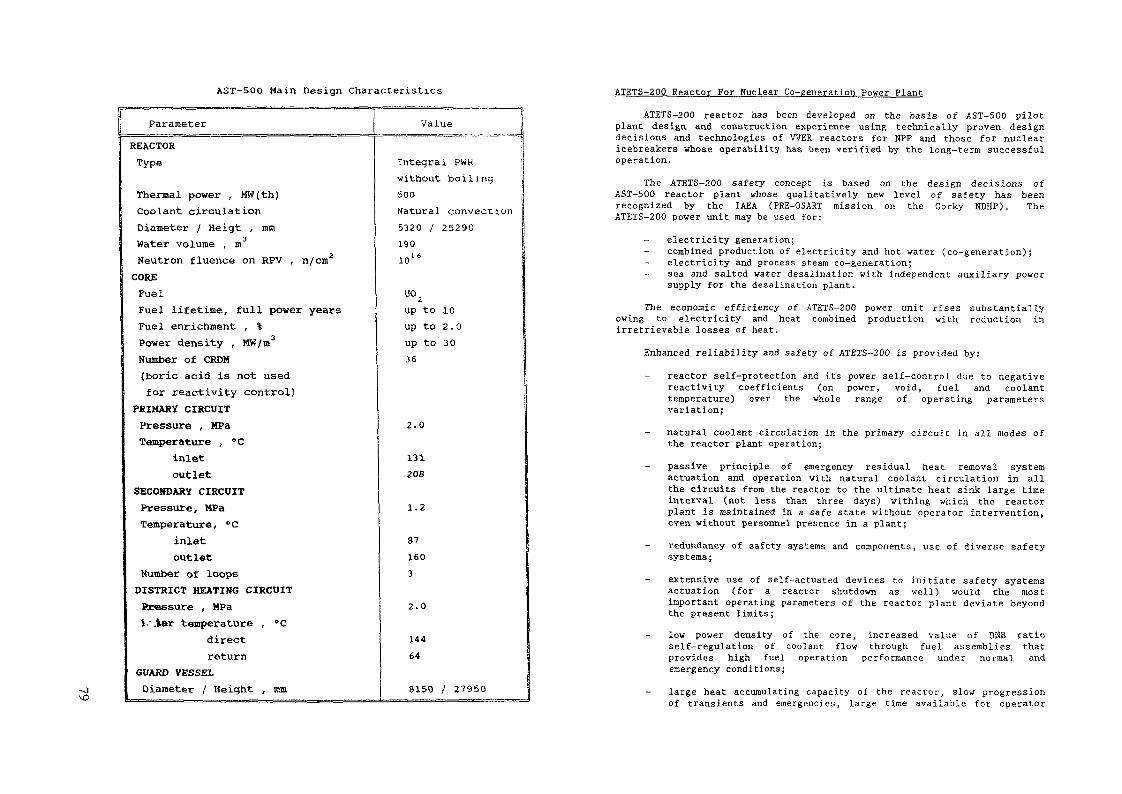
AST-500 Main Design Characteristics ATETS-200 Reactor For Nuclear Co-generation Power Plant
ParameterREACTORType
Thermal power , MW(th)Coolant circulationDiameter / Heigt , nunWater volume , mNeutron fluence on RPV , n/cm2COREFuelFuel lifetime, full power yearsFuel enrichment , %Power density , MW/m3Number of CRDM(boric acid is not usedfor reactivity control)
PRIMARY CIRCUITPressure , MPaTemperature , °C
inletoutlet
SECONDARY CIRCUITPressure, MPaTemperature, °C
inletoutlet
Number of loopsDISTRICT HEATING CIRCUIT
Pressure , MPa$s\ter teraperature , "C
directreturn
GUARD VESSELDiameter / Height , mm
Value
Integral PWKwithout boiling500Natural convection5320 / 2529019010"
up to 10up to 2.0up to 3036
2.0
131208
1.2
871603
2.0
14464
8150 /' 27950
ATETS-200 reactor has been developed on the basis of AST-500 pilotplant design, and construction experience using technically proven designdecisions and technologies of WER reactors for NPP and those for nuclearicebreakers whose operability has been verified by the long-term successfuloperation.
The ATETS-200 safety concept is based on the design decisions ofAST-500 reactor plant whose qualitatively new level of safety has beenrecognized by the IAEA (PRE-OSART mission on the Gorky NDHP). TheATETS-200 power unit may be used for:
electricity generation;combined production of electricity and hot water (co-generation);electricity and process steam co-generation;sea and salted water desalination with independent auxiliary powersupply for the desalination plant.
The economic efficiency of ATETS-200 power unit rises substantiallyowing to electricity and heat combined production with reduction inirretrievable losses of heat.
Enhanced reliability and safety of ATETS-200 is provided by:
reactor self-protection and its power self-control due to negativereactivity coefficients (on power, void, fuel and coolanttemperature) over the whole range of operating parametersvariation;natural coolant circulation in the primary circuit in all modes ofthe reactor plant operation;passive principle of emergency residual heat removal systemactuation and operation with natural coolant circulation in allthe circuits from the reactor to the ultimate heat sink large timeinterval (not less than three days) withing which the reactorplant is maintained in a safe state without operator intervention,even without personnel presence in a plant;
- redundancy of safety systems ana components, use of diverse safetysystems;
extensive use of self-actuated devices to initiate safety systemsactuation (for a reactor shutdown as well) would the mostimportant operating parameters of the reactor plant deviate beyondthe present limits;low power density of the core, increased value of DNB ratioself-regulation of coolant flow through fuel assemblies thatprovides high fuel operation performance under normal andemergency conditions;large heat accumulating capacity of the reactor, slow progressionof transients and emergencies, large time available for operator

ooO
1 Reactor vessel2 Upper block3 Guard vessel4 Steam generator5 CPS control rod drive6 In-vessel barrel7 Guide tubes - connecting devices
uni t8 Condenser9 Core
[0 Suspension of ionization chamber11 Biological shielding of the f irs t level12 Biological shielding of ihe secondary
level
5m
FIG. 6. ATETS-200 reactor unit.

to analyse emergencies and, if necessary, to organize the accidentmanagement ;the reactor integral layout, minimization of penetrations andtheir location in upper part of the reactor vessel, large waterinventory over the core, negligible neutron irradiation of thereactor pressure vessel;use of a guard vessel that allows a substantial reduction in theamount of local radioactivity and keeps the core covered duringthe accidents involving a loss of reactor pressure vesselintegrity. Simplicity of circulation circuits and residual heatremoval channels, clearly -understood and well studied thermal-physical processes, ensure confidence to the design.
ATETS-200 Main Design Characteristics
ParametersReactor thermal power , MW(th)Plant electric power , MW(e)COREHeight , mMax. fuel rod linear hear ratingFuel enrichment , %Number of fuel assembliesFuel burn-up , MW.day/tFuel lifetime ', full power yearsRefuelling interval , yearsNumber of CRDM(boric acid is no used forreactivity control)
W/cm
Neutron fluence on RPV ,PRIMARY CIRCUITFlow path height , mCore outlet temperaturePressure , MPaSECONDARY CIRCUITSteam pressure , MPaSteam temperature , °C
n/cm
Valueup to 620up to 210
2.52603.0109320008236
10' '
9.434015.5
4.5295
Residual heat is removed through:
steam generators when the feed water is available and rejection ofheat into the steam turbine condenser;steam generators when feed water is available and heat is rejectedinto the grid heaters (heating grid);steam generators by natural circulation of steam-water mixture onactuation of emergency heat removal channels connected to thesecondary circuit loops (into service water and atmosphere);condensers of EEHRS channel which is located on the reactor andoperates at natural coolant circulation in all the circuits;
- heat exchangers of primary coolant clean-up system.Safety analysis is based on a combination of deterministic and
probabilistic approaches. Safety analysis involved consideration of a widespectrum of design basis and beyond design basis reactivity and heatremoval accidents with primary coolant looses including reactor vessel lossof integrity, external effects such as earthquake, aircraft crash, shockwave and operator errors, including inaction.
Engineering decisions and safety systems adopted in ATETS-200virtually exclude core melt accidents and the result severe radiologicalconsequences.
Core damage probability is substantially reduced compared with thatfor NPP existing in the world and does not exceed 10~8 per reactor-year.Such accidents do not make a significant contribution to the risk to thepopulation and completely eliminates the necessity for evacuation of thepopulation.

00to DESIGN STATUS AND PERSPECTIVESOF ADVANCED WATER COOLED REACTORAPPLICATION FOR PRODUCTION OFELECTRICITY AND HEAT IN CZECHOSLOVAKIA
Z. MLADYSkoda,Plzeu, Czechoslovakia
Abstract
At present there are 8 units with VVER-440 reactors inoperation in the CSFR. Moreover, further 4 units withVVER-440 reactors and 2 units with VVER-1000 reactors arenow under construction. It is also assumed to bring intooperation 2 additional units with APWR after the end of thisdecade.
SKODA as a main equipment manufacturer and supplier ofpower plants in the CSFR has already about 5 years ago reco-gnized the necessity of substantional improvement of techno-logical, safety, and cost features of all nuclear power plant(NPP) units which will be in the future constructed in theCSFR, and delivered by SKODA. For this reason, at the end of1985 year, the start of preliminary design study was ini-tiated with the aim to develop an A P W R type unit of mediumpower range (500-600 MWe) that should be appropriate forelectricity and district heat cogeneration. The initialdesign stage was finished in the first half of 1990 yearwith the result that it is reasonable to proceed the comple-tion of final design and to supply such a NPP with a predomi-nant participation of domestic industry. An information isgiven in the submitted paper with regard to results of theabove mentioned preliminary design study.
1. STATUS AND PERSPECTIVES OF ENERGY PRODUCTION INT H E C S F R
At present the total installed electrical capacity ofall power stations in the CSFR is nearly 15 GW and the shareof NPPs in the total electric power generation amounts about27 i>. After completion of all NPPs which are now underconstruction this share will reach the value of about 42 °»in the second half of the current decade.
The future development of energy production in the CSFRis supposed to be very strongly affected in several nextyears by the transition to free market economy and also bythe necessity to solve extremely unfavourable ecologicalsituation which has been mainjy caused by the extensive and
moreover inefficient combustion of domestic inferior coalwith high sulphur content in coal-burning power plants. Thepresent significant increase of energy prices in the CSFRwill necessarily cause the successive reduction of energyconsumption along with the effort to produce energy in a moreeffective way. From above described state of affairs followsthat in the near future capital investments needed forupgrading of already operated power plants will tend to domi-nate those associated with the construction of new energysources. It is therefore reasonable to assume that anincrease of total power generation in the CSFR can beexpected mainly after the year 2000. In spite of the abovementioned situation, the role of a nuclear power generationshould remain important. That is why both main energy pro-duction companies in the CSFR have jointly initiated a bidinvitation process for delivery of two units with APWRreactors (rated power 1000-1400 MWe per unit) or for deli-very of two mid-size passive units (rated power about 600 MWeper unit). The beginning of commercial operation of bothunits is demanded to be in the time interval between 2000 and2005 year.2. OBJECTIVES OF THE PRELIMINARY DESIGN STUDY RELATED TO
T H E N P P WITH MID-SIZE A P W R UNITSObjectives of the preliminary design study performed by
SKODA were following:(1) to identify and analyse main problems associated with the
development and construction of mid-size passive units,(2) to identify the scope of all design and other activities
which are of particular concern with regard to deliveryof mid-size units,
(3) to assess the capability of SKODA, and of domestic industryto carry out all necessary activities in the field of engi-neering, manufacturing, and construction of mid-sizeunits, and to determine the scope of appropriate technologytransfer,
(4) to perform a preliminary assessment of important economicparameters associated with the design and construction ofmid-size units,
(5) to establish the future business strategy of SKODA in thefield of nuclear power generation.
3. REQUIREMENTS REGARDING THE DESIGN, OPERATING CONDITIONSAND PERFORMANCE OF THE NPP
Before the beginning of design activities the followingdesign objectives and requirements had been set down.(1) The NPP must enable simultaneous cogeneration of electri-
city and heat with the capability to extract heat in therange up to 600 MW per unit to district heat systems.With regard to necessary redundancy of heat supply theremust be situated at least two units on the site.

(2) From the point of view of safety its level must enableto locate the NPP relatively close to areas with highpopulation density (up to 15-20 km). For this reason itis necessary to meet following safety goals:- core melt frequency: 10 - 10~° per year,- severe release frequency: 10"' - 10~° per year.
(3) The units of the NPP must be solved with a view to applythe standardization of reactor coolant system main com-ponents for following power range groups:- 500-600 MWe: 2 or 4/2-loop arrangement,- 900-1000 MWe: 3-loop arrangement,- 1200-1300 MWe: 4-loop arrangement.
(4) The solution of the NPP must enable to provide low spe-cific capital investment costs, nuclear fuel cycle costs,and operation costs which will be competitive with thoseattained in contemporary large-power NPPs. From thisfollows that it is necessary to aim at: simplified plantarrangement, short construction schedule, high burnup offuel, refueling cycle of 18-2A months, simplified mainte-nance and repair procedures, etc.
(5) The design of the NPP must enable to reach:- station lifetime: 50-60 years,- availability: greater than 0.85.
4. BRIEF DESCRIPTION OF NPP
4 . 1 S i t e l a y o u t
OO
The site layout is arranged so that it is possible tooperate individual units separately and independently. Thesimplified site layout is shown in Figure 1.4 . 2 N u c l e a r i s l a n d
The reactor coolant system (RCS) consists of: reactor(dimensions of the pressure vessel are nearly the same as inthe case of VVER-1000 reactor), 2 vertical steam generators,pressurizer, RCS main loop piping (2 hot and 4 cold legs) and4 main reactor coolant pumps. An arrangement with 2 VVER-typehorizontal steam generators was studied as well. The squareconfiguration of fuel in the active core was selected. Thedesign of pressure vessel and internal parts of reactor isvery similar to solutions applied in VVER-1000 reactor withthe exception of active core and fuel assemblies. Main para-meters of RCS and turbine system are presented in Table 1.Schematic representation of RCS is then shown in Figure 2.
The reactor coolant system is enclosed in cylindricaldouble-wall containment of conventional design (inner shellmade of steel) with the vented space between both shells.The outer concrete shell is designed to resist all designbasis loads caused by severe external events (earthquake,blast wave, aircraft crash, etc.).
14
15
Cooo0
11
12
(
(
16
—
C
03
10
—
o0
r^nF7~l1 —— 1
nj£
0
i
5
&{|
r
9
Js^
LDC
17
A-i,?
}
3 dC
1R 1
1
rl ! _1TO,1— — -A«— ^N—j1 2 _
f >Laa'~J
1 CJ
00
1 - reactor building 8 -2 - electrical equip-
ment building 9 -3 - turbine buildingt> - heat extraction 10 -
station5 - reactor auxiliary 11 -
building,microtowers , 12 -dieselgenerator
6 - service building 13 -7 - cooling water pump
house 14 -
15-district heatsupply stationadministrative 16building 17main control buil-18ding, simulatorworkshops ,s to res 19water t reatmentbull dingauxil iary boiler 20-buiIdingmedical service 21-center 22-
main entrancebuilding
- f i rehouse-labs-act ive work-shops
- rad ioac t ive wa-ste t reatmentbuildingflammable sub-stances s to ragegas storagecompressor andrefrigeratorstat ion
FIGURE1 : S ta t ion layout - plan

TABLE 1. Main parameters of the NPP
PARAMETER
A. UNIT1. - number of units on site2. - gross electrical output, MW3. - net electrical output, MW4. - net efficiency
B. REACTOR1. - thermal power, MW2. - number of fuel assemblies3. - fuel assambly array4. - active core height/diameter,5. - fuel enrichment, w/o U-2356. - average linear power, kW/m7. - average power density, kW/lo- average heat flux, kW/m
- coolant outlet pressure, MPa8.9.10.11.12. - active core flow rate, m /hr13. - pressure vessel i.d., m
- coolant inlet temperature, C- coolant outlet temperature, °C
3 ,
VALUE
>2610573
0. 32
179012118 x 183.4/2.8553.6
14.582.2
48615.9
29533042.45 x 1034.131
C. TURBINE1. - steam pressure, MPa 6.92. - steam temperature, °C 284.83. - steam flow, kg/sec 1.003 x 10J4. - feedwater temperature (s.g. inlet), 230
°C5. - exhaust pressure, kPa 1 (max)
MCP
CL
RPV - reactor pressurevessel (o.d.4535 mm)
SG - s t eam g e n e r a t o rP - p r e s s u n z e r
RPV
MCP - main coolant pumpHL - hot leg ( i.d. 850 mm)CL - cold leg ( i.d. 650 mm)
FIGURE 2 : Reactor coolant system configuration
All equipment and structures of the nuclear island aredesigned to withstand the effects of the maximum design basisearthquake (in this case 7° MSK-64), and to maintain theiroperating functions. When a greater seismic resistance isrequired the spring-supported concept is assumed to applyin the design of the containment building ground slab.
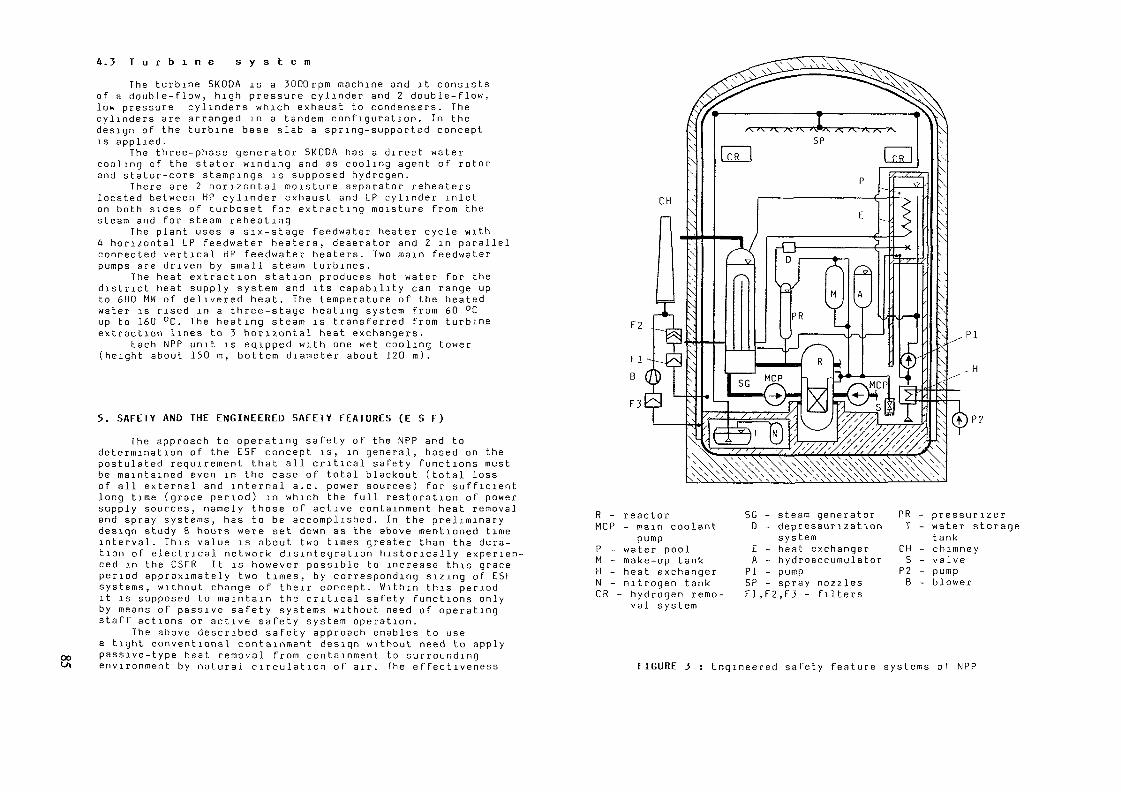
4 . 3 T u r b i n e s y s t e m
P°
The turbine SKODA is a 3000rpm machine and it consistsof a double-flow, high pressure cylinder and 2 double-flow,low pressure cylinders which exhaust to condensers. Thecylinders are arranged in a tandem configuration. In thedesign of the turbine base slab a spring-supported conceptis applied.
The three-phase generator SKODA has a direct watercooling of the stator winding and as cooling agent of rotorand stator-core stampings is supposed hydrogen.
There are 2 horizontal moisture separator reheaterslocated between HP cylinder exhaust and LP cylinder inleton both sides of turboset for extracting moisture from thesteam and for steam reheating
The plant uses a six-stage feedwater heater cycle with4 horizontal LP feedwater heaters, deaerator and 2 in parallelconnected vertical HP feedwater heaters. Two main feedwaterpumps are driven by small steam turbines.
The heat extraction station produces hot water for thedistrict heat supply system and its capability can range upto 600 MW of delivered heat. The temperature of the heatedwater is rised in a three-stage heating system from 60 °Cup to 160 °C. The heating steam is transferred from turbineextraction lines to 5 horizontal heat exchangers.
Each NPP unit is eqipped with one wet cooling tower(height about 150 m, bottom diameter about 120 m).
5. SAFETY AND THE ENGINEERED SAFETY FEATURES (E S F)
The approach to operating safety of the NPP and todetermination of the ESF concept is, in general, based on thepostulated requirement that all critical safety functions mustbe maintained even in the case of total blackout (total lossof all external and internal a.c. power sources) for sufficientlong time (grace period) in which the full restoration of powersupply sources, namely those of active containment heat removaland spray systems, has to be accomplished. In the preliminarydesign study 8 hours were set down as the above mentioned timeinterval. This value is about two times greater than the dura-tion of electrical network disintegration historically experien-ced in the CSFR It is however possible to increase this graceperiod approximately two times, by corresponding sizing of ESFsystems, without change of their concept. Within this periodit is supposed to maintain the critical safety functions onlyby means of passive safety systems without need of operatingstaff actions or active safety system operation.
The above described safety approach enables to usea tight conventional containment design without need to applypassive-type heat removal from containment to surroundingenvironment by natural circulation of air. The effectiveness
PI
R - reactorMCP - main coolant
pumpP - water poolM - make-up tankH - heat exchangerN - nitrogen tankCR - hydrogen remo-
val system
SG - steam generator PR - pressurizer0 - depressurization T - water storage
systemE - heat exchangerA - hydroaccumulator
PI - pumpSP - spray nozzlesF1,F2,F3 - filters
tankCH - chimneyS - valve
P2 - pump8 - blower
FIGURE 3 : Engineered safety feature systems of NPP

00ON TABLE 2. Parameters of ESF equipment (supplement to Fig.3)
MAPEHPIP2TN
Equipment
Make-up tankHydroaccumulatorWater poolHeat exchangerHeat exchangerPumpPumpStorage water tankNitrogen tank
Number perunit
3 (33 (32 (22 (23 (33 (33 (33 (33 (3
XXXXXXXXX
100S)100S)50S)5050100%)100SS)1005050X)50S)
Volume per ,equipment , m3060 (5 MPa)750--_-60-
and reliability of passive heat removal, in fact, stronglydepends on changeable meteorological conditions and undersome unfavourable circumstances not enough heat could beremoved.
The schematic representation of basic ESF systems isshown in Figure 3 and some characteristics of theirequipment are given in Table 2. The most important passiveESF are: reactor heat removal system, RCS depressurizationsystem, passive containment spray system, emergency Feed-water system (it acts after depressurization of steam gene-rator secondary side) and isolation systems. The containmentheat removal system and the active containment spray systembelong to the active part of ESF. The main purpose of passi-ve and active containment spray systems is to prevent thecontainment internal pressure from exceeding the value ofabout 0.3 MPa. As the main heat sink, two water pools aresupposed to accumulate the residual heat generated in reac-tor. Partial evaporation of their water is, in principle,acceptable.6. CONSTRUCTION SCHEDULE AND PROJECT IMPLEMENTATION
In the framework of the preliminary design study a timeschedule for final design, erection, assembly, testing andstart-up was evaluated as well. From the analysis followsthat a simplification of plant arrangement, reduction inequipment and bulk quantities, application of advancedconstruction procedures (monolithic concrete structures,modular assembly, etc.) and time optimization of constructionactivities enables to attain relatively short constructionschedule of about 55-60 months (from the start of concretingup to commercial operation). In addition to this, the peaknumber of construction personnel on site is supposed to beless than 4200 people. As an illustration the simplifiedconstruction schedule is shown in Figure 4.
YEAR
Design
Stores,workshopsAuxiliaryu CCSbuildingequipmentbuiIdinoReactorbuilding
Turbinebuilding
Otherbuildings
1 2 3 4 __5___ 6i n in iv i ii.iii iv i n in iv i H'III ivT~iilTTv~i if III iv
CN - contract negotiationsGS - ground slab concretingC - construction (structu-
res)S - start-up
WD - working (final) designand safety documentation
A - equipment assemblyT - testing
FIGURE 4 : Construction schedule of NPP
As for the project implementation, the turnkey contractor split package contract approach is assumed to apply. Fromthe results of evaluation follows that the delivery shareof a domestic industry could reach the value of about 80 %.The remaining part must be covered by use of licencetransfer (e.g. vertical steam generators) or by deliveryof some equipment from abroad (e.g. some instrumentationand control subsystems).

TABLE 3. Economic evaluation of power plants 8. OTHER ACTIVITIES OF S K O D A IN THE FIELD OF A L W R
NPP Net electricaloutput/unit, MW
NPP Temelin 1000CSFRABB 80* 1345NPPAdvanced 3ÜOfossil- faredpower plantCombined 340gas-steamcycle power plant
NPP with 600mid-sizeAPWR units
Supposed Normalizedload factor specific
capitalinvestmentcost
0.85 1(=100S)
0.85 1.14
0.68 0.98
0.42 0.51
0.85 0.86
Normalizedspeci f icelectricitygeneratingcost1( = 100SO
1.06
1.78
1.82
0.88
oo
7. ECONOMIC EVALUATION
A compansion of main economic parameters of the mid-sizeNPP with those of some advanced nuclear and fossil-firedpower plants has been made with the aim of economic evaluation.The results are given in Table 3 in which as a basis for com-parision the NPP Temelin was selected. The compansion bymeans of normalized values was preferred, because of absolutevalues are changing at present as a result of the transitionto free market economy (cost rise, inflation pressure,currency exchange rate changes, etc.). From Table 3 followsthat economic parameters of the NPP with APWR mid-size unitsare sufficiently favourable.
In the economic analysis, the "modified capital in-vestment cost" methodology was applied with the use of "uti-lity functions". This method enables to compare power plantsof various types built in various periods of time. Moreoverthe approach of the investment economic evaluation which iscommon in west european countries was taken into account aswell.
The project of a nuclear district heating plant with200 MW reactor is now in final stage in SKODA. Negotiationsare, at present, proceeding with municipal authorities ofPlzen city concerning the construction, and consultationsare in progress with authorities of some other regions ofthe CSFR.
9. CONCLUSIONS
The results of the preliminary design study have shownthat it is reasonable to proceed in the project activitieswith the aim to offer such a NPP in near future as a new powersource of energy system in the CSFR. The scope of SKODA acti-vities in this field will, however, depend on the way ofsupposed association of SKODA with some strong foreign company.
REFERENCES
III - "Preliminary design study of the NPP with APWR mid-sizeunits", Volume 1 - "Initial conditions and main objecti-ves", SKODA, 1990
111 - "Preliminary design study of the NPP with APWR mid-sizeunits", Volumes 2-11 - "Description of the NPP", SKODA,1990
/3/ - "Preliminary design study of the NPP with APWR mid-sizeunits", Volumes 12-18 - "Evaluation of the NPP", SKODA,1990

CURRENT ACTIVITIES ON ADVANCED LIGHT WATERREACTOR DESIGN AND TECHNOLOGY AT THEJAPAN ATOMIC ENERGY RESEARCH INSTITUTE
T. TONEJapan Atomic Energy Research Institute,Tokai-mura, Naka-gun, Ibaraki-ken,Japan
Abstract
An overview of the research activities on advanced light waterreactors (LWEs) in the Japan Energy Research Institute (JAEEI) ispresented. The advanced LWR concepts proposed are divided into threeresearch areas which feature, respectively, simplified and passive safetysystems, high performance reactor core and fuel designs and thetransmutation/incineration of transuranium elements. Major research anddevelopment activities and test facilities for exploring the advanced LWRtechnologies are described.
1. INTRODUCTION
The Japanese basic strategy for the reactor development is "from LWRs to FBRs".However, it is presumed that LWRs will continue to be the mainstream of nuclear powergeneration for a considerably long time before FBRs become practical. The evolutionaryimprovement of the conventional LWR system can be carried out by the private sector.In view of the forecast prolongation of the LWR-mainstream era, JAERI (Japan AtomicEnergy Research Institute) has been making efforts in the pursuit of new possibilities forLWR technology innovation. In this regard JAERI is carrying out research on advancedLWR concepts in order to further improve safety, reliability/maintainability, economy, andefficient utilization of uranium resources with a wide and long-range view.
There are three different research areas for advanced LWR concepts developmentin JAERI. In the first area, a small and medium size reactor system having advancedsafety features is pursued. From an innovative approach the SPWR (system-integratedpressurized water reactor) concept with simplified and passive safety systems has beenproposed. In the second area, research works on high performance reactor core and fuelare promoted to aim at a high conversion ratio up to around unity and a high burnup ofmore than 100GWd/t. The purpose of the third area is to explore a reactor core and fuelcycle system concept in view of the transmutation/incineration of transuranium elements(TRUs excluding plutonium) and the TRU-recycle. The core characteristics of the reactorconcepts proposed for the latter two research areas will be described.
From the viewpoint of implementing basic research and underlying technologydevelopment for the advanced LWR concepts a study of test facilities required is now inprogress in JAERI.
Table 1 Major design parameters of SPWR
Reactor :Thermal power output(MW) 1,100Electric power output(MW) 350Coolant inlet/outlet temp.(°C) 290/320Coolant flow rate(ton/h) 23,000Total pressure drop(MPa) 0.14Core outlet pressure(MPa) 13Core/Fuel Assembly :Equivalent core diameter(m) 2.99
height(m) 2.4a5U enrichment(%) 4.5Core average power density(kw//) 65Number of fuel assemblies 121Average fuel burnup(GWd/t) 45Fuel assembly pitch(triangle)(mm) 259Number of fuel rods 325Fuel rod diameter(mm) 9.5Lattice pitch(triangle)(rnm) 14.0Average linear heat rating(W/cm) 141Steam Generator :(once-through helical coil type)Steam temperature(°C) 285
pressure(MPa) 5.3Feedwater temperature(°C) 210
pressure(MPa) 5.9Steam flow rate(ton/h) 2,000Tube material Incolloy 800Tube inner/outer diameter(mm) 15/19Heat transfer area(inner total)(m2) 8,840
2. SYSTEM-INTEGRATED PRESSURIZED WATER REACTOR(SPWR)[ 1 - 3]
A design study of a passive safe integral reactor SPWR has been carried out in thedirection of developing a new concept of small and medium size power reactors. The maindesign goals of SPWR are aiming at enhanced passive safety features, and easyoperation/maintainability and improved economy through the simplification of plantsystems. The major design parameters are listed in Table 1.

(Water level)
(Steam) <c^
(Feed water
Hydraulicpressurevalves(x3)
Poison tank
Motor of MCP
Spray header
Pressurizerheater
(Feed water)
c^ (Steam)
Mainci rculatingpump
Steamgenerator(4 systems)Reactorvessel(Inner D 6mHeight 25m)
Fuelassemblles
Density lock
Fig. 1 Reactor vessel and internals of SPWR(350 MWe)
(1) Basic Design FeaturesThe SPWR structure concept is shown in Fig. 1. The reactor core, the steam
generator, the main circulation pump, the pressurizer and the borated water tank are allcontained within a single pressure vessel Control rods are not installed, which providesthe advantage of a great simplicity in the reactor structure design. The use of control roddrive system for safe shutdown of the reactor is excluded on the basis of the designphilosophy placing reliance on natural laws of thermohydraulics and gravity in accidentsituations without any dependence on active mechanical devices. For emergency shutdownof the reactor highly borated water is influxed into the core through passive mechanismsThe normal reactor operation including startup, scheduled shutdown and load followingis controlled by means of the boron concentration in the primary coolant and negativereactivity coefficients of temperature and coolant density
Steam generatormaintenance area t
header(x4)A
Steam header(x4) J
S Gmaintenancearea
-<t>40 000 A - A
Fig. 2 Quadruplet unit installation of SPWR(1400 MWe)
The reactor core is immersed in water of a relatively low boron concentration andis surrounded by a tank of highly borated (neutron poison) water. The poison tank isconnected to the bottom of the reactor core through a lower core/tank interface zone(honeycomb structures) similar to that used in the PIUS concept. At the top of the tank,the passive hydraulic pressure valves are installed as the upper interface between theprimary coolant and the tank water. The SPWR containment design adopts the pressuresuppression containment vessel for utilizing passive safety feedwater and suppression pool(heat sink) systems
The integral reactor housing the steam generator within a reactor vessel has asmaller power output due to the current fabrication capacity of the reactor vessel,compared with conventional large LWRs. However, the compact and simplified SPWRdesign is easy of modularization, which enhances the economy. Figure 2 exemplifies aplant layout concept for a quadruplet unit SPWR (1400 MWe) installation

(2) Safety FeaturesThe safety design philosophy of the SPWR concept is based on simplified systems
and passive performance systems. The reactor core is designed to provide the intrinsicsafety characteristics similar to those of existing PWRs which possess negative reactivitycoefficients of temperature and coolant density. In the latest SPWR design a relatively lowpower density core (65 kw/7) is employed, which increases safety margins. The enhancedsafety features are as follows.(a) There are no possibilities of rapid reactivity insertion accidents because of the
elimination of control rods.(b) Because the integral design does not include any large-bore piping, there cannot be
large-break pipe failures (LOCA). Besides all of the primary piping are positionedat an elevation above the reactor core. Hence, these can keep the core fully coveredfor a long time period (several hours) even without cooling system.
(c) The emergency shutdown system is made with use of hydraulic pressure valves andhighly borated water tank.
(d) Decay heat in accidents is removed by passive pressure-balanced feedwater (supplyby natural circulation) systems with passive hydraulic pressure valves and thesuppression pool housed within the containment vessel.
(e) For long-time cooling of decay heat the suppression pool water is designed to bepassively cooled with use of a heat pipe system which transports the decay heat to theultimate heat sink (atmosphere or seawater).
(3) Functions of Passive Safety SystemsTransients in accident situations are very slow due to the elimination of rapid
reactivity insertion accidents and large-bore primary piping failures, and passive safetysystems containing large water inventory provide a long grace period. The design featuresof the passive safety systems are as follows.1) Emergency reactor shutdown
Three hydraulic pressure valves are installed at the top of the neutron poison tank.The valve is controlJed by a hydraulic piston normally closed by a delivery pressure fromthe main circulation pump. In the design, the valve shown in Fig. 3 is closed at the flowrate of higher than 40% of rated flow of the pump. If the pump delivery pressure fallsbelow the minimum required to overcome the weight, the weight pull opens the valve,allowing the reactor coolant to flow into the top of the tank and the highly borated waterin the tank into the bottom of the reactor core. As a consequence the reactor is shutdownwithin several seconds after the pump trip and is cooled by natural circulation.
This passive system can be used as an active reactor shutdown system byreducing/stopping the pump rotation or by closing a valve installed between the pump andthe hydraulic pressure valve, in order to open the hydraulic pressure valve.2) Decay heat removal systems
During normal reactor shutdown the residual heat in the core is removed throughthe secondary cooling system via the steam generator, and during reactor maintenance anauxiliary residual heat removal system is provided.
In accident situations the passive emergency reactor shutdown system is capableof maintaining the core covered for long time cooling. To further enhance the safety
Cover plate
CylInderPiston
Va lve diskValve seat
LeakdetectionI me
Cyl mderPiston-
Pump Va lve diskV a l v e
- Pumpde l i ve rypressure
Poison tank Leakupper plate detection
I inePoison tankupper plate
Normal operation - valve closed Emergency operation - valve open
Fig. 3 Hydraulic pressure valve structure
Pressure re l l e t va l ve
Head AH
Storage tankpressurrzfng 1(ne
Reactor veassel
L\ L\Suppression pool
HPV Hydraul ic pressure va lve
'^Containment vesse l
Fig. 4 Passive core cooling systems

features for preventing an uncovered core the following passive safety systems areinstalled for long-time decay heat removal.(a) Pressure-balanced feedwater system
Figure 4 illustrates the pressure-balanced feedwater system which consists ofborated feedwater tanks, a suppression pool, two types of hydraulic pressure valves andsafety relief valves. The feedwater tanks are outside of the containment vessel andelevated above the reactor. The hydraulic pressure valves are normally held closed by thedelivery pressure of exclusive-use pumps and installed at pipe lines connecting the reactorcore and the feedwater tanks.
In case the reactor water level falls below a designated level, the hydraulic pressurevalve A shown in Fig. 4 opens, which causes pressure reduction in the reactor vessel andpressure buildup in the tanks. If the pressure in the tanks exceeds a safety design levelduring an accident, the relief valves discharge the steam to the suppression pool inside thecontainment vessel and its heat is released to the pool. When the pressures in the reactorvessel and tanks are balanced, the valve B opens and then the borated feedwater entersthe reactor core by natural circulation. This circulation water flow prevents the core fromapproaching diyout conditions. The hydraulic pressure valves are normally held closed bythe delivery pressure provided from small pumps placed at the designated level in thereactor vessel. For safety redundancy in accident situations, two pumps are in parallelinstalled and two valves of type A and B each are also in parallel provided. The feedwatercapacity of the tanks is designed to provide a three-days grace period.(b) Heat removal system of the suppression pool
The decay heat released into the suppression pool is passively removed to theultimate heat sink (atmosphere or seawater) by a heat pipe system. A few design optionsof heat pipe system are under investigation.
3. HIGH CONVERSION LIGHT WATER REACTORS(HCLWRs)
For the HCLWR concept development the design efforts aim at both highconversion and high bumup. On the other hand, the use of core with a tighter pitch latticeand MOX(mixed uranium and plutonium oxide) fuel with highly enriched plutonium toattain these goals leads to serious problems with respect to positive void reactivity andlarge plutonium inventory. In reactor physics aspect the design requirement to securenegative void reactivity effects degrades the conversion and bumup performances.Moreover, thermohydraulic feasibility should be demonstrated concerning safe heatremoval for the tight lattice fuel assembly during normal operation and accidents.Accordingly, an optimum design concept development is required upon consideration ofthese aspects.
(1) Design Fcaturcs>[4, 5]A new HCLWR concept was proposed at JAERI, to achieve both high conversion
and high burnup with a negative void coefficient. The reactor core concept is based on anaxially heterogeneous configuration of flat pancake core and blanket. The void coefficient
problem can be overcome by increasing the neutron leakage in the axial direction fromthe core. The leakage neutrons are utilized in the axial blankets to enhance the conversionratio.
Because of the short core height, an output power of single flat core may berestricted by the current fabrication capacity of the reactor vessel from the viewpoint ofits diameter size. One of the most direct way to apply the flat core concept is its use insmall and medium sized reactors ( s 400 MWe). To provide an output power as large asthat of current LWRs a double-flat-core HCLWR concept has been employed. In thisconcept two such flat cores with axial blankets and an inner blanket are stacked toconstruct a reactor as shown in Fig. 5.
Control RodDrive Mechanism
Pressure Vessel
Control Rod ClusterGuide Tube
Control RodC lus te rBarrel
Upper Core Plate
Fuel Assembly
Blanket
Core
Lower Core Plate-
Fig. 5 Double-flat-core type HCPWR(HCPWR-JFDl)

The axially heterogeneous reactor concept has been investigated for bothpressurized water reactor (HCPWR) and boiling water reactor (HCBWR) In the HCPWRdesign study, one-dimensional survey calculations of reactor physics characteristics wereperformed changing fundamental design parameters such as moderator-to-fuel volumeratio, core height, inner blanket thickness and so on Based on the survey results onreactor physics characteristics as well as thermohydraulic and safety analyses, referencedesign parameters of the double-flat-core HCPWR-JDF1 with a semitight pitch latticewere determined, as shown in Table 2 Fulfilling a negative void coefficient, anoptimization among allowable linear heat rating, obtainable burnup and conversion ratioprovides the dimensional parameter of core height, blanket thickness and moderator-to-fuel volume ratio For the reference HCPWR-JDF1 an effective burnup of 56 GWd/t andan average conversion ratio of 0 83 were obtained from three-dimensional burnupcalculations
Table 2 Reference parameters of HCPWR-JDF1
Reactor CoreThermal power output(MW) 2432Electric power output(MW) 810Equivalent core diameter(m) 4 37Equivalent blanket diameter(m) 4 80Unit core height(m) 0 6Top and bottom blankets thickness(m) 0 3Inner blanket thickness(m) 0 3Blanket material Depleted UO2Number of fuel assembhes(FA) 313Number of control rod clusters 85Average linear heat rating at BOC/EOC(W/cm) 114/109Radial power peaking factor 1 48Axial power peaking factor 1 22Average conversion ratio 0 83Equilibrium Puf ennchment(%) 10 0Initial Puf loadmg(ton) 4 9Fuel AssembliesNumber of fuel rods 372Fuel assembly pitch(mm) 235 4Fuel rod pitch(mm) 117Fuel rod outer diameter(mm) 9 5Fuel cladding material ZircaloyCladding thickness(mm) 0 57Spacer type gridNumber of control rods per FA 24Moderator-to-fuel volume ratio 1 06
The HCBWR design effort is aiming at a higher conversion ratio of around unityby taking full advantage of BWR core features where a low effective moderator-to-fuelvolume ratio can be attained due to the moderator voidage resulting from boiling Theconcept development work has been carried out jointly with Energy Research Laboratory,Hitachi, Ltd The mam objectives of the neutronic core design are to reach a negative voidcoefficient and to reduce a large plutonium inventory in the previous plutonium generatingBWR (PGBR) design concept[6] To achieve a conversion ratio close to unity, theeffective moderator-to-fuel ratio must be less than 0 3, which can be realized by theclosely packed hexagonal lattice with the rod-to-rod clearance of 1 3 ~ 1 5 mm and thecore averaged void fraction more than 50 % A preliminary design study based on one-dimensional parametric survey calculations indicates that the void coefficient is reducedby increasing the inner blanket thickness A further detailed investigation is in progressfor developing the design concept and the methodology including three-dimensionalneutronic and thermohydraulic analyses
(2) Safety Features[7]Thermohydraulic feasibility studies have been performed for the double-flat-core
HCPWR design concept Evaluation methods and models for the design concept weredeveloped based on experiments in critical heat flux, pressure drop and reflood coolingUnder the steady-state operational conditions in the present design, the estimatedminimum DNBR (departure from nucleate boiling ratio) assures an enough safety margin,and the core pressure drop is estimated to be much smaller than that in current PWRs
Safety analyses for large break loss-of-coolant accident (LOCA), locked rotoraccident of one out of three primary coolant pumps, and anticipated transient withoutscram (ATWS) triggered by station blackout were performed with a best-estimate codeJ-TRAC developed for primary system transient calculations The results show that theHCPWR design meets the current safety criteria for licensing applied to LWRs Thethermohydraulic feasibility of the double-flat core HCPWR is mainly attributed to thedesign features such as the large water inventory in the reactor vessel, short core length,low axial peaking factor, and negative void and coolant temperature reactivity coefficients
4 VERY HIGH BURNUP PRESSURIZED WATER REACTOR[8, 9]
A very high bumup pressurized water reactor (VHBPWR) core concept aiming ata high bumup of more than 100 GWd/t was proposed to improve fuel utilization and toreduce the fuel cycle cost of MOX fuel In the VHBPWR concept fuel assemblies consistof highly enriched plutonium MOX fuel rods with a lattice pitch close to that of currentPWRs and fertile natural/depleted uranium oxide rods used for neutron spectral shift
Larger sized fertile rods in diameter than the MOX fuel rods are used to providea spectral shift effect required for a bumup reactivity increment They are inserted into thecore at the beginning of the bum cycle As the fuels burn up, fertile rods are withdrawnto gam a further burnup reactivity by varying the modcrator-to-fuel volume ratio fromthe initial value of 1 5 to 3 0 (Table 3)
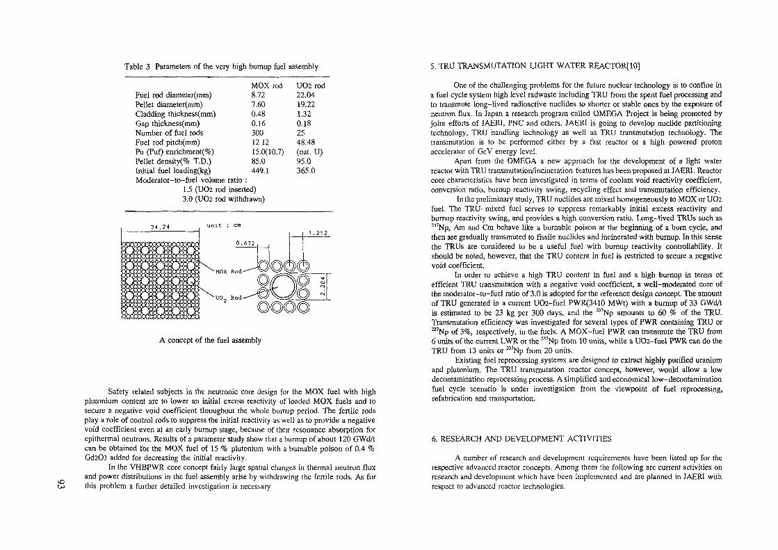
Table 3 Parameters of the very high bumup fuel assembly
MOX rod UO2 rodFuel rod diameter(mm) 8.72 22.04Pellet diameter(mm) 7.60 19.22Cladding thickness(mm) 0.48 1.32Gap thickness(mm) 0.16 0.18Number of fuel rods 300 25Fuel rod pitch(mm) 1212 48.48Pu (Puf) enrichment(%) 15.0(10.7) (nat. U)Pellet density(% T.D.) 85.0 95.0Initial fuel loading(kg) 449.1 365.0Moderator-to-fuel volume ratio :
1.5 (UO2 rod inserted)3.0 (UO2 rod withdrawn)
2 4 . 2 41 .212
A concept of the fuel assembly
Safety related subjects in the neutronic core design for the MOX fuel with highplutonium content are to lower an initial excess reactivity of loaded MOX fuels and tosecure a negative void coefficient throughout the whole bumup period. The fertile rodsplay a role of control rods to suppress the initial reactivity as well as to provide a negativevoid coefficient even at an early burnup stage, because of their resonance absorption forepithcrmal neutrons. Results of a parameter study show that a burnup of about 120 GWd/tcan be obtained for the MOX fuel of 15 % plutonium with a burnable poison of 0.4 %Gd2O3 added for decreasing the initial reactivity.
In the VHBPWR core concept fairly large spatial changes in thermal neutron fluxand power distributions in the fuel assembly arise by withdrawing the fertile rods. As forthis problem a further detailed investigation is necessary
5. TRU TRANSMUTATION LIGHT WATER REACTOR[10]
One of the challenging problems for the future nuclear technology is to confine ina fuel cycle system high level radwaste including TRU from the spent fuel processing andto transmute long-lived radioactive nuclides to shorter or stable ones by the exposure ofneutron flux. In Japan a research program called OMEGA Project is being promoted byjoint efforts of JAERI, PNC and others. JAERI is going to develop nuclide partitioningtechnology, TRU handling technology as well as TRU transmutation technology. Thetransmutation is to be performed either by a fast reactor or a high-powered protonaccelerator of GeV energy level.
Apart from the OMEGA a new approach for the development of a light waterreactor with TRU transmutation/incineration features has been proposed at JAERI. Reactorcore characteristics have been investigated in terms of coolant void reactivity coefficient,conversion ratio, burnup reactivity swing, recycling effect and transmutation efficiency.
In the preliminary study, TRU nuclides are mixed homogeneously to MOX or UO2fuel. The TRU-mixed fuel serves to suppress remarkably initial excess reactivity andburnup reactivity swing, and provides a high conversion ratio. Long-lived TRUs such as^'Np, Am and Cm behave like a burnable poison at the beginning of a burn cycle, andthen are gradually transmuted to fissile nuclides and incinerated with bumup. In this sensethe TRUs are considered to be a useful fuel with burnup reactivity controllability. Itshould be noted, however, that the TRU content in fuel is restricted to secure a negativevoid coefficient.
In order to achieve a high TRU content in fuel and a high burnup in terms ofefficient TRU transmutation with a negative void coefficient, a well-moderated core ofthe moderator-to-fuel ratio of 3.0 is adopted for the reference design concept. The amountof TRU generated in a current U02-fuel PWR(3410 MWt) with a burnup of 33 GWd/tis estimated to be 23 kg per 300 days, and the B7Np amounts to 60 % of the TRU.Transmutation efficiency was investigated for several types of PWR containing TRU ora7Np of 3%, respectively, in the fuels. A MOX-fuel PWR can transmute the TRU from6 units of the current LWR or the M7Np from 10 units, while a UO2-fuel PWR can do theTRU from 13 units or a7Np from 20 units.
Existing fuel reprocessing systems are designed to extract highly purified uraniumand plutonium. The TRU transmutation reactor concept, however, would allow a lowdecontamination reprocessing process. A simplified and economical low-decontaminationfuel cycle scenario is under investigation from the viewpoint of fuel reprocessing,refabrication and transportation.
6. RESEARCH AND DEVELOPMENT ACTIVITIES
A number of research and development requirements have been listed up for therespective advanced reactor concepts. Among them the following are current activities onresearch and development which have been implemented and are planned in JAERI withrespect to advanced reactor technologies.

(1) Activities on the SPWRMajor safety components in the SPWR design are the hydraulic pressure valves and
the lower interface. Design studies for these components and a fundamental test for thehalf-scale hydraulic pressure valve fabricated based on the design concept have beencarried out. The results of the test show satisfactory characteristics of the valve in termsof piston motion stability, hydraulics, allowable water leakage through the valve seat andso on.
In the SPWR design study analyses on reactor dynamics for various conditions ofstartup, shutdown, load following and accidents have been in detail carried out. Toconfirm experimentally these dynamic characteristics at thermohydraulic mockup testfacility is under investigation, which simulates the passive safety system features and thereactor core by using an electric heater of about 10 MW.
As for the SPWR safety, basic experiments on the DNBR at an emergency reactorshutdown are planned and an application of probabilistic safety assessment (PSA) is inprogress.
(2) Activities on HCLWRsThe JAERI has conducted a research and development program for HCLWRs
which consists of two phases ; Phase I running from 1985 to 1990, and Phase II from1991 to 1994. The major technical fields in the program are reactor physics and thermo-hydraulics.
The main purpose of Phase 1 is to evaluate the technical feasibility of the HCPWRconcept and to identify the key problems to be solved, while deepening the understandingof the relevant basic phenomena. In theoretical reactor physics studies on neutroniccharacteristics, nuclear data and calculation methods were extensively made to improvethe data and methods, and to design the reactor core with a negative void coefficient. Inorder to verify the data and methods experiments were conducted on two types of criticalassemblies, FCA (Fast Critical Assembly) and TCA (Tank-type critical assembly). As forthermohydraulics small scale experiments have been made on hydraulic characteristicssuch as pressure drop and thermal diffusion, critical heat flux, reflood cooling and so on,for analysis models assessment and understanding the basic phenomena. Computer codesfor safety analysis (J-TRAC) and subchannel analysis (COBRA-IV-I) have been alsodeveloped.
The purpose of Phase II is to choose the optimal design parameters of the HCPWRcore and to evaluate the technical feasibility of the HCBWR concept with a conversionratio of about unity and a negative void coefficient. Large scale experiments on neutronicand thermohydraulic characteristics are planned. Hydraulic test facilities (multi-dimensional hydraulic loop and multi-purpose hybrid loop) planned in Phase II are nowat a preparatory stage to install.
(3) A Study of Integrated Test FacilitiesFrom a long-term research and development standpoint in the prolonged LWR-
mainstream era, we are now performing a preliminary study of integrated test facilitieswhich aim at exploring the innovation of LWR technologies to be deployed in the 21stcentury. A plan of the test facilities is investigated to implement the research and
development of advanced LWR technologies in an effective and comprehensive way. Theemphasis on the research and development using the facilities is currently put on testingthe characteristics of the passive safety system and the HCLWR core, and developing thevery high bumup fuel, the TRU-mixed fuel and the TRU-recycling technology includingthe fuel processing.
The facilities complex is classified into three groups ;(a) a test reactor for fuel irradiation, passive safety system performance, and so on(b) fuel engineering facilities for test-fuel fabrication, post-irradiation examination, fuel
reprocessing process competent to advanced fuel concepts, and so on(c) reactor engineering facilities for criticality experiment, thermohydraulics, and so on
Among these facilities the test reactor plays a central role of the advanced LWRtechnology development. Key design features and parameters are as follows ; PWR corewith semitight pitch lattice (moderator-to-fuel ratio of 0.7 for U02 and 1.4 for MOX) asa standard core, and thermal output power of 300 MW with an average power density of100 kW//. Fuel assemblies with a semitight pitch lattice are adopted to provide a relativelyhard neutron spectrum. A design study of BWR-type test reactor is also underway.Installation of a large-scale irradiation loop is under consideration. The test of the passivesafety system performance is now planned to be implemented by installing the necessarycomponents (valves and poison tank) and loops outside the reactor vessel to simulate thehydraulic characteristics of the SPWR concept.
REFERENCES
[1] SAKO, K., "Conceptual Design of SPWR (System-integrated Pressurized WaterReactor)", ANS Topical Meeting on Safety of Next Generation Power Reactors,Seattle, USA, May, 1988.
[2] SAKO, K., et al., "Feasibility Study of SPWR as the Next Generation Power Plant",Proc. for the Seminar on Small and Medium-sized Reactors (Post Conf. SMiRT),III.5.21, San Diego, USA, Aug. 1989.
[3] SAKO, K., et al., "Conceptual Design of SPWR, a PWR with Enhanced PassiveSafety", JAERI-M 89-208(in Japanese), 1989.
[4] ISHIGURO, Y., et al., "The Concept of Axially Heterogeneous High ConversionLight Water Reactor", IAEA-TCM on Technical and Economic Aspects of HighConverters, Nuremberg, FRG, March 1990.
[5] OKUMURA, K., et al., "Conceptual Design Study of High Conversion Light WaterReactor", JAERI-M 90-096(in Japanese), 1990.
[6] TAKEDA, R., et al., "Plutonium Generation Boiling Water Reactor Concept", Proc.of Int. Conf. on the Physics of Reactors(Marseille, France, March 1990), Vol. 4,P.III-64.
[7] IWAMURA, T., et al, "Thermal Hydraulic Feasibility Study of a Double-Flat-Core Type High Conversion Light Water Reactor", Thermal Hydraulics of AdvancedNuclear Reactors, HTD-Vol. 150, ASME, 1990.
[8] ICHIKAWA, H, et al, "A Very High Bumup Pressurized Water Reactor withHighly Enriched Plutonium Fuel Assemblies Using a Spectral Shift Concept", Procof Int Reactor Physics Conf, Vol IV, pp21, Jackson Hole, USA, Sep 1988
[9] NAITO, Y , et al, "Design Study on a Very Long Life Light Water Power ReactorCore", JAERI-M 91-028 (in Japanese), 1991
[10] TAKANO, H , et al, "Higher Acttmde Confinement/Transmutation Fuel Cycles inFission Reactors", Ref [6], Vol 4, P II1-145, and private communication
Vi
SBWR TECHNOLOGY AND DEVELOPMENT
A S. RAO, C D SAWYER, R.J. McCANDLESSGE Nuclear Energy,San Jose, California,United States of America
Abstract
The simplified Boiling Water Reactor (SBWR) is a 600 MWe total plant design that isbased on proven and state of-the art Light Water Reactor (LWR) technology Itincludes technology extensions that are based on extensive testing This paperprovides the technology basis and a description of specific testing done to support theSBWR design The primary focus of the testing has been on safety systems thatinclude innovations beyond the operating plant technology base The overalltechnology program provides high confidence in the overall plant reliability and safety
1 INTRODUCTION
The development of the next generation of GE nuclear power plants is acooperative effort involving plant designers, constructors and owner-operators Thejoint effort results in a plant design that has the overall characteristics of beingsignificantly simpler to build, operate and maintain To achieve these characteristics,the plant design must focus on simplification of systems, processes, controls, andcomponents as well as simplification of the structural configuration and arrangementThe design must utilize and incorporate advances in existing proven technology thathave been developed over the past thirty years of commercial nuclear plant operationThe development of the advanced and simplified next generation plant must considerand involve the entire power plant and not only the nuclear steam supply or safetysystems Considering the entire plant in the design and development process ensuresthat the final plant design will be highly reliable, simpler to construct, and easier tooperate and maintain The resulting enhancement of plant safety systems ensures agreater degree of acceptance of the design by regulatory bodies and the generalpublic
As part of this effort to develop the next generation of the Boiling Water Reactor,General Electnc Company started the development of the Advanced Boiling WaterReactor (ABWR), a 1300 MWe reactor design that utilizes all of the advantages of theeconomy of scale but represents the utilization of all the advances in technologyTable I lists the major technology enhancements in the design of the ABWR and showsthat major improvements have been made in the design of the plant to make it simplerto operate and maintain in addition to ensunng a high reliability of the systems Table Ialso lists the features that are common to the smaller advanced BWR, called theSBWR The remainder of this paper descnbes the features and the technology basisfor the features that are unique to SBWR Additional details on the design of theABWR are given m Reference [1] and on the design of the SBWR in Reference [2]

VOo\ Table I Comparison of Advanced BWR Features to Operating BWR's Table II - SBWR Technical Data Summary
Feature
Materials
Water treatment
Operator Procedures
Emergency Procedures
Environmental QualificationSeparation
Fire Protection
Structural LoadsPlant Operation
Fuel
Reactor Vessel
Control Rod Drives
Neutron Monitoring
Safety/Relief Valves
Control & Instrumentation
Cabling
Control Room
Offgas
Feed water
Turbine Last Stage Bucket
Severe Accident Mitigation
Core Flow/Recirculation
Safety Systems
GE Operating BW«
IGSCC sensitiveFilter demmerahzersand/or deep bed
Complex, written
Event based (retrofitsympton based)
Retrofit
Mixed
Distance or barriers
Retrofit
Manual and Demanding
GE standard
Welded plate
Hydraulic
3 stage
Pilot operated
Analog
Hardwired
System basedComplex
Turbine/motor
43 inchesActive
External pumps
Active
ABWR & SBWR
Fully qualified, tested
Hollow fiber plus deep bed
Optimized displayedSymptom based
Fully Qualified
Complete
3 hour barriers
Fully defined, testedSemi automated andPre engineered
GE standard
Forged rings
Electro hydraulic
2 stage
Air operated
Digital
MultiplexedOperator task based
Simplified
Variable speed motor
52 inches
Passive
Internal pumps (ABWR)
Natural circulation (SBWR)
Simplified active (ABWR)
Passive (SBWR)
Plant outputNet electrical outputPlant cycleVessel dome pressureMam steam flowTurbineReheat stages
Nuclear boilerReactor vesselInner diameterHeightPrimary coolantrecirculationRecirculation flow
Core and lue!Active fuel lengthEquivalent core diameterPower densityNumber of assembliesFuel matenalCladding matenalFuel lattice type
Reactivity controlNumber of control rodsNeutron absorberControl rod formControl rod drive
Other control
ContainmentTypeConfiguration
Construction ScheduleFirst concrete to fuel load
600 MWeDirect717MPa3490 tons/hourTC2F-52 inchesNone
6 m2 4 6 mNatural circulationsystem23,700 tons/hour
2 743m473m41 5 kw/1732UO2Zircaloy 28x8 barrier
177B4CCruciformElectro-hydraulic,fine-motionBurnable poison
(Gd203)
Pressure suppressionCylmdncal reinforcedconcrete, steel lined
30 months
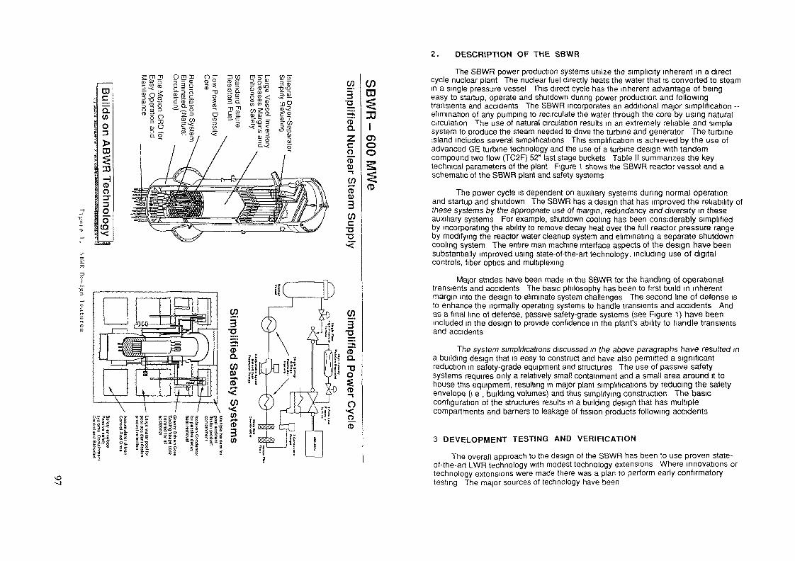
2. DESCRIPTION OF THE SBWR
CD
CD
30
(0o3"3OO
(Q
W3
co_ct>QJ
(f)<-*•o0)3Wc•o
CD
lcnoo
(D
The SBWR power production systems utilize the simplicity inherent m a directcycle nuclear plant The nuclear fuel directly heats the water that is converted to steamin a single pressure vessel This direct cycle has the inherent advantage of beingeasy to startup, operate and shutdown during power production and followingtransients and accidents The SBWR incorporates an additional major simplification --elimination of any pumping to recirculate the water through the core by using naturalCirculation The use of natural circulation results in an extremely reliable and simplesystem to produce the steam needed to drive the turbine and generator The turbineisland includes several simplifications This simplification is achieved by the use ofadvanced GE turbine technology and the use of a turbine design with tandemcompound two flow (TC2F) 52" last stage buckets Table II summarizes the keytechnical parameters of the plant Figure 1 shows the SBWR reactor vessel and aschematic of the SBWR plant and safety systems
The power cycle is dependent on auxiliary systems during normal operationand startup and shutdown The SBWR has a design that has improved the reliability ofthese systems by the appropriate use of margin, redundancy and diversity in theseauxiliary systems For example, shutdown cooling has been considerably simplifiedby incorporating the ability to remove decay heat over the full reactor pressure rangeby modifying the reactor water cleanup system and eliminating a separate shutdowncooling system The entire man machine interface aspects of the design have beensubstantially improved using state-of-the-art technology, including use of digitalcontrols, fiber optics and multiplexing
Major strides have been made in the SBWR for the handling of operationaltransients and accidents The basic philosophy has been to first build in inherentmargin into the design to eliminate system challenges The second line of defense isto enhance the normally operating systems to handle transients and accidents Andas a final line of defense, passive safety-grade systems (see Figure 1) have beenincluded m the design to provide confidence in the plant's ability to handle transientsand accidents
The system amplifications discussed in the above paragraphs have resulted ina building design that is easy to construct and have also permitted a significantreduction m safety-grade equipment and structures The use of passive safetysystems requires only a relatively small containment and a small area around it tohouse this equipment, resulting m major plant simplifications by reducing the safetyenvelope (i e , building volumes) and thus simplifying construction The basicconfiguration of the structures results in a building design that has multiplecompartments and barriers to leakage of fission products following accidents
3 DEVELOPMENT TESTING AND VERIFICATION
The overall approach to the design of the SBWR has been to use proven state-of-the-art LWR technology with modest technology extensions Where innovations ortechnology extensions were made there was a plan to perform early confirmatorytesting The major sources of technology have been

a) The 30 year international investment in the worldwide complement ofoperating BWRs
b) Adoption of proven and state-of-the-art technology from the ABWRprogram
c) Completed SBWR specific technology development programs designedto show the feasibility and performance of SBWR unique features
d) Ongoing development programs that will demonstrate the margin builtinto some of the key safety features - such as decay heat removal andinventory control
The emphasis of new testing and analyses falls into two categones a)component testing to ensure performance and reliability of the design during thelifetime of the plant and b) testing analysis to provide a high confidence that safetysystems will perform as expected and as analyzed in safety analyses Thecomponent testing focused on major new features whereas the safety system testingfocused on passive safety systems
Table III summarizes the technology base for the key SBWR features It showsthat the majonty of the new features are based on applications from operating plantsor the technology developed for the ABWR In a few cases there is a modestextrapolation from operating plants experience These extrapolations do not result inoperating conditions for the system components that are beyond the range ofoperating experience, ensuring high confidence in the system operation
The four basic, safety functions decay heat removal and control of coolantinventory, reactivity and fission products are being performed using simplified safetysystems that rely pnmanly on natural forces like gravity, to operate This approach isdifferent in some respects to that for operating plants, hence an extensive test anddevelopment program has been focused on these areas The following paragraphsdiscuss this technology development in the high and low pressure inventory control,high and low pressure decay heat removal, reactivity control and fission productretention and control
High pressure decay heat removal and inventory control for the SBWR isperformed using three isolation condensers - heat exchangers that condense thesteam generated by decay heat and return the condensate by gravity back to thevessel The basis for this technology is the expenence gained over the last 20 yearswith isolation condensers on operating plants Since the basic concept is the sameno feasibility issues were raised However because of the use of vertical tubesinstead of horizontal tubes on operating plants, a full scale confirmation test isplanned for completion in 1993 This test program will verify the margin in thethermal hydraulic performance and mechanical design of this key component
Inventory control following loss of coolant accidents is handled similar tooperating plants by depressunzmg the reactor to enable low pressure inventorymakeup The depressurization system has been made more reliable by providingdiversity using the standard safety/relief valves and a squib actuated
Table III Technology Base for SBWR Features
SBWR Feature
1 Natural Circulation
Fine Motion Control Rod Drive
3 Turbine Island Simplifications- 52" Last stage buckets- No reheat and single
feedwater heater tram- High velocity moisture
separator- Adjustable speed drives for
feedwater pumps4 Materials5 Digital Control and
Instrumentation
6 Multiplexing and fiber optics
7 Man Machine Interface8 Reinforced concrete technology
and pressure suppressioncontainment with horizontaldischarges
9 Equipment and structuralmodularization techniques
10 System simplifications/enhancements e g CRDhydraulic flow increase, fullpressure shutdown cooling
11 Refueling system
Experience/Technology Base.
Natural circulation operating plants e gDodewaard, Humboldt BayForced circulation operating plantsoperating without recirculationpumpsOperating plants in EuropeABWR test/development programDemonstration test at the Lasalleplant
Operating plantsOperating plants
Operating plants
Operating fossil fuel plants
Operating plants technologyRetrofits to operating plantsExperience in other industries e gairline
Operating plants and airline industryGE ERIS/Omnibus productsABWR programABWR development testing
ABWR Program
ABWR design and operating plants
Extrapolation of operating plantremote technology

depressunzation valve The latter being a new feature, it was tested extensively tochoose a reliable propellant and confirm the reliability of the valve design undervarious operating conditions Unlike operating plants, the inventory makeup relieson gravity instead of a pumped system To demonstrate that the low driving headsand slower mixing did not result m new phenomena, a full height, volume scaledsystem test was performed of the gravity makeup system The tests were completedin 1989 and were used to qualify the analytical codes descnbed in reference [3]These tests supplemented the already existing extensive data base used to qualifythe model in reference [3]
Since the major safety innovation in the SBWR is the use of the isolationcondenser system to remove decay heat for all transient and accident conditions, amajor effort went into demonstrating the feasibility of the system and to develop theadditional technological base The testing program involved testing to develop heattransfer correlations for full length individual tubes Then a full height volume scaledintegral system performance test was performed to demonstrate the feasibility of theconcept This test was completed m 1990 and showed that the noncondensable gasis purged from the isolation condenser to the wetwell via the vent line (Figure 1 ), as aresult of the drywell/wetwell pressure difference Additional testing is planned todemonstrate the margin in the overall plant design These tests include a full scaleheat exchanger mechanical and thermal hydraulic performance test to be completedin 1993 An additional full height integral test is planned for completion in 1995 todemonstrate the impact of 3-dimensional effects on the system response Thisfacility is full scale in height and about 1/25 by volume of the do/well and wetwellvolumes
The SBWR has a diverse reactivity control system consisting of an accumulatordriven boron injection system Confidence in the ability to get the boron well mixedm the vessel is based on extensive testing done as part of the ABWR program, wheretesting for a number of injection locations and configurations showed that the boronis well mixed
REFERENCES
[1] Hucik, S A , Rao, A S 'ABWR-First of the New Generation of Reactors for the90 s" IAEA meeting on "Progress in Development and Design Aspects ofAdvanced Water Cooled Reactors" Rome, Italy, Sept 9 12, 1991
[2] Rao, A S , Sawyer, C D and McCandless, R J , "Simplified Boiling Water ReactorDesign" JSME/ASME International Conference on Nuclear Engineering,Tokyo, Japan Nov 3-8,1991
[3] Andersen, J G M , Chu, K H and Shaug, J C , "BWR Refill-Reflood Program Task4 7-Modei Development Basic Model for the BWR versssion of TRAC,August 1983", GEAP-22051
4. SUMMARY AND CONCLUSIONS
The SBWR design is based on the extensive expenence gained from the 30years of LWR operating experience This expenence has been supplemented by theuti lization of technology developed over the last 15 years for the ABWR, which is areactor that utilizes state-of-the-art technology SBWR specific testing wasundertaken under sponsorship of the U S Department of Energy, with an emphasison the innovations in the safety systems Testing to demonstrate feasibility has beencompleted Ongoing or additional future testing is planned to better quantify themargins in the overall safety systems designs
vo

CONCEPTUAL DESIGN OF AN INHERENTLYSAFE AND SIMPLE TUBE REACTOR USINGWATER MODERATOR AND COOLANT
SOON HEUNG CHANG, WON-PIL BAEKCenter for Advanced Reactor Research,Korea Advanced Institute of Science and Technology,Seoul, Republic of Korea
Abstract
This paper describes conceptual design features of an inherently safe and simple
tube reactor (ISSTR) using light or heavy water moderator and coolant The ISSTR is
a loop-type pressurized water reactor which does not require emergency core cooling
system against loss of-coolant accident (LOCA)
In ISSTR, fuel channels are arranged in the water moderator pool within a large
Calandna vessel Each fuel channel consists of fuel matrix and a surrounding
channel tube Fuel matrix is designed so that fuel elements and coolant holes are
distributed in the Zircaloy matrix The radial gap between the channel tube and fuel
matrix plays a role as a thermal switch between normal operation and LOCA
In normal operation, the fission heat generated in fuel elements is transferred to
coolant and then used to generate steam in steam generators as in the present PWRs
or PHWRs At complete LOCA, however, the decay heat is transferred to the
moderator by conduction through Zircaloy matnx, radiation between the matnx and
the channel tube, and natural convective boiling between the channel tube and
moderator Moderator is cooled by natural circulation through a condenser located in
the large m-contamment water storage tank above the reactor Analysis shows that
the maximum Zircaloy temperature can be maintained well below the permissible
value dunng a postulated complete LOCA
The ISSTR presented in this paper is expected to maximize the utilization of the
proven technology as well as to revolutionarily improve the safety, since design
features of present PWRs or PHWRs can be directly applied except the reactoi It is
also expected to be easy to test, simple to analyze accidents and easy to explain the
safety to the public
1. INTRODUCTION
There is a world-wide effort to design next-generation nuclear reactors which are
expected to revolutionarily improve the safety and economy of the nuclear power
plant These efforts are pursued mainly in three directions light water reactors
(LWRs), liquid metal reactors (LMRs), and high temperature gas-cooled reactors
(HTGRs), among which the LWR design concept is the most actively studied primarily
due to its much greater operating expenence than the other types
Lately conceptual designs of four small-sized passive safety LWRs have been
developed AP600 (Advanced Passive 600MWe Reactor), SBWR (Simplified BWR),
PIUS (Process Inherent Ultimate Safety) and SIR (Safety Integral Reactor) All of
them are designed with a primary objective to minimize the probability of core
uncovery since severe accident cannot occur as far as the reactor is properly tripped
and core is submerged in coolant Among them, the PIUS and SIR have basically the
pool-type NSSS and the design efforts for them seem to be somewhat depressed now
AP600 and SBWR, which adopt the loop-type NSSS, are sponsored by the US
government and are expected to acquire design certification by the mid 1990s But
they require the emergency core cooling system (EGGS) to assure the safety during
LOCA Though the ECCS operates using the natural phenomena such as the
gravitational force or natural circulation, it requires an active depressurization
system for proper injection of emergency core cooling water
There is a general consensus that the loop-type passive safety LWR is the most
promising candidate for the next generation reactors before commercialization of
liquid metal fast breeder reactors In this regard, a inherently safe loop-type LWR not

requiring the ECCS would be the moj>t attractive solution to overcome problems
related to safety, hcensibihty and public acceptance
Fhib paper describes conceptual design features of the ECCS free Inherently Safe
and Simple Tube Reactor (1SSTR) under study at Center for Advanced Reactor
Research (CARR) in Korea Advanced Institute of Science and Technology (KAIST)
The ISSTR is a loop-type pressurized light or heavy water reactor which reflects above
considerations Although more detailed design and analysis are being performed now,
preliminary design calculation shows that the excessive temperature increase can be
avoided even for the complete core uncovery following LOCA
2. CONCEPTUAL DESIGN FEATURES
Basic configuration of the ISSTR NSSS is shown m Figure 1 with more detailed
reactor configurations in Figures 2 and 3 Figures show that ISSTR is similar to
CANDU m the arrangement of NSSS equipments However ISSTR adopts much
different core design including matrix type fuel channels The primary design
objective is to achieve inherent decay heat removal capability by moderator fooling at
complete loss-of-coolant accident
The unique design feature of ISSTR is the use of matrix-type fuel m a tube as
illustrated in Figure 3 Each fuel matnx is composed of 8 fuel elements, 12 coolant
holes, 1 instrumentation/control hole and Zircaloy matrix in a manner that fuel
elements and coolant holes are distributed in Zircaloy matnx Design of fuel elements
and coolant holes may have several different options As the first option, we adopt the
CANDU-600MWe fuel pellets of 0 012154m diameter stacked in 0 012243m holes
The diameter of coolant holes is adopted as 0 008859m which gives the same flow area
per fuel element as CANDU-600MWe In this design, the pressure boundary of the
primary system would be the Zircaloy matrix But the fuel channel tubes are designed
to the reactor coolant condition so that the failure of Zircaloy matnx can be properly
accommodated
In-ContainmentWater Storage Tank
EModerator Cooling;| Heat Exchanger =
SteamGenerator
(S/G)
Reactor CoolantPump (RCP)
Moderator"Cooling Loop
ControlElementDrives
Reactor
Pressunzer
S/G
RCP
Figure 1 Schematic of the ISSTR NSSS

oN>
Fuel Channels
133
Unit [mm]
Array of Fuel Channels
829
Calandna Shelloooooooo op oooooooooooooooooooooooooo
5OOOOOOOOOOOOOOOOOOOOOOOOO0000000000000*0000000000000
OOOOOÛOOOOOOOO OjO OOOOOOOOOOOOOOoooooooooooooo opoooooooooooooo
oooooooooooooooo opooooooooooooooooooo ooooooooooooooooooooooooooooooo
oooooooooooooooooo o o oooooooooooooooooooooooooooooooooooo oio oooooooooooooooooo
O O O O O O O O O O O O O O O O O O O O O p O O O O O O O O O O O O O O O O O O O Ooooooooooooooooooooo op ooooooooooooooooooooooooooo ooooooooo ooo oooooooo oooooooooooooooooooooooooooooooooooopoooooooooooooooooooo
ooooooooooooo oooo oooooo'oooooo oooooooooooooooooooooooooo ooooooooooooooioooooooooooooooooooooooO O O O O O O O O O O O O O O O O O O O O O OjO O O O O O O O O O O O O O O O O O O O O O Oooooooooo oooo oooooooooooooo oooooooooooooooo oooooooooooo oooo oooo oooo oopo oooo oooo oooo oooooooooO O O O O O O O O O O O O O O O O O O O O O OJO O O O O O O O O O O O O O O O O O O O O O OOOOOOOOOOOOOOOOOOOOOOO O'O OOOOOOOÛOOOOOOOOOÛOOOOO O O O O O O O O O O O O O O O O O O O O O OIO O O O O O O O O O O O O O O O O O O Û O O O
_ OOOOOOO OOOO O O O Q O Q Q Q Q Q O OjO O Op OOOO Op O O QQ OOOO OO OOOO O O O O O O O O O O O Û O O O O O O O O O OjO O O 0 O O O O O O O O O O O O O O O O O O Ooooooooooooooooooooooo op oooooooooooooooooooooooooooooooooooooooooooo op ooooooooooooooooooooooO O O O O O O O O O O O O O O O O OOOOOO'OOOO O O O O O O O O O O O O O O O O O O OO O O O O O O O O O O O O O O O O O O O O O OIO O O O O O O O O O O O O O O O O O O O O O Ooooooooooooooooooooooo 0,0 ooooooooooooooooooooooooooooo oooo oooo oooo oooopooooo oooooooooooo oooooooooooooooooooooooooooopooooooo oooooooooooooooO O O O O O O O O O O O O O O O O O O O O O Op O O O O O O O O O O O O O O O O O O O O O O
O O O O O O O O O O O O O O O O O O O O O !O O O O O O O O O O O O O O O O O O O O OO O O O O O O O O O O O O O O O O O O O OIO O O O O O O O O O O O O O O O O O O O OO O O Û O O O O O O O O O O O O O O O O O.O O O O O O O O O O O O O O O O O O O O Ooooooooooooooooooooo op oooooooooooooooooooo
O O O O O O O O O O O O O O O O O O O p O O O O O O O O O O O O O O O O O OO O O O O O O O O O O O O O O O O O Op O O O O O O O O O O O O O O O O Û O
oooooooooooooooo o'o ooooooooooooooooO O O O O O O O O O O O O O O O OIO O O O O O O O O O O O O O O O O
O O O O O O O O O O O O O O O.O O O O O O O O O O O O O O Ooooooooooooooo op oooooooooooooo
oooooooooooo op oooooooooooooooooooooooo opoooooooooooo
oooooooo o'o ooooooooO O O O O O O O O|O O O O O O O O O
Instrumentation orControl Hole (1)
Coolant Hole (12)
Fuel Elements (8)
130
130
Zircaloy Matrix
Fuel Channel Tube(Zr-Nb Alloy)
HsO or D2O Moderatorand Reflector
Unit [mm]
Figure 3 Detail of Fuel Channels
Figure 2 Array of Fuel Channels in Calandria

NORMAL OPERATION
Heat is transferred to coolant flowingin coolant holesGap is large enough to restrict heattransfer to the moderator
Decay heat is t ransfer red tomoderator by a series of conduction,radiation and nucleate boilingDecreased gap due to thermalexpansion enhances radiation heattransfer m the gap
Moderator
Heat Removal —by Coolant _
To Coolant
To Moderator
COMPLETE LOCA
Moderator
Heat Removal by— Moderator
OTo Coolant( Lost ;
To Moderator
Figure 4. Concept of the Thermal Switch
In normal operation, the fission heat generated in fuel elements is transferred to
coolant via conduction through the Zircaloy matrix Heat loss to moderator is
minimized by the gap between the channel tube and fuel matrix. The heat transferred
to coolant is used to generate steam in steam generators as in the present PWRs or
PHWRs
At complete LOCA, however, the decay heat cannot be cooled by coolant.
Instead, it is transferred to the moderator by conduction through Zircaloy matrix,
radiation between the matrix and the channel tube, conduction through the channel
tube wall, and natural convective boiling between the channel tube and moderator.
Moderator is cooled by natural circulation through a condenser located in the large
in-containment water storage tank (IWST). The Zircaloy matrix behaves as a heat
absorber during short period immediately after reactor trip as well as a conductor of
the decay heat. Analysis shows that the maximum Zircaloy temperature can be
maintained below 1200°C in any location during a postulated complete LOCA.
Therefore BCCS is not required in ISSTR. The non-safety grade chemical and volume
control system can supply cooling water if electrical power is available.
The concept of thermal switch between normal operation and LOCA is illustrated
in Figure 4. The difference in thermal expansion between the Zircaloy matrix and the
channel tube due to different temperature rise results in smaller gap in LOCA
condition compared with that in normal operation. This effect facilitates the decay
heat transfer to moderator in the complete LOCA.
Fuel channels are arranged m the water moderator pool within a large
horizontal Calandria vessel as in CANDU. The pitch-to-diameter ratio of the fuel
channel array is about 1.54. Reactivity control is basically achieved by the control
elements inserted from the top in the moderator pool. Since moderator pool is under
near atmospheric pressure, automatic drop of the control elements by gravity is
assured at loss of driving power. Furthermore any excessive heat generation to
generate the void in moderator gives negative reactivity insertion.

Table 1 Comparison of ISSTR-600 Design Parameters with CANDU-600
Parameters
Core thermal
Coolant
Core
Fuel channels
power [MWt]
- material
- pressure [MPa)
- flow rate [kg/h]
- temperature [°C]
- radius [m]
- length [m]
- total number
- fuel elements per channel
- pitch [m]
- outside diameter [m]
Fuel elements - total number
Moderator
- pellet diameter [m]
- material
enrichment
material
- pressure [MPa]
ISSTR 600MWe(LWR Option)
2060*
H20
111*
2 68xl07"
2666/312"
3143*
5944*
1748
8
0133
00829
13984
0 012154"
UO2
2 - 3 %*"
H20
~ o 1**"
CANDU 600MWe
2060
D20
11 1
2 68xl07
2666/312
3 143
5944
380
37
0 28575
0 13035(Calandna tube)
14060
0 012154
UO2
natural
D20
0 1
Notes * The same data as CANDU-600 are used
** 1 - 2% for the HWR-option
*** Subject to change according to the cooling loop design
A loop is provided for moderator cooling m both normal operation and accident
condition A centrifugal circulating pump is located in the loop to achieve forced
circulation m normal operation In case of the pump trip at accident condition, the
two phase natural circulation mode is established The heat exchanger (condenser) m
IWST is designed so that single-phase and two phase circulation is established m the
moderator cooling loop in normal operation and complete LOCA, respectively
Many options are possible for the design parameters of the reactor coolant
system Particularly PWR or PHWR(CANDU) design parameters are the most
attractive options because they allow us to use the similar NSSS equipments as in the
present plants Considering the configuration of ISSTR similar to CANDU, the
CANDU design parameters are selected as the first option In this case, three
different moderator and coolant combination is possible, H2O-moderator / H2O-coolant
(LWR option), D2O-moderator / H2O-coolant, and D2O moderator / D2O-coolant (HWR
option) Passive containment concepts proposed m AP600 et al can be directly
applied for ISSTR
The more detailed design study are now being performed at CARR with
consideration of various options for design parameters and arrangement of NSSS
Basic design parameters of ISSTR 600MWe (LWR Option) are compared with CANDU
600 in Table 1, admitting that they are only typical values Here the same design
parameters are used for core and Calandria dimensions, coolant pressure and flow
rate, etc
3. DISCUSSION
The ISSTR presented in this paper has several advantages over existing LWRs
and suggested passive LWRs as follows
a) The safety of reactor is remarkably improved since no active system is
required to cool the core after LOCA Core damage could occur only at the
simultaneous loss of coolant and moderator which constitute separate loops

b) Selection of loop type NSSS maximizes the use of proven technology and
existing design of NSSS components
c) Elimination of the ECCS makes the plant be simple, economical, easy to
design and analyze, and easy to understand
d) Design verification test is remarkably simple and requires short time Two
principal subjects to be tested are the heat removal capability of a separate uncovered
fuel channel and natural circulation of the moderator cooling loop
e) Change of reactor power is easily achievable by changing the number of fuel
channels and re sizing of the coolant loop and the moderator cooling loop
Though more detailed analysis is still needed to optimize the basic design
parameters of the ISSTR, it has been clearly shown that inherently safe decay heat
removal can be achieved without the ECCS and low ennchment fuel can be used even
for the LWR concept The ISSTR concept suggests us several specific research topics
m both thermal hydraulics (T/H) and material engineering
In the T/H area, the radiation heat transfer in the gap between the Zircaloy
matrix and the fuel channel tube is very important Extensive experimental study is
required to determine the radiational heat transfer properties of the materials and to
determine the optimum gap size Low pressure two-phase flow and boiling is anothci
important subject in relation to the moderator cooling Here low pressure natural
circulation, nucleate boiling and condensation would be the typical subjects
In the materials area, manufacturing of the Zircaloy matnx would be the most
important subject As the manufacturing process is improved with improvement of
mechanical properties, the smaller and more ecomomical fuel channel can be achieved
As described in the previous section, ISSTR may have various options m the
aspects of loop design and thermal power ISSTR concept can be easily applied for the
reactor of vanous purposes including the small sized district heating reactors or
research reactors
4. CONCLUSION
The concept of the Inherently Safe and Simple Tube Reactor (ISSTR) is briefly
introduced in this paper It is shown that an ECCS free and economical loop type
water reactor is feasible with maximizing the use of existing technology It is also
expected to be easy to test simple to analyze accidents and easy to explain the safety
to the public Many options are possible in the aspects of power and loop design
Comparative studies for the different possible options and more detailed design study
are now being performed
AcknowledgementThe authors express great appreciation to many colleagues, especially to N E
Todreas, MIT, whose advice helped us to choose the direction of the reactor
development
References
1 K Hannerz, Making progress on PIUS design and verification, Nucl Eng Int l
29 31 (Nov 1989)
2 S N Tower et al , Passive and simplified system features for the Westmghouse
600MWe PWR, Nucl Eng Des 109, 147 154 (1988)
3 R Bradbury et al , The design goals and significant features of the Safe Integral
Reactor, Presented at ANS 1989 Annual Meeting, Atlanta (June 1989)
4 R J McCandless and J R Redding, Simplicity the key to improved safety,
performance and economics, Nucl Eng Int l, 20-24 (Nov 1988)
5 W Kwant et al , PRISM reactor design and development, Proc Int. Topical Mtg
on Safety of the Next Generation Power Reactors , Seattle, 130135 (May 1988)
6 J Varley, Interest grows m the Modular HTGR, Nucl Eng Int L, 25-28 (Nov
1989)

T3SD(QCD
CD"CTS)
7 P Hejzlar, N E Todreas and M J Dnscoii, Passive Decay Heat Removal m
Advanced Reactor Concepts, MIT Report No MIT-ANP-TR-003 (May 1991)
8 W M Rohsenow and J P Hartnett, Handbook of Heat Transfer, McGraw-Hill,
New York (1973)
9 PP Incrupera and D P DeWitt Fundamentals of Heal Transfer (3rd ed ), John
Wsley&Sons, New York (1990)

CONTAINMENT SYSTEMS(Session 2)
Chairmen
PJ. MEYERGermany
Y. DENNIELOUFrance

TRENDS IN THE REQUIRED PERFORMANCES OFCONTAINMENTS FOR THE NEXT GENERATIONOF NUCLEAR POWER PLANTS
L. NOVIELLO, I. TRIPPUTIEnte Nazionale per 1'Energia Elettrica,Rome, Italy
Abstract
There is a widespread consensus that the containment system will continue to playa key role in the safety philosophy of next generation plants as it did in mostdesigns of commercial nuclear power plants in the past. But, at the same time, itseems clear that the design bases should be revisited and extended to provide aclear technical answer to the events that operational experience ana analysesshowed plausible.Required performances will not be limited to assure the gross structural integrityof the containment structure but also its leaktightness, in order to providetechnical bases for simplified Emergency Planning requirements and for thereduction of the evacuation zone to (or closed to) the site boundary, as it wasbefore the TMI-2 accident.The paper outlines some criteria currently being discussed in Italy, describes somecommon trends that can be identified among several countries, underlines theneed for additional design guidance and standards, and, finally, points out the needfor an international consensus on such themes, which could be achieved also withthe help of international organizations such as the IAEA.
Introduction
In the followup of the Chernobyl accident public debates on the use of nuclearenergy in Italy lead to the cancellation of the existing projects and the shutdown ofthe operating plants, but, at the same time, the Governement requested studiesand evaluations of a new generation of nuclear power plants with enhanced andtransparent safety characteristics more acceptable to the public.ENEL has complied with these general guidelines and is producing a number ofdetailed requirements to be discussed with the Industrial and Regulatory parties inItaly. These requirements, based on well proven technologies and operatingexperience, will be the benchmark to assess the compliance of the existing projectswith the Italian objectives; at the same time ENEL is pursuing the largestinternational consensus on these requirements, since it is our belief that theacceptability of any future projects will be played in an International arena andsingle country approaches will be more and more difficult to support for socio-political, industrial and economic reasons.
Safety objectives for a new generation of nuclear reactors in Italy
The step forward in safety requested in Italy has been interpreted by ENEL in anumber of general safety objectives (v:
the impact on the population and on the environment shall be virtuallynégligeable for any credible situation and, in particular, evacuation of thepopulation shall not be needed in any conceivable circumstances,
safety levels shall be achieved as indipendently as possible from operatoractions; operator role, however, shall be facilitated and optimized toprovide even larger safety margins,
passive safety systems and inherently safety characteristics shall be includedin the design to the extent possible in order to achieve the safety levels bynatural laws, reducing the potential failure modes,
reactor design shall provide slow and benign responses to all transients andaccidents to facilitate operator actions, to reduce the stresses to thecomponents and to leave the longest time to recovery actions.
It is worth mentioning that the means to achieve the above objectives shallmantain compatibility with plant productivity and economics goals.
Containment role and required performances evolution
The control of public exposure after an accident was first attained by the use oflarge exclusion areas surrounding the first non-commercial reactor installations(2>. Thus in 1943 the Clinton pile in U.S. was located in a portion of 240 km2
restricted area in Tennessee, designated Oak Ridge; the graphite productionreactors were located in an even larger restricted area, designated Hanford, in theWashington desert near the Columbia river, and the National Reactor TestingStation was established in the desert of Idaho. In each of these istances thedistances from the reactors to the site boundary was intended to permit adequatecontrol (i.e. reduction) of any activity that might be accidentally released.However, the need to site the commercial reactors in populated areas, whererestricted areas could be much smaller, required the reduction of external releasesby an outer vessel or containment, which was very simple at the beginning andbecame more complex later, including several active systems to controlcontainment atmoshere and valves to isolate the penetrating lines.Consequence calculations were requested in the USA to be carried out with asevere accident type source term, and an intact containment with the performancesrequired for a LOCA. The distance over which emergency planning was requiredwas generally limited to an area around the plant site referred to as the LowPopulation "Zjcme, which typically was about two to three miles in radius. As aresult of this relatively small area, emergency planning only indirectly involvedoffsite authorities.The containment performance requirements were, at a certain extent, decoupledfrom the presence of core damage preventing systems, in line with the defense indepth philosophy; therefore a containment has been always required in thecommercial LWRs of the western world.The problem at that time was to select the appropriate design bases for such acontainment.

The risk of severe accidents was recognized since the dawn of the commercialreactors era as real, but remote and largely undefined. At that point a decision wasmade to use a surrogate accident as a design basis for the containment and tomove forward with the development of nuclear power. That surrogate accident, asudden large-break LOCA, has been the basis for a conservative LWRcontainment design in the western world setting the design thermohydraulicconditions.At the same time in the USA fission products assumed to be released into thecontainment were selected in order to represent a severe core damage event (atleast for noble gases and iodine), rather than the design basis LOCA (•>).In many European countries the approach in general was similar with regard ofconsidering the LOCA as the reference accident, but differed in terms of theassociated source term, which was more realistic, or mechanistic, while at the sametime the allowed population doses were lower than 10CFR100 vv.While in the early 70s the ECCS rule in the US was published and a netimprovement was achieved on the prevention side, the situation remainedessentially stabilized with regard to the containment design and assessments untilWASH-1400 was published; as a result of the study a probability was calculated foreach containment failure mode and a systematic list of containment failure modeswas presented; the conclusions were strictly valid for the plants included in thestudy, but in general were considered as typical of the American typecontainments.The conclusions were that, in the average, plant safety levels were acceptable (noimmediate regulatory action followed the publication of the results) and that inparticular no generic action was warranted for the containment.But, at the same time, actions were initiated in the USA to increase the EPZ size,in Une with the potential large releases calculated by WASH-1400. In December1978 (NUREG 0396) an NRC/EPA task force reccommended a plume exposureplanning zone of about 10 miles and an ingestion pathway zone or about 50 milesin radius.During the 1979 accident at TMI-2, a containment designed to the DBArequirements functioned effectively to protect the public in case of a large coredegradation and melting providing a confirmation of the capabilities of thecontainment design basis, but the emergency planning organization, although notactually needed, was considered poor. Therefore both the Kemeny and theRogoyin reports on the accident pointed out the need for better EmergencyPlanning and better management; so in the aftermath of the accident, regulationswere promulgated essentially in agreement with the above mentioned task forcereccommendations assigning a leading role on Emergency Planning to FEMA.Severe accident researches and risk assessments, increased in number and scopesince 1979 both in USA and in Europe; they confirmed the conclusions of WASH-1400 that a broad range of high-energy loads caused by accidents more severethan at TMI-2, might threaten containment integrity and source term reductionsystems, but provided more realistic and supportable data to quantify their effects.Mainly in Europe backfilling actions were initialed on ihe containment and on theEmergency procedures.While these actions were evolving in 1986 the Chernobyl accident occurred andthe lack of an efficient containment system was blaimed as a major cause of theeffects on the environment. The accident gave an additional push to the evaluationof stronger containments on one hand andof severe accidents on the other.Therefore PSA results and, much more, the profound impact of these twoaccidents seemed to show at the end of the '80s with striking evidence to mosldesigners, utilities, Regulatory Bodies, scientisls and general public lhal Ihedividing line belween design basis events and incredible accidents has not been
drawn at the righl place. The consequence was in many cases the adoption ofbackfitting measures on the operating plants and a few regulatory requirements forfuture reactors.In summary Ihe situation of containments of current operating plants is generallythe following. Current plants may be proved to survive many severe accidentsequences giving credit to the margins in the design, a proper AccidentManagement and taking advantage of a filtered containmenl venting to preventcontainmem failure by late overpressurization. However, since certain highlyunlikely severe accidents phenomena could cause containmenl loads well beyondthe DBA loads, and since the backfilling actions could nol change somecharacteristics of the existing containments, there is still the possibility, althoughvery remote, of a release of health-threatening quantities of fission products. Inorder to cover this residual risk, Emergency Plans enforced for all commercialreactors; their size and complexity are generally in relationship to the extent of theimplemented backfitting actions.It could be argued from this historical outline that the approach so far has notbeen fully consistent, albeit it resulted in strong and effective containmenls. Webelieve that the industry has the possibility now to rivisit the entire approach in thefuture plants and, on the bases of the results from the research, the operatingexperience and the insights gained from PSAs, explicitly include severe accidentsand other credible "beyond current design bases" into the containment designprocess. Of course while expanding the design bases the "rules of the game" forthe assessement of these extreme events should be changed and many conservativeassumptions used for DBA shall be reconsidered. On the other side theseimprovements should be reflected in a more rational approach to the EPZrequirements.However, once established thai a revisiting of ihe design bases is needed, anumber of questions should be answered. For mosl of them ENEL is currentlydeveloping a position in concurrence with the original designers, the Italianindustry and Safety Authority, and is mantaining a technical dialog wilh foreignutilities and international organizations.One of the most importanl issues is the selection of the reference scenarios to betaken into account for the containment design.It is nol in the scope of the present paper a detailed discussion of ihe selectionprocess, considering also lhal ihe details are different for different reactors. Thegeneral phylosophy, however, is that this process cannot be limited to the use of aprobabilistic approach but it should DC supplemented by a well-balancedengineering judgement and, where applicable, by the operating experienceanalysis. The combination of the selection approaches should assure that even theall plausible events are properly assessed in the design process.In the following some specific requirements are presented.
Structural requirements
Containmenl slructure shall withstand all internal and external loads associatedwith internal accidents (including credible severe accidents) and external events(including in our case a severe earthquake and an aircraft crash).In order to mantain the required leaktightness even large deformations, notinvolving pressure boundary collapse, shall be avoided.Severe accident loads may vary depending on the specific sequence. All potentialloads shall be evaluated and included in a realistic and mechanistic loadcombination, if they are not prevented by design, so that they are impossible.

The phenomena associated with severe accidents and subject to the abovescreening process are:
In-vessel and ex-vessel steam explosions,Direct containment heating,Hydrogen detonations and combustions,Molten core-concrete interactions,
In addition the extreme seismic loads will be identified with a similar process andfactored into the design.The ultimate capacity of the structure shall also be investigated with the aim ofverifying the margins in the design with respect to the expected loads; it is requiredthat, indipendently from the fact that collapse pressures are not expected in anycircumstances, as a good engineering practice, the containment structure bedesigned to have a leak-before-burst behaviour and a preferential rupture point beincluded. As good engineering rupture point shall be located so that surroundingbuildings can still provide a reduction in the radioactive release to theenvironmentAs already said an important question is what design margins should be used forsevere accidents. Traditional engineering procedures include the use of largesafety margins. Part of the reasons of the safety margins of the containment wasthe some land of protection against events beyond the design bases. However inthis new approach, where all events are considered in the design, we consideracceptable a realistic assessement of severe accident consequences, provided thatuncertanties in the load calculation and design methods are quantified and takeninto account It is clear that national and international rules and regulations shallbe interpreted and even updated to formalize this approach.
Leaktightness requirements
The main charter of the containment is, of course, to contain the fission productsreleased in case of an accident and it is clear that its performances in terms of leakrate are strictly related to the required limitation of external consequences, oncean accident happened.We consider that a design goal of 0.1 % per day in weight of the internalatmosphere would be feasibfe without any major step forward in the currenttechnology, taking into account the operating experience and the simplifications inthe isolation systems in terms of number of valves. This value should represent asignificant margin with respect to the value to be verified by periodic testing and tobe credited in the safety analysis, which could be higher. Specific features such aspenetration pressurizing systems could be added, if necessary, particularly on thelines directly connected to the environment.In addition the contribution of the primary containment to the dose reduction shallbe supplemented by a passive secondary containment, which shall be capable ofholding up the leaks from the primary containment. Since it may be expected thatcurrent construction technologies may well limit the leak from a reinforcedconcrete shell with a metallic liner or from a metallic containment shell, thisconcept may be implemented by enclosing the penetrations into a sealed or low-leakage structure. Particular care shall be devoted to the potential bypass paths ofthis structure.New containments should not need a filtered containment venting, since they aredesigned to withstand all credible sequences, even without operator actions for along period. Moreover the compatibility of a containment venting to the
environment with the low doses to the public without credit to evacuation is highlyquestionable. A small vent may be added to finally depressurize the containmentin the long term and terminate any release, but its use shall not be dictated by therisk of a containment failure.An interesting issue is the possibility of a so-called primary containment bypass,which is, as a matter of fact, speaking of a primary containment not really a bypass,but a leak occurring at a location not considered in the usual leak paths. A majorexample is a single or multiple Steam Generator Tube Rupture producing a directpath from the primary system to the environment. Such "bypasses" shall beeliminated since their effects are not easily quantifiable and may exceed theexternal dose limits, even without a substantial core damage. In the case of aSGTR a possible solution is to increase the design pressure of the steamgenerators secondary side, in order to prevent the opening of the safety and reliefvalves on the steam lines.The isolation system shall be passive by at least one of the IAEA definition ofpassivity (*). This implies that e.g. Motor Operated Valves cannot be closed by acmotors supplied by large distribution networks and rotating machineries.A continuous monitoring system for the containment integrity, e.g. similar to theone include in the EOF plants, is required to further reduce the probability of alarge preexisting opening.A potential issue is the Integral Leak Rate Test pressure; if the containment shellis not designed for normal operation at severe accident pressure it is not possibleto test the Teak rate periodically at such a pressure. This problem may be, however,overcome by some special design features and testing provisions: most isolationvalves, for istance, may be tested^ individually at severe accident pressure and otherpenetrations as well, while special provisions may assure that the leaks through theshell (both steel or concrete) are négligeable with respect to the others.
Heat Removal Capability Requirements
Since the containment is expected to provide a sealed boundary with very highleaktighness performances, it shall provide the Ultimate Heat Sink functiondirectly, or it should provide at least a passive path to remove the decay heat Ingeneral, however, contaminated fluids (air/steam and water) shall remain in thecontainment boundary or in its close proximity, in order to minimize the possibilityof radioactive spreading in the plant and the environment.The required performances shall be carried out by passive systems (mainly naturalcirculation and large heat transfer surfaces).The heat removal function shall prevent containment overpressurization, in theshort and long term, and, if possible, shall not require any actuation signal or valvemovement; at the same time the performances shall be assured without credit tooperator actions for at least 72 hours. A design capable of preventing containmentfailure also in the absence of any actions in the very long term (at least 30 days) isin our opinion feasible and would add margins to the assurance of the containmentintegrity.In addition, since releases should be terminated as soon as possible, the internalpressure should be reduced and practically equalized with the atmosphere in theshort time after the 72 hours limit, taking into account also the use of qualifiednon-safety, ac powered systems.
The role of the International organizations
There is presently a number of activities in all international organizations relatedto the development of containments for future designs, including design criteria.
For example the WG1 of the CEC, which has as a main charter the harmonizationof the rules and regulations in the European Market member countries, hasincluded severe accidents and containment as priority targets. A ReinforcedConcerted Action will be probably launched in the next future on the themes ofthe containment with specific reference to the future reactors. The need for anharmonization in the member countries ig going to be more and more stringentwith the increased integration of the economies, the industrial structures and thesocial attitudes.OECD has a number of Principal working groups, expert groups, etc. on thesubjects of severe accidents and containment, which are working hard to comparedifferent national positions, to produce documents on the state-of-the-art and topromote benchmark exercises.The IAEA has a unique position, in that it is the only worldwide organization inthe nuclear energy field. It may provide a unique forum for discussions andinformation exchanges for utilities, industries, regulatory bodies separately andnot.Its role is very important since safety criteria and, more generally, the safetyculture shall be harmonized worldwide and should not be better or worse inrelationship with the specific situation of each country (public attitude, social andpolitical environment, economic situation).One specific subject on which the international organizations could produce anextremely important position is the definition of a dose limit, under which by anypractical means no effect on the population may be expected and the calculation ofcollective doses are meaningless. This is the standard approach for all toxicchemicals and the same approach should applied to radioactive materials; inpractice this has been adopted for radioactive waste with the introduction of BelowRegulatory Concern definition, but a similar approach, reasonably developped forpractical purposes, should be applied to the public doses also. This limit, togetherwith a proper selection of plausible severe accidents to be considered, couldprovide the needed boundary conditions to optimize the containment design.
Conclusions
Next generation plants should provide, in general, "better" safety than existingplants. This may not imply that public protection will be better than the bestexisting plants, but that protection levels shall be achieved in a more transparentway(e.g. by explicitly including severe accidents in the design process), not relyingon protective actions disrupting people life and perceived by the public as"Damocle's sword", which may spring out every single day. These are therequirements for the next generation plants to be adopted in Italy. We areconfindent that the new designs presently under scrutiny may comply with theItalian requirements.With specific reference to the containment there are clear indications that thereare converging international trends to similar design approaches for future plants,but this trend shall be emphasized with the help of the interested internationalorganizations.
REFERENCES
0) L. Noviello, I Tripputi - Italian criteria for a new generation of nuclearpower plants - Paper presented at the SMS Nuclear Reactors Seminar, NewDelhi - August 1991
(2) Wm.B. Cottrell, A.W. Savolainen - U.S. Reactor Containment Technology -ORNL-NSIC 5 - August 1965
(3) JJ. DiNunno et al., Calculation of distance factors for power and testreactor sites, U.S. Atomic Energy Commission, TID-14844 (March 1962)
(4) H. Karwat - Commission of the European Communities, Practices and rulesapplied for the design of large dry PWR-containments within EC countries -EUR 12251 EN -1989
(5) Safety related terms of advenced nuclear plants - IAEA - draft TECDOCreport - December 1990

PIUS, ASPECTS OF CONTAINMENT:PHILOSOPHY AND DESIGN
C. SUNDQVIST, L. NILSSON, T. PEDERSENABB Atom AB,Västeras, Sweden
Abstract
A key word in safety philosophy and reactor design is defence in depth.Defence in depth can be expressed as a hierarchically ordered set ofdifferent, independent levels of protection. These different levels includeboth accident prevention and accident mitigation. It is the combinedefforts of prevention and mitigation together with accident managementand off-site intervention that should be assessed to establish theenvironmental consequences.
The containment is one of the most important mitigative measures, afterChernobyl probably the most important. When considering the mitigativemeasures one has, especially as a reactor vendor, also to consider whatcan be done and/or what has been done regarding the preventingmeasures.
The weaker the first line of defence (preventive measures) the moreefforts have to be spent on the following lines of defence (mitigation,accident management and off site intervention). A very strong first lineof defence will on the other side ease the burden of the following lines ofdefence. Consequently, more efficient and reliable preventive designefforts should make it possible to accept simplifications in thecontainment design. The trade off between preventive and mitigativemeasures should be carefully considered for the next generation ofreactors.
The current trend is to employ more inherent and/or passive safetyfeatures (preventive measures) in the reactor design. The goal is todecrease the risk of core melt by simplifying the plant, ease the burden ofthe operators and eliminating the need of safety-grade AC-power. Thecontainment should preferrably be passive and above all for a passiveplant.
Double containment requires safety grade AC-power and willconsequently not be compatible with the design goal for a passive plant.
1. Introduction
Two nuclear plant accidents, the TMI and the Chernobyl accidents,have affected many people's view on reactor safety.
After TMI a number of safety measures were undertaken to lowerthe probability of such events and to decrease the environmentalimpacts should they occur.
After the Chernobyl accident it was obvious that public aversion ofsudden short timeframe catastrophic events, especially in thenuclear industry, is much higher than the opposition to continuousreleases, regardless the overall risk involved. During the last decadeit has become evident to the nuclear community that in order to makethe nuclear option more attractive a rebuilding of public confidence isnecessary. The nuclear technology must be based on a higher degreeof safety and based on principles clearly understandable by laymen.
A key word in safety philosophy and reactor design is defence indepth. Defence in depth can be expressed as a hierarchically orderedset of different, independent levels of protection. These different levelsinclude both accident prevention and accident mitigation. It is thecombined efforts of prevention and mitigation together with accidentmanagement and off site intervention that should be assessed toestablish the environmental consequences.
The containment is one of the most important mitigative measures,after Chernobyl probably the most important. When considering themitigative measures one has, especially as a reactor vendor, also toconsider what can be done and/or what has been done regarding thepreventing measures. The trade off between preventive andmitigative measures should be carefully considered for the nextgeneration of reactors.
The PIUS reactor belongs to the next generation of LWR plants andhas been under development by ABB Atom during the last decade [1,2], This paper will present aspects on the containment issue relatedto PIUS.
2. Safety Guidelines for the next generation of nuclear power plants
The current generation of reactors represents a proven, maturetechnology. Most of the plants are light water reactor plants (LWRs)and consequently the LWR technology is the most established andwellknown.
It is natural that the next generation should be based upon andutilize the vast experience from the about 4,500 reactor years of LWRexperience cumulated so far.

Basic elements of safety policy, which can respond to the demandsafter TMI and Chernobyl can be expressed as follows [3]:
a. Enhanced safety margins in order to slow down the accidentsequences progression, to increase the potential for recoveryactions (grace period) and the inherent stability and power self-limitation
b. Delay the radioactive release, in order to avoid early evacuation,and related provisions in the Emergency Plans as periodicdrills.
c. Limit the integrated radioactivity release during an accident sothat even temporary relocation needs beyond a short distancefrom the plant can be avoided and land uses can be maintainedto the maximum extent.
d. Reduce the role of operating personnel, the most critical link inthe chain
e. Simplify the plant design, in particular through the adoption ofpassive system
f. Strengthen the containment
3. Design aspects
Since the public has a deep-rooted fear of radiation the prime goalshould be efforts that directly or indirectly lead to a limitation of theenvironmental impact. To reach this goal the design has to provide abalance between core protection and core-damage mitigation. This isin line with the defence in depth principle, i.e. the use of variouslayers of multiple, diverse and complimentary means that help toensure the safety. Defence in depth can be characterized as a safetyand design logic where the layers are categorized as prevention,protection, mitigation and emergency planning.
The PIUS design maintains the defence in depth by addressing allthese four categories.
For a new reactor design it comes natural to investigate if a trade-offbetween prevention and mitigation would be a better way to fulfil thesafety goal listed above. The same reasoning has been expressed byU.S. NRC [4], where it is stated:
"... The advanced reactor concepts shall maintain the "defence indepth" concept, consideration may be given to the unique safetycharacteristics of the advanced plants. Some trade-off betweenprevention and mitigation is acceptable. ..."
The PIUS design is based on current LWR technology but makes ashift in emphasis from mitigation features to highly reliableprevention and protection features. Inherent and passive featuresare employed in a novel design to prevent core degradation in allcredible events.Mitigation is also provided, but, considering the unique safetycharacteristics in PIUS, in a different way (trade-off) than in currentLWRs.
4. Containment
4.1 General
Mitigation contains a number of different components and thecontainment is the most important.
The containment is traditionally an important part of the defence indepth. The TMI accident, causing limited environmentalconsequences, and the Chernobyl accident, causing majorenvironmental consequences, confirmed the great value of acontainment. To restore the public confidence in nuclear power afterChernobyl we consider that a containment is a must. As aconsequence the trade-off between preventive and mitigative actioncannot be taken too far, i.e. the enhanced prevention in the PIUSdesign cannot be fully credited in the mitigation efforts.
The containment philosophy applied in PIUS is based on multiplephysical barriers:
1. The U02-fuel pellets. Ceramic material with high meltingpoint, lowered linear heat load and high retention capacity forradioactive materials
2. The fuel cladding
3. The pressure retaining parts of the primary system, i.e.Concrete Pressure Vessel, primary piping and SteamGenerators
4. The Containment
5. The Containment Isolation Valves (in pipes penetrating theContainment)
The strength of the third barrier is enhanced in PIUS by theemployment of the PCRV prestressed concrete pressure vessel. ThePCRV makes it possible to provide a sufficiently large quantity ofwater directly available to the core. The decay heat is removed via thereactor pool and a fully passive system to the environment [1, 5]. Thisarrangement of the PIUS will reduce the risk of a core melt to an

extremely unlikely event. In addition to this the low rated core, thelarge amount of water, and the PCRV will result in enhancedperformance of the following components of mitigation:
Physical phenomena• Fission product hold-up• Fission product plate-out• Fission product decayLong response time
4.2 Design philosophy for the PIUS containment
The general safety philosophy for PIUS is that, considering alldefence in depth provisions as a whole, the Committed Effective DoseEquivalent (EDE) shall, for all credible events, be below the levelwhere no health effect to the surrounding population is expectedwithout the need for evacuation.
The basic design philosophy for the PIUS containment is the same asfor current LWEs. There are, due to the unique characteristics ofPIUS, some essential differences which have to be regarded in thecontainment design:
Source term
The amount of radioactive matter, which can be released to thecontainment after a pipe break, LOCA, is significantly lower forPIUS than for a current LWR, as the core integrity in PIUS isprotected by passive, self-protective means.
Decay heat removal, DHR
Following the initial blow-down of the primary system after aLOCA, there will be no significant release of steam or waterand hence no long-term pressurization of the containment. Thelong-term DHR is always ensured by the fully passive system,containing pool coolers, piping and the dry cooling towers. Theinitial release of steam is condensed on the walls, structuresand components inside the containment and in thecondensation pools.
Core coverage
Both for a LOCA inside as well as outside the containment, thecore will be covered with water and the decay heat will beremoved by the passive DHR system.
These three special design features of PIUS will ease therequirements on the containment.
The cladding temperature will be very low after a LOCA and theamount of hydrogen generated by metal-water reaction thusinsignificant.
During the long-term phase after a LOCA there will be no release ofsteam or water to the containment as the reactor pool will be keptbelow 100°C Hence, no dedicated containment spray and venting isrequired.
The inherent/passive safety features make PIUS more "forgiving",i.e. independent of operator action. A "grace period" of one week wasarbitrary chosen as a design criteria.
All these design features comply with the overall safety goal:enhanced safety by inherent/passive means.
SEeam 'eiief c oc "ensaiew/ re'ief V3ues
LCCA blcw-dc vn c"0nrc>
pressure SUDS-OS encondensation ccc
Severe ace dc"'miticaiion cod
Figure 1 BWR 90 Reactor Containment

4.3 Design basis for the PIUS containment
ABB Atom has a long experience from design and construction ofcontainments for the eleven BWRs built by ABB Atom. Thesecontainments are all of the pressure suppression type, usingprestressed concrete and an embedded carbon steel liner, see figure1.
All the Swedish reactors, BWRs and PWRs, have during the Suiesbeen equipped with filtered-venting systems of ABB Atom's design[6], see figure 2.
Utilizing this vast experience the PIUS containment will employ thepressure suppression principle. The containment contains theprimary system and the condensation pool. The containment is asafety-grade system. The containment and the PIUS safety-gradestructure is shown in figure 3.
This type of containment has two advantages:
• The condensation pool is a very efficient scrubber, i.e. aerosolsand gaseous iodine are separated and kept in the pool water
* The containment pressure will be rapidly reduced to "nearatmospheric pressure".
Figure 2 FILTRA MVSS, The Multiventuri Scrubber System
Passive, long-termRHR system(one of four loops)
Air
V*XXX/VX/VX//<«VX\ I j fSftS*tt**ttt4fSS\f*tfftfSffs*f**s\ I I mtjs/sttj***jt4tffjfft*fst*********J^ 1 ' fjjffsfttffsstsfftt
Reactor
Reactorcore
Figure 3 PIUS Safety-grade structures
The basis for the containment design is that the containment shall beable to withstand the design pressure, without exceeding a designleakage rate.
The condensation pool is also utilized as heat sink for the blow-downfrom the primary system, as well as the secondary side of the steamgenerators.
The relatively large containment volume and the pressuresuppression principle result in a low design pressure, 2.8 barsabsolute (after a pipe rupture).

The objective for the design leak rate is 0 5 % per day in weight of thecontainment free volume at the peak pressure of the DBA (the worstaccident)
There are a number of external events to be considered such as
EarthquakesExtreme winds and water levelsExternal fire and explosionTransport accidentLightningAircraft hazardSabotage
The external events and the spécifie design requirements, to be takeninto account for the containment designs, are to a large extent siterelated
An external event will not cause a pipe break within the containmentand these are generally assumed not to be combined
The two external events that, beside the pipe break, create anenvelope for the containment design are earthquakes and aircrafthazards A containment, designed to resist 0 3 g SSE for earthquakesand a crash of a jet liner, will be a very rugged structure, that cancomply with other external events
The PIUS containment is made of reinforced concrete provided withan internal steel liner, see figure 4 and 5
A general basis for the structural design is ASME Code, Section III,Div 2, Article CC-3000 for the concrete structures and ASME Code,Section III, Div 1, Article NE-3000 for the pressure retaining steelStructures
The main load-beanng parts of the containments are
the base mat
two cylindrical walls
the roof structure (including the wall and slab structure of thereactor service room)
the containment steel dome
internal concrete and steel structures
The primary leak-tight barrier is an inside surface liner attached tothe concrete wall and slab structures The liner is made of stainlesssteel in the pool compartments, otherwise of carbon steel
The PCRV is anchored to the base mat by the outermost vertical rowof prestressing cables
The low elevation of the core and the sturdy PCRV facilitate theaseismic design
Figure 4 PIUS Containment

Figure 5 PIUS
The general arrangement of containment isolation valves in PIUS isapplied in a similar manner as in current LWR plants. The mostimportant difference is that even if a pipe rupture occurs in a PIUSplant and the break is not isolated by means of the isolation valve, thecore integrity will still be protected by the inherent passive, self-protective features.
The Leak-Before-Break concept is adapted for the design of pipe-whiprestraints inside the containment.
Leak testing of the containment will be carried out in accordancewith LWR practice (Appendix J to US 10CFR Part 50).
Conclusions
Defence in depth, a long standing fundamental principle of reactorsafety, results in the concept that multiple barrier should be providedto ensure against any significant release of radioactivity. This callsfor a design which provides a balance between prevention andmitigation. The PIUS design maintains the defence in depthprinciple. Inherent and passive safety features are employed toprevent core damage in all credible events. Although the ruggedPCRV is a strong and very reliable physical barrier, PIUS is, in linewith the defence in depth principle, equipped with a containment.
The unique inherent/passive features will ease the requirements onthe containment. The containment is, however, designed to cope withpipe ruptures and external events, such as earthquake, flooding,fire, sabotage.
The PIUS containment is made of reinforced concrete and utilize thepressure supression principle.
The design basis for the PIUS containment is that, considering alldefence in depth provisions as a whole, the Committed Effective DoseEquivalent (EDE) shall, for all credible events, be below the levelwhere no evacuation planning is needed.
REFERENCES
L Nilsson, T PedersenAdvanced Reactor Design Philosophy and Application - waysand means to prevent core meltProgress in Development and Design Aspects of AdvancedWater-Cooled Reactors, Rome, 9-12 September, 1991
C Sundqvist, K Hannerz, L Nilsson, T PedersenConcept Status and Marketing Strategy of ABB PIUS andSECURE ReactorsJahrestagung on Nuclear Technology '91, Bonn, May 1991

3. L NovielloEvolution of the Design Criteria presently considered in ItalyEnergia Nucleare, Anno 7/N2/Maggio-Settembre 1990
4. Key Licensing Issues associated with DOE sponsored AdvancedReactor DesignsSECY-88-203, July 15, 1988
5. C FindSome Natural Convection Phenomena in the PIUS ReactorDesignJahrestagung on Nuclear Technology '91, Bonn, May 1991
6. L T TirénFiltered Venting of Swedish Reactor Containments,U.N. Conference on the Promotion of Uses of Nuclear Energy,Geneva, March 23-April 10, 1987 (A/Conf.l08/C.2/Inf.l)
NEW RESEARCH TRENDS FOR THE STRUCTURALASSESSMENT OF CONCRETE CONTAINMENT STRUCTURESUNDER EXTREME LOAD CONDITIONS WITH EMPHASISON CONSTITUTIVE LAWS OF CONCRETE
P. ANGELONI*, L. BRUSA**, P. CONTRÎ*,R. PELLEGRINI*, M. VENTURUZZO*
*ISMES SpA,Bergamo
**Ente Nazionale per L'Energia Elettrica,Rome
Italy
Abstract
The new National Energy Plan approved on August 1988 by the Italian Government,has defined the general guide-lines for the next generation reactor designsconsidered for a potential future use in Italy. In terms of safety the newdesign criteria require a step forward focused to reduce the consequences of anaccident, rather than the probabilities of occurrence. In case of core damageand release of fission products into the containnent and the environment, theenvironmental impact has to be minimized and reduced below a level so low that
no effects to the health of the surrounding population are expected, without theneed of evacuation.
Based on the requirements of this new safety policy, the concrete containment
structures become of extreme importance as integrity and leaktightness must be
assured for the entire duration of all conceivable accidents. To design andassess the level of technical performance of concrete containment structures new
advanced numerical modelling techniques are required. The computational methods
have to account for the cracking of concrete, in the areas of high stress
concentration, as well as the deformation limits at the interface betweenconcrete and steel components.
A research program is being developed jointly by ENEL and ISMES to define, test
and consolidate a complete analysis procedure capable of supporting the
selection of the reference containment and the related structural optimization.The preliminary results of the research, primarily oriented to the methodicalaspects, are presented and discussed in the paper. The future developments of

(Oothe research are also shortly considered, with special emphasis to the openproblems that still affect the analysis of the long tens structural behaviour ofconcrete for thick vailed structures.
INTRODUCTION
On August 1988, a new National Energy Plan was approved by the ItalianGovernment. The Plan, according to the December 1987 request of the ItalianParliament, for studies and research activities on a new generation of nuclearpower plants, points out the general guide-lines for design of nuclear reactorswith the potential of being built in Italy. In line with the most advancedtrends at the International level, the Plan calls for a step forward in safety,to be achieved by avoiding any radical departure from the existing well proventechnologies. As a result of a great number of technical, political, economicand social issues, emerged in Italy in the last few years, the basis of the newsafety policy is focused to reduce the consequences of an accident rather thanthe probabilities of occurrence. To comply with the above policy in the Italiancontext, the Plan requires the possible environmental impact from allconceivable accidents be minimized and reduced below any significant effect,with reference to :
population short and long tern doses;
emergency actions, and in particular the evacuation of the population;
relocation of population groups.
The technical performance of the new advanced nuclear plants must be such that,should a core damage occur and fission products be released into the containmentand the environment, the Committed Effective Dose Equivalent (EDE) is limited tolevels so low that no effects to the health of the surrounding population areexpected, without the need of evacuation.
In the development of advanced nuclear plants, based on simplified systems andcomponents having inherent safety characteristics, the containment plays then avery important role. The emphasis is to design simpler and safer containmentstructures, whose Integrity and leaktightness are assured for the entireduration of all conceivable accidents. To pursue this design requirement, theplant Designer can nowadays take advantage of the new available numerical
modelling techniques, capable of providing reliable results in terms of globaland local behaviour of the structure under investigation.
For concrete containment structures, the level of technical performance issignificantly affected by the cracking of material, in the areas of high stressconcentration, as well as by the deformation pattern at the interface betweenconcrete and steel components, such as liners and hatch reinforcements. Toevaluate the leaktightness of the containment for each Plant Condition and theultimate structural capability of the proposed design configurations, thecalculation methods have to take into account the rheology of materials for eachstate of stress and strain, and rely to an experimental characterization andqualification which Is not trivial. The need of meeting the new safety designrequirements for containment structures by means of state of the art calculationmethods has oriented the Italian National Power Board (ENEL) to initiate In the1990 a new research program specifically addressed to the structural analysisissues of reinforced concrete with or without pre-stressing. The final scope ofthe work is to define, test and consolidate a complete analysis procedurecapable of supporting the Initial phase of definition of the best preferablecontainment configuration, as well as of assisting the plant Designer in thefinal optimization process which necessarily includes the reference to thesequence of construction and pre-loading.
The research activity has started by recovering the previous experience ENEL andISKES collected in the middle seventies when numerical and experimental analyseswere carried out for the sake of providing the required support for the possibleuse of Pre-stressed Concrete Pressure Vessels (PCFV). After that, what Is now inprogress is a careful definition of the analysis targets in terms of solutionstrategies and comprehension and qualification of the existing tools that seembest suited to support the design and verification of the actual concretecontainment structures. As later on discussed and presented, most of theactivity is up to now dedicated to cover the methodical aspects of thesimulation problems, with special emphasis to the definition and application ofsolution procedures to be used for the analysis of short term loadings withmoderate temperature effects. Further developments of the research program areplanned to overtake the current limits of analysis and being able to face thespecific problems that may affect the design of thick-walled containmentstructures, never built up to now.

Fig 1 Model of a PCPV structure tested in the previous research activity [3]
I
14H W
u 3 —
lwoc00
W«•omAu
c
&0CJJcdi41EXO
ganiz
ations
rl0
!<Up
g-
>-,JD
•o4)
?4)U4-1d
r*in
141.Û
r— <cdu
f th
e
num
e r :
0
»4)
ΣO
ompr
ehen
sive
urHrH
S0)
•3•H
gWD.
M4lV4
2Buw
i-i«4)
1
<0>J2
cert
ain
ly
to
w>5-oCcd
tjM4>l-lWJJe•H
<4H0
B4)rH£Ou(X
i4J
4)
2Ocdu
o4J
vrH•srH
Cd>03
•3JU4>S
OI,ß
>ïWH•HrH
§er•aCa4lC•HMH
a>•oou
4-)
new
a
t te
mp
1cdMHo•pG
•r*OEX
B°•rl(JV-lcduM
cd
\nfl
•o4)rl4)
*t-l
cons
Xurt
revio
us
re
se;
excU•s0
«a•Htus.
irallel
anal;
&et
u
pro
cedure
.
How
eve
co•iHW3r-tOH
4)U)^«34J
Ov>0}
S0)
J3
««x:W4)
s eve
n t i
XrH
Ü41
41x:u
5toÏWrH
g
5-•o4liJ3U
X4>
>%JJ
>•HUycd
•sc4«(04>H
4)
•g5•o4)•öCP
g«14lt>0Ccd
•g1U
•ä.r)rH
aj:
ceat
in
tere
st
to
bO
<*J0
•o«•s*rt
cons
EigXft
U3O
•o4>•HUu0}U
V)cd»
r^W•r)
ese
arc
h a
cti
K
3O
•rf>UrlO.
*W4)WO
t"0.
1wt>
u
str
a
•aÄ
HO
«H
MCUH
3g£jUW
£U
U-l0
a*•<u•8rH
1P.0)
supp
ort
the
co
ne
ou
H
•gOJ
JS
ju4JAX4-1
4-1<
m
CM
Ui.
BWR)
re
act 0
1
rl
Ss00
rH»HO(4
1X
4lVJ3
V
frÄ
c
their
evo
lut
IM0böB•H
6~H>VA
1
u01
4)M
Sg*4
num
eric
al
sia
ula
i
<HoM4ltH4J
•i(XQ)o
1
il
reso
urc
es
g
iputa
tic
1u
>f
availa
ble
o
1v
constrain
ts
in t
3•oi
4-J
XU•H3
>NrH4Jc£ri3U
UPM
rHrH
SV)
cd
5
•O<u41an
1
gun4)
rH
g1
sss3
0
9>4MOrJex
ucd.
4>in4>S4-1
1Urlt)Uc
xHtO04)
<*HO
§4)4J
t^rO
•oOnnvuucd41rl4>
he su
perm
arke
t, w
4J
Ucd•oCP
|rQ•rlVi*JM
•rf•o
rHölIH34->
UM
4>
IIM0B)
TJO(Xo
hous
e
deve
l
K•H
«ti
<MO
WM
MbuOrlCu
S>rl4J
4l ui «s2 «W r^
rH« <dX CU «
Ucd
J3ubOCtH
UlWeau3O
•o4)
•«Hrl
Sog•o4)Vt4-u>>rH4JC
gram
was
co
nseq
ue
oM[X
X0ä4>M4>rl
Q>
s5
6M
once
ptu
al
de
o
.nitia
l
"
JS
assis
t in
t
04J
•ocu
sim
ula
tion
is
us
rHcdO•Hn
ic,
M
£4)bO
W
O•aM4
rH4)
McdS
•*HrH
*J-ÎuCiHrCiJ
tH»
S14)K
41
unes
th
e
str
uctu
r
=>(4U)cdXu•rl
•§
(DCO
*H4JwH
U
bOc
I•oÖJ•HrH
1cd
54-9
•oi
121

Ni
0004 'OOOl 'ooo'lOOOl 'ooo'l000"
Iooooooeooooo
ooo
ooo
1oooi
OOul" 'i
OOOi'l [I1,1 I1
OOOll '.'I I
oooj1 'I
coo'1' i
ooo1
oooll
V*
AA-A SECTION
LONGITUDINALCABLES
HOOPCÂBLES
FINITE ELEMENT MODEL
LINERELEMENT
SOLIDELEMENT
EQUATORIAL SECTION
MERIDIANBAR ———'
HOOPBAR
Fig.2 Reinforcement detail and FE model (3J
P - working pressure i 40 Kg/cm2
_ P (Kg/cm I
Fig 3 Pressure vs radial and axial deformation obtained from testing [3]

^- FigK>
PRESTRESSING ONLY
THICK MODEL
THICKJjOpEX
2?S
THICK MOO£L
s T
««« JQO . «o i
Comparison between thick and thin models based an stress resultsform FE elastic analyses [2]
DMMB MOOR [HIN MOOÜ
o
01 10°C
PH[STBKSIIjG.tCAS PRESSURE [60 Kq/ati'ljMtMPeBAHJRE VAMIOH 01 °C
PKSTBKSIjj'CAS PRESSURE [77 kg/cm'l iltMPEBAlUBE VAPIAIIQH 0 CT
SAFETY FACTORS CALCULATED
BY MOHR CAQUOT METHOD
Fig 5 Safety factor evaluation based on the results of an elastic stressanalysis [2]

FINITE ELEMENT MESHFOR LIO DESIGN
1 I SU8SIRUC1UHE MtSH
T) BARREL MESH
Ti LiO MESH
0 100 200 300 CTI
Fig.6 Global FE model of a PCPV for BWR with removable lid
only linear up to values of the applied pressure chat slightly exceed theworking pressure. Beyond these values the structure shows a highly non-linearbehaviour, which includes the effect of all irreversible phenomena that occur inand between the various materials.
The type of computations feasible in the seventies provided important parametersto support the designer when assessing the relative level of technicalperformance of alternate design configurations, as in the case of the thick andthin walled models of the HTR containment shown in Figure 4. However, the
FINITE ELEMENT MESH
HOOP OAR £L£M£wr
MERIDIAN BAR ELEMENT
INPUT DATA
INITIAL SHEAR MODULUS Co « 19VOOO Kg/cm1
INITIAL BULK MODULUS KO - 323*000 Kg/cm7
MONCAXUL COMPRESSION FAILURE Gc - 560 Kg/cm1
BIAXIAL COMPRESSION FAILURE Oc* - &?o Kg/cm1
MONOAXIAL TENSILE FAILURE Ot - 40 Kg/cm1
COMPARISON BETWEEN PHYSICALMODEL ANQ F. E. HQQEl
PHYSICAL MOOCL
— ———— F.E- MODEL
Fig. 7 Detailed FE model of the lid and comparison between experimental andnumerical results computed using non linear elastic costitutive
behaviour for concrete (6)

available results neither could provide any measure of the actual damageproduced in the unsafe regions, for example shown in Figure 5. nor could takeinto account the effect of stress and strain redistribution which follows eachlocal failure To overcome the above mentioned problems an attempt was made inthe previous research activity, by implementing a non-linear elasticconstitutive model for concrete, capable of considering the basic effects ofcracking and crushing post failure [4] The model was successfully applied toforesee the global behaviour of the lid of the BWR shown in Figures 6 and 7Although containing the sane basic concepts nowadays available in the mostsophisticated elasto-plastic models, the model was still unsatisfactory toprovide a measure of the local damage in the areas of failure and furthermorewas implemented in a solution procedure hard to handle up to the requiredconvergence levels
In spite of that, the whole work done in the seventies is certainly to beconsidered of great interest and success, expecially if evaluated consideringthe pioneering scenario of development Starting from this point the newresearch strategies can be now well defined, taking into account that there are
wide experiences available in the constitutive modelling of complicatedmaterials,
no more coscraints in computer's power,
additional design requirements to be satisfied
From the above considerations the new research activities have been first of allpointed at the definition and qualification of a reliable computationalprocedure capable of providing accurate results for each normal or extreme loadcondition in terms of global and local behaviour
NEW TREND OF THZ RESEARCH
In addition to code assessment based on safety factors, the standards, as inASHE code [5] recommend the analysis of the ultimate capacity of the structures,for precise probabilistic risk assessment, but also as a global confirmation ofthe conventional assumptions in terms of failure modes
During the last five years, many research programs, see for example [6], bothnumerical and experimental, have tried to define a global strategy to fix someuncertainties pertaining to the highly non linear behaviour of the typical
containments The first consequence of the new safety criteria points to leakageas the dominant failure mode for concrete containments, partially modifyingprevious theories stressing the importance of the stability of the overallstructure This is particularly true for pre-stressed containments owing to thereduced ductility of the overall structure The containment leakage isessentially tied to the steel liner tearing, occuring usually near penetrationsor stiffness discontinuities, and requires refined local effects analyses Somedata from one of the samples studied in [6] highlight the problem, showing that
a) in a cylindrical reinforced containment the design pressure is 0 Psi,
b) the concrete hoop cracking initiates at 30 Psi,
c) the liner yelds at 70 Psi
d) the first leakage occurs at 112 Psi
e) the global failure of the structure occurs between 120 Psi and 135 Psi,when liner exhibits hoop strain of 7 8%,
The above results indicate that leakage occurs for values of pressure which arealmost 2 times the design pressure The local failure, that has nowadays becomeone of the major concerns. Is then attained without reaching the structuralcollapse that occurs at three times the design pressure The possibility ofassessing the leakage failure mode, in the design process, requires the analysisof the local aspects related to concrete - steel interaction, mainly governed bypunch shear effects induced by the anchoring studs The liner is in factsubjected to a displacement controlled process which induces local perturbationto the global stress field due to the opening of the various cracks even belowthe design pressure Furthermore this phenomenon Is often complicated by thecomplexity of the geometry in the most critical areas The difficulties inmodelling this local problems have suggested simplified criteria for predictingleakage, based on local strain values calculated as a function of pressure andgeometry, using global 2D analysis According to the results of the most recentresearches, some well known procedures for the evaluation of leakage limit statehave been developed and assessed The approach proposed in [6,7] uses arelationship between global and local results which is expressed by means ofthree magnification factors related to stress Intensifications, triaxiality ofstress field, and strain localization next to stiffness discontinuities Allthese factors have to be initially conputed for each specific stressconcentration area, following a combined numerical and expérimental analysis on

ON3D local models. Based on the above described phenomena and results of mostrecent researches, the development of a strategy for the assessment of a newtype of containment structures requires the availability of:
reliable 2D numerical models capable to provide global stress fields andto determine critical areas. Such models have to consider the liner-concrete interaction, as well as the actual rebar configuration. Concreteconstitutive law has to reproduce fully developed cracking fields evencorresponding to stress redistributions;
results from either numerical or experimental analysis leading to therequired estimate of local strain Intensifications, strictly tied togeometry and loading configurations.
The above considerations furtherly substantiate the need of completing thequalification of numerical modelling techniques, as well as of supporting theresults with an adequate, experimental activity which is essential to estimatethe accuracy of the whole sequence of analysis. As later on discussed, the needfor experimental assessment is also of great importance for a confidentcharacterization of material data.
Stort of InejaitleOenavior
l\ Unload/reload «-«soons«
/ __———— ld«alïa«d («'asftc) uolood/r«laad rtipons«
. Crocking failure
NBXERICAL QUALIFICATION IN PROGRESS
The principal phenomenological characteristics of concrete mechanical behaviour
that are believed should be described by a comprehensive concrete constitutivemodel are :
departure from linearity In uniaxial and biaxial tests occurring longbefore the maximum stress, with occurrence of irreversible strain;
degradation of the elastic stiffness with progressing inelasticdeformation;
strain dependency of post peak behaviour on the confinement stress;
generation of damage, characterized locally by anisotropy and by aunilateral constraint on displacements across the crack;
localized character of post-failure deformation and non-uniqueness of itsdescription.
Fig.8 Uniaxial behaviour of plain concrete predicted by ABAQUS 4.9 model
Formerly the approach used as a first attempt to model the concrete behaviourwas within the theory of elasticity (4 ) . However, it is only with thedevelopment of plasticity, and strain hardening plasticity models, that it waspossible to start taking into account many of the characteristics listed above.
Todays constitutive models for concrete implemented in codes as ABAQUS [8] andDIANA [9] may be considered as a reasonable compromise between thesophistication of the most advanced models proposed in the scientific literature
(10, 11], which take into account many of the above requirements for acomprehensive model for concrete, and the design oriented approaches.
These codes have been selected as the most advanced in the field ofgeomechanical analysis in the non linear domain, respect to element library,constitutive models implemented and robustness of the integration procedures.
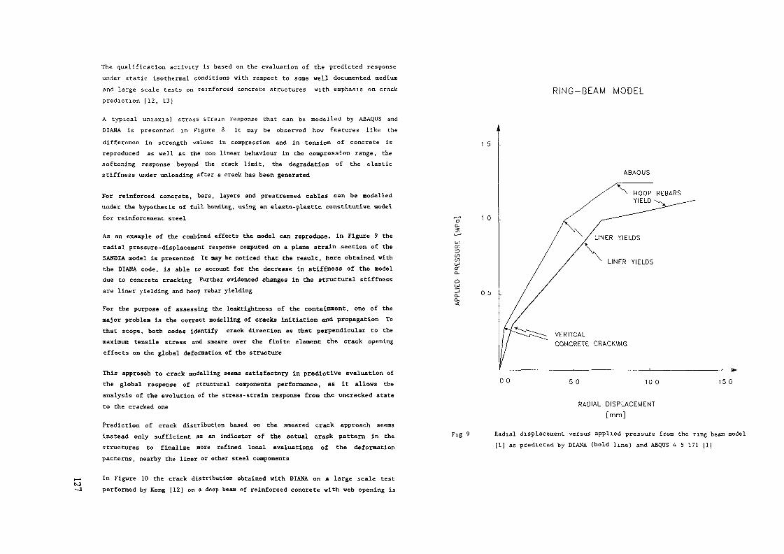
ts>
The qualification activity is based on the evaluation of the predicted response
under static isothermal conditions with respect to some well documented medium
and large scale tests on reinforced concrete structures with emphasis on crack
prediction (12, 13]
A typical uniaxial stress scram response that can be modelled by ABAQUS and
DIANA is presented in figure 8 It may be observed how features like the
difference in strength values in compression and in tension of concrete isreproduced as well as the non linear behaviour in the compression range, thesoftening response beyond the crack limit, the degradation of the elasticstiffness under unloading after a crack has been generated
For reinforced concrete, bars, layers and prestressed cables can be modelledunder the hypothesis of frill bonding, using an elasto-plastie constitutive, model
for reinforcement steel
As an example of the combined effects the model can reproduce! in Figure 9 theradial pressure-displacement response computed on a plane strain section of theSANDIA model is presented It aay be noticed that the result, here obtained withthe DIANA code, is able to account for the decrease in stiffness of the modeldue to concrete cracking Further evidenced changes in the structural stiffness
are liner yielding and hoop rebar yielding
For the purpose of assessing the leaktightness of the containment, one of the
major problem is the correct modelling of cracks initiation and propagation Tothat scope, both codes identify crack direction as that perpendicular to themaximum tensile stress and smeare over the finite element the crack opening
effects on the global deformation of the structure
This approach to crack modelling seems satisfactory in predictive evaluation of
the global response of structural components performance, as it allows the
analysis of the evolution of the stress-strain response from the uncracked state
to the cracked one
Prediction of crack distribution based on the smeared crack approach seems
instead only sufficient as an indicator of the actual crack pattern in the
structures to finalize more refined local evaluations of the deformationpatterns, nearby the liner or other steel components
In Figure 10 the crack distribution obtained with DIANA on a large scale test
performed by Kong [12) on a deep beam of reinforced concrete with web opening is
RING-BEAM MODEL
1 5 -
ABAQUS
1 0 .
(fi
o:Q-
0 5 .
VERTICALCONCRETE CRACKING
0 0 5 0 10 0 15 0
Fig 9
RADIAL DISPLACEMENT
[mm]
Radial displacement versus applied pressure from the ring beam modelil] as predicted by DIANA (bold line) and ABQUS 4 5 171 [I]

N)00
n«AL C1VCK DISTRlHUno«
L
Fig 10 Predicted (DIANA 4 0) and experimental crack pattern of thereinforced deep beam with web opening tested by Kong [12]
Fig 11 Predicted crack pattern at ultimate load for the prestressed slabtested by Bangash [13] Results obtained with ABAQUS 4 9

CLJDo
oooo
Spenmentale
Caso II
Fig 12
2 4
Spostamento in Mezzeria (mm)
Predicted and experimental response of the center of the prestressedslab tested by Bangash (13) under the applied pressure Resultsobtained with ABAQUS 4 9
1 00 -,
0 80 -
0.60 -
0.40 -
0 20 -
0.00
W - a x 37500 kN
0.00i i i l i i i i i i i n i i i i ' i i i "i '
2.00 4.00 600 800Spostamento Verticale Nodo 17
10.00
Fig. 13 Predicted load deflection at the midspan of the deep beam tested byKong (12], for different fracture energy values of concrete Resultsobtained with ABAQUS 4 9
to
presented. The crack zone compares well with the experimental results, alsopointing out the two major cracks that are evidenced displaying the cracks thatare actually open at the final level of loading.
In the case of the reinforced prestressed concrete slab reproducing the top capof a pressure vessel tested by Bangash [13), the crack pattern obtained at the
ultimate load on the lower face of the slab with ABAQUS (Figure 11) shows thepresence of two major crack families, which were observed also In the test.
The most important consideration arising from the first phase of qualificationIs that the selection of the properties influencing the post crack behaviour,such as fracture energy and crack band width, is the key issue for finalizing aprocedure of evaluation of reinforced concrete structures with these models.
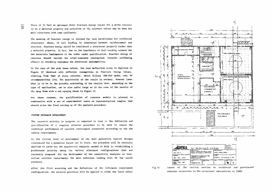
There is in fact av» agreement about fracture energy values for & given concreteto be a material property and selection of the relevant values may be done formost structures with some confidence.
The meaning of fracture energy is instead far less established for reinforcedstructures, where, if full bonding is considered between reinforcement andconcrete, fracture energy should be considered a structural property rather thana material property. In fact, due to the hypothesis of full bonding oetween thetwo materials Implemented in the codes under qualification, fracture energy ofconcrete should include the steel-concrete interaction <tenslon stiffeningeffect) to correctly reproduce the structural defornability.
In the case of the slab shown before, the load deflection curve is depicted inFigure 12 obtained with different assumptions on fracture energy values,starting from that of plain concrete, which follows CEB-FIP model code 90recommendations [14]. The sensitivity of the result is evident. However lowerwhat is to be is the possible scattering of the results that, depending on thetype of application, can be also quite large as in the case of the results ofthe deep bean with a web opening shown in Figure 13.
For these reasons, the qualification of concrete models is planned incombination wich a set of experimental tests on representatives samples thatshould allow the final setting up of the analysis procedure.
FUTURE RESEARCH DEVELOPMENT
The research activity in progress is expected to lead to the definition and
qualification of a complete solution procedure to be used to assess the
technical performance of concrete containment structures according to the new
safety requirements.
At the current level of development of the next generation reactor designs
considered for a potential future use in Italy, the procedure will be initiallyapplied to carry out the sensitivity analysis needed Co help in establishing a
preference priority among the various alternate configurations that are
currently proposed. For the development of the sensitivity analysis on thin-
walled concrete containments the main reference loading will be the inside
pressure.
After the first screening and the definition of the reference containment
configuration, the solution procedure will be applied to study the local effect
—
3I ?— 'r^~ ^
-)-)-1
TACLK) HOOEUI l ^°°
!(1
1... — -- - - , r - f— - ---
»£t • 01S - Ott/*)
TURAU SV HOOEUI E «OIOI»I
POMIOKE Dt FABBRPCATO n*MOAGIM SU HQQEU1 IXC.A 0 «'• C A f
HANT* PUUQ TERRA
P...r..,. I . BC
ïï& Id Layout of the testing section on reinforced and prestressed
concrete structures in the structural laboratories at ISHES.

of main penetrations and geometry discontinuities For carrying out theseanalyses the global model is expected to be replaced by local refined modelsthat allow a more detailed simulation of the interface between concrete andsteel components The structural analyses of the penetrations will be developedto assist in the definition of the best layout which simplifies the isolationsystem and reduces the potential leak paths
Future developments of the research program are also planned beyond the currentanalysis requirements of thin-walled concrete containments In view of thepossible future interest toward the use of heavier massive structures bothnumerical and experimental analysis capabilities are required to account foradditional phenomena which are intrinsic characteristics of concrete, such asshrinkage and dehydratation heat diffusion after casting, creep in the longperiod under constant loading, decrease of strength and toughness with time,effects of the thermal loads on the long term behaviour
The development and qualification of numerical procedures to be used from thesesimulations have already started and are based on the use of state of the artachievements in constitutive modelling However, the results of the researchactivity on computational methods will be additionally supported by anexperimental work to be executed on reduced scale models of the actualstructures of interest The experimental activity will be developed in a newlaboratory which is now in preparation at ISHES (Figure 14) The laboratory'slayout is foreseen to house the construction and testing of models having anoutside diameter and a height up to 6 and 8 meters, respectively
With the coupling of numerical and experimental testing capabilities theresearch program is expected to lead to the complete solution for all global andlocal problems of concern, also for heavy thick-walled structures, including thesimulation of construction phases and loading sequences
The research activity under development will then make available an integrateddesign and testing environment where to assess and optimize huge structuresnever built up to now, and with a potential field of application that can be ofgreat interest also outside the nuclear engineering constructions
REFERENCES
[I] Clauss D B (1987) Round Robin Pretext Analysis of a 1 16 ScaleReinforced Concrete Containment Model Subject to Static Internalpressurization NUREG/CR 4913, SAND87-0891
[2) Scotto F L , (1974) Triaxial State of Stress in "Tiny Hailed PCPV forHTR Comparison with a conventional "Thick Solution", IABSE Seminar onConcrete Structure Subjected to Triaxial Stresses, ISMES, Bergamo
[3] Fanelli M , Riccioni R , Robutti G (1974) Finite Element Analysis ofPrestressed Concrete Pressure Vessels", IABSE Seminar on ConcreteStructure Subjected to Triaxial Stresses, ISMES, Bergamo
[4] Riccioni R , Robutti G , Dal Bo C , Scotto F L , (1977) Finite Elementand Physical Model Analysis of a Removable Lid of a PCPV for BWR, SHIRTPaper H6/S
(5) ASME, Section 3rd, Division 2, App B, General requirements for structuralevaluation of concrete containments
(6) EPRI HP-6260-H Criteria and guide-lines for iredicting concretecontainment leakage, April 1989
[7J SAND90-0019, Insights into the behaviour of nuclear power plantcontainments during severe accidents
[8] Hibbitt Karlsson and Sorensen ABAQUS Manuals Version 4-9
[9] DIANA Analysis B U DIANA Manuals Version 4 0
(10) Ortiz M (1985) A constitutive theory for the inelastic behaviour ofconcrete, Mech of Materials, 4 67
[II] Kachanov M C (1982) On micro crack model of rock inelasticity Mech ofMaterials, 1,19
[12] Kong F K , et al (1978) Structural idealization for deep beams with webopening, further evidence Magazine of Concrete Research Vol 30, No 103
[13] Bangash N Y M (1989) Concrete and Concrete Structures, NumericalModelling and Applications, Elsevier
(14) CEB-FIP Model Code (1990) Material Properties, Chapter 2

toDEVELOPMENT AND QUALIFICATION OF THEFUMO CODE FOR THE CONTAINMENT SYSTEMSIMULATION OF ADVANCED LWRs
P. BARBUCCI*, A MANFREDINI**,G MARIOTTI*, F ORIOLO**, S PACI**
*Centro di Ricerca Termica e Nucleare,Ente Nazionale per L'Energia Elettnca,Pisa
**Dipartimento di Costruzioni Meccamche e Nuclean,Pisa University,PisaItaly
Abstract
In the framework of a cooperation between ENEL-CRTN and theDipartimento di Costruzioni Meccamche e Nuclean (DCMN) of Pisa University, abest estimate thermal hydraulic computer code, named FUMO, for multicompartment containment systems has been developed and assessed It is a lumpedparameter code and contains all the models necessary to realistically describe thephysical phenomena occurring m a passive containment system, following a DBA ora severe accident
A number of different containment tests have been analyzed to assess the coderesponse and to evaluate the influence of the different models implemented in thecode on the calculation results The tests were selected on the basis of their focus onthe most relevant physical phenomena for the new containment systems
Preliminary analyses of passive LWR containment systems were also earnedout In particular, a Large LOCA sequence in the AP 600 nuclear reactor wasstudied, taking, as reference data, a published sequence calculated by Westmghouse
I - INTRODUCTION
Thermal hydraulic codes used for evaluating safety margins in nuclear reactorcontainment systems need to be carefully assessed against experimental tests in orderto establish their ability to describe the mam physical phenomena In particular, inorder to realistically evaluate the hydrogen distribution and the behaviour of thefission products inside the containment system a correct modelling of naturalconvection processes is required, these phenomena are potentially very importantwith respect to deposition rates, transport and leakage of aerosols, i e to the sourceterm definition [ 1 ]
In the framework of a cooperation between ENEL C R I N and DCMN, animproved version of the FUMO code [2| [3j J4| for containment analysis wasdeveloped to achieve a better simulation of a wide range of phenomena, includingnatural circulation, and to evaluate their influence on the distribution of gases andaerosols during severe accidents
The code was submitted to a systematic assessment process, based on thevalidation of some models on separate effect tests, followed by post calculation ofintegral containment tests This work has recently been completed by performing bestestimate (BE) analysis to simulate the HDR El 1 2 and TU 'S tests |5| and the BMCFIPLOC 1-2 experiment [6| These tests were selected because they are representativeof the thermal-hydraulic conditions in the containment during SA and they allow themodels implemented in the code for natural circulation and hydrogen distribution tobe accurately assessed
2 - FUMO CODE DESCRIP1 ION
FUMO is a BE thermal hydraulic code for multicompartment systems It is alumped parameter code and contains the necessary models to realistically describephysical phenomena occurring in a containment system following a DBA or an SA
The containment can be described by a set of up to 100 volumes, 200junctions, 30 of which can have time dependent areas, and 100 heat transferstructures The thermodynamic conditions in each control volume are calculatedaccording to the following input options1 a stagnant homogeneous mixture of steam, liquid water and air2 a two regions model, consisting of a homogeneous gas/steam mixture region and a
liquid pool region The pool region may or may not be in thermal equilibrium withthe atmosphere one In the gaseous region it is possible to solve the mass balancefor seven gases Different deentramment models are available for evaluating thewater mass condensed in the atmosphere region and its falling velocity They allowthe drop diameter and the atmosphere turbulence and composition to be taken intoaccount
The control volumes are connected together through junctions The flow areacan be time dependent It is also possible to model pressure dependent junctionswhich are opened by a trip on the pressure difference between the two joinedvolumes Junctions with the inlet or/and the outlet submersed by the water, present inthe source or/and m the receiver node, can also be simulated This model can be usedto analyse the pressure suppression containment systems or the water management inthe LWRs with gravity driven safety systems
The junction flow rate is calculated as follows1 The Bernouilh equation is solved for the evaluation of water flow rate2 The momentum balance equation is solved for transients characterized by rapid
thermofluid dynamic variations The flow rate is evaluated using one of thefollowing models
Moody critical flow,homogeneous menial flow,orifice polvtropic flow

The method requires small time steps and theretoic should not be used in a longterm transient because ol the considuable CPU time needed
^ In order to study the long term phase of an accident a model is used whichassumes the pressure differences between control volumes to be negligible, theflow rates are evaluated in such a way that the pressure in the connectedcompartments is balanced This option turns TUMO into a fast runn ing code and alarge number of control volumes even it they are connected in complex ways, canbe used
The natural circulation model [3| is able to predict the buoyancy driven flow, both inserial volumes and in complex loops t urthermore a simplified model that simulatesthe hydrogen vertical distribution m a control node is implemented in the code Themodel is utilized to modify the hydrogen miss percentage of junction flow rates,depending on the junction heights in the source volumes
Particular care is given in the code to the flexibility in modelling the heatsinks and the heat transfer coefficients The temperature distribution inside a structureis evaluated by solving the Fourier equation by a finite difference method or with acoarse-mesh method, specifically developed by DCMN [7]
Several models, covering a wide spectrum of physical processes that mayoccur within the containment, were introduced in the code These models includeprocesses like hydrogen combustion heat and mass transfer (convection and/orcondensation on cold structures), corium water interaction, as well as BWR specificfeatures (suppression pool and safety relief valve discharge) A detailed model for thedescription of thermal transient of a metallic structure cooled by a passive externalspray was also developed [8] (briefly described in section 4) As the code does notconsider in vessel processes, it must rely upon separate analysis performed with aprimary system code, to provide sources of mass and energy to the containment Toovercome this limit, a simplified model, which can simulate a transient in the primarysystem, is under development This model will allow the simultaneous analysis of therelevant processes both in the primary and in containment systems
3 - FUMO CODE ASSESSMENT AND QUALIFICATION
The FUMO code was tested to verify its reliability in simulating the abnormaltransients that can take place m a m u In compartment contaminent system The codevalidation was based on the comparison between the values of the most importantthermal hydraulic variables measured during expenmental tests and the values of thesame variables calculated by the code
3.1 Review of the past assessment workFirst assessment activities of FUMO include some numerical benchmark
problems, in order to evaluate the degree of approximation of us models A series ofseparate effect tests were carried out in a facility installed at the DCMN, in order toobtain a better understanding of the influence on the containment behaviour of someimportant phenomena, such as the deentramment of droplets and the effect of the highturbulence, induced by the blowdown jet expansion, on the heat transfer to thethermal structures
In order to obtain an in depth validation of the code the qualification programcontinued wi th participation in some international exercises based on tests carried outin apparatuses with various volumetric scales Particular attention was paid to thevalidation of the models which describe the long term phase of an incidentalsequence During this phase the following tests were simulated
the OFCD CSNI Benchmark Problem 2 \2\ proposed in the framework of thePWG 2 Task group on Ex Vessel Thermal hydraulics, in particular toquantify the pressunzation and the combustible gas distribution m acontainment system during a core melt down accident in a LWRthe OECD CSNI 1SP 16 |2|, carried out in the HDR Facility at the end of1982, for the analysis of the first 12(X) s of a large LOCA sequence, and thesecond phase of the same test, named HDR V44, for the study of thetemperature stratification,the pre and post test calculations [9] of the LACE tests 4 and 6, performed atthe CSTF (Hanford W USA)
3 2 - Recent assessment workFUMO assessment has recently focused on some complex phenomena that
may occur in the containment of new simplified plants, such as buoyancy drivennatural convection flows, condensation of steam on structures and long term coolingof the plant by passive features This was achieved again by comparing expenmentaldata (from HDR and BMC facilities) and code calculation results
3 2.1 - The HDR facilityThe HDR containment (11300 m"5) consists of a steel shell 60 m in height and
20 m m diameter [10] This steel shell is surrounded by a secondary concrete shellwhich is separated from the former by an annular gap The containment is subdividedinto 69 subcompartmems of different shapes and sizes by concrete partition wallsTwo spray systems internal and external to the steel liner can be activated during thetransient
Two HDR tests 15] 111 ] were analyzed, simulating the containment behaviourafter the rupture of a large diameter steam pipe (HDR T31 'S) and a small breakLOCA (Test El 12) respectively Their timing characteristics allow a goodassessment of the code particularly for the long term analysis
Analysis of the HDR T31.5 testA seven volume nodalization was used for the analysis with FUMO of the
T31 5 test [51 This test is characterized by a relevant stratification over the height ofthe containment, due to the heat exchange processes and to the evolution of theconvective flows A stable temperature distribution can be identified, with a measuredtemperature differences of roughly 50 °C between the upper and lower parts of thecontainment Stratification decreases gradually dunng the last phase of the test, withthe exception of a localized region around the blowdown node The good evaluationof temperature trends, obtained with FUMO, is a necessary condition for a correctsimulation of the hydrogen distribution

<2 o
•—D— Experiment—^—— Without NC-O—— With NC
0 0 2 0 3 0Time (s) *104
Fig 1 HDR T31 5 - Hydrogen concentration in theblow-down volume
.1 5
30 5
Experiment-A— Without NC-O— With NC
1 0 20 30Time (s) *104
Fia 2 HDR T31 5 - Hvdrooen concentratjon in thecentral volume
Hydrogen volumetric concentrations are compared with the experimental onesin Figs 1 and 2 The hydrogen injection starts at 35 mm into the transient and lastsfor 12 mm Most of the released hydrogen leaves the blowdown volume, along thestaircases, and reaches the upper dome region The zones below the injection positionare also affected, due to diffusion and convective flows Figure 1 shows the results forthe blowdown volume, the agreement between experimental and calculated values isquite good, especially in the long term The natural circulation and the hydrogendistribution models are fundamental for this goal In the same plots also the resultsfrom a calculation performed without activating the model for the natural circulationare shown In this case FUMO calculates an unrealistic hydrogen peak, due to the lackof convective flows
For the other control volumes the influence of the natural circulation is not sorelevant In a volume located at the same height of the blow-down node (Fig 2) thereis a very good agreement in the results, with the exception of the first few minutes
Fig 3 Natural circulation flows inside HDR containment
after the hydrogen injection The differences are probably due to the technique usedfor hydrogen concentration measurement, which requires some time to initiate thecatalytic process in the hydrogen transducers
Analysis of the HDR E11.2 testThe experimental Ell 2 conditions simulate, in the first phase (740 mm), a
SB-LOCA (Fig 3) During the following phase a steam and hydrogen/helium mixtureis injected at an elevation of +23 5 m, near the staircase This mixture, being lighterthan the air present in the containment rises up to the dome The air is thus pushedthrough the spiral stair into the lower region of the HDR containment, like in a plugflow A very large amount of air is displaced in the first 100 mm, so that 50% of theair has been expelled from the dome at this time The injected steam stronglyaccumulates in volumes above the break location, but u does not flow down in asubstantial quantity The temperature transients make this impressively clear, with apeak temperature of 130 °C in the region above +25 m, whilst only 65 °C wasmeasured at +15 m At the bottom of the containment, below 10 m, the temperaturesare almost constant between 22-26 °C
A detailed nodahzation was set up for FUMO, based on 15 control volumes,85 heat structures and 64 junctions The compartments inside the steel shell werenodahzed using 12 control nodes two nodes were used for the gap and one forsimulating the external back-up volume of the gas sampling sensors
Figure 4 shows the comparison between the measured and the predicted totalpressure in the containment up to 1300 mm The very good prediction of the long
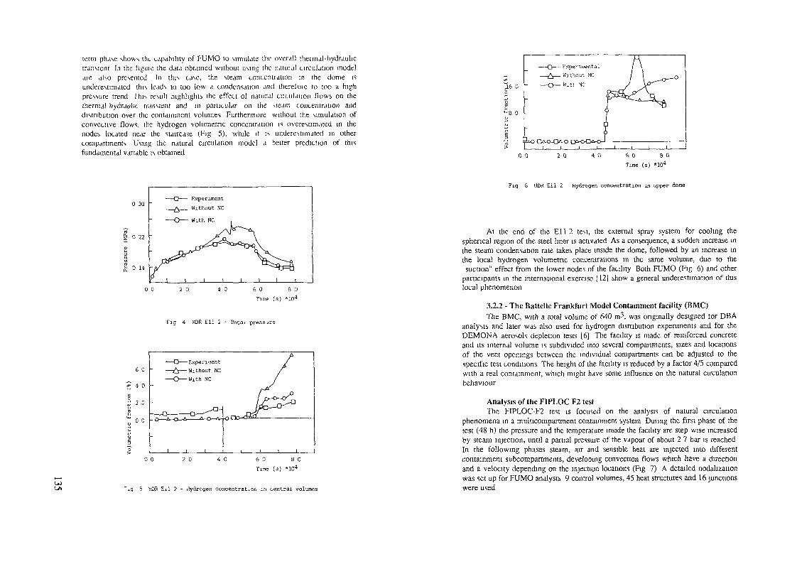
term phase shows UK capability of F-UMO to simulate the overall ttiennal-hydraulict ransient In the f iguie the data obtained without using the natural circulation modelaie also presented In this case, the steam concentiation in the dome isunderestimated this leads to too low a condensation and therefoie to too a highpressure trend I his result highl ights the effect of natural uiculauon flows on thethermal hydraulic transient and in particular on the sfeam concentration anddistribution over the containment volumes Furthermore without the simulation ofconvective flows, the hydrogen volumetric concentration is overestimated in thenodes located near the staircase (Fig 5), while it is underestimated in othercompartments Using the natural circulation model a better prediction of thisfundamental variable is obtained
0 30
0 22
If. 0 14 -
2 0 4 0 6 0 8 0Time (s) *104
Fig 4 HDR Ell 2 - Tota± pressure
0 0 2 0 6 0 8 0Time (s) *104
-il 2 - dydrcgen concentration in oentral volumes
0 0 2 0Time (s) *104
Fig 6 HDR Ell 2 Hydrogen concentration in upper dome
At the end of the El 1 2 test, the external spray system for cooling thespherical region of the steel liner is activated As a consequence, a sudden increase inthe steam condensation rate takes place inside the dome, followed by an increase inthe local hydrogen volumetric concentrations in the same volume, due to thesuction" effect from the lower nodes of the facility Both FUMO (Fig 6) and other
participants- in the international exercise [12] show a general underestimation of thislocal phenomenon
3.2.2 - The Battelle Frankfurt Model Containment facility (BMC)The BMC, with a total volume of 640 m3, was originally designed tor DBA
analysis and later was also used for hydrogen distribution experiments and for theDEMONA aerosols depletion tests 16) The facility is made of reinforced concreteand its internal volume is subdivided into several compartments, sizes and locationsof the vent openings between the individual compartments can be adjusted to thespecific test conditions The height of the facility is reduced by a factor 4/5 comparedwith a real containment, which might have some influence on the natural circulationbehaviour
Analysis of the FIPLOC F2 testThe FIPLOC-F2 test is focused on the analysis of natural circulation
phenomena in a multicompartment containment system Dunng the first phase of thetest (48 h) the pressure and the temperature inside the facility are step wise increasedby steam injection, until a partial pressure of the vapour of about 2 7 bar is reachedIn the following phases steam, air and sensible heat are injected into differentcontainment subcompartments, developing convection flows which have a directionand a velocity depending on the injection locations (Fig 7) A detailed nodahzationwas set up for FUMO analysis 9 control volumes, 45 heat structures and 16 junctionswere used

O\
Steam ——
7 Natural circulation *lows in BMC facility
0 30 -
18 0 22 0 26 0
Time (s) *.»04
Fig 8 FIPLOC F2 - Total pressure
130 0
—O—Experiment—A—Without NC—O—With NC
110 0
18 0 22 0 26 0Time (s) *104
Fig 9 FIPLOC F2 - Temperature
In Figs 8 and 9 the measured and calculated global pressure and temperaturewith and without the use of natural circulation model are compared Theunderestimation of pressure data (Fig 8), calculated without using the naturalcirculation model, can be explained through the prediction of a higher steamconcentration m the dome of the BMC facility this induces an overestimation of thecondensation on thermal structure
More insight into the problem of a correct prediction of the long termcontainment condition is obtained from the analysis of temperature trends (Fig 9)The difference between measured and calculated values, of about 8 °C during all thetransient, is due to uncertainties of initial value The calculation performed withoutthe use of natural circulation model shows an oscillatory behaviour due to anunrealistic evaluation of heat exchange coefficients
4 - APPLICATION OP FUMO CODE TO INNOVATIVE LWRs
FUMO is being used at present for analysing the containment systems ofSBWR and AP600 reactors The nodahzation has been completed and tested for bothreactors (Figs 10 and 11) For AP600 some results are already available Below theyare compared with data available m literature [H), obtained by Westlnghouse usingan independent methodology
4.1 External spray modelThe AP-600 containment design is similar to a dry containment arrangement
in terms of size and design pressure The safety functions are devoted to a PassiveContainment Cooling System, which is capable of transmitting heat directly from thereactor containment structure to the environment [14]
Containment cooling is performed by a falling liquid film and a countercuirent natural circulation air flow A monodimensional model is used in FUMOMass and energy balance equations are solved both for the liquid film and for theair/steam mixture The energy balance takes into account terms due to heatconduction through the film, convective heat transfer between film and air and latentheat carried by the evaporating flow The evaporation rate is evaluated using acorrelation derived from the analogy between heat and mass transfer in turbulentforced convection, this is acceptable because of the high Reynolds number whichcharacterizes the mixture flow The solution of the mass balance equation along theheight of the containment structure means that the film thickness can be calculatedthis is necessary for the evaluation of the heat transfer phenomena and also for theverification of its hydro dynamic stability
A minimum flow-rate is required to guarantee the stability of the liquid film,but there is a large spread in the experimental values of this limit, ranging from 0015Kg/ms to 60 kg/ms for water at room temperature [15] The exact value dependsupon the geometry and the nature of the vertical surface the initial distribution of theliquid and the mass transfer between the liquid and the surrounding gas Specific testsin order to investigate this phenomenon will be earned out at the DCMN In FUMOthe value of 0015 Kg/ms is used at present When the liquid film flow rate drops

L_
Fig. 12: Sensitivity analysis for Large LOCA in AP600.Pressure inside containment.
Fig. 13: Thermal flux through liner internal surface.
Fig. 14: Thermal flux through liner external surface.

below this value the lower portion of the containment is assumed to be dry and theconvectlve heat transfer coefficient is evaluated on the basis of the air/steam flow rateinduced by natural circulation
4.2 AP600 Large LOCA analysisA preliminary analysis of AP6(X) containment response to a Large LOCA was
performed using FUMO The containment was nodalized with 15 control nodes, 11inside the steel liner and 4 outside
A reference calculation (case A) was performed without modelling theIRWST pool or injecting steam into the Containment during the whole transient with atotal enthalpy flow equivalent to the decay power of the reactor
A sensitivity study was also performed to evaluate the effects of the limit forfilm instability and of the way of providing the blow down table In the secondcalculation (case B) the instability test described in the previous paragraph was bypassed Figure 12 shows that the assumed minimum flow rate value stronglyinfluences the pressure transient inside the containment In fact, the instabilitycondjtion is reached at about 80000 s, and, starting from this time, the pressure risessignificantly
In the third calculation (case C) the IRWST was simulated, and decay power,given by the ANS curve + 20%, was directly added to the pool in the reactor cavityThis approach needs a more complex calculation, but it matches the actual situationbetter, in fact it allows a correct simulation of the water balance inside thecontainment and of the steam generation in the long term phase, when a pool ofsaturated water is present The importance of a correct evaluation of the blow-down isevident from Fig 12 The higher steam generation present in case C induces asignificantly higher pressunzation of the containment
In Figs 13 and 14 the heat flux trends, internal and external to thecontainment steel wall, are given The results are compared with those obtained byWestmghouse in a similar analysis [B] The good agreement between the resultsobtained in the two calculations is highlighted, in particular, a good quantitativeagreement is present also m the initial phase of the transient, when the heat transferprocess is dominated by the external spray action
5 - CONCLUSIONS
The presented results show FUMO s ability to analjze thermal hydraulictransients in the containment system of the current and the new generation of LWRsduring a DBA or a SA sequence In particular the results obtained in the assessmentprocess show the validity of the natural circulation model and its importance for a BEanalysis of a containment system
Also the new models, related to the ESFs present in the new LWRs, have beentested with satisfactory results A further assessment may be useful to improve theexternal spray film model especially as far as the stability condition is concernedThis work will be done both with calculations for separated effects tests and forintegral tests when available
The first application of FUMO, performed for the AP600 reactor also showedthe importance of a correct simulation of the interaction between the primary systemand containment A solution to this problem will be achieved through the integrationof the FUMO code with a fast running primary system program that will also allowto improve the evaluation of the feedback effect of the containment pressure on theprimary system
REFERENCES
11 i H Karwat, The Importance of Natural Circulation inside NuclearContainment Systems , EUROTHERM Seminar No 16, Pisa, October 1990
12) M Mazzim, F Onolo, S Paci, Realistic Simulation of Thermal HydraulicTransient in Full Pressure Containment System during Severe Accident ,IAEA/OECD International Symposium on Severe Accidents in Nuclear PowerFiants, Sorrento (Itafy), March 1988
H | A Manfredini, F Onolo, S Paci, A Model for Simulating NaturalCirculation Phenomena in LWRs Containment Systems , ENC 90Conference, Lyon (France), September 1990
|4| A Manfredini, M Mazzim, F Onolo, S Paci, II codice FUMO descnzionee manualeduso DCMN, Umversita di Pisa, RL 416 (89)
[5] L Valencia, L Wolf, Overview of First Results on H2 Distribution Test atthe Large Scale HDR Facility Second International Conference onContainment Design and Operation Toronto (Canada), October 1990
|6| K Fischer, CEC benchmark Exercise on FIPLOC verification experiment F2in BMC Specifications for Phase I! , Bdttelle Institute e V , Frankfurt (FRG),September 1989
|7] W Ambrosmi, B Montagmm, F Onolo Un metodo coarse mesh per ilcalcolo del calore scambiato per conduzione neue strutture in un impianlonucleare ad acqua leggera in seguito ad un incidente IV CongressoNazionale sulla Trasmissione del Calore UIT, Genova (I), Giugno 1986
[8] A Manfredini M Mazzmi, F Onolo, S Paci, Valutazione dell efficaciadello spruzzamento esterno del contemmento in impianti nuclean a maggioresicurezza passiia VIII Congresso Nazionale sulla Trasmissione del CaloreUIT Ancona (I), Giugno 1990
|9| M Mazzim S Lanza F Onolo S Paci, C Zaffiro Thermal hydraulicAnahsys of the LACE Experiments and us fall out on the Safety Analisys ofLWRs Containment S\stems , II International Conference on ContainmentDesign and Operation, Toronto [Canada], October 1990
110] M Schall, Design Report for the HDR Containment Experiments V21 1 toV21 3 and V42 to V44 with specifications for the pre test computations ,PHDR Report No 3280/82, January 1982
J i l l L Valencia et aJn, Hydrogen Distribution Experiment Ell 1 El 15Preliminary Design Report , PHDR Work Report No 10000/89 March1989

|12| Minutes of the "HÖR Workshop <in LI! 2 p/c-lcsi lalt-ulalioiu", KfKKarlsnihe (FRG), Novembei 29 30, 1990
1 1 3 ] A F Gagnon, K S Howe "Containment integrity analyst!, for the (W)AdvamedAP-6üü", ANS Winter Meeting, S Francisco (CA), November1989
114) L K Conway, "The WeMnght>u.\e AP6ÜÜ Pa\itive Safety SyMem-Key to aSafer, Simplified PWR ", ANS Winter Meeting, S Francisco (CA), November1989
115) R H Perry, C H Chllton, "Chemical Enj>meer\ ' Handbook ", Fifth Edition,Me Graw Hill Book, pp 5-57
STUDIES ON ALWR CONTAINMENTSYSTEM PENETRATIONS
F. MANTEGA, E. PENNOCISE Tecnologie Innovative SpA,MilanP. VANINIEnte Nazionale per L'Energia Elettrica,RomeItaly
Abstract
Public acceptance of the next generation of nuclear power plantscould be achieved if the "Containment System" is able to withstandSevere Accident (SA) conditions so that the radioactive release tothe environment can be minimized. The reduction of the radioactiverelease during an accident may be achieved improving some preciseplant requirements, among which the leaktightness of primarycontainment.One of the critical points of this matter is reppresented by thecontainment penetrations that should be carefully investigated tohighlight weak points.Penetrations may be divided into -.1. Penetrations which see the containment atmosphere and release
directly into the environment,2. Penetrations which do not see the containment atmosphere and
release directly into the environment,3 Penetrations which see the containment atmosphere and do not
release directly into the environment,4. Penetrations which do not see the containment atmosphere and
do not release directly into the environment.With reference to external dose reduction target, the roost criticalkind of penetrations is the first one.The study program is therefore focalized on the followingtypologies :
electric penetrationsmechanical penetrationspersonnel and equipment hatches
The updated quality (particularly the pressurized one) allows tosolve satisfactory the issue of the electric penetrations.About the mechanical penetrations, the isolation valves of theventilation system can. presently, represent a possible source ofrelease. Studies are in progress to find a different kind of valvehaving a double airtight, the possibility to be tested underaccident pressure value, a long life and the possibility to applya positive leakage control system

-fio Experience done on personnel and hatches have shown a goodbehaviour of whole components with respect to pressure (untill 2.0MPa even at 425' C). Tightness of both personnel airlocks andhatches depents on the degradation temperature of the elastomer inplace The studies are aimed at exploring some critical areas suchas heat dissipation, temperature of the seal gaskets, deformationunder accident pressure and applicability of a back-up system. Afinite element analysis shall be done on this equipments to betterestimate their behaviour under accident conditions and to verifythe efficiency of the improvements.The program also foresees the final tests of all technicalsolutions at the accident conditions.
INTRODUCTIONA significant discussion has taken place in the scientificcommunity over the last several years on the sub3ect of containmentperformance for new generation of nuclear plants.It is growing opinion that the new containment performance shall bebased upon definite target of environmental impact limitation. TheItalian target is to eliminate the necessity of evacuation planningand to limit extensive land contamination for any conceivableaccident including severe accidents and related phénoménologies.To pursue this target it is necessary to improve the current plantdesign in order to cover the technical reasons and the "what if"beyond the design criteria which are the causes of emergencyplanningTo do this in a real way it seems suitable to proceed through threestepsa. Consider, in the plant design, events beyond the current
licensing design basis, this item needs a deep examination ofSevere Accident (SA) phénoménologies in order to avoidunrealistic situations causing design requirements to becometoo heavy.
b. Provide a containment design able to assure the design leakrate for any conceivable accident. This target needs:b 1 To solve containment bypass issues (interfacing systemLOCA, multiple SG tube rupture, isolation functionimprovements, etc.),b.2 To provide isolation devices able to assure the designleak rate for the new environmental condition, accidentduration included.
c Improve the plant system design in order to be sure about thecontainment leak rate in any moment in which accident mayoccur (e.g. by means of a continuos leakage monitoringsystem).
As the ALWR design philosophy allows a considerably reduction ofmechanical and electrical penetrations and the current technologyprovides zero-leakage electrical penetrations the most criticalissue regarding the isolation device involves the personnelairlock, the equipment hatch and the isolation valves of HeatingVentilation and Air Conditioning HVAC systems (vent and purgeincluded). These are critical componentes because they are:
potential main contributors to total containment leak rate inSA conditions,a potential direct path between the containment atmosphere andthe environment,a weak point, if their tightness is trusted to organicmaterials that are susceptible of aging and thermal damage.
The purpose of ENEL/CISE studies is to develop the criteria andconceptual design for personnel airlocks, equipment hatchs andisolation valves of HVAC systems in order to solve the issue b.2according to the new target for future nuclear plants.
CONTAINMENT ISOLATION VALVES FOR HVAC SYSTEMS
The containment HVAC systems have the largest isolation valves (upto 42") in the nuclear plant and the system arrangements are suchthat the leakage through the two isolation valves of each line canflow directly to the environment.Currently these isolation valves are of the butterfly type becausethe governing requirements are size, weight, simple and relativelyfast acting, cost ect. They also present a good behaviour aboutleaktightness at uniform accident design temperature.Also taking into account the system arrangement, the problemsrelated to the butterfly valve isolation function are:
high closing torque under accidental flow condition,in the soft seal application, tightness is trusted to organicmaterial susceptible of aging and thermal damage,as abovementioned,in the metal-to-metal seal application, thethreatened by particulate deposition (9),
tightness is
deformation of the valve body, with consequent loss oftightness, can occur when temperature reaches high values ina not uniform way (9),containment wall displacement can generate loads on thevalves, this may prevent the valve from isolating thecontainment during an accident.

Many tests were performed to investigate these aspects The mostmeaning results are:
the closing torque under accidental flow condition is high(about 1000 kg-m for a 24" valve) (1)the leakage (1) at pressure of 0 9 MPa and 180' C is quite lowbut increases remarcably after the valve has been cooleddown •
valve size8'U*
I' 5 HiT/b (C 651 Yolnie/dayl'U 5 hcj/b (21 voluie/dayl'
the currently extimated SA temperature is not far fromelastomer property limits.
To overcome these concerns it seems advisable, first of all,to define some general requirements such as.
Pursue improvements in fuel design and in primary loopleaktightness in order to reduce containment cleaning andpurge need The target is to reduce containment penetrationnumber and size,Provide containment Air Conditioning system with fan coolersinside the containment. The target is to eliminate largenormally open isolation valves.Especially for Email Pressure Suppression Pool (PSP) typecontainment, provide the design for containment interfacingsystems in order to avoid the pressure build-up insidecontainment itself. The target is to avoid containment ventingneeds during normal operation and then to allow blind flangesinstallation on vent lines, removable during plant shutdown,
and then some precise requirements like:elastomer performance characteristics can be optimized byvalve design Valves with smaller cross section seals seem tobe somewhat more resistant to the compression set of the sealsthan other valve désignes,study case by case the possibility to use different type ofisolation valves like the gate one and in particular the splitwedge (fig.l) or the parallel slide double disc gate valve(fig.2),provide leak test on each valve at SA condition and in theexpected direction of the leakage flow.
About this subject the ENEL/CISE activity in progress is todefine the valve type able to optimize the above issues and toinclude a potential simple and reliable positive leakagecontrol system in order to claim for zero leakage for thiskind of containment isolation valves without stressing weightand costFurthermore these valves and their interfaces have to bedesigned and qualified for conservative estimated SAcondition. For this reason a finite element analysis shall bedone on whole mechanical penetrations related to theseequipment to better evaluate their behaviour under accidentconditions and to verify the rightness of the improvements.
CPACKING
STEM
BONNET
BODY
conversion to percent volume per day are based on 50 000m3 containment building Fig. I - Split wedge gate valve

STEM
DISC RETAININGPINS
DISC
DISC CARRIER
SEAT
PRELOAD SPRING
Fig. 2 - Parallel slide double disc gate valve.
PERSONNEL AIRLOCKSPersonnel airlocks provide access into and out of the containmentbuilding for maintenance and inspection crews and for the trasportof light equipment.As part of the U.S. Nuclear Regulatory Commission's ContainmentIntegrity Program, tests (6) were performed on a full-sizepersonnel airlock.The purpose of the test was to characterize the performance of thewhole airlock equipment when subjected to conditions that simulatecurrently estimated SA conditionsThe gaskets tested had a cross-section known as a "double dog-ear"configuration and were made from EPDM E603. The seal were aged atan accelerated rate to simulate aging that might occur during 40years of continuous service and a loss of coolant accident (LOCA).A total of nine tests were performed on the airlock. In the mostrigorous of these tests, the airlock inner door was subjected topressures and temperature largely beyond the design basis. Theairlock was originally designed for a pressure of 410 kPa and170oc.
The conclusions of this test program were:although the gasket was degraded by an accelerated agingprocess, simulating both heat and radiation damages, noleakage of the inner airlock door occurred untill the gasketwas subjected to the temperature lower than degradationtemperature of EPDM E603 (approximately 330oC),failure of gasket seal was related to temperature beyond theabove mentioned value,the gasket expanded while increasing temperature causingsignificant upward deflection of the door and resulting inlarger gaps between the inner door and bulkhead,the personnel airlock survived 2.07 MPa internalpressurization at 427° C. The behaviour of the structureremained in the elastic range,the outer door at 2.07 MPa did not leak due to its lowtemperature (below 100°C).
The examination of the above results leads to these followingthoughts:
the failure of the inner door gasket must not causetemperature increase on outer door due to the metal-to-metalcontact between door and bulkhead. Although the gasket couldbe completely destroyed the metal-to-metal contactaccomplishes a strong resistence to the gas circulation,heat transfer conditions of the structure have an importanteffect on the temperature distribution. The outer doortemperature and consequently the airlock isolation functiondepend on this heat transfer.
The objective of ENEL/CISE ongoing activity on this subject is todevelop a design approach able to solve the above issues and it canbe summarized in the following steps (based on the current airlockdésignes):
1. Get SA containment environmental condition input from safetyanalysis currently in progress, if possible.
2. define, based on aging test of gaskets, the maximumtemperature at which the outer door can survive for a verylong time (e.g. some months).
3. Define the thermal conditions of the structure (see Fig. 3) inorder to keep the temperature of the outer door at the abovementioned value while the inner door temperature is at the SAconditions or at a value beyond the gasket degradation ones(about 330'C),

FINNING The leakage behaviour for the three seal design has been assessedThe temperature range at which failure of elastomer seals can beexpected is as follow
THERMAL INSULATIONFig. 3 - Improved current personnel airlock in order to get lower
temperature at the outer door.
4. Optimize airlock design and material.5. Perform a finite element analysis on the whole device to
verify its behaviour under the foreseen conditions.6. Test the Tightness of the new approach on an actual component,if possible
EQUIPMENT HATCHES
Equipment hatches provide access into and out of the containmentbuilding for large items.Because of the large size of these hatches the critical point arethe structural deformations of the assembly and the seal behavior.Three seal désignes commonly used for nuclear power plantcontainment were tested at the Idaho National EngineeringLaboratory (5)These seal design were:a) double tongue-and-groove (DIG) with silicone rubber seals
b) double 0-ring (DOR) with neoprene and EPDM seals.c) double gumdrop (DGD) with neoprene and EPDM seals.
seal latenalSilicon robber8PDKStatuâtimHeoprene
fa i lu re tetperature31COC315- 3500C2<0-260°C300-330°C260°C
J,The leak rate varied from 3.2E-04 to 1.3E01 Nnr/h per meter of sealbefore the failure of the seals and from 1.2E+00 to 4.2E+01 afterfailure of the seals.As the above mentioned case the leak rate was not significantlyinfluenced by thermal aging of the seals.Degradation and subsequent failure of the gasket seal was relatedto temperatures exceeding the temperature at which organicmaterials are stable. In this condition metal-to-metal contact atthe sealing surface can reduce leakage (7).The conclusions are the same as those personnel airlock concerningtemperature while a very important problem is the deformation ofthe assembly essentially due to pressure although the generalarrangement of the seal area allows to have a satisfactorybehaviour about tightness.Therefore the ENEL/CISE activity about hatches starts from thefollowing assumptions:
door design shall be such that a metal-to-metal contact isprovided as back-up of elastomer seal according to the mostof current désignes,improvements of the current hatch geometry are required inorder to get a better defence in depth level. A radicalimprovement could be a double door arrangement.
Then the activity steps are the following:1. Get SA containment environmental condition input from safety
analysis currently in progress, if possible.2. Study improvements of a current hatch design (with a single
door) in order to get:a sort of back-up system for tightness functiona passive heat dissipation of the improved structure inorder to assure better thermal conditions of the sealingelastomer
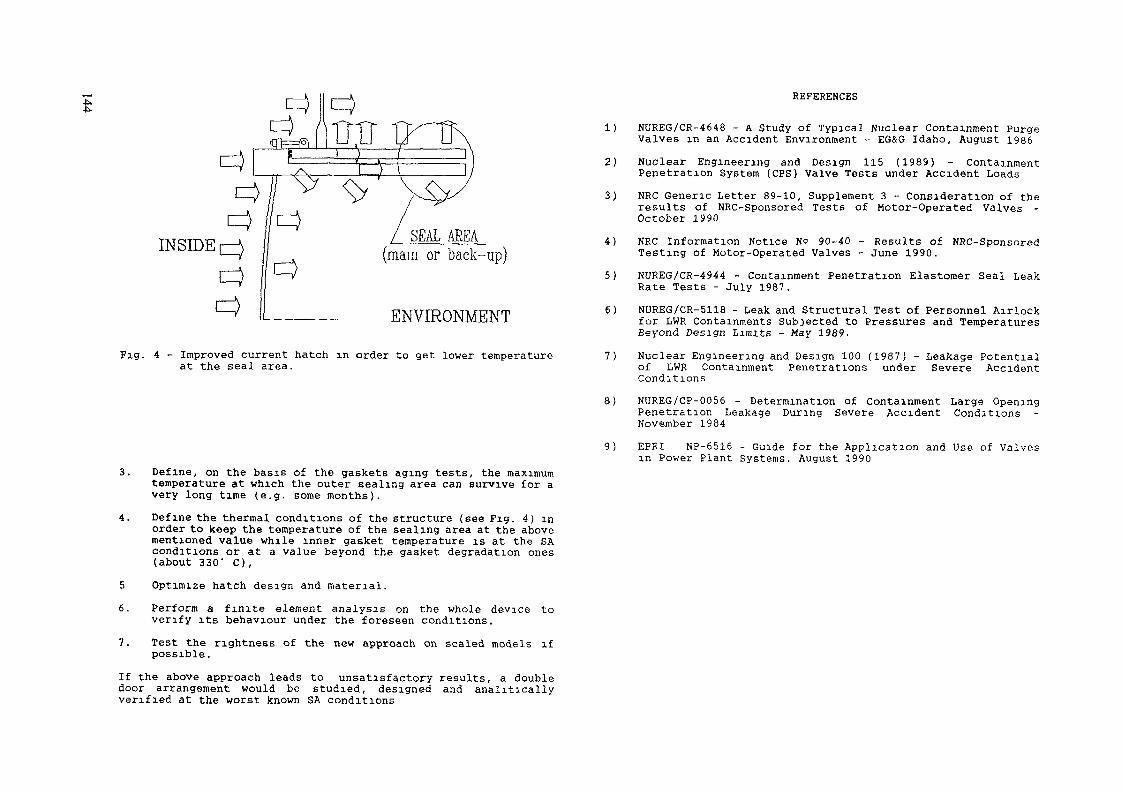
SEAL AREA(mam or back-up)
ENVIRONMENT
Fig. 4 - Improved current hatch in order to get lower temperatureat the seal area.
REFERENCES
1) NUREG/CR-4648 - A Study of Typical Nuclear Containment PurgeValves in an Accident Environment - EG&G Idaho, August 1986
2) Nuclear Engineering and Design 115 (1989) - ContainmentPenetration System (CPS) Valve Tests under Accident Loads
3) NRC Generic Letter 89-10, Supplement 3 - Consideration of theresults of NRC-Sponsored Tests of Motor-Operated Valves -October 1990
4) NRC Information Notice NO 90-40 - Results of NRC-SponsoredTesting of Motor-Operated Valves - June 1990.
5) NUREG/CR-4944 - Containment Penetration Elastomer Seal LeakRate Tests - July 1987.
6) NUREG/CR-5118 - Leak and Structural Test of Personnel Airlockfor LWR Containments Subjected to Pressures and TemperaturesBeyond Design Limits - May 1989.
7) Nuclear Engineering and Design 100 (1987) - Leakage Potentialof LWR Containment Penetrations under Severe AccidentConditions
8) NUREG/CP-0056 - Determination of Containment Large OpeningPenetration Leakage During Severe Accident ConditionsNovember 1984
9) EPRI NP-6516 - Guide for the Application and Use of Valvesin Power Plant Systems. August 1990
3. Define, on the basis of the gaskets aging tests, the maximumtemperature at which the outer sealing area can survive for avery long time (e.g. some months).
4. Define the thermal conditions of the structure (see Fig. 4) inorder to keep the temperature of the sealing area at the abovementioned value while inner gasket temperature is at the SAconditions or at a value beyond the gasket degradation ones(about 330' C),
5 Optimize hatch design and material.6. Perform a finite element analysas on the whole device to
verify its behaviour under the foreseen conditions.7. Test the Tightness of the new approach on scaled models ifpossible.If the above approach leads to unsatisfactory results, a doubledoor arrangement would be studied, designed and analiticallyverified at the worst known SA conditions

DESIGN OF THE AP 600 PASSIVE CONTAINMENTCOOLING SYSTEM STRUCTURES
M. OLIVIERI, S. ORLANDIANSALDO SpA,Genoa,ItalyR. ORRWestinghouse Electric Corporation,Pittsburgh, Pennsylvania,United States of America
Abstract
The AP 600 is a greatly simplified 600 MWe Pressurized Water Reactor,for the 1990's and beyond.
Among its major features, a passive containment cooling system (PCCS)is designed to remove the residual heat, directly from the containmentsteel vessel, and transmits it to the environment.
The design and analysis of the PCCS structures is being performedjointly by ANSALDO and WESTINGHOUSE, as part of the AP 600 program underWESTINGHOUSE's overall leadership, and will be presented in this paper.
The PCCS uses the steel containment wall as a heat transfer surface.The surrounding concrete shield building is used along with a baffle todirect air from the top located air inlets down to a lower elevation of thecontainment and back up along the containment vessel. In addition a waterstorage tank is housed in the shield building roof at an elevationsufficient to allow gravity drain of the water on top of the steelcontainment.
The air and the evaporated water exhaust through a chimney in the roofof the shield building.
For the roof, a reinforced concrete conical configuration, with acylindrical stainless steel lined water tank, has been selected and acomprehensive feasibility study has been performed including seismicbehaviour, constructability, préfabrication and modularization, adaptabilityto cope with the External Events strength requirements. For the PCCS airbaffles general functional and structural design criteria have beenestablished by including requirements for the air flow path configuration,leakage through the baffles, inspection and maintenance; a series ofalternate designs have analyzed, leading to the selection of a referenceconfiguration that will be briefly described.
1. INTRODUCTIONThe AP 600 is a greatly simplified 600 MWe Pressurized Water ReactorPWR) plant with major improvements in safety, operability,maintainability, life cycle cost and construction schedule, comparedto existing nuclear plants.Major features of this new plant are a simplified reactor coolantsystem, employing sealed canned motor pumps mounted on the steamgenerator channel head, simplified plant systems including passivesafety systems and an integrated plant arrangement including amodular construction approach.The passive containment cooling system (PCCS), more specifically, isprovided in case the normal containment fan coolers are not availableor an accident has occurred that requires containment heat removal atelevated pressures and temperatures.The design and analysis of the PCCS structures is beingperformed jontly by ANSALDO and WESTINGHOUSE, as part of the AP 600program under WESTINGHOUSE's overall leadership, and will bepresented in this paper.
2. PCCS FUNCTIONSScope of the PCCS is to keep the containment internal pressure andtemperature within the design values, following any postulated designbasis event and to reduce the internal pressure in the long term.The PCCS is required to perform its containment heat removal functiononly following a postulated design basis (e.g., a LOCA or steam linebreak) event which results in a large energy release into thecontainment or following the loss of all alternate ultimate heatsinks for an extended period of time. Heat removal by the PCCS isinitiated automatically in response to a high containment pressuresignal, and, with the exception of the initial actuation, requires noactive components or electrical power to perfora its safety function.Also manual actuation can be accomplished by the operator from themain control panel or the safety grade shutdown control panel.As shown in Figure 1, actuation of the PCCS initiates water flow bygravity from a tank contained in the shield building structure abovethe containment onto the containment dome outer surface forming awater film over the structure. The path for the natural circulationof air upward along the outside walls of the containment structure isalways open. Heat is then removed from the containment, utilizing thesteel containment structure as the heat transfer surface combiningconductive heat transfer to the water film, convective heat transferfrom the water film to the air, radiative heat transfer from the filmto the air baffle, and mass transfer (evaporation) of the water filminto the air. Connections are provided to an alternate water source(s) such as the fire protection system to provide longer term (> 3days) capability of containment external spray.As the containment shell heats up in response to high containmenttemperature, heat is transferred to the water on the containmentsurface and to the air in the annul us space surrounding thecontainment. As the air heats up and water evaporates into the air,it becomes less dense than the cold air in the air inlet annul us.

a\
I*. ,'
FIG 1 AP 600 passive containment cooling system
This causes an increase in the natural circulation of the air upwardalong the containment surface, with heated air/steam exiting thetop/center of the shield building.The elevated PCCS water storage tank will provide water for wettingthe containment surface for three days following PCCS actuation.Operator action can be taken to replenish this water supply throughinstalled piping connections and water sources. If no operator actioncan be taken after 3 days when the tank has drained, naturalconvective air heat removal will continue to function.This provides sufficient heat removal to ensure that containmentintegrity is maintained although containment pressure would increaseto near the design pressure.The arrangement of the "cold" air inlet and "hot" air exhaust in theshield building structure has been selected to ensure air naturalcirculation during all site meteorological conditions. The air inletsare placed at the top/outside of the shield building providing asymmetrical air inlet which will not be affected by windspeed/direction or adjacent structures. The air/water vapor exhauststructure is elevated above the"co!d" air inlet to eliminate thepossibility of "hot" air being drawn into the air inlet.
FIG 2 AP 600 general layout
3. PCCS STRUCTUREThe PCCS structures are schematically represented in the containmentgeneral layout of fig. 2.The 130 ft diameter steel containment, hausing the primary equipmentand safeguard systems, includes a cylindrical shell with ellipticalheads for both the upper and lower head of the vessel.The surrounding concrete shield building has top air inlet openingsand houses a baffle to create the required air path.A reinforced concrete conical roof ends with the air exhaust chimneyand houses a 450.000 U.S. gallons water storage tank at an elevationsufficient to allow gravity drain of the water on top of the steelcontainment.The roof, 2 ft thick, rests on the cylindric shield building wallwith 16 reinforced concrete columns, 5 ft high and spacedcircumferentially to leave 16 openings, 16 ft wide. A flat shieldplate is suspended from the chimney lower end.

4 SHIELD BUILDING ROOF AND PCCS WATER TANK DESIGN4.1 Optimum configuration selection.
Different roof and tank configurations have been investigated,prior to the final selection.A flat roof with deep carbon steel girders andintegral water tank was first considered butsignificant recoating effort was expected, to assure long termtank durability.Preliminary cost and material comparisons showed that there arebenefits in having a stainless steel boundary that would not beexpected to require maintenance during the life of the plant.The second option therefore attempted to retain the originalconfiguration and build the tank using stainless steel and cladplates. This configuration results in a combination of carbonsteel, clad plate and stainless steel members in a singlestructure. It was recognized that this would be a difficultconstruction and could lead to quality and licensing questions.These considerations led to the selection of the reinforcedconcrete conical roof with a separate stainless steel linedconcrete tank.Material quantities and costs were estimated forthe cylindrical stainless steel lined concrete tank and theconical reinforced concrete roof. The cost was estimated to beonly slightly higher (7%) than that of the original integralcarbon steel option, with significantly lower maintenance cost.The conical roof with the integral stainless steel tank also hasother advantages, such as larger stiffness and strength reservemargins, better thermal insulation, better tornado missile impactresistance. Its main disadvantage is that it is more difficult toconstruct in comparison with the flat roof where all of the steelstructure would be installed as a single large module.
4.2 Structural feasibilityFor the reinforced concrete roof a comprehensive feasibility studyhas been performed. An axisvwetric model of the roof has beendeveloped and coupled with a sufficiently long portion of of theShield Building cylinder with fixed botton end boundary conditions.Orthotropic properties have been included for the air inlet region.Deflections and member forces in the main structural elements(cylinder, cone, inner and outer pool walls, pool roof) were analysedfor each of the main design loads (dead weight, pool hydrostatic,seismic). The deformed shape under dead weight and hydrostatic loadsis shown, as an example, in fig. 3. Preliminary reinforcement sizeswere developed complying with ACI 349 Code requirements, includingtypical connection details at the main structural discontinuities,(see figures 4 and 5).
FIG. 3. AP 600 R.B. roof: Deformed shape under dead weightand hydrostatic loads.
4.3 Seismic BehaviorThe axisymmetric model of the shield building roof has also been usedto evaluate its dynamic characteristics. The pool water mass has beenrigidly lumped to the tank pool boundary, based on results of apreliminary analysis of the seismic induced hydrodynamic effects. Themodel was used to size the suspension columns to avoid vibrationresonances of the suspended shield plate with the supporting shieldbuilding.The horizontal and vertical fundamental modes have frequencies of 5.2and 7.5 Hertz respectively and are shown in figure 6. The verticalfrequency is significantly higher than that of the flat steel roof(4.5 Hertz).An equivalent lumped mass stick model of the concrete roof andsupporting columns has been developed, as shown in figure 7, withinertia and stiffness properties determined to match the dynamiccharacteristics of the axisymmetric model. This simplified model hasbeen included in the overall seismic model of the Nuclear Island.

-P".oo
FIG. 5. Roof-cylinder connection
FIG. 4. PCCS tank rebar pattern

/' X
* LUS
FIG. 6. AP 600 R B. concrete roof: fundamental mode shapes
»UT —— < i
SO FIG. 7. Seismic analysis model: shield building roof structure.
4.4 ConstructabilityConstructability of the roof has been extensively investigated,together with significant advantages achievable with préfabrication;the following basic criteria have been used as a guide for suchconstruction study.
Wide use of removable forrawork; although this would imply sometime for formwork removal, it will allow that the finishedstructure be all reinforced concrete, without steel exposed tocorrosion potential.Extensive use of préfabrication of reinforcing rebar moduli,including liner or embedded plates, leading to significantconstruction time savings.Use of mechanical rebar splices at selected locations, insteadof conventional longer lap splices, to reduce the weight of someprefabricated moduli.All above mentioned techniques have been already satisfactorilyused for more recent nuclear power plant constructions.Typical construction sequences, identified for the conical roofand the upper radiation shield slab are shown in figures 8 and 9respectively.
5. PCCS AIR BAFFLEThe function of the air baffle is to provide a pathway for naturalcirculation in the event of a postulated design basis event resultingin a large energy release into containment. In this event the outersurface of the containment vessel above the operating floor wouldtransfer heat to the air flowing upwards between the baffle and thecontainment shell. Air is drawn in through the air intakes at the topof the shield building cylinder, as shown in figures 1 and 2, flowsdown between the shield building wall and the baffle and then up the12 inch wide gap between the baffle and the shell to the diffuser anddischarge stack. Heat fro» the vessel heats the air adjacent to thevessel and the lower density air creates flow.General air baffle functional and structural design criteria havebeen established and used in evaluation of alternate designs. Theseinclude requirements for the air flow path configuration, leakagethrough the baffle, inspection and maintenance of the baffle and thecontainment vessel, and extreme environmental conditions for whichthe baffle must function.A series of alternate designs were prepared in order to develop anoptimum design to Beet these functional requirements. These designsinclude alternates attached to the containment vessel and othersattached to the shield building, as well as various sizes of panelsto permit their removal if maintenance of the containment vesselcoating is required. When the baffle is attached to the containment,

- FORMWORK SUPPORTED ON THE STEEL DOME
- TEMPORARY CONSTRUCTION LOADVERIFICATION REQUIRED
- TEMPORARY STEEL BEAMS SUPPORTED ATONE END OH STEEL PLMES EMBEDDED IKTHE SHIELD BUILWNa VWLL
- HALF THE BEAMS STOPPED AT ABOUTHALF FtAOOIS
- FORMWORK ANC REMAINING FOftMWORKSUPPORT CONVENTIONAL AND SUPPORTEDON RADIALLY ARRANGED STEEL SECTIONS
- THE 32 FEET DIAMETER CHtMNFV OPCNIHQAMPLE ENOUQH TO REMOVE FORMWORK ANDSUPPORT BEAMS AFTER CONCRETEHAflDENINQ
FIG 8 Concrete conical roof construction scheme
FORMWORK SUPPORT FftAMINä PLAN
5ECT. 3A-3A
r INSTAU. ronMv*c«K aoff^x-no er THECOHTAINM«NT O0"l.
2 P«tfA(SWC*.TE BtAMS A
3 INSTALL 8OTT0M fftl^FO
* IH8TAU. »EAM9 * HPOSITION.
5 INSTAS.I. SMBA« TIES
a fou« THE LOWM ro* Of SLABT AFTSU TUB CONCWÏT» I» MATUflBD. «SMOV«
SICTIOW«
MKNT OF «LAfc
IN TUB FINAL
8 INSTALL TOF «E
? PCXJK THB «SST Of TH8 TyitCKWess or SLAB.
10 RBMOVtl FOKMt F«OM TH« 3ID« e*TM8*t^»
It INSTALL TTm «HN^ORCeMfNT AKOfNO9T*«L HANOEft«.
It INSTALL FORMS AHOUMD HANaCRS AMD POU FtCONCFUT» PWOTtCTIOM ABOUND HAWSIUS
It BBMOV« F-O1M8
I—<Hi«Lo »LAB
FIG 9 Construction sequence for shield slab
150

iI.4
provisions must be made to accoraodate the containment growth underpressure and temperature conditions. The critical structural loadsare the results of extreme wind or seismic conditions. Evaluation ofthese alternatives led to the selection of the reference design whichis described below for the cylindrical portion and shown in figureThe cylindrical portion of the air baffle comprises 64 panels in eachof 5 rows (320 total), with each panel approximately 210 cm wide and467 cm high. Each panel is fabricated from either stiffened steelplate or corrugated plate with the final selection based on vendoravailability and cost. The panels are attached to the containmentvessel at the corners of each panel.The panels are guided at each attachment point so that they may sliprelative to the containment vessel growth, (see fig.11).Cover plates are provided at these joints to minimize leakage flowthrough the baffle. For minor inspections, a series of windows areprovided in the baffle or a TV camera may be lowered into the annulusfrom the top of the cylindrical portion.The cylindrical portion terminates with an upper row of dome panelsinterfacing the conical roof.
o
6. ADAPTABILITY TO EXTERNAL EVENTS REQUIREMENTSFeasibility studies have been performed to investigate theadaptability of the present Reactor Building layout to cope, withminor modifications with special external events, strengthrequirements frequently specified in European countries.For the aircraft impact excitation, thickening of the conical roofand additional protection at the air intake and exhaust openings ofthe Reactor Building have been characterized and their acceptabilityfrom the air flow path requirement view point has been investigatedwith model wind tunnel testing.For the external pressure wave excitation, originated by assumed gascloud explosions, the wave propagation through the air inlet andoutlet openings into the annulus between the containment and theReactor Building has been preliminarily evaluated and tfie resultingtransient external pressure acting on the steel containment vesselwall has been determined.As a conseguence of the relatively small buckling resistencecapability to external pressure of the cylindrical steel wall, theneed of some stiffening rings has been identified, to be welded onthe inside face of the containment, in order to avoid obstacles tothe external flow of cooling water and air.Less problems are anticipated for the steel dome because its bucklingcapability is larger and an increased thickness can be used withrespect to the one needed for the internal pressure load.

toENHANCEMENT Of ADVANCED PWRSAFETY MARGINS THROUGH RELAXATION OFPCS AND CONTAINMENT DBA ASSUMPTIONS
C. ADDABBOSafety Technology Institute,Commission of the European Communities,Joint Research Centre,Ispra
Abstract
Referring to advanced Pressurized Water Reactors (PWRs) there is thetendency to conceive them with larger and deeper pressure vessel tomitigate core thermal response during anticpated accidents or abnormalevents This is however resisted by present Design Basis Accident (DBA)assumptions which would prescribe the reduction of Primary Cooling System(PCS) volume in order to minimize mass and energy release and thuspressure and temperature build up in the containment following a largebreak Loss of Coolant Accident (LOCA) caused by a complete severancewithin the primary and secondary systems pipework
The relaxation of the current DBA assumptions which on the basis of theacquired experience and probabilistic risk assessment studies have beenshown to be overly conservative could have a significant impact on theconceptual development of advanced PWRs Specifically, the volumes ofboth the primary and secondary cooling systems could be optimized withoutclose linkage to containment performance providing enhanced safetymargins with respect to primary thermal excursions as partially confirmedby LOCA experiments conducted in the LOBI Test Facility
INTRODUCTIONThe evolutionary approach in the conceptual development of advancedreactors while still relying on engineered safety features is also trying toexploit the potential advantages of any conceivable inherent safetycharacteristic This approach, however, has to comply with current safetypractices based on the "defense-in-depth" concept which is ultimatelyaimed at preserving containment integrity in the aftermath of postulatedaccidents
In PWRs of current design, the primary as well as the secondary fluid volumesare minimized in order to mitigate mass and energy releases into thecontainment following a DBA occurrence In atypical 4-loop PWR, this eventis associated with the release into the contain ment of the entire inventory ofthe primary cooling system and of the secondary cooling system of onesteam generator This is in turn used to determine eventual containmentloads and related design requirements
The acquired reactor operational experience and probabilistic riskassessment studies, however, have shown that the ensuing prescriptiverequirements to be complied with in the safety evaluation of water cooledreactors are generally overly conservative [1] The adoption of more realisticDBA assumptions such as the Leak Before-Break (LBB) criterion, on the otherhand, could lead to enhanced safety margins by providing the basis for theoptimization of primary and secondary cooling system volumes withoutstringent constraints strictly coupled to containment response
Within this context, experiments conducted in the LOBI installation, anintegral system test facility operated in the Ispra Site of the Commission ofthe European Communities Joint Research Centre, have shown thatsignificant safety improvements could be achieved through the increase ofprimary system volume, generally, core thermal response was considerablymitigated when the experimental installation was configured with a largeReactor Pressure Vessel (RPV) volume Although the reported experimentalresults cannot be directly extrapolated to full-size prototypes, they are,however, indicative for the development of advanced PWR concepts which,among others, are being conceived with larger and deeper pressure vessel,larger pressunzer and secondary system volumes
PERSPECTIVE ON DBA ASSUMPTIONSIn the safety evaluation of current PWRs a complete severance of theprimary loop pipework and of the steam line of one steam generator istaken as the reference case for the assessment of the emergency safetysystems performance and containment response The inherent safetymargins embedded in this assumption have lead to the adoption of thediversity and redundancy criteria in the configuration of the safety systemsand to rugged design constraints for the containment
Referring to the containment vessel, the pressure build up resulting fromflashing of the inventory released by the primary and secondary coolingsystem under DBA assumptions and added safety allowance have lead totypical maximum containment pressures of c 6 3 bar Regardless of thesafety allowances which notionally included [2] decay heat (ANS standard+ 20 %), free volume of containment (reduced by 2 %), primary system andsteam generator volumes (increased by 2 %) and a 15 % increased for excesspressure, present DBA assumptions call for a general reduction of liquidvolumes This approach, however, while minimizes the safety challenges tothe containment, neglects the potential benefits resulting from an adequateoptimization of both primary and secondary system volumes
It is now generally recognized that the reconsideration of present DBAassumptions could be justified by the acquired reactor operationalexperience and by the fact that probabilistic risk assessment studies haveshown an expected frequency of occurrence far below 10-6/y, on the otherhand, there is emerging a general consensus of opinions that the adoptionof the LBB criterion is a more realistic one Also, there are indications thatthe safety features of advanced containments should be rather matched tocope with the consequences of severe accidents whereby eventualoverpressures could be limited by venting possibilities

All in all, it appears that compliance with more realistic criteria could lead toadvanced reactor configurations which while satisfying generally acceptedsafety criteria would provide sufficient margins for the exploitation of thesafety features inherent to the availability of a larger fluid inventory
THE LOBI RESEARCH PROGRAMME
Programme ObjectivesThe LOBI (LWR Off normal Behaviour Investigations) Research Programmewhich represents a significant contribution to the overall Reactor SafetyResearch Programme of the Commission of the European Communities, hasbeen mainly devoted to the generation of an experimental data baserelevant to PWR postulated accident conditions Within this contextexperiments have been conducted in a scaled, integral system test facility forthe
identification and/or verification of basic phénoménologies governingoverall system response and components interaction during theevolution of
large break LOCAssmall break LOCAsanticipated and abnormal transientsrecovery proceduresaccident management strategies
assessment of the predictive capabilities of system codes used in reactorsafety analysis
The research programme originated from a reactor safety R&D contract withthe Bundesminister fur Forschung und Technologie (BMFT) of the FederalRepublic of Germany which early in the 70's decided on the need of anintegral system test facility for thermal hydraulic investigations relevant toPWRs of German design On the basis of its tender the Commission of theEuropean Communities was charged by the BMFT with the execution of thisproject under a contractual agreement The BMFT programme was thencomplemented with a Community programme of general interest and freelyaccessible to all EC member states
The experimental programme is strictly linked to comprehensive codeapplication and assessment activities RELAP5/MOD1 EUR andRËLAP5/MOD2 m their IBM versions as well as CATHARE, ATHLET/DRUFAN,TRAC and RETRAN have been used either within the JRC or by outsideorganisations for test design and test prediction calculations
The LOBI Test FacilityThe LOBI test facility is a full-power, full pressure integral system test facilityrepresenting an approximately 1 700 scale model of a 4-loop, 1300 MWePWR of German design The test facility which incorporates the essentialfeatures of the reference reactor primary and secondary cooling systems,was commissioned m December 1979 and operated until June 1982 in theMOD1 configuration for the investigation of large break LOCAphénoménologies, it was then extensively modifiea in the MOD2
configuration which was recommissioned m April 1984 and operated untilJune 1991 for the investigation of phénoménologies relevant to small breakLOCAs and Special Transients
The test facility comprises two primary loops, the intact and the broken loopwhich represent respectively three loops and one loop of the reference PWREach primary loop contains a mam coolant circulation pump and a steamgenerator The simulated core consists of an electrically heated 64 rodbundle arranged in an 8 x 8 square matrix inside the pressure vessel model,nominal heating power is 5 3 MW Lower plenum, upper plenum, anannular downcomer and an externally mounted upper head simulator areadditional major components of the reactor model assembly The primarycooling system which is shown schematically in Fiq 1 operates at nominalPWR conditions approximately 158 bar and 294 326° C pressure andtemperature, respectively Heat is removed from the primary loops by thesecondary cooling system which contains a condenser and a cooler, the mainfeedwater pump, and the auxiliary feedwater system Normal operatingconditions of the secondary cooling system are 210° C feedwatertemperature and 64 5 bar pressure
Fig 1 The LOBI Test Facility

u«
l*f? I f f583 * SS g- » « ä o 2-0 D. £3I s |H| * I! It * In » 5
MW*«l*Jt«000 -vj Oi-J<T. £ £ »1 - *0 ££ £ in^WM-* .
- • « Q Q O O O O Q O Q O O O ö O O •« Q O O U O O O U O O
S 2 £ S S S S £ — o 2 3 3 3 £32^3 SSS SSSSSriSSÏÏSSSSS2225ÎÏ Ï2 222SS SSS SSSSSS
^^SSS^SSSSSS ulo°'*S *A°ss«****,****** ***s* *p***nnnï,,iiPPr>nr. P r. P »! o p£P_ _r-»-l-_iX«-I-H>n.l-f-'- m »" 0> — r1 ^"raPP PpP*p PwP p p p p p p
JIJil ?SP f lilfpsgSgïlS £2^5 sS
- R - « R R R R
? O" «
§ Si og 0
il
s1cr
Oco
OO0)3CL
OoX•an>
3ro
O(Q53Bn>
The measurement system consists of a total of about 470 measurementchannels. It allows the measurement of all relevant thermohydraulicquantities at the boundaries (inlet and outlet) of each individual loopcomponent and within the reactor pressure vessel model and steamgenerators. The whole LOBI-MOD2 test facility and individual componentswere scaled to preserve, insofar as possible or practical, similarity of thermal-hydraulic behaviour with respect to the reference plant during normal andoff-normal conditions. A process control system allows the simulation ofboth reactor main coolant pump hydraulic behaviour and core decay heat.
The Experimental ProgrammesThe overall LOBI Experimental Programme comprises two parts defined Aand B:
the Experimental Programme A has been performed in the frameworkof the contractual agreement between the CEC and the German BMFTthe Experimental Programme B has instead been performed in theframework of the CEC Reactor Safety Research Programme withindependent contribution from several industrial and institutionalorganisations of EC Member Countries.
Generally, the methodology used in the definition of each test case and inthe establishment of the corresponding test profile, was to reproducegoverning physical phenomena rather than reference plant expectedspecific behaviour. While the test cases of the A matrix were defined toreproduce phénoménologies of specific interest to PWRs of Siemens-KWUdesign, the test cases of the B matrix were instead specified to representconditions of general interest in reactor safety analysis. Also, a PartnerCountry was allocated to each test of the B matrix; that is, an EC membercountry organisation having the task to collaborate, on behalf of allparticipating countries, with the LOBI staff in the detailed test specificationas well as in the pre- and post-test analysis of the results with large systemcodes. A list of all tests executed in the context of the LOBI ExperimentalProgramme is given in Table 1.
LOBI RESULTS RELEVANT TO ADVANCED PWRs
In the context of the LOBI-MOD1 Experimental Programme which wasmainly devoted to the evaluation of the DBA scenarios, two test series wereperformed differing in the volume of the simulated reactor pressure vesselmodel; specifically, the gap width of the annular downcomer was 50 mm inthe first test series and 12 mm in the second series (Fig. 2). This lead to a RPVvolume which differed by a factor of c. 3.6 in the two configurations. Theoriginal underlining rationales for the two configurations are detailed in[3]; here, we are interested on the enhancement of safety margins derivingfrom increased RPV volume with particular reference to prospectiveconceptual developments of advanced PWRs.
The relevance of increased RPV volume for the potential enhancement ofsafety margins during the blowdown-refill period of a large break LOCA canbe inferred from the following comparative analysis of tests having similartransient assumptions.

es i
PRESSURE (MPA)
ta r—3 OO- CD</i 7*3 SSLO^ o
O" o°!=C3™
HEATER ROD TEMPERATUBE (C) COLLAPSED LEVEL(M)
Z S8lÏ £ro Hi. §" 's< &
esgg "i

Ölo\ L08I T E S T f t l - 6 612A B R E f t K PUMP -UEÇSEL , DC \Z HM)D O T E OF T F S T i (53 JULY 1981
Fig. 6.Fluid Distribution within the LOBI Test Facility with Small RPV Volumeduring a Large (200%) CL Break LOCA
Fig. 7:Fluid Distribution within the LOBI Test Facility with Large RPV Volumeduring a Large (200%) CL Break LOCA
Large 200 % Cold Leg Break LOCABoth tests referred to hereafter, simulated a large 200 % cold leg breakLOCA with accumulator emergency core cooling safety injection. Overallinitial and boundary conditions were generally similar or directlycomparable being the RPV volume the discriminating parameter.
No perceptive influence of RPV volume on the system thermal-hydraulicresponse occurred during the very first blowdown period whensubcooled fluid conditions persisted upstream of the break (Fig 3 toFig. 5). However, the course of the transient was strongly affectedduring the subsequent saturated blowdown and refill periods. Afterfluid evaporation had also started in the cold regions of the system asexpected the PCS depressurized at a reduced rate in the case of largeRPV volume (Fig. 3); however, persistance of higher liquid level in thesimulated core region (Fig. 4) and the re-establishment of core flowwere much more pronounced in the test with large RPV volume leadingto enhanced cooling of the heater rod bundle (Fig. 5). The respectivefluid distributions within the primary and secondary cooling systems at asignificant time corresponding to minimum primary fluid inventory aregiven in Fig. 6 and Fig 7 for the two test cases.
Intermediate 50 % Cold Leg Break LOCAThe influence of RPV volume on overall system response was much morepronounced in the intermediate break size range (Fig. 8 to Fig. 10). As inthe large break LOCA, regardless of RPV volume, tne depressurizationrate was quite similar until subcooled conditions existed upstream of the
20 40 60 BO 100 130 HO 160 1
Fig 8.LOBI-MOD1 Pressura Response during an lmermediate(50%)CL Break LOCA l<x Urge and Small RPV Volume

VPL R E V < 2 30 791
l 1_ILU
S 'Q 5
O 3O
XXX EXWCLRtSERY Y Y ÊXSJCLRSER
0 20 U 60
Fig 9
) tOO 120 140
TIME (51
LOS! MODI Core Cdapsed Liquid Level Response during an Intermediate(50%) CL Break LOCA lor Large and Small RPV Volume
160 180 200 220
L O e l T E S T fil 681«0 SO U R E R k PUMP VESSEL,DC lemnOOTE OF TFS1 an (JCT 1981
Fig 11Fluid Distribution within the LOBI Test Facility with Small RPV Volumeduring an Intermediate (50%) CL Break LOCA
VPt REV 4 2 30 791
XXX EXS8THUF1MYYY ËJCSÎTH3IF1M
Small RPV Volume
20 0 20 40 60
Rg 10
I 100 120 140 160
TIME (S)180 200 220
L08I MODI Peak Heater pod Temperature Response during an Intermediate(50%) CL Break LOCA lor Largo and Small RPV Volume
uoei TEST ns ss(i« 0 sa eREfiK Punp-uESSEL)
Fig 12Flud Distribution within the LOBI Test Fac My with Large RPV Volumeduring an Intermediate (50%) CL Break LOCA

^ break and the pressunzer surge line had not uncovered Thereafter, theoo test case with small RPV volume experienced a faster depressunzation
(Fig 8) with early core uncovery (Fig 9) and dryout (Fig 10) Corecoolability was always ensured in the test case with larger RPV volumeThe relative fluid distributions within the experimental installation at70 s into the transient are given m Fig 11 and Fig 12
As a general consideration, the reported experimental results confirm thepotential benefit resulting from increased PCS volume in general and RPVvolume in particular, with respect to the general evolution of LOCA eventsand related safety systems performance as well as operator requirements
CONCLUDING REMARKS
The adoption of larger primary and/or secondary system volumes in theconceptual development of advanced PWRs could certainly provideenhanced safety margins This is however m apparent contrast with theneed to comply with present DBA assumptions which try to minimize massand energy release into the containment following postulated accidents Onthe other hand, it is also generally recognized that present DBAassumptions are overly conservative and unnecessarily hinder potentialsafety improvements In addition, there are indications that the safetyfeatures of advanced reactors should be rather matched to cope with theconsequences of severe accidents whereby eventual containmentoverpressures could be limited by venting possibilities This could pre-emptythe need to strictly couple primary liquid volume to containmentperformance and design requirements
REFERENCES
[1] G A Davis.R A Matzie, M D Green, H D BrewerandW A FoxDesign Considerations for Severe Accident Containment PerformanceNuclear Engineering and Design, 120(1990), 115-121
[2] J Czeck, H Fabian, P Gastand O GremmMitigation of Severe Accident Consequences by the ContainmentDesign of KWU-LWRNuclear Engineering and Design, 117(1989), 11-17
[3] H Stadtke, D Carey,W L RieboldInfluence of Downcomer Volume and Gap Width on SlowdownProceedings of the "International Meeting on Thermal NuclearReactor Safety", Chicago, USA, 1982
FOUNDATION BEARING CAPACITY ON SOFT SOILS
C. RICCIARDI, G. LIBERATI,R. PREVITI, G. PAOLIISMES SpA,Bergamo, Italy
Abstract
In Pressurized Water Reactors (PWRs) of current design, the primary aswell as the secondary volumes are minimized in order to mitigate mass andenergy releases into the containment following a postulated Design BasisAccident (DBA). In a typical 4-loop PWR, this event is associated with therelease into the containment of the entire inventory of the primary systemand of the secondary of one steam generator. This is in turn used todetermine eventual containment loads.
Present DBA assumptions consider a simultaneous large break LOCAwithin the primary pipework and within the secondary steam line. Therelaxation of these assumptions which on the basis of the acquiredexperience have been shown to be overly conservative could have asignificant impact on the conceptual development of advanced PWE concepts.Specifically, the volumes of both the primary and secondary systems couldbe optimized providing enhanced safety margins.
Within this context, experiments conducted in the LOBI installation,an integral system test facility operated in the Joint Research Centre,Ispra Site, have shown the potential benefit resulting from increasedprimary system volume with respect to the general evolution of LOCA eventsand related safety as well as operator requirements; generally, corethermal response was considerably mitigated when the experimentalinstallation was configured with a larger primary volume.
Although, the experimental results acquired in the L.OBI installationand proposed in the paper cannot be directly extrapolated to full-sizeplants, they are however indicative for the development of advancedreactors which, among others, are being conceived with larger and deeperpressure vessel, larger pressurizer and low care power density.
1 INTRODUCTION
Present work is part of the studies started by ENEL-DSR/VDN on ALWR systems
Among these studies, soil structure interaction in dynamic stress conditionsdetermining the forces transmitted to the soil and consequent bearing capacityis of fundamental importance from a geotechnical point of view

lOQ 200 300 400 500 fiOO 700 800 900 1000
SHEAR WAVE VELOCITY Cm/si100 200 300 400 500 BOO 700 800 900 1000
SHEAR WAVE VELOCITY [m/s]
Design 'Soft profi le '
Field data range
Design ''son profile"
Field data range
FIG 1 Italian incoherent soil profiles FIG 2 Italian cohesive soil profiles
3 ^~*
f •oi111C
4)
t>
S
a n
«1c S M
00i
159

SHEAR WAVE VELOC1TT OBITWEICHT
_, GROUND 0* W&Ttfi LCVtL
CU
t00200iOO*OOS006QQ700«00*00 »00V, (m/.)
17 1ft 1* 20 21 22
COHESIVE LAYER
\
UN DRAIN COCOHEStO*
m CTION ùN&Lt
ao 03 04 OB oa tot (•]
SKTAR MODULES, AND DAMPINGVERSUS SHEAR'STRAIN'___
\
SHEAR STRAIN SHEAR STRAIN
SMEAR STRAIN
SANDSHEftR STRAIN
COHESIVE LAYFR
FIG 3 Incoherent soft profile

SHEAR WAVE VELOCITY
GROUND• WATER LEVEL
SILT AND CLAY
90
TOO
110
ÎÎO
130
HO
1500 100200300WOSOOM0700K»«» tOOO
Va [m/s]
0
10
20
+O
50
70
00
90
100
HO
Î2O
UO
140
130t
WEI"GHT
7 ie 19 20 ai Mf [kN/m*]
SHEAR MODULES AND DAMPINGVERSUS SHEAR STRAIN
- -*x,
\\\\
0
10
20
30
40
30
60
70
50
90
100
110
120
130
HO
1300
UNDRAINEDCOHESION
1O O2 04 06 QJÏ 1
c„ [MPa]
SHEAR STRAIN [« ]
0
10
20
30
£0
60
70
BO
3D
100
110
120
IM
HO
mn
POISSON'S- RATIO
.
•
'
.
•
-
•
•
•
-
•
•
•
SHEAR STRAIN [*]
o\FIG. 4. Cohesive soft profile.

o\ Subsequently shear wave propagation velocity values in relation to depth wereexamined. Shear wave velocity can be correlated to the initial shear modulus1values (Gmax). As well-known, those two parameters are the most widely used tocharacterize the soil behaviour in dynamic stress conditions.
Shear wave velocity (Vs) design curves were determined starting from Vsfield data (fig. 1, 2), relating both to mainly incoherent profiles and mainlycohesive profiles. These two curves can be considered representative of so -called "soft profiles" among incoherent and cohesive profiles.
It should be noted that the "soft profile" definition does not thereforecorresponds to an absolute criteria but to a relative criteria, that arisesfrom the variability of the field data examined and from the effectivestratigraphie conditions found in Italian alluvial areas.
The Vs values related to the sites defined as soft show an increasing trendwith depth, starting from 150*200 m/s at ground level up to 450-5-500 m/s at 150m depth. As. shown in figures 1 and 2, these values represent the lowerbound of the variability range of the sites used as references. It is to pointout that the sites considered do not include rocky sites, characterized aswell known by much higher shear waves velocity values (Vs-1000*1500 m/s).
Considering the preliminary and parametric character of the studies to becarried out, the soil conditions have been modelled with stratigraphicallyhomogeneous geotechnical profiles, respectively incoherent and cohesive,to analyse soil-structure interaction.
For the bearing capacity evaluations referred to the incoherent profile, thepresence of cohesive layers, as found in some incoherent sites, cannot beignored. Therefore for such evaluations the presence of cohesive levels wastaken in account at average depths of 20; 40; 55; 80; 110 m from ground level,with thickness of 2.5; 2.5; 5; 10; 10 meters.
The geotechnical parameter values related to the two soft incoherent andcohesive profiles were defined according to the experimental data collected atthose sites where shear wave velocity values are closer to the Vs curvesselected.
The position of the ground water level was assumed to coincide with groundlevel considering also the real site conditions.
The geotechnical reference profiles selected for present work are shown infigures 3 and 4, where the main soil parameters are summarized.
3. SOIL-STRUCTURE INTERACTION
Soil-structure interaction assessment requires the following activities to becarried out:
- modelling of structure;
- seismic input definition.
Soil-structure interaction was analysed on the base of these elements and of thesoil data referred to in the previous paragraph, assuming a linear-equivalentsoil behaviour, taking in account the stratigraphie effect and foundationembedment.
3.1 Structure Modelling
The structures examined relate to the SBWR and PIUS system buildings; in thefollowing, we do not go into the modelling problems, summarising only the mainfeatures of the models necessary to carry out the analyses.
The semplified models adopted for the analysis are shown in figures 5, 6, 7,8; the PIUS system is characterized by its circular foundation shape withmass and rigidity axial symmetry, while the SBWR system has a rectangularfoundation shape with a mass and rigidity eccentricity on the plane XY.
Another essential element of the models is determined by the embedment, thatfor PIUS is assumed equal to 8 meters, whilst for the SBWR system it is equalto 20 meters. This depth appears to be of particular importance from ageotechnical point of view, taking in account construction methods especially inorder to control the water level. Embedment value therefore could require afurther study in the future, that at present time goes beyond the aim ofsoil-structure interaction studies.

M7
Me
»'Ms
MzMi
3-Wfo ——> Z
FIG. 5. SBWR: Y-Z section.
Me
FIG. 6. SBWR: Y-X section.
163

Ms
FIG 7 PIUS Y-Z section
fvU
FIG 8 PIUS Y-X section
164

3.2 Seismic Input TABLE I LOAD VALUES OF SOIL PROFILE
With reference to the criteria followed in Italy, the analyses were carriedout taking as seismic input synthetic time histories obtained from awide band response spectrum
In particular the Newmark spectrum, modified for soft soils according to ENELcriteria (ENEL 1986) was used scaled to 0 3g and 0 18g (hereinafter S3 andS18)
The 0.3g value was assumed in accordance with the preliminary value proposedby ENEL (1991) for SSE (Safe Shutdown Earthquake) The 0 18g value representthe minimum value in accordance with the design criteria requested in Italy forNuclear plants
In Italy is available also a large amount of data related to historicalseismicity (with a catalogue very good from a temporal and spatial point ofview, covering at least 1000 years); neotectonic seismicity,instrumental strong motion records (Friuli, Irpinia etc ) Therefore itwas possible also to choose some real time-histories (hereinafter Rl, R2,R3), characterised by a maximum acceleration ranging from 0 08g to 0 14g andselected from a group of Italian records related to site, magnitude andepicentral conditions reasonably representative for typical Italian "softsites"
SBWR
O\Lft
3 3 Foundation Loads
Foundation loads were calculated with an iterative procedure (SOILFLEX
and STICK/NASTRAN Computer Codes), that involves calculating
representative concentrated soil parameters and the dynamic response of
the soil-structure system The iterative process ends when convergence on soil
deformation values is reached
First, the equivalent soil damping and rigidity values were calculated for the
"soft incoherent and cohesive profiles", to hetter estimate the
geotechnical parameters (Newmark, 1980).
Seisn- c inputSeisrrc loadN (t)TX (O'2 (t)MX (t*m)MZ (t*m)
S18
321204286540200864680889890
S3
5213061 HO67770
14453601246580
R1
108001023017000358200230900
PIUS
Seismic InputSeismic loadN <t>IX (t)TZ (t)MX (;*m)HZ (t'en)
S18-
252804094040100
12273001298700
S3
413355769065860
18558301951150
R1
69901514017250
521500479780
R2
90901019018980555060334030
R3
518066306590
210260246690
Then, the seismic loads acting on the foundation were calculated Load valuesshown in table 1 represent the worst condition, corresponding to the incoherentsoil profile
To these dynamic loads are to be added the vertical dead loads that as order ofmagnitude are equal to 1.800 000 kN (185.000t) for both sistems buildings
4. BEARING CAPACITY ANALYSIS
Bearing capacity evaluations were carried out starting from the foundationloads and soil resistance parameters using traditional pseudostatic approach bylimit equilibrium methods
The bearing capacity evaluations were carried out combining the whole loadsrelating to a direction with the 40% of the homologous loads arising fromthe excitation acting along the others directions.

The calculations were performed referring to the following conditions for soilparameters
cohesive homogeneous soilincoherent homogeneous soil,incoherent soil with interbedded cohesive layers
The geotechnical parameter values related to these three situations wereassumed according to geotechnical reference profiles discussed above
Calculations were carried according to the Terzaghi Bnnch Hansen formula,strictly valid for homogeneous soil, both for incoherent and cohesiveprofile To examine the presence of cohesive layers at different depthswithin the incoherent profile, reference was made to the slice method, also oflimit equilibrium kind, assuming sliding surfaces passing through the cohesivelayers
As well-known, with the Terzaghi Brinch Hansen method, the safety factorvalue is defined in global terms of forces, as ratio between the resistantvertical force (calculated taking in account the horizontal and eccentricloads) and the acting vertical force However, in the slice method the safetyfactor is defined in terms of stresses, as ratio between the resistant shearstress and. the acting one along the sliding surface, assuming a constantsafety factor along this one
In order to compare the results obtained with these two methods, thevalues obtained with the slice method were expressed in terms of forces,increasing the acting vertical load until the safety factor value (in terms ofstresses) reaches the unit value along the sliding surface The ratio ofvertical resistant forces determined in this way versus the acting loads,represents the safety factor value in terms of forces that can be comparedwith that deduced with the Terzaghi Brinch-Hansen formula (Fig. 9).
The qualitative results of the numeric analyses obtained in this wayexpressed as safety factors in terms of forces, are shown in table 2 for thetwo systems SBWR and PIUS
Examining these results, the preliminary and parametric character of theanalyses performed shall be taken in account
II K/AGI11 BRINCH HANSPN
i .-«/i
u{ {*—
11
—
ör H 1 1 1 1 1 1 1 1 1 1 1
HH11
Q
HUUUU«
(b)
qo - Qo/B'L = c No fc fcl -f q Nq f, fq:L + h 7 B
B - B 2eBL' - L 2eL
NeN, ) Bearing Capacity Factors
7
fc
fc,
) Shape Factors
Inclination Factors
(Win t e rko rn Fang Foundation Engineering Handbook )
FfG 9 Theoreticaf slip patterns under eccentric and inclined loads

TABLE 2. SAFETY FACTORS IN TERMS OF FORCES t M B E D M E N T SURFACE LEVEL
SAFETY FACTOR
PIUS
Seismic inputS3S18R1R2R3
Soil typeCohesiveHomogeneous Soil*
******#
IncoherentHomogeneous Soil**
************
Incoherent Soilwith Cohesive Layers
* . *** _ ***** . ***** . ***** . ***
SBUR
Seismic inputS3S18R1
Soil typeCohesiveHomogeneous Soi 1*
****
IncoherentHomogeneous Soi 1*
******
Incoherent Soilwith Cohesive Layers** _ ***
** _ ****** _ ***
(o) INCOHERENT SOIL
(Ë) COHESIVE LAYER
77777777
FIG. 10. Soil conditions.
GROUND WATERLEVEL
**
***
S3S18
Safety Factorwould be satisfied with further analysisw i l l be satisfied with further analysisis satisfiedwith reference to existing codes of practice
0.30 g0.18 g
R1, R2, R3 Real Time Histories
O\-J
For cohesive homogeneous soil conditions, referring to the Italian sites, theanalyses performed suggest the need of performing further studies thatconventionals involving seismic input level also, to better assess thefoundation bearing capacity.
For incoherent homogeneous soil conditions, at this step of studies do not ariseproblems in order to bearing capacity. Some more considerations shall bedeveloped about the maximum seismic input level
Incoherent soils with interbedded cohesive layers conditions show the influenceof cohesive layer depth. Problems about bearing capacity decrease withincreasing depth of the layer. In this case further analyses, similar tohomogeneous cohesive conditions, should be performed, taking in accountpossibility of soil improuvement from both a technical and economical point ofview (Fig. 10).
5. STANDARDS AND SAFETY FACTORS
In order to evaluate the results shown above comparing them with standards fromcodes of practice in the following, same consideration are illustrated about thebearing capacity calculation methods and corresponding safety factors
IAEA (Safety Series No 50-SG-S8 and No 50-SG-S2).
The safety factor depends on the calculation method. When traditional typeanalyses at limit equilibrium (Terzaghi Brinch-Hansen) are performed, itrefers to standards of each AIEA member, specifying chat some of them require avalue of safety factor equal to 3 in static conditions and 2 in dynamic
conditions Further analyses are required if inadequate safety factorvalues are obtained by limit equilibrium method and as no reference value aregiven, considerations about the safety factor should be developed according tothe method of analysis adopted
Italian Code DM LL PP 11 3 88
No particular calculation methods are referred to, it can be assumedthat reference is made to traditional methods at limit equilibrium(Terzaghi Brinch- Hansen) The safety factor must be 3, but different valuescan be adopted if adequately supported, it should be the case of different kindof analyses
Eurocode 7 Geotechnics, Design
The safety factors is generally evaluated in terms of partial coefficients
A multiplicative coefficient higher or equal to one has to be applied to theacting loads and a coefficient lower than one to tne soil resistanceparameters
The bearing capacity design value must be greater or equal to the actingvertical load multiplied as above
The design bearing capacity, according to Eurocode 7, can be assessed withthe classical approach (Terzaghi Brinch-Hansen) assuming as partialsafety coefficient 1/1 2 for the tangent of the angle of friction and 1/1 8for cohesion
6 CONCLUSIONS
The aspects related to the bearing capacity evaluations in seismicconditions for sites defined as "soft" have been discussed for the buildings ofALWR systems (systems SBWR and PIUS)
Analyses were carried out parametrically, the aim was to reach somepreliminary assessments and identify the significant elements thatinfluence the analyses and that need more development in the future
Examination of geotechnical field data collected at real Italian sites,allows to identify some "soft" sites showing the importance of bearing capacityevaluation in dynamic conditions
The development of future studies should concerne
- seismic input definition
- bearing capacity calculating methods
With reference to the last point, the available standards provide safetyfactor values that can be referred to the use of limit equilibrium methodsthat should not always be satisfactory In such cases more complex methodsshould be considered taking into account the effective soil stress-strainbehaviour, such finite elements, boundary elements etc , to calculate soildeformations for complex load histories in static and dynamic terms
With these methods the limit load can be higher than that obtained with thetraditional techniques and the safety factor can be defined corresponding atan acceptable deformation level
BIBLIOGRAPHY
CHRISTIANO P P , e Al (1974) "Compliance of layer elastic system"Institution of Civil Engineeres London
ELSABEE F , MURRAY J P (1977) "Dynamic behavior of embedded foundation" MITpub n R77 33
ENEL (1986) "Criteri per la progettazione strutturale", documente G P R 13
HALL MOHRAZ, NEWMARK "Statistical analyses of earthquake response spectra
ISMES, (1991) "Attivita' interazione suolo struttura, Profili geotecnici diprogetto", Prog ASP 5961, RAT-CGA Oil
JAMIOLKOWSKI, LANCELLOTTA (1977) "Moderni raetodi nella valutazione dellacapacita' portante délie fondazioni superficiali", atti istituto Scienza delleCostruzioni, Politecnico Torino Nov 1977

coo
l
l
COO
-
g-(flXU
•or »
"cOiHWnj•oC30m
so1— 1r-l<flAW
4-t0
>1uHÜojexcdO
W)cH
rß0)
CO
u",
-
**
UMC/iUJ
DOC03
ÜH
GOCjSrH
nîWX•acncvjo^a)jjCH»
(V
X
^,0
•o014JH•ou
Üoo=0rtŒ
MCH
igin
eer
W
corl
ac0
•at-<
Rel
nho
1
WozCn)
C0H•U(0NH10)JJOtßV-(ra
^co>1J-J10)aoVw
ex,
«yi-iG03
J2O0)e
i— trH0
C/l=
/ >1
mGO
i— <
^-^
-
H0
S_i
HOUL
SB1
0-,
0
33HO
COiJM
13O
tt<
•§tO
Woc«os
HO
C0
4-1C0O
WCM
JJrHi— l
_ -
W0)i-i
Tl0)OOnaCOHW
r-injC
C
CO
t-<
0OWHV
g1-j
f*<V3
ë1HV)0)
Cr-lbß
Next page(s) left blank 169

SAFETY SYSTEM AND ANALYSIS(Session 3)
Chairmen
Y.OKAJapan
Z. MLADYCzechoslovakia

INVESTIGATION OF PASSIVE SYSTEMS FOR THENUCLEAR POWER INTERNATIONAL PWR
U KRUGMANNNuclear Power International,Pans, FranceR SCHILLINGSiemens AG,Erlangen, Germany
Abstract
In the framework of the cooperation of Siemens and Framatome, NPI isdeveloping and designing an advanced PWR. During the early conceptualphase a systematic investigation of passive systems for possibleimplementation in the NPI-PWR was made to assess their merits for alarge-sized PWR.
The paper gives firstly an overview on:objectives of a possible implementation of passive features,areas for evaluation of passive systems and evaluation criteriaused.
Secondly, a number of examples of candidates for implementation ofpassive systems will be presented: the relevant plant conditions and systemfunctions will be outlined, and the main results of the conceptualevaluation will be given.
Finally, the most promising innovative passive system underconsideration, a secondary-side safety condenser which could replace theemergency feedwater system will be described and the safety assessment doneup to now will be presented
INTRODUCTION
In the frame of the cooperation of Siemens and Framatome, NPI is developing anddesigning an advanced innovative PWR which shall meet the requirements on operation andsafety to be raised for the next generation of nuclear power plants in France and GermanyFrom the very beginning it was clear that this development had to be based on the broaddesign and construction experience existing in Siemens and Framatome and on the positiveoperational experience of the existing plants in France and Germany.
This evolutionary approach does not fit totally to the U S evolutionary advanced reactorwhich is mainly characterized by a large power size and active safety systems, by contrastwith passive advanced reactors which employ smaller reference sizes and mainly passivemeans for essential safety functions What is called evolutionary advanced in the UnitedStates is to a large degree close to existing designs in France and Germany But it is notonly the purpose of the NPI cooperation to harmonize present requirements and designfeatures in France and Germany, but also to introduce essential innovations, mainly for thepurpose of better balancing contributors to the core melt risk and of improving thecontainment function for severe accidents
The reference size for the NPI-PWR was chosen mainly on the basis of economical and gndconsiderations In any case, a nuclear power plant for the future has to compete with fossilpower generation This seems for today's technologies and on the basis of present pricesonly possible above a power size of about 1000 MW For the integrated grids m westernEurope, there is no need to deviate from a power size of around 1400 MW which is alreadypresently successfully operated So the NPI product aims preferably at this power size
The question of performing safety functions by active or passive means is in NPI's view nota principal and autonomous safety concern and also not a general question for the wholeinnovative plant, but it has to be answered for each of the different technical features of theplant separately, taking into account all advantages and disadvantages of the possiblesolutions mainly in terms of safety and cost
One of the possibilities for innovation is introducing more passivity compared to existingdesigns Therefore at the beginning of the product development, independent of therelatively large power size, a systematic review of passive features for a possibleimplementation in the NPI product was done
DEFINITION OF "PASSIVE"
The IAEA definition of a passive component is
a component which does not need any external input to operate It may experience achange in pressure, temperature, radiation, fluid level and flow m performing itsfunction The function is achieved by means of static or dormant unpowered orselfacting means
and the associated definition of a passive system is
a system which is composed of passive components and structures (1)
Looking around to the developments of passive reactors worldwide, it seems that they arenot strictly based on this definition, but more on a definition like it is proposed byEPRI (2)
"passive system systems which employ primarily passive means (i e naturalcirculation, gravity, stored energy) for essential safety functions - contrasted with

active systems Use of active components is limited to valves, controls andinstrumentation"
Therefore also solutions according to the EPRI definition were included in the review
3 PURPOSE OF POSSIBLE IMPLEMENTATION OF PASSIVE SYSTEMS
The idea of performing safety functions by passive means is not new All existing PWRsemploy successfully passive features like accumulators, gravity-driven control rod insertionor natural circulation in the primary circuit The question for NPI was can the use ofpassive features be extended without loosing the safety advantages of presently operatedPWR plants which mainly consist in the well-known multi-bamer concept and the defense-m-depth approach It seemed advantageous to look for passive features mainly in thedefense-in-depth level 3 (accident mitigation) for the purpose of
- introducing higher degree of diversity
- allow for enhanced simplification
- decreasing needs for safety-grade electrical power
- improving safety (probabilistically or radiologically)
- increasing grace periods for operator intervention
This paper deals only with possible passive features for defense-in-depth level 3 But it shallbe stressed, that also in level 4 (severe accident mitigation) a potential for implementationof passive systems exists
4 INVESTIGATION OF PASSIVE FEATURES
In Fig 1 a list of principal passive system approaches is given which were investigated forpossible implementation in the NPI-PWR These features were subject to a systematicassessment with respect to the following criteria
simplicity of design
impact on plant operation
safety
cost
The first two assessment criteria concern in more general terms simplicity
Firstly, the design should be simplified, or at least not complicated by the implementationof passive features In this context, proven technology of the components employed isrequested Furthermore, the degree of passivity shall be investigated where does a proposedsolution rely on active equipment like valves or on active auxiliary systems like cooling orventilation'' And the overall system configuration shall also be simplified If possible, anactive system should be removed, or at least simplified by the implementation of a passivesystem In addition, the overall system configuration should be simplified Indicators forthat could be e g necessary system interconnections
Secondly, the operation of the plant and of the passive system should be simple Normaloperational modes like power operation, startup, shutdown, refuelling, maintenance shouldnot be affected by the passive system Spurious actuation of the passive system would haveto be investigated, as well as the possibility to detect it and to take straight-forward recoveryactions to avoid undue consequences on overall plant operation And the operation of thepassive system itself should also be simple This includes initiation which should be basedon plant status and not on a perhaps difficult diagnosis of an accident scenario, as well assystem operation (e g need for adjustment of operational modes as a function of plant statusor operating situation should be avoided)
As a rule, passive features to be implemented should be mspectable and have in-servicetesting capability with the testing mode as close as possible to the operational mode of thesystem
The last two assessment criteria concern safety and cost As already mentioned, theimplementation of a passive system should cause a clear safety or economical advantage
Questions related to safety concern e g
- diversification of safety systems and thereby improvement of system and plantreliability
- decrease of accident releases
It should be avoided, that new accident scenarios are introduced by the passive system Andthe system should fit to the well-proven defense-m depth concept and allow for a gradualresponse m incidents or accidents The incident consequences should not be aggravated bythe system operation Furthermore, the multi barner concept (strong reactor coolantpressure boundary, control of containment leakages by double containment) presentlyexisting in French and German PWR should not be weakened by the introduction of thepassive system
Questions related to economics concern all costs related to the passive system development,verification and qualification including analytical and experimental efforts, as well as plantinvestment costs
It must be stated that most of the principal passive system approaches listed in Fig 1 had tobe dropped already after a rough qualitative investigation

Primarv-3lde RHR
1 (high pressure) heat exchanger connected to primary side passive coolingchain
2 heat up of a pool connected to primary side via density locks
Secondary side RHR
1 condenser connected to secondary side air/water cooling on tertiary side
2 secondary depressunzation and passive feed
Prlmarv-slde make-up
1 high head safety injection gravity driven from make up tank
2 medium head safety injection by steam injectors
3 medium head safety injection by accumulators
4 gravity dnven low head safety injection from tank/sump by primary systemdepressunzation
Containment heat removal
1 metal containment outside cooling (water/air)
2 sump cooler with passive cooling chain
Fig 1 List of Principal Passive System Approaches Investigated
5 SAFETY CONDENSER (SACO)
Only for the secondary side safety condenser, a conceptual development of the component(Fig 2) and the system (Fig 3) was done and a detailed safety and cost assessment is underway
The SACO shall replace the emergency feedwater and atmosphenc steam relief systems andprovide a confinement of the secondary side steam discharge m case of accidents (e gSGTR)
toro
IQ.<D
D<D
3-0>01
<3
toDQ.
S
C Ö O O - ' ^ O ^ . O
3 3 3~ 3 3
3 3 33 3 3
cCr
«

-Jo\STARTUP / SHUTDOWN PUMPS
* FEEDWATER PUMPS
I
DN550700
SAFETYCONDENSER
Zbdl-DN_ O
ANNULUS
CONTAINMENT
STEAM GENERATOR
Fig. 3 Safety Condenser, Basic Circuit Diagram
Small break LOCA
The SACO shall contribute to heat removal and thereby keep the secondary side at atemperature level enabling primary-side make up by medium-head safety injection (MHSI)at a relatively low pressure head (= 80 bar)
Steam Generator tube rupture (SGTR) with coincident loss of condenser
After detection of a SGTR by an activity signal, the SACO shall remove heat from all SGs(including the defective one) to prevent the response of the secondary-side safety valves orat least restrict the response of the 15% safety valve to the very short term Afteridentification and isolation of the affected SO, the associated SACO will have to be cut offActivity release is prevented thanks to a MHSI head well below the secondary safety valvesetpomts These measures shall considerably reduce releases in case of SGTR accidents
The main functional requirement in the medium term (< 1 day) is to cool down the reactorto RHR conditions
First safety assessment indicates that these functional requirements could be met
First probabilistic studies show that the reliability of the "passive" SACO depends stronglyon the reliability of the active components involved, mainly of the valves on SACOsecondary and ternary side and on sufficient tightness of the mam steam and feedwaterisolation valves More detailed studies will have to show which measures will be necessary
eg - diversification of valves
- diversification of valve actuation and/or power supply
- introduction of a passive secondary side make-up
to achieve an overall safety level for secondary side cooling which is compatible with theprobabilistic target of the NPI PWR
The overall assessment including costs and comparison with an active secondary side heatremoval system is expected in the next year
The mam functional requirements in the sho
Loss ofoffstte power, loss of feedwater
L are the following
By initiation of SACO operation it is the target to remove the heat and thereby prevent theresponse of secondary-side safety valves If this will not be possible, the response shall belimited to the small and isolatable 15% safety valve in the very short term (= first 100s)
REFERENCES
(1) IAEA 622-I3-TC-633'Description of passive safety-related terms
(2) EPRI ALWR Requirements document

INNOVATIVE SYSTEMS AND COMPONENTS AIMED ATPROVIDING PWRs WITH COMPLETELY PASSIVEEMERGENCY SHUTDOWN AND DECAY HEAT REMOVAL
M. CAIRA, M. CUMO, L. GRAMICCIA, A. NAVIGLIOUniversità di Roma "La Sapienza",Rome, Italy
Abstract
A nev, interest for nuclear power generation is expected to start within a nearfuture in several countries. It is time to concentrate research efforts oninnovative safety systems able to fit with experienced nuclear designs.Among the key issues to be considered there are prevention of primary coolantpressure boundary failure, decay heat removal through simple, passive systems,the emergency core shutdown through simple, passive devices.In the paper, the innovative systems developed for the MAKS nuclear plant aredescribed, aiming at i) emergency core cooling for an infinite time, onlyrelying on static nechanical components, one mechanical passive component (aspecial check valve) and the action of physical laws to perform the protectiveaction, 11) safe core shutdown, through devices sensible to core temperature andable to utilize the core temperature increase and gravity to perform theprotective function through passive subcomponents.
-J-J
INTRODUCTION
The main concern on the safety of nuclear power plants is originated bv theimpossibilitj of excluding a-priori an unbalance between power generated andpower removed by the core, thus leading to lack of fuel integrity and release ofradioactive matter.Substantial improvements in the capability of the core to maintain its integritymay be achieved through an in-depth re-design of the nuclear plant safetysystem, utilizing sub-systems and components characterized by a higher standardof reliability in performing the two basic functions of nuclear safety coreshutdown and decay heat removalAPPROACH TO SAFETY
Traditional shutdown systems and emergency core cooling systems in PWR's rely onan extended plant operation experience This could lead to the search ofproposing only limited modifications to their design in order to achieve higherreliability of intervention and, as a consequence, a lower probability of severefuel damage. Nevertheless, the approach itself to safety, adopted in theirdesign, prevents achieving substantial improvements through limitedmodifications, because their intervention is dependent on a complex chain ofsensors, instrumentation, active components, which is inherent with the systems'conceptual design.
Hundreds of mechanical and electric components and subcomponents are called tointervene in case of the safety function demand, and the reliability of theglobal system may be only partially improved through minor simplifications orthe introduction of some mechanical passive components instead of active onesThis situation is, on the other hand, confirmed by the vanishing improvement inthe fuel damage probability figure, due to the modifications proposed in thelast years to traditional shutdown and emergency core cooling systems for PWR's,based on conceptual designs basically unmodified.That is why if a. substantial improvement in the fuel damage probability isdesired and is considered as an imperative design goal, only substantialmodifications to the design of shutdown and emergency core cooling systems mustbe proposed. In the following, the main features of completely innovativeshutdown and emergency core cooling systems proposed to be utilized inconjunction with traditional PWR nuclear systems are described.
EVENTS LEADING TO FUEL DAMAGE - NEW DESIGN REQUIREMENTS
If the initiating events potentially leading to full damage in PWR's areconsidered, together with the events which may play a negative role in anaccidental sequence, it is possible to identify the issues which should becomereference design criteria for innovative shutdown and emergency decay heatremoval systems.The first issue is the protection of the primary coolant boundary so as to avoid(or to reduce substantially the probability of) failures and damages leading toloss of pressure boundary integrity and to loss of coolant. This may be achievedonlv through the inclusion of the whole primary coolant in a secondarypressurized containment, operating at the same pressure as the primary coolantin order to avoid pnmarj stresses in the pressure boundary, and designed so asto preclude the leak of primary coolant into the secondary pressurizedcontainment in the unrealistic event of pressure boundary failure, and conceivedso as to make a potential failure of the secondary containment uneffective withrespect to the failure of the pressure boundary.Once the probability of occurrence of primary coolant loss is abated and thepersistence of primary coolant flow is assured in the reactor core, the greatpart of probability for severe accidents in PWR's, as calculated through PSA's,is eliminated.The next issue is to provide the plant with a decay heat removal with adrastically improved reliability, in order to allow the primary coolant alreadyassured in the core, play the required role of heat removal.Events susceptible to prevent the correct operation of emergency core coolingsystems include mechanical loads overcoming design values, faults in theconstruction/assembling process, area events not correctly considered in thedesign stage, unexpected failures of components and subcomponents, faults in theoperation and maintenance procedures. A first-quality design process, relying onexperience and suitably sustained by Quality Assurance programs, allows fordesign errors to be basically eliminated. Nevertheless, even a perfect designcannot eliminate unexpected failures of components and subcomponents, veryprobable especially in active and energized components, and faults in theoperation and maintenance, due to human errors. The only solution, in this case,is the elimination of as many components as possible, which may fail or may beaffected by operation and maintenance failures, obviously guaranteing therequested performance of the system.If considerable reliability improvements are to be expected, the said philosophymust be brought to the extreme consequences the new design of emergency core

J~î cooling systems shall be based on a few components only (not thousands, notoo hundreds), no active components shall be allowed, no external energization shall
be allowed, a total protection against sabotage shall be required. The newsystem will ha\e to be extremely simple, with only static and - if not avoidable- passive components.Natural laws will be called up both in the identification of the protectiveaction requirement and to perform the protection function itself (motion of thecoolant and heat removal).The new design criteria regarding the emergency core cooling system allow toobtain important achievements in fuel damage occurrence probability reduction.There is a further aspect, though less important, which must deserve a specialconsideration: the possibility of reducing the probability of core shutdownfailures, and thus of ATWS.Thermal transients in the fuel due to transient power unbalances which may occurduring ATWS are to be fight against, in the view of a new generation of nuclearreactors, incorporating advanced features of passive safety. The third issue,therefore, is to provide the plant with an innovative shutdown system to beadded to the traditional control rods shutdown system, and designed to satisfythe requirement of core shutdown independently from the operation of thetraditional reactor protection system. The innovative shutdown system shall besensible to thermal transients within the core and shall perform the protectiveaction through a few passive components only, directly driven by natural laws.
TABLE 1MARS {HOD. 4)
REACTOR CHARACTERISTIC DATA
RATED POWERFUEL THERMAL POWERINLET CORE COOLANT TEMPERATUREOUTLET CORE COOLANT TEMPERATURESATED PRESSUREFUEL ROD EXTERNAL DIAMETERFUEL ACTIVE LENGTHFUEL RODS ARRAYFUEL RODS PER FUEL BUNDLERODS PITCHFUEL BUNDLESCOSE EQUIVALENT DIAMETERCORE HEAT TRANSFER SURFACECORE LINEAR POWER DENSITYCORE AVERAGE THERMAL FLUXCORE AVERAGE VOLUMETRIC POWER DENSITY
600582214244V2
0.9826015x152041.3962161564114.337.263
MWtMWt'C'Cbarcmcm
cmcmm2W/cm2W/cm2kW/l
THE INNOVATIVE EMERGENCY CORE COOLING SYSTEM
The innovative emergency core cooling system described in the following has beendesigned for the MARS plant (Table 1 includes the main data of the plant). Itallows removal of decay heat from the reactor core by switching primary coolantflow from the user loop (including circulation pumps and steam generator) to
PUMP ON PUMP OFF
FIG. 1 - OPERATION PRINCIPLE OF MARS EOCS
another loop, where gravity, through thermal gradients, assures the circulationof the primary coolant and of secondary fluids (fig. 1). A cascade of loopstransfers the heat from the primary system to the external air, allowing for anindefinite cooling capacity. The switching effect of the primary coolant fromthe user loop to the emergency core cooling system relies on a special checkval\e (item N' 14 in fig. 2), which is an innovative component, driven bygravity and designed so as to guarantee a very high reliability on denand. Thespecial check valve will open in any case following a reduction of flowdelivered by the user loop circulation pump (item N" 16 in fig. 2).The emergency core cooling system designed for the MARS reactor plant includestwo trains; each train aay remove the 100Z of the decay power. In an accidentalevent (e.g., station black-out or steam generator feed-water loss) itsactivation is automatic and the operation of the system is completely passive.

l ) REACTOR2) STEAM GENERATOR3) PRESSURIZER4) HEAT-EXCHANGER (REACTOR COOLANT/INTERMEDIATE COOLANT)5) HEAT-EXCHANGER (INTERMEDIATE COOLANT/FINAL HEAT SINK COOLANT)6) HATER RESERVOIR7) PRIMARY CONTAINMENT SYSTEM8) INTERMEDIATE LOOP PRESSURIZER9) HEAT-EXCHANGEE (PRIMARY CONTAINMENT HATER COOLING SYSTEM)10) CHEMICAL AND VOLUMETRIC CONTROL SYSTEM HEAT-EXCHANGERS11) HATER STORAGE TANK12) RESIDUAL HEAT REMOVAL SYSTEM HEAT-EXCHANGER13) PRESSURIZER RELIEF TANK14) SAFETY CORE COOLING SYSTEM CHECK VALVE15) PRIMARY CONTAINMENT PRESSURE CONTROL SYSTEM PRESSURIZER16) MAIN COOLANT PUMP17) PRIMARY LOOP ON/OFF VALVE18) CVCS TANK19) STEAM LINE ON/OFF VALVE20) ULTIMATE HEAT SINK CONDENSER21) COMMUNICATION PATH HITH THE ATMOSPHERE22) SAFETY CORE COOLING SYSTEM PRIMARY LOOP23) SAFETY CORE COOLING SYSTEM INTERMEDIATE LOOP
FIG. 2 - MRS PRIMARY OOOIANT SYSTEM FLOW DIAGRAM
Each train includes:- a Primary Safety Cooling loop (PSC)- an Intermediate Safety Cooling loop (ISC)
a reservoir of cold hater (pool) with piping which brings the steam producedto a special atmoshperic-pressure-condenser, cooled b> environment airthrough natural circulation (Pool and Condenser Loop, PCL).
The PSC loop is directly connected to the reactor vessel through 16 ' piping. Incase of system intervention, after a first transient phase, the forcing head forthe circulation of the coolant is assured by a difference in level of about 7 mbetween the vessel outlet nozzle and the primary heat exchanger (item "4" infig. 2). The heat exchanger that transfers heat from PSC to ISC is a shell-and-tube heat exchanger with \ertical straight tubes.The tubes (about 2000) are 3/4" in diameter, 3 m in length, stainless steeltype. In this heat exchanger, the PSC fluid, at a high pressure (72 bar), flowstube-side. The difference of level for the natural circulation in the ISC loopis of about 10 B. The pressure in the ISC loop is 72 bar and has been selectedin order to guarantee sub-cooling water conditions of the fluid during anyaccidental situation or transient. This value of the pressure is maintained bymeans of a pressurizer connected to the hot leg of the loop. The heat exchanger(item "5" in fig. 2) which transfers the heat from the ISC circuit to the waterof the emergency reservoir is realized by means of a tube bundle submerged in apit filled with water, which is the main water reservoir pool (see fig. 2).

00o In the MARS plant, during normal operation of the plant, fluid circulation ineach PSC loop is prevented by two special check valves on the cold leg.The emergency water reservoir is built in reinforced concrete, internally linedby stainless steel, and is designed to guarantee the core cooling for atheoretically infinite period.The reservoir water flows through the pit owing to local recirculation,absorbing heat from the ISC loop; its temperature rises and then it vaporizes.Steam produced is mixed with air initially present in the dome over the pool.The pressure in the dome tendentially rises and this causes a flow of themixture (air + steam) towards a connection path with the atmosphere (item "21"in fig. 2). Between the pool dome and the connection path is an inclined tubesheat exchanger (item "20' in fig. 2), where steam is partially condensated. Withthe progress of vaporization in the pool, the air content in the dome decreases,and the blanketing effect of air on condensation is reduced, thus causing anincrease in the condensation rate in the heat exchanger, which is cooled byexternal air in natural circulation. After a short transient from the beginningof vaporization, the heat transfer capacity of the condenser is such thatpractically all the steara produced in the pool condenses, no further steamlosses occur through the communication path, and the condensate produced goesback to the pool.The performance of the system allows, without presence of pumps, motors, specialdiesel generators, or any other active component, a core cooling in safeconditions.The operation of the emergency core cooling system relies on mechanicalcomponents only (no electronic or electric device is needed), no activecomponents are foreseen, and only one component is not static, the innovative,special check valve. Even if PSA of MARS reactor shows that the probability offailure of the emergenc\ core cooling function is several orders of magnitudelower than in traditional PWRs" design even if traditional check valves are usedin the innovative MARS emergency core cooling system, nevertheless a specialcare was devoted to the design of an innovative check valve, because it is theonly not static component involved in the operation of the system. In the MARSplant, the valves are four in number, in parallel on two trains, due toreliability reasons (see PSA), but functionally one valve only' could perform thesafety function.During normal operation of the plant, the head delivered by the pnmarj pumpcauses the special check valves to remain in a closed position, when, due to theprimary pump coast-down (whatever its cause), the difference of pressure betweeninlet and outlet of the core decreases, the force which maintained the checkvalves closed is not sufficient anymore, and the weight of the plug makes itfall, thus opening the flow path through the valve.The special horizontal check valve, shown in fig. 3, at the moment selected forthe installation in the MARS plant, performs the closure of the plug using theforce exerted by an active component, as described below. Then it remains inclosed position owing to the difference of pressure created by the main coolantpump. When this difference of pressure decreases during a main coolant flowdecrease, the considerable weight of the plug opens the valve completely.A small-size connection exists between the upper plenum of the valve and theECCS piping (towards the heat exchanger).One of the systems analyzed to perform the closure of the valve is based on adifference of pressure generated between the suction of the valve and a plenumbelow the valve, whose pressure is increased during the action of closing theplug, relying on a small-size centrifugal pump. After the valve closure, whenthe primary pump is delivering the rated flow and before bringing the core to
BE \RINC
UPPER PLENUM\
SHUTTER
CONNECTION TO THE PSC(PRIMARY LOOP OF THESCCS) - VESSEL SIDE
LOWER PLENUM
CONNECTION TO THEPSC - HEAT EXCHANGERSIDE
BEARING
S M A L L - S I Z EC E N T R I F U G A L P U M PF O R V A L V E C L O S I N G
FIG. 3 - HORIZONTAL-TYPE SPECIAL CHECK VALVE

00
FIG. 5 - PRIliftRY COOLANT SYSTEM ENCLOSED IN THE PRESSURIZED CONTAINMENT (CPP)
criticality conditions, the pressure in the lower pressurized plenum is broughtto the same value of the primarv coolant, through the disconnection of the motormoving the small centrifugal pump. This disconnection must be assured duringplant operation. The connecting piping containing the operating centrifugal pumpassures the same pressure between the vessel-side PSC piping and the lowerplenum of the valve during the normal operation of the reactor.The characteristics of this design are: the very wide range of selection of theweight of the plug which may allow to freely select a value of the main coolantflow set point for the valve opening.Preliminary tests on prototypes showed an excellent performance and a verj highreliability.The described, innovative emergency core cooling system is based on thepresence, in the reactor vessel, of the primary coolant even in accidentalconditions. In the MARS plant, this has been achieved through the inclusion ofall the primary coolant pressure boundary in a pressurized containment (CPP).The MARS CPP is filled with water at the same pressure as the primary coolant,at 70 'C.In figs. 4 and 5, the simplified sketch and a schematic view of the CPP arereported. This solution is aimed at a global easy disassembling of allcomponents. All components of CPP are in carbon steel, may be built and testedin shop and easily transferred and assembled in site. The special bends areplaced on rails in order to simplify the operations of connection anddisconnection.

00»o
FIG. 7 - PRIMARY SYSTEM AND PRESSURIZED CONTAINMENT
FIG. 6 - PRIMARY SYSTEM AND PRESSURIZED OONTAINM3JT
Special mention should be made to the special coupling with the shell of thesteam generator, which allows the realization of, also through this component,the double barrier enclosing the primary coolant (the shell of the steamgenerator is designed to withstand the total pressure of the primary coolant (72bar)).A slofc flow of water is maintained in the CPP, in order to realize a uniformityin its temperature and in order to make easy, though special check points, thedetection of potential small losses of primary flov> into the CPP, through theflanged couplings.The detection is made possible by small underpressure of the CPP boundary withrespect to the primary coolant pressure The small difference in pressure isalso the reason why the water in CPP is not borated.Should the concept of the innovative emergency core cooling system be consideredfor application to PWR's without the enclosure in a pressurized containment,modifications nay be proposed to guarantee the coolability of the reactor core,even after accidents involving a break of the primary coolant pressure boundary.
THE INNOVATIVE EMERGENCY SHUTDOWN SYSTEM
In the development of the design of the MARS PWR plant, an innovative designcriterion was adopted, regarding the provision of an additional specialshutdown system, completely passive and relying on physical laws only, aiming atavoiding ATWS accidents. Therefore, in the MARS plant, two coexistent andmutually independent scram systems have been selected. The first one is atraditional rod cluster type PWR control system, driven by magnetic jackactivation and by gravity. Independent from this is an additional, special scramsystem (ATSS), which was studied and designed to provide the automatic and safeshutdown of the reactor as soon as the fluid temperature in the core rises overa selected maximum operation temperature.This special scram system eliminates the occurrence of ATWS accidents Thereactivity control of the additional scram system is obtained through theinsertion, into the core, of control rod clusters with the sane geometrical andphysical caracteristics as the traditional scram system. The difference betweenthe two systems is in the type of actuator selected.In order to assure the required inherent safety of actuation, each control rodcluster of the innovative scram system is controlled by a special actuator,based on a simple physical principle: the thermal expansion of a rod, due to thevariation of temperature of the core coolant, which leads to the disconnectionof hooks holding the control rod cluster.

tlEH € HT
Œ>
FIG. 8 - WORKING SCHEME OF THE ATSS SENSOR
ooOJ FIG. 9 - WORKING SCIIEM-' OF 11 IE Al SS SENSOR
FIG. 10 - INNOVATIVE PASSIVE SHuTTJOW SYSTEM
The geometry and the design of the innovative actuator have been selected so asto assure a considerable mechanical force to operate the mechanical hooks.In order to describe functionally the proposed new device, two bars, A and B,should be considered, made up by materials with a different thermal expansioncoefficient, connected in the lov-er extremities, as in figs. 8 and 9.1C the upper extremity of B is fixed (on the structure of reactor vesselinternals) and that of \ is maintained free, owing to a temperature variationthe A edge will exhibit a displacement "8" referred to the B edge.The differential expansion for a uniform heating is a thermonetric parametercorrelated to the absolute local temperature and, consequently, it is possibleto select the position of the bar edges in order to obtain an expected action,at a selected core temperature.The geometry of the ATSS sensor for the MARS reactor has been chosen hith theaim of being introduced in the fuel element, having the dimensions of a fuelrod; the two-metal sensor is realized using a square section bar, concentric toa 9.6 mm O.D. tube.
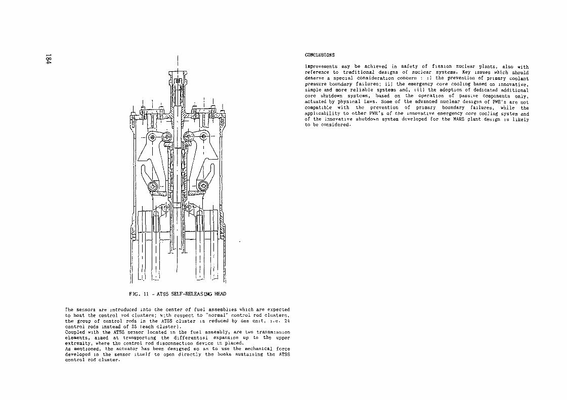
CONCLUSIONS
Inprovements may be achieved in safety of fission nuclear plants, also withreference to traditional designs of nuclear systems. Key issues which shoulddeserve a special consideration concern : i) the prevention of primary coolantpressure boundary failures; ii) the emergency core cooling based on innovative,simple and more reliable systems and, lii) the adoption of dedicated additionalcore shutdown systems, based on the operation of passive components only,actuated by physical laws. Some of the advanced nuclear designs of PWR's are notcompatible with the prevention of primary boundary failures, while theapplicability to other PWR's of the innovative emergency core cooling system andof the innovative shutdown system developed for the MARS plant design is likelyto be considered.
FIG. 11 - ATSS SELF-RELEASING HEAD
The sensors are introduced into the center of fuel assemblies which are expectedto host the control rod clusters; with respect to "normal" control rod clusters,the group of control rods in the ATSS cluster is reduced by one unit, i.e. 24control rods instead of 25 (each cluster).Coupled with the ATSS sensor located in the fuel assembly, are two transmissionelements, aimed at transporting the differential expansion up to the upperextremity, where the control rod disconnection device in placed.As mentioned, the actuator has been designed so as to use the mechanical forcedeveloped in the sensor itself to open directly the hooks sustaining the ATSScontrol rod cluster.

STEAM INJECTORS AS PASSIVE COMPONENTSFOR HIGH PRESSURE WATER SUPPLY
L. MAZZOCCHICISE Tecnologie Innovative SpA,MilanP. VANINIEnte Nazionale per FEnergia Elettrica,RomeItaly
Abstract
Steam injectors are static devices in which steam and subcooledwater are mixed, together and the outflowing subcooled water canreach a pressure significantly higher than both inlet pressures.A specific application, addressed in this paper, concerns the useof this kind of device in Advanced Light Water Reactors (ALWR's)for high pressure makeup water supply; this solution would takeadvantage of the available steam energy without introduction ofany rotating machinery.The design requirements of this system were defined according tothe following considerations:- water discharge pressure must be at least ten percent more thansteam pressure;
- the device will have to operate in a quite wide range of steampressures (e.g. from 9 MPa down to 1 MPa or less).
At present, two different calculation approaches were developedand used to evaluate the feasibility of a steam injector for thisapplication:- an overall control volume analysis;- a more detailed, one-dimensional analysis.The results, summarized in the paper, confirm the capability ofa suitable steam injector to satisfy the mentioned requirements.An instrumented prototype, at present in the design phase, willbe used for an experimental activity in order to confirm thetheoretical results.
1. INTRODUCTION
00
The Steam Injector, hereinafter shortly named SI, is a devicewhere a subcooled liquid and its vapour are mixed producing aflow of still subcooled liquid; a special feature is that theoutflowing fluid may reach pressures higher than both inletfluids. The operating principle is in some way similar toconventional ejectors, where a high pressure (driving) and a low
pressure (driven) fluid are mixed and the outlet pressure isintermediate between inlet pressures. The distinguishing SIfeature is steam condensation that makes available a large heatamount; it can be partly converted into mechanical work usefulfor pumping the liquid. In this respect, SI can be regarded asequivalent to different devices, like turbine-driven pumps, wheresteam thermal energy is used to pressurize a liquid; incomparison to this kind of equipment, the main difference is thatin SI all thermodynamic processes rely on direct contacttransport phenomena (mass, momentum and heat transfer) betweenfluids, not requiring any moving mechanism. According to thedescribed features, SI can be suitable to different applications,provided that:- a steam supply is available;- high pressure, hot water flow is required.Indeed, SI applications can be found as boiler feed pump for
ships and locomotives and for high pressure hot water supply inthe food industry; studies have also been found about thepossible use in LMHD (Liquid-metal Magneto-HydroDynamic) energyconversion. In recent years, a new nuclear reactor generation hasbeen the subject of intensive research and developmentactivities; the main objective is to design nuclear power plantsin which equipment and systems are simplified, and that can beconsidered safer because their emergency systems operateaccording to passive features (the different levels of systempassivity in Advanced Light Water Reactors (ALWR's) arethoroughly discussed in (1) ) . In connection with this new reactorgeneration, the attractiveness of Si's is quite evident, becausean high pressure water supply can be essential to very importantemergency functions (like emergency core cooling, feedwatersupply for decay heat removal and so on) and usually a steamsupply is easily available in power plants. Moreover, SI can beregarded to a great extent as a passive system, as it does notrequire any external energy supply or moving mechanical part.ENEL, the Italian Electricity Generating Board, which is
engaged in a wide range of activities concerning ALWR's, decidedto evaluate the applicability of SI in this field; so CISE, whichis a research company property of KNEt,, was charged to performa feasibility study in cooperation with ENEL itself, includingthe following steps:- review of existing experience on Si's;- identification of design requirements for a specificapplication to ALWR's problems;
- set-up of a theoretical model to be used for a preliminary SIsizing.
At present these activities have been completed; the obtainedresults, described in this paper, appear quite encouraging sothat an experimental activity on a scaled SI model is now inpreparation.2. DESIGN REQUIREMENTS
The application of Steam Injectors as basis for high pressureemergency water supply could be attractive in different ALWR'splant configurations, both of the boiling water and the

REACTORCONDENSATESTORAGE TANK
STEAM LINE
STEAM INJECTOR
Pig. 1 Schematic arrangement of the steam injector system forSBWR application
pressurized water type. For the purpose of the present study, SIuse for high pressure injection system of SBWR's was assumed asa reference. In this case, the driving fluid would be steampresent in the reactor vessel, while the cold water supply couldbe provided by any large water reservoir, operating atatmospheric pressure, available in the power plant (for examplethe condensate storage tank). The schematic arrangement of thesteam injector system is shown in fig. 1. The main design goalis to reduce the ADS (Automatic Depressurization System)actuation frequency, especially in connection with small-breakLOCA's; at the same time, plant safety behaviour would beimproved.According to small break LOCA features, a relatively small
water flowrate at high pressure is required. This need could besatisfied also by different systems, based for example onelectrical or steam turbine driven pumps, but a solution making.use of the SI would provide an higher passivity level. In orderto establish a precise reference condition for the presentfeasibility study, the maximum break size and the break locationfor SI system design have to be specified. So the generalrequirement assumed is the following:1) The SI system must be able to supply the reactor system
with a water flowrate corresponding to a 2 inches sch. 80pipe break in the bottom region of the reactor vessel.
Obviously, the range of reactor system conditions to beconsidered in SI design must also be specified. In this respect,the choice has been to cover a reasonably wide spectrum; so thefollowing additional requirement has been established:
2) The SI system must satisfy the requirement 1) for reactorsystem pressure ranging form 1 to 8.7 MPa.
For SI system preliminary design, the requirements 1) and 2)must be expressed in a more practical form, establishing thewater flowrate and pressure required for any reactor systempressure. The flowrate values, estimated according to therequirement 1), are shown in tab. 1, while for the water pressurethe assumed criterion is 10% more than steam pressure,considering that it is sufficient to overcome the pressure dropsalong the steam and water piping. As far as the cold waterreservoir is concerned, the following conditions have beenassumed:- water temperature 25°c;- water pressure 0.17 MPa.Finally, the steam at SI inlet is assumed to be dry satured.
TABLE 1 Required water flowrate Q versus reactor systempressure. Notice that the indicated values refer tothe water flow taken from the storage tank and do notinclude the steam flow condensed in the SI
(MPa) Q (kg/s)8.786421
6254.4504023.315
3. STEAM INJECTOR DESCRIPTION
The SI system, in addition to the SI itself, will include allthe necessary piping, valves, instrumentation and controls; asthis equipment can be considered more or less conventional, allthe attention will be devoted to the SI.A steam injector sketch is shown in fig. 2. It can be
subdivided into the following regions:a) steam nozzle, producing a nearly isoentropic expansion and
partially converting steam enthalpy into kinetic energy; itcan be a sonic nozzle or, if a stronger expansion isrequired, a supersonic nozzle with the typical converging-diverging shape;
b) water nozzle, producing a moderate acceleration anddistributing the liquid all around the steam nozzle outlet;

STEAM
Fig. 2 Steam injector schematic arrangement: a) steam nozzle,b) water nozzle c)mixing section d)diffuser
calculation models of the involved thermodynamic and transportphenomena are required. In this respect the four different SIregions (steam and water nozzles, mixing section, diffuser) canbe separately considered. For the most challenging situation,concerning the mixing section where complex interactions betweensteam and water take place, the development of specialcalculation procedures was felt necessary; for the other regions,the following simplified approaches were used:- expansion in the steam nozzle is considered an isoentropicequilibrium process, that can be evaluated by application ofthe usual mass and energy conservation laws and by steam tableuse; because of the saturation conditions at the nozzle inlet,the expansion occurs in the wet region, so the hypothesis ofan homogeneous steam-water flow has been assumed;
- expansion in the water nozzle is considered an isoentropicprocess too, neglecting head losses;
- the diffuser has not been modelled at all; its behaviour,expressed by the diffuser outlet pressure, is bounded by thestatic pressure (corresponding to zero diffuser efficiency) andthe total pressure (corresponding to efficiency equal to one)at the diffuser inlet.For the mixing section, two different calculation approaches
were used:- an overall control volume analysis (OCVA);- a more detailed, one-dimensional analysis.The two approaches, that took advantage of previous works ( 2 ),(3), will be shortly described in the following sections.
oo
c) mixing section, where steam and water come into contact.Steam transfer to water heat (because of temperaturedifference), mass (because of the related condensation) andmomentum (because of velocity difference). The final resultis the complete steam condensation, with an outflowingsubcooled liquid at relatively high pressure. The shape ofthe mixing section is usually converging, for reasonsexplained later on;
d) diffuser, where the liquid kinetic energy at mixing sectionoutlet is partially recovered producing a further pressurerise.
The pressure variations along the steam injector arequalitatively shown in fig. 2. It must be noticed that thearrangement of steam and water nozzles could be inverted,creating a circular water nozzle and an annular steam nozzle.However, the arrangement shown seems more convenient because itminimize the perimeter of the steam nozzle and avoids theimmediate contact between steam and mixing section walls; in thisway viscous dissipations are reduced.4. CALCULATION MODELS4.1. Modelling needsIn order to perform a preliminary sizing of a SI able to
satisfy the above defined requirements, and to estimate itsperformaces under different operating conditions, some
LIQUIDOla-»-
VAPOURQva —*-
MASS BALANCESection a
ISection
LIQUID-de
MOMENTUM BALANCE
Flo. AidPva Ava ~
Ola ViaQva Vva
ENERGY BALANCE
aiaChidtvlQ-2/E)
Fig. 3 Overall controlequations
volume analysis: conservation
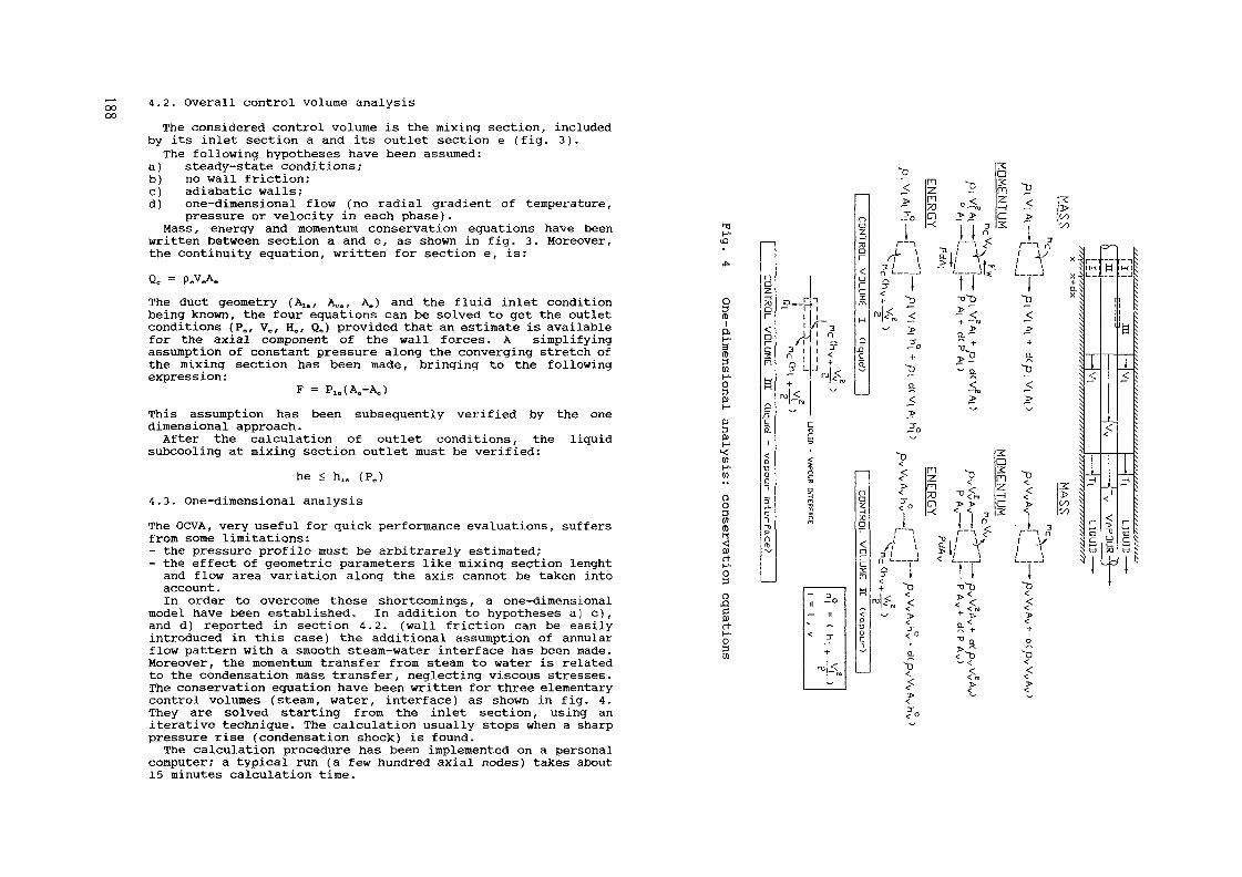
oooo4.2. Overall control volume analysisThe considered control volume is the mixing section, included
by its inlet section a and its outlet section e (fig. 3).The following hypotheses have been assumed:
a) steady-state conditions;b) no wall friction;c) adiabatic walls;d) one-dimensional flow (no radial gradient of temperature,
pressure or velocity in each phase).Mass, energy and momentum conservation equations have been
written between section a and e, as shown in fig. 3. Moreover,the continuity equation, written for section e, is:Q. = P.V.A.The duct geometry (Ala, A^, A.) and the fluid inlet conditionbeing known, the four equations can be solved to get the outletconditions (P., V,, H0, Q.) provided that an estimate is availablefor the axial component of the wall forces. À simplifyingassumption of constant pressure along the converging stretch ofthe mixing section has been made, bringing to the followingexpression:
F = PI. (A.-A.)This assumption has been subsequently verified by the onedimensional approach.After the calculation of outlet conditions, the liquid
subcooling at mixing section outlet must be verified:he < hla (PJ
4.3. One-dimensional analysisThe OCVA, very useful for quick performance evaluations, suffersfrom some limitations:- the pressure profile must be arbitrarely estimated;- the effect of geometric parameters like mixing section lenghtand flow area variation along the axis cannot be taken intoaccount.In order to overcome these shortcomings, a one-dimensional
model have been established. In addition to hypotheses a) c) ,and d) reported in section 4.2. (wall friction can be easilyintroduced in this case) the additional assumption of annularflow pattern with a smooth steam-water interface has been made.Moreover, the momentum transfer from steam to water is relatedto the condensation mass transfer, neglecting viscous stresses.The conservation equation have been written for three elementarycontrol volumes (steam, water, interface) as shown in fig. 4.They are solved starting from the inlet section, using aniterative technique. The calculation usually stops when a sharppressure rise (condensation shock) is found.The calculation procedure has been implemented on a personal
computer; a typical run (a few hundred axial nodes) takes about15 minutes calculation time.
*TIH-
•
O3(0
1P.
a3mH-o3
H1
»130)M
1
OO3se
rvat
H-03
rac;surtH-o301
—
oÏ—170
Rnn
m
g
5cCLl
vap
ou
r
3rf11"Ï-bPaiD
———
!D
r
•ru
.«_
/•31
?
-
<n
-
3
L
ciii
.
i
:
îïi
v
<
1
' 3
/-\
<
_J 1 ^fXN^v
1 W
[
!
i3
t
\111
50-
.
—-t-
rv| ro
^
oaz70Dr
arc2:nH
SCQ.
——
—— 1
na"Z.-H70Dr
ar~cR
*
£•P
0CT
t» §".. n >, 2: >1< 2 " m P-^ Çî "D^ 2 *• "^Jo CI ^ > C *> M1 - < , 1 3 2 : , n1 1 J n 1
r •• -n ^"' << ^n n3 N
/f \ 2l/ V / V x^3; \ ^t/ \u ; T ^9 i fi 1 +;:J I II t Q.
+ ^ "^^D ^O s
< ~~ ï* ^ ^"" -Oro < ^ *C <v \
" > a^™ 5 ^~° * + + $
>"2 A ^^D ^. 0 "O ^' — 7x ' — ^O, < < ^^ --ru — N
i " " $*~ \
^ i ^< n ^ ° -n $
^* n *> z **<- 3: $"L 73 "ü<'™ -H < >5ro CT1 > > C > OO \t "^ ^ 1 ^ 1 3 - ^ - *^ ^^
/"\ ijfV" rv i3 i J < i * ' ^ ^O - ! _ _ . _ ! 1 ———— _J
| 1 t 1 1-!- ^D T3'~0 tD
™<<„ < ?< << -h < "
^^ î* ^ ^"
^T °- +f O '™v
+ "° a. aA <""€ t)
^ "k <<
> C C<fo
IM
±i
^~
1
r~S3c:tu
i
o^~
W
tijii
— ~**
1— j
QC70
T
— iM 1
J
1[.JN
±<
1
LIQU
ID -
1

5. CALCULATION RESULTS
A large number of calculations, using both the OCVA and the onedimensional model, have been performed in order to clarify theeffect of different design parameters (like steam nozzleexpansion ratio, mixing section area contraction, mixing sectionconvergence angle, steam/water flowrate ratio and so on). Somehighlights of the most significant results will be given here.A first analysis, performed by the OCVA, has concerned the SI
performances at varying mixing section contraction ratios. Theresults are sinthetized in fig. 5, where both the static and thetotal pressure at mixing section outlet are plotted. As can beseen, the outlet pressure satisfies the design goal (P„ln equalto steam pressure plus 10%) for contraction ratios less than 0.1.This result can be understood by considering the momentumequation (fig.3): other things being constant, the smaller A0 is,the greater P, is obtained. At very small A„/A„ ratios the staticpressure P. shows a maximum, because the kinetic energy termbecomes larger and larger, while the total pressure Poc seems toincrease indefinitely (remember that in OCVA wall friction isneglected).
A possible critical point of the assumed design requirementsis the very wide variation of the operating steam pressure.Being the pressure at mixing section inlet approximatelyconstant, that means that the steam nozzle expansion ratio shouldhave large variations (let say 87/1 to 10/1 if pressure at mixingsection inlet is assumed to be about atmospheric). On the otherhand, a supersonic nozzle is characterized by a well definedexpansion ratio: if the back pressure is too low in respect to
.'_ J ._ , _...-
- - - -- - - - - - - -
* l
* • " " * ~ + ~ ~ " " ~ ~
1 0 0 Q
P\o=37t
i
t
a
P«o=2
20 3) 40 50 60lifet «oter Ik» l kgÄ )
70
Fig. 6 OCVA approach: SI performance at different steampressures, for steam nozzle expansion ratio 87/1
70
60
__50
LI3020
10
0 01
ape•+ PoexPmin
0 1Ae/Aa
•t _ . _'
i
+ ^.^ +
o—— a o —._^__- — —
' x x x1 ' 1 1 1 I - 1
M
Pw=a/
Pvo=6t
a
x
Pvc=1
10 20 X « 50 60 70lifet »der fou ! lg/_ I
oo Fig. 5 OCVA approach: effect of mixing section contractionratio
Fig. 7 OCVA approach: SI performance at different steampressures, for steam nozzle expansion ratio 40/1

oCL
i i i05 1 15 2
Axri pesta ! m 1
Fig. 8 One dimensional analysis: effect of the mixing sectionconvergence angle
y5
Fig. 9
464442i38363432
0 2 4 6 8 10Ctnwgence hdf-cngte ! degrees ]
Effect of the mixing section convergence angle,analyzed by combined use of one-dimensional analysisand OCVA
this ratio, a free expansion occurs downstream the nozzle, whilein the opposite case a compression occurs in the diverging nozzlesection, involving complex shock wave phenomena. Therefore thequestion arise what is the best steam nozzle expansion ratio inorder to get acceptable performances over all the required steampressure range. A preliminary answer to this question has beenobtained by use of the OCVA again: the results are shown in figs.6 and 7. Fig. 6 represents SI performance for steam nozzleexpansion ratio 87.1; exit pressure is not acceptable for steampressures less than 4 MPa. In fig. 7 the behaviour for expansionratio 40/1 is acceptable over all the required range.One of the applications of the one-dimensional analysis has
been the effect of the mixing section convergence angle. Fig. 8shows the pressure variation along the mixing section fordifferent angles. One can observe:- the pressure profile is quite flat at the beginning, showingthat the assumption made in the OCVA is reasonable;
- the smaller the angle is, the faster is the pressure recovery(as can be understood considering the steam phase compressionin a converging channel);
- the calculation stops casually at different pressure values,so a final answer for the effect of angle on SI performancescannot be drawn from this calculation.In order to obtain a significant comparison between different
angles, the one-dimensional calculation results have beentruncated at the same contraction ratio and the OCVA have beenapplied from that point on. The results are shown in fig. 9. Theperformances calculated without considering wall friction seemto indicate an improvement at decreasing angles: that can beascribed to the greater length of the converging section, thatallows a larger condensation and therefore a better kineticenergy recovery during steam recompression. In the same figure,results obtained taking wall friction into account are alsoshown: in this more realistic case the trend is the opposite,because the friction effect becomes more and more important asthe convergence angle decreases and the duct lenght increases.The optimum angle can be estimated at about 8'.
6. PRELIMINARY SIZING OF A SIAccording to the results obtained with the theoretical
analyses, a preliminary sizing indicated in Chapter 2 has beenpossible. The main design parameters are summarized in tab.2. Torefine this preliminary sizing and to get more confidence in theSI performances, the following points have to be clarified:- effect of boundary layer and non-equilibrium phenomena on steamnozzle behaviour;
- performance trend at different steam pressures;- mixing section length actually required to obtain the completesteam condensation.For this purpose, an experimental activity is foreseen on a
scaled-down model (flowrate scale about 1:9) operating atprototypical temperature and pressure. At present, the SI modeldesign is under way.
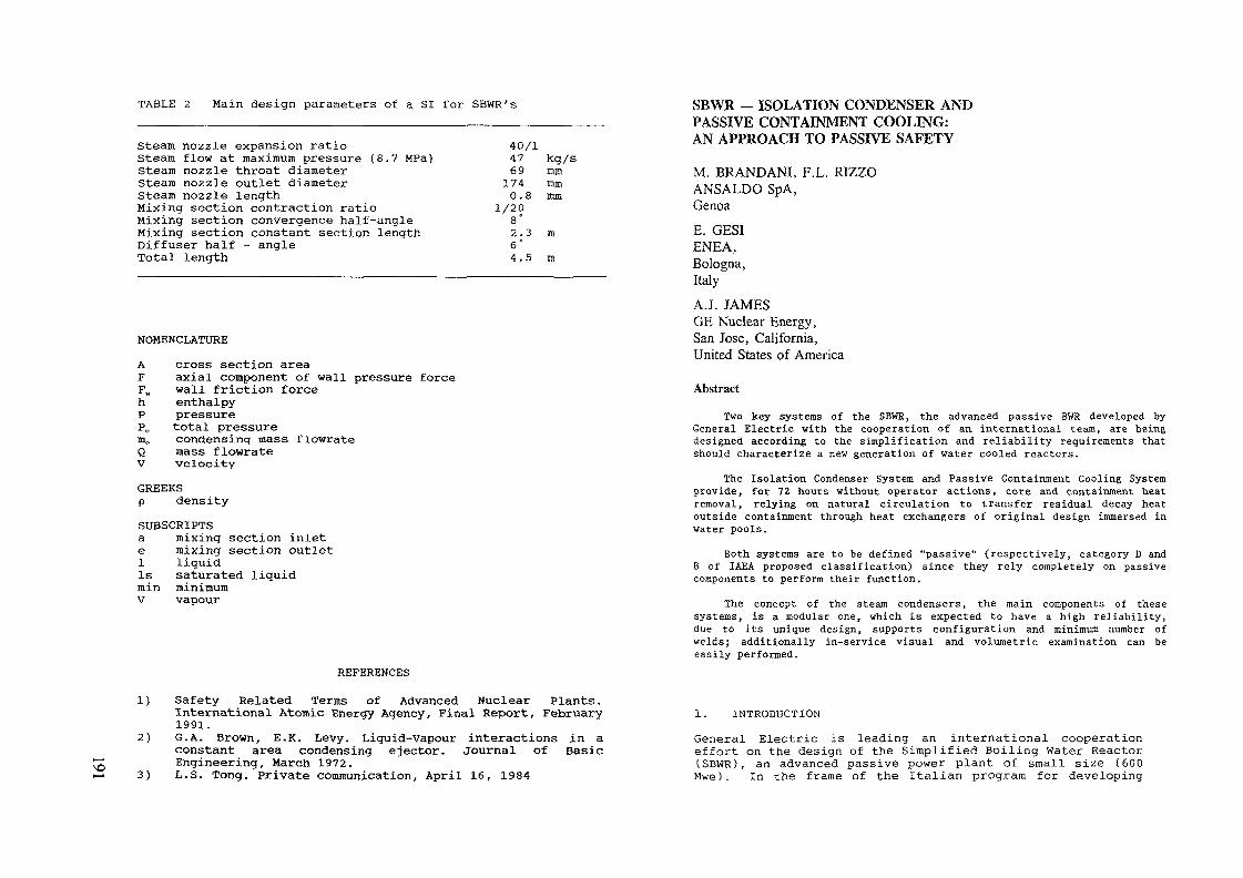
TABLE 2 Main design parameters of a SI for SBWR's
Steam nozzle expansion ratioSteam flow at maximum pressure (8.7 MPa)Steam nozzle throat diameterSteam nozzle outlet diameterSteam nozzle lengthMixing section contraction ratioMixing section convergence half-angleMixing section constant section lengthDiffuser half - angleTotal length
40/147691740.8
1/208°2.36°4.5
kg/smmmmmm
min
NOMENCLATUREA cross section areaF axial component of wall pressure forceF„ wall friction forceh enthalpyP pressureP0 total pressuremc condensing mass flowrateQ mass flowrateV velocityGREEKSp densitySUBSCRIPTSa mixing section inlete mixing section outlet1 liquidIs saturated liguidmin minimumV vapour
REFERENCES
1) Safety Related Terms of Advanced Nuclear Plants.International Atomic Energy Agency, Final Report, February1991.
2) G.A. Brown, E.K. Levy. Liguid-Vapour interactions in aconstant area condensing ejector. Journal of BasicEngineering, March 1972.
3) L.S. Tong. Private communication, April 16, 1984
SBWR — ISOLATION CONDENSER ANDPASSIVE CONTAINMENT COOLING:AN APPROACH TO PASSIVE SAFETY
M. BRANDANI, F.L. RIZZOANSALDO SpA,GenoaE. GESIENEA,Bologna,Italy
A.J. JAMESGE Nuclear Energy,San Jose, California,United States of America
Abstract
Two key systems of the SBWR, the advanced passive BWR developed byGeneral Electric with the cooperation of an international team, are beingdesigned according to the simplification and reliability requirements thatshould characterize a new generation of water cooled reactors.
The Isolation Condenser System and Passive Containment Cooling Systemprovide, for 72 hours without operator actions, core and containment heatremoval, relying on natural circulation to transfer residual decay heatoutside containment through heat exchangers of original design immersed inwater pools.
Both systems are to be defined "passive" (respectively, category D andB of IAEA proposed classification) since they rely completely on passivecomponents to perform their function.
The concept of the steam condensers, the main components of thesesystems, is a modular one, which is expected to have a high reliability,due to its unique design, supports configuration and minimum number ofwelds; additionally in-service visual and volumetric examination can beeasily performed.
1. INTRODUCTION
General Electric is leading an international cooperationeffort on the design of the Simplified Boiling Water Reactor(SBWR), an advanced passive power plant of small size (600Mwe). In the frame of the Italian program for developing

J2 new generation reactors, sponsored by ENEL and ENEA, ANSALDOto is partecipating to this effort and has primary
responsibility for the design of two systems for passivecore and containment heat removal.These systems have been conceived and are being designedaccording to the simplification and reliability requirementsof safety related systems which are expected to characterizea new generation of improved nuclear power plants.Simplification is a proper means to improve the operabilityand maintainability as well as the reliability of a system,a key point in achieving an enhanced level of safety.As a result of this approach both systems rely only onnatural forces and passive components to perform theirfunctions; pumps have been eliminated and no operator actionor support system is needed during their operation for atime period of T2 hours.The two systems and their main components, the steamcondensers, are described hereafter.
2. ISOLATION CONDENSER SYSTEM (ICS)
2.1 System FunctionsThe function of the Isolation Condenser System is to removedecay heat when the reactor becomes isolated during poweroperations as a consequence of a transient; the system shallcontrol reactor coolant pressure and temperature within arange so that Safety/Relief Valves will not lift andautomatic reactor depressurization will not occur.These functions, when the Isolation Condenser System hascome into operation, are to be performed in a completelypassive way with no need of both operator actions or controland external AC power sources or forces.The Isolation Condenser System is not defined as an"Engineered Safety Feature" since other ESF's providereactor protection and incident mitigation should the ICS beunavailable; the system, however, is designed as a safetyrelated system to prevent unnecessary reactordepressurization and operation of Engineered SafetyFeatures.2.2 System Description and OperationThe Isolation Condenser System consists of three totallyindependent loops, connected directly to the steam regionand the downcomer region of the reactor pressure vessel;they provide core heat removal relying on naturalcirculation to transfer residual heat outside containmentthrough heat exchangers of original design (1C condensers)immersed in water pools vented to the atmosphere.Each loop is designed for 30 MW heat removal capacity; threeloops are provided to obtain the required system capacity(60 MW) and redundancy.
\ l l
SUPPRESSION POOL
REACTOR
VESSEL
MAIN STEAM UNE
Figure 1 . ISOLATION CONDENSER SYSTEM
Figure 1 is a simplified diagram of a typical loop.A single steam supply line connects the reactor vessel toeach 1C unit placed in a large pool of water outsidecontainment at a higher elevation.On the run of the steam supply line, inside the containmentboundary, are located two normally-open isolation valves inseries; the line vertically penetrates the containment roofslab and, up to the connection to the 1C unit, is enclosedin a guard pipe in order to avoid any large steam-LOCAoutside containment.On the condensate return piping, also located insidecontainment, are provided two normally-open isolation valvesin series and, just upstream the reactor vessel entry point,

a loop seal and a pair of condensate-return valves inparallel . These two valves are closed during normal poweroperation and since the steam supply line valves arenormally open, condensate will fill the 1C unit up to thesteam distributor (Figure 2) above the upper headers.On a high reactor pressure signal or a main steam lineisolation signal one condensate-return valve in each loopopens starting the ICS into operation; the condensate insidethe 1C units is drained into the reactor vessel downcomerand the steam-water interface in the 1C tube bundle movesdownward, below the lower headers to a point in the maincondensate return line.When non-condensable gases build up in the condenser, ventvalves open and the gases are routed to the suppressionpool.According to the classification of passive systems proposedby IAEA Consultant's Group, the Isolation Condenser System,in its current configuration, should be included in CategoryD since an external signal triggers the passive process ofdecay heat removal opening the condensate-return valve.However the possibility is being investigated of activatingthe system opening the condensate-return valve by means ofmechanical actuators triggered directly by an increase ofreactor coolant pressure, thus increasing the level ofpassivity of the system and avoiding possible failures ondemand due to an external "intelligence" failure.
2.3 Isolation Condenser unit DescriptionThe 1C is operated simply by opening a normally closedcondensate-return valve This means that the component isnormally at RPV pressure and that it will experience asignificant thermal transient every time it is called uponto function.These very high and rapid thermal transients constitute oneof the component main characteristics; in fact, if theequipment is too rigid, the material plasticization ispossible but local plastic behaviour must be avoided due tothe possible presence of the physical conditions generatingthe Intergranular Stress Corrosion Cracking (IGSCC).Another conflicting requirement consists of the need toresist high pressure while at the same time assuring a goodthermal performance through the tubes. Therefore, thethermal capacity of the various parts assumes a greatimportance.Other important issues such as flow differences inside thedifferent tubes, possible vibrations, ISI accessibilityrequirements and long term immersion have been consideredand resolved in compliance with the arrangementrequirements.
The conceptual configuration proposed by ANSALDO is designedso that each part of the unit is free to move, in order tomeet its thermal expansion needs without experiencingsignificant restrictions imposed by other interconnectingpartsFigures 2 and 3 show the configuration of the componentEach module is obtained by connecting an upper header with alower one by means of a vertical tube bundle- a very well-known and common configuration which eliminates the need ofa thick plate and reduces the material volumeEach header is closed at both ends with double-sealedflanged covers allowing the complete opening for thetubes/header welds inspectionThe connection with the vertical steam supply line isobtained through a X-shaped forging provided with fouroutlet lines (two for each module), each featuring a built-in Venturi orificeA guard pipe is provided around the main supply steam linein the pool outside the containmentEach lower header is drained by a flexible line, connectedthrough a tee to the main condensate line, which penetratesthe primary containment and discharges into the RPV abovethe core.The whole weight of each module is sustained by the uppersupport which provides also the required seismic restraintThe lower restraint allows the heat exchanger tubes verticaldownward expansion and the header axial expansion, butprevents any seismic movement in either horizontaldirection.Each heat exchanger tube may also expand with some delay orin a different way compared with the bundle globalbehaviour. In fact, each tube is provided with two smalladditional bends which will take care of the additionalstressesThe main advantages of this solution ar-e the following:
A modular configuration,A very flexible design in order to accomodate possiblesurface changes or changes in the available pool depthand width according to the arrangement configurationneeds,Low additional stresses due to the various partsthermal expansion,Low pressure drops for natural circulation,A good in-place accessibility and the possibility ofcomplete removal.Outlets provided with orifices in case of pipe rup-tures;A modular full scale testability.
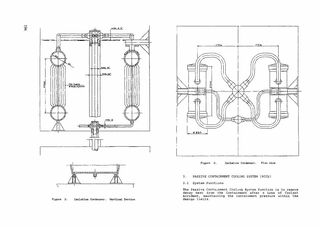
Figure 3. Isolation Condenser. Plan view
Figure 2- Isolation Condenser. Vertical Section
3. PASSIVE CONTAINMENT COOLING SYSTEM (PCCS)
3.1 System FunctionsThe Passive Containment Cooling System function is to removedecay heat from the Containment after a Loss of CoolantAccident, maintaining the containment pressure within thedesign limits.

The containment heat removal function shall be provided fora minimum of 72 hours, in a passive way, without anyexternal intervention by support systems or operators.The system is an Engineered Safety Feature ana as such isdesigned as a safety related system.3.2 System Description and OperationThe Passive Containment Cooling System consists of twototally independent loops open to the primary containment,connecting the drywell with a steam condenser (the PassiveContainment Cooling Condenser) located outside containmentin a large pool of water vented to the atmosphere.Figure 4 is a simplified diagram of a typical loop.
U
! SUPPRESSION POOL
Figure 4 . PASSIVE CONTAINMENT COOLING SYSTEM
The condenser receives a steam-gas mixture directly from thedrywell through a central supply line which penetrates thecontainment roof slab vertically and has no isolationvalves .Steam is condensed inside the vertical tubes of the PCCcondenser and drained to the Gravity Driven Cooling Systempool located inside the containment drywell.On the drain line and submerged in the GDCS pool, justupstream of the discharge point, is a loop seal : itprevents back flow of steam and gas mixture.Non-condensible gases are routed to the suppression pool inthe wetwell through a vent line, which, like the drain line,has no valves.The Passive Containment Cooling System, therefore, is alwaysin a "ready standby" condition. Its safety function isinitiated by the pressure increase in the drywell due to theloss of coolant accident itself : the difference inpressure between drywell and wetwell initially provides thedriving head for the steam-gas mixture flow through thecondenser. Then condensation promotes the steam flowcausing' a local pressure reduction and drainage of condensa-te to the GDCS pool relies on gravity.The PCCS is therefore a completely passive safety relatedsystem as far as the initiation of the process is concernedand the functions execution as well : it should beclassified in category B of passive systems according to theIAEA proposed classification.
3.3 Passive Containment Cooling Unit DescriptionConsidering the opportunity of maintaining the same configu-ration already adopted for the 1C, which meets therequirements of modularity and the arrangement needs, thePCC unit has been developed based on the 1C concept, takinginto account its less severe design conditions.In fact:
Its operating pressure and temperature are much lower;Only one significant operating cycle is considered forthe entire working-life;Standby stress levels are insignificant so IGSCC is nota problem;The equipment is normally empty and the tubes are incontact with the containment atmosphere -
On the other hand, the amount of expected non-condensablegases mixed with the condensing steam is much larger andrequires greater diameter vent pipes.Figures 5 and 6 show the resulting design, which is afree-standing condenser placed on the bottom of the pool andexpanding upwards without any need of sophisticated seismic

Figure 5. PCC Condenser. Vertical Section Figure 6. PCC Condenser. Plan view

restraints; the penetrations are simplified, the headercovers may be flat and all the material to be used can bestainless steel.The condensate return line and the non-condensable gasesvent line have been arranged in a single concentric tube,thus reducing the number of penetrations and maintaining thepossibility of disassembling the unit from the top.Considering the very delicate function performed by both the1C and PCC components with respect to the plant safety andtaking into account their location outside the containment,the number of welds for large pipes has been reduced to avery low minimum in order to improve the units reliability.Actions such as inspection and possible plugging of the heatexchanger tubes are expected to be easily accomplished and,if desired, they could also be automated by means of aproper robotic device.
4. TESTINGThe ICS and PCCS are two key features of the SBWR and theirfunctioning is strongly dependent on the proper design ofthe two condensers.As a consequence, since both the condensing units arefirst-of-a-kind devices, their expected performance has tobe confirmed through a full scale test campaign, whichrepresents the third step of the integrated testing programset up by General Electric, based on the MIT and UCB testcampaign and on the small scale PCC Toshiba tests.The 1C and PCC units testing will be conducted at SIET(Società Informazioni Esperienze Termoidrauliche) facilitieslocated in Piacenza, Italy, under the lead responsibility ofENEA.
4 .1 Isolation Condenser TestingA prototypical module of the 1C will be tested todemonstrate the adequacy of the design from both a thermal-hydraulic and structural standpoint.Specifically, the 1C heat removal capability over theexpected range of SBWR conditions will be measured as wellas the tube side heat transfer and flow rates to confirmthat the condenser operation is stable and not affected bylarge fluctuations.Additionally, it will be demonstrated that a specifiedfraction of the 1C thermal cycles expected during itslifetime (60 years) will not result in excessivedeformation, crack initiation or excessive crack growth ratein the module.4.2 PCC condenser testingSimilarly to the 1C testing, the thermal-hydraulic andstructural adequacy of the PCCS will be verified through theprototypical testing of the PCC unit.
The heat removal capability over the expected range of SBWRconditions will be measured and also the scheme for ventingthe non-condensible gases from the PCC will be tested.The stress levels at critical locations on the PCC will bemeasured to confirm that they do not exceed design values.Finally, the behavior of the unit under cyclic loads typicalof the PCC system operation will be investigated.Currently, the design of the test facility is completed andthe equipment for both loops ( ICS and PCCS) is beingprocured

M?00
DESIGN OF BACK-UP PROTECTION SYSTEMS FORNEW GENERATION NUCLEAR REACTORS
A. GHIRI, M. NOBILEEnte Nazionale per l'Energia Elettrica,RomeG. TORSELLOCISE Tecnologie Innovative SpA,Milan
Italy
Abstract
The addition of a Back-up Protection System (BPS) for the preventionand mitigation functions, meets the aim to reduce at the minimum possiblelevel the contribution of the common mode failure (CMF) to the frequency ofhigh release.
Protection Systems (PSs), are based on microprocessor technology and,consequently, on the related software. In these cases experience hasproven that hardware and, chiefly, software may be prone to CMF. But thePS is required to be highly reliable and for this reason a Back-upProtection System, to be used in the new generation nuclear reactors, hasbeen studied and is under design.
Owing to the necessity of not having CMF with the PS, the EPS designhas been based on the following general design criteria:
The BPD design is required to be based on operating principleswhich are diverse with respect to the ones adopted in the PS.
For this reason BPS design doesn't use microprocessor technology;- components used in the BPS are required to be simple, reliable and
passive.For this reason the EPS design foresees extended use of LADDIC MODULES.
Finally the use of 2-out-of-4 (2004) logic characterizes BPS design.
The paper presents the design of a BPS aimed to guarantee theContainment Isolation (Mitigating Function). BPSs design for thepreventing function will follow.
In the end of the design activities a representative divisional panelwill be constructed and, successively, subjected to a qualification programin accordance with the IEEE procedures for class IE equipments.
1. INTRODUCTION
The Protection System (PS) as well as the Control System(CS) for Passive Plants is based on digital technology and ischaracterized by enhanced features in terms of reliabilitycompared to protection systems based on conventional technology.
The Passive Plant PS design adopts the same componentboth safety and non safety systems.
The common cause failure of these components, althoughunlikely to occur, represents a significant contribution to theCore Damage Frequency (CDF) and to the high radioactivity releasefrequency, as PSA evaluations indicate. This is due to the factthat the PS failure affects both preventing and mitigatingfunctions.
In particular, three major protection functions need veryhigh reliability:
- Reactor Shut-down and Reactor Vessel Depressurizationto reduce the CDF and to make the probability ofsequences leading to core melt at high reactor vesselpressure negligible;Containment Isolation to guarantee the containmenttightness during any accident sequence independentlyof the possible failure of the preventing systemscalled for operation during the accident evolution.
The addition of a Back-up Protection System (BPS) for theaforesaid prevention and mitigation functions, fulfils therequirement for reducing to the minimum possible level thecontribution of the PS failure to the frequency of high release.
One of the most important concepts to be included in thepassive plant design is the requirement for the diversity ofalternate systems which are relevant for safety. For this reason,since the PS is based on the microprocessor technology, a Back-upProtection System (BPS) should be provided, based on a diversetechnology, using simple, reliable, low consumption and possiblypassive (without moving parts) components.
The solution presented in this paper is based on the use ofLADDIC modules, already employed in other nuclear plants and inparticular foreseen for the BPS of the Italian standardized PWRplant (PUN).
2. BPS SAFETY CHARACTERISTICS
To design a system having the features reported in theprevious section, it is necessary that the BPS is based on thefollowing safety criteria:
1. In conjunction with the primary Protection System, theSafety Systems and the Containment Protection andIsolation Systems, the BPS is to be designed tominimize the probability of accident sequences leadingto core melt with the containment formerly by-passedor at high reactor vessel pressure, and to guaranteethe containment tightness during any acccident

sequence, independently of the possible failure ofpreventing systems called in operation during theaccident evolution.
2. The BPS is to be designed to perform its intendedsafety functions when exposed to natural phenomenaincluding earthquake, tornado, wind, flooding and man-made hazards such as aicraft crashes. The BPS shouldbe designed to operate in the presence of severeenvironmental conditions caused by such events.
3. The BPS is to be designed and located to minimize theprobability and effects of postulated hazards such asfire and explosions. The BPS is to be capable toperform its safety function in the presence of suchhazards.
4. The BPS is to be designed and located to minimize theeffects of inadvertent actuation of plant systems suchas fire suppression.
5. The BPS is to be protected against the effects ofmissiles and conditions that may be caused by pipebreaks or other equipment failures, including non-Class le equipments which may be located in thesame area as BPS.
6. The BPS is to be designed to perform its intendedsafety functions when exposed to the environmentalconditions associated with normal operation,maintenance, testing and postulated accidents.
7. The BPS is to be designed for high functionalreliability and inservice testability, in agreementwith the overall reliability targets.
8. The BPS is to be designed to permit periodical testingof its functions as far as feasible with norestriction on the reactor operation.
9. The BPS is to be designed to assure that (1) no singlerandom failure results in loss of protective functionand (2) removal from service of any component orchannel results neither in loss of required minimumprotection nor in an increased probability of spuriousactuation.
10. The BPS is to be designed to fail into a safe state ifcondition such as system disconnection, loss of energysupply, or adverse environmental condition areexperienced.
11. The BPS is to be separated and diverse from theprimary Protection System so that any failure of thelatter does not impair the correct operation of the
12.
BPS. Possible exclusion from these criteria could berepresented by sensors and actuators when completediversification and/or separation is not practical ornot required.BPS set-points shall not reduce the operating marginsof the primary protection system both during normal ortransient operations.
13. Once initiated, any protective function of the BPSshall continue to completion.
14. The BPS design shall minimize the spurious actuationoccurrence.
15. When actuating equipments are shared between PS andBPS, the latter shall provide actuation signals tothese equipments overriding possible faulted stop ornon-actuation signals generated by the PS. In case ofa spurious actuation of BPS, the resetting should bemade only according to the general criteria forpassive plants on this matter.
3. BPS DESIGN CRITERIAThe following criteria of redundancy,
diversity are followed in designing the BPS.independence and
Redundancy ; The BPS is to be designed to perform its intendedsafety functions from any single random failure originated withinthe system. This requirement is met by incorporating redundancyinto the BPS design, providing a fault-tolerant design asfollows:
Four redundant guard-lines must be considered forgathering plant data, for transmitting them to thesystem and to generate the system level actuatingsignal according to a 2 out of 4 logic.Single failure within the BPS must not cause aspurious reactor trip or a spurious actuation of asafety system.
- In case of random failure of a single channel the BPSmust automatically reconfigure to a 2 out of 3 logicin order not to affect plant availability in case ofa further failure or a spurious signal.
Independence The BPS design must have an adequate degree ofindependence among the equipments costituting the system itself.To this purpose, the electrical isolation among redundantcomponents and sub-systems is to be guaranteed. Redundantcomponents and/or subsystems are to be arranged in separatecabinets, although physical segregation between the cabinet isnot required. The BPS is to be completely independent of theprimary Protection System to the following extent:
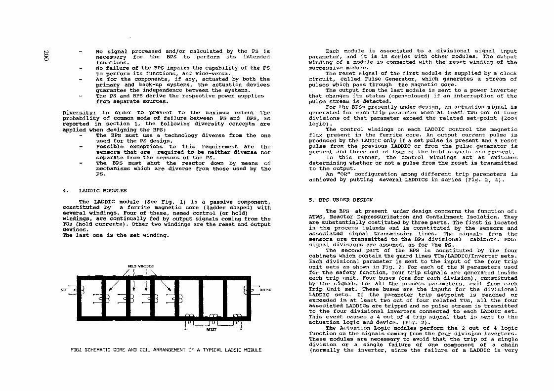
-Ko signal processed and/or calculated by the PS isnecessary for the BPS to perform its intendedfunctions.No failure of the BPS impairs the capability of the PSto perform its functions, and vice-versa.
- As for the components, if any, actuated by both theprimary and back-up systems, the actuation devicesguarantee the independence between the systems.
- The PS and BPS derive the respective power suppliesfrom separate sources.
Diversity: In order to prevent to the maximum extent theprobability of common mode of failure between PS and BPS, asreported in section 1, the following diversity concepts areapplied when designing the BPS:
- The BPS must use a technology diverse from the oneused for the PS design.
- Possible exceptions to this requirement are thesensors that are required to be neither diverse norseparate from the sensors of the PS.
- The BPS must shut the reactor down by means ofmechanisms which are diverse from those used by thePS.
4. LADDIC MODULESThe LADDIC module (See Fig. 1) is a passive component,
constituted by a ferrite magnetic core (ladder shaped) withseveral windings. Four of these, named control (or hold)windings, are continually fed by output signals coming from theTUs (hold currents). Other two windings are the reset and outputdevices.The last one is the set winding.
FIG.1 SCHEMATIC CDRE AND COIL ARRANGEMENT OF A TYPICAL LADDIC MODULE
Each module is associated to a divisional signal inputparameter, and it is in series with other modules. The outputwinding of a module is connected with the reset winding of thesuccessive module.
The reset signal of the first module is supplied by a clockcircuit, called Pulse Generator, which generates a stream ofpulses which pass through the magnetic core.
The output from the last module is sent to a power inverterthat changes its status (open-closed) if an interruption of thepulse stream is detected.
For the BPSs presently under design, an actuation signal isgenerated for each trip parameter when at least two out of fourdivisions of that parameter exceed the related set-point (2oo4logic).
The control windings on each LADDIC control the magneticflux present in the ferrite core. An output current pulse isproduced by the LADDIC only if a set pulse is present and a resetpulse from the previous LADDIC or from the pulse generator ispresent and three out of four of the hold signals are present.
In this manner, the control windings act as switchesdetermining whether or not a pulse from the reset is transmittedto the output.
An "OR" configuration among different trip parameters isachieved by putting several LADDlCs in series (Fig. 2, 4).
5. BPS UNDER DESIGN
The BPS at present under design concerns the function of:ATMS, Reactor Depressurization and Containment Isolation. Theyare substantially costituted by three parts. The first is locatedin the process islands and is constituted by the sensors andassociated signal transmission lines. The signals from thesensors are transmitted to the BPS divisional cabinets. Foursignal divisions are assumed, as for the PS.
The second part of the BPS is constituted by the fourcabinets which contain the guard lines TUs/LADDIC/Inverter sets.Each divisional parameter is sent to the input of the four tripunit sets as shown in Fig. 2. For each of the N parameters usedfor the safety function, four trip signals are generated insideeach trip unit. Four buses (one for each division), constitutedby the signals for all the process parameters, exit from eachTrip Unit set. These buses are the inputs for the divisionalLADDIC sets. If the parameter trip setpoint is reached orexceeded in at least two out of four related TUs, all the fourassociated LADDICs are tripped and no pulse stream is trasmittedto the four divisional inverters connected to each LADDIC set.This event causes a 4 out of 4 trip signal that is sent to theactuation logic and device. (Fig. 2).
The Actuation Logic modules perform the 2 out of 4 logicfunction on the signals coming from the four division inverters.These modules are necessary to avoid that the trip of a singledivision or a single failure of one component of a chain(normally the inverter, since the failure of a LADDIC is very

a.t.o
(4-
<a
Zau
£
13*-«U.
iSENSl
r
TRIPAMP
SENS3
fi
TRIPAMP
SENS3
V
TRIPAMP
SENS4
TTRIPAMP
f » f < TfT f UTTPULSEGENER.
PULSEGENER.
PULSEGENER.
PULSEGENER.
: »T*?1 1 LADDIC
1 ' I I?»??
j 1 LADDIC
! Ml LADDIC
1
?»<41 i LADDIC
1
1
J] !i
j ii •
iJ i
iD i
i
|PGlH LADDIC 1
ENDDFUNEMODULE
ENDDFLINEMODULEj
ENDDFLINEMODULE
ENDDFLINEMODULE
-JINVERTER | ——— ,
-(INVERTER | ———
-JINVERTER j ———
-JINVERTER | ———
,
HiNvir-r> —— • — -* i- M , ,n \-~
|PG4~f LADDIC 5 H^V'ïH r>-r j i iFRDMSOUR
RL iaQ QRL
r-
RL 2upn Y\ RL
,
PDVERCE
lb
-TD DEVICE
FIG.3 TYPICAL ONE-PRGCESS PARAMETER LINE
201
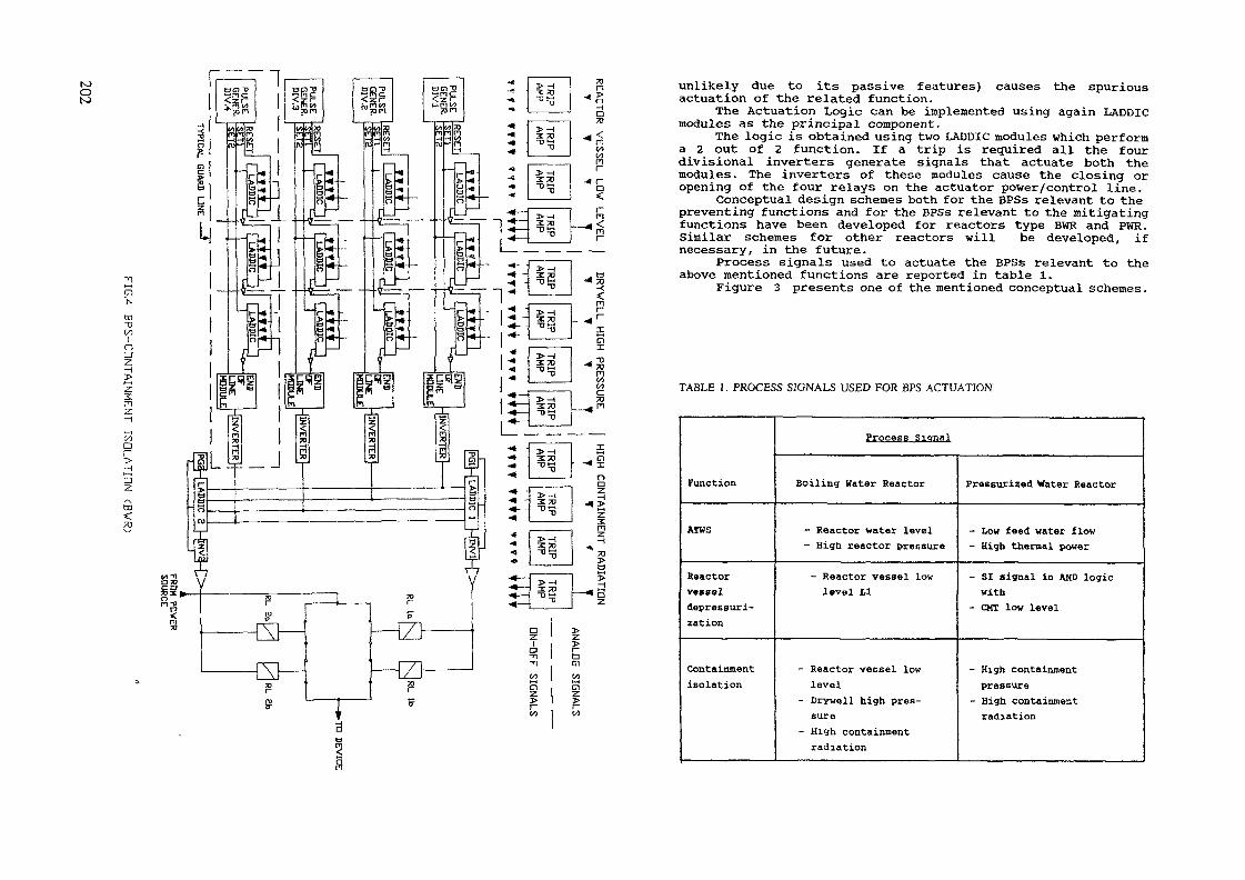
tootO
öd"DWlna
2n
(Aa
azca
^r\ 1
VImrro
•^-:^ -^- -^>4•»•4r
>— 13: 70"D
is
^i53
"O
DR
YW
ELL
HIG
H
PRESSU
RE
' !_
' 1
£z3:FI
azia nciM*~4Cl
unlikely due to its passive features) causes the spuriousactuation of the related function.The Actuation Logic can be implemented using again LADDIC
modules as the principal component.The logic is obtained using two LADDIC modules which perform
a 2 out of 2 function. If a trip is required all the fourdivisional inverters generate signals that actuate both themodules. The inverters of these nodules cause the closing oropening of the four relays on the actuator power/control line.
Conceptual design schemes both for the BPSs relevant to thepreventing functions and for the BPSs relevant to the mitigatingfunctions have been developed for reactors type BWR and PWR.Similar schemes for other reactors will be developed, ifnecessary, in the future.
Process signals used to actuate the BPSs relevant to theabove mentioned functions are reported in table 1.
Figure 3 presents one of the mentioned conceptual schemes.
TABLE 1. PROCESS SIGNALS USED FOR BPS ACTUATION
Function
ATWS
ReactorvesseldepresBuri-zation
Containmentisolation
ProceES Signal
Boiling Water Reactor
- Reactor water level- High reactor pressure
- Reactor vessel lovlevel U
- Reactor vessel lowlevel
- Drywell high pres-sure
- High containmentradiation
Pressurized Water Reactor
- Low feed water flow- High thermal power
- SI signal in AND logicwith
- CUT low level
- High containmentpressure
- High containmentradiation
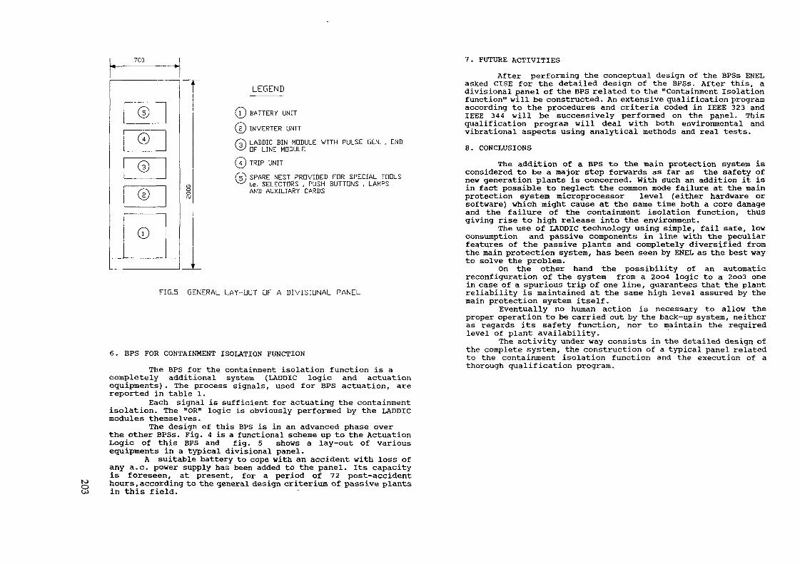
700
©
0
©
©
©
\
o0oOJ
1
LEGEND
(T) BATTERY UNIT
(£) INVERTER UNIT
© LADDIC BIN MODULE VITH PULSE GEN. , ENDDF LINE MODULE
(7) TRIP UNIT
© SPARE NEST PROVIDED FOR SPECIAL TOOLSI.e. SELECTORS , PUSH BUTTONS , LAMPSAND AUXILIARY CARDS
FIG.5 GENERAL LAY-OUT DF A DIVISIONAL PANEL
6. BPS FOR CONTAINMENT ISOLATION FUNCTIONThe BPS for the containment isolation function is a
completely additional system (LADDIC logic and actuationequipments). The process signals, used for BPS actuation, arereported in table 1.
Each signal is sufficient for actuating the containmentisolation. The "OR" logic is obviously performed by the LADDICmodules themselves.
The design of this BPS is in an advanced phase overthe other BPSs. Fig. 4 is a functional scheme up to the ActuationLogic of this BPS and fig. 5 shows a lay-out of variousequipments in a typical divisional panel.
A suitable battery to cope with an accident with loss ofany a.c. power supply has been added to the panel. Its capacityis foreseen, at present, for a period of 72 post-accidenthours, according to the general design critérium of passive plantsin this field.
7. FUTURE ACTIVITIES
After performing the conceptual design of the BPSs ENELasked CISE for the detailed design of the BPSs. After this, adivisional panel of the BPS related to the "Containment Isolationfunction" will be constructed. An extensive qualification programaccording to the procedures and criteria coded in IEEE 323 andIEEE 344 will be successively performed on the panel. Thisqualification program will deal with both environmental andvibrational aspects using analytical methods and real tests.8. CONCLUSIONS
The addition of a BPS to the main protection system isconsidered to be a major step forwards as far as the safety ofnew generation plants is concerned. With such an addition it isin fact possible to neglect the common mode failure at the mainprotection system microprocessor level (either hardware orsoftware) which might cause at the same time both a core damageand the failure of the containment isolation function, thusgiving rise to high release into the environment.The use of LADDIC technology using simple, fail safe, lowconsumption and passive components in line with the peculiarfeatures of the passive plants and completely diversified fromthe main protection system, has been seen by ENEL as the best wayto solve the problem.
On the other hand the possibility of an automaticreconfiguration of the system from a 2oo4 logic to a 2oo3 onein case of a spurious trip of one line, guarantees that the plantreliability is maintained at the same high level assured by themain protection system itself.
Eventually no human action is necessary to allow theproper operation to be carried out by the back-up system, neitheras regards its safety function, nor to maintain the requiredlevel of plant availability.
The activity under way consists in the detailed design ofthe complete system, the construction of a typical panel relatedto the containment isolation function and the execution of athorough qualification program.

gADVANCED REACTOR DESIGN PHILOSOPHYAND APPLICATION - WAYS AND MEANS TOPREVENT CORE MELT
L. NILSSON, T. PEDERSENABB Atom AB,Västeras, Sweden
Abstract
Looking at the energy supply situation in the world it is obvious that the globalenergy demand will rise drastically, in particular in the less developed coun-tries. It is also clear that energy use will shift towards electricity, ie., thedemand for electricity generation capacity will increase significantly.
There is also an increasing awareness that, for environmental reasons, a largescale increase in utilization and burning of fossil fuels must be avoided. Hence,nuclear power should be a strong option for meeting the increase in energydemand.
Unfortunately, public confidence in nuclear safety has eluded the present gene-ration of reactor designs to such an extent that the phasing out of operatingplants rather than expansion is considered in some countries. Steadily in-creasing safety requirements have resulted in an ever-increasing complexity ofthe current designs which makes them more or less "incomprehensible" tolaymen.
A prerequisite for a real revival of the nuclear option may be a drastic designchange yielding a quantum jump in perceived safety and reduced plant com-plexity. From the public point of view the important question is not whether therisk of core melt is once per a million years or once per ten million years; butwhether they will have to evacuate their homes in the event of "accidents" innearby power plants. Hence, there is a distinguishable trend in design goals fornew plants - do your utmost to prevent core melt.
The approach to nuclear safety is based on the "defense-in-depth" conceptwhich can be characterized as a design logic with four major steps - prevention,protection, mitigation and emergency management (or off-site actions). A•reduction in the requirements of the latter category implies a shift in emphasisto the other three; in some of the advanced designs today strengthening of themitigation is utilized, in others improved protection, and in a few the emphasisis put on the prevention.
One of the latter advanced designs is PIUS and this plant design will be utilizedto illustrate the philosophy and its application in the plant design with the aimof "eliminating" the risk of core melt.
Introduction
It seems to be a general consensus, among both technicians and politicians,that the global energy demand will rise drastically in the years to come, inparticular in the countries that are less developed today, - a necessity for im-proving their standard of living. The growth in energy demand is furthermoreexpected to involve a strongly increased demand of electric energy; historically,an increasing standard of living has implied a tendency to use more electricity.
It is also widely agreed that the number of possible options to meet suchdemands on increased energy supply is quite limited, taking into account thepotential environmental impacts and hazards of the different large-scaleenergy sources. What kind of energy source(s) can then be used?
Today, coal and other fossile fuels are utilized widely for producing heat andelectricity, but firing of fossile fuels results in emissions of carbon, sulphur andnitrogen oxides, particulates and other gases with detrimental effects on the en-vironment. Oil and gas are "cleaner", but still emit carbon dioxides. And thereis an obvious question: Should oil and gas be used for generating electricity orsaved for other purposes?
Nuclear power contributes considerably to the world's energy supply today; lastyear roughly 20% of the electricity generation came from nuclear. And it willcontinue to be needed. It's environmentally clean, but it has had its problems;instabilities in safety requirements, public perception, etc. An accident receivesmuch more publicity than years of safe, clean electricity production, and tech-nical ignorance is easily exploited by opponents. If nuclear power is to remainan option for the future, it must be commonly perceived to be really safe andeconomical and without threat of degrading the environment.
It is considered as one of the major options for electricity generation of the nearfuture in many countries, and looking forward to a revival of the nuclear powerplant market the major nuclear vendors are developing a number of advancedreactor designs; water-cooled reactors, gas-cooled reactors, and liquid metalreactors. Basically, these new (or advanced) designs fall into two kinds or cate-gories; "evolutionary" types and more "innovative" types.
The "evolutionary" types, mostly Light Water Reactor (LWR) plant versions,can be characterized as modest modifications (or improvements) of present-dayplant designs with a strong emphasis on maintaining "proven designs" andavoiding need for additional experimental verification. In other words, thesetypes represent an evolution of existing plant designs.
The more "innovative" LWR reactor types are also based on well establishedLWR technology, but incorporate departures from, or supplements to, currentLWR designs in various aspects. For some of these types, the major develop-ment goal is stated to be simplification and enhanced use of passive safetyfeatures based on current LWR plant designs; this is the simplified "passive"advanced light water reactor program pursued in the U.S. by EPRI (the ElectricPower Research Institute). Others have more ambitious development goals -

too
eg , striving for PRIME safety which necessitate more radical modifications ofplant structures or system arrangements [PRIME is an acronym introducedby Dr Charles Forsberg, ORNL for Passive, Resilient, Inherent, Malevolenceresistant, and Extended time safety ]
Are advanced designs needed?
From a nuclear vendor, and perhaps also from a power utility, point of viewconstruction of new plants exactly as previous ones ( repeats") would implyadvantages as it represents reduced engineering and construction work, lesserrors and significant cost savings On the other hand, a plant design cannotlive forever, it has to be "up graded to implement new technology developmentsand new generations of equipment, to incorporate improvements based onexperience gained from construction, commissioning and operation of theplants, and to adapt to new regulatory requirements There is also an ambition,by both vendors and utilities, to improve their product, - as far as possible withrespect to economy, - making the nuclear plants safer, more reliable and easierto operate Without such an ambition the risk of getting a reduced productquality is imminent
From the point of view of competitivity, striving for excellence is a necessity forthe vendors , but it is also important for the utilities from the public perceptionpoint of view - good averages are necessary but not sufficient, since the publicwill always base their judgement on the poorest performers This was recentlyunderlined by Lord Marshall, chairman of WANO (World Association of Nu-clear Operators), in a statement at its general meeting in Atlanta in April 1991
it is no good having 99% of nuclear plants safe if the other 1% have lowstandards '
This implies that there has been, and will always be, a "continuous develop-ment of new, advanced designs, the situation today, with a rather large numberof advanced designs under development, is remarkable only due to the longperiod of no nuclear market a revival of a nuclear market can be envisagedwithin this decade
The safety level of modern nuclear power plants in operation is high andfurther improvements of the safety performance is not generally a dominatingconcern in the requirements on new, advanced designs, requests for plant sim-plifications and reliability improvements are given a higher priority The safetyof present day modern plant designs is based on rather complex interactionsbetween a large number of redundant and diverse safety systems, as a result ofnumerous system add-ons over the years to meet escalating safety concernsFrom the technical point of view, this represents a challenge to plant designersand operators with respect to ensunng reliable and safe operation, and fromthe public perception point of view, it makes it very difficult to inform- a laymancan not fully understand the interactions Besides, the plant complexity in-volves much equipment, building volumes, engineering and analysis work, dis-cussions with authorities etc , it costs a lot of time and money when constructmg the plant
The complexity of safety systems may also be a detrimental factor for plant operation reliability and that will obviously affect the economy of the power plantSafety grade systems and components require extensive periodic testing, in-spections and maintenance, and a large number of such systems and compo-nents represent a heavy work load on the utility personnel Much of this workhas to be carried out in connection with the refuelling outage and thereforetends to extend the plant shutdown, the plant economy is affected
The economy of nuclear power, as well as its safety, has been under muchdebate, both in the public and within the industry, - and this explains whyvendors and utilities strongly emphasize the need for simplification and im-proved reliability
From the utility point of view, the socalled evolutionary types of advancedreactors would normally be preferable, since they do not differ much from theirpredecessors, even though some simplifications are introduced For the moreinnovative types the utility will have to take a risk, since these plants deviatemore from the present-day designs
And, for plants to be built in industrialized countries, the benefits of thesechanges and differences may not be of decisive importance, the infrastructureand the safety culture of the society are adequate for safely constructing andoperating also the evolutionary types under development The anticipated eco-nomy of the plant, its provenness and experience background, reliability andefficiency, flexibility and maintainability will m many of these countries be themost important evaluation parameters
In less developed countries, the situation is different, there is often a lack ofinfrastructure - scarcity of qualified and trained workers, shortage of materialand equipment, no tradition and expenence of operating industries, - and lackof a well-educated middle class that could provide a natural basis for dedi-cated operators Hence, construction and operation of nuclear power plants thatare closely similar to the present-day types in less developed countries mightwell prove to be in conflict with Lord Marshall's statement on 'the other 1%above It seems that implementation of nuclear power in the less developedcountries should be based on significantly simplified and more forgivingnuclear power plant designs
Advanced reactor design features
As noted above, the design goals for the advanced reactors are to a large extentfocusing on a rather small number of typical common design considerations,which sometimes are differentiated by supplementary national concerns
The two most fundamental goals are related to plant simplification and to in-creased design margins - both with the prime objective of making plant opera-tion simpler, from the point of view of the operator Simplification improves ope-rator comprehension of plant functions and implies that he more easily cansupervise the actual operating conditions in the plant, i e , he can devote moreof his attention to keeping the plant in operation and generating kWhs In-

todIX
4
1?
2
15
6
' rCore
i7
8
1
Current andEvolutionaryAdvanced LWRs
B"Passive",SimplifiedAdvanced LWRs
C
PIUS
1. Reactor coolant system2. Instruiront leads, cables3. Diagnostic equ'fxnent4. Signal processing, logics5. Flow rerouting/reactor shutdown;
valves and control rod drives
6. Piping and control rods7. Forced core coolant supply;
diesel generators and pumps8. Piping9. "Self-protective" thermo-
hydraulte feedback
Figure 2 - Functions and equipment needed forcore protection in LWR plants
In present-day reactor designs as well as in the evolutionary types and in mostof the more innovative types reactor shutdown is initiated/triggered by a controland monitoring system. A substantial improvement of this function can only begained if and when the process itself can "sense and evaluate" the operatingconditions and adjust itself to a safe state.
The next functional step relates to the "tool" that is utilized to shut down thereactor or at least to bring it to a safe state. As noted above most reactor designsutilize control rods which are inserted into the core by means of stored energy(in gas accumulators) or dropped by gravity, with borating systems as backup.
The control rods represent a rather reliable means of shutting down thereactor, but they also generates a number of problems and safety concerns -reactivity insertions and power distortions by erroneous rod manoeuvering orequipment failures. From this point of view, elimination of control rods, both forpower control and reactor shutdown, should be an advantage, since - as somecritics say - control rods are needed to handle the problems that arise fromhaving control rods. Arranging the boron supply to the core in such a way thatthe process itself can control it,, represents a practical problem that is not easilysolved in normal reactor design configurations.
Finally, what about the core cooling? Systems that operate in a passive mode,i.e., without external input of energy or control signals, following an initialactuation, are utilized in many of todays advanced reactor designs to a varyingdegree. A characteristic feature of such systems is that only few and simplecomponents (with well-defined function) are allowed to be involved in the "pas-sive" function in order to ensure simplicity and a rather reliable function. Still,further simplification and improvement can be gained if the function can beaccomplished in an entirely passive way, without any components such ascheck valves, and without need for actuation.
A reactor design that can fulfil the requirements of these three paragraphs,with a self-protecting reactor process, with a shutdown system without movingparts, and with a core cooling system that does not rely on activation and move-ment of components nor on external energy input, will meet the basic prerequi-sites for a "no core melt" plant. These are necessary but not sufficient condi-tions; careful engineering and design of the complete plant are quite obviouslyabsolutely necessary supplements.
Locating the reactor core in a large pool of water will beyond doubt provide corecooling without need for external actuation or energy supply etc. if the powerlevel of the reactor can be restricted and prevented from exceeding the coolingcapability of the pool water. The latter condition is easily met by dissolving boronin the water; an adequate boron concentration in the water will stop and pre-vent fission reaction in the reactor core. Having a core located at the bottom of alarge pool of borated water does not make anyone happy, however. The crucialquestion is whether this can be utilized as a basis for a power reactor design inwhich normal operation is accomplished and ensured by means of controlsystems and pumping forces etc. but where the system will revert to its "cooled,shutdown condition" by itself when operating conditions exceed acceptablelimits. If a practical solution to this problem can be found, a "no core melt"plant can be built.
The use of quotation marks here indicates that this may not be valid in absoluteterms but within certain limits with respect to initiating events etc. (cf. com-ment above on need for a threshold of occurrence frequency). This observation isalso in correspondence with the discussion of safety concepts in the Descriptionof "Safety related Terms for Advanced Nuclear Plants" that has been preparedby the IAEA. Care is recommended to add qualifications to stated terms - e.g.,valid under this and that condition. In line with that and the "Good neighbour"approach above the practical solution and its implementation in a reactor

design should ensure that no core melt will occur in the event of credibleoccurrences and accidents. These include all events in the traditional "DesignBasis Event" packages used for licensing analysis of present-day reactors, aswell as less probable events ("beyond" these "Design Basis Event" packages), ifpossible extending to individual events and event sequences with estimatedoccurrence frequencies down to about 10 -6 .
Designing for core melt prevention
ABB Atom in Sweden has for more than a decade been working on reactordesigns in which core melts are prevented - the PIUS type reactors. These arebased on the "core submerged in a borated poor-principle outlined above as onedeparture point for designing a "no core melt" plant, and a unique physicalarrangement which makes it possible to operate the plant at power in normaloperation with an "isolated" reactor primary loop even though it is in reality inopen connection with the surrounding borated reactor pool water. [Cf. figure 3]Reactor coolant pumps draw reactor coolant from the top of the riser, throughsteam generators or heat exchangers, and bring it back to the reactor core inlet,and by speed control of the pumps the flow rate can be adjusted to match thenatural circulation flow rate through the core and up the riser, as determinedby the thermal and gravitational conditions of the primary loop compared withthose of the reactor pool. This adjustment of pump speed (pump flow rate)
A Heating of water m a ope results m a water flow up through the ppe Theppe is connected to a pool of water at top and bottom. heated water flowsout at top. cold water «filers at bottom.
B By means of a pump and speed (How rate) adjustment all rising water isrelumed to pipe bottom, no water outflow to the pool and no inflow from itA separated pump loop has been accomplished with permanent openingsto a surrounding pool of water
C By means of a heat exchanger (or steam generator), inside or outside thepool, reactor heat can be utized When pump work is lost, or reactor powerincreases, hydraulic balance wilt be disturbed, providing automatic 'inherent"self-protective feedback
Figure 3 - Operating principles of PIUS
establishes a "no flow" region and pressure equilibrium between the primaryloop coolant and the reactor pool water in the opening below the reactor core,and due to the natural circulation flow up through the riser also in an otheropening located in the vicinity of the riser top.
By this arrangement the "isolated" primary loop can be operated at a low boroncontent and elevated temperatures, as needed for the power operation, whereasthe reactor pool is kept at low temperature and high boron content. As long asthe power production in the core is balanced by the heat extraction in the steamgenerators (or heat exchangers) the reactor operation will be quite stable with-out water exchange in the openings, but in the event of disturbances the pres-sure balances will also be disturbed and water may flow into or out of the pri-mary loop. For small, frequent disturbances which do not call for a reactorscram, the pump speed control will adjust the pump flow rate in such a waythat there will not be any net in- or outflow; temperature monitors in theopenings (designated "density locks") will detect displacement of the interfacebetween warm and cold water and "order" pump flow in- or decrease. An in-crease is needed when the plant load decreases, as the primary loop tempe-rature then increases; and plant load increases similarly result in pump flowdecrease. It should be noted that the locks are provided with buffer volumes inorder to ensure stable power plant operation during normal situations.
In the event of more severe transients the pump speed control can no longercounteract the changes and borated pool water will enter the primary loop,either through the lower density lock or through the upper one. The ingress ofpool water tends to stop the nuclear reaction (to shut the reactor down) but insome transients the reactor will not shut down completely but continue opera-tion at a safe power level.
The natural equilibrium state of this arrangement is "a shutdown reactor withthe core cooled in natural circulation by borated pool water"; the operationalpoint can only be maintained by adding pump work and adjusting this pumpwork to match the operating conditions.
This brief description has outlined the general arrangement of PIUS reactorswith the intent of showing that the general principles for accomplishing a "nocore melt" plant can be adapted and realized in a practical reactor design, but toprovide background for qualifying evidence a more detailed review of its diffe-rent design features is needed.
The PIUS reactor
The PIUS reactor concept is based on well established LWR technology.Basically, it is a passive and simplified, reconfigured PWR incorporating alsosome BWK features. The current standard version has a nominal power outputof 600 MWe. Its basic arrangement is outlined in Figure 4, and the main plantparameters are provided in Table 1. The modified arrangement reflects thegoals of achieving increased simplicity and safety, in particular with respect toprotection of the reactor core in possible accident scenarios.

too
Passive, long-termRHR system'(one of four loops)
Figure 4 - Safety-grade structures of PIUS
Table I: PIUS 600 M a i n Data
Core thermal power 2,000 MWNet electric power 640 MWeCirculating water temperature 15°CNo of fuel assemblies 213Core height (active) 2 50 mCore équivalent diameter 3.76 mAverage fuel linear heat rate 11.9 kW/mAverage core power density 72.3 kW/lCore inlet temperature 260°CCore outlet temperature (mixed mean) 290°COperating pressure (pressurizer) 9 MPaCore coolant mass flow 13,000 kg/sAverage burnup 45,500 MWd/tEquilibrium core ingoing enrichment (12 months) 3.5%Concrete vessel cavity diameter 12 mConcrete vessel cavity volume 3,300 m^Concrete vessel total height 43 mConcrete vessel thickness 7-10 mNo. of steam generators and coolant pumps 4
The core is a low-rated, open PWR type core ensuring large fuel margins. Andin correspondence with the core cooling concerns above, it is located near thebottom of the reactor pool, containing a highly borated water mass. The reactordoes not use control rods, neither for shutdown nor for power shaping. Reacti-vity control is accomplished by means of reactor coolant boron concentrationand temperature. Burnable absorber in the fuel rods is utilized to suppressexcess reactivity and to control power distribution. This way, the coolant boronconcentration can be kept relatively constant over the fuel operating cycle.Hence, a strongly negative moderator temperature coefficient of reactivity canbe achieved under all operating conditions, and this is utilized for a convenientpower control of the reactor.
The reactor pool is enclosed m a large prestressed concrete reactor vessel, andthe leaktightness of the cavity is ensured by avoiding penetrations and pro-viding a double barrier system, a stainless steel plated liner on the inner sur-face and a carbon steel membrane embedded into the concrete. The pool wateris cooled by two systems; one with forced circulation through out-of-vessel heatexchangers and one with entirely passive function, utilizing natural watercirculation and dry, natural-draft cooling towers. The passive system ensuresthe pool cooling in accident, and station blackout, situations and preventsboiling of the reactor pool water inventory. In the hypothetical case that all poolcooling systems fail, the water inventory ensures the core cooling for a pro-tracted period of time (several days).
From the reactor core, the heated coolant passes up through a riser pipe andleaves the reactor vessel through nozzles on the sides of an upper plenum. Thecoolant continues in four hot leg coolant pipes to steam generators, mounted ontwo sides of the concrete vessel. The mam coolant pumps which are locatedbelow the steam generators, are glandless, wet motor design pumps similar tothose that have been utilized in the ABB Atom BWR plants. The cold leg pipingenters the reactor vessel through nozzles at the same level as the hot legnozzles, and the return flow is directed downwards to the reactor core inlet viaa downcomer.A siphon breaker arrangement is provided to prevent siphoningoff the reactor pool water inventory in the hypothetical event of a cold leg piperupture. During normal operation, the siphon breaker does not affect the watercirculation. At the bottom of the downcomer, the return flow enters the reactorcore inlet plenum.
A pipe that opens to the enclosing reactor pool, is located below the core inletplenum. A tube bundle arrangement inside this pipe minimizes water turbu-lence and mixing and ensures stable layering of hot reactor loop water on top ofthe colder reactor pool water. This pipe, with the bundle arrangement and thestratified water, is called the lower "density lock" and is one of the special com-ponents required to implement the basic design philosophy. Temperature mea-

surements are used to determine the position of the hot/cold interface, for controlling the speed, and hence the flow rate, of the mam coolant pumps Anotherdensity lock arrangement is provided at a high location in the pool, connected
to the upper nser plenum This reactor configuration, with the two continuously open density locks connected to the high boron content pool water, provides the basis for the PIUS principle
A natural circulation loop from the pool, through the lower density lock, to thecore, up the nser, through the upper density lock and back to the pool, is alwayspresent, but during normal plant operation, it is kept inactive by means of themain coolant pumps In the event of a severe transient or an accident, thenatural circulation flow loop is activated, providing both reactor shutdown andcontinued core cooling
In a similar way as in other LWR plants, the nuclear steam supply system isenclosed in a containment structure, experience has shown that this mitigativefeature must be maintained, for acceptability reasons The containment is inturn partly enclosed in a reactor building Pools for storing spent fuel and forreactor internals during refuellings are arranged in the reactor building, ontop of the reactor containment The containment and the fuel pool portion of thereactor service room are designed with sufficient strength to provide protectionagainst a crashing aircraft
PIUS Safety Perfonnance
The main emphasis in the development work has been to prevent core degradation accidents under any credible conditions, without recourse to the functionof safety equipment that need actuation signal or power, or to operator actionsor interventions, in other words, in an entirely passive way But, in line withthe concerns stated in the general discussion above, the economy and oper-ability of the plant must not be sacnfized to achieve this, however
Accident analyses performed so far confirm that the safety goals are fulfilledNo accident sequence leading to core degradation has been identified
The plant response to a postulated large LOCA, a double ended cold leg piperupture at a low location, can illustrate the favourable safety performanceInitially, primary loop water flows out through both the hot and cold leg pipenozzles, borated water enters the core from the pool and shuts the reactordown (Cf figure 5 curves )
Outflowing primary loop water flashes to steam in the containment, and its gasatmosphere is compressed The containment is of the pressure-suppressiontype and most of the compressed gas will be displaced to the gas compressionchamber in the wetwell, via the blowdown pipes and the condensation pool Thesteam flowing down into the pool condenses, and the peak pressunzation of thecontainment will be limited by the heat capacity of the pool
The hot leg pipe outflow stops when the water level in the vessel has droppedbelow the nozzles Then the containment pressure equals the reactor pressure,
Pressure
kPa
100 1000 10000 100000 1 000000 10000000
Figure 5 - PIUS response to large LOCA
and the cold leg outflow stops due to the siphon breaker arrangement The coreis cooled by reactor pool water in natural circulation, and the decay heat is absorbed in the pool The pressure in the containment attains a peak and thendecreases due to steam condensation on containment walls and structures Inabout 2 hours it is down to slightly above atmospheric pressure again
The reactor pool is cooled by the passive system arranged in four groups, eachwith a cooling tower on top of the reactor building Postulating failure of onegroup, the reactor pool water temperature will still be kept below boiling temperature at atmospheric pressure
The accident does not result in fuel damages, and the release of radioactivematerial to the containment is determined by the amount of such products thatwas present in the primary loop water prior to the accident [The increased

K> iodine concentration following from spiking will remain in the reactor poolto water since there will be no subsequent boiling.] Hence, release to the contain-
ment will be very small and combined with moderate and short pressurizationof the containment, the release to the environment will be minimal; the wholebody dose at the plant fence has been calculated to about 1 mrem.
Conclusion
These deliberations show that the "good neighbour" requirement of "no-releaseplants" can be met by present-day LWR plants, and by evolutions from thesedesigns, by adding some equipment and systems. They also show that theprime threat itself, the core degradation, can be eliminated as a practical con-cern, and reveal a feasible way of doing so, the PIUS design concept.
In PIUS, the protection against core degradation accidents is ensured by thelaws of physics alone. Intervention of active systems is needed to keep thereactor in operation, not for safety, preventing it from reverting to a state ofshutdown and natural circulation core cooling. [Cf. figure 6] It is based onestablished LWR technology, and the existing regulatory framework should besufficient as a basis for licensing. From a licensing point of view, the concrete
PIUS
Control Functions
Ba If representing reactor
Other LWRs
If normal controlfunctions fail:
PIUS tends toshut itself down
Processcharacteristics • all other LWRs
require control^ action to avoid
Power severe accidentBalf representing reactor
Control Functions
vessel and the absence of control rods represent important departures fromcurrent technology, but they are also, together with the totally passive safetysystems, the key elements for the favourable safety performance. The absence ofcontrol rods is actually an advantage since mechanical devices and interactingdetector and insertion systems are eliminated. The risk of serious reactivityinsertion due to control rod malfunctions is also eliminated.
Compared with existing LWR designs, a number of safety-grade systems havebeen eliminated, allowing major simplification. Thus, PIUS should be simplerto operate and maintain than present-day LWR plants.
The self-protective thermal-hydraulics have been successfully demonstrated innormal and under severe transient conditions. Experiments that have beencarried out, have provided adequate evidence of the feasibility and practical ope-rability, but further tests are planned for verification of detailed design and per-formance of the new features.
References
[1] C. Sundqvist, K. Hannerz, L. Nilsson, T. Pedersen; Concept Status andMarketing Strategy of ABB PIUS and SECURE Reactors; Special Sessionon Development of Thermal Reactors, Jahrestagung Kerntechnik '91,Bonn, Germany
[2] T. Pedersen; Reactors take a large step towards "inherent safety"; PowerGeneration Technology 1990/91
[3] C. Sundqvist, L. Nilsson, T. Pedersen; Aspects on Containment - Philo-sophy and Design, IAEA TCM on Progress in Development and DesignAspects of Advanced Water-cooled Reactors, Rome, Italy
[4] C.Pind; Some Natural Convection Phenomena in the PIUS ReactorDesign; Problems, Calculations and Tests.; Special Session on NaturalCirculation Cooling Problems, Jahrestagung Kerntechnik '91, Bonn,Germany
[5] EPRI; Advanced Light Water Reactor Utility Requirements Document,Volume I, March 1990
Power
Figure 6 - Operating principles of PIUS vs other LWR plants

SUMMARY OF THEORETICAL ANALYSES ANDEXPERIMENTAL VERIFICATION OF THE PIUSDENSITY LOCK DEVELOPMENT PROGRAM
C. FIND, J. FREDELLABB Atom AB,Vâsteràs, Sweden
Abstract
PIUS belongs to the next generation of LWR plants and has been under deve-lopment by ABB Atom during the last decade. The core and the primary loopcoolant guiding structures are submerged in a large pool of highly borated coldwater. The cold borated pool water is separated from the hot primary waterwith low boron content by Density Locks where hot water is stably layered overcold water building a density interface that most effectively blocks transport ofboron from the pool water to the primary water
In case of pump tnp or station black out, the density locks "open" fully andwith a low pressure loss admits pool water into the primary system where itshuts down fission reaction m the core and by natural circulation takes thedecay heat via coupled natural circulation systems to the ambient air. Nomechanically moving parts are needed to open this cooling circuit.
The Density Locks represent new and unique PIUS features that have beentested extensively in ABB Laboratories. Theoretical studies of the transportphenomena in the Density Locks have been verified experimentally and give asa result that the transport of boron through the locks during normal operationhas very little influence on operation and economy The tests have coveredsmall scale experiments as well as full scale and high temperature andpressure tests. A final test in full scale but limited to atmosphenc pressure and100 deg C is planned for the near future and will give information of thestability of and the boron transportation through the density lock for theoperation conditions where stability is most endangered.
The PIUS reactor has been under development by ABB Atom during the lastdecade and is known to the nuclear public through many articles (Ref 1, 2, 3).
The NSSS of the PIUS reactor are submerged in a large pool of highly boratedwater as can be seen from Fig 1 showing the main components of the nuclearsteam supply system. The pool and the primary flow guiding structures arepressurized to 95 bar and located in a concrete vessel with an upper steelextension. During normal operation the primary circulation flow of 13000 kg/sis driven through the core at the bottom of the pool by 4 main coolant pumps.
1 Pressunzer steam volume 7 Embedded steel membrane2. Steam generator (4)3 Upper density tack4 Mam coolant pump (4)5. Riser6 Core instrumentation
8 Pool liner9 Core
10 Lower density lock11 Submerged pool cooler, cooled
in natural circulation by ambient air.
Figl.PIUS - Main features of NSSS

The coolant pumps are suspended below the 4 external steam generators,where the 2000 MWth power is transformed to secondary steam of 40 bar,giving about 600 MW electric power from the station.
The primary flow guiding structures in the pool keep the primary circuit withwater temperatures at 260-295 °C separated from the pool water of 50 °C. Thereactor power is controlled by the boron content in the primary system water.This primary water has a relatively low boron content of 100-200 ppm of boronin contrast to the 2000 ppm boron content of the pool.
The primary water is in always open connection with the poolwater throughthe upper and the lower density locks. In the density locks hot primary waterwith low boron content is layered above cold water with high boron content. Theinterface between hot and cold water is very stable and prevent penetration ofpoolwater into the primary system. The level of the interface between coldpoolwater and hot primary water is in the lower density lock controlled by thepumpspeed. If one or more of the pumps fail, the control of the density locklevel is disturbed and the cold highly borated poolwater enters the density lockand the primary system, thereby shutting of the reactor and cooling the core. Anatural circulation path is then formed from the pool through the lowerdensity lock to the core and up through the riser to the upper density lock andout to the pool again. This circulation is driven by the core decay heat warmingthe incoming poolwater to higher temperature and lower density, giving thedriving pressure difference across the core.
Main new elements in the PIUS design are the density locks and the big pool.The density locks have been studied at ABB Atom since 1983 theoretically aswell as with experiments. The upper density lock in PIUS is influenced bynatural circulation in the pool and calculations for pool flows had to be made tocorrectly investigate the behavior of the density lock.
Density locks
The purpose of the density locks is to separate the primary system coolingwater from the cold highly borated pool water. The separation of the two watervolumes must function without a physical membrane or valve that couldjeopardize the natural circulation cooling of the core during shutdown.Although the density lock is new as a reactor component, separation by densitydifferences has been used for many years in other non-nuclear applications,e.g. in heat storage tanks, and is abundantly used by nature.
A key issue of the design of the density locks is that the driving pressure for thenatural circulation cooling is limited by the hydrostatic pressure differencebetween the primary side and the pool side. It is therefore important to designfor a low flow resistance in the density locks.
The level difference between the upper and the lower density locks must be sothat under normal operation the pressure drop over the core equals this leveldifference times the density difference between poolwater and primary water.This imposes a limitation specially on the height of the core in PIUS.
When the natural circulation cooling system is transporting the decay heatfrom the core to the pool, the flow goes through the lower density lock, the coreand the upper density lock. These three components give rise to most of the flowresistance in this path. The flow resistance of the density locks must thereforebe low.
Another key demand on the density locks is that the mass transport of boronthrough the locks at normal operation must be very low. At normal operation ofthe plant there is no net flow through the locks but by diffusion and mixingthere can be an influx of boron into the primary system and this influx has tobe removed by an online purification system, which in its other end has anevaporator to separate boron from the primary water. The evaporator system israther costly, so the influx of boron into the primary system must be kept lowduring normal operation of the plant.
The important mechanisms for mass transfer through the density lock areconvection and turbulent and molecular diffusion. The classical literatureabout mixing across stable density interfaces describes the mixing as inter-mittent breaking of waves in the density interface. This led to the thought ofmaking the horizontal distance for travelling waves very small, and the idea ofa honeycomb structure was born. The honeycomb structure is located withvertical cell axis, so that the flow resistance to vertical flow is minimized. Thereduction in transport observed in small scale experiments with honeycombstructures was almost three orders of magnitude against those without.
The first set of experiments was made at atmospheric pressure and the densitydifference was produced by salinity. The turbulence was produced by anoscillating grid on one side of the density interface. The presence of a honey-comb structure was found to reduce the mixing strongly provided the interfacewas sufficiently stable.
The most important stability parameter characterizing the interface is the socalled overall Richardson number defined by
Ri =Pou*
(1)
Ap is the density difference between the two sides of the interface, g is theacceleration due to gravity (9.81 m/s2), h is the honeycomb height, po is themean density and u is the turbulence rms-value just outside the honeycomb.The Richardson number can be interpreted as the ratio between the stabilizingforce Apgh and the turbulent kinetic energy po u2 of the fluid with density poand velocity u. A large value of Ri corresponds to a stable interface, and asmaller value of Ri gives a more instable interface. Ri must be well above 1 inall cases of interest where a honeycomb is used to reduce mixing.
Initial experiments were followed by a systematic investigation of thedependence on the most important parameters. The extended set of experi-ments were performed at the ABB laboratories in Västeras, and at The Royal

tot/»
Variable speed dnve
CO+AC PO+AP
Gnd
Honeycomb
-Gnd
Fig 2Sketch of the apparatus used in the experiments
Institute of Technology, Stockholm. They were performed at room temperaturein a container with a honeycomb across a density interface. The densitydifference was established first by salinity and later also by temperature. Theturbulence was generated on both sides of the density interface by oscillatinggrids as shown schematically in fig 2. Stroke and frequency of the grids wereadjustable.
To correlate the experimental results one uses the effective entrainment velo-city Ue defined by the equation
dCldt =
C2-C1' H (2)
Where Cl and C2 respectively are the concentration in the two layers, H is therïOl
depth of each of the two layers (which is assumed to be equal). ~^~ is the rate of
U
10"
10"
10'-3
2-10 MO 2-105
KFig 3Comparison of mixing with and without honeycomb The slopeof the upper line is 3 and that of the lower line is 4 Thedensity ratio —5— = 0.045, the honeycomb - length = 0.1 m,and the length - to - width ratio = 10 The symbols in thefigure are: X for the unprotected interface and a for theinterface within a honeycomb
change of concentration in the top layer. The entrainment velocity is related toan effective diffusivity Ke by
Ah
where Ah is the length (hight) of the gradient.
(3)
The reduction of the transport by introduction of a honeycomb across thedensity interface was found to be substantial. A direct comparison by Gebart(réf. 6) showed that the reduction could be as large as 3 orders of magnitude(see Fig. 3).

10ON
t o '
10'
» A D
èA
10 1 10
ReRiFig 4Effective diffusivity for 3 different density ratios and 3différent viscosities The data collapse when plotted againstReRi * ° The honeycomb length = 0 l m and the length towidth ratio = 10
Symbol
A
A
-
•
D
ipp
oot001
002
004
0045
V
(m/s)
1 10 '
3 10 '
1 10'
' 10'
1 10'
10"
K
K,
10 -
—i—
10 10'
RiFig 5Effective diffusivity for heat transport normalized with theheat diffusivity in water versus Richardson number The slopeof the line is 1 The honeycomb length = 0 l m and the length
to width ratio = 10 The results for r = 0 01 is representedA Pby 3 and the results fortUt-= 0 02 is represented by •
A number of expenments were performed in water but with temperature asthe density affecting agent When these data were normalized with the molecular diffusivity for heat K as in Fig 5, all the data collapsed around a singleline The effective diffusivity for these heat expenments can be expressed as
Collapse of the measured data for various density ratios and viscosities isobtained if the nondimensional effective diffusivity is plotted versus Re Ri * 5
(Fig 4) A good fit to the data from the salt experiments is obtained with
= A Re Ri l 5 (4)
where the Reynolds number is based on turbulent intensity, u, and theturbulent length scale 1 (dimension of grid) The constant A is 2 5 10 5 in thesalt expenments
(5)
In some of the heat expenments a low concentration of salt was added (as mthe PIUS density locks) The resulting effective heat flux was identical to theflux measured without salt The most interesting result from the combinedheat and salt expenments is that the slope of the salt transport curve is different from that for the heat curve
The result of all the expenments is that the transport through a density profilein a honeycomb is very strongly dependent of the Richardson number
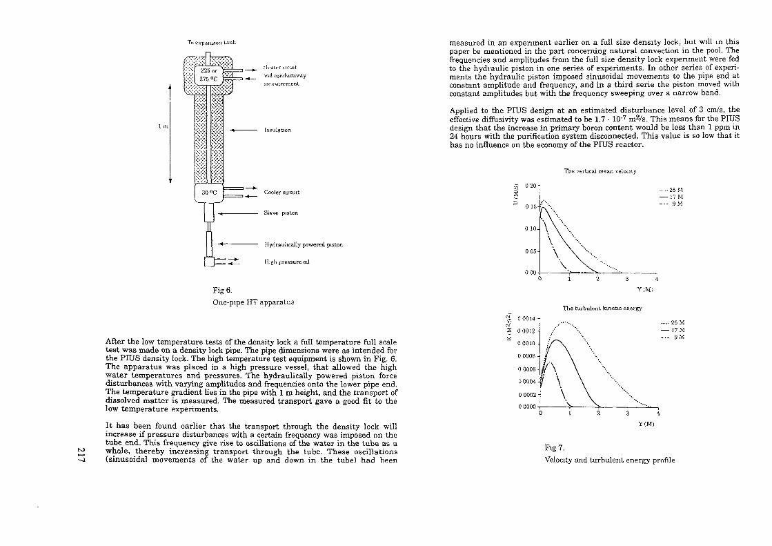
To expansion tank
UT ( . ICUi t
ind conductivityint-asuremcnt
Hydraukcaily powered piston
High pressure oil
Fig 6.One-pipe HT apparatus
After the low temperature tests of the density lock a full temperature full scaletest was made on a density lock pipe. The pipe dimensions were as intended forthe PIUS density lock. The high temperature test equipment is shown in Fig. 6.The apparatus was placed in a high pressure vessel, that allowed the highwater temperatures and pressures. The hydraulically powered piston forcedisturbances with varying amplitudes and frequencies onto the lower pipe end.The temperature gradient lies in the pipe with l m height, and the transport ofdissolved matter is measured. The measured transport gave a good fit to thelow temperature experiments.
It has been found earlier that the transport through the density lock willincrease if pressure disturbances with a certain frequency was imposed on thetube end. This frequency give rise to oscillations of the water in the tube as awhole, thereby increasing transport through the tube. These oscillations(sinusoidal movements of the water up and down in the tube) had been
measured in an expenment earlier on a full size density lock, but will in thispaper be mentioned in the part concerning natural convection in the pool. Thefrequencies and amplitudes from the full size density lock expenment were fedto the hydraulic piston in one series of experiments. In other series of experi-ments the hydraulic piston imposed sinusoidal movements to the pipe end atconstant amplitude and frequency, and in a third série the piston moved withconstant amplitudes but with the frequency sweeping over a narrow band.
Applied to the PIUS design at an estimated disturbance level of 3 cm/s, theeffective diffusivity was estimated to be 1.7 • 10'7 m2/s. This means for the PIUSdesign that the increase in primary boron content would be less than 1 ppm in24 hours with the purification system disconnected. This value is so low that ithas no influence on the economy of the PIUS reactor.
The vertical mean velocity
020-1
0 15-
0 10-
0 OS-
000
- 25 M- 17 M- 9.M
The turbulent kinetic energy
et& 0 0014 -i
0 0012 -
0 0010 -
0 0008 -
0 0006 -
0 0004 -
0 0002 -
00000
.25 M- 17 M- 9M
1 2 3 4Y (M)
Fig 7.Velocity and turbulent energy profile

(O
ooNatural Convection in the Pool
The large pool of highly borated water in the PIUS vessel surrounds theprimary internal parts consisting of mainly the core, the riser and the down-comer. The primary system has a mean temperature of 275 °C and the poolkeeps a temperature of 50 °C at normal operation. Thermal energy is trans-mitted through the primary parts thermal insulation and this gives rise tonatural circulation in the pool with mainly upgoing velocity near the internalparts and downgoing velocities nearer the walls of the concrete vessel. Thecomputer code Phoenics has by Lena Hedgran (réf. 7) at the ABB ResearchCenter been used to simulate the thermal boundary layers along the riser inthe reactor pool in order to estimate the turbulence intensity. The simulation ofnatural convection by means of Phoenics was checked by a comparison withexperiments on thermal boundary layers from the literature.
The result of these calculations are seen on Fig. 7. The boundary layer calcula-tions for PIUS resulted in a maximum mean velocity of 0.17 m/s and a maxi-mum turbulent kinetic energy of 1.35 • 10'3 m2/s2. The heat flux through thethermal insulation had a constant value of 10.0 kW/m2. The max temperatureincrease above the pool temperature was found to be only 2.5 °C. The calcula-tions gave with hand that an upper limit for the magnitude of the fluctuatingvertical velocity would be 0.03 m/s - 0.052 m/s. The question was now how muchthese velocities can disturb the upper density lock whose underside is placed inthe vertical upflow of this natural circulation.
Honeycomb
points on a free water surface
Pump
s Wide angle diffuser
Fig 8.Density Locks - Arrangement of atmospheric test
A full scale experiment was conducted to clear up this question. The apparatusused is shown in Fig. 8. The pump circulates water in the system and thewaterflow is directed upwards against a simulated density lock. Before hittingthe honeycomb grid from below the water was led through a wide anglediffuser and through adjustable slots. These slots were adjusted so that thewater at hitting the honeycomb had the velocity profile as calculated in theabove related Phoenics calculations. Above the honeycomb the water had alower density than in the circulating water. The density difference could becontrolled with temperature or with salinity. The exchange through theHoneycomb (Density lock) was then measured, giving an effective diffusioncoefficient as earlier defined in this paper. During the experiments it wasobserved that a sloshing movement appears in the vertical honeycombchannels. The vertical channels resonate at a given frequency (the BruntVäsilä frequency) and in the experiments the vertical velocity inside individualtubes was measured. The disturbance level and the velocity profile under thedensity lock were varied. This was done to give information on how thesealterations resulted in typical oscillations inside the density lock. Later thisinformation was used to simulate the sloshing movements in the high tempe-rature experiment already mentioned. The vertical velocity inside the honey-comb tubes was measured with an ultrasonic anemometer capable of resolvingvery low (and reversing) velocities. The velocity signal was integrated in time togive a vertical displacement which was found to be almost purely sinusoidal intime but with varying amplitude. The characteristic "sloshing" frequency inthe experiment agrees very well with theoretical calculations.
Final full scale test on the density lock
The final step in developing the density lock design for PIUS will be a full scaletest at about 100 °C to test the instrumentation and measure the transportvelocity at the lowest Richardson number that is encountered during operationof the PIUS reactor.
REFERENCES
1. Nuclear Technology Vol. 91 (July 1990) pp 81-88.Kare Hannerz et. al."The PIUS Pressurized Water Reactor: Aspects of Plant Operation andAvailability"
2. ENC '90 Proceedings Vol. II pp 701-718.Kare Hannerz, Lars Nilsson and Tor Pedersen"Nuclear Power Facing Human Fallibility - The PIUS Design"
3. Nuclear Science and Engineering: 90, pp 400-410 (1985)Dusan Babala, Ulf Bredolt and John Kemppainen"A Study of the Dynamics of the SECURE Reactor: Comparison ofExperiments and Computations"

5. Sixt Proceeding of Nuclear Thermal Hydraulics 1990 WintermeetingNovember 11-16, 1990 Washington DC.UlfBredolt"PIUS - Verification of Primary System Boron Transport Phenomena byComparison of Experimental Results with Simulations using the RIGEL-Code"
6. The Royal Institute of Technology, Department of Mechanics. TRITA-MEK-88-02. ISSn 0348-467-XB. Rikard Gebart"Transport Mechanisms at a stable Density Interface - Influences ofVertical Rigid Walls"
7. Hedgran, L. 1985"Numerical simulation of the thermal boundary layers along the riser inthe reactor pool of Secure"ABB Corp. Res. internal rep: TR KZBH 85-075
LONG TERM DECAY HEAT REMOVAL WITHPASSIVE FEATURES IN ALWRs
L. MAZZOCCHI*, P. VANINI**, R. VANZAN*
*CISE Tecnologie Innovative SpA,Milan
**Ente Nazionale per FEnergia Elettrica,RomeItaly
Abstract
In Advanced Light Water Reactors the efforts towards the use ofpassive mechanisms for the most relevant safety systems lead thedesigners to introduce innovative solutions to the problem ofpost-accident containment cooling.For example, in the PIUS type reactors a natural circulationwater loop cools the reactor pool and transfers heat to anexternal dry cooling tower. SBWR type reactors make use of an"Isolation Condenser" submerged into a large water pool;following a postulated accident the pool water boils off,releasing steam to the atmosphere and assuring passivecontainment cooling for at least three days.A further improvement could be the Isolation Condenser PoolCooling System (ICPCS), at present under study in Italy. Itsexpected benefits are:- the elimination of constraints on the "grace period" duration;- the possibility to avoid an extended release of a visible andpotentially radioactive steam plume.
According to the design philosophy of Advanced Light WaterReactors, a natural circulation system using the atmosphere asfinal heat sink is envisaged.Among the topics to be solved in the feasibility study of theICPCS, a particular problem arises from the presence of a largeamount of non condensible gas in the pool atmosphere, that cangreatly impair the natural circulation and heat transfermechanisms involved.After examination of several possible solutions, very promisingfeatures have been pointed out in the use of reflux condensingheat exchangers directly connected to the pool gas space; noncondensible gases can be vented during the earlier phase ofoperation by means of valves operating in passive way.
to

totoa1. INTRODUCTION
A new generation of nuclear power plants is at present beingstudied and developed in many different countries. The maineffort is directed to increase the acceptance of nuclear powerby evolutions of existing reactor concepts, with the introductionof simpler plant configurations. This is especially true as faras safety related systems are concerned: whenever is practical,use is made of "passive" mechanisms, which means that systemoperation does not rely on human action, external energy supplyand, if possible, on moving machinery or fluid motion (1).
A specific problem of nuclear plants, which may have asignificant importance from the safety viewpoint, is decay heatremoval after reactor shutdown or postulated accidents. In nextgeneration reactors this need is often satisfied by use ofpassive mechanisms, like natural circulation of fluids. Forexample, in the PIUS reactor a cooling loop, containing subcooledwater, connects an heat exchanger submerged in the reactor poolto dry cooling towers located on the top of reactor building. Inthis solution, heat generated inside the reactor pool istransferred to the cooling loop, producing natural circulationof the loop water; heat is then released to the cooling towers,where natural circulation of atmospheric air takes place. Thefinal result is therefore the decay heat release to theatmosphere without use of any external energy supply or fluidmakeup.
1C POOL
REACTOR
Fig. 1 Isolation Condenser schematic arrangement
In SBWR reactors a different solution to the same need hasbeen envisaged. Several heat exchangers, named "IsolationCondensers" (IC's) and connected to the reactor system or to thecontainment drywell, are submerged in a large water pool, locatedinside the reactor building at a suitable elevation above thereactor (fig.l). In case of reactor isolation or following apostulated accident producing a release of decay heat to thecontainment, steam is condensed in the IC's and the condensateis returned by gravity to the reactor system or to thecontainment pool. Water present in the 1C pool heats up to thesaturation temperature and starts boiling; produced steam isdirectly released to the atmosphere. This process goes on,releasing decay heat to the atmosphere without any humanintervention or external energy supply, till 1C pool water hasbeen completely boiled off. The presently established pool volumeis sufficient to ensure decay heat removal for a period of atleast 72 hours, named "grace period" according to the definitionreported in (1).
In the frame of the studies performed in Italy by ENEL/DSR/VDNon next generation reactors, the possibility to increase as muchas possible the grace period duration for the above describedconditions was felt very attractive. Therefore CISE was chargedto perform a feasibility study of a system able to satisfy thisgoal, that was named "Isolation Condenser Pool Cooling System"(ICPCS).
Main objectives of the study are the following:- to identify the possible system configuration;- to perform a preliminary si2ing, in order to be able toestimate physical size, to predict performances and toevaluate costs;
- to identify critical areas for system design and to defineresearch needs, if necessary.At present the study has attained the first and the second of
the mentioned objectives, while the last is in progress. Thispaper summarizes the main results till now achieved.
2. BENEFITS OF THE PROPOSED SYSTEM
The benefits expected from the introduction of the ICPCSsystem mainly concern the extension of the grace period durationand the environmental impact. Indeed, the capability to cool the1C pool water avoiding an extensive boiling and releasing heatdirectly to the atmosphere could allow decay heat removal for atheoretically infinite time period, independently of the poolwater volume (it must be noticed, however, that a large wateramount is nevertheless useful in order to exploit its thermalcapacity during earlier transient phases, when decay heat poweris largest). Moreover, the elimination of a prolonged (about twodays) steam release to the environment could achieve twobenefits:- no effect of a plant malfunction would be visible outside thereactor building;- the risk of radioactive release to the atmosphere, possible incase of 1C tube bundle leakage, would be avoided.
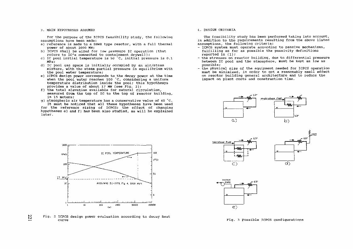
3. MAIN HYPOTHESES ASSUMED
For the purpose of the ICPCS feasibility study, the followingassumptions have been made:a) reference is made to a SBWR type reactor, with a full thermal
power of about 2000 MW;b) ICPCS shall be sized for low pressure 1C operation (that
refers to IC's connected to containment drywell);c) 1C pool initial temperature is 50 °C, initial pressure is O.I
MPa;d) 1C pool gas space is initially occupied by an air/steam
mixture, with the steam partial pressure in equilibrium withthe pool water temperature;
e) ICPCS design power corresponds to the decay power at the timewhen the pool water reaches 100 °C, considering a uniformtemperature distribution inside the pool; this hypothesysprovides a value of about 17 MW (see Fig. 2);
f) the total elevation available for natural circulation,measured from the top of 1C to the top of reactor building,is 15 meters;
g) atmospheric air temperature has a conservative value of 40 °C.It must be noticed that all these hypotheses have been used
for the reference sizing of ICPCS; the effect of changinghypotheses e) and f ) has been also studied, as will be explainedlater.
ANSI/AVS 5.1-1979, Fig 4, 2000 MUt
Fig. 2 ICPCS design power evaluation according to decay heatcurve
4. DESIGN CRITERIA
The feasibility study has been performed taking into account,in addition to the requirements resulting from the above listedassumptions, the following criteria:- ICPCS system must operate according to passive mechanisms,fulfilling as far as possible the passivity definitionsreported in (1);
- the stresses on reactor building, due to differential pressurebetween 1C pool and the atmosphere, must be kept as low aspossible;
- the physical size of the equipment needed for ICPCS operationmust be minimized, in order to get a reasonably small effecton reactor building general architecture and to reduce theimpact on plant costs and construction time.
. air
two-phase fluhj
Ü
e)
Fig. 3 Possible ICPCS configurations
totoN»
5. IDENTIFICATION OF POSSIBLE CONFIGURATIONS
The most obvious way to satisfy ICPCS system requirementsseems to be the condensation of steam produced inside the 1Cpool, releasing latent heat to an heat exchanger cooled by airin natural circulation and returning the produced condensate tothe pool. Unfortunately, this process is hindered by the presenceof a large air volume above the 1C pool (hypothesis d) in Ch.3)that can greatly impair both steam/water natural circulation andcondensation heat transfer. Therefore, a number of differentconfigurations, schematically shown in fig.3, have been takeninto consideration.a) This solution, shown in Fig.3a, is the simplest one: a steam
pipe directly connects the 1C pool gas space to an heatexchanger cooled by air in natural circulation; condensate isreturned to the pool. The main drawback is the presence of alarge air amount in the pool cover gas (air mass concentrationmay be about 70% assuming a pressure of about 0.2 MPa duringICPCS operation); the air would accumulate in the heatexchanger stopping natural circulation and making the systemuneffective.
b) In this case, presented in Fig. 3b, heat is transferred fromthe 1C pool to the external, air-cooled heat exchanger via anintermediate loop full of liquid, establishing a single-phasenatural circulation. That eliminates any non-condensible gasconcern for fluid circulation. It can be noticed that thissolution is very similar to the PIUS one. Disadvantagesregard: the necessity of a second, internal heat exchangerwhich increases system complexity, size and cost;theintroduction of additional temperature differences, due to theintemediate loop, that increase the external heat exchangersize if the pool pressure is assumed to be unchanged.
c) This solution (Fig. 3c) is quite similar to the previous one,but the intermediate loop operates with a two-phase fluid,boiling in the internal heat exchanger and condensing in theexternal one. In comparison with case b), further advantagesare connected to a more efficient natural circulation, thanksto the bigger density differences, and to the practicallyisothermal intermediate loop that improves thermodynamicbehaviour.
d) System configuration (Fig. 3d) is similar to case a), but thenon-condensible gases are vented during early system operationby a valve actuated by system overpressure. When air vent hasbeen performed, a sufficient heat transfer in naturalcirculation occurs, system pressure decreases and the valvecan close, stopping the steam-air mixture release. Thissolution combines the simplicity of configuration a) with athenaodinanic efficiency even better than case c); the mainshortcoming is that the system is not completely closed to theenvironment, reducing some benefits mentioned in Ch. 2. Itmust be considered, however, that steam-air release would belimited to a very short time (a few minutes).
e) This last solution (Fig. 3e) makes use of a vacuum pump inorder to reduce air partial pressure during steady-stateoperation, improving system behaviour in comparison with case
a). However the non condensible gases cannot be completelyvented in this way, while the necessity of an active pumpand the vacuum conditions in the pool during normal operationmake this configuration less attractive than the previousones.According to the mentioned advantages and shortcomings,
subsequent evaluations have been restricted to solutions c) andd); for case c) two different configurations, named cl) and c2)have been taken into consideration, corresponding to differentlocations of the internal heat exchanger: in the 1C pool gasspace or directly submerged in the pool water.
6. PRELIMINARY SIZING OF THE SELECTED CONFIGURATIONS
6.1 Solution cl) (intermediate two-phase loop, internal heatexchanger in gas)
6.1.1 Basic designIn this configuration, ICPCS is composed by the following
equipment:- an internal heat exchanger, located above the 1C pool waterlevel, composed by nearly horizontal plain tubes in which theintermediate loop fluid (supposed to be water) boils; steamproduced by the 1C condenses on the outer side of the tubes;
- an external heat exchanger, made of nearly horizontal finnedtubes; the heat exchanger is located around the upper part ofthe reactor building, as shown in Fig. 4, and is cooled by airin natural circulation;
- all the necessary piping connecting the internal and theexternal heat exchangers.The mentioned equipment has been sized according to well
established heat transfer and pressure drop correlations; theresults can be summarized as follows:- the internal heat exchanger surface is about 2500 m2, while theexternal one has about 38000 m3 that require to locate the heattransfer panels all around the reactor building for a width ofabout 6 meters;
- the maximum pressure reached in 1C pool is about 0.19 MPa forthe hypotheses assumed (17 MW power, 40 °C air temperature).
6.1.2 Sensitivity studiesIn order to check if performances of the above described basic
design can be significantly improved with an acceptable increaseof ICPCS system size and cost, two possible modifications havebeen taken into consideration:- an increase of natural draft elevation from 15 m, used forbasic design, to 30 m;
- an increase by a factor two of external heat exchanger surface.The former change would produce a strong impact on reactor
building size and cost without an appreciable performanceimprovement: the 1C pool maximum pressure could be reduced toabout 0.18 MPa. The latter modification could be done without big

REACTORBUILDING
44 n
73 m
toto
Fig. 4 Air-cooled heat exchanger schematic plan
effects on reactor building (notice that a twofold heat transfersurface is compatible with the same building enlargment if a 60°arrangement of finned tubes is used instead of the horizontalone); the 1C pool maximum pressure would decrease in this caseto about 0.17 MPa. So the heat transfer surface increase ispossible and can be convenient if the heat exchanger additionalcosts are compensated by the reactor building stress reduction.6.1.3 Effect of 1C pool partitions
In the preliminary sizing performed reference has been madeto the uniform temperature assumption in the 1C pool water (Ch.3, hypothesis e)) that brings to a ICPCS design power of 17 MW.This assumption is reasonable if 1C pool is internally open,while it becomes unrealistic and non conservative in case ofinternal partitions. To evaluate the effect of this differentsituation, a division of 1C pool into 12 smaller modules has beenconsidered; in this case the water heat capacity of just onemodule has been taken into account, while a completely mixed gasspace has been assumed. In this way, the ICPCS design power canbe evaluated to be about 43 MW, because of the much faster watertemperature increase. Assuming the same ICPCS sizing as in thebasic design, the 1C pool maximum pressure would be about 0.3
MPa, while an increase of all heat transfer surfaces by a factor2.5 would be required in order to get the same performances asin the previous case.6.2 Solution c2) (intermediate two-phase loop, internal heat
exchanger in water)6.2.1 Basic design
In this configuration, ICPCS is composed by the same equipmentas in case cl), but the internal heat exchanger is located belowthe 1C pool water level. A more efficient heat transfer mechanismoccurs at the outer surface of this heat exchanger, i.e. freeconvection with single-phase liquid instead of steam condensationwith large non-condensible gas concentration. Considering exactlythe same heat transfer surfaces as in basic design of solutioncl), a better thermodynamic performance is therefore obtained:maximum pressure inside the 1C pool is about 0.15 MPa.
It must be noticed that in this case the uniform temperaturehypothesis in the pool water should be critically evaluated; thewater free convection certainly requires some temperaturegradient between different pool regions. Therefore, the maximumwater pool temperature could be appreciably higher thantemperature of water flowing along the cooling surface, with theconsequence of a maximum pressure in the 1C pool higher thanpredicted. Some numerical analysis of pool velocity andtemperature fields is required in order to get confident of theabove indicated performance improvement.6.2.2 Sensitivity studies and effect of 1C pool partitions
The same checks of the influence of ICPCS sizing, as describedin 6.1.2, have been performed also in this case, with verysimilar results.
The assumption of a 1C pool partition has in this case twodifferent effects:- the design power increases to about 43 MW, as explained in6.1.3;
- the internal heat exchanger must be inserted in the same poolmodule where the 1C is located, with strict space limitations.The latter constraint imposes to reduce the heat exchanger
surface from 2500 to about 1400 m2, with a further performancedecrease in comparison with the basic design. Assuming the samesize of the external heat exchanger, the maximum 1C pool pressurehas been estimated to be about 0.3 MPa.6.3 Solution d) (non condensible vent)6.3.1 Basic design
In this configuration, ICPCS is composed by the followingequipment:- an external heat exchanger, made of 60° inclined, finnedtubes; the heat exchanger is located around the upper part ofthe reactor building, as in previous solutions, and is cooled
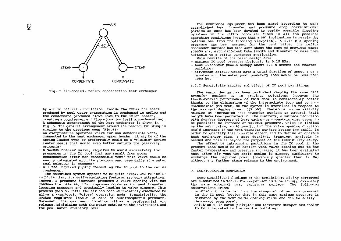
to AIR
STEAM STEAM
CONDENSATE CQNDENSATE
Fig. 5 Air-cooled, reflux condensation heat exchanger
by air in natural circulation. Inside the tubes the steamproduced by pool water evaporation is condensed in upflow andthe condensate produced flows down to the inlet header,creating a countercurrent flow situation (reflux condensation).A schematic arrangement of the heat exchanger is shown inFig. 5. The general arrangement around the reactor building issimilar to the previous ones (Fig.4);
- an overpressure operated valve for non condensible vent,connected to the heat exchanger upper header; it may be of thespring loaded type or preferrably could be a "fluidic" device(water seal) that would even better satisfy the passivitycriteria;
- a vacuum breaker valve, required to avoid excessively lowpressures in the 1C pool that may result from steamcondensation after non condensible vent; this valve could beeasily integrated with the previous one, especially if a waterseal solution is choosen;
- all the required piping connecting the 1C pool to the refluxcondenser.The described system appears to be quite simple and reliable;
in particular, its self-regulating features are very attractive.Indeed, a pressure increase produces a valve opening with noncondensible release; that improves condensation heat transfer,lowering pressure and eventually leading to valve closure. Thisprocess goes on until the air has been sufficiently evacuated toallow a completely "close" operation mode. Symmetrically, thesystem regulates itself in case of subatmospheric pressure.Moreover, the gas vent location allows a preferential airrelease, minimizing both the steam outflow to the environment andthe pool water inventory loss.
The mentioned equipment has been sized according to wellestablished heat transfer and pressure drop correlations;particular care has been devoted to verify possible floodingproblems in the reflux condenser tubes in all the possibleoperating conditions (notice that a 60° inclination is nearly theoptimum one from the flooding viewpoint). A 0.15 MPa openingpressure has been assumed for the vent valve; the refluxcondenser surface has been kept about the same of previous cases(39000 m2), with different tube length and diameter to make themsuitable to a reflux condenser application.
Main results of the basic design are:- maximum 1C pool pressure obviously is 0.15 MPa;- heat exchanger panels occupy about 3.5m around the reactorbuilding;
- air/steam release would have a total duration of about 3 or 4minutes and the water pool inventory loss would be less than1000 kg.
6.3.2 Sensitivity studies and effect of 1C pool partitionsThe basic design has been performed keeping the same heat
transfer surface as in previous solutions; however thethermodynamic performance of this case is considerably betterthanks to the elimination of the intermediate loop and to non-condensible gas vent, so the system is oversized in respect tothe assumed design power (17 MVJ). Therefore no sensitivitystudies at increasing heat transfer surface or natural draftheigth have been performed. On the contrary, a surface reductionwith further decrease of heat exchanger geometric size seems tobe possible; no increase of maximum pressure, which is limitedby the vent valve, would result, but the valve opening durationcould increase if the heat transfer surface became too small. Inorder to quantify this possible effect and to define an optimumheat exchanger size, a more detailed, transient analysis isneeded and this is beyond the purpose of the feasibility study.
The effect of introducing partitions in the 1C pool in thepresent case would be an earlier vent valve opening due to thefaster temperature and pressure increase; it has been evaluatedthat after air vent the basic design is already sufficient toexchange the required power (obviously greater than 17 MW)without any further steam release to the environment.
7. CONFIGURATION COMPARISON
Some significant findings of the preliminary sizing performedare summarized in Tab.l. The comparison is made for approximatelythe same external heat exchanger surface. The followingobservations arise:- solution d) is better from the viewpoint of maximum pressurein the 1C pool (notice that in this case maximum pressure isdictated by the vent valve opening value and can be easilydecreased even more);
- solution d) is notably simpler and therefore cheaper and easierto be integrated in the reactor building;

Tab. 1 Summary of the preliminary ICPCS sizing
CONFIGURATION
Maximum 1C poolpressure (MPa)External heatexchanger width w(see Fig. 4) (m)External heatexchanger surface
(ms)Internal heatexchanger surface
(m2)Maximum pressurefor poolpartitioning (MPa)Completely closedsystemIntermediate loop
cl)
0.192
6
38000
2500
0.3
YES
YES
C2)
0.152
6
38000
2500
0.3
YES
YES
d)
0.15
3.5
39000
N.A.
0.15
NO
NO
- the effect of introducing partitions in the 1C pool ispractically negligible in case d) , while it can significantlypenalize the remaining solutions;
- solution d) main shortcoming is that the system is notcompletely closed to the environment; however the shortduration and the limited amount of the air/steam release canbe considered substantially acceptable in respect to ICPCSrequirements ;
- among the cl) and c2) cases, both having the advantage of acompletely closed system, c2) supplies a lower maximumpressure, but the actual free convection behaviour in the poolmust be carefully analyzed and the effect of pool partitionsis more penalizing.A final choice between the different candidate solutions has
not been made at the moment; however, solution d) can beconsidered as the most attractive.
8. CONCLUSIONS AND FUTURE WORK
The study till now performed has shown that the ICPCS systemis technically feasible with reasonable size and cost and is ableto supply acceptable performances. The most suitable solutionseems to be a reflux condenser cooled by air in naturalcirculation.
Next activity steps will concern:- identification of critical areas for system design;- planning and execution of the reguired research activities(numerical calculations, experimental tests);
- detailed system design.Some possible subjects of the research activities are finned
tube heat transfer with natural circulation air at very lowvelocity and, in case the adopted solution is d), refluxcondensation phenomena with non-condensible gases, vent/vacuumbreaker valve (or water seal) behaviour and reliability.
REFERENCE(1) Safety Related Terms of Advanced Nuclear Plants.International
Atomic Energy Agency, Final Report, February 1991.

t-JM SURVEY OF ACTIVITIES FOR ASSESSING
THERMALHYDRAULIC ASPECTS OF NEW REACTORS
C. BILLAENEA,PisaF. D'AURIAPisa University,PisaE. GESIENEA,BolognaItaly
AbstractThe present paper deals with an overview of some activities carried
out in Italy in the field of safety related thermalhydraulics studiesafter the decision of the Government to shut down the nuclear powerplants.
The described activities have been performed in the frame ofcooperations supported by ENEA and involve the Pisa University.
Results obtained from the operation of PIPER-ONE (gravity drivenreflood) and from Accident Management studies performed with reference toa loss of feedwater and a small break LOCA experiment, are brieflydescribed.
All the above studies are directly applicable to the technology ofthe new generation reactors.
1. INTRODUCTIONIn Italy the production of electric energy from nuclear power
plants has been suspended after the Chernobyl accident; nevertheless theresearch in the field from various organizations including university isactive and concerns applied technology aspects as well as studies ofbasic phénoménologies having as objective the safety of the newgeneration reactors.
In the area of thermalhydraulics, activities on the codesassessment, like the International Standard Problems (ISP) or theevaluation of the experimental data base obtained in the facilitiesavailable in various countries, have been maintained in this period;these have a role in the knowledge of the scenarios foreseen in accidentsituations in the nuclear reactors.
The failure of the emergency systems, the operator actions, theexploitation of the whole spectrum of available systems in the plant, areamong the issues of current interest.
The main purpose of the present work is to give an outline of fewrelevant activities carried out in the last years in this frame. Emphasisis given to researches performed by ENEA in cooperation with PisaUniversity, dealing both with experimental studies and codes assessment.Some of the researches are directly related to the study of aspectsrelevant to the new generation reactors, e.g. the experimentalinvestigations of the behaviour of gravity driven core cooling systemwith the PIPER-ONE facility /!/. Additional activities in this contextrelate to the evaluation of transient scenarios in AP-600 and SBWR plantsand are documented in another paper in this conference 111.
Finally, a synthetic view is given of recent work performed at PisaUniversity in cooperation with ENEA related to the analysis of AccidentManagement situations in the present LWR: some aspects can beextrapolated to the new generation reactors. In particular AccidentManagement have been investigated in SPES and BETHSY facilities /3,4/.
2. AVAILABLE FACILITIES AND CODES ASSESSMENT ACTIVITYSeveral activities have been in progress in Italy in '70 to
evaluate the safety of nuclear power plants. In particular two facilitieswere designed and built at the beginning of '80, SPES and PIPER-ONEsimulating PWR and BWR respectively.
Activities in code assessment concerned the utilization of RELAPScode series (ENEA, ANSALDO, CISE, Universities) and of CATHARE codeavailable at Pisa University since 1986.
In this chapter an outline of experimental facilities and codes isgiven.2.1 Spes facility
The SPES facility /5/, is designed to simulate the whole primarycircuit, the relevant parts of the secondary circuit (steam generatorsecondary sides, feedwater lines downstream the isolation valves, mainsteam lines upstream the turbine valves), and the most significantauxiliary and emergency systems (charging and letdown system, safetyinjection systems, Emergency FeedWater, steam dump, etc.) of the PWRplant.
The basic features of the facility are:- volume scaling ratio equal to 1:427- three active loops to Simulate a three loop reactor;- design pressure 20 MPa, design temperature 638 K, allowing tests with
primary pressure above the reactor design value;- core simulator consisting of 97 electrically heated rods, with uniform
flux (local hot spots are simulated by means of three rods, with apeaking factor of 1.19);
- maximum channel power corresponding to about 140% of the reactornominal power (roughly 6.5 MW) allowing the simulation of reactorpower excursions;
- the height of all the components is the same as in a real plant,except for the pressurizer which is shorter, in order to preserve thevolume scaling ratio and to maintain, at the same time, an acceptableflow area.
A sketch of the facility is reported in Fig. 1.

STEAMGENERATOR 1
STEAMGENERATOR 3
ADS
PUMPS
to Fig. 1 - Sketch of SPES integral test facility (PWR simulator). Fig. 2 - Sketch of PIPER-ONE integral test facility (BWE simulator).

toN)OO
fig. 3 - Sketch of the GDCCS system installed in PIPER-ONE facility.
2.2 PIPER-ONE facilityThe simplified sketch of the PIPER-ONE apparatus is shown in Fig. 2
J6J. The main loop simulates the BVffl vessel and can be subdivided intonine zones: lower plenum, core, core bypass (external to the core),control rod guide tubes, upper plenum, separators and dryers, steam dome,upper downcomer and jet pump. The ECCS simulators (ADS, LPCI/LPCS,HPCI/HPCS), the Steam Relief Valve (SEV) and steam lines, as well as theblow-down line, complete the apparatus.
The facility comprises also structure heating and cooling systems;the former is used to compensate the heat losses to the environment; thelatter has the aim of mitigating the impact of heat exchange betweenwalls and coolant that cannot be correctly scaled down in such a type ofapparatus.
The heated bundle consists of 16 (4x4) indirectly heated electricalrods, whose height, pitch and diameter are the same as the fuel elementsin the reference plant. The maximum available power is 250 kW, sufficientto simulate the power decay of the nuclear reactor.
The volume scaling factor is about 1/2200, while the piezometricheads acting on the lower core support plate are the same in the modeland in the- reference plant.
The facility hardware was slightly modified for studying thebehaviour of a Gravity Driven Core Cooling System (GDCCS). The SRVdischarge tank, 80.1 dma capacity, able to withstand an internal pressureof 0,2 MPa greater than the atmospheric one, was connected to the lowerplenum of the primary circuit (Fig. 3). The SRV tank is located at the4th floor of the main frame, roughly 10 m above the lower plenum inletnozzle. In order to avoid distortions in the transient due to the lowtank capacity, an automatic system was added, which mantains constant (±2 cm) the liquid level in this tank.
2.3 Computer codes featuresSeveral versions of RelapS and Cathare codes have been in use;
nevertheless, the discussion is restricted hereafter to Relap5/mod2 111and Cathare l v. 1.3 /S/.Relap5/mod2
Relap5/mod2 is a transient analysis code for complex thermal-hydraulic systems. The fluid and energy flow paths are approximated byone-dimensional stream tube and conduction models. The code containssystem components peculiar to pressurized water reactors. In particularpoint neutronics, pumps, turbines, valves, separators, and controlsystems are simulated. The code also contains a jet pump component thathas been used for modeling boiling water reactors.
The code is based on a non-homogeneous non-equilibrium set of 6partial derivative balance equations for the steam and liquid phase. Anon-condensable component in the steam phase and a non-volatile component(boron) in the liquid phase can be treated by the code.
A fast, partially implicit numerical scheme is used to solve theequations inside control volumes connected by junctions.

Tab. I - Overview of code assessment activities carried out at DCKN ofPisa University by CATHARE and RELAPS codes (Status Aug. 1991).
eisic coot «SSESSMXI coce isscssnxt coot issesszxr cooe ISSCSSKXT <xa.(CCOLDG «auMT «JUKI »OIXST KAOST TO sirenSHJOIG rwouemL swuuit cma unvxu. KJJTT uo
MO«UKS OPOUJOTS ECPOIKEXIS MTl
Uill U> fluid Irlclita - »>
t - branch - 0UOood I»
Crlllc»!
Cold >g - i
l cbuiMi« «odU«
ccn. «<. tnr «tu»»« buodi« boo. »>ccn. «t eir «Lik <*< buodn both *>ccn. «t irrr «iu itiit UoU« bou i°
- f lp«r MUll boU K> 'I nov boU »
(1) urtod icklil« f«cUUj P« a> <
lut. clrc. I« «l«« fJcUiljïcoitj dclv» nl^cad iaPITOt-0« (K>-tO-7)
rno-on <p»-a>-S)
I - LUI 1>«1 NR ^ULoa - LOU u-u r* *°fitoa - LOM U-W F«8 0 '«OH - LOM K.-21 F« I«.l. cire. U«I 12-771 I« *IUI. die. LOU 11-Î2 FUB Ims - LOU 12-40 rueION- UU «-00 P«Bta- uu n-oi w«US - LOU K-OJ F»Lor« • at» «Mu-02 FUSauci - wu. IT - a<L-u F««.i. dec. KU n- n-K-<a f«IUI. dJX. lOSi It - «T-HC-09 FUBmoa - LOO - u-ff-2 FUB
(*) «en - n* «2•<7) OLOQ - ura-u« »o-«-7 iw
szuci - nm-aa. ro-a-7c >ue• »«t. ein:.- ma-o«t FO-SO-VI »«• lui. dit:, rtpa-ca FO-CM/U >w
(5) nU>Cl - KTKST 9.1.b. f«OUX1 - SFÏ3 0-A-03 FUBuuci - JP (»Uar» ma-ax ro-u-i WB 'IUI. dre. «KS ST-tCHX t« '
ssLoa - ua ru« i<io) son - ooa N« i
LutV - LOBSTADT W* ^feaUllo W z
f - ItoaUllo B« 'ITJVSaW - XontOU Mi I«WHSIY - CMC» ** I
(O OLOC1 - TRIM M INT- OH» (MB ISU- IM l« r
• '•fy» - ifeatilu Pue ILtLoa - 1KOO rw IIXLOd - IP600 PUR I ^ULOd - JP ttijure ÏUR Iht. d«. BaU f« Iu< n«u»i rauud u sets rue i
z • ULtKflaa• owct<rp«rt UA o>aniuci r i .3U caa t» 25 2) can of 113) caa 19 22 <) an la xs) uu at 2 <) iiu <K l7) aw IS» 21 *) «mil .od.lU.Uoc ii) caa ig 27 w) can is 20
229

N> CathareO Essentially Cathare code has the same main peculiarities as RelapS.
The difference, from a general point of view, outcomes from theconsideration that the code is mostly devoted to the analysis oftransients in Pressurized Water Reactors with U-tubes steam generators.
In particular the structure of the code is modular, each moduledescribing a particular plant feature: pipes, large capacities,connections among pipings, as tee junctions and branches, boundaryconditions like dead ends, assigned flow rates, etc. The basichydrodynamic module, adopted for pipes and other ID parts of the plant,is based on six balance equations expressing the conservation of mass,momentum and energy for the two phases. Space discretization of theseequations is made using a finite difference scheme, based on thedefinition of "scalar nodes" where mass and energy equations are solvedand "vector nodes" where momentum equations are solved, making extensiveuse of the "donor cell principle" and of the "staggered mesh" technique.2.4 Assessment methodology
The ultimate goal of codes use, in any case, consists in theapplication to nuclear plant systems in order to evaluate the safetymargins, to optimize the plant design and the operating procedures, and,possibly, for a better training of the operators.
System codes such as those previously presented, contain a numberof approximations when applied to the prediction of the behaviour of areal continuous system. These approximations are necessary due to thefinite storage capabilities of computers, the need to obtain calculatedresults in a reasonable time, and, in many cases because of limitedknowledge about the physical behaviour of components and processes thatare modelled. Very little objective information is available regardingthe source of errors introduced by the mentioned approximations; almostall of this outcomes from the comparison between measured and calculatedtransients.
The actual framework of code assessment results from the aboveconsiderations. The code assessment is a quite complex process and can bedistinguished into the following main steps /9/:a) in depth analysis of code manuals considering the basic models and
the description of input data deck;b) user qualification through study and applications of nodalizations
set up by experienced users;c) application of the code to fundamental physical and numerical
problems;d) application of the code to separate effect test facility data
including extensive comparison with experimental data;e) application of the code to transients measured in integral test
facilities possibly of the same type of the plant to be analyzed;f) code use for plant design and safety.
An overview of the activity carried out at University od Pisaresults from Tab. I, with reference to both Cathare and Relap codes; thevarious steps of the code validation process, can be recognized in thefirst column of the table.
3. GRAVITY DRIVEN REFLOOD TESTSThe tests PO-SD-6 A, B and C performed in PIPER-ONE were designed
by taking into account the peculiarities of the facility with theobjective of simulating phenomena that are typical of gravity drivenreflood.
The GDCCS plays a crucial role for the safety of new LWR concepts,particularly of the General Eletric SBWR (Simplified BWR). For thisreason, the first step in the research was to identify the limitations ofthe available facility in simulating SBUR related scenarios. The activeheight of the core (2.2 m and 3.7 m in SBWR and in PIPER-ONE,respectively) and the distance between the bottom of the Active Fuel(BAF) and the initial liquid level in the GDCCS pool (22 m in the reactorand 9 m in the facility) were identified as the major potential sourcesof distortions. The heat exchange across the fuel rod box constitutes anadditional difference between the model and the prototype. Thus, thedirect extrapolation of the phenomena measured in the PIPER-ONE facilityto the plant situation is not possible. Therefore, the objectives of theexperiments were limited to:- the experimental study of the gravity driven reflood phenomenology;- the achievement of a data base suitable for validating system codes,also utilized in the licensing process of the SBWR; low pressureconditions are challenging from the code assessment point of view.
The core power was fixed considering the needs to be representativeof the decay power and to compensate for heat losses. The GDCCS injectionwas located in the lower plenum to avoid the influence of the jet pumpssimulator in the PIPER-ONE facility.
Code analyses were performed by Relap5/Mod2, utilizing theavailable nodalization, properly updated to simulate the GDCCS. Thecalculated data were used to determine a suitable diameter for the GDCCSdischarge line consistent with the core power.
Details about initial and boundary conditions are given in TablesII and III.
Tab. II - Initial conditions of PO-SD-6 experiments.
QUANTITY
LP absolute pressureCore level "DC level bLiquid temperature in LPLiquid temperature in LDCMax cladding temp, (level G) =GDCCS pool temperatureGDCCS pool level"
UNIT
MPammKKKKm
TESTPO-SD-6A
0.23-0.42.2370.410.460.285.9.
TESTPO-SD-6B
0.17-0.71.9360.400.460.285.9.
TESTPO-SD-6C
0.18-0.22,4360390.420.285.9.
a- Starting from BAF (2.7 m above LP bottom)b- Starting from downcomer bottom (1.1 m above LP bottom)c- The levels are shown in Fig, 2.

Tab. Ill - Boundary conditions and sequence of events during PO-SD-6experiments.
QUANTITY
Core powerOpening of the GDCCS valveInitial pressure in GDCCS poolGDCCS reverse flowTest end signal (PCT or H)"Test end
UNIT
KWs
MPas
K or ms
TESTPO-SD-6A
50.60.0.1
70. -130.900 K300.
TESTPO-SD-6B
50.40.0.27NO
6.5 m-140.
TESTPO-SB-6C
50.65.0.18NO
6.5 m-220.
to
d- The test ends when PCT > 900 K (no core quench) or when the liquidlevel in the core (H) reaches TAF.
e- Starting from LP bottom.
Heating power, rod surface temperatures, pressure and levels inboth the downcomet and the core regions are represented in Figs. 4 to 9.
The data emphasize the relevance of the pressure boundaryconditions on the scenario.Test PO-SD-6A
Water coming from the GDCCS rewetted the core bottom but the steam,produced mostly at the quench location, caused a local pressure increasewhich prevented quench front progression. The pressure drops at theconnections between the primary circuit and the containment play acrucial role in this respect. Reverse flow occurred in the GDCCS line inthe period 70-130 s (Fig. 4). Following a period of electrical powercycling, power was finally switched-off roughly at "300 s (Fig. 5).Test PO-SD-6B
The addition of an equivalent gravity head, through the control ofGDCCS pool pressure (0.1 MPa above the primary loop ressure), allowed aprompt reflood of the «hole core. This was completed in about 70 s afterGDCCS activation (Fig. 7). It should be noted that the steam produced bythe core quench caused an increase of about 0.1 MPa in the lower plenumpressure.Test PO-SD-6C
A configuration that, under some extent, is more close to the plant(i.e. the primary system discharges the steam into the pool) allowed therewet of the rods in a few hundreds of seconds (Fig, 9).
The experimental research was carried out with the aim ofcharacterizing phenomena occurring during gravity driven refloodsituations, which are expected to be typical of the new nuclear reactorconcepts. Several limitations of the facility (mostly the active heightof the core rods) prevent a direct extrapolaion of the data to thereactor situation. As a relevant finding, the data obtained in threedifferent tests confirmed the huge impact of boundary conditions relatedto the GDCCS pool and primary circuit pressure on the involvedphenomenology. Changes in these conditions, that are negligible if pumpsare available, cause the occurrence or not of the core reflood. Theresulting data base appears useful for the assessment at low pressure ofthe models implemented in the codes. So far, the Relap5/Mod2 code hasonly been used in the design of the experiments (pre-test calculations).
0.2
t (s) 3000.1
Fig. 4 - PIPER-ONE GDCCS experiments:Trends of LP and core region in testPO-SD-6A.
Fig. 5 - PIPER-ONE GDCCS experiments:Trends of heating power and rodsurface temperature in test PO-SD-6A.

to(•) Starting fröre LP bottera
Core level (*}
-100 -*> -» 100 HOt(c)lW
Fig. 6 - PIPER-ONE GDCCS experiments:Trends of LP pressure and liquidlevels in DC and core region in testPO-SD-6B.
Fig. 8 -PIPER-ONE GDCCS experiments:Trends of LP pressure and liquidlevels in DC and core region in testPO-SD-6C.
-100 -49 -K 20 «0 100 M0t(s) !«0
Fig. 7 - PIPER-ONE GDCCS experiments:Trends of heating power and rodsurface temperature in test PO-SD-6B.
Fig. 9 - PIPER-ONE GDCCS experiments:Trends of heating power and rodsurface temperature in test PO-SD-6C.

to
phase 1 phase 2 t hase3 phase4 phase 5PRZ FULL
-LOFW
_MSIV CLOSURE
-SCRAM
18
16,
</>W
12
10
2.5TIME (S) x103
7.5
Fig. 10 - SPES experiment SP-FW-02: pressurizer pressure and level.
12
10
§ 8_iL" /-> 6LU-J
4
2
0
P' ase1 phase 2 phases phase4 phase 5
-/l
SG SRVCYCLING—— MSIV
CLOSURE
SGDRYOUT
SG LEVELRESTORATION
as sTIME (s) x103
COREQUENCH -
EFWACTUATION
Ts——
6 ^
5 wLUo:
4°-
E'S-
Fig. 11 - SPES experiment SP-FW-02: steam generators pressure and level.
If
1 a
a g §3 3
ls
s?o"
tl"! W(0 T)Hl M(D [«l-l
overvim
ent
O.
O
ooM
§o.
rt(D

4. ACCIDENT MANAGEMENT
Accident management (AM) quantifies all the actions which aim toanticipate or mitigate accidents in industry- In nuclear power plants theaccident management, within the prevention limits, tries to maintain corecoolability and containment integrity for Design Basis Accident eventsusing safety related and operation systems inside the design limits. Inaccident with core melt, accident management attempts to mitigate theconsequence of core distruption and the release of radioactive materialto the environment, by making the best use of all existing systems, evenoutside the design limits.
The activities have been performed with reference to the analysisof transients performed in SPES and BETHSY facilities.
The described results demostrate the capabilities of AM proceduresin mitigating accident severity.
4.1 Accident Management in case of Loss of FeedWaterThe transient utilized at the basis activity, performed in the Spes
facility, is a Loss of FeedWater in all the three steam generators withdelayed activation of Emergency FeedWater. The transient evolves through5 phases reported in Figs. 10 and 11.
The code demonstrated to be able to predict the relevant phenomenaoccurring during the transient as can be seen from the comparison betweenthe calculation and the experimental data /10/.
The most important phenomena occuring during the experiment were:- core dryout;- pressurizer overfill and emptying;- core quench;- heat transfer across the steam generator at variable mass inventory in
primary side.Preliminary sensitivity calculations were performed in relation to
the position and the number of Emergency FeedWater systems available forplant recovery. The summary of all the performed calculations is given inTab. IV.
The results demonstrated that in all cases (calcs. 00 to 03) corequenching and consequent recovery of the plant occurred. Calc-01 led tothe worst situation (Fig. 12) as far as core temperature was concerned.Considering the calculated scenario with Emergency FeedWater in loop 2 asthe reference test, additional calculations were performed:- POHV in "stuck open" position (TMI type accident) when the pressurizer
pressure fell below the nominal closure set point (calc-OA);- as above, assuming pumps restart when rod surface temperature was
greater than 750 K (calc-05);- as above, assuming available accumulators and LPIS (calc-06).
Significant results of these calculations are shown in Figs. 13 to17.
As a main conclusion, with respect to the reference LOFWexperiment, it has been demonstrated that further failures such as PORVin "stuck open" position, involves a much more severe accident scenario,making impossible, the plant recovery /3/ (Figs. 13 to 15). Thecombination of operator intervention aiming at restarting the pumps, andthe availability of safety systems at low pressure, permits a completecore cooling (Figs. 16 and 17).
700
K
rmc («) K looo
Fig, 12- SPES AM study: rod temperaturetrends at the core top in sensitivitycalculations with different EFWinjection locations.
6,0 7.3Ttne U) K looo
Fig. 13 - SPES AM study:, trends ofvessel level and rod temperature atthe core top in the case of PORV in"stuck open" position.
D O
12-
t o -
e
o.« 1.5 6.0 7.5
TW« U) « 1000
tei
16
14
• 1 2
10
5
6
X
2
0
Fig. H- SPES AM study: trends of theprimary pressure in the referencecalculation and in the case withPORV in "Stuck open" position andand pumps restart.
Fig. 15 - SPES AM study: trends ofthe rod temperature at the core topin the reference calculation and inthe case with PORV in "Stuck open"position and pumps restart.
Fig, 16- SFES AH study, trends of theprimary pressure in the casereference calculation and in thecase with PORV in "Stuck open"position, pumps restart availabilityof the low pressure emergencysystems.
Fig. 17-SPES AM study, trends ofthe primary pressure in the referencecalculation and in the case with PORVin "Stuck open" position pumpsrestart and availability of the lowpressure emergency systems.

toMPa
1 6
12
8
4
i\
1i1C
1 ——— n ————— r-" i i >]f1 phase M phase IUphasei A iB( C ,
1 «, | i -O- PS pressurei i • I -|SG ; SG ' 1control depres. i/ ,/ 1 -i-""0"! ACC ii iVon 'j \ fif^C*l ' \ off ' LPIS Core flooded -! ; V X L _ _ / Ii i ! 1 1 i —— -Q i
5 , 8t ime SX10 3 11
MP»16
•O EXP-u- CALC
5 8time 5x10³ 11
Fig. 18 - Bethsy experiment 9.1.b: primary side pressure. Fig. 19-Bethsy experiment 9.1.b:comparison between measured andcalculated trends of primaryside pressure.
It should be noted that the same accident in the plant would evolvein less severe way than that resulting from this calculations.
4.2 Accident Management in case of small LOCAThe test, performed in the Bethsy facility is a SBLOCA with the
break (roughly 0.4%) located in the cold leg of the loop with thepressurizer; HPIS is not available. Three different phases can berecognized during the transient (Fig. 18) /4/:1. subcooled blowdown;2. mass depletion in primary side;3. ultimate procedure.
1. subcooled blowdown: following the break opening the primarypressure falls down and scram occurs when the pressure reaches 13.1 MPa.Safety injection signal (SI) occurs at 11.9 MPa. Following SI signal,turbine bypass occurs and main feed water is off.
2. mass depletion: the second phase is characterized by massdepletion and almost constant pressure and temperature in primary loop(saturation values). Oscillations in break flowrate in the first period ofphase 2 testify of voiding of the cold leg of the broken loop. Secondaryside conditions (mostly levels) remain constant in this period. At the endof this phase two dryout situations in core region occur; the first onecauses the trip for the ultimate procedure;
3. ultimate procedure: due to the accumulators and LPIS actuations,three different parts can be distinguished during the last phase of thetransient (A, B and C, respectively).
In the A period, starting with the opening of dump valves in thesecondary side and ending with accumulators isolation, two rewet phenomenaoccur (the first rewet could be the consequence of liquid coming from the
KPa120
80
40
O- EXP core OP-a- EXP rod temperature-*- CALC core DP"*" CALC rod temperature
11
K750
600
450
300
time sx103
Fig. 20- Betshy experiment S.l.b:comparison between measured andcalculated trends of core DP androd temperature.
upper zones of the loop - mostly, SG U-tubes - and the second caused by theliquid injection from accumulators). Fast depressurlzatlon of secondaryside also occurs during the A period
Period B occurs from the accumulators isolation up to the LPISactuation. A continuous mass depletion of primary side without ECCinjection characterize this phase.
Very early in period C, LPIS flowrate becomes larger than breakflowrate leading to the recovery of the plant. The achievement ofconditions for RHR operation mode, that fix the end of the simulatedtransient, largely depends upon LPIS flowrate.
In this case the ultimate procedure was sufficient for recovery ofthe plant
Relap5/Hod2 was utilized in pre-test analysis to predict thetransient evolution /A/. The results were in very good agreement with theexperimental data as shown in Figs. 19 and 20.
The ultimate procedure was planned with the U-tube of the primarycircuit empty and the secondary circuit full. It appears interesting toverify the possibility to have still recovery of the plant in thistransient when considering the trip for the ultimate procedure at lowsecondary mass inventory.5 CONCLUSIONS
An overview has been presented of relevant activities concerningthermalhydraulic studies in LUR safety, performed in the frame ofcooperations between ENEA and Pisa University.
Two main facilities, SPES and PIPER-ONE, have been maintained intooperation in the last years at research centers of Pisa and Piacenza. Theassessment of system codes like RelapS (Mod2 and Mod3) and CATHARE (one andtwo) also continued in the same period.
Three aspects have been discussed in some detail in the paper:a) advanced codes assessment (RelapS and Cathare) has been performed at
Pisa University considering a wide spectrum of situations;b) the gravity driven reflood experiments performed in PIPER-ONE facility
demonstrated the large dependence of reflood phenomenology upon boundaryconditions like the connection modalities between primary system andcontainment (pressure drops between primary system and containment);
c) the accident management studies carried out with reference to twosituation typical of PWR, can be directly applied to scenarios in newreactors
In definitive, the activities demonstrated that some presidium andcompetence in this field has been mantained in Italy.
10
ACCACCUADSAMAP-600ATWS
ABBREVIATIONS
AccumulatorAccumulatorAutomatic Depressurization SystemAccident ManagementAdvanced PWRAnticipated Transient Without Scram
BAFBWRCalc/CALCCCFLCHTCSNIClC2DCDCMNDNBDPECCSEÎWENEAEXPGDCCSHHPCIHPCSHPISIAEAIRWSTISPIBLOCAJPLDCLOCALOFWLPLPCILPCSLPISLVIRHSIVPCTPORVPRHRPRZPSPWRSBLOCASEWRSGSGTRSISLSLBSOOTSRVTAFTMUPISUTP
Bottom of Active FuelBoiling Water ReactorCalculationCounter Current Flow LimitationCore Make-up TankCommittee on the Safety of Nuclear InstallationsCalculation 1Calculation 2Down Come rDipartmento di Costruzioni Meccaniche e NucleariDeparture from Nucleate BoilingPressure DropEmergency Core Cooling SystemEmergency FeedWaterItalian Committe for Nuclear and Alternative EnergiesExperimen ta1Gravity Driven Core Cooling SystemCore HeightHigh Pressure Coolant InjectionHigh Pressure Core SprayHigh Pressure Injection SystemInternational Atomic Energy AgencyIn Containment Rad-Waste Storage TankInternational Standard ProblemIntermediate Break LOCAJet PumpLower DowncomerLoss of Coolant AccidentLoss of FeedWaterLower PlenumLow Pressure Coolant InjectionLow Pressure Core SprayLow Pressure Injection SystemLight Water ReactorMain Steam Isolation ValvesPeak Cladding TemperaturePilot Operated Relief ValvePressurizer Residual Heat RemovedPressurizerPrimary SystemPressurized Water ReactorSmale Break LOCASimplified BWRSteam GeneratorSteam Generator Tube RuptureSafety InjectionSteam LineSteam Line BreakStucX Open Relief ValveSteam Relief ValveTop of Active FuelThree Mile IslandUpper Plenum Injection SystemUpper Tie Plate

toCO00
Symbols
PT, RTVL
= average mass flow rate= pressure= core rod temperature= vessel level
/9/ D'Auria F , Galassi G.M"Code Assessment methodology and results" TAEA TechnicalWorkshop/Committee on Computer Ailed a Septy Analyses - Moscow(USSR) May 1A 17, 1990
/10/ Bonuccelli M., D'Auria F , Galassi G.M., Lombardi P"art-test Analysis of Ses Test SP-FW-02 W.M. Relap5/Mod2 code"DCMN Report, University of Pisa NT 175(91), July 1991
REFERENCES
III Bovalini R., D'Auria F., Mazzmi M."Experiments of Code Coolability by a Gravity Driven Systemperformed in PIPER-ONE Apparatus"ANS Winter Meeting, San Francisco (Ca), Nov. 10-15 191.
121 Andreuccetti P., Barbucci P., Donatini F., D'Auria F., GalassiG.M., Oriolo F."Capabilities of RelapS in simulating SBWR and AP-600thermalhydraulic behaviour"IAEA TCM on progress in Development and Design Aspects of AdvancedWater Cooled Reactors - Rome (I), Sept. 9-12, 1991.
/3/ Billa C-, D'Auria F., Galassi G.M."Accident Management in Case of Loss of FeedWater in PWRs"1991 ANS Annual Meeting - Orlando (Fl), June 2-6 1991Submitted at J. Nuclear Technology.
/A/ D'Auria F., Galassi G M., Billa C., Debrecin N."OECD/CSNI Isp. 27. pre-test prediction of the Betsy Small BreakLOCA experiment 9.1.A performed by Relap5/Mod2 code"DCMN report, University of Pisa NT 168 (91) March 1991
/5/ Cattadori G., Rigamonti M."SPES: Description and Specification for OECD/CSNI InternationalStandard Porblem N 22 (SP-FW-02 TEST), Vol. I: Spes SystemDescription"ENEA Term.-Risil, MFAG ITPMB 87073, November 1987.
/6/ Benigni E , Billa C , Bovalini R , D'Auria F , Di Marco P.,Giannecchim S., Mazzini M , Piccinini L , Vigni P"Description of PIPER-ONE Facility-Final Report" (In Italian) DCMN,Pisa University, RL 251(86) - Pisa (I), Dec 1986.
Ill Ransom V H , Wagner R.J , Trapp J.A , Feinhauer L R-, Johnson G.W.,Kiser D M., Riemke R.A"Relap5/Mod2 Code Manual Volume 1 Code Stucture, System Models andSolution Methods"NUREG/CR-A312, Aug. 1985
/8/ Boulet M."User Manual of CATHARE 1 V.l.3 Code" - Dossier d'Exploitation D A-s.Ceng Technical Note SETH-LEML EM 87-86, Grenoble (F), 1987.

RESEARCH ACTIVITIES IN THEFIELD OF SEVERE ACCIDENT ANALYSIS
F CECCHINI, F CORSI, F DE ROSA, M PEZZILLIDipartimento Reatton Innovativi,ENEA, Bologna,Italy
Abstract
The paper presents issues on Source Term and Containment studies whichhave been approached by ENEA Dipartimento Reattori Innovativi in the fieldof severe accident analysis in advanced water-cooled reactorIn a deterministic approach to safety, which includes the evaluation ofconsequences of severe accidents, progresses are needed in reducinguncertainties in the evaluation methodologies, making reference to threecritical areas description of phenomena occurring in severe accidentsequences, thermo-mechamcal behaviour of containment structure, sourceterm release, transport and behaviour in the containment atmosphereThe analysis of the consequences of severe accidents, able to challengethe containment integrity, requires to model phénoménologies notcompletely known and not easely reproducible in experimental conditionsThis has brought to a limited number of research program with a largeinternational partecipation The ENEA partnership in these programs andthe use of available codes and results m the safety evaluation ofinnovative reactors, are shortly describedSome application of code system CASTEM 2000-TRIO to the structuralverification of the containment are described, with specific attention tomaterial behaviour, singularity points in the containment structure,dynamic load effectsIn the Source Term analysis accuracy of methodologies for the evaluationof transport, diffusion and deposition of aerosol particles should beincreased, taking into account, in an implicit way, the variations ofthermodynamic conditions m the containment atmosphere induced by thecondensation on suspended aerosols and the presence of hygroscopicparticles Some considerations related to this problem are brieflyreported
Introduction
This document presents an overview of the R&D activities in the field ofsevere accidents that the Dipartimento Reatton Innovativi of ENEA is incharge of developing in the next three years, as contribution to the Italianprogram on nuclear development oriented to the study of innovativereactors with enhanced inherent and passive safety characteristics
Facing the indications given by the referenda and the followinggovernment decisions, the approach to safety, necessary for a possiblerestart of the nuclear program in Italy, requires the definition of newsafety objectives and criteria, more restrictive m terms of admissiblerisk with respect to those adopted m the past In the same way, for theirachievement, technical solutions must be researched being simple,transparent for the public, preferably with inherent and passivecharacteristics
The major safety goal m this new approach is to limit the environmentalimpact and the off site radiological consequences in such a way that nospecific evacuation plan shall be needed, nor any significant long termland contamination shall occurConsequences of the accidents shall be ensured acceptable by adeterministic analysis for all conceivable events, even extremely rare, assevere accident with extended core degradation and large radioactiverelease
In this approach, which continues to be based on the "defense-m-depth"concept, the containment system has a key role His performance andintegrity, and the adequacy of all auxiliary systems, must be demonstratedm all accidental circumstances, even though their probability ofoccurrence can be considered very low, in order to assure the achievementof the safety goal
On the development of the containment system and related safetyevaluations, a relevant contribution is provided by different nationaloperators (the Utility ENEL, the Industries and ENEA), either in the field ofresearch and development, either in more specifically industrial areas,taking advantage of the existing qualified experience
to The Dipartimento Reatton Innovativi of ENEA, who has a specific role forresearch, experimental support and industrial promotion, has identified

Mê different areas of research, shortly described in the following,considering these main objectives:
- to develop and validate new methodologies for a deterministic approachto safety, reducing uncertainties and conservativism in the evaluationprocedures;
- to provide background experience for an improvement of the containmentand other auxiliary systems, including new design solutions and makingextensive use of inherent and passive concepts for the mitigation of theconsequences of severe accidents.
A relevant part of these activities will be performed in the framework ofnational and international collaborations. In more details:
- a Research Contract has been signed with ANSALDO and FIAT (nowconsociated in the GENESI Consortium) and contacts have beenestablished with Italian Universities (e.g. Pisa and Roma) to takeadvantage of synergies existing at national level;
- a collaboration agreements have been defined by ENEA and ANSALDOwith industrial companies proposing innovative reactor designs withenhanced inherent and passive safety characteristics (G.E. for the SBWRand PRISM; Westinghouse for the AP 600; ABB for the PIUS), in order toreceive all information needed for the evaluation process requested bythe Italian government;
- a Research and Development Agreement on Future Reactors has beensigned with the Commissariat à l'Energie Atomique (CEA France) and acollaboration on themes of specific interest for safety has been started;contacts have been established with BMFT and KfK in Germany forcollaboration on containment studies related to severe accidents
The increasing consideration given to the containment system for thefuture reactor brought the Commission of European Communities topropose a "Reinforced Concerted Action" on this subject. Furtherdiscussion will certainly create new opportunities for improvingcollaboration at international level.
The research activities selected by the Dipartimento Reattori Innovativi,can be grouped in three main areas:
the study of the phénoménologies occurring in severe accident conditionsand the evaluation of the consequences in terms of mechanical andthermal energy, able to challenge the containment integrity;
the development and validation of a methodology for the structuralanalysis and integrity evaluation of the containment system, withparticular reference to dynamic load conditions;
the study of the radiological source term and the development andvalidation of a methodology for the evaluation of the production,transport, diffusion and deposition of fission products in the plant andin the containment system.
Phenomenoloaical studies for the evaluation of the consequences of severeaccidents
The main objective of these studies is the possibility of developing adeterministic approach to the safety evaluation of the future reactors,which is considered a possible way to increase the public acceptability.
The activities of the ENEA Dipartimento Reattori Innovativi are addressedto the analysis of the consequences of severe accidents, which are able tochallenge the containment integrity; this study requires to modelphénoménologies not completely known and not easily reproducible in theexperimental conditions.The considerable engagement required for the research on severeaccidents (experiments, code validation) has brought to limit the numberof the research programs, enhancing a large international partecipation;examples are the SARP (NRC), ACE (EPRI), PHEBUS (CEA), FARO (CEC).ENEA is in the partnership of these programs and has access to results anddeveloped codes. Integral codes as STCP and MELCOR and othermechanicistic codes developed in the SARP NRC program, are extensivelyused for severe accident evaluation in innovative reactors.The french code ICARE for the core degradation studies has been recentlyimplemented at ENEA and will be developed and validated with PHEBUS P.F.experiments in the framework of the ENEA-CEA Collaboration Agreement.
Among the phénoménologies expected during a severe accident sequence,events as the high pressure melt ejection and the direct containmentheating, the steam explosion, the hydrogen detonation have the potential

of energy generation inside the containment able to challenge itsintegrityThe analytical effort will be devoted to reduce the uncertainties alreadyexisting m the computational methodologies through an extendedvalidation program on the existing experimental data base and takingbenefit of international code assessment programs A tight collaborationwith University of Pisa is envisaged in this area
In the same time, the possibility of mitigating the consequences of severeaccidents by using passive design solution will be evaluated On thispossibility, a large international consensus exists Conceptual solutionsare developed for reactors of the present generation and can be extendedto innovative designsThis activity, conducted with the support of the industries, will refers toreactor cavity design, cages and screens, passive heat removal through thecontainment wall, hydrogen burners, pressure discharge systems andfi l tersA development of a post-accidental instrumentation system will be a partof this study, mainly referring to the needs of mitigation managementprocedures
Thermal and mechanical analysis of the containment structure
The requirement imposed to the containment system, to be able towithstand severe accident and the need of a deterministic verification inspite of any probabilistic consideration requires to improve structuralanalysis methodologies through the optimization of the computationtechniques and a better description of the material behaviour underdynamic load conditions
The Code System CASTEM 2000-TR1O, whose development and validationfor research and industrial application purposes is object of a specificagreement between ENEA and CEA, will be used for the structural analysisof the containment A validation program has been defined, which will besupported by reduced scale experimental tests, with the aim of reducinguncertainties in the modeling of composite material in the containmentstructure
A development of the PLEXUS code is also foreseen, to improve itscapability to treat impulsive phenomena, as hydrogen detonation, steamexplosion, internal and external impacts
In the same time, the Dipartimento reatton Innovativi of ENEA issupporting GENESI in design activities aimed to optimize thosesubsystems relevant for the containment tightness and integrity during anaccident, as penetrations passive heat removal system, confinement ofmolten material in the reactor cavityThe possibility of conducting an experimental program on small scale orprototypic subsystems and component has been envisaged ENEA has thepotentialities to perform this experiments in his Research Centres and inassociations with GENESI and the University of Pisa as soon as thespecifications of the verification program will be defined
The activities already mentioned identify some characteristics of thecontainment system which can be investigated without precise referenceto the reactor type As a parallel action, the collaboration withWestmghouse and General Electric will give the opportunity ofparticipating in the design verification on the reference containmentdesign and the possibility of proposing improved solutions to be adopted inItaly and in other countries having similar requirements
Source Term evaluation studies
In the Source Term analysis, the activity of the Dipartimento ReattonInnovativi is aimed to increase the accuracy of the methodologies for theevaluation of transport, diffusion and deposition of radioactive productsin the containment atmosphere Improvement of existing codes will beobtained through a validation program in the framework of existinginternational cooperations, where ENEA intends to maintain an activepartecipation
The PHEBUS F P Program is the most relevant experimental program forthe coming years m the area of Source Term Evaluation His majormotivation is to give integral test results for code validation m a m-pilefacility specially designed to obtain the best possible representative ofthe source and the environmental conditions encountered by the fissionproducts in their route during an accident ENEA considers theseobjectives important for the assessment of a deterministic approach,therefore, considering the opportunities of the agreement with CEA andthe partnership with CEC, it is intended to propose a partecipation of ENEApersonnel in the PHEBUS P F Program technical structure
to4 .K)
Furthermore specific actions for the development and validation ofmechanicistic codes for source term studies have been defined m theframework of the ENEA-CEA collaboration Independent calculations onreference test cases will be performed with FUMO, a containmentthermodynamic code developed by University of Pisa, and IDRA, an aerosolbehavior code developed by ENEA, in order to assess uncertainty areas andverify the needs of further developments
In the area of source term mitigation studies, the experimental programon the SPARTA facility, conducted by ENEA at Casaccia Centre and aimedto determine the decontamination factor exerted by water pools foraerosols generated during severe accidents, is scheduled to start m themiddle of next year, with the support of the CEC Ispra The test matrixwill be discussed with different organizations participating to the "PoolScrubbing Group" A first scoping test was conducted m December '89,with satisfactory results
On these bases a new code is under development through a collaborationbetween the Dipartimento Reatton Innovativi of ENEA and theDipartimento di Costruziom Meccamche e Nuclean of the University ofPisa The code structure will be organized m such a way to have all thenecessary models, describing phenomena occurring at the same time,physically and functionally connected Due attention will be given to thepossibility of maintaining a suitable computation timeIndividual models will be also qualified, checking validity limits ofcorrelations derived m specific experimental conditions and extrapolationdifficulties due to particular geometries and physical conditions of thecontainment system during severe accidents
T3S)(QCD
CTS)
Consideration is also given to the need of reducing weakness anduncertainties already existing in the analytical modeling of the sourceterm behaviour m the containment atmosphere A key aspect is todetermine the distribution of the condensed mass of steam onto thesuspended aerosol particles as well as onto the containment structuresurfaces Condensation onto wails characterize a diffusiophoreticdeposition (Stefan flow) while condensation onto particles influence theirdeposition by gravitational settling, thus acting both of them as a naturalreduction process of the source term available for a potential release tothe environmentUncertainties in the evaluation of condensed mass onto particles arerelated to same specific non equilibrium phenomena (the Kelvin and soluteeffects) and to the presence of hygroscopic particles which may inducecondensation even at subsaturated conditions This effect must be rightlyconsidered also m connection with aerosol dynamics, m fact hygroscopicmatters are produced during LWR severe accidents and may enter thecontainment atmosphere, producing a not negligible effect
Because the saturation conditions are strongly affected by the loss ofsteam and the release of latent heat during condensation, the condensationphenomena will influence so much the thermodynamics m the containmentas the aerosol dynamics Sensitivity calculations have shown theimportance of a fully coupled computation of the thermodynamic transientand the source term esimate

PHYSICS AND THERMOHYDRAULICS(Session 4)
Chairmen
M. CUMOItaly
J. RIXONUnited Kingdom
USE OF SLIGHTLY ENRICHED URANIUMIN A PHWR IN ARGENTINA
G. ANBINDER, A.M. LERNER, C. NOTARI,R. FEREZ, J. SIDELNIKComisiön Nacional de Energfa Atomica,Buenos Aires,Argentina
Abstract
The nuclear power plant Atucha 1 (Atucha 1 NPP) usesnatural uranium as fuel. Due to the manufacturing process, thefuel has a strong impact on the electricity cost.
Different possibilities are analyzed in order to improvethe exit burn-up.
Assuming that the present fuel design and fuel operationlimits remain unchanged as much as possible, the alternativeof an enrichment of 0,85 w % in U235 seems to be the mostadequate, since increase in the burnup brings economicbenefits and optimization of uranium resources of about 30 %with respect to natural uranium.
I) INTRODUCTIONArgentina has two operating nuclear power plants.
The first one, Atucha 1, located at about 100km from BuenosAires,is of the pressure vessel type. The fuel is naturaluranium and the coolant and moderator are D20.
It has a thermal power of 1179 Mwth. and startedcommercial operation in 1974.
It is refuelled on power and the spent fuel is kept indecay pools with capacity for the whole life of the plant.
The fuel element consists of a 36-pin cluster of U02pellets and an additional structural rod. The uranium massis 153.5 kg and it has an active length of 5300 mm.
The present exit burnup is of about 6 Mwd/kgU whichrequires a refuelling rate of 1.3 fuel elements / full powerdays (f.e/fpd).
Due to the manufacturing process, the fuel has a strongimpact on the electricity cost; thus, any increase in the exitburnup produces an important economic benefit.
In this work, we analize the possibility of using fuelelements with different degrees of enrichment in U235, inorder to increase the fuel burnup.
This analysis was made assuming that the fuel elementdesign and the present operating limits are maintained as wellas the reactivity reserve necessary to perform power cycles.
At this stage it is supposed that no significant changesexist in the effectiveness of safety and control systems, sothat the safety analysis for the natural uranium core isvalid.
11 ) PRESENT FUEL MANAGEMENT FOR NATURAL URANIUM . OPERATINGLIMITSThe reactor core is divided into three fuel burnup zones,
(figure 1).
FIG. 1: ATUCHA 1 CORE; FUEL BURNUP ZONES

N> The fresh f.e. is entered in the intermediate zone, andOs once it has reached a burnup of 2.8 Mwd/kgU it is moved to the
central zone. At 5.1 Mwd/kgU it is again moved to the externalzone and from here to the decay pool with an exit burnup of 6Mwd/kgU. The average residence time is of 200 full power days(fPd ).
The core is further divided into eight thermohydraulicconcentric zones, having decreasing coolant flows from thecenter to the periphery, thus imposing the maximum channelpower in each zone.
The flows are restricted by nozzles at the coolantchannel inlets. A change in the flow distribution wouldrequire structural modifications and a long shut down of thereactor probably not compensated by the economic benefits ofthe change of type of fuel.
In order to avoid fuel failure due to p.c. interactionthe maximum linear power is limited. Moreover, limitations arealso imposed to linear power steps produced by fuel shuffling.
As no modification of the f.e. design is considered,all these limits should be taken into account.
Ill) MODEL USEDA simplified model of the core was used.The lattice calculations were performed with WIMSD4 (1)
and the reactor calculations with PUMA (2) in its time-averageoption.
The core is divided into uniform burnup zones. The exitburnup is fixed keeping the same value for the reservereactivity as in the natural uranium case.
For each zone the f.e. are represented by cross sectionshaving averaged values between the input and exit burnups.An iteration process is performed between flux calculationand burnup, reaching convergence in a few steps.
The controlinsertion is keptto full power.
rods are explicitly represented and theirconstant with an average value corresponding
Results were obtained for natural uranium, andenrichments of 0.85 %, 1% and 1.2 % in U235.
IV) LATTICE CALCULATIONSFigure 2 shows k-effective as a function of burnup for
the different enrichments
Figure 3 shows the relative power of the outer ring offuel rods as a function of burnup For higher enrichmentsthis variation is more important than for natural uranium
This parameter is important because it is related to thef e power limits
0 1000 2000 3000 4000 6000 6000 7000 8000 8000BURNUP (Mwxfay/Ton)
- nsturanlum -0.85*11236- 1.00* U235—— 1.20* U235
FIG 2 K-EFF vs BURNUP FOR DIFFERENTENRICHMENTS
1 11&
1.080 1000 2000 3000 4000 5000 0000 7000 8000 8000BURNUP (Mw.day/Ton)
• naturanlum —— 0.86% U236 —— 1.00* U236 —— 1430* U235
FIQ 3 RELATIVE POWER IN THE OUTERRING FOR DIFFERENT ENRICHMENTS
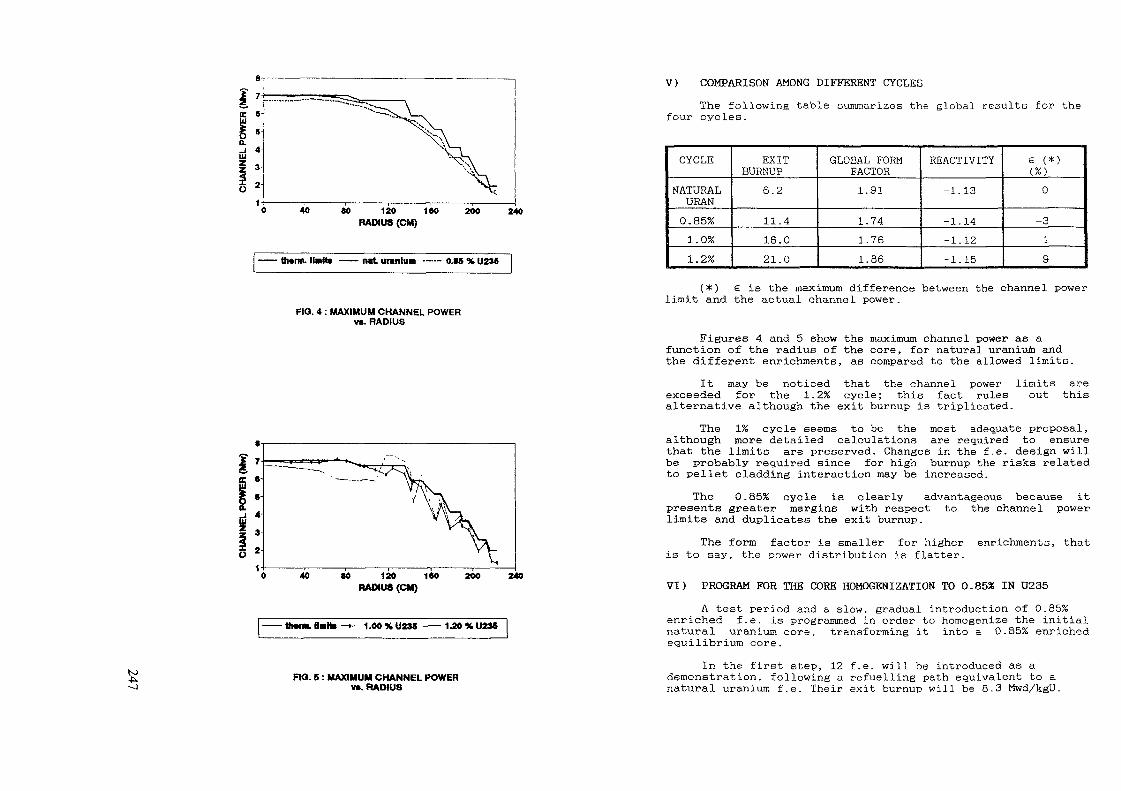
«0 120 1<0RADIUS (CM)
200 240
• twrt. uranlim —— O.M % U236
FIQ. 4 : MAXIMUM CHANNEL POWERvs. RADIUS
40 SO 120 160RADIUS (CM)
200 240
• ttMTM. Halte 1.00%U236 1.20%U2M
(0 FIO. 5 : MAXIMUM CHANNEL POWERvs. RADIUS
V) COMPARISON AMONG DIFFERENT CYCLESThe following table summarizes the global results for the
four cycles.
CYCLE
NATURALURAN0.85%1.0%1.2%
EXITBURNUP
6.2
11.416.021.0
GLOBAL FORMFACTOR1.91
1.741.761.86
REACTIVITY
-1.13
-1.14-1.12-1.15
6 (*)(%)0
-319
(*) 6 is the maximum difference between the channel powerlimit and the actual channel power.
Figures 4 and 5 show the maximum channel power as afunction of the radius of the core, for natural uranium andthe different enrichments, as compared to the allowed limits.
It may be noticed that the channel power limits areexceeded for the 1.2% cycle; this fact rules out thisalternative although the exit burnup is triplicated.
The 1% cycle seems to be the most adequate proposal,although more detailed calculations are required to ensurethat the limits are preserved. Changes in the f.e. design willbe probably required since for high burnup the risks relatedto pellet cladding interaction may be increased.
The 0.85% cycle is clearly advantageous because itpresents greater margins with respect to the channel powerlimits and duplicates the exit burnup.
The form factor is smaller for higheris to say, the power distribution is flatter.
enrichments, that
VI) PROGRAM FOR THE CORE HOMOGKNIZATION TO 0.85% IN U235A test period and a slow, gradual introduction of 0.85%
enriched f.e. is programmed in order to homogenise the initialnatural uranium core, transforming it into a 0.85% enrichedequilibrium core.
In the first step, 12 f.e. will be introduced as ademonstration, following a refuelling path equivalent to a.natural uranium f.e. Their exit burnup will be 8.3 Mwd/kgU.

The following steps will be 24, 50 and the 100 enrichedf e.(0.85%) to be introduced in a period of two yearsapproximately,with a gradual increase of the exit burnup
As the refuelling schene in Atucha i allows the re-entrance of spent fuel elements from the pool, it is possibleto consider a strategy of spiking of half-burnt naturaluranium f.e. in a slightly enriched homogeneous core in orderto optimize costs This possibility has not been studied yet
VII) ECONOMIC BENEFITS OP 0.85% ENRICHED F.E.As the exit burnup is duplicated, the number of f.e.
needed assuming an annual load factor of 85 %, is decreasedfrom 396 to 205. This implies an annual saving of 30 % infuel cost, and 31 % in uranium resources.
This evaluation was performed withfor the important cost parameters.
international values
It should be mentioned that the average exit burnup of a0.85 % enriched f.e. must be 7.9 Mwd/kgU in order to obtainthe same generation cost as for the natural uranium f.e.
The economic benefit is thus evident from the initialtest stage.
As an additional argument, we should also mention thatthere is a reduction impact in the number of fresh f.e thatare necessary in order to be able to operate the plant during6 months with a load factor of 80 %. 184 elements arerequired, while only 95 f.e. are needed in the presently 0.85%case.
We should also take into account that within 30 years ofoperation all the vacant positions in the decay pool willbe occupied, whereas if the enrichment program is initiated,vacant positions will still be found for 8 to 10 years more,thus, this will be not be a limiting factor for the eventuallife extension of the plant.
The economic benefits due to the less frequent use of thetransport system, as well as the less degraded inventory ofD20 produced by the utilization of 0 85 % enriched f.e. couldnot be calculated
VIII)CONCLUSIONSUnder the assumptions of maintaining the same
thermohydraulic design of the plant and producing the leastnumber of changes in the f.e. manufacturing, the alternativeof 0.85 % enriched fuel seems to be the most adequate forAtucha 1 NPP
This alternative duplicates the fuel exit burnup andimplies an annual saving of approximately 30% in fuel cost anduranium resources
It also results in vacant positions in the decay poolwhich facilitates the eventual life extension of the plant
A program based in a gradual introduction is proposedin order to be able to perform a detailed following of thef e. until a completely homogenized enriched core is obtained.
A check of the results obtained with the simplifiedmodel will be required with a more detailed one, simulatingthe fuel management for a long period and studying thevariations of the control and shut down effectiveness as ameasure of the plant reliability.
REFERENCES{1} 'A summary of WIMS-D4 input options" M. H. Halsall- AEEW
M1327 (1980){2} "PUMA: Descripciôn y manual de uso ' . C. Grant. IT 1043/90
(1990)

PERSPECTIVES ON INNOVATIVE FUELAND ASSOCIATED CORE PHYSICS
J PORTACommissariat à l'énergie atomique,Centre d'études nucléaires de Cadarache,Samt-Paul-lez-Durance,France
Abstract
Increasing the safety level of future water reactor may be reached bydifferent ways
One way consists in keeping the present configuration of the core andincreasing the efficiency or reliability of safety devices in order to ensure a better globalsafety In some cases the margin optimization is obtained by lowering the linear powerof the fuel
A second way might be followed it tries to get a more forgiving reactorphysics by optimization of different reactivity coefficients, avoiding some reactivityaccident initiators, using a colder fuel In doing so, one increases the level of preventionrather than the protection itself
In order to illustrate this approach this paper emphasizes 2 aspects
* PWR without soluble boron (excepted for safety injection) this goal will bereached by using burnable poisons (heterogeneous and/or homogeneous) optimizingmoderating ratios, cycle length, primary temperature versus load, others absorber rodsIn doing so, an important reactivity induced accident initiator would be eliminated
* Another way is related to 'cold fuels' The objectives are to reduce storedenergy, pellet clad interaction fission gases release and increased margin on DNB
This paper describes the different possible "cold fuels' and the very firstassociated core physics studies in term of spectral effects on different temperaturecoefficients
At the CEA development programmes for future reactors are directed simultaneously according to twoapproaches
1 ) The evolutionary approach on the basis of the actual core design, the efficiency orreliability of safety related equipments {and procedures), materials etc , is increased soas to reach an overall higher level of safety
2) The "revolutionnary" or innovative approach consists tn inquiring into reactor physics, forconditions which tend to ensure more forgiving systems through the optimization of the variousreactivity coefficients, the elimination of initiators of reactivity accidents, the utilizationof a colder fuel etc
This second approach improves the level of prevention rather than increasing the protection against therxsk.
The subject of this paper is to illustrate specifically the second approach
For this purpose two aspects, now under investigation at the CRN will be developed These aspects arerelated to
1) Boron free PURs (coolant without soluble boron)2) Itrplementation of "cold fuels"
2 BOROK FREE PWRs
2 1 interest in suppressing soluble boronSafety Soluble boron appears as the major initiator of reactivity accidents in case of untimelydilution Indeed, probabilistic studies showed an occurrence frequency which was not neglectibleboth during operation and on cold shutdown
Limitation of cycle lencijh Boron content in the coolant is limited to < 1200 ppm to fulfill therequirement of a negative temperature coefficient For instance with a pure uranium core in a1300 MUe with I/A core reloading, the average burn up limit is 55 GUd/t , with Mox fuels, due tohardenmng of the spectrum and subsequent loss of absorption properties of boron, cycle length wouldbe further shorten (by a factor close to two)
Limitation of load follow Because of limited dilution rate load follow with boron adjustments isnot possible during the last part of the cycle
Waste potential chemical polution with boron and a source of tritium could be removed Also, theefficiency of the CVCS purification on ion exchangers O e for Cs) w i l t be improved without theinterference of boron
1 1HTROOUCT1QM
Simplification of the systems and of operation Boron injection systems, CVCS, waste processingsystems (boron recycling ) w i l l be consistently simplified For operators, it is also the end ofthe constraining specification on coordinated boron to lithium ratio
Feed back experience from the 56 PWRs which are now (Dec 1990) under operation in France, hasdemonstrated that actual Nuclear Water Reactors (W R ) can reach a high standard of safety andoperational reliability
However, looking to the future reactor generations, it seems always possible to further reduce theresidual risk and to iitprove reliability
DRN Direction des Réacteurs Nucléaires (Nuclear ReactorDirectorate)

toc/»oCorrosion Suppresion of boric acid is expected to
improve corrosion rates of austenmc materials, wich are at the origin of dose rates on outof core surfaces,
- presumably have a positive influence on IASCC in the S G. tubes (as one knows, °0 X of thesecraks are originated from the primary side),
presumably, improve corrosion resistance of zircaloy cladding, this parameter being one ofthe barrier to extend burn-up (it has been shown that Li* recoil from B(n, ) Li reactionwas penalizing to ztrcaloy corrosion rates)
However one of the positive aspect of the boron is the usually homogeneous absorbance minimizing theaxial offset.
2.2. Quantitative aspects of boron in reactivity control
The proeminent part of soluble boron and the orders of magnitude of the associated negativereactivity are, for a 1300 HWe PWft :
- fuel burn-up : 8500 pan,- Sra and Xe poisoning : 1500 pcm,
(Load follow 100 X -> 30 X NP with control rod cluster * 3000 pcm)
- fuel Doppler : 500 pen,- moderator density • 6500 pcm,(cold shutdown)
safety subcriticality margin 5000 pcm,
TOTAL • 22000 pcm
2.3. Alternative options
a) Fuel burn-up the reactivity to ensure cycle length implies the extensive use of burnablepoisons (heterogeneous and/or homogeneous with respect to the fissile materials.
Among the criteria for the candidate burnable poisons a difficulty (especially on large conmercialreactors) is to accomodate the poison and fuel burn-up rates and to minimize their mismatch, overthe entire fuel life Ckeff close to 1) (mismatch is ajusted by grey rods).
Theoretical considerations show the benefits on combining various poisons (since no single one willburn-out at the same rate as the fuel itself)
Fortunately, many parameters can be considered for this adjustment i.e. :
nature, isotopic content and density of the poison
- poison in an inert support (i.e.
- self shielding, by adjusting the spatial location m the core and using discretization of thematerial (grams with adjusted sizes)
SHIM ttoo CHANNEL
[1] MUltlCIU KUM8U
FIGURE 1 : 1/6 OF THE SSCR ASSEMBLY
Minimization of the penalty on fuel Iifetime (residual poison) wi II require refined neutronicstudies and a new philosophy of in pile fuel management
The safety enterest, is to lead to a global reactivity coefficient close to one as a constant forthe cycle length and so to approach the inherent safe assembly, concerning the excess of reactivitycriterion, respecting the definition given by [1],
A preliminary study, at the fuel pin level, has been performed, concerning a SSCWR (Spectral ShiftConvertible Water Reactor) MOX fuel loaded CPu/U +• Pu = 9,14 X) core, moderating ratio close to1,4 [2], where several rods (depleted UOg, GdjO , ZrBg.--) were fitted into the 30 guide thimbles ofthe 331 locations of the assembly (figure 1). The results of the study indicated that, at first, thewater displacement caused by the poisoning rods induces a hardenmng of the spectrum and itsassociated non neglectiblc variation of the moderator temperature and density coefficients caused byboth the Lowering of the volumetric ratio of water and the hardenning of the spectrum Then themajor result is the spectral interaction between Gd^j, Gd^y and UPu which grows stronger theintrinsic direct negative reactivity of Gd2f>$ (direct effect of Gd2U3 ** - 260Û pcm, induced spectraleffect on Pu v -4QOQ pcm).
An another degree of freedom is the abundance of the Gadolinium in the support (figure 2) and theisotopic weight abundance.
The effects are rather different for the burn-up kinetic and the Pu induced spectral efficiency(table 1). Figure 2 shows that between 0 and 500 (mg/ctir*), natural Gd2U3 is a burnable poison with akinetics able to roughly change the affinity of the physics (of the curves), between the referencecase and the perturbed one. Between 500 and 1000 (mg/cnr*). GdjQ is an absorber and it does notchange the physics because its burn-up kinetic is not well fitted to the fuel one.
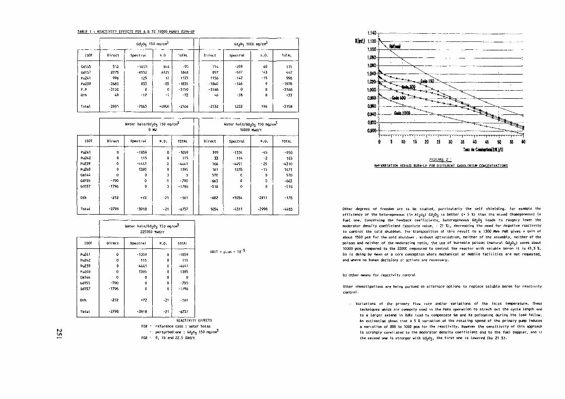
TABLE 1 : BEACT1VITV EFFECTS FOR A 0 TO 10000 MUd/t BURH-UP
I SOT
Gd155Gd157Pu241Pu239F.POth
Total
CdjOj 150 mg/cra3
Direct
5122275996
-2683-3150
49
-2001
Spectral
-1450-6552
1259330
-12
-7063
H.O
8486125
12-850
-1
•6900
TOTAL
-9018481135
-1835-3150-72
-2164
CdjOj 1000 us/cm5
Direct
7148971156-1840-3168
•6
-2132
Spectral
-259-597-142-1460
-78
1222
H.O.
60143-15900
196
TOTAL
515442998
-1978-3168+33
-3158
I SOT
Pu241PU242Pu239Pu240Cm144Gd155Cd1S7
Oth
Total
Water hole/GdjOj 150 mg/cm30 HU
Direct
00000
-790-1796
-212
-2798
Spectral
-105«115
-44411395
000
»72
-3918
H.O.
0000000
-21
-21
TOTAL
-1059115
-444113950
-790-1796
-161
-6737
Water Kole/Gd^ 150 rog/cnr510000 MWd/t
Direct
39933166161570-663-518
-682
1054
Spectral
-1304114
-44511276000
•3934
-4311
H.O.
-45-2
-25-15000
-2911
-2998
TOTAL
-950145
-43101421570-663-518
-178
-4483
I SOT
Pu241Pu242Pu239Pu240Cra144Gd155Gd157
Oth
Total
Water hole/Gd203 150 mg/cm3225000 MUd/t
Direct
00000
-790-1796
-212
-2798
Spectral
•1059115
-44411395
000
*72
-3918
H.O.
0000000
-21
-21
TOTAL
-1059115
-44411395
0-790-1796
-161
-6737
UHIT = p.cm = 10"5
REACTIVITY EFFECTSFOR - reference case : uater holes
perturbed one : Gd20j 150 mg/cnrFOR - 0, TO and 22.5 GWd/t
5 10 15 10 25 30 Î5 40 45 W M W
FIGURE 2 :&OVARÏATIOH VERSUS BURH-UP FOR DIFFERENT GADOLINIUM CONCENTRATIONS
Other degrees of freedom are to be studied, particularly the self shielding. For example theefficiency of the heterogeneous (in AljOj) Gd2&j is better (+ 5 X) than the mixed (homogeneous) infuel one. Concerning the feedback coefficients, heterogeneous GdgOj leads to roughly lower themoderator density coefficient (absolute value, - 21 X), decreasing the need for negative reactivityto control the cold shutdown. The transposition of this result to a 1300 HWe PWR gives a gain ofabout 1500 pcm for the cold shutdown . Without optimization, neither of the assembly, neither of thepoison and neither of the moderating ratio, the use of burnable poison (natural Gd^Oj) saves about10000 pan, compared to the 22000 requested to control the reactor with soluble boron it is 45,5 X.So is doing by mean of a core conception where mechanical or mobile facilities are not requested,and where no human decisions or actions are necessary.
b) Other means for reactivity control
Other investigations are being pursued on alternate options to replace soluble boron for reactivitycontrol.
- Variations of the primary flow rate and/or variations of the inlet temperature. Thesetechniques which are commonly used in the PWRs operation to strech out the cycle length andto a larger extend in BURs lead to compensate Sm and Xe poisoning during the load follow.An estimation shows that a 5 X variation of the rotating speed of the primary pump inducesa variation of 800 to 1000 pcm for the reactivity. However the sensitivity of this approachis strongly corellated to the moderator density coefficient and to the fuel Doppler, and ifthe second one is stronger with Gd203, the first one is lowered (by 21 X).

tot-AtoAs an attempt to differremiate control systems, calculations have been carried out with gazeouspoisons rods replacing of grey rods in a 1300 HWe PWR [3] Gazeous rods poisons consist of eitherBHj (natural or enriched boron) or mixed He^/He^ in the guide thimbles A part from anyconsiderations on mechanical faisability (and reliability), the equivalent control rods worth isobtained with a pressure of 70 bar for BHj (nat) and 35 bar for 25 X of Hfrj in mixed Hej/He^ or with15 bar for in 106 enriched (90 X) and 8 bar for 100 K He^
The overall reactivity of such a system has to be kept low enough to make sure that depressunzationof gazeous rods does not induce reactivity accident
The major interests, from the neutronical and safety point of view, are .
Whereas the dry out conditions are dependent only on the thermohydraulics, melting temperatureof the fuel is mainly dependent on the burn-up, many manufacturing factors, and, evidently, isan intnnsec property of a particular compound Even if there is an important margin between thefuel melting point and operating conditions, the existence of the critical flux help to avoidfailure threshold on load follow From the point of new fuels like metals, with relatively lowmelting point, these criteria need to be reconsidered in details. Some of these requirements canbe achieved on us i ng oxyde fuel under t ts actual configurati on, for instance by decreasinglinear power density (as this is a general trend for Advanced - Water - Reactor) Benefits fromthis I imitation are expected on cladding corrosion (decrease in metal to oxide interfacetemperature), fission gas release, on CPI and DNB margins, and on decreasing the stored energyin case of accident
a rough decrease of the temperature coefficient with the gazeous rods,the absorbance is axially homogeneous and does not induce Xenon tilts and so restricts the
axial power tiIts.- it is a fine tuning control system
Concerning the gazeous rods, many other investigations have to be carried out ; spatial location ofthe rods, optimization of the radial power shape, mechanical faisability and safety analizis of sucha system. However, it should be pointed out that some facilities are operating with equivalentsystems : GEM (Gas Expansion Modules) in FFTR, aeroballs in some BUR'S and HeliumS gazeous rods inthe safety test reactor CABRI therefore, it can be reasonably assumed that this existing technologycan be further developed.
3. COLD FUELS
The increasing trends of the Nuclear Community to save fissile materials creates a strong demand tofurther optimize fuel performance.
Parameters to be possibly increased to satisfy this goals are :
linear power density,- peaking capability,- average burn up at discharge, by increasing the number of cycles and / or cycle length.
However, it is required that the safety criteria and the margins be maintained, at least at the samelevel of reliability as they are at present time for all the conditions of operation.
The technological limitations of the above mentioned parameters are
1) Cladding resistance to waterside corrosion . oxyde growth and consecutive hydriding of thezircaloy causes a loss in ductility of the metal together with thinning of the clad Theactual requirement is expressed as a temperature limit at the metal oxyde interface
2) Fission gases release :- increase of the fission gases release with the increase of the fuel center-line
temperature,increase of the clad internal pressure,
- increase of the clad-pellet interaction (iodine).3) Clad-pellet-interaction during operation :
operation : closing of the gap (20 GUd/t),load follow : local linear power density on hot rods may exceed failure threshold.
4) No local melting of the pellet and no OHB (for cat. 1 and 2)The more penalizing of these two parameters permit to define a limit to the maximum local heatflux so called "critical flux".
A study W] shows that the decrease of the Linear Power Density (LPD), by mean of the decreaseof the central temperature in the fuel pellet would lead to :
a) A decrease of the cladding corrosion because of lower oxycte-metal interface temperature.The range of this decrease can be calculated with CEA corrosion code for stress relievedzircaUoy 4.
- - 10 X LPO -> - 30 X corrosion,- 20 X LPO -> - 50 X corrosion
b) A decrease of the fission gas release which leads to increase margins versus internalpressure criterion.
c) Increase of the DHB margin.d) Increase of the CPI margins.e) Gam concerning mechanical and chemical aspects.
As a result, higher burn-up can be reached without having to consider neu cladding materials.
From the safety point of view, the decrease of the stored energy, by decreasing the pellettemperature is a favorable step in case of accident.
It should be noted that the specific power could be kept unchanged by decreasing the fuel pindiameter and increasing their number.
Other attempts currently under investigation consist in improving UOj conductivity with metaladditives, or to use a Urge gram fuel, limiting the diffusion of fission gases.
However these improvements proceed from the first evolutionnary approach and are not preciselythe subject of this talk Our "innovative" approach focuses on developing new type of fuels withsuch characteristics as a high thermal condictwity, a significant high density in f issi leatoms, compatibility with the coolant and cladding material and so on.
Four options of new fuels are presented below
metallic fuels CUAl, UZr ), already extensively used in research reactors studied forthe LMFBR PRISH [5] From the safety point of view, the disavantage for WR is todrastically increase the inventory of oxizidable metal in the core (during a severeaccident the hydrogen from the oxidation of the fuel would add to this originating fromthe oxidation of zircaUoy cladding, possibly leading to explosive reaction) On theother hand metallic fuels present a strong swelling rate on irradiation property whichimply to limit the weight density to 60/70 X of the theoretical density,
• carbide (UC1 already used in LHFBR, a Japanese study shows that it could a very promisingfuel for FBR [6], but in UR, the compatibility with hot uater (in case of claddingfai lures) is questionable In addition the fuel reprocessing is not praticable wt thcurrent technology.

» » 2.s < -i< •? "
1113 o —" K •<
*n11}T O <-< 3 jo.
? S. -.
= Xj?5
a ü.1' ^I »ïï **
nT
O
D
>
ro3
rt
1•<
=r
o
3O
C
?to
TJ
8
X
»jf
* '•H
tn
11
C '
i1,31 JQ> C
S j
1
'
c
'1
r i
J- '
1 ?
2 -, sta
bi i ity
an
d ;
' -
' 0
c rt
* iriU' 3-1' J- s.u "•
5 0
C 3•" O->1
* -oi s.* i> 3
' 2.<-•; a-: «
* "3
1
- S
Sû.'D
rhermat
D
SiIQ.
tJ1
er
sCQtu
TD-3
|
S
D
S&3
O
=r
no.
lI1£
a
3
X
O
fo
s«
3
2"o
1!ajju
3
C1
i
iro
•?&
<
er-iTt
io
a
(Ï n
8 "'-» n
** -i
i ?«t
? i'=•• sW Q.^^•c !.on
W
-i10
•oa>T
O
?s--aS"
i'oöT~]<;.1i?
Jecreas
n0
1
K
ï^
Ä3S
I
is5
•gS
S-i
r»
<
^<
-1
Cm
£
c
Jens ity
r.
re
sss1
ü<'r*x:Q.C
^0
o.
is
KtnC
i.1
01
a5
=r
<i
i'o
n-t
<'
-<e
3"
5nK
•"*Q.
irt•<
C
-»X
fn2T
jy decreasing the
o$so
s0
1S"
§Î,IÎI0
3
><
-Jjx
-ft
iiPVJ11?1
n 3
? * •" g Suz5 r» s w D
i «•*- 3- *"2, " Da g aO" ^ "'"* 2, p? "** Vrt 0 w
rt rt *~l =T 00O f»
« rt **
§ i2 s5 0rt Is |
Ä**? o"s> 1-tr1 s2 ?ten
the spectrum
,s
hift
induces a
/ / /
? ? ?C S
^ n~ r?
^o o i-J 4S O>
X W X
-i C >
s ^ "?• T S" 1-1 ?
Ü!l!l» ° si 2 s» •< „!•
I s I
§ '•g ÏÏ3 S
- -
i-t O 01"I »
•* p- =0 » rt"• 2 ?
ÎUS JS
S T-< n
o •<
a a
c _.
3 l S 3 S'? = 3 £. &
1/1 in ^ -"'
3 s
Ï- ? (O
Sn> 5 J o•» u. û nvi n c -K
•R Ti3 3
Reactivity (E-5)

The global effect for cold shutdown is 6750 pern for UZrN and 6750 pern for UÛ2- The use of UZrNrequires the same control rods for the cold shutdown as for UOj but UZrN will be more forgivingon power or reactivity transients
Studies on burn-up
Figure^ shows the burn-up behaviour of different nitride fuels. The different slopes of thecurves can be interpreted as the result of a very different production comsumption rates for
and 239pu Table 2 shows that, in fact the in-out masses balances are rather different235„
The most important physics features is the effective moderating ratio variations with the typeof fuels. Starting from a standard PUR assembly (moderating ratio MR = 2), one obtains oneffective HR of 1,3 for UN, 1,8 for UZrH d = 90 X Td, 2,3 for UZrH d = 70 X Td So varying thetype and the density of the fuel it is possible to increase the consumption of ^U and * 'PU
= 2,3 over moderated core) or to increase the production (and in quality too) of Pu= 1,3 under moderated core). Doing so the impact of these fuels is very strong on the
strategy and cycle, particularly for the minimization of the Actmide production. Tabte 2 showsthat UN and UZrH cycle lengths are shorter, versus reactivity, than for UOj, but corrosion andgases release are roughly lowered it becomes thus possible to increase cycle lenght by mean of^U enrichment. Concerning the safety, including a metal in a ternary compound is not a235,,
f avorabl e step because the oxi dat i on and hydrogen rel ease i n case of ace i dent, it will bepreferable to sudy compound including unoxizidable material (i.e.
From the economical point of view, several estimations [7] [10] give a 10 to 20 F/g price forN15 and shou that the N15 enrichment cost presents very low variations between 30 and 90 X of15N. A recent synthesis HD gives, for LHFBR a 16 F/g price as a threshold of profitability.
0.800 5 10 15 20 25 30 35 40 45
GWd/tFIGURE 4
VARIATION Of THE KINflHI UITH TUE
TABLE 2CRITERION EQUIVALENT k INFINI FOR UQ? B U = 23.75 GWd/t
Tc HWEH HWj/t
LOT HWj/t
DUREE JEPP
Energie TVh
Fin de cycle MWj/t
Pu 9 %
Pu 0 X
Pu 1 %
Pu 8 X
Pu Z X
A« X
N Pu TOT
Pu Fis X
us 'l»f
T rejet X
AUS
AUS
AU5/HU5 X
AU8/NUS X
A (U5HI8)
A(U5»U8)/(U5»U8)'X
P
Hasse
P/ lin
U0?
23750
10300
256
5.53
41200
51.56
24.1
H. 3?
2.3
7,2
0.42
2,3031-1/1
65.93
1,7-1
21,075
0,8
6 7572-1/1
0.658/1
79,9
3.02
1 33372/1
6.13
900 HV
72 5 t
175 5 U/cm
U Z r N 70X
24600
9840
240.2
4,39
39360
51.6
24.85
14, W
2
7.14
0.4
1 7806-1/0.773
65.64
1,5-1
17.926
0.83
5.6705-1/0,84
0.501/0.76
79.08
2 . 7 2
1.068/0.8
5.58
763 MW
60,4 t
148 8 U/cm
UZ rN 90%
22600
9040
220.3
5.18
36160
56,36
82.54
14
1.42
5.Z9
0.39
Z. 4839-1/1. 08
70.35
2.13-1
23.06
0.92
7,0892-1/1,049
0.632/0.96
76.89
2.67
1.34092/1.005
5.45
981 HV
77.6 t
191.3 W/cm
UH 1 4
15200
6080
151.6
4.36
24320
67 83
17 44
11.45
0 8
2.24
0 25
2.8381-1/1.23
79.28
5.3-1
29 05
1.79
6.224-1/0 92
0.565/0 86
54
1 91
1 874/0 89
6 09
1200 HU
97 t
234 U/cm
UN!5«K
21800
8720
217,5
6,26
34880
59.06
20.62
13.62
2,08
4.25
0.37
3.3863-1/1.47
3 514-1
28.747
1.206
8.01-1//1 185
8.18-1/1.243
69 5
2.76
1 619/1 214
S. 26
-

Estimations give 3 possible price for 15N close to 2 F/g for a 80 t/y production Considering a10 F/g averaged cost of 15N it is only 3 X of the fuel cycle cost (including reprocessing) and0 7 X if the price is 2 F/g
The resistance to oxizidation of different ternary compounds is a part of on going experimentalstudies conducted at CEA/Cadarache The results (avalaible at the end of 1991} will allow tointerest the studies in qualification core calculations for the candidate compounds Associatedwith economic and strategic calculations these studies will allow to define the place that coldand dense fuel would take m the future reactors
[51 VAN TKUYLE and alSummary of advanced LHR evaluations PRISM and SAFR NURÊG/CR 5364October 1989SALERNO and alALHR fuel cycle economics San Diego August 19S9
(6) H TÊZUKA and alConceptual desing study of LHFBR core with carbide fuelInt top ANS meeting Pans April 1987
4 CONCLUSION[7] I S SLESAREV and al
The high safety and economy NPP with liquid lead cooled reactorsSeminar Moscow 22 24th October 1990
The review of the physics exposed here leads to define the major axes of a three points Programm ofstudies requesting several competencies
Convertible boron free PURLowered linear power density convertible assembly with locations for a control using burnablepoisons
Cold and dense fuel allowing to increase the performancies in terms of cycle length, economy ,while respecting (or increasing) the level of the safety
r_8] A KAVENOKY
Neptune a modular system for the calculation of LWRConf 750413 Charleston 1975R SAHCHEZ J HONDO!
Specifications détaillées APOLLO 2 internal CEA note SERHA T 1632
[9j J PORTA and alSensitivity studies on high conversion power reactor viaperturbation methods and information conditionningHucl Sei Eng 95(4) 266 1987
Aknowledgements
Thanks to Dr MAXY NOE CEA/DRN/OER/SIS for many enlighting discussions and informations concerning thecorrosion and the effects of the temperature on the mechanical and chemical cladding resistance and forreviewing the manuscript and to Dr AZZOUG for his contribution to the studies concerning nitride fuelin PURs
[10] H N0£ J ROUAULTInternal CEA working group DER/SIS OEC/CPCE and privatecommunication
[11] H N0€Justification d'une étude techmco économique de l'enrichissementisotopique en MIS pour les combustible RHR futursInternai CEA DER/SIS note 91/1027 April 1991
[1] IAEA consultants group safety related terms of advanced nuclearplants Final report Vienna 3 6 December 1990
{21 J PORTA and alSearch of a few group structure for plutonium fueled advancedreactors4th 1CENES, 30th June, 4th July 1986 MADRID
N>
[31 P THOMET
Emploi d'absorbants gazeux dans les reacteurs a eau pressuriséeConséquences sur la neutronique du coeur Internai CEA/OÊR/SISnote 91 1022 June 1991
[4] M NOeInternal DER/SIS working group and private communication

ft LOW POWER REACTIVITY INITIATED<* ACCIDENTS IN NEW GENERATION
LIGHT WATER REACTORS
G. ALLOGGIO, E. BREGAEnte Nazionale per 1'Energia Elettnca,MilanE. FIORINOEnte Nazionale per 1'Energia Elettnca,RomeItaly
Abstract
Plant low-power operation had been generally considered to be a safercondition than high power operation. Results from Probabilistic RiskAssessment studies for French PWR's pointed out the importance of risk whenthe reactor is shut-down or in refuelling.
The low-power concern is in part directed at loss of decay heatremoval accidents. This paper is focused however on reactivity accidents,which are worst at zero/low power than at rated conditions due to thelarger amount of reactivity that can be potentially added, to the lowermoderator feedback available to quench the excursion and because controlsystems operative at power are often inoperative during shutdown.
A review of low-power reactivity accident scenarios for SBWR and AP600 reactors is provided.
In particular, 3-dimensional space-time analyses are presented forcontrol rod drop/control rod ejection accidents in the SBWR; thepossibility to mitigate such events by a suitable startup procedure isdiscussed.
Reactivity excursions due to the insertion or dropping of a fuelassembly into the core during plant refueling are discussed for SBWR andAP 600.
Accident scenarios for AP 600, involving the possibility of rapidboron dilution, are discussed; the possibility to improve the plantperformance by the use of burnable absorbers is highlighted.
1 Introduction
Pl.inl low power operation ( i c < 5% ) had been generally considered to be a safer condition than high powerOperationMost of the events occurring at high power conditions, like for example turbine trip, loss of feedwater, MSIVclosure, are less severe at low power or are not possible at all1 he same is true for LOCA's, due to the reduced level of stored energy m the fuel and of radionuclides inventoryFurthermore LOCA's are by far less probable at zero power due to the drastic réduction of the primary systempressureIn spite of these considerations, PRA studies for French PWR's put emphasis on the importance of risk when theiLddor is shutdown or when it is in refueling These states account for over half ( 55 % ) of total calculated coremelt risk in the 1300 MWe plants and almost one-third in the 900 MWe plants These high values may result fromthe lact that there are generally no automatic systems to counter accident situations in shut down conditions andtha i human intervention is therefore necessaryT hough the concern is in part directed at loss of residual heat removal system events, this paper will focus onreactivity accidents initiated at /ero / low power conditions which represent the most limiting power level for manyreactivity accidents in LWR's due toi) the larger amount ot reactivity that can be potentially added ( with obvious exceptions like void reactivity inBWR overpressunzation transients ),u) the lower moderator feedback available to quench the excursion,m) possible unavailability or uneffectivness of reactor protection system
In particular this latter point was stressed in the US Nuclear Regulatory Commission report subsequent to theChernobyl accident [1], which recommended to focus on sequences that involve relatively large reactivity additionsdue to one or more of the following- low or zero power or testing as an initial condition
inadequate response of shutdown systemsa positive moderator temperature coefficienthuman errordeliberate bypassing or disabling of any safety feature
As an outgrowth of such recommendations, Ref [2] investigated, from a deterministic and/or probabilistic point ofview, LWR reactivity event sequences for their potential to result in fuel fragmentation and prompt dispersal
In this paper we intend to review reactivity initiated accidents ( RIA ) during zero and low power operation forsome of the new generation light water reactors, that is the Simplified Boiling Water Reactor ( SBWR ) and thePWR type AP600, highlighting design and procedural features that improve inherent plant réponse to RIA'sAnalyses for the SBWR, discussed in Section 2, were performed within the framework of a more generalagreement between General Electric and ENEL, they are at a final stage and are based on detailed threedimensional space-time calculationsPreliminary evaluations for the AP600, discussed m Sections 3, were aimed at the mdividuation of accidentscenarios worthwhile to be analyzed in detail by dynamic calculations Section 4 summarizes the conclusions drawnin this reportFinally, some details about calculalional models are presented in Appendix 1
2 SBWR Reactivity events
Low power BWR reactivity event sequences can be grouped as follows [9]i) Events due to thtt rapid removal of control absorbers
1) Control rod drop accident2) Control rod ejection accident3) Continuous control rod withdrawal4) Boron dilution during ATWS,

n) Events due to the insertion of fuel bundle ( Refueling accidents )5) Fuel bundle loading accident6) Fuel bundle drop accident
111) Events with rapid insertion of cold water7) ATWS with boron injection failure
Sequences 1), 2), 5) were explicitcly analy/cd for the SBWR plant, by 3 dimensional space time calculations ( seeAppendix 1 for a short description of analytical methods ), in support to the SBWR PRA study and the results arediscussed in the next sections A qualitative discussion K provided also for the sequences 3) and 6)
Sequence 4) consists in the flushing of the boron injected by the Standby Liquid Control System during the latterphase of an ATWS, by unborated ECCS water when the pressure is abruptly lowered below the low-pressureinjection set-point by the Automatic Depressun/^tion System ( ADS ) madvertant actuation The possibility thatboron flushing might lead to a severe power excursion had been of concern for standard BWR's |2]The accident was recently analy/cd for a BWR-4, the Browns-Ferry plant, by RELAP5/MOD2 [3] The injectionof cold unboraled water causes indeed a severe power excursion ( with power peaks of around 3 4 times the ratedpower ), but inherent feedbacks limit the peak fuel enthalpy to less than 220 cal/g Although fuel prompt dispersalis not expected, fuel damage may occurr as a result of excessive clad temperatures This may be caused directly bythe high power levels leading to boiling transition or indirectly because the energy generated in the core cannot bedissipated and excessive containment suppression pool temperature can lead to failures of systems cooling the corePrevious sequence is very similar to the case where there is a boron injection failure after an ATWS ( Sequence 7above ) with ADS actuation and low pressure injection In that case, the power is not shut-down prior todepressuriiation, but once that cold water enters the system, a power excursion is produced, due to the decrease insaturation temperature and subsequent void collapseSequences involving plant depressunzation and rapid inlet of cold, unborated water from the Gravity DrivenCooling System ( GDCS ) is less important in the SBWR, due to the automatic inhibition of ADS Furthermore,GDCS injection flow is very sensitive to the vessel backpressure, so that flow is reduced or stopped by the pressuresurge caused by the power excursion Anyway, the event is much slower than in a standard BWR
Summary of SBWR CRDA resulis
RUN
I7
3
45
678910
DI-iCRlrMION
Single ErrorMultiple ErrorMultiple Lrror
with scramMultiple ErrorMultiple Error
Single DropSingle Drop
Multiple DropMultiple DropMultiple Drop
ADDEDK1J\
m185301303
309309
225234565572574
MODERAI ORINLET
SUBCOOLIiNGCO9898
98
381
3818382818
PEAKHJEL
LNTHALPY(«1/g)
179321299
30321
175187
>375306259
PEAKPOWER
(MW)607248511763182
9431015949
3466038756
276424281844281868
PHAK.POWER
I1ML
«050303930423
03890379
03110307025302520251
VOID ONSJ'lI1MI
M08620.5880646
04400378
04210331
>026002520250
Beginning of equilibrium cycleRuns 1-4 SBWR 9ft Single control rod dropRuns 5 9 SBWR-êft Multiple RWM failuresC ore power 10 rated powerCore flow 15% rated flowModerator Saturation Temperature 118 °C ( Runs 6-8 ) / 81 °C ( Run S )
to
2.1 Control rod drop accident analysis
The control rod drop accident ( CRDA ) is the postulated dropping of a control rod at Us maximum velocity Inorder to be able to fall by gravity, control rod blade must separate from the control rod drive, with the bladesticking in the inserted position while the drive is withdrawnControl rod drive design in the SBWR is completely different from standard GE design, to allow control rod finemotion As a consequence of such modifications, features has been introduced, like a modified drive-bladecoupling and a separation detection device, which make the possibility of a control rod drop even more remote Onthe other hand the control rod blade free fail velocity is much higher than m standard BWR's ( about 3 versus 0 9m/s average speed ), due to the elimination of the control rod velocity limiterIn the same way than in standard BWR's, control rod worth is minimised by the hard-wired Rod Worth Mmimi?ersystem ( RWM ), which constrains the sequence of control rod withdrawalEven with multiple errors ( that is with multiple failures of RWM ), control rod worth is significantly less m SBWRthan in a conventional BWR maximum worths with single and multiple errors are respectively 1 9% and 3 0% (SBWR with 9ft long fuel at the equilibrium cycle, 20 °C ) to be compared with typical values of about 2 5% and4 0% for a conventional BWR core [4],[5] This important inherent feature is reflected by the increased shut downmargin allowed by the heavy use of burnable absorbers and by the reduced power density of the SBWR plant
Control rod drop accident has always been considered the bounding reactivity accident for BWR's genericsensitivity studies [4], [6] concluded that zero power conditions are the limiting ones for this accident, since, whenthe reactor is at power, control rod worth is significantly reduced and voids exist in the core to quench readily thereactivity excursion
CRDA was analyzed at cold /ero power conditions ( moderator temperature less than 100 °C ), for two differentSBWR core configurations, that is- the 2000 MWth core with 9 ft fuel active length ( SBWR-9ft, the present core configuration ), during theequilibrium fuel cycle,- the 1800 MWth core with 8 ft fuel active length ( SBWR-8ft ), at first cycle beginningAnalyses for the SBWR-9ft considered a single control rod drop, with single or multiple errors in the control rodwithdrawal sequence Analyses for the SBWR 8ft considered instead single or multiple control rod drops, withmultiple errors in the withdrawal sequenceThe results obtained are summarised in Table 2 1, while figures 1-3 plot some key data for the most severe singleCRDA analyzed ( case 2 in Table 2 1 )
Most of the accidents were analyzed assuming no scram scram of course would bt required anyway in the longterm to keep the reactor shut down at /ero power, but in the short term it is scarcely effective, reducing fuel peakpellet enthalpy by less than 10% ( compare cases 2 and 3 ) In fact, though scram is triggered very early ( 0 006 sinto the transient, plus 02s delay ) by a low period signal of the startup range neutron monitor system ( which is anew feature respect to standard BWR's ), too few rods are available to add anti reactivity to be effective inreducing fuel enthalpy
The dependence of CRDA behaviour on accident parameters is now discussedThe initial power burst is limited by Doppler feedback ( with the exception of the low subcoohng cases 5 and 10 ),note m Figure 1 that, at the power peak, the total reactivity is 1 $, as it should be in a super-prompt criticalexcursion, fuel temperature rise decreases the neutromc importance above the control rod tip This effect, in turn,reduces control rod reactivity

NJC/l00
SBWR-9« CONTROL ROD DROP ACCIDENTMULTIPLE RWM FAILURE 20 C ( CA3E 2 )
Power / Ratad Power Pamk Fuel Enthalpy (c*l/o>
O.2 0.4 O.eTin» <»c)
FIGURE 1
O.8
1000
800
eoo
400
200
SBWR-9ft CONTROL ROD DROP ACCIDENTMULTIPLE RWM FAILURE 20 C ( CASE 2 )
Hot Nod« Clad Temperatur» (K)
r«w«r r*ik TIM
0.2 0.4 0.6Tim« (eec)
FIQURE 3
0.8
SBWR-9U CONTROL ROD DROP ACCIDENTMULTIPLE RWM FAILURE 20 C ( CASE 2 )
Reactivity comportante (pcm - thouaand«)
-30.4 O.e
Tim« (aac)
FIQURE 2
4OO
300
200
100
SBWR CONTROL ROD DROP ACCIDENT AT CZPHOT NODE FUEL ENTHALPY VS REACTIVITY
HOT NODE ENTHALPY (c«l/g)PROMPT BOILINQ ONSET>38 C SUBCOOLINQ
PEAK PELLET ENTHALPY •LPF x HOT NODE ENTHALPY
ROMPT BOILING ONSET.................... ..28 C SUBCOOLINQ
PROMPT BOILINQ ONSE18 C SUBCOOLINQ
* SUBCOOLINQ 9« C
D SUBCOOLINQ 38 C
O SUBCOOLINQ 28 C
0 SUBCOOLINQ 18 C
2 3 4
ADDED REACTIVITY (%)FIGURE 4
t nerivv is u interred lo the cool ml bv he it conduclion md hv neulron slowing down md gamma r<ivs absorptionIXlaved gamma ibsorpiion and all energy contributions deposited within luel el iddmg were not taken into accountin our malyses a conservative value of VA v. is therefore used is moder Hor to fuel energy deposition ratio1 he inilnl leedback, caused by moderator temperature rise doesn t contribute significantly to the reactivitybalanceThough the "ettective" heat conduction time constant during severe CRDA's is much lower than at quasi steadystate conditions, being of the order of tenth of seconds instead of seconds, the initial energy transfer is essentiallydue to prompt moderator healingHowever as soon as void formation occurs, the reactor is quickly shutdown in an inherent way the larger ismoderator subcoohng, the longer is void onset timeFor a fixed core design, key parameters affecting the accident behaviour are the added reactivity and moderatorsubcoohng The interplay between these two parameters is summarized m Figure 4, which plots the hot nodeaverage enthalpy ( peak pellet enthalpy divided by the local peaking factor ) versus the added reactivity ( excludingcase 3, wilh scram , and 5 at different saturation temperature ) If the subcoohng is high enough, fuel enthalpydoesn t depend significantly on moderator temperature ( compare cases 2 and 4 ) in such case m fact voids comeinto play just to limit the "tail of the accident, but fuel enthalpy is primarily determined by the added reactivity andDoppler feedbackIf the moderator temperature is nsed enough, prompt moderator heating by alone ( i e with no contribution fromheat conduction ) will be able to overcome moderator initial subcoohng and get saturated boiling It can be easilyshown, by a plain energy balance, that, neglecting subcooled voids and assuming stagnant moderator ( which isjustified in view of the short accident time scale ), node average fuel enthalpy at saturated boiling onset is given by
T, T,„)/ß
Ts
TmCßdH
whereRr moderator to fuel mass ratio,
moderator saturation temperature,moderator inlet temperaturewater specific heat,
moderator to-fuel energy deposition rationode average fuel enthalpy rise at saturated boiling onset
to
In such regime, fuel enthalpy will depend essentially on subcoohng alone, because larger reactivity additions areeasily compensated by an increased core voidage At the low pressures typical of cold zero power conditions, suchincreased voidage is obtained at the expense of a small fuel enthalpy increase, so that a plateau m the reactivityenthalpy curve is obtained Data in Figure 4 ( corresponding to cases 7, 8, 9 in Table 2 1 ) show that nodeenthalpies from 3 D dynamic analyses arc in fair agreement in the plateau region with the "prompt boiling onsetenthalpy calculated from previous equation
Data in Table 2 1 show that, even in the event of a CRDA with a single RWM failure, core damage would not bevery extensive Fuel peak pellet enthalpy is just above the irradiated fuel rod cladding failure threshold ( about 140ca'/g, [7] ) and below that one for umrradiated fuel ( 205 to 225 cal/g [7] ) assuming about 60 cm of failures perrod, about HO irradiated fuel rods are expected to fail, while fresh fuel should not fail at allShould a CRDA with multiple RWM failure and high inlet subcoohng ( > 25 30 °C ) occur, the hottest pelletswould be fragmented ( peak pellet enthalpy > 280 cal/g, (7) ), about 80 rods ( both irradiated and fresh ) would bebroken up and fractured ( fuel enthalpy > 220 cal/g, [7] ) Further 350 irradiated rods will have the claddingcracked and failed ( fuel enthalpy > 140 cal/g )However, if moderator subcoohng is low enough, even an extreme and unrealistic addition of more than 5 5%reactivity ( simultaneous drop of 5 control rods, with multiple RWM failures ) would not produce fuel pelletfragmentation
The original SBWR startup plan was to use nuclear heating from cold zero power ( with typical moderatortemperatures around 50-60 °C ) up to rated conditionsThe current SBWR startup plan requires instead to withdraw control rods only after completion of the followingsteps [81
Establish a vaeuum in the reactor vessel to about 0 1 atm,Begin heating of reactor coolant by terminat ing shutdown cooling operation and, if necessary, by external hcatup
to about 80 °CThis procedure allows to get a core inlet suhcoolmg close to /cro case 5 in Table 2 1 shows ( CRDA with multipleRWM failures ) the subsequent dramatic reduction of fuel enthalpy to inconsequential values ( peak pelletenthalpy of about 20 cal/g )The revised startup procedure therefore eliminates, in an inherent way, the possibility of fuel fragmentation, evenfor low probability multiple failure CRDA scenarios
The only remaining possibility to have a serious CRDA is then during the shutdown margin demonstration test,performed to verify the existence of an adequate subcnticahty margin at the end cf each refueling, with the reactorvessel still open In that case the containment is open and a direct path to the environment exists for the fissionproducts in such conditions not only fuel fragmentation, but even the lack of fuel cladding integrity is of concernFission product release from core would be more severe than for the fuel handling accident ( drop of a fuelassembly, with subsequent fuel rod mechanical damage ), the refueling accident usually considered for off-site doseevaluation, due also to the much larger fission product inventory released by each fuel rod m the CRDA caseHowever, the probability of a CRDA during the shutdown margin demonstration test is even lower than duringstartup, due lo the low frequency occurrance of such testing condition, and can be considered negligible
2.2 Control rod ejection accident analysis
Control rod ejection accident ( CREA ) is usually not analyzed in standard BWR's because the control rod housingsupport system, provided for safety, has been judged sufficient to reduce the probability of the event to levels belowthose requiring standard analysisThe redesign of control rod drives in the SBWR affects this conclusion control rod ejection would be possible fordifferent reasons, including major breaks of the control rod drive housing or failures of the drive insert line fromthe hydraulic control unit ( HCU ) Since each HCU is connected to two control rod drives, in the latter case adouble control rod ejection could be possible however the control rods assigned to the same HCU are sufficientlyfar apart lo be neutromcally decoupledC ontrol rod ejection speed will depend on the system pressure at the rated core pressure Ihe average speed isabout 1 2 m/s, significantly less than Ihe conlrol rod free fall velocilyThe peculiarity of CREA is that it is physically possible only if the reaclor is pressurized the bounding conditions«ire those wilh the lowest possible core void inventory, that is at zero power In the SBWR, plant pressunzation isaccomplished by nuclear hcatup of the coolant, so that the moderator is anyway close to saturated conditionsmoderator subcoohng in the upper part of the core is in fact less than about 1 °C
TABLE 2 2
Summary of SBWR CREA resulis
RL\
1234
Run 1Runs 234PressureCore CowerCore Row
DESCRIPTION ADDLD MODhRAfORRtA IM IT
S.LBCOOLING(%) CO
imgle Ejection 1 29 IDouble Ejection 1 95 1Double Ejection 2 05 1Double Ejection 2 21 4
Beginning of equilibrium cycleEnd of equilibrium cycle1019 psi( Runs 12) / 750psi( Runs 34)10 3 ( Runs 1 2 3 ) / 9xl<T3 ( Run 4 ) rated power15% rated flow
PEAKFUEL
1 NTHA! PY(«"/Ö
32373125
PEAKPOWER
(MW)3684833555601457
PEAKPOWERTIME
(01127094111211 WO
VOIDOSS1 1TIMI
«0850931 10093

tos SBWR-9ft CONTROL ROD EJECTION ACCIDENTDOUBLE EJECTION 286 C ( CASE 2 )
Pow«f/Rated Power Peak Fu.l Enthalpy (eal/g)
1 OE-02 =
1 OE-03 =
1 OE-04 15
SBWR-9ft CONTROL ROD EJECTION ACCIDENTDOUBLE EJECTION 286 C ( CASE 2 )
160000Reactivity component« (pcm)
FIGURE 6
CREA was analyzed for (he SBWR 9fl core configuration, during equilibrium fuel cycle at different combinationsof system pressure / inlet subcoohng, considering single and double ejections, assuming to have no scramThe results are summarized m Table 2 2, while Figures 5, 6 present some key dau for the most severe caseanaly/cd ( Case 2 in Table 2 2 )CREA is a very mild event in fact subcoohng is so low that voids come into play even before the power peak, theadded reactivity is compensated essentially by void feedback ( see Figure 6 ), while Doppler feedback is ofsecondary importance Fuel enthalpy is quite independent on the added reactivity and stays very low, with peakvalues of less than 40 cal/g
23 Refueling reactivity accident analysis
The rapid insertion or dropping of a fuel assembly into uncontrolled core locations could result m a reactivityexcursion To preclude this event from occurring, refueling interlocks exist which require all control rods to beinserted prior to loading fuel in the core The administrative bypassing of such interlocks, to allow multiple controlblade removal for maintenance, is permuted as long as several criteria, including removal of fuel assembliessurrounding the control rods to be withdrawn, arc satisfiedThe sequence of events leading to the accident [9],[10] requires that at least two control blades have been removedfrom the core and made inoperable The surrounding fuel bundles would also have been unloaded As part of therefueling ( in violation of administrative procedures ), fuel is then loaded back into the locations adjacent to theremoved blades When the last fuel bundle is placed into the core, the reactivity insertion would be sufficient tocause a severe power excursion, scram would be impossible because control rods are still inserted or areinoperableThe analysis done by General Electric [10J for a standard BWR took into account two face adjacent withdrawncontrol blades, with a resulting fuel bundle worth of 6 25%, wuh the bundle inserted at the maximum fuel grapplespeed of 20 32 cm/s Calculations were performed with an external coupling between a 2 dimensional ( R Zgeometry ) adiabatic code and a thermal-hydraulic code to predict moderator feedback The calculated fuel peakpellet enthalpy ( about 400 cal/g ) was well above (he fuel fragmentation threshold ( 280 cal/g ) In view also of therelatively high frequency ( somewhat greater than 10"*/ry ), this event was considered m Ref [2] the most severereactivity accident for LWR'sSpecific calculations were performed for the SBWR 9ft core configuration, at beginning of the equilibrium cycle,with the same hypotheses described above, about removed control rods and fuel grapple lowering speedHowever, due to the large SBWR shutdown margin, the core is still subcntical withdrawing two face-adjacentcontrol rods ( 60 °C ) Therefore u was postulated that the refueling floor operator misplaces fuel assemblies,clustering îhe most reactive ones in and possibly around rhe two uncontrolled cellsRespectively with 4 and 10 misloadmgs, core is supercritical by 3 2% and 4 0% a number of errors larger than 10is not possible, because otherwise the core would not be subcritical before the last fuel assembly is loweredThe dynamic analysis of the case with 4 misloadmgs was performed ( 60 °C ) and the main results are shown in thefigures 7,8The initial power peak, at 0 956 s, is 18% MW, less than the rated power The added reactivity at this point iscompensated essentially by Doppler feedback, continued bundle insertion adds more reactivity, which iscompensated by the fuel temperature rise, while power stays essentially constant The reactivity addition rate is solow that heat conduction significantly contributes to the energy transport to the coolant Saturated boiling onset isat 1 714 s, void feedback quickly reduces reactor power to about 1 3% rated and fuel starts to cool-down peakpellet enthalpy is 95 cal/g After the complete insertion of the fuel bundle, the reactor stabilizes around 1% powerlevel
The SBWR fuel loading accident is a relatively mild event no fuel cladding failure is expected, sensitivity studiesare in progress to assess the effect of larger reactivity additions ( up !o the théorie maximum of about 4% ) andreduced moderator temperatures, below 60 °C
In the most unlikely event of a bundle drop in one of the uncontrolled cells, concurrent with the misplacement ofhigh-reactivity fuel assemblies herein, consequences would be of course much more severe since the reactivityaddition is similar to that of CRDA with multiple RWM failures, the occurrance of fuel fragmentation andextensive fuel damage can be anticipated, but the expected frequency is negligible
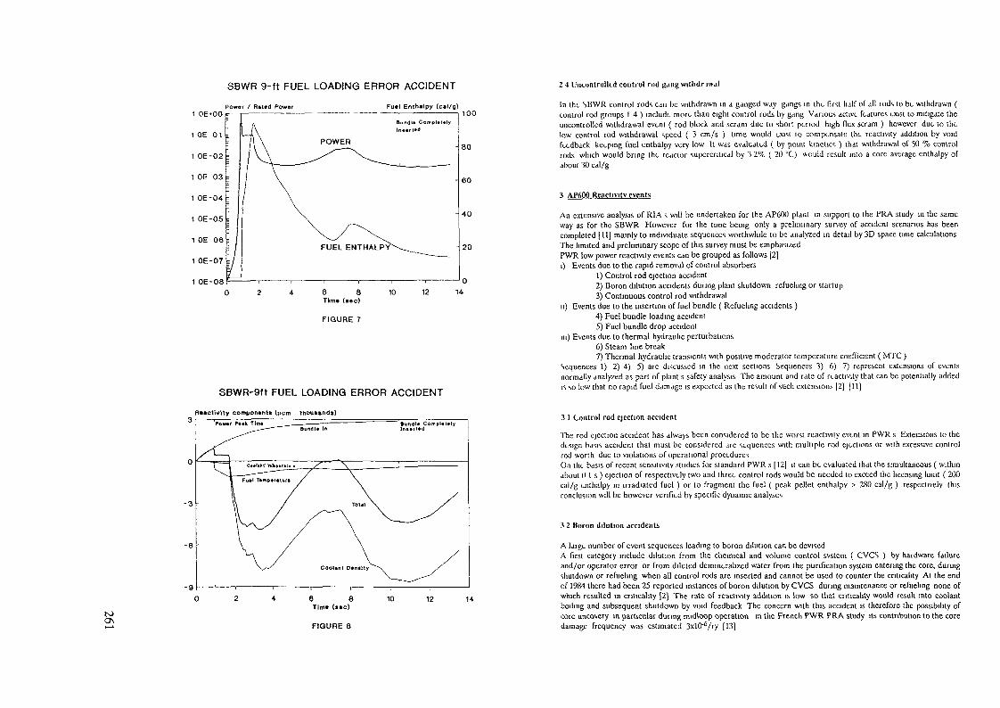
SBWR 9-ft FUEL LOADING ERROR ACCIDENT 2 4 Uncontrolled control rod gang wilhdr iwal
Power / Riled Power Fuel Enthalpy (cil/g)100
1 OE-08
- 20
—'012
FIGURE 7
SBWR-9ft FUEL LOADING ERROR ACCIDENT
In the SBWR control rods can be withdrawn m a ganged way gangs in the first half of alt rods to be withdrawn (control rod groups 14) include more than eight control rods by gang Various active features exist to mitigate theuncontrolled withdrawal event ( rod block and scram due to short period high flux scram ) however due to thtlow control rod withdrawal speed ( 3 cm/s ) time would exist to compensate the reactivity addition by voidfeedback keeping fuel enthalpy very low U was evaluated ( by point kinetics ) that withdrawal of 50 % controlrods which would bring the reactor supercritical by 3 2% ( 20 °C) would result into a core average enthalpy ofabout 30 cal/g
3 AP600 Reactivity events
An extensive analysis of RIA s will be undertaken for the AP600 plant in support to the PRA study in the sameway as for the SBWR However for the time being only a preliminary survey of accident scenarios has beencompleted [11] mainly to individuate sequences worthwhile to be analyzed in detail by 3D space time calculationsThe limited and preliminary scope of this survey must be emphas^edPWR low power reactivity events can be grouped as follows [2]i) Events due to the rapid removal of control absorbers
1) Control rod ejection accident2) Boron dilution accidents during plant shutdown refueling or startup3) Continuous control rod withdrawal
u) Events due to the insertion of fuel bundle ( Refueling accidents )4) Fuel bundle loading accident5) Fuel bundle drop accident
m) Events due to thermal hydraulic perturbations6) Steam line break7) Thermal hydraulic transients with positive moderator temperature coefficient ( MTC )
Sequences 1) 2) 4) 5) are discussed in the next sections Sequences 3) 6) 7) represent extensions of eventsnormally analy?ed as part of plant s safety analysis The amount and rate of reactivity that can be potentially addedis so low that no rapid fuel damage is expected as the result of such extensions [2] [11]
Heactitflty componenti (pern thouiftnd«)
toO\
-9
FIGURE 8
3 1 Control rod ejection accident
The rod ejection accident has always been considered to be the worst reactivity event m PWR s Extensions to thedesign basis accident that must be considered arc sequences with multiple rod ejections or with excessive controlrod worth due to violations of operational proceduresOn the basis of recent sensitivity studies for standard PWR s [12] it can be evaluated that the simultaneous ( withinabout O l s ) ejection of respectively two and three control rods would be needed to exceed the licensing limit ( 200cal/g enthalpy in irradiated fuel ) or to fragment the fuel ( peak pellet enthalpv > 280 cal/g ) respectively thisconclusion will be however verified by specific dynamic analyses
3 2 Boron dilution accidents
A large number of event sequences leading to boron dilution can be devisedA first category include dilution from the chemical and volume control svstem ( CVCS ) by hardware failureand/or operator error or from diluted demmerahzed water from the purification system entering the core, duringshutdown or refueling when all control rods are inserted and cannot be used to counter the criticahty At the endof 1984 there had been 25 reported instances of boron dilution by CVCS during maintenance or refueling none ofwhich resulted in criticality [2] The rate of reactivity addition is low so that criticahty would result into coolantboiling and subsequent shutdown by void feedback The concern with this accident is therefore the possibility ofcore uncovery in particular during rmdloop operation in the French PWR PRA study its contribution to the coredamage frequency was estimated 3xlO^/ry [13]

Though, taken per se, slow boron di lut ion could result at worst into core melt and not into rapid fuel damage itcould be the ini t iator of a refuel ing accident, as discussed in section 3 3
Various event sequences leading to rapid boron dilution were identified in Ref [2] for standard PWR s The mostsignificant were
321) Addition of diluted water, from accumulators or from the refueling water storage tank ( RWST ),during shutdown due to slow leakage or blowdown through single valve or madvertanl safely injection,322) Large loss of coolant accident with diluted water from accumulators or RWST,323) Startup of a reactor coolant pump after improper boron dilution
As for sequences 3 2 1 and 322 above, the frequency of a potentially significant event was > 10"^/ry, taking intoaccount (he sensitivity to human error probability, only for the cases with madvcrtant safety injection and for aLOCA with diluted accumulators (2) However, no thermal hydraulic calculation with boron transport wascompleted to verify if an unacceptable power excursion would occur, or if sufficient mixing with borated waterwould exist to prevent rapid fuel damageCategory 323) includes those sequences in which there is the restart of reactor coolant pumps after a period whenboron dilution has been carried outSwedish investigators [14) considered various initiating events in this category and in particular a dilution sequence,that could occurr during recovery from a steam generator tube rupture the analyses ( performed by a 3dimensional model of boron transport in the vessel and by point kinetics to describe core behaviour ) showed thatthe maximum supercnticality was about 7%, added in about 10 s, and resulted into a delta fuel enthalpy of 149cal/g, that is without appreciable fuel damageThe incorrect startup of an isolated loop was analyzed by Finnish investigators [15] for a WER plant ( the six-loopSoviet-type PWR ), by a flux-synthesis model, which accounts for the extreme asymmetry of neutron flux shapeduring the accident, in an approximate way Reduction of boron concentration by 660 ppm in one coolant loop,resulted into a peak pellet enthalpy of 234 cai/g, so that limited fuel damage occursDifferent event sequences in category 323 was considered in the French PWR PRA study [13], the most importantone can be schemaii/ed as follows
i) Normal dilution operation in progress,n) Loss of offsite power supply,in) Dilution operation goes on (backed up by auxiliary power supply),i\ ) Recovery of offsite power supply,v) Starting of primary pump #1 according to procedure
As result, a water plug, without boron and cooler than primary coolant, is pushed within the core The probabilityof this sequence was reduced to 1 2x10 6/rv implementing an automatism that, on reactor pump trip, swithchedmake up pump suction on RWST and reset boron dilution [13]Using neutron point kinetic approximation and assuming no water mixing, French investigators evaluated that, ifcore reactivity at accident conditions ( HZP, all control rods inserted, primary temperature reduced by 30 °C ) islarger than 5%, the peak fuel enthalpv would exceed the licensing acceptability threshold for RIA's ( > 200 cal/gin irradiated fuel ), which coincides with extensive cladding damage onset and is well below fuel pelletfragmentation threshold Such condition is satisfied in the first part of the fuel cycle of French PWR's [13]However, U must be stressed [hat analyses based on point kinetics are inconclusive, due to the extremely skew fluxprofile and to the sensitivity of core reactivity to boron distributionThe l imits of reactivity additions following postulated boron dilutions were estimated for each of the rapid borondilution sequences 3 2 1 , 3 2 2 323On the basis of the comparison of reactivity balance, reactivity insertion rate, reactivity feedback and moderatorsubcoolmg, it was concluded [11] that the reactor coolant loop startup event would represent the bounding caseAfter having evaluated the specific AP600 plant design features that could impact or mitigate this event, detailedanalyses will be performed to assess the resulting core damage
33 Refueling accidents
The possibility to initiate a reactivity accident loading a fuel assembly during refueling was not considered in Ref[2] for PWR's, as it was instead for BWR's A possible sequence of events is
i) Boron has been diluted for some reason, like for example CVCS malfunctioning, leakage from a dilutedaccumulator or RWST dilution
n) The refueling floor operator misplaces fuel assemblies, clustering the most reactive ones and/or loads fuelassemblies without control rod however the reactor is still subcntical due to the presence of water holes in thecorem) When the last fuel assembly is lowered into the core, a reactivity excursion takes place
Dynamic analyses will be performed to assess the accident severity in fact, if the fuel assembly is lowered by thefuel grapple ( fuef loading accident ), (he Kdctivtty addition raft could be w low, lo allow lor enough ht*<il transferand subsequent coolant voidagc, avoiding m this way extensive fuel damage, even for large reactivity additions Onthe basis of the comparison with the SBWR case, U is expected that no less than 4 5% reactivity is needed todamage fuelIn the ease of a bundle drop, concurrent with boron dilution and bundle misplacements 3% reactivity could beenough lo fragment the fuel but the frequency for these sequence of events is expected to be insignificant
3 4 Benefits of burnable absorbers use
Current PWR core design employs 3 batches out-m loading scheme, with no burnable absorbers ( BA ) use in theequilibrium fuel cycle Extensive use of BA would offer instead several advantages
i) Increased fuel management flexibility, with the possibility to implement low leakage fuel loading schemes[16]n) More negative moderator temperature reactivity coefficient ( MTC ) at beginning of cycle, which willimprove plant performance during ATWS heatup events ( for example loss of normal feedwater, LONFW ),usually the more severe ones in PWR's Sensitivity of peak system pressure, the limiting parameter, to MTCchanges is very significant for standard PWR's a decrease of about 20 [17] 60 [18] psi per 1 pcm/°C MTCdecrease ( more negative ) was evaluatedOn the other hand, ovcrcoohng accidents, like steam-line break accident, will not be affected from this point ofview, because bounding conditions are at end-of cycle, when MTC is approximately unchangedin) Mitigation, or even elimination by design, of boron dilution accident concern, due to the decreased coreexcess reactivityiv ) Mitigation, or even elimination bv design, of refueling RIA concern, due to the reduced worth of highreactivity fuel bundles
Table 3 1
FARAMETFR
H.I t DISCHARGE BURNLP(MWD/Kg)MAX ASSEMBLY AVO POWER PEAKING FACTORMAX PIN POWER PEAKING FACTOR
CRITICAL BORON BOC HFP ARO EQUILIBRIUM XENON ppmCRITICAL BORON BOC CZP ARI NO XENON ppmfcXCLSS REACTIVITY BOC V. ?P ARO NO BORON NO XENON (%)
Ml C BOC HIT ARO (pcm/'C)MTC DOC HZP ARO (ffmfC)
SHUTDOWN MARGIN BOC (%)SI RONGEST CONTROL ROD WORTH O BOC HZP (%)MAXIMUM BUNDLE WORTH BOC CZP (%}
42.55127142
136]12#>102
2311.55
212382
42281391.57
9216432 2
356513
S 2155.5
ARJ All control rods inserted ARO AJ1 control rods withdrawnCZP cold ( 20 °C ) zero power WZP zero power moderator temperature reduced by 30 °C respect to HZPBOC Beginning of cycle equilibrium samanum v > All but the strongest control rod inserted

2000
1500
1000
500
000
STANDARD COREHOT ZERO POWER • NO BORON • NO XENON
CORE REACTIVITY
Keff 1 ( * )
-500
BOC
— AM Rod« Out 640 K
— All Rodi In 64» K
-e- All Rod» In 61» K
PEAK ENTHALPY > 200 cW/g
( FRENCH ANALYSIS )
2O 4 MWO/KgU
14 15 "6 17 18 19 20 21 22 23 24 26 26 27 28 29 30CORE AVa ACCUMULATED BURNUP (MWD/KgU)
Figure 9
STANDARD CORECOLD ZERO POWER • FUEL LOADING ACCIDENT
LAST LOADED FUEL BUNDLE WORTH
LAST LOADED BUNDLE WORTH (*)
00
80
70 -FIGURES SPEFIFY THE
60 -NUMBER OF ERRORS
50 -
40 -
30 ^
20 -
1 0
C-7.0
IN FUEL AND/OR
RCCA POSITIONING
C-1
-8
B-8
600 750 900 1050 1200 1350 1500 1650 1800 1950CRITICAL BORON WITH LAST BUNDLE OUT
too\
CORE WITH BURNABLE ABSORBERSHOT ZERO POWER • NO BORON * NO XENON
CORE REACTIVITY
2000
1500
1000
500
000
-500L
BOC—— All Hod«-0ul 64» K
—— All Rod» In 64» K
—0- All Rod« In 619 K
PEAK ENTHALPY > 200 c»l/g ( FRENCH ANALYSIS )
14 15 16 17 18 19 20 21 22 23 24 25 26 27 28 29 30CORE AVQ ACCUMULATED BUHNUP (MWO/KoU)
Figure 10
CORE WITH BURNABLE ABSORBERSCOLD ZERO POWER • FUEL LOADING ACCIDENT
LAST LOADED FUEL BUNDLE WORTH
LAST LOADED BUNDLE WORTH (*)
80
70
60
50
40
30
20
1 0
n r»
STANDARD
D-9 D
oD-7o D-5
" ' r> i- i
D-1
CORE MAXIMUM BUNDLE WORTH
D-13CM£'Ä\
;10_V D-wS-a^6
D-11 D-17^oD 19
FIGURES SPECIFY THE NUMBER OF
ERRORS IN FUEL AND/OR RCCA
POSITIONING
600 760 900 1050 1200 1350 15OO 1650 1800 1950CRITICAL BORON WITH LAST BUNDLE OUT
Figure 12

A conceptual study to help quant i fy the design configuration and performance parameters for a PWR with BA inthe equi l ibr ium cycle is currently in progress at ENbL Integral BA in the form of gadolmia doped fuel rods, wereselected for this study, due to advantages over boron bearing BA in terms of increased fuel management flexibility,better control of mira assembly power peaking and elimination of additional storage and disposalOnly the equilibrium fuel cycle is modeled, by two dimensional calculationsResults are briefly discussed for an example case comp inng i standard PWR core ( 18 months, 3 batches, in outloidmg scheme, no BA use ) to an al ternative core design employing a 3 batches in out in fuel loading schemewith \2 rods, doped with 1% Gd oxide in each fresh fuel assembly Table 3 1 compares some key results
Fuel discharge burnup is about the same in both cases indicating thit the reduced radial leakage approximatelycompensates for Gd parasitic residual absorption ( about \°/i in this case )
The higher peaking factor of Ihe BA core, by about 10%, will imply some loss of thermal margins however,preliminary estimates suggest that approximately 15% margin still exists to DNB Power distribution can beimproved optimizing BA loading strategy, by the use of fresh fuel sub-batches with proper Gd loading, andimproving the mtra assembly peaking factor, by enrichment shaping or by alternative neutron poisons, like erbium(19)Critical boron is reduced at BOC by about 440 ppm, which allows to get a significatively more negative MTC, bothat HFP and at HZP Based on generic sensitivity studies quoted above [16],[17], a reduction of 240 720 psi in peakpressure after a LONFW ATWS at HFP could be expected, but, due to the great sensitivity to plant parameters,this should be verified by plant specific ATWS studiesShutdown margin is significantly improved, by about 3%, which would reduce the concern for core recnticahtyafter a steam-line break accidentThe concern for rapid boron dilution accidents is essentially eliminated by designCalculations, performed for the standard core with different boron / moderator temperature non-uniformdistributions and with assumptions consistent to the French event sequence depicted m Section 3 2 indicated that
i) At beginning of cycle ( BOC ), the core can be brought to prompt-cnticahty by a relatively small, completelydiluted, water plug ( about 08m 3 )n) Neutron flux is of course extremely asymmetrical, with radial peaking factors in the range 7 19in) Plugs of 3 5-6 m3 ( 25-45 % core water volume ) can add 10% reactivity ( BOC ), more than 98% of all theavailable boron reactivity reactivity addition depends very significantly on boron spatial distribution At therated loop flow, such plugs could be pushed into the core in less than one secondiv) If the plug is large enough ( approximately more than 2 5 m 3 ) , reactivity addition and flux distributionbecome fairly independent on the mital boron concentration, due to the low neutronic importance of the stillborated core region
If the French criterion described m Section 3 2 is applied to the standard core, it indicates that, in the first part ofthe cycle, enough reactivity ( WZP, ARI, no boron, no xenon conditions ) is available to damage fuel (see Figure<•>)However, if we use the same criterion for the BA core, we can see that core reactivity is significantly below 5%along the whole cycle ( Figure 10 ), so thai no fuel damage is expected by the injection into the core of a cold,diluted water plug On the other hand, reactivity events involving addition of diluted water at CZP, ARI conditions( sequences 3 2 1 ) would require much higher dilution of accumulators or RWST down to about 640 ppm, whichfur ther decreases their probabilityIn order to assess the impact of BA on refueling accidents fuel bundle worths were evaluated for the two cores atbeginning of the equilibrium cycle as a function of the number/ location of misloadeed bundles, number of waterholes into the core and boron concentration For any given fuel bundle whose worth has to be calculated, theminimum possible boron concentration corresponds to the value that makes the reactor just critical before thebundle itself is loaded, such concentration, of course, maximizes core reactivity aliter the bundle has been loadedResults from different misloaded bundle arrangements are summarized in Figure 11 ( standard core ) and 12 ( BAcore ), where the last-loaded bundle reactivity is plotted versus the boron concentration defined aboveThe higher the number of misplaced bundles, the lower the boron dilution necessary to allow the accident in thestandard core case, boron dilution is actually not needed at all if the number of misloadings is high enough Withthe nominal 2000 ppm boron concentration, the standard core could be made prompt critical lowering the lastbundle if four fuel assemblies ( including the last one ) were misplaced The maximum reactivity obtained wasslightly less than 5%, with 9 misloaded assemblies ( including the last one )
The worth of a single misplaced bundle in the standard core is around 3 4%, depending on distribution of waterholes, with critical boron concentrations of 1100-1200 ppmThe standard eore fuel bundle worth is maximum at intermediate boron dilution / # of misloadings maximumworths of about 8% were obtained in some cases, wiih 6 9 misplacements and 1400 1500 ppm boronRefueling reactivity accidents also would be significantly mitigated by BA use not only the maximum bundleworth is reduced to 5 5% ( Figure 12 ) due to the reduced k infinite of the most reactive assemblies, but a largerboron dilution and/or number of misloadings would be required to initiate the accident
4 Conclusions
Low power reaclvity accidents have been discussed for SJ3WR and AP600 reactors
In the SBWR case, control rod drop, control rod ejection and fuel loading accidents have been analyzed in detailthe only identified possibility to have severe fuel damage are a control rod drop accident with RWM failures,during cold zero power nuclear testing, or fuel assembly drop, concurrent with multiple violations of refuelingadministrative procedures However, the frequency of such events is expected to be negligible Key inherentfeatures, for the well behaved plant performance with respect to these accidents, are the reduced core excessreactivity, which significantly reduces control rod and fuel bundle worths respect to standard BWR's, and a revisedstartup procedure, which allows to achieve criticahty with the moderator close to saturated conditions
No definite conclusion can be drawn at the present stage about the potentially more severe reactivity eventsidentified for AP600, that is rapid boron dilution and fuel loading accidents, which still need to be investigatedfrom both deterministic and probabilistic point of views Should such analyses identify any concern, it could besignificantly reduced, or even eliminated by design, by the extensive use of burnable absorbers in the fuel
Appendix 1
Some details about calculational models used are presented in this Appendix
Nuclear data libraries at rated and off rated conditions were generated using the CASMO 3 code [A 1]
SBWR steady stale state core follow up, to obtain nodal parameters like fuel exposure and void history, wasperformed with the 3 dimensional, 1 5 groups, coarse mesh simulator CETRA [A 2]
PWR calculations were carried out with the 2 dimensional code MBS [A 3], which solves the 2-group neutrondiffusion equation bv finite difference tccniquc assuming homogem/ed cross sections within each fuel assembly inthis study each assembly was subdivided into 4x4 meshes
Dynamie analyses were performed with the QUANDRY EN code [A4], which solves the steady state and timedependent two group neutron diffuston equation by the well known Analytic Nodal Method [A 5], includingdiscontinuity factors The thermal hydraulic model is based on the COBRA 3C/MIT model and has the capabilityto treat coolant transverse cross flow ( PWR s only ) and boron transport
The present model simulates the reactor core only time dependent forcing functions are used for thermalhydraulic boundary conditions Constant values for inlet core flow and system pressure were used in all theanalyses reported hereinQUANDRY EN has been benchmarkcd against Peach Bottom 2 turbine trip ( BWR ovcrpressurization transients) and SPERT HIE ( control rod ejection transients ) tests

REFERENCES ADVANCED BOILING WATER REACTORSjlj b S Nuclear Regulatory ( ommisiion "Implied I ions of the accident al the Chcrnobyl for Safely Regulation of Commercial Nuclear Power
llanism ihc United Stales' NLRt C> 1251 V2 ( April 1989)|2| IXJ Diamond CJ Hsu Rlil/palnck "Reactivity accidenls a reassessment of the design basis events NURK./CR 5368 »NI NLRTO
52198 (January 1990)("ÎJ O Mirkovic DJ Diamond "Lffcct of flushing boron dunng a boiling valor rcaclor anticipated transient without scram NuclearIcchnology 95 163 ( 1991 )|4| C J Paonc R.C Slim Jj\ Woolley -Rod drop accident analysis for large boiling water reactors NLDO 10527 ( March 1972 )|5| L r-ionno "Evaluation of control rod worths in standard BWRs beyond licensing design basis accident scenarios FNLL/DSR VONinternal memo ( 1 ebruary 1990 )(6] M Chcng D J Diamond "Analyzing ihc rod drop accident in a boiling water rcaclor" Nuclear Icchnology 56 40 ( 1982 )[7| P fc MacDonald ct al "Assessment of Light Water Rcaclor fuel damage dunng a React vity Initiated Accident" Nuclear Safely 2!^ 5 (October 1980 )j8]CKlang "SBWR startup plan" private communication[91 R C Stim "BWR Reactivity initialed accidents" presented to "IÎWR Safety technology Workshop" 1 ugano Switzerland ( Apnl 7 101987)
[10] DC Cambra R.C Stirn "Fuel bundle loading accident Supplemental information to refueling interlock bypass procedure* Generalricctnc memo CFSD-81299 ( December 1981 )[11] C Fionno "Preliminary survey of AP600 reactivity initiated accident scenarios" l NE 1 internal report ( to be published )|tt) M Gonncl C Neaume T Bisiaux -Rod Ejection Analysis m PWR s with a 3D kinetic new code' in Proceedings ot the ConferencePHYSOR90 Marseille France ( Apnl 1990 )[13] J Dnsbois "Probabilistic Safety Assessment for French PWR 900 MWc Dilution Accidents" Presentation to U S Nuclear Regulatory
Commission ( March 5 1990 )[14] SJacobson "Some local dilution transients in a Pressurized Water Reactor" HL 11 K LIC 1989 11 Lmkopmg University Institute ofTechnology[15] M-Annla RKirky Rajamaki M Rajamaki H Raty PSiltancn TVanttola "Application of the synthesis model in an asymmetricreactivity disturbance of the WER-440 type Lovnsa reactors" in Proceedings of the Amcncan Nuclear Society 1 opical Meeting on Safety ofThermal reactors Portland USA ( July 1991 )]16]WBochm H D Kiehlmann ANeufert M Pechs "Gd2C>3 up to 9% w/o an established burnable poison for advanced fuel managementin PWR s" in Proceedings of the Topical Meeting on Advances m Fuel Management Pmchurst L.SA ( March 1986 )[17] WE Burchill "Anticipated transients without scram" in "Guidebook to Iighl Water Reactor Safely Analysis" Hemisphere PublishingCorporation ( 1985 )|18j B S PCI G PYu O Clin Y P Ma "Assessment of the safety function for the anticipated transient without tnp mitigation systemactuation circuitry at Maanshan nuclear power station" Nuclear Icchnology 90 49( 1990)[19] H G Joo cl al "A feasibility study of utilizing crbia burnable absorber m Korean PWRs in Proceedings of Topical meeting onAdvances in Mathematics Computations and Reactor Physics Pittsburgh LSA ( April 1991 )
|A1| Mhdemus AAhlm BH r-orsscn "CASMO 3 A fuel assembly burnup program S1LDSV1K/M A 86/7[A 2] G Alloggio EBrcga R Guandalim M Mcngoli "Outlines of the BWR-oricnlcd I M I Integrated Code System (EICS) CISF 5793 (May 1991 )
[ A 3 ] O Nonndcr EJonsson K Olsson "MBS a 2 D core analysis diffusion theory code MBS users manual version 17SI LOSVIK/NR-85/80 ( 1985 )[A 4] G Alloggio f- Brcga L Salma QLANDRY hN a computer code for the ncutromc and thermal hydraulic space and time dependent
analysis of 1 ight Water Reactor cores by advanced nodal tccmqucs ( Rev "! ) Report m progress
[AS] K S Smith "An Analytic Nodal Method for solving the 2 group Multidimensional Static and I ransicnt neutron d ffus in equationsNuc Ing Fhesis Dept of Nuc I ng Mil Cambridge MA ( r cbruary 1979 )
(O
VG RODRIGUESInstitute de Pesquisas Energéticas e Nucleares,Comissäo Nacional de Energia Nuclear,Säo Paulo, BrazilD STEGEMANNInstitut fur Kerntechnik,Universität Hannover,Hannover, Germany
Abstract
Power distribution, fuel cycle, void reactivity and the first insightof the thermal-hydraulics problem of an Advanced Boiling Water Reactor wereanalysed. The calculations have showed that it is possible to obtain along fuel cycle, with a 3% Plutonium enrichment. The moderator voidcoefficient, even in a complete voiding of the reactor, is negative. Thethermal-hydraulic calculations have demonstrated that it is necessary toreduce the coolant flow rate in order to maintain the same pressure drop asin a reference reactor.
INTRODUCTION
Studies have demonstred that it is possible toincrease the conversion tatio of the Pressurized WaterReactor near to 1 [1,2,3). These reactors.called Advanced Pressurized Water ReiCtor(APWR), have been searchedfor ahn.» r two decades at d the F> & D are still goingon. The main characteristics of these reactors is thehexagonal core structure with a low moderator to fuelvolume ratio. The main physical effect of this changeis n stuft of tho nmitroric spectrum from the thermalrt-'gioti to the high energ> region, increasing thus theresonance capture in the fuel fertile materials and corisequently the conversion ratio.
Boiling Water Reactors present in the average ha£der neutronic spectrum than th.it of the Pressurized Wa;ter Reactors. If the geometrical change done in the PWRcore were considered in the BWR core, the effect should

be rauch more enhanced and the conversion ratio alsoshould go UD. Based on such concept we have studied thefeasibility of an "Advanced Boiling Water Reactor"(ABWR).
1 n! *111lll
l11
—— »-WI»
•pc/ZTz:oooooooVv^.
o
•«••«•1
oooO:Ooo
AKCtrw*
n-rr-rr
Oo(r^--— -r-^
&'Oo
/iV-W..<o•rrzg.*
-©:
0'Y^^"'/SS,'
• .• / 'o——
2J!.JLJ£2
Oo'Q-~*;A ———
reoo
jzr^^F
r? s m
Ooooooo
t • /.J J S
rr *j>3
OOoooo1
Of
1„
'•
\}\\
,! ,
FIG. 1. BWR fuel bundle cell.
Parametric studies(4,5l lias shown that the physics of the ABWR is feasible. From this study we selected two basic conceptions, named as Alternative 1 and~2. This paper deals with the calculation of the powerdistribution, fuel cycle, reactivity control and thefirst insight on the thermal-hydraulic problems of theABWR-Alternatives.
METHODS and CODES
The calculât ional nethods employed in this studyare briefly described herein. The calculation was donewith the RSYST-program[6). Th<> BWR fuel bundle cell isshown in Figure J. The cell was divided in four typicalregions. For each region the neutron spectrum generatedwas condensed to build up a basic 60-groups library.this 60-groups structure covers the fast and the the£mai energy ranges. This library with 30 - fast energygroups ( 14 MeV - 1.86 e\ , ) was generated with the GAMcede and the 30 - thermal pn« r;;> groups (1.86 - 0 eV)was generated with the TV ERM code. The group structurewas strongly oriented tovard the Plutonium and U - 238resonances. The group corstants were generated for a4 I mixed U02-Pu02 fuel for ,n volumetric moderator tofuel r.ilio of : 2,0 ; 1 ,( ; 0,6 and 0. The collapsedspectrum was generated fcr Ihr«1«? temppratures : 20 °C280 ?C nnd 663 9C.
THE REFERENCE CONCEPTION
From the parametric stucly[4] we selected two b£sic conceptions for ihe ABWR reactor. Figure 2 showsthe fundamental properties of Pu02-U02 BWR-lattico asa function of the moderator fraction ir» the core.- Forthe three different enrichments of fissile Plutonium(Pu-239 and Pu-24l) t.he infinite multiplication factorand the conversion ratio are plotted against th* «;ff».!c:tivc moderator to fuel volume traction, uy roducing themoderator volume, the; multiplication Factor decreases.

WNefta» V « « ) / V < » > - r«* P»»*«
O.4
1.«
.•J
1
*«^^^p
-'/',' /y//////X
/
/
/^
/(
K
tetft
— » WM«
'//S/<
|o|oio|oiO!o!/-,|U
S/7Sj>
^K —
Mraë
*«*
/V/2
oooooou
rSSj
'*£SJ
OOOOOOU'// /
— «
*-~f 7;
Oooooo0/ss
f f
ccccccGSi
/ s*
)5D)55;'/
t»~
f
ccccc£(j/,/
>-•
1/ (
))))));/
; / f~
oooooo/~\s ->
c V,
0• *
J
-\1-11
1-\1
114
!-1
1
-11
-I111v
)////
s////
/
/
/
//
,/
* t
— I
1
\i
4 -
(MOL)
1H•4t• U
14.: t 1 1M.S187
4.T
47
FIG. 2. K» and conversion ratio m a UO2-PuO2 fuel bundle lattice FIG. 3 Geometrical parameters of ABWR alternatives.

£J T.iblo 1. B.isic Um a Constitutive for AISWRo° Alternatives
Al te rna t ive
. Fuel rods/El emßnt
. V ( U 2 0 ) / V ( f u e l ) - Cell
. V ( H , 0 ) / V ( f u e l ) - Element
. Fuel rod diameter (tun)
. Pin pitch (nun)
. Core active lenght(mm)
. Fuel (mixed oxide)
. P l u t o n i u m en r i chmen t (X)
. Average Burmip (MWd/kg)
. Conversion ratio
1
7 x 70,61,3
14,315,3
2300,0DO,- PuO,3,050,00,88
27 x 70,71 ,7
14,315,7
2300,0U02-Pu02
4 ,0-
0,80
'Ihe conversion ratio goes up because of the increasedresonance absorption. P'igure 3 shows the geometricalconfiguration of the ABWR basic fuel bundle. Table 1shows the main parameters of the two concepts extractedfrom the parametric study. Forthcoming we prt-so'it thepower distribution, fuel cycle, reactivity control andmoderator reactivity coefficient for the first ABWRAlternative.
I___________________I
i
1,444
l.«84
1440
IJTT
1.400
J*l»
1.MO
1*97
.•T»
.Ttl
.«•r
-TOO
.TM
l.tl«
MK>
.Ttl
•0
6*0
.wr
.«41
IJOlt
»n
.•M
.M«
.01«
.SU
•or
»•0
1IM
.TOO
.MO
.»»1
.•44
.•to
.•Tft
IMt
.TM
.•M
•O«
.WO
.TOO
»ATT
1*4O
1400
1OU
*M
.871
ijon
L.44*
.J«•ff • i£T*4Tc* «a*r
FIG. 4. Power distribution (PuO2 : 4%)
POWKR DISTRIBUTION
Firstly the power distribution was calculate inan homogeneous core with 4 % Plutonium enrichment.Figure A shows the homogeneous power distributi-n Theouter fuel rods in the Fuel Assembly have a high powerfactor than the inner rods. This non-uniform power di^tribution is caused by the soft neutronic spectrum du<?to the wide moderator channel in the periphery of theFuel Assembly.
To reduce the power factors the calculation was donefor a heterogeneous core with a four different Pu -enrichments. Figure 5 shows the power distribution theeffective multiplication factor and the conversion ratio. We ran sco that the inner rods even with a highPu-enrichment have a lower power factor than the outerrods. The cause for that is the inner region neutronicspectrum being more energetic than the outer regionneutronic spectrum. The power distribution was acceptedonce the power factor is lower than the perraited value.

r
riu.
r
•v}i?j*
1 \
]
1
1 •••
1JO»
\ oni»*•
tr»t
10««
i
itt«
i»i
l-Ml
MO
t
Mr
Ml
t
W»
I1M4
LOTI
»J»
ltd«4
MO
M«
4
Ll*t
>
»*4
M«
IM
l«0
4
M*
•.1»
4
M<J
1
• »
•»
MO
M*4
n»
ri»4
•M
1
W*
11J
lO*»
MO
1 II«
4
•M
»M
4
t 14«
1
no
ita»
UK
Mt
»
•M
.«»7
*
»JO
>
If«
«•* nw«
iti4
-„-M
1
It
«0
M
*,*
110
l«• 0
toONvO
FIG 5 Power distribution (distributed enrichment)
FUEL BURNUP
The burnup ch.ir.iot-eri st i rs for an hoterojvnoouscore with a 3Z average enrichment is shown in Figure 6,From this Figure we can see that with a 6Z reactivityit is possible to have a long fuel cycle higher than60 MWd/kg. Calculations show that it is possible to reduce the average Pu-enrichment in order to increasethe conversion ratio.
to*
IJOt
If»-
OM
«10
• M
B*»
«iff
—1—•0
-1—•—•—'—'—I—•k> *0
I «CO« < •*»«/!«)
•0
FIG 6 Kefl and conversion ratio vs burnup
VOID REACTIVITYOne of the most important criteria to evaluate
ihe safety of power reactor is the behavior of the inor.Jtnr void coefficient in ra«.o of loss of coolant ac<-_i_d^iit. Figure 7 shows the void characteristics of anABWR for three different enrichments of the fissile

to~Jo P l u t o n i u m . In the c a l c u l a t i o n of the loss of coolantit is demonst ra ted by a reduct ion of moderator to f u e lvo lume r a t i o . We can see that the r e a c t i v i t y has a clearnep, i t i v i ' t endency c-von for a h i j ; h Pu-enricrwnt . Thi-suresul ts point out that the physics of the ABWR issible.
*., -x
Table 2. Control rod characteristics
TypeMaterialLenghtWing sizeWing thicknessAbsorber active lenghtAbsorber rod diameterB C - densityAbsorber rods/wing
crue i formS.S.
104,84 mm7,90 nra1 , 38 nua
2300,00 ram4 , 7 0 mm1,76 g/cm>
15
04 Cf—I—l t
FIG 7 ABWR reactivity characteristics (central pm cell) FIG. 8. Control rod

REACTIVITY CONTROL
The reactivity for the ABWR can be controlled bythe BWR-conventional control tods. The control rods were fitted to the new geometry of the fuel element cells.Figure 8 shows the control rod structure and Table 2lists the main characteristics.The calculation h.is been done for the cold condition(worse) and hot conditioti(operational). The cold condition is interesting since the absorber worth has aminimum value. Figure 9 shows the effective roultiplicat ton factor as a function of the rod insertion for coldand hot conditions. The efficacy of the control rod isstrong since for a 70Z insertion the subcriticality is
AZ for the hot condition. In compaiison vith the coldconditions, this subcriticality w i l l be reached onlywith a 100Z of insertion. With a fully inserted controlrod the reactivity is 13,6X for the hot condition. Thisreactivity is enough for a safety shutdown margin, ca_lculations uncertainties and m.inuf .icturi ng tolerances.A first evaluation for the ABWR reactivity is presentedin Table 3.Some data was taken from a 770MWe BWR reference reactor.This assumption is conservative since the reactivityfor Advanced Light Water Reactor is smaller than thatfor normal Lip,ht Water Reactors. Table 3 shows that the
Table 3. Reactivity balance
tjt-
IX«
O «0 <W «O »0 100
10-
OJW-
ft»
toFIG. 9. Ken vs control rod insertion.
kAkAkAkAkAk ,Ak
Ak ,AkAk ,
Ak
Keff
cold, cleancold - hotDopplerModeratorXe , SmHut impTrim
TotalControl rod, coldGd , cold
Total (full controlled)
cold, clean (fullControlled)
BWR
1.2140-»•0.0100-0.0070-0.0230-0.0330-o. n GO-0.0050
-0.2140-0. 1740-0. 11 10
-0.2850
0.9290
ABWR
1. 1879+0.0100-0.0070-0.0230-0.0330-0.0400-Ü.OÜ50
-0.0680-0,2260
-
-0.2260
0.9620

toto
reactivity equivalent to the rapidly satured fissionproducts is one order of magnitude smaller than in thetraditional BWR. The reactivity reserve for a long fuelcycle,almost 60 MWd/kg, is a factor 4 lower than thatin the normal BWR reactor. Another interesting point inTable 3 is the lower reactivity reserve for the ABWR(6,8%) in comparison with the normal BWR(21,4Z). It is
advised that the control rod calculation presented hereshould not be taken as a final one but only as a firscinsight into the problem.
THERMAL-HYDRAULICS
• W*
The subchannel analysis of the ABWR core were donewith a well-known code COBRA-41 [7], The presented eva_luation of critical heat flux ia valid only as a firstapproximation for ARWR thermal-hydraulics conditions.
The calculation was performed for the followingof mass flow rate and heat flux:pairs1.
m
m •>
48.8 W/cm'15.75 kg/s48.8 W/cm*8.0 kg/s58.6 W/cmJ8.0 kg/s
(reference BWR)
(ABWR)
(20% overpower)The point 1 are the actual parameters of a converi
tional BWR data. Point 2 differs from I in the massflow rate since this is the minimum mass flow rate toreduce the core pressure drop. Values under this limitwill generate unacceptable core void fractions with apossible low safety margin for a ÜNBR. Point 3 simula^tes 20% overpower. Figure 10 shows schemactic of thecore channels, gridspacers positions and the axial power distribution.
«rM WOOOTI
T
.
t-
..
L
n-
-
M3X>
1*1.0
15» O
JZ7O
MA
0.0
«O.G
j
*M* +**t t<C«K1
JLto o.is
0.1 0 4»
on o«ooto ono» oezOK) 112O» 1.»04O 1 4004« 1.4«O.OQ 1.60f\ IM I ^M\) DO LWO*O 1410« U»OTO ISZon LUO*0 LO»0*0 o»>0.90 07«OW OMuX> O.K>
FIG. 10. Grid spacer positions and axial power factors.
RESULTS
a. PRESSURE DROP
The tight fuel plenum! lattice to the AHWR leadto a expanded core pressure drops because of the 50%reduced coolant flow cross sect-ion. Figure 11 showsthe ABWR-core pressure drop. For comparison it was irieluded in the Figure the reference HWR pressure drop(dotted line). The vertical dotted line indicates thegrid spacer contribution to the core pressure drops.To keep the ABWR-core pressure drop in the order of thereference BWR pressure drop, the coolant flow rate mustbe reduced to a very low value. As exposed the coolantflow rate limit is 8.0 k;;/s. At this point Alternative2 has almost the same core pressure drop. For Alternafive 1 the core pressure drop is f>()% higher th.in the-reference pressure drop. Fortunately at the IJWU only

FIG. 11. ABWR core pressure drop.
a small portion of the total pressure drop of the pri
to
mary circuit ocurs in the reactor core. Therefore ifnecessary the mass flow rate can be increased, e.g. ,to10,0 kg/s, and the core pressure drop will be lessthan 1.0 bar.b. TEMPERATURE DISTRIBUTION
The axial temperature distribution for the hotrod of Alternative 1 is show in Figure 12. For comparison the axial temperature distribution of the BWR-reference reactor (dotted line) was included. At the noraTnal condition for the ABWR (point 2) the fuel centraltemperature and the clad surface temperature is lowerthan the temperature at the operational point in thereference BWR reactor. Even with a 20Z overpower and502 reduction in core coolant (8.0kg/s) the ABWR central fuel temperature is 459C higher than the fuel cetïtral temperature in the reference BWR.
The calculations show that the maximum fuel central and clad surface temperatures in the ABWR concej»tion is far down the safety limits.
no MO CM «00 MO t t O M O M O M O M O
FIG. 12. Temperature distribution (alternative 1).

to-J-p*
« 4O
<""M */•**
- maximum hear flux 127 W/cm2
- maximum linear heat rate 570 W/cm2- minimum DNBR (MDNBR) 2
.04 •l*
Figure 13 shows the MÜNBR versus quality for Alternat!ve 1. The minimum DNBR is larger than the safety 1 inuts (> 2). Nevertheless this should not be taken as anabsolute value, but only as an indicative. The criticalheat flux evaluation must be done with appropriate correlations and further experimental rigs.
AlUfftOtlv« t
s •
1 - WS
t . I&RACL1 - IMC»eTH
<C . 4M »/€•*
.Q« X»
FIG. 13. MDNBR vs quality.
c. CRITICAL HEAT FLUX
The critical heat flux was calculated with thewell-known W-3, MacBeth and Israel correlations[8]. Inthe calculation the minimum DNBR was searched for eachfuel rod, coolant channel and axial height. The Chermal-hydraulics limits imposed tor safety operationalconditions were:
CONCLUSIONS
The results presented were b;ised on tanuy conservative assumptions, however wt found out some conclusionsabout the physics and the thermal-hydraulics to set upthe basic conception for an Advanced Boiling WaterReactor:
- From the parametric studies we selected two basicconceptions(Alternatives) with conversion ratio of theorder of 0.8.- It is possible to have a long fuel burnup (50 or 60MWd/kg) with a low reactivity (3 or 4%).
- The conventional BWR-control rod seems to be enoughto control the reactivity of the ABWR.
- The moderator re.'ictivity coefficient even with complete core voiding is negative.
- To keep the core pressure drop in the same order ofthat in the reference BWR, the coolant flow rateshould be reduced to about 8,0 kg/s (50% reduction).
- The fuel central and clad surface temperatures ofthe hot rod is far from the safety limits.
- The minimum DNBR, even with a low mass flow rate ishigher than the safety limit.
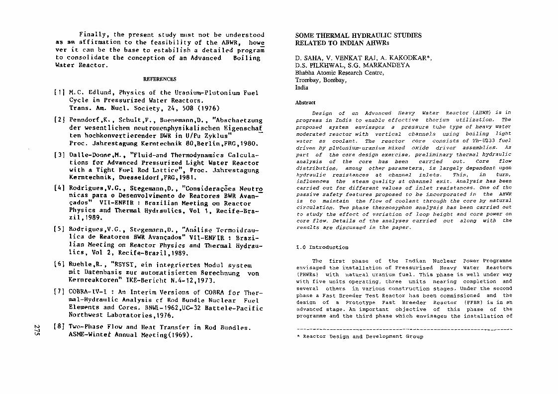
to-JUi
Final ly , the present study must not be understoodas an aff irmation to the f e a s i b i l i t y of the ABWR, however it can be the base to es tabi l i sh a detai led programto consolidate the conception of an Advanced BoilingWater Reactor.
REFERENCES
[1] M . C , Edlund, Physics of the Uranium-Plutonium FuelCycle in Pressurized Water Reactors.Trans. Ära. Nucl. Society, 24, 508 (1976)
[2] Penndorf,K., Schult,F., Buenemann.D., "Abschaetzungder wesentlichen neutronenphyst kali sehen Rigenschaften hochkonvertierender DWR in U/Pu Zyklus" ~~Proc. Jahrestagung Kerntechnik 80,Berlin,FRG,1980.
[3] Dalle-Donne.M., "Fluid-and Thermodynamics Calcula-tions for Advanced Pressurized Light Water Reactorwith a Tight Fuel Rod Lattice", Proc. JahrestagungKerntechnik, Duesseldorf,FRG,1981.
[A] Rodrigues.V.G., Stegeraann,D. , "Consideracoes Neutre»nicas para o Desenvolvimento de Reatores BWR Avan-çados" VIÏ-ENFIR : Brazil ian Meeting on ReactorPhysics and Thermal Hydiauiics, Vol 1, Recife-Bra-z i l , 1989.
(5] Rodrigue» ,V.C. , Stogemann.D. , "AnaUse Tormoidrau-lica de Reatores BWR Avançados" VH-ENFIR : Brazi-lian Meeting on Reactor Physics and Thermal Hydrau-lics, Vol 2, Recife-Brazil ,1989.
[6] Ruehle,R. , "RSYST, ein integriertes Modul systemmit Datenbasis zur automatisierten Berechnung vonKernreaktoren" IKE-Bericht N . 4 - 1 2 , 1 9 7 3 .
[7] COBRA-lV-l : An Inter im Vers ions of COBRA for Ther-mal-Hydraulic Analysis cf Rod Bundle Nuclear FuelElements and Cores. BNWI-1962.UC-32 Battele-PacificNorthwest Laboratories,1976.
[8] Two-Phase Flow and Hent Transfer in Rod Bundles.ASME-Winte£ Annual Meeting(1969).
SOME THERMAL HYDRAULIC STUDIESRELATED TO INDIAN AHWRs
D. SAHA, V. VENKAT RAJ, A. KAKODKAR*,D.S. PILKHWAL, S.G. MARKANDEYABhabha Atomic Research Centre,Trombay, Bombay,India
Abstract
Design of an Advanced Heavy Water Reactor (AHWR) is inprogress in India to enable effective thorium utilization. Theproposed system envisages a pressure tube type of heavy watermoderated reactor with vertical channels using boiling lightwater as coolant. The reactor core consists of Th-U233 fueldriven by plutonium-uranium mixed oxide driver assemblies. Aspart of the core design exercise, preliminary thermal hydraulicanalysis of the core has been carried out. Core flowdistribution, among other parameters, is largely dependent uponhydraulic resistances at channel inlets. This, in turn,influences the steam quality at channel exit. Analysis has beencarried out for different values of inlet resistances. One of thepassive safety features proposed to be incorporated in the AHWRis to maintain the flow of coolant through the core by naturalcirculation. Two phase thermosyphon analysis has been carried outto study the effect of variation of loop height and core power oncore flow. Details of the analyses carried put along with theresults are discussed in the paper.
1.0 Introduction
The first phase of the Indian Nuclear Power Programmeenvisaged the installation of Pressurised Heavy Water Reactors(PHWRs) with natural uranium fuel. This phase is well under waywith five units operating, three units nearing completion andseveral others in various construction stages. Under the secondphase a Fast Breeder Test Reactor has been commissioned and thedesign of a Prototype Fast Breeder Reactor (PFBR) is in anadvanced stage. An important objective of this phase of theprogramme and the third phase which envisages the installation of
* Reactor Design and Development Group

Ni U233 fuelled reactors is the effective utilisation of the vastO\ reserves of thorium in India The thorium reserves in India are
estimated to be around 363,000 Te [1] The Advanced Heavy WaterReactor (AHWR) being designed in India is aimed at extractingsizeable fraction of energy from thorium with minimum consumptionof plutonium The reactor core of the proposed AHWR thus consistsof Th-U233 fuel driven by Plutonium-Uranium driver assembliesThe proposed system envisages a pressure tube type of heavy watermoderated reactor with vertical channels using boiling lightwater as coolant Some of the desirable design features are i)effective utilisation of thorium with minimum fissile materialconsumption, 11) use of light water as coolant instead of heavywater to reduce capital as well as running costs, 111) achievinga negative void coefficient of reactivity and iv) incorporationof passive safety features.
One of the passive safety features proposed to beincorporated in the AHWR is the natural circulation of coolantthrough the primary loop. The thermal hydraulic studies beingcarried out on the proposed AHWR, as part of the preliminaryinvestigations being conducted to establish its feasibility,include analysis of the core comprising of two types of fuelassemblies and also two phase thermosyphon analysis of theprimary loop. Details of the system, analyses carried out and theresults obtained are discussed in the following sections.
2.0 Primary Heat Transport (PHT) System
A schematic of the proposed system is depicted in fig.l Theaim is to maintain the flow of the coolant through the PHT systemby natural circulation From the inlet header , the light watercoolant enters the core, comprising of vertical fuel channels,through feeder pipes and lower channel extensions Fuel channelsare housed in the calandria filled with heavy water moderatorSteam-water mixture from the fuel channels is led to the outletheader via the upper channel extensions and feeder pipes. Fromthe outlet headers, steam water mixture flows through the risersto the steam drums Separators inside the steam drums separatesteam from water and the steam goes to the turbine Feed waterenters the system through the steam drums and the subcooled waterfrom steam drums flows to Secondary Steam Generator (SSG). Heatis rejected to the secondary side of the secondary steamgenerators before the coolant enters the inlet header. Anisolation condenser (not shown in the figure) is provided toremove decay heat when the reactor is shut down.
INLET HEADER / INLET HEADER- FEEDER
Fig 1 SCHEMATIC Of AHWR PRIMARY HEAT TRANSPORT SYSTEM

Tn-U233 BUNDLE
DRIVER ZONE
Fig.2 CORE CONFIGURATION
3.0 Reactor Core
The major part of the core consists of thorium oxide fuelclusters enriched with U233. However, this lattice is designed tobe some what sub-critical [2]. The additional reactivity isprovided by driver zones consisting of mixed plutonium-uraniumoxide fuel. The boiling light water functions both as moderatorand coolant in this zone. The voiding of this zone and consequent
removal of moderator results in an overall negative voidcoefficient of reactivity for the core even though the Th-U233zone has a small positive void coefficient of reactivity. As partof the feasibility investigations, a number of coreconfigurations are being studied. The core configurationconsidered for the present study is depicted in fig.2 [3]. Thecore consists of 328 fuel channels out of which 272 channels haveTh-LT233 fuel and the rest have PuO2- UO2 fuel. Locations of theeight driver zones are shown in fig. 2. Seven fuel channels havingPuO2-U02 fuel are located in each of these eight zones. Each ofthe fuel channels in both the zones houses a 37 rod fuel bundle.Each of these bundles has 36 fuel rods and a central structuralrod. Ten spacers and two tie plates have been considered for thepresent analysis.
4.0 Core Thermal Hydraulic Analysis
The hydraulic circuit of the core consists of a number ofparallel channels connected to the headers. The header pressureand resistance of individual channels as well as the thermalhydraulic conditions in them determine the flow through thesechannels. In the AHWR, having boiling light water as coolant, thecore power distribution also has a major effect on the channelflow distribution. This is because of the effect of power onsteam quality and hence on the two phase pressure drop. Animportant aspect of the thermal-hydraulic design of the core iscoolant channel orificing. In a core, with varying power andboiling coolant in the channels, orificing is resorted to, toeven out the quality of vapour-liquid mixture emanating fromvarious fuel channels. Orificing also reduces the dependency ofthe flow on power, though at the cost of additional pressuredrop. Considering the various factors mentioned above, the steadystate thermal hydraulic analysis of the proposed AHWR core wascarried out with the objective of determination of following mainparameters with and without orificing.
Channel flow distributionChannel pressure dropNon-boiling lengthChannel exit steam qualityChannel exit void fraction.
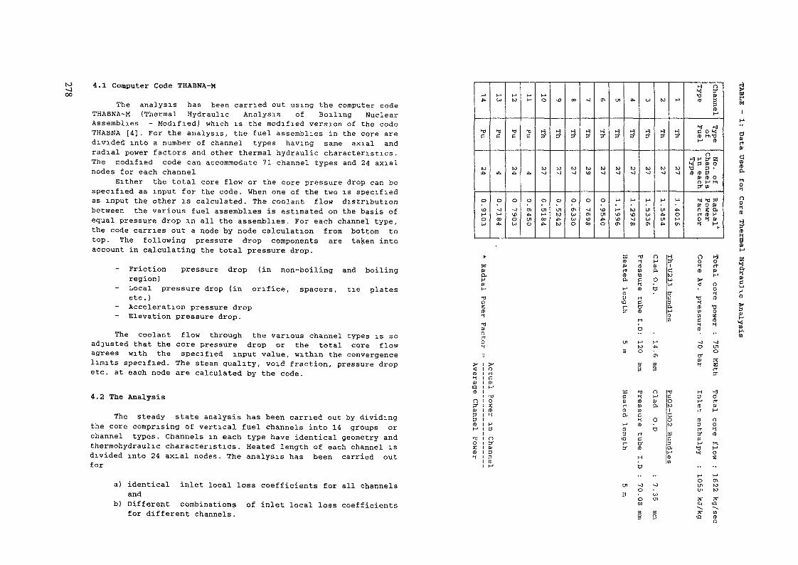
NJ~J00
4.1 Computer Code THABNA-M
The analysis has been carried out using the computer codeTHABNA-M (Thermal Hydraulic Analysis of Boiling NuclearAssemblies - Modified) which is the modified version of the codeTHABNA [4]. For the analysis, the fuel assemblies in the core aredivided into a number of channel types having same axial andradial power factors and other thermal hydraulic characteristics.The modified code can accommodate 71 channel types and 24 axialnodes for each channel
Either the total core flow or the core pressure drop can bespecified as input for the code. When one of the two is specifiedas input the other is calculated. The coolant flow distributionbetween the various fuel assemblies is estimated on the basis ofequal pressure drop in all the assemblies. For each channel type,the code carries out a node by node calculation from bottom totop. The following pressure drop components are tajcen intoaccount in calculating the total pressure drop.
- Friction pressure drop (in non-boiling and boilingregion)Local pressure drop (in orifice, spacers, tie platesetc.)Acceleration pressure dropElevation pressure drop.
The coolant flow through the various channel types is soadjusted that the core pressure drop or the total core flowagrees with the specified input value, within the convergencelimits specified. The steam quality, void fraction, pressure dropetc. at each node are calculated by the code.
4.2 The Analysis
The steady state analysis has been carried out by dividingthe core comprising of vertical fuel channels into 14 groups orchannel types. Channels in each type have identical geometry andthermohydraulic characteristics. Heated length of each channel isdivided into 24 axial nodes. The analysis has been carried outfor
H-»ife-
>T)
C
to£t
0
10K1
O
Mlo
TJC
*»
o^jt->C»
H«to
TJe
COA
o-ou>0
MM
'OC
•Ci
or^•r*in
Mo
1-3y
toj
oUlM!»
U>
1-3y
to~j
0
intoil»to
CO
1-3ff
to^j
oO*Wwo
~J
4y
to<o
oi
m1003
CTi
1-3y
to-o
oUJinj»o
in
Hy
to^j
h*
i-*UÎu>CT\
ib.
h^ET
to• J
M
(0VÛ
CO
W
t_5Jj-
CO-J
H*,cnuW<7ï
to
j-3ff
CO•o
fj
Öl£•in
M
1-3a-
to•J
M
it>OMtn
^ O><! y•d »i(t 3
3(tt~»
>J) i-3C O kjIt Hi'0M (t
O1-3 H 3- 2i>< 3 » O•O 3 •IP (H 3
!» (t OO H Hl3- W
11 T)!*P O 0>O S O .rt (t H0 Hs (w* M»
os(D11"101n
(t11PIQIt
ny3(Di-1T)ou(ttl
rrC,01M
TiOS(D^
H3
nySa33ro
cn
3
Ä(D0?rtfl>
l—»fD^3iQ
o
I
TJH((D(0WC
(t
rrC0-
H
M£•
cn33
n -oM(»o,
oD
C0to1
GOco
CüC3
>->(tW
•J0
tro>
H3
(trt
(D3rtypH«
*<
ino
I
D"
1-3Ort01M
OOln>Hl
OS
fW
O»rtCuitO.
^J W l"CO <7* ib
H> y rj y;tn I I -1
s •« n 1-3 o 1-3It 1-! HW (t pt W Q!•D Wa. c or-1 (t ait3 rta ct ery (t
H
3" O Oa ( D BtO H-1U >Ui < O
0er *î- "O (t
ü. ( D t )H W O(t w îw c: (t
1 1-1a it
Therm
i»H"
Wa.WcHHo
3
H
UH-
a) identical inlet local loss coefficients for all channelsand
b) Different combinations of inlet local loss coefficientsfor different channels.
-Jooinin

coerooOa>a.
fl>rt(D
jb
O
a\o
H"
Ul01
OÏin
H1
~J
01
U3CO
VT)
•~J0
ÜJ
t*J
oCDH
l->
a\-)
|E>Ol
W
Öl
1C»
»•J
Ol
OlkO
O
DO
O
~JM
M
01£t
UlLJ
1Û
Öl
Öl
kuoo
01ko
M
M
O
U3Ol
H>
ÖlVO
W^J
-J
Öl
£.
00ib.
CO
01u>o
o
Öl
oo
totoH>
O
o
Öl
en
oo
öiIÛ
o
iß
uioo
10
i-*CO
o0*
Öl
CO
oo
ÖlU5
Ito
CO
*.too
toH>CO
0
ai
01
UJ
l-1Ul
Ifa
ÖlCO
U)
^J
uCJto
N)
>->to
£*
Öl
Öl
00
|£>J^u>
Öl10
£>
01
CO
U)~0
toHv->
H1
to~0
01
W
Öl£t
o
01»vO
o01H
V-i
*»to
Ul
M
UlU>
to0m
toÖl
~J
Öl
^J
-JCO
to
Ölvu
LJ
i&
H
*.O
toOO
OJCO
Ul
~J
W
00!-•
~0
-Joo
W
1-»
0VD
CO
O*-*
ibÖl
o
Öl
Ul
CO^JUl
Öl10H
10
)J0CO
H"
U3^ß
*>01
01
01U)
CO-J
^]
ÖlVO
Ul
M
H*
tolb
tooW
WCO
01
Öl
Ul
03£>
Öl
Ölk£>
o
KL,
r
0Sa
fl>
l-1
nvmto
oÏUu
h>
O
n
co
n£DU
)-"
OUn
to
ca
se
1nu»(tto
-3 nS S3"
0 13p(Pt-J
f S(P OS 3|Qrt 1tr
Wo— H-3 i-
«
O 0C ff(D (U
H. 3rt (0K M
— W* X
f
n1 y1^ B)Si 30 3rt (DH' MOB M
X
S rt
OH-a
Ch
an
ne
l I
Dro
p
(be 're
ssu
reir)
rM
0MlO0
sH
t
H-n
&Dl
Analysis carried out for the case of identical values oflocal loss coefficient for all channels (case 1) and one case ofdifferent inlet local loss coefficient values for differentchannels (case 2) are presented and discussed in this paper. Thedata used in respect of channel types, number of channels, radialpower factor etc. are given in Table 1.
4.3 Results and Discussions
Channel exit quality and void fraction, non-boiling lengthand channel pressure drop for the two cases defined in section4.2 are depicted in table 2. With identical value of inlet localloss coefficient for all channels, the coolant channel exitquality varies from 0.0 to 46.6% for thorium bundles and 37.7%65.1% for Pu bundles. Values of exit quality in Pu bundles arehigher than those in Th bundles because of higher hydraulicresistance of Pu bundles which have smaller flow area. Variationof exit quality in channels having same type of fuel is mainlydue to variation of channel power. For case 2, by adjusting theinlet local loss coefficient, the variation of exit quality hasbeen reduced to a great extent. The variation is from 16.3% to17.3% for Th bundles and 16.4% to 17.6% for Pu bundles. However,exit quality has been evened out at the cost of additional corepressure drop which has increased from 0.61 bar (case 1) to 1.42bar. The increase in pressure drop is because of the increase inthe value of inlet local loss coefficient. The pressure drop canbe reduced if variation of exit quality to a larger extent isfound to be acceptable.
5.0 Thermosyphon Analysis of the PHT System
Two phase thermosyphon analysis of the PHT system has beencarried out using the computer code RELAP4/MOD6 [5] for differentcases.
5.1 Cases Analysed
i) Effect of variation of loop height Z (see fig.l) on naturalconvection flow. The height Z was varied by varying Zj andZ2 . The values of Z (in metre) considered are 10, 15, 20,25, 30, 38, 46 and 60. The core power was maintainedconstant at 750 MWth for all these cases.

tooo ii) Effect of variation of core power on natural convectionflow. Analysis was carried out over a range of values forcore power from 50% to 100% with steps of 5% (100%corresponds to 750 Mwth). Loop height Z was maintainedconstant at 38 m for these studies.
5.2 Analysis
The detailed nodalisation scheme adopted for the analysis isdepicted in figure 3. The PHT system was simulated as a set ofcontrol volumes and junctions. Fourteen control volumes andfourteen junctions were considered for the analysis as shown inthe figure. The fuel was modelled as heat generating cylindricalslab. Core inlet hydraulic resistance corresponding to case 2 ofSection 4.2 was considered for the analysis. The steam drumpressure was maintained constant at 69 bar.
1, 2___.14: CONTROL VOLUME Nos.
(T)0———©FUNCTION Nos.
PIPE
UPPERCHANNEL
EXTENSION
CORE
LOWERCHANNELEXTENSION
REACTORINLET
FEEDER PIPES HEADER RIPE12
DOWNCOMER
2500 r
2000
1500
° 1000
500 -
00
POWER : 750 MWth
10 20 30 40HEIGHT (m)
50 60
FIG. 3 NODALIZATION SCHEME FOR THE AHWRTHERMO SYPHON ANALYSIS
FIG. 4 VARIATION OF CORE FLOW WITHLOOP HEIGHT (2 )
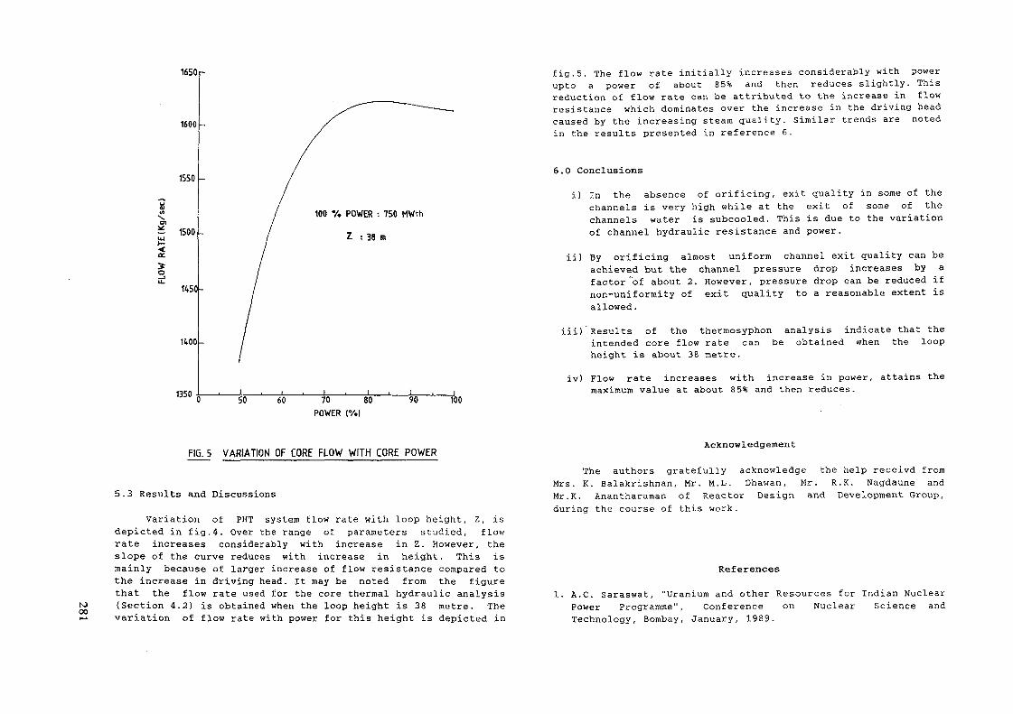
1650
1600
1550
~ 1500
o1450-
1400
1350
100 V. POWER : 750 MWth
Z : 38 m
SO 60 70POWER
80 90 100
fig.5. The flow rate initially increases considerably with powerupto a power of about 85% and then reduces slightly. Thisreduction of flow rate can be attributed to the increase in flowresistance which dominates over the increase in the driving headcaused by the increasing steam quality. Similar trends are notedin the results presented in reference 6.
6.0 Conclusions
i) In the absence of orificing, exit quality in some of thechannels is very high while at the exit of some of thechannels water is subcooled. This is due to the variationof channel hydraulic resistance and power.
ii) By orificing almost uniform channel exit quality can beachieved but the channel pressure drop increases by afactor of about 2. However, pressure drop can be reduced ifnon-uniformity of exit quality to a reasonable extent isallowed.
iii) Results of the thermosyphon analysis indicate that theintended core flow rate can be obtained when the loopheight is about 38 metre.
iv) Flow rate increases with increase in power,maximum value at about 85% and then reduces.
attains the
tooo
FIG. 5 VARIATION OF CORE FLOW WITH CORE POWER
5.3 Results and Discussions
Variation of PHT system flow rate with loop height, Z, isdepicted in fig.4. Over the range of parameters studied, flowrate increases considerably with increase in Z. However, theslope of the curve reduces with increase in height. This ismainly because of larger increase of flow resistance compared tothe increase in driving head. It may be noted from the figurethat the flow rate used for the core thermal hydraulic analysis(Section 4.2) is obtained when the loop height is 38 metre. Thevariation of flow rate with power for this height is depicted in
Acknowledgement
The authors gratefully acknowledge the help receivd fromMrs. K. Balakrishnan, Mr. M.L. Dhawan, Mr. R.K. Nagdaune andMr.K. Anantharaman of Reactor Design and Development Group,during the course of this work.
References
1. A.C. Saraswat, "Uranium and other Resources for Indian NuclearPower Programme", Conference on Nuclear Science andTechnology, Bombay, January, 1989.

(O00tO
2 K Balakrishnan and A Kakodkar Preliminary Physics Designof Advanced Heavy Water Reactor (AHWR)' IAEA TechnicalCommittee Meeting on Technical and Economic Aspects of HighConverters Nurenberg, FRG, March 1990
3 Communications from KDivision, BARC, India
Balakrishnan, Reactor Engineering
4 V. Venkat Raj, A K Anand, D Saha "THABNA- A Computer Programfor the Thermal Hydraulic Analysis of Boiling NuclearAssemblies" Second National Heat and Mass TransferConference, Kanpur, India, December, 1973
5 S.R Fischer et al , "RELAP4/MOD6, A Computer programme fortransient thermal hydraulic analysis of nuclear reactors andrelated systems, User's manual", CDAP-TR- 003, Jan., 1978
6. R.B. Duffey and J.P. Sursock, "Natural Circulation PhenomenaRelevant to small breaks and transients". Nuclear Engineeringand Design, V 102, PP 115-128, 1987.
CAPABILITIES OF THE RELAPS IN SIMULATINGSBWR AND AP600 THERMAL-HYDRAULIC BEHAVIOUR
P ANDREUCCETTI, P BARBUCCI, F DONATINIEnte Nazionale per 1'Energia ElettncaF D'AURIA, G M GALASSI, F. ORIOLOPisa University
Pisa, Italy
Abstract
This paper deals with the application of the RELAP5/Mod2 code for the analysis of thermal hydraulictransients in the SBWR and AP600 nuclear reactors.
The RELAPS limits and capabilities as far as the development of the nodalization and the simulation ofeach plant are discussed. In particular, limitations have been found in the applications of code models to lowpressure scenarios where gravity is the dominant driving force for core cooling
1 INTRODUCTION
In the framework of ENEL activities for the safety evaluation of passively or intnnsecally safe nuclearreactors, SBWR and AP600 plants are under study.
SBWR and AP600, proposed by General Electnc and Westinghouse respectively, are the result of anevolution of BWR and PWR technologies widely used for the electncity production over the last thirty years. Inboth cases the electric power ranges around 600 MWe and substantial simplifications have been introduced inall the main systems to improve the reliability and reduce the cost of power generation Passive safely features,mostly based on gravity, characterize the abnormal operation systems, large water pools are available at higherelevations than the core and allow cooling in any low pressure accident scenario
For the analysis of thermal-hydraulic response of the two plants ENEL and Pisa University havedeveloped two RELAP5/Mod2 models and have undertaken a program in order to assess and validate thembefore the use for safety evaluations.
RELAP5/Mod2 /!/ is a well known transient analysis code for complex thermal hydraulic systems. It isbased on a non-homogeneous non-equilibnum set of six one-dimensional balance equations for the steam andthe liquid phases.
The RELAP5/Mod2 has been intensively used at DCMN of University of Pisa in the analysis oftransients in experimental facilities /2/, /3/ as well as in real plants /4/, /5/ Limits and capabilities of thecode have been identified with reference to the various phenomena occurring in nuclear reactors in accidentconditions.
When applying the code to the SBWR and AP600 it has to be consider that the typical accidentscenarios in these plants can be subdivided into two parts a) time before the equalization between primary andcontainment pressures; b) long term cooling period, with gravity heads at near atmospheric pressure which arethe dnving forces for different natural circulation loops in the plant. Furthermore, the interaction between theprimary circuit and the containment is a fundamental aspect in the safety of these reactors.
Now, while the RELAPS code has been assessed worldwide /6/ in relation to phenomena occurring inpart a) of the scenario, very limited expenence in the application to phenomena typical of the part b) isreported

Tab. I - Boundary and initial conditions for SBWR Feedwater Trip and Steam Line Break accidents
1C POOL
GOCCS POOL
SUPPRESSION POOL
QUENCHER
ACC-CRD POOL
Fig. 1 - Sketch of SBWR including safety systems
1 Steam dome pressure2 Core Power3 Feed Water Temperature4 Core Flow Rate5 Steam Line Flowrate6 Lower Plenum Temperature7 Downcomer Level8 HPIS and CRD fluid temperature9 HPIS flow rate10 Liquid temperature of the pools11 Break occurrence12 Feed water closure13 Scram14 Actuation of15 Actuation of16 MSIV closure17 Actuation of18 Actuation of19 Actuation of
20 Actuation of
21 Actuation o£
(+)90 s delay(++)135 s delay(++-O150 s delay
CRDHPIS
1CSRV
SL-DPV
RPV-DPV
GDCS
DCDCDCDCDCDC
DC
DC
DC
(HPa)(MW)(K)(Kg/s)(Kg/s)(K)Cm)(K)(Kg/s)(K)(s)(s)
levellevellevellevellevellevellevellevel
level
FWT7.041800.488.7556970.551.15.03300.19.63000.
=13.98 m==
=13.98 m=12.96 m=12.98 m
==
==
==
==
SLB
= 13= 13= 13
0.0989898
=11.98= 12= 10
= 10(
= 10
= 10
985353++)53
53
mmmmmm
m
m
m
K>00
The purpose of this paper is to discuss the main results of RELAP5/Mod2 code application to theanalysis of four scenarios (two for each plant) in SBWR and AP600 reactors. It has to be noted that both theplant models have been developed starting from plant data updated to design status in the early 1990 and thatsome details of particular components of the plants were not available. Moreover the developed models arealready under validation. Therefore the results discussed in this paper have to be considered as preliminary.
2. SBWR ANALYSES
The SBWR plant /7/,/8/,/9/ (Fig. 1) is designed to use natural circulation to cool the core both innormal and accident conditions. In accident conditions the reactor is cooled by the following systems:
- Isolation Condenser (1C), High Pressure Injection System (HPIS) and Control Rod Driving (CRD)for high pressure transients;
- Gravity Driven Cooling System (GDCS) at low pressure conditions.The 1C system allows the energy exchange between the vessel and an external pool, by the condensation
of the steam coming from the vessel without fluid discharge from primary system. The GDCS injects into thevessel the water coming from a pool at an elevation higher than the top of the core, in order to provide theadequate head for system operation at low pressure.
The primary system depressurization is allowed by groups of valves on the steam Unes that dischargefluid in the containment suppression pool.
The containment cooling is provided by the Passive Containment Cooling System (PCCS), whichperforms the heat transfer to environment, condensing the steam of the containment atmosphere with a threedays operational capability.
For SBWR two accidents have been selected among those which contribute to the overall risk of theplant. They are a complete Feedwater Trip (FWT) and a double ended Steam Line Break (SLB).
The main boundary and initial conditions, are given in Tab. I. The considered conditions do notnecessarily reflect the nominal reference values of the plant.
2.1 SBWR nodalization
The SBWR model consists of 200 fluid volumes, 220 junctions and 183 heat conducting structures (Fig.2). The core is subdivided into four parallel channels to account for the radial power distribution; an additionalchannel simulates the bypass region between the fuel assemblies. The isolation condenser, the two steam lines,and the GDCS can be easily identified in the nodalization.
Each large tank (GDCS and Isolation Condenser) is connected with a node having assigned conditionsbecause it is impossible to model the presence of air in the control volume using the available code version.

IsJoo
Fig. 2 - Simplified RELAP5/Mod2 nodalrzation scheme for SBWR
23. SBWR transient results
Preliminary results about SBWR thermal hydraulic response to the feedwater tnp and to the mamsteam Une break transients can be seen in Fig 3 and 4, respectively
In the transient originated by feedwater tnp, the vessel isolation occurs after about 100 s. The scram isactuated earlier due to low level in the downcomer The HPIS and the isolation condenser activations aresufficient to keep the core in a stable cooled situation at relatively high pressure Natural circulation alsooccurs between core and bypass leading to negative values of the bypass flowrate
The transient calculation for the SLBA has been stopped shortly after the GDCS has been activatedThe primary depressunzation is enhanced by the opening of various groups of discharge valves (see Tab I)The low pressure at the top of the vessel leads to an increase in the core flowrate during the transient up tovalues typical of nominal conditions. Core power at this time corresponds to decay power values and bypassflowrate remains positive for almost all the transient Wide oscillations occurs in the core flowrate In the latestpenod of the transient, mainly following GDCS actuation, the isolation condenser flowrate becomes negativeAn apparent effect of the GDCS intervention is a step increase of subcoohng ui the lower plenum thatimproves the core heat transfer potential
Q PRIMARY PRESSURE
O CORE MASS FLOW RATE
M Pa
60 -
^o
200
Fig 3 Primary system pressure and core mass flow ratefollowing a. feedwater trip in the SBWR plant
- 35
15
HPIS STARTS
D PRIMARY PRESSURE
A CORE MASS FLOW RATE
K / SHO'
095
075
055
-150 -50 0 50 150 250 350 450 s
Fig 4 - Pnmary system pressure and core mass flow ratefollowing a mam steam Une break in the SBWR plant
035

Vo'i
eoo
CDCSFLQXV
o BAS- ci-s;à. S£N.'$ITIY<ÎY
-150 -50 50 150 250 350 <SO
Fig, S - Flowrate delivered by GDCS in the SLB transient in theS3WR, for different operation modes of check valves
I , I,."••* »..'
ntssuwzaTTTrtKilib^}
CO«t MAJCUlANl Q
0
toooFig. 6 - Sketch of AP600: a) primary loops; b) safety systems
With reference to this accident, the effect of two different GDCS flowrates has been investigated andthe obtained results are given in Fig. 5.
The reference case, where GDCS valve is assumed to work properly, is compared with the result of acalculation where it is assumed that the valve opens (and after that time it remains always open) when thepressure difference between the primary system and a point upstream to the valve is still positive.
3. AP600 ANALYSES
The AP600 plant /Id/, ]\\l is cooled by a simplified primary system with two loops, employing invertedcanned motor pumps feeding cold liquid to two separate cold legs (see Fig. 6). AP600 safety features include:
a) the Passive Residual Heat Removal (PRHR), whose function is similar to the I.e. one in the SBWRplant;
b) the Inside containment Refueling Water Storage Tank (IRWST), which provides the reactor coolingat low pressure condition through a Sine connected to vessel downcomer;
c) the Depressurization System, consisting of four group of valves;d) two Core Make up Tanks, essentially consisting in large reservoirs of fluid;e) two accumulators pressurized at 4.9 MPa by nitrogen.Transients that are widely investigated for conventional PWR have been selected in the case of AP600.
Both of these are Loss of Coolant Accidents (LOCAs): an intermediate LOCA (ILOCA), originated by abreak in the safety injection pipe (piping connecting the accumulator and CMT to the reactor vesseldowncomer), and a double ended LOCA in one of the cold legs of the loop with pressurizer.
The main boundary and initial conditions arc reported in Tab. II.
3.1 AP600 nodalization
The model consists of 245 fluid volumes, 264 junctions and 253 heat conducting structures (Fig. 7).There are three parallel channels connected by cross junctions in the core model. The two cold legs includingcanned motor pumps, were modelled in each primary loop. The engineered safety features were modelled withdifferent levels of detail.
3.2 AP600 transient results
Preliminary results about AP600 thermal-hydraulic response to the intermediate break LOCA and thelarge break LOCA can be seen in Fig. 8 and 9, respectively.
In both the considered scenarios the primary pressure becomes lower than the secondary pressure earlyin the transient: consequently the secondary sides of the steam generator that remains isolated from theturbine and condenser (Tab. II), do not play an important role unless as heat source late in the transient.
In the case of the ILOCA the break is in one of the two main delivery lines of the emergency system andcauses the discharge of the liquid contained in one accumulator and in one CMT, directly to the containmentwithout contribution to core cooling. The behaviour of the various systems can be summarized as follows:
- reverse flow (from the cold leg to the pressurizer surge line) occurs after the activation of the PRHRowing to the pressure balance in the loop; afterwards a stable circulation is established in the rightdirection;
- the Depressurization System causes a positive steam flow from the pressurizer towards the IRWST andthe CMT;
- in the early period of the transient, the accumulators discharge prevents the liquid fall from the CMTconnected to the intact line owing to a counterpressure in the delivery lines.No dryout situation results during the ILOCA transientOn the other hand, an extended dryout mostly in the central part of the core characterizes the LBLOCA
scenario which appears similar to the one predicted for the "conventional" PWR. Early core rewet in the lower

to00
P- WL.5 |s(3
Fig. 7 - Simplified RELAPS/ Moö2 nodalization scheme for AP600
part of the fuel bundles is also observed in the calculation. The accumulators and the liquid discharge from theCMT are effective in bringing the plant to a safety condition.
It has to be noted that code results for calculations in the low pressure range are strongly influenced byvariations in plant lay-out, initial conditions or plant nodalization.
In the following some examples of this are given.
Position of sparger in the IRWSTThe reference ILOCA calculation was performed assuming that the sparger of the depressurization
system in the IRWST pool is located near the top of the volume occupied by the liquid, hi this case only partialcondensation of the steam discharged from the primary system is observed; the remaining part of the steamcontributes to the pressurization of the pool volume, allowing the drainage of the liquid from the pool towardstfvecore.
MPa
168 Ä E A X OPENS
SCBAM' RCP TB1P
MSL ISOLATION SUftT
D PRIMARY PRESSURE
A CORE LEVEL35
-02 0 02 04 06 0.8 1.0 1.2 1.4 US 1.8
Fig. 8 - Primary system pressure and core level trend following anIntermediate Break LOCA in the AP600
O ROD TEMPERATURE-PERIPHERAL CHANNEL
-120 -80 -40 40 80 120 160 200
- 800
- 600
400
Fig. 9 - Primary system pressure and fuel rod temperature toUownja Large Break LOCA in the AP600

Tab. II - Boundary and initial conditions for AP600 Intermediate and Large Break LOCA
12345
678
9101112131415
1617
QUANTITYPressunzer pressureCore PowerHot leg Fluid temperatureCore How rateSteam generator secondarypressureFeedwater temperatureFeedwater how rateSteam generator recirculationratioBreak occurrenceReactor tripCMT actuationFeedwater tripSteam line tripRCP tripRCS depressunzationactuation: 1st stage
2nd stage3rd stage4th stage
PRHR actuationStart at delivery atIRWST liquid into the RCS
VALUE OR SETPOINT(MPa)<™th>(K)(Kg/s)
(MPa)(K)(Kg/s)
(-)time =
PRZ pressure =PRZ pressure =PRZ pressure =SG levelPRZ pressure =
CMT levelCMT levelCMT levelCMT levelCMT level
Prcs < Pirwst
15.531812.596.489216.33508.15515.84
4.0 s
12.7 MPa12.7 MPa12.7 MPa11.1 m12.7 MPa4.4 m3.97 m2.33 m10% initial level44 m
-C2 0 02 01 06 OE 10 12 14 16 18 '
Fig. 11 - ILOCA analysis for AP600: effect of different liquidtemperature in the CMT
1200
600
O BASE CASE
A SENSITIVITY
C
\
-02 0 02 04 06 08 1.0 \2 14
71
67
55
* CKM2 SENSITIVITYO C V T l SENSITIVITY
C CMT! BASE C'SEL Ci-'Ti BASE CASH
-120 -80 40 80 120 1SO 200
tooo Fig. 10 - ILOCA analysis for AP600: effect of different positionsof the depressunzation system sparger in the IRWST
Fig. 12 - LBLOCA analysis "or AP600: effect of nodalization ofthe CMT discharge lines

to00oo
A second calculation was carried out assuming that the sparger is located in the bottom of the pool. Inthis case, a nearly complete steam condensation prevents the pool liquid from discharging and leads toextended core dtyout (Fig. 10).
Effect of liquid temperature in the poolAgain with reference to the ILOCA in the AP600 plant, while the reference calculation was done
assuming an initial temperature of the liquid in the Core Make up Tanks equal to 373 K (to prevent the stop ofthe calculation owing to numerical problems), a second calculation was run considering a lower (323 K) liquidtemperature in the Core Make up Tanks. In this case the large vaporization in the connection zone betweenthe CMTs lines and the vessel creates a steam upward flow in the lines that prevents liquid drainage and causesdryout early in the transient (Fig. 11).
Effect of nodalization of the CMT discharge linesThe line connecting the CMT to the vessel presents a complex layout in the vertical plane. Different
approaches in modelling the line result in quite different prediction of CMT discharge. The CMT levels in thereference case for LBLOCA are compared with those obtained in the sensitivity study in Fig. 12(*). In thereference case the fairly coarse nodalization of the discharge Unes modifies the pressure drop situation in theplant causing a large positive flow from the cold leg to one of the CMT, that does not experience any leveldecrease despite the liquid delivery to the vessel. The nearly constant level situation in one tank prevents theactivation of the depressurization system.
The more detailed nodalization used in the sensitivity calculation allows the complete discharge of bothCMTs.
4. EVALUATION OF CODE LIMITS
As already mentioned, in the evaluation of code results two periods in each of the four transients shouldbe distinguished:
a) primary system pressure greater than about 0.5 MPa;b) subsequent period, including the interaction between the primary loop and the containment system
and the long term behaviour of the passive safety systems.Phase a) is within a range of physical situations for which an accurate code qualification process based
on international standard problems, already exists.Phase b) results must be considered outside the qualification boundary limits of the code, considering
the international assessment activity.As all the phenomena relevant to the safety in the analyzed transients(**) occur in the period a), the
obtained results have to be considered reliable. Nevertheless some limits of the code models with mainreference to the capabilities required to simulate low pressure scenarios governed by gravity, should behighlighted.
Specific limits of the code are as follows:- at low pressure (P <, 02 MPa), very wide oscillations occur in the physical quantities. This requires
the use of very small time steps and cause the interruption of the calculation;
(*) The steps observable in the curves for the reference case occur when the level crosses the volume boundary and constitute a clearnodalhation effect.
(**)The only eception is the LBLOCA evtnt in the AP6ÛO. In this case the past experience in the analysis of large LOCA in PWR's canhelp in the evaluation of the results.
- the simulation of the fluid behaviour downstream of a critical section (supercritical flow) is notallowed in any geometric configuration;
-the transition between critical flow model and Bernoulli model leads to instabilities in thecalculation, mainly at low pressure;
- the temperature stratification in pool with large vertical dimension is not well calculated by thecode. This may results in wrong prediction of gravity heads and in large errors in mass flowrates;
- the natural circulation in the system constituted by primaiy loops and containment, largely dependson local loss coefficients in complex three dimensional geometries that must be supplied as input bythe user,
- the zero-dimensional neutronic kinetic model is not suitable for simulating the 3D behaviour oflarge cores, and in particular of the SBWR one where the control rods and the peculiar moderatordistribution are strong sources of non uniformities;
- the condensation at the "ECCS port" is a further source of instability that stops the calculation.
5. CONCLUSIONSThe RELAP5/Mod2 code has been used to develop models for the SBWR and AP600 plants and to
cany out preliminary analyses of two typical accidents for each plant.As it is well know, passive LWR's are characterized by the interaction between primary circuit and
containment system, the occurence of the most important scenarios at low pressure and the existence of severalpotential natural circulation loops.
The obtained results showed the safe response of the plants to the analyzed accidents. Some plantfeatures that could require additional investigations by designers, and code limits in the simulation of thecomplete thermal-hydraulic transient have also been identified.
As far as the qualification of the code is concerned, its validation in the physical conditions that arespecific of the new reactors is strictly necessary. The behaviour of components like the isolation condenser inSBWR and the cooling pools injecting liquid in the core by gravity, are an example of items requiring an indepth study.
ACKNOWLEDGEMENTS
At DCMN the following people directly took part in the analysis of the code results and contributed tothe solution of various problems of the code computer interface: W. Ambrosini, A. De Varti, R. Dini, G.Fruttuoso, P. Lombard!.
REFERENCES
/!/ V.H. Ranson, RJ. Wagner, JA. Trapp, L.R. Feinhauer, G.W. Johnson, D.M. Riser, RA. Riemke:"RELAP5/MOD2 Code Manual Vol. l, Code Structure, system models and solution methods"NUREL/CR - 4312, August 1985
/2/ F. D'Auria, G. M. Galassi:"Code Assessment Methodology and Results" IAEA Tech. Committee Workshop on Computer AidedSafety Analysis - Moscow (USSR), May 14-17,1990
/3/ F. D'Auria, G. M. Galassi:"Assessment of RELAP5/MOD2 code on the basis of experiment performed in LOBI FacilityJ.Nuclear Techonology, Vol 90 (3), p. 340-355,1990

/4/ P Camiciola, F D Auna, P Marsili, P Petnni"OECD CSNI ISP 20 post test calculation and sensitivity analyses by RELAP5/MOD2 performed withreference to the SGTR accident Doel 2 NPP"University of Pisa Report, DCMN RL 290 (87), Pisa 1987
IS/ F D Auna, P Maugen"Analysis by RELAP5/MOD2 of a Loss of Feedwater Transient in the Leibnstand BWR-6 plant"Int Conf on Thermal Reactor Safety, Avignon (F) Octobers 7,1988
161 CSNI Group of Experts.Thermalhydraulics of Emergency Core Cooling in Light Water ReactorsCSNI Report 161, Pans October 1989
/?/ B Wolfe, D R. Wilkms."Future directions in Boiling Water Reactor Design"J Nuclear Engineering and Design, Vol 115pag 281 288,1989
/8/ J D Duncan, C D Sawfer"Capitalizing on BWR Simplicity at Lower Power Rating"ANS/ENS International Conference, November, 1984
ßl JD Duncan"SBWR, a Simplified Boiling Water Reactor"Nuclear Engineering and Design, Vol 109, n l and 2,1988
/10/ RA. Bruce, R.P Vyulc"Conceptual Design for an advanced Passive 600 MWa PWR"ASME IEEE Power Generanon Conference, Miami Beach, USA, October 4 8,1987
/11/ CM Vertes."Passive Safeguards Design Optimation Studies for the Westinghouse AP600"1989 ANS Winter Meeting, San Francisco, USA, November 20-30,1989
ASSESSMENT OF THE PIUS PRIMARY SYSTEMUSING ANALYTICAL AND EXPERIMENTAL MODELS
P BARBUCCI*, C BERTANI**, C CARBONE*,G DEL TIN**, F DONATINI*, G SOBRERO**
*Ente Nazionale per 1'Energia Elettnca,Pisa
**Pohtecruco di Torino,TurinItaly
Abstract
This paper deals mainly with the application of the RELAPS code to the thermal hydraulicanalysis of PIUS system
In the first part, the RELAPS model and the analysis of plant steady state under forced andnatural circulation conditions are descnbed The analysis outlines the influence of different modelling ofheat conducting structures and pressure losses on the prediction of plant response
The second part describes the analytical and experimental models under development in order toanalyse particular separate effects typical of the innovative nature of the PIUS plant
1 INTRODUCTION
to00\o
The assessment of PIUS primary system requires the development of analytical and expenmentalmodels in order to simulate the thermal hydraulic behaviour in normal and accident conditions
In the frame of a cooperation between ENEL-CRTN and the "Diparnmento di Energetica" ofPohtecmco di Torino, a RELAPS model of PIUS reactor has been developed and implemented on ENELCRAY XMP/14 computer system
The selection of RELAPS code denves from the following considerationsRELAPS is an advanced best estimate thermal hydraulic code, developed at 1NEL under theUSNRC support for safety analysis of nuclear reactors, and submitted to a wide qualificationprogram based on expenmental facilitiesRELAPS has been adopted by ENEL also for the thermal hydraulic analysis of SBWR and AP600reactors, in order to provide an homogeneous tool for the companson of the three differentsystems.Some sensitivity studies have been earned out to evaluate the influence of the constitutive models
implemented in the code (heat transfer, wall f nction and form losses, etc )On the other hand the innovative features of PIUS system require an accurate assessment of code
capability in simulating particular phenomena like natural circulation, syphon breaker behaviour, borondiffusion, etc In order to start this assessment process an expenmental test facility for lower density lock

1 Pressunzer steam vomume2 Steam generator (4)3 Upper density lock4 Mam coolant pump (4)5 Riser6 Core instrumentation7. Embedded steel membrane8 Pool liner9 Core10 Lower density lock11. Passive RHR cooler
Fig. 1 - Sketch of PIUS Reactor
simulation has been designed and 2-D fluid dynamic analyses have been carried out using FLUENT code.FLUENT code, which solves the Navier Stokes equations in complex geometries, provides an usefull toolin the analysis of separate effects as support to plant design.
Z PIUS SYSTEM DESCRIPTION
PIUS (Process Inherent Ultimate Safety) /!/ is a modified PWR where the main differencecompared with the current reactors is the safety concept which leads to a different layout of primarysystem and design of out-of-«ore components. The name implies that safety against serious accident isinherent in the design of heat removal process and not a result of outside safety features such asemergency core cooling systems. In addition this inherent safety is always present as ultimate protectionagainst serious accidents, even though such accidents are usually averted by normal plant control system.
To preserve the core integrity and to avoid radioactive releases to the environment the PIUS coreis submerged in a large pool of borated water enclosed in a prestressed concrete vessel (Fig.l). Thereactor core is a PWR type core with 213 fuel assemblies with standard PWR fuel rod diameter andreduced height. The 2000 KfWt core is located at the bottom of the reactor pool and does not use controlrods, neither for reactor shutdown, nor for power shaping. Reactivity control is accomplished by means ofreactor coolant boron concentration and temperature control. Reactivity compensation for burnup isprovided by burnable absorber (gadolinium) in selected fuel rods, while the moderator températurereactivity is strongly negative throughout the operating cycle.
The coolant leaving the core at 290 °C, passes up through the riser pipe and leaves the reactorvessel through nozzles connected to the side of the upper plenum. The coolant enters the 4 hot legs andgoes to the 4 once-through steam generators. The main coolant pumps are located in the steamgenerators outlet plenum and are structurally integrated with the steam generators. The cold leg pipingenters the reactor vessel through nozzles in the upper plenum at the same level as the hot leg nozzles andreturn flow at 260 °C is directed downward to the reactor core inlet via a downcomer. On its way downthe flow is accelerated and there are open connections between downcomer and riser providing a siphon-breaker arrangement.
The siphon-breaker prevents siphoning off the reactor pool water inventory in the event of a coldleg rupture. During normal operation the siphon-breaker does not affect the water circulation. At thebottom of the downcomer the return flow enters the reactor core inlet plenum. A pipe that is open to theenclosing reactor pool, is located below the core inlet plenum. A tube bundle arrangement inside thispipe minimizes water mixing and ensures stable layering of hot reactor loop water on top of colderreactor pool water. This pipe is called "lower density lock" and the position of the interface between hotand cold water, defined by temperature measurements, is used to control the speed of the main coolantpumps and hence the flow rate in the primary system in order to maintain the interface level at a constantposition during normal operation.
There is another density lock at a higher location in the pool, connected to the upper riser plenum;here the temperature measurements for the interface level are used to control the primary loop watervolume. This reactor system configuration with the two continuously open density locks connected to thehigh boron content water pool, provides the basis for the PIUS principle. There is always an open naturalcirculation path from the pool through the lower density lock to the core, through the core itself, up theriser, from the upper riser plenum to the upper density lock and back to the pool.
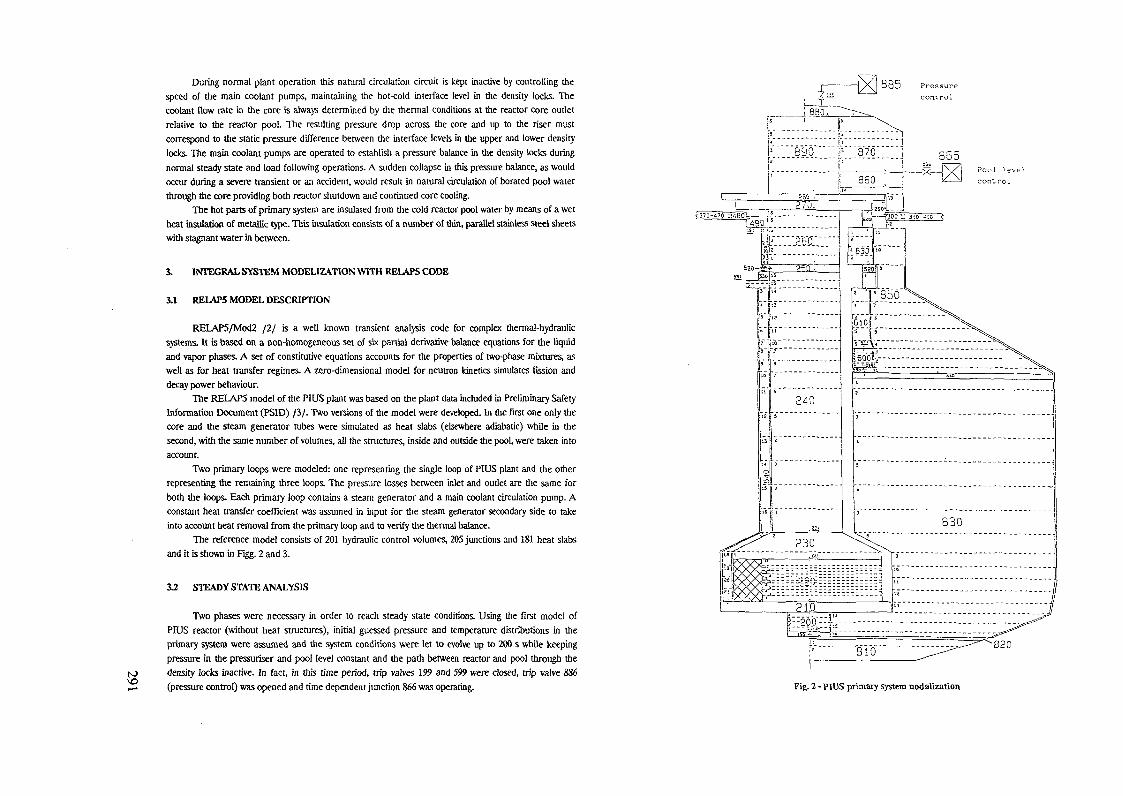
to
During normal plant operation this natural circulation circuit is kept inactive by controlling thespeed of the main coolant pumps, maintaining the hot-cold interface level in the density locks. Thecoolant flow rate in the core is always determined by the thermal conditions at the reactor core outletrelative to the reactor pool. The resulting pressure drop across the core and up to the riser mustcorrespond to the static pressure difference between the interface levels in the upper and lower densitylocks. The main coolant pumps are operated to establish a pressure balance in the density locks duringnormal steady state and load following operations. A sudden collapse in this pressure balance, as wouldoccur during a severe transient or an accident, would result in natural circulation of borated pool waterthrough the core providing both reactor shutdown and continued core cooling.
The hot parts of primary system are insulated from the cold reactor pool water by means of a wetheat insulation of metallic type. This insulation consists of a number of thin, parallel stainless steel sheetswith stagnant water in between.
Î. INTEGRAL SYSTEM MODEL1ZATION WITH RELAPS CODE
3.1 RELAPS MODEL DESCRIPTION
RELAP5/Mod2 /2/ is a well known transient analysis code for complex thermal-hydraulicsystems. It is based on a non-homogeneous set of six partial derivative balance equations for the liquidand vapor phases. A set of constitutive equations accounts for the properties of two-phase mixtures, aswell as for heat transfer regimes. A zero-dimensional model for neutron kinetics simulates fission anddecay power behaviour.
The RELAP5 model of the PIUS plant was based on the plant data included in Preliminary SafetyInformation Document (PSID) ß/. Two versions of the model were developed. In the first one only thecore and the steam generator tubes were simulated as heat slabs (elsewhere adiabatic) while in thesecond, with the same number of volumes, all the structures, inside and outside the pool, were taken intoaccount.
Two primary loops were modeled: one representing the single loop of PIUS plant and the otherrepresenting the remaining three loops. The pressure losses between inlet and outlet are the same forboth the loops. Each primary loop contains a steam generator and a main coolant circulation pump. Aconstant heat transfer coefficient was assumed in input for the steam generator secondary side to takeinto account heat removal from the primary loop and to verify the thermal balance.
The reference model consists of 201 hydraulic control volumes, 205 junctions and 181 heat slabsand it is shown in Figg. 2 and 3.
12 STEADY STATE ANALYSIS
Two phases were necessary in order to reach steady state conditions. Using the first model ofPIUS reactor (without heat structures), initial guessed pressure and temperature distributions in theprimary system were assumed and the system conditions were let to evolve up to 200 s while keepingpressure in the pressuriser and pool level constant and the path between reactor and pool through thedensity locks inactive. In fact, in this time period, trip valves 199 and 599 were closed, trip valve 886(pressure control) was opened and time dependent junction 866 was operating.
885 Pressurecontrol
K 890 ""Y"Q7Ô"~"]
Fig. 2 - PIUS primary system nodalization

to^oto
£
200 300 400 500 600Tempo Is) Time (s)
Fig. 4 - Pressurizer liquid level
700
400 500Time (s)
Fig. S - Flow through the lower density lock
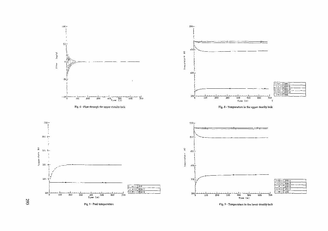
i W
200 300 400 500 600Time f.,J
400p
)
*
" 0 100 200 300 <00 500 600 700Time (s) T
-— —— . ——— _•— —
500- :600-2600-3600-4=.Qö
Fig. 6 - Flow through the upper density lock Fig. 8 - Temperature in the upper density lock
I /
to300 JOO 500 600
Time (a)
Fig. 7 - Pool temperature
-- ——
—— • ——
5 JO630-'.830-9
700
"JJ....,.,
0 100. . ! . . . . 1 . . . . I - . . . . I , . . . 1 , , , . 1
—— E ——. ._.. ——
•• _
——— • ——
200-4200-3200-2200 -;195
200- 300 400 500 600 700Tim« (»)
Fig. 9 - Temperature in the lower density lock

N) Tab I - Comparison between reference and calculated values for steady state condition
VARIABLES CALCULATED VALUESWITH heat slabs
Pressuriser levelpool
- riser funnel
Core flow
Total flow
Bypass flow
Loop 1 flow
Loop 2 flow
Inlet core temperature
Outlet core temperature
Inlet SG temperature
Outlet SG temperatureInlet core pressure
Outlet core pressureLoop 1 SG power
Loop 2 SG power
41 5943 665
13001
13602
600 28
3400
10202
260 02
289 91
288 50
260 05
9 3598
9 2955
497 096
1491 41
mm
kg/s
kg/s
kg/s
kg/s
kg/s
°C
°C
"C
°C
MPa
MPa
MW
MW
REFERENCE VALUESWITHOUT heat slabs
39 8543 64113002
13601599 83399 910201
260
289 89
288 52260 05
9 3325
9 2681
499 9641500 01
mm
kg/s
kg/skg/skg/skg/s°C°C°C"C
MPa
MPa
MW
MW
40 843 65
13000
13600
600
3400
10200
260
290
290
260 3
9 27
9 20
500
1500
mm
kg/skg/skg/skg/s
kg/s
°C
°C
°C
°C
MPa
MPa
MU
MW
Once obtained steady state conditions by the model without heat structures, the same procedurewas applied to the second model, which simulates all heat structures. The obtained steady state conditionsdo not differ significantly from those evaluated without heat structures.
The behaviour of the main thermal hydraulic variables after the opening of density locks trip valve(at 0 s in the case of the second model) are shown in Fig 4 through 9 and Tab 1 compares steady stateconditions obtained by the two models to the reference values /2/
Moreover, the effects of opening times of density locks tnp valves, pressure and pool level controlsystems and pool liquid level height on the system behaviour were studied The main results can besummarised as follows.
system behaviour is not affected if only the lower density lock tnp valve is opened, while when onlythe upper density lock tnp valve is opened relevant oscillations are observed in the flow ratethrough density locks, liquid level in the pressuriser and pressure throughout the reactor Thesephenomena can easily be explained by taking into account that the lower liquid inertia and fnctionforces that characterise the flow path through the upper density lock, nser upper plenum, riserfunnel in the pressunser and reactor pool induce a slower smoothing of disturbances with respectto the circulation path through the lower density lock,steady state conditions are reached more quickly if the upper density lock is opened before thelower one In fact, when opening the upper density lock, only two parallel circulation paths arepresent in the system if the lower density lock is still closed, while, if the lower density lock hasalready been opened, the presence of three parallel circulation paths allows a greater and morecomplex disturbances propagation through the reactor system and reduces the oscillationsmoothing velocity;pool liquid control system helps to smooth oscillations of flow rate through density locks, ofpressunser liquid levels and pressures in all the system,higher pool liquid level increases the dumping velocity of disturbances, but also increases the initialamplitude of flow oscillations through the density locks.
4. SEPARATE EFFECTS ANALYSES
4.1 EXPERIMENTAL FACILITY FOR CODE ASSESSMENT
This phase was necessary in order toevaluate the influence of some uncertain parameters (both geometric and thermo fluid dynamic)on the system behaviour;set uncertain parameters and conditions so as to obtain, at 200 s, the reference values of the mainthermal hydraulic system parameters (pressunser pressure, inlet and outlet core temperatures,power, liquid level in the nser funnel, flow rates through core, siphon breakers and loops, hot-coldinterface level in density locks),set uncertain parameters and conditions so as to reach steady state conditions and minimise thedifferential pressure across the density locks tnp valves 199 and 599 and therefore reduce the flowrate that goes through the density locks as soon as they are openedIn the second phase, from 200 s to 500 s, the natural circulation path through the pool was
activated by opening tnp valves 199 and 599, pressure and liquid level controls in the pool were turned offand the system was let free to evolve to stationary conditions.
The innovative features of PIUS plant require an accurate assessment of code capability insimulating particular phenomena like natural circulation, density locks, boron diffusion, etc In order tobegin this assessment process an expenmental test facility for the lower density lock simulation has beendesigned and some fluid dynamic analyses have been earned out using FLUENT code /4/
The expenmental apparatus is shown in Fig 10, where Tl is the lower density lock model, C is thecore and T2 is the storage tank used for costant driving force tests. For forced circulation condmons theother loop, with heat exchanger and pump, will be operated
The aims of the expenmental studies areto characterize the lower density lock behaviour in terms of pressure losses versus flow, from zeroup to the natural circulation conditions,to analyse the stability of hot-cold interface in operating condmons,to analyse the transients during the phase from forced to natural circulation conditions, withregard to boron mixing and diffusion

toMD
Fig. W - Experimental facility simulating the lower density lock of PIUS plant Fig. 11 - FLUENT model of lower density lock

to 1i-, -n H t H > 11 ' i- <• -lU Jl U l U J H U ^
Fig. 12 - Local velocity distribution in the lower density lock calculated by FLUENT code
A bidimensional FLUENT model of this faciliry has been set up consisting of about 16000 cellsFigg 11 and 12 show the grid and the calculated local velocity distribution.
5. CONCLUSIONS
The PIUS reactor represents an innovative approach to nuclear safety, even if it maintainsestablished and proven LWR technology, then further analyses are required, especially in thermal-hydraulic field.
Up to now the application of RELAPS to the evaluation of PIUS steady state conditiondemostrates the capability of the code in simulating the plant behaviour under forced and naturalcirculation operations.
ACKNOWLEDGEMENTS
Authors are grateful to Dr. P Ghen and Dr. G. Manotti of ENEL-CRTN, who developed theFLUENT model of the expenmental facility for lower density lock simulation and provided somepreliminary results of then- analyses.
REFERENCES
/!/ T. Pedersen, G M CrovatoThe Intrinsic Safety: Possible Break-through for the Nuciear Issue in Italy"Energy Technologies from Italy -1990, Publisher "L'Annuano" - Italy
/2/ V.H.Ramsonetal.•RELAP5/Mod2 Code Manual-Idaho National Engineering Laboratory, March 1987.
ßl PIUS 2000 - Preliminary Safety Information DocumentABB Atom -1988
/4/ FLUENT"User Manual v. 3 02"Creare Incorporated, NH, 1990.

to
SIMULATION OF OPERATIONAL ANDACCIDENT TRANSIENTS OF THEPIUS REACTOR BY TRIP MODEL
E BREGAEnte Nazionale per 1'Energia Elettnca,MilanC LOMBARDI, M RICOTTIPohtecnico di Milano,MilanA RILLIEnte Nazionale per 1'Energia Elettnca,RomeItaly
Abstract
A simplified but complete simulation model for describing the operational andaccident transients of PIUS reactor has been Implemented in the computerprogram TRIP Reactor accident transients are well coped with by the operationof the density locks, but those implying lower temperatures In the primarysystem, in this last case the plant behaviour is similar In the short run tothat of conventional PWRs System stability does not appear to be affected bythe density locks, but boron concentration seems an important parameterReactor startup appears a feasible procedure to be better investigated andoptimized
1 INTRODUCTION1
The PIUS (Process Inherent Ultimate Safety) is a well known reactor conceptaimed at improving inherent and passive safety features of present light waternuclear reactors Starting from PWR (Pressurized Water Reactor) technology ituses two new components the density lock and a cold, pressurized and boratedwater vessel containing the reactor core and a portion of the primarycircuit Its features are described in a number of publicationsThe analysis of this reactor concept concerns two aspects safety andoperabihty As far as safety is concerned, large loss of coolant accidents(LOCA) do not appear the critical ones, being the density locks straightlyactivated by the strong pressure unbalances caused by these accidents In thiscase, the cold borated water, coming from the containment vessel through the
The conceptual part of thl» activity was carried out with the financial•upport of MUHST (Ulniitero deU'unlvenU 1 doll» Rlcerca Scientific« eTecnologlca), computer profram implementation and systematic validation werecarried out under a reiearch contract sponsored by ENEL/CRTN of Milan
lower density lock is capable to cool the reactor and shut down rapidly theneutron power On the contrary some doubts about a satisfactory inherentreactor behaviour may arise in the case of slow' accidents where the waterinjected through the density locks is smoothed down by the limited pressureunbalance across them Slow transients include loss of flow accidents (LOFA),due to pump loss of energy flow and temperature transients in the secondaryside of the steam generator disturbance m the boron controlling circuit,slow depressunzation of the primary circuitAs far as operabihty is concerned the hydraulic circuit behaviour may resultrather soft , so as to enhance any possible disturbance in a way tofacilitate borated water injection through the density locks in this case asteady state reactor power may result rather troublesome to obtain In thiscontest, startup operation seems to be a critical one, because the continuouschange of equilibrium conditions going from zero to full power, might involvean oscillatory exchange between the water inside the primary circuit and thatof the outside containment so as to impede a regular power augmentationThese considerations led us to the conclusion that a reactor computation modelwas necessary to better focus the quantitative aspects of these transientsThis model should be simple but complete, in order to obtain a flexibleinstrument for parametric calculations, to be performed by Personal ComputersThe slowness of the transients to be analyzed and the difficulty to reach andmaintain two-phase conditions in the primary circuit (this supposed a priori,was thoroughly verified a posteriori) allowed us to adopt the hypothesessuitable for an incompressible fluid, and, m particular, to disregard thesound speed effects However, two-phase flow is taken into account in asimplified manner by applying the same equations adopted for the liquid phase,corrected for the increased specific volumeThis model, called TRIP (TRansiton Impianto Pius), is detailed m this papertogether with its applications to practical cases the conclusion so farreached about the above mentioned aspects will be briefly illustrated
2 THE THERMOHYDRAULIC MODEL
The thermohydraulic model, implemented in the TRIP program, is based on asubdivision of the circuit components in two categories those described bydistributed parameters (constant cross section pipes including the reactorand the steam generators) and those described by lumped parameters (transitioncross section between two different components density locks, plena pumps,containment vessel)For distributed parameter analysis the three conservation equations of massmomentum and energy are written by applying different simplifying hypothesesThe pipe component is assumed monodimensional disregarding the lateralexchange Then the three conservation equations, for a constant cross sectionpipe become as follows
3t
ÖGFT 4
ah
dG"8x"
(mass) (1)
IE. . f^içi .pg8x 2Dp Pg (momentum) (2)
3h <(> IT Op~n~ IT ax (energy) (3)
where the unknowns are five G mass flux, p fluid density, p pressure,h specific enthalpy, f friction factor while the assigned variables are

N^ CJ cross section area, D equivalent diameter, n heated perimeter, 0 heat flux,oo 6 is the gravity acceleration
Two further equations are given by fluid density state equation and theempirical correlation for friction factorp = p(h,p) , f = f(h,p,G,geometry) (4)where the dependence on h comes about because of the need to determine thefluid viscosity M The fluid is assumed incompressible, but thermallyexpandable, and calculated as it were at saturation condition, thendp P = p(h)| (5)
In the energy equation, the terms connected to the pressure variation and thefriction losses are neglected,
3T3p _"aF -= 0 (6)
therefore the energy and the momentum equations are decoupledIn the mass conservation equation, the term 3p/3t is neglected, by assumingslow transient conditions
ap ap ah = 0dp"ST * 0 and
( thermal expandability)
ahat
(«low transients)
= 0at ah atThis yields
!£- = 0 * G(x,t) = G(t)
then, the acceleration term m the momentum equation becomes'
(7)
(8)
(9)
By substituting to G and # the total f lowrate F and the linear power w, i er = G n , w = 0 n do)and taking into account the above mentioned simplifying hypotheses, the eqs(1) (2) and (3) become
r = nt)
- f-ap_ax
3hat
2flzDp,. ah
- pg - I. arn at
(11)
(12)
(13)
Obviously f can vary stepwise, connected with lumped parameter components, andin particular when some fluid is injected in or extracted from the circuit, asthrough the density locks and the pressunzerFor lumped parameter components, a zero dimension solution of mass, momentumand energy equations is carried out, as follows
- = r - rdt In out
(mass) (14)
LIT + ——- - —— (momentum) (15)
n n2 >out In
ËU. = r h - r hdt In In out out (energy) (16)
where £3, L, Az and K are the component cross section, length, elevation, andtotal form loss coefficient respectively, while M and U are the mass and theinternal energy of the fluid contained inside the component When the volume Vis constant, another conservation equation is given bydV _ d(M/p)HT —art 0
The time derivative of internal energy is equal to
dUdt
dH"dT
n VP"dT - v"dT
(17)
(18)
where H is the available fluid enthalpy The second term on the right side ofthe equation is zero for all components with constant volume, and for thosewhere it is different from zero (the funnel and the containment), it is asmall quantity in any case, for this reason it is always neglected The thirdterm is really small for the accidents which can be analyzed by this program(i e accidents where pressure changes slowly), and it is neglected as well
3 THE SOLVING METHODThe solving procedure is based on the usual finite difference method, once aspace-time grid is defined For the time derivatives of the above mentionedequations the grid is obtained by a fixed time interval At Then the solvingprocedure differentiates according to lumped or distributed parametercomponentsThe lumped parameter components are subdivided in four categoriesI) transition cross section components and pumps, II) plena, III) densitylocks, IV) containment The transition component cross section represents theboundary between two adjacent components, their axial length is zeroFor first category components, only the momentum equation (15) is solved, bymodifying the pressure by an amount equal to the concentrated frictionpressure drops and the kinetic terms (the head term in the case of the pump)For all other components the calculation procedure is as follows (see eqs(5), (14), (16) and (17), taking into account the simplifications indicated atthe end of the previous paragraph)
r"*1 - r1"1) AtIn out
hn" = _J_ [ M" hn + (rntl hn + rn" h" ] At]
..n+l [_ ^ In In out out) J
p"*' = pin"*')
JLnP
(19)
(20)
(21)
(22)

to
andiwhere the superscripts n and n+1 represent the variable value at time t ant+At respectively F *' is known, as explained below, while Fn*' hn*', p"'
In out r
and Mn* are obtained by solving the above four equations by a rapidlyconverging iterative procedure Then the outlet pressure is determined by themomentum equation (15) as
= P,n*I .
- P gAz -- r"At (23)
For the density lock component the above equations are applied by taking intoaccount the presence of a separation level between cold and hot water (seenext paragraph) The inertia term of eq (23) is particularly important inthis component, where the flowrate may undergo sharp accelerations, due tocontinuous changes m direction Some simplifications are adopted for thecontainment, as explained in the next paragraphFor distributed parameter components the energy equation is solved by adoptingthe "method of characteristic", recalling that3h_ _ dh _ 3h dt8x dx " 8t dx (24)
dxdT (25)
where v is the fluid speed, and substituting eqs (24) and (25) m eq (13),one obtainsdhdx
wT (26)
which is solved by finite difference method, along the characteristic line ,defined by eq (25)The variables at the time tn+1 are calculated by an implicit method Thespace-time grid is obtained by the same fixed time interval At of lumpedparameter components, and a variable space intervals Ax ("mobile grid ), asdefined here belowThe eqs (25) and (26) turn intoAxAtflhAx
(27)
(28)
where <v>, <w>, <F> are the values averaged along the characteristic line, byassuming a linear trend The stability condition which is equal to
AxAt =s mm (29)
is satisfied by eq (27), which defines the value of Ax interval, variable mtime and space The subdivision of pipe components according to this mobilegrid, is shown m fig 1The solving equations become
hn*l
At (30)
At At = fixedAx = variablex = mobile
1-1 l S 1 + 1
Flj.l - Subdivision of pipe componenti according to mobile grid.
subscripts P and S refer to the corresponding points of fig 1 <F> is constantversus x, as previously assumed (eq (11)), <w> is obtained by the neutronkinetic equation and/or heat transfer equation, <v> is the arithmetic mean ofthe values obtained m S and P (see fig 1)
vn"p (31)
and h" is obtained by a linear interpolation between the corresponding valuesn nin x and xi i+i
The space interval Ax is determined by ^<v>, which depends on Ax through theenthalpy h and the corresponding p Thus, a short iterative process is
p Pimplemented on the relative speed difference, within a fixed convergence error(typically 10"4)The momentum equations (12) and (23) are integrated spatially, by using fordistributed parameter components the same space grid assumed for the energyequation, and by adopting m each component the fluid density and theviscosity values as obtained by the energy balance. The friction term of eq(120 includes both the distributed pressure drops and the concentrated ones(if present)The integral of 3p/3x extended to the whole circuit must be nihil, being theinitial cross section coincident with the last one This is obtained by aniterative procedure on F, which remains the last unknown to be determinedIn conclusion, at t"*1, F is assumed initially equal to the value of theprevious time step t", then, the equations (30) and (19) through (22) aresolved, with the resulting p ana p values the eqs (12) and (23) areintegrated and the value of integral of 3p/3x is determined, if this integralis not zero, within a prefixed convergence error (typically 10 kPa), theprocedure is repeated, by assuming a more correct F value, by adopting thenull method The procedure is repeated until the convergence is reachedAccording to the hypotheses done, the solution is affected by an error, which,m particular, reflects on a difference between the space integrals of massand energy ("photographic ) and the corresponding time integrals ("historic'),normalized to the same initial conditions Assuming binding the historicintegrals, the photographic ones are continuously corrected, by adding m thecircuit, in each time step, the historic-photographic difference, thisdifference should be distributed along the whole circuit, but for the sake ofsimplicity it is introduced in the pressunzer

n+l
ni-i S
• ————
S> i n
1
^ I,*-7
Ax*l
w
3
4. THE CIRCUIT COMPONENTS
The PIUS primary circuit is discretized as shown in fig.3. In particular, thefour external circuits are lumped together, so that no dissymmetry effectsbetween the four circuits can be described. This hypothesis should be bearedin mind, when LOFA, concerning less than four pumps, are analyzed.
end of componentable i *ia prenurizer
n+l
1-1 - S i 1 + 1
Fl;.2 - Procedure to « h l f t upstream point S In o r d e r to co inc ide withcomponent end.
The two-phase mixture, when present, is treated in a simplified way. The steamquality is determined by the excess of fluid enthalpy over the saturation one,which is checked in every cross section of the cell ends or inside the lumpedparameter components, by referring to the pressure calculated for the previoustime step. The mixture specific volume is calculated by the homogeneous modeland assuming slip ratio equal to one. Pressure drops are obtained by using the'same equations adopted in single phase, corrected for the mixture specificvolume, without referring for the time being to specific correlations validfor this condition.The mobile spatial grid implies that the last cell of each distributedparameter component does not, in general, coincide with the actual componentend. Thus, the abscissa of the starting point S is shifted upstream, asindicated in fig.2, until the convergence is obtained.The boron moves along the distributed parameter components coherently withflowrate, without any axial mixing; when it enters a concentrated parametercomponent it is instantaneously mixed in the whole volume; boron distributionalong the density lock is described in the next paragraph.
12l
l , Z . 3 . 4 , S Hot leg8 . 9 . 1 0 . 1 1 Cold l e g
6 Steam Generator12 S i p h o n Breakers
1 3 . 1 4 Down comer1 6 , 1 7 RUer
A Löwe r P l enumA Upper PlenumD Lower Density LockD Upper Density LockF FunnelC Connect Ing Tube
B ,B2 Pool
Flj-3 - D i s c r e t i z a t i o n o f P I U S r e a c t o r »y t t em In T R I P m o d e l

Some components require a special modehzation i e the reactor, the steamgenerator, the pump, the density lock the siphon breaker the pressunzer andthe containment The reactor core model is rather complex and it will bepresented in the following paragraphThe power exchanged in the steam generator is calculated by assigning thetemperature of the secondary fluid This is uniform along the whole steamgenerator and it corresponds to the steam saturation temperature, its valuemight not be constant with time, but, in this case, it is to be assigned as aninput The overall total heat resistance is normalized in order to exchangethe nominal reactor power with the actual heat exchange surface Its value isthen subdivided in two terms a constant one, representing the thermalresistance of the tube thickness, the crud deposition and the secondary sideboiling, and a variable one, representing the primary side heat transfer,which is proportional to the f lowrate to an exponent of 0 8The pump characteristic is assumed having the following form
= A + A -^- -g- + A2no Qo 3
(32)
where H, Q, n are the head, the volumetric flowrate and the revolutions perminute, respectively, while A , A , A are constants, characteristic of the
1 2 3pump and subscript (o) indicates the nommai valuesThe pump is described in three different conditions normal condition, lossof energy condition, cavitation conditionIn normal condition, the pump volumetric flowrate is obtained by the value ofT calculated during the procedure previously explained, while the revolutionsper minute are constant during the time step Their value is calculated bysetting to zero the lower density lock flowrate, or optionally setting withina prefixed interval the interface level between cold and hot water in thelower density lock, always referring to the previous time step conditionsTherefore, at the end of each time step, the rotation speed is adjustedthrough an approximate procedure The maximum speed cannot exceed 57. of thenominal speed, no pump inertia effect is taken into account m thisadjustment In loss of energy condition, the pump decay speed is calculated bysolving the usual dynamic equation, where the pump is characterized by anoverall rotational inertia, which is assigned, and by an efficiency keptconstant during the transient Loss of energy may involve 1, 2, 3 or 4 pumpsof the circuit The model takes into account the behaviour of a system, havingin parallel some pumps regularly fed by external energy, and some pumpswithout power supply Cavitation condition is obtained when the assigned NPSH(Net Positive Suction Head) value is reached at the pump entry In this casethe head is set to zeroThe density lock is a vertical cylinder filled by a bundle of open tubes At acertain elevation, there is a separation interface between hot and cold waterAcross this interface, the water temperature and boron concentration undergo astepwise change no turbulence mixing is here consideredDensity lock flowrate is determined through eq (23), where the inertia term isslightly increased to take into account the contribution of the movement ofthe water mass surrounding the density lock The density lock flowrate, whenentering the plenum to which it is connected, is instantly mixed with all thewater contained in the plenum itself The entering water remains at theconditions (temperature and boron concentration) existing above the densitylock separation interface, till this is displayed beyond the highest sectionof the density lock, beyond this point, cold and borated water (containment
water) enters the plenum When the water is flowing m the direction from theprimary circuit to the containment, the conditions above the interface areobtained by an instantaneous mixing between the entering water and thatalready existing in this zoneThe siphon breaker is simulated as a localized pressure drop No coolantbypass, between riser and downcomer, is taken into account, being its effectprobably limited, but really complicated to describeThe pressurizer is kept at constant pressure in any condition, and this shouldimply a small effect in the transient to be studied, however its value maychange against time, if defined in input The pressurizer part connected tothe main circuit is divided in three volumes (see fig 3) the funnel (F), theupper plenum (A ), the vertical annular connection to the upper density lock(C) Each volume is treated separately, according to the above said procedureadopted for plena During startup operation, A and C enthalpies may be quite
different and in this case a rather complex heat transfer process should takeplace, mainly between the downcomer (12) and volume C For the time being, asimplified model is adopted, which implies only a heat exchange between AZ andC, calculated by a term proportional to their temperature difference (thetemperature is uniform in each volume according to our model)The funnel and the containment levels are correctly calculated, by consideringany water spill over between the funnel and the containment and the densitylock flowrates The containment water temperature and boron concentration areassumed constant in space and time Therefore, the containment is assumed withits actual volume for level calculation and with an infinite volume forenthalpy and boron calculation
5 THE REACTOR CORE
The reactor core modehzation presents three aspects channel thermohydraulic,fuel rod behaviour, and neutron power kineticFrom a thermohydraulic viewpoint the core may be approximately described by abundle of channels, assumed separated, each one containing one fuel elementThe channels, with different power inputs, have also slightly differentflowrates, m order to satisfy the boundary condition to obtain the same corepressure drop During transient conditions, a steam-water mixture may beobtained m the hottest channel and this would imply a slightly higherasymmetry in channel flowrate distribution and above all a "void" generation,which produces a negative reactivity feedback A thorough description of thisthermohydraulic configuration is really too complicated for our program aimsand then a simplification is adoptedThe reactor core is described by a single power channel representing the coreaverage channel This is easily modelized as a 'pipe of constant crosssection, with a power input calculated by the fuel rod subroutine However, atthe end of each time step, keeping constant the already calculated coreboundary conditions, the parallel channel behaviour is determined out of lineThree channels are examined, each one representing those of the central,intermediate and peripheral zone In this way, a more precise temperature andvoid distribution is calculated, which determines the reactivity feedbackdata This out of line calculation follows an iterative procedure to correctthe flowrate of each channel, for the same overall flowrate, in order toconverge on the same pressure drop Two hypothetic conditions were calculatedsaturation conditions are obtained at the outlet of the average channel,
U)s either halving the nominal flowrate or doubling the nominal power Thenegative reactivity feedback, due to moderator temperature and void, iscalculated for the average channel or as the average of the three channels512 pcm against 1369 pcm and 779 pcm against 2150 pcm are obtained for thefirst and second case respectively This example clearly shows the importance,for the reactivity effects, to consider three different channels in parallelActually, the overall effect on the transient is damped out substantially,because a higher void reactivity feedback reduces more rapidly the reactorpower, which, in its turns, reduces the void formation (inherent feedbackphenomenon)The fuel rod temperature distribution is described only in the radialdirection The cross section is subdivided in five annular zones, three in thefuel, one in the gap and one in the cladding, and their temperature are theunknowns The general Fourier equation was discretized by referring to thesefive temperatures The boundary conditions are the power generated in eachzone which is proportional to its area (coming from the neutron kineticsubroutine), the coolant temperature and the corresponding heat transfercoefficient In conclusion, five linear algebraic equations are obtained, thesolution of which yields the desired temperature distribution and then thethermal power transferred to the coolant, and a suitable mean fuel temperaturefor Doppler reactivity calculationThe conductivities and the specific heats of zircaloy and uranium oxide aretaken as temperature dependent, while their density is assumed constant Gapconductivity is supposed to be burnup and linear power dependent an empiricalcorrelation based on a rather complex fuel performance model was developedThis model is applied to the average fuel cross section of the reactor Thecoolant boundary values are taken at the average conditions as well Thisconclusion was reached after some calculations showed that the adoption ofseveral fuel cross sections (six for each of the three above mentionedchannels) yielded a reactivity feedback value which was only few per centdifferent from the single cross section valueThe neutron power is calculated out of line, at the end of each time step, theresulting value is the power input for the calculation of the fuel rodtemperature distribution in the next time step The reactivity is calculatedas the sum of four terms due to fuel temperature (Doppler effect), moderatortemperature, moderator voids, boron coolant concentration Each one iscalculated by multiplying the corresponding parameter variation with respectto a reference condition, by a given Input constant (reactivity coefficient)As for Doppler reactivity, an effective fuel temperature is defined as
6 + 669 (33)
where 8Qand e^re the fuel center and peripheral temperature respectivelyThe neutron kinetic equations (Nordheim-Fuchs) are written for six delayedneutron groups and solved by the simplified Runge-Kutta method, according tothe procedure indicated m ref [1] The solution is obtained by a time stepshorter then the one used in the thermohydraulic part of the program(typically 10 ms against 100 ms) Therefore, the neutron kinetic integrationis carried out with constant input data during the whole thermohydrauhc timestep The delayed neutron decay time constants and their fractions are inputdata, burnup dependent When a reactor moderator parameter (temperature, void,boron) is averagetd, this can be done weighing the quantity both linearly or onthe square of the* actual neutron flux (axially and radially)
Present version of simulation program TRIP-2 is implemented in about 6000statements, subdivided in 34 subroutines The program is currently run on a386-20 Mhz PCÜBM Compatible) Significant improvements of TRIP model are inprogress, namely pressunzer steam generator and axial core kinetics
6 ACCIDENT TRANSIENTS
The PIUS steady state condition has been obtained by the TRIP-2 program as theasymptotic result of a transient having input data equal to the nominal ones,but the flowrate This last one is obtained by this calculation, coherentlywith the assumed distance between the two density locks and the condition ofzero flowrate through them Then the density lock distance can be adjusted toobtain the nominal flowrateDifferent incidents and accidents have been simulated and namely loss of flowof 1 to 4 primary pumps, uncontrolled boron dilution, primary depressunzationby a fixed rate, loss of flow of feed water pumps, steam line break, bypass ofsteam cycle preheaters and feed water flow increase These last four have beensimulated by assuming prefixed transients for the heat transfer coefficient,and feed water temperature m the steam generatorA typical transient of a loss of flow in two primary pumps is detailed infig 4, where the resulting main circuit parameters versus time are shownThe analysis so far carried out may be synthesized as follows- In all transients, but those relevant to reheaters bypass, the density lockswork as expected, thus showing a true passive behaviour The power mayinitially increase, anyway to a limited extent, but the asymptotic value isalways lower than the nominal one, including in many cases the zero value- Bypass of steam cycle preheaters and feed water flow increase implies aprogressively reduced feed water temperature In this situation the PIUSbehaviour does not seem substantially different from a conventional PWR one,being the lower density lock not activated However, borated water injectionthrough the upper density lock gives, m the long run, some advantages mcoping with cold water reactivity effects- The density locks, once activated during a slow transient, show basically anoscillating behaviour In fact, as soon as the cold water enters the primarycircuit and it displays along the reactor core and the riser, the driving headis progressively lowered, then opposing any further water entrance In theseconditions, the driving head increases (the water heats up m the primarycircuit) and the cold water enters again the primary circuit and thisoscillation goes on until the transient is terminated- An increase of density lock flow resistance appears effective both mimproving safety transients (the final reactor power is lowered) and mdampening the above mentioned oscillating behaviour- Steam-water mixture is difficult to obtain for long periods of time insidethe primary circuit, because as soon as it is formed the density locks arequickly activated, and high flowrates of cold and borated water is injectedinside the primary circuit, thus collapsing rapidly the existing steam andshutting down the reactor This result justifies our choice, done a priori, todisregard any sound speed effect- During normal operation the reactor shutdown can be obtained by simpleoperations on the circuit components, through purely thermohydraulicphenomena- In general, it seems that the density locks render the system safetybehaviour rather insensitive to many design parameter values, thus giving thedesigner a certain freedom in their definition

»KC
REACTOR FLOWRATE _ _ _
STEAM GENERATOR FLO\VRATE __
1000,
0
-1000
•5000
TOTAL REACTIVITY
300
«00
as
OPERATING PUMPS SPEED .
TRIPPING PUMPS SPEED _
LOWER D LOCK INTERFACE
UPPER D LOCK INTERFACE
REACTOR THERMAL POWER
time |i|
Tig.4 - Typical system parameter trends vs. time In the case of loss of flowof two out of four pumps.
303

•p 015
DL-ON / PC-ON
_ DL-ON PC-ON
DL-OFF PC-OFF
_ DL-ON PC-ON
. DL-OFF PC-OFF
fig -5- Relative amplitude of reactor power, lower density locklevel, reactivity divided by relative amplitude of steam generatorsecondary side temperature disturbance versus frequency (DL^densltylock, PC«=pump control)
p 0.3
fig -6- Relative amplitude of reactor power, lower density locklevel, reactivity divided by relative amplitude of pump speeddisturbance versus frequency (DL»density lock).
DL-ON PC-ON
DL-OFF PC-OFF
DL-ON PC-ON
I |Hz|
DL-ON PC-ON
DL-OFF PC-OFF
_ D L - O N PC-ON
- DL-OFF PC-OFF
I [H>l
fig -7- Relative amplitude of reactor power, lower density lock level, reactor boronconcentration and reactivity divided by relative amplitude of boron concentrationdisturbance at pump exit versus frequency (DL«denslty lock, POpump control).
304

Flg.8 - Typical system parameter trends vs. time dur ing reactor startup(actual startup duration is longer thin the showed one).
305

7 SYSTEM STABILITY
System stability has been studied by analyzing the effect of a given parameterdisturbance, varying smusoidally with an assigned frequency, on the othermam parameters, mainly reactivity reactor power, and lower density lockinterface elevation The results have been synthesized plotting the relativeamplitude of the parameter under consideration divided by the relativeamplitude of the parameter purposelv varied (disturbance) versus the frequencyof this last one (symbol y) In order to understand the density lock effect,the analysis has been repeated by closing the density locks, condition whichshould be rather near that typical of a conventional PWR Obviously m thiscase the control of the primary pump speed has been disconnectedUp to now the following parameters have been varied temperature of the steamgenerator secondary side (uniform m our model), pump speed (pump speedcontrol is out m both cases), boron concentration The results are shown infigs 5,6 and 7 on each plot the stationary value of y (frequency equal tozero) is indicated on the ordinale scaleFrom these plots the following conclusions may be drawn- Temperature of the steam generator secondary side the density lock effectis negligible under all circumstances Reactor power and reactivity are alwayslower than the steady state ones (I/3-I/2), while interface level (in the caseof density lock open) shows a limited resonance in correspondence off= 0 07s"1, almost two times the steady state value- Pump speed in this case the dens-ty lock effect is not negligible, but theystabilize the system, because they are able to absorb part of the flowratevariation by changing their interface level Reactor power and reactivity showa limited resonance, roughly two times the steady state value- Boron concentration the density lock effect is negligible under allcircumstances However, m this case a rather marked resonance (an order ofmagnitude) is present at f= 0 04s , while progressively lower resonances areevident at multiples of this frequency The coolant transit time is m ourcase equal to about 25s, equivalent to the above mentioned frequencyIn conclusion, the PIUS stability does not appear to be affected by thepresence of the density locks Boron concentration seems an importantparameter for stability behaviour, the effect of which should be betterinvestigated
8 STARTUP OPERATION
Reactor startup from cold conditions (100°C) to full power takes place bylowering the boron concentration m the primary circuit, leaving the densitylocks open This has been obtained by injecting a fixed flowrate of cleanwater at the reactor inlet (60 kg/s) This flowrate is started or interruptedwhen the reactivity is lower or higher than 30 or 40 pcm respectively (40-50initial 1000s) The steam generator starts extracting thermal power only whenthe primary temperature exceeds the nominal secondary temperature (248 5°C)Because of unavailable data about the pool and the funnel level controlsystems, only the pump speed one is simulated by TRIP, having as controlvariable the lower density lock level (reference value 0 4±0 05m) for thisreason the startup asymptotic values are not exactly equal to the nominalvalues calculated by TRIP The results are synthesized in fig 8 From theseplots it may be concluded that the startup procedure appears feasible, but thelong transit time of boron content m the circuit (from 75s to 25s accordingto flowrate) may promote reactivity oscillations Moreover, the thermal powerdoes not show a permanent monotonie behaviour, appearing a single long
oscillation around 150 MW Thermal power extraction in the steam generatorresults stabilizing on the overall procedure (tä:3000 s on the graphs) then itseems advisable to anticipate its operation at lower primary temperatures, astypically occurs in PWRs
NOMENCLATURE
total mass flowrateheated perimetercross section areafluid densityfluid viscosity
D equivalent diameter rf friction factor frequency ng gravity acceleration fiG mass flux ph specific enthalpy fiH total enthalpy, pump headK total form loss coefficient SubscriptsL component lengthM fluid massn pump revolutions per minutep pressureQ volumetric flowratet timeU internal energyv fluid speedV component volumez elevationx axial coordinatew linear powerA difference<j> heat fluxy relative amplitude of a parameter/ n at time t
relative amplitude of disturbance n+1 at time t+At
imlooutpssatwP
boron concentrationgeneric space grid positioninletdensity lock interface elevationnominal valueoutletpoint P of fig 1point S of fig 1saturationreactor powerreactivity
Superscripts
REFERENCE
1 Yung-An Chao, A Attard A Resolution of the Stiffness Problem of ReactorKinetics - Nuclear Science and Engineering, N 90 1985

ARGENTINA
Dr. J. SIDELNIK
BELGIUM
Mr. J. BASSELIER
Mr. J. REMACLE
BRAZIL
Mr. V.G. RODRIGUES
CZECHOSLOVAKIA
Mr. Z. MLADY
Mr. J. KUJAL
DENMARK
Mr. Per E. BECHER
FRANCE
Mr. Y. DENNIELOU
LIST OF PARTICIPANTS
Technical Committee MeetingRome, 9-12 September 1991
Comisiôn Nacional de Energia AtomicaAv. del Libertador 82501429 Buenos Aires
BelgonucléaireAvenue Ariane 2-4B-1200 BrusselsInformation Management SectionBELGATOM (Tractebel)Avenue Ariane 7B-1200 Brussels
Experimental Thermal-hydraulic DivisionComisiôn Nacional de Energia Nuclear/Sao PauloTravessa R, 400 Cidade Universitaria05508 Sao Paulo
SKODA Praha a.s.Spâlenâ 17113 31 Praha 1
Nuclear Research Institute250 68 Rez
Riso National LaboratoryThe Systems Analysis DepartmentP.O. Box 49DK-4000 Roskilde
Electricité de France/SEPTEN12, Avenue Dutrievoc69628 Villeurbanne
FRANCE (cont.)
Mr. A. LERIDON
Mr. J. PORTA
GERMANY
Mr. P.-J. MEYER
Mr. U. FISCHER
Mr, U. KRUGMANN
Mr. W. FRISCH
INDIA
Mr. D. SAHA
ITALY
Mr. L. NOVIELLO
Mr. G.C. BOLOGNINI
Mr. A. GADOLA
Mr. I. TRIPPUTILOO-J
Commissariat à l'Energie Atomique (CEA)Centre d'Etudes Nucléaires de CadaracheDER/SIS - Bât. 21113108 Saint-Paul-lez-Durance Cedex
Commissariat à l'Energie Atomique (CEA)Centre d'Etudes Nucléaires de CadaracheDER/SIS - Bât. 21113108 Saint-Paul-lez-Durance Cedex
Siemens AG; KWU N253Haramerbacherstr. 12+14D-8520 Erlangen
Siemens AG/KWU, V2P.O. Box 3220D-8520 ErlangenNuclear Power InternationalP.O. Box 3220D-8520 ErlangenGesellschaft für Reaktorsicherheit (GRS) mbHForschungsgeländeD-8046 Garching
Bhabha Atomic Research CentreHall No. 7, Reactor Safety DivisionTrombay400 085 Bombay
ENEL R&D Direction - Nuclear DepartmentViale Regina Margherita 1371-00198 Rome
ENEL R&D Direction - Nuclear DepartmentViale Regina Margherita 1371-00198 RomeENEL R&D Direction - Nuclear DepartmentViale Regina Margherita 1371-00198 RomeENEL R&D Direction - Nuclear DepartmentViale Regina Margherita 1371-00198 Rome

00ITALY (cent.)
Mr. M. PAELANTI
Mr. L. BRUSA
Mr. M. NOBILE
Mr. A. PAPA
Mr. P. VANINI
Mr. P. BARBUCCI
Mr. G. MARIOTTI
Mrs. C. BERTANI
Mr. E. BREGA
Mr. M. FORASASSI
Mr. F. ORIOLO
Mr. F. D'AURIA
ENEL R&D Direction - Nuclear DepartmentViale Regina Hargherita 1371-00198 RomeENEL R&D Direction - Nuclear DepartmentViale Regina Margherlta 1371-00198 RomeENEL R&D Direction - Nuclear DepartmentViale Regina Margherita 1371-00198 RomeENEL R&D Direction - Nuclear DepartmentViale Regina Margherita 1371-00198 RomeENEL R&D Direction - Nuclear DepartmentViale Regina Margherita 1371-00198 RomeENEL-Centro di Recerca Termica e NucleareVia Andréa Pisano 12056100 PisaENEL-Centro di Recerca Termica e NucleareVia Andréa Pisano 12056100 PisaENEL-R&D - Direction Nuclear and
Thermal Research CenterVia Monfalcone 1320132 MilanENEL-R&D - Direction Nuclear and
Thermal Research CenterVia Monfalcone 1320132 MilanUniversita di PisaDipartimento Costruzioni Meccaniche e NucleariVia Diotisalvi 256126 PisaUniversita di PisaDipartimento Costruzioni Meccaniche e NucleariVia Diotisalvi 256126 PisaUniversita di PisaDipartimento Costruzioni Meccaniche e NucleariVia Diotisalvi 256126 Pisa
ITALY (cont.)
Mr, A. NAVIGLIO
Mr. C. LOMBARDI
Mr. L. MAZ20CCHI
Mr. R. VANZAN
Mr. F. MUZZI
Mr. P. ANGELONI
Mr. C. R1CCIARDI
Mr. F. DAMONTI
Mr. R. ADINOLFI
Mr. M. BRANDANI
Mr. M. OLIVIERI
Mr. E. LO PRATO
Mr. G. PETRANGELI
Mr. L. RIZZO
University of Rome "La Sapienza"Corso Vittorio Emanuele 2°. 24400186 RomePolitecnico di MilanoDepartment of Nuclear EngineeringPiazza Leonardo da Vinci, 3220132 MilanTransfer & Fluid Flow Processes SectionCISE Tecnologie Innovative SpAVia Reggio Emilia 3920090 Segrate - MilanoCISE Tecnologie Innovative SpAVia Reggio Emilia 3920090 Segrate - MilanoISMES S.p.A.Via de'Crociferi, 4400187 RomeISMES S.p.A.Viale Giulio Cesare, 2924100 BergamoISMES S.p.A.Via de'Crociferi, 4400187 RomeCarlo GAVAZZI Impianti Company20010 Marcallo con Casone (Milano)ANSALDO S.p.A.C. So Perrone 2516161 GenovaANSALDO S.p.A.C. So Perrone 2516161 GenovaANSALDO S.p.A.C. So Perrone 2516161 GenovaENEA/DISPVia V. Brancati 4800144 RomaENEA/DISPVia V. Brancati 4800144 RomaANSALDO S.p.A.Corso Perrone 2516161 Genova

ITALY (cent.)
Mr. C. SALVETTI
Mr. F. DE ROSA
Mr. R. TAVONI
Mr. G.P. SANTA ROSSA
Mr. M. PEZZILLl
Mr. A. VILLANI
Mr. M. RIGAMONTI
Mr. M. CUMO
Mr. C. ZAFFIRO
Mr. R. DI SAPIA
JAPAN
Mr. T. TONE
Mr. K. KURIYAMA
c/o ENEAViale R. Margherita 12500198 RomeENEAVia Martiri di Montesole 440129 BolognaENEAVia Martiri di Montesole 440129 BolognaENEAVia Vitaliano Brancati 4800144 RomaENEAVia Anguillara 30100060 S. Maria di GaleriaRomaENEAVia Anguillara 30100060 S. Maria di GaleriaRoma
SPES FacilityS.I.E.T.Via H. Bixio 2729100 PiacenzeENEAViale Regina Margherita 12500198 RomeENEA/DISPVia V. Brancati 4800144 RomaENEAViale Regina Margherita 12500198 Rome
Japan Atomic Energy Research InstituteTokai-mura, Naka-gunIbaraki-ken, 319-11 JapanInstitute of Applied EnergyShinbashi Sy Building14-2 Nishishinbasai 1-ch.omeMinato-ku, Tokyo 105
JAPAN (cont.)Mr. Y. OKA
Mr. K. NISHIDA
KOREA. REPUBLIC OF
Mr. S.H. CHANG
Mr. S.S. CHAE
POLAND
Mr. M. JURKOWSKI
RUSSIAN FEDERATION
Mr. V.S. KUUL
Mr. V.G. FEDOROV
Mr. B.V. BUDYLIN
Mr. V.A. VOZNESENSKY
SWEDEN
Mr. Tor PEDERSEN
Dept. of Nuclear EngineeringUniversity of Tokyo7-3-1 KongoBunkyo-ku, TokyoInstitute of Research and Innovation1 Chôme 6-8, YushimaBunkyo-ku, Tokyo
KAIST373-1 Kusong-dongYusong-gu, Taejon 305 701Korea Electric Power Corporation167, Samsong-DongKangnam-Gu, Seoul
State Inspectorate for Radiationand Nuclear Safety
National Atomic Energy Agencyul. Krucza 3600-921 Warsaw
Experimental Design Bureau of Machine Building603603 Nizhny Novgorod-74Burnakovsky proezd, 15, OKBMEDO "Gidropress"Ozdzhonikidze 21Podolsk142103 Moscow
USSR Ministry for Atomic Power and IndustryDepartment of Nuclear ReactorsStaromonetny pereulok 26109180 MoscowI.V. Kurchatov Institute of Atomic EnergyI.V. Kurchatov Sq. l123182 Moscow
Nuclear Systems DivisionABB AtomS-721 63 Vasteras

SWEDEN (cent.)
Mr, Lars HILSSON
Mr, Cnut SUNDQVIST
Mr. Jan FREDELL
Mr. Christen FIND
Mr. Dag DJURSING
SWITZERLAND
Mr, K. FOSKOLOS
UNITED KINGDOM
Mr. J. RIXON
Mr. J.M. ROGERS
Mr, John G. MOORE
Mr. J.B. BARTLETT
Mr. M.J. FAWKES
UNITED STATES OF AMERICA
Mr. Frank A. ROSS
Nuclear Systems DivisionABB AtomS- 721 63 Vasteras
Nuclear Systems DivisionABB AtomS-721 63 Vasteras
Nuclear Systems DivisionABB AtomS- 721 63 VasterasNuclear Systems DivisionABB AtomS- 721 63 VasterasSwedish State Power BoardVattenfalS-16287 Vällingby
Paul Scherrer InstituteWürenlingen and VilligenCH-5232 Villigen PSI
Nuclear Installations InspectorateBaynards House1 Chepston PlaceLondon W2 4TFAEA TechnologyWinfrith Technology CentreDorchester, Dorset DT2 8DHAEA Technology (SRD)Wigshaw Lane, CulchethCheshire WA3 4NE
HM Nuclear Installations InspectorateSt Peters HouseStanley PrecinctBootle, Merseyside L20 3LZBritish Nuclear Fuels PicRisley, WarringtonCheshire WA3 6AS
U.S. Department of EnergyNE - 42Washington DC 20585
UNITED STATES OF AMERICA (cont.)
Mr. David J. McGOFF
Mr. R.S. TURK
Mr. R.J. McCANDLESS
Mr. A.S. RAO
Mr. S. ANDERSEN
Mr. John C. DeVINE
ORGANIZATIONS
Mr. H. HOLMSTROEM
Mr. C. ADDABBO
IAEA
Mr. J. KUPITZ
Mr. V. KRETT
Mr. S. SORDINI
Mr. L. KABANOV
U.S. Department of EnergyNE - 40, GTNWashington DC 20585
ABB Combustion Engineering Nuclear Power1000 Prospect Hill RoadWindsor, CT 06095
GE Nuclear Energy, M/C 781175 Curtner AvenueSan Jose, CA 95125GE Nuclear Energy, M/C 754175 Curtner AvenueSan Jose, CA 95125Westinghouse Electric CorporationP.O. Box 355 M/S ECE 4-26APittsburgh, PA 15230GPU Nuclear Corporation1, Upper Pond RoadParsippany, NJ 07054
Nuclear Safety DivisionOECD Nuclear Energy Agency38, boulevard Suchet75016 ParisCommission of the European CommunitiesCentre Commun de Recherche d'lspraSafety Technology Institute21020 Ispra (VA)
International Atomic Energy AgencyWagramerstrasse 5A-1400 Vienna
International Atomic Energy AgencyWagramerstrasse 5A-1400 Vienna
International Atomic Energy AgencyWagramerstrasse 5A-1400 ViennaInternational Atomic Energy AgencyWagramerstrasse 5A-1400 Vienna

Consultants MeetingVienna, 9-13 December 1991
Mr. L. BRUSA
Mr. P.J. MEYER
Mr. J. RIXOH(Chairman)
Mr. J. KUPITZ
Mr. V. KRETT
Mr. S. SORDINI
ENEL-DSR-VDNVie. Regina Margherita 1371-00198 RomeItalySiemens AG, Group KWUDepartment N 162Hammerbacherstr. 12+14P.O. Box 3220D-8520 ErlangenGermanyH M Nuclear Installations InspectorateBaynards House1 Chepstow PlaceWestbourne GroveLondon W2 4TFUnited KingdomInternational Atomic Energy AgencyWagramerstrasse 5A-1400 ViennaInternational Atomic Energy AgencyWagramerstrasse 5A-1400 ViennaInternational Atomic Energy AgencyWagramerstrasse 5A-1400 Vienna