
Scientific and Technical Report 2001 - International Atomic ...
128
PAUL SCHERRER INSTITUT ISSN 1423-7350 March 2002 Scientific and Technical Report 2001 Volume VI Large Research Facilities ed. by: Renate Bercher, Carmen Büchli, Lotty Zumkeller CH-5232 Villigen PSI Switzerland Phone: 056/310 21 11 Telefax: 056/31021 99 http://www.psi.ch
-
Upload
khangminh22 -
Category
Documents
-
view
0 -
download
0
Transcript of Scientific and Technical Report 2001 - International Atomic ...
PAUL SCHERRER INSTITUT ISSN 1423-7350 March 2002
Scientific and Technical Report 2001 Volume VI
Large Research Facilities
ed. by: Renate Bercher, Carmen Büchli, Lotty Zumkeller
CH-5232 Villigen PSI Switzerland
Phone: 056/310 21 11 Telefax: 056/31021 99
http://www.psi.ch
I
Accelerator Physics and Development Operation of the PSI-accelerator facility in 2001 5 Progress in the production of the new ring cyclotron cavity 7 Coupled field analysis of the new ring cyclotron cavity 9 Experimental upgrade of the injector II150 MHz RF system 11 Replacement of magnet power supplies, control and field-bus for the PSI cyclotron accelerators 13 Investigations on discharges of high voltage devices based on a transient recorder program 15 Test of a radio-frequency-driven mulitcusp proton source 16 Emittance measurements at the PSI ECR heavy ion source 17 Profile measurement of scanning proton beam for LiSoR using carbon fibre harps 18 A fast dégrader to set the energies for the application of the depth dose in proton therapy 20 MAD9P a parallel 3D particle tracker with space charge 22 Behaviour of the different poisson solvers in the light of beam dynamics simulations 24 Computational electrodynamics on the LINUX-cluster 26 Particle ray-tracing program TRACK applied to accelerators 27
Experimental Facilities Rebuilt beam line section between the targets M and E 31 Disposal preparation for meson production targets 33 A novel method to improve the safety of the planned MEGAPIE target at SINQ 34 Beamline adaptation for the MEGAPIE-target 36 Programme "TUR" and two uniform number generators 37 Conceptual design of the spallation target for the ultra cold neutron source UCN 38 Shielding and activation calculations for an ultracold neutron facility at PSI 41 A rotating filter for the materials science beamline of the SLS 43
Spallation Neutron Source The Spallation Neutron Source Division ASQ: An overview 47 From the Kantonsschule to the MEGAPIE-project 50 Status of the MEGAPIE-project and the international collaboration 51 Configuration optimisation of concave target safety enclosures 53 Hypothetical accident analysis on falling container of the MEGAPIE-target 55 Heat transfer in the case of leaking target material 57 Influence of freezing of Lead-Bismuth Eutectic on the strain distribution in a model container 59 Volume change of LBE after solidification 61 Calculated power deposition in the liquid lead bismuth and target lower enclosures of the MEGAPIE target 63 KILOPIE - Design of a thermal hydraulic experiment for the MEGAPIE target window 65 Tensile testing of MANET II in flowing Pb-Bi at elevated temperature in LiSoR loop 67 SINQ target irradiation programs, STIP-II and STIP-III 69 Temperature dependence of the microstructure of high energy proton irradiated F82H martensitic steel 71 Tensile properties of T91 irrdiated at SINQ-target MARK-II to 10 dpa 73 Liquid metal loop LiSoR 74 Stress wave experiments with the ASTE mercury spallation target 75 Status of the strain-field diffractometer POLDI 77 Experiments on the magnetic flux line lattice in the high temperature superconductor YBCO in high magnetic
fields 78 Applied energy-selective neutron radiography and tomography at the PGA station 79 Neutron radiography with fast neutrons at 14-MeV accelerator source 81 Investigation of the hydrogen accumulation in the cladding material of nuclear fuel by neutron radiography 83 Dynamic behaviour of the water distribution in wet aramid-based ballistic body armour panels investigated by
neutron radiography 85
TABLE OF CONTENTS
Foreword l
II
Setup of CCD based detection system at the NCR station 86 3D investigations of pore size distribution in sandstone 87 Selective radiography of 1 0 B distribution in organs using cold and thermal neutron beams 88 On-line gamma-spectrometric measurements of short-lived radioisotopes inmigration experiments at the
Grimsel Test site 89 Characterisation of thermally sprayed deposits, treated by hot isostatic pressing (HIP) 90 Characterization of void morphologies in thermally sprayed metallic deposits using scattering techniques 91 Intergranular fracture in nanocrystalline metals 93 Computer simulation of displacement cascades in nanocrystalline metals 94 Structural and mechanical properties of nanocrystalline FCC metals 95 Low-frequency vibrational properties of nanocrystalline materials 97 Atomistic simulations of nanoindentation in interface dominated materials 98 Microstructural analysis of electrodeposited and severe plastically deformed Ni and their mechanical behaviour.... 99 Structure of lipid bilayers of dimeric ionpaired amphiphiles 101 Role of counterion distribution on the structure of micelles in aqueous salt solution 102
Technical Support and Co-ordination Versatility of the ATK division 105 The PROSCAN project: a progress report 109
List of publications 111
Contributions to conferences and workshops 115
Lectures and courses 122
Dissertations 123
Members of scientific committees 123
Awards 124
Reports / books 124
Chapter in book 124
1
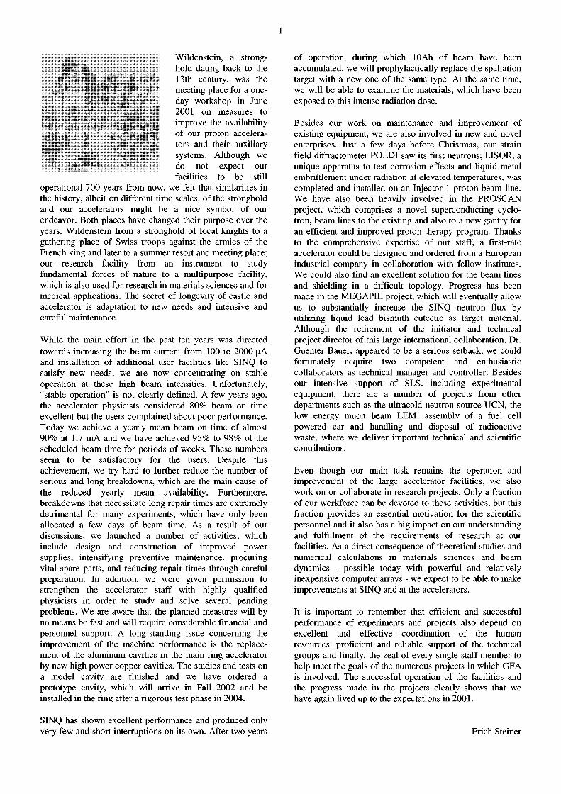
Wildenstein, a stronghold dating back to the 13th century, was the meeting place for a one-day workshop in June 2001 on measures to improve the availability of our proton accelerators and their auxiliary systems. Although we do not expect our facilities to be still
operational 700 years from now, we felt that similarities in the history, albeit on different time scales, of the stronghold and our accelerators might be a nice symbol of our endeavor. Both places have changed their purpose over the years: Wildenstein from a stronghold of local knights to a gathering place of Swiss troops against the armies of the French king and later to a summer resort and meeting place; our research facility from an instrument to study fundamental forces of nature to a multipurpose facility, which is also used for research in materials sciences and for medical applications. The secret of longevity of castle and accelerator is adaptation to new needs and intensive and careful maintenance.
While the main effort in the past ten years was directed towards increasing the beam current from 100 to 2000 uA and installation of additional user facilities like SINQ to satisfy new needs, we are now concentrating on stable operation at these high beam intensities. Unfortunately, "stable operation" is not clearly defined. A few years ago, the accelerator physicists considered 80% beam on time excellent but the users complained about poor performance. Today we achieve a yearly mean beam on time of almost 90% at 1.7 mA and we have achieved 95% to 98% of the scheduled beam time for periods of weeks. These numbers seem to be satisfactory for the users. Despite this achievement, we try hard to further reduce the number of serious and long breakdowns, which are the main cause of the reduced yearly mean availability. Furthermore, breakdowns that necessitate long repair times are extremely detrimental for many experiments, which have only been allocated a few days of beam time. As a result of our discussions, we launched a number of activities, which include design and construction of improved power supplies, intensifying preventive maintenance, procuring vital spare parts, and reducing repair times through careful preparation. In addition, we were given permission to strengthen the accelerator staff with highly qualified physicists in order to study and solve several pending problems. We are aware that the planned measures will by no means be fast and will require considerable financial and personnel support. A long-standing issue concerning the improvement of the machine performance is the replacement of the aluminum cavities in the main ring accelerator by new high power copper cavities. The studies and tests on a model cavity are finished and we have ordered a prototype cavity, which will arrive in Fall 2002 and be installed in the ring after a rigorous test phase in 2004.
SINQ has shown excellent performance and produced only very few and short interruptions on its own. After two years
of operation, during which 10Ah of beam have been accumulated, we will prophylactically replace the spallation target with a new one of the same type. At the same time, we will be able to examine the materials, which have been exposed to this intense radiation dose.
Besides our work on maintenance and improvement of existing equipment, we are also involved in new and novel enterprises. Just a few days before Christmas, our strain field diffractometer POLDI saw its first neutrons; LISOR, a unique apparatus to test corrosion effects and liquid metal embrittlement under radiation at elevated temperatures, was completed and installed on an Injector 1 proton beam line. We have also been heavily involved in the PROSCAN project, which comprises a novel superconducting cyclotron, beam Unes to the existing and also to a new gantry for an efficient and improved proton therapy program. Thanks to the comprehensive expertise of our staff, a first-rate accelerator could be designed and ordered from a European industrial company in collaboration with fellow institutes. We could also find an excellent solution for the beam lines and shielding in a difficult topology. Progress has been made in the MEGAPIE project, which will eventually allow us to substantially increase the SINQ neutron flux by utilizing liquid lead bismuth eutectic as target material. Although the retirement of the initiator and technical project director of this large international collaboration, Dr. Guenter Bauer, appeared to be a serious setback, we could fortunately acquire two competent and enthusiastic collaborators as technical manager and controller. Besides our intensive support of SLS, including experimental equipment, there are a number of projects from other departments such as the ultracold neutron source UCN, the low energy muon beam LEM, assembly of a fuel cell powered car and handling and disposal of radioactive waste, where we deliver important technical and scientific contributions.
Even though our main task remains the operation and improvement of the large accelerator facilities, we also work on or collaborate in research projects. Only a fraction of our workforce can be devoted to these activities, but this fraction provides an essential motivation for the scientific personnel and it also has a big impact on our understanding and fulfillment of the requirements of research at our facilities. As a direct consequence of theoretical studies and numerical calculations in materials sciences and beam dynamics - possible today with powerful and relatively inexpensive computer arrays - we expect to be able to make improvements at SINQ and at the accelerators.
It is important to remember that efficient and successful performance of experiments and projects also depend on excellent and effective coordination of the human resources, proficient and reliable support of the technical groups and finally, the zeal of every single staff member to help meet the goals of the numerous projects in which GFA is involved. The successful operation of the facilities and the progress made in the projects clearly shows that we have again lived up to the expectations in 2001.
Erich Steiner

2

3
Accelerator Physics and Development

4
5
OPERATION OF THE PSI ACCELERATOR FACILITY IN 2001
M. Hwnbel, A.C. Mezger, P.-A. Schmelzbach
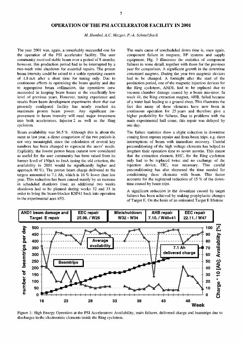
The year 2001 was, again, a remarkably successful one for the operation of the PSI accelerator facility. The user community received stable beam over a period of 8 months; however, this production period had to be interrupted by a two-week mini shutdown for essential repairs. The proton beam intensity could be raised to a stable operating current of 1.8 mA after a short time for tuning only. Due to continuous efforts in optimising the beam quality and due to appropriate beam collimation, the operations crew succeeded in keeping beam losses at the excellently low level of previous years. However, tuning experience and results from beam development experiments show that our presently configured facility has nearly reached its maximum proton beam power. Any significant improvement in beam intensity will need major investment into both accelerators, Injector 2 as well as the Ring cyclotron.
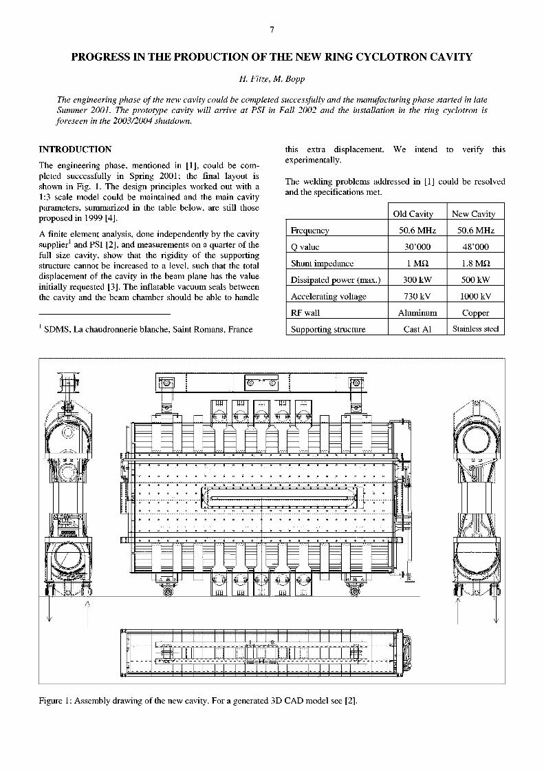
Beam availability was 86.5 %. Although this is about the same as last year, a direct comparison of the two periods is not very meaningful, since the calculation of several key numbers has been changed to represent the users' needs. Explicitly, the lowest proton beam current now considered as useful for the user community has been raised from its former level of 150uA to 1mA (using the old criterion, the availability in 2001 would be significantly higher and approach 90 %). The proton beam charge delivered to the targets amounted to 7.1 Ah, which is 16 % lower than last year. This reduction has been caused mainly by an increase in scheduled shutdown time; an additional two weeks shutdown had to be planned during weeks 32 and 33 in order to bring the beam-blocker KSF41 back into operation in the experimental area JtE5.
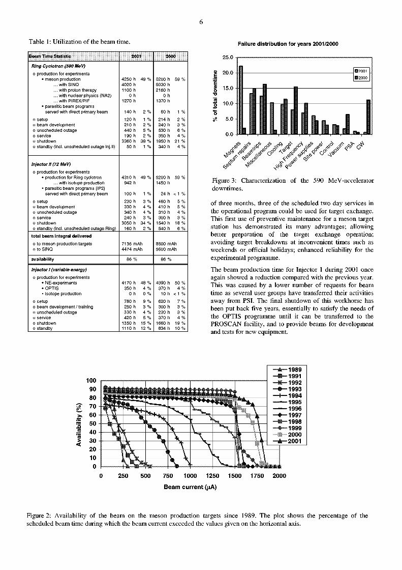
The main cause of unscheduled down time is, once again, component failure in magnets, RF systems and supply equipment. Fig. 3 illustrates the statistics of component failures in some detail, together with those for the previous year for comparison. A significant growth in the downtime concerned magnets. During the year two magnetic devices had to be changed. A fortnight after the start of the production period, one of the magnetic injection devices for the Ring cyclotron, AND1, had to be replaced due to vacuum chamber damage caused by a beam mis-steer. In week 41, the Ring extraction magnet, AHB, failed because of a water leak leading to a ground short. This illustrates the fact that many of these elements have now been in continuous operation for 25 years and therefore give a higher probability for failures. Due to problems with the main experimental hall crane, this repair was delayed by one day.
The failure statistics show a slight reduction in downtime coming from septum repairs and from beam trips, e.g. short interruptions of beam with immediate recovery. Careful preconditioning of the high voltage elements has helped to lengthen their operation time to seven months. This meant that the extraction element, EEC, for the Ring cyclotron only had to be replaced twice and no exchange of the injection device, EIC, was necessary. This careful preconditioning has also shortened the time needed for conditioning these elements with beam. This factor accounts for the registered reduction of 15 % of the downtime caused by beam trips.
A significant reduction in the downtime caused by target failures has been achieved by making prophylactic changes of Target E. On the basis of an estimated Target E lifetime
A N D 1 b e a m d a m a g e a n d EEC repa i r I M i n i s h u t d o w n A H B repa i r EEC repa i r T a r g e t E repa i r 2 5 . 0 6 . / W 2 6 j W 3 2 - W 3 4 7 . 1 0 . / W 4 0 + 4 1 2 2 . 1 1 . / W 4 7
> (0 "D i_ fl> o. (0
o. E (0 fl>
S3
fl>
E 3 C
18 23 28 33 38 43 48 Week
.a "<5 > <
< o * fl>
u> (0 .£ Ü
Figure 1: High Energy Operation at the PSI Accelerators: Availability, main failures, delivered charge and beamtrips due to discharges in the electrostatic elements inside the Ring cyclotron.
6
Table 1: Utilization of the beam time.
Beam Time Statistic 2000
Ring Cyclotron (590 MeV)
o production for experiments • meson production 4250 h 49 % 5200 h 59 %
... with SINQ 4020 h 5030 h
... with proton therapy 1100 h 2160 h
... with nuclear physios (NA2) 0 h 0 h
... with PIREX/PIF 1270 h 1370 h • parasitic beam programs
served with direct primary beam 140 h 2 % 60 h 1 %
o setup 120 h 1 % 214 h 2 % o beam development 210 h 2 % 240 h 3 % o unscheduled outage 440 h 5 % 530 h 6 % o service 190 h 2 % 350 h 4 % o shutdown 3360 h 38 % 1850 h 21 % o standby (incl. unscheduled outage lnj.ll) 50 h 1 % 340 h 4 %
Injector Jl (72 MeV)
o production for experiments • production for Ring cyclotron 4310 h 49 % 5200 h 59 %
... with isotope production 942 h 1450 h • parasitic beam programs (IP2)
served with direct primary beam 100 h 1 % 24 h < 1 %
o setup 230 h 3 % 460 h 5 % o beam development 330 h 4 % 410 h 5 % o unscheduled outage 340 h 4 % 310 h 4 % o service 240 h 3 % 300 h 3 % o shutdown 3050 h 34 % 1540 h 18 % o standby (incl. unscheduled outage Ring) 160 h 2 % 540 h 6 %
total beam integral delivered o to meson production targets 7136 mAh 8500 mAh o to SINQ 4474 mAh 5600 mAh
availability 86 % 86 %
Injector J (variable energy)
o production for experiments • NE-experiments 4170 h 48 % 4390 h 50 % • OPTIS 350 h 4 % 370 h 4 % • isotope production 0 h 0 % 10 h < 1 %
o setup 780 h 9 % 620 h 7 % o beam development / training 250 h 3 % 300 h 3 % o unscheduled outage 330 h 4 % 230 h 3 % o service 420 h 5 % 370 h 4 % o shutdown 1350 h 15 % 1660 h 19 % o standby 1110 h 12 % 834 h 10 %
Failure distribution for years 2001/2000
Figure 3: Characterization of the 590 MeV-accelerator downtimes.
of three months, three of the scheduled two day services in the operational program could be used for target exchange. This first use of preventive maintenance for a meson target station has demonstrated its many advantages; allowing better preparation of the target exchange operation; avoiding target breakdowns at inconvenient times such as weekends or official holidays; enhanced reliability for the experimental programme.
The beam production time for Injector 1 during 2001 once again showed a reduction compared with the previous year. This was caused by a lower number of requests for beam time as several user groups have transferred their activities away from PSI. The final shutdown of this workhorse has been put back five years, essentially to satisfy the needs of the OPTIS programme until it can be transferred to the PROSCAN facility, and to provide beams for development and tests for new equipment.
100 90 80 70 60 50
« 40 "<5 30 > 30 <
30 20 10
0
- A - 1 9 8 9 • - • - - 1 9 9 1 - * - 1 9 9 2 - • - 1 9 9 3 —f—1994
1995 1996
- • — 1 9 9 7 ™mffimm 1998 - • - - 1 9 9 9 " • » 2 0 0 0 —A—2001
- A - 1 9 8 9 • - • - - 1 9 9 1 - * - 1 9 9 2 - • - 1 9 9 3 —f—1994
1995 1996
- • — 1 9 9 7 ™mffimm 1998 - • - - 1 9 9 9 " • » 2 0 0 0 —A—2001
- A - 1 9 8 9 • - • - - 1 9 9 1 - * - 1 9 9 2 - • - 1 9 9 3 —f—1994
1995 1996
- • — 1 9 9 7 ™mffimm 1998 - • - - 1 9 9 9 " • » 2 0 0 0 —A—2001
- A - 1 9 8 9 • - • - - 1 9 9 1 - * - 1 9 9 2 - • - 1 9 9 3 —f—1994
1995 1996
- • — 1 9 9 7 ™mffimm 1998 - • - - 1 9 9 9 " • » 2 0 0 0 —A—2001
- A - 1 9 8 9 • - • - - 1 9 9 1 - * - 1 9 9 2 - • - 1 9 9 3 —f—1994
1995 1996
- • — 1 9 9 7 ™mffimm 1998 - • - - 1 9 9 9 " • » 2 0 0 0 —A—2001
- A - 1 9 8 9 • - • - - 1 9 9 1 - * - 1 9 9 2 - • - 1 9 9 3 —f—1994
1995 1996
- • — 1 9 9 7 ™mffimm 1998 - • - - 1 9 9 9 " • » 2 0 0 0 —A—2001
- A - 1 9 8 9 • - • - - 1 9 9 1 - * - 1 9 9 2 - • - 1 9 9 3 —f—1994
1995 1996
- • — 1 9 9 7 ™mffimm 1998 - • - - 1 9 9 9 " • » 2 0 0 0 —A—2001
- A - 1 9 8 9 • - • - - 1 9 9 1 - * - 1 9 9 2 - • - 1 9 9 3 —f—1994
1995 1996
- • — 1 9 9 7 ™mffimm 1998 - • - - 1 9 9 9 " • » 2 0 0 0 —A—2001
- A - 1 9 8 9 • - • - - 1 9 9 1 - * - 1 9 9 2 - • - 1 9 9 3 —f—1994
1995 1996
- • — 1 9 9 7 ™mffimm 1998 - • - - 1 9 9 9 " • » 2 0 0 0 —A—2001
M
T"m""!Ä""!*J »4M 250 500 750 1000 1250 1500 1750 2000
Beam current (uA)
Figure 2: Availability of the beam on the meson production targets since 1989. The plot shows the percentage of the scheduled beam time during which the beam current exceeded the values given on the horizontal axis.
7
PROGRESS IN THE PRODUCTION OF THE NEW RING CYCLOTRON CAVITY
H. Fitze, M. Bopp
The engineering phase of the new cavity could be completed successfully and the manufacturing phase started in late Summer 2001. The prototype cavity will arrive at PSI in Fall 2002 and the installation in the ring cyclotron is foreseen in the 2003/2004 shutdown.
INTRODUCTION
The engineering phase, mentioned in [1], could be completed successfully in Spring 2001; the final layout is shown in Fig. 1. The design principles worked out with a 1:3 scale model could be maintained and the main cavity parameters, summarized in the table below, are still those proposed in 1999 [4].
A finite element analysis, done independently by the cavity supplier1 and PSI [2], and measurements on a quarter of the full size cavity, show that the rigidity of the supporting structure cannot be increased to a level, such that the total displacement of the cavity in the beam plane has the value initially requested [3]. The inflatable vacuum seals between the cavity and the beam chamber should be able to handle
1 SDMS, La chaudronnerie blanche, Saint Romans, France
this extra displacement. We intend to verify this experimentally.
The welding problems addressed in [1] could be resolved and the specifications met.
Old Cavity New Cavity
Frequency 50.6 MHz 50.6 MHz
Q value 30'000 48'000
Shunt impedance 1 M Í2 1.8 M Í2
Dissipated power (max.) 300 kW 500 kW
Accelerating voltage 730 kV 1000 kV
RF wall Aluminum Copper
Supporting structure Cast Al Stainless steel
Figure 1: Assembly drawing of the new cavity. For a generated 3D CAD model see [2].
8
P R O D U C T I O N P H A S E S
The procurement of the raw materials has already taken place and the fabrication of the cavity has started. The main steps are:
• Production of the cavity body from 8 mm copper sheets. The welding jig shown in Fig. 2 is used to fix the sheets during the electron beam welding process. The cooling channels, made from stainless steel sheets, are TIG-welded to the cavity body (see Fig. 3).
Figure 2: Alignment and welding device.
Figure 3: Welding of the cooling channels to the cavity body at SDMS.
• Production of the support structure. • Joining together the cavity body and the support
structure. This procedure irreversibly defines the coarse resonance frequency of the final cavity and is therefore a very delicate step.
• Mounting the accessories, such as the tuning yokes (see Fig. 4) and the cooling pipes.
• Adjustment of the resonance frequency of the evacuated cavity. For this purpose, the distance between the cavity body and the support structure has to be properly shimmed.
• Factory acceptance test.
Figure 4: Tuning yoke under test at PSI.
N E X T S T E P S
• Function tests of the cavity accessories:
- Check that the service lives of the tuning yokes and, in particular, the hydraulic bellows are sufficient.
- Check that the inflatable vacuum seals can handle the required deformation.
- Check that the electrical contacts, used in the high power coupling loop, are able to carry the RF currents at full power.
• Setup of a test stand in the experimental hall, which will allow high power testing of the cavity prototype prior to the installation in the ring cyclotron.
R E F E R E N C E S
[1] H. Fitze et al., "Progress in the Development of the New Ring Cyclotron Cavity", PSI Scientific and Technical Report 2000
[2] M. Bopp, „Coupled Field Analysis of the New Ring Cyclotron Cavity", this report
[3] M. Bopp et al., "Technical specification for the 590 MeV cyclotron RF cavity", PSI internal document: NK-001, 2000
[4] H. Fitze et al., "Development of a new high power cavity for the 590 MeV ring cyclotron at PSI", Proc. of the 1999 Particle Accelerator Conference, New York City
9
COUPLED FIELD ANALYSIS OF THE NEW RING CYCLOTRON CAVITY
M. Bopp, H. Fitze
A coupled field analysis, thermal/structural/RF, is used to predict the frequency drift of the new ring cyclotron cavity. The simulation is entirely carried out within the finite element program ANSYS/Multiphysic.
I N T R O D U C T I O N
The new normal conducting cavities for the ring cyclotron are designed for an accelerating voltage of up to 1MV and 500kW dissipated RF power (see Figure 1). The cavity is essentially a large vacuum vessel and consists of an inner copper wall, the actual cavity, and a stainless steel support structure, which prevents the cavity from collapsing under atmospheric pressure. A large number of cooling channels, directly welded onto the copper walls, provide the necessary cooling for the entire cavity surface.
The main parameters of the cavity are: Resonance frequency: Accelerating voltage: Dissipated power: Hydraulic tuning system range: Cavity wall: Support structure: Vacuum pressure: Cooling water consumption: Cooling water inlet temperature: Overall dimensions: Weight:
50.6328 MHz +/- 1 kHz 1 MV 500 kW 450 kHz Cu-OFHC Stainless steel 316LN 10"6 mbar 34m 3 /h 30-35 °C 5.6 x 3.9 x 0.95 m 25'OOQ kg
Hydraulic tuning yol-e*.-
cooling _—w^\sJmar** » . 't'^L'it'mt \ "i
Figure 1 : New ring cyclotron cavity.
During operation, the resonance frequency of the cavity has to be maintained within a small range of ±1 kHz. The resonant frequency of the RF-Cavity is changed by the deformation of its shape due to the atmospheric pressure and the inhomogeneous heat flux in the RF-cavity walls. In order to predict the frequency change, a thermal/structural analysis is required to find the deformation of the cavity walls. A subsequent high frequency analysis determines the frequency drift of the deformed cavity. Once the frequency drift is known, the range of the tuning system will be simulated. The tuning system of the cavity consists of ten hydraulic yokes, which elastically deform the cavity walls in order to compensate for frequency drifts during operation.
S I M U L A T I O N
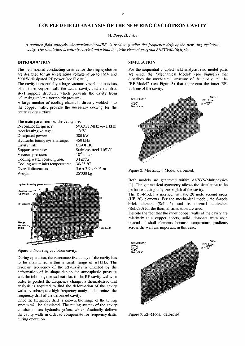
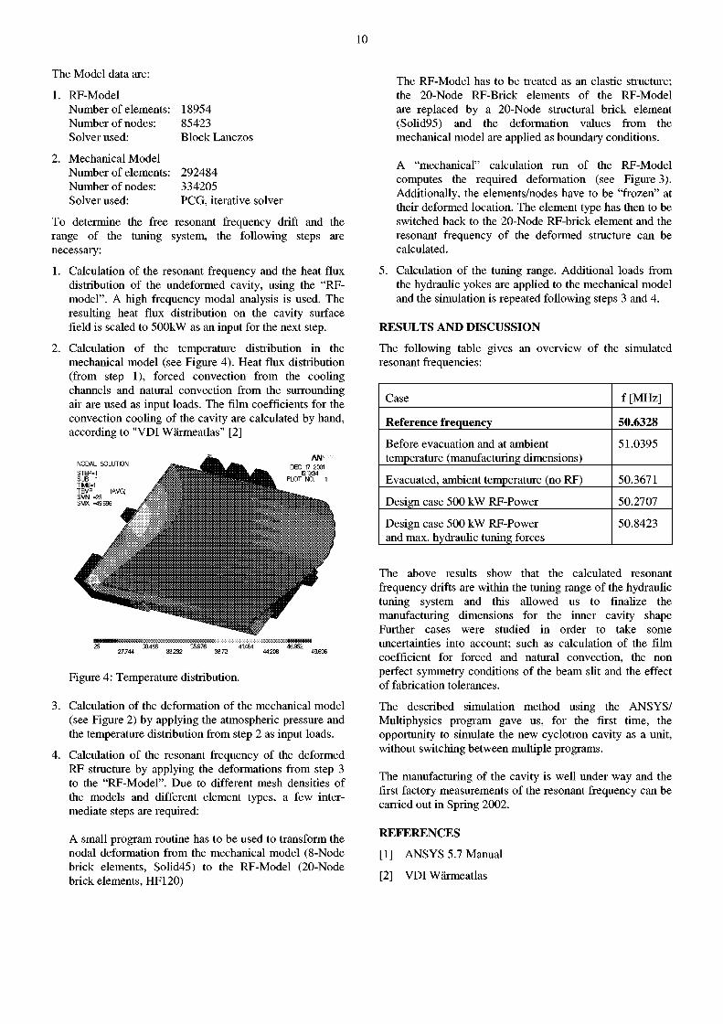
For the sequential coupled field analysis, two model parts are used: the "Mechanical Model" (see Figure 2) that describes the mechanical structure of the cavity and the "RF-Model" (see Figure 3) that represents the inner RF-volume of the cavity.
SUB -1 TIME-1 DMX -.011
DEC 17 2001 M:15:18
PLOT NO. 1
Figure 2: Mechanical Model, deformed.
Both models are generated within ANSYS/Multiphysics [1]. The geometrical symmetry allows the simulation to be performed using only one eighth of the cavity. The RF-Model is meshed with the 20 node second order (HF120) elements. For the mechanical model, the 8-node brick element (Solid45) and its thermal equivalent (Solid70) for the thermal simulation are used. Despite the fact that the inner copper walls of the cavity are relatively thin copper sheets, solid elements were used instead of shell elements because temperature gradients across the wall are important in this case.
STEP-1 SUB -1 TIME-1 DMX -.011
DEC 17 2001 M31:30
PLOT NO. 1
Figure 3: RF-Model, deformed.
10
The Model data are:
1. RF-Model Number of elements: Number of nodes: Solver used:
2. Mechanical Model Number of elements: Number of nodes: Solver used:
18954 85423 Block Lanczos
292484 334205 PCG, iterative solver
To determine the free resonant frequency drift and the range of the tuning system, the following steps are necessary:
1. Calculation of the resonant frequency and the heat flux distribution of the undeformed cavity, using the "RF-model". A high frequency modal analysis is used. The resulting heat flux distribution on the cavity surface field is scaled to 500kW as an input for the next step.
2. Calculation of the temperature distribution in the mechanical model (see Figure 4). Heat flux distribution (from step 1), forced convection from the cooling channels and natural convection from the surrounding air are used as input loads. The film coefficients for the convection cooling of the cavity are calculated by hand, according to "VDI Wärmeatlas" [2]
NODAl sni i rrriN STEP-SUB . TIME-' TEMP SMN • SMX -
AN
• ¡ ¡ • i
Figure 4: Temperature distribution.
3. Calculation of the deformation of the mechanical model (see Figure 2) by applying the atmospheric pressure and the temperature distribution from step 2 as input loads.
4. Calculation of the resonant frequency of the deformed RF structure by applying the deformations from step 3 to the "RF-Model". Due to different mesh densities of the models and different element types, a few intermediate steps are required:
A small program routine has to be used to transform the nodal deformation from the mechanical model (8-Node brick elements, Solid45) to the RF-Model (20-Node brick elements, HF120)
The RF-Model has to be treated as an elastic structure; the 20-Node RF-Brick elements of the RF-Model are replaced by a 20-Node structural brick element (Solid95) and the deformation values from the mechanical model are applied as boundary conditions.
A "mechanical" calculation run of the RF-Model computes the required deformation (see Figure 3). Additionally, the elements/nodes have to be "frozen" at their deformed location. The element type has then to be switched back to the 20-Node RF-brick element and the resonant frequency of the deformed structure can be calculated.
5. Calculation of the tuning range. Additional loads from the hydraulic yokes are applied to the mechanical model and the simulation is repeated following steps 3 and 4.
RESULTS AND DISCUSSION
The following table gives an overview of the simulated resonant frequencies:
Case f [MHz]
Reference frequency 50.6328
Before evacuation and at ambient temperature (manufacturing dimensions)
51.0395
Evacuated, ambient temperature (no RF) 50.3671
Design case 500 kW RF-Power 50.2707
Design case 500 kW RF-Power and max. hydraulic tuning forces
50.8423
The above results show that the calculated resonant frequency drifts are within the tuning range of the hydraulic tuning system and this allowed us to finalize the manufacturing dimensions for the inner cavity shape Further cases were studied in order to take some uncertainties into account; such as calculation of the film coefficient for forced and natural convection, the non perfect symmetry conditions of the beam slit and the effect of fabrication tolerances.
The described simulation method using the ANSYS/ Multiphysics program gave us, for the first time, the opportunity to simulate the new cyclotron cavity as a unit, without switching between multiple programs.
The manufacturing of the cavity is well under way and the first factory measurements of the resonant frequency can be carried out in Spring 2002.
REFERENCES
[1] ANSYS 5.7 Manual
[2] VDI Wärmeatlas
11
EXPERIMENTAL UPGRADE OF THE INJECTOR II150 MHZ RF SYSTEM
W. Tron, M. Märki
To run the SINQ facility at its design current of 2 mA, the primary beam current of the PSI cyclotrons would have to be raised to 3mA. This beam requires a 35% increase of the energy gain per turn in the injector II cyclotron. Using existing equipment, we present an experimental upgrade, which will increment the accelerating voltage by about 3%.
I N T R O D U C T I O N
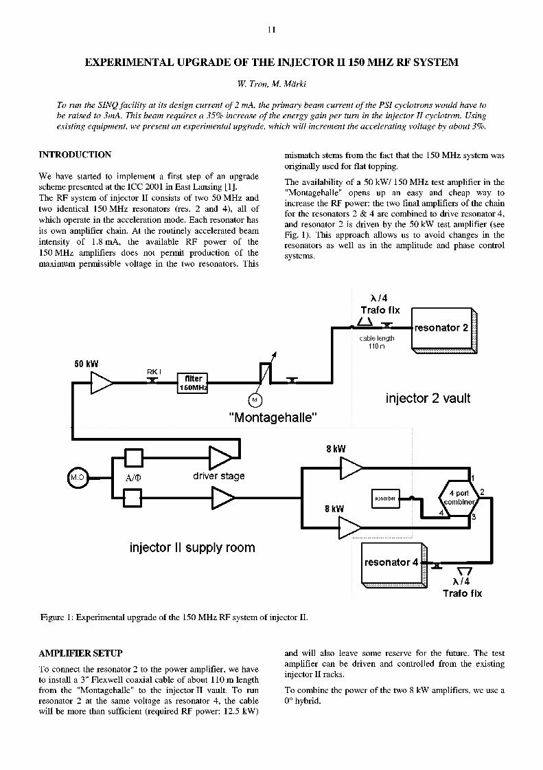
We have started to implement a first step of an upgrade scheme presented at the ICC 2001 in East Lansing [1]. The RF system of injector II consists of two 50 MHz and two identical 150 MHz resonators (res. 2 and 4), all of which operate in the acceleration mode. Each resonator has its own amplifier chain. At the routinely accelerated beam intensity of 1.8 mA, the available RF power of the 150 MHz amplifiers does not permit production of the maximum permissible voltage in the two resonators. This
mismatch stems from the fact that the 150 MHz system was originally used for flat topping.
The availability of a 50 kW/ 150 MHz test amplifier in the "Montagehalle" opens up an easy and cheap way to increase the RF power: the two final amplifiers of the chain for the resonators 2 & 4 are combined to drive resonator 4, and resonator 2 is driven by the 50 kW test amplifier (see Fig. 1). This approach allows us to avoid changes in the resonators as well as in the amplitude and phase control systems.
50 kW
| - t> RKI
niter 1S0MH:
ÍM .O
X / 4 T r a f o f i x
"Montagehalle"
cable length 110m
r e s o n a t o r 2
injector 2 vault
rO A/0 dr i ve r s t a g e
->-injector II supply room
V7 X / 4
T r a f o f i x
Figure 1: Experimental upgrade of the 150 MHz RF system of injector II.
A M P L I F I E R S E T U P
To connect the resonator 2 to the power amplifier, we have to install a 3" Flexwell coaxial cable of about 110 m length from the "Montagehalle" to the injector II vault. To run resonator 2 at the same voltage as resonator 4, the cable will be more than sufficient (required RF power: 12.5 kW)
and will also leave some reserve for the future. The test amplifier can be driven and controlled from the existing injector II racks.
To combine the power of the two 8 kW amplifiers, we use a 0° hybrid.
12
DESIGN O F T H E 0° HYBRID
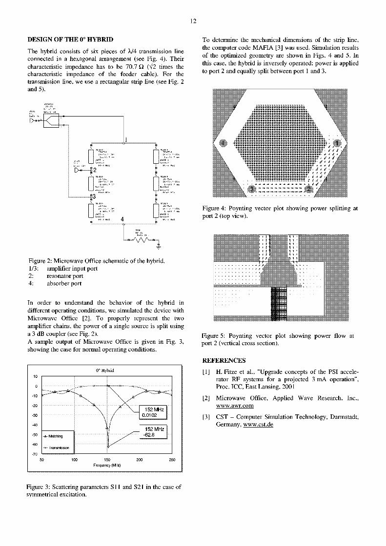
The hybrid consists of six pieces of À/4 transmission line connected in a hexagonal arrangement (see Fig. 4). Their characteristic impedance has to be 70.7 Q, (V2 times the characteristic impedance of the feeder cable). For the transmission line, we use a rectangular strip line (see Fig. 2 and 5).
To determine the mechanical dimensions of the strip line, the computer code MAFIA [3] was used. Simulation results of the optimized geometry are shown in Figs. 4 and 5. In this case, the hybrid is inversely operated: power is applied to port 2 and equally split between port 1 and 3.
1
Figure 2: Microwave Office schematic of the hybrid. 1/3 : amplifier input port 2: resonator port 4: absorber port
In order to understand the behavior of the hybrid in different operating conditions, we simulated the device with Microwave Office [2]. To properly represent the two amplifier chains, the power of a single source is split using a 3 dB coupler (see Fig. 2). A sample output of Microwave Office is given in Fig. 3, showing the case for normal operating conditions.
0° H y b r i d
150 Frequency (MHz)
250
; , 2
Figure 4: Poynting vector plot showing power splitting at port 2 (top view).
Figure 5: Poynting vector plot showing power flow at port 2 (vertical cross section).
REFERENCES
[1] H. Fitze et al., "Upgrade concepts of the PSI accelerator RF systems for a projected 3 mA operation", Proc. ICC, East Lansing, 2001
[2] Microwave Office, Applied Wave Research, Inc., www.awr.com
[3] CST - Computer Simulation Technology, Darmstadt, Germany, www.cst.de
Figure 3: Scattering parameters S i l and S21 in the case of symmetrical excitation.
13
REPLACEMENT OF MAGNET POWER SUPPLIES, CONTROL AND FIELD-BUS FOR THE PSI CYCLOTRON ACCELERATORS
D. Anicic, T. Blumer, G. Dzieglewski, G. Janser, I. Jirousek, H. Lutz, A.C. Mezger
Magnet power supplies in the PSI accelerator complex with their control and field-bus are outdated. Some components are more than 30 years old. To facilitate further maintenance and to meet the more demanding specifications for operation with the 2mA beam, they have to be replaced. The switched power supplies, developed for SLS, will be used. This implies a major redesign of part of the accelerator control system, which is currently based on CAMAC, ROAD-C and other in house developed hardware including the machine protection system. The modified control for the new set-up will be based on VME and alternatively CAMAC, with dedicated processors for the functionality of the machine protection system.
INTRODUCTION
The everlasting need for renewal of the control system has hit us again. Power-supplies (PS) are old, the field-bus is outdated, the Front-End processors are no longer available and serial CAMAC is not fast enough. The technology of some of these components goes back to the early 1970's. Stability, ripple and mains rejection of the PS is no longer up to the requirements imposed by the 2 mA beam. The new PS's will no longer have an analog interface. All this implies a new control concept for the PS, including the KOMBI, a local controller that also acts as a supervisor to generate Interlock signals, Interlock being our hardware implemented fast run permit system. ROAD-C, the field bus used to control the PS via the KOMBI is also old, in house developed and lacks error detection. All I/O in our system is based on CAMAC. We intend to add the possibility of using VME I/O. For some applications, the I/O bandwidth of the 5 MHz bit serial loop is a limiting factor.
On the other hand, the overall system is very good and flexible to changes. We plan to use the same control system for the PROSCAN project (the new biomedical facility at PSI) under construction. This is motivation enough for a major upgrade of the system.
MODIFICATION PATH O F THE SYSTEM
We will extend the control system Ethernet to strategic points in the equipment buildings. 100Mbps optical links with the option to go to lGbps and beyond will be used in conjunction with switches that support diagnostic facilities. The addition of front-ends at these locations adds the possibility of VME I/O in the field. Intelligent interface modules to the PS with a dedicated CPU in VME, will replace the old "KOMBIs" as well as part of the Interlock logic. This enhancement implies the extension and the port of the front-end software to a new processor.
THE NEW FRONT END
F E C software upgrade/replacement
In our distributed client-server based Control System, the Front-End Computers (FEC) act as servers, providing the I/O for data acquisition and control. The FECs continuously wait for client requests (Ethernet 802.3, UDP or Unix Message Queues), perform the requested operations and return status and results. FECs are configured at boot time with the data related to Device, Module-handler, Address
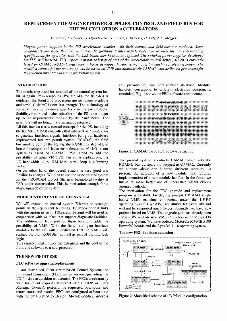
etc. provided by our configuration database. Module-handlers correspond to different electronic components (modules). Fig. 1 shows the FEC software architecture.
C o m m u n i c a t i o n
E t h e r n e t 8 0 2 . 3 , UDP, M e s s a g e Q u e u e
; ConhQ : i DB
S e r v i c e s P l O s e r , BLKse r , L O O P s e r , L A M s e r , I LKser , C A M s e r
f v ' cxJUe n a r d h r r .
A b o u t 1 0 0 m o d u l e t y p e s
C A M A C d e v i c e d r i v e r
Figure 1: CAMAC based FEC software structure.
The present system is entirely CAMAC based with the ROAD-C bus transparently mapped to CAMAC. Currently we support about one hundred different modules. At present, the addition of a new module type requires implementation of a new module handler. In the future we intend to make better use of inheritance within object-oriented methods. The motivation for the FEC upgrade and replacement program is twofold. Firstly, the present HP rt743 single board VME real-time computers, under the HP-RT operating system (LynxOS), are almost ten years old and will not be supported much longer. Secondly, we have new projects based on VME. The upgrade path has already been chosen. We will use new VME computers with the LynxOS operating system. We have ordered Motorola M VME 5100 PowerPC boards and the LynxOS 3.1.0 operating system.
The new F E C database extension
VME-^CMC- ,ROADC-X c r a t e V M E I O . C M C I O - . R O A D C
y control loop
next
contro l led by 1 • . , ! » I i i r . i i i . l
Minliilly,!
Driver Speci f icat ion
l > i : u i - . » ' A t l i l l i i l t t -
SetPScurrentO GetPScurrentO
l l . ( R i l i : - i f u i . i l - m i i W y
!<J: i i l i i i i l i i i . i i i m - :-—1 impl
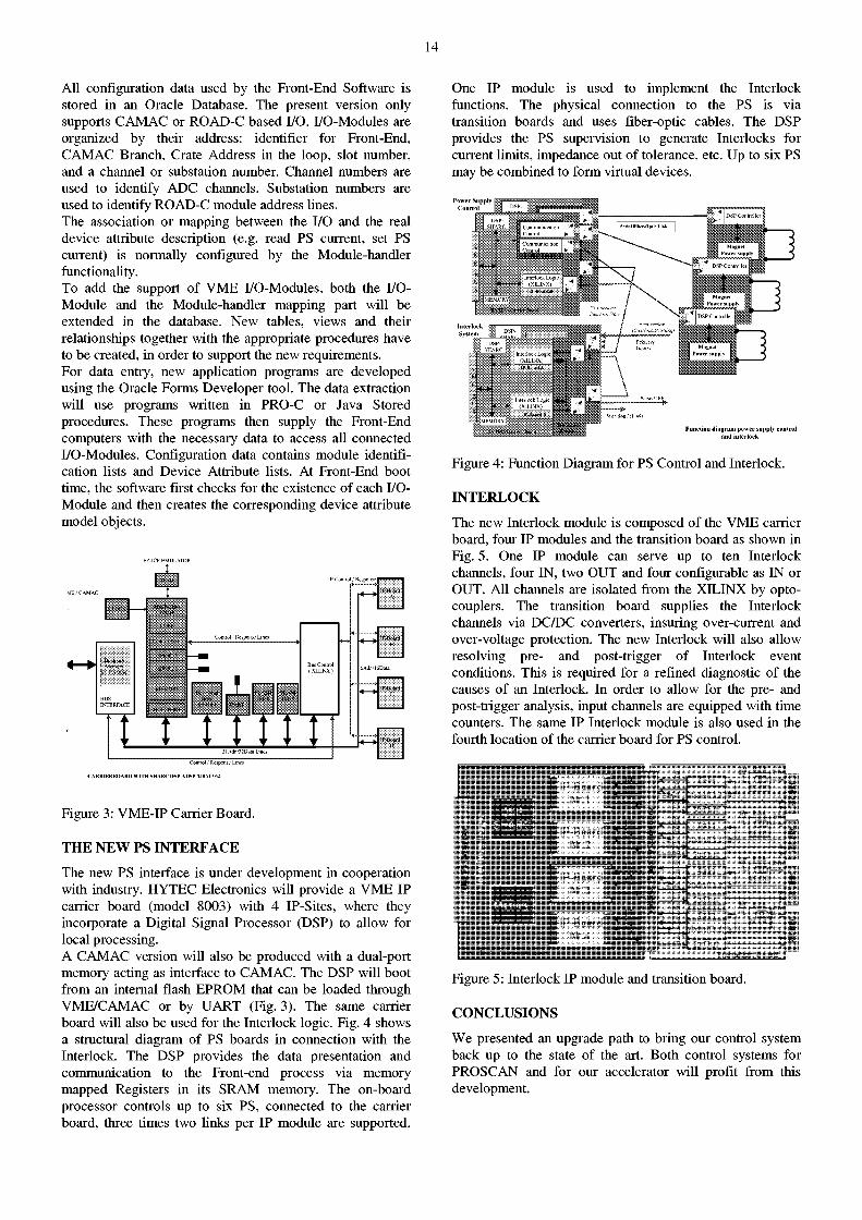
Figure 2: Simplified scheme of I/O-Module configuration.
14
All configuration data used by the Front-End Software is stored in an Oracle Database. The present version only supports CAMAC or ROAD-C based I/O. I/O-Modules are organized by their address: identifier for Front-End, CAMAC Branch, Crate Address in the loop, slot number, and a channel or substation number. Channel numbers are used to identify ADC channels. Substation numbers are used to identify ROAD-C module address Unes. The association or mapping between the I/O and the real device attribute description (e.g. read PS current, set PS current) is normally configured by the Module-handler functionality. To add the support of VME I/O-Modules, both the I/O-Module and the Module-handler mapping part will be extended in the database. New tables, views and their relationships together with the appropriate procedures have to be created, in order to support the new requirements. For data entry, new application programs are developed using the Oracle Forms Developer tool. The data extraction will use programs written in PRO-C or Java Stored procedures. These programs then supply the Front-End computers with the necessary data to access all connected I/O-Modules. Configuration data contains module identification lists and Device Attribute lists. At Front-End boot time, the software first checks for the existence of each I/O-Module and then creates the corresponding device attribute model objects.
EZ-ICE EMULATOR
VIE / CAMAC
IP-Control / Responsi
Control / Response Lines
Control / Response Lines
CARRIERBOARD WITH SHARC DSP ADSP-21061 / 62
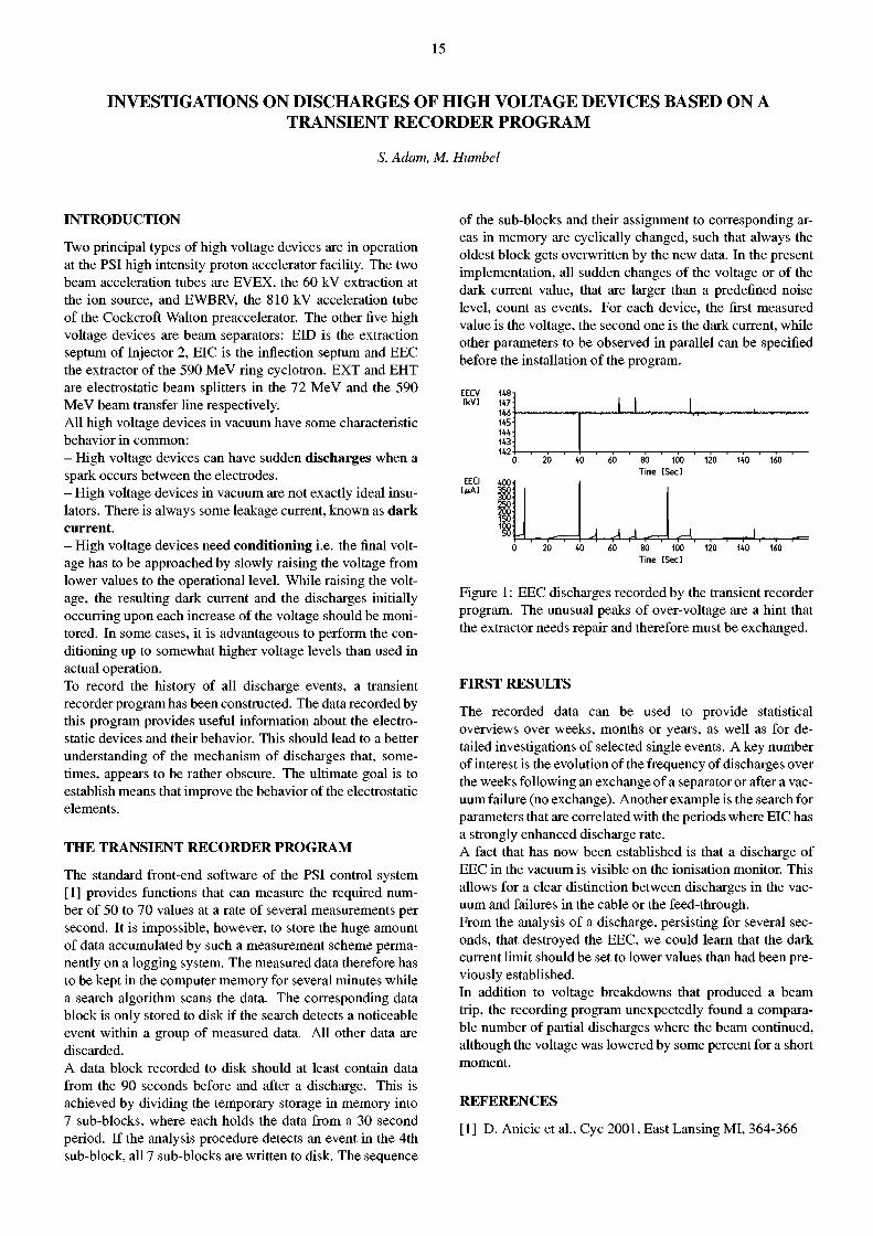
Figure 3: VME-IP Carrier Board.
THE NEW PS INTERFACE
The new PS interface is under development in cooperation with industry. HYTEC Electronics will provide a VME IP carrier board (model 8003) with 4 IP-Sites, where they incorporate a Digital Signal Processor (DSP) to allow for local processing. A CAMAC version will also be produced with a dual-port memory acting as interface to CAMAC. The DSP will boot from an internal flash EPROM that can be loaded through VME/CAMAC or by UART (Fig. 3). The same carrier board will also be used for the Interlock logic. Fig. 4 shows a structural diagram of PS boards in connection with the Interlock. The DSP provides the data presentation and communication to the Front-end process via memory mapped Registers in its SRAM memory. The on-board processor controls up to six PS, connected to the carrier board, three times two links per IP module are supported.
One IP module is used to implement the Interlock functions. The physical connection to the PS is via transition boards and uses fiber-optic cables. The DSP provides the PS supervision to generate Interlocks for current limits, impedance out of tolerance, etc. Up to six PS may be combined to form virtual devices.
Function diagram power supply control and interlock
Figure 4: Function Diagram for PS Control and Interlock.
INTERLOCK
The new Interlock module is composed of the VME carrier board, four IP modules and the transition board as shown in Fig. 5. One IP module can serve up to ten Interlock channels, four IN, two OUT and four configurable as IN or OUT. All channels are isolated from the XILINX by opto-couplers. The transition board supplies the Interlock channels via DC/DC converters, insuring over-current and over-voltage protection. The new Interlock will also allow resolving pre- and post-trigger of Interlock event conditions. This is required for a refined diagnostic of the causes of an Interlock. In order to allow for the pre- and post-trigger analysis, input channels are equipped with time counters. The same IP Interlock module is also used in the fourth location of the carrier board for PS control.
Figure 5: Interlock IP module and transition board.
CONCLUSIONS
We presented an upgrade path to bring our control system back up to the state of the art. Both control systems for PROSCAN and for our accelerator will profit from this development.
15
INVESTIGATIONS ON DISCHARGES OF HIGH VOLTAGE DEVICES BASED ON A TRANSIENT RECORDER PROGRAM
S. Adam, M. Humbel
I N T R O D U C T I O N
Two principal types of high voltage devices are in operation at the PSI high intensity proton accelerator facility. The two beam acceleration tubes are EVEX, the 60 kV extraction at the ion source, and EWBRV, the 810 kV acceleration tube of the Cockcroft Walton preaccelerator. The other five high voltage devices are beam separators: EID is the extraction septum of Injector 2, EIC is the inflection septum and EEC the extractor of the 590 MeV ring cyclotron. EXT and EHT are electrostatic beam splitters in the 72 MeV and the 590 MeV beam transfer Une respectively. All high voltage devices in vacuum have some characteristic behavior in common: - High voltage devices can have sudden discharges when a spark occurs between the electrodes. - High voltage devices in vacuum are not exactly ideal insulators. There is always some leakage current, known as dark current. - High voltage devices need condit ioning i.e. the final voltage has to be approached by slowly raising the voltage from lower values to the operational level. While raising the voltage, the resulting dark current and the discharges initially occurring upon each increase of the voltage should be monitored. In some cases, it is advantageous to perform the conditioning up to somewhat higher voltage levels than used in actual operation. To record the history of all discharge events, a transient recorder program has been constructed. The data recorded by this program provides useful information about the electrostatic devices and their behavior. This should lead to a better understanding of the mechanism of discharges that, sometimes, appears to be rather obscure. The ultimate goal is to establish means that improve the behavior of the electrostatic elements.
T H E T R A N S I E N T R E C O R D E R P R O G R A M
The standard front-end software of the PSI control system [1] provides functions that can measure the required number of 50 to 70 values at a rate of several measurements per second. It is impossible, however, to store the huge amount of data accumulated by such a measurement scheme permanently on a logging system. The measured data therefore has to be kept in the computer memory for several minutes while a search algorithm scans the data. The corresponding data block is only stored to disk if the search detects a noticeable event within a group of measured data. All other data are discarded. A data block recorded to disk should at least contain data from the 90 seconds before and after a discharge. This is achieved by dividing the temporary storage in memory into 7 sub-blocks, where each holds the data from a 30 second period. If the analysis procedure detects an event in the 4th sub-block, all 7 sub-blocks are written to disk. The sequence
of the sub-blocks and their assignment to corresponding areas in memory are cyclically changed, such that always the oldest block gets overwritten by the new data. In the present implementation, all sudden changes of the voltage or of the dark current value, that are larger than a predefined noise level, count as events. For each device, the first measured value is the voltage, the second one is the dark current, while other parameters to be observed in parallel can be specified before the installation of the program.
EECV [kV]
EECI
80 100 Time [Seel
-I. , 80 100 Time [Sec]
120
Figure 1: EEC discharges recorded by the transient recorder program. The unusual peaks of over-voltage are a hint that the extractor needs repair and therefore must be exchanged.
F I R S T R E S U L T S
The recorded data can be used to provide statistical overviews over weeks, months or years, as well as for detailed investigations of selected single events. A key number of interest is the evolution of the frequency of discharges over the weeks following an exchange of a separator or after a vacuum failure (no exchange). Another example is the search for parameters that are correlated with the periods where EIC has a strongly enhanced discharge rate. A fact that has now been established is that a discharge of EEC in the vacuum is visible on the ionisation monitor. This allows for a clear distinction between discharges in the vacuum and failures in the cable or the feed-through. From the analysis of a discharge, persisting for several seconds, that destroyed the EEC, we could learn that the dark current limit should be set to lower values than had been previously established. In addition to voltage breakdowns that produced a beam trip, the recording program unexpectedly found a comparable number of partial discharges where the beam continued, although the voltage was lowered by some percent for a short moment.
R E F E R E N C E S
[1] D. Anicic et al., Cyc 2001, East Lansing MI, 364-366
16
TEST OF A RADIO-FREQUENCY-DRIVEN MULTICUSP PROTON SOURCE
H. Einenkel, P.A. Schmelzbach (PSI), M. Olivo (TRIUMF)
Tests of a RF driven multicusp proton source have been performed at the PSI Ion Source Test Stand. Different antenna coatings have been investigated in order to increase the lifetime of the source. It remains questionable if this source can reach the performance requested for operation at the PSI High Intensity Proton Accelerator.
INTRODUCTION
The PSI High Intensity Cyclotron is presently equipped with a multicusp ion source with two tungsten filaments. The lifetime of the source is therefore limited to about 500 hours before maintenance is required. After the replacement of a filament fine-tuning of the injection line is needed. The proton ratio of about 40% at the operating proton current of 12 mA is rather low, and the occasional occurrence of short instabilities leads to load variations on the electrostatic preinjector and thus to unstable beam energy and beam optics at the injection into the cyclotron. While this source has been successfully operated since 1984 and can deliver the current needed for the routine operation of the PSI accelerator at 1.8 mA, the increasing demand on beam reliability lead us to study other types of ion sources.
The ideal source would have a life time in excess of 1000 hours, provide beams with a proton ratio over 80%, and in order to also satisfy future requirements, be able to deliver reliably stable proton currents up to 30 mA. A possible candidate might be the RF-driven multicusp source developed at LBNL by Leung et al. [1]. In this device, the plasma is excited by means of a helicoidal antenna fed by a few kW of RF-power at 2 MHz. While originally designed for pulsed operation it was claimed that this type of source is also suitable for DC operation. Such a source was therefore purchased and installed on the Ion Source Test Stand. This type of source is also of general interest since it looks promising for the production of very intense H" ion beams. The front end of the US Spallation Neutron Source will be equipped with such a source.
EXPERIMENTAL RESULTS
Antenna insulation
The material used to provide the electrical insulation at the antenna-plasma boundary is crucial for the reliability of the source and is much more important than the shape of the antenna. The antennas delivered with the source were coated with porcelain by Patch & Glaze (USA). They all failed before reaching 50 hours of DC operation at 6-8 kW RF-power, due either to cracks or to the build up of a conducting layer on the surface. A series of experiments with different porcelains were therefore undertaken in order to understand the phenomena limiting the lifetime of the coating. Coatings from Verzinkerei Zug (Switzerland) and Ferro (Germany) have been tested. Critical aspects are the material choice (e.g. a low dielectric constant and metallic content), and the technique for depositing a non-porous, homogenous layer that binds well to Copper. Ferro eventually succeeded in the serial production of such antennas, reaching a 100% probability of passing the insulation test in the electrolytic tank. Coatings of glass ceramic and of sprayed aluminum oxide have also been
tested, however they failed because of microscopic cracks or an excessive porosity.
Plasma-antenna interaction
None of the investigated porcelain coatings survived more than 200 hours of DC operation at a power level of 5-8 kW. It appears that the metallic components used to bind the porcelain form a conducting surface layer thus preventing the functioning of the antenna. Chemical analysis on the different porcelains used (i.e. doped with either Titanium, Copper or Cobalt) confirmed the dominance of this process.
Table 1 : Maximum lifetime of different antenna coatings.
Type of antenna/coating Max. lifetime [h] Cu tube / P & G Porcelain 50 Cu tube / Verz. Zug Porcelain (Ti) 100 Cu tube / Ferro Porcelain (Co) 200 Cu wick / Quartz (5 kW) 250
Antenna tests have also been, or are being performed under various conditions at other laboratories, for example at LBNL (13.56 MHz, DC, 2 kW), or at DESY (2MHz, 0.02% Duty Cycle, 45 kW). References and a survey of the world status of this technique can be found in Ref. [2]. Quartz is indeed considered to be the most promising insulating material. However, since shaping a Copper-Quartz antenna is not possible due to their too different thermal properties, other materials for the conductor or other geometries have to be investigated. At PSI, an initial, 250 hours long test with a Copper wick in a Quartz tube, has been performed at reduced power. This system is however too unsafe for routine operation. A second test with a stainless steel antenna had unfortunately to be interrupted after 100 hours of operation due to a failure in the H.V. power supply of the RF generator, which then took eight months to be factory repaired. Testing will be resumed early in 2002.
CONCLUSIONS AND ACKNOWLEDGEMENTS
At the present stage of its development the RF driven multicusp source is not mature enough to satisfy our requirements and further progress is likely to be slow. Our main effort for the future will therefore be shifted to the investigation of other types of proton sources.
We are very much indebted to R. Keil for the chemical analyses, to B. Nussberger for the glassblower work, and to Ferro Co. for their free contribution to this work.
REFERENCES
[1] K.N. Leung et al., Rev. Sei. Instrum. 62(1) 100 (1991)
[2] M. Stockli et al., Proc. of the 9th Int. Conference on Ion Sources, Oakland, Ca, USA, 2001, in Press
17
EMITTANCE MEASUREMENTS AT THE PSI ECR HEAVY ION SOURCE
S. Drack, P.A. Schmelzbach
The emittance pattern of the beam extracted from the ECR Heavy Ion Source are characterized by distortions due to the hexapole field. This effect is especially pronounced for ions with a low charge to mass ratio and/or at low extraction energies. The beam quality can be increased by a simple correction of the field in the extraction region.
INTRODUCTION
ECR ion sources are very efficient devices for the production of highly charged ions. The ionization process occurs stepwise by collisions with hot electrons, accelerated as they cross surfaces of the B-field structure where the cyclotron resonance condition with the injected microwaves exists. The attainable charge state depends strongly on the time spent by the ions in the source plasma before extraction. The plasma confining magnetic structure consists of an axial field with a high mirror ratio, and a superimposed intense hexapole field. To maximize these parameters, the ECR sources now in development use superconducting magnets producing fields up to two times higher than achieved with conventional designs.
Large magnetic fields may cause a severe degradation of the beam emittance, especially if the extraction voltage cannot be scaled accordingly. Due to the multiple charge exchange processes in the ion production, the complicated magnetic structure and the resulting inhomogeneous plasma density distribution it is, at the present time, not possible to calculate accurately the characteristics of the extracted beam. However, the experience with existing ECR sources of conventional design might help to evaluate the importance of this effect and show ways to improve the situation.
The Caprice (10 GHz, IT) ECR source in operation at the PSI Philips Cyclotron is used mainly for the production of lighter species ( 1 2 C, 1 6 0 , 1 8 0 , 1 9 F, 2 0 Ne, 2 2 Ne). The extraction of some of these beams has been investigated at voltages down to 4 kV and with charge states down to 2+. Due to the low charge to mass ratio of the heavy ions to be produced in the new sources (e.g. Pb 2 3 + ) one can expect that the beam properties would be similar to those observed at our source.
EXPERIMENTAL RESULTS
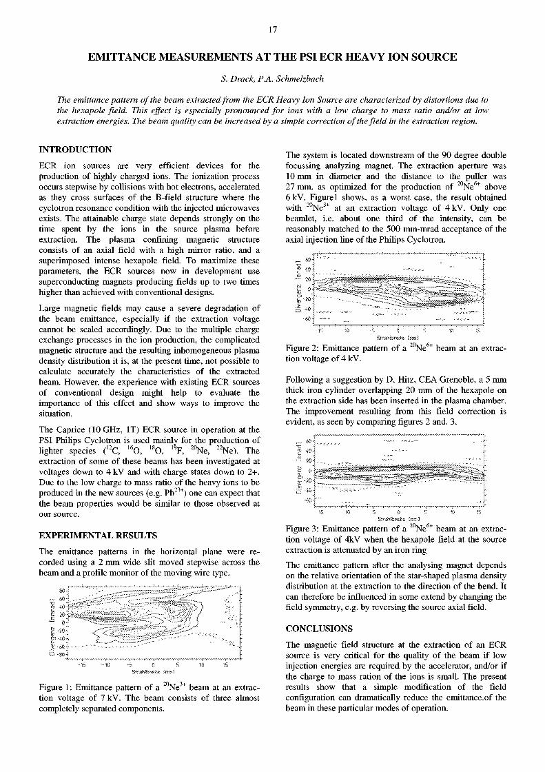
The emittance patterns in the horizontal plane were recorded using a 2 mm wide slit moved stepwise across the beam and a profile monitor of the moving wire type.
if
c A _ t>~ c ) -
CS <
J -9 -
Figure 1: Emittance pattern of a 2 0 N e 3 + beam at an extraction voltage of 7 kV. The beam consists of three almost completely separated components.
The system is located downstream of the 90 degree double focussing analyzing magnet. The extraction aperture was 10 mm in diameter and the distance to the puller was 27 mm, as optimized for the production of 2 0 N e 6 + above 6kV. Figurel shows, as a worst case, the result obtained with 2 0 N e 3 + at an extraction voltage of 4kV. Only one beamlet, i.e. about one third of the intensity, can be reasonably matched to the 500 mm-mrad acceptance of the axial injection line of the Philips Cyclotron.
m *
•>
-»•(' > <•>
A.
Sírahíoreíte Ixtrnl
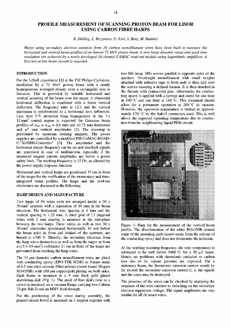
Figure 2: Emittance pattern of a 2 0 N e 6 + beam at an extraction voltage of 4 kV.
Following a suggestion by D. Hitz, CEA Grenoble, a 5 mm thick iron cylinder overlapping 20 mm of the hexapole on the extraction side has been inserted in the plasma chamber. The improvement resulting from this field correction is evident, as seen by comparing figures 2 and. 3.
Figure 3: Emittance pattern of a 2 0 N e 6 + beam at an extraction voltage of 4kV when the hexapole field at the source extraction is attenuated by an iron ring
The emittance pattern after the analysing magnet depends on the relative orientation of the star-shaped plasma density distribution at the extraction to the direction of the bend. It can therefore be influenced in some extend by changing the field symmetry, e.g. by reversing the source axial field.
CONCLUSIONS
The magnetic field structure at the extraction of an ECR source is very critical for the quality of the beam if low injection energies are required by the accelerator, and/or if the charge to mass ration of the ions is small. The present results show that a simple modification of the field configuration can dramatically reduce the emittance.of the beam in these particular modes of operation.
18
PROFILE MEASUREMENT OF SCANNING PROTON BEAM FOR LISOR USING CARBON FIBRE HARPS
R. Dolling, L. Rezzonico, U. Frei, S. Benz, M. Humbel
Harps using secondary electron emission from 16 carbon monofûament wires have been built to measure the horizontal and vertical beam profiles of an intense 71 MeV proton beam. A very large dynamic range and good time resolution are achieved by a newly developed 16 channel CAMAC read-out module using logarithmic amplifiers. A first test at low beam current is reported.
INTRODUCTION
For the LiSoR experiment [1] at the PSI Philips Cyclotron, irradiation by a 71 MeV proton beam with a nearly homogeneous averaged density over a rectangular area is foreseen. This is provided by suitable horizontal and vertical scanning of the beam over the target. A sinusoidal horizontal deflection is combined with a linear vertical deflection. The frequency ratio is 12:1 and the vertical maximum is synchronised to a horizontal zero deflection. Less than 5 % deviation from homogeneity in the 3 x 12 mm 2 central region is expected for Gaussian beam profiles of Oho r = Over t = 0-6 mm and ±2.75 mm horizontal and ±7 mm vertical amplitudes [2]. The scanning is performed by upstream steering magnets. The power supplies are controlled by a modified PSI CAMAC-ROAD-C-"KOMBI-Controller" [3]. The amplitudes and the horizontal master frequency can be set and interlock signals are generated in case of malfunction, especially if the measured magnet current amplitudes are below a preset safety limit. The working frequency is 15 Hz, as allowed by the power supply response function.
Horizontal and vertical harps are positioned 17 cm in front of the target for the verification of the momentary and time-integrated beam profiles. The harps and the read-out electronics are discussed in the following.
HARP DESIGN AND MANUFACTURE
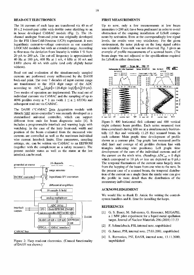
Two harps of 16 wires each are arranged inside a 30 x 30 mm 2 aperture with a separation of 18 mm in the beam direction. The horizontal wire spacing is 1 mm and the vertical spacing is 1.25 mm. A third grid of 13 diagonal wires with 2 mm spacing is mounted in the mid-plane between the two harps. These wires, as well as two 30 x 30 mm 2 electrodes (positioned horizontally 16 mm below the beam axis) in front and behind of the aperture, are biased to +300 V. Thereby, the secondary electrons from the harp wires themselves as well as from the target or from a (15 x 19 mm 2) collimator 21 cm in front of the harps are prevented from reaching the harp wires.
The 33 um diameter carbon monofilament wires are glued with conducting epoxy (EPO-TEK H20E) to frames made of 0.5 mm thick ceramic filled printed-circuit board (Rogers RO4350B) with 100 urn copper/gold plating on both sides. Each frame is mounted in a 9 mm thick gold plated aluminium disk (Fig. 1). The stack of four disks (one as a cover) is mounted on a vacuum flange carrying two Caburn 25-pin Sub-D and an MHV feed-through.
For the positioning of the wires during assembly, the printed-circuit board is mounted on a support together with
two M6 (resp. M8) screws parallel to opposite sides of the aperture. Overlength monofilament with small weights attached with adhesive tape to both ends is then laid over the screws ensuring a defined tension. It is then attached in the threads with cyanacrylat glue. Afterwards, the conducting epoxy is applied with a syringe and cured for one hour at 100 °C and one hour at 160 °C. This treatment should allow for a permanent operation at 200 °C in vacuum. However, the operation temperature is limited to approximately 170 °C by the Sub-D connectors used. This is well above the expected operating temperature due to conduction from the neighbouring liquid PbBi circuit.
Figure 1: Harp for the measurement of the vertical beam profile. The discolouration of the white RO4350B around some of the mounting pads (inset) stems from the solvent of the conducting epoxy and does not deteriorate the isolation.
At the working scanning frequency, the wire temperature is estimated to be well below 1000 °C for a 50 uA beam. Hence, no problems with thermionic emission or carbon loss due to its vapour pressure are expected. For a stationary beam, the thermionic emission current would by far exceed the secondary emission current (i. e. the signal) and the wires may be destroyed.
The presence of the wires can be checked by analysing the response of the wire currents to switching on the secondary electron suppressor voltage. The signal amplitudes are very similar for all 16 intact wires.
19
READ-OUT ELECTRONICS FIRST MEASUREMENTS
The 16 currents of each harp are transferred via 40 m of 10 x 2 twisted-pair cable with double outer shielding to an in house developed CAMAC module (Fig. 2). The 16-channel analogue front-end print was originally developed for the PSI Ultra-Cold-Neutron (UCN) experiment. It uses logarithmic current-to-voltage converters as our standard LOGCAM modules but with an extended range. According to first tests the deviation from linearity is within 1 % from 20 pA to 200 uA. The cut-off frequency is approximately 40 Hz at 100 pA, 400 Hz at 1 nA, 4 kHz at 10 nA and 8 kHz above 40 nA with cable (and only slightly better without).
Read out and evaluation of the simultaneously sampled currents are performed every millisecond by the DASH back-end print. The over 7 decades of input current range are transformed to the 1024 digit range of the ADC according to ADC o u t [digit ]=128digit log( / [pA]/ l0pA). Two modes of operation are implemented: The read out of individual currents via CAMAC and the sampling of up to 4096 profiles every n * 1 ms (with 1 < n < 65536) and subsequent read out via CAMAC.
The DASH ("CAMAC Data Acquisition module with Hitachi SH2 micro-controller") was recently developed as a standardised universal controller, which can support different front ends for beam diagnostic tasks [4]. It includes a programmable interlock and warning logic with watchdog. In the case of the harp front-end, width and position of the beam evaluated from the measured wire currents are controlled as well as the maximum individual wire current. Interlock limits, filter parameters, sampling settings, etc. can be written via CAMAC to an EEPROM (together with the complement as a safety measure). The present module status as well as the status at the last interlock can be read.
grounded at source 16 channels
<
DC/DC converter DC/DC converter
interlock «—^ outputs
surge arresters
g| logarithmic I/V converters
differential amplifiers
16 sample & hold i t
> analog multiplexer 3 E
ADC 10 bit I I/O I I flash EPROM 256 kB |
microcontroller HITACHI SH2 ft ft .. S "
RAM 128 kB + 128 kB EEPROM 8 kB
CAMAC bus H FPGA - CAMAC interface
ft
DASH
Figure 2: Harp read-out electronics. (Unused functionality of DASH not shown.)
Up to now, only a few measurements at low beam intensities (<200 nA) have been performed in order to avoid obstruction of the ongoing installation of LiSoR components by activation. Even at the correspondingly low signal levels, the results were very satisfactory. For the given environment, the noise pick-up on the long signal cables was tolerable. Cross-talk was not observed. Fig. 3 gives an example of profile measurements of a scanned beam. (The beam shape was not adjusted to the specifications required for LiSoR in either direction.)
HARP - Scan Nr. Harfensonden für LiSor Experiment Dahin:
190 - ^ 2S-0CT-01 Zeitt
ho r i zon ta l sum - 0.391 EnA] max - 0.882 InA l
18,10,51 v e r t i c a l
timeaveraged profi le [nA] sum - 0.304 [r>AÎ momentaneous profi le InAJ max - 0.191 [nA l
0.2 0 .8 -6 I? Isum [nA] left
• 4 - 2 0 2 position [mml
0.00 0.25 ¡5 Isum [nA] up
6 -4 -2 0 2 4 6 Dosition [mml down
Figure 3: 400 horizontal (left column) and 400 vertical (right column) beam profiles. Each series measured (not time-correlated) during 800 ms at a simultaneously horizontally (15 Hz) and vertically (1.25 Hz) scanned beam. In each column: Main graph: time development of profile shown as a contour plot. Top graph: last measured profile (full line) and average of all profiles (broken line with triangles indicating wire positions). Left graph: time development of the sum of the individual currents and of the current on the ninth wire. (Readings ADCout = 0 digit which correspond to 10 pA or less are depicted as 0 pA.) The temporal fluctuations of the current sums largely stem from the hopping of the beam from one wire to the next. In the present case of a scanned beam, the temporal distribution of the current on a single (here the ninth) wire can give the profile in more detail than the distribution of the momentary individual currents.
ACKNOWLEDGEMENT
We would like to thank D. Anicic for writing the control-system handlers and R. Erne for installing the harps.
REFERENCES
[1] G. S. Bauer, M. Salvatores, G. Heusener, MEGAPIE, a 1 MW pilot experiment for a liquid metal spallation target, Journal of Nuclear Materials 296 (2001) 17-33
[2] P. Schmelzbach, PSI, internal note, unpublished
[3] G. Janser, PSI, internal note, 27.03.2001, unpublished
[4] L. Rezzonico, PSI, DASH, internal note, 13.11.2000, unpublished
20
A FAST DEGRADER TO SET THE ENERGIES FOR THE APPLICATION OF THE DEPTH DOSE IN PROTON THERAPY
H. Reist, R. Dölling, M. Graf, E. Pedroni, M. Schippers (PSI), A. Breiing (ETHZ), J. Evertz, D. Schäpper (Tribecraft AG, Zürich)
Proton therapy with a fixed energy cyclotron needs a dégrader to adjust the energy of the proton beam for the application of the depth dose. Within the scope of the PROSCAN project, a dégrader system is being realized that meets the requirements as given by the spot-scan technique. This requires infinitely variable energy in the range of >240 MeV down to 70 MeV. The depth, referred to as the range of the protons into the body, has to be set within an accuracy and a reproducibility of 0.1 mm water equivalent. The time to change the penetration depth of the protons by a typical step of 4.5 mm water equivalent has to be <50 ms.
INTRODUCTION
The objective of the PROSCAN project is to expand the existing facility and technical infrastructure with an independent cyclotron that meets the high specifications and requirements for the application of advanced and improved irradiation techniques. With the spot-scan technique, many individual beam spots are superimposed in the target volume in such a way as to impose the desired radiation dose distribution uniformly within a tumour. To achieve this, the individual spots have to be positioned precisely in a rapid sequence. This can be realised with a fixed energy cyclotron combined with a fast dégrader system that permits a rapid setting of the different beam energies. Furthermore, the beam transport system from the cyclotron to the treatment rooms has to satisfy the requirements for the implementation of energy modulation in addition to lateral scanning. Magnets and power supplies have to enable the desired rapid change of the beam setting in order to transport the beam properly.
The dégrader is an important component of the facility, and it has to fulfil the general requirements imposed on the whole facility. These are high reliability (99% availability of scheduled beam time), short service periods (maintenance task <4 h), fast accessibility and low dose load in case of required servicing. Specifically, the dégrader has to be constructed with standard units, with the drive installed outside the vacuum chamber. The dégrader should be small and light and be fabricated out of high-density graphite to reduce activation and beam losses due to scattering. Equally important is redundant diagnostics to control and read back the setting and the position of the dégrader.
DUAL DEGRADER UNIT
The dégrader has to enable an infinitely variable energy setting in the range of >240 MeV down to 70 MeV. For that the thickness of the absorber has to be increased uniformly. A change of the penetration depth of the beam into the body, typically -4.5 mm water equivalent, has to be accomplished within 50 ms with an accuracy of +0.1 mm. The positional change of the dégrader itself depends on the beam energy and on the specific design of the dégrader. The settings have to be performed according to a measured calibration curve.
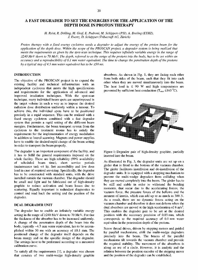
To satisfy all the requirements [1], a dégrader was chosen that consists of two multi-wedge high-density graphite
absorbers. As shown in Fig. 1, they are facing each other from both sides of the beam, such that they fit into each other when they are moved simultaneously into the beam. The heat load is < 90 W and high temperatures are prevented by sufficient heat conduction ( T m a x <165 °C).
Figure 1: Dégrader pair of high-density graphite, partially inserted into the beam.
As illustrated in Fig. 3, the dégrader units are set up on a girder that is fixed to the bottom of the vacuum chamber. The girder facilitates installation and de-installation of the dégrader units. It is equipped with a stopping mechanism to prevent the multi-wedge degraders from colliding when they are moved completely into the beam. The girder has to be stiff and stable in order to withstand the bending moments, that occur due to the accelerating forces, the vacuum force, the pressure forces of the bellows and the moment of inertia, which can add up to as much as 300 N. As a result, there are no dynamic forces acting on the vacuum chamber and therefore it does not deform when the dual absorbers are moved at the high acceleration of 6 m/s2. This enables the dégrader pair to be set at the desired position with the necessary precision of 0.03 mm, which corresponds to the required accuracy of 0.1 mm water equivalent in the penetration depth of the protons.
Screw thread drives, driven by stepping motors and guided by parallel mechanisms, shift the multi-wedge degraders precisely into the beam. The braces of the parallel mechanisms tilt towards the vacuum chamber and provide the required stability. The movement of the absorbers is along an arc of a circle. However, it is analytic and the relation between the position encoder of the stepping motor and the position of the dégrader can be established.
21
The beam spot size at the exit of a multi-wedge dégrader is larger than that of a compact dégrader for identical energy degradation. This is due to beam divergence in the drift lengths between the wedges. The differences in the beam spot sizes are particularly distinct at moderate degradation where the drift lengths are larger. However, at lower energies, when the multi-wedge degraders nest more and more into one another to form an almost compact body, the difference of beam spot sizes decreases. At 70 MeV the beam spots have almost the same size. As can be seen in Fig. 2, the dependence of the beam-size on the absorber setting is reduced and the dynamic range is more constant. Together with the selected beam spot size, this decreases possible control and stability uncertainties of the beam intensity.
250 240 230 220 210 200 190 180 170 160 150
E„u, [MeV]
Figure 2: Beam spot size at the exit of the multi-wedge dégrader compared to that of a compact dégrader.
DEGRADER SYSTEM
REFERENCE
[1] H. Reist, Anforderungen an den PROSCAN Dégrader, P22/RH85-161.3
Figure 3: Dégrader system with the dual dégrader unit that is set-up on a girder. The beam enters the vacuum chamber at the front side. Schematically shown are the diagnostics box, the beam stopper-Faraday cup, the set of retractable scatter foils, the dégrader unit, the adjustable set of collimators and the collimator to stop the beam halo.
The dégrader system is installed in a small and compact vacuum chamber. This is to enhance safety and to avoid contamination risks. Radiation protection requirements would not allow this length of beam section in an air-filled box, which would have to be evacuated and flushed before opening. This is in contradiction with the desired fast access.
The dégrader system consists of:
1. Beam diagnostics (beam position, profiles and intensity) in order to position the beam properly at the entrance of the dégrader.
2. A beam stopper-Faraday cup: It has a hole for the beam passage at normal operation, and it also serves as a beam stopper when the beam is kicked off the beam axis to interrupt the beam at the target. To stop the beam, the Faraday cup is shifted further into the beam in <0.5 s, and the current can be measured accurately.
3. Stack of scatter foils: At higher energies the scattering in the dégrader may be too small. This may lead to an increase of possible control/stability uncertainties. To increase scattering, various foils can be inserted. This decreases the beam transmission from the cyclotron exit to the target, but may possibly make the dynamic range of the beam intensity more constant.
4. Dual dégrader unit.
5. Adjustable stack of collimators with apertures ranging from 1 to 15 mm in diameter to select the beam spot size.
6. Collimator of graphite to suppress the beam halo.
22
MAD9P A PARALLEL 3D PARTICLE TRACKER WITH SPACE CHARGE
A. Adelmann
INTRODUCTION
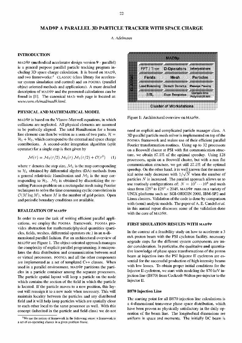
M A D 9 P (methodical accelerator design version 9 - parallel) is a general purpose parallel particle tracking program including 3D space charge calculation. It is based on M A D 9 , and two frameworks:1 C L A S S I C (class library for accelerator system simulation and control) and on P O O M A (parallel object oriented methods and applications). A more detailed description of M A D 9 P and the presented calculations can be found in [1]. The canonical M A D web page is located at: www. cern. ch/mad/mad9. html.
PHYSICAL AND MATHEMATICAL MODEL
M A D 9 P is based on the Vlasov-Maxwell equations, in which collisions are neglected. All physical elements are assumed to be perfectly aligned. The total Hamiltonian for a beam line element can then be written as a sum of two parts, % = "Hi + 'Hi, which correspond to the external and space charge contributions. A second-order integration algorithm (split operator) for a single step is then given by
M(T) = MI(T/2) M2(T) MI(T/2) + 0(T3) (1)
where r denotes the step size, Mi is the map corresponding to Tii obtained by differential algebra (DA) methods from a general relativistic Hamiltonian and yV12 is the map corresponding to 7Í2- M-1 is obtained by discretizing the resulting Poisson problem on a rectangular mesh using Fourier techniques to solve the time consuming cyclic convolution in 0{M log M), where M is the number of grid points. Open and periodic boundary conditions are available.
REALIZATION O F m a d 9 p
In order to ease the task of writing efficient parallel applications, we employ the P O O M A framework, P O O M A provides abstraction for mathematic/physical quantities (particles, fields, meshes, differential operators etc.) in an n-di-mensional parallel fashion. For an architectural overview of M A D 9 P see Figure 1. The object-oriented approach manages the complexity of explicit parallel programming; it encapsulates the data distribution and communication between real or virtual processors, P O O M A and all the other components are implemented as a set of templated C++ classes. When used in a parallel environment, M A D 9 P partitions the particles in a particle container among the separate processors. The particle spatial layout will keep a particle on the node which contains the section of the field in which the particle is located. If the particle moves to a new position, this layout will reassign it to a new node when necessary. This will maintain locality between the particles and any distributed field and it will help keep particles which are spatially close to each other local to the same processor as well. With this concept (inherited in the particle and field class) we do not
'We use the notion of framework in the following sense: a framework is a set of co-operating classes in a given problem frame.
Clus te r of Works ta t i ons
Figure 1 : Architectural overview on M A D 9 P .
need an explicit and complicated particle manager class. A 3D parallel particle mesh solver is implemented on top of the P O O M A framework and makes use of their efficient parallel Fourier transformation routines. Using up to 32 processors on a Beowulf cluster at PSI with flat communication structure, we obtain 87.5% of the optimal speedup. Using 128 processors, again on a Beowulf cluster, but with a non flat communication structure, we get still 37.5% of the optimal speedup. On the other hand, it is well known that the numerical noise only decreases with 1 / \Z/V when the number of particles ./V is increased. The parallel approach allows us to use routinely configurations of: ./V = 10 7 • • • 10 8 and mesh sizes from 128 3 to 128 2 x 2048. M A D 9 P runs on a variety of UNIX platforms such as: SGI-ORIGIN 2000, IBM-SP2 and Linux clusters. Validation of the code is done by comparison with (semi) analytic models. The paper of A. E. Candel et al. in this annual report discusses some of the validation done with the core of M A D 9 P .
FIRST SIMULATION RESULTS W I T H MAD9P
In the context of a feasibility study on how to accelerate a 3 mA proton beam with the PSI cyclotron facility, necessary upgrade steps for the different system components are under consideration. In particular, the qualitative and quantitative knowledge of phase space transformations of the proton beam at injection into the PSI Injector II cyclotron are essential for the successful production of high intensity beams with low losses. To obtain proper initial conditions for the Injector II cyclotron, we start with modeling the 870 keV injection line (B870) from Cockroft-Walton pre-injector to the Injector II.
B870 Injection Line
The starting point for all B870 injection line calculations is a 4-dimensional transverse phase space distribution, which have been proven as physically satisfactory in the daily operation of the beam line. The longitudinal dimensions are uniform in space and momenta. The initially DC beam is
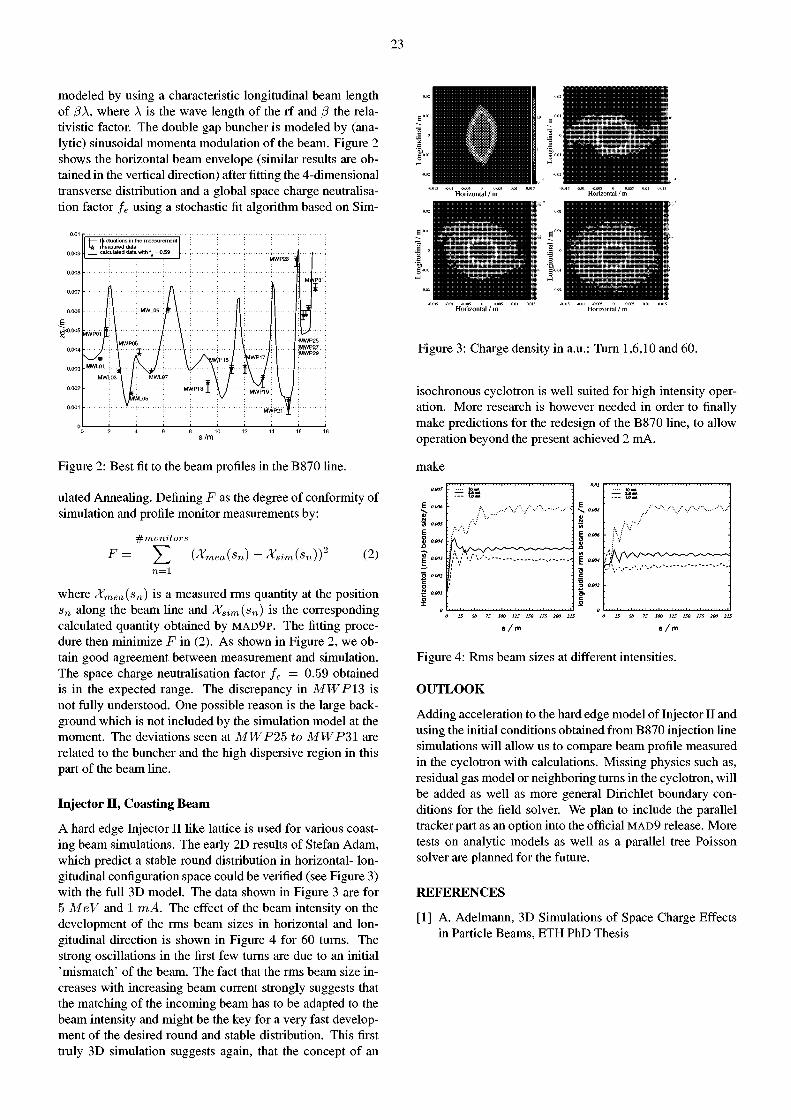
23
modeled by using a characteristic longitudinal beam length of ß\, where A is the wave length of the rf and ß the rela-tivistic factor. The double gap buncher is modeled by (analytic) sinusoidal momenta modulation of the beam. Figure 2 shows the horizontal beam envelope (similar results are obtained in the vertical direction) after fitting the 4-dimensional transverse distribution and a global space charge neutralisation factor fe using a stochastic fit algorithm based on Sim-
•1— fluctuations in the measurement 1* measured data
. calculated data with f = 0.59 HWP23 i HWP23 i
(1 A ÍP31:
I...;
1 : A : . MWL09 'ml 11 • '•
ÍP31:
I...;
MWP01 f£ 1 Í \ : ï 1 :
/ : 1MWP05 /: \ : 1 \ \-
\ /? ¡ \ AMWPIS / Vw p i 7/ ;
MWL01 : I : X/ V * T\ I :
:MWP25 :
;MWP27..; :MWP29 :
MWt-Osl / : MWLÔ7 V j : \ J \
""\ L \ y • MWP1 g ; ' ' V ' ' 7 ;
\JMWL05 : I \B ; MWP2Î X ;
1 1 1 1 1 1 1 1 1
s/m
Figure 2: Best fit to the beam profiles in the B870 Une.
ulated Annealing. Defining F as the degree of conformity of simulation and profile monitor measurements by:
^monitors F= Yl (Xmea(Sn) - Xsim(Sn)? (2)
n = l
where Xmea(sn) is a measured rms quantity at the position sn along the beam Une and Xsim(sn) is the corresponding calculated quantity obtained by M A D 9 P . The fitting procedure then minimize F in (2). As shown in Figure 2, we obtain good agreement between measurement and simulation. The space charge neutralisation factor fe = 0.59 obtained is in the expected range. The discrepancy in MWP13 is not fully understood. One possible reason is the large background which is not included by the simulation model at the moment. The deviations seen at MWP25 to MWP31 are related to the buncher and the high dispersive region in this part of the beam Une.
Injector I I , Coasting Beam
A hard edge Injector II like lattice is used for various coasting beam simulations. The early 2D results of Stefan Adam, which predict a stable round distribution in horizontal- longitudinal configuration space could be verified (see Figure 3) with the full 3D model. The data shown in Figure 3 are for 5 MeV and 1 mA. The effect of the beam intensity on the development of the rms beam sizes in horizontal and longitudinal direction is shown in Figure 4 for 60 turns. The strong oscillations in the first few turns are due to an initial 'mismatch' of the beam. The fact that the rms beam size increases with increasing beam current strongly suggests that the matching of the incoming beam has to be adapted to the beam intensity and might be the key for a very fast development of the desired round and stable distribution. This first truly 3D simulation suggests again, that the concept of an
Horizontal / m Horizontal / m
Figure 3: Charge density in a.u.: Turn 1,6,10 and 60.
isochronous cyclotron is well suited for high intensity operation. More research is however needed in order to finally make predictions for the redesign of the B870 Une, to allow operation beyond the present achieved 2 mA.
make
s / m s / m
Figure 4: Rms beam sizes at different intensities.
OUTLOOK
Adding acceleration to the hard edge model of Injector II and using the initial conditions obtained from B870 injection Une simulations will allow us to compare beam profile measured in the cyclotron with calculations. Missing physics such as, residual gas model or neighboring turns in the cyclotron, will be added as well as more general Dirichlet boundary conditions for the field solver. We plan to include the parallel tracker part as an option into the official M A D 9 release. More tests on analytic models as well as a parallel tree Poisson solver are planned for the future.
REFERENCES
[1] A. Adelmann, 3D Simulations of Space Charge Effects in Particle Beams, ETH PhD Thesis
24
BEHAVIOUR OF DIFFERENT POISSON SOLVERS IN THE LIGHT OF BEAM DYNAMICS SIMULATIONS
A. Adelmann (PSI), A.E. Candel (PSI/ETH)
A program for simulation of the dynamics of a charged particle bunch has been developed, based on MAD9P. Three different Poisson solvers based on: direct particle-particle method, the FFT-based particle-mesh method and the hierarchical tree method are compared on simple, analytically treatable test cases.
INTRODUCTION
For a more detailed exposition of the problem and references see [1]. Many different physical phenomena (astrophysics, molecular dynamics, beam dynamics) can be described as interactions between pairs of particles. For systems containing a large number of particles, the numerical calculation of the forces acting between all particles can be a very time-consuming task. Three different methods to speed up the calculations at the price of decreased accuracy have been compared in the context of beam dynamics.
Relativistic Beam Dynamics
We consider a bunch of N classical particles (protons) with mass m, and electric charge q¡. A state of the system is specified by the 6N canonical coordinates and their conjugate momenta {ri,pi} in the laboratory frame, measured relative to a reference particle moving along in the i-direction (longitudinal) with energy 7 . The form-invariant Hamiltonian formalism is used to describe the dynamics. Assuming the particle energy spread to be much smaller than the reference energy, A 7 / 7 <S 1, the following Hamiltonian can be used:
¿-^ \ 2m¿7 Imci3 ) 7 2
where
is the electrostatic space charge potential and = r¿ — fj. Note that there is no external potential included and the system is assumed to be collisionless. We limit ourselves here to open boundary conditions for the Poisson problem. In order to solve the resulting Hamilton's equations numerically, the Lorentz force needs to be calculated in the laboratory frame at each time-step. This is best accomplished by calculating the electric field in the moving beam frame and then transforming it back to the laboratory frame, where the transversal electric field is reduced by a factor of 7 due to the self-focusing magnetic field. The time-integration is accomplished by a symplectic, time-reversible second-order split-operator integrator which is accurate through third order in the positions and first order in the momenta.
THREE POISSON SOLVERS
Using the "kernel" of MAD9P, three different Poisson solvers to calculate the electric field in the beam frame have been implemented.
Particle-Particle Solver
The Particle-Particle (PP) solver is conceptually and computationally the simplest of all methods as it directly calculates the electric field at every particle's position by summing over the contributions from all other N — 1 particles. This is exact up to numerics, as no approximation is made, but at the price of the highest computational effort, needing Ö(N2) calculations. A smoothing parameter e is often introduced to prevent artificial halo creation due to close encounters:
^ - 4^o 4?. q j rfj ~ 4 ^ h ^ + «2)3/2
Particle-Mesh Solver
The Particle-Mesh (PM) solver is one of the oldest improvements over the PP solver, introduced 1985 by Hockney & Eastwood. In our case, an adaptive rectangular computational domain containing all particles is segmented into a regular mesh of M grid points. The charge density is then assigned from the particle positions onto the grid points using an interpolation scheme, such as the cloud-in-cell (CIC) method. The Poisson equation is then solved on the mesh and the electric field at the particle positions is obtained by interpolating back from the mesh. Solving the Poisson equation on the grid can be done very rapidly applying the convolution theorem in reciprocal space using fast Fourier-transform (FFT) and an appropriated discretized Green's function. Therefore, the PM solver only needs ö(N+MlogM) calculations. While PM methods are much faster than the PP method and thus very efficient for large systems, the limited spatial resolution of the mesh leads to difficulties in dealing with strongly non-uniform, correlated or geometrically complex systems.
Hierarchical Tree Solver
Hierarchical tree (TREE) methods overcome this problem while providing a much better scaling than the PP method. In order to keep track of all particles and their attributes in a systematic way, an octagonal top-down tree is constructed by recursively subdividing non-empty space into equal octant boxes. At every recursion level, the particles contained by the corresponding octant are taken together to a pseudoparticle
25
with averaged properties. In order to sum up the contributions to the electric field, the tree is walked through and a pseudoparticle is considered a sufficiently accurate approximation of the original particles if the geometrical viewing angle of its containing box is smaller than a fixed tolerance parameter 0. For reasonable values of 0 (0.1... 1), the tree solver needs O(NlogN) calculations. The used implementation by Barnes features optional quadrupole corrections in the field calculation. Again, a smoothing parameter e is used to prevent artificial halo creation.
SELECTION O F RESULTS
In order to validate the simulation results, a comparison to the analytic solution for the time-dependence of the beam envelopes for a uniformly charged ellipsoid in free drift space with given semi-axis, mass and charge has been done. For small initial emittance, the time-dependence of the rms-envelopes can be exactly calculated by solving three coupled ordinary differential envelope equations featuring linear space charge terms. Time-reversibility of the used integrator has been verified up to machine precision. Figure 1 shows the relative deviation of the x rms-envelope from the analytic solution for a uniform ellipsoid in free drift space at 7 = 2, with an initial semi-axis of 1.5x2.5x4.5 [cm] and a total charge of 60 nC. For the PP (TREE) solver, N = 10 4 (10 5 ) and e = 0.5(0.25) mm was used. For PM,
= 10 6 and M = 64 3 . All solvers render a very good agreement to the analytical solutions in rms and maximal particle extent. The statistical errors given by the number of particles are less than one percent in all the simulations.
c o o >
"O
> o
0.001
0
-0.001
-0.002
-0.003
-0.004
-0.005
•0.006
+ + + + + + + + + + + : + + * + + + + + + + :
• T
• • • • •
T T T T T T T T + Particle-Particle N=1E4, rel. stat. error + / - 0.01 • Barnes-Hut Tree N= 1E5, rel. stat. error + / - 0.003 • Particle-Mesh N-1E6, rel. stat. error + / - 0.001
_ l _ _ l _ _ l _ _ l _
0 5 10 15 20 25 dr i f t length / m
Figure 1 : Relative deviation of the x rms-envelope.
O
E I E E
u c o
E o> I vt E
0.8
0.7
0.6
0.5
0.4
0.3
0.2
0.1
0
I 1 1 1 1 I
l i l i l í :
tí***
+ Portícle-PortícleN=1E4 • Bornes-Hut Tree N-1E5 • Portlcle-Mesh N=1E6
10 20 30 40 50 60 dr i f t length / m
70
Figure 2: x rms-emittance.
space charge forces result in an almost constant emittance, as expected.
CONCLUSION AND OUTLOOK
The objective of the present study was the preparation of a simulation program with the purpose to compare different Poisson solvers in the light of beam dynamics simulations. The resulting program allows fast and accurate studies at a high level of comfort. It can be used for simulation of rela-tivistic non-radiating charged particle dynamics as well as of gravitational dynamics. For the simulation of a uniform ellipsoid in free drift space, both the TREE and the PM solver can be regarded as very good substitutions for the PP solver. With properly tuned parameters and in combination with a time-reversible, symplectic integrator, both the PM and the TREE method follow the classical conservation laws almost as well as the PP method, and show a huge performance advantage, allowing much larger systems to be simulated. This results, for example, in smaller statistical inhomogeneities in the particle distribution and thus in a better representation of sensitive quantities like the emittance. A further study on emittance growth could reveal more details on the errors introduced by the different solvers.
References
[1] A. E. Candel, Behaviour of different Poisson Solvers in the Light of Beam Dynamics Simulations, Master's Thesis, ETH Zürich IPP 2001-07
Figure 2 shows the transversal x rms-emittance in the case of a uniform sphere of radius 2 cm with the same parameters. A higher number of particles leads to a more homogeneous initial distribution and therefore to a lower emittance growth in the initial phase, which is mainly due to non-linear forces. After the initial repartition of the bunch, the nearly linear
26
COMPUTATIONAL ELECTRODYNAMICS ON THE LINUX-CLUSTER
L. Stingelin
The PSI RF group currently uses the electromagnetic solvers of the commercial codes MAFIA and ANSYS for the design and study of accelerator components such as cavities, rf windows, combiners and electron-guns. The contacts established with the SLAC advanced computations department for a collaboration between SLAC, ETHZ and PSI, allowed us to import the new Omega3P and Tau3P codes onto the PSI LINUX cluster. These codes are optimized for large scale electromagnetic computation on unstructured grids [1]. They run parallel on distributed memory machines using LAM-MPI. Omega3P is an Eigensolver using linear and quadratic finite elements on a tetrahedral grid, while Tau3P is a time domain solver on a modified Yee grid with a leapfrog scheme for time advancement, discrete surface integral (DSI) method, and noise filtering. The advantages of Omega3P have already been used for a cross-check of the Eigenmode calculation of the cyclotron rf-strucrure to be delivered by ACCEL GmbH for the PSI PROSCAN project (see Fig. 1). This structure consists of two galvanically and two capacitively coupled double gap cavities. The coupling leads to push-pull and push-push modes with a resonant frequency separation of only approxima-tively 1 MHz. The insertion of the tube for the ion-source (small bright dot in the center of zoomed ellipse in Fig. 1) and the insertion of the pullers on the Dee at injection, affect the coupling of the cavities and decrease the field strength in the cavity to the left. More than 1.2 million elements were used for this simulation. The calculated resonance frequency of the fundamental mode was 73MHz with an unloaded quality factor of lO'OOO.
Figure 1: Omega3P simulation of the rf current density distribution of the PROSCAN cyclotron. The center is zoomed in the small ellipse on the top right corner. The symmetry plane on the bottom is taken to be a perfectly magnetic conducting boundary.
MAFIA is not suited for direct Eigenmode calculations of this kind of geometry, because its structured grid allows only a poor approximation of the geometry at the gaps and in the center region. ANSYS's finite element solver for Eigenmode calculations is limited by the memory available on the computer.
Figure 2: Contour plot of the longitudinal wakefield for a particle bunch traveling in the mid-plane of a rectangular cavity.
The collaboration with SLAC will allow the modification of Tau3P. It will be extended for simulations of the field excitation by particle bunches moving much slower than the speed of light and applied to the case of the PSI high intensity cyclotrons. In order to get acquainted with C++ and LAM-MPI programming, a small Finite Difference Time Domain (FDTD exercise) program was written for parallel computers. This code also uses a leapfrog scheme for time advancement and the orthogonal Yee cell [2] for discrete field value allocation. The boundary conditions are taken to be second order accurate and smoothed at the particle location. The Marder Langdon method [3] was implemented in order to improve the continuity equation. Suitable convergence in the Marder correction step was only obtained for small relaxation factors and Gauss's law is therefore only approximated. A further problem was noise, which increased with each time step and became visible after about five hundred steps. This could probably be solved with filtering. Finally, the program was upgraded to include a graphic display using OpenGL. An example of a screen shot is shown in Fig. 2. A part of the work for next year will be the continuation and refinement of the FDTD exercise. Studies will be focused on the improvement of the continuity equation and noise suppression. An attempt will be made to model the effect of the excited field on the beam distribution function using the ensemble parameters [4].
REFERENCES
[1] K. Ko, Proc. of the Snowmass Conference 2001 -T7 Working Group, (2001)
[2] D.M. Sullivan, Electromagnetic Simulation using the FDTD Method, IEEE Press, (2000)
[3] A.B. Langdon, Computer Physics Communications, 70, (1992), 447-450
[4] A. Novokhatski et al., Proc. of the Particle Accelerator Conference, New York, (1999)
27
PARTICLE RAY-TRACING PROGRAM TRACK APPLIED TO ACCELERATORS
V. Vrankovic, D. C. George
INTRODUCTION
A brief development history of the particle ray-tracing program TRACK is given, followed by the program's concept, necessary for understanding its analysis features and its application possibilities. The latest development, the introduction of radio frequency accelerating fields is presented with an example.
P R O G R A M HISTORY
The particle ray-tracing programme TRACK is written and maintained by the PSI Magnet Section. The development begun in 1987 and it has continued until today. TRACK is used to analyse the ion-optical properties of beam transport magnets and has proved itself as a powerful design tool.
There are three distinctive phases in the program's development history and its analysis capabilities.
In its first phase, TRACK was made to ray-trace charged particles in three dimensions and only in magnetic fields. The general particle motion in a constant magnetic field is a helix, so the core tracking subroutine HEL was designed to calculate helical paths along spatial steps. (Actually the very first tracking subroutine was S T E P [1])
In the second phase, we introduced the possibility of particle ray-tracing through combined magnetic and electric fields. The tracking subroutine HEL was completely rewritten (from then on HELBE) in such a way to include the analytical solution of the equation of motion. The motion calculation is stepped in time rather than in space as before. Due to the particle energy change coming from the electric fields, the relativistic effect had also to be taken into account and is included.
The third phase started this year with the introduction of time varying harmonic fields (both electric and magnetic). TRACK is now capable of tracking particles through accelerating radio frequency cavities.
SHORT DESCRIPTION O F TRACK
TRACK is written in FORTRAN, originally on VMS, and is running currently on Tru64-UNIX Alpha computers. It is using the graphics package GRAPHX [2].
The particle ray-tracing is fully three-dimensional. The integration of the motion is done stepwise, with the assumption that the fields are constant within the step. The program automatically checks the effect of field variation within the step and adjusts the step size accordingly.
The magnetic and electric field maps can be either calculated [3], measured or mathematically generated. TRACK accepts standard PSI two or three-dimensional formats in a cartesian co-ordinate system. The field is interpolated linearly except for sextupole and higher order magnets. Since the magnetic field of sextupoles changes quadratically, the linear interpolation is done on the multipole coefficients rather than on the fields.
The field maps can be translated and rotated in space. They can also be copied and the field levels can be linearly adjusted. The program library also includes some basic collimator shapes. In this way, it is very easy to build complex beam Unes with many elements. Element optimisation is possible within the program.
The beam source is made of either regularly phase spaced particles or it can be any randomly generated particle set. The program library recognises most of the elementary particles but particles with any rest mass can also be specified.
Tracking starts at a defined point in space and time and ends at either an intersection with a plane or after a given fixed axial distance. Particle positions, directions, path length and elapsed time at the end of tracking can be stored in a file with the same format as the inputs so that it can be reused as a new source.
The visualisation of particle trajectories is possible in a number of ways: orthogonal projections on the principal planes, in a three-dimensional view and with reference to the beam axis. Beam cross section, momentum dispersion and phase space plots at a given position can be also obtained.
There is a simple command language interpreter with do loops and i f blocks built into the program user interface enabling greater control of the program execution and easy data transfer to user applications.
INTRODUCTION O F DYNAMIC FIELDS
The time dependent fields (magnetic and electric) need to be stored in a map file at the time when their values are at their maximum. All fields from one map file oscillate with the same frequency and have the same phase, but different frequencies are allowed for different field maps. Time varying electric fields are cosine dependent and the accompanying magnetic fields are sine dependent.
A good test for the new TRACK functionality was the tracking analysis of the ACCEL superconducting cyclotron that is in its design phase and will be built for PROSCAN. Magnetic fields were obtained from an ACCEL model (k251_07) recalculated at PSI while the electric fields were calculated by ACCEL and sent to PSI. Dr. Kim, MSU, kindly provided the "ideal" cyclotron magnetic field.
With the help of the TRACK built-in command language interpreter, it was easy to find the true closed particle orbits in the magnetic field of the cyclotron and to store the tracking data in an external file for further analysis. Plotting the inverse of particle time of flights i.e. the frequency versus particle starting radius shows the isochronicity of the cyclotron model.
From this plot, a good initial value for the frequency for the time dependent electric fields of the accelerating cavity can be obtained. Another important parameter is the starting
28
time of the particle. This is not difficult to find with the help of the new time plot now available in TRACK as shown below. The particle positions are marked when the E-fields are either zero (dark blue) or at their peaks (green and light blue). The imperfection in the model field (meandering spiral) as compared to the ideal field (smooth spiral) is shown clearly.
REFERENCES
[ 1 ] Courtesy of Dr. J. Crawford, PSI
[2] G. Rudolf "GRAPHX Benutzer-Handbuch", PSI
[3] V. Vrankovic, D.C. George "Recent Usage of TOSCA Group Codes at PSI," VF European User Group Meeting, Saarbrücken, Deutschland, September 1990

29
Experimental Facilities

30
31
REBUILT BEAM LINE SECTION BETWEEN THE TARGETS M AND E
U. Rohrer
During the last shutdown (2001), the old and non-radiation resistant components (designed for 100 uA beam current only) of the beam line section between the targets M and E have been replaced with newly engineered and carefully pre-assembled components, so that later replacement or repair can be made without exposure of personnel to high dose rates [1]. The whole beam line was pre-assembled and tested outside the proton channel well in advance of the shutdown. This operation was considered to be mandatory for the successful replacing and testing of a beam line section during a shutdown of four months duration in a radioactive zone. Although there were still some time-consuming unforeseen problems to be solved during the shutdown period, the pre-assembly was decisive in reducing them to an absolute minimum.
During the following commissioning phase, which had to take place simultaneously with the first beam onto the
targets M and E after a long shutdown, no problems were seen with the newly built-in components; 2 pairs of horizontal and vertical steering magnets, 4 pairs of profile and beam position monitors (BPMs) with their protection collimators (the 4 t h one had to be placed inside the quadrupole lens QHTC18, which was relatively easy to achieve after cleaning out the old components and pushing it through the common vacuum chamber of the 2 n d
quadrupole triplet), 1 current monitor and 3 ionisation chambers. It should also be mentioned that no disturbing side effects from the 4 protection collimators in front of the new profile monitor plug-in units have been observed with the proton beam so far.
Figure 1 shows a top view of the new beam line region after finishing all work and just before covering the whole section with the top layers of concrete shielding blocks. Figure 3 shows the same region in a side view drawing.
Figure 1: Top view of the new beam line section between the quadrupole triplet after Target M (left) and the one before Target E (right). The white surfaces are the top faces of the newly added local shielding blocks. Clearly visible are also the 3 pairs of motor drives for the profile monitors, the water- and current-connections of the 2 pairs of steering magnets, the dual turbo molecular vacuum pumping aggregate and part of the air-cooling ventilation system for the region behind the target E.
Figure 2: Transport Envelope Fit of the 1.8 mA proton beam between the targets M and E. The profile data used were taken with the new profile monitor devices after a short commissioning period. Also included in the plot are the diverse aperture constraints (old and newly added collimators (symbolized with arrows), quadrupoles and bending magnets). The scaling of the aperture extent compared with that of the beam envelopes is reduced by a factor of five.
32
Vfl i f i l : i l ¡ol l
QHTC15
Figure 3: Side view drawing (simplified construction layout). The elements shown are, from left to right: Vacuum gasket, a pair of steering magnets (SHD13y and SHD14x), ionisation chamber (MHI12), profile/BPM-monitor pair (MHP/S25/26), 2 vacuum pumps (PH16/17), profile/BPM-monitor pair (MHP/S27/28), vacuum gasket, ionisation chamber (MHI12b), beam current monitor (MHC4), vacuum valve (VHD7), profile/BPM-monitor pair (MHP/S29/30), a second pair of steering magnets (SHD15y and SHD16x), vacuum gasket, ionisation chamber (MHI13). All devices are placed on 2 specially shaped concrete blocks and integrated into a local shielding environment consisting of concrete or steel blocks. On top of the local shielding, the heat exchanger and the ventilator for the air-cooling system are also visible.
Figure 2 shows a graphical output of a TRANSPORT (computer code) envelope fit with the measured profile widths as input constraints (represented with J. at locations marked with MHxx). The data are well interpolated with the drawn curves (86%-beam envelopes), which therefore represent quite well the actual proton beam in this section.
Table 1: Emittance data at Target-E gained from the TRANSPORT envelope fit shown in Figure 2.
ax 0.65 mm ax' 3.0 mrad rl2 0.0 ay 0.8 mm ay' 1.3 mrad r34 0.0
The beam emittance data gained with this fit have proven to be very useful for extrapolating the size of the beam spot and the slope of the beam at the target E location (see Table 1). A small horizontal spot size at the location of Target E is important in order to allow horizontal play of at least ±1 mm over the target width of 6 mm, which is crucial
for avoiding frequent transmission-interlocks produced by some beam missing the Target E [2]. These computed emittance data also play an important role in safety considerations for the planned MEGAPIE target at the SINQ [3] for the case where a substantial portion (>10 %) of the proton beam misses the Target E because the possibility of a failure in the beam transmission interlock has to be taken into account.
REFERENCES
[1] R. Reckermann, H.R. Vetterli, Shutdown Scheduling for the Accelerator, PSI Scientific and Technical Report 2000, Volume VI, page 93
[2] K. Deiters, F. Foroughi, G. Heidenreich, U. Rohrer, Reduction of Target-E Length from 60 mm to 40 mm, PSI Scientific and Technical Report 1999, Volume VI, page 26
[3] U. Rohrer, A Novel Method to Improve the Safety of the Planned Megapie Target at SINQ, PSI Scientific and Technical Report 2001, Volume VI, page 34
33
DISPOSAL PREPARATION FOR MESON PRODUCTION TARGETS
S. Teichmann, A. Geissler, A. Hagel, O. Morath
INTRODUCTION
A description of the meson target facilities can be found in [1]. They are operated with a 590 MeV proton beam at intensities of up to 2 mA. The targets consist of rotating wheels of polycrystalline graphite. The target of the meson production station E has three principal components:
• a graphite "ring" (ca. 1.4 kg, diameter ca. 0.5 m), shaped in the form of a truncated cone with extension lugs for its mounting system,
• 6 spokes (Inconel 600 steel, ca. 0.4 kg), • a cylindrical hub (stainless steel 316L, ca. 0.7 kg).
The spokes are attached to the graphite ring with graphite bolts held in place with a twisted wire at both ends. The assembly is shown in Fig. 1.
The lifetime of these targets is limited by shape deformations leading to a radial wobble. Since the accelerator upgrade program of 1991, up to Summer 2001, six target E's had reached the end of their lifetime. They were stored in special containers, which allow the controlled release of tritium produced at high levels in the graphite due to proton irradiation. Additional storage space was taken up by targets to be re-used, so that the need arose to free some of the storage space.
WASTE TREATMENT CONSIDERATIONS
Tritium is the main nuclide (with respect to disposal) produced in the graphite and is expected to be present at levels of ~ 1 0 1 0 Bq/kg (from measurement [2]) to ~ 1 0 u Bq/kg (from calculations [3]). A packaging together with other accelerator waste into concrete containers entails a high risk of breaking the graphite ring and releasing highly activated fine graphite dust into the air. At the PSI-East facilities, waste with high tritium content is conditioned in special drums. The steel parts however cannot be handled there, so that it would be necessary to first separate the graphite part from the steel parts. In collaboration with people from the ATEC hot cell, the target group, radiation protection and from the group for radioactive waste treatment, a plan of action was decided upon.
M E T H O D AND RESULTS
In the ATEC hot cell, each graphite ring is separated from the steel parts using a special tool designed and made by the target group to remove the graphite bolts. Special care was taken to minimize the graphite contamination by using a stainless-steel tub covered with a damp cloth as containment for the separation procedures (see Fig. 1). Each graphite ring is packed inside a labelled polyethylene bag, which are then placed inside a container for transfer to the conditioning facility at PSI-East. The steel parts are placed, together with other conventional accelerator waste, inside a concrete container. All steps are carried out with the ATEC manipulator (see Fig. 1). The separation procedure, together with the packing and sealing of the polyethylene bag, took about 1 hour per target.
Figure 1: Insertion of the bolt-cutting tool.
Dose rates (mainly due to Be-7 in case of the graphite) were measured separately for the graphite and steel parts and the tritium content in the hot cell was constantly monitored. Table 1 shows data for the 4 disposed targets.
The tritium concentration in the hot cell increased to about 5 MBq/m 3 in the vicinity of the targets, but no significant increase of tritium was observed in the central waste air system. Cleaning of the ATEC hot cell after the procedures were finished showed contamination values within the normal range.
Table 1: Data for the disposed target E's; the dose rates were measured at 10 cm on July 23/24, 2001.
# 7 0 # 7 1 # 7 2 # 7 8 used from 24/06/91 07/06/94 11/03/96 12/02/97 until 07/06/94 11/03/96 20/09/96 18/12/98 proton current 3.98 5.14 3.89 11.35 integral [Ah] surface dose rate [mSv/h]: graphite 0.005 0.01 0.02 0.039 steel 3.2 3.9 8.2 13
REFERENCES
[1] G. Heidenreich, Operation of the meson target facilities, PSI Scientific and Technical Report, Volume VI: Large Research Facilities, 2000, 26
[2] M. Argentini, R. Weinreich, Measurement of radionuclide contents in activated graphite, PSI Scientific and Technical Report, Volume I: Particles and Matter, 2000, 159
[3] F. Atchison, Calculated nuclide inventories for four rotating target assemblies from the Target-E system, PSI internal note, September 15, 1999
34
A NOVEL METHOD TO IMPROVE THE SAFETY OF THE PLANNED MEGAPIE TARGET AT SINQ
U. Rohrer
Currently, the SINQ spallation targets are only protected from being hit by some unscattered and therefore more intense beam, caused by protons missing the target-E, through the target-E beam transmission interlock. In order to improve this situation, an additional method to detect even small portions of unscattered beam is proposed. The idea is to block the unwanted beam with a newly added slit at the dispersive focus of the proton beam line and to trigger an interlock via an ionisation chamber when the unscattered beam hits the lower jaw of the slit.
INTRODUCTION
Because of the possibility of the contamination of the proton beam line underneath SINQ with liquid metal pouring out of a broken MEGAPIE project liquid metal target, it is desirable to add at least one additional safety
Figure 1: Portion of the graphic output of the TRANSPORT envelope fit (with target E length = 4 cm) of the proton beam between bending magnet AHN and SINQ-target together with the computed 1%-dispersion trajectory (dotted line), which reaches a maximum inside the quadrupole lens QHJ30 near the dispersive focus (best separation of the 2 beams).
element to the existing beam transmission interlock. The main reason for a possible failure of the two windows of the liquid metal target is overheating caused by the unscattered proton beam, which has a much smaller spot size at the SINQ target (caused by ion-optical reasons) than the beam passing through the graphite material of target E.
THE NEW IDEA
As can be seen in Figure 1, the momentum dispersion at the dispersive focus between the 2 bending magnets AHN and AHO is quite large (20 mm / %). This means that the 2 beams (momenta p= 1181 and 1205 MeV/c) at this location are separated by about 40 mm with a beam spot size in y of only about 12 mm FWHM (see Figure 2). In order to verify the Monte-Carlo (TURTLE) computations, the observable profile widths (measured with profile monitors MHP41-MHP58) have been compared with the simulated profile widths and found to be in good agreement. Furthermore, the behaviour of a proton beam, which is shifted sidewards by
2 mm at the target E location has been investigated with the same Monte-Carlo computations and experimentally by performing a so-called AHPOS-plot [1] and at the same time observing MHP56 when the proton beam is positioned near one or the other edge of the target E, so that around
: M H P 5 6
y ( m m )
Figure 2: Monte-Carlo simulation with TURTLE of the beam profiles at MHP56 and at the dispersive focus (IF) inside the quadrupole QHJ30. The beam centre in front of target E (4 cm graphite) has been shifted by 2 mm off centre, so that about 10 % of the protons are missing the target (Ap/p=+2%).
M H P 5 6
- 2 5 0 25 y (mm) Figure 3: Measured beam profile (MHP56) with some beam (1-2%) steered besides the target E (6 cm graphite). A small peak can be clearly seen at +20 mm. For a 4 cm target the separation would be less (14 mm).
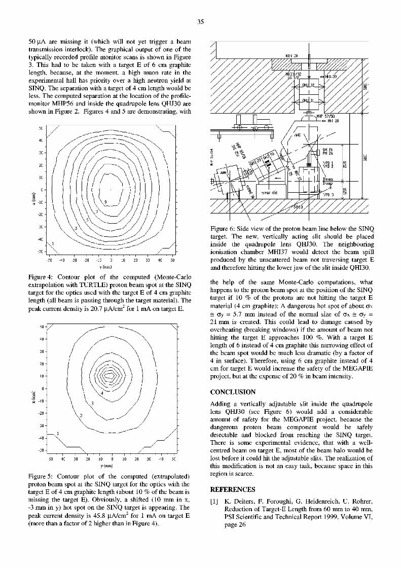
35
50 |oA are missing it (which will not yet trigger a beam transmission interlock). The graphical output of one of the typically recorded profile monitor scans is shown in Figure 3. This had to be taken with a target E of 6 cm graphite length, because, at the moment, a high muon rate in the experimental hall has priority over a high neutron yield at SINQ. The separation with a target of 4 cm length would be less. The computed separation at the location of the profile-monitor MHP56 and inside the quadrupole lens QHJ30 are shown in Figure 2. Figures 4 and 5 are demonstrating, with
y (mm)
Figure 4: Contour plot of the computed (Monte-Carlo extrapolation with TURTLE) proton beam spot at the SINQ target for the optics used with the target E of 4 cm graphite length (all beam is passing through the target material). The peak current density is 20.7 u,A/cm2 for 1 mA on target E.
y (mm)
Figure 5: Contour plot of the computed (extrapolated) proton beam spot at the SINQ target for the optics with the target E of 4 cm graphite length (about 10 % of the beam is missing the target E). Obviously, a shifted (10 mm in x, -3 mm in y) hot spot on the SINQ target is appearing. The peak current density is 45.8 u,A/cm2 for 1 mA on target E (more than a factor of 2 higher than in Figure 4).
Figure 6: Side view of the proton beam line below the SINQ target. The new, vertically acting slit should be placed inside the quadrupole lens QHJ30. The neighbouring ionisation chamber MHI37 would detect the beam spill produced by the unscattered beam not traversing target E and therefore hitting the lower jaw of the slit inside QHI30.
the help of the same Monte-Carlo computations, what happens to the proton beam spot at the position of the SINQ target if 10 % of the protons are not hitting the target E material (4 cm graphite): A dangerous hot spot of about ax = ay = 5.7 mm instead of the normal size of ax = ay = 21 mm is created. This could lead to damage caused by overheating (breaking windows) if the amount of beam not hitting the target E approaches 100 %. With a target E length of 6 instead of 4 cm graphite this narrowing effect of the beam spot would be much less dramatic (by a factor of 4 in surface). Therefore, using 6 cm graphite instead of 4 cm for target E would increase the safety of the MEGAPIE project, but at the expense of 20 % in beam intensity.
CONCLUSION
Adding a vertically adjustable slit inside the quadrupole lens QHJ30 (see Figure 6) would add a considerable amount of safety for the MEGAPIE project, because the dangerous proton beam component would be safely detectable and blocked from reaching the SINQ target. There is some experimental evidence, that with a well-centred beam on target E, most of the beam halo would be lost before it could hit the adjustable slits. The realization of this modification is not an easy task, because space in this region is scarce.
REFERENCES
[1] K. Deiters, F. Foroughi, G. Heidenreich, U. Rohrer, Reduction of Target-E Length from 60 mm to 40 mm, PSI Scientific and Technical Report 1999, Volume VI, page 26

36
BEAMLINE ADAPTATION FOR THE MEGAPffi-TARGET
E. Wagner, A. Strinning, S. Forss
INTRODUCTION
Within the scope of the MEGAPIE project, it is planned to replace the existing solid SINQ target by a liquid Lead-Bismuth Eutectic (LBE) unit. The LBE will be homoge-nously activated by the high energy proton beam resulting in ß/y- and a-emitters. For safety reasons, the primary LBE enclosure is protected by a double walled safety-hull, which can hold accidentally leaking LBE. In case this safety hull should also leak, the beam Une directly underneath the target is adapted in such a way that LBE can be collected in a shielded tank and safe handling can be guaranteed even after leakage and breakage of the three target enclosures.
BEAM LINE ADAPTATION
Unlike the collimator, where no changes are necessary, the vertical part of the beam line directly below the collimator has to be prepared in such a way that liquid LBE - either dropping or flowing down - cannot stick to horizontal or semi-horizontal surfaces in the vacuum chamber. This can be achieved with suitable funnels in the following sections: => EVK (in place of the existing halo monitor) => Profile monitor (MHP 57) => Bellows system just on top of the catcher
Furthermore, it has to be guaranteed that liquid LBE cannot enter the horizontal part of the vacuum system of the beam Une. To prevent this, a dripping edge is foreseen inside the bending magnet AHO.
CATCHER ADAPTATION
The existing catcher - designed for a water-cooled solid metal target - has to be replaced by a shielded vessel, which can collect the total amount of LBE. Therefore, it has to be adapted in size, with respect to shielding dimensions and handling features. In addition a mirror system will be installed to observe the temperature of the target window. The catcher will hold 135 dm 3 LBE and be shielded with 14 cm of pure lead. A heating and cooling system as well as an electronic weighing system will be added. After dismounting and removing the damaged target from the top to reduce the irradiation level in the basement, the catcher can be removed and stored for a year to cool down.
1.E+03
£ 1.E+02 á £ 1.E+01 s » 1.E+00 8
D 1.E-01
1.E-02
V atC Catcher surfac 6
, at 1 m
18 24 Cooling time [month]
Figure 1: Dose rates of the catcher containing the total amount of LBE (worst case), irradiated 1 year at 1 mA.
Weighing system
Figure 2: View of the Beamline underneath the Megapie-Target.
HANDLING O F THE CATCHER
Before the catcher can be disconnected and removed, the activated LBE must be enclosed by a surface layer of inactive LBE (14 cm), transferred from the melting tank. This sealing and upward shielding enables manual handling. However, a minimum cooling time of a few months will still be required (Fig. 1).
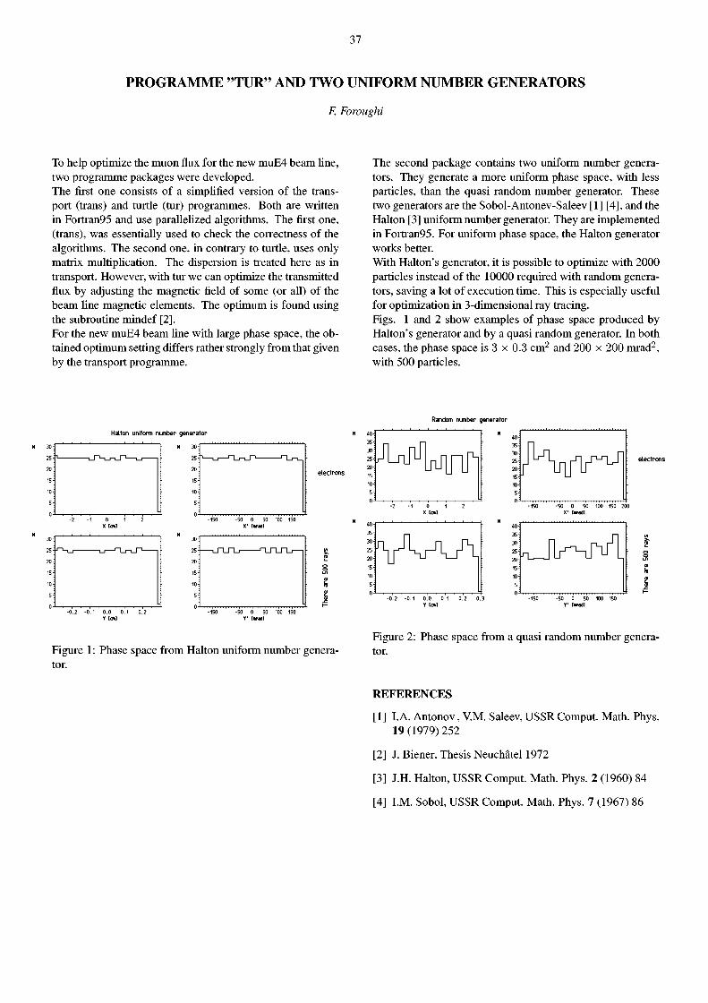
37
PROGRAMME "TUR" AND TWO UNIFORM NUMBER GENERATORS
F. Fowughi
To help optimize the muon flux for the new muE4 beam Une, two programme packages were developed. The first one consists of a simplified version of the transport (trans) and turtle (tur) programmes. Both are written in Fortran95 and use parallelized algorithms. The first one, (trans), was essentially used to check the correctness of the algorithms. The second one, in contrary to turtle, uses only matrix multiplication. The dispersion is treated here as in transport. However, with tur we can optimize the transmitted flux by adjusting the magnetic field of some (or all) of the beam Une magnetic elements. The optimum is found using the subroutine mindef [2]. For the new muE4 beam line with large phase space, the obtained optimum setting differs rather strongly from that given by the transport programme.
The second package contains two uniform number generators. They generate a more uniform phase space, with less particles, than the quasi random number generator. These two generators are the Sobol-Antonev-Saleev [1] [4], and the Halten [3] uniform number generator. They are implemented in Fortran95. For uniform phase space, the Halten generator works better. With Halton's generator, it is possible to optimize with 2000 particles instead of the 10000 required with random generators, saving a lot of execution time. This is especially useful for optimization in 3-dimensional ray tracing. Figs. 1 and 2 show examples of phase space produced by Halton's generator and by a quasi random generator. In both cases, the phase space is 3 x 0.3 cm 2 and 200 x 200 mrad2, with 500 particles.
Random number generator
Halton uniform number generator
-50 0 50 100 150 Y' brad]
Figure 1 : Phase space from Halton uniform number generator.
s Ol h Ol fe É
Figure 2: Phase space from a quasi random number generator.
REFERENCES
[1] I.A. Antonov, V.M. Saleev, USSR Comput. Math. Phys. 19 (1979) 252
[2] J. Biener, Thesis Neuchâtel 1972
[3] J.H. Halton, USSR Comput. Math. Phys. 2 (1960) 84
[4] I.M. Sobol, USSR Comput. Math. Phys. 7 (1967) 86
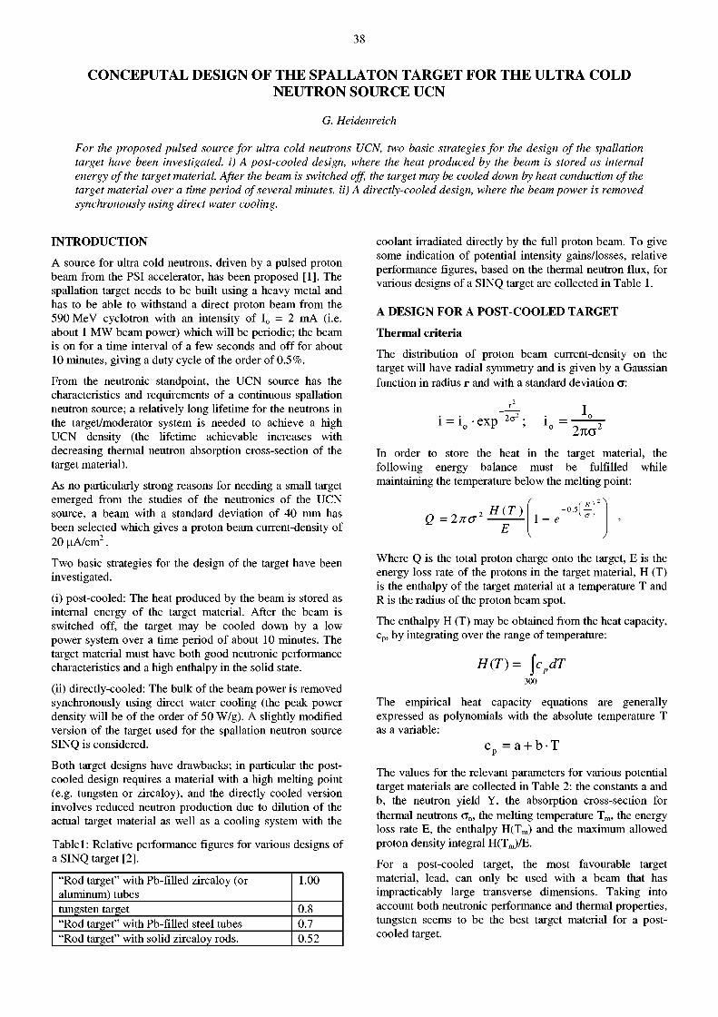
38
CONCEPUTAL DESIGN OF THE SPALLATON TARGET FOR THE ULTRA COLD NEUTRON SOURCE UCN
G. Heidenreich
For the proposed pulsed source for ultra cold neutrons UCN, two basic strategies for the design of the spallation target have been investigated, i) A post-cooled design, where the heat produced by the beam is stored as internal energy of the target material. After the beam is switched off, the target may be cooled down by heat conduction of the target material over a time period of several minutes, ii) A directly-cooled design, where the beam power is removed synchronously using direct water cooling.
INTRODUCTION
A source for ultra cold neutrons, driven by a pulsed proton beam from the PSI accelerator, has been proposed [1]. The spallation target needs to be built using a heavy metal and has to be able to withstand a direct proton beam from the 590 MeV cyclotron with an intensity of I 0 = 2 mA (i.e. about 1 MW beam power) which will be periodic; the beam is on for a time interval of a few seconds and off for about 10 minutes, giving a duty cycle of the order of 0.5%.
From the neutronic standpoint, the UCN source has the characteristics and requirements of a continuous spallation neutron source; a relatively long lifetime for the neutrons in the target/moderator system is needed to achieve a high UCN density (the lifetime achievable increases with decreasing thermal neutron absorption cross-section of the target material).
As no particularly strong reasons for needing a small target emerged from the studies of the neutronics of the UCN source, a beam with a standard deviation of 40 mm has been selected which gives a proton beam current-density of 20 uA/cm 2 .
Two basic strategies for the design of the target have been investigated.
(i) post-cooled: The heat produced by the beam is stored as internal energy of the target material. After the beam is switched off, the target may be cooled down by a low power system over a time period of about 10 minutes. The target material must have both good neutronic performance characteristics and a high enthalpy in the solid state.
(ii) directly-cooled: The bulk of the beam power is removed synchronously using direct water cooling (the peak power density will be of the order of 50 W/g). A slightly modified version of the target used for the spallation neutron source SINQ is considered.
Both target designs have drawbacks; in particular the post-cooled design requires a material with a high melting point (e.g. tungsten or zircaloy), and the directly cooled version involves reduced neutron production due to dilution of the actual target material as well as a cooling system with the
Table 1: Relative performance figures for various designs of a SINQ target [2].
"Rod target" with Pb-filled zircaloy (or aluminum) tubes
1.00
tungsten target 0.8 "Rod target" with Pb-filled steel tubes 0.7 "Rod target" with solid zircaloy rods. 0.52
coolant irradiated directly by the full proton beam. To give some indication of potential intensity gains/losses, relative performance figures, based on the thermal neutron flux, for various designs of a SINQ target are collected in Table 1.
A DESIGN F O R A POST-COOLED TARGET
Thermal criteria
The distribution of proton beam current-density on the target will have radial symmetry and is given by a Gaussian function in radius r and with a standard deviation a:
l = l 0 exp 2<TZ
L 1„ =
2no
In order to store the heat in the target material, the following energy balance must be fulfilled while maintaining the temperature below the melting point:
Q = 2no 2 H(T)
1 - e
Where Q is the total proton charge onto the target, E is the energy loss rate of the protons in the target material, H (T) is the enthalpy of the target material at a temperature T and R is the radius of the proton beam spot.
The enthalpy H (T) may be obtained from the heat capacity, c p, by integrating over the range of temperature:
H(T)= \cpdT 300
The empirical heat capacity equations are generally expressed as polynomials with the absolute temperature T as a variable:
C p = a + b -T
The values for the relevant parameters for various potential target materials are collected in Table 2: the constants a and b, the neutron yield Y, the absorption cross-section for thermal neutrons G n , the melting temperature T m , the energy loss rate E, the enthalpy H(Tm) and the maximum allowed proton density integral H(Tm)/E.
For a post-cooled target, the most favourable target material, lead, can only be used with a beam that has impracticably large transverse dimensions. Taking into account both neutronic performance and thermal properties, tungsten seems to be the best target material for a post-cooled target.
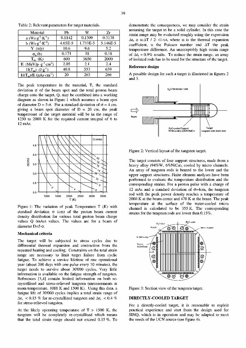
39
Table 2: Relevant parameters for target materials
Material Pb W Zr a (Ws-g'-K"1) 0.1142 0.1309 0.3138 b (Ws-g'-K"2) 4.65E-5 1.733E-5 5.146E-5
Y (n/p) 10.6 9.6 5.2 a„(b) 0.171 18 0.18
T m (K) 600 3650 2000 E (MeV/p g ' c m 2 ) 2.05 2.1 2.4
H(Tm) (J-g 1) 40.8 553 639 H(Tm)/E (uAs-crn2) 20 263 266
The peak temperature in the material, T, the standard deviation a of the beam spot and the total proton beam charge onto the target, Q, may be combined into a working diagram as shown in Figure 1 which assumes a beam spot of diameter D = 5 a . For a standard deviation of a = 4 cm, giving a beam spot diameter of D = 20 cm, the peak temperature of the target material will be in the range of 1250 to 2000 K for the required current integral of 6 to 12mAs.
f f 3.5
1000 1500 2000 2500 3000 3500 T(K)
Figure 1: The variation of peak Temperature T (K) with standard deviation a (cm) of the proton beam current density distribution for various total proton beam charge values Q (mAs) values. The values are for a beam of diameter D = 5 a .
Mechanical criteria
The target will be subjected to stress cycles due to differential thermal expansion and contraction from the repeated heating and cooling. Constraints on the total strain range are necessary to limit target failure from cyclic fatigue. To achieve a service lifetime of one operational year (about 200 days with one pulse every 10 minutes), the target needs to survive about 30'000 cycles. Very little information is available on the fatigue strength of tungsten. References [3,4] contain limited information on both re-crystallised and stress-relieved tungsten (measurements at room temperature, 1088 K and 1500 K). Using this data, a fatigue life of 30'000 cycles implies a total strain range of Ae t < 0.15 % for re-crystallized tungsten and A£( < 0.4 % for stress-relieved tungsten.
At the likely operating temperature of T > 1500 K, the tungsten will be completely re-crystallised which means that the total strain range should not exceed 0.15 %. To
demonstrate the consequences, we may consider the strain assuming the target to be a solid cylinder. In this case the strain range may be evaluated roughly using the expression Ae t = a-AT / 2- (l-t>), where a is the thermal expansion coefficient, v the Poisson number and AT the peak temperature difference. An unacceptably high strain range of A£( ~ 0.9% results. To reduce the strain range, an array of isolated rods has to be used for the structure of the target.
Reference design
A possible design for such a target is illustrated in figures 2 and 3.
Target Tungsten rods (6x20 mm)
Figure 2: Vertical layout of the tungsten target.
The target consists of four support structures, made from a heavy alloy (94%W, 6%NiCu), cooled by micro channels. An array of tungsten rods is brazed to the lower and the upper support structures. Finite element analyses have been performed to evaluate the temperature distribution and the corresponding strains. For a proton pulse with a charge of 12 mAs and a standard deviation of a=4cm, the tungsten rod with the peak power density reaches a temperature of 2000 K at the beam center and 470 K at the braze. The peak temperature at the surface of the water-cooled micro channel is calculated to be 355 K. The corresponding strains for the tungsten rods are lower than 0.15%.
H 2 0 inlet
Micro channels
W-NiCu-alloy
Figure 3: Section view of the tungsten target.
DIRECTLY-COOLED TARGET
For a directly-cooled target, it is reasonable to exploit practical experience and start from the design used for SINQ, which is in operation and may be adapted to meet the needs of the UCN source (see figure 4).
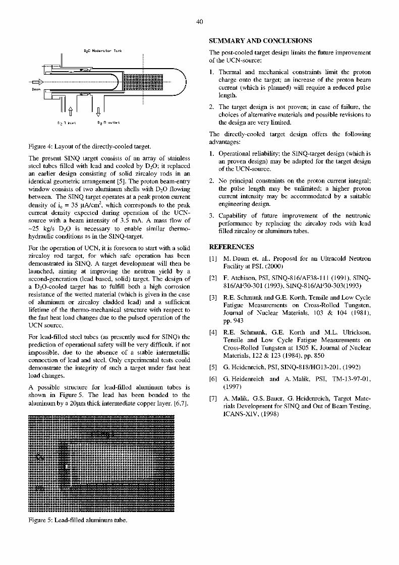
40
DgG M o d e r a t o r T o n k
D 2 n i n l e t D 2 n o u t l e t
Figure 4: Layout of the directly-cooled target.
The present SINQ target consists of an array of stainless steel tubes filled with lead and cooled by D 2 0 ; it replaced an earlier design consisting of solid zircaloy rods in an identical geometric arrangement [5]. The proton beam-entry window consists of two aluminum shells with D 2 0 flowing between. The SINQ target operates at a peak proton current density of i 0 = 35 uA/cm 2, which corresponds to the peak current density expected during operation of the UCN-source with a beam intensity of 3.5 mA. A mass flow of -25 kg/s D 2 0 is necessary to enable similar thermo-hydraulic conditions as in the SINQ-target.
For the operation of UCN, it is foreseen to start with a solid zircaloy rod target, for which safe operation has been demonstrated in SINQ. A target development will then be launched, aiming at improving the neutron yield by a second-generation (lead based, solid) target. The design of a D 2 0-cooled target has to fulfill both a high corrosion resistance of the wetted material (which is given in the case of aluminum or zircaloy cladded lead) and a sufficient lifetime of the thermo-mechanical structure with respect to the fast heat load changes due to the pulsed operation of the UCN source.
For lead-filled steel tubes (as presently used for SINQ) the prediction of operational safety will be very difficult, if not impossible, due to the absence of a stable intermetallic connection of lead and steel. Only experimental tests could demonstrate the integrity of such a target under fast heat load changes.
A possible structure for lead-filled aluminum tubes is shown in Figure 5. The lead has been bonded to the aluminum by a 20um thick intermediate copper layer. [6,7].
.HlHg3
SUMMARY AND CONCLUSIONS
Figure 5: Lead-filled aluminum tube.
The post-cooled target design limits the future improvement of the UCN-source:
1. Thermal and mechanical constraints limit the proton charge onto the target; an increase of the proton beam current (which is planned) will require a reduced pulse length.
2. The target design is not proven; in case of failure, the choices of alternative materials and possible revisions to the design are very limited.
The directly-cooled target design offers the following advantages:
1. Operational reliability; the SINQ-target design (which is an proven design) may be adapted for the target design of the UCN-source.
2. No principal constraints on the proton current integral; the pulse length may be unlimited; a higher proton current intensity may be accommodated by a suitable engineering design.
3. Capability of future improvement of the neutronic performance by replacing the zircaloy rods with lead filled zircaloy or aluminum tubes.
REFERENCES
[1] M. Daum et. al., Proposal for an Ultracold Neutron Facility at PSI, (2000)
[2] F. Atchison, PSI, SINQ-816/AF38-111 (1991), SINQ-816/AF30-301 (1993), SINQ-816/AF30-303(1993)
[3] R.E. Schmunk and G.E. Korth, Tensile and Low Cycle Fatigue Measurements on Cross-Rolled Tungsten, Journal of Nuclear Materials, 103 & 104 (1981), pp. 943
[4] R.E. Schmunk, G.E. Korth and M.L. Ulrickson, Tensile and Low Cycle Fatigue Measurements on Cross-Rolled Tungsten at 1505 K, Journal of Nuclear Materials, 122 & 123 (1984), pp. 850
[5] G. Heidenreich, PSI, SINQ-818/HG13-201, (1992)
[6] G. Heidenreich and A. Malik, PSI, TM-13-97-01, (1997)
[7] A. Malik, G.S. Bauer, G. Heidenreich, Target Materials Development for SINQ and Out of Beam Testing, ICANS-XIV, (1998)
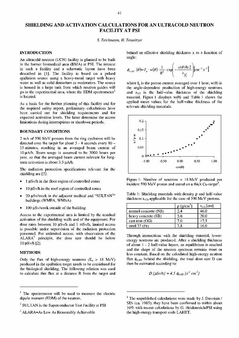
41
SHIELDING AND ACTIVATION CALCULATIONS FOR AN ULTRACOLD NEUTRON FACILITY AT PSI
S. Teichmann, H. Temnitzer
INTRODUCTION
An ultracold neutron (UCN) facility is planned to be built in the former biomedical area (BMA) at PSI. The interest in such a facility and a schematic layout have been described in [1]. The facility is based on a pulsed spallation source using a heavy-metal target with heavy water as well as solid deuterium as moderators. The source is housed in a large tank from which neutron guides will go to the experimental area, where the EDM spectrometer1
is located.
As a basis for the further planning of this facility and for the required safety report, preliminary calculations have been carried out for shielding requirements and for expected activation levels. The latter determine the access limitations during interruptions or shutdown periods.
BOUNDARY CONDITIONS
2 mA of 590 MeV protons from the ring cyclotron will be directed onto the target for about 3 - 4 seconds every 10 -15 minutes, resulting in an averaged beam current of 10 \iA/h. Beam usage is assumed to be 3000 hours per year, so that the averaged beam current relevant for long-term activation is about 3.5 nA/h.
The radiation protection specifications relevant for the shielding are [2]:
• 1 irSv/h in the floor region of controlled zones
• 10 irSv/h in the roof region of controlled zones
• 20 nSv /week in the adjacent medical and "SULTAN2" buildings (WMFA, WMSA)
• 100 irSv/week outside of the building
Access to the experimental area is limited by the residual activation of the shielding walls and of the equipment. For dose rates between 10 irSv/h and 1 mSv/h, limited access is possible under supervision of the radiation protection personnel. For unlimited access, with observation of the ALARA 3 principle, the dose rate should be below 10 n S v / h [2].
METHODS
Only the flux of high-energy neutrons (En > 18 MeV) produced in the spallation target needs to be considered for the biological shielding. The following relation was used to calculate this flux at a distance R from the target and
behind an effective shielding thickness x as a function of angle:
t,HE ( 0 ) = V w ( 0 ) ~ . e x p K
í \ x(9)\n2
xy2
[cm ! J ' ]
where I p is the proton current averaged over 1 hour, w(0) is the angle-dependent production of high-energy neutrons and Xi/2 is the half-value thickness of the shielding material. Figure 1 displays w(0) and Table 1 shows the applied mean values for the half-value thickness of the relevant shielding materials.
Figure 1: Number of neutrons > 18 MeV produced per incident 590 MeV proton and sterad on a thick Cu-target4.
Table 1: Shielding materials with density p and half-value thickness x 1 / 2 , applicable for the case of 590 MeV protons.
P [g/cm3] xi /2 [cm] normal concrete (NB) 2.4 46.0 heavy concrete (SB) 5.6 20.0 cast iron (GG) 7.0 17.5 steel 37 (Fe) 7.8 16.0
Through interactions with the shielding material, lower-energy neutrons are produced. After a shielding thickness of about 1 - 2 half-value layers, an equilibrium is reached and the shape of the neutron spectrum remains more or less constant. Based on the calculated high-energy neutron flux <|)n>HE behind the shielding, the total dose rate D can then be estimated according to:
D [fjSv/h] = 4.5 <t>n,HE [s1 cm'2]
1 The spectrometer will be used to measure the electric dipole moment (EDM) of the neutron. 2 SULTAN is the Superconductor Test Facility at PSI 3 ALARA=As Low As Reasonably Achievable
4 The unpublished calculations were made by J. Duvoisin / SIN (ca. 1985); they have been confirmed to within about 10% with recent calculations by G. Heidenreich/PSI using the high-energy transport code LAHET.

42
where the factor of 4.5 includes the following contributions:
• the dose rate due to neutrons below 18 MeV, assumed to be about equal to the dose rate from high-energy neutrons (resulting in a factor of 2)
• the dose rate due to photons, assumed to correspond to 25% of the total neutron dose (giving a factor of 1.25)
• a flux-to-dose conversion factor of 500 pSv cm 2
• the conversion from seconds to hours
This approach has been used at PSI in the past and was seen to give conservative results. It is based on references [3] and [4].
Estimates for the dose rate related to residual activation are based on extrapolations of mostly unpublished results of various measurements at PSI. More details can be found in [5].
RESULTS
Figures 2 and 3 show the proposed shielding design with hrniting dose-rate values according to the radiation protection specifications.
<10 u S v / h )
(1 u S v / h )
Figure 2: Sectional view of the target region (Wo=week).
Figure 3 also shows selected locations in the target and in the experimental area, labelled 1 - 8, for which activation levels were estimated. The corresponding expected dose rates, with an uncertainty factor of 2 - 3 , are listed in Table 2.
More detailed results and considerations on additional safety-relevant aspects can be found in [5].
(20 nSv/Wo) 0 m 5
Figure 3: Sectional view at beam height (Wo=week).
Table 2: Dose-rate estimates in units of [iSv/h due to residual activation after 1 year of operation and for different cooling times tc. The locations are shown in Figure 3.
location tc= 2 mo tc= 10 d tc= 1 d tc = 2h
1 81'000 150'000
2 16'000 30'000
3 1.5 1.5 9 24
4 4 7 13 57
5 9 15 21 115
6 1 2 3 15
7 0.1 1.7
8 0.04 0.6
REFERENCES
[1] F. Atchison et. al., An ultracold neutron facility at PSI, PSI Scientific Report, Volume I (Particles and Matter), 2000, 27
[2] Richtlinien für den überwachten Bereich der Kernanlagen und des Paul Scherrer Instituts, HSK-R-07/d, Juni 1995
[3] G. Hauswirth: Activation et debits de dose; SIN AN 10-74, Juli 1972
[4] Engineering Compendium of Radiation Shielding, Volume III Shield Design and Engineering; ed. R.G. Jaeger, 1970
[5] H. Temnitzer, S. Teichmann; Berechnungen der Abschirmung und Aktivierung im geplanten UCN-Areal, PSI TM-86-01-01, 2001
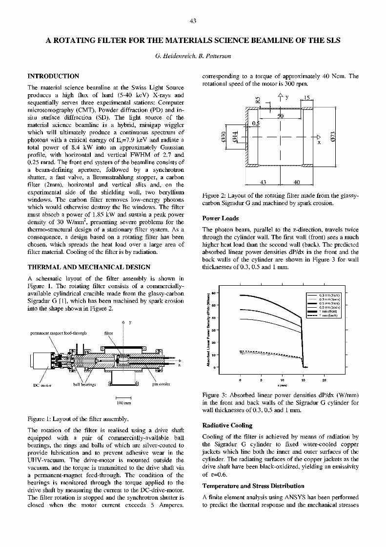
43
A ROTATING FILTER FOR THE MATERIALS SCIENCE BEAMLINE OF THE SLS
G. Heidenreich, B. Patterson
INTRODUCTION
The material science beamline at the Swiss Light Source produces a high flux of hard (5-40 keV) X-rays and sequentially serves three experimental stations: Computer microtomography (CMT), Powder diffraction (PD) and in-situ surface diffraction (SD). The light source of the material science beamline is a hybrid, minigap wiggler which will ultimately produce a continuous spectrum of photons with a critical energy of E c=7.9 keV and radiate a total power of 8.4 kW into an approximately Gaussian profile, with horizontal and vertical FWHM of 2.7 and 0.25 mrad. The front end system of the beamline consists of a beam-defining aperture, followed by a synchrotron shutter, a fast valve, a Bremsstrahlung stopper, a carbon filter (2mm), horizontal and vertical slits and, on the experimental side of the shielding wall, two beryllium windows. The carbon filter removes low-energy photons which would otherwise destroy the Be windows. The filter must absorb a power of 1.85 kW and sustain a peak power density of 30 W/mm2, presenting severe problems for the thermo-structural design of a stationary filter system. As a consequence, a design based on a rotating filter has been chosen, which spreads the heat load over a large area of filter material. Cooling of the filter is by radiation.
THERMAL AND MECHANICAL DESIGN
A schematic layout of the filter assembly is shown in Figure 1. The rotating filter consists of a commercially-available cylindrical crucible made from the glassy-carbon Sigradur G [1], which has been machined by spark erosion into the shape shown in Figure 2.
permanent magnet feed-through
DC-motor ball bearings % ij3 pin cooler
I 1 100 mm
Figure 1: Layout of the filter assembly.
The rotation of the filter is realised using a drive shaft equipped with a pair of commercially-available ball bearings, the rings and balls of which are silver-coated to provide lubrication and to prevent adhesive wear in the UHV-vacuum. The drive-motor is mounted outside the vacuum, and the torque is transmitted to the drive shaft via a permanent-magnet feed-through. The condition of the bearings is monitored through the torque applied to the drive shaft by measuring the current to the DC-drive-motor. The filter rotation is stopped and the synchrotron shutter is closed when the motor current exceeds 5 Amperes,
corresponding to a torque of approximately 40 Ncm. The rotational speed of the motor is 300 rpm.
o O Ol
0,5 5b
15_
43 40
x er,
Figure 2: Layout of the rotating filter made from the glassy-carbon Sigradur G and machined by spark erosion.
Power Loads
The photon beam, parallel to the z-direction, travels twice through the cylinder wall. The first wall (front) sees a much higher heat load than the second wall (back). The predicted absorbed linear power densities dP/dx in the front and the back walls of the cylinder are shown in Figure 3 for wall thicknesses of 0.3,0.5 and 1 mm.
Figure 3: Absorbed linear power densities dP/dx (W/mm) in the front and back walls of the Sigradur G cylinder for wall thicknesses of 0.3,0.5 and 1 mm.
Radiative Cooling
Cooling of the filter is achieved by means of radiation by the Sigradur G cylinder to fixed water-cooled copper jackets which line both the inner and outer surfaces of the cylinder. The radiating surfaces of the copper jackets as the drive shaft have been black-oxidized, yielding an emissivity of e=0.6.
Temperature and Stress Distribution
A finite element analysis using ANSYS has been performed to predict the thermal response and the mechanical stresses
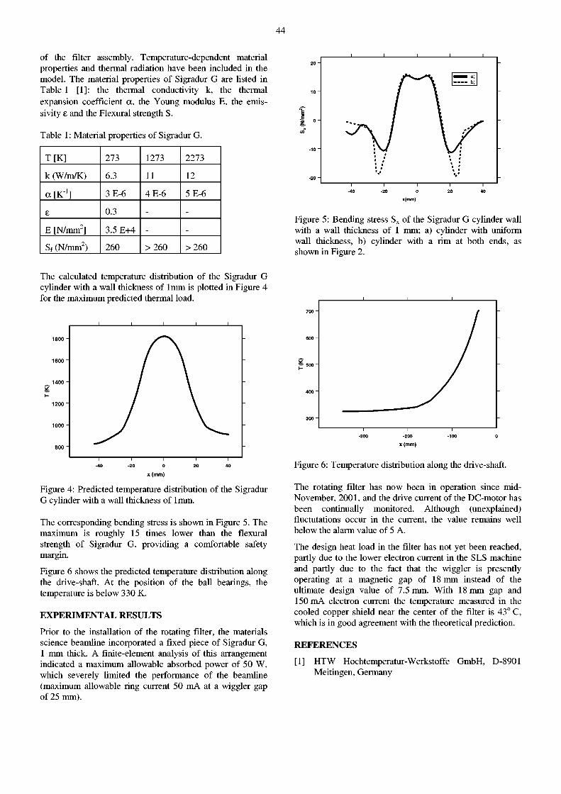
44
of the filter assembly. Temperature-dependent material properties and thermal radiation have been included in the model. The material properties of Sigradur G are listed in Table 1 [1]: the thermal conductivity k, the thermal expansion coefficient a, the Young modulus E, the emis-sivity e and the Flexural strength S.
Table 1 : Material properties of Sigradur G.
T[K] 273 1273 2273
k (W/m/K) 6.3 11 12
a [K"1] 3 E-6 4 E-6 5 E-6
£ 0.3 - -
E [N/mm2] 3.5 E+4 _ _
S f (N/mm2) 260 > 2 6 0 > 2 6 0
Figure 5: Bending stress S x of the Sigradur G cylinder wall with a wall thickness of 1 mm; a) cylinder with uniform wall thickness, b) cylinder with a rim at both ends, as shown in Figure 2.
The calculated temperature distribution of the Sigradur G cylinder with a wall thickness of 1mm is plotted in Figure 4 for the maximum predicted thermal load.
x (mm)
Figure 4: Predicted temperature distribution of the Sigradur G cylinder with a wall thickness of 1mm.
The corresponding bending stress is shown in Figure 5. The maximum is roughly 15 times lower than the flexural strength of Sigradur G, providing a comfortable safety margin.
Figure 6 shows the predicted temperature distribution along the drive-shaft. At the position of the ball bearings, the temperature is below 330 K.
EXPERIMENTAL RESULTS
Prior to the installation of the rotating filter, the materials science beamline incorporated a fixed piece of Sigradur G, 1 mm thick. A finite-element analysis of this arrangement indicated a maximum allowable absorbed power of 50 W, which severely limited the performance of the beamline (maximum allowable ring current 50 mA at a wiggler gap of 25 mm).
-300 -200 -100 0
x(mm)
Figure 6: Temperature distribution along the drive-shaft.
The rotating filter has now been in operation since mid-November, 2001, and the drive current of the DC-motor has been continually monitored. Although (unexplained) fluctutations occur in the current, the value remains well below the alarm value of 5 A.
The design heat load in the filter has not yet been reached, partly due to the lower electron current in the SLS machine and partly due to the fact that the wiggler is presently operating at a magnetic gap of 18 mm instead of the ultimate design value of 7.5 mm. With 18 mm gap and 150 mA electron current the temperature measured in the cooled copper shield near the center of the filter is 43° C, which is in good agreement with the theoretical prediction.
REFERENCES
[1] HTW Hochtemperatur-Werkstoffe GmbH, D-8901 Meitingen, Germany

45
Spallation Neutron Source

46
47
THE SPALLATION NEUTRON SOURCE DIVISION ASQ: AN OVERVIEW
In summer of 2001 the Spallation Neutron Source Division ASQ found Günter Bauer leaving to take over as director of the ESS project group at the FZ Jülich. Günter was the head of ASQ since the division was established in 1996. Under his guidance and responsibility ASQ accomplished the demanding task of a professional commissioning, a safe and reliable operation and an efficient development of the Neutron Spallation Source SINQ, obeying his self-given mission of 'Minimum Radiation Exposure to People, Maximum Fluence of Neutrons to Samples'. Before that, Günter in leading position was participating in the design and construction of SINQ. For the improvement on the neutron flux the target development program always was his most ambitious initiative, culminating in MEGAPIE, a project joining six European research institutions and JAERI (Japan), DOE (USA) and KAERI (Korea) to design, build, operate and explore a liquid lead-bismuth spallation target for 1 MW of beam power. This project, meanwhile approaching the end of the engineering design phase, and the associated activities required and still require major personal resources from PSI, in particular from ASQ. Thus, a major part of the ASQ team was kept busy in helping to realise this demanding task.
The management of PSI reacted with professional promptness to fill the personal gap which Günter left behind by the immediate nomination of the former deputy
and writer of these lines to the new head of the division. Furtheron, an encouraged regrouping of the MEGAPIE management took place, appointing Friedrich Gröschel as the technical project director and gaining Knud Thomsen to participate on the project directors' board as well. Thus, before the project was able to struggle it was brought back to course.
SINQ OPERATION
After the busy yet successful annual shut-down SINQ restarted its routine operation on May 9 t h and operated in a 'Swiss-clockwork' manner until the end of the year, following, with few exceptions, the availability of the proton beam by almost 100%. Figure 1 documents the splendid performance. With the Target 'E' of 4 cm length installed in the proton beamline, the average beam current on SINQ target was routinely 1250 uA (out of 1800 uA being delivered from the cyclotron). After October 24 t h
(week 43), a 6 cm thick Target 'E' was installed temporarily in order to achieve higher muon fluxes for MuSR experiments. This reduced the proton beam on SINQ to approximately 1000 uA for the rest of the year, thus reducing the neutron flux by about 25% and causing some displeasure in the neutron user community.
< E
oí i_
a
I
a> i_ 3 Ü
2 4 0 SINQ: Beam on Target 2 0 0 1
89 89 94 93 82 72 97 99 96 98 89 94 96 49 93 98 97 96 89 43 59 98 92 95 99 98 71 83 87 94 98
O Week o> O) l-
in
Figure 1: Charge history of SINQ in 2001. The total charge delivered to the target was 4.47 Ah. The numbers given above the bars give the overall reliability (in %) of the facility including the accelerator.
48
The present SINQ target (MARK 3), having been operated for two years without any serious indication of degradation or damage, and having accumulated a proton dose of little above 10 Ah during its life, will be removed and taken out of service in early 2002. As did the previous target (MARK 2), it accommodates about 1500 test samples and test rods. After their dismantling, they become investigated within the STIP-2 program in order to gain more information on the materials performance after having been exposed to the realistic target irradiation environment. Such investigations are recognised as the most important prerequisite for a reliable development of future targets and yield an indispensable R&D support for MEGAPIE. A new target of the same type is ready for installation, again instrumented with thermocouples and equipped with test samples. This target is scheduled to operate in 2002 and 2003.
SINQ DEVELOPMENT P R O J E C T S
LiSoR (Liquid metal - Solid metal .Reactions), an important experiment accompanying the MEGAPIE target development, in 2001 had been assembled at a test site in the OBLA-building at PSI. The commissioning and testing of the liquid metal lead-bismuth loop (without proton beam) have successfully been accomplished. Meanwhile, LiSoR is transferred to the irradiation position at the beamline of Injector 1. Figure 2 documents that no dispensable space is left over in the bunker. After the scheduled shutdown of the accelerator facility and after the final licensing and operation tests on site the irradiation program will start in June 2002. The initial irradiation program comprises samples of a 9Cr-lMo martensitic steel (T91), the most promising material to be used for the liquid metal enclosure hull of MEGAPIE. The general aim is to test whether the material's degradation effects, like liquid metal embrittlement, become enhanced by the combined load of stress and irradiation.
Figure 2: The LiSoR installation inside the bunker at a beamport position of Injector I (view through the open roof).
INSTRUMENTS AND USER OPERATION
The instrument for Small Angle Neutron Scattering (SANS) restarted operating in May 2001 after the accelerator shutdown, equipped with the new detector readout system developed at PSI. The detector now showing excellent
homogeneity and stability, the common opinion of the SANS crew and the users was, that this brought a quantum jump in the overall performance of the instrument.
The first scheduled experiment in 2001 was a challenge by still another reason: the new 11 Tesla cryomagnet had its 'maiden-trip' at the SANS facility with a proposal to investigate flux-line lattices in high-Tc superconductors. During preparatory tests, as documented in Figure 3, the experiment crew was obviously amused by the ability of rotating and tilting the giant device.
Figure 3: The new 11 Tesla magnet now available at the SINQ-SANS facility for high-field low-temperature experiments. The ability of tilting and rotating the magnet allows a very flexible alignment of the sample and field relative to the neutron beam.
After the long period of development the strain scanning instrument POLDI finally received its detector and at least a part of the readout electronics. This enabled first test measurements of the entirely assembled facility in the last week of beamtime in 2001. We expect the final commissioning and full operation in May 2002, immediately after the accelerator shutdown period.
Several proposals for beamtime at POLDI, approved by the SINQ Scientific Committee, are already queuing for access to the instrument.
One important and very special application of POLDI is the ability to handle highly radioactive samples, as already realized for the radiography station NEUTRA (called NEURAP), and as in the process of realization for SANS. Not only ASQ itself will profit from this option for the SINQ target development program, waiting to investigate irradiated target components. As well, the EU-financed project INTERWELD with the objective to investigate strains in the heat affected zone of welds in a reactor pressure vessel, is waiting for the committed beamtime.
The utilisation of neutron imaging with thermal and cold neutrons at the facilities NEUTRA and NCR was intensified with an extended user program by research
49
groups and industry. A workshop on neutron radiography held in May 2001 at PSI attracted about 80 participants. The most important improvement of the radiography facilities was the implementation of neutron tomography as a standard technique. This was successfully used for the non-destructive analysis of small and large technical objects like the sprinkler nozzle shown in Fig. 4. Other techniques like laminography and auto-radiography using imaging plates were tested successfully. The main development project at present concentrates on real-time imaging.
Foundation, the EC- program-TMR, and the TOPNAN021 program of the ETH board.
The group was also main organiser of an international workshop "Structure and Mechanical Properties of Nanostructured Materials: Promoting a Synergy Among Computer Simulations, Experiments and Theory" held in Barga, Italy, June 3-8, 2001. This workshop was financed by the United Engineering Foundation (USA) and COST 523-action on nanostructured materials.
The project THERMETCOAT: 'Development of optimised, thermally sprayed metallic deposits using novel level of microstructure control', a EUREKA/KTI financed project joining six partners from research and industry, came to its scheduled termination at the end of 2001. The application of SANS and MSANS (multiple SANS) to thermally sprayed metallic deposits is still continued within an ongoing PhD-work in ASQ.
Figure 4: Axial cut through the neutron tomography volume of a sprinkler nozzle for the non-destructive analysis of leak tightness. The rubber gasket in the nozzle plug can be clearly visualized.
SCIENCE
The most significant extension of the scientific activities of ASQ was spurred on in the group of 'Computer Modelling and Experiments'. The research is focussed on the structural and mechanical properties of nanocrystalline metals, and is approached by experiments and molecular dynamics computer simulations. A typical computer sample of nanocrystalline Ni, containing 15 grains with a mean grain size of 20 nm is given in Figure 5. The group complemented their research program with three new topics: the computer modelling of irradiation effects, the modelling of nano-indentation and the in-situ tensile testing of nano- and near-nano materials at the Materials Science Beamline of SLS. For the latter, a new miniaturized tensile machine is in preparation and will be installed to serve for in-situ diffraction analysis during tensile tests. The research programs are financed by the Swiss National Science
Figure 5: A typical computer sample of nanocrystalline Ni containing 15 grains with a mean gran size of 20 nm, in total 6 Million atoms. The dark-shaped dots are atoms in grain boundaries.
Dr. Werner Wagner Head of Division
50
FROM THE KANTONSSCHULE TO THE MEGAPIE PROJECT
K. Thomsen
In the spring of 2001 a first sabbatical has taken place. A teacher from the Alte Kantonsschule in Aarau and the author exchanged their place for three months.
INITIATIVE
Following an idea of Ralph Eichler and several teachers PSI offers a "sabbatical" for science teachers at the level of Kantonsschule. The aim is to give teachers a chance to immerge for some time in a scientific environment and thereby rejuvenate. Refreshed enthusiasm for science should then enable the teacher to transfer some of it to his/her students. In order to see how that could work out in practice a prototype sabbatical has been run in spring 2001. To keep administrative loads at a minimum, for a first case of precedence the physics teacher from the Alte Kantonsschule in Aarau who came to the PSI Laboratory for Astrophysics was simply replaced by a PSI physicist.
RESULTS
The teacher did some very useful modelling studies. Real astrophysical data on stars were available from XMM_RGS (to which PSI had contributed some major hardware components). He enjoyed his stay at PSI a lot. The replacement teacher did his best to show how physics relates to "real life" as wished by the students. The poor students, as an example, were told to take the elevator down from to the 6 t h floor to the basement and come back walking or running, depending on what type of shoes they wore, - all in the hope that they would "feel" the difference
between the basic concepts of work and power. The exchange was also a challenge and a most interesting task for someone who long ago wanted to become a teacher, offering some never-dreamt-of insight into the Swiss school system. Almost everybody involved or affected appreciated the effort in general and found the idea of a sabbatical worth of support. Two students got so much interested in physics that they volunteered to program the web-pages for the MEGAPIE project during their special course in WWW programming.
PERSPECTIVE
As all parties were happy with the first attempt, the next step must be to find a form in which a sabbatical at PSI can be established as a standard offer to science teachers in Aargau. It would be a pity if administrative or budgetary obstacles could prevent future sabbaticals and exchanges.
REFERENCE
[1] R. Eichler, R. Wehrli, K. Thomsen, Sabbatical für Kantonsschullehrer am PSI, Ein Pilotversuch am Labor für Astrophysik, PSI Bericht Nr. 01-06, Juni 2001
Figure 1 : A class of interested students. The one in the second row, third from right, now works on the MEGAPIE homepage.
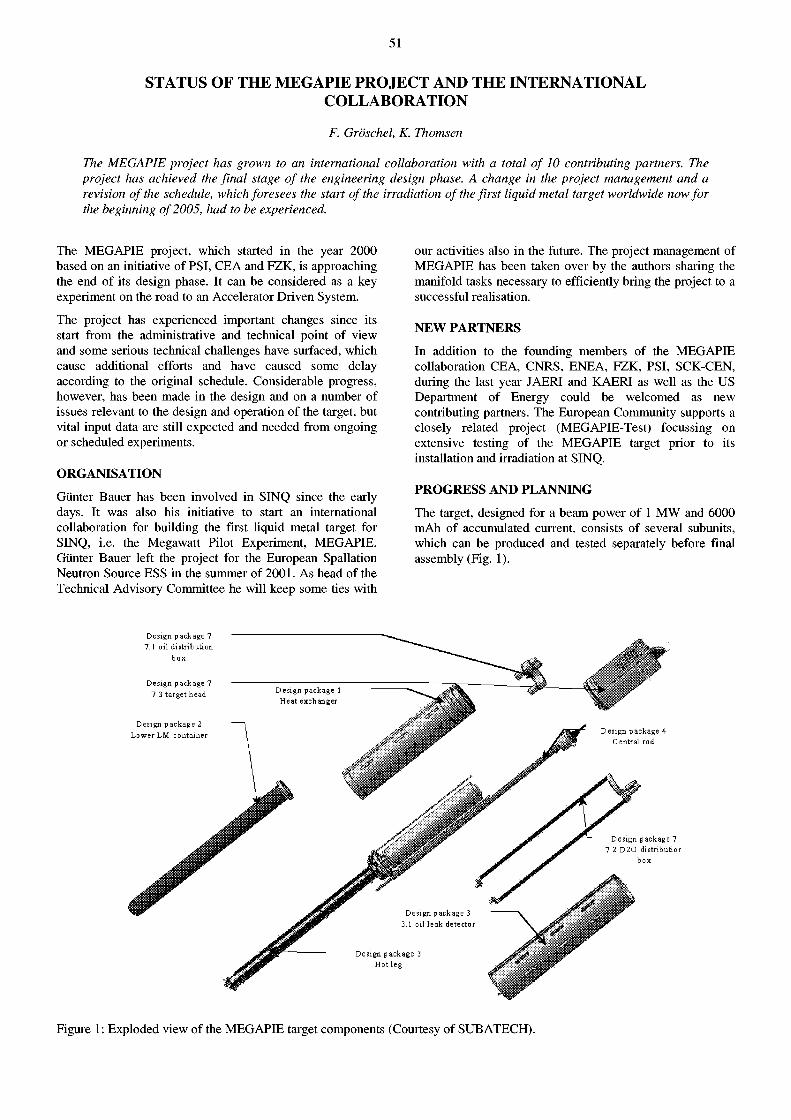
51
STATUS OF THE MEGAPIE PROJECT AND THE INTERNATIONAL COLLABORATION
F. Gröschel, K. Thomsen
The MEGAPIE project has grown to an international collaboration with a total of 10 contributing partners. The project has achieved the final stage of the engineering design phase. A change in the project management and a revision of the schedule, which foresees the start of the irradiation of the first liquid metal target worldwide now for the beginning of 2005, had to be experienced.
The MEGAPIE project, which started in the year 2000 based on an initiative of PSI, CEA and FZK, is approaching the end of its design phase. It can be considered as a key experiment on the road to an Accelerator Driven System.
The project has experienced important changes since its start from the administrative and technical point of view and some serious technical challenges have surfaced, which cause additional efforts and have caused some delay according to the original schedule. Considerable progress, however, has been made in the design and on a number of issues relevant to the design and operation of the target, but vital input data are still expected and needed from ongoing or scheduled experiments.
ORGANISATION
Günter Bauer has been involved in SINQ since the early days. It was also his initiative to start an international collaboration for building the first liquid metal target for SINQ, i.e. the Megawatt Pilot Experiment, MEGAPIE. Günter Bauer left the project for the European Spallation Neutron Source ESS in the summer of 2001. As head of the Technical Advisory Committee he will keep some ties with
our activities also in the future. The project management of MEGAPIE has been taken over by the authors sharing the manifold tasks necessary to efficiently bring the project to a successful realisation.
NEW PARTNERS
In addition to the founding members of the MEGAPIE collaboration CEA, CNRS, ENEA, FZK, PSI, SCK-CEN, during the last year JAERI and KAERI as well as the US Department of Energy could be welcomed as new contributing partners. The European Community supports a closely related project (MEGAPIE-Test) focussing on extensive testing of the MEGAPIE target prior to its installation and irradiation at SINQ.
PROGRESS AND PLANNING
The target, designed for a beam power of 1 MW and 6000 mAh of accumulated current, consists of several subunits, which can be produced and tested separately before final assembly (Fig. 1).
Figure 1 : Exploded view of the MEGAPIE target components (Courtesy of SUB ATECH).
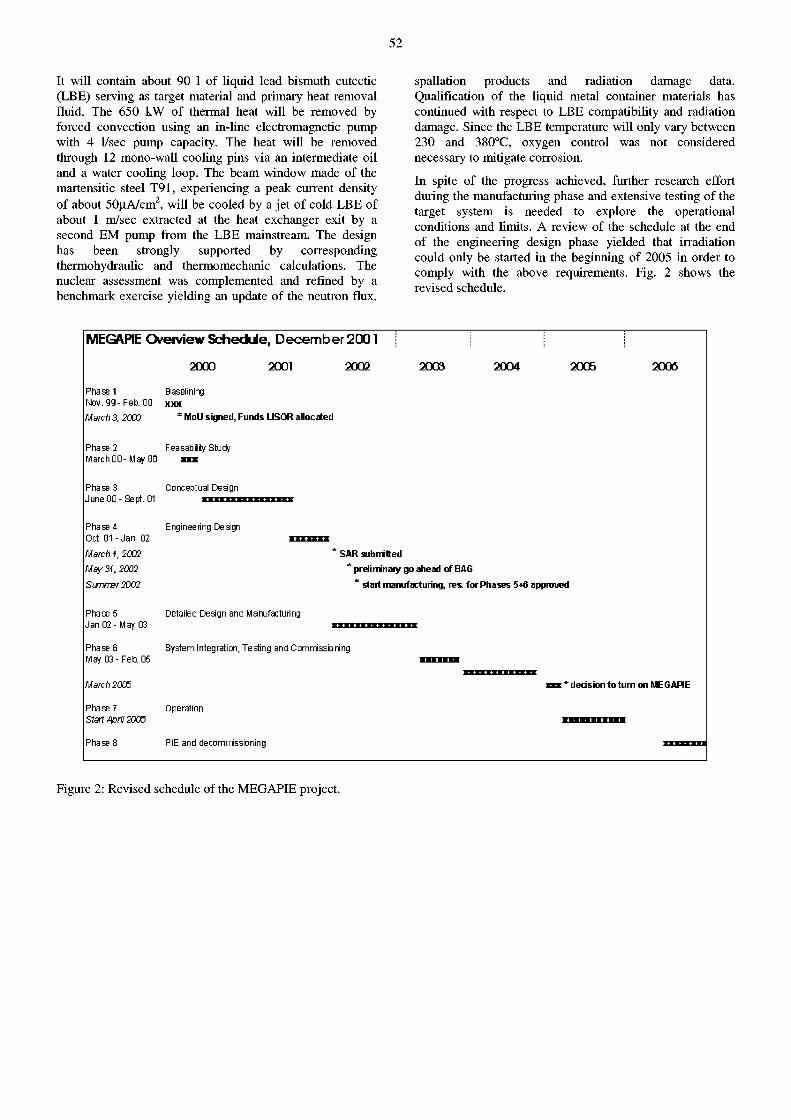
52
It will contain about 90 1 of liquid lead bismuth eutectic (LBE) serving as target material and primary heat removal fluid. The 650 kW of thermal heat will be removed by forced convection using an in-line electromagnetic pump with 4 1/sec pump capacity. The heat will be removed through 12 mono-wall cooling pins via an intermediate oil and a water cooling loop. The beam window made of the martensitic steel T91, experiencing a peak current density of about 50uA/cm 2, will be cooled by a jet of cold LBE of about 1 m/sec extracted at the heat exchanger exit by a second EM pump from the LBE mainstream. The design has been strongly supported by corresponding thermohydraulic and thermomechanic calculations. The nuclear assessment was complemented and refined by a benchmark exercise yielding an update of the neutron flux,
spallation products and radiation damage data. Qualification of the liquid metal container materials has continued with respect to LBE compatibility and radiation damage. Since the LBE temperature will only vary between 230 and 380°C, oxygen control was not considered necessary to mitigate corrosion.
In spite of the progress achieved, further research effort during the manufacturing phase and extensive testing of the target system is needed to explore the operational conditions and limits. A review of the schedule at the end of the engineering design phase yielded that irradiation could only be started in the beginning of 2005 in order to comply with the above requirements. Fig. 2 shows the revised schedule.
MEGAPIE O v e r v i e w S c h e d d e , D e c e m b e r 2 0 0 1
2000 2001 2002
Phase 1 Basel in ing Nov. 99-Feb. 00 xxx Match 5, 2000 * Moll signed, Funds LISOR allocated
Phase 2 Feasability Study March 00-May 00 m
Phase 3 Conceptual Design
June 00-Sept . 01 • • • • • • • • • • • « • • •
2009 2004 2005 2006
Phase 4
Oct. 01 - Jan. 02
March 1, 2002
May 31, 2002
Sumrrer2002
Phase 5 Jan 02- May 03
Phase 6
May 03-Feb. 05
M arch 2003
Phase 7 Start April 2005
Phase 8
Engineering Design
SAR submitted
* preliminary go ahead of BAG
* start manufacturing, res. for Phases 5̂ 6 approved
Detailed Design and Manufacturing
System Integration, Testing and Commissioning
Operation
PIE and decommissioning
'decision to turn on MEGAPIE
Figure 2: Revised schedule of the MEGAPIE project.
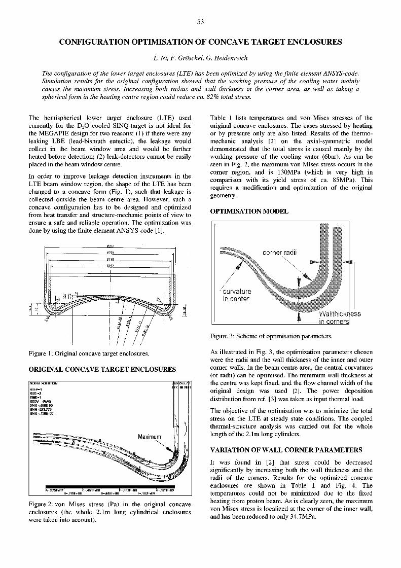
53
CONFIGURATION OPTIMISATION OF CONCAVE TARGET ENCLOSURES
L. Ni, F. Gröschel, G. Heidenreich
The configuration of the lower target enclosures (LTE) has been optimized by using the finite element ANSYS-code. Simulation results for the original configuration showed that the working pressure of the cooling water mainly causes the maximum stress. Increasing both radius and wall thickness in the corner area, as well as taking a spherical form in the heating centre region could reduce ca. 82% total stress.
The hemispherical lower target enclosure (LTE) used currently for the D 2 0 cooled SINQ-target is not ideal for the MEGAPIE design for two reasons: (1) if there were any leaking LBE (lead-bismuth eutectic), the leakage would collect in the beam window area and would be further heated before detection; (2) leak-detectors cannot be easily placed in the beam window centre.
In order to improve leakage detection instruments in the LTE beam window region, the shape of the LTE has been changed to a concave form (Fig. 1), such that leakage is collected outside the beam centre area. However, such a concave configuration has to be designed and optimized from heat transfer and structure-mechanic points of view to ensure a safe and reliable operation. The optimization was done by using the finite element ANSYS-code [1].
Figure 1 : Original concave target enclosures.
ORIGINAL CONCAVE TARGET ENCLOSURES
fl-.925E*07 OASXM ^.B33E*08 G-.120E*09 B-.27BE*08 D-.64SEi0e F-102EiO9
Figure 2: von Mises stress (Pa) in the original concave enclosures (the whole 2.1m long cylindrical enclosures were taken into account).
Table 1 lists temperatures and von Mises stresses of the original concave enclosures. The cases stressed by heating or by pressure only are also listed. Results of the fhermo-mechanic analysis [2] on the axial-symmetric model demonstrated that the total stress is caused mainly by the working pressure of the cooling water (6bar). As can be seen in Fig. 2, the maximum von Mises stress occurs in the corner region, and is 130MPa (which is very high in comparison with its yield stress of ca. 85MPa). This requires a modification and optimization of the original geometry.
OPTIMISATION M O D E L
corner radii
curva in cer
¥ vsi im nun -in co rne r s l
Figure 3: Scheme of optimisation parameters.
As illustrated in Fig. 3, the optimization parameters chosen were the radii and the wall thickness of the inner and outer corner walls. In the beam centre area, the central curvatures (or radii) can be optimised. The minimum wall thickness at the centre was kept fixed, and the flow channel width of the original design was used [2]. The power deposition distribution from ref. [3] was taken as input thermal load.
The objective of the optimisation was to minimize the total stress on the LTE at steady state conditions. The coupled thermal-structure analysis was carried out for the whole length of the 2.1m long cylinders.
VARIATION O F WALL CORNER PARAMETERS
It was found in [2] that stress could be decreased significantly by increasing both the wall thickness and the radii of the corners. Results for the optimized concave enclosures are shown in Table 1 and Fig. 4. The temperatures could not be minimized due to the fixed heating from proton beam. As is clearly seen, the maximum von Mises stress is localized at the corner of the inner wall, and has been reduced to only 34.7MPa.
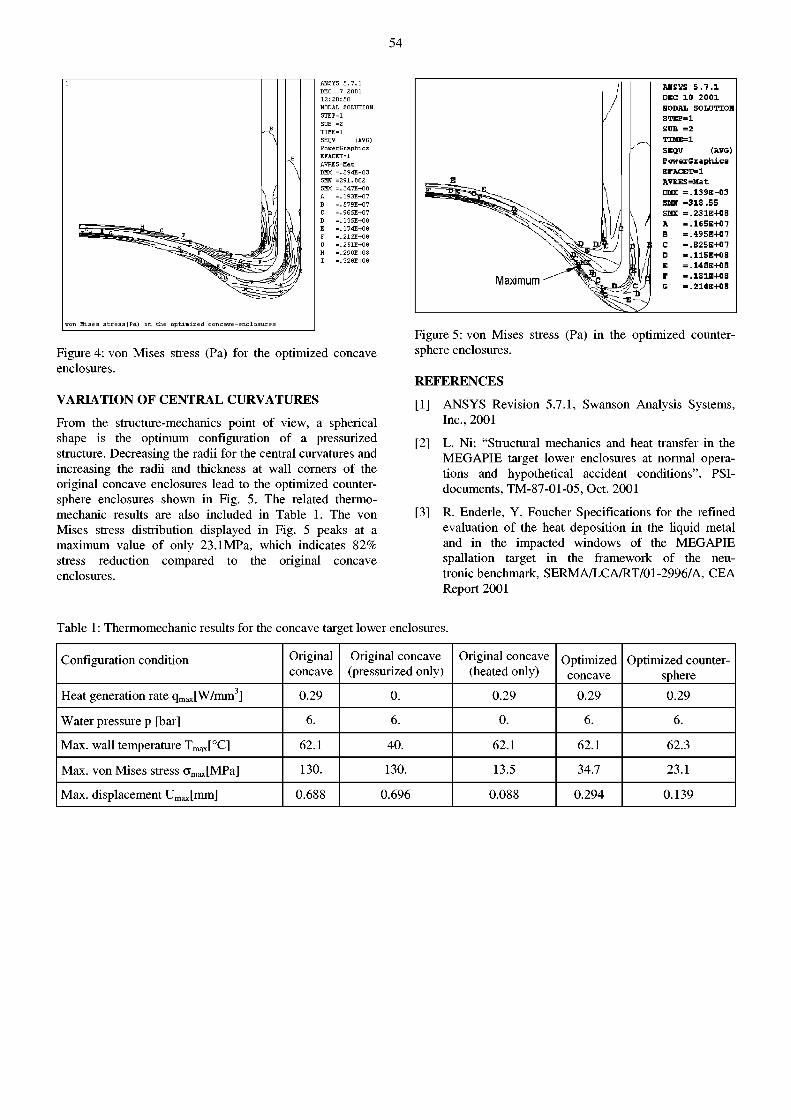
54
ANSYS 5 . 7 . 1 DEC 7 2 0 0 1 1 2 : 2 0 : 5 0 NODAL SOLUTION S T E P = 1 SUB =2 T I H E = 1 SEOV (AVG) P o w e c G E a p h i c s EFACET=1 AVFES=Mac DHX = . 2 9 4 E - 0 3
= 2 9 1 . 0 0 2 = . 3 4 7 E + 0 8 . . 1 9 3 E + 0 7 = . 5 7 9 E + 0 7 = . 9 6 5 E + 0 7 = . 1 3 5 E + 0 8 = . 1 7 4 E + 0 8 . . 2 1 2 E + 0 8 = . 2 5 1 E + 0 8 = . 2 9 0 E + 0 8 = . 3 2 8 E + 0 8
SHN = SHX :
Figure 4: von Mises stress (Pa) for the optimized concave enclosures.
VARIATION O F CENTRAL CURVATURES
From the structure-mechanics point of view, a spherical shape is the optimum configuration of a pressurized structure. Decreasing the radii for the central curvatures and increasing the radii and thickness at wall corners of the original concave enclosures lead to the optimized counter-sphere enclosures shown in Fig. 5. The related thermo-mechanic results are also included in Table 1. The von Mises stress distribution displayed in Fig. 5 peaks at a maximum value of only 23.1MPa, which indicates 82% stress reduction compared to the original concave enclosures.
ABSXS 5 . 7 . 1 DEC 10 2 0 0 1 NODAL SOLUTION STEP=1 SUB =2 THffE=l SEQV (AVG) EowexGxaphics EFACET=1 AVRES=Mat DMX = . 1 3 9 E - 0 3 SUN =318.55 SHX = .231E+0S A = . l « 5 E + 0 7
= .4S5B+07 = .825E+07 « .115E+0B = . 1 4 8 E + 0 8 - . 1 S 1 E + 0 8 = .214E+0S
Figure 5: von Mises stress (Pa) in the optimized counter-sphere enclosures.
REFERENCES
[1] ANSYS Revision 5.7.1, Swanson Analysis Systems, Inc., 2001
[2] L. Ni: "Structural mechanics and heat transfer in the MEGAPIE target lower enclosures at normal operations and hypothetical accident conditions", PSI-documents, TM-87-01-05, Oct. 2001
[3] R. Enderle, Y. Foucher Specifications for the refined evaluation of the heat deposition in the liquid metal and in the impacted windows of the MEGAPIE spallation target in the framework of the neu-tronic benchmark, SERMA/LCA/RT/01-2996/A, CEA Report 2001
Table 1: Thermomechanic results for the concave target lower enclosures.
Configuration condition Original concave
Original concave (pressurized only)
Original concave (heated only)
Optimized concave
Optimized counter-sphere
Heat generation rate qm a x[W/mm 3] 0.29 0. 0.29 0.29 0.29
Water pressure p [bar] 6. 6. 0. 6. 6.
Max. wall temperature T m a x [°C] 62.1 40. 62.1 62.1 62.3
Max. von Mises stress a m a x [MPa] 130. 130. 13.5 34.7 23.1
Max. displacement U m a x [mm] 0.688 0.696 0.088 0.294 0.139
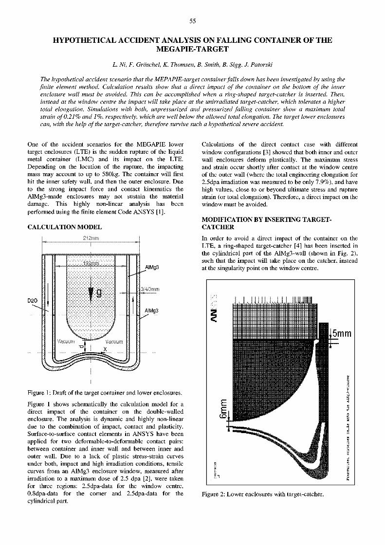
55
HYPOTHETICAL ACCIDENT ANALYSIS ON FALLING CONTAINER OF THE MEGAPIE-TARGET
L. Ni, F. Gröschel, K. Thomsen, B. Smith, B. Sigg. J. Patorski
The hypothetical accident scenario that the MEPAPIE-target container falls down has been investigated by using the finite element method. Calculation results show that a direct impact of the container on the bottom of the inner enclosure wall must be avoided. This can be accomplished when a ring-shaped target-catcher is inserted. Then, instead at the window centre the impact will take place at the unirradiated target-catcher, which tolerates a higher total elongation. Simulations with both, unpressurized and pressurized falling container show a maximum total strain of 0.21% and 1%, respectively, which are well below the allowed total elongation. The target lower enclosures can, with the help of the target-catcher, therefore survive such a hypothetical severe accident.
One of the accident scenarios for the MEGAPIE lower target enclosures (LTE) is the sudden rupture of the liquid metal container (LMC) and its impact on the LTE. Depending on the location of the rupture, the impacting mass may account to up to 580kg. The container will first hit the inner safety wall, and then the outer enclosure. Due to the strong impact force and contact kinematics the AlMg3-made enclosures may not sustain the material damage. This highly non-linear analysis has been performed using the finite element Code ANS YS [1] .
CALCULATION M O D E L
212mm
Figure 1 : Draft of the target container and lower enclosures.
Figure 1 shows schematically the calculation model for a direct impact of the container on the double-walled enclosure. The analysis is dynamic and highly non-linear due to the combination of impact, contact and plasticity. Surface-to-surface contact elements in ANSYS have been applied for two deformable-to-deformable contact pairs: between container and inner wall and between inner and outer wall. Due to a lack of plastic stress-strain curves under both, impact and high irradiation conditions, tensile curves from an AlMg3 enclosure window, measured after irradiation to a maximum dose of 2.5 dpa [2], were taken for three regions: 2.5dpa-data for the window centre, 0.8dpa-data for the corner and 2.5dpa-data for the cylindrical part.
Calculations of the direct contact case with different window configurations [3] showed that both inner and outer wall enclosures deform plastically. The maximum stress and strain occur shortly after contact at the window centre of the outer wall (where the total engineering elongation for 2.5dpa irradiation was measured to be only 7.9%), and have high values, close to or beyond ultimate stress and rupture strain (or total elongation). Therefore, a direct impact on the window must be avoided.
MODIFICATION BY INSERTING TARGET-CATCHER
In order to avoid a direct impact of the container on the LTE, a ring-shaped target-catcher [4] has been inserted in the cylindrical part of the AlMg3-wall (shown in Fig. 2), such that the impact will take place on the catcher, instead at the singularity point on the window centre.
Figure 2: Lower enclosures with target-catcher.
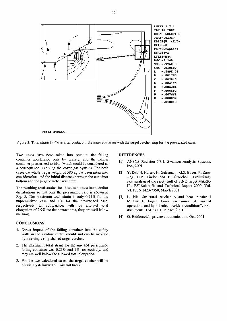
56
A H S Y S 5 . 7 . 1 J A N I S 2 0 0 2 NODAL S O L U T I O N T I M E = . 0 1 3 4 7 E F T O E Q V ( A V G ) E f f H u = 0 P o w e r G r a p h i c s E F A C E T = 1 A V R E S = M a t DMX = 5 . 2 4 9
. 9 7 6 E - 0 8
. 0 1 0 6 0 7
. 5 8 9 E - 0 3
. 0 0 1 7 6 8
. 0 0 2 9 4 6
. 0 0 4 1 2 5
. 0 0 5 3 0 4
. 0 0 6 4 8 2
. 0 0 7 6 6 1
. 0 0 8 8 3 9
. 0 1 0 0 1 8
SMH SMX A
Figure 3: Total strain 13.47ms after contact of the inner container with the target catcher ring for the pressurized case.
Two cases have been taken into account: the falling container accelerated only by gravity, and the failing container pressurized to 6bar (which could be considered as a consequence involving the cover gas system). For both cases the whole target weight of 580 kg has been taken into consideration, and the initial distance between the container bottom and the target-catcher was 5mm.
The resulting total strains for these two cases have similar distributions so that only the pressurized case is shown in Fig. 3. The maximum total strain is only 0.21% for the unpressurized case and 1% for the pressurized case, respectively. In comparison with the allowed total elongation of 7.9% for the contact area, they are well below the limit.
CONCLUSIONS
1. Direct impact of the falling container into the safety walls in the window centre should and can be avoided by inserting a ring-shaped target-catcher.
2. The maximum total strain for the un- and pressurized falling container was 0.21% and 1%, respectively, and they are well below the allowed total elongation.
3. For the two calculated cases, the target-catcher will be plastically deformed but will not break.
REFERENCES
[1] ANSYS Revision 5.7.1, Swanson Analysis Systems, Inc., 2001
[2] Y. Dai, H. Kaiser, K. Geissmann, G.S. Bauer, R. Zum-steg, H.P. Linder and F. Gröschel: ..Preliminary examination of the safety hull of SINQ target MARK-II", PSI-Scientific and Technical Report 2000, Vol. VI, ISSN 1423-7350, March 2001
[3] L. Ni: "Structural mechanics and heat transfer I MEGAPIE target lower enclosures at normal operations and hypothetical accident conditions", PSI-documents, TM-87-01-05, Oct. 2001
[4] G. Heidenreich, private communication, Oct. 2001
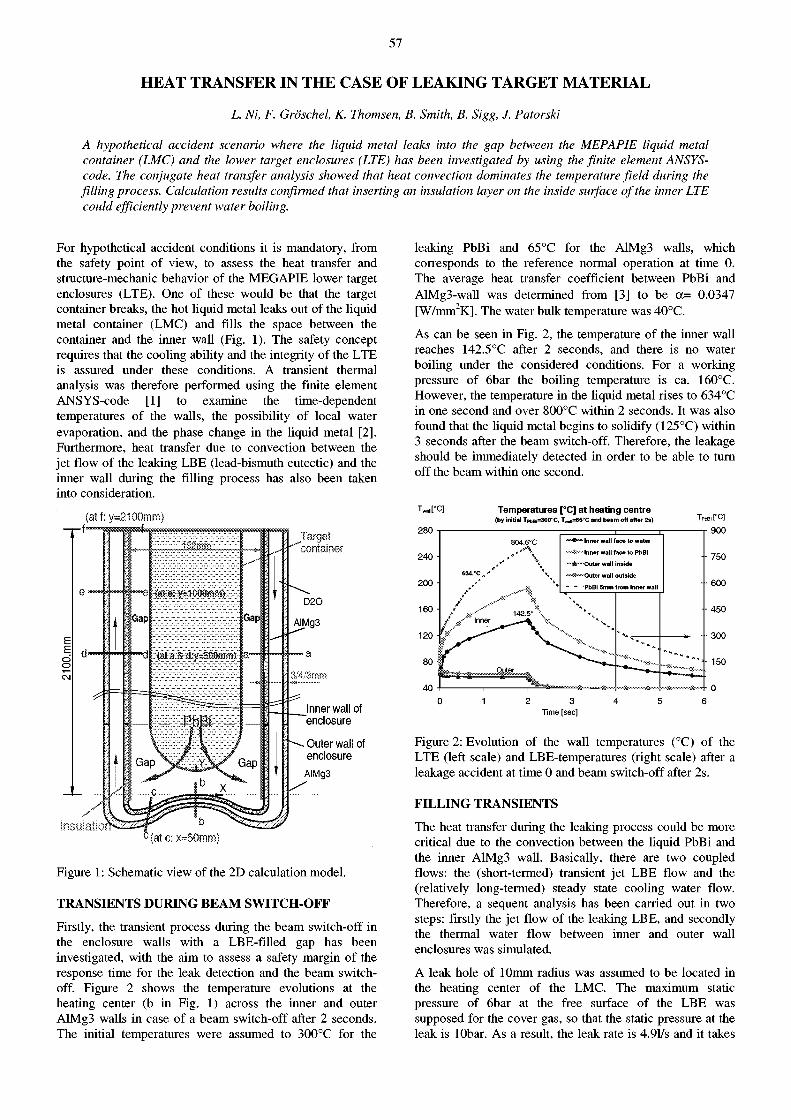
57
HEAT TRANSFER IN THE CASE OF LEAKING TARGET MATERIAL
L. Ni, F. Gröschel, K. Thomsen, B. Smith, B. Sigg, J. Patorski
A hypothetical accident scenario where the liquid metal leaks into the gap between the MEPAPIE liquid metal container (LMC) and the lower target enclosures (LTE) has been investigated by using the finite element ANSYS-code. The conjugate heat transfer analysis showed that heat convection dominates the temperature field during the filling process. Calculation results confirmed that inserting an insulation layer on the inside surface of the inner LTE could efficiently prevent water boiling.
For hypothetical accident conditions it is mandatory, from the safety point of view, to assess the heat transfer and structure-mechanic behavior of the MEGAPIE lower target enclosures (LTE). One of these would be that the target container breaks, the hot liquid metal leaks out of the liquid metal container (LMC) and fills the space between the container and the inner wall (Fig. 1). The safety concept requires that the cooling ability and the integrity of the LTE is assured under these conditions. A transient thermal analysis was therefore performed using the finite element ANSYS-code [1] to examine the time-dependent temperatures of the walls, the possibility of local water evaporation, and the phase change in the liquid metal [2]. Furthermore, heat transfer due to convection between the jet flow of the leaking LBE (lead-bismuth eutectic) and the inner wall during the filling process has also been taken into consideration.
(atf:y=2100mm)
Inner wall of enclosure
Outer wall of enclosure
inst
Figure 1: Schematic view of the 2D calculation model.
TRANSIENTS DURING BEAM SWITCH-OFF
Firstly, the transient process during the beam switch-off in the enclosure walls with a LBE-filled gap has been investigated, with the aim to assess a safety margin of the response time for the leak detection and the beam switch-off. Figure 2 shows the temperature evolutions at the heating center (b in Fig. 1) across the inner and outer AlMg3 walls in case of a beam switch-off after 2 seconds. The initial temperatures were assumed to 300°C for the
leaking PbBi and 65 °C for the AlMg3 walls, which corresponds to the reference normal operation at time 0. The average heat transfer coefficient between PbBi and AlMg3-wall was determined from [3] to be a= 0.0347 [W/mm2K]. The water bulk temperature was 40°C.
As can be seen in Fig. 2, the temperature of the inner wall reaches 142.5°C after 2 seconds, and there is no water boiling under the considered conditions. For a working pressure of 6bar the boiling temperature is ca. 160°C. However, the temperature in the liquid metal rises to 634°C in one second and over 800°C within 2 seconds. It was also found that the liquid metal begins to solidify (125°C) within 3 seconds after the beam switch-off. Therefore, the leakage should be immediately detected in order to be able to turn off the beam within one second.
TWall[°C]
280
Temperatures [X] at heating centre (by ini t ial Tn>Bi=300°C, T^=65°C and beam off after 2$)
• Inner wal l face to water
™S>~"lnner wall face to PbBi
™***™Outer wal l Inside
— ® — O u t e r wa l l outs ide
" " 'PbBi 5mm f r o m inner wal l
Tptei 900
750
600
450
300
150
2 3 Time [sec]
Figure 2: Evolution of the wall temperatures (°C) of the LTE (left scale) and LBE-temperatures (right scale) after a leakage accident at time 0 and beam switch-off after 2s.
FILLING TRANSIENTS
The heat transfer during the leaking process could be more critical due to the convection between the liquid PbBi and the inner AlMg3 wall. Basically, there are two coupled flows: the (short-termed) transient jet LBE flow and the (relatively long-termed) steady state cooling water flow. Therefore, a sequent analysis has been carried out in two steps: firstly the jet flow of the leaking LBE, and secondly the thermal water flow between inner and outer wall enclosures was simulated.
A leak hole of 10mm radius was assumed to be located in the heating center of the LMC. The maximum static pressure of 6bar at the free surface of the LBE was supposed for the cover gas, so that the static pressure at the leak is lObar. As a result, the leak rate is 4.91/s and it takes
58
ca. 2 seconds to fill the gap between the container and the inner wall enclosure up to 2.1m height. In addition, the average temperature of the leaking LBE was taken to be 300°C. During the filling process, the surface temperature of the LMC was kept at 300°C, and the beam was supposed to be off.
T[°C] Temperatures(0C) along outside surface of inner wall (face to water) at different time points
0 100 200 300 400 500 600 700 800 900 1000
Distance upstream from the heating centre [mm]
Figure 3: Interface temperature (°C) along the inner wall surface of the enclosure.
Water bulk temperatures(0C)
Time(second)
Figure 4: Water bulk temperature (°C) along the flow path.
Figure 3 displays the temperatures along the outside surface of the inner wall (i.e. the interface to the cooling water) as a function of the distance starting from the heating center point b (or the enclosure axis) after time periods of 0/0.1/0.5/l/2/3s. The profile at t=0s indicates normal operation. The temperature in the heating center area increases dramatically since the jet flow impinges there. It reaches a maximum of 189°C after 0.5s. Afterwards, the flow field in the heating center region becomes more stationary. As the liquid LBE flows towards the cylindrical part of the gap space, it heats not only the wall enclosures, but also the cooling water upwards between them. The time dependent water bulk temperatures can be seen in Fig. 4 along the flow path a->f shown in Fig. 1. The water bulk temperature at the outlet reaches 160°C, which would cause water boiling at the water flow further downstream. It should be noted that the calculated temperatures, which are higher than 160°C, are not quotable since sub-cooling heat transfer was not included in the model.
MODIFICATION BY AN INSULATION LAYER
T(°C) Water bulk temperatures(°C)
Td J ? T« >
Tc
iff -•-Ta ~*~T ) - » ~ Tc -Td -«-Te -»-Tf
I f j Tb
Ta
0 1 2 3 4 5 6 7 8 9 10 Time(second)
Figure 5: Water temperature (°C) with 1mm insulation layer.
OUTLOOKS
Another scenario would be that the beam is still on when the leak occurs. In this case, the PbBi and LTE walls could be further heated. This would result in higher temperatures and therefore needs further investigation. In addition, modeling of the sub-cooled heat transfer should be added, such that the maximum allowed heat flux could be determined.
REFERENCES
[1] ANSYS Revision 5.7.1, Swanson Analysis Systems, Inc., 2001
[2] L. Ni: "Structural mechanics and heat transfer I MEGAPIE target lower enclosures at normal operations and hypothetical accident conditions", PSI-documents, TM-87-01-05, Oct. 2001
[3] VDI-Wärmeatlas: "Berechnungsblätter für den Wärmeübergang", Springer-Verlag Berlin Heidelberg, 1997
To avoid the effect of water boiling in the above scenario, an insulation layer of 1mm plasma sprayed Ca-Zr0 2 was applied on the cylindrical inside surface of the inner wall enclosure. Because of the very low thermal conductivity of this insulation material (0.15W/mK in comparison with 135W/mK for AlMg3), the enclosures would be effectively shielded. As shown in Fig. 5, the outlet water temperature can be kept below 75°C. Furthermore, the cooling ability in the window bottom area (see temperatures at b and c) would also be improved significantly.
59
INFLUENCE OF THE FREEZING OF LEAD-BISMUTH EUTECTIC ON THE STRAIN DISTRIBUTION IN A MODEL CONTAINER
JA. Patorski, F. Gröschel, G. von Holzen, P. Häberli, M. Dubs (PSI), G.S. Bauer (FZ Jülich)
The phenomenon of long-term expansion of frozen Lead-Bismuth Eutectic (LBE) should be taken into account for the integrity of liquid metal (LM) target containers during operation and handling. The temperature dependency of the LBE expansion in the range from freezing (approx. 125 °C) to room temperature (RT) and the effect of mechanical constraints are unknown. The results show, that the maximal strains occur at the lowest exposure temperature (50°C) and are located in the lower part of the LM container near the hemispherical enclosure of the cylindrical vessel. With rising temperature the strains decrease drastically. The extent of expansion in the direction of constraint was found markedly smaller than that communicated for freely expanding conditions. This behavior can be explained by plastic flow of the LBE and the decrease of the shear yield stress caused by rising temperature.
INTORDUCTION
During freezing and remelting of Lead-Bismuth Eutectic (LBE) a significant mechanical effect can be exerted on structures due to the non-compliance of the alloy's volume and mechanical characteristics and the structure response evolution [1].
The main goal was therefore to assess the influence of long-term changes of the LBE density, i.e. expansion of the frozen LBE, within the temperature range of interest between the melting point of 125.5°C and room temperature (RT) on the strain/stress distribution in a model LM target container.
EXPERIMENTAL SET UP
Fig. 1 shows the geometry of the container and the location of the strain gauges and thermocouples.
LBE free surface no vertical constraint
St35 steel LM container
SG - »¡ SG 'TC
TC
SO f> ÍJSG TC
cylindrical pipe 0 i ! ! 5 t e f l s - 45/50mm
. „ Levei E 4 ! insert 0 18 mm
SG = ¡' SG TC
Levei E3 ¡ insert 0 24 t
Level E 2 ; inser t© 13 mm
£
CM :
SG = » SG c Level E1 ; no insert TC
hemispherical enclousure of \ cylindricai pipe 0 a n ï . f o l l K - 45/50mm
Figure 1: Sketch of the LM container; positions of measurement levels E1-E4 instrumented with strain gauges (SG =) for circumferential and (SG ||) for axial directions and thermocouples (°TC).
The walls of the cylindrical container and a metal insert impose the geometrical constraints for the expanding solid LBE.
The material used for the container is steel St35. It was filled with LBE and placed in a heating chamber, which allowed a constant temperature in the range between room temperature and 300°C. Four sets of strain gauges (SG) were placed at different levels to measure the circumferential and axial strains. Four thermocouples (TC) were used to measure the container's outside surface temperature on each level, and one TC was placed in the center of the container to determine the temperature of the LBE. A data acquisition unit was used to collect the data at given intervals.
Table 1 shows the experimental matrix.
Table 1
# Temperature [°C] Duration [hours] 1 140(l iquid)/115/100 1 / 72 / 504 2 140 (liquid) / 75 1 /456 3 140 (liquid) / 50 1 / 4 3 2
RESULTS
Figs. 2-4 show the evolution of circumferential strains at the four levels of the specimen for the three exposure cases. Figs. 5-7 show that of the corresponding axial strains.
The presence of inserts and shorter distance to the free surface for the levels E2, E3 and E4 caused smaller strains in all cases. The decrease of the exposure temperature below 75 °C has caused a substantial increase of the strains in the lower part of the specimen. The maximum circumferential strain is reached for case #3 with T=50°C amounting to 0.15%, which is well in the plastic range for steel St35.
In all cases, the strains observed are considerably smaller than that observed for freely expanding LBE [2], which leads to the conclusion that a mechanical constraint may induce plastic flow of the alloy in the unconstraint direction. The higher strains at the lower temperatures can be explained by the strength increase of solid LBE.
It is know from [2], that unconstraint specimens continue to expand over a longer time period than presented here. The observed constancy or even decrease in circumferential strains after only a short-term increase therefore has to be attributed to the plastic flow of LBE. Due to the lower yield stress at high temperature, this effect was noticed at all four levels in case #1 (Fig. 2), for the levels E2-E4 in case #2
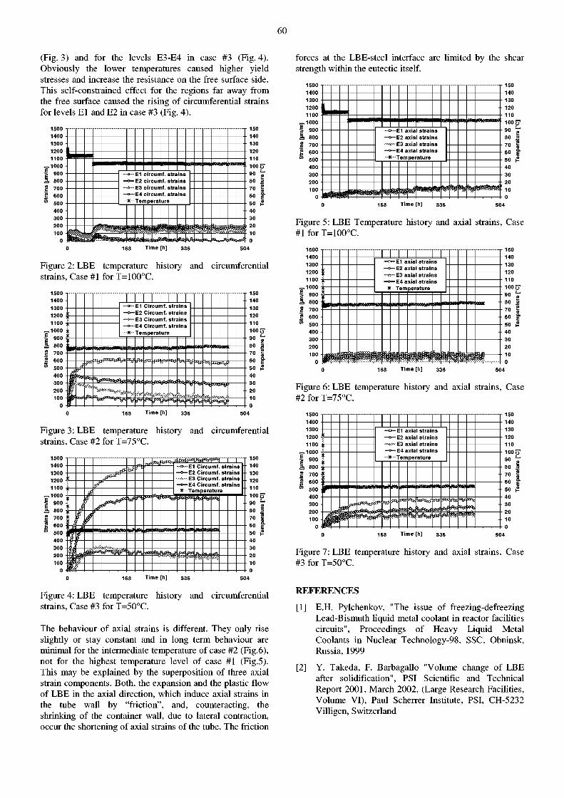
60
(Fig. 3) and for the levels E3-E4 in case #3 (Fig. 4). Obviously the lower temperatures caused higher yield stresses and increase the resistance on the free surface side. This self-constrained effect for the regions far away from the free surface caused the rising of circumferential strains for levels El and E2 in case #3 (Fig. 4).
1500 • 1400 • 1300 -1200 j 1100 -1000 •
E E
900 -a. 800 • VI c
700 -
trai
600 -500 -400 • 300 • 200 -100 -
0 -
™o™E1 circumf. strains —o— E2 circumf. strains ~**~~E3 circumf. strains —«—E4 circumf. strains - -*- - Temperature
™o™E1 circumf. strains —o— E2 circumf. strains ~**~~E3 circumf. strains —«—E4 circumf. strains - -*- - Temperature
™o™E1 circumf. strains —o— E2 circumf. strains ~**~~E3 circumf. strains —«—E4 circumf. strains - -*- - Temperature
™o™E1 circumf. strains —o— E2 circumf. strains ~**~~E3 circumf. strains —«—E4 circumf. strains - -*- - Temperature
CS? J u l * tSStf «4
140 130 120 110 100 í 90 \ 80 j 70 ! 60 j 50 { 40 30 20 10 0
Time [h]
Figure 2: LBE temperature history and circumferential strains, Case #1 for T=100°C.
1500 1400 1300 1200 1100
,1000 ; 900 i 800 ! 700 ! 600 ' 500
400 300 200 100
0
•»~E1 Circumf. strains •o— E2 Circumf. strains ^ - E 3 Circumf. strains O—E4 Circumf. strains
•»~E1 Circumf. strains •o— E2 Circumf. strains ^ - E 3 Circumf. strains O—E4 Circumf. strains
•»~E1 Circumf. strains •o— E2 Circumf. strains ^ - E 3 Circumf. strains O—E4 Circumf. strains
•»~E1 Circumf. strains •o— E2 Circumf. strains ^ - E 3 Circumf. strains O—E4 Circumf. strains
* - Te up »rat ure
•4* 1
I -MX
A i 4**
150 140 130 120 110 100 90 80 70 60 50 40 30 20 10 0
Time [h] 33$
Figure 3: LBE temperature strains, Case #2 for T=75°C.
history and circumferential
1500 1400 1300 1200 1100 1000 900 800 700 600 500 400 300 200 100
0
Circumf. strains Circumf. strains Circumf. strains
Circumf. strains Circumf. strains Circumf. strains
—0—E4 Circumf. strains x— -x Te m perature
w Ax * <r t té w
150 140 130 120 110 100 90 80 70 60 50 40 30 20 10 0
Time [h]
Figure 4: LBE temperature strains, Case #3 for T=50°C.
history and circumferential
The behaviour of axial strains is different. They only rise slightly or stay constant and in long term behaviour are minimal for the intermediate temperature of case #2 (Fig.6), not for the highest temperature level of case #1 (Fig.5). This may be explained by the superposition of three axial strain components. Both, the expansion and the plastic flow of LBE in the axial direction, which induce axial strains in the tube wall by "friction", and, counteracting, the shrinking of the container wall, due to lateral contraction, occur the shortening of axial strains of the tube. The friction
forces at the LBE-steel interface are limited by the shear strength within the eutectic itself.
1500 1400 1300 1200 1100
- 1 0 0 0 I 900 3¡ 800 g 700 f 600 °> 500
400 300 200 100
0
- O — E1 axial strains —o—E2 axial strains ~ï3f~E3 axial strains
E4 axial strains - Tem perature
S 1 0 0 ?T
Time [h]
Figure 5: LBE Temperature history and axial strains, Case #1 for T=100°C.
1500 1400 1300 1200 1100 i
„ 1 0 0 0 * • I 900 §• 3 800 S 700 f 600 • m 500 •
400 • 300 • 200 100
0
—o—El axial strains —o— E2 axial strains "**—E3 axial strains —«—E4 axial strains
-Temperature
150 140 130 120 110 100 í 90 \
• 80 : 70 j 60 j 50 { 40 30 20 10 0
Time [h] 504
Figure 6: LBE temperature history and axial strains, Case #2 for T=75°C.
1500 1400 1300 1200
900 -
S 700 • S 600 • °> 500:
400
200 100
0
T T T T T T T T i i i i i i i i ~«>—E1 axial strains —o— E2 axial strains •~*£~~E3 axial strains
E4 axial strains Temperature
~«>—E1 axial strains —o— E2 axial strains •~*£~~E3 axial strains
E4 axial strains Temperature
*
~«>—E1 axial strains —o— E2 axial strains •~*£~~E3 axial strains
E4 axial strains Temperature *
~«>—E1 axial strains —o— E2 axial strains •~*£~~E3 axial strains
E4 axial strains Temperature
* t !
I
150 140 130 120 110 100 90 80 70 60 50 40 30 20 10 0
Time [h]
Figure 7: LBE temperature history and axial strains, Case #3 for T=50°C.
REFERENCES
[1] E.H. Pylchenkov, "The issue of freezing-defreezing Lead-Bismuth liquid metal coolant in reactor facilities circuits", Proceedings of Heavy Liquid Metal Coolants in Nuclear Technology-98, SSC, Obninsk, Russia, 1999
[2] Y. Takeda, F. Barbagallo "Volume change of LBE after solidification", PSI Scientific and Technical Report 2001, March 2002, (Large Research Facilities, Volume VI), Paul Scherrer Institute, PSI, CH-5232 Villigen, Switzerland
61
VOLUME CHANGE OF LBE AFTER SOLIDIFICATION
Y. Takeda, F. Barbagallo
An experiment of volume change of LBE after solidification has been performed. Preliminary results show that the change is significant in two ways; the change is very fast and large in the initial phase of ca. lOOmin, and it continues still beyond 2xl03min. The effects are larger at 70 °C than at 30 °C. A test at 110°C is wider way. We observed that no saturation of the expansion has been reached. This requires the experiment to be continued and the phenomenon to be monitored for a longer time
INTRODUCTION
It is known that LBE (Lead Bismuth Eutectic mixture) exhibits a considerable volume change after solidification. This is different from a volume change occurring at phase transformation or from thermal effects, and is a characteristic feature of any eutectic mixture of binary and ternary metals. There is, however, little quantitative information about this phenomenon, except that supplied by a manufacturer.
For safety considerations of the liquid metal target for SINQ and MEGAPIE, solidification of LBE in the container requires a quantitative evaluation of the volume change after solidification, for which existing data are insufficient.
The purpose of the present investigation is to obtain quantitative information about the time variation of the volume after solidification, where the specimen is kept at constant temperature at different levels. It was easily understood that the volume change might be affected by physical configuration such as an existence of the solid wall that encloses the material, and that the change occurs in all directions of space. Therefore, a direct measurement of the volume was designed and performed.
Since we found that the expansion continues for quite a long time until up to half a year, the experiment is still under way and we here report some preliminary results.
EXPERIMENTAL
The experimental set-up was designed such that a volume change could be measured directly, not through measurement of other physical dimension like length. At the same time, the specimen is kept free from any external stress for its free deformation. For realising this condition, a glass container was prepared in which a rectangular LBE block is kept and which was filled with silicon oil. On top of this container, a capillary glass tube (02 .8 mm) was used for measuring the level of the oil (Fig. 1).
The size of the specimen was designed to be a 38mm rectangular solid (Fig. 2). It was determined from a reference volume change [1] of roughly 1% and a resolution of reading the oil level in the capillary (ca. lOui). We prepared a special mould for the specimen casting that can be easily disassembled for dismounting. A copper plate with water-cooling channel is set at the bottom for fast solidification from the lower portion. This is important for avoiding void formation inside the solid. It was still inevitable, although minimised, that the top surface of the solid was not completely flat. Often a deep hole was formed on the top surface, and if formed, this surface was
machined. The initial weight was measured accurately by a balance up to the order of 10mg.
The glass container, after the LBE block being prepared, is set into a constant temperature bath. It was unavoidable that the temperature of the specimen and container is different from the bath temperature for an initial short period and thus a fairly large volume change was observed during this period. The same procedure without LBE in the container or with a dummy block of aluminium was applied to check this effect. After reaching a thermal equilibrium, no change of the oil level was observed for periods up to one week, and the system was stable.
Figure 1: Glas Container.
Figure 2: LBE solid specimen.
62
After solidification, it took roughly 10 to 20 minutes until the specimen was located in the constant temperature bath, depending on the case with and without machining the top surface. It should be noticed that the volume change is fairly large during this initial period.
The oil level in the capillary together with the temperature was photographed in defined intervals over the whole exposure period which lasted up to 1 month.
RESULTS AND DISCUSSION
Experiments have been made at 3 different temperature levels; 30°C, 70° and 110°C. The latter is still running after a month of operation and the result is not given here.
Figure 3 shows clearly that the volume change is significant for the initial time period until ca. 100min. The rate then decreases linearly (on log-log plot) down to 0.001 mm/min at 104min after solidification. The change of the oil level is converted to a change of the specific volume as shown in Figure 4 for 30°C and 70°, for comparison. The reference volume was computed from the weight of the specimen divided by a nominal density of 10.73. The volume change of 0.8 to 1.2% after 10 3 min. can be compared to a linear expansion coefficient of 0.3% as given by the manufacturer for room temperature, a satisfactory agreement. A fairly significant difference to [1] was observed in the rate of volume change. Our measurements show a considerable increase for the initial period up to lOOmin, whereas it is much more gradual in the reference data. This seems to be due to the temperature tested. The reference data was obtained at room temperature. In our experiments, it increases faster at 70° than at 30°C.
1.E+02 1.E+03 Time (min)
1.E+04
Figure 4: Variation of the specific volume change for 30°C and 70 °C.
10.
10.
10.
10.
! io. Q 10.
10.
10.
10.
10.
.86
.84
.82
.80
.78
.76
.74
.72
.70
.68
1.E+01
• • • • •
Measur« density : 10.746
C¡ - . » > • tur
J¡¡¡¡¡¡¡¡¡¡¡§_j[ Rete rence density : 10.73
1 .E+02 1 .E+03 1 .E+04
Time after solidification (min)
1.E+05
Figure 5: Variation of density after solidification.
o
\ a
IIIMOg > 0 a o
»
Q O
»0 < <
%t 1 f o 001
« > 0 J o CO
f o 001
« >
1.E+01 1.E+02 1.E+03 1.E+04 1.E+05
Time after solidification (mln)
Figure 3: Variation of the rate of level change.
The important difficulty in our measurement is that it is not possible to know the volume of the specimen immediately after solidification. We measured the volume after stopping the measurement, and computed back the volume (and density) using this result of time dependent specific volume change. This is shown in Figure 5 by means of the time dependant change of density. Hence the density and/or the true volume of the solid LBE depends on the exposure temperature and the time elapsed between solidification and measurement.
REFERENCES
[ 1 ] Data given by HEK, Lübeck
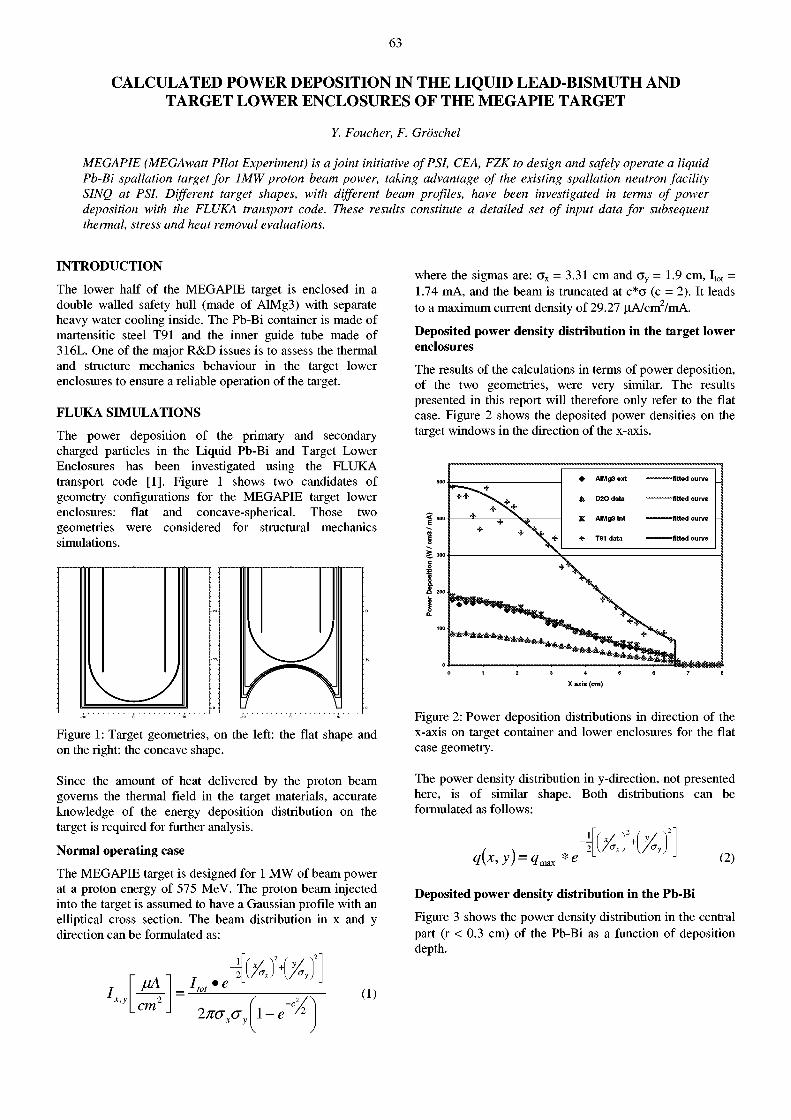
63
CALCULATED POWER DEPOSITION IN THE LIQUID LEAD-BISMUTH AND TARGET LOWER ENCLOSURES OF THE MEGAPIE TARGET
Y. Foucher, F. Gröschel
MEGAPIE (MEGAwatt Pilot Experiment) is a joint initiative of PSI, CEA, FZK to design and safely operate a liquid Pb-Bi spallation target for 1MW proton beam power, taking advantage of the existing spallation neutron facility SINQ at PSI. Different target shapes, with different beam profiles, have been investigated in terms of power deposition with the FLUKA transport code. These results constitute a detailed set of input data for subsequent thermal, stress and heat removal evaluations.
INTRODUCTION
The lower half of the MEGAPIE target is enclosed in a double walled safety hull (made of AlMg3) with separate heavy water cooling inside. The Pb-Bi container is made of martensitic steel T91 and the inner guide tube made of 316L. One of the major R&D issues is to assess the thermal and structure mechanics behaviour in the target lower enclosures to ensure a reliable operation of the target.
FLUKA SIMULATIONS
The power deposition of the primary and secondary charged particles in the Liquid Pb-Bi and Target Lower Enclosures has been investigated using the FLUKA transport code [1]. Figure 1 shows two candidates of geometry configurations for the MEGAPIE target lower enclosures: flat and concave-spherical. Those two geometries were considered for structural mechanics simulations.
where the sigmas are: G x = 3.31 cm and G y = 1.9 cm, I t o t = 1.74 mA, and the beam is truncated at c*G (c = 2). It leads to a maximum current density of 29.27 u,A/cm2/mA.
Deposited power density distribution in the target lower enclosures
The results of the calculations in terms of power deposition, of the two geometries, were very similar. The results presented in this report will therefore only refer to the flat case. Figure 2 shows the deposited power densities on the target windows in the direction of the x-axis.
X axis (cm)
Figure 1: Target geometries, on the left: the flat shape and on the right: the concave shape.
Figure 2: Power deposition distributions in direction of the x-axis on target container and lower enclosures for the flat case geometry.
Since the amount of heat delivered by the proton beam governs the thermal field in the target materials, accurate knowledge of the energy deposition distribution on the target is required for further analysis.
Normal operating case
The MEGAPIE target is designed for 1 MW of beam power at a proton energy of 575 MeV. The proton beam injected into the target is assumed to have a Gaussian profile with an elliptical cross section. The beam distribution in x and y direction can be formulated as:
cm 2naxay
(1) \-e
The power density distribution in y-direction, not presented here, is of similar shape. Both distributions can be formulated as follows:
i(x,y) = > *e '<yx
(2)
Deposited power density distribution in the Pb-Bi
Figure 3 shows the power density distribution in the central part (r < 0.3 cm) of the Pb-Bi as a function of deposition depth.
64
Depth axis (cm)
Figure 3: Power density distribution as a function of deposition depth in the Pb-Bi.
It is also important to know the beam spreading inside the Pb-Bi. Figure 4 shows the evolution of sigma-spreading as a function of the depth axis.
• sigma-x " " " " f i t t e d curve
at sigma-y ^««««*> fitted curve • 1
. , . A * J > * * * * * 1
Depth axis (cm)
Figure 4: Power density spreading as a function of deposition depth axis.
The power deposition inside Pb-Bi can be formulated as:
Q(z) = A*e z+zh
l-e zd-z
1 + B(Zd - Z)e
With: OxAz) = a.y + b z + c z
(3)
(4)
In a hypothetical case, Target E may be bypassed by the proton beam, which will result in a beam of more focussed shape hitting the SINQ target. The function describing the beam density still is identical to (1) but the parameters of the Gaussian are modified: a x = 0.561 cm and a y = 0.588 cm [2]. This leads to a maximum current density of 482.5 uA/cnr/mA.
The results for all relevant parameters are given in Table 1.
The thermalized total power deposited in the target system is constant for both beam profiles considered. Table 2 shows the power deposition in the different materials of the target.
Table 1: Main parameters for the different equations (1, 2, 3 and 4).
Normal Operation Beam Focussing
Beam Parameters < j x = 3.31 cm < j v = 1.9 cm <TX = 5.61 mm < j v = 5.88 mm
q m a x (W/cm3/mA)
AIMg3 outer 180 180 2785 2785
AIMg3 inner 185 185 2890 2890
T91 container 490 490 7825 7825
Coolant D 20 87 87 1347 1347
Pb-Bi functions
A(W/cm3/mA) 764.4 25500
B (cm 1) 4.1 5.5
ZA(cm) 16 5.7
Z B (cm) 4.5 3.3
ZO(cm) 4 9
Z D (cm) 26.7 26.6
Z.(cm) 0.45 0.45
a X l V (cm) 3.3604 1.9686 0.62553 0.64329
BX.V (cm) 1.67E-02 -1.69E-03 -1.48E-02 -1.26E-02
cX.V (cm) 0 1.15E-03 3.29E-03 3.13E-03
Table 2: Total power deposition in the target materials.
Materials
Normal operating case Beam focussing case
Materials Total Pd (W/mA) Total Pd (W/mA)
AlMg3 outer 1866.54 1676.32
D2O coolant 2388.83 2270.51
AlMg3 inner 1972.75 1763.04
T91 container 4009.44 3354.50
316L 3497.22 1201.46
Pb-Bi 399062 405824
Escaping 87600.8 83326.2
Total 500397 499417
CONCLUSION
Using the FLUKA transport code, different target configurations and beam profiles have been investigated for the MEGAPIE target. The calculated power density distributions constitute a detailed set of input data for temperature estimations and structural mechanics behavior for the lower target enclosures, and for fluid dynamics calculations for the Pb-Bi.
REFERENCES
[1] A. Ferrari, Sala, Proc. Int. Conf. On Nuclear Data Science and Technology, NDST-97, Trieste, Italy, 1997, ed. Italian Phys. Soc , Vol. 59 part I, p. 247
[2] U. Rohrer, private communication
65
KILOPIE - DESIGN OF A THERMAL HYDRAULIC EXPERIMENT FOR THE MEGAPffi TARGET WINDOW
J.A. Patorski (PSI), I. Platnieks (IPULRiga)
The paper presents the design of the KILOwatt Pilot Experiment (KILOPIE). The experiment supports the development of liquid metal (LM) targets at the PSI Spallation Neutron Source SINQ in the context of the MEGAwatt Pilot Experiment (MEGAPIE). The measurement of the local convection heat transfer coefficient a and temperature distribution in the MEGAPIE target window area at various hydraulic conditions of LM cooling flow are the subjects of the experiment. The experimental device provides the geometry of the target part which is responsible for forming the flow structure in the target window area. The experiment aims at most realistic conditions regarding Lead-Bismuth Eutectic (LBE) flow, beam window's material T91 and realistic temperatures and heat flux distribution.
INTRODUCITON
In the MEGAPIE target, the beam window of the liquid metal container will be cooled by a jet flow of LBE across the window area. For a proper design, the knowledge of the cooling characteristic of LBE for the specific flow configuration and for the real target window material is necessary. The MEGAPIE proton beam entry window is made of the martensitic steel T91 (9Cr-lMoVNb). The heat deposition in the steel will produce a heat flux up to 140 W/cm 2. The KILOwatt Pilot Experiment (KILOPIE) will investigate the LBE cooling characteristics by simulating these conditions.
The main goal of the experiment is the measurement of the local convection heat transfer coefficient a in the region of the proton beam entry window for characteristic bypass pump mass flow (q) and main pump mass flow (Q) ratios.
Other objectives are
• Determination of optimal operating range for q and Q on the way shown in [1].
• Validation of Computational Fluid Dynamics (CFD) calculations.
Heating power levels from approx. 1 kW up to 10 kW will be applied during the experiment.
TEST FACILITY
The KILOPIE experiment is planned to be performed at the thermal hydraulic loop THEADES of the KArlsruhe Lead LAboratory KALLA at the Forschungszentrum Karlsruhe FZK.
EXPERIMENTAL CONDITIONS
The KILOPIE test section is a mockup of the MEGAPIE target bottom section (Fig. 1). The geometrical flow configuration corresponds to the actual MEGAPIE target design (for some detailed dimensions see Figs. 2-3). The geometry of the end of the riser made of AISI316L can be modified; e.g. flat or slanted, as well as the nozzle of the bypass pipe.
The bulk temperature of the LBE will be 180°C. The q / Q cases will be defined within the reference ranges for q<1.0 litre/sec and for Q<4.0 litres/sec.
INSTRUMENTATION
Two different instrumentation types will be used for two series of KILOPIE experiments. The first series will use the 2-Dimensional Heat Emitting Temperature Sensitive Surface (2D-HETSS) and thermocouples (TC).
Figure 1: Double-flanged test section and steel dish with foil glued to the outside surface.
The second series will use Infrared Thermography (IRT) and thermocouples (TC). These measurement techniques have been used successfully in previous PSI investigations for LM targets [2-5]. In both series a double-flanged test section is used (Fig. 1), which allows mounting of a small steel dish (diameter ca. 150 mm, wall thickness 0.5 mm) representing the central part of the hemispherical window enclosure.
2D-HETSS experiments
For the development of the thermal boundary layer the realistic distribution of the heat flux densities could be important. Likewise the magnitude of the heat flux density can influence the dynamic viscosity of LM and therefore can influence both (velocity and thermal) boundary layers.
To simulate the heat flux deposited by the proton beam, a thin, 50 \im nickel foil is glued to the dish and is heated electrically. This heating foil (see lower part of Fig. 2) is specially tailored, such that it allows to apply a heat flux deposition in a profile similar to the proton beam heat deposition as calculated for the MEGAPIE target at the PSI SINQ facility [6]. However, the simulation of the maximum heat flux of approx. 140 W/cm 2 using nickel foils can fail, if the cooling in the middle of the dish will not be sufficient
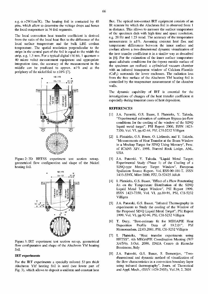
66
e.g. a >2W/(cm2K). The heating foil is contacted by 48 pins, which allow to determine the voltage drops and hence the local temperature in 36 foil segments.
The local convection heat transfer coefficient is derived from the ratio of the local heat flux to the difference of the local surface temperature and the bulk LBE coolant temperature. The spatial resolution perpendicular to the strips in the central part of the foil is equal to the width the strip, e.g. 1.3 mm. For a typical digital (16 bit, 1 quantum = 40 micro volts) measurement equipment and appropriate integration time, the accuracy of the measurement in the middle can be predicted to approx. ±1% and at the periphery of the nickel foil to ±10% [7].
180/176
125/122 24 / 20 t- •»••>;
Figure 2:2D HETSS experiment test section set-up, geometrical flow configuration and shape of the Nickel heating foil.
180/176
Figure 3: IRT experiment test section set-up, geometrical flow configuration and shape of the Aluchrom Yhf heating foil.
IRT experiments
For the IRT experiments a specially tailored 53 ujn thick Aluchrom Yhf heating foil is used (see lower part of Fig. 3), which allows to deposit a uniform and constant heat
flux. The optical non-contact IRT equipment consists of an IR scanner by which the Aluchrom foil is observed from 1 m distance. This allows to measure the surface temperature of the specimen dish with high time and space resolution, e.g. 20 Hz and 1.25 mrad. The accuracy of the temperature measurement is ±1%. Assuming constant heat flux and temperature differences between the inner surface and coolant allows a two-dimensional dynamic visualization of the heat transfer coefficient a in a similar way as described in [8]. For the estimation of the inner surface temperature quasi adiabatic conditions for the (open) outside surface of the specimen are realised: a cylindrical vacuum chamber with an infrared transparent window of Calcium Fluoride (CaF2) surrounds the lower enclosure. The radiation loss from the free surface of the Aluchrom Yhf heating foil is controlled by the temperature measurement of the chamber walls.
The dynamic capability of IRT is essential for the investigations of changes of the heat transfer coefficient a especially during transient cases of heat deposition.
REFERENCES
[1] J.A. Patorski, G.S. Bauer, I. Platnieks, Y. Takeda, "Experimental estimation of optimum Bypass-jet-flow conditions for the cooling of the window of the SINQ liquid metal target", PSI Report 2000, ISSN 1423-7350, Vol. VI, pp.42-44, PSI, CH-5232 Villigen
[2] I. Platnieks, G.S. Bauer, O. Lielausis, and Y. Takeda, "Measurements of Heat Transfer at the Beam Window in a Mockup Target for SINQ Using Mercury", Proc. of ICANS XIV, 1998, Starved Rock Lodge, ANL, USA
[3] J.A. Patorski, Y. Takeda, "Liquid Metal Target; Experimental Study (Phase 1) of the Cooling of a SINQ-type Mercury Target Window", European Spallation Source Report, Vol. ESS-00-101-T, ISSN 1433-559X, März 2000, FZJ, D-52425 Jülich
[4] I. Platnieks, G.S. Bauer, "Effect of a Flow Penetrating Jet on the Temperature Distribution of the SINQ Liquid Metal Target Window", PSI Report 1999, ISSN 1423-7350, Vol. VI, pp.89-91, PSI, CH-5232 Villigen
[5] J.A. Patorski, G.S. Bauer, "Infrared Thermography in experiments to Study the cooling of the Window of the Proposed SINQ Liquid Metal Target", PSI Report 1999, Vol. VI, pp.92-94, PSI, CH-5232 Villigen
[6] T. Dury, "Best-estimate fit for MEGAPIE Heat Deposition Profile Data of 19.2.01", PSI Memorandum, 22.03.2001, PSI, CH-5232 Villigen
[7] I. Platnieks, "Heat transfer experiments using HETSS", 4th MEGAPIE Coordination Meeting (WP X4/5/6), 5.Oct. 2000, ENEA Centro di Ricerche Brasimone, Italy
[8] J.A. Patorski, G.S. Bauer, S. Dementjev, "Two-dimensional and dynamic method of visualization of the flow characteristics in a convection boundary layer using infrared thermography", Journ. of Theoretical and Appl. Mech., (ISSN 1429-2955), Vol.39, 2, 2001
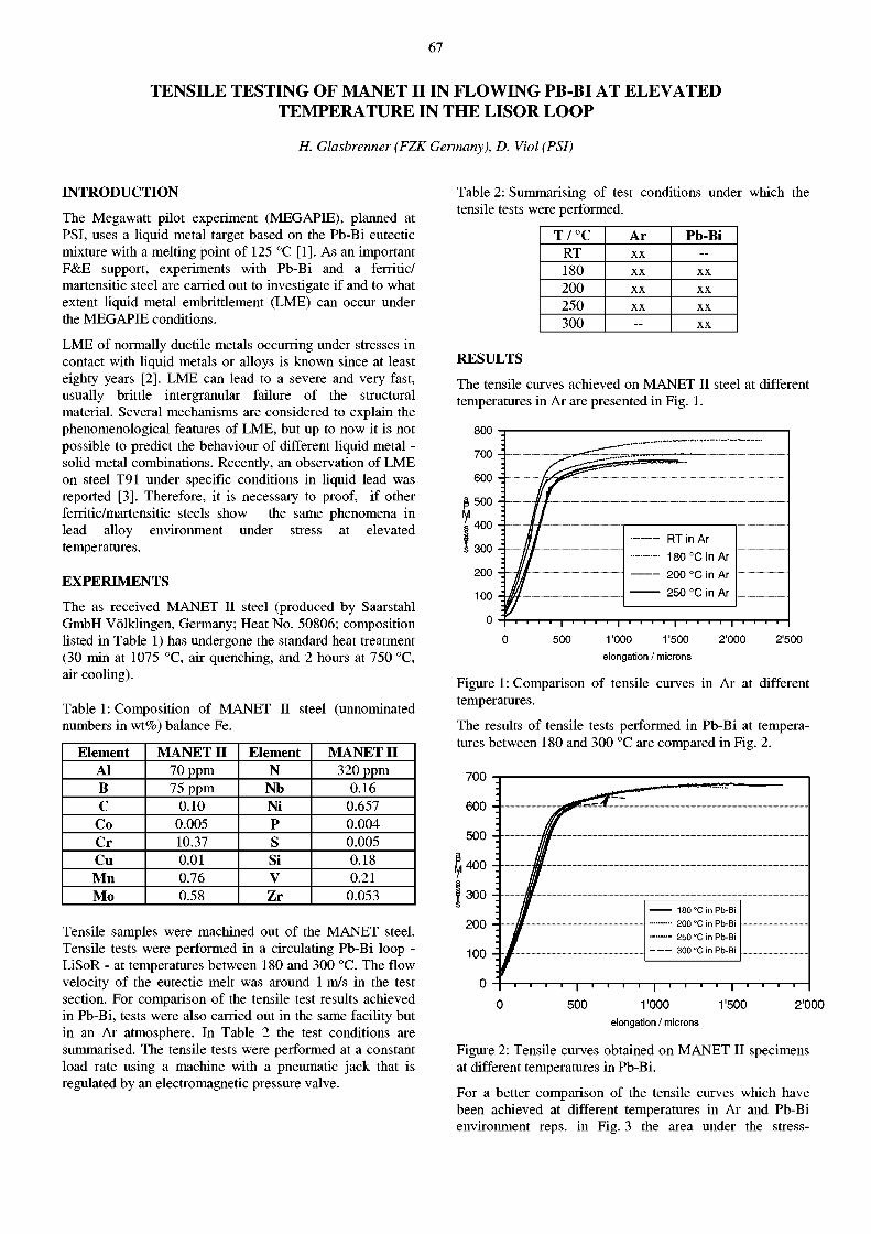
67
TENSILE TESTING OF MANET II IN FLOWING PB-BI AT ELEVATED TEMPERATURE IN THE LISOR LOOP
H. Glasbrenner (FZK Germany), D. Viol (PSI)
INTRODUCTION
The Megawatt pilot experiment (MEGAPIE), planned at PSI, uses a liquid metal target based on the Pb-Bi eutectic mixture with a melting point of 125 °C [1]. As an important F&E support, experiments with Pb-Bi and a ferritic/ martensitic steel are carried out to investigate if and to what extent liquid metal embrittlement (LME) can occur under the MEGAPIE conditions.
LME of normally ductile metals occurring under stresses in contact with liquid metals or alloys is known since at least eighty years [2]. LME can lead to a severe and very fast, usually brittle intergranular failure of the structural material. Several mechanisms are considered to explain the phenomenological features of LME, but up to now it is not possible to predict the behaviour of different liquid metal -solid metal combinations. Recently, an observation of LME on steel T91 under specific conditions in liquid lead was reported [3]. Therefore, it is necessary to proof, if other ferritic/martensitic steels show the same phenomena in lead alloy environment under stress at elevated temperatures.
EXPERIMENTS
The as received MANET II steel (produced by Saarstahl GmbH Völklingen, Germany; Heat No. 50806; composition listed in Table 1) has undergone the standard heat treatment (30 min at 1075 °C, air quenching, and 2 hours at 750 °C, air cooling).
Table 1: Composition of MANET II steel (unnominated numbers in wt%) balance Fe.
Table 2: Summarising of test conditions under which the tensile tests were performed.
Element MANET H Element MANET H Al 70 ppm N 320 ppm B 75 ppm Nb 0.16 C 0.10 Ni 0.657
Co 0.005 P 0.004 Cr 10.37 S 0.005 Cu 0.01 Si 0.18 M n 0.76 V 0.21 Mo 0.58 Zr 0.053
Tensile samples were machined out of the MANET steel. Tensile tests were performed in a circulating Pb-Bi loop -LiSoR - at temperatures between 180 and 300 °C. The flow velocity of the eutectic melt was around 1 m/s in the test section. For comparison of the tensile test results achieved in Pb-Bi, tests were also carried out in the same facility but in an Ar atmosphere. In Table 2 the test conditions are summarised. The tensile tests were performed at a constant load rate using a machine with a pneumatic jack that is regulated by an electromagnetic pressure valve.
T / ° C Ar Pb-Bi RT X X — 180 X X X X
200 X X X X
250 X X X X
300 - X X
RESULTS
The tensile curves achieved on MANET II steel at different temperatures in Ar are presented in Fig. 1.
RT in Ar 180 °C in Ar 200 °C in Ar 250 °C in Ar
500 1 I 1 1 1 1 I 1
r o o o 1'500 elongation / microns
1 I 1
2'000 2'500
Figure 1: Comparison of tensile curves in Ar at different temperatures.
The results of tensile tests performed in Pb-Bi at temperatures between 180 and 300 °C are compared in Fig. 2.
700
-i—i—j—i—r
r 0 0 0 1'500 2'000
elongation / microns
Figure 2: Tensile curves obtained on MANET II specimens at different temperatures in Pb-Bi.
For a better comparison of the tensile curves which have been achieved at different temperatures in Ar and Pb-Bi environment reps, in Fig. 3 the area under the stress-
68
elongation curves versus the temperature is plotted. The ductility is progressively reduced by an increasing test temperature. An influence of the LBE is clearly observable.
i i i i j i i i i j i i i i i i i i i j i i i i i i i i i j i i 1
100 150 200 temperature / °C
an influence of Pb-Bi on the ductility of MANET II. A mixed fracture surface dimple and brittle was observed on the MANET II ruptured at 300 °C in Pb-Bi . Similar observations on the fracture face of T91 exposed to Pb under specific conditions, were made by Nicaise et al. [3]. In [4] it is reported that MANET II steel exhibits LME when tested in tension and in contact with Pb-17Li at 250 and 300 °C. Hence, ferritic/martensitic steels can be sensitive to LME in lead and lead alloy environments.
Figure 3: Area under the stress-elongation curves versus temperature achieved in Ar and Pb-Bi environment.
This change in the mechanical behaviour is also reflected in the fracture surfaces of the tensile samples which can be observed by scanning electron microscopy.
Fig. 4 shows the fracture surface of MANET II ruptured at 200 °C in Ar. The fracture is fully ductile and shows the typical dimple structure.
¡lilllília 11 «*
** & *4 !
WKÊÊÊ • l i l i
A S -
• i i lSI:
BBpp|M.
* IUI "III 111 * I B
<3il.:;¿ib:;t.¿inrt 12 rVEír^rnOoriirift 1H HH K X P h o t o Nr -3452 D e t e k t o r = S E I
Figure 4: Fracture surface of MANET II tested at 200 °C in Ar.
Fig. 5 shows a mixture of a brittle-ductile surface structure on the tensile MANET II specimen tested at 300 °C in Pb-Bi. The brittle fracture is flat with no dimples and corresponds to a cleavage-like failure. Adherent Pb-Bi is detected on different areas of the fracture face. An etched cross section of the same sample indicates the penetration of Pb-Bi along the grain boundaries. Pb-Bi is easier to recognise in a non-etched optical micrograph (see Fig. 6) than in an etched image.
DISCUSSION AND CONCLUSIONS
The stress-elongation curves and the fracture surfaces investigated by SEM and metallurgical investigation confirm
, „ M l)E3t.okt.or s r : i
Figure 5: SEM showing the fracture surface of MANET II tested at 300 °C in Pb-Bi.
Figure 6: Optical micrograph of MANET II tested at 300 °C in Pb-Bi.
REFERENCES
[1] G. Bauer, M. Salvatores, G. Heusener, J. Nucl. Mater. 296 (2001) 17
[2] A.K. Huntigton, J. Inst. Met. 11 (1914) 108
[3] G. Nicaise, A. Legris, J.B. Vogt, J. Voct, J. Nucl. Mater. 296 (2001) 256
[4] R. L. Klueh, Donald R. Harries, Monograph 3 (American Society for Testing and Materials), Juli 2001
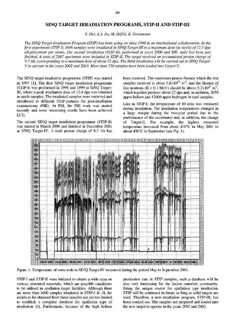
69
SINQ TARGET IRRADIATION PROGRAMS, STIP-II AND STIP-III
Y. Dai, X.J. Jia, M. Häfeli, K. Geissmann
The SINQ Target Irradiation Program (STIP) has been going on since 1998 in an international collaboration. In the first experiment (STIP I) 1646 samples were irradiated in SINQ Target-Ill to a maximum dose (in steels) of 12.5 dpa (displacement per atom). The second irradiation (STIP-II), performed in years 2000 and 200, andl has been just finished. A total of 2087 specimens were included in STIP-II. The target received an accumulated proton charge of 9.7 Ah, corresponding to a maximum dose of about 22 dpa. The third irradiation will be carried out in SINQ Target-V to operate in the years 2002 and 2003. More than 750 samples have been loaded into Target-V.
The SINQ target irradiation programme (STIP) was started in 1997 [1]. The first SINQ target irradiation programme (STIP-I) was performed in 1998 and 1999 at SINQ Target-Ill, where a peak irradiation dose of 12.4 dpa was obtained in steels samples. The irradiated samples were retrieved and distributed to different STIP-partners for post-irradiation examinations (PIE). At PSI, the PIE work was started recently and some interesting results have been achieved [2,3].
The second SINQ target irradiation programme (STIP-II) was started in March 2000 and finished in December 2001 at SINQ Target-IV. A total proton charge of 9.7 Ah has
been received. The maximum proton fluence which the test samples received is about 5 .6x l0 2 5 m"2, and the fluence of fast neutrons (E > 0.1 MeV) should be above 5 .2x l0 2 5 m"2, which together produce about 22 dpa and, in addition, 2050 appm helium and 12000 appm hydrogen in steel samples.
Like in STIP-I, the temperature of 10 rods was measured during irradiation. The irradiation temperatures changed in a large margin during the two-year period due to the performance of the accelerator and, in addition, the change of Target-E. For example, the highest measured temperature increased from about 410°C in May 2001 to about 490°C in September (see Fig. 1).
24.0S.20m 08.86.2001 23.88.2031 Û8137.2081 23.0WCÎ01 0?«.2Û« 22,08,2081 QÈMSm 21.S8.2» 86.18.28tH
Figure 1: Temperature of some rods in SINQ Target-IV measured during the period May to September 2001.
STIP-I and STIP-II were initiated to obtain a wide scan on various structural materials, which are possible candidates to be utilised in spallation target facilities. Although there are more than 3600 samples irradiated in STIP-I & -II, the results to be obtained from these samples are yet too limited to establish a complete database for spallation type of irradiation [4]. Furthermore, because of the high helium
production rate in STIP samples, such a database will be also very interesting for the fusion materials community. Being the unique source for spallation type irradiation, STIP will be continued in future as long as solid targets are used. Therefore, a new irradiation program, STIP-III, has been worked out. The samples are prepared and loaded into the new target to operate in the years 2002 and 2003.
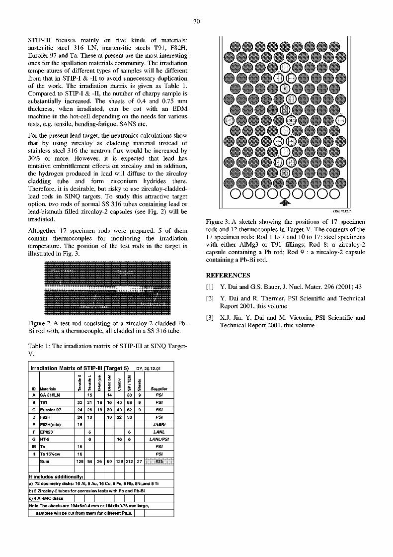
70
STIP-III focuses mainly on five kinds of materials: austenitic steel 316 LN, martensitic steels T91, F82H, Eurofer 97 and Ta. These at present are the most interesting ones for the spallation materials community. The irradiation temperatures of different types of samples will be different from that in STIP-I & -II to avoid unnecessary duplication of the work. The irradiation matrix is given as Table 1. Compared to STIP-I & -II, the number of charpy sample is substantially increased. The sheets of 0.4 and 0.75 mm thickness, when irradiated, can be cut with an EDM machine in the hot-cell depending on the needs for various tests, e.g. tensile, bending-fatigue, SANS etc.
For the present lead target, the neutronics calculations show that by using zircaloy as cladding material instead of stainless steel 316 the neutron flux would be increased by 30% or more. However, it is expected that lead has tentative embrittlement effects on zircaloy and in addition, the hydrogen produced in lead will diffuse to the zircaloy cladding tube and form zirconium hydrides there. Therefore, it is desirable, but risky to use zircaloy-cladded-lead rods in SINQ targets. To study this attractive target option, two rods of normal SS 316 tubes containing lead or lead-bismuth filled zircaloy-2 capsules (see Fig. 2) will be irradiated.
Altogether 17 specimen rods were prepared. 5 of them contain thermocouples for monitoring the irradiation temperature. The position of the test rods in the target is illustrated in Fig. 3.
Figure 2: A test rod consisting of a zircaloy-2 cladded Pb-Bi rod with, a thermocouple, all cladded in a SS 316 tube.
Table 1: The irradiation matrix of STIP-III at SINQ Target-V.
Irradiation Matrix of STIP-III [Target 5) DY, 20.12.01
sile
S
sile
L
3
o> id ba
r
>. Q.
S Ul H a
ID Materials £ c I Ï
m DO £ O
O. o>
£ Supplier A SA 316LN 15 14 30 9 PSI
B T91 32 21 18 16 40 58 9 PSI
C Eurofer 97 24 26 18 20 40 62 9 PSI
D F82H 24 10 10 32 50 PSI
E F82H(ods) 16 JA ER I
F EP823 6 6 LANL
G HT-9 6 16 6 LANUPSI
IB Ta 16 PSI
H Ta15%cw 16 PSI
Sum 128 84 36 60 128 212 27 675
It includes additionally: a) 72 dosimetry disks: 16 Al, 8 Au, 16 Cu, 8 Fe, 8 Nb, 8Ni,and 8 Ti b) 2 Zircaloy-2 tubes for corrosion tests with Pb and Pb-Bi
c) 4 AI-B4C discs I I I Note:The sheets are 104x8x0.4 mm or 104x8x0.75 mm large,
samples will be cut from them for different PIEs. | |
QOQOÖOQÖQP o o o o o o o o o o
QQQOQPQPQP OOOOOOOOO ' • ooo'' : OOOOOOOOO OOOOQPQpQP OOOOOOOOO OOOOOOOOOO OOOOOOOOO Figure 3: A sketch showing the positions of 17 specimen rods and 12 thermocouples in Target-V. The contents of the 17 specimen rods: Rod 1 to 7 and 10 to 17: steel specimens with either AlMg3 or T91 fillings; Rod 8: a zircaloy-2 capsule containing a Pb rod; Rod 9 : a zircaloy-2 capsule containing a Pb-Bi rod.
REFERENCES
[ 1 ] Y. Dai and G.S. Bauer, J. Nucl. Mater. 296 (2001 ) 43
[2] Y. Dai and R. Thermer, PSI Scientific and Technical Report 2001, this volume
[3] X.J. Jia, Y. Dai and M. Victoria, PSI Scientific and Technical Report 2001, this volume
71
TEMPERATURE DEPENDENCE OF THE MICROSTRCTURE OF HIGH ENERGY PROTON IRRADIATED F82H MARTENSITIC STEEL
X. Jia, Y. Dai (PSI), M. Victoria (CRPP-EPFL)
The F82H low-activation martensitic steel was irradiated in SINQ target Mark-II to doses of 10 to 12 dpa in a temperature range of 140 to 360 °C. Transmission Electron Microscopy (TEM) observations show that (1) high-density helium bubbles of a size ~1 nm are present in the samples irradiated at temperatures >174 °C, the size of the bubbles increasing with increasing irradiation temperature, but the density decreasing slightly. (2) The irradiation temperature is the controlling parameter for the amorphization of the precipitates in F82H steel. For F82H steel the amorphization temperature is about 230 °C, corresponding to 0.3Tm (Tm is the absolute melting point temperature). (3) With increasing irradiation temperature the size of the defect clusters increases from around 255°C and above, while the density of the defect clusters shows no significant change below 255°C but decreases rapidly above this temperature.
INTRODUCTION
Due to its good thermal and mechanical properties, F82H steel is a tentative candidate material for the first wall of the future fusion reactor, and also for the container of the liquid metal target of the European spallation neutron source [1,2]. Because of these applications, irradiated ferritic/martensitic steels have been studied intensively in the last decades in an extensive irradiation temperature range (50 - 750°C) and exposed to high irradiation doses (up to 200 dpa). However, in particular the microstructure after irradiation in the low temperature range (<350°C) is, so far, not well understood.
The first SINQ target irradiation program (STIP-I) was carried out in the SINQ target Mark-II from July 1998 to December 1999 with an interruption of three months at the beginning of 1999. A maximum dose of 12.5 dpa and helium concentration of 850 appm was obtained in the steel specimens. The irradiation temperature ranged from 90 to 370°C [3]. A series of TEM samples of F82H steel irradiated at different temperatures and to different doses was obtained. This paper presents the results of the TEM investigation on these samples.
EXPERIMENTAL
The F82H steel used for this irradiation was provided by the Fusion Technology Materials group (PIREX) of CRPP-EPFL. Its composition is: 7.65 Cr, 2 W, 0.16 Mn, 0.16 V, 0.02Ta, 0.11 Si and 0.09 C, all in wt%, and Fe for the balance. The material was subjected to the standard heat treatment that produces a fully martensite structure [4].
TEM investigation of the microstructure was performed at 200 kV using a JEOL 2010 microscope. The most often used imaging conditions were bright field (BF) and weak beam dark-field (WBDF) at g(4g), g(5g) and g(6g), g=110 near z = l l l . Only the micrographs of g(5g) were used for quantifying the size and density of the defect clusters. A magnification of 150000 or 200000 was used for the analysis of the irradiation induced defect clusters. For the observation of small helium bubbles a magnification of 250000 was often applied. The thickness of the foils in the imaging areas was deduced from the number of fringes. The uncertainty of the defect densities is estimated to be about ±15%.
RESULTS AND DISCUSSION
The microstructure of F82H prior to irradiation consisted of tempered martensitic laths. Only M 2 3 Q type carbide precipitation was identified mainly along prior austenite grain boundaries and martensitic lath boundaries. The size of precipitates varied from about 0.1 to lu.m.
Figure la and lb show the microstructure of F82H steel before and after irradiation. The tempered martensite structure is stable after irradiation, even after the irradiation to a dose of 12.2 dpa at 360°C. Size and distribution of carbides also show no distinct change after irradiation. However, the crystal structure of these precipitates can be changed significantly depending on the irradiation temperature. The present observations show that in the samples irradiated at 200°C and below, the precipitates have changed from crystalline to amorphous after irradiation (Fig. lc). However, for the samples irradiated at 255°C and above the crystalline structure of the precipitates remains unchanged after irradiation (Fig. le). The critical transition point is around 233°C (Fig. ld), where some precipitates are partly amorphous.
s i i f i i i i i p i S i â y y ï i i i i ¡ ¡ ¡^^^=«¡¡ ¡ ¡ ¡ ¡ ¡ ¡111
Figure 1: The microstructure before and after irradiation a): un-irradiated, b): irradiate at 360°C, 12.2 dpa, c): 200 °C, 5.9 dpa, d) 233 °C, 10.2 dpa and e) 255°C, 10.3 dpa. The scale in the left corner of c) is 200 nm for a, b, c), 50 nm for d) and 100 nm for e).
72
Figure 2 presents the microstructure in the samples irradiated at 140, 255, 295 and 360°C to 10, 9.9, 10.3 and 12.2 dpa, respectively. It demonstrates that with increasing irradiation temperature the size of the defect clusters increases, from around 255°C and above, while the density of defect clusters shows no significant change below 255°C but decreases rapidly above this temperature.
Figure 2: Micrographs showing defect cluster structures in irradiated F82H steel samples: a): 10.0 dpa / 140°C; b): 10.3 dpa / 255°C; c): 9.9 dpa / 295°C; d): 12.2 dpa / 360°C.
The most interesting finding of the present work is the observation of helium bubbles in the samples irradiated at about 174°C and above, of high-density and with an average size around 1 nm , as shown in Fig. 3 for different cases. For the samples irradiated to doses of 10 to 12.2 dpa at temperatures increasing from 174°C to 360°C, the mean size of helium bubbles increases gradually from about 0.8 nm to about 1.6 nm while the density of helium bubbles decreases slightly. In the samples irradiated at 150°C and below, no helium bubbles can be resolved, even if the helium concentration is higher, e.g. 472 appm He in the sample at 140°C and 10 dpa as compared to the 220 appm He in the sample at 200°C and 5.9 dpa.
Figure 3: High-density helium bubbles after irradiation at higher temperatures a) 10.5 dpa, 255 °C, BF image and over-focused, b) same as a) but under-focused, c) 10 dpa, 295°C, and d) 12.2 dpa, 360°C.
Regarding the tensile properties, little or no effect of helium has been measured after high-energy proton irradiation at low dose levels (about ldpa) where no helium bubbles were observed. However, some recent experiments on F82H indicate an increase in the ductile-brittle transition temperature due to the presence of helium bubbles [5]. The tensile samples with the same irradiation conditions as for Figure 3 are going to be tensile tested to investigate the effects of the high-density helium bubbles on the tensile properties.
CONCLUSION
1. The controlling parameter for the amorphization of the precipitates in our samples is the irradiation temperature. The present work shows that the amorphization temperature is about 230°C, corresponding to the 0.3Tm of the martensitic steel.
2. The irradiation with high-energy protons induced high-density helium bubbles in F82H steel at irradiation temperatures of 174°C and above. The size of the bubbles increases with the increase in irradiation temperature, while the density decreases slightly.
3. With increasing irradiation temperature the size of the defect clusters increases, from around 255°C and above, while the density of defect clusters shows no significant change below 255°C but decreases rapidly above this temperature.
4. No irradiation-induced precipitates were found after irradiation to 12.2 dpa at 360°C.
ACKNOWLEDGMENT
This work is included in the SPIRE (Irradiation effects in martensitic steels under neutron and proton mixed spectrum) subprogram of the European 5th Framework Program and supported by Swiss Bundesamt für Bildung und Wissenschaft.
REFERENCES
[1] M. Tamura, H. Hayakasa, M. Tanimura et al. J. Nucí. Mater. 141-143 (1986) 1067
[2] Y. Dai, Proc. 13th Meeting of the Int. Collaboration on Advanced Neutron Sources (ICANS-XIII) and 4th Plenary Meeting of the European Spallation Source Project (ESS-PM4), 1995, 604
[3] Y.Dai, G.S. Bauer, J. Nucl. Mater. 296 (2001) 43
[4] R. Schaeublin, M. Vicoria, J. Nucl. Mater. 283 (2000) 339
[5] R. Lindau, A. Moslong, D. Preininger, et al. J. Nucl. Mater. 271-272 (1999) 450
73
TENSILE PROPERTIES OF T91 IRRADIATED AT SINQ TARGET MARK-II TO 10 DPA
Y. Dai, R. Thermer (PSI), K. Farrel (ORNL, USA)
A number ofT91 samples were irradiated at SINQ Target III in a temperature range of 90 to 290°C up to 10.1 dpa and tested at 22, 250 and 350°C. The results demonstrate that the irradiation hardening increases with the increase of dose. The uniform elongation is normally less than 1%, while the total elongation is greater than 5% in all cases. All the samples broke in a ductile fracture mode.
INTRODUCTION
Martensitic steel T91 has been selected as the container material for the liquid Pb-Bi target of MEGAPIE. The material of the container, especially at the beam window, will be exposed to severe irradiation in a neutron and proton mixed spectrum, to mechanical load up to 100 MPa and tentative liquid Pb-Bi corrosion and embrittlement. At the beam window the material will be irradiated in a temperature range from 250 to about 400°C. The peak radiation damage will be about 30 dpa after 9 months of operation. However, there is very little information on the material behaviour under such kind of conditions. The present preliminary study is an effort to access the mechanical properties of T91 steel after irradiation in a similar spectrum.
The T91 samples were supplied by Oak Ridge National Laboratory. The material is from Heat 30176. The samples were manufactured from a 3 mm thick plate, previously cold-rolled from a 6mm thick plate. The final heat treatment was: normalizing at 1040° C for 1 hour, rapid cooling, and then tempering at 760°C for 1 hour. The composition of the material: 8.32Cr, 0.09NÍ, 0.86Mo, 0.48Mn, 0.20V, 0.06Nb, 0.092C, 0.15SÍ, 0.012P and 0.055N in wt%, and Fe for the balance.
EXPERIMENTS
The samples were placed in Rod 1 and Rod 10 in SINQ Target III [1]. The samples in Rod 1 were irradiated in a temperature range of 90 to 370°C to a maximum dose of 12.4 dpa. However, the samples in the peak flux region were lost during an unintentional short over-focus beam excursion. The samples used in this study, irradiated outside of this region, had received a maximum dose of 10.1 dpa at temperatures up to 290°C. It should be noted that the irradiation was performed with a total proton current of about 0.85 mA for the first 12 months and about 1.04 mA for the last 2 months of actual beam time. The difference in irradiation temperature in these two periods is as large as 15% of the temperature values. The temperature values reported here are the average values of those in the two periods.
Most of samples were tested at 250°C. For comparison some samples were tested at room temperature. Only one sample was tested at 350°C, which is higher than the irradiation temperature. The tensile tests were performed on a 2kN MTS machine at a strain rate of about lxlO"3 s"1 in Ar gas.
RESULTS AND DISCUSSION
The tensile stress-strain curves obtained are shown in Figure 1, which includes also those from unirradiated samples. The results of the samples tested at 22 and 250°C demonstrate, that the irradiation hardening increases with the increase of dose. Like normally observed at irradiated martensitic samples tested at low temperatures, the samples started to neck immediately after yielding. This leads to short uniform elongation of less than 1%, although the total elongation is grater than 5% in all cases. Comparing with those tested at 22°C, the samples are slightly less ductile when tested at 250°C as well as 350°C. As an example, Fig. 2 presents the pictures of the unirradiated and 10.1 dpa samples tested at 250°C. Although the 10.1 dpa sample may have less cross-section area reduction than the unirradiated sample, it still shows a significant necking. Hence, there is strong indication that all the samples broke in a ductile fracture mode.
Strain (%)
Figure 1: Engineering tensile stress-strain curves of T91 irradiated at SINQ target MARK-II and tested at 22, 250 and 350°C.
Figure 2: Pictures of samples tested at 250°C (a) unirradiated and (b) to irradiated 10.1 dpa.
REFERENCES
[1] Y. Dai, G.S. Bauer, J. Nucl. Mater. 296(2001) 43
74
LIQUID METAL LOOP LISOR
S. Dementjev, K. Geissmann, F. Heinrich, A. Kalt, D. Viol, K.Kohlik (PSI), H. Glasbrenner (FZK Germany) T.Kirchner (Subatech France)
INTRODUCTION
The LiSoR experiment (Liquid metal Solid metal Reaction), an R&D sub-project of the MEGAwatt Pilot Target Experiment (MEGAPIE), has been initiated to investigate the influence of lead bismuth eutecticum (LBE) on corrosion and liquid metal embrittlement of a possible window structural material. It will use PSFs 72 MeV Philips cyclotron to irradiate steel specimen (T91 and 316L) in contact with flowing eutectic Pb-Bi (LBE) under a static mechanical stress up to at least 2 dpa. The liquid metal loop maintains the specified temperature and flow rate of LBE in the LiSoR test facility.
LBE PATH
The LiSoR experimental facility is an automatically operating LBE loop and able to work under the special conditions of an irradiation facility. It is designed to provide the specified flow rate and temperature of the liquid metal in the test section: temperature of LBE - 150°C ... 350°C; flow rate - 0.2 1/s, which corresponds to a linear velocity in the test section of 0.9 m/s.
A schema of the LBE loop is presented in Fig. 1. The main parts of the loop are an electromagnetic induction pump, an electromagnetic induction flow meter, a temperature regulation system (thermostat), consisting of two heat exchangers (LBE-oil and oil-water) and special valves equipped with pneumatic activators.
Figure 1: Schema of LBE path: 7-LBE tank, 2-induction pump; 3-electromagnetic flow meter; 4-thermostat (4-1 and 4-2-LBE-DIPHYL and DIPHYL-WATER heat exchangers; 4-3-oil pump; 4-4-flow meter tube; 4-5-bypass; 4-6-oïl expansion tank; 4-7-valves for oil loop filling and draining) 5...72-automatic valves; 73-expansion tank; 14 and 75-inlet and outlet pipe.
The operating elements are connected with pipes fabricated from austenitic steel 316L of 0 30 x 2 mm. The LBE, driven by electromagnetic pump, flows through the thermostat and the flow meter to the inlet of the test-section. The outlet is connected to the electromagnetic pump.
A powerful 12 kW heater controls the temperature of the LBE at the inlet of the test section. Additionally, flexible heaters are mounted along the pipes to compensate heat losses. All elements of the LBE loop are heat-insulated.
The main technical parameters of the pump are: working medium LBE; max temperature 400°C; pressure 0.5 ... 1.5 bar; flow rate 0.1 ... 0.3 1/s. A design concept based on rotating permanent magnets has been chosen for the induction pump.
The electromagnetic flow meter, designed and produced by MERS Ltd, allows to measure the flow rate of LBE in a nonmagnetic stainless steel pipe within the range of 0.05 -0.5 1/s. The measurement error, refering to the full-scale value of the signal, does not exceed 2.5%.
The calibration characteristics of the flow meter are linear. The reading of the flow meter does not depend significantly on such conditions like wetting of the tube wall. The sensor of the flow meter may be easily positioned on the pipe and also dismounted from it. This increases the flow meter's service life in the conditions of elevated temperature and radiation. The sensor operates at a frequency of =163 Hz, and at 150-300mA generated by the electronics of the flow meter.
The distinctive feature of the thermostat is the separation of LBE and water circuits with an additional oil loop to prevent a direct contact in the case of leakage. The oil loop is filled with a high-performance heat-transfer fluid DIPHYL THT produced by Bayer Ltd for high radiation resistance.
The thermostat needs two heat exchangers which have a special design to ensure a small size and a good efficiency of heat transfer by considering the relatively high viscosity of DIPHYL THT at temperatures below 120°C.
CONCLUSIONS
The experience accumulated by combining calculations, design and fabrication of the LiSoR loop is indispensable for operating this facility in an irradiation environment. This experience and the results of future operation of the LiSoR loop will not least be useful for the development of the electromagnetic pump system for the MEGAPIE target.
75
STRESS WAVE EXPERIMENTS WITH THE ASTE MERCURY SPALLATION TARGET
M. Cates (ORNL), B. Riemer (ORNL), H Spitzer (PSI), C. Byloos (FZJ), H Conrad (FZJ), J Hastings (BNL)
Single and multi-bunch pulses from the Brookhaven AG synchrotron have been employed to measure stress waves on the surface of the ASTE mercury target container. A systematic study of both axial and hoop stresses has been made using 30 fiber-optical Fabry-Perot strain gauges distributed over the container surface. Simultaneous power deposition measurements with 31 thermocouples placed within the mercury have been done in order to serve as input for computer simulations. Selected results from these experiments are presented and compared to finite elements calculations. A reasonably good quantitative agreement of experiment and simulation seems to be obtained. Tentative conclusions concerning the integrity of a liquid metal target container exposed to high-energetic short proton bursts are presented.
A particular problem of short pulse spallation sources employing liquid metal targets are the pressure and stress waves due to the shock-like energy deposition into the target and its container. Stress waves within the container walls are generated by direct heating of the beam window as well as by pressure waves due to the pulsed heating of the mercury proper. Numerical calculations had indicated [1] that stresses in the container wall may be close or even beyond permissible limits for typical austenitic and martensitic steels.
Figure 1: The ASTE mercury target system with 30 ultra fast fiber-optical Fabry-Perot strain gauges on the target surface.
Checking these predictions is of utmost importance for a service Ufe assessment of liquid metal targets, in particular with respect to spallation sources in the MW regime like SNS, JSNS or ESS. Therefore it had been decided to perform experiments under realistic energy deposition conditions. An international collaboration (ASTE, AGS Spallation Target Experiment) had been established employing the Alternating Gradient Synchrotron (AGS) at
Brookhaven for these studies. The mercury target used by the ASTE collaboration is of cylindrical shape with a length of 1.3 m and a semi-spherical beam window. The vessel diameter is 0.2 m with a wall thickness of 0.25 cm (see Fig. 1). The target is equipped with thermocouples in 31 relevant locations within the mercury in order to measure the distribution of energy deposition during the pulse. Stress waves are measured with 30 ultra-fast fiber-optical Fabry-Perot strain gauges attached to appropriate positions on the container surface.
According to the operating mode of the AGS, multiple bunches of 24 GeV protons with up to 3 x l 0 1 2 particles per bunch could be delivered to the target at a rate of approximately 30 Hz. Due to only 8 available data acquisition units for the strain gauges, some 50 single bunch shots had been taken using varying combinations of gauges. Several 6 and 12 bunch shots were recorded in addition in order to check the absence of unwanted disastrous stress build-up with multiple bunches.
An example of energy deposition in mercury with a 12 bunch shot is shown in Figure 2. The plotted temperature rise measured with thermocouples located along the target axis corresponds roughly to that expected in a single ESS pulse of 1 u,s duration. A typical result of axial stress wave propagation along the target surface is shown in Figure 3. For the sake of clarity, the response of only two strain sensors are shown in this plot.
50
40
4> TJ
4> in
30
4)
5 20
.4)
Ï Directk protor
jn of the i beam
.X. Ï
T
Directk protor
jn of the i beam
T
i I
100 200 300 400 500
Z-axis of the target [mm]
600 700
Figure 2: Temperature distribution along the Z-axis of the ASTE mercury target with 12 proton bunches of 85 kJ total energy deposited within 330 ms.
76
2.2E-04 3.2E-04 4.2E-04 5.2E-04 6.2E-04 7.2E-04 8.2E-04 9.2E-04 Time [s]
Figure 3: Response of two selected strain sensors on the ASTE mercury target as a function of time after the impact of a single pulse with 2 .54xl0 1 2 protons of 24 GeV. Deposited energy is 6kJ corresponding to about 10% of an ESS pulse. The sensors are mounted aligned along the target surface at 11 cm (SN13) and 40 cm (SN21) from the beam window. They quantitatively exhibit the different propagation times of axial stress waves in steel (pulse impact is at t = 2.2x1o - 4 s). Even the striking feature of stress wave reflections from a massive flange at the target end is seen by observing a reversal of the time sequence of strain maxima.
The absolute strain numbers and the time dependence are in good agreement with finite elements calculation using the commercial code ABAQUS. An example is shown in Figure 4. It should be pointed out that in order to speed up the computations, the length of the model target used had been 0.7 m only. Therefore stress wave reflections occur at correspondingly shorter times in the numerical calculations as compared to the experimental observation. Remarkably, the calculations exhibit more details than the experimental data. In particular, the double peak structure of the calculated strains (viz. Fig. 4) fit extremely well the superposition of stress waves caused by direct heating of the steel container and stresses due to the impact of the pressure wave generated in the mercury proper.
From the results of the present experiment we can conclude that reliable and reproducible strain data are available now. Numerical calculations with a parabolic beam profile (r = 2 cm, E d e p = 2.5 kJ) yield axial strains between 56 and 70xl0~ 6 at selected locations, whereas the experimental data at corresponding locations with a Gaussian profile
(a =1 .3 cm, Edep = 5.8 kJ) range from 64 to 74xl0~ 6. Despite the different energy density distributions with their maxima differing by about 40%, the agreement is surprisingly good. With a measured maximum strain of lOOxlO"6 (not shown here), the corresponding maximum stress is estimated to be 30 MPa at about 12 % of ESS energy deposited. With a wider beam cross section, extrapolation to full energy would at least not harm a cylindrically shaped target container. From multi-bunch runs it is deduced that no constructive stress interference is to be feared. Applicability of the present stress related conclusion to the much more sophisticated target shapes envisaged for SNS or ESS is not considered obvious. Experiments with corresponding target container shapes are proposed.
2 Vi o
60
20
~ -20 05
A—»
"03
-60
111 i 1 1 111 1 11 1 1 1 1 1 1 1 1 1 1 1 11 1 1 1 1 1 111 i T T T
i i i i i i i i i I i i i i i i i i i i i i i i i i i i i i i i i i _L
0.0 1.5 Time [x 10-4 s]
3.0
Figure 4: Results from numerical simulations of stress waves in an ASTE-type target. The strains are plotted for the same positions on the target container surface as those selected for Fig. 3. Due to the shorter model target used in the calculations, the stress wave reflections occur at correspondingly shorter times.
REFERENCES
[1] L. Ni, G.S. Bauer, H. Spitzer; Nucl. Instr. Meth. A 425, 57 (1999)
[2] C: Byloos (unpublished)
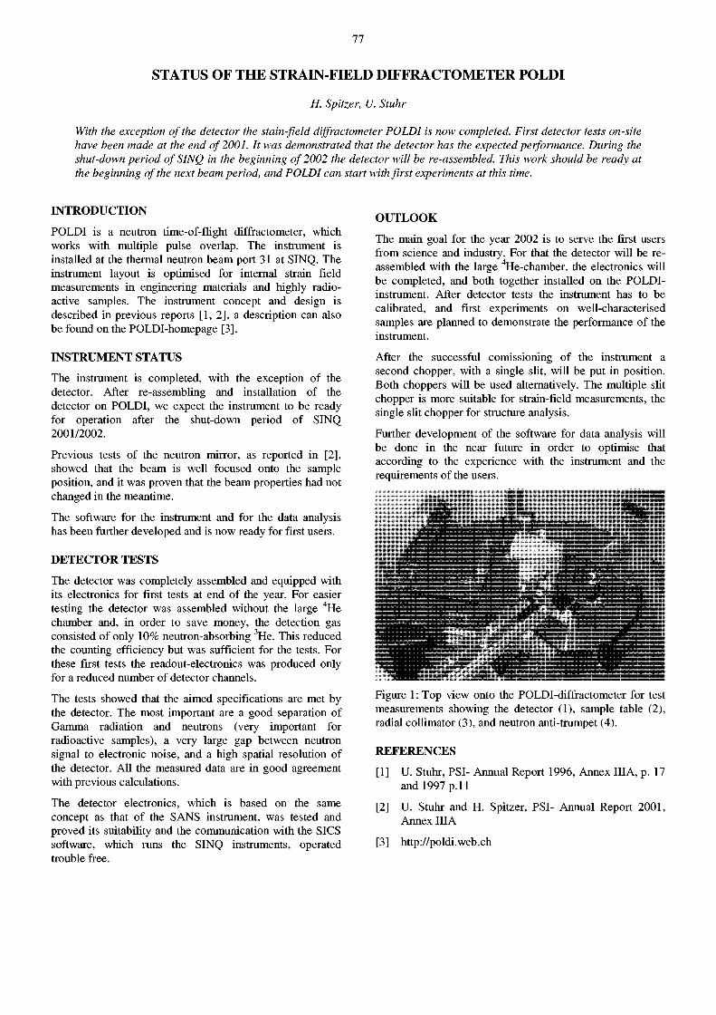
77
STATUS OF THE STRAIN-FIELD DIFFRACTOMETER POLDI
H. Spitzer, U. Stuhr
With the exception of the detector the stain-field diffractometer POLDI is now completed. First detector tests on-site have been made at the end of 2001. It was demonstrated that the detector has the expected performance. During the shut-down period of SINQ in the beginning of 2002 the detector will be re-assembled. This work should be ready at the beginning of the next beam period, and POLDI can start with first experiments at this time.
INTRODUCTION
POLDI is a neutron time-of-flight diffractometer, which works with multiple pulse overlap. The instrument is installed at the thermal neutron beam port 31 at SINQ. The instrument layout is optimised for internal strain field measurements in engineering materials and highly radioactive samples. The instrument concept and design is described in previous reports [1, 2], a description can also be found on the POLDI-homepage [3].
INSTRUMENT STATUS
The instrument is completed, with the exception of the detector. After re-assembling and installation of the detector on POLDI, we expect the instrument to be ready for operation after the shut-down period of SINQ 2001/2002.
Previous tests of the neutron mirror, as reported in [2], showed that the beam is well focused onto the sample position, and it was proven that the beam properties had not changed in the meantime.
The software for the instrument and for the data analysis has been further developed and is now ready for first users.
DETECTOR TESTS
The detector was completely assembled and equipped with its electronics for first tests at end of the year. For easier testing the detector was assembled without the large 4 He chamber and, in order to save money, the detection gas consisted of only 10% neutron-absorbing 3He. This reduced the counting efficiency but was sufficient for the tests. For these first tests the readout-electronics was produced only for a reduced number of detector channels.
The tests showed that the aimed specifications are met by the detector. The most important are a good separation of Gamma radiation and neutrons (very important for radioactive samples), a very large gap between neutron signal to electronic noise, and a high spatial resolution of the detector. All the measured data are in good agreement with previous calculations.
The detector electronics, which is based on the same concept as that of the SANS instrument, was tested and proved its suitability and the communication with the SICS software, which runs the SINQ instruments, operated trouble free.
OUTLOOK
The main goal for the year 2002 is to serve the first users from science and industry. For that the detector will be reassembled with the large 4He-chamber, the electronics will be completed, and both together installed on the POLDI-instrument. After detector tests the instrument has to be calibrated, and first experiments on well-characterised samples are planned to demonstrate the performance of the instrument.
After the successful comissioning of the instrument a second chopper, with a single slit, will be put in position. Both choppers will be used alternatively. The multiple slit chopper is more suitable for strain-field measurements, the single slit chopper for structure analysis.
Further development of the software for data analysis will be done in the near future in order to optimise that according to the experience with the instrument and the requirements of the users.
•
Figure 1: Top view onto the POLDI-diffractometer for test measurements showing the detector (1), sample table (2), radial collimator (3), and neutron anti-trumpet (4).
REFERENCES
[1] U. Stuhr, PSI- Annual Report 1996, Annex IIIA, p. 17 and 1997 p. 11
[2] U. Stuhr and H. Spitzer, PSI- Annual Report 2001, Annex IIIA
[3] http://poldi.web.ch
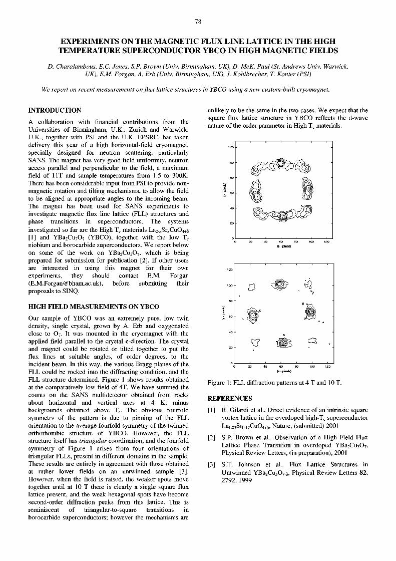
78
EXPERIMENTS ON THE MAGNETIC FLUX LINE LATTICE IN THE HIGH TEMPERATURE SUPERCONDUCTOR YBCO IN HIGH MAGNETIC FIELDS
D. Charalambous, E.C. Jones, S.P. Brown (Univ. Birmingham, UK), D. McK. Paul (St. Andrews Univ. Warwick, UK), E.M. Forgan, A. Erb (Univ. Birmingham, UK), J. Kohlbrecher, T. Konter (PSI)
We report on recent measurements on flux lattice structures in YBCO using a new custom-built cryomagnet.
I N T R O D U C T I O N
A collaboration with financial contributions from the Universities of Birmingham, U.K., Zurich and Warwick, U.K., together with PSI and the U.K. EPSRC, has taken delivery this year of a high horizontal-field cryomagnet, specially designed for neutron scattering, particularly SANS. The magnet has very good field uniformity, neutron access parallel and perpendicular to the field, a maximum field of 1 IT and sample temperatures from 1.5 to 300K. There has been considerable input from PSI to provide nonmagnetic rotation and tilting mechanisms, to allow the field to be aligned at appropriate angles to the incoming beam. The magnet has been used for SANS experiments to investigate magnetic flux line lattice (FLL) structures and phase transitions in superconductors. The systems investigated so far are the High T c materials La 2_ xSr xCu0 4 +s [1] and YBa 2 Cu 3 0 7 (YBCO), together with the low T c
niobium and borocarbide superconductors. We report below on some of the work on YBa 2 Cu 3 0 7 , which is being prepared for submission for publication [2]. If other users are interested in using this magnet for their own experiments, they should contact E.M. Forgan ([email protected]), before submitting their proposals to SINQ.
H I G H F I E L D M E A S U R E M E N T S O N Y B C O
Our sample of YBCO was an extremely pure, low twin density, single crystal, grown by A. Erb and oxygenated close to 0 7 . It was mounted in the cryomagnet with the applied field parallel to the crystal c-direction. The crystal and magnet could be rotated or tilted together to put the flux lines at suitable angles, of order degrees, to the incident beam. In this way, the various Bragg planes of the FLL could be rocked into the diffracting condition, and the FLL structure determined. Figure 1 shows results obtained at the comparatively low field of 4T. We have summed the counts on the SANS multidetector obtained from rocks about horizontal and vertical axes at 4 K, minus backgrounds obtained above T c. The obvious fourfold symmetry of the pattern is due to pinning of the FLL orientation to the average fourfold symmetry of the twinned orthorhombic structure of YBCO. However, the FLL structure itself has triangular coordination, and the fourfold symmetry of Figure 1 arises from four orientations of triangular FLLs, present in different domains in the sample. These results are entirely in agreement with those obtained at rather lower fields on an untwinned sample [3]. However, when the field is raised, the weaker spots move together until at 10 T there is clearly a single square flux lattice present, and the weak hexagonal spots have become second-order diffraction peaks from this lattice. This is reminiscent of triangular-to-square transitions in borocarbide superconductors; however the mechanisms are
unlikely to be the same in the two cases. We expect that the square flux lattice structure in YBCO reflects the d-wave nature of the order parameter in High T c materials.
Figure 1: FLL diffraction patterns at 4 T and 10 T.
R E F E R E N C E S
[1] R. Gilardi et al., Direct evidence of an intrinsic square vortex lattice in the overdoped high-Tc superconductor La 1 83Sro.i7Cu04+ 8, Nature, (submitted) 2001
[2] S.P. Brown et al., Observation of a High Field Flux Lattice Phase Transition in overdoped YBa 2 Cu 3 0 7 , Physical Review Letters, (in preparation), 2001
[3] S.T. Johnson et al., Flux Lattice Structures in Untwinned YBa2Cu307_5, Physical Review Letters 82, 2792, 1999
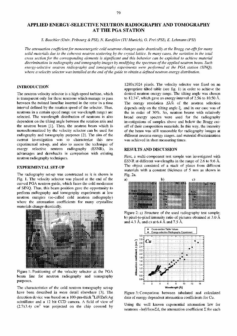
79
APPLIED ENERGY-SELECTIVE NEUTRON RADIOGRAPHY AND TOMOGRAPHY AT THE PGA STATION
S. Baechler (Univ. Fribourg & PSI), N. Kardjilov (TU Munich), G. Frei (PSI), E. Lehmann (PSI)
The attenuation coefficient for monoenergetic cold neutrons changes quite drastically at the Bragg cut-offs for many solid materials due to the coherent neutron scattering by the crystal lattice. In many cases, the variation in the total cross section for the corresponding elements is significant and this behavior can be exploited to achieve material discrimination in radiography and tomography images by modifying the spectrum of the applied neutron beam. Such energy-selective neutron radiography and tomography experiments were performed at the PGA station (SINQ), where a velocity selector was installed at the end of the guide to obtain a defined neutron energy distribution.
INTRODUCTION
The neutron velocity selector is a high-speed turbine, which is transparent only for these neutrons which manage to pass between the twisted lamellae inserted in the rotor in a time interval defined by the rotation speed of the selector. Thus, neutrons in a certain speed range (or wavelength range) are selected. The wavelength distribution of neutrons is also dependent on the tilting angle between the rotation axis and the neutron beam [1]. Then, the neutron beam which is monochromatized by the velocity selector can be used for radiography and tomography purposes [2]. The aim of the current investigation was to characterize this new experimental set-up, and also to assess the technique of energy selective neutron radiography (ESNR), its advantages and drawbacks in comparison with existing neutron radiography techniques.
EXPERIMENTAL SET-UP
The radiography set-up was constructed as it is shown in Fig. 1. The velocity selector was placed at the end of the curved PGA neutron guide, which faces the cold moderator of SINQ. Thus, this beam position gave the opportunity to perform radiography and tomography experiments at low neutron energies (so-called cold neutron radiography) where the attenuation coefficients for many crystalline materials change drastically.
Figure 1: Positioning of the velocity selector at the PGA beam line for neutron radiography and tomography purposes.
The characteristics of the cold neutron tomography set-up have been described in more detail elsewhere [3]. The detection device was based on a 100-um-thick 6LiF/ZnS:Ag scintillator and a 12 bit CCD camera. A field of view of (2.7x3.4) cm 2 was projected on the chip covered by
1280x1024 pixels. The velocity selector was fixed on an appropriate tilted table (see fig. 1) in order to achieve the desired neutron energy range. The tilting angle was chosen to 12.74°, which gave an energy interval of 2.56 to 10.50 A. The energy resolution Äk/X of the neutron selection depends only on the tilting angle \ , and in our case was of the in order of 30%. So, neutron beams with relatively broad energy spectra were used for the radiography investigations of samples above and below the Bragg cutoff of their composition materials. In this way, the intensity of the beam was still reasonable for radiography images at different neutron energy ranges, and material discrimination was achieved in short measuring times.
RESULTS AND DISCUSSION
First, a multi-component test sample was investigated with ESNR at different wavelengths in the range of 2.6 to 9.6 Â. The object consisted of a stack of plates from different materials with a constant thickness of 5 mm as shown in Fig. 2a. a) b) c)
« M ii
Figure 2: a) Structure of the used radiography test sample; b) pixel-to-pixel intensity ratio of pictures obtained at 3.0 A and 4.3 Â, and c) at 6.4 Â and 7.5 Â.
• Cross-section Table Values A Energy-selective Radiography Experiment
1 1 1 1 1 1 1
Cu ' 1 ! 1 ! 1
.. ..m. •• m
• m ••
A
A A .
• • :
•
0 2 4 6 8 10 12 14 Wavelength [Â]
Figure 3: Comparison between tabulated and calculated data of energy dependent attenuation coefficients for Cu.
Using the well known exponential attenuation law for neutrons -ln(I/Io)=Xd, the attenuation coefficient X for each
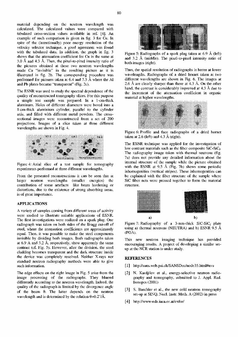
80
material depending on the neutron wavelength was calculated. The calculated values were compared with tabulated cross-section values available in ref. [4]. An example of such comparison is given in fig. 3 for Cu. In spite of the (intentionally) poor energy resolution of the velocity selector technique, a good agreement was found with the tabulated data. In addition, the graph in fig. 3 shows that the attenuation coefficient for Cu is the same at 3.0 A and 4.3 A. Then, the pixel-to-pixel intensity ratio of the pictures obtained at these two neutron wavelengths made Cu "invisible" in the resulting picture as it is illustrated in fig. 2b. The corresponding procedure was performed for pictures taken at 6.4 and 7.5 A where the Al and Pb plates became "transparent" (Fig. 2c).
The ESNR was used to study the spectral dependence of the quality of reconstructed tomography slices. For this purpose a simple test sample was prepared. In a 1-cm-thick aluminum. Holes of different diameters were bored into a 1-cm-thick aluminium cylinder, parallel to the cylinder axis, and filled with different metal powders. The cross-sectional images were reconstructed from a set of 200 projections. Images of a slice taken at three different wavelengths are shown in Fig. 4.
Beambarctening Strong absorbing ar©a
Figure 4: Axial slice of a test sample for tomography experiments performed at three different wavelengths.
From the presented reconstructions it can be seen that at larger neutron wavelengths (smaller energies) the contribution of some artefacts like beam hardening or distortions, due to the existence of strong absorbing areas, is of great importance.
APPLICATIONS
A variety of samples coming from different areas of activity were studied to illustrate suitable applications of ESNR. The first investigations were realized on a spark plug. One radiograph was taken on both sides of the Bragg cut-off of steel, where the attenuation coefficients are approximately equal. Then, it was possible to make the steel components invisible by dividing both images. Both radiographs taken at 6.9 Â and 3.2 Â, respectively, show apparently the same contrast (cf. Fig. 5). However, after the division, the steel cladding becomes transparent and the dark structure inside the device was completely resolved. Neither X-rays nor standard neutron radiography methods were able to give such information.
The edge effects on the right image in Fig. 5 arise from the image processing of the radiographs. They blurred differently according to the neutron wavelength. Indeed, the quality of the radiograph is limited by the divergence angle of the beam 6. The latter depends on the neutron wavelength and is determined by the relation 6=0.2°/A.
Figure 5: Radiographs of a spark plug taken at 6.9 Â (left) and 3.2 A (middle). The pixel-to-pixel intensity ratio of both images (right).
Thus, the spatial resolution of radiographs is better at lower wavelengths. Radiographs of a dried hornet taken at two different wavelengths are shown in Fig. 6. The images at 2.6 A are clearly sharper than those at 4.3 A. On the other hand, the contrast is considerably improved at 4.3 A due to the increment of the attenuation coefficient in organic material at higher wavelengths.
Figure 6: Profile and face radiographs of a dried hornet taken at 2.6 (left) and 4.3 Â (right).
The ESNR technique was applied for the investigation of low contrast materials such as the fiber composite SiC-SiC f. The radiography image taken with thermal neutrons (fig. 7a) does not provide any detailed information about the internal structure of the sample while the picture obtained with the ESNR at 9.5 A (Fig. 7b) shows some periodic inhomogenities (vertical stripes). These inhomogenities can be explained with the fiber structure of the sample where SiC fiber nets were pressed together to form the material structure.
a) b) Figure 7: Radiography of a 3-mm-thick SiC-SiC f plate using a) thermal neutrons (NEUTRA) and b) ESNR 9.5 Â (PGA).
This new neutron imaging technique has provided encouraging results. A project of developing a similar setup at the NCR station is under study.
REFERENCES
[1] http://sans.web.psi.ch/SANSDoc/node35.html#nvs
[2] N. Kardjilov et al., energy-selective neutron radiography and tomography, submitted to J. Appl. Rad. Isotopes (2001)
[3] S. Baechler et al., the new cold neutron tomography set-up at SINQ, Nucl. Instr. Meth. A (2002) in press
[4 ] http://www-nds.iaea.or.at/exfor/
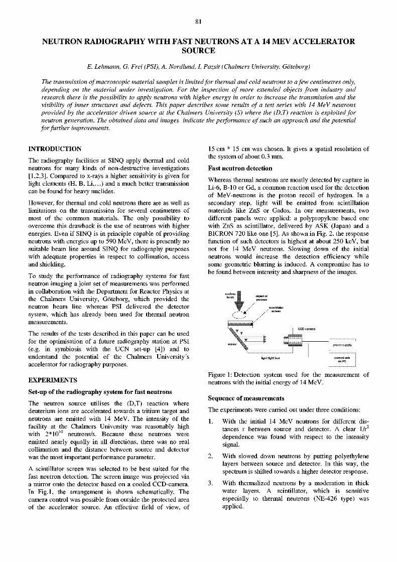
81
NEUTRON RADIOGRAPHY WITH FAST NEUTRONS AT A 14 MEV ACCELERATOR SOURCE
E. Lehmann, G. Frei (PSI), A. Nordlund, I. Pazsit (Chalmers University, Göteborg)
The transmission of macroscopic material samples is limited for thermal and cold neutrons to a few centimetres only, depending on the material under investigation. For the inspection of more extended objects from industry and research there is the possibility to apply neutrons with higher energy in order to increase the transmission and the visibility of inner structures and defects. This paper describes some results of a test series with 14 MeV neutrons provided by the accelerator driven source at the Chalmers University (S) where the (D,T) reaction is exploited for neutron generation. The obtained data and images indicate the performance of such an approach and the potential for further improvements.
INTRODUCTION
The radiography facilities at SINQ apply thermal and cold neutrons for many kinds of non-destructive investigations [1,2,3]. Compared to x-rays a higher sensitivity is given for light elements (H, B, Li,...) and a much better transmission can be found for heavy nuclides.
However, for thermal and cold neutrons there are as well as limitations on the transmission for several centimetres of most of the common materials. The only possibility to overcome this drawback is the use of neutrons with higher energies. Even if SINQ is in principle capable of providing neutrons with energies up to 590 MeV, there is presently no suitable beam line around SINQ for radiography purposes with adequate properties in respect to collimation, access and shielding.
To study the performance of radiography systems for fast neutron imaging a joint set of measurements was performed in collaboration with the Department for Reactor Physics at the Chalmers University, Göteborg, which provided the neutron beam line whereas PSI delivered the detector system, which has already been used for thermal neutron measurements.
The results of the tests described in this paper can be used for the optimisation of a future radiography station at PSI (e.g. in symbiosis with the UCN set-up [4]) and to understand the potential of the Chalmers University's accelerator for radiography purposes.
EXPERIMENTS
Set-up of the radiography system for fast neutrons
The neutron source utilises the (D,T) reaction where deuterium ions are accelerated towards a tritium target and neutrons are emitted with 14 MeV. The intensity of the facility at the Chalmers University was reasonably high with 2*10 1 0 neutrons/s. Because these neutrons were emitted nearly equally in all directions, there was no real collimation and the distance between source and detector was the most important performance parameter.
A scintillator screen was selected to be best suited for the fast neutron detection. The screen image was projected via a mirror onto the detector based on a cooled CCD-camera. In Fig.l, the arrangement is shown schematically. The camera control was possible from outside the protected area of the accelerator source. An effective field of view, of
15 cm * 15 cm was chosen. It gives a spatial resolution of the system of about 0.3 mm.
Fast neutron detection
Whereas thermal neutrons are mostly detected by capture in Li-6, B-10 or Gd, a common reaction used for the detection of MeV-neutrons is the proton recoil of hydrogen. In a secondary step, light will be emitted from scintillation materials like ZnS or Gadox. In our measurements, two different panels were applied: a polypropylene based one with ZnS as scintillator, delivered by ASK (Japan) and a BICRON 720 like one [5]. As shown in Fig. 2, the response function of such detectors is highest at about 250 keV, but not for 14 MeV neutrons. Slowing down of the initial neutrons would increase the detection efficiency while some geometric blurring is induced. A compromise has to be found between intensity and sharpness of the images.
neutron L beam g objector
process
Figure 1: Detection system used for the measurement of neutrons with the initial energy of 14 MeV.
Sequence of measurements
The experiments were carried out under three conditions:
1. With the initial 14 MeV neutrons for different distances r between source and detector. A clear 1/r2
dependence was found with respect to the intensity signal.
2. With slowed down neutrons by putting polyethylene layers between source and detector. In this way, the spectrum is shifted towards a higher detector response.
3. With thermalized neutrons by a moderation in thick water layers. A scintillator, which is sensitive especially to thermal neutrons (NE-426 type) was applied.
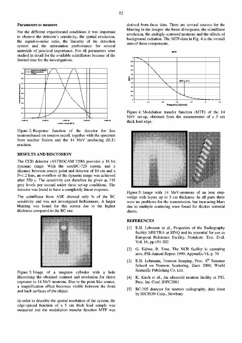
82
Parameters to measure
For the different experimental conditions it was important to observe the detector's sensitivity, the spatial resolution, the signal-to-noise ratio, the linearity of the detection system and the attenuation performance for several materials of practical importance. Not all parameters were studied in detail for the available scintillators because of the limited time for the investigations.
" " response scintillator \ "™™flsslon spectrum * \
;
: \ •
• *\ \
•L— \ 1.ÛÛE+0Û
neutron energy [MeV]
Figure 2: Response function of the detector for fast neutronsbased on neutron recoil, together with the spectrum from nuclear fission and the 14 MeV producing (D,T) reaction.
RESULTS AND DISCUSSION
The CCD detector (ASTROCAM 3200) provides a 16 bit dynamic range. With the usedBC-720 screen, and a distance between source point and detector of 10 cm and a F=1.2 lens, an overflow of the dynamic range was achieved after 550 s. The sensitivity can therefore be given as 118 grey levels per second under these set-up conditions. The detector was found to have a completely linear response.
The scintillator from ASK showed only % of the BC sensitivity and was not investigated furhtermore. A larger blurring was found for this screen due to the higher thickness compared to the BC one.
Figure 3: Image of a tungsten cylinder with a hole illustrating the obtained contrast and resolution for direct exposure to 14 MeV neutrons. Due to the point like source, a magnification effect becomes visible between the front and back surfaces of the object.
In order to describe the spatial resolution of the system, the edge-spread function of a 5 cm thick lead sample was measured and the modulation transfer function MTF was
derived from these data. There are several sources for the blurring in the images: the beam divergence, the scintillator resolution, the multiply scattered neutrons and the effects of background radiation. The MTF-data in Fig. 4 is the overall sum of these components.
0¿ 1.2
frequency [Ip/mm]
Figure 4: Modulation transfer function (MTF) of the 14 MeV set-up, obtained from the measurement of a 5 cm thick lead edge.
Figure 5: Image with 14 MeV-neutrons of an iron step-wedge with layers up to 5 cm thickness. In all parts there were no problems for the transmission, but increasing blurs due to multiple scattering were found for thicker material sheets.
REFERENCES
[1] E.H. Lehmann et al., Properties of the Radiography facility NEUTRA at SINQ and its potential for use as European Reference Facility, Nondestr. Test. Eval. Vol. 16,pp.l91-202
[2] G. Kühne, R. Erne, The NCR facility is operating now, PSI-Annual Report 1999, Appendix-VI, p. 70
[3] E.H. Lehmann, Neutron Imaging, Proc. 8 t h Summer School on Neutron Scattering, Zuoz 2000, World Scientific Publishing Co. Ltd.
[4] K. Kirch et al., An ultracold neutron facility at PSI, Proc. Int. Conf. INPC2001
[5] BC-705 detector for neutron radiography, data sheet by BICRON Corp., Newbury
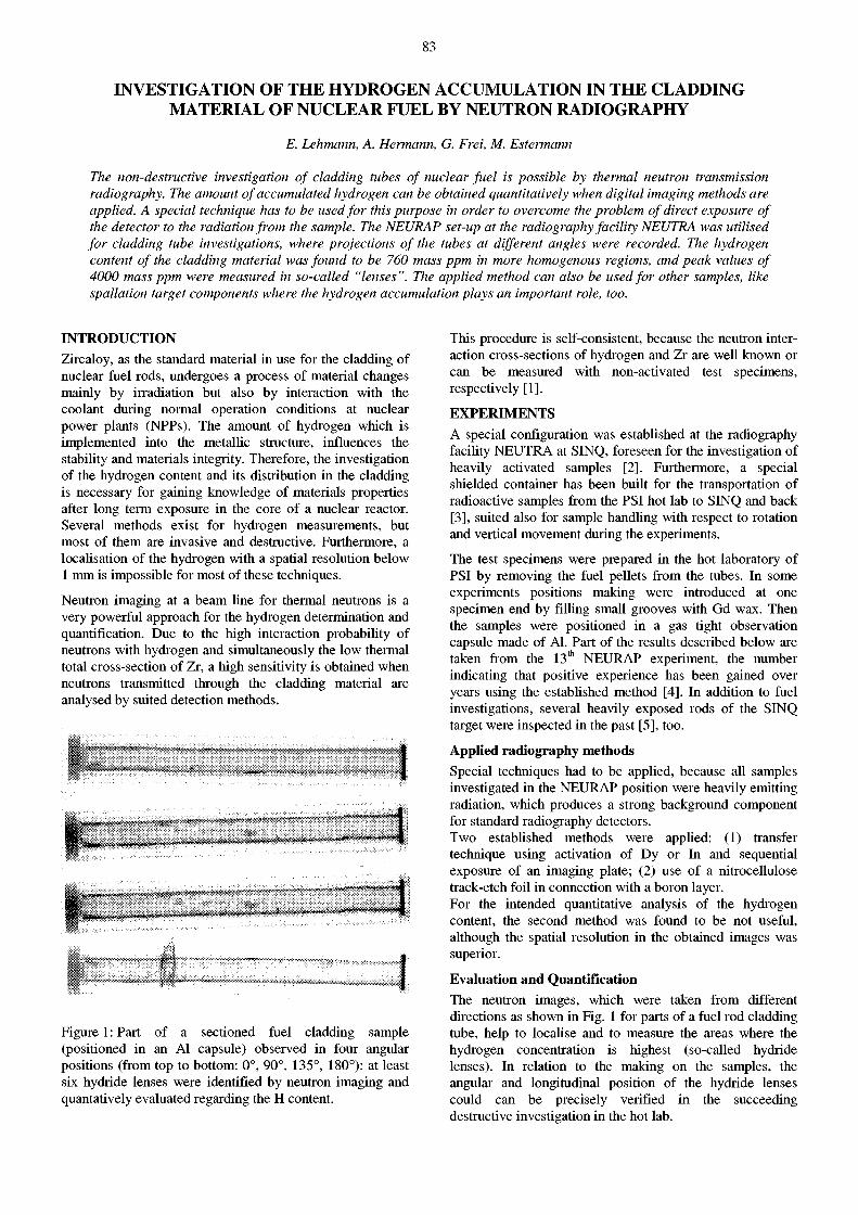
83
INVESTIGATION OF THE HYDROGEN ACCUMULATION IN THE CLADDING MATERIAL OF NUCLEAR FUEL BY NEUTRON RADIOGRAPHY
E. Lehmann, A. Hermann, G. Frei, M. Estermann
The non-destructive investigation of cladding tubes of nuclear fuel is possible by thermal neutron transmission radiography. The amount of accumulated hydrogen can be obtained quantitatively when digital imaging methods are applied. A special technique has to be used for this purpose in order to overcome the problem of direct exposure of the detector to the radiation from the sample. The NEURAP set-up at the radiography facility NEUTRA was utilised for cladding tube investigations, where projections of the tubes at different angles were recorded. The hydrogen content of the cladding material was found to be 760 mass ppm in more homogenous regions, and peak values of 4000 mass ppm were measured in so-called "lenses". The applied method can also be used for other samples, like spallation target components where the hydrogen accumulation plays an important role, too.
INTRODUCTION Zircaloy, as the standard material in use for the cladding of nuclear fuel rods, undergoes a process of material changes mainly by irradiation but also by interaction with the coolant during normal operation conditions at nuclear power plants (NPPs). The amount of hydrogen which is implemented into the metallic structure, influences the stability and materials integrity. Therefore, the investigation of the hydrogen content and its distribution in the cladding is necessary for gaining knowledge of materials properties after long term exposure in the core of a nuclear reactor. Several methods exist for hydrogen measurements, but most of them are invasive and destructive. Furthermore, a localisation of the hydrogen with a spatial resolution below 1 mm is impossible for most of these techniques.
Neutron imaging at a beam Une for thermal neutrons is a very powerful approach for the hydrogen determination and quantification. Due to the high interaction probability of neutrons with hydrogen and simultaneously the low thermal total cross-section of Zr, a high sensitivity is obtained when neutrons transmitted through the cladding material are analysed by suited detection methods.
Figure 1 : Part of a sectioned fuel cladding sample (positioned in an Al capsule) observed in four angular positions (from top to bottom: 0°, 90°, 135°, 180°): at least six hydride lenses were identified by neutron imaging and quantatively evaluated regarding the H content.
This procedure is self-consistent, because the neutron interaction cross-sections of hydrogen and Zr are well known or can be measured with non-activated test specimens, respectively [1].
EXPERIMENTS A special configuration was established at the radiography facility NEUTRA at SINQ, foreseen for the investigation of heavily activated samples [2]. Furthermore, a special shielded container has been built for the transportation of radioactive samples from the PSI hot lab to SINQ and back [3], suited also for sample handling with respect to rotation and vertical movement during the experiments.
The test specimens were prepared in the hot laboratory of PSI by removing the fuel pellets from the tubes. In some experiments positions making were introduced at one specimen end by filling small grooves with Gd wax. Then the samples were positioned in a gas tight observation capsule made of Al. Part of the results described below are taken from the 13 t h NEURAP experiment, the number indicating that positive experience has been gained over years using the established method [4]. In addition to fuel investigations, several heavily exposed rods of the SINQ target were inspected in the past [5], too.
Applied radiography methods Special techniques had to be applied, because all samples investigated in the NEURAP position were heavily emitting radiation, which produces a strong background component for standard radiography detectors. Two established methods were applied: (1) transfer technique using activation of Dy or In and sequential exposure of an imaging plate; (2) use of a nitrocellulose track-etch foil in connection with a boron layer. For the intended quantitative analysis of the hydrogen content, the second method was found to be not useful, although the spatial resolution in the obtained images was superior.
Evaluation and Quantification The neutron images, which were taken from different directions as shown in Fig. 1 for parts of a fuel rod cladding tube, help to localise and to measure the areas where the hydrogen concentration is highest (so-called hydride lenses). In relation to the making on the samples, the angular and longitudinal position of the hydride lenses could can be precisely verified in the succeeding destructive investigation in the hot lab.
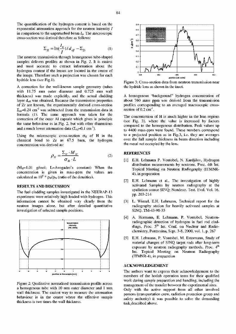
84
The quantification of the hydrogen content is based on the exponential attenuation approach for the neutron intensity I in comparison to the unperturbed beam I0. The macroscopic cross-section was derived therefore as follows:
zH=M-!-)/dejf-zZr (i)
The neutron transmission through homogenous tube-shaped samples delivers profiles as shown in Fig. 2. It is easiest and most accurate to extract information about the hydrogen content if the lenses are located in the centre of the image. Therefore such a projection was chosen for each hydride lens (see Fig.l).
A correction for the well-known sample geometry (tubes with 11.75 mm outer diameter and 0.725 mm wall thickness) was made explicitly, and the actual cladding layer d e f f was obtained. Because the transmission properties of Zr are known, the experimentally derived cross-section Zz^O.24 cm"1 was subtracted from the transmission data in formula (1). The same approach was taken for the correction of the outer Al capsule which gives in principle the same behaviour as in Fig. 2, but with other dimensions and a much lower attenuation data (ZA 1=0.1 cm"1).
Using the microscopic cross-section g h of H in the chemical bond to Zr as 67.5 barn, the hydrogen concentration was derived as:
H H ~ T (2)
(MH=1.01 g/mol; L=Avogadro's constant) When the concentration is given in mass-ppm the values are calculated as 10 6 * Pu/pzr (ratio of the densities).
RESULTS AND DISCUSSION The fuel cladding samples investigated in the NEURAP-13 experiment were relatively high loaded with hydrogen. This information cannot be obtained very clearly from the neutron images alone, but after detailed quantitative investigation of selected sample positions.
t r ansmiss ion in tens i ty [rel. un i ts ]
\ ( pos i t ion in t h e samp le [ m m ]
Figure 2: Qualitative normalised transmission profile across a homogenous tube with 10 mm outer diameter and 1 mm wall thickness. The easiest way to measure the attenuation behaviour is in the centre where the effective sample thickness is two times the wall thickness.
E o i 0 .5
W
0.4
0.3
0.2
SHll
I 1
L A A . l f\j\
300 350 400 450 500
pos i t ion [rel. un i ts ]
Figure 3: Cross-section data from neutron transmission near the hydride lens as shown in the inset.
A homogenous "background" hydrogen concentration of about 760 mass ppm was derived from the transmission profiles corresponding to an averaged macroscopic cross-section of 0.2 cm"1.
The concentration of H is much higher in the lens regions (see Fig. 3), where the value is increased by factors compared to the homogenous distribution. Peak values up to 4400 mass-ppm were found. These numbers correspond to a projected position as in Fig.3, i.e. they are averages over the full sample thickness in beam direction including the metal not occupied by the lens.
REFERENCES
[1] E.H. Lehmann P. Vontobel, N. Kardjilov, Hydrogen distribution measurements by neutrons, Proc. 4th Int. Topical Meeting on Neutron Radiography (ITMNR-4), in preparation
[2] E.H. Lehmann et al., The investigation of highly activated Samples by neutron radiography at the spallation source SINQ; Nondestr. Test. Eval. Vol. 16, pp. 203-214
[3] L. Wiezel, E.H. Lehmann, Technical report for the radiography station for heavily activated samples at SINQ, TM-43-98-35
[4] A. Hermann, E. Lehmann, P. Vontobel, Neutronradiographic detection of hydrogen in fuel rod claddings, Proc. 5 t h Int. Conf. on Nuclear and Radio-chemistry, Pontresina, Sept. 3-8, 2000, vol. 1, p. 267
[5] E.H. Lehmann, P. Vontobel, M. Estermann, Study of material changes of SINQ target rods after long-term exposure by neutron radiography methods, Proc. 4 t h
Int. Topical Meeting on Neutron Radiography (ITMNR-4), in preparation
ACKNOWLEDGEMENT The authors want to express their acknowledgement to the members of the hotlab operation team for their qualified work during sample preparation and handling, including the management of the transfer between the experimental sites. Only with the active support from all other involved persons (transportation crew, radiation protection group and safety authority) it was possible to solve the demanding task described above.
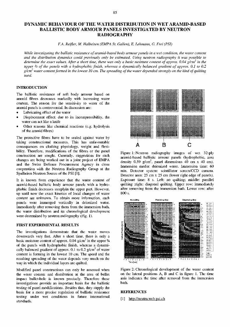
85
DYNAMIC BEHAVIOUR OF THE WATER DISTRIBUTION IN WET ARAMID-BASED BALLISTIC BODY ARMOUR PANELS INVESTIGATED BY NEUTRON
RADIOGRAPHY
F.A. Reifler, M. Halbeisen (EMPA St. Gallen), E. Lehmann, G. Frei (PSI)
While investigating the ballistic resistance of aramid-based body armour panels in a wet condition, the water content and the distribution dynamics could previously only be estimated. Using neutron radiography it was possible to determine the exact values. After a short time, there was only a basic moisture content of approx. 0.04 g/cm2 in the upper 3A of the panels with a hydrophobic finish, whereas a dynamically balanced gradient of approx. 0.1 to 0.2 g/cm2 water content formed in the lowest 10 cm. The spreading of the water depended strongly on the kind of quilting used.
INTRODUCTION
The ballistic resistance of soft body armour based on aramid fibres decreases markedly with increasing water content. The reason for the sensitivity to water of the aramid panels is controversial. In discussion are: • Lubricating effect of the water • Displacement effect: due to its incompressibility, the
water can act like a knife • Other reasons like chemical reactions (e.g. hydrolysis
of the aramid fibres)
The protective fibres have to be sealed against water by taking constructional measures. This has unfavourable consequences on clothing physiology, weight and flexibility. Therefore, modifications of the fibres or the panel construction are sought. Currently, suggestions for such changes are being worked out in a joint project of EMPA and the Swiss Defence Procurement Agency in close cooperation with the Neutron Radiography Group at the Spallation Neutron Source of the PSI [1].
It is known from experience that the water content of aramid-based ballistic body armour panels with a hydrophobic finish decreases steeplyin the upper part. However, up until now the exact kinetics of local changes of water content are unknown. To obtain more information, such panels were immerged vertically in deionized water. Immediately after removing them from the immersion bath, the water distribution and its chronological development were determined by neutron radiography (Fig. 1).
FIRST EXPERIMENTAL RESULTS
The investigations demonstrate that the water moves downwards very fast. After a short time, there is only a basic moisture content of approx. 0.04 g/cm 2 in the upper % of the panels with hydrophobic finish, whereas a dynamically balanced gradient of approx. 0.1 to 0.2 g/cm 2 of water content is forming in the lowest 10 cm. The speed and the resulting spreading of the water depends very much on the way in which the individual layers are quilted.
Modified panel constructions can only be assessed when the water content and distribution at the area of bullet impact bullet-hole is known precisely. Therefore these investigations provide an important basis for the ballistic testing of panel modifications. Besides that, they supply the basis for a more precise regulation of ballistic resistance testing under wet conditions in future international standards.
Í I
A C Figure 1: Neutron radiography images of wet 32-ply aramid-based ballistic armour panels (hydrophobic, area density 0.59 g/cm2, panel dimensions 40 cm x 40 cm). Immersion media: deionized water. Immersion time: 60 min. Detector system: scintillator screen/CCD camera. Detector area: 25 cm x 25 cm (lower right edge of panels). Exposure time: 8 s. Left: no quilting; middle: parallel quilting ;right: diagonal quilting. Upper row: immediately after removing from the immersion bath. Lower row: after 800 s.
No quilting Parallel quilting Diagonal quilting
Time [sec]
Figure 2: Chronological development of the water content on the lateral positions A, B and C in figure 1. The time axis indicates the time after removal from the immersion bath.
REFERENCES
[1] http://neutra.web.psi.ch
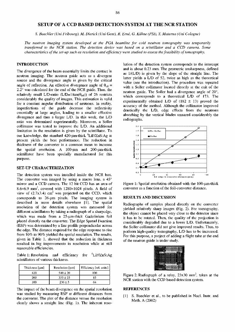
86
SETUP OF A CCD BASED DETECTION SYSTEM AT THE NCR STATION
S. Baechler (Uni Fribourg), M. Dierick (Uni Gent), R. Erné, G. Kühne (PSI), T. Materna (Uni Cologne)
The neutron imaging system developed at the PGA beamline for cold neutron tomography was temporarily transferred to the NCR station. The detection device was based on a scintillator and a CCD camera. Some characteristics of the set-up such as resolution and efficiency were studied to assess the feasibility of tomography.
INTRODUCTION
The divergence of the beam essentially limits the contact in neutron imaging. The neutron guide acts as a divergent source and the divergence angle is given by the critical angle of reflection. An effective divergence angle of 9 e f f = 2.2° was calculated for the end of the NCR guide. Thus, the relatively small L/D-ratio (L/D=l/tan(9eff)) of 26 restricts considerably the quality of images. This estimation is valid for a constant angular distribution of neutrons. In reality, imperfections of the guide decrease the reflectivity essentially at large angles, leading to a smaller effective divergence and thus a larger L/D. In this work, the L/D ratio was determined experimentally. Moreover, a Soller collimator was tested to improve the L/D. An additional Hmitation in the resolution is given by the scintillator. To our knowledge, the standard 420-irm-thick 6LiF/ZnS:Ag at present yields the best performance. The reduction in thickness of the converter is a common mean to increase the spatial resolution. A 100-um and 200-um-thick scintillator have been specially manufactured for this purpose.
SET-UP CHARACTERIZATION
The detection system was installed inside the NCR box. The converter was imaged by using a macro lens, a 45° rnirror and a CCD camera. The 12 bit CCD has an area of 8.6x6.9 mm 2, covered with 1280x1024 pixels. A field of view of (2.7x3.4) cm 2 was projected on the CCD, which corresponds to 26-um pixels. The imaging system is described in more details elsewhere [1]. The spatial resolution of the detection system was measured for different scintillators by taking a radiograph of a sharpedge, which was made from a 25-|^m-thick GadoUnium foil placed directly on the converter. The Edge Spread Function (ESF) was determined by a Une profile perpendicular across the edge. The distance required for the edge response to rise from 10% to 90% yielded the spatial resolution. The results, given in Table 1, showed that the reduction in thickness resulted in big improvements in resolution while at still reasonable efficiencies.
Table 1: Resolution and efficiency for 6LiF/ZnS:Ag scintillators of various thickness.
Thickness [um] Resolution [urn] Efficiency [rel. units]
420 540 ± 20 100 200 335 ± 25 85 100 236 ± 5 64
The impact of the beam divergence on the spatial resolution was studied by measuring ESF at different distances from the converter. The plot of the distance versus the resolution clearly shows a straight Une (Fig. 1). The inherent reso
lution of the detection system corresponds to the intercept and is about 0.23 mm. The geometric unsharpness, defined as 1/(L/D) is given by the slope of the straight Une. The latter yields a L/D of 52, twice as high as the theoretical value (see the introduction). The procedure was repeated with a Soller collimator located directly at the exit of the neutron guide. The Soller had a divergence angle of 20°, which corresponds to a theoretical L/D of 173. The experimentally obtained L/D of (182 + 13) proved the accuracy of the method. Although the collimator improved drastically the L/D, edge effects from the neutrons absorbing by the vertical blades smeared considerably the radiographs.
0 20 40 6 0 80 1 0 0 G d _ E d g e to c o n v e r t e r d i e ta n e e [ m m ]
Figure 1: Spatial resolution obtained with the 100-um-thick converter as a function of the foil-converter distance.
RESULTS AND DISCUSSION
Radiographs of samples placed directly on the converter yielded relatively sharp images (Fig. 2). For tomography, the object cannot be placed very close to the detector since it has to be rotated. Then, the quality of the projection is considerably degraded due to a lower L/D. Unfortunately, the Soller collimator did not give improved results. Thus, to perform high-quality tomography, L/D has to be increased. For this purpose, a project of adding a flight tube at the end of the neutron guide is under study.
Figure 2: Radiograph of a relay, 23x30 mm 2, taken at the NCR station with the CCD based detection system.
REFERENCES
[1] S. Baechler et al., to be published in Nucl. Instr. and Meth. A (2002)
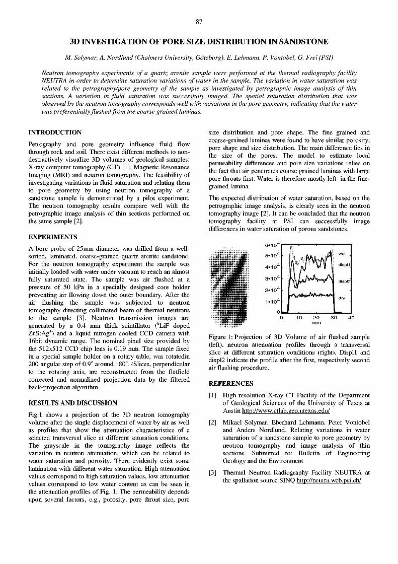
87
3D INVESTIGATION OF PORE SIZE DISTRIBUTION IN SANDSTONE
M. Solymar, A. Nordlund (Chalmers University, Göteborg), E. Lehmann, P. Vontobel, G. Frei (PSI)
Neutron tomography experiments of a quartz arenite sample were performed at the thermal radiography facility NEUTRA in order to determine saturation variations of water in the sample. The variation in water saturation was related to the petrography/pore geometry of the sample as investigated by pétrographie image analysis of thin sections. A variation in fluid saturation was successfully imaged. The spatial saturation distribution that was observed by the neutron tomography corresponds well with variations in the pore geometry, indicating that the water was preferentially flushed from the coarse grained laminas.
INTRODUCTION
Petrography and pore geometry influence fluid flow through rock and soil. There exist different methods to non-destructively visualize 3D volumes of geological samples: X-ray computer tomography (CT) [1], Magnetic Resonance Imaging (MRI) and neutron tomography. The feasibility of investigating variations in fluid saturation and relating them to pore geometry by using neutron tomography of a sandstone sample is demonstrated by a pilot experiment. The neutron tomography results compare well with the pétrographie image analysis of thin sections performed on the same sample [2].
EXPERIMENTS
A bore probe of 25mm diameter was drilled from a well-sorted, laminated, coarse-grained quartz arenite sandstone. For the neutron tomography experiment the sample was initially loaded with water under vacuum to reach an almost fully saturated state. The sample was air flushed at a pressure of 50 kPa in a specially designed core holder preventing air flowing down the outer boundary. After the air flushing the sample was subjected to neutron tomography directing collimated beam of thermal neutrons to the sample [3]. Neutron transmission images are generated by a 0.4 mm thick scintillator (6LiF doped ZnS:Ag+) and a liquid nitrogen cooled CCD camera with 16bit dynamic range. The nominal pixel size provided by the 512x512 CCD chip lens is 0.19 mm. The sample fixed in a special sample holder on a rotary table, was rotatedin 200 angular step of 0.9° around 180°. (Slices, perpendicular to the rotating axis, are reconstructed from the flatfield corrected and normalized projection data by the filtered back-projection algorithm.
RESULTS AND DISCUSSION
Fig.l shows a projection of the 3D neutron tomography volume after the single displacement of water by air as well as profiles that show the attenuation characteristics of a selected transversal slice at different saturation conditions. The grayscale in the tomography image reflects the variation in neutron attenuation, which can be related to water saturation and porosity. There evidently exist some lamination with different water saturation. High attenuation values correspond to high saturation values, low attenuation values correspond to low water content as can be seen in the attenuation profiles of Fig. 1. The permeability depends upon several factors, e.g., porosity, pore throat size, pore
size distribution and pore shape. The fine grained and coarse-grained laminas were found to have similar porosity, pore shape and size distribution. The main difference lies in the size of the pores. The model to estimate local permeability differences and pore size variations relies on the fact that air penetrates coarse grained laminas with large pore throats first. Water is therefore mostly left in the finegrained lamina.
The expected distribution of water saturation, based on the pétrographie image analysis, is clearly seen in the neutron tomography image [2]. It can be concluded that the neutron tomography facility at PSI can successfully image differences in water saturation of porous sandstones.
Figure 1: Projection of 3D Volume of air flushed sample (left), neutron attenuation profiles through a transversal slice at different saturation conditions (right). Displl and displ2 indicate the profile after the first, respectively second air flushing procedure.
REFERENCES
[1] High resolution X-ray CT Facility of the Department of Geological Sciences of the University of Texas at Austin http://www.ctlab.geo.utexas.edu/
[2] Mikael Solymar, Eberhard Lehmann, Peter Vontobel and Anders Nordlund. Relating variations in water saturation of a sandstone sample to pore geometry by neutron tomography and image analysis of thin sections. Submitted to: Bulletin of Engineering Geology and the Environment
[3] Thermal Neutron Radiography Facility NEUTRA at the spallation source SINQ http://neutra.web.psi.ch/
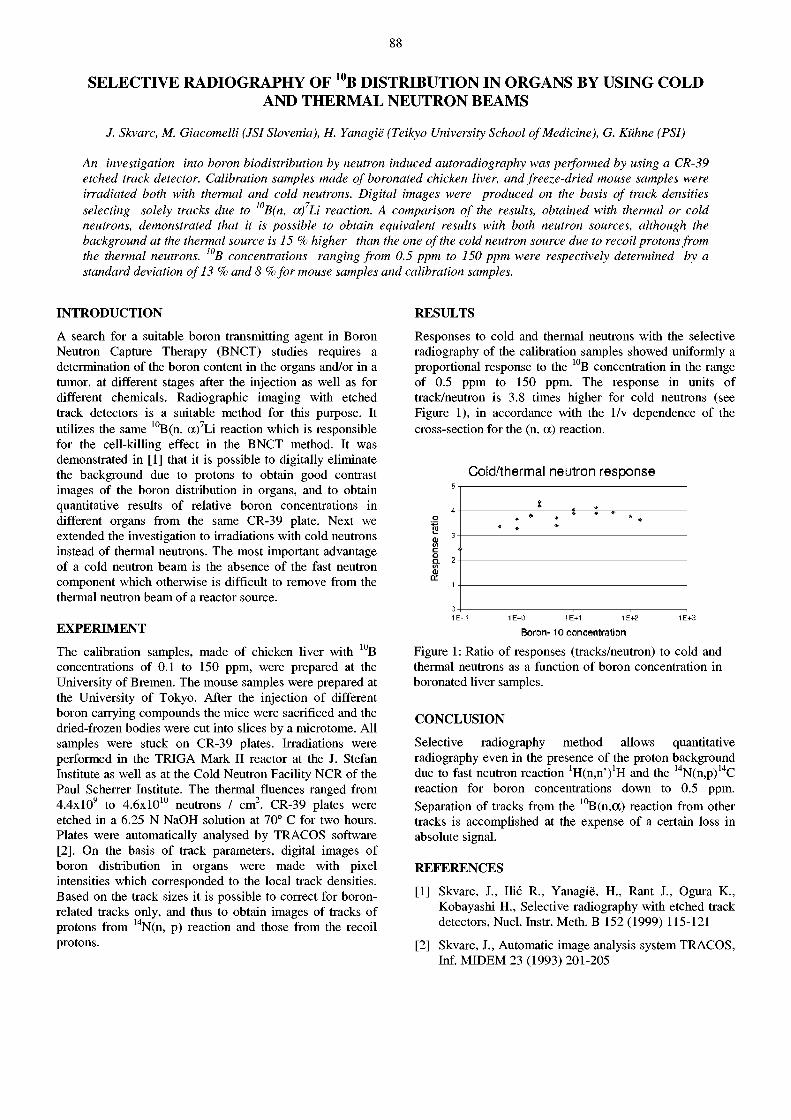
88
SELECTIVE RADIOGRAPHY OF 1 U B DISTRIBUTION IN ORGANS BY USING COLD AND THERMAL NEUTRON BEAMS
/. Skvarc, M. Giacomelli (JSI Slovenia), H. Yanagië (Teihyo University School of Medicine), G. Kühne (PSI)
An investigation into boron biodistribution by neutron induced autoradiography was performed by using a CR-39 etched track detector. Calibration samples made of boronated chicken liver, and freeze-dried mouse samples were irradiated both with thermal and cold neutrons. Digital images were produced on the basis of track densities selecting solely tracks due to 10B(n, a)7Li reaction. A comparison of the results, obtained with thermal or cold neutrons, demonstrated that it is possible to obtain equivalent results with both neutron sources, although the background at the thermal source is 15 % higher than the one of the cold neutron source due to recoil protons from the thermal neutrons. 10B concentrations ranging from 0.5 ppm to 150 ppm were respectively determined by a standard deviation of 13 % and 8 %for mouse samples and calibration samples.
INTRODUCTION
A search for a suitable boron transmitting agent in Boron Neutron Capture Therapy (BNCT) studies requires a determination of the boron content in the organs and/or in a tumor, at different stages after the injection as well as for different chemicals. Radiographic imaging with etched track detectors is a suitable method for this purpose. It utilizes the same 1 0B(n, a) 7Li reaction which is responsible for the cell-killing effect in the BNCT method. It was demonstrated in [1] that it is possible to digitally eliminate the background due to protons to obtain good contrast images of the boron distribution in organs, and to obtain quantitative results of relative boron concentrations in different organs from the same CR-39 plate. Next we extended the investigation to irradiations with cold neutrons instead of thermal neutrons. The most important advantage of a cold neutron beam is the absence of the fast neutron component which otherwise is difficult to remove from the thermal neutron beam of a reactor source.
EXPERIMENT
The calibration samples, made of chicken liver with 1 0 B concentrations of 0.1 to 150 ppm, were prepared at the University of Bremen. The mouse samples were prepared at the University of Tokyo. After the injection of different boron carrying compounds the mice were sacrificed and the dried-frozen bodies were cut into slices by a microtome. All samples were stuck on CR-39 plates. Irradiations were performed in the TRIGA Mark II reactor at the J. Stefan Institute as well as at the Cold Neutron Facility NCR of the Paul Scherrer Institute. The thermal fluences ranged from 4.4xl0 9 to 4 .6x l0 1 0 neutrons / cm 2. CR-39 plates were etched in a 6.25 N NaOH solution at 70° C for two hours. Plates were automatically analysed by TRACOS software [2]. On the basis of track parameters, digital images of boron distribution in organs were made with pixel intensities which corresponded to the local track densities. Based on the track sizes it is possible to correct for boron-related tracks only, and thus to obtain images of tracks of protons from 1 4N(n, p) reaction and those from the recoil protons.
RESULTS
Responses to cold and thermal neutrons with the selective radiography of the calibration samples showed uniformly a proportional response to the 1 0 B concentration in the range of 0.5 ppm to 150 ppm. The response in units of track/neutron is 3.8 times higher for cold neutrons (see Figure 1), in accordance with the 1/v dependence of the cross-section for the (n, a) reaction.
Cold/thermal neutron r e s p o n s e
0-1 : 1 1 1
1E-1 1E+0 1E+1 1E+2 1E+3
Boron-10 concentration Figure 1: Ratio of responses (tracks/neutron) to cold and thermal neutrons as a function of boron concentration in boronated liver samples.
CONCLUSION
Selective radiography method allows quantitative radiography even in the presence of the proton background due to fast neutron reaction 'Hin.n') 1!! and the 1 4N(n,p) 1 4C reaction for boron concentrations down to 0.5 ppm. Separation of tracks from the 10B(n,(X) reaction from other tracks is accomplished at the expense of a certain loss in absolute signal.
REFERENCES
[1] Skvarc, J., Ilic R., Yanagië, H., Rant J., Ogura K., Kobayashi H., Selective radiography with etched track detectors, Nucí. Instr. Meth. B 152 (1999) 115-121
[2] Skvarc, J., Automatic image analysis system TRACOS, Inf. MIDEM 23 (1993) 201-205
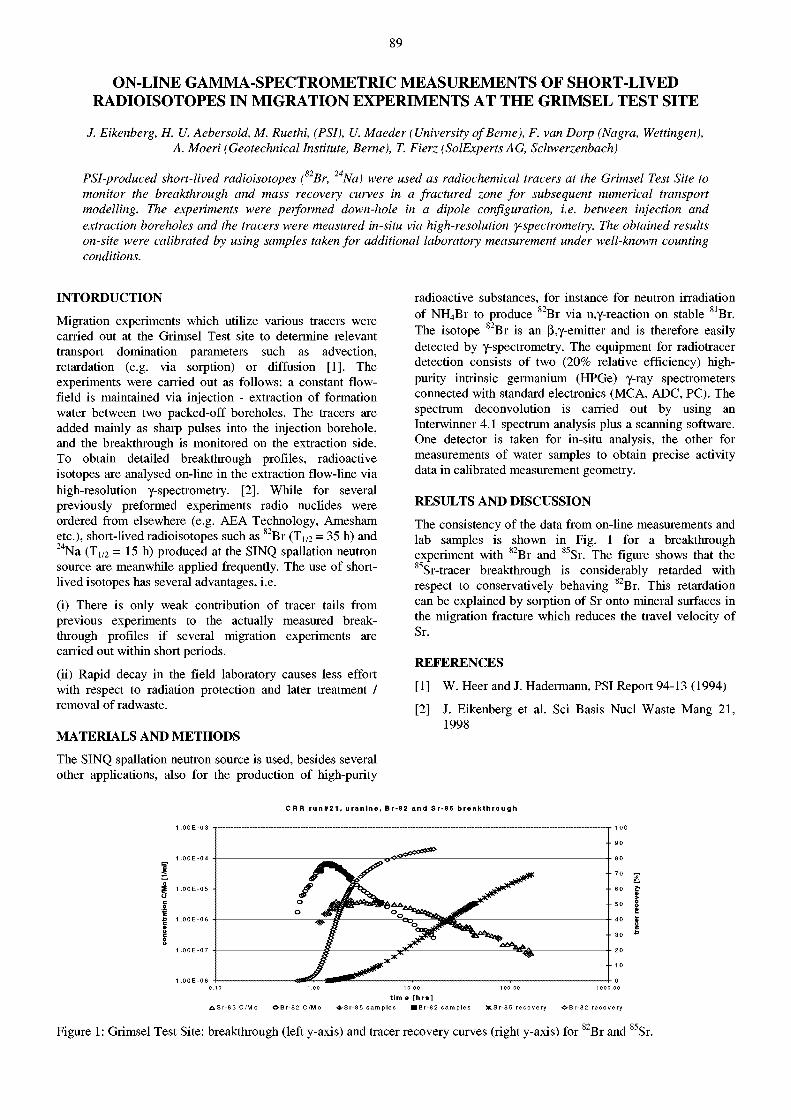
89
ON-LINE GAMMA-SPECTROMETRIC MEASUREMENTS OF SHORT-LIVED RADIOISOTOPES IN MIGRATION EXPERIMENTS AT THE GRIMSEL TEST SITE
/. Eikenberg, H. U. Aebersold, M. Ruethi, (PSI), U. Maeder (University of Berne), F. van Dorp (Nagra, Wettingen), A. Moeri (Geotechnical Institute, Berne), T. Fierz (SolExperts AG, Schwerzenbach)
PSI-produced short-lived radioisotopes (82Br, 24Na) were used as radiochemical tracers at the Grimsel Test Site to monitor the breakthrough and mass recovery curves in a fractured zone for subsequent numerical transport modelling. The experiments were performed down-hole in a dipole configuration, i.e. between injection and extraction boreholes and the tracers were measured in-situ via high-resolution y-spectrometry. The obtained results on-site were calibrated by using samples taken for additional laboratory measurement under well-known counting conditions.
INTORDUCTION
Migration experiments which utilize various tracers were carried out at the Grimsel Test site to determine relevant transport domination parameters such as advection, retardation (e.g. via sorption) or diffusion [1]. The experiments were carried out as follows: a constant flow-field is maintained via injection - extraction of formation water between two packed-off boreholes. The tracers are added mainly as sharp pulses into the injection borehole, and the breakthrough is monitored on the extraction side. To obtain detailed breakthrough profiles, radioactive isotopes are analysed on-line in the extraction flow-line via high-resolution y-spectrometry. [2]. While for several previously preformed experiments radio nuclides were ordered from elsewhere (e.g. AEA Technology, Amesham etc.), short-lived radioisotopes such as 8 2 Br (JM = 35 h) and 2 4 Na (Ti /2 = 15 h) produced at the SINQ spallation neutron source are meanwhile applied frequently. The use of shortlived isotopes has several advantages, i.e.
(i) There is only weak contribution of tracer tails from previous experiments to the actually measured breakthrough profiles if several migration experiments are carried out within short periods.
(ii) Rapid decay in the field laboratory causes less effort with respect to radiation protection and later treatment / removal of radwaste.
MATERIALS AND METHODS
The SINQ spallation neutron source is used, besides several other applications, also for the production of high-purity
radioactive substances, for instance for neutron irradiation of NIL,Br to produce 8 2 Br via n,y-reaction on stable 8 1Br. The isotope 8 2 Br is an ß,y-emitter and is therefore easily detected by y-spectrometry. The equipment for radiotracer detection consists of two (20% relative efficiency) high-purity intrinsic germanium (HPGe) y-ray spectrometers connected with standard electronics (MCA, ADC, PC). The spectrum deconvolution is carried out by using an Interwinner 4.1 spectrum analysis plus a scanning software. One detector is taken for in-situ analysis, the other for measurements of water samples to obtain precise activity data in calibrated measurement geometry.
RESULTS AND DISCUSSION
The consistency of the data from on-line measurements and lab samples is shown in Fig. 1 for a breakthrough experiment with 8 2 Br and 8 5Sr. The figure shows that the 85Sr-tracer breakthrough is considerably retarded with respect to conservatively behaving 8 2Br. This retardation can be explained by sorption of Sr onto mineral surfaces in the migration fracture which reduces the travel velocity of Sr.
REFERENCES
[1] W. Heer and J. Hadermann, PSI Report 94-13 (1994)
[2] J. Eikenberg et al. Sei Basis Nucl Waste Mang 21, 1998
C R R r u n # 2 1 , u r a n i n e , B r - 8 2 a n d S r - 8 5 b r e a k t h r o u g h
E
o
•
S" * £ -
V A
0 . 1 0 1 .0 0 1 0.0 0 1 0 0 . 0 0 1 0 0 0 . 0 0
t i m e [ h r s ] A S r - 8 5 C / M o O B r - 8 2 C / H o # S r - 8 5 s a m p l e s • B r - 8 2 s a m p l e s a c S r - 8 5 r e c o v e r y • B r - 8 2 r e c o v e r y
Figure 1: Grimsel Test Site: breakthrough (left y-axis) and tracer recovery curves (right y-axis) for 8 2 Br and 8 5Sr.
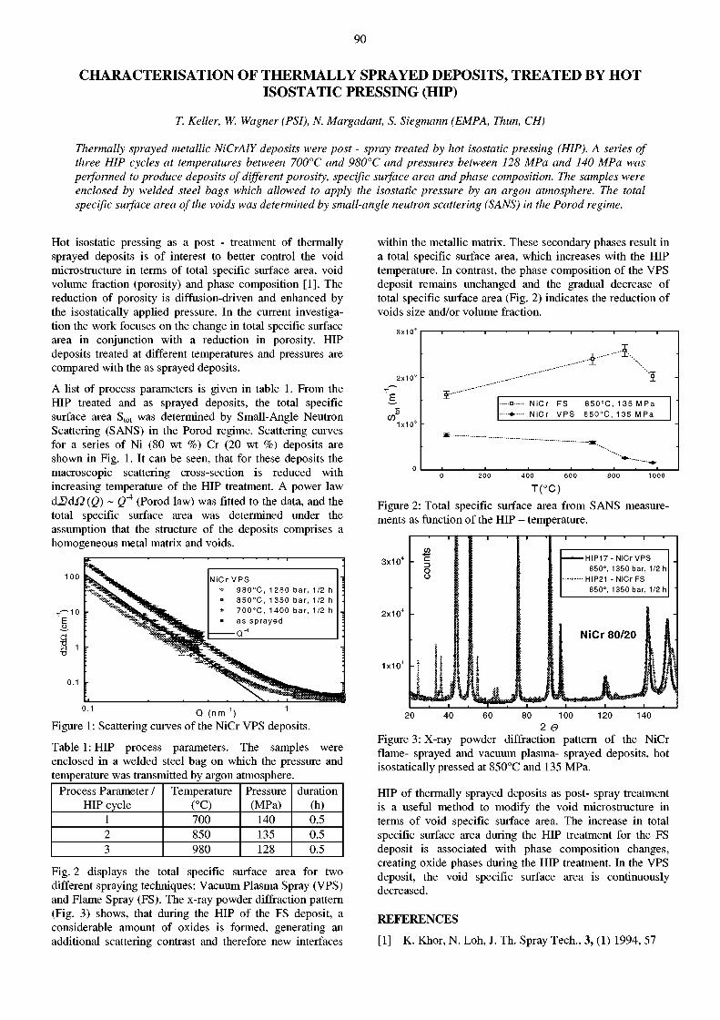
90
CHARACTERISATION OF THERMALLY SPRAYED DEPOSITS, TREATED BY HOT ISOSTATIC PRESSING (HIP)
T. Keller, W. Wagner (PSI), N Margadant, S. Siegmann (EMPA, Thun, CH)
Thermally sprayed metallic NiCrAlY deposits were post - spray treated by hot isostatic pressing (HIP). A series of three HIP cycles at temperatures between 700°C and 980°C and pressures between 128 MPa and 140 MPa was performed to produce deposits of different porosity, specific surface area and phase composition. The samples were enclosed by welded steel bags which allowed to apply the isostatic pressure by an argon atmosphere. The total specific surface area of the voids was determined by small-angle neutron scattering (SANS) in the Por od regime.
Hot isostatic pressing as a post - treatment of thermally sprayed deposits is of interest to better control the void microstructure in terms of total specific surface area, void volume fraction (porosity) and phase composition [1]. The reduction of porosity is diffusion-driven and enhanced by the isostatically applied pressure. In the current investigation the work focuses on the change in total specific surface area in conjunction with a reduction in porosity. HIP deposits treated at different temperatures and pressures are compared with the as sprayed deposits.
A list of process parameters is given in table 1. From the HIP treated and as sprayed deposits, the total specific surface area S t o t was determined by Small-Angle Neutron Scattering (SANS) in the Porod regime. Scattering curves for a series of Ni (80 wt %) Cr (20 wt %) deposits are shown in Fig. 1. It can be seen, that for these deposits the macroscopic scattering cross-section is reduced with increasing temperature of the HIP treatment. A power law âIlâ£2(Q) ~ Ô"4 (Porod law) was fitted to the data, and the total specific surface area was determined under the assumption that the structure of the deposits comprises a homogeneous metal matrix and voids.
NiCr V P S •» 9 8 0 ° C , 1 280 bar, 1/2 h • 8 5 0 ° C , 1 3 5 0 bar, 1/2 h » 7 0 0 ° C , 1 4 0 0 bar, 1/2 h • as sprayed
O"4
Q ( n r r f 1 )
Figure 1: Scattering curves of the NiCr VPS deposits.
Table 1: HIP process parameters. The samples were enclosed in a welded steel bag on which the pressure and temperature was transmitted by argon atmosphere.
Process Parameter / Temperature Pressure duration HIP cycle (°C) (MPa) (h)
1 700 140 0.5 2 850 135 0.5 3 980 128 0.5
Fig. 2 displays the total specific surface area for two different spraying techniques: Vacuum Plasma Spray (VPS) and Flame Spray (FS). The x-ray powder diffraction pattern (Fig. 3) shows, that during the HIP of the FS deposit, a considerable amount of oxides is formed, generating an additional scattering contrast and therefore new interfaces
within the metallic matrix. These secondary phases result in a total specific surface area, which increases with the HIP temperature. In contrast, the phase composition of the VPS deposit remains unchanged and the gradual decrease of total specific surface area (Fig. 2) indicates the reduction of voids size and/or volume fraction.
3x10
O
CO 1x10'
ï
---o NiCr F S 8 5 0 ° C , 1 3 5 M P a NiCr V P S 8 5 0 ° C , 1 3 5 M P a
T(°C) Figure 2: Total specific surface area from SANS measurements as function of the HIP - temperature.
3x10 -
2 x 1 0 4 -
1x10 4 -
¡o c O
o
— H I P 1 7 - NiCr VPS 850°, 1350 bar, 1/2 h
--<—HIP21 - N i C r F S 850°, 1350 bar, 1/2 h
80 100 120 2 0
Figure 3: X-ray powder diffraction pattern of the NiCr flame- sprayed and vacuum plasma- sprayed deposits, hot isostatically pressed at 850°C and 135 MPa.
HIP of thermally sprayed deposits as post- spray treatment is a useful method to modify the void microstructure in terms of void specific surface area. The increase in total specific surface area during the HIP treatment for the FS deposit is associated with phase composition changes, creating oxide phases during the HIP treatment. In the VPS deposit, the void specific surface area is continuously decreased.
REFERENCES
[1] K. Khor, N. Loh, J. Th. Spray Tech., 3, (1) 1994, 57
91
CHARACTERIZATION OF VOID MORPHOLOGIES IN THERMALLY SPRAYED METALLIC DEPOSITS USING SCATTERING TECHNIQUES
T. Keller, W. Wagner (PSI), J. Ilavsky, A.J. Allen (NIST, Gaithersburg, USA), N Margadant, S. Siegmann (EMPA, Thun, CH), G. Barbezat, (Sulzer Metco, Wohlen, CH), J. Pisacka, (IPP, Prague, CR), R. Enzl ( Skoda Research,
Plzen, CR)
The complex void microstructures of thermally sprayed deposits can be modelled by three major void subsystems: interlamellar pores, intralamellar cracks, and volumetric globular voids, each having different volume fractions, anisotropy, size and shape. This complex void morphology is expected to have a strong influence on the properties of thermally sprayed coatings. A NiCrAlY deposit was manufactured by atmospheric-plasma spray (APS), and the total specific surface area of the voids was determined by small angle neutron scattering (SANS) in the Porod regime. To characterize the void system in more detail, the technique of multiple small angle neutron scattering (MSANS) was applied. The three-component void morphology was modeled, based on empirical considerations and on the analysis of SEM micrographs of coating cross-sections. The model results suggest that for this APS metallic deposit the interlamellar pores are the dominant component of the overall void system. Only a small void volume fraction is found for the fine intralamellar crack system.
The microstructure of thermally sprayed deposits, and therefore their material properties, are to a large extent related to the internal void structure. Important parameters are the total void volume fraction and the total specific surface area of the voids. Of further interest are usually average pore size as well as the orientation of aniso-tropically shaped pores. Small-angle neutron scattering (SANS) techniques can provide information on the total specific surface area and, in principal, also directly on the size of voids up to about 100 nm. The complex void structure of many thermal spray deposits extends over a size regime up to a few micrometers in diameter, such that it does not allow a direct determination of the pore size by this method. Nevertheless, the total specific surface area can still be obtained in the Porod regime [1]. A method has been developed to deduce average pore size and orientational distribution by the technique of multiple small-angle neutron scattering (MSANS). The analysis employs the experimentally determined wavelength-dependent broadening of the primary neutron beam, when the neutrons undergo copious multiple scattering in the sample. Recently this method was extended to model the void structure of thermally sprayed ceramic deposits by allowing for the three distinct void subsystems [2]. In the present investigation, the MSANS technique was applied to an atmospheric plasma-sprayed metallic NiCrAlY deposit. The total specific surface area was determined previously from SANS measurements in the Porod regime [3].
The results presented here are obtained from investigations of an atmospheric plasma-sprayed (APS) metallic NiCrAlY deposit. The chemical composition of the feedstock material was 67% Ni, 22% Cr, 10% Al, 1% Y (all values in wt.%). The MSANS beam-broadening at wavelengths À between 12 A and 18 A was determined for two sample orientations with respect to the neutron beam: from a cross-section sample and a free-standing deposit. The shape of the broadened neutron beam after having passed the sample was assumed to be Gaussian. The MSANS beam broadening, rc> was expressed by the standard deviation of a Gaussian fit to the beam profile in the region of small scattering vectors. To analyze the MSANS anisotropy, the MSANS data for the cross-section sample were averaged over 15° wide sectors around the beam center, and an
ellipse was fitted to the data. The void structure was modelled and the model parameters fitted to the orientationally-averaged MSANS beam-broadening r c (À) data obtained for the two sample orientations, obeying the boundary condition of total porosity. Further modelling constraints were the total specific surface area experimentally determined from SANS and the observed MSANS anisotropy.
From the SANS analysis in the Porod regime the total specific surface area was determined to be Stot = (0.766 ± 0.010) x 10 6 m 2 m"3. The total volume fraction was found to be 0.081 ± 0.001. The experimentally determined orientationaly averaged MSANS beam-broadening is shown in Fig. 1 for the cross-section and free-standing deposit. Model and experimental anisotropics are displayed in the polar plot of Fig. 2. The MSANS anisotropy of the cross-section sample, determined by averaging the aspect ratios of the ellipses for all wavelengths, was found experimentally to be 1.35 ± 0.03.
0.0045
) 0.0035
¿ O 0.0030
a cu
1 i ° Sd 0.0025
0.0020
B free standing deposit experiment (circularly symmetric) free standing deposit model fit
(circularly symmetric) ® cross section exp. (anisotropic)
cross section model (anisotropic)
I-f
Atmospheric Plasma Sprayed Deposit
15 Wavelength X (Á)
Figure 1 : Beam broadening of the APS deposit. Model results and experimental data are displayed for the neutron beam parallel and perpendicular to the spray direction.
The model assumes the total void volume fraction to be split into three distinct void subsystems, two of them consisting of oblate spheroidal elements (characterized by a radius R, aspect ratio ß and probabilities g L , gM and gH for
92
finding their short axis oriented within 0°-30°, 30°-60° and 60°-90° with respect to the spray direction). Their mean opening dimension is <O.D.> = 4ß<R>ß. The third void system consists of globular pores of diameter <2RG>. By non-linear least-squares fitting, the model parameters were determined [4], meeting all other constraints: the model MSANS anisotropy is 1.38, and the total specific surface area for the model is found to be 0.769 x 10 6 m 2 m"3. The mean opening dimensions of the spheroidal pore systems together with their mean orientation distributions and the mean globular pore radius obtained by the model fit are given in Table 1. Table 2 compares the fraction of void volume with the fraction of specific surface area for each subsystem.
residual stresses built up during the spray process. The interlamellar pores are mainly located between stacked splats. The assignment of the ß = 1/10 void system to intralamellar cracks and of the ß = 1/5 void system to interlamellar pores is supported by their orientation distributions with preferential alignment perpendicular and parallel, respectively, to the substrate (gL, gM, gH values in Table 1), as well as by the principle agreement with the analysis of SEM micrographs (Fig. 3). The relatively low volume fraction of 7 % of the intralamellar crack system can be explained by reduced residual stresses and hence less cracking in the more ductile metal matrix, compared to ceramic coatings [2].
J < 0.003
0.001
m o.ooo
< CO 0.001 s o O. 0.002
2 ,Í2 0.003 c
< 0.004 Atmospheric Plasma
Sprayed Deposit
Figure 2: Anisotropic MSANS beam-broadening for the APS cross-section sample as measured and fitted by the model for different wavelengths. Standard deviations of the experimental data are indicated for X = 12 A.
Table 1 : Modelled mean opening dimensions and orientation distributions of the void subsystems of the APS deposit.
<O.D.> (Urn)
<2RG> (urn)
£ L §u 8h
ß= 1/10 0.097 - 0.04 0.22 0.74 ß= 1/5 0.194 - 0.64 0.31 0.05 Globular pores - 1.892 - - -
Table 2: Specific surface areas and volume fractions of the three void subsystems of the APS deposit, calculated from the MSANS model parameters.
Specific surface area[10 6m 2m" 3]
Volume fraction
ß= 1/10 0.127 = 17% 7 % ß=l/5 0.563 = 73 % 6 2 % Globular pores 0.079 = 10% 31 % ^ t o t a l 0.769 = 100% 0.081 = 100%
The modelling of the MSANS broadening of the APS metallic NiCrAlY deposit needs three void systems to be distinguished. The different void subsystems can be described as fine intralamellar cracks (ß =1/10) comprised of oblate spheroidal elements preferentially aligned perpendicular to the substrate, interlamellar pores (ß =1/5), also comprised of oblate spheroidal elements mainly aligned parallel to the substrate, and globular pores. Intralamellar cracks most likely originate from a release of
1|im I—I
Figure 3: SEM micrograph of a polished cross-section of the APS NiCrAlY deposit. The spray direction is vertical from the top of the figure.
On the other hand, the interlamellar void system accounts for 62 % of the total porosity: This strongly suggest that, for this deposit, macroscopic anisotropic material properties (e.g. elastic modulus, electrical [5] and thermal [6] conductivity) are related to the morphology of splats and interlamellar pores.
REFERENCES
[1] J. Ilavsky, G.G. Long, A.J. Allen, L. Leblanc, M. Pry-stay, C. Moreau, Proc. ITSC (1998), 1577
[2] A.J. Allen, J. Ilavsky, G.G. Long, J.S. Wallace, C.C. Berndt, H. Herman, Acta Mater. (2001), Issue 49,1661
[3] T. Keller, W. Wagner, J. Ilavsky, N. Margadant, S. Sieg-mann et. al., Proc. 2nd Internat. Thermal Spray Conference (2001), 653
[4] T. Keller, W. Wagner, A.J. Allen, J. Ilavsky, N. Margadant, S. Siegmann, G. Kostorz, submitted to Appl. Physics A. Material Science & Processing (supplement ICNS 2001)
[5] N. Margadant, S. Siegmann, J. Patscheider, T. Keller, W. Wagner et al, Proc. 2nd Internat. Thermal Spray Conference (2001), 643
[6] B. Shafiro, M. Kachanov, J. Appl. Phys. (2000) Issue 87,12, 8561
93
INTERGRANULAR FRACTURE IN NANOCRYSTALLINE METALS
D. Farkas (Virginia Technology, Blacksburg, VA), H. Van Swygenhoven, P.M. Deriet (PSI)
Crack propagation studies in nanocrystalline Ni samples with mean grain sizes ranging from 5 to 12 nm are reported using atomistic simulations. For all grain sizes pure inter granular fracture is observed. The Inter granular fracture is shown to proceed by the coalescence of micro-voids formed at the grain boundaries ahead of the crack. The energy released during propagation is higher then the Griffith criterion, indicating an additional grain boundary accommodation mechanism.
For many polycrystalline metallic materials, grain size refinement represents a unique opportunity by which the material may be simultaneously strengthened and toughened. This is particularly attractive because most strengthening mechanisms result in an inverse relation between strength and fracture toughness. A crack that is propagating within one grain no longer satisfies the fracture criterion when it crosses to the neighbouring grain. The crack then stops at the grain boundary (GB) and delays the propagation of fracture. As the grain size decreases, the crack will be stopped in this way more effectively, explaining the beneficial role of structural refinement on fracture toughness.
In this project we explore by means of molecular dynamics the fracture behaviour in nanocrystalline materials, investigating the possibility of a breakdown of the fracture toughness increase brought about by grain size refinement. In particular, we show that at these small grain sizes the crack propagates via an intergranular mechanism as opposed to an intragranular dislocation based process, as it is in coarse-grained metals. The initial atomic configurations are generated using a Voronoi construction and the mean grain sizes of the samples range from 5 to 12 nm. The isotropic elastic approximation was used to introduce a mode I semi-infinite crack in a nano-crystalline simulation block. For the purposes of simulations at the atomistic scale this represents crack lengths of macroscopic sizes. This solution is used to fix the positions of the outermost atoms away from the crack tip and the crack tip region is then relaxed and allowed to find the minimum energy configuration via a standard conjugate gradient technique, whilst the boundary conditions (the continuum part) are updated accordingly. Periodic boundary conditions are used in the direction of the crack front. The initial crack is an atomically sharp wedge whose tip is located near the center of the simulation block. The semi-infinite crack is incrementally loaded to higher stress intensities, starting from a value well below the Griffith criterion, and the system is further relaxed for each value of applied loading.
Our results show that cracks propagate intergranular in nanocrystalline Ni. When a crack tip is artificially made inside a grain, the crack initially blunts by a limited emission of partial dislocations, but soon this behaviour is taken over by the creation of nano-voids in the surrounding grain boundaries, initiating an intergranular fracture mechanism, the nanovoids joining the main crack. Figure 1 shows a cross section of the 5nm sample configuration taken at different applied stresses along the crack front. At the Griffith stress (a) the crack front remains at the triple junction region and blunting is observed. At two times the
Griffith value (b) blunting is even more pronounced and the nucleation of two nanovoids ahead of the crack front can be seen. At larger loads (c) the crack then propagates along the intergranular path containing the nanovoids and stops at the next triple junction, where again blunting is observed. Only minor dislocation activity can be observed during the crack propagation, in the form of partial dislocations emitted from the grain boundary or the triple junction region. The atomic scale mechanism, by which the crack both blunts and then continues to propagate, must therefore be primarily a grain boundary accommodation mechanism.
Figure 1: Crack tip configuration in a section of a sample with 5 nm grain size a) at the Griffith load b) at twice the Griffith load and c) at 2.5 the Griffith load.
In spite of the intergranular fracture mechanism observed, the fracture toughness observed is up to three times the expected Griffith value, indicating an energy release process by means of a grain boundary accommodation mechanism, which is the matter of further research.
REFERENCES
[1] H. Van Swygenhoven, D. Farkas, and A. Caro. Phys. Rev. B 62, 831 (2000)
[2] D. Farkas, H. Van Swygenhoven, P.M. Derlet, submitted to PRL
94
COMPUTER SIMULATION OF DISPLACEMENT CASCADES IN NANOCRYSTALLINE METALS
M. Samaras, P. M. Deriet, H. Van Swygenhoven (PSI), M. Victoria (EPFL)
Large-scale molecular dynamics of cascade production of the primary damage state have been performed in fee nanocrystalline Ni of average grain diameters of 5nm and 12nm. Primary Knock-on Atom (PKA) kinetic energies ranging from 5keV to 30keV have been simulated. It is shown that the GB structure acts as an interstitial sink resulting in a vacancy dominated defect structure. (Work supported by EC-TMR(ESS))
The reduction of grain size down to the nanometer regime has opened new and fascinating avenues for research in several aspects of material science. Nanocrystalline (nc) materials are believed to exhibit quite different responses under irradiation environments compared to coarser-grained materials.
The proton and neutron irradiation of materials can result in important micro-structural changes with correspondingly significant changes in the mechanical properties. Such changes in the atomic scale structure begin with the primary damage state which arises from highly localised time and space processes, and is therefore amenable to the Molecular Dynamics (MD) technique. MD simulations have predominantly been performed on perfect fcc/bcc/hcp geometries of metals and alloys, allowing for atomic scale characterization of vacancy and interstitial clusters. The initial microstructure of the target material plays an important role in the resulting defect/damage character as a function of dose, with GBs acting as sinks for mobile defects. In polycrystalline material, where grain sizes are large compared to the characteristic diffusion length of mobile defects, comparison with perfect lattice geometries is justified. However in the nano-scale regime, where grain sizes are comparable or even smaller than the maximum cascade volumes, such an approach is no longer warranted.
We have performed large-scale MD simulations of displacement cascades in nc-Ni for 5keV, 20keV and 30keV PKA Ni atoms in samples with mean grain sizes of 5 and 12 nm [1]. The nc-Ni samples used in the present work have been employed extensively in previous studies of GB structure and their deformation properties [2]. They contain a fully three dimensional GB network based on the Voronoi construction. Each configuration contains approximately 1.2 million atoms, corresponding to 125 grains for the 5nm grain size sample and 15 grains for the 12nm sample. The GB and cascade visualisation is aided by identifying the local crystalline order of each atom using a short-range topological analysis.
At the nanoscale, we find that the GB plays an important role in the resulting damage and defect structure of the primary damage state due to proton and neutron irradiation. In the presence of a nearby GB, the liquid like core region and subsequent thermal spike region tend to 'funnel' atoms towards the GB, with mass transport occurring via the replacement collision sequence (RCS) mechanism. The grain is left with a defect structure that is mainly based on vacancies, which in some cases is completely removed by the surrounding GB/Triple junction regions (Figure 1). This
is quite different from the single crystal result where the primary damage state arises from a vacancy/interstitial defect distribution. Measurements in ion irradiated nc-Au at 300K [3] have similarly shown a smaller defect production than in polycrystalline-Au. At higher PKA energies, we found that a dislocation network forms, which accommodates most of the vacancy population created by the mass transport to the surrounding GB structure. In general such complex and extended dislocation networks are not observed experimentally in bulk single crystal fee systems.
In summary we have found that at the nanoscale the GB structure strongly affects the primary damage state left by cascade evolution. The GBs act as interstitial sinks resulting in a vacancy dominated defect structure or no defects; at higher PKA energies a complex partial dislocation network forms.
Figure 1: a-b) GB structure after to a 5keV PKA The GB is represented by the greu atoms and the atomic displacement vectors represent the activity of the cascade. The inset shows a magnified view of the vacany defects in the cascade region after cooling down.
REFERENCES
[1] M. Samaras, P. M. Deriet, H. Van Swygenhoven, M.Victoria, submitted to PRL
[2] H. Van Swygenhoven et. al., Phys. Rev. B 62, 831 (2000)
[3] Y. Chimi et. al., J. Nucl. Mater. 297, 355 (2000)
95
STRUCTURAL AND MECHANICAL PROPERTIES OF NANOCRYSTALLINE FCC METALS
A. Hasnaoui, H. Van Swygenhoven and P. M. Derlei
Molecular dynamics simulation is used to study the tensile mechanical properties of fee Ni nano-crystalline materials with mean grain size of 12 nm. Two samples are considered; one as prepared (at 300K) and the other one flash annealed at 800K and then deformed at 300K. The stress-strain curve revealed less deformation for the flash annealed sample compared to the as prepared one.
In the last ten years, a large amount of data has been published on structural and mechanical properties of nanocrystalline metals, including hardness, creep, tensile and compression tests [1]. These data give some information on the "non-equilibrium" state of the grain boundary (GB) and on the strain in the grain interior of the sample. A number of experimental results show the importance of these additional parameters. Also mechanical testing revealed the issue of the "GB state" by means of property dependence on thermal history and internal strains. It is shown that a substantial strengthening can be obtained by a short heat treatment. The reason cause of the strengthening is possibly associated with a reduction in internal strains and/or dislocation content produced by the annealing. These results strongly suggest that there is still a lack in understanding of the relation between GB and Triple Junction (TJ) "state" and the structural and mechanical properties of the material.
The use of large-scale molecular dynamics in the study of the structural and mechanical properties of nanocrystalline (nc) fee materials [2-4] provides a level of atomic detail that still remains inaccessible to experiment. It enables to address the structure of the GB [3], the transition from intra grain deformation mechanism such as dislocation activity to inter grain deformation mechanism. We should, however, emphasize that such deformation simulations are carried out over time scales which typically are no more than a nanosecond, and under high-stress conditions. Thus only the short time/initial stages of deformation can be addressed, and those rate-limiting processes that may exist at the experimentally accessible time scales are outside the scope of the present technique.
We wish to establish a link between the degree a GB is away from equilibrium (or equivalently, the level of structural order it has) and the material's deformation properties. We will show that the non-equilibrium GB has a large influence on the obtained plasticity of the sample, tending to the property that GB relaxation induces strengthening. This can be accomplished by comparing the deformation properties between a nc sample prepared at 300K and deformed by uniaxial tension, and the same sample which first has been annealed for a while to allow GB relaxation and then deformed under the same uniaxial tensile conditions. From an experimental perspective, this is referred to as "annealing without grain growth", allowing for the production of nc-samples with GB closer to equilibrium. It is shown that this type of thermal history induces strengthening, but that the strain rate obtained under uniaxial tension is very similar, indicating the same mechanism at atomic level.
All Molecular dynamics were performed within the Parrinello-Rahman approach [5], with periodic boundary conditions and fixed orthorhombic angles. We used the second moment (tight binding) potential of Cleri and Rosato for model fee Ni [6]. All deformation simulations are performed at 300K under an applied uniaxial stress of 2.6GPa resulting in strain rates of the order of 4xl0 6 /s after 0.3ns. Atomic visualization is aided by determining the local crystalline order according to the Honneycutt analysis [7] (for more details about this procedure we refer to [3]). Using this classification scheme, we define four classes of atoms, which allow to identify easily GB atoms, hep atoms and fee atoms.
0.030
(A
0.025
0.020
0.015
0.010
0.005
_ _ I
as-prepared annealed
0 . 0 0 0 1 — . — i — . — i — . — i — . — i — . — i — . — i — . — r 0 20 40 60 80 100 120 140
Picoseconds
Figure 1: The deformation curves for the as-prepared and annealed sample, in which all have been unloaded after deformation to determine the residual strain.
Figure 1 displays the deformation curves for the two samples. The annealed sample exhibits significantly less deformation compared to the as-prepared sample. To confirm that the decrease in strain does indeed arise from a reduction in plastic deformation activity at the GB, we unloaded the as-prepared and annealed samples to determine the residual strain. The difference in residual strain is 0.43%, which is only slightly less than the 0.56% strain difference under load conditions. Inspection of this figure also reveals that the strain rate for the as-prepared sample is 2.2 x 10 7/s, whereas for the annealed sample it is 9.4 x 6 /s , which is a reduction of more than a factor of 2. These strain rates where calculated using the last 30ps of deformation data before unloading and should be regarded as applicable only to the time scale of figure 1. The deformation simulations were continued up to 0.3ns, by
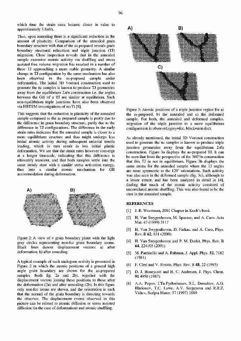
96
which time the strain rates became closer in value to approximately 3.8e6/s.
Thus, upon annealing there is a significant reduction in the amount of plasticity. Comparison of the annealed grain boundary structure with that of the as prepared reveals grain boundary structural relaxation and triple junction (TJ) migration. Close inspection reveals that in the annealed sample extensive atomic activity via shuffling and stress assisted free volume migration has resulted in a number of these TJ approaching a more stable geometry. A similar change in TJ configuration by the same mechanism has also been observed in the as-prepared sample under deformation. The initial 3D Voronoi construction used to generate the nc samples is known to produce TJ geometries away from the equilibrium 2^/n construction i.e. the angles between the GB of a TJ are similar at equlibrium. Such non-equilibrium triple junctions have also been observed via HRTEM investigations of nc-Ti [8].
This suggests that the reduction in plasticity of the annealed sample compared to the as prepared sample is partly due to the difference in grain boundary structure, partly due to the difference in TJ configurations. The difference in the early strain rates indicates that the annealed sample is closer to a more equilibrium structure and thus might undergo less initial atomic activity during subsequent uniaxial tensile loading, which in turn result in less initial plastic deformation. We see that the strain rates however converge at a longer timescale, indicating that this difference is ultimately transient, and that both samples settle into the same steady state with a similar stress activation energy, thus into a similar atomic mechanism for GB accommodation during deformation.
B) f ' ' V i
mm,
Figure 2: A view of a grain boundary plane with the light gray circles representing non-fcc grain boundary atoms. Black lines denote displacement vectors: a) after deformation; b) after annealing.
A typical example of such analogous activity is presented in Figure 2 in which the atomic positions of a general high angle grain boundary are shown for the as-prepared samples (both fig. 2a and 2b), together with the displacement vectors joining these positions to those after the deformation (2a) and after annealing (2b). In this figure only non-fcc atoms are shown, and the orientation is such that the normal of the grain boundary is directing towards the observer. The displacement events observed in this picture can be related to atomic diffusion or stress assisted diffusion (in the case of deformation) and atomic shuffling.
Figure 3: Atomic positions of a triple junction region for a) the as-prepared, b) the annealed and c) the deformed sample. For both, the annealed and deformed samples, migration of the triple junction to a more equilibrium configuration is observed.(grey=fcc, black=non-fcc).
As already mentioned, the initial 3D Voronoi construction used to generate the nc samples is known to produce triple junction geometries away from the equilibrium 2n/n construction. Figure 3a displays the as-prepared TJ. It can be seen that from the perspective of the 360°/n construction that this TJ in not in equilibrium. Figure 3b displays the same atoms for the annealed sample where the TJ angles are more symmetric to the 120° orientations. Such activity was also seen in the deformed sample (fig. 3c), although to a lesser extent, and has been analyzed in detail in [4], finding that much of the atomic activity consisted of uncorrelated atomic shuffling. This was also found to be the case in the annealed sample.
REFERENCES
[ 1 ] J. R. Weertman, 2001 Chapter in Koch's book
[2] H. Van Swygenhoven, M. Spaczer, and A. Caro. Acta Mat. 47(1999) 3117
[3] H. Van Swygenhoven, D. Farkas, and A. Caro, Phys. Rev. B 62, 831 (2000)
[4] H. Van Swygenhoven and P. M. Deriet, Phys. Rev. B 64, 224105 (2001)
[5] M. Parrinello and A. Rahman, J. Appl. Phys. 52, 7182 (1981)
[6] F. Cleri and V. Rosato, Phys. Rev. B 48, 22 (1993)
[7] D. J. Honeycutt and H. C. Andersen, J. Phys. Chem. 9 1 4950 (1987)
[8] A.A. Popov, I.Tu.Pyshmintsev, S.L. Demakov, A.G. Illarionov, T.C. Lowe, A.V. Sergeyeva and R.R.Z. Valiev, Scripta Mater. 37 (1997) 1089
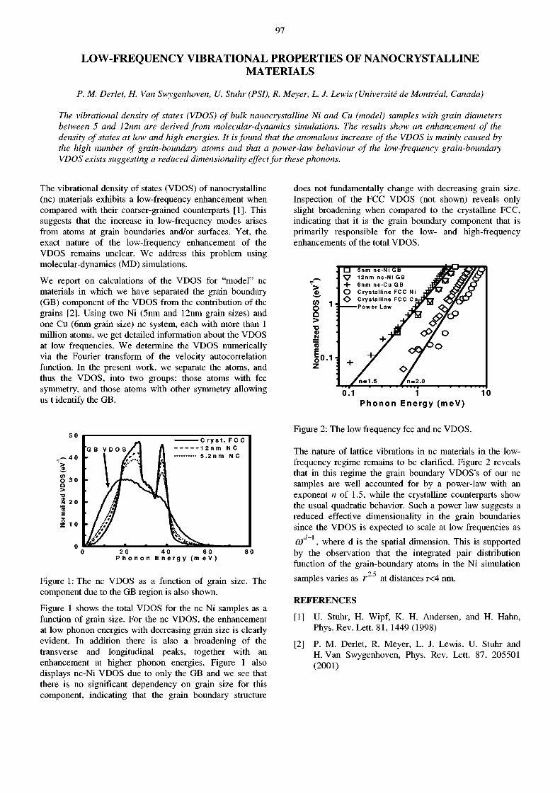
97
LOW-FREQUENCY VIBRATIONAL PROPERTIES OF NANOCRYSTALLINE MATERIALS
P. M. Deriet, H. Van Swygenhoven, U. Stuhr (PSI), R. Meyer, L. J. Lewis (Université de Montréal, Canada)
The vibrational density of states (VDOS) of bulk nanocrystalline Ni and Cu (model) samples with grain diameters between 5 and 12nm are derived from molecular-dynamics simulations. The results show an enhancement of the density of states at low and high energies. It is found that the anomalous increase of the VDOS is mainly caused by the high number of grain-boundary atoms and that a power-law behaviour of the low-frequency grain-boundary VDOS exists suggesting a reduced dimensionality effect for these phonons.
The vibrational density of states (VDOS) of nanocrystalline (nc) materials exhibits a low-frequency enhancement when compared with their coarser-grained counterparts [1]. This suggests that the increase in low-frequency modes arises from atoms at grain boundaries and/or surfaces. Yet, the exact nature of the low-frequency enhancement of the VDOS remains unclear. We address this problem using molecular-dynamics (MD) simulations.
We report on calculations of the VDOS for "model" nc materials in which we have separated the grain boundary (GB) component of the VDOS from the contribution of the grains [2]. Using two Ni (5nm and 12nm grain sizes) and one Cu (6nm grain size) nc system, each with more than 1 million atoms, we get detailed information about the VDOS at low frequencies. We determine the VDOS numerically via the Fourier transform of the velocity autocorrelation function. In the present work, we separate the atoms, and thus the VDOS, into two groups: those atoms with fee symmetry, and those atoms with other symmetry allowing us t identify the GB.
does not fundamentally change with decreasing grain size. Inspection of the FCC VDOS (not shown) reveals only slight broadening when compared to the crystalline FCC, indicating that it is the grain boundary component that is primarily responsible for the low- and high-frequency enhancements of the total VDOS.
P h o n o n E n e r g y ( m e V )
50
— 40
0
F C C
'GB V D O S /1 A 12nm N C
• \ f\ 11 5 .2 n m 1*1
N C
• I M JL<vl
- /S / !*i i •**/ / .-**/ / ."*/
» t '*/
M
' m s* y
0 20 40 60 80 P h o n o n E n e r g y ( m e V )
Figure 1: The nc VDOS as a function of grain size. The component due to the GB region is also shown.
Figure 1 shows the total VDOS for the ne Ni samples as a function of grain size. For the nc VDOS, the enhancement at low phonon energies with decreasing grain size is clearly evident. In addition there is also a broadening of the transverse and longitudinal peaks, together with an enhancement at higher phonon energies. Figure 1 also displays nc-Ni VDOS due to only the GB and we see that there is no significant dependency on grain size for this component, indicating that the grain boundary structure
Figure 2: The low frequency fee and nc VDOS.
The nature of lattice vibrations in nc materials in the low-frequency regime remains to be clarified. Figure 2 reveals that in this regime the grain boundary VDOS's of our nc samples are well accounted for by a power-law with an exponent n of 1.5, while the crystalline counterparts show the usual quadratic behavior. Such a power law suggests a reduced effective dimensionality in the grain boundaries since the VDOS is expected to scale at low frequencies as
0 ) D 1 , where d is the spatial dimension. This is supported by the observation that the integrated pair distribution function of the grain-boundary atoms in the Ni simulation
2 5
samples varies as r at distances r<4 nm.
REFERENCES [1] U. Stuhr, H. Wipf, K. H. Andersen, and H. Hahn,
Phys. Rev. Lett. 81, 1449 (1998) [2] P. M. Deriet, R. Meyer, L. J. Lewis, U. Stuhr and
H. Van Swygenhoven, Phys. Rev. Lett. 87, 205501 (2001)
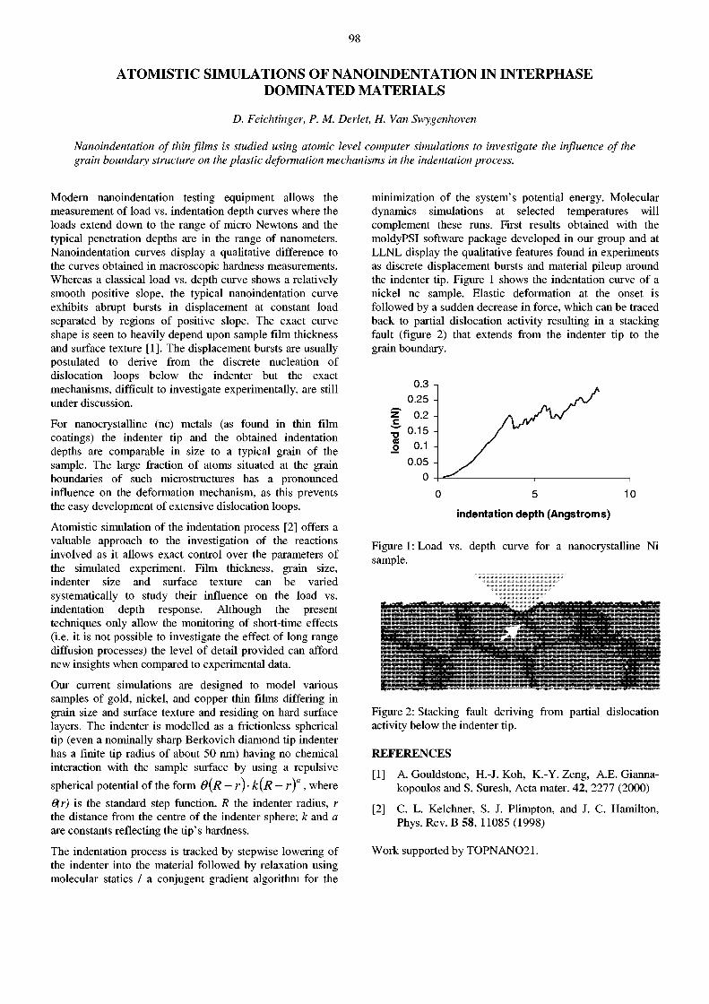
98
ATOMISTIC SIMULATIONS OF NANOINDENTATION IN INTERPHASE DOMINATED MATERIALS
D. Feichtinger, P. M. Deriet, H. Van Swygenhoven
Nanoindentation of thin films is studied using atomic level computer simulations to investigate the influence of the grain boundary structure on the plastic deformation mechanisms in the indentation process.
Modern nanoindentation testing equipment allows the measurement of load vs. indentation depth curves where the loads extend down to the range of micro Newtons and the typical penetration depths are in the range of nanometers. Nanoindentation curves display a qualitative difference to the curves obtained in macroscopic hardness measurements. Whereas a classical load vs. depth curve shows a relatively smooth positive slope, the typical nanoindentation curve exhibits abrupt bursts in displacement at constant load separated by regions of positive slope. The exact curve shape is seen to heavily depend upon sample film thickness and surface texture [1]. The displacement bursts are usually postulated to derive from the discrete nucleation of dislocation loops below the indenter but the exact mechanisms, difficult to investigate experimentally, are still under discussion.
For nanocrystalline (nc) metals (as found in thin film coatings) the indenter tip and the obtained indentation depths are comparable in size to a typical grain of the sample. The large fraction of atoms situated at the grain boundaries of such microstructures has a pronounced influence on the deformation mechanism, as this prevents the easy development of extensive dislocation loops.
Atomistic simulation of the indentation process [2] offers a valuable approach to the investigation of the reactions involved as it allows exact control over the parameters of the simulated experiment. Film thickness, grain size, indenter size and surface texture can be varied systematically to study their influence on the load vs. indentation depth response. Although the present techniques only allow the monitoring of short-time effects (i.e. it is not possible to investigate the effect of long range diffusion processes) the level of detail provided can afford new insights when compared to experimental data.
Our current simulations are designed to model various samples of gold, nickel, and copper thin films differing in grain size and surface texture and residing on hard surface layers. The indenter is modelled as a frictionless spherical tip (even a nominally sharp Berkovich diamond tip indenter has a finite tip radius of about 50 nm) having no chemical interaction with the sample surface by using a repulsive
spherical potential of the form OÍR — r) • k(R — r)", where 6(r) is the standard step function, R the indenter radius, r the distance from the centre of the indenter sphere; k and a are constants reflecting the tip's hardness.
The indentation process is tracked by stepwise lowering of the indenter into the material followed by relaxation using molecular statics / a conjugent gradient algorithm for the
minimization of the system's potential energy. Molecular dynamics simulations at selected temperatures will complement these runs. First results obtained with the moldyPSI software package developed in our group and at LLNL display the qualitative features found in experiments as discrete displacement bursts and material pileup around the indenter tip. Figure 1 shows the indentation curve of a nickel nc sample. Elastic deformation at the onset is followed by a sudden decrease in force, which can be traced back to partial dislocation activity resulting in a stacking fault (figure 2) that extends from the indenter tip to the grain boundary.
0 5 10
indentation depth (Angstroms)
Figure 1: Load vs. depth curve for a nanocrystalline Ni sample.
Figure 2: Stacking fault deriving from partial dislocation activity below the indenter tip.
REFERENCES
[1] A. Gouldstone, H.-J. Koh, K.-Y. Zeng, A.E. Gianna-kopoulos and S. Suresh, Acta mater. 42, 2277 (2000)
[2] C. L. Kelchner, S. J. Plimpton, and J. C. Hamilton, Phys. Rev. B 58, 11085 (1998)
Work supported by TOPNAN021.
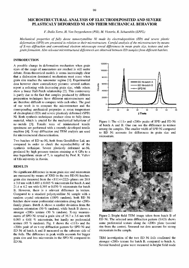
99
MICROSTRUCTURAL ANALYSIS OF ELECTRODEPOSITED AND SEVERE PLASTICALY DEFORMED NI AND THEIR MECHANICAL BEHAVIOR
F. Dalla Torre, H. Van Swygenhoven (PSI), M. Victoria, R. Schaeublin (EPFL)
Mechanical properties of fully dense nanocrystalline Ni made by electrodeposition (ED) and severe plastic deformation (SPD) are presented in relation to their microstructure. Careful analysis of the microstructure by means of X-ray diffraction and conventional electron microscopy reveal differences in mean grain size, texture and sub-grain formation. Also relevant microstructural differences are observed between ED samples from different batches.
INTRODUCTION
A possible change in deformation mechanism when grain sizes of the range of nanometres are reached is still under debate. From theoretical models it seems increasingly clear that a dislocation dominated mechanism must cease when grain size reaches the nanometer regime [1]. Experimental data however show contradictory pictures: several authors report a softening with decreasing grain size, while others show a linear Hall-Petch relationship [2]. This controversy is partly due to the fact that samples produced by different preparation techniques have different microstructures and are therefore difficult to compare with each other. The goal of our work is to compare the microstructure and the corresponding mechanical properties at room temperature of electroplated (ED) and severe plasticaly deformed (SPD) Ni. Both synthesis techniques produce close to fully dense material, which is crucial for the mechanical behaviour of nc- metals [3]. Tensile tests of miniaturized tensile specimens are performed with a recently developed tensile machine [4]. X-ray diffraction and TEM analysis are used for microstructural characterisation.
Two batches of ED nc-Ni, both from Goodfellow Ltd, are compared in order to check the reproducibility of the synthesis technique. Severe plasticaly deformed nc-Ni, produced by high pressure torsion straining at 6 GPa to a true logarithmic strain of 7, is supplied by Prof. R. Valiev of Ufa university in Russia.
RESULTS
No significant difference in mean grain size and microstrain are measured by means of XRD in the two ED-Ni batches: grain size measured from the < l l l> /<222> planes are 20.8 ± 3.0 nm with 0.403 ± 0.015 % microstrain for batch A and 21.4 ± 4.2 nm with 0.393 ± 0.070 % microstrain for batch B. However, there is a relevant difference in texture. Compared to a standard polycrystalüne Ni sample with a random crystal orientation (100% random), both ED Ni batches show some preferential orientation along the <200> family planes. Batch A shows a smaller deviation from the random orientation (50 % random), while batch B shows a stronger <200> texture (30 % random). X-ray measurements of SPD Ni reveal a grain size of 36.7 ± 3.6 nm with 0.095 ± 0.01 % microstrain, but hardly no preferential texture (93 % random). Fig. 1 shows the <111> and the <200> peak of an x-ray diffraction pattern for SPD Ni and ED Ni of batch A and B measured on the substrate side of the foils. The difference in peak width accounts for bigger grain size and less microstrain in the SPD Ni compared to ED Ni.
o O 40000
•ED Ni-batchA •ED Ni-batch B •SPD Ni
2Theta
Figure 1: The <111> and <200> peaks of SPD and ED Ni of batch A and B. One can see the difference in texture among the samples. The smaller width of SPD Ni compared to ED Ni accounts for differences in grain size and microstrain.
1Nte
•ill ill IIP
• 1
ââi*
mm Figure 2: Bright field TEM image taken from batch B of ED Ni. The selected area diffraction pattern (SAD) shows some preferential texture along the <200> plane (second rim from the centre). Smeared out dots account for strong microstrain in the sample.
TEM investigation of the two ED Ni foils confirmed the stronger <200> texture for batch B, compared to batch A. Several hundred grains were measured in bright field mode
100
to get good statistics on mean grain size and grain size distribution. Similar mean grain size of 21 ± 8 nm and a narrow grain size distribution was measured for both ED Ni batches. A representative picture of the microstructure is given in Fig. 2.
• a .
Í
y '
Figure 3: Bright field TEM image of SPD-Ni. The SAD pattern reflects the relaxed microstructure by distinct spots.
TEM investigations in SPD Ni revealed a much larger mean grain size of 98 ± 56 nm compared to the XRD results, and a broad grain size distribution (Fig. 3). The big deviation in grain size stems from the fact that small angle grain boundaries do not show strong contrast in TEM images, while x-ray diffraction does account for them. Indeed, tilting of TEM foils provides change in contrast within grains, and smaller subgrains become visible, indicating the presence of small angle grain boundaries. Measurements of subgrains reveal a size of 34 ± 10 nm, which is very close to what is measured by x-rays. The more relaxed microstructure of SPD Ni is consistent with less strain measured by X-ray diffraction compared to ED Ni.
TEM investigation at higher magnification showed no porosity in SPD Ni. But pores of 1-2 nm size incorporated during the electrodeposition process could be detected in ED Ni situated at grain boundaries and in the grain interior.
TENSILE TESTS
Tensile tests of batch A and B of ED Ni showed differences in strength and ductility. Tab. 1 summarizes the results obtained for tests performed at room temperature. A lower ultimate tensile strength (UTS) and yield stress together with a reduction in ductility are measured for batch B. This result suggests the importance of texture in the ED-samples.
Table 1: Results on room temperature tensile tests of ED Ni for batch A and B.
UTS [GPa] ov [GPa] Plastic Strain %
Batch A 2.04 ±0 .1 1.60 ±0 .1 4.0 ±0 .2
Batch B 1.82 ±0 .09 1.43 ±0 .09 2.6 ± 0 . 6
Fig. 4 shows stress-strain curves for ED (batch B) and SPD Ni. A much lower strength and a reduced ductility is observed in SPD Nickel. The observed reduction in strength cannot be explained via the classical Hall-Petch relation using the difference in mean grain size observed by XRD: this means that the more detailed grain size distribution observed in TEM (bigger grains with subgrains confined by small angle grain boundaries) affects the mechanical behaviour. Lower ductility in SPD Ni is not expected from theoretical predictions. Further analyses are necessary to explain these experimental findings.
strain %
Figure 4: A stress strain curve for SPD and ED (batch B) Ni.
SUMMARY
Microstructural investigations of two batches of ED Ni and SPD Ni show, that not only mean grain size is governing the mechanical properties. Stronger <200> texture in ED Ni leads to lower plasticity and strength compared to more randomly oriented samples. Different grain size measured by XRD and TEM in SPD Ni indicates domains of small angle GB's surrounded by high angle ones, resp. Latter grain size values agree with the applied Hall-Petch relation
REFERENCES
[1] E. Arzt, Acta mater. Vol. 46, 5611, 1998
[2] R. A. Masumura, P. M. Hazzledine, and C. S. Pande. Acta Mater. Vol. 46,4527, 1998
[3] F. Dalla Torre, H. Van Swygenhoven, W. Wagner, R. Schaeublin, M. Victoria, PSI- Report 2001, VI, 54
[4] M. Schild, A. Bollhalder, F. Dalla Torre, H. Van Swygenhoven, W. Wagner, PSI-Scientific Report 2001, VI, 60
Supported by Swiss National Science Foundation, grand no. NSF-project 21-52 451.970.
101
STRUCTURE OF LIPID BILAYERS OF DIMERIC IONPAIRED AMPHIPHILES
V.K. Aswal (PSI), S. Bhattacharya (IISc, Bangalore)
Small-angle neutron scattering (SANS) experiments have been carried out on a novel series of vesicle forming ionpaired amphiphiles containing four chains and two head groups connected by a spacer of varying length. It is found that these amphiphiles form highly polydispersed unilamellar vesicles. The mean radius of the vesicles increases and the bilayer thickness decreases with the increase in the spacer length.
INTRODUCTION
Synthetic amphiphiles that form micellar or vesicular aggregates in aqueous solution are of great interest for their potential in diverse applications such as drug delivery, catalysis and synthesis of nanomaterials [1]. The amphiphiles, which form vesicles, are also used in studies of their role as models for more complex biological membranes. A series of dimeric ionpaired amphiphiles containing four chains with two isolated head groups, has recently been synthesized (Fig. 1). In each of these amphiphiles the two head group charges are separated by a flexible polymethylene spacer chain -(CH 2)n- of varying lengths (n). The length and the conformation of the spacer chain determine the intra-monomer head group separation [2]. SANS measurements have been carried out to understand the structure of the unilamellar vesicles of these amphiphiles.
C H 3 C H 3
C y O - H a C - ^ C H ^ - N i C r V C y O
C15H31 C 1 6 H 3 3 C 1 6 H 3 3 C 1 5 H 3 1
Figure 1 : Chemical structure of dimeric ionpaired lipids.
RESULTS AND DISCUSSION
All the amphiphiles were hydrated with D 2 0 and subjected to 4 or 5 freeze-thaw cycles above the phase transition temperatures (Tm). The resulting opalescent solutions were then sonicated to produce the unilameller vesicles. Fig. 2 shows the SANS data of 2 mg/ml vesicular solutions of amphiphiles of different spacer lengths n = 2, 6 and 10. The data has been analysed assuming polydispersed unilamellar vesicles in the solutions. The fitted parameters in the analysis are the mean radius as well as the bilayer thickness and the polydispersity of the vesicles. The polydispersity is fitted with the Schultz distribution. The parameters are given in Table 1. It is found that vesicles are highly polydispersed in all solutions. The mean size of the vesicles increases while the bilayer thickness decreases with the increase in the spacer length. These results indicate a different structure of bilayers for different spacer lengths. The significant decrease in the bilayer thickness with the increaseing spacer length suggests an interdigitated nature of a bilayer organization which is presumably an outcome
of flexibility of the spacer chain with increasing spacer length.
The phase transition temperature (Tm) of the vesicular solution of these amphiphiles depends on the spacer length. The values of Tm for n = 2, 6 and 10 are 74.1, 45.6 and 41.1°C, respectively [2]. SANS experiments discovered that, for the temperatures above Tm, the size of the vesicles is larger while the bilayer's thickness is more or less the same as the thickness of below Tm.
1 0 0 0 0 0 t 1
Q ( n m " 1 )
Figure 2: SANS data from vesicular solutions of dimeric ionpaired lipids for different spacer lengths at 30 °C.
Table 1: The parameters of vesicles of dimeric ionpaired lipids for different spacer lengths at 30 °C.
System Radius (nm)
Polydispersity (%)
Thickness (nm)
n=2 16±1.0 63±2 4.210.2 n=6 23±0.5 82±2 3.010.1 n=10 42±1.0 85±2 2.710.1
REFERENCES
[1] J.M. Schnur, Science 262, 1669 (1993)
[2] S. Bhattacharya, S. De, Langmuir 15, 3400 (1999)
102
ROLE OF COUNTERION DISTRIBUTION ON THE STRUCTURE OF MICELLES IN AQUEOUS SALT SOLUTIONS
V.K. Aswal (PSI), P.S. Goyal (BARC, Mumbai)
Small-angle neutron scattering (SANS) experiments have been carried out on aqueous micellar solutions of cationic surfactant cetyltrimethylammonium bromide (CTAB) at different temperatures in presence of varying concentrations of salt KBr. It is found that the micelles grow strongly by adding salt at low temperatures, but this effect is significantly reduced with an increase in temperature. These results are explained in terms of an increasing amount excess of counterions surrounding the micelles with the increasing temperature.
INTRODUCTION
Surfactant molecules such as CTAB ionize in aqueous solution. The corresponding micelles are aggregates of CTA+ ions. The Br- ions, known as counterions, tend to stay near the CTA+ micellar surface. It is well known that salts such as KBr induce noticeable growth of CTAB micelles due to charge neutralization at the micellar surface [1]. Unlike the CTAB surfactants where the micelles grow by the addition of salts [2], we recently observed that the sizes of micelles of multi-headed surfactants were independent of these additives [3]. We now have carried out systematic SANS studies on the single-headed surfactant CTAB at different temperatures in presence of varying concentrations of salt KBr. The dissociation of the counterions around the micelles multiplies with an increase in temperature. We correlate these results with the multi-headed surfactants where the increase in the number of head groups increases the effective dissociation of the counterions around the micelles.
RESULTS AND DISCUSSION
Fig. 1 shows the SANS data of 100 mM CTAB with the addition of KBr at two different temperatures, 30 and 75 °C. These data show a strong correlation peak which is an indication of the interacting charged micelles in the solution. The correlation peak usually occurs at Qm ~ 2nld, where d is the average distance between the micelles. It is observed that at 30°C, the cross-section increases and the peak position shifts to lower Q values with the increase in the salt concentration. This indicates an increase in the size of the micelles in the presence of salt. The increase in cross-section at low Q and the shifting of the correlation peak become less pronounced when the temperature is increased to 75 °C. This shows the respective differences in the growth of the micelles by the addition of the salt at different temperatures. The analysis of the data shows that charge neutralization becomes less effective by the addition of the salt when the temperature is increased. This in turn shows that an increase in the micelle size is smaller at the temperature of 75 °C than that of 30 °C. Small-angle x-ray scattering experiments are planned for the direct examination of the counterion distribution in the above systems. While neutron scattering in micellar solutions originates predominantly from the core of the micelle, x-rays are largely scattered by counterions especially when the counterion has a large atomic number (e.g. Br") [4].
40 100 m M C T A B + Cs KBr
T = 30 °C
0.01 Q (A " 1 )
0.1 0.2
10
8 100 m M C T A B + Cs KBr
T = 75 °C
0.01 Q ( A " 1 )
0.1 0.2
Figure 1: SANS data from 100 mM CTAB with addition of KBr (Cs = 0 (O), 20 ( • ) , 40 (A), 60 (V), 80 (0 ) and 100 (+) mM).
REFERENCES
[1] Y. Chevalier, T. Zemb, Rep. Prog. Phys. 53, 279 (1990)
[2] V.K. Aswal, et al., Phys. Rev. E 61, 2947 (2000)
[3] J. Haldar, et al., Angew. Chem. Int. Ed. 40, 1228 (2001)
[4] V.K. Aswal et al., Chem. Phys. Lett. 329, 118 (2000)

103
Technical Support and Co-ordination

104
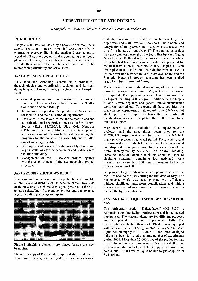
105
VERSATILITY OF THE ATK DIVISION
J. Duppich, W. Gloor, M. Liithy, R. Kobler, J.L. Pochon, R. Reckermann
INTRODUCTION
The year 2001 was dominated by a number of extraordinary events. The sum of these events influences our Ufe. In contrast to everyday Ufe, in the small and easy to grasp world of ATK, one does not find a dominating date, but a plenitude of dates; planned but also unexpected events. Despite their non-spectacular character, they have to be treated with particularity and seriousness.
JANUARY IST: SCOPE O F DUTIES
ATK stands for "Abteilung Technik und Koordination", the technologies and coordination division, and its main duties have not changed significantly since it was formed in 1998:
• General planning and co-ordination of the annual shutdown of the accelerator faciüties and the Spallation Neutron Source (SINQ).
• Technological support of the operation of the accelerator facilities and the realisation of experiments.
• Assistance in the layout of the infrastructure and the co-ordination of large projects such as the Swiss Light Source (SLS), PROSCAN, Ultra Cold Neutrons (UCN) and Low Energy Muons (LEM). Development and monitoring of the timetable and generating the programs for the construction, assembly and installation of such large faciUties.
• Development of concepts for the assembly of new and large installations for the accelerator and reaüsation of radiation shielding.
• Management of the PROSCAN project together with the establishment of the accompanying project structure.
JANUARY 3RD: SHUTDOWN BEGIN
It is essential to achieve and keep the highest possible reUabiUty and availabiUty of the accelerator faciüties. One of the measures, which make this goal possible, is the systematic scheduüng of preventive services and maintenance work, including the necessary repairs.
Figure 1: Shielding elements are placed beside the new beam line.
The terminology of PSI includes large and short shutdowns, which are, however, not clearly defined. Scientists always
find the duration of a shutdown to be too long, the organizers and staff involved, too short. The amount and complexity of the planned and executed tasks needed the time from January 3 r d until May 4 t h . The dominating project was the complete renewal of the beam Une between Target M and Target E. Based on previous experience; the whole beam line had been pre-assembled, tested and prepared for the final installation in the proton channel (Figure 1). With this replacement, the last but one radiation resistant section of the beam line between the 590 MeV accelerator and the Spallation Neutron Source or beam dump has been installed ready for a beam current of 2 mA.
Further activities were the dismounting of the separator close to the experimental area 7 iM l , which will no longer be required. The opportunity was taken to improve the biological shielding in this region. Additionally, the targets M and E were replaced and general annual maintenance work was carried out. To execute all these activities, the crane in the experimental hall moved some 1760 tons of shielding, magnets, supports, exchange flasks, etc.. After all the shutdown work was completed, the 1760 tons had to be put back in place.
With regard to the installation of a superconducting cyclotron and the appertaining beam lines for the PROSCAN project, which will be placed in the NA hall, many set-up activities had to get started. There were several experimental areas in the NA hall that had to be dismounted and disposed of in preparation for the expansion of the proton therapy faciüty. Some 500 tons of iron shielding, some 800 tons of concrete shielding, about 250 tons of shielding containers containing low activated waste material and more than 100 tons of magnets had to be removed from this hall.
As planned long in advance, it was possible to give the facilities back to the users during the first days of May. The maintenance work was accompüshed with efficiency, without significant unforeseen compUcations and with a lower collective radiation dose than had been estimated by the health physics controllers.
JANUARY 16TH: LIQUID NITROGEN DEWAR F O R SLS
The refrigerator section "Kälteanlagen" (OG 8820) is responsible for four helium refrigerators and its connected apparatuses. The various plants are for different purposes and are placed in different experimental halls. The availability was higher than 95%. Plant 2 was equipped with a new purifier. This guarantees a larger and safer üquid heüum supply at PSI. Some 140'000 Utres of Uquid heüum has been deüvered to a large number of experiments during 2001. More than 26'000 Utres of the production has been deüvered to other universities in Switzerland. Because of a general shortage of the heüum supply in Europe, we sold about 18'000 litres of liquid helium to gas suppliers in Switzerland.
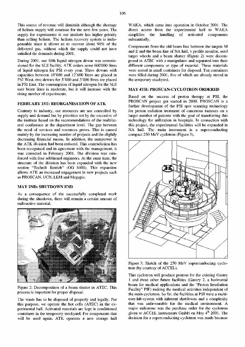
106
This source of revenue will diminish although the shortage of helium supply will continue for the next few years. The supply for experiments at our institute has higher priority than selling helium. The helium recovery system is indispensable since it allows us to recover about 90% of the delivered gas, without which the supply could not have satisfied the demands during 2001.
During 2001, our fifth liquid nitrogen de war was commissioned for the SLS facility. ATK orders some 600'000 litres of liquid nitrogen for PSI every year. Three dewars with capacities between lO'OOO and 12'600 litres are placed in PSI West, two dewars for 5'000 and 3'000 litres are placed in PSI East. The consumption of liquid nitrogen for the SLS user beam lines is moderate, but it will increase with the rising number of experiments.
FEBRUARY IST: REORGANISATION O F ATK
Contrary to industry, our resources are not controlled by supply and demand but by priorities set by the executive of the institute based on the recommendations of the multilateral conference at the department level. The gap between the need of services and resources grows. This is caused mainly by the increasing number of projects and the slightly decreasing financial means. In addition, the manpower in the ATK division had been reduced. This contradiction has been recognised and in agreement with the management, it was corrected in February 2001. The division was reinforced with four additional engineers. At the same time, the structure of the division has been expanded with the new section "Technik Betrieb" (OG 8400). This expansion allows ATK an increased engagement in new projects such as PROSCAN, UCN, LEM and Megapie.
MAY 2ND: SHUTDOWN END
As a consequence of the successfully completed work during the shutdown, there will remain a certain amount of radioactive material.
r""-- • • .*~.ag~~. 1
Figure 2: Decomposition of a beam shutter in ATEC. This process is important for proper disposal.
The waste has to be disposed of properly and legally. For this purpose, we operate the hot cells (ATEC) in the experimental hall. Activated materials are kept in conditioned containers in the temporary stockyard. For components that will be used again, ATK operates a new storage hall
WAKA, which came into operation in October 2001. The direct access from the experimental hall to WAKA simplifies the handling of activated components substantially.
Components from the old beam line between the targets M and E and the beam line of NA hall, a profile monitor, used target wheels and a beam shutter (Figure 2) were decomposed in ATEC with a manipulator and separated into their different components or type of material. These materials were stored in small containers for disposal. Ten containers were filled during 2001, five of which are already stored in the temporary stockyard.
MAY 4TH: PROSCAN-CYCLOTRON ORDERED
Based on the success of proton therapy at PSI, the PROSCAN project got started in 2000. PROSCAN is a further development of the PSI spot scanning technology for proton radiation treatment of cancerous tumours on a larger number of patients with the goal of transferring this technology for utilization in hospitals. In connection with this project, the experimental facilities will be expanded in NA hall. The main instrument is a superconducting compact 250 MeV cyclotron (Figure 3).
Figure 3: Sketch of the 250 MeV superconducting cyclotron (by courtesy of ACCEL).
This cyclotron will produce protons for the existing Gantry 1 and three other future facilities (Gantry 2, a horizontal beam for medical applications and the "Proton Irradiation Facility" PIF) making the medical activities independent of the main cyclotron. So far, the facilities at PSI were a multiuser-lab-system with inherent shutdowns and a complexity that was unfavourable for the medical environment. A major milestone was the purchase order for the cyclotron given to ACCEL Instruments GmbH on May 4 t h 2001. The decision for a superconducting cyclotron was made because
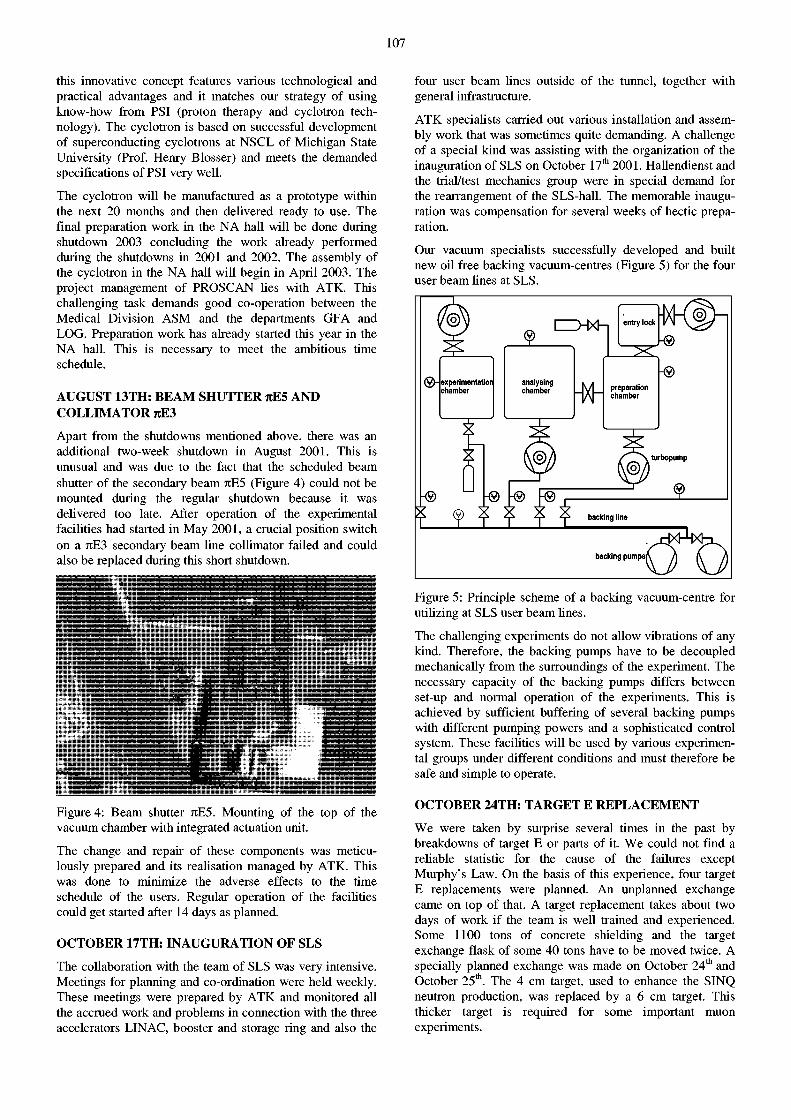
107
this innovative concept features various technological and practical advantages and it matches our strategy of using know-how from PSI (proton therapy and cyclotron technology). The cyclotron is based on successful development of superconducting cyclotrons at NSCL of Michigan State University (Prof. Henry Blosser) and meets the demanded specifications of PSI very well.
The cyclotron will be manufactured as a prototype within the next 20 months and then delivered ready to use. The final preparation work in the NA hall will be done during shutdown 2003 concluding the work already performed during the shutdowns in 2001 and 2002. The assembly of the cyclotron in the NA hall will begin in April 2003. The project management of PROSCAN lies with ATK. This challenging task demands good co-operation between the Medical Division ASM and the departments GFA and LOG. Preparation work has already started this year in the NA hall. This is necessary to meet the ambitious time schedule.
AUGUST 13TH: BEAM SHUTTER jrE5 AND COLLIMATOR jrE3
Apart from the shutdowns mentioned above, there was an additional two-week shutdown in August 2001. This is unusual and was due to the fact that the scheduled beam shutter of the secondary beam JtE5 (Figure 4) could not be mounted during the regular shutdown because it was delivered too late. After operation of the experimental facilities had started in May 2001, a crucial position switch on a JtE3 secondary beam line collimator failed and could also be replaced during this short shutdown.
Figure 4: Beam shutter nE5. Mounting of the top of the vacuum chamber with integrated actuation unit.
The change and repair of these components was meticulously prepared and its realisation managed by ATK. This was done to minimize the adverse effects to the time schedule of the users. Regular operation of the facilities could get started after 14 days as planned.
OCTOBER 17TH: INAUGURATION O F SLS
The collaboration with the team of SLS was very intensive. Meetings for planning and co-ordination were held weekly. These meetings were prepared by ATK and monitored all the accrued work and problems in connection with the three accelerators LINAC, booster and storage ring and also the
four user beam Unes outside of the tunnel, together with general infrastructure.
ATK specialists carried out various installation and assembly work that was sometimes quite demanding. A challenge of a special kind was assisting with the organization of the inauguration of SLS on October 17 t h 2001. Hallendienst and the trial/test mechanics group were in special demand for the rearrangement of the SLS-hall. The memorable inauguration was compensation for several weeks of hectic preparation.
Our vacuum specialists successfully developed and built new oil free backing vacuum-centres (Figure 5) for the four user beam Unes at SLS.
LZD-Kh
experimentatior analysing chamber chamber -M-
-® -® -® h® j -
entry lock
I S
preparation chamber
turbopump
backing line
backing pumpsl
Figure 5: Principle scheme of a backing vacuum-centre for utilizing at SLS user beam Unes.
The challenging experiments do not allow vibrations of any kind. Therefore, the backing pumps have to be decoupled mechanically from the surroundings of the experiment. The necessary capacity of the backing pumps differs between set-up and normal operation of the experiments. This is achieved by sufficient buffering of several backing pumps with different pumping powers and a sophisticated control system. These facilities will be used by various experimental groups under different conditions and must therefore be safe and simple to operate.
OCTOBER 24TH: TARGET E REPLACEMENT
We were taken by surprise several times in the past by breakdowns of target E or parts of it. We could not find a reliable statistic for the cause of the failures except Murphy's Law. On the basis of this experience, four target E replacements were planned. An unplanned exchange came on top of that. A target replacement takes about two days of work if the team is well trained and experienced. Some 1100 tons of concrete shielding and the target exchange flask of some 40 tons have to be moved twice. A specially planned exchange was made on October 24 t h and October 25 t h . The 4 cm target, used to enhance the SINQ neutron production, was replaced by a 6 cm target. This thicker target is required for some important muon experiments.
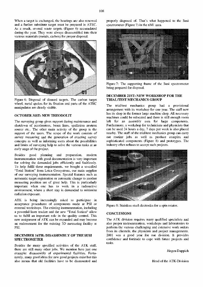
108
When a target is exchanged, the bearings are also renewed and a further substitute target must be prepared in ATEC. As a result, several waste targets (Figure 6) accumulated during the year. They were always disassembled into their various materials (metals, carbon) for proper disposal.
properly disposed of. That's what happened to the Susi spectrometer (Figure 7) in the 7 iMl area.
Figure 6: Disposal of disused targets. The carbon target wheel, metal spokes for its fixation and parts of the ATEC manipulator are clearly visible.
OCTOBER 31ST: NEW THEODOLIT
The surveying group gives support during maintenance and shutdown of accelerators, beam lines, spallation neutron source etc.. The other main activity of the group is the support of the users. The scope of the work consists of survey measuring and the generation of exacting survey concepts as well as informing users about the possibilities and limits of surveying help to solve the various tasks at an early stage of the project.
Besides good planning and preparation, modern instrumentation with good documentation is very important for solving the demanded jobs efficiently and faultlessly. To help fulfil these requirements, we bought a so-called "Total Station" from Leica Geosystems, our main supplier of our surveying instrumentation. Special features such as automatic target registration or automatic change to another measuring position are of great help. This is particularly important when one has to work in a radioactive environment, where a short stay is demanded to minimize radiation exposure.
ATK is being increasingly asked to participate in acceptance procedures of components made at PSI or external workshops. The existing instrumentation, including a powerful laser tracker and the new "Total Station" allow us to fulfil an important role in the quality control. This new assignment of ATK can be expanded and may become an endorsement for the existing 3D measuring facility at PSI.
DECEMBER 16TH: DISASSEMBLY O F T H E SUSI SPECTROMETER
Besides the many specified activities of the ATK staff, there are still many other jobs. We mention here just one example: disassembly of experimental facilities. Fortunately, many good ideas for new good projects exist but this also means that old facilities have to be dismounted and
Figure 7: The supporting frame of the Susi spectrometer being prepared for disposal.
DECEMBER 21ST: NEW W O R K S H O P FOR T H E TRIAL/TEST MECHANICS GROUP
The trial/test mechanics group had a provisional arrangement with its workshop for one year. The staff now has its shop in the former large machine shop. All necessary machines could be relocated and there is still enough room left for an assembly area for large components. Furthermore, a workshop for technicians and physicists that can be used 24 hours a day, 7 days per week is also placed nearby. The staff of the trial/test mechanics group can carry out routine jobs as well as produce complex and sophisticated components (Figure 8) and prototypes. The industry often refuses to accept such projects.
ll̂s »̂»MMfc**̂ Figure 8: Stainless steel electrodes for a spin rotator.
CONCLUSIONS
The ATK division requires many qualified specialists and also proper instrumentation, workshops and laboratories to perform the various challenging and extensive work orders from its clientele, the physicists and project managements. 2001 was a good year for our division. It provides confidence and fortitude to cope with future projects and tasks.
Jürgen Duppich
Head of the ATK-Division
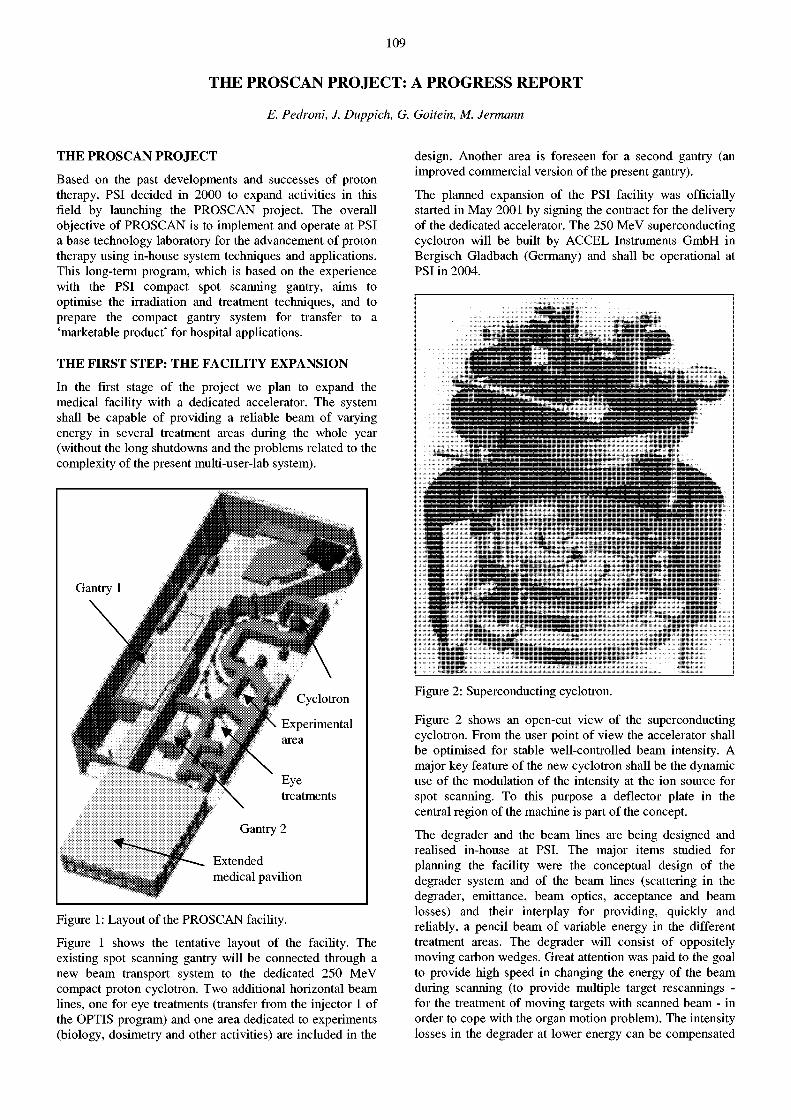
109
THE PROSCAN PROJECT: A PROGRESS REPORT
E. Pedroni, J. Duppich, G. Goitein, M. Jermann
THE PROSCAN P R O J E C T
Based on the past developments and successes of proton therapy, PSI decided in 2000 to expand activities in this field by launching the PROSCAN project. The overall objective of PROSCAN is to implement and operate at PSI a base technology laboratory for the advancement of proton therapy using in-house system techniques and applications. This long-term program, which is based on the experience with the PSI compact spot scanning gantry, aims to optimise the irradiation and treatment techniques, and to prepare the compact gantry system for transfer to a 'marketable product' for hospital applications.
THE FIRST STEP: THE FACILITY EXPANSION
In the first stage of the project we plan to expand the medical facility with a dedicated accelerator. The system shall be capable of providing a reliable beam of varying energy in several treatment areas during the whole year (without the long shutdowns and the problems related to the complexity of the present multi-user-lab system).
Figure 1: Layout of the PROSCAN facility.
Figure 1 shows the tentative layout of the facility. The existing spot scanning gantry will be connected through a new beam transport system to the dedicated 250 MeV compact proton cyclotron. Two additional horizontal beam lines, one for eye treatments (transfer from the injector 1 of the OPTIS program) and one area dedicated to experiments (biology, dosimetry and other activities) are included in the
design. Another area is foreseen for a second gantry (an improved commercial version of the present gantry).
The planned expansion of the PSI facility was officially started in May 2001 by signing the contract for the delivery of the dedicated accelerator. The 250 MeV superconducting cyclotron will be built by ACCEL Instruments GmbH in Bergisch Gladbach (Germany) and shall be operational at PSI in 2004.
IflflM
Figure 2: Superconducting cyclotron.
Figure 2 shows an open-cut view of the superconducting cyclotron. From the user point of view the accelerator shall be optimised for stable well-controlled beam intensity. A major key feature of the new cyclotron shall be the dynamic use of the modulation of the intensity at the ion source for spot scanning. To this purpose a deflector plate in the central region of the machine is part of the concept.
The dégrader and the beam lines are being designed and realised in-house at PSI. The major items studied for planning the facility were the conceptual design of the dégrader system and of the beam Unes (scattering in the dégrader, emittance, beam optics, acceptance and beam losses) and their interplay for providing, quickly and reliably, a pencil beam of variable energy in the different treatment areas. The dégrader will consist of oppositely moving carbon wedges. Great attention was paid to the goal to provide high speed in changing the energy of the beam during scanning (to provide multiple target rescannings -for the treatment of moving targets with scanned beam - in order to cope with the organ motion problem). The intensity losses in the dégrader at lower energy can be compensated
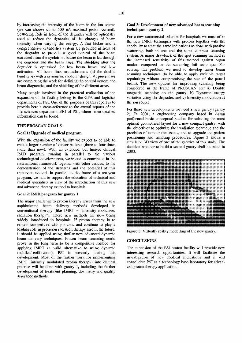
110
by increasing the intensity of the beam in the ion source (we can choose up to 500 nA maximal proton current). Scattering foils in front of the dégrader will be optionally used to reduce the dynamics of the changes of beam intensity when varying the energy. A fast kicker and a comprehensive diagnostics system are provided in front of the dégrader to provide a good control of the beam extracted from the cyclotron, before the beam is led through the dégrader and the beam Unes. The shielding after the dégrader is optimised for low beam losses and low activation. All beam Unes are achromats (of the double bend type) with a symmetric modular design. At present we are completing the work for defining the control system, the beam diagnostics and the shielding of the different areas.
Many people involved in the practical realisation of the expansion of the facility belong to the GFA and logistics departments of PSI. One of the purposes of this report is to provide here a cross-reference to the annual reports of the Ufe sciences department BIO of PSI, where more detailed information can be found.
THE PROSCAN GOALS
Goal 1: Upgrade of medical p rogram
With the expansion of the faciUty we expect to be able to treat a larger number of cancer patients (three to four times more than now). With an extended, but limited clinical R&D program, running in parallel to the various technological developments, we intend to contribute, in the international framework together with other centres, to the demonstration of the strengths and the potential of this treatment method. In parallel in the frame of a ten-year program, we aim to support the education of technical and medical speciaüsts in view of the introduction of this new and advanced therapy method to hospitals.
Goal 2 : R&D program for gantry 1
The major challenge to proton therapy arises from the new sophisticated beam delivery methods developed in conventional therapy (like IMRT = "intensity modulated radiation therapy"). These new methods are now being widely introduced in hospitals. If proton therapy is to remain competitive with photons, and continue to play a leading role in precision radiation therapy also in the future, it should be appüed using similar new advanced dynamic beam deUvery techniques. Proton beam scanning could prove in the long term to be a competitive method for applying IMRT (a vaUd alternative to using dynamic multileaf-colUmators). PSI is presently leading this development. Most of the further work for implementing IMPT (intensity modulated proton therapy) into clinical practice will be done with gantry 1, including the further development of treatment planning, dosimetry and quality assurance methods.
Goal 3: Development of new advanced beam scanning techniques - gantry 2
For a new commercial solution for hospitals we must offer the new IMRT techniques with protons together with the capability to treat the same indications as done with passive scattering, both in one and the same compact scanning system. A major drawback of the spot scanning method is the increased sensitivity of this method against organ motion compared to the scattering foil technique. For solving this problem we need to develop faster beam scanning techniques (to be able to apply multiple target repaintings without compromising the size of the pencil beam). The new options for improving scanning being considered in the frame of PROSCAN are: a) Double magnetic scanning on the gantry, b) Dynamic energy variation using the dégrader, and c) Intensity modulation at the ion source.
For these new developments we need a new gantry (gantry 2). In 2001, a engineering company based in Aarau performed basic conceptual studies for selecting the most optimal geometrical layout for a new compact gantry, with the objectives to optimise the irradiation technique and the precision of tumour treatments, and to upgrade the patient positioning and handling procedures. Figure 3 shows a simulated 3D view of one of the gantries of this study. The decision whether to build a second gantry shall be taken in 2003.
Figure 3: Virtually reality modelling of the new gantry.
CONCLUSIONS
The expansion of the PSI proton facility will provide new interesting research opportunities. It will facilitate the investigation of new medical indications and it will consoüdate PSI as a technology base laboratory for advanced proton therapy appücation.

Ill
LIST OF PUBLICATIONS
ACCELERATOR PHYSICS AND DEVELOPMENT
P. van Luijk, H.P. Bijl, R.P. Coppes, A.J. van der Kogel, A.W.T. Konings, J.A. Pikkemaat and J.M. Schippers Techniques for precision irradiations of the lateral half of the rat cervical spinal cord using 150 MeV protons Phys. Med. Biol. 46 (2001) 2857-2871
SPALLATION NEUTRON SOURCE
V. Aksenov, M. Avdeev, M. Balasoiu, L Rosta, Gy. Torok, L. Vekas, D. Bica, V. Garamus, J. Kohlbrecher, SANS study of concentration effect in magnetite/oleic acid/benzene ferrofluid Applied Physics A 2001, accepted.
V.K. Aswal, P.S. Goyal, J. Kohlbrecher and P. Bahadur SANS study of salt induced micellization in PEO-PPO-PEO block copolymers Chem. Phys. Lett. 349 (2001) 458
G.S. Bauer, Y. Dai, S. Maloy, L.K. Mansur, H. Ullmaier Summary of the fourth international workshop on spallation materials technology (IWSMT-4) Journal of Nuclear Materials 296 (2001) 231
G.S. Bauer, M. Salvatores, G. Heusener MEGAPIE, a 1MW pilot experiment for a liquid metal spallation target Journal of Nuclear Materials 296 (2001) 17
A. Caro, H. Van Swygenhoven Grain Boundary and Triple Junction Enthalpies in Nanocrystalline Metals Phys, Rev. B 63 (2001) 134101
Y. Dai and G.S. Bauer Status of the first SINQ Irradiation Experiment, STIP-I Journal of Nuclear Materials 296 (2001) 43.
Y. Dai, X. Jia, J.C. Chen, W.F. Sommer, M. Victoria, G.S. Bauer Micro structure of both as-irradiated and deformed 304L stainless steel irradiated with 800 MeV protons Journal of Nuclear Materials 296 (2001) 174
S.Dementjev, H.Glasbrenner, T.Kirchner, F.Heinrich, I.Bucenieks, E.Platacis, A.Pozdnjaks, S.Krysko, G.Kirshtein, A.Mikoelov Liquid metal loop of the LiSoR experimental facility Magnetohydrodynamics, 37 (2001) 386
S.Dementjev, G.Bauer Conductive measurements of LBE flow rate and velocity PSI TM87-01-02, 5. July 2001
S.Dementjev, E.Platacis, H.Glassbrenner Eutectic InGaSn. Review oflPUL experience and Russian language publications PSI TM87-01-03, 24. July 2001
S.Dementjev, S.Ivanov Measurements of MEGAPIE TARGET by-pass nozzle hydraulic resistance on a mercury loop PSI TM87-01-07, 7. December 2001
P. M. Derlet and H. Van Swygenhoven The Role Played by Two Parallel Free Surfaces in the Deformation Mechanism of Nanocrystalline Metals: A Molecular Dynamics Simulation Phil. Mag. A 82 (2002) 1
112
P. M. Deriet, R. Meyer, L. J. Lewis, U. Stuhr, and H. Van Swygenhoven Low-Frequency Vibrational Properties of Nanocrystalline Materials Phys. Rev. Lett. 87 (2001) 205501
M. Dietz, S. Harder, J. Graff, G. Kunig, P. Vontobel, K.L. Leenders, H. Baas Levodopa pharmacokinetic-pharmacodynamic modeling and 6-[18F] levodopa positron emission tomography in patients with Parkinson's disease Clin Pharmacol Ther. 70 (2001) 33
O. Gardelle, U. Roelcke, P. Vontobel, N. Crompton, I. Guenther, P. Blauenstein, A.P. Schubiger, H. Blattmann, J.E. Ryser, K.L. Leenders, B. Kaser-Hotz [76Br]Bromodeoxyuridine PET in tumor-bearing animals Nucl Med Biol. 28 (2001) 51
M. Grosse, U. Stuhr, M. Ceretti, L. Koszegi Measurement of Radial Strain in the Cross Section of a Railway Wheel Hoop Journal of Neutron Research 9 (2000) 489
J. Haldar, V.K. Aswal, P.S. Goyal and S. Bhattacharya Molecular modulation of surfactant aggregation in water: effect of incorporation of multiple head groups on micellar properties Angew. Chem. Int. Ed. 40 (2001) 1228
J. Haldar, V.K. Aswal, P.S. Goyal and S. Bhattacharya Role of incorporation of multiple headgroups in cationic surfactants on micellar properties Small-angle neutron scattering and fluorescence studies
J. Phys. Chem. B 105 (2001) 12803
S. Koerner, B. Schillinger, P. Vontobel, H. Rauch A neutron tomography facility at a low power research reactor Nuclear Instruments and Methods in Physics Research A, 471 (2001) 69
M. Lanz, E. Lehmann, R. Imhof, I. Exnar, P. Novak, In-situ radiography of lithium ion batteries during charge/discharge cycling Journal of Power Sources 101 (2001) 177
E. H. Lehmann, P. Vontobel, L. Wiezel, Properties of the Radiography Facility NEUTRA at SINQ and it Potential for the Use as European Reference Facility Non-Destructive Testing and Evaluation, 16 (2001) 191
E. H. Lehmann, P. Vontobel, L. Wiezel The investigation of Highly Activated Samples by Neutron Radiography at the Spallation Source SINQ Non-Destructive Testing and Evaluation 16 (2001) 203
E. Lehmann, P. Vontobel, P. Niemz Anwendung der Methode der Neutronenradio graphie zur Analyse von Holzeigenschaften Holz als Roh- und Werkstoff, Springer-Verlag, 59 (2001) 463
J.F. Löffler, H. B. Braun, W. Wagner, G. Kostorz, A. Wiedenmann, Crossover in the magnetic properties of nano structured metals Mater. Sei. Eng. A 304-306 (2001) 1050
J.F. Löffler, W. Wagner and H. B. Braun Magnetism of nanostructured ferromagnets - experiments and theoretical model Scripta mater. 44 (2001) 1425
J.F. Löffler, H. B. Braun and W. Wagner Magnetic Correlations in Nanostructured Ferromagnets (Reply) Phy. Rev. Lett. 87 (2001) 9702
113
L. Ni Structural mechanics and heat transfer I MEGAPIE target lower enclosures at normal operations and hypothetical accident conditions
PSI-documents, TM-87-01-05, Oct. 2001
J.A. Patorski, G.S. Bauer, S. Dementjev Two-dimensional and dynamic (2DD) method of visualization of the flow characteristics in a convection boundary layer using infrared thermography
Journal of Theoretical and Applied Mechanics 2, 39 (2001) 353
J.A. Patorski, I. Platnieks KILOPIE Experiments, Pre-Test Thermal Hydraulics Experimental Investigations for MEGAPIE MEGAPIE Project Coordination Group (PCG) Meeting Villigen PSI, 10-11, Mai 2001, PSI Paul Scherrer Institute, Switzerland J.A. Patorski KILOPIE; Update on status of windows experiments
7 t h MEGAPIE X4/X5/X6 Coordination Meeting, Villigen PSI, 22 June 2001, PSI Paul Scherrer Institute, Switzerland
R. Przenioslo, R. Winter, H. Natter, M. Schmelzer, R. Hempelmann and W. Wagner Fractal Pore Distribution and Magnetic Microstructure of pulse-electrodeposited Nanostructured Ni and Co Phys. Rev. B 63 (2001) 054408 R. Przenioslo, J. Wagner, H. Natter, R. Hempelmann and W. Wagner Studies of the Fractal Microstructure of Nanocrystalline and Amorphous Chromium obtained by Electrodeposition J. of Alloys and Compounds 328 (2001) 259
M. Samaras, P. M. Deriet, H. Van Swygenhoven and M. Victoria Computer Simulation Of Displacement Cascades In Nanocrystalline Ni Phys. Rev. Lett., 2001, in press
J. Sharma, V.K. Aswal, P.S. Goyal and H. Bohidar SANS studies of chemically crosslinked gelatin solutions and gels Macromolecules 34 (2001) 5215
C. Sommer, J. S. Pedersen, S. U. Egelhaaf, L. Cannavacciuolo, J. Kohlbrecher, and P. Schurtenberger Wormlike Micelles as "Equilibrium Poly electrolytes ": Light and Neutron Scattering Experiments, submitted and accepted to Langmuir
U. Stuhr, H. Spitzer Design and Present Status of the SINQ Strains Scanning Diffractometer POLDI Swiss Neutron News 20 (2001) 18
U. Stuhr POLDI - the new Time of flight Diffractometer at PSI for Strain Field Measurements Journal of Neutron Research 9 (2000) 423
H. Takei, Y.Takeda Beam Dump for High-Current Electron Beam at JNC IEEE Transactions on Nuclear Science,48, August, 2001, 1329
H. Takei, Y.Takeda Development of beam dump for high current eletron beam using the EGS4 code HOUSYASEN, 27, (2001) 41, Japan Society of Applied Physics
H. Van Swygenhoven, A. Caro, D. Farkas Grain Boundary Structure and its influence on plastic deformation Scripta Materialia 44 (2001) 1513 Phil. Mag. A. 82 (2002) 1
H. Van Swygenhoven and P. M. Derlet Grain Boundary Sliding in Nanocrystalline Fee Metals Phys. Rev. B 64 (2001) 224105

114
Van Swygenhoven, A. Caro, D. Farkas A molecular dynamics study of polycrystalline fee metals at the nanoscale: grain boundary structure and its influence on plastic deformation
Materials Science and Engineering, A309 (2001) 310
W. Wagner Small Angle Neutron Scattering, a versatile technique to characterize nanoscale structures IAEA TECODC series, special issue on 'Nuclear Analytical Methods with Competitive Methods for Materials Characterization' (2001) G. Yamanaka, H. Kikura, Y. Takeda, T. Sawada and M. Aritomi Velocity Profile Measurement on Oscillating Pipe Flow of a Magnetic Fluid by UVP Method Transaction of the Japan Society of Mechanical Engineers, 67-663, B (2001), 2717 (in Japanese)
R.Kh. Zalavutdinov, Y.Dai, A.E. Gorodetsky, G.S.Bauer, V.Kh.Alimov and A.P.Zakharov A study on martensitic and austenitic steels after exposure in mercury at 573 K up to 5000 hours Journal of Nuclear Materials 296 (2001) 219
115
CONTRIBUTIONS TO CONFERENCES AND WORKSHOPS
ACCELERATOR PHYSICS AND DEVELOPMENT
S. Adam, A. Adelmann, R. Dolling Steps to enhance the knowledge on space charge effects
Sixteenth International Conference on Cyclotrons and Their Applications, May 13 - 17, 2001, East Lansing, Michigan (USA)
A. Adelmann Status ofMad9p, a Parallel Version of Mad with Span Charge SNOWMASS 2001, The future of Particle Physics, July 2001, Snowmass Village, Colorado (USA) D. Anicic, T. Blumer, G. Dzieglewski, G. Janser, I. Jirousek, H. Lutz. A.C. Mezger Replacement of magnet power supplies, control and field-bus for the PSI cyclotron accelerators International Conference on Accelerator and Large Experimental Physics Control System (ICALEPS) 2001, November 27 - 30, 2001, San José, California (USA)
D. Anicic, T. Blumer, I. Jirousek, H. Lutz, A. Mezger Requirements and solutions for accelerator control systems
Sixteenth International Conference on Cyclotrons and Their Applications, May 13 - 17, 2001, East Lansing, Michigan (USA)
M. Bopp, H. Fitze, P. Sigg, L. Stingelin Upgrade concepts of the PSI accelerator RF Systems for a projected 3mA operation
Sixteenth International Conference on Cyclotrons and Their Applications, May 1 3 - 17, 2001, East Lansing, Michigan (USA)
R. Dolling Measurement of the time-structure of the 72 MeV proton beam in the PSI injector-2 cyclotron Proc. of the 5 t h European Workshop on Diagnostics and Beam Instrumentation (DIPAC 2001), Grenoble (F), 13-15 May, 2001 J. Duppich, R. Dölling, G. Goitein, F. Jenni, M. Jeimann, U. Kalt, M. Lüthy, A. Mezger, E. Pedroni, H. Reist, U. Rohrer, M. Schippers, P. Sigg, H. Temnitzer, M. Werner A new and dedicated accelerator and beam transport system for the proton therapy at the Paul Scherrer Institute (PSI) / Switzerland
XXXV workshop of the Proton Therapy Cooperative Group (PTCOG), November 14 - 16, 2001, University of Tsukuba, Japan
A.C. Mezger, D. Anicic, T. Blumer, I. Jirousek Integration of a NEW Knobbox in the PSI Control System ACS and EPICS International Conference on Accelerator and Large Experimental Physics Control System (ICALEPS) 2001, November 27 - 30, 2001, San José, California (USA) J.M. Schippers High Precision radiobiology experiments with energetic proton beams NUPECC conference on Applications of nuclear physics, November 22 - 23, 2001, Dourdan (F)
P.A. Schmelzbach, Th. Stammbach Beam intensity modulation at the PSI Philips Cyclotron, Sixteenth International Conference on Cyclotrons and Their Applications, May 13 - 17, 2001, East Lansing, Michigan (USA)
Th. Stammbach, S. Adam, T. Blumer, D. George, A. Mezger, P.A. Schmelzbach, P. Sigg The PSI 2mA beam and future applications Sixteenth International Conference on Cyclotrons and Their Applications, May 13 - 17, 2001, East Lansing, Michigan (USA)
SPALLATION NEUTRON SOURCE
A.B. Abrahamsen, M.R. Eskildsen, P.L. Gammel, P.C. Canfield, V. Aswal, J. Kohlbrecher, N.H. Andersen Formfactor analysis of the square flux line lattice in superconducting and magnetic TmNi2B2C Vortex Matter in Superconductors II, European conference in school format, Crete, Greece, September 15-25, 2001
116
V.K. Aswal, J. Haldar, P.S. Goyal and S. Bhattacharya SANS Study of micellar aggregation of multi-headed surfactants International Conference on Neutron Scattering, ICNS Munich, Sept. 2001
V.K. Aswal, P.S. Goyal, J. Kohlbrecher and P. Bahadur SANS study of micellar bahaviour of pluronics in aqueous solutions International Conference on Neutron Scattering, ICNS Munich, Sept. 2001
M.Balasoiu, M.Avdeev, V.Aksenov, D.Bica, L.Rosta, J. Kohlbrecher, L.Vekas SANS study of concentration effects in ferrofluids
International Conference on Neutron Scattering, München, September 9-13, 2001
G.S. Bauer Experience with SINQ target
Giornata di Studio sulle Tecnologie del Target per sorgenti di Spallazione, ENEA Brasimone, Italy, Feb. 2001
G.S. Bauer Das MEGAPIE Projekt an der SINQ - Pilotexperiment für ein 1 MW Flüssigmetall-Target Reihe "AMI heute", PSI, März. 2001 G.S. Bauer, H. Spitzer, T. Hofmann Cold Moderator Development at the Spallation Neutron Source SINQ
Workshop on Cold Moderator concepts and Optimization for Spallation sources, HMI Berlin, March 2001
G.S. Bauer The MEGAPIE Experiment — An international collaborative effort to demonstrate the feasibility of a liquid PbBi-spallation target at the 1 MWbeam power level
II. Intern. Workshop on Materials for Hybrid Reactors and related Technologies, Brasimone, Italy, April 2001
Y. Dai The behaviors of structural materials after high energy proton irradiation 7th ESS General Meeting, Seggau, Austria, 27-29 Sept. 2001 A.B. Geiger, E. Lehmann, P. Vontobel, G.G. Scherer, A. Wokaun In-Situ Investigation of Carbon Dioxide Patterns in Anode Flow Fields of Direct Methanol Fuel Cells by Neutron Radiography 1st European Polymer Electrolyte Fuel Cell Forum, Luzern, Switzerland, July 2-6, 2001 Y. Dai, K. Geismann, X.J. Jia, F. Gröschel and Günter S. Bauer SINQ Target Irradiation Program, STIP
10th International Conference on Fusion Reactor Materials, ICFRM10, Baden-Baden, Germany, Oct. 10-15, 2001
Y. Dai, X.J. Jia, S. Maloy and G.S. Bauer Temperature dependence of mechanical properties and micro structure in F82H irradiated with 800 MeV protons 10th International Conference on Fusion Reactor Materials, ICFRM10, Baden-Baden, Germany, Oct. 10-15, 2001 P. M. Derlet and H. Van Swygenhoven The Vibrational Properties of Nanocrystalline Ni as a Function of Grain Size: A Molecular Dynamics Study 6th U.S. National Congress on Computational Mechanical, Dearborn, Michigan, USA, August 2001,
P.M. Derlet, U. Stuhr, H. Van Swygenhoven Vibrational density of states in fee nanocrystallien metals UEF Conference, Barga, Italy, June 2001
N. Furuichi, Y. Takeda et al A spatial structure of a flow in an axisymmetric sudden expansion
1st International Symposium Turbulence and shear flow phenomena, Stockholm, June 2001
M. James, Y. Dai, G.S. Bauer Radiation Metrology of the STIP-I Irradiation Using Activation Foils AccApp '01/ADTTA '01 Reno, NV, USA, November 11-15, 2001
117
N. Kardjilov, E. Lehmann, P. Vontobel Considerations about image distortions in neutron radiography due to scattered neutrons Proc. Int. Conf. on Neutron Scattering (ICNS 2001), Munich, Sept. 2001
T. Keller, W. Wagner, J. Ilavsky, N. Margadant, S. Siegmann, J. Pisacka, J. Matejicek, G. Barbezat, P. Fiala, T. Pirling Microstructural Studies of Thermally Sprayed Deposits by Neutron Scattering
Proc. ITSC 2001: 2nd Internat. Thermal Spray Conf. ASM Intern. Eds. Berndt, Khorr, Lugscheider (2001) 653
T. Keller, W. Wagner, N. Margadant, S. Siegmann, J. Ilavsky, J. Pisacka Characterization of Anisotropic, Thermally Sprayed Microstructures using Small-Angle Neutron Scattering MSMF-3 Proceedings, 3rd International Conference "Materials Structure & Micromechanics of Fracture", Brno, Czech Republic, June 27-29, ed. Pavel Sandera (2001) 460 T. Keller, T. Pirling, N. Margadant, W. Wagner., S. Siegmann, J. Matejicek Residual Stress Measurements in Thermally Sprayed Metallic Coatings ILL Millenium Symposium and User Meeting, Grenoble, April 6-7 (2001) 261
T. Keller, W. Wagner, J. Ilavsky, N. Margadant, S. Siegmann, J. Pisacka, J. Matejicek, G. Barbezat, P. Fiala, T. Pirling Microstructural Investigations by Neutron Scattering on Thermally Sprayed Coatings by Various Spraying Techniques ITSC 2001: 2nd Internat. Thermal Spray Conf. Singapore, May 21-23, 2001
T. Keller, W. Wagner, N. Margadant, S. Siegmann, J. Ilavsky, J. Pisacka Characterization of Anisotropic, Thermally Sprayed Micro structure s using Small-Angle Neutron Scattering MSMF-3: 3rd International Conference "Materials Structure & Micromechanics of Fracture", Brno, CZ, June 27-29, 2001
T. Keller, T. Pirling, N. Margadant, W. Wagner, S. Siegmann, J. Matejicek Residual Stress Measurements in Thermally Sprayed Metallic Coatings ICNS 2001: Int. Conf. On Neutron Scattering, Munie (D), September 9-13, 2001
T. Keller, W. Wagner, A.J. Allen, J. Ilavsky, S. Siegmann, N. Margadant, G. Kostorz Characterization of Thermal-Spray Metallic NiCrAlY Deposits by Multiple Small Angle Scattering ICNS 2001: Int. Conf. on Neutron Scattering, Munie (D), September 9-13, 2001
H. Kikura, G. Yamanaka, T. Taishi, M. Aritomi, Y. Takeda and M. Mori Development of ultrasonic Velocity profile method for flow rate measurements of power plant (Effect of measurement volume on turbulent flow measurement)
9th Int. Conf. on nuclear engineering (ICONE9), Nice, France (June 2001), 1-8
H. Kikura, M. Aritomi, Y. Takeda and M. Mori Development of Flow Rate Measurements using Ultrasonic Doppler Method for Nuclear Power Plant, Proc. of 1st Asian Specialist Meeting on Future Small-Sized LWR Development, Bangkok, Thailand (2001) 10.1 J.Kohlbrecher, M.Balasoiu, M.Avdeev, D.Bica, L.Vekas SANS investigation of magnetic correlations in ferrofluids International Conference on Magnetic Fluids, July 23-27, 2001
G. Kühne, R. Erne A New Irradiation Facility at PSI Neutron Capture Radiography NCR
4th Int. Topical Meeting on Neutron Radiography (ITMNR-4), PennState University, June 2001
E. Lehmann, P. Vontobel The use of amorphous Silicon flat panels as detector in neutron imaging 4th Int. Topical Meeting on Neutron Radiography (ITMNR-4), PennState University, June 2001 E. Lehmann, P. Vontobel, N. Kardjilov Hydrogen distribution measurements by neutrons
4th Int. Topical Meeting on Neutron Radiography (ITMNR-4), PennState University, June 2001
E. Lehmann, P. Vontobel, M. Estermann Study of material changes of SINQ target rods after long-term exposure by neutron radiography methods 4th Int. Topical Meeting on Neutron Radiography (ITMNR-4), PennState University, June 2001
118
E. Lehmann Development and Application of Neutron Radiography
IAEA Advisory Group Meeting, IAEA Headquarter, Vienna, October 1-4, 2001
E. Lehmann, P. Vontobel, G. Frei, B. Schillinger, N. Kardjilov Nutzung von Neutronenradiographie und -tomographie für die zerstörungsfreie bzw. nichtinvasive Untersuchung technischer Objekte und Prozesse Workshop "Rapid Prototype Development", Fraunhofer Institut IPA (Institute for Manufacturing Engineering and Automation), Stuttgart, Oct. 2001 E. Lehmann Neutronenradiographie - ein wichtiges Werkzeug der zerstörungsfreien Materialuntersuchung Fraunhofer Institut f. Zerstörungsfreie Prüfung Dresden, Oct. 2001
E. Lehmann Neutronenradiographie am Paul Scherrer Institut Reihe "AMI heute", PSI, Sept. 2001
N. Margadant, S. Siegmann, J. Patscheider, T. Keller, W. Wagner, J. Ilavsky, J. Pisacka, G. Barbezat, P. Fiala Microstructure-Property Relationship and Cross-Property-Correlations of Thermal Sprayed Ni-Alloy Coatings Proc. ITSC 2001: 2nd Internat. Thermal Spray Conf. ASM Intern. Eds. Berndt, Khorr, Lugscheider (2001) 643
L. Ni Report on Structural Analysis of Safety Windows
6th MEGAPIE Coordination Meeting for Work Packages X4/X5/X6, FZK Karlsruhe, Germany, April 26th 2001
L. Ni Status of Thermal and Structural Mechanics on the MEGAPIE Safety Windows MEGAPIE Project Co-ordination Group Meeting, PSI, Switzerland, May 10th-l 1th, 2001 L. Ni Configuration Optimization of the MEGAPIE Safety Windows and Hypothetical Accident Analysis by Falling Container MEGAPIE Project Co-ordination Group Meeting, PSI, Switzerland, June 21th-22th, 2001
L. Ni Safety Issues on the MEGAPIE Target Lower Enclosures
MEGAPIE Project Co-ordination Group Meeting, PSI, Switzerland, Oct. 10th 2001
Y.Ozaki, Y.Takeda et al. High time resolution ultrasonic Doppler Profiler Proc. Experimental Thermodynamics, Huid How and Heat Transfer Conference, September 23-27, 2001, Tessaloniki, Greece M. Samaras, P. M. Deriet, H. Van Swygenhoven, M. Victoria Computer Simulation of Displacement Cascades in Nanocrystalline Ni ICFRM 10, Baden-Baden, Germany, Oct. 10-15, 2001
E. Seth and V.K. Aswal SANS study of micelle formation in the fractal structure of protein-detergent complexes International Conference on Neutron Scattering, ICNS Munich, Sept. 2001
A. Stradner, C. Sommer, S.U. Egelhaaf, J.S. Pedersen, J. Kohlbrecher, P. Schurtenberger From Equilibrium Poly electrolytes to Vesicles
Swiss-Danish workshop on neutron scattering, PSI, November 16-17, 2001
U. Stuhr, W. Wagner, J. Kohlbrecher, H. Van Swygenhoven Nanocrystalline Materials: Interfaces and Mesoscopic Correlations Studied by Neutron Scattering International School and Symposium on Physics in Material Science, ISSPMS'2001, Jascowiec, Poland, September 23-29, 2001 (invited) U. Stuhr, P. Vorderwisch, V.V. Kokorin Phonon Softening Preceding the Forward and Reverse Martensitic Transformation in N¡2MnGa International Conference on Neutron Scattering, ICNS 2001, München, September 9-13, 2001
119
U. Stuhr, H. Spitzer Status ofPOLDI - the new Time of Flight diffractometer at PSI
International Conference on Neutron Scattering, ICNS 2001, 9-13 September 2001, München
Y.Takeda, T.Kawaguchi A high frequency multiplet - A new state in the transtion regime of the cylindrical Taylor-Couette System Proc. of 12th Intern. Couette Taylor Workshop, 6-8. September, Evanston, IL, USA Y. Takeda, N. Furuichi, M. Mori, K. Tezuka, H. Kikura and M. Aritomi Development of flow rate and profile measurement using ultrasonic Doppler method (9) Development of an unit with a variable ultrasonic basic frequency Proc. of Annual Meeting of the Atomic Energy Society of Japan, Musashi Institute of Technology, Japan (March 2001), 293 (in Japanese)
B. van den Brandt, E. Fanchon, J. Gaillard, H. Glättli, I. Grillo, M. van der Gruiten, P. Hautle, H. Jouve, R. Kahn, J. Kohlbrecher, J.A. Konter, S. Mango, R. May, E. Leymarie, H.B. Stuhrmann, R. Willumeit, O. Zimmer Contrast enhancement in polarized neutron scattering by selective proton polarisation in macromolecules, ILL millennium symposium & European user meeting, Institut Laue-Langevin, Grenoble, April 6-7, 2001
B. van den Brandt, H. Glättli, I. Grillo, P. Hautle, H. Jouve, J. Kohlbrecher, J.A. Konter, S. Mango, R. May, E. Leymarie, H.B. Stuhrmann, O. Zimmer How to produce spatially defined polarized proton domains and detect them by small angle polarized neutron scattering B-13, International Conference on Neutron Scattering, München, September 9-13, 2001
B. van den Brandt, H. Glättli, I. Grillo, P. Hautle, H. Jouve, J. Kohlbrecher, J.A. Konter, S. Mango, R. May, E. Leymarie, H.B. Stuhrmann, O. Zimmer Time resolved small angle neutron scattering from selectively polarized proton domains B-195, International Conference on Neutron Scattering, München, 9-13 September 2001
B. van den Brandt, H. Glättli, I. Grillo, P. Hautle, H. Jouve, J. Kohlbrecher, J.A. Konter, S. Mango, R. May, E. Leymarie, H.B. Stuhrmann, O. Zimmer How to produce spatially defined polarized proton domains and detect them by small angle polarized neutron scattering ESF Exploratory Workshop on Time-resolved Investigations of Structural Changes in Soft and Solid Matter with Neutrons and X-rays, Sommerfeld, September 5-7,2001
B. van den Brandt, H. Glättli, I. Grillo, P. Hautle, H. Jouve, J. Kohlbrecher, J.A. Konter, S. Mango, R. May, E. Leymarie, H.B. Stuhrmann, O. Zimmer Polarized Proton domains in matter International Workshop on Polarized Sources and Targets (PST2001), Nashville, Indiana, USA, Sep. 30-Oct.4, 2001
B. van den Brandt, H. Glättli, I. Grillo, P. Hautle, H. Jouve, J. Kohlbrecher, J.A. Konter, S. Mango, R. May, E. Leymarie, H.B. Stuhrmann, O. Zimmer Polarized neutron scattering from very dilute paramagnets Swiss-Danish workshop on neutron scattering, PSI, 16-17 November 2001
H. Van Swygenhoven and P. M. Derlet Large Scale Atomistic Simulations of Structural and Mechanical Properties in Nanocrystalline Metals 6th U.S. National Congress on Computational Mechanical, Dearborn, Michigan, USA (invited), August 2001
H. Van Swygenhoven, P. M. Derlet, A. Caro Grain Boundary Sliding, Migration and Dislocation Activity in Nanocrystalline Metals during Deformation: A Molecular Dynamics Investigation MRS Spring Meeting in San Francisco, USA, April 2001
P. M. Derlet and H. Van Swygenhoven The Influence of Thin Film Geometry on Plastic Deformation Mechanisms in Nanocrystalline Ni, MRS Spring Meeting, San Francisco, USA, April 2001
H. Van Swygenhoven Atomistic simulations in nanocrystalline metals SCSC-computing center Mano-CH, November 2001 (invited)
120
H. Van Swygenhoven On the deformation behaviour of nanocrystalline metals
MID-TERM meeting COST523, Limerick University, Ireland, Sept 24-26, 2001 (invited)
H. Van Swygenhoven Modelling of structural and mechanical properties in nanocrystalline metals MID-TERM meeting COST523, Limerick University, Ireland, Sept 24-26, 2001 (invited) H. Van Swygenhoven Molecular dynamics computer simulations in nano structured materials COST Nano-Science and -Technology Advisory Group (NanoSTAG), European Comission, Leuven-Belgium, October 29, 2001 (invited)
H. Van Swygenhoven and P.M. Derlet Plasticity in nanocrystalline fee metals: grain boundary sliding and its accommodation processes Intern. Workshop "Modelling Materials: From Atoms to Microstructures", CECAM, Lyon, France, Sept., 18-21, 2001 (invited)
H. Van Swygenhoven and P.M. Derlet Atomistic simulations in nanocrystalline fee metals TMS annual meeting, New Orleans, Februar 2001
H. Van Swygenhoven and P.M. Derlet Atomistic simulations of nanocrtystalline metals in relation to their microstructure UEF Conference, Barga, Italy, June 2001
P. Vontobel, E. Lehmann, B. Schillinger Limitations in Neutron Tomography
4th Int. Topical Meeting on Neutron Radiography (ITMNR-4), PennState University, June 2001
P. Vontobel, E. Lehmann, B. Winkler, I. Pazsit, B. Berkowitz Tomography Studies of Rock Samples - the Practical Use of this Method in Geology and Soil Physics 4th Int. Topical Meeting on Neutron Radiography (ITMNR-4), PennState University, June 2001 S. Wada, H. Kikura, M. Aritomi, N. Furuichi, Y. Takeda and M. Mori Development of flow rate and profile measurement using ultrasonic Doppler method (10) Multiline Flow Rate Measurement for non Developed Flow,
Proc. Fall Meeting of the Atomic Energy Society of Japan, Sapporo, Japan (2001), 315 (in Japanese)
W. Wagner, J. Kohlbrecher, J. F. Löffler Intergranular Magnetic Correlations in Cluster-Consolidated Nanostructured Metals and Nanophase Alloys Proc. of 'Materials Week 2000', Int. Congress on Advanced Materials, Processes and Applications, www.materialsweek.org/proceedings, mw2000_433.pdf (2001) W. Wagner The Swiss Spallation Neutron Source SINQ
Swiss Physical Society Spring Meeting, EMPA Dübendorf, May 2, 2001 (invited)
W. Wagner, G. S.Bauer, Y. Dai SINQ: Layout, operation, applications and R&D to high power Journées d'Autonne 2001, Paris (F), October 29-31, 2001 (invited) W. Wagner MEGAPIE : Instrumentation and Operation MEGAPIE Technical Workshop, FZK Karlsruhe (D), Feb. 20, 2001
W. Wagner Materialuntersuchungen mit Neutronen Swissmem Kontaktbesuch, PSI Villigen, March 20, 2001
W. Wagner, J. A. Eastman Porosity and Grain Structure of Nanophase YSZ Films Grown on Polycrystalline A1203 Substrates ICNS 2001: Int. Conf. on Neutron Scattering, Munie (D), September 9-13, 2001

121
R. Kh. Zalavutdinov, Y. Dai, A. E. Gorodetsky, V. Kh. Alimov, G. S. Bauer and A. P. Zakharov Stressed austenitic and martensitic steels after exposure inflowing mercury at 573 K up to 2100 hours 7th ESS General Meeting, Seggau, Austria, 27-29 Sept. 2001
TECHNICAL SUPPORT AND CO-ORDINATION
J. Duppich The proton therapy project PROSCAN at the PSI Loma Linda University Medical Center, March 2001, Loma Linda, CaHfornia, USA
J. Duppich, R. Dolling, G. Goitein, F. Jenni, M. Jeimann, U. Kalt, M. Lüthy, A. Mezger, E. Pedroni, H. Reist, U. Rohrer, M. Schippers, P. Sigg, H. Temnitzer, M. Werner A new and dedicated accelerator and beam transport system for the proton therapy at the Paul Scherrer Institute (PSI) / Switzerland XXXV workshop of the Proton Therapy Cooperative Group (PTCOG), November 14 - 16, 2001, University of Tsukuba, Japan

122
LECTURES AND COURSES
ACCELERATOR PHYSICS AND DEVELOPMENT
S. Adam
• Virtual University on Beam Physics, Michigan State University • Ingenieurmathematik, Fachhochschule, Zürich
A. Adelmann
• Simulation von Protonenstrahlen hoher Intensität in Beschleunigern, ETH Zürich, Seminarvortrag, Seminar für angewandte Mathematik ETHZ
• Technische Informatik, Fachhochschule, Zürich
J . Cherix
• Elektronik, Technikerschule ISZ, Zürich
R. Delling
• Vortrag im Winterseminar des Instituts für Angewandte Physik der J. W. Goethe-Universität Frankfurt am Main, Riezlern, Austria, 4-10 March 2001, Status der Zeitstrukturmessung am Injektor-2-Zyklotron des PSI
H.R. Fitze
• Hochfrequenz und Verstärker Technik, Fachhochschule Zürich
J .M. Schippers
• Physics aspects of modern facilities for radiation therapy with proton beams, Review talk at farewell symposium of Prof. Dr. B.G. Szabó, September 30, 2001, University Hospital Groningen (NL)
• Radiation therapy with protons and ions, International FANTOM PhD research school, November 15 - 16, 2001, Gent (B)
P. K. Sigg
• Technische Informatik, Fachhochschule Zürich
T. Stammbach
• Joint Universities Accelerator School (CERN)
SPALLATION NEUTRON SOURCE
H. Heyck
• Fachhochschule Aargau, Abt. Maschinenbau „Kerntechnik mit Reaktorpraktikum"
• Fachhochschule beider Basel, Abt. Elektrotechnik und Informatik Wahlfach V o r l e s u n g „Kernenergienutzung"
G. Kühne
• Fachhochschule Aargau, Direktionsbereich Technik, Brugg-Windisch, Physikpraktikum
J . Kohlbrecher • Fachhochschule Aargau, Direktionsbereich Elektrotechnik, Brugg-Windisch, Physik für Elektroningenieure

123
DISSERTATIONS
SPALLATION NEUTRON SOURCE
V. Bonny
• Synthesis and Characterization of Metallic Nanoparticles: a Practical Case Study ofNi3Al and Pd EPFL Lausanne, March 2001 Supervisors: Dr. H. van Swygenhoven, Dr. W. Wagner, Prof. J. J. van der Klink
MEMBERS OF SCIENTIFIC COMMITTEES
ACCELERATOR PHYSICS AND DEVELOPMENT
A. Adelmann
• Co-Organizer Workshop on High Performance Computing in Particle Accelerator Science and Technology at the International Conference on Computational Sciences
T. Blumer, A. Mezger
• International Scientific Advisory Committee (ISAC) to the International Conference on Accelerator and Large Experimental Physics Control Systems (ICLAEPS): Member
P.A. Schmelzbach
• Adivsory Committee European Cyclotron Progress Meeting
P. Sigg • Accelerator Utilization and Reliability, Subgroup of the NEA Working Party on Partitioning and Transmutation • Technical Co-Operation Expert for the International Atomic Energy Agency
T. Stammbach, P.A. Schmelzbach
• International Organizing Committee for the International Conference on Cyclotrons and their Applications: Member
SPALLATION NEUTRON SOURCE
E. Lehmann
• Coordinator for Switzerland COST-Action 524 "Neutron Imaging Techniques for Detection of Defects in Materials", Chairman of Working Group 1 "Standardisation", Chairman of Working Group 5 "Tomography and Digital Imaging Methods", Member of the Management Committee
• Swiss Representative COST-Action G8 "Non-destructive analysis and testing of museum objects", Member of the Management Committee
U. Stuhr
• European Committee for Standardization, CENT/TC 138 AHG7, 'Standard test method for determining residual stresses neutron diffraction'
Y. Takeda
• Member of Review committee of the Reactor Research Institute of Kyoto University, Japan
124
H. Van Swygenhoven
• "Structure and Mechanical Properties of Nanophase Materials: theory and Computer Simulation vs. Experiment", symp. Organized in the Fall Meeting of the Materrials Society MRS, Boston, dec-2001. Publication: MRS symposium proceedings, volume 634, 2001Ed: D. Farkas, H. Kung, M. Mayo, H. Van Swygenhoven, J.R. Weertman
• United Engineering Foundation International Workshop "Structure and Mechanical Properties of Nanostructured Materials: Promoting A Synergy Among Computer Simulations, Experiments and Theory" Barga, June 3-8, 2001
• COST-Action
AWARDS
SPALLATION NEUTRON SOURCE
A.B. Geiger, E. Lehmann, P. Vontobel, G. Scherer, A. Wokaun
• Christian Friedrich Schoenbein Bronze Medal during the 1st European Polymer Electrolyte Fuel Cell Forum
REPORTS/BOOKS
SPALLATION NEUTRON SOURCE
R. Bercher, G. Kühne (ed.)
• Proceedings des Anwender-Workshops zur Nutzung der Neutronenradiographie, Mai 2001, ISSN1019-6447
R. Enderle, J. Klein, Y. Poitevin, E. Lehmann, Y. Foucher, F . Piscane, L. Aphecetche, K. Tsujimoto, C. Broeders, N. Mar ie
• Compilation of Results of the Neutronic Benchmark on the MEGAPIE Spallation Target, RapportDM2S, SERMA/LCA/RT/01-3027/A, CEA Saclay
Y. Dai, L.K. Mansur , G.S. Bauer, H. Ullmaier, S. Maloy
• Proceedings of the 4th International Workshop on Spallation Materials Technology (IWSMT-4) Journal of Nuclear Materials, Volume 296, 2001
CHAPTER IN BOOK
SPALLATION NEUTRON SOURCE
H. Van Swygenhoven
• Matériaux a nanostructure: Propriétés mécaniques des matériaux métalliques nanocrystallins Traité des Matériaux TM, 19, 2001