AIAA 2001-1531
9
(c)2001 American Institute of Aeronautics & Astronautics or Published with Permission of Author(s) and/or Author(s)' Sponsoring Organization. -25260 42nd AIAA/ASME/ASCE/AHS/ASC Structures, Structural Dynamics, and Materials Conference and Exhibit Seattle, WA 16-19 April 2001 AIAA 2001-1531 Primary to Secondary Buckling Transition and Stability of Composite Plates Using a Higher Order Theory Adrian G. Radu* and Aditi Chattopadhyay 1 ^ Arizona State University, MAE Department PO Box 876106 Tempe, AZ 85287-6106, USA Abstract A variationaly consistent mathematical model based on the refined higher order theory is used to develop a finite element procedure for analyzing the dynamic instability under biaxial buckling loads of rectangular composite plates. Laminates with various thicknesses and stacking sequence under various biaxial loads and boundary conditions are considered. The natural frequencies and mode shapes as well as the buckling loads and deformed shapes are computed for different values of transverse compressive load and the shift between the primary and secondary buckling modes is analyzed. The second order approximation of the instability regions corresponding to the first two natural frequencies are determined and the effects of static transverse and longitudinal compressive loads are investigated. Introduction Recently there has been an increase use of composite materials as primary structural components in both aerospace and civil applications. The analysis of such structural members under severe static and dynamic loading regimes has therefore been an active area of research. Structural elements under dynamic buckling loads can exhibit stable or unstable behavior depending on the excitation amplitude and frequency. Their load carrying capacity and structural integrity are critical to the overall performance of the structures containing such elements. In the investigation of static and dynamic stability of composite laminates the classical and first order shear deformation theories have been used by many authors 1 " 3 . Higher order theories (HOT) have been shown to better predict the natural frequencies and critical buckling loads 4 " 6 . In a recent study Chattopadhyay et. al. used a higher order theory, which more accurately models transverse shear effects, for the analysis of dynamic stability of composite plates under combined static and dynamic loads 7 . The instability regions are derived in most of the reported research from the first natural bending mode, that is, from the first harmonic and corresponding sub-harmonics. The regions of instability derived from higher harmonics are completely ignored despite the fact that certain types of practical applications often imply high frequency excitations. In order to address these situations, the instability regions associated with higher vibratory and buckling modes become important. In addition, complex loading, pre-stress conditions and/or boundary conditions also have an important influence on the behavior of structural components and higher modes become important. A second order approximation of the instability regions has been successfully used in investigating dynamic buckling of composites laminates 8 In the buckling analysis, secondary plate buckling modes can be obtained by either impeding the manifestation of the first buckling mode 9 or by applying localized or along the edge compression or tension loads 10 . Secondary buckling modes are also exhibited by stiffened plates under simply supported boundary conditions due to loads higher than the critical buckling load 11 . The dynamic stability issues associated with secondary buckling have not been addressed adequately. In the present work, the authors extend the use of an already developed HOT based finite element model 7 ' 8 to investigate the effect of biaxial compressive static loads on the dynamic stability of composite plates. The effect of transverse compressive loads on the natural frequencies and mode shapes as well as on critical buckling loads and deformed shapes of composite plates of various geometry, stacking sequence and boundary conditions are investigated. Finally, both transverse and longitudinal static compressive loads are superimposed on the compressive dynamic load to examine their effect on the instability regions of composite laminates . Problem Formulation A rectangular composite plate with the coordinate plane (x,y) as the mid-plane and the z-axis Copyright © 2001 by Adrian G. Radu, Published by AIAA Inc. with Permission. * Graduate Research Associate, AIAA, ASME student member f Professor, Associate Fellow AIAA, Member AHS, ASME.
Transcript of AIAA 2001-1531
(c)2001 American Institute of Aeronautics & Astronautics or Published with Permission of Author(s) and/or Author(s)' Sponsoring Organization.
-2526042nd AIAA/ASME/ASCE/AHS/ASC Structures,
Structural Dynamics, and Materials Conferenceand Exhibit
Seattle, WA 16-19 April 2001
AIAA 2001-1531
Primary to Secondary Buckling Transition and Stability of Composite PlatesUsing a Higher Order Theory
Adrian G. Radu* and Aditi Chattopadhyay1^Arizona State University, MAE Department
PO Box 876106 Tempe, AZ 85287-6106, USA
AbstractA variationaly consistent mathematical model
based on the refined higher order theory is used todevelop a finite element procedure for analyzing thedynamic instability under biaxial buckling loads ofrectangular composite plates. Laminates with variousthicknesses and stacking sequence under various biaxialloads and boundary conditions are considered. Thenatural frequencies and mode shapes as well as thebuckling loads and deformed shapes are computed fordifferent values of transverse compressive load and theshift between the primary and secondary bucklingmodes is analyzed. The second order approximation ofthe instability regions corresponding to the first twonatural frequencies are determined and the effects ofstatic transverse and longitudinal compressive loads areinvestigated.
IntroductionRecently there has been an increase use of
composite materials as primary structural componentsin both aerospace and civil applications. The analysis ofsuch structural members under severe static anddynamic loading regimes has therefore been an activearea of research. Structural elements under dynamicbuckling loads can exhibit stable or unstable behaviordepending on the excitation amplitude and frequency.Their load carrying capacity and structural integrity arecritical to the overall performance of the structurescontaining such elements.
In the investigation of static and dynamicstability of composite laminates the classical and firstorder shear deformation theories have been used bymany authors1"3. Higher order theories (HOT) havebeen shown to better predict the natural frequencies andcritical buckling loads4"6. In a recent studyChattopadhyay et. al. used a higher order theory, whichmore accurately models transverse shear effects, for theanalysis of dynamic stability of composite plates undercombined static and dynamic loads7. The instabilityregions are derived in most of the reported research
from the first natural bending mode, that is, from thefirst harmonic and corresponding sub-harmonics. Theregions of instability derived from higher harmonics arecompletely ignored despite the fact that certain types ofpractical applications often imply high frequencyexcitations. In order to address these situations, theinstability regions associated with higher vibratory andbuckling modes become important. In addition,complex loading, pre-stress conditions and/or boundaryconditions also have an important influence on thebehavior of structural components and higher modesbecome important. A second order approximation of theinstability regions has been successfully used ininvestigating dynamic buckling of compositeslaminates8
In the buckling analysis, secondary platebuckling modes can be obtained by either impeding themanifestation of the first buckling mode9 or by applyinglocalized or along the edge compression or tensionloads10. Secondary buckling modes are also exhibitedby stiffened plates under simply supported boundaryconditions due to loads higher than the critical bucklingload11. The dynamic stability issues associated withsecondary buckling have not been addressedadequately. In the present work, the authors extend theuse of an already developed HOT based finite elementmodel7'8 to investigate the effect of biaxial compressivestatic loads on the dynamic stability of compositeplates. The effect of transverse compressive loads onthe natural frequencies and mode shapes as well as oncritical buckling loads and deformed shapes ofcomposite plates of various geometry, stackingsequence and boundary conditions are investigated.Finally, both transverse and longitudinal staticcompressive loads are superimposed on thecompressive dynamic load to examine their effect onthe instability regions of composite laminates .
Problem FormulationA rectangular composite plate with the
coordinate plane (x,y) as the mid-plane and the z-axis
Copyright © 2001 by Adrian G. Radu, Published by AIAA Inc. with Permission.* Graduate Research Associate, AIAA, ASME student memberf Professor, Associate Fellow AIAA, Member AHS, ASME.
(c)2001 American Institute of Aeronautics & Astronautics or Published with Permission of Author(s) and/or Author(s)' Sponsoring Organization.
along the thickness direction is considered. Using thehigher order theory of Reddy4, the in-planedisplacements u and v and the out-of-planedisplacement w of an arbitrary point (x,y,z) within theplate, are time dependent functions of spatialcoordinates and are expressed as follows
dvO 4(p 3
(1)
3xJ 3h2
= v 0 + z \|/—— ——-:1 dy) 3h2
In Eqn. (1), the unknown rotations (p and \\i and theunknown mid-plane displacements u0, v0, and w0, aredefined as time dependent functions of coordinates xand y, and the laminate thickness is denoted h. Theabove displacement field satisfies the stress freeboundary conditions on the top and bottom surfaces ofthe plate.
The total strain, 8, can be expressed in matrixform as follows.
O l J O6 = + z- 8l 3 6 3
+ z (2)
In Eqn. (2), e0 is the mid-plane strain and the quantities81 and 83 are the bending strains corresponding to thelinear and the cubic variations in z, 8S is the mid-planeshear strain and 8s2 is the shear strain corresponding tothe quadratic variation in z.
The stress resultants vector is defined as<JT = {N T M T P T Q T R T J where N, M and Q are the in-plane force resultant vectors and P and R denote thehigher order stress resultants vectors. The constitutiverelation can be written asa = Ce (3)where 8 is the strain tensor and C is the stiffness matrix.Equation (3) is used in computing the strain energy ofthe plate.
The equation of motion is derived usingHamilton's principle
:0 (4)
where T, U and W are the kinetic energy, the strainenergy and the work done by the buckling loadrespectively.
The governing equation of the plate isobtained in matrix form as follows.Mq+KLq+FKGq = 0 (5)where M is the mass matrix, KL is the linear stiffnessmatrix, KG is the geometric stiffness matrix, F is thegeneric applied force and q is the vector of nodalunknowns (u, 9, v, \|/, w, 9w/9x, dw/dy, c^w/dxSy).
The finite element analysis is performed usinga quadrilateral element with four nodes and eight
degrees of freedom per node using bilinearinterpolation functions for u, a, v and P and sixteenterm cubic interpolation functions for the out of planedisplacement, w.
The geometric stiffness matrix is obtained byassembling the following elemental geometric stiffnessmatrix over the entire plate.
10, (6)Q
where the matrix Ge is expressed using the matrix ofderivatives dRj of the cubic shape functions withrespect to x and y coordinates and the summationsymbol indicates horizontal augmentation of the fournodal matrices.
(7)
(8)
(9)
(10)
The T matrix in Eqn. (6) represents the load matrix1
N N xy
which assumes the following form
T =«
with longitudinal applied loads and
with transverse applied loads.
Stability AnalysisThe stability analysis of the plate is performed
by expressing the longitudinal (Fx) and the transverse(Fy) component of the applied static force, in terms ofthe longitudinal critical buckling load, (Pcr)i, as follows.
y c r , ( }
where ot0 and (Xi are the static and the dynamicparameters with values ranging from zero to unity and(Pcr)n represents the critical load corresponding to thenA buckling mode 13. The quantity £ represents thepercentage of the longitudinal buckling load applied inthe transverse direction of the plate. Its minimum valueis zero while its maximum possible value is the ratio ofthe longitudinal and transverse critical buckling loads.Substituting for the buckling load (Eqn. (11)) in Eqn.(5), the governing equation of the plate is written asfollows.
(12)
+ [a1(Pcr)ncos(et)]KGLq = 0where KGL is the geometric matrix computed usingEqn. (9) for longitudinal in-plane force while KGT is thegeometric matrix computed using Eqn. (10) fortransverse in-plane static force.
(c)2001 American Institute of Aeronautics & Astronautics or Published with Permission of Author(s) and/or Author(s)' Sponsoring Organization.
Equation (12) is a Mathieu type equation,describing the nonlinear instability behavior of the platesubjected to a periodic in-plane load. The generalizedeigenvalue problem obtained from Eqn. (12) is solvedby neglecting both terms containing Pcr to obtain thenatural frequencies. If the harmonic and the mass termsare neglected, the new generalized eigenvalue problemyields the critical buckling load. If only the harmonicterm is ignored the natural frequency of the loaded plateis obtained. The instability regions are determined fromthe boundaries of instability13, which represent theperiodic solutions of Eqn. (12). These solutions are asfollows
q = b0 + JT( a; sin(i61/2)+ b{ cos(i0 t/2))i=2,4...
00
q = X( ai Sin(i0t/2)+ bj cos(i0
(13)
where a; and bi are unknown coefficient vectors and 0represents the frequency. The first order approximationof the instability region is obtained from Eqn. (13)considering only the first terms in the series solutions,that is i = 2 and i = 1 in the first and second solutionrespectively. The generalized eigenvalue problems areobtained as follows.
whereK* =K + a0(^cr XK G L + 5(XCT )jKGT (15)
The plus/minus sign in Eqs. 14 determines theupper and the lower boundaries of the instability regionrespectively. In Eqs. (14), the quantity (A,cr)i representsthe buckling eigenvalue corresponding to the criticalbuckling load while (A,CT)n corresponds to the n*buckling load. The quantity (0n)i represents the firstorder approximation of the parametric resonancefrequency for the n* instability region associated withthe n* natural frequency of the plate.
The second order approximation of theinstability regions is obtained from the solution (Eqn.(13)) by considering the first two terms in the series (i =2,4 and i = 1,3 respectively). The resulting generalizedeigenvalue problems are presented as follows
K
- 44-M0 0
GL
-(16)
where the notation in Eq. (15) is used.The Eqs. (16) are solved in an iterative manner
by using the first order approximation results, (9n)bresulted from Eqn. (14). to obtain the boundaries of thesecond order approximation of the instability regions.
In Eqn (16), the second order approximation of theparametric resonance frequencies, (6n)2, for the upperboundary are obtained using the negative sign for thefirst diagonal term, while the lower boundary results arefound using the positive sign for the first diagonal term.
ResultsResults are presented for Graphite/Epoxy
composite laminate consisting of eight plies, of equalthickness in a symmetric arrangement. The laminatesare made out of 8 identical plies with materialproperties: EI = 1.344 105 MPa, E2 = E3 = 1.034 104
MPa, On = G13 = 4.999 103 MPa G23 = 1.999 103 MPa,Vi2 ~ Vi3 = v23 = 0.33. The plate has length L = 127 mmand width b = 76.2 mm. Three different plate thicknessh = 1.016 mm, h = 5.08 mm and h = 10.16 mmresulting in three cases L/h = 125, L/h = 25 and L/h =12.5 are analyzed. Both cross-ply and angle-plylaminates under harmonic compressive loads in thelongitudinal (x) direction and static compressive loadsin the transverse (y) direction are investigated. Theeffect of boundary conditions varying from cantileverto two and four edges simply supported on dynamicstability characteristics are studied.
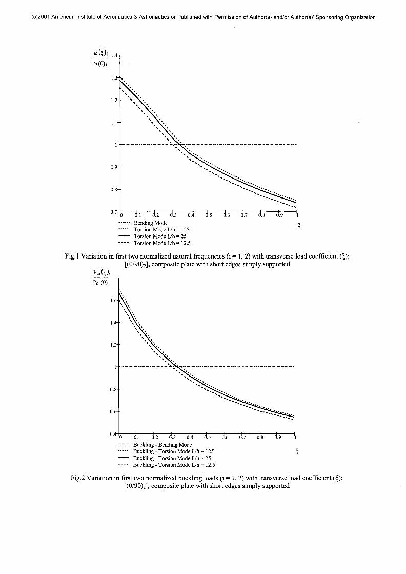
First, the effect of transverse compressivestatic loads on the natural frequencies, buckling loadsand buckled shapes are investigated and the results arepresented in Figs. 1-5. The natural frequencies obtainedfrom Eqn. (12) in the absence of the harmonic term,normalized with respect to the natural first frequency ofthe unloaded plate (£ = 0, in Eqn. 12) are determinedfor cross-ply composite plates, with three differentthickness ratios, with the short edges simply supported.It must be noted that the HOT based finite elementmodel used in this work has been extensively validatedin terms of natural frequencies and buckling loadresults, by comparison with available experimental dataand NASTRAN 3D solutions7'8. The variation of thefirst two normalized natural frequencies with thetransverse load coefficient (£) is presented in Fig. 1. Asseen from this figure, the bending natural frequency,which is not influenced by the magnitude of thetransverse compressive static load, remains constant.The torsional natural frequency decreases as thetransverse compressive static load is increased. For acertain value of the transverse load coefficient (£) itsvalue becomes lower than the bending naturalfrequency and the torsion mode becomes the firsteigenmode. This phenomenon is due to the fact that thetransverse compressive static load stiffens the plate inthe transverse direction without affecting its stiffness inthe longitudinal direction.
The same type of behavior is observed whenanalyzing the first two buckling loads also obtainedfrom Eqn. (12) by ignoring the inertia and the harmonicterms. The results are presented in Fig. 2 where the
(c)2001 American Institute of Aeronautics & Astronautics or Published with Permission of Author(s) and/or Author(s)' Sponsoring Organization.
0/M0——Itl...... Bending Mode e— • • Torsion Mode L/h = 125—— Torsion Mode L/h = 25—— Torsion Mode L/h = 12.5
Fig.l Variation in first two normalized natural frequencies (i = 1, 2) with transverse load coefficient (£);[(0/90)2]s composite plate with short edges simply supported
PcrGOi
0 0.1 0.2...... Buckling - Bending Mode— • • • • Buckling - Torsion Mode L/h =125 5—— Buckling - Torsion Mode L/h = 25—— Buckling - Torsion Mode L/h = 12.5
Fig.2 Variation in first two normalized buckling loads (i = 1, 2) with transverse load coefficient (£);[(0/90)2]s composite plate with short edges simply supported
(c)2001 American Institute of Aeronautics & Astronautics or Published with Permission of Author(s) and/or Author(s)' Sponsoring Organization.
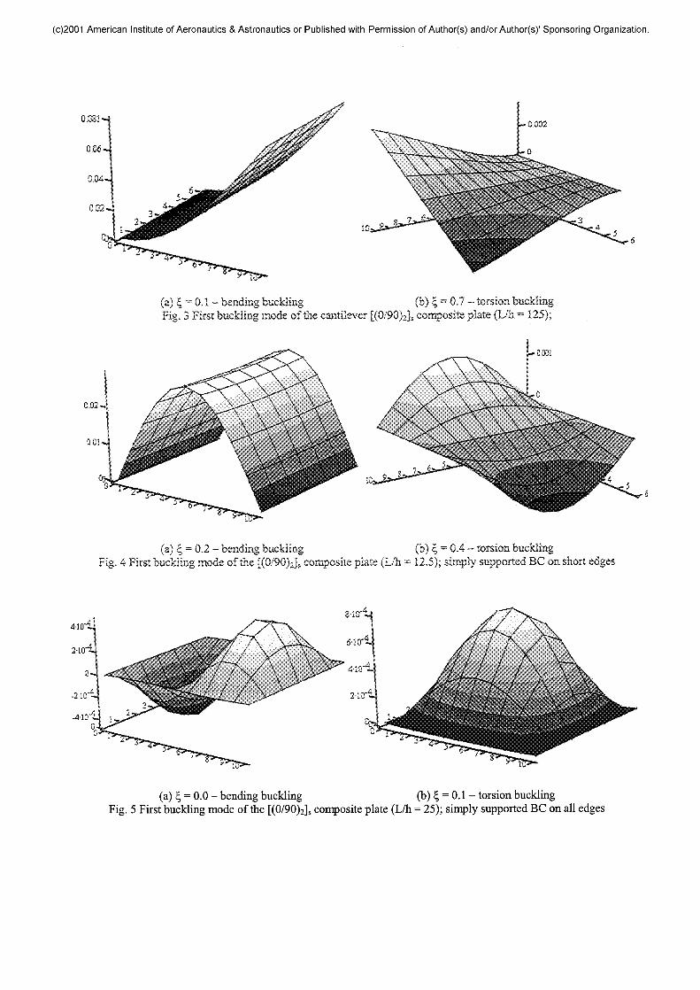
0,081-4
(a) | = 0.1 - bending tackling (b) § = 0.7 - torsion bucklingFig. 3 First buckling mode of the cantilever [(0/90)2]s composite plate (L/h = 125);
0,02-.
(a) | = 0.2 - bending buckling (b) £ = 0.4 - torsion bucklingFig. 4 First buckling mode of the [(0/90)2]s composite plate (L/h = 12.5); simply supported BC on short edges
(a) £ = 0.0 - bending buckling (b) £ = 0.1 - torsion bucklingFig. 5 First buckling mode of the [(0/90)2]s composite plate (L/h = 25); simply supported BC on all edges
(c)2001 American Institute of Aeronautics & Astronautics or Published with Permission of Author(s) and/or Author(s)' Sponsoring Organization.
buckling loads of the three plates are normalized withrespect to the critical buckling load of the unloadedplate (£ = 0 in Eqn. 12). Figure 2 shows that thetransverse compressive static load does not affect thebending buckling mode while the torsion type of elasticinstability, normally discarded in engineering analysis,becomes the first buckling mode as its critical valuedecreases with increase in the transverse compressivestatic load. It must be noted in Figs. 1 and 2, that themaximum value of the applied transverse compressivestatic load equals the critical buckling load of the platein the longitudinal direction which is much lower thanthe critical buckling load in the transverse direction, thelength over width ratio being 5/3.
Figures 1 and 2 also show that the transition ofthe bending natural frequency and the bending criticalbuckling load to the torsion natural frequency andtorsional critical buckling load, respectively, occurs forsmaller values of the transverse load coefficient as thethickness of the plates increases. This is due to theincrease in transverse shear effects with plate thickness,which is accurately captured by the HOT based finiteelement model.
The shift in buckling loads corresponds to ashift in buckling modes that is illustrated in Figs. 3 and4 for applied transverse compressive static loads of0.2(Pcr)! and 0.7(Pcr)i respectively. The samephenomenon is observed for the first bending-torsionnatural mode shape pair irrespective of the boundaryconditions. As shown in Fig. 3 for the buckled shape ofthe cantilever cross-ply composite plate thefundamental bending deformation is observed for £ =0.1 and fundamental torsional deformation is observedfor £ = 0.7. Similar observations can be made for othertypes of boundary conditions presented in Figs. 4 and 5.
The boundary conditions however, doinfluence the transition from primary to secondarybuckling. In Fig. 3, primary to secondary bucklingtransition for the cantilever plate (L/h = 125) occurs fortransverse compressive static loads in the range 60 and70 percent of the longitudinal buckling load of theunloaded plate (0.6 > § > 0.7). In Fig. 4, the plate withtwo short edges simply supported (L/h = 12.5) exhibitstransition from primary to secondary buckling fortransverse compressive static load values between 30 to40 percent of the longitudinal buckling load of theunloaded plate (0.3 > £ > 0.4). In Fig. 5 the primary tosecondary buckling transition of the plate with all edgessimply supported occurs for transverse load coefficientvalues smaller than 10 percent of the longitudinalbuckling load (0.0 > £ > 0.1). This is due to the fact thatby imposing additional boundary conditions on theplate edges, an overall increase in critical bucklingloads is achieved by constraining the plate edges fromdeforming freely. For example, the critical buckling
load of the cantilever plate is lower than the criticalbuckling load of the plate with two edges simplysupported which in turn is lower than the criticalbuckling load of the plate with all four edges simplysupported. Additional boundary conditions not onlyaffect the magnitudes of the critical buckling loads butalso affect the ratio between secondary and primarybuckling loads. Therefore the boundary conditionsinfluence the transition between the two bucklingmodes by lowering the magnitude of transverse loadcoefficient at which this transition occurs. For example,the ratio of secondary and primary buckling load forthin composite cantilever plate (L/h = 125) is 3. and 1.7for the case with short edges simply supported.
The same numerical experiment wasperformed using a [(±45)2]s angle-ply arrangement andthe buckling load results are presented in Fig. 6 for athin laminate (L/h = 125). It must be noted in this casethe results differ significantly from the [(0/90)2]s case.The shifting between bending and torsion bucklingloads (and modes), does not occur in this case due tothe presence of significant inplane bending coupling inangle-ply arrangement.
PcrOOiPcr(0)l
4--
0 (tl d.2 0.3 d.4 0.5 0.6 0.7 0.8 0.9 1—— Buckling - Bending Mode *—— Buckling - Torsion Mode
Fig.6 Variation in first two normalized buckling loads(i = 1, 2) with transverse load coefficient (£); [(±45)2]s
composite plate with short edges simply supported
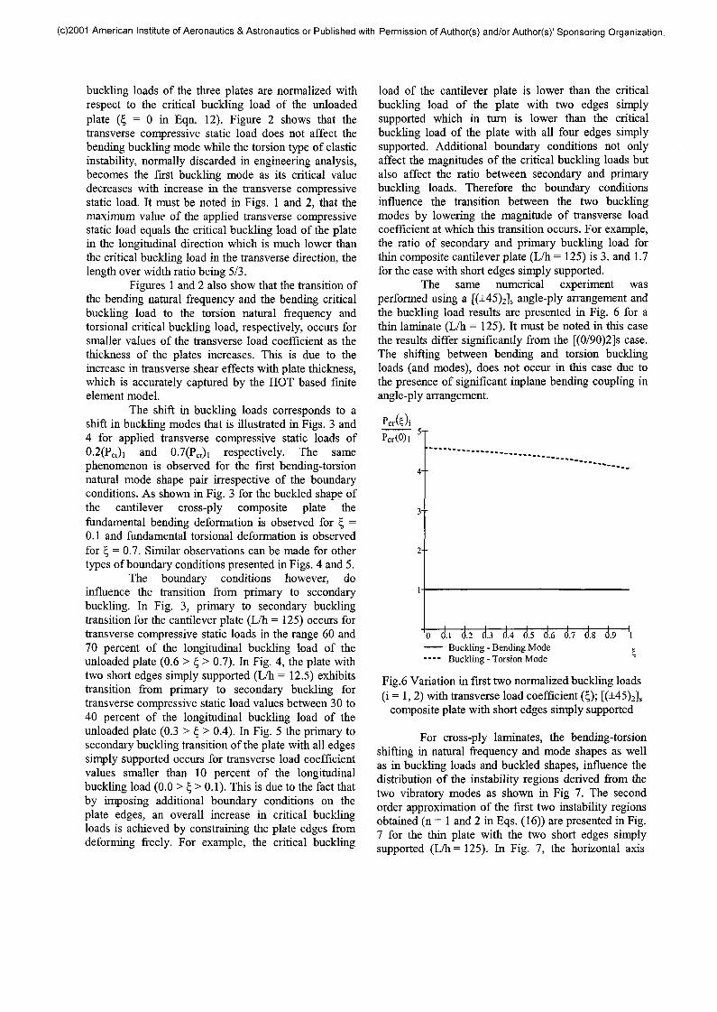
For cross-ply laminates, the bending-torsionshifting in natural frequency and mode shapes as wellas in buckling loads and buckled shapes, influence thedistribution of the instability regions derived from thetwo vibratory modes as shown in Fig 7. The secondorder approximation of the first two instability regionsobtained (n = 1 and 2 in Eqs. (16)) are presented in Fig.7 for the thin plate with the two short edges simplysupported (L/h =125). In Fig. 7, the horizontal axis
(c)2001 American Institute of Aeronautics & Astronautics or Published with Permission of Author(s) and/or Author(s)' Sponsoring Organization.
[Hz]
600
500 --
400--
300 —
200
"O.
1st Inst. - 0 Transv. Force•—• 2nd Inst. - 0 Transv. Force.
1st Inst. - 0.4Pcr Transv. Force2nd Inst. - 0.4Pcr Transv. Force
ibo ifcrFig. 7 The second order approximation of the first two stability regions for the [(0/90)2]s composite plate with the
two short edges simply supported (L/h = 125) under two different transverse compressive static loads;
represents the amplitude of the longitudinal excitingforce (ctiPcri) in Eqn. (16), and the vertical axisrepresents the parametric resonance frequency, (0n)2,obtained from the solution of the eigenvalue problem(Eqn. (16)) for the two instability regions (n = 1 and 2).The areas between the solid lines represents the bendingtype instability region while the area between the dottedlines represents the torsion type instability region.Within these regions the vibration amplitudes of theplate are predicted to grow unboundedly and thephenomenon is known as parametric resonance13.Between these two regions as well as above and belowthem, the behavior of the plate is predicted to be stable.It can be seen that due to the applied compressivetransverse static load the torsional instability regionwhich is above the bending instability region for zerotransverse compressive static load (shown by dotedline), moves below the bending instability region whenthe transverse compressive static load equals thelongitudinal buckling load of the unloaded plate (shown by 'o' dotted line). As seen from Fig. 7, inaddition to the shift between bending and torsioninstability regions, the transition in buckling load andnatural frequency caused by transverse compressivestatic loads (Figs.l and 2), reduces the horizontal extentof the instability regions and increases their width.
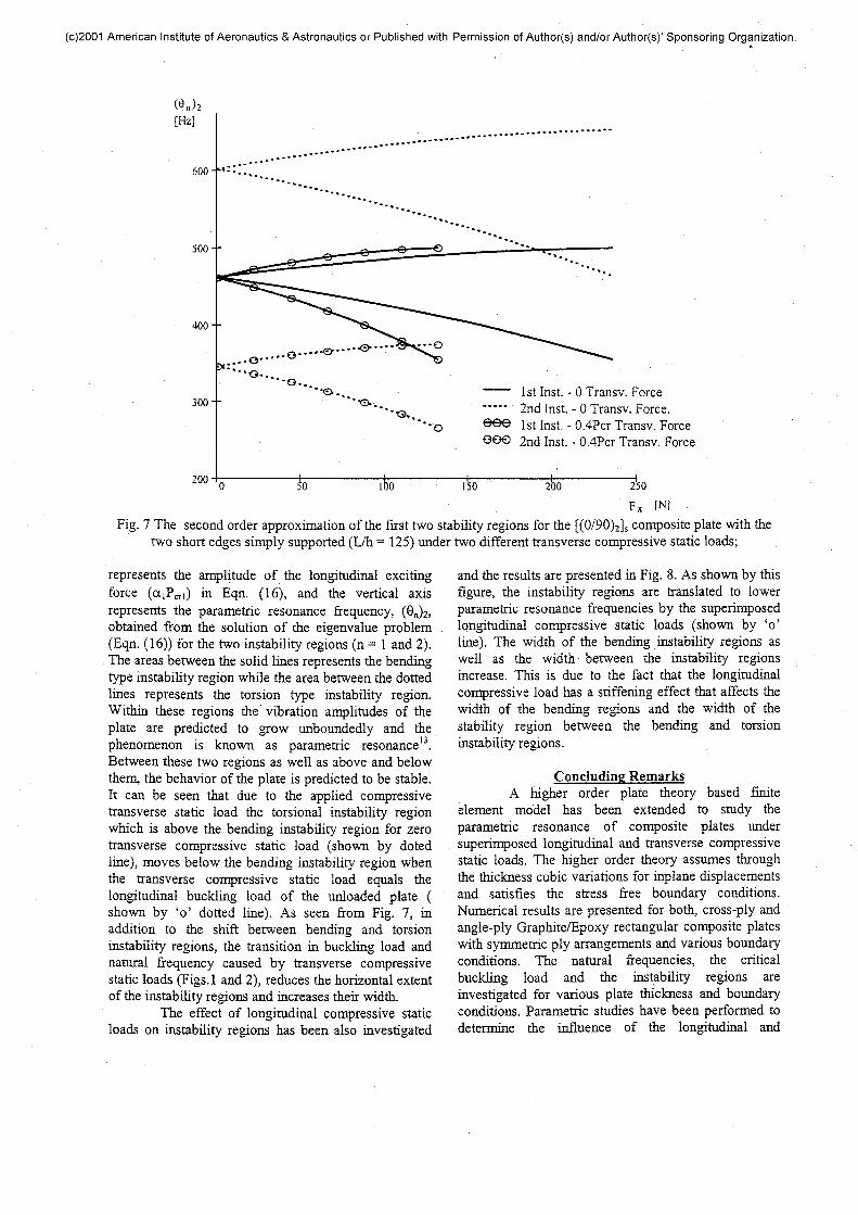
The effect of longitudinal compressive staticloads on instability regions has been also investigated
and the results are presented in Fig. 8. As shown by thisfigure, the instability regions are translated to lowerparametric resonance frequencies by the superimposedlongitudinal compressive static loads (shown by 'o'line). The width of the bending instability regions aswell as the width between the instability regionsincrease. This is due to the fact that the longitudinalcompressive load has a stiffening effect that affects thewidth of the bending regions and the width of thestability region between the bending and torsioninstability regions.
Concluding RemarksA higher order plate theory based finite
element model has been extended to study theparametric resonance of composite plates undersuperimposed longitudinal and transverse compressivestatic loads. The higher order theory assumes throughthe thickness cubic variations for inplane displacementsand satisfies the stress free boundary conditions.Numerical results are presented for both, cross-ply andangle-ply Graphite/Epoxy rectangular composite plateswith symmetric ply arrangements and various boundaryconditions. The natural frequencies, the criticalbuckling load and the instability regions areinvestigated for various plate thickness and boundaryconditions. Parametric studies have been performed todetermine the influence of the longitudinal and
(c)2001 American Institute of Aeronautics & Astronautics or Published with Permission of Author(s) and/or Author(s)' Sponsoring Organization.
[Hz]
3000
2500
2000--
1500 —
1000 --
500-
*%-o*.
——"" 1 st Inst. - 0 Long. Force—" 2nd Inst, - 0 Long. Force.^^ 1st Inst. - 0.4Pcr Long. ForceGOO 2nd Inst. - 0.4Pcr Long. Force
0.6
Fig. 8 The second order approximation of the first two stability regions for the [(0/90)2]s composite plate with thetwo short edges simply supported (L/h = 12.5) under two different longitudinal compressive static loads
transverse compressive static loads on the naturalfrequencies, critical buckling loads and second orderapproximation of the instability regions. The followingobservations are made from this study:(a) For cross-ply laminates, the application oftransverse compressive static loads can cause shift inthe torsion natural frequencies and modes, and shift inthe torsion buckling loads and modes below thecorresponding bending entities. The shift is influencedby the transverse shear effect and plate boundaryconditions.(b) The application of transverse compressivestatic loads also shifts the torsion instability regions ofcross-ply composite plates below the bending instabilityregions. The width of the bending instability region isincreased and the amplitude of the dynamic force isdecreased for the same excitation frequency.(c) The primary to secondary buckling transitioneffects have not been observed for angle-plycomposites due to strong inplane-bending couplingeffects.(d) The longitudinally applied compressive staticloads has translated the instability regions to lowerparametric resonance frequency and has increased thewidth of the bending instability regions. The stabilitymargin between bending and torsional instabilityregions has also been increased by the transversecompressive loads.
AcknowledgementsThe support of the present research by U.S.
Army Research Office, Grant # DAAH04 -94-G-0157,Technical Monitor, Dr. Gary Anderson isacknowledged.
References1. Bert, C.W., "Dynamic Instability of ShearDeformable Antisymmetric Angle-Ply Laminates",InternationalJournal of Solids and Structures, Vol. 23,1987, pp. 1053-1061.2. Srinivasan, R.S. and Chelepandi, P., "DynamicStability of Rectangular Laminated Composite Plates",Computers and Structures, Vol. 24, 1986, pp. 233-238.3. Balamurugan, M., Ganapathi, M. and Varadan,T.K., "Nonlinear Dynamic Instability of LaminatedComposite Plates Using Finite Element Method",Computers and Structures, Vol. 60, 1996, pp. 125 -130.4. Reddy, J.N., "A simple higher-order theory forlaminated composite plates", Journal of AppliedMechanics, Vol. 1, 1984, pp. 745-52.5. Reddy J.N., Phan, N.D., "Stability and Vibration ofisotropic, orthotropic and laminated plates according toa higher order shear deformation theory", Journal ofSound and Vibration, Vol. 98(2), 1985, pp. 157-170.6. Chattopadhyay, A, Gu, H., "Exact elasticity

(c)2001 American Institute of Aeronautics & Astronautics or Published with Permission of Author(s) and/or Author(s)' Sponsoring Organization.
solution for buckling of composite laminates",Composite Structures, Vol. 34, 1996, pp. 291 - 299.7. Chattopadhyay, A., Radu, A., Dragomir-Daescu,D., "Dynamic buckling of composite laminates using ahigher order theory", Modeling and Simulation BasedEngineering, Vol. 1, Tech Science Press, 1998, pp. 619-624.8. Chattopadhyay, A., Radu, A.G., "DynamicInstability of Composite Laminates Using a HigherOrder Theory", Computers and Structures, Vol. 77,2000, pp. 453-460.9. Timoshenko, S.P., Gere, J.M., Theory of ElasticStability, McGraw-Hill, 1961, New York.
10. Deolasi, P.J., Datta, P.K., "Parametric InstabilityCharacteristics of Rectangular Plates Subjected toLocalized Edge Loading (Compression or Tension)",Computers and Structures, Vol. 54, 1995, pp. 73 - 82.11. Tiwary, N., Hyer, M.W., "Secondary buckling ofLaminated Composite Plates", 41st AIAA/ASME/ASCE/AHS/ASC Structures, Structural Dynamics andMaterials Conference, Atlanta, GA, 3-6 April 2000.12. Zienkiewicz, O.C., Taylor, R.L., The FiniteElement Method, McGraw-Hill, 1991, New York.13. Bolotin, V.V., The Dynamic Stability of ElasticSystems, Holen-Day, 1964, San Francisco.