Nailing of Proximal Third Tibial Shaft Fractures Using Cortical ...
Upload
independentCategory
view
3download
0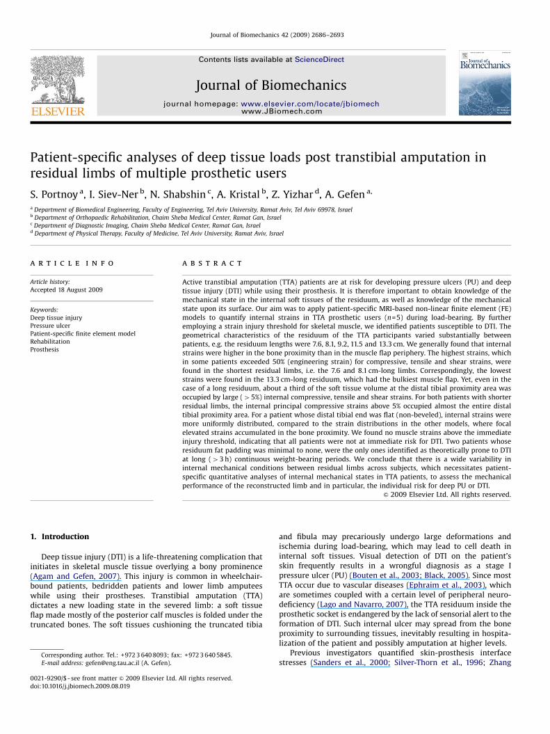
ARTICLE IN PRESS
Journal of Biomechanics 42 (2009) 2686–2693
Contents lists available at ScienceDirect
journal homepage: www.elsevier.com/locate/jbiomech
Journal of Biomechanics
0021-92
doi:10.1
� Corr
E-m
www.JBiomech.com
Patient-specific analyses of deep tissue loads post transtibial amputation inresidual limbs of multiple prosthetic users
S. Portnoy a, I. Siev-Ner b, N. Shabshin c, A. Kristal b, Z. Yizhar d, A. Gefen a,�
a Department of Biomedical Engineering, Faculty of Engineering, Tel Aviv University, Ramat Aviv, Tel Aviv 69978, Israelb Department of Orthopaedic Rehabilitation, Chaim Sheba Medical Center, Ramat Gan, Israelc Department of Diagnostic Imaging, Chaim Sheba Medical Center, Ramat Gan, Israeld Department of Physical Therapy, Faculty of Medicine, Tel Aviv University, Ramat Aviv, Israel
a r t i c l e i n f o
Article history:
Accepted 18 August 2009Active transtibial amputation (TTA) patients are at risk for developing pressure ulcers (PU) and deep
tissue injury (DTI) while using their prosthesis. It is therefore important to obtain knowledge of the
Keywords:
Deep tissue injury
Pressure ulcer
Patient-specific finite element model
Rehabilitation
Prosthesis
90/$ - see front matter & 2009 Elsevier Ltd. A
016/j.jbiomech.2009.08.019
esponding author. Tel.: +972 3 640 8093; fax
ail address: [email protected] (A. Gefen).
a b s t r a c t
mechanical state in the internal soft tissues of the residuum, as well as knowledge of the mechanical
state upon its surface. Our aim was to apply patient-specific MRI-based non-linear finite element (FE)
models to quantify internal strains in TTA prosthetic users (n=5) during load-bearing. By further
employing a strain injury threshold for skeletal muscle, we identified patients susceptible to DTI. The
geometrical characteristics of the residuum of the TTA participants varied substantially between
patients, e.g. the residuum lengths were 7.6, 8.1, 9.2, 11.5 and 13.3 cm. We generally found that internal
strains were higher in the bone proximity than in the muscle flap periphery. The highest strains, which
in some patients exceeded 50% (engineering strain) for compressive, tensile and shear strains, were
found in the shortest residual limbs, i.e. the 7.6 and 8.1 cm-long limbs. Correspondingly, the lowest
strains were found in the 13.3 cm-long residuum, which had the bulkiest muscle flap. Yet, even in the
case of a long residuum, about a third of the soft tissue volume at the distal tibial proximity area was
occupied by large (45%) internal compressive, tensile and shear strains. For both patients with shorter
residual limbs, the internal principal compressive strains above 5% occupied almost the entire distal
tibial proximity area. For a patient whose distal tibial end was flat (non-beveled), internal strains were
more uniformly distributed, compared to the strain distributions in the other models, where focal
elevated strains accumulated in the bone proximity. We found no muscle strains above the immediate
injury threshold, indicating that all patients were not at immediate risk for DTI. Two patients whose
residuum fat padding was minimal to none, were the only ones identified as theoretically prone to DTI
at long (43 h) continuous weight-bearing periods. We conclude that there is a wide variability in
internal mechanical conditions between residual limbs across subjects, which necessitates patient-
specific quantitative analyses of internal mechanical states in TTA patients, to assess the mechanical
performance of the reconstructed limb and in particular, the individual risk for deep PU or DTI.
& 2009 Elsevier Ltd. All rights reserved.
1. Introduction
Deep tissue injury (DTI) is a life-threatening complication thatinitiates in skeletal muscle tissue overlying a bony prominence(Agam and Gefen, 2007). This injury is common in wheelchair-bound patients, bedridden patients and lower limb amputeeswhile using their prostheses. Transtibial amputation (TTA)dictates a new loading state in the severed limb: a soft tissueflap made mostly of the posterior calf muscles is folded under thetruncated bones. The soft tissues cushioning the truncated tibia
ll rights reserved.
: +972 3 640 5845.
and fibula may precariously undergo large deformations andischemia during load-bearing, which may lead to cell death ininternal soft tissues. Visual detection of DTI on the patient’sskin frequently results in a wrongful diagnosis as a stage Ipressure ulcer (PU) (Bouten et al., 2003; Black, 2005). Since mostTTA occur due to vascular diseases (Ephraim et al., 2003), whichare sometimes coupled with a certain level of peripheral neuro-deficiency (Lago and Navarro, 2007), the TTA residuum inside theprosthetic socket is endangered by the lack of sensorial alert to theformation of DTI. Such internal ulcer may spread from the boneproximity to surrounding tissues, inevitably resulting in hospita-lization of the patient and possibly amputation at higher levels.
Previous investigators quantified skin-prosthesis interfacestresses (Sanders et al., 2000; Silver-Thorn et al., 1996; Zhang
ARTICLE IN PRESS
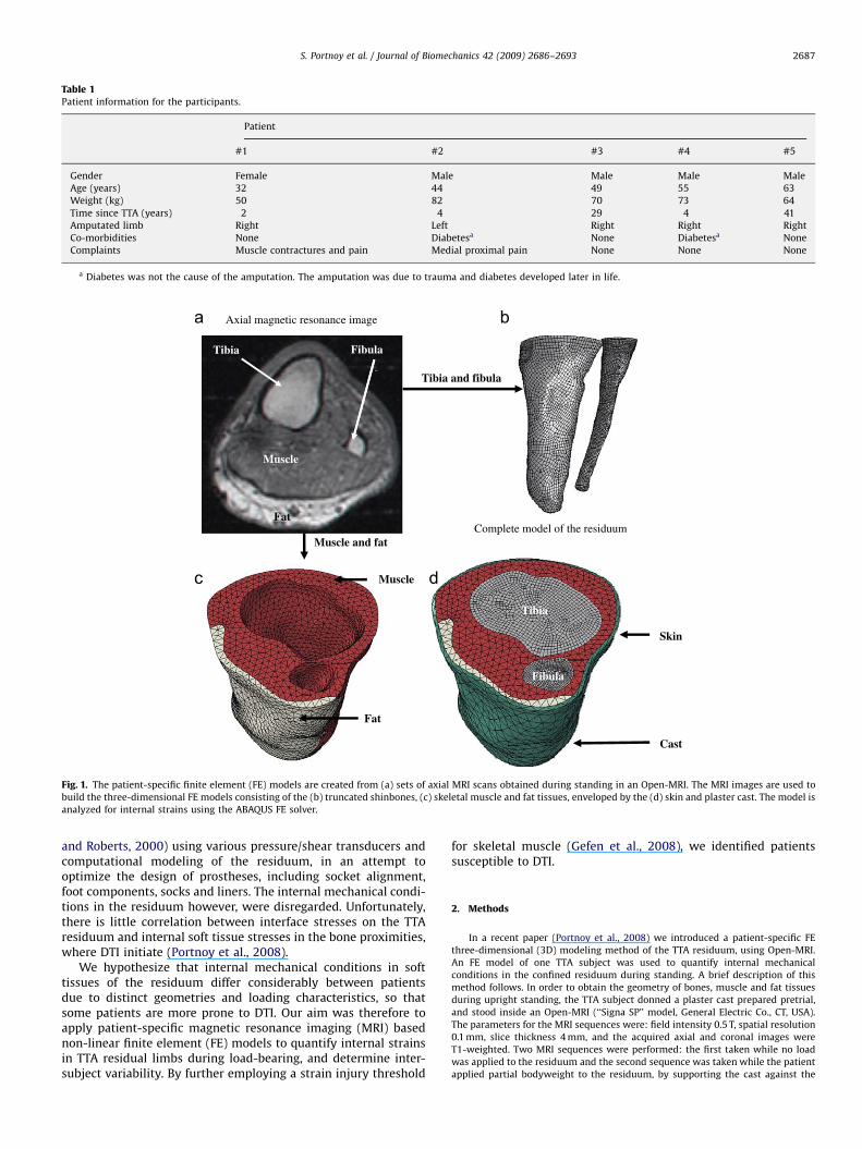
Table 1Patient information for the participants.
Patient
#1 #2 #3 #4 #5
Gender Female Male Male Male Male
Age (years) 32 44 49 55 63
Weight (kg) 50 82 70 73 64
Time since TTA (years) 2 4 29 4 41
Amputated limb Right Left Right Right Right
Co-morbidities None Diabetesa None Diabetesa None
Complaints Muscle contractures and pain Medial proximal pain None None None
a Diabetes was not the cause of the amputation. The amputation was due to trauma and diabetes developed later in life.
Axial magnetic resonance image
Complete model of the residuum
Tibia Fibula
Tibia and fibula
Muscle
Fat
Muscle
Muscle and fat
Fat
Tibia
Skin
Fibula
Cast
Fig. 1. The patient-specific finite element (FE) models are created from (a) sets of axial MRI scans obtained during standing in an Open-MRI. The MRI images are used to
build the three-dimensional FE models consisting of the (b) truncated shinbones, (c) skeletal muscle and fat tissues, enveloped by the (d) skin and plaster cast. The model is
analyzed for internal strains using the ABAQUS FE solver.
S. Portnoy et al. / Journal of Biomechanics 42 (2009) 2686–2693 2687
and Roberts, 2000) using various pressure/shear transducers andcomputational modeling of the residuum, in an attempt tooptimize the design of prostheses, including socket alignment,foot components, socks and liners. The internal mechanical condi-tions in the residuum however, were disregarded. Unfortunately,there is little correlation between interface stresses on the TTAresiduum and internal soft tissue stresses in the bone proximities,where DTI initiate (Portnoy et al., 2008).
We hypothesize that internal mechanical conditions in softtissues of the residuum differ considerably between patientsdue to distinct geometries and loading characteristics, so thatsome patients are more prone to DTI. Our aim was therefore toapply patient-specific magnetic resonance imaging (MRI) basednon-linear finite element (FE) models to quantify internal strainsin TTA residual limbs during load-bearing, and determine inter-subject variability. By further employing a strain injury threshold
for skeletal muscle (Gefen et al., 2008), we identified patientssusceptible to DTI.
2. Methods
In a recent paper (Portnoy et al., 2008) we introduced a patient-specific FE
three-dimensional (3D) modeling method of the TTA residuum, using Open-MRI.
An FE model of one TTA subject was used to quantify internal mechanical
conditions in the confined residuum during standing. A brief description of this
method follows. In order to obtain the geometry of bones, muscle and fat tissues
during upright standing, the TTA subject donned a plaster cast prepared pretrial,
and stood inside an Open-MRI (‘‘Signa SP’’ model, General Electric Co., CT, USA).
The parameters for the MRI sequences were: field intensity 0.5 T, spatial resolution
0.1 mm, slice thickness 4 mm, and the acquired axial and coronal images were
T1-weighted. Two MRI sequences were performed: the first taken while no load
was applied to the residuum and the second sequence was taken while the patient
applied partial bodyweight to the residuum, by supporting the cast against the
ARTICLE IN PRESS
S. Portnoy et al. / Journal of Biomechanics 42 (2009) 2686–26932688
MRI table. Each patient was instructed to apply painless loading to the residuum so
as not to exceed subjective standing loads. During the second MRI sequence we
used piezoresistive ultra-thin pressure sensors (thickness of �0.2 mm; accuracy
75%, FlexiForce, Tekscan Co. MA, USA) to verify that there was load-bearing in
this posture.
All the patients chosen for this study were active individuals, who use their
prostheses for several hours daily. We excluded TTA patients with contra-
indications for MRI including those with foreign metallic bodies, pacemakers,
intravascular stents or orthopaedic implants. A careful selection process had to be
followed because traumatic TTA sometimes involves implant fixations, or intra-
body metallic fragments associated with the trauma. Six traumatic unilateral TTA
patients eventually participated. Helsinki approval (#4302/06 from Sheba Medical
Center, Ramat-Gan, Israel) and informed consents were obtained before each trial.
The MRI scans obtained from one male TTA patient (age 62, weight 115 kg) were
found to be of lower quality with respect to the others (boundaries between
muscle and fat tissues were, in places, indistinguishable, likely because the patient
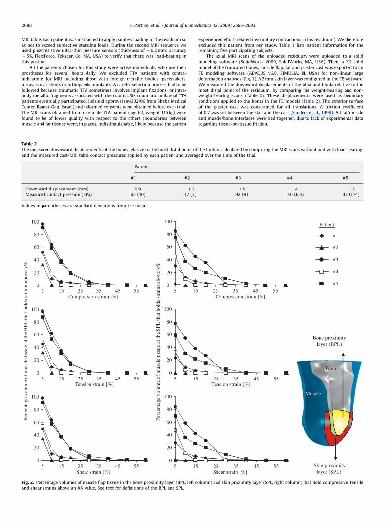
Table 2The measured downward displacements of the bones relative to the most distal point of
and the measured cast-MRI table contact pressures applied by each patient and averag
Patient
#1 #2
Downward displacement (mm) 0.9 1.6
Measured contact pressure (kPa) 65 (10) 17 (7)
Values in parentheses are standard deviations from the mean.
Compression strain [%]
0
Tension strain [%]
0
60
80
100
20
40
80
100
40
60
20
60
80
100
20
40
Perc
enta
ge v
olum
e of
mus
cle
tissu
e at
the
SPL
that
hol
ds s
trai
ns a
bove
x%
0
0
Perc
enta
ge v
olum
e of
mus
cle
tissu
e at
the
BPL
that
hol
ds s
trai
ns a
bove
x%
60
80
100
20
40
100
40
60
80
20
60
80
100
20
40
0
Shear strain [%]5
0155 15 25 35 45 55
5 15 25 35 45 55
5 15 25 35 45 55 5 15
5 15
Fig. 2. Percentage volumes of muscle flap tissue in the bone proximity layer (BPL, left c
and shear strains above an X% value. See text for definitions of the BPL and SPL.
experienced effort-related involuntary contractions in his residuum). We therefore
excluded this patient from our study. Table 1 lists patient information for the
remaining five participating subjects.
The axial MRI scans of the unloaded residuum were uploaded to a solid
modeling software (SolidWorks 2009, SolidWorks, MA, USA). Then, a 3D solid
model of the truncated bones, muscle flap, fat and plaster cast was exported to an
FE modeling software (ABAQUS v6.8, SIMULIA, RI, USA) for non-linear large
deformation analyses (Fig. 1). A 2 mm skin layer was configured in the FE software.
We measured the downward displacements of the tibia and fibula relative to the
most distal point of the residuum, by comparing the weight-bearing and non-
weight-bearing scans (Table 2). These displacements were used as boundary
conditions applied to the bones in the FE models (Table 2). The exterior surface
of the plaster cast was constrained for all translations. A friction coefficient
of 0.7 was set between the skin and the cast (Sanders et al., 1998). All fat/muscle
and muscle/bone interfaces were tied together, due to lack of experimental data
regarding tissue-on-tissue friction.
the limb as calculated by comparing the MRI scans without and with load-bearing,
ed over the time of the trial.
#3 #4 #5
1.8 1.4 1.2
92 (9) 7.6 (6.3) 330 (74)
#1
#2
Patient
#3
#4
#5
Compression strain [%]
Bone proximitylayer (BPL)
Tibia
Tension strain [%]
Muscle
25 35 45 55
25 35 45 55
25 35 45 55
Skin proximitylayer (SPL) Shear strain [%]
olumn) and skin proximity layer (SPL, right column) that hold compressive, tensile
ARTICLE IN PRESS
S. Portnoy et al. / Journal of Biomechanics 42 (2009) 2686–2693 2689
By imposing downward bone displacements, we calculated 3D distributions
of soft tissue strains per each model. Since calculation of strain energy density
and stresses requires knowledge of patient-specific mechanical properties of soft
tissues, which were not available from the present experimental design, we
recognized strains only as our outcome of interest. However, since ABAQUS
formally requires definitions of constitutive laws for each model component, these
were defined as follows. The bones were assumed to be rigid. The cast was
assumed to be a homogeneous, isotropic and linear-elastic material. All the soft
tissues were assumed to be hyperelastic, homogeneous and isotropic, and were
modeled using the Generalized Mooney-Rivlin Solid strain energy function:
W ¼ C10ðI1 � 3ÞþC11ðI1 � 3ÞðI2 � 3Þþ1
D1ðJ � 1Þ2 ð1Þ
where the invariants of the principal stretch ratios li are I1=l12 +l2
2+l32 and
I1=l1�2+l2
�2+l3�2, the relative volume change is J=l1l2l3, and C10, C11, D1 are
constitutive parameters that were not specified as this is a displacement–strain
analysis.
An example of the meshing of one FE model is shown in Fig. 1. The bones were
meshed with 4-node quadrilateral surface elements (‘‘SFM3D4’’ in ABAQUS). The
muscle flap, fat tissue and plaster cast were meshed with second-order 10-node
modified quadratic tetrahedron elements (‘‘C3D10M’’). The skin tissue was meshed
with 6-node quadratic triangular membrane elements (‘‘M3D6’’).
We calculated distributions of principal engineering compressive and tensile
strains and maximal shear strains for each patient-specific model (n=5). For
comparisons of strain exposures in muscle tissue across patients, we defined two
separate muscular volumes of interests (VOI; Fig. 2 bottom right frame): the first
VOI, termed the bone proximity layer (BPL; colored yellow in Fig. 2), is a layer of all
the muscle tissue elements contacting the distal third of the tibia. The second VOI,
named the skin proximity layer (SPL; colored red in Fig. 2) contains all the muscle
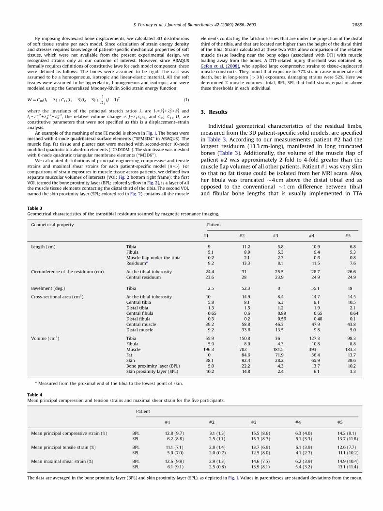
Table 3Geometrical characteristics of the transtibial residuum scanned by magnetic resonance
Geometrical property
Length (cm) Tibia
Fibula
Muscle flap under the tibia
Residuuma
Circumference of the residuum (cm) At the tibial tuberosity
Central residuum
Bevelment (deg.) Tibia
Cross-sectional area (cm2) At the tibial tuberosity
Central tibia
Distal tibia
Central fibula
Distal fibula
Central muscle
Distal muscle
Volume (cm3) Tibia
Fibula
Muscle
Fat
Skin
Bone proximity layer (BPL)
Skin proximity layer (SPL)
a Measured from the proximal end of the tibia to the lowest point of skin.
Table 4Mean principal compression and tension strains and maximal shear strain for the five
Patient
#1
Mean principal compressive strain (%) BPL 12.8 (9.7)
SPL 6.2 (8.8)
Mean principal tensile strain (%) BPL 11.1 (7.1)
SPL 5.0 (7.0)
Mean maximal shear strain (%) BPL 12.6 (9.9)
SPL 6.1 (9.1)
The data are averaged in the bone proximity layer (BPL) and skin proximity layer (SPL),
elements contacting the fat/skin tissues that are under the projection of the distal
third of the tibia, and that are located not higher than the height of the distal third
of the tibia. Strains calculated at these two VOIs allow comparison of the relative
muscle tissue loading near the bony edges (associated with DTI) with muscle
loading away from the bones. A DTI-related injury threshold was obtained by
Gefen et al. (2008), who applied large compressive strains to tissue-engineered
muscle constructs. They found that exposure to 77% strain cause immediate cell
death, but in long-term (43 h) exposures, damaging strains were 52%. Here we
determined %-muscle volumes: total, BPL, SPL that hold strains equal or above
these thresholds in each individual.
3. Results
Individual geometrical characteristics of the residual limbs,measured from the 3D patient-specific solid models, are specifiedin Table 3. According to our measurements, patient #2 had thelongest residuum (13.3 cm-long), manifested in long truncatedbones (Table 3). Additionally, the volume of the muscle flap ofpatient #2 was approximately 2-fold to 4-fold greater than themuscle flap volumes of all other patients. Patient #1 was very slimso that no fat tissue could be isolated from her MRI scans. Also,her fibula was truncated �4 cm above the distal tibial end asopposed to the conventional �1 cm difference between tibialand fibular bone lengths that is usually implemented in TTA
imaging.
Patient
#1 #2 #3 #4 #5
9 11.2 5.8 10.9 6.8
5.1 8.9 5.3 9.4 5.3
0.2 2.1 2.3 0.6 0.8
9.2 13.3 8.1 11.5 7.6
24.4 31 25.5 28.7 26.6
23.6 28 23.9 24.9 24.9
12.5 52.3 0 55.1 18
10 14.9 8.4 14.7 14.5
5.8 8.1 6.3 9.1 10.5
1.3 1.5 1.2 1.9 2.1
0.65 0.6 0.89 0.65 0.64
0.3 0.2 0.56 0.48 0.1
39.2 58.8 46.3 47.9 43.8
9.2 33.6 13.5 9.8 5.0
55.9 150.8 36 127.3 98.3
5.9 8.0 4.3 10.8 8.8
196.3 702 181.5 393 183.3
0 84.6 71.9 56.4 13.7
38.1 92.4 28.2 65.9 39.6
5.0 22.2 4.3 13.7 10.2
10.2 14.8 2.4 6.1 3.3
participants.
#2 #3 #4 #5
3.1 (1.3) 15.5 (8.6) 6.3 (4.0) 14.2 (9.1)
2.5 (1.1) 15.3 (8.7) 5.1 (3.3) 13.7 (11.8)
2.8 (1.4) 13.7 (6.9) 6.1 (3.9) 12.6 (7.7)
2.0 (0.7) 12.5 (8.0) 4.1 (2.7) 11.1 (10.2)
2.9 (1.3) 14.6 (7.5) 6.2 (3.9) 14.9 (10.4)
2.5 (0.8) 13.9 (8.1) 5.4 (3.2) 13.1 (11.4)
as depicted in Fig. 1. Values in parentheses are standard deviations from the mean.
ARTICLE IN PRESS
Compression strain [%]Patient
FatFat Fat
Tension strain
Fat
Shear strain
#1 #2 #3 #4 #5
#1 #2 #3 #4 #5
#1 #2 #3 #4 #5
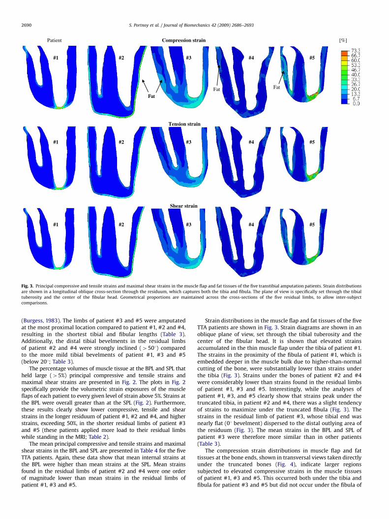
Fig. 3. Principal compressive and tensile strains and maximal shear strains in the muscle flap and fat tissues of the five transtibial amputation patients. Strain distributions
are shown in a longitudinal oblique cross-section through the residuum, which captures both the tibia and fibula. The plane of view is specifically set through the tibial
tuberosity and the center of the fibular head. Geometrical proportions are maintained across the cross-sections of the five residual limbs, to allow inter-subject
comparisons.
S. Portnoy et al. / Journal of Biomechanics 42 (2009) 2686–26932690
(Burgess, 1983). The limbs of patient #3 and #5 were amputatedat the most proximal location compared to patient #1, #2 and #4,resulting in the shortest tibial and fibular lengths (Table 3).Additionally, the distal tibial bevelments in the residual limbsof patient #2 and #4 were strongly inclined (4501) comparedto the more mild tibial bevelments of patient #1, #3 and #5(below 201; Table 3).
The percentage volumes of muscle tissue at the BPL and SPL thatheld large (45%) principal compressive and tensile strains andmaximal shear strains are presented in Fig. 2. The plots in Fig. 2specifically provide the volumetric strain exposures of the muscleflaps of each patient to every given level of strain above 5%. Strains atthe BPL were overall greater than at the SPL (Fig. 2). Furthermore,these results clearly show lower compressive, tensile and shearstrains in the longer residuum of patient #1, #2 and #4, and higherstrains, exceeding 50%, in the shorter residual limbs of patient #3and #5 (these patients applied more load to their residual limbswhile standing in the MRI; Table 2).
The mean principal compressive and tensile strains and maximalshear strains in the BPL and SPL are presented in Table 4 for the fiveTTA patients. Again, these data show that mean internal strains atthe BPL were higher than mean strains at the SPL. Mean strainsfound in the residual limbs of patient #2 and #4 were one orderof magnitude lower than mean strains in the residual limbs ofpatient #1, #3 and #5.
Strain distributions in the muscle flap and fat tissues of the fiveTTA patients are shown in Fig. 3. Strain diagrams are shown in anoblique plane of view, set through the tibial tuberosity and thecenter of the fibular head. It is shown that elevated strainsaccumulated in the thin muscle flap under the tibia of patient #1.The strains in the proximity of the fibula of patient #1, which isembedded deeper in the muscle bulk due to higher-than-normalcutting of the bone, were substantially lower than strains underthe tibia (Fig. 3). Strains under the bones of patient #2 and #4were considerably lower than strains found in the residual limbsof patient #1, #3 and #5. Interestingly, while the analyses ofpatient #1, #3, and #5 clearly show that strains peak under thetruncated tibia, in patient #2 and #4, there was a slight tendencyof strains to maximize under the truncated fibula (Fig. 3). Thestrains in the residual limb of patient #3, whose tibial end wasnearly flat (01 bevelment) dispersed to the distal outlying area ofthe residuum (Fig. 3). The mean strains in the BPL and SPL ofpatient #3 were therefore more similar than in other patients(Table 3).
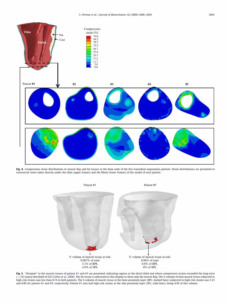
The compression strain distributions in muscle flap and fattissues at the bone ends, shown in transversal views taken directlyunder the truncated bones (Fig. 4), indicate larger regionssubjected to elevated compressive strains in the muscle tissuesof patient #1, #3 and #5. This occurred both under the tibia andfibula for patient #3 and #5 but did not occur under the fibula of
ARTICLE IN PRESS
Compressionstrain [%]Tibia
Fat
Cast70.064.2
Fibula 58.352.546.735.029.317.511.75.80.0
#5 #4 #3 #2Patient #1
Fig. 4. Compression strain distributions in muscle flap and fat tissues at the bone ends of the five transtibial amputation patients. Strain distributions are presented in
transversal views taken directly under the tibia (upper frames) and the fibula (lower frames) of the model of each patient.
Patient #1
% volume of muscle tissue at risk:0.067% of total3.1% of BPL4.9% of SPL
% volume of muscle tissue at risk:0.06% of total0.8% of BPL0% of SPL
Patient #5
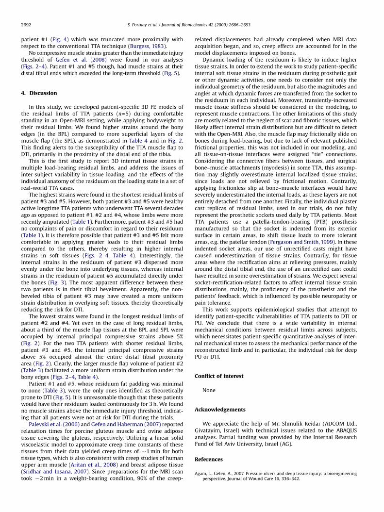
Fig. 5. ‘‘Hotspots’’ in the muscle tissues of patient #1 and #5 are presented, indicating regions at the distal tibial end where compressive strains exceeded the long-term
(43 h) injury threshold of 52% (Gefen et al., 2008). The fat tissue is subtracted in this display to show only the muscle flap. The %-volume of total muscle tissue subjected to
high-risk strains was less than 0.1% in both patients. The %-volume of muscle tissue in the bone proximity layer (BPL; dashed lines) subjected to high-risk strains was 3.1%
and 0.8% for patient #1 and #5, respectively. Patient #1 also had high-risk strains at the skin proximity layer (SPL; solid lines), being 4.9% of this volume.
S. Portnoy et al. / Journal of Biomechanics 42 (2009) 2686–2693 2691
ARTICLE IN PRESS
S. Portnoy et al. / Journal of Biomechanics 42 (2009) 2686–26932692
patient #1 (Fig. 4) which was truncated more proximally withrespect to the conventional TTA technique (Burgess, 1983).
No compressive muscle strains greater than the immediate injurythreshold of Gefen et al. (2008) were found in our analyses(Figs. 2–4). Patient #1 and #5 though, had muscle strains at theirdistal tibial ends which exceeded the long-term threshold (Fig. 5).
4. Discussion
In this study, we developed patient-specific 3D FE models ofthe residual limbs of TTA patients (n=5) during comfortablestanding in an Open-MRI setting, while applying bodyweight totheir residual limbs. We found higher strains around the bonyedges (in the BPL) compared to more superficial layers of themuscle flap (the SPL), as demonstrated in Table 4 and in Fig. 2.This finding alerts to the susceptibility of the TTA muscle flap toDTI, primarily in the proximity of the distal end of the tibia.
This is the first study to report 3D internal tissue strains inmultiple load-bearing residual limbs, and address the issues ofinter-subject variability in tissue loading, and the effects of theindividual anatomy of the residuum on the loading state in a set ofreal-world TTA cases.
The highest strains were found in the shortest residual limbs ofpatient #3 and #5. However, both patient #3 and #5 were healthyactive longtime TTA patients who underwent TTA several decadesago as opposed to patient #1, #2 and #4, whose limbs were morerecently amputated (Table 1). Furthermore, patient #3 and #5 hadno complaints of pain or discomfort in regard to their residuum(Table 1). It is therefore possible that patient #3 and #5 felt morecomfortable in applying greater loads to their residual limbscompared to the others, thereby resulting in higher internalstrains in soft tissues (Figs. 2–4, Table 4). Interestingly, theinternal strains in the residuum of patient #3 dispersed moreevenly under the bone into underlying tissues, whereas internalstrains in the residuum of patient #5 accumulated directly underthe bones (Fig. 3). The most apparent difference between thesetwo patients is in their tibial bevelment. Apparently, the non-beveled tibia of patient #3 may have created a more uniformstrain distribution in overlying soft tissues, thereby theoreticallyreducing the risk for DTI.
The lowest strains were found in the longest residual limbs ofpatient #2 and #4. Yet even in the case of long residual limbs,about a third of the muscle flap tissues at the BPL and SPL wereoccupied by internal principal compressive strains above 5%(Fig. 2). For the two TTA patients with shorter residual limbs,patient #3 and #5, the internal principal compressive strainsabove 5% occupied almost the entire distal tibial proximityarea (Fig. 2). Clearly, the larger muscle flap volume of patient #2(Table 3) facilitated a more uniform strain distribution under thebony edges (Figs. 2–4, Table 4).
Patient #1 and #5, whose residuum fat padding was minimalto none (Table 3), were the only ones identified as theoreticallyprone to DTI (Fig. 5). It is unreasonable though that these patientswould have their residuum loaded continuously for 3 h. We foundno muscle strains above the immediate injury threshold, indicat-ing that all patients were not at risk for DTI during the trials.
Palevski et al. (2006) and Gefen and Haberman (2007) reportedrelaxation times for porcine gluteus muscle and ovine adiposetissue covering the gluteus, respectively. Utilizing a linear solidviscoelastic model to approximate creep time constants of thesetissues from their data yielded creep times of �1 min for bothtissue types, which is also consistent with creep studies of humanupper arm muscle (Aritan et al., 2008) and breast adipose tissue(Sridhar and Insana, 2007). Since preparations for the MRI scantook �2 min in a weight-bearing condition, 90% of the creep-
related displacements had already completed when MRI dataacquisition began, and so, creep effects are accounted for in themodel displacements imposed on bones.
Dynamic loading of the residuum is likely to induce highertissue strains. In order to extend the work to study patient-specificinternal soft tissue strains in the residuum during prosthetic gaitor other dynamic activities, one needs to consider not only theindividual geometry of the residuum, but also the magnitudes andangles at which dynamic forces are transferred from the socket tothe residuum in each individual. Moreover, transiently-increasedmuscle tissue stiffness should be considered in the modeling, torepresent muscle contractions. The other limitations of this studyare mostly related to the neglect of scar and fibrotic tissues, whichlikely affect internal strain distributions but are difficult to detectwith the Open-MRI. Also, the muscle flap may frictionally slide onbones during load-bearing, but due to lack of relevant publishedfrictional properties, this was not included in our modeling, andall tissue-on-tissue interfaces were assigned ‘‘tie’’ connections.Considering the connective fibers between tissues, and surgicalbone–muscle attachments (myodesis) in some TTA, this assump-tion may slightly overestimate internal localized tissue strains,since loads are not relieved by frictional motion. Contrarily,applying frictionless slip at bone–muscle interfaces would haveseverely underestimated the internal loads, as these layers are notentirely detached from one another. Finally, the individual plastercast replicas of residual limbs, used in our trials, do not fullyrepresent the prosthetic sockets used daily by TTA patients. MostTTA patients use a patella-tendon-bearing (PTB) prosthesismanufactured so that the socket is indented from its exteriorsurface in certain areas, to shift tissue loads to more tolerantareas, e.g. the patellar tendon (Fergason and Smith, 1999). In theseindented socket areas, our use of unrectified casts might havecaused underestimation of tissue strains. Contrarily, for tissueareas where the rectification aims at relieving pressures, mainlyaround the distal tibial end, the use of an unrectified cast couldhave resulted in some overestimation of strains. We expect severalsocket-rectification-related factors to affect internal tissue straindistributions, mainly, the proficiency of the prosthetist and thepatients’ feedback, which is influenced by possible neuropathy orpain tolerance.
This work supports epidemiological studies that attempt toidentify patient-specific vulnerabilities of TTA patients to DTI orPU. We conclude that there is a wide variability in internalmechanical conditions between residual limbs across subjects,which necessitates patient-specific quantitative analyses of inter-nal mechanical states to assess the mechanical performance of thereconstructed limb and in particular, the individual risk for deepPU or DTI.
Conflict of interest
None
Acknowledgements
We appreciate the help of Mr. Shmulik Keidar (ADCOM Ltd.,Givatayim, Israel) with technical issues related to the ABAQUSanalyses. Partial funding was provided by the Internal ResearchFund of Tel Aviv University, Israel (AG).
References
Agam, L., Gefen, A., 2007. Pressure ulcers and deep tissue injury: a bioengineeringperspective. Journal of Wound Care 16, 336–342.
ARTICLE IN PRESS
S. Portnoy et al. / Journal of Biomechanics 42 (2009) 2686–2693 2693
Aritan, S., Oyadiji, S.O., Bartlett, R.M., 2008. A mechanical model representation ofthe in vivo creep behaviour of muscular bulk tissue. Journal of Biomechanics41, 2760–2765.
Black, J.M., 2005. Moving toward consensus on deep tissue injury and pressureulcer staging. Advances in Skin and Wound Care 18, 415–421.
Bouten, C.V., Oomens, C.W., Baaijens, F.P., Bader, D.L., 2003. The etiologyof pressure ulcers: skin deep or muscle bound?. Archives of Physical Medicineand Rehabilitation 84, 616–619.
Burgess, E., 1983. Amputations. Surgical clinics of North America 63, 749–770.Ephraim, P.L., Dillingham, T., Sector, M., Pezzin, L.E., Mackenzie, E.J., 2003.
Epidemiology of limb loss and congenital limb deficiency: a review of theliterature. Archives of Physical Medicine & Rehabilitation 84, 747–761.
Fergason, J., Smith, D.G., 1999. Socket considerations for the patient with atranstibial amputation. Clinical Orthopaedics and Related Research 361,76–84.
Gefen, A., Haberman, E., 2007. Viscoelastic properties of ovine adipose tissuecovering the gluteus muscles. Journal of Biomechanical Engineering 129,924–930.
Gefen, A., van Nierop, B., Bader, D.L., Oomens, C.W., 2008. Strain-time cell-deaththreshold for skeletal muscle in a tissue-engineered model system for deeptissue injury. Journal of Biomechanics 41, 2003–2012.
Lago, N., Navarro, X., 2007. Evaluation of the long-term regenerative potential in anexperimental nerve amputee model. Journal of Peripheral Nervous System 12,108–120.
Palevski, A., Glaich, I., Portnoy, S., Linder-Ganz, E., Gefen, A., 2006. Stress relaxationof porcine gluteus muscle subjected to sudden transverse deformation asrelated to pressure sore modeling. Journal of Biomechanical Engineering 128,782–787.
Portnoy, S., Yizhar, Z., Shabshin, N., Itzchak, Y., Kristal, A., Dotan-Marom, Y.,Siev-Ner, I., Gefen, A., 2008. Internal mechanical conditions in the softtissues of a residual limb of a trans-tibial amputee. Journal of Biomechanics41, 1897–1909.
Sanders, J.E., Greve, J.M., Mitchell, S.B., Zachariah, S.G., 1998. Material properties ofcommonly-used interface materials and their static coefficients of frictionwith skin and socks. Journal of Rehabilitation Research and Development 35,161–176.
Sanders, J.E., Zachariah, S.G., Baker, A.B., Greve, J.M., Clinton, C., 2000. Effects ofchanges in cadence, prosthetic componentry, and time on interface pressuresand shear stresses of three trans-tibial amputees. Clinical Biomechanics 15,684–694.
Silver-Thorn, M.B., Steege, J.W., Childress, D.S., 1996. A Review of prostheticinterface stress investigations. Journal of Rehabilitation, Research andDevelopment 33, 253–266.
Sridhar, M., Insana, M.F., 2007. Ultrasonic measurements of breast viscoelasticity.Medical Physics 34, 4757–4767.
Zhang, M., Roberts, C., 2000. Comparison of computational analysiswith clinical measurement of stresses on below-knee residual limb in aprosthetic socket. Medical Engineering and Physics 22, 607–612.
Copyright © 2022 FDOKUMEN