INTE~ATIONM LINEfi COLLIDER TECHNIC - SLAC - Stanford ...
199
INTE~ATIONM LINEfi COLLIDER TECHNIC~ ~~EW COMMITTEE ~PORT 1995 -. SLAC-R-471 Stanford Linear Accelerator Center, Menlo Park, CA 94025 Work supported in part by US Department of Energy contract DE-AC03-76SF00515.
-
Upload
khangminh22 -
Category
Documents
-
view
1 -
download
0
Transcript of INTE~ATIONM LINEfi COLLIDER TECHNIC - SLAC - Stanford ...

INTE~ATIONMLINEfi COLLIDER
TECHNIC~ ~~EWCOMMITTEE ~PORT
1995
-.
SLAC-R-471
Stanford Linear Accelerator Center, Menlo Park, CA 94025
Work supported in part by US Department of Energy contract DE-AC03-76SF00515.

.-
Stanford Linear Accelerator CenterTechnical Pubhcations DepartmentStanford ~niveysityP.O. Box 4349Stanford, CA 94309, USAEmd address: [email protected]
--
This document and the material and data contained herein were developed un-der the sponsorship of the governments, their agencies, and the institutions,universities, and employing orgtiations of the members of the InternationalLinear CoMder Technical Review Committee. None of th~e entiti~, nor theiremployees, nor their respective contractors, subcontractors, nor their employeesm~e any warranty, express or imphed, or assume any Hability or responsibihtyfor accuracy, completeness or usefubess of any information, apparatus, productor process disclosed, or represent that its use d not infringe privately-ownedrigh~s. Mention of any product, its mmufacturer, or supptiers shall not, noris it intended to, imply approval, disapprod, or fitness for any particdar use.The sponsoring entiti~, individually and at dl tires, retain the right to use anddisseminate this information for any purpose whatsoever. Notice 951220
This report w= produced on behalf of the International Linear Collider Techni-cal Review Committee by the Stanford Linear Accelerator Center under contractDEAC0376SFO0515 with the U.S. Department of Ener~. Copies may be obtained by rquesting SLAC-R-9S471 from the:

Foreword
This 1995 report of the International Linem CoUder Technical Review Committee is thefist attempt to gather in one document the cument status of aH major e+e- hnear co~derprojects in the world. The report is the result of a collaborative effort of scientists frommany laboratories working together over a period of about one year. A short description ofthe orgtiation, origins and history of the report is given below.
To get an idea of the organization, the reader should fist refer to the Table of Contents.Chapter 1 is an introduction and general overview of the respective 500 GeV cm. energymachines. In contrast, Chapter 2, cutting across individual machine boundmies, gives acomparative description and discussion of W the major machine subsystems as well w par-
ticle physics experimentation, showing where these subjects stand today and what additiondwork needs to be done in the next few years to reach the point where complete design reports can be prepared. Chapter 3 describes the various paths to ener~ upgrades, and otherexperimental options (~ ~, e– e-, etc.). Chapter 4 gives a short status report of the machineexperiments and test facihties being built in the world. Chapter 5 outhnes current and otherpossible are= of collaboration and tidy, Chapter 6 summarizes our principal conclusions.
The reader shotid note that the idea of generating this report w= not born overnightbut rather, was the result of a protracted series of events and observations. To quote DavidBurke from SLAC,
“The accelerators and colliders needed to explore particle physics at high ener-gies have become increasingly expensive and complex. The successful integrationof the resources and effotis of scientists from diffeting countries in the comple-tion of the HERA electron-proton collider and ongoing international cooperationin the design and building of accelerators at CERN have demonstrated the feasi-bility of international collaborations to realize the imtruments required to explorefurther the high energy physics frontier. In contrast, the failure of the SSC hasemphasized the necessity of such wllaboratiom.
me LHC, now approved for constmction at CERN, has garnered consider-able interest amongst scientists from all over the globe, and the project is movingforward to perhaps ‘be the first scientific instrument built by a tmly world-widecollaboration. There is also great interest in the world in the future of electron-positron colliders. The successful use of the SLC to study the physics of the ZOhas demonstrated the feasibility of linear colliders as tools for qloration of theTeV energy scale, and research at many laboratories around the world is directedat several diflerent approaches to the design and construction of such a collider.In anticipation of the need for international collaboration to realize a Te V-scalelinear collider, these laboratories have joined together in the Interlaboratoy Col-laboration for R@D on TeV-scale Linear Colliders. This Collaboration is intendedto provide a more fomal awangement for the discussion and evaluation of thevatious technical options for future linear colliders, and to set a point of referencefor those laboratotie~ wishing to participate in the research on related acceleratorphysics and technologies. ”

1-
A fist and preliminary organizational meeting of the Interlaborato& Collaboration W=held on October 18, 1993, during LC93 at SLAC. At that time, DESY, KEK and SLACpresented drafts of proposti for Memorada of Understmding, and various discussions took
place on how this international co~aboration might be orchestrated. The fist oficid meetingof the CoUaboration Council wu held in June 1994 at EPAC 94 in London. A membershiphst of the Council is shown on page iv. The Council, w one of its fist missions, decidedto create a Technical Review Cotittee and asked its members to prepare a report, inaccordance with the foHowing charge:
“The Technical Review Committee is to consider the goal to design, build,and operate a TeV-scale linear electron-positron collider capable of satis~ing theneed to explore the particle physics of this energy range. Specifically, the Com-mittee is to examine accelerator designs and technologies suitable for a colliderthat will initially have center-of-mass energy of 500 GeV and luminosity in excessof 1033cm-2s-1, and be built so that it can be expanded in energy and luminos-ity to reach 1 TeV center- of-mms energy with luminosity of 1034cm-2s-1. TheCommittee should consider construction and operation of both the initial facilityand the upgrade path to 1 TeV. The Committee G abo inked to comment on thepotential of technologies to reach higher energies and luminosities, and to providealternative physics capabilities, for example gamma-gamma collisions.
The Technical Review Committee is to identify the accelerator physics andtechnological requirements for each approach to provide particle physics opportu- _nities at the energy and luminosity goab stated above. The report of the Com-mittee should contain a brief commentay of the status of and expected progresstoward understanding and achieting the most important of these requirements.The Committee should attempt to identi~ arem of possible firther collaboration .in the world-wide linear collider R@D program.
A drafi of the Committee report should be submitted to the CollaborationCouncil shortly afler the LC95 meeting scheduled for March 1995 in Japan. ”
The membership of the Technical Review Committee w= gathered gradually via tel~phone and emti- dwing the summer and fa~ of 1994. Following some rather lengthy discwsions on both content and format, and on how best to communicate with dl its members,the committee began substantive work in November 1994. Partial encounters and meetingstook place in winter 1995, and some fist drafts were delivered at LC95, in March 1995 inTsukuba. At that point, we co~ectively realized that much coordination and editing workw= left to do. Some fundamental disagreements on content were clemed up and the fialtable of contents codd then be fimed up. We agreed that the body of the report wouldbe focused on the 500 GeV cm. machines and that upgrades to 1 TeV cm. and otheroptions (e– e–, ~~, e–~) wodd be treated in a separate chapter. We dso agreed that in thisfist report we wotid stay away from cost estimates and any discussions of spectic sites.Wherever possible, hsts of references wotid be avoided.
A fist progress report -was given at the second meeting of the CoHaboration Council atPAC95 in DaHas on May 2, 1995. A second progress report was given on September 8, 1995,at the LCWS95 held in Morioka-Appi, Iwate, Japan. The current structure and membershipfist of the Technical Review Committee is shown on page v.
ii

While the material which the reader wi~ fid here is the restit of a considerable amountof work, we are co~ectively aware that much rem:~ins to be done and improved. The designsare W pro~essing nicely but they are sti~ in a s~ate of flux. While this state of tiairs may
give the impression of a utished symphony, it abo testifies to the competitiveness andvitality of the field.
G.A. LoewChairman
T. Wefland
Secretary
December 1995
Acknowledgements
As pointed out above, the scientists who put this report together met a few times in groupsor sub-groups, in various-places in the world. However, most of the exchanges, discussions,arguments and cross-checks took place via innumerable ~mail messages. AU chapters, notwithout some ~ctity, were transmitted around the world in m. The entire commu-nications process would have been impossible without the dedication and enormous effortmade by Eleanor MitcheU at SLAC who lived through and helped us with the preparation ofthe entire re~ort. She W* dso assisted at SLAC by Scott Berg from the Accelerator Theoryand Special Projects Department, and Evelyn Eldridg~Dim and Terry Anderson from thePublications Department.
-.
. ..111
.,.,.,.--

I
Interlaboratory Collaboration for
R&D Towards TeV-scale Electron-Positron Linear CollidersJuly 1995
AsiaIHEP
KEKPOSTECH
FSUBINPJINR
EmopeAachenBerlinCEACERNDarmstadtDESYPrankfurtFr*catiLAL (Orsay)
- SEFT
America -BNL
CEBAFCornellFermilabLBNLMarylmdSLACUCLA
Ex officioICFA
s. WangK. TakataW. Namkung
EMtil:
EMtil:
EMdk
WANGSHbepc2.ihep.ac.cn
TAKATA@[email protected]
V. Bdakin EMtil [email protected]
A. Sissakian EMtiI: [email protected]
K. LubelsmeyerH. HenkeJ. HaissinskiK. HubnerT. WeilandB. WiikH. KleinS. TazzariJ. LefrancoisR. Orava
R. Palmer
Ch. LeemmH. Padamsee
S. HohnesW. BarlettaA. DragtD. BwkeC. PeHegrini
EMtil:
EMtil:
EMtil:
EMtil
EMtil
EMtik
EMtik
EMtil:
EMtil
EMtil
EMtil
EMtil
EMtil
EMtil
WMtil
EMtil:
EMtil:
EMtil:
LUEBELSME~R@acphW .hep.~h-aachen. [email protected]@[email protected].&technik.th-darmstadt .deF35BLU@dhhdesy3UF14@ddags13TAZZA~@[email protected]@phcu.hebinki.fi
PALMER@[email protected]@cer10.lns.corneU.eduHOLMES@[email protected]@[email protected]@uclahep
J. Peoples--
EMtil [email protected]
iv

Steering Group:
Structure ad Members of theTectilcd Review Committee .
G. Loew, ChairmanT. Weiland, Secretariat
Reading Committee:
B. Aune, V. Baltin, H. Edwards, K. Hubner, E. Paterson,A. Sessler, K. T&ta, G. Vignola, G. Voss, B. Wiik
Worting Groups:
1) Injection Systems and Pr~AcceleratorsM. Yoshioka, ChairA. Mikhaili&enko, Deputy ChairH. Braun, J.P. Delahaye (CLIC), K. Flottmann, J. Fris&, R. Miller, C. Pagati, L. Rnom,
J. Rosenzweig, H. Tang, C. Travier, D.A. Yeremian
2) Damping and Compression Systems
J. Rossbach (SBLC), ChairJ. Urakawa,Deputy ChairS. Chattopadyhay, A. Mikhaih&enko, J.P. Potier, T. Raubenheimer
3) Linac Technology
P. Wilson (NLC), ChtirD. Proch, Deputy ChairN. Holtkarnp, Deputy ChairG. Caryottis, T. Higo, H. Mizuno, W. Namkung, H. Padamsee, R. Palmer,
: N. Solyak (VLEPP), G. Westenskow, I. Wilson
4) Beam Dynamics
K. Yokoy~ (JLC), ChairA. Mosnier, Deputy ChairG. Guignard, R. Ru:h, R. Wanzenberg
5) Beam Delivery
R. Brinkrnan (TESLA), ChairV. Tehov, Deputy ChairA. Dragt, J. Irwin, O. Napoly, K. Oide, A. Sery, B. Zotter
--
6) Experimentation
R. Settles, ChairT. Markiewicz, Deputy ChairS. Betiolucci, S. Kawabata, D. Miller, R. Orava, F. Ri&ard, T. Tauchi, A. Wagner
-.

Contents
ix
x
LIST OF FIGURES
LIST OF TABLES
1 INTRODUCTION mdGENERAL OVER~EW of 500 GeV cm. 1
51013151822
3131313132404546 _-46464750 .5557575767808989899099
102102102103111111113
1.1 TESLA . . . .
1.2 SBLC . . . . .1.3 JLC . . . . . .1.4 NLC......1.5 VLEPP . . . .1.6 CLIC . . . . . .
. . . .
. . . .
. . . .
. . . .
. . . .
. . . .
. . . . . .
. . . . .
. . . . . .
. . . . . .
. . . . .
. . . . .
. .
. .
. .
. .
. .
. .
. . . .
. . . .
. . . .
. . . .
. . . .
. . . .
.,. .
. . . .
. . . .
. . . .
. . . . .
. . . . .
. . . . .
. . . . .
. . . . .
. . . .
. .
. .
. .
. .
. .
. .
2 WORKING GROUPS-2.1
2.2
2.3
2.4
2.5
2.6
INJECTOR SYSTEMS . .2.1.1 The Group . . . .2.1.2 Overview . . . . .
. . . .
. . . .
. . . .
. . . .
. .
. .
. .
. . . . .
. . . . .
. . . . .
. . . . .
. .
.,
. .
. .
. .
.,
. .
. .
. .
2.1.3 Where We are Today . . .2.1.4 The Steps to be T&en in the Next Three Yeas . . .2.1.5 Summmy and Comparisons . . . . . . . . . . . . . .DAMPING and COMPRESSION SYSTEMS . . . . . . . . .2.2.1 The Group . . . . . . . . . . . . . . . . . . . . . . .2.2.20verview . . . . . . . . . . . . . . . . . . . . . . . .2.2.3 ~ere We are Today.... . . . . . . . . . . . . . .2.2.4 The Steps to be Tden in the Next Three Yeas . . .2.2.5 Summary and Comparisons . . . . . . . . . . . . . .
. . . .
. . . .
. . . .
. ..4
. ..<
LINAC TECHNOLOGY . . . . . . . . . . . . . . . . . . . .2.3.1 The Group . . . . . . . . . . . . . . . . . . . . . . . .2.3.20verview . . . . . . . . . . . . . . . . . . . . . . . . .
. .
. . . . ,
2.3.3 Where We are Today and R&D Needed over the Next Three Years2.3.4 Summary and Comparisons . . . . . . . .
. . . . .
. . . .
. . . . .
. . . . .
. . . . . .
. .
. .
. .
. .
. .
. .
. .
. .
. .
. .
. .
. .
. . . .
. . . .
. . . .
. . . .
. . .
. . . .
. . . .
. . . .
. . . .
. . . .
. . . .
. . . .
. . . .
. .
. .
. .
. .
. .
. .
. .
. .
. .
. .
. .
. .
. .
BEAM DYNAMICS2.4.1 The Group .2.4.2 Overview . .2.43 Where We are
. . . . . . . . . . .
. . . . . . . . . . .
. . . . . . . . . . .
. . . .
. . . .
. . . .
Today . . . . . . . . . . .
Design2.4.4 Status and Wture Plans for EachBEAM DELIVERY . . . . . . . . . . . .2.5.1 The Group . . . . . . . . . . . .
-2.5.20verview . . . . . . . . . . . . .2.5.3 Where We are Today . . . . . . .
Mwhine. . . .
. . . . .
. . . . .
. . . . .
. . . .
. . . .
. . . .
. . . .
2.5.4 The Steps to be T&en in the Next Three Years .2.5.5 Summary ind ‘Comparisons . . . . . . . . . . . .EXPERIMENTATION . . . . . . . . . . . . . . . . . . .
..,.,. . -,,-..-—

2.6.1 The Group . . . . . . . . . . . . . . . . . . . . . . . . . . . . . . . . .. 1132.6.21ntroduction . . . . . . . . . . . . . . . . . . . . .. . . . . . . . . .. 1132.6.3 Physics . . . . . . . . . . . . . . . . . . . . . . . . . . . . . . . . . . .1132.6.4 Experimentation Aspects . . . . . . . . . . . . . . . . . . . . . . . . . 1142.6.51R and Detector . . . . . . . . . . . . . . . . . . . . . . . . . . . . .. 1192.6.6 Detector Options . . . . . . . . . . . . . . . . . . . . . . . . . . . .. 1252.6.7 Tabulation of~at H~ Been Done. . . . . . . . . . . . . . . . . . . 1262.6.80 ther Ttings Lefi to Do... . . . . . . . . . . . . . . . . . . . . . . 126
2.6.9 Summary and Recommendations . . . . . . . . . . . . . . . . . . . . 1282.6.10 Appen&ces . . . . . . . . . . . . . . . . . . . . . . . . . . . . . . .. 129
3 UPGRADES AND OTHER OPTIONS 1393.1
3.2
Up~ades tol TeVc.m. ad Above. . . . . . . . . . . . . . . . . . . . . . . 1393.1.1 TESLA . . . . . . . . . . . . . . . . . . . . . . . . . . . . . . . ...1393.1.2 SBLC . . . . . . . . . . . . . . . . . . . . . . . . . . . . . . . . ...1423.1.3 JLC . . . . . . . . . . . . . . . . . . . . . . . . . . . . . . . . . ...1423.1.4 NLC . . . . . . . . . . . . . . . . . . . . . . . . . . . . . . . . . ...1433.1.5 TBNLC . . . . . . . . . . . . . . . . . . . . . . . . . . . . . . . ...1433.1.6 VLEPP . . . . . . . . . . . . . . . . . . . . . . . . . . . . . . . . ..lU3.1.7 CLIC . . . . . . . . . . . . . . . . . . . . . . . . . . . . . . . . . ...144
Inter~tion Region for Gamma-Gamma and Gamma-Electron Collisions . . . 1453.2.1 Introduction and Motivation . . . . . . . . . . . . . . . . . . . . . . . 1453.2.2 The General Scheme . . . . . . . . . . . . . . . . . . . . . . . . . . .146 -3.2.3 Laser Paameters . . . . . . . . . . . . . . . . . . . . . . . . . . . . .1463.2.4 Electron Beam Parameters and TT Luminosity . . . . . . . . . . . . . 1493.2.5 FFS . . . . . . . . . . . . . . . . . . . . . . . . . . . . . . . . . ...150.3.2.6 L~er Optical Path . . . . . . . . . . . . . . . . . . . . . . . . . ...1503.2.71P Issues . . . . . . . . . . . . . . . . . . . . . . . . . . . . . . . . . .1523.2.8 L~er Technolo~ . . . . . . . . . . . . . . . . . . . . . . . . . . . . .153
‘3.2.9 Concluiom . . . . . . . . . . . . . . . . . . . . . . . . . . . . . . .. 153
4 EXPEWMENTS and TEST FACILITIES 1544.1 The Find Focus Test Beam (FFTB) at SLAC . . . . . . . . . . . . . . . . . 1544.2 The TESLA Test Fuitity(TTF)at DESY . . . . . . . . . . . . . . . . . . . 1564.3 The S-Band Linem Cofider Test Facility (SBLC TF) at DESY . . . . . . . 1584.4 The Accelerator Test Facifity (ATF) at KEK . . . . . . . . . . . . . . . . . . 161
4.5 The Next Linear Cofider Test Accelerator (NLCTA) at SLAC . . . . . . . . 1634.6 The VLEPP Test Facihty (VTF) at BINP . . . . . . . . . . . . . . . . . . . 1654.7 The Compact Linear CoMder (CLIC) Test Facihties at CERN . . . . . . . . 165
_4.7.1 CTFl . . . . . . . . . . . . . . . . . . . . . . . . . . . . . . . . ...1654.7.2 CTF2 . . . . . . . . . . . . . . . . . . . . . . . . . . . . . . . . ...1674.7.3 CLIC Ah~ent Test Facihty . . . . . . . . . . . . . . . . . . . . . . 169
4.7.4 The C~TA and JINR Test Facihties . . . . . . . . . . . . . . . . . . 1694.8 The Relativistic Two Accelerator (RTA) Test Facfity at LBNL . . . . . . . . 170
vii

!
It
5 PRESENT ad FUTURE AREAS5.1 htroduction . . . . . . . . . . . .5.2 List of Etisting Collaborations . .
of COLLABORATION -. . . . . . .
. . . . . . .
5.3 Other Possible Puture Are~ of Co~aboration5.4 List of P=t Linear Colfider Workshops . . , .
6 CONCLUSIONS6.1 General Comments . . . . . . . . . . . . . . .6.2 Machine Groups . . . . . . . . . . . . . . . . .6.3 Common Problems and Issues . . . . . . . . .6.4 The~ture . . . . . . . . . . . . . . . . . . .
!.. .
. . . .
. . . .
. . . .
. . . .
. . . .
. . .
. . . .
. . . . . . .
. . . . . .
. . . . . .
. . . . . .
. . . . . .
. . . . . .
. . . . . .
. . . . . .
. . . .
. . . .
. . . .
. . . .
. . . .
. . . .
. . . .
. . . .
175175175177178
180180180183185
-.
. .

---— -——— ————— —LIS’1 OF FIGURES
I
Fig. 1.1Fig.1.2Fig. 1.3Fig.1.4Fig.1.5Fig.1.6Fig.1.?Fig. 1.8Fig.1.9Fig,l.10Fig.1.11Fig.1.12Fig.1.13Fig. 1.14Fig.1.15Fig.1.16
Fig.1.l?Fig.1.18
Fig.2.3.lFig.2.3.2
Fig.2.3.3Fig.2.3.4aFig.2.3.4b
Fig.2.3.5Fig.2.5.lFig.3.2.lFig.3.2.2Fig. 4.laFig. 4.lb
Fig. 4.2Fig. 4:3
Fig. 4.4
Fig. 4.5Fig. 4.6Fig. 4.7Fig. 4.8Fig. 4.9
OverW TESLA layout.Basic module of the TESLA main tinac.TESLA cross-section at mid-point of a cryostat.Overall SBLC machine layout.SBLC hnac tunnel layout.JLC schematic layout.JLC ~nac cross-section.NLC schematic layout.NLC possible tunnel layout.Another possible NLC tunnel layout.VLEPP general layout.VLEPP hnac. Schematic of a 50 m supermodule in the tunnel,VLEPP tunnel cross-section.CLIC general layout.CLIC tunnel layout.CLIC tw-beam accelerator layout (drive beamparameters for single bunch operation).CLIC injector complex for the e+ and e- sources.CLIC drive beam generation reference schemefor single bunch operation.Main Linac Power Units for 500 GeV cm.Schematic diagram of the Delay Line Distribution System(DLDS) for the JLC.Schematic layout of the NLC RF system.Layout of a TBLNC unit.Desired waveform of the rf fields in the high gradientxcelerator for the TBLNC design.Schematic layout of the VLEPP RF system.Sketch of a beam delivery system.General schematic of a ~~ cohder interwtion point.Details of the interaction region.Final Focus Test Beam layout.Measurement of vertical height of the beam at the FFTBfocal point with the lwer-Compton spot monitor.TESLA Test Facihty building.General layout of the S-band test faci~ty with two modulessimilar to that of the LC setup.Sketch of the injector set-up of the S-band test facitity up tothe injection into the fist six-meter accelerator structure.The Accelerator Test Facility (ATF) at KEK.Next Linear Colfider Test Accelerator (NLCTA).CTF1 layout.CTF2 proposed layout.Layout of the RTA Test Facfiity.
P~e
689111214161719202123242527
2829
3060
626365
6566104147151155
155157
159
160162164166168171
ix

I
LIST OF TABLESPage
Table 1.1
Table 1.2
Table 2.1.1
Table 2.1.2
Table 2.2.1
Table 2.2.2
Table 2.2.3
Table 2.3.1
Table 2.3.2
Table 2.3.3
Table 2.3.4
Table 2.3.5
Table 2.3.6
Table 2.4.1
Table 2.5.1
Table 2.5.2
; Table 2.5.3
Table 2.5.4
Table 2.5.5
Table 2.6T1
Table 2.6.2
Table 2.6.3
Table 2.6.4
Table 2.6.5
Table 3.1
Table 3.2
Table 3.2.1
I Table 4.1
Linear coMders: overd andfind focus parameters -500 GeV (cm.).
Pr~hnacs, damping rings andmain hnac parameters -500 GeV (cm.).
Parameters relevant to e- and e+ sources.
Positron source parameters for various hnear colhder projects.
Parameters for damping rings.
Pmameters for bunch compressors.
Comparison of damping ring and bunch compression issues,challenges and diffictities in the respective machines.
General RF design parameters for main bnac.
RF system efficiencies and AC power requirements: design gods.
Klystron paameters: design goak and achieved to date.
Modtiator parameters: design goals and achieved to date.
RF pulse compression and power transmission:design gods and actieved to date.
Accelerating structures: design goals anddemonstrated accelerating gradient.
Linac parameters related to beam dynamics for 500 GeV cm.
B=ic IR parameters.
Pmameters related to beam-beam effects.
Parameters of the find focus systems.
Jitter and drift tolerances for the FFS.
Parameters of the beam cofimation system.
Some e+e- physics topics and the correspondingperformance quahty needed for machine and detector.
Some e+e= physics topics related to known SM processesand the corresponding performmce quahty needed formachine and detector.
3
4
32
39
51
52
56
83
84
85
86
87
88
93 --
105
105
107
108
108
115
116
Table of some machine parameters related to IR and detector design. 123
Table of some machine parameters related to backgrounds. 124
Examples of detector performances used in physics studies. 125
Linear cofiders: overall and final focus parameters - 1 TeV (cm.). 140
Pre-hnacs, damping rings and main finac parameters -1 TeV (cm.). 141
Monochromatized ~~ luminosities attainable with currente+e– designs for Em = 500 GeV with an optimized FFS. 149
Progress frem N test facihties (December 1995). 172!
x

- ,.
-.

I
1 INTRODUCTION md GENERAL OVERVIEWof 500 GeV cm. MACHINES
The purpose of this first chapter is to provide the reader with an overview of au the majore+e- hnear colhders cmently under consideration in the world at a center-of-mms energy
of 500 GeV with a ltinmity of at least 1033 m-2 s–l. These cowders include TESLA(coordinated by DESY), the $band Linear CoMder or SBLC (also coordinated by DESY),
the JLC with its S-band, C-band and X-band variations for the main linac (coordinatedby KEK), the NLC (coordinated by SLAC), VLEPP (coordinated by BINP) and CLIC(coordinated by CERN). The term “coordinated is used here because dl these projects, in
one way or another, are co~aborative efforts (see Chapter 5).Information on these projects is first presented in tabular form for ease of comparison.
Table 1.1 summarizes the overd and find focus parameters and Table 1.2 summarizes the
prehnac, damping ring and main-hnac parameters. All the symbols, nomenclature, etc.
follow the standard definitions used in current accelerator physics hterature. The nominalluminosity, for the sake of uniformity, is simply defined as N2/4m a~u~ multiphed by thenumber of crossings per second, where N is the number of particles per bunch and starredsymbols are those meastied at the final focus. For the nominal luminosity cdctiation,
collisions” are assumed to be head-on, and hour-glass and pinch effect are neglected. Theactual luminosity includes d the effects relevant to each specific design. The backgroundnumbers appeming at the bottom of Table 1.1 have au been calculated by P. Chen atSLAC. They differ somewhat from those appearing in Section 2.6 because of slightly dfierent .
methodologies and assumptions. In both Tables 1.1 and 1.2, the udoaded gradient is the
average gradient per section and the loaded gradient includes the effect of singlebunch andmultibunch beam loading, assuming the bunches ride on crest. The main finac active length
~is defined as that length which is needed to reach 500 GeV in the center-of- mass, including .off-crest rmning and a reserve for Mystron popdation management. The total linac lengthincludes the extra length needed for beam tine components, cryostats, etc. The total lengthfor “beam delivery” is the distance between the ends of the e- and e+ main hnacs, which isrequired for co~imation, bends and tial foci. The total AC power needed to make rf powerfor the main hnacs does riot include power for water cooling, magnets and instruments. AHother parameters me listed and discussed in subsequent chapters.
General descriptions with machine and tunnel layouts We given in sections 1.1 through1.6 below. The material used for these descriptions has been supphed by:
R. Br@ann (TESLA)J. Rossbach/N. Holtkamp (SBLC)K. Yokoya (JLC)T. Raubenheimer (NLC)N. -Solyak (VLEPP)J.P. Delahaye (CLIC)
The reader sho~d be= in mind that ~ these macfine desi~s are in a dynamic state of
evolution and that idem and puameters change frequently. Thus, it is Wely that in the nextfe~r months and certtiy years, many changes, improvements and refinements will appear.
1
—-~ . .,.-,

I—,.. ...............-—,.<
This state of ~airs is the inevitable restit of active, productive and competitive R&D.Upgrades to center-of-mms energies higher than 500 GeV and other physics opporttities
are described in Chapter 3.

.- . .. .— —“....—--——. ..— -- .-.,
31
Table 1.1
Linear Colliders: Overall and Final FOCUSParameters ‘– 500 GeV (cm.)
TESLA*
Initial energy (c.of m.) (Gev) 500RF frequency of main linac (GHz) ‘ 1.3Nominal Luminosity (1033cm-2s-2)t 2.6Actual luminosity (1033 cm-2s-2)t 6.1Linac repetition rate (Hz) 10No. of particles/bunch at IP (1010) 1 5.15No. of bunches/pulse 800Bunqh separation (nsec) I 1000Beam power/beam (MW) 16.5Damping ring energy (GeV) 4.0Main linac gradient, unloaded/loadedt t (MV/m) 25/25Total tw~linac length (km) 29Total beam delivery length (km) 3
~ez/~ Cy(m-Tad x 10-8) 2000/100fl;/P; (mm) 25/2
m ~~/~~ (nm) before pinch 1000/64O; (Pm) 1000Crossing Angle at IP (mrad) oDisruptions D./Dv 0.56/8.7HD 2.3Upsilon sub-zero .02Upsilon effective .036B (%) 3.3n~ (no. of ~’s per e) 2.7NP.a.. (p~ 19.0an=20 MeV/c,Omin=O.15)
/N~.d,On, crossing 0.17Nj.~8 x 10⁻² (p~=3.2 GeV/c) 0.16
SBLC50032.23.75502.912516.07.263.1521/17333
1000/5022/0.8670/285003.36/8.51.8.037.0423.21.98.80.100.14
JLC (S) JLC (C)5002.85.24.3501.44505.61.32.031/-22.13.6
330/4.810/0.1260/3.01206.4.29/251.6.20.2212.72.231.60.983.4
5005.77.36.11001.0722.82.92.040/3218.83.6
330/4.810/0.1260/3.01206.0.20/181.4.14.1446.51.510.30.230.66
JLC (X)50011.45.15.2150.63851.43.22.073/5810.43.6
330/4.810/0.1260/3.0906.1.096/8.31.4.12.123.5.942.90.050.14
NLC50011.45.37.1180.65901.44.22.050/3715.64.4
500/510/0.1320/3.210020.07/7.31.34.089.0902.4.82.00.030.08
VLEPP5001412.39.3300201
2.43.0100/9173
2000/7.5100/0.12000/47506.4/2152.0.059.07413.35.0170045.956.4
CLIC500300.7-3.41.07-4.82530-1210.81-1o.67.8-3.92.1580/788.82.4
300/1510/0.18247/7.420010.29/9.81.420.07.0753.61.353.00.05 .0.10 ,
Refer to Section 1.1 regarding possible TESLA parameter changes.
For the sake of uniformity, the nominal luminosity is simply defined as N2/4n a: o: times the number of crossings per second, and in all cases~sumes head-on collisions, no hour-glass effect and no pinch. The actual lum~n;sity incorporates all these effects, including crossing anglewhere applicable. NLC calculations assume crab-crossing.
The loaded gradient includes the effect of singlebunch (all modes) and multibunch beam loading, assuming that the bunches ride on crest.Beam loading is based on bunch charges in the linacs, which are slightly higher than at the IP.

,1
*
tt
Pre-linacs, Damping Rings and
Pre-linacsFirst stage e+ energy (GeV)Second stage e+ energy (GeV)Beam energy to make e+ (GeV)
Damping RingsS+ pr~damping ring energy (GeV)e+ damping ring energy (GeV)Ring circumference (m)Damping times (ins) (~z/~Y)Number of bunches per ringBunch length (mm)
TESLA*
4
, 250
I
420,00020/2080010
Extr. beam emittance, 7 e./7 eY10-6
Main LinacsRF frequency (GHz)Unloaded/loadedt t gradient (MV/m)Active two-linac length (km)Total tw~linac length (km)Total number of klystronsTotal number of modulatorsKlystron peak power (MW)Klystron repetition rate (Hz)Klystron pulse length (~sec)Pulse compression ratioPulse compression gainRF pulse length at linac (flsec)Number of sectionsSection length (m)a/A (range if applicable)Total AC power to make rf (MW)Wall plug + beam efficiency(%)
20/1
1.325/2520296046048101315
1315193281.04.1516420
SBLC
3.15
250
3.156503.8/3.81253.610/.5
3.021/1730.23325172517150502.8
2.850346.16/.1113910.4
Table 1.2Main Linac Parameters – 500 GeV (cm.)
JLC (S)
1.98
10
1.981.982226.1/8.01004.83/0.03
2.831/-19.822.125602560135504.53.75~21.251203.6.14/.101183.0
JLC (C)
1.982010
1.981.983213.5/4.32885.03/0.03
5.740/3215.718.843562178481002.453.5.48087121.8.16/.121394.6
JLC (X)
1.9810-2010
1.981.982774.0/5.23405.03/0.03
11.473/588.710.433203320135150.521.96.23066401.31.20/.141145.6
NLC
2103-6
2.02.02234.1/4.63604.12.5/0.03
11.450/3714.215.639361970501801.253.83.24078721.8.22/.151038.2
VLEPP
3.0
150
—
3.01601.8/2.939.845.5/0.45
14100/915.87.01400140150300.54.553.2.11056001.0.14578.4
CLIC
2.159.02.15
2.152.1528310.5/10.548x1O1.82.5/0.04
3080/786.38.82NANA2530/1210.0116/.00176
.0116/.00176224660.280 !
.201001.6/7.8
Refer to Section 1.1 regarding possible TESLA parameter changes.
The loaded gradient includes the effect of singl~bunch (all modes) and multibunch beam loading, assuming that the bunches ride on crest.Beam loading is based on bunch charges in the linws, which are slightly higher than at the IP.
t

1’
!1 1.1 TESLA
The TESLA approach tow=ds a next generation hnemcofiderof 500 GeV center-of-massenergy uses superconducting accelerating structures operating at a frequency of 1.3 GHz anda grdient of 25 MV/m. To realize such a large scale superconducting rf system, to operateit stably at the required gradient and to build it within reasonable cost hmits representsa considerable technological cha~enge. It is the goal of the TESLA Test Facihty (TTF)
to demonstrate that this cha~enge can be met. The TTF is presently under constructionat DESY and Ml tests with beam will be performed by 1997. The justification for thistechnological effort is given by the foHowing essential dvantages of the TESLA approach:
I ● The comparatively low rf frequency restits in small transverse and longitudinal wake
fields in the accelerating structures, enabling one to loosen the tolerances required for! emittance preservation in the hnac.
● The high rf-t~beam power transfer efficiency of the superconducting rf system d-
lows for a high average beam power, while keeping the AC power consumption withinacceptable limits. A high luminosity can thus be achieved without the need for an
excessively sma~ spot size at the IP, again contributing to looser tolerances.
. h contrast to conventional approaches, the klystron ped power is low and the beamin TESLA is accelerated in very long rf pulses (800ps). This feature leads to a largespacing between bunches (At~ = lps) which is advantageous from the point of view ofexperimentation because it makes it easy to resolve individud bunch crossings. Thebunch spacing is also large enough to use the first in the train of 800 bunches as a pflot -bunch, measure its orbit deviation and correct for the other 799 bunches with a kicker.The problem of pdset~pulse orbit vibrations is therefore practica~y ehminated forTESLA. Furthermore, coupled bunch oscillations driven by transverse HOM’S in the ~accelerating structures are very effectively suppressed tith the large bunch spacing.
Given below is a brief description of the overa~ TESLA layout, as sketched in Fig.1.l.For the electron part of the injection system, two options are being considered. With therelatively large beam etittance of TESLA, it may be possible to generate the requiredbeam quafity directly from a laser-driven rf gun. In this case, a damping ring for theelectron beam would not be required. The alternative solution (and also a possible upgadeof the machine towards sm~ler emittance) wotid require a damping ring similar to the
~ one inevitably required for the positron injection system (although with somewhat rel=ed
I
requirement: for the d-ping time and injection acceptmce).The positron part of the injection system has to provide an average chmge of 4 x 10¹³ e+
1
per ptise, which does not seem fe~ible with a conventional source. Instead, the alternativethat is being considered is to produce the positrons from ~-conversion in a thin tmget. Thephotons-are produced by p=sing the spent e- be~ after the interaction through a wiggler.The captured positrons me pr&~celerated to 4 GeV ~d injected into the damping ring.The ring h= to accommodate the bun& train in a compressed mode, i.e. reduced bunch
I sP~~g. TWO options for ‘the ‘damping ring are being investigated. One version uses a 20km-long dogbone-shaped ring which, except for the short arcs, is almost entirely housed inthe s~e tunnel as the main hnac, thus eliminating the need for a costly long additiond
5
. . .. . .. . - --—

I....
.-.,
.-
))6
I
tunnel. The second version usumes that TESLA is to be btit at a site where a ringtunnel of sticient size (TEVATRON, HERA) is already available. ~ere~ this version ispreferable from the cost point of view (in particdar if there is abeady an electron ring suitable
as a damping ring, i.e. HERA-e), the dogbone, being about three times longer, has the
advantage of relined requirements concerning coherent multibunch instabihty suppressionand injection/extrxtion hmdware. For both approaches, a single bunch compressor wi~ besticient to yield the design bunch length of lmrn. In order to be able to comission thee+ bac without having to run the e– hnac, an auxifi~ low-intensity e+ source is planned.
The b=ic modde of the TESLA main hnac consists of an 8 MW klystron powering32 lm-long 9-cell superconducting cavities (see cryostat layout in Fig. 1.2). Assuming anaverage pading factor of 0.70, the total length of the two main finacs amounts to 29 km(including 2% reserve for energy management). A sketch of the linac tunnel layout is shownin Fig. 1.3. The AC power specified in the parameter table to produce the rf power includesa 9.5 MW reserve for the control of ph=e errors caused by mechanical vibrations of thecavities. Beam focussing in the linac is achieved by superconducting quatipoles so that nosignificant additional power for their excitation is needed.
The beam transport between the linac and the IP (the s~cded beam delivery section)consists of cofimation, beamke separation (for two separate IP’s) and find focus sections.In the interaction region no crossing angle is needed since the beams can be separated well
before the first parasitic co~ision (150m from the IP) by an electrostatic separator. Thismakes it possible to use large aperture superconducting quads for the find doublet before
the IP. One consequence of this is that collimation requirements upstream are very relued.Backgrounds from muons originating at the co~imators are tiikely to be a problem for --TESLA. An additiond advantage of the large bunch spacing is the possibihty of deflectingthe beam into a dump in case the loss rate at the collimator exceeds a tolerable hmit.
The TESLA interaction parameters are chosen for good energy resolution and low back-~ound in the experiment. The beamstrahlung photons and the disrupted beams are safely ~extracted from the IR through the large aperture superconducting quads. This design h=the tiditional advantage that a compensating solenoid to shield the quads from the detectorfield is not ;equired.
Note on TESLA Pameters
Given the small wakefield effects in the TESLA linac, the design value for the verticalbeam emittance is very conservative. The TESLA linac is therefore idea~y suited to dehver asma~er CU.The TESLA collaboration is currently investigating the implications of parameter
changes towards a smaller vertical emittance for the 500 GeV cm. machine. This opensup the potential of incre~ing the luminosity or, alternatively, decreasing the operating costby reducing the repetition rate at constant luminosity. With a moderate reduction of eyby a factor of 4 and a repetition rate of 5 instead of 10 Hz, TESLA can deliver the sameluminosity w quoted in Table 1.1 at a tw~hnac AC power of 88 MW (+ 5 MW for 10% controlreserve). While the vertical spot size at the IP in this case decreases to 19 nm, disruptionand bearnstrtiung parameters are kept essentidy constant for this new par~eter set. Noconcurrent changes need to be made in the design of the linac components (i.e. number ofMystrons, klystron power ~d fi ptise length).
7

He gas return pipe quadruple package\ \
,module length 12.2 m
—
w
va
beam tube
/beam position monitor
. He gas return pipe (HeGRP) is supported from aboveby three support posts (fiberglas pipe); it acts as agirder and is used for alignment
. the 8 cavities, the quadruple package andauxiliary equipment are attached to the HeGRPby means of stainless steel collars
. two aluminum radiation shields are at intermediatenominal temperatures of 4.5 K and 70 ~ they arecooled by means of flexible copper braids connectedto the centerline of the shield upper section
. the input coupler penetrate both shields and havespecial radiation shield cones
. approx. 120 temperature sensors and 2 accelerometersare foreseen on the prototype cryomodule
● the anticipated static heat load budget for onec~omodule is
<4W @l.8K=14W @4.5K=120 W@70K
Fig. 1.2 Bmic module of the TESLA main linac.
I

I
Fig. 1.3 TESLA cross-section at mid-point of a c~ostat.
--
-
. . ...”.. , -—

I
1.2 SBLC
The Sband Linear Cofider (SBLC) approach is breed on the widespread experience with 3
GHz technology. Compared to W other designs, it benefits most directly from the S-bandtechnology, beam diagnostics tools and tuning procedures developed at the only etistinghnear cotider, namely the SLC at Stanford (USA), and therefore seems to be a natural
extension of that machine. k addition, comparatively sma~ wakefields and looser tolermcesm we~ a high power conversion efficiency make the SBLC design a fe~ible choice.
The relatively low rf frequency and a moderate =celerating gradient a~ow for a highoverd efficiency by accelerating a 2.0 KS long bunch train in a 2.8 ~s long rf ptise witha repetition rate of ody 50 Hz. The proposed 3 GHz (S-band) accelerating structures areconventional traveling-wave sections with a loaded gradient of 17 MV/m, considered to be agood choice to balance estimated hne= costs and rf power costs.
The overa~ SBLC machine layout is shown in Fig 1.4. The electron part of the injectionsystem stats with a standard therrnionic ~, or optiontiy a polarized l~er-driven gun..The desired smW emittance is produced in a 650 m circumference, 3.15 GeV damping ringwhich stores one bunch train per ptise. Longitudinal bunch compression can be achieved in
a one-stage system since a compression factor of only about 8 is required.The positron part of the injection system h= to provide 3.6 x 10¹² e+ per pulse, which
does not seem fe=ible with a conventional positron source using known technolo~. Thealternative being considered is to produce the positrons from a y-beam converted in a thintarget. The photons tie produced by pasing the spent e- beam after the interaction point -through a wiggler. The captured positrons are pre-accelerated to 3.15 GeV and injectedinto the e+ damping ring which is very similar to the e– damping ring. In order to be able
to commission the positron finac without having to run the entire e- hnac, an auxiharylow-intensity e+ source is planned.
The b=ic modde of the SBLC linac consists of a 150 MW klystron which directly feedstwo 6 m-long accelerating structures. A pdse compression scheme is not considered necessaryfor the 500 GeV cm. design; it will be added later to increase the machine ener~ withoutincreasing the machine len@h but by shortening the effective rf ptise. The klystron is
powered by a 2.8 ps pulse length modtiator. In total, 2518 of these basic modules areneeded for the two 250 GeV finacs, including overhead for Mystron popdation managementand off-crest rting for BNS damping. Assuming a packing factor of 90 YO and the aboveoverhead, the total length of the two tiacs amounts to 33 km. To overcome the mdtibunchinstability, a scheme for the suppression of HOM modes h= been proposed recently, whichreduces the qu~ty factor of the higher order modes by approximately a factor of 8. At thesame time the fundamental mode dissipation is only incre~ed by less than 5 Yo. This is doneby coating the fips of some of the accelerator irises with a high loss material. In addition,ptiset~pulse orbit stabilization of the mdtibunch train is foreseen at different positionsalong the hnac to increase the beam breakup threshold even further. Measuring quadruplevibrations and using feedback to stabilize their position h= been tested and proven to bepossible, even in a nois~Sont@nated environment. It is assumed that W finac componentsare insta~ed in one tunnel and that access to the tunnel during machine operation is possiblefor Mystron replacement and general maintenwce by having sticient shielding between theaccelerator beam tie and the Mystrons (see Fig. 1.5).
10

I
,’‘,,
,,.,
,.,,,,
iiI
--
wc.-.
—
11

7m
—
.
Fig. 1.5 SBLC hnac tunnel layout.
12

I
The beam transport between the hac and the IP (the s~cdled beam delivery system)
consists of cohation, be- tine sepmation (for two sepmated IP’s) and final focus sections.This brings the total len@h of the SBLC to 36 km. In the interaction region, a crossing angleof 3 mrad provides sepmation of the incoting and outgoing beams. Non-zero dispersion atthe IP makes use of the correlated single bunch energ spread and provides crab crossing
without using crab catities. The design tiue for the vertical spot size at the IP is 28 nmand thus only about a factor of two smaller than heady achieved at the FFTB experiment.The interaction parameters are chosen for a smaU energy spread due to beamstr~ung andmanageable backgrounds from e+e– pairs m well M hadronic events.
1.3 JLC
R&D on the Japan Linear Colhder (JLC) started offici~y in 1986 = a restit of a recom-mendation by the Japanese High Energy Physics Committee. Until that time, a couple ofpossible options were being considered for the main acceleration mechanism of the linear col-hder, but after some discussions it W* decided to select the conventional rf linac approachusing beam pdses with multiple bunches. The desired center-of-mass ener~ was around
1 TeV, and an rf system at 11.4 GHz (X-band) was chosen for the main hnacs to reachthis god. Starting in 1992, as the Japanese physics community dso became increuinglyinterested in lower center-of-mass energies, two alternate lower rf frequencies for the mainhnac, namely 2.9 GHz (S-band) and 5.7 GHz (Gband), were dso chosen for consideration.As a few more years of resemch are needed to decide which frequency to adopt, some of theparameters for au three frequencies are presented in this report (see Table 1.1), tithough the --optimization of S and Gband is still in a primitive stage.
As shown in Fig. 1.6, the electron beam is created by either a therrnionic gun, an rf gun or
a l=er-driven photocathodes w which can produce polmized electrons. The positron beamis produced from a 10 GeV electron beam accelerated by an S-band hnac and impin~ng on a “target somewhat larger than that of the SLC positron source. The electron beam is injecteddirectly intq a damping ring, whereas the positron beam, having a larger efittance, mustfirst be 7’cooled down” to an invariant emittance of ~~z N 0.001 m-rad in a pr~dampingring.
The beam energy of the damping rings is chosen to be 1.98 GeV and the equihbrium
emittances me respectively ~e~ = 3 x 10⁻⁶ and 7CY = 3 x 10⁻⁸ rn-rd The damping isprovided mtinly by a long wiggler section and the sma~ emittmce by the arcs with a FOOFlattice. The 5 m-long bunch from the damping ring is compressed to 90120pm by a singl+stage bunch compressor consisting of an rf section and a chicane. The beam energy spreadafter the compressor is more than 5%. The preacclerator linac parameters (rf frequency,energy, etc.) have not yet been studied in detail. After acceleration up to an energy suchthat the fractional energy spread becomes sma~ enough, the beam is injected into the maintiac.
To make the total linac length reasonably short, the unloaded gradient in the mtin Enacsis set to relatively high values for dl three bands under consideration: 31, 40, 73 MV/mfor S, C, ad X-band resp~ctively. The beam loading ranges from 20 to 27%. Constant-gradient structures would be adopted for S-band and C-band and detuned structures forX-band. Ptise compression would be achieved by three alternate schemes, nmely tw~port
13

1.98 GeVPre-Damping
Ring
I1.98 GeV 10 GeVInjector Linac
Positron . .
Da~%n~~!ng ‘P I Target
ok~~=~e~;::~$s~
o.::::ce~
/\150-250
GeVFF FF 150-250
/\
m= 0.08 mm\
Bunch 8 GeV Main Linac 0.3-0.5 GeV O.:::aev
Compressor pre-Accelerator TeV Main Linac 8 GeV
*~
Pre- BunchAccelerator Compressor
0.05km 0.9 km ~~,~~10.9 km 2 km
25.9 km0.9km 0.1 kmO.05km
Positron ElectronJllll I.,, llll’II\i;l.o:ldO ,,,,,, ,,,,,,
50-90 buncgs x 50 ‘--150 _50-90 buncgs x 50-150
1.4- 5.6nsec
.-
-.
Fig. 1.6 JLC schematic layout.
-.
14

SLED, disk-lo~ed SLED II, ~d DLDS (see section 2.3.2), respectively. The transient beamloading wotid be compensated by structures using frequency-shifted cavities for S-band, orstagger-timed triggering of Mystrons for C-band and X-bred. A possible cross-section of thehnac is shown in Fig. 1.7.
The beam dehvery system consists of s~cdled’7 big bends,” collimators and the find focussystem. The fist two are inserted in order to suppress backgrounds at the experiments. The“big bends” dso make it possible to have two colhsion points, one of which may be used
for colhsions other than e+-e-, such as ~-e and ~-~. The find focus system is based on a
tw~family non-interleaved sextupole scheme and is designed to give a tid spot size (a; x a;)
as small as N 300 x 3 nm.
1.4 NLC
The SLAC NLC finear collider design is b~ed on linear accelerators using normal conductingtravehng-wave structures and powered with 11.424 GHz (X-band) rf. The required X-bandrf power is generated in modules consisting of klystrons and modtiators producing ptises ofabout 1 ps length. These pukes are compressed to roughly 200 ns, a process wtich incremesthe peak power to produce the required gradient along the accelerator sections. The choiceof the X-band frequency for the main finacs has been considered very cmefully because itrequires developing a new technology, but X-band has the major advantage that it can moree~ily supply and sustain the higher gradients necessary for the find center-of-mass energydesired for the coUider. Most of this new technology is being developed at the present timeand will be tested in the form of a complete system during the next few years at the NLC --Test Accelerator (NLCTA).
The SLAC NLC is being designed to start at an initial center-of-mass energy of 500 GeVcapable of being decre~ed to about 350 GeV for study of the top quark, and upgradable to
‘the TeV level at a later time. One of the main advantages of the X-band rf is the capabihty ~for high accelerating gradients up to *1OO MV/m with low dark current. The requiredpower wiU be supplied by conventional klystrons that are being developed in the rf R&Dprogram at-SLAC. The main parameters of the 500 GeV design are listed in Table 1.1 whilea schematic of the layout is illustrated in Fig. 1.8. If one simply considers the componentsnecessay for the 500 ‘Gev design, the overall physical len~h is about 20 km including thespace necess~ for the finacs and the beam dehvery sections (see below) which transportthe beams from the ends of the linacs to the IP. However, the plmned design has an overalllength of rougMy 26 km to allow for the adiabatic energy increase to 1 TeV.
The electron injector sYstem for the colhder is based upon a polarized photocathodeselectron gun with a subharmonic bunching system. This system is very simfiar to thatoperating rehably at the SLC. The beams from the injector are accelerated in an S-band linac
to 2 GeV, where they are injected into a damping ring that decreases the beam emittancesto ye= =.3 x 10-6 rn-rad and ~Cv = 3 x 10⁻⁸ m-rad.
The positron injector sYstem is b~ed upon a convention~ source using m electromagnetic
shower. The parameters are scaled from the operating SLC positron system. A drive electronbe~, accelerated in an Wand Enac to an energy between 3 and 6 GeV, collides with arot sting target and produces a shower. To improve the positron capture efficiency, thePositrons are accelerated in a large aperture Lband hnac and then injected into a large
15
... . . . .. . “.. . . .

1A.-—:.-.-. ------......... .. .-,,-—. _,
JLC Main Linac Tunne 1
A ,,%@ ,,, I
:%..:; ::,” :
\\ ..,.,’:;::-”- ! ;~. ,,,’‘\ .“~.>, ,.
\.. 1;~’~~f~:1!
‘:+ ::,i)
,.\,,
‘:! \,,
,- .* ‘ \..:, Li,““.,-, ~,’.’
Km~ M’~ , ~It
. .----- (-
\
~ “5?R,.. . ,----- ---..--7. ‘-------- .-.<-
— 1
;NeMng W* ( t. 2.M)E
Ii/ ,~lerating &re ‘).
[ RF Source Tunnel ]= :i [ Linac Tunnel—— -
) Iam. 3.W 3.m 1 l,W I app. z.m :
IWD. 6.w Z.m w.
3,m-.
-12m
Fig.1.7 JLCtinac cross-section.
1
--
16

\—
. ... ... . . ..- -,—...-.-..” .—.--——--——— -
,1
1
2 GeV (S) 240 GeV (X)
O
5Compressor
I 200 m
\i 8 GeV (S)
Compressore+ Target
e- ~1iniector 3-6 GeV (S) 2 GeV (L)
Dump First Dump
Detector
Final FinalFocus Focus 2 GeV (S)
f:..
w~
Compressor
;:E% 200 mI
PositronPre-damping Electronand DampingRings DampingRing2 GeV, 714 MHz 2 GeV, 714 MHz
— Linac
(L) 1.428 GHz
(S) 2.856 GHz
(X) 11.424 GHz Fig. 1,8 NLC schematic layout.10.94
7W6M

aperture pr~damping ring at 2 GeV. After the predamping, the positrons are injected intoa main damping ring, identicd to the electron main damping ring.
After the damping rings, the electron md positron bunches are compressed in two bunchcompressors. The first compressor, located immediately after the damping rings, compressesthe bmches horn 4 mm to 500pm for injection into an S-band pr-finac that accelerates thebeams to 10 GeV. At this point, the bunch lengths me further compressed to 100 pm in a twostage compressor that also reverses the direction of travel; this allows for further up~adesof the main linac length and dso permits feedforward corrections using the extracted beamsfrom the damping rings.
The beams are then injected into the X-band hnacs, where they =e accelerated to afind energy of 250 GeV. The finac focusing lattice is designed to allow the center-of-mmsenergy to vary from 350 GeV to 1 TeV. Diagnostic stations are located at five positions alongeach linac. These stations include l~er wire scanners to me~ure the transverse phue space,beam-bmed feedbacks to correct for centroid shifts of the bunch train, mtitibunch BPMs and
high-frequency kickers to me~ure and correct bunch-t~bunch position errors, and magneticcticanes to provide non-inwive ener~ and energy spread me=urements. Possible tunnellayout schematics for the NLC are shown in Figs. 1.9 and 1.10.
After the linacs, the beams enter the beam detivery sections which start with arraysof coHtiators where the beam energy spread and transverse phme space me collimated.CoMmation is performed for both the x and y planes at both the IP phwe and the fial-doublet ph~e. This primary colhmation is then fo~owed by a secondary co~imation, againin both planes and both ph~es, to remove additiond scattered particles. -.
At this point, the beams pass a dc deflecting magnet which can be used to switch thebeams from one IP colhsion point to the other. Two separate IP’s are needed to a~ow forother experiments. The IP switch is fo~owed by short arcs that provide a deflection of 10
: mrad, leading to a total crossing angle of 20 mrad.FinaHy, the beams enter the final focus systems. At this point the e+ and e- flat beams
follow the design of the FFTB bedine at SLAC. It consists of a matching section withbeam ph=e space diagnostics, horizontal and vertical chromatic correction sections, a findtransformer, a find doublet, and a diagnostic/dump line for the exiting beam. The tid
doublets are mounted in a single barrel and reqtie active stabibation to insure beamcollisions. The spot size tuning is to be performed by using an advanced laser fringe monitor
and the beam-beam deflections. The IP parameters me chosen to minimize the backgrounds.
1.5 VLEPP
A general layout of VLEPPmetrical with respect to the
is shown in Fig. 1.11. The VLEPP machine is entirely sym-interaction point. The hdk for beam prepmation (injectors,
preaccelerators, damping rings, etc.) and the detector hdl are situated at the symmetrypoint. The main hnacs (left and right) are housed in 5.1 m diameter twels.
VLEPP is designed ~ a macfine with a single bunch per rf pfie. The intense 2 x 10¹¹single bunches e+ are ac~lerated in room-temperature traveling-wave rf linacs powered byklystrons. To keep the cost down, a high gradient (100 MV/m) and a high rf frequency (14GHz) have been chosen. The single bunchstructure.
regime simplfies the design of the accelerating
18

●✍
S
1—
--

—E .......,..[[III
11’
I
-●✍
\
0
-.
20

i
VLEPP
k 1000 Gev/i2 Kn d
--
! - ;nit;a[inJectorj 2 - ;nterned;ate occelerotor; 3 - debunncher-monochromet;zeq 4 - denodulatorj 5 - Sp;n rote torj1.
6 - dawing ring 7- focusing lensesj 8- nodulotor; 9- bunche~ 10 - klystronj 11 - occeluro ting structure;12- hel;calondulotor; 13- conversion torgetj 14 - short focus;ng iense~ 15- pre-occe[ero tor; 16 - ffioi focus Ilenses; 17- beomdunp;1$ - septm mognet;]9 - k;cker; 20- Ifi 21 - bean corrector; 22 - bend nngnets?3 - @h volfoge source.
-.
Fig.1.11 VLEPP general layout.
--
21

The problem of single bunch transverse wakefields can be solved by using the smcded“autophasing” regime together with an adaptive feedback tignment system. The one-meter
long accelerator sections are of the standard 2r/3 mode, constant-impedance type with arelatively large aperture-t~wavelength ratio. Four sections me powered by one 150 MW X-
band klystron. The peak power from each klystron is increased by a factor of 3.2 by a pulsecompression system. The VLEPP klystron is somewhat different from more conventionaltubes: it is a DC high voltage powered (1 MV), grid-controlled, PPM focused, high gainklystron with a traveling-wave output structure. Without a modulator, the power supply
system consists of DC HV sources (HVS) feeding the capacitances of ptise forming Enes(PFL).
The hnacs consist of identicd modties and have a tw~level architecture. On the fistlevel there are large 50 m-long modties (supermodules) that include one HVS feeding a 50m-long PFL and 10 Mystrons. A general layout of a supermodule in the tunnel is shownin Fig. 1.12. On the second level, the b~ic 5 m-long units consist of 4 accelerating sections,
quads, BPM’s, pumping and coofing systems, etc., assembled on a support table and poweredby one klystron through two pfie compressors. Hence, one supermodtie includes 10 basicunits. All this equipment cm be easily housed in a 5.1 m diameter tunnel (see Fig.1.13).
The polarized electron and positron bunches are produced from gamma conversion in athin target. The polarized photons are produced by a 150 GeV beam from the main Unac,passing through a hehcal unddator. The bunches are captured, preaccelerated to 3 GeV,decompressed and injected and “cooled in a damping ring. To conserve beam polarizationduring transport, spin rotators Me used. Unpolarized electrons are used from the injector --
only during the fist pulse.The VLEPP hd focus and interaction parameters are chosen to give low backgrounds
and mtimurn luminosity. The use of a “travehng focus” regime at the IP decreases the re~ quirement on the vertical emittance. After interaction, the photons and beams are extracted “
and dumped, using a 6 mrad angle between the colhding e+ and e- beams.
1.6 CLIC
In the mdtidimentiond- space of possible parmeters for hnem co~ders, the CLIC studyexplores the technical feasibihty of beam acceleration by travefing-wave structures at room
temperature and high frequency (30 GHz), powered by a superconducting drive hnac, thes~cded tw~beam-acceleration scheme. The two main advantages of high frequency accel-
erating structures are their relatively low rf energy requirements for tihng because of theirreduced volume and their capability of sustaining high accelerating fields with a negligibledark current. As a consequence, the specfied luminosity of 1033 cm-2s-l at a cm. energyof 500 GeV is reached with colhsions of single bunches at a repetition frequency of 2.5 kHzand a reasonable wall-plug power consumption of 100 MW for rf power generation. Theluminosity is further increased to almost 5 x 1033 m-2s- 1 by a possible operation with tenbunches per pdse which is now under study. In both modes, good conditions for physicsexperimentation are ~~d, in partictiar an average energy loss in the bunches at co~sionlimited to 3.5%. Based on accelerating fields of 80 MeV/m, the overa~ physical dimension of11.2 km for the whole complex, including 2.4 km for the find focus and detectors, is rathercompact as illustrated in the general layout in Fig. 1.14. The main drawback of the high
22

Fig.1.12 VLEPP linac. Schematic of a 50 m supermodtie in the tunnel.
-.
:
)f!r
--
23

n
Fig. 1.13 VLEPP tunel cross-section.

I
f
P1
\It
-.

frequency comes fromstrong wakefields ad
the small accelerator iris aperture which leads to the generation ofpotential etittance dilution. To control these effects, one needs S*
phisticated methods of bem trajectory correction and structure tignrnent within a & 10 pmr.m.s. precision for beam emittance preservation. Such tight tolerances over long dstmcesue achieved with stat~of-theart technology on structure fabrication, precise prefignmentof the elements on their girders via an automatic stretched-tie system and active beam-
based alignment optimizing the position of the quadruples to minimize beam emittanceblow-up. Bunches of 8 x 10⁹ electrons or positrons are accelerated to the spectied energyof 250 GeV with 11233 accelerating sections of length 28 cm in each hnac. About 107o ofthese sections me used m microwave quadruples with simtitaneous acceleration and timedependent transverse focusing for single bunch wakefield stabilization. Beam focusing with
a total of 532 quadruples arranged in 6 sectors with constant lattice in each sector and ascting to the beam energy from sector to sector is specially adapted for strong wakefields.This extends the length of each main linac from 3.1 km for active acceleration to 4.4 kmwhen taking into account the necessary space for magnetic elements, beam instrumentationand drifts for flanges, bellows, vacuum system, etc. One partictiarly ch~en~g mpect ofthe CLIC scheme is the rf power generation at a frequency at which high power Mystrons
are not fe~ible. Accelerating structures are fed, via standard waveguides, with 30 GHz rfpower extracted from a drive beam with a 2.6 PC charge and m initial energy of 3 GeV. The
drive beam, running dl along the Unac, is progressively decelerated in transfer structwesand fidly dumped after conversion of up to 7570 of its energy into rf power. This restits ina ptiictiarly simple arrangement of the structures in a single tunnel without any active rf _ .element, ~ iuustrated in Figs. 1.15 and 1.16.
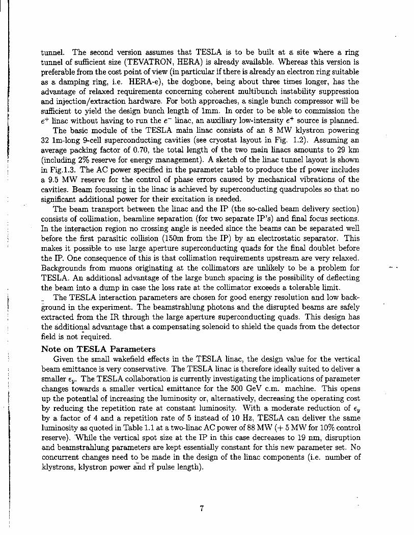
The two injector complexes for the e+ and e- main beams (Fig. 1.17) ~ we~ = for thedrive beams (Fig. 1.18) =e both located in a central area close to the detector, centr~zingthe main activities and anticipating further extension of the facihty to tigher energies. The ~beams are then transported at 9 GeV for the main beams and at 3 GeV for the drivebeams to the injection point of the finac via simple transport tines in the main tunneland isachronous loops. Both complexes are based on superconducting structures fied withpower in a continuous mode for their exce~ent beam power efficiency and compatibility withoperation at a high repetition frequency. As a consequence, transfer efficiencies as high ~26% from wdl plug to rf power and about 8% from wdl plug to beam power in ten bunchoperation mode, are expected.
26

!,
--
Fig.1.15 CLIC tuel layout.--
27
-’”- ‘“~

&30 fic
1.510’‘e-\bunch
02= 2 Psec (0.6mm)
Oz = 2oop )
Fig. 1.16 CLIC two-beam accelerator layout (drive beam parameters
for single bunch operation).
I
m --
Fig. 1.17 CLIC injector complex for the e+ and e- somces.
29

‘2km -200 m -2km-2km -200 m -2km
/
1,.:..,:.:.Transfer
Momen~m exchange ficker - sep~ Structures
1.7 GV 7M MHz- Separamr
_ su~rconducttig
hjector Ltiac
Pre-kjectOr
(Switchyad or~M)
I
60mfI flauetig
I* loatig
70 m Wmpaation
630m
20 m (1S0 m)
T
Switch-yad
360 MV
1.4 Gm
220 MV333 mz
220 MV366 ~Z
3.8 GV
350 MW
4 trains of 22 bunches in 12 ns
chage ~r bunch: 30 nC
12x4trtisof
22bunc~ets -
$ 57 ns
!
or more
2.86ns
0.72ns
.
Fig. 1.18 CLIC dive beam generation reference schemefor single bunch operation.
30

12ns
c
of
Ls
2 WORKING GROUPS
2.1 INJECTOR SYSTEMS
2.1.1 The Group
M. Yoshioka (Chairman)Physifi Department, KEK, 1-1 OhO,Tsukuba-shi, lbarti-Ken 305, Japan. Emtil: YOSHIOKA@jpnke~A. Mikhailichenko (Deputy Chairman)BINP, Pr. Lavren@eva11, 630090 Novosibirsk, Russia. Present addr=: Cornell University.Bmail:~H~Qlns62 .lns.cornell.eduH. BrainCERN, PS/LP, CH-1211, Geneva 23, Switzerland. Email: HBWUNticern.tern.chK. Flottm=nDESY,Notkestrasse 85, 22603 Hamburg, Germany. Emtik MPYFLO@&yibm.day.deJ. FrischSLAC,Mail Stop 66, P.O.Box 4349, St~ord, CA 94309. Email: [email protected]. MillerSLAC,Mti Stop 26, P.O.Box 4349, Stanford, CA 94309. Emafl: [email protected]. PaganilXF~ ~LANO - LASA,Via F.lli Cervi 201, 20090Segrate (Mane), Italy. Email: PAGANIQmvlasa.mi. infn.itL. RinolfiCERY, PS/LP, CH-1211, Geneva 23, Switzerland. Emti: [email protected]. RosenzweigUCLA,Dept. of Physics, 405 Hilgard Av. LOSAngeles,CA 90024. Emafl: [email protected],ucla.eduH. Tang
- SL.4C,Mti Stop 66, P.O.Box 4349, Stanford, CA 94309. Email:[email protected] C. TravierL.ALOrsay,Bat. 200, Centre d’orsay, g1405 Orsay Cedex, France. Emd: [email protected] .fr
D. YerembSL.4C,Md Stop 26, P.O.BOX4349, Stanford, CA 94309. Email: [email protected]
2.1.2 Overview
T~s chapter describes the electron and positron sources for the various kear co~iders dis-cu~ed in this report. ~tie not all the mactine designs include plans for polarized electrons,it is expected that most if not all of them will switch to a polarized electron gun in the future.Some of them may ~so have polmized positrons. The specific parameters relevant to the
~urces are dictated by the bunch ch~ges, time structures and tolerances of the various ma-chin~. Table 2.11 s~maizes these pmaeters. Note that t~s table does not yet include
the actual bunch charges and emittmces needed at the etit of the sources. These dependon derating factors for known and unknown beam losses and other assumptions that are notyet available.
--
31
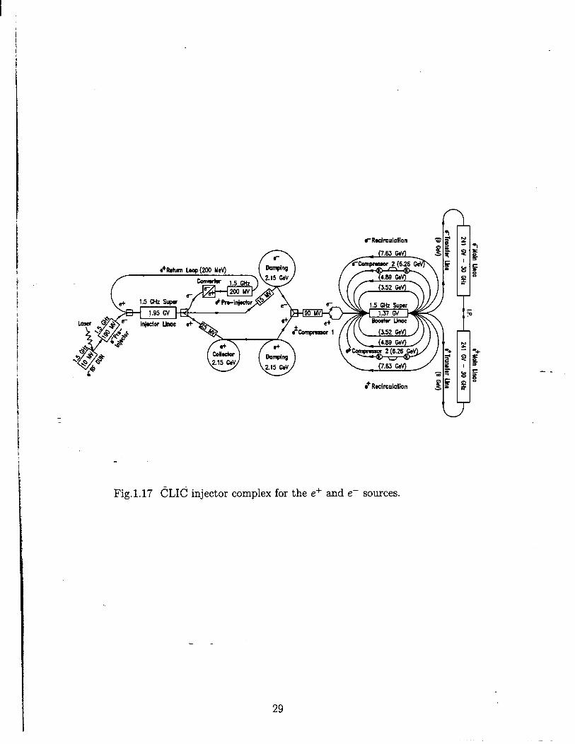
Table 2.1,1Pmameters relevant to e- and e+ Sources
TESLA SBLC JLC-S JLC-C JLCX NLC ~EPP CLICNo. of particl=/bun&at IP (1010) 5.15 2.9 1.44 1.0 0.63 .65-1.25 20 .8Repetition rate (Hz) 10 50 50 150 150 180 300 253&1210No, of bun&es/puk 800 125 50 72 85 90 1 1-1oBe- puke len@h (psec) 800 2 .280 .202 .119 .126 NA .006Bun& separation (nsec) 1000 16 5.6 2.8 1.4 1.4 NA .667
2.1.3 Where We are Today
Electron SourcesMany of the electron injectors required for the future linear colliders described here ti~
benefit from technology that is tieady quite mature today. Production of short high peakintensity bunches has been successfu~y demonstrated by machines in many imtitutions auover the world. Much progress has been made in developing and operating various injectorsystems such as conventional subharmonic bunchers with thermionic and polarized DC guns,M we~ as rf guns. Much work has also been done in developing accelerating systems forinjectors and in controMng effects such as beam loading, emittance growth and wakefields.
Thermionic guns and bunching systemsThe conventional subharmonic bunching system pioneered at SLAC has been successfully
used on the SLC for almost 15 years. The SLC injector is currently capable of producing two20 ps long bunches with a charge as high as 9 nC each at the entrance of the damping ring, --
and routine operation with 7 nC. Most of the injectors proposed for future linear cofidersplan to use this type of bunching scheme. The relatively new issues to be addressed for thisscheme ~e the production of the bunch train, the bunch-t~bunch intensity stabtiity, the .overd intensity stabfity from pulse to p~e and beam loading.
The cleanest way to produce the desired bunch train is to do it right at the gun by using
a gidd-d gun, and p~ing the grid at the required rate. Such pulsers have been developedat KEK in Japan for the ATF, and tio for the DESY SBLC in Germmy. The ATF godis to produce a tiain of bunches 1.4 ns apart. Currently, the KEK team is able to producea train with 2.8 ns bunch spacing, and development continues for the 1.4 ns spacing. TheDESY pulser is able to meet the fti requirements of the SBLC injector of producing buncheswith three options of bunch separations, i.e., 8, 16, and 24 ns.
The SBLC and JLC test accelerator facilities use injectors which are identicd to those
planned for their future co~ders. For budget and schedtie reasons, the NLCTA injector atturn-on will not have the ultimate subharmonic bmcher systems to be used on the NLC. Theearly injector wi~ operate at X-band and the multibunch issues will be addressed by makingthe average current in the pulse equal to that of the eventual NLC system. A subharmonicsystem wi~ be added later.
Polarized guns and bunching systemsIn the p~t 5 yea-s the use of a polaized electron gun together with a convention~
subharmonic bunching system has become the routine method of operating the SLC injector,producing M much * 5.5 nC in a single bunch at the IP, with 8070 polmization. This
32

polarized source has operated with over 99% uptime when the rest of the SLC w= on.Routine maintenance of the polarized source is minimal. It includes msiation every 4 or 5days, which takes 20 minutes, and laser flash lamp replacement every 2 months which takesabout 4 hours. Tfis quick cesiation h= been made possible through the use of the SLCcontrol system. Furthermore, extensive use of feedback systems helped to reduce the laserintensity jitter at the cathode to less than 270. The electron beam intensity jitter was less than1% as a resdt of the s-c~ed “surface charge tit” phenomenon of the cathode. Much h=been learned about this phenomenon and appropriate techniques to =sure the survivabilityof these cathodes in the accelerator environment have been estabhshed at SLAC. In addition,successful photocathodes development programs are ongoing in Japan, Germuy, Russia, andat other institutions in the US, promising improved charge and polarization performance.
RF gunsIn the past 10 years, much progress has been mde in the development of low emittance
photocathodes rf guns, and TESLA and CLIC in partictiar plm to use these devices. While~ mentioned earlier, most of the other proposed machine injector designs are bssed on con-ventional bunching systems for their basehne approach, it is clear that if rf guns, particularlypolarized source rf ~ns, cotid be used rehably, many of them wodd also adopt this scheme.Indeed, producing a low (1 to 3 mm-mrad rms) normahzed emittance from the injectorwould greatly simplify the operation of the electron damping rings. In the case of TESLA,
the damping ring could be eliminated altogether.Work is in progress at CERN, LAL, LANL, BNL, KEK, SLAC, UCLA and other insti-
tutions on various aspects of making an rf gun work, but even SO, additiond support may _
be needed to accelerate progress in this area.LANL, where the photocathodes rf gun concept w= pioneered, has had several successti
rf guns operating with a cesiurn-pot=sium antimonide cathode and ~ Lband structure.They have successftily used one of their rf guns m an injector for FEL experiments. BNL ~hm been successful in using metdhc cathodes with a UV laser system in an S-band structure,while CERN has developed a high quantum efficiency and robust cesium telluride cathodewhich works with a UV laser. The promising Ti:SappMre l~er that can produce very shortoptical pdses (O.1-10 ps) has been successfu~y used at the LAL (Orsay) rf gun to illuminatemetdic and dispenser cathodes. The high pressure titra pure water rinsing technique,origina~y developed at CERN, is a critical step towards the survivability of polarized electroncathodes in an rf gun.
While various laser systems have been constructed to be used with rf gun development
progrms, a reliable laser with the appropriate bunch train structure and stabihty requiredby the various hnew colhders is not yet in existence. The subsection below spells out therequirements for these various lasers.
Laser requirementsMost linear cofider designs use a photocathodes gun for the electron source, and therefore
require a photocathodes drive l~er. The type of laser required wi~ depend on the type ofelectron gun used: polarized, unpoluized, DC or RF. While none of the proposed hnearco~ider source designs pusfi the current state of the art in liners in any one pmameter, theydo require a combination of parameters which d require some l~er development. Forexample, the wavelengths, peak, and average powers needed for these sources are readily
33

achieved but the spectic ptise structures and intensity are not.SLAC has used a laser system driving a polarized photocathodes DC gun as the elec-
tron source for the mtin linac for several years. This system, based on Nd:YAG pumpedTi:Sapphire (Titanium doped Sapphire) has operated successtily, but the pdse structureused is considerably different from that required by most future linear co~ider designs.
The TTF laser, under development at the MW Born Institute, and the University ofRochester/Fermilab R&D lsser more closely resemble linear coltider source lasers. Thesesystems dehver beams appropriate for the TESLA rf gun. The current systems are based
on Nd:YLF, and are appropriate for UV photocathodes guns. If a decision is made to usepolmized electrons from a semiconductor photocathodes, a different Iwer material wifl bereqtied to obtain the required wavelength.
As many of the Enear co~der sources reqtie either electron polarization (and thereforetunable laser wavelengths) or very short (N 1 picosecond) ptises, high budwidth tunablelaser materials may be used. At the present time Ti:Sapphire is the most commonly usedtunable l~er material. It provides high gain and good thermal properties. Unfortunately, itis dfictit to flssMamp pump, and is usutiy pumped with either frequency doubled YAG,or CW Argon ion lasers. This wi~ make it somewhat difficdt to obtain the pdse structuresrequired for some designs.
Newer materials, most notable LICAF and LISAF, can produce short ptises with tunablewavelengths. They are easily pumped by fl~hlamps or diodes, and shodd be able to producethe required time structures. Unfortunately, their thermal properties are poor, and somedevelopment wi~ be required to reach the repetition rates and average powers required byhnear co~iders. Development of new laser materiak is ongoing, and may yield better solutionsfor source lasers.
There do not seem to be any serious obstacles to the development of source lasers apI propriate to any of the tinear coMder designs. The reqtied laser systems will, however, be “
quite complex, and some time to develop them is to be expected.
Positron SourcesThe basic processor positron production on which W of proposed hnem col~der positron
sources rely is e* pair production from electromagnetic interaction of a high energy ph~ton with the Cotiomb field of a nucleus. Depending on how the high energy photons are
generated, the proposed positron sources may be classified into two categories: conventionalSLC-type sources and wiggler-based sources. The use of a heficd unddator also offers theunique possibility of polarized positrons. The JLC, NLC and CLIC positron sources fti inthe first category, where= the TESLA, SBLC and VLEPP sources belong to the second.In an SLC-type source, a thick high-Z (such as tungsten) target is used both for the gen-eration of high-energy photons (via bremsstrahlung radiation) and for their conversion intoe* pairs. In a wiggler-based source the high-energy photons are generated in a wiggler orundulator using a primary electron beam with an energy in excess of 150 GeV, and positronproduction is then accomplished in a thin target. In an SLCtype source, thermal stress inthe conversion target due to the impact of a single drive beam puhe imposes a practicallimit on the obtainable positron beam puhe intensity. This difficulty is greatly titigated ina wiggler-based positron source.
34

In addition, MD is in progress to develop a new type of positron source using 2 to 10 GeV
electrons channeling through a thin single crystal to produce the high energy photons.Regardess of the positron source type, the phase space of the positrons generated at the
target is in general characterized by broad transverse and longitudinal momentum distribu-tions but narrow phase and transverse position distributions. On the other hand, the opticsof the positron capture system, i.e., a high-gradient accelerating section embedded in a uni-form solenoidd field, is char~terized by a large transverse position acceptance but a smalltransverse momentum accept~ce. For optimum capture efficiency, therefore, a phase spacematching device must be used to match the phase space of the positron beam emerging fromthe tuget to the acceptmce of the capture optics. Both the positron yield and the energyspread of the captured beam are strongly dependent on the phase space transformer. Thebroad-bred Adiabatic Matching Device (AMD) is the design of choice among the variousproposals, with the exception of VLEPP for which a fithium lens design h= been proposed.A tithiurn lens has been in operation at BINP since 1970.
1 Conventional positron sources similar to the SLC sourceThe SLC positron somce has operated very rehably since 1991 over extended periods of
physics runs. As the most intense positron source in the world, it may be used as a basis for
i positron source design for future lines cofiders. The SLC source uses a 30 GeV singl~bunch
k drive electron beam with an intensity of 3-5 x10¹⁰ electrons/bunch to produce positrons from
~a W75Re25 tmget with a thickness of 6 radiation lengths (Xo). Its capture system includes
k an adiabatic matching device and a high-gradient S-band section with an aperture of 18mm diameter embedded in a 0.5 T uniform-field solenoid. The positron yield after capturedownstrea of the target is typically 4 per drive electron. After 180° turn-around and ener~analysis, it is reduced to 2.5 positrons at 200 MeV within a &5Y0 energy spread. SLC-typepositron sources have been proposed for JLC, NLC and CLIC.: In the proposals for these three linear co~iders, the energy of the drive electron beam ~ranges from a few GeV to 10 GeV, while the target thickness ranges from 4 to 6 radiationlengths. In order to meet the positron beam intensity requirements for the respective finemcoHiders, which are more than an order of magnitude higher than that of the SLC, boththe dive beam power and the capture efficiency must be incremed over those of the SLCpositron source. Since excessive thermal stress in the target caused by singl~pulse beamheating may lead to target failure, the size of the drive beam incident on the target mustbe sticiently large to keep the single-pulse beam ener~ density below the material ftilurethreshold. For a ~75Re25 target, the faflure threshold has been determined at SLAC to be
Iabout
Ne- E,- GeV~th = = 2.0 x 10¹² —
~Q2 mm2
with about 2070 of the beam ener~ deposited in the target. In practice, as stated in thevmious desi~s, it is wise to keep the deposited energy density in the target comfortably belowthis threshold, e.g., N 6070. To satisfy this criterion, the rms spot size of the drive beam
I
on the tmget for the proposed SLCtype sources ranges from 3 to 8 rnm2. The cumdativeeffect of thermal stress build-up due to successive mtitiple beam puke impacts is minimizedby adopting a rotating target design such that the areas of successive beam puke impactsare adequately separated.
35
I

The AMD used for transverse phase space matching is comprised of a ptised flux con-
centrator embedded in a DC tapered-field solenoid. The ided protie of the longitudinal fieldprofile along the axis in the AMD should be
B(z) = ‘il+g. z
where Ba is the initial (maximum) field and g is the taper parameter, typicdy in the range of30-60 m-l. Strictly speaking, the condition for adiabatic transformation only holds for par-ticles of energies below =10 MeV. Particles with higher energies experience a non-adiabaticfield, leading to a decrease in the transverse momentum acceptance for such high energy
particles and hence pmticle losses. Purther beam losses also occur as a restit of bunchlengthening due to path length differences in the AMD and the capture accelerator, andvelocity differences for positrons of varying transverse and longitudinal momenta. Increasedcapture efficiency may be achieved by increming the aperture of the high-gradient sectionand by increasing the magnetic field in the AMD and in the capture section. The NLCpositron source design uses an L-band capture accelerator with a 40 mm diameter aperture,more than twice that of the SLC source, yielding an invmiant transverse phas~space acceptance of 0.06 m-rad. On the other hand, the proposed JLC source retains the S-band design
but ~th an enlarged aperture and increased magnetic fields. The designs for the JLC, NLCand CLIC sources have a~owed at least a factor of 2 safety margin in the positron beamintensity after the captme section to m~e up for unforeseeable downstream beam losses.
In the SLC-type positron sources, by limiting the dive beam pfie energy density on the --target below the material failure threshold, incremed positron production can be realized odyby increasing the drive bem size, which restits in a proportional increase of the transversephase space volume of the emerging positrons. This leads to a captured high intensitypositron beam with a lager transverse emittance. The optics of a damping ring designed to ~yield an invariant equfibrium vertical emittance of about 5 x 10⁻⁸ m-rad within the timehmit given by the repetition frequency of the co~der and the number of simtitaneouslystored bkam p~es dictates that the dynamic acceptance of the ring be typically Halted to~ 0.01 m-rad. The emittance of the positron beam produced by the SLC-type sources isthen simply too large ‘for such a damping ring. Therefore, the use of a predarnping ringto reduce the tranverse beam emittance of the positron beam prior to its injection into themain damping ring hw been proposed. The predarnping ring is characterized by a largedynamic aperture, a short damping time, and an intermediate equihbrium emittance. Inthis scheme, the total time for emittance damping is also doubled.
Positron sources based on radiation from tigglers or c~std channelingThe SLC-type approach to positron production is characterized by a high-powered drive
beam impacting a ttick tmget which must absorb a si~cant fraction of the beam power.If the-requirement on the positron beam intensity is of an order of magnitude higher thanfor JLC and NLC, i.e., TESLA or SBLC, this approach becomes unfeasible because of theengineering ~ctity of cooling the target and the dficulty of efficiently co~ecting positronsfrom a largesize drive beam. Thus, positron sources based on wiggler radiation have beenproposed instead for TESLA and SBLC. In the wiggler scheme, photons generated froma high-energy electron beam, typicdy ~ 150 GeV, p~sing through an unddator, produce
36

I
positrons by ptir production in a thin target. The use of a hehcal undtiator dso providesthe possibihty for producing polarized positrons as we~ as electrons. .
In the channeling scheme, photom generated from electrons with energies in the range of2 to 10 GeV travehg through an appropriate crystal produce positrons in a thin amorphoustarget. This scheme could be applied to JLC, NLC or CLIC.
Wigglers and Undtiators
The basic principle is to use a wiggler to generate an intense photon beam from a high-energy (> 150 GeV) electron beam. The beam of the main linac can be used before or afterco~sions for the production of photons in a wiggler section. After cobion, the emittance
of the primary beam is distorted because of beamstrahlung and a special matching opticsis required to capture a high fraction of particles (N 70 Yo). This problem is avoided if thebeam is used before interaction. However, the effect of the wiggler on the emittance of theprimary beam has to be investigated in more detail. In the wiggler, photons with a meanenergy of N 20 MeV are emitted in a cone of mgle l/~ along the forward direction. Thephotons are then converted into e* pairs inside a very thin target (<1 Xo), while the primaryelectrons leaving the wiggler are deflected by a dipole magnet. Thus, thermal stress problemsin the conversion target are reduced. In addition, since the conversion efficiency is to firstorder independent of the material, it is possible to use low Z materials which in generalhave a higher heat capacity (Dtiong-Petit rule). The positron yield of titanium is onlyabout 16% lower than tungsten if a target of 0.4 ~ is considered. The mtimurn a~owablebeam energy density inside the tmget is, however, up to an order of magnitude higher fora titanium alloy than for a tungsten Woy. An additiond advantage of the thin target isthe reduction of multiple-scattering inside the target. As a result of the narrower transverse
--
momentum distribution, the phase-space density of the emerging positrons is higher in thecase of a thin tmget source. Finally the mean power deposition and the neutron productionqre dso reduced in a source based on wiggler radiation.
For the capture and matching optics, TESLA and SBLC use an AMD phme space trans-former. Because of the higher phase space density, the positron capture efficiency is incremedby a factor & = 5 compmed to an SLGtype source with the same acceptmce of the captureoptics. The designs for TESLA and SBLC allow a factor of two safety margin in positronbeam intensity after the capture section. Because of the relatively small emittance of thecaptured positron beam, a pre-damping ring is generally not required. For VLEPP, a lithiumlens has been proposed to serve m the matching device.
Polarized positron sourcesThe physics potential of polarized positron beams is discussed in section 2.6. A polarized
positron source is proposed for VLEPP, while TESLA and SBLC regard the polarized sourcess ~ option. For polmized positrons, a helical undulator h= to be used to produce circulmlypolarized photons which are converted into longitudina~y polarized positrons in the target.In order to tde care of ~ processes, polarization states have been included into the MonteCarlo code EGS4. The emittance requirements of the incoming electron beam me muchtighter than in the case of unpolarized sources. Hence the electron beam has to be usedbefore the interaction pointv Simulations show that a polarization of Up to 70% can be
~hieved with a helical undulator of about 1 cm period len@h and lT field strength. Thetotal lengh of the und~ator has to be about 150m. However, if polarization is not required,
37
. .

the undtiator maybe shorter and the an~ar sepmation is less stringent. The technical andoperational fe=ability of a heficd undtiator with these parameters hm to be proven.
Crystal chmnelingIn this scheme the high energy photons me produced by electrons (with energies on the
order of 2 to 10 GeV) ch-ehng through a single crystal: the photons are generated by the gexistence of periodic atomic potentials in the crystal. Both the crystal and the conversion Itarget are thin, ensuring that the thermal loads are minimum. The emerging positron beam iretains the characteristics of a narrow transverse momentum distribution and hence a high
phw~space density. For this approach to work, the angle of incidence, or the angle betweenthe beam direction and the direction of the atomic rows in the crystal along which electronchanneling is expected to occur, must be smder than a critical angle given by:
re.= ~ I
where E. is the particle energy and V. is the depth of the potential well. In addition, the 1electron beam divergence Wo needs to be smder than e~. Coherent pair production in cry%t~ using high energy photon beams (150 GeV) hx tieady been measured at CERN witha Germanium crystal orientated on its <<110~~ axis. However, more R&D is necessary toestabhsh the fe~ibitity of ths approach and the survivability of the crystal over a re~onableperiod of use.
--
Current statusThe important parameters for the positron sources are summarized in Table 2.1.2. As a
reference, the parameters of the existing SLC positron source are dso included.The present status of the positron production for
below.
TESLAThe positron source is b~ed on radiation from a
high energy electron beam emerging after the cofision
the various finear colhders is given ~
wiggler. The primary beam is the
~oint. 1 The emittances are thereforedistorted because of betitraMung, ad special optics are required to capture x70% of thepmticles. The primary beam power is the highest among the various linear colliders. A f~trotating e+ target wi~ be built to increae the impact area on the tuget wittin each rf ptise.The required beam pdse is 800 w and it will provide the greatest number of positrons perpuke of au the proposed machines. However, an rf mtitipdse SLED-system should be builtin order to incre~e the gradient and reduce the Joule losses in the structure of the captureaccelerator. No pr~damping ring is required for TESLA because of the msmed bettersource performance and the large acceptance of the damping ring. Positron polmizationis regwded as an option. An auxil~ positron source bwed on a conventional target andcapture section is planned to test the system before the electron beam is avatiable to makethe positrons.
--
1 Since the yield depends on the energy of the wiggled bea producing the photins, it should be notathat this yield dl be quite low for energi~ below 100 GeV.
38

I
>.3.s.
t
,,.
!rIt.e?rInLdte
;4
t
Table 2.1.2Positron source paraeters for various linear colfider projects. SLC parmeters are given asa reference.
- . ..” .-w A gutim G--- “ U“-* Ivbti v h~~r ~UJVwiggler/ wiggler/ SLCtype SLCtype wiggler/ SLCtype
undulator undtiatorPositron Source be
undulatorbti
General P-metersbased
Ne+/pu& at IP 10’U >5 4120 362.5No. of bundes per pufse 1
53.6 58.5800
20125
0.8-8
Puk duration85
Us90 1
3. 10-6 800 21-1o
Bun& sp~ing0.119 0.126
1000NA 0.006
E–16
Wpetition frquency1.4
120 101.4
500.66
150 180 - 150 253&
Primary Be-1210
Ener~ GeV 30 >150 >150Ne- /pub 1010
10%5
3.114000
150360
2.15
Bw power kW35
17-29135 20
>96133.%38
>4326Linac frquency MHz
842856
1211300
721 33-1582998
Wiggler length2856 2856
m14000 1500
35(2 150) 35(Z 150) -Wiggler period cm
* 1503.6(- 1.2) 3.6(* 1.2) –
Pd field T* 1.0
1.7(* 0.9) 1.7(- 0.9) – 0.5No. of photons per elwtron — -350 -350Conversion T-get
100
Materid W?s&2S Ti aUoyThitiS
Ti alloy W75Re25 W75Re256.0
W, Hg W75Re25Xo 0.4 0.4 6.0 4 0.5 4.5
RMS spot size of drive b-m mm 0.8 0.7 0.7 1.2 1.6 1.0Temperature rise per puke K 2~300
1.0- 800 - 800
Meandeposited power kW- 220 * 200 - 200 * 200
4.2+.0 14Ne+/puk at ~it
5.91010
- 30 * 10 0.2 9.H718&300 43700 3930
Capture System750 * 800 60 2G200
Matching deviceInitial field
AMD* AMD* AMD* AMD*7.0
AMD* Li-Lens AMD* “
mzl –10
Taper parameter10 8.0
307.0 7.0
End field T30 50
Length0.5 0.62 0.62 0.8
m 0.150.5 0.5
Wavelengh o; accel. RP0.5 0.5 0.18
m 0.10.2
0.10.01 0.15
Minimum ~ r~ius0.1 0.105
9.0 9.00.21 0.01 0.2
Gradient9.0
- M?~m13
3020
15 3018.0
30 20Pr4mptig ring rquird No No No
12Ye Ye No Ye
Ne+/puke at entrance ofPrdamping ring 1010 4.s7.5 8000 720 108 144Efficiencyincl, deph~ing % 4 18
50 0.>9
?A Ofpr~amping rtig~18 14
0.0117
0.01220
0.012Ener~ of pr~d~ping ring ;:V 1.15
0.0274.0
0.09 0.13.15
0.341.98 2.0 3.0
Ener~ accept. of matd. device MeV 202.15
poktiation*3O *3O 40 30 20
~~ of polarization %– (70)proverconsumption (up to DR) MW
(70) - - - 75
. d,ah>,;e --.-c. . .option option 25
\ .—A---’”“’a’cnlngaence= notiw Scceptmce
-.
39
--
—-,e . . ... .,,.

I.=- .. ... ,....— ... . . . ..
SBLCThe positron source is breed on wiggler radiation. SimilUly to TESLA, the primary bem
is the spent electron beam after the cofision pointl and therefore h= the same constraintsand advantages regarding energy. Polarized positrons with the use of a helical undulator meregarded ~ an option.JLC
The positron source is of the SLC type. A dedicated 10 GeV e- S-band Enac to producethe positrons uses either a thermionic gun or an rf gun ~ a source. This is the ody designthat uses an S-band capture section and pre-accelerator among the SLC-type sources.
NLCThe positron source is of the SLC type. The primq beam comes from a dedicated
34 GeV S-band hnac and the e+ beam is accelerated in an bband hnac. In order toincrease the refiabibty and maintainability of the positron sowce, two para~el positron pr~
duction and capture systems are being proposed, which are set sideby-side in sepmate roomsadequately shielded from each other.
VLEPPThe positron source uses a hehcd undtiator before the co~ision point. The design is
made, ‘from the beginning, for polarized positrom and electrons. It is the ody hnear cofiderdesigned to use a W or perhaps Hg target to produce positrons and a fithium lens, whichis simply a hthium rod of about 1 cm in length, = the matching device. A field gadientof up to 1600 T/m and 100 kA current can be generated in the hthium rod, correspondingto a focal length of 0.4 cm for 20 MeV positrons. Electrons are defocused and hence theseparation of positrons and electrons starts tieady in the lens. The smd ener~ acceptanceof the lithim lens is used for prehminary ener~ selection, which is essential for co~ectinghig~y polarized positrons. The primary beam is accelerated with an rf frequency of 14 GHz.
CLICThe positron production is of the SLC type. However, the SLC yield must be improved
by a fac~or 3. This seems achievable if the transverse acceptances of the capture optics aredoubled and the loggitudind acceptance is increased by 50%. The use of an Lband captuehnac and a pr~damping ring meet the incre~ed acceptance requirements. The charge of3.8 x 10l”e- per bunch at an energy of 2.15 GeV provides an energy density on the target of1 x 1011 GeV/mm* which is we~ below the failure threshold. This =sumption is made fora beam radius of 0=1 mm. In the c~e of mtitibunches, one can incre~e the bem size on
the target.
2.1.4 The Steps to be TAen in the Neti Three Yems
Electron SourcesAs we have seen earlier, there are st~ a number of problems that must be solved to upgrade
today’s sources to meet the fufl requirements of future finear colhders. These problems areconsidered below. - -
--
Thermionic guns ad bunching systemsMost of the single bunch problems that come up with conventional thermionic guns and
subharmonic buching-type injectors have tieady been solved. The issues that must be
40
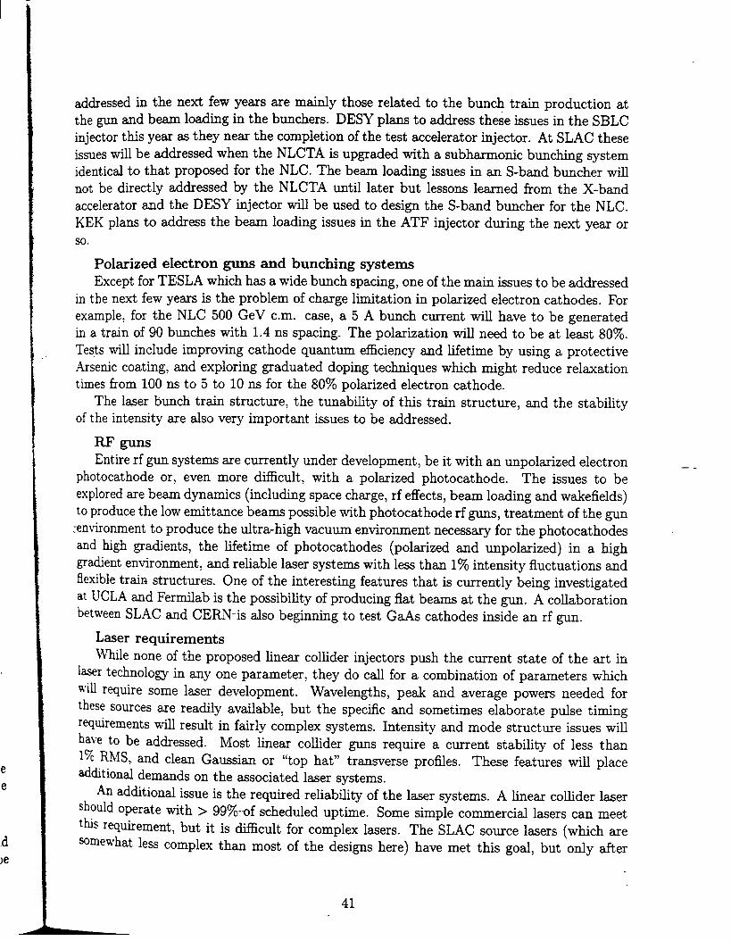
I
.d)e
addressed in the nefi few yeas me m~~y those related to the bunch train production atthe gun and be~ lo~~g in the bunchers. DESY plans to address these issues in the SBLCinjector this yem = they nem the completion of the test accelerator injector. At SLAC theseissues WU be ti~essed when the NLCTA is upgraded tith a subh-onic buching systemidenticd to that proposed for the NLC. The beam loading issues in an S-bred buncher willnot be directly ad~essed by the NLCTA wtil later but lessons learned from the X-bandaccelerator and the DESY injector ~U be wed to design the S-band buncher for the NLC.KEK plans to address the beam loa~ng issues in the ATF injector during the next year orso.
Polarized electron guns and bunching systemsExcept for TESLA which h= a wide bunch spacing, one of the main issues to be addressed
in the next few yeas is the problem of charge limitation in polarized electron cathodes. Forexample, for the NLC 500 GeV cm. case, a 5 A bunch current wi~ have to be generatedin a train of 90 bunches with 1.4 ns spacing. The polarization wi~ need to be at lewt 80Y0.Tests will include improving cathode quantum efficiency md hfetime by using a protective.4rsenic coating, and exploring graduated doping techniques which might reduce relaxationtimes from 100 ns to 5 to 10 ns for the 80% polarized electron cathode.
The l~er bunch train structure, the tunabihty of this train structure, md the stabihtyof the intensity are dso very important issues to be addressed.
RF gunsEntire rf gun systems are currently under development, be it with an unpolarized electron – _
photocathodes or, even more difficult, with a polarized photocathodes. The issues to beexplored are beam dynamics (including space charge, rf effects, beam loading and wdefields)to produce the low emittance beams possible with photocathodes rf ~s, treatment of the gun
xn~tironment to produce the ultra-tigh vacuum environment necessary for the photocathodesand high gradients, the hfetime of photocathodes (polarized and unpolarized) in a high
gradient environment, and rehable laser systems with less thm 1% intensity fluctuations andflexible train structures. One of the interesting features that is currently being investigatedat UCLA ~d Ferfilab is the possibility of producing flat beams at the gun. A co~aborat ion
bet~’een SLAC and CERN-is dso beginning to test GaAs cathodes inside an rf gun.
Laser requirementsJmle none of the proposed linear collider injectors push the current state of the art in
laser technology in any one parameter, they do cdl for a combination of parameters which
~i~ r~uire some laser development. Wavelengths, ped and average powers needed forthese sources are readily available, but the specfic and sometimes elaborate pdse timingr~tiements wi~ result in fairly complex systems. Intensity and mode structue issues wi~have to be addressed. Most hnear coHider guns require a current stability of less thanlx RMS. and clean Gaussim or “top hat” trmsverse profles. These features will place~ditiond demands on the ~sociated laser systems.
~ dditional issue is the requhed reliability of the laser systems. A finear co~ider lasershould operate with > 99YOwf sehedded uptime. Some simple comercid l-ers can meett~s r~uhement, but it is ~cdt for complex lasers. The SLAC somce liners (which are~rne~hat less complex than most of the designs here) have met this goal, but ody after
41

I AL..... .
considerable development time. It may be desirable to have two independent source lasersystems in order to provide the required system uptime.
It is difficult to estimate the cost and development time required for these systems withouta detailed design. A rough guess wodd be that these systems wi~ aH have hardware costswithin a factor of 2 of a mi~ion US do~ars, and require three to five yems of developmenttime.
Future developments in laser technology may have some impact on these systems. Inparticdm, the pump lasers may be replaced by diod~pumped sofid state lasers, resultingin a significant reduction in system size, and possibly cost. At the present time, however,
commercial diode pumped systems are more expensive than conventional l~ers. New l~ermaterials could Ao simphfy the laser designs. At the present time, however, there are
no promising alternatives to Ti:Sapphire for high repetition rate, tunable or short pfieoperation.
Although the source laser probably represents a modest technological challenge, in com-ptiison to the rest of a kear co~der laser system designers shotid expect a si~cantdevelopment time.
Positron SourcesMost of the parameters listed in Table 2.1.2 me based on judicid choices or extensive
numerical simtiations. A guiding principle behind all these designs is that the parametersshotid au be achievable using existing technologies. R&D efforts in the areas outlined in thefo~owing paragraphs shotid greatly enhance the current designs.
●
●
Conventional positron sources stiar to the SLC source.
The SLAC test on target material failure due to single bem pfie impact was con-ducted for a single target thickness (W 5.4XO) and a single drive beam energ (* 22 GeV).The 3LC, NLC and CLIC positron source designs d rely on extrapolating from thisone data point in a large tw~dimensiond parameter space constituted by beam energyand target thicknesi, which ranges from 2 to 10 GeV and from 4 to 6 Xo, respectively.Since the reliability of such an extrapolation is questionable, it is higMy desirable toperform a more exhaustive target failure test within the parameter range of the variousdesigns.
For NLC, high-power Lband klystrons and a mechtism to sed the rotating targetshaft need to be developed, the latter dso applicable to JLC. For JLC, NLC andCLIC, positron source maintenance, which directly affects operating efficiency, is a
challenging problem because of the very high radiation levels in the positron productionmea and capture section. The tw~source design for NLC shodd significantly improvethe serviceability of each source. Compared with the electron beam, the intensity jitterof the positron beam is Wely to be much more dfictit to control. A careti analysis ofthis problem is needed. Engineering experience will be gained from the ATF positronsource which is under construction at KEK.
Positron sources based on radiation from wigglers/undulatory.
_— -
ThequeWdWc
to ‘by10Tsa
itd~~
ar
i
Prex
-- ~hei
theiTh(or :
jus
br(S(
tcktl
tc
42

I
fThe technical and operational fe~ibtiity of long helical uddators is one of the majorquestions for polaized positron sources. The beam transport though the undtiatorand emittances at the undtiator exit need careful investigation through simtiationsand experiments. Also, the stability of a source driven by the spent electron beam h=to be investigated in more detail, since in this case the drive beam intensity is affectedby the quality of the beam-bem interaction. Fin~y, the target material failure for alow Z titanium a~oy target has not been determined experimentdy. Even if a highsafety margin on this hit h= been included in the designs for TESLA and SBLC,
it would be higtiy desirable to perform failure tests with low Z materiah in order todetermine the stress hmit more accurately. This wotid also be ~efd for the design ofother hnear co~ider components like scrapers and dumps. Operational issues wtil beadressed in the various high energ accelerator laboratories.
The principles of polarized positron sources will be investigated by a Compton backscat-tering experiment at KEK.
The reahzation of a single crystal capable of withstanding the high power beam withoutdamage to the crystdfine structure will be investigated at SLAC. The performances ofpositron production with such crystals wiH be evaluated at SLAC and at CERN.
Pr~AcceIeratorsAU the machines have pr~accelerators or s~called prehnacs, genera~y located between
their sources and their damping rings, and in some c~es between their damping rings andtheir main linacs. The energies of these pr~accelerators are between roughly 2 and 10 GeV. -Their designs are just being developed. In most c~es, they operate at Lband (x1.4 GHz)or at S-band (w3 GHz) and they have bunch compressors of the same rf frequency locatedjust upstream or downstream of them (see machine schematic diagrams in Chapter 1).- It is too early to describe these pre-accelerators in detail but a few generic issues can be
brought up here. For example, the NLC complex has six S-band linacs and 3 Lband hnacs(see Fig. 1.8). The main Lband hnac accelerates the positron beam from the positron targetto 2 GeV wkere it enters the predamping ring. In addition there are two 134 MeV Lbandhnacs ~sociated withjhe electron and positron first-stage compressors at the output of the
two damping rings. These hnacs are run in ph~e quadrature with the beam to introducethe tinear correlation between time and energy within each bunch which is required forcompression. The six S-band linacs me the fo~owing:
1. The positron drive linac which accelerates the electrons which strike the positron target;
2. The electron booster hnac which accelerates the electron beam to 2 GeV where it entersthe electron damping ring;
3. and 4.- The electron and positron pr~accelerators which accelerate the beams from the
damping rings to 10 GeV where the second bunch compression occurs;
~. and 6. The 2 GeV S-band linacs to produce the linear energy correlation required for eachof the second-stage compressors.
43

These bats share enough common characteristics and design problems that it is appr~priate to discuss their rf design together in this section. The principal design issues are beamloading and dipole wakefields. Except for the fist 200 MeV portion of the positron Lbandlinac which is inside a 0.5 T solenoid, au of these hnacs must be capable of accelerating about2-ampere beams with about 100 ns macroptise length. The part of the positron Lband linacinside the solenoid needs to accelerate a total effective curent of about 5.5 amperes since
both electrons and positrons get captured md drift on to their respective accelerating crests,A/2 apart. Because the electrons are produced by ionization M we~ as by pair production,there are about 2570 more electrons than positrons.
All of these hnacs are fairly heavfly loaded by a beam with a pdse length much shorterthan the fling times of the structures which in tmn are shorter than the ringing time, 2Q/w,of the structures. In this situation, the ener~ of the beam wi~ &op approximately tinearlywith time during the pulse as a result of beam loading. For this c~e, there are two naturalchoices for beam loading compensation: 1. A-t (or early injection), i.e., injecting the beaminto the structure before the structure is M; 2. A-f, i.e., having one or more acceleratorstructures running at a frequency 1 to 2 MHz above or below the nominal frequency androugtiy in phase quadrature with the accelerating phme. Thus the beginning of the pfie canbe decelerated by the off-frequency-section(s), while the end of the pulse is accelerated. Theadvantage of A-t compensation is that the compensation occurs in every accelerator section,so that the energy spread can be nmow tboughout the hnac, thus minimizing emittancegrowth from dispersion and chromatic effects. The disadvantage of emly injection is thatthe compensation requires a partictim structure fi~ng time which is typicdy shorter than --wotid be chosen for optimizing the use of rf power, and so in general it can require morerf power than the A-f technique. The disadwtage of the A-f technique is that two moretypes of accelerator structures need to be designed and constructed, one tuned for - A-f and .one for +A-f.
The S-band accelerator sections wi~ be detuned by about 10% in a Gaussian densitydistrib~tion to diminish the effect of dipole wakefields. This will cause the structure to bewhat might be cded “over constant-gradient, “ i.e., the gradient rises from the input to the
output. Damping wi~ *O be desirable.The JLC(X) pr~accelerators will be comprised of 3 m long S-band accelerator sections
driven in pairs by 85 MW x 4.5 microsecond klystrons with 2-iris SLED ptise compression.This combination wi~ achieve 50 MeV/m tioaded gradient, 40 MeV/m loaded in 3 m-longShintake chok~mode structures. Beam loading compensation wi~ use the A-f technique.The kacs wi~ be about 300 m long and wi~ have 34 klystrons each.
Findy, it shodd tio be mentioned that between the pre-accelerators and damping rings,it may be desirable to inst~ rf debunchers which improve the injection process into the ringsby decreuing the incoming bunch energy spread and by lengthening the bunch length. Sucha device was insta~ed in the SLC injection fine to the positron damping ring with someme=ure of success.
44

I
2.1.5 Summmy and Compmisons
Electron sources
Unpolarized electrons
For unpolmized electrons, conventional thermionic guns with appropriate bunching sys-tems are available at the present time. RF guns with relatively robust cathodes are planned
for the TESLA and CLIC co~ders.SBLC wifl use a DC gridded gun with the desired time structure. The puker for this
gun has tieady been constructed. JLC is working towards achieving the 714 MHz bunchseparation with their gun pulser.
Polarized electrons
For polarized electrons, photocathodes with conventional DC guns are proposed for JLCand NLC. Many of the polarized source problems have been solved and reliable operationh= been estabhshed at SLAC. The main dficulty in using polmized sources for NLC and
JLC is the abifity to sustain the 4 to 6 Ampere peak current from the cathodes for a bunchtrain of duration greater than 100 ns, Present cathode development shows that we are abouta factor of 5 away horn producing the required charge for the NLC gun because of the chargetiting phenomenon observed on the GaAs cathodes. A further challenge will be to operaterf guns with polmized uthodes. Aggressive R&D programs are required to develop all thesesources and to show that they can be operated refiably.
Lasers
The lasers to drive the polarized or unpolmized sources use conventional componentsavailable with today’s technology. However, these liner systems tend to be complex, requiringfeedback and feedforward systems to attain the required intensity stability and operational;eliabitity. In addition, the lasers for rf guns have to meet extra requirements for theirbroadband ptise trains. The most difficdt problem for the lasers for most linear co~iderdesigns is the less than 1% RMS intensity jitter tolerance which is at the fimit of today’stechnology. -
Positron sOUrces _ .
Conventional positron sources similar to the SLC source
JLC, NLC md CLIC will have SLC-type positron sources driven by dedicated electronbeams horn hnacs. The JLC positrons will be captured with a similar S-band hnac where=the NLC and CLIC positrons wfll be captured by Lband hnacs for increased acceptancead capture efficiency. These positron sources require further study and development, inPartictiar in the area of target technology.
Positron sources based on radiation from wigglers or undulatory
TESLA and SBLC plan to pass their spent beams (i.e., at the exit of their IR’s) through~lwlers or undtiators to produce ~’s which in turn wfll generate the proper trains ofPositrons through interaction with a thin tmget. TESLA may obtain polarized positrons, wa possible option. VLEPP w-ill use a hehcd undulator before the co~sion point to producepol~ized positrons. These sources are based on a promising scheme which, however, h= notYet been demonstrated for co~ider operation.
45
--
2.2 DAMPING md COMPRESSION SYSTEMS
2.2.1 The Group
J. Rossbach,(Chairman)DESY, Notkestrasse 85, 22603 Hamburg, Germany. Emd: H02ROBQdsyibm.desy.deJ. Urhwa,(Deputy Chairmm)KEK, 1-1 Oho, Tsukuba-Shi, Ibaraki-ken 305, Japan. Emti: [email protected]. ChattopadhyayLBL, 1 Cyclotron Rd., MS 71-259, Berkeley, CA 94720, USA. Email: [email protected]. MikhailichenkoBINP, Pr. Lavren~em 11, 630090 Novosibirsk-90,Russia. Emd: [email protected]. PotierCERN, PS/LP, 1211 Geneva 23, Switmrland. Email: POTIERQcernvrn.tern.chT. WubenheimerSLAC, 2575 Sand Htil Rd., Menlo Park, CA 94025, USA. Emti:
2.2.2 Overview
[email protected]. edu
To ~hieve ‘the desired luminosity, au the hear co~ider schemes need very small transverseand longitudinal beam emittmces. Presently, there is no experimentdy verified method ofproducing the desired (normalized) phme spree densities directly at the electron or positronsource. For electrons, it is conceivable that with vigorous MD on laser driven photocathodes
rf guns, one may begin to reach the required ph~e spree density, but the chances of successand required time scales are currently both uncertain. Thus, a mechanism is required thatovercomes Liouville’s Theorem. This theorem states that the normalized phase space density .cannot be incre~ed in isolated, non-inter~ting Hamiltonian systems. The solution proposedby au the coUder schemes is to use rtiiation damping in a storage ring. In a damping ring,the two primmy parameters are the equilibrium emittance and the damping times. These aredetermined by the ring energy, the magnet lattice, and the mechanical tolerances. Beyond anenergy of 1 GeV or so, the vwious scattering mechanisms within a high density beam lead toneghgible emittance blow up”. However, some schemes come close to these hts. The typicalemittmce dues are comp~able to those attained in the third generation synckotron hghtsources but the required damping times are considerably shorter.
There is agreement that, in order to stay within reasonable beam-beam interaction pa-
rameters, dl schemes need flat beams, i.e. EV<< ~z. Since decreasing the vertical emittance&Yis one of the few ways to increase luminosity without incre~ing beamstrahlung ener~losses, one should, at lemt in principle, reduce &Vuntil it is limited by intra-beam scattering,
by the natural opening angle of synchrotron radiation, or by vertical disruption during beam-beam inter=tion. Actually, in the 500 GeV cm. collider desi~s, tolermce considerations
in both the main finm and damping rings lead to considerably larger values of &V.~le it is Mely that the required transverse emittance values can be whieved with stor-
age ring desi~s at le=t coq~~le with efisting m~hines, the equihbrium bunch length
h* to be further compressed after extr~tion from the damping ring. The reason is that gen-eration of a bunch len~h below a few ~meters in a storage ring would require insta~ation
46

of extremely high rf voltages and wodd titimately be limited by. the microwave instability.The proposed bunch compressors consist of an rf system that generates a correlated
energy distribution along the bunch and a subsequent bending section with a nonzero m~mentum compaction described by the R56 matrix element. In a compressor, the bunch lengthis compressed while the uncorrelated energy width is incre~ed, according to LiouviUe’s Theorem apphed to longitudinal phme space. Transverse and longitudinal emittance growth
occurs because of higher order dispersion and nonlinear chromaticity if the energy spread af-ter the bunch compressor exceeds a few percent. Thus, the large compression factor, neededfor those cofider designs with bunch lengths in the 100 micron range, wodd be ~cdt ifnot impossible to achieve just after the damping ring. One proposed solution is a tw-stagecompressor: after a moderate compression at the exit of the damping rings, the beam isaccelerated to above 10 GeV, thereby reducing the fractional energy width. At this point,the find compression is performed. The inherent complication with this solution is that theemittmce growth due to synchrotron radiation incremes rapidly with beam energy. To avoidthis problem, the compressor length must be increased.
Another problem that must be addressed is the compensation of bunch-t-bunch phaseoffsets induced by beam loading in the damping rings and the compressor rf sections. If notcorrected, these phme” errors become energy errors at the end of the linac. Idedy, a “90°”compressor (i.e. ~55 = O, ~56 # O) provides this compensation, although the nonlinearities
degrade the perforrnmce for large compression factors. A second-stage compressor of thesame type, however, again transforms momentum errors into phase errors. Thus, a second-stage compressor must provide R55 # O,R56 = O (i.e. a longitudinal telescope) which is
tectictiy more dficdt.It is obvious that the ph~e offset compensation becomes more demanding with both
increasing rf frequency ~d decre~ing bunch length in the main linac. It is helpful, however,that the phase offsets are demagnified along with the bunch length.
2.2.3 Where We are Today
Damping RingsParameter lists of the present damping ring designs are given in Table 2.2.1. Electron
and positron rings are resumed to be identicd in the respective designs. Therefore, they arerepresented ordy once (e*) in the table. Since the acceptance and damping reqtiements inthe positron system til always be more demanding, it is possible that the parameters ofthe electron damping rings may be relaxed compared to the values quoted in the table. Inaddition, the requirements on the electron rings cotid be further relaxed if an rf gun (givingpolarized electrons when necessary) cotid be used = the electron source.
It should be noted that none of the existing storage rings operate at present at thenormalized phme space densities quoted in Table 2.2.1. To achieve both the horizontal emit-tance dues and the short damping times simtitaneously, very strong focusing is required.Consequently, the rings tend to have severe dynarnicd acceptance fimitations. Similarly, inthe vertical plane, very tight mechanical tolerances are required to minimize ccjuphng andspurious dispersion. ~le it is true that emittance ratios (&V/eZ) below 170 have routinelybeen achieved in several storage rings, one should be aware that at very smd &Vvalues,the critical parameter which matters is not the coupling nor the etittance ratio, but the
47

absolute level of dgnment.Because of high bunch chmge and small beam dimensions, single bunch instabfities are an
issue for damping rings. As a figure of merit, a longitudinal impedance threshold (Z/n)t~re~~
given by
(z/n),,,e., =(2r)3/2Eo:ozaF
Ne2chasbeen included in the parameter fist.
As a consemtive ~surnption for the form factor, & = 1 has been used. Wile the tidityof this formtia may be doubted by many experts, it might at least serve as a conservative fistestimate until more detatied investigations are performed. Of course, using the value (Z/n)to compare rings with very different circumferences codd be misleading since a large ringwould have a larger vacuum chamber and fewer obstacles (contributing to the impedance)per meter length (see LEP experience).
In Table 2.2.1 on the damping rings we have included the Touschek hfetime. Althoughthis fifetime is much longer than the envisaged beam storage time in the damping ring, itmay impose constraints on the commissioning procedure.
Because of its comparatively large design emittances, TESLA is the only LC scheme whichmight use direct injection from an rf gun instead of an electron damping ring. However, anappropriate rf gun which can produce polarized electrons has not yet been designed. For theTESLA damp~g ring, the m-tin chtienge is to compress the 240 km long bunch train, toiaccommodate as many = 800 bunches in the damping ring and, after damping, to expmdthe train again. Two damping ring alternatives are considered: an unconventional “ring” _fitting into the main linac tuuel (except for small loops at the ends) ca~ed the “dog-bone”
ring, and a big circtiar ring of the size of HERA.At this time, for the dog-bone ring, a magnet lattice design is avdable. For that lattice,
hnear optics and dynamic acceptance values meet the requirements. The vertical emittance ~is smaller than required even in the presence of substantial misalignment errors.
A rough estimate shows that the required parameters for the big circtiu ring solutioncan also be met. The primary problem stems from the need for very fast injection/extractionkickers (<25 ns rise time) that must operate at 1 MHz. A system sirnilm to the one proposedfor CLIC might be useful. - h addition, the big ring seems to be more expensive than thedog-bone scheme, if a circdar tunnel of appropriate size is not tieady available; the size iscomparable to the HERA or TEVATRON tunnek.
The SBLC damping ring has been investigated in some detail. It was shown that usinga modified Chasman-Green (CG) lattice, the dynamic acceptace is sticient, even in thepresence of substantial tistignment errors, and the vertical emittance is sti~ ten timessmder than required. No intensity hrniting effects have been studied yet. However, sincethe design a; at the IP is 0.5 mm and the rf frequency is low, one could tolerate a longerbunch in the damping ring than indicated in Table 2.2.1 (e.g., a. >10 mm).
Since a conventional positron source needs a large damping ring acceptmce compared tothat of a wiggler based source, NLC, JLC and CLIC need a “pr~dmping ring” (see section2.2.1). This ring has large acceptance to coHect the positron “cone” and provides some ititial
d~ping – typictiy damping the injected positron emittance to the level of the correspond-ing injected electron emittance and thereby tiowing identical electron and positron maindamping rings. Because of moderate focusing7 a larger dynamic acceptance is achieved at
48
the expense of larger equilibrium emittances. Damping is nevertheless sticient to resdt inemittances that cm easily be injected into the main damping r~g. Most Urnitations in thepr~darnping rings are less irnportmt than in the main damping rings. The three primaryissues are the d~amic aperture, which must be very large, the injection/extraction kickers,which must provide large deflections (although the stability tolerances are looser than in themain rings), and the extra costs for installation and operation.
As seen in Table 2.2.1, the NLC and JLC main damping rings are quite similar. Opticsdesigns are fairly advanced for both of them. As very sm~ vertical emittmce values aremandatory for NLC and JLC, techniques for di~ent, control, and compensation of magnetmisahgnrnents will be essential. The respective tolerances are close to the present stateof the art and wi~ be reached using beam-bmed tectiques. Therefore, the rwults of theAccelerator Test Facifity (ATF), currently under comtruction at KEK, will supply invaluableinformation on the feasibility of these parameters. In addition, since the ATF parametersare very close to the required NLC and JLC parameters, a careful investigation of the ATFlongitudinal impedance threshold can be used to verify the vacuum chamber design. Forthe JLC ad NLC damping rings, the Intra-Beam Scattering (IBS) h= been investigated in
detail and the effects me not thought to be severe.For VLEPP-type single bunch colhders, ody three (however intense) bunches have to be
stored, and a long bunch length wodd be tolerable. Tolerances and instability considerationshave not yet been worked out. The choice of the vertical emittance is based on the limitsgiven by IBS consideration. In view of the resdting design p=ameters, the vertical magnettignment tolerance is expected to be severe. . -.
The CLIC scheme is very special because it h= to serve a very high hac repetition rate,and very smd emittances (see Fig. 1.17). The proposed solution is to damp simultaneously
50 or 150 bunch trains where each train consists of 10 bmches or a single bunch, respectively.These trains must be injected and extracted by a very fast kicker system involving a pair ofrf transverse deflectors (effective rise time <6.5 ns). In order to cope with the mtitibunch
scheme with bunch-t-bunch spacing as smd as 20 cm, the rf frequency is chosen to be1.5 GHz. It appems that this makes the goal of achieving the ambitiously low longitudinalimpedance even more difficdt. For short bunches, it is expected that the bunch spectrumsamples the high- frequency capacitive component of the ring impedance significmtly, thuscompensating bunch lengthening effects caused by the low frequency inductive impedancecomponent. This needs further investigation.
The damping ring lattice providing the very smd desired emittance is sensitive to sex-tupole rnisdgnments - in the JLC and NLC rings. The normalized horizontal emittancey~z is 20 YObelow the design due at the IP in order to take into account dilution in themain hnac due to strong wakefields. ~ether this is adequate shotid be addressed in section2.4.
Mdtibunch instabilities will be an issue for all damping rings (even for those serving singlebunih linacs). Nurnericd simulations involving higher order mode (HOM) damped cavitieshave been performed for NLC and JLC. Preliminary measurements of HOM damping in botha novel ‘7choke mod?” _cavity (JLC) and the singl~mode PEP-II cavities have shown gooddamping characteristics. Because of the smd interbunch spacing, active feedback systemsneed wider bandwidth than existing systems, although the NLC ~d JLC requirements areclose to the systems designed for PEP-II and the ALS. Ody SBLC, TESLA and VLEPP
49

I
I
parameters are close to dues of the operatinghowever, wotid not tolerate the enormous beamwithin one turn.
Bmch Compressors
HERA feedbwk. The HERA feedback,lotiing from a M bunch train injected
The main pmameters of the bmch compressors for the various collider schemes are col-lected in Table 2.2.2.
Neither the TESLA nor the SBLC bunch compressor has been considered in detail.Because of the long design bunch len~h at the IP, both codd use single stage compressorswith comparatively moderate puameters. Also, as the hnac rf frequency is not very muchlarger than the damping ring rf frequency, beam loading phase offsets might be compmativelyeasy to compensate.
For NLC a tw~stage system has been designed and investigated in detail. The fist stageprovides zero net bending and can be driven either by an S-band or by an bband hnac. Thesecond stage (the longitudinal telescope, mentioned in section 2.2.2) consists of a 180° arcplus. another Enac section followed by a chicane. For the second-stage linac section, bothX-band and S-band versions have been investigated. Table 2.2.2 presents only the lowerfrequency versions. They -will be somewhat more expensive but a~ow looser tolerances.Ahgnment. tolerances for qudupoles and accelerating structures are sti~ demanding. RF
phase tolerances have not yet been specified. A scheme to compensate the beam loading ofcompressor cavities (necessary for JLC, NLC and, maybe, SBLC) has been discussed butneeds further study. Emittance dilution from systematic effects (higher order dispersion,chromaticity) is smd.
For JLC, a system similar to that for the NLC hm been investigated, but the presentdesign favors a single stage scheme. It is considered less comphcated and less expensive.tince it does not comprise any net bend, a feedforward system stabfizing bunch-t~buncho-ffsets cannot be installed. Emittance dilution due to the large energy spread and largespace chmge forces at the exit of the compressor will be severe. This problem has not yetbeen investigated.
A VLEPP bunch compressor scheme is still under consideration. Space charge mayrequire that the final compression be done at higher than 3 GeV beam energy. The maincomplication might arise from cavity tignment tolerances on a account of high bunch charge.
Because of its high repetition rate, CLIC proposes to use superconducting linacs in theinjector complex. To save cost, a tricky system has been devised that allows to use the samehnacs for both electrons and positrons. Tolerances on ahgnment, field stabtiity and phaseerrors have not yet been specified. They may be very tight because of the many bends and
optics involved (i.e., four isochronous recircdations) and because of the very high frequency~ the main hnac.
2.2.4 The Steps to be T~en in the Next Three Yews
The following Est of t~ks focuses on those issues which might be critical for the respective~near colhder schemes. Of course, many more details have to be considered for any realisticdesign. Potential trapped ions and vacuum issues are generic to a~ damping rings and requireattention. Some of these problems wiH be studied at the ATF at KEK and the ALS at LBL.
50

,!
1 Table 2.2.1
Parameters for Damping Rings
I
TESLA SBLC JLCdog-bone e+ d.r.
NLC VLEPPbig ring
CLICe+pr~d.r. e+ main d.r.
Energye+pr~d.r. e+ main d.r. e* d.r.
GeV 4.0 6 3.15 1.98e+coll.d.r. e+ main d.r.
1.98 2.Circumference m 18600 6336
2.650 63.
3.222.5
2.15 2.15
<I> mA 1034~z,v“
303114
268223
726160.
410 410112**”
4102a3”””
54.a6,54.?l 61.16,62.2a 43.la, 27.29lao 260 226-75a’*
11.6,5.2 24.7,13.6 lo.la, 4.la 23.al, a.62 15.74,15.6a 11.4,3.2~cz, ~ey 10-6rrm 14., < o.a 20, 1“
31.2, 13.44.1,0.05
Lwigg48., 4a. 2.7,0.04 25, 25 2.9, 0.02 45,5,0.05 ?
3ao 90 a464,1.5 2.5,0.04.
10-:0
CC 1.1100 0
1.4 1.1526
0.72o? o
0.91 1.0
az mm 9 11 3.70.9
~z , Tg11.
1.64.a
o.9a7.0
o.a34.1
MS 19.1, 19.1 20, 209.a
3.a3, 3.a3 2.44.6 l.a
6.1, a.o 3.4, 3.4 4.1, 4.6 la, 2.93.
2.7,2.71 1 1
10.5,10.51. 1.3?
a 0.00029 0.00031.34 1.15 1.6 ?
0.00017 0.0111. 1.
o.0009aVrf MV
0.005 0.000540
0.0013 ?20 5 2.0
0.0043 0.00022
m frf MHz1.1
500 5001.5
5001.0
7141.5 1.5 1.
F714 714
Momentum aperture 0.012 0.012 o.02a714
0.017700
0.0191500 1500
Lattice Type FODO FODO0.015
C-G0.02
FODO0.011 0.01 0.021
FOBDOP nTorr 1?
FOOF TME FOBDO FDBDF1? 1? 1 1?
FDBDF
7Advn 0.0310 1
xm 0.05 >0.01 0.0271?
0.0031? 1?
CBPM mm 0.1>0.1
? 0.1 0.1>0.009 0.003 0.33”
0.1 0.1 0.10.016
‘misalign. 0.1?
mm 0.2 0.1 0.2 0.050.025 0.025
Ostab. 0.010.1 0.05 ?
mm ? ??
0.02 0.010.050
? ?(z/n)~~re,~ 0 0.045
?0.14
?o.02a
?2.34 0.145 2.a 0.14
rTou8chek s aoo 1300 160 26000.16
411.5
710000.02
400Total power per d.r. MVA = 15 = 10 = 10 3
305
71000?
155a(?) ? = 1.5 5
Table 2.2.1 Parameters for the damping rings. Normalizeddynamic acceptance~AdV~valu= and normalizedverticalemittance Ycurefer to the rms sextupole misalignments
umi~a~i~n. quoted (orbit correction assumed) and to the rmpective rms quadruple stability a~~ab. over one day. Intr&Beam Scattering has not been included. The averagecurrents <I> quoted in this table are based on the approximate assumption that there are no significant beam losses between the damping rings and the IP in any of thesemachines. WOU~chekis a crude -timate of the Touschek lifetime.
For the JLC, there are three versions of the damping ring under discussion, depending on the choice of the linac frequency. We pr~ent only the S-band version because itmight be the most demanding one with r=pect to Touschek lifetime and longitudinal impedance, and because difference are not very big.
* Indicates that tolerances have not yet been specified to achieve the respective value.** Refers to 1 and 10 bunches, respectively.*** Indicates that straight sections for cavities and injection/extraction are not included.
1,. IIE

—— —-
1
Table 2.2.2
Parameters for Bunch Compressors
TESLA SBLC JLC NLC VLEPP CLICf dog-bone big ring 1st stage 2nd stage 1st stage 2nd stage
Energy GeV 4. 6. 3.15 2. 2. 10. ? 2.15 6.26RF voltage MV 200. 400. 150. 600. 134. 1300. ? 150. 1370.RF frequency GHz 1.3 1.3 3. 3. 1.4 2.8 ? 1.5 1.5Length m ? ? ? 400 100. 300.,200.* ? 18.7 32.3Bending field T ? ? ? 0.89 1.4 0.4 ? 0.29 0.33Bending radius m ? ? ? 7.4 4.8 80 m ? 25. 62.5R56 m 0.8 0.6 0.35 0.089 0.5 0.5,0.1* ? 0.43 0.12Entrance bunch length mm 9. 11. 4. 5 6. 0.5 10. 1.8 0.48Compression factor 9. 11. 8. 62.5 12. 5. 13.3 4.0?
10-3 1.12.45
Oeat entrance 1.4 1.2 0.9 1. 2.5 1.6 1.0 1.5OEat exit IO-3 = 10 <20 10. 56. 12. 12.5 22 4.1 3.6‘Ymag pm ? ? ? 10. 17. 20. ? ? ?hyacc pm ? ? ? % 10 100. 4. ? ? 76# deg ? ? ? 0.8 ? ? ? ? ?6(~cz), 6(~ev) 10-6nm ? ? ? 0.03, 0.003 0.03, 0.0002 0.02, 0.0002 ?, ? 0.0017 0.026,?
Table 2.2.2 Parameters for the bunch compressors. Note that the two-stage system for CLIC is foreseen to allow longitudinal bunch shaping inorder to e~e wakefieldeffects in the main linac.
~ymag,by.cc, and 64 represent the tolerances on vertical magnet alignment, accelerating structure alignment and rf phase stability, respectively.6(vE) is the normalized emittance growth in the compressor.
● Designates values for the arc and chicane components, respectively.

TESLA
●
●
●
●
●
●
●
●
●
Optimization of damping ring lattices including tracking and fignment tolermces
Detailed design of injection/extraction regions
Development of rf gun to eliminate electron damping ring
R&D on fmt kickers operating at 1 MHz
Studies of mdtibunch instabihties in the presence of transient beam loading and feed-back
Longitudind impedance budget
Investigation of intra-beam scattering
Detailed design of bunch compressor, including tolerances
Specification of commissioning ad correction procedures
SBLC
●
●
●
●
JLC
e
●
●
●
●
Detailed design of injection/extraction regions
Studies of mtitibunch instabilities in the presence of transient beam loading and feed- --back
Longitudind impedance budget
Investigation of intra-bem scattering
Detailed design of bunch compressor, includtig tolerances
Specification of commissioning and correction procedures
Detailed design of injection/extraction regions
Studies of mtitibunch instabihties in the presence of tramient beam loading and feed-back
Spectication of rf tolerances for compressor
R&D on compensation of static phae offsets due to beam loading in the rings
R&D to achieve tight dignrnent tolerances--
Studies of emittance dilution by a singlestage compressor
Specification of commissioning and correction procedures
53

I II~
I
Resu!ts from the ATF under constmction at KEK will provide answers to many ofthese qu~tions
Detailed design of injection/extraction regions
R&D -on broad-band ring irnpedmce
Stu&es of multibunch instabilities inback
to determine longitudinal microwave threshold
the presence of transient beam loading and feed-
Specification of rf tolerances for compressor
WD on compensation of static phase offsets due to beam lodng in the rings
R&D to achieve tight atignrnent tolerances
Study of required magnet stabdity
Specification of commissioning and correction procedures
Results from the ATF under constmction at KEK and the ALS at Berkeley will provideans~ers to many of these questions
VLEPP
●
●
●
●
●
CLIC
●
●
●
●
●
●
●
Design of damping ring lattices including trwking and alignment tolerances-.
Design of bunch compressor lattices including tracking and ahgnment tolerances, andspace charge
Studies on multibunch instabihties in the presence of transient beam loading and feed-back
Longitudinal impedance budget
Spectication of commissioning and correction procedures
Detailed design of injection/extraction regions
R&D on very fast kickers and rf transverse deflectors
Studies of mdtibunch instabilities in the presence of transient beam loading and feed-back
Longitudinal impedance budget
Detailed investigation of intra-beam scattering
Specification of com~ssioning and correction procedures
Simtiation of compressor including ahgnment, stabi~ty tolerances and rf phase errors
54
2.2.5 Summq and Comparisons
In the previous section we compiled a number of important topics which must be examined inthe next few years in order to complete the designs of the respective damping and compressionsystems. In contrwt, in this smmary we attempt to tabtiate the intrinsic challenges anddifictities ~sociated with each machine. This is not easy because all linear collider designsare in varying stages of development and a number of issues have not yet been investigated,specitiy when straightforward solutions appeared to be available.
On the other hand, for this comparison to be fair, we cannot ignore a serious problemsimply because it hss not yet been considered. In any c=e, it is clear that the comparisonscompiled in Table 2.2.3 are on a less sofid basis than the information in the previous sections.
Since W damping rings have unusually sm~ momentum compaction factors as a restitof using low emittance lattices, it is possible that we may be entering a new regime ofsingle bunch instability parameters. This problem needs careti attention and further work.Experiments at the ATF at KEK shotid be able to provide answers to these questions.
--
--
--
55

—
-—-- .——
Table 2.2.3
Comparison of Damping Ring and Bunch CompressionIssues, Challenges and Difficulties in the Respective Machines
Name Description of Issue Challenges and DifficultiesTESLA T.ar~e circumference im~lications need to be studied
SBLC
JLC
NLC
VLEPP
CLIC
Ring sizeInjection/extractionVertical emittanceMultibunch instability
Multibunch instabilityMicrowave instability
Vertical emittance
Longitudinal positionMultibunch instabilityMicrowave instability
Vertical emittanceLongitudinal position
-. _Fast kickers at 1 MHz (~specially for big circular ring)Alignment tolerances (to be checked)Broadband feedback, transient beam loading
Broadband feedback, transient beam loadingLongitudinal impedance
Alignment tolerances, for single stage bunch comprwsion:Large energy spread and space chargeRF phase tolerances, beam loading compensationBroadband feedback, transient beam loadingLongitudinal impedance
Alignment tolerancesRF phase tolerances, beam Iosding compensation
Mul~ibunch instability Broadband feedback, transient beam loadingMicrowave instability
Vertical emittanceVertical emittance vs.
Vertical emittanceIniection/extraction
wakes
M~ltibunch instabilityLongitudinal position
Microwave instabilityRecirculation -
Longitudinal impedance
Magnet alignment tolerancesCavity alignment tolerances
Alignment tolerancesn F kickers. ..Broadband feedback, transient beam loadingVery tight rf phme toleranc~,Beam loading compensationLongitudinal impedance, high rf frequencyField stability, tolerances

2.3 LINAC TECHNOLOGY
2.3.1 The Group
P. Wilson, (Chairman)
I SLAC/MS-26, P. O. Box 4349, Stanford, CA 94309. Email: P~SONQslac.stanford.eduN. Holtkamp, (Deputy Chairman)DESY, Notkestr..85, D-22603 Hamburg, Germany. Email: [email protected]. Proch, (Deputy Chairmm)DESY, Notkestr. 85, D-22603 Hamburg, Germany. Emafl: [email protected]. CaryotakisSLAC/MS-33, P. O. Box 4349, Stanford, CA 94309. Email: CARYOQslac.stanford.eduT. HigoKEK, 1-1 Oho, Tsukuba-shi, Ibaraki-ken, 305 Japan. Email: [email protected]. MizunoKEK, 1-1 Oho, Tsukuba-shi, Ibaraki-ken, 305 Japan. Email: [email protected]. NamkungPohm-g Inst. of Sci. & Technology,P. O. Box 125, Pohang, Korea. Email: [email protected].~.hH. PadarnseeLaboratory of Nuclem Studies, Cornell University, Ith=a, NY 14853. Email: [email protected]. PalmerBrooMaven National Laboratory, Upton, NY 11973. Emd: [email protected]. SolyakBrmch Institute of Nuclear Physics, Protvino, Russia. Email: [email protected]. WestenskowLawrence Livermore Laboratory, Livermore, CA 94550. Email: [email protected]. WilsonCERN, CH-1211 Geneva 23, Switzerland. Email: [email protected]
2.3.2 Overview
AH of the Enear colhder designs under discussion here are based on the production andmanipulation of rf power in the frequency range 1.3-30 GHz. The rf system itself must
convert power from the ac mains (wd plug) to rf power at the input of the acceleratingstructure with the greatest possible efficiency. The design of the xcelerating structureinvolves two factors: fist, to establish the desired accelerating gradent with some fractionof the input rf power; and swond, to transfer a re~onable fraction of this power to the beam.
In general, it is easier to attain a high accelerating gradient at a higher rf frequency.
Breakdown field strengths increase with frequency, and the capture of s~ca~ed “dark cur-rent” has a threshold which dso increases with rf frequency. The theoretical thresholdSadients for the various co~ider projects are approximately: TESLA, 7 MV/m; SLC, 15MV/m; SBLC, 16 MV/m; NLC and JLC X-Band, 61 MV/m; VLEPP, 75 MV/m; CLIC,160 MV/m. Dak current, whether captured or not, originates from field-emitted electrons,secondary-emitted electrons and possibly others. Field emission is a steep function of sur-f~e electric field and depends-on surface conditions (flatness, clean~ess, crystal boundaries,
etc.). lt can be decreased by careful rf conditioning. The potentially deleterious effects of
57
-,

these electrons me that they can produce radiation and undesirable noise in fit~ent~(e.g., BPM’s), and if transmitted to the end of the accelerator, can generate backgrou&.There is dso a concern that asymmetries in these currents may produce trmverse wakefields.Noise in instruments and current at the end of the machine are observed at SLAC where theSLC finac runs at an average accelerating gradient of 21 MV/m with a few sections at 30MV/m. An S-band accelerator section recently built by KEK using Hot Isostatic pressed(HIP) copper for the disks, along with high standards of cleanness, showed only 300 HAof pe~ current for a maximum accelerating field of about 50 MV/m. The same techniqueh~ been used for the KEK ATF tinac. As this report goes to press, this Unac has reachedan accelerating gradient of 26 MV/m without any measurable dark current on intercepting
screens. For superconducting cavities, TESLA results are encouraging and it appears thatfield emission can be minimized at 25 MV/m. Considerable and very interesting research isunderway in au these areas, and W the test facihties coming on line in the nem future WUno doubt elucidate many of these questions.
Although a higher frequency in general a~ows a tigher accelerating gradient for copper
structures, nature imposes other fimitations on the rf system. The energy stored per unit“length in the wcelerating structure wi~ scale roughly M G2A~f. If one chooses a gradientwhich scales with the dark current threshold grtiient (admittedly not a unique choice),then the stored energy per unit length remains roughly constant, independent of frequency.However, the time Wowed for this energy to be co~ected in the accelerating structure dependson the decrement time, 2Q/u - w‘3/2. Thus the rf ptise length will dso tend to scale asw‘3/2 and since the stored energy per meter is roug~y constant under the above sc~ngassumptions, the peak power required per meter will scale as W312. Unfortunately, themaximum output power available from a klystron tends to decre~e rather than increase asfrequency increases. Thus high frequency rf systems using klystrons to generate the rf power(NLC, JLC X-Band, VLEPP) require some sort of pulse compression to enhance the peakklystron output. The additiond loss associated with the compression process tends to lowerthe overa~ efficiency of the rf system. The tw~beam accelerator concept (TBNLC, CLIC)bypasses the Imitations imposed by conventional klystrons in producing high frequency,high peak power rf at short pulse lengths. The drive beam in a tw~beam accelerator is, infact, equitient to the beam in a klystron, and the TBA scheme is also ctied a “relativisticklystron’). A co~ider using a superconducting accelerator structure (TESLA) increases the2Q/w limitation on ener~ co~ection time by a very large factor over that of copper, Wowinga long pulse, low peak power, efficient rf system with low ohmic losses in the structure. Aswi~ be discussed later, both klystron and moddators which operate at a long ptise length
tend to be more efficient than klystrons and modtiators which must produce short, very high
peak power ptises. However, the additional power required by the refrigeration systems mustbe included in cdctiating the over~ efficiency of the rf system, Note that this report doesnot include a description of the cryogenics systems required for TESLA and CLIC.
General RF Design Parameters and Brief System DescriptionsTable 2.3.1 gives general design parameters for the main linac rf systems of the various
machines. The active len-~h is computed by the expression in footnote (1) of this table,except that in the c~e of CLIC there is no allowance for energy management, and for TESLA
f
--
a
7
fi
a-a]OiIeo~afeptisre’is
S1
58
--

I
there is no factor for BNS damping or energy management. By “ener~ management” wemea a provision for additiond active finac length to dow for klystron failures, either fromend-of-tife or from missing ptises due to modulator, vacuum or reflected power faults. Alsoincluded in ener~ management is an overhead for feedback systems (for example to smoothout modtiator amphtude ripple). In the case of TESLA, a ‘ke@ation reserve” is neededto provide for feedback against cavity dettig w a function of field amplitude due to theLorentz force acting on the cavity wa~s. The total finac length is taken to be 1.1 timesthe active length for SBLC, JLC, NLC and the NLC/TBA option. For VLEPP the totalfinac length is based on the number of supermoddes, each 5.0 m in length (1.2 times theactive length). For TESLA ad CLIC special considerations (cryostat length, etc. ) lead tothe numbers shown. A Power Unit is defined ~erently for each of the machines (see Fig.2,3.1.) . For TESLA it is one klystron with moddator feeding 32 accelerating sections. Forthe SBLC it is one Mystron with modtiator feeding 2 accelerating sections. For the X-bandapproach of the JLC it is two klystrons and two modulators driving one ptise compressionunit which feeds four accelerating sections. Note that the JLC(S) and JLC(C) variationswhich ako appear in Fig. 2.3.1 are not described in this section and are shown here ody
for reference. For NLC it is one mod~ator for two Mystrons, which together drive onepulse compression unit feeding four accelerating sections. For the TBNLC it is one transferstructure per NLC accelerating section. For VLEPP it is one grid-mod~ated klystron drivingtwo ptise compression units which together feed four accelerating sections. For CLIC it isone transfer structure driving two accelerating sections.
FoHowing are some brief descriptions of the rf systems for the v=ious machine proposals --
at 500 GeV cm. energy. Upgrades to 1 TeV are described in Chapter 3.
TESLAThe hnac consists of superconducting cavities with a frequency of 1.3 GHz. The Lband
fr~uency is a compromise between arguments for small wakes, low higher-order-mode power
and low BCS resistance (in favor of low frequencies) vs. high r/Q values, low stored energyand cost (in favor of high frequencies). The actual tiequency of 1.3 GHz is chosen becauseof availability ~f klystrons. The 9-ce~ superconducting cavities (structmes) have an activelength of 1.035 m and operate at a design gradient of 25 MV/m. The beam pulse consists
of 800 bunches of 8 nC etih, separated by 1 ps. The klystron pulse is 1.3 ms long, includinga 515 MScavity filbng time. The output power of 7.1 MW per klystron is equally spht tofeed 32 cavities. D~ing the beam pulse the cavities are matched, and a power of 213 kW
per cavity is transferred to the beam. The cavities operate at 1.8 ‘K. The cooling poweris suppfied by 16 cryoplants operating with cold compressors. The AC power required forrefrigeration is 58 MW. The AC power for producing RF, not including a re@ation reserve,is 96 MW. A 1070 (~ 10 MW) regulation reserve is plamed.
SBLCThe rf accelerating system for the S-band kear co~ider (SBLC) consists of modulators,
~ystrons and travemng-wave accelerating sections operating at a frequency close to 3.0 GHzmd at a be~-~o~ed ~~ent of 17 MV/m. One Mystron and one mod~ator, together
~lth two accelerating sections-and- the quadruples, correction coils and beam diagnostics~t~led in between, defie a module of the coltider. This module is repeated in the tunnelapproximately 1260 times for each finac.
59

Main Linac Power Units for 500 GeV cm.
TESLA(1.3 GHz)
‘7
SBLC(3 GHz)
7I
‘Y32 sections
48 m ~? I 2 sections I
M
K
GK
IL
TS
SCL
VPM
PFL
DLDS
I
I JLC(S)
7
JLC(C)[2.8 GHz) (5.7 GHz)
n
—-
TBNLC(1 1.4 GHz)
Moduktor
Klystron
GM Mystron
Induaion Linac
Transfer Stmdure
Super@ndu~ing Linac
VLEPP Power Multiplier
Pube FormingLine
Delay Lme DistributionSystem
12-95
JLC(X)(1 1.4 GHz)
77
I
I 4 sections I
SLED11 II 1
I I i i L L L,,L~
C::v
1 sectionflS300 m ~?
VLEPP PFL
+
CLIC(14 GHz) “c (30 GHz) =
VPM VPM
4 sectionsL 5m~ L l.4m — I 2 sectlon=s
Fig.2.3.l Main Lina~ Powc] ~rnit+ f~, .soo” c,.v , ,,,

I
An S-band frequency w~chosen foranumber ofre=ons. Astrong bwe of technologytieady etits at this frequency (in particulu, at the SLC cofider at SLAC). The relativelylow rf frequency abo impfies lower wakefield strengths and looser tolerances on the fabricationand tignment of the accelerating sections.
A pulse compression system is not required for the 500 GeV cm. design, but will beconsidered for the second stage in upgrading the cm. energy to 1 TeV.
JLCSince the choice W= made to study an X-band rf system for the main Unac of the JLC,
most of the R&D to date on Mystrons, accelerating sections, etc., have been carried out atX-band (see discussion in Sec. 1.3.1). A schematic layout of the JLC/X-band rf system isshown in Fig. 2.3.2. A unique feature of this design is a novel rf puke compression method,termed the Delay Line Distribution System (DLDS). In this scheme, the time for power toflow to the upstream pair of accelerating sections, plus the time for the electron beam topropagate back to the downstream pair, is adjusted to be onehti the klystron output ptiselength. The power from two Mystrons is combined in a 3db coupler and is directed upstreamduring the fist hdf of the ptise. A 180° phase shift at the input to one of the klystronsswitches the combined power to the downstream pair of structures ha~ way through theptise. There is one modulator for each of the 130 MW klystrons.
NLCThe primary re=on for choosing the NLC frequency of 11.4 GHz is to achieve a higher
accelerating gradient with a reasonable wdl plug power, and to allow an eventual upgradeto 1.0 or 1.5 TeV. It wx also chosen to be an integer multiple of the SLC frequency, andto stay within the X-band frequency range where rf components are readily available and
-“
a b~e in industrial accelerator technology presently exists. As mentioned previously, themajor disadvantages of a higher rf frequency me stronger wakefields, tighter tolerances, the~cdty in producing klystrons with the required peak power, and the need for an rf ptise ~compression system.
A schematic layout of an NLC modde is given in Fig. 2.3.3. Note that one moddatordrives two 50 MW Mystrons. The power from the klystrons is combined to dive a SLED-IIptise compression system. The output of the pulse compression system is split four ways todrive four 1.8 m acceleiatirig sections at a loaded gradient of 37 MV/m.
TBNLCThe TBNLC describes a relativistic klystron tw~beam accelerator point design which
could serve, in the more distant future, as an alternative rf power source for the main linacof the NLC (see Section 3.1.5). A five-year R&D program to explore this technology is nowunderway. The peak rf power provided by the TBNLC is higher (200 MW/m in TBNLC vs.50 MW/m in NLC), producing a higher tioaded gradient (100 MV/m vs. 50 MV/m). Atthe higher gradient, and for the same beam loading factor, twice the charge per bunch canbe accelerated. The rf pulse length provided by the TBNLC is longer (100 ns rise time witha 200 ns flattop) than in the NLC design allowing a longer bunch train to be accelerated
(140 bunches vs. 90 bunches); however the repetition rate is lower (120 Hz vs. 180 Hz). Thecombination of these factors provides a luminosity which is several times higher than that
of the NLC design. One disadvantage of the TBNLC scheme is that there is less flexibility
to adjust the ph~e (for BNS damping), or to time-moddate the phme (for finetuning
61
.—

I
RF Reference tine s
#2
-30 m (100 ns)+ ~ x 3 dB H@nd Coupler
T~l WavWuide
(a) (b)
Beam~ - -
Ace. Guide 200 ns (tF + bunch tiain duration)
la m7Alo
Fig.2.3.2 -Schematic da~am of the Delay Line Distribution System (DLDS) for the JLC.
62

AC Une
Mdulators
Kystrons
~lNm~l~E.........3..* :..%:...:...... g .:
‘~.:.:~shielding:.~.:<$:+:...............................’. ....<. <:.?
, ......................................................
SLED-II Delay L~~r
Accelerator Structures
Fig.2.3.3 Schematic layout of the NLC RF system. D~hed lines show up~ade to 1 TeV.
--
-.

beam loading compensation) at the individud transfer structures. Some adjustment co~d,however, be implemented in quantized steps of 300 m (the len@h of an individud TBNLcdrive beam) by adjusting the phme of the drive beam bunches with respect to the m~
beam, and by timemoddating the bunch charge in the drive beam.Figure 2.3.4 shows a schematic &agram of a TBNLC unit. The TBNLC colhder wo~d
use 26 of these units for a 0.5 TeV cm. colhder. BBU concerns limit the extraction len@hof the drive beam in each unit to 300 meters. The front end of each TBNLC unit consistsof a 1.2 kA injector, fo~owed by an rf chopper at 2.5 MeV, and an “adiabatic capture” titin which the chopped beam (average current 600 A) is accelerated to 10 MeV and ~herbunched with ider cavities in preparation for injection into the main TBA. To enhance theefficiency of the TBNLC system, an “afterburner” at the end of the main TBA continuesto extract rf power through 12 successive output cavities before depositing the spent beam(average beam energy about 3 MeV) at the beam dump. The overall efficiency (driv~be~to rf ) of each TBNLC unit is calculated to be about 90%. The wd-plug to rf efficiency isabout 40Y0.
The technical challenges for making the TBNLC into a reahzable power source he inthe dynamics of the driv~beam, which must propagate over long distances. In partictiar,the beam breakup (BBU) instabihty through a long multi-cavity TBNLC is known to besevere. mile BBU suppression techniques have been successtily demonstrated for a fewcavities, a demonstration of beam control over many traveling-wave cavities M requireexperimental verification of the BBU suppression scheme proposed for TBNLC where Wthe rf extraction cavities are located at betatron nodes. Sirnilmly, the longitutial stability _ .of the rf bunches over a mtiti-cavity TBA must be able to be demonstrated. Becauseof uncertainty with the construction of a Ml scale hear co~ider based on the relativisticklystron tw~beam accelerator concept, we envision that the fist large scale demonstrationcotid be incorporated into NLC as an upgrade for a 1 TeV system.
VLEPPThe VLEPP frequency of 14 GHz w= chosen to Wow a tigh gradient (100 MV/m
unloaded), and hence a shorter hnac with, what the proponents beheve, a lower total cost.The Unac rf system consists of identicd moddes having a tw~level architecture. On the firstlevel are supetiodules 50 m long, each of which includes one DC high voltage supply whichcharges the capacity of a ptise forming hne (PFL) up to 1.15 MV. The PFL is assembled fromidenticd &m pieces, each of which serves to pulse the grid of one Mystron. Each Mystrondrives two VPM (VLEPP Power Mdtipher) ptise compression cavities, and each cavity inturn powers two accelerating structures. Thus a 5-m submodule (one klystron) powers fouraccelerating sections (4.0 m active length). A schematic diagram of a VLEPP rf modde isshown in Fig. 2.3.5.
CLIC-The rf linac consists of normal conducting disk-loaded waveguide structures operating at
a frequency of 30 GHz and a gradient of 80 MV/m. The rf power is suppfied by transferstructures which extract energy from a 3 GeV high-intensity electron drive hnac runningparallel to the main tina~ in the same tunnel. The transfer structure consists of an 11.5mmdiameter circularthe broad side of
beam tube coupled bytwo periodicdy-loaded
two diametricdy-opposite 4.5 mm wide slots torectan@~ waveguides. It is designed to have a
64

2.5 MeV 10 MeV 10 MeV 2S MeV
B’wy’F{/=;m~?
Bwm Bunch Efficiency Beammodulation compression enhancement -p
Each rf output structure is d~igned toproduce 360 W of rf power.
Fig.2.3.4a Layout of a TBLNC unit. Each unit wotid provide the rf power for 300 meters
of the high gradient accelerator; 64 of the units would be used to provide the rf power for a1 TeV cm. co~ider
rffields
100 ns 300 ns
Fig.2.3.4b Desired waveform of the rf fields in the high gradient accelerator for the TBLNCdesign. With 1.3 x 10¹⁰ electrons per bunch and 143 bunches per train the loaded gradientwould be 74 MV/m. The active length of the accelerator would be 2 x 7.1 km.
--
65

I
11
(
Fig.2.3.5 Schematic layout of the VLEPP RF system.
66

low fundamental mode shunt impedance (r/Q=45 ohms/m) and to have a low transverseimpedance. The section has a drtin time of 2.84 m and a Q Aue of 3420 (0.9 theoreticalQ). Each 35 cm long section produces two 11.6 ns long 44.6 MW power ptises which drivetwo accelerating structures. This output power is extracted from the beam with an efficiency
of 9570. The total drive beam charge of 2.58pC is contained in four trains of 22 bunches pertrain (29 nC/bunch) with a space between bunches of 1 cm and an rms bunch length of 0.6mm.
A schematic layout of the drive beam generation md acceleration scheme is shown in
Fig. 1.18. The 88 bunches of the drive beam are produced by a battery of 11 S-bandphotoinjector finacs. Each Enac provides 8 bunches which occupy the 1, 2, 12, 13, 23, 24and 34, 35 rf buckets. Each photoinjector hnac consists of a lmer-tiurninated (262 nm)
photocathodes (Cs2Te) in an S-band rf gun (100 MV/m) followed by an S-band rf booster.The energies of the 11 hnacs me shghtly dtierent (25-50 MeV) a~owing the 11 outputs whichare timed relative to each other by 1 cm to be merged in a magnetic combiner to he along
a single trajectory. The resulting 12 ns long bunch train is accelerated to 3 GeV using 3.8GV of 350 MHz (6 MV/m) SC cavities combined with 0.36 GV of 1400 MHz (10 MV/m) SCcavities for pulse flattening. Short sections (each 220 MV) of SC cavities operating at 333and 366 MHz compensate the effects of beam loading. The net beam loting of each trainis zero in the 4th harmonic cavities because the train duration covers exactly one period.No r~acceleration of the drive beam is necessary in the tunnel but a “momentum rotation”section using 700 MHz SC cavities is foreseen to maximize energy extraction efficiency. Thedrive beam is finally dumped at about 350 MeV.
--
RF System Efficiency and AC Power BudgetDesign goals for rf system efficiencies and ac power requirements are sumarized in Table
2.3.2. Details concerning the efficiencies of the various subsystems — klystron, modulator, .rf puke compression and power transmission — are given in the fo~owing sections. Notethat net efficiencies for production of rf power dl fdl in the range 3G40Y0, while the totalac power requirements fa~ in the range 6&160 MW. The mxhines differ over a wider rangein the efficiency of converting ac power to beam power.
2.3.3 where we are Today and R&D Needed over the Next Three Years
KlystronsTable 2.3.3 shows design and achieved klystron parameters for those machines employing
Ptised klystrons ~ m rf source to drive the main linac. For application to a linear collider,~ystron eficiencY is of ob~ous importance. It is well kno~ that klystron efficiency dependsOD the micrope~eance, de~ed ~ KP = (~~/V~f2) x 106, where I* and Vbare the beam currentmd voltage. On a plot of efficiency vs. microperveance, points representing the performance
of both measured and simtiated tubes dl fa~ below a line given by q = 0.80–0. 15KP.CM’ ~d long pulse Mystrons sometimes approach this line; high peak power, short pulseUYstrons tend to fa~ further below it. Although this m~imum efficiency is not a rigidPhYsic~ barrier, the gap bet-weefi it md the design efficiency is a measure of the technological~ctity ~ ~~e~ng the design efficiency. values for this limiting efficiency are listed ~
67
.. ..

“scaled mmim~ efficiency” in the table. A short smmary of the status of emh of the
Mystron designs begins on the fo~oting page.
--
68
. . - -.—.. ,-----,...-- —, .------ —-—- . . .. ..

TESLAIn total 60410 MW diode Mystrons ~e foreseen to operate at 1.315 msec with a rep rate
of 10 Hz. The high voltage ptise of 110 kV is produced by a GTO switch discharging a 1.4mF capacitor (which is in series with a bouncer circuit) into a pulse transformer. The droop
of the high voltage pfie during 1.315 msec is less than lVO. The rf power is distributed viaa central circtiator, WR 650 waveguides and tiectiond couplers. The loss in the waveguidesystem is estimated to be 4Y0. The vector sum of 32 cavities is kept constant by phase andamphtude controls. An amount of 107o additional rf power for re@ation reserve incremesthe w~ plug power of 96.6 MW by another 9.5 MW. Klystrons with TESLA specificationsare available at the power level of 5 MW. The efficiency, however, is below 45Y0. Therefore,
contact with industry h= been established to develop a 10 MW high efficiency Mystron.Simtiations show that a multi-beam klystron with reduced perveance and efficiency above70% is possible. A development contract hm been signed to develop a prototype within thetime frame of two years.
SBLCIn order to satisfy the rf power requirements for the S-band finear cofider, a separate
R&D program together with SLAC w= stated in 1993. Following an earlier developmentdone in 1986 when a 150 MW, 1 psec-~ystron with an efficiency of more than 50% was built,the goal was to construct and operate a 150 MW klystron with a pulse length of 3 psec anda repetition rate of 50 Hz, fo~owing the general parameters for the SBLC. By 1994, 1-1/2years later, the Uystron wm tested and met these specifications. The operating parametersachieved with the first of at le~t two different klystrons being constructed so far, are givenin Table 2.3.3.
The main aims for ftiher WD are to reduce investment costs and improve the Mystronefficiency, fifetime, and power gain. To achieve these ends, several efforts may be pursued:
(i) the klystron focusing, which takes around 10 kW of average power with a solenoidoptimized for this klystron. Superconducting solenoids or periodic permanent magnetic
[PPM) focusing have to be investigated.
(ii) the electronic efficiency of the klystron should be incremed. Therefore, the micr~perveance should be decreased and the beam voltage increased, although this seems notto be desirable for a number of reasons. Installing two klystrons per moddator with
a lower peak power each and very low microperveance could be considered, comparinginvestment (more klystrons) and operating costs (higher efficiency).
(iii) the hfetime should be incremed, which requires conservative values for the cathodeloading and probably new developments on cathodes.
(iv) the gain should be increased to decrease the drive power to a value which couldeasily be met with sotid state mphfiers (probably less than 200 W).
~ terms of investment costs, two ~pects are investigated abeady. With four windows,~though being conservative m the power level transmitted through one window (40 MW),‘he ~ystron is more expensive, mechanically very large and difficult to handle around theoutput cavity region.

In general new designs of klystrons have to be tested, which cotid combine the advantageof a switch tube moddator with the efficiency requirement of the klystron by using a griddedgun. In addition, a solution to eliminate the room temperature focusing solenoid of theMystron wodd be higMy desirable. If superconducting solenoids could be used, the genertidesign of the Mystron wotid not have to be chmged. For PPM focusing, lower perveanceand therefore higher beam voltage is desirable. This wotid be the optimum solution for afinear colhder in terms of investment and operating costs. Nevertheless it is st~ an openquestion whether an efficiency larger than 50% can be achieved. However, if none of thesedesirable developments come through, the SBLC Mystron is (apart from TESLA) the odytube which could tolerate standard focusing at an acceptable consumption Emit for ACpower; the increme would be 18% if a 10 kW solenoid is used.
JLCKEK together with Toshiba has tested a 100 MW elms klystron named XB72k. Two
tubes have achieved 340 MW DC beam power with a longer pulse length than the design
value. A maximum efficiency of 33% was obtained. The power output of the present designwith a single output gap is hmited by rf breakdown in the output gap. A multi-gap outputcircuit version, which has a lower surface field, is under design study in co~aboration withVLEPP.
NLCAll experimental results to date at X-band are based on solenoid-focused tubes. At the
beginning of the program, the objective was to achieve 100 MW of peak power in a high -perveance (microperveance = 1.8) design. The experience gained horn building a series ofeight of these tubes (XC series) narrowed the choice of rf output circtits suitable for achievingthe required peak power and ptise length, and led aho to gun and rf window improvements.In the interest of a more conservative and more efficient design, the microperveance was
dropped to 1.2 and the design power to 50 MW (XL series). Two tubes in this series haveachieved the design power md ptise length (50 MW at 1.2 ps or more), with an efficiencyof about 40Y0. Of the various teckological development efforts associated with the X-bandklystro~, rf window development and refinement is the fmthest along toward meeting the finddesign requiremeti. In resonmt ring tests travebg-wave TEO1 windows have demonstratedthe capability of transmitting over 100 MW at 1.5 ps pulse length,
To achieve the NLC design gods, a PPM-focused tube with a microperveance of 0.6 isunder design. Two PPM-focused test vehicles wi~ be completed in calendar yea 1995. Thefirst is a beam stick, to test gun design and dc beam transmission. The second is a 50MW tube with a projected efficiency from computer simtiations of 66%, although the actualdesi~ god-is 60%. One additiond XLseries Mystron is dso being built to supply the NLCTest Accelerator (NLCTA) and to provide additiond comparisons of meaured rf efficiencywith computer simdations. An efficiency of 54% is predicted for this more advanced XLtube with a four-ce~, disk-loaded output circuit and a computed output of 84 MW.
For eventual upgrades, a PPM-focused klystron is dso under design with a microper-veance of 0.75 and an output power of 72 MW at an efficiency greater than 6070.
--VLEPP
The VLEPP Mystron h= several features which contrmt with those of conventionalMystrons: a gridded gun with a honeycomb 120 mm diameter oxide mdtice~ cathode, a
70

I
high voltage segmented initiator with 15 intermediate electrodes, aPPM focusing system,eight gain cavities tithin the beam drift tube, and a 14ceU trave~ng-wave output structure.A few units of these Mystrons have been produced and tested in two high voltage regimes:
ptied (HV ptise length about 100 psec) and at DC voltage. The obtained beam transmissionefficiency in the PPM beam trmport system is > 95% and can be improved by careful tuning
of the magnetic system and beam steering. An output power of 60 MW was obtained in a0.7 psec ptise: A very high gain (N 90 dB; the design gain was 75 dB) was demonstratedfor a power level of 50 MW. The achieved power w= limited by a dipole-mode instability inthe klystron, which can be suppressed by additional losses in the &ifi tubes. This has beendemonstrated experimentally.
In Dubna, the large apertme Mystron studies will be continued, using a 1 MV x 300A x 0.25psec beam from an induction linac, to reach a design 100 MW power level. InNovosibirsk (INP), another klystron wi~ be studied by using a pulsed HV generator (ELIT)with 1 MV x 200 A x 0.8psec. Power from the klystron wiH be used for tests of high powercomponents of the rf system in a resonant ring (rf windows, direction couplers, pumpingports, etc.).
ModulatorsThe rise time of a modulator is an important parameter in determining the modulator
efficiency. k a conventional modtiator, the pulse forming network (PFN) capacitance ischarged by a dc power supply to a voltage VPFN. The PFN is then (completely) dischargedby a switching device, usually a thyratron, through the primary of a puke transformer with aturns ratio n. The output of the ptise transformer produces a voltage n. VPFN/2 (single stagePFN), or n . VPFN (two stage or Bludein PFN). In the c~e of the TESLA modtiator, anenergy storage capacitor is partially discharged through the primary of the puke transformer.T& switching is done by solid state devices (GTO’S, or thyristors).
The ener~ efficiency, qE, of the pulse transformer is defined ~ the useful energy in theflat-top portion of the ptise divided by the total energy in the ptise. The energy in thefa~-time portion of the ptise tends to scale in proportion to the rise time, so that the energyefficiency can be written as:
-.
T~ T~qE=— TE = TK+Q.T~
where TK is the flat top portion of the ptise, TE is the ener~ width and a is a coefficientbetween about 1.0 and 1.2 which depends on the pulse shape md the definition of rise time.
In turn, a simple physical mgument leads to the scahng TR N n . (TE)1i2. Combined withthe preceding relation, this gives
TE =( )
p. n+ (D2. n2 +4TK)1i2 2
2
I
Where @is a constant that ca~ be-obtained by fitting to existing pulse transformer designs.For the pdse transformer driving the 5045 klystron at SLAC, ~ = 0.0333. It is found that theabove expression then gives a good fit to a nmber of the other pulse transformers measured
I 71

at SLAC having a variety of turn ratios and puke len@hs. Along with T~ and n, tiues of TEare fisted in Table 2.3.4 for the various modulator designs ~ the “scaled energy eficienc~.An accurate simtiation of energy efficiency must *O include the effect of the load (~ystron)capacitance and the series inductances of the thyratron and high current leads on the r~etime. As shown in Table 2.3.4, core losses in the pulse trmsformer and resistive losses in the
thyratron and high cwent leads dso assipate several percent of the energy. An additiond$10% is lost in the dc power supply. Of course, the best efficiency is obttined by eliminattig
the modtiator entirely, i.e. using a gridded Hystron = proposed for VLEPP. Brief co~entsfo~ow on the mod~ator designs for the vmious proposed machines.
TESLAThe TESLA modulator consists essentidy of a 1.4 mF capacitor bank, a bouncer circuit,
a GTO switch and a ptise transformer. The output pdse is stinted by turning on the GTOswitch, which connects the capacitor bank to the ptise transformer prim~. During theptise, the capacitor bank discharges by 20% of its initial voltage, putting an intolerable 20%slope on the output puke. To decrease the slope to the l% level without resorting to a 20mF capacitor, the slope is corrected with a bouncer circuit. This is a resonant LC circuit,which creates a single sine wave with a period of 7 ms. The bouncer is triggered slightly
before the main pdse so that the linear, bipolar portion of the cycle is in progress duringthe main pdse. The bouncer waveform reduces the 20% slope to less than 1%. The pheis terminated after 2.3 ms by turting the GTO off. The primary ptie level is 9.6 kV/1.14
kA, and is stepped up to the klystron operating level by the 13: 1 puke transformer. Thepulse rise time is less than 100 microseconds. The power fluctuations seen by the mains arereduced to 15% by a 3 H choke.
Inst&lation at DESY and successful find commissioning took place in April, 1994. Sincethen the modulator h~ been in regular use without my problem. The modulator is describedin more detail in: “A Long Ptise Modtiator for Reduced Size and Cost”, H. Pfeffer et ai.,to be published in the Proceedings of the 21st Power Modulator Conference, Costa Mesa,CA, Jgne 2@23, 1994. Two more such modulators are presently being built at FNAL.
SBLCThe modtiator being considered to drive the 150 MW Mystron is a PFN type modtiator
with the pdse forming network connected to a pdse transformer. Such a moddator hssaheady been constructed at SLAC to test the Mystron at M power and a mtimum repeti-tion rate of 60 Hz. Two tither moddators are under construction at DESY for the S-bandtest facility. The moddators are designed for a mtimum voltage and current of 550 kV and700 A. The main aim for further R&D has to be the reduction of investment and operatingcosts, which’ means that new components have to be developed and the power comumptionh= to be reduced.
To address these points, several improvements have to be made:
(i) The rise and fa~ time of the modulator ptise have to be decre~ed.
(ii) Instead of operating the modtiator with two th~atrons in pwdel, a rehablethyratron capable of operating at 70 kV and 10 kA hi to be developed.
(iii) The size of the moddator h= to be minimized for installation in the tunnel.
-.
72

Reduction of investment cost is ~cult to quantify, because the restit depends stronglyon the detailed =sumptions made for cost reductions for lmge quantities. k pardel, a
switch tube modtiator h= been designed and tested up to 150 kV at DESY to investigatethe possibhty of direct switching of the high voltage p~e to the klystron, which shotidincre~e the efficiency and decre=e investment costs at the same time.
JLCThe first Bl@ein-type moddator =sembled in the same oil tank with a 1:7 pulse trans-
former is now under low voltage tests. Preliminary operation with a transistor switch insteadof a thyratron showed a 200 ns rise time. For the JLC design version, all parts such as ahigh voltage capacitor, a thyratron, etc. are available commercidy. As the next step, somechanges wi~ be made in the parts and the design specifications, and these have to be tested.
NLCThe NLC modulator is designed to drive two NLC Mystrons at beam voltages up to 500
kV. It utifizes a ptise transformer with a low turns ratio (1:7) in order to minimize leakageinductance and obtain a fast rise time of the output ptie. A Bludein p~e forming beis used to reduce the voltage on the thyratron switch and energy storage fines to a nominalvalue of about 70 kV. Previous modulators built at SLAC have had risetime problems duein part to the poor qutity of the capacitors used in lumped-element PFN’s. The currentlyplanned modtiator uses a distributed fine designed around a Hehax tritial cable, whichis filled with a high dielectric constant liquid (er = 7) to reduce the length. The ptisetransformer is built with two b~ar secondmy windings to allow each of the Mystron heatersto be independently controlled. The distributed fine is charged directly from an efficient 80
-.
kV switching power supply, which dso provides the necessary voltage re~ation and control.Detailed simulations on this modtiator design are in progress. A fti-scde prototype wiH
& constructed and tested over the next two years. b the meantime, construction of threemodtiators of conventional design (single stage PFN with 1:21 ptise transformer) for the
XLCTA is now nearing completion. Tests on these modtiators wiU provide useful tiormationon measured WS.simtiated performance.
An additiond prototype modulator, with a 3-stage PFN (V.”t = 1.5nVPFN) and a 1:5Ptie transformer is now ready to begin f~ power tests. Measured results will vahdate thedesign procedures and simtiations for a modulator bwed on a low turns ratio, fast rise timepuke trmsformer.
\ .LEPP
The DC high voltage system consists of a high voltage source and a cotid pulse forming~ne (pFL), which is pressurized with SF6 up to 12 atm in order to incre~e the electric fieldnren~h tithin the PFL. The design operating DC voltage is 1 MV. A 5-meter piece of‘he pFL W= tested in the VLEPP Test Facility (VTF) in Protvino, and 960 kV has been‘~e~~. Also, the high voltage source hm now been produced md tested. Testing andS Udyof th-e DC High Voltage components will be continued at the VTF. The main god in‘he nm thee years is to test standmd &meter accelerating modties, designed for the hnac.
--
73
. ~-.,..,---- . .- ,.,

RF Pdse Compression SystemsRF pdse compression is a method of enhancing the Mystron output power at the expem
of ptise width. Although some energy is lost in the compression process, the eficienqcan in principle be quite high. High Q energy storage elements, either resonant ca~tiaor delay lines, are required to actieve efficient pulse compression. As an example, a Q onthe order 106 is readily obtained at X-band using a TEol-mode delay line with a di~eter
of 14 cm. However, such a compression system C= be awkward in overd length, mdin addition is higMy overmoded, which implies certain technological complexities. us~g
resonant cavities, a more manageable size can be gained at the expense of lower efficiency. &
a fid introductory comment, it shodd be noted that getting rid of the rf puke compressionsystem does not necessarily lead to a higher overti rf system efficiency. A certain totalamount of ener~ compression must be carried out between the ac line and the rf puke atthe input to the accelerating structure. If there is less rf pulse compression, then more dcptise compression is needed in the modulator in order to produce a shorter output p~eat higher peak power, with a consequent lower modtiator efficiency. For the low frequencymachines like SBLC (500 GeV cm.), no puke compression wi~ be required because thegradients and the required peak power per meter are relatively low. Therefore, the overdcomplexity of the rf system is reduced. In the csse of TESLA, the superconducting structureitseti is in essence an rf pdse compressor, since it can co~ect energy at low peak power over
a long period of time.RF ptise compression is used in three of the 500 GeV cm. designs. VLEPP and NLC use
a SLED-type scheme (SBLC plans to use a SLED system ody for the energy upgrade). In aSLED compression system, ener~ builds up in a storage element (resonant cavity for SLED-1 or resonant length of delay line for SLED-II) over the major part of the Mystron outputptise. During the find part of the ptise (equal to the desired output pdse length), a phwereversal triggers a discharge of the stored energy, which adds to the energy cotig directlyfrom the Mystron. During the ~ng time of the storage device, there is an unavoidable
power reflection. In addition some energy is left behind after the output p~e. Together,these factors lead to a maximum intrinsic efficiency for a SLED system on the order of8070, even assuming lossless components. Taking losses into account gives a net efficiency ofapproximately 7570. On the other hand, the JLC uses a compression method (DLDS) whichis inherently 1007o efficient. Although related to Binary Puke Compression, the DLDS usesless delay Une pipe by feeding power in the upstream beam direction, thus taking advantageof the beam transit time to achieve a factor of two reduction in the required delay fine length.
Both the DLDS md the SLED-II compression schemes have the advantage of producing aflat output pulse. The VPM scheme uses a single travehng wave resonator, and is thereforevery compact. SLED-I and VPM output pulses me not ifierently flat, which is of noconsequence for shgle bunch acceleration. In fact, methods have been proposed and testedto fit the rf output p~e of a SLED p~e compressor to compensate for transient beamloadng in a multibunch linac; this compensation must be done for W designs in any case.Pmameters for the three pdse compression systems are given in Table 2.3.5; a brief discussionof these systems fo~ows.--JLC
Since the DLDS (Delay Line Distribution System) wm recently proposed at KEK, ody
74

I
preliminary design work hm been done. This scheme wi~ be simple to implement since the
main rf components such u a mode converter, ~dB coupler etc. exist tieady. The fistDLDS, which is equivalent to a factor of two rf compression scheme, is to be ~sembled in1995 under close co~aboration with the VLEPP group.
NLCThe SLED-II rf pdse compression system proposed for the NLC has a compression ratio
of five and an intrinsic efficiency of 80.4%. h addition, there me copper losses in the SLED-11 components (3 db coupler, reflective irises, tapers, flower petal mode converters, andovermoded delay lines), and potential mode conversion losses in the delay fines. A designefficiency of 95Y0, based on measured efficiencies for individual components, takes account ofthese losses. An efficiency of about 9170 for these losses has been measured on a prototypesystem. The additional loss is thought to be due largely to mode conversion associated withthe flower petal mode converters, which couples to pmasitic resonances in the delay ties.A redesigned mode converter which includes mode suppression chokes wi~ be tested soon.The design efficiency for power transmission from klystron to compression system, and fromcompression system to accelerating section input, is 94Y0. ~ansmission efficiencies measuredin practice have been si@cantly lower than this, again because of resonmt mode conversionproblems. It is expected that work over the next year wi~ push these efficiencies toward thedesign dues.
The peak power at the output of the SLED-II 3 db coupler reaches 380 MW for the 500GeV design parameters. In high power tests on a prototype system, a peak power of 205MW (150 ns pulse len@h) has been reached at this location. Within the next sk months, it _ ais planned to combine the output of two klystrons in the ASTA test area to drive a prototypecompression system to the Ml design power level.
VLEPP
- The compact VLEPP pbe compression system (VPM), which uses as a storage element ~a barrel-hke open cavity, has been successftily tested at KEK in 1994. The 150 MW peakobtained so far was limited by the klystron. The gain and efficiency are close to the designvalues (see Tible 2.3.5). It hm also be shown experimentally at low power that pulse shape
ad efficiency can be improved by using two or more of these cavities in series.-.
Accelerator SectionsThe primary fmction of the accelerating section is to transform input rf power into accel-
erated beam in the most efficient manner possible. copper sections designed for mtitibunchacceleration c- an additional burden — that of suppressing frequency dipole-mode w~~fields, which would otherwise lead to un~ceptable emittance growth over the length of theb~ch tr~n. The most ~cult pat of this tmk is to decouple the wakes from the individualceh in the structme on a time sc~e equal to the bunch spacing, At. This is accomplished
by tuning each cell to a different dipole mode frequency, while maintaining the acceleratingmode frequency bY appropriate pert~bations in ce~ geometry. The total frequency spread
which is required is on the order of Aw s T/At. A standmd constant gradient section designProtides the required frequeicy spread in the case of SBLC, which has a comparatively largeb~fi spacing. The section for an X-band colhder requires stronger detuning. In addition,the JLCand NLC designs propose a detuning in which the &pole mode density is Gaussian
75

w a function of frequency. This leads to a tirn~ domain wake which is *O Gaussim, ~~ha sigma less than the time between bunches. h a structure with a tite number of ce~, N,the wakefield recoheres on a time scale on the order oft s N/Aw. This can be avoid~ ~
introducing some additiond tight damping, where (2Qd/W) x (N/Aw). In the NLC tk kaccomplished by running four damping manifolds along the structure, with a smau coup%to every ce~. In the SBLC, stainless steel sputtered on the tips of the irises will decre~
the Q sticiently. In the c~e of TESLA, damping couplers are used to lower the Q’s of
both dipole md longitudinal modes. Lon@tudin~ mode reson~c~ me *O d~gerous forTESLA because they can extract power from the be~ and produce excessive ~ssipation atthe 2°K level.
Manufacturing tolerances are dso w important comideration in accelerat~g structuredesign. They are obtained from simulations of emittance growth in the presence of ~
offset errors on a scale ranging from one accelerating cell to many accelerating sections, aSdiscussed in the Beam Dynamics section of tfis report. Errors on a sc~e longer than thelen~h of one section are alignment tolerances. Errors on a scale less than the length of onesection impose a straightness tolerance on the section. The tightest of these tolerances, withthe corresponding scale lengths, ae listed in Table 2.3.6. Comments fo~ow on the design ofthe accelerating sectio~ for the wious machines.
TESLAThe accelerating structure consists of %ce~ standing-wave superconducting cavities at
1.8°K. The coaxial input coupler is placed at one end of the resonator; two HOM couplersare used, one at each end of the structure. The input coupler matches the beam power
demand of 214 kW by adjusting the external Q-value to 3.106. The HOM couplers loadthe dominant longitudinal and transverse higher order modes to Q-values around 104. Abroadband absorber is placed every 8 cavities in the beam pipe to dump the propagatingpower of the very high frequency part of the spectrum at 70°K. Slow tuning of the resonant “frequency is ~complished by a motor and gear box placed at cryogenic temperatures. For afrequency change of +30 KHz the length of the cavity is enlarged by 0.1 mm.
The Eavity is fled with rf energy during the fist 0.515 rnsec. A sttiening ring aroundthe iris of the cavity reduces the shift of the cavity resonance due to the Lorentz force toabout one bandwidth (429 Hz). During Ming the generator tracks the resonance frequency.At beam arrival, the frequency is locked and the phase shp during the 800 msec ptise iskept below 1° by the feedback system of the vector sum control. The cavities are fabricatedfrom niobium sheet material by forming and welding techniques. Production techniques tofabricate sedess cavities are under investigation. Careful cleaning and handing procedures(automated chemistry, furnace treatment, high pressure water cleting, dust free han~ng,high power processing) are essential to reach the design gradient of 25 MV/m without quenchor field emission loading. The main ~culties in achieving a gradient of 25 MV/m are thephenomena of therrnd breakdown and field emission. To overcome thermal breakdown, thethermal conductivity of the niobium h= to be raised. Ttis can be done by starting withsheet metal with a higher thermal conductivity, or by a later sohd-state gettering process. Toreduce field emission, improved cleaning techniques have been successfully apphed. FinWya technique cded High Ptised Power (HPP) processing h= been proven to destroy fieldemitters and substantidy improve gradients. A new infr~tructwe has been set up at DESY
Col
baphthte
toHtldS1
-. Pt
t
1
76

(site of the Tesla Test Facifity or TTF), where afl the required facihties, such = automatedchemistry, high press~e water rinstig, UHV high temperature furnace, and HPP processinghave been instwed. BY late 1994, 6 prototype cavities had been fabricated by industryand 12 more wiu be defivered in lgg5. TWO pr~series cavities were used to commissionthe infrastructure. The fist complete treatment of one of these cavities resulted in an
accelerating ~tiient of ZO MV/m under continuous wave conditions. The first productioncavity reached 25 MV/m under ptised conditions. The beam loading was simulated by
shaping the Mystron power so that a flat top of 800 msec at high gradient was estabhshed.Within the coming next two years (1995/96) sticient experimental evidence is expected toqualify procedures to fabricate high grtiient cavities.
Mechanical vibrations might produce a substantial chdenge to the ampfitude and phase
control system. The loaded Q of the superconducting cavities is 3.0 x 10⁶, the equivalentbandwidth is 429 Hz. Therefore the cavity transforms smaH vibration amplitudes into largephase and amplitude modtiations. Experience with vibrations in cryogenic systems showsthat external noise sources, like rotating pumps, can be decoupled by damping or detuningtechniques in the connecting fines. The internal cryostat construction is carefully designedto avoid mechtical resonances or to shift them so they are not close to a harmonic of the 10Hz repetition rate. Furthermore, an overlap of resonance frequencies of the cavity structure,the cold support system md the vacuum vessel is avoided by careful attention to mechanicaldesign. A residual fluctuation in phase or amphtude can be compensated by the vectorsum control of 32 cavities per klystron. In spite of aU theoretical predictions, the vibration
problem must be investigated by experiments. Here the TTF activity is expected to dehver -.the appropriate experimental data.
Field emitted current wi~ be captwed above 10 MV/m and will be accelerated throughthe adjacent cavities. Simtiations show that this current will be deflected out of the beamaperture at the next quadruple, but additional cryogenic loading and potential errors inb=am monitor readings due to dark current must sti~ be avoided. Thorough cleaning (high
Pr=sure water rinse) and in situ cleaning (high peak power processing) are appfied to min-imize the number of possible field emitting sites. In total, 40 cavities (or 80 cavities for an
up~tied TTF program) wi~ be treated at the TTF installation. It hm to be demonstratedthat high gradients at low field emission lotiing can be established.
SB~C
The section is a standmd 2m/3 mode constant gradient section designed to have a con-
~‘~uous taper from the beginning to the end. The final required straightness of the section isd~:ertined by the maximum HOM excitation that can be tolerated. Assuming an average QJ-Jue of the HOM’s of 2500 (accelerating-mode Q ~ 13,000) with a bunch chage of 3 x 10¹⁰,~~~~o~erancecalculated so far is 30~m rms over the full six meter length. The first section‘~’ b~n rneaswed after brazing and maximum deviations from the axis on the order of onec.~~lrneterwere found. After co~ection, the rms value was on the order of 100 micrometers;~~~~nheless~this deviation is still too large by ahnost a factor of 4.
other major technical developments in progress so far are the co~near load and a very“-’~P~~ symmetric high power input coupler. The colhnear load absorbs the remaining‘i “@Werover the l~t eight ceils of the section while sti~ accelerating the beam. Such a‘Wj avoid a second high power coupler (thereby reducing costs), is perfectly symmetric (no
77

transverse kick) and *O absorbs higher-order modes touching the downstre~ end.Due to the high conversion efficiency of rf to beam power at 300 rnA average current, the
extracted power is almost 40Y0, resulting in a wiation of the heat load along the section bythe same amount. Without feedback/feedforwmd, this resdts in a temperature dependent,intolerable energy spread and must be compemated with a f=t-re~ating coohng ~stemreacting. immediately to average current or average power changes in the section.
To control HOM excitation and the restiting emittance growth, each section wiU beequipped with two HOM dampers. One wi~ be located near the front end, and one almostat the 2/3 point of the section length. Two couplers Me defiitely not sticient for d~pingati the modes in the first HEM1l p=sband became about 2/3 of the severe modes in this
p~sband are trapped at ~erent locations of the section. The HOM couplers, in combinationwith a set of micromovers, wi~ have to control the beam induced HOM power. We theHOM couplers are used to couple out as much HOM power w possible, the amptitude of theextracted power can in addition be processed to produce a control signal for the micromovers.A second method for internal damping is under development. Sputtering a 20pm stainless (
steel layer onto the iris up strongly damps trapped higher order modes, but ofly reduces
the shunt impedance of the fundamental mode by a very sma~ and tolerable amount. Thecombination of these two methods wi~ provide the required overa~ damping and HOMcontrol.
In addition, a second R&D program h= been set up with the MEPhI in Moscow todevelop symmetric high power couplers which can couple out the HEM1l modes which me (trapped close to the input end.
JLCBy utihing the capability of the precision machining shop at KEK, the efforts have been I
focused on the fe=ibi~ty study of a purely detuned structure (or a sfightly damped one with I
Q,z x 2000) ahning at controlhng the ce~ frequencies within 6~/~ = 10-4 and obtaining ace~ ahgnment tolerance on the order of a few microns. By a diffusion bonding technique,KEK has obtained the required frequency control in a short structure 30 cm long, and an (ahgnmefit tolerance of 40 microns along a 1.2 m structure. The high field capabtity for a ti (size structure h= not been tested yet, although the 20 cm structure made by CERN with 1
precision mactirig ~d brazing techniques w= tested up to 100 MV/m without serious
problems. (
NLC (
The design of the NLC detuned structure is we~ documented (SLAGPUB-6032). The (
necessq detuning is achieved by varying the iris thickness in addition to the iris aperture. i
This serves to give additiond detuning to the higher-order dipole modes, which cotid other- i—
wise produce unacceptable emittance growth. Dipole mode wakefield suppression has beenme~ured with a beam on a ti-scde 1.8 m prototype structure in the ASSET test area of <
the SLC; meaured results are in good agreement with theory. Recently, it has been decided i
to achieve damping of the long-range resurgence wake (arising, M mentioned above, from the i
hmited number of cek atilable in a single section to model the Gaussjan distribution) by (
means of damping m~olds, rather than by interleaving the distributions for several struc-1
tures. The four damping manifolds &o serve as beam position monitors, and can possibly 1
provide information on structure straightness. Test stacks are now being prepared for veri- 1
78

I
.
fying ce~ dimensions. A fu~-sctie 1.8 m section with damping manifolds wi~ be completed
~d ready for ASSET wakefield mewurements by Spring 1996. In the meantime, two 0.9 minjector sections and a second 1.8 m section (detuned but without damping manifolds) wi~have been constructed and installed in the NLCTA. Later in 1996 and in 1997 additionalrefinements wi~ be made in section design, with beam tests in ASSET and NLCTA, andhigh-gradient tests up to 100 MV/m in the ASTA area in the SLAC Test Laboratory build-ing. The design effort wi~ focus on developing construction techniques for achieving tightertolerances at reduced cost.
A fu~-scde 1.8 m detuned section (without damping manifold) has been tested to 65
MV/m (150 MW input power at a pulse length of 150 ns). Dining 1995, using combinedoutput from two klystrons to drive the 150 ns prototype ptise compression system in ASTA,the same section wi~ be tested to a gradient approwhing 100 MV/m. Shorter test sectionshave akeady been tested at high gradients. A 75 cm constmt impedace section reached anaverage accelerating gradient of 79 MV/m and a 26 cm section reached an average gradientof 101 MV/m; in both cases the gradient was limited by the available rf power. A 6 cmstanding-wave structure wm limited by rf breakdown at a peak surface field of 500 MV/m(corresponding to about 210 MV/m accelerating field in a 1.8 m traveling-wave section).
VLEPPThe required 2 p rms machining precision for the cell and iris diameters is achieved in
practice with a specia~y designed lathe, which can produce cells with a 1 MHz rms frequencyerror, A specially designed technology for brazing l-meter long sections avoids the need forany tuning on single ce~s after brazing. The section is brazed from two l/2-meter pieceswith a few correction cells. Tuning the section to the find operating frequency is achieved by
-.
individud temperature regulation within a range of (40 + 5)°C for each section. At present,ten fdl sc~e sections have been produced for technolog studies and power tests.
CLICThe main emph~is of CLIC structure studies h= until now been oriented towards the
development of constant impedance (CI) sections. The following information therefore con-cerns only the CI structures. For mdtibunch operation, damped and/or detuned structures~ill be required and these me being studied.
The 30 GHz CI ~eelerating sections have ~ external diameter of 35 mm, have 84
ce~s! we 28 cm long and operate at 80 MV/m, 30 GHz was chosen to minimize storedener~ tithout creating excessive wakefields. Working at such a high frequency essentiallyeliminates au dak current problems. The 35 mm outer diameter, which is machined toa Pr~ision and concentricity with the beam aperture of <<1 pm, serves as the reference‘or ~~rnent. Individual cells are pumped by four vacuum manifolds through radial holes.‘he lnternd geometry of the cavity celk is machined by singlepoint diamond turning to an
“~ac~ of lpm and to a surface finish of 20 nm. The unit cost of m~s-producing the cups‘or these sections has been estimated by a recent in-depth cost estimate study carried out by‘ow lndep~dent firns to be about $12. The individud cups are brazed together by a special
‘PPer~oPper *ion/br~ing technique developed at CERN for this specific apphcation.‘~lcroWaVequtipoles are used for singlebunch wakefield stabilization-they focus the tail‘ore ‘trongly than the head- These quadruples, featuring simdtaneous acceleration and‘m~ependent transverse focusing, are obtained by giving 107o of the accelerating sections
79

a circdar aperture in a flat (qu~i-rectan~ar) ce~. Two M-length accelerating swtiom 1have been fabricated and tested with the CLIC nominal pwe length of 12 m to 94 MV/m(the nomin~ CLIC gradient is 80 MV/m) without breakdown (no conditioning was n~ded)
Status of TBNLCDemonstration of rf power extraction from an intense relativistic electron beam has been
performed. Also, the concept of the reacceleration of a bunched bea and later rf power ex. b
traction has been shown experimenttiy and theoretic~y. Construction of a partial TBNLCunit is planned to start this year at LBNL and to be completed tithin a fiv~year period.This test facility wi~ investigate issues of beam dynamics, efficiency, and operational control.Physics and engineering support wi~ explore beam dynamics that wotid be seen in a Mscale TBNLC unit and refine cost estimates. The test unit codd dso provide the rf powerfor a 100 MV/m test at the NLCTA at SLAC.
1
Status of CLICThe present status is that: (i) a 95 MeV drive beam consisting of a train of 24 bunches
spaced at 10 cm with a charge per bunch of 4.2 nC and an rms bunch length of 1.3 mmhas been generated using a photoinjector linac consisting of a Iaser-illuminated (262 nm)photocathodes (Cs2Te) in an S-band rf gun (100 MV/m) followed by an S-band rf booster;(ii) 76 MW of 30 GHz power h= been generated by the 95 MeV drive hnac — this power h= --been transmitted to a CLIC accelerating section in a tw~beam configuration and has beenused to accelerate a low intensity electron beam; (iii) the output waveguide of the transferstructure has tramitted 60 MW of 30 GHz power without breakdown (nominal waveguide
power 45 MW) but has not yet been tested with a bunched beam.
The work remaining to be done includes:
●
●
●
(i) further studies of beam dynamics of the drive beam to substantiate the sssurnedminimum energy level, to design a retistic segmented focusing layout, to check velocitydephasing/debunching, and to study wakefields and energy spread effects on beam sizein SC cavities.
(ii) futher studies of momentum rotation section.
(iii) studies of an alternative scheme based on beam stacking in an isochronous ringfor improved power efficiency and lower cost.
2.3.4 Summ~ and Compnisons
The present status of hnac technology for the various machine propos~ is summarized inthe four tables on Mystrons, moddators, pdse compression and accelerating structures. Thegaps between design go_ds ~d the restits that have been achieved to date is apparent inthese tables; details x to how these gaps will be overcome by further R&D during the nextfew years have been given in the preceding text. The tables themselves provide the bestsummary of hnac technolog status, and ody a few brief comments wi~ be added here.
80
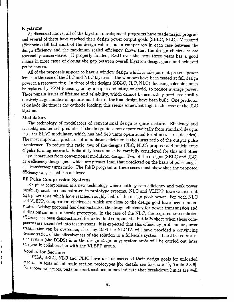
I
1
a.
1
t
t
KlystronsAs discussed above, ~ of the ~ystron development programs have made major progress
and several of them have re~hed their desia power output gods (SBLC, NLC). Measuredefficiencies still f~ short of the desi~ dues, but a cornpuison in each case between thedesign efficiency ~d the rn~murn scaled efficiency shows that the design efficiencies arereasonably conservative. If properly funded, R&D over the next three yems has a good
chance in most c=es of closing the gap between overall klystron design gods and achievedperformances.
N1 of the proposals appew to have a tindow design which is adequate at present powerlevek; in the c~e of the JLC and NLC klystrons, the windows have been tested at fti designpower in a resonant ring. In three of the designs (SBLC, JLC, NLC), focusing solenoids must
be replaced by PPM focusing, or by a superconducting solenoid, to reduce average power.There remain issues of fifetirne and retiabtiity, which cannot be accurately predicted until a
relatively large number of operational tubes of the fid design have been bufit. One predictorof cathode life time is the cathode loading; this seems somewhat high in the c=e of the JLCNystron.
hfodulatorsThe technology of modtiators of conventional design is quite mature. Efficiency and
reliabihty can be well predicted if the design does not depart radicdy from standard designs{e.g.! the SLAC modulator, which has had 240 units operational for almost three decades).The most important predictor of moddator efficiency is the turns ratio of the output pulsetransformer. To reduce this ratio, two of the designs (JLC, NLC) propose a Bltiein typeof p~e forming network. Rehability issues must be caretily considered for this and other
major departures from conventional modulator design. Two of the designs (SBLC md JLC)have efficiency design go~ which are greater than that predicted on the basis of ptise lengthSnd transformer turns ratio. The R&D program in these c~es must show that the proposedefficiency can, in fact, be achieved.
RF Pulse Compression SystemsRF pdse compression is a new technology where both system efficiency and peak power
capability must be demonstrated in prototype systems. NLC and VLEPP have carried outhigh power tests which have-reached roughly half of the design peak power. For both NLC
ad vLEPP, compression efficiencies which me close to the design goal have been demon-s rated. hTeither proposal has demonstrated the design efficiency for power transmission and
rf ~stribution on a fu~-scde prototype. k the case of the NLC, the required transmission
eficiency has been demonstrated for individual components, but falb short when these com-Wnents are assembled into test systems. It is expected that this efficiency problem for powertr~mission can be overcome; if so, by 1996 the NLCTA wi~ have provided a convincingdernomtration of the effectiveness of the solution in a ftil-scde system. The JLC compres-
‘l~n s~stem (the DLDS) is in the design stage ody; system tests wi~ be carried out latert~~ ~~ar in co~aboration with the VLEPP group.
Accelerator Sections
TESL.4, SBLC, NLC and CLIC have met or exceeded their design goals for unloaded~~ient ~ tests on fu~-scde section prototypes [for details see footnote 1), Table 2.3.6].
‘or coPPer structures, tests on short sections in fact indicate that breakdown hmits are well
81

I y-
above the design gradients for W of the machine propos~. The red problem hasbeenobtaining sficient rf power to drive a ti-scde structure to the design gradient. The majorpotential problem is not so much breakdown in the accelerating sections at the operating
gradient, but the magnitude and effects of dmk current (on beam position monitors forexample). Tests on dark current effects wi~ be an important goal for the multi-section testfacihties which are planned for TESLA, SBLC and NLC.
The second major component of accelerating structure design is w~efield suppression.For dl of the proposed section designs, theory and simtiation indicate that the suppressionis adequate to prevent unacceptable emittance growth. The NLC detuned section h= beentested with a beam (ASSET studies in the SLC), and good agreement was found betweenthe measurements and theory. It is tiy expected that further beam tests in the S-band TestFaciUty (DESY) and the NLCTA (SLAC) ti~ verify the adequacy of wakefield suppressionin the design of the SBLC and NLC sections. TESLA h= additional problems due to thesuperconducting nature of the structure: microphonics, detuning due to the electromagneticforces acting on the metdfic surface, and enhanced cryogenic losses due to beam-inducedhigher-order-mode power dissipation. These effects wi~ be tiy memured in the TTF atDESY.
The biggest problem facing all of the structure designs is not a scientific problem but anequally ~ctit practical one: how to manufacture the accelerating sections to the requiredtolerances at a re~onable cost. AU of the groups wiU be working hard on this as p~t OStheir R&D programs for the next three years.
--

Table 2.3.1General RF design Parameters for Main Linac
TESLA SBLC JLC NLC TBNLC VLEPP CLICRF frequency (GHz) 1.3 3.0 11.4 11.4 11.4 14 30Accelerating Gradient 1
Unloaded/Loadedl) (MV/m) 25/25 21/17Overhead Factor,2) FOH 1.00 1.05
Active Linac Length3) (km) , 20 30.2Total Linac Length4) (km) 29 33
, Peak Power per Meter (MW/m) 0.206 12.2Structures per Power Unit (PU) 32 2
I Structure length per PU (m) 33,2 12Total Number of Power Units5) 604 2517Total Number of Klystrons 604 2517Total Number of Modulators) 604 2517Repetition Rate (Hz) 10 50RF Pulse Length at Structure (ps) 1315 2.8Peak Beam Current8) (A) .0083 0.30Total Ave. RF Pwr. at Str. (MW) 54 51.6
1) On-crest beam loaded gradient, taking into account both single-bunch and multibunch beam loading.2) Includes allowance for: off-crest operation for BNS damping; feedback overhead; inactive accelerating sections (repair margin), feedback overhead
and repair margin not included for TESLA and CLIC.3) Active length = [(500 GeV – 2 x injection energy) /(loaded gradient)] x FOH.4) Total linac length = Active length plus allowance for beam line components, including cryostat where applicable.5) Number of power units = number of klystrons for TESLA, SBLC and VLEPP, = number of pulse compression units for JLC and NLC,
= number of transfer structures for TBA and CLIC. For VLEPP there are two pulse compressors per power unit.6) Number of drive beams for TBA and CLIC and number of high voltage sources (supermodules) for VLEPP,7) Equivalent length for a rectangular pulse.8) SB=single bunch acceleration.9) For acceleration of 1/10 bunches.
73/581.09
8.710.4
1004
5.216603320
33201500.230.8032.4
50/371.09
14.215.6504
7.2196839361968
1800.2400.7430.6
100/74
1.10
7.1
7.8200
1
1.83938
26120
0.2427)1.4941
100/91
1.075.8
7.01204
4.0
14001400
140
3000.11SB22
80/781.02
6.3
8.81442
0.5611233
—
22530/12109)
.0116SB/1.92g)
26.4

Table 2.3.2RF System Efficiencies and AC Power Requirement: Design Goals
,TESLA SBLC JLC NLC TBNLC VLEPP CLIC
Klystron Electronic Efficiency 1)(%) 70 50 45 60 92 60 752.7—
9686
5861
58
2.5 7— 9897 9580 823.5 5— —
6 12
38 34
1.57794723
—
4
31
—
98443
—
3
40
1.47495950.4
2
40
—
—
90521
2425
35
Klystron Auxiliary Power2J (Mw)Pulse Compression Efficiency (%)Power Transmission Efficiency (%)
, Modulator Efficiency) (%)
Modulator Auxiliary Power 4, (MW)‘ Cryogenic Power (MW)
Total Aux. plus Cryo. Power (MW)RF System Efficiency Excluding
Auxiliary & Cryogenic Power (%)
AC Power Excluding Auxiliaryand Cryogenic Power (MW)
Total AC Power (MW)
Net Efficiency for Productionof RF PowerG) (%)
Efficiency for Conversion ofAC Power to Beam Power (%) 21 10.4 5.6 8.2 16.7 8.4 1.6/7.8
1) For TBNLC/CLIC: efficiencyfor conversion of drive beam power to rf.2) Cathode heater plus solenoid power.3) Drive beam production efficiency for TBNLC/CLIC,4) Thyratron cathode and reservoir heater power (drive beam focusing for CLIC).5) Does not include regulation reserve.6) Including cryogenic power for TESLA and CLIC.
945)
1545)
133 102139 114
98103
103106
55
57
75100
35 37 30 30 39 39 26

(1 Table 2.3.3
Klystron Parameters: Design Goals and Achieved to Date
TESLA SBLC JLC NLC VLEPPDesign Ach. ‘d Design Ach. ‘d Design Ach. ‘d Design Ach. ~d Design Ach >d
RF ~equency (GHz) 1.3 1.3 3.0 3.0 11,4 11.4 11.4 11.4 14 .14Peak Output-Power (MW) 7.1 5.o 150 150 135
Pulse Length (ps) 1314 2010 2.8 3 0.5Repetition Rate (Hz) 10 , 10 50 60 150Ave. Output Power (kW) 93 100 21 27 10Microperveance 0.51) ‘ 2.0 1.2 1.8 1.2Electronic Efficiency (%) 70 45 50 42 45Scaldd Max. Efficiency) (%) 73 50 62 53 62Beam Voltage (kV) 110 130 575 528 600Beam Energy per Pulse3) (J) 13,300 10,100 840 1070 150
m Cathode Loading (A/cm2) 3.1 6 6 13.5a Cathode Heater Pwr. (kW) 0.5 1 2 0.5
Focusing Type sol. sol. PPM sol. SCMSolenoid Power (kW) 4 4— 15 1Output Window Type Coax. Pillbox Pillbox Pillbox TE1l
TWNo. of Windows/Klystron 1 1 2 4 2Overall Length (m) 2.0 2.5 2.5 1.5
1) Perveance per beam in multibeam klystron.2) ~ (Max) x 0.80- (0.15 x Microperveance).
96/50 500.1/0.2 1.2
100 18011
1.2 0.633 6062 71
620 455170 10013.5 7.40.5 0.4sol. PPM40 —
TEII TEOIA/2 TW
2 1
67/550.05/1.5
600.2/5
1.244/38
62444/430
8/2157.60.4sol.
= 20TEO1
Sw1
1.5 1,3 1.3
1500.5030024
0.2560
7610001255
1.0PPM
TEIITW
21.46
600.72
0.1540
7810001005
1.0PPM
—
TE1l
21.46
3) In flat-top portion of pulse.

1)2)
I
Table 2.3.4. .Modulator Parameters: Design Goals and Achieved to Date
TE$LAModulator Typel)
SBLC JLC NLC VLEPPStorage cap. PFN Blumlein PFN Blumlein PFL Gridded Gunwith bouncer
Design Ach.’d Design Ach.’d Design Ach.’d Design Ach. )d5) Design Ach.’dFlat Top Pulse Length, T~(Ps) 1314 201O 2.8 3.0 0.5 0.7 12 15 0.50Output Voltage (kV) 1)0 130 575 528
0.50600 620 . .455 455 1000Transformer Ratio n 1:12 1:13 1:18
9601:23 1:5 1:7 1:7
PFN Voltage (kV) 9 10 651:20 — —
Rise/Fall Energy Efficiency (%) 89 89 86.5Scaled Energy Efficiency2) (%) 99 99 7012R/Thy./Core Loss Efficiency (%)
97Energy Stored on PFN3) (J) 15000 22000 1000Power Supply Efficiency (%) 97 97 g5Mod. Eff. without Aux. Power (%)
79.5Auxiliary Power4) (kW)
1.5Net Modulator Efficiency (%) 86 86 77.5Ave. AC Input Power (kW) 155 260 54.2(Including Auxiliary Power)
PFN = lumped element pulse forming network; PFL = pulse forming line (transmission line).See text.
46 120 80 66 46- 1000N 65 89 70 80
960=60 — —
65 79 70 81 58 — _95 97 97 —
1650—
174 25890 g5 93 = 90
= 60 82 72 s 523 1.5 1.5 1,5 ;3
59 80 70 92.588 2g 51.5 40.5
3) Energy switched per pulse from storage element for TESLA and VLEPP.4) Includes thyratron cathode heater, reservoir heater and other control power.
5) Standard (not Blumblein) PFN.
Table 2.3.5nm n-.1—- m—--——————! —— -— A n------ R_-- —:--:---- n--:-.. -—-1- --. .1 A ..1. :... . ...1 A.. il . . . .

‘ral)lc 2.3.51?1..J’IIIsftC:{)l?]?)rfsssif)rl nnd J’owil.
‘&ansmission: Design Goals and Achieved to Date
JLC NLC VLEPPType of Pulse Compression System 1, DLDS SLED-II VPM
1 Design Ach. ‘d Design Ach. ‘d Design Ach.’dCompression Ratio 2 5 6 4.55 4.55Input/Output Pulse Length (ns) 500/250 1200/240 900/150 500/110 500/110Compression Efficiency (%) 98 76.5 73 74 72Power Gain 1 1.96 3.83 3.7 3.37 3.3Power ~ansmission Efficiency (%) 95 94 84 95 95
I Power Gain Including ~ansmission Loss 1.86 3.60 3.0 3.20 3.1Length of Structure per Power Unit (m) 5.24 7.20 4.004Power at Structure per Power Unit (MW) 524 360 150 480Maximum Power in P.C. System (MW) 282 380 205 250 150
m Required Klystron Power (MW) 2 x 141 2x50+
2x75
1) DLDS = Delay line distribution system; VPM = VLEPP Power Multiplier.
.,

Table 2.3.6Accelerating Structures: Design Goals and Demonstrated Accelerating Gradient
Demonstrated TESLAAccelerating Mode T SwStructure Type and Sw
Wakefield Control , 2HOMcouplers
Damping (Q.) ‘= 1 x 10⁴Length L (m) 1.035Number of Cells (N) 9Filling Time (ns) 515 psAttenuation Parameter (nepers)Iris Aperture (a/A)
Group Velocity (% c)
QI to QN (or Qo/QL for SW)R/LQ (kQ/m)Unloaded Gradient (MV/m)
Gradient Achievedl) (MV/m)Input Power (MW)Power Diss. per Meter (kW/m)
RMS Straightness Tel. (pm/N)z)
—
0.30—
5x 10⁹/3 x 1061.002525
0.213.002@ l,8°K
500pm/9
SBLC JLC2z/3 TW 2z/3 TW
const. grad. gauss. det.2 damping damping
cells, p-movers=2000
6.01807900.55
0.16-0.11
4.2-1.413.5 X103
3.6-4.72121731.1
30pm/20
cells ?~
1.311501100.58
0.20-0.1410-2
7.2-6.4 X 10310.2-13.6
73
1302.63)
NLC2x/3 TW
gauss. det.dampingmanifold
1 x 1031.80206100
0.530.22-0.1511.9-3.0
7.4-6.7 X 1039.1-13.2
50
65150
1.63)
10pm/10
VLEPP
const. imp.
—
—
1.001421100.790.14
3.16.0 X 103
17.7100
120
3.02pm/1
CLIC2~/3 TW
const. imp.RF quads
—
0.28084
11.60.250.208.2
4.2 X10326.2
80
9440.2
2.1
SB/?10 fim/142
1) In high-power tests on full-scale, near-prototype structure. Except: the NLC structure was tested without damping manifold; the TESLAstructure was a “fully dressed” production cavity with a somewhat different input coupler, but tested in a vertical cryostat.2) Tightest tolerance on structure straightness over N cells. SB=single bunch acceleration with loose tolerance.3) At unloaded gradient.

2.4 BEAM D~AMICS
2.4.1 The Group
K. Yokoya (Chairman)Physics Department, KEK, 1-1 Oho, Tsukuba-Shi, Ibaraki-Ken 305,Japan. Email: YOKOYA@jpnkekvxA. Mosnier (Deputy Chairman)CEA Swlay, DAPMA/SEA, CE Swlay, 91191GIF-sur-Yvette, France, Email: [email protected]. cea.fiG. GuignardCERN, SL/AP, CH-1211, Geneva 23, Switzerland. Emti: [email protected]. RuthSLAC, SLAC, PO Box 4349, St*ord, CA 94309, U.S. Email: [email protected]. eduR. WuenbergDESY, Notk@rme 85, 22603 Hamburg, Germany. Email: [email protected]
2.4.2 Overview
The main linac is the lmgest component in a finear colhder complex. Its purpose is towcelerate the beam to the desired energy. The major concern of the beam dynamics group,however, is not the acceleration itseti but preserving the high beam quality to the final focussystem. This. must be done both longitudinally and transversely.
The longitudinal quality is defied by the spread and stabi~ty in the beam energy, andby the bunch length and stabifity of the arrival time. Except for the special case when
the physics demands an extremely shmp energy distribution, &e in t-i physics, the tirectrequirements on the energy spread/stabihty come from the energy acceptmce of the fialfocus system. The energy spread itself is not hard to achieve; however, it has an importanteffect on the transverse beam quality via chromatic effects. The bunch length is determinedby the bunch compressor system md is frozen once the beam enters the lin~ because ofthe high beam energy. The bunch length @ects the energy spread because of the curvatureof the rf accelerating field and the induced longitudinal w~efield. The arrival time of thebunch at”the fin~l focus is only important relative to the arrival time of the opposing bunch.This relative time depends upon the phase locking of the electron and positron systems andsets tight tolerances on the stability of the timing system.
The transverse quality is defied by the emittance and the stabifity of the beam center.Recent designs of ~1 the tinear collider systems adopt very flat beams at the coUision pointin order to mififize the beamstr~~g. Flat beams are obtained by using a small verticalbeta f~ction at the Colfision point and by using a sma~ vertical emittance. Because thissma~ efittance must be generated in the damping ring or source and then preserved throughthe ~celeration of the beam, the major problems in the finacs are related to the vetiical
beam dynamics.The transverse degradation of the beam ultimately comes from the misalignments or
~lbrations of the hnac components, i,e, accelerator structures, focusing magnets and beamPosition monitors (BPM). The physical mechnism of the emittance blowup from the rnis-ti~ent/vibration includes the optical effects of the focusing system and the transverse
~~e effects in the accelerator structures. If one assumed a very low intensity, and if thebe~ were strictly monochromatic, the optical effect wodd be to shift the beam center,
89
--

which cotid easily be compensated by a simple on~t-one correction method, even ptietmpulse using a feedback system, udess the vibration were too fret. However, the actualsituation is much more comphcated because of the chromatic/dispersive effects which cd formore sophisticated correction methods. The wakefield can also cause Werent trajectoriesfrom puticle to ptiicle depending on their longitudinal position in the bunch. The relativeweights of these two effects depend on the design. In VLEPP and CLIC, wakefield effects
are clearly more importmt, wherea the two effects are comparable in JLC and NLC.All the existing designs, except VLEPP, adopt mtitiple bunches in each rf pfie in
order to raise the luminosity with ody modest added power consumption. By somewhatdecreasing the bunch charge of each bunch, it is also possible to decrease the backgroundsdue to beam-beam effects at the IP. On the other hand, the mtitibunch scheme introduces
another complication to each item above. The transient beam loading due to the bunch trainis roughly 20V0 in SBLC, JLC and NLC. Thus the bunch-t~bunch energy compensation isvery important. The energy spreti due to the long-rmge higher-order longitudinal wakefields
is not significant. However, cumulative beam breakup due to the long-rmge transverse wdecan cause a severe problem and must be reduced by a carefti design of the acceleratorstructures.
2.4.3 Where We are Today
Longitudind DynamicsSingl~bunch energy spread
The short-rmge wake effects on the singl~bunch energy spread have been studied extensivelyin the SLC. The bunch is placed off the rf crest so that the slope of the rf compensates thevariation of the induced single bunch beam loading. This technique wi~ also work for NLC,JLC, SBLC and CLIC. VLEPP, where the bunches are longer and more intense, must alsorely on a cmcelation of higher order loading effects.
In addition to the above energy spread, a correlated energy spread is added in manydesigns to compensate the transverse wakefield (NLC, JLC, SBLC, VLEPP). This technique,cafled BNS dampin~ takes advantage of the increased focusing on the lower energy tail of thebunch to compensate the deflecting wake due to offsets. This energy correlation can be addedand removed by varying the phase of the rf along the hnac. It can be left in to pass throughthe Find Focus provided that the bandwidth is sticient. These shifts in phme requireenergy overhead. In the CLIC design the correlation in focusing strength is produced by rfquadruples which decouple the BNS compensation md the ener~ overhead. In TESLA,since the single bunch wakes are sm~, BNS damping is probably not needed. The bunchcan be placed at the optimal phase for minimum energy spread. In VLEPP, energy spreadcan be contro~ed by adjusting bunch length m a function of totti bunch charge.
Inter-bunch energy spreadThe problem of the bunch-t~bunch energy spread is more severe because the uncompensatedenergy spread due to the transient beam-loading is one order of magnitude larger thanthat due to the short-range wake. In the TESLA design, the loading is the largest andis compensated by matching the power extr~ted by the beam to the rf power suppliedby the generator during the beam puke. The residud variations due to Lorentz forces or
90

,
rnicrophonic detting, rf mismatch, beam current fluctuations and power sotice ripple mustbe compensated by a feedback system.
The JLC and SBLC design use the “staggered timing” method. By varying the triggertiming from power unit to power unit, one can reduce bunch-t~bunch energy fluctuationsto a few pints per thousand. The NLC design mhieves the we effect by ramping theinput rf power to match the transient of the beam loading. This method will be testedin the NLCTA. Both methods are flexible enough to dow for changes in parameters suchas bunch poptiation or accelerating gradient. The staggered timing method is simple buthas the disadvantage that the compensation is not done loca~y but over several rf systemmodties, dewing the beam to travel through some distance along the focusing system beforethe bunch energies are ~ly equ~ed. This effect has implications for the transverse beam
dynamics.The staggered timing method cannot be applied to the tw~beam machine CLIC where
the timing is determined by the single driving beam. CLIC will solve ttis problem bymoddating the rf power by vmying the charge of the drive beam bunc~ets.
Another method to compensate beam loading is to add structures and klystrons, withsm~ frequency shifts from the fundamental tiequency. This method is proposed for theJLC(S) and wi~ be tested in the S-band injector tiac of the ATF at KEK. The required num-ber of frequency-shifted structures in JLC(S) is about 3% and the residual bunch-t~bunchenergy spread will be a few parts per thousand. Again, this technique has the disadvantagethat it is not local.
Because of the large loading, the tolerance on the ptis~t~pulse fluctuation of total population of a bunch train is quite tight. This problem is due to dispersive effects in the linac,energy bandwidth of the final focus and in some cases requirements for physics experiments.Since the total energy spread due to the uncorrected loading is about 20% (SBLC, JLC,NLC), a 1% fluctuation of the train population will cause an energy change of 0.2%. Thetolerance on the random vmiation among bunches is much less severe. TESLA plans to tiowa 1~0 fluctuation in current; however, this requires that the rf field feedback system reducethe resultant loading variation by more than a factor of 100; without compensation the 107ochange wotid lead to a 4% energy variation.
Since the normahzed vertical emittance in all the designs is considerably smder thanthat in existing linacs, the emittance preservation is a critical issue even in the absence of
the wakefields.
Choice of opticsApart from details, the Unac optics can be characterized by the energy scaling of the beta
function and the phase tivance per FODO cell, SBLC, JLC and NLC adopt the sca~ngpm~awitha = 1/2, and use a phase advance of about 90 degrees. This scahng makesthe required BNs energy spread constant. In the case of TESLA where the wakefields areweak, the beta function is larger and scales weakly with energy, Q = O to 0.2. The CLICdesign, because of strong wakefidds, allows the phase advance to vary from 90 degrees at the
entrance to 60 degrees at the exit of the hnac with a = 0.35. In dl cmes, the vertical and
91
--

horizontal phme advances shodd be separated by about 5-10% to decouple the two Plm=
Vibration and centroid feedbackThe afignment of a hnea coltider varies in time because of microseismic activity. If we look ~the frequency domain, the motion can be q~te Imge at low frequencies of about.2 Hz, but itffi off dramatically at higher frequencies. In addition, the dfierentid motion betwwn my
two points can be correlated. For example, at very IOW frequency the ent~e ~nem co~dersite simply moves = a unit. At low frequency the beam Cm be used in a feedback loop tokeep the bunches co~iding by using steering magnets. Thk tectique is used routinely atthe SLC. At a frequency greater than about ~,v/20 tMs becomes very ~c~t to do, andone must rely on the reduced motion at high frequency, correlations of neighboring magnetsor some Iocd damping of supports to reduce the motion of quadruples. This fast motion(caUed jitter) h= the tightest tolerance which ranges from 10nm to 100nm from JLC/NLC
to TESLA (see Table 2.4.1),
--
--
92
—.-
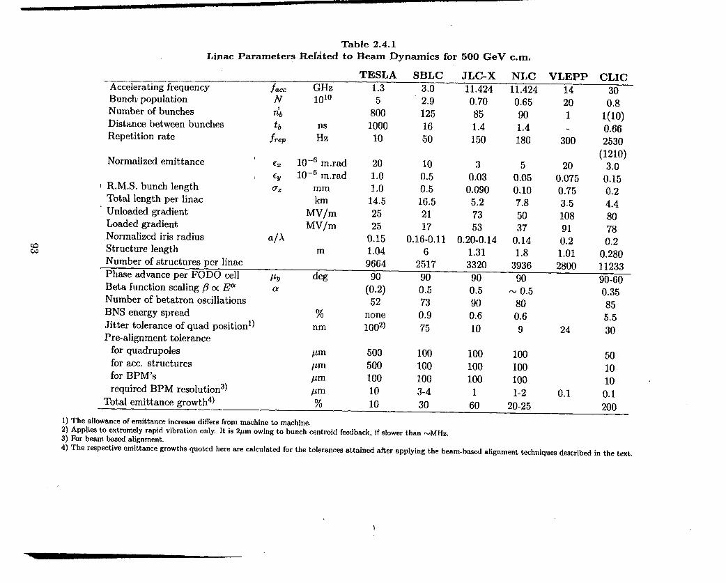
Table 2.4.1
Linac Parameters Related to Beam Dynamics for 500 GeV cm.
Accelerating frequencyBunch populationNumber of bunchesDistance between bunchesRepetition rate
Normalized emittance
TR.M.S. bunch lengthTotal length per linac
4 Unloaded gradientLoaded gradientNormalized iris radiusStructure length
TESLA SBLCjacc GHz 1.3 3.0N 1010 5 2.9n’b 800 125tb 1000 16
~rep :z 10 50
e~ 10–6 mrad6V 10-6 mrado~ mm
kmMV/mMV/m
a/Am
201.01.0
14.52525
0.151.04
100.50.516.52117
0.16-0,116
JLC-X NLC VLEPP CLIC11.424 11.424 14 300.70 0.65 2085 90 1 1!1:)1.4 1.4 - 0.66150 180 300 2530
(1210)3 5 20 3,0
0.03 0.05 0,075 0.150.090 0.10 0.75 0.2
5.2 7.8 3.5 4.473 50 108 8053 37 91 78
0.20-0.14 0.14 0.2 0.21.31 1.8 1.01 0.280
Number of structures per linac 9664 2517 3320 3936 2800 11233Phase advance per FODO cell Pv deg 90 90 90 90 90-60Beta function scaling ~ u EaNumber of betatron oscillationsBNS energy spreadJitter tolerance of qud positionl)Prealignment tolerance
for quadruplesfor ace. structuresfor BPM’srequired BPM resolution)
a (0.2)52
% nonenm 1002)
pm 500pm 500pm 100pm 10
0.5730.975
1001001003-4
0.5900.610
100100100
1
-0.5800.69
1001001001-2
0.35855.5
24 30
501010
0,1 0.1Total emittance growth4) % 10 30 60 20-25 200
1) The allowance of emittance increase differs from mwhine to machine.2) Applim to extremely rapid vibration only. It is 2pm owing to bunch centroid feedback, if slower than -MHz.3) For beam based alignment.4) The respective emittance growths quoted here are calculated for the tolerances attained after applying the beam-based alignment techniques described in the text.

If the local motion is too large compared to the tolerances, it cm be reduced by an activestabilization of the magnets using a geophone. Recent tests from the SBLC test facihtyyielded a reduction by a factor of 3 (20nm in their case). The repetition rate ~,v sets thescale for the ma~itude of the problem in a particdw design. The advantage of loosertolerances in the SBLC design is partly bdaced by larger vibration amplitudes at lowerfrequencies which are more relevant because of the low repetion rate, while machines such
as JLC, NLC and CLIC with tighter tolerances wi~ have smder motions to deal with dueto the higher repetition rate.
The exception to this is TESLA which h= a very low repetition rate. In TESLA, wherethe bunches within a train have very large spacing, one can apply feedback on the bunchcentroid within the train rather than horn pulse to ptise. In this c~e the fist several buncheswould be used at the end of each hnac to learn the new trajectory and fast correctors would beadjusted to cause the remaining bunches to colhde. If the motion is too lmge ptis~t~ptise,then a local correction technique must be used to avoid filamentation.
Correction techniquesFor the large displacements due to the “fixed’ quadruple misalignments of the system,one must use dipo~ correctors or quadruple movers to correct the trajectory. A commontechnique that is used extensively in the SLC is a one-t~one (or on~t~few) correctionthat uses the nearby position at BPMs to determine the settings of corrector magnets. ForTESLA, the one-t-one correction is sticient, though a more sophisticated correction canrel~ the tolerances. For the other designs, the quad and BPM alignment tolerance for one --t~one correction is much tighter, a few ~m to 20~m over a length smder than the betatronwavelength in the Enac. For larger misalignments, a one-t-one correction causes emittance
dilution in the cme of SBLC, JLC and NLC, because of dispersive effects and comparablewake effects. In the case of CLIC, the one-t~few correction allows recentering the initidy
pretigned quadruples (50 pm r.m.s. or more) to within the position tolerance (10 pm) ofthe position monitors, provided that the BPMs are aligned to this accuracy.
If the BPM centers can be located in the quadruples to high accuracy, the beam can beused to align the quadruples to about that same accuracy. This can be accomplished to thelevel of the BPM resolution by varying the quadruple strength and observing beam motion
on BPM’s downstream. This method has been used extensively for quadruple tignment inthe SLC where the afignment is about a factor of 8 worse than the BPM resolution. Thistechnique h= the disadvantage that it is time consuming. If the dilutions are primarfly
caused by dispersive effects, one can use a similar technique called DF (Dispersion Free)steering that reduces the dispersion loca~y. This technique works quite we~ with weakwakefields and can loosen quadruple tolerances to the 100 pm (NLC, JLC) and 500 pm
(TESLA) levels respectively. This technique ako depends upon the BPM resolution whichranges from 1 ~m to 10 pm in the above examples. VLEPP h= developed a differentcorrection scheme called “adaptive ~~gnment .“ It consists of memuring the beam positionfor a single ptise or averaged over several ptises in au quadupoles simultaneously, by usingthe data from three adjacent BPM’s for each quadru~ole. This correction can be applied forthe entire hnac on the 6rder of ten times per second, and used continuously during a physicsrun. By this method, the short wavelength components of the misahgnment can gradu~ybe smeared out and the vibrations of linac elements with frequencies on the order of 1 Hz can
94

be compensated. The corrections can be achieved by moving the quadruples or by using
special dipole cods on the quadruples.
Wakefield effectsThe next step is to include the effects of the wakefields. It has been known for more than tenyears that the effects of the short-range transverse wake can be reduced by BNS damping.This technique h= been tested extensively at the SLC. BNS damping is essential for dl thedesigns except for TESLA. The variation in the betatron frequency from head to tail of thebunch is less than 1% for SBLC, JLC and NLC. In these three designs, the frequency changeis produced by the negative ener~ slope obtained from the longitudinal wake and the rfphase. The energy spread is eventually ehminated at the end of the linac by a compensatingchange in the rf phase. h case the IP is designed with a small crossing angle, this energyslope can be kept for crab crossing using the dispersion function (SBLC), provided that highluminosity is more important than energy spread.
The required spread for BNS damping in CLIC is very large (5%) because of the strongwakefields. In this case the BNIS damping is made by moddating the transverse focusingstrength along the bunch by using a time dependent (rf) quadruple field generated by ovd-bodied accelerating cavities. These rf quads work at a phase where the acceleration and
the slope of the transverse focusing are mtimum since only this slope is relevant for BNSdamping. VLEPP, for wtich the required spread exceeds 10%, may have a more sophisticatedmechanism called “autophasing.”
W’hen considering an alternating gradient system, BNS damping only takes place in theaverage. To avoid enhancing wake effects in this case, the above DF correction should bereplaced by a DcWed WF (Wake-Free) correction, in which the strengths of focusing anddefocusing quads me changed dfierently. In the ideal case this technique causes wake effects* well as dispersive effects to cancel locally.
Several other methods of correction have also been proposed. In one of them the bunch
P@dation and/or bunch length are changed instead of changing quadruple settings. N-tematively (and more simply) the accelerator structure misahgnments can be ehrninated bymoving.the structure to reduce the HOM signals induced in the structure. This technique isP!med for the”SBLC, NLC and VLEPP. For VLEPP, special movers with a few nanometers
~CUWY and a frequency response up to 30 Hz have been designed and tested to move accel-erator structures. Also, w-~efield effects can be canceled nonlocally by using nondispersive
~~rnps (except in CLIC where the wakefields are too high). In this way, wakefield tails can‘~~Compensated wit bout introducing extra dispersion.
The strategy of including dl these correction techniques, fwt to slow, small to large~~p~[udes, wi~ be discussed in the section on alignment.
Transverse Multibunch Dynamics%<’~ln~ that the bunch-t-bunch energy spread is well compensated, the major problem
:f ‘~~ tr~verse multibunch dynamics is cumulative beam breakup. Again, the problem is~:y’;~~’~ SBLC, JLC and NLC. For TESLA, a slight damping of the higher order modes is‘+’(d ~ ~dition to the natural frequency spread due to the fabrication errors.
‘o: S~LC, JLC and NLC vmious types of accelerating structures have been investigated* a cue for the beam bred~p problem. These can be classified into two categories, damped‘.‘-u’@ ~d detuned structures. In addition, damped structures can be divided into
I 95
--

I
strongly damped structures (i.e. Q N 20) and lightly damped st~ctures (Q N 1000).Mthough many different types of strongly damped structures have been consider~, the
most promising is the choke mode cavity. This structure is a combination of a rati~ hewhich damps dl modes by letting them leak out, and a choke that just reflects bmk the
accelerating mode. The required Q-value of the do~n~t TM1l mode for the JLC is leSSthan 20, whereas the expected Q in the desia is much less th~ 10. Det~~ ~e discussed inthe section on linac technolog. An sband model Wm co~tructed at KEK for high powerexperiments and has revealed exce~ent properties as expected from the design.
Constant-gradient structures, which in some sense me tie~y detued stmctures, havebeen studied for SBLC, JLC and NLC. The constant-gradient structures me known to befar better thm constant-impedance structures with respect to the beam break-up problembecause of the spread in the deflecting mode frequencies. The idea of the detuned structure isto enhance this effect by intention~y distributing the frequencies in a smooth distribution.This has been considered for the JLC(X) and NLC. The required spread is determined by
the bunch-t-bunch distance, and in the c=e of JLC and NLC is about 10%. This spread iscreated by changing the iris aperture from ce~ to ce~. In the NLC design, the disk thicknessis dso varied in order to have a large spread in the higher deflecting mode frequencies. A Wscale detuned structure has been tested at SLAC with a satisfmtory agreement with theoryif one t~es into account the fabrication errors. However, the cance~ation of the long-rangetd is st~ mmginal. To cure this problem, JLC may have an interleaved distribution of ce~frequencies between two structure families. The NLC design wi~ use the detuned struct~ebut add additiond damping by means of four symmetricdy placed waveguides runningpara~el to the structure and closely coupled to each ce~. These damping manifolds restit inQ’s = 1000 for the deflecting modes and leave the fundamental essenti~y unchanged. Themanifolds can dso be used m monitors for beam position in the structure for ~gnment.In the cme of SBLC, the conventional constant-gradient structure h= a sm~er relativefrequency spread, but the bunch-t-bunch distance is 48 fundamental rf buckets as comparedto 16 buckets in JLC and NLC. The increased spacing and lager number of bunches causethe long range td of the wake to be more important in SBLC. The beam breakup cureadopted for SBLC is to prepare ten types of constant-gradient structures with the HOMfrequency shifted by 36MHz in total. In addtion, the higher order modes are damped downto Q < 4000- via-two damping ports per plane and lossy material covering the tips of anumber of irises. The HOM signal detection is abo planned for monitoring the structureposition, and moving the structure with respect to that signal by means of a mover.
If after this effort, there remain some orbit Werences between bunches, the residuddifference can be corrected by several pairs of fast position monitors md kickers whichcan be adjusted for each bunch, or at least for groups of bunches. The memurement andcorrection need not be pfiet~pbe and one may accumdate information over many ptises.
Alignment TechniquesRecent experimental and theoretical studies have restited in the development of a number
of beam-based tignrnent techniques. With these techniques, the initial or pr~dignrnenttolerance is looser than the available survey accuracy. This kind of pre~~ent is stiarfor ~ machines. A value of 100pm over a distance of a betatron wavelength is tieady
96

within the present level of technology. The predgnrnent tolerances (or the usumed surveyaccuracy) for the Werent machines are given in Table 2.4.1.
The ground motion h= been investigated in various locations in the world. What isimportant for hnear coWders is how the relative displacement between two points vaies intime. Apart from some systematic motions (due to, for example, the electric power Unes andthe ocean tides, etc.), the s~ca~ed “ATLlaw”, which was first suggested by the VLEPPgroup, seems to apply at relatively long time scales, The law states that if one measures thechange Ay of the relative position of two points separated by L, the expectation value aftera time T WN be expressed as (Ay2) = A x T x L, where the coefficient A depends on thesite and ranges from 10-lgm/s in quiet places to 10-16 m/s in noisy places. Although everymotion cannot be described by this law, it is a good model for sirntiation studies. Assumingthe coefficient, one can estimate how often each correction has to be repeated.
Every linear colhder design uses a somewhat different hem-based tignment technique.The accepted total emittance growth together with the required resolution of the BPM’s istiso given in the table. The orbit correction and a~gnment philosophies for each machineme discussed below.
TESLAIn TESLA, the initial rms misahgnrnent resulting from a standard survey wi~ be on the
order of 500 microns for the cavity and qutirupole components. The qudupole and BPMerrors must then be located to the 100 micron level by a beam-based di~ment procedure.This level has been achieved at the SLC with BPM resolutions of about 15 microns. TheTESLA BPM resolution must be of that order also. An alternative method that avoids -finac modehng is to vary the quadruple strengths one by one to determine the location ofthe quadruple magnetic centers. The beam is then steered with the on~t~one correction.With a cavity rnisafignment tolerance of 500 microns, the combined effects - dispersive and
wakefield effects - give an emittance growth of about 10 Yo, including the initial and cor-related energy spreads. Both effects have been balanced by a proper optimization of thelattice. No cavity movers are needed to ahgn the structures to the beam. Thanks to threecombined effects: structure damping (Q & 104 to 105), natural cavity-t~cavity detuning dueto fabrication errors (0.5 to 1 MHz) and the large bunch spacing, the multibunch emittancedilution is much smaller (about 10 times) than the single-bunch dilution. For that reason,combined single and multibunch simtiations give very similar results to the singl~bunchones. In addition, the non-dispersive bump technique is very efficient for all the individualbunches of the train and can increase the cavity misalignment tolerance.
Because of the large bunch spacing, a kicker located at the kac exit could be used toretign the centroids of the later bunches in the train. The jitter tolerance on quadruplemotion, which is then determined by the single bunch emittance dilution, amounts to a
few microns. For slow ground motions, a feedback is needed to r~steer the bem period-ica~y. According to the ATL law, the feedback has to be faster than 40 to 400 seconds,depending on the A factor. When the quadruple displacement becomes too large, on theorder of 100 micro~, the quad and BPM errors have to be determined again through abeam based ~ignment. The re-alignment procedure shodd be repeated every 4 to 40 days.The stepby-step correction WOUl~be applied’ if the periodicity is of a few weeks, whereas a
“dispersion/wakefree” type correction would be preferable for a shorter time.
-- I
97

I
SBLCThe SBLC design study considers the fo~owing alignment approach. AU componen~
wi~ have to be pr~tigned within a 100 pm (rms) tolerance over a distance of about 500m. After an initial on~t~one steering with a low intensity single bunch, a beam b+orbit correction will be performed using the DF and WF algorithms. Then the acceleratorstructures will be moved on the basis of the sign~ from the HOM dampers. AS a res~t
of this, a final atignment tolermce of 30 pm (rms) for the accelerating st~ctures til haveto be actieved with respect to the orbit. This should lifit the emitt~ce ~otih to 25 %.Non-dispersive bumps may be used for a fine tuning of the emittance preservation.
NLCIn the NLC correction procedure, the initial finac alignment of qudupoles and structures
wi~ be done with conventional techniques to the level of about 100 pm. Then the errorbetween the BPM centers and quad centers wi~ be determined to a few microns by varyingthe quabupole strengths. After this, the trajectory will be steered through the centers ofthe quadruples, a process which estab~shes a “gol& trajectory. Using HOM detectionon each structme, the accelerator structures wi~ be aligned to tbs trajectory with moversto the level of about 10 pm. Higher intensity bunches wi~ be used to cofim alignment.If there Me residud bunch-t~bunch effects, these will be corrected with bunch-t~bunchkickers that wi~ realign the train. The beam wi~ be frequently resteered back to the goldtrajectory. If necessary, the gold trajectory may be quickly updated with WF steering.Centroid feedback will be used to stabihze the bunch train for motions below 10 Hz. Forhigher frequency ground motion due to background and cultural noise, the size wi~ hav;tobe (and is expected to be) small enough to keep resultmt beam motion to less than a/4.
CLICFor CLIC, the accelerator WM have to be prefigned so that the beam passes through the
available aperture along a fraction of the tinac. It is foreseen to do this by using signals froma stretched-wire system; the relative positions of two adjacent support girders (1;4 m long)
wi~ thus be maintained within a few microns transversely, while excwsions from a straigthfine of about 0.2 mm will be a~owed over longer distances of say 100 m. The quadupoles wi~bk supported and activated independently of the string of girders, and the BPM signals wi~be used to Qptimize their positions. First using a one-t~few algorithm with approximately3 monitors for 1 quadruple, correction wi~ be effected by moving the quadruples whichare thus recentered toward the ided tine within the position tolerances of the monitors (i.e.10 pm). Next wi~ come corrections based on trajectory difference memurements and onthe obsemation of the emittance at 10 or 12 positions along the linac. These may be eitherthe DF and WF algorithms or a correction method which uses Merence measurementswhile simtitanously varying the bunch intensity w we~ ~ the quadruple setting in order tominimize the wakefield effect and the dispersion. The high resolution of the 30 GHz resonmtcavity BPM (O.1 ~m) makes these methods very efficient, and the vertical emittance growthmay be maintained below the CLIC design value even in the presence of strong wakefields.Corrections may be iterated and the high repetition rate wi~ offer the possibility of fastfeedback.
--
98
w“

2.4.4 Status and Puture Plms for Each Machine Design
The beam dynamics parameters of d linear cotider design stu~ties cab be found in Table2.4.1.
TESLAFor TESLA, the short-range and long-range wakefield effects me sma~ because the rf
frequency is low and the iris aperture is lmge. Nevertheless, the magnitude of these lon-gitudinal and transverse wakefields can and wi~ be carefully checked in the TESLA TestFacifity by injecting the bunches on and off-tis. The single bunch energy spread can bekept smafl (on the order of 5 x 10⁻⁴) because the longitudinal wakefield is sma~ and no BNSis needed, and the mdtibunch beam-loading in the ided case is compensated by the rf gen-erator along the entire bunch train. The different energy spread sources wi~ dso be c~efu~ystudied in the facility. Although the di~ment tolerances are rather loose, the ahgnmenterrors of the components inside the cryostat must also be measured before and tier cool-down. Apti from these checks, no new developments concerning the beam dynamics arerequired because dl the components akeady exist: the BPM resolution is rexonable, no mi-cromovers are needed, there are no stringent mechanical tolerances in the cavity fabricationand quadruple stabihzers are not required.
SBLCFor the SBLC design study, it is worthwhile to mention that the invariant emittance
in the SLC linac at SLAC is, even for the vertical plane, only a factor 10-20 higher thanassumed for the SBLC design. Furthermore, the bunch poptiation of 2.9 x 10¹⁰ is lower thanthe values aheady achieved at SLAC. However, the atignment tolerances of structures andquadruples are tighter than those in the SLC.
To avoid single bunch emittance growth and multibunch beam breakup, the followingdiagnostics and cures me considered for the SBLC: beam-b~ed alignment techniques, higherord~r mode dampers at each accelerating structure and lossy irises, accelerating structuremovers, nondispersive trajectory bumps (tuned by emittance measurements), fast kickers,and titive stabihzation of quadruple supports, which have aheady been experimentallystudied at the iest fac~ity.
To preserve the smdl_single bunch emittuce in the SBLC, a BPM resolution of 3 to4 pm is required m indicated by computer simulations. For the FFTB at SLAC an evenbetter BPM resolution hm been actieved. The mechanical prealignment tolerances of the
quadruples and the BPM’s are much looser (N 100 pm). HOM dampers are necessary todamp the dipole modes, which drive the cumulative mtitibunch beam breakup. Furthermore,the accelerator structures can be moved on the b~is of the HOM signals. The usefuhess ofthe HOM signah as a diagnostic tool wi~ be investigated at the DESY S-band test facility.Once the multibunch beam break-up is cured by HOM dampers and structure movers, thesingle bunch effects determine the alignment tolerances.
--
99
--

JLCFor the JLC, there are sti~ many items to be studied, in partictiar for the Sband and
C-band designs. AH three designs are based on the same emittance and have the same findfocus system which was origindy intended for the X-band design. H the smd emittancedesign for X-band is fe~ible, there is no strong reason against adopting the same sma~emittmce for the lower frequency bands. The smd emittance Wows low beam power whichis adwtageous in designing the particle sources and the damping rings. One disadvantageof the tight focusing at the IP for low rf frequencies is the need for a short bunch length.However, as a problem in linac dynatics for a given emittance, the lower bands shoddshow ~erent features maidy because of the reduced wakefields. In fact, the structuremistignrnent tolerance in the present design is considerably looser for S- and C-band (e.g.,a factor of 4 greater in C-band than in X-band). Therefore, tither studies in the directionof looser focusing in the tinac should be carried out.
NLCFor the NLC, most of the beam dynamics issues have been modeled in detail, and where
possible, experience from the SLC and FFTB has been used to develop the design. Thebeam-based a~gnrnent of quads is we~ estabhshed in the SLC and FFTB. With the achievedBPM resolution in the FFTB, the NLC linac can be aligned to the required level using beam-based techniques. BNS damping is well understood, both theoretically and experimentdy,
The detuned structure performs as expected, and the damped detuned structure will furtherdecrease the wakefields to eliminate beam breakup. The tolerances on the structure con-struction are about 10pm and are achievable with care. The damping manifolds will allowatignrnent of the structme by providing a structur~t~beam position. Calculations indicate --that at 180 Hz, with expected correlations, beam motions restiting from observed intrinsicground vibrations in model sites remain within acceptably low hmits.
CLICFor CLIC, development work is being carried out on micron-displacement systems, submi-’
cron resolution BPM’s and active pr~~gnment schemes. The work is breed on the principle
of mounting four accelerator structures on a support girder, the positions of which can beadjusted by micr~movers. These movers with a resolution of 0.1 gm and an absolute accu-racy o-f 1 pm over +4 mm provide both large displacements for initial tignrnent and micronmovements for c-orrection. The structures are fixed to the girder via V-supports with a pr~cision of 3 pm. The ends of two adjacent girders are on a common platform which assurescontinuity of position between units. This system maintains the tolerances but allows themovement of groups of 4 structures in a continous path. The present simulation model usesthe actual dimensions (coming from the test bench) for the girders, the drift spaces and thestructures; it ako includes a more realistic layout divided into 6 sectors of incre~ing length,with constant lattice in each sector, but different focusing characteristics corresponding tothe energy scafing.
The parameters of Table 2.4.1 suggest that the following points for CLIC ho be consid-ered.- The high resolution of the BPM’s which is inherent to the design (resonant cavity) butnot an actual requirement for the corrections, would work as we~ with a value on the orderof 1 to 2 pm, i.e., sma~ with respect to the position tolerances (10 pm). The preatignmenttolerances of the quadrfipo~es reflect a beam transmission condition applied to the whole 250
100
. . .

GeV tiac; they cotid easily be increased to say 100 pm, by applying this condition to odya fraction of the ~ac. Up to now in CLIC, the possibility of using HOM measmementsand of moving groups of four stuctures on girders was not yet considered and wi~ be the
subject of investigations. Such a correction wotid allow to rela the pr~dignment tolerancesgiven in Table 2.4.1 for the cavities, which presently represent the bare dues required foremittance control. For these reasons, they should be compared to the positioning tolerancesaimed at in other designs after beam-based corrections, that range between 10 and 30 gm fornon-superconducting linacs. In CLIC however, the correction efficiency rehes on the goodpre~gnment of the BPMs that are not lified to the quadruples but rather to the cavitygirders, for the beam must be we~ centered in the cavities.
CLIC offers the substmtial advantage that the single bunch mode of operation Weadyprovides a significant and useful luminosity (> 1033m-2s-1). However, reaching highervalues implies running CLIC in the multibunch mode (10 bunches). The multibunch optionrequires studies of damped/detuned accelerator structures for the roll-off of the w~efieldsbetween consecutivelong range wdefield
bunches, and beam dynamics studies to figure out by how much thehas to be attenuated.
--
--
101

2.5 BEAM DELIVERY
2.5.1 The Group
R. Britiann,(Chairman)DESY, Notkestr-e 85, 22603 Hamburg, Germany. Emti: [email protected]. Telnov, (Deputy Chairman)BINP, Pr. Lavrentyeva 11, 630090 Novosibirsk-90,Russia. Emafi: [email protected]. Dra@Universityof Maryland, High Energy Laboratory, ~~ege Park, MD 20742. Emti: [email protected]. IrwinSLAC, 2575 Sand Htil Road, MS 26, Menlo Park, CA 94025, USA. Emti: [email protected]~ord. eduK. OideKEK, 1-1 Oho, Tsukuba-Shi, Ibaraki-ken 305, Japan. Email: OIDE@jpnkekO. NapolyCEA Smlay; DAPMA, F-91191 Gif-sur-Yvette CEDEX, France. EMail: [email protected]. SeryIHEP, RU-142284 Protvino MoscowRegion, Russia. EMti: [email protected]. ZotterCERN, PS/LP, 1211 Geneva 23, Switzerland. Em~: [email protected]
2.5.2 Overview
The beam defivery system for a linear co~ider is definedhnac and the interaction point (IP). It h~ to provide:
as the section between the main
. Demagnification of the transverse beam dimensions to the required spot size at the IP,
. ~Correction of the strong chromatic aberrations inevitably induced by the demagni~ing
●
●
beam optics,
Protection Qfthe interaction region (IR) horn back~ond caused by electrons (positrons)with large deviations from the central orbit and/or energy,
Removal of the disrup~~d beams after the IP and the beamstrahlung from the IR, andseparation of the outgoing from the incoming beam.
The fist two requ~ements me ~~ed by a s~table bew-opticd system, the Final FOCUS
System (FFS). Issues critical to the design of the FFS ae the energy bandwidth which hasto Wcomodate the total energy spread of the incoming beam, and the tolerances regardingrnamet positions and stren@hs which lead to a degradation of luminosity due to partialtr~verse separation of the co~iding beams and/or blow-up of the spot size at the IP.
The ttid condition requires a beam co~imation system (BCS) between the linac and theFFS w~ch restricts the particle betatron amplitudes and energ deviation to hmits set by‘he Properties of the FFS and the IR layout. Issues critical to the BCS are wakefields from‘he srn~-aperture co~mators whhh may spoil the emittance, machine safety problems in‘e Of bea 10SSin the colhmators, and the overall co~mation efficiency (one minus theProbabihty that large amphtude hdo p~ticles escape horn the BCS and reach the IR).
102

I
Furthermore, muons originating from the coMmators/absorbers are a source of e~per~entd
background and must be kept under control.The lmt condition concerns the geometry of the IR, in particular the crossing ~g]e ~
the IP and the aperture of the tid quadruples. The opening angles of the disrupted be-and the hard ~ beamstrahlung require a layout which safely @ales the debris out from theIR. For the designs which use more than one bunch per rf pfie, a sticiently large bemseparation at the positions of parasitic crossings must be provided. The disposd of the spentbeams ha to be effected safely and methob to me them for ~a~ostic p~poses mut bedeveloped. Specific use of the spent electron beam for positron production is briefly discusdbelow, and in Section 2.1.
There is general agreement (also see Section 2.6) that the be~ de~very system shoddprovide two separate IR’s. Therefore, additional bending sections have to be included whchprovide separation of the two beam hnes and yield the geometrical matching of the IR’s to
the main linacs.
2.5.3 Where We are Today
Overall LayoutA complete detailed layout of the entire system exists for TESLA, SBLC, JLC and NLC.
The SBLC layout (very similar to the TESLA layout, except for the zero crossing angle forTESLA) is sketched in Fig. 2.5.1 m an example. It is assumed that the beam hes are
sptit up after a common co~imation section, thereby saving tunnel and beam fine costs. The --same approach is foreseen for NLC. The JLC design ~sumes sep=ate bearn~nes after thebending section following the Unac.
The total length of the system from hnac to IP (two identicd lattices for the e- and e+beams are assumed) is about 1.5 km for SBLC and TESLA, 1.8 km for JLC, and 2.2 km ~for NLC, the differences resdting maidy from the length of the co~mation section lattice(see page after next), and in the cwe of NLC, from an additiond 400 m long section for4D b~ch size diagnostics and betatron couphng correction (sirnilm additiond sections wi~most probably have to be added to the other designs as we~). All designs assume that themain finacs he on para~el lines so that the required crossing angle at the IP results ~om thenet bend angle of the respective beam delivery systems.
Interaction RegionThe interaction parameters for the =ious designs are Usted in Table 2.5.1. The beam
sizes at the IP include aberrations in the FFS (see page after next), but do not include thebeam-beam pinch effect, the crossing angle, and the hourglws effect. An effective luinosityenhancement factor which represents a combination of these effects is included in Table2.5.2. With respect to the hourglass effect, which becomes substantial if the beta-functionis srnder than the bunch length aZ, VLEPP is an exception. It is ~surned for VLEPP thatthe condition ~~ < CZ can exist without luminosity reduction by employing the sectiedtrave~ng focus scheme. This scheme uses the coherent ent?rgy spread (oE,ak = 1~0) in thebunch together with a partia~y uncompensated chromaticity of the find quad to obtain az-dependent focal point, which together with the pinch reduces the hourglms effect. The
103

AA
Fig.2.5. 1 Sketch of a beam delivery system.
-.
--
104

trave~ng focus leads to an enhanced sensitivity of the luminosity with respect to beam Iseparation at the IP. The luminosity loss due to beam offsets is about a factor of 5 largerthan for the other designs. The coherent intra-bunch energy spread is dso used for SBLC,where the effect of the crossing angle on luminosity is compensated by introducing a kitedispersion function at the IP: crabcrossing is obtained without the need for rf detices but~E,Coh= 0.5% is required.
N=(lOIU)T cz/7 CV (m-rad x 10-6)
o;/q (m)a~/~~ (nm) before pin~a; (mm)0. (mrad)1- (m)aQ (~)t
TESLA5.1
20/1
25/2
1000/63
10324
SBLC2.910/.5
22/.8
678/30
.5
32
4
JLC(X).653.3/.045
10/.1280/3.5.077.22,56.8
NLC.655/.0510/.1320/3.2.12025
VLEPP.6320/.06100/.2
2000/6
.?5
51.25
6
CLIC0.83/.1510/.18250/7.5.211.253.5
t Find qu~ apetiure.~ble 2.5.1 Basic IR parameters. The spot sizes include aberrations in the FFS.
< T >=..< AE/E >ti. (%)< AE/E >C.m.(%)N7/NeDisr. Param. Dz/DYEd. Fct. HnLhnch(lo2g&-2)L(lo33m-2s-1)
TESLA.0293.11.82.7
.5/8.52.33.296.04
SBLC.0412.81.51.8.4/8.51.73.303.51
JLC(X).0964.52.5.95.1/61.23.875.22
NLC.163.01.8.85.1/8.1.44.607.40
VLEPP.07410.84.05.4/1701.0324.87.8
CLIC.0753.51.81.35.3[9.81.4241.00
~ble 2.5.2 Parameters related to beam-beam effects. The machine luminosity h~ beenincluded for consistency with other sections of the report. In the case of CLIC, the-luminosityis given for single bunch operation . For operation with 10 bunches (option under study) theCLIC luminosity- would be 4.8x 1033m-2s-l. For VLEPP, the effective enhancement factorincluding the crossing angle has been estimated according to simtiation restits obtainedwith R. Brinkmwn’s computer code.
For the crossing angle OC,two criteria must be considered. The fist sets a lower hmit inorder to avoid the mdtibunch kink instabihty arising horn parasitic long-range beam-beaminteractions between the bunch trains traveling in opposite directions. VLEPP, being asingle bunch machine, and TESLA, with the first parasitic interaction 150 m from the IP,are exceptions here. The criterion is fumed for au desi~. However, for CLIC with themtitibunch option, a 1 mrad crossing angle wotid be close to the Emit.
The second criterion in the choice of OCconcerns the exit of the debris from the IPthrough the find quad. Bearnstrtiung and p~icles from the disrupted beam must nothit the quad aperture.- A bger OCis desirable here (JLC, VLEPP), but even for SBLC (3mrad) simulations have shown that the specfied quad aperture aQ and crossing angle are*O sticient to fuMH this criterion. For CLIC this is yet an open question: the detailed IR
-.
105

layout is sti~ under discussion and the use of lmge aperture superconductingprovide a solution.
quads might
NLC favors m even larger crossing angle and requires crab crossing using special rfcavities. This Wows the use of permanent magnet fial quads (with advantages concerting
field and position stability) accompanied in series by superconducting quads (outside of thedetector) for energy tunability.
~ansmitting the spent beams outside the final quads is also considered advantageousfrom the point of view of using them for diagnostic purposes. The tolerance for the crab rfphase is 0.2 degrees, but it concerns only the relative phase Merence between the cavitiesfor the e+ and thee- beams. Powering both cavities from one klystron wfi help achieve ttisphase stabihty.
TESLA will have head-on co~isions with a separation scheme using electrostatic separa-tors (compensated by a magnetic field for zero deflection of the incoting beam) outside theIR and the use of lmge aperture superconducting quads close to the IP, through which thespent beam can safely exit. With iron-free superconducting quads, TESLA does not needa compensating solenoid to shield the quads in the IR. The resulting coupfing effect due tothe superposition of the quadruple with the longitudinal field of the detector solenoid canbe compensated by a sma~ skew quad close to the final doublet.
The properties of the various designs in relation to the beam-beam interaction are sum-marized in Table 2.5.2. Background issues are discussed in Section 2.6. Most results quotedhere have been obtained with the ABEL simulation code. A difficult c~e is VLEPP, wherethe extremely large vertical disruption parameter makes the calctiation of the pinch effect~cult with ABEL (the result obtained by A. Sery is quoted in the table). The quoted
-.
effective luminosity enhancement factor includes the pinch effect due to the beam-beaminteraction according to the simulation, the hourglass effect and the crossing angle.
Fifial Focus SystemThe lattice and optics for all FFS’S are based on the same concept. The lmge chromaticity
from the-final lens is compensated by two non-interleaved pairs of sextupoles separated bya betatron phmk dtierence of 180°. The designs differ in the method that is applied toincreasethe momentum acceptance of the FFS. SBLC, NLC and VLEPP employ additionalsextupoles to m~ifize higher order chromatic aberrations. JLC achieves a higher bandwidthby introducfig a deliberate asymmetry in the dispersion function at the sextupoles. TESLAdoes not need a l~ge bandwidth, and CLIC has so far not investigated ftiher optimization.AH FFs systems provide a bandwidth in excess of the peak-t~peak beam energy spread (seeTable 2.5.3). The remaifing higher order aberrations and synchrotron radiation in dipolesad qua~upoles cause a ~lution of the be~ emittance. The effective spot size growthdue to these effects (not inclu~ng tolerances) is included in Table 2.5.3 ad *O tden into
xcomt in the design luminosity quoted in Table 2.5.2.Concerning tolerances, the sensitivity of the luminosity to various classes of errors is
specfied in two categories. First, a puls~t~pube jitter of transverse quadruple positions~~es a reduction in lutiosity due to offsets of the beams at the IP. These tolerances fora l~nosity decrease of 270 are specfied in the first part of Table 2.5.4, msurning uncorr~lated simdtaneous position errors for dl quads in the FFS (without the find doublet), and
106

TESLA SBLC JLC(X) NLC VLEPP CLICLength (m) 400 450 590 760 ? 680Bend angle (mrti) -4.8 -9 -? 5.3 ? 4.8Bandtidth (%) *.8 +1.8 +.8 +,8 +2 +.7(AE/E)be=m,m (%) *.1 *1 +.8 *.4 +2 *.5Aberr. of ~~g~ (%) 1 6 30 10 20 1
Table 2.5.3 Parameters of the find focus systems.
separately for the find doublet. The puls~twpulse beam jitter tolerance must be viewedin relation to the repetition frequency, since the mechanical magnet vibration ampfitudedecremes with frequency, and orbit feedback can only operate at a fraction (about 1/10) ofthe linac repetition frequency ~,w. This makes it emier for the designs with high ~r@ (see
Table 2.5.4) to stabilize the orbit (TESLA is an exception here, see below).Second, drifts in magnet position and strength cause an incre~e in the spot size at the IP,
an effect related to a longer time scale than the former one. These tolerances, again assuminguncorrelated errors and 2% luminosity reduction, we summarized in the l~t thee rows ofTable 2.5.4. Various correction and optimization procedures have to be applied continuouslyin order to keep the “spot size at the IP close to its design value. Orbit correction, beamb~ed ahgnment and tuning algorithms have been investigated for JLC, NLC and VLEPP.It is found that a BPM resolution of l~m with a stabihty of O.lpm is required.
A detailed description of the complex spot size stabi~zation procedure is beyond thescope of this summary. In general, one may say that the ability to achieve nanometer -tolerances depends on detaik of (a) the ground motion spectrum from ctitural and seismicsources coupled together with magnet support systems, (b) the resolution of beam-bmed andelement-b=ed &agnostics, and (c) the spectral performance of beam based feedback system.For example, specification of ground motion requires knowledge of a spectral function P(k,a).
The integral of this function over k gives the we~-known spectral power distribution of themotion of a single point. However, the k dependence at a given w is less we~ known. Sincethe bea wi~ fo~ow the contours of long wavelength lattice motions, they are less importantthan short wavelength motions, making knowledge of the k-dependence of P(k,w) essential.Diffusive ~ound motion measurements (fro known ~ the “ATL law”) suggest a spectrum
that has short wavelengths at d frequencies, wherew wav~hke phenomena wotid haveonly long wavelengths associated with the larg~amphtude low frequency ground motion.Mexurements to determine P(k,w) for frequencies between 1 and 1/100 Hz are underway atseveral laboratories.
The requirements for TESLA are substantidy Werent from those for the other designssince, on account of the large separation between bunches, there etists the possibility of af~t orbit feedback responding within the passage of a pulse train. The position of the fistbunches in the train can be measured, and the remainder of the pdse steered so m to insurecoMsion of the l~ge majority of the bunches in the train.
Collimation section - -The co~mation system h= to assure that in (x,x’, y,y’,dp/p) phase space, the coordinates
are restricted so that (a) the beam is we~ cotied within the aperture of the find quads in
107

FFS jitter x/y (nm)F.D. jitter x/y (nm)f..p(H~)FFS pOS. X/y (Pm)
FFS strength (10-4)F.D. strength (10-4)Bend stren@h (10-4)
TESLA186/48?4/10
101/.5
8.6.8
SBLC184/2851/550.33/.141.3.3
JLC(X)15/1.515/.5150.2/.07.2.08.06
NLC15/415/1180.22/.04.1.06.06
WEPP300/?260/.6300.15/.016(?).05?
CLIC61/1019/1.52500.6/.051
.2
.1
~ble 2.5.4 Jitter and drift tolerances for the FFS (see text for definitions).
front of the IP, and (b) synchrotron radiation generated in the find quads does not hit theface of the fist quad on the other side of the IP. The latter condition is the more restrictiveone (except for NLC because of the very large crossing angle) and is used to define theacceptance of the co~imation section. Since the offset of a trajectory at the find doubletis essentidy defined by its slope at the IP, the required restriction in phme space concernsthe sin~~e (w.r.t. the IP) part of the trajectory much more than the cosin~like pmt. Thismgument h= been used for the design of the TESLA and SBLC colhmation systems, whereit is ~sumed that co~imation at the IP-phme (i.e. for cosine-we trajectories) is much morerelaxed than at the doublet-phase (i.e. for sin~tike trajectories). The prerequisite for such asimphfied co~mation system to be sticient is that not too much “mixing” occurs betweenthe two phases between the colhmation system and the IP, i.e., an initidy large amplitudewith the IP-phase must not couple too strongly into the quad-phme bemuse of aberrationsin the bending section and the FFS.
Prefirnin~ results from tracking calculations for SBLC and TESLA indicate that thisis indeed not the case and that an asymmetric collimation scheme is conceivable, although
questions We rescattering of p~ticles from the spoilers and absorbers, and synchrotronradiation in quadruples along the beam line have not yet been studied in ftil detail. TheJLC and NLC approaches are less optimistic in this. respect and resume that co~mationfor both phases h= to be equtily tight. No detailed investigations of colhmation have been
performed so fq for VLEPP and CLIC.The parameters of the TESLA, SBLC, NLC and JLC co~imation systems are shown in
Table
~ble
2.5.5. Au systems me based on ideas origindy developed for NLC. The essential idea
TESLA SBLC NLC JLC ~EPP CLIC ‘Len@h (m) 310 400 2000 800 ? ?Accept, Az/Av(lO-gm) 4/2 1/.05 .3/.07 .3/.07 ? ?
No. of 0’s (A=/c=)1i2/(Au/ey )l/2 10/35 7/7 9/40 6/35 ? 7
Accept. dE/E (%) *3 *3 *4 *1.5 ? ?Hti gap .fv (mm) 2/4 2.4/1 .7/.5 .3/.3 ? ?
2.5.5 Pmameters of the beam co~mation systems.
--
k to intercept lmge amplitude trajectories by short spoilers (2 R.L. of pyro~tic graphiteor Ti for SBLC and TESLA, .25 R.L. of graphite for NLC) which create a large spread inp~icle energy and/or trajecto~ angle. At suitable positions downstream of the spoilers,these trajectories are then stopped in absorber blocks. Although conceptu~y similar in
108

principle, the approaches are different in detail. TESLA, SBLC and NLC resume a s~c~edconventional approach where the spoilers are placed at lattice positions with large beta-
functions to provide a sficiently lage beam spot size on the spoiler so = to avoid damagein case of excessive beam loss due to mis-steering, etc. The JLC design employs a strongsextupole upstream of the spoilers which creates the required blow-up of beam size, andremoves the nodineu distortion after the spoiler by a second sextupole placed 180 degreesdotitream of the fist one.
The above mentioned ~erence regmding singl~phase vs. tw~phme collimation resdtsin considerable differences in the length of the collimation systems. For TESLA and SBLCit is assumed that no additiond lattice is required for IP-phase co~mation, which is simply
provided by introducing a sextupole at a suitable (IP-phase) position upstream of the fistspoiler so that the trajectory acquires a large angle and is intercepted by the quad-phasespoiler. In addition, energy co~imation is done simtitaneously with transverse co~mation(separate for JLC). The tolerances concerning magnet position errors for SBLC, TESLAand JLC are relaxed compared to the ones in the FFS, whereas the NLC system h= jittertolerances comparable to the FFS.
A critical issue concerns wakefields induced by the smd-aperture spoilers wtich candilute the emittance in cxe of a beam offset. Tapers are planned in order to reduce thediscontinuity introduced in the vacuum pipe, and gold-plating of the graphite (or Ti) is
proposed to minimize the resistive wdl component of the wakefield. These effects do notplay an essential role in TESLA.
The required efficiency of the co~mation system is directly connected with the fraction - “of the beam that hes outside the accepted phase space area. This number is dficult toestimate since it requires detailed knowledge of dl effects which popdate tails in the ph~espace distribution, as for example gm scattering, wakefields and dark current in the main.finac.
For NLC and JLC it is ~sumed that 1010 particles per ptise (about 1% of the totalintensity) have to be scraped off the beam by the col~mation system. SBLC designersconsi~r that this number is Nely to be too pessimistic, but a definite estimate has not yetbeen made. For TESLA it is beheved that scraping of beam halo is much less of an issuesince the acceptance- is large and the popdation of taik is expected to be smd due to thesma~ wakefields in the superconducting linac (it is assumed in that c~e that the beam is
properly co~imated before the entrance into the main linac).The efficiency of the co~mation system is mainly timited by edge scattering effects. It
is likely that a smd frwtion of Iwgeampfitude particles can escape from the system. border to stop these trajectories w we~, post-collimation in the bending section between thecolhmators and the FFS, and/or in the FFS, are foreseen for W designs. For NLC and JLCthe system is designed to yield an efficiency of 10-7, for SBLC and TESLA 10-5.
Bending and matching sectionsTo complete the overti design of the beam delivery system, additiond bending sections to
provide the required beam hne geometry are included. These sections me placed between thelinac and the BCS,NLC and JLC) use
and between the BCS and the FFS. AU existing designs (TESLA, SBLC,simple FODO lattice structures, the main boundary condition being that
109
I

emittance growth due to synchrotron rtiiation is tolerable (typicaUy on the order of a few%). An additiond advantage of the bend between the BCS and the FFS is a reduction inmuon background at the IP (muons originate from the spoilers/absorbers of the BCS). Thereduction factor is found to be about 20 for d designs. Purther reduction is possible byinstdhng a system of magnetized toroid spoilers at strategic positions between the BCS andthe IR, and/or by introducing offsets in the tunnel.
For NLC, a beam size diagnostic and coupling correction section, inserted between thebig bend and the FFS, has been worked out in detail. As mentioned before, such a latticeinsertion will be required for dl designs and wi~ add length to the delivery systems (about400 m in case of NLC).
A special feature of the TESLA design arises from the large spacing between bunches in atrain (1 ps). This a~ows the inst~ation of a beam dump system at the entrance of the BCSwhich can be triggered between bwch passages if the loss rate at a spoiler exceeds tolerablefimits (there is sufficient drift space available in the BCS for this purpose). Furthermore,
as has been mentioned earfier, it is possible to measure the transverse position of the firstbunch in a train and correct for the orbit of au other bunches with kicker magnets, thuscompensating pds=t~pube orbit variations originating from quti vibrations in the mainlinac.
Be- line ~er the IPIn addition to the requirement that the disrupted beams must be extracted horn the
IR safely without hitting any aperture fimitation, the possibi~ty of continuous monitoringof their properties such w energy distribution, an@ar distribution and polarization canbe of great value. So far, httle work has been done in this uea for any of the designs.As mentioned above, NLC designers consider it advantageous to use a large crossing angleand pass the beams outside the final quads, whereas for SBLC, JLC, VLEPP and CLICthe: spent beams go through the find doublets with an offset. One possible problem withthis approach comes from the nonlinearity of the quad fields at large offsets which canconsiderably distort the phase space distribution. For TESLA, the beams exit through thecenter of the d~ublets and thus remain in the region of good (linear) field. In this case, as wellas for SBLC, the properties of the spent electron beam are important because it is plannedto be used for positron production (see Section 2.1). An optics has been designed which iscapable of capturing about 70 YO of the spent TESLA beam with an effective emittance of
t. = 2 x lo-gm, Ev= 10-llm. The layout also includes methods for sepmating the outgoingfrom the incoming beam fine, and for colhmation of beamstrahlung and the low energy tail ofthe disrupted beam. Preliminary results for SBLC indicate that the effective emittance of thecaptured beam will be linger than for TESLA but still sficiently small for the production
of unpolarized positrons. Production of polarized positrons seems to be excluded for SBLC,whereas for TESLA with a somewhatbeam) it might just be possible.
tighter ener~ cut (i.e. less than 70 % of the spent
--
--
110

2.5.4 The Steps to be T*en in the Next Three Yeas
TESLAConcerning the spot size at the IP ~d the FFS optics, the TESLA design is safe b
view of the FFTB experiment wtich has demonstrated the feasibility of a vertid bem s~every close to the TESLA desi~ due. It is nevertheless necessary to investigate tuning adcorrection procedures in order to determine the requirements for instrumentation (e.g. BpMresolution), to check for the necessity of additional matching and diagnostic lattice sectiom,
etc. The jitter tolerances of the superconducting final quads may be more ~c~t to achievethan for conventional desi~ and they need special attention.
In addition, the method of ehminating orbit offsets of the coMding beams by me~uring
the deflection at the IP for the first bunch and correcting for the traihng ones should beinvestigated in more detail. Asymmetric cohmation should be cmefly reviewed and theefficiency of the co~imation system checked in more detd.
SBLCConcerning spot size stabilization, the requirements are similar to those for TESLA
but more critical because of the smder beam size and the larger beam energy spread.CoUimation issues should be reviewed in more detail and an estimate of the number of halopmticles should be made. The solution for the capture of the spent beam has to be optimized.
NLC, JLCFeedback systems for spot size stabihzation operating at various time scales are vital
for the few-nm vertical beam size. The instrumentation required for spot size stabilization- -has to be developed (e.g. bgh resolution BPM’s). Benefits/difficulties of mechanical vs.nofinear co~imation wi~ be reviewed.
VLEPPMore work is necessq on the overall layout of the complete delivery system. In partic-
dar, a solution for coMmation must be found that takes into account the strong wakefieldeffects due to the high bunch chmge. Requirements concerning spot size stabihzation aresi~lar to NLC/J LC. Additional tightening of tolerances for the travelhng focus schemeshould be investigated.
CLIC - “Optimization of the IR layout for mtitibunch operation must be studed. OverW desi~ of
the delivery system hm to be completed. Spot size stabilization is reqtied m for NLC/JLC.
2.5.5 Sum~ md Comp=isons
since the most important issue in the beam delivery system is to provide and maintainthe IP spot size required for high luminosity, one may divide the Werent designs intotwo categories. Wereas TESLA ad sBLC aim for a vertical beam size comparable to orabout a factor of two sm~er thm that achieved at the FFTB experiment, the other designsdemand a beam size smder by about an order of magnitude. This translates into a differencein the tolerances OFdso about an order of magnitude between the two categories. menthe ~erent finac repetition frequencies are taken into account, the dfierences conce~gvibration tolerances become less pronounced because at a higher frequency a better orbit
111
,—---—.. -

stabflity can be achieved. TESLA has the special advantage here of a~owing for a fast orbitcorrection within about l~s.
The other designs must stabihze their systems by using either beam-based feedback basedon their higher repetition rate, or observe and compensate element motion directly for a smallnumber of critical elements, or a combination of both.
Concerning the important and chdenging issue of beam coumation, the somewhat dif-ferent approaches of SBLC and TESLA, NLC, and JLC do not seem to be fundamenta~y
related to the basic dfierences between these hnear colhder designs. bstead, a particularlygood solution found for one machine is Wely dso to be beneficial for the other machines.
We wotid We to conclude that during recent years good progress has been made on thedesign of all beam defivery systems, and sophisticated solutions for the dtierent choices ofhnear co~der designs are available. There are stifl many details to be looked at caretily,
and it is strongly recommended that the d~erent design groups continue to cooperate boththeoreticdy and experimentally in this field of accelerator physics and technology.
112

2.6 EXPERIMENTATION
2.6.1 The Group
R. Settles (Chairman)Max-Planck-Institut fir Physik, Fohringer Ring 6, D80805 Munchen, Germany.Emd: [email protected]. Markiewicz (Deputy Chairman)Stanford Linear Accelerator Center, P.O. Box 4349, Stanford, CA 94309, USA.Emafi [email protected]. BertolucciINFN, Laboratory N~ionali di Rascati LNF, CP 13, 1-00044Frascati, Itrdy.
Emti: BERTOLUCC1@irtif. bltnetS. KawabataPhysics Department, KEK, 1-1 Oho, Tsukuba-Shl, Ibaraki-Ken 305, Japan.Emti: KAWABATA@jpnkek. bitnetD. MillerPhysics“andAstronomy, Univ. College London, Gower St., GB-London, W.C.lE 6BT, England.Emafl: [email protected]. OramU. Hekinki, Res.Inst.for Hi.En.Phys. SEFT, Siltavuorenpenger 20C, SF-00170 Hekinki, Finland.Rmati: [email protected]. RichardUniversit6de Paris-Sud, Inst. Nat. de Phys. Nucleaire, LAL, F-91405 Orsay Cedex, Rmce.Emafl: WCHARD@l~cls.tern.chT. TauchiPhysicsDepartment, KEK, 1-1 Oho, Tsukuba-Shl, Ibaraki-Ken 305, Japan.Ema~: [email protected]
A. WagnerDESY,Deutsches Elektronen-Synchrotron, Notketr~ 85, D-22603Hamburg, Germany.Emati: Fll WAG@~hhdesy3.bitnet
2.6.2 Introduction
The purposes of this subgroup are to summarize:
(1) the important physics goals and their demands on the machine and detector,(2) issues relating to the experimental programrne,(3) the effect of machine parameters on detector and experiment,(4) generic detector possibilities,(5) the areas of R&D which need close teamwork between machine and detector.
2.6.3 Physics
The physics discussion here and in the-next subsection will be brief, in form of an executive
‘~~. More detafls and references may be found in the Appendices.
113

The e+e- physics topics and examples of experiments with requirements “on machine ~ddetector are listed in Tables 2.6.1 and 2.6.2, which reflect the iesults of recent internation~workshops [1]-[16]. Three facets of the physics potential of the e+e- co~ider are:(1) a programme of new physics, Table 2.6.1- search for the Higgs boson and for physicsbeyond the standard model (SM), for example supersymmetry (SUS~);(2) a rich programme of standard physics, Table 2.6.2- measurements in hitherto pOOrIymapped regions of the SM, such as top quark properties and trifinear gauge couphngs, andme~urements in famihar regions such as QCD;(3) a potential, the second topic of Table 2.6.1, for understanding the mechanism for thespontmeous breaking of electroweak symmetry even in the heavy, strongly-interacting Higgsscenario, which involves precision measurements of gauge boson production at the highest
energy.Mher options are discussed below. Complementary theoretical predictions will be con-
fronted in the e-e-, ~~, and e-~ colhder modes. Running on the 2° peak with polarizedbeams could measure sin2 ew to greater accuracy than at LEP/SLC md provide the indirect~Hi~~~ determination to test the $M framework .
The main goal of next-generation col~ders is to understand the origin of electroweaksymmetry breaking. (~SB). The mechanism for ESB is most probably operating in theenergy regime [11] of W m 0(1 TeV) or below, which will be accessed in complement~ways by the hadron colliders and the e+e - co~iders.
2.6.4 Experimentation Aspects
Issues relating to the experimental programme are addressed here.
E~etimentation phases@ – At the international workshops the fist-stage energy has been clewly demonstrated
tobefi~ 0.5 TeV, which yields a healthy physics programme complementary to that ofLHC.
If it wotid turn out to be advantageous to commission the machine at a lower energy, thefollowing energies could be possible milestones, ~cording to present knowledge:-At W = 0.3 TeV with lfb-l of data, any measurement gap that might exist between LEP2
and LHC could be closed, a definitive test of the SUS~-Higgs scenaios cotid be performedsince in those models the lightest Higgs has Mh ~ 150 GeV/c2 and would be discovered,and many standard analyses could be performed, for example the trihne~ gauge couphngs(WWV, V=~,Z”) measured about twice as precisely as at LEP2. ~eady at ~ ~ 0.3 TeV,the e+e- linear co~ider is unique in being able to cover W presently known SUSY Higgsmodels and, more generally, theories involving mtiti-Higgs doublets and singlets.
-At @ a 0.4 TeV, the top threshold could be found with a binary scan involving 0.5fb-lofdata-at each of -6 energies, or with a 2-3fb-l run above threshold, to yield Mtv to about +2GeV/c2. The trilinem-gaug~coupling precision wodd improve by a factor of four relative toLEP2. The top threshold scan with lfb-lper point at 10 energy points, which cotid fo~owstraight away or be dday ed until later, wotid determine Mtw to &O.5 GeV/c2. Now thatthe indirect knowledge (from LEP and SLC operation with e+e–) of the top quark has beencotirmed by the drect discovery (at the Tevatron), @ = 0.4 TeV would *O be viable as
114

Table 2.6.1 Some e+e- physics topics and the corresponding performance qutityneeded for machine and detector. Quality key: from “-” not important, to “*’7very importmt (LEP/SLC detectors * ~).
PHYSICS I MACHINEU I DETECTORU
sLdt fi N-OW Po1. Herm* ~~- CalOr- 3Dim. Lepton Vertex pi/K
fi-l/Y TeV ~(~) beams ticity ing imetry Granul. I.D. Tag I.D.
●HIGGS
Light Hi~s 1-10 .2
Higgsspin-parity 20 to *C *** * ***
SM/Susy B.R. I 100 ~.5 I
Intern. Hi~s 200 -1
●HEAVY,sTRoNGLY-INTEMcTING HIGGs
Light t I 10 .2
S.,y spectroscopy I 20 to
SUSYpuameters 100
w 100 *1-2
●ExTEXDED GAUGE
I I
Overall 1-from * ~d --*-* -M
T*I= 261, 2.6,2
a~UTOW c.rn.s. energy spread Uising from rnahine and bearnstr~ung eff~ts. * means the‘era spreadfrom the machine must be sm~l (a = 0(0.270)); the luminosity spedrum must be
‘Y1l-rn~Urti (to the +0.170 level); the last row of Table 2.6.2 describes the performance qudty~!the de~~r for rne~urbg the lurninOSitY sP~trum.
bBY~a~ng!, ad ({c~or~etw~~ ~ meat the me~urbg accuracy for momentum ad ‘ner~t
~~xt ively.
clf .il~,gg,~ MZO, upgrade to ~.#lf~UPeSDetrY ~ discovered, UP~~e ‘o *.
--
115
$
--
i

Table 2.6.2 Some e+e- physics topics related to knom SM processes and thecorresponding performance quality needed for m=hine and detector, Quality key:from’’-” not important, to “*” very important (LEP/SLC detectors - H).
PHYSICS MACHINEa DETECTORb
Sldt @ Narrow Po1. Hem- nd- Cd.r- &Dim. Lepton VerteX ,,,K
fi-l/Y TeV ~(fi) beams ticity ing imet~ Grand. I.D. Tag I.D
●ELECTROWEAK GAUGE BOSONS
Wwv-wupl. 10 .3
Unfold?, Z-auPl. 50 to * * *** ti*.-
Wwvv-mupl. 100 1
●TOP QUA~
Thr. ~an 10 -.35 * * ** * *** I
g-2,hel.md.,V+A 50 .4
Rare dcys 50 to * *** * * * * _.
Yuhw Coupl. 100 1
●QCD
Hadronization 1 For
Heaq flavom * ** * * **’
as(s) :2.(vifiu~)~~Minijets 1
fl(~ Q2) 10 * *C * * * * * *
HeaW flavore _ 10.
~(fi) Det.a *** * ti --
“Narrow c.m.s. energy spread arising from machine and beamstrahlung effwts. - means the
energy spread from the machine mut be sma~ (a = 0(0.2%)); the luminosity sp=trum must be
well-m~ured (to the *O.170level); the last row of the table describes the performance qutity ofthe detector for measuring the luminosity spectrum.
~BYc~afig~~ ad ~~calorimetv~’~ rne~t the measuring wcurmy for rnornenturn md ener~,
r~pwtively.cSm~ mgle tagger wo~d Wow low-z studies and high Q2.
--
116

I
tist-stage energy of the machine.-At the design god of the fist stage, tith l&lOOfb-l of data at ~ = 0.5 TeV, manyproperties of the efigmatic top quwk wotid be measured, M* again to < *0.5 GeV/c2,
the tritinear gauge coupfings to about +0.2%, and the Higgs bosons with masses up to -350GeV/c2 co~d be ~scovered. If ught superspetry exists, depending on how it is reatizedin nature, this tist stage could find some of the tighter supersymmetric particles (~~, ~~, ~).
Q - The second stage uncovers the new physics that lies at higher energies along withStandad physics at those energies. The machine energy codd be increased to successively
higher values, tith -10@200fi-l of data to be taken at appropriate energies up to ~ R 1-2TeV. The goal wotid be to semch for heatier Higgses and/or supersymmetric particles. TheSM Higgs ~SM cotid be discovered Up to a mass of M+o a 800 GeV/c2. If SUSY has beenfound earher, the search for the heatier Higgs states (H” and A“, produced in ~sociation,and H*, produced in pairs) and the colored superpmtners (j, Q), which are heavy in mostmodels wi~ fo~ow.
@ - Finauy, if the Higgs twns out to be heavier than w800 GeV/c2, it is no longerdiscoverable as particle, and the Higgs sector is strongly interacting. The programme forstudying the mechanism of electroweak spontmeous symmetry breaking would consist ofprecision measurements of gauge boson production, e.g., the W~W~ scattering experimentat the highest energy to which the machine codd be upgraded. This again shotid probablybe -1.5 TeV~ At this stage, the e+e- hne~ co~der will be the best place to measure newphenomena which may exist at such energies. Examples are the direct or indirect evidencefor an extended-gauge Z’, or the production of new heavy fermions if their mwses are withinthe energy range of the co~ider. This highest energy question wi~ be a topic for futureworkshops.
I Complementatity of Hadron and e+e- Colliders
This point is addressed briefly here, since it touches the discussion several times in this
Chapter. It hw been emphasized at the international workshops [1]-[1I] that the pp and e+e–
ph~slcs prograties me complemental, and what will have been found at the LHC wi~~fiuence the exper~ental ~ro~ame at the e+e- co~ider. tither examples of comparison
~r the physics potential of e+e- and pp colliders are found in Refs. [17], [18], and [19], andthe most thorough examination to date is contained in the DPF study [11].
These studies show that the complementmity of the e+e- machine to LHC is tieadymportmt enough ~d s~cient to justi~ its construction at @ N 0.5 TeV, which is a
a~~sw technological step on the way to the higher energies; afterwards this complemen-!~’lt!’shifts to other areas with the increase in X of the e+e- machine. For example, theYGPerties of a hght Higgs would be measured at the first phase of the machine running at
‘he W* of the Higgs production cross section, whereas an intermediat~mass Higgs wodd‘w rne~~ed at the second phase of the machine running at the appropriate energy. Most‘~2 qu~k properties will be derived from running at the peak of the tf cross section aroundG4 ‘e~ A s~flar strategy wotid be fo~owed ,for measuring the properties of the supersym-‘~: ‘lCP@icles and for mapping otit ~~~~ parameter space: beam energy md polarization*““id ~ tdored to the measurement in question. If the new physics, now hoped for, were2:’: t0 @t, the mechanism for &sB wotid be studied in W+ W– production at 1.5 TeV and
9 .,-
1 11(

in precision measurements with polarized beams at lower energies. -Hence, it is the capabihty to optimize the different me~urements by rting at low or
high energies, with or without polarized beams, that gives the e+e- colhder its M physics
potential and Ml complementarily to the hadron co~iders. It is we~ understood [17] thatthe discovery reach of the LHC is matched by the e+e- machine at the second stage of 1 to2 TeV, and that this match is ultimately needed for more precise me~urements of any newphysics found there. But the experiments at lower energy me an essential part of the entireprogramme, so that a starting energy of X & 0.40.5 TeV is tily justified.
Finally, the e+e- and pp programmed not only complement each other, they dso overlapu we~, and the crosschecks that emerge from the competing experiments wi~ enrich thescientfic understmding of the mewurements.
Two Experiments, Two IRsThe reasons for needing at lemt two experiments are
–scientific redundancy: particlephysics memurements must be done several times indepen-dently to ensure that the result is correct;womplementarity: with two detectors, au requirements for e+e- in Tables 2.6.1 and 2.6.2can be fumed;-ompetition: the competition of physics ideas between several detector collaborations is animportant stimulous for scientific progress;~ociology: the constituency of particle physicists interested in e+e--physics is large enoughfor at Iemt two co~aborations.
--
–rehabihty: having at le~t two operational detectors wi~ improve the overall machinedetector performance, since time lost for detector maintenance can be reduced.
Two experiments cotid of course c~exist in a push-p~ f=hion at one IR, wtich wodd.mean less expensive construction costs for the co~ider but more expensive operating costssince the switchover time would take longer. Abe, such a setup wodd put one experimentat a disadvantage with respect to the other.
Other advantages of having two or more IW are:-ne of them cotid be equipped for the ~~ and e-~ programes;-ne of them codd be equipped for machine development studies;wspecia~y attractive is the possibility discussed at LC95 of being able to switch betweentwo IR within a short time [20], which would clearly increase the flexibility of the facfiityand make it possible to serve two experiments with data in the s-e running period. Ideasfor producing a collider facifity with multiple IR should be explored further [21].
The e-e-, ~~, and e-y collidersThese options allow complementary memurements to those of the e+e- co~ider. A few
examples of standard physics and of new physics fo~ow here, and more in Appendix B. Thereactions e-e-ee - W- v, ~~aW+W–, and e–~+W–v provide alternate ways of me~uringthe trihnem gauge couphngs and thus yield sensitive tests of the SM. Also au three co~dermodes offer alternate wys of producing supersymmetric pmticles, e.g., e-~~~~.
The e-e- co~ider gives access to possible exotic doubly charged objects, Higgses ordileptonic bosons, and to possible discovery of a heavy Major=a neutrino. Since the e-e-colfider requires ordy minor changes to the hardware of the e+e- machine and detector, its
118

programme cotid be pursued during the first phase of the facflity if there are strong physicsarguments for it at that time.
A most importmt option, which should be a benchmark for fe=ibihty studies of the ~~co~der (see next subsection), is to use it for direct production of the Higgs boson, whichproceeds via loops with contributions from new particles = well M from t~ and W+ W-.Thus a precision meuurement of r ~~-~igg~ gives ti~rect access to new physics.
The e-y co~der is the best conceivable machine for memuring the quark and gluonstructure of the photon.
ZO-pole running for physicsThis option is discussed in Appendix C. The physics case might be made at some time
to test sensitively the internal consistency of the SM with precision measurements at lowenergy, for example if no Higgs particle has been found up to W m 1 TeV. The luminosity
‘2 ‘l for ZO-pole running for precision memmements using p~requirement is *5 x 1031cm slarized beams. Both beams shotid be polarized to reduce the error on sin26W to we~ below+0.0001. For experiments memuring CP violation in the &quark sector or B: oscillations,a luminosity of ~1033cm-2s-1 wotid be needed.
Polatized beamFor the reason just given, for disentangling the ~ and 2° contributions to the trihnear
couphgs, for the g – 2 me~urement of the top qumk, for SUSY studies, to mention a
few examples, polarized beams permit qualitatively new and important measurements to be
performed. The SLC/SLD experience demonstrates that this technique opens new windowsto precision measurements without excessive demands on luminosity.
L(V), the luminosity spectwmSome physics studies require the highest possible luminosity, even at the cost of a larger
machin~energy spread and significant beamstrahlung. But both machin~ener~ spreadand beamstrahlung must be kept to a minimum for the top threshold scan, for an ~~i~~~measurement, m for precision measurements of the trihnear gauge couphngs, among otherthings. The ideal tinac will operate in both a high-luminosity mode and in a narrow machineenergy-spread mode. In the latter mode the machine-energy spread shodd be of order 0.2%
(stmdard deviation) or less, and the detector for measwing L(W) will need good endcaptracking so that the luminosity spectrum can be known to a matching precision of +0.1%
(see last row of Table 2.6.2) [22].
ZO-peakrunning for calibrationRunning at the ZO-peak wotid be of great help for the calibration of the detectors, but
ody about 3 pb–l of data is enough per calibration run, of which about three per year wotidbe needed. T~US a luminosity of *1031 cm-2s-lis s~cient for this purpose.
2.6.5 IR md Detector
Issues for which the machine ~d detector closely interactaffecting the detector design fo~ow in Tables 2.6.3 and 2.6.4.
are discussed, and quantities
--,
119

The machine parameter fists born LC95 [16] were used by Daniel Schdte/DESY to derive an interntiy consistent set of figures for luminosity and background. That is, the ~meset of Monte Carlo programs w= used to cdcdate the numbers for d macties, so that ~relative comparison of condtions at the experiment due to machine effects is possible. ~
Chapter 1 of this report, ltinosity ~d b~k~ound fimes fiom anal~ic form~M by PiskChen/SLAC were used. The absolute accuracy of the numbers in the tables will be the
subject of further study. Those in Table 2.6.3 related to luminosity from the Monte CW1Otend to be larger than the ones from the ~alytic c~c~ation, but awee to 30% or better kmost c=es. The figures in Table 2.6.4 related to back~ounds due to mfijets me dflerentfrom those of the analytic formtiae because of the ~~tion of the ~rect process and theonceresolved process (describing the interaction of vfiu~ qu~ks or gluons from one photonwith the photon horn the other beam) in the Monte Ca10. BY and l~ge the Monte CU1Oand andfiic calculations always agree within a factor of two.
BackgroundsThe sowces of background are synchrotron radiation and debris from the find qua&,
muon backgrounds arising horn upstream sources, e+e– pair creation in the field of theco~ding bunches, and hadron produced by co~isions of red or virtual photons from beam-stratiung or initial state radiation. Synchrotron backgrounds are typically produced by
particles in the beam tails which radiate photons in the latter sections of the fial focus (FF)which strike the tip of the l-t quadruple. These backgrounds can be controHed by scrapingbeam taik in the post-finac collimation section. The muon background which restits from --
this cofimation is controlled by the big bend and by a number of spoiler magnets which Nthe transverse dimensions of the tunnel. The majority of e+e- pairs from beam-beam effectsare produced at small angles to the bem axis, ~th a tr=verse momentum and angle de .termined by the beam size and intensity. Their angulu distribution defines a s~cded deadcone which must be covered by a mask. Wle the machine design shodd mitiize this cone,the mmk shotid be instrumented with an e+e- pair monitor, which can provide informationabout the size of the luminous region, and small angle bhabha (luminosity) monitor. Thedetailed design of the masks, detectors, the aperture of the exit quadruples, and the valueof the beam crossing ‘angle determine how many backscattered pairs wi~ reach the detector.In Table 2.6.3 dues for crossing angle, dead cone (for 2T magnetic field, 0.5m to mask),co~mation, drift to IP, and aperture of quadruples are Usted.
Beam pmameters at the interaction point (IP) control the number of primary e+e-and hadron pairs produced at inherently large angles. Table 2.6.4 compares backgroundsper bunch crossing and the backgrounds for the example of a subdetector integrating over..100ns. The number of particles (e*) from beam-beam effects are seen in rows 6 and 9 ofTable 2.6.4, and those for hadronic events produced in tw~photon reactions are in rows7,8 and 10,11. The actual backgrounds of e* reaching the detector me suppressed by themagnetic field; the average energy of the particles fisted in rows 6 and 9 is only 100 MeV,independent of mwhine design. Note that the backgrounds in Table 2.6.4 are not exactlythe same ~ those cdcdated by P. Chen which appem in Tables 2.1 and 3.1. This differenceis due to the use of sfightly different methodologies and wsumptions. Nso note that N inrow 6 here designates individual particles and not pairs.
120

VibrationsAll machine designs, whether at 0.5 or 1.0 TeV, require beam stability at the sub10 nm
level toachieve their design luminosities, ascanbe seen inthevalues forthe spot-heightau in Table 2.6.3, row 8. Ground vibration, of either seismic or cdturd origin, must be
contro~ed to we~ below this level at the FF. After site selection, mechanical means mustbe used to reduce vibrations at frequencies greater than those which can be corrected bybeam-bmed feedback. Active devices which feedback signals memuring absolute or relativequad motion are mder investigation; if successful in principle, they must be engineered intothe detector environment. The pmsive device most frequently suggested to date is a supporttube linking the quads on either side of the IP. The size and mms of such a tube, the weightof the masks and quadruples it must support, and the consequences to detector access mustbe considered. However, it wotid be better for the experiment if a way could be found toavoid this tube, which wodd add additional scattering material inside the detector volume.Detector and FF quad tooting and gas systems must be desi~ed which do not introduceany additiond vibrations.
I~ Beam diagnostics near the IP
It is important to be able to measure the beam parameters at the IP separately for eachbeam at the fdl beam intensity. Physical wires wiH not survive; current designs for opticalwires or interferometers wi~ not work at wavelengths less than about 10 nm. Thus R&D toproduce such devices and locate them within 20% of the distance from the IP to the firstquad is needed and WN require close cooperation between detector and machine physicists.
IEtiracted beam diagnostics
Experience from the SLC/SLD tells us that these entail an energy spectrometer, a Compton polarimeter, and a beamstrahlung photon monitor. Initial design work, as elaboratedon:later, shodd begin ~ soon as possible.
y~-collider implicationsThe laser photons must be transported to within a few centimeters of the IP for Compton
b~kcattering ~d the electrons must be e~racted without creating too much background.
The interaction among these devices, the vertex detector, the other beam monitoring equipment, and the maks is s@cientlY Comphcated so x to require the design of a dedicateddetector for the 77 experiments at a de~cated IR. conceptu~ engineerkg solutions have not
!et begun to address these issues. Since e- e–Ph!sics questions to e+e-,
~v~) ~d e-? couiders are addressing similarit is possible that the outer detector for an e+e- experiment with
a rnotied imer detector would be suitable.
Detator timzng
The b~ch the structme of the Vmious desi~ ~ries from 0.67 ns (CLIC) to 1000 ns
T~LA), ~ seen in Table 2.6.3, row 7. Through the beam-beam interaction, each bunch‘Khg occwing within the time resolution of the detector may produce particles that can‘i~~ obscure a real physics-event triggered by a different bunch in the train. Or, the‘~uo~d event may itse~ produce a non-physics junk trigger (~ dealt with in the next‘ion). Thus, the time resolution of the detector and the mtimum tolerable trigger rate
121
-. I

become potentidy importmt parameters in deciding between competing machine desiw. ,~
If subnanosecond timing were trivial and computing power large, f~, and cheap enough,
any machine bunch structure could be considered. Unfortunately, such is not the ewe. ~le Isubnanosecond timing has been actieved in various detectors, it is typica~y not trivial and
not available in red-time. Proponents of machine designs requiring f~t, tigh resolutiondetectors must begin retistic conceptual detector designs as soon as possible, or demon- I
strate that the back~ounds do not adversely tiect their analyses. Table 2.6.4, row 11 gives ~a measure of the probability of having stti particles horn underlying hadronic events in agood physics event for a detector with a typical timing resolution of 100 ns. The situation
degenerates beyond that described in Table 2.6.4 if the bunch spacing and crossing angle arenot sticient to prevent the interaction of incoming bunches which have passed the IP withoutgoing bunches yet to arrive at the IP.
Ttigger rate and Data volumeAt the SLC/SLD the trigger rate and data volume can vary enormously from ptiset~
pulse. Overall trigger rates under poor conditiom are much larger than can be explainedby physics or simulated b~kgrounds. TypicaUy they are ascribed to abnormal md atypicalbehavior of some part of the accelerator. mile one hopes that any future cofider wi~be immune to such problems, it is prudent to design the trigger and data acquisition withsufficient dynamic range to ride out these disturb~ces. Additiondly, it hm been found thatthe detector often provides some of the most useful diagnostics for the accelerator. Theability to e~ily correlate its data with that of the machine shotid be a design consideration.
-.
All the machine designs except VLEPP incorporate multibunch operation. men theinterbunch spacing is long enough to allow for a trigger decision, one can imagine schemeswhere the rate of the fist-level trigger would be the product of the average bunch-crossing.rate (Table 2.6.4, row 12) md the probability for a hadronic background event from thebeam-beam interaction (Table 2.6.4, row 7). The restiting trigger rate (Table 2.6.4, row 13)
can be compmed, for example, with the LEP fist-level triggers.men the interbunch spacing is very short, it males more sense to consider a simple
bunch train crossing w first level trigger [4]. This would be followed by a software triggerthat analyzed W data btiered into memory during the bunch train. In this model, themtimum trigger rate wodd be the machine repetition rate, w tabulated in Table 2.6.4 row14. For comparison, Table 2.6.4 row 15 shows the rate for useti physics events, ~suming20pb w a rough idea of the cross section.
There are dfierent ways to imagine the architecture for the trigger and data acquisitionsystem as indicated above, and some combination of hardware and software triggers can be.adapted to the time structure of the machine that is titimately built. The system wotidconsist of btiering the frontend signals in pipelines at a rate related to the instantaneousbunch-crossing rate (see Detector timing above) along with hardw~e triggers to pick outwhich locations in the pipefine should be transferred to memories for the last-level softwaretrigger. Rows 12 and 13 indicate that hardware triggers cm reduce by an order of ma@tudethe number of locations in-the pipehne that have to be transferred.
FinaUy, a Wess at the data volume can be made using row 15 (the 20pb rate). Extrap~lating from LEP/SLC experience, a good event might contain a few megabytes of information[4].
122

Table 2.6.3 Table of some machine pmameters related to IR and detector desi~.
TESLA SBLC JLC(S) JLC(C) JLC(X) NLC VLEPP CLIC
Upper numbers for 0.5 TeV=@~ mtiine version
[Units in brdets] kwer numbers for 1.0 TeV= fi~ madine version
I)c (tith pind) 6.0 3.9 4.6 9.3 5.1 6.9 9.7 1.Q4.5
[1033cm-2s-1] 10.1 6.3 21.1 9.6 14.1 2.2-9.7
2)J Ldt/y=lo7s 20 13 15 31 17 23 32 315
X33%eff.[fb-1] 33 21 ?0 32 46 7-32
3)6B (due to bmstr.) 2.9 3.1 8.2 4.9 3.0 2.5 10 3.6
[.vg.beam en.loss in %] 2.4 6.5 8.0 7.5 7.1 7.3
4)t (fi>o.99&o) 3.4 2.1 1.7 4.4 3.2 4.3 1.4 0.~2.4
[lo33cm-2s-1] 6.4 2.2 7.7 4.4 5.9 0.%3.6
S)Bunches/train 800 125 50 72 85 90 1 1-10
4180 50 72 85 75 1-10
6)Rains/= 10 50 50 150 150 180 300 253&1210
5 50 150 150 120 400&1800
7)1nterbunchsp~ing 1000ns 16ns 5.6m 2.8ns 1.4ns 1.4ns 3.3ms 0.67ns
200ns 10ns 2.8ns 1.4ns l.hs 0.67ns
8)02 / OV-spOtsize 1000/64 670/28 260/3.0 260/3.0 260/3.0 320/3.2 2000/4 250/ 7.5
~ [nm] 325/8 5?2/9 372/2.2 191/2.2 357/2.3 200/6.0
qa~-spot size 1000 500 120 120 90 100 750 200
I#rn] 500 500 120 81 100 200
10)Pb-l/bunch ?.5 6.3 18.2 8.6 4.0 4.3 323 3.%3.7
[10-7 pb-1] - 4.8 25.2 19.5 7.5 15.7 5.s5.3
11)Crossingangle o .3 6.4 6.0 6.1 20 6 1
:m’~1 o 3 6.0 5.0 20 1
! 12)bt~or de~ mne 79 83 120 9? 85 81 124 66
?T.O.Smto m=k) [mrad] 65 85 116 89 107 70
13)Gll]m~tie~ n x ~ 12x38 7x7 6x35 6x35 6x35 10X4O 6x13
!noz x mav]
:4b (drift to QOI) 3.0 2.0. . 2.5 2.5 2.5 2.0 1.25s,.,
‘5a (6 aperture of Qol) 48. 8.‘==]
13.7 13.7 13.7 10. 12.
--
123
-- I

1(,..,
Table 2.6.4 Table ofsomemachine parameters related to back~ounds.
TESLA I SBLC JLC(S) JLC(C) JLC(X) NLC VLEPP CLIC1
Upper numbers for 0.5 TeV machine version
[Units in brackets] LOwr numbers for 1.0 TeV mtilne version
l)NeA per buncb 5.1 2.9 1.44 1.0 .63 .65 20
[,0’0]
.8
.9 2.9 1.44 .62 1.1 .8
2)7~z/7~y\
20./1. 10./.5 3.3/.045 3.3/.045 3.3/.045 5./.05 20./.075 3./.15
[lo-6rn rad] 5.2/.063 10./.1 3.3/ .04a 3.3/.045 5./.05 3.9/.2
3)6z/@v at Ip 24.5/2. 22./.a 10./.1 10./.1 10./.1 10./.1 100./.1 10./.18
[-1 20./1. 32./.a 41./.1 11./.1 25./ .1 lo./.la
4)Nkamstr.yPer e* 2.6 2.0 1.a 1.3 .9 .a 4.7 1.4
1.2 2.2 1.4 1.1 1.2 1.7
5) (E&amstr.7 )- 2.9 3.9 11.3 9.3 a.6 7.3 5.3 6.3
[Gev] 9.5 14.5 2a. 33. 29. 22. 1
Backgrounds/bun& {
6)N&am~tr,eA /bun& 31 18 37 15 6 6 1219 7
e > 150mrad, PT >20MeVjC a 53 29 10 21 10
7)Hadr.ev. per bunch .15 .10 .33 .13 .05 .05 6.1 .05
E77-c.m.s. ~5Gev .09 .60 .47 .19 .34 .13
a) Minijet ev. per bun&[10-2] 32/o16 .261.o14 1.9/.10 .52j.03 .16j.oog .,3,.007 2a,~4 ,,~,,oog
P~(GeV/c)= 3.2/8 .41/.022 4.4/.23 5.2/.26 2.0/.10 3.1/.16 1.2/.063
Btigrounds j100ns/
9)N&am~~re* /100m 31 112 661 536 429 429 1219 7-70
6 >l~Omrad, PT >20MeVjc 8 530 1036 714 1500 1G1OO
10)Hadr.ev. j100ns .025 .16
per unit Iumi[1033cm:2s-~]
1.3 .50 .70 .52 .63 .0$.11
.009 .95 .ao 1.4 1.7 .W.13
ll)Minijet ev./100ns ,003 .016 .33 .la .11 .09 28 .002-.015
Pp=32GevlC .004 .44 1.9 1.4 2.2 .01>.12
Wtes
12)(Bunch croesing rate ) a. 6.25 2.5 Io.a 12.75 16.2 .3 2.5>12.1
[kHz] 20.9 2.5 lo.a 12.75 9. 4.-18.
13){Hadr.ev. rate) [kHz] 1.2 .6 .a 1.4 .6 .a 1.a .1-.6
qy-c.m.s. >5GeV 1.9 1.5 5.1 2.4 3.1 .52.3
14)Train croesing rate 10 50 50 150 150 lao 300
[Hz]-
253&1210
5 50 150 150 120 400Glaoo
15)1 event/20pb rate .12 .08 .09 .la .11 .14 .19
[Hz]
.02.09
;20 .13 .42 .19 .28 .04.19
124

I 2,6.6 Detector Optiom
TOsumm=~e the discussion UP to now, the physics implications on the detector design arehsted in Tables 2.6.1 ~d 2.6-2, and the effects of the ~fferent machine designs on the IPand detector desire =e given in Tables 2.6.3 md 2.6.4. Here, some performmce fi~es ofdetectors Wed in s~ulations for workshops [4, 22, 23,24, 25, 26, 27, 28, 29, 30, 31, 32, 33,34, 35, 36, 37, 40, 41, 42, 43, 44, 46] are fisted in Table 2.6.5.
Earlier studies have shown that the performance of existing e+e- detectors would begood enough to do much of the physics in the early phase of the machine at low energy.T~ical performance figures ae shown in the fist three columns of Table 2.6.5. For higherluminosities and/or higher energies, high performance detectors are needed, and such detec-tors ue the subject of the last two columns. Examples given we the “JLC Detector” [4]which is being designed at KEK and the “1 TeV Detector” [44] suggested in Europe. TheJLC Detector is conceived to have good hermeticity over the fu~est possible solid angle, tohale jet invariant mass resolution comparable with the natural widths of the W* and the2°, and give a lepton pair recoil mass resolution for e+e- +Z”HsM compmable with thebeam enei~ spread of N200 MeV. The 1 TeV Detector is being designed with the demandson performance listed in Tables 2.6.1 and 2.6.2 in mind. Both detectors are lmge and givegood performance at the higher energies of the second phase of the machine. An alternativewodd be a smaU”high-field detector [37, 46]; the details of such a detector have not yet beenworked out.
Table 2.6.5 Examples of detector performances used in physics studies.
LEP/SLC- ee500 ee500 JLC 1 TeVS~le 1991 Tmid Detector Detector
P*ng+ =C:= 8 S1OO 10 1 2Bhf Cdorirneter-
0.2 0.02-0.15 0.1 0.15 0.10
Hdrotic Cdorirneter
0.9 0.31.0 0.8 0.40 0.65
Ener~ Flow6E =z 0.65 0.3-0.8 0.5 0.3 0.4
Vertefing6(IP) = A@ ;
A = 25 520 10 11B
10= 100 5G1OO 50 28 50
Hemeticco~ragelCOSel< 0.96 0.700.99 0.95 0.98 0.98
-.
Utits
X10–4GeV/c–1
I
pm
fimGeV/c
125

1-
2.6.7 Tabulation of What Has Been Done
Backgroundse* pairs -ABEL runs into JLC and LEP/SLC-We detector
(T. Tauchi) using EGS/GEANT (G.Pti, D. Schultz).-Interface ABEL to GEANT with SLC/LEP-type detectors
(M. Ronan, D. Schtite).SW&otron rad. -QSR program vectors ~ IP (T. Tauchi)from Q’s ~ detector using EGS(G.P&, D. Schdte).
Muons -Feldm~ MarkII muon transport code run on NLC/JLC/TESL.\
beam lines ~ “big bend” md co~imators to reduce flu
(L. Keller, Y. Narnito, M. S~hwitz, J. Schreiber).ProgramsBeam-be= effects ABEL (K. Yokoya, P. Chen, T. Tauchi)with e* pair creation MACPAR+TRACKIT (S. Ritter, D. Schtite)
GUINEA PIG (D. Schtite)RBEAM tith no pairs (L. Wood, O. Napoly, P. Pierini7 D. Schtite)
Minijets Minijet (P. Chen, T. Barklow)GUINEA PIG (D. Schdte) ,
!MINIJET (A. Miyamoto, H. Hayashi)
Synchrotron rad. MQRAD (T. Morimoto, T. Tauchi)SLAC QSR ( S, Hertzbach)
Muons
--
MU-CARLO (G. Feldman, S. Rokni )MUON89 (W. R. Nelson ) - analytic ‘calculation
Vibrations
Ground memurements done at SLAC, DESY, KEK, CERN, Finland and Sazare(Japan). ~Support tube design and calculations (SLAC, KEK, DESY)Be- spot size (nm)
Laser interferometer (T.Shintake)e* pair monitors (T. Tauchi, P. Chen)BearnstraMung photon monitor (D. Schulte)IP-BPM ( T. Shintake )Nanometer RF BPM (S. Hartman)
2.6.8 Other Things Left to Do
VibrationsMeasurements ofGround Motion
Cuent measurements of ground motion have concentrated on the frequency dependenceof the displacement power spectrum and the normalized correlation fiction relating the coherence of motion between two detators sepmated by a given distmce. We now understandthat the quantity most useful as input to the cdctiation of tolerances for a given km orfind focus lattice is the power spectum S(f, k) as a function of both frequency ~ and wavenumber k, measured in units of l/distance. This function cent sins dl spatial and temporalcorrelations. Current tolerance estimates use semi-empirical formtiae to relate frequencyand wave number.
126

S(~, k) should be measured at a quiet, a moderate, and a noisy site, tabdated, and
made generdy avdable. The emphasis should not be on supporting one partictiar site overanother, but on pointing out the sensitivity of each machine design to the problem. Currentlythe devices used for these seismic measurements compare two absolute measurements ofmotion. Arrays of devices which can accurately measure the di~erences in motion may needto be developed.
Additiondy, as most of the power in seismic events is carried within one wavelength ofthe surface in s~cdled fileigh waves, the general dependence of S(~, k) as a function ofdepth shotid be made. Moreover, the tunnel itse~ may serve to ifiuence the propagationof waves impinging on it from an otherwise homogeneous material. Studies, whether bysimulation or me=urement, of how this may tiect the overd problem of ground motionshould be carried out.
Engineering of SupportsSupports for magnets, rf structures, and the detector should be designed which do not
ampfify the effects of seismic or cultural noise. The concept of the support tube hting bothends of the final focus needs to be more adequately developed. Insticient engineering h=been done to indicate what the size and mass of such a tube must be to provide stabihtyagainst relative motion of both sides of the FF quads. If indeed necesswy it wodd limitaccess, add mass, and, if not carefully supported, it cotid translate low frequency seismicnoise to the higher frequencies of its normal modes where it would be more difficdt to controlwith feedback. --
Active and Passive Vibration SuppressionTests which attempt to feedback seismic signals to piezoceramic actuators in a closed
fedback loop have begun at SLAC, KEK, and DESY. Ewly restits show a factor of threereduction in rms jitter in the 1-10 Hz frequency range. More work to develop systems withhigher attenuation is necessary. This may require the development of devices to measurethe exact quaQtitY of interest for beam stability. For example, using a geophone to measurethe motion of a ma~et tight be less desirable than measuring the change in field that the
beam sees as a result of such motion. If correlated motion between two magnets is drivingluminosity 1055, then perhaps devices which accurately measure the relative motion of thetwo ma~ets need to be developed. One would not feel cotident until at least a factor often safety mar~n efi5t5 in the frequency range not covered by beam-b~ed feedback.
Engineering efforts for structure or magnet mounts might include passive damping if such
a s~stem did not compromise the long term stability of the machine afi~ent. Investiga-tion into elastic materiak or the effects of trenches to isolate structures from shallow groundwaves of high frequency may be in order.
B~m-Based- Feedback as a Vibration Suppression ToolCurrent e5timate5 of the eficwity of be= b~ed techniques to control vibrations are
bad On models of the SLC feedback system extrapolated to the bunch frequency of the‘e~ rnwhines. Estimates based on-actual SLC performance shotid be carried out.
127

Analysis of the Spent BeamBeamstraMung at the IP wi~ shift the mean energy and introduce a large ener~ sPre~
when the beams are in collision. Wen the beam are not in colhsion they will have thek
fu~ energy and narrow width. Beam dump devices such & the ener~ spectrometer and
Compton polarimeter must be btit in such a way M to be able to m~e memurementsunder both conditions. Akeady at SLC, the beamstrtiung photon b=kground makes thesemeasurements dficult. Designs which can handle the increased photon background of thehigher energy colliders must be developed. Depolarization of the electron beam due to thespin-flip (Sokolov-Ternov) effect in the field of the opposing beam is expected to be about0.4% at 0.5 TeV and go up to about 5% at 1 TeV. A system of pre- and post-colhsionpolarimeter may be required to understand the polarization completely.
Conceptual designs exist for using the distribution of electron pairs produced by thebeam-bea interaction w a diagnostic tool. The practical design of detectors which can sur-vive the radiation environment and readout in the mtitibunch environment of the machines
should be developed.
Background StudiesStudies which incorporate the tracking of secondary particles from beam-beam interaction
pairs into vertex detectors have begun. More elaborate simtiations which model realisticdetectors, and which a~ow events from the physics generators to be overlaid, must ako begin.Discussions of machine design would be facilitated if these simtiations were in some sensegeneric. That is, machine design comparisons wi~ be more meaningful if the simulations use asingle model detector and physics generator, a common program to calculate the beam-beambackgrounds, and a mutually ageed upon benchmark physics process.
2.6.9 Summary -d Recommendations
One concludes from the discussion on Tables 2.6.1 and 2.6.2 above and in the Appendicesthat:
0 – ttie lowest energy of the machine shodd overlap with the highest energy of LEP so thatno e+e- “discovery/measurement gap” exists;
@ – the first stage of the co~der shodd be W = 0.5 TeV, which opens much of the physicspotential Ested in Tables 2.6,1 and 2.6.2, a~ows precision memurements of the SM andperhaps discovery of the Higgs and/or SUSY and provides a physics programme compl~mentary to hadron co~ders;
0 – the machine design should include an upgrade path to W = 1-2 TeV in order to matchthe discovery reach of LHC, to discover/me~ure any new physics in this ener~ regime, andto study &SB in the heavy Higgs c~e;
@ - the luminosity required is J Ldt up to 100fi-l/yem for precision measurements;@ - polarized beams open new physics windows and me necessary: polarized e- are essential,polarized e+ wi~ improve the power of this technique; and
0 – z“-peak running with polarized beams offers the possibihty for sensitive new tests ofthe internal consistenc~ of the SM.
The series of physics milestones between LEP energies and ~ = 1 TeV show that aconvincing physics c=e can be made for commissioning the machine at lower lwinosity
-
I
128

(1033cm-2S-1) ud a c.m.s. energy of 0.3 to 0.4 TeV before reaching thetist stage energy of
Ws 0.4 to 0.5 TeV. The combination of experiments with polarized beams and attainment
of the design luminosity (a few x 1033cm-2 ‘1s ) wodd round out a physics prograrnme that
wodd span sever~ yems. The second stage til continue with a stepwise energy increaseuptofi=l- 2 TeV. Both stages contain important ingredients of the complementarily
and competition to the hadron co~ders.How the increase to 1 TeV or higher is reahzed is a question generating considerable
discussion and leatig to several options: increme the accelerating gradient, increase thelen@h of the machine, change the technology, or a combination of these. The final designreport for the 0.5 TeV machine should include a viable strategy for such an energy increase,
which of course cotid change after the experience with the tist-stage running is gained.In the event that no tight Higgs boson has tieady been found before the linear cohder is
built, then the decision to build the 77 option can be left until after the physics restits havebeen extracted from the 0.5 TeV e+e- running - as can decisions about ener~ upgrades or
running at the Z“-pole. The modifications needed for the e-e- co~der seem to be modest,so that this running cotid fo~ow at any time the physics c=e warrants it.
The detectors me more challenging that those for LEP/SLC, though easier than forhadron co~iders. There seems to be no critical aspect of the detectors which wodd te~ usthat any one of the machine designs wodd preclude achieving the physics goals set forth. Forthe hardware, larger beam spots make mechanical problems easier to solve but high repetitionrates favoring the efficacy of feedback systems may offset the disadvantages of designs withsmall beam spots. For the physics analyses, a larger bunch-crossing time reduces the effectsof underlying events. The backgrounds for the different machines are sitilar and will belarger than at LEP, but not so lmge as to spoil the cleanliness of e+e- experimentation asexperienced in the past.
Considerable WD work related to IR issues must be done, = discussed in subsection6 abeve; it is mainly related to ehrnination of vibrations and to a better understanding of
backgrounds,
2.6.10 Appendices
A. The e+e- Linear Collider ExperimentationTables 2.6.1 and 2.6.2 of the subsection on main e+e- physics topics serve as a @de to
the interplay between physics requirements, machine parameters and detector performancefor the e+e- co~der. In this append~ some details of the re~ofing leading to those tables
~e discussed.
The hst of physics topics and their imphcations is the result of many international work-S~OPSon e+e- physics beyond LEP2 - La Thuile [1], SLAC [2], Snowmass [3], Japm [4, 13],‘UOPe [5, 9, 10, 12], Finland [6], the USA [7, 11], Hawaii [8], among others – and from the‘~r~hops on the machine technology: LC88 at SLAC, LC90 at KEK, LC91 in Prot vino,L~2 [14]in Garmisch-Ptie&hchen, LC93 [15] at SLAC, and LC95 at KEK [16].
‘.1 OverviewEX~ples of the main e+e- physics gods cited in Tables 2.6.1 and 2.6.2 are:
● ‘!%s hsons: discovery and exploration of Higgs bosons (via Higgs-strahlung and gauge
129
. . ..
boson-fusion) and of msociated production in the case of the minimal WSY model (MSSN);measurement of the spin-puity quantum numbers and of the branching ratios in order totest the theory (e.g., to distinguish between SM and MSSM Higgses).● W~W~-scattering: in the heavy Higgs scenario, study the mechanism for ~SB through
measurement of WLW~-scattering at the highest possible energy if no light Higgs is found.. Supersymmetry: search for signals of charginos, neutrtios, sleptons, as we~ M of squarksand gluinos; if discovered, extraction of the mass spectrum, the widths and the couptings;measurement of the SUSy-model parameters to understand the mechtism for supersym-metry breaking.● Extended-gauge modeh: discovery fimits for new gauge bosons and new matter p@icles.
● Gauge bosons: me~urement of the trilinear couptings, of the quadrihnear coupfings; uR-folding the ~ and 2° couphngs with polarized-beam experiments.. Top quark: measurement of Ma at and above threshold, of the top quark magnetic andelectric dipole moments, of its decay properties, of the Yukawa couphng, and of rare decays.● Quanturnchromodynamics: measmement of 0$ (s), many studies of the hadronic find state.
o Tw~virtud-photon collisions: systematic study of QPM-QCD ( “minijet” ) phenomenol-ogy; measurement of the photon structure function ~ (z, Q2), and of inclusive resonancesand heavy-flavor production.
The global machine aspects of interest fisted in Tables 2.6.1 and 2.6.2 are: luminosity,+ = c.m.s. energy, Z(m spread, and beam polmization. In this evaluation one assumesthat both beams are polarized. Narrow L(W) means that the energy spread from themachine must be small (a = 0(0.2%)) and the luminosity spectrum we~-measured (to the&O.1% level).
The detector performance has the fo~owing general breddown in Tables 2.6.1 and 2.6.2:
hermetic coverage, tracking (~), calorimetry (~), three dimensional (3D) granulmity of
the subdetectors, chmged lepton identification (and sign determination), vertex tagging, andn/K identification, Table 2.6.5 lists the performance used in physics simtiations for the in-ternational workshops [4, 22, 23, 24, 25, 26, 27, 28, 29730, 31, 32, 33, 34, 35, 36, 37, 40, 41,42743, 44, 46].
A.2 The Etiuatiom in Tables 2.6.1 and 2.6.2The basis for the *-ratings, which me being continua~y updated, is i~ustrated with a few
examples.
. The Higgs bosonIn the SM there exists a single CP-even scalar boson HSM. In the MSSM the physical
spectrum consists of three neutral bosons, the CP-even ho and Ho and the CP-odd A“,and a pair of charged bosons H*. The searches for these particles have been simtiated inquite some detail using the performance of existing detectors [23, 26, 32, 35, 40, 49], andthe discovery with such detectors is straightforward in the fight-Higgs scenarios studied upto now (i.e., for Higgs masses up to about 350 GeV/c2 at W = 0.5 TeV). Vertex taggingimproves the si~cance of the signals considerably and is thus rated highly, in particdar if
~~i~~~~ MZO [32]. ExceHent tracking improves the MHz~~~determination [4]. Hermeticity is
-.
130

I
I needed to identify decays with lmge missing energy and therefore might help to distinguishbetween SM and MSSM since the MSSM Higgses can possibly decay invisibly. ~lefight Higgses can be discovered with detectors of a performance similar to LEP and SLCdetectors, the measurement of a heavier Higgs at higher ~ requires a detector with improvedresolution as indicated in Table 2.6.5.
High luminosity is needed to measure the Higgs branching ratios [35]. A higher c.m.s.ener~ and luminosity are required in case the SM Higgs is heavy; the HSM cotid bediscovered up to a mass of M40 = 800 GeV/c2 [36]. Higher luminosity and ~ are akoneeded if the world is supersymmetric, since then the Higgs masses range from hght (ho) topossibly very heavy (H”,Ao) and the charged Higgs (H*) may dso be heavy. k additionto Higgs-strtiung, the neutral WSY Higgses are produced in association and the chargedHiggs is pair-produced.
As stated earlier, tieady at ~ = 0.3 TeV, the e+e- Enear coMder is unique in beingable to cover dl presently known SUSY Higgs modek and, more generdy, theories involvingmdti-Higgs doublets and singlets.
● WLWL scatteringIf ~~i~g.is larger than N800 GeV/c2, the Higgs is strongly interacting md no longer dis-
coverable as particle, and the programme for understanding the mechanism of electroweakspontaneous “symmetry breaking wotid consist of precision measurements of gauge boson
production, the WLWL-scattering experiment 28, 43], at the highest energy to which themachine could be upgraded, which shotid be at least 1.5 TeV.
* SupersymmetryThe hghtest supersymmetric particle (LSP) is often assumrned to be the lightest neu-
tralino ~~ and stable. It is weakly interacting and frequently an end-product in reactions
producing supersymmetric particles. Thus topologies involving WS~ particles are oftencharacterized by missing energy, so that hermeticity of the detector is essential for thesemeasurements. On the machine side, beam polarization wi~ help for the searches, sincefor example slepton production is enhanced while the W+ W- background is supressed. IfSUSY is discovered, be~ polarization becomes a very important tool for measuring its
properties [33], and very good threedimensiond granularity of the detector makes the stud-ies of the complicated find states more tractable. h many SUSY modek, the non-coloredstates (chmgino ~~, neutr~~o ~~,slepton ~) are light and might be produced at the 0.5 TeV
phase of the machine, while the colored states (squmk ~, gluino ~) tend to be heavy so thattigher energies would be needed to study them.
● Extended gauge modehExtended gauge models almost always require higher energies, higher luminosities, and
the best possible detectors. If a Z’ exists, or new heavy fermions, the finear coltider is idedlys~ted to investigate these objects. For these studies the tighest energy of the e+e- coUidershould be reahzed, @ = 2 TeV, and the &scovery reach of the LHC wiU be exceeded bytiud Z’ production in e+e- [11~ -
131

I_ .. ..
● The electroweak gauge bosons
The golden channel for the measurement of anomalous W* couphngs (WW~ V = ~,zo)[28, 31] is e+e-~W+W-~ tv~~. Detector aspects for the measurement of anomalous W*coupfings are &scussed in Ref. [41]. Hermeticity is important bwause of the energetic
neutrino in the find state. The LEP/SLC-type detectors me adequate for efiracting thecoupfings at X = 0.5 TeV [28], but detectors as studied for JLC [4] md for 1 TeV [44]improve the sma~-angle tracking performuce, which is duable due to the fomard-petingof the production an@ar distribution. These detectors Wow good tracking down to Ices 81<0.98 for the heficity analyses. At higher energies, the improved tracking performance isnecessq.
A we~-me=ured luminosity spectrum, polarized beams, high luminosity and higher en-erg are important machine =pects. The error in me=uring the trihnear gauge couplingsdecreases roug~y as 1/s, so that higher energies are preferable [28] for this measurement,along with the corresponding increase in luminosity. Beam polarization is of great help in
disentanghng the ~ and 2° coupkgs.
. The top quark.The study of the top quark is one of the central resemch topics at the linear co~ider
[30]. The demands on the colhder performance will be different for the two ener~ regions inwhich topquark studies wi~ be done: at the threshold of ti- production and at the maximumener~ of the coltider. In both cases the majority of t; events wi~ have a characteristic six-
jet structure coming from the prompt decay of each t-quark into a &quark and a W-boson.Monte Carlo studies show that these events wi~ be efficiently separated from backgrounds.
The measurement of the top mass in the threshold region is particularly exacting. The tt-
threshold scan ti be a distinct and importat part of the early programme of the co~ider’sfirst phase, and it is important that the tinac design be capable of operating in the requiredlow-momentum-bite, low-beamstrahlung mode at around 0.35 TeV, for which the machine
parameters may need reoptimization. Thus one needs to know what beamstr~ung spectruma luminosity of 1033m-2s-l and a machine energy spread of o = 0.270 would yield. EquWy
important for the accuracy with which the top mms can be determined is the precisionmemurement of the luminosity spectrum Z(@ to an accuracy of +10-3. This requiresgood tracting in the endcap region of the detector [22], as indicated in the l~t row of Table2.6.2 top quark mass, so that a precision of better than +500 MeV/c2 can confidently bepredicted from a 10 fb-l scan. This provides a crucial extra input to the fits of the standard
model parameters which can be used to constrain the Higgs boson rows. In this c~e, thelight Higgs boson mass can be restricted to <500 GeV/c2 (90% CL) [53].
For topquark studies above threshotd, where t~ events wi~ be produced at about thesame rate as p+p– events, the coltider can operate in its highest luminosity mode, producingof the order of 10,000 we~ reconstructed t~ events for analysis of anwlm &stributions anddecay-modes, Wowing new precision measurements of parameters of the SM and openingnew windows on its possible breakdown or extension. Examples listed in Table 2.6.2 are themeasurements of the t~p ~omdous magnetic (g – 2) and electric dipole moments, of itsdecay (V& A) structure, of searches for rare decay modes such as t ~H+b and t ~~~~, andof the Yukawa coupfing. The measurements tend to require higher luminosity and energyand dso beam polarization for those involving the analysis of hehcity states.
--
I
132

I
A LEP/SLCsized detector could do many of these measurements [24, 25, 30]. Hermetic
coverage down to Ices OI <0.98 is important for forward-backwad measwements of the hehcity structure and for detecting r=e decays involving the ~~. Good lepton I.D. is essentialfor studying the leptonic decays of top, for the pt~ measurement during the threshold scan,for the hehcity analyses and for the study of rare decays t+H+b , H++ 7+V. The latterreaction abo calls for good vertex detection, which is important for the standard t~W+bdecay mode. For the calorimetry/energy-flow memurement, the calibration error must bebelow 1% to enable an uncertainty in the M* measurement to less than +500 MeV/c2.
● QCDThe measurement of the energy dependence of the strong coupfing constant is an impor-
tant measurement of the SM, md requires the machine energy to be varied over a broadrange [39]. Other QCD studies include the me=urement of the general properties of hadronicfind states. Maidy the tr~ng and calorimetry of the detector shotid be good but theydo not have to be excellent for these studies, and the lower luminosity expected in the earlyoperating phase of the machine is sticient.
. Tw~photon physicsEven at m e+e- cofider there are usefti event rates both from virtual photon collisions
and from beamstr~ung cohsions with virtual photons. The higher energy and luminosityof the hnear co~ider will si~ticantly enhance the precision physics done at TRISTAN andLEP - particulmly studies of heavy flavour production and the determination [38] of the
quark and gluon structure of the photon by measurement of hadronic ~~ events with andWithout an observed fid state electron.
B. ~ Topics for e-e- ? y~t md e–~ Collider Progr~esThese progra~es are in the formation stage, even though much theoretical work h=
been and is being done [45, 48]. The reason that clem goals which make a solid physicsme are still bei~g ~scussed is that these pro~ammes wi~ fo~ow the 0.5 TeV e+e- phaseOfthe machine. The e-e-, TT, ~d e-~ reactions encompass SM and non-~~ physicsQtilar to e+e-, and are also complementary to e+e- since other Feynman diagrams governthe Processes. More emphasis isneeded on the import~ce of the complemental mpects ofe-e-, 77! ~d e-v physics, since the~ exploration fillcome afierthe e+e - physics h~ been
mt rwted from the 0.5 TeV running.
B.1 The e-e- Collider
~Msiom of ~-e- beams could be studied in an early ph~e of the machine with a normal
~-e- interaction region and detector [48]. The ody special requirement would be a second~tilti electron somce. The luminosity wi~ be a factor of two or three lower than the
‘n~POntig e+e- luminosity since the beas will blow up rather than pinch.tiples are
●-‘- ‘e- ~~: copious production for precision tests of the standard model;~-e-- --- .H. m case of existence of an extended Higgs sector;~-e-~ ---x. production of a possible Weptonic boson;
133

1-
e–e–+e–e–: anomalous effects in MoHer scattering reveal substructure ‘or Z’ effects;e–e–+W - W–: due to the exchange of a heavy Majorma neutrino.
B.2 The ~~ ColliderThe reaction ~~+~iggs can give an indirect window to new physics in a similm way
that the precision LEP/SLC me=urements are sensitive to the top quark and Higgs bosonmmses. Polarization of incoming laser hght and of the electrons can be used to give a narrow
energy peak on-resonmce.The most important quantity to be measured is r~~-~z~~., which could have an anomalous
value without violating present knowledge, and it could be sensitive to loops of undiscov-ered heavy charged particles. Thus the Higgs couplings and branching ratios test for SM,
MSSM, or extended-SUSY particles. One would memure, for example, ~~+Higgs+bbor ~~+Higgs+Z”Zo, depending on the value of ~~i~~~ up to 300 GeV/c2 for the 0.5 TeVphase of the co~der [45].
Other important examples are~~+~”or A“, which are possible for some MSSM scenarios,~~+;~, which is favored by an@ar momentum over the equivalent e+e- channel,
~T+tf, which has a larger cross section than in e+e- production because of the coupling tothe charge of the top quark, and~~+W+W- and W+ W-Zo, for which the copious production dews for precision tests ofanomalous coup~ngs, complementary to the e+e– measurements.
B.3 The e-~ ColliderInteresting processes which this machine is ided to study include:Copious production of e-~+ W-v provides a complemerit~ me~urement of the WW~
Couphg.Th6 reaction e-y+~~ is Wely to provide the lowest observable SUSY particle threshold,
possibly with a cross-section as large as *1O fi [50]. Analysis is straightforward with a clearsingle electron si~d and a mass memurement from the Jacobian peak in ~.
Hundreds of events of the type e-~+ tib wi~ be produced with 10 fb-l, providng an
excellent laboratory for measuring lv~bl.The process e-~+e- (tagged)+ hadrons wi~ a~ow the study of the qumk structure of
the photon to lower z and higher Q2 than by any other technique [51]. The detector wi~
require a smW-angle tagger. Polarized beams will give access to pol~ized structure func-tions. Sirnil=ly, the process e-~+jets or inclusive hea~ flavour wi~ allow for the study ofthe gluon structure of the photon.
-.
B.4 Etiension to Energies >1 TeVThe new particle se-mch-channeh may need an extension of the ener~, but an additiond
strong motivation will come if there is no light Higgs boson [45].
~~+WWZZ,WWWW, ~th > 100 fb-l: a 700 GeV/c2 Higgs may appear as a broadfinal state W~W~ resonance, or enhanced rates may be seen [47]. The strongly interacting
134

II
electroweak sector could generate a family of nmowerW~W~ resonances at’ higher mass.
e-e- + VVW- W - with > 200 fi-l: this experiment would give unique access to 1 = 2resonant states for production of strong WLWL resonances [48].
c. Z“-Pe* Running for PhysicsOne of the prirn~ goak of precision electroweak measurements is to be sensitive to the
Higgs boson mass. If not performed at LEP, an e+e- Lnear co~ider, running at the Z“-
peak with longitudindy polarized beams and with higher luminosity than the SLC, cotiddo exce~ent measurements in this field since, even if the Higgs h~ been discovered, it canprobe sensitively the internal consistency of the SM. This was fist discussed in the JLCreport [4].
At present the main fimitation on the sensitivity to MHi~9$comes from the poor knowledgeof M@, but this shotid improve soon with new measurements from the Tevatron. ~om theprecision on sin2 @w of AO.0003 which shotid be xhieved by LEP and SLC and from theaccuracy on M@ from Fermilab of *5 GeV/c*, one wotid be able to set a significant upperbound on the Higgs mass provided its central value is below 150 GeV/c2, as predicted bySUSY. In that case the upper bound wodd be N500 GeV/c* at 90% confidence level (CL),which would imply that the Higgs boson shotid be observed directly at futwe colliders, and
if it is not observed, then something is wrong with the SW. If the MHi~~~ is ~ghter, i.e.-100 GeV/c2, its mms wodd be known to *40-50 GeV/c* [53].
If the upper bound is inconclusive, for example because of me~urement errors or if nofight Higgs is found at the e+e- hnear colfider or at LHC, then it wodd seem urgent tocross-check and sharpen the indirect determinations of the Higgs mass, The linear co~dercan help in two ways: (1) with the accurate Mtq measurement to AO.5 GeV/c* and (2)with a measurement of dLR which improves on that of SLC. The latter would be possible ifthe accuracy of the polarization memurement can be improved. Assuming 6P/P < &O.5%,i.e. Iwice as good as SLD, then with ody 100pb–l of data taken at the Z*-peak, sin26Wcould be measured to AO.0001. Thus a luminosity of m 5 x 1031cm-2s-1 would suffice. Thiserror on -the polarization is easily achievable if e+ polarization is available [52]. At thislevel of accurac~ there is a new limitation due to uncertainties on Q(MZ) coming from poor
knowledge of the hadronic-cro~ section in e+e- below 10 GeV. Assuming that progress inthe nem future wi~ reduce this uncertainty by a factor of two, then the ZO-peak runningwould set an upper bound on the Higgs mass of, for example, 800 GeV/c* (9070 CL) for a
central value of MOO = 500 GeV/c*.
This option would thus open new avenues for attack on the SM via precision me~ur~.ments using polarized beams with modest requirements on luminosity. Another example isthe me~urement of sin2 Ow for dfierent flavors.
If 1033cm-2s-l is available for Z*-pole running, then experiments become fe~ible such
~ measuring CP violation in the &quark sector [4], or B: oscillations [54], in ewe there arestill open questions from” experiments now in preparation.
--
135

a
References
[1]
[2]
[3]
[4]
[5]
[6]
[7]
[8]
[9]
[10]
[11]
[12]
[13]
[14]
Proceedings of the Workshop on Physics at Future Accelerators (La Thuile 19g7), M
J.H. Mulvey, CERN 87-07 (1987).
C. Ahn et al., Opportunities and Requirements for Eqetimentation at a Very High En-ergy e+e- Collider, SLAC-Report-329 (1988).
Promedings of the Summer Study on High Energy Physics in the 1990s (Snowm,
1988), ed. S. Jensen (World Scientific, Singapore, 1989).
Three Workshops on the Japan Linear CoHider (1989,1990,1992) resulting inJLC Group, JLC-1, KEK Report 92-16 (1992).The latest workshop took plae in 1995.
e+ e- - Colltiions at 500 GeV: me Physics Potential, Parts A and B (Workshops atMunich, Annecy, Hamburg, 1991), ed. P.M. Zerwas, DESY 92-123A&B (1992).
Physics and Eqetiments tith Linear Colliders, Vok. I and II, eds. R. Orava, P. Eerola
and M. Nordberg (World Scientfic, Singapore, 1992).
Proceedings of the 1992 Workshops on High-Energy Physics with Colliding Beam (Tril-
ogy of Workshops at Yale, Wisconsin, Santa Cruz, 1992), ed. J. Rogers, SLAC428(1993).
Workshop on Physics and Eqeriments with Linear e+e- Colliders, Vob.I and 11(Waikoloa, Hawaii, 1993), eds. F.A. Harris, S.L. Olsen, S. Pakvma and X. Tata (World
Scientfic, Singapore, 1993).
e+ e-- Colltiions at 500 GeV: me Physics Potential, Part C (Workshops at Munich,Annecy, Hamburg, 1992-1993), ed. P.M. Zerwas, DESY 9$123C (1993).
Proceedings of the Zeuthen Workshop on Elementary Particle Thwry - Physics atLEP200 and Beyond (Teupitz/Brandenburg, Germany, April 1994), eds. T. Riemannand J. Bltilein, Nucl. Phys. B (Proc. Suppl.) 37B( 1994). I
This yea (1995) the proceedings of the studies in the USA by “DPF Long RangePlanning” working groups (DPF is the Division of Particles and Fields of the Amer-ican Physical Society), to assess the particlephysics landscape tier the cancell-ation of. the SSC, have been completed and appe~ on the World Wide Web underhttp: //~.pha.jhu.edu/cltp/.
Physics mth e+e- Linear Colliders, Part D (Workshops at Annecy, Gran Smso, Hm- ~burg, 1995), proceedings to be published as DESY 9&123D.
Proceedings of the 1995 Inte~ational Linear Collider Workshop at Motioka-Appz (Sept.S12, 1995), to be-published.
Protiedings of LC92, the ECFA Workshop on e+e- Linear Colliders, Voh. I and II, ed.R. Settles, MPI-PhE/93-14, ECFA 93-154 (1993).
136I
[15] Proceedings of the Fifih International Worhhop on N~t-Generation Linear Colliders(LC93, SLAC, October 13-21, 1993), SLAC436 (1993).
[16] Proceedings of the S&h International Workshop on Linear Colliders (LC95, KEK,Mmch 26-31, 1995), KEK Report, to be pubtished.
[17] Michael E. Peskin, “Complementmity of e+e- and pp Colhders for the Exploration of
Electroweak Symmet~ Breaking”, SLAC-PUB-6582 (August 1994).
[18] S.L. Gl=how, Proceedings of the LEP Summer Study, CERN 79-01, Vol.1, p.285.
[19] P. Zerwm, Phys. B1. 49(1993)187.
[20] P. Emma, in Ref. [6].
[21] K. Oide, in Ref. [16].
[22] M.N. Rary and D.J. Miller, in Ref. 5], p.379.
[23] P. Janet, in Ref. [5], p.107.
[24] G. Bagliesi, et.al., in Ref. [5], p.327.
[25] K. Fujii, in Ref. [6], p.203.
[26] S. Komarniya, in Ref. [6], p.277.
[27] J.-F. Griv~, in Ref. [6], p.353.
[28] T. Barklow, in Ref. [6], p.423.
[29] David Burke, in Ref. [14], Vol. II, p.557.
I[30] P. Ig~Kemefies, in Ref. [8], p.95.
[31] A. Miyamoto, in Ref. [8], p141. [8]
[32] P. Janet, in Ref. [8], p.192. [8]
I {33] S. Orito, in Ref. [8], p. 230.
18]T. Tsukamoto, in Ref. [8], p. 814.
I 34] DL Borden, inRef. [8], p.323.
\
135]M.D. Hildreth, in Ref, [8], p.635.
!36] JLC Study” Group (Y. Kurihara), Ref. [4], p.73, and KEK Proceedings 91-10 (Nov.1991), p.293.
--
~37]p. Gross~Wiessm~n, contribution to Hawaii Workshop; cf. WiUiam W. Ash, in Ref.18],p.402.
137

[38]
[39]
[40]
[41]
[42]
[43]
[44]
[45]
[46]
[47]”
[48]
[49]
[50]
[51]
[52]
[53]
[54]
D.J. Miller, B.W. Kennedy, J.J. Wad, and J.R. Forshaw, in Ref. [~, p;577.
S. Bethke, in Ref. [8], p.687.
A. Sopczak, in Ref. [9], p.121.
R.W. Forty, J.B. Hansen, J.D Hansen and R. Settles, in Ref. [9], p.235.
R. Settles, for the ee500 Experimentation Working Group (G. Coignet, P. COIW, J.D.
Hmsen, D. MiHer and R. Settles) in Ref. [9], p.591.
T. Barklow, SLAC-PUB-6618 (1994).
R. Settles, in Ref. [10], p.316.
Proceedings of the Gamma-Gamma Collider Workshop (Berkeley, March 28-31, 1994),ed. A. Sessler, NIM A355(1995).
F. Richard, Conventional Detectors for a Photon-Photon CoWder, LAL 9445 (June1994).
G. Jikia, in Ref. [45], p. 84.
Proceedings of the Santa Cmz Workshop on e-e- Collisions (Sept. 45, 1995), ed.C. Heusch, to be published.
-“
P.
D
D
KK
F.P.
Ig~Kemenes, in Ref. [12], to be published.
Cfine, UCLA, private communication.
MiHer, in Ref. [13], to be pubhshed.
Flottm~, DESY 9$064.;Fujii and T. Omori, KEK Preprint 9$127.
Richard,-LAL 95-25;Renton, private communication.
H.-G. Moser, NIM A295(1990)435.
I
-.
138

3 UPGRADES AND OTHER OPTIONS
3.1 Upgrades to 1 TeV cm. ud Above
In Chapters 1 and 2, we considered the line= colhder designs for 500 GeV cm. ener~.This was the first chmge to the Technical Review Committee. We now come to one of theadditional charges which was to consider how these machines, once built, codd be extendedin energy to 1 TeV c,m. md possibly higher, with a luminosity reaching 1034m-2s– 1. TheTRC has not had the time to consider this charge in the same depth as the 500 GeV cm.c-e but W the designs have an upgrade path to higher energy. Tables 3.1 and 3.2 su-arizethe 1 TeV cm. parameters, Here again, the background numbers have been cdctiated by
P. Chen at SLAC. Brief pmagraphs, whichmight be upgraded.
3.1.1 TESLA
foUow below, describe how each of the machines
Upgrading TESLA to higher energies and luminosity can be effected by means of a numberof steps. Tables 3.1 and 3.2 show an increased luminosity and 1 TeV cm. restiting from:
● A sma~er emittmce
. A sma~er ~~ and sma~er spot
. More bunches per ptise (closer spacing)
● A lower chmge per bunch
. A shorter bunch
. Doubting the number of klystrons, modulators and sections
. Unchange@ beam power
. Reduction of the repetition rate from 10 to 5 Hz (this step may Nso be adopted fromthe beginning for the 500 GeV cm, case)
The above conditions still keep 6B at about the same level as for the 500 GeV cm. design,i.e., a factor of about 3 lower than for the other machines. Cavity position tolerances in thelinac are kept rel~ed by lowering the bunch charge. The bunch spacing (354 ns instead of800 ns) is reduced but stiu sficient to resolve single bunch crossings. However, the optionof an rf gun tithout a damping ring for electrons seems to be excluded for this low emittance
approach.It may be possible to reach an energy of 1.6 TeV cm. if the cavity gradient can be
increased to 40”MV/m with a Q. of 5 x 10⁹ to keep rf losses within reasonable limits.
Concerning the ~ – ~ option for TESLA, ideas exist based on the concept of generatingFEL radiation from the beams at low energy and converting the intense soft photons intohard ~’s by backscattering off the e- and e+ in the IR. This option, as we~ as e- – e- mde- – 7 co~sions in TESLA require further study.
139

1{
t
tt
Table 3.1Linear Colliders: Overall and Final Focus Parameters – 1 TeV (cm.)
Initial energy (c.of m.) (GeV)RF frequency of main linac (GHz)Nominal Luminosity (1033cm-2S-2)tActual luminosity (1033cm-2s-2)tLinac repetition rate (Hz)NP. of particles/bunch at IP (1010)No. of bunches/pulseBunch separation (nsec)Beam power/beam (MW)Damping ring energy (GeV)Main linac gradient, unload(Total tw~linac length (km)Total beam delivery length
~ c./~ 6V(m-rad x 10-8)@~/@~(mm)~~/~~ (nm) before pinch~J (~rn)
TESLA
10001.37.4812.851.8226035416.54.0
~/loadedtt (MV/m) 25/2558
km) 4
Crossing Angle at IP (mrad)Disruptions D=/DVHDUpsilon sub-zeroUpsilon effective6B (%)n~ (no, of ~’s per e)~pair~(~~~) = 20 MeV/c, d~i. = O.15)Nh.~rm,/crossingNj.~~x 10-2(p~an) = 3.2 Gev/C
1400/625/0.7598/6.550000.2/141.64.053.0532.51.27.3.16.66
SBLC
100033.256.3502.950105.83.1542/36334
1000/1032/0.8572/95003.26/16.21.68.06.066.51.47.6.19.80
JLC (C)
10005.76.46.3501.44722.84.22.058/4726.66
330/4.841/0.1372/2.21206.0.07/12.11.32.28.299.61.413.8.555.3
JLC (X)
100011.4109.17150.7851.46.42.073/5821.86
330/4.810/0.1184/2.2906.1.1/8.91,42.33.339.01.24.9.191.9
NLC
100011.410.414.51201.1751.47.92.085/6318.76.8
500/525/0. 1360/2.310020.05/7,61.35.27.277.41.17.0.252.3
VLEPP
10001417.313300201—4.83.0100/91144
2000/7.5200/0.12000/2.77506.2/1652.0.12.1526.65.0???
CLIC
1000301.7-7.62.20-104000-1800.81-1o.672.6-11,72.1580/7817.62.4
390/2010/0.18200/6.02001.22/7.41.32.17.187.71.523.4.13.95
For the sake of uniformity, the nominal luminosity is simply defined as N2/4n a; a; times the number of crossings per second, and in all cases-=assumes head-on collisions, no hour-glass effect and no pinch. The actual luminosity incorporates all these effects, including crossing anglewhere applicable. NLC calculations assume crab-crossing.
The loaded gradient includes the effect of singlebunch (all modes) and multibunch beam loading, assuming that the bunches ride on crest.Beam loading is based on bunch charges in the Iinws, which are slightly higher than at the IP.

Table 3.2Pre-linacs, Damping Rlngsand Main Linac Parameters– lTeV (cm.)
TESLA SBLC TBNLC VLEPPPr-linacsFirst stage e+ energy (GeV) 4Second stage e+energy (GeV) -Beam energy to make e+ (GeV) 500,Damping Ringse+ pre-damping ring energy (GeV) -e+ damping ring energy (GeV) 4Ring circumference (m) , 20,000Damping times (ins) (7z/~v) 20/20Number of bunches per ring , 2260~unch length (mm) 10Extr. beam emittance, ~ eX/~CY10-6 10/.5Main LinacsRF frequency (GHz) 1.3Unloaded/loaded gradienttt (MV/m) 25/25Active two-linac len@h (km) 40Total tw~linac length (km) 58Total number of klystrons 1280Total number of modulators 1280Klystron peak power (MW) 8Klystron repetition rate (Hz) 5Klystron pulse length (psec) 1300Pulse compression ratio 1Pulse compression gain 1RF pulse length at linac (psec) 1300Number of sections 38656Section length (m) 1.04a/~ (range if applicable) .15Total AC power to make rf (MW) 184Wall plug 4 beam efficiency(%) 17.9
3.15
500
3.156503.8/3.850410/.5
3.042/3629.43349044904150502.8??2.850346.16/,112844.1
JLC (C)
1.982010
1.981.983213.5/4.328853/0.03
5.758/4722.226.661763088100502.453.5.48123521.8.16/.122004.4
JLC (X)
1.9810-2010
1.981.982774.0/5.234053/0.03
11.473/5818.221.869106910135150.521.96.23138201.31.20/.142206.7
NLC
2106
2.02.02234.1/4.64x754.13/0.03
11.485/631718.794564728721201.153.6.2294561.8.22/.151917.9
2106
2.02.02234.1/4.64x754.13/0.03
11.485/631718.764t18912t38480f120.30011.30094561.8.22/.1515220
3.0—
150
—3,01601.8/2.939.845.5/0.45
14100/9111.6142800280150300.54.553.3.110112001.0.141148.4
CLIC
2.15,9.02.15
2.152.1528310.5/10.572x1O1.82.5/0.04
3080/7812.817.64NANA4000/1800.0176/.0176NANA.0116/.0176457720.280.202751.9/8.5
t The definitions for the TBNLC are somewhat different from the other machina. Each 300 m-IonK induction linac driver is counted as one klvstron. There are 64such drivers. Ewh has approximately 300 induction pulse power modules for reacceleration which ire counted as modulators. There are two such modulm per NLC
... –...
accelerator section. With the rf pulse length increased to 300 ns, the number of bunchw could be incressd from 75 to 143, with a corresponding increase in luminosity.
t t The load~ gr~ient includ~ the effect of singlebunch (all mods) and multibunch beam loading, -uming that the bunch= ride on cr-t. Beam loading is based on
bunch charges in the Iinacs, which are slightly higher than at the IP.

3.1.2 SBLC
The path to 1 TeV cm. and higher luminosity for SBLC shown in Tables 3.1 and 3.2 consists
Ofi
●
●
●
●
●
●
●
●
A smaller vertical emittance
Similm @
Reduced bunch separation
Reduced number of bunches
Reduced beam power
Increased gradient (by a factor of 2)
Doubfing the number of klystrons and modulators
Addition of pulse compression to enhance Mystron peak power by a factor I“of2
On other options, SBLC is similar to TESLA above..
3.1.3 JLC
JLC(X) has been designed from the beginning for 1 TeV cm. ener~. The upgrade from500 GeV to 1 TeV cm. (see Tables 3.1 and 3.2) is obtained by:
●
●
●
●
●
Approximately doubhg the length of the main linacs.
Hence, doubling the number of klystrons, modulators and sections
Keeping practically d beam parameters unchanged in the damping
Doubfing beam power md AC power
rings md hnacs
Obtaining the enhanced luminosity from smder spots via adiabatic damping
The upgrade of JLC(C) is obtained by:
●
●
●
●
●
Increasing the length of the linacs by 40%
Incre~ing the numbers of klystrons, moddators and sections by 40%
Doubling the peak power of the Mystrons--
Reducing the repetition rate from 150 to 50 Hz to conserve AC power
Incre~ing the number of particleslbunch by 44%
142

● Keeping the beam power approximate ely constant
● Increming ~~ from 10 to 41 m to keep 6B at an acceptable level
The JLC(S) is not show in the tables. The ody remonable way to upgrade it is tolengthen the entire complex to s50 km without changing the gradient because the gradientis tieady very Mgh. The number of particles per bunch and the number of bunches cannotbe increased because of the total beam loading and the beam loading compensation by SLED.The reduction of the beamstraMung in this approach can be obtained only by increasing thehorizontal beam size but this inevitably reduces the luminosity.
3.1.4 NLC
The NLC, similmly to JLC(X), has been designed from the beginning for a 1 TeV cm.energy, with several upgrade paths to 1.5 TeV. The path from 500 GeV to 1 TeV cm. (seeTables 3.1 and 3.2) codd be implemented gradudly or in a single step. It is obtained by:
●
●
●
●
●
●
Increasing the tw~hnac length and number of accelerator sections by 20%
Doubling the number of Mystrons and modulators per tit length -4 klystrons wouldthen feed a single SLED-II pulse compressor
Increasing the klystron peak power from 50 MW to 72 MW. The combination ofincre=ing the Mystron power and doubting the number of Mystrons per SLED-II yieldsa 72% incre~e in accelerating gradient.
Increasing the bunch charge correspondingly to the increase in accelerating gradientto keep the beam loading constant
Increasing ~~ from 10 to 25 mm to keep 6B at an acceptable level
Reducing the repetition rate from 180 to 120 Hz and shortening the bunch train by16% to save AC power and contain the beam power
Details of the ~ – ~ and other options are under design.
3.1.5 TBNLc
The TBNLC appro~h is another option tow~ds the 1 TeV cm. upgrade of the NLC. Detailsof the TBNLC tec~oloa have been described in Section 2.3. The path to 1 TeV cm. withthe TBA wo~d depend on whether the NLC for 500 GeV Cm, hd originally been btiltwith conventional rf or not. If it had, the trmsition to a TBNLC system would requireComiderable changes in the layout s~ce the tu~el would now have to include the inductionkw &ivers ~d the trmfer struct~es The SLED-II rf pulse compression system wotid
no longer be needed. Referring to-the TBNLC column in Table 3.2, the following equipment~Odd have to be insttied:
143

●
●
●
●
●
64 relativistic klystrons with theh injectors, choppers, capture sections, transfer timc-
tures, afterburners and dumps
AH the X-band linac structmes wodd have to be in~vidu~y reconnected to the cor-responding transfer structures
Au the equipment peripheral to the TBA wodd have to be i~t~ed ~ the Mystrongdery
The control system would have to be rebuilt for the TBA mode
h principle, the prim~ e+ and e– beams could be very simflar to the NLC beams
Conversely, if one started with a TBNLC at 500 GeV cm., the path to 1 TeV cm. wotiddepend entirely on the length and configuration of the 500 GeV cm. system tieady inplace.
3.1.6 VLEPP
The VLEPP path from 500 GeV to 1 TeV cm. is straightforward (see Tables 3.1 and 3.2)
and “simply involves:
●
●
●
●
●
7
Doubting the length of the two hnacs and the number of sections
Doubfing the number of klystrons, power supplies and power compressors
Keeping dl the beam parameters unchmged except the beam power, which is doubled
Doubhng the AC power
Incre~ing the luminosity by decre~ing the horizontal beam spot via adiabatic damping
– ~ and other options are under study.
3.1.7 CLIC
The CLIC upgrade path from 500 GeV to 1 TeV cm. (see Tables 3.1 and 3.2) is obtainedby:
●
●
●
●
Doubling the length of the main and drive beam linacs, hence doubhng the number ofsections in both linacs
Doubling the power of the drive bem generation systems to produce two extra drivebeams, and adding isochronous loops at the ends of the main and drive beam hnacs inorder to inject the beams into the new ends of the hnacs
-.Keeping the gradient unchanged
Increasing the number of ptises per second to 1800 Hz
144

. Adapting the quadruple focusing to the new ener~ in the original linacs
As fa- as ~ – ~ or other options ~e concerned, FEL’s at the end of the drive beamsgenerate soft photons whih are converted to hard ~’s by backscattering off the main beams.
3.2 Interaction Region for Gamma-G~ma and Gamma-Electron
Collisions
This section ww written by Kwan-Je Kim (mentioned here because he was not an officialmember of the Technical Review Committee) of LBNL, together with Valery Tekov, Deputy
Chairman of the Beam Dehvery working group.
3.2.1 Introduction md Moti-tion
In order to mtimize the accessible high energy physics, it is sensible that a future hnear col-hder, if built, shotid be provided with at least two interaction points (IPs): one for “normal’)e+e- or e-e- co~sions and a second one for ~e- and ~~ co~sions. High energy photons,i.e., ~ rays, for these colhsions are most effectively produced via Compton backscattering offocussed laser beams by the tigh energy electron beams of the linear co~ider. The high en-
ergy photon” beams are then brought into col~sion with opposing electron and photon beamfor ~e- coMsions and ~~ co~isions, respectively. Since positrons are not necessary for thisoperation, the colhder may be operated in the e–e– mode before one or both electron beams --
are “converted’ to ~ rays. With suitable laser and electron beam parameters, a luminosityof ~e- or ~~ co~isions comparable to that of the e+e- coItisions can be achieved. The polar-ization of the high energy photons can be contro~ed by the pol~izations of the laser and theelectron beam. With high luminosity and variable polarization, the ~~ and ~e- cofisions atTeV energies wi~ significantly enhance the discovery potential and analytic power of a TeVfinear co~der complex.
The physics opportunities for ~e- and ~~ collisions me described in detail in Section 2.6.Some examples-ue:
1) A ~~ or ~e- colhder serving as a W-factory, producing 106 – 107 W’s/year, allowing a
precision study of the gauge boson interactions and search for their possible anomaties;
2) A ~~ co~ider for semching new charged pmticles, such as SUSY particles, leptoqu~ks,excited states of electrons, etc., because photons are generally more effectively coupledto these particles than electrons or positrons;
3) A ~~ cotider to me~ure the tw~photon decay width of the Higgs boson, providing a
gUmpse of the mms scale beyond the TeV range;
4) A ~e- co~der to study the photon structure functions, and others. tithermore, e–e-cohions (without conversion to ~ rays) are also interesting in themselves.
--
The idea of incorporating ~e- or VT cousions in a future linem collider via Compton
backscattering has been studied for sometime, especia~y by scientists horn Novosibirsk.
145

However, the work so far has been maidy at the conceptual level, a review of ~M~ ~be found in the proceedings of a recent workshop at Berkeley. More serious work O= thefemibihty of such collider is now under way. In the following sections we briefly re~ew the
concept, the current status, and various issues =sociated with the development of ~e- md~~ co~iders.
3.2.2 The General Scheme
The general scheme for a ~~ colfider is shown in Fig. 3.2.1. Two electron beams from theurespective find focus systems (FFS) are heading toward the IP. At a location a short ~stmce(of order 1 cm) upstream from the IP, referred to hereafter w the conversion point (Cp),
a laser beam is focussed and Compton backscattered by the electrons, resultbg in a highenergy beam of photons. The photon beam follows the orimal electron motion tith a smdangular spread of order 1/7, arriving at the IP in a tight focus, where it cofides with anopposing high ener~ photon beam similarly produced by the other electron beam.
The energy of the high energy photon depends strongly on the scattering angle, beingmtimum in the the original electron direction and decre~ing rapidly away from this d-rection. Thus the spectral luminosity of the ~~ colhsion depends strongly on the distance bbetween the CP md the IP. Introducing the parameter p = ~/7a~, where a; is the verticalrms electron beam size (assumed to be smaller than the horizontal size) in the absence ofthe CP, the spectral luminosity is broady distributed as a function of the cm. energy ofthe two photon system when p << 1. As p is increased, the low energy part of the lumi-nosity spectrum becomes suppressed because of the larger spot size occupied by low energyphotons. Thus the luminosity spectrum develops a we~ defined peak at the high energy endwith a bandwidth of about 10~o when p ~ 1. For most applications, one would choose p a 1to obtain a narrow spectrum without incurring a large luminosity reduction.
By v~ing the polarization of the electron and the laser beams, the polmization of thehigh energy photon beams can be tailored to fit the needs of a partictiar experiment. Con-tro~ng the polarization is *O important to sharpen the spectral ped in the ~~ luminosity.Because of the polarization dependence of the Compton scattering, the spectral peak presentin the cme p z 1 is significantly enhanced by choosing the hehcity of the l~er photons tobe of the sign opposite to the hehcity of the electrons.
The “spent” electron beam, fo~owing its interaction at the CP, together with the photonbeam wi~ cause background ~e- and e-e- events M we~ as producing copious bearnstrtiungphotons, which wi~ further incre~e the backgrounds, in interaction with the other electronbeam. b Fig. 3.2.1, the spent electron beam is shown to be bent away from the IP bya sweeping magnetic field. Several other idem have been proposed to reduce unwantedbackground events ( See Section 3.2.7).
A ~e- cohder would be similar to a y? co~der discussed above, except that it woddhave ody one CP.
3.2.3 L=er Pnmters
The energy of the Compton scattered photon is a muimum when the scattered photon is inthe direction of the incoming electron, i.e., in the backscattering direction. The maximum
146

-.
I A
147

energy is given by
z;lEo’w~=—
where
4EOW0x —“153[%1[31’=~2&
Here W. is the ener~ of the laser photons and E. is the initial energy of the electrom.Hence, the energy of the backscattered photon increases with increasing tiue of the para-
eter x, but if x is larger than 4.8, high energy photons can be lost because of e+e- paircreation in colhsion with unscattered laser photons. Thus, the optimum due is x = 4.8.
For E. = 0.25 TeV, this leads to a laser wavelength of about 1 pm.The probability of the Compton backscattering per unit length is linearly proportional
to the luer pulse energy A. The total “conversion” probability for high energy photons perindividud electron in such a circumtmce is approtiately given by k = 1 – exp(–A/Ao),where A. is the l~er p~e energy corresponding to a conversion probability of 65Y0. Theincreme in the conversion probability with a laser ptise energy luger than A. is relativelysmau, and, tihermore, is expensive because of higher l~er power requirements. We shdtherefore use A = A. and k = 65% for the following estimates.
The l~er ptise energy A. is minimized when the electron pfie length 1., the Imer ptiselength H, and twice the Rayleigh length are dl about the same, and is given approximatelyby Ao[J]~ 151. [cm]. However, the corresponding l~er intensity could at times be so largethat notinear QED effects may spoil the conversion process (such as mtitiphoton pairproduction) and reduce the high energy photon flu. For a 1 pm l~er beam, these effectscan be suppressed if the liner intensity remains below 1 x 10¹⁸ W/cm2. At this Emitingintensity, the l~er pulse length is determined by c~[cm]~ 0.2 E[TeV] and the puke energyAo[J]~ 4Eo[TeV]. The required l~er puke energy and length are given by the larger of thevalues obtained from each of these considerations.
Versatile polarization control is crucial for a ~~ or ~e- co~der for physics experimentationw wefi ~ for luminosity cahbration. Puk~t~ptie switching of hehcity is proposed to
characterize W heficity components of the luminosities.The l~er parameters required for an optimum conversion at x = 4.8 may then be sum-
marized w :
Micropube energy A. N max(151.[cm], 4Eo[TeV]), JMicropube duration a N m~(l~, 0.2 E[TeV]), cm
Repetition rate Same w electron beam ptise rateWavelength A = 4.2 Eo[TeV] pm or W. = 0.3/Eo[TeV] eV
Spotsize Near diffraction hrnitedPolarization FuHy polarized with adjustable heficity
-.
I
Consequently, the laser parameters for a 500 GeV cm. energy coltider are: wavelengthabout 1 pm, micropdsg ener~ about 1-3 J, and rnicroptie duration 1-5 ps. The peak poweris therefore in the TW range. With a pulse repetition of rate of 104 Hz, the time averagedpower of the optical beam wotid therefore be tens of kW. In Section 3.2.8, we discuss thetechnology of luers producing the required optical beams.
148
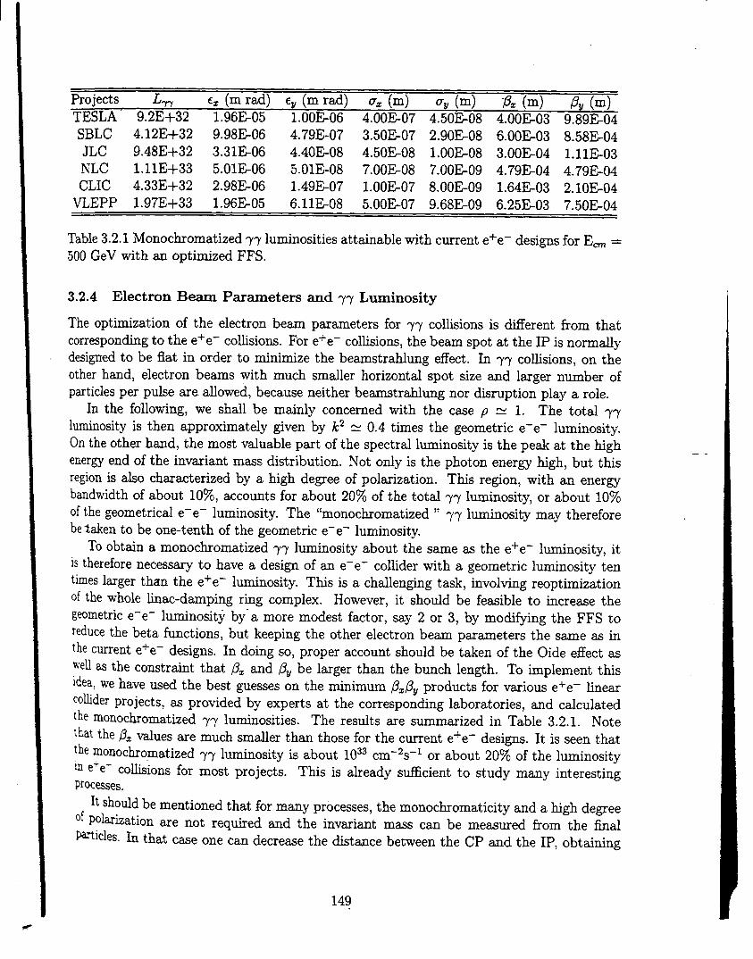
Projects LW c= (m rad) eV (m rad) 0= (m) ~g (m) p= (m) PY (m)TESLA 9.2E+32 1.96E05 1.00E06 4.00E07 4.50E08 4.00E03 9.89E04
SBLC 4.12E+32 9.98E06 4.79E-07 3.50E07 2.90E08 6.00E03 8.58E04
JLC 9.48E+32 3.31E06 4.40E08 4.50E08 1.00E08 3.00E04 1.11E03
NLC 1.11E+33 5.01E06 5.OIE-08 7.00E08 7.00E09 4.79E04 4.79E04
CLIC 4.33E+32 2.98E06 1.49E-07 1.00E07 8.00E09 1.64E03 2.1OEO4
VLEPP 1.97E+33 1.96E05 6.llE-08 5.00E07 9.68E09 6.25E03 7.50E04
Table 3.2.1 Monochromatized ~~ luminosities attainable with current e+e- designs for Em =
500 GeV with m optitized FFS.
3.2.4 Electron Be- Parmeters and ~~ Luminosity
The optimization of the electron beam parameters for ~~ collisions is d~erent from thatcorresponding to the e+e- co~sions. For e+e– collisions, the beam spot at the IP is normdydesigned to be flat in order to minimize the beamstrahlung effect. In ~~ co~sions, on theother hand, electron beams with much smaller horizontal spot size and linger number ofparticles per pdse are dewed, because neither beamstraMung nor disruption play a role.
In the following, we shall be mainly concerned with the case p R 1. The total ~~luminosity is then approximately given by k2 = 0.4 times the geometric e-e- luminosity.On the other hand, the most valuable part of the spectral luminosity is the peak at the highenergy end of the invariant mass distribution. Not ody is the photon energy high, but this
--
region is dso characterized by a high degree of polarization. This region, with u energybandwidth of about 10%, accounts for about 20% of the total ~~ luminosity, or about 10%of the geometrical e-e- luminosity. The “monochromatized “ ~~ luminosity may thereforebetaken to be one-tenth of the geometric e-e- luminosity.
To obtain a monochromatized ~~ luminosity about the same as the e+e- luminosity, it
is therefore necessary to have a design of an e-e- colhder with a geometric luminosity tentimes linger than the e+e– l~inosity. This is a chauenging task, involving reoptimizationof the whole ~nac-d~ping r~g complex. However, it should be fe~ible to increase the
gwmetric e-e- luminosity by” a more modest factor, say 2 or 3, by modifying the FFS toreduce the bet a functions, but keeping the other electron beam parameters the same as inthe current e+e- designs. In doing so, proper account should be taken of the Oide effect as
~e~ = the constraint that ~z and BV be larger than the bunch length. To implement thisl~ea, we have used the best guesses on the minimum @z~Vproducts for vmious e+e- tinearco~der projects, as provided by experts at the corresponding laboratories, and cticulatedthe monochromatized ~y luminosities. The results are summarized in Table 3.2.1. Notethat the ~z values are much smaller than those for the current e+e- designs. It is seen that
the rnonochromatized ~~ luminosity is about 1033 cm–2s–1 or about 20% of the luminosity~ e-e- co~sions for most projects. This is tieady sufficient to study many interestingProcesses.
It shotid be mentioned that br many processes, the monochromaticity and a high degree‘~ POl~ization are not required and the invariant mass can be me~ured from the final
~~icles. In that case one can decrease the distance between the CP and the IP, obtaining
149

a tot~ ~~ l@nosity larger by a factor 3 or 4.As the y~ luminosity is not ~ted by co~sion effects, it is worthwhile to opt-
the damping ring designs for a smaller horizontal emittance. This should res~t ~ ~ ~luminosity several times larger than that obtained above.
Incre~ing the number of particles per bunch at a reduced ptise repetition rate WN ~herincreme the ~~ luminosity. This will dso relw the requirement on the average l=er power.
but wi~ require a detailed r~optimization of the hnac~arnping ring complex.
3.2.5 FFS
As was stated in the preceding section, the value of the beta functions used in Table 3.2.I
were best guesses by experts and need to be verfied through a detailed FFS design. Itshould be noted that, for most c=es, the focussing is much stronger in the z-direction mdsomewhat weaker in the y-tiection than is the case for the corresponding e+e– desi~, ~that ~Z and PV are similm in ma~tude. An FFS producing such focussing wodd probablyinvolve a find triplet, rather than a doublet, of quadruples. A design of an FFS for ~~
collisions at the NLC is currently under way.
3.2.6 Laser Optical Path
Designing a high power optical transport system leading to a tight focus at the CP, whilesatisfying various constraints imposed by pdicle detectors, electron transport hardwue, the
coil arrangement for the sweeping magnet if employed, and so on, is one of the major t~ksin designing a ~~ cofision region. Figure 3.2.2 illustrates a possible mirror mangement forthe ~~ cofision region of the NLC. The figure shows the inner radius of the vertex chambersurrounding the IP, the conical mask, the quadruple holders indicated by two cyhnders,the incoming electron beam path indicated by a line nearly parallel to the MS, and theoutgoing, disrupted electron bem path indicated by a narrow cone emanating from the IPnext to- the incoming beam pat h. The smd e~iptical objects are the mirrors, the numbersindicating the path of the l~er beam in time. One of the laser beam enters para~el to theMS from the right, incident on mirror 1 wd deflected to mirror 2 (located at the edge ofthe quadruple holder, at a symmetry point of mirror 9 on the left side), incident on mirror3 and deflected to mirror 4. The l~er beam until this point is wide. The beam is thenfocussed to a spot a smti distance away from the top edge of mirror 6, thus avoiding it.The beam further propagates to ~ mirror 5, reflected and focussed to the CP fwing the
incoming electron beam from the right. The liner beam further propagates and Ns mirror6, reflected and focussed now to a spot a small distance away from the bottom edge of mirror5, thus avoiding it. The beam propagates further to mirrors 7, 8, 9, and 10, and exits to theleft.
Mirror 5 has two holes, a smd one for the incoming electron beam and a larger oneto accommodate the 10 mr an~ar cone of the outgoing disrupted electron beam. The laserprofle is designed so that the intensity profile incident on mirror 5 is uniform over the surfaceto tinimize loss from t%e holes. An ~/10 optics is used for focussing the l~er beam to theCP, which is an optimum condition for the conversion efficiency. Mirror 6 is identicd tomirror 5. This mirror mangement is symmetric with respect to the IP.
150

----------.,..
....
---.-—
..-.
--

I
Another l~er beam enters from the left fo~owing a path symmetric to the beam co~ngfrom the right, nemly overlapping the exiting beam. The exiting beam should be prevented
from entering the laser amphfier.It is ~surned that the mirrors wiu be of dielectric materi~ ~th stitable multilayer
coatings developed for high power laser systems. The problems of the power loading andradiation damage need to be caretily studied in the future.
A laser path arrangement in which a laser pulse is reused several times wi~ greatly reducethe optical power requirement. Several multipass schemes have been proposed, for examplean arrangement involving confocd cavity arrangement. Practical implementation of theseide~ appears to be ~ctit in view of the tight geometry of the interaction region, and thenecessity to preserve the picosecond time structure of the optical ptises.
The coil for the sweeping magnet, which is not shown in Fig.3.2.2, may sti~ be accom~dated. There are also schemes where the sweeping magnet is not employed.
3.2.7 IP Issues
The energy of individud electrons after multiple Compton backscattering may be as low as
3% of their initial energy. Low energy electrons will be deflected up to an angle of about10 mrad because of collisions with the opposing electron beam. The crossing mgle shoddtherefore be larger than 10 mrad plus an additional angle to clear the quadruple face. Forthe NLC, the crossing angle for the ~~ cofision is taken to be 30 mrad. Crabbing theelectron beam is therefore essential for a ~~ coltider. The effect of the solenoidd field on -beam co~isions with a large crossing angle dso needs to be studied.
To obtain good monochromaticity of ~~ collisions and clean ~~ or ~e- events, it isdesirable to sweep the spent electrons by an external magnetic field. The magnetic fieldshould extend longitudinally to about 1-3 cm with a strength 0.$2 T. The sweeping magnet “could be either a superconducting or a pdsed magnet. It is important that the magnetpresent a minimum obstruction to the detector. A plasma lens to overfocus the spent electron
beam has ako been proposed. This scheme must inject gases to produce the plasma and&oremove them from the interaction region. Another proposal is to arrange the electron beamsto repel and miss each other entirely in “ a heads-up “ colfision, in which the front ends ofthe electron beams before the CP are displaced by a few vertical beam sizes to stimdatebeam-beam instabilities. For this scheme to work, the electron beam intensity needs tobe much higher than that contemplated in most finew collider proposah. It may also bepossible to mitigate the effect of the spent electron beam by introducing a sma~ offset inthe vertical direction, about one rms beam size, in the overlap of the two beams at the IP.Such an offset wotid have only a small effect on the ~~ luminosity, w~e reducing the e-e-luminosity sigticantly because of the beam-bea disruption. However, the background dueto e-~ luminosity is a serious problem of this scheme.
Developing codes which wi~ simulate the entire complex of CP and IP physics, includingmultiple Compton scattering and other QED effects such as beamstrtiung, is an urgenttrek. Such a code hm- beep developed at Novosibirsk and appears to work we~. Anothercode, CAIN, is uder development by the NLC ~oup and by the JLC group. It is desirablethat several codes be avdable so that simdation results can be crosschecked.
152

I
3.2.8 Laser Technolo~
As we have seen in Section 3.2.3, the optical beam for ~~ or ~e- co~ders consists of asequence of TW micropulses, each a few ps long, with an average power of tens of kW.Udess mdtipass optics can be used in the interaction region, these are the requirements forthe lasers.
Lasers with TW peak power and picosecond pfie len@h have been built using chirpedpuke amp~cation and compression techniques. However, the maximum average power of
these lasers is, at present, only about 10 W. On the other hwd, solid state CW lasers pumpedby diode arrays producing 500 W have also been built. It maybe necessary to combine thesetwo te~nologies, for example, by pumping a Nd-glass laser with diodes, which could inturn pump a broadb=d Ti:Saphire l~er whose pulse can then be compressed. The mainchallenge wodd be the power handfing capability, which may be solved by techniques suchas a moving slab(or disk) geometry of the arnp~er, phase conjugate tirrors (or adaptiveoptics), dielectric gratings, etc.
free-electron lasers(FEL) are another option for photon coltiders. Several schemes havebeen proposed based on different combinations of FEL osciUators, amphfiers, and opticalswitching techniques. A scheme based on the chirped ptise amp~cation and compression,sitiar to the technique used in sofid state lasers but replacing the amphfier with an FELdriven by h induction linac, is another attractive option. In the pmticd= case of CLIC, theavtibility of a 3 GeV drive beam at high charge per bunch offers an interesting possibilityof simple adaptation to a ~~ or ~e* co~ider. The first bunch is used for polarized light
mplification by an FEL in an appropriate wiggler. The amphfied fight is then converted-.
into a polarized ~ beam by Compton backscattering on the incoming electron beam close tothe I.P.
3;2.9 Conclusions
With a relatively small increment~ cost and relatively straightforward modification, the
Physics capabtity of a future e+e- collider can be enhanced significantly by providing ~~CoMsions~th a monoc~omatized l~inosity of about 1033 cm-2s–1 (and by a factor 3more for ~e- co~sions). -A higher l~inosity is feasible by re-optimizing the colhder systemdesi~s. At present, l=ers ad the ~sociated optics for terawatts of peak power and kilowatts
of average power, suitable for ~~ co~ders, are being ~tively pursued for various other e+e-Physics applications. Many relevant and cha~enging issues in ~~ co~der design may bek\’estigated bY a cost efiective up~ade of the SLC. Therefore, with strong support from
the HEP physics community, a ~~ co~ider with the potential for fundamental physics not~Cessible to, and with higMy desirable redundancy of the data from these e+e– collisions,aPPeas to be both a tantalizing and realistic possibihty.
153

II4 EXPE~MENTS md TEST FACILITIES
I This chapter gives a summary of the purpose and status of W the Enear col~der experimentsand major test facfities currently under development d over the world. They are presentedin the fo~owing order:
I1. The Final Focus Test Beam (FFTB) at SLAC
2. The TESLA Test Facflity (TTF) at DESY
3. The S-Band Test Facfity (SBLC TF) at DESY
4. The Accelerator Test Facitity (ATF) at KEK
5. The Next Linear Collider Test Facility (NLCTA) at SLAC
6. The VLEPP Test Facfity (VTF) at BINP
7. The CLIC Test Facilities at CERN
8. The Relativistic Two Accelerator (RTA) Test Facifity at LBNL
I At the end of the chapter, Table 4.1 summarizes the work that h= aheady been achievedand what remains to be learned at these various facilities.
4.1 The Final Focus Test Be- (FFTB) at SLAC
With the successti operation of the SLC starting in 1990, it became apparent that a TeV-scde kear cofider was feasible. It abo became apparent, however, that d concepts for sucha co~der required that beams of electrons and positrons be focused to dimensions at least oneand perhaps two orders of magnitude sma~er than in the SLC. A collaboration was formedto e@eriment~ly address this problem. The Final Focus Test Beam Collaboration, m it h=come to be ca~ed, consists of scientists from the Budker Institute (BINP), DESY, Fermilab,KEK, LAL (Orsay), MPI (Munich), and SLAC. The collaboration designed a beam hne to beinstalled at the end of the SLAC hnac to demagnify the SLC beam by factors consistent withthose needed for my TeV-s~le colhder. The Find Focus Test Beam (FFTB) was built fromcomponents desi~ed ~d fabricated by the laboratories of the participating institutions and
~dustries in the respective countries and brought to SLAC for instdation and testing in theFFTB beam channel. Construction of the FFTB was completed in 1993, and commissioningad scientfic investigation of its properties began shortly thereafter. A layout is shown in
Fig. 4.la.
Initial testing of the FFTB hardwme and software took place during the Fdl and Springof 1993/ lgg4. Durfig the latterput of the spring running, the SLC beam was dehvered
~ith a vertical invariant emittance of 2 x 10⁻⁶ rad-m, and was demagnified in the FFTBby a factor of N 320 to a height of 70 nm. This resdt was close to the design go~ of
‘be e~eriment (50 nm). Experimentation with the FFTB continued in the Fdl of 1994.Mttied studies of the geometric and-chromatic properties of the lattice were made that‘ev~ed good agreement with the expected behavior.
~~~mement of the smti FFTB beam spot is a difficult cha~enge. Two monitors have~u desi~ed and btit to do this job. One monitor built by KEK md Kaw~&i Heavy
I 154

SLC
Quadruples Dipoles Final Quads
&w Fig. 4.la Final Focus Test Beam layout. 67~M
—
250
200
II I I I 1 I 1 t I-0.8 -0.4 0 0.4
Electron Beam Vetiical Position (~m)
Fig. 4.lb Memurement ofverticd height of the beam at the FFTB focal point with thelaser-Compton spot monitor. The observed fringe spacing agrees well with the 0.5 micron
expected from the wavelength of the liner. The beam height is 73 nm in this case.
155

I
kdustfies uses a l-er be~ that is sp~t ~to two P@S. The restiting beam tie brought backinto coherent interference ~th ewh other at the bem fine where an optical fringe patternis created. The electron be~ is scmed across t~s pattern. The resulting moddationof Compton-scattered photons is used to determine the beam size. An example of such ameasurement is shown ~ Fig. 4. lb. A second monitor designed and built by the ~OUpat LAL (Orsay) usesthe interaction of a gas Wimuthdy surrounds the focal point is usedto detect the ~i~ of HE or ~ ions created in the interaction of the beam with the gm.Measurements of the flight tfies ~d azimuthal distributions of the ions are used to recreatethe density and shape of the electron spot. Estimates of the beam size made by the twomotitors agree weu, and serve to provide confidence in the performance of the FFTB.
The FFTB Collaboration wiU continue to conduct experiments with the beam tine over
the next yem or so. Further investigation of the optics of the lattice WN be made, and
a number of studies of the stabfity of the beam spot are planned. New rf beam positionmotitors me being constructed to dow memurement of the position of the beam centroidto a few nanometers. This system of monitors wi~ a~ow studies to be made of the pdset~ptie motion of the beam spot, and shodd provide a good first look at the problems inherentto co~iding nanometer-size beams.
4.2 The TESLA Test Facility (TTF) at DESY
The TESLA Test Facility (TTF) under construction at DESY (Fig. 4.2) by an internationalco~aboration is an R&D test bed for the superconducting cavity approach to future TeV-scale ~near cotiders. The main body of the TTF linac will consist of four cryomodties, eachcontaining eight 1 m long nin~cell cavities made from bti niobium and operated at bbandfrquency (1.3 GHz). The MaStructure to process and test these cavities W= insta~edin 1993/1994. The facility includes a complex of clean rooms, an ultraclean water plantad S chemical etching installation for cavity surface preparation and cavity assembly, Wunder conditions of extreme clediness. To improve the cavity performance with respectto thermal conductivity, a firing procedure at 1400° C in an titra-high vacuum furnace is&o avtiable. An existing cryogenic plant has been modfied to cool down the cavitiesbelow 2° K ~d to mea~e them in vertical and horizontal test cryostats. The rf powerfor the fin~ wi~ be provided Gy two 4.5 MW Mystron-modtiator systems (pulse length
~~). One system is Wo being used for a high power rf treatment to further improve cavityperformance by eliminating potential sources of field emission. The whole infrastructure has&n com~ssioned Wth two prototype cavities, both surpmsing the TTF god of 15 MV/m
at Q = 3x10⁹. (The find Tesla 500 GeV cm. machine goal is 25 MV/m at Q = 5x10⁹).Thrw ~ditional prototype fiv&ce~ ca~ties have been test~ at CorneH and have achieved
Ueater thm 25 MV/m at Q greater than 3x10⁹.For be~ tests ~th the fist c~omod~e, a first injector wi~ be installed in 1995 and
‘1~ Protide 8 mA beam current within a 800 ps long macro pulse. Bunch structure for‘~ ~jector is at 216 MHz. An electrostatic gun is combined with a buncher cavity and a~~d~d TESLA superconducting cavity preaccelerator.
A s~ond injector breed on ~ liner-driven rf ~ combined with a bunch compressor
k ~der development. This injector wi~ need to operate with a buch charge of 5x10¹⁰d~trons at 1 MHz buch spacing and again a macrop~e length of 800 ps.
156

\
\o
—\ n ml II ——nHe- Pwilier
Fig. 4.2 TESLA Test Facility builciil]g.

I
i Beam analysis mess are provided to study both injected and high ener~ output beasinexcessof 500 MeV.
The main pwpose of the test facflity is to demonstrate the feasibihty of superconductingtechnology. This includes that these test cavities can be rehably constructed to achieve
I gradients of 15 MV/m or greater, and that they can be successftiy =sembled and operatedto provide the accelerated beam in the TTF finac. Experience gained in the construction willaho provide information for cost estimates of the TESLA 500 GeV cm. machine. Si@cantimprovement over existing installations in performance/cost ratio must be demonstrated.
Specific technical issues to be addressed in the TTF beyond retiable high-gradient, high-Q operation are: low heat leak cryostats, alignment stability of the cavities and quadrupleswithin the cryostat, pulsed rf operation and low level rf control, dark current, and with thesecond injector, HOM loss md wake field measurements. Additiond studies are underwayfor efficient rf generation and cavity fabrication cost reduction methods.
The whole TESLA Test Facility with the high bunch charge injector and a total of fourlow heat leak, low cost cryostats shodd be operational early 1997. Tests with the firstinjector and the first cryomodule me planed to begin at the end of 1995.
4.3 The S-Band Linear Collider Test Facility (SBLC TF) at DESY
The S-Band Linear CoUider Test Facifity under construction at DESY will serve as a testbed for the necessary technical developments of a large scale 500 GeV cm. S-band hnearcofider. The test facility consists of two modtiar units sirnilm to those that would beinstalled in a tines colfider tunnel (Fig. 4.3). Although S-band Enear accelerator technologyis we~ accepted and used around many laboratories, the demands placed on an S-band finear
cofider are not a simple extrapolation from any existing accelerator, not even the SLC atSL_AC. Two main re=ons lead to the decision to build and operate an S-band test acceleratorat DESY.
The parameters being proposed for the line= colhder technology, even if they are basedon we~ proven and etisting finacs, have been pushed to what we tti are the hmits whichcan be achieved within the next few years. EspeciWy for the Mystrons and modtiators, thepeak power is more thm twice as high M that of the 5045 klystron being used at the SLCright now. Because the modulators and the Mystrons must be fabricated in large numbers,retiable operation must be proven and the costs for production have to be estimated. A ded-icated test accelerator wfll provide the possibility of proving the feasibihty and to a certainextent the retiabihty of these components. In addition, an injector is being installed andcommissioned which will produce the fu~ charge bunch train with different bunch-t~bunchspacings (Fig.4.4). However, the small emittance, the bunch length and the single bunchenergy spread required for the hnear co~der cmot be achieved. Open questions concern-ing the stabi~ty of a flat beam in a 15 km-long $band finear accelerator have ody beeninvestigated by computer simulation so far. mile with the SLC single bunch instabilitieshave been investigated experimentdy in great detail, the mtitibunch operation required inthe SBLC wi~ lead to strong cumdative effects of the beam break-up type if the higherorder modes (H OM’S) are not &ontrolled from the beginning in the design of the acceleratorstructure. For this purpose, HOM excitation, damping using HOM couplers and internalloads WM be studied. The measurement of the HOM’S through the HOM couplers will have
I 158

.,..,.
la..

I3 -------
u 190061
DEW-MIN . . ! =, ! :W g=-,** ~-
1*.-
Wo 2000 3900 2200 2>00 2600 ?%00 ?600 I1700 7800 ?900 3000 3!00 9200 3300 %00 ?500 3600 >700 380C
--
Fig. 4.4 Sketch of the injector set-up of the S-band test facifity up to the injection into thefist sk-meter accelerator structure.
--
160.

to provide the possibihty of using a mechanical feedb~ with microrno~ers -at two SUPpo~-ing positions of the accelerating structure near the front and the b~ end. Ground motionfeedback loops, mdtibunch energy compensation sfiemes ~d buch to bmch monitors w
*O be investigated.while a large fraction of the injector is a~eady being setup and tested, beam wceleration
to the tial energy of 450 MeV will not t~e pl~e before lgg7. The first Mystron instdedat the test facility has Weady been operated at 150 MW ~th a 3 PS p~se length and arepetition rate of 60 Hz. The fist modulator is uder construction wtile the second oneis under preparation. Many components, such = the qua~upoles, beam position monitorsand beam diagnostics, etc., are under construction.
4.4 The Accelerator Test Facility (ATF) at KEK
The Accelerator Test Facitity (ATF) at KEK consists of three major puts: an S-band injectorkac, a damping ring, and a bunch compressor (Fig. 4.5). Each part directly contributes tothe development of technologies relevant to Mgh luminosity finear co~iders. The ATF wi~verify the fe~ibitity of the mtitibunch scheme (putting many bunches in one rf pulse) inall parts born the injector to the bmch compressor. The multibunch scheme is essential toboost the rf-t~beam transfer power efficiency in the acceleration, and wi~ be used in mostdesigns of future Knear colhders. The ATF wi~ generate, =celerate, damp, and compress atrain of 20 bunches with 2 x 10¹⁰ electrons/bunch and 2.8 ns spacing. The amount of totalchmge per train will be about hti of the 500 GeV cm. JLC design, but is enough to test itsfemibfity. The ATF h= tieady produced some of the b-it technologies for the mdtibunchscheme, such m a multibunch therrniotic gun, a mdtibunch buncherj and a choke-mode S-
band damped accelerating structure. The ATF wfi continue to help develop ad test manytechniques to hande the mdtibunch beam. One is the beam loading compensation system ‘in the injector hnw. A new idea using two rf sidebands wi~ be app~ed to compensate thebunch-t~bunch energy deviation due to beam loading. A newly developed damped cavitywill “suppress the coupled-bunch instabilities in the damping ring. A new simtitaneousinjection-extraction system for the damping ring wi~ solve the problem of transient beamloading due to mdti-t~ain- operation in the damping ring. The beam loading in the bunchcompressor wiH be compensated by a higher harmonic rf system (Cband).
The contribution of the ATF to provide a beam with an extremely smti emittance iseven more exciting. The goal is to achieve a norrn~ed emittance of 5 pm horizontal and
0.03 pm vertical and a 100 pm bunch length for the mdtibunch beam. The smd spot size atthe interaction point requires smd emittances and strong foc~ing. The damping ring is thenecessary ~d s@cient tool to refize such a sma~ emittmce since there is no mechanism
to damp the beam during acceleration in the linac. The sm~ emittance horn the dampingring will be achieved by speci~ design of a strong focusing lattice with precise afignment ofcomponents and beam orbit control. The no~nem behavior of the b- wiu have to be we~understood to provide enough dynamic aperture under such strong focusing conditions. Sincethe beam intensity is very high because of the multibunch scheme, an mconventional designis necessary for the rf cavity and the vacuum chamber in order to reduce the impedance andmaintain the smau emittance. The ATF damping ring wi~ operate at 25 Hz with 2 to 5 bunchtrains, 10 to 60 bunches/trti and 1 to 3x 101” particles/bunch. The buch sp~ing a be
161

Fig. 4.5- The Accelerator Test Facility (ATF) at KEK.
--

-2.8 ns and the train spacing 60 ns. New idea for the mtitibunch sin-d-emittance b- !will dso be tested in the injection/extraction system, m we~ u b~= lo~ng compemationand beam diagnostics. Strong focusing of the beam W inevitably require a short bunch Ito reduce the depth of focming (smd ~-function). The short bunch wi~ be produced bYthe bunch compressor. The bunch compressor wi~ be p~icularly ch~enging since it Wconsist of a single stage device with a huge (1:50) compression ratio. I4.5 The Next Linear Collider Test Accelerator (NLCTA) at SLAC
The Next Linear CoUider Test Accelerator (NLCTA) is a prototype figh-grtient X-bandlinac that is being built at SLAC to integrate the new technologies of X-band rf systems andaccelerator structures being developed for the NLC. The NLCTA wi~ serve x a test bed asthe design of the NLC evolves, and wi~ provide a model upon which a refiable cost estimatefor the rf system of an NLC can be based.
The NLCTA, which is 43 m long, is suounded by concrete shielding and consists ofan injector, chicane, finac and spectrometer (Fig. 4.6). The injector cent sins a therrnionicgun, two X-band pr~bunchers, and two 0.9 m long X-band (capture and premcelerator)structures. It ti generate a 126 ns long train of 74 MeV bunches with an average currentequal to that of the NLC design. The bunch spacing wi~ initidy equal the rf wavelength,
88 ps, and wi~ be incremed to the NLC design due of 1.4 ns by upgrading the injector (theaverage current wi~ remain the same).
Downstream of the injector, the beam will p~s through a chicane where its transverse _ .and longitudinal phase space will be truncated using colhmators. The restiting beam wi~then traverse six 1.8 m long X-band accelerator structures. These structures and thosein the injector wti be built to suppress beam induced long-range transverse wakefields byeither detuning the ce~ dipole mode frequencies, or by a combination of detuning and modedamping using manifolds that couple to d ce~s.
The sk tinac structures and two injector structures will initidy be powered in pairs by50 MW klystrons whose peak power wi~ be quadrupled by SLED-II rf pdse compressors.This wifl restit in a hnac accelerator field gradient of 50 MeV/m which wi~ be loaded to
37 MeV/m at the notind beam current of 6.5 x 10⁹ electrons per 1.4 ns. The Mystronmodtiators are being designed to wcommodate a future energy upgrade in which each ofthe 50 MW tubes will be replaced by two 75 MW tubes. The additiond rf power til incre~ethe beam ener~ by W to about 800 MeV at the end of the hnac for operation with a Whigher beam current to produce the same 25% fractional beam lo~g. This upgrade pathpardeb that plmed for the NLC linac to incre~e its energy...
Fo~owing the linac, the bunch train will pus though the spectrometer region to a beamdump. A pulsed kicker magnet wi~ sepmate the bunches verticdy so that the variation inbunch-t~bunch energy can be memured from the beam protie after the spectrometer dipolema~et. For this and other measurements, devices to monitor beam she, length, position,
ph=e and intensity ti be located throughout the beam tine.An important god Qf th~ NLCTA experimental program is to veri~ that rf puke shaping
can be used to offset the 2570 trasient beam loading in the kac accelerator structures to thedesired O.1% level. The pdse shaping ti be achieved by feedback controlled amplitude andph~e modtiation of the klystron rf drive, and wi~ be verfied by the spectrometer energy
163
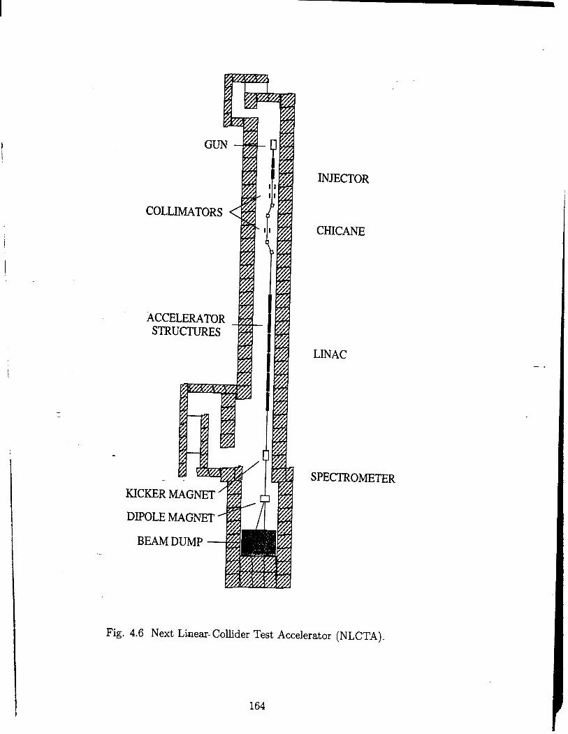
I
I
I!
I
..
I
GUN 4
COLLIMATORS ~
ACCELERATOR ~STR[
~C~R MAGNET
+/
c
DIPOLE MAGNET
BEAM DUMP
NECTOR
CHICANE
LINAC
SPECTROME~R
Fig. 4.6 Next Lhear- Colhder Test Accelerator (NLCTA).
164

4.6 The VLEPP Test Facility (VTF) at BINP
The VLEPP Test Facihty (VTF) is currently under construction in Protvino. The VTF
site is a 25 m-long, 5 m-diameter tunnel contained within a 1 m thick concrete shieldbg
wa~. One of the mtin gofi of the VTF is to test and operate an integrated VLEPP X-band fin= module. This modtie consists of a DC high voltage system, an rf system andhigh-~adient accelerator structures. Aho, to be tested at the VTF are the components ofan adaptive feedback tignment system, thermal stabilization, electronics, etc. The VTFconsists of a 200 kV injector, one DC high voltage source feeding four basic 5 m-long linacunits, and a spectrometer. The fist 5 m-long basic units (klystron, two pdse compressors,four accelerator sections and quads) together with the injector and the spectrometer arenemly complete and insttied. During the next year, the main effort wi~ be concentratedon studying the DC high voltage system and the Mystron. The next step (1997-1998) wi~consist of high gradient and beam tests in the linac.
4.7 The Compact Linear Collider (CLIC) Test Facilities
at CERN
4.7.1 CTF1
CERN has built and is currently operating a test facility for hnear co~der studes (the CLICTest Facihty or CTF) to (i) study the production of short, high charge electron bunches
from laser i~urninated photocathodes in rf guns, (ii) generate tigh power 30 GHz rf pulses “by passing bunch trains through transfer cavities for testing CLIC prototype componentsand [iii) test beam position monitors.
The s~c~~ed CTF1 test-facihty hm been in a state of transition between 1994 and 1995.Fig. 4.7 shows a generjc layout of the f~ihty which includes some of the changes which took
place during this period. A 3 GHz l.$cell rf gun equipped with a liner-driven photocathodesand operating at 100 MV/m produces a bunched beam with a momentum of 4.5 MeV/c. Asolenoid at the outlet of the gun provides some focusing of the beam before it is acceleratedto 11 MeV/c in a Acell standing-wave gun-booster cavity. Final acceleration to 95 MeV/cis obtained using a 4.5 m long trave~ing wave section - a spare of the LEP Injector Linac(LIL) referred to as LAS. Ener~ is etiracted from the beam by a 30 cm long traveMng-wave section to provide short high power 30 GHz rf pdses. This power is in turn fed toa second identicd CLIC structure to produce high accelerating gradients. The deceleratedbeam then either goes through a prototype 33 GHz CLIC BPM system to a dump, or isturned through 180° by bending magnets at the end of the fine and r+accelerated by thesecond high-gradient CLIC section. The facifity can be operated in either single bunch ormtitibunch mode at a repetition rate of 10 Hz. Mdtiple bunches are made by splitting thelaser pdse into a train of pubes, spaced apart by 10 cm. The synchronized laser system hasbeen optimized at the fourth h~onic (262 nm) providing a mtimm energy of 0.5 mJ per
165
.,/
me~urements. Other experiments will examine structureemitted dark ttients, tramerse !
accelerating fields, and the effect of long-range transverse wakefields on betatron motion.

II
Ii
i
i
I
I
>aaz Schematic Layout of CLIC Test Facility
Laser
rf gun
3GHZw$~:es-s,’..:,g!;},,e..,,,,’F,.....:> --Qt\/,&., ,~, TR:
—-—.. . . . . . “-c..
~“’’””’’r--r< - 15m
TRS : 30 GHz CLIC structure
LAS: 4.5m 3GHz A~lemting ae~ionused os transfer structure
NAS: 0.7m 3GHz kcelerating sedonCAS : 30 GHz CLIC structure
used as accelerating structure
Fig. 4.7 CTF1 layout.
-.
166

p&e (before sp~tting) and a pulse length of 8 ps FWHH. The Cs2Te photocathod~ ~e
prep~ed in the laboratory and trmsported under vacuum and instded into the ~ ~~ga specidy desi~ed transfer system. Initial quantum efficiencies are t~icdy 57., &oPPing
to around 0.5 % after 250 beam hours. A maximum single bunch charge of 35 nC hm beent
obtained from the gun-booster tith a laser spot of about 10 ~ ~~eter. The length of theelectron buches is mewured with a streak camera using the photon beam produced bv the 1
.interaction of the bunch with either a transition rtiiation monitor or a Cerenkov mo~torAfter the gun-booster cavity, the length is typicdy 14 PS (FWHH). Signific~t amounts of30 GHz power can only be extracted from the CLIC section by using bunch trains. 76 MWhas been generated by a 48 bunch train containing 160 nC at the exit of LAS and 81 nC
at the exit of CAS (CLIC Accelerating Section). For this charge of 3.3 nC per bunch, thememured bmch length was o. N 1 mm. This power level corresponds to a decelerating fieldin the section of 124 MV/m (more than the CLIC nominal accelerating grtient). In 1994the mtium charge which cotid be dehvered to the power-generating structure w= limitedby w~efields and beam loading in LAS. By replacing this section by a much shorter (0.7 m)high gradient (60 MV/m) section (referred to as NAS), it is expected that this maximumchmge limit wfll be more than doubled. The accelerating field in the second CLIC structureis determined from the difference between maximum and minimum energy gain of the beamas its phme with respect to the beam-induced rf accelerating field is varied. The highest r~accelerating grdent obtained to date is 104 MV/m. With the ma~etic bunch compressorinstalled between the booster and the NAS section, a bunch of 15 ps (FWHH) at the gunexit ww compressed down to 3 ps (FWHH). The me~ured charge w= 10 nC. A new tighcharge 2.5-ceU rf gun wi~ be insta~ed later on in the yea.
-.
4.7.2 CTF2 I
The etisting CTF will be up~aded in stages during the period 199G1998 to a tw~beam test ‘linac resembling as closely as possible the red CLIC design. The proposed layout is shownin Fig.- 4.8. The drive beam train (44 bmches spaced at 10 cm) of 1 pC total charge wiUbe generated by the new 2.5-ceU rf w driven by the existing laser and wi~ be acceleratedto 55 MeV by two new 1 m long HCS (High Charge Section) high gradient (60 MV/m)TW structures. These structures, designed to minimize both beam loading and transversewakefield effects but abo working at two slightly different frequencies wi~ provide beam
loading compensation to reduce the energy spread along the train. After p~sing througha magnetic buch compressor, the bunch train is used to drive a string of CLIC transfer
structures (CTS). Each CTS in turn drives two CLIC accelerating sections with 40 MW,12 ns long, 30 GHz power ptises. The 1.3 nC probe bea simdating the CLIC main linacwi~ be generated by the existing 1.&cell CTF rf gun and liner and wi~ be accelerated withthe existing SAS section to 50 MeV before entering the string of 30 GHz high ~adient (80MV/m) accelerating sections. In order to minimize problems due to mistignrnents and atthe same time to simulate the CLIC twel cotiguration x closely as possible, both 30 GHzlinacs wi~ be equipped with the CLIC support and active pr~dgnment system which isnow based on the stretched-wire technique.
167

— —- ._.— ——--_. ——— .—— —
<1
A DEMONSTRATION OF THE TWO BEAM ACCELERATION SCHEME
IN THE CLIC TEST FACILITYI
3 GHz +f
48 MeVRF gun
100 MeV/mDRIVE
BEAM
3
PROBEBEAM
~i }\ 1\ SAS @
5: y:: 80 MeV/mb
9 320 Mev
3 GHz<
-12m-lOm >
SAS: STANDARD ACCELERATING STRUCTURECTS: 30GHz CLIC TRANSfER STRUCTUREHCS: HIGH CHARGE SECTIONCAS: 30GHz CLIC ACCELERATING STRUCTURE
II
Fig. 4.8 CTF2 proposed layout.
t

4.7.3 CLIC Ali~ent Test Facility I
An active tignment test facflity has been built in an wused Udergrbund twel at CERN Ito study the fe=ibifity of making controlled submicron displmements and to try out tign- f
~ ment systems. The structures to be tigned, dummy wcelerating sectio~ for the moment,are supported by V-blocks on 1.4 m long sificon carbide girders. The ends of two adja- b
cent girders sit on a common platform which ensures continuity of position between units.The platforms me activated by three stepping-motor-driven precision jacks (two in the ver- ttical plane for vertical displacement and tid rotation, and one in the horizontal plane). #Movements of the set-up are monitored by finear and angular displacement tr~sducers (0~1 ‘micron md 10 microradian resolution resp=tively). A stretched wire runtig along the tisof the structures and passing through cap~itive position transducers where the BPMs woddnormdy be placed is used to simuIate the beam. The set-up is controUed remotely from asmd computer. After deliberate mistignments of lmm, the system which is progr~edfor automatic tignment with respect to any of the transducers, settles back to nominal P*sitions within <1 micron. The set-up is ako being used to test a new optical pr~ahgnmentsystem, developed by NIKHEF in Amsterdam, for use before injection of the beam. Theimage of a squareshaped red fight source is focused on a fight-detecting four-quadrant ceUby a ttin lens. Displacements of the source, lens or four-quadrant cell out of the optical MSof the instrument produce an imbalance at the detector. This system has been incorporatedinto the six ho~ow support girders of the test modtie and enables the relative positions ofthe far ends of two adjwent girders to be maintained in position with respect to the idealstraight hne to <2 microns. This pretignrnent system is however un~ely to be used in _
CLIC because of potential radiation damage and W be replwed by a system based onstretched wires.
4.7.4 The CESTA and JINR Test Facilities
CoUaborations have been set-up between CERN and the Centre d’Etudes Scientfiques etTechniqu@ d’Aquitaine (CESTA) in Bordeaux (France) = well m with JINR at Dubna
(Russia) to study an alternative scheme of drive beam generation by direct bunching at 30GHz in an bduction Linac driven Free Electron Laser (FEL). In both laboratories, testfacihties are being prepared using existing inst~ations to the extent possible, to study andobserve the quality of the bunching at a few MeV. In a later phase it is plaMed to use thebunched beam to generate rf power with a CLIC transfer structure.
In CESTA, the Induction Linac, LELIA, provides a 1 kA, 50 nsec electron beam at 2 MeVwhich is tr~sported to a helicti wiggler specidy built for this purpose, where it interacts
with a c~propagating 35 GHz wave de~vered by a 120 kW magnetron. The beating of theelectromagnet ic wave and the wiggler magnetostatic field gives rise to ~ axial ponderomotiveforce -d a consequent bunching of the injected ptie. The bunching, however, might be
tiected by longitudinal space charge forces at this particdmly low energy.In Dubna, a sitiar experiment is in preparation, taking advantage of the 9.5 MeV
SILUND 21 Induction Linac made of seven moddes of 1.5 MeV emh. The detrimenteffects of spree charge in this c=e wi~ be sigticantly reduced.
169

I
4.8 The Relativistic
at LBNL
Two Accelerator (RTA) Test Facility
Construction of the Relativistic Two Accelerator (RTA) Test Factity has bew at LBNLto study physics, engineering, and costing issues of usirig Relativistic Klystro-n Two BeamAccelerators (RK-TBA) as rf power sources for finear colliders, We use the term TBNLC toreference the proposed l-TeV NLC upgrade using RK-TBA technology. All major comp~nents of the TBNLC rf power source wi~ be tested at the RTA. These components includethe induction gun, accelerator ce~s, chopper (beam modulator), pdsed power system, outputstructures, md the control system. However, due to fiscal constraints, the 25 m long RTAprototype wi~ ody have 8 rf output structures, with a possible upgrade to 12, instead of the150 envisioned for the TBNLC. ~o, the average beam energy in the main extraction sectionwi~ be ody 4 MeV insteti of 10 MeV. The lower RTA beam energy requires us to place theoutput structures and the focusing elements at a closer spacing than in the TBNLC design.The RTA prototype output structures are located every meter and wi~ generate 180 MWper structure. Tolerates on emittance growth and beam energy flatness are more severe in
the RTA than the ,TBNLC. A layout of the RTA Test Facitity is shorn in Fig. 4.9. Thisfacitity could dso be used to supply the rf power to the accelerating structures now beingstudied in the NLCTA Test Facihty.
Important issues to be addressed by the RTA me eficiency, longitudinal beam dynamics,beam stabifity, emittmce preservation, and rf amplitude ~d phase control. Efficiency canbe separated into the conversion efficiency of wdl plug power into beam power and beampower into rf power. A major component hmiting high conversion efficiency of w~ plug
power into beam power is the loss in the induction cells. The induction ce~s wi~ be testedwith a pulsed power system appropriate for the TBNLC design. This will aHow us to achievea good estimate of the wa~ plug power to beam power efficiency for the TBNLC.
_High conversion efficiency of beam power to rf power can ody be obtained in an RK-TB-A system with a large number of output structures. For the TBNLC, the number ofoutput structures will be limited by beam stabihty and transport issues. The direct study ofbeam dynamic? issues involving the beam transport through many tens of output structureswi~ not be possible with the prototype. However, the reduced beam energy in the extractionsection of the prototype wi~ permit the observation of akost an entire synchrotron period.
This will be sdcient to allow the beam to approach a steady state condition that can
then be extrapolated to a fu~ scale system with high cotidence. The verification of com-puter simtiations used to model the beam dynamics in the TBNLC wiU be a high priority.Beam dynamics issues related to transverse moddation, misahgnrnent of magnetic focusingsystems, tid adiabatic compression, e.g. emittance growth and corkscrew motion, can be
adequately studied.
--
170
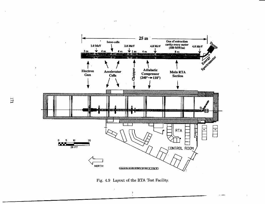
E
I mm
--
171
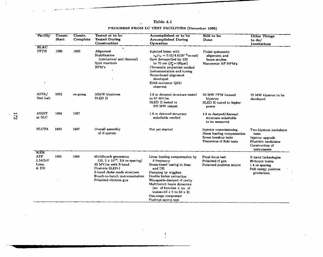
. - .-. —---- -.-””-””” ““.
Table 4.1(!PROGRESS FROM LC TEST FACILITIES (December 1995)
Wcility Constr. Constr. Tested or to be Accomplished or to be Still to be Other ThingsStart Complete Tested During Accomplished During Done
Constructionto do/
Operation LimitationsSLACFFTB
!
ASTA~Test Lab
ASSETat SLC
NLCTA
KEK
1989 1993
1992 on-going
1994 1997
1993 1997
Alignment Injected beam withStabilization
(mechanical and thermal)cv/ez = 0.15/4 .0(10 -6m-rad)
Spot demagnified by 320Spot monitors to 70 nm (flJ=100pm)BPM’s Chromatic properties verified
1 Instrumentation and tuningBeam-baaed alignment
I developedE144 nonlinear QED
observed
50MW klystrons 1.8 m detuned structure testedSLED II to 67 MV/m
SLED 11 t-ted to205 MW output
Overall assemblyof rf system
1.8 m detuned structurewakefields verified
Not yet started
Finish systematicalignment andbeam studies
Nanometer RF-BPM’s
50 MW PPM focusedklystron
SLED 11 t=ted to higherpower
1.8 m dampsd/detunsdstructure wakefieldsto be measured
Injector commissioning
75 MW klystron to bedeveloped
Tw~klystron modulatorBeam loading compensation tatsBeam breakup tests Injector upgrade~ansverse rf field tests Blumlein modulator
Construction ofinstruments
ATF 1992 1996 Multibunch generation Linac loading compensation by Final focus teat X-band technologies1.54 GeV (20, 2 x 10¹⁰, 2.8 ns sp~ing) 6-frquency Polarized rf gun 9@bunch trainsLinac 33 MV/m with S-band Beam-based tuning in linw Polarized positron source 1.4 ns spacing& DR Dual-iris SLED-I and DR Full energy positron ~
S-band choke mode structure Damping by wigglers productionBunch-t* bunch instrumentation Double kicker extractionPolarized electron gun Waveguid&damped rf cavity
Multibunch beam dynamics(no. of bunches x no. of
trains=10 x 5 to 60 x 2)One-stage compr~orPositron source test
.—

(1
Table 4.1 (continued)
PROGRESS FROM LC TEST FACILITIES (December 1995)
Facility Constr. Constr. Tested or to be Accomplished or to be Still to be Other ThingsStart Complete Tested During Accomplished During Done to do/
Construction t Operation Limitations
BINPVLEPP 1992 1997 60 MW klystron High power test of structure 120 MW gridded-gun X-band technology
400 MeV 1 MV DC voltage system High power test of VPM klystrons with Single bunch dynamicsVPM (rf pulse comprsn.) Alignment PPM focusing Cost estimata
1 m structur- Super-preciza BPM’s Feedback system5 m submodule ;f VLEPP Micromoverz
CERN-CLICCTF1 , 1989 1995 RF gun photoca~hode
Laser systemShort bunch measurement,
,30 GHz accel. structures
CTF2 1996 1999 New 2.5 cell RF gun3 GHz accelerating sections
adapted to high charg=
Demonstration of twmbeam principld Beam loading compensationGeneration of 35 nC/b, 76 MW 30 GHz power Bunch compression with trainsNo 30 GHZ breakdown up to E= 125 MeV/m, obtain 30 nC with u.=2ps(E) =94 MeV/m in CLIC SCC. section%ting 33 GHz BPM & 30 GHz transfer sectionBunch compression (ltiC, a, = 2 psec)
Not yet started Beam loading compensationwith trains
Bunch comprwion1 MC (48 bunch=)30 GHz reaccel. to 320 MeVActive afignment systemWakefield studies
CESTA 1993 1997 Generation of bunched beam (1 cm spacing)
DESYSBLC 1992 1996 Modulator I tested Appropriate bunched beam generated Beam dynamiu of single and Machine too short
Test 150 MW klystrons I with compr~ion to 250 ps multibunch to study complete
Facility & 11 tated Qusdrupole vibration feedback successful, (125) trains with 8, 16, 24 ns eflects, filamentation, etc.
400MeV 6m sections with HOM with 12 dB attenuation spacing (300mA) Need RF pulse shapingROBAX-ceramic support between 1-20 Hz
Injector d=ign
to correct beam loading
BPM’s

%> ~ble 4.1 (continued)
g PROGRESS FRO’~ LC TEST FACILITIES (December 1995)
Facility Constr. Constr. Tested or to be Accomplished or to be Still to be Other ThingsStart Complete Tested During Accomplished During Done to do/
Construct ion Operation LimitationsDESYTESLA 1993 1997 Cavity gradient, Qo Not yet startd RF/Energy control Refine cost estimates ofTeat Processing steps Cryo heat leak, static, alternate designs forWllity Fabrication methods fundamental, HOM500MeV Lorentz force control
cavity fabricationAlignment stability High-eficiency klystron
Cryogenics, RF power Vibration, microphonics SMES ModulatorInjecto; design High-charge injection TESLA design
Long transv. wakes, Overall cost estimatessingle bunch, multibunch
Cavity misalignmentf Cryo procedures warm up/
cool down
4 In-situ HPPDark current, beam 1~
LBNLand radiation
RTA 1995 2002 Not yet started Cost and efficiency issuee in Performance and efficiencydrive-beam generation of an extended system
Beam transport and BBU limitsRF production and stability

II
5 PRESENT ad FUTURE AREASofCOLLABORATION
I 5.1 Introduction
As the reader wi~ have noted, internation~ and interlaboratory collaboration in the field ofe+e- bear cotider R&D is rapidly becoming a way of life. It shotid be stated, however,that while co~aborations are extremely desirable and usefti because they bring togetherinstitutions with diverse specialties and resources, and people with complementary talents,
forming these co~aborations is not always straightforwmd and generally requires a great dedof effort. The funding agencies and laboratory administrators shodd be encouraged to lendtheir support to such endeavors, wherever they emerge, because in the long run they canody help the global cause.
The purpose of this chapter is to bring together in one place fists of many of the in-
stitutions currently co~aborating with each other on hnear co~ider R&D. These fists meundoubtedly incomplete but they give a glimpse of how interwoven the fabric of collabora-tion’ hm become. Other opportunities for collaborations that may materitize in the future
are dso discussed.
5.2 List of Existing Collaborations
Institutions Collaborating with DESY on TESLA:
IHEP Academia Sinica - BeijingMax Born Institute - BertinTH - DarmstadtTU - BerUnUniversity of FrtifurtTU - DresdenFZ - KmlsruheGH - WuppertdSEFT - Helsinki - “CEA - SaclayLAL - OrsayINP - OrsayINFN - ~ascati, Milan, RomeUniversity of CracowUniversity of WmsawPohsh Academy of Sciences
JINR - DubnaIHEP - ProtvinoINP - NovosibirskCorne~ University - Ithaca -Ferdab - BataviaUCLA - Los Angeles
175

II
iInstitutions Collaborating tith DESY on SBLC:
TH - DarmstadtKEK - TsukubaSLAC - StanfordRWH - AachenINR - MoSCOWMEPM - MOSCOW
Institutions Collaborating tith KEK on JLC:
SLAC - StmfordIHEP - BeijingBINP - Novosibirsk/ProtvinoTohoku University (Laboratory of Nuclear Science) - SendaiTohoku G~uin University (Facdty of Engineering) - Miyagi
University of Tokyo (Institute for Nuclear Study) - TokyoUniversity of Tokyo (Nuclear Engineering Research Laboratory) - IbarakiTokyo Metropolitan University (Factity of Science) - TokyoNagoya University (School of Science) - NagoyaKyoto University (Faculty of Science) - Kyoto
Institutions Collaborating tith SLAC on FFTB:
BINP - Novosibirsk/ProtvinoKEK - TsukubaLAL OrsayMPI - Munich
~ DESY - HamburgFermilab - Batavia
Institutions Collaborating tith SLAC on NLC:
LBNL --BerkeleyLLNL - Livermore -KEK - TsukubaFermilab - Batavia
Stanford University Mechanical Engineering Department - Stanford
Institutions Collaborating tith BINP on VLEPP:
JINR -- DubnaIHEP - SerpukhovMEPhI - MOSCOWMSU - MOSCOWIM - NovosibirskKhPTI - KharkovSEFT - Helsinki - -
KEK - TsukubaSLAC - Stanford
176

..+I.
-.Institutions Collaborating tith CE~ on CLIC:
CEBAF - Newport NewsCESTA - BordeauxJINR - DubnaEwopean Network on Photocathodes and PhotoinjectorsINP - ProtvinoKEK - TsukubaLAL - OrsayLBNL - BerkeleyMIT - CambridgeSLAC - StanfordUniversity of Uppsala
There are, in addition, many people who w individuals co~aborate with institutions awayfrom their home b=es.
5.3 Other Possible ~ture Areas of Collaboration
Listed below are other are= of possible future collaborations:
Design and experiments on electron and positron sources:Mmost W the machines dl use complex high current souces capable of producing _
multibunch trains of polarized electrons and positrons, also polarized in certain cases. Thisresearch involves cathodes, liners, special vacuum systems, targets, timing systems and in-strumentation where mutual help is ahnost indispensable.
Damping rings and compressors: IThis is an uea where the ATF at KEK will serve the entire community. men commiss-
ioning begins, it is likely that scientists from all institutions WU spend some time on thatmachin~ since the resdts wi~ be important for everybody.
Linac technology: -While there is tieady btense collaboration on power sources, their focusing systems,
pdse compressors, structures, breakdown studies, alignment, fabrication methods, ttis effortcan ody increase. For those machines where pulsed moddators are used, progress in onelaboratory will be picked up everywhere else. The series of modtiator workshops, of whichthe most recent one w= held at SLAC in October 1995, is a good example of this type ofcooperative work. The NLCTA, as it is completed, ~ we~ w the test facilities at DESY andCERN, wi~ *O be focal points for design integration and mutual help.
Be= dynamics:So far, many of the discoveries regarding this topic have been experimentdy tested at
the SLC and the FFTB at SLAC. Also, M ide~ have come from elsewhere M for exampleBNS damping, the SLC w= used as the test bed. This wi~ probably continue for some time,but as the other test facfities are commissioned, mutual co~aboration of m experimentalnature wi~ grow at these new sites. Instrumentation such as BPMs, profile monitors, timingdevices, f~t kickers, l~er wires, W kinds of support and tignrnent devices and many others
177

1’
wi~ be needed, and it wi~ become essential to both shine and dividi the necessq ~dalways insticiently available mwpower. AS far as theory is concmned, most of the be~dynamicists tieady work together. An example where intense exchange of i~ormation is
currently taking place is the whole subject of ground stabifity and vibratiom.
~eam delivery:What has just been mentioned for beam dynamics a~o counts for the beam defivery
effort. Except for some dtierences in beam power and in the desired emittuces, ~ thebeam dehve~ systems are stiar. Colhmators, spoilers ~d long mrays of vev stable bend
and focusing magnets wi~ have to be developed whch will not differ too much from mm~neto machine.
Experimentation:Section 2.6 of this report was written as an international coUaboration. Since it is ~kelY
that only one or two detectors wi~ eventudy be needed, the collaboration will come together naturaUy as for detectors at other existing laboratories. This wiU be true for e+e-experirnents as well as for ~~ and all other variations. For ~~ in partictiar, such a hugearsenal of speci~ed technology wi~ have to be developed that it is inconceivable that anY
one laboratory cotid cmry the burden by itself. Who wifl do what cannot be determinedahead of time but that coahtions wiU be formed is a certainty.
5.4 List of P=t Linem Collider Workshops
Finally, for the record we fist here the LC (machine) and LCWS (physics) workshops that --have taken place in the p-t.
Accelerator Physics Linear Collider WorkshopsYear Workshop Location1988 LC88 SLAC1990 LC90 KEK1-991 LC91 Protvino1992 LC92 Gmmisch1993 LC93 _SLAC1995 LC95 KEK
Workshops Relevant to Particle Physics tith Linear CollidersYear W~rkshop Location
1987 SLAC Study Group SLAC
198819891990
1991199219931995
La Thuile CLIC StudyLCWS88First JLCWorkshopLCWS90Second JLC WorkshopEE500 WorkshopsCo~ding Beams-WorkshopsLCWS93LCWS95
CLICSnowmass, U.S.KEKSnowmass, U.S.KEKSaariseka, FtiandUs.Waikoloa, HawaiiMorioka-Appi, Japan
178

./-
In ad~tion to these general workshops, there are other more specihed on-going series
on rf somces, damping rings, fid foci, garnma-g~a, polarization tid others.
--
179

II
6 CONCLUSIONS
6.1 General Comments
Producing this fist report of the hternational Linear Cowder Technical Review Committee(TRC) has been a very chdenging and interesting coUective enterprise. Over my scientistsfrom seventeen institutions participated in this international endeavor. Whenever appropri-ate, the names of the people making soup contributions were shown near the headings ofthe various chapters and sections of the report. h contrast, the conclusions which appearin this last chapter were written by the TRC chairman alone, sanctioned however by theworking group chairpersons before the fid pubhcation of the report.
As requested by the charge hmded to ow committee, we have attempted to describe,assess and compare various technical approaches towards a single god, namely the design of a500 GeV cm. e+e- hnear coUider with a luminosity greater than 1033cm-2s-1, expandableto 1 TeV cm. with a luminosity of 1034m-2s-1. The process h- no doubt been very
educational for afl the participants, and together with the LC workshops, it has broughtan international community of scientists closer together, even if and when agreement on aparticulm issue cotid not always be reached without some hvely argument or discussion.
Where do we find ourselves at this juncture in the development of e+e- tinear colfiders?A great deal of progress has been made in the lmt two or three years and the process of
producing this report has further advanced and clarified many issues in our individud R&Defforts. It is sometimes claimed that if we W now joined forces, chose one of the five or sixtechnical approaches being worked on, and collectively concentrated on it, we would makeeven faster progress towards the single goal of a Conceptual Design Report and the eventualrea~zation of a large hnear co~der somewhere in the world. While this might be true, .choosing one particular approach over W others at this point wodd involve considerablerisk in case this single approach ran into Mctities or surprises, technical or fiancid. As it
turns out, the diversity of projects and test facihties we have created somewhat spontaneouslythroughout the world comunity is a good hedge against mistakes and, through competitionas well as co~aboration, it is producing a broad body of knowledge that benefits au of theprojects. Turning off ‘my “one of the approaches at this time wotid result in a collectiveloss. Hence, financial and technical support for dl the projects should continue vigorously,at least until the various test facilities begin to bem fruit and reveal the answers for whichthey were conceived.
6.2 Machine Groups
If we look at dl the various projects, we find that we can classify them into four groups,arrmged in order of ascending main hnac rf frequency:
1.
2.
3.
TESLA
SBLC, JLC (S-band) - -
VLEPP, JLC(X-band), NLC (with its possible future TBNLC option)
180
--

I 41
4. CLIC-.
JLC(Cband), ody supported to a modest extent in Japan, cotid be a hedge againstsurprises in group (2) or (3).
Given below is a short summmy of the overd characteristics of the four groups of ma-chines and the chdenges they face. One wotid hope that after Wher studies and mutualconstitutions, the designs of the machines in each group would coalesce.
Group 1 (1.3 GHz)
TESLA, done in group (1), is characterized by the lmgest IP beam spots (commensuratewith the spot measured at the FFTB, udess the repetition rate is reduced from 10 to 5 Hz
and the loss in ltinosity must be made up by sma~er spots), most relued tolerances,lowest wdefields and widely spaced bunches, which can be resolved e=ily and betweenwhich steering can be changed. This signficmt advantage, however, wi~ titimately have tobe weighed against the cha~enge of perfecting the necessary superconducting rf technologyat an affordable cost. This technology, in d its det~, must be developed to reach 25MV/m reliably in the pti-sed mode. For example, mechanical detuning due to the Lorentzforce during each rf ptie must be compensated, field emission must be suppressed, and itmust be shown that the tignment tolerances, though looser than for the other machines bya factor of about 5, can be attained inside the dewars. Once attained, a clear advantageof these relaxed tolerances is that short-term ground motion effects may be compensated
by fret-orbit feedback and above 100 kHz wi~ be negligible. On a longer time scale (days),the effect of drift remains to be studied and wi~ depend on the site. The electron bunchtrain may be produced from a lwer-driven rf gun (polarized if possible). Worn such a gun,~he emittance may be low enough to obtain the beam spots required in the 10 Hz casewithout the electron damping ring. The positron bunch train is too intense to be producedby electrons impinging on a conventional tmget and needs to be generated by ~-conversionin a thin r~tating target, a technique wtich is promising but hu not yet been proven onan actual accelerator. The photons must be produced by p~sing the spent e- beam afterthe IP through a wiggler or undulator. Regarding damping, the “dog bone” (or other)damping ring(s) must be designed so that it (they) can accept the long trains of bunches ina “compressed mode. To upgrade the machine to 1 TeV cm., the main hnac gradient wi~have to be increased toward the fundamental Nb superconducting hrnit of about 50 MV/min order to keep the length of the ~nacs from becoming excessive. To obtain the desiredluminosity at the higher energy, the beam spots WM have to be reduced but ~ remaina factor of three larger than those of the other machines while keeping the beamstrdungsmaHer by a factor of three.
Group 2 (=3 GHz)
In group (2), SBLC and its close cousin JCL(S) benefit from the most widespread and proventechnology developed at the SLC and elsewhere over many y~ars. SBLC has the next-t-l=gest IP beam spots after TESLA, and relatively relaxed tolerances. On the other hand,the bunches me much more closely spaced and the accelerator structures must be designed todamp and/or detune mtitibunch wakefields. Residud beam-induced sign~ may be used to
181

dgn the structures to the beam. The main Enacs for the 500 GeV C.rn.-case do not requireother fundamental rf tiovations, but with a 17.5 MV/m ~adient, they wiH be ten timesm long as the SLAC finac. Hence, efforts wiU have to be made to simphfy the constructionof klystrons, modtiators, accelerator structures and other hac components to m&e themefficient and economical. The electron bunch train may be produced by a standwd thermionicgun or a polarized l=er-driven gun. The positron bunch train production is very si~m toTESLA’s in that it uses ~-conversion in a ttin twget, but the bunches are so close togetherthat the rotating motion of the target wi~ be negligible during the bunch train. The d~pingrings are not fundaentdly different from those required for group (3). Compared to SBLC,
JLC(S) uses smder spots and higher gradients. For the SBLC 1 TeV cm. option, therelative beam spot size advantage is preserved, but reaching 103*m-2s- 1 lurninositY is verY
chdenging. In order not to increase kac length, the number of klystrons must be doubledand SLED-I type rf puke compressors capable of hanting bunch trains with the desiredbunch-t-bunch energy spread must be added. The resdting gradient then exceeds the s~called “dark current” capture gadient by a factor of 2, a problem which stiH needs to beexamined carefuHy. No upgrade option to 1 TeV cm. has been offered for JLC(S).
I Group 3 (=11.4 GHz)
Group (3) lumps together JLC(X), NLC and VLEPP. Even though VLEPP is designed for14 GHz, this frequency is not sticiently different from JLC(X) and NLC (11.4 GHz) to putit in a separate group. For these three machines, the beam spot sizes at the IP are relativelysmder and tolerances are tighter than for S-band. However, the main hnac gradients mehigher and the machines are relatively shorter. At this time, JLC(X) and NLC Mer fromeach other in their klystron peak powers, types of rf puke compression systems, and in theirnumbers of modulators. They face cha~enges similar to the S-band machines with respectto=reliable and economical mass production of components, and a way must be found tofocus their Mystrons with permment magnets, or at least superconducting solenoids, tosave power. The accelerator structures must be detuned and/or damped to suppress themdtibunch w~efields which are more severe than at L and S-bred. VLEPP gets rid of this
problem by using ody one b~ch per rf pulse. It has an even higher gradient and a shorterhnac length, but in turn faces Mctit singl-bunch and background problems. The newrf technolo~ proposed for VLEPP requires a considerable amount of ~D. The electron
bunch trains for JLC(X) md NLC may be produced by thermionic or most probably laser-
, driven photocathodes guns, and the positrons by conventional SLCtype sources, albeit of an
~ upgraded mechanical design to take care of beam power dissipation. VLEPP may pass a 150GeV electron beam through a hefical undulator to produce polarized positrons. The damping
{ rings for these machines have tignment tolerances a factor of 2 tighter than B-factories and
I
must, in the case of JLC(X) and NLC, store four trains of bunches. Bunch compressionis more severe than for Groups 1 and 2. To reach 1 TeV cm., JLC(X) and VLEPP are
\
simply doubled in length, NLC, in its conventional form, is lengthened by 20Y0, the numberof Mystrons per power unit is doubled, and the peak power per klystron goes from 50 to 72MW. If by then, the TBNLC technology has been developed successfu~y and the physical
1 layouts are compatible, the NLC codd have its array of klystrons, modtiators and rf ptise\
compressors replaced by 64 sequential induction bac driver units, each 300 meters long,~
182

with transfer structures to supply the individud finw structures with the proper rf p~es.
Group 4 (30 GHz)
CLIC occupies a unique position in parameter space. The IP spots are similar to those inGroup 3 with UVsomewhat larger and a= somewhat smder. The machine is characterized bythe highest finac rf frequency, highest dark current capture field and potentially highest gra-dient. On the other hand, the machine requires many innovations, h= the largest wakefields,
and therefore the tightest fabrication and dgnment tolerances. The greatest innovation isthe method of generating the rf power with an intense drive beam, accelerated by LEP-typesuperconducting structures, which induces the power in special transfer structures. These
structures play the role of the klystron output cavities in conventional machines. The problem of producing thousands of Mystrons, modulators and rf puke compressors is replacedby having to create two (or four in the 1 TeV cm. c=e) high current dive beams with abunch time structure capable of generating rectan@a rf pfies at 30 GHz. The complexityof producing these drive beams and then conserving their ph~e space qutities along the Mlength of the kacs is a major challenge. An important advantage of the CLIC tw~beamscheme is the absence of any active rf equipment along the length of the main accelerator,a~owing U components to be housed in one tunnel. The front end of the main e+e– beam
generation is analogous to the front end of the SLC. A number of design features of thesedrive and main beams remain to be elucidated, partictiarly for 10 bunch/pfie operationwhich has not yet been fu~y engineered but which is needed to increase the luminosity. Ex-cept for VLEPP, the length of CLIC is the shortest of dl the machines. For 1 TeV cm.energy, the linacs are simply doubled in length. Because of d these innovations which pushthe stateof-th~art into many new directions, it is clear that CLIC R&D wti spawn a largenumber of t echnologicd developments which wi~ also benefit other machines.
6.3 Common Problems and Issues
Placing the finear colhders into four separate groups emphasizes some of their fundamentaldifferences. For more detaik, the reader must go back to Chapter 1 for the 500 GeV cm. caseand to Chapter 3 for the-1 TeV cm. case and other upgrades. Chapter 2 which presentedthe compmative descriptions of d the subsystems, gives summaries and conclusions foreach working group. There is no re~on to reproduce these here in detail but it is worthwhileto bring out some of the sfient requirements which are shared by W these machines:
a) Much of the R&D on sources and injection systems is of common interest. AU machines,to be competitive, wi~ have to end up with polarized electrons. Laser-driven cath-odes with the desired bunch time structure w~ require investments into both laserand cathode R&D. The development of rf guns capable of producing polarized elec-trons with low etittance, and possibly flat beams from the cathodes, wotid constitutea very important contribution to the entire field. Better coordinated and supported
R&D wotid be higtiy desirable. The production of intense trains of positrons fromphotons hitting thin-targets for TESLA, SBLC and VLEPP wi~ &o require a con-siderable development program. Findy, the design of low frequency (L and S-band)preaccelerators wi~ cd for new Mystron m well a structure developments.
183I
.—

i
b) Thereqtirements ofpr~xcelerators meclosely coupled tothose of thebwch compressorsand damping rings. Multibunch beam loading compensation and emittmce preserva-tion permeate the design of au these subsystems, exerting pressure on both the magnetand rf requirements. The damping rings, in addition to tight tignment tolerances, wi~require sophistical ed kicker systems, stringent rf stabtity, very low impedance vacuumchabers, and broadband feedback systems sirnilm to those designed currently forBfactories and synchrotron radiation fight sources.
c) To control emittance tiution, the beam dynamics from the damping rings and com-
pressors through the main finacs W impose tolerances, which in broad terms becometighter as a function of rf frequency, and Meet the fo~owing elements:
. Qubpole jitter and alignment
● Accelerator structure fabrication and alignment
● Beam position monitor ahgnment and resolution
Fortunately, remedies suggested at many institutions (BINP,etc.) and in many cases tested on the SLC, allow one toqudupole jitter tolerances and W pr~fignment tolerances
SLAC, DESY, CERN,considerably relu the
(i.e., the tolerances towhich these components must be dgned before the beas are tinned on). Against jit-ter, these remedies include BNS damping or aut~phming, and f~t beam-bmed steering _feedbacks. To relax the tolerances, the remedies consist of beam-b~ed alignment tech-
niques, which by iterative steps, reduce the emittance dilutions to acceptable leveh.
Similar techniques have been proposed for aligning the linac structures but these needfurther experimental verification. These techniques, which wfll be apphed somewhat ~
~erently from machine to machine, will tend to bring the tolerances closer together.FinaHy, dl the machines except TESLA (see remarks above) require further R&D todetermine the power spectrum, correlations, and wavelengths of wound vibrations todecide what parts of the frequency spectrum maybe corrected by feedback and whichmay have to be damped through appropriate local mechanical techniques. This R&Dis proceeding at many sites mound the world.
d) The s~called beam delivery sections between the ends of the main linacs and the IP cur-rently differ somewhat from machine to machine but have many problems in common.They au consist of col~mation sections, bending and matching sections, symmetricalfind foci and post-IP beam ties with diagnostics and dumps. TESLA (widebunchspacing) and VLEPP (single bunch) do not have problems with pmasitic crossing in-stabihties. TESLA uses head-on collisions while au the other machines have crossingangles, and in the c~e of SBLC and NLC some form of crabcrossing. TESLA andSBLC with larger spots maybe somewhat eaier to tune for colhsions. TESLA with itswid~bunch spacing, and the higher repetition rate machines (JLC, NLC, VLEPP andespecially CLIC) d b-enefitfrom higher sampling rates for stabilization through feed-back. Materials for spoflers and absorbers require common research. At the presenttime, the lengths of the respective beam delivery sections differ by more than a fac-tor of two. This is patly because they are in Wering stages of design, and partly
. lM

because of dtiering concerns regmding the needs for orthogonal diagnostics and lev-
ek of cofimation. It is Wely that they wi~ come more closely together when seriouscomparisons we made and one faces the decision to instd tunnels horn the beginningthat can accommodate an dtimate upgrade to 1.5 TeV cm. The bending agle mustbe such m to accommodate a layout with two Ifi since it is generdy recognized thatsuch an option shotid be available, even if two beam tines and detectors me not nec-essarily instded from the beginning. The problem of ground vibrations in the fidquadruple doublets is being addressed for au machines by wious stabi~zation andfeedback methods.
e) FinWy, the types of physics experimentation must be studied in great detail before anymajor detector design decisions can be made. A good start has been made in this reportto examine and propose a physics program, and background calculations me underway,but this is only a beginning. Generic detector design is abo just starting. One of theencouraging facts is that so far, the experimental physicists who have compared thevarious bunch structures coming from the various machines have not flagged any “showstoppers.” TESLA with its very wide bunch spacing h= an advantage here but themuch closer bunch spacings from the other machines can *O be handled. Presumably,
since a choice of machne wi~ probably not be made in the immediate future, there issti~ sticient time to examine these b~ic questions before forging ahead with a specficdetector design. Other options such w ~~ and ~e- maybe exploited in a second phase,with more time to develop the backscattering l=ers and msociated equipment such ~
beam pipes, mirrors, supports, and so on. Any machine that is built must be capable -of ho producing e-e- fid foci with polaized electrons coming from both sides.
J 6.4 The fiture
The broad summary of issues that h= been presented here indicates that a large but fairlywe~ defined program of work must be accomplished in the next few years. For maximum
progress on the various machines, the continued use of the SLC md the FFTB, and the turn-on and thorough exploitation of the various test facilities (TTF, SBLC TF, ATF, NLCTA,VTF, CTF and RTA TF) is of crucial importmce. The need for technical support andadequate funding for these facihties to allow them to produce the information for which theywere built cannot be overemph~ized.
Above and beyond these studies, there me some major issues that this TRC report didnot have the time nor the stti to consider, but which wi~ have to be addressed along thepath to a machine selection. In this respect, the arduous turn-on and lengthy commissioningof the fist and ody finear cofider, i.e., the SLC, h= taught us a number of lessons whichmust
1.
2.
3.
4.
not be forgotten. The next TRC report shotid include:
Procedures for turning on the machines, commissioning them and operating them
Maintainabfity, re~abfi-ty and failure analysis
A complete chapter on instrumentation and control
A thorough discussion of machine protection, given the large beam powers involved
185

5.
6.
7.
8.
9.
10.
A chapter on radiation safety and other safety issues
A chapter on site considerations, including civil engineering, ground vibrations andenergy expandibihty
An analysis of cryogetic systems, where apphcable
A chapter on utflities
Complete construction cost estimates
Operating cost estimates
As the reader can see, the next years wfll be extremely challenging.
--
186