LBL-9332 - SLAC, Stanford
115
THE DEVELOPMENTOFHEAVYIONACCELERATORS ASDRIVERSFORINERTIALLYCONFINEDFUSION W .B .HERRMANNSFELDT STANFORDLINEARACCELERATORCENTER STANFORDUNIVERSITY,STANFORD,CALIFORNIA94305 LAWRENCEBERKELEYLABORATORY UNIVERSITYOFCALIFORNIA,BERKELEY,CALIFORNIA94720 THISWORKWASSUPPORTEDBY THEOFFICEOFINERTIALFUSION OFTHEU .S .DEPARTMENTOFENERGY UNDERCONTRACTNO .W-7405-ENG-48 JUNE1979 LBL-9332 SLAC-221 UC-21
-
Upload
khangminh22 -
Category
Documents
-
view
4 -
download
0
Transcript of LBL-9332 - SLAC, Stanford
THE DEVELOPMENT OF HEAVY ION ACCELERATORS
AS DRIVERS FOR INERTIALLY CONFINED FUSION
W . B. HERRMANNSFELDT
STANFORD LINEAR ACCELERATOR CENTER
STANFORD UNIVERSITY, STANFORD, CALIFORNIA 94305
LAWRENCE BERKELEY LABORATORY
UNIVERSITY OF CALIFORNIA, BERKELEY, CALIFORNIA 94720
THIS WORK WAS SUPPORTED BYTHE OFFICE OF INERTIAL FUSION
OF THE U .S . DEPARTMENT OF ENERGYUNDER CONTRACT NO . W-7405-ENG-48
JUNE 1979
LBL-9332SLAC-221UC-21
PREFACE
This document is a compilation of material assembled for useas a reference in establishing a major R & D effort aimed atapplying the technology of large-scale particle acceleratorsto the problem of providing a driver suitable for commercialpower production from inertially confined fusion . In addi-tion to work by the author, it contains several sectionscontributed by other workers in the field of Heavy Ion Fu- .sion. Chapter 3 on the interaction of high-energy heavyions with matter was conributed by Roger Bangerter . Chapter4 by Lloyd Smith contains a description of the types of ac-celerators which have been considered, their advantages andlimitations, and a summary of the status of relevant accel-erator the-3ry . The appendices contain descriptions of com-plete accelerator driver systems contributed by the staffsat Argonne, Brookhaven and Berkeley . Draft copies of thereport were distributed to members of review committees andother workers in the field of inertial fusion . It is beingprinted at this time in response to the need for a sourcebook for new workers in HIF .
Although the author's home institution is SLAC, the reportis being published as an LBL document because the work hasbeen supported through the Accelerator and Fusion ResearchDivision of LBL . I wish to thank all those who contributedto the report, either directly or by discussions .' In par-ticular, I wish to thank Dr . Terry Godlove of DOE for hiscomments and encouragement . Finally, it is a pleasure towelcome new workers to this exciting field .
W . B . Herrmannsfeldt
Version of ; June 22, 1979
TABLE OF CONTENTS
PREFACE ii
Chapter
page
1 • INTRODUCTION AND SUMMARY 1
A Statement of Purpose 1Definitions of ICF and HIF 2A Summary of the Status of the ICF Program . . . . 4The Status of Heavy Ion Fusion 5
The HIF Program 5The Accelerator Physics Community5
The Role of HIF in the DOE Fusion Policy Plan . . 6Define HIF Program Options 7
Fast Program 7Staged Program • . • . .
8Delayed Program 9
High Energy Physics Program Support9
BIBLIOGRAPHY 11
2 . COMMERCIAL APPLICATION OF INERTIAL FUSION ENERGY . . 15
The Economics of ICF Power 15Introduction 15Capital Charge Rates 16Capital Costs of ICF Facilities19
Indirect Costs • • • • . • . • • . • . . . . 19Heavy ion drivers 20"Modular" drivers 21Reactor and power plant 21Pellet factory and tritium handling
equipment 22Total ICF plant cost 23
The Cost of ICF Generated Power23Comparison of Power Costs 24Conclusion 26
Small (few hundred megawatt) Power Plants . . . . 26Beam Requirements Imposed by Reactor Designs . . . 27
Pure Fusion Power Reactor 27Tritium Generating Reactor 28The Tritium Breeding-Fusion Power Hybrid . . . 29Electro-nuclear Breeding Reactor29The Fission-fusion Hybrid 30
General Discussion • . • • . • • • . . . • • . . . 31Reliability Discussion 31Tritium • . • . . . . 32Safety and Environmental Considerations . . • . 33
BIBLIOGRAPHY 35
3. IONS AS ICF DRIVERS 48
The Beam-Target Interaction in Heavy Ion Fusion . 48
BIBLIOGRAPHY
. . . • . . . . •• • • • • • 54
4 . HEAVY ION ACCELERATORS . • . • • . • . •55
Principal Components . .
••
. 55Injectors . . • . • • 55
Ion Sources •55Pre-accelerators . . . . • . • . . . . • . • 56Lov-beta Accelerators . . .
. 56Main Accelerators •• • • • .
. • . 57Rf Linacs • • • . • • • . 57Induction Linacs . • 58synchrotrons . . . • . • . . . • •59
Other Components . • . • • . 60Accumulator Rings . • . . . •60Linear Compressors . . • . . . •60Beam Transport Lines 61Final Focusing•• • . 61
Beam Loss Mechanisms . • . . • •• • • . 62Theoretical Considerations . • . •63
Phase Space Constraints •• . . 63Space Charge Limit in Circular Accelerators and
Accumulator Rings . . . .
•64Beam Transport Limits . • 65
BIBLIOGRAPHY
. • • . . • . . . . • . . . • • • . • . . . 67
5 . HEAVY ION FUSION IMPLEMENTATION PLAN . . . • . . . . 68
Construction schedule • •• • • • 68Program options • .
. 71Fast Program•• . • . . 71
The Staged Program • • . . • • . 7 2Delayed Program • . . . 76
BIBLIOGRAPHY • . . . •78
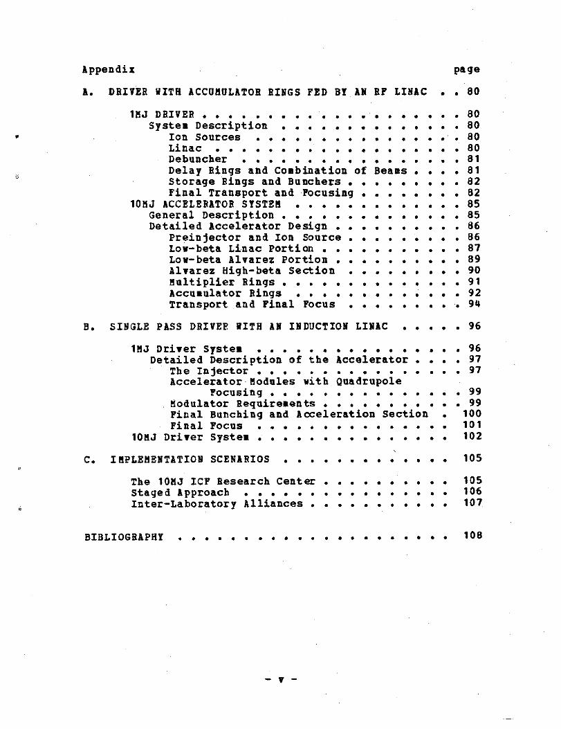
Appendix page
A . DRIVER WITH ACCUMULATOR RINGS FED BY AN BP LINAC . . 80
1MJ DRIVER . . 80System Description . . 80
Ion Sources • . • . .' . 80Linac 80Debuncher 81Delay Rings and Combination of Beams . . . . 81Storage Rings and Ranchers . . 82Final Transport and Focusing . . 82
10MJ ACCELERATOR SYSTEM 85General Description 85Detailed Accelerator Design . . 86
Preinjector and Ion Source . . 86Low-beta Linac Portion. . 87Low-beta Alvarez Portion . . 89Alvarez High-beta Section . . 90Multiplier Rings 91Accumulator Rings 92Transport and Final Focus 94
B . SINGLE PASS DRIVER WITH AN INDUCTION LINAC . . . . . 96
1MJ Driver System 96Detailed Description of the Accelerator . . . . 97
The Injector . . 97Accelerator Modules with Quadrupole
Focusing 99Modulator Requirements. . 99Final Bunching and Acceleration Section . 100Final Focus . 101
10MJ Driver System . . .
. 102
C. IMPLEMENTATION SCENARIOS 105
The 10MJ ICY Research Center . 105Staged Approach 106Inter-Laboratory Alliances . 107
BIBLIOGRAPHY•• . • . . . . 108

LIST OF TABLES
Table page
1 . bus-bar costs for future plants in 1977 dollars . . 24
2 . Bus-bar costs for future plants in 1979 dollars . . . 25
3 . Parameters at injection to each linac section . . . . 88
4 . Accumulator Parameters 92
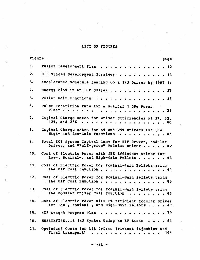
Figure
LIST OF FIGURES
page
1 .
Fusion Development Plan 12
2 .
HIF Staged Development Strategy 13e
3 . Accelerated Schedule Leading to a 1NJ Driver by 1987 14
4.
Energy Flow in an ICF System 37
5.
Pellet Gain Functions 38
6 .
Pulse Repetition Rate for a Nominal 1 Gee PowerPlant 39
7.
Capital Charge Rates for Driver Efficiencies of 3%, 6%,12%, and 25% 40
8.
Capital Charge Rates for 6% and 25% Drivers for theHigh- and Low-Gain Functions 41
9 .
Total ICP System Capital Cost for HIF Driver, ModularDriver, and "Half-price" Modular Driver42
10 . Cost of Electric Power with 25% Efficient Driver forLow-, Nominal-, and High-Gain Pellets43
11 . Cost of Electric Power for Nominal-Gain Pellets usingthe HIF Cost Function 44
12. Cost of Electric Power for Nominal-Gain Pellets usingthe HIF Cost Function 45
13. Cost of Electric Power for Nominal-Gain Pellets usingthe Modular Driver Cost Function46
14 . cost of Electric Power with 6% Efficient Modular Driverfor Low-, Nominal-, and High-Gain Pellets . . . . 47
15 . HIF Staged Program Plan 79
16. HEARTHFIRE . . .A 1MJ System Using an HF Linac . . . . 84
21 . Optimized Costs for LIA Driver (without injection andfinal transport) 104
Chapter 1
INTRODUCTION AND SUMMARY
by W . B . Herrmannsfeldt
1 .1
A STATEMENT OF PURPOSE
This document concerns the Heavy Ion Fusion (HIF) programfor Inertial Confinement Fusion (ICF) . It is intended tocomplement the Fusion Policy Plan presented to the HouseScience and Technology Committee on September 18, 1978 byJohn M . Deutch (Deutch [1978]) .
There is probably no better place to look for an appropriateintroduction than in the opening statement given by Dr .Deutch, which is quoted below verbatim :
"Early in the next century, diminishing reserves of fos-sil and fissile fuels will force us to place increasingreliance on inexhaustible sources of energy . There arethree such inexhaustible sources : fission breeder reac-tors, solar energy, and fusion energy . These technolo-gies will require many years of development before theycan generate power economically . Fusion is the furthestof the three from practical economic utility,
but itspotential rewards are great . Successful commercializa-tion of fusion could provide the world with an energysource whose ultimate fuel (deuterium extracted fromwater) is essentially unlimited, and whose by-productswould pose much reduced environmental problems comparedto those of coal and fission power .
Fusion power sta-tions would pose no increased risks to the community(beyond those of ordinary fossil fuel plants) and wouldface no geographical limitations . Fusion hybrid reac-tors could be used to produce fissile fuel, or to prod-uce other useful fuels, such as hydrogen ."(Deutch(1978 ))
Because of the cost of the fusion research program, and be-cause of the value to society of a successful outcome, it isimportant to determine as soon as possible whether con-trolled fusion can become a practical source of energy . Todo this it is necessary to solve two classes of problems ;
1 . the physics questions, including ;
- 1 -
a) confinement of plasmas, and
b) the heating of plasmas,
2 . and the engineering questions, including ;
a) designing workable power plants,
b) tritium breeding and containment,
c) reliability, safety, environmental acceptabil-ity, and
d) economic power production .
In addition to the Fusion Policy Plan (Deutch [1978]), com-ments and recommendations found in two reviews of the fusionprogram are important foundations for this document ;
1 . The JASON Study : Heavy-Ion-Driven Inertial Fusion(JASON [ 1978])
2 . The Report of the Ad Hoc Experts Group on Fusion(Poster (1978])
1 .2 DEFIN-IITIO_NS_ OF I-F fND HI F_
Brief definitions of the Inertial Confinement Fusion Programand the Heavy Ion Fusion Program may be of use to some read-ers :
.
1 . The ICF process involves the deposition of a largeamount of energy on a small pellet containing thefusion fuel . By heating the wall of the pellet,the pellet is caused to implode, heating and com-pressing the fuel, and igniting the fusion reac-tion . Achieving a sufficiently high energy multi-plication (gain) to be effective requires burninga reasonable percentage of the fuel before thepellet can explode and disperse .
The largest investment in the current program isin lasers which are used as the pellet driver,i .e ., the device for providing the energy to heatand compress the pellet . Up to this point in theICF program, this balance has seemed appropriatebecause it made it possible to achieve high inci-dent power on the pellets with modest incident en-ergy . The application of ICF to commercial powerrequires relatively high input energy to achieveadequate gain from reasonably priced pellets. The
- 2 -

efficiency and repetition rate of the 'driver arecrucial parameters .
2 . A recently identified type of driver, meeting theapparent requirements for commercial fusion powerplants, adapts particle accelerator technology tothe problem of accelerating intense beams of heavyions . The process is called Heavy Ion Fusion(HIF) even though it is not the heavy ions whichare being fused . There are several potential ad-vantages to HIF ;
a) Heavy ions have a very short, well definedrange in matter, which results in efficientclassical coupling of the particle energy tothe wall of the pellet . (This will be coveredin Chapter 3 .)
b) Heavy ion beams, with a low charge state, cancarry large amounts of energy with relativelymodest current and at low kinetic energy pernucleon .
c) The high-current particle accelerators whichare of interest have inherently moderately highelectrical efficiency . To maintain this effi-ciency throughout the system, it is necessaryto operate at reasonable repetition rates>_1Hz) and to use efficient components in sub-systems (e .g ., use superconducting beam trans-port magnets) .
d) Accelerator systems can readily achieve morethan adequate pulse repetition rates .
e) Accelerators can be . made highly reliable . Ac-celerator systems in operation routinelyachieve 80-90% operational availability inspite of the fact that existing systems are inresearch applications and do not have thebuilt-in redundancy that one would put in anaccelerator driver for . a power plant .
f) A mature base of technology exists from the ac-celerators built for basic research . Existingmachines must meet the simultaneous needs ofmultiple users, each with different beam re-quirements, which is sore difficult than therequirement anticipated for a fusion driver ofa single, dedicated and unchanging function .
g) Heavy ion accelerators make a good match to theneeds of a commercial power plant because ;
- 3 -

i)
It is relatively easy to achieve the nec-essary beam energy, even to about 10MJ .
ii) To overcome space charge effects on theion beam, it is necessary to have fairlyhigh particle energy . This results inneeding fairly large pellets in order tostop the high energy ions .
iii) Larger pellets, requiring more beam en-ergy for ignition, have higher confidencelevel designs for achieving adequategain .
1 .3
A SUMMARY OF THE STATUS OF THE ICF PROGRAM
The ICF program is newer than the Magnetic Fusion Energy(MF&) program . There are two principle reasons for pursuingthe ICF option ;
1 . Confinement is based on entirely different physi-cal principles than those used for magnetic con-finement .
2 . Engineering advantages result from the fact thatICF drivers can be designed nearly independentlyof the reactor design because the driver can bephysically separated from the reactor system .(This is especially so for HIP, but may not betrue for certain light particle drivers .)
The largest single segment of the present ICF program is forthe development of glass lasers . Their main purpose is forsteps leading to an early demonstration of scientific break-even . However, glass lasers are generally acknowledged tobe inappropriate as drivers for commercial power plants be-cause of low efficiency and difficulty with adapting to highrepetition rates . There is a high-power carbon dioxidelaser program at LASL to demonstrate the potential of gaslasers as drivers for commercial power plants . There isalsa a high-power electron and light ion program at Sandiato show possibility of adapting these systems as drivers .Programs in advanced laser development and long lead tech-nology including reactor design and pellet fabrication areunder way in several laboratories and, industrial firms .
1 .4 THE_ STATUS OF _HEAVY ION FUSION
1 .4 .1
T_h_ee HIF Pro-gr-a-m-
The first public suggestions to apply high energy accelera-tor technology to the generation of the needed beams camefrom accelerator physicists at two high energy physics labo-ratoriies ; ANL and BNL . Direct DOE funding for HIF began inApril 1977 . The FY1979 budget for HIF is about $3 .5N sharedbetween three major laboratories (ANL, BNL and LBL) plus afew smaller contracts . The ICF community has held three an-nual workshops ;
1 . Claremont Hotel, Oakland in 1976 (LBL 5543)(this was before formal funding was initiated)
2 . Brookhaven Lab in 1977 (BNL 50769)
3 . Argonne Lab in 1978 (ANL 1978)
The references for the workshops, which are the proceedingsof these meetings, constitute the principal body of documen-tation in the field and will be repeatedly cited in the fol-loving chapters . The concepts of HIF were independently re-viewed by a JASON panel in February 1978 which found"nothing within the scope of our study that would in princi-ple bar such a system from delivering the energy and peakpower required to ignite the fuel pellet ."(JASON [1978])
1 .4.2 The Accelerator Physics Comm_uu- n-lety
Contrary to an opinion expressed by some observers of sci-ence, the field of accelerator physics is anything_ but astagnant area in need of just any new machine tobuild . . . good projects abound and the competition for thetime and interest of scientists in the field is intense . Itis because of the outstanding opportunity that fusion offersto the future betterment of all mankind that so much enthu-siasm exists for HIF . In high energy physics (BEP), thefield from which HIF was spawned, large construction pro-jects are underway on the east coast (ISABELLE, a 4000eV su-perconducting proton-proton storage accelerator at BNL), inthe ∎idwest (the TEVETRON, a 1000GeV superconducting syn-chrotron at FERMILAB), and on the west coast (PEP, a 15Gevpositron-electron storage ring being jointly built by SLACand LBL) . A similar list could be compiled of new ideaswhich are being actively studied included electron-protoncolliding beams (PEP II) and proton-antiproton collidingbeams at Fermilab . Other major accelerator projects under-way in the U .S . include electron storage rings for synchro-tron light at BNL and the Univi of Wisconsin, projects rela-
- 5 -
ted to neutral beam injection into Tokamaks, the CESRelectron storage ring at Cornell, the high intensity accel-erator being built for a neutron source at Hanford by LASL,and two electron linear induction accelerators being builtat LLL .
As a result of this competition, only a small part of theaccelerator community has been involved in HIF . Very sig-nificant progress has been made in evalulating design con-cepts, determining theoretical limits to the transport ofhigh intensity beams, and finally evolving to a unified con-cept in which either of two types of linear accelerators arefound to be promising candidates for the HIF application .Although either the high-current induction linac, or the rflinac with accumulator rings will fill the HIF requirements,the choice between these two approaches is not trivial .Synchrotrons, which were the third major candidate for anHIF driver, have received less attention because the poten-tial for cost savings does not presently appear as great asit did when somewhat higher ion energies were being consid-ered . Also, the curtailed budget levels do not permit mucheffort to be spent on problems which are peculiar to syn-chrotron scenarios, such as ion-ion cross sections and therequirement for better vacuum . One confidently expects thatan appropriate effort, such as that outlined in the "stagedprogram option," would result in new ideas that would im-prove the cost and performance projections of all of thesesystems significantly beyond present designs .
1 .5 THE_ _R-2L-E- OF HIF IN TH_E DOE_ FUSI_OH P_O-LICI PLAH
According to the Fusion Policy Plan, the driver for the En-gineering Test Facility (ETF) is to be chosen during the1986-7 period . The program chart for the Fusion Policy Planis shown in Fig . 1 . A heavy ion accelerator system shouldbe one of the candidates for the ETF driver . Its energywould probably be in the 1-5MJ range . Such a machine couldbe upgraded in energy, repetition rate and efficiency, tobecome the driver for the Experimental Power Reactor (EPR) .Although the EPA is scheduled to be started about 1997, asuccessful heavy ion ETF driver could be converted to becomethe EPR driver in a such shorter time .
The present RIF program is an element in filling the needfor an expanded engineering base . It draws on physics andengineering concepts up to 50 years old, and on a net in-vestment in engineering, construction and development of$1-2B in the postwar HEP program .

1 .6 DEFINE HIP_ PROGRAM_ OPTIONS_
1 .6 .1
Fast Pro_g_ram
The HIF driver could be built rapidly because of the ad-vanzed state of accelerator technology . An appropriateschedule, after the decision to begin, would be as follows ;Preliminary design, R & D, build prototypes 2 yearsFinal design, site preparation, test prototypes 1 yearConstruction 4 yearsOperational checks and debugging
1 year
Such a plan would be justifiable if ;
1 . a high-priority national requirement could be sat-isfied, (e .g ., the HIF accelerator would becomethe principal driver for doing pellet physics ex-periments),
2 . and the HIF driver would be "reactor adaptable,"i .e ., could be upgraded to become the driver forthe ETF and EPR stages of the program,
3 . or there was found an alternative source of fund-ing (e .g . collaboration with industry or a for-eign government) .
A necessary precaution would be to require that tests, par-ticularly during the prototype stage, would establish com-plete feasibility of each stage beyond reasonable doubt .
A schedule similar to that described here would be a veryfast program considering the present level of HIF funding .It would be a higher risk effort than a slower, staged pro-gram in which each step was made after the previous step hadsucceeded in meeting the required performance . Certainly, avery rapid build-up from the present level of HIF accelera-tor R & D would be needed . Two benefits that could be ex-pected to result from such an effort are ;
1 . The total cost of a fast program, assuming successin meeting requirements, would be less than thecost of a comparable staged program .
2 . A fast-paced, large-scale effort would attract theserious attention of the scientific community, andthe best workers in the relevant fields could berecruited .
1 .6 .2
S§t1ged- Program
The path to a high-efficiency HIP driver can be appropri-ately charted with several technical levels, or stages,which one must achieve before committing the next larger in-crement of funds . Such a staged program is illustrated inFig . 2 . A very preliminary version of such a plan follows :
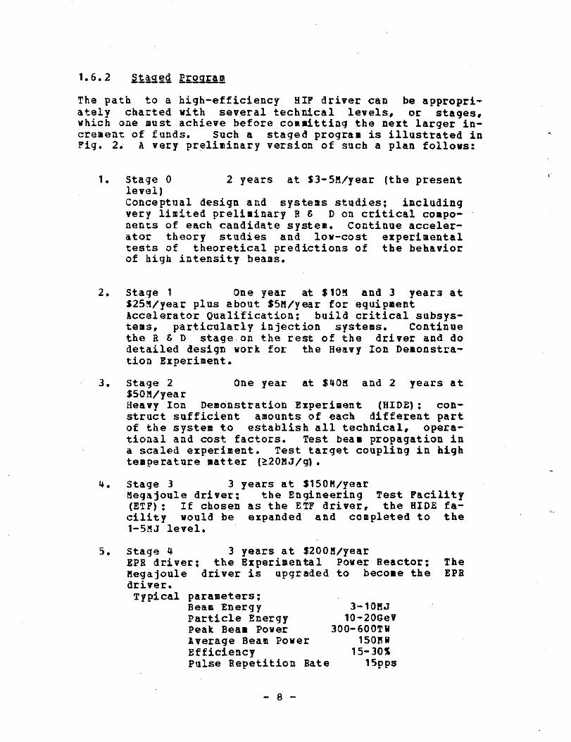
1 . Stage 0
2 years at $3-5M/pear (the presentlevel)Conceptual design and systems studies ; includingvery limited preliminary R E D on critical compo-nents of each candidate system . Continue acceler-ator theory studies and low-cost experimentaltests of theoretical predictions of the behaviorof high intensity beams .
2 . Stage 1
One year at $1OM and 3 years at325M/pear plus about S5M/year for equipmentAccelerator Qualification ; build critical subsys-tems, particularly injection systems . Continuethe R & D stage on the rest of the driver and dodetailed design work for the Heavy Ion Demonstra-tion Experiment .
3 . Stage 2
One year at $40M and 2 years at$50M/yearHeavy Ion Demonstration Experiment (HIDE) ; con-struct sufficient amounts of each different partof the system to establish all technical, opera-tional and cost factors . Test beau propagation ina scaled experiment . Test target coupling in hightemperature matter (-20MJ/g) .
4 .
5 .
Stage 3
3 years at $150M/yearMegajoule driver ; the Engineering Test Facility(ETF) ; If chosen as the ETF driver, the HIDE fa-cility would be expanded and completed to the1-5MJ level .
Stage 4
3 years at S200M/yearEPH driver ; the Experimental Power Reactor ;Megajoule driver is upgraded to become thedriver .Typical parameters ;
Beam EnergyParticle EnergyPeak Beam PowerAverage Beam PowerEfficiencyPulse Repetition Rate
3-10MJ10-20GeY
300-600Th150MH
15-30%15pps
TheEPH

If this schedule is followed beginning with Stage 1 inFY1980, the Megajoule driver would be available by about1989 . If, after completion of Stage 1, a decision were madeto push for earlier availability of the Megajoule system,two to three years could be saved between Stages 1-3 by afaster funding schedule . Such a schedule, as illustrated inFig. 3, would be equivalent to that described above underthe heading of "Fast Program ." The total cost would be thesame or slightly less . (Considerably less if inflation isconsidered .)
1 .6 .3
De-laa-yed Uoaram
The third option, labelled "delayed program," is essentiallythe present level of funding, $3 .5M/year, continued forFY'79 and FY'80 . A number of projects that had just beenstarted in expectation of modest budget increases that wouldpermit them to be carried out, have been stopped because ofthe decrease in funding . The net effect on the continuityof the research, and on the abilities of the laboratories toretain vital personnel, may be worse than just to delay HIF .The present level of funding is estimated by comparison withaccelerator R & D in HEP, to be too low by about a factor ofthree for driver R & D at the present stage . At the presentlevel, the funding is probably "subcritical" to what is re-quired to make the necessary advances over the next fewyears . This funding level delays indefinitely the determi-nation of whether heavy ion accelerators can be used asdrivers for commercial ICF power plants . The DOE policy onfusion projects a total expenditure of some $18 billion inthe next two decades to determine if fusion can be a practi-cal energy source . By supporting HIP at the level proposedfor the staged program, rather than at the present level, itshould be possible to get answers to the questions of prac-ticality of ICF several years sooner than projected . Thenet monetary savings alone makes the faster program worth-while .
1 .7 HIGH_ EEElERQX PHYSICa4 -PPROGRAM_ 5-0--PORT
When HIF work was initiated by scientists in HEP laborator-ies, their efforts were encouraged by the HEP program as animportant spin-off application of HEP technology . Later, asthe effort grew, it was identified at the level of about$1 .5m as a share from HEP to help get the new concepts offthe ground . The Office of Laser Fusion provided the bal-ance, about $3 .5M in FY'78 . Actually, the total contrib-ution from HEP was significantly higher since pieces of
- 9 -

equipment not immediately needed by HEP have formed thebackbone of the HIP B E D at each of the three HIP labora-tories . Examples of loans from one laboratory to another ;
1 . LBL loan of rf equipment and ion source to BNL .
2 . FNAL loan of insulators to LBL
Other examples of uses of existing equipment ;
1 . Many components from the LBL electron ring accel-erator experiment are being reused for the HIPprogram .
2 . ANL obtained a surplus Dynamitron from a DOD lab
3 . BNL made bunching tests on the AGS
4 . LLL loan of induction cores and vacuum chambers toLBL
Also, scientists at non-HIP laboratories, notably FERMILAB,have made very significant contributions to the program. AsHIP enters its fourth year, these voluntary contributionscontinue unabated, but after due notice, the HEP programdoes not have funds budgeted for HIP for FY'79 and beyond .Not surprisingly, the progress that can be made with recy-cled equipment is limited . That limit appears close athand ; the logical extension of the progress, mostly in ionsource and low energy accelerators, will require new equip-ment very soon .
Thus it is the fact that the Laser Fusion Office did not in-creise the HIP funds, rather than that it cut them, that hasresulted in the drop in the level of HIP support . There isalso, of course, severe competition for the funds for laserfusion, and as the aforementioned reviews indicate, a greatdeal of careful study of the position and direction of theICF program . This option plan is designed to establish acoherent heavy ion fusion program, and to demonstrate howthat program fits within the Fusion Policy Plan .
The Ad Hoc Experts Group On Fusion spoke eloquently on theneed for ICF to broaden its base of engineering, particu-larly for driver technology, before committing too such ofits resources to extending existing technology of questiona-ble application (Foster [1978]) . The HIF community believesthese remarks were directed precisely at the kind of promiseHIF can demonstrate for inertial fusion .
BIBLIOGRAPHY
(Deutch (1978)) . STATEMENT ON FUSION ENERGY, HQMSECOM_UYT_TEE ON SCIENCE-AND_ TECH-NQLOGY, John M . Deutch,Director, Office of Energy Research, U .S . Department ofEnergy, September 18, 1978
(JASON [1978]) . H EAVY- I_0- N_-_DRVEEENN INERTIAL FUSION, JASON,SRI International, 1611 N . Kent St ., Arlington, Virginia,JSR-77-41, February 1978
(Foster [1978]) . FINAL R_E_PO_R_T_ OF THE- AD--HOC- EXPERTS GROUPON FUSION, John S . Foster, Chairman, U .S . Department ofEnergy, DOE/ER-0008, June 1978
(LBL 5543) . PROCEEDINGS OF THE ERDA _SUM MER STUDY OF HEAVY-IONS FOR INERTIIO_I_N, LBL 5543, Claremont Hotel,
Oakland/Berkeley, California, July 19-30, 1976
(BNL 50769) . PROCEEDINGS- QE THE HEA_V--Y IO_N FUSION WORKSHOP,BNL 50769, Brookhaven National Laboratory, Upton, NewYork, October 17-21, 1977
(ANL 1978) . P_RQCEEDING_S_ OF THE HEAVY ION -FUSION WORKSHOP,Argonne National Laboratory, Argonne, Illinois, September19-26, 1978

MFE
ICF
TOKAMAK
ETF
0
0MIRROR
1984
19921983
LASER
PARTICLEBEAMS
1986
FIGURE 1 : FUSION DEVELOPMENT PLAN
ETF
0
01987
1995
0E
0 0DEMOp > IOC0
1997
2004 2005
2015

INDUCTION LINAC
HIDE0ETF
0 EPR0DEMO
0 -1b. IOC
RF LINAC/RINGS
1979
1983
1986
1990
1994
2000
10 J WOO) 1 KJ WOO) 100 KJ (x1O)
1 MJ (X10)
10 MJ
HEAVY ION OPTION PLAN
Figure 2 : HIF Staged Development Strategy

INCREASE R&D
DECISION POIPItS
SUBMIT PROPOSALS
RF LINAC
ACCEL. DEMO FACILITIES
2-5KJ
1-2KJ`INDUCTION LINAC
CH
1980
1
1981
1
1952
1983
1
OOSE SITE ISITE PREPARATION
PEEDCONCEPTUAL DESIGN
WRITE PROPOSAL
-BUILD PROTOTYPES-ION SO RRCES
ACCELERATING STRUCTURESCURRENI MULTIPLIERS
ANAL hOCUS
FAST PROGRAM
IfCHOOSE RF OR LIAPROCEED WITH CONSTRUCTION
I--DETERMINE INITIAL BEAM ENERGY
HIF DRIVFR CnNSTRIJCTION
HIDE/ET
1984
1
1985
I
1986
CONSTRUCTION
50-100 KJ TEST
-QUALIFICATION IESTS-
BEAM TRANSPORTPHASE SPACE/BEAM MANIPULATION
BEAM-TARGET INTERACTIONINAL FOCUS
Figure 3 : Accelerated Schedule Leading to a 1 MJ Driver by 1987
I 1987
DEBUG>]fvlf
Chapter 2
COMMERCIAL APPLICATION OF INERTIAL FUSION ENERGY
by W . B . Herrmannsfeldt
2 .1
THE ECONOMICS OF -ICF POWER
2 .1 .1
Introduction
This section will attempt to answer the following question ;"if there exists a reasonable technical basis for proceedingwith the R & D towards the development of an Inertial Con-finement Fusion (ICF) power system, is there any possibilitythat electricity made with such a system would be afforda-ble?" The significance of this question can best be appre-ciated if one asks what the proper program strategy shouldbe if the answer is clearly and emphatically negative .Then, probably, one should choose among the following op-tions ;
1 . Abandon all pretext of an energy program and con-centrate only on the military aspects .
2 . Revert to a purely research mode in driver andpellet development, and downgrade reactor and sys-tems R & D, until further developments give a morepositive answer to the question .
If the answer is "yes," even marginally, then one would beencouraged to pursue the R & D to test the concepts . Notethat even a marginally economic fusion system could still besuccessful if adapted as a fission-fusion hybrid or as afission fuel breeder . Although the economics of hybrid sys-tems is beyond the scope of this paper, it seems probablethat the most economic pure fusion system is most likely toprovide the most economic hybrid system .
The question of whether such a technical basis exists is thesubject of the next two chapters of this paper . To answerthe question of affordability, an economic analysis of ICFpower production will be presented using conventional tech-niques of cost prediction for power plants. Comparisonswith the methods and results found in the literature forother fuels will also be presented .

2 .1 .2 C-apiIa-1- charge RRa-lea
Because the cost of fuel used for generating electrical en-ergy by fusion is very low (about 0 .006mills/kwh for lithiumand deuterium (Holdren (19781)), nearly all the cost ofelectricity results from capital charges and from plant op-eration . Operation is likely to be of the order of 10% ofthe power cost and can thus be readily added as a "tax" onthe capital charges. The capital charges can be found from
Ce = Ct •R/(365 •24eCf •P n)
(1)
where Ct is the capital cost of the entire facilityR is the annual fixed charge rate,Cf is the capacity factor, andPn is the rated net power of the plant .
Most comparisons of power costs similar to that being at-tempted here use about 15% for the annual fixed charge rate .one finds studies from 13% (Ford [1976]) up to 20% (Rossin(1978)) . Since the purpose of this paper is more for com-parison than for an absolute estimate, a level of 15% willbe assumed for the fixed charge rate . The reader must scaleappropriately in any comparison of estimates using differentrates .
One also finds other authors using capacity factors anywherein the range from 60% to 70% . The argument for the lowervalue is based on recent experience with large, new nuclearplants . The argument for the higher value, besides a desireto appear more competitive, is that after the technology ma-tures, the more capital intensive plant, with lower fuelcost, will be operated for base load as much as possible .Since the purpose of this study is to compare ICF technologyto other mature technologies, after the ICF approach hasalso matured beyond the initial models, it seems appropriateto use the compromise value of 65% for the capacity factor .Again, the reader may have to make adjustments when compar-ing results from different studies .
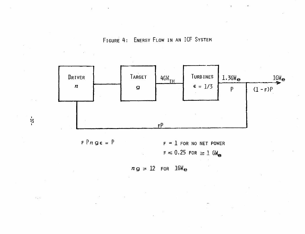
A simple energy flow model is shown in Fig . 4 .
The netpower of the plant is given by
Pa = (1 - f)P
(2)
where P is the total electrical power generated andfP is the recirculating power to the driver .The total power is given by
P = fPfgr
(3)
where h is the driver efficiency,g is the pellet gain, andc is the thermal conversion efficiency of the turbine plant .
By limiting d to a conservative 33%, allowance is made foran unknown fraction of recirculating power for pumps, etc .,in the reactor system. This relatively low efficiency istypical of nuclear systems which run at lower temperaturesthan do fossil fuel plants . The reason for this is a matterof materials technology that might be totally irrelevant toan ICF plant . However, because this is more a question oftechnology than of economics, the more conservative value of33% will be used here . Combining Eqs . 2 and 3 yields
Pn = (kgc - 1) fP
(4)
which, since fP is the power into the driver, can be rewrit-ten as
Pn = (hgt - 1) nE/n
(5)
where n is the pulse repetition rate, andE is the pulse energy from the driver in megajoules .Finally, by substituting from Eq . 5 into Eq . 1, and insert-ing the suggested values for the parameters, one finds
Ce/Ct
26n/(()(g/3 - 1)nE)
($/kWh-$G)
(6)
In Eq 6, the capital cost has been divided through to get anexpression depending only on the physical parameters .
The relationship between gain and driver energy can be foundfor some selected pellets designed by the group at LLL (Ban-gerter (1979]) . The expression
g = 200(EO .* - 0 .5)
(7)
fits data points at 1 and 4MJ, and is probably reasonablyapplicable up to about 10MJ for a family of single shelltargets . A warning provided with these results is that itmay be necessary to reduce the expected gain by about a fac-tor of two in a real environment . Higher gains are possi-ble, but would probably require more complicated doubleshell pellets . Plots of the curve of Eq. 7, and curves afactor of two higher and lower, are shown in Fig . 5 .
Since the capital charge for electric power is found to beinversely proportional to the repetition rate, it is inter-esting to explore the practical upper limits on n . To ob-tain about 4000MWth, which is approximately the thermalpower needed for a 1 GWe plant, one would need between lpps(at 10MJ per pulse) and 40pps (at 1MJ per pulse) to staywithin the range of validity of Eq . 7. The 1MJ driver,would appear to be the easier driver to build, but it re-quires an average output power of 40MW compared to the aver-age of about 10MW for the 1pps driver . Repetition rate doesnot necessarily have a large impact on the cost of the
- 17 -

driver . Although at some level there are certainly costpenalties for very high average beam power, (additionalcooling capacity, etc .) repetition rate is mostly a ques-tion of employing appropriate technology . For the reactorsystem, one expects that most of the effects of high repeti-tion rate would be beneficial since the peak blast intensi-ties are reduced . This permits the construction of smallerreactor chambers and requires less drastic means for pro-tecting the chamber walls . Other implications of high repe-tition rate impact the pellet system . The allowable upperlimit for the cost of each pellet is reduced, but in the ab-sence of any estimate of pellet costs, there is no way toassess the significance of this limitation . It is probablethat pellet cost is dominated by the capital cost of thepellet factory . The difference between a 1pps system (2 •1 0'pellets per year) and a 40pps system (10+ smaller pelletsper year) would not permit grossly different technologies tobe used . The pellet factory would have to be fully auto-mated in either case. If one reactor is used, at a reasona-ble insertion velocity of about 100m/s, the pellets would beonly 2 .5w apart at 40pps . This implies a limit on reactorvessel size, but because the blast is proportionately lessintense, it may not be incompatible with other constraints .Fortunately, the required repetition rate drops off rapidlywith higher energy, as shown in Fig . 6, so that the need forvery high repetition rate to achieve 4000MJ is limited toonly the low-energy, low-gain cases .
In Fig . 7, the capital charge ratios from Eq . 6 are plottedusing the gain curve from Eq . 7. Curves are shown fordriver efficiencies of 3%, 6%, 12% and 25%, covering the ef-ficiency range for drivers which have been suggested for ICFpower systems . Similar curves in Fig . B are plotted for thehigh and low pellet gain functions for drivers with effi-ciencies of 25% and 6% .
The plots in Figs . 7 and 8 show an asymptotic limit of19 .5mills/(kwh-$G) . Somewhat surprisingly, this limit isclosely approached for all driver energies at moderate effi-ciency . It is also approached for lower efficiency driversat higher pulse energies . only lower energy-low efficiencydrivers have capital charge ratios that are significantlyhigher because they are operating just above practicalbreakeven . A driver with efficiency greater than 25% may,if developed, cost less because it needs less utility serv-ices, but the capital charge ratio would not be signifi-cantly lower because of the approaching asymptotic limit .
2 .1 .3 CA,Pita-1- C-2 is o_f- I_9F Fac_ilitii--en
2 .1 .3 .1
Indirect Costs
The total cost of an ICF facility can be expressed as
Ct = Cd + Cr • Cp (8)
where Cd is the cost of the driver,Cr is the cost of the reactor, including the turbine plant,cooling system, etc ., andCp is the cost of the pellet factory including the tritiumrelated equipment .
For any construction project, the direct costs of construc-tion must be multiplied by a factor to account for variousindirect costs . The basis for computing this factor for apower plant is very different from the way it is calculatedfor a research facility to be built with government funding .The four elements of the indirect factor are ;
1 . Engineering, Design, Inspection and Administration(EDIA) ,
2 . Contingency,
3 . Escalation (Inflation), and
4 . Interest on the funds spent during construction .
For power plant construction, the equivalent of EDIA, in-cluding special construction tooling, is typically 24% ofthe direct construction cost (Lee (1976)) . For power plantestimates, a contingency factor of 12% is common (Lee(19761) .
Escalation has to be anticipated by the designers of a re-search facility when seeking funding from the government .However, in comparing power plant costs and the resultingrates, it is more useful to compute the bus-bar cost ofpower in current year dollars . . Inflation can then be put inat an appropriate rate to compare power costs calculated forany two different times . Thus escalation will be omitted atthis stage of this study in order to be consistent with themethods used in other reports, e . g ., by Rossin and Rieck(Rossin [1978]) .
Interest on funds spent during construction, i .e ., beforeoperation commences, must be added to the construction costof a power plant . The construction time, the interest rate,and the spending curve are all needed to calculate this fac-tor .
One can reasonably hope that the construction times
would be less than the decade or more that has been therecent experience of nuclear plants . Lee (1976] uses 52% ofconstruction cost (direct plus EDIA and contingency), forinterest charges, equivalent to almost five years at 9% .This implies a ten year construction project, with a linearspending curve, or its equivalent .
In summary, the indirect multiplier can be found from ;
1 . EDIA ; 24% of direct construction cost,
2 . Contingency ; 12% of direct construction
3 . Escalation ; omitted for now,
4 . Interest ; about 52% of construction costs includ-ing EDIA and contingency,
The resulting indirect factor is 107% which will be roundedto 100% for this study .
2 .1 .3 .2
Heavy ion drivers
Fairly detailed computer optimized estimates have been madefor the cost of an induction linac driver similar to thesystem described in Appendix B . The latest estimate for a1MJ heavy ion induction linac is $350 (Hoyer (1979]) . Otherestimates by groups at ANL and BNL for rf linac systems withstorage ring current multipliers are very similar ; any dif-ferences may be less than the uncertainties . The cost ofthe driver can be expressed as
cost,
Cd ($G) = (0 . 35Ea •+ + f (rep rate) ) • (2 . 0)
(HIF)
- 20 -
(9)
where the factor of 2 .0 accounts for the indirect costs .The 0 .4 power dependence on energy has been found to be agood approximation in several estimates between 1 and 10MJby all three laboratories . The expression is in FY1979 dol-lars . The added °rep rate" function is required only fordriver systems operating at repetition rates higher than aregenerally assumed . For 0.1 to 10pps, it has been assumedthat there would be no cost increment . For the followingcalculations, at 20pps a penalty of 10% will be added and at40pps the penalty will be 20% of the total driver cost .Generally a small fraction of the cost of a facility evendepends on average power . Recent construction experiencehas found the direct costs proportional to average beampower to be only about $300/kw (PEP (1978]) . This costwould amount to about 1% of the cost of the 1MJ, 10MW heavyion driver .
Thus, these penalty allowances would appear to

be conservative, but in any case, are not very significantto the resulting cost of power . The nominal expected effi-ciency of any of the heavy ion accelerators is around 25% .
2 .1 .3 .3
"Modular" drivers
Other driver candidates include various types of lasers andaccelerators for either electrons or light ions . Generallythese devices have in common the trait that higher pulse en-ergy, beyond some threshold which is usually well below onemegajoule, is obtained by replicating the basic modulerather than just by making the whole device larger . Thesemachines will be called "modular" drivers in this discus-sion .
There are no preliminary designs, with cost estimates, forhigh repetition rate modular drivers available in the liter-ature . Since many of the components, such as pulsers, cool-ing systems, etc ., will be similar in capacity, it may bethat any modular driver would have a similar cost to that ofa low energy heavy ion accelerator . with the benefit of R &D in this new area, the cost night be reduced to, for exam-ple, half that of a 1MJ heavy ion accelerator . This is rea-sonable to expect because the low velocity part of any ofthe heavy ion accelerators that have been proposed appearsto be relatively expensive . The energy scaling exponent isalmost certainly different for energies above that of thebasic module . The scaling rule that has been suggested forlarge carbon dioxide lasers is the 0 .8 power (Frank (1978]) .Ignoring the "rep rate" function, because there is no tech-nical basis for any part of this estimate anyway, and assum-ing the same cost at 1MJ as the heavy ion accelerator, thecost of the modular driver is
Cd ($G) = (0.35E0•4)•(2.0) (modular) (10)
2 .1 .3 .4
Reactor and power plant
There are no appropriate published cost estimates for ICFpower plants . Conceptual design work at Livermore (Manis-calco (1978]), Los Alamos (Booth [1978]), and earlier stud-ies which were reviewed by EPRI (1976], have concentrated onexploring possible technical solutions to the combination ofrequirements facing the reactor designer . For the purposeof this paper, it will be initially assumed that the cost ofthe ICF reactor system is the same as that of a comparablelight water reactor (LWR), including all cooling, turbines,
controls, containment vessels, etc ., but not including thedriver, tritium handling equipment and pellet factory . Theheart of the LWR, the Nuclear Steam Supply System (NSSS),generally accounts for not more than 20% of any total costestimate. Thus, since it is assumed that all the rest ofthe facility is essentially the same, the uncertainty in thecost estimate is concentrated in a small fraction of the to-tal .
There are many published estimates for the cost of a LWRplant . One of the more recent ones, made on approximatelythe same basis as the driver estimate above, is by Rossinand Rieck (Rossin (19781) for dual 1200MWe plants at$692/kWe in FY1977 funds . Escalated for two years at 10%,this comes to $1 billion per plant . Other published esti-mates are within a few percent of this, probably dependingon regional variations .
The objective of this study has been to define the cost of anominal 1GWe plant . The power industry seems to be stand-ardizing on a nominal 1300MWe for the NSSS (Ford (19761) .The turbine systems are presumably optimized to match thislevel . working backwards, assuming a thermal conversion ef-ficiency of 33%, the thermal requirement is 3 .9GWth, hencethe nominal 4GWth that was initially chosen as the thermalpower requirement for this study . Differences between thenominal 1GWe and the possible 1 .3GWe are in the fraction ofrecirculating power to the driver system . By using the ap-proach of Eq . 6, the cost of power delivered accounts forthe recirculating power, i .e ., what is not recirculated isavailable for distribution . Thus, the term Cr is compatiblewith the total estimate for a 1200MWe plant, escalated to1979 dollars, and Cr = 1($G) .
2 .1 .3 .5
Pellet factory and tritium handling equipment
The term Cp represents systems for which there is no designon which to base a cost estimate . It could be argued thatpellet cost is like a fuel charge and that the facilitiesshould not be included in the capital cost for the plant .However, since there are no such facilities, and since thetritium handling equipment must be installed on every reac-tor, even those not designed to breed tritium, at least partof the total is a legitimate capital cost . If dual ICF re-actors are built on a site, the pellet factory costs couldbe split between them, but no such detailed accounting isappropriate at this time . The Livermore group has suggestedS100M apiece for the cost of the pellet factory and for thetritium handling system . Intuitively, one feels that if thepellets can be mass produced at all, these numbers must beabout right. However, even if they are low by a factor oftwo, the cost of electricity would be only affected by about
- 2 2 -
10%, which is less than the error due to the uncertaintiesin any of the other estimates . Thus, it will be initiallyassumed that Cp = 0 .2($G) .
2 .1 .3 .6
Total ICF plant cost
The total cost of the ICF power plant, found by making theindicated substitutions in Eq . 8, is
Ct ($G) = (0 .35E° .' + f (rep rate) ) 2 .0 +1 .2
(HIF) (11)
for the heavy ion system .
For the modular driver system itis
Ct(SG) = (0 .35Eo. • )2 .0 +1 .2
(modular)
(12)
The expressions in Eqs . 11 and 12 are plotted in Fig . 9 .Also shown on Fig . 9 is a "half-price" curve of Eq . 12 withthe driver cost divided by a factor of two .
2 .1 .4 Zh-e C-o_st of ICF Ge--necated po_wweer-
By multiplying the costs in Fig . 9 by the appropriate ratesfrom Eq . 6, the family of electricity costs shown in Figs .10 through 14 are obtained . An operating "tax" of 10% hasbeen included . This "tax" would generate about $30H/yearfor a plant selling electricity at 50eills/kWh and operatingat a capacity factor of 65% .
The most striking feature of the results in Fig . 10 is thatelectricity costs for 25% efficient drivers are essentiallyindependent of driver energy over a very wide range ; from 1to beyond 4HJ . The rates are also very weakly dependent onpellet gain over the same region as shown by the area be-tween the high- and low-gain curves in Fig . 10 . only bysignificantly changing the plant costs can the indicatedrates be very much changed . For example, a reduction of 10to 20 mills results from reducing the driver cost by 50%,which could be accomplished by operating two reactors fromone driver . As a worst case example, if the costs are $1billion higher than estimated here, power rates would be 25to 30 mills higher .
In Fig . 11, the cost curve for the heavy ion accelerator,Eq. 11 has been used, with the nominal gain curve, to calcu-late the cost of power using driver efficiencies of 3%, 6%,12% and 25% . In Fig . 12, the same expression has been used,with the nominal gain curve, to show the cost dependence onefficiency for several different energy drivers .
The
- 23 -
modular driver cosst function, Eq. 12, has been used withthe nominal gain curve to show the dependence on efficiencyin Fig . 13 . Rates for the lower efficiency drivers, are notonly substantially higher, but also show a very strong de-pendence on pellet gain . In Fig. 14, the 6% efficiency casehas been plotted for the modular cost function, Eq . 12,showing the high-, low-, and nominal-gain cases .
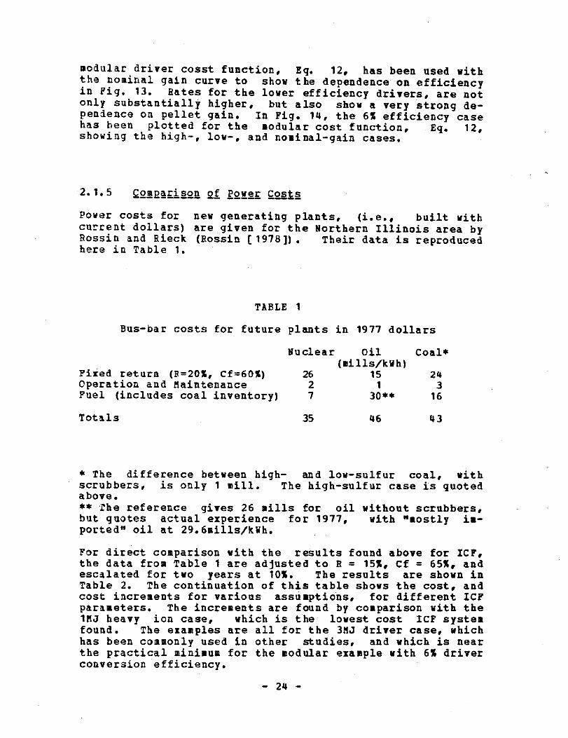
2 .1 .5 C_o_ --m2a-ris_on of Power CostsPower costs for new generating plants, (i .e ., built withcurrent dollars) are given for the Northern Illinois area byRossin and Rieck (Rossin [1978]) . Their data is reproducedhere in Table 1 .
* The difference between high- and low-sulfur coal, withscrubbers, is only 1 mill . The high-sulfur case is quotedabove .** The reference gives 26 sills for oil without scrubbers,but quotes actual experience for 1977, with "mostly im-ported" oil at 29.6mills/kwh .
For direct comparison with the results found above for ICF,the data from Table 1 are adjusted to R = 15%, Cf = 65%, andescalated for two years at 10% . The results are shown inTable 2 . The continuation of this table shows the cost, andcost increments for various assumptions, for different ICFparameters . The increments are found by comparison with the1MJ heavy ion case, which is the lowest cost ICF systemfound . The examples are all for the 3MJ driver case, whichhas been commonly used in other studies, and which is nearthe practical minimum for the modular example with 6% driverconversion efficiency .
- 2 4 -
TABLE 1
Bus-bar costs for future plants in 1977 dollars
Nuclear
Oil
Coal*(mills/kwh)
Fixed return (R=20%, Cf=60%) 26 15 24Operation and Maintenance 2 1 3Fuel (includes coal inventory) 7 30** 16
Totals 35 46 43
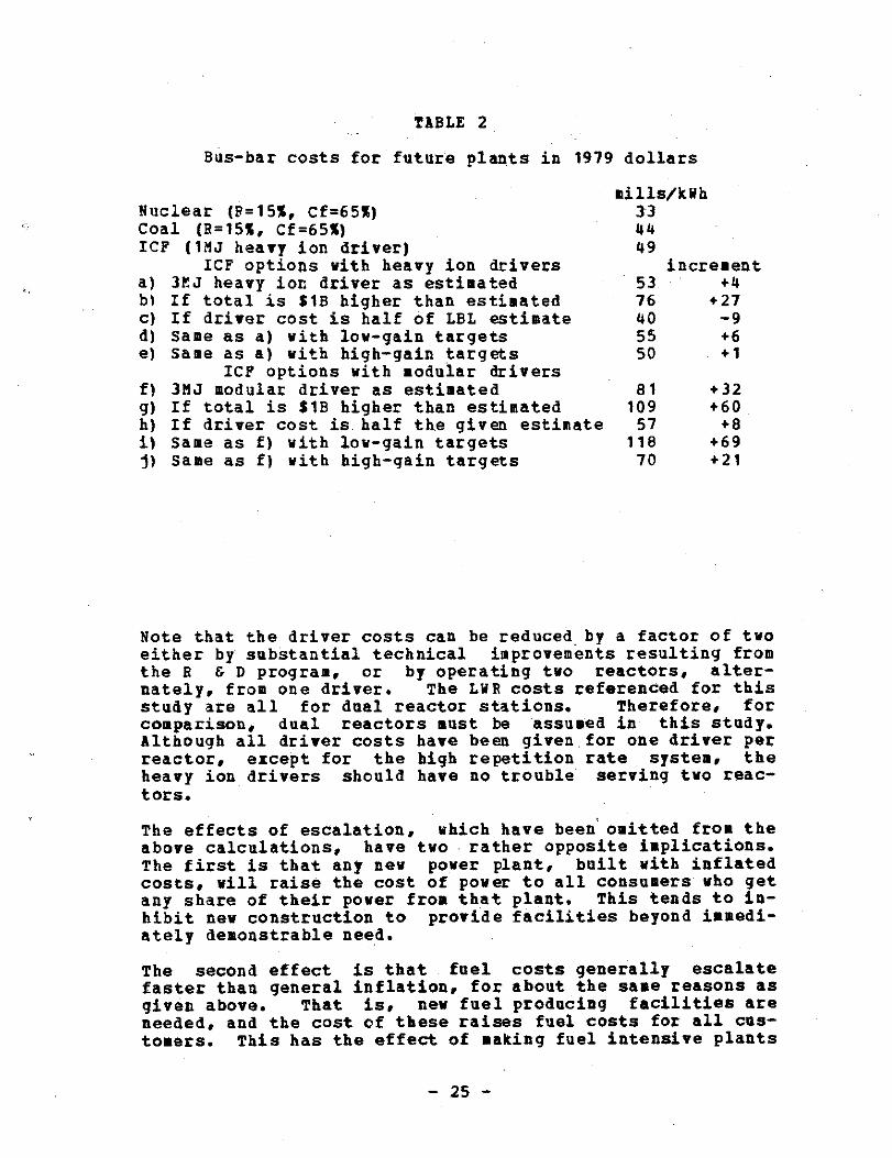
TABLE 2
Bus-bar costs for future plants in 1979 dollars
Note that the driver costs can be reduced by a factor of twoeither by substantial technical improvements resulting fromthe R & D program, or by operating two reactors, alter-nately, from one driver . The LWR costs referenced for thisstudy are all for dual reactor stations . Therefore, forcomparison, dual reactors must be assumed in this study.Although all driver costs have been given . for one driver perreactor, except for the high repetition rate system, theheavy ion drivers should have no trouble serving two reac-tors .
The effects of escalation, which have been omitted from theabove calculations, have two rather opposite implications .The first is that any new power plant, built with inflatedcosts, will raise the cost of power to all consumers who getany share of their power from that plant . This tends to in-hibit new construction to provide facilities beyond immedi-ately demonstrable need .
The second effect is that fuel costs generally escalatefaster than general inflation, for about the same reasons asgiven above . That is, new fuel producing facilities areneeded, and the cost of these raises fuel costs for all cus-tomers . This has the effect of making fuel intensive plants
-25-
mills/kWhNuclear (F=15%, Cf=65%) 33Coal (R=15%, Cf=65%) 44ICF (1MJ heavy ion driver) 49
ICF options with heavy ion driversa) 3CJ heavy jot driver as estimated 53
increment+4
b) If total is SIB higher than estimated 76 +27c) If driver cost is half of LBL estimate 40 -9d) Same as a) with low-gain targets 55 +6e) Same as a) with high-gain targets 50 +1
ICF options with modular drivers81 +32f) 3MJ modular driver as estimated
g) If total is SIB higher than estimated 109 +60h) if driver cost is half the given estimate 57 +8i) Same as f) with low-gain targets 118 +69j) Same as f) with high-gain targets 70 +21

progressively less economic, and acts to promoteconstruction of never, ∎ore capital intensive plants . Thisimplication of inflation eventually will make up for asmall, presently perceived, difference between IC? power andcoal, as it has already allowed fission to bypass fossil fu-els for economy . It is probably not a significant effect ifthe cost differences are large, but if coal continues to es-calate 3% faster than general inflation, fifteen years fromnow the above calculations would show coal power as expen-sive as fusion for all except the pessimistic cases with in-crements greater than 20 mills/kWh .
2 .1 .6 Qo-gc-}Ujon
The question posed at the beginning of this section, "is ICFpower affordable?" can now be answered . If the cost esti-mates given here are not much too low, ICF power from aheavy-ion accelerator system should cost between 5 and 10mills more than power from a new coal plant . One would ex-pect this difference to shrink with time as coal prices risefaster than general inflation . Furthermore, this differ-ence, which is largely independent of a wide range of as-sumptions, is less than the difference between the powercosts from new coal and new LW8 plants . Since it is not aninsurmountable deterrent for new coal plants, it should notbe insurmountable for ICF .
on the other hand, power from a driver with efficiency inthe 3% to 6% range costs at least 25mills/kWh more thanpower from a new coal plant, and only comes close to thelower end of this range if one makes optimistic assumptionsabout pellet gain . One exception to both of the abovestatements is if the driver cost is cut in half . . Then, ifall the other assumptions work out, the heavy ion drivensystem could actually produce power for less than the costof coal produced power . . Another exception would be for anentirely different mathematical model to apply . This wouldoccur if, for example, fission-fusion hybrid systems areconsidered ; a task well beyond the scope of this paper .
2 .2
S-HALL (FEW HONDRE,_D EG W gg) ?Q!$a PlUNTS
one does hear suggestions that the electric power industrywould prefer much smaller fusion reactors. In view of theevidence that small fission power plants are being shut downbecause they are uneconomic, these suggestions should atleast be questioned . One possible rationale for small fu-sion installations is that, as in the case, of earlier fis-
- 26 -
sion power plants, the very first reactors night not begigawatt sized units . Some lower power units would be builtfrom which to scale up to full size units. Indeed, the Fu-sion Policy Plan (Deutch (1978]) calls for essentially justsuch a step in the Experimental Power Reactor .
It appears certain that the capital cost of fusion powerplants of any type will be greater than that of equivalentfission plants . Thus there appears to be no rationale forprojecting a future power industry consisting of many smallfusion plants scattered about the countryside .
2 .3 BEAM- -REQO-I-FEMENTS, 1-422§D B_} E-EhQIQR DESI_GN_S_
It is useful to attempt to determine what can be deducedabout the characteristics of fusion power reactors, particu-larly as those characteristics affect the design of ICFdrivers .
2 .3 .1 Pare Fus_iion Powe-r R-eac o-g
The pure fusion power reactor would be of the type discussedin the first section of this chapter on the economics .of fu-sion power . The reactor chamber would be quite large, 5 to10 meters in radius, in order to absorb the repeated blastsof neutrons, electromagnetic radiation and debris . The ra-dius of the chamber determines the minimum standoff distancefor the last focusing elements. From the standoff distance,one can deduce the necessary beam quality . If, as it willbe shown later in the HIP case, the required beam quality isbetter than can be delivered by the accelerator, it is nec-essary to divide the beam into a number of less intensebeams . It will, in fact, turn out that the number of beamsneeded to achieve adequate beam quality is significantlyhigher than the minimum needed to provide adequately symme-tric illumination of the pellet .
The environment in the reactor vessel may be important forthe final transport of the ion beam to the target . Thereappears to be no question that the beams can be made to hitthe required spot size if the reactor chamber is evacuated .If there is a substantial pressure, such as the vapor pres-sure from liquid lithium, then theoretical and experimentalstudies are needed to resolve the final transport questions .However, it is interesting to note that if the lithium temp-erature is maintained at around 6000F, i .e ., somewhat higherthan the coolant temperature in a light water reactor (LHR),then the vapor pressure is in the 10-sTorr range, adequatefor the vacuum requirements
for beam transport .
An
- 27 -
accelerator capable of a definitive test of bean transportin a gas or plasma at a pressure <- 1Torr would have many ofthe characteristics needed for an ICP driver. Thus it nowappears that such tests would have to be part of a develop-ment program such as that described in Chapter 5 . However,it appears certain that some pure fusion reactor scenariosexist with evacuated chambers . Liquid metal getters can beused for fast pumping, and first wall protection schemescompatible with vacuum conditions have been described by Ho-vingh [1976] . Critical questions of materials, radiationdamage, first wall lifetime, and cost, all remain to bestudied .
2 .3 .2 7iitiu-m Generating &eacto-;
It appears certain that the first generation of fusion reac-tors will require some mixture of tritium-deuterium fuel .The use of "advanced" fuels, i .e., without tritium, is at-tractive mainly because it eliminates the complication ofseparating, purifying and storing tritium. However, evenadvanced fuel reactors will result in unburned tritium "ash"in the residue . Thus the environmental problems of tritiumcontainment will be part of any fusion plant, for eithermagnetic or inertial confinement .
The critical tritium question is "how much?" or rather, howlittle tritium needs to be mixed with the deuterium in thefusion fuel . In the case of ICP, if sufficient bean energyis supplied to the pellet, the reaction should propagatewith significantly less than a one-to-one D-T mixture . Witha lower tritium fraction, the inventory of tritium and theinvestment in tritium handling equipment can both be re-duced . Calculations to show the dependence of pellet gainon the D-T mixture have shown only a small drop (5 10%) ingoing from a one-to-one mixture to a two-to-one D/T ratio(Skupsky (1978]) . While it is possible that only the tri-tium ash from the pure fusion reactor may to needed, a ∎orelikely scenario is that some reactors are designed for anddedicated to tritium breeding . A tritium breeding reactordesigned for the maximum production of tritium could yieldapproximately twice as much tritium as required to sustainthe reactor itself with a one-to-one D-T mixture (donsler[1978)) .
The tritium breeding reactor is likely to borrow heavily onthe existing technology for generating tritium in fissionreactors. Although much of this technology is classified,it is common knowledge that the tritium is generated by neu-tron absorption in lithium . To aid in handling the tritium,particularly to minimize the tendency to permeate throughmetals, such as the stainless steel plumbing, the tritium iskept as cool as is practical .
- 28 -
A tritium breeding fusion reactor based on existing technol-ogy would not also be used as a power reactor . There may bea beryllium, or lead, or refractory metal blanket for neu-tron multiplication . The interior of the reactor chambermight not be much different from that of the pure fusionpower reactor, except that the ambient temperature could belower . If the liquid lithium "waterfall" concept is used,and the lithium is maintained at about 2000C, (just abovemelting) the vapor pressure is reduced to < 10 - sTorr .
2 .3 .3 The Tritium Brge-djn_g Eusjon p_oger _Hy_br}d_
The reactor designs usually presented as part of ICE scenar-ios are of the tritium-fusion hybrid class (Maniscalco[1977]) . They usually use a lithium blanket, sometimes in a"waterfall" configuration, to serve the double purpose ofproviding a first surface shield and a high solid angle forthe lithium to be exposed to the flux of neutrons .
2 .3.4 Electronuclear B-seeding Reactor
Electro-nuclear breeding of fissile fuel, rather than purefusion, may be the key to unlimited, inexhaustible energyfor the future . There is every reason to believe that thesafety record of the fission reactor industry, especiallywhen compared to that of the fossile fuel industry, willeventually convince the general public about the safety ofnuclear power . The other critical issues of fission, pro-liferation and waste disposal, have technical solutions .
The principle uncertainty for fission reactors is the con-tinued availability of enriched fuel at reasonable prices .The fast breeder reactor should in theory solve the fuelproblem except for two serious drawbacks ;
1 . It' is generally felt to be more prone to cata-strophic accidents, and
2 . The breeding rate is too slow to make it possibleto fuel non-breeding reactors in any quantity .
Thus there has recently been increased interest in the con-struction of systems for electro-nuclear breeding . Earlierstudies have been underway in Canada for a number of years .These studies generally conclude that electro-nuclear breed-ing is an attractive alternative to fast breeder reactors .With some new concepts of insitu enriching of fuel rods,
- 2 9 -
perhaps as many as three or four times (Grand (1978]), therewould be no need for either enrichment or reprocessing fa-cilities . This at once greatly improves the economics andeliminates the problems of proliferation by diversion ofweapons materials . Unfortunately, the cost of operatingsuch a powerful accelerator, makes the cost of the resultingfuel relatively uneconomic, (though not as uneconomic asfast breeder reactors) .
An electro-nuclear breeding accelerator obtains about oneneutron from every 10Mev of bean energy . These are rela-tively low energy neutrons . By contrast, about 80 percentof the energy from a D-T fusion reactor is in 14 .1Me4 neu-trons . By the use of a beryllium and/or refractory metalmultiplier blanket, the flux of neutrons can be further en-hanced (Rose 1961]) . Even without such enhancement, at apellet gain of two, the yield of neutrons per MeY of inputbeam from an ICF reactor would be comparable to that fromthe accelerator breeder . However, to achieve comparableflux as that proposed in the Brookhaven study, the pelletgain should be about 60 if one 10MJ pulse per second is as-sumed . The proposed accelerator breeder is designed to pro-vide fuel for three light water reactors . The ICF drivercould, in theory, serve 15 similar fuel breeding facilities,providing fuel for 45 light water reactors . In practice,the need for tritium will require some fraction of thedriver pulses . If a lower ratio of tritium is used, thenthe neutrons from D-D collisions would account for an appre-ciable part of the flux . These neutrons are at a lower en-ergy and may be less able to be multiplied .
In the absence of a comprehensive study, such as that madefor the accelerator breeder, the optimimum values cannot beassigned to the various factors described above . However,it is apparent that with only a modest pellet gain, a veryinteresting electro-nuclear breeder could be designed. itis also difficult to guess at all the characteristics of thereactor chamber as they apply to the ICF driver except topoint out that, as in the case of the tritium generator,first wall protection will be a primary consideration . Thereactor chamber could be kept relatively cool and at pres-sures low enough to avoid beam transport problems .
2.3.5 fh-g Fjs-won- u jo-n- H-q-bKUd-
Combining the electro-nuclear breeder with the power gener-ating capability of a fusion reactor has the advantage ofgreatly reducing the fusion gain needed to yield net outputpower .
- 30 -
2 .4
GEHER&L DI-SCUSSION-
ee have tried to survey the range of reasonable reactor sce-narios to find what characteristics of the driver can be de-duced . The survey is admittedly superficial, partly becauseof limitations on time and resources, but certainly also be-cause very little significant reactor design work has beendone for ICF. The work that has been done appears to betailored to show that marginal, (low energy-low efficiency)drivers could be used in a contrived fusion scenario . Thehistory of ICF has been highlighted by attempts to make apellet burn with whatever driver characteristics are availa-ble. By contrast, what is clearly needed is an adequatedriver with which to study the properties of a range of pel-let designs . The HIP driver would be the tool that couldprovide the definitive tests for ICF .
2 .4 .1 RRilliaabilitty Disc_ussio_n
If, in particular, a single driver provides beam to severalfusion reactors, then the questions of reliability of crit-ical components of the driver are crucial . Most linear ac-celerator systems, including those being proposed for HIPdrivers, can operate with some acceleration stages, turnedoff . Standby units are available with the next pulse shoulda fault be detected with one of the accelerating units . In-deed, the particle energy of the beam is normally adjustedby varying the number of standby units . Only the injectorand front end or "low-beta" part of the linac is essential .These essential components, which comprise only about 5% ofthe total driver cost, can be replicated for reliability .
The trend in recent years has been toward power parks con-sisting of several generator facilities, each of about 1GWecapacity . For example, facilities consisting of clusters ofup to eight 1GWe fission reactors are planned for Brazil,Iran and Saudi Arabia . The needs for security, a cadre ofskilled operators and technicians, the pellet fabricationfacility, etc ., all lead to the conclusion that fusion powerplants of the next century will be very large facilities .To mention just one very good reason ; it is generally sucheasier to get governmental permits for one large facility,or to enlarge an existing site, than to arrange for severalsmall or medium sized sites .
Another consideration is that reliability in power plantsmay not be as important in the future as it is today. Al-most all electricity today is generated for high quality ap-plications . It is simply too expensive to use electricityfor most low quality applications, such as building heating,desalinization of water, hydrogen generation, etc.
In the
"intensive-electrification" scenarios studied for energysystems of the next century (ERDA-48), electricity must beused for many applications that are covered by fossil fuelstoday . Recalling that only solar energy, electricity, andwaste heat from power plants will be available after fossilfuels run out, one recognizes that there will be both a suchlarger power grid than exists today, and many sore inter-ruptable users .
2 .4 .2
Tritium
k substantial case can be made for considering the tritiumbreeding reactor, rather than a power reactor, to be thelogical first application of controlled fusion . A neutronconverting lithium to tritium is more valuable than a neu-troa used only for its kinetic energy converted to heat .one can even envisage a scenario of magnetic confined fusionreactors becoming customers for ICF produced tritium .
Another aspect of the tritium problem is that, if substan-tial amounts of power are generated from pure fusion, li-thium could become the limiting natural resource . This isbecause the lithium inventory in some fusion reactor designsis quite large and not because so such lithium will be con-verted to tritium . In fact, the identified U .S . terrestriallithium, without resorting to obtaining it from seawaterseparation, could run D-T fusion power plants at ten timesthe 1976 U.S . electricity generating rate for 1000 years(Holdren [1978]) . The lithium inventory problem would besolved if a few, dedicated, tritium breeding reactors wereused rather than requiring a large lithium inventory in ev-ery fusion power reactor .
The tritium inventory needed for a fusion power plant hasbeen estimated for some magnetic confinement systems . Al-though some designs, particularly those using the D-D reac-tion, may have a much smaller inventory, the typical numberis 250MCi per GWe (Holdren (1978]) . This is equivalent toabout 25kg of tritium and would permit operation at the 1GVelevel for about four days from a plant in which all the en-ergy comes from the D-T reaction . The inventory is furtherbroken down into "active" and "reserve" parts, the laterconsisting of about 60% of the total, is maintained in coldstorage to permit continued operation when the tritium re-covery system is down . The active part, which would be cur-rently undergoing separation and preparation for injectioninto the reactor, would be the only part assumed potentiallyvulnerable to a sudden release .

2 .4 .3 Safety 1&.4 Envizo-naegta1 __ Co-g,~- erations
The traditional aim of fusion power is to provide an inex-haustible source of energy with a minimum of safety and en-vironmental hazards . some such hazards have been identifiedand these will be briefly discussed below .
The major new problem created by pure fusion is the handlingof a large tritium inventory . Following Holdren [1978]along the lines of the previous section, if the "active"100MCi were suddenly released, it would produce only aboutone percent of the number of early fatalities and injuriesof the comparable fission reactor accident considered in theRasmussen report (WASH 1400) . Holdren points out that afurther five-fold decrease in the tritium inventory, such aswould be permitted by a reduced percentage of tritium in thepellets, would reduce to zero the prompt fatalities from aworst case tritium release . If, however, the accident in-volves the accidental release of quantities of LiOH from li-thium reacting with water, the toxic hazard is far greaterthan the hazard from radioactivity (Booth [1977]) .
A possibly more difficult problem is the one of "chronic"release of tritium which escapes into the biosphere . Thedaily loss of inventory should not exceed about one part permillion in order to stay below present NEC "design objec-tives" for fission power reactors (Hoidren (1978]) . Designsare claimed for magnetic confinement that can theoreticallyachieve better containment than this implies, but practicalexperience, and application of these designs to ICF, areboth required . Because tritium diffuses through metalsfaster at elevated temperature, tritium breeding fission re-actors are kept relatively cool and are not simultaneouslyused for power generation .
The higher energy neutrons from fusion (about 14MeV) makesneutron shielding more difficult for fusion than for fis-sion. The necessary barriers of concrete are practical andno major design effort appears needed for ICF . However,neutron activation of reactor materials does present a de-sign problem . The effect of the release of activated mate-rials in the event of a catastrophic accident also needs tobe evaluated . Material lifetimes in such intense neutronfluxes are known to be limited . It is here perhaps morethan in any other area, that ICF has an advantage over MFE .The simpler ICF reactor, without large external magnets forconfinement, and with the driver far removed, has fewer sen-sitive materials in the vicinity of the intense flux of neu-trons .
In the absence of any fission-fusion hybrid scheme, the con-tainment and shutdown problems of fission reactors do notapply to fusion power . Even if fission fuel breeding is in-
- 33 -
corporated, as long as the fuel is kept cool, i .e ., noattempt is made to extract fission energy to operate a powerplant, it is easy to design in such a way as to assure safeshut down if any problems occur . This is perhaps the singlebest reason to avoid the fission-fusion hybrid in first gen-eration fusion scenarios .
Accelerator safety is a well understood engineering disci-pline . Interlocks, personnel protection, and machine pro-tection systems are it satisfactory use at all large re-search accelerators . In spite of the unprecedented powerlevels needed from an HIF driver, the accelerator shieldingproblems are less severe than those at any HEP laboratory .This is because the principal radiation hazard in REP labo-ratories is from nuclear fragments due to the high energyper nucleon of the incident beam . Although the ion energyis high for HIF, the per nucleon energy (about 100deV) isquite low and shielding is relatively easy .
BIBLIOGRAPHY
(Holdren (1978]) . John P . Holdren, FUSIEN _NER_I IN CSNT__EAT :I-T$ FITN-E- SS Up THE L--ON-G- MERE, Science 200, pp 168-180,14 April 1978
(Lee [1976]) . T . H . Lee, POWER GENIE--ACTION E_C NQHICS- , Testi-mony to the Connecticut PUCA, January 22, 1976, materialobtained from the Atomic Industrial Forum, Inc .
(Rossin [1978]) . A . D . Rossin and T . A . Rieck, ECONOMICS- QFNUCLE
_P WER ' Science 201, pp 582-589, 18 August 1978-A- R- Q---(Frank (1978]) . T . G . Frank, Private communication, U . S .
Department of Energy
(Bangerter [1979]) . Roger 0 . Bangerter, Private communica-tion, Lawrence Livermore Laboratory
(Hoyer [1979]) . Egon Hoyer, Private communication, LawrenceBerkeley Laboratory, A description of the Linear Induc-tion Accelerator appears in the Proceedings of the Ar-gonne Workshop on Heavy Ion Fusion, Argonne National Lab-oratory, September 1978
(EPRI (1976]) . K . A. Brueckner, ASSESSMENT OF LASER-DRIVE-1LFUSS-ZION, EPRI ER-203,Electric Power Research Institute,September 1976 .
(FORD [1977]) N_UCCLEAR ROWER ISSUES AND -C_BQIICES_, AEPORE' QFTHE- NgC-LEllR- ENERGY PO-LICY STUDY- GROG-2g, Spurgeon M . Keeny,Jr., Chairman, Ford Foundation Study, Ballinger Publish-ing Co ., 1977
(Booth [1977]) L . A . Booth and T . G. Frank, COMMENCIAL AP-P-LLI-C-ATIO-N- 0-F INERTIAL -L NF_INEN-EN T--NT- FUSION, LA-6838-MS, LosAlamos Scientific Laboratory, Los Alamos, NM, May 1977
(PEP (1978]) The estimate of $300/kW of installed beam powerwas obtained from the engineering staff of PEP, the col-liding beam project now under construction at SLAC, whichwill have 6MW of installed rf power . The rate does notinclude accelerating components, but does include itemssuch as substations, cooling towers, water pumps, venti-lation, etc., that depend on input power .
- 3 5 -

(Deutch [1978]) . STA EIE!I ON F_USION RNER_GI, EQU_S_E_ CQSEIE-IE--E QN S_C_I_ENCE AND T_ECHNRLOYY_, John M . Deutch, Director,Office of Energy Research, U .S. Department of Energy,September 18, 1978
(Hovingh [1976]) ION_ BB-EA! MACTH FIRST_ WALL- DESIGN, J . Ho-vingh, LBL 5543, December 1976 .
(Skupsky (19781) HIGH Zf E_RM NUQLLEAE _ENR -I _GAIB_S_S i!II_H A _Q1T_RI_TI_U _M__M I- VENTORY FOR_ I_NRIIAL_LY C_C_N_FIN_ED- FUSION, StanleySkupsky, OSA Topical Conference on Inertially ConfinedFusion, San Diego, California, February 1978 .
(Monsler [1978]) .
M. Monsler, Private communication, Law-rence Livermore Laboratory
(ERDA-48) A NAT-IO_NAL -?-LA--N-FO-!
ENERGY -RRSEARC1-H, RE_VELOPMEN_IAND_ DEMJ-N_STRATIObU .S . Energy Research and DevelopmentAdministration, June 1975
(Maniscalco [1977]) REACTTQRS, BNL 50769, October 1977 .
(Rose (1961]) . D . J . Rose and M . Clark, PLASMAS AND CON--T-ROLLED FUS_IOON, 1961, MIT Press
(Grand (1978]) CONCEPTUAL_ _DESIGN AID ECONOMIC- ANALYSIS n AL-I_G_H_T -AT_E-R- REACTOR FUEL REGENERATOR, edited by P . Grandand H . J . Routs, Brookhaven National Laboratory, Upton,New York, BNL 50838, May 1978
(WASH-1400) REACTOR SAFETY- SIUDY : AN_ ASSESS-MENl QE ACCI-DENT-RI-S-MS IN -U.S. COMMER_CI_A__L NULL-E_AR PQ!ER -!PLANTS, WASH-1400,Nuclear Regulatory Commission, NUREG 75/014, 1976
DRIVER
n
F PngE = P
FIGURE 4 : ENERGY FLOW IN AN ICF SYSTEM
TARGET
9
FP
4GWTH
n g ~,- 12 FOR 1GWe
TURBINES
E = 1/3
F = 1 FOR NO NET POWER
F _ 0 .25 FOR ? 1 GWe
1 .3GWe
1GWe
P (1 -F)P

1000 -
800 -
600 -
z 400 -
CD
200 -
Figure 5 : Pellet Gain Functions
PELLET GAIN VS. DRIVER ENERGY
38
IIIIIIII
I IIIIIII
2
4
6
8
DRIVER ENERGY (MEGAJOULES)
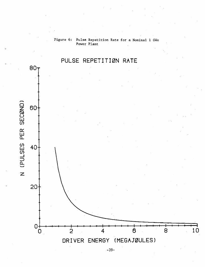
zz 60-eUWW
xWa-
Vz
80-
20-
Figure 6 : Pulse Repetition Rate for a Nominal 1 GWePower Plant
PULSE REPETITION RATE
111111IIIIIII
I
I
I
I II112
4
6
10
DRIVER ENERGY (MEGAJOULES)-39-

80 -
00
Figure 7 : Capital Charge Rates for Driver Efficienciesof 3%, 6%, 12%, and 25%
POWER COST PER !BILLION CAPITAL COST
2
4
6
8
10
DRIVER ENERGY (MEGAJOULES)
-40-
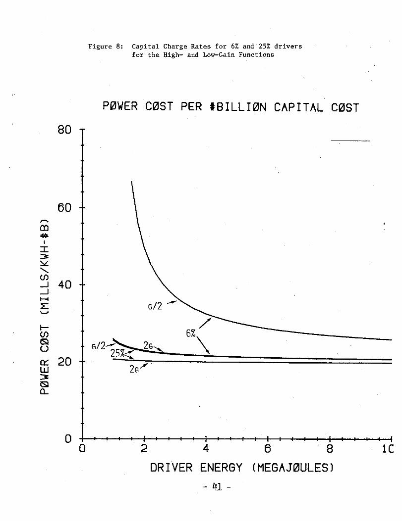
80 -
Figure 8 : Capital Charge Rates for 6% and 25% driversfor the High- and Low-Gain Functions
POWER COST PER #BILLION CAPITAL COST
iIIIIIIiiiI
I
IIIIII,1
2
4
6
8
1C
DRIVER ENERGY (MEGAJOULES)

HJJm
6
4
2
1
Figure 9 : Total ICF System Capital Cost for HIF Driver,Modular Driver, and "Half-price" Modular Driver
1 GWE ICF SYSTEM COST1979 * BILLIONS
HIF
+ : HIGH REP RATE HIF
2
4
6
8
10
DRIVER ENERGY (MEGAJOULES)
-42-
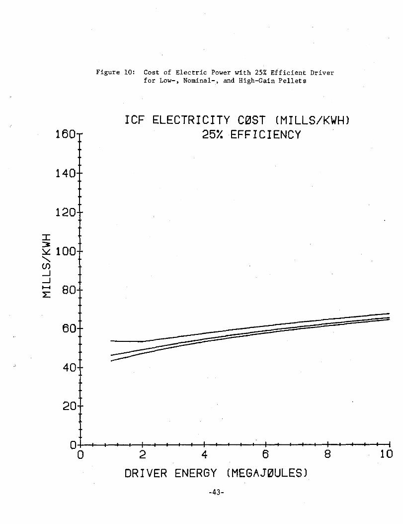
140-
120-
60-
40-
20-
Figure 10 : Cost of Electric Power with 25% Efficient Driverfor Low-, Nominal-, and High-Gain Pellets
ICF ELECTRICITY COST (MILLS/KWH)160-
25% EFFICIENCY
0fIIIIIIIfI
I
I$
I i'$1
4$
1
10
2
4
6
10
DRIVER ENERGY (MEGAJOULES)-43-
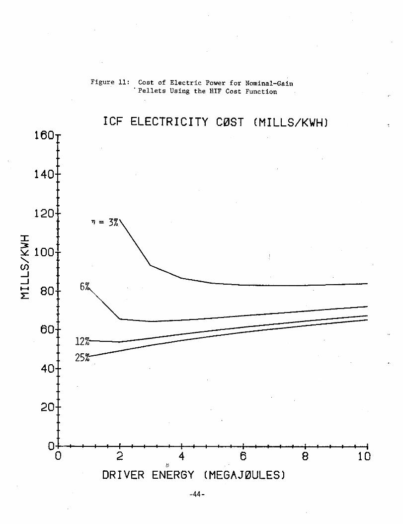
160-
140-
120-
20-
Figure 11 : Cost of Electric Power for Nominal-Gain'Pellets Using the HIF Cost Function
ICF ELECTRICITY COST (MILLS/KWH)
n = 3%
011r11r1111111111rr1
0
2
4
6
DRIVER ENERGY (MEGAJOULES)-44 -
10
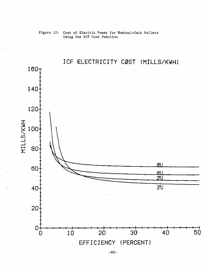
Figure 12 : Cost of Electric Power for Nominal-Gain PelletsUsing the HIF Cost Function
ICF ELECTRICITY COST (MILLS/KWH)
EFFICIENCY (PERCENT)-4 5 -
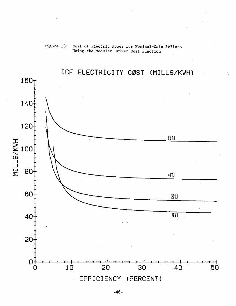
160-
140-
120-
60-
40-
20-
0i0
Figure 13 : Cost of Electric Power for Nominal-Gain PelletsUsing the Modular Driver Cost Function
ICF ELECTRICITY COST (MILLS/KWH)
F*IIIII
I II
I IiIIIrII10
20
30
40
50
EFFICIENCY (PERCENT)
-4 6-
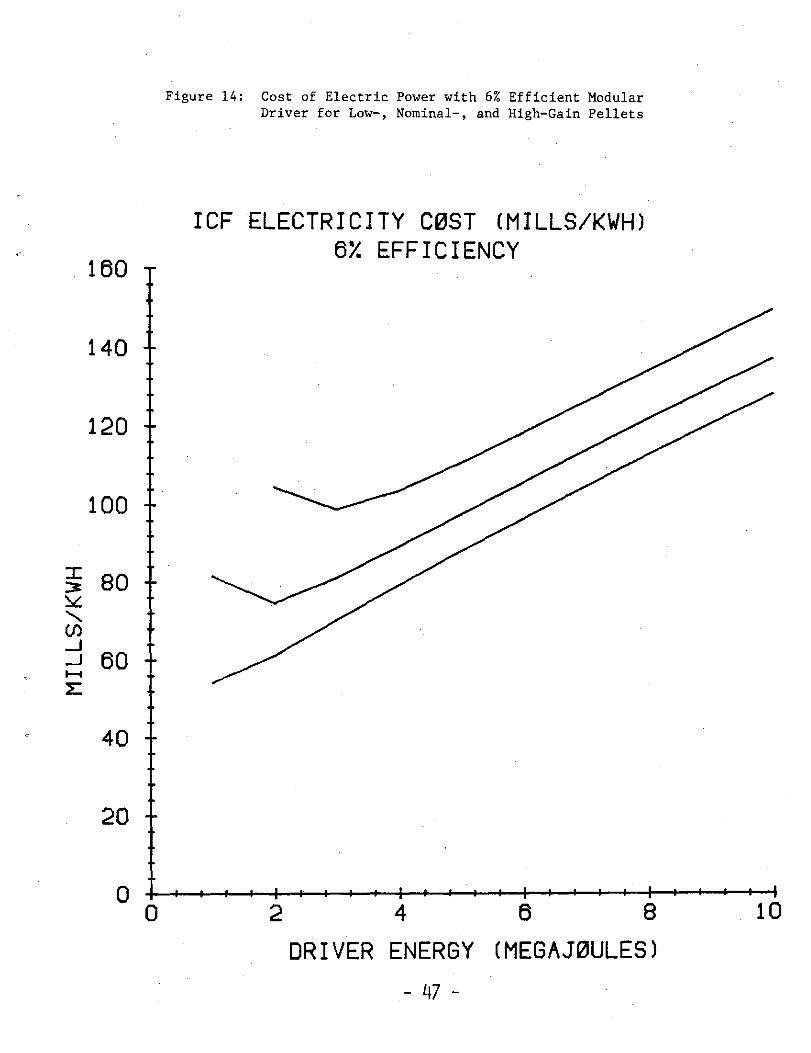
Figure 14 : Cost of Electric Power with 6% Efficient ModularDriver for Low-, Nominal-, and High-Gain Pellets
ICF ELECTRICITY COST (MILLS/KWH)6% EFFICIENCY
DRIVER ENERGY (MEGAJOULES)
_47-

Chapter 3
IONS AS ICF DRIVERS
by Roger 0 . Bangerter
3 .1 THE BEAM-TARGET INTERACTION_ IN AEIV-I ION FUSION
The beam-target interaction in laser fusion has proved to bea very challenging problem . It is therefore natural to beconcerned about the beam-target interaction in heavy ion fu-sion . Much of this concern seems to arise from the feelingthat a beam capable of target ignition is in some sense "in-tense" and thus qualitatively different than the low-inten-sity beams with which we are familiar in nuclear science .For example, we will show that for typical target and beamparameters the electron density in the target is roughlynine orders of magnitude larger than the density of beamions . Furthermore there are about 1000 Debye lengths be-tween beam ions in the target so that one might expect thebeam ions to behave independently . These statements aresimply an manifestation of the fact that for heavy ion fu-sion each particle carries a large energy (about 10GeV) .This can be contrasted with light ion (proton) or electronbeam fusion where the expected particle energy is 1-10MeV orwith laser fusion where each photon carries an energy ofabout 1 eV .
However, there are some ways in which heavy ion beams mustbe considered intense . Collective effects are important inthe propagation of the beam in the accelerator and throughthe combustion chamber to the target . This is discussed inChapter 4 ; Heavy Ion Accelerators .
There are two classes of ion beam physics that must be con-sidered : electromagnetic and nuclear . Recent acceleratordesign effort has been directed toward accelerating heavyions to a maximum of about 20GeV . At this energy the calcu-lated range of a heavy ion is much less than a nuclear col-lision length so that only a small fraction of the incidentions will produce nuclear reactions (Silberberg [1977]) .Furthermore, nuclear processes are unaffected by the stateof matter in the target so that measurements of cross sec-tions with low intensity beams are directly applicable . Theonly area of conceivable uncertainty involves electromag-netic phenomena .
- 48 -
The electromagnetic interaction of low intensity ion beamswith ordinary matter has been reasonably well understood forabout 60 years . The calculated energy loss of heavy ions inmatter (or range) is in excellent agreement with experiments(Tarle (1978.])(Northcliffe [1963]) . However, experimentswith heavy ion beams at the appropriate energies, intensi-ties, and matter temperatures, have never been performed .Some additional relevant experiments might be performed atexisting heavy ion accelerators, but it has not yet beenpossible to obtain fusion intensity beams. The continuingexperiments in light ion fusion are also relevant to heavyion deposition and may provide early verification of ionstopping predictions in hot matter .
In order to achieve fusion conditions, it is necessary todeposit >_2 •1 0'J/g in the target (Bangerter [1977]) . Thusfor a given target size, less total energy is required ifthe range of the incident ions is short . On the other hand,there are significant accelerator design considerations thatpush one in the direction of high ion kinetic energy andtherefore long range . Any anomalous effect that shortensthe range of the ion would be welcome . Conversely, if therange of the ions were significantly larger than calculatedit would increase the cost of the heavy ion accelerator .The estimates presented in the appendices show acceleratorcosts increasing as (output energy)0 .4, Thus if the rangewere 25% too long, one could compensate by increasing theoutput energy by 25% to achieve 22 •1 0'J/g . This would in-crease the accelerator cost by about ten percent . This rep-resents the worst case because it might be possible to rede-sign the target or accelerator to reduce the cost penaly .Fortunately, fundamental physical arguments indicate thatthe range will not be significantly larger than calculated .
As an ion passes through matter, it transfers energy to theions and electrons in the matter through binary Coulomb col-lisions. It may also lose energy through excitation ofplasma waves or other collective processes (Jackson (1962]) .In the following considerations, we will place an upper,limit on the range of ions by making the pessimistic assump-tion that only binary Coulomb collisions with electrons con-tribute to the energy loss . As a by-product we will alsoobtain an expression for the spectrum of the energetic elec-trons produced by an ion beam, and discuss preheating in thetarget .
The cross section for scattering of electrons by ions withcharge Z is given by the well-known Nott cross section .
2 4dSt
4p2v2esin4tl- v 2 sin2
- 49 -

where P is the three-mosentum of the incident particle, v isits velocity, and 0 is the scattering angle . The speed oflight is set equal to unity . Assuming that the electron isinitially at rest (or moving slowly), it is convenient toexpress this cross section in terms of the final kinetic en-ergy of the electron in the laboratory,
T = mp2 d (1 - cosh )
where a is the electron mass, beta is the ion velocity, and,as usual,
- p2)_2
Making the transformation of variables, we obtain
do' _ 28Z2e4 1 _ 1dT
m 2 CT2
2m12T
Note that the maximum electron kinetic energy,
Tmax, isgiven by setting cos A = -1, so that
Tmax = 2mp2r 2
For nonrelativistic ions, 2m ZT >> T 2 so that the electronspectrum produced by nonrelativistic ions is given by
dP/dT a i/T2
As usual, this diverges as T-+ 0, corresponding to an infi-nite impact parameter, and it is necessary to impose someTain. Physically, Tain is determined by atomic binding en-ergies or Debye screening, depending on the state of thestopping medium . In addition to the electrons having the1/T2 spectrum, there can also be a component associated withthe incident ion if it is not fully stripped when it hitsthe targets . Since these electrons have about the same ve-locity as the incident ion, their kinetic energy is down bythe ratio of the sum of their masses to the ion mass . Thusthey contain only a negligible fraction of the beam energyand can be ignored .
Using the electron spectrum we have performed detailed MonteCarlo calculations of target preheat . These calculationsare somewhat dependent on specific target designs and beamenergies, but indicate that electron preheat is not a prob-lem .
We now return to the question of energy loss. The energyloss of an ion per unit length is calculated by integratingd /IT between Tain and Tmax yielding,
- 50 -
dE/dx oc Z eff I L1(Tmaz/T min ) -8 21 J2
Note that we have replaced ZZ by Zeff2 since the ion may notbe fully stripped .
In order to obtain values for the parameters in this expres-sion, we consider typical beam and target parameters . Inparticular, we will assume that a 1010 watt, 20Gev heavy ionbeam (A about 200) is incident on a target having an elec-tron density of 1020/cm3 (approximately equal to solid den-sity) at a temperature of 200ev . The beam radius is assumedto be >_ 1mm . With these values, the ion density in the beamis <-2 •1 010/cm3 . The Debye length is about 3 •10-Gcm and thethermal speed of thee target electrons is about 0 .03 c. Forthe typical speed of an incident ion, we take the value af-ter it has lost one half of its initial energy, approxi-mately 0 .3 c .
It has been experimentally established that Zeff is a func-tion of ion velocity (Betz [ 1962 ]) (Brown (1972]) . As onemight expect, an ion is stripped to the point that the or-bital velocities of the remaining electrons are about equalto the velocity of the ion . Brown and cloak (Brown (1972])find that the experimental data for a variety of projectilesand targets are well approximated by Zeff/Z =1-1 .034exp (-137fi/ZO •i t) . Thus for 8 ?0 .3 even heavy ionsare more than 80% ionized and the dependence of Zeff on bhas become very weak . Although the experiments have beenperformed in cold matter, the fact that Zeff depends only on$ and not on other target characteristics implies that inthe plasma case Zeff will depend on the relative velocity ofthe ion with respect to the target particles. In our caseis an order of magnitude larger than to which is in turn 2or 3 orders of magnitude larger than the thermal velocity ofthe target ions so that temperature effects on Zeff shouldbe small. In fact, in the limiting case wherel«Se, Zeffis increased relative to cold matter by thermal ionization .
In obtaining dE/dX, we should also integrate over the appro-priate thermal electron distribution . It can be shown thatthis is important only for /y!_& (Spitzer [1962]) .
For ft =0.3, Tmax is about 100kev . . In a plasma the electricfield of the incident ion is expected to be screened at dis-tances greater than the Debye length . Thus, for free elec-trons, Tmin is determined by setting the impact parameterequal to a Debye length . In this case, (Jackson [1962])
42Z 2eff e < 10-2
keV .Tmin mp,2~ 2D
Since the electron density is about 1023/cm3 and the Debyelength is about 3 •10-ecm there are only a few electrons in aDebye "cube" . For this reason collisions with impact param-eters less than the Debye length must be unscreened binarycollisions . We can ignore g2 compared to ln(Tmax/Tmin)since Tmax/Tmink10 • . The energy loss due to plasma excita-tion at impact parameters larger than a Debye length hasbeen calculated by Jackson (1962] . The net effect of thisadditional loss is equivalent to multiplying Tmax/Tmin by(1 .123)/wp TD]2 where Lop is the plasma frequency . For ourassumed conditions this increases the value of Tmax/Tmin bya factor of 290 . Thus even in the worst case whereTmax=104, binary collisions alone account forln(10 4 )/ln(290e104) 62% of the total dE/dx . This repre-sents a minimum energy loss rate that is independent of adetailed understanding of the plasma physics .
Our ability to calculate this minimum energy loss rate de-pends on only three obvious or well-tested assumptions :
1 . validity of the Mott cross section .
2 . Weak dependence of Zeff on target conditions forrelevant beam and target parameters .
3 . Binary nature of collisions for impact parametersless than a Debye length (especially since thereare only a few electrons per Debye cube) .
Since the ions must lose energy through binary collisionsthat account for most of the energy loss, the only way therange can be significantly longer than calculated is forsome mechanism to exist that accelerates the ions . To com-pete with the binary collisions, the accelerating fieldwould have to add about 20GeV to a heavy ion in about 1ca(range about 1g/cm2 -)- Ica at density = lg/cm3) . AssumingZeff <- 100, this would require a minimum electric field of2•10$V/cm over a distance of about 1ca .
Since the only source of energy is the ion beam this wouldrequire a chain of events whereby the ion beam could accel-erate itself . In any case 2•1 0eV/cm fields are rather in-conceivable . Joule heating results in a power dissipationper unit volume given by E2/h where E is the electric fieldand ) is the resistivity of the plasma . Following Spitzer(1962] we calculate n=10-3 ohm-cm for a high-Z plasma and1=10-5 ohm-cm for a low-Z plasma . Since the total power de-posited by the bean is only about 3 •1 0ISW/cm3 the Spitzerresistivity would have to be wrong by more than 3 to 5 or-
-52-
ders of magnitude before such fields become energeticalypossible .
In order to simplify the analysis we have considered onlyfree electrons. For typical conditions high-Z targets areonly about 40% ionized so that there is also a contributionto dE/dx from bound electrons . Energy transfer to boundelectrons is well understood from our experience with ordi-nary matter (Northcliffe [1963]), but two modifications arerequired in the partially ionized case . The average bindingenergy of the electrons is increased and impact parametersgreater than the Debye length are excluded . Neither ofthese modifications fundamentally alters the physics of thesituation .
If the beam strikes matter at all, we are confident that itwill stop as predicted . if the beam carried a large amountof momentum, it is conceivable that it could sweep the tar-get material out of its way . Very simple calculations showthat the effects of momentum deposition by a heavy ion beamare negligible compared to the thermal pressure developed byenergy deposition . In conclusion, it seems unlikely thatfusion-intensity ion beams will have significantly less en-ergy loss than predicted .
BIBLIOGRAPHY
(Silberberg [1977]) . R. Silberberg and C . H. Tsao, BBL50769, pp . 76. The calculations in this paper are for63Gev bismuth . The formulas can be used with range-en-ergy information to obtain results at 20Gev . Range-en-ergy information for ions incident on lead is given byNorthcliffe (Northcliffe (1963]) . For low-Z targets therange is nearly a factor of two less .
(Tarle [1978]) . G. Tarle and H . Solarz, Phys Rev. Lett.4- 1- , 483 (1978) . This paper reports very small discrepan-cies between theory and experiment . For the purposes ofheavy ion fusion the agreement is excellent .
(N-%rthcliffe [1961]) . L. C. Borthcliffe, Ann . Rev. Nucl .Sci . -13- , 67 (1963) .
(Bangerter [1977]) . R . 0 . Bangerter, BBL 50769, 1977 . bibJackson [1962]) . J. D . Jackson, C-LASSICIL EELECE-IRODYNAg-IC- S-, Chapter 13, John Wiley and Sons, 1962 .
(Betz [1972]) . H. D . Betz, Rev . Hod . Phys .
44, pp. 465(1972) .
(Brown [1972)) .
. Brown and C. D. Hoak, Phys . Rev . B 5,pp . 90 (1972) .
(Spitzer (1962]) .
L. Spitzer, PHYSICS, QF- FDLLj IONIZEDj1212, Chapter 5, John Wiley and Sons, 1962 .
Chapter 4
HEAVY ION ACCELERATORS
by Lloyd Smith
The purpose of this chapter is to provide some orientationin accelerator technology as applicable to the HIF applica-tion . The various components will be briefly described,certain essential concepts will be defined, and the aspectsrequiring new development will be pointed out . More de-tailed information can be found in the proceedings of thethree workshop sessions and in reports issued by variouslaboratories .
4 .1
PRINCIPAL COMPONENTS
4 .1 .1
Ig,ie_912rs
4 .1 .1 .1
Ion Sources
The production of ions for acceleration is a more complexprocess than the production of electrons, which can be ob-tained in copious amounts from a conventional cathode orfield emission source . The method that has been used forover forty years is to establish a gaseous discharge in asmall, enclosed volume ; ions of the desired species are ex-tracted by applying an electric field to the plasma surface .Currents of heavy ions, adequate in intensity and brightness .for injection into an rf linear accelerator, can be readilyobtained in this way . Other types of accelerators requiremuch higher currents than the rf linac and for this reasondevelopment work is under way or contemplated on contactionization sources, the use of pulsed diodes, and multiplearrays of conventional sources . . All of these methods haveyielded high currents in other applications, but their com-patibility with a subsequent accelerator has not been demon-strated .
4 .1 .1 .2
Pre-accelerators
The typical ion source operates with extraction voltages ofsome tens of kilovolts, at which level the velocity of theions is low and the mutually repulsive space charge forcesare too great to permit acceptance by any of the main accel-erator systems . Consequently the ion source is housed in aterminal maintained at high dc voltage, most commonly pro-vided by the voltage multiplying circuit first used by Cock-roft and Walton in 1932 . A voltage of 750 kilovolts is con-venient and standard for proton accelerators ; higher voltagewould be desirable for intense heavy ion beams, but thepractical upper limit is probably a few million volts (Vande Graaff accelerators are not able to meet the high currentrequirements) .
4 .1 .1 .3
Low-beta Accelerators
For the proton machines of HEP, dc acceleration to less than1MeV is adequate for injection into a conventional rf linaceven at intensities of several hundred ∎illiamperes . Heavyions at that energy are moving more slowly by an order ofmagnitude (thus the term "low-beta", beta being the symbolfor the ratio of ion speed to the velocity of light) so thateven though the current may be only 50mA or less, anotherelement must be added to the accelerating chain . This ele-ment represents a new development in accelerator technologyand absorbs much of the current effort in all three of theU .S . laboratories involved .
The problem lies in the fact that if oscillating electricfields are used for acceleration (one of the few availableoptions), the efficiency of acceleration and maintenance ofbeam quality are strongly increasing functions of the ratioof velocity to oscillation frequency, so that for exception-ally low velocity, an exceptionally low frequency must beused . The use of a resonant cavity is precluded because ofits enormous size and power consumption ; a different elec-trical configuration is needed which will also provide spacefor adequately strong focusing elements to overcome thetransverse space charge forces . A favored candidate is theWideroe structure, invented in 1928, but abandoned laterwhen power sources at high frequency became available . TheWideroe was resurrected in recent years by GSI in Darmstadt,where a modern version works well for heavy ion accelera-tion, but is still at a very low current and at a frequencysubstantially higher than what is required for the HIP ap-plication . A similar machine is under construction at LBL .Somewhat different configurations, specific to high currentacceleration of heavy ions, are being explored at AWL andBNL .
- 56 -

For the induction linac to be . used as a single pass device,with a single bunch traveling from ion source to pellet, itis desirable to start with such high currents that continu-ously oscillating fields are not attractive ; instead a se-ries of electrodes pulsed on and off as the bunch passes isbeing developed . The electrodes, called drift tubes, aremade as large as is necessary to let the entire bunch beshielded inside as the potential of the drift tube isswitched to form an accelerating field at the next gap . Theelectrotstitic focusing system, which is used to confine thebeam transversely, is effective for a charge density up toabout JOuC/m3 . The charge needed for HIP, up to about200uC, would require drift tube sections with up to about20m3 of active volume . Longitudinal focusing can be pro-vided by shaping the accelerating voltage pulse .
4 .1 .2
Main_ Accelerators
Although there are many types of accelerators which can pro-vide particle beam energies suitable for HIP, all but a fewhave limitations which preclude their use . The cyclotron,for example, has served well in heavy ion research for ∎anyyears, but is inherently a dc device, providing currents inthe microampere range . Its variant, the synchrocyclotron,is restricted to even lower intensities . Apart from thethree devices described below, a number of schemes have pro-posed, and some are in an experimental stage, to accelerateions in intense bursts by means of electric fields from even∎ore intense streams or bunches of electrons . As of thiswriting, nothing of this sort has reached a stage of devel-opment which permits evaluation of applicability to HIP .
4 .1 .2 .1
Rf Linacs
The type of rf linac best suited to HIP is called the Alva-rez structure, the first of which was built by Louis Alvarez_at the end of World war II, exploiting the then new develop-ments in radar transmitters . In its present form it con-sists of a succession of cylindrical cavities, resonant atfrequencies from about 50 to 200MHz in their lowest ∎ode, inwhich there is a uniform axial electric field . In each cav-ity is suspended a succession of smaller cylinders ("drifttubes") adjusted in length so that as the ions pass throughthe cavity, they are shielded from the electric field in itsdecelerating phase . In order to provide the transverse con-tainment for the beam, focusing magnets or electrodes arecontained in each of the drift tubes . Rf power to maintainthe accelerating field and to supply energy to the ions iscoupled into the sides of the cavities from multi-megawattpower amplifiers .
-57-
Every high energy proton accelerator has an Alvarez linac inits chain of accelerators, and so the behavior of this typeof accelerator is very:: well known . Average electric fieldsof a few MV/m are conservative and appropriate to this ap-plication . Average' currents approaching an ampere are fea-sible, providing the beam is properly prepared in the pre-ceding low-beta accelerators .
4 .1 .2 .2
Induction Linacs
The first induction linac was built by N. Christofilos in1958 . In spite of its relative newness, the induction linacis attractive for NIP because of its high current capabil-ity . With the induction linac it is possible to make a sin-gle-pass system frcm ion source to pellet, achieving currentmultiplication by compression during acceleration . The ac-celerating action can be described as analogous to a trans-former ; there is a ferromagnetic ring with a one-turn pri-mary and the beam acts as a one-turn secondary winding .Actually, pulsed power terminology is more accurate and morerelevant to induction linac technology . An energy source(capacitors. Blumlein line, or other) is connected by aswitch (spark gap) to a transmission line which enters thenon-resonant accelerating module from the side .
The line voltage, power, and impedance are seen by the pass-ing beam on one side of the transmission line while the fer-romagnetic material on the other side presents a high impe-dance which prevents the energy from entering the side awayfrom the beam . Accelerating capability, expressed as theproduct of gap voltage times pulse length, is limited bysaturation of the ferromagnetic material, which is in turndetermined by the amount of material present. A high repe-tition rate is achievable because the energy per module usmuch less than in the typical pulsed diode . The voltagewave form can be precisely controlled because the beam cur-rent is independent - of voltage ; however, the line character-istics must be matched to the anticipated current .
Transverse focusing for the induction linac is provided by∎agnets.placed between' accelerating modules . In contrast tothe rf linac, in which beam intensity is limited by the rateat which the cavity stored energy can be replaced, the in-duction linac works best when the pulse length is short (todecrease the amount of ferromagnetic material needed for agiven voltage) and the current is high (to increase the ef-ficiency of supplying energy to the beam) . Therefore it isimportant to compress the bunch as rapidly as possible dar-ing acceleration by shaping the voltage wave form . Theability of the focusing fields to contain high currents, asubject to be discussed in a later section, becomes a domi-nant factor in the design of an induction .linac .
-- 58 -
4 .1 .2 .3
Synchrotrons
The work horse in HBP-applications for the past twenty yearshas been the alternating gradient ("strong focusing") protonsynchrotron . This machine consists of an array of bendingand quadrupole magnets closing on itself around an approxi-mately circular path . Accelerating cavities on a ∎ore mod-est scale than in an rf linac are distributed arount thering. Ions are injected into the ring from a linac orsmaller synchrotron, after which the magnetic fields are in-creased in strength . In accordance with the principle ofphase stability, discovered by McMillan and Veksler 35 yearsago, bunches of ions are locked in step with the rf fre-quency and gain energy from the rf cavities, and the fre-quency is modulated upward to correspond to the rotationfrequency demanded by the increasing magnetic field . Atpeak magnetic field and ion kinetic energy, the ions can beextracted from the ring, usually by pulsing special magnets,and the beam can be used for physics experiments . Thisprocess can be repeated, up to about once per second forramped magnetic fields, or at 10 pulses per second or morewith magnet power supplies based on resonant circuits .
Although the synchrotron is the simplest and most economicmeans available for achieving high kinetic energy, and totalenergies on the order of a megajoule seem feasible, peakcurrent is severely restricted except under highly transientconditions . The tolerable range of transverse ion opticaloscillations is quite low because the repetitive circulationof the beam permits resonant interaction with magnetic fieldimperfections and resulting catastrophic loss of beam . Con-sequently, a substantial change in transverse frequency dueto space charge forces is unacceptable . It follows that thebeam must be extracted in many small bunches, complicatingdelivery to a target pellet .
The energy efficiency of a synchrotron is inherantly low be-cause of the power required by the magnets . In short, dueto limitations of current, repetition rate, and efficiency,for the presently accepted target requirements, the synchro- .tron seems the least likely candidate for the main accelera-tor, in spite of its basic simplicity, economy of construc-tion, and long history of reliable performance . Thesynchrotron principle might still be applied in an interme-diate scenario, for example as an inexpensive means of in-creasing the energy of an accumulated beam .
4 .1 .3 Qth-e_; Component
In addition to the accelerating systems, an number of othercomponents are required to provide current amplification andto deliver the ions to the target . Those currently underconsideration are described in this section .
4 .1 .3 .1
Accumulator Rings
The current expected from a single conventional ion sourceand low-beta accelerator is of the order of 25mA . By usingseveral such units funneling together in pairs to form atree-like collection of rf linacs, a current of perhaps500mA can be achieved at the high kinetic energy end, Sucha manipulation has never been experimentally tested but ap-pears on paper to be feasible . Even so, the problem remainsto reach the kiloampere level . An obvious step in thatprocess is to have the linac feed one or more accumulatorrings . These rings would consist of arrays of bending andfocusing magnets, s imilar. to a synchrotron in appearance,but operating at constant field strength, thus eliminatingthe expensive pulsed power requirement . They would probablyuse superconducting magnets to reduce electrical power re-quirements . The linac beam can be injected into an accumu-lator ring for as many as a hundred turns . The resultingcirculating current would then be about 50 amperes. Anotherpotential application of accumulator rings is to match thelow energy end of an induction linac to an ion source.
4 .1 .3 .2
Linear Compressors
The final stage of compression of bunch length and corre-sponding increase in instantaneous current is probably mosteasily achieved by using induction accelerator modules inwhich the voltage waveform is such that the early-arrivingions are decelerated slightly and the late ones strongly ac-celerated . The ions then drift freely, contained tran-sversely by quadrupole magnets, until the faster ions catchup with the slower ones at the target . The induction accel-erator modules can be located in the accumulator ringsand/or in the transport lines following beam extraction fromthe rings .
4 .1 .3 .3
Bean Transport Lines
At each stage of transfer from one type of accelerator toanother, from accelerator to accumulator rings, and fromrings to the target, the beams are guided by a succession offocusing magnets, most probably superconducting quadrupoles .Such lines are standard equipment in HEP installations,mostly still using iron-copper quadrupoles, but shifting to-ward superconducting magnets as that technology matures andthe cost of electric power rises . These transport lines arementioned here because they will probably be numerous andwill contribute substantially to the capital cost of a HIFfacility . The present picture of the target is that of anobject with two or more spots which must be hit with thebeam. Various constraints on beam properties to be dis-cussed later tend to favor the use of multiple beams . Justhow many beams will be manageable in practice is a subjectof current debate, but there probably will be several linesapproaching the target on each side of a two-sided symmetri-cal configuration .
4 .1 .3 .4
Final Focusing
A small but important part of each transport line to thetarget is the last set of two or three quadrupoles whosefunction is to concentrate the beam on a spot a few millime-ters in diameter located five or ten meters from the lastquadrupole . In contrast to the transfer line, in which anaperture of the order of ten centimeters is adequate, beamoptics constraints require an expansion to perhaps as muchas a meter in diameter in the final lenses . At that size,fortunately, space charge forces are relatively unimportantand remain so in the reactor vessel even without the chargeand current neutralization that would be provided by a back-ground plasma . This is because the ions, which are offairly high energy and are quite hard to bend, are highlyconcentrated for only a very short distance near the target .However, the lenses must be of high quality, comparable to .the best that has been achieved in quadrupoles for other ap-plications . A more fundamental problem is that of aberra-tions ; chromatic because of the momentum spread in the beam,and geometric (analogous to spherical aberration in lightoptics) due primarily to the non-linear fringing fields atthe ends of the quadrupoles . Means for compensating forthese effects are being investigated, but it may well turnout that the properties of the final lens systems will dic-tate the entire accelerator complex (beam quality, number ofbeam lines, number of accumulator rings, etc .) since thefraction of beam striking the target is a direct multiplieron overall efficiency .
4 .2
BUM Lo_§ s- gECHAWIS_MS
In operations such as the combining and splitting of beams,physical structures such as electrodes or current carryingsheets must often be located in places where they may inter-cept some fraction of the ions . This problem is well knownand the losses can be restricted to a few percent in a pre-dictable way . Also well known is the phenomenon of cata-strophic loss due to failure of some component . Places atwhich the beam has sufficient energy to damage the vacuumchamber or other components are protected by suitable pro-tection collimators or beam dumps which are blocks of mate-rial, cooled if necessary, and capable of absorbing the beamenergy . Radiation hazards should be minimal for the typesof accelerators being considered since at these kinetic en-ergies, the range of the ions is much less than the nuclearmean free path . Thus the ions are stopped by atomic colli-sions, resulting in heating the stopper, rather than by nu-clear interactions which, with faster ions, can result inthe emission of nuclear fragments .
There are two other loss mechanisms which are not as wellunderstood because of uncertainties in some atomic cross-sections. If an ion in colliding with a molecule of resi-dual gas, gains or loses an electron, the change in radiusof curvature in bending magnets or quadrupole lenses, willdrive it into the wall of the vacuum chamber . A signifi-cantly good vacuum is thus required to prevent significantlosses. Because the ions spend a relatively long time incircular machines, the vacuum required in accumulator ringsand synchrotrons is in the range 10-1o to 10-11Torr, whichis achievable with present day techniques . In the linearaccelerators, either the rf linac or the induction linac,vacuum requirements are usually determined by voltage break-down limits and pressures 5 10-TTorr, which are needed, areadequate for the beam loss criterion . There is no reason tobelieve that heavy ions lost to the walls will cause moresecondary emission problems than are known with protonbeams, but an experimental check of this subject should bemade at some time .
The second bothersome loss mechanism is intra-beam chargeexchange. within a bunch, the ions are in constant colli-sion with each other as they oscillate back and forth . Ifsuch an encounter leads to a change in charge state, the ionwill be lost to the wall of the vacuum chamber . The proba-bility of such an event is poorly known as no experimentaldata exists. Present best estimates lead to lifetimes ofthe order of one second . This is on the border line forsuccess or failure for some otherwise attractive schemes us-ing accumulator rings with singly or doubly charged ions .Some improvement can be expected if some specific ionizationstates are chosen to leave the ion in a closed shell, such
- 62 -
as Xe+S .
There is an
urgent need for experimentalinformation in this area .
4 .3
HEQuflc-jL CONSI_DE_alkTION4i
This section deals with some matters of principle which arewell known and set the framework for design requirements,and also with some new questions specific to HIF whichstrongly influence design but which are not easy to answerexperimentally until intense high heavy ion beams are avail-able .
4 .3 .1
ph-a-s-e- S_pa_ce Con-s-tpa is
From ion source to target, the forces applied to the ions tocontain and accelerate them, and the forces exerted by theions on each other, are electro-magnetic in nature and arederivable from the formalism of Hamilton . If individualparticle encounters are neglected compared to the long rangecollective forces, (an excellent approximation for accelera-tors), then Lionville's Theorem reduces to the statementthat the volume occupied by the required number of particlesin the six-dimensional space of three coordinates, and thecorresponding components of momentum, is a constant of thenotion. The area of the projection of this volume onto aplane defined by one coordinate and its corresponding ∎omen-tu∎ component is called the emittance of the beam in thatdegree of freedom ; horizontal, vertical or longitudinal .The product of the three emittances is the six dimensionalvolume and is also a constant of the motion .
This theorem provides a powerful necessary condition onchoice of design . If the transverse emittances at the, finallens are limited by geometric aberrations, and the longitu-dinal emittance is limited by pulse duration and allowablemomentum spread, and the maximum number of beams is l imited .b y practical considerations, then the ion source and low-beta accelerator must supply the required number of ions ina phase volume less than the product of the final three em-ittances and the number of final beams . If this is notachieved, no degree of complexity or ingenuity in the inter-vening hardware can produce the desired result .
Unfortunately, the theorem does not establish a sufficientcondition . In practice, it is impossible to carry out thevarious required beam manipulations without stirring some"air" into the six-dimensional volume, much as the volume ofan egg is increased by beating it . According to the presentknowledge of ion sources and low-beta accelerators,
and
- 63 -
presently specified target parameters, the necessaryconditions are satisfied by a comfortable margin . Neverthe-less, a substantial accelerator experiment is needed to de-termine how well the dilution of phase volume can be con-trolled . The nature of the problem is well known fromexperiences with research accelerators, but in that fieldthere has been little incentive to achieve high, efficiencyand there has been no experience with the bean intensitiesrequired for RIF .
4 .3.2 Space Charge jUnit Ia gIEVIal Accelerators andAccumulator Rings
As mentioned in the section describing synchrotrons, circu-lar machines are quite sensitive to the ratio of transverseoscillation frequency, determined by the strength of the fo-cusing quadrupoles and the defocusing effect of the spacecharge, to the rotation frequency . For example, an integralnumber of oscillations per, turn is disastrous because thecorresponding Fourier component of errors in guide fieldstrength or quadrupole position will quickly drive the os-cillations of the particles to an amplitude exceeding thevacuum chamber dimensions . Even if the tune is kept wellaway from an integer, the tolerance on quadrupole positionis a few tenths of a millimeter ; a large synchrotron is oneof the finest examples of precision surveying . At half-in-teger tune, errors in quadrupole strength cause the oscilla-tions to be linearly unstable and at smaller fractional val-ues, non-linear instabilities arise, but in this case theamplitude growth is limited by the slightly non-linear char-acter of the unperturbed oscillations . For reliable and re-producible performance, the tune is usually controlled bycorrecting elements to within a few hundredths of an in-teger .
If the space charge forces on all the particles were thesame, the tune could still be controlled by correcting ele-ments . However, the particles must be bunched in azimutheither for acceleration or as a means of current amplifica-tion before subsequent extraction . In this situation, par-ticles at the center of the bunch experience stronger defo-cusing forces than those at the ends, and externalcompensation for all particles simultaneously is not possi-ble. Analysis of particle notion including the forces be-tween particles is quite complicated, but rough estimatescombined with extensive experience indicate that the maximumtolerable tune depression is about one quarter of an in-teger . The formula used for introducing this constraintinto synchrotron or accumulator ring design is derived byassuming a uniform space charge density, which gives rise to
- 64 -
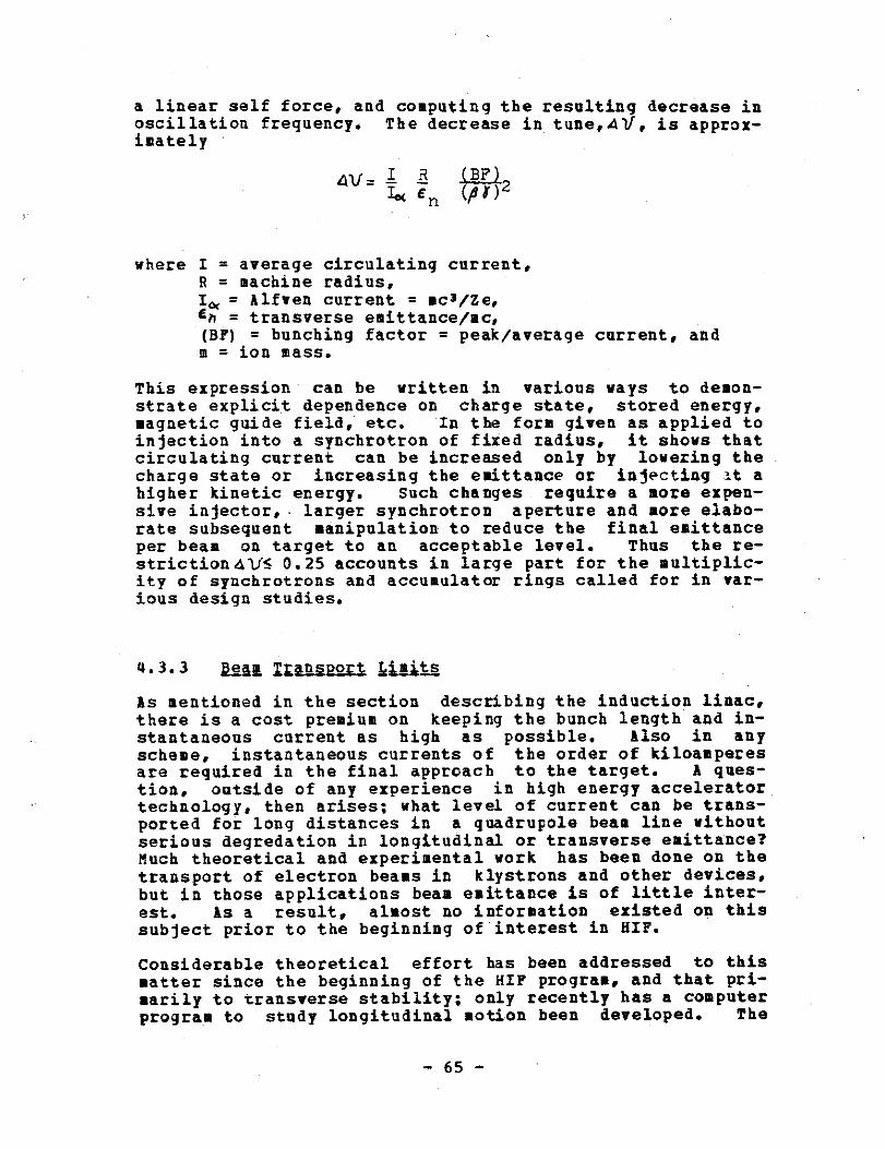
a linear self force, and computing the resulting decrease inoscillation frequency . The decrease in tune,4 V, is approx-imately
4V= Ia En(p1) 2
where I = average circulating current,R = machine radius,I.,= Alfven current = ∎c3/Ze,En = transverse emittance/mc,(BF) = bunching factor = peak/average current, andm = ion mass .
This expression can be written in various ways to demon-strate explicit dependence on charge state, stored energy,magnetic guide field, etc . In the form given as applied toinjection into a synchrotron of fixed radius, it shows thatcirculating current can be increased only by lowering thecharge state or increasing the emittance or injecting :t ahigher kinetic energy . Such changes require a more expen-sive injector, larger synchrotron aperture and ∎ore elabo-rate subsequent manipulation to reduce the final emittanceper beam on target to an acceptable level . Thus the re-striction 4 V5 0 .25 accounts in large part for the multiplic-ity of synchrotrons and accumulator rings called for in var-ious design studies .
4 .3 .3
Beam Transport Jilits
As mentioned in the section describing the induction linac,there is a cost premium on keeping the bunch length and in-stantaneous current as high as possible. Also in anyscheme, instantaneous currents of the order of kiloamperesare required in the final approach to the target . A ques-tion, outside of any experience in high energy acceleratortechnology, then arises ; what level of current can be trans-ported for long distances in a quadrupole beam line withoutserious degredation in longitudinal or transverse emittance?Much theoretical and experimental work has been done on thetransport of electron beams in klystrons and other devices,but in those applications beam emittance is of little inter-est . As a result, almost no information existed on thissubject prior to the beginning of interest in HIF .
Considerable theoretical effort has been addressed to thismatter since the beginning of the HIF program, and that pri-marily to transverse stability ; only recently has a computerprogram to study longitudinal notion been developed .
The
- 6 5 -
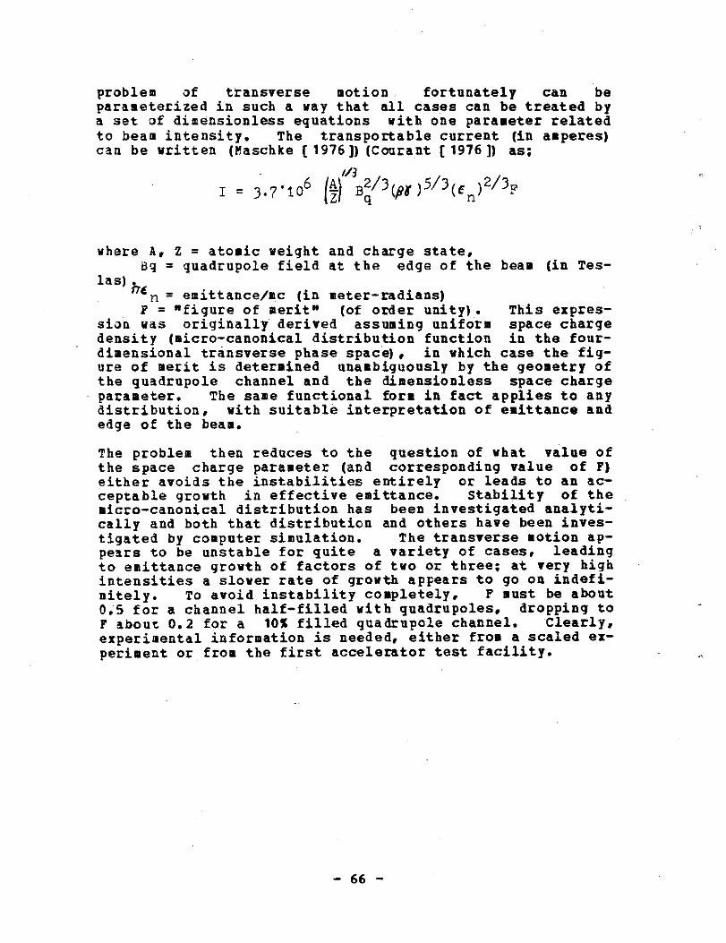
problem of transverse motion, fortunately can beparameterized in such a way that all cases can be treated bya set of dimensionless equations with one parameter relatedto beam intensity. The transportable current (in amperes)can be written (Maschke [ 1976 ]) (Courant (1976]) as ;
' i/j
I = 3 .7 .106 ,Z) Bq/3(,BA )5/3( En )2/3F
where A, Z = atomic weight and charge state,Bq = quadrupole field at the edge of the beam (in Tes-
las) he n = emittance/mc (in meter-radians)F = "figure of merit" (of order unity) . This expres-
sion was originally derived assuming uniform space chargedensity (micro-canonical distribution function in the four-dimensional transverse phase space), in which case the fig-ure of merit is determined unambiguously by the geometry ofthe quadrupole channel and the dimensionless space chargeparameter. The same functional form in fact applies to anydistribution, with suitable interpretation of emittance andedge of the beam .
The problem then reduces to the question of what value ofthe space charge parameter (and corresponding value of F)either avoids the instabilities entirely or leads to an ac-ceptable growth in effective emittance . Stability of themicro-canonical distribution has been investigated analyti-cally and both that distribution and others have been inves-tigated by computer simulation . The transverse notion ap-pears to be unstable for quite a variety of cases, leadingto emittance growth of factors of two or three ; at very highintensities a slower rate of growth appears to go on indefi-nitely . To avoid instability completely, F must be about0 .5 for a channel half-filled with quadrupoles, dropping toF about 0 .2 for a 10% filled quadrupole channel . Clearly,experimental information is needed, either from a scaled ex-periment or from the first accelerator test facility .
BIBLIOGRAPHY
(Maschke (19761) A . Maschke, Private Communication, Brookha-ven National Laboratory
(Courant [1976]) E . D . Courant, LBL 5543, 1976
Chapter 5
HEAVY ION FUSION IMPLEMENTATION PLAN
Three possible schedules for implementation of a HIF facil-ity will be examined in this chapter :
1 . The first, labelled the "fast" program, would com-plete a 1-3MJ driver by about 1986 if a strong B 6D effort was undertaken beginning in 1979 . Thusthe fast program could result in making up theperceived difference between the status of ICFand :9FE, at least insofar as the driver system isconcerned .
2 . The second, labelled the "staged" program, wouldtake two to four years longer, but would entailsubstantially less risk . Assuming that HIF fund-ing is increased to an appropriate level by FY1981, the staged program would approximatelyachieve the schedule suggested by Deutch [1978](see Fig . 1) and Battelle [1978] for the decisionpoint for the ETF driver .
3 . The third, labelled the "delayed" program, extendsindefinitely the time required to determine if theHIF approach can succeed in the role of the driverfor a commercial fusion power plant . The delayedprogram, if continued at the same pace beyond FY1980, appears to be too slow to meet the DOEschedule for choosing between alternative drivercandidates .
5 .1 QQ-NS-URU-CTI_QN_ SCHEDULE
Since the ultimate aim of this plan is the construction oflarge accelerator facilities for use as ICF drivers, it isuseful to explore how such construction should occur . AnHIF driver, of good efficiency and high repetition rate,could be built rapidly, partially because of the advancedstate of accelerator technology . A rapid constructionschedule is practical because ;
1 . In any large accelerator, most of the cost is foritems whch are replicated ∎any times .
Also, if
- 6 8 -
one includes housings in this category, most ofthe cost is for products of conventional technol-ogy which are readily available from industrialsources,
2 . The relatively recent appearance on the market ofmini-computers for process control, (which owessuch of its technological inspiration to accelera-tor-related applications) has had the effect ofstandardizing the hardware components of accelera-tor control systems . This was historically one ofthe expensive "custom" engineering tasks on everyaccelerator .
3 . Once the main accelerator is under construction,the engineering staff is able to turn its atten-tion to the details of the special systems such asthe beam transport interfaces between major por-tions of the accelerator system . This dual use ofstaff has been repeated several times on big ac-celerator projects . It results in substantialpersonnel savings by reducing the number of paral-lel engineering projects .
4 . Large accelerators not only can be built rapidly,but for economic reasons, they should be . Thesurest way to increase costs on a large technolog-ical project is by a long, delayed constructionschedule . It has been by necessity that all largeresearch accelerators of recent years have been"on time" and "under budget."
The statement that the HIF driver could be built rapidly isnot equivalent to a statement that construction should startin the immediate future. There are two classes of R & Dthat should be carried forward for at least two years beforea decision to begin construction would be appropriate :
1 . The first of these is in the general scope of thepresent ICF program, particularly in pellet andreactor systems studies . It is demonstrably truethat the vast majority of ICF pellet studies havebeen tailored to suit lasers which, as a genericclass, have relatively low energy, high power pul-ses . A great deal of effort from the HIF commu-nity has gone into trying to match the laser par-ameters in the 100 kJ, 100TH range. It turns outthat this is a particularly poor match for thecharacteristics of heavy ion accelerator drivers .Larger targets, requiring pulses of higher energyand relatively modest peak power, are a such bet-ter match for accelerators and also, apparently,are more appropriate for commercial power reactors(Battelle [1978]) .
- 6 9 -
Systems studies are also needed to identify thecharacteristics of practical, economic reactors .Designs suitable for use with high energy chargedparticle drivers may be quite different from reac-tors designed for use with lasers or light, lowenergy charged particles . In particular, althoughthere appear to be pressure regions in which thefinal transport process is stable, there appearsto be no uncertainty about the stability of thisprocess in a vacuum . Thus work on an evacuatedreactor vessel could avoid needless complicationsfor the HIF driver .
2 . The second class of needed R E D is for the injec-tion and low-beta part of the heavy ion accelera-tor . The acceleration of high-intensity, lowcharge state, heavy ions is an essential departurefrom past experience . As in any area of technol-ogy, one expects to make considerable improvementin subsequent designs after some experience .Also, the results of tests with the injector andlow-beta accelerator may profoundly affect the de-sign of the main accelerator . Even though thelow-beta part of the complete accelerator repre-sents a small fraction of the total cost, R & Dand experimental verification in this area may paylarge dividends in the final system .
Assuming that the R E D suggested above has been completed,the appropriate construction schedule can be patterned afterthe schedules for other accelerators and other similar scaleprojects . An example of such a schedule, beginning with theonset of construction funding, is the following ;
1 . Year 1 ; Preliminary design, R 6 D, build proto-types .
2 . Year 2 ; Final design, site preparation, test pro-totypes.
3 . Year 3 ; Begin construction, design special items .
4 . Year 4; Finish conventional facility construction,begin installation of accelerator components .
5 . Year 5; Finish installation, preliminary check-outs .
6 . Year 6 ; operational checks and debugging.
This total construction schedule is six years, including oneyear before actual groundbreaking and one year for finishingtouches while debugging is in progress . Including the twoyears of R & D, the total period needed is eight years .
- 70 -

5 .2 PRO_G-$A--j1 OPTIONS
5 .2 .1
Past L21U
The schedule described above, which will be called the"fast" program, is probably within about one year of the op-timum period needed to construct a 1-3MJ driver along thelines of the systems described in the appendices . However,at the present time, there are significant drawbacks to fol-lowing a fast schedule, including ;
1 . the financial impact that a strong commitment to asingle approach would have on other avenues of fu-sion research,
2. questions about the design of pellets that may beresolved with the existing ICF program, and mayindicate different ranges of parameters for HIFdrivers,
3 . the possibility of missing some cost-saving inno-vations that might be demonstrated by a broaderbased accelerator R E D effort, and
4, the risk that the accelerator say not be able toperform to theoretical expectations . Assuranceagainst such an eventuality is contained in the"staged" program described below .
If in spite of the aforementioned drawbacks, the necessarypolitical, technical and financial conditions could be si-multaneously met, the fast program has the advantage of thelowest cost for the driver . Also, the speeded up schedulemakes for the lowest total cost to determine whether ICFpower is an attainable goal . The conditions that need to bemet include ;
1 . Politically ; it would require recognition that anaccelerated ICF program committed to the HIF op- .tion is a proper strategy, particularly if by sucha program, other fusion approaches are curtailedor even stopped .
2 . Technically ; it would require evidence from otherparts of the ICF program that HIF has persuasiveadvantages over other drivers, as well as a highprobability of success . .
3 . Financially ; it would require financial supportbeyond the present DOE-ICF program . In additionto expansion of the DOE-ICF program, funding couldbe obtained from other sources such as by collabo-ration with industry and/or foreign governments .
The DOE-ICF program could be supplemented bysupport from the utility industry, (for example,through the Electric Power Research Institute,EPRI) . 'It could also be increased by a combinedprogram to investigate the electro-nuclear breed-ing of fissile fuel with either large acceleratorsor with neutrons from fusion-reactions . Otherpossibilities include the collaboration with for-eign governments on the (unclassified) driver partof the program, or with other U .S. agencies inter-ested in pulse power systems .
5 .3 JI S_TT-1GEDD PROGFBM
The program towards a heavy ion fusion accelerator systemmay be divided into the following chronological periods ;
1 . Conceptual design and system studies ; including R& D on critical components and experimental testsof theoretical predictions of high intensity beanbehavior .
2. Accelerator qualification ; including source quali-fication, construction of prototype components andconceptual design of the accelerator systems forthe HIDE and ETF facilities described below .
3 . Heavy Ion Demonstration Experiment (HIDE) ; includ-ing the construction of adequate amounts of eachsubsystem to establish all technical, operationaland cost factors . HIDE also includes beam propa-gation and target coupling tests at the 20M3/glevel .
4 . Engineering Test Facility (ETF) Driver ; includingupgrading HIDE to the 1HJ, 100TW level for scien-tific breakeven tests .
5 . Experimental Power Reactor (EPR) Driver ; includingfurther upgrades (to the 3-1OPIJ, 300-600Th levelif that is appropriate) with high repetition rateand high efficiency .
6 . Commercialization ; including continued acceleratorsystem improvements .
If for each of the chronological periods listed above, acorresponding "milestone" is established, then one can spec-ify technical levels, or stages, which one must achieve be-fore committing the next larger increment of funds . Thisprocess very much reduces the risk of a failure at some
- 7 2 -
level causing a large waste of resources because allsubstantive technical questions are scheduled for resolutionat the earliest possible stage. A very preliminary versionof such a plan follows :
1 . Stage 0
The present
period ;
funding at$3-SM/yearAccelerator theory and conceptual design ; Buildand test ion sources . Do very limited R E D onlow-beta accelerators . Due to budgetary limita-tions, conceptual design activities have had to berestricted to consideration of only the two mostpromising driver candidates (rf linac plus accumu-lator rings and single-pass linear induction ac-celerator), and only the most critical problems ; avery narrow program .
It would be unfortunate if it turns out to be mandatory toselect a leading and an alternative HIF driver candidate atthis stage of program funding, before there exists scien-tific evidence upon which to base such a decision . However,if this decision is forced, one would expect that an impar-tial ad hoc advisory panel would be formed ; that it would becharged with considering the entire ICF driver program torank all of the potential power plant driver candidates ; andthat until such time as large construction commitments haveto be made, DOE would endeavor to maintain viability of thebest of these driver candidates by funding their respectiveR & D programs .
2 . Stage 1 One year at $10M and 3 years atf25M/pear plus about f5M/year for equipment . Thefirst year is a transition year for staffing anddesigning experiments . The funds are assumed to R& D operations . However, about E10-15M per yearcould be designated construction funding, so longas the total of approximately $30M per year wasmaintained . Design and construct acceleratorqualification facilities and do conceptual designfor HIDE, ETF (> 1NJ), and EPP ; including prelimi-nary R & D on critical components of each candi-date system . Continue accelerator theory studiesand experimental tests of theoretical predictionsof the behavior of high intensity beams .
Design and build a significant accelerator quali-fication demonstration for each of the two mostpromising heavy ion driver candidates . By defini-tion, the accelerator qualification experimentsshould be a significant step, in both energy andcurrent, beyond the low level experiments of Stage0 . They should be aimed toward providing a con-vincing demonstration that the design concepts forthe driver are well founded and are scalable . Ap-proximate goals, as perceived at this time, are ;
a) For the single pass, induction linac ; a beamenergy of approximately one kilojoule seems asuitable point from which to extrapolate toHIDE from the Stage 0 experiments . It is an-ticipated that all of this work will be prop-erly R S D operations plus equipment . LBL hasmade a rough estimate of $8M per year includingabout $2M for equipment .
b) For the rf linac approach ; a linac "tree" (ofat least two branches) with frequency jumpingand longitudinal phase space matching, followedby a 200MV linac, followed by a low-energy, ul-tra-high-vacuum, storage ring, would test thecritical questions . ANL has made a preliminaryestimate of E35-50M for this work, depending oncertain options (e .g ., going only to 100MV), ofwhich an unknown fraction is equipment . TheANL estimate is contained in a proposal for do-ing this work as a construction project usingexisting facilities being vacated as the ZGS isshut down at ANL. However,' if it is possibleto begin the project sooner as an R & D effort,that option would be preferable . The balanceof the listed funds, (about $4M operating and$1M equipment) would be primarily for sourceand low-beta accelerator development .
- 7 4 -
During the third year, a decision would be made to determinethe accelerator system to be built for HIDE (Stage 2, be-low) . This decision would commit the HIP accelerator commu-nity to join forces . If another accelerator system stillappears to offer ultimately superior advantages for a powerplant driver, it may be supported at an R S D level as analternative approach .
The logic for the Staged Program is illustrated by the HIPEngineering Development Scenario in Fig . 15 . Phase I in thefigure corresponds approximately to Stage 1 in this descrip-tion . There is a decision point after Phase I depending onthe success of pellet physics at that time, i .e., roughly1983 . If the pellet physics program has been successful andthe pellets are well understood, it would be appropriate todesign and build HIDE in such a way as to make it upgradableto become the ETF and eventually the EPR drivers . That pathis assumed in the following discussion . However, if thepellet physics is less well defined, it might be appropriateto develop HIDE into a facility just to do pellet experi-ments, continuing to a 1MJ HIDE-upgrade or HUP, to do high-gain pellet experiments . The implications of this decisioncannot be defined this early, but ∎ay include the speed offunding and the location of the HIDE and HUP facilities .
3 . Stage 2
One year at $40M and 2 years at$50M/pearDuring the first year, finish qualification evalu-ation and initiate construction of HIDE . Alsoduring the first year, organize the consolidationof the HIP community for the HIDE project . con-tinue R & D stage on the rest of the driver and dodetailed design work for HIDE . Continue R & D onalternative approach if one is chosen . During thenext two years, construction of the Heavy Ion Dem-onstration Experiment (HIDE) ; construct sufficientamounts of each different part of the system todemonstrate all technical, operational and costfactors . Test bean propagation in a scaled expe-riment . Test target coupling at the 20MJ/q level .
4 . Stage 3
3 years at S150M/yearMegajoule driver ;
the Engineering Test Facility(ETF) ; If chosen as the ETF driver, the HIDE fa-cility would be expanded and completed to the

5 .
1-3MJ level .
Stage 4
3 years at S200M/yearMulti-megajoule driver ; the Experimental Poweractor ; The 1MJ driver is upgraded to becomeEPR driver .Typical parameters ;
Beam EnergyParticle EnergyPeak Beam PowerAverage Beam PowerEfficiencyPulse Repetition Rate
If this schedule is followed beginning with the onset ofStage 1 by FY 1980, the HIDE facility would be available by1987 . The megajoule driver could then follow as early as1990. If a decision were made to push for earlier availa-bility of the 1MJ system, two to three years could be savedbetween Stages 1-3 by a faster funding schedule . The totalcost would be the same or slightly less . (Considerably lessif escalation is considered .)
When the above schedule is compared with the Fusion Develop-ment Plan in Fig. 1 (Deutch (1978]), it is noted that thetime required to advance from the ETF decision point to theoperational ETF is reduced from about nine years to three,or perhaps four to allow for the onset of construction .Similarly, the time to build the EPR is reduced from sevenyears to three or four . These reductions are possible be-cause the HIF accelerator is assumed to have been designedfrom the outset to be upgradable at each stage and to even-tually meet the requirements anticipated for a commercialpower plant .
5 .3.1 D-e-1-a-yed Proara.
The third option, labelled "delayed program," is essentiallythe present level of funding, about $3 .5M/year, continuedbeyond FY 1979 . A number of projects that had just beenstarted in expectation of modest budget increases that wouldpermit them to be carried out, have had to be stopped be-cause of the decrease in funding . The net effect on thecontinuity of the research, and on the abilities of the lab-oratories to retain vital personnel, say be worse than justto delay HIF . When compared with the accelerator B & D ef-fort in HEP, the present level of funding of HIF driver R &D is estimated to be too low by about a factor of three forthe task at hand . At the present level, the funding is"subcritical ." It is urgent to at least restore the cuts
- 7 6 -
3-10MJ10-20GeV
300-600TW150MW
20-30 %15 pps
Be-the

that were suffered between the FY 1978 and PY 1979 budgetsin order to return the HIP effort to criticality .
This funding level delays indefinitely the determination ofwhether heavy ion accelerators can be used as drivers forcommercial ICP power plants . It will certainly cause theHIP option to be inadequately developed by the time a deci-sion should be made on the choice of a driver for the ETF .The DOE policy on fusion, projects a total expenditure ofsome 3188 in the next two decades to determine if fusion canbe a practical energy source . By supporting HIP at thelevel proposed for the staged program, rather than by delay-ing it at the present level, it should be possible to getanswers to the questions of practicality of ICF severalyears sooner than projected .

BIBLIOGRAPHY
(Deutch [1978]) STATEHEN_T_ ON PUSI_O ENEBGj, HOUSE c_QIilI_TT- E-E-2d S_cIE_C__E iD TECHNOL-O-G-j, John M . Deatch, Director, Of-fice of Energy Research, U .S . Department of Energy, Sep-tember 18, 1978
(Battelle (1978]) ENGINEERING D_E-YELQZBNT PROGAAN _MN F2aINERTIALL CONFINEMENT. F-OS-ION_, Draft of Volume II, ProgramStrategy, PBL-2582, Battelle, Pacific Northwest Labora-tories, Richland, Washington, March 1978 .
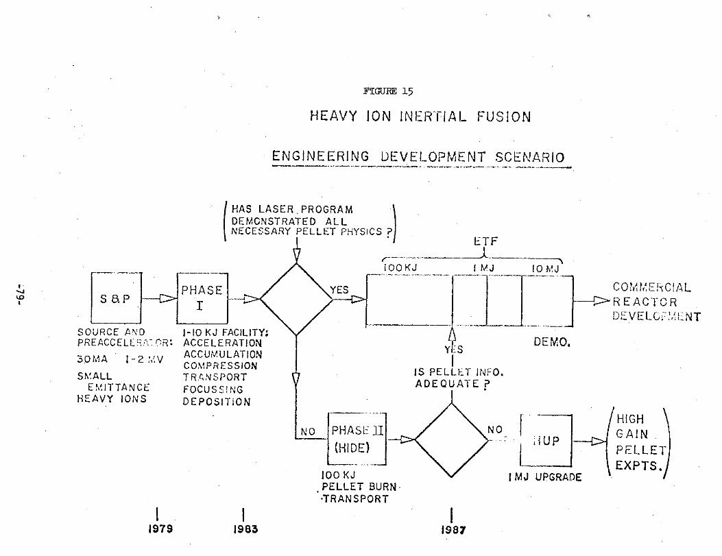
PHASEI
S aP
SOURCE ANDPREACCELLR (-.R'
30MA
1-2 :,.V
SMALLEMITTANCE
HEAVY IONS
11979
I-10 KJ FACILITY:ACCELERATIONACCUiAULATIONCOMPRESSIONTRANSPORTFOCUSSINGDEPOSITION
HAS LASER .PROGRAMDEMGNSTRATED ALLNECESSARY PELLET PHYSICS ?
1983
FIGURE 15
HEAVY ION INERTIAL FUSION
ENGINEERING DEVELOPMENT SCENARIO
ETF
1 OO KJ
I MJ
10 MJ
Y S
IS PELLET INFO .ADEQUATE?
PHASE 1I
(HIDE)
100 KJ
1 MJ UPGRADEPELLET BURN-
.TRANSPORT
1987
DEMO.
JUP
C0:'v MEkC!AL--
REACTORDE VELC ?/LNT
C
HIGHGAINPELLETEXPTS .
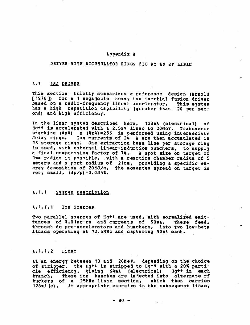
Appendix A
DRIVER WITH ACCUMULATOR RINGS FED BY AN BF LINAC
A .1
fi. QR- I--VE- R
This section briefly summarizes a reference design (Arnold[1978]) for a 1 ∎egajoule heavy ion inertial fusion driverbased on a radio-frequency linear accelerator . This systemhas a high repetition capability (greater than 20 per sec-ond) and high efficiency .
In the linac system described here, 128mA (electrical) ofHg+$ is accelerated with a 2 .5GV linac to 20GeV . Transversestacking (4x4) x (4x4)=256 is performed using intermediatedelay rings . Ion currents of 24 A are then accumulated in18 storage rings . One extraction beam line per storage ringis used, with external linear-induction bunchers, to supplya final compression factor of 74 . A spot size on target of1mm radius is possible, with a reaction chamber radius of 5meters and a port radius of 21cm, providing a specific en-ergy deposition of 20MJ/g . The momentum spread on target isvery small, (dp/p)=0 .035% .
A .1 .1
SSis-tem_ Descript,1o-n
A .1 .1 .1
Ion Sources
Two parallel sources of Hg+l are used, with normalized emit-tances of 0 .O1mr-cm and currents of SOnA. These feed,through dc pre-accelerators and bunchers, into two low-betalinacs operating at 12 .5MHz and capturing 40mA each .
A .1 .1 .2
Linac
At an energy between 10 and 20MeV, depending on the choiceof stripper, the Hg+1 is stripped to Hg+s with a 20% parti-cle efficiency, giving 64MA (electrical) Hg+ • in eachbranch . These ion bunches are injected into alternate rfbuckets of a 25MHz linac section, which then carries128mA(e) .
At appropriate energies in the subsequent linac,
- 80 -
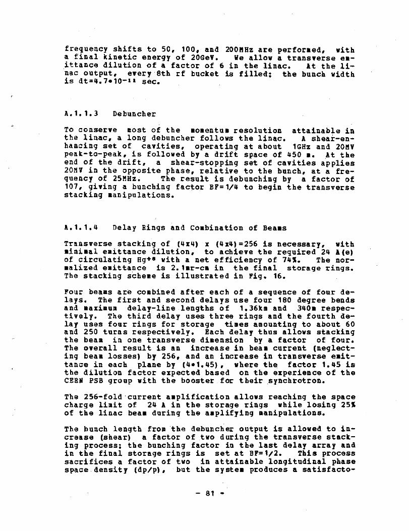
frequency shifts to 50, 100, and 200MHz are performed, witha final kinetic energy of 20GeV . We allow a transverse em-ittance dilution of a factor of 6 in the linac . At the li-nac output, every 8th rf bucket is filled ; the bunch widthis dt=4 .7 •1 0-11 sec .
A .1 .1 .3
Debuncher
To conserve most of the momentum resolution attainable inthe linac, a long debuncher follows the linac . A sheaf-en-hancing set of cavities, operating at about 1GHz and 20MVpeak-to-peak, is followed by a drift space of 450 ∎ . At theend of the drift, a shear-stopping set of cavities applies20MY in the opposite phase, relative to the bunch, at a fre-quency of 25MHZ . The result is debunching by a factor of107, giving a bunching factor BF=1/4 to begin the transversestacking manipulations .
& .1 .1 .4
Delay Rings and Combination of Beams
Transverse stacking of (4x4) x (4x4)=256 is necessary, withminimal emittance dilution, to achieve the required 24 A(e)of circulating Hg+' with a net efficiency of 74% . The nor-malized emittance is 2 .1mr-cm in the final storage rings .The stacking scheme is illustrated in Fig . 16 .
Four beams are combined after each of a sequence of four de-lays . The first and second delays use four 180 degree bendsand maximum delay-line lengths of 1 .36k∎ and 340∎ respec-tively . The third delay uses three rings and the fourth de-lay uses four rings for storage times amounting to about 60and 250 turns respectively . Each delay thus allows stackingthe beam in one transverse dimension by a factor of four .The overall result is an increase in beam current (neglect-ing beam losses) by 256, and an increase in transverse emit-tance in each plane by (4 .1 .45), where the factor 1 .45 isthe dilution factor expected based on the experience of theCERN PSB group with the booster for their synchrotron .
The 256-fold current amplification allows reaching the spacecharge limit of 24 A in the storage rings while losing 25%of the linac bean during the amplifying manipulations .
The bunch length from the debuncher output is allowed to in-crease (shear) a factor of two during the transverse stack-ing process; the bunching factor in the last delay array andin the final storage rings is set at BF=1/2 . This processsacrifices a factor of two in attainable longitudinal phasespacee density (dp/p), but the system produces a satisfacto -

rily small value which should be quite sufficient to avoidchromatic aberration problems in the final focus .
The delay rings (as well as the final storage rings) have arotation time of 0.88 usec, an average radius of 18 .511, andan average dipole field of about 2 T . The delay rings, andthe storage rings during the fill cycle, operate on a har-monic number h=22, with single turn injection .
The rings in each array are filled sequentially ; then thebeams are simultaneously extracted, combined with the beanfrom the previous array (except for the last array) usingfour septum magnets, and the combined beam is used to fillone ring at a time in the next array .
A .1 .1 .5
Storage Rings and Butchers
The 18 final storage rings are filled sequentially, usingone-turn injection, with successive 22 bucket bursts fromthe last delay array . The bunching factor is BF=1/2 .
After each ring is filled, the 22 circulating bunches areadiabatically debunched and rebunched using rf cavities intoone 440 nsec bunch, maintaining BF=1/2 . At extraction time,the bunches in all storage rings are simultaneously ex-tracted into beam lines that pass through an external line-ar-induction compressor . The latter provides a final com-pression factor of 74 (above the space-charge limit), with122MV . The bunches are restored in the rings for the firstpart of the collapse and the collapse is completed duringpassage through the beam lines leading to the target cham-ber .
Economy is obtained in the bunch compressors by stacking thegroup of 9 beam lines (from each half of the final storagering array) in a common compressor aperture, using inte-grated 3 x 3 quadrupole arrays .
A .1 .1 .6
Final Transport and Focusing
Transport of 160 Terawatts (unshaped 1113 pulse 6 nsec long)in 18 beam lines, i .e ., 9TA per beam, requires an averagequadrupole field of 4 Tesla (50% packing factor), with Hg*mat 20Gev, with un-normallized emittance of 2 .1mr-cm .
A target spot radius of 1 .06mm is allowed for 111J of 20GeTHg, which has a range of 0 .7 g/cm, maintaining 209J/g speci-fic deposition . With the an-normalized emittance 4 .4mr-cm,we require a minimum port radius of 21cm for a 5m radius re-
- 8 2 -

action chamber . The momentum spread of the beam after finalcompression is calculated to be (dp/p)=0 .00035.
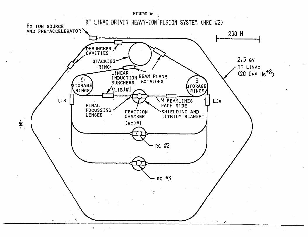
HG ION SOURCEAND PRE-ACCELERATOR
FIGURE aS
RF LINAC DRIVEN HEAVY-ION :FUSION SYSTEM (HRC #2)
1200 M
0
woo
EBUNCHER /CAVITIES
STACKINGRING'
9!TORAGERINGS
LIB/FINALFOCUSSING
REACTIONLENSES
CHAMBER(RC)#1Aft,w,,r~
9TO RAGERINGS
LINEAR.INDUCTION BEAM PLANEBUNCHERS ROTATORS
9 BEAMLINES
[ LIBEACH SIDESHIELDING ANDLITHIUM BLANKET
RC #2
RC #3
2,5 GvRF LINAC(20 GEV HG +8 )

A .2 1EMJ Ac-CELE&ATOE SS STEM
The following section is taken from a conceptual design de-veloped by Maschke (1978] . A Heavy Ion Accelerator systemis described which is based upon existing technology, andwhich is capable of producing 150MW of average bean power in10MJ, 200TW bursts, 15 times per second . It consists of anrf linac which accelerates doubly ionized uranium ions to anenergy of 20GeV . Then by utilizing the well known procedureof multiturn injection, a 6 .6-msec-long burst of linac cur-rent is stored in eight separate "accumulator" rings . Atthe conclusion of the filling process, a pulsed rf systembunches the beam in each of the eight rings simultaneously .As the bunches decrease in length, they are then extractedfrom the rings and transported for about 1km to one of five"boilers", in which the thermonuclear pellet has beenplaced . The eight beams (2 opposing clusters of four beamseach) are then focused simultaneously onto the pellet .
A .2 .1 G-gn-2L11 Descrip jo-g
For the purpose of this study, it has been assumed that ura-nium ions are accelerated . Any one of several other ionsincluding xenon, mercury, gold or bismuth could have beenused without having a significant effect on the design . Theions start out of a rather conventional source, and are ac-celerated first in a 500kv high-gradient dc column . A beanof 50mA of U+1 is produced at the end of the column. Itwould be preferrable to have a higher current, and a highervoltage . Both choices here are made because they are ratherconservative and do not represent a significant extrapola-tion from electromagnetic isotope separation experience .The design current for the - linac is 160mA, obtained bystarting with eight linacs of 20mA each. As the ions gainenergy, the bunches of bean are combined, until finally allthe current is in a single structure . The acceleratorstarts out as a cascade of eight 2MHz Wideroe linacs, in-jecting into four 4MHz Wideroe linacs . At about 6MeV thebeam is stripped to U42, with about 50% efficiency, i .e .,the current of U+2 is still the same as it was for the U+1 .At about 13MeV, the beams are combined into two 8MHz Wideroestructures . At 30MeV, the beams of 8OmA each are combined ina 48MHz Alvarez linac . At 120MeV this beam is matched intoa 96MHz Alvarez, and at 480Mev into a 192MHz Alvarez . The192MHz structure is continued until the final energy of20GeV is reached .
At this point the beam is injected into a very long (6 .3 ki-lometer) "multiplier" ring. Ten turns are injected intothis ring by means of ∎ultiturn injection into the horizon-tal phase space .
At the completion of the 10 turn filling,
- 8 5 -

the beam is extracted, the horizontal and vertical phaseplanes are exchanged via a series of skew quadrupoles, andthe beam is multiturned into the aperture of a multiplierring of 100 meter radius . we have now a current amplifica-tion factor of 100 . This beam is now transferred to one ofthe eight waiting accumulator rings . The linac beam couldhave been multiturned directly into the accumulator . How-ever, because small losses occurring during ∎ultiturn injec-tion could affect the vacuum, and since the vacuum require-sent in the multiplier rings is at . least an order ofmagnitude less than for the accumulators, it is safer tohave separate rings for this purpose . The stacking arrange-ment is illustrated in Fig . 17 .
After all eight accumulator rings are filled the beams arebunched with a low frequency (1st harmonic of the rotationfrequency) pulsed rf system . This starts a longitudinal"implosion" of the bunch which carries the beam a factor often over the "space charge limit" of the accumulator . Thisis possible because of the transient nature of the implo-sion . When the beams are extracted, another factor of fiveincrease in the current occurs in the 1km drift from theaccumulator to the boiler . . At this point the eight beamsare simultaneously focused onto the pellet, with an instan-taneous current of 2500 amperes in each of the beams .
The entire cycle takes 6.6ms, and is repeated 15 times persecond . The beam is transported alternatively from oneboiler to another . Each boiler is fired 3 .75 times per sec-ond .
A .2 .2 Retailed kcceler-at - Dess-ii
No substantive effort was made in this study to optimize thedesign in any real sense . Rather, the emphasis was put onexhibiting a design that requires the least departure fromexisting technology . It is important to remember that it isonly within the past year that a development effort has beenstarted to advance the state of the art in the area of heavyion accelerators for inertial fusion . Therefore a similarstudy, started in a few years from now, could be expected toincorporate many new features which are at present only inthe "concept" stage .
A .2.2 .1
Preinjector and Ion Source
For purposes of this study a 500kV Cockcroft-Walton acceler-ator is taken for the dc terminal. This is a conservativechoice between a desire for high voltage to alleviate space
- 86 -
charge problems versus a fear of breakdown and contaminationdamaging a higher voltage accelerating column . Extensiveexperience at GSI at 320kv indicates that one could easilygo somewhat higher in voltage. If 400kv had been chosen forthe terminal voltage, the overall design of the facilitywould not be altered appreciably . Ion sources of a typesuitable for injection into a preinjector acceleration col-uma have been developed for protons with currents on the or-der of an ampere. Child's law, from which one calculatesthe space charge limited extracted current, requires thatthe current vary inversely with the square root of the at-omic number . This means that we might expect currents about15 times smaller for heavy ions . The performance assump-tions made here require a beam of about 40mA from each ofeight accelerating columns . Isotope separation sources, de-veloped over the past 35 years, have routinely producedheavy ion beams of currents higher than required here . Forpurposes of this study, U+1 has been selected as the ion tobe accelerated in the "pre-stripper" portion of the acceler-ator. The final choice would be decided on the basis ofrather subtle differences between species . Isotopic purity,ion-ion cross sections, stripping considerations, etc ., willall play a role in the final choice . None of these consid-erations are expected to make a significant difference ineither the design of the facility or its performance . If aparticular species was found to have unusually small ion-ioncharge-exchange cross section one might chose to alter thescenario to take advantage of the resulting longer beamlifetime in the accumulator rings . However, using a geome-tric cross section as an upper bound, the system consideredhere loses only about 1% of the beam .
1 .2 .2 .2
Low-beta Linac Portion
A 500 kev heavy ion has a velocity of about .002 c. This isabout a factor of 2 .5 times lower than any existing heavyion accelerator . (A Model Heavy Ion Linac with beta=0 .003has operated successfully at BNL .) Because the drift tubesbecome so small, it is necessary to go down in frequency asthe velocity decreases. If one took the GSI wideroe linacas an example, one might consider scaling that to 2 .5 timeslower frequency, i .e., 10MHz . However, space charge forcesare another factor which must be taken into account .
Longitudinal space charge forces become more severe as thebunches become shorter. Therefore, the maximum transporta-ble current is inversely proportional to the frequency. Ifone assumes that some ratio of longitudinal space chargeforce applied to rf focusing constitutes a longitudinal cur-rent limit, then it follows that i(max) is proportional toTE/(fA), where T is the kinetic energy of the ion, E is the
-87-

average accelerating field, f is the frequency, and A theatomic number .
An estimate of what can be expected can be obtained empiri-cally by examining the performance of an accelerator operat-ing near its longitudinal space charge limit, of which theFNAL 200MeV proton linac is probably the best example. Us-ing the FNAL peak current figures of 300-400.A, one obtainsthe following approximate relation for heavy ions; (f/E)=10and i(max)=20mA . For this study E was about 0 .2MV/m andf=2MHz. This choice is not completely arbitrary . For in-stance, as one increases E, and increases the frequency atthe same time, the drift tubes become shorter, the aperturebecomes smaller and the transverse focusing requirement be-comes more severe . Ir the model described here, the longi-tudinal "synchrotron" oscillation frequency is below that ofthe transverse "betatron" oscillation frequency . This situ-ation remains throughout the linac . A choice of high gra-dient and high frequency could lead to a situation where thelongitudinal frequency is greater than the transverse .Sometime before the end of the linac, this relationshipwould have to be reversed . The coupling of transverse andlongitudinal motion can give rise to emittance blow-up, andis to be avoided where possible .
Table 3 shows the sequence of events as one goes from the2MHz, 20mA injector to the beginning of the 160.A, 192MHzlinac section . The columns i(tr) and i(lo) are the ratiosof the injected current to the space charge limited currentin the transverse and longitudinal dimensions, respectively .Note that the current is taken as the limiting value at in-jection to the 2MHz section . The most severe problem occursat the injection into the 48MHz Alvarez . If one was limitedat injection into the 2MHz structure, then an emittanceblow-up of about (1 .34)3/2=1 .55 would be expected .
TABLE 3
,
Parameters at injection to each linac section .
E q v/c f i i (tr) i (lo)
0 .5MeV 1 .002116 2MHz 20mA 1 . 1 .2 .0 1 .004232 4 40 .63 1 .6 .4 2 .007570 4 40 .32 .704
12 .8 2 .010706 8 80 .36 1 .30 2 .016390 48 160 1 .1 1 .34
120 2 .032781 96 160 .69 1 .34480 2 .065562 192 160 .43 1 .34
-88-
If we assume an adiabatic damping of the longitudinal phasespace, and further assume that the phase length of the beanat the entrance to each new linac system is the same, wethen find the following relation ;
(v/cf)(zR)1/3=coast .
This allows one to determine reasonable beta values at whichto jump the frequency without losing beam . For differentfrequency linacs with the same average electric field, onesees that one must double the velocity if one rants to dou-ble the frequency. For this example, if one did not want abunch of greater phase length than that at the beginning ofthe 2MHz structure, one obtains :
v > 6 .2•10-*fc(zE)1/3
where f is in MHz, and E in MV/meter .
A .2 .2 .3
Low-beta Alvarez Portion
After a suitable length of 8MHz Wideroe linac one can jumpto an Alvarez structure at 48MHz . The longitudinal accept-ance is increased in the Alvarez because it has an averageaccelerating field in the neighborhood of 1MV/meter . Thefirst set of Alvarez tanks are about 45 meters long . Thenthe frequency doubles, and after 135 meters of 96MHz struc-ture we go to 192MHz. This is the frequency which will bekept for the remainder of the linac . About 80 meters of the192MHz linac are included in the low-beta portion . This isthe section of the system which would be replicated for re-dundancy to provide higher reliability and to permit ∎ainta-nence on one low-beta linac while the rest of the system re-mains in operation . In the later portion this redundancywill not be necessary because individual rf stations can beserviced while the bean accelerator is operating .
Alvarez linacs in both this frequency range and velocityrange have been built previously and present absolutely nonew scientific or technical problems . However, the highcurrent and the beam loading percentage are unprecedented .More than 50% of the rf power will be going into the beam .While the FNAL linac has accelerated much higher currents,the pulse length was rather short, and the acceleration de-pended on energy stored in the cavities. The highest longpulse currents are about 100mA at the BNL linac (pulselength about 200 usec) . The 160mA assumed for this designis 60% higher than at BNL, but is not expected to presentany serious problems.* The duty cycle assumed is 10% maxi-mum ., which is relatively modest compared to the 25-35% dutycycles used in existing heavy ion linacs .
- 89 -
A .2 .2 .4
Alvarez High-beta Section
The high-beta portion of the linac is not like any existinglinac . Whereas the Alvarez structure obtains its best shuntimpedance in the range between beta's of .1 to .4, the ex-isting .proton linacs in this velocity range are of necessityquite different . While a proton will go through this veloc-ity range in about 50 meters, the heavy ion linac requiresabout 5km. The change in structure from one tank to anotheris almost negligible . At the beginning of this section oflinac, a synchrotron oscillation is about 82 meters long .Tanks 6 meters long would add 20Mev to the beam . If a sin-gle 6 meter cavity was turned off, a 10% increase in the ac-celeration of 5 upstream and 5 downstream cavities couldcompensate for this loss . This fact makes the reliabilityof the high-beta portion very much greater than it would beotherwise .
Because heavy ion fusion power stations are likely to belarger than conventional single unit power sources, the re-liability of the ignitor is of rather greater concern . At aconventional or nuclear energy center, single units areabout 1GWe .
The cavity design for the approximately 1000 cavities re-quired in the high-beta section is especially simple . Be-cause the ions have an energy of about 1Gev at the inputend, the ratio of voltge gain/gap to total kinetic energy isvery small (about 200 times smaller than for protons) . Whatthis means is that the effect of gap-defocusing is verysmall, and can be ignored without effecting anything . Also,the transverse emittance is about ten times smaller than fora similar proton linac. The consequence of this is that thedrift tubes do not require magnetic lenses placed in them .These two factors allow one to make substantial design sim-plifications . The focusing elements can be inserted in theinter-tank regions, where their outer diameter is not con-strained, and they can be simply maintained . The drifttubes themselves need never be aligned, because there are nolenses in them . The tank becomes a simple welded steelstructure, the inside of which is then copper plated .
The principal cost item for the high-beta section is the rfsystem. It consists of 1000 2.5-3 .0MW rf drive systemscapable of operating with a 10% duty cycle, and 6 .6ms longpulses . A number of options are available for the rf and a∎ore detailed design is required to chose between them . New200fHz kylstrons are just beginning to enter the market and
--------------------
* some design studies for high current linacs used to breedfissile material have considered currents as high as 300mA .
- 90 -
9
appear like an attractive solution . The rule of thumb,$10/watt for peak, f1/watt for average does not appear to befar off the mark .
An interesting consequence of the small longitudinal phaseadvance in each cavity is that it is not necessary to pro-vide amplitude modulation (i.e ., feedback) on all of the rfsystems . Roughly speaking, it is sufficient for only onecavity in 10 to control its amplitude during the pulse toadjust for time dependent beam-current fluctuations or drivefluctuations in the different rf systems .
3 .2 .2 .5
Multiplier Rings
These rings are a novel part of this linac/accumulator scen-ario . The current multiplication in the accumulator is afactor of 100 over the linac current . This is obtained bystacking in the horizontal and vertical phase space . Inprincipal, this could be done by putting 100 turns into aring in one single operation. However, in the spirit ofthis design study, it was decided to use a ∎ore conservativetechnical solution involving two multiplier rings ; one witha circumference of 6 .3 kilometers and another with a 630 me-ter circumference. The large ring is a race track shapedand encloses the entire rf linac . The linac injects tenturns into the horizontal phase space of the long multiplierring . This ∎ultiturn injection process is straight-forward .The first multiturn injection into a strong focusing syn-chrotron was done at the BNL AGS, and since has been in useat many accelerator laboratories. The next step is to ex-tract the beam from the long multiplier ring, and rotate thebeam by 90 degrees, i .e ., exchange horizontal for verticalphase space . This can be done either with a solenoid orwith a series of skew quadrupoles (quadrupoles rotated 45degrees from their normal configuration) . This beam is nowmulti-turned into the small multiplier ring, where onceagain ten turn aultiturn injection is performed . Upon com-pletion of this ∎ultiturn process the resulting beam is adi=abatically "bunched" by a small rf system on the 1st har-monic of the revolution frequency . Then the beam isextracted, without loss, and transferred to one of the eightaccumulator rings .
There are several advantages to this process over that ofinjection directly into all the accumulators . First, we re-quire only the two sets of simple aultiturn hardware . Sincethe bean remains in the multiplier only about 1/8 as long asin an accumulator, the vacuum requirement is such less se-vere. Therefore the chance that bean losses ∎ay effect thevacuum are reduced . Furthermore, since aultiturn injectionis the only function done in the multiplier rings,
it is
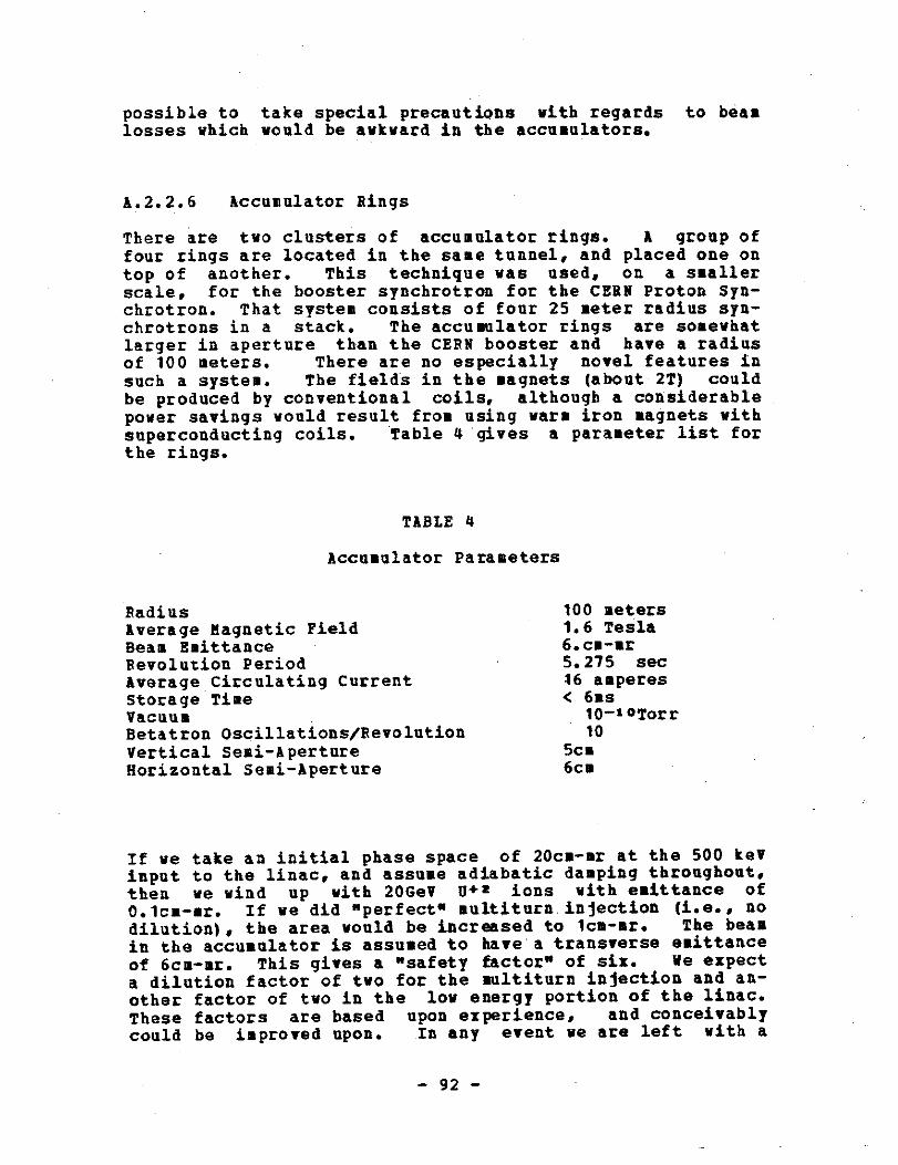
possible to take special precautions with regards to beamlosses which would be awkward in the accumulators .
A .2 .2 .6
Accumulator Rings
There are two clusters of accumulator rings . A group offour rings are located in the same tunnel, and placed one ontop of another . This technique was used, on a smallerscale, for the booster synchrotron for the CERN Proton Syn-chrotron. That system consists of four 25 meter radius syn-chrotrons in a stack . The accumulator rings are somewhatlarger in aperture than the CERN booster and have a radiusof 100 meters . There are no especially novel features insuch a system . The fields in the magnets (about 2T) couldbe produced by conventional coils, although a considerablepower savings would result from using wars iron magnets withsuperconducting coils . Table 4 gives a parameter list forthe rings.
TABLE 4
Accumulator Parameters
dilution), the area would be increased to 1cm-mr . The beamin the accumulator is assumed to have a transverse emittanceof 6cm-mr . This gives a "safety factor" of six .
We expecta dilution factor of two for the multiturn injection and an-other factor of two in the low energy portion of the linac .These factors are based upon experience, and conceivablycould be improved upon .
In any event we are left with a
- 92 -
RadiusAverage Magnetic FieldBeam EmittanceRevolution Period
100 meters1 .6 Tesla6. cm-ar5 .275 sec
Average Circulating CurrentStorage Time
16 amperes< 625
10-10TorrVacuumBetatron Oscillations/Revolution 10Vertical Semi-Aperture 5c∎Horizontal Semi-Aperture 6c∎
If we take an initial phase space of 20cm-mr at the 500 keVinput to the linac, and assume adiabatic damping throughout,then we wind up with 20GeV 0+z ions with emittance of0 .1cm-mr . If we did "perfect" multiturn .injection (i .e ., no

residual safety factor of 1 .5. This is not very large, andillustrates the importance of determining the performance ofthe low energy sections before designing the final portions .
Each accumulator acquires the longitudinal phase space areaof a total of about 84 of the 2MHZ bunches . Each 2MHz bunchhas longitudinal emittance of about .008 volt-seconds .Therefore the entire accumulator has a longitudinal phasespace corresponding to 1 .3 volt-seconds, assuming a factorof two dilution in the linac . Nov chromatic aberrations inthe final focus restrict the momentum spread in the beam .Given the requirement to bunch the beam, in order to obtainthe requisite "peak currents", this translates into a limi-tation on the longitudinal phase space . Taking a 1/2% valuefor dp/p, and 20ns for the half width of the bunch we obtaina requirement of 4 volt-seconds . This leaves a safety fac-tor of three for the longitudinal emittance . It is worthnoting that the safety factors for both the transverse andlongitudinal phase spaces could be increased by adding ∎oreaccumulator rings. If the number of accumulator rings weredoubled it would only increase the system cost by 20% .
A novel feature of the accumulator rings is the rf system tocompress the beam longitudinally . Experiments at BUL havedemonstrated that a rapid bunching of the beam can producebeams of higher currents than the space charge limit wouldimply because of the transient nature of the bunching . Eachof these accumulator rings contains 100 small, low impedancecavities. These cavities are driven by a spark-gap switchedresonant circuit . A voltage of approximately 10MY/turn isapplied for 20-40 turns at the frequency of the first har-monic, i .e., around 200 kHz . Because systems to do thishave not yet been built, and design work is just beginning,it represents the greatest cost uncertainty . The system isclearly buildable, but engineering is necessary to pin downthe costs and produce optimized designs .
The storage times in the accumulator rings vary from 6as forthe first one filled, to only a few hundred microseconds forthe last one . Assuming that hydrogen is the principal back=ground gas, then a vacuum of 10-toTorr will result in alifetime for stripping, i .e ., U+2 to U' 3 , etc . on the orderof 400ms. Therefore, on average, less than 1% of the beamwill be lost on this account . Nevertheless, this representsabout 1MN of average bean energy lost in the accumulator .Special precautions will have to be taken to collect theseparticles on appropriately designed aperture stops. Thiscare is important for two reasons ; one is that careless han-dling of these lost particles could cause physical damage tothe vacuum chambers and/or deterioration of the vacuum, andthe other consideration is that of activation of the machinecomponents . It is desirable to keep the machinery as freeof residual radioactivity as possible .
Fortunately, heavy
- 9 3 -
nuclei with energies of 85Hev/nucleon tend to stop beforehaving a nuclear interaction .
An appropriate choice of ma-terial can further minimize the amount of residual activityproduced .
It is a design option, of course, to improve the vacuum tobring it into the 10 - f1Torr range . However, bean loss dueto the ion-ion charge exchange from the collision of parti-cles within the beam among themselves may become important .There is no direct experimental measurement of the chargechanging cross sections, say 0+2 + O+2 to 0+3 + etc .
Plau-sible estimates of the cross sections put the lifetime inthese accumulators at about 1 second . The lifetime could beincreased by using a larger radius accumulator . Lifewise, alower betatron frequency would also increase the lifetime .Since the lifetime increases as Rs/2, the loss rate could behalved by increasing the radius from 100 meters to 132 me-ters .
A .2.2 .7
Transport and Final Focus
Before the longitudinal bunching process has terminated inthe accumulator rings, the beams are extracted and trans-ported for a distance of about 1 kilometer to the targetchamber . During this time the bunch continues to shorten,until at the end of the transport the instantaneous currentin each beam has risen to 2500 amperes, or a peak power of25 TV/beam . The eight beams result in a total of 200TW forabout 50 ns, corresponding to the total input energy ofMi . Pulse shaping can easily be done by shaping and tim-ing of the eight separate bunches .
The beams are transported in tunnels containing four beams .The beams consists of series of quadrupoles whose strengthincreases somewhat as the bean gets closer to the boiler .The transport consists of 10cm diameter iron quadrupoles,employing superconducting coils as an energy conservingmeasure . Since this is a "once-through" system, the vacuumover most of the 1 kilometer can be in the 10-'Torr range .In the last 100 meters, these will be a transition to ahigher pressure, perhaps to 0 .03 Torr at the boiler di-rectly . The principal limit on the peak current in thesetransport lines is the beams , own space charge, which tendsto defocus the beam . The currents assumed in this study are .able to be transported without resorting to any neutraliza-tion schemes, although savings would result if space chargeneutralization is shown to be a possible solution to thetransport problem .
For the last few meters of bean transport,
the beam iswithin the boiler, and must be focused to a suitable spot .
- 94 -
In this case, a spot size of about 0 .5cm diameter isrequired . The magnetic quadrupoles would probably be 5-10meters from the final focus . Because of the close integra-tion of the final focusing elements with the boiler, no ef-fort was made in this study to attempt a design or cost es-timate for these lenses . These costs would be included aspart of the boiler cost .
Each of the quadrupole focusing elements subtends a solidangle of about 0 .015 steradians . All eight of then then in-tercept about 1% of the pellet energy . One important conse-quence of this is that one can quite readily afford to takespecial precautions to protect the front surface of theselenses, which one might not wish to consider for the entireboiler . Theiefore, the radius of the boiler and the focallength of the lenses do not have to coincide . It is quiteplausible to have the lenses "protrude" into the chamber .
There have been suggestions made that an intense beam ofheavy ions might propagate in a self-focusing mode throughthe chamber if the pressure was in the 1Torr range. If thisturns out to be the case it would be a considerable simpli-fication . Lacking experimental confirmation, it seems pru-dent to assure that one can obtain satisfactory performancein a vacuum . The "gas" expected in the boiler is in factpredominantly metal vapor . This would come from either thepellet, the walls or a liquid heat transfer median in theboiler . These metal vapors are easily condensed out by aspray of colder material . This same spray of cold liquidmetal will also extinguish any plasma in the chamber, which∎ay have been residue from the previous shot . The metalspray is the logical equivalent of the exhaust stroke of aninternal combustion engine .
Appendix B
SINGLE PASS DRIVER WITH AN INDUCTION LINAC
B .1
1MJ D-AVER_ S_YSTE!_i
The following description of a 1MJ Linear Induction Acceler-ator LIA, is taken from an LBL report (Keefe (1978]) . Theaccelerator is designed to accelerate uranium in one bunchfrom a 1MeV source to a final energy of 19GeV . The sourceis assumed to be a large area contact ionization type simi-lar to the one ampere cesium source under development atLBL . However, other high current heavy ion sources might beequally, or even more, suitable . The beam is initially ac-celerated by a three stage, pulsed drift tube linac DTL(Faltens [1977]). A stripping cell and charge separatinganalyzer are located between the second and third drifttubes . The beam is then accelerated by a series of lowvoltage induction acceleration modules in the q=+4 chargestate to an energy of 200Mev . This completes the injectorportion of the accelerator .
For the bulk of the acceleration, from 0 .20GeV to 19Gev, thecurrent level at any energy is continuously adjusted bybunch length control to be near the cost minimum . Near theend of the accelerator a modest energy tilt is applied inorder to compress the bunch and increase the beam power tothe desired 100TW level . The beam implodes somewhat like anelastic spring (Judd [1977]) . The energy tilt and bunchshape are controlled so that at the time of the beam's pass-ing through the final focusing magnets, the space chargeforces of the bunch remove the previously applied energytilt . At the end of the final acceleration/compression sec-tion, and before the final focusing lenses, the beam issplit vertically and horizontally by thin septum magnets tofacilitate focusing onto the target . In this type of sys-tea, since one bunch is split transversely, timing is deter-mined by path lengths to the target and the final beamletswould be in perfect synchronism .

B .1 .1 Detgil-ed Descr ptjoe of the j_c_c_e_1_epator,
B .1 .1 .1
The Injector
This section describes one possible way of achieving the in-itial acceleration of a charge of more than 150uC to about200Mev . other conceptual designs have been and will be pur-sued for this energy interval . While this interval repre-sents less than 1% of the particle energy required at thetarget, it presently accounts for several percent of thecost and a larger fraction of the technical problems . Thealternative designs, such as the one presently being inves-tigated by Herrmannsfeldt (1978], offer promise of verylarge cost reductions, but will require comparative evalua-tions and detailed designs . The system described here ac-celerates the entire charge in three large drift tubes whichare followed by a low gradient induction accelerator sec-tion .
The accelerator begins with injection of 7 .5A of U+' from alarge area, 1MV source into a 1MY drift tube about 27 meterslong . The source may be of the contact ionization type(Hashmi (1975]) which would supply uranium ions of very lowtransverse energy and which would be of similar design tothe LBL Cs ion source. Alternatively, it may be of an en-tirely different type and for some other heavy element of A> 200 . However, the calculations are all based on a uraniumsource . The drift tubes are pulsed in a bipolar manner toprovide 2MV potential difference each . At the end of thesecond drift tube, the particles are stripped in a heliumgas cell and the q=+4 charge state selected . It is assumedthat the loss in particle number is compensated by the in-crease of charge state in such a manner that the requiredcharge of 210uC is obtained at the output . The beam is far-ther accelerated in the third drift tube with ramped volt-ages in order to start decreasing the pulse duration . It isclear that the beam energy as a function of longitudinalposition should be constant up to the analyzer . However, itis not yet certain what the maximum energy tilt limit is forthe transport system and how rapidly the pulse duration canbe decreased . In this scenario, the voltage at the input tothe third drift tube is taken as a flat 1MY, and the voltageat the output as a linear ramp in time from 0 to 1MY .
The drift tubes are followed by a series of low voltage in-duction acceleration modules . The core cross section is de-termined by the time integral of core voltage . Therefore atilt in voltage waveform ∎ay be superimposed on the averagevoltage of the pulse without any increase in core size . Therear particles of the bunch must have somewhat higher energythan the front particles in order to decrease both the phys-ical bunch length and the pulse duration .
At the beginning
- 97 -
of the induction section, the acceleration rate has anaverage value of about 20kV/m, or 80 keV/m for the q=+4charge state . At this average acceleration rate the bunch,which is initially about 70m long, at an average energy of12MeV, should have a tilt of t 2.8MeV just to maintain itslength, and a somewhat larger tilt in order to start bunchlengthh compression . Later in the acceleration process therequired ramp is fractionally such smaller . The maximum en-ergy tilt desired may be obtained in a distance shorter thanthe initial bunch length if the induction units are drivenwith triangular voltage pulses, while a longer distance isrequired with a less steep voltage ramp . For simplicity, weassume that the particles in the middle of the bunch are ac-celerated at the average rate permitted by the inductioncores . The induction cores used at the beginning all have aconstant cross section which is sufficient for 1 volt-secondof acceleration . As the beam pulse is accelerated its dura-tion is decreased as V-s/6, and consequently the accelera-tion rate is increased .
Some of the above may be clarified by a sequence of energyprofiles of the bunch as a function of z at constant t atseveral locations, and of the core voltage pulses at theselocation as a function t, shown in Fig . 18 .
In addition to the linearly-rising voltage waveforms re-quired for pulse shortening, it is necessary to counteractthe average longitudinally defocusing electric field at theends of the bunch, arising from the space charge . This maybe accomplished by applying opposite polarity steep ramps or"ears" which form a sort of rf bucket for the particles .Because the beam generated electric field varies across theradius of the beam, there is no wavefor∎ which may be exter-nally applied to compensate for the space charge forces onall of the particles . Instead, for a sufficiently strongapplied field, there will be an equilibrium bunch shape .Individual particles will slowly oscillate longitudinally asin an approximately square potential well .
The transverse focusing within the drift tube section isprovided by periodic electrostatic focusing . The focusingwithin the induction section is with internal quadrupoles .
In addition to the electrostatic focused DTL, other possibleinjection systems for the LIA that have been considered in-clude ;
1 . drift tubes with very large, high field solenoids,
2 . an rf linac plus a low(Godlove (19761) ;
energy accumulator ring
3 . recirculating the beam through the low energy ac-celerator structure with rapid multiple pulsing(Faltens (1977)),, and
4 . a tree of linacs to build up to the requisite cur-rent level .
With any of these injection systems, the goal is to matchthe output current of the injector to the transportable cur-rent limit of the quadrupole focusing system of the acceler-ator . As examples, this limit is about 1A at 1MeV and 7A at10MeV for U+1 in a 4T FODO lattice with a normalized beamemittance of 3cm-mrad . Because the acceleration cost permeter is a rapidly decreasing function of energy, it is de-sirable to inject at as high an energy as possible. Alter-native designs are evaluated on the basis of their cost perunit of bean energy as a function of beam energy .
B .1 .1 .2
Accelerator Modules with Quadrupole Focusing
Several packaging configurations are possible for the induc-tion accelerator modules and focusing quadrupoles. At lowenergies, the space needed for focusing magnets, and thecore requirements, combine to provide very low average ac-celerating gradients . As acceleration proceeds, a smallerfraction of the accelerator length needs to be devoted tothe magnets, and the accelerating modules themselves changein appearance . Peak voltage constraints become dominant asthe particle energy is increased and the pulse duration de-creased . The differential cost of acceleration is a mono-tonically decreasing function of particle energy. This re-sults in a proportionately small increase in cost for alarge increase in beam energy when the system is desired tobe extended .
B,.1 .1 .3
Modulator Requirements
The driver or modulator must supply current to the inductioncore and to the beam . The core current may have a varietyof waveforms while the magnitude of the core current ∎ay begreater than or less than the beam current . The beam cur-rent has a magnitude which is determined by the transverseand longitudinal focusing requirements of the bunch, and isan increasing function of the particle kinetic energy--ofthe order of amperes at 1MeV for U+L and kiloamperes atGeVenergies . Near the end of the pulse the current to the corerises rapidly as saturation is approached .
- 99 -
At the low-energy end of the machine the bean current ∎ay beignored, and a modulator-compensating network combinationconstructed to generate a voltage wavefor∎ which would beoptimized for one voltage level and pulse duration . A suit-able pulse generating circuit could be a tapered-impedance,lumped-element transmission line . The calculated energy re-quired to drive the accelerating core has been doubled toarrive at total modulator energy requirements, thus account-ing for uncertainties in core losses, and for energy putinto compensating networks, dissipated in the circuitry, andleft in the modulator after the pulse. The core require-ments are easily measured, and part of the core evaluationprogram will be to select the best material and core geome-try and to determine how far into saturation any core shouldbe . driven . The preliminary estimates are that most coreswould dissipate less than one kilojoule .
At the high-energy end of . the accelerator, the beam currentbecomes the major load for the modulator . To guard againstdamage in the event that the modulator is pulsed in the ab-sence of beam, a resistive load may be placed in parallelwith the core to help limit the open circuit voltage and togreatly increase the pulse damping rate . For initial esti-mating purposes, the energy required by the core plus thebean has again been doubled to arrive at total modulator re-quirements . In the high energy region, the energy requiredper unit is only about 100 joules, and several acceleratingunits ∎ay be driven in parallel with one modulator. In allcases enough damping will be provided between sections toprevent dumping most of the energy at any one location inthe event of a fault . A suitable pulse generating circuithere would be a Blumlein pulse line and a spark gap switch .If a resistor placed in parallel with the core is chosen sothat under normal operating conditions the current flowinginto it is equal in magnitude to the beam current, then inthe absence of the beam the accelerating gap voltage is lessthan 1/3 higher than the voltage in the presence of thebeam, while the acceleration efficiency would be near 50%when normal beam current is present .
B .1 .1 .4
Final Bunching and Acceleration Section
The acceleration voltages are ramped steeply in the finalsection to provide simultaneous acceleration and tilting ofthe momentum ellipse . At the end of this section, the beanis split transversely into four beans, which are thenbrought separately to the target, with two beams incidentfrom each side as shown in Fig. 19 .
Assuming an average acceleration rate of 0 .8MV/m, this sec-tion of modules will occupy a length of 1km, acceleratingthe q=+4 beam from 16GeV to 19Gev, while the beam splitters,final focus, and bending will require about 350m along thebeam path . The applied voltage pulses in this final sectionconsist of three major parts : the accelerating field ; thebunching rasp; and the space charge field compensating"ears ." The incident particles are assumed to have beenpreviously slightly ramped in energy in order to compensatethe bunch lengthening which would normally occur from accel-eration . At subrelativistic velocities, the bunch length Lis proportional to its velocity v with L=Li(v/vi)=1 .09 Liover the course of the last kilometer, where Li and vi arethe initial bunch length and velocity, respectively . Thiswould correspond to a bunch lengthening of about 6 metersfor the 70 meter long incident bunch . The energy tiltingrequired to keep the bunch length constant is equal to theenergy difference between the front and rear particles ofthe bunch - that is 56 q MeV for this example . This energytilt of about 1 .4% is assumed to have been applied previ-ously for bunch length control .
To achieve the desired final bunching an additional ramp of200 q clew (i .e.,±100 q Mew) will be applied within the lastkilometer. As the bunch leaves the accelerating structure,the rear end of the bunch will gain an additional 35 q Mev,because at that point the bunch will have already decreasedto half of its initial length . within the accelerator, theparticles within the bunch all move in the rest frame of thecenter of the bunch as if in a force field whose magnitudevaries linearly from the center . The collapse of the bunchis parabolic within the accelerator and linear outside .Space charge repulsive forces become dominant when the bunchis quite short, and determine the minimum length of the
B .1 .1 .5
Final Focus
Both geometric and chromatic aberrations place certain limi-tations on the nature of the final-focus lenses and indi-rectly therefore on the minimum number of beamlets that willbe required to strike the focal spot . For the example ofinterest here, it appears that geometric aberrations are thelimiting factor in determining the required number of beam-lets. If we consider focusing with quadrupole doublets (atriplet allows a little relaxation in the conditions de-scribed below), then reference to Garren (1976] shows thathis parameter b will probably be between 5 and 35, where
bunch . These repulsive forces are dependent on the current,bunch profile, beam radius and beam pipe radius .
It is ex-pected that, by proper design, most of the energy tilt whichcauses the bunch compression will be removed by the spacecharge repulsion at the end of the drift path .
b=L/(rho*theta),L=standoff distance (5-10a),rho=iagnetic radius of ion in a field equal to the pole-tipfield of the lens, andtheta=half angle of the bean at the target . Combining thisresult with those of Neuffer (1978) on the third-order aber-rations we can derive a limit on the maximum permitted ra-dial excursion X, of X < (1 to 2)r*rho, where r=focal spotradius . In many cases examined, I turns out to be of order15cm .
In addition, from Neuffer's results we can derive a limit onthe normalized longitudinal emittance that can be toleratedin a beamlet in a final focus lens: <_ 0.12*beta*gaasa*r •/ S, .For a typical case the emittance limit say be in the range0 .5 to 0 .7cm-ar .
in doublet configurations discussed by Garren, the maximumradial excursion was in the x-plane and aberration problemsare far worse in this plane than in the y-plane . This asym-metry arises because of assumptions of equal emittance inboth the x- and y-planes . Recent results by Neuffer indi-cate that the emittance in the y-plane (and hence excursionsin y) can be increased to about 1 .5 the emittance in the x-plane before aberrations in each plane have comparable ef-fects . Figure 20 shows a concept for transverse splittingof the beam into four beamlets just upstream of the finallenses by a four- way septum current-sheet magnet . (Similarschemes can be devised for 2-, 3-, 6- and 9-way splits,etc .) The septum edge is below the spall threshold, butcould if needed be armored with tantulum, titanium or car-bon. Apart from losses on the splitting septum, thereshould be very little dilution in the process despite thesomewhat irregular beam envelopes emerging from the split-ter .
We can define, for transverse splitting, the minimum numberof final beams as:
n = (2/3)(transverse emittance/longitudinal emittance) 2 .
For transverse and longitudinal emittance of 3cm-mr and0.7cm-mr, respectively, twelve beamlets, arranged for exam-ple in two clusters of six, would meet the requirements .
B .2 -10_MSJ DRIVER SYSTEM_
The sample 1MJ design described above can be expanded tohigher total energy be increasing either the length of theLIA or by increasing the charge being accelerated,
or by
- 1 02 -

some combination of both . The computer-optimized costprogram has been used to find the trajectory of minimumcosts as a function of energy which is plotted in Fig. 21 .These costs do not include injection and final transportsystems, and thus are usually considered to be about 80% ofthe completed cost estimate . They also, of course, do notinclude indirect construction costs .

1000
500
200
100Co0H
10
0 .1
FIGURE 21 : Optimized Costs for LIA Driver
(without injection and final transport)
1 .0
ENERGY (MT)
- 104 -
2 .0 5 .0 10 .0
Appendix C
IMPLEMENTATION SCENARIOS
by W . B . Herrmannsfeldt
A large number of scenarios have been suggested for the im-plementation of HIF . A selection of such scenarios is pres-ented in this appendix . Comments as to the relative meritsand problems of each scenario are the personal opinion ofthe author unless otherwise identified .
C .1
TIRE 10_171_ ICF RES 11R_C_H_ CEInE_R-
The most ambitious first step which has been suggested isprobably that of a 10MJ facility by Al Haschke . The accel-erator part of this proposal is contained in Appendix A .2 .The thinking has gone beyond the accelerator system to in-clude several target areas . These could be specially de-voted to ;
1 . pellet R & D,
2 . blast chamber testing,
3 . accelerator beam tests .
As success is achieved in each of these, targetbe adapted to testing disigns for ;
1 . tritium breeding,
2 . steam generation,
3 . fissile fuel breeding .
At even ∎ore advanced stages, target areas could devoted to ;
1 . advanced fuel pellets (i .e.,tritium) *
- 1 05 -
areas would
with little or no

2 . direct conversion of electromagnetic energy fromthe blast to electric power,
3 . direct chemical conversion (e .g, production of"natural" gas) .
The 10MJ accelerator system is intended to be large enoughto allow such a wide range of experiments while recognizingthat in the early stages, both the accelerator and the pel-lets may have to be downrated somewhat .
Comments: At $O .8B to $2 .OB, depending on whose estimatesone wishes to use, this facility is both the most expensiveand the most economic route to fusion energy . In fact, noresearch tool in history has cost so much . Since the pricedoes nut include laboratories, pellet factory, target areas,offices, etc ., the total could easily approach 13B . Para-doxically, it is also very probably the cheapest route tofusion since it would bypass years of piecemeal develop-ments, currently costing $150M/pear, but clearly underfundedat that rate . The $350M/year currently being spent by MFEis probably a better guide to what is realistically needed .By concentrating the entire ICF program on such a facilityfor a decide, one can virtually guarantee a definitivestatement at the end about the feasibility of ICF .
The largest drawback to this plan is not the price, which aswas pointed out above, is not so such ∎ore than is alreadybeing spent, but is in the political issues . The only pos-sible way in which such a project could be promoted would beby a unified push by the scientific community including, es-pecially, all parts of the fusion community . With the mul-titude of fusion schemes, both MFE and ICF, now being pro-moted, it will be very difficult to achieve such a unity inthe immediate future .
C .2 _SI11QQED- APPROACH
This scenario, based essentially on the staged program de-scribed in Chapter 5, would devote 2 1/2 to four years onaccelerator R & D along two parallel fronts ;
1 . rf linacs with current multiplying rings (possiblyincluding synchrotron rings),
2 . single pass linear induction accelerators .
At the end of this period, a decision would be made choosingone of these systems to be built on a suitable site .
- 1 0 6 -
C .3 I--NlER-_LA_B-ORATORY 4L_L_UANCES
Alliances between weapons laboratories and accelerator labo-ratories offer one of the most logical scenarios toward aHIP facility . Probably the most obvious alliance candidate .i s LBL-LLL because of their proximity . Other possibilitiesinvolve ANL and BNL as accelerator laboratories allied withLLL, Sandia or LASL, or possibly NRL, in any possible combi-nation . Yet another possiblility is for LASL, which has astrong rf linac group, to pursue HIF by itself .
Comments : There is at least some precedent for a large-scale collaboration between DOE laboratories in the jointLBL-SLAC project to build PEP . For a collaborative effortto be joined, both laboratories must see the project as be-ing to their advantage, even though the construction cannotbe located at both centers . In the case of a large HIF fa-cility, it is possible that it would not be located at anyof the existing scientific labortories . Rather some of theproduction and test facilities, such as Savannah River,Arco, Idaho, and the Nevada Test Site are probably ∎ore ap-propriate locations .
BIBLIOGRAPHY
(Maschke [1978]) CPNCEPTUIL _DESIGN OF A Hill ION F_U_SIOf E-U-EL1GY- CENTER- , A . W . Maschke, BNL 50817, Brookhaven Na-tional Laboratory, Upton, New York, March 1978
(Keefe (1978 )) LINEAR IUQDCTIOU 1LCC__EIERATQ$ CQ TICEgTUAL RE-a1§110 HIP Staff, D. Keefe, et al, HI-FAN-58, LawrenceBerkeley Laboratory, Berkeley, CA, Sept 1978
(Arnold [1978)) HEARTHPI-EE REFER--EK-E C-QEQ1ll U-0 . 22- , Arnold,Burke, Foss, Khoe and Martin, Argonne National Labora-tory, Argonne, Illinois, Sept 1978
(Paltens (1977]) OUASI-S_TAA-TTI-Q QR-I-FT_T iB IiCCELERATI-N-G_RU C_-IVEE FF-QR- L-22)j-SPEED H3kV-j IONS, A . Faltens and D . Keefe,BNL 50769,1977 .
(Judd (1977])
ESTIMATES OO-F- 1OST-" .G LE_RAATIQ! LQECQITU_QI!IL_B-UN_CC-U QO_fLESSIQ_N, D . L. Judd, BNL 50769, 1977 .
(Herrmannsfeldt (19781) A IGLjj=kt9_EHF -H_EAS1-Y TON INJECTOR_FF-O-E L NEA#_ INDUCTION_ E-C_LER-j QQfl USI N G PERIODIIc ELECt-l92jATIC FOCUS NG, W . B . Herrmannsfeldt, (ANL [1978]),Sept 1978 .
(Hashsi (1975]) QfE--SST_El SEPARATION_ 0-_P I-S_QTQP_ES U "12 A PRA-U1_0_1 P-LssfL- , M . Hashsi and A . J . Van Der Houven VanOordt, Conference on uranium Isotope Separation,BNES/KTG, London, March 5-7, 1975 .
(Godlove [ 1976 ]) AN IUD-U-C_IIQN LI__LC_ SYSTE. W TQ E L-OU=.jUE&G-jIIQC_gfQLA-I0R IN_JECTOR_, T . Godlove, LBL 5543, 1976 .
(Garren (1978)) FINAL F-QCSING QF TH-F 1_QN HAM QF_ ~, 91"_IFU-21_22 REACTOR -I QU-A- DRUPOLE D_FIETS-, A . Garren, LBL5543, 1976
(Neuffer [1978]) -GEOMEtUQ ABERjjjI-0_N IN F_IELL F_QCU_2I_UG_, D .Neuffer, HI-FAN-36, May 1978, and internal note, August1978 .
- 1 0 8 -U .S.GPO:1979-689-058(F)36