Untitled - Stanford
154
-
Upload
khangminh22 -
Category
Documents
-
view
3 -
download
0
Transcript of Untitled - Stanford


DISCLAIMER
This report was prepared as an account of work sponsored by an agency of the United States Government. Neither the United States Government nor any agency Thereof, nor any of their employees, makes any warranty, express or implied, or assumes any legal liability or responsibility for the accuracy, completeness, or usefulness of any information, apparatus, product, or process disclosed, or represents that its use would not infringe privately owned rights. Reference herein to any specific commercial product, process, or service by trade name, trademark, manufacturer, or otherwise does not necessarily constitute or imply its endorsement, recommendation, or favoring by the United States Government or any agency thereof. The views and opinions of authors expressed herein do not necessarily state or reflect those of the United States Government or any agency thereof.

DISCLAIMER Portions of this document may be illegible in electronic image products. Images are produced from the best available original document.

w --
4
id
id
~
PROCEEDINGS OF A TOPICAL MEETING ON SMALL SCALE GEOTHERMAL POWER PLANTS AND GEOTHERMAL POWER PLANT PROJECTS
-
Y
w ’ &
i
FEBRUARY 12-13, 1986 RENO, NEVADA
MEETING SPONSORED BY:
GEOTHERMAL RESOURCES CO JNCIL P.O. BOX 1350 DAVIS, CALIFORNIA 95617
PROCEEDINGS PUBLISHED BY: bid
e ENERGY TECHNOLOGY ENGINEERING CENTER P.O. BOX 1449 CANOGA PARK, CALIFORNIA 91304 UNDER CONTRACT TO U.S. DEPARTMENT OF ENERGY
(., I
il.

FOREWORD
THE REPORTS CONTAINED HEREIN ARE REPRINTED FROM THE BEST AVAILABLE COPY AND ARE SUBJECT TO THE FOLLOWING DISCLAIMER:
"Neither the United States Government nor any agency thereof, nor any of their employees, makes any warranty, express or implied, or assumes any 1 egal 15 abi 1 i t y or responsi bi 1 i t y for the accuracy, compl eteness , o r usefulness of any information, apparatus, product, or process dis- closed, o r represents that i t s use would not infringe privately owned rights. Reference herein t o any specific commercial product, process, or service by trade name, trademark, manufacturer, or otherwise, does not necessarily constitute or imply i ts endorsements , recommendation, or favoring by the United States Government or any agency thereof. The views and opinions of authors expressed herein do not necessarily state or reflect those of the United States Government or any agency thereof."
I '
L
t
T A B L E OF CONTENTS
SMALL POWER PLANT CYCLES AND PRIME MOVERS
FLASHED STEAM MODULAR POWER PLANTS Gary Shulman, Geothermal Power Co. ...................... not avai lable
i; ELECTRICAL POWER FROM MODERATE TEMPERATURE GEOTHERMAL SOURCES WITH MODULAR MINI-POWER PLANTS L. Bronicki , Ormat Systems, Inc. ...................... 7 I 4
t t
ROTARY SEPARATOR (BIPHASE TURBINE CYCLE) Walter Studhal ter , Biphase Energy Systems ................ 27
HELICAL SCREW EXPANDER POWER PLANT Roger Sprankle, Hydrothermal Power Co. ................... 39
L MODULAR WELLHEAD POWER PLANTS
f d
I,
Ken Nichols, Barber-Nichols Engineering Co. .............. 59
RADIAL INFLOW TURBINES Robin Dakin, Rotoflow Corp. ............................. 67
HYBRID PONER SYSTEM FOR A GEOPRESSURED WELL I Evan Hughes, EPRI ....................................... 79
P' Y

f '
t R
1
t
t
L

t;
I t ' Iy
J
f
TABLE OF CONTENTS ( CONT I NUED 1
SMALL POWER PLANT PROJECTS UNDER CONSTRUCTION OR NEWLY COMPLETED
BRADY POWER PROJECT Stephen Munson, Munson Geothermal ....................... .not avai lab1 e
BEOWAWE POWER PLANT PROJECT Len Elliott, Chevron Geothermal .......................... 83
HAMMERSLY CANYON UNITS Jack Wood, Wood & Associates ............................. not ava
COVE FORT FACILITY 99 Wayne Portanova, Mother Earth Industries .................
DESERT PEAK POUER PLANT (C. Diddle & W. Gonser), Phillips Petroleum .............. 107
i
lable
f L
t
i-
t
i L

TABLE OF CONTENTS (CONTINUED)
SMALL POWER PLANT OPERATING EXPERIENCE
HAWAIIAN ELECTRIC POWER PLANT George Jenkins, Hawaii E lec t r i c Co. .....................not avai lable
MAMMOTH GEOTHERMAL POWER PLANTS Richard Campbell & Ben Holt, The Ben Ho l t Co. ........... 113
DELIVERABILITY AND EFFECT ON COSTS Jon Gudmundsson, Stanford Universi ty .................... 119
UTAH POWER AND LIGHT GEOTHERMAL PROGRAM Robert Davis, Utah Power & L igh t Co. .................... 143

t '
t
L
i
f L I i
t io
f
L

ELECTRICAL POWER FROM MODERATE TEMPERATURE GEOTHERMAL SOURCES
WITH MODULAR MINI-POWER PLANTS
L. Bronicki
Pres ident and Technical Di rec tor
Ormat Systems Inc.
Sparks, Nevada, U . S . A .
A B S T R A C T
Organic Rankine Cycle Geothermal P lan t s u s i n g moderate tempera- t u r e s - ( 8 5 t o 150 degree C ) 185 t o 400 deg. F and higher - have been pioneered by ORMAT and a r e made i n s i z e s of 300 t o 1200 KW f ac to ry i n t e r g r a t e d and t e s t e d modules. The skid-mounted power package module c o n s i s t s of heat exchangers, t u r b i n e , genera tor , c o n t r o l s y s t e m s , low v o l t a 8 e s w i t c h - g e a r a s w e l l a s v a l v e s , s a f e t y c i r c u i t s and p i p i n g .
Two or more u n i t s can be combined f o r a p p l i c a t i o n s where the geothermal or i n d u s t r i a l waste heat source i s s u f f i c i e n t t o per- m i t l a r g e r power p l a n t s t o be economically i n s t a l l e d .
E x p e r i e n c e . h a s been a c q u i r e d i n o p e r a t i o n i n low e n t h a l p y g e o t h e r m a l p r o j e c t s i .n Nevada, U t a h , C a l i f o r n i a , O r e G o n a n d Mexico. discussed. Reference i s made t o pract ica l f i e l d experience wi th the un i ts i n commercial power generation, and t o automation i n the operation o f the power .plants.
Several typica l power plants rated 800 kW 3.2 MW, 7MW and 30 lilGI are
* .
. .
8
I, t
c b
t ’
I:
t i
t
f
L

1 . I N T R O D U C T I O N
T h e s m a l l m o d u l a r p r e f a b r i c a t e d power p l a n t c o n c e p t has s i g - n i f i c a n t a d v a n t a g e s o v e r c o n v e n t i o n a l d e s i g n s . W h i l e t h e c o s t per kW may b e h i g h e r , t h r o u g h r e d u c e d i n s t a l l a t i o n , ~ i t e w o r k s , e n g i n e e r i n g a n d d e s i g n w o r k , a p p r e c i a b l e s a v i n g s c a n b e r e a l i z e d . G r e a t l y r e d u c e d o p e r a t i n g a n d m a i n t e n a n c e c o s t s w i l l e n h a n c e p r o j e c t e c o n o m i c s . I n f u e l p o o r c o u n t r i e s o r i n c o u n t r i e s w i t h i n e f f i c i e n t d i s t r i b u t i o n , remote i n s t a l l a t i o n s c a n o p e r a t e o n a c o s t e f f e c - t i v e b a s i s w i t h l o n g u n a t t e n d e d c o n t i n u o u s d u t y m a i n t e n a n c e i n t e r v a l s .
O r g a n i c R a n k i n e C y c l e ( O R C ) t u r b o g e n e r a t o r s i n m o d u l a r c o n f i g u r a - t i o n p l a n t s ( O R M P ) p r e s e n t a v i a b l e s o l u t i o n i n low e n t h a l p y geo the rma l r e s o u r c e s .
9

2. THE O R G A N I C R A N K I N E CYCLE POWER MODULE
2 . General
As w i t h conventional steam t u r b i n e s the Organic Rankine Cycle Power Module ( O R M P ) i s based on t h e Rankine power cyc le ; b u t u n - l i k e steam t u r b i n e s i t uses an organic motive f l u i d i n s t ead of
' water and ope ra t e s on a s u b c r i t i c a l cycle . The organic Rankine cycle ha5 the advantage that a t moderate and low temperatures i t has higher efficiencies than the steam cycle and requires no superheating.
Modules have been b u i l t i n t he power range between 400 and 1200 kW, depending on the parameters of t h e heat source (media, tem- pe ra tu re and f l o w r a t e ) . Spec ia l ly t a i l o r e d models t o genera te power below 400 kW o r above 1200 kW have been b u i l t a l s o .
2.2 S y s t e m Operation
T h e ape ra t ion of t h e ORMP u n i t i s based on t h e organic Rankine cyc le , as follows: ( F i g . 11
Organic motive f l u i d , s e l e c t e d according t o t h e parameters of t h e h e a t s o u r c e , i s p u m p e d b y t h e f e e d p u m p i n t o t h e prehea ter /vapor izer where i t i s heated and vaporized.
T h e h i g h pressure vapor expands through t h e vapor t u r b i n e which i s d i r e c t - c o u p l e d t o a g e n e r a t o r p roduc ing c o n d i t i o n e d g r i d - synchronized e l e c t r i c power.
The low pressure exhaust vapor condenses i n a water cooled, sur- f ace condenser. The condensate i s pumped by t h e feed pump back i n t o t h e p rehea te r , t h u s completing t h e cyc le .
The thermodynamic cyc le i s shown i n a T-S diagram i n F i g 2 . The schematic flow c h a r t i s shown i n F i g . 3.
T h e geothermal ORC opera t ion corresponds t o a bas i c geothermal binary cyc le descr ibed a s fol lows ( F i g . 4):
- The geothermal f l u i d coming out from t h e well (Wg) t r a n s f e r s heat t o a low b o i l i n g poin t organic f l u i d , causing i t s vaporation ( V I
- The organic f l u i d vapor flows t o t h e t u r b i n e (TI, which i n t u r n l a connected t o a eene ra to r (GI.
i n o rder t o complete t h e cyc le and t o be re-used. - T h e organic f l u i d vapor i s condensed (C) and r e c i r c u l a t e d
10

. . . _. ..
hen1 rejection low pressure
high prrssure vapour
FIGURE 1: Organic Rankine Cycle
11

I ‘ 4
T (TEMPERATURE) I I - 2 Vaporization 2 - 3 Expansion 3 - 4 De-Superheating 4 - 5 Condensation 5 A 6 Pumping 6 - I Pre-Heating
. --. .. - - s. (ENTROPY)
FIGURE 2: T-S Diagram o f the Organic Rankine Cycle
b
t f L I -
f
i i ’ L’ 3 ’
t
12

- WATER --.c
FEED PUMP
?
FIGURE 3: Organic Rankine Cycle Power Ebdule (Schematic Flow Chart) ~f
Lr
13
!

r-
I W
z
0
I I u
I-a
UA
ww
I
Q:
3
L L i i
i t i t t i I 1
L t L i t .L 14
L

- The spent geothermal f l u i d i s r e i n j e c t e d (Wr) o r drained t o an evaporat ion pond ( L ) .
- The f u l l y automated plant i s i n s t a l l e d along w i t h a cool ing tower ( C T ) and a c i r c u l a t i n g pump.
2.3 I n s t a l l a t i o n Reauirements
The se l f - con ta ined f ac to ry t e s t e d O R P M ' s r e q u i r e a m i n i m u m of i n s t a l l a t i o n , a s f o l l o w s :
a. Prepara t ion o f a l i g h t , l e v e l concre te base of s u i t a b l e
b. Prepara t ion o f a concre te base of s u i t a b l e dimemsions
dimensions and s t r e n g t h .
inc luding a mounting f l ange f o r pos i t i on ing t h e v e r t i c a l feed pump.
thermally i n s u l a t e d pipes and and automatic c o n t r o l valves. c . Connecting t h e heat source by means of standard f l a n g e s ,
d . Connecting t h e cool ing water source by means of s tandard f l a n g e s , p ipes t o and from t h e cool ing water source , a cool ing water pump ( i f r e q u i r e d ) , shut -of f valves and f l o w switch and m o n i t o r i n g instruments .
e . E l e c t r i c a l connect ions w i t h a mul t ip l e conductor w i r i n g t o wire t h e s k i d mounted junc t ion box t o t h e power and c o n t r o l cab ine t and w i t h power cab le s t o wire t h e power c a b i n e t - t o t h e g e n e r a t o r a n d t o the g r i d .
3 , MODULAR GEOTHERMAL POWER PLANTS
I n t h e p a s t , low enthalpy l i q u i d dominated o r low p res su re steam geothermal resources could not be economically used f o r e l e c t r i - c a l power genera t ion because of a lack o f proven equipment, and hence were abandoned.
Modular Geothermal Power P l - a n t s ( M G P P ) d e s c r i b e d h e r e i n were s p e c i f i c a l l y designed t o genera te e l e c t r i c a l power economically from low t e m p e r a t u r e l i q u ' i d dominated o r low p r e s s u r e s team
The p r a c t i c a l a p p l i c a t i o n s a r e descr ibed below.
I
' geothermal resources .
3 . 1 50 kW Geothermal ORC a t Los Azufres, Mexico ( F i g . 5 )
T h i s i s one o f the f i r s t success fu l a p p l i c a t i o n s of an ORC t o a geothermal source. I t was a j o i n t demonstration p ro jec t of t h e I n s t i t u t o de Inves t igac iones E l e c t r i c a s o f Mexico and Ormat.
15

FIGURE 5 : - 50kl.f Geothermal ORC A t Los 4tufres
L 'CII
:c L
'i L! L 1 c L
i' - L
t 16 I

- T h e i n i t i a l t e s t p e r i o d was 600 h o u r s . S i n c e t h e n t h e u n i t i s operated o n a n i n t e r m i t t e n t mode. T h e l a s t se r ies of tes ts was performed i n 1985.
3.2 900 kW M o d u l a r Geothermal P i l o t P l a n t i n L a k e v i e w , O r e g o n F i g ( 6 ) .
T h e f i r s t p i l o t m o d u l a r i n s t a l l a t i o n was made b y Wood a n d A s s o c i a t e s t ' t a k e v i e w , O r e g o n . T h e t h r e e 300 kW u n i t i n s t a l l e d r a n s u c c e s s f u l l y a s a d e m o n s t r a t i o n p l a n t i n 1982 a n d i n t e r m i t - t e n t l y s i n c e t h e n .
T h i s was a l s o t h e f i r s t e x p e r i m e n t w i t h a s i m p l e c a s c a d i n g c o n f i g u r a t i o n . 3.3 F i r s t Commercial A p p l i c a t i o n of a Geothermal ORC:
The Wabuska P l a n t of T a d ' s E n t e r p r i s e s (Fig. 7 )
The f i r s t geothermal power ' p l a n t t o g e n e r a t e e l e c t r i c a l power from geothermal r e s o u r c e s i n t h e s t a t e o f ' l e v a d a was c o n s t r u c t e d b y T a d ' s E n t e r p r i s e s i n Wabuska . T h e f i r s t m o d u l e , ra ted 800 kW, has b e e n o p e r a t i n g s i n c e September 1984. T h i s O E C u n i t was i n i - t i a l l y d e s i g n e d f o r a n i n d u s t r i a l a p p l i c a t i o n a n d was m o d i f i e d a t t h e s i t e t o u s e geothermal f l u i d as a s o u r c e of power. T h e water a t 224 degrees F from a 350 f t d e e p well i s pumped a t 765 GPM p r o d u c i n g a gross o u t p u t of 750 kW. D u r i n g t h e i n i t i a l s t a r t - u p pe r iod of s i x m o n t h s , t h e a v a i l a b i l i t y was 6 5 % , t h e n i t i n c r e a s e d t o 70% a n d t h e n t o 92%. T o d a y , i t i s a t 96%. T h e u n i t d e l i v e r s 103% of t h e p ro j ec t ed o u t p u t a t t h e r a t e d c o o l i n g water flow.
3.4 S u l p h u r d a l e , Utah (Fig 8 )
T h e S u l p h u r d a l e p r o j e c t of Mother Ear th I n d u s t r i e s is a m o d u l a r power p l a n t w h i c h Ormat c o n s t r u c t e d o n a t u r n k e y b a s i s . T h e f i r s t phase , u s i n g f o u r 800 kW m o d u l e s , r a ted a t 3.2 M W , was i n - a u g u r a t e d I n September 1985. T h e power p l a n t I s operated b y t h e m u n i c i p a l u t i l i t y f o r t h e C i t y o f P r o v o w h i c h is also t h e p u r - chaser of t h e power. T h e ,power is t twheeledt t from S u l p h u r d a l e t o P r o v o o v e r U t a h P o w e r a n d L i g h t t r a n s m i s s i o n l i n e s . S i n c e s t a r t - u p , t h e f o u r u n i t s h a v e b e e n o p e r a t i n g c o n t i n u o u s l y , d e l i v e r i n g t h e p ro j ec t ed o u t p u t a t a n a v a i l a b i l i t y h i g h e r t h a n 95%.

FIGURE 6 : The 9QOkW Modular CIeothemia1 P l a n t - Lnkeview -
18
i

. . . . . *

.'hG& 8: :- The 3.2W Geothermal 'Power Plant - Sulphurdale
20

3.5 Modular Cascading Power P lan t a t Steamboat Springs, Nevada (Fig 9 1
*: r+ ,;;* *
a ) General Descr ipt ion
The 7 . 4 M W g ross ( 5 MWe n e t ) G.D.A. ProJect is loca ted a t Steam- boat S p r i n g s , Nevada. The power from t h e p l an t is s o l d t o S i e r r a P a c i f i c Power Company. The i n i t i a l s t a r t - u p was performed i n December 1985. F u l l opera t ion i s scheduled f o r June 1986.
The power p l a n t is composed o f . s e v e n OEC arraneed i n a cascading t e m p e r a t u r e c o n f i g u r a t i o n , a s shown i n Fig. 10. W i t h t h i s arrangement, four h i g h temperature ORC modules rece ive geothermal water a t 334 degrees F (168 deg. C ) from the production we l l s , and th ree low temperature ORC modules r ece ive geothermal par- t i a l l y cooled water a t 284 denrees F ( 1 4 0 deg. C ) from t h e h i g h temperature modules.
The geothermal resource is t o produce hot water a t 334 degrees F (168 deg. C ) from two production wel l s t h a t a r e equipped w i t h downhole p u m p s t o d e l i v e r s i n g l e phase l i q u i d w a t e r under pressure. T h i s hot geothermal water is a l k a l i n e a n d has a t o t a l dissolved s o l i d s content of about 2,400 ppm, which is mostly ch lo r ides of sodium and potassium w i t h some s u l f a t e , bicardonate , and c a r b o n a t e , p l u s abou t 325 ppm of d i s s o l v e d s i l i c a . T h e cooled geothermal water w i l l be t o t a l l y r e inJec t ed w i t h none of i t consumed i n t h e power generat ion process.
The hot geothermal water hea ts and vaporized an organic working f l u i d , on the she1 1 side of a she1 I-and-tube preheater-evaporator.
Some 2 0 percent of t h e gross power generated is consumed by t h e f ans , pumps, and o the r a u x i l i a r y equipment needed t o opera te t h e p lan t . The balance o r net power produced i s suppl ied t o S i e r r a Pac i f i c Power Company g r i d .
The f a c i l i t y is expected t o produce an annual average of 5 MWe (about 4 4 mil l ion kWh per yea r ) e l e c t r i c a l power f o r s a l e u s i n g e i t h e r evaporat ive o r d r y cool ing.
21
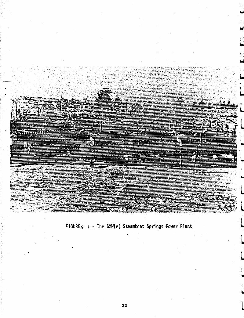
FIGURE9 : - The SMIJ(e) Steamboat Springs Power Plant
22

b ) D e s i g n C r i t e r i a
D e s i g n B a s i s A v e r a g e a n n u a l wet b u l b t e m p : 4 3 degrees F (6 deg. C ) A v e r a g e a n n u a l d r y b u l b t e m p : 50 degrees F ( 10 d e g . C )
C o o l i n g water T e m p e r a t u r e D e s i g n s o u r c e Make-up Blowdown d i s p o s a l
: 7 0 degrees F ( 2 1 deg. C ) : E v a p o r a t i v e t o w e r : F r e s h water f r o m w e l l s : E v a p o r a t i v e p o n d
Geothermal r e s o u r c e ( l i q u i d d o m i n a t e d ) Geothermal h o t water t e m p
F l o w r a t e of h o t geothermal water
D e s i g n geothermal water r e i n j e c t i o n t e m p e r a t u r e D i s p o s a l r a t e o f g e o t h e r m a l water
O E C m o d u l e s i n cascade H i g h t e m p e r a t u r e ( L e v e l I )
Rated c a p a c i t y
Low t e m p e r a t u r e ( L e v e l 11) R a t e d c a p a c i t y
Rated g e n e r a t i o n c a p a c i t y
P r o j e c t e d a v e r a g e g e n e r a t i o n c a p a c i t y
G e n e r a t o r d r i v e C o n d e n s e r
? l a n t r e q u i r e m e n t s O p e r a t i o n S t a f f i n g El a i n t e n a n c e
C o n t r o l
O p e r a t i n g l i f e
23
: 320 degrees F (160 deg. C )
: 1450000 l b s / h r . (660 t o n s / h r )
: 210 degrees F (99 deg . C )
: 1450000 l b s / h r . (660 t o n s / h r )
: 4 @ 1 , 2 5 0 kW c a p a c i t y : 5.0 MWe (gross)
: 3 @ 850 kW c a p a c i t y '
: 2 . 5 5 M W e ( g r o s s )
: 7 . 5 5 MWe ( g r o s s )
: 5.02 M W e ( n e t )
: Ormat t u r b i n e : Water c o o l e d
: C o n t i n u o u s base l o a d : R o u n d - t h e - c l o c k : D a y s o n l y : i n d i v i d u a l
m o d u l e s w i l l be t a k e n o f f l i n e f o r m a i n t e n a n c e
n o s t i c s a n d a u t o m a t i c s h u t down
: 20 yea r s .
: A u t o m a t e d w i t h d i a g -

T h e es t imated r a n g e a n d a n n u a l a v e r a g e g e n e r a t i o n c a p a c i t i e s a r e s u m m a r i z e d a s f o l l o w s :
R a n g e Minimum Maximum
A n n u a l A v e r a g e ( t i m e w e i g h t e d )
Gross C a p a c i t y 6.6 M W 8.0 M W 7 . 2 5 M W
T h e t i m e - w e i g h t e d a v e r a g e m e c h a n i c a l power p r o d u c t i o n c a p a b i l i t y i s b a s e d o n t h e power c y c l e l i m i t a t i o n s o n l y . A d j u s t m e n t s f o r a n y e l e c t r i c a l g e n e r a t o r l i m i t a t i o n s , i n t e r n a l power u s a g e , a n d a v a i l a b i l i t y f a c t o r s a r e t a k e n i n t o a c c o u n t .
3 . 6 T h e 30 M W ORMESA MGPP i n t h e I m p e r i a l V a l l e y , C a l i f o r n i a
T h i s s i t e is p a r t i c u l a r l y s u i t a b l e f o r O R C f o r t h r e e p r i n c i p a l r e a s o n s :
( 1 ) T h e geothermal r e s o u r c e i s wel l d o c u m e n t e d w i t h e x p l o r a t o r y a n d p r o d u c t i o n wel ls ;
( 2 ) T h e geothermal f l u i d i s n o n - c o r r o s i v e a n d n e a r l y p o t a b l e , a n d
( 3 ) T h e t e m p e r a t u r e o f t h e geothermal f l u i d i s a p p r o x i m a t e l y 302 degrees F ( 150 deg. C ) t o 338 ( 1 7 0 deg . C). O R C m o d u l e s d e s i g n e d a n d b u i l t by Ormat a r e p a r t i c u l a r l y w e l l s u i t e d f o r o p e r a t i n g t e m p e r a t u r e s i n t h i s r a n g e a n d h a v e a c l e a r c o m p e t i t i v e a d v a n t a g e . o v e r steam t u r b i n e s .
T h e p r o j e c t w i l l c o n s i s t o f two m a j o r e l e m e n t s : t h e f i e l d , e q u i p p e d w i t h we l l s a n d pumps; a n d t h e power p l a n t , w i t h n e c e s - s a r y a u x i l i a r y s y s t e m s . T h e p l a n t i s compr ised o f 26 t u r b i n e s s y s t e m s , r e f e r r e d t o a s Ormat E n e r g y C o n v e r t e r M o d u l e s , w h i c h w i l l h a v e a c a p a c i t y of 1.25 ME each. T h e geothermal f l u i d i s g a t h e r e d from t h e we l l s a n d t h e n p i p e d t o t h e p l a n t where t h e e n e r g y c o n v e r s i o n p r o c e s s t a k e p l a c e . T h e r e a f t e r , t h e geothermal f l u i d i s r e i n j e c t e d i n t o t h e f i e l d . No geothermal f l u i d i s c o n - s u m e d d u r i n g t h e p r o c e s s . T h e e n e r g y c o n v e r s i o n p r o c e s s i s d e s c r i b e d i n g r e a t e r d e t a i l below.
T h e f i e l d , when f u l l y d e v e l o p e d , w i l l i n c l u d e t h e e x i s t i n g s e v e n p r o d u c t i o n wel l s a n d t h r e e r e i n j e c t i o n wel l s p l u s s i x new we l l s . T h e f i e l d w i l l a l s o c o n s i s t of a d d i t i o n a l p r o d u c t i o n a n d r e i n j e c - t i o n w e l l s , d o w n - h o l e p u m p s , a n d a s u r f a c e p i p i n g s y s t e m t o g a t h e r t h e geothermal f l u i d a n d t r a n s p o r t i t t o t h e power p l a n t . A f t e r t h e f l u i d h a s b e e n u s e d a n d c o o l e d , t h e p i p i n g s y s t e m r e t u r n s i t t o t h e r e i n j e c t i o n w e l l s .
24
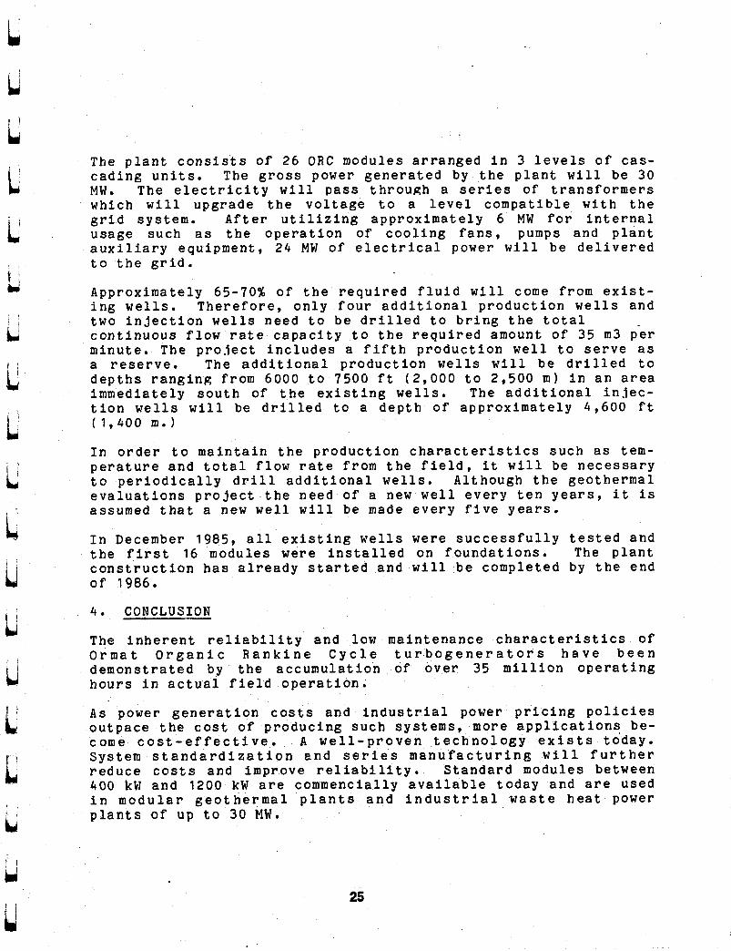
T h e p l a n t c o n s i s t s o f 26 O R C m o d u l e s a r r a n g e d i n 3 l e v e l s o f cas- c a d i n g u n i t s . T h e g r o s s power g e n e r a t e d by t h e p l a n t w i l l be 30 M W . T h e e l e c t r i c i t y w i l l pass t h r o u g h a se r ies o f t r a n s f o r m e r s w h i c h w i l l u p g r a d e t h e v o l t a g e t o a l e v e l c o m p a t i b l e w i t h t h e g r i d s y s t e m . Af t e r u t i l i z i n g a p p r o x i m a t e l y 6 MW f o r i n t e r n a l u s a g e s u c h a s t h e o p e r a t i o n o f c o o l i n g f a n s , pumps a n d p l a n t a u x i l i a r y e q u i p m e n t , 24 MW of e l e c t r i c a l p o w e r w i l l b e d e l i v e r e d t o t h e g r i d .
A p p r o x i m a t e l y 6 5 - 7 0 s o f t h e r e q u i r e d f l u i d w i l l come f r o m e x i s t - i n g wel l s . Therefore , o n l y f o u r a d d i t i o n a l p r o d u c t i o n we l l s a n d t w o i n j e c t i o n we l l s n e e d t o b e d r i l l e d t o b r i n g t h e t o t a l c o n t i n u o u s f l o w r a t e c a p a c i t y t o t h e r e q u i r e d a m o u n t of 35 m 3 p e r m i n u t e . T h e p r o j e c t i n c l u d e s a f i f t h p r o d u c t i o n wel l t o s e r v e a s a r e s e r v e . T h e a d d i t i o n a l p r o d u c t i o n wells w i l l b e d r i l l e d t o d e p t h s r a n g i n g from 6000 t o 7500 f t ( 2 , 0 0 0 t o 2 ,500 m ) i n a n a r ea i m m e d i a t e l y s o u t h of t h e e x i s t i n g wel ls . T h e a d d i t i o n a l i n l e c - t i o n wel l s w i l l be d r i l l e d t o a d e p t h o f a p p r o x i m a t e l y 4 , 6 0 0 f t ( 1 , 4 0 0 m . )
I n o r d e r t o m a i n t a i n t h e p r o d u c t i o n c h a r a c t e r i s t i c s s u c h a s tem- p e r a t u r e a n d t o t a l f l o w r a t e f r o m t h e f i e l d , i t w i l l be n e c e s s a r y t o p e r i o d i c a l l y d r i l l a d d i t i o n a l wells. A l t h o u g h t h e geothermal e v a l u a t i o n s p r o j e c t t h e n e e d o f a new we l l e v e r y t e n y e a r s , i t i s a s s u m e d t h a t a new w e l l w i l l b e made e v e r y f i v e years .
I n December 1985, a l l e x i s t i n g wel l s were s u c c e s s f u l l y t e s t e d a n d t h e f i r s t 16 m o d u l e s were i n s t a l l e d o n f o u n d a t i o n s . The p l a n t c o n s t r u c t i o n h a s a l r e a d y s t a r t e d a n d w i l l b e comple ted b y t h e e n d o f 1986.
4 . C O N C L U S I O N
T h e i n h e r e n t r e l i a b i l i t y a n d low m a i n t e n a n c e c h a r a c t e r i s t i c s o f Ormat O r e a n i c R a n k i n e C y c l e t u r b o g e n e r a t o r s h a v e b e e n d e m o n s t r a t e d by t h e a c c u m u l a t i o n of o v e r 35 m i l l i o n o p e r a t i n g h o u r s i n a c t u a l f i e l d o p e r a t i o n .
As p o w e r g e n e r a t i o n c o s t s a n d i n d u s t r i a l power p r i c i n g p o l i c i e s o u t p a c e t h e c o s t of p r o d u c i n g s u c h s y s t e m s , more a p p l i c a t i o n s be- come c o s t - e f f e c t i v e . A w e l l - p r o v e n t e c h n o l o g y e x i s t s t o d a y . S y s t e m s t a n d a r d i z a t i o n a n d s e r i e s m a n u f a c t u r i n g w i l l f u r t h e r r e d u c e c o s t s a n d i m p r o v e r e l i a b i l i t y . S t a n d a r d m o d u l e s b e t w e e n 400 kW a n d 1200 kW a r e c o m m e n c i a l l y a v a i l a b l e t o d a y a n d a r e u s e d i n m o d u l a r g e o t h e r m a l p l a n t s a n d i n d u s t r i a l w a s t e h e a t p o w e r p l a n t s of u p t o 30 MW.
25

GEOTHERMAL WATER OUT
l0O0C I . *
FIGURE 10: Omt Energy Converter Modules i n a Cascading Temperature Arrangement

R O T A R Y SEPARATOR (BIPHASE TURBINE CYCLE)
Walter R. S t u d h a l t e r B iphase Energy Systems
ABSTRACT :
The B i p h a s e T u r b i n e C y c l e u t i l i z e s an i n n o v a t i v e t o t a l - f l o w e x p a n d e r t o p roduce a d d i t i o n a l power from g i v e n l i q u i d - d o m i n a t e d geothermal wells. T h i s a d v a n t a g e may be u s e d t o r e d u c e t h e number of wells needed i n a p r o j e c t , t o r e d u c e wel l f lows and t h u s p r o l o n g r e s o u r c e l i f e and t o add f l e x i b i l i t y t o a power p l a n t t h a t operates w i t h a h a n g i n g r e s o u r c e c o n d i t i o n s . The g e o t h e r m a l e x p a n d e r , Model 54RST, has b e e n d e m o n s t r a t e d i n Utah, and a p p l i e d t o geothermal r e s o u r c e s in Utah by Utah Power and L i g h t Company, and i n Nevada by P h i l l i p s P e t r o l e u m Company. B i p h a s e was a p i o n e e r in d e v e l o p i n g t h e c o n c e p t of small ( w e l l h e a d ) , f a c t o r y pre-assembled power p l a n t s y s t e m s .
C a r e f u l a n a l y s i s of a d d i t i o n a l geothermal r e s o u r c e s has l e d t o f u r t h e r deve lopment of t h e B iphase c o n c e p t :
( a ) For h i g h e n t h a l p y and h i g h N.C. gas c o n t e n t , B special a d a p t a t i o n of t h e B lphase machine f e a t u r i n g a r e a c t i o n ro to r and i m p u l s e steam b lades .
(b) F o r r a p i d l y c h a n g i n g r e s o u r o e c o n d i t i o n s , t h e
( c ) F o r g e n e r a t i n g a d d i t i o n a l power from e x i s t i n g
Mi t su i -B iphase t o p p i n g cycle.
f l a s h p l a n t s , t h e larger Model 72RST Biphase g e o t h e r m a l machine.
STATUS OF BIPHASE GEOTHERMAL SYSTEMS:
Biphase Energy Systems began t o a p p l y t h e i n n o v a t i v e two-phase t u r b i n e t o g e o t h e r m a l power p l a n t s i n 1976. Liqu id -domina ted r e s o u r c e s d e l i v e r m i x t u r e s of steam and water w h i c h are f e d t oge the r t o t h e B iphase rnaohine t o e f f i c i e n t l y p r o d u c e power. After p r o t o t y p e programs s p o n s o r e d by DOE and B iphase , Utah Power and L i g h t Company and E lec t r i c Power Resea roh I n s t i t u t e J o i n e d forces i n 1980 t o t e s t a p r o d u c t i o n v e r s i o n of t h e geothermal t u r b i n e . Pe r fo rmance and e n d u r a n c e t e s t s were s u c c e s s f u l .
27

The Model 54RST i m p u l s e machine e n a b l e s s y s t e m s i n c l u d i n g a steam t u r b i n e t o g e n e r a t e 10 t o 30 p e r c e n t more power f rom g i v e n r e s o u r c e f l o w s . The Biphase s y s t e m u s i n g t h e Model 54RST was a l s o s ized so t h a t t h e power p l a n t c o u l d be f a c t o r y a s sembled and erected on s h o r t s c h e d u l e s n e a r wells. The "wel lhead" small power p l a n t s were p i o n e e r e d by Biphase s t a r t i n g in 1980. The idea of employing small p l a n t s in m u l t i p l e has s i n c e become dominant in p l a n n i n g f o r many r e s o u r c e s i t u a t i o n s , as t h e p a p e r s a t t h i s m e e t i n g w i l l a t t e s t .
l I
The B i p h a s e t u r b i n e c y c l e s u b s t i t u t e s t h e B i p h a s e R o t a r y Separator T u r b i n e , a Tota l Flow Expander ( T F E ) ,
I f o r a f l a s h tank i n t h e more t r a d i t i o n a l f l a s h c y c l e s . I F i g u r e s 1-4 f rom t h e r e c e n t a u t h o r i t a t i v e p a p e r on TFE
( R e f e r e n c e 1 ) show t h e s i n g l e - s t a g e f l a s h and i t s TFE c o u n t e r p a r t , and t h e two-stage f l a s h and t h e two-stage TFE system. I n t h e two-stage case, t h e TFE replaces t h e l o w - p r e s s u r e f l a s h t a n k . Note t h a t t h e B i p h a s e T u r b i n e (TFE) also s u p p l i e s i n 3 e c t i o n p r e s s u r e l e l i m i n a t i n g o r m i n i m i z i n g t h e i n j e c t i o n pumping r e q u i r e d by t h e f l a s h s y s t e m s .
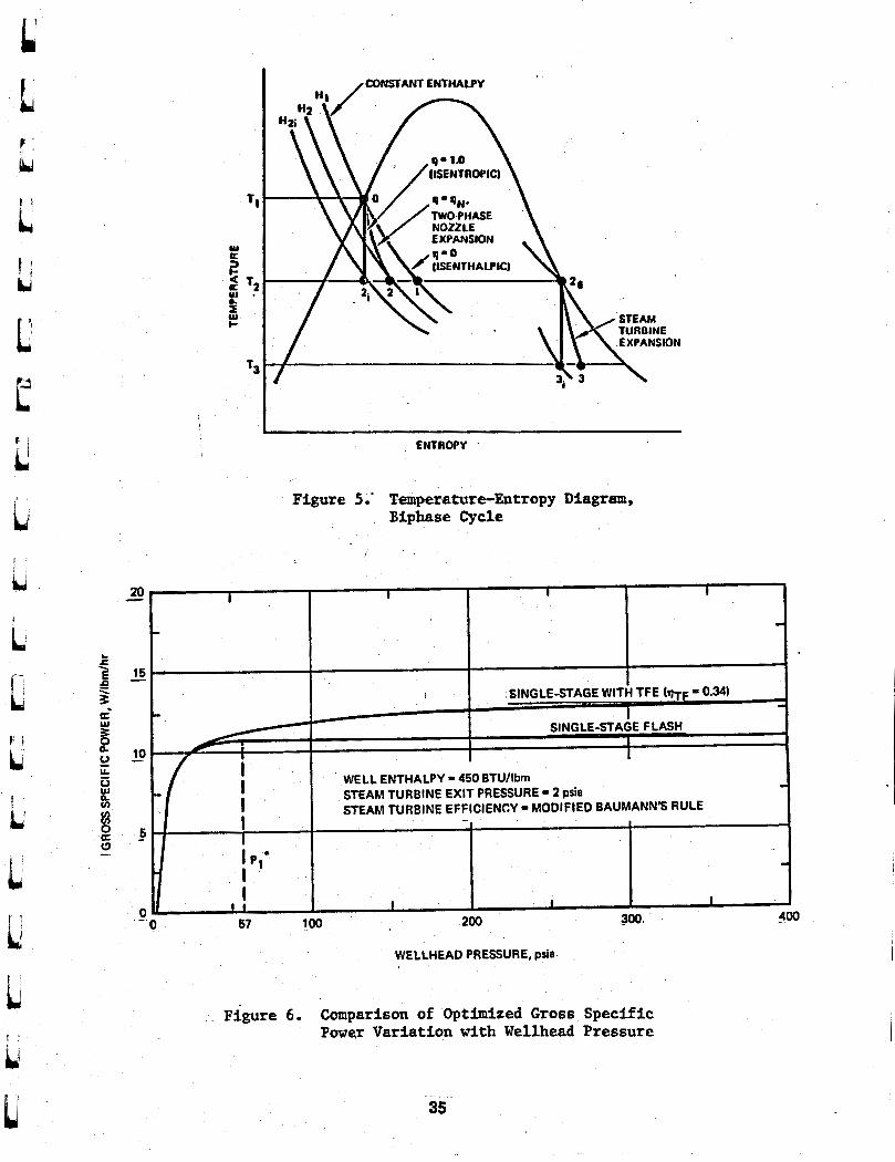
The B i p h a s e cyc le is i l l u s t r a t e d on a t e m p e r a t u r e - e n t r o p y diagram, F i g u r e 5. Assuming s a t u r a t e d water a t p o i n t "On, t h e f l a s h t a n k i s e n t r o p i c e x p a n s i o n f o l l o w s p a t h w O - l w . The steam produced is separated, p o i n t "2gn and expanded in a steam t u r b i n e "2g-3w p r o d u c i n g power as shown by a change in e n t h a l p y . The B i p h a s e e x p a n s i o n of t h e l i q u i d f o l l o w s p a t h "0-2". I f 100 p e r c e n t e f f i c i e n t , t h e e x p a n s i o n would be i s e n t r o p i c , W 0 - 2 i R . The B i p h a s e e x p a n s i o n c h a n g e s e n t h a l p y from "81" t o "H2" , t h u s making power a v a i l a b l e . Separated steam ( s l i g h t l y l e s s t h a n t h e i s e n t h a l p i c case f o r a c la s s i ca l f l a s h t a n k ) is d u c t e d t o t h e steam t u r b i n e , W2g-3w.
T h e a d d i t i o n a l power produced by B i p h a s e in a s i n g l e - s t a g e case is shown in F i g u r e 6 , a l s o from R e f e r e n c e 1, as a f u n c t i o n o f we l lhead p r e s s u r e . Note t h a t t h e s p e c i f i c power o f t h e f l a g h s y s t e m is c o n s t a n t f o r any w e l l h e a d p r e s s u r e above P l = 57 p s i a , w h i l e t h e s p e c i f i c power o f t h e B i p h a s e s y s t e m c o n t i n u e s t o i n c r e a s e w i t h wel lhead p r e s s u r e . R e f e r e n c e 1 c o n t a i n s a set o f c u r v e s similar t o F i g u r e 6 which are u s e f u l f o r e s t i m a t i n g many g e o t h e r m a l s i t u a t i o n s .
28

The o p e r a t i n g p r i n c i p l e s o f t h e B iphase g e o t h e r m a l t u r b i n e are d e s c r i b e d and i l l u s t r a t e d i n R e f e r e n c e 2. -
s Petroleum Calpganv. Desert P-. Nevada, The 9 MN power p l a n t a t Desert Peak was d e s i g n e d by P h i l l i p s P e t r o l e u m t o u t i l i z e a "power skidm which i n c l u d e d a B i p h a s e RST and a T r a n s a m e r i c a D e l a v a l steam t u r b i n e . The s k i d was f ab r i ca t ed and assembled i n T r a n s a m e r i c a D e l a v a l ' s s h o p s i n T r e n t o n , N e w Jersey, The power s k i d i s 13 by 56 f e e t p l a n d i m e n s i o n s , we igh ing 260,000 pounds. The s k i d was s p l i t be tween t h e t u r b i n e and g e n e r a t o r f o r r a i l and t r u c k s h i p m e n t t o Desert Peak. T h i s system is d e s c r i b e d in R e f e r e n c e s 4 and 5, and i s t h e o n e you w i l l o b p e r v e on t h e f i e l d t r i p . R e f e r e n c e 4 s t a t e s t h a t , f o r a r e s o u r c e e n t h a l p y of 384 BTU/ lbm, t h e n e t o u t p u t power i s 10.03 megawatts p e r m i l l i o n lbm/hr geothermal f l u i d .
Power and L i g h t (UPQL) , t oge the r w i t h P h i l l i p s P e t r o l e u m , EPRI and DOE, ass is ted i n t h e pe r fo rmance and d e m o n s t r a t i o n o p e r a t i o n s of t h e B i p h a s e RST a t R o o s e v e l t Hot S p r i n g s . Us ing d e m o n s t r a t e d pe r fo rmance numbers, UPQL and S o u t h e r n C a l i f o r n i a E d i s o n Company e v a l u a t e d t h e B iphase geothermal s y s t e m and compe t ing s y s t e m s i n compar i son w i t h coal-fired power p l a n t s . Compar isons were made on l e v e l i e e d b u s b a r costs . The r e s u l t i s s ta ted ( R e f e r e n o e 3 ) , R t h e o n l y a l t e r n a t i v e o o m p e t i t i v e w i t h o u r coa l - f i red u n i t is t h e AST wel lhead systemR. . A s a r e s u l t , UPQL c o n t r a c t e d w i t h Biphase Energy Sys tems f o r t h e d e s i g n of 14.5 MU wel lhead s y s t e m s f o r t h e Roosevelt Hot S p r i n g s r e s o u r c e , and f o r d e l i v e r y of these u n i t s as e l e c t r i c i t y demand r e q u i r e s them.
APPLICATIONS:
f am s u r e t h a t t h i s a u d i e n c e i s wel l ware t h a t e v e r y new geothermal r e s o u r c e is d i f f e r e n t rom a l l o t h e r s . B iphase found t h a t t h e i r u n d e r s t a n d i n g of t h e t e c h n i c a l and economic fac tors of Biphase and wellhead s y s t e m s l e d t o p roposa l s which e x t e n d e d Biphase t e c h n o l o g y i n s e v e r a l d i r e c t i o n s . Three s u c h e x t e n s i o n s w i l l be d i s c u s s e d b e c a u s e of c u r r e n t i n t e r e s t in t h i s e x p a n d i n g t e c h n o l o g y .
ah Power & IJ&&. Raasevelt Hot SD-S. Ut& Utah
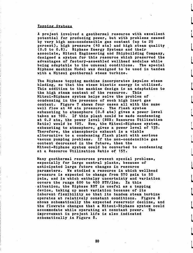
A p r o j e c t i n v o l v e d a geothermal r e s o u r c e w i t h e x c e l l e n t p o t e n t i a l f o r p r o d u c i n g power, b u t w i t h p rob lems c a u s e d by v e r y h i g h non-condens ib l e gas c o n t e n t ( u p t o 25 p e r c e n t ) , h i g h p r e s s u r e (40 a t a ) and h i g h steam q u a l i t y (0 .5 t o 0 .8 ) . B i p h a s e Energy Systems and t h e i r a s soc ia t e , M i t s u i E n g i n e e r i n g and S h i p b u i l d i n g Company, d e s i g n e d a sys t em f o r t h i s r e s o u r c e which p r e s e r v e d t h e a d v a n t a g e s of f a c t o r y - a s s e m b l e d w e l l h e a d modules w h i l e b e i n g a d a p t a b l e t o t h e u n u s u a l c o n d i t i o n s . The s p e c i a l B i p h a s e machine Model was d e s i g n e d t o be u s e d i n tandem w i t h a M i t s u i g e o t h e r m a l steam t u r b i n e .
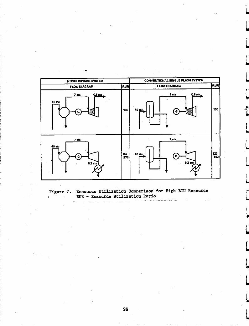
The B i p h a s e t o p p i n g machine i n c o r p o r a t e s i m p u l s e steam b l a d i n g , so t h a t t h e steam k i n e t i c e n e r g y I s u t i l i z e d . T h i s a d d i t i o n t o t h e machine d e s i g n is a n a d a p t a t i o n t o t h e h i g h steam c o n t e n t of t h e r e s o u r c e . T h i s Mi t su i -B iphase s y s t e m h e l p s s o l v e t h e problem of c o n d e n s i n g in t h e p r e s e n c e of s u c h h i g h i n e r t gas c o n t e n t . F i g u r e 7 shows f o u r cases a l l w i t h t h e same w e l l f l o w a t 40 ata p r e s s u r e . The f l a s h system e x h a u s t i n g t o atmosphere ( 0 . 8 a t a ) g i v e s a power l e v e l t a k e n as 100. If t h i s p l a n t c o u l d be made c o n d e n s i n g a t 0.2 a t a , t h e power l e v e l ( R U R : Resource U t i l i z a t i o n R a t i o ) would be 125. Now, t h e M i t s u i - B i p h a s e s y s t e m , e x h a u s t i n g t o a t m o s p h e r e , g i v e s a power l e v e l of 135. Therefore, t h e a t m o s p h e r i c e x h a u s t i s a v i a b l e a l t e r n a t i v e t o a c o n d e n s i n g f l a s h p l a n t w i t h s e r i o u s vacuum pumping problems. I f t h e non-condens ib l e gas c o n t e n t decreased i n t h e f u t u r e , t h e n t h e Mi t su i -B iphase s y s t e m c o u l d be c o n v e r t e d t o c o n d e n s i n g a t a Resource U t i l i z a t i o n R a t i o of 157.
f ' L
t I
! ' t
I
I
t
Many geothermal r e s o u r c e s p r e s e n t s p e c i a l problems, e spec ia l ly f o r large c e n t r a l p l a n t s , b e c a u s e of a n t i c i p a t e d l a rge f u t u r e c h a n g e s i n r e s o u r c e parameters. N e s t u d i e d a r e s o u r c e i n whioh wel lhead p r e s s u r e i s e x p e c t e d t o change from 570 ps ia t o 50 p s i a , and i n w h i c h e n t h a l p y u n c e r t a i n t y and v a r i a t i o n c o v e r s t h e r a n g e 600 t o 400 BTU/lbm. I n t h i s s i t u a t i o n , t h e B i p h a s e RST i s u s e f u l as a t o p p i n g d e v i c e , t a k i n g up most v a r i a t i o n b e c a u s e of i t s i n h e r e n t f l e x i b i l i t y so t h a t i t s tandem steam t u r b i n e operates a t r e l a t i v e l y c o n s t a n t o o n d i t i o n s . F i g u r e 8 shows s c h e m a t i c a l l y t h e e x p e c t e d r e s e r v o i r d e c l i n e , and t h e f lowra te c h a n g e s t h a t a M i t s u i - B i p h a s e s y s t e m c o u l d accommodate w h i l e o p e r a t i n g a t c o n s t a n t power. The improvement i n p r o j e c t l i f e i s a l s o i n d i c a t e d schemat ica l ly i n F i g u r e 8.
i L 1 1 L
30

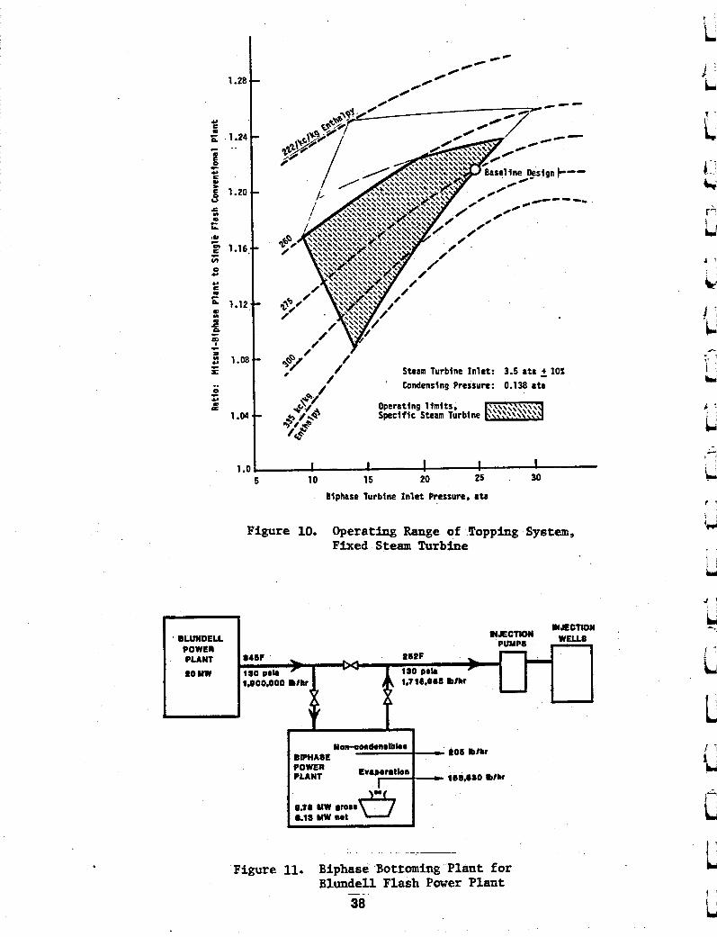
F i g u r e 9 i l l u s t r a t e s an area c h a r a c t e r i z e d by Biphase RST i n l e t p r e s s u r e and e n t h a l p y , in which a B i p h a s e - M i t s u i stead t u r b i n e s y s t e m Lcould e lec t t o o p e r a t e f o r 10 MW and 15 MU power p l a n t s . I f t h e steam t u r b i n e is f i x e d , w i t h an i n l e t p r e s s u r e of 3.5 a t a , t h e n r a n g e of s a t i s f ac to ry s y s t e m is shown in F i g u r e 10. When t h e Biphase i n l e t p r e s s u r e is r e d u c e d t o a p p r o x i m a t e l y 10 a t a , we would p r o p o s e t o remove i t from t h e system and c o n t i n u e w i t h t h e steam t u r b i n e a l o n e . The Biphase t u r b i n e may i n c o r p o r a t e i m p u l s e steam b l a d i n g which can improve i t s e f f i c i e n c y and a d a p t a b i l i t y .
Svstepl. UP&L B l - 1 1 Power Planf;.
Utah Power & L i g h t Company has c o n t r a c t e d w i t h Biphase Energy Systems f o r a d e s i g n s t u d y of a abo t tomingf f sys tem t o be u s e d w i t h t h e B l u n d e l l 20 MW f l a s h p l a n t a t R o o s e v e l t Hot S p r i n g s , U tah . This e x i s t i n g power p l a n t , F i g u r e 11, d i s p o s e s of 1,900,000 l b / h r f l u i d a t 3453 and 130 p s i a , wh ich is pumped t o i n j e c t i o n wells. The B i p h a s e b o t t o m i n g s y s t e m i s added t o t h i s d i s p o s a l p i p e l i n e , as shown, w i t h o u t in any way c h a n g i n g o p e r a t i o n of t h e 20 MW p l a n t o r r e q u i r i n g more wel l flow i n t o t h e p l a n t . With c o n d i t i o n s as shown, t h e Biphase b o t t o m i n g p l a n t w i l l d e l i v e r 9.78 MW gross , 9.13 MU n e t e l e c t r i c power .to UPdCL. T h i s u s e of otherwise-wasted e n e r g y w i l l have v e r y f a v o r a b l e economics.
The c o m b i n a t i o n of r e l a t i v e l y low e n t h a l p y and h i g h f lowrate b o t t o m i n g p l a n t i n p u t are beyond t h e c a p a c i t y of the Model 54RST geothermal machine. A c c o r d i n g l y , B iphase Energy Systems d e s i g n e d t h e n e x t larger frame s i z e , t h e Model 72RST. I n t h i s machine, t h e p r i m a r y r o t o r diameter is 72 i n c h e s , in place of 5 4 i n c h e s f o r t h e predecessor. The Model 72RST m a i n t a i n s t h e bas ic d e s i g n c o n c e p t which has proved t o have h i g h r e l i a b i l i t y , and i t employs 8 n o z z l e s w i t h i n t e r n a l m a n i f o l d i n g in g r o u p s of f o u r . There are two f l u i d i n l e t s i n t o t h e machine. Also t h e t h r o t t l e / s t o p v a l v e s are i n t e g r a l w i t h each n o z z l e . The Model 72RST c a n h a n d l e f lowrates up t o 2,500,000 lbm/hr , and t h u s w i l l complement t h e Model 54RST in c o v e r i n g a v e r y w i d e range of a p p l i c a t i o n s .
31

SUMMARY:
Valuable attributes of small power plants, the subject of this meeting, include modular construction, short schedules, flexibility in deployment to match load demands, and low operating and maintenance costs. All of these help improve the owner's cash flow. Biphase Energy Systems has participated in hardware programs which demonstrate advantages of wellhead plants, and also demonstrated that the proprietary Biphase turbine will improve system performance and extend system flexibility and adaptability.
32
REFERENCES:
1. Bauer, E. and Record, J . , 'An Evalua t ion o f t h e Performance Gains A v a i l a b l e by Using T o t a l Flow Expanders in Geothermal Power Sys temsu, 2 0 t h I n t e r s o c i e t y Energy Conversion Engineer ing Conference, Miami Beach, FL, 1985.
2. S t u d h a l t e r , W.R. and Eiden, T.E., " B i p h a s e Geothermal Wellhead P lan t s " , Proceedings 6 t h N e w Zealand Geothermal Workshop, U. of Auckland, 1984.
3. Eldredge , D.L. and'Rasband, J . L . , 'Cost and Performance Ana lys i s of Wellhead and C e n t r a l Geothermal Power P l a n t Development a t Roosevel t Hot Spr ings" , (BP1196-2), E P R I E i g h t h Geothermal Conference, Sea t t le , WA, 1984.
4. C e r i n i , D . J . * D i d d l e , C.P. and Gonser, W.C., "Pro jec t Development, Desert Peak 9 NW Power Plant ' , Proceedings , E i g h t h Annual Geothermal Resources Counci l , Reno, N V , 1984.
5. D i d d l e , C.P. and Gonser, W.C., ' P ro j ec t Development, Desert Peak', Proceedings , Ninth Annual Geothermal Resources Counci l , Kona, Hawaii,
33

I~JECTION WELL
QEN. TANK
i
ATMOSPHERE (14.7 pain ) OR CONDENSER (2 pala)
Figure 1. Single-State Flash System Schematic
n I
Pw P
TFE I
- FRODUCTION WELL TO
. ATMOSPHERE
I (14.7 pela
- INJECTION WELL
OR CONDENSER (2 p i la )
Figure 2. Single-Stage System with TFE
DUAL HI-P’
TANK
PW
I TFE
,
CONDENSER - INSECTION WELL
(2 pela 1
Figure 3. Two-Stage Flash System Schematic
- . . . .
DUAL
PRODUCTION
I~JECTION , WELL
Figure 4. Two-Stage System with TFE
34 b
T
20 r I I c I I
.I -
1 CONSTANT ENTHALPY
ENTROPY .
Figure 5.' Temperature-Entropy Diagram, Biphase Cycle
15 -
10 -
6 -
67 100 0 - 0
WELLHEAD PRESSURE, psia
Figure 6. Comparison of Optimized Gross Specific Power Variation with Wellhead Pressure
. ..
35
MlTSUl BIPHASE SYSTEM CONVENTIONAL SINGLE FLASH SYSTEM
FLOW DIAGRAM FLOW DIAGRAM RUR I
Figure 7. Resource Utilization.Comparison for High BTU Resource RUR = Resource Utilization Ratio
- - __ - -. -
L
L P’
+
I ‘
‘b
36
t

c
w -l
LIFE-CYCLE OF MODULAR PLANT
Well end reservoir chancterlstic curve, successlve years
Conventlonal-Flosh-Concept
ISO-Power-Cuwc (MI tsuf-Blphase)
p i Wellhead Pressure
PROJECT LIFE’ INCREASE
/btm Drawdown Rate
Figure 8. Application of Biphaae Cycle t o Topping Variable Pressure Resource
1.28
Y c p.
0 P 0
Y E 0)
0 V
s
I 1.24 c
r
g 1.20
w
e 5 1.16
s
d c cn
Y
o 1.12
m w
c P c 9 R 1,oI c
Y
% c
.. c 0
* 0 p:
1 .o
1.
Condcnslng Pressure: 0.138 eta ‘ Y %V’ , / 0 i
/ *a/
I I I I I
10 1s 20 25 30 5 Biphase Turbine I n l e t Pressurn. e ta .
Figure 9 . Operating Range Topping System with Biphaee Model 54RST
7 1
1
1
1 .i
it
1 i
4
9 .. -1
OE . 52 02 EL 01 E I I I I I
c li I; I"
t
1'
HELICAL SCREU EXPANDER POWER PLANT
TEST RESULT ANALYSIS MODEL 76-1
January 24, 1986
bY
ROGER S. SPRANKLE General Partner
Hydrothermal Power Co. P. 0. Box 2701
Paso Robles, CA 93447 805/239-3521
Before attempting an analysis of the test results, a better understanding o f the prime mover can be gained by reviewing the theory of operation. Although Model 76-1 utilizes helical screw or Lysholm type rotors, there are two noteworthy features t h a t distinguish it from prior Lysholm type prime movers. Figures 1 and 2 can a i d i n the understanding o f these features and the theory of operation.
The first feature involves the inlet region and method used t o f i l l the high pressure pocket. A variable converging nozzle is located a t the rotor endface and appropriately positioned t o f i l l the newly forming pocket. During the i n i t i a l stages o f formation, the pocket pressure ( P i ) approaches Po, the f nlet pressure. As the pocket becomes fully developed, pressure Pi decreases t o p2 and a h igh velocity j e t exits from the nozzle throat towards the rotor. The nozzle throat opening .is governor controqled and adJusted according t o the resource inlet pressure conditions and desired power output. Th i s feature is new and unique t o Model 76-1, giving it high volume rat io and pressure r a t i o capabilities.
limited volume ratio. The volume ra t io i inlet nozzle throa t opening.
The second noteworthy feature o f Model 76-1 involves the rotor pocket opening t o the exhaust, p3 t o P4. Design care was taken t o fully open the rotor pocket along both the rotor endface and axially along the rotor t i p . Designed thus, the f lu ids travel through the machine i n the straightest possible path. In addi t ion , w i t h square card expansion, the pressure drop from
from p2 t o P3 i s pos ive displacement ex ansion w i t h a etermined by the ro P or profile and
39
He1 ical Screw Expander Power P1 a n t Model 76-1 Test Result Analysis January 28, 1986 Page 2
the pocket i n t o the exhaust occurs w i t h a minimum of loss. Th i s feature is important when operation involves law pressure vacuum exhaust.
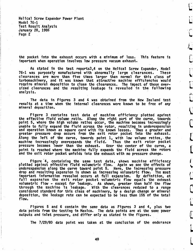
As stated i n the tes t reports3,4 on the Helical Screw Expander, Model 76-1 was purposely manufactured w i t h abnormally 1 arge clearances. These clearances are more t h a n five times larger t h a n normal for this class o f turbomachinery, and it was known t h a t attractive machine efficiencies would require mineral deposition t o close the clearances. The impact of these over- sized clearances and the resulting leakage i s revealed i n the fo l lowing analysis.
The da ta i n Figures 3 and 4 was obtained from the New Zealand test results a t a time when the internal clearances were known t o be free of any mineral deposition.
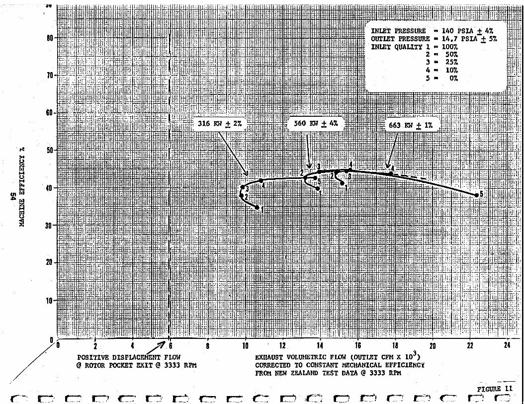
Figure 3 contains t e s t data of machine efficiency plotted against the effective f l u i d volume ratio. Along the r igh t part of the curve, towards p o i n t 5, where the h igh volume ratios occur, the machine becomes increasingly unable t o fully expand the f l u i d across the rotor, resulting i n underexpansion and operation known as square card w i t h its known losses. Thus a greater and greater pressure drop occurs from the exit rotor pocket i n t o the exhaust. Along the l e f t of the curve, towards po in t 1, w i t h low volume ratios,. the machine increasingly overexpands the f l u i d . Thus the e x i t ro tor pocket pressure becomes lower t h a n the exhaust. Near the center of the curve, a point i s reached where the machine fully expands the f l u i d across the rotors and the exit rotor pocket unfolds in to the exhaust w i t h no pressure change.
Figure '4, containing the same test d a t a , shows machine efficiency plotted against effective f l u i d volumetric flow. Again we see the effects o f underexpansion along the curve toward point 5. Here, the increasing pressure drop and resulting expansion i s shown as increasing volumetric flow. The most important information revealed occurs a t full expansfon. By definit ion, a t f u l l expansion the ex i t ro tor pocket volumetric flow equals the exhaust volumetric flow - except for leakage. As shown, greater than half the flow t h r o u g h the machine i s leakage. With the clearances reduced t o a range considered standard for this class o f machinery, by a design change or mineral deposition, the leakage rate can be expected t o be less than 15% of the to t a l f 1 ow.
Figures 5 and 6 contain the same data as Figures 3 and 4 , p lus two The data points are a t the same power
The 7/29/80 data po in t was taken a t the conclusion of the endurance
data points from the testing i n Mexico. outputs and inlet pressure, and differ only as stated i n the figures.
40

Helical Screw Expander Power Plant Model 76-1 Test Result Analysis January 28, 1986 Page 3
testing. Later inspection of the rotors revealed mineral deposition partially cl osi ng the cl earances.
The 2/06/81 d a t a p o i n t was taken after an extended idle period t o allow for the conversion to condensing operation. L i t t l e or no mineral deposition was observed before or after this data po in t was obtained. The data p o i n t gives no indication of degraded performance due t o low pressure exhaust operati on.
Figure 7 provides i n s i g h t i n t o the relationship between clearances and machine efficiency. The f igure is from Dr. 0. E. Balje and h i s work on
In the figure, families of machine efficiency are drawn for three different rotor clearances. The rotor length t o diameter (L/D) curves are s l ight ly displaced because the diameter is changed ( t o change the clear- ance) for each family of curves. Model 76-1 .has a leakage gap t o rotor diameter r a t i o (S/D) greater than .004, which is four times larger than the worst case shown on the graph. As can be seen, clearances have a major impact on machine efficiency,
The leakage problem w i t h Model 76-1 makes further analysis of the tes t results difficult. Leakage is not only a function of clearance, but also a function of clearance d i s t r i b u t i o n through the machine. In addi t ion , pressure drap and d i s t r i b u t i o n across the machine is a factor. Two phase flow also influekes leakage. In Figure 4, there is a drop i n machine efficiency when going from 50% ual i ty t o a l l steam. The disappearance of l i q u i d phase
Figures 8 and 9 contain the same data as i n Figures 3 and 4, plus data a t other power levels. With decreasing power output, the curves peak a t lower qualities. A t - the 316 KW ou tpu t level, the curve never peaks and the highest efficency is a t 0% quality. Here, overexpansion is occurring i n a l l the data points, w i t h 0% qual i ty nearest t o fu l l expansion.
Before drawing any conclusions, the influence of mechanical efficiency on performance needs t o be included. Model 76-1 was conservatively designed for operation over a broad range of s eeds and loads. A t 3333 RPM the bearing and seal losses amount t o 37 KW. TRis loss varies predominantly w i t h speed and only slightly w i t h load. A t 316 KW the mechanical efficiency is 88.3%; a t 560 KW i t is 93.4%; and a t 663 KW it is 94.4%. Figures 10 and 11 show the results of correcting the curves t o the same mechanical efficiency of 94.4%.
I t can be reasoned t h a t peak efficiency occurs not a t ful l expansion bu t w i t h some amount of underexpansion. Here, basically, the add i t ion of a small
. turbomachinery.4
sealing is clearly ev 9 dent.
41

Hel ical Screw Expander Power Plant Model 76-1 Test Result Analysis January 28, 1986 Page 4
amount o f underexpansion increases the power output faster than the losses. This ef fect i s only s l i g h t and should put the point o f f u l l expansion s l i g h t l y t o the l e f t o f peak ef f ic iency on each curve.
The fol lowing observations can be made from Figures 10 and 11. F u l l expansion and peak ef f ic iency f o r a l l loads and q u a l i t i e s occur i n a range between 13,800 and 16,000 CFM w i t h machine e f f i c i enc ies between 41% and 44%. This leads t o the fo l lowing conclusion. I f the leakage loss were reduced t o 15% o f the mass flow, f u l l expansion and peak ef f ic iency f o r a l l loads and qual S t i e s would occur near 6900 CFM wi th machine e f f i c i enc ies above 75%. Stat ing the conclusion d i f ferent ly , machine e f f i c i enc ies above 75% can be expected for any qua l i t y resource i f designed and operated a t the appropriate load. Thus, f o r Model 76-1, wi th the in ternal clearances reduced by mineral deposition o r a design change, and bearings sized appropriately f o r the load, operation a t 316 KW wi th 0% quali ty, a t 560 KW w i t h 10% quali ty, and a t 663 KW wi th 25% qua l i t y would a l l show machine e f f i c i enc ies above 75%.
The balance o f the New Zealand t e s t data broadens the conclusion t o include d i f f e ren t i n l e t pressures. I n addition, the vacuum exhaust t e s t data f r o m Mexico broadens the conclusion t o include vacuum exhaust pressures.
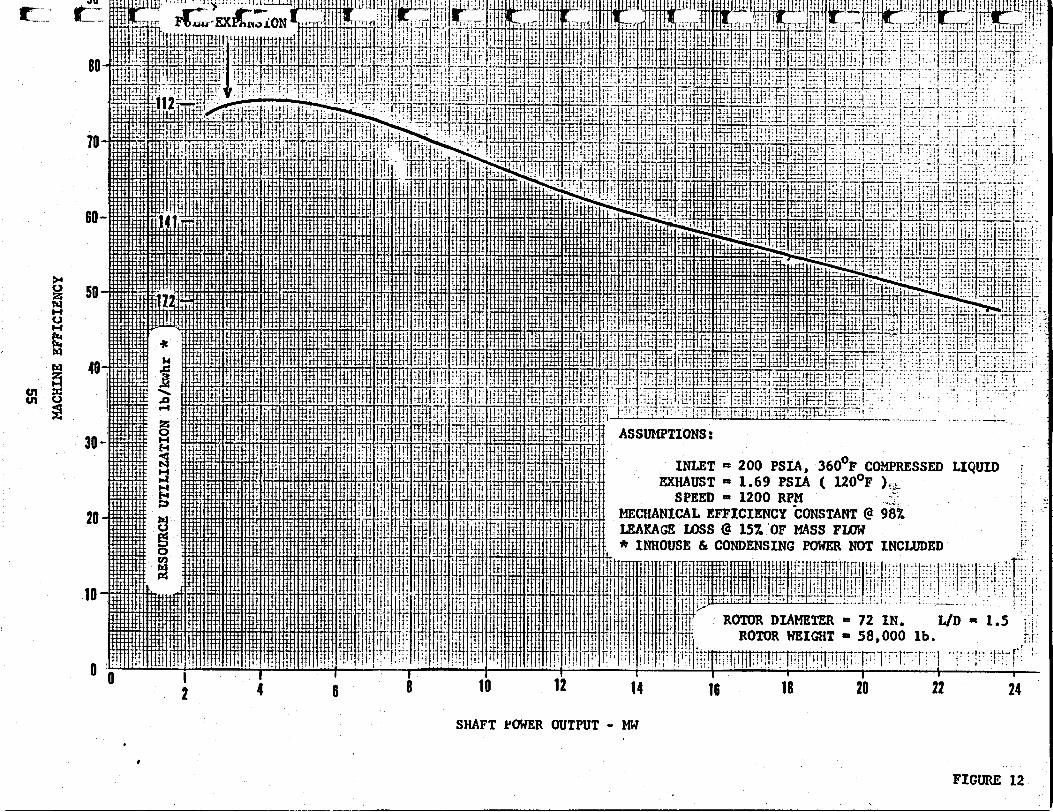
Figures 12, 13 and 14 are based upon the previous conclusion and theory o f operation. The curves show the benefi ts from u t i l i z i n g underexpansion. A l l the ffgures are f o r the same 72 inch r o t o r diameter. I n Figure 12, the same resource as the Heber binary p lan t i s u t i l i z e d f o r comparison. A low grade resource i s u t i l i z e d i n Figure 14. With l ightweight r o t o r fabr icator tech- niques, t h i s resource can be viable.
The rotat ional speeds i n Figures 12, 13 and 14 are considered conserva- t ive. The upper bounds o f speed ( t i p ve loc i ty) and i t s r e l a t i o n s h i p t o dynamic losses o r erosion, i f any, has not been determined.
42

Helical Screw Expander Power Plant Model 76-1 Test Result Analysis January 28, 1986 Page 5
1.
2.
3.
4,
References
U.S. Patents 3,977,818 and 3,751,673 and foreign patents held by Hydro- thermal Power Co., Ltd.
He1 ical Screw Expander Evaluation Project Final Report, Richard McKay, March 1, 1982, J P L Publication No. 82-5; DOE/ET-28329-1, Distribution Category UC-66D. This report may be ordered under the DOE Accession No. DOE/ET-28329-1, or the NASA Accession No. N82-22659, from the National Technical Information Service (NTIS), U.S. Department of Commerce, 5285 Port Royal Road, Springfield, VA 22161.
In te rna t iona l Test and Demonstration of a 1-MI4 Wellhead- Generator: Helical Screw Expander Power P lan t , Model 76-1, Final Report, Richard A. McKay, June 1, 1984, JPL Publication No, 84-29; DOE/ET-37116-2, Distribu- t ion Category UC-66df.
0. E. Balje, Turbomachines: A Guide t o Design, Selection and Theory, John Wiley & Sons, Inc., 1981.
43

I
44
I
c
, MODEL 76-1 1 L FIGURE 1

"c p3 t o Pq- process €6 characterized by pressure drop fmparting torque t o rotors, Also known as square card expansion
VOLUME v * d-*
P-V D I A w 3 A M FOR MODEL 76-1
45 FIGURE 2

c'
\
46 X A
3NX
I31dd3 3NIH
3W
r
i
J'

U
i \
E ps c3 (3
(3
cc)

0
W
0
w
2 113N313IddZ Z
NIR
3W
40
i' 0 c
0 c
0
'f3
.o
c
'C
E a ici c3 c3
e
k
v)
E? c 0 E
G L i I.

VOLUMKTRIC FLa# - ( OUTLET CFH x io3 I 7
POSITIVE L DISPIACEHENT *
F U N 3333 RPH FROM NEW ZEAUND TEST DATA @ 3333 RPM
- --- FIGURE 6

.1 - I Pl
M ULTl LOSE
5 R e = 'IO
I i
. . - -_-... ._ - - .
_-._. -
. . . . . .. - __ ...... ._ .....
. . . . . . .. ... .....
. . . . . . . -- .. . . . . . . . . . . - .. . ._ .- . _._-_ . - _-_ -- ... - . . . . . .
. _-_ .--. ..
- . . __ .. - - - . . . . ._ . . . -. __ -- . - -_ .~ .- . , .~
. . . . . . . . .., ~-
. . . . . . . . . . . . . . .- . .
. . . . . . . . . - - .. -.-_ - ____. . . . . . - ~ . . . .- . . . ~. ~ -. . -- .-. . . . . .----_-_. ..____." .-.-.. . _--_-.___-_ ~ --__._
. . . . . . - 3 --.--.-. - - _ -
---_I-. -..-.I-
. . . Symbols - - . .
... .- . --. . . - . . - Machine Reynolds Number -
-: L = Rotor Length -- D = Rotor Diameter S = Clearance Gap D, - Specific Diameter I
Ns - Specific Speed -- Machine Efficiency .- '7
. . . ---- __ - - -. . -
. . .
_. . . . . . . *... "i L 1
. , . . . . .
. . . . . .... ._ . . ._ . . . . . - I _I _-. .. - - - - _ _ .__I__ . ..
1 - - ~ I _
1 - - . 1-
.l . ~ .
Specific Speed N, ( after O.E. Balje)
Figure 3.
FIGURE 7 -- 50


1 I

0
0
0 c
0
CT
0
m
0 -I
.O c
0
m
N
0
O\
0
LC
I 0
0
0
00
c1
a
a .-
n
“i X3N
ZI31dd3 3N
IH3W
54
U 4 6 8 10 12 14 16 18 20 22 24
SHAFT YWER OUTPUT - MW *
FIGURE 12

..._ .
. .
..
... .
i __
.
. .
'. __.- _.I.
, .
-. . .
. .
.__
. .
..
.....
. +
:. ..
.
.,
.
-
. - __ . . -
-LA...
. -. . .
- . . . , . . .
. .
. . . _~
-.
,-
~:
-~
L~
--
~~
~-
~-
.
. -

\
-u

i
58

MODULAR WELLHEAD POWER PLANTS
Ken Nichols Barber-Nichols Engineering Co.
Arvada, CO 80002
ABSTRACT
Geothermal wellhead power plants, based on the organic Rankine cycle, can provide very reliable power with high utilization of the avialable resource. The power cycle is adaptable to water or steam resource temperatures of 180°F to 350°F. The power plant cycle working fluid is a halogenated hydrocarbon refrigerant that is se- lected to provide the best overall performance as a function of resource temperature. contains all of the heat exchangers, power turbine, alternator and controls. ing on resource temperature. The larger size plants utilize one additional heat rejection module. at the wellhead, producing several megawatts if the energy is avail- able. project initiation.
Each power plant consists of one module which .
The power plant can generate from 300 kW to .lo00 kW, depend- .
Multiple plants can be located
These plants can be on line in approximately six months from ' F '
CYCLE DISCUSSION
The wellhead power plant is referred to as a "Power Genera- tion Module'' or PGM for short. scribed as follows:
The principle of operation is de-
Water is used for the working fluid in large utility power The low molecular weight of water requires multi-stage plants.
turbines to obtain high efficiency. heat source temperatures below 800°F, organic fluids with molecular weights greater than that of water can provide high cycle efficiency and result in simpler and less costly single-stage expanders. working fluid is a halocarbon-type refrigerant that is nontoxic, nonflammable and readily available.
For Rankine engines with
The
59
I

L2,
I
1 L
FIGURE 1
The PGM is based on the Rankine power cycle concept. This is the same basic cycle used by utilities in their steam generating plants. shown in the schematic of Figure 1. It consists of heat exchangers (the preheater/evaporator) which transfers energy from a heat source (such as geothermal hot water or steam) to the working fluid. The heat supplied is sufficient to completely vaporize the working fluid which is at a relatively high pressure. The vaporized working fluid is expanded through a turbine where shaft power is fproduced to drive a generator and thus produce electricity. The working fluid then flows to the condenser where heat is rejected to a heat sink (such as the evaporation of water or ambient air) and the working fluid is condensed. back to the preheater/evaporator, thus completing the cycle.
The main components of a simplified Rankine cycle are
The liquid working fluid is pumped from the condenser
The major components of the PGM include the heat exchangers, rotating machinery and a control system for the automatic startup and operation of the PGM. The major components are all assembled into one module and then shipped to the site for installation. -This approach maximizes the factory work done under well-equipped condi- tions and minimizes the expensive field work. to match the resource so the details can vary from one installation to another.
.
The PGM is tailored
60

-3-
POWER POTENTIAL
The generating potent of a geothermal resource for various geothermal hot water temperatures and flow rates is shown in Figure 2. Knowing the geothermal water temperature and flowrate, one can use this figure to estimate the potential power output. As an example, assume a geothermal resource has a liquid temperature of 250°F and flows at 300 gpm. generate 330 kW of electrical power. power output in this figure is net output power, i.e., the PGM para- sitic loads such as the condenser and feed pump power have been accounted for; geothermal pumping requirements, if any, have not been accounted for. gpm.
From Figure 2, the resource could It should be noted that the
Single PGM's can handle flow rates up to 1000 Multiple PGM units can accommodate greater flow rates and
=ma RWER GEuEEanohi
l6X
0
61
produce proportionately larger output powers. from two-phase water-steam or steam alone is much greater than the curves shown for liquid.
The output power
COMPONENT DESCRIPTION
The preheater and evaporator are tube-and-shell type heat ex- changers. dance with the ASME pressure vessel code and meet the standards of the Tubular Exchanger Manufacturers Association (TEMA') .
The preheater and evaporator are constructed in accor-
The standard working fluid condenser is known as an "evapora- This type of condenser combines the functions of tive condenser1'.
a condenser and cooling tower into one integrated package. working fluid is condensed inside the condenser tubes. sprayed over the outside of the tubes to absorb the heat from the condensing fluid. water is evaporated. temperature throughout the condenser. condenser pumps and fans is supplied by the PGM. The water flow rate in the evaporative condenser is much less than required for a tube and shell condenser supplied by a cooling tower or cooling pond and large water pumps with their higher power usage are not required. This approach is used to improve the efficiency of the PGM and since it is less costly in most cases, it improves the return on investment as well.
The PGM Water is
'
Air is blown over the water and a portion of the This process maintains a nearly constant tube
The power required for the
ROTATING MACHINERY
The rotating machinery includes the turbine, generator and the feed pump. The turbine is a high efficiency, single stage design, direct-coupled to the 3600 rpm generator. the requirement for a speed-reducing gearbox. mechanically driven by the turbine output shaft. eliminates the number of energy conversions and improves overall efficiency. efficiency and low maintenance.
This eliminates The feed pump is
This approach
The feed pump drive is designed to provide high
62

-5-
TURBINE
The turbine blading and nozzle design is based on the results The blading.uses a highly refined of aerospace research programs.
contour and a manufacturing process that provides extremely good surface finishes. Turbine efficiencies of 80% in a single stage have been achieved.
. _
The feed pump is a centrifugal-type pump and is mechanically driven by the turbine output shaft to eliminate the losses asso- ciated with a motor drive. stalled to provide adequate net positive suction head (NPSH) for reliable operation.
The pump is specially selected and in-
GENERATOR
The induction or synchronous generator is directly connected to the turbine by a drive shaft. 480 volt, 3-phase, 60 Hertz. The electrical output of the PGM is compatible with the electric utility.
Standard electrical output is
63

-6- L CONTROLS AND SAFETY EQUIPMENT
The PGM controls provide for automatic system startup and operation. The PGM operation is self-monitored and, in the event that selected operating parameters are exceeded, the module will automatically shut down. Automatic telephone notification of a problem to an operator is provided. A full-time operating staff is not required. When the condition that caused a shutdown is cleared, the unit will automatically restart and properly recon- nect to the power line.
PGM PACKAGE
The rotating equipment, controls, preheater and evaporator are packaged in a structural steel frame. The structure also su.p- ports the evaporative condensers which are located above the other equipment. The structure is enclosed within a lockable, weather- proof, metal enclosure to provide environment protection and secur- ity. The module size is approximately 40 feet long, 23 feet high and 10 feet wide, and is arranged as shown in Figure 3 . aging facilitates easy installation on a simple concrete slab and transportability of the module by truck.
The pack-
t
64 i L
Ei I
ri
-7-
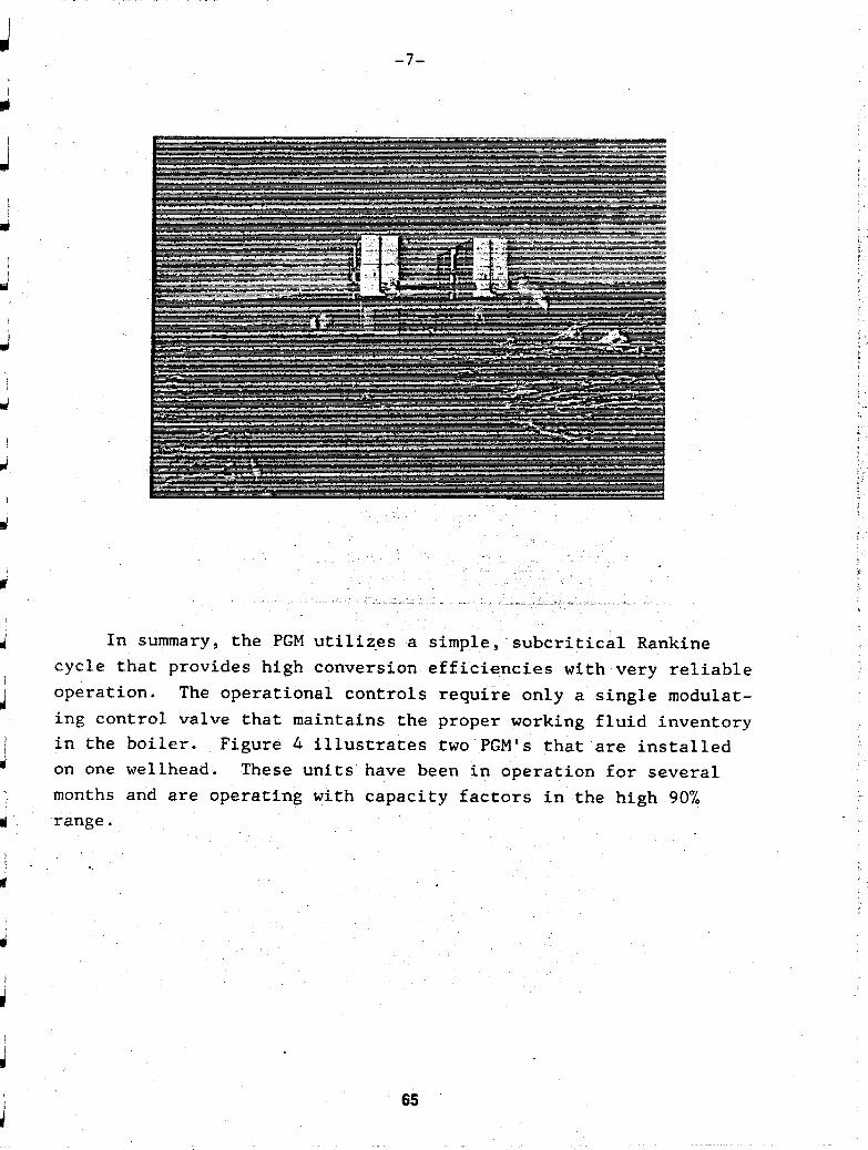
In summary, the PGM utilizes a simple, subcritical Rankine cycle that provides high conversion efficiencies with very reliable operation. The operational controls require only a single modufat- i ng control valve that maintains the proper working fluid inventory in the boiler. Figure 4 illustrates two PGM's that are installed on one wellhead. months and are operating with capacity factors in the high 90% range.
These units have been in operation for several
65
I t
66
t L c
t I I t L t

' %
RADIAL INFLOW TURBINES ROBIN DAKIN
ROTOFLOW CORPORATION
I ntroduct i on
This paper descri'bes some of the many features on the modern turbo- expanders which makes this type o f turbine suitable for the geothermal industry.
Expanders rated a t more t h a n 15,000 HP are already existing, having been developed from 10 HP - a 2000-fold scaleup.
These large expanders routinely give design efficiency i n the 85 t o 87 percent range.
I
Ld! 1.
Why is the radial inflow turbine important t o the geothermal industry.
L'
2.
3.
4 I
ci 4.
Ld 5.
6.
I t ' u
ILi
I t can handle almost any amount of l i q u i d condensing i n the turbine itself. This reduces the amount of superheat or eliminates i t and for a given resource temperature, produces the maximum power from the resource . Because this turbine can handle a very large volume ratio, a sin le
varying flows can be more efficiently handled w i t h o u t "stage" mismatch.
As there is only a single stage turbine, complex development is eliminated and dangers o f stage interaction are done away w i t h . T h i s applies particularly t o vibration.
The variable nozzle philosophy eliminates wasteful power loss of t h r o t t l i n g valves, and permits more rapid response from the machine t h a n if one had t o work w i t h a large inertia valve i n the turbine inlet.
I t i s available as a custom matched design i n the time frame normally allotted t o "off the shelf" power machinery.
Closed loop isobutane systems involve rapid bo i l ing and this results i n quite extensive carryover of solids. These i n t u r n can cause severe erosion of components, b u t the radial inflow turbine can be b u i l t t o haudle this. The passage o f particles through the turbi~ne is essentially parallel t o the blading w i t h negligible impingement. Nozzles can be treated t o resist the erosion of solid particles. Simple centrifugal treatment of the condensate should remove whatever particles are causing trouble, but on a startup i t i s d i f f i c u l t t o achieve 100% cleanliness.
stage can most often be used. T h i s has the further advantage t s, a t
b Page 1 , 67
.. .

7. A simple overhung turbine can be made "stiff" i.e. one that is run below its first shaft or bearing critical speed. This in turn greatly reduces wear and tear in the event of any accidental or unforeseen damage to a turbine which in turn greatly reduces repair times. It also permits use of non-contacting seals.
8.
To expand on these points:
1. Capability of handling condensation
Easily adaptable to other conditions should a field deplete or be moved to another location.
About 40 years ago Dr. 3. S. Swearingen built and operated the first natural gas cryogenic expansion turbine in the United States. From cryogenics to warm binary turbines is no big step and has been done now for many years.
Fig. 1 shows what happens when condensation takes place in a radial inflow turbine. The droplets "float" through the turbine and do not impinge on the blading. The discharge velocities are also much less than with an axial machine, a characteristic which results in inherently higher efficiency (see Fig. 2).
2,
The single stage turbine has another unique characteristic in that it can handle a varying flow in a somewhat unusual manner,
A t part power, the nozzle throttles the flow more than at design, leaving a little less for the turbine. At the turbine discharge the outer periphery runs full and at close to design conditions, but the pressure drop is not quite sufficient to bring the gas to the inner diameter: the latter results in some recirculation and an ideal dead zone.
Ability to handle a wide range of Flow
It is this characteristic in conjunction with the variable nozzles that give the radial inflow turbine such a flat operating characteristic with volume flow. See Fig. 3.
One of the principal effects on the turbine occurs because o f varying condensing conditions. We can make the most use of the turbine in the winter months by allowing the backpressure to fall and obtain more power. The resulting enthalpy increase in an axial turbine tends to mismatch the stages. In the radial inflow turbine the relative velocity at entry to the turbine is small so changes are far less significant than with for instance an impulse type of unit with high relative velocity. Commonly we have to deal with as much as a 30% change in enthalpy relative to design. The effect on efficiency is shown in Fig. 4.
Page 2 68

- u u L
turbine design together with the use o f computers is now small compared with the routine actions of getting the raw material castings or forging and putting these parts through a machine shop. Typically the control- ling items in a job are not those items we specifically manufacture, but purchased items such as generators and gearboxes. Small machines have been built in as little as three months, larger units typically will take up most of a year. This data is necessary for those attempting to plan potential geothermal plants.
u
I
u
I
li u
3. Simple Machine
A radial inflow turbine wheel has to be designed within criteria of weight, performance, vibrational characteristiks and be able to handle whatever rotational stresses arise as well as gas bending loads. It is always qutcker to design one of something than several, so a single stage radial inflow turbine as well as being inherently more efficient is quicker to design and develop.
Where each new application has similarities to those already proven, it sometimes occurs that the combinations are unique. As an example, in the case of one 'closed loop isobutane cycle, the combination of a high molecular weight with relatively high pressure ratios 11.3 to 1 resulted in excitation by some nozzle harmonics that had not been previously seen. Solutions that ha3 shown years of satisfactory service were not adequate for the combination of very high pressure ratio and high molecular weight and exact speed that this machine gave. Estab- lishing a solution once the problem was realised was straight forward and took no more than week. Realizing we had a brand new phenomena took longer and was complicated by other factors such as contamination.
With a multiple stage machine, handling of new phenomena is far more difficult and particularly with the axial machine, there is less scope for adjustment. The multi-million dollar investment in the aircraft gas turbine industry is witness to this.
4. Variable Geometry
There 3s Qnly so much energy available; to waste it with a throttling device upstream of the turbine defeats the purpose, also because volume flows can be very large, the size of such a valve is large and .its mass and inertia can preclude sensitive control The radial inflow turbine is controlled by a single set of variable nozzles of low inertia where the throttling effect is converted to kinetic energy which is directly recoverable in the turbine. Smaller sizes are easily operated with conventional actuation and the nozzles are pressure clamped to avoid the leakage build up that plagued other designs that operated with any sort of clearance.
Larger sizes are more tolerant to leakage and more sophisticated designs are in use for instance with the 50 inch turbines, operating with the U.S. Air Force. See Fig. 5.
5. Custom Availabilitj!
Page 3 69

6. Abili ty t o handle Sol ids
Over many years, we have experienced the effects of pipe lines t h a t have no t been as clean as the optimists would have them and we have had to evolve methods of preventing d i r t erosion damage. Fig. 6. shows a simple approach t o preventing d i r t scouring t h a t has proven effective over many years. I t prevents a l i t t l e closed loop of d i r t and gas recirculating around the seal t h a t can cause rapid wear, loss of per- formance and an upset t o thrust balance.
Many would consider t h a t a closed loop Rankine cycle system is naturally cleaner t h a n a pipeline. However, we have seen by f a r our worst erosion i n closed loop systems where there i s no clean up and a d i r t source has been introduced. In one case we had an instance of a heat exchanger i n storage t h a t was supposedly clean bu t contained a pound or two of iron oxide. Hard nozzles and ad jus t ing rings were worn almost through.. Once the source was cleaned up, the problem ceased b u t i n a very large loop such as a geothermal Rankine cycle, there are several sources of contamination.
(a) Site contamination: Often sites are i n remote areas and i n the pace o f construction, sand, gravel and weld scale o r beads are easily introduced.
( b ) Manufactured items: heat exchangers, casings and p i p i n g are rarely corrosion free and machining chips or casting sand can be overlooked and will break loose w i t h a l i t t l e thermal cycl i ng .
(c) The working f l u i d : having a h i g h density, the working f l u i d can carry particles and because i t is delivered as a l i q u i d a considerable quantity of contaminants can be introduced from this source.
( d ) Any damage of failure item: - if something should break and get i n t o the system, then as i t breaks u p these particles can go around and add t o the erosion burden.
The h i g h b o i l i n g rates prevent too much settling of contaminants and unless physically removed from the system, these contaminants will greatly reduce the service l i f e of the turbine. The removal is most easily accomplished a t the condensate stage, where a centrifugal f i l t e r will handle the bulk of fines. A mesh pad over the boiler will a lso eliminate a l o t of carryover.
Specially designed inlet screens are available t h a t will take a h i g h pressure drop w i t h o u t bursting and catch any large rocks or articles entrained i n the loop - 1 well recall seeing a cigar i n i t s aluminum tube f loa t ing o u t of one lube system many years ago. Strangely, no one claimed i t .
Hard coatings such as Tungsten Carbide have been used very successfully i n systems where particle separation i s impossible t o eliminate completely bu t are a last resort and normally no t necessary.
Page 4 70

7. Why a "St i f f" Shaft is Better
A non-contacting shaft labyrinth seal allows a small amount of gas t o contact seal o i l . The o i l is then heated t o drive off dissolved gas and returned t o the lube system. There i s no need then f o r a separate seal o i l system.
8. Adaptable t o other conditions
.
Fields do change and when they do the conditions f o r which the expander was designed also change. A new wheel is often a71 tha t is required t o exactly match the new conditions. A 1% improvement i n efficiency on a 5 Mw machine can result i n $42,000 per year increased prof i tabi l i ty .
Similarly if financial conditions are more a t t rac t ive i n another location, the turbine can be reoptimized simply and easi ly t o suit those conditions.
Summarizing
The radial inflow turbine presents the best s t a t e o f the a r t solution t o maximize return from any geothermal site tha t is suitable f o r binary operation.
Page 5 71
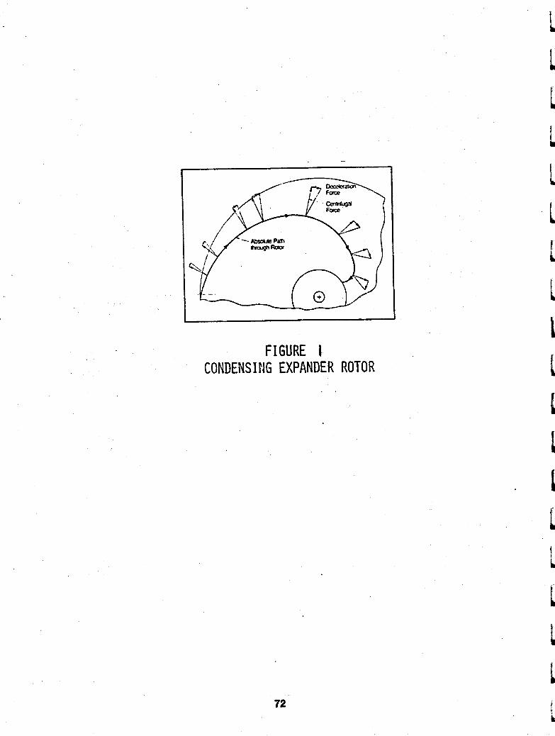
t
FIGURE I CONDENSING EXPANDER ROTOR t
E
t ci
72

- c
3 6
P.
(
II
73
! !
W
u,
.

view c.C at Partial Load
FIG. 3 OPERATION AT LOW FLOW
74

I
~J
75

Mechanical c e n t e r s e c t i o n o f Roto f low r e f r i g e r a t i o n t u r b i n e system can be removed i n t a c t f rom main u n i t . Compressor i m p e l l e r above has 55- inch d i a m e t e r .
FIG, S
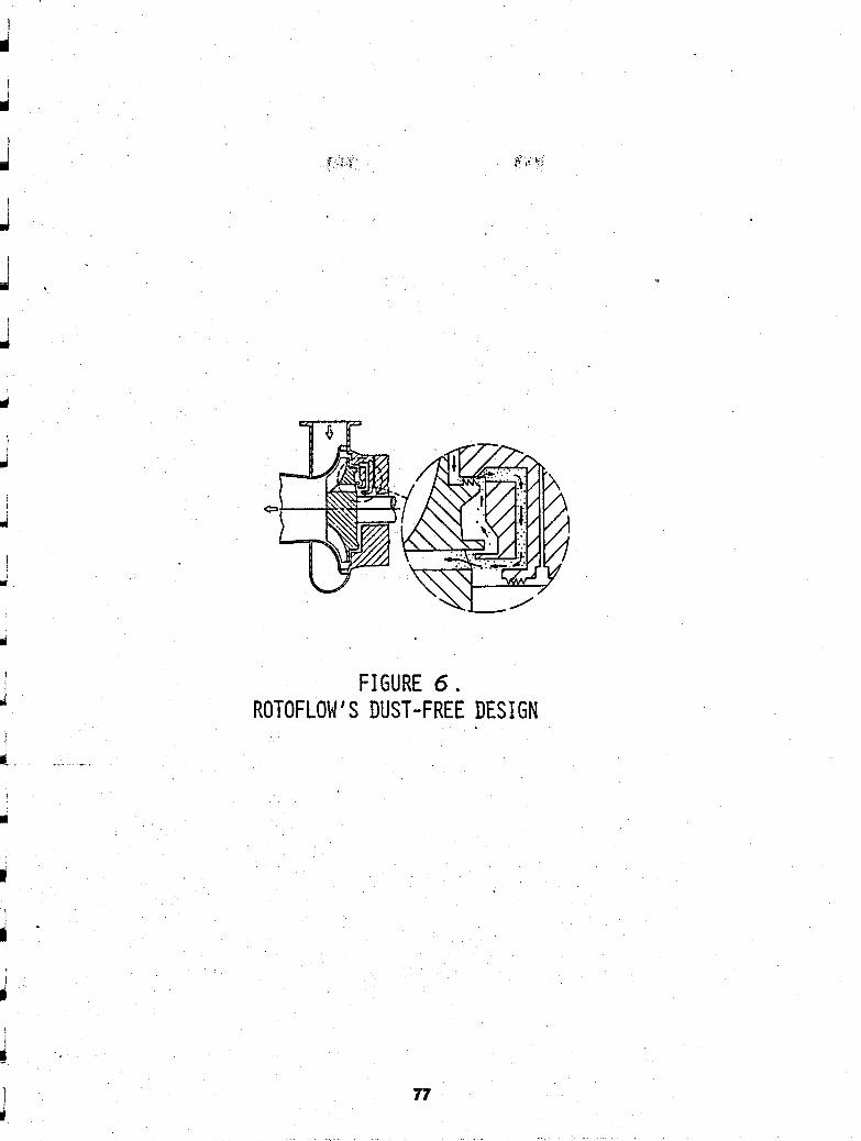
FIGURE 6. ROTOFLOW'S DUST-FREE DESIGN
77
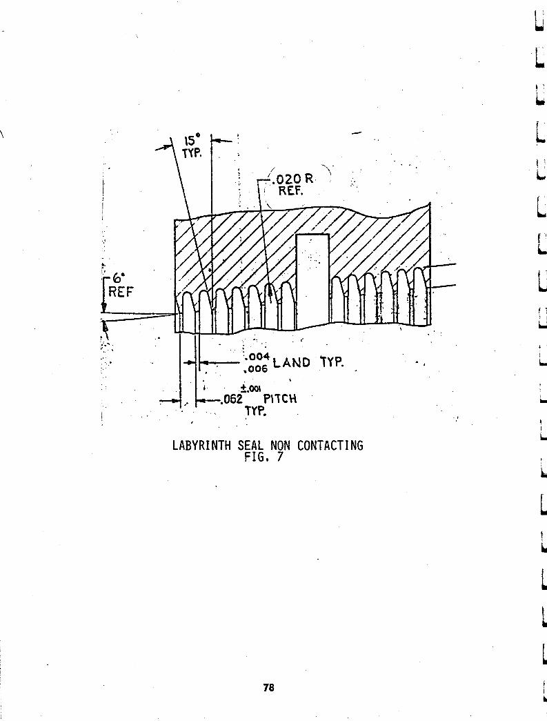
4 \
. . ,
LABYRINTH SEAL NON CONTACTING FIG. 7
70
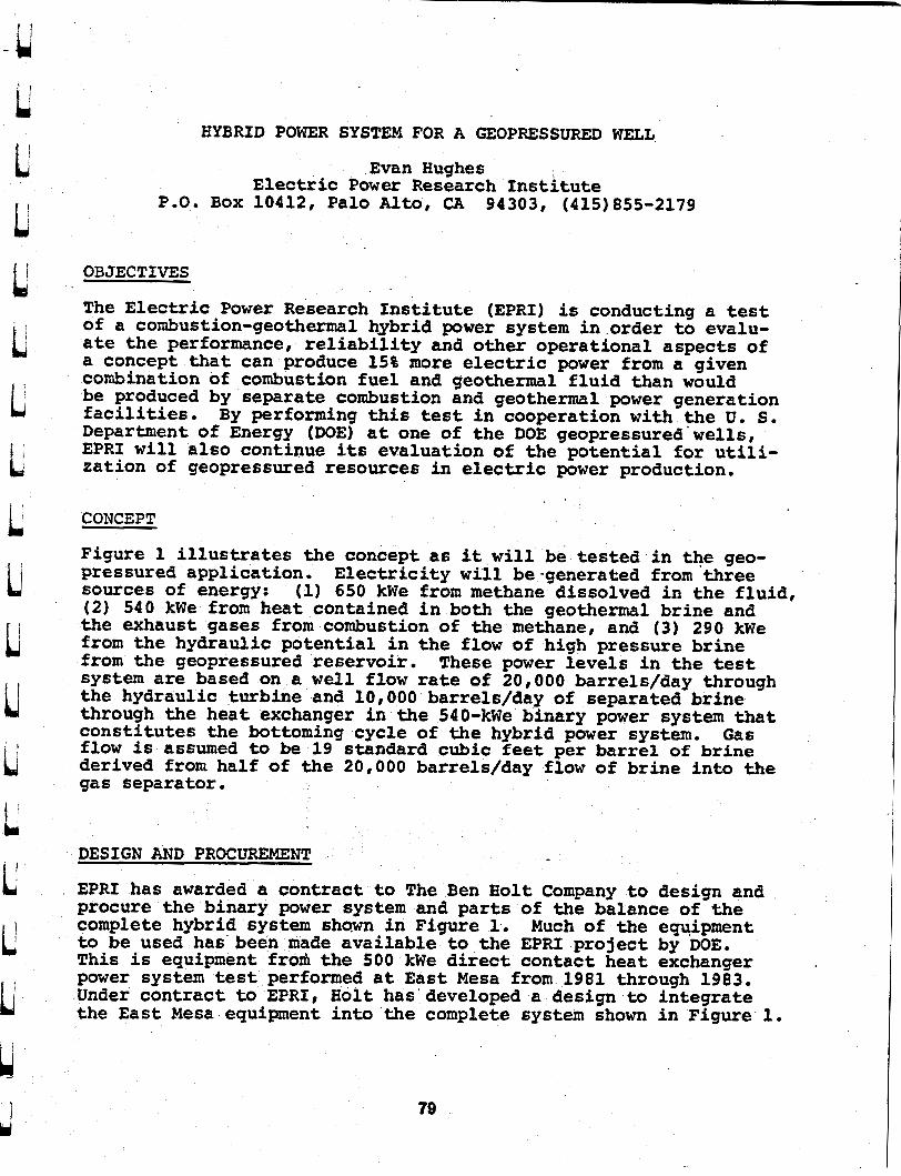
HYBRID POWER SYSTEM FOR A GEOPRESSURED WELL
Evan Hughes Electric Power Research I n s t i t u t e
P.O. BOX 10412, Palo A l t o , CA 94303, (415)855-2179
OBJECTIVES
The Electric Power Research I n s t i t u t e (EPRI) is conducting a test of a combustion-geothermal hybrid p o w e r system i n order t o evalu- a t e t h e performance, r e l i a b i l i t y and other operat ional aspects of a concept tha t can produce 15% more electric power from a given combination of combustion f u e l and geothermal f l u i d than would be produced by separate combustion and geothermal p o w e r generation facil i t ies. By performing t h i s test i n cooperation w i t h the U. S. Department of Energy (DOE) a t one of the DOE geopressured'wells, EPRI w i l l also continue i t s evaluat ion of t h e poten t ia l for u t i l i - zat ion of geopressured resources i n electric power production.
CONCEPT
Figure 1 i l l u s t r a t e s the concept as it w i l l be t e s t ed i n t@e geo- pressured appl icat ion. E l e c t r i c i t y w i l l be-generated from three sources of energy: (1) 650 kWe from methane dissolved i n t h e f lu id , (2) 540 kWe from heat contained i n both the geothermal br ine and the exhaust gases from combustion of the methane, and (3) 290 kWe from the hydraulic po ten t ia l i n the flow of high pressure br ine f r o m the geopressured reservoir . These power l eve l s i n the test system are based on a w e l l f l o w rate of 20,000 barrels/day through the hydraulic turbine and 10,000 barrels/day of separated br ine through the hea t exchanger in the 540-kWe binary power system tha t cons t i t u t e s the bottoming cycle of the hybrid power system. Gas f l o w is assumed t o be 19 standard cubic feet per barrel of brine derived from half of the 20,000 barrels/day f l o w of br ine i n t o the gas separator . DESIGN AND PROCUREMENT
EPRI has awarded a contract t o The Ben Holt Company t o design and procure t h e binary power system and p a r t s of the balance of the complete hybrid system s h m i n Figure 1. Much of t he equipment t o be used has been made ava i lab le t o the EPRI pro jec t by N E . T h i s is equipment frorh the 500 kWe d i r e c t contact heat exchanger power system test performed a t E a s t Mesa from 1981 through 1983. Under contract t o EPRI, B o l t has'aeveloped a design to i n t eg ra t e the E a s t Mesa equipment i n t o the complete system shown i n Figure 1.
79
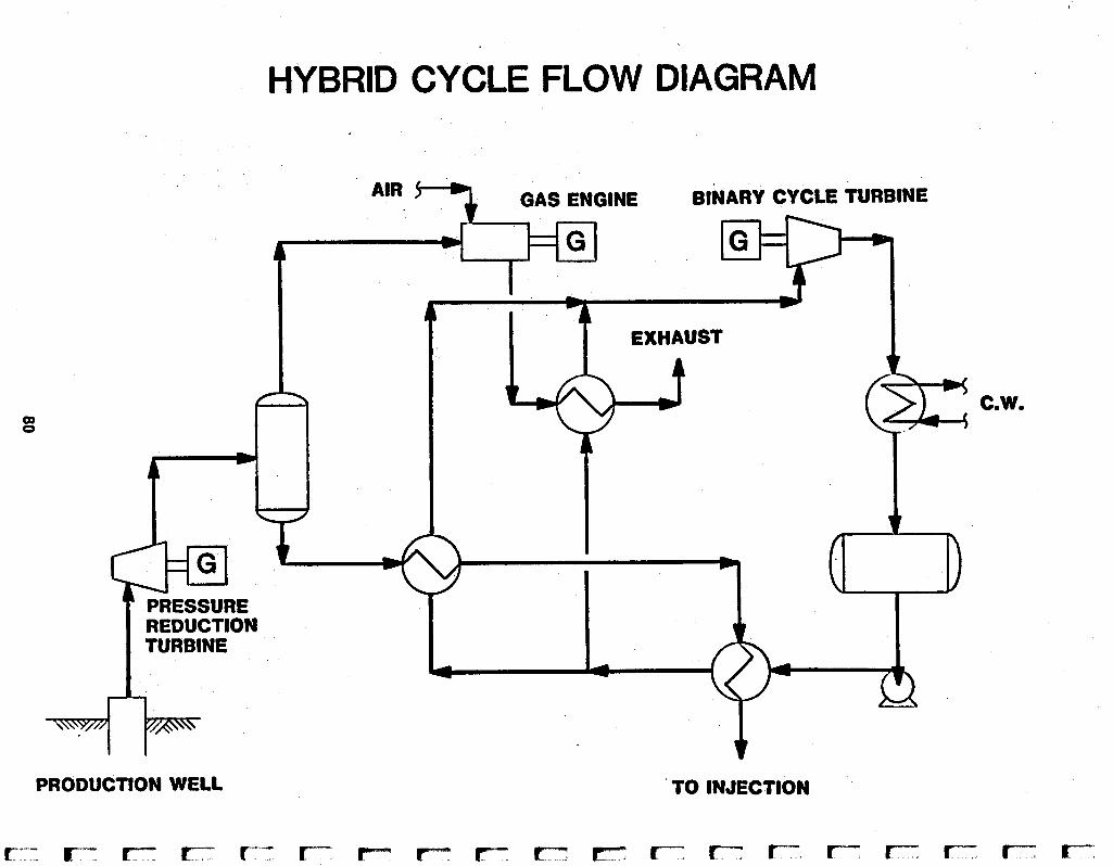
HYBRID CYCLE FLOW DIAGRAM
PRODUCTION WELL TO INJECTION
C.W.

GEOPRESSURED HYBRID POWER PLANT PROJECT
PROJECT OBJECTIVES:
EVALUATE THE COMBUSTION-GEOTHERMAL HYBRID POWER CONVERS ION CONCEPT AT THE PLEASANT BAYOU GEOPRESSURED WELL.
0 OBTAIN GEOPRESSURED RESERVOSR AND FLUID DATA IN LONG-TERM (3-5 YEARS) FLOW TEST,
0 EPRI, DOE, MK TECHNOLOGY; COSPONSORS
0 EPRf * S CONtRACTORS FOR DESIGN, PROCUREMENT, TESTING
DOE' S CONTRACTORS FOR I NSTALLATI ON, OPERAT 1 ON AND TEST I NG
EEH

c L 1 L I c L L
02

BEOWAWE 16W 6EOMER1W. POUER PLANT PROJECT
CHEVRON GEOTHERHAL COWANY/CRESCENT VALLEY ENER6Y CO.
NOVMBER 6, 1985
L.T. E l l i o t t
Chevron Geothermal Co. of California
San Francisco, CA
ABSTRACT
Chevron Geothermal Company of California and Crescent Val ley Energy
Company, a subsidiary of Rosemead, California based Southern California
Edison Company (SCE), have entered into a general partnership t o develop
the Beowawe Known Geothermal Resource Area located near Beowawe, Nevada.
The resource, which has been developed by Chevron i n recent years, will
provide geothermal heat i n the form of hot water and steam t o a dual
f lash plant which is being b u i l t by Crescent Valley Energy Company. The
power plant will generate 16.6 MW Gross of e lec t r ica l energy which will
be sold t o Southern California Edfson Co. The project is currently i n
the f ina l stages of construction and plant start-up i s scheduled fo r
mid-December.
INTRODUCTION
The Beowawe Known Geothermal Resource Area i s located i n the north-
central portion of Nevada, a few miles south o f In te rs ta te Highway 80
and six miles west of the small town of Beowawe. See Figure 1.
Geologically, the field is i n the Basin and Range province a t the
83.

I OREGON
I
04
IDAHO
.
Battle Mountain
0 E
Beowawe Geothermal Area
EIko 0
EiY 0
Reno B
NEVADA UTAH
Silver Peak
ARIZONA
0 50 100 - MltES
I
I FIGURE PROJECT LOCATION I
I
L i
e: s L L
boundary of a volcanic plateau which lies to the south and the
downfaulted Whirlwind Valley to the north. The geologic set t ing of t h i s
area has been extensively studied and documented i n the l i t e r a tu re and
no attempt will be made here t o review tha t information i n detai l . In
summary, the key elements of the geologic model o f the Beowawe Area are
a deep reservoir i n lower Paleozoic carbonates a t 15-20,000 f ee t which
is regionally charged by meteroric waters. Th i s reservoir feeds an
L
inclined thermal plume w i t h i n the Malpais Fault Zone tha t is tapped by
the production wells. This upward flow of geothermal waters also
accounts for the thermal surface manifestations i n the area. A
simplified drawing of this model is shown i n Figure 2.
L L L
Chevron Geothermal Company of California and Crescent Valley Energy
Company have formed a general partnership f o r the purpose of developing,
owning and operating the i n i t i a l power plant project on the Beowawe
resource. The partnership is ca l l ed the Beowawe Geothermal Power
Company (BGPC). The project consists o f instal l ing field production and
I
id i
h injection f a c i l i t i e s and a dual f lash power plant t o generate 16.6 MU
Gross (15.1 MW Net) of e lec t r ica l energy from the geothermal heat
t ' produced a t the Beowawe resource. Power from the project will be b
c transmitted via Sierra Pacific Power Co. (SPPCo) transmission l ines t o
Southern California Edison's transmission system where i t will be sold
under a power sales contract w i t h SCE.
L PROJECT DEVELOPMENT HISTORY i ~1
The Beowawe area has been well known fo r the geysers, fumeroles, and
boiling springs tha t have existed there for many years. These surface
b
L 85 u

- .. . ~. . ..... - .~ . - - ~ ~ ... . . .- ... . . . .- . . . ~ - ~ - -
A A'
!LOWER PALEOZOIC CARBONATES~
- 8 THERMAL WATERS
- M n r o R l c W A t E R S
GEOLOGlC CROSS SECTION FIGURE
REGlONAL CONCEPTUAL MODEL 2 I I

&-,* manifestations led Magma Power Co. and Sierra Pacific Power Co. t o drill
eleven shallow wells between 1959 and 1965 t o evaluate the potential for
geothermal development. Chevron acquired the leases for the Beowawe
area i n 1973-1975 and began extensive exploratory work of the area.
Chevron dril led i t s first well, the Ginn 1-13, i n 1974 t o a depth of
9600 f t . and has since dril led three additional wells i n the area t o
further define the resource. See Figure 3.
Based on the geologic evaluations and well testing performed by Chevron,
a geologic model and development plan were defined. An i n i t i a l power
plant development project was proposed by Chevron to the Nornev group of
five u t i l i t i e s for a lOMW binary plant u t i l i z i n g the heat i n f l u i d
produced from wells located i n the sirlter terrace portion of the field.
Th i s i s the area where the surface manifestations have occured and most
of the evaluation wells have been drilled. Negotiations on this
proposal continued fo r several years; however, the changing economic
climate i n t he , early 1980's caused several of the u t i l i t i e s i n the
Nornev group t o withdraw from the project and it became necessary t o
suspend plans for the development.
Despite the economic climate and fa i lure of the Nornev project Chevron
was determined t o proceed with field development. Chevron retested the
Ginn 1-13 well and noticed significant improvement i n the well's
productivity over t h a t seen i n ear l ier testing such that a development
f n that area became economic. Geologic and well testing data indicated
t h a t the fau l t zone feeding the Ginn 1-13 well could be tapped w i t h one
additional well and that sufficient f l u i d could be produced t o feed.a
a7

R-48-E ' t I
I ELK0 /A pprox.
55 Miles A Appro%. 7 Miles
BEOWAWE
SIERRA PACIFIC 4 r/
2
I BEOWAWE AREA-WELL I FIGURE LOCATIONS I 3 I

15MW (net) power plant. The project scope was* then developed and
operational and process parameters defined. Quotation requests for the
supply of a complete power plant package were prepared and issued based
on the expected production rates and f l u i d temperatures from the two
wells. Based on the responses, an order was placed w i t h Mitsubishi
Heavy Industries' (MHI) i n l a t e 1984 t o provide the dual f lash power
plant equipment. In the mean time, Chevron was having intensive
discussions w i t h Crescent Valley Energy Co. (CVEC) which ultimately
resulted i n the formation of the partnership. Under the partnership
agreement CVEC took over responsibility for the construction of the
power plant from Chevron.
PROJECT DESCRIPTION
The 16.6MW dual f lash power plant design is based on the delivery of
1.254 million pounds per hour of f l u i d w i t h a bottomhole resource
temperature of about 410OF. The geothermal f l u i d has a TDS of about
1200 ppm and a noncondensible gas content of only a few ppm. The f l u i d
w i l l be delivered t o the p l a n t from the two production wells i n the two
phase flowing mode. A t plant delivery conditions the flow stream w i l l
contain about 13% steam. The existing Ginn 1-13 well is located about
one mile west of the s in te r terrace area, and is ut i l ized as one
producing well. A second well, the Ginn 2-13, has since been drilled
i n t o the producing f a u l t zone and will supply the remainder of the f l u i d
t o the plant . I n i t i a l flow tests of this second well indicate tha t the
desired production requirements and temperature for t h e plant can be
met. The layout of the f i e ld f a c i l i t i e s i s shown i n Figure 4.
I
, 89

R-47-E
RRA PACIFIC POW€R CO. kv TRANSMtSSlON LINE
t- ------T
CD 0
3-48-E
I--'
#' I
/ i ! A
I A 4 ELK0
/Appro%. i Mile@
:LL
BEOWAWE 15 MW PROJECT
NEVADA
FIGURE
4
The power plant consists of a single t r a in of h i g h and low pressure
f lash vessels which separate the two phase production stream and feed
steam t o the double pressure turbine-generator u n i t . The f irst stage
f lash pressure is 64 psia and the second stage pressure is 16 psia. The
turbine exhausts a t B pressure o f 1-25" Hg t o a direct contact spray
type condensor which u t i l i ze s a f ive ce l l wet cooling tower. The
unflashed geothermal f l u i d returned from the plant i s pressured for
injection by pumps a t the p l a n t and is transported via a 10" diameter
two mile long insulated above ground pipeline t o the existing Batz well,
which had originally been drilled by Magma i n 1975, where i t will be
injected for disposal. The p l o t plan for the power plant is shown i n
Figure 5, and a simplified process flow diagram is shown i n Figure 6.
The power plant comes complete w i t h a l l equipment, instrumentation,
controls, control house and switchgear. Foundations and s i t e
preparation are provided by CVEC. The i n t e r t i e transmission l i ne from
the plant t o an existing Sierra Pacific Power Co. 60 KV power l i ne
located about one mile from the plant will be constructed and operated
by Sierra Paci f ic .
CONTRACTUAL ARRANGEMENTS
Partnership Agreement
The partnership agreement forming the Beowawe 6eothermal Power Co.
provides f o r 50/50 ownership of the project f a c i l i t i e s . Each of the
partners is responsible fo r contributing certain capital f a c i l i t i e s t o
the project. Chevron is responsible fo r providing the two production
wells, production f a c i l i t i e s , injection pipeline, and the injection
well. CVEC i s responsible fo r providing the power plant and making the
91

200' 7 15MW POWER PLANT
? M H O 1 WELL PUMPS
STEAM LINES FROM
IP 'Y
PRODUCTION WELLS
GlNN 1-13
PRODUCTION WELLS PIT
BEOWAWE FACILITIES
SCHEMATIC LAYOUT
FIGURE
5 I
92

arrangements t o d e l i v e r t he power t o SCE. Revenues and expenses from
the par tnersh ip w i l l be shared equally. Chevron has been designated as
the opera t ing par tner and w i l l be responsib le f o r - t h e day t o day
opera t ion and maintenance o f bo th the p l a n t and f i e l d f a c i l i t i e s .
Overa l l opera t ion and management o f t h e p r o j e c t i s handled by a
par tnersh ip management committee.
It i s s i g n i f i c a n t t o note t h a t t h i s p r o j e c t i s being accomplished
e n t i r e l y by two p r i v a t e l y f inanced subs id ia r i es o f a major o i l company
and a major u t i l i t y which have formed a par tnersh ip t o share i n t h e
development o f a geothermal resource.
Power Sales Aqreement
I n 1984 Chevron negot ia ted and executed a power sa les c o n t r a c t w i t h
Southern C a l i f o r n i a Edison Co. which a l lows the power generated by t h e
p r o j e c t t o be so ld a t t he l ong term avoided cos t a v a i l a b l e under a
Standard O f f e r No. 4 contract . Chevron i s ass ign ing t h i s con t rac t t o
the partnership. The con t rac t i s based on f i r m capacity, base load
opera t ion o f t he p lant . I f t h e p l a n t produces more power than can be
t ransmi t ted across the i n t e r t i e t ransmiss ion l i n e between t h e SPPCo. and
SCE systems the excess power w i l l be s o l d t o SPPCo.
Transmission and Wheeling Contracts
CVEC has assumed r e s p o n s i b i l i t y , on behal f o f t h e partnership, f o r
nego t ia t i on o f t he transmission agreements w i t h SPPCo. t o prov ide f o r
d e l i v e r y o f t he p r o j e c t power t o t h e SCE system. The arrangements
inc lude prov is ions f o r phase s h i f t i n g equipment and a d d i t i o n a l
94

telecommunications facilities to allow power to flow into the SCE system
through the intertie between the two utilities.
SCHEDULE AND STATUS
Initial site preparation work on the project started in June,-1985 with
the construction of the well drilling pad and power plant rough grading.
Drilling of the Ginn 2-13 well, the second production well, began in
August and was completed in September. The well was drilled to a depth
of about 7000 feet. South El Monte based Associated Southern
Engineering Co. is responsible for engineering and construction
management of the power plant. Construction of the power plant
foundations and installation of the plant equipment and facilities
started in July and at this point construction is approaching
completion. Following installation of the foundations the assembly of
the prefabricated packaged power plant equipment has proceeded at a
rapid pace.
The current project schedule, Ffgure'l, calls for start-up procedures to
commence later this month leading up to fluid delivery, turbine roll,
and initfal synchronization by mid-December of this year. the start up
schedule is ambitious but at this point appears to be
Chevron Geothermal Co. and Crescent Valley Energy Co. have structured a
unique relationship in establishing the Beowawe Geothermal Power Company
to develop the Beowawe resource. In a period of just over one and one
half years, the project scope has been developed, a power plant
95
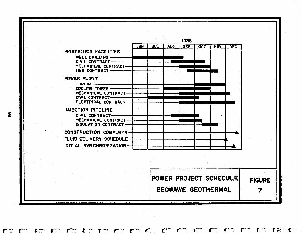
I -~ ~~~~ - - ~ ." . .. . , . . " . .." . . ... . . .
1985
PRODUCTION FAClLl WELL DRILL1 CIVIL CONTR MECHANICAL CO I B E CONTRACT
POWER PLAN TURBINE COOLING TOWER MECHANICAL CO CIVIL CONTRACT ELECTRICAL CONTRACT
INJECTION PIPELIN CIVIL CONTR MECHANICAL INSULATION
CONSTRUCTION COMPLETE FLUID OELIVERY SCHEDULE I I I I I 1
INITIAL SYNCHRONIZATION I I I I . I
I BEOWAW E GEOTHERMAL I 7

specified, b id and ordered, designs completed, construction commenced,
and a partnership formed u t i l i z ing t private .fjnancing 1 . t o bu i ld and
operate a geothermal power p l a n t . The project is currently providing
construction jobs i n the Northern Nevada area and will continue to
provide additional tax revenues and employment f o r the years t o come.
The completion and operation of this project is a significant step i n
our e f fo r t s t o develop geothermal resources i n the State of Nevada.
i t
i
id 97

98
i c
L i
I' Y
t
L t
i
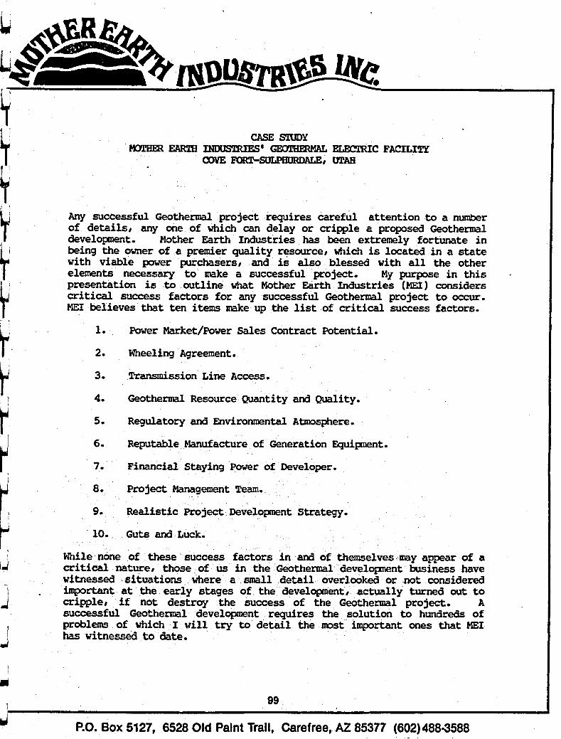
4 CASE STUDY
EARTH ELMZTRIC FACILITY 4 O O y E ~ D A G E r VL'AB 7 '
I d
Any successful Geothermal project requires careful attention to a number of detailsr any one of which can delay or cripple a proposed Geothermal developnent. Mother Earth Industries has been extremely fortunate in being the owner of a premier quality resourcer which is located in a state with viable power purchasers, and is also blessed with all the other elements necessary to make a successful project. My purpose in this presentation is to outline what Mother Earth Industries (MEI) considers critical success factors for any successful Geothermal project to OCCUT. ME1 believes that ten items make up the list of critical success factors.
1. Power Market/Power Sales Contract Potential.
2. Wheeling Agreement.
3. Transmission Line Access.
4.
5. Regulatory and Environmental Atmosphere.
Geothermal Resource Quantity and Quality. d
I 6. Reputable Manufacture of Generation Equipment. d
7. Financial Staying Power of Developer. 1 i 8. Project Management Team.
9. Realistic Project Development Strategy. d
While none of these success factors in and of themselves m y appear of a i critical naturer those of us in the Geothermal developnent business have Y witnessed situations where a small detail overlooked or not considered
important at the early stages of the developmentr actually turned out to
successful Geothermal development requires the solution to hundreds of 1 problems of which I will try to detail the mst important ones that ME1 I has witnessed to date.
4
. cripple, i f not destroy the success of the Geothermal project. A i
89
F.O. Box 5127, 6528 Old Paint Trail, Carefree, AZ 85377 (602)488-3588 d
Case Study Mother Earth Industries' Geothermal Electric Facility page 2.
1. Market/Power Sales Contract
The supreme and all-important law of Geothermal development is "if you can't sell it, don't make it." I should also add "at a profit." TOO often this particular item is either *assumed or overlooked by the developer at the early stages, where the developer assumes.he will obtain a PURPA type contract similar to that which had been negotiated by other parties. Very often the PURPA contracts have clauses in them which make the power either
elected not to enter into a PURPA contract with the local utility, Utah Power & Light. Instead, ME1 concentrated on developing municipal power buyers, and entered into a Power Sales Contract with the City of Provo, Utah. MEI's relationship with its municipal buyer has developed into a sound, joint developnent arrangement with respect to its &eam resource located at Cove Fort. When MEI initiated discussions with local power purchasers, including the local PURPA purchaser, the PURPA rates were an insignificant 20 mil rate. ME1 proceeded to actively participate in the Public Service Commission process and eventually has been successful in raising the PURPA rate, along with the other independent power producer organization members, to an estimated 5.4 cents per kWH. This PURPA rate compares to a Power Sales Contract rate in excess of 60 mils with the local municipal government buyer, Provo.
difficult, if not impossible to deliver at a profit. ME1
2. Wheelinq Agreement
Probably everyone at this conference is well familiar with the trials and tribulations of obtaining wheeling agreements, and the number of stalled projects that exist in the West because of failure to obtain a satisfactory wheeling arrangement. MEX'S strategy to obtain the first independent, private wheeling agreement in the State of Utah was a very carefully planned strategy coordinated with the City of Provo to utilize OUT multiple efforts to obtain a wheeling agreement with Utah Power & Light, to transmit MEI's power the approximate 140 miles to the City of Provo distribution system. It should also be noted that the power market in the State of Utah is a rather unique opportunity for marketing and distribution. A number of captive municipal buyers exist within the Utah Power & Light Service District, and until this date there has been no alternative except to wheel over Utah Power & Light's lines. A great deal of progress has been m d e with Utah Power & Light and the public Service Comission in allowing qualified Small Power Producers to wheel Over Utah Power & Light's lines when there is a legitimate Power Sales Contract in effect with a legitimate power buyer, such as the City of prove.
100
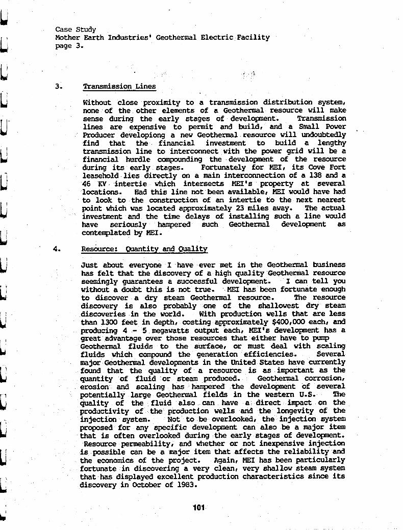
1; u- t: /-j
L
u IJ L
Case Study Mother Earth Industries' Geothermal Electric Facility page 3.
3. Transmission Lines
Without close proximity to a transmission distribution system, none of the other elements of a Geothermal resource will make sense during the early stages of development. Transmission lines are expensive to permit and build, and a Small Power Producer developiong a new Geothermal resource will undoubtedly find that the financial investment to build a lengthy transmission line to interconnect with the power grid will be a financial hurdle compounding the development of the resource during its early stages. Fortunately for MEI, its Cove Fort leasehold lies directly on a main interconnection of a 138 and a 46 K V . intertie which intersects MEI's property at several locations. Had this line not been available, ME1 would have had to look to the construction of an intertie to the next nearest point which was located approximately 23 miles away. The actual investment and the time delays of installing such a line would have seriously hampered such Geothermal development as contemplated by MEI.
'
4. Resburce: Quantity and Quality
Just about everyone I have ever met in the Geothermal business has felt that the discovery of a high quality Geothermal resource seemingly guarantees a successful developnent. I can tell you without a doubt this is not true. MEI has been fortunate enough to discover a dry steam Geothermal resource. The resource discovery is also probably one of the shallowest dry steam discoveries in the world. With production wells that are less than 1300 feet in depth, costing approximately $400,000 each, and producing 4 - 5 megawatts output each, MEI's development has a great advantage over those resources that either have to pump Geothermal fluids to the surface, or must deal with scaling fluids which cosnpound the generation efficiencies. Several major Geothermal developments in the United States have currently found that the quality of a resource is as important as the quantity of fluid or steam produced. Geothermal corrosion, erosion and scaling has hampered the developnent of several
large Geothermal fields i e western US. The the fluid also can direct impact on the
productivity of the production wells the longevity of the injection system. Not to &e overlooked, the injection system proposed for any specific development can also be a major item that is often overlooked during the early stages of developnent. Resource permeability, and whether or not inexpensive injection is possible can &e a major item that affects the reliability and the economics of the project. Again, ME1 has been particularly fortunate in discovering a very clean, very shallow stem system that has displayed excellent production characteristics since its discovery in October of 1983.
101

Case Study Mother Earth Industries' Geothermal Electric Facility page 4.
5. Regulatory and Environmental Atmosphere
As with the wheeling agreements noted in item 2 above, the regulatory and environmental atmosphere of a proposed development can often be the difference between success and failure. The potential obstacles to development encompassed by this category is virtually limitless. mental requirements could limit, delay or cripple a potential development from happening. ME1 has been particularly fortunate to this point in time by developing a healthy working relationship with all of the Regulatory officials in the State, Federal, and local governments. We have found that if you take the extra time to work with these officials at an early stage of development I you can often eliminate developer's nightmares, and discovering at the eleventh hour that a major item has been missed of a Regulatory nature. ME1 is indebted to the tremendous s u p r t it has received from the Regulatory officials in the Federal, State and local level within the State of Utah. Particularly important is MEI's relationship that has developed with the Bureau of Land Management and Forest Service in Utah.
Any one of the regulations or environ-
6. Reputable Manufacturer
Detennining who is or is not a reputable manufacturer can often be a difficult and uncertain process. Just because a major name stands behind the equipment is no guarantee that the equipment will perform as represented. Also, getting a manufacturer to stand behind his representations amd warranties can be a frustrating, if not impossible task under certain situations. MEI's Rule of Thumb is and has been that a contract is only as good as the handshake behind the document. I would strongly suggest that any Small Power Producer that is contemplating entering the development side of the business be certain that his relationships with a potential mufacturer are at a high enough level to not suffer the impact of personnel changes or company policy changes. I can also tell you from my personal experience that there are a number of unethical practices which occur on the part of equipment suppliers. Unfortunately, m y of these item are learned the hard way by you and me. I would encourage anyone seeking entry into the small power production business to very carefully and thoroughly investigate all elements of a potential generator manufacturer, equipment supplier, or consultant before making any firm cormnitments.
7. Financial Stayinq Power
Another ME1 Rule of numb in Geothermal developnent is that everything takes twice as long and costs twice as much to accomplish as originally budgeted. Make sure you have what is called a massive miscellaneous contingency fund (conanonly known
102

i
L
! I
ii
u t' i;
L
Case Study Mother Earth Industries' Geothermal Electric Facility page 4-
as an MMCF). atever you think your contingency budget should be and at least double it.
Zhe second item under this category is not just a reserve of dollars. I strongly urge every potential developer to calculate what the effect of finding themselves delayed from entering production for a period of one or two years will be on the project. What I can tell you from person& experience is that these delays will and do occur regularly. While ME1 probably has the best track record in the industry with respect to on-line comercia1 production from resource discovery in less than twenty-four months, had it not been for errors, miscalculations and contractual difficulties, MEI should have been in production as much as six months sooner. With respect to financing a Geothermal project, ME1 has taken an innovative approach wherein it drills the wells and takes all of the resource associated risk with its own funds. Its relationship with its municipal buyers has supplied additional capital for the developnent of the generation and transformation facilities. While ME1 has been offered mney from independent investors, the tern and conditions have' not been of an acceptable kind to this date. ME1 will continue to rely on its own resources and those of its micipal buyers until such time as it cah identify an institutional or corporate partner who shares the same developnent objectives as ME1 .
MY R& of ~humb is to ta
8. Pro-ject Team
I cannot say too much about the importance of developing a multi-talented and compatible project team to cover the many items of Geothermal developnent. ME1 has been fortunate to have assembled such a project team during the early days of field discovery. Forsgren-Perkins Engineering of Salt Lake City has acted as lead project engineer.responsible for all permitting and design engineering for the Facility. Bigginson-Barnett Consultants of Bountifulr Ytah have acted as team geologists and hydrologists responsible for the resource identification and well site selection. Also, water right permits and a great deal of public relations efforts have been undertaken by Higginson-Barnett. ThermaSOurce, Inc. of Santa Rosa, California has performed the functions of drilling engineer, reservoir
and supplied all well testing and drilling management for the drilling of five ME1 wells to date.
Professor Ronald DiPippo of Brown C Southeastern Massachusetts University acts as team thermodynamicist and is critical for the review and analysis of proposed generation power cycles for the property. Veizades Engineering of San E'rancisco, California is responsible for the steam line gathering system. In addition, ME1 has two team of lawyers and an accounting firm that have developed an integral knowledge of the Geothermal laws ,and requirements.
103

Case Study Mother Earth Industries' Geothermal Electric Facility page 5 .
The second mst important item after assembling the team is appropriate team chemistryr and a willingness to work for the benefit of the project and not just. for the dollars involved. ME1 has been fortunate that everyone of its project team members is not only one of the most respected firms in the fieldr but also has infused the project with energy and enthusiasm which has become contagious to the Regulatory officials and the local conarmni ties.
9. Realistic Developnent Strateqy
All too often it appears that developers of Geothermal projects propose developnt schedules and budgets that are unrealistic given the facts of life with respect to Geothermal development. The Geothermal industry has enough stalled or failed projects on its record list to date. We do not need anymore failures and we certainly do not need disgruntled investors. Any Geothermal failure affects all the rest of us. It is also my impression that the shakeout of "fly by night" consultants and developers has occurred within the industryr leaving serious and legitimate projectsr developersr and consultants dominating the field. During the time frame of the late 1970's and the early 1980's when a surplus of government-sponsored contracts existedr a number of underqualified people developed consulting practices or investment schemes which gave the Geothermal industry a tainted image which still exists in part today.
Againr I must urge all members of the Geothermal Coxtununity to be realistic about the developent obstacles and the risks associated with any Geothermal developnent. Our cormunity has seen Geothermal successes when conducted by the large corporate entity. However, you can only count the operational Small power Prcducer on approximately two fingers as-of this writing. We all know of the failures of the entrepreneurial Geothermal developer to this point in time. If we do not self screen and protect our industry from the less reputable developersr consultantsr and equipment suppliersr all of our individual lives will become more difficult .
--
10. Guts and Luck
I think we all must be slightly crazy to be in the Geothermal industry given the economic climate today/ the depressed energy prices today# and the elimination of many of the Federal incentives which have made our projects viable in the past. My assessment is that there is much less room for error in the Geothermal caranunity today than there has ever been. An error of even the smallest magnitude could lead to failure. Our community is not for the weak of stomach or weak of pocket book. If you do
104

' L t
I:
u
Case Study Mother Earth Industries' Geothermal Electric Facility page 6.
elect to become a Geothermal developer in the Small Power Producer categoryr I encourage you to thoroughly do your homework because of the magnitude of the odds against success.
Finally, ME1 would not be the success which it is today without tremendous luck. We have been blessed with the financial resources to accomplish our goals, the cooperative and wonderful partnership developed with the City of Provor the'enthusiastic and cooperative support of all of the Federal officials in the Bureau of Land Management and the Forest Servicer and the tremendously supportive populous of the State of Utah.
WhP:mh

- L i
i 1 L
t t
106 t

Reprinted by permission from
~;OJlhCfmaI Resooms Coundl
PROJECT DEVELOPMENT DESERT PEAX
C. P. Diddle and W. C. Conser
Ph i l l i p s Petroleum
ABSTRACT
In late 1982 Phi l l i p s Petroleum Company began preliminary design of a power plant for b r a r t Peak i n Churchill County, Nevada. lscause each geothermal resource is unique, c r r a fu l considerrt ioa o f exis t ing process achomes and design techno1ogier was required. ‘Ihls paper vi11 review process studies, examine soma of the d e t a i l design and discurt the con- r t ruct ion program. 80 attempt w i l l be made t o rtlrcuss geological aspects of the resource.
1WTRODVCTION
Phil l ips Petroleum Company has obtained approximately 24,600 acres of Federal rnd Lauthern Pacif ic Railroad leases i n the Srady- tlarsn Knom Geothermal Eesource Area (KGRA), an area commonly referred t o as Desert Peak. mi8 redlum temperature hot water dominated resource 1s located i n a r id ro l l i ng deser t of the Rot Lprlngr Hountrins, 65 miles northeast of brio, Nsvada. After preliminary evaluations of the raIource, Phi l l ips began i n late 1982 a compre- hanrivc study of a l ternat ives which ultiraately rorulted i n the current 9 MJ f a c i l i t y design.
Proeeaa Parameters
Tabla 1 r h w s process parameters u t i l i zed lor berert Peak.
Table 1 Production Well Charac t e r~s t i c s
Avarage flowratc per well Avarage wellhead temp 326OF Avarage wellhead prersute 97 PSIA Average resource temp 400oF Average resource enthalpy 384 BTU/lb
SO0,OOO lbm/hr.
SCoam flash by mass 9.9%
Studler - The process specif icat ion for Desert Peak
ovolved from criteria established by Phi l l i p s Crothermal Branch and process studies. Each rtudy was bared upon exis t ing condition8 a t
Desert Peak and an objective t o generate the most power a t the lowest c a p i t a l cost.
Cooling Towers vs Air Pin Exchangers
Table 2 srtmmarizes e l e c t r i c a l power pro- duced by a system cooled by e i the r air fia exchangerr o r cooling tower.
Table 2 A i r FinfCooling Tower E lec t r i ca l Power
Production Comparison Cooling
bit Fin Tover
Pa ras i t i c IwB 1509 756 B e t Power f o r Sale KUH S770 9266 Differen& (3496) t f fectiveness 62%
Elec t r i ca l Power - Crors Power Output ltvB 7279 10022
Also, the c a p i t a l c o r t of the cooling tower was one th i rd of the cost of the air f i n ex- changerr.
Two Phase Flow 0s Wellhead Separation
Wellhead separator syrtcms and two phase flow ryrtems -re atudied to determine which could provide the lowest pressure drop a t the lowest investment and operating Costa. -0
phase flow vas selected because operating and -investment costs were reduced by eliminating wellhead separators. By locating the plant downhill o€ the production wells and insuring there were so pockets i n the l ine; damage due t o slug f lov was eliminated. Urge diameter piper a180 assis ted i n separating fluids.
.-. ‘ P l o a t i n ~ Power
Floating power means that equipment is s i red t o Lake advantage of temperature ranges. As the Cooling aystem responds t o lower tempera- tures more horsepower can be developed by the turbine and more power can be generated. When f loat ing power is considered, the production rate remains constant) hovever, temperature fluctuations are ref lected by annualized mean termperatures. Table 3 rummarires design condi- t ions and pover output.
107

Diddle et al.
Table 3 Constant Pover/Floating Power Compariron
Conditionr Power Power Constant Floating
Production rate lbmbr 1,086,000 1,086,000 Cooling Water t o
Cooling Water
Electr ical Power
Procerr 670F( 1) 530F(2)
from Procesr 107OF(1) 930F(2)
l e t Power KUB l0.000 11,050 Percent increase 10. sz
( I ) Summer conditions (2) tkan annual
Binary v i Full Flow Unit
Phi l l ip# compared an internal ly designed binary ryatem with a rotary separator turbine (=TI ryatem. BST power akid operating par-- e t e r s were provided by Tr8n88meriC8 &lava1 Biphare Energy Systems and Ph i l l i p s developed the procear flowsheet fo r the system. The PST procear war relected primarily because it pro- duced more net power a t a lover cap i t a l cost. Table 4 summarizes both procesrea.
Table 0 BinarylRST Compariron
Binary RST
System Characterist ica Well f l w lbmbr 1,500,000 1,500~000 Irobutane flow lbm/hr 2,026,OQO Cooling water c i r cu la t ion
rate lbm/hr 12,865,000 6,488,620 Elec t r i ca l Power
Parar t ic M? l e t for s a l e M?
l e t
Grosr M?
Conversion Efficiency
15.08 13.46
10.98 12.06 4.10 1.40
7.09% 7.32% Estimate Cost Different ia l (1982 Costs) 57,200,000 Bare
NOTE: Geothermal f lu id war cooled t o approxi- mately 167OF in the binary ryrtem t o accomodate minimum inject ion temperature.
Current Design
The current design ir the r e r u l t of h p l e - menting the conclusion# of previourly discursed rtudiea. Figure 1 show the 24 in. and 30 in.
' two phase gathering rystem with the plant located a t the l w e s t elevation. As ahown by Figure 2 geothermal f lu id r are reparated i n t o high prearure steam and brine in the high prcr- sure reparator. Righ prerrure rteam f l o w through a knock out ve r r e l t o the Item turbine inlet . Brine from the high pressure separator is divided between the BST and the low prerrure separator. Because of low syatem preraure, the RST cannot proeeas a l l brine produced i n the
high prearure separator. EXCer8 brine ir flrrh- ed i n the low prersure reparator. Lov prerrurc steam from the RST and low prerrure reparalor enter# the steam turbine 8 f t e r any cxreaa ao i r tu re i8 removed by knock out rerrelr Steam a t Lerr than. atmorpheric preasure ir b l s - charged from the rteam turbine in to a di rect contact rpray condenaer where vacuum i r provldcd by rtcam ejectorr . Heat i r rejected through (I
cooling tower and make up fo r the s y r t m i a con- denrate. t r i n e from the UST f l o w t o the few pressure separator. %e inject ion system includer the discharge from the recond @tag@ reparator, cooling tower blw do=, in jrc tbn pumps and an inject ion w e l l . Figure 3 rhovr the plant layout.
FIEURE 1 ESERT PEAK PLOT PLRN
108
c' I L 1
t L L I
t L
I
L f
L; 4 '
i
t 1 L L t t
1 t

Diddle e t a1.
Dereit Peak Simulator
Procers- a t d i e s , process design and d e t a i l desiga could a o t have been accomplished i n the rhort t h e allocated i n the project rchedule i f t he Oerert Peak Simulator (DPSIHF) had mot been developed. The simulator developed by C. P. piddle, PhUlips Petroleum Company models ringle flash, dual flash mud ILST ryrtemr from produc- t ion wetlhead(s) t o the inject ion wellhead including ell auxiliary srstcms. Its progrnn is
.written i n BASSICA fo r use on the IBH PC. Table 5 8hOW the t a r i a b l e r which can be changed by thc engineer v i t h input from the keyboard. The temperature, pressure, flov, and percent vapor a t the top of the wellhead are given conditionr which can be changed f o r d i f f e ren t rerervoirs. The nmaiader of the r a r i ab le r are s e k e t e d by the procerr engineer.
program provider for change o f vari- ich are l f r t e d by letter codes. Aa
put will r e s u l t i n a question t o be anevered r a l l codes except: (1) XT = GET OUT OF TFlE
SIWLATOR, (2) UINS = Caurer the program t o run a f t e r changer of r a r i ab le r are complete and a
109
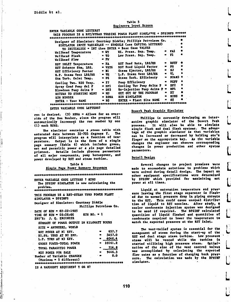
Diddle Dt a l .
Table 5 Engineers Input Screen
ENTER VARIABLE CODE LETTERS? THIS PROGRM IS A RSTISTEM TURBINE POWER PLANT SIw[IwlTr)H + DPSIWD *-**
w****m*******w*f******nn**+tt******************+mw*w***w*******m
c * Designer o f Simulators Courtney Diddle: Phi l l ips PetrOleurP Co.
Wellhead Temperatun - HI. Press. Sep. Temp. Fdl Wellhead Flash = VO LOW Press. Sep. Temp. - F1 * Wellhead Flov - F w RST IXLET Temperature - FA RST Feed Rate, US/= R!XF RST Enhance Stm, LBS. - VST6 RST Peed Liquid Factor = FS * RST Efficiency Factor - It1 Steam Ejector, us/= SJ * W.P. Steam Vent LSSlHR = W - L.P. Steam Vent LBS/HR - VL * Stm Turb. Oulet Temp. - F6 Steam Turb. Efficienty Ii2hl0 *
Spray Cond Pump d e l P = DP1 Cooling Twr Pump de l t a P = DP2 * Blowdown Pump de l t a P - DP3 Re-Injection Pump d e l t a P 9 DP4 * BETvBlD TOSTARTINCHENU -)ID CETOUTOFTHEP- XT RUN lWKBER ENTER - Your NAME = It$ ENTER - Plant Si te NA?fE S$
SIKLILATOR IlppUT VARIABLES -- SYHBOLS (use CAPITAL TO INITIALIZE = INT then ENTER - Base Case VALUES
Cooling Two. H20 Temp. = F7 Pump Efficiency - PEFF *
= RUNA RUN SIHUULATOR 9 ms +*w*m*+*w*****w****ww**********+*t*n*****~*****~f****m~** ENTER VARIABLE CODE LETTEU?
Deserk Peak Graphic Simul8tor run is desired. (3) RUNA - Allows for an over- r i de of the Run Number, since the program w i l l Phi l l ips is currently developing an intQr- automatically increme!t the run number by one act ive graphic simulator of the Desert F Q A ~ (1) each RUNS. process. It w i l l a l s o be able t o slauhte
The simulator contr ins a -atema t r b l c 6 t h s ingle f lash and dual f lash systems. The Advan- saturated data between 32-705 degrees F. The tage of the graphic simulator is t ha t v a r i a b b r program w i l l in terpolate as a function of tem- can be increased o r decreased by holding ona'n perature. Output is i n the form of e single finger the Appropriate key. Aa the varirble page sunnnary (Table 6) vbich includes gross, changes the engineer can observe correspondlng net and pa ras i t i c power o r a s i x page detai led changes i n Power production and other ry r tw printout. Details include p'rocess parameters parameters. of a l l major components, pwnp horsepower, and power developed by RST and ateam turbine. Detail Design
Table 6 Several changes t o project premirar %re Single Page Paver Surmaarp Sequence made t o accomodate solutions t o problems w h k h
The impact an *+**.***m**w*-*******m******-****~ other equipment . pec i f i ca t io~s were detemlngd ENTER VARIABE CODE LETTERS ? RUNS by DPSIHF which provided for maximiring nQt
power at a l l times.
*nm+*-m+t*m*******-***** Liquid-at saturat ion temperature and pter- THIS PROGW IS A RST-STEAM NRB POWER PLANT 8ure leaving tba first stage reparator i r f l a b - SIMULATOR - DPSIXFD ed due t o noma1 pressure drop in piping onmute
t o the'RST. mi8 could cause unequal distribu- t i o n of l iquid t o EST noztler. After rtudy, Designer of Simulator: Courtney Diddle cooler condensate inject ion system was dertgned
DATE OF RtM = 02-22-1985 to be ased i f required. The DPSm crkuki tod TIME OF RUN = 08:28:00 RUN NO. = 1 quant i t ies of l iquid flashed and quant i t ler ef ENG'B: J. Q. ENGIREER tondensate required t o lwer the temperature t o
were colved during d e t a i l design.
The DPSIMF SIHULhTOR is now c a 1 c u h t i ~ g the problem.
Ph i l l i p s Petroleum CO.
SUIWARY OF POWER OUTPUT IN KILOWATT HOURS match the expected pressure a t the RST inlet .
The vent-rel'ief 8ystem i r e s sen t i a l for the management of steam duriag the tartu up of the RST and dual stage steam turbine. Low prerrun ' steam w i l l be vented while the turbine $@ L.P. TURN AT W EFF. = 4046.4
GROSS POWER-fOTAL POWEB - 10161.2 s t a r t ed u t i l i z ing high pressure steam. Qptkd-
SITE -ERE, WORGO RST POWER AT I1 EFF. - 657.7 HIePP. TURB AT Hz EFF. = 5457.0
. TOTAL P W I T I C POWER - 714.8 r a t ion of the sire of the vent control V A l V e 4 NET POWER FOR SALE 9446.1 was accomplished by calculat iag the oxpeetad
Number of Variable CHARGES I 0.0 flow rates as a function of changing back prer- r u n . The calculat ion was made by tho bPlllWt (&ximum = 5 d i f f e ren t )
+m***t*ftrn+t********w~***m+********~ simulator. IS A HARDCOPY REQUIREP? I OR N?
i i
i lu
L t t t ' L
t a t t L I. 1- L
I c I L
110

In order t o meet excepted operating condi- tion8 the brine dirporal pondr which were premired t o be instal led i f required have been constructed. Diverting production t o the pondr wilt . a s s i s t i n limiting the rate of the lncreare i n the ryrtems temperatuF during rtart-up. A h 0 rol idr lbasenedby well cleaning can be prevented f r a entering production pipeliner and equipment.
As the operating and atar tup procedurcr developed, it vas determined tha t a d i r t r i bu ted control and pemi r r ive interlock ryrtenu would be required. A programable control ler with &C memory and 128 1/0 point8 vas selected t o tmplement rhut-dova logic and permissive start requencing. The process d l 1 be .controlled by 4 eight loop programable eontrollerr . A CRT r t a t ion w i l l be rued t o monitor and make procers adjustment. Because the ryrtem floats on the w e t bulb temperature and production cha tac t e r i r t i e r change the r e su l t of well rcaling a l l ryrterrm must be t e p t in balance and have a rearonablt operation range. It would be h p o r r i b l e t o manua11y control t h i r dynamtc ryrtcm.
Construct ion
The overal l project rchedule VU developed t o take advantage of a11 t a t incentiver and be operational by December 31, 1985. In order t o meet t h i r objective the construction philosophy provide for reparate s i te preparation, plant erection, insulation and painting contractr . S i t e preparation WSB completed in mid Hatch 1985 and the main contract vas awarded i n ea r ly April. The RST pover skid i s ncheduled t o be shipped by mid-July and plant 8t.tt-Up La rcheduled for December.
Reference6
Phil l ips Petroleum Company Computer Programs a) DPSIHF RST-Sfew turbine Pouer Plant
b) DPCSIU EST-Steam Turbine Pover Plant S €mu l a t o r
Graphic Simulator
Cerini, 0. S., Diddle, C. 0. and Conset, U. C. Project Development Derert Peak 9NIJ Power Plant Proceeding8 Eight Annual Geothermal Reroutccr Council pgr. 33-39, 1 9 8 L
Diddle et al.

112
t
f
t t t
i t L

DESIGN, CONSTRUCTION AND OPERATION OF THE MAMMOTH GEOTHERMAL POWER PLANTS
Richard C. Campbell and Ben Holt The Ben Hol t Co.
201 South Lake Avenue Pasadena, CA 91101 (213) 684-2541
ABSTRACT The world's first modular air-cooled binary plant went on l ine i n November of 1984 near Mammoth Lakes, California. I t is now operating reliably and producing power a t rates i n excess of design. Availability exceeds 90%. The fac i l i ty consists of four production wells, three injection wells and two identical binary power plants each having a year-round net capacity of 3,500 kW, exclusive of well pumping power.
The reservoir i s a low-sal i n i t y (1,500 ppm) moderate temperature (34OOF) resource. Multi-stage shaft driven pumps are employed t o deliver the h o t water t o the plant under sufficient pressure t o eliminate flashing and pre- vent scaling.
Air cooling is used t o reject heat t o the atmosphere. The result is that there are no a i r or water emissions from either the geothermal resource or from the pl ants.
BACKGROUND The Mammoth Geothermal Project is located w i t h i n the Long Valley Known Geo- thermal Resources Area (KGRA) on the eastern slope of the Sierra Nevada mountain range of California some 300 miles north of Los Angeles. Three miles west of the plant is the village of Mammoth Lakes, and well-known winter and summer resort.
The plant is owned by Mammoth-Pacific (M-P) , a joint venture of Pcifica Geo- thermal Company ( a subsidiary of Pacific Light ing Corporation of Los Angeles) and Mammoth Binary Power Company. The general partner of Mammoth Binary Power Company is Holt Geothermal Company, an a f f i l i a t e of The Ben Holt Company based i n Pasadena, California.
Design and construction was handled by The Ben Holt Co. , who also through the Mammoth Binary Power Co. operates the plant.
Nearly a l l of the residentlal and commercial space heating i n the Mammoth Lakes area is electrical , served by the Southern California Edi son Company (Edi son) . Electrical usage peaks i n the wintertime, un l ike the rest of the Edison system. While some power is provided by hydro plants i n the area, most o f the Edison supply arrives via a transmission l ine connecting t o Edison fac i l i t i es i n the Moj.ave desert some 200 miles to the south. Peak power consumption i n the area is about 40 We. *
113

Field construction of the power plants was minimized by the use of modular design. Two identical u n i t s were b u i l t , side by side, w i t h common u t i l i t i e s and common spare equipment. Wherever possible , equipment was skid-mounted and/or shop fabricated to minimize field costs. A l l of the system components are commercially available.
Design and operation of the plant takes advantage of the low ambient tempera- tures a t the plant si te. The plant is a t an elevation of 7300 feet w i t h an annual average dry bulb temperature of approximately 4OOF. Condensation of the working f l u i d uses floating cooling. That i s , the condensing temperature is allowed t o vary w i t h changes i n the in le t a i r temperature. Power production dur ing the summer is lower than average, b u t the h igh power production during the rest of the year makes up for the low summer production.
The geothermal brine a t Casa Diablo has a dissolved solids content of about 1500 ppm and is non-corrosive. As a result, the p ip ing and power plant have been b u i l t w i t h carbon steel as the primary material of construction. Reservoir E i g h t geothermal wells were drilled on Magma's property and flow tested i n the early sixties. T h i s early work demonstrated the existence of a reservoir of ho t water a t shallow depths (400 t o 800 ft.). Reservoir temperatures averaged about 33OOF and total dissolved solids were about 1500 ppm. The early t e s t work involved free flowing the wells for periods varying from a few days t o a few weeks. formation i n the well bore.
Carbon dioxide was evolved dur ing these tests, resulting i n calcite
A shaft-driven downhole pump was used i n subsequent t e s t work to eliminate cal- c i t e formation by maintaining single phase flow i n the wells and surface equip- ment.
The geology of the area has been described i n a paper, "The Hydrothermal System of Long Val 1 ey Caldera , Cal i forni a'' (USGS Professional Paper 1044-A). Design Criteria The following cr i ter ia were the key elements i n deciding upon the design.
The fac i l i ty must be environmentally acceptable since i t i s surrounded w i t h National Forest land i n an area possessing great scenic and recreational value.
In order t o minimize construction costs i n a remote area, the fac i l i ty should employ modular construction techniques t o the maximum extent possible.
In order t o qualify as a base load fac i l i ty , i t should be designed for high avai 1 abi 1 i ty and re1 i abi 1 i ty.
These considerations led t o the choice of a simple binary cycle plant employing 100% a i r cooling. The geothermal f l u i d is maintained i n a l i q u i d s ta te through- out and 100% of the f l u i d i s reinjected. Moreover, no cooling water is required i n an area where fresh water is a t a premium. Thus the plant i s a pollution-free i nstal 1 a t i on.
114
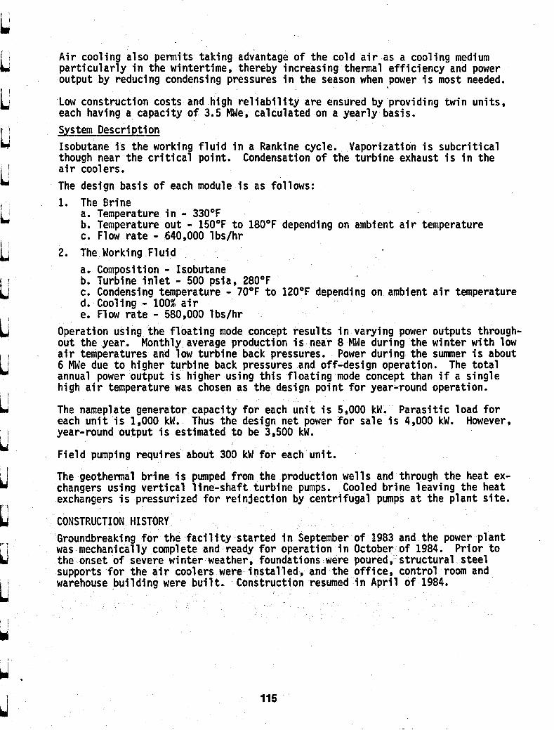
Air cooling also permits taking advantage of the cold a i r as a cooling medium particularly i n the wintertime, thereby increasing thermal efficiency and power o u t p u t by reducing condensing pressures i n the season when power is most needed.
Low construction costs and h i g h re l iabi l i ty are ensured by providing t w i n units, each having a capacity of 3.5 We, calculated on a yearly basis. System Description Isobutane is the working f l u i d i n a Rankine cycle. Vaporization is subcritical though near the cr i t ical point. Condensation of the turbine exhaust is i n the ai r coolers . The design basis of each module is as follows: 1. The Brine
a. Temperature i n - 33OOF b. Temperature out - 1 5 O O F t o 1 8 O O F depending on ambient a i r temperature c. Flow rate - 640,000 lbs /hr
a. Composition - Isobutane b. Turbine inlet - 500 psia, 280°F c. Condensing temperature - 7OoF to 1 2 O O F depending on ambient a i r temperature d. Cooling - 100% a i r e. Flow rate - 580,000 lbs /hr
2. The Working F lu id
Operation using the floating mode concept results i n varying power outputs through- out the year. Monthly average production is near 8 We during the winter w i t h low a i r temperatures and low turbine back pressures. Power during the summer is about 6 We due t o higher turbine back pressures and off-design operation, The total annual power ou tpu t i s higher us ing this floating mode concept than if a single h igh a i r temperature was chosen as the design po in t for year-round operation.
The nameplate generator capacity for each u n i t is 5,000 kW, Parasitic load for each u n i t is 1,000 kW. Thus the design net power for sale is 4,000 kW. However, year-round output is estimated t o be 3,500 kW.
Field pumping requires about 300 kW for each u n i t .
The geothermal brine is pumped from the .production wells and through the heat ex- changers using vertical line-shaft turbine pumps. Cooled brine leaving the heat exchangers is pressurized for reinjection by centrifugal pumps a t the plant s i te .
CONSTRUCTION HISTORY Groundbreaking for the fac i l i ty started i n September of 1983 and the power plant was mechanically complete and ready for operation i n Octobe of 1984. Prior t o the onset of severe winter weather, foundations were poured structural steel supports for the a i r coolers were installed and the office control room and warehouse bu i ld ing were b u i l t . Construction resumed i n April of 1984.
115

Four production wells and two injection wells were dril led i n the f a l l and winter months. Testing was limited t o short term open flow t e s t s i n t o Baker tanks . The production pumps were installed i n the spr ing and most of the f ie ld p ip ing completed. A program of production and injection we1 1 testing was undertaken i n the summer and early f a l l . OPERATING HISTORY The operatinghistory of the plant and f ie ld as of June 1, 1985 may be summarized as follows:
' Wells The four original production wells (MBP-1,2,4 & 5) were drilled t o a depth of 650'. Casing was s e t and cemented a t 250' and a slotted liner (9-5/8")set a t depth. Pumps were set a t 600'.
One injection well (IW-2) was d r i l l e d t o a depth of 1,800 feet. The injection interval was 1,300 t o 1,900 feet. The second injection well was a converted well dri l led i n 1979 by Union O i l Company. I t was plugged a t 1,900 feet . The 7" l iner was slotted from 1,100 t o 1,900 feet.
During early operation, three of the wells (MBP-2,4 & 5) developed communication t o the surface indicating a fa i lure of the casing cement. The surface eruptions adjacent t o the wells were sufficiently serious t o require reworking MBP-4 and MBP-5 and abandonment of MBP-2. The reworks were successful and involved re- moving the casing and liner, resetting and cementing the casing t o 400 feet .
Late i n 1984 a new well, MBP-3, was dril led as well as a t h i r d injection well (IW-1).
A t the present time, three of the wells (MBP-1,3 & 4) are sufficient t o supply the p l an t (about 2,800 gpm a t 340aF) and appear t o be pump limited. Very l i t t l e drawdown occurs on each we1 1 and we1 1 head temperatures have remained constant.
The production pumps have given excellent service and show no indication of re- duced performance as a result of corrosion or erosion.
Two of the three injection wells are i n service a t any given time. pressures a t the wellhead are low and the injection pumps are not required. P lan t The f i r s t u n i t ( U n i t 100) was turned over t o operations i n October. chemical cl eani ng of the i sobutane ci rcui t was completed and i sobutane loaded. Circulation was established and the first power was sent t o the g r i d i n late November, 1984. U n i t 200 f i r s t delivered power t o the gr id i n March of 1985.
Numerous s ta r tup problems have been encountered and solved, not the least of which was the necessity of start ing up during the winter. The current status of the power p l an t equipment is as follows:
Injection
In November
Firm operation was established i n February, 1985.
116
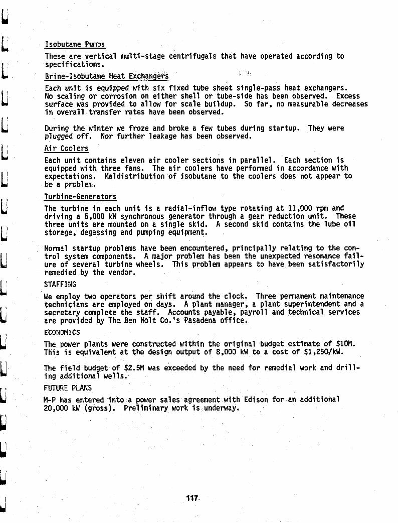
Isobutane Pumps These are verti cal mu1 ti-stage centri fuga1 s that have operated according t o specifications. Bri ne-Isobutane Heat Exchangers Each u n i t is equipped w i t h six fixed tube sheet single-pass heat exchangers. No scaling or corrosion on either shell or tube-side has been observed. surface was provided t o allow for scale buildup. So fa r , no measurable decreases i n overall transfer rates have been observed.
Excess
During the winter we froze and broke a few tubes during startup. They were plugged off. A i r Coolers Each u n i t contains eleven a i r cooler sections i n para1 le1 . Each section is equipped w i t h three fans. The a i r coolers have performed i n accordance w i t h expectations. Maldistribution of jsobutane t o the coolers does not appear t o be a problem. Turbine-Generators The turbine i n each u n i t i s a radial-inflow type rotating a t 11,000 rpm and d r iv ing a 5,000 kW synchronous generator through a gear reduction u n i t . These three units are mounted on a single skid. A second s k i d contains the lube oi l storage, degassing and pumping equi pent.
Normal startup problems have been encountered, principally relating t o the con- trol system components. A major problem has been the unexpected resonance f a i l - ure of several turbine wheels. T h i s problem appears to have been satisfactorily remedied by the vendor. STAFFING We employ two operators per shift around the clock. Three permanent maintenance technicians are employed on days. A plant manager, a plant superintendent and a secretary complete the staff . Accounts payable, payroll and technical services are provided by The Ben Hol t Co. 's Pasadena office. ECONOMICS The power plants were constructed w i t h i n the original budget estimate of $lOM. T h i s i s equivalent a t the design ou tpu t of 8,000 kW t o a cost of $1,25O/kW.
The f ie ld budget of $2.5M was exceeded by the need for remedial work and d r i l l - i n g additional wells. FUTURE PLANS M-P has entered into a power sales agreement w i t h Edison for an additional 20,000 kW (gross). Preliminary work is underway.
Nor further leakage has been observed.
117.

t i
118

1 lth Workshop on GeothermaI Reservoir Engineering, Stanford University, Stanford, CA, January 21-23, 1986.
DELIVERABILITY AND ITS EF'F'ECT ON GEOTHERMAL POWER COSTS
JS. Gudmundsson and JA. Marcou
Petroleum Engineering Department, Stanfard University
Stanfbrd, California 94305
Abstract
The deliverability of liquiddominated geothermal resuvoirS is presented in terms of
reservoir performance, inflow perfomance, and wellbore performance. Water influx modering
is used to match the perfoxmance of Wairake.i in New 2iAand, and Ahuachapan in El Salva-
dor. The M o w perfo!mance is given in tenns of a linear productivity mdex for l iquiddy
flow, and a solution-gas drive relationship for two-phase flow. A 9-98" production well is as-
sumed, flowing 25OT water from 900 m depth, with a wellhead pressure of 100 psia. A
Geothermal Devdopxntkt Model, that couples reservoir deliverability and power plant perfor-
mance, and assigns costs to both, is used to illustrate how the development cost of geothermal
electric power projects can be estimated
Introduction
The performance of rescrvoir/weUbore systems is perhaps the major cause of uncertainty
in geothermal field development decisions, at least in comparison to the performance of surface
facilities and power plants. Because of this uncertainty it is difficult to optimize the develop-
ment of liquid&& ted resources for electric power production. This may be the reason why
issues of geothermal &source exploitation and power plant operations tend to be dealt with
separately in the literature. In this paper, we couple the reservoir and economical issues in a
Geothermal Development Model, and consider the effect of deliverability on the cost of geoth-
ermal electric power from liquiddominated resources. ?he overall performance of a

- 2 -
resavoirlwellbore system with time is what we call deliverability. It has duee components:
reservoir performance, inflow performance, and wellbore performance.
Reservoir Performane
A reservoir model describes the change m reservoir pressure as a function of 5uid p
duction. The reservoir models available range from simple decline cuxves, through lumped-
parameter models, to distributed-parameter models. Grant (1983) has reviewed these for geoth-
ennal uses. Figure 1 shows the drawdown in reservoir pressure versus cumulative mass with-
drawal for three liquiddominated reservoirs: Ahuachapan, Svartsengi, and Wairakei. 'ihese
data were taken from Vides (1982) and QuintaniUa (1983) for Ahuachapan, and from Gud-
mundsson et at (1985) and Stacey and Thain (1983) for Svartsengi and Wairakei, respectively.
Figure 1 shows that the drawdown in the three reservoirs is similar. The Wairakti reservoir is
known to be larger than the others. In tenns of surface awi, it is reported to be about 15 km2
(Donaldson and Grant, 1978). while Ahuachapan and Svartsengi are likely to be m the range
5-10 km2. Figure 1 suggests that Svartsengi is the smallest of the
down at lower levels of production. Through 1982, the average rate of 5uid production from
Wairakei was about 1500 kgls; the rate at Ahuachapan was about 600 kgls through 1983; from
Svartsengi the average rate wasabout 150 kgls, currently it is about 300 kgk The three fields
are reaching nearly the same level of drawdown as cumulative mass production increases. The
long-term drawdown appears to be about 3 MPa, although the drawdown m the two smaller
fields has not levelled off as much as Wairakci. We observe that these gcothermaI liquid-
it shows greater draw-
dominated reservoirs exhibit I similar drawdown characteristic; thex overall uniform behavior
suggests they can be modeled using similar resenroir engineering techniques. The Wairakei,
Ahuachapan, and Svmengi reservoirs have a steadvapordominated zone above the main
liquiddominated zone; see Donaldson and Grant (1981), Rivera-R. et al. (1983). and Gud-
mundsson and Thorhallsson (1986) for details, respectively.
We elected to use a lumped-parameter model with water influx to study the performance
120
t L L- i I L L b t i t i t i
1 .
t t I I
L
t
i 1 e
f b
I L

1 i
. C
.. . . =.
i I1
m &
rl 0
Q)
0)
L
al U
Q
c rl
Q
I w
rl 1
W
rl
rl
Q)
01 &
2 m Eo 5 c 4
Q)
b
u) 0
) L
a
&
.rl 0
2 2 $ 0)
&
c 4
5 % s 0
w
d
Q)
& 3
M
.rl F

- 6 -
Wellbore Performance
We considered wells that produce steam/water mixtures at the wellhead. In the main
they will have liquid water feedzanes; in some cases the fluid will be two-phase, as in Figure 3
when the well flowing pressure falls below the saturation pressure. Wellbore performance con-
cerns the pressure drop fiom the bottom or main feedzone to the wellhead. This performance
depends on many variables, including: fluid enthalpy, fesavoir pressure, well diameter and
depth, and wellhead pressure. Ambastha and Gudmundsson (1986) present flowing pressure
and temperature profiles m 10 twephase geothermal web; they also match the data using a
wellban simulator based on the Orl&mda (1967) pressure drop correlations. Such a simula-
tor can be used to consuuct performance curves for two-phase geothermal wells. Butz and
PIooster (1979) and Butz (1980) have published performance curves for well Utah State 14-2.
The curves are based on a fiuid enthalpy of 1100 Hkg (liquid water at 250°C). a reservoir
pressure of about 9.7 Mpa (1430 pia) at a depth of 900 m, and a wellhead pressure of 0.69
MPa (100 pia). We present these cu~es m Figure 4 as wellbare performance mes for a 9-
98" and 13-3/8" casmg from 900 m depth to surface. The wellbore performance cmes are
independent of inflow performance and reservoir prformance; when we couple them, however,
we obtain the reservoirlwellbore system delivaability.
Geothermal Development Model
Decision making about geothermal developments deals with objectives, choices, and con-
straints. To optimize this decision making pr~~css, we need a model that includes both the
physical and economic features of development. We have made such a model from the point
of View of reservoir engineering, to study the effect of deliverability on electric power costs.
The elements of the Geothermal Development Model are shown in Figure 5. Several physical
models or.features can be selected for each of these elements; similarly, different problems can
be investigated: (1) reservoir can be modeled using decline curves, lumped-parameter models,
or distributed-parameter models, (2) wellbore flow can be modeled using generalized, or flow
122

- 3 -
of the three liquid-domipated reservoirs; specifically, the simplified method of Hurst (1958).
This method was used by Oisen (1984) and Gudmundssm and Olsen (1985) to match the pro-
duction history of the Svartsengi memoir. Marcou (1985) extended this work to include
Ahuchapan and Wairakei - the tarter match will be discussed here. We assumed the reservoir
to be radial and finite, and the supporting aquifer to be radial and Mnite. In water influx
modeling we focus on fluid flow across the between the hat reservoir and sunound-
ing warm aquifeIs. The reservoir is taken to have homogeneous Pmperties and uniform pres-
sure. The model equation is given in terms of the warm aquifer physical Prapertits; the
permeability-thickness product of the reservoir and aquifa are talcen to be equal; the compres-
sibility of the reservoir and aquifa- provide the main contrast in Properties. In a general way,
the pressure r e s p s e of the reservoir is dominated by the 5ow of water into the main reservoir
volume frmn surrounding aquifers. If there was no 5uid fiowing into the reservoir, it could be
modeled as a Kmstant volume tank under decompression or drainage. 'Ihere are t h e con-
stants used in the Hurst (1958) simplified method
where the symbols have the usual meaning, and the subscripts Q and I stand for aquifer and
reservoir, respectively. Grant et al. (1982) showed that for typical geothermal reservoir condi-
tions, the compressibility of Squid water is of the order of 109 Pa-', steam vapor lo-' Pa-',
and a two-phase mixture lab Pa-'. This range of several orders of magnitudes affects greatly
the pressure response of geothermal reservoirs, particularly when two-phase zones are present.
We matched the Wairakei data using 3 years, 6 years, 12 years, and 25 years of produc-
tion history. The match parameters obtained from the partial data sets were then used to
123

- 4 -
predict the drawdown in reservoir pressure for the 25 years of history. Our matches are shown
in Figure 2. We wanted to test the forecasting ability of the model. Using the h t three years
of history, the model overpredicts the drawdown; using six years or more the match between
Mdel and Bctual drawdown was reasonable. That is, using six years of production history, we
were able to forecast the next twenty years of drawdown with reasonable success. "he follow-
ing values of model constants were obtained from the full match: A - 6.7 x 10² Paslkg; B ., 9.3 x le s-l; C = 0.19. For an aquifer compressibility of 2.4 x 10⁹ FW1. the reservoit
compressibility becomes 26 x 1p Pa-'. It appears from this xesult that boiling m the two-
phase zone does not significantly infIuence the compessibility of the Wairakei reservoir.
Inflow Performance
The relationship between reservoir pressure and wellbore flowing pressure we call infIow
performance. In general, the mass flowrate w increases with increasing difftrence between the
two pressures, as expressed by the relationship
where J is a constant called the productivity index. This equation usually applies for single-
phase laminar flow into the wellbore; single-phase Darcy-type flow. In the case of geothermal
wells, the well flowing pressure pdought to be measured at the depth of the well's main feed-
m e fracture. The linear productivity index has been used by Gudmundsson (1984) m the cal-
culation of output curves of geothermal wells wirh single-phase feedzones, using a wellbore
simulator. We use it here for single-phase flow from the reservoir into the wellbore; when the
well flowing pressure pg is greater than the saturation pressure popt of water. Figure 3 shows
that inflow performance of well Utah State 14-2 in the Roosevdt Hot Springs geothermal area.
The data w& taken from Butz and mooSter (1979), and Bue (1980); see also M d e s (1982).
The productivity index of this well was determined to be about 40 tonnekMPa (600
lb/hr.psi), which is an average-kind of a well. A more productive well is well 12 in the Svart-
sengi field, which was reported by Gudmundsson (1984b) to have a productivity index of about
124

I
I t
I 1
I
I

- 5 -
100 tonndhr.IWa (1500 lb/hr.psi). We note that the productivity index is the inverse slope of
the line above pa in Figure 3. A larger productivity index, therefore, means that a greater
flowrate is achieved for the same pressure drive. Furthermore, the advantage of increased cas-
ing size is greater for wells with a large productivity index.
At relatively high flowrates, and when a steamlwater mixhlre flows from the reservoir
into the wellbore, the relationship between mass flowrate w and driving pressure @, - pg), is
likely to become non-linear. This problem was investigated by Vogel(1968) for solution-gas
drive reservoirs in the petroleum industry; Mauies (1982) d d e r e d a similar problem of
steam/water flow in fractures, including the effect of heat transfer from the rock to lwo-phase
mixture. The Vogel-method was used in our work because of its simplicity.
The Vogel(l968) inflow perfom~~~ce curve is an empirical relationship, obtained for the
situation where gas is coming out of solution: the flow of oil from its bubble point to increas-
ing gWoil ratio. We decided to apply the Vogel(l968) relationship to only the two-phase
flow part of the geothermal inflow perfmance cwe. For this situation the relationship taka
the form
The Aw is the incremental mass flowrate we achieve by lowering the well flowing pressure
below the fluid’s saturation pressure. The Aw- is what would ideally be achieved if the well
flowing pressure became negligible; in other words, if there was negligible pressure drop in the
wellbore. The square term m the modified Vogel(l968) relationship takes into account m-
bulent losses and other non-linear effects. The inflow performance below the saturation pres-
sure in Figure 3 is a solution-gas-type relationship. We see that the inflow performance of
well Utah State 14-2 can be matched with a linear productivity index at pressures above the sa-
turation pkssure, and a combined linear and nm-linear relationship at lower pressures.
126

L ii u I h I'
e U
0
10
1'
127

5:
m w
I-+
U
0 1
ID a m r( 0" 1 D 1
n
ID
0
0 0
8ZC
Wel
l fl
ow
ing
pre
ssu
re (
MP
a)
VI
I

1: Figure 5. Elements of geothermal development model.
129

- 7 -
pattern specific two-phase flow models, (3) surface facilities can have separators at each well-
head, or a central separator station (4) wellhead units and a central station are rypical power
plant choices (5) spent fluids can be disposed of at the surface or injected back into the reser-
voir, with or without chemical treatmew And, for whatever choices we make, there are asso-
ciated costs, and constraints.
Above we presented the main features of the reservoir, inflow, and wellbore perfor-
mances used. The following are a few details needed to complete the coupling of the individu-
al perfonnances to get the resemoidwellbore system deliverability. We decided to use a 9-518"
wellbore casing. The Mow performance curve in Figure 3, the 9-58" wellbore casing perfor-
mance m e m Figure 4, intersect at a total flowrate of 220 m& (a0 kg/s). This flowrate
then, is the initial flowrate from a well like Utah State 14-2, for a wellhead pressure of 0.69
MPa (100 psia). With decreasing reservoir pressure, this flowrate will also decrease, because
the Mow performance curve will move down in parallel with the initial m e , because it is
canstrained to go through the current reservoir pressure. We determined the deliverability of
our typical well to follow the approximate relationship
w = 30pr - 60 where w is mixture flowrate (kg/s) and pr the average memoir pressure (MPa). We used this
equation in the development model to determine how many wells are needed at start-up, and
when new wells are needed.
For a mixture enthalpy of 1100 kJkg and a separator pressure of 0.69 Mpa, the mass
fraction of steam is 22 percent. We reviewed a number of publications on geothermal electric
power plants to obtain a value far the conversion efficiency of steam to electric power (see
Marcou, 1985). We found that the following values were representative: condenser plants 8
tonnelhr.MW Ad back-pressure plants IS tonndhr.MW. We assumed negligible pressure loss
from the wellhead to power p1ant. It follows that a well like Utah State 14-2 can generate
about 6 MW of electric power initially. The average capacity of wells in liquiddominated
reservoirs worldwide is about 5 MW.
130

- 8 -
We divided the total cost of development into steamfield costs and power plant costs.
Again, we reviewed a number of publications on geothermal electric power developments. The
studies reviewed indicated that steamfield costs range from 25 to 50 percent of total develop-
ment cost. Two of the references are reports by Holt and G h d e y (1976) and Southan et a!.
(1983). We decided to select typical m t values fix use €n the development modeL The initial
invesrment cost of central power plants was takcn IIS 13 M$ per installed MW. This is cost in
1984 dollars, and includes expenses during construction. The initial investment cost of con-
denser wellhead units was taken as 0.7 M$ per MW. The cost of backpressure wellhead units
was taken as 0.5 M$ perm. We used an annual cost of 0.03 M$/yearper MW for central
plants, 0.06 M$/year per MW for candenser wellhead units, and 0.03 M$/year per MW for
backpressure wellhead units. The wellhead units were assumed 5 MW in capacity. The in-
vestment cost values used m the development model can be thought of as total cost at start-up.
Steamfield costs include production wells, separators, pipeIines, and injection wells; that
is, the total cost of delivering steam to a pker plant w e lumped these costs into one value
and assigned them to a production well. In other words, we assumed that total steamfield costs
are proportional to the number of production wells. We selected 22 M$ per production well
as a representative value. The annual steamfield expenses we estimated 0.3 M$lyear per pro-
duction well. Note that the cost of injection w&, for example, is included in this cost value;
we are simply using the production web as our yardstick. Like the power plant costs, the
steamdeld costs ought to be thought of as the total cost at start-up.
A project life of 25 years and a discount rate of 10 percent were selected for our study.
( Costs were discounted to find their net present value at the start of the project. J
For a project involving a central plant, the total development cost was anived at as fol-
lows. The initial plant investment cost, plus the sum of the discounted annual plant cost, were
added to the the initial steamfield investment cost, plus the discounted annual steamfield costs.
In addition, as the deliverability of each well declines with time, mort wells need to be drilled
to maintain stem production. The cost of the additional wells was discounted to present value
131

- 9 -
along with their annual steamfield costs. Fa a project involving a wellhead unit, the plants
and wells were installed at the same time in pairs. Wells and wellhead plants added after the
h t year of the project, were discounted to the first year, that is, their investment and m u d
COStS.
The steamfleld was assumed to operate every day of the year; at 100 percent capacity.
The power plant was assumed to be operated at 80 percent capacity. Therefore, the drawdown
in resemoir pressure was calculated assuming the wells were on-line all the time; the Mst of
electricity was calculated assuming the power plant was on-line 80 percent of the time.
Results and Discussion
The general form of our results is shown in Figure 6. The total cost of project develop-
ment in million dollars, based on net present value at start-up, is plotted against generation lev-
el or installed electric power m megawatts. Consider the nature of this m e . Point A is a 50
MW power project, and point B a 150 Mw project. The net present value development cost of
the 50 MW project is 100 M$, while the 150 MW project costs almost 450 M$ (447 u$),
which give 2000 $/kW and about 3000 $kW as specific costs, respectively. Figure 6 happens
to be based on Ahuachapan match parameters and 5 MW wellhead plants with condensers.
The slope of the cuxve in Fig- 6 gives the energy cost from different site developments. For
example, at point A the gradient conespan& to a levalid energy cost of 31 mWkWh, at
point B it is 83 miuslkwh, and at point C (90 MW plant) it is 47 millslkwh. We distinguish
between the average and marginal cost. The average cost of energy is found from the slope of
a line cunnecting some point on the m e with the origin. The marginal cost is found from
the slope of the tangent to some point on the curve. At point A both the average and marginal
costs are the same. At point B, however, the average cost is 47 milwkwh, but the margmal
cost83 mills/kWh.
Why does the marginal c a t of energy mcrease with generation level? The main reason,
we think, is that the flowrate of the production wells decreases more rapidIy at high generation
132
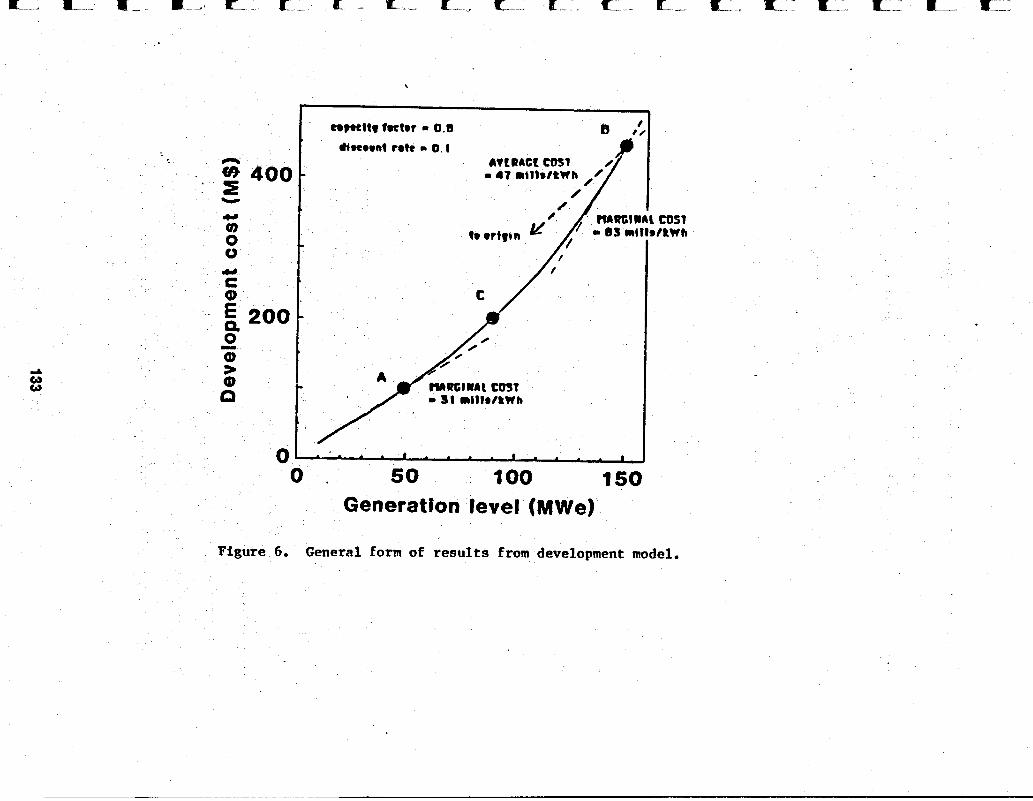
\
COST f RWh
0 . 50 too 150 Genetatfon level (MWe)
Figure 6. General form of results from development model.

- 10 - c levels than low, but also because we assumed no economy of scale in power plant costs. To
illustrate this point 11 wells are required for the 50 MW project m Figure 6, yet 78 wells are
required for the 150 MW project. Thmfore, while the generation level tripled, the nquired
number of we& (over the life of the project) increased about seven times, Neither did we
lower the cost associated with production we& with time: that is, we assumed the same ratio
of injection to production wells at start-up and later. We are fix@ to conclude that geother-
mal power developments shown diseconomy of scale when steamfield costs and power plant
costs are coupled
The Geothermal Development Model can be used to study any number of
resavoir/wellbore deliverability and power project scenarios. We used the reservoir and
economic parameters already discussed, to study the effect of different resemoirs, di€€cmt
power plant choices, and different wellfield operations. In the last of these, we contrasted the
effect of constant wellhead pressure production, against constant flowme production (choked
wells). We found that lower development costs were achieved m the constant welIhead pres-
sure case. Jn our study of different power plant choices, we found the backpressure option was
in all cases much more expensive than the condenser option; the reason being the large
difference in their conversion efficiency fram thermal to electric power.
Figure 7 shows the effect of different types of power plank; that of wellhead units with
condensers (same as Figure 6), and a central power station (with condensers). We used the
reservoir match parameters for Ahuachapan. At low generation levels the wellhead option
costs less, but at high generation level it costs more. This results comes about due to the con-
straint of having each wellhead unit hooked up to just one well. At high generation levels the
fiowratc of the wells declines much more than at low generation levels. Each of the wellhead
units is generating below what is is capable of generating, resulting in over-installed capacity.
In the cenw plant scenario, on the other hand, the installed capacity is always the same, be-
cause make-up wells can be connected to the plant as required. We did the same calculation
using match parameters from the Wairakei reservoir. Unlike that shown in Figare 7, the cen-
L t I ' k
L 7 ' t L f
b I
134

I / i
n e3 s -
400 0 0
8 tonne/MW-hr
Portable condenser ptants etttclency 8 tonne/ hr-M W
0 50 I O 0 2 50 Generation level (MWe)
Figure 7. Effect of plant choice on development c o s t for Ahuachapan match parameters.

- I1 - tral power plant option costs more at all generation lev& because the reserVair/wellbore
deliverability does not decline as much as at Ahuachpan.
The scenario of different size reservoirs for the same type of power plant d e c k is
shown in Figure 8. Using the deliverability of Ahuachapan and Wairakei we calculated the
development cost for wellhead units with condensers. The message of Figure 8 is that there is
a great cost advantage m having a large reservoir over that of having a medium ar small reser-
voir. This advantage becomes more pronounced with increasing generation level. At 150 MW
the Ahuachapan option has a marginal energy c a t of 83 mills/kWh, while the Wabalsei aptiOn
has a marginal cost of40 millskwh.
Conclusions
The production histories of the liquiddominated Ahuachapan, Svartsengi, and Wajrakei
reservoirs, were successMy matched using the radial form of Hum's simplified water
influx method. In the case of Wairakci, for example, six years of production data were
sufficient to match the full twenty-five years of history.
The deliverability of resavoirlwellbore systems consists of resavoir performance, inflow
performance, and wellbore performance. Methods and data are available to model the
deliverability of liquiddominated geothermal xesenroh. The methods selected here
were intentionally kept simple, so there is ample scope for improvements.
The Geothermal Development Model can be used to study the effect of
resmoirlwellbore deliverability and different power plant schemes on the economics of
geothermal electric power. With model refinements, it ought to be possible to optimize
geothermal field developments.
The cost of geothermal electric power and energy increases more rapidly than linearly
wiih the size of development; there exists a dis-economy of scale m geothermal power
developments. 'Ihis effect is especially true for large developments and small and medi-
um sized reservoirs.
136
t 1. -L t 1 t I, h c t 1 I I I L 1 i: t L

E-- h- -
h tt) z - .
400 0
- 0
c *
E Q.
Q)
n 0 200
> Q) P
0
, Portable condenser plants eftlcfency 8 tonnelhr-MW /
Ahuachapan match /
0 50 I00 t 50 Generation level (MWe)
Figure 8. Effect of reservoir/wellbore deliverability on development cost for wellhead condenser plants.

- 12- L Acknowledgements
This work was supported by the Stanford Geothermal Program, through contract DE-
ATO3-80SF11459 with the U.S. Department of Energy. Thantr you, Marly MoUq, for the-
four-years of cooperation.
138

References
Ambastha, A.K.. and Gudmundsson, JS. (1986). "Pressure Profiles in Two-Phase Geothermal
Wens," Roc., 1 lth Workshop Geothermal Reservoir Engineering, Stanford University,
Buk, JR. (1980). "A Case Study of Two-Phase Flow at the Roosevelt Hot Sprbgs, Utah
KGFtA," 'Ifans., Geothermal Resources Council, 4,439442.
Butz, J. and Plmter, M. (1979). Subsurface Investigations at the Roosevelt Hot Springs, Utah,
University of Denver Research Institute, Report DOuET/28389-1, Denver, CO.
Donaldsan, I.G. and Grant, M.A. (1978). "An Estimate of the Resource Potential of New Zea-
land Geothermal Fields for Power Generation," Geothennics, 7(24), 33-22.
Donaldson, 1.0. and Grant, M A (1981). "Heat Extraction from Geothermal ReservoirS,"
GeothermaI Systems: Psinciptes and Case Histoxies, Rybach. L. and Muffler, UP. (e&.),
John Wiley, Chichesm, England.
Grant, M A (1983). " G e o t h e ~ ~ ~ ~ l R C S ~ O ~ Modeling," Geothermics, 12,251-263.
Grant, MA., Donaldson, I.G. and Bixley, P.F. (1982). Geothermal Reservoir Engineering,
Academic Ress, Inc., New York, NY.
Gudmurtdsson, JS. (1984). "Discharge Analysis of Two-Phase Geothermal Wells," Trans.,
Geatf. Resources Council, 8,295-299.
Gudmundsson, JS. and Olsen, G., (1985). Water In5ux Modeling of Svprsengi Geothermal
Field, Icelkd," SPE Paper 13615, Society of Petroleum Engineers, California Regional I
L
Meeting, Bakersfield, CA
Gudmundsson, JS . and ThOmallsson, S. (1986). "The Svmengi Reservoir in Iceland," Geoth-
139

- 2 - i. d s , 1986, m press.
Gudmundsson, JS., Olsen, G. and Thidkson, S. (1985). " S m e n g i Field F'roduction Data
and Depletion Analysis," Proc., loth Warkshop Geothermal Reswroir Engineering, Stan- L ford University, Stanford, CA.
Holt, B. and Ghodey, EL. (1976). Energy Conversion and Economics for Geothermal Power
t i Generation at Heber, California, Valles Caldera, New Mexico; and Raft River, Idaho -
L Case Studies, Electric Power Research Institute, Report EPIU ER-301, Palo Alto, CA
Hurst, W. (1958). ""he SimpIScation of the Material Balance Formulas by the Laplace
TmSfOnnatiOn," Tran~. AIME, 213,292-303.
Marcou, J.A. (1985). Optimizing Development Strategy for Liquid Dominated Geothermal
Reservoirs, Stanford Geothermal Program, Report SGP-TR-90, Stanford Universiy, Stan-
ford, CA
Menzies, AJ. (1982). Flow Characteristics and Relative Permeability Functions fa a Two-
Phase Geothermal Reservoir From a One-Dimensional Thermodynamic Model, Stanford
Geothermal Program, Report SGP-TR-59, Stanford University, Stanford, CA.
Olsen, G. (1984). Depletion Modeling of Liquid-Dominated Geothermal Reservoirs, Stanford
Geothermal Progranz Report SGP-TR-80, Stanford University, CA.
t h Orkiszewski, J. (1967). "Predicting Two-Phase Wssure Drops in Vatical fipe," J. Pet. Tech.,
(June), 829-838.
Quintadla, A. (1983). Computer Modelling of Ahuachapan Geothermal Field, Project Report,
G e o t l ~ d Institute, University of Auckaland, Auckland, New zealand id
1 t L
Rivera-R., J., Vides-R., A, Cuellar, G, Samaniego-V, F. and Ncri G. (1983). "A Status Re-
port on the Exploitation Conditions of the Ahuachapan geothermal Field," Proc, 9th
140

- 3 -
Wurkshop Geothermal Reservoir Engineering, Report SGP-TR-74, Stanfurd University,
Stanford, C& 97-106.
Southan, J A N . , Wigley, D.M., Carey, BS., Constable, LK., Hall, N X , Mills, TS. and Sell,
u P, (1983). Report on Small Geothermal Power Development in New Zealad, Ministry of
Works and Development, Ministry of Energy, Aucfrland, New Zeatand.
Stacey, RE. and Thain, LA. (1983). "25 Years of Operation at Wairakei Geothermal h e r
station," Proc., 5th New Zealand Geothermal Workshop, University d Auckland, Auck-
land, New Zealand, 79-90.
Vides, JR. (1982). Model Simulation of the Bchaviour of Ahuachapan G e o t h d Field, Pro-
ject Report, Geothermal Institute, UniverSity of Aucktand, Auckland, New zealan&
Vogel, J.V. (1968). " M o w Performance Relationships for Solution-Gas Drive Reservoirs," J.
pet Tech., 20(1), 83.
lil c i; I
I
jii
141

,
142
f L
t
t
t

UTAH POWR C LIGKT GEOTHERElAL POWER PROGRAM
R o b e r t D . Davis
U . S . DEPARTlIENT OF ENERGY GEOTHERElAL TOPICAL REVIEW MEETING
NOVENBER 6 , 1985
RENO, NEVADA
143

,
UTAH POWER & LIGHT GEOTHERMAL POWER PRO,GPa!
This morning I will address the following topics with reference to Utah Power & Light Company's Geothermal Power Program:
0 Early involvement.
0 Well drilling experiences, and subsequent acquisition of resource utilization rights.
0 Initial reservoir and equipment testing,
L- L t
0 Commercial power plant development.
0 Problems encountered during construction and subsequent . start-up and operation.
0 Present operating status, associated activities and programs.
0 Future plans for geothermal power development.
Since the 19601s, Utah Power & Light Company (UP&L) has been exploring geothermal energy as a possible heat source for electric generation.
In 1971, UP&L began funding surveys to determine the geothermal potential within the state. In the mid 1970's, UP&L co-funded a drilling program in northern Utah northwest of Brigham City, and participated in drilling programs in southern Utah west of Cedar City. The temperature of the resource found at these two locations was determined to be inadequate for commercial production of electrical power. In 1974, Phillips Petroleum Company obtained a lease at Roosevelt Hot Springs, approximately 12 miles northeast of Milford, Utah, and discovered a hydrothermal reservoir which has the potential of supporting 200 to 400 MW of electric generation for as long as 35 years. .Phillips and UP&L signed a contract in 1980 in which Phillips, as the resource manager, agreed to drill, explore, and provide field operation for the geothermal resource and UP&L agreed to provide a generating plant and steam and brine transportation facilities, Phillips' operating responsibilities are, for the most part, confined to the limits of the production and injection well pad areas ,
A cooperative agreement was reached between UP&L, Phillips, and Transamerica Delaval, Inc. (TDI) with participation from Electric Power Research Institute (EPRI) to construct a facility and perform testing on the Roosevelt Geothermal Reservoir. Subsequently a wellhead electric generating system incorporating a rotary separator turbine developed by Biphase Energy Systems and manufactured by TDI was designed and tested.
144
1 II L L t t 1 t i t I
b

The skid-mounted RST module arrived by truck at the job site on September 16, 1981. 57 days later on November 11, 1981. Testing at the facility continued on an intermittent basis until mid-summer of 1984, yielding a great deal of pertinent information concerning the equipment and reservoir characteristics.
Minor modifications were made to the RST during the testing period which invluded a field modification to successfully demonstrate the machines capacity to increase flow from 500,000 to 1,000,000 pounds per hour. During 4,000 hours of operation, there was only minor scaling of the internals of the equipment and few problems of significance were encountered. The rotary separator turbine module operated quite satisfactorily.
Problems encountered during construction and subsequent operation of the wellhead unit involved such items as:
It was synchronized and went on UP&L's grid
0 Tripping the unit due to shorting of the substation when steam from the discharge pond drifted through the equipment.
Drifting of brine-laden steam over wellhead area equipment, and the general area up to one-quarter mile away, depositing a fine film which was extremely difficult to remove.
battery-operated radio telephones which often malfunctioned.
O
0 Communication with the outside world, utilizing
0 Ten miles of unimproved dirt and gravel road to the nearest paved highway..
On May 15, 1984, Utah Power & Light Company was presented the Governor's Award for "Excellence in Energy Innovation" at the 1984 Energy Conference held in Salt Lake City, Utah in recognition of the rotary separator turbine wellhead geothermal development program. Subsequently on October 1, 1984, the U.S. Department of Energy, presented Utah Power t Light Company a "Special Award for Energy Innovation" in recognition of a significant contribution to our nation's energy efficiency, at the National Awards Program for Energy Innovation held in Washington D.C. sponsorship of the IJellhead Geothermal Development Project.
UPCL's obligation under the 1980 contractual agreement with Phillips was to construct a 20 MW geothermal electric generating power plant. Site preparation for the plant was commenced on March 17, 1982. The plant design incorporated the use of a single flash multiple stage General Electric turbine and generator, an Ecolaire direct contact condenser positioned beneath the turbine, and a four cell B.A.C. Pritchard cross-flow
This award was presented in recognition of our

coolhg tcver. The plant was declared operational on July 31, 1984.
Construction was complicated by the remoteness of the site; contention with heavy winds, ice, and snow during the winter, trucking in fresh water until a three mile pipe delivery system was completed, faulty end bevels on over land piping, and a strike in the manufacturing facility supplying the plant siding. Late delivery of a portion of the manual valves, pipe hangers and electrical equipment, and problems with power cable identification and routing, created further delays.
Subsequent to start-up, operation of the Blundell Plant has been continually hampered by critical problems with vertical multiple stage brine transfer and injection pumps and motors, and pump mechanical seals. This is still an ongoing problem,
The vertical multiple stage brine transfer and injection pumps have had serious alignment and vibration problems which continue to persist in spite of the concentrated effort of the manufacturers. The pumps have had problems such as:
Shearing of the 2-inch main shaft from torque loading apparently when an unidentified object became lodged in one of the impellers,
Pump shaft settling until the impeller assemblies contacted, and ground into, the bowl rings causing extensive damage.
Factory clearance setting for impellers and bowls were inadequate for geothermal operation.
Bearings freezing to pump shafts.
Pump shaft wear and grooving in the bearing and seal contact areas.
Destruction of upper head bearing for no apparent reason.
Eccentric shaft rotation.
Drive motor to pump coupling failure.
been plagued with brine pump alignment and vibration problems from the beginning of our operation. thought favored by UP&L is that the vibration problems are associated with differential clearances between the pump shafts and t he bearings, an avemgz. clearance of twelve thousandths of an inch, and the pump shafts and the mechanical seals, with an average clearance of seven thousandths of an inch. The seals failed primarily due to the shaft movement being controlled by the bearings which have greater clearances.
One train of
L-
L t 1 I t i
b
i i h L
146

The bolt holes in the pump heads were enlarged to permit greater flexibility for alignment with the motors. Two-piece shafts were removed and replaced with single shafts as a measure for reducing vibration. hard faced. It is now very apparent that our vertical cannistor brine transfer and injection pumps are not suitable for high temperature and pressure brine service. Our effort is now being directed toward the in service testing of a 75 horse power split case horizontal pump, which we anticipate will be installed in parallel with one of our brine transfer pumps by mid November of 1985.
Also the bearing contact areas on the shafts were
With reference to our brine puhp mechanical seals, we have had on going problems with seal face erosion, scarring, chipping, and heat checking with associated brine and cooling fluid leakage. The seal assembly springs in the single seals repeatedly froze due to chemical build-up from brine water deposits. We have replaced all of our single seals with double seals which do not have the troublesome external spring assemblies. It soon became apparent that the double seal had coolant circulating problems. The seal housing was redesigned to improve the flow of coolant to the inboard seal. The seal face materials were changed from the original carbon-to-carbon to a combination of carbon-to-silicon carbide faces then to the combination of silicon carbide-to-tungsten carbide. most successful for controlling heat checking and has given the best service to date.
We have progressed from the original pump seal cooling or buffer systems utilizing brine water coolant circulated by pump rings with fan draft heat exchangers to stainless steel seal cooling systems utilizing turbine oil as a coolant with external motor driven pressurizer circulators and fan draft heat exchangers. The latter system has essentially overcome the circulating coolant temperature problem, and seal face "cooking" which occurred when the circulation of the cooling fluid was dependent upon pumping rings which ceased to operate when the pump shafts stop rotating.
During plant start-up, the main steam valve froze. seat and the disk were manufactured from different types of material and differential expansion occurred. was manufactured from materials having equivalent expansion coefficients and installed in the valve, correcting the problem.
The gross output of the turbine-generator commenced in the range of 23 NW. problems with the system somewhere between the main steam control valve and the condenser. producing power steadily degraded over the first eight weeks of operation until gross production was down to about 17 MW. Borascope inspection of the turbine revealed scaling was taking place in the first and second stages. inspected.
The latter combination has been the
The valve
A replacement disk
It soon became apparent that there were serious
The equipment's capability for
The turbine was opened and Heavy scaling, mostly silica, was found on the first
147

f ' h
stage diaphram and blades of the turbine. Indications are that chemical carryover from the primary separators, transported by the steam through the delivery piping, is precipitated in the turbine. In an effort to understand the problem and identify appropriate corrective action, a test program was undertaken. One product of this program was data which indicated that the steam entering the turbine was well within steam purity limits previously thought to be acceptable, yet the turbine still experienced serious scaling.
The gross output of the plant commenced at about 23.5 W7, following the regular monthly blade cleaning operation and deteriated to about 19.5 MW before shutdown. continued until the middle of June 1985. At this time, in an attempt to reduce the mineral carryover into the turbine, two additional steam pots or traps were added to the main steam line. For the next eight weeks the plant production held more or less steady at a gross output of 21 MW, twice as long as the previous runs with essentially no degradation of production. During the maintenance period in August and September twenty three additional steam traps were added to the steam delivery system, and seventeen existing traps were modified, making a total of forty two traps on the overall steam piping system.
This cycle
1 L i i t ' t I I
Since start-up, the latter part of September, the plant has only L been able to operate at about half load mainly due to production well and brine transfer pump problems. on October 9, 1985 revealed that only a very small amount of scale had been deposited on the first stage diaphragm. Testing is planned over the next few months to determine the effects of the steam trap installations and other modifications on the 20 ElW plant operation and to provide design information for future plants. It is felt, however, that a resolution of the turbine scaling issue has been found with the present modifications.
Because of the scale formation in the 20 MW turbine, it has become evident that a steam purity standard has to be established for the proposed future plant units. UP&L is proceeding with the forming of a program for developing such a standard.
A hook and vane separator has been manufactured and is scheduled for installation mid November 1985 on the 20 Elk' plant system. The separator is to be installed in line with the steam piping adjacent to a production well in order to conduct tests on the steam production system. The purpose of this piece of equipment is to varify that commercially available separation equipment can be used to provide an acceptable steam product, establish an acceptable method for determining the magnitude of the carryover from the existing primary separators, and establish a point which represents a five percent loss'of load over a two year period.
L I I I c L c
Inspection of the turbine
t-
k
148
I t

In early 1984, a wellhead plant utilizing dual flash was envisioned as the next geothermal plant unit. with the 20 t?w plant and recent load factors have delayed work'on the wellhead concept. wellhead plant on line sometime in the mid*199OVs.
Not all of the etlergy available in the geothermal fluid now being produced from the field for the 20 MW Blundell Plant is being utilized. UP€& has contracted with TDI/Biphase Energy Systems to conduct an engineering evaluation on the Blundell Plant to review the possibility of further energy extraction. termed the 20 NW bottoming cycle, presents some unique challenges which must be resolved before it becomes a credible option for our company. cycle could become a reality in the late 1980's.
However, problems
A t present, UP&L is expecting to bring a
This application,
With continued effort in this area, the bottoming
The single flash technology presently employed by the Blundell Plant extracts only a portion of the energy available in the . geo-fluid. in our area in the future, plant cycles which extract a much greater portion of the available energy must be utilized. The dual-flash technology and its competitor, dual-flash with the biphase rotary separator turbine, are significantly more efficient than single-flash. either underway or soon to be commenced, which are designed to verify the appropriate application of dual flash technology at the resource.
Careful cultivation of the geothermal reservoir will be required in order to fully realize and protect this resource's potential. In order to accomplish this objective, a comprehensive understanding of the nature of the resource and its application to the generation of electricity must be developed. A competent reservoir engineer has been retained in our behalf to support this effort.
In order for geothermal energy to remain competitive
A number of test programs are
The Roosevelt Hot Springs Geothermal Resource has the potential of providing our company the option of supplementing its generation base with small, cost competitive geothermal units as the need arises, and our intention is to utilize the resource to this end.
149