Instruction Manual - Hans Schmidt
16
Edition FS-422 01.2.E Instruction Manual Valid as of: 01.10.2016 • Please keep the manual for future reference! Tension Meter Series: FS-422 Model: FS1-422 FSP-422 FSH-422 FSW-422 FSL-422 FSB1-422 Software Tension Inspect 3 Version: TI3 TI3-4 TI3-8 TI3-16 TI3-24 SCHMIDT control instruments
-
Upload
khangminh22 -
Category
Documents
-
view
4 -
download
0
Transcript of Instruction Manual - Hans Schmidt

Edition FS-422 01.2.E
Instruction ManualValid as of: 01.10.2016 • Please keep the manual for future reference!
Tension Meter Series: FS-422
Model: FS1-422 FSP-422 FSH-422 FSW-422 FSL-422 FSB1-422
Software Tension Inspect 3Version: TI3 TI3-4 TI3-8 TI3-16 TI3-24
S C H M I D Tc o n t r o l i n s t r u m e n t s

2
Contents1 Warranty and Liability .............................................................................................. 3
1.1 Notices within the Operating Instructions ............................................................... 31.2 Responsibilities of the Operating Company ........................................................... 31.3 Responsibilities of the Personnel ........................................................................... 31.4 Informal Safety Measures ...................................................................................... 41.5 Training of the Personnel ....................................................................................... 41.6 Intended Use .......................................................................................................... 41.7 Dangers in Handling the Device ............................................................................. 41.8 Copyright ................................................................................................................ 41.9 Declaration of Conformity, RoHs II and WEEE Registration .................................. 4
2 Available Models....................................................................................................... 52.1 General Information ............................................................................................... 5
2.1.1 Available FS Models with RS-422 Interface ..................................................... 52.1.2 Available FSP Models with RS-422 Interface ................................................... 62.1.3 Available FSH Models with RS-422 Interface................................................... 72.1.4 Available FSW Models with RS-422 Interface .................................................. 72.1.5 Available FSL Models with RS-422 Interface ................................................... 82.1.6 Available FSB1 Models with RS-422 Interface ................................................. 8
2.2 Specifications of the FS-422 Series ....................................................................... 92.3 Pin Assignment of the RJ45 Connector ................................................................. 9
2.3.1 Connecting the Tension Meter ......................................................................... 92.4 Optional Accessories ............................................................................................. 92.5 Delivery Includes .................................................................................................. 102.6 Unpacking ............................................................................................................ 10
3 Initial Setup and Operating Procedure ................................................................. 103.1 Notes Before Starting Measurement .................................................................... 103.2 Mounting possibilities ........................................................................................... 103.3 Setting the Sensor Addresses .............................................................................. 103.4 Connecting the Sensors ....................................................................................... 113.5 Internal Adjustment of the Sensors ...................................................................... 12
3.5.1 ZERO Adjustment........................................................................................... 133.5.2 GAIN Adjustment ............................................................................................ 14
4 Service and Maintenance ....................................................................................... 144.1 Rollers .................................................................................................................. 14
5 Cleaning................................................................................................................... 14
6 Verification Interval ................................................................................................ 146.1 Verification of Calibration and Determination of Repair Costs ............................. 15
7 Correspondence ..................................................................................................... 16
8 Repairs..................................................................................................................... 16

3
All persons who work with the device agree to perform the following duties before starting work: - to observe the basic regulations on industrial safety and accident prevention. - to read the chapter on safety and the warning notices in these Operating Instructions and to confirm with their signatures that they have understood them.
1 Warranty and LiabilityIn principle, the supply of the device is subject to our “General Conditions of Sale and Delivery.” These have been provided to the operating company on conclusion of the contract, at the latest. Warranty: - SCHMIDT tension meters are warranted for 12 months. Parts subject to wear, electronic components and measuring springs are not covered by the warranty. No warranty or liability will be accepted for bodily injury or property damage resulting from one or several of the following causes: - Misuse or abuse of the device. - Improper mounting, commissioning, operation and maintenance of the device (e.g. verification interval). - Operation of the device if any safeguards are defective or if any safety and protection precautions are not properly installed or not operative. - Failure to comply with the notices in the Operating Instructions regarding transport, storage, mounting, commissioning, operation, maintenance and setup of the device. - Any unauthorized structural alteration of the device. - Insufficient inspection of device components that are subject to wear. - Opening the device or improper repair work. - Disasters caused by the effects of foreign objects or by force majeure.
1.1 Notices within the Operating InstructionsThe fundamental prerequisite for the safe handling of this device and its troublefree opera-tion is the knowledge of the basic safety notices and safety instructions. These Operating Instructions contain the most important notices for the safe operation of the device. These Operating Instructions, in particular the safety notices, must be observed by any person who works with the device. In addition, the applicable local rules and regulations for the prevention of accidents must be complied with. The representations within the Operating Instructions are not true to scale. The dimensions given are not binding. General indications of direction, such as FRONT, REAR, RIGHT, LEFT apply when view-ing the front of the device.
1.2 Responsibilities of the Operating CompanyIn compliance with the EC Directive 89/655/EEC, the operating company agrees to only permit persons to work with the device who: - are familiar with the basic regulations on industrial safety and accident prevention and who have been trained in handling the device. - have read and understood the chapter on safety and the warning notices in these Operating Instructions and have confirmed this with their signatures. - are examined regularly on their safe and conscientious working method.
1.3 Responsibilities of the Personnel
4
The device has been designed according to the state of the art and the approved safety standards. Nevertheless, its use may cause serious or fatal injury to the user or third persons, and/or an impairment of the device or of other material assets. The device may only be applied: - For its intended use in a faultless condition with regard to the safety requirements. - Malfunctions that could impair safety must be remedied immediately. - Personal protective equipment must be used according to the EC Directive 89/686/EEC.
The Operating Instructions must always be kept on hand where the device is operated. Apart from the Operating Instructions, the applicable general and local regulations on accident prevention and environmental protection must be provided and complied with.
1.4 Informal Safety Measures
1.6 Intended Use
1.7 Dangers in Handling the Device
The device is intended exclusively to be used as a tension meter.Any other use or any use exceeding this intention will be regarded as misuse.Under no circumstances shall HANS SCHMIDT & Co GmbH be held liable for damage resulting from misuse. The intended use also includes: - Complying with all notices included in the Operating Instructions and observing all inspection and maintenance works.
1.8 CopyrightThe copyright on these Operating Instructions remains with the company HANS SCHMIDT & Co GmbH. These Operating Instructions are intended for the operating company and its personnel only. They contain instructions and notices that may only be reproduced on the prior writ-ten permission of HANS SCHMIDT & Co GmbH and under indication of the complete reference data. Violations will be prosecuted.
1.5 Training of the PersonnelOnly trained and instructed personnel is permitted to work with the device. The responsi-bilities of the personnel must be clearly defined for mounting, commissioning, operation, setup, maintenance, and repair. Trainees may only work with the device under the super-vision of experienced personnel.
The device must not be operated in potential explosive areas and must not come into contact with aggressive substances.
1.9 Declaration of Conformity, RoHs II and WEEE RegistrationIn compliance with the EU Directives 2014/30/EU and 2011/65/EU
HANS SCHMIDT & CO GmbH is registered in compliance with the German Electrical and Electronic Equipment Act (ElektroG)under WEEE Reg. No. DE 48092317.

5
2 Available Models2.1 General Information
These Operating Instructions refer to the FS1-422 Model of the FS Series; they are also applicable to the following models: FSP-422, FSH-422, FSW-422, FSL-422, FSB1-422 The individual models of the FS Series are also available with the following modifications (customized versions): - Customized measuring head width - Special tension ranges - Customized roller dimensions and materials - Customized distance between outside guide rollers - Special calibration using customer supplied material The Operating Instructions can also be used for these instruments as their handling is the same.
Model Numbers:
Model with
tension range
Code for g
uide rollers
(if not standard)
Complete
Order No.
FS1-1000-422 + ASY = FS1-1000-ASY-422
2.1.1 Available FS Models with RS-422 Interface
Model withTension Range
TensionRange [cN]
*Measuring Head Width [mm]
**SchmidtCalibration Material
FS1-100-422 0 - 100 64 PA: 0.12 mm ØFS1-200-422 0 - 200 64 PA: 0.12 mm ØFS1-500-422 0 - 500 64 PA: 0.20 mm ØFS1-1000-422 0 - 1000 64 PA: 0.30 mm ØFS1-2000-422 0 - 2000 124 PA: 0.50 mm ØFS1-5000-422 0 - 5000 124 PA: 0.80 mm ØFS1-10K-422 0 - 10 daN 124 PA: 1.00 mm ØFS1-20K-422 0 - 20 daN 224 PA: 1.50 mm ØFS1-50K-422 0 - 50 daN 224 Steel rope 1.50 mm Ø

6
FS1 Guide Rollers:
V-Groove Line Speed [m/min ... max.] Roller Material
Standard 2000 Hard-coated aluminiumCode K 3500 Hard-coated aluminium
Code H 5000Plasma-coated aluminium
(FS1-100-422 and higher ranges)Code ST 1000 Hardened steel
Code B 1000Heat-treated steel, specially for
measuring tire cordCode CE2 1000 Ceramic
AsymmetricalGroove
Code ASY1000
Hard-coated aluminium(FS1-500-422 and higher ranges)
Code ASYB 1000Heat-treated steel
(FS1-500-422 and higher ranges)U-Groove
Code U 2000Hard-coated aluminium
(FS1-500-422 and higher ranges)
2.1.1 Available FS Models with RS-422 Interface (Cont.)
2.1.2 Available FSP Models with RS-422 Interface
FSP Führungsstifte:
Model withTension Range Tension
Range [cN]*Measuring Head
Width [mm]
**SchmidtCalibration
MaterialFSP-100-422 0 - 100 64 PA: 0.12 mm ØFSP-200-422 0 - 200 64 PA: 0.12 mm ØFSP-500-422 0 - 500 64 PA: 0.20 mm ØFSP-1000-422 0 - 1000 64 PA: 0.20 mm Ø
Ceramic Pins Line Speed [m/min ... max.] Pin Material
Standard 6000 Aluminium-oxide ceramic 5.2 mm Ø

7
2.1.3 Available FSH Models with RS-422 Interface
Model withTension Range
TensionRange [cN]
*Measuring Head Width [mm]
**SchmidtCalibration Material
FSH-1000-422 0 - 1000 150 PA: 0.30 mm ØFSH-2000-422 0 - 2000 150 PA: 0.50 mm ØFSH-5000-422 0 - 5000 200 PA: 0.80 mm ØFSH-10K-422 0 - 10 daN 200 PA: 1.00 mm ØFSH-20K-422 0 - 20 daN 250 PA: 1.50 mm Ø
FSH-50K-422 0 - 50 daN 250Steel rope 1.50 mm Ø
(7 x 7 x 0.20)
FSH-100K-422 0 - 100 daN 250Steel rope 1.50 mm Ø
(6 x 7 x 0.30)
FSH Guide Rollers:
2.1.4 Available FSW Models with RS-422 Interface
FSW Guide Rollers:
Model withTension Range
TensionRanges [daN]
*Measuring Head Width [mm]
**SchmidtCalibration Material
FSW-20K-422 0 - 20 550Steel rope: 1.5 mm Ø
(7 x 7 x 0.25)
FSW-50K-422 0 - 50 550Steel rope: 3 mm Ø
(6 x 7 x 0.30)
FSW-100K-422 0 - 100 550Steel rope: 4 mm Ø
(6 x 7 x 0.50)
FSW-200K-422 0 - 200 550Steel rope: 4 mm Ø
(6 x 7 x 0.50)
V-Groove Line Speed [m/min ... max.] Roller Material
Standard 2000Hard-coated aluminium
max. wire diameter 5 mmU-Groove Code R2 2000 Hard-coated aluminium (radius R 5)
Code R3 2000 Hard-coated aluminium (radius R8)
V-Groove Line Speed [m/min ... max.] Roller Material
Standard 4000 Hardened steel (max. 4 mm Ø)U-Groove Code R1 4000
Hard chrome plated steel (3 - 9 mm Ø)
Code R4 1000Hardened steel (8 - 11 mm Ø)
Model FSH-50K-422 and higher
Code R5 1000Hardened steel (12 - 15 mm Ø) Model FSH-50K-422 and higher
flatCode B6 2000 Hardened steel, width 6 mm
Code B10 2000 Hardened steel, width 10 mm
8
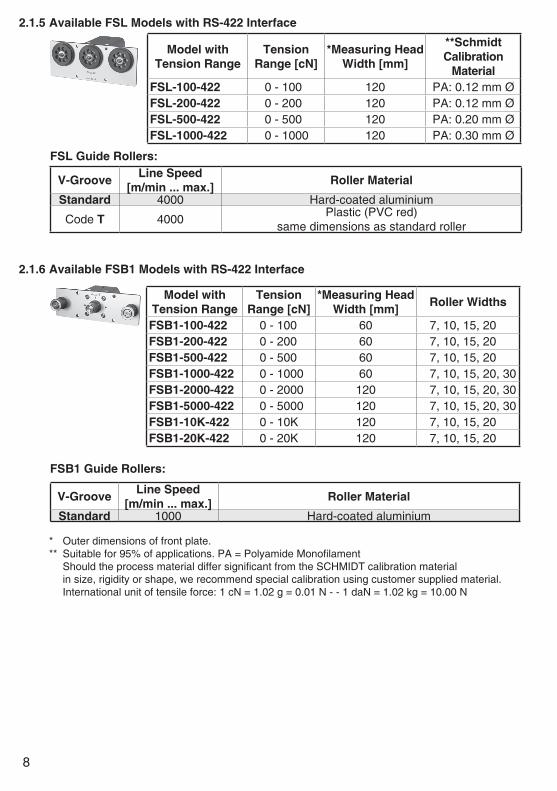
2.1.5 Available FSL Models with RS-422 Interface
FSL Guide Rollers:
Model withTension Range
TensionRange [cN]
*Measuring Head Width [mm]
**SchmidtCalibration
MaterialFSL-100-422 0 - 100 120 PA: 0.12 mm ØFSL-200-422 0 - 200 120 PA: 0.12 mm ØFSL-500-422 0 - 500 120 PA: 0.20 mm ØFSL-1000-422 0 - 1000 120 PA: 0.30 mm Ø
V-Groove Line Speed [m/min ... max.] Roller Material
Standard 4000 Hard-coated aluminium
Code T 4000Plastic (PVC red)
same dimensions as standard roller
* Outer dimensions of front plate. ** Suitable for 95% of applications. PA = Polyamide Monofilament Should the process material differ significant from the SCHMIDT calibration material in size, rigidity or shape, we recommend special calibration using customer supplied material. International unit of tensile force: 1 cN = 1.02 g = 0.01 N - - 1 daN = 1.02 kg = 10.00 N
2.1.6 Available FSB1 Models with RS-422 Interface
FSB1 Guide Rollers:
Model withTension Range
TensionRange [cN]
*Measuring Head Width [mm] Roller Widths
FSB1-100-422 0 - 100 60 7, 10, 15, 20FSB1-200-422 0 - 200 60 7, 10, 15, 20FSB1-500-422 0 - 500 60 7, 10, 15, 20FSB1-1000-422 0 - 1000 60 7, 10, 15, 20, 30FSB1-2000-422 0 - 2000 120 7, 10, 15, 20, 30FSB1-5000-422 0 - 5000 120 7, 10, 15, 20, 30FSB1-10K-422 0 - 10K 120 7, 10, 15, 20FSB1-20K-422 0 - 20K 120 7, 10, 15, 20
V-Groove Line Speed [m/min ... max.] Roller Material
Standard 1000 Hard-coated aluminium

9
2.2 Specifications of the FS-422 SeriesCalibration: According to SCHMIDT factory procedureAccuracy: ± 1% FS* and ± 1 digit or better Other calibration material: ± 3% FS* or better Overload Protection: 100% of rangeMeasuring Principle: Strain gauge bridgeMeas. Roller Deflection: 0.5 mm, max.Natural Frequency of Measuring Spring: Approx. 500 Hz, depending on tension rangeSignal Processing: Digital 12-bit A/D converter, sampling rate approx. 4800 /s Internal averaging up to 4 s Communication Frequency: Approx. 200 readings /sOutput Signal: RS-422 (57600 baud, 8 bits, no parity, 1 stop bit) ASCII communication, max. cable length 400 mTemperature Coefficient: Zero point: less than ± 0.05% FS* / °CTemperature Range: 10 - 45 °CAir Humidity: 85% RH, max.Power Supply: 15 to 24 V DC, 50 mA (regulated)Housing: Aluminium
2.3 Pin Assignment of the RJ45 Connector
PinNo. Signal Description
1 VCC Supply voltage2 GND Ground (GND)3 TX+ (Y) TRANSMITTED DATA +4 RX- (B) RECEIVED DATA +5 RX+ (A) RECEIVED DATA -6 TX- (Z) TRANSMITTED DATA -7 Not assigned8 Not assigned
1 2 3 4 5 6 7 8
RJ45 connectors
2.4 Optional AccessoriesCode SW-TI3: Tension Inspect 3 software for PC evaluation of readingsCode SW-TI3-XX Tension Inspect 3 software for PC evaluation of readings from up to 24 sensorsCode EBG-800: RS-422/RS-232 converterCode EK-0715: Open-ended connection cable (length 3 m) for connection to the RS-422/RS-232 converterCode EK-0711: Sensor-to-sensor connection cable, length 3 mCode EK-0712: Sensor-to-sensor connection cable, length 1.5 m
The requirements of the CE specification are only complied with if the ten-sion sensor is equipped and operated with display units and connecting cables supplied by HANS SCHMIDT & Co GmbH. Certification to the CE specification does not extend to, and shall be invalid for any other combi-nation. Under no circumstances shall HANS SCHMIDT & Co GmbH be held liable for any damage resulting from the use of non-SCHMIDT sensors or cables.
2.3.1 Connecting the Tension Meter
10
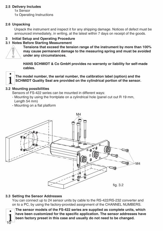
2.6 UnpackingUnpack the instrument and inspect it for any shipping damage. Notices of defect must be announced immediately, in writing, at the latest within 7 days on receipt of the goods.
2.5 Delivery Includes1x Sensor 1x Operating Instructions
3 Initial Setup and Operating Procedure3.1 Notes Before Starting Measurement
Tensions that exceed the tension range of the instrument by more than 100% may cause permanent damage to the measuring spring and must be avoided under any circumstances.
HANS SCHMIDT & Co GmbH provides no warranty or liability for self-made cables.
The model number, the serial number, the calibration label (option) and the SCHMIDT Quality Seal are provided on the cylindrical portion of the sensor.
3.2 Mounting possibilitiesSensors of FS-422 series can be mounted in different ways:- Mounting by using the frontplate on a cylindrical hole (panel cut out R 19 mm, Length 54 mm)- Mounting on a flat platform
3.3 Setting the Sensor AddressesYou can connect up to 24 sensor units by cable to the RS-422/RS-232 converter and on to a PC, by using the factory-provided assignment of the CHANNEL NUMBERS.
The sensor models of the FS-422 series are supplied as complete units, which have been customized for the specific application. The sensor addresses have been factory preset in this case and usually do not need to be changed.
M4
fig. 3.2
M4

11
Online sensor 01
Online sensor 02
Other online sensors
1 2 3 4 5 6 7 8
RJ45 connectors
1 2 3 4 5 6 7 8
1 2 3 4 5 6 7 81 2 3 4 5 6 7 8
3.4 Connecting the Sensors- Install the sensor in the desired position at the measuring location using the provided mounting holes (frontplate or housing). - Connect the sensor(s), the RS-422/RS-232 converter, and the PC.
fig. 3.4bRS-422/RS-232 converter
PC
PinNo. Signal Description Colors
8 Not assigned7 Not assigned6 TX- (Z) TRANSMITTED DATA - Blue / White5 RX+ (A) RECEIVED DATA + Green4 RX- (B) RECEIVED DATA - Green / White3 TX+ (Y) TRANSMITTED DATA + Blue2 GND Ground (GND) Brown / White1 VCC (+VS) Supply voltage Brown
Input
fig. 3.4aMounting holesfront plate
RJ45 connectors
LEDMounting holesHousing

12
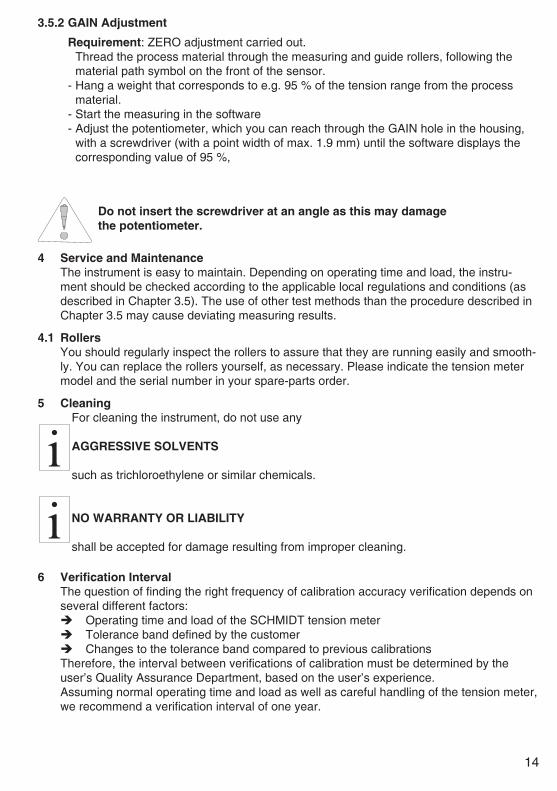
3.5 Internal Adjustment of the SensorsGeneral information:If the sensor has been delivered with a display unit, the ZERO and GAIN adjustments should only be carried out with the supplied display unit.All tension meters are calibrated with standard materials - such as polyamide monofila-ment (PA) - according to the SCHMIDT factory procedure; the material path is vertical. Any difference in process material size and rigidity from the standard material may cause a deviation of the accuracy.In 95% of all industrial applications the SCHMIDT calibration has been proven to provide the best results and is used for comparative purposes.If required you can also operate the sensors with a material path other than vertical. Should the process material differ significantly from the SCHMIDT calibration material in size, rigidity or shape, we recommend special calibration using customer supplied material. If the material path is other than vertical or if the process material deviates sig-nificantly from the SCHMIDT calibration material, you need to carry out static ZERO and GAIN adjustment as described in Chapters 3.5.1 and 3.5.2.
3.4 Connecting the Sensors
The cable length between the last sensor and the converter may be max. 1000 m.The cable length between the converter and the PC may be max. 10 m

13
- Hang a weight that corresponds to e.g. 10 % of the tension range from the process material.- Start the measuring in the software- Adjust the potentiometer, which you can reach through the ZERO hole in the housing, with a screwdriver (with a point width of max. 1.9 mm) until the software displays the corresponding value of 10 %,
Do not insert the screwdriver at an angle as this may damage the potentiometer.
3.5.1 ZERO Adjustment
Mounting holes 4x
Weight
fig. 3.5a fig. 3.5b
Material path symbol
Measuring roller
Guide rollers 2x
ZEROGAIN
fig. 3.5c
- Install the sensor in the desired position at the measuring location using the provided mounting holes.- Allow approx. 10 minutes for thermal stabilization of the sensor.- Thread the process material through the measuring and guide rollers, following the material path symbol on the front of the sensor.
When threading the process material through the rollers, follow the material path symbol on the front of the sensor. If a force is applied to the middle sensor roller in the incorrect direction, damage could result.
Since ZERO and GAIN adjustments are always performed statically, the readings may differ under dynamic load.
14
4 Service and MaintenanceThe instrument is easy to maintain. Depending on operating time and load, the instru-ment should be checked according to the applicable local regulations and conditions (as described in Chapter 3.5). The use of other test methods than the procedure described in Chapter 3.5 may cause deviating measuring results.
4.1 RollersYou should regularly inspect the rollers to assure that they are running easily and smooth-ly. You can replace the rollers yourself, as necessary. Please indicate the tension meter model and the serial number in your spare-parts order.
5 CleaningFor cleaning the instrument, do not use any AGGRESSIVE SOLVENTS such as trichloroethylene or similar chemicals.
NO WARRANTY OR LIABILITY shall be accepted for damage resulting from improper cleaning.
6 Verification IntervalThe question of finding the right frequency of calibration accuracy verification depends on several different factors: Operating time and load of the SCHMIDT tension meter Tolerance band defined by the customer Changes to the tolerance band compared to previous calibrationsTherefore, the interval between verifications of calibration must be determined by the user’s Quality Assurance Department, based on the user’s experience.Assuming normal operating time and load as well as careful handling of the tension meter, we recommend a verification interval of one year.
Requirement: ZERO adjustment carried out. Thread the process material through the measuring and guide rollers, following the material path symbol on the front of the sensor. - Hang a weight that corresponds to e.g. 95 % of the tension range from the process material.- Start the measuring in the software - Adjust the potentiometer, which you can reach through the GAIN hole in the housing, with a screwdriver (with a point width of max. 1.9 mm) until the software displays the corresponding value of 95 %,
3.5.2 GAIN Adjustment
Do not insert the screwdriver at an angle as this may damage the potentiometer.

15
6.1 Verification of Calibration and Determination of Repair Costs
Flow chart for verifying the calibration of used tension meters, incoming and outgoing verification with Inspection Certificate 3.1 according to DIN EN 10204
Delivery
Unit can becalibrated
(functional)
Repair costsexceed 40 % of as
new value
Costs approvedby customer
No
Yes
No
Yes
No
Yes
Vertification of thecalibration
Visual inspectionand functional test
Values withinspecification
Prepare certificationfor
incoming calibration
Determinationof costs
Make ofcost estimate
Repair andadjustment
Verification of thecalibration
Calibration labelon the instrument
No
Invoice scrappingand disposal
Invoice repair andcalibration services
and dispatch
Invoicecalibration services
and dispatch
Prepare certificatefor outgoingcalibration
Yes
Calibration labelon the instrument
7 CorrespondenceShould you have any questions regarding the instrument or Operating Instructions, or their use, please indicate above all the following details which are given on the ID plate: 1.) Model 2.) Serial number
8 RepairsShipping instructions:We kindly ask for return free of charge for us, if possible by airmail parcel. All occurring charges, if any (such as freight, customs clearance, duty etc.), will be billed to customer. For return from foreign countries, we ask you to include a proforma invoice with a low value for customs clearance only, e.g. 50 Euro, each and to advise the shipment in advance by fax or eMail.
To avoid unnecessary follow-up questions, and the resulting loss of time or possible misunderstandings, please return the instrument with a detailed fault description to our service department. Please indicate in your order whether you require an Inspection Certificate 3.1 according to DIN EN 10204.
Service address: HANS SCHMIDT & Co GmbH Schichtstr. 16 84478 Waldkraiburg Germany
Mailing address: P. O. B. 1154 84464 Waldkraiburg GermanyShipping address: Schichtstr. 16 84478 Waldkraiburg Germany
Hans Schmidt & Co GmbHPhone: int. + 49 / (0)8638 / 9410-0 Fax: int. + 49 / (0)8638 / 4825 int. + 49 / (0)8638 / 67898
More than 70 years - Worldwide -
e-mail:[email protected]
Internet:http://www.hans-schmidt.com